
WOM General Catalog 2015 - JL Offshore AS
64
-
Upload
khangminh22 -
Category
Documents
-
view
0 -
download
0
Transcript of WOM General Catalog 2015 - JL Offshore AS


WOM proudly celebrates 35 years of providing the oil & gas industry with meticulously designed, well-engineered pressure and flow control equipment. WOM looks forward to continuing to make a positive impact on the process of safely extracting one of the
world’s most precious resources. We are honored to work with the businesses that have trusted our commitment to excellence and appreciate each member of our group that
has contributed to our success.

Table of ContentsTable of ContentsIntroduction .................................................................................................................................................................................... 4Worldwide Service Support ........................................................................................................................................................... 5Vision and Mission ...................................................................................................................................................................... 6-7HSE and Quality ......................................................................................................................................................................... 8-9 Magnum Gate Valve...................................................................................................................................................................... 10 Advantages of the Magnum Design ...................................................................................................................................... 11Gate Valve Standard Trim Chart ................................................................................................................................................... 12Research and Development ........................................................................................................................................................... 14Model 200M Gate Valve ............................................................................................................................................................... 15Model WV 200 Gate Valve ........................................................................................................................................................... 15WOM Subsea ................................................................................................................................................................................ 16WOM Asia Pacific ........................................................................................................................................................................ 17Subsea Gate Valve ...................................................................................................................................................................... 18-19Actuator ...................................................................................................................................................................................... 20-21 Fail Safe Pneumatic and Hydraulic Actuator ........................................................................................................................ 20 Magnum Subsea Actuator ..................................................................................................................................................... 21Slurry Service Gate Valve ............................................................................................................................................................. 22Model 600 Mud Valve................................................................................................................................................................... 22Line Pressure Operated SSV ......................................................................................................................................................... 23Dual-Seal Ball Valve ..................................................................................................................................................................... 24Dual-Seal Ball Valve Trim Chart .................................................................................................................................................. 26Diverter System Valves ................................................................................................................................................................. 27Wellhead and Christmas Tree Systems ......................................................................................................................................... 28 Wellhead Products .............................................................................................................................................................. 29-31Single Piece Wellhead System ...................................................................................................................................................... 32Multi-Completion Wellhead System ............................................................................................................................................. 33Manifold Systems ......................................................................................................................................................................... 34 Choke Manifolds ................................................................................................................................................................... 34 Cement Manifolds ................................................................................................................................................................. 35 Standpipe Manifolds ............................................................................................................................................................ 35Blow Out Preventers ..................................................................................................................................................................... 36 Ram Type WU BOP .............................................................................................................................................................. 37 WGK Annular BOP............................................................................................................................................................... 38Subsea Intervention System .......................................................................................................................................................... 40Subsea Intervention Deployment Summary Chart ....................................................................................................................... 42Subsea Intervention Package ........................................................................................................................................................ 44Subsea Trees.................................................................................................................................................................................. 46Subsea Manifolds .......................................................................................................................................................................... 47Subsea Connection System ........................................................................................................................................................... 48Well Containment System ............................................................................................................................................................ 48Slimbore Drilling Package ............................................................................................................................................................ 49Subsea Shut off Device ................................................................................................................................................................. 49Pump Saver ................................................................................................................................................................................... 50Check Valves ................................................................................................................................................................................. 50Chokes........................................................................................................................................................................................... 51Controls and Instrumentation ..................................................................................................................................................... 52-53MTC-Well Test Equipment ........................................................................................................................................................... 52Well Test Valves .......................................................................................................................................................................... 54Flowheads ..................................................................................................................................................................................... 55Custom Design and Manufacture .................................................................................................................................................. 56Global Service and Support .......................................................................................................................................................... 57 Repair and Retrofit ................................................................................................................................................................ 57Magnum Forge and Machine Works ............................................................................................................................................. 58Conversion Chart .......................................................................................................................................................................... 59Worldwide Location and Service Center ...................................................................................................................................... 60Terms and Conditions ................................................................................................................................................................... 63
Houston, Usa ▪ Aberdeen, Uk ▪ Pune, India ▪ Dubai, Uae ▪ Singapore Ashgabat, Turkmenistan ▪ Jakarta, Indonesia ▪ seoul, south Korea
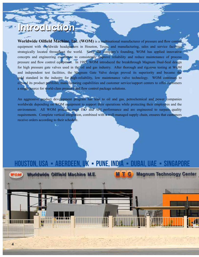
Worldwide Oilfield Machine, Inc. (WOM) is a multinational manufacturer of pressure and flow control equipment with worldwide headquarters in Houston, Texas, and manufacturing, sales and service facilities strategically located throughout the world. Since the company’s founding, WOM has applied innovative concepts and engineering excellence to consistently improve reliability and reduce maintenance of process pressure and flow control equipment. In 1985, WOM introduced the breakthrough Magnum Dual-Seal design for high pressure gate valves used in the oil and gas industry. After thorough and rigorous testing at WOM and independent test facilities, the Magnum Gate Valve design proved its superiority and became the gold standard in the industry for high-reliability, low maintenance valve technology. WOM continues to expand its product portfolio, manufacturing capabilities and customer service/support centers to offer customers a single source for world-class pressure and flow control package solutions.
An aggressive product development program has lead to oil and gas, petrochemical and power companies worldwide depending on WOM equipment to support their operations while protecting their employees and the environment. All WOM products meet ISO and API performance and are engineered to surpass quality requirements. Complete vertical integration, combined with a well-managed supply chain, ensures that customers receive orders according to their schedule.
IntroductionIntroduction
4

Worldwide Service and SupportWorldwide Service and Support
Houston, Usa ▪ Aberdeen, Uk ▪ Pune, India ▪ Dubai, Uae ▪ Singapore Ashgabat, Turkmenistan ▪ Jakarta, Indonesia ▪ seoul, south Korea
SERVING THE OIL AND GAS INDUSTRY FOR OVER YEARS!
This catalog is an overview of the WOM product line, while more details on each product and product family highlighted herein are available within individual product descriptions. Please visit the WOM at www.womusa.com to download a file copy of any product or system
Your local WOM representative is also available to assist in selecting the right piece of equipment to meet the reliability and operating requirements of the application, and ensure the success of your project.
Satisfying customer needs is top priority at WOM. Whether there is a technical/operational question, custom
design requirement or call to service equipment in the field, WOM Engineering and Service Centers are strategically
located worldwide to support your operations. With one of the largest inventories of replacement parts available,
spares can be rapidly shipped to where they may be needed. Factory-trained technicians, deployed from WOM
Service Centers, also perform comprehensive site assessments, reconditioning and upgrading of existing
equipment. Recognizing the mission-critical nature of our customers’ operations, world-class WOM service facilities and highly trained, experienced service technicians are available 24/7 to support WOM equipment
and systems in the field. The WOM comprehensive service program reduces the risk of downtime while
increasing safety.
5

To make a difference in the communities in which the WOM group of companies operates by providing a world-class organization that develops a way of existence and sets the pinnacle of standards in all walks of life, whether at work or in society, to ensure future generations healthy, stable, and fruitful lives.
VISIONVISION
6

To service the oil & gas industry by providing relentless reliability in our products and fulfilling our customer’s “wish lists” by continuously designing and developing innovative features that will reduce the end users’ maintenance and increase overall safety and production.
MISSIONMISSION
7

The policy of Worldwide Oilfield Machine (WOM) is to maintain a Health, Safety, and Environmental Program by conforming to regulatory standards and best practices while providing a safe, healthy, and sustainable environment for its employees and customers.HSEHSE
8

The Quality Policy of Worldwide Oilfield Machine is to meet and exceed the quality standards expected by our customers by providing the finest quality products and services as we become the premier supplier of Well Control Systems and Products.
WOM is committed to comply with the requirements of industry-regulated bodies (API Q1, ISO 9001:2000) by showing continual improvements to the effectiveness of the Quality Management System.
The Quality Policy, Business Mission and Company Objectives are understood, implemented and maintained at all appropriate levels of the WOM organization. The Quality Assurance Manual sets forth the requirements for establishing and maintaining a Quality Man-agement System at WOM.
QualityQuality
9

10
Can be equipped with pneumatic or hydraulic actuators and is ideally suited for Manifold and Christmas Tree applications.
PATENTED
Magnum Gate Valve
• Available in sizes 1-13/16” - 9”• Working pressure ratings of 2,000 to 20,000 psi.• Full Bore, Through-Conduit Seal• Bi-Directional Sealing • Primary (Upstream) Seal • Secondary (Downstream) Seal• Lower Torque • Floating Gate with T-Slot • Centralized stem threads • Superior finish on gates and seats • Balanced forces on gate and seats• Longer Life of Gate and Seals
• Minimal exposure to contaminants• Minimal lubricant loss
• Elastomer Assist Metal-to-Metal Seal or Non-Elastomeric Seals• Differential Avoids Pressure Lock• Extended Service Life with Minimum Maintenance Requirements
Features and Benefits
WOM Magnum Gate Valve
The Magnum Gate Valve incorporates a design which has become the cornerstone of the WOM product line and is synonymous in the oil & gas industry for unmatched quality and unsurpassed service life.
Available in a wide range of material selections and suitable for harsh environments such as C02 and H2S applications, the Magnum Gate Valve has proven its versatility in the North Sea, the Gulf Coast, the Middle East, South America, North America, Africa, Singapore, China and drillships and platforms across the globe and is trusted by the biggest names in the industry.

A T-Slot Gate paired with an independent stem nut allows the gate to float, maintaining contact with the seats without binding on the stem and requiring less torque to cycle the
valve during operation.
Compatible with Elastomeric &
Non-Elastomeric Seals
Gate in the CLOSED PositionPrimary Upstream Seal presses against
the gate to provide a seal and avoid intrusion into the body cavity.
Gate in the CLOSED Position If the Primary Upstream Seal fails, the
Secondary Downstream Seal takes over to avoid intrusion into the thru-bore.
Gate in the OPEN Position Primary Upstream & Downstream Seals press against the gate to provide a seal and avoid intrusion into the body cavity
and thru-bore.
Zero Leak
The heart of this bidirectional valve is the MAGNUM “Sure Seal”. This simple gate/seat assembly eliminates gate guides, seat skirts and springs. Instead, line pressure expands the seat assembly against the floating gate forming a true upstream seal.
Advantages of the Magnum Design
T-SLOT GATE

12
Sizes: 1-13/16” through 9” (larger sizes available upon request)Working Pressures: 2,000 psi through 20,000 psi
Notes: 1. Materials shown are for reference purposes only and are subject to change.2. Special trims and materials are available, such as duplex stainless steel for bodies and bonnets, Inconel HF for gates and seats, and Inconel for stems. 3. Abbreviations: SS-Stainless Steel; QPQ-Quench Polish Quench; HF-Stellite/ Colmonoy, W/HF-Hard Facing. 4. -75°F (-59°C) available upon request.5. Wire-line and fire safe valves available upon request.6. High temperature (450°F) (232°C) valves available upon request.7. All QPQ Gate and Seats have an option of Colmonoy Hard-Facing.8. Alternate material for Stems-Inconel 7259. Alternate material for HH Trims-Duplex SS
Gate Valve Standard Trim Chart

13

Research and Development
WOM’s state-of-the-art Research and Development facility allows for in-house testing, which greatly speeds up the new product development and qualification testing. This lab includes environmental chambers for extreme temperature testing and testing booths for room temperature testing. The temperature chambers are some of the most advanced in the world, capable of reaching temperatures from -100°F to 600°F. WOM has successfully completed HPHT API 6A PR2 testing with a temperature range of -20°F to 450°F for 3-1/16”- 20,000 PSI Magnum Gate Valve and 3-1/16”-15,000 PSI Model 200M Gate Valve.
The lab also includes an advanced control room from where the testing can be monitored remotely, providing a safe environment away from the actual product testing.
14
Before - 20
oF to 450
oF Testing
After - 20
oF to 450oF Testing

Model WV200 Gate Valve
Model 200M Gate Valve
Model 200M Gate Valve
• Available in sizes 1-13/16” - 7-1/16”
• Working pressure ratings from 2,000 psi-15,000 psi
• Forged body and bonnet for the highest mechanical integrity
• Bi-directional flow design offers versatility and increased service life
• Grease injection fitting located in bonnet, eliminating body penetration
• Bearing cap grease fitting allows positive bearing lubrication
• Available in standard flange ends, butt weld ends and block body configurations
• Can be equipped with pneumatic or hydraulic actuators
• The 200M Gate Valve has been API 6A fire tested to 450ºF and can be fitted for HPHT service
Features and Benefits
• Available is sizes 2-1/16” - 3-1/8”
• Available in working pressure rating of 5,000 psi
• Single piece, floating slab gate reduces deflection and binding at high pressure
• Material construction forged body and bonnet
• Bi-directional sealing
• Metal-to-metal sealing gate/seat, seat/body and body/bonnet interfaces
• Low torque requirements to reduce operator fatigue
• Cost efficient gate valve that provides reliable downstream sealing capability
Features and Benefits
Model WV 200 Gate Valve
15
WOM Subsea
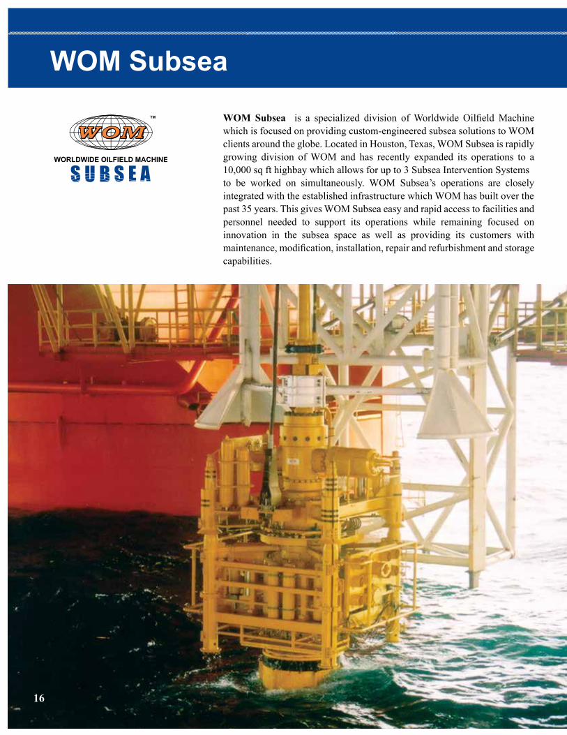
WOM Subsea is a specialized division of Worldwide Oilfield Machine which is focused on providing custom-engineered subsea solutions to WOMclients around the globe. Located in Houston, Texas, WOM Subsea is rapidlygrowing division of WOM and has recently expanded its operations to a 10,000 sq ft highbay which allows for up to 3 Subsea Intervention Systemsto be worked on simultaneously. WOM Subsea’s operations are closely integrated with the established infrastructure which WOM has built over thepast 35 years. This gives WOM Subsea easy and rapid access to facilities andpersonnel needed to support its operations while remaining focused on innovation in the subsea space as well as providing its customers with maintenance, modification, installation, repair and refurbishment and storage capabilities.
16

17
WOM Asia Pacific (WOM AP) formerly known as Magnum Subsea Systems (MSS), is focused on designing and delivering reliable subsea systems which meet our client’s technical requirements WOM AP has combined with WOM SEA (referred to solely as WOM AP) to provide its customers with Front End Engineering Design (FEED) study, project Management Services, Field Support Services along with refurbishment, redesign and recertification Services, all from one point of contact.
TMTM
WOM Asia Pacific

18 WOM Magnum Dual Block used for capping on Macondo Well (Gulf of Mexico)

Drilling and Production Applications
Features and Benefits
19
Subsea Gate Valve
• Designed, built and tested to API 6A and 17D
• Tested to a water depth of 13,200 feet
• Anti-explosive decompression seals and energized non-elastomeric lip seals
• Metal-to-metal seal (seat to gate)
• Magnum “Dual-Seal” seat design seals upstream and downstream
• With Magnum “Dual-Seal” seat design seals “thru-conduit”, bonnet can be removed and replaced while the valve is in working condition. This will minimize the maintenance time and inventory cost for customers
• Gate and seat faces are hard faced with Colmonoy 4, 5 & 75 and polished to 1-2 RMS. This is for wear resistance and low operating torque. Tungsten Carbide, Stellite and other HF material are also available
• Cladding of “all wetted parts” is available
• “T” Slot stem and gate connection allows the gate to “Float” between seats without misaligning the stem under pressure
Magnum Subsea Dual-Block

Pneumatic Fail Safe Actuator
Hydraulic Fail Safe Actuator
ActuatorsFail Safe Pneumatic and Hydraulic Actuator
• WOM’s pneumatic and hydraulic actuators are manufactured and tested to API 6A
• Single forged unitized top cap and cylinder for simple in-line maintenance
• Quick disconnect mechanism allows for fast removal without disturbing the body/bonnet connection and provides immediate access to stem packing
• Anti-explosive decompression seals and energized non-elastomeric lip seals are available • Factory preset drift eliminates the need for field adjustments
Features and Benefits
20

21
WOM’s Magnum Subsea Actuator design boasts a “Truly Fail Safe”capability- no line pressure or hydraulic control pressure is required to assist in closing the valve. A unique feature of the Magnum Subsea Actuator is its “Double-Safe” design which incorporates a single acting fail-safe hydraulic actuator with a spring return. In addition to an ROV mechanical override, the Magnum Subsea Actuator offers an additional port to accommodate ROV hydraulic override.
Magnum Subsea Actuator• Magnum Subsea Actuators are designed, built and tested to API 6A and 17D
• Magnum Subsea Actuators are designed and tested to a water depth of 13,200 feet
• Equipped with anti-explosive decompression seals and energized non-elastomeric lip seals
• Pressure equalization system maintains 0 psi differential pressure
• Factory pre-set drift eliminates the need for field drift adjustments.
Features and Benefits
Actuator body completely contains compressed spring
Quick disconnect mechanism allows fast removal without disturbing body/bonnet connection. Provides immediate access to stem packing
Magnum “Sure-Seal” mechanism is pressure-energized for upstream/downstream sealing, equalizing line pressure on both sides of the gate
Factory preset drift eliminates need for field adjustment
“T” slot stem and gate connection allow gate to “float” between seats without misaligning the stem
Gate and seat faces are hard-faced and polished for wear resistance and low operating torque
Full bore through-conduit flow in full open position
Single forged unitized top cap and cylinder for simple in-line maintenance
Magnum Subsea Gate Valve with Fail Safe Actuator

Magnum Mud Gate Valve
Skirted DUAL-SEAL TM
Seat Assembly(Magnum Gate Valve)
Designed for mud, cement, fracturing and water service to handle high and fluctuating pressure and abrasives.
Slurry Service Gate Valve
Model 600 Mud ValveThe Model 600 Mud Valve was designed for corrosive CO2 injection and waterflood applications in the enhanced oil recovery market. It is commonly used for applications such as high pressure mixing lines, standpipe manifolds, wellheads, production manifolds and production gathering systems.
• Available in sizes 1 13/16” - 5 1/18”
• Available in working pressures from 5,000 psi and 7,500 psi
• Floating slab gate design
• Heavy duty roller bearings
• Seat assembly engineered with “lock shell” ensures accurate seat alignment
• Available with threaded, welded and flanged end connections
• Rising stem design with visual position indicator lens
• Replaceable stem packing
Features and Benefits
• Available in sizes 1-13/16” - 5”
• Available in working pressure ratings from 3,000 psi-10,000 psi
• Features WOM’s patented Magnum Dual Seal™ system
• Thru-Conduit seal eliminates the turbulence experienced in paddle gate mud valves
• Skirted seat assembly prevents contaminants from entering the valve body cavity
• Body cavity is exposed to line pressure only during valve opening and closing
• Better lubricant retention, less exposure to line contaminants and longer service life than comparable valves
• Can be easily serviced in-line and all internal components can be inspected and replaced
• All mud valves meet or exceed the requirements for API 6A
Features and Benefits
Model 600 Mud Valve
22

• Available in sizes ranging from 1-13/16” - 7-1/16”
• Available in working pressures from 2,000 psi to 20,000 psi
• Ideal for single point protection where control pressure is not available, installed as a secondary master on a tree, on flow lines, header valves, gathering lines, pipelines and transmission lines
• Self-operating system which uses line pressure as control pressure to activate the actuator
• High and low pressure pilots sense line pressure continuously. Abnormal pressure changes cause the pilots to exhaust control pressure from the safety valve, closing the valve
• Centralized stem threads and T-nut combined with T-slot gate reduce the overall torque needed to cycle the valve
• Colmonoy 4, 5 & 75, Tungsten Carbide, Stellite and other HF materials are available
• Compatible with elastomer-assist metal-to-metal seals or non-elastomeric seals
Features and Benefits
Line Pressure Operated SSV
WOM’s Line Pressure Operated Surface Safety Gate Valve
23
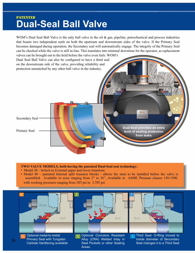
Dual-Seal Ball ValveWOM’s Dual Seal Ball Valve is the only ball valve in the oil & gas, pipeline, petrochemical and process industries that boasts two independent seals on both the upstream and downstream sides of the valve. If the Primary Seal becomes damaged during operation, the Secondary seal will automatically engage. The integrity of the Primary Seal can be checked while the valve is still in-line. This translates into minimal downtime for the operator, as replacement valves can be brought out to the field before the valve even fails. WOM’s Dual Seal Ball Valve can also be configured to have a third seal on the downstream side of the valve, providing reliability and protection unmatched by any other ball valve in the industry.
1 2 3
1
Ball
Body
Ball
Body
2
Ball
Body
3
Optional metal-to-metal Primary Seal with Tungsten Carbide Hardfacing available
Optional Corrosive Resistant Alloy (CRA) Welded Inlay in Seat Pockets or other Sealing Areas.
Third Seal: O-Ring moved to inside diameter of Secondary Seal changes it to a Third Seal
PATENTED
TWO VALVE MODELS, both having the patented Dual-Seal seat technology: • Model 30 – bolted on External upper and lower trunnions• Model 40 – patented Internal split trunnion blocks - allows the stem to be installed before the valve is assembled. Available in sizes ranging from 2” to 36”, Available in ASME Pressure classes 150-1500, with working pressures ranging from 285 psi to 3,705 psi
Secondary Seal
Primary SealDual-Seal provides an extra level of sealing protection
from leaks
24

25
• Primary Seal acts as a wiper ring to clean off the ball and protect the Secondary Seal
• All valves are Double Block and Bleed (DBB)
• Engineered to prevent pressure build-up in the body eliminating the need for thermal relief
• All Dual Seal Ball Valves are ISO Fugitive Emissions Certified
• Available in working pressures from 2,000 PSI to 5,000 PSI
• All valves are Fugitive Emissions certified per ISO 15484-1: 2006
• Fire-Safe per ISO, API 6FA, or API 607
• Integral stop ensures precise 90 degrees of rotation • Patented Split-Block in the Model 40 features the Valve stem inserted from body interior, making the stem positively blowout proof
• In Liquids service there is no need for external pressure relief from thermal expansion. Valve self-relieves internally
• Optional Third Seal for additional protection, and to control which end of the valve the thermal relief will bleed to
• Optional Metal to Metal Primary seat for severe service conditions
• Designed to replace through-conduit gate valves in mainline service
Features and Benefits for Model 30 & 40

Dual-Seal Ball Valve Trim Chart
Component Trim A Trim B Trim C Trim D Trim E Trim F Trim G
General Service- Oil, Natural Gas, Refined
Products Temp Range: -29 to
+121C, -20F to +200F
Low Temperature Service -Oil and Gas
Service Temp Range: -45C to +121C, -50C to +200F
Mild Brine Service- Temp Range: -29C to +121C, -20F to +200F
Severe or Sour Brine Service -
Temp Range: -29C to +121C, -20F to +200F
Severe Sour Service- Oil and Gas NACE S.S. Trim
Temp Range: -29C to +121C, +20F to +200F
Highly Corrosive Oil and Gas H2S/CO2 Sour
Service- NACE Full S.S. Temp Range: -29C to +121C, -20F to +200F
Highly Corrosive hydrocarbon and
chemicals NACE Full S.S Temp Range: -29C to +121C, -20F to +200F
Body, End Connections (1)
Alloy SteelAlloy Steel, Q&T
controlled hardness RC-22 max A216 WCB
Alloy Steel Seat Pockets overlayed with 316 S.S.
A216 WCB
Alloy Steel controlled hardness, RC-22 max.
Seat pockets overlayed with 316 S.S A216 WCB
Alloy Steel controlled hardness A216 WCB
CF8M Cast Stainless Steel Duplex Stainless Steel
Stem 4130 Alloy w/ENP4130 Alloy Steel
w/ENP Controlled Hardness
4130 Alloy w/ .003" ENP 17-4 PH S.S Inconel 718 Inconel 718 Duplex Stainless Steel
Seat AssemblyCarbon Steel/
Electoless Nickle PlateCarbon Steel/
Electoless Nickle PlateCarbon Steel w/.003" Electoless Nickle Plate
17-4 PH S.S 17-4 PH S.S 17-4 PH S.S Duplex Stainless Steel
BallCarbon Steel/
Electoless Nickle PlateCarbon Steel/
Electoless Nickle PlateCarbon Steel w/.003" Electoless Nickle Plate
17-4 PH S.S 17-4 PH S.S 17-4 PH S.S Duplex Stainless Steel
Seat Insert PTFE/Nylon PTFE/Nylon PTFE/Nylon PTFE/Nylon PTFE/Nylon PTFE/Nylon PTFE/Nylon
Stem Seal (2) Viton Viton Viton Viton Viton Viton Viton
Springs 17-7 S.S Inconel X-750 17-7 S.S Inconel X-750 Inconel X-750 Inconel X-750 Inconel X-750
O-Rings (3) Viton Low Temp O-Ring Viton Viton Viton Viton Viton
Bolting A193-B7 A193-L7M A193-B7A193-B7 Fluropolymer
coated A193-B7M A193-B7M A193-B7M
Body Fittings Carbon Steel Stainless Steel Stainless Steel Stainless Steel Stainless Steel Stainless Steel Stainless Steel
WOM Dual Seal ™ Ball Valve Material Selection
Notes: 1. C.R.A (Corrosion Resistant Alloys) inlay in seat pockets can be added to any valve2. Upper stem seals are self-energized Viton seals with additional Viton back up O-rings3. Various O-ring materials can be used depending on temperature range and service conditions4. Fluorocarbon coating on bolting is optional
26

• Rugged construction• Dual-Seal™ technology offering Primary and Secondary Seals• Optional Flush ports to wash contaminants from body• Repairable on the rig or reverse the valve for a new set of seals• Integral stop for accurate positioning of open/closed• Hydraulic automation available
NO FUGITIVE EMISSIONSISO Spec 15848-1: 2006 (E), valve cannot exceed 50ppm of fugitive emissions after1500 full pressure openings at 2220 psi.
The Dual-Seal Ball Valve passed this test with standard stem seals.
Annular BOP
Dual-Seal Ball Valve
Diverter System Valves
27

The Patented Magnum Gate Valve, the key component of any WOM wellhead system, provides the most reliable long-term seal and lowest lifecycle costs. WOM designs, manufactures and supplies Wellhead and Christmas Tree Systems of all sizes, working pressures, and trims. The WC-22 wellhead system is the standard for outstanding service - onshore and offshore. The WC-22 wellhead system can be built to meet specific requirements for pressures from 2,000 psi through 20,000 psi, with metal-to-metal seal technology being standard on high-pressure applications.
Wellhead and Christmas Tree Systems
Typical WOM XMAS Tree
29
Wellhead and Christmas Tree Systems Wellhead ProductsCasing Heads
Casing Head Spools
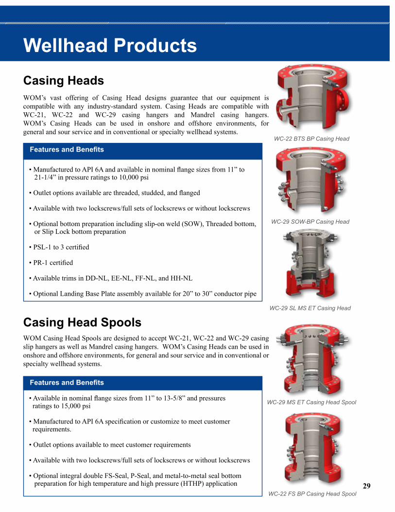
WOM’s vast offering of Casing Head designs guarantee that our equipment is compatible with any industry-standard system. Casing Heads are compatible with WC-21, WC-22 and WC-29 casing hangers and Mandrel casing hangers. WOM’s Casing Heads can be used in onshore and offshore environments, for general and sour service and in conventional or specialty wellhead systems.
WC-22 BTS BP Casing Head
• Manufactured to API 6A and available in nominal flange sizes from 11” to 21-1/4” in pressure ratings to 10,000 psi
• Outlet options available are threaded, studded, and flanged
• Available with two lockscrews/full sets of lockscrews or without lockscrews
• Optional bottom preparation including slip-on weld (SOW), Threaded bottom, or Slip Lock bottom preparation
• PSL-1 to 3 certified
• PR-1 certified
• Available trims in DD-NL, EE-NL, FF-NL, and HH-NL
• Optional Landing Base Plate assembly available for 20” to 30” conductor pipe
Features and Benefits
WC-29 SOW-BP Casing Head
WC-29 SL MS ET Casing Head
WOM Casing Head Spools are designed to accept WC-21, WC-22 and WC-29 casing slip hangers as well as Mandrel casing hangers. WOM’s Casing Heads can be used in onshore and offshore environments, for general and sour service and in conventional or specialty wellhead systems.
• Available in nominal flange sizes from 11” to 13-5/8” and pressures ratings to 15,000 psi
• Manufactured to API 6A specification or customize to meet customer requirements.
• Outlet options available to meet customer requirements
• Available with two lockscrews/full sets of lockscrews or without lockscrews
• Optional integral double FS-Seal, P-Seal, and metal-to-metal seal bottom preparation for high temperature and high pressure (HTHP) application
Features and Benefits
WC-29 MS ET Casing Head Spool
WC-22 FS BP Casing Head Spool

30
Tubing Head Spools
Tubing Hangers
WOM’s Tubing Head Spools feature a straight bore design for single and multiple completions. This design accepts all WTC series tubing hangers and easily converts from a single completion to multiple completions
• Available in nominal flange sizes from 7-1/16” to 11” and pressure ratings to 20,000 psi
• Outlet options available to meet customer requirements
• Designed to accept WC-21, WC22, and WC29 casing slip hanger and Tubing hangers
• Available with full sets of lockscrews
• Optional integral single or double Down Hole Control Line (DHCL) preparation
• Optional integral double FS-Seal, P-Seal and interchangeable metal-to- metal seal bottom preparation for HTHP application
Features and Benefits
WTC-MS1-ET Tubing Head Spool
WTC-FS-ET Tubing Head Spool
WOM Tubing Hangers allow for nippling up/down the Christmas tree without blowout preventer (BOP) protection. WOM Tubing Hangers feature an annulus compression elastomer seal pack off or an optional annulus metal-to-metal seal energized by a compression ring.
• Available in nominal sizes from 7-1/16” to 11” and pressure ratings to 20,000 psi
• Manufactured to API-6A specifications with stainless or Inconel body material and can be customized
• Extended Neck with multiple elastomer type seals or optional metal- to-metal seals are available for high temperature and high pressure (HTHP) application
• Annulus compression elastomer seal pack off or optional annulus metal- to-metal seal are energizing by compression ring
• Available with internal or external running and retrieving thread
• Standard type “H” Back Pressure Valve (BPV) preparation
• Available with API or Premium bottom internal thread
• Available with or without continuous and non-continuous Down Hole Control Line (DHCL) preparation
Features and Benefits
WOM WTC Series Tubing Hangers
Wellhead Products Con’t.

Tubing Head AdaptersWOM Tubing Head Adapters are suitable for conventional and specialty wellhead systems, onshore and offshore and general and sour service applications. Designed for containing pressure and fluids within the tubing bore. WOM Tubing Head Adapters are fully customizable for the project at hand. Options include continuous or non-continuous Down Hole Control Line inlet preparation and integral manual or actuated Lower Master Valve.
• Available in studded or flange bottom sizes from 7-1/16” to 11” and studded or flange top sizes from 2-1/16” to 4-1/16”, with pressure ratings for both to 20,000 psi • PSL-1 to 3G certified
• PR-1 certified
• Available trims: DD-NL, EE-NL, FF-NL and HH-NL
• Available with S-Seal or metal-to-metal seal bottom preparation
• Available with or without continuous and non-continuous Down Hole Control Line (DHCL) inlet preparation
• Available with integral manual or actuated Lower Master Valve
Features and Benefits
WOM Tubing Head Adapters
31

WOM Design SP 3 Stage Wellhead System
WOM’s SPTM Compact Wellhead is a single-piece, compact wellhead system developed to accommodate different requirements of working pressure and casing programs. The SPTM Wellhead uses a minimum number of components all which are interchangeable within the system resulting in reduced installation time, possible leak paths and overall costs.
• Compact design saves space and permits the use of smaller platforms at a reduced cost
• Nominal size 9”, 11”, 13-5/8” or 18-3/4” and pressure rating of 5,000 psi or 10,000 psi
• Available in 2 or 3 stage hanger systems
• “WQ” Quick Connector on housing top connection • Casing programs offer flexibility and can be easily changed on site
• Fluted mandrel-type hangers for effective cementing flow-by
• Mandrel-type hangers offer complete BOP control, eliminating work under BOP stack and enhancing safety
• Internal lockdown for hangers
• Same pack-off for all sizes of mandrel hangers
• Elastomeric and metal seal assemblies are interchangeable
• Design based on field-proven and fully tested technology
• Enhanced safety with minimum through-wall penetrations
• Cold cut option is available for emergency purposes
• Designed to meet API 6A, latest edition to PSL 1-4, Temperature Rating 0-350° F and Material Classification AA-HH meet NACE requirements
Features and Benefits
Single Piece (SPTM) Wellhead System

33
Single Piece (SPTM) Wellhead System Multi-Completion (WMCTM) Wellhead SystemWOM WMCTM Wellhead System combines two or more wellhead systems, providing the ability to reach multiple pay zones, from a single conductor.
• WMCTM Wellhead System is WOM’s field-proven SPTM Wellhead, that offers a compact, safe and reliable solution to multiple completion projects
• Fewer connections in the system results in significant rig time reduction
• Reduced envelope dimension allows for smaller platform requirement
• Various casing separation methods are available to meet specific drilling requirement
• Full metal to metal (MTM) seal completion is available
• Available in 2-in-1 and 3-in-1 configurations
• Individual wellheads can be configured to have a 9”, 11”, or 13-5/8” nominal size, up to a 10,000 psi pressure rating and a temperature range of -75oF to 250oF
• Manufacturing meets API Spec. 6A standards, and can be specified to meet at the material class, temperature class, and PSL level requirements of this specification
Features and Benefits
Multi-Completion (WMCTM) Wellhead System

34
Manifold Systems
WOM specializes in the manufacture of manifolds for a complete range of onshore and offshore applications. WOM Manifold Systems may incorporate WOM Magnum Gate Valves, Check Valves, Chokes and WOM Actuators depending upon the application. WOM manifold designs meet virtually any industry requirement, including H2S environments up to 20,000 psi. Skid mounted and fully automated packages are available complete with control panels and instrumentation.
Choke ManifoldsWOM’s Choke Manifolds incorporate Magnum Gate Valves which have set the industry standard for reliability. All Manifold Systems are tested for function and pressure rating prior to delivery. WOM offers Choke Manifolds in five valve rectangular and four valve diamond patterns for limited space on offshore rigs.

35
Cement ManifoldsWOM’s Cement Manifolds are available in working pressures up to 20,000 psi. Each system incorporates Magnum Gate Valves or Model 700 and is designed for heavy slurry and high pressure. WOM can designs and manufactures Cement manifold to meet any custom requirements.
WOM’s Standpipe Manifolds incorporate Magnum Mud Gate Valves or Model 600 Mud Gate Valves and are rated for pressures up to 10,000 psi. Welded, flanged, hubbed, high-pressure fittings and hammer union constructions are built to meet customer preference. All systems are designed, manufactured and certified in accordance to recognized oilfield standards.
Standpipe Manifolds

For onshore and offshore operations, WOM manufactures popular Annular and Ram BOP designs.
WOM is certified to ISO 9001 Designed to NACE MR-01-75 materials standard for resistance to sulfide stress cracking.
Blow Out Preventers
Typical WOM WGK Annular and WU Ram Type BOP Assembly

37
The WU BOP’s simple and compact design makes it well suited for operations offshore and onshore. WOM’s WU BOP’s parts are fully interchangeable with U-Type BOPs in the market. The operation system of WU BOPs are designed to provide a fast and reliable closure around pipe or casing in the well bore. The sealing is energized by the pressure and is maintained even with loss of closing pressure. WOM’s WU BOPs are operating in various places all over the world such as USA, Algeria, Kuwait, UAE, India, Indonesia, China and Oman.
• Available in sizes ranging from 7”-5K to 26”-3K
• Ram packing is generous and self-feeding. It cannot be dislodged by fluid flow
• Operating pressure is moderate, due to the large area of the piston
• Changing the ram is quick and easy
• Hydraulically operated locking mechanisms to hold the Rams closed without actuation pressure
• Seals and a vent hole prevent well pressure from bleeding into operating cylinder
• All operating parts, as well as rams and seals, can be replaced on location, thus providing a completely reconditioned preventer
Features and Benefits
Ram Type WU BOP
WU Ram BOP

WGK Annular BOP

The WGK Annular BOP has proven reliability with an easy to operate design. The piston and packing unit are the only moving parts, ensuring minimal wear. The WGK Annular BOP is safer and more efficient, requiring less maintenance and downtime. WOM offers both WGK Screw type and WGK latch type Annular BOPs.
• Available in sizes ranging from 7”-5K through 21” - 3K
• Conical bowl design of the piston provides a simple and efficient method of closing the packing unit
• Design enhances the ability of the packing unit to reopen to full bore position
• Remaining packing unit life is measurable without disassembly and ensures the longest and safest use of the packing unit
• Pipe can rotate and tool joints stripped without breaking the seal during engagement
• Optional packing unit rubber compounds permits more flexible applications
Features and Benefits
WGK Annular BOP
WOM WGK BOP (Latched Type)
WOM WGK BOP (Screw Type) 39

40
The Subsea Intervention System is fitted with an Emergency Shut Down (ESD) control system. The system will carry out a controlled closure of the Flowhead, EDP (Emergecy Disconnect Package), and LRP (Lower Riser Package) valves in emergency situations. The Intervention System Components, Flowhead, EDP, LRP and Choke Manifolds will isolate and secure the well. Additional components of the Subsea Intervention System are the HPU (Hydraulic Power Unit) and the Umbilical Reeler.
• Compact, lightweight modular system design
• Significant weight and space advantages
• Can be run guideline or guideline less
• Safely work over wells from much smaller, less expensive vessels
• Offers two levels of redundancy for safety
• Ability to isolate wellbore pressure when changing out tools
• Ability to cut 2-7/8” coil tubing to shut in the well
• The WOM “Sure-Seal” has proven to successfully seal the well after cutting, in low pressure gas testing
• Will interface with both Horizontal or Vertical trees
• Quickly adapts to Tree Running Tool’s (TRT) and or wellhead connectors offshore
• The system can be outfitted for Riser or open water wireline operations
• Full metal-to-metal thru bore sealing on all well control valves
• Capable of shearing coil tubing and wireline/slickline
• All pressure containing valves and components rated to full working pressure (thru bore and annulus) • Can be deployed on dedicated intervention vessels or, vessels of opportunity (VOO) - MODU’s
• On board hydraulic equipment (SPM’s, regulators, subsea accumulation) allow for direct hydraulic or MUX control system interface
• IWOCS control lineswith pass thru capabilitiy eliminates the need for Guillotines or running of IWOCS unbilical over the side.
Features and Benefits
WOM's Subsea Intervention System being deployed on Cal Dive's (Helix) Q-4000
Subsea Intervention System

Intervention Riser SystemSubsea Intervention System
41

42
Subsea Intervention Deployment Summary Chart

43
Subsea Intervention Deployment Summary Chart
The WOM Intervention Riser System (IRS) as operated from 2003 to 2015 have performed nearly all aspects of intervention operations. The systems have operated in real time well pressures of up to 9000 PSI and water depths exceeding 9000 feet. The chart shows some of the major operators and water depths that the WOM’s IRS systems have completed intervention projects in.

Emergency disconnect package Features
SUBSEA INTERVENTIONSYSTEM
SUBSEA DUAL BLOCKACTUATOR
SUBSEA MAGNUM
GATE VALVE
SUBSEA DUAL-SEAL BALL VALVE
SLIM BORE DRILLINGPACKAGE
SURFACE BOP STACK
SUBSEASHUT-OFF DEVICE
Emergency Disconnect Package
Lower Riser Package
Lower riser package
The unit consists of:• 7-3/8” 10k Retainer valve block • Hydraulic Collet Connecter• 2” bore annulus female receiver • 2-1/16” 10k Manual Annulus valves• ROV intervention panels • Subsea Accumulators• Hydraulic coupler moving stab plate assembly • IWOCS pass thru capability • EH/MUX equipment • Controls and ancillary equipment• Frame
The Emergency Disconnect Package (EDP) forms the upper section of the Intervention System when connected to the Lower Riser Package (LRP). The EDP serves as the disconnect package and also adds another pressure barrier for the wellbore and annulus when in normal riser based operations. The interface to the riser is completed at the top of the RTV (Retainer Valve) block valve on this portion of the package. The EDP assembly consists of the EDP connector and the RTV valve block and EDP annulus valves. This equipment is assembled and secured in a suitable frame complete with control system, pressure compensation system, umbilical termination and annulus termination, accumulation, regulators and ancillary equipment.
The Lower Riser Package (LRP) forms the indpendent well control barrier immediately above the Production Tree or Wellhead. The LRP interfaces with the EDP package by means of a hub end reentry mandrel. The LRP package encompasses the dual valve block assembly that facilitates the well bore sealing mechanism. The Lower cutting valve (LCV) is capable or cutting tubing while the Upper Cutting Valve (UCV) is capable or cutting slickline/ wireline. The annulus valve arrangement on the LRP completes the capabilities to access all areas of the well with redundant barriers. This equipment is assembled and secured in a suitable frame complete with control system, pressure compensation system, umbilical termination and annulus termination, accumulation, regulators and ancillary equipment.
The unit consists of: • Hydraulic Connector • 7-3/8” 10K Dual Valve Block• Annulus Crossover valve arrangement • 13-5/8” 10K hub end Re-entry Mandrel • Hydraulic Control Coupler Plate • Subsea Accumulator bank • Support and protection Frame • ROV Intervention panels • IWOCS pass thru capability • Controls and ancillary equipment • Frame
Subsea Intervention Package
Emergency Disconnect Package

45
Riser-Less Light Well Intervention System
With WOM’s modular design concept, the basic building blocks of the system allows many of the same pieces to be used both in the riser based and riser-less intervention systems. Many of the same features of the riser based system are incorporated into the riserless system, i.e. controls options, dual barrier on the LRP package, full cutting capability for wire and e-line, IWOCS pass thru, etc.
WOM’s Riser-less Light Well Intervention (RLWI) system is designed to perform all types of wireline jobs using braided wire or slick line. It enables operations of tool strings with variable length, and is can be designed with or without the capability of circulating well fluids to the intervention vessel. The system is flexible and can perform operations on all Subsea Tree configurations for production and injection wells.
Subsea Intervention Package

46
Subsea TreesWOM offers Production & Injection Subsea Trees for both shallow water and deep water applications, rated up to 15,000 psi and designed to API 17D specifications.
Vertical Tree Systems• Available in mono-bore and dual-bore configurations
• Mono-bore configuration built with WOM Patented Magnum Gate Valve blocks available with nominal bore sizes up to 5”
• Dual-bore configuration incorporates annulus access valve to monitor annulus pressure
• Dual-bore configuration available with production bore up to 5” and annulus bore up to 2”
Horizontal Tree Systems• Horizontally positioned primary valves give easy access for tubing retrieval and workover intervention without the need for removing the tree
• Available with production bores up to 5” and annulus bores up to 2”
• Tubing hanger features metal-to-metal seal
• Guide funnel allows for running without guide wires
• Optional protective structure is available
Mudline Suspension Tree• Paired with WOM’s MLS Wellhead, the diver-assisted mudline suspension tree is a cost-effective solution for shallow water completions
• Available with production bores up to 5” and annulus bores up to 2”
• Utilizes WOM’s dual-seal hydraulic and manual gate valves
• Tubing hanger has required tubing preparation and downhole control functions
• WOM’s WQ Mechanical Connector reduces make-up/ break-up time
• Optional protective structure available
WOM’s Mono-bore Vertical Subsea Tree
WOM’s Mudline Suspension Tree

47
Subsea ManifoldsOne of our major areas of expertise includes the design and construction of Subsea Manifolds, PLETs and PLEMs. We provide detail engineering and project management to our clients to ensure successful completion of these structures. The reliable Magnum Subsea Gate Valves and Actuators have been incorporated in several applications of subsea manifolds and Pipeline End Terminations including the East Sterling manifold installed in the North Sea and the Chevron PLETs installed offshore Angola.
• WOM provides custom engineered subsea manifolds along with the project management support to ensure successful completion of these projects
• Subsea manifolds can be configured with provisions for multi-well tiebacks, flowmeters, chokes, check valves, control systems and inlet and oulet flowline connection systems
• Optional insulation system
• Cathodic protection system

48
WOM’s subsea connections use hydraulically actuated Collet segments or a lock ring to connect to the hub and generate preload. A self-locking taper on the Cam ring enables the connector to maintain preload without the need for an external locking pressure
Subsea Connection Systems
• Wellhead/XT Connector
• Riser adaptor/EDP/LRP Connector
• Flowline/Jumper Connector
WOM’s 18 ¾-10K Connector Subjected to Bending Load Test
WOM’s 7-5K Flowline Connector
• Dual ram assemblies
• Lightweight assembly capable of being deployed on cable, drill pipe or riser
• ROV-operated controls and on-board accumulators eliminate the need of an external power supply to secure the well. • Accumulators can be recharged thru a conduit line from the surface or a SAM • Two dual block valves act as fail-safes and provide venting and circulation underneath the rams
Well Containment Device (WellCap) is used in the event of an uncontrolled flow from an existing subsea tree or wellhead during well intervention and light completion and work over’s.
The Wellcap can be deployed from any Semi, Drillship or mono hull type vessel that meets the weight and loading requirements. This allows the system to be situated over a flowing well with the thru bore open and unobstructed to allow the well fluids to pass thru the WellCap.
Well Containment System

49
WOM’s Slimbore Drilling Package is a 13-5/8” full-bore, modular well control package designed for offshore drilling, completion and work over (intervention) applications particularly where rig/moonpool space is limited.
• Maximum working pressure of 10,000 psi at a depth of 10,000 ft
• Modular uncomplicated design facilitates assembly, deployment and routine maintenance
• Redundant hydraulic, acoustic and mechanical controls with positive feedback ensure reliability and safety.
• Standardized components for ease of operation and maintenance as well as simplified logistics and spare parts inventory
Slimbore Drilling Package
Subsea Shut-Off Device
Provides emergency backup well control in the event of BOP and control unit malfunctions
• Able to cut and seal both wireline and coil tubing
• Optional wellhead connector & mandrel profile designs available
• Can be configured for guideline or guideline-less appli cations with required coating and cathodic protection
• Controls are isolated form standard BOP control sys tems and have backup ROV intervention interfaces for increased redundancy and safety

WOM’s Magnum Pump Saver uses easy-to-install rupture disks which require no special tools to remove and replace. Pump Savers from WOM are available up to 10,000 psi and are more accurate than standard industry pop/relief valves. WOM’s Pump Saver offers a consistent +/- 5% repeatability up to 3,500 psi and a remarkably precise +/- 3% repeatability over 3,500 psi.
WOM Pump Saver with high pressure flanged end connections
• 4 times more accurate than pop/relief valves
• Quick Make-up Cap Assembly
• Manufactured from quality high pressure forged materials
• Available in a wide choice of end connections
• Trimmed to handle H2S and salt water contents
• New rupture discs can be easily and quickly replaced
• WOM’s Pump Saver is completely interchangeable with existing pop or relief valves.
Features and Benefits
WOM offers a lift type check valve for the prevention of back flow in high pressure and/or high temperature mud lines, choke & kill manifolds and Christmas tree injection and kill lines. Available in sizes 1-13/16” through 4-1/16” (larger sizes available upon request) and pressure ratings of 3,000 psi through 20,000 psi, WOM Check Valves can be configured with flanged, butt weld, hub type, or a combination of end connections to suit customer’s specifications.
Standard Type “R” Check Valve Lock-Open Type Check Valve
Pump Saver
Check Valves

51
ChokesWOM manufacturers a wide range of low maintenance chokes. All chokes are manufactured to API 6A with a choice of trims, temperature ratings, and end connections to meet a variety of services.
WOM Positive Choke WOM Manual Adjustable Choke
• Positive and Adjustable Chokes available in pressure ratings from 5,000 psi to 20,000 psi
• Positive and Adjustable Chokes available with inlet and outlet flanges from 2-1/16″ to 5-1/8″
Features and Benefits
Pump Saver
Check Valves
WOM’s Choke Manifold

Controls and InstrumentationStandard Control PanelWOM’s Standard Control Panels come in stand-alone, blind HPU and remote wall mount configurations. ■ API 16C Drilling Conformance ● Nitrogen Connection ● Rig Air Connection ● Casing Pressure ● Drill Pipe Pressure ● Choke Position ● PSC ● Primary and Back Up Pump ● Emergency Hand Pump ● Accumulator
■ Lid for Protection Against the Elements
■ Choke Speed Control
■ Stainless Steel Cabinets Type 316SS
■ Suitable for Zone 1
Custom Control System - DeepwaterWOM’s Choke and Kill and Buffer Manifold (MPD) Control Systems can be configured with the following features: ■ Local Control Panel ● Manifold Pressure Monitoring ● Hydraulic Gate Valve Control via Touchscreen HMI ● Valve Position Feedback via HMI ● Local/Remote Control ● Standard Hydraulic Internals ● Choke Speed Control ● Suitable for Zone 1 ■ Remote Control Panel ● PLC/ 15” HMIs ● Data Logging ● Gate Valve Control via HMI ● Position Feedback on HMI ● Choke Speed Control ● Interface/Communication with Driller’s Control System ● Suitable for Zone 2
■ Stainless Steel Cabinet Type 316SS
■ System Integration with Drillers Panel
■ PLC/HMI ● 15”/19“ HMI ▪ Widescreen-TFT-Display ▪ 16 million Colors ▪ Profinet Interface, MPI/profibus DP Interface ▪ Panel Mount Design ● Dual Power Supplies with Redundancy Module ● DP/DP Coupler ● Integrated Display on PLC Faceplate for Controller Status

53
Controls and Instrumentation
Industry Standards■ API 16C ■ DNV-OS-E101
■ ABS CDS ■ ATEX
■ IECEx ■ CSA
■ Norsok
ESD SystemWOM’s ESD system provides functional safety shutdown in the event of a hydrocarbon escape or other dangerous event. WOM provides:
■ Control Console ■ Shut Down Stations ■ Hydraulic Hoses ■ ESD Valve
Gauge Calibration Service WOM Controls offers “Annual Rig Gauge Calibration Services” to drilling contractors around the world. We will visit the rig with a calibrated test pump/ gauge. This will be used to verify that all gauges on the rig (digital and hydraulic) are within calibration. If found outside of the parameters, we will install a replacement gauge based on rig spares availability. The faulty gauge would be returned for repair. We will put a sticker on each gauge successfully calibrated showing annual calibration date. A report showing all gauges will be submitted to the rig.
Digital Gauges WOM’s Controls also manufactures Digital Gauges for the control systems, such as: pressure gauges, PSC (pump stroke counter) gauge, CPI (choke position indicator) gauge. Datasheets are available upon request.
■ Software ● PLC and HMI Software written based on Graphics ● Integrated System Diagnostics ● Fast Error Localization and Error Analysis ● Configuration of the Diagnostics is Integrated in the PLC/HMI System in a User-Friendly Way ● Identical Visualization of Error Messages in the Software Portal, on HMI, on the Web Server and on the PLC CPU in Plain Text Format
■ ATEX Third Party (Notified Body) Certified for Hazardous Area Operation
■ DNV & ABS Certification

Magnum Technology Center (MTC) designs and manufactures complete equipment packages for well testing & production and managed pressure drilling services and offers an extensive catalog of onshore and offshore well test equipment that has been specifically designed to be as compact and easily deployable as possible. As part of the WOM Group, MTC has full access to the resources and engineering capacity of WOM and makes liberal use of Magnum valves in all of its well test equipment. Fully certified to industry and governmental standards and backed up by extensive operational experience and customer support, MTC delivers well test equipment that is suitable for virtually any well test application.
Well Test Equipment
A WOM Group Company

55
WOM’s Well Test Valves take full advantage of the Magnum design providing a bi-directional, thru- conduit, upstream and downstream seal. WOM’s Surface Safety Valves (SSV) and Wireline Cutting Gate Valves are enclosed in a protective frame to protect the valve during use. WOM’s SSV’s and Wireline Cutting Gate Valves are trusted by oilfield operators throughout the industry to reliably close and cut under any condition.
Both the SSV and the Wireline Cutting Gate Valve meet API standards and can be provided with a variety of connections including hammer lug unions, Graylocks, API 16A hubs or API 6A flanges.
SSV’s can be configured with a manually operating hydraulic pump or a hydraulic control unit with Emergency Shut Down system.
The Wireline Cutting Gate Valve is capable of cutting braided line or slick line up to 7/32″ in diameter and provides a single point cut to ensure a reliable seal after a cutting
Well Test Valves
Flowheads• WOM’s Modular Flowhead uses a tubing swivel to allow for string rotation without the need for rotation of the flowhead itself
• WOM’s Solid Block Flowhead Systems are designed with the choke and kill line outlets at a downward angle in order to satisfy minimum space requirements
• Flowheads can be supplied with any connection type and are manufactured, assembled and tested as a complete field unit
• WOM offers both Modular Flowheads and Solid Block Flowhead Systems
• Removable crash frame included to provide protection for valves and actuators
• All valves are single-piece slab gate valves with hard faced surfaces

56
The basic building block of these systems is the Magnum Gate Valve. The versatility, adaptability and reliability of this valve design ensures ease of incorporation with other components to provide greater safety, longer service life and minimized maintenance.
Customer requirements for controlling unique pressure situations may not always be successfully achieved by off-the-shelf components. To address these potential situations, WOM provides custom designed systems for onshore, offshore and subsea applications. All of WOM’s custom designed production equipment utilizes Magnum technology wherever possible to provide the highest level of reliability in every package. WOM’s custom designed packages are made to meet and surpass the guidelines of both the client and industry regulatory agencies. All custom packages are manufactured using the API and ISO approved facilities and methods with which WOM’s standard products are manufactured.
Custom Design and Manufacture

Global Service and SupportAs a manufacturer of quality products, WOM provides factory authorized service on all of its products through strategically located service centers throughout the world. Particular emphasis has been placed on serving regions that are especially active in drilling, completion and production such as North America, Europe, Far East, Middle East and Southeast Asia.
With WOM you get superior systems, engineering, manufacturing and worldwide service and support. All WOM products meet ISO and API standards and quality requirements. WOM offers prompt delivery and dependable after- the-sale service.
Along with manufacturing and refurbish- ment, WOM provides in-the-field service support for its complete catalog of equipment. WOM’s team of highly trained technicians have decades of experience installing, maintaining and repairing WOM equipment and have the capability to be deployed wherever in the world they are needed. Service work can cause hours of downtime and there is no better solution for minimizing this cost than utilizing WOM’s in-house service department to quickly and effectively diagnose and repair any piece of WOM-manufactured equipment.At our subsea facility, WOM employee testing a repaired Flowhead before it
goes back to the customer
Repair and RetrofitTo help lower the total cost of ownership of used valves, WOM provides a comprehensive remanufacturing process for all major brands of gate valves. “Magnumize” your existing valve inventory with Magnum Dual-Seal™ components.
This service can provide customers with advanced Magnum sealing technology: zero leak, lower torque, longer life of critical components, upstream and downstream thru-conduit sealing.
All gate valves that undergo the WOM remanufacturing process are tested to OEM specifications and delivered with a full two-year limited warranty.
Custom Design and Manufacture

58
MAGNUM FORGE AND MACHINE WORKS
High Pressure FittingsGate Valve PartsBall Valve BallsRam BOP Parts
Annular BOP PartsWellhead Forgings
XMas Tree and Choke ForgingsWell Testing Forgings
Bodies for High and Low PressureValves up to 20,000psi
Power Transmission Parts(Hubs & Sleeves)
Open Die Forgings
FORGED PRODUCTS
Magnum Forge produces forgings in a variety of configurations to meet virtually any customer requirement. Magnum Forge maintains strict quality control procedures that conform to standards set by the industry in which the product will be used. The plant has the capacity to ensure quick delivery with competitive pricing.
• Heat Treatment & 4,700 Gallon (18,000 liter) Quenching Tank • CNC Machines/Die Sinking Machines • Central Lathe• Ultrasonic Testing • Magnetic Particle Testing• Chapry Impact Testing • Chemical Laboratory• Physical & Metallurgical Laboratory • Open and Closed Dye Forging• 16 Ton Pneumatic Closed Die Hammer • Bogie & Bofco Furnaces• Heat Treatment Furnaces • Machine Shop• Cutting Shop • Low & Medium Carbon Steel• Alloy Steel • Stainless Steel• Inconel • 17-4PH• Duplex & Super Duplex
Magnum Forge and Machine Works

59
FROM
Conversion TableMagnum Forge and Machine Works

60
worldwide locations
Worldwide Oilfield Machine, Inc. Headquarters/ U.S.A11809 Canemont Street Houston, Texas 77035 USA Phone: +1 (713) 729-9200 Fax: +1 (713) 729-7321
Worldwide Oilfield Machine, Inc.5800 CunninghamHouston, Texas 77041 USA Phone: +1 (713) 937-0795Fax: +1 (713) 937-8574
Worldwide Oilfield Machine, Inc.11625 Fairmont St. Houston, Texas 77035 USA Phone: +1 (713) 721-5200 Fax: +1 (713) 721-5205
Worldwide Oilfield Machine - Subsea 11400 Tanner Rd. Houston, TX 77041 Phone: +1 (713) 937-8323Fax: +1 (713) 937-8574
Worldwide Oilfield Machine Pvt. Ltd - IndiaGat No. 778, at Post VeluPune Satara Rd.Tal. Bhor, Dist. Pune 412 205. IndiaPhone 1: +91-8308210300Phone 2: +91-8308215300
Worldwide Oilfield Machine, Inc.- TurkmenistanYimpash Business CentreTurkmenbashy Shayoly 54Office #308 3rd FloorAshgabat –Turkmenistan 744000Phone 1: +99-365 820130Phone 2: +99-365 309757
Worldwide Oilfield Machine Ltd. - UK7 St Machar Road AberdeenAB24 2UU Scotland, UKPhone: +44 (01224) 484400Fax: +44 (01224) 489740

61
www.womusa.com
Worldwide Oilfield Machine, M.E. - U.A.EJebel Ali Free Zone (JAFZA) South,Plot# S61302, Near Gate#12, P.O. Box: 32478Dubai (UAE)Phone: +971-4 81 63 600Fax: +971-4 81 63 601
Magnum Technology Center Plot # S61301, Jebel Ali Free zone (South) Dubai (UAE)Phone: +971-4 88 06 911 Fax: +971-4 81 63 601
PT Worldwide Oilfield Machine - Indonesia#11-08 One Pacific PlaceSudirman Central Business DistrictJl. Jenderal Sudirman Kav. 52-53, Jakarta 12190Phone: +65 6690 1792
Worldwide Oilfield Machine Asia Pacific Pte. Ltd. - Singapore17 Gul WaySingapore 629194Phone: +65 6690 1700Fax: +65 6560 3859 +65 6558 7562
Worldwide Oilfield Machine - Korea #1012, 481-10, Byucksan Digital Vally-II, Gasandong, GumchonGu,Seoul, Korea 153-803Phone: +82 2 854 6806
worldwide service CentersCANADAMEXICOBRAZILARGENTINATRINIDAD AND TOBAGO NORWAYFRANCEALGERIA
EGYPTOMANKUWAITMYANMARCHINAJAPANKUALA LUMPURAUSTRALIA


Terms and Conditions
WORLDWIDE OILFIELD MACHINE INC., USA THIS ORDER IS SUBJECT TO ALL OF THE TERMS AND CONDITIONS PRINTED HEREOF, WHICH INCLUDE PROVISIONS DISCLAIMING AND EXCLUDING LAIBILITY FOR CONSEQUENTIAL DAMAGES, EACH OF WHICH BUYER AGREES TO BY ACCEPTANCE OF THIS ORDER. ONLY SUCH TERMS AND CONDITIONS SHALL CONSTITUTE THE AGREEMENT BETWEEN THE PARTIES.1. CONTROL OF AGREEMENT: Buyer agrees that this Agreement, and the terms and conditions contained herein, shall control the sale of any Equipment and Services from Worldwide Oilfield Machine, Inc (“WOM”). Any additional or different terms which may be contained in Buyer’s purchase order or any other documents furnished by Buyer, includingbut not limited to, inquiries, specifications, purchase orders, acceptances or acknowledgements, shall not control the sale of Equipment and Services unless accepted in writing by WOM’s Management Committee.2. PAYMENT: Factory Invoices are issued as of the date of delivery covering deliveries from our stocks and as of the date of shipment covering direct shipments. Buyer will pay without deduction or set-off the fees summarized on the invoice for the Equipment and Services purchased by Buyer. All invoices are net and due and payable 30 days from date of shipment in the lawful currency of the United States of America unless otherwise specifically agreed in writing. Past due amounts bear interest at the rate of 1.5% per month (or the highest rate allowed by law, whichever is less)Beginning from the date first due until paid in full. If any time a Buyer (i) fails to take delivery, (ii)exceeds its credit limit with WOM, (iii) is overdue with payment, (iv) suspends payments, (v) makes arrangements with its creditors or otherwise in WOM’s opinion appears to be in financial difficulties or (vi) ceases to trade, then WOM may without liability or prejudice to its other rights stop Equipment and Services in transit and defer or cancel further Equipment and Services under contract with Buyer or require advance payment or satisfactory security for payment of such services and no forbearance, course of dealings or prior payment shall affect the rights of WOM. The acceptance of any order or specification and terms of payment on all sales and orders is subject to approval of WOM’s Credit Department and WOM may at any time decline to make any shipment or delivery or perform any work except upon receipt of payment or security or upon terms and conditions satisfactory to WOM’s Credit Department.3. PRICES. The prices stated herein are based on the prices in effect as of the date hereof. Upon expiration of validity date of quotation, prices are subject to change without notice, in accordance with the prices in effect as of the date of shipment. The 2 prices herein apply only to the Order Acknowledgement as stated herein and not to any further orders being placed. If substitute or additional equipment , or repair parts are purchased by Buyer from WOM, the terms and conditions of the contract created upon acceptance of this offer to sell shall be applicable thereto, the same as if such substitute or additional equipment or repair parts had been originally purchased hereunder. Any Tax now or herein after imposed by Federal, state, municipal, or other governmental agency thereof and /or any foreign taxing entity, based on or measured by the sale or use of the material, merchandise of services covered here or by the gross receipts from this transaction or any allocated portion thereof, or by this gross value of the material, merchandise or services covered hereby, or any similar tax in any State where WOM does business, all sales, use excise, and similar taxes which WOM may be required to pay or collect with respect to goods covered by this Order shall be the account and the responsibility of Buyer, except as otherwise provided by law. WOM shall not be responsible for freight, transportation, insurance, shipping, demurrage or similar charges unless agreed upon in writing that is signed by both Buyer and WOM’s authorized representative at time of quotation. Any fees related to importing or exporting of components, parts and products shall be paid for by Buyer, including but not limited to consular fees for legalizing invoices, stamping bills of lading, or other documents required by the laws of any country or destination, and any other such fees associated therewith are not included in quotations or selling prices.4. FORCE MAJEURE: WOM shall not be liable for non-performance and/or delay in performance resulting from any governmental law or regulation, now or hereafter in effect, or for delays caused by WOM’s suppliers, or caused by acts of God, fire, flood, wind, sabotage, strikes or other labor troubles, accidents, necessary repairs to machinery, adverse weather conditions or other causes beyond WOM’s control, including customs, duties, and/or changes in currency exchange rates. In the event of any of the foregoing, WOM shall have the right to allocate and reschedule production, delivery and/or cancellation of Equipment and/or Services to Buyer as WOM, in its sole discretion shall deem fair and practical without liability for any failure of performance, or consequential or incidental damages which may result.5. DELIVERY: Sales are F.O.B. point of shipment and risk of loss shall pass to Buyer upon delivery of material to carrier unless otherwise expressly stated and agreed to in writing signed by both Buyer and WOM. Within thirty (30) days after receipt of Equipment and/or Services, Buyer shall notify WOM in writing of any claims for nonconformity, shortages, errors in shipment or errors in charges. Failure to so notify WOM shall constitute conclusive evidence that WOM has satisfactorily performed and that Buyer has accepted the Equipment and/or Services and waived any right to reject the Equipment and/or Services. Equipment may be returned only upon WOM’s prior written 3 authorization. WOM’s liability is limited to replacing non-conforming Equipment or Services or to allow credit to the extent of invoice value of such Equipment and/or Services, at WOM’s option. All material accepted for credit is subject to WOM’s normal restocking charge. No material will be accepted to credit after one year from date of shipment. Any delivery dates specified by WOM are approximate only and are based on normal plant operation. WOM shall not be liable for any loss, damage, or expense of any kind, whether arising from delay, transportation, or any other cause whatsoever. WOM shall be given reasonable opportunity and access to investigate the merits of any claim made under this Paragraph.6. CANCELLATION: Orders placed by Buyer may not be cancelled except upon WOM’s prior written consent. In the event of cancellation, WOM shall be entitled to recover any and all damages suffered by it by virtue thereof as allowed by law, including but not limited to, WOM’s costs and other commitments incurred to date of cancellation, WOM’s incidental damages, and the profit WOM would receive from full performance of this contract.7. DEFAULT: If Buyer fails to make any payment when due, hereunder or under any other agreement between Buyer and WOM, or if the financial responsibility of the Buyer becomes impaired or unsatisfactory in WOM’s judgment, WOM may, without prior notice or demand and without breach of contract, defer shipments, cancel the unshipped balance of order, suspend performance of any obligation (including without limitation, repair, replacement or investigation obligations under Paragraph 8 herein) and/or take immediate possession of Equipment delivered until the full purchase price of Equipment and/or Services shall be paid by Buyer or, at WOM’s discretion, until security satisfactory to WOM shall be given by Buyer. Any costs incurred by WOM as a result of suspending performance or repossession or collection shall be payable by Buyer. WOM may sell repossessed Equipment with proceeds to be applied to unpaid balance and expenses incurred in sale, repossession and collection. Buyer shall pay any remaining deficiency. WOM shall have the right at any time to examine and take possession of Equipment without restrictive action by Buyer.8. SECURITY INTEREST: WOM hereby reserves a security interest in all of the Equipment until full payment of the purchase price of the same. Buyer shall execute and deliver such financing statements and other documents as may be requested by WOM from time to time for the purpose of evidencing the interest of WOM in the Equipment.9. WARRANTY: WOM warrants its Equipment and/or Service to be free from defects in material and workmanship, provided such products are used in the service and within the pressure range for which they were manufactured. Any claim under this Warranty must be made by Buyer to WOM in writing within thirty (30) days of Buyer’s discovery of the claimed defect but in no event later than twenty-four (24) months from the date of delivery. Buyer’s failure to notify WOM of such non-conformance as required herein shall bar Buyer from recovery under this Warranty This warranty shall not apply to any equipment, which has been 4 1.) subjected to misuse, neglect,
or accident, or 2.) has been altered or tampered with, or on 3.) which corrective work has been done without WOM’s specific written consent. WOM’s sole obligation and Buyer’s exclusive remedy in connection with the Equipment and/or Services shall be limited, at WOM’s option, to either replacement of Equipment and/or Services conforming to this warranty or credit to Buyer’s account in the invoiced amount of the non-conforming Equipment and/or Services.WOM MAKES NO OTHER WARRANTIES CONCERNING THE EQUIPMENT AND/OR SERVICES. NO OTHER WARRANTIES OF ANY KIND, WHETHER EXPRESS, IMPLIED OR STATUTORY, SUCH AS WARRANTIES OF MERCHANTABILITY OR FITNESS FOR A PARTICULAR PURPOSE SHALL APPLY. WOM does not recommend and will not assume any responsibility for rebuilding, repairing special plating, coating, welding, or heat-treating done outside WOM’s plant by or at the request of Buyer. Products not of WOM’s manufacture and included in WOM’s proposal, and special plating, coatings, or heat treatment applied to WOM’s products are not warranted in any way by WOM but carry ONLY the manufacturer’s warranty, if any. Any recommendation or suggestion relating to the use of the Equipment and/or Services made by WOM wether in its technical literature or in response to specific inquiry, or otherwise, is based on data believed to be reliable; however, the Equipment and/or Services and information are intended for use by Buyers having the requisite skill and know-how in the industry, and therefore it is for Buyer to satisfy itself of the suitability of the Equipment and/or Services for its own particular use and it shall be deemed that Buyer has done so, at its sole discretion and risk. Variations in environment or changes in procedures or use may cause unsatisfactory results.10. LIMITATION OF LIABILITY: WOM’s liability on any claim of any kind, including claims based upon WOM’s negligence, or strict liability for any loss or damage arising out of, connected with, or resulting from the use of the Equipment and/or Services, shall in no case exceed the purchase price allocable to the Equipment and/or Services or part thereof which gives rise to the claim.UNDER NO CIRCUMSTANCES WILL WOM BE LIABLE FOR CONSEQUENTIAL, INDIRECT, SPECIAL, PUNITIVE, OR INCIDENTAL DAMAGES OR LOST PROFITS, WHETHER FORESEEABLE OR UNFORESEEABLE, BASED ON CLAIMS OF BUYER OR ANY OTHER PARTY ARISING OUT OF BREACH OR FAILURE OF EXPRESS OR IMPLIED WARRANTY, BREACH OF CONTRACT, MISREPRESENTATION, NEGLIGENCE, STRICT LIABILITY IN TORT, FAILURE OF ANY REMEDY TO ACHIEVE ITS ESSENTIAL PURPOSE, OR OTHERWISE NOT WITHSTANDING THE FORM (e.g., CONTRACT, TORT, OR OTHERWISE) IN WHICH ANY LEGAL OR EQUITABLE ACTION MAY BE BROUGHT. 5 11. INDEMNIFICATION: BUYER RELEASES AND WILL DEFEND, INDEMNIFY AND HOLD WOM (AND ITS OFFICERS, DIRECTORS, AGENTS AND EMPLOYEES) (COLLECTIVELY “INDEMNITEES”) HARMLESS FROM ANY AND ALL LOSSES, LIABILITIES, SUITS, DAMAGES, CLAIMS, DEMANDS, AND EXPENSES (INCLUDING, WITHOUT LIMITATION, REASONABLE ATTORNEYS’ FEES) (“CLAIMS”), WHETHER BASED ON CONTRACT OR TORT (INCLUDING STRICT LIABILITY), RESULTING FROM A CLAIM BY A THIRD PARTY (INCLUDING ANY EMPLOYEE OF BUYER OR GOVERNMENTAL AGENCY) BASED ON ACTIONS BY WOM UNDERTAKEN UPON THE INSTRUCTIONS OF BUYER, OR ARISING OUT OF ITS PROVISION OF PRODUCTS OR SERVICES. THIS INDEMNITY WILL NOT COVER ANY LOSS, LIABILITY, CLAIM AND EXPENSE ARISING OUT OF WOM’S OWN GROSS NEGLIGENCE OR WILLFUL MISCONDUCT. EXPRESS NEGLIGENCE: THE INDEMNIFICATION, RELEASE AND ASSUMPTION PROVISIONS PROVIDED FOR IN THIS AGREEMENT SHALL BE APPLICABLE WHETHER OR NOT THE LOSSES, COSTS, EXPENSES AND DAMAGES IN QUESTION AROSE SOLELY OR IN PART FROM THE ACTIVE, PASSIVE OR CONCURRENT NEGLIGENCE, STRICT LIABILITY OR OTHER FAULT OF ANY INDEMNI- FIED PARTY. BUYER AND WOM ACKNOWLEDGE THAT THIS STATEMENT COMPLIES WITH THE EXPRESS NEGLIGENCE RULE AND IS CONSPICUOUS.12. RECOMMENDATION: No statement or recommendation made or assistance given by WOM or its representatives to Buyer or its representatives in connection with the use of any Equipment and/or Services by Buyer shall constitute a waiver by WOM of any of the provisions herein or affect WOM’s liability, as herein defined, or be deemed to provide warranties additional to those set forth herein.13. WAIVER: Waiver by WOM of any breach of any provision herein shall not be considered a waiver of any other or future breach of the same provision or of other provisions.14. ASSIGNMENT: Buyer may assign this Agreement only pursuant to a merger, acquisition, sale of all or substantially all assets, corporate reorganization or other similar transaction, provided that the scope of use of any Equipment and/or Services provided hereunder will not be expanded beyond the business of Buyer and its majority owned subsidiaries and assignee assumes, and is capable of assuming, all obligations (including financial) of Buyer hereunder. WOM may assign this Agreement to any successor to WOM’s interests in the subject matter. WOM may assign its right to payment hereunder or grant a security interesting this Agreement or such payment right to any third party. WOM may perform any obligation pursuant to this Agreement using agents and subcontractors.15. ENGINEERING AND SERVICE. Upon request, WOM will provide engineering and/or technical information regarding its products and their uses. If confidential and/or 6 proprietary materials and/or information is furnished and/or requested, the Buyer will be asked to sign a non-disclosure agreement, before such material and/or information is furnished. ShouldBuyer refuse to sign the provided non-disclosure agreement, then WOM will provide more general engineering and/or technical information and/or such information that does not contain confidential and/or proprietary information. Further, any such information, service or assistance so provided, whether with or without charge, shall be advisory only. In this regard, neither WOM nor Buyer assumes any liability for the acts or omissions of the other party or of third parties. Please note that WOM offers equipment operation manuals in English. However, WOM can offer same operational manuals in other languages for a fee upon request. 16. MISCELLANEOUS: (a) WOM and Buyer are independent parties. Nothing in this Agreement will be construed to make either party an agent, employee, franchisee, joint venturer, or legal representative of the other party. (b) This Agreement will be governed by and interpreted in accordance with Texas law, excluding its conflict of law principles and both parties consent to the jurisdiction of the federal and state courts of Harris County, Texas, waiving any objection to forum non conveniens. (c) WOM will be entitled to its reasonable attorneys’ fees in addition to any other damages and amounts awarded to it in any action to collect unpaid fees owed pursuant to this Agreement. (d) This Agreement constitutes the complete and entire statement of all terms, conditions, and representations of the agreement between WOM and Buyer with respect to its subject matter and supersedes all prior writings or understandings. (e) If any provision of this Agreement is held unenforceable, in whole or in part, such holding will not affect the validity of the other provisions of this Agreement. Paragraphs 2, 7, 9, 10, 11, 13 and 14 of this Agreement will survive any expiration or termination of this Agreement. (f) No waiver, amendment, or other modification of this Agreement will be effective unless in writing and signed by the party against whom enforcement is sought.

64
www.womusa.com
TM
TM
Disclaimer. This catalog is published for informational purposes only. All previous catalogs are not valid and should not be used as a reference in any form.Revised 2016