NAUTICAL EDUCATION FOR OFFSHORE CXTRACTIVC ...
218
Lso-B-7i-ooz NAUTICAL EDUCATION FOR OFFSHORE CXTRACTIVC INDUSTRI RV G-H. HOFFMANN WITH FRED TOWNSEND AND WARREN NORVILLE 5' GRAHT PUI3I.ICATIOH HO. LSU-II-77-OL C6NTCR fOR WETLAND RESOURCES ~ LOUISIANA STATC UNIVf RSIEY ~ BATON ROUCIC, LOUISIANA 7000
-
Upload
khangminh22 -
Category
Documents
-
view
3 -
download
0
Transcript of NAUTICAL EDUCATION FOR OFFSHORE CXTRACTIVC ...

Lso-B-7i-ooz
NAUTICAL EDUCATION FOR OFFSHORE CXTRACTIVC INDUSTRIES
RVG-H. HOFFMANN WITH FRED TOWNSEND AND WARREN NORVILLE
5' GRAHT PUI3I.ICATIOH HO. LSU-II-77-OL
C6NTCR fOR WETLAND RESOURCES ~ LOUISIANA STATC UNIVf RSIEY ~ BATON ROUCIC, LOUISIANA 7000

NAUTICAL EDUCATION FOR THE
V~M$pQog767 QoMG. H. Ho f fmann
with Fred Townsend and Warren Norville
LOUISIANA STATE UNIVERSITY
CENTER FOR WETLAND RESOURCES
BATON ROUGE, LA 70803
Sea Grant Publication No.
LSU-8-77-001
September 1977
This work is a result of research
sponsored jointly by the TerrebonneParish School Board and the Louisiana
Sea Grant Program, a part of theNational Sea Grant Program maintainedby the National Oceanic and AtmosphericAdministration of the U.S. Departmentof Commerce.


CONTENTS List
List
of Figures
of Tables Vi
Acknowledgments
Beginnings of the Oil IndustryThe Offshore RevolutionDrilling a Wildcat WellThe Petr omar ine Fleet
4.1 Tankers
4.2 Seagoing Tank Barges and Tugs4.3 Inland Tank Barges and Towboats4.4 Inland Drilling Barges4.5 Offshore Drilling Tenders4.6 Submersible Drilling Vessels4.7 3ack-up DrilIing Barges4.8 Semi-Submersible Drilling Vessels4.9 Drill Ships4.10 Crewboats
4.11 Supply vessels4.12 Tugs4.13 Derrick Barges4.I4 Pipelaying Barges4.15 Air Cushion Vehicles ACV!Producing Oil and GasDesign Procedures6.1 Owner Requirements6.2 Design Drawings and Specifications6.3 Regulatory Agencies6.4 Design Calculations6.5 The Measurements of a Ship6.6 Free Surface
6.7 Model Testing
Construction Procedure
7.1 Estimating7.2 Working Plans7.3 Production
7.4 Inspection7.5 Trials and Tests
DeliveryStability and Trim9.1 Stability9.2 Transverse Metacenter
9.3 Calculating GM9.4 KM and KG9. 5 Calculating the Shif t of the
Center of Gravity9.6 Procedure for finding VCG KG!
When Loading or Discharging a Vessel9.7 Stability vs. Stowage9.8 Complete Solution of the Stability Problem9.9 Relationship between GM Metacentric
Height! and Rolling Period
1 2
4 6 6ll
1316
1617
18
19
20
27
28
3031
31
37
3744
4445
49
54
60
6869
7070
7274
76
78
80
82
82
8687
88
94
96
100100
102

Bibliography
Appendix A Glossary
Appendix B Exercises
10.
12
13
15
16
Stability and Trim10. 1 Trim Calculations10,2 Moment to Change Trim One Inch10.3 Finding How Far Weight Has Been Shifted10.4 Loading or Discharging Weight10.5 Stability at Large Angles of Inclination10.6 Stability Characteristics � An AnalysisMaterials and Methods of Construction11. 1 Mat er ial s11.2 Methods of Forming Steel11.3 Strength of Materials11.4 Factors of Safety11.5 Beams11.6 Plates11.7 Shapes Found in Vessel Construction11.8 Welding vs. Riveting11.9 Terms
Vessel Members12.1 Keel
12.2 Floors12.3 Bottom Longitudinals12.4 Double Bottoms12.5 Frames and Framing Systems12.6 Shell Plating12.7 BulkheadsStem, Bow, and Stern13.1 Stem
13.2 The Bow13.3 The Stern13.4 Rudders
Decks and Deck Fittings14.1 Decks
14.2 Terms and Deck FittingsGround Tackle
15.1 The Anchor
15.2 Anchor Chain15.3 Anchor WindlassVessel Systems16.1 Propulsion16.2 The Steering System16.3 The Bilge and Ballast System16.4 The Fuel Oil System16.5 Fresh Mater System16.6 The Sanitary Water System
102
102
104
106
108
110
113
115
115
116
117118
119
120
120
121122
122122
125
125
126
126
129
133134
134135
137
138
141
141142
143
143
144
148
152152
157161
168
168
170
171
173
195

Platform rig.LIST OF
FIGURESOperation of a seismic boat.Drilling bit.Surface well equipment.
3.1
3.2
3.3
34
3434
35-36
36
42
42
42
43
4343
Production platform.
Directional dr illing techniques.Platform installation procedure.Subsea production system.ELF Ocean articulated column.
Underwater christmas tree.
5.1
5.2
5.3
5.4
5.55.6
50
51
52
53
6162
63
6.16.2
6.36.4
6.56.6
6.7
6.8
7.1-7.4 Construction of the vessel begins with assembly7.5-7.8 The vessel begins to take shape as the various
parts are assembled on the ways.
73
75
NOTE: First number before decimal refers to section chapter! figureis in; numbers af ter decimal are chronological in each section,
4.1
4.2
4.3
4.4
4.5
4.6
4.74.8
4.94.10
4.114.12
4.13
4.14
4.15
4.164.17
4.18
4.19
4.20
4.21
4.22
4.23
4.24
Towing winch.Large river tow.Push boat with barges.Znland drilling barges.Drilling tender.Submersible drilling vessel.Jack-up drilling rig.How a jack-up moves into location.Schematic of semi � submersible drilling rig'Semi-submersible anchor.
Moving a semi-submersibleThe drillship Glomar II.Dynamically positioned vessel.Layout of Discoverer III.Crewboat wheelhouse.
Crewboat engineroom.Crewboat interior.
Offshore crewboat.
Supply boat.Deck of tugt'supply vessel.Tugboat.A-D. Installation of offshore platform.Operation of lay barge.Air cushion vehicles.
Lines drawing.Skeleton half model and terminology.Midships section drawing.Piping diagram.Calculation of center of buoyancy.Typical curves of form.Deadweight scale and freeboard markings.ABS load line mark and lines to be used
with this mark.
21
2122
22
2222
2222
2323
2323
24
24
33
3333
33

7.9-7.12 Primary mern'bers of the vessel are visibleas construction proceeds. 7.9 Keel cover.
7.13-7.16 The nearly complete vessel is moved toits launching ways. Tt enters water either
been launched.
9.6 Points that determine stabi.lity.9.7 � 9.9 Seesaw, and with weights added at one end,
9.19.2
9.3
9.4
9.5
7.10 Transverse frames in the engine room.7.11 Bulkheads and stiff eners. 7.12 Girders,deckbeams, frames.
sideways or stern first. Final outfitting andinstallation often occur after the vessel has
Schematic of centers of gravity and buoyancy.Schematic of the movement of cente of buoyancy.Schematic of how a couple is formed whenthe vessel. rolls.
GZ, the righting arm,Location of G in the righting arm.
77
81
8585
85
85
85
89
9. 10
9. 11
9.12
9.13
107
107
114
114
114
124
124124
124
124
10.110.2
10.310.4
10.5
ll. 1
11. 2
ll. 3
11. 4
11.5
12.112. 2
12. 3
12.4
12.5
12.612.7
12.8
12.9
and at both ends.
Equal movements cause the seesaw to balance,How the movements of weights affects G.The ship as a vertical seesaw.How addition of weight affects G.
Longitudinal center of flotation.Tank plan. Each tank is identified by numberand by letters P port!, S starboard!,F.O. fuel oil!, Bal ballast!, and V void, anempty space!.Comparison of GMComparison of GZHow freeboard affects stability.
Compression, tension, shearing stress.Excessive sagging s tress.Excessive hogging stress.Types of plate: A, furnaced; B, rolled,C, flat.Various shapes in vessel construction:1, plain angle; 2, inverted angle,' 3, bulb angle4, T-bar; 5, T-bulb bar; 6, channel; 7, I-beam',8, H-beam
Bar keel.Flat-plate keel.Bilge keel.The floors.
Arrangement of floors.Double-bottom tank.Transverse frames.
Transverse framing system,Longitudinal framing, steel construction
95
95
97
97
97
127
127
127
1.27
127
130130
130
130

12.1012.11
12.1212.13
Methods of plating.Sheer strakes.
Bulkhead stiffeners.
Cofferdam.
131131
131
131
13.1
13.2
13.313.4
13.513.6
13.713.8
136
136
136136
139139
139
139
Tugboat stem.Bow shapes.Stern shapes.Stern frame for a single � screw vessel.Rudder profile for a twin � screw vessel.Typical stern frame of a twin � screw vessel.Streamlined, double � plate rudder.Unbalanced, semi-balanced, and spade rudders.
15.115.2
15.3
15.4
15.5
15.6
Typical oil field boat anchor.Di-lok anchor chain.
Detachable link.Anchor windlass with stripping bar.Arrangement of ground tackle.Eductor operation.
147147
147
147
151
151
16. 116.2
16.3
16.4
16.5
16.6
16.7
How a sail works.A job adds to the effiency of the sail.Propellor before installation.Parts of the propellor.Steering controls in wheelhouse.Hand-powered steering arrangement.Turning circle. The sideways movement isslighter than illustrated but has beenexaggerated for clarity.
A � E Valve types: A, globe valve; B, gate valve;C, butterfly valve; D, check valve; E, pressure-relief valve.
General layout of fuel oil system aboard offshorevessel: FO fuel oil!; M main engine!;CP cargo pump!; G generator!; TP transfer pump!.All valves are numbered: 3 and 4 are check valves;
156
156
156
156162
162
162
16.8
166
16.9
near valves 1 and 9, pipeline passes up through deck
Simplified arrangement of tanks and lines aboard anoffshore supply vessel bilge and ballast system:SS sea section!; FW fresh water!; D discharge!;BP bilge pump!; FO fuel oil!; S suction!;
suction foot!; valve!.Sanitary and freshwater piping system.Freshwater pump and pressure tanks.
16. 10
167
170
17016. 1.1
16.12
LIST OF
TAbLES Drilling vessels: advantages and disadvantagesof each type.
4.125
Stability curves. See inside back cover.Summary of tank characteristics capacity plan!.Cross curves of stability. See inside back cover.
Merchant service markings or anchor chain markings.
9.1
9.2
9.3
15.1
99
148
where a fuel hose is connected to transfer the fuel.Fuel oil piping is usually painted red. 167


ACKNOWLEDGMENTS
William Hamilton of Friede and Goldman, Naval Architects naval architecture section!.
V. J. Gianelloni, attorney and past director of theLafourche Parish Nautical Science Program rules andregulations section! .
Capt. Cliff Barnett of Smit Lloyd Co. towing section!.
Gerald J. Bergeron, CPO, U.S. Navy Ret.! seamanshipsection!.
Other consultants we want to acknowledge are:
Capt. Rudy Vorenkamp, executive vice-president, AcadianMarine Service classification societies section!.
Bob King, drilling superintendent, Exxon USA drillingand production operations sections!.
Jack Brandau, marine engineer ship construction section!.
We are particularly indebted to the staff and managementof the following companies: Exxon USA, Houston, Tex; Tide-water Marine Inc., New Orleans, La.; Arthur Levy Boat Co.,Morgan City, La.; International Logistics Inc., Houma, La.;Quality Equipment Inc., Houma, La.; the Offshore Co., Inc.,Houston, Tex.; and Shell Oil Co., New Orleans, La.
Special thanks are due Jean Gazaway, LSU Center forWetland Resources, Baton Rouge, La., who brought the manus-cript together.
Photographs are printed courtesy of:
Jesse T. Grice, The Photo Mart figures 2.1; 3.3; 4.1;4.4; 4.5; 4.6; 4.7; 4.11; 4.15; 4.16; 4.17; 4.18; 4.19;4.20; 4.21; 4.22 a, b, c, d; 5.1; 5.6; 16.5!, who holdsthe copyright.
Tidewater Marine figure 4.10!.
Bell Aerospace figure 4.24!.
Offshore Co. figure 4.9!.
Global Marine figure 4.12!.
Dixie Carriers Inc. Figures 4.2, 4.3!.
The nature of this study required assistance and informa-tion f'rom a large number of individuals and businesses, forwhich we are extremely grateful. Among those who contributedwritten material to the text were:

Other photographs by Fred Townsend.
This work is a result of research sponsored jointly bythe Terrebonne Parish School Board and the Louisiana Sea Grant
Program, a part of the National Sea Grant Program maintainedby the National Oceanic and Atmospheric Administration of theU.S. Department of Commerce. The U.S. Government is authorizedto produce and distribute reprints for governmental purposesnotwithstanding any copyright notation that may appear hereon.

1. BEGINNINGS OF THE QII. INDUSTRY
America's oil and marine industries have been closelylinked, almost since the first discovery well was drilled.Highlights in development of today's modern petromarineindustry include the following:
~ Discovery of oil at Titusville, Pa., in 1859.Edwin Drake's successful well set off anexploration boom in western Pennsy1vania thatsoon spread nationwide.
~ Barge shipment of oil in wooden barrels. Riverships and barges offered popular, convenientmeans of shipping commodities to market; earlyphotographs show they were readily adapted tothe new oil and refined products.
~ Ocean shipment of oil in wooden barrels. Oil-thirsty European markets provided welcome exportoutlets for American crude oil and refinedproducts.
~ Metal tanks. Fitted in conventional ships asearly as 1862, metal tanks marked a departurefrom the leaky, fire-prone wooden barrels originallyused. Nevertheless, even to this day the barrelremains the standard unit of measure f' or oilin commerce.
~ Oil tankers. Gluckhauf, the first truly successfuloil tanker, was launched in 1887 after severalearlier designs had failed. Oil tankers, alreadycommonplace visitors in world parts by 1900, grewin numbers and size. Today's tankers are theworld's leading category of ships.
Development of coastwise barges paralleled that of ocean-going tankers. Whenever a river, lake, or coastal sea couldfloat a barge, such raft provided the best and cheapestmeans of transporting crude oil from field to refinery, andfrom refinery to market.
The relationship between the marine and petroleum indus-tries strengthened further as the search for oil and gas

extended from the land to offshore regions. Exploration ofthe continental shelves beneath the world's oceans markedman's first earnest ventures to recover mineral resourcesbeneath the sea. Use of the marine hull was indispensableto offshore search for oil.
2. THE OFFSHORE REVOLUTION
Drilling in the ocean dates from the turn of thecentury when wells were drilled in California's coastalarea. The drilling was done by rigs located on land oron piers alo g the beach.
Use of the marine hull was pioneered in southLouisiana. The Louisiana swampland was a difficult placeto find solid land to support a land-drilling rig. Thisled to the use of marine hulls in oil exploration. In1930, a rig was mounted on a barge, and the barge was sunkto the swamp bottom to drill a well. The "inland" drillingbarge was successful, and these facilities became commonalong the coast of Louisiana.
Some south Louisiana oil fields were discovered in
coastal swamp that was actually the edge of the Gulf ofMexico, The underground deposits of oil were formedmillions of years ago, long before any land existed abovethe water level of the area. As far out as the oilmen
dared to take an inland drilling barge, they found oil andgas. Logically, the oil field did not stop existing justbecause it became covered by deeper water.
The idea of developing oil fields in water deeper thanthe 10 to 15 feet working depth of the inla~d drillingbarge became a challenge to the oil industry.
Oil men turned to the platform drilling concept fordrilling in water too deep for an inland barge to work.Platform drilling had proved successful in Lake Maracaibo,Venezuela. As early as the 1920s, timber platforms hadbeen constructed in Lake Maracaibo. Years later, concreteplatforms were used there for dri]ling in water 120 feetdeep. Similar platform operations were used in Cross Lakenear Shreveport, La.
Just before World War II, the first wooden driIIingplatforms, in water too deep for an inland drilling barge,were erected in south Louisiana. The wildcat wells were
drilled one-balf mile from the coastline in the Gulf ofMexico. The field was named "Creole Field."

Af ter World War II, oil men thought about drilling farenough offshore to be out of sight of land. There weresome problems that had to be considered. For example,there was virtually no data in existence on the size of.hurricane waves in ocean waters. Little research had beendone to permit calculation of the force of hurricanewaves upon an offshore structure. The first industry studyof wave force led to a platform design for the offshorearea. In 1947, the first steel drilling platform foroffshore use was erected. The platform was atop 100 steelpiles that were driven almost 200 feet into the ocean floor.
The first platform supported only the drilling derrick.A large ocean barge was converted to carry supplies, to
provide crew quarters, and to provide drilling mud treat-ment and pumping machinery. This barge was the firstdrilling tender.
By a stroke of luck, the first well drilled from thefirst platform found a new oil field. The offshore oilexploration facility became a production facility, and ithas continuously operated since 1957. The offshore oilindustry was successfully launched!
Between 1947 and 1954, many oil companies entered thesearch for oil and gas fields in Louisiana and Texascoastal waters. Discoveries were found in waters 20 to 60feet deep. Many platforms were built large enough to beself-contained with crew quarters and equipment and supplystorage space, But fixed platforms were too expensive forexploratory drilling. The demand arose for mobile drillingrigs. These mobile drilling rigs were similar in purposeto the inland drilling barges, but they were able to workin the open sea conditions of the Gulf of Mexico.
The first true offshore mobile drilling barges enteredservice in 1954. They were followed quickly by manyfurther units of different designs, capable of working inever increasing depths of water.
In succession, over a ten-year period from 1954, camethe submersible drilling barge, the jackup drilling barge,the drill ship with anchors for holding station, the semi-submersible drilling unit, and, most recently, the dynam-ically positioned drill ship.
Since the inland drilling barges, used from 1930onward, had to be supplied with personnel, supplies, andservices, the offshore mineral and oil transportationsupport industry was born.


Small fast boats were used as floating buses to carrypersonnel. These boats were called crewboats. As rigsmoved into rough ocean waters, the demand arose for largerand more seaworthy crewboats, which we see today.
Supplies for inland drilling barges were moved byinland-type barges. The barges carried supplies such asfuel, pipe, drilling mud, cement and tools. Supply bargeswere generally about 100 feet long, and they were towed bysmall tugs and even wooden luggers, which, in many cases,had been fishing and oystering craft.
As drilling moved offshore, the barges had to becomemore seaworthy, and the tugs also became larger, morepowerful, and better designed for rough water. As bargesproved too difficult to bring alongside offshore drillingrigs- � especially when wind and waves came up � � self-propelledsupply barges were converted from surplus World War II tanklanding vessels.
Inland drilling in the marshes and shallow coastalregions gave rise to the need for derrick barges forconstruction work. Offshore operations required stilllarger derrick barges, the early ones having cranes lifting100 to 200 tons. Today, the largest cranes in service canpick up 2,000 tons at one time. Similarly, pipelines tocarry oil and gas were first laid in inland areas by smallbarges. Offshore demands have seen pipelaying bargesbecome giant vessels full of pipe-laying, welding, andmooring equipment.
Before a well is drilled offshore, the underwater areamust be surveyed by seismic methods. Special vessels forthis purpose were first employed right after the end of thesecond World War. Today many seismic vessels are fulloceangoing vessels of 100 to 200 feet in length. Somesurvey boats are even larger.
So, as we can see from the foregoing, marine vesselsof many types are vital in the entire operation of findingoil and gas and bringing it ashore for use by man.
The inter-relationship of the shipping and petroleumindustries has existed since the oil search began over 100years ago.
3. DRILLING A WILDCAT WELL
Before a well is drilled offshore, the underwater area

must be surveyed. Vessels equipped with seismic. instru-ments are sent into the area to be surveyed.
In principle, the seismic vessel sets off a series ofexplosive charges in the water. The sound waves travel tothe ocean floor and into the earth below the ocean floor.
The earth is made up of different materials at variouslevels. These levels are known as strata. From eachstrata, the sound waves reflect back to the seismic devicesaboard the boat. The many reflections of sound waves arepicked np by special listening devices called ~eo bones.Other instruments record sound waves. When records areprocessed, a geologist can identify areas of possible oiland gas deposits. This is the place where drilling takesp lace.
The term "wildcat well" is used in the oil industry todescribe the exploration for oil. The drilling of a wildcatwell begins with a bit twisting into the earth's surface atthe ocean bottom. The drilling bit, shown in Figure 3. 2 isequipped with teeth mounted on roller cones. From 20,000to 75,000 pounds of weight is placed on the bit. By turningthe drill-pipe at the surface, the rotation of the drillbit at speeds of 50 to 200 revolutions per minute isaccomplished.
As the bit becomes hot during the drilling of thehole, it is necessary to cool it. The cooling of the bit,along with carrying cuttings out of the hole, stabilizingthe walls of the hole, and containing high formationpressures, is done by using special drilling fluids. Thedrilling fluids often have densities twice that of water.These fluids are circulated at high rates of speed byseveral surface pumps which run up to 1,500 horsepowereach.
When a bit is worn, as happens many times in thedrilling of a deep well, it must be replaced. Each replace-ment may require 10 to 20 hours. The drill pipe must bepulled to the surface, disconnected into 90 foot lengths,and stacked in the derrick before the bit can be replaced.The drill pipe is made up again as the bit is returned tothe bottom of the hole.
A predominant piece of equipment used in drilling awell is the blow � out preventer. The blow-out preventer isa safety device. It closes off the well in case of anemergency. An example of an emergency that would causethe blow-out preventer to be used is a situation where

high pressure in the subsurface area threatens to blowthe drilling fluid out of the hole.
B1ow-out preventers are aimed at stopping catastro-phies. However, oil well fires, which nearly everyone hasseen pictures of, still occur. 81ow-out preventers arehydraulically operated. A normal one weighs about 300 tonsand stands 14 feet high.
Other important well equipment includes strings ofcasing, or large diameter pipe. Strings of casing are runinto the well during the course of dri1ling the hole. Thecasing is cemented in place to prevent weaker strata fromcrumbling. Casing also protects against high pressureformation and makes it possible to re-enter the well inorder to carry out any number of operations. In thetypical 12,000-foot deep well, over 300 tons of casing andover 300,000 pounds of cement are used.
The surface equipment of the derrick includes thetravel block. The traveling block is the movable unit,containing six to eight sheaves and a large hook, whichsuspends the drill pipe. It may weigh over eight tons.The traveling block is raised and lowered by cable attachedto the draw works, a large power � driven hoisting drum, Thedraw works may weigh up to 40 tons and can lift 250,000pounds of drill pipe 90 feet in less than 30 seconds.
Operation of the drilling rig is a continuous job fora crew that averages five men per shift. Because of thegreat amount of material supply and services required inthe drilling process, as many as 150 men become invo1ved atone time or another on drilling location.
4. THE PETROMARINF, FLEET
t Me call the vessels that are involved in the offshoreoil exploration and support industries the "petromarinefleet."
The following is a description of the vessels thatmake up the petromarine fleet.
4.1 Tankers
A tanker is a ship that carries crude oil or liquid petroleumproducts in. bulk form, The cargo, as the petroleum

Fig. 2. 1 Platform rig. 1 J /r
lli >I l f ! lq'92'II
Fig. 3.1 Operation of a seismic boat.

Fig. 3.2 Drilling bit.
Fig. 3. 3 Surface well equipment.

products are called, is carried in a number of largetanks, from which comes the name "tanker."
With few exceptions the modern tanker has its machinery,crew accommodations, and navigating facilities as far aftas possible. The entire hull, forward of the machineryspace, is taken up by the cargo tanks, except for the most.forward part of the ship, which is used for anchoring andmooring equipment and for a water ballast tank.
Tankers are built for carrying different commodities,and their size, number of tanks, piping and pumping systems,and other features vary in accordance to the type of com-modities carried.
The size of the vessel may be determined by the ton-nage that the owner wants to carry each trip. When a largesupply of oil is available, the size of the ship may belimited only by man � made or natural restrictions. Forexample, the ship size might be limited by water depths inand near ports. That is the reason that oil companies havebegun an effort to develop "superports" on the Gulf Coastsof Texas and Louisiana.
Tankers are usually divided into two types, though thedistinctions are not always clearcut. One type is calledthe "dirty" tanker, the other type the "clean" tanker, orproduct carrier.
Crude oil tankers and those that carry other thick,black refined products such as bunker oil and asphalt aredirty tankers. Asphalt, crude oil, and the like, leave aresidue of heavy oil and sludge in the tanks. If a cleanproduct, such as gasoline, kerosene, and another light-colored product were carried in a tank that had previouslycarried dirty products, the clean product might becomecontaminated.
Some product carriers can simultaneously carry bothclean and dirty products. A clean tank can usually beswitched to carry a dirty product, but the tank must bemeticulously cleaned before it is once again used for aclean product..
In almost all cases, the tankers carry cargo in onlyone direction. They sail back empty except for necessarywater ballast. Crude oil carriers travel from the areawhere oil is produced to the refineries, then go back foranother load.

Product carriers pick up their refined products at therefineries and carry them to t'erminals located in theconsumer's port area. Then they return empty for anotherpayload. In most cases there is no cargo available for atanker to carry back to its oil loading port. To reducethe proportion of the distance sailed in ballast, sometankers have been constructed that can carry solid bulkcargoes on their return. These vessels are termed ore-oilcarriers �0! and oil-bulk-ore carriers �80!.
To show how such a vessel is operated, an OBO maystart in the Persian Gulf with a load of crude oil destined
for Philadelphia. After discharge in Philadelphia, thevessel sails to New Orleans in ballast, and the crew c1eansout the tanks to be used for dry cargo. In New Orleans,the ship loads grain for Japan. From Japan, the shipreturns in ballast back to the Persian Gulf for another oil
cargo.
By following the aforementioned pattern, the 080 maycarry a paying cargo over 65 to 75 percent of the miles itsails, against the tanker's 50 percent figure. In turn,the 080 costs more to construct and operate, so that undersome market conditions, it may be less profitable than atanker.
Crude oil and most of the products derived from itrequire great care against fire and explosion. No smokingis permitted on the deck of a tanker, and precautions aretaken against causing any sparks.
On the deck of a tanker, one sees a great number ofpipes and valves. These are used in loading the cargo intothe tanks and for discharging the cargo at delivery.Smaller pipes carry water for washing down the decks, forfighting fires, for carrying steam to deck machinery, forheating heavy crude oil and thick bunker oil, and fortaking aboard fuel oil and drinking potable! water.
while sailing backis necessary to beload of cargo. Thebefore any repair
Cargo tanks must be cleaned at seain ballast to a loading port. Cleaningsure the tank is fit to accept the nexttanks must be cleansed and made gas free
Petroleum product cargoes give off fumes that arehighly explosive when mixed with oxygen. Any spark or openflame will set off the explosion. The subject of safetyonboard tankers is a major item in itself, and it is onlybarely mentioned in this chapter. However, it wi11 becovered in some depth later in the book.

work can be done in the tank or on deck. Cleaning iscarried out by powerful water-washing machines, oftencalled Butterworth machines.
Butterworth machines hurl high pressure streams ofwater in all directions within the tank. In cases wherethe tanks carried heavy sticky oils, the water is firstheated, and, in some cases, detergents are added. Thebottom of the tank becomes full of a mixture of water andoil and also chemicals, if they are used!. This mixtureat the bottom of the tank is termed "slop." Until recentyears, the slop was pumped overboard at sea. An oily trailwould extend for hundreds of miles behind the tanker.Such pollution is no longer acceptable, and all new shipsmust carry slop tanks to separate out the oil beforepumping the slop water overboard.
Many newer tankers are equipped with inert gas gener-ators which supply low-oxygen fuel gas to fans which forceit, under pressure, into all the cargo tanks. The inertgas fills any space left in a filled tank. Also, the inertgas is forced into the free space when a tank is beingpumped out. In addition, the inert gas is constantlyforced into the empty tank, even during tank-washing oper-ations. Proper use of inert gas results in safety againstpetroleum gas explosions.
When the cargo is Ioaded into the tanker from storagetanks on shore, the loading pumps near the land tanks forcethe oil through pipelines to the loading wharf.
Large flexible hoses connect the shore lines to theship's loading pipes, through which the cargo is sent tothe desired ship tank. Care must be taken not to let thetank overflow. An oil spill in port is dangerous and oilpollution causes huge fines to be levied against the ship.
For discharging cargo, the ship is typically equippedwith three or four large, powerful pumps. The pumps takesuction from any tank to which it is piped and sends itoverboard through the land pipeline, under great pressure,to the land storage tank.
4.2 ~Sea nin Tank Bar ss and ~Tu s
Seagoing tank barges are fairly common in Americancoastwise service and have been f or f if ty years or so.Oddly enough, barges as a means of oil transport are rarein the rest of the world.

In some cases the barges are used for crude oil move-ment. Primarily, however, their present trades are inrefined products.
The decision to build or charter tank barges ratherthan tankers is usually strictly one of economics. Bothtypes of v'essels can perform the same service.
The seagoing tank barge is much like a tanker exceptthat it has no propulsion machinery, no navigating facil-ities, and quarters for only a small crew, if any.
The deadweight capacities of tank barges range fromcraft as small as several thousand tons to as large as40,000 tons. The upper limit on size of the barges isdecided by economics and by safe towing limitations.
Most tank barges are pulled by very long wire ropeswhile at sea. As the tow comes into restricted waters
harbors, channels, etc. requiring tight control of thetow!, the towline is shortened up and towing speed isreduced. When sheltered water has been reached the tugusually comes alongside the barge, or pushes from the sternof the barge, to give best handling and safety.
Many seagoing tank barges have a V-shaped slot builtinto the stern area. The tug places its bow into the slotand pushes the barge from this position. With a deep slottaking about one-third of the tug's length, and with amplerubber fenders and securing wires, the tug can push thebarge in open ocean until the waves become quite high,
Some operators claim safe push towing by this meanscan be accomplished In waves up to 10 feet high. Whenhigher waves occur, the tug is released from the slot andtakes up the conventional ahead-pulling position.
Why bother to push instead of pull the barge at sea?The answer is a higher speed with the same power and bettersteering control of the tug-barge combination.
Loading and discharging cargo is carried out much thesame way as for a tanker. Cargo discharging pumps areusually driven by diesel engines. Tank-cleaning and gas-freeing must be done in port as there are neither manpowernor facilities fitted to the tank barges for these purposes,
A recent innovation is the tank barge and tug combin-ation that secure together to form a rigidly connectedvessel. The securing arrangements must be extremely strongbecause in high waves the tug can be flung half out of the
12

water and a few seconds later be pushed deep into theocean.
When joined together, the tug and barge actuallybecome a self � propelled tanker. The tug may be readilydetached from one barge and switched to another that isspecially built for this usage.
For some trades, the rigidly connected tug � bargesystem has economic advantages, but only time will tell ifthere will be wide-spread usage of this concept.
Seagoing tugs for pulling or pushing ocean tank bargesare not different from most other ocean tugs. Depending onthe size of the barge being towed, the power of the tug mayrange from 1,600 to 3,200 horsepower for single-screw tugs,and from 4,000 to 10,000 horsepower for twin-screw tugs.
Even more powerful tugs are used in some cases. Themodern trend is to have a raised forecastle for about one-half of the tug length forward, to keep the foredeck drierduring heavy weather.
A large towing winch, just aft of the middle of thevessel, is virtually a necessity for heavy towing. Thewinch is necessary because the towline may be of heavy wireup to two inches in diameter and some one-balf mile of wiremay separate the tug and the barge. Obviously such atowing line cannot be successfully handled without a largewinch.
The winch is usually the automatic-tension type. Thismeans that the winch will pay out wire in case of a heavy,sudden pull on the towing wire. As soon as the additionalpull is no longer sensed, the winch automatically reels inthe extra length of wire paid out during the surge load.
4.3 Inland Tank Barges and Towboats
The American inland waterways system utilizes thou-sands of tank barges for carrying crude oil, refinedpetroleum products, petro � chemicals, and even refrigeratedliquified gases such as propane and butane.
The typical tank barge ranges between 200 and 300 feetin length, 50 feet in breadth, and has a loaded draft of 83/4 feet in fresh water.
Most tank barges are moved in tows containing anywherefrom two to forty barges. To make towing easier, most
13

barges have one end raked shaped to move through the watereasily! and the other end squared off. When two bargeshave their square ends butted together, the two move throughthe water as one long shape.
Some barges are squared at both ends. These arecalled box barges. Box barges are placed in the middle ofthe tow to make the assembled tow longer with still onlyone shaped-end forward, and another shaped-end aft. Suchgroups of barges are called inde rated tows.
The entire purpose of the integrated tow is to movethe cargo as fast as safely possible, with the least ex-penditure of propulsion power.
Most oil barges are single skin vessels. This meansthe cargo tank extends to the shell and deck plating at thebottom, sides and on top. There is always at least onecenterline bulkhead running the length of the cargo tankspaces, and a number of transverse bulkheads divide thecargo spare further.
At the end of most barges is an empty space called arake tank. The rake tanks have two main purposes. Most ofthe damage to barges occurs at the ends of the barge notethe term "most" does not mean "all"!. The rake tank actsas a buffer zone, so that if holes are punctured in the endof the barge oil will not leak out. Also, the rake tanksprovide flotation when all the cargo tanks are full ofcargo.
Tank barges are equipped with piping and pumps to filland discharge the cargo. The barges have towing fittings bitts, cavels, buttons, winches, etc.! for connecting thebarges into a tow, and for securing the tow to the towing pushing! vessel.
Double-skin barges are used for some oil products thatrequire high cleanliness. Also, double-skin barges areused for products such as hot asphalt. This is done tokeep heat in the product. To make it pumpable the doublewalls and bottom keep a layer of air between the asphaltand the river water, and this serves as an insulator,
Double-skin barges are also used for products thatrequire a higher degree of assurance against their beingspilled into the water following collision or groundingdamage to the barge.
Of course, the double-skin barge is more expensive tobuild than the single-skin barge but the difference is not
14

too great. Jn recent years some owners have ordered double-skin barges for carrying ordinary oil products. Thus thechance of pollution is reduced in times of accidents. Amajor collision will easily penetrate both skins and stillcause an oil spill, but most hull incidents will not besevere enough to go through more than one of the two skins.
Some petro-chemicals must be handled very carefullysince they may be highly corrosive acids! or make peoplesick or even be deadly toxic!.
In such cases the barge may have a set of long,cylindrical tanks that are not part of the barge structure,in which the cargo is carried. Such barges are calledinde~endear tank barges. The tanks may be made ot stainlesssteel or may be rubber-l.ined to withstand corrosion by thecargo. Some independent tanks may carry the cargo underpressure, to keep it from evaporating into the atmosphere.Some independent tanks are heavily insulated to carry veryhot or very cold liquids.
River taws are pushed, not pulled. Pushing permitsmore speed for the same horsepower. A pusher towboat makespossible excellent steering, slopping, and even goingastern ort the tow. Pulling a large tow of barges upstreamwould be very difficult, but pulling a tow coming down-stream would be impossible.
Nodern river towboats for long runs, with heavy tows,are usually twin, triple, or quadruple screw-craft with3,000 up to 11,000 horsepower. Diesel engines are the onlyengines now used for ri~er towboats.
Nany towboats have cylindrical tubes around eachpropeller, called Kort nozzles. Behind each propeller is alarge steering rudder, and in front of each propeller areone or two small rudders called flan~kin rudders.
The ~steerin rudders ara usually ample to steer a bigtow around the twisting banks of a big river. When steer-ing power is needed with the propellers going astern, theflanking rudders do the job. Sometimes both sets ofrudders must be used under very tight maneuvering situ-ations. A pilot needs a great deal of experience and skillto use all the rudders, as well as engines, to keep his towfrom danger.
Of course, as a pusher, the towboat has big pushingknees at the bow which extend from the normal water levelto some 10 to 15 feet above the water. Tn this way, theknees will come into contact with a high, empty barge, aswe11. as a low, deeply loaded one.
15

Smaller towboats are used for small tows, and for towsin narrow channels, such as the Gulf Intracoastal Waterway.These boats may range from 1,000 to 2,000 horsepower, andthey are small versions of the open river pushers.
4.4 Inland Drilling Barges
Gulf Coast drilling people sometimes refer to inlanddrilliog barges as ~swam ba~res or mat b~ar es. The firstinland drilling barges entered service in the 1930-35period. By 1950, more than 100 inland drilling barges werein service.
The total number of inland drilling barges has re-mained fairly constant since 1950. Prior to the firstswamp barge, the drillers had to build up an area in theswamp to support a land drilling rig. This was costly andtook up time.
The swamp barge carries the entire drilling rig,supplies, crew quarters, and everything else needed fordrilling. A "slot" or vertical groove 8 to 12 feet wideruns down the middle of the hull for about half the hull
length.
Drilling takes place through the slot. Upon comple-tion of a well, and placement of the christmas tree controlmanifold!, the open slot enables the rig to move clear ofthe well affd proceed to the next well site. Swamp bargescan be used in swamp areas, inland lakes, and coastal areasnat subject to severe ocean wave action. They are towedfrom one place to another. The hull has a number of ballasttanks, and these are filled to sink the barge at the desiredplace. Upon completing a well, the ballast tanks are pumpedout and the rig resumes a floating position so that it canbe towed away.
While afloat, some care is necessary to avoid capsiz-ing the rig. Partly filled tanks free surface! must bekept to a minimum. Drill pipe and casing should be securedagainst shifting when the barge rolls. Skilled drill bargesuperintendents are aware of steps necessary to assureagainst capsizing.
d.5 Offshore ~Drillia Tenders
Offshore drilling tenders were popular in the earlyyears of offshore drilling. In recent years not many newones have been built.
16

Earlier drilling tenders were converted from surplusWorld War II vessels of 250 ta 350 feet in length. Thevessel has a large mooring system, consisting usually ofeight big anchors and heavy chain, ar wire � anchor lines.Anchors are laid radially outward f rom the tender to keepit close to the fixed platform.
During extremely large waves, the tender movements maybecame great enough to strike the platform. Before thiscan happen, the tender is maved further away from the plat-form by adjusting some of the anchor lines.
4.6 Submersible ls
The first offshore submersible drilling vessels werebuilt in the 1950-55 period.
The submersibles basically extended the inland bargeprinciple to deeper water than the 10 foot working depthsof the swamp barges. Additionally, the submersibles werebuilt to withstand the farce of hurricane waves.
Sma11. submersible craft worked in the 15 to 40-footwater depth range. Larger units could go to 60 feet.After a while, even larger craft were built to sit on thebottom of the ocean floor in as much as 150 feet of water.
To keep rigs from capsizing while raising from orlowering to the bottom, a number of different concepts wereused.
Some units were tipped, end first, ta rest an thebottom, then the other end was lowered, all by ballasting.Some units used "legs" or "pods" which were hydraulicallylowered to bottom, then the rig was ballasted and lowered.
The final, simplest, and most successful type ofsubmersibles used the floating drydock principle, Verticalcylindrical caissons very large tubes! extended from thelower hull to abave the deepest water level to be workedin. These gave full, positive stability and great safetyduring submerging and raising.
17
The drilling tender is a self-propelled or non-propelledvessel that carries drilling supplies, crew accommodations,and most of the drilling mud system. It is moored within20 feet or so af a small fixed drilling platform containingthe derrick draw works and a minimum of other items.

The submersible drill barge has a lower hull of largesize, and high above this is an elevated main deck supportedby columns.
The main deck is intended to always be clear of waveaction. On it are located the drilling machinery, crewquarters, power plant, and the drilling supplies.
The lower hull usually has a number of fuel oil anddrill water tanks. The hulk of the hull volume is givenover to ballast tanks.
Though popular for shallow waters, few submersibleshave been built since 1960. Other types with greater waterdepth capability have taken over the field.
fi.7 ~Jat.k-u Dr illin~Bazges
Jack-up drilling barges are the most common type ofmobile drilling units. They make up about half of allmobile units in the world.
The typical jack-up consists of a large flotation hullwitb three or four long legs. Different sized units arebuilt to work in water up to 300 feet deep.
The j ack-up floats to a new location with its talllegs towering over the hull. Powerful electric or hydraulicjacks push the legs down to the ocean floor, and they keeppushing it until the hull rises out of the water. Thedesired elevation of the jack-up is one that lifts the hullout of the water clear of expected storm wave action.
The hull contains all machinery, drill rig, supplies,fuel, water, quarters, helipad, etc.
In very soft ocean bottoms, the jack-up legs wouldkeep sinking into the mud and never gain enough support topush the hull out of the water, so some jack-ups have theirlegs connected to a second hull, or mat. This mat rests onthe soft ocean floor when the legs are jacked down.
Some ocean bottoms are so soft that this "mat" methodis also ineffective, therefore the jack-up cannot work insuch places.
The jack-up can be j acked up or down in calm water andin small waves. Many ocean areas are relatively calmexcept for occasional storms.
18

Jack-ups are excellent craft for areas of calm. Oncejacked up the rig can survive great storms. But in regionswhere rough seas can be expected for much of the year, thejack-up can lose a great deal of time waiting for a ratherquiet spell of weather. Like any good tool, the jack-upbarge has many excellent capabilities. At the same time,there are some clear limitations. This can be said not
only for the jack-ups, but just as well for the other typesof drilling vessels described in this unit.
8. 8 Semi Su-bmersible Drilling Vessels
The semi-submersible is a direct development from thesubmersible. Like the submersible, the semi-submersibleuses the dry dock principle for its stability.
While it is submerging to the ocean floor, if onestopped adding ballast water to a submersible the vesselwould just stay partly submerged for as long as it was leftthat way.
When water depths became too great for submersiblesand j ack-ups, imaginative men decided they could drill froma moored submersible in the semi-submerged position.
When the drilling from a semi-submerged position wastried, i.t worked well. Further, a great benefit was thesmall motions caused to the rig by any wave other than thelarge ones.
Today the semi-submersible is the number one drillingcraft for deep and rough waters. It is used in the NorthSea, for example.
The semi-submersible depends on a huge anchoringsystem. Eight to twelve anchor lines radiate out in everydirection. The anchor pattern looks like a giant spiderweb with a giant spider sitting in the center.
Each anchor weighs 20,000 to 40,000 pounds, and thewire lines or chains are powerful in proportion.
Semi-submersibles are steady and stable work platforms.However, amounts of supplies, fuel, water, pipe, etc. mustbe carefully checked daily. This is necessary to maintainstability and proper working draft.
Many variations in design and appearance may be seenamong semi-submersibles. Some designs use two lower hulls.Others have three, four, and even more hulls. Without
19

question, the semi � submersible features more fantasticdesign variations than are found in any other class ofoffshore rig.
4. 9 Dr ill~She s
Drilling ships are really similar to the drillingtenders discussed earlier in this section. The main excep-tion is a hole moon ~ool to a driller!, which is cutthrough the middle of the ship. The driIling derrick iserected over the moon pool.
Most drill ships have gigantic mooring systems similarto the semi-submersibles. Some ships are dynamicallypositioned, which means the vessel has a large number ofpropellers that can push or twist the vessel in anydirection.
A computer tells each propeller how long and hard towork to keep the vessel closely positioned over the well.that is being drilled.
The computer knows where the well is by means of soundwaves from devices placed on the ocean floor. Sonar deviceson the ship pick up the sound waves and inform the computerwhere the ship has moved relative to the well location.
Drill ships are usually 400 to 500 feet long. Someare built from scratch. Others are converted cargo ships.
When compared to the small and slow motions caused bywaves to a semi-submersible, a drill ship jumps aroundquite a bit. Special equipment has been developed tocompensate for vertical motion, called "heave." Mechanicalhandling devices are available to handle drill pipe andcasing, while the ship is moving about. These improvementsdecrease the lost time due to bad weather.
A fu1ly equipped drill ship can be a good performer inwaves up to 10 feet high, perhaps higher for less delicatewell operations.
A great advantage of the drill ship is its speedunderway. Most drill ships make 10 to 12 knots and somenew designs even run at 15 to 16 knots.
The drill ship is narrow enough to go through thePanama Canal, if it must be moved from the Atlantic to thePacific, or vice versa. Jack � ups and semi-submersibles,with few exceptions, are too wide to move through thecanal.
20

Fig. 4.1 Towing winch.
;$XKZkÃl ~k~kibh@k>iOi4~!~ l!l'<<4X»
Fig. 4. 2 Large river tow.

Fig. 4. 3 Push boat with barges.
F ig. 4. 6 S ubmer s ib le dr i 1 lingvessel.
Fig. 4,4 Inland drilling barges.
Fig. 4.7 Jack � up drilling rig.
Fig. 4.5 Drilling tender. Fig. 4.8 How a jack-up movesinto location.
22

Fig. 4,12 The drillship Glomar Il.
Fig. 4.9 Schematic of semisub-mersible drilling rig.
Fig. 4.IO Semisubmersible anchor.
Fig. 4.11 Moving a semisubmersible-
23

Fig. 4.13 Dynamically positionedvessel.
Fig. 4. 14 Layout of Discoverer III.

CtR
o O Fcc5
0 cr!6! 'C5 JJcg Qc 6
C
0 IUOl 00
'0 OhC
-rtCJ '0CU 0rd CV cd
'0 cd
g0 OC 0CQ 4
QU0
VI0 0JJ0 GU6 55 VJ
ch uVl M5 V 6x
5 5g5 GIH
'0VhC IdH OJ'0
C4cd uO
Vl0X
C
IJ gl
6DGI0. Mx
GJ GlC
nt00 I g
0 OJ cdV GJ VJ Ch5 C0 I4 MQJ 4 u O rc6 0. M Cct0VJ
M Qt'0 00C C
w 4V CJ0- 'Dv cd
0IJGt
0,I06 ACJ! 0Ql5 0E4 Qlu
Gl 6C Gl0 5
p,u0 0, rh6 IU 00QI VJ C
jVJ u 0M fhIIJ 0 CG
6 sx
5
4t rdOJ
4OJ
O !OO 5
Vh4GI
C ! O X0
5 C cd'0
CI
uVrd cd0. ard 5 OGV V C
!ct Cd
cd GI
C0 00 0
40 uVC
w0 rc
CJ
cdV Cw 5w 6
0IJJ
4I Qlu C M4t
MJJI M
r
r,
w 0W OQ
CGl
'0 ! 0 '0
M Olu 50 WW O
I. I5IJcd
C 0 50 5 IJ O rt 'rlu 0 M C0
x
6Gl 00
0
WGl 0rh
Gl6 cd
0g 0C u CG
54 W
! 0V 5
4 4 C5Qt
G0 ChIU
04t
000
0 M 04
u cd0,
v vhuCW rC r/I
w ! C0 IUg CJJ
CJM W4 w
0 0W 'rlJJ
0 rdGl V
C 00 r I
Cd6
cd5 CG
6 0
u 0M w0
C uQJ4t 5
W0 M g0
'45
CG GIw
cdJ 4u 0
g QtIU 4 ! Gl0 W
rh JDw u C
c5 QJ CQIP. r1 0 IGI 0. X GJ
GJ~ ~ O0 JO
C VJMGl
!I'HJ'CILNVAGV
I MM 6QJ 4C 0cd u
GJ 0Jo u 4 5!c '0
5J. Cch Gh '0OJW CQI Vl cd '0
5 IJ CC '0 MrdO
ch 00
0 CO 000
SZOVLefAaVSZ
00
V' 'rl50
00 rtcu C «5
0rd 0 c � CJC
CE'=4M5 V.' 5
u IJV I 4 W5 40! 'CC 0
C 0 65 0rh w 4 CU 0pod C
C M5 M od CJ 4 H C
Ql c- 4C 0
Qt c
vl CU u 0c u 60V uW0 GQ0 0IJ W T
0 00 0S V0 rheau IJ r, C
V Vl Gl W VQi 0%0 rc 0.
C5u VCgu rt u SlVJ rc IG Cd5 'rl Ih
0 Ill 5~ wK!!
50

04J
0
IJC
G G4IJJId
O 0X
0
0 0X
CtO O4
00
C 4 0 0'OCU
cd4J
0
* tb ttlG Ut
0 0 W 4I00O' R
G 0V
IJGW
Ei
0O O JPI
0
C 0
0 «4
4JQtG
O IVI
4J
0X
26
A
UC
C4J
Ql
I
G
'O 00 0D 0
O '00 00 0
«3
0 00 0
4JG
4IIJ D
0«JI «tc
0ctl
Itl O~ J
4J JJCG G
G QlcJ «J
«ct
4JCQl G
G Qt«J «J
J«JJJ
O
'0 0 O0 G
4I
4IO 0
C04Jcd
cd err0!c OId
QlJ-IJ4I
IJcd
g
CT dlG
00 4Jy-I
O'0 G
GG
bl «TC QlQl
4JG tbbb
tbcd
00
0 Ql
C 0
JJ
0
G 4 Ctd 0«J4J 4
C 4J «IQl0 4J
td D.C 00 4J
G 04 0 cd
bd
O CIC
4G 0
0IJ
O cdQl4J 4I
G '00 CQJ G cd
G 00
O' '04t C
cd4J
0C IJ
0 al0
'O G
004J
Cl
tdIJ
«JW
40 0«cc
E W
X A
QIQl !G
0 CcbG
cbcb 0'G QJ«J
GQJ4J tdW 4l0 A
920tb 4I
QJdt «T4I QJ«J4«
Vl Ql
G
'0 G4J
QJ
G C QlQlC 0
6 UJ0 C04J
al u0Z
000C
C0 O4J cdttl WC QlG 0
0 4I«l.
QlQJ 0CIU Itl0
I
CUJ 00
X
4Jcd
C G'0 0X
QlQJ !p4J 4JcdQt
QJM
Qlcd4l 4l
4ID 0 Gdd W
cb0 4 OG O4J O
e cd Vlcd J
IUcdQt
00 4J QJ8 Ib0 4 OQI O
4J Oe Gcd
cb4lG dl4-I W
tdOO
bd0
tbQJG dJW
ctlO
C
C04Jcd
C.0-

4. 10 Crewboats
Crewboats are the water buses used for transport ofmen and light supplies. Crewboats offer higher speeds thanany other boat can make.
Of course, helicopters also carry men and light cargoloads, and in most offshore oil operations, both crewboatsand helicopters are used.
Crewboats are generally built of steel or aluminum.They are quite powerful, and fast for their size. In quietwaters and small waves, crewboats are fairly comfortable,but in rough waters, the crewboat must be run slowly.Their motions can sorely test the stomach of even the bestof sailors.
The operation of crewboats requires reasonable skilland seamanship. Particular skill is needed to "come along-side" a drilling rig when a stiff wind is causing roughwater.
Crewboats running offshore have radar to help navigateduring low visibility periods. Radio telephones keep themin contact with shore bases and rigs.
When the first offshore oil well was drilled in theGulf of Mexico at the end of World War II, supplies andpersonnel were transported by a few tired, war-surpluscraft or converted pleasure craft ill suited to the work.
The first crewboats were wooden craft with gasolineengines. Such boats fell short of meeting the demands ofthe offshore industry. Modified pleasure boats had highmortality rates because of light construction. Also, thehazards associated with gasoline engines caused problems.
Offshore passenger transportation was upgraded withthe introduction of craft with a planing surface, a hulldesigned to receive dynamic lift from water surface uponwhich it moves, and constructed of steel and powered bydiesel engines. A second step in the development of themodern crewboat was the introduction of light-weight,welded aluminum hull construction.
27
Today, most crewboatsstruction, diesel powered,engines. In addition, theditioned and equipped withcommunications gear.
are of aluminum or steel con-
with twin- or triple-screwmodern crewboats are air-con-
modern electronic radar and full

Despite the similarities, there are some differencesin the types of operations undertaken by different kinds ofcrewboats.
Inshore crewboats are usually those around 50 feet inlength. These small crewboats have 200 to 500 horsepowerengines. They are capable of speeds of 20 to 30 knots withpassenger capacities of 12 to 20 men.
Offshore crewboats vary in size. The boats in the 80foot class can carry 50 to 75 passengers and may have from1.,000 to 1,500 horsepower. Average speeds of these boatsis from 24 to 28 knots. Operational range for the boats is75 to 100 miles offshore.
Larger crewboats ranging from 95 to 125 feet are usedto carry men and supplies offshore. Boats of this sizerange may have from 1,500 to 2,500 horsepower, with a speedrange of nearly 30 knots. Passenger capacity for the 95 to125 footers is about 50 to 125 men. These boats are often
used from 100 to 200 miles offshore.
Hull-form improvements in the crewboat will likelyincrease deck area, deckload capacity, and passenger spacebelow deck. Future crewboats, with new hull designs, willalso have a capability of higher speeds than today's crew-boats.
F 11 ~Su y~l Vessels
The modern supply vessels are the 'heavy duty trucks ofthe offshore industry.
Supply boats range from several hundred tons deadweightto as much as 2,000 tons deadweight. The supply boats aregenerally from 100 to 200 feet. in length.
Every year supply boats carry thousands of tons ofsupplies and equipment to the rigs. The simplest supplyvessels are strictly cargo carriers; some newer models haveexpanded duties including towing and anchor-handling.
Most supply boats are designed with their super-structure forward with an open main deck. The long, opendeck is perfect for loading pipe, machinery, and supplies.
BeLow deck, the supply vessels use several tanks tobring diesel oil and fresh water out to the r igs. Therest of the hull space is devoted to the engine room, fuel

tanks, ballast tanks, and void spaces. Void spaces arehull compartments that are left unused.
Many supply boats have cylindrical dry-bulk tanksfitted below deck. Drilling operations utilize tons of drymaterials, such as cement and drilling mud. Most offshorerigs are equipped with dry-bulk tanks, too. The handlingof dry-bulk materials from the supply vessel to the rig isdone by means of hoses and compressed air. The operationis fast and eliminates much physical handling.
Even with bulk tanks, however, a substantial number ofsacks of specia1ized materials, including cement and mud,are regularly carried to the rigs.
Many supply vessels are equipped with powerful winches.Winches are placed just aft of the superstructure andusually a large roller is set at deck level, running trans-versely at the stern.
Vessels equipped with winches and rollers are calledtug/supply vessels. The winches and rollers are necessaryin anchor � handling duties, where the supply boats help themobile dri1ling vessels place and recover their giantanchor systems. The winch is also a necessary piece ofequipment when the supply vessel is performing towingduties in the open ocean.
Anchor handling and towing require much larger propul-sion power than a supply vessel would need for its ownrunning purposes. An ordinary supply vessel may have twinscrews totaling 2,000 to 3,000 horsepower. For towing andanchor handling, power is increased to 6,000 to 10,000horsepower.
Some supply vessels have controllable pitch propellersto give quick control of the amount of thrust both aheadand astern. A number of these vessels have nozzels around
the propellers to increase the towing pull. Many supplyvessels have bow thrusters forward. The bow thrusters pushthe bow one way or the other during low speed maneuvering.Handling quality at low speed is important in rough waters.The vessel must be positioned within close range of thedrilling rig, and yet not drift into a collision.
A supply vessel with controllable pitch propellers anda bow thruster ran be wonderfully well handled in roughwater by a skilled seaman.
29

4.12 ~Tu s
A great number of tugs are used in many areas andtypes of operations in the petroleum industry.
Some tugs are primarily harbor tugs to help dock theoceangoing tankers.
Other types af tugs tow the non-propelled barges andvessels in protected water. Still others tow non-propelledvessels in the open ocean.
The smallest tug may be only about 40 feet long, witha 200 horsepower diesel engine. The largest may approach300 feet long with over 20,000 horsepower on two pra-pellers.
Besides towing and docking, tugs are sometimes equip-ped with fire-fighting equipment. Large tugs often havehuge towing winches. Same are equipped for anchor handlingassistance to the mobile drilling rigs, offshore derrickbarges, ocean pipelayers, etc.
Harbor tugs almost always have quite low freeboardamidship and aft. Low freeboard keeps the towline as lowas possible. Freeboard is the vertical distance fram thedeck to the waterline.
When pulling a towline that is in any direction otherthan straight aft, the puH. has a tripping or overturningeffect upon the tug. The higher the towline is attached tothe tug, the stranger the tripping effect is, Ship design-ers keep towing bitts as low as possible to minimize thetripping effect.
A tug operator takes care to prevent the towing linefrom coming too close abeam. With great tension in thetowing line, the tug can be capsized and sunk.
The harbor tug is designed with emphasis on developingthe highest thrust passible from its propeller, and it hasa large rudder for greater steering capability.
The larger harbor tugs are often capable ocean tugs aswell. Ocean tugs for long distance and heavy towing, needbigger hulls than the usual harbor tugs. Great quantitiesof fuel must be carried for nan-stap transocean tows.
Many ocean tugs have a forecastle running about halftheir length. The forecastle keeps much af the green seas
30

rough water or large waves! from coming aboard. It alsogives more reserve buoyance to the hull.
Some ocean tugs are equipped especially for salvagework. The salvage tugs carry large portable pumps, aheavy-lift cargo-boom, extra anchors and cables, and otherequipment.
4. 13 Derric~kBar es
Construction of drilling and production platforms inthe open ocean has required the development of giant derrickbarges.
A typical derrick barge for open ocean work is 400 feetlong by 100 feet wide. Near the stern is mounted a hugerevolving crane that can lift from 800 to 1,200 tons. Evenlarger cranes are in service which are capable of 2,000 tonlifts.
Derrick barges set the jackets, the tubular islandsextending from the ocean floor to a short distance abovethe ocean surface. Long piles are driven through the tubu-lar legs into the ocean floor. The crane then places theupper part of the island on top of the jacket. Heavypackages of machinery, quarters block, and other itemsare then placed.
To keep it from moving around at sea, the derrick bargeis equipped with a mooring system like the one used in semi-submersible drilling units. During storm waves or highswells, however, the hull rolls and pitches too much for thecrane to safely handle a load. Lifting work must thereforewait for calm weather. When the weather is suitable, work iscarried out around the clock. The derrick barge provides theliving quarters for the 100 to 200 workmen on the site.
Most derrick barges are non-propelled. A few exist thatare self-propelled and capable of making a trip without tugs.
4.14 P~ie~la ing Barges
Pipelaying barges were first developed for layingpipelines in the coastal zone of Louisiana and Texas.
Oil found in the swampy regions could be collected intanks, loaded in barges, and towed out. Or if the quantitywere sufficient, a pipeline could be laid to the refinery.
31

With gas there was no choice. Gas could only be pipedout. Early pipelaying "spreads" for marsh areas consistedof inland deck barges outfitted with crawler cranes tohandle pipe, welding equipment, X-ray gear to check thequality of the welds, and space to wrap the pipe and coatit with the cement that weights it down underwater. Allthese operations were spread over a number of barges tiedend to end.
The modern offshore pipelayer must put all thesefunctions into one large hull as rough seas do not permit anumber of smaller hulls to be tied together. In manycases, but not all, the pipelayer has a huge revolvingcrane to serve as a derrick barge. Thus, the descriptiongiven for the derrick barge also applies to the pipelayer.
The pipelaying function requires some special equip-ment to do the job. Once the pipe is brought from shoreand loaded on the pipelayer, the pipe must be welded to-gether, starting usually with 40 foot lengths of pipe. Thejoints are first prepared on shore by coating with a cement-like ~ixture to protect and weigh down the pipe on or belowthe ocean floor, This mixture is not applied near the endsof the joint, where welding is done.
The joints are welded together, X-rayed, wrapped, andthe weight-coating applied. The pipe is then loweredgradually to the sea bottom.
The pipe is fed through tensioners that keep thepipeline under control while being paid out. The pipe goesdown an incl.ined ramp to the stern of the layer, and fromhere it rests on a long framework, called a stinger, hingedto the stern of the layer.
As each joint of pipe is welded on and paid out, thebarge moves ahead by taking in the bowlines and paying outthe stern lines. Large pipe, 24 to 48 inches in diameter,can be laid at a rate of a mile or so a day. Smaller pipeis laid at a faster rate. There must be a lot of pipesupplied continuously to the layer, frequent movement ofthe anchors, resetting of the anchors, and pipelayer move-ment ahead, joint by joint.
Pipelaying requires good weather. Barge motionsbecome too great for pipelaying when waves are 6 feet highor greater. In higher waves, it becomes too rough totransfer pipe from the supply vessel. to the layer. Thus,in the North Sea, a pipelayer of the conventional barge-hull type gets very little done during rough winter months.
32

Fig. 4. 15 Crewboat wheelhouse.Fig. 4. 17 Crewboat int.erior.
Fig. 4. 16 Crewboat engine room ; i ji '!' j!?~!x?!~?:»'!k:8> j!y!i%! jF? <l?!'PI?~ qp!!~!~> 7k! '0 ! f? 8Q �, j! !!P t!g%>'!j g7'j5?j!jjg~!!.!!'!!?<?? !t! j c� ?x >! �%? P$Qvp +! tfYL!x!! ! f!jill !! ? iY jc>yk SUpVk 40jP k+!
Pig. 4.18 Offshore crewboat.
33

Fig. 4.19 Supply boat
Fig. 4. 20 Deck of tug/supplyvessel.
Fig. 4.21 Tugboat.

Fig. A.22 a � c Installation of anof fshore plat form.
35

Fig. 4 .22 d Installation ofoffshore platform.
rWELDING
rX-RAY INSPECTION
JOINT COATING
LAY BARGE ~ P IPELINESTINGER
Fig. 4.23 Operation of lay barge.
I ig. 4. 24 Air cushion vehicles.
36

To overcome problems, the low-motion, semi � submersibleprinciple is being applied to a new generation of pipelayingbarges. While very high in initial cost, the new pipelayersare able to lay pipe in rough areas except when really badstorms occur.
4.15 Air Cushion Vehicles ACV!
It is possible that in the future a new use may be foundin the offshore mineral and oil transportation industry forthe air cushion vehicle.
The ACV is a new mode of transportation with a lot ofpotential for crew and supply movement. It is a vehiclecapable of being operated so that its weight, including itspayload, is wholly or significantly supported on a contin-uously generated cushion or "bubble" of air. The air bubbleor cushion is put under pressure by fans and generallycontained beneath the vehicle's structure by flexible skirtsor sidewalls.
ACVs are also known as "hovercraft" or "surfaceeffect" vehicles. The ACV has some advantages which includethe fact that it is twice as fast as most modern crewboats.
This speed becomes more important as oil leases move furtheroffshore.
Load-bearing ability of hovercraft is similar toboats of the same size, which means that the ACVs shouldnot force boat operators to trade cargo or payload forspeed.
Additional.ly, the ACVs, which are currently in operationtoday, seem to be seaworthy, and they give a much morecomfortable ride in moderate to light seas than the crewboatdoes.
Of course, there are a great number of unknowns when itcomes to dealing with the ACVs, Would t' he crews currentlyoperating the crewboats be able to handle ACVs? Would themaintenance costs be prohibitive? Would ACVs stand up tothe actual offshore work load? These questions must beanswered before the ACV becomes accepted as a member of thepetromarine fleet.
5. PRODUCING OIL AND GAS
We have now discussed the methods used to find offshoreoil deposits, means of drilling wells, and the marine vessels
37

used in the process. Now we can turn to the area whi.chfollows exploration � the oil and gas production.
Once an oil field is discovered, and its dimensionsoutlined, the field must be developed. This development isaccomplished by drilling a ~umber of additional wells todrain oil and gas effectively, a process that might take fromfive to seven years.
The mobile drilling rig, which makes the initialdiscovery, is moved to another location and replaced with a"production" platform. It is from the production platformthat additional wells are drilled. When a number of we11s
are drilled from a single platform, directional drillingtechniques are used. Such directional drilling allows theplatform to reach oil more than one mile away, in horizontaldistance, from the platform. After twenty to si~ty wells aredrilled, the production platform then becomes the supportfacility for equipment through which the wells produce.
As drilling is completed on each well, production casingis placed in the hole and cemented into place. Additional,smaller pipe, called "tubing" � through which the petroleum isto flow � is usually suspended inside the innermost string ofcasing from an assemblage of valves and other equipment at
controls, and connections designed to regulate the flow offluids from the well.
Devices ca1,led downhole safety valves are installed inthe tubing string below the ocean floor. These valves aredesigned to automatically shut in the well when flow pres-sures vary from the normal predicted pressures, Some valvesare designed to be operated from the surface.
Master switches, located at various places on the rig,are designed to shut down all operations should an emergencyoccur that might endanger. life or property or cause an oilspill. Other safety devices include automatic and manuallyoperated valves, alarms, and monitoring and recordingequipment.
Dry holes are permanently plugged by pumping a cementingmaterial into the well. This seals the layers that havepenetrated and prevents leakage between the earth formationsor into surface waters. All casing on a dry hole is cut off15 feet beIow the ocean fIoor, and the ocean floor is thendragged fax any remaining objects.
38

Wells are protected by a smal.l four-pile installationknown as a well jacket. Well jackets are connected to aproduction platform by the two � to four � inch diameterflowline. Usually, oil and gas are separated on the plat-form. It then flows ashore through pipelines.
Most production platforms are built of steel, but afew of the facilities in shallow water have concrete pilingand deck sections.
A typical shallow-water production complex containson its platform oil and gas separation equipment, pumpingequipment, living quarters, and offices Fig. 5.3!.
Figure 5.3 shows a deepwater production platform in-stallation. The template, or jacket, is transported tolocation by barge. A derrick barge l.ifts the jacket, settingit in an upright position.
In an extremely soft-bottom sediment, mud skirts provideadditional stability. Also, the derrick barge drives mainpiles that measure 30 to 48 inches in diameter. These pilespenetrate the ocean bottom by 200 to 400 feet..
Deck sections are set on piles and welded in place. Asmuch equipment as possible is pre-assembled on the decksections. The pre-assembly reduces the number of derrick-barge lifts.
Early platforms were built using small sections. Thatwas a time-consuming procedure and was replaced by thepractice of fabricating larger sections. A drawback to thelarger sections, however, was the strain placed on thelifting capacity of the derrick barges. As mentioned in thederrick barge section of this unit section 4. 13! the liftingcapacity was continuously increased.
However, despite a growth in the lifting capacity of themodern derrick barges, some jackets weigh more than 2,000tons. Derrick barges are unable to handle large platformjackets which are designed to be used in water depths of 200feet or more,
Two techniques have been developed to install largerjackets. One is the method of launching the jacket from abarge. The second is to use a caisson � type floating jacket.
The jacket is launched from the barge into the water byballasting the barge in a manner so that the jacket slidesoff into the water.
39

After launching, the jacket is rotated to a verticalposition by a derrick barge. Then, the derrick barge drivesthe piles, sets the deck, and installs the equipment.
The floating jacket approach is used in remote locationswhere large derrick barges are unavailable, or in cases wherethe jacket is too heavy to be lifted with conventional equipment.
The caisson-type jackeThe caisson-type jacket is floated into position. The
legs are normally 15 to 20 feet in diameter. The legsprovide buoyancy and stability during the controlled sinkingoperation.
A number of major oil companies have taken leases inwaters ranging to 900 feet. As the trend toward operationin deeper water continues, several companies have devel.opedtechnology and equipment for completion and maintenance ofunderwater wells.
One application for this type of equipment arises whenwells cannot reach all parts of a reservoir with directionalwells drilled from a single platform. In such a case,satellite underwater completions can be used for surroundingwells. Another application springs from wells that producedirectly to shore, without using production platforms. Thereare several such installations off the coasts of Californiaand Peru.
The ultimate advantage of subsea systems is, of course,the deep water application. It is hoped that eventuallysubsea completions will provide production facilities inwater depths where fixed platforms are likely to be unfea-sible, Total subsea operations might a1so be necessary inhostile environments where ice presents a problem.
At present almost all subsea completed wellshave their flowlines run to a platform, to shore, or to abuoy to accomodate and control the production.
New types of structures are being called upon to aid inthe change from fixed bottom supported platforms to a totalseafloor production. Host experts feel that some sort ofplatform will be required with subsea systems for quite sometime to come. These platforms must provide crew quarters,oil storage facilities, separation equipment, auxilaryequipment, and transportation facilities. One such structureis the Elf-Ocean articulated column, which was designed tosupport drilling and production operations. FI.oating pro-duction units, such as the tension leg platform and the SPARfloating storage platform, have a greater water depthcapability than bottom supported storage structures and can
40

be moved from location to location. Many companies arecurrently using FLSM3 exposed location single mooring buoys!in conjunction with fi~ed platforms and subsea completions.These buoys receive crude production and deliver it directlyto shuttle tankers that deliver the petroleum to refineries.
Huge new storage tanks and platforms called gravitystructures! have been built of concrete. Gravity structuresare desirable in waters such as the North Sea where water is
too deep or too rough to drive pilings. Unlike other fixedbottom supported platforms, gravity structures do not requirepiles to hold them in place. Ballast such as seawater keepsthe structure anchored to the ocean floor.
The heart of all subsea systems is the underwaterchristmas tree, which is installed on the subsea landing baseby a mobile rig after the drilling and completion operationsare complete.
Subsea christmas trees can be divided into two basic
types, the "wet" and the "dry." The wet type has all com-ponents exposed to the sea and must be serviced by speciallydesigned manipulators, conventional divers, or by recoveringthe tree or components to the surface. The dry type. has alltree components housed in a chamber. This system can beserviced by men working in a normal pressure air environ.�ment on the seafloor.
Typically, the wet tree is completely assembled andtested before it is installed from the drilling rig. Thetree is lowered and latched to the seafloor landing base witha hydraulic connector controlled from the rig floor. Withthe dry chamber system, the chamber is lowered and latched tothe landing base in a manner similar to the wet tree,However, all of the tree parts are disassembled and stowedinside. After the rig moves off the location, a service boatis moored near the well and a capsule called a DUC downholeutility capsule! transports men to and from the chamber wherethey assemble and service the tree.
With both systems divers are often required to performvarious operations. Closed-circuit television is used tocheck on the position of the underwater drilling and pro-duction equipment. An experimental robot was recently builtto perform a limited number of operations on a speciallydesigned christmas tree.

TH<KIT OH Kol'IOM
Fig. 5.3 Platform installa-tion procedure.
42
Fig. 5.l Production platform.
Fig. 5.2 Directional drilling techniques.
TV
Ml !OwKPKCK 11<HOH
g I'
OK!VI KPIIII I'III!
IOl IIP ~ IPOKCC TKCTIOH

43
Elf-Ocean articulated
column.
Fig. 5.4 Subsea productionsystem.
Fig. 5. 6 Underwaterchristmas tree.

6. DESIGN PROCEDURES
In this part we shall consider the process by which avessel is designed and built. The process is interestingand involves many people from the time the owner of acompany desires to have a vessel built to the time thevessel is delivered to the owner by the shipyard.
You will have a first-hand look at design drawings,model testing, and construction procedure.
Vessels are not designed and built in a haphazardmanner. Hopefully, the knowledge you gain in this partwill cause you to appreciate and respect the wonderfulvessel on which you may be employed one day.
6.1 Owner Requirements
The design process for any vessel or piece of equipmentstarts with the requirements of the owner who will pay forand use the vessel or equipment.
The owner first establishes his needs--that is, is hetrying to drill for oil, move cargo from one place toanother, supply already working oil rigs, or performanother service? The owner must also determine what typeand size of vessel will suit his particular operation.Once he has estimated the type and size of the vessel, hemust do an economic analysis,
The economic anaIysis cannot begin until the ownertalks with a designer. The designer may be a consultingnaval architect, a representative of a shipyard engineeringdepartment, or the owner's company engineer or designconsultant. At any rate, the owner explains what he wishesto accomplish with the vessel he wants built.
The designer makes preliminary plans, and from theplans estimates the cost of construction. The owner'seconomic analysis begins by calculating the constructioncosts. Other factors to be considered are the crew costs,fuel, food, and repairs and maintenance. Also, interest onborrowed money if any!, taxes, port dues, overhead, andother expenses are figured.
From that point> the owner looks at estimated revenue.He must determine if the revenue will pay off the vessel ina reasonable period of time, usually seven to ten years,
44

and provide a rate of return on the investment that ishigher than he could make by investing his money in anotherway .
Once the owner has decided on a particular vessel forhis company, he gives the designer all the data he can.The data will enable the designer to know exactly what theowner wants.
Data made available to the designer may vary from"Hey, John, design me a towboat to push a 6,000 ton oil towup the Mississippi!" to a full set of performance specifi-cations and preliminary plans.
The owner gives the naval architect all the informationnecessary to enable the designer to build the vessel suitedto the owner's needs. The owner should specify how muchand what type of cargo is to be carried and the speedrequirements, The area of operation North Sea, Gulf ofMexico, etc.!, the number of crew and other persons to becarried are important. Special equipment, such as a craneor winch, or special cargo arrangements are important tothe designer,
In areas where the owner is not specific, the designermust use his knowledge of the vessel type and operation todevelop the best unit for the owner.
6. 2 Des~in Dnawi~ns an~dS eoi2 iaations
The process for designing a specific vessel is one ofdevelopment. An estimate is first made of the physicaldimensions of the hull and the power required for thedesign speed. Then the plans are developed to suit theseestimated conditions. After the plans are sufficientlydeveloped, those values that can be calculated are found,and if the first estimate was not quite correct, then thecharacteristics and dimensions are adjusted so that thevessel will be built within the budget. The designer givesdetailed construction drawings to the shipyard as instruc-tion. These drawings are also sent to the regulatorybodies for review at the completion of the design.
The specifications are an accumulation of facts and de-scriptions concerning the vessel to be built and a list ofthe requirements to be met by the builder concerning theperformance and quality of the ship. The dimensions of thevessel along with the displacement, expected speed anddeadweight, are all spelled out in the specifications. In
45

addition, the number of cargo holds, type of machinery,number of staterooms, and a listing of the furniture andtype of construction for the quarters is included. Acomplete listing of all the machinery and the machinerysizes and details, methods of operations of each pipingsystem, and any other systems are also defined.
General ar~ran ament draw~in s fully describe thearrangement of the vessel showing layouts of each deck, aninboard profile, and any other details necessary to showhow the vessel will look after construction.
The line dr~amia is a very special drawing whichdescribes the exact shape of the hull of the vessel.
Some of the early shipbuilders made their craft from asmall model and enlarged the proportions of this to thefull-size ship. Others, at a later date, built from ascale drawing that depicted the contours of the hull by theuse of various shaped planes.
The method employed today to depict a vessel's form isby a drawing called the lines, or more correctly, the linesof form. This drawing is a composite one, in which theshape of the hull is shown by various planes cut throughthe hull at stated intervals. Some planes are horizontalto show the shape of the ship at the stated points hori-zontally. Also some planes are vertical to show the shapeof the ship vertically. In addition to these, there arealso transverse planes cut across the ship vertically atgiven intervals, to show the shape of the ship at thestated points.
The horizontal planes are called the water lines, orwat~er lanes. They are drawn at, and parallel to, thesurface of the water at which the ship is designed tofloat. If a model of a ship were whittled out. of a blockmade up of horizontal layers and then taken apart, theshape of each layer would be the shape of a water plane atthe joints between the layers.
The vertical planes are called the buttock lines andare planes parallel to the ship's center line and at rightangles to the water line. They would be the shape of thelayers, if the model referred to previously had been builtwith the layers in a vertical, fore and aft, direction.
The sections, stations, or frame lines are planestaken at right angles to the ship's center line and atright angles to the water lines. They depict the shape of
46

planes cut through the hull in a transverse direction muchin the same manner as a saw cut through a model would appearwhen looking directly at its face.
The lines drawing is composed of three views showingthe successive horizontal~lanes in one view called the
profile, and in another showing the transverse sectionscalled the ~bod plan.
The plan shows the contours of all water lines, theshape of the deck, the location of the buttock lines, andthe location of the sections or stations.
The deck line on the plan shows the half widths of thedeck at all the stations as well as its contour around thestern of the vessel and at the bow. As both sides of theship are alike, only half a plan is usually drawn.
The profile shows the contour of all of the buttocklines, the sheer or curvature of the deck, the shape of thebow and of the stern. On it is given the location of a11the water lines and stations. This drawing is most gener-ally drawn as a projection of the plan view, with thestation lines continued across its surface from the planbelow.
The bod~ plan shows the shape of all transverse sec-tions and is drawn with the sections aft of the midshipsection of the ship on one side of the center line, and thesections forward of midship on the other side of the centerline. The body plan shows the water lines and buttocks asstraight lines, sheer of the deck is shown in the body planas a curved line if the deck has sheer, as a horizontalline if sheer is not present.
gtroctnral drawings or scantlin~drawindgs show all ofthe structure and the sizes of the structural members usedto build the vessel.
A mids~hi section drawing shows a typical section ofthe vessel cut transversely to show the shell plating, sideframes, longitudinal bulkheads, decks, and the frames thatsupport these items. Profiles and deck plans complete thepictorial description of all of the structure that goesinto the construction of the vessel.
The machiner arran ements dr~awin s depict the loca-tions, types and sizes of all the major machinery and mostof the auxiliary machinery. The main engines, reductiongears, shafting, bearings, and propellers are always well
47

defined and arranged on the drawings. Generally, theinnerbottom, each level in the machinery space, and allauxiliary space levels are shown. Elevations and sectionsof these areas are also included.
plans to describe each piping system such as bilge, saltwater, compressed air, fuel, and other lines Co define themethod and equipment to be built into the vessel.
Electrical~dig ram, generally referred tn as theone line dia ram, is another drawing made for the builder'suse in estimating and building the vessel. This drawingdescribes, by one line on paper for each electrical connec-tion, the power generation and distribution system for theship.
The above drawings are the ones generally provided todescribe the way the ship is to be built. The structure>shape, machinery, outfitting, and quarters are well definedby these drawings. The specifications require the builderto meet certain regulations, performance requirements, andthey define other details and generalities that cannot bedescribed by the drawings.
The h~drostatic curves or curves of formimportant at this point. This drawing, whichcurves that depict the characteristics of themade with draft as the vertical scale and the
items plotted horizontally;
are mostis a set of
vessel, isfollowing
a! Displacement, both molded and total, in fresh andsalt water.
b! Vertical center of bouyancy.
c! Longitudinal center of bouyancy.
48
The following drawings are furnished to give theshipyard and the regulatory bodies data to confirm thedesign for stability and operational ability. These cal-culations and drawings are made by the designer based onthe best estimates he can make, at this point, of theshape, weight estimate, and locations of equipment. All ofthese calculations and drawings are made again by theshipyard based on the final and exact data developed byChem for the actual ship built. At this point in thedevelopment, however, it is essential that everyone--designer, owner, regulatory bodies, and shipyard--be surethat the vessel as designed will indeed do the job requiredand do it safely.

d! The height of the transverse metacenter.
e! The height of the longitudinal metacenter.
f! The moment to trim the vessel one l! inch,
g! The longitudinal center of flotation or center ofarea of the water planes.
h! The tons per inch immersion.
These values are calculated as explained later in thischapter.
The trim and stabilit calculations are made to show
that the vessel has the ability to trim properly and retainadequate stability in any of the anticipated operatingconditions. These are usually in the form of calculations,so made in a standard format that anyone familiar withthese calculations can follow them no matter what vessel is
being considered. The data for these is also defined inmore detail later.
For larger vessels ion itudinal strewn th calculationsare also made. These figures show that the vessel hasample strength in the length of the ship for any loadingcondition that might be encountered, in calm water, or inany waves that are likely to be met by the ship.
6. 3 Re~ulato~rA~encies
All of the afore-mentioned drawings and calculationsare sent to the regulatory bodies that exercise controlover the design and operation of each vessel. These groupsinclude the following.
6.3.l. The United States Coast Guard. This govern.-mental agency is charged by law to preserve the safety ofall vessels and their personnel. They, therefore, are veryinterested in the design of the ship ior safety, navigation-al equipment lights!, lifesaving appliances, fire fightingequipment, and other equipment onboard the vessel thatcould cause an unsafe condition. The Coast Guard publ.ishesregulations for all types of vessels. Those of interest tothe oil industry would be passenger vessels, tankers,mobile offshore drill units, cargo and miscellaneousvessels, which would include supply vessels, and uninspectedvessels, which include vessels not inspected for stability,strength, or equipment such as tug boats and river towboats.
49

I I
~ II II
J I i ~ 111
~ ' ~l
~ II
11
-I
, t -II '1
I
50

b0
0 0 F Ql
I
4 0 4 «0A CV
51

52

53

The only interest here by the Coast Guard is in navigationlights and lifesaving and fire fighting equipment.
6.3.2 The American Bureau of Shi~i~n. A non � profitsociety, the American Bureau of Shipping was formed by allthe vessel owners to set standards of construction for all
kinds of vessels so that the insurance companies and otherinterested parties will have a standard by which a vesselcan be measured for safety. L~lo ds Roister in England,Dureau Veritas in France, Germanische 1~1o d's in Germany,and Norske Veritas in Norway are other societies accom-plishing the same purpose in their countries. Each of themcan also class vessels in countries other than their own.
An owner will generally select the classification~societ , as these groups are known, which he wishes to havecognizance over his vessel. The specifications will alsospecify the class to which the vessel is to be built. Thatis, the society will list it for service--tanker, tug,supply vessel, etc.--and also for area of service such asfull ocean going, rivers, or restricted ocean services.A supply vessel, for instance, which will operate in onlythe sheltered waters near shore would be classed as "SupplyVessel+ AlQE Restricted Coastwise." The maltese cross +!means that the vessel has been inspected during construction.The QE means that the equipment, such as anchor chain andhawsers, has been inspected and tested at the manufacturer'splant. The Al indicates that the design has been reviewedand approved for strength.
These agencies generally require that the designdrawings be sent for their review as early as possible. Inaddition they require the shipyard to send all of theirdetail drawings for approval before construction is startedon any item on that drawing. The shipyards must also senddrawings to the U.S. Public Health Service for review froma sanitary construction" aspect. If the Maritime Adminis-tration is also involved in the financing or subsidizing ofthe construction of the vessel, they will require a set ofconstruction drawings be sent to them for review.
6.4 ~Desi n Calculations
One of the most important aspects of a naval archi-tect's work is the making of the calculations that deter-mine the behavior of the vessel. It is essential to know,before the vessel is built, exactly how it will operateunder the conditions anticipated for it. The operators ofthe vessel must be assured of the characteristics of their

ship so that they know they are making a wise investment.The items of interest to the owner are how much cargo willit carry, how fast will it go, what happens if they moveweights forward or aft or one side to the other, and, mostimportantly, will it remain stable, that is, stay uprightthrough all its working life. All of these questions canbe answered by the naval architect based on the followingcalculations:
6.4.l Buo anc and dis lacement. The fact that a
steel vessel will float is often a puzzling problem to thelayman. If a piece of steel is placed in water it wouldimmediately sink even though a steel vessel in the samewater will remain afloat. All such phenomena as this obeynatural laws. The law of buoyancy was discovered byArchimedes. Stating it briefly, the principle underlyingthe Archimedian Law of Buoyancy is this: Any body immersedin a liquid will be supported in that liquid by a forceequal to the weight of the liquid that it displaces.
The piece of steel that. was thrown overboard, beingheavier than the water which it displaced, sank. Thevolume of a ship is mostly hollow, and, since it weighsless than the volume of liquid it displaces, it floats. Ifwe were to have thrown the steel bar into a pool of mercuryinstead of the water, we would have seen the uncommon sightof steel afloat. This would have been due to the fact that.
the steel, being lighter than the mercury of the samevolume, would have been supported by a force equal to itsweight.
If we were to fill a bowl with water to the pointwhere it would not hold a drop more, and place a steel ballor other non-buoyant object in the water, we would findthat a certain amount of water would overflow. If we wereto measure the amount that overflowed, we would find thatit exactly equalled the volume of the ball or other objectplaced in the liquid.
Carrying this experiment further, if we were to placea wooden ball in the water and again measure the overflow,we would find that the weight of the liquid overflowingwould exactly equal the weight of the wooden ball.
From the foregoing it becomes evident that to knowwhether a body or ship wi.ll float or sink in water, twothings must be known: first, the ~wei ht of the ship orbody, and secondly, the volume. The weight of the ship canbe calculated by taking each of the component parts andcalculating its weight. The summation of all the separate
55

weights will produce the weight of the ship as a whole.The volume of the immersed hull can readily be calculatedby ~gim son's Rules or other methods. If we know the weightand immersed volume, we can determine whether or not theship will float.
So far we have dealt with water, disregarding itsdensity. Fresh water will be less dense than sea water,and hence a ship will have to displace more fresh waterthan salt water to support a given weight. Ships leavingthe Mississippi River at New Orleans, with a draft of about28 feet, will draw about five inches less when they enterthe Gulf of Mexico than they drew in the freshwater river.
A ship's displacementof tons of 2,240 pounds eacubic feet of sea water orwater will weigh one ton.volume of the ship in cubis ix, we can get i ts weight
is generally calculated in unitsch long tons! . Thirty-f ive
thirty-six cubic feet of freshThus by dividing the immersed
c feet by thirty-five or thirty-in sea or fresh water.
The calculation of buoyancy is a rather simple oneeven though laborious. The areas of the water lines arefirst calculated and then put through ~gim son's Rules forVolume. The volume in cubic feet. is then divided bythirty-five to get the tons of water displaced by thevessel. In regular practice this process is repeated foreach water line. The "curve of areas of the water planes"is first plotted, and from this, the areas are picked offat intervals and put through ~gim son's Rules to get thevolumes. From the volumes the displacement is calculatedand plotted at the various water lines, giving us theship's displacement curve.
56
The disglacement curve gives the ship's displacementat any given draft and is much used by the ship operator toget the displacement after his ship is afloat. At each endof the vessel and amidships, before it is launched, marksindicating the draft are painted on the hull. Figures forthese marks, as a general rule, are six inches high andspaced each foot. The bottom of the figure is the line ofdraft that the particular figure denotes. Thus if thevessel is floating half way up on the twelve foot mark, sheis floating at a draft of twelve feet-three inches at thatparticular point. In the calculation of displacement, themean of the two end marks is taken to read off the curve.Thus if she is floating at ten feet aft and eight feetforward, the mean of these two nine feet! is taken asbeing the draft that is read off the displacement scale.Drafts are taken above the lowest point of the ship's keel.

Another useful curve relating to displacement is the
displacement that will be caused by the vessel sinking inthe water, or increasing her mean draft, one inch. It isobtained at any given water line by dividing the area ofthat water line in square feet by twelve to convert a layerone inch thick into cubic feet, and then again by thirty-five to get the tons displacement in sea water.
6.4.2 Center of buoyanc~. The center of buoyancy isa theoretical center point of the volume of the displacedwater. Another way to look at it is that it is the pointthrough which all the buoyancy force can be exerted on thehull and cause the same behavior of the hull as the totalbuoyancy force does acting all along the total hull. Thi.scenter must be calculated from three different. base 1ines.The naval architect is interested in how high the center ofbuoyancy is above the keel, how far it is from the midpointof the vessel the point called midships!, and how far itmay be off the center line one side or the other. Mostvessels are symmetrical about the center line and thereforethe center of buoyancy will always remain on that centerline, but it is best to always remember that it must bedefined in three dimensions. This center is essential indetermining how the vessel will trim and in determining thevessel's stability.
6.4.3 Center of~ravit . The center ot gravity iathe center of the total weight of the parts of the shipincluding whatever i.t is carrying. It is the center of thetotal mass of the vessel and its contents. Its usefulnessin calculations is in the characteristic that this is thepoint in the vessel through which all the weight of thevessel acts. The ship behaves as though all the weight isacting downward through the center of gravity. Thiscorresponds to the center of buoyancy � the point throughwhich all of the buoyant force of the ship acts. Thecenter of gravity is calculated by summing up all of theweights and their moments about the same three base lineswe used for the buoyant forces. The vertical moments takenabout the keel, the longitudinal moments, either forward oraft, are taken about the midship point, and the transversemoments, to one side or the other, are taken about thecenter line. Please note that even though a hull may besymmetrical about its center line, it is not necessarily sothat the weights of all of the structure or the cargo beingcarried is symmetrical about the center line. Therefore,it is important that the transverse center of gravity becalculated for any vessel to insure that there is no
57

unbalance to one side or another to cause a permanent listin the vessel.
6.4.4 ~Stabilit . prom the data developed from thelines plan the naval architect must calculate the stabilityof each vessel. The resultant answers are plotted at
vessel, at various displacements, to right itself, that is,to return to its original upright position.
Another set of calculations must be done by the navalarchitect to determine the dam~a e stabi~lit . The problemhere is similar to the calculations done previously forstability except that certain compartments are considereddamaged and, therefore, flooded from the sea. The vesselmust be able to stay upright with any one major compartment
upright with any two compartments flooded to be a two~com artment ship. Generally only passenger vessels arerequired to be two compartment ships while all othervessels should each be at least a one compartment ship.
6.4.5 Curves of fo~rm deadwei ht scale, and~ca atilt~lan. When all of the ship's calculations are completed,they are gathered together on a large graph plan called thecurves of form. This graph is compiled so that values ofbuoyancy, areas of water planes, moments to alter trim oneinch, tons per inch of immersion, and the metacenter curves,both transverse and longitudinal, may be read off for thevarious drafts at which the ship may float.
Some of this same information may be placed on the~ca gelt~~lan. This is a plan showing the general arrange-ment of the ship which gives such information as may beneeded to work the ship on the voyages. The plan will showthe capacities of all the ship's tanks, the hale and graincapacities of the cargo holds as well as information per-taining to her cargo handling booms and arrangements. Onthis plan is also included a deadweight scale. This scaleshows the displacement for all of the ship's drafts. Thedeadweight, tons per inch, and moment to trim are alsogiven for these drafts.
Let us see just how useful this plan is to the ship' sskipper. He is in port and has a certain amount of cargoto load. At the harbor entrance there is a bar that hemust pass over to get to sea. He notes that the draft ofhis ship as it lies at the dock is so many feet. Prom thecurves of form or the deadweight scale, he determines thedisplacement of his vessel. To this, he adds the weight ofthe cargo he is to take aboard. From the resultant
58

displacement he reads off the new draft, and from the depthof water over the bar he knows whether it is safe to take
on the proposed amount of cargo.
On the deadweight scale is also included the momentnecessary to alter trim one inch. This gives the skipperan idea of how to stow his cargo to get a certain trim onhis vessel.
The ship is pretty close to the Plimsoll or freeboard mark,and this is as deep as she may be legally loaded. There isstill about two hundred tons of cargo on the dock to beloaded. The tons per inch at the draft that the ship isfloating is 54. It is loading in fresh water and still cango about five inches deeper, so a very simple problem indivision will show that they still can load this amount.The deadweight scale will also show how much cargo may beloaded at a given draft, as this scale is, in reality, thetrue measure of how much cargo the ship will carry.
The Plimsoll or freeboard mark is another interestingpart of the capacity plan. This mark has a bit of historyattached to it. Years ago, in England, the ship ownerswere loading their vessels to such a point where theybecame unseaworthy. Many lives were lost through thispractice and a bill was introduced in the Parliament by aman named Plimsoll to forbid this. The bill sought toassign enough freeboard to every vessel so that under allconditions she would be seaworthy. The underwriters weregiven the task of assigning this amount of freeboard, Nowit is assigned by the classification society, under govern-ment supervision.
Freeboard. Freeboard is the distance from the water
line to the top of the freeboard deck measured amidships,at any time.
Freeboard deck. The freeboard deck is the uppermostcontinuous deck to which all the main transverse watertightbulkheads are carried. The freeboard deck is also called
the main deck.
Once the classification society assigns the minimumamount of freeboard for any particular vessel, the loadlinemark is placed on the side of the vessel amidships. Themark is passed through a circle called the Ioadline disc.Previously we found that the draft of the ship will varywith the density of the water. Freeboard is assigned forordinary salt water under normal conditions at sea. If the
59

ship is loaded in fresh water it is evident that she can beloaded deeper than in salt, and divisions are marked along-side the disc to take care of this. For instance the shipcan load the deepest in tropical fresh water and the leastin the North Atlantic in the winter time.
The American Bureau of Shipping's Rules for Buildingand Classin Steel Vessels definitely specify the arrange-
ment and measurements of the loadline marks. The deck line
is permanently marked or affixed amidships and the top ofthe line passes through the top of the deck plating on thefreeboard deck. A symbol represents the classificationsociety, AB, American Bureau of Shipping; L-R, Lloyds-Registez.
A line through the center of the loadline disc marksthe summer freeboard and the upper edge of the line passesthrough the center of the disc.
The loadline discs, lines, and letters are to bepainted in white or yellow on a dark background or in blackon a light background. They are also to be marked perman-ently by center punch, chisel cut, or bead weld.
Because the loadline marks indicate the minimumfreeboard of a vessel, they also indicate her maximum draft.
The final loadline assignment, capacity plan, andcurves of form are made by the shipyard after completion ofthe vessel. The naval architect, however, must make all ofthese calculations to develop the operating characteristicsfor the owner to insure the vessel will serve the owner's
needs as a completed vessel.
6.5 The Measurements of a Sh~i
Prior to a discussion of a ship ' s measurements thefollowing terms should be understood:
Waterline. The waterline is the line af the water' s
edge where it meets the side of the vessel when she isafloat.
The load waterline. The load waterline is the line of
the water's edge where it meets the side of the vessel whenthe vessel is loaded to her maximum draft.
The li ht waterline. The light wat'erline is the lineof the water's edge where it meets the side of the vesselwhen she is not loaded with any cargo, stores, crew,passengers, fuel or water; in other words, when she isempty.
60

.-w-~C" pC
.%~~~' DP,P,FT = O' � Cf"
QaP".P
Column Q503 04
Column ColumQ6
Column Column03 04
Long'LPuoyancTaken A
Stem
Vertical CenterBuoyancy ft!
Taken About VerticalMoment
Dimensions ft!
Volume cu f t!
30x30x6x 1/2 3.0 8,100
43,200
2,700
14,400
20.0
3.080x30x6 70.0
20x30x6x 1/2 4.0 7 200
58,500
~1800
18,900
116. 6
er displacement: AS< = ~18 900 cu ft = 540.0 long tons35 cu ft/ton
center of buoyancy: KB = 58~500 = 3.1 ft above baseline k18,900
*F 6 y yf: 008 = 1 272 006 = 67. 30 ff f . 118,900
Fig. 6. 5 Calculation of center of buoyancy.

.~ix x'ZC'
8 C.CB4~~~gq~gaa~n /FAN .9$ C't /j~r~g~v'
r~~Jww~ ~i>~~F~32dcLWPM
Fig. 6. 6 Typical. curves of form.
62

OEADWE/Gi5 T SCAiEPod O orord 99' or lrl dordr id 9 ' To rr5 9 R I M 9I
DIRAF T 59 O Mf
TOO Or Fr TO -JJArrrOFcKI Er 9odd
I ~ rrdI IJ--
I
TF
WNA
Waae~VZ~~ronrsI' 9 J
dd
r dd
ooo
9 rd
5 IOWT Jdrrr
DZAD&ZZ~er SCA>E
FiPEEi%NZD rVAZE'
Fig. 6.7 Deadweight scale and freeboard markings.
63
-Z3';f.t. I
OdddI
PJIHSOLL cent FRlEDCW4 9 JAN'Kdrd f
7r � r~y>ewe a=~+ vv~r~uf.XESV lkiir~P7X i? agcy! 5' r i I!A TEP
i5oi! 7V5J � V VTTt Jr<& '!Iri,! 79'VAIA 5JT?, .rk A? rEHÃr"L4 855!CN E? FP~EZ58APB

Assigned Summer
Free bo a rd
0
0
CL
Fig. 6.8 ABS load line mark and lines to be used with this mark.
64

The middle bod~section. The middle body of s vesselis the widest part of the hull amidships.
The entrance of a vessel. The entrance of a vessel is
the forward underwater portion of a vessel at or near thebow where the underwater body begins to narrow.
The run. The run is the after underwater portion ofthe vessel at or near the stern where the underwater bodybegins to narrow.
Fine lines. A vessel which has a relatively shortmiddle body and a long and tapering entrance and run issaid to have fine lines.
Hase line. The base line is a line on the plans fromwhich vertical heights are measured. For instance, themain deck may be 20 feet above the baseline. The base lineis usually taken to run through the top edge of the keelplate.
Centerline. The centerline is the fore and aft middle
line of the vessel and the locations of various items onthe vessel are given as their horizontal displacement fromthe centerline.
~Len th, bteedth, end width. The length of the vessel
vessel measured from the fore part of the stem to the
LOA! is the extreme length of the vessel, measured fromthe foremost. part of the hull to the aftermost part of thehull.
R~e istered breadth or width is the width of the hullat the widest part measured amidships between the outersurfaces of the shell plating. Molded breadth or width isthe width of the hull at the widest part measured amidshipsbetween the inner surfaces of the shell plating.
~Re istered dearth is the depth of the hull measuredamidships between the top of the floors to the top of theupper deck beams. Molded d~e th is the depth of the hullmeasured amidships between the top of the keel and the topof the upper deck beams at the side of the vessel.
Tonne e. When a ship owner is contemplating theconstruction of a new vessel, the thought uppermost in hismind is the profit she will make. No man can keep a shipon the seas, indefinitely, at a loss. There must be some
65

measure of its cargo weight carrying capacity. Thismeasure is found by means of displacement ~tonne es.
The displacement tonnage of the vessel is the actualweight of the entire vessel and everything aboard her at~an time in long tons �,240 lbs!.
The ship's weight alone is spoken of as the ~li ht~dis lacement, ~li ht ~shi, or light weilght tonnage. Thisweight includes: the hull and machinery and all piping.It also includes all of the steward's outfit, the dishes,the mattresses, floor coverings, and anything necessary toproperly outfit the ship. The light displacement tonnagedoes not include any fuel, fresh water, or other consumablestores necessary for the operation of the ship.
The loaded di~slacement ton~na e or simply loadeddisplacement of a vessel is the weight of the vessel fullyloaded with cargo, fuel, water, stores, etc. This is thedisplacement of the vessel when she is loaded to the great-est draft that maritime law and insurance regulations willallow.
It should be obvious that if we subtract the weight ofthe vessel alone light displacement! from the vessel andher maximum amount of fuel, water, stores, and cargo loaded displacement!, we will arrive at the maximum amountof cargo, fuel, water, stores, etcva that the vessel cancarry, This is called the dead~eel ht tonne~a of the vessel.
6.5.1 ~Re istered t~onna e. We have now acquaintedourselves with two tonnages employed in rating a ship:displacement tonnage and deadweight tonnage. There isanother tonnage just as important to a ship's operation asthe two former tonnages. This tonnage is termed re istered~tonne e. and it is the oldest rating of a ship's size ofthe three, and the one in general use in shipping circles.Whereas displacement tonnage and deadweight tonnage are~wei ht. tonnages, registered tonnage is s volume tonnage.Registered tonnage is the measure of the volume of theship's interior. It is the tonnage on which all of theport and canal fees are based. The ton, in the case ofregistered tonnage, is a unit of measure equal to onehundred cubic feet.
Registered tonnage is divided into two divisions,gross tonnage and net tonnage. Gross tonnage is a measureof the total interior volume of the vessel, less the volumeof the ballast. tanks, measured in units of 100 cubic feet.It is composed of the under deck tonnage and the tonnage of
66

all superstructure, such as poop, bridge, and forecastleenclosures. The under deck tonnage is the volume af theship under the tonnage deck less the ballast tanks volume,which is exempted. The ~tonne e deck is the upper deck inall ships having two decks or less, and the second deckfrom the keel in all ships with three decks ar more.
The net tonnage is the amount of volume of the shipafter all legal allowances are deducted. These allowancesare machinery spaces, and all spaces given over to theship's use such as carpenter shop, stare rooms, crew quar-ters;in short, all spaces not available to the carriage ofcargo or passengers for hire.
The tonnage of a ship is computed on the volume insidethe ship's frames � the volume above her hold flooring � andbelow her deck beams. If cargo battens are fitted to theframes, the tonnage is computed to their inner face.
The Panama and Suez canals authorities have some
variations from the usual methods of measuring, and theship is also classed under these measurements and rated byPanama Canal Tannage and Suez Canal Tannage.
6.5.2 Other vessel measurements. Similar to thetonnage measurements and calculations are the measurements
of grain c~aa~cit and bale ~ca neith of the cargo holds.These measurements are not of much concern in offshoresupply and crew vessels, but we shall describe them here asadded information.
The measurement for grain capacity entails the calcu-lation of volume of the cargo hold to the inner side of theship's plating. From the total capacity of the hold isdeducted the volume of all the members proj ecting into thehold space, such as the frames and bulkhead stiffeners.All hold stanchions or pillars are deducted, and all otherobj ects which would not permit the stowage of grain arecalculated for volume, and their cubic capacity is deducted.Where the hold happens to be the lowest one, the volumeincluded in the hatch trunk projecting through the deckabove is included in the volume of the hold below. Thissame volume is then deducted when the capacity of the holdabove is calculated.
A careful grain capacity calculation will take intoaccount such small items as the volume of sounding pipesand other non-structural parts of the hold. Where ceilingbattens are fitted for the carriage of other cargoes, thevolume of these is also deducted. As these are sometimes
67

taken out to carry grain, the stated volume on the ship' scapacity plan should specify the volume of the hold withand without ceiling battens. This may be a hair splittingrequirement, but is sometimes insisted on by some shipoperators.
Similar to the grain capacity of the hold is the balecapacity. This takes in the available volume of the holdinside of the ceiling battens. The deduction of bulkheadstiffeners and other obstructions to stowage of bales istaken into account as well as the availability of the hatchtrunks for the stowage of the cargo, the same as in grainmeasurements.
The tanks aboard a ship have their own particularmeasurements, Tank capacities are measured by two means,soundi~ns and uL~La e. The soundings are generally appliedto water, or other light liquids. They are made up intables giving either the capacity of the tank in gallons,barrels, or tons for different depths of the tank. Thetables are carried aboard the ship in a booklet, or areshown on the ship's capacity plan. It is general practiceto give the capacities of the peak tanks and all otherballast tanks in tons, so that the ship's personnel mayreadily calculate the amount of tankage necessary to trimthe ship. The drinking water and other tanks are generallygiven in gallons.
A sound~in is the actual depth of the liquid in thetank. The sounding pipes that are installed in the ship donot always run perfectly vertical through the tank, so thata rod dropped down them would read a greater sounding thanactually existed. This is allowed for in the tables.Soundings are most generally taken with a jointed steel baror a brass rod attached to a piece of rope. The rod issometimes chalked to distinguish just how far it went intothe liquid.
In an oil tank the tank tables are made up in u~lla es.An ullage is the actual amount of oil out of the tank,instead of in it. The ullage is measured from a plate onthe hatch above the tank, to the surface of the liquid.For instance, the ullage table will show that the tank hasso much liquid in it when the distance below the ullageplate is a certain figure.
6.6 Free Surface
One other important calculation that must be takeninto consideration is free surface. This is a calculation

made by the shipyard for all the tanks in the vessel, butmust also be carefully taken into account by the designer.
When a ship is inclined, the solid weights f ixed tothe ship do not change their center of gravity, and there-fore do not have a changing effect on the total ship centerof gravity. A tank completely full of a liquid will act inthe same manner as a solid weight because the shape of thevolume of liquid, and therefore the center of gravity ofthe liquid cannot move.
However, if a tank of liquid is only partly full, atotally different situation exists. When a partly Filledtank is inclined, the liquid inside moves in the samedirection, thus moving its center of gravity toward thedirection of the inclination. The effect of this movement
of the weight of liquids must be taken into account.
The measure of the effect of this shift of weight isdependent dizectly on the amount of the athwartship dimen-sion of the surface of the liquid free in the tank. Thusthe term free surface. If the total hull were a series of
tanks, each of which goes completely across the ship, andonly partly filled with a liquid, the vessel would becompletely unstable because the horizontal shift of weightwould be equal to the movement of the center of buoyancy.
The free surface effect is expressed as an equivalentvertical shift of the center of gravity so that it can bededucted from the calculated GM to determine the actualstability of the vessel.
6.7 Model
A very important tool of the designer is the modelbasin or model tank. As the name implies, this is a largebasin of water in which models of ships and other vesselsare tested under conditions simulating actual serviceconditions. Generally, when the designer completes hishull design, he needs to confirm his predictions of speed,power requirements, seaworthiness, and general behavior.
The personnel at a model basin will make an exactreplica of the ship's hull and characteristics includingthe center of gravity and radius of gyration. The scale isgenerally such that the model is about twenty feet long, asthis is as large as most tanks can handle.
The model is put into the water and attached to atowing carriage which can pull the model through the water
69

at a speed proportional to the actual speed of the vessel.The carriage contains instruments to measure the speed andresistance of the hull going through the water. Somemodels are self-propeH.ed so that the actual horsepowerrequired to propel the model can be measured and thencalculated to give the horsepower for the full size ship.
For studying the effects of waves on the ship, manytanks can provide waves of any specific size and frequencyor random woes such as are actually encountered at sea.Some tanks can also provide confused seas, that is, wavesfrom more than one direction, which is also a conditionsometimes encountered in service. Through measurementsmade on the hull during these tests the designer can findout how his ship or drill rig or platform will behave underany sea condition he expects the unit to encounter.
7. CONSTRUCTION PROCEDURE
Af ter the designer has completed his work and theowner decides that he wishes to actually build the vessel,the design is given to a number of shipyards for them tobid on on the construction of the ship. Following a periodof negotiation between the owner and the builder of hischoice, the vessel is constructed. The following is adescription of the steps taken by the shipyard.
7.1 Estimat~in
Figs.7.l to
7.4
The material list is also used to determine the amountof labor hours that are going to be required. The laborhours are usually directly proportional to the amount ofsteel, pipe, electric cable, paint, and other materialsthat will be used in the vessel. After the material costis established and the labor hours that are required havebeen calculated, the yard will multiply the labor hours by
70
The estimate is built up from material cost and labor costplus other fixed costs of the plant. The first step is togather together a list of all of the material needed forthe vessel. This will include a complete list of themachinery, the shafting, propellers, plus a total compil-ation of all of the steel weight needed for the ship, inaddition to all of the pipe required, electrical cable, andthe paint. In other words, all of the material that mustbe used to build the ship. The price of each item is thengathered from the various vendors of the material. Theyard will get more than one quotation for each item ofmaterial to be sure they can purchase the least expensive.

their hourly average rate, that is, the rate paid to theaverage worker in the yard. They must keep in mind at thispoint that they have to use the average rate that will bein existence from now until the end of the contract, whichmay be for three to four years.
The labor needed for the first ship of a kind isgenerally higher than that needed for the following orduplicate ships. The estimators therefore use what theycall a Learni~n curve to figure the cost of the second,third, fourth, fifth ships of the series. The learningcurve is so named because it reflects the fact that theworkmen learn how to make a particular vessel on the firstunit. They will make mistakes on the first unit, but theylearn from these mistakes; presumably the mistakes will notbe repeated in the following ships and therefore the costwi1.1 be less.
A rule of thumb for the use of the learning curve isthat the labor hours should be reduced by 5 percent pership each time the number of ships is doubled. That is,reduce the nu~ber of man hours for the second ship by 5percent and then another 5 percent reduction for the fourthship and another 5 percent reduction for the eighth shipand so on. Nowadays inflation of labor and material costscan easily nullify the effects of the learning curvesavings, but nevertheless they must still be calculated.
Overhead is the next item to be added to the cost.This covers most of the normal yard cost that cannot becalculated in the man hours or material price. Examples ofthis are the costs of the administration people--accountingdepartment, personnel department, security force, clean-upcrews, the president, vice � president, and so forth. Theutilities used for the yard are also included on overheadalong with the cost of paid vacations for the men, socialsecurity payments, hospitalization plans, and other relateditems.
Now must be added certain fixed costs that are knownto be needed. Insurance on the yard against mistakes,weather catastrophes, and other risks, is a known item thatmust be accounted for as well as tug cost for launching,any new equipment needed for this job in particular, andother items that can be attributed only to this particularship.
After all of the costs are totaled the yard personnelthen must decide on a price for the owner. The yard, ofcourse, must make a profi.t on their work or they will not

stay in business very long. Yet the price cannot be sohigh that the owner will decide to go to some other yardfor the work. Sa the price must be carefully worked out. bythe yard. Sometimes the final price is arrived at bynegotiation between the yard and the owner.
Once the contract is settled, and both the owner andthe shipyard know exactly what is to be built, the yard isgiven notice to proceed.
7.2
The first workers to start on the ship are in theengineering department. They start making a detailed take-off of the steel in all the sizes that will be needed for
the ship so that the material can be ordered. The detaildrawings are then started. Each group in the departmentmakes drawings that show where each piece of steel, pipe,electrical cable, ventilation duct, joiner bulkhead, floorcovering, and other components must be placed to constructthe ship.
Each group must coordinate with the other to insurethat there are no interferences of one piece of materialwith another. For this purpose composite plans are oftenmade. These plans show all of the steel, ventilationducts, pipes, and any other material for location and sizein three dimensions to assure that each piece clears theothers.
The process of detail drawing development takes almostas long as the construction time of the ship, therefore thefirst drawings needed are the ones that are started first.For the structural group, the keel and bottom sections arestarted first and the top of the superstructure, and suchthings as railings and the small lines that can be put inlast, are drawn last.
As with the drawings that were developed by thedesigner, all of the detailed drawings must be sent to theregulatory bodies for review and approval. Generally, allof the detail drawings are also sent to the owner or theowner's representative, his naval architect, for review andapproval at the same time they are sent to the regulatorybodies. This saves time in the approval process. Thecontract generally provides that all of those people whohave review responsibility must approve the drawings beforeany of these drawings can be used for construction.
72

73

At the end of the construction, the engineering depart-ment must take all of the drawings that it has produced andcorrect them to agree with the ship "as built." Thesedrawings, which now reflect the exact pieces of material insizes and dimensions to which the actual ship was built,are given to the owner for his office and put aboard theship for the use of the people there.
7.3 Production
The beginning of production is in the planning group.Planning is the most important tool of the productiondepartment. A study must be made of the man � hour estimatethat had been developed by the estimating department. Thisstudy is made to determine the number of man-hours requiredby each craft and at what time during the production pro-cedure they will be required. As an example, the structuralpeople will study the number of ship fitters needed, thenumber of welders needed, the number of tackers, what craneservices are required, and plan all of these man-hours inaccordance with the time schedule intended for the construc-
tion of the hull. The pipefitting department must do thesame with their man power. Each group must then plan theirown operations with each of the other craft groups, so thateach group will work without interfering with the othergroups. Obviously, it would be impossible for all of themen to work on the ship at the same time, therefore, theplanning group must lay out the time schedule so that whenthe structural peopl.e have finished a section, the pipe-fitters can then put their pipe in and that can be followedby the ventilation duct people and then again followed bythe electrical people.
Figs.7.5 to
7.8
The hull work is started in the mold loft. This work
is generally done in a large space where the lines of thevessel can be laid down on the floor to full size. Then
74
During the development of the drawings, the samedrawings that have been produced by the designer are againproduced by the shipyard, that is, the curves of form,capacity plan, stability calculations, Bon jean curves,damage stability calculations, and so forth, are all madeby the shipyard based on the actual construction dimensionsand weight of the vessel. One of the biggest jobs for theshipyard's engineering department is to make a very accurateweight estimate of the ship in all its parts, that is,every piece of steel, every pipe, every piece of machinerymust be included in the weight estimate and this must besubmitted to the owner for his review and approval.

75

Figs.
7.9 to
7.12
A superstructure is the last steel structure to beplaced on top of the hull. Sometimes it is built in place,and sometimes it is built off to one side, in one piece,and lifted that way on top of the hull.
After the lowest section of the hull. is complete, someof the other crafts begin their work within that section.The piping people will put the ballast and bilge pipinginto the lower inner bottom sections and as the sides come
up they will put the fuel oil piping in for the fuel tanks.
7.t ~ine ection
During the entire construction period all the workbeing done by the shipyard is carefully watched and in-spected by various people, in accordance with the owner'sdesires. If the vessel is subject to the U.S. Coast Guardregulations, they must inspect the work. Also, if the shipis being classed by the American Bureau of Shipping and theowner wants inspection signified by the Maltese Cross inthe classification!, then the ABS will have an inspectorwatching over the construction.
The owner can also have his own inspection staff inattendance at the yard for this purpose. Sometimes theowner will have people from his company do the inspection,but more often he will hire someone, such as his designer,to do this job. Many naval architectural firms can supply
76
templates are made of each of the frames, each of thelongitudinal girders, and often each of the plates that aregoing to be laid on the hull of the vessel. These templatesare taken to the shops for fabrication of the pieces.After the individual pieces have been fabricated they axeput into sections in accordance with the drawings that havebeen made by the engineering department. These sections orblocks are carried to the area in which the hull will beerected. Sections are then put together on the launchingways like building blocks. The keel section will be laiddown first and then gradually each section outboard of thekeel with the side sections on top of that. The decksection is then laid on top. In order to give the machineryinstallation people and the piping people an early start,the construction of the hull starts with the engine roam.Generally the engine room is in the middle part of theship, so that portion can be laid down first and the hullsection can work forward and aft of that. Meanwhile, themachinery installation people, the piping peopl.e, and eventhe electrical people can be working within the machineryspace.

~ ~
4 0 ~ ~V Ql~ ~
0
LW
G '0
v 0 K Uctf
0.rl
v g 0 aJ ~ 2 0 0~ +
GCIJ
Q LlQJ Q
W0
Q!VJ K
«0QJ
ed
cd
77

an inspection force, in addition to review of the detailplans produced by the yard.
Inspection involves a close watch of all of thebuilding procedures, such as welding quality and methods;this includes examining X-rays of welds in critical areasof the vessel to insure the soundness of these welds. Theinspector must also look for continuity of structuralmembers to insure the steel will act in the manner i.t wasintended. A great deal of the inspection time must also bespent in observing tests of watertight compartments, doors,and hatches. Each of the systems of the ship, piping,electrical, and ventilation, must be watched duringinstallation.
Operating tests of all the yard � supplied equipmentaboard the vessel are also observed and approved by theinspection personnel. The actual testing is generallyperformed by the shipyard's testing department.
One of the most important duties of the AmericanBureau of Shipping is to inspect certain items of material.All the steel going into a hull to be classed by ABS mustbe inspected and tested at the steel mill to see that itmeets the physical and chemical requirements of the ABSrules. In addition, the vital machinery of the vessel,main engines, generator sets, shafting, propellers, andsteering gear are all inspected by the ABS in the factorieswhich produced the items.
During sea trials the inspection forces are kept verybusy checking on all the operating equipment as well as theoverall operation of the vessel.
Any time during the inspection process an inspectormay call a halt to the construction of a particular item ifhe finds it does not meet the requirements of the drawingsor specifications. If the yard agrees that it is in errorthen they will proceed to correct it. However, there aretimes when the yard will not agree with an inspector andthen the matter must go to negotiation or arbitration, asmay be called out in the contract for disagreements. Inany case, it is the duty of each inspector to watch care-fully and determine fairly the correctness of the ship-yard's workmanship.
7.5 Trials and Tests
When the vessel is essentially complete and all themachinery has been checked out for its ability to operate,
78

the vessel is sent on sea trials or river trials, if thatis where it will enventually operate!. The sea trials areintended to prove the overall capability of the ship to dothe job it was intended to do.
Figs.7.13 to
7. 16
Speed runs are made to check the speed of the vesselat varying horsepower outputs of the engines. Usually twoor three runs are made over a measured course, going inopposite directions, for each power, The speed made ineach direction will generally vary because the wind andwaves will have an effect on the speed of the hull. Whenthe vessel is going in the same direction as the wind orwaves it will go faster than when it goes against them.Therefore, the speeds made both ways are averaged addedtogether and divided by the number of runs! to give thespeed that would occur in calm water, thus eliminating theeffect of the wind and waves or river current!.
Another important part of the sea trial is the endur-ance run. For this the vessel is run at full power for aspecified time, generally four hours, and data is taken onall the main propulsion equipment to verify that the plantis operating as designed. This data would include temper-atures and pressures in all the steam lines, lubricatingoil lines, cooling water lines, and any other systems inthe propulsion system. The horsepower output is generallymeasured with a horsepower meter and the fuel consumptionis determined for the period of the run. This informationis extremely important to the chief engineer who will berunning the vessel in service so that he will know what theconditions are for the normal running of the plant.
The anchor windlasses are usually given their first.test on sea trials as there is never enough depth of waterat the yard to lift the anchor and any appreciable amountof anchor chain. All the operating machinery is given athorough test during the sea trials. The electronicnavigation equipment., such as radar, radio directionfinder, depth recorders, collision avoidance system, andgyro compass are given their first real test during thesetrials. Usually the compass is adjusted at this time also
79
Also, during the sea trials the vessel is run asternto determine its ability in that direction. Crash stopsahead and astern are usually done to give the owner, andparticularly the captain, an idea of how fast the vesselcan stop from a full power situation. Turning tests arealso made to determine the minimum turning radius for thevessel. This is essential information for the operators ofthe vessel.

because it is the only time the vessel can be turned tovarious positions to check the effect of the steel hull onthe magnetic compass.
Sea trials may be only one day in duration or they maylast for 2 or 3 days. This will depend on the extent oftesting to be done, and also on how long it takes to travelto the area for testing, The areas must be open enoughto do all the maneuvering needed to check all the systems,and make long enough runs for good speed checks. It mustalso have enough water depth to be sure that there will notbe any effect on the speed from shallow water. The depthof water should be at least five times the draft of thevessel.
If the sea trials are successful the ship returns tothe yard and final finishing touches are put to it to makeready for delivery. If the trial is unsuccessful, if amajor item did not work, or if the vessel did not performas required, then the ship must be returned to the yard forcorrective work and another trial made to prove the vessel.
8. DELIVERY
After the vessel is proven on trial and the work hasbeen finished to the satisfaction of all the inspectinggroups involved, the ship can be delivered. At this pointthe owner's crew, who may have been at the yard for a fewweeks, and even on sea trials, to learn the operation ofthe ship, will take over the vessel and take it out and putit to work. Some items needed aboard are not included inthe shipyard price and these must be put aboard the ship atthe shipyard directly after delivery, oz they may be putaboard at some local dock that is owned or used by theowner. These items include linens for the crew quarters,utensils for the galley and messrooms, food and othersteward supplies, tools for the engine room, Lubricatingoils, spare parts, and other miscellaneous items.
The delivery of the vessel does not end the shipyard'sinterest in it. Most contracts will include a guarantee bythe shipyard of their work for some period of time, usuallysix months. During this time the ship personnel willreport any item that they find is not working as intended,and if the shipyard agrees that it is because of faultyinstallation or material used, they will fix it. Naturallyaccidents or crew negligence in handling the equipment orthe vessel will not be accepted by the yard as a reason forthem to correct an item.
80

QQJ
QJGJ
SL4
cd
NK
U
pOJ
OW0
K p
cdcd
oC Mccj
rlcd
Vgcd
cd
OC
pV
aJ
p pR
VJ
Ql W
0J g
8g p ch
4 0 KcR

Af ter the delivery of the vessel the owner can finallybegin to put the unit to work for him to make a profit inhis business. Up to this point he has paid out a largeamount of money to get this unit to this point. Here henow must depend on his crew to successfully operate thevessel.. The remainder of this book gives the reader a goodidea of what is required of this crew.
9. STABII.ITY AND TRIM
What. is stability? Anyone who has been aboard avessel and felt it roll to the force of the waves has seenstability in action. Stability is what brings a vesselback to an upright position after it has been inclined dueto the forces of the sea.
9.l Stabilit~
A more complete definition for the word stabilitywould be, "Stability is the tendency of a vessel to returnto its original upright position after it has been inclineddue to external forces."*
The way that a vessel rolls is a good indication ofher stability. If she has been loaded in such a way as tomake her top heavy, she is said to be in a tender or cran~kco~dition, Her roll is slow, and she has a weak tendencyto return to her original upright position. Her stabilityis poor.
If she has a concentration of weight toward the bottomshe is said to be in a stiff condition; she rolls quicklyand has a strong tendency to return to her original uprightposition. She has excess stability.
A vessel should be loaded in such a way as to give heran easy rolling period, neither too fast nor too slow.When a vessel rolls too fast, the upper parts of the vesselare stressed, and such a condition also creates a veryuncomfortable ride for those aboard. A vessel that rollstoo slowly has poor stability and could capsize due toheavy weather or damage.
9.1.1 Centers of ddravity and boo~a~no . The stabilitycondition of a vessel is determined almost totally by thelocation of two points in the vessel, the center of gravi~tand the center of bu~oan~c
82

All of the vertically downward forces of weight ofa vessel are considered to act. downward through a pointknown as the center of gravity. All of the verticallyupward support forces buoyancy! are considered to be con-centrated at the center of buoyancy. The position of thecenter of buoyancy is determined by the shape of the under-water portion of the vessel because the center of buoyancyis also the center of volume of the underwater portion ofthe vessel.
9.12 The couple. When a boat rolls due to theforce of the seas or some other outside force, the centerof gravity remains fixed in position. This is always thecase unless weights are free to move. If the vessel doesnot have a list the position of G is on the centerline ofthe vessel.
However, when a boat rolls, the center of buoyancy B!moves because it is the center of volume of the part of thevessel under the water.
This movement of B establishes a tendency for the boatto return to its original upright position. The strongerthis tendency is, the more stable the vessel is.
Why does the movement of B away from its positiondirectly under G cause a tendency for the boat to returnto its upright position? The movement of B away from itsposition directly under G causes a tendency for the boatto return to an upright position due to something known asthe clou le. Whenever two equal forces are applied on abody in opposite directions and along parallel lines, acouple is formed.
To illustrate this fact, lay a book down on a flatsurface. Now push the lower right corner of the book tothe left and the upper left corner to the right. Be surethat you are pushing in parallel lines and that you arepushing with the same force on each finger.
What happens? The book will revolve. Next, placeyour fingers closer to the center of the book and push asbefore. Although the book will revolve, it does not do soas quickly as before. If you place your fingers at thecenter of the book and push, the book will not revolve.You no longer have a couple.
This couple is what rotates the ship back to anupright position.
* LaDage, John, and Van Gemert, Lee. 1972. Ftabilit~and Trim for the ~dhi 'a Officer. 2d ed. Cornell MaritimePress, Inc., Cambridge, Nd.
83

The example of the book illustrates what happens whena vessel rolls. Figure 9.5 shows that when B moves, thelines of force through G and B separate. A couple has nowbeen formed. This couple is what rotates the ship back toan upright position.
The couple has been formed by the two equal forces ofweight G! and buoyancy B! . These two forces are paralleland in opposite directions. The farther the lines through Gand B move apart, the stronger is the force of the couple.
G and B are in the same vertical line as long as noexternal force is inclining the vessel. However, when thevessel rolls, B moves toward the Low side of the vessel, anda couple is formed which tends to right the vessel.
9.1.3 Moments. A11. couples are expressed as a certainforce weight! times a length. This weight times a Lengthis called a moment.
Suppose you pushed on the book wi.th a force of twopounds with each finger and the distance between the linesof force through your fingers is one foot. Then there is amoment of two foot-pounds tending to rotate the book. Thelength is the distance between the two parallel lines offorce and the force is equal to one of the two equal forces.In the case of a vessel, the force is the weight of thevessel and the length is equal to the perpendicular distancefrom G to the line of action of B. The couple is formed bymultiplying the weight of the vessel displacement! by thisdistance and the couple is known as the ~ri hting moment.For those who have forgotten, displacement is the totalweight of the vessel and everything aboard her at anycertain time.
It is customary as shown in Figure 9.6 to label thedistance between the lines of force through G and B as GZ.GZ is known as the ~ri hting arm. For a boat then, therighting moment is equal to her displacement A! x herrighting arm. Another way of saying this is �! x GZ!righting moment.
For the examples below, you are given displacement ofthe vessel in tons and the length of GZ in feet. Figureout the tendency of the vessel to right herself. In otherwords, what is the total force tending to turn the vesselupright again?

Fig. 9.2 Schematic of the move-ment of center ofbuoyancy.
Fig. 9.4 GZ, the righting arm.
Fig. 9.l Schematic of centers ofgravity and buoyancy.
7--
G7
> ' !B
Fig. 9.3 Schematic of how a couple is formed when thevessel rolls.

Righting Moment ft/tons!D~ie lacemeat GZ
By now you should begin to realize what stability is,i.e., where the tendency to return to an erect positioncomes from, and upon what two things that tendency depends.The righting moment depends upon the displacement of theboat and the length of GZ. The greater the weight of theboat, the greater the righting moment.
If you have the information at hand, the righting arm GZ! alone can be used as a very good indication of sta-bility. This should be easy to understand. A vessel'sweight does not change when she rolls. She weighs or dis-places a certain number of tons. GZ does change, however.If GZ doubles, the righting moment doubles, and so forth.
9.2 Transverse Netacenter
This section must be read in conjunction with thecareful study of the drawings in Figure 9.5.
In each of the figuressame. The boat is inclined
and the displacement of theof buoyancy remains at thebecause the underwater portThe only difference is thatloaded differently, so thatin a different pIace.
In case 1 the vessel has been loaded to have a low
center of gravity G!. This produces a large righting~oment due to the distance between the lines of force.
In case 2 the vessel has now been loaded in such a wayas to have its center of gravity G! higher than in the
86
10,00010,000
6,000200
700
100
250
600
1,20012,000
2 4 1 2 34 1
I/2
5 2
a number of things remain theto the same angle in each case,boat is the same. The center
same point in each figureion of the vessel is the same.
in each drawing the boat isthe center of gravity is located

first case. Nothing else has changed except the positionof G. Notice that GZ, or righting arm, has been shortened.The righting moment has been decreased.
In cases 1 and 2, the couple tends to right the vessel.
She posseses positive stability, and if she rolls, she willreturn to an upright position.
In case 3 there is no couple. G has been. raised to apoint where the lines of force through G and B are thesame. There is no tendency for the vessel to right herselfonce she rolls. If the vessel should roll to the positionshown in the drawing, she would stay there. She is said tobe in a condition of neutral e~uilibrium.
In case 4, G is located still higher, Once again thelines of force through G and B are separated. However, therighting arm, or GZ, is negative and the couple thus formedtends to upset the vessel.
The vessel is now in a state of unstable e~uilibrium.
Case 5 merely shows G raised even higher than in case4. The boat is even more unstable.
In each of the drawings shown in Figure 9.5 "N" iscalled the transverse metacenter. Although it is a diffi-cult sounding term, transverse metacenter simply means"that point to which G may rise and still permit the vesselto possess positive stability." *
The distance from G to M is called the metacentric
~hei ht GM!. Looking at the previous drawings, you can ssethat the larger the GM is, the greater the stability of thevessel. This is true except where GN is negative, as it isin cases 4 and 5.
9.3 Calculating GN
M = transverse metacenter
G = center of gravity
* LaDage and Van Gemert l972!.
87
As captain of ain calculating GM toStudy the drawing inletter in the figure
vessel, you will be mainly interesteddetermine the stability of your vessel,Figure 9.8. A definition of eachis.

center of buoyancykeel
distance from G to N, calculated by the skipper.This is a good indication of how stable the boatis ~
distance from K to G, the height of the center ofgravity above the keel. It must be calculated bythe skipper.distance from K to M and is the height of thetransverse metacenter above the keel. KM can be
looked up in the stability curves of the vessel.
BK =
GN =
KG =
From Figure 9.6 and the definitions above you shouldbe able to see that KN � KG = GM. A few examples willillustrate how this is done.
Example 1: Your vessel has a KG of 27 feet and a KM of 30feet. What is your boat's GM?
30 � 27 = 3 feet
Your vessel's vertical center of gravity is 33feet above the keel. The height of the trans-verse metacenter above the keel is 30 feet.
What is the metacentric height for your vessel?
Example 2:
30 � 33 = -3 feet The vessel is in unstablecondition.!
9.4 KM and KG
In previous example problems you were given KM and KG.It will be your duty in practice, however, to find KM forthe vessel from the stability curves and KG from your owncalculations. Since KM minus KG equals GM, you must firstfind KM and KG before you can know what GM is.
88
At this point you might say, "Fine. I' ve come up witha number for GM and I know the bigger the number, the morestable my boat is. But what is a good GM for my boat?"First of all it would be wise to check the stability curvesfor your vessel and see what GN is required. The GMrequired varies with the draft of the vessel. By consult-ing Table 9.1 you can see what the required GN is for a 184-foot supply vessel in different conditions of load withdifferent drafts. Notice in the tab1e that the deeper thevessel is loaded the greater her draft!, the larger the GMrequired for the safety of the vessel.


Table 9.1
Stability CurvesI;printed separately!
90

stability curves for the 184-foot supply vessel in Table9.1 to find her KM for several different conditions ofdraft. The table is entered from the side at the appro-priate draft. Continuing transversely across the tablefrom the draft, you intersect the KN curve. From the pointof intersection of the KM curve, follow a line of sightdirectly to the bottom of the table where you read KM, theheight of the transverse metacenter above the keel. Forinstance, when the draft is 6 feet, the height of thetransverse metacenter is 26.7 feet. When the draft is 6.5feet, KM is 25.17 feet. What is the height of the trans-verse metacenter for 8 feet? For 7 feet? For 5.5 feet?
9.4.2 Findin~ KG. In this section we will concentrateon the methods which a competent captain must utilize tocalculate KG. The height of KG the center of gravity!varies with each different way in which the vessel isloaded.
Before a successful attempt at calculating the KG ofthe vessel at any particular time, the captain must firstknow the position of the center of gravity for the vesselin a light condition in other words, with no cargo,passengers, fuel, water, stores, or crew aboard!. Usuallylight KG is found at the time the vessel is built by per-forming the inclining experiment on the vessel at theshipyard. If information about light KG is not availableto the captain, he should communicate with his superiors toobtain it.
9.4.3 9~sin Moments to Find KG. A piece of play-ground equipment, the seesaw, will illustrate how it ispossible to use moments to find KG. Let us suppose that wehave a seesaw that is 30 feet in length. The center ofgravity of the seesaw is, of course, at its midpoint seeFig. 9.9!.
Figs.9,7 to
9.9
91
Once loading begins, every weight that is added tothe weight of the vessel affects the position of the centerof gravity. To find out the change in the position of thecenter of gravity, the captain must ascertain, as accuratelyas possible, the positions of the center of gravity ofevery weight loaded including fuel, water, cargo and stores.He must then multiply each weight by the height of itscenter of gravity above the keel and divide the sum ofthese moments by the total weights to find the new centerof gravity. We will investigate this procedure step bystep.

The answer is 10 feet. You may have subconsciouslyused the theory of moments to obtain the answer. Themoment of 1,100 foot tons �0 ft x 1.10 lbs! on the right-hand side of the seesaw had to be matched by a moment of1,100 foot tons on the left-hand side. The theory ofmoments can also be used to determine the placement ofdiffering weights on either side of the fulcrum. Forinstance, suppose that you had placed a 100-pound weight on
the right-hand side of the seesaw 16 feet from the fulcrum.How far from the fulcrum on the left-hand side would a 200pound weight have to be placed to balance the seesaw? Theanswer is 8 feet. The theory of moments could be used toobtain the answer as follows: weight x distance = moment.
V~ei ht �bs! Distance ft! Noment foot-pounds!
16
81, 6001> 600
100
200
The moments on each side of the fulcrum are the sameand therefore the seesaw balances,
See if you can work the following two problems usingthe theory of moments.
1! If you placed 200 pounds on the right-hand side of theseesaw 20 feet from the fulcrum, on t' he left-hand sideof the seesaw you would have to place 250 poundsfeet from the fulcrum?
2! If you placed 150 pounds 10 feet from the fulcrum onthe right-side of the seesaw, you would place 75 pounds
feet from the fulcrum on. the left-hand side of theseesaw?
Besides shifting weights there is another method ofmaking the seesaw balance. Let us consider that we have150 pounds on the left-hand side of a seesaw which is 10Eeet from the fulcrum. On the right-hand side of theseesaw we place 225 pounds 10 feet from the fulcrum. Ourseesaw is 40 feet long see Fig. 9.11!. How far would wehave to move the fulcrum to the right to make the seesawbalance?
92
We will now place a 110 pound weight on the right-handside of the seesaw 10 feet from the fulcrum. How far from
the fulcrum on the left side of the seesaw! must another110 pound weight be placed to make the seesaw balance seeFig. 9.8!?

Distance ft!We~i ht �bs! Moment
1,5006~7 508,250 total
moment!
10
30
150
225
375 total wts!
Divide the total moment by the total weight:
22 feet from the left end!375
Since the fulcrum is presently 20 feet from the leftend of the seesaw, we see that we would have to move thefulcrum two feet to the right to make the seesaw balance.
When the seesaw balances, we may consider the fulcrume.o represent the center of gravity of the seesaw. When wehad greater ~eights on the right-hand side of the seesawthe center of gravity moved to the right. A ship might beconsidered as a vertical seesaw see Fig. 9.l2! Thefulcrum of our seesaw in the boat is the center of gravityof the vessel. The left-hand side of the seesaw is the
keel. When weights are added above or below the verticalcenter of gravity, the center of gravity or fulcrum! willmove toward the greater weight. Using the theory of mo-ments, we can find the distance of the vertical center ofgravity from the keel left � hand side of our seesaw! usingthe same method as we used in the previous example. Infuture examples in this text we will use two terms--centerof gravity and vertical center of gravity VCG!- � to meanthe same thing. The two terms will be represented by theletter symbols KG, which simply means the height of thecenter of gravity above the keel.
In previous examples we did not take into consider-ation the weight of the seesaw since it was minor. How-ever, the weight of a vessel is considerable and we musttake into account the weight of the light ship and herlight vertical center of gravity VCG! when working sta-bility problems.
93
To f igure this out, f ind the distance of each weightf rom the lef t � hand side of the seesaw Fig. 9, 11! . The150-pound weight is 10 feet from the left-hand side of theseesaw. The 225-pound weight is 30 feet from the left-handside of the seesaw. Using the theory of moments: Weight xDistance = Moment.

Using an example, let us now see how moments are usedto find the height of a vessel's center of gravity abovethe keel KG! .
A ship floating at her light draft displaces weighs!2,000 tons. The center of gravity for the vessel in alight condition is 15 feet above the keel. 100 tons areloaded 10 feet above the keel, and 300 tons are loaded 20feet above the keel, what will be the position of the newcenter of gravity? Using the theory of moments: weight xVCG = moment in foot-tons.
We~tht tons! Moments foot-tons!VCG
15
10
20
37~ 00015.4 feet new KG!2,400
To illustrate the problem above, imagine a giantseesaw weighing 2,000 tons with its fulcrum 15 feet fromthe left-hand side see Fig. 9.13!.
Next, imagine a weight of 100 tons placed on theseesaw 10 feet from the left end, Also imagine a weight of300 tons placed on the seesaw at a distance of 20 feet fromthe left end. Then work the problem the same way we workedprevious examples using the seesaw.
Dis tanc e VCG! Moment f opt-tons!4lei~ht
15
10
20
30,0001%0006 000t
37,000
15.4 ft from left-hand side new fulcrum position!37 000
24,000
9.6 Cslcolstin~the Shift of the Center o~fGrsvit
In the problems we have worked thus far we have calcu-lated the shift in the center of gravity and the positionof the new center of gravity after loading or discharging anumber of weights.
94
2,000100
300
2,400
2,000100
300
2,400
30,0001,0006 000
37,000 foot-tons

30
IO
IO
Fig. 9.7 � 9.9 See;.. ~~, and ~'ith ~-eightsad<" ec at one end and at
1 oth ends� .
Fig. 9.10 Equal movements cause seesaw to balance.

What method should be used, however, to find the shiftin the position of the center of gravity for a vessel whenweight which is already on the vessel is shifted to adifferent position on the vessel?
For instance, let us use the following example: Avessel with a displacement of 1,500 tons and a KG of 20feet has 500 tons of cargo shifted vertically upwards adistance of 10 feet. What will happen to the center ofgravity? It is easy to understand that if weight isshifted upward, then the center of gravity for the vesselwill move upward. But how far will the center of gravitymove upward?
To solve this problem we will use the formula*
GG' = w x d
disp 1.
GG' = the shift in the center of gravityw = the weight shif tedd = the distance the weight is moved from its earlier
position.
So getting back to our previous problem, the formula lookslike this:
GG' = 500 x 10 , which equals 5~000 , which is 3.33'l., 500 19 500
Therefore the center of gravity has shifted vertically up-ward a distance. of 3.3 feet. The position of the new centerof gravity KG! is 20 + 3.3 or 23.3 feet.
9.6 Procedure for Findin~VCG KG! WhenLag~din or Ili h ' V ssel
In finding the VCG for a vessel which is to be com-pletely loaded, the following steps must be taken:
l. Find the VCG for every compartment and tank on thevessel.
2. Multiply these distances by the weights in therespective compartments and tanks.
3. Add the total weights including the weight of thelight ship.
* LaDage and Van Gemert �972!.
96


4. Add the total moment including the moment for thelight ship displ. x KG!.
5. Divide the total moments by the total weights todetermine the final KG.
Let us take an example of how the above process works:
The light displacement of our 184-ft supply vessel is 608.0tons. Her light KG is 11.9 feet. It is calculated thatthree tons of crew and baggage will have a VCG of 18 feet;10 tons of stores are loaded with a VCG of 24 feet above
the keel. No. 3 and 4 ballast tanks port and starboard arefilled. No. 16 ballast tanks port and starboard are filled.What is the KG of the vessel? Weight x VCG = Moment.
~Wei ht VCG Moment
608.0
3.0
10.0
176.6
220.6
47.4
1 l. 9
18. 0
24. 0
8. 42
7.36
ll. 34
7,235.254.0
240.0
1,487.01,623.6
537.5
1,065.6
Dividing total moments by total weight:
11,177.3
yp. 481,065.6
Therefore the new KG for the vessel is 10.48 feet.
Note: The weights for Nos. 3, 4, and 16 ballast tanks andtheir VCGs came off the capacity plan for the vessel inTable 9.2.
98
The centers of gravity for all compartments and tanksare found on the vessel's capacity plan, Summary of TankCharacteristics Table 9.2!. If this plan is not aboardthe vessel, make an attempt to obtain a copy from theoffice. Should you be told that this plan is not available,your only choice is to estimate the center of gravity foreach space. In rectangular compartments and tanks, thecenter of gravity is in the center of the tank, halfway be-tween the top and the bottom. In other locations in thevessel � � where the sides of the compartment gradually widentoward the top, a close approximation is to figure that thecenter of gravity is slightly over half the height of thecompartment.

Table 9. 2 Summary of Tank Characteristics capacity plan!
FreeSurface
Designation andLocation
Correctionstjt-tLiquid
No. 7 Fuel OilFr. 26-40 P&S ea!
No. 8 Fuel OilFr. 40-52 P&S ea!
No. 9 Fuel Oil*Fr. 52-58 P&S ea!
No. 13 Fuel OilFr. 69-77 P&S ea!
No. 14 Fuel OilFr. 69-77 P&S ea!
No. 15 Fuel OilFr. 77-87 P&S ea!
8, 35'+27. 04 10,268 33.0
11,361 36.5
4>544 14.6
3.510,696 34.4
11,834 38.0
4,733 15.2
8.27 - 1.50II
8.27,-22.50
3.8No. 2DieselOil
18.1 10.29~ -56.92I
I41.4 9.33'-57,05
12.8 12.33 -72.54
5,401
12>375
17.4 6.15,626
r41.6 ft3
12,891L.Ton
39.8 39.9
12.3 , 7.6
10.8 ' 1.2
3,997 3,837I
I 2,89236.0 fNo. 10 Pot. Water
Fr. 62-66 P&S ea! 11. 2 8. 561-40.453,013
No. 11 LubeFr. 67-69
No. 11 LubeFr. 67-68
No. 12 LubeFr. 68-69
OilPortOilSt'BdOilSt'Bd
4.0 0.54,21,340
~ 43~4>4L.Ton
695 2.2
667 2.1
2.1 0.2
2 0 i 0 2
17.1 39.9
31.2 36.4
4,666 17.8 1.
SaltWater 84. 8 142. 9
225. 0105,935.0 ft3
L.Ton
Bl. 7 88. 6
71. 5 77.5
22.8 35.66,206 23.7 1
9,774 37.3 1 850.835,8
*Day Tank
No. 1Fr.
No. 2Fr.
No. 3Fr.
No.Fr.
No, 5Fr.
No. 6Fr.
No. 1Fr.
No. 1Fr.
Forepeak Bal.3 1/2-10Ballast.10-18 P&S ea!Ballast18-26 P&S ea!Ballast26-40 P&S ea!Ballasr40-45 P&S ea!Ballast45-52 P&S ea!
6 Ballast77-83 P& S ea!
7 Aftpeak Bal.87-88
8,510 32.5
23,114 88.3
28>873 110.3
22,275 85.1
19>491 74.5

9. 7 Stabilit vs. Stowa e
At times it is necessary to compromise between thedesired stability and stowage considerations of the cargobeing carried. The nature of the cargo may make itnecessary to place the heavier cargo at the bottom of thestorage compartment and the lighter cargo on top. Or youmay wish to separate a wet, dripping cargo from cargo whichmight be severely damaged by contact with moisture. Insituations such as this you should do all wi.thin your powerto obtain the best stabi.lity that you can under thecircumstances.
Ideally, stability calculations should be made whilethe stowage plan is being made up. If you are operatingan offshore supply vesse1, this stowage plan is usually madeup by the company which has chartered the vessel.
Typically, you as captain! are consulted very Littleabout what is to be loaded on your vessel and sometimes youare not asked about where the cargo should be stowed.Usually, however, you are asked to sign papers verifyingthat the cargo has arrived aboard and has been stowed andsecured properly. Remember, it will be your responsibil.ityif something happens to the cargo or the vessel due toimproper stowage. So ask to see the list of cargo sched-uled for loading aboard your vessel before it is loaded andhave the cargo placed where you desire. UsualLy the dockforce will cooperate in meeting your requirements as theydo not wish to jeopardize either the safety of the vesselor her crew.
It is always best to make stowage changes on paperbefore the ship is loaded to produce good stability. Ifcalculations are made while the vessel is being loaded, orafter she is loaded, it may be too late to correct for poorstability. Many skippers try to do this by pumping waterballast overboard. All they accomplish is to raise the VCGsince the weight. they remove is stowed lower than theweights loaded on deck. Raising the center of gravitydecreases the stability of a vessel.
9.8 Com foo of the Steblll~tftoblem
We have learned that KM � KG = GM. We have learned how
to calculate KG for a vessel. Previously you practicedreading KM from the stability curves in Table 9.l. Thetable was entered with the draft of the vessel to find KM.
100

It is now time to put ouz knowledge of KG and KM towork to find GM because GM is our indication of the sta-
bility of our vessel.
Before we do this, however, there is still one curvein Table 9.1 which we must learn to use. As mentioned
above, to find KM you have to know the draft of the vessel.However, if you are figuring stability for the vesselbefore the actual loading begins, how do you know what thedraft will be?
9. 8.1 Usin~Curves to Find Draft and KM. This problemis once again solved nicely by the Stability Curves inTable 9.1. On the stability curves you can find out whatthe draft of the vessel will be for any given displacement.Displacement is simply the total weight of the vessel andeverything aboard her at any given time. So, if we knowwhat the expected displacement of the vessel will be, thenwe can determine what the expected draft of the vessel willbe. Draft is then used to find KM.
9.8.2 The Complete Stability Problem. In these twofinal problems you are to assume that you as captain areresponsible for determining the stability condition of a184 ft supply vessel. Information for use in solving theproblems is contained in Tables 9.1 and 9.3 which you havealready had practice in using.
l. Your 184 ft supply vessel has a light displacement of608 tons and a light KG of 11.9 feet.. No. 5 port andstarboard ballast tanks are filled. No. 1 ballast tank
is filled.
a! What will be the new KG for the vessel?b! What will be the displacement of the vessel after
loading?c! What will be KM for the vessel?d! What will 'be GM for the vessel after loading?
2. Preparing for this voyage, the supply vessel is loadedas follows: No. 10 port and starboard potable watertanks are filled. No. 3 port ballast tank is filled.No. 5 starboard ballast tank is filled.
a! What is the new KG for the vessel?b! What is the new displacement of the vessel?c! What is the draft of the vessel after loading?
101

d! What is KM for the vessel at her new draft?e! What is GM after loading?
9.9 Relationshi~ Between GM Metacentric Height!and Rollin Period
For those familiar with square root, it is interestingto note the formula discussed in this section.
The GM of a vessel has a definite relationship to therolling of the vessel. A vessel with a large GM is "stiff"and rolls quickly. A vessel with a small GM is "tender"and rolls slowly.
The ship's officer, once he has calculated GM, candetermine the rolling period of the vessel. The rollingperiod is the amount of time it takes the vessel to rollfrom one side to the other and back again.
The formula to be used is:
T = .44 x B
4H
T = the full rolling period in secondsB = the beam of the vessel
For example, a vessel with a GM of 4 feet and a beam of50 feet would have a rolling period of 11 seconds. Avessel with a GM of l6 and a beam of 50 feet would have arolling period of 5.5 seconds. Notice that the larger GM,the quicker the ship rolls.
10 ' STABILITY AND TRIM
10.1 Trim Calculations
Trim may be defined as "the difference in draft forwardand aft." If a vessel has a greater draft astern thanforward she is said to be down by the stern or to have atrim by the stern. If the vessel has a greater draftforward, she is down by the head or trimmed by the head.
Example: Forward draft 20 feet. After draft 22 feet. Thevessel has a 2 foot trim by the stern.
Example: Forward draft 6 feet. After draft 8 feet. Thevessel has a 2 foot trim by the stern.
102
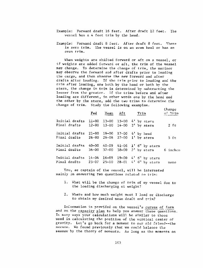
Example: Forward draft 16 feet. After draft 12 feet. Thevessel has a 4 foot trim by the head.
Example: Forward draft 8 feet. After draft 8 feet. Thereis zero trim. The vessel is on an even keel or has an
even trim.
When weights are shifted forward or aft on a vessel, orif weights are added forward or aft, the trim of the vesselmay change. To determine the change of trim, the marinermay observe the forward and after drafts prior to loadingthe cargo, and then observe the new forward and afterdrafts after loading. If the trim prior to loading and thetrim after loading, are both by the head or both by thestern, the change in trim is determined by subtracting thelesser from the greater. If the trims before and afterloading are different, in other words one by the head andthe other by the stern, add the two trims to determine thechange of trim. Study the following examples.
Changeof TrimFwd Mean Aft TZ ilrl
13-00 15-00 4' by stern13 � 00 14-00 2' by stern
Initial draf ts 11-00
Final drafts 12-00 2 ft
19-00 17 � 00 4' by head26-06 27 � 00 1' by stern
Initial drafts 21-00
Final drafts 26-00 5 ft
40-09 41-06 1' 6" by stern37-00 38-00 2' by stern 6 inches
Initial drafts 40-00
Final drafts 36-00
Initial drafts 14-06 16-09 19-00 4' 6" by sternFinal drafts 23 � 07 25-10 28 � 01 4' 6" by stern none
You, as captain of the vessel, will be interestedmainly in answering two questions related to trim:
l. What will be the change of trim of my vessel due tothe loading discharging of weight?
2. Where and how much weight must I load or dischargeto obtain my desired lnean draft and trim?
103
Information is provided on the vessel's curves of formand on the ca~acct plan to help you answer these questions.In many ways your calculations will be similar to thoseused in calculating the position of the vertical center ofgravity. Let's go back for a moment to our old friend � � theseesaw. We found previously that we could balance theseesaw by the theory of moments. As long as the moments on

one side of the seesaw were equal to the moments on theother side, the seesaw was level and would balance.Remember � a moment is a certain weight times a certaindistance. Let us consider our vessel a seesaw balanced ona fulcrum. The fulcrum for the vessel is called the"tipping center" or the "longitudinal center of flotation."If weight is shifted on the fore and aft direction, or ifweight is 1oaded or discharged forward or aft of thevessel's tipping center, the vessel will trim about thetipping center in the same way that a seesaw trims aboutits fulcrum.
If weight is loaded or discharged exactly at the LCF,the vessel's trim will not change. It would have the sameeffect as placing a weight over the fulcrum of the seesaw.
The tipping center longitudinal center of flotation!is the center of the waterplane at any particular draft.Since the shape of the waterplane changes according to thedraft of the vessel, the longitudinal center of flotationdoes not remain in the same position. The position of thelongitudinal center of flotation is given for variousdrafts on the hydrostatic curves or curves of form for thevessel.
The value of the trimming moment for a vessel is theweight loaded, discharged, or shifted times the distance itwas loaded or discharged from the LCF, or the distance itwas shifted.
Example: 100 tons is loaded 10 feet from the LCF. What isthe trimming moment? 100 x 10 = 1000 foot tons trim-ming moment.
Example: 20 tons is loaded 50 feet from the tipping center LCF!. What is the trimming rnornent? 20 x 50 = 1000foot tons trimming moment.
Kxampl e: 15 tons is shifted 5 feet in a fore and aftdirection longitudinally!. What is the trimmingmoment created? 15 x 5 = 75 foot tons trimming moment.
10.2 Moment to Ch~an e Trim One Inch
The moment required to change the trim of the vesselone inch NTI! is given for various drafts of the vessel onthe curves of form and on the deadwe~i ht scale of thevessel. When shifting weight longitudinally all themariner needs to do ta find the change of trim is to dividethe total trimming moment by the NT1.
104

Example: The f orward draf t of a vessel is 23 f eet, theafter draft is 21 feet; 100 tons of sea water ar e
pumped from No. 1 ballast tank to No. 8 ballast tank � � adistance of 100 feet. The mariner wishes to find the
change of trim and the new drafts for the vessel.
Solution: The mariner first figures the mean draf t of thevessel. Using the mean draft �2 feet!, he finds theMT1 for that draft on the vessel's deadweight scale, oron the curves of form. MT1 is 500 foot tons.
The mariner then calculates the trimming moment.100 x 100 = 10,000 foot tons.
Trimmin Moment
MT1Change of Trim in inches!
10,000 20 inches change of trim500
Since the weight was moved aft, the forward draft willdecrease and the after draft will increase. Half the
change of trim is applied to the forward draft and half tothe after draft.
AftMean
Example: The drafts of a vessel prior to the shifting of aweight are 9 feet forward and 10 feet 6 inches aft;300 tons are shifted forward a distance of 20 feet.
MT1 at the mean draft again is 500 foot tons. Find thechange of trim and the new drafts.
Solution: Assuming that the mariner had not been givenMT1, he would calculate the mean draft--which is 9 feet3 inches. Using this he would use the curves of formto find MT1 � 500 foot tons.
Trimm~in Momenr Change of TrimMTl
12 inches change of trim500 500
105
Initial draft 23-00
Change of trim 00-10Final draft 22-02
22-00
22-00
21-00
00-10
21-10

Fwd AftNean
8-00
068-06
9-03 10-06
06
10-00
Initial drafts
Change of trimFinal draft 9-03
Using the curves of form for our 184-foot supply vesselin Table 9.1, find NTl for the following mean drafts.
88 foot tons104.2 foot tons122,5 foot tons166.5 foot tons
6 ft
8 ft
9 f eet 6 inches11 feet
In actual practice, no one will be standing next to youin the wheelhouse to tell you NTl so you will have to useyour vessel's mean draft as you did above to find MT1.Also, no one will help you determine how far or how muchweight has actually been shifted.
10.3 ~Findin Hnw Far Wef~hr Has Been Shifted
Let us say that you pumped the contents of No. 1 fore-peak ballast tank which was full on our supply vessel toNo. 17 afterpeak ballast tank, which was empty. How muchweight has been shifted and how far has it been shifted?Let us look at the Summary of Tank Characteristics in Table9.2. You will notice that the full contents of No. 1forepeak ballast tank are equivalent to 17.8 tons, so thisis the weight which has been shifted.
Now, just how far has the weight been shifted? Lookingonce again at the Summary of Tank Characteristics you willsee that the center of gravity of each tank is given for-ward or aft of amidships. For No. 1 forepeak tank thelongitududinal center of gravity is 76.5 feet forward ofamidships. 'For No. 17 afterpeak ballast tank the longi-tudinal center of gravity is 85.9 feet aft of amidships.Adding the two distances together you determine how far theweight has been shifted.
76. 5
85. 9
162.4 f t
106
Example: Our vessel's mean draft is 11 feet, with a forwarddraft of 9 feet and an after draft of 13 feet. The

Fig. 10. 1 T.ongitudinal center of flotation.
g«
5
BAL! B
sj v ~ 9s ¹ j p.o.!
~i ~me Alum Qe r s,I, I I ..I J.l.. ! I I .l...... Js, Q3 g7 61 ~< 4X 58 S2. 'f5 '/0 A
z.ro J8 ~G
Fig. 10. 2 Tank plan. Each tank is identif ied by number and theletters: P port!, S starboard!; FO fuel oil!;Bal ballast!, and V void, an empty space! .
107
t/L v'as
FO
5P
B

contents of No. 16 ballast tank which is full are
pumped to No. 2 ballast tank which is empty. Find thechange of trim and the new drafts for the vessel.
1. Find how much weight has been shifted on the Summaryof Tank Characteristics. No. 16 P R S = 47.4 tons.
2. How far has the weight been shifted' ?
69.4
63.3
132.7 ft
3. What is the trimming moment? w w d = 47.4 x 132.76290 ft tons.
4. Using the curves of form, find MTl at your meandraft.
MT1 = 166 5 f t tons
5. Iri~~in Moment Chan e of Trim = ~6290 37 8inches
6. Fwd Mean Af IL
Inital draft 9-00
Change of trim 18.9Final draft 10-06.9
13-00
18.9
11-00
]1-05.111-00
10.4 L~oadio or Dis ght
When weight is loaded or discharged rather than merelybeing shifted from one point on the vessel to another, ourcalculations of necessity are somewhat different. Themariner first assumes that the weight is loaded at thetipping center. Remember, the only thing that happens ifweight is loaded or discharged at the tipping center isthat the mean draft of the vessel will change. Trim is notaffected. Using TPI tons per inch immersion!, the marinercalculates exactly what the new mean draft will be. Hethen uses this mean draft to find MTl as before. Asbefore, trimming moments divided by MTl equals the chan~eof trim. Trimming moments are calculated as the weighttimes the distance it is loaded or discharged from thetipping center.
108

Example: Prior to loading, the forward draft of our 184-ftsupply vessel is 7 feet; after draft is 9 feet; 100tons are loaded 15 feet aft of the tipping center.Find the change of trim and the new drafts for thevessel.
Solution: 1! The mariner first assumes that the weight isloaded at the tipping center LCF!. Using the curvesof form the mariner determines that the TPI at hisoriginal mean draft of 8 feet is 12.1 tons per inch.In other words, if 12.1 tons is loaded the vessel willsink 1 inch deeper in the water. He is loading 100tons. How much will the vessel's mean draft change?100 = 100 = 8.3 inches.TP1 12.5
Mean draft
Change of mean draftNew mean draft
8 ft
8. 3 inches
8 � 08.3
2! The mariner then imagines that the weight isshifted to its actual position; 100 tons is shifted 15feet aft of the tipping center. What is the totaltrimming moment created? w x d = 100 x 15 = 1500 foottons.
3! Rememhering that TrimminK Moment equals theÃTl
change of trim, the mariner finds MT1 for his new meandraft of 8 feet 8.3 inches--ill.0 foot tons.
Trimmin~Moments13.5 inches change of trim
111
4! The mariner now proceeds as in the previousexamples.
Fwd Mean Aft
7-00
8.3"8-00
3 I92
Initial draftsChange of mean draft
9 � 003 I'I
7-01.5
6.8
8 � 08,3 10-03.1
6.810-09.9
Change of trimFinal. drafts 8-08. 36-06. 7
109
As mentioned earlier, you will have to find all therequired information necessary for the solution of the trimproblem. You have done this in the previous example allexcept for one thing. You were given how far the weightwas loaded from the tipping center. For any particulartank or compartment filled you will have to determine how

far the weight is placed forward or af t of the tippingcenter. As mentioned earlier, the position of the tippingcenter longitudinal center of flotation! changes withchanges in draft. On the curves of form of the vessel isgiven the position of the LCF for a number of mean drafts.IE you know the position of the LCF in relation to amid-ships, and the position of the longitudinal center ofgravity of the tank or compartment in relation to amid-ships, finding the distance from the tipping center is asimple matter.
La~t e An lea of Inclinationlo. 5
Previously we have studied initial stability, i.e.,stability at small angles of inclination. We calculated GMand used this as an indication of the stability of ourvessel. GM as an indicator of the stability of the vesselloses validity as the vessel rolls to large angles, say, 20degrees.
A more proper criteria to use for examining the sta-bility of a vessel at large angles of heel. is GZ. If youwill remember, and as illustrated in Figure 9.4, GZ isknown as the righting arm and is the distance between thelines of force through G center of gravity! and 8 centerof buoyancy!.
Generally, the greater the heel of the vessel, the greaterGZ. However a point is reached where GZ begins to decreasewith any further angle of roll. The angle at which GZ islargest and the angle at which GZ begins to decrease isusually at the point at which the edge of the deck on thelow side of the vessel is immersed or covered with water.This angle is called the "angle of deck edge immersion," orthe "angle of maximum righting arm."
Offshore supply vessels have a high initial GN. Shownbelow is comparison of initial GM GM for inclinations upto 10 degrees! for a typical offshore supply boat and alarge oceangoing cargo vessel.
At first glance it appears that the offshore supplyboat possesses much greater stability than the conventionalcargo vessel. But remember, GM is a good indicator onlyfor small angles of inclination. The high initial GM ofoffshore supply vessels led to two pitfalls. First of all,it covered up the need for a more complete stabilityanalysis. Second, it very likely caused poor operatingpractices. Capsized vessels were commonly found to have
110

had many slack tanks and to have open cross connectionsbetween tanks. This could very possibly have been anattempt by the operator of the vessel to produce a morecomfortable ride. Because as we have mentioned, a high GMresults in a stiff, uncomfortable vessel.
In 1959, eleven lives were lost due to the capsizingof the offshore supply vessel National Pride. In January1963, the uninspected supply vessel D~ivetsit capsized inheavy weather with the loss of the lives of all five crewmembers. On November 25, 1968, the 160 foot supply vesselTriple Crown, while engaged in picking up anchors and chainfor a drilling rig off Santa Barbara, Calif., capsized withthe loss of nine crew members. It is known that the vesselhad little freeboard at the stern easily understoodbecause when handling anchors, supply vessels are pumpeddown at the stern so that the stern roller is partially inthe water!, and that flooding of the engine room occurredthrough a stack door which was blocked open by an anchor.
This points out a basic fact � that the best criteriaof overall stability is GZ or righting arm. This informationis provided the captain on the stability curves of thevessel. These curves may be presented in two differentways: by statical stability curves, and by cross curves ofstability, The cross curves of stability are shown inTable 9.2 for our 184-foot supply vessel. Before lookingat them however, let us go back to our previous comparisonof the supply boat and the conventional large cargo vessel.Shown in Figure 10.4 is the same graph which we usedearlier to compare the GM of the two vessels. Drawn onthis graph now are the statistical stability curves for thetwo vessels. GZ at any angle of roll is the verticaldistance from the base line to the curve.
Notice the large value of the righting arms for thelarge cargo vessel and the relatively smaller righting armsfor the offshore supply vessel. Notice that the angle ofmaximum righting arm for the supply vessel is approximately18 degrees while for the conventional cargo vessel, thisangle is approximately 42 degrees.
On the statical stability curves the baseline is theangle of the roll. A number of curves are drawn forselected displacements of the vessel, On the cross curvesof stability, the baseline is the displacement of thevessel and a number of curves are drawn for differentangles, of inclination, or roll. On both presentation, GZin feet forms the left-hand vertical measure.

'ZabI e 9. 3
Cross Curves of Stability printed separately!

You can learn a number of things by analyzing thestability curves for your vessel. We shall concentrate onanalyzing the cross curves of stability shown in Table 9.3.
10.6 gtabilit Characteristics � An A~nal sis
10.6.1 Initial Stabi~lit . The initial stability ofthe vessel is indicated by GN which closely follows thestatical stability curve for the first 10 degrees of roll.The sharper the slope, the greater the initial stability.
10.6.2 Maximum R~i htin Arm. The maximum righting armis the maximum vertical distance from the baseline to thecurve.
righting moment for the vessel, simply multiply the dis-placement by maximum GZ.
to the angle at which the maximum righting arm is developedand is approximately equal to the angle of deck edgeimmersion mentioned previously. The angle at which thedeck edge will be immersed is dependent upon the freeboardof the vessel. Study Figure 10.5 in which two vessels areshown, one with little freeboard and one with a lot offreeboard. This shows why freeboard is such an importantfactor in the stability of a vessel.
10, 6. 5 Angle of Maximum List. The angle of maximumlist corresponds approximately to the angle of deck edgeimmersion. When a ship i.s listed ta any particular angle,she is in equilibrium. In other words she is listed to acertain angle and the lines of force through G and B are onthe same line and G and B are vertically under each other.This is different from a vessel which rolls to a certainangle where the lines of force through G and B are separateand parallel lines. When a vessel is listed over due tosome reason such as the way that her cargo is stowed, sheis in equilibrium; there is no tendency for her to returnto an upright position, and neither is there any tendencyfor her to continue inclining. If a ship lists her deckedge under, she will Rr~obabl ~ca size. Remember, we arenot speaking of a vessel which rolls and immerses her deckedge,
10.6. 6 Angle of ~Dan erous list. If your vessel isI.isting over and continuing to take on water, then continuesto list farther and farther over, what do you consider a
113

!o- .~ ~~'
L ' ! ....!........ I. . .. ......I... ..,, .J ��o !o 2o 30 40 ~o 0 7o 80 90
9'
Fig. 10.3 Comparison of GM.
Fig. 10.4 Comparison of GZ,
I REEBDIIRD
~G
z- ""' f'
/
/
! BEE,F.'VLH,D
Sam
114
Fig. 10.5 How freeboard affects stability.

dangerous list? In other words, when should you abandonship? We could go into a lot of discussion about this butthe final decision made depends upon various factors suchas the master's knowledge of his ship and weather conditions.However, it is generally accepted that an angle of dangerouslist is the angle which is one � half the angle of deck edgeimmersion.
10.6.7 Angle of~has erous Roll. The angle of dangerousroll which should be feared by any captain with any sense,corresponds to the angle of maximum stability. In otherwords, it corresponds to the angle of deck edge immersion.If your vessel is rolling her deck edge under, you hadbetter take corrective action if possible, or prepare forthe worst!
10.6.8 Angle of Maximum Roll. The angle of maximumroll is the angle at which there is no longer a rightingarm. In Figure 10e5 we have drawn this angle at approxi-mately 42 degrees. In other words, when the supply vesselpictured rolls to 42 degrees, there is no longer anytendency for her to return to an upright position. GZ righting arm! has vanished. This angle of maximum roll isalso known as the "vanishing point."
11. MATERIALS AND METHODS OF CONSTRUCTION
The captain of a vessel should know something of thevessel's construction. He should know the purpose of everyvalve and fitting. This knowledge will serve him well inthe operation of his vessel and in the wise use of vesselequipment. In the event of an emergency such as damage tothe underwater hull, he should know which measures to takeand how to describe the damage over the radio. If thecompany owner sends him to a shipyard to represent thecompany during the construction of new vessels, he mustknow what to look for and know the desirable arrangement ofequipment, pipes, fittings, and other gear.
Throughout the history of shipping many differentmaterials and methods of construction have been used. As
knowledge and techniques have advanced, the material usedhas changed from wood to steel.
11.1 MateriaIs
11.1.1 Wood. Wood was the first shipbuilding mater-ial used. Supplies were abundant and it was easy to work.
115

However, the drawbacks of wood prompted the switch to othermaterials. Wood is not uniform in strength and is combust-ible. Furthermore, the length of vessels built. of wood islimited by the fact that they sag in the middle and thereis difficulty of tying the joints together which causesleaks. One other notable point is that wood is heavierthan steel of the same strength.
11.1.2 ~Wrac ht Iron. The first metal to be used inship construction was wrought iron. Wrought iron isstrongly resi.stant to corrosion and some vessel hulls ofover 50 years in age are still in operational condition.The development of the steel making industry caused thediscontinuance of the use of wrought iron because steel isstronger and cheaper.
ll.le3 Concrete. In the past, concrete has also beenused as a shipbuilding material. The strength of the hullwas provided by steel rods within the concrete. Becausethe concrete hull in a large vessel is heavy and relativelyeasily damaged, concrete has never been commerciallyfeasible as a material for construction of larger vessels.
11.1.4 Steel. With the notable exception of aluminumused in crewboat construction, steel is the material nowused for the construction of most vessels. Although steelis more susceptible to rust and corrosion than wroughtiron, it is stronger and can be easily worked. Steel mustbe carefully painted and maintained to prevent corrosion.
There are many different types of steel. A special,although very expensive type, called Corrosion ResistantSteel CRS!, Is often used in places susceptible to greatcorrosive action. Armor steel finds application in mili-tary vessels where the hard outside surface of the platebreaks the head of a projectile while the somewhat softerand tough inside of the plate absorbs the energy of theshell.
lls2 Methods of Formin Steel
Some means must be employed to put the steel into thecorrect shape desired for its place in the vessel. The twomajor processes used are ~for in and ~castin
11.2.1 ~For in s. Forgings are used where greatstrength and toughness are required. They are made byheating the steel white hot and then beating it into shape.Some examples of forged materials on the vessel are therudder stocks, crankshafts, and propeller shafts.
116

11.2.2 ~Castin s. As the word "castings" suggest, thesteel is poured or cast into a mold in this method offorming steel. A wooden pattern is made to the exact shapeof the piece desired with a slightly larger dimension toallow for shrinking as the steel cools. The wooden patternis then placed into special casting sand. After the castingsand hardens, the pattern is removed and the molten steelis poured into the hole left. The stern frame, rudderframe, struts, hawsepipes, and anchors are a11 examples ofpieces aboard a boat which are cast.
11.3 Stren th of Materials
A ship and its component parts must be built to resistvarious stresses which will be placed upon it by the weightof its cargo and the forces of the sea. There are threebasic types of stress which we will discuss here.
11.3.1 Tension. Tension or tensile stress! is thestress which occurs between two parts of a body when eachtends to draw the other toward itself see Fig. 11.1!.
11.3.2 Co~a tension. Compression or compressivestress! occurs between two parts of a body when each ispushed toward the other see Fig. 11.1!.
11.3.3 Shearin stress. Shearing stress occurs whenone part of a body has a tendency to slide over anotherpart see Fig. 11.1!.
The vessel's structure must be strong enough toresist each of the above stresses. In discussing thestrength of a vessel we must consider both the strength ofeach particular piece or part of the vessel and also thestrength of the vessel as a whole. The strength of any oneparticular component of the vessel is known as localstrength. The strength of the ship as a whole is known ashull girder strength.
The term "hull girder strength" comes from the factthat each part of the vessel contributes to the totalstrength of the ship. The entire ship structure must beable to meet and endure the stresses placed upon it byrolling, pitching, and the pounding of the seas. Forcalculating just how well the ship will hold up under thesestresses, the hull of the ship is often considered to be agigantic box girder. The bottom of the box is the bottomof the hull. The top is the deck of the ship and the sidesof the girder are the sides of the ship.
117

can be placed on the structure of the hull as a unit, twodifferent situations and their probable results are shownin Figures 11.2 and 11.3, when the vessel is overstressed.
In Figure 11.2 the bow and stern of the ship aresupported on the crests of waves. The vessel is said to bein the saggin~ condition.
In Figure 11.3 the vessel is supported primarilyamidships by the crest of a wave. The vessel is said to bein the ho~Le condition.
Even though we can, when considering hull girderstrength, picture the hull as a simple beam for illustra-tion, the idea should not be conceived that the ship's hullis only a beam and need only face hogging and saggingstress. The ship's hull must stand up as it drives throughheavy seas, rapidly picking up speed only to slam intoanother wave and have its direction changed, being furtherstressed by internal vibration from its own propulsionmachinery and propellers.
11.4 Facto
When he designs a ship structure, the naval architectmust first calculate as accurately as possibIe just what.loads the structure will have to bear. It would be extreme-ly hazardous to build the ship only as strong as needed tosupport this load, for it is conceivable that the unexpect-ed may occur, and the vessel will be called upon to meet astress or load far over its normal load. For this reasonthe vessel is built to support loads far greater than whatis normally expected. A factor of s~afet is decided uponand the vessel is built using this safety factor. Let usimagine for an instant that the deck on a particular vesselwill normally be called upon to bear a load of 2SO tons.Let us also say that the naval architect wishes to use asafety factor of 4. This means that the vessel will bebuilt to handle a load four times as large as that normallyexpected �50 x 4 = 1,000 tons!, or 1,000 tons.
Another term usually comes up when discussing safetyfactors. This is breaking strength. Breaking strength BS! simply means the amount of load which must be appliedto a material before it will break. In other words, if youhad a bar of steel which would break when you placed a loadof 20 tons on it, its breaking strength would be 20 tons.You would never in practice push a material to its breakingstrength because this is an unsafe practice. Instead you
118

use the safety factor SF! to determine what would be asafe load to place on the material under ordinary workingconditions. This is called the safe working load SWL!.Let's say that you have a steel cable which will support aload of 20 tons before it will break. You wish to observeor use a safety factor of 4. What would be the safe work-ing load for the steel cable using a safety factor of 4?The answer is obtained by dividing the breaking strength�0 tons! by the safety factor �!. Twenty divided by fourequals 5. So to observe a safety factor of 4 you wouldnever load the cable over 5 tons. The relationship betweenbreaking strength, safety factor and safe working load canbe expressed as follows: BS = SF x SWL. Breaking strengthequals the safety factor times the safe working load. Thisholds true no matter what material you are working with�wood, steel, cable, fiber rope, etc. Safety factors of 6are now uncommon in ship construction, especially for itemswhich are critical to the safety of the vessel and herpersonnel.
Safety factors for merchant ships and the scantlings sizes! of the various components for merchant vessels aregenerally specified by various classification societies see Section 5.3!.
11.5 Beams
A beam is an athwartship, horizontal member of thevessel supporting a deck or a flat. One example of a beamwould be a deck beam. The size of the beams is determined
largely by five factors:
load the stronger the beam must be. A 'beam which would haveto support a 5 ton load would not have to be as large as abeam supporting a 50 ton load, The type of load is also aninfluencing factor. If the load is concentrated in onepoint, the beam must bellarger than if the load is spreadout over the length of the beam.
must run 50 feet between supports must be larger than abeam which runs only 5 feet between supports. The moresupports, the more the load must be before the beam willbend.
11.5.3 ~Te of end connections. A beam which has theends stoutly secured can support a greater load than a beamwhich is not secured at both ends. For this reason,
119

the better the end connections, the smaller the beam canbe.
11.5.d Number of su~orts . The fewer the number ofsupports, the larger the beam must be to support a givenload.
11.5.5 Material. Perhaps the most obvious factorinfluencing the size of a beam is the material of which itis made. The stronger the material, the smaller the beammay be for a given load.
11.6 Plates
Plates are sheets of steel rolled to a uniform thick-ness of 1/4" or more usually 1/4" to 1 1/4"!. Plates,because they are in some manner supported at the ends andsupport loads, act as a beam. In building a vessel., thenaval architect must determine the thickness of the plateto be used. Here he must make a compromise between weightand strength. Thicker plates possess more strength butthey are heavier than lighter plates. Stiffeners are usedto stiffen plate or make it stronger. If stiffeners areused, thin plate can be made as strong as thick plate.However, there is a point at which we must stop addingstiffeners to reduce plate thickness because weight savinggained by using the thinner plate is more than offset bythe added weight of the stiffeners. The naval architectmust be very careful to see that he uses the proper ratioof stiffeners to plate weight so that he can get therequired strength with the least weight.
11.6.1 T es of late. Plate may be flat, rolled orfurnaced. This depends upon the way in which the plate ismade. Most of the plates in the vessel are flat platesand are made with no curvature. Plates which have curva-ture in one direction only--such as those found at theturn of the bilge, are rolled plates. These plates arecold rolled by a machine. At some points in the vessel,such as at the bow and stern, plates which possess curva-ture in two directions must be used. These plates arecalled furnaced plates and they are heated and hammered tothe correct shape using a special shaped steel form.
11.7 ~Shs es Found in Vessel Construction
Various shapes may be found when looking at thestructure of a vessel. These shapes are each designed toserve a special purpose. Imagine that you are looking at
120

the end of a long steel bar and seeing each of theseshapes in turn.
frames, beams, and stringers. They are also used toconnect together two other members of the vessel at rightangles. The parts of an angle are shown in Figure 11.5,If the angle is connected as shown in Figure 11.5�!, itis known as an inverted angle. Inverted angles providegreater strength than plain angles.
11..7.2 Bul~bAn le. Bulb angles are used only inriveted construction. They are simply plain angles whichhave a bulb of material added to the toe of the angle atthe point of greatest stress. They are much stronger thanthe plain angle.
11.7a3 T-Bar. The T-Bar is an angle � one leg ofwhich has been centered on the other. It will not fallover or "trip" as easily as a plain angle. When used itmay be inverted. When inverted, the side of the vessel orother structure to which it is attached forms anotherflange and the T-Bar then acts as an I-Beam and becomes astrong and rigid stiffener.
1.1.7.4 T-Bulb Bar. The T-Bulb Bar is simply a T-barwhich has had a bulb of material added to the bottom ofthe stem to increase its strength,
11.7.5 Channels. Channels are used for side frames,deck beams, bulkhead stiffeners, and pillars.
11.7.6 I-Beam. A rolled shape which has a crosssection like the letter I is called an I-Beam. The I-beamis used chiefly for deck beams and girders.
11.7.7 H-Beam. When the flanges of an I-Beam are aswide as the web, it is called an H-Beam. H-beams are usedchiefly as columns or pillars.
lla8 Weldin vs. Rivetin
In the early days of shipbuilding, all metal shipswere built using riveted construction. Today most con-struction methods utilize welding. The disadvantage ofriveted construction is that leaks often develop becauseit is too difficult to obtain absolute tightness. Weldingis the art of uniting two pieces of metal at the meltingpoint, without using another metal having a lower meltingpoint to make the joint. When two pieces of steel are
121

welded together, the two become one piece as strong as theoriginal two pieces.
Where two pieces of metal, are joined together bywelding or riveting, this is called a seam. Riveting isstill used in places on some vessels because it possessesone major advantage. This advantage is related to theseam previously mentioned. Imagine four steel plates.Two of the plates are welded together. Two are rivetedtogether. If a crack begins in one of the two plateswelded together, it can continue from one plate all theway through the seam and into the next plate. If a crackbegins in one of the two plates riveted together, thecrack may continue to the seam but will not continue pastthe seam because the two plates are still separate pieces.At places on a ship where cracks are prone to begin, suchas in areas of high stress, riveted seams are sometimesemployed to limit the damage. Such a device used toprevent a crack from spreading is called a crack arrestor.Another method which may also be used to prevent a crackfrom spreading is used after the crack has started. Asmall hole may be dril.led at the end of the crack. Thecrack will usually stop at the hole. Then at a lateropportunity the plates are replaced.
11.9 Terms
Before proceeding further, study the following termsin the glossary at the end of this book. forward, aft,fore and aft, amidships, athwartship, centerline, beam,below, bow, frame, inboard, intercostal, midship, outboard,overboard, panting, plating, stem, stern, stow, bracket,girder, bilge.
12. VESSEL HEHBERS
12.1 Keel
The keel is the backbone of t: he vessel's frame. Itis the principal fore and aft member of a ship's frame.The keel runs along the bottom and connects the stem andthe stern,and the frames of the vessel are connected toit. Because the keel is the bottom structure of the boxgirder formed by the hull, it must be strong enough toresist longitudinal stresses and the concentrated pressuresdue to grounding, drydocking, and cargo.
There are two main types of keel, the bar keel andthe flat plate keel,
122

12.1.1 Bar keel. The bar keel. may be thought of asa heavy flat bar of steel which runs fore and aft alongthe centerline and protrudes through the bottom of thevessel. The bar keel was very common in the early days ofshipping. It protected the bottom of the vessel in theevent of grounding on a hard bottom and also served some-what to reduce the roll of the vessel. The main disad-vantage of the bar keel is the fact that it increases thedraft of the vessel. Let us assume that for a particularvessel, 100 tons of cargo must be loaded to increase thedraft of the vessel one inch. I,et us also assume thatthis particular vessel is now being loaded at the dock andthat she has a bar keel extending 10 inches down from thebottom of the hull. In order to leave the harbor, thevessel must pass over a bar. A similar vessel without abar keel will just skim the top of the bar when passingout to sea. Our vessel with the bar keel must be 10'higher out of the water in order to cross over the bar.How much cargo must be unloaded to permit the ship to rise10" out of the water: 100 tons x 10" = 1,000 tons. So,our vessel with the bar keel can carry 1,000 tons lessthan the vessel without the bar keel. This represents a
sizable loss of money to our vessel's owner because of thelost freight on the cargo which could not be carried.
12.1.2 F~lat late keel. The Flat plate keel wasdeveloped to provide a backbone for the vessel withoutincreasing the draft of the vessel. It is basically afore and aft row of flat plates increased in thickness.This row of plates runs along the bottom of the ship fromstem to stern.
The flat plate keel is reinforced by the centervertical keel, vertical flat plates running fore and afton the centerline. When the rider plate is placed atopthe center vertical keel, the structure formed is a rigidand powerful I-beam. The rider plate is a fore and aftrow of flat plates placed atop the center vertical keel.
The cent.er vertical keel may run fore and aft in onecontinuous piece or it may be intercostal to the floorswhich are to be discussed below.
12.1.3 ~$11 e keel. Another type of keel which isnot used for the same purpose as the bar keel or the flatplate keel is the bilge keel. The bilge keel is a fin-like piece of steel fitted to the vessel at the turn ofthe bilge to reduce the rolling of the vessel in a seaway.
123

IF ANGE
' 'I;p<ESSIOU
!
~F LINC- I
~ t. ~'Ii Ff.
11. 1 Compression, tension, Fig. 11. 5shearing stress.
Fig.
Fig. 11.4 Types of plate: A! Furnaced; B! Rolled; C! Flat.
Fig. 11.5 Various shapes in vesselcons truct ion: �! plainangle; �! inverted angle;�! bulb angle; �! T-bar;�! T-bulb bar; �! channel;�! E-beam; 8! H-beam.
Fig, 11,4
124
Fig. 11.2 Excessive sagging stress.
Fig. 11.3 Excessive hogging stress
f' L.

12. 2 Floors
A floor is a plate placed vertically in the bottom ofa vessel, usually on every frame, and running athwartshipfrom bilge to bilge. Its purpose is to give additionalstrength and stiffness to the vessel's structure.
The vertical height of the floors is determinedchiefly by the height of the center vertical keel. Floorsmay be of solid construction or open construction.
12.2.1 ~0 enin~s in the floors. Open floors arebuilt up of structural members as opposed to a solid floorwhich is made up of plate. Solid floors are not, however,watertight. Solid floors do have openings in them calledlimber, lightening, and air holes.
Limber holes allow water or other liquids to drainbetween floors.
~Li hteni~n holes serve the pnrfose of lightening theplate used in construction of the floors. The lighteningholes also serve the invaluable purpose of providingaccess between floors during construction and for necessarymaintenance. For this reason they are sometimes ca1ledaccess holes.
Air holes are cut in the floors to prevent an airlock from forming and thus prohibiting the free flow ofliquid between the floors,
Under the engine room the floors are heavier toprovide for the extra load and vibration at this point.As mentioned earlier, the floors may be continuous and t' hecenter vertical keel intercostal, or vice versa.
12e3 Bottom Lon~itudinals
Bottom longitudinals are longitudinal members of thevessel which prevent the floors from ~tri i~n or fallingover. They run fore and aft along the bottom of thevessel parallel to the keeI.
The keel, floors, and bottom longitudinals divide theinner bottom of the vessel into rigid cell-like compart-ments which add significantly to the hull girder strengthof the vessel.
125

12.4 Double Bottoms
The double bottoms, sometimes called the doublebottom tanks, are the compartments at the bottom of thevessel between the inner and outer bottoms. The outerbottom is formed by the bottom shell plating of thevessel, The inner bottom is formed by the rider plate andthe strakes or rows of plating parallel to the rider platewhich are laid over the top of the floors. Inside thedouble bottoms are the center vertical keel, the floors,and the bottom longitudinals. The depth of the doublebottoms is determined by the height of the center verticalkeel. However, the double bottoms must always be deepenough to allow access and to provide the required strength.
In the early days of shipping, ballast in the form ofsand and stones or other weight material was loaded direct-ly into the bottom of the holds in order to bring thevessel down deeper in the water when necessary. Uponarrival at a loading port, the ballast then had to beremoved before cargo could be loaded. This was a long andcostly process. The development of double bottom tanksdid away with this process. Now ballast, in the form ofliquids, can be pumped into or out of the double bottomtanks as necessary, swiftly and easily. The doublebottoms also serve other purposes. One of the mostnoticeable is that because of the cell-like construction,they add great strength to the structure of the 'vessel.The double bottom tanks can also be used to carry fuel,water, or oil. In the event the bottom of the vessel outer bottom! is tom open by grounding, the inner bottomprovides a valuable "second skin" which prevents theseawater from flooding the vessel. If the double bottomshave been loaded with liquid prior to grounding, no changein trim will result after a hole is ripped in the outerbottom due to the fact that no seawater can enter.
12.5 Frames aed Fr~amia 8 stems
Frames are the "ribs" of the ship in much the sameway that the keel is the backbone of the ship,
Two main types of framing systems are found invessels, the transverse framing system and the longitudinalframing system.
12.5.I Transverse framin~ system, The variousmembers of the transverse framing system are shown inFigure 12.8. Transverse means athwartship, at right
126

Fig. 12.1 Bar keel. Fig. 12.2 Plat-plate keel.
..-TAB Klb'HER
[q �,~�c
Fig. 12.3 Bilge keel.Fig. 12.4 The floors.
EP I"LA
Fig. 12. 5 Arrangement of floors.
127

angles to the keel. The main elements or parts of thetransverse framing system are;
a! Floors. As described earlier, the floors arevertical plates ru~ning athwartship from bilge tobilge.
Bottom ion itudinals. As described earlier, thebot.tom longitudinals are members which run in afore and aft direction. They add strength andkeep the floors from tripping."
c! Transverse frames. The transverse frames act as
the ship's ribs. They radiate outward trans-versely from the keel and are attached to theshell plating,
d! ~Dee web frames. The deep web frames are massive,built up frames fitted into the hull to addstrength and rigidity at points of special stress.They support the side stringers which in turnsupport the transverse frames. Fitted in areassuch as the engine room they absorb vibration andadd strength.
e! Strin~ezs. Stringers are fore and aft membersused to give longitudinal strength to the shellplating.
Pillars. Pillars, sometimes called stanchions,are vertical members used to support the deckgirders.
g! Girders. A girder is a continuous member whichruns in a fore and aft direction under the deck
for the purpose of supporting the deck beams andthe deck.
h! Deck beams. The deck beams run athwartship andare supported by the girders. They act tosupport deck loads and the deck plating. Theyprevent wrinkling of the deck plate and act as atie to keep the sides of the vessel in place.
Brackets. A bracket is a triangular plate usedto join two or more members together.
12. 5. 2 Lon~itudinal f ramin~s~stem. The longitudinalframing system differs from the transverse framing systemin that the shell plating and the bottom plating aresupported by closely spaced longitudinal frames which run

fore and aft. These longitudinal frames are supported bywidely spaced deep web frames. The longitudinal framingsystem is favored for tankers and barges whereas thetransverse framing system is favored in tugs, crewboats,supply boats and other oilfield vessels.
One result of the longitudinal framing system is thatthe deep web frames used protrude into cargo holds andhinder the stowage of cargo in vessels such as oceangoingfreighters. This is not a factor in vessels which carry1iquid cargoes such as tankers and tank barges where thelongitudinal framing system is used to advantage. Vesselsare sometimes built with a combination of the longitudinaland transverse framing systems. The transverse framingsystem is more effective in preventing damage to the hullwhen it comes in contact with docks, piers, and platforms.
12.6 Shell Pl~atin
Shell plating refers to the plating on the hull ofthe vessel. One fact that may surprise you is thatmerchant vessels in general possess heavier plating thannaval vessels, The reason for this is that they usuallyreceive rougher treatment and less care than naval vessels.
is put on the hull, plating may be in and out, clinker,flush, or joggled. All of these methods are used inriveted construction.
In the in and out method of plating the inner plateis laid flush against the frame. The next plate laps overthe edge of the inner plate and the next plate is againplaced flush against the frame. In this method a steelliner is used to fill the space left between the outsideplates and the frames.
somewhat similar to the outside weatherboarding used on ahouse. Here again liners must be used. One end of eachplate is laid against the frame while the other end lapsover the next plate.
In the jo~led system, each end of the outer plate isjoggled or offset so that the center of the plate may belaid flush against the frame. The inner plates are laidflush against the frame. No liners are required by thismethod of plating.
129

Fig. 12. 6 Double-bottom tank.
Fig. 12. 7 Transverse frames.
Fig. 12. 8 Transverse framing system. Fig. 12.9 Longitudinal framing,steel construction.
130

SHE.LL
l «4YL
12.10 Methods of plating.Fig.
, ~ 1 i>4K';>
IF
b'I G. ' TR4<E 5-
Fig, 12.11 Sheer strakes.
Fig. 12. 12 Bulkhead stif f eners.
131
I'l.l <Hi..41!' >, ' ~I/I K>
Fig. 12.13 Cofferdam.
WEE'NTRAIEE
/I i Ia ./P1

frames and welded together.
12. 6. 2 ~es ~of l~atin . As mentioned previouslyplate may be flat, rolled, or furnaced according to itslocation on the hull.
12.6.3 Strakes. Shell plating is laid in long foreand aft rows called strakes. We speak of a strake ofplating meaning a course or row of plates. Some strakesof plating start at the bow and run all the way aft to thestern. These are called th~rou h strakes. Because thebody of the vessel tapers and narrows as you approach thebow or the stern, some strakes of plating are not carriedall the way through from bow to stern. They are discon-tinued in lieu of another strake at some point. These arecalled ~dro strakes.
Each strake of plating is given a letter for ident-ification except the keel strake. This method of identifi-cation is shown in Figure 12.12. You will notice that "i"is not used. The reason for this is that each plate in astrake is numbered starting with I for the plate closestto the stem and continuing aft in the strake. If theletter i were used it might lead to confusion with thenumber l. Thus a particular hole in the shell plating maybe identified as damage ta plate H3, 318, and so an.
Certain strakes of plating are also given specialidentifying names, The keel strake is the strake ofplating which runs fore and aft on the center line of thevessel. The ~arboard strakes are the strakes af platingon either side of the keel strake. The ~bil e strakes arethe strakes of plating at the turn of the bilge where thebody of the vessel begins to turn upward. The sheerstrakes are the topmost strakes of plating an the hull afthe vessel.
12.6.4 Double~rlates. Wherever there i ~ an openingin the shell plating, ar any other plating aboard thevessel, it is necessary that the plating around the openingbe of a greater thickness to compensate for the loss ofstrength caused by the hole. The plating used may bethicker or a doubler plate may be placed around the open-ing. A doubler plate is a plate placed on top of anotherta add extra strength and stiffness. As an example,doubler plates are placed around the portholes and wherethe hawse pipe comes through the deck and shell plating.
132

12.7 Bulkheads
A bulkhead is a vertical steel
to the walI of a room. Landlubbers
A sailor uses the term "bulkhead."
either athwartship or fore and aft.purposes:
partition correspondinguse the term "wall."
Bulkheads may runThey serve many
I! They prevent water from passing from one compart.�ment to another.
2! They act as fire checks to stop the spread offire.
3! In fighting a fire, they allow various parts ofthe vessel to be flooded.
4! They strengthen the hull of the vessel.
12.7.1 ~Satin . Genetally the spacing of the bulk-heads is used as a criteria by classification societies todetermine the safety of a vessel. The closer the bulkheadsare spaced the Less chance there is of flooding the entirevessel through a single hole in the shell plating. A sub-division of space or room in a ship formed and bounded bybulkheads is known as a compartment. Vessels are commonlydescribed as one compartment ships, two compartment ships,and so on see Section 6.4.4!.
12.7.3 Wate~rti ht bulkhead. A watertight bulkheadis a bulkhead having absolutely no openings. Water cannotpass through the bulkhead. The forward collision bulkheadis one example of a watertight bulkhead, In some vesselsthere are also watertight bulkheads running athwartship inother locations. The after collision bulkhead runsathwartship at the stern of the vessel. Machinery spacebulkheads running athwartship at the forward and afterends of the machinery spaces prevent water from damagingthe propulsion equipment.
~Lon itudinal waterti~ht bulkheads are also employedin some vessels. With these types of bulkheads some means
133
12.7.2 Collision bulkhead. The forward collision
buLkhead, usually referred to simply as the collisionbulkhead is the foremost or first watertight bulkhead inthe bow of the vessel. Required by the ABS, this bulkheadruns athwartship and water cannot pass from one side ofthe bulkhead to the other. The main purpose of thecollision bulkhead is to prevent flooding of the vessel inthe event of damage to the bow. It acts as a "second bow."

must be provided to let water pass from one side of thebulkhead to the other. The reason for this is easilyunderstood. Can you imagine what would happen if only oneside of a vessel was flooded? This is known as "unsymet-rical" flooding and its danger was first brought to
sized due to the flooding of one engine room compartment,and caused the loss of 1,000 lives. These openingsusually take the form of valves whi.ch may be opened fromoutside the compartment to let water pass from one side ofthe vessel to the other.
12.7.4 Bulkhead stiffeners. Bulkhead stiffeners are
angle bars, T-bars, or channels, used to stiffen thebulkhead plating. Bulkhead stiffeners usually run vert-ically although they may be placed horizontally. The sizeof the stiffeners is usually decreased toward the top ofthe bulkhead due to the reduced water pressure.
12.7.5 Cofferdams. A cofferdam is the space betweentwo bulkheads formed by placing them a few feet apart.Their purpose is to prevent leakage from one compartmentto another. For instance, a particular vessel may becarrying water in one tank and fuel in the tank adjacent.If the two tanks share a common bulkhead and a leak
develops in the bulkhead, the water will be contaminatedby the fuel and the fuel will be contaminated by thewater. If a cofferdam is placed between the two compart-ments, leakage will drain into the cofferdam and not intothe next compartment. Cofferdams also serve the purposeof permitting inspection of the bulkheads and access for
quick repairs, 13. STEM, BOW, AND STERN13.1 The Stem
The stem is the extreme most forward part! bow ofthe ship. It is like an extension of the keel and givesstrength and rigidity to the hull structure.
The stem is fastened to the keel and connects the two
sides of the shell plating at the bow. It can be a forgedor cast piece of metal, or it can be rounded plate.
The stem must be similar in strength and size to thekeel, because it encounters the pounding of heavy seas andthe impact of obstructions. One particular experiencecomes to mind which illustrates the strength of the stemin a vessel. A particularly large ship had taken a pilot
134

aboard in Saigon harbor. After all moorings had been castoff, the vessel was in the process of turning around withthe assistance of tugs and its own propulsion. All of asudden, power was lost due to boiler failure on the ship.Before the anchor could be dropped the vessel's bow swungaround and completely crumpled the bridge wing and part ofthe wheelhouse of a vessel tied up at the dock. Damage tothe stem � a I/4" dent.
13.2 The Bow
13.2.1 Plumb bow. The plumb bow cuts through thewater rather than riding over the waves. The fact thatthe plumb bow possesses very little flare sometimes causesdifficulties when raising the anchor as the anchor mayfoul on the shell plating as it comes up.
13.2.2 Clipper bow. The clipper bow possesses a lotof flare and a lot of rake. The large amount of flarecauses the deck to remain drier because the flared sidesthrow the water aside. More room is also provided for thedeck machinery because, due to the flare, the sides of thevessel move rapidly apart as the deck l.evel is approached.Because of the flare the anchor can also be raised withoutfouling the shell plating.
An unusual feature of clipper type bows is that theycause less damage in a collision. Due to their extremerake, they penetrate the upper portion of the hull. ofanother vessel first and the underwater hull may be leftintact. If every vessel on the water possessed a clipperbow with a soft nosed stem there would be far fewer sink-ings due to collision.
13.2.3 ~Soon bow. The spoon bow is a very seaworthydesign because it rises to the waves. Ice breakers areoften equipped with spoon bows because the bow of thevessel rides up on top of the ice where the weight thusbrought to bear allows the vessel to crash down throughthe ice and break a path.
13.2.4 Innui or bulbous bow. The innui bow, oftencalled the bulbous bow, has a bulb at the lower portion ofthe stem. This bulb can be used to carry cargo or ballast,however, its main advantage lies in the fact that itenables the vessel to attain greater speeds at or nearfull power than vessels without it.
135

Fig. 13. 3 Stern shapes.
Fig. 13.1 Tugboat stem. Fig. 13.4 Stern frame for asingle-screw vessel.
i~i IB BC
/
L==>POOQ t'C/i
,/
I I~INLI I BOttit'
Fig. 13.2 Bow shapes.
136

13.3 The Stern
13.3.2 Stern frame. The stern frame is the largecasting or forging attached to the after end of the keelto form the ship's stern. This defini.tion ls very appro-priate for single screw vessels; however, it is somewhatinaccurate when discussing twin or triple screw vessels.
13.3.3 Single screw installation. The stern frameconsists of two posts, the propeller post and the rudderor stern past. It can be considered a vertical extensionof the keel, like the stem. It connects the two sides ofthe shell plating at the stern and supports the propellerand rudder. The stern frame in a single screw vesselconsists of:
a! The rudder. A large heavy fitting that is hingedto the stern frame and used for steering thevessel.
b! The lu~s. Projections cast. or fitted to theforward edge of the rudder to which the pintlesare attached.
c! Pintles. Hinge pins on the rudder which project.from the lugs.
dj Cud~sons. Projections on the sternpost drilledto accept the pintles.
e! ~A erture. The opening between the sternpost andthe propeller post for the propeller.
f! The skeg. A shoe which forms the botto~ of thestern frame.
g! T r post. The pos t in the s tern framethrough which the propeller passes.
137
13.3.1 Stern~aha es. Although there are many vari-ations in stern shape we shall discuss only two � themerchant cruiser stern and the transom stern. The
merchant cruiser stern is rounded. The transom stern,which is sometimes known as the "barndoor" stern, is mostcommon on offshore crew and supply vessels. It is broadand fairly flat underneath. It prevents "squat" at highspeeds and decreases resistance 3 to 5 percent. Squat isreadily visible as the force which causes the ster~ of avessel to sink down in shallow water at high speeds. Youmay have noticed this effect yourself at one time oranother.

h! Boss. The swelled up portion of the propellerpost through which the shaft passes,
i! The rudder ~ost. Also called the stern post, therudder post is the after post of the stern frameand is the post on whi.ch the rudder is hinged.
j! The rudder stock. The shaft of the rudder whichextends up through the hull of the vessel.
13. 3.4 Twin or triple screw installation. Therudder may be hinged on a rudder post or may simply hangdown from the hull supported by a huge bearing inside thehull. The propeller shaft is supported by struts whichextend down from the lower hull. A skeg may or may not bepresent. Other parts of the stern frame are similar tothose in a single screw vessel.
13.4 Rudders
The rudder is the means by which the vessel issteered. Flat-blade rudders which are the same thicknessall the way through are found only on older vessels andsmall boats. Modern rudders are streamlined in shape,being broader forward and tapering aft to a point. Theforward part of a rudder is called the ~leadin ~ed e. Theafter side of the rudder is called the t~railin edpe.
Rudders may be either s~in le or double plate rudders.A single plate rudder is made up of a single heavy pieceof steel cut to the desired shape. This type of rudder isvery inefficient at its job and modern vessels generallyuse double plate rudders. The double plate rudder consistsof an interior frame upon which steel plates are welded.The thickness of the rudder decreases from the leadingedge to the trailing edge because stress on the rudderdecreases toward the trailing edge. The leading edge iscomparatively wide and rounded. Streamlining a rudder insuch a fashion may in some cases reduce the total resist-ance of a vessel by as much as 5 percent. The interior ofdouble plate rudders is usually hollow. This reducestheir weight. Small plugs are fitted on the bottom of therudder for draining and for pressure testing for leaks.
13.4.1 Rudder a~ha es. Three common types of ruddersaccording to shape are: the unbalanced rudder, the semi�balanced rudder sometimes caLled a balanced rudder!, andthe ~s ade rudder.
138

f I
Fig. 13.9 Fig. 13 ' 6 Typical stern frame ofa twin-screw vessel.
F P DING DGE�
TRAILING ED~E�
Fig. 13. 7 Streamlined, double-plate rudder.
139
Fig. 13. 8 Unbalanced, semibalanced,and spade rudders.
Rudder-tubearrangement.
Fig. 13.5 Rudder profile fora twin-screw vessel.
RLIDDER 5TQCIC~

The unbalanced rudder has all of its effective areaaft of the rudder's pivot point. The effective area oF arudder is the part of the rudder which assists in turningthe vessel. The pivot point of the rudder is the pointabout which the rudder turns.
The semibalanced rudder has part of the blade ex-tended forward of the pivot point. Although this rudderis sometimes called a "balanced" rudder, it is impossibleto have a truly balanced rudder and the term is incorrect.The semibalanced rudder requires less force to turnbecause the waterflow acts on the forward part of therudder when it is put over to help turn the rudder.Approximately 25 percent of the rudder blade is forward ofthe pivot point in a semibalanced rudder.
When seen from the side, the spade rudder looks likethe blade of a shovel. The spade rudder is fairly commonon oilfield vessels.
1.3.4.2 Rudder bearin~s. Although the rudder ishinged on pins called pintles, the rudder bearing acts tocarry the main portion of the weight of the rudder, Therudder bearing is enclosed within the hull of the vesseland is placed above the sternpost. The inside of therudder bearing is cylindrical and the rudder stock passesup through the bearing. A carrier is welded or bolted tothe upper part of the rudder stock and carries the weightof t' he rudder. All rudder � bearing surfaces are lined withnonfriction metal and must be well lubricated. Where therudder stock passes up through the hull of the vessel, itis enclosed in a watertight shaft packed to prevent waterfrom entering the rudder compartment.
It should be noted that in most smaller offshorevessels rudder bearing and carrier arrangements areusually not as elaborate or as sophisticated as in largervessels. Because of this they need frequent checking andlubrication. It i.s not uncommon to see a small circularplate or disc welded or bolted to the rudder stock as thecarrier. This "carrier" may rest directly, metal tometal, on the top of the rudder bearing. Grease zircs areusually provided for the purpose of squirting greasebetween the carrier and the top of the rudder bearing.When this arrangement is left to itself without main-tenance, it is not uncommon for vibration to eventuallycause the carrier to become separated from the rudderstock and allow the rudder to drop down or be lostcompletely. Such an accident can cause, at the least,loss of maneuvering power, and at the worst, flooding ofthe vessel and damage to steering gear.
140

13.4.3 Rudder sto~s. Stops in the form of metalbars are usually provided on offshore crew and supplyvessels to limit the angle through which the rudder may beturned. These stops are placed either side of the rams orquadrants inside the rudder compartment. It has beenproven that the maximum effective rudder angle is between30 and 35 degrees from the centerline of the vessel. Inother words, when the rudder is turned hard over or allthe way over to one side, the rudder will be turned only35 degrees off the fore and aft centerline of the vessel.Turning the rudder to any greater angl.e, say 50, 60, or 90degrees, will not allow the vessel to turn any faster orin a shorter circle. As a matter of fact, it would hinderthe turning ability of the vessel.
14. DECKS AND DECK FITTINGS
14.1 Decks
The decks of a vessel correspond to the floors in abuilding. Although decks may be made of wood or steel,they all serve the following purposes:
1! The upper deck increases the seaworthiness of thevessel by forming a watertight covering to thehull.
2! Decks contribute to the strength of the vessel.
3! They serve as working platforms.
4! They provide living space.
The decks of the vessel are supported by the deckbeams which are in turn supported by the girders, frames,pillars, stanchions, and bulkheads. When steel plating isused for a deck covering, it is fitted in wide fore andaft strakes. The outer strake of deck plating on eachside ot the deck is called the st~rin er plate. Thestringer plate receives the most stress of all the deckplating and is usually of a larger size than the rest ofthe deck plating. In the past, some vessels have beencompletely lost due to cracks which developed in theoutside strake of deck plating and carried all the wayacross the deck and down through the sides of the hull.
14.1.1 Camber. Decks possess camber. Camber is theathwartship curvature of the deck. The deck rises to acrown or high point at the centerline and then slopes downto the stringer strake at the sides of the deck. Camber
14 1.

permi.ts water shipped on deck to drain outboard to scup-pers and drains and thus overboard. A vessel. whose deckspossess a lot of camber is usually allowed to load to adeeper draft than similar vessels with little camber inthe decks.
14.1.2 Sheer. Sheer is the fore and aft curvatureof a deck. Simply, it is the slope upward of the deck asyou approach the bow. Sheer allows a vessel to ride thewaves with a drier deck for water drains aft. Freeboardregulations also allow a vessel with sheer to load to adeeper draft than one without sheer.
14.1.3 Sh~eathin . The vessel's decks are oftensheathed or covered with wood in some places. Sheathingserves several functions:
a! Sheathing distributes the weight of cargo loadedon deck and prevents damage to the deck platingfrom loads which are dropped on the deck. Thisis an important function of the afterdeck sheath-ing on offshore supply boats as loads are usuallyplaced on deck offshore by a crane operatorsitting as much as 70 feet above the water.
b! Sheathing increases the stiffness of the deck.
c! Sheathing insulates the deck and compartmentbelow.
d! Sheathing prevents sweating in compartments belowdeck due to rapid temperature changes.
e! Cargo placed on a deck sheathed with wood willnot slide around as it would on a bare steeldeck.
14.2 Terms and Dec
We have now covered most of the basic structure ofthe vessel. In addition ta this basic structure, thereare many miscellaneous structures and fittings which needto be investigated. Study the following terms in theglossary of terms at the end of the book:
142

15. GROUND TACKLE
Ground tackle is the name given to the ship's anchor,the anchor chain, the anchor windlass, and the associatedequipment used in raising and lowering the anchor.
151. The Anchor
At one time ships used huge stones or blocks ofconcrete for anchors. The modern anchor is quite differentfrom its earlier counterparts. Basically it consists of ashank with flukes attached which bite into the bottom.
The desirable characteristics of an anchor are that it be
capable of holding the vessel, that it be lightweight, andthat it can be conveniently stowed once it has been weighed.
There are many different types of anchors includingthe ~rs nel, the mushroom, the stocklessend ,the old-fashioned anchor. We shall discuss the properties of eachof these anchors in the chapter on seamanship.
Before the anchor is placed aboard a vessel, it. istested in accordance with classification society rules.In the drop test, the anchor is dropped from a certainheight and then inspected to check for damage. In theproof test, a sample of the same piece of metal used inconstruction of the anchor is put to the test in a machinewhich stresses the metal until it yields or breaks. The
143
Ballast
Berth
Booby hatchBoat deck
Bl,ock
BridgeBitts
Bulwark
Bulwark stayCleat
Chock
Chain locker
CoamingCrow's nest
Charley NobleCapstanDead lightDogDavit
Ensign staff
Engine ordertelegraph
Forecastle
Forecastle deck
Freeing portFairlead
Fixed lightFlag staffFunnel
Gasket
GangwayGalleyGate
Hatch
Hull
Locker
Ladder
Mast
Poop deckPad eye
Port
Porthole
QuatersRails
SuperstructureSwash platesStrongbackShroud
StaySounding pipeScupperTween decks
Tackle
Ventilator pipeVoice tube
Wind scoopWheelhouse
Weather deck
Yard
Yardarm

load at which the metaL yielded is then noted. The anchoris then stamped or marked with certain informationincluding:
1! The anchor ' s number e. g., 24195!
2! The inspector's initials e.g., EGP!
3! The date of inspection e. g., 11/75!
4! The proof test applied e. g., 76,440!
5! The classification society that witnessed thetest e. g., ABS!
6! The weight of the anchor e. g., 4, 200!
Anchors may be named according to their use orlocation on the vessel. The bower anchors are the anchorsin place on either side of the bow. The ~s are bower achoris carried on deck, usually behind the forecastle and isused as needed to replace one of the bower anchors. Thespare bower is sometimes called the sheet anchor. Usuallyit is the same size as the bowers. The stream anchor is
an anchor carried at the stern of some vessels and used to
keep the boat from swinging around in restricted waters.A stern anchor is any anchor carried at the stern of avessel. A ~ked e anchor is a small anchor used for kedging.Kedging is moving a vessel a little at a time by takingthe kedge anchor out with another vessel or one of theship's boats, dropping the ancho~ and then heaving on theanchor chain.
Anchor Chain
Anchor chain is also known as chain cable or anchor
cable. The Chinese were apparently the first mariners touse anchor chain for handling a ship's anchors. In theyear 2200 B.C. Chinese vessels used two chains forward andtwo aft to steady and stop the vessel. Alexander theGreat equipped the vessels of his fleet with chain cablesso that enemies could not swim out in the darkness and cuthis vessels adrift.
In England in 1634, Phillip White patented a methodof heating and tempering iron for the purpose of makinganchor chain. This was the real birth of anchor chain.
However, most vessels were still not equipped with anchorchain. In 1771, Bougainville, a French explorer, complained
144

that he had lost six anchors in nine days due to the factthat his vessels were not equipped with iron chain.
In 1808, Robert Plinn, an Englishman, became thefirst to make improved iron anchor chains vhich receivedwidespread recognition and success. Studs to stiffen thechain links appeared in 1812. The links had now developedto their present form. Studs in anchor chain links pre-vent the link from elongating, prevent the chain fromfouling when being paid out ar taken in, and add approx-imately 15 percent to the strength of each link,
The U.S. Navy recognized the advantage of anchorchain, and in 1816 a 2 1/4" iron stud link chain wasinstalled on the U.S,S. Constitution. By 1817 a chain-making plant was constructed at the Washington Navy Yardfor the purpose of replacing the hemp anchor cables thenin use.
Anchor chain found wide use in the merchant service
by 1836, and its superiority was well known. Insuranceunderwriters stopped charging higher insurance rates forvessels using iron chain. In 184-6 Lla ds Re ister ofShipping changed its rules ta require that thereafter allanchor chains for classed vessels would be proof testedand stamped on each end to indicate the load applied. In1853 Lloyds Rules made it mandatory that in order for avessel to be classed, a certificate must. be producedshoving the test of the anchor chain and in 1858 issuedrules stipulating the length and size of anchor chain.
The anchor chain is connected to the jew's harp orring of the anchor by means of a be~odin shackle. Toprevent the chain from fouling an any other piece ofground tackle when the anchor is let go, the baw of thebending shackle should always face outboard in the chain.
Anchor chain is measured in shots, usually a 15-fathom length. Offshore supply vessels may have an equalamount of chain attached to both the port and starboardbower anchors, or one anchor may passess more chain thanthe other. The weather anchor should possess more chainthan the other. In the northern hemisphere the weatheranchor is the ~ort anchor. The reason far designating aweather anchor is that in strong winds yau may wish tomoor the vessel with both the port and starboard anchor.Because with time, the wind usually veers, or shiftsclockwise in the northern hemisphere, having more chain onthe weather anchor will prevent twists or crossing of thechain as the wind shifts.
145

The size of the anchor chain varies with the size of
the vessel, and, of course, with the size of the anchor.The size of the anchor chain is the diameter of one link
of chain at the side. In 1778, George Washington had abuoyed barrier chain constructed to prevent passage of theBritish Fleet at West Point, N.Y. It took six weeks forseventeen American blacksmiths to forge. a 1,700 foot chainof 3 L/2" diameter. Fach link weighed 275 pounds.
There are different methods of manufacturing anchorchain. In the ~dro ~for e process, each link is forged orbent to the correct shape with a press or forge and thenwelded. The next link is passed through the first andforged and welded and so on. Cast chain is made by cast-ing several links of chain in a mold. When the links comeout of the mold, they are already connected. Di-lok chainis formed by connecting the male and female ends of asingle Link. The cold male section, which consists of twostems, is inserted into the two openings on the heatedfemale section of the link and the joint is then struck toseal the connection.
Most anchor chain has a stud or crosspiece in eachlink. Studs in anchor chain links prevent the link fromelongating, prevents the chain from fouling when beingpaid out or taken in, and adds approximately 15 percent tothe strength of each link.
Any link of chain which connects two shots of chainis called a connectin~ link. The most common type ofconnecting link is the detachable link. The parts of thedetachable link are shown in Figure 15.3. A forelock pinlocks the Link in the closed position and a lead pellet isplaced on top of the pin to prevent it from backing out,These links can be easily opened with the proper equipment.When the anchor has been dropped and the chain is beingveered paid out!, the most favorable point to stop andsecure the chain is at a point where you have the connect-ing link on deck. In this manner you may easily ~sli orrelease the anchor and chain if you cannot recover theanchor for some reason.
One point not of ten realized by the student is thatthe weight of the anchor chain itself contributes greatlyto the holding power of the ground tackle. The more chainyou have out, the more weight there is under the water andon the bottom holding the vessel.
15.2.l Anchor chain markings. When the anchor is letgo, the chain picks up speed and begins running out at a
146

A. The numoer of' the certificate 8urnished oy the cur veyor'The initials of the surveyox who scitnesses the prof f' testwonth and year of testProff test applieditgniiying that the testing machtne ts recogrdzect oy the coszsittee or theAmertcan fureau of' ohtppfngThe weight or the anchor
G. Thgnifytng that the anchor head has veen tested oy a surveyor of the Amer-ican azreau op Atpptng
M. The ~eight of the anchor headThe tnftiale or the surveyor who witnesses the drop test
K. ffonth arri year og drop test
Fig. 15.1 Typica1. oil field boat anchor.
Fig. 15. 3 Detachable link. Fig. 15.2Di-lok
anchor chain.
Fig. 15.4 Anchor windlass with strippingbar.
147

swift rate. It is desirable that some method be availableof knowing how much chain is out and how close to the endof the anchor chain you are. For this reason a markingsystem of paint and wire markings is employed. The wiremarkings allow you to determine how many shots are out ift' he paint markings have become worn off or covered withmud or rust. This marking system is shown in Table 15.1.
15.2.> Connec~tin the bitter end of the chain. As oneend of the anchor chain is attached to the anchor, theother end must be secured aboard the vessel in some manner.
Most commonly, the bitter end of the chain is shackled toa padeye in the bottom of the chain locker. This is asomewhat difficult arrangement because, with chain piledon top of it, it is hard to get at this connection if itis desired to release the anchor chain. The pin on thisshackle should never be welded so that it cannot come
loose, but may be keyed or bolted. Another method ofsecuring the chain is to connect the bitter ends of thechain from the port and starboard anchors together throughthe bulkhead between the port and starboard chain locker.Still another method and perhaps the best method is topass the bitter end of the chain through a ring at thebottom of the chain locker. The bitter end of the chainis then brought up and secured to a padeye at the top ofthe chain locker. Thus the fittings securing the bitterend of the chain in the chain locker can be periodicallyinspected to determine whether they are in good condition,and by reaching through the manhole opening into the chainlocker the chain may be slipped easily and swiftly fromoutside the chain locker.
15. 3 Anchor Windlass
The heavy winch used for heaving in or paying out theanchor chain is called the anchor windlass. The anchorchain is engaged by a sprocketed wheel on the anchorwindlass termed the wildcat. A s~tri in har or chainstart er is fitted on the windlass directly under thewildcat to strip the chain links off the wildcat shouldthey become stuck. When the wildcat is engaged the anchorchain may be taken in or walked out slowly with thewindlass motor. When the wildcat is disengaged it isallowed to free wheel and the anchor chain pays outrapidly. Disengaging the wildcat on the anchor windlassalso allows use of the ffyy~sheads on the anchor windlassfor heaving in on lines without moving the anchor chain.A brake is fitted on the windlass to lock the wildcat fromturning and thus preventing the chain from paying out.
148

Table 15.1 Merchant Service Markings or Anchor Chain Markings
Wire Marking Paint MarkingFathom
30
45
60
90
149
1 turn of wire on 1st
stud from each side of
connecting link
2 turns of wire on 2nd
stud from each side of
shackle
3 turns of wire on 3rd
stud from each side of
connecting link
turns of wire on 4th
stud from each side of
connecting link
5 turns of wire on 5th
stud from each side of
connecting link
6 turns of wire on 6th
stud from each side of
connecting link
White paint on one-halfthe stud on each side
of connecting link
White paint on one andone-half links on each
side of connecting link
White paint on two andone-half links on each
side of connectinglink
White paint on threeand one-half links on
each side of connect-
ing link
White paint on fourand one-half links on
each side of connect-
ing link
White paint on fiveand one-half links on
each side of connect-
ing link

The anchor chain passes from the wildcat into the chainlocker through an opening in the deck called a ~s ill ~i e.Most chain lockers on modern vessels are "self-stowing."In other words, they are narrower at the bottoms to causethe chain to fall into place without piling up and becomingtangled, The anchor chain passes down through the deckthrough the hawse holes into the hawse pipe and then outthrough the hull. Buckler plates are provided so that thehawse pipe may be covered up on deck to prevent water fromcoming up on deck through the hawse pipe and also toprevent serious injury to seamen from stepping accidentlyinto the hawse pipe.
A number of different type fittings may be employedon the vessel to secure the anchor and chain. A rid~inchock is placed on the forecastle deck between the hawsepipe and the anchor windlass. The chain rides in thischock which acts to fairlead the chain to the wildcat andprevent it from jumping around on deck. Fitted on theriding chock is the ~ridin ~awl. When the anchor is heinglet go, the riding pawl is raised up so that it. does notrest on the chain. When the anchor is being weighed orwhen the anchor is on the bottom, the riding pawl rests onthe chain. It thus prevents the passage of any links tothe hawse pipe. The devil's claw is a two pronged metalhook which is attached to a padeye on deck by means of aturnbuckle. When the anchor is secured the devil's clawis hooked into a link of chain and thus prevents the chainfrom paying out.
On long voyages some means mus t he employed to preventwater shipped on deck from entering the chain lockerthrough the spill pipe. In some instances plates areprovided for this purpose. A hetter seal may be obtained,however, by jamming sticks into the opening, covering thesticks with burlap and pouring a thin layer of cement overthe burlap. Upon arrival at destination, the cement iseasily broken out.
The chain locker may be drained by a drain in theoutboard corner of the chain locker. The problem withsuch an arrangement is that significant amounts of mudcollect in the chain locker from the anchor chain and the
drain may become plugged. A more desirable arrangement isto have an eductor fitted in the chain locker. Theprinciple of the eductor involves water pressure that isusually provided from the ship's fire main. Because thisallows no mud to pass through a pump, the eductor is anideal method for pumping out the chain locker.
150


16. VESSEL SYSTEMS
There are many systems incorporated within a vesseland each of them must work properly if the vessel is toperform her job. We shall briefly investigate six ofthese systems; the ~ro ulsion system, the steerin~ system,the ~bil e and ballast system, the fuel oil system, thepotable water system, and the sanita~r water system.
16. 1 P~ro ulsion
Propulsion may be defined as "the means used to movea vessel through the water." There are various types ofpropulsion employed on marine craft with which you arefamiliar.
16.1.1 Oars. Oars are of course the earliest method
used to propel vessels.
16.le2 Sails. The sail operates on the principle ofpressure, similar to the wing on an airplane. The factthat the air on the convex side of the sail has farther
to travel than the air on the back or concave side of the
sail causes it to flow at a faster speed. This carrses anarea of low pressure on the forward side of the sail whichactually draws the sail and the boat forward.
Square rigs were the f irst type of sail rigs used.These square sails worked very well when the vessel wassailing before the wind with the wind coming from behind!and they were used to advantage in the trade winds.However, they were of little use when sailing to windward.
Pore and aft rigs with the sails set fore and aftwere thus developed and overcame the disadvantage of thesquare sail when sailing to windward. Close hauled, afore and aft rigged boat can sail to within four points ofthe wind.
There are two general types of fore and aft rigs.The j ib headed or Bermuda rig sports triangular sails andis the original prototype of the now much evolved modernsail rigs. The ~aff rig utilizes four-sided sails butthis rig is seen today only on the traditional or"character" boats.
The mainsail is the main or largest sail on thevessel. The foresail is the sail on the most forward
mast, called the foremast, on the vessel if she is schooner
152

rigged. A boom or long wooden or light metal spar is usedto hold the bottom edge of the sail secure. The variouscables and ropes aboard a sailboat which cannot be movedand are securely fastened into place are known as standingrigging. The movable lines aboard the vessel are termedrunnin~ rigging,
A ~ib is the name given to a small triangular sailextending forward from the foremast. The jib tunnels thewind past the mainsail and can add as much as 50 to 75percent more pull to the sails.
When a sailboat is sailing as close into the wind asshe can sail, this is known as sailing close hauled. Whensailing with the wind at any point between close hauledand astern, she is ~reanhin . When the sailboat is sailingwith the wind astern, she is said to be ~rennin free.Running free as meant in the Rules of the Road meanssailing with the wind abaft the beam, and would include avessel on a broad reach. When changing course by swingingher head through the wind, she is comi~n about, or rankinTacking is more often used to mean sailing a series ofcourses, close hauled with the wind. alternately on eachside to make good a course to windward. When she changescourse, swinging her stern across and through the wind,she is ~weartn . When the wind is on or forward of thestarboard beam, a sailboat is on the starboard tack, Whenthe wind is on or forward of the part beam, a sailboat ison the port tack.
16.1.3 Paddle wheels. Paddle wheels are an effec-
tive method of propulsion when the vessel is operating inshallow, protected waters. There is no propeller project-ing down into the water which may be damaged by obstruc-tions. However, in rough water, paddle wheels lose theireffectiveness. Paddle wheel towboats operated untilrelatively recently upon the Mississippi and other inlandriver systems.
16.1.4 ~Jet ro olsion. d water jet is fanned byhousing the propeller in a long tunnel open at each end.This method of propulsion has not been commerciallysuccessful on larger vessels. One of its drawbacks isthat logs, trash, and debris may clog the tunnel and jamthe propeller.
16.1.5 P~ro eller. The propeller, also called thewheel or screw, is the most universally employed method ofmarine propulsion. The action of a propeller is similarto that of a pump--it generates thrust by pushing thewater.
153

A propeller may have three or more blades. Theforward part of the blade is termed the ~leadin ~ed e, theafter edge is called the trail~in ~ed e. The forward sideof a propeller is called the back or suction side. Theafter side of the blade is known as the face or ~ressureside. The blades of the propeller are attached to a hub.On some propellers the blades are permanently affixed tothe hub while on others they may be moved or taken off.
A~d'eatable pitch p~ro ellers are constructed withdetachable blades capable of being twisted when the shipis in drydock. Controllable ~itch ~ropellers are construc-ted with detachable blades capable of being twisted by ahub mechanism controlled from within the pilothouse.
Pitch is the distance which the propeller wouldadvance in one revolution if it were acting as a fixednut. In other words, if you turn a nut on a bolt onerevolution, the distance it moves up the bolt would besimilar to the pitch of the propeller. However, you mustremember that both the propeller and the water are movingand the propeller does not operate exactly like a fi~ednut. Theoretically, a propeller should advance in onerevolution a distance equal to the pitch. This neverhappens, however, due to a phenomenon known as ~sli . Slipis the loss of efficiency of a propeller due to the move-ment aft of the water pushed by the propeller.
To reduce vibration caused by the turning of thepropeller to a minimum, the hull clearance from thepropeller tip should be at least one sixth the diameter ofthe propeller.
Propeller wake or ~ro wash is used by the mariner todenote the swirling mass of water trailing aft of, andcaused by, the propeller.
Pr~o aller performance is affected by the followingthings;
1! The number of blades on the propeller.
2! The location of the propeller. Me have alreadymentioned tip clearance. The propeller shouldalso be located far enough aft of the propellerpost for the water coming in from both sides ofthe hull to come together before flowing to thepropeller.
3! The material of the propeller. Host propellersare of manganese bronze which is a tough, corrosionresistant material.
154

4! The number of screws. A single propeller may notbe able to absorb all the power required.Multiple screw vessels also possess bettermaneuvering properties. There is also the addedadvantage of a backup in the case of damage toone propeller.
5! The pitch of the propeller.
The loss of propeller ef f iciency in a propeller is intwo main parts:
1! The loss due to movement of the column of waterpushed by the propeller aft.
2! The loss due to the frictional drag of the bladesthrough the water.
The first effect can be reduced by moving a largeamount of water at a slow speed rather than the fastmovement of a small amount of water. Larger blades andslower turning propellers accomplish this. You are ofcourse aware that the propeller on a vessel does not turnas fast as the flywheel on the engine. Can you imagine apropeller turning at 1,800 revolutions per minute?Reduction ~ears fitted between the engine and the pro-peller shaft reduce the rpms out of the engine to aslower rate of revolution for t' he propeller.
The second effect may be reduced by using narrowblades, but the narrower the blade, the more the increasein pressure to the square inch of blade surface. Becauseof this, it is usually favorable to increase the number ofpropeller blades as the blades became narrower.
If a propeller turns so fast and develops so muchthrust that the blades push the water aft faster thanwater can flow into the back or suction side of the propel-ler, small bubbles or cavities will form on the back ofthe blades. This effect is known as cavitation. It
causes the propeller to lose thrust and efficiency.Cavitation deteriorates the structure of the propellerblade and can cause holes or gaps in the blades.
155
It can also
are cheaperhowever, poobstruction
easier than
shock of co
shaft where
be highly polished. Cast iron bladesbut corrode rapidly. They do,
ssess the advantage that when anis met, the cast iron will breaka bronze blade and thus prevent the
llision from being transmitted up theit may damage shafting and machinery.


Cavitation can also cause racing of the engines which isvery harmful to machinery. To prevent cavitation theblades may be increased in diameter or width.
16e2 The Steering System
16.2.1 ~Com onents. Th* devices which are used totransmit movement from the wheel to the rudder, includingthe wheel and the rudder, are termed the ~steerin gear.The basic components of the steering gear are: the wheel,the steering engine connecting devices, the steeringengine, the helm or tiller, and the rudder.
The steering wheel is a wooden or metal wheel havingits spokes extended through the rim for handholds and usedto control the rudder.
The ~steerin ~en ine connecting devices consist of theshafting or ropes led through guides and fairleads, orthe electrical, pneumatic, or hydraulic lines used totransmit the movement of the wheel to the steering engine.
The steerin~ ~an ine is simply the name given to thedevices which actually turn the helm or tiller!. On mostoffshore supply and crew vessels, the steering engineconsists of the steering pumps, a reservoir and valves,and the required piping. On many vessels there is nosteering engine. Cables are led directly from the wheelto the tiller.
The helm or tiller is connected to the rudder stock.By pushing the helm to port or starboard the rudderis turned. Some vessels possess a quadrant rather than atiller.
On vessels with both a port and starboard rudder, itis necessary that both rudders move together and maintainthe same angle. In some cases interconnecting cables areused. In other cases a ram is utilized to connect togetherboth tillers. Rudder quadrants and tillers are fitteddirectly above the rudder carrier.
16.2.2 ~Tes of steerin~ear. We shall classifysteering gear in two main categories � hand-powered steering,and power-assisted steering.
Hand-powered ~steerin gear was the only type ofsteering gear before the advent of the motor. In thistype of steering system, power to turn the rudder isprovided by the man at the wheel. There are no motors
157

invo1ved, and shaf ting, rope, or cables are used toconnect the wheel to the tiller or quadrant. Fairleads inthe form of sheaves are used to guide the cables aft tothe rudder compartment. It is extremely important thatthe cables and sheaves in this system be frequentlygreased and inspected.
In ower-assisted steeri~n , power to turn the rudderis provided by motors. The major types of power-assistedsteering are electric steering, hydraulic steering, andair pneumatic! steering, or combinations of the foregoingsuch as electro-hydraulic steering. In electric steering,electrical cable is run from the wheelhouse to the steeringengine and transmits the signal to turn the rudder. Inhydraulic steering, oil under high pressure in hosestransmits the signal to turn the rudder to the steeringengine. In pneumatic steering, air under pressure inpipes turns the rudder. In electro-hydraulic steering,the steering engine connecting devices are electricalcables and the lines from the steering engine to thetiller are oil bearing hoses. In most steering systems inoffshore vessels and tugs, where hydraulic lines run fromthe steering engine to the rudder, hydraulic cylindersconnected to the tiller turn the rudder. The ends of thehydraulic cylinders are connected securely to the deckwhile the other ends with the piston are attached to thetiller.
With hand-powered steering the rudder only turns asfar as the wheel is turned because the wheel is connected
directly by cable or shafting to the rudder. With power-assisted steering there must also be some method employedfor telling the rudder just how much to turn, for instance15 degrees, and for telling the wheel just how far therudder has moved. The moving liquid in the lines mustturn the rudder just so far and then stop turning therudder. This is accomplished by means of a piece ofequipment called the ~follow-u . This control allows youto spin or turn the wheel as fast as you desire to anyangle. The rudder then follows and stops at the correctangle.
16.2.3 Manual vs. automatic~staerin . Manual steeringneeds a man at the wheel to steer. Automatic steeringmakes use of an autopilot to steer the vessel. A nicknamefor the autopilot is the iron mike. If you askwho is steering and someone tells you Mike is at thewheel, he means the vessel is on the autopilot.
An ~auto ilot is a mechanical-electrical apparatuswhich will steer a ship automatically on course. It gets
158

its directive force or instructions from a magnetic or
gyro compass.
In order that the autopilot can be useful under allconditions, facilities are provided in the equipment totake care of variable factors which influence the steeringof the vessel such as weather conditions and the character-
istics of the vessel itself. These two adjustments arethe weather adjustment and the rudder adjustment. Both ofthe adjustments can be manually applied by controls on theautopilot.
The weather adjustment is designed to compensate foryaw, pitch, and roll and prevents the continual movementof the rudders back and forth as the vessel moves off
course.
Yaw is the movement of the vessel's head to port orstarboard of the course line.
Pitch is the up and down movement. of the bow andstern of the vessel.
Roll is the rocking, side to side, movement of thevessel about the vessel's centerline.
In calm weather, the vessel's head may vary only partof a degree to the port or starboard of the desiredcourse. In rough weather, however, especially with season the quarter, the vessel's head may swing suddenly fouror five degrees off course due to wave and swell action.However, the vessel's head generally comes back, crossesthe course line and then goes off course four to fivedegrees on the opposite side of the course line. Thisaction continually occurs and an experienced wheel mandoesn't fight this action any more than necessary. If thevessel should be thrown off course to port of the desiredcourse, he does not turn the wheel sharply to starboardbecause the next thing that the vessel will naturally dois come back to starboard. This in combination with a
sharp turn of the wheel to starboard will cause the vesselto come flying back to starboard, and go even farther offthe course to starboard.
The autopilot is told by the compass when the vesselis off course. If the weather adjustment is set to onedegree, when the vessel has swung off course one degreethe autopilot will turn the rudder to bring the vesselback on course. In rough weather a one degree setting ofthe weather adjustment would cause the autopolot tocontinually move the rudders back and forth to bring the
159

vessel back on course and its action wouId be like that of
an inexperienced wheelman overcompensating for yaw. Sothe weather adjustment may be set to three or four degrees,or whatever is desired. This means that the vessel would
have to swing a certain amount of degrees off her coursebefore the autopilot took corrective action.
The rudder a~d'ustment varies the amount of rudderapplied for a given amount of departure from the setcourse. This adjustment is designed to take into accountthe condition of load of the vessel. A deeply loadedvessel will move off course more slowly than a vessel. inthe light condition, but once it begins moving or swingingit is harder to stop, and it takes a sharper turn of therudder in the opposi.te direction of the swing to bring thevessel back on course. Thus, if the vessel were deeplyloaded and the weather adjustment was set to two degreesand the rudder adjustment was set to five degrees, whenthe vessel had swung two degrees off course, the autopilotwould immediately turn the rudder five degrees in theopposite direction to counter and stop the swing of thevessel. After the initial correction of five degrees therudder movement decreases if more is needed to bring thevessel back on course.
16.2.4 Meetin and checki~n . To check the vesselmeans to stop the swing of the vessel off course. To meetthe vessel means to turn the rudder so as to stop themovement of the vessel as she swings back to the propercourse so that she does not go off course to the oppositeside of the course line,
16.2. 5 Steeri~n r~euirements. Besides inspection ofpipes and pumps for structural defects and leaks, twoother general standards are set for steering systems'.
1! In most vessels, two steering motors and twosteering pumps are required.
2! In all vessels, the steering gear must be capableof moving the rudder from hard over on one sideto hard over on the other side in not more than
30 seconds.
16.2.6 Turnln~the vessel. In conjunction with thesteering gear it is desirable that the mariner know some-thing of the turning characteristics of his vessel. Todetermine the turning characteristics of any vessel, thevessel is turned in a number of circles during sea trialsto determine her handling characteristics under differentcircumstances.
160

The pivot point is the point about which the shipturns when the rudder is put over. The position of thepivot point depends upon the underwater hull shape of thevessel and on how the vessel is loaded. It moves forwardwhen the vessel is trimmed down by the head. It moves aftwhen the vessel is trimmed down by the stern. Generally,however, the pivot point is located approximateiy I/3 ofthe length of the vessel back from the bow.
The turning circle is the path followed by the pivotpoint during a 180 degree turn or change of course.Various terms are associated with the turning circle'.
Kick is the distance the ship moves sideways from theoriginal course away from the direction of the turn whenthe rudder is first put over.
Advance is the distance gained in the direction ofthe original course when the vessel has turned through 90degrees.
Transfer is the distance gained at right angles tothe original course when the vessel has turned through 90degrees.
Tactical diameter is the distance gained to the rightor left of the original course when a turn of 180 degreeshas been made.
Final diameter is the distance perpendicular to theoriginal course between the 180 degree turn and the 360degree turn.
Knowing the turning characteristics of his vesselassists the mariner in the proper handling of his vesselin avoiding other vessels and dangers.
16.3 The Bil~eand Ballast~Sstem
The bilge and ballast system pumps overboard waste ordrainage water which collects in the bilgesof the vessel. Ballast is usually liquid in the form ofwater which is used to trim the vessel, or to sink thevessel deeper in the water.
Any particular vessel may have a separate bilge pumpand a separate ballast pump, or one pump may serve bothpurposes.
l61

Fig. 16.5 "teering controls in wheelhouse.
L I ''*h,. i
d
162
Fig. 16.6 Handpowered steeringarrangement .
Fig. 16.7 Turning circle. Thesideways movement isslighter than illus-trated but has been
exaggerated for cIarity.

Nanifolds are used in the system to direct the flowof liquid in the proper direction. Nanif olds are a systemof pipes and valves. Suction lines carry liquid to a pumpwhile discha~r e lines carry liquid away from a pump.There is usually a mud basket installed between themanifold and the suction side of the pump. This mudbasket contains a strainer to prevent solid or semi-solidmaterials from clogging the pump.
The end of a suction line is termed the suction foot.It is usually located in the after inboard side of thecompartment which it services because this is the lowest
point in the compartment and all drainage will flow to it.The suction foot is usually enclosed in a strum box alsocalled a rose box! inside the compartment. This is aboxlike structure with one or more perforated sides. Theidea here again is to prevent solid materials from beingsucked up in the suction line. The suction foot may alsobe enclosed in what is termed a drain well. The drainwell is similar to the rose box except that its top isflush with the bottom of the compartment. The top of thedrain well is covered by a metal plate with holes in it tostrain out solid materials.
The sea suction is the line which takes in seawaterthrough the hull of the vessel. The end of the seasuction line is enclosed in a structure called the seachest. The sea suction runs from. the pump to the seachest which is constructed of solid metal plate except forthe side of the sea chest which exits to the side of thevesse1. This side of the sea chest is composed of a metalgrating or strainer. Attached to the top of the sea chestinside the vessel is a blowdown plus. When the sea chestbecomes clogged, an air line may be attached to this plugto blow the trash in the sea chest out through the hull.
The overboard discha~r e is an opening in the hull ofthe vessel through which liquid is pumped out of thevessel.
Fig�.16.8,a � e
163
16.3.1 Valves. Various types of valves are installedin the bilge and ballast system. A ~ate valve has a gateinside which is raised and lowered by turning the valvestem. The butterfly valve has a partition inside which isturned to either block or permit the flow of water. Acheck valve is a valve which permits the flow of water inone direction only. Check valves are installed in variouscritical places. For instance there is a check valvebetween the overboard discharge and the pump. There arecheck valves installed on the discharge sides of pressuretanks so that water once pumped out will not slowly drain

back into the tank. A pressure � relief valve is installedand set to a certain pressure. Once the pressure on thevalve becomes too great it releases and "dumps" the liquidor air creating the pressure. This prevents the rupture oftanks and pipes and prevents damage to pumps.
Where valves are inaccessible and cannot be reached
for opening and closing, reach rods are installed. A reachrod is essentially a long metal rod which may be thought ofas an extension of the valve stem. The reach rod extends
from the valve to a location from which i.t. may be operatedfrom outside the compartment. Where reach rods passthrough a deck, they should be enclosed in a watertightpacking. Reach rods should never be disconnected, and theyshould be maintained in good operating condition.
When a valve is opened it should be turned completelycounterclockwise and then closed one quarter turn. Thiswill prevent "freezing" of the valve in the open position.When a valve is closed it should be closed completely,quickly opened one quarter turn and then closed againcompletely. This action is designed to flush out anyparticles which may have become jammed in the valve gatethat would prevent a tight seal.
16.3.2 Soon~din tubes. Sounding tubes, otherwiseknown as sounding pipes, are long hollow metal tubes whichextend from the deck down into the compartment for thepurpose of "sounding" the tank to determine how muchliquid is in the tank. A chalked tape or line with aweight on the end is dropped through the sounding tubeuntil it strikes the bottom of the tank and is then pulledout to determine the depth of the Liquid in the tank. Atthe bottom of the sounding tube is a steel plate called a~strikin plate. The striking plate is not a part of thesounding tube because the sounding tube does not run allthe way to the bottom of the tank. This striking plate isdesigned to prevent the weight used in sounding the tankfrom eventually wearing a hole in the metal in the bottomof the tank underneath the sounding tube. At the top ofthe sounding tube is the sounding� ~lu . This is a threadedplug which caps the sounding tube and prevents water fromentering the tank through the sounding tube. These plugsare usually recessed. in the deck and are opened with aspecial wrench. Never allow cargo to be placed on top ofthese plugs! If you desired to sound the tank in anemergency, when you wished to determine if you were takingon water through a hole in the hull, you would not be ableto do so. These plugs are usually of brass and theirthreads are extremely delicate. Don't throw them around
164

carelessly or you may damage the threads. Be certain whentightening them that you have cleaned all the dirt fram thethreads, and do not strip them by taking up on them toomuch when tightening.
16, 3. 3 Fil] lines and ven~t~ies. Fill line is thename given any line which may be used to fill a tank orcompartment with liquid. Vent ~i es are those pipes usedto prevent a buildup of pressure and vapors within a tank.A gooaeneck vent ia a vent pipe with an 180 degree turn inthe end of it. In other words, it turns back toward thedeck,
16.3.4 Bilge and ballast system requirements. Thefollowing requirements must be met by installation piping;
1! All sounding tubes must be not less than one andone half inches in diameter.
2! Sounding tubes are to be installed on all tankswhich are not at all times readily accessible.
3! Sounding tubes must extend to within two inches ofthe bottom of the tank which they serve.
4! Every tank must be fitted with at least one ventpipe.
5! Vent pipe diameter shall be not less than two andone half inches.
6! Where the tanks are to be filled by pump pressure,the total area of the vents shall be at least
equal to the area of the filling line.
7! All vent and overflow pipes should terminate byway of a U-bend..
8! The height of the end of vent pipes from the deckshall be at least 36 inches on the main deck and
18 inches on superstructure decks.
9! Vent outlets must be fitted with corrosion resis--tant wire gauze and a satisfactory means ofclosing in an emergency. This means of closingmay consist simply of a wooden plug. Some ventpipes have a ball valve on the end to preventwater from entering the vent pipe. On manyoffshore vessels, cut rubber inner tubes have beenused on the end of vent pipes to the fuel tanks toprevent water from entering.
10! Vent pipes are to be led as directly as possible,and their inclination is not to be less than 30
degrees from the horizontal,
165

Fig. 16.8 a � e Valve types: a! globe valve; b! gate valve; c!butterfly valve; d! check valve; e! pressure � relief valve.
166

F 0.
4 X~MEANS.
W/I I II DKUP TONllIII DK
ej.
SIIPf'LYSUPPLV! I
g gl 2 l>g gl4
1, 'GEN. C~EN
I' ,I«I/2I'N IvI A I hi
L
If
~ ~ ~ ----? /EE TIIIINL,......
General layout of fuel oil systemaboard offshore vessel: FO fuel oil!;oil!; M main engine!; CP cargopump!; G generator!; TP transferpump!. All valves are numbered:3 and 4 are check valves; nearvalves 1 and 9, pipeline passes upthrough deck where a fuel hose usually painted red! is connectedto transfer the fuel.
Fig. 16.9
!?C''
ELi!2.! ' IV, a~qT?sw I' . 'TLVK
/ 2«I»'«" 2'
!I/?2 A . I'A.-A~ T, TA.?vK
;> ~4<
«I,? 2' 'IK
«AS"- C 'Ail".
Simplified arrangement of tanksand lines aboard an of f shore
supply vessel bilge and ballastsystem: SS sea suction!; FM fresh water!; D discharge!;BP bilge pump!; FO fuel oil!;S suction!; 0 suction foot!;
valve! .
'? ,>$2l~2 ',Fig. l6. lO
,'F.; ' 4',1 F?,' I ';!K I'L
4 I: S IS
l67

16s4 The Fuel Oil System
Fuel oil day tanks are installed in the system forboth the port and starboard main engines and generators.Fuel oil is pumped from the fuel oil tanks to the fuel oilday tanks where trash and water gravitate to the bottom.From the fuel day tanks the fuel is supplied to the engines.
Fuel flows to the main engines and generators throughsu~le lines and unburned fuel returns to the day tanks bymeans of a return line. Fuel oil plum s on the dieselengines draw or suck fuel oil from the day tanks.
Fuel filters are installed at various locations in the
system to strain out impurities. Water traps are alsoinstalled near the day tanks to separate water from thefuel. Water should be drained from these traps frequentlyand the filters changed when necessary. The fuel oil daytanks are equipped with ~si ht dlassas which allow you todetermine visually the level of the fuel in the tank.
The fuel oil ~car o ~um is used to pump fuel oil fromthe vessel's tanks to platforms, rigs, and other boats.This pump is equipped with a meter which allows the engineerto monitor the number of gaLlons which he has transferred.A strainer is also placed by this pump to clean the fueloil before it passes to another vessel.
The fuel oil transfer guam is used to transfer fuelfrom the fuel tanks to the fuel oil day tanks. The daytanks are pumped up as needed.
The fuel oil day tanks andusually separated from the sidecofferdam to prevent leakage ofthe hull be punctured.
the fuel oil tanks are
of the hull by a void orwater into the tanks should
16.5 Fresh Water System
The fresh water system of the vessel provides waterfor drinking, showering, cleaning, and cooking. Thissystem is also known as the potable water system. By Iaw,this system is required to be independent of and separatefrom all other systems aboard the vessel.
168
The fuel oil system aboard offshore crew and supplyvessels is designed to serve both the needs of the vessel'sown engines and to supply fueI oil to offshore drilling rigs,platforms, and other vessels. Fuel oil tanks aboard off-shore supply vessels are commonly designed to carry in theneighborhood of I.00,000 gallons of fuel.


The main function of the fresh water guam is to pullwater by suction from the fresh water tanks into itsmechanism and then deliver the water under pressure to astorage or pressure tank. A pressure switch on the storagetank tells the pump when to run. This pressure switch canbe set by an adjusting screw to the desired pressure usually 35 to 40 pounds! and when the pressure in thestorage tank drops due to the use of water, the switchkicks on the pump. As soon as the pressure is back up tothe desired level, the switch cuts the pump off. From thepressure tank, the water flows under pressure to a faucetwhenever the faucet is opened.
A check valve is installed on the suction side of the
pump to prevent water once pumped into the storage tankfrom draining back into the fresh water tanks. A pressurerelief valve is usually installed on the pressure tank toprevent rupture of the tank, damage to the pump, or damageto the piping should pressure become too high. In addition,on most pressure tanks a screw cap is located on the sideso that air can be bled out of the tank. Don't stand
behind this plug when removing it because it may fly offunder pressure. Unscrew it slowly and let the air bleedoff gradually.
TS.S The Sanitnr~Wa~ter S stem
The sanitary water system takes suction from the seachest and delivers sea water to the sanitary facilities ofthe vessel. A sanitar~ water gum~ pulls water from the seachest and delivers it under pressure to the sanitary waterpressure tank.
In general, the installation of pressure switches andcheck valves is similar to that of the fresh water system.
170

Brady, E. M. 1967. ~lu s Powboats and ~levin . Cornell Mari-time Press, Cambridge, Md,
Cornell, Felix, and Allan Hoffman. 1964. American MerchantSeaman's Manual. Cornell Maritime Press, Cambridge, Md.
Dunlap, G. Dag and H. H. Shufeldt. 1969. Dutton's Naviga-tion and ~pilotin . Naval Institute Press, Cambridge, Md.
Knight, A. M. 1972. ~Kni ht's ModernVan Nostrand-Reinhold, New York.
15th ed.
La Dage, J. H. 1965. Modern ~ghi s. Cornell Maritime Press,Cambridge, Md.
Lane, css and J. Montgomery. 1949. Navi ation the Ea~s ~waW. W. Norton, New York.
Norville, W. 1975. Coastal Nevi~ation: ~gte ~b ~gteInternational Marine Publishing, Mobile, Ala.
Sauerbier, C. L. 1975. Marine ~Car oNew York.
John Wiley,
Turbin, E. Aem and W. A. MacEwen. 1965. Merchant MarineOfficers Handbook. Cornell Maritime Press, Cambridge, Md.
U.S. Coast Guard Dept. Transportation. 1973. Oil PollutionControl for Tankermen. Government Printing Office,Washington, D. C.
C.S. Dept. Cozsaerce. 1976. ~Shi board Guide to Pollution-Free Operations. Government Printing Office, Washington,D. C.
U.S. Dept. Commerce. n.d. Training Notes � Loran Training.Government Printing Office, Washington, D. C.
~ar . Government Printing Office, Washington, D. C.
Warren, C. B. 1971. ~giolo and Water Pollution ControlB. Saunders, New York.
171
BIBLIOGRAPHY Baker, Elijah III. 1953. Introduction to Steel ~ghi bu~ildinMcGraw-Hill, New York.


APPENDIX A
GLOSSARY
B � Symbol for buoyancy.backing angle � A short piece of angle for reinforcing the
butt joint or splice of two angles, pIaced behind theangles joined.
ballast � Any weight or weights used to keep the ship frombecoming topheavy or to increase its draft oz trim.In some designs which may be too stable and therefore ridetoo hard when light, ballast may be placed high in thevessel to reduce stiffness.
173
access hole � Opening in any part of the ship's plating usedas a passageway while ship is under construction.
accomodation ladder � A portable set of steps suspended overthe ship's side for the accommodation of people boardingfrom small boats or a pier.
added weight method � A method of solving foz damage stabilitywhere the water which enters the vessel is considered asan added weight,
aft � Toward, at, or near the stern adverb!.after � Toward, at, or near the stern adjective!.afterpeak � The compartment in the narrow part of the stern,
aft of the last watertight bulkhead.afterpeak bulkhead � Watertight bulkhead farthest aft.after perpendicular � A line perpendicular to the base line,
intersecting the after edge of the sternpost at thedesign water line on fantail stern ships. On shipswith a cruiser stern, it is usually take~ at the end ofthe waterline. This also applies to merchant cruiserstems. The after perpendiculaz usually passes throughcenter of rudder stock when vessel does not have a sternpost.
air-escape hole � An aperture cut in the top of floors or intanks to prevent air lock from inhibiting the free flowof a liquid.
air port � A circular window with hinged glass in the ship' sside or deckhouse, for light or ventilation; also called"porthole."
amidships � In the vicinity of the middle portion of a ship,as distinguished from the ends.
angle clip � A short piece of angle bar used for attachment.anneal � To relieve locked-up stresses by heating and gradual
cooling'anti-rolling devices � These include the bilge keel, or
rolling chocks, anti-rolling tanks, gyro stabilizer, ands t ab iliz ing f ins.
aperture � The space provided between rudderpost and propellerpost for the propeller.
assemble � To put together sections of the ship's structure onthe skids, in advance of erection on the ways.
athwartship � Across the ship, at right angles to the fore-and-aft center line of a vessel.
auxiliaries � Various winches, pumps, motors, and other smallengines required on a ship.

ballast tank � Watertight compartment to hold water ballast.base line � A fore-and-aft datum line from which vertical
heights are measured. On riveted hulls it is usuaIlyparallel to the top edge of the garboard strakes. Onwelded hulls it is usually para11el to the top edge of theflat plate keel. However, as the location of this ~eferenceline is a designer's option, the lines plan should bechecked to determine i.ts e~act location.
beam � An athwartship horizontal member supporting a deckor flat. Also, the extreme width of the ship.
beam bracket � A triangular flat plate welded or rivetedto the shell frame and the deck beam where they terminate.
beam-draft ratio � Ratio of beam to draft, This ratio has an
important bearing on the height and movement of "M."below � Below a deck or decks corresponding to "downstairs"!.bending rolls � A machine in which power � driven steel rollers
are used to give cylindrical curvature to plates.bending slabs � Heavy cast-iron perforated slabs arranged to
form a large floor on which frames, etc., are bent, afterheating in a furnace.
berth � A place where a ship is docked or tied up. 2: A place tosleep; a bunk.
between decks � The space between any two continuous decks;also called "tween decks."
bevel � The angle between the flanges of a frame or other member. Greater than right angle, open bevel; less, closed bevel.!
bilge � Curved section between the bottom and the side of aship; the recess into which all water drains.
bilge bracket � A flat plate welded or riveted to the tank topor margin plate and to the frame in the area of the bilge,sometimes called "margin bracket,"
bilge keel � A fin fitted on the bottom of a ship at. the turnof the bilge to reduce roIling. It commonly consists of aplate running fore-and-aft and attached to the shell platingby welding or by angle bars. It helps materially insteadying a ship and does not add much to the resistanceto propuision if fitted in the streamline flow. Sometimescalled "rolling chocks."
bilge pump � Pump for removing bilge water.bilge strake � Course of plates at the bilge.bilge water � Water collecting in the bottom of a ship owing
to leaks, sweat, etc.binnacle � A stand or box for holding and illuminating a
compass so that it may be conveniently observed by thesteersman.
bitt � Tie post for making 1ines fast on deck.bitumastic � An elastic bituminous cement used in place of
paint to protect steel.block � An encased roller revolving on a pin. Sometimes
called a "pulley."block coefficient � A coefficient of fineness which compresses
the relationship between the volume of displacement anda block having the length, breadth, and draft of the vessel.
174

BN � Symbols for metacentric radius; distance between 3 and M.boat deck � Deck on which lifeboats are kept.booby hatch � Watertight covering over an opening on deck
of a ship for a stairway or ladder.boom � A long, round, heavy spar pivoted at one end, ordinarily
used for hoisting cargo.bosom piece � 1: A short piece of angle riveted inside a butt
joint of two angles. 2: A butt strap for angle bars; splicepiece.
boss � The curved swelling portion of the ship's hull aroundthe propeller shaft.
boss frame � Hull frame that is bent for clearing propellershaft tube.
boss plate � Shell plate covering curved portion of hull wherepropeller shaft passes outboard.
bow � The forward end of a ship.bracket � A triangular plate used to connect rigidly two or
more parts, such as deck beam to frame or frame to margin plate.braze � To join certain metals by the use of a hard solder.breasthook � A flanged plate bracket joining port and starboard
side stringers at their forward end at the point of the stem.bridge � I: Platform extending athwartship at pilothouse. 2: An
amidships superstructure,bridge deck � Deck at top of bridge superstructure.brow plate � Any ramped sloping plate around an access opening
which facilitates the handling of cargo over an obstruction.building slip � Place where the ship is built before launching.bulb angle � Angle shape reinforced at one toe.bulb plate � Narrow plate reinforced on one edge.bulb tee � T-bar with toe of web reinforced.bulkhead � A vertical steel partition corresponding to the
wall of a room, extending either athwartship or fore-and-aft.
bulwark � The strake of shell. plating above a weather deck.It helps to keep the deck dry and also serves as a guardagainst losing deck cargo or men overboard.
bunker � A compartment used for the stowage of coal orother fuel.
buoyancy � Ability to float; upward force of water pressure. It isequal to the weight of the displaced liquid.
buoyancy reserve � The additional buoyancy that would resultif that part of the vessel's hull which is abave the load waterline were immersed.
butt � The joint formed when two parts are placed edge toedge; the end joint between two plates.
buttock � The intersection of a fore-and-aft vertical planewith the molded form of the ship.
butt strap � A strip or strap that overlaps both pieces,serving as a connecting strap between the butted ends of plating.
camber � The rise or crown of a deck, athwartship.cant frame � A frame not square to the center line, usually at
the counter of the vessel.
175

capsize � To "turn turtle" due to loss of transverse stability.capstan � A revolving device with axis vertical, used for
heaving-in mooring lines.cargo � The freight carried by a ship.cargo batten � Strip of wood used to keep cargo away from
steel hull.
cargo boom � Heavy boom used in loading cargo.cargo hatch � Large opening in a deck to permit loading
of cargo into holds.cargo port � Opening in a ship's side for loading and un-
loading cargo.carling also called "carlines"! � Fore-and-aft member at side
of hatch, extending across ends of beams where cut to formhatch; also placed between beams to stiffen areasunder points of great stress such as u~der winches.
casting � An obj ect made by pouring molten metal into a moldand allowing it to cool.
caulk calk! � To make a joint watertight.ceiling � A surface, usually of wood, placed over the tank
top for protection.center line � The fore-and-aft middle line of the ship, from
stem to stern.
center of buoyancy � That point at which all the verticallyupward forces of buoyancy are considered to be concentrated;the center of volume of the immersed portion of the vessel.
center of flotation � The center of gravity of the waterplane;the point around which a vessel trims.
center of gravity � That point at which all the verticallydownward forces of weight are considered to be concentrated;the center of the mass of the vessel.
chafing plate � Bent plate for minimizing chafing of ropes,as it hatches.
chain locker � Compartment in forward lower portion of shipin which anchor chain is stowed.
chain pipe � Pipe for passage of chain from windlass to chainlocker.
change of trim � The algebraic sum of the initial trim andthe trim after weight has been shifted, loaded, ordischarged.
chart house � Small room adjacent to steering wheel for chartsand navigational instruments.
chock � A heavy fitting through which ropes or hawsers maybe led; saddle or seat of wood or metal.
classification society � An institution that supervises theconstruction of vessels under established rules, witnessesall tests on materials for hulls, machinery, and boilers,proof-tests all anchors and chains, and issues a certificateof classification. The major institutions are AmericanBureau of Shipping ABS!, United States; Lloyd's Register LR!, Great Britain' ,British Corporation BC!, Scotland; andNorwegian Veritas NV!, Norway. Numerous other smallsocieties exist.
176

cleat � A fitting having two arms or horns around which ropesmay be made fast. A clip on the frames of a ship to holdthe cargo battens in place.
coaming � The vertical boundary of a hatch or skylight,cofferdam � Narrow empty space between two bulkheads that
prevents leakage into adjoining compartments.collision bulkhead � First watertight bulkhead from bow of ship.companion way � An access hatchway in a deck, with a ladder
leading below, generally for the crew's use.compartment � A subdivision of space or room. in a ship.compartment standard � The number of compartments in any loca-
tion which can be flooded up to the margin line withoutcausing the vessel to sink. Based on a certain permeability,usually 63 percent for cargo spaces and 80 percent formachinery space.
compass � A device for indicating the magnetic north, bymeans of a magnetized bar or needle, or the true north,through the action of a gyroscope.
compression � Stress caused by pushing.Contraguide � a trade name usually referring to the Gold
schmidt patented contraguide rudder, rudderpost andstern frame "from which the vessel receives a forward
push from the rotation of the water in the propellerrace which is lost energy unless the contraguides arefitted." Words in quotations are claimed.!
counter � Overhang of stern of a ship.countersink � The taper of a rivet hole for a flush rivet.couple moment � Created by two equal forces e~erted in
opposite directions along parallel lines, In stability,the forces through G and B.
cowl � Hood-shaped top of ventilator pipe.crack arrestor � A slot cut or hole bored near an area of
probable high stress to stop a crack should one startin the stressed area. The theory being that the intensestresses in the apex of a crack will lessen when theapex becomes a slot or circular hole.
cradle � 1: A form on which furnaced plates are shaped.2: The support in which a ship lies duri~g launching,called "launching cradle."
cranky ship � A vessel with small metacentric height; topheavy.criterion of service numeral � A number usually between 23
and 123! based on the dimensions and service in whichthe vessel is engaged, which is used to obtain the subdivi-sion requirements for a vessel.
cross curves of stability � Curves for various angles ofinclination up to 90 degrees. The ordinates are displace-ments. Intersection of ordinates with curves producethe abscissas righting arms!.
crow's nest � An elevated lookout station on a ship, usuallyattached to forward side of foremast.
curves of form � See "hydrostatic curves."curves of statical stability � See "statical stability curves."
177

damage stability � Stability of a vessel af ter flooding.davit � A crane arm for handling anchors, lifeboats, stores,
etc.
dead flat � The portion of a ship's form or structure that hasthe same transverse shape or the same area as the midshipsectio~.
dead rise � Rise or slant up athwartship of the bottom of aship from the keel to the bilge; the distance the bottomrises in one half the beam.
deadweight � The total weight of cargo, fuel, water, stores,passengers and crew, and their effects, that a ship can carry.
deadweight scale � A scale of values of TPI, Y7I, displacement,and deadweight, for all drafts.
deck � The deck on a ship, corresponding to the floor ina building.
deck beam � Athwartship support of deck.deck, bulkhead � The uppermost continuous deck to which all
the main transverse watertight bulkheads are carried.This deck should be watertight to prevent any compartmentthat is open to the sea from flooding the one adjacent toit.
deck, freeboard � 1: Deck to which freeboard is measured.2: Deck above which bulkheads need not be watertight.3: The watertight deck; also called "bulkhead deck,"
deck house � Shelter built on deck, not extending to the sides.deck, main � The principal deck, usually the freeboard deck.deck, orlop � A partial deck in the hold.deck, shelter � A complete weather deck above the freeboard
deck is suitable for carrying cargo, although it isexempt from tonnage measurements since the deck is theo-retically nonwatertight. Since this is the uppermostthrough deck, it is sometimes the strength deck.
deck stringer � The strake of plating that runs along theouter edge of a deck.
deck, weather � Full deck with no overhead protection; watertight except in case of a shelter deck.
deep tank � A tank usually used for carrying sea � water ballast,but also used for carriage of fuel oil and cargo.
deflection � The amount of bending.degree of subdivision � A relative term expressing the relation
of actual subdivision to required compartment standard.density � The weight per unit volume of a substance.derrick � A device for hoisting heavy weights, cargo, etc.die � 1: A tool having several cutting edges, used for
cutting threads. 2: In drop-forging work, a templatetool used to stamp out a piece of work in one operation.
displacement � The total weight of the ship when afloat,including everything on board, equals weight of waterdisplaced. Displacement may be expressed in either cubicfeet or long tons. A cubic foot of sea water weighs64 lb, and one of fresh water 62.5 lb; consequently, onelong ton is equal to 35 cu ft of sea water or 35.9 cu ftof fresh water. One long ton equals 2,240 lbs.
178

docking keel � Keel on each side, and in place of regularkeel, used to distribute the weight in dry dock as inthe case of large ships. Seldom used except on largestnaval ships and now almost extinct.!
dog � 1: A small metal fitting used to hold doors, hatchcovers, manhole cov'ers, etc., closed. 2: A bent bar ofround iron used for holding shapes on the bending slab.
double bottom � Compartments at bottom of a ship betweeninner-and-outer bottoms, used for ballast ta~ks, oil,water, fuel, etc.
doubling plate � A plate fitted outside or inside of andfacing touching! against another to give extra strength orstiffness.
draft marks � The numbers painted at the bow and stern of avessel to indicate how much water she draws. These marks
are 6 inches high and spaced 12 inches from the bottom ofone number to the bottom of the next number.
drift pin � A small tapered tool driven through rivet holesand used to draw adjoining plates or bars into alignment witheach other.
drop strake � A strake that is terminated before it reachesthe bow or stern, The number of strakes dropped dependson the reduction of girth between the midship sectionand the ends.
dry dock � A dock in which a ship's hull may be kept out ofwater during construction or repair. Three types areused: a! the graving dock, a basin excavated near a waterway,with a gate to exclude the water after pumping out; b! thefloating dock, a hollow structure of wood or steel, whichis sunk to receive the ship to be docked and is pumpedout to lift it from the water; and c! the marine railway,a cradle of wood or steel on which the ship may be hauledout of water along inclined tracks leading up the bank ofa waterway.
dutchman � Any piece used to connect two or more pieces or apiece to fill in the gap between members.
dynamical stability � The energy which a vessel possesses toright herself due to the work performed in inclining her.
ensign staff � A flagstaff at stern of vessel from which thenational. ensign may be flown.
equilibrium � Vessel is in a state where there is no movement;G must be in the same vertical line with B.
erect � To hoist into place and bolt up on the ways fabricatedand assembled parts of a ship's hull, preparatory toriveting or welding.
escape trunk � A vertical trunk usually located in the afterend of the shaft alley to permit the engine room personnelor anyone trapped in the shaft alley a means of escape.
even keel � A ship is said to be on an even keel when the keelis level or parallel to the surface of the water and thehull is not listed, or tipped, sideways,
179

expansion trunk � Upper portion of a tank on an oil tanker,used to allow for the expansion of oil when the tempera-ture rises, and for contraction upon cooling withoutpermitting a large area of free surface.
eyebrow � A plate shaped around the top of an opening toprevent drainage from entering the opening.
fabricate � To process hull material in the shops prior toassembly or erection. In hull work fabrication consistsof shearing, shaping, punching, drilling, countersinking,scarfing, rabbeting, beveling, etc.
factor of subdivision � A number less than one obtained fromcurves of factor of subdivision which, when multipliedby floodable length produces permissible length ofcompartment. It is the reciprocal of the compartmentstandard.
fair fair up! � 1: To correct or fair up a ship's lines onmold-loft floor. 2: To assemble the parts of a shipso that they will be fair, i.e., without kinks, bumps,or waves. 3: To bring rivet holes into alignment.
fairlead � Any ringbolt, eye, loop, or sheave which guidesa rope in the required direction.
fantail � l: Pan-shaped plate on center line of ah fp onoverhanging stern. 2: Plates forming overhang atstern.
fathom � A measure of length, equivalent to six linearfeet, used for depths of water and lengths of rope orchain.
faying surface � The surface between two adjoining parts,fender � Heavy strip of wood or steel attached to the side
of the vessel, running fore-and-aft, at the waterline, for the purpose of preventing rubbing or chafingof the hull.
fidley hatch � Hatch around smokestack and uptake forventilating the boiler room.
fixed light � Circular window with fixed glass in side ofship, door, skylight cover, etc.
flatstaff � A light spar or pole from which a flag may bedisplayed.
flange � Portion of a plate or shape at or nearly at!right angles to main portion; to flange is to bendover to form such an angle.
flare � The outward curvature of a ship's side.floodable length � At any point of a ship, the length of
the space having its center at that point, which canbe flooded without causing the ship to sink.
floor � A plate placed vertically in the bottom of a ship,usually on every frame, and running athwartship frombilge to bilge.
floor plate � Vertical plate in bottom see "fl.oor"!.fore-and-aft � In line with the length of the ship;
longitudinal.
180

forecastle � The forward upper portion of the hull, usuallyused for rope, paint, and boatswain's stores.
forefoot � The part, of the stem that curves aft to meetthe keel.
forepeak � A narrow compartment, or tank, at the bow inthe lower part of the ship forward of the collisionbulkhead.
forward � Near, at, or toward the bow of the ship.forward perpendicular � A line perpendicular to the base
line, intersecting the forward edge of the stem at thedesigned water line.
foundations, main � Supports for boilers and engines.foundations, auxiliary � Supports for small machinery such
as winches, condensers, heaters, etc.founder � To sink due to loss of reserve buoyancy.frame � One of the ribs forming the skeleton of a ship.frame spacing � The fore-and-aft distance between heel and
heel of adjacent transverse frames along the centerline.
frame, web � Heavy side or continuous frame, made with webplate between its members.
freeboard � The distance from the water line to the top ofireeboard deck at side.
freeing port � An opening in the bulwarks, close to thedeck and fitted with a flap cover which opens outboard,or with rods, to allow water shipped upon the deck tofree itself from the vessel rapidly but withoutcarrying any crew members with it.
free surface � Condition existing when a liquid is free tomove in the tank or compartment of a vessel. Causesa virtual rise of the ship's center of gravity.
funnel � Smokestack of a vessel.
furnace � Heater or large forge for heating plates orshapes for bending. To furnace is to bend afterheating in a furnace.
G � Symbol for center of gravity.galley � A cookroom or kitchen on a ship.galvanizing � Coating metal parts with zinc for protection
against rust.gangway � A passageway, ladder, or other means of boarding
a ship.gasket � Plexible material used to pack joints in machinery,
piping, doors, hatches, etc., to prevent leakage ofliquids or gases.
GG' � Distance that the center of gravity moves due toweight movement or free surface of liquid.
girder � A continuous member running in a fore-and-aftdirection under the deck for the purpose of supportingthe deck beams and deck. The girder is generallysupported by widely spaced pillars.
girth � Distance around a vessel's s'hell from gunwale tobilges, to keel, to bilge, to gunwale.
181

GM � Metacentric height; distance from the center ofgravity to the metacenter.
grating � A structure built out of wooden strips or metalbars, to form a walkway across a deck or openingwithout interference wi.th light, drainage, or ventilation.
gross tonnage � A figure obtained by dividing the totalvolume of the ship, in cubic feet by 100, after theomission of all spaces exempted from measurement bylaw.
ground ways � Timbers fixed to the ground, under the hullon each side of the keel, on which ship slides duringlaunching.
gudgeons � Bosses on sternpost drilled for pins pintles!for rudder to swing on.
gunwale � Junction of deck and shell at top of sheerstrake.
gunwale bar � Angle bar that connects deck stringer plateand shell plates at weather deck.
gusset plate � Triangular plate that connects members orbraces.
GZ � Righting arm or lever. Distance between lines offorce through G and B.
hatch � Opening in deck For passage of cargo, etc.hatch beam � Portable beam across the hatch to support covers.hawse pipe � Casting extending through deck and side of ship
for passage of anchor chain, for stowage of anchor inmost cases.
header � A member added for local strength which is notparallel to the main strength members of the vessel.Usually used to deliver the load from some strengthmember which has been cut to other strength members inthe area.
heel � The transverse angle of inclination of a vessel.heeling � l.. Tipping of a vessel to one side. 2: Listing.heeling moment � The moment tending to heel the vessel;
opposed by the righting moment.helm � A term used to designate the rudder's position as
controlled by the tiller, wheel, or steering gear.heterogeneous cargo � Cargo of a varied nature; general
cargo,hogging � Straining of the ship that tends to make the bow
and stern lower than the middle portion see "sagging"!.hold � 1: The spaces below deck allotted for the stowage of
cargo. 2: The lowermost cargo space.homogeneous cargo � Cargo of the same density throughout.horseshoe plate � Small horseshoe-shaped plate around rudder-
stock on shell of ship, for the purpose of preventingwater from backing up into the rudder trunk.
hull � The body of a ship, including shell plating, framing,decks, and bulkheads.
182

hydrostatic curves � Curves based on the form of the immersedportions of a vessel. They include: coefficients offineness, TPI, displacement, increase of displacementfor one foot trim by the stern.
I � Symbol for inertia.inboard � Inside the ship; toward the center line.inclining experiment � Experiment, which by inclining a
vessel a few degrees, produces with the aid of a formulathe metacentric height GN! and the position of thecenter of gravity of a vessel.
initia1 stability � Stability of a vessel for small anglesof inclination up to 15 degrees!.
inner bottom � Plating forming the top of the double bottom;also called "tank top."
intact buoyancy � Intact space below the surface of a floodedarea.
intercostal � Made in separate parts, between successiveframes or beams; the opposite of "continuous."
inverted angle � An angle with the toe welded to a plate,thus, in effect, in conjunction with a portion of theplate adjacent to t' he toe, forming a channel.
jack staff � A flagpole at bow of vessel, from which theunion jack may be displayed.
joggle � To offset a plate or shape to save the use ofliners.
K � Symbol for keel.KB � Linear distance from the keel to the center of buoyancy
when vessel is upright!.keel � The principal fore-and-aft member of a ship's frame,
which runs along the bottom and connects the stem andto which are attached the frames of the ship. The back-bone of the ship's frame.
keel, bar � A keel that protrudes through the bottom.keel blocks � Heavy blocks on which ship rests during
construction.keel, flat � A fore-and-aft row of flat plates end to end on
the center line, running along the bottom of the shipfrom stem to stern, the forward and after plates beingdished up into a U shape to fit the stem and sterncasting,
keelson, side � Fore-and-aft member placed on each side ofthe center vertical keel.
keel, vertical � Vertical plate on center line, used asreinforcement for longitudinal flat keel; sometimescalled "center keelson."
KG � Height of center of gravity above keel.king post � A stub mast, outboard from center line, to carry
cargo booms; also called "Samson post."KN � Height of metacenter above keel.
183

knot � A speed measurement of one nautical mile per hour, anautical mile being about one and one-seventh landmiles �,080 ft or one-sixtieth degree at the equator!.
knuckle � A sharp bend in a plate or shape.knuckle plate � A plate bent to form a knuckle.
ladder � Vertical or inclined steps aboard ship, taking theplace of stairs.
lap � A joint in which one part overlaps the other, the useof a butt strap being thus avoided.
laminated plate � A rolled piece of steel which looks moresandwich-like than solid when viewed edgewise. Laminatedsteel is invariably condemmed.
launching � The operation of placing the hu11. in the waterby allowing it to slide down the launching ways.During launching the weight of the hull is borne by thecradle and sliding ways, which are temporarily attachedto the hull and slide with it down the ground ways.
laying off � Marking plates, shapes, etc., for fabrication.length between perpendiculars � The length of a ship measured
from the forward perpendicular to the after perpendicular.length over all � The length of a ship measured from the
forwardmost point of the stem to the aftermost point ofthe stern.
lift � To "lift" a template is to make it from measurementstaken from the job.
light displacement � Weight in long tons of vessel in alight condition.
lightening hole � A hole cut in a structural member toreduce its weight.
limber hole � A hole of a few inches diameter cut in a floorplate near the bottom to allow water to drain to lowestpoint of tank.
liner � A flat or tapered strip placed under a plate orshape to bring it in line with another part that itoverlaps; a fil.ler.
lines � The plans of a ship that show its form.list � Transverse angle of inclination of a vessel.listing � See "heeling."load displacement � Weight of vessel in long tons when fully
loaded.
load water line � Line of surface of water on a ship whenloaded to maximum allowance in salt water in thesummertime.
longitudinal � A fore-and-aft structural member runningparallel or nearly parallel to the center verticalkeel, along the inner bottom, shell, or deck.
longitudinal stability � Tendency of a vessel to return toits original longitudinal position. Longitudinalsta'bility terms: longitudinal metacenter, GML, centerof buoyancy, center of gravity.
N � Symbol for metacenter.main deck � See "deck, main."
184

manhole � A round or oval-shaped hole cut in a ship' sdivisional plating, large enough for a man to passthrough.
manifold � A box casting containing severs.l valves to whichpipelines are led to or from various compartments andpumps on a ship, thus allowing any tank to be connectedto one or more pumps.
margin � 1: Usually a plate or a shape attached to an outeredge. 2: an allowance for error plus or minus.
margin angle � Angle bar connecting margin plate to shell.margin bracket � A bracket connecting the frame to the
margin plates. Sometimes called "bilge bracket" or "wingbracket."
margin plate � Any one of the outer row of plates of theinner bottom, connecting with the shell plating at thebilge.
mast � A large long spar, placed nearly vertical on thecenter. line of a ship.
mean draft � That draft midway between the draft forward anddraft aft.
mess roam � Dining room for crew.metacenter � The highest point to which "G" may rise and
still permit the vessel to have positive stability.Found at the intersection of the line of action of "B"when the ship is erect with the line of action of "B"when the ship is given a small inclination.
metacentric height � Distance between "G" and "M". Used asa measure of initial stability.
metacentric radius � Distance between "B" and "M."midship � Center of ship! located at the midpoint between
the forward and after perpendiculars.midship section � A plan showing a cross section of the ship
through the middle, or amidships. This plan showssizes of frames, beams, brackets, etc., and thicknessesof plating.
mold � 1: A light pattern of a part of a ship, usually madeof thin wood or paper. 2: A template.
mold loft � A building with a large smooth floor for layingdown the lines of a vessel to actual size to be usedfor making templates from them for the structural workentering the hull,
moment � Created by a force or weight moved through a distance.mooring � securing a ship in position by several lines or
cables so that she cannot move or swing.mooring ring � A round or oval casting inserted in the
bulwark plating of a ship, through which the mooringlines, or hawsers, are passed,
moment to trim one inch MTI! � The moment necessary tochange the trim of the vessel one inch.
negative stability � Exists when "G" is above "M," that is,when. there exists a negative "GM" or "GZ."

net tonnage � A figure obtained by making deduction from thegross tonnage for space not available for carryingcargo or passengers.
neutral equilibrium � exists when "G" coincides with "M."The vessel does not tend to return to an upright posi-tion if inclined, nor to continue it's inclination ifthe inclining force is removed.
oiltight � Riveted, caulked, or welded ta prevent oil leakage.outboard � Away from the center line, toward the side of a
ship.overboard � Outside, over the side of a ship, in the water.overhang � Portion of the hull over and unsupported by the
water.
oxter plate � 1: A bent shell plate that fits around upperpart of sternpost. 2: A tuckpiate. Now practicallyobsolete.!
packing � 1: Material put between plates or shapes to makethem watertight, 2: Wooden blocks and wedges supportingship on sliding ways.
panting � The in-and-out movements of the frames and shellplating due to variation of wave pressure, most notice-able in the bow and stern.
parallel sinkage � Vessel increases her draft so that thedrafts forward and aft are increased by the same amount..Increase of draft without change of trim.
paravane � An object shaped like a small airplane. Twoparavanes attached to steel cables are lowered intoposition on the paravane skeg--one port and one star-board, which trail out at 45-degree angles. When theanchoring cable of a mine strikes the paravane cable,the mine travels to the paravane where it is cut loose.
paravane skeg � A finlike protuberance at the bottom of thestem which allows the paravane crotch to ride at thelowest point of the stem.
peak � The space at the extreme lower bow or stern.permeability � The percentage of the volume of a compartment
which can be occupied by water if flooded.permeability of surface � The percentage of the surface of a
flooded compartment which is occupied by water.permissible length � Maximum length permitted between main,
transverse bulkheads. Found by multiplying factor ofsubdivision by floodable length.
pillar � 1: Vertical member or column giving support to adeck girder. 2: Stanchion.
pilothouse � Deckhouse containing steering wheel, compass,charts, etc., used for navigation of a ship. It isgenerally placed forward, near navigating bridge.
pintles � The pins or bolts that hinge the rudder to thegudgeons on the sternpost.
pipe tunnel � A longitudinal or transverse metal box throughwhich pipes are run.
186

planking � 1Jood covering for decks, etc.platen � Skids plated over, on which structural welded parts
are assembled.
platform � A flat deck, without camber or sheer.plating � The plates of a hull, a deck, a bulkhead, etc.Plimsol mark � A mark scribed and painted on the side of a
vessel., designating the depth to which the ship may beloaded.
poop � The after upper portion of the hull, usually con-taining the steering gear.
port � I; The left-hand side of a ship looking toward thebow. 2: An opening in the side of a ship for loadingcargo, etc.
porthole � A circular opening in the ship's side. See "airport.
profile � Side elevation or fore-and-aft centerline sectionof a ship's form or structure.
propeller � A revolving device that drives the ship throughthe water, consisting of three, four or more blades,resembling in shape those of an electric fan. Sometimescalled a "screw" or "wheel."
propeller post � Forward post of stern frame, through whichpropeller shaft passes.
quadrant � A casting, forging, oz built-up frame on therudderhead, to which the steering chains are attached.
quarter deck � That portion of the weather deck nearest thestern.
quarters � living or sleeping rooms.
rabbet � A depression oz offset of parallel depth designedto take some other adjoining part, as, for example, therabbet in the stem to take the shell plating.
racking � Straining of a ship that tends to make the decksand bottom no longer square with the sides.
rail � The rounded section at the upper edge of the bulwarks,or a horizontal pipe forming part of a railing fittedinside of a bulwark.
range of stability � The end of the range of stability isreached at an angle of inclination when the rightingarm is equal to zero. Practically, the range of stabilityis ended shortly after deck edge immersion in mostvessels.
reaming � Enlarging a rivet hole by means of a revolvingcylindrical, slightly tapered, tool with cutting edgesalong its sides.
reserve buoyance � The volume of all intact space above thewaterline.
ribband � I: A fore-and-aft wooden strip or heavy battenused to support the transverse frames temporarily aftererection and to keep them in a fair line. 2. Anysimilar batten for fairing a ship's structure.
187

rigging � Ropes, wire ropes, lashings, etc., used to supportmasts, spars, booms, etc., and also for handling andplacing cargo on board ship.
righting arm � The distance between the line of force through"B" and the line of force through "G," when there ispositive stability.
righting ~oment � The product of the weight of the vessel displacement! and the righting arm GZ!.
rivet � A short, round metal connection used to fasten twoor more members together by clinching after heatingred-hot. Certain alloys of aluminum rivets are drivenice-cold.
roller chock � See "chock, roller."rolling period � The time it takes a vessel to make a com-
plete roll, that is, from port to starboard and back toport again.
rose box � A galvanized iron box with the sides perforatedby small holes, the combined areas of which equal atleast twice the area of the bilge suction pipe. Thepurpose is to prevent refuse from clogging the pumpswhen pumping 'bilge water.
rough bolt � To bolt a plate or frame temporarily in. placeuntil it can be faired for reaming.
rudder � A large heavy fitting hinged to the stern frameused for steering the ship.
rudder lug � A projection cast or fitted to the forward edgeof the rudder frame for the purpose of taking thepintle.
rudderpost � 1: After post of stern frame to which rudder ishung. 2: Sternpost.
rudderstock � Shaft of rudder, which extends through counterof ship.
rudder stop � Lug on stern frame or a stanchion at each sideof quadrant, to limit the swing of the r~dder toapproximately 34 degrees port or starboard.
sagging � Straining of the ship that tends to make themiddle portion lower than the bow and stern see"hogging" !.
Samson post � 1: A heavy vertical post that supports cargobooms. 2: Kingpost.
scantlings � The dimensions of t' he frames, girders, plating,etc., that go into a ship's structure. For merchantships these dimensions are taken from the classificationsociety rules.
scarf � A connection made between two pieces by taperingtheir ends so that they will mortise together in ajoint of the same breadth and depth as the piecesconnected. It is used on bar keels, stem and sternframes, and other parts.
screen bulkhead � A bulkhead, dusttight but not watertight,usually placed between engine and boiler rooms.
188

scupper � Drain from weather decks to carry off sea andrain water. Usually called "drain" when it evacuateswater from enclosed spaces.
scupper pipe � Pipe that drains free moisture from scuppersthrough side of a ship, or to the bilges.
scuttle � A small opening, usually circular, generallyfitted in decks to provide access, or to serve as amanhole or opening for the stowage of fuel, water,and small stores.
scuttlebutt � 1: A drinking fountain aboard ship. 2: TheNavy term for "rumors" aboard ship.
sea chest � A casting fitted to shell of a vessel for thepurpose of supplying water from the sea to the condenserand pumps.
seam � Fore-and-aft joint of shell plating, deck and tank-top plating, or lengthwise side joint of any plating.
seam strap � Strap connecting plates to form a flush seam.serrated member � A rolled section in which the web has
been cut alternately long and short. The longer webpieces are welded to the plating leaving the shortersection clear of the plating for drainage. By theserrated cutting of a 12 inch I beam, two 7 inch teesare produced.
settlers � Tanks used for "settling" fuel oil before using.shaft � Long, round, heavy forging connecting engine and
propeller, or other rotating machinery to its parts.shaft alley shaft tunnel! � A watertight casing covering
propeller shaft, large enough to walk in, extendingfrom engine room to afterpeak bulkhead, to provideaccess and protection to shaft in way of after cargoholds.
shape � Bar of constant cross section throughout its entirelength, such as a channel, T-bar, or angIe bar.
shear � A stress that tends to cause the adjacent parts of abody to slide over each other.
shear line � Line to shear or cut to.shears � Large machine for cutting plates and shapes.sheave � A grooved roller revolving on a pin. Rhen encased
complete with a shackle, it is called a "block."sheer � Fore-and-aft curvature of a deck.sheer plan � Side elevation of a ship's form; a profile.sheer strake � Top full course of shell plates at strength
deck level.
shell expansion � A plan showing details of all plates ofthe shell.
shell landings � Points on the frames showing where theedges of shell plates come.
shell pIating � The plates forming the outer skin of thehull.
shelter deck � See "deck, shelter."shore � A brace or prop.
189

skeg � A deep finlike projection on the bottom of a vesselusually toward the stern, installed a! to support thelower edge of the rudder, and b! to prevent erraticsteering in seaway.
skids � A skeleton framework used to hold assemblies off
ground to permit riveting or welding see "platen" !.skylight � An opening in a deck to give light and air to the
compartment below, usually fitted with hinged covershaving fixed lights.
slack tank � Tank which is not completely filled or empty.sliding ways � See "launching."slop chute � Chute for dumping garbage overboard.smokestack � A metal chimney or passage through which the
smoke and gases are led fram the boiler uptakes to theopen air.
sounding pipe � Pipe in oil or water tank used to measuredepth of liquid in tank.
spar � A long, round, wooden timber used to carry rigging.split frame � A channel or "Z" bar frame split at the bilge
so that one flange may connect ta the shell plating andthe other to the tank top.
sponsons � BuIges on the upper sides of canoes and othersmall boats which add breadth when the boat inclines.
stable equilibrium � Exists when "H" is above "G." A vesselwill tend ta return to an erect position if inclined toa small angle.
stability � Tendency of a ship to return to her originalposition when inclined away from that position by anexterior force.
stability tables � Tables which show the proper and improperdistribution of weights and their effect on the "GN"and rolling period of a vessel.
stabilogauge � A device which automatically calcuIates "GN"when actuators indicating weights loaded ar dischargedare turned.
stanchion � A pillar or upright post; a vertical rail post.staple angle � A piece of angle bent in the shape of a
staple or other irregular shape.stapling � Collars, forged of angle bars, to fit around
continuous members passing through bulkheads for water-tightness now obsolete!.
starboard � Right side of a ship looking forward.statical stability curves � Curves for various displacements
up to and past load displacement. The ordinates areangles of inclination. Intersection of ardinates withcurves produces the abscissas righting arms!.
stay � A guy line.stealer � A plate extending into an adjoining strake in the
case of a drop strake. Stealer plates are located in thebow and stern, where the narrowing girth compels a reduc-tion in the number of strakes.
190

steering gear � Apparatus for controlling the rudder.steering wheel � Wooden or metal wheel having its spokes
extended through the rim for handholds and used. tocontrol rudder by rope leads, or otherwise, throughsteering engine.
stem � Forging, casting, or rounded plate farming extremebow of ship, extending from keel to forecastle deck.
step � To set in place, as applied ta a mast.stern � After end of a ship.stern frame � Large casting or forging attached to after end
of keel to form ship's stern. Includes rudderpost,propeller post, and aperture for propeller.
sternpost � 1: After part of a stern frame to which rudderis attached. 2: Rudderpost.
stern tube � Tube through stern through which propellershaft passes.
stiffener � An angle bar, T-bar, channel, built-up section,etc., used to stiffen plating of a bulkhead, etc,
stiff ship � Vessel with low center of gravity and largemetacentric height.
stopwater � Canvas soaked in red lead or other material,fitted between two metal parts to make a watertightjoint.
storm valve � A check valve in a pipe opening above waterline on a ship.
stow � Ta put away.
stowage � Kquipment for support and fastening of articles tobe stowed, as anchor or boat stowage.
strain � Alteration in shape or dimensions resulting fromstress.
strake � A course, or row, of shell or other plating.stress � Force per unit area.stringer � A fore-and-aft member used to give longitudinal
strength to shell plating. According to location,stringers are called "hold stringers," "bilge stringers,""side stringers," etc.
stringer plate � 1: Deck plate outboard edge of deck, con-nected to the shell of a ship by welding oz with anangle. 2: Web of built-up side stringers.
strongback � 1; Portable supporting girders for hatchcovers. 2: A rig used in. straightening bent plates,3: A bar for lacking cargo ports. 4; A central girderto support covers of wood, metal, or canvas.
strum box � The enlarged terminal on the suction end of apipe and forming a strainer that prevents the entranceof material likely to choke the pipe. See "rose box."
strut � Outboard support for propeller tail shaft, used onships with more than one propeller.
superstructure � A structure extending across the ship,built immediately above the uppermost complete deck.
swash bulkhead � Longitudinal bulkhead, with or withoutlightening holes, installed for the purpose of reducingfree surface effects.
191

swash plate � Baffle plate in tank to prevent excessivemovement of the contained liquid.
sweat batten � A plank attached to the inboard surface ofthe frames to prevent. cargo touching the shell whichmay be damp due to the difference in temperature of thewater outside and the air in the hold.
synchronous rolling � Occurs when the rolling period of thevessel is the same as the wave period> a condition tobe avoided.
table of stability � See "stability tables."tail shaft � Short section of propeller shaft extending
through stern tube and carrying propeller.tangency bracket � A bracket whose inner face is curved
rather than straight to distribute the stress over theface of the bracket rather than concentrate it in thecorners.
tank � Compartment for liquid or gas, either built intoship's structure ar independent of it and supported byan auxiliary foundation.
tank top � The inner-bottom plating.template � A mold or pattern made to the exact size of a
piece of work that is to be laid out or formed and onwhich such information as the position of' rivet holesand size of laps is indicated. Common types are madeof paper or thin boards.
tender ship � See "crank ship,"tension � Stress caused by pulling.thrust � Push or driving force.thrust bearing � Bearing on propeller line shaft, which
rel.ieves the engine from the driving force of thepropeller and transfers this force to the structure ofthe ship.
tie plank � I: The fastening which keeps the ship fromsliding down the ways. 2: Solepiece.
tie plate � A single fore-and-aft course of plating attachedto deck beams under a wood deck to give extra strength.
tiller � Arm attached to rudderhead for operating the rudder.tipping center � See "center of flotation."tons per inch TPI! � Number of tons necessary to change to
mean draft of a vessel one inch; varies with draft.transom � The aftermost transverse frame.
transverse � Athwartship; at right angles to the keel.transverse frames � Athwartship members forming the ship' s
"ribs."
transverse metacenter � See "metacenter."
trim � To shift ballast to make a ship change its positionin the water noun!. The trim is the excess of draftforward or aft.
trim calculator � A device which calculates quickly the trimof a vessel after loading or discharging.
I92

trimming tables � Tables which calculate change of meandraft and change of trim after loading, discharging, orshif ting of weights.
trimming tanks � The forward and after peak tanks.tripping bracket � A small piece of steel placed beside a
plate or shape to prevent its collapsing or foldingover. A more correct name would be "antitripping."
trunk � Steel casing passing through deck and forming anenclosure for ladders or cargo hatches.
tumble home � Slant inboard of a ship's side above thebilge.
'tween decks � 1: The space between any two continuousdecks. 2: "Between decks."
unstable equilibrium � Exists when "G" is above "N." Vesseldoes not tend to return to an erect position afterbeing inclined but, for small angles, tends to continueinclination.
uptake � A metal casing connecting the boiler smokebox withthe base of the smokestack. It conveys the smoke andhat gases from the boiler to the stack.
vertical center of gravity VCG! � The vertical height ofthe center of gravity of a compartment above its bottom,or of the center of gravity of a vessel above its keel.
vertical keel � Row of vertical plates extending alongcenter of f1at plate keel. Sometimes called "centerkeelson."
virtual rise of G � Caused by the "swinging" motion of waterin a slack tank.
voice tube � Large speaking tube.
warping bridge � 1: Bridge at after end of hull, used whiledocking a ship. 2: Docking bridge.
water line � The line of the water's edge when the ship isafloat; technical.ly, the intersection of any horizontalplane with the molded form of the ship,
waterplane � The plane defined by the intersection of thewater in which a vessel is floating with the vesselsides.
waterplane coefficient � A coefficient of fineness whichexpresses the relationship between the area of thewaterplane and a rectangle having the length and breadthof the vessel at that waterplane.
watertight � So constructed as to prevent the passage ofwater.
watertight flat � Short section of watertight deck, forminga step in a bulkhead or the top of a watertight com-partment or water tank.
waterway � 1: A narrow passage along the edge of the deckfor the drainage of the deck. 2: A gutter.
ways � Structure on which a ship is built and launched.
193

weather deck � See "deck, weather."web � The vertical portion of a beam, the athwartship
portion of a frame, etc.web frame � A built � up member consisting of a web plate, to
the edges of which are attached single or double barsif riveted, or a face plate, if welded.
welding � Making a joint of two metal parts by fusing themetal in between them or by forging together at weldingheat.
well � Space in bottom of a ship to which bilge water runsso that it may be pumped out.
wheel � 1: Nickname for propeller. 2: Steering-gear control.winch � A small hoisting engine, usually used in connection
with the cargo gear.windlass � The machine used to hoist the anchors.wind sail � A tabular canvas ventilator open at the bottom
and with a slot at the top. At each side of the slotare two large canvas flaps which direct the wind intothe slot and down into the space to be ventilated.
wind scoop � A device used to divert air into a compartmentof a ship through an air port.
wing ballast tank � Tank, usually located in the upper'tween deck on either side of the engine room casing,which is especially valuable in raising the center ofgravity of a light ship. These tanks also serve todampen the period of roll of a vessel. Any weights"winged out" increase the "mass moment of inertia" of avessel, thus dampening rolling.
194

Work the following problems in displacementtonnages:
APPENDIX 8
EXERCISES
l. A vessel's light displacement is 6,000 tons. Thevessel's deadweight tonnage is 5,000 tons. What is herloaded displacement?
2. A vessel's light displacement is 900 tons. She isloaded with 50 tons of bulk cement, 100 tons of bulk mud,100 tons of fuel oil, and 10 tons of pipe. What is herdisplacement?
3. A vessel can carry 600 tons of cargo, fuel, and storeswhen she is loaded to capacity. What is her deadweighttonnage?
4. A Japanese vessel with a loaded displacement of 10,000tons is loaded to her capacity. She then proceeds to NewYork where she offloads 6,000 tons of cargo. What is herdisplacement?
5. The M/V Jesse Mechem has a light displacement of 980tons. She has a loaded displacement of 11,000 tons. Whatis her deadweight tonnage?
6. A vessel has a displacement of 6,780 tons. Her lightdisplacement is 5,364 tons. How much cargo, fuel, andstores is she carrying?
7. The deadweight tonnage of the S/S Orient Express is11,250 tons. How many tons of fuel, cargo, and stores canshe carry when fully loaded? Her light displacement is22,000 tons.
8. The light displacement of the H/V Miss Maggie is 1,000tons. Her loaded displacement is 1,800 tons. What is herdeadweight tonnage?
10. The Itco has a loaded displacement of 150 tons. Thelight displacement of the vessel is 98 tons. She is carry-ing a cargo of 40 tons. How much more cargo can she load?
195
9. The M/V John Clark has a displacement of 100 tons. Herlight displacement is 75 tons. a! How many tons of cargo,fuel, and stores is she carrying? b! The John Clark'sdeadweight tonnage is 38 tons. Referring to a! above,answer the following question: The rig pusher would liketo load a 15-ton cement tank on her stern, Should the
captain okay this?

EXERCISES IN REGISTERED TONNAGE
1. The gross tonnage of the M/V Bo True 19 is 198 tons,Her net tonnage is 123 tons. How much space on the Bo True19 cannot be used to carry passengers or cargo?
2. The internal volume of the M/V Magcobar Mercury is19,800 cubic feet. What is the gross tonnage?
3. The M/V Ida Cadies has a gross tonnage of 199 tons.Her total internal volume which cannot be utilized for thecarriage of freight or passengers is 5,900 cubic feet.What is her net tonnage?
The S/S Nubiko Maru has a volume of 155,000 cubic feet,which may be used for the carriage of cargo and passengers.What is her net tonnage?
5, The net tonnage of a vessel is 530 tons. Her grosstonnage is 870. How many cubic feet of her internal volumeis not used for the carriage of freight or passengers?
196

EXERCISES IN CALCULATING GM
To become proficient in using tables such as Table9.1, work the following problems. The first two are donefar you.
Reguired GM ft!Draf t mean f t!
2.2
2.4
The GM's which you found above were the required GM ineach case for the vessel in question, for reasons of safety.If the vessel had already been loaded, the skipper mighthave found later, by consulting the curves, that GM waseither greater or smaller than that required. However,keep in mind that GM should be at. least equal to the re-quired GM for reasons of safety. Any GM of a greater valuethan that required by the curves in Table 9.1 would havebeen all right. However, remember, too large a GM makesthe ship "stiff." She will ride uncomfortably and stressthe upper parts of the vessel due to her sharp roll.
For each of the problems below, find KN, height of thetransverse metacenter, using the curves in Table 9,1.
Draft ft!
197
l.
2.
3.
5.
7.
9.
10.
l.
2.
3.
4,
5.
6.
9.1
10.0
8.5
11.0
12.0
11.5
9.8
10.6
12.9
10.5
8.0
7.9
6.3
8.9
10. 0
11. 0
EXERCISES IN FlNDING KH AND KG

For each of the problems below you are given draft andKG, the height of the center of gravity above the keel.Using the formula KN � KG = GN, find GN.
KG ft! GMDraf t f t!
Exercises using the theory of moments: weight x VCG =moments in foot � tons.
l. A certain vessel has a light displacement of 608 tons.Her light KG is 12 feet. Some 34 tons of fuel oil areloaded 8.2 feet above the keel, and 100 tons of ballastare loaded 3.5 feet above the keel.
a! Do you expect the center of gravity to shift up ordown?
b! What is the new VCG KG! of the vessel?c! What has been the change in the position of the
center of gravity?
2, A vessel has a light displacement of 1000 tons and alight ship VCG of 22 feet; 200 tons of cargo are loaded30 feet above the keel; 100 tons of cargo are loaded 25feet above the keel.
a! Do you expect the center of gravity to move up ordown?
b! What is the new VCG KG! for the vessel?c! What has been the shift in the position of the VCG?
3. A vessel has a light displacement of 500 tons and inthe light condition her VCG is 14 feet. 100 tons ofbananas are loaded 15 feet above the keel; 100 tons ofmonkeys in cages are loaded 13 feet above the keel.
a! Do you expect the center of gravity of the vessel.to move up or down?
b! What is the new VCG KG!?c! What has been the shift in the position of the VCG?
4. A vessel has a light displacement of 500 tons and herVCG in the light condition is 14.0 feet; 100 tons ofbananas are loaded 15 feet above the keel; 200 tons ofgorillas are loaded 13 feet above the keel.
198
l.2.
3.
5 ~
6.0
6.5
8.0
7.0
5.5
26.0
24.83
22.0
21.0
24.8

a! 13o you expect the center of gravity to shif t up ordown?
b! What will be the new VCG KG!?c! What has been the shift in the center of gravity?
5. A vessel floating at her light condition displaces weighs! 5,000 tons. The center of gravity is located20 feet above the keel; 300 tons are loaded 10 feetabove the keel; 700 tons are loaded 5 feet above theoriginal center of gravity.
a! What will be the new VCG KG!?
6. The boat in problem 5 now has the following weightsremoved from the locations listed: 200 tons from aposition 10 feet above the keel and 400 tons from aposition 2 feet above the keel.
a! What will be the new VCG KG!?
7. A certain boat has a displacement of 7,000 tons and aVCG of 30 feet. The following weights are discharged offloaded!: 1,000 tons from a position 20 feet abovethe keel; 500 tons from a position 2 feet above thekeel.
a! What is her new VCG?b! If KN is 36 4, then what is GM?c! Is the boat in stable equilibrium or unstable
equilibrium? Why?
EXERCISES IN CALCULATING THE SHIFT IN THE CENTER OF GRAVITY
Work the example problems below and check your answerswith those at the end of the exercise.
1. A boat with a displacement of 608 tons and a KG of 15feet has 38 tons shifted downward a distance of 5 feet.
What will be the shift in the VCG and what will be the
position of the new center of gravity?
2. A boat with a displacement of 10,000 tons and a KG of30 feet has 200 tons of cargo shifted vertically up-wards a distance of 10 feet. What will be the shift in
the center of gravity and what will be the position ofthe new center of gravity of the vessel?
199

Some 300 tons of cargo are shifted vertically upward adistance of 5 feet. The vessel has a displacement of6000 tons and a KG of 20. What will be the position ofthe new VCG?
On a ship with a displacement of 500 tons and a KG of20, 50 tons of wheat are shifted from their position 5feet above the keel to a position 15 feet above thekeel. What will be the shift in the center of gravityand what will be the new KG for the ship?
A vessel has a displacement of 12,000 tons and a KG of23. Some 600 tons of raw hides are shifted from aposition 28 feet above the keel to a position 23 feetabove the keel. What will be the shift in the centerof gravity and what is the new KG?
On a vessel with a displacement of 1,000 tons and a KGof 15 feet, 60 tons of cargo with a VCG of 10 areshifted vertically downward a distance of 6 feet. Whatwill be the shift in the center of gravity and whatwill be the vessels new KG?
Answers: �! .31 ft, 14.69 ft �! .2 ft, 30.2 ft �!.25 ft, 20.25 ft �! 1 ft, 21 ft �! .25 ft, 22.75ft �! .36 ft, 14.64 ft
Work the fallowing problems to find the KG for the 184-footsupply vessel. Information concerning tank capacities andVCGs may be found in Table 9.2. Light ship displacementand KG taken from the stability curves for the 184-footvessel in Table 9.1 are 608 tons and 11.9 ft respectively.
Our 184-ft supply vessel is now loaded in the followingmanner: Nos. 8 and 9 fuel oil tanks port and starboardare loaded. No. 3 port and starboard ballast tanks arehalf filled. No. 4 ballast tank is completely filledon both the port and starboard sides. No. 6 portballast tank is completely filled. What is the new KGfor the vessel?
The supply boat problem 1! is now loaded in thef ollowing manner: No. 7 port and starboard fuel oiltanks are filled. No. 10 potable water tanks port andstarborad are f illed half full. What is the new KGfor the vessel?
The supply boat during her next stay at the dock isloaded in the fol,lowing manner: No. 1 forepeak ballasttank is filled. No. 14 port fuel oil tank is filled.What is the new KG for the vessel?
200

4. The supply boat is loaded during her next voyage in thefollowing way: No. 11 port and starboard lube oiltanks are f illed. No. 4 ballast tank port is loadedhalf full. What is the new KG for the vessel?
Usi~n Curves to Find Draft and KM
Use the curves in Table 9.1 to find draft of the vessel
for the given displacements.
Disylacements tons! Draft
Use the curves in Table 9.1 to find KM for the drafts
found in each of the problems above.
Draft ft!
For the following mean drafts find the position of thelongitudinal center of flotation forward or af t of the amid-ships.
Mean Draft ft!
For the following problems determine how far forward oraft of the tipping center the weights have been loaded,
1. Mean draft is 7 feet. No, 2 ballast tanks are
f illed.
201
620
650
720
920
1,140
5.9
6.1
6.6
9.0
9.5
7.0
5.5
8.0
10.1
. 3 f t forward of amidships1.75 f t forward of amidships
.8 ft aft of amidships6, 2 f t af t of amidships

Note: Plus signs are used to designate distancesforward of amidships. Minus signs are used todesignate distances aft of amidships.
2. Mean draf t is 5. 5 f eet. No. 8 fuel oil tanks are
discharged.
3. Mean draft is 10.1 feet. No. 4 ballast tanks are
filled.
Example: Our 184 � foot supply vessel has a forward draf t of10 feet and an after draft of 8 feet; 150 tons ofballast are taken in ballast tanks No. 6 P & S. Find
the change of trim and the new drafts.
Solution: 1! Mean draft is 9 feet. Find TPZ from thecurves of farm. TPI is 12.6 tons per inch.
2! Determine how much mean draft will change if 150tons are loaded at the tipping center. Weight =change of mean draft = 150 = 11.9 inches.
12.6
3! Determine the new mean draft. 9' + 11.9" = 9-11.9.
4! Using the new mean draft, find MT1. MT1 = 133.5 fttons from the curves of form!.
5! In order to find the total trimming moments youmust find the weight and the distance it has beenloaded from the tipping center.
You already know the weight � 150 tons. Find theposition of the tipping center at the mean draft of9-11.9 and also find the position of the longi-tudinal center of gravity of No. 6 ballast tanks.
202
Longitudinal center of gravity No. 2Tipping center from amidshipsDistance from tipping center
Longitudinal center of gravity No. 8Tipping center from amidshipsDistance from tipping center
Longitudinal center of gravity No. 4Tipping center from amidshipsDistance from tipping center
Longitudinal center of gravity No. 6Tipping center from amidshipsDistance from tipping center
+63.3 ft
+ .3 ft
63.0 ft
� 1.5 ft
+l. 7 ft
3.2 ft
+27.5 f t
� 6.2 ft
33.7 f t
-9.5 ft
-5.2 ft
4.3 ft

6! Find trimming moment. w x d 150 x 4.3 = 645 fttons
7! Find change of trim. Triamin~Noment = 6454.8 inches MTl 133.5
8! Find new drafts:
AftMean
8 � 00
11.9
10-00
11.9Initial drafts
Change of mean draft8-11. 9
2.410-11.9
2.3Change of trimFinal drafts 9 � 02.39-11.910-09.5
Example: The supply vessel is floating at a forward draftof 9 feet and an after draft of ll feet. No. 1 fore-peak ballast tank is filled with sea water and No. 17afterpeak ballast tank which was full is pumped over-board. Find the change in trim and the new drafts.
Solution: 1! Mean draft is 10 feet. Find TPT at thisdraft from the curves of form. TPI is 12.2 tons perinch.
2! Determine how much mean draft will change for 17.8tons No. 1 F.P.! loaded at the tipping center and 37.3tons No. 17 A,P.! offloaded at the tipping center.
37. 3
17,819.5 tons aggregate offloaded
19.5 1.6 inches change in mean draft
3! Determine the new mean draft. Since you took offan aggregate total of 19.5 tons by pumping No. 17overboard the vessels, draft will decrease.
10.0 ft
1.6 inches
9 ft 0.4 inches
4! Using the new mean draft, find MT1. From thecurves of form, MTl = 131 ft tons.
203
Initial mean draft
Change of mean draftNew mean draft
9 � 00
ll. 9
9-11, 9

+76. 5 fr.
� 4.8 ft
81.3 ft
Longitudinal center of gravity No. 1Tipping center from amidshipsDistance from tipping center
Longitudinal center of gravity No. 17Tipping center of amidshipsDistance from tipping center
-85.9 ft
� 4.8 ft
81.1 ft
6! Find the total trimming moment.
17.8 tons ~ 81.3 ft = 1,447.1 ft tons forward37.3 tons x 81.1 ft = 3 023.0 ft tons forwsrd!Net trim moment 4,472.1 ft tons forwsrd!
Note: Since weight was discharged at the stern itcould be considered that the weight was loaded forwardor that the trimming moment acted to depress the bow ofthe vessel as shown in the calculations above.
7! Find the change of trim.
~frimmin Moment = 4t472.1 = 34.1 inchesMTl 131
8! Find the new drafts.
Fwd Hean Aft
Initial drafts
Change of mean draft9 � 00
01.6
10-00
01.6
9-10.4
11-00
01. 6
8 � 10.4
17.0
10-03.4
10-10.4
17.0Change of trimFinal drafts 9-10.4 9-05.4
204
5! In order to f ind the total tr imming moments youmust find the weight and the distance it has beenloaded or discharged from the tipping center. You knowthat 17.8 tons have been loaded in No. 1 and that 37.3tons have been discharged f rom No. 17. Find theposition of the tipping center at the mean draft of 9ft 10.4 inches and also find the position of thelongitudinal center of gravity for No. 1 forepeak andNo. 17 afterpeak tanks.