Wireless & Mobile Networks - 3. Antennas & Propagation
24
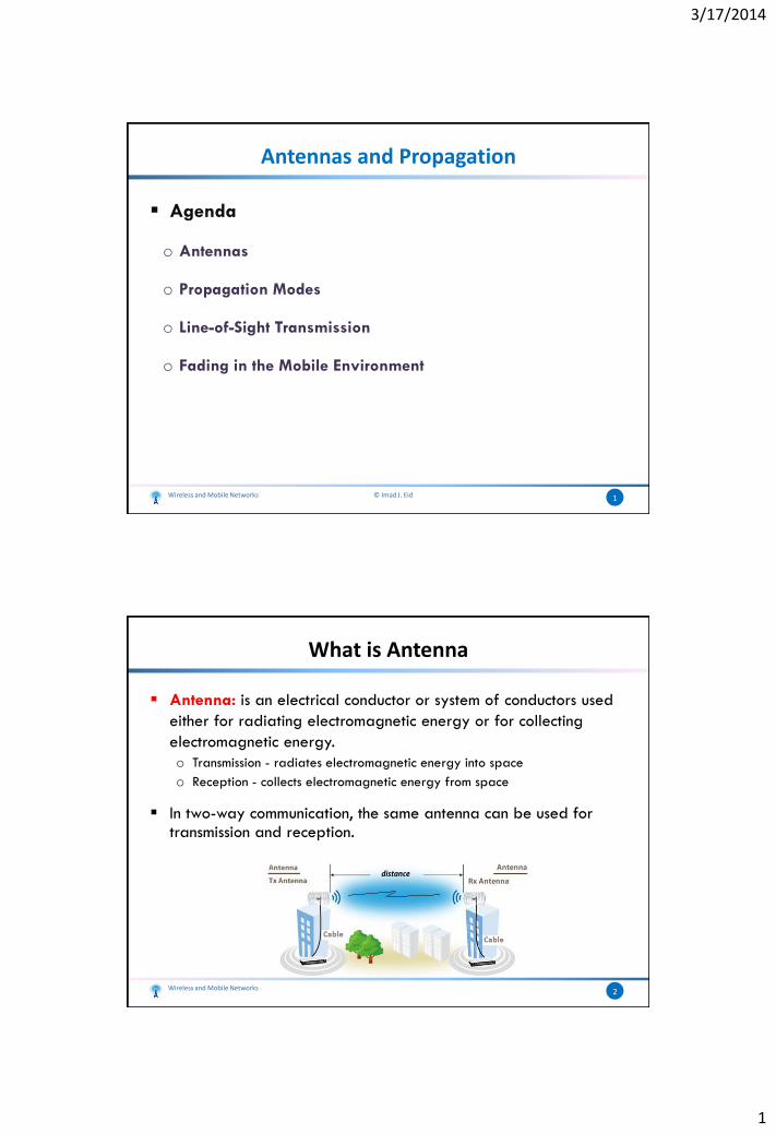
3/17/2014 1 Antennas and Propagation Agenda o Antennas o Propagation Modes o Line-of-Sight Transmission o Fading in the Mobile Environment 1 Wireless and Mobile Networks © Imad J. Eid What is Antenna Antenna: is an electrical conductor or system of conductors used either for radiating electromagnetic energy or for collecting electromagnetic energy. o Transmission - radiates electromagnetic energy into space o Reception - collects electromagnetic energy from space In two-way communication, the same antenna can be used for transmission and reception. Wireless and Mobile Networks 2
Transcript of Wireless & Mobile Networks - 3. Antennas & Propagation
3/17/2014
1
Antennas and Propagation
Agenda
o Antennas
o Propagation Modes
o Line-of-Sight Transmission
o Fading in the Mobile Environment
1Wireless and Mobile Networks © Imad J. Eid
What is Antenna
Antenna: is an electrical conductor or system of conductors used
either for radiating electromagnetic energy or for collecting
electromagnetic energy.
o Transmission - radiates electromagnetic energy into space
o Reception - collects electromagnetic energy from space
In two-way communication, the same antenna can be used for transmission and reception.
Wireless and Mobile Networks 2
3/17/2014
2
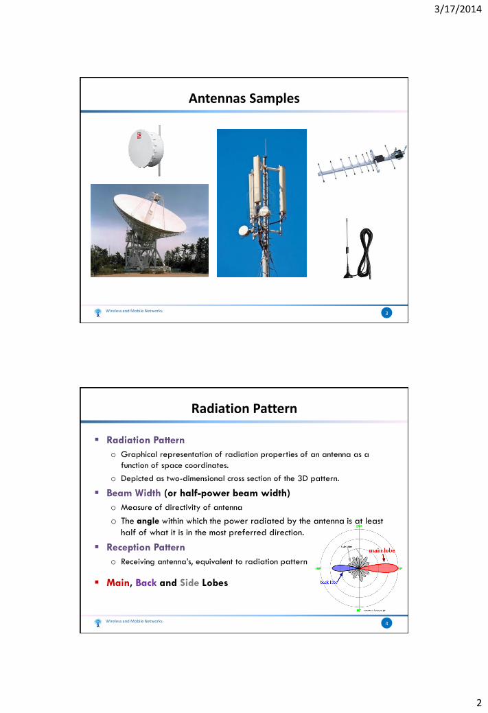
Antennas Samples
Wireless and Mobile Networks 3
Radiation Pattern
Radiation Pattern
o Graphical representation of radiation properties of an antenna as a
function of space coordinates.
o Depicted as two-dimensional cross section of the 3D pattern.
Beam Width (or half-power beam width)
o Measure of directivity of antenna
o The angle within which the power radiated by the antenna is at least
half of what it is in the most preferred direction.
Reception Pattern
o Receiving antenna’s, equivalent to radiation pattern
Main, Back and Side Lobes
Wireless and Mobile Networks 4
3/17/2014
3
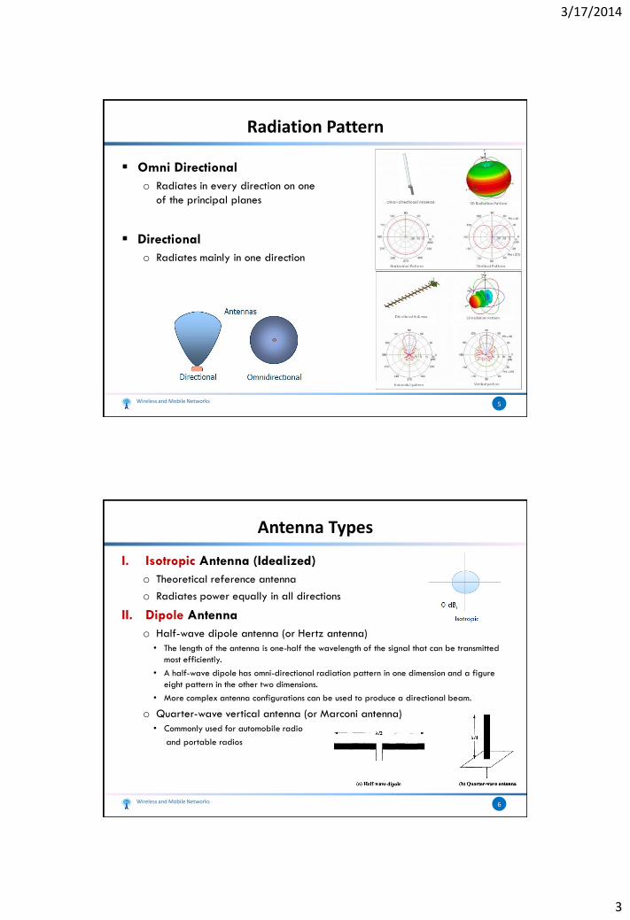
Radiation Pattern
Omni Directional
o Radiates in every direction on one
of the principal planes
Directional
o Radiates mainly in one direction
Wireless and Mobile Networks 5
Antenna Types
I. Isotropic Antenna (Idealized)
o Theoretical reference antenna
o Radiates power equally in all directions
II. Dipole Antenna
o Half-wave dipole antenna (or Hertz antenna)
• The length of the antenna is one-half the wavelength of the signal that can be transmitted
most efficiently.
• A half-wave dipole has omni-directional radiation pattern in one dimension and a figure
eight pattern in the other two dimensions.
• More complex antenna configurations can be used to produce a directional beam.
o Quarter-wave vertical antenna (or Marconi antenna)
• Commonly used for automobile radio
and portable radios
Wireless and Mobile Networks 6
3/17/2014
4
Antenna Types
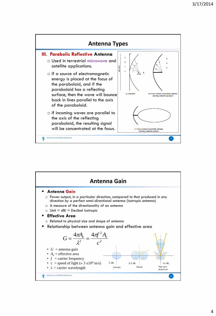
III. Parabolic Reflective Antenna
o Used in terrestrial microwave and satellite applications.
o If a source of electromagnetic energy is placed at the focus of the paraboloid, and if the paraboloid has a reflecting surface, then the wave will bounce back in lines parallel to the axis of the paraboloid.
o If incoming waves are parallel to the axis of the reflecting paraboloid, the resulting signal will be concentrated at the focus.
Wireless and Mobile Networks 7
Antenna Gain
Antenna Gaino Power output, in a particular direction, compared to that produced in any
direction by a perfect omni-directional antenna (isotropic antenna)
o A measure of the directionality of an antenna
o Unit = dBi = Decibel Isotropic
Effective Areao Related to physical size and shape of antenna
Relationship between antenna gain and effective area
• G = antenna gain
• Ae = effective area
• f = carrier frequency
• c = speed of light (» 3 x10⁸ m/s)
• = carrier wavelength
Wireless and Mobile Networks 8
2
2
2
44
c
AfAG ee
3/17/2014
5
Antenna Gain
Wireless and Mobile Networks 9
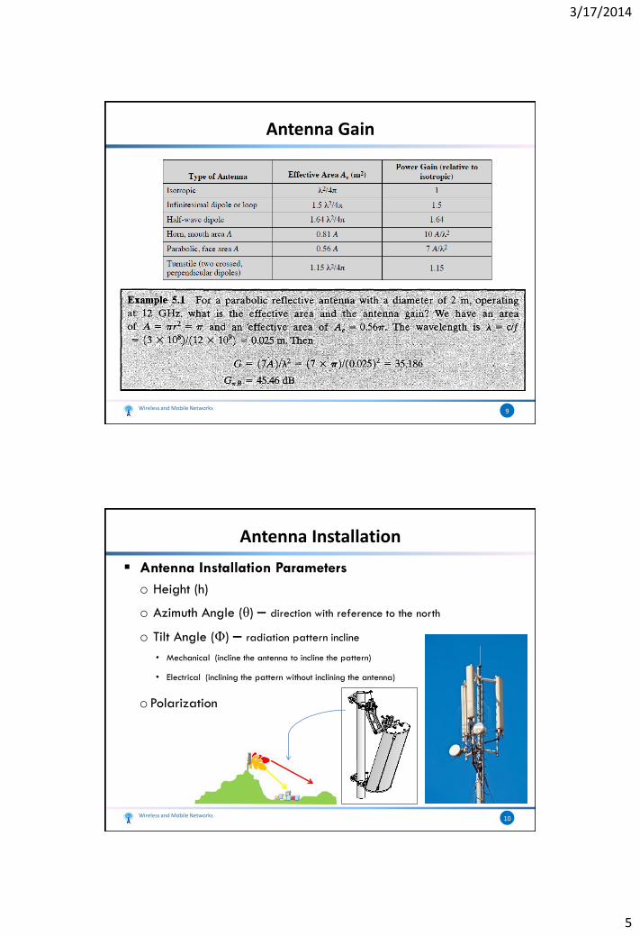
Antenna Installation
Antenna Installation Parameters
o Height (h)
o Azimuth Angle (θ) – direction with reference to the north
o Tilt Angle (Φ) – radiation pattern incline
• Mechanical (incline the antenna to incline the pattern)
• Electrical (inclining the pattern without inclining the antenna)
oPolarization
Wireless and Mobile Networks 10
3/17/2014
6
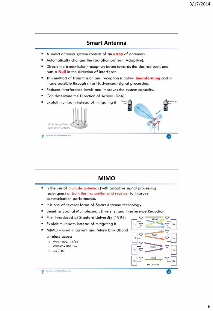
Smart Antenna
A smart antenna system consists of an array of antennas.
Automatically changes the radiation pattern (Adaptive).
Directs the transmission/reception beam towards the desired user, and
puts a Null in the direction of Interferer.
This method of transmission and reception is called beamforming and is
made possible through smart (advanced) signal processing.
Reduces interference levels and improves the system capacity.
Can determine the Direction of Arrival (DoA)
Exploit multipath instead of mitigating it
Wireless and Mobile Networks 11
Wi-Fi Access Point with Smart Antenna
MIMO
Is the use of multiple antennas (with adaptive signal processing
techniques) at both the transmitter and receiver to improve
communication performance.
It is one of several forms of Smart Antenna technology
Benefits: Spatial Multiplexing , Diversity, and Interference Reduction
First introduced at Stanford University (1994)
Exploit multipath instead of mitigating it
MIMO – used in current and future broadband
wireless access
o WiFi – 802.11n/ac
o WiMAX – 802.16e
o 3G / 4G
Wireless and Mobile Networks 12
3/17/2014
7
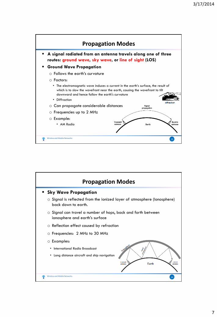
Propagation Modes
A signal radiated from an antenna travels along one of three
routes: ground wave, sky wave, or line of sight (LOS)
Ground Wave Propagation
o Follows the earth’s curvature
o Factors:
• The electromagnetic wave induces a current in the earth‘s surface, the result of
which is to slow the wavefront near the earth, causing the wavefront to tilt
downward and hence follow the earth's curvature
• Diffraction
o Can propagate considerable distances
o Frequencies up to 2 MHz
o Example:
• AM Radio
Wireless and Mobile Networks 13
Propagation Modes
Sky Wave Propagation
o Signal is reflected from the ionized layer of atmosphere (Ionosphere)
back down to earth.
o Signal can travel a number of hops, back and forth between
ionosphere and earth’s surface
o Reflection effect caused by refraction
o Frequencies: 2 MHz to 30 MHz
o Examples:
• International Radio Broadcast
• Long distance aircraft and ship navigation
Wireless and Mobile Networks 14
3/17/2014
8
Propagation Modes
Line-of-Sight (LOS) Propagation
o Transmitting and receiving antennas must be within line-of-sight
• Satellite communication – signal not reflected by ionosphere
• Ground communication – antennas within effective line-of-site due to refraction
o Frequencies: Above 30 MHz
o Examples:
• Mobile Communication
• Satellite Communication
• Wi-Fi, Wi-MAX ….
Wireless and Mobile Networks 15
Note: in practice, this mode can be used
for non-line of sight communication because
the signal can penetrate some obstacles and
because of signal reflections.
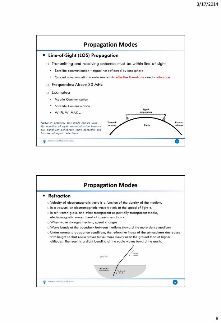
Propagation Modes
Refraction
o Velocity of electromagnetic wave is a function of the density of the medium.
o In a vacuum, an electromagnetic wave travels at the speed of light c.
o In air, water, glass, and other transparent or partially transparent media,
electromagnetic waves travel at speeds less than c.
oWhen wave changes medium, speed changes
oWave bends at the boundary between mediums (toward the more dense medium)
o Under normal propagation conditions, the refractive index of the atmosphere decreases
with height so that radio waves travel more slowly near the ground than at higher
altitudes. The result is a slight bending of the radio waves toward the earth.
Wireless and Mobile Networks 16
3/17/2014
9
Optical and Radio LOS
Line-of-Sight Equations
o Optical line of sight
o Effective, or radio, line of sight
• d = distance between antenna and horizon (km)
• h = antenna height (m)
• K = adjustment factor to account for refraction, rule of thumb K = 4/3
Wireless and Mobile Networks 17
hd 57.3
hd 57.3
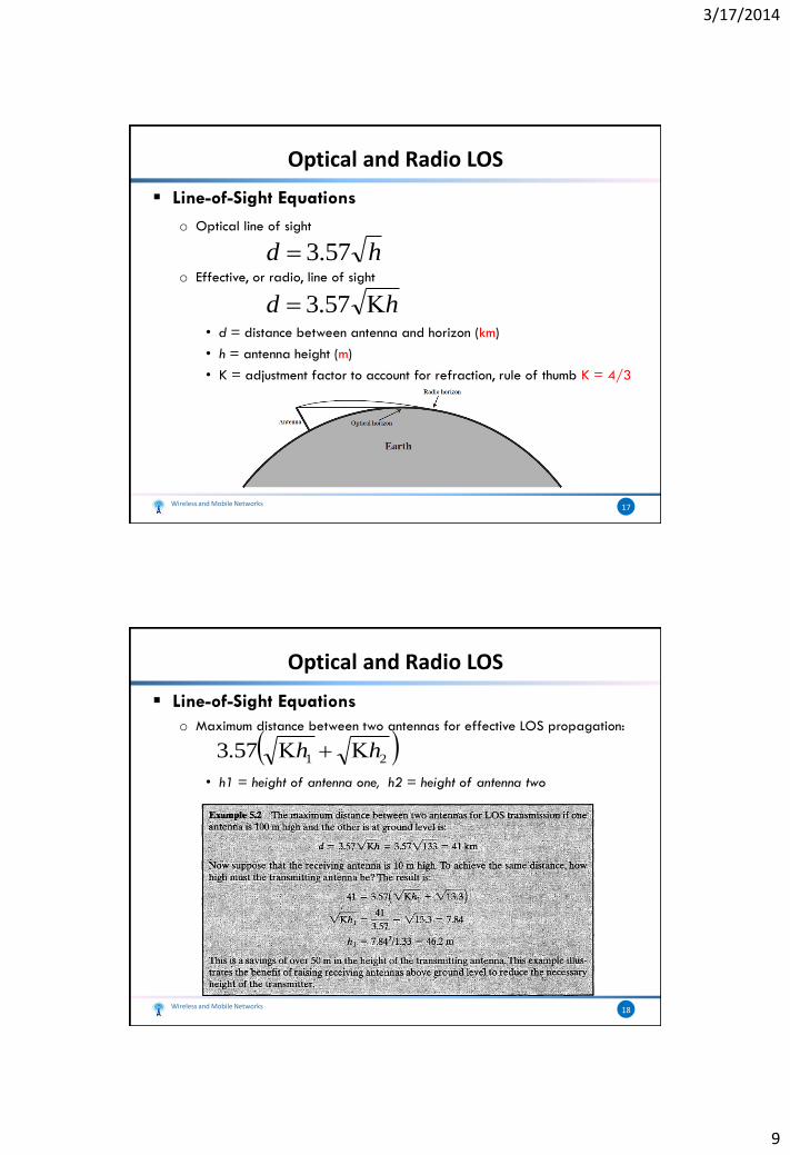
Optical and Radio LOS
Line-of-Sight Equations
o Maximum distance between two antennas for effective LOS propagation:
• h1 = height of antenna one, h2 = height of antenna two
Wireless and Mobile Networks 18
2157.3 hh
3/17/2014
10
Line-of-Sight Transmission
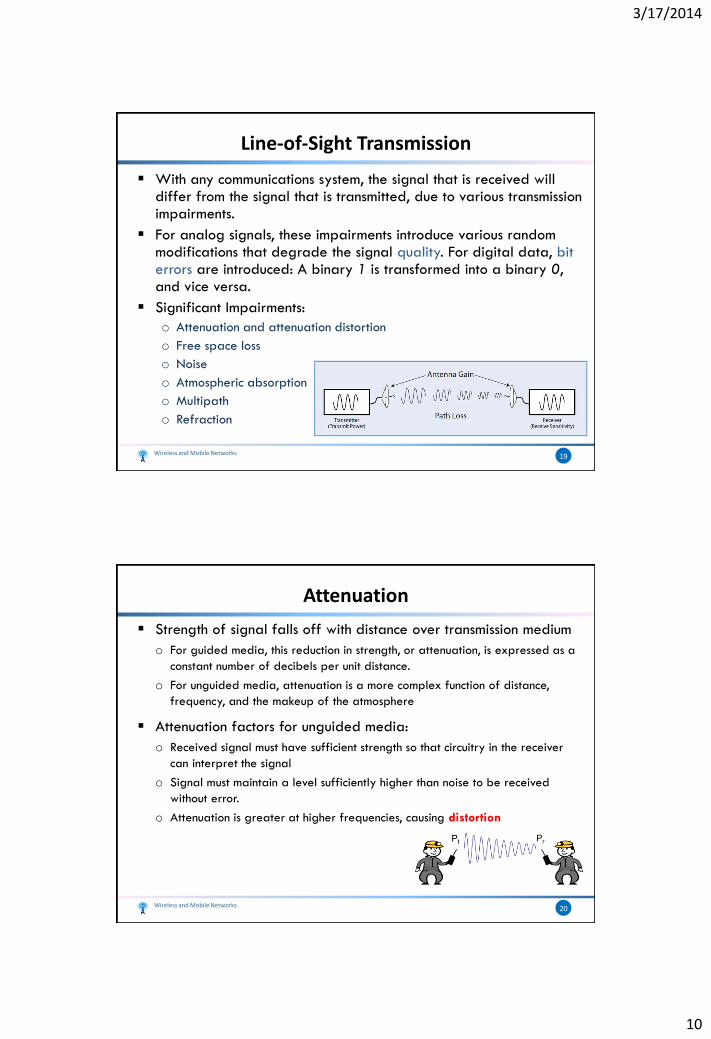
With any communications system, the signal that is received will differ from the signal that is transmitted, due to various transmission impairments.
For analog signals, these impairments introduce various random modifications that degrade the signal quality. For digital data, bit errors are introduced: A binary 1 is transformed into a binary 0, and vice versa.
Significant Impairments:
o Attenuation and attenuation distortion
o Free space loss
o Noise
o Atmospheric absorption
o Multipath
o Refraction
Wireless and Mobile Networks 19
Attenuation
Strength of signal falls off with distance over transmission medium
o For guided media, this reduction in strength, or attenuation, is expressed as a
constant number of decibels per unit distance.
o For unguided media, attenuation is a more complex function of distance,
frequency, and the makeup of the atmosphere
Attenuation factors for unguided media:
o Received signal must have sufficient strength so that circuitry in the receiver
can interpret the signal
o Signal must maintain a level sufficiently higher than noise to be received
without error.
o Attenuation is greater at higher frequencies, causing distortion
Wireless and Mobile Networks 20
3/17/2014
11
Free Space Loss
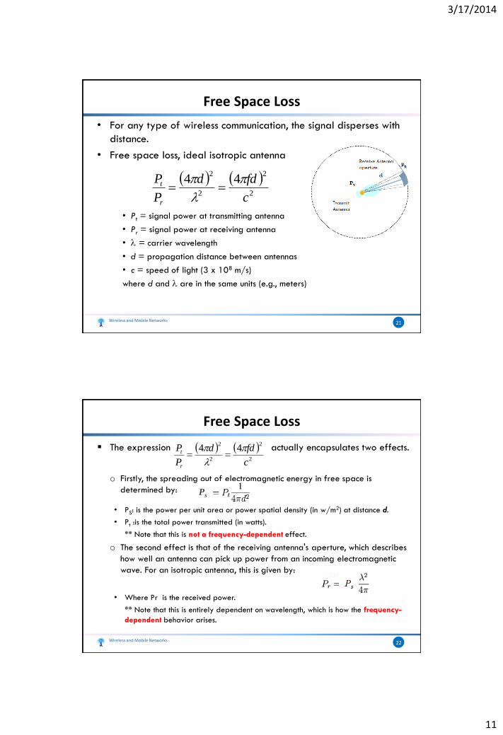
• For any type of wireless communication, the signal disperses with
distance.
• Free space loss, ideal isotropic antenna
• Pt = signal power at transmitting antenna
• Pr = signal power at receiving antenna
• = carrier wavelength
• d = propagation distance between antennas
• c = speed of light (3 x 10⁸ m/s)
where d and are in the same units (e.g., meters)
Wireless and Mobile Networks 21
2
2
2
244
c
fdd
P
P
r
t
Free Space Loss
The expression actually encapsulates two effects.
o Firstly, the spreading out of electromagnetic energy in free space is
determined by:
• PS: is the power per unit area or power spatial density (in w/m2) at distance d.
• Pt :is the total power transmitted (in watts).
** Note that this is not a frequency-dependent effect.
o The second effect is that of the receiving antenna's aperture, which describes
how well an antenna can pick up power from an incoming electromagnetic
wave. For an isotropic antenna, this is given by:
• Where Pr is the received power.
** Note that this is entirely dependent on wavelength, which is how the frequency-
dependent behavior arises.
Wireless and Mobile Networks 22
2
2
2
244
c
fdd
P
P
r
t
Ps
3/17/2014
12
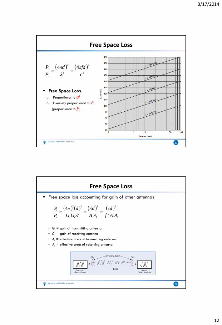
Free Space Loss
Free Space Loss:
o Proportional to d2
o Inversely proportional to λ2
(proportional to f2)
Wireless and Mobile Networks 23
2
2
2
244
c
fdd
P
P
r
t
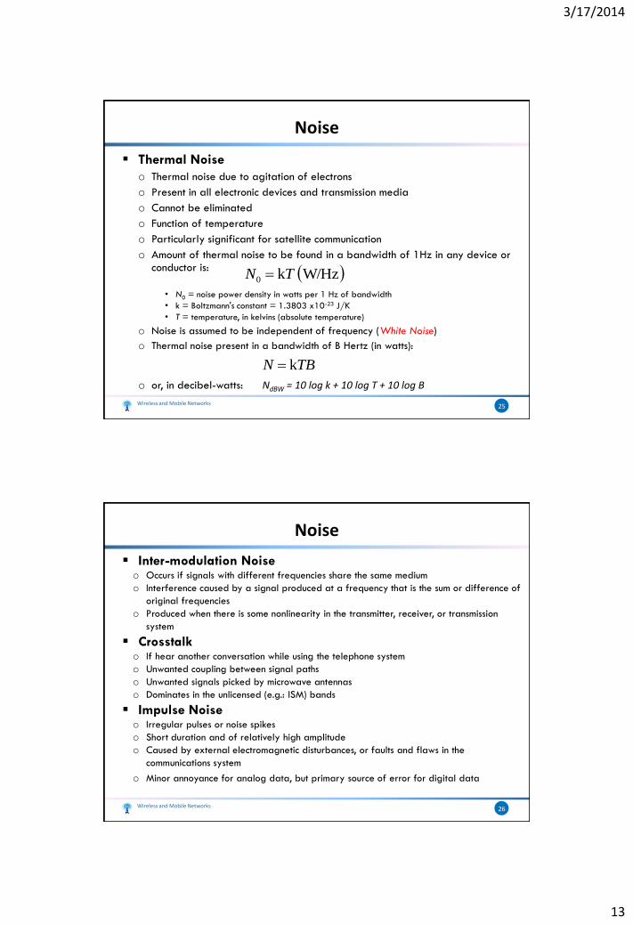
Free Space Loss
Free space loss accounting for gain of other antennas
• Gt = gain of transmitting antenna
• Gr = gain of receiving antenna
• At = effective area of transmitting antenna
• Ar = effective area of receiving antenna
Wireless and Mobile Networks 24
trtrtrr
t
AAf
cd
AA
d
GG
d
P
P2
22
2
224
3/17/2014
13
Noise
Thermal Noise
o Thermal noise due to agitation of electrons
o Present in all electronic devices and transmission media
o Cannot be eliminated
o Function of temperature
o Particularly significant for satellite communication
o Amount of thermal noise to be found in a bandwidth of 1Hz in any device or conductor is:
• N0 = noise power density in watts per 1 Hz of bandwidth
• k = Boltzmann's constant = 1.3803 x10⁻²³ J/K
• T = temperature, in kelvins (absolute temperature)
o Noise is assumed to be independent of frequency (White Noise)
o Thermal noise present in a bandwidth of B Hertz (in watts):
.
o or, in decibel-watts: NdBW = 10 log k + 10 log T + 10 log B
Wireless and Mobile Networks 25
W/Hz k0 TN
TBN k
Noise
Inter-modulation Noiseo Occurs if signals with different frequencies share the same medium
o Interference caused by a signal produced at a frequency that is the sum or difference of
original frequencies
o Produced when there is some nonlinearity in the transmitter, receiver, or transmission
system
Crosstalko If hear another conversation while using the telephone system
o Unwanted coupling between signal paths
o Unwanted signals picked by microwave antennas
o Dominates in the unlicensed (e.g.: ISM) bands
Impulse Noise o Irregular pulses or noise spikes
o Short duration and of relatively high amplitude
o Caused by external electromagnetic disturbances, or faults and flaws in the
communications system
o Minor annoyance for analog data, but primary source of error for digital data
Wireless and Mobile Networks 26
3/17/2014
14
The Expression Eb/N0
A parameter related to SNR
A standard quality measure for digital communication system performance.
Ratio of signal energy per bit to noise power density per Hertz
Consider a signal that contains binary digital data transmitted at a certain bit rate R
Recalling that 1 watt = 1 J/s
Eb =STb = S/R
S: Signal Power R: Bit Rate, R = 1ITb
Wireless and Mobile Networks 27
TR
S
N
RS
N
Eb
k
/
00
The Expression Eb/N0
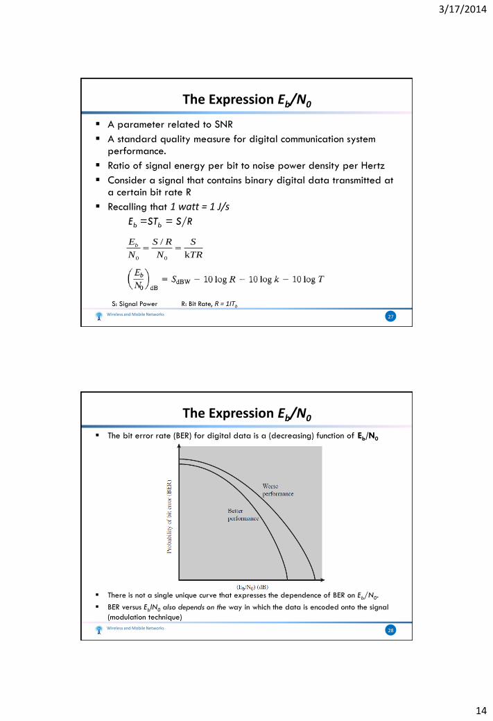
The bit error rate (BER) for digital data is a (decreasing) function of Eb/N0
There is not a single unique curve that expresses the dependence of BER on Eb/N0.
BER versus EblN0 also depends on the way in which the data is encoded onto the signal
(modulation technique)
Wireless and Mobile Networks 28

3/17/2014
15
The Expression Eb/N0
As bit rate R increases, transmitted signal power must increase to maintain required Eb/N0
Wireless and Mobile Networks 29
Expression Eb/N0
We can relate Eb/N0 to the SNR as follows:
The noise in a signal with bandwidth BT is
N = NoBT
Shannon’s:
Equating BT with B and R with C
This is a useful formula that relates the achievable spectral efficiency C/B to Eb/N0
Wireless and Mobile Networks 30
3/17/2014
16
Other Impairments
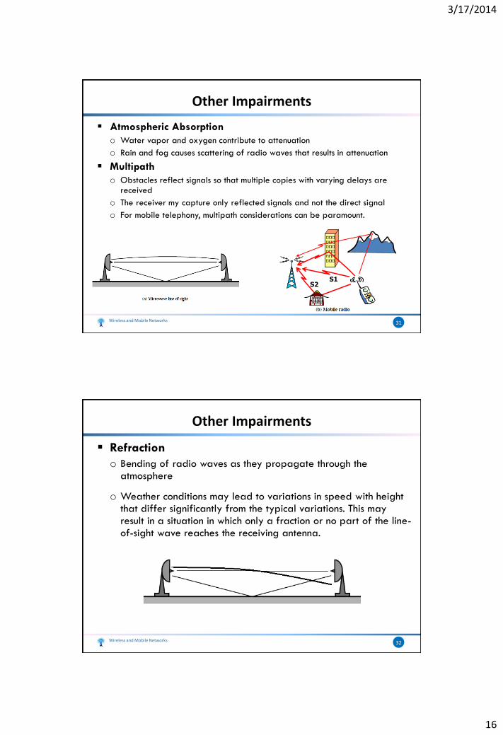
Atmospheric Absorption
o Water vapor and oxygen contribute to attenuation
o Rain and fog causes scattering of radio waves that results in attenuation
Multipath
o Obstacles reflect signals so that multiple copies with varying delays are received
o The receiver my capture only reflected signals and not the direct signal
o For mobile telephony, multipath considerations can be paramount.
Wireless and Mobile Networks 31
S1S2
Other Impairments
Refraction
o Bending of radio waves as they propagate through the atmosphere
o Weather conditions may lead to variations in speed with height that differ significantly from the typical variations. This may result in a situation in which only a fraction or no part of the line-of-sight wave reaches the receiving antenna.
Wireless and Mobile Networks 32
3/17/2014
17
Fading in the Mobile Environment
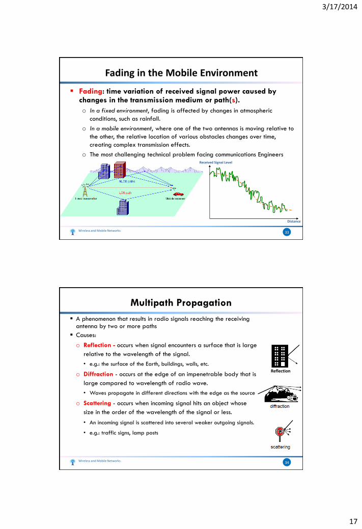
Fading: time variation of received signal power caused by changes in the transmission medium or path(s).
o In a fixed environment, fading is affected by changes in atmospheric
conditions, such as rainfall.
o In a mobile environment, where one of the two antennas is moving relative to
the other, the relative location of various obstacles changes over time,
creating complex transmission effects.
o The most challenging technical problem facing communications Engineers
Wireless and Mobile Networks 33
Distance
Received Signal Level
Multipath Propagation
A phenomenon that results in radio signals reaching the receiving antenna by two or more paths
Causes:
o Reflection - occurs when signal encounters a surface that is large
relative to the wavelength of the signal.
• e.g.: the surface of the Earth, buildings, walls, etc.
o Diffraction - occurs at the edge of an impenetrable body that is
large compared to wavelength of radio wave.
• Waves propagate in different directions with the edge as the source
o Scattering - occurs when incoming signal hits an object whose
size in the order of the wavelength of the signal or less.
• An incoming signal is scattered into several weaker outgoing signals.
• e.g.: traffic signs, lamp posts
Wireless and Mobile Networks 34
Reflection
3/17/2014
18
Wireless and Mobile Networks 35
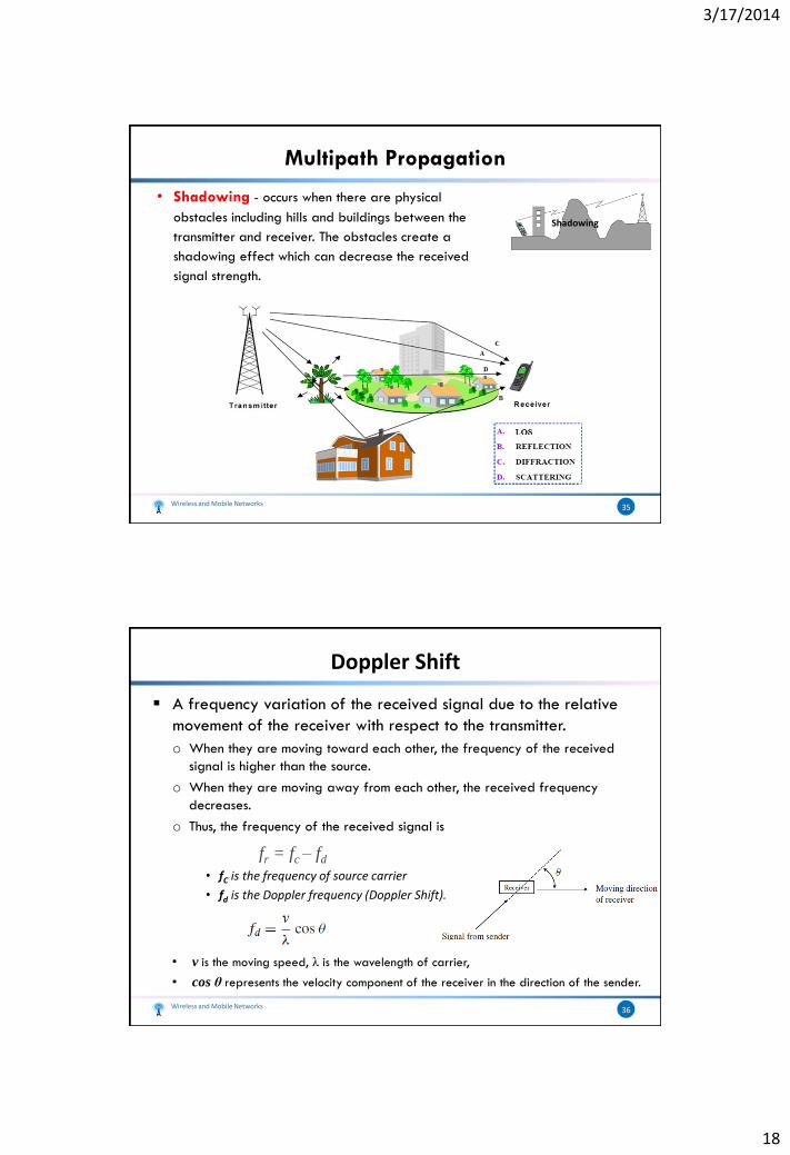
• Shadowing - occurs when there are physical
obstacles including hills and buildings between the
transmitter and receiver. The obstacles create a
shadowing effect which can decrease the received
signal strength.
Shadowing
Multipath Propagation
A frequency variation of the received signal due to the relative
movement of the receiver with respect to the transmitter.
o When they are moving toward each other, the frequency of the received
signal is higher than the source.
o When they are moving away from each other, the received frequency
decreases.
o Thus, the frequency of the received signal is
fr = fc – fd
• fC is the frequency of source carrier
• fd is the Doppler frequency (Doppler Shift).
• v is the moving speed, λ is the wavelength of carrier,
• cos θ represents the velocity component of the receiver in the direction of the sender.
Wireless and Mobile Networks 36
Doppler Shift

3/17/2014
19
Positive:
o Helps receive signals even without line of sight.
o With smart Antennas, can substantially increase the usable received
power
Negative:
o Multiple copies of a signal may arrive at different phases
• If phases add destructively, the signal level relative to noise declines, making detection more difficult and increases errors.
o Inter-symbol Interference (ISI)
• One or more delayed copies of a pulse may arrive at the same time as the primary pulse for a subsequent bit
Wireless and Mobile Networks 37
Effects of Multipath Propagation
ISI:
Wireless and Mobile Networks 38
Effects of Multipath Propagation
3/17/2014
20
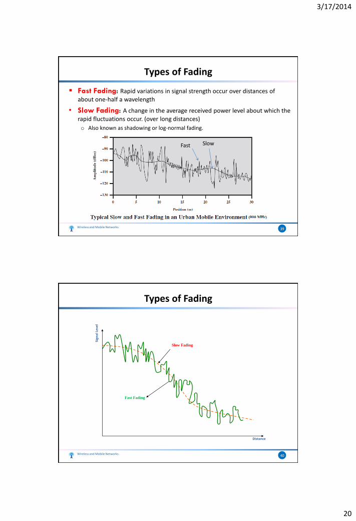
Fast Fading: Rapid variations in signal strength occur over distances of
about one-half a wavelength
• Slow Fading: A change in the average received power level about which the
rapid fluctuations occur. (over long distances)
o Also known as shadowing or log-normal fading.
Wireless and Mobile Networks 39
Types of Fading
SlowFast
Wireless and Mobile Networks 40
Types of Fading
Distance
Slow Fading
Fast Fading
Sign
al L
evel

3/17/2014
21
• Flat Fading: All frequency components of the received signal fluctuate in the
same proportions simultaneously
• Selective Fading: Affects unequally the different frequency components of
the received signal.
Wireless and Mobile Networks 41
Types of Fading
frequency
Channel Frequency Response
Additive White Gaussian Noise (AWGN) Channel
o The desired signal is degraded by thermal noise
o This model is fairly accurate in some cases, such as space communications and some wire transmissions, such as coaxial cable
Rayleigh Fading o Occurs when there are multiple indirect paths between transmitter and
receiver and no distinct dominant path, such as an LOS path.
o This represents a worst case scenario
o Used in difficult outdoor environments, such as downtown urban settings.
Rician Fading o Occurs when there is a direct LOS path in addition to a number of indirect
multipath signals.
o Used in indoor environment, smaller cells or in more open outdoor environments.
Wireless and Mobile Networks 42
The Fading Channel

3/17/2014
22
The channels can be characterized by
a parameter K (Rician K–factor),
defined as follows:
When K = 0 the channel is Rayleigh
When K = ∞, the channel is AWGN
Worst: Rayleigh + Selective
Wireless and Mobile Networks 43
The Fading Channel
An empirical mathematical formulation for the characterization of radio
wave propagation as a function of frequency, distance, and other
conditions.
Used to predict the received power or path loss
To determine the coverage area of the transmitter
Most famous model: Okumura-Hata
o Okumura made extensive measurements (empirical model – plots)
o Hata transformed Okumura’s plots to an analytical model
o Valid for 150-1500 MHz
o Model takes the effect of
• Transmitter height
• Receiver height
• Frequency fc in MHz
• Distance d in km
• Different environments (Terrain, Building Profile, Roads ...)
Wireless and Mobile Networks 44
Radio Propagation Model

3/17/2014
23
I. Forward Error Correction
o The receiver, using only the received bits (data plus error-correcting
code), detects and corrects bit errors in the data
o Backward error correction: the receiver merely detects the presence of
errors and then sends a request back to the transmitter for
retransmission.
• Not practical in many wireless applications
o Typically in mobile wireless applications, the ratio of total bits sent to
data bits sent is between 2 and 3.
II. Adaptive Equalization
o Used to combat inter-symbol interference (ISI)
o Involves gathering dispersed symbol energy back into its original time
interval
Wireless and Mobile Networks 45
Error Compensation Mechanisms
Adaptive (DSP based) Equalizer
Wireless and Mobile Networks 46
Error Compensation Mechanisms
3/17/2014
24
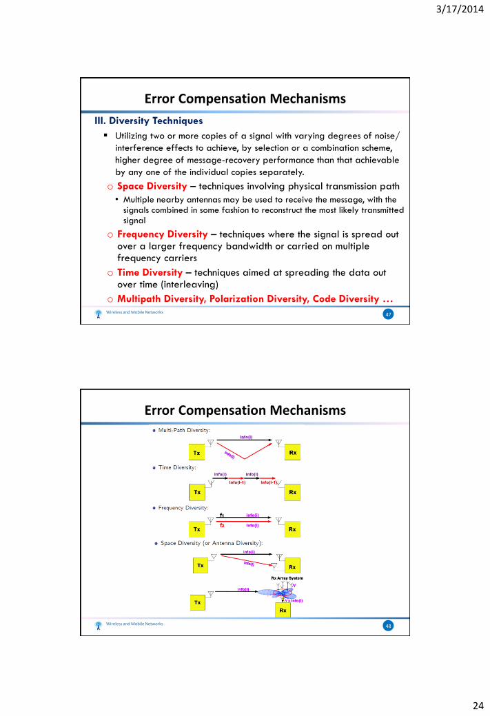
III. Diversity Techniques
Utilizing two or more copies of a signal with varying degrees of noise/
interference effects to achieve, by selection or a combination scheme,
higher degree of message-recovery performance than that achievable
by any one of the individual copies separately.
o Space Diversity – techniques involving physical transmission path
• Multiple nearby antennas may be used to receive the message, with the signals combined in some fashion to reconstruct the most likely transmitted signal
o Frequency Diversity – techniques where the signal is spread out over a larger frequency bandwidth or carried on multiple frequency carriers
o Time Diversity – techniques aimed at spreading the data out over time (interleaving)
o Multipath Diversity, Polarization Diversity, Code Diversity …Wireless and Mobile Networks 47
Error Compensation Mechanisms
Wireless and Mobile Networks 48
Error Compensation Mechanisms