Wireless I/O and Ethernet Connectivity Catalog - Professional ...
111
Industrial Data Connectivity Wireless I/O and Ethernet Connectivity Catalog
-
Upload
khangminh22 -
Category
Documents
-
view
3 -
download
0
Transcript of Wireless I/O and Ethernet Connectivity Catalog - Professional ...

Industrial Data Connectivity
Wireless I/O and Ethernet ConnectivityCatalog
Weidmüller – Partner in Industrial Connectivity
As experienced experts we support our customers and partners around the worldwith products, solutions and services in the industrial environment of power,signal and data. We are at home in their industries and markets and know thetechnological challenges of tomorrow. We are therefore continuously developinginnovative, sustainable and useful solutions for their individual needs. Together weset standards in Industrial Connectivity.
Weidmüller Interface GmbH & Co. KGKlingenbergstraße 1632758 Detmold, GermanyT +49 5231 14-0F +49 5231 [email protected]
Weidmuller, Canada10 Spy Court Markham, Ontario L3R 5H6Telephone: (800) 268-4080Facsimile: (877) 300-5635Email: [email protected]: www.weidmuller.ca
Weidmuller, MexicoBlvd. Hermanos Serdán 698, Col. San Rafael Oriente Puebla, Puebla, Mexico C.P. 72029 Telephone: 01 222 2686267Facsimile: 01 222 2686219Email: [email protected]: www.weidmuller.com.mx
Weidmuller, United States821 Southlake Blvd. Richmond, Virginia 23236Telephone: (800) 849-9343Facsimile: (804) 379-2593Email: [email protected]: www.weidmuller.com
Order number: XXXXXXXXXX/01/2015/XXXX
Cata
logW
ireles
s I/O
and E
ther
net C
onne
ctivit
y
12

Product Portfolio
PCB terminals
PCB connectors
Automation DeviceSignal or power electronics
Tools and identification systems
FieldPower®
Fieldbus distributors
Heavy-dutyconnectors
MarkersPrinterSoftwareCutting tools Stripping tools Crimping tools
More tools
PCB connectors
®
Switches
DATA
SIGNAL
Enclosures and accessories
Passive sensor-actuator-interfacesand cables
Mediaconverter
Terminal rail outlet
JACKPAC®
IP68
More tools
Cable glands
IP68
Active sensor-actuator-interfaces
JACKPAC
IE-LINEplug-in connectors
FrontCom® Micro Service interface
Electronicshousings
Signalconverters
Solid-state relays
Relay modules
Interface Units Surge protection for Instrumentation & Control equipment
CabinetStud terminals
POWER
Modular Terminal Blocks
IE-LINEConnection components
Power supplies
Surgeprotection
1
Con
tent
s
Wireless I/O and Ethernet ConnectivityCatalog 12
Product Overview Introduction . . . . . . . . . . . . . . . . . . . . . . . . . . . . . . . . . . . . . . . . . . . . . . . . . . . . . . . . . . . . 3
Industry Applications . . . . . . . . . . . . . . . . . . . . . . . . . . . . . . . . . . . . . . . . . . . . . . . . . . . . . . . . . . . . . . . . . . . . . . . . 6
Application Notes . . . . . . . . . . . . . . . . . . . . . . . . . . . . . . . . . . . . . . . . . . . . . . . . . . . . . . . . . . . . . . . . . . . . . . . . 8
Application Examples . . . . . . . . . . . . . . . . . . . . . . . . . . . . . . . . . . . . . . . . . . . . . . . . . . . . . . . . . . . . . . . . . . . . . . . . 9
Wireless I/O Unidirectional Transmitter/Receiver Units Introduction . . . . . . . . . . . . . . . . . . . . . . . . . . . . . . . . . . . . . . . . . . . . . . . . . . . . . . . . . .16 ProductData . . . . . . . . . . . . . . . . . . . . . . . . . . . . . . . . . . . . . . . . . . . . . . . . . . . . . . . . .19
Transmitter (Single Sensor Units) Introduction . . . . . . . . . . . . . . . . . . . . . . . . . . . . . . . . . . . . . . . . . . . . . . . . . . . . . . . . . .21 ProductData . . . . . . . . . . . . . . . . . . . . . . . . . . . . . . . . . . . . . . . . . . . . . . . . . . . . . . . . .24
Wireless Meshing I/O Units Introduction . . . . . . . . . . . . . . . . . . . . . . . . . . . . . . . . . . . . . . . . . . . . . . . . . . . . . . . . . .25 ProductData . . . . . . . . . . . . . . . . . . . . . . . . . . . . . . . . . . . . . . . . . . . . . . . . . . . . . . . . .27
Multi-I/O Units Introduction . . . . . . . . . . . . . . . . . . . . . . . . . . . . . . . . . . . . . . . . . . . . . . . . . . . . . . . . . .28 ProductData . . . . . . . . . . . . . . . . . . . . . . . . . . . . . . . . . . . . . . . . . . . . . . . . . . . . . . . . .31
Expansion I/O Units Introduction . . . . . . . . . . . . . . . . . . . . . . . . . . . . . . . . . . . . . . . . . . . . . . . . . . . . . . . . . .33 ProductData . . . . . . . . . . . . . . . . . . . . . . . . . . . . . . . . . . . . . . . . . . . . . . . . . . . . . . . . .36
Wireless Gateways Introduction . . . . . . . . . . . . . . . . . . . . . . . . . . . . . . . . . . . . . . . . . . . . . . . . . . . . . . . . . .38 ProductData . . . . . . . . . . . . . . . . . . . . . . . . . . . . . . . . . . . . . . . . . . . . . . . . . . . . . . . . .40
Wireless Data Modems Introduction . . . . . . . . . . . . . . . . . . . . . . . . . . . . . . . . . . . . . . . . . . . . . . . . . . . . . . . . . . . .43 SerialOnlyData . . . . . . . . . . . . . . . . . . . . . . . . . . . . . . . . . . . . . . . . . . . . . . . . . . . . . . . . .44 EthernetandSerialData . . . . . . . . . . . . . . . . . . . . . . . . . . . . . . . . . . . . . . . . . . . . . . . . .47 EthernetOnlyData . . . . . . . . . . . . . . . . . . . . . . . . . . . . . . . . . . . . . . . . . . . . . . . . . . . . . .49 Licensed Frequencies . . . . . . . . . . . . . . . . . . . . . . . . . . . . . . . . . . . . . . . . . . . . . . . . . . . .50
Enclosures Specialty Enclosures . . . . . . . . . . . . . . . . . . . . . . . . . . . . . . . . . . . . . . . . . . . . . . . . . . . . .52 Pre-configuredWirelessEnclosures . . . . . . . . . . . . . . . . . . . . . . . . . . . . . . . . . . . . . . . .53
Cellular - Routers Introduction . . . . . . . . . . . . . . . . . . . . . . . . . . . . . . . . . . . . . . . . . . . . . . . . . . . . . . . . . . . .55 ProductData . . . . . . . . . . . . . . . . . . . . . . . . . . . . . . . . . . . . . . . . . . . . . . . . . . . . . . . . . . . .57
Wireless Accessories Selection Guide . . . . . . . . . . . . . . . . . . . . . . . . . . . . . . . . . . . . . . . . . . . . . . . . . . . . . . . . .60 ConnectionDiagrams . . . . . . . . . . . . . . . . . . . . . . . . . . . . . . . . . . . . . . . . . . . . . . . . . . . .64 RadiationPatterns . . . . . . . . . . . . . . . . . . . . . . . . . . . . . . . . . . . . . . . . . . . . . . . . . . . . . . .66 ProductData-Antennas . . . . . . . . . . . . . . . . . . . . . . . . . . . . . . . . . . . . . . . . . . . . . . . . .69 ProductData-Cables . . . . . . . . . . . . . . . . . . . . . . . . . . . . . . . . . . . . . . . . . . . . . . . . . . . .90 ProductData-Hardware . . . . . . . . . . . . . . . . . . . . . . . . . . . . . . . . . . . . . . . . . . . . . . . . .92 ProductData-Adapters . . . . . . . . . . . . . . . . . . . . . . . . . . . . . . . . . . . . . . . . . . . . . . . . . .94 ProductData-Filters . . . . . . . . . . . . . . . . . . . . . . . . . . . . . . . . . . . . . . . . . . . . . . . . . . . . .95
Ethernet ProductData-Switches . . . . . . . . . . . . . . . . . . . . . . . . . . . . . . . . . . . . . . . . . . . . . . . . . .96 ProductData-Converters . . . . . . . . . . . . . . . . . . . . . . . . . . . . . . . . . . . . . . . . . . . . . . . .99 ProductData-NetBlocMountingRailOutlets. . . . . . . . . . . . . . . . . . . . . . . . . . . . . 100
Power Supplies ProductData . . . . . . . . . . . . . . . . . . . . . . . . . . . . . . . . . . . . . . . . . . . . . . . . . . . . . . . . . . 101
Glossary . . . . . . . . . . . . . . . . . . . . . . . . . . . . . . . . . . . . . . . . . . . . . . . . . . . . . . . . . . . . . . . . . . . . . 104

Weidmuller Catalogs at a GlanceCatalog 1: Modular Terminal Blocks•P-Series(Push-in)•PowerDistribution BlocksandFuseBlocks
• Stud Style (Screw clamp)
Catalog 2: PCB Terminals and Connectors• Space Saving Technologies•WideVarietyofClampingTechnologies•PitchesRangingfrom3.50mmto15.00mm•OrientationsRangingfrom90˚to270˚
Catalog 3: RockStar®– Heavy Duty Connectors• Inserts• Modular System•HousingsIP65andIP68•CableGlands
Catalog 4.1: Analog Signal Conditioning•IntrinsicallySafeConditioners•SignalConvertersandMonitoringDevices•IndicatorsandConfigurableDisplays
Catalog 4.4: Surge Protection•SurgeProtectionforLow-Voltage•SurgeProtectionforInstrumentationandControl•SurgeProtectionforDataInterfaces•SurgeProtectionforPhotovoltaicSystems
Catalog 4.5: Interface Units and PLC Solutions•InterfaceUnits•PLCInterfaces–H-,R-andS-System•BytePrecablingSolution
Catalog 5: Enclosures and Cable Glands• Enclosures•CableGlands•Cabtite(CableEntrySystem)
Catalog 9: Industrial Ethernet• Unmanaged Switches• Managed Switches• Routers• Media Converters
Catalog 4.2: Relays and Optocouplers• Mechanical Relays• Solid-State (opto) Relays•PowerSolid-StateRelays•MultifunctionRelaysandTimers
Catalog 8: Sensor Actuator Interface•SAIPassiveBlocks•SAIUniversal•SAIASI•CablesandConnectors
•JACKPAC®IP67
Catalog 7: Marking Systems•TerminalMarkers•WireandCableMarkers•DeviceandEquipmentMarkers•PrintingSystemsandSoftware
Catalog 6: Tools• Cutting• Stripping• Crimping• Screwdrivers
Catalog 12: Wireless I/O and Ethernet Connectivity• Wireless I/O and Ethernet• Wireless Gateways• Wireless Transceivers•AntennasandAccessories
Catalog 11: Circuit and Surge Protection•CircuitBreakers•OvervoltageProtection•ACReceptacles• GFCI Outlets
• Z-Series (Tension clamp)• W-Series (Screw clamp)
Catalog 4.3: Power Delivery•PowerSupplies•UPScontrolunits/batterybackupunits•ACoutletDIN-RailMountableReceptacles
Catalog 10: Industrial Connectivity• Short Form Catalog•ProductOverview
• AutomaticMachines• Ferrules
2
• SteadyTEC®
• IE Connectors•Accessories

3
Prod
uct O
verv
iew
Product Overview
Types of Wireless ProductsProduct Overview
Weidmuller industrial wireless products provide secure andreliablesolutionsforawiderangeofindustriesandapplications,asanalternativeforsignalanddatawiring.Theseproductsfallintofourgroups:
WirelessMeshingI/O,combinesmultiI/Oand/orgatewayfunctionalitywiththereliabilityofsecure,scalablemeshdistancecommunications.TheIP-basedaddressingprovidesmesh/self-healingofnetworkcommunications,multi-hoprepeatingandremoteovertheairre-configurationanddiagnostics.TheMeshingI/Ounitsfurthercomplementedbyitseaseofcommissioningandintegrationintoexistingplantinfrastructureplusseamlessinterfacewithnon-meshingsystems.
WirelessI/O,alsoknownasradiotelemetry,connectdirectlyto sensor and control signals and transmit the signal values byradio.Thesignalsareeitherre-createdassimilarsignals,oroutputasadataconnection—Ethernet,Profibus,Modbusetc.WirelessI/Onetworkscanbeassimpleastwounitstransferringasmallnumberofsignalsfromonepointtoanother,ortheycanbecomplexdata-acquisitionnetworkswithmultiple“master”interfacestoexternalsystems.
WirelessGatewaysprovidewirelessconnectivitybetweendatabuses-connectivitybetweendevicesusingthesamedatabus,orbetweendifferentdatabuses(EthernettoProfibustoDeviceNettoModbusetc).Wirelessgatewaysaresimilarinoperationtowirelessmodems,howevergatewaysonlyprovidearegisterinterfacetothedatabus,transferringI/O registers only.
WirelessModemstransmitserialorEthernetdata,providingawirelessextensionofthedatalink.ExampleapplicationsarePLCtoPLCconnections(point-to-point),connectingSCADAtoagroupofPLCs(point-to-multipoint),orformingawirelessPLCLAN(multidrop).Wirelessmodemstransmitthedatawithminimaltransformation.
Wireless I/O
Wireless Modems
Wireless Meshing I/O
Wireless Gateways
4
Prod
uct O
verv
iew
Product Overview
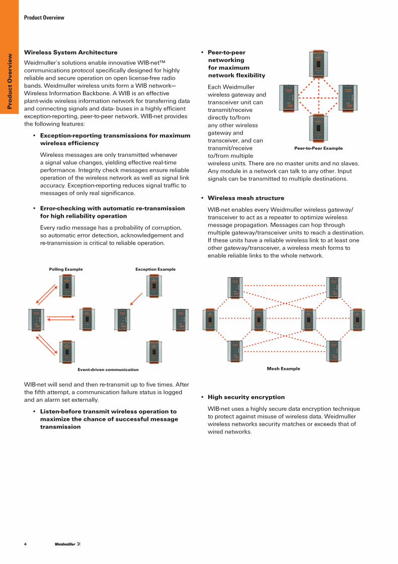
• Peer-to-peer networking for maximum network flexibility
Each Weidmuller wireless gateway and transceiver unit can transmit/receive directlyto/fromany other wireless gateway and transceiver,andcantransmit/receive to/frommultiplewireless units. There are no master units and no slaves. Anymoduleinanetworkcantalktoanyother.Inputsignalscanbetransmittedtomultipledestinations.
• Wireless mesh structure
WIB-netenableseveryWeidmullerwirelessgateway/transceiver to act as a repeater to optimize wireless message propagation. Messages can hop through multiple gateway/transceiver units to reach a destination. Iftheseunitshaveareliablewirelesslinktoatleastoneothergateway/transceiver,awirelessmeshformstoenablereliablelinkstothewholenetwork.
• High security encryption
WIB-netusesahighlysecuredataencryptiontechniquetoprotectagainstmisuseofwirelessdata.Weidmullerwirelessnetworkssecuritymatchesorexceedsthatofwirednetworks.
Wireless System ArchitectureWeidmuller’ssolutionsenableinnovativeWIB-net™communicationsprotocolspecificallydesignedforhighlyreliableandsecureoperationonopenlicense-freeradiobands.WeidmullerwirelessunitsformaWIBnetwork—WirelessInformationBackbone.AWIBisaneffectiveplant-widewirelessinformationnetworkfortransferringdataandconnectingsignalsanddata-busesinahighlyefficientexception-reporting,peer-to-peernetwork.WIB-netprovidesthefollowingfeatures:
• Exception-reporting transmissions for maximum wireless efficiency
Wireless messages are only transmitted whenever asignalvaluechanges,yieldingeffectivereal-timeperformance.Integritycheckmessagesensurereliableoperationofthewirelessnetworkaswellassignallinkaccuracy.Exception-reportingreducessignaltraffictomessagesofonlyrealsignificance.
• Error-checking with automatic re-transmission for high reliability operation
Everyradiomessagehasaprobabilityofcorruption, soautomaticerrordetection,acknowledgementand re-transmissioniscriticaltoreliableoperation.
WIB-netwillsendandthenre-transmituptofivetimes.Afterthefifthattempt,acommunicationfailurestatusisloggedand an alarm set externally.
• Listen-before transmit wireless operation to maximize the chance of successful message transmission
Peer-to-Peer Example
Polling Example Exception Example
Event-driven communication Mesh Example

5
Prod
uct O
verv
iew
Product Overview
Input/Output MappingProcesssignalsorsensorsconveythevalueofaninput valuetoadesignatedoutputchannel:
•Systemaddress(15-bit,1–32768)•Sourcemoduleaddress(1–127)•Destinationmoduleaddress(1–127)• Repeater addresses (up to 5 addresses)•Outputchannelnumber•I/Osignalvalue(16-bit)•CRCerror-checking(16-bit)
Allmodulesinthesamesystemshareauniquesystemaddresstoavoidcross-talkbetweensystemsinthesameradioenvironment.Theconfigurationsoftwareautomaticallygeneratesarandomsystemaddressforeachsystem.
Destinationorrepeatermodulesautomaticallyacknowledgemessageswhenreceivedwithacorrecterror-checkvalue,exceptformessagesfromtransmit-onlyunits.Ifanacknow-ledgementisnotreceivedwithin500milliseconds,themessageisre-transmitted.Themessagewillbetransmitteduptofivetimeswithrandomre-trytimes.Afterthefifthattempt,a“comms-fail”eventwillbeset,whichcanbeusedto trigger an output alarm or register.
Block MessagesBlockmessagesaresimilartoothertransmissions.However,signalinformationiscondensedinto“blocks”andtheseblocksaresentatprogrammedintervals.Eachblockmessagecontainsupto64x16-bitsofvalues.Blockmessagesareonlytransmittedorrepeatedbythewirelessgatewayproductrange(D2WGMD).
Discrete/digitalvaluescanbepacked[i.e.upto1024 (64x16)]intoablockmessageandunpackedatthedestination gateway.
Blockmessagingcreatesamorerobust,reliableandefficientsystembyreducingthechancethatmessageswillbecomecorruptandbyminimizingradiofrequencycongestion.
Message ControlTheWIB-net™protocolisbasedonexception-reportingforoptimumperformance.Messagescanbetriggeredbyany ofthefollowing:
• Exception–changeininputvaluecomparedtouser-configurable“sensitivity”values
• Updatetime–user-configurabletimeperiodsincethe lastmessage,individuallyconfiguredforeachI/Oregister
• Realtime–blockmappingsonly;messagestransmittedon real time values
• Ondemand–blockmappingsonly;pollcommandfromanotherwirelessunitorwritecommandbyaconnecteddatabusdevice
Beforeamessageistransmitted,theradiochannelischeckedtoensureitisclear(listen-before-transmit).Themessageisprecededbyalead-intransmission;thelengthdependsontheradiomodeltoallowallotherunitstolockontothetransmitted message.
Security EncryptionSecurityencryptionofwirelessmessagesisuser-selectable.A64-bitsecureproprietaryencryptionalgorithmisused.The64-bitkeyisrandomlygeneratedbytheconfigurationsoftwareandisneverdisclosedtotheuserortransmittedbyradio.Configurationfilesareprotectedbypassword,upto256 characters.
6
Indu
stry
App
licat
ions
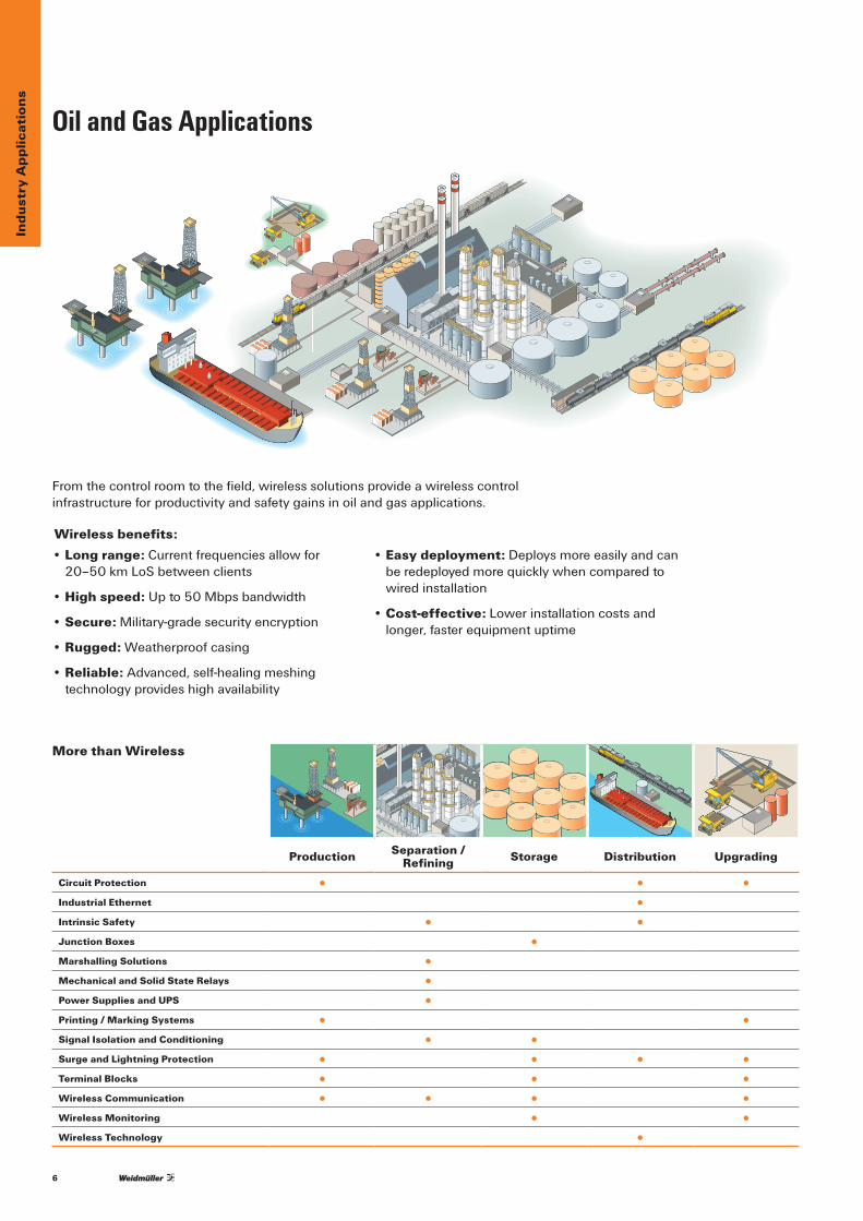
Oil and Gas Applications
More than Wireless
Fromthecontrolroomtothefield,wirelesssolutionsprovideawirelesscontrol infrastructureforproductivityandsafetygainsinoilandgasapplications.
• Long range:Currentfrequenciesallowfor20–50kmLoSbetweenclients
• High speed:Upto50Mbpsbandwidth
• Secure: Military-grade security encryption
• Rugged:Weatherproofcasing
• Reliable:Advanced,self-healingmeshing technologyprovideshighavailability
• Easy deployment:Deploysmoreeasilyandcanberedeployedmorequicklywhencomparedtowired installation
• Cost-effective: Lower installation costs and longer,fasterequipmentuptime
Wireless benefits:
Production Separation / Refining Storage Distribution Upgrading
Circuit Protection • • •Industrial Ethernet •Intrinsic Safety • •Junction Boxes •Marshalling Solutions •Mechanical and Solid State Relays •Power Supplies and UPS •Printing / Marking Systems • •Signal Isolation and Conditioning • •Surge and Lightning Protection • • • •Terminal Blocks • • •Wireless Communication • • • •Wireless Monitoring • •Wireless Technology •

7
Indu
stry
App
licat
ions
More than Wireless
Water and Waste Water Applications
Wireless benefits:• Optimizes response times and immediately indicates critical diagnosticinformation
•Improvesmonitoringandcontrolofwaterflowoverextendeddistances
•Improvesoperatorsafetyandefficiencybyeliminatingtraveltimeto remote site locations
•Reduceslaborexpensesandmaximizesefficiency
•Simplifiesinstallationandcommissioningofnetworkwithreduced infrastructurerequired
•Providesenhancedreliabilitythroughaflexiblenetworktopologythatcanself-heal,whileeasingfutureexpansion
Wireless solutions reduce remote installation costs up to 70% and communicatereliable,secureEPAcompliancedataforsystemlocationsincluding:
•HeadWorks,MainLiftStations, RemoteLiftorPumpingStations
•StormSewerOverflow,SanitarySewersandCollectionPits
•EffluentDischargePoints:River,LakeandWetlands Re-use
•TransportationandPavedRunoffAreas
•PotableWaterStorageandProcessing
• Security and Surveillance
Head Works Influent Aeration Treatment Effluent
Circuit and Surge Protection • •Distribution Blocks •Engineered Systems •Industrial Ethernet Networks • •Interface Systems •Intrinsic Safety • • •Mechanical and Solid State Relays •Power Supplies and Battery Backup • • •Printing / Marking Systems / Ferrules •Signal Conversion and Isolation • •Terminal Blocks •Wireless Communication • •Wireless Systems •Wireless Technology • •
8
App
licat
ion
Not
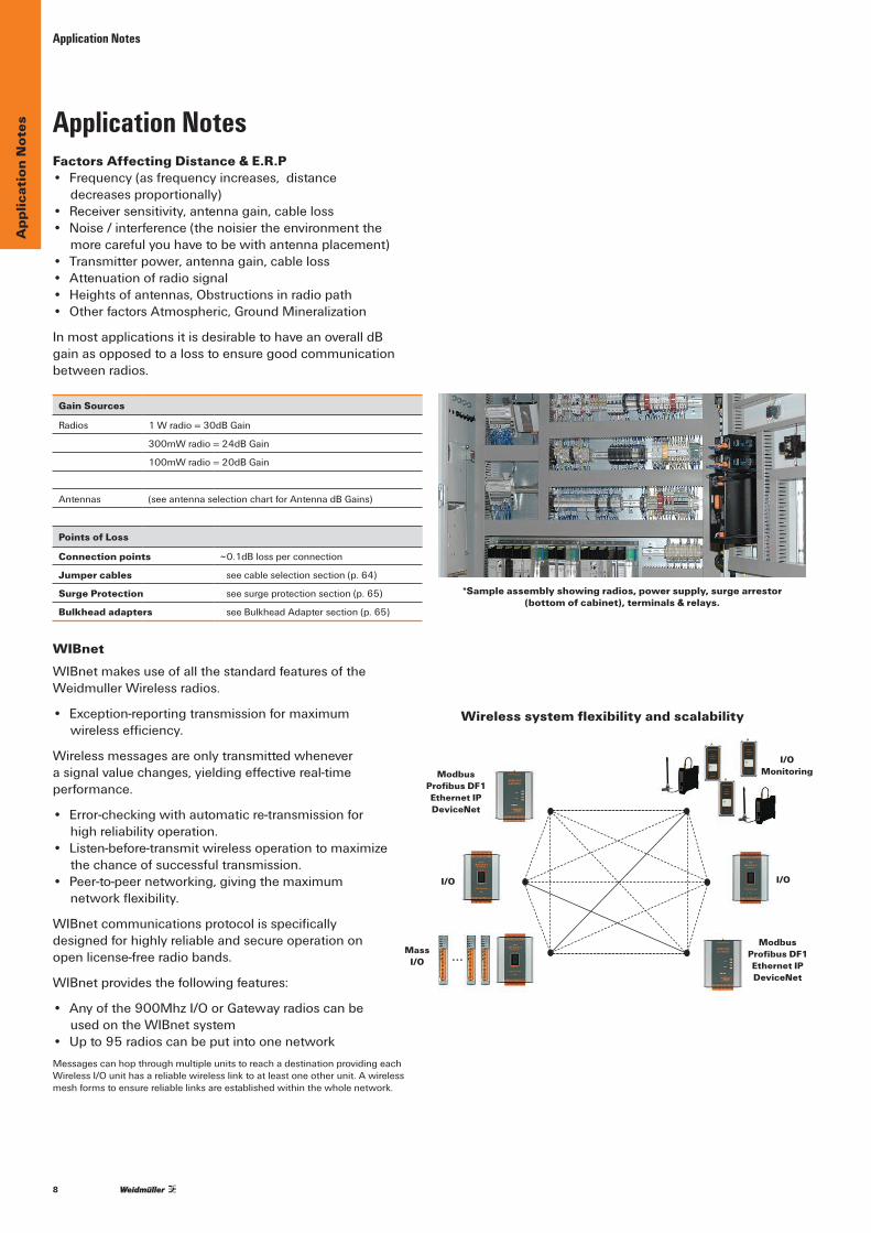
esApplication Notes
Application NotesFactors Affecting Distance & E.R.P• Frequency(asfrequencyincreases,distance
decreases proportionally)• Receiversensitivity,antennagain,cableloss• Noise/interference(thenoisiertheenvironmentthe
morecarefulyouhavetobewithantennaplacement)• Transmitterpower,antennagain,cableloss• Attenuationofradiosignal• Heightsofantennas,Obstructionsinradiopath• OtherfactorsAtmospheric,GroundMineralization
InmostapplicationsitisdesirabletohaveanoveralldB gain as opposed to a loss to ensure good communication betweenradios.
Gain Sources
Radios 1Wradio=30dBGain
300mWradio=24dBGain
100mWradio=20dBGain
Antennas (seeantennaselectionchartforAntennadBGains)
Points of Loss
Connection points ~0.1dBlossperconnection
Jumper cables seecableselectionsection(p.64)
Surge Protection see surge protection section (p. 65)
Bulkhead adapters seeBulkheadAdaptersection(p.65)
WIBnetWIBnetmakesuseofallthestandardfeaturesoftheWeidmuller Wireless radios.
• Exception-reportingtransmissionformaximumwirelessefficiency.
Wireless messages are only transmitted whenever asignalvaluechanges,yieldingeffectivereal-timeperformance.
• Error-checkingwithautomaticre-transmissionforhighreliabilityoperation.
• Listen-before-transmitwirelessoperationtomaximizethechanceofsuccessfultransmission.
• Peer-to-peernetworking,givingthemaximumnetworkflexibility.
WIBnetcommunicationsprotocolisspecificallydesignedforhighlyreliableandsecureoperationonopenlicense-freeradiobands.
WIBnetprovidesthefollowingfeatures:
• Anyofthe900MhzI/OorGatewayradioscanbeusedontheWIBnetsystem
• Upto95radioscanbeputintoonenetworkMessages can hop through multiple units to reach a destination providing each WirelessI/Ounithasareliablewirelesslinktoatleastoneotherunit.Awirelessmeshformstoensurereliablelinksareestablishedwithinthewholenetwork.
*Sample assembly showing radios, power supply, surge arrestor (bottom of cabinet), terminals & relays.
Modbus Profibus DF1 Ethernet IP DeviceNet
Wireless system flexibility and scalability
I/OMonitoring
I/O
Modbus Profibus DF1 Ethernet IP DeviceNet
I/O
Mass I/O .. .

9
App
licat
ion
Exam
ples
Application Examples
Application ExamplesRemote Wastewater Overflow Protection
Company: JEA, City of Jacksonville, FloridaIntroductionJEAisthemunicipalutilitiesproviderforJacksonvilleFlorida.Theywerefacingaproblemwithsanitaryseweroverflows(SSO)inthedowntownsectionofJacksonville.Avoidingsewageoverflow,asidefrombeingasafety,environmentalandpublicrelationsnecessity,isgoodbusinessforJEA.
ObjectiveTheengineersatJEAneededawaytomonitorundergroundsewer levels throughout the city.The plan involved the placementofmeasuringdevicesinstrategicallylocatedmanholesaroundthecityinordertomonitorthevariousfluidlevels at each location.
This approach required the city to install power and control circuits at the strategic locations. Since the manholes were proventobeaveryharshClass1,Division1environment,theyknewthatthesolutionwasnotgoingtobeeasy.JEAhadalreadyinvestedinaveryrobustSCADAsystemtocontrolandmonitorover1200liftstations.TheendgoalwastolocateamonitoringsystemfromthesewermanholetotheexistingSCADAsystem.
AboutTheissuefacedbyJacksonvilleinestablishingamonitoringsystemisthatthecityitselfisphysicallyintheway–buildings,bridges,communicationlines,powerlinesandothertypicalcityfixtures.Theywouldneedtodigupmostofthedowntownatacostofmillionsofdollarsandmonthsoftrafficcongestionanddelays.Theideawasproposedtomonitor the manholes and their levels wirelessly. This solutioncouldprovidethecitywithaquickwaytoinstall asolutionthatwouldnotrequirethedemolitionofthe entire city.
Asearchwasconductedtodeterminewhocouldprovideasolutionthatfitaveryspecificlistofrequirements.Theserequirements included the necessary power to send signals through the ground and steel manhole covers wirelessly to receiverslocatedincontrolcabinetswithinthecity;theneedforultralowpowerconsumption;theabilitytopowerthesolutionviabatteries;becontainedinaClass1,Division1enclosure;theabilitytosendbothanaloganddiscretesignals;and beportablesoitcouldbemovedtodifferentlocationsinthecityasneeded.Afterextensivefieldtestsandevaluationsforsignalstrengthanddurability,alongwithcarefulevaluationofdifferenttypesofequipment,a Weidmuller wireless solution was selected.
Thecomponentsofthesolutionincludeacompact,easy-to-usewirelesstransmitter(WI-I/O-9-K),coupledwithitsmatchingbatterypack(WI-BP-I/O-9-K),whichdoesnotrequireanyspecialOEMbatteries.Thewirelesstransmittersends analog and discrete signals to a wireless transceiver (WI-I/O9-4).ThisunitcollectsthedatafromeachtransmitterandforwardsitviaawiredconnectionintotheJEA’sSCADAapplication.ThereceiverworksverywellwiththeexistingSCADAsystem.Theprogrammingsoftwareforthedevices isprovidedforfreeviawebdownloadandiseasytouse and understand.
ThesoftwarethatisincludedwitheachdevicemakesitsimpleforJEAtomapthetransmissionofsignalsandcontroltransmitschedules,thusprolongingbatterylife.Basedonthelevelofpowerconsumption,JEAcouldreplacethebatteriesonceayear,however,theyhaveimplementedaproactivebatterymaintenanceprogramtochangeoutthebatteries(standardAAsizedAlkaline)every6months.
ThesewirelessdevicesaremountedinaClass1,Division1explosionproofenclosurewithasmallexternalantenna. Each enclosure unit is then placed in a cradle within the manhole.PortabilityisanimportantfeaturebecauseitallowsJEAtoredeployeachwirelessradioinotherlocationsinthecity as needed.
Thetransmittersendssignalsfromeachundergroundmanhole installation to set receivers through the downtown area.JEAteamedwithalocaldistributorandpackaged theWeidmullerradiosystem,enclosure,terminalsandequipmentneededtomeetapplicationrequirementsof this monitoring system.
Outcome Thiswirelessmanholemonitoringsystemhasbeenusedin17manholesinJacksonville.Itwasimplementedinjustsixmonthsatasavingsofmillionsofdollarsandmanymonthsoftime,versusawiredsolution.
Thesystemhasproventobeaverysuccessfulsolutionto animportantproblem.Sincetheimplementationofthemanholemonitoringsystem,JEAhassuccessfullypreventednumerousmanholesanitaryseweroverflows(SSO),thusprotectingthepublicandtheenvironment–atoppriorityforJEAandthecity.
Wireless TransceiverWI-I/O-9-4
Wireless TransmitterWI-I/O-9-K
STREET
MANHOLE
SCADA
Battery PackWI-BP-I/O-9-K
Direct I/O

10
App
licat
ion
Exam
ples
Application Examples
Remote Pumping Station Monitoring
Company: Pemex, Coatzacoalcos, Mexico
IntroductionPetroleosMexicanos(PEMEX)isMexico’sstate-ownedpetroleumcompany.Itisthetenthlargestoilcompanyintheworldintermsofrevenueandrankedthirty-fourthinFortune500companies.ThecompanycontrolstheentireoilindustryforthenationofMexico.Thisincludesextraction,storage,refiningandmarketingtothepublic.
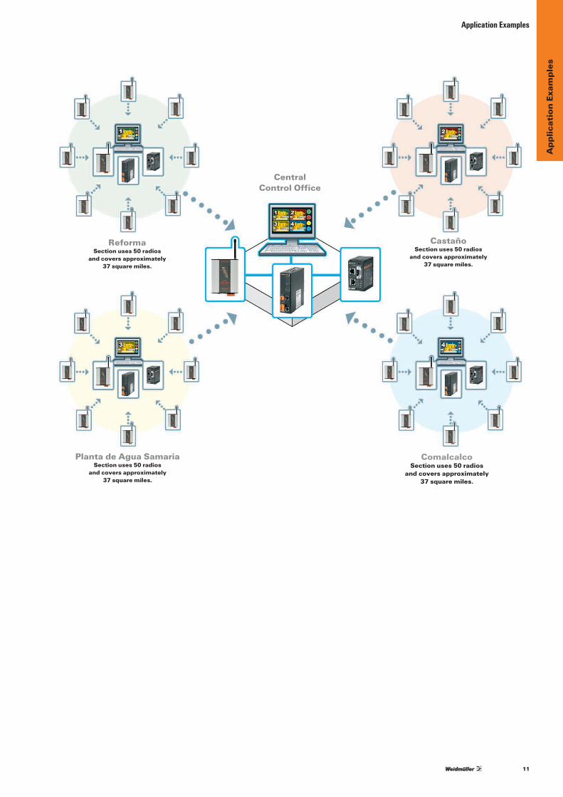
ObjectiveTheengineersatPEMEXneededtomonitor200+differentremotepumpingstationsandcompressors.Thepumpingstationsarescatteredovera180squaremileareathatiscoveredinverydenseforestgrowth,makingthetransmissionofwirelesssignalsarealchallenge.Thepumpingstationsarephysicallyclusteredintofourgroups.Eachgrouphasapproximately50pumping/monitoringlocations.ThesegroupsareReforma,Castano,PlantadeAguaSamariaandComalcalo.Eachoftheremotepumpinglocationscoversanareaof37squaremiles.Thesefourremoteareaswithpumpingstationsneedtosendsignalsbacktoacentralofficelocation.
SolutionWeidmullerdesignedasolutionthatuseswirelessEthernetmodems(WI-MOD-E)ateachpumpinglocation(Level3)toacquireandtransmittherequestedinformationtoacentralpointineachofthefourpumpingareas(Level2).AnotheridenticalEthernetmodemisusedtotransmitalltheneededinformationfromeachcentralpointineachpumpingareabacktotheCentralControloffice(Level1).TheWeidmullermodems,with300mWbroadcastpower,weretheonlyoneswithapowerfulenoughtransmittertopenetratethedenseforestgrowthwithaclearandreliablewirelesssignal.
EachwirelessEthernetmodemcommunicatesbetweeneachpumplocation(Level3)toeachcentralpumpingsection(Level2)andbacktotheCentralOffice(Level1)viaModBusTCP.Thecomponentsusedinthisinstallationinclude250Ethernetmodems(WI-MOD-E),5unmanagedEthernetswitches,5Ethernetrouters,250DC-DCconvertingpowersupplies(toisolateradiosfromtherestofthesystem)andallnecessaryterminalandfuseblockstocompletethesystemconnectivity.
Outcome PEMEXnowhasasimpleeasy-to-usesolutionformonitoringtheirremotepumpingstations.Theywereabletodeploythissolutionquicklyanditwasupandrunninginamatterofmonths.Trainingandmaintenanceisstreamlinedbecausethesolutionemploysonetypeofproduct,usingonesoftwareinterfaceforallthreelevelsoftheirsystem,from200+remotestationstothecentralofficelocation.ThewirelessproductswerecoupledwithotherWeidmullercomponents,providingacompleteandseamlesssystemthatiseasyforPEMEXtomaintainandsupport.
11
App
licat
ion
Exam
ples
Application Examples
ReformaSection uses 50 radios
and covers approximately 37 square miles.
Planta de Agua SamariaSection uses 50 radios
and covers approximately 37 square miles.
Central Control Office
ComalcalcoSection uses 50 radios
and covers approximately 37 square miles.
CastañoSection uses 50 radios
and covers approximately 37 square miles.

12
App
licat
ion
Exam
ples
Application Examples
Wireless Remote Vehicle Control
Company: Meggitt Training Systems, Inc.
Company ProfileMeggittTrainingSystems,Inc.(MTSI),apartofMeggittPlc,providestrainingsystemsusedbymilitaries,lawenforcementandsecurityagenciesaroundtheworld.Theydevelop,manufacture,marketandservicehighqualityvirtualandlivefiretrainingsystems.MTSIemploysover500peopleattheirheadquartersinAtlantaandinotherfacilitiesinAustralia,Canada,Singapore,theNetherlands,theUAEandtheUnitedKingdom.Theyaretheindustryleaderofinteractivesimulationsystemsforthehandlinganduseofsmallandsupportingarmstraining.
OverviewMeggittdesignedandinstalledoneofthemostadvancedlivefirerangeseverprovidedtotheU.S.Military.Therange,installedandoperatinginFortCarson,Colorado,isadigitallycontrolledheavyarmorrange.Itiscomprisedof14movingtargetslocatedacrossa60squarekilometerarea.Eachofthe14movingtargetsincludesonebunkerlocationandaseparateremotevehicleormover.Thebunkersaremadeofreinforcedconcreteandcontainthetechnologytooperatethemoversincluding a wireless Ethernet modem.
Themoverisa3000lb.vehiclethatismountedontoaraisedmetaltrack.Thisremotevehiclehasfourliftarmsthatenableittoraiseandloweratarget,whichisasilhouetteofanarmoredvehicle.Acontrolboxlocatedonthemovercontainsanotherwirelessmodemandthecircuitrytooperatethedrivemotorsandtheliftarmsofthevehicle.Theraisedmetaltracksvaryinlengthfrom300to500meters,dependingontherange.Eachofthe14movingtargetrangesiscontrolledviaEthernetsignalsfromacentralRangeOperationsCenter(ROC).
ProblemMeggittfacedtwomajorproblemsattheFortCarson,Coloradorange.Thefirstchallengewasenvironmental.Operatingconditionsonalivefireheavyarmorrangearenotfavorabletoelectronicequipment–especiallyhighlysensitive,hightechnologywirelessdevices.Thetemperatureinsidethecontrolboxoneachmovervariesfrom-40°C(-40°F)inthewinterto+65°C(+149°F)inthesummermonths.Inadditiontotemperatureissues,operatingonarangewithtanksfiringliveammunitionnecessitatedawirelessdevicethatwithstandsshockandvibration.
Thesecondchallengewastosecurereliableandstablewirelesscommunicationbetweeneachbunkerlocationanditsrespectivemover.Themoverneedstobecontrolledateverypointalongitstracksoitcanmoveineitherdirection,stop,raiseandlowerthetarget.Themoverrollsonasetofraisedtracksthatextendawayfromthebunkeratadistanceof300to500meters,withvariouselevationchangesandturns.Normally,alargeantennaplacedateachbunkerandoneachmoverwouldsolveanysignalcommunicationissues.However,theantennasatFortCarsoncouldnotextendbeyondtheprotectivewallthatguardedeachmoverfromtheliveammunition.

13
App
licat
ion
Exam
ples
SolutionWeidmuller’sWI-MOD-E-300modemsweretestedandselectedfortheapplicationbecauseoftheirabilitytooperatewithintherequiredtemperatureranges.Theywerealsothemostpowerfulproduction802.11bmodemsavailable.WeidmullersentateamtoFortCarsontoinstalltenWI-MOD-E-300wirelessmodemsat5bunker-moverlocations.Themodemswereinstalledusingantennaandconnectingcablesthatwerealreadyon-sitefromapreviousvendor.SignalstrengthwasimprovedandtheWeidmullerteamwasabletogetfourofthefiverangescommunicatingsuccessfully.
Thenewinstallationsweretestedforseveralmonthsafterinstallationanditwas determined that communications were not as consistent as desired. The WeidmullerteamreturnedtoFortCarsonandperformedextensivesitesurveysateachofthe14differentbunker-moverlocations.Thisinformationenabledanaccuratediagnosisofeachinstallationandtheresultsdeterminedthatthepreviouslyinstalledcablesandantennaswereatfault.Theyhadnotbeenproperlyinstalledbythepreviousvendorandinsomecasesincorrectcablesandantennashadbeenused.TheWeidmullerteamdevelopedasolutiontocorrectthe communication issues at each range location. The recommended solution wasacceptedbyMeggittTrainingSystemsandinstalled.
InordertostreamlinethesupportandsparepartsmanagementfortheFortCarsonrange,allofthecomponentsandequipmentusedforeachbunker-moverlocationareidentical.ThetechnologysolutionincludesaWI-MOD-E-300wirelessEthernetmodem,WI-ACC-LMR400-55FTjumpercableandaWI-ANT24GHz-4DBONMIantenna.EachmoverisequippedwithamatchingWI-MOD-E-300wirelessEthernetmodem,WI-ACC-LMR195-3FTjumpercableandaWI-ANT-24GHZ-4DBOMNIantenna.
Outcome WeidmullerandMeggittTrainingSystemshavereplacedalloftheoriginalfaultymodemsfromapreviousvendorandinstalledallnewconnectingcablesandOmniantennasineachbunkerandoneachmover.Theentirerangeisupandfullyoperational,providingsoliddataandcontrolconnectionsforeachofthe14bunker-moverlocations.MTSIconsiderstheirFort CarsondigitalrangeinstallationacompletesuccessandtheU.S.militaryisactivelyusingtherangeasatestingfacilityfortanksandotherarmoredvehicles.
Application Examples
Mover with target raised
Wireless Ethernet Modem mounted within an enclosure located inside bunker
Wireless Ethernet Modem mounted inside control box on a mover

14
App
licat
ion
Exam
ples
Application Examples
Weidmuller Wireless Ethernet
Company: Targa Energy
OverviewTargaEnergyownsand/oroperatesover11,300milesofnaturalgasgatheringpipelinesandLiquefiedNaturalGas(NGL)pipelinesthroughthestatesofTexasandLouisiana.Thesepipelinescoveratotalareaofover14,400squaremiles.Targaalsooperates22naturalgasprocessingplants,withatotalofover10,250MMcf/dofgrossprocessingcapacity.Inadditiontothesegatheringsystemsandprocessingplants,TargamanagesanonshoreplantfacilitythatprovidesaccesstonaturalgassuppliesinthePermianBasin,FortWorth/BendArchBasin,SouthLouisianaBasin,deepwateranddeepshelfGulfofMexico.
ProblemTheTargaEnergygasplantinChico,Texasisamultifunctionlocationthatperformspumping,storageandprocessingforthenaturalgasindustry.Thislocationcoversseveralsquaremiles,andincludesacompressorstationandmultipleremotepumpingstationslocatedaroundtheplant.Mostofthepumpingstationsareveryremoteandhavenoaccesstotheplant’scommunicationnetwork.Someofthepumpingstationshaveasatelliteuplinkthatisonlyusedforprocessingdata,productionlogisticsandsafetyinformation.
Targarequiredasolutionthatcouldprovidenetworkaccesstotheircompressorstationandnumerouspumpingstationlocations,andmakeasignificantsectionoftheirgasplanta“HotSpot”forbroadbandEthernetaccess.Targa’sfieldtechnicianswouldrequireaccesstothisbroadbandnetworktoconductsystemmonitoring,accessdatafilesandconnectwithotherofficesorcompanyresourcesviathecompany’sIntranetnetwork.Thefieldtechniciansuselaptopcomputers,thereforea2.4GHz(WiFi)wirelessfrequencywasnecessary.
Targawashavingdifficultyachievingreliableandstableconnectionsduetothedistancebetweenthepumpingstations,thecompressorstation,andtheplant(over3.5milesinsomecases)andtheneedtousethe2.4GHz(WiFi)spectrumforfieldtechnician access.
SolutionAtTarga’srequest,Weidmuller’sapplicationengineervisited theplantlocationandperformedawirelessEthernetsitesurvey.Afterthesitesurveywascompleted,asolutionwasproposedthatincludedacombinationofwirelessEthernetmodems(WI-MOD-E-300)anddipoleantennaswith3dbiofgain.TheEthernetmodemsprovidedtheneededlevelofpowerfulsignaltransmission,andcombinedwithasensitivehighperformancesignalreceiver,Targawasabletoreceivethenecessarysignalstrengthandreliabilityrequiredfortheirlocations.

15
App
licat
ion
Exam
ples
Application Examples
Thiswirelesssolutionprovidestherequired“HotSpots”forservicetechnicianstoaccesstheIntranetnetworkwiththeirlaptops,aswellasenablingconnectivitybetweenTarga’sbasestationlocationsandseveralremotepumpingstationsforanaddedlevelofcommunicationandinformationexchange.
Compressor Station
Example Architecture
Pumping Station
Pumping Station
Pumping Station Compressor Station
Base Station
Field Technician
Field Technician
Field TechnicianField Technician
2.4Ghz Wireless(WiFi) Coverage Area

16
Wir
eles
s I/
OW
irel
ess
I/O
Unidirectional Transmitter/Receiver Units — Introduction
Unidirectional Transmitter/ Receiver Units – IntroductionWireless Input/Output (I/O) WirelessI/Oconnectsdirectlytoanalog,discreteandpulsetransducersignals.Thesignalsaretransmittedbyradioandeitherre-createdasoutputsignals,oroutputviaseriallink orfield-bus.
WeidmullerWirelessI/Ounitshavetheabilitytoformsophisticatedpeer-to-peernetworks,withevent-reportingmessaging to optimize wireless density. Weidmuller products aredesignedforhighreliabilityoperationonopenlicense-freeradiobands.
WI-I/O 9-L Unidirectional Transmitter/Receiver UnitsTheUnidirectionalWirelessI/Orangeofproductsissuitableforconnectingtoasinglesensororgroupofsensorsandprovidesaneconomicalsolutionforremotemonitoringsystems.TheUnidirectionalLproductscanalsobeusedinmorecomplexnetworksassignaltransmittersorreceivers.
• Frequencyhoppingspreadspectrum902-928MHz1Wlicense-freeUSA/Canada/Mexico
• Configurablesub-bandslicense-freeSouthAmerica,Australia/NZ,Asia,Europe
Applications• Wirelessconnectionofflowmetersorenergymeters• Monitoringstoragetanks• Monitoring cathodic protection on pipelines• Wirelessalarmsfrompowerreticulationfaultrelays
FeaturesMatched transmitter/receiver pair of modules, or individual transmitter and receiver units
• Peer-to-peercommunications.Exceptionreporting.Reliableself-checkingmessages.Highlysecuredataencryption.
• Multi-hoprepeaterfunctions-upto5intermediate unitscanbeconfiguredinanyinput-outputlink
• FactoryconfiguredasamatchedTransmitter/Receiver pairoruser-configurablewithE-SeriesWindowsconfigurationprogram
Digital Analog Thermocouple
Digital Analog
Transmitter unit• Input-onlytransmitterunit-twodigital/pulseinputs,one
analog input and one thermocouple mV input• Transmits to Receiver unit as a matched pair where the
inputsignalsarere-createdasoutputsignals,orcantransmit to a Multi-I/O or Gateway unit
• Class1Div2hazardousareasapprovalC US
• Upto3000wirelessunitspernetwork• External inputs plus internally calculated values - analog
setpointstatus,pulsecount,powersupplyvoltage• Thermocoupleinput–20to+100mVwithcold-junction
compensationandlinearizationforJ,KorT-type• Setpointsstatusgeneratedbycomparinganaloginputto
high and low setpoints • Digitalinputscanalsobeusedaspulsecountinputs• Powersupply9–30VDC,measuredandavailableasa
transmittedvariable• 24VDCanalogloopsupplyinternallyprovided• RS232Configurationanddiagnosticsport

17
Wir
eles
s I/
OW
irel
ess
I/O
• Humidity:0-99%RH• Regulatory Approvals:EMCcompliant89/336EEC,
EN301489,AS3548,FCCPart15,ApprovedtoFCC Part15.247,RS210
• Housing:DIN-railthermo-plasticenclosure100x22x120mm/3.9x0.9x4.7inches
• Transmitter Unit:Power/OK,radioTX,DIN1,DIN2, analog set-point status
• Receiver Unit:Power/OK,radioRX,DO1,DO2,DO3, communicationsfailLEDsalsousedtoprovideradio signal strength indication
Transmitter Inputs
InputvaluestransmittedasperWIB-net(seepage8)protocol-exception-reportingonsignalchange,andupdatetime.Upto5repeateraddresses,configurable.
Unidirectional Transmitter/Receiver Units — Introduction
Receiver unit• Output-only receiver unit - three digital contact outputs
and one analog output• ReceivesradiocommandsfromTransmitterunitasa
matched pair where the input signals are re-created as outputsignals,orcanreceivecommandsfromaMulti-I/Oor Gateway unit
• Class1Div2hazardousareasapprovalC US
• Upto3000wirelessunitspernetwork• Powersupply9–30VDC;24VDCanalogloopsupply
internally provided• Communicationsfailureindicationandconfigurable
output• Outputscanbeconfiguredasretainedorreset(fail-safe)
oncommunicationsfailure• LEDindicationofradiosignalstrength• RS232Configurationanddiagnosticsport
Transmitter/Receiver Unit Ordering InformationUnit DescriptionWI-I/O9-L-T WirelessTransmitter(900MHz)WI-I/O9-L-R WirelessReceiver(900MHz)WI-I/O9-L-P1 900MHzWirelessTransmitter/ReceiverPairwithtwo-2dBDipoleAntennasWI-I/O9-L-P2 900MHzWirelessTransmitter/ReceiverPairwithtwo0dBDipoleAntennas
Dimensions
General• Frequency:frequencyhoppingspreadspectrum
902-928MHz,sub-bandsavailable,1W• Sensitivity:line-of-sightrange20miles(4WERP-
“effectiveradiatedpower”),15km(1WERP);3000ft/1000minobstructedindustrialenvironments;radiodistancescanbeincreasedbyupto5intermediatetransceiver or gateway units
• Antenna Connector:SMAconnectorforantennaorcoaxialcableconnection
• Temperature:-40to60°C/-40to140°F
6720005005
SET
WI-I/O 9-L-T
OK
D1
D2
SP
TX
AZ
PG3.9"
(100 mm)
4.7"(120 mm)
.09"(23mm)
Input Type Source FunctionDigital external statusPulseTotal external countAnalog external analogThermocouple external analogSetPoint internal statusSupply Voltage internal analog

18
Wir
eles
s I/
OUnidirectional Transmitter/Receiver Units — Introduction
Digital / Pulse Inputs• Twoinputs,suitableforvoltage-freecontacts/NPN,
orvoltageinput0-1VDCon/>3VDCoffpulseinputmax.rate10Hz,50msecontime.Pulsecountedas16-bitregister.
Analog Inputs• 0-20mA(4-20mA)• “Floating”differentialinput,resolution16-bit,
accuracy < 0.1 %
Thermocouple Inputs• Millivolt(-20mVto+100mV),J,K,orTtype
linearizationwithon-boardcold-junctioncompensation• Accuracybetterthan1°C
Power Supply• Normal Supply: 9-30VDC,powerconsumption
@12VDC-receivernormal70mA,max.250mA• Transmitternormal70mA,transmittingmax.600mA• Analogloopsupplyinternallygenerated,24VDC35mA• Internalmonitoringofsupplyvoltagemaybe
transmitted as an “input” (transmitter unit only)
Set-point Status• Highandlowset-pointsgenerateinternaldigitalstatus-
set-point status sets (on) when analog value < low set-pointandresets(off)whenanalogvalue>highset-point.Statusistransmittedasperdigitalinput,set-pointvaluesaresetviathefrontpanelrotaryswitchorconfigurationsoftware.
• Separateset-pointsfor(4-20mA),thermocoupleandsupplyinputsareconfigurable
Receiver OutputsDigital Outputs
• Threerelaycontactoutputs,260V1A
Analog Outputs• 0-20mA,sourceoutput,12-bitresolution,
0.1% accuracy
Communication Failure• Internalstatusbasedonconfigurabletime-outvalue• “Comms-fail”statuscanbeconfiguredtoalocaloutput
Fail-Safe• On“comms-fail,”outputsuser-configurableasretained
lastcorrectvalueorreset(fail-safe)
Serial Port• RS232RJ45femaleDCE,usedforconfiguration
and diagnostics
LED Indication
Transmitter Unit• Power/OK,radioTX,DIN1,DIN2,analog
set-point status
Receiver Unit• Power/OK,radioRX,DO1,DO2,DO3,
communicationsfail• LEDsalsousedtoprovideradiosignalstrength
indication
Configuration and Diagnostics• Factoryconfigurationtransmitter/receivermatched
pair,AItoAO,2DIto2DO,SPstatustoDO3via RS232-RJ45cable
• Userconfigurationviaserialport.Unidirectionalunitscanbeconfiguredtonetworkwithmulti-I/Oand gateway units.
• Diagnosticsfeatures:readinputvalues,writeoutputvalues,radiosignalstrength,monitorcommunicationmessages
19
Wir
eles
s I/
O
Unidirectional Transmitter/Receiver Units — 900 MHz
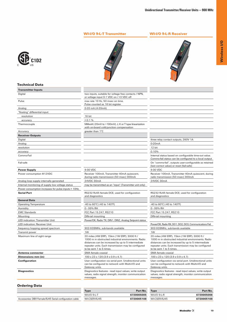
WI-I/O 9-L-T Transmitter WI-I/O 9-L-R Receiver
Technical DataTransmitter InputsDigital
Pulse
Analog“floating”differentialinput: resolution accuracyThermocouple
Accuracy
Receiver OutputsDigitalAnalogresolutionaccuracyComms-Fail
Fail-safe
Power SupplyPowerconsumption@12VDC
AnalogloopsupplyinternallygeneratedInternalmonitoringofsupplylowvoltagestatusPowerconsumptionincreasesforpulseinputs>10Hz.Serial Port
General DataOperating TemperatureHumidityEMC StandardsMountingLEDindication:TransmitterUnitLEDindication:ReceiverUnitfrequencyhoppingspreadspectrumTransmit powerMaximumlineofsightrange
Antenna connectorDimensions mm (in)Configuration
Diagnostics
Ordering Data
Accessories:DB9Female-RJ45Serialconfigurationcable
twoinputs,suitableforvoltagefreecontacts/NPN, orvoltageinput0-1VDCon/>3VDCoffmaxrate10Hz,50msecontime. Pulsecountedas16bitregister.0-20mA(4-20mA)
16bit< 0.1 %Millivolt(-20mVto+100mV),J,KorTtypelinearizationwithon-boardcold-junctioncompensationgreaterthan1°C
9-30VDCReceiver100mA,Transmitter40mAquiescent, duringradiotransmission(50msec)300mA24VDC30mAmaybetransmittedasan“input”(Transmitterunitonly)
RS232RJ45femaleDCE,usedforconfiguration and diagnostics
-40to60°C(-40to140°F)0-99%RHFCCPart15.247,RS210DIN-railmountingPower/OK,RadioTX,DIN1,DIN2,AnalogSetpointstatus
902-928MHz,sub-bandsavailable1W20miles(4WERP),15km(1WERP);3000ft/ 1000minobstructedindustrialenvironments.Radiodistancescanbeincreasedbyupto5intermediaterepeaterunits.Eachtransmissionmaybeconfiguredtobesent1to5times.SMAfemalecoaxial100x23x120(3.9x0.9x4.7)Userconfigurationviaserialport.UnidirectionalunitscanbeconfiguredtonetworkwithMulti-I/OandGateway units.Diagnosticsfeatures-readinputvalues,writeoutputvalues,radiosignalstrength,monitorcommunicationmessages.
Type Part No.WI-I/O 9-L-T 6720005005WI-CSER-RJ45 6720005108
threerelaycontactoutputs,260V1A0-20mA12bit0.10%Internalstatusbasedonconfigurabletime-outvalue.Comms-failstatuscanbeconfiguredtoalocaloutput.On“comms-fail”,outputsuser-configurableasretained(lastcorrectvalue)orreset(fail-safe)9-30VDCReceiver100mA,Transmitter40mAquiescent,duringradiotransmission(50msec)300mA24VDC30mA
RS232RJ45femaleDCE,usedforconfiguration and diagnostics
-40to60°C(-40to140°F)0-99%RHFCCPart15.247,RS210DIN-railmounting
Power/OK,RadioRX,DO1,DO2,DO3,CommunicationsFail.902-928MHz,sub-bandsavailable1W20miles(4WERP),15km(1WERP);3000ft/ 1000minobstructedindustrialenvironments.Radiodistancescanbeincreasedbyupto5intermediaterepeaterunits.Eachtransmissionmaybeconfiguredtobesent1to5times.SMAfemalecoaxial100x23x120(3.9x0.9x4.7)Userconfigurationviaserialport.UnidirectionalunitscanbeconfiguredtonetworkwithMulti-I/OandGateway units.Diagnosticsfeatures-readinputvalues,writeoutputvalues,radiosignalstrength,monitorcommunicationmessages.
Type Part No.WI-I/O 9-L-R 6720005006WI-CSER-RJ45 6720005108
C1D2C US
20
Wir
eles
s I/
OUnidirectional Transmitter/Receiver Units — 900 MHz
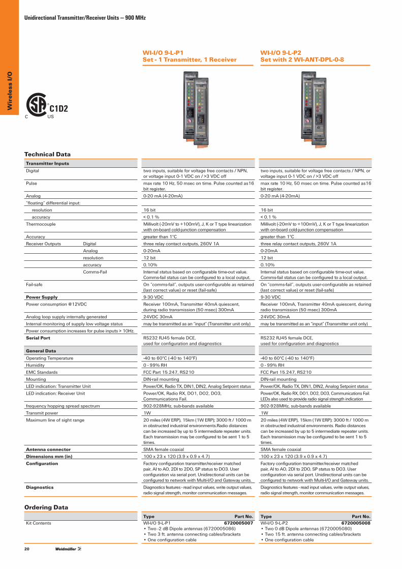
WI-I/O 9-L-P1 Set - 1 Transmitter, 1 Receiver
WI-I/O 9-L-P2 Set with 2 WI-ANT-DPL-0-8
Technical DataTransmitter InputsDigital
Pulse
Analog“floating”differentialinput: resolution accuracyThermocouple
AccuracyReceiverOutputs Digital Analog resolution accuracy Comms-Fail
Fail-safe
Power SupplyPowerconsumption@12VDC
AnalogloopsupplyinternallygeneratedInternalmonitoringofsupplylowvoltagestatusPowerconsumptionincreasesforpulseinputs>10Hz.Serial Port
General DataOperating TemperatureHumidityEMC StandardsMountingLEDindication:TransmitterUnitLEDindication:ReceiverUnit
frequencyhoppingspreadspectrumTransmit powerMaximumlineofsightrange
Antenna connectorDimensions mm (in)Configuration
Diagnostics
Ordering Data
KitContents
twoinputs,suitableforvoltagefreecontacts/NPN, orvoltageinput0-1VDCon/>3VDCoffmaxrate10Hz,50msecontime.Pulsecountedas16bitregister.0-20mA(4-20mA)
16bit< 0.1 %Millivolt(-20mVto+100mV),J,KorTtypelinearizationwithon-boardcold-junctioncompensationgreaterthan1°Cthreerelaycontactoutputs,260V1A0-20mA12bit0.10%Internalstatusbasedonconfigurabletime-outvalue.Comms-failstatuscanbeconfiguredtoalocaloutput.On“comms-fail”,outputsuser-configurableasretained(lastcorrectvalue)orreset(fail-safe)9-30VDCReceiver100mA,Transmitter40mAquiescent, duringradiotransmission(50msec)300mA24VDC30mAmaybetransmittedasan“input”(Transmitterunitonly)
RS232RJ45femaleDCE, usedforconfigurationanddiagnostics
-40to60°C(-40to140°F)0-99%RHFCCPart15.247,RS210DIN-railmountingPower/OK,RadioTX,DIN1,DIN2,AnalogSetpointstatusPower/OK,RadioRX,DO1,DO2,DO3,Communications Fail.902-928MHz,sub-bandsavailable1W20miles(4WERP),15km(1WERP);3000ft/1000minobstructedindustrialenvironments.Radiodistancescanbeincreasedbyupto5intermediaterepeaterunits.Eachtransmissionmaybeconfiguredtobesent1to5times.SMAfemalecoaxial100x23x120(3.9x0.9x4.7)Factoryconfigurationtransmitter/receivermatchedpair,AItoAO,2DIto2DO,SPstatustoDO3.Userconfigurationviaserialport.UnidirectionalunitscanbeconfiguredtonetworkwithMulti-I/OandGatewayunits.Diagnosticsfeatures-readinputvalues,writeoutputvalues,radiosignalstrength,monitorcommunicationmessages.
Type Part No.WI-I/O9-L-P1 6720005007 •Two-2dBDipoleantennas(6720005086) •Two3ft.antennaconnectingcables/brackets •Oneconfigurationcable
twoinputs,suitableforvoltagefreecontacts/NPN,orvoltageinput0-1VDCon/>3VDCoffmaxrate10Hz,50msecontime.Pulsecountedas16bitregister.0-20mA(4-20mA)
16bit< 0.1 %Millivolt(-20mVto+100mV),J,KorTtypelinearizationwithon-boardcold-junctioncompensationgreaterthan1°Cthreerelaycontactoutputs,260V1A0-20mA12bit0.10%Internalstatusbasedonconfigurabletime-outvalue.Comms-failstatuscanbeconfiguredtoalocaloutput.On“comms-fail”,outputsuser-configurableasretained(lastcorrectvalue)orreset(fail-safe)9-30VDCReceiver100mA,Transmitter40mAquiescent,duringradiotransmission(50msec)300mA24VDC30mAmaybetransmittedasan“input”(Transmitterunitonly)
RS232RJ45femaleDCE, usedforconfigurationanddiagnostics
-40to60°C(-40to140°F)0-99%RHFCCPart15.247,RS210DIN-railmountingPower/OK,RadioTX,DIN1,DIN2,AnalogSetpointstatusPower/OK,RadioRX,DO1,DO2,DO3,CommunicationsFail.LEDsalsousedtoprovideradiosignalstrengthindication902-928MHz,sub-bandsavailable1W20miles(4WERP),15km(1WERP);3000ft/1000minobstructedindustrialenvironments.Radiodistancescanbeincreasedbyupto5intermediaterepeaterunits.Eachtransmissionmaybeconfiguredtobesent1to5times.SMAfemalecoaxial100x23x120(3.9x0.9x4.7)Factoryconfigurationtransmitter/receivermatchedpair,AItoAO,2DIto2DO,SPstatustoDO3.Userconfigurationviaserialport.UnidirectionalunitscanbeconfiguredtonetworkwithMulti-I/OandGatewayunits.Diagnosticsfeatures-readinputvalues,writeoutputvalues,radiosignalstrength,monitorcommunicationmessages.
Type Part No.WI-I/O9-L-P2 6720005008 •Two0dBDipoleantennas(6720005080) •Two15ft.antennaconnectingcables/brackets •Oneconfigurationcable
C1D2C US

21
Wir
eles
s I/
O
Transmitter (Single Sensor Units)—Introduction
• External inputs plus internally calculated values - analog setpointstatus,pulserateandpulsetotal,powersupplyvoltage,powersupplyalarm
• Setpointstatusgeneratedbycomparinganaloginputto high and low setpoints.
• Pulseinputsgenerateseparatepulsecountvalueandapulseratevalue.Pulseratesaretreatedasinternalanalogregisterswithaconfigurablemaximumvalue.
• PowersupplygeneratesinternalI/Ovaluesthatcanbetransmitted–lownormalsupplyvoltagestatus,lowbatteryvoltagestatusandbatteryvoltage(analog)
• Can connect to up/down counter transducers such as shaft-encoders
• Easilyconfiguredtorepeatthetransmissionseveraltimes to ensure that the transmission is received correctly
• Easy-to-useE-SeriesWindowsconfigurationavailable at www.weidmuller.ca or weidmuller.com
The Single Sensor Wireless I/O range ofproductsissuitableforconnectingtoasinglesensororgroupofsensorsandprovidesaneconomicalsolutionforremotemonitoringsystems.Capableofbeingpoweredbybattery-onlysupplies,theseproductsareparticularlysuitablewherepowerisnotavailable.
• Frequency hopping spread spectrum 902-928MHz1W,license-freeUSA/Canada/Mexico
•Configurablesub-bandslicense-free SouthAmerica,Australia/NZ,Asia, Europeavailableonrequest
Applications •Wirelessconnectionofflowmetersorenergymeters •Monitoringofstoragetanks • Monitoring cathodic protection on pipelines •Wirelessalarmsfrompowerreticulationfault-relays
Features• Input-only unit - two digital/pulse one analog • NetworkswithMulti-I/OandGatewayunits• AnalogLoopSupplyforfielddevices• Sensor signals (inputs) are transmitted to a Multi-I/O
modulewherethesignalsarere-createdasoutputsignals,orpassedviaserialorEthernetdatabustoahostdevicesuchasaPLCorSCADAsystem.
• Extremelylowpowerconsumptionbyrevertingto“sleep”mode
• Multiplepowersupplyoptionsincludingbattery-onlysupply
• WeatherproofIP66/NEMA4enclosures• Class1Div2hazardousareasapproval
C US• Upto3000wirelessunitspernetwork• Anyinputonanyunitcanbewirelesslylinkedtoany
outputonanyunit.Inputscanbelinkedtomultipleoutputs.
• Peer-to-peercommunications.Exceptionreporting.Reliableself-checkingmessages.Highlysecuredataencryption.
• Multi-hoprepeaterfunctions-upto5intermediateunits canbeconfiguredinanyinput-outputlink
DirectI/O
DirectI/ORepeater
PCDCSSCADAPLC
DirectI/O
DirectI/O
DirectI/O
Digital Analog Pulse
Digital Analog Pulse
WI-I/O 9-K Transmitter Ordering InformationUnit DescriptionWI-I/O-9-K WirelessTransmitter(900MHz)
WI-I/O 9-K Transmitter (Single Sensor Units)
22
Wir
eles
s I/
OTransmitter (Single Sensor Units) — 900 MHz
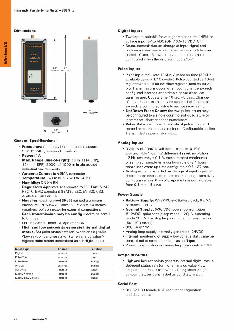
Dimensions
General Specifications• Frequency:frequencyhoppingspreadspectrum 902-928MHz,sub-bandsavailable
• Power: 1W• Max. Range (line-of-sight):20miles(4ERP), 15km(1ERP);3000ft/1000minobstructedindustrial environments
• Antenna Connector:SMAconnector • Temperature:-40to60°C/-40to140°F • Humidity:0-99%RH • Regulatory Approvals:approvedtoFCCPart15.247,
RS210;EMCcompliant89/336EEC,EN300683,AS3548,FCCPart15
• Housing: weatherproof(IP66)paintedaluminumenclosure170x64x36mm/6.7x2.5x1.4inches;weatherproofconnectorforexternalconnections
• Each transmission may be configuredtobesent1to 5 times
•LEDindicators-radioTX,operationOK• High and low set-points generate internal digital
status. Set-point status sets (on) when analog value <lowset-pointandresets(off)whenanalogvalue>highset-point status transmitted as per digital input.
Input Type Source FunctionDigital external statusPulseTotal external countPulseRate internal analogAnalog external analogSet-point internal statusSupply Voltage internal analogSupply Low Voltage internal status
Digital Inputs •Twoinputs,suitableforvoltage-freecontacts/NPN,or
voltageinput0-1.5VDC(ON)/3.5-13VDC(OFF) •Statustransmissiononchangeofinputsignaland
on time elapsed since last transmission - update time period10sec.-5days,aseparateupdatetimecanbeconfiguredwhenthediscreteinputis“on”
Pulse Inputs •Pulseinputmax.rate10KHz,3msecontime(50KHz
availableusinga1/10divider).Pulsecountedas16-bitregisterwitha16-bitoverflowregister(totalcount32-bit).Transmissionsoccurwhencountchangeexceedsconfiguredincreaseorontimeelapsedsincelasttransmission. Update time 10 sec. - 5 days. Change-of-statetransmissionsmaybesuspendedifincreaseexceedsaconfiguredvaluetoreduceradiotraffic.
• Up/Down Pulse Count: the two pulse inputs may beconfiguredtoasinglecounttosuitquadratureorincrementalshaftencodertransducers.
• Pulse Rate:calculatedfromrateofpulseinputandtreatedasaninternalanaloginput.Configurablescaling.Trans mitted as per analog input.
Analog Inputs •0-24mA(4-20mA)availableallmodels,0-10V
alsoavailable“floating”differentialinput,resolution12-bit,accuracy<0.1%measurementcontinuousorsampled,sampletimeconfigurable0-9.1hours,transducerwarm-uptimeconfigurable0.5-127sec.
•Analogvaluetransmittedonchangeofinputsignalortimeelapsedsincelasttransmission,changesensitivityconfigurablefrom0.7-75%,updatetimeconfigurablefrom0.1min.-5days
Power Supply • Battery Supply:WI-BP-I/O-9-KBatterypack,6xAA
batteries,9VDC • Normal Supply:6-30VDC,powerconsumption
@12VDC-quiescent(sleepmode)120μA,operatingmode10mA+analogloopduringradiotransmission(50 - 100 msec.)
•300mA@1W •Analogloopsupplyinternallygenerated(24VDC) •Internalmonitoringofsupplylowvoltagestatusmaybe
transmitted to remote modules as an “input” •Powerconsumptionincreasesforpulseinputs>10Hz
Set-point Status •Highandlowset-pointsgenerateinternaldigitalstatus.
Set-point status sets (on) when analog value <low set-pointandresets(off)whenanalogvalue>high set-point. Status transmitted as per digital input.
Serial Port •RS232DB9femaleDCEusedforconfiguration
and diagnostics
5.1"(150 mm)
6.7"(170 mm)
1.4"(36mm)
2.5"(64 mm)
23
Wir
eles
s I/
O
Transmitter (Single Sensor Units) — Battery Pack
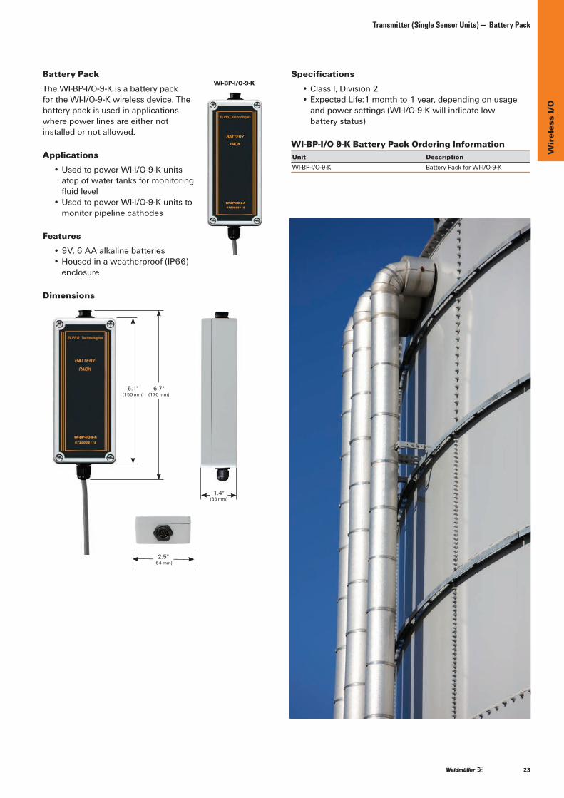
Battery PackTheWI-BP-I/O-9-KisabatterypackfortheWI-I/O-9-Kwirelessdevice.Thebatterypackisusedinapplicationswhere power lines are either not installed or not allowed.
Applications •UsedtopowerWI-I/O-9-Kunits
atopofwatertanksformonitoringfluidlevel
•UsedtopowerWI-I/O-9-Kunitstomonitor pipeline cathodes
Features •9V,6AAalkalinebatteries •Housedinaweatherproof(IP66)
enclosure
Dimensions
Specifications •ClassI,Division2 •ExpectedLife:1monthto1year,dependingonusage
andpowersettings(WI-I/O-9-Kwillindicatelow batterystatus)
WI-BP-I/O 9-K Battery Pack Ordering InformationUnit DescriptionWI-BP-I/O-9-K BatteryPackforWI-I/O-9-K
5.1"(150 mm)
6.7"(170 mm)
2.5"(64 mm)
1.4"(36mm)
WI-BP-I/O-9-K

24
Wir
eles
s I/
OTransmitter (Single Sensor Units)
WI-I/O-9-K
Technical Data
Inputs
Digital
Pulse
Up/DownPulseCountPulseRate
Analog
resolutionaccuracysampletimeconfigurabletransducerwarm-uptimeconfigurableanalogvaluetransmittedonchangeofinputsignalortimeelapsedsincelasttransmission,changesensitivityconfigurableupdatetimeconfigurableSetpoint Status
Power SupplyPowerconsumption@12VDCPowerconsumptionduringradiotransmission (50 - 100 msec)AnalogloopsupplyinternallygeneratedInternalmonitoringofsupplylowvoltagestatusPowerconsumptionincreasesforpulseinputs>10Hz.
General DataOperating TemperatureHumidityEMC StandardsApprovalsMountingLEDindicationfrequencyhoppingspreadspectrumTransmit powerMaximumlineofsightrangeReceiver data sensitivityDatarateAntenna connectorDimensions mm (in)
Ordering Data
BatteryPack(optional)PlugandLead-1meter(includedw/radio)
twodigital/pulseinputs,suitableforvoltagefreecontacts/NPN, orvoltageinput0-1.5VDC(ON)/3.5-13VDC(OFF)statustransmissiononchangeofinputsignalandontimeelapsedsincelasttransmission-updatetimeperiod10sec-5days,aseparateupdatetimecanbeconfiguredwhenthediscreteinputis“on”Pulserateupto1000Hz,3msecontime.Pulsecountedas16bitregisterwitha16bitoverflowregister(totalcount32bit).Transmissionsoccurwhencountchangeexceedsconfiguredincrease,orontimeelapsedsincelasttransmission;updatetime10sec-5days;changetransmissionsmaybesuspendedifincreaseexceedsaconfiguredvaluetoreduceradiotraffic.thetwopulseinputsmaybeconfiguredtoasinglecount,tosuitquadratureorincrementalshaftencodertransducers.calculatedfromrateofpulseinputandtreatedasaninternalanaloginput.Configurablescaling.Transmittedasper analog input.oneanaloginput0-25mA(4-20mA) 0-10Valsoavailable“floating”differentialinput12bit< 0.1 % measurement continuous or sampled 1 min - 5 days0.5-127 sec
0.7-75%0.1min - 5 dayshigh and low setpoints generate internal digital status setpointstatussets(on)whenanalogvalue<lowsetpointandresets(off)whenanalogvalue>highsetpoint status transmitted as per digital input
6-30VDCquiescent(sleepmode)120µA,operatingmode10mA+analogloop300mA@1W,220µA@500mW 100mA@100mW,50mA@10mWYesmaybetransmittedtoremotemodulesasan“input”
-40to60°C(-40to140°F)0-99%RHcompliant89/336EEC,EN300683,AS3548,FCCPart15Housing-IP66NEMA4;FCCPart15.247,RS210,Class1,Div.2
C US
RadioTX,OperationOK902-928MHz,sub-bandsavailable1 W20miles(4WERP),15km(1WERP)-108dBm19.2KbswithforwarderrorcorrectionSMAfemalecoaxial170x64x36(6.7x2.5x1.4)
Type Part No.WI-I/O-9-K 6720005004WI-BP-I/O-9-K 6720005112WI-PLI-9-K 6720005113
C1D2C US

25
Wir
eles
s I/
O
Wireless Meshing I/O Units
Wireless Meshing I/O UnitsWeidmuller’sWI-I/O-9-U2combinesmultiI/Oand/orgatewayfunctionalitywiththereliabilityofsecure,scalablemeshdistancecommunications.TheWI-I/O-9-U2IP-basedaddressingprovidesmesh/self-healingofnetworkcommunications,multihoprepeatingandremoteovertheairre-configurationanddiagnostics.TheWI-I/O-9-U2isfurthercomplementedbyitseaseofcommissioningandintegrationintoexistingplantinfrastructure.
Features:• 902-928MHzFrequencyShiftKeying(FSK):FrequencyHoppingSpread
SpectrumChannels/HopSets:50x250kHz;2frequencychannels.• IPBasedWirelessMESHTechnology@1Watttransmitpower.• Self-healing,repeatable,securecommunicationsto128bitAES• UserfriendlyoperationwithselfdiscoveryofradiopathandexpansionI/O• Remoteovertheairre-configuration,firmwareupgradeandfaultanalysis• Scalable,simpletocomplex,andpointtomultipointnetworkdesign• BlockMappingandBlockMessagingtechnologyforeaseofsystemintegration• I/Oand/orgatewayfunctionalityviafeaturekeyupgrade• Systemwideview,localizedI/Oreferencing,andprinting/exporting
ofconfiguration
Dimensions
1.38"(35mm)
6.97"(177 mm)
6.49"(168 mm)
5.91"(150 mm)
WI-I/O-9-U2 TCTheWI-I/O-9-U2TCisathermocoupleadapterinterfacefortheWI-I/O-9-U2product.TheWI-I/O-9-U2TCprovidesgreateraccuracybyallowingcalibrationbetweentheadapter,measurementdevicesandambienttemperatures.Temperature measurement accuracy depends on the measuredtemperatureandambienttemperature.Errorsarearesultofbotherrorsincoldjunctiontemperatureandthermocouple voltage measurement. The WI-I/O-9-U2 TC providesforgreateraccuracybyallowingcalibrationofthecoldjunctiontemperatureoffsetvalueandthermocoupletemperature(i.e.offsetcalibration).
Supported Thermocouple: Type T
Measurement ranges:-200to+30°Cand0to+390°C
Basic Accuracy (Un-calibrated):+/-3.5°Cat-200to +30°C+/-2°Cat0to+390°C
Calibrated Accuracy:+/-1°Coverambienttemperaturerange+/-0.5°Catcalibrationtemperature
Security and ConfigurationData encryption:64bit;128bitAESPassword:httpsaccessibilityUser Configuration:Webpage;softwareconfiguration

26
Wir
eles
s I/
OWI-I/O-9-U2 Meshed Multi I/O and Gateway
WI-I/O-9-U2 Meshed Multi I/O and GatewayConfiguringandcommissioningtime/effortonthe WI-I/O-9-U2hasbeendesignedforeaseofcustomeruseandcostsavingsduringcommissioning.TheconfigurationutilityallowsforsimplenominationofI/Opointsoriginand destination with automatically detecting and routing themostefficientpathtothedestinationnode.Thisiscomplementedbyperiodicinterrogationforoptimalpathverification,quickrecoveryofnetworkcommunicationsandautomaticdetectionofexpansionI/O(Weidmuller’sWI-I/O-EX-1-S).Italsoincorporatesefficient‘changeofstate’radiocommunicationsanduserconfigurableI/Oorregisterperiodicreportingoflinkstatus(ieupdatetime).Allcombinetoensuretheuserisinchargeofnetworkcommunications.
Remote/local configuration, upgrade and analysis.Weidmuller’sIP-basedaddressingfurtheraidsincostreductionprovidingremoteanalysisand/orupgrade.Ausermayperformremoteorlocalovertheairre-configurationandinterrogationofnodesfordiagnosticsandfirmwareupgrade.UsernominatedlocalizedreferencingofI/Oandsystemwidenetworkviewingaidsinfaultanalysisandexporting/printingofnodeconfigurationissupported.
Quicker, more cost effective commissioning.RadionetworkefficiencyandcommissioningoftheWI-I/O-9-U2intolegacyprocesscontrol/automationnetworksisaidedwithblockmappingandblockmessagingtechnology.
Blockmappingtechnologyallowsend-userstogatherrelated,non-contiguousdatapoints/registers,intoasingleradio message structure and scatter these points at receiving devicesforeaseofintegration(egPLClogic,SCADAtags).
Blockmappingtechnologyiscomplementedbyblockmessaging technology allowing end users to select continuous,related,I/Oandregistersforforwardingtoreceivingdevicesinasinglemessage.Bothblockmappingandblockmessagingcombinewithhighlyefficient‘changeofstate’,densecapacityradiomessagingcapabilitiesinprovidingscalablesystemdesignforevergrowingapplicationneeds.
Cost effective, distance IP based mesh networks.TheWI-I/O-9-U2combinesdistance,900MHz,IPmeshcommunicationswitheaseofconfiguration,local/remoteovertheairre-configurability,firmwareupgradeanddiagnosesofnodesinthenetwork.
FeaturingWeidmuller’sIP-basedaddressingtechnologywithitsinnovationsinnetworkcommunicationsefficiency,theWI-I/O-9-U2providesforscalablenetworkdesignforprocesscontrolandautomationbaseapplications.
Local/remote over the air re-configuration, firmware upgrade and
fault analysis with automatic detection of expansion I/O to reduce overheads.
Remote LAN
Locate LAN
Process network
Automatic detection of expansion I/O
Block messaging communicates continuous blocks of data improving the efficiency of radio band use and even more scalable network design.
1st Block Message
2nd Block Message
Block Messaging Technology
1 Message
Block Mapping Technology
Block mapping technology enables non-contiguous data to be transferred between network devices reducing re-programming time and associated costs.
Configuration is user friendly by nominating and labelling origin and destination points, and IP-based addressing
finds the most efficient route.

27
Wir
eles
s I/
O
WI-I/O-9-U2 Meshed Multi I/O and Gateway
Technical DataInputsDigital:opto-isolated(5kV)inputssuitableforvoltagefreecontactsorNPNtransistorAnalog: “floating”differentialinputs,commonmodevoltage27V,24VDCforpoweringexternalloopsprovided,digitalfiltering1sec.Pulse:(configurableDigitalInputs)
OutputsDigital
Analog:currentsinktocommon,maxloopvoltage27V,maxloopresistance1000ohms
Pulse: FET30VDC200mAmax10kHz
Power SupplyBatterysupplyNormalsupply BatterychargingcircuitAverageCurrentDrawTransmitCurrentDrawInternal monitoringNotes
ConnectionsRS232/RS485RS232connectionRS485 connectionEthernetPortUSBPortGeneral DataFrequencyTransmitPowerTransmissionModulationReceive SensitivityChannel SpacingDataRate
Range (LoS)Operating TemperatureHumidityEMC StandardsApprovalsMountingLEDindicationAntenna connectorDimensions mm (in)
Ordering Data
WirelessMeshI/O8DI/O,4AI,2AO,1-4PI/OWirelessMeshRadio+ModbusGateway software(Preloaded)ModbusTCP/RTUGateway(softwareAdd-on)TCPAdaptor(TypeTThermocoupleAdd-on)
Upto8DI(Configurable), On-stateVoltage<2.1VWetting,Current5mA4AI(2differential:2singleended)resolution14bits;accuracy0.1%CurrentRange-0-24mAVoltageRange:AI1,2:0-25V,AI3,4:0-5V4PIDI1,2:Max.Pulserate50kHz,Pulsewidthmin10usDI3,4:Max.Pulserate1kHz,Pulsewidthmin0.2ms
Upto8DO(Configurable)FET(30VDC@200mAmax.)On-stateVoltage-DOMax:30VDCWettingCurrent-DOMax:200mA
2AO0-24mA; resolution13bits;accuracy0.1%
4PODO1,2Max.Pulserate50kHz,Pulsewidthmin.10µsDO3,4Max.Pulserate1kHz,Pulsewidthmin0.2ms
12-15VDC15-30VDC,over-voltageandreversepowerprotectedincludedfor1.2-12AHrsealedbattery220mA@12VDC(Idle),110mA@24VDC(Idle)500mA@12VDC(1W),250mA@24VDC(1W)powerfailandbatteryvoltageAninternalDC/DCconverterprovides24VDC150mAforanalogloopsupply.
serialport9600baud,8bits,noparity,1stopbitEIA-562(RJ45connector)maxcabledistance2000mterminalconnections10/100BaseT;RJ45-IEEE802.3USB-Bconnectorforconfiguration
902-982MHz1mW(+0dBm)to1W(+30dBm)FrequencyHoppingSpreadSpectrum(FHSS)FrequencyShiftKeying(FSK)[email protected](3%FER)50x250KHz19.2-115.2Kbps“AutoMode”selectsfastestratepossiblerelativetoRSSI32Km(20mi.)@1W-40to60°C(-40to140°F)0-99%RHEN300683;FCCPart15;AS3548;89/336/EECClass1Div2 C US ,CE,IEC60950,IECexDIN-railmountingPower,RF,RS232,RS485,DI/O(PI/O),AI/O1xSMAfemalecoaxial180x150x35(5.91x7.09x1.38)
Type Part No.WI-I/O-9-U2 6720005011
WI-I/O-9-U2-MODTCP-900US 6720005014
WI-I/O 9-U2-GTWY* 6720005012WI-I/O 9-U2 TC 6720005013
WI-I/O-9-U2
C1D2C US
*Note:GatewaySoftwareAdd-onislicensedtoasingleWI-I/O-9-U2RadioSerialnumber&isnotintendedforuseonmultipleradios.WhenorderingWI-I/O-9-U2-GTWYalone,pleaseincludeexistingWI-I/O-9-U2radioSerialNumber(printedonthesideofthe unit).

28
Wir
eles
s I/
OMulti-I/O Units — Introduction — 900 MHz
• Short distance and long distance applications with license-freeandlicensedproducts
•Multi-hoprepeaterfunctions–upto5intermediate unitscanbeconfiguredinanyinput/outputlink
•Fourversionsavailable •Anyinputonanyunitcanbewirelesslylinkedto
anyoutputonanotherunit.Inputscanbelinkedtomultiple outputs.
•Inputsandoutputscanbeaddedviaadditional serial units
•Theunitscanbepre-programmedtoconsideranalogset-points,pulserateandpulsetotal,powersupplyvoltage,powersupplyalarm
•Set-pointstatusgeneratedbycomparinganaloginputs tohighandlowset-points.AvailableonAI1of-1units, andAI1-4of-2units.
•Pulseinputsgenerateaseparatepulsecountvalueandapulseratevalue.Pulseratesaretreatedasinternalanalogregisterswithaconfigurablemaximumvalue.
•Widevoltagepowersupply,withintegralUPSbattery charger and solar regulator
•Powersupplygeneratesinternalsignalvalueswhichcanbetransmitted,lownormalsupplyvoltagestatus,lowbatteryvoltagestatusandbatteryvoltage(analog)
•Multiplecommunicationfailurediagnosticswithoutputstatus.Fail-to-transmitalarmandfail-to-receivealarmstatus.
•RadioreceivessignalandbackgroundRFnoise measurement / logging diagnostics
•Inputmeasurementdisplayandoutput“forcing”diagnostics
• Communication logging diagnostics •Easy-to-useE-SeriesWindowsconfigurationavailable
at www.weidmuller.ca or www.weidmuller.com
ALARMPLC
Gas Analyzer
Metering
Alarms
Gauges
Plant Control
WI-I/O 9 Multi I/O UnitsAtransceiverisawirelessdevicemade upofatransmitterandreceiver.Since eachmodulecanmanagebothinputand outputsignals,itcanbeusedtomonitor transducers and control industrial processes.Thismodulecanalsobeused as a repeater to relay another wireless device’stransmission,thusincreasing theoverallrangeofthesystem.
Typical Applications •Wirelessjunctionboxinaprocessplanttoconnecta
largenumberofsignalstootherpartsoftheplantandtothe plant control center
•SimpleRemoteTerminalUnit(RTU)inaSCADAsystem, connecting sensors/instrumentation/process signals inpumpstations,sub-stations,pipelineregulatorstations,etc.
•Machine-to-Machinewirelessconnectivityinfactories
Features •ClassI,Division2hazardousareasapproved
(USA/Canada);(CSAcertified) •Multipleinputs/outputchannelsformonitoring
andcontrolfunctions •Upto95wirelessunitspernetwork • Each wireless unit can connect to input/output
expansion modules via RS485 multi-drop with up to31expansionmodulesperwirelessunit
•Sensorsignalsconnectedatonemodule;input signals are transmitted to another module where the signals are re-created as output signals or passedviaserialtoahostdevicesuchasaPLC orSCADAsystem

29
Wir
eles
s I/
O
Multi-I/O Units — Introduction — 900 MHz
Dimensions
General • Frequency:frequencyhoppingspreadspectrum
902-908MHz,sub-bandsconfigurable • Power:transmitpower1W,approvedtoFCC
Part15.247,RSS210 • Sensitivity:receiverdatasensitivity–108dBm • Max. Range (line-of-sight):USA/Canada-4W
ERP,20+miles.Othercountries-1WERP,15+kmdepending on local conditions
• Data Rate: 19.2Kb/swithforward-errorcorrection • Antenna Connector:SMAfemalecoaxial • Temperature:-40to60°C/-40to140°F • Humidity: 0-99%RH
• Regulatory Approvals: EMCFCCPart15,AS3548,89/336/EEC,EN301489
• Certifications: CSAClassI,Division2hazardousareas(USA/Canada)
• Housing:extrudedaluminumcase,5.1"x7.4"x2.4" (130x188x60mm)withDIN-railmounting
• Removable terminals up to 2.5 mm2 (12 gauge) wires • LED indication forpowersupply,modulestatus,
digital I/O
Inputs and Outputs*Digital Inputs •Opto-isolated(5000V)inputssuitableforvoltage-free
contactsorNPNtransistor,contactwettingcurrent5mA • Type-1 & -2 -fourinputs • Type-4 - upto16inputs(4inputs+12selectableI/O).
The12selectableinputsaresurgeprotected,but not isolated.
Digital Outputs • Type-1 - fourrelay,contacts,FormA,AC50V5A/DC
30V2A • Type-2 - 1FEToutput30VDC500mA • Type-3 - 8FEToutput30VDC500mA • Type-4 - upto16FEToutput(4outputs+
12selectableI/O)
Analog Inputs •“Floating”differentialinputs,commonmodevoltage
27V.24VDCforpoweringexternalloopsprovided. Digitalfiltering1sec.
• Type-1 - two4-20mAresolution15-bit,accuracy0.1% (overrangeindication2-25mA)
• Type-2 - six0-20mAresolution12-bit,accuracy0.1% (overrangeindication0-25mA)
6.57"(167 mm)
7.4"(188 mm)
2.16"(55 mm)
2.4"(60 mm)
5.1"(130mm)
Multi-I/O Unit Ordering Information WI-I/O 9 -1 -2 -3 -4Digitalinputs 4 4 0 4–16 Voltage-freecontacts Voltage-freecontacts Voltage-freecontacts Voltage-freecontactsDigitaloutputs 1+3 1 8 4-16 Relay+FET FET FET FETAnaloginputs 2 6 0 0 4-20mA 0-20mA/0-10VAnalogoutputs 2 0 8 0 4-20mA 0-20mA/0-10VPulseinputs 1 4 0 4 100Hz 1x1KHz,3x100Hz 1x1KHz,3x100HzPulseoutputs 1 0 4 4 100Hz 1x1KHz,3x100Hz 1x1KHz,3x100Hz
Note:Pulseanddigitalinputsaresameconnectionpoint. FET=FieldEffectTransistor
*SeetableaboveforInput/Outputsummary
30
Wir
eles
s I/
OMulti-I/O Units — Introduction — 900 MHz
Analog Outputs •Currentsinktocommon,max.loopvoltage27V,max.
loop resistance 1000 ohms• Type-1 - two4-20mAresolution15-bit,accuracy0.1%(overrangeindication0.5-25mA)
• Type-3 - eight0-20mAresolution12-bit,accuracy0.1%(overrangeindication0-20.5mA)
Pulse Inputs •Specificationsasperdigitalinputs,max.pulserate
100Hz,pulsewidthmin.5ms • Type-1 - oneinput(DI1) • Type-2 - fourinputs(DI1-4)-firstpulseinput(DI1)max.
1000Hz,pulsewidthmin.0.5ms • Type-4 - fourinputs(DI1-4)-firstpulseinput(DI1)max.
1000Hz,pulsewidthmin.0.5ms
Pulse Outputs •FET30VDC500mAmax.100Hz • Type-1 - one • Type-3 & -4 -four
Power Supply • Battery Supply: 11.5-15.0VDC • Normal Supply: 12-24VACor15-30VDC,over-
voltage and reverse power protected •Internalmonitoringofpowerfail,solarchargestatus
andbatteryvoltage.Thesevaluesmaybetransmittedtoremotemodulesformonitoring.
•InternalDC/DCconverterprovides24VDC150mAforanalog loop supply
•Batterychargingcircuitincludedfor1.2-12AHrsealedbattery
•Solarregulatorfordirectconnectionofsolarpanel (upto30W)andsolarbattery(100AHr)
Serial Port •Aserialportcanbeusedtoconfiguretransceiversand
to hard wire one transceiver to another when desired. This connection avoids the need to add wireless nodes tocircumventimpenetrableobstructionsandprovidesaredundantpathforcriticalapplications.
•RS232/RS485serialport9600baud,8bits,noparity,1stopbit
•RS2329pinDB9femaleconnector •RS485terminalconnections(max.cabledistance
2000m)
31
Wir
eles
s I/
O
Muti-I/O Units — 900 MHz
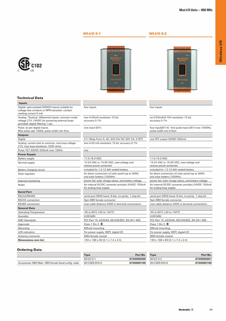
WI-I/O 9-1 WI-I/O 9-2
Technical Data InputsDigital:opto-isolated(5000V)inputssuitableforvoltagefreecontactsorNPNtransistor,contactwettingcurrent5mAAnalog:“floating”differentialinputs,commonmodevoltage27V,24VDCforpoweringexternalloopsprovided,digitalfiltering1sec.Pulse:asperdigitalinputs, Maxpulserate100Hz,pulsewidthmin5ms
OutputsDigitalAnalog:currentsinktocommon,maxloopvoltage27V,maxloopresistance1000ohmsPulse:FET30VDC500mAmax100Hz
Power SupplyBatterysupply
Normalsupply
BatterychargingcircuitSolar regulator
Internal monitoringNotes
Serial PortRS232/RS485RS232connectionRS485 connection
General DataOperating TemperatureHumidityEMC StandardsApprovalsMountingLEDindicationAntennaconnectorDimensions mm (in)
Ordering Data
Accessories:DB9Male-DB9FemaleSerialconfig.cable
fourinputs
two4-20mAresolution15bit, accuracy 0.1%
oneinput(DI1)
4(1RelayFormA,AC,50V5A/DC30V2A;3FET)two4-20mAresolution15bit,accuracy0.1%
one
11.5-15.0VDC12-24VACor15-30VDC,over-voltageand reverse power protectedincludedfor1.2-12AHrsealedbatteryfordirectconnectionofsolarpanel(upto30W) andsolarbattery(100AHr)powerfail,solarchargestatus,andbatteryvoltageAninternalDC/DCconverterprovides24VDC150mAforanalogloopsupply.
serialport9600baud,8bits,noparity,1stopbit9pinDB9femaleconnectormaxcabledistance2000mterminalconnections
-40to60°C(-40to140°F)0-99%RHFCCPart15,AS3548,89/336/EEC,EN301489Class1Div2 C US
DIN-railmountingForpowersupply,WDT,digitalI/OSMAfemalecoaxial130x188x60(5.1x7.4x2.4)
Type Part No.WI-I/O 9-1 6720005000WI-CSER-905-9 6720005105
fourinputs
six0-20mA/0-10Vresolution12bit, accuracy 0.1%
fourinput(DI1-4)-firstpulseinput(DI1)max1000Hz, pulse width min 0.5ms
oneFEToutput30VDC500mA
11.5-15.0VDC12-24VACor15-30VDC,over-voltageand reverse power protectedincludedfor1.2-12AHrsealedbatteryfordirectconnectionofsolarpanel(upto30W) andsolarbattery(100AHr)powerfail,solarchargestatus,andbatteryvoltageAninternalDC/DCconverterprovides24VDC150mAforanalogloopsupply.
serialport9600baud,8bits,noparity,1stopbit9pinDB9femaleconnectormaxcabledistance2000mterminalconnections
-40to60°C(-40to140°F)0-99%RHFCCPart15,AS3548,89/336/EEC,EN301489Class1Div2
C US
DIN-railmountingForpowersupply,WDT,digitalI/OSMAfemalecoaxial130x188x60(5.1x7.4x2.4)
Type Part No.WI-I/O 9-2 6720005001WI-CSER-905-9 6720005105
C1D2C US
32
Wir
eles
s I/
OMuti-I/O Units — 900 MHz
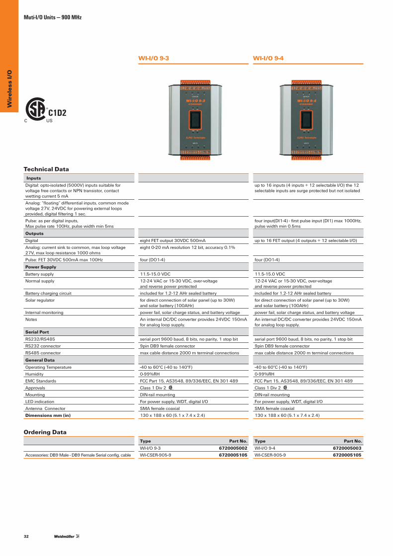
WI-I/O 9-3
eightFEToutput30VDC500mAeight0-20mAresolution12bit,accuracy0.1%
four(DO1-4)
11.5-15.0VDC12-24VACor15-30VDC,over-voltage and reverse power protectedincludedfor1.2-12AHrsealedbatteryfordirectconnectionofsolarpanel(upto30W) andsolarbattery(100AHr)powerfail,solarchargestatus,andbatteryvoltageAninternalDC/DCconverterprovides24VDC150mAforanalogloopsupply.
serialport9600baud,8bits,noparity,1stopbit9pinDB9femaleconnectormaxcabledistance2000mterminalconnections
-40to60°C(-40to140°F)0-99%RHFCCPart15,AS3548,89/336/EEC,EN301489Class1Div2 C US
DIN-railmountingForpowersupply,WDT,digitalI/OSMAfemalecoaxial130x188x60(5.1x7.4x2.4)
Type Part No.WI-I/O9-3 6720005002WI-CSER-905-9 6720005105
Technical Data InputsDigital:opto-isolated(5000V)inputssuitableforvoltagefreecontactsorNPNtransistor,contactwettingcurrent5mAAnalog:“floating”differentialinputs,commonmodevoltage27V,24VDCforpoweringexternalloopsprovided,digitalfiltering1sec.Pulse:asperdigitalinputs, Maxpulserate100Hz,pulsewidthmin5ms
OutputsDigitalAnalog:currentsinktocommon,maxloopvoltage27V,maxloopresistance1000ohmsPulse:FET30VDC500mAmax100Hz
Power SupplyBatterysupplyNormalsupply
BatterychargingcircuitSolar regulator
Internal monitoringNotes
Serial PortRS232/RS485RS232connectorRS485 connector
General DataOperating TemperatureHumidityEMC StandardsApprovalsMountingLEDindicationAntennaConnectorDimensions mm (in)
Ordering Data
Accessories:DB9Male-DB9FemaleSerialconfig.cable
WI-I/O 9-4
upto16inputs(4inputs+12selectableI/O)the12selectableinputsaresurgeprotectedbutnotisolated
fourinput(DI1-4)-firstpulseinput(DI1)max1000Hz, pulse width min 0.5ms
upto16FEToutput(4outputs+12selectableI/O)
four(DO1-4)
11.5-15.0VDC12-24VACor15-30VDC,over-voltage and reverse power protectedincludedfor1.2-12AHrsealedbatteryfordirectconnectionofsolarpanel(upto30W) andsolarbattery(100AHr)powerfail,solarchargestatus,andbatteryvoltageAninternalDC/DCconverterprovides24VDC150mAforanalogloopsupply.
serialport9600baud,8bits,noparity,1stopbit9pinDB9femaleconnectormaxcabledistance2000mterminalconnections
-40to60°C(-40to140°F)0-99%RHFCCPart15,AS3548,89/336/EEC,EN301489Class1Div2
C US
DIN-railmountingForpowersupply,WDT,digitalI/OSMAfemalecoaxial130x188x60(5.1x7.4x2.4)
Type Part No.WI-I/O 9-4 6720005003WI-CSER-905-9 6720005105
C1D2C US
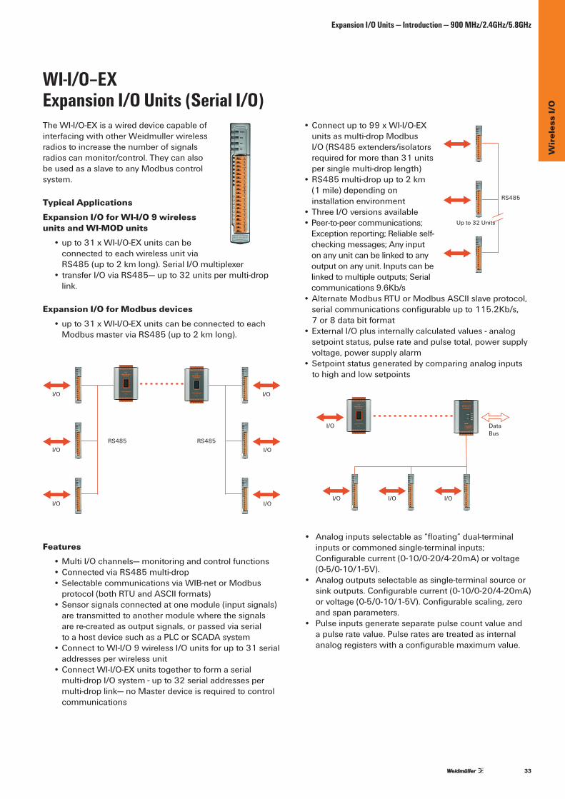
33
Wir
eles
s I/
O
Expansion I/O Units — Introduction — 900 MHz/2.4GHz/5.8GHz
•Connectupto99xWI-I/O-EXunitsasmulti-dropModbusI/O (RS485 extenders/isolators requiredformorethan31unitsper single multi-drop length)
•RS485multi-dropupto2km (1 mile) depending on installation environment
•ThreeI/Oversionsavailable •Peer-to-peercommunications;
Exceptionreporting;Reliableself-checkingmessages;Anyinputonanyunitcanbelinkedtoanyoutputonanyunit.Inputscanbelinkedtomultipleoutputs;Serialcommunications9.6Kb/s
•AlternateModbusRTUorModbusASCIIslaveprotocol,serialcommunicationsconfigurableupto115.2Kb/s,7 or8databitformat
• External I/O plus internally calculated values - analog setpointstatus,pulserateandpulsetotal,powersupplyvoltage,powersupplyalarm
•Setpointstatusgeneratedbycomparinganaloginputsto high and low setpoints
• Analoginputsselectableas“floating”dual-terminalinputsorcommonedsingle-terminalinputs;Configurablecurrent(0-10/0-20/4-20mA)orvoltage(0-5/0-10/1-5V).
• Analogoutputsselectableassingle-terminalsourceorsinkoutputs.Configurablecurrent(0-10/0-20/4-20mA)orvoltage(0-5/0-10/1-5V).Configurablescaling,zeroand span parameters.
• Pulseinputsgenerateseparatepulsecountvalueandapulseratevalue.Pulseratesaretreatedasinternalanalogregisterswithaconfigurablemaximumvalue.
WI-I/O–EX Expansion I/O Units (Serial I/O)TheWI-I/O-EXisawireddevicecapableofinterfacingwithotherWeidmullerwirelessradiostoincreasethenumberofsignalsradios can monitor/control. They can also beusedasaslavetoanyModbuscontrolsystem.
Typical ApplicationsExpansion I/O for WI-I/O 9 wireless units and WI-MOD units •upto31xWI-I/O-EXunitscanbe
connected to each wireless unit via RS485(upto2kmlong).SerialI/Omultiplexer
•transferI/OviaRS485—upto32unitspermulti-droplink.
Expansion I/O for Modbus devices •upto31xWI-I/O-EXunitscanbeconnectedtoeach
ModbusmasterviaRS485(upto2kmlong).
Features •MultiI/Ochannels—monitoringandcontrolfunctions • Connected via RS485 multi-drop •SelectablecommunicationsviaWIB-netorModbus
protocol(bothRTUandASCIIformats) • Sensor signals connected at one module (input signals)
are transmitted to another module where the signals arere-createdasoutputsignals,orpassedviaserial toahostdevicesuchasaPLCorSCADAsystem
•ConnecttoWI-I/O9wirelessI/Ounitsforupto31serialaddresses per wireless unit
•ConnectWI-I/O-EXunitstogethertoformaserialmulti-dropI/Osystem-upto32serialaddressespermulti-droplink—noMasterdeviceisrequiredtocontrolcommunications
RS485
I/O
I/O
I/O
I/O
I/O
I/O
RS485
Upto32Units
RS485
I/O DataBus
I/O I/O I/O

34
Wir
eles
s I/
OExpansion I/O Units — Introduction
•Multiplecommunication-failurediagnosticswithoutputstatus.Fail-to-transmitalarmandfail-to-receivealarmstatus.
•Class1Div2hazardousareasapproval C US
•Inputmeasurementdisplayandoutput“forcing”diagnostics.
• Communication logging diagnostics. •Easy-to-useE-SeriesWindowsconfigurationavailableat
www.weidmuller.ca or weidmuller.com
Serial Unit Ordering Information 67200005038 67200005039 67200005040 WI-I/O-EX -11 -12 -13Digitalinputs upto16 upto8 upto8 Voltage-freecontactsDigitaloutputs upto16 upto8 upto8Analoginputs 0 4“floating”/8commoned 0 0-20mA/0-10VAnalogoutputs 0 0 8sink/source 0-20mA/0-10VPulseinputs 4 0 0 1KHzPulseoutputs 8 8 8 100Hz 100Hz 100Hz
Note:Digitalinputsandoutputsarecombinedchannels.Whenachannelisusedasanoutput,itisnotavailableasaninput.PulseanddigitalI/Oaresameconnection.
Dimensions
6.49"(168 mm)
6.97"(177 mm)
1.38"(35mm)
General Specifications • Temperature:-40to60°C/-40to140°F • Humidity:0-99%RH • Regulatory Approvals:EMCFCCPart15,AS3548,
89/336/EEC • Certifications:CSAClassI,Division2hazardous
areas(USA/Canada) • Housing:highdensitythermo-plastic,5.91"x6.97"x
1.38"(150X177x35mm)withDIN-railmounting • Removable terminals up to 12 gauge (2.5 mm2)
wires • LED indicationforpowersupply,processorOK,serial
TXandRX,digitalI/O
5.91"(150 mm)

35
Wir
eles
s I/
O
Expansion I/O Units — Introduction
Inputs and OutputsDigital Inputs •Suitableforvoltage-freecontactsorNPNtransistor,
contactwettingcurrent5mA,inputsaresurgeprotected• Type -11 - upto16selectableI/O• Type -12, -13, - upto8selectableI/O
Digital Outputs •FieldEffectTransistor(FET)outputs,30VDC200mA
• Type -11 -upto16selectableI/O• Type -12, -13, -upto8selectableI/O
Analog Inputs •“Floating”differentialinputs,commonmodevoltage
27V,24VDCforpoweringexternalloopsprovided, 0-20mA/0-10V,resolution12-bit,accuracy0.1%
• Type-12 - 8inputchannels,selectableas4dual-terminalfloatinginputsor8single-terminal commoned inputs
Analog Outputs •Selectableascurrent/voltagesourceorcurrentsinkto
common,max.loopvoltage27V,max.loopresistance 1000ohms,0–20mA/0–10V,12-bit,accuracy0.1%
• Type -13 - 8 channels
Pulse Inputs •Specificationsasperdigitalinputs,max.pulserate
1kHz,pulsewidthmin.0.5ms • Type -11-4inputs(DIO1-4)
Pulse Outputs •Specificationsasperdigitaloutputs,max.pulse
rate100Hz,pulsewidthmin.5ms • Type -11,-12,-13, -8outputs(DIO1-8)
Power Supply • Battery Supply: 9-30VDC,over-voltageandreverse
power protected •Internalmonitoringofsupplyvoltage.Thesevaluesmay
betransmittedtoremotemodulesformonitoring. •InternalDC/DCconverterprovides24VDC250mAfor
analog loop supply
Serial Port •RS485serialportconfigurableupto115.2Kb/s,7or8
databits,none/even/oddparity,1or2stopbits •RS232configurationport9pinDB9femaleconnector,
9.6Kb/s,8/n/1 •RS485maxcabledistance2000mterminalconnections
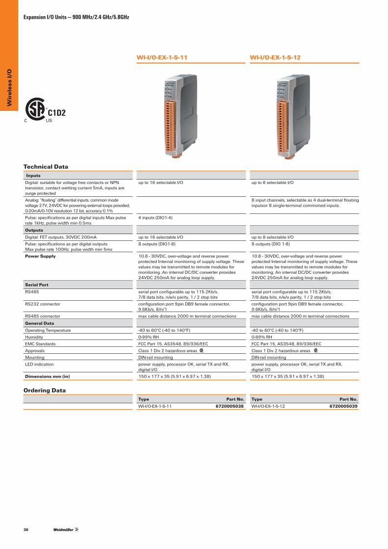
36
Wir
eles
s I/
OExpansion I/O Units — 900 MHz/2.4 GHz/5.8GHz
WI-I/O-EX-1-S-11
upto16selectableI/O
4inputs(DIO1-4)
upto16selectableI/O8outputs(DIO1-8)
10.8-30VDC,over-voltageandreversepowerprotectedInternalmonitoringofsupplyvoltage.Thesevaluesmaybetransmittedtoremotemodulesformonitoring.AninternalDC/DCconverterprovides24VDC250mAforanalogloopsupply.
serialportconfigurableupto115.2Kb/s, 7/8databits,n/e/oparity,1/2stopbitsconfigurationport9pinDB9femaleconnector,9.6Kb/s,8/n/1maxcabledistance2000mterminalconnections
-40to60°C(-40to140°F)0-99%RHFCCPart15,AS3548,89/336/EECClass1Div2hazardousareas C US
DIN-railmountingpowersupply,processorOK,serialTXandRX, digital I/O150x177x35(5.91x6.97x1.38)
Type Part No.WI-I/O-EX-1-S-11 6720005038
Technical Data InputsDigital:suitableforvoltagefreecontactsorNPNtransistor,contactwettingcurrent5mA,inputsaresurge protectedAnalog:“floating”differentialinputs,commonmodevoltage27V,24VDCforpoweringexternalloopsprovided,0-20mA/0-10Vresolution12bit,accuracy0.1%Pulse:specificationsasperdigitalinputsMaxpulserate1kHz,pulsewidthmin0.5ms
OutputsDigital:FEToutputs,30VDC200mAPulse:specificationsasperdigitaloutputs Maxpulserate100Hz,pulsewidthmin5msPower Supply
Serial PortRS485
RS232connector
RS485 connector
General DataOperating TemperatureHumidityEMC StandardsApprovalsMountingLEDindication
Dimensions mm (in)
Ordering Data
WI-I/O-EX-1-S-12
upto8selectableI/O 8inputchannels,selectableas4dual-terminalfloatinginputsor 8 single-terminal commoned inputs.
upto8selectableI/O8outputs(DIO1-8)
10.8-30VDC,over-voltageandreversepowerprotectedInternalmonitoringofsupplyvoltage.Thesevaluesmaybetransmittedtoremotemodulesformonitoring.AninternalDC/DCconverterprovides24VDC250mAforanalogloopsupply.
serialportconfigurableupto115.2Kb/s, 7/8databits,n/e/oparity,1/2stopbitsconfigurationport9pinDB9femaleconnector,9.6Kb/s,8/n/1maxcabledistance2000mterminalconnections
-40to60°C(-40to140°F)0-99%RHFCCPart15,AS3548,89/336/EECClass1Div2hazardousareas C US
DIN-railmountingpowersupply,processorOK,serialTXandRX, digital I/O150x177x35(5.91x6.97x1.38)
Type Part No.WI-I/O-EX-1-S-12 6720005039
C1D2C US
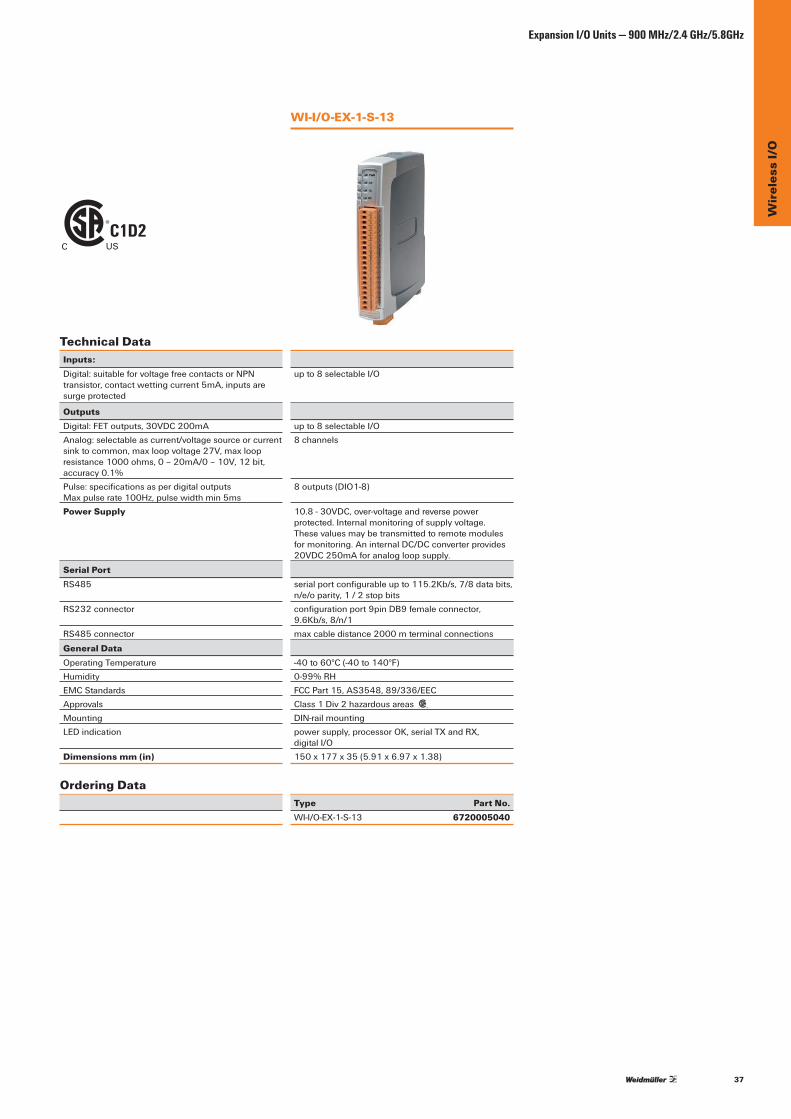
37
Wir
eles
s I/
O
Expansion I/O Units — 900 MHz/2.4 GHz/5.8GHz
WI-I/O-EX-1-S-13
upto8selectableI/O
upto8selectableI/O8 channels
8outputs(DIO1-8)
10.8-30VDC,over-voltageandreversepowerprotected.Internalmonitoringofsupplyvoltage.Thesevaluesmaybetransmittedtoremotemodulesformonitoring.AninternalDC/DCconverterprovides20VDC250mAforanalogloopsupply.
serialportconfigurableupto115.2Kb/s,7/8databits,n/e/oparity,1/2stopbitsconfigurationport9pinDB9femaleconnector,9.6Kb/s,8/n/1maxcabledistance2000mterminalconnections
-40to60°C(-40to140°F)0-99%RHFCCPart15,AS3548,89/336/EECClass1Div2hazardousareas
C US
DIN-railmountingpowersupply,processorOK,serialTXandRX, digital I/O150x177x35(5.91x6.97x1.38)
Type Part No.WI-I/O-EX-1-S-13 6720005040
Technical DataInputs:Digital:suitableforvoltagefreecontactsorNPN transistor,contactwettingcurrent5mA,inputsare surge protected
OutputsDigital:FEToutputs,30VDC200mAAnalog:selectableascurrent/voltagesourceorcurrentsinktocommon,maxloopvoltage27V,maxloopresistance1000ohms,0–20mA/0–10V,12bit,accuracy 0.1%Pulse:specificationsasperdigitaloutputs Maxpulserate100Hz,pulsewidthmin5msPower Supply
Serial PortRS485
RS232connector
RS485 connector
General DataOperating TemperatureHumidityEMC StandardsApprovalsMountingLEDindication
Dimensions mm (in)
Ordering Data
C1D2C US

38
Wir
eles
s I/
OWireless Gateways — Introduction
Wireless Gateways WI-GTWY-9Wirelessgatewaysinterfacebetweenother Weidmuller wireless devices and controlsystems(suchasPLC’s,DCSandSCADA).Inadditiontochannelingthewirelessnetworkdataintoonecentralcontrolsystem,theycanalsoactas an eight input/output transceiver.
Applications •WirelesslyconnectPLCsonanewmachinetoan
existingfactoryautomationsystem •Interfacedifferentautomationsystemsindifferent
sectionsofaplant• Connect protocol devices into a common wireless network
• Weidmuller wireless units are used to wirelessly transmitsignalsforPLCsorDCS
Wireless gateways connect to popular process control and automationdatabusesandconvertsignalinformationtotheprovenWIB-netwirelessprotocol.
Main benefits: •Wirelessextensionoffactoryautomation,providinga
highsecurityfirewall.Thewirelessgatewayconnectsto adatabusandtransfersI/Ovaluestoanotherwirelessgateway unit via WIB-net communications. The other gatewayinterfacestoitsowndatabus.MultiplegatewayunitscancommunicateinaWIBpeer-to-peernetwork.
•ThereisanefficientwirelessprotocolconversioninthemodulesenablinganefficienttransferofdatatoModbus,Profibus,EthernetandDeviceNet.
•InterfacebetweenPLCs,DCS,HMI,orSCADAandWeidmuller wireless units. The wireless gateway keepsan“image”oftheremotewirelessnetworkinitsmemoryandinterfacesthisimagetothedatabus.
•Networkwirelessunitsandgatewaystoconnectsensorsignals and control systems
Features •Connectstodatabusatfullbusspeed(e.g.12Mb/sfor
Profibus,100Mb/sforEthernet) •ProvidesProtocolConversion(Profibus,Modbus,
Ethernet,DeviceNet) •Caninterconnectmaster-slave,slave-slave
and master-master •Interconnectsdifferentdatabuses-wireless
protocol conversion •Providesapeer-to-peerwirelessnetworkusingWIB-net •Highsecuritydataencryption •Automaticacknowledgmentanderror-correction • Multiple path routing •Eighton-boarddiscreteI/O,individuallyconfigurable
as input or output •Networkconfigurationisperformedwitheasy-to-use
freesoftware •Widerangepowersupplywithintegralback-up
battery-chargingfeature • Frequency hopping spread spectrum •902-928MHz1Wlicense-freeUSA/Canada/Mexico •Configurablesub-bandslicense-freeSouthAmerica,
Australia/NZ,Asia,EuropeavailableonrequestInterconnection Flexibility
Modbus
Profibus Ethernet
DF1
DirectI/O

39
Wir
eles
s I/
O
Wireless Gateways — Introduction
Dimensions
General Specifications
• Frequency: frequencyhoppingspreadspectrum902-928MHz,sub-bandsconfigurable
• Power:transmitpower1W,approvedtoFCCPart15.247,RSS210
• Sensitivity:receiverdatasensitivity–108dBm • Max. Range (line-of-sight): USA/Canada,4WERP
20+miles;othercountries,1WERP,15+kmdependingon local conditions
• Data Rate:19.2Kb/swithforward-errorcorrection • Antenna Connector: SMAfemalecoaxial • Temperature:-40to60°C/-40to140°F • Humidity:0-99%RH • Regulatory Approvals:EMCCompliantEN301489,
FCCPart15 • Certifications: ClassI,Division2(USA,Canada) • Housing: extrudedaluminumcase130x183x
60mm,5.1x7.2x2.4inches,DIN-railmounting,removableterminalblocksforeaseofmodulereplacement,terminalssuitablefor12gauge (2.5 mm2) wire
• Radio communications can be configured forcombinationofevent-reporting(change-of-state),updatetime,read/writeblocksandpollresponse.Radiomessageincludessystemaddressing,unitaddressing,error-checkingandconfigurablesecurityencryption. Communication control includes message acknowledgmentsanduptofourre-transmissions.
• Peer-to-peer addressing.Messagesmayberoutedthroughfiveintermediaterepeateraddresses.
• Fail-to-transmit and fail-to-receive alarms areconfigurable.
• LED indication forprocessorOK,radioTXandRX,serialTXandRX,activestatus
• Modbus RTU(binary),master/slaveconfigurable; RS232orRS485,300-19200bits/sec.
Inputs and Outputs •EightdiscreteI/O,individuallyconfigurableasinputor
output.Inputssuitableforvoltage-freecontacts.Outputs areFET,30VDC500mA.
Power Supply •BatterySupply:batterychargingcircuitincludedfor
12Vback-upbattery,max.chargecurrentregulated to0.7A(>12Vsupply)
•NormalSupply:9-30VDC/12-24VAC •Normalcurrentdrain:12V150mA;24V90mA
add5mAperactiveI/O,currentdrainduringradiotransmission,addtoabove:12V350mA;24V200mA
Set-point Status •Modbus4300I/Opoints(analogplusdiscrete)
Serial Port •RS2329pinDB9femaleconnector • RS485 terminal connections
Configuration and Diagnostics •Diagnosticsincludeonlineread/writeofI/Oregisters,
radiosignalstrengthvaluesfromremoteunitsand off-linetestingofdatabusprotocol.
6.57"(167 mm)
7.2"(183mm)
2.16"(55 mm)
2.4"(60 mm)
5.1"(130mm)

40
Wir
eles
s I/
OWireless Gateways — 900 MHz
WI-GTWY-9-MD1 Modbus (Master and Slave), DF1
WI-GTWY-9-PR1 Profibus DP Slave
Technical Data Power Supply
Current drain during radio transmissionI/O Capacity
Register SizeNumberofremoteWI-GTWY-9addresses
General DataOperating TemperatureHumidityEMC Standards
ApprovalsMountingLEDindication
Dimensionsmm(in)Wireless Communications
On-board I/O
ConfigurationDiagnostics
Radio TransceiverFrequency hopping spread spectrumTransmit powerReceiver data sensitivity Maximumline-of-sightrangeDatarateAntennaconnector
Ordering Data
Accessories:DB9Male-DB9FemaleSerialconfig.cable
9-30VDC/12-24VACBatterychargingcircuitincludedfor12Vback-up battery,maxchargecurrentregulatedto0.7A (>12Vsupply) Normalcurrentdrain MD1version12V150mA;24V90mA Otherversion12V270mA;24V170mA Add5mAperactiveI/OAdd12V350mA;24V200mAtoabove4300I/Opoints(analogplusdiscrete)
16bit500
-40to60°C(-40to140°F)0-99%RHEN301489,FCCPart15, ApprovedtoFCCPart15.247,RS210Class1Div2
C US
DIN-railmounting,forprocessorOK,radioTXandRX,serialTXandRX,active status130x183x60(5.1x7.2x2.4)ModbusRTU(binary),master/slaveconfigurable.RS232orRS485,300-19200bits/sec.Allen-BradleyDF1full-duplex.RS232only,300-19200bits/sec.
EightdiscreteI/O,individuallyconfigurableasinputoroutput.Inputssuitableforvoltagefreecontacts. OutputsareFET,30VDC500mA.viafreeWindowssoftwareon-lineread/writeofI/Oregisters,radiosignalstrengthvaluesfromremoteunits,andoff-linetestingofdatabusprotocol.
902-908MHz,sub-bandsconfigurable1W-108dBmUSA/Canada,4WERP,20+miles19.2Kb/swithforward-errorcorrectionSMAfemalecoaxial
Type Part No.WI-GTWY-9-MD1 6720005020WI-CSER-905-9 6720005105
9-30VDC/12-24VACBatterychargingcircuitincludedfor12Vback-up battery,maxchargecurrentregulatedto0.7A (>12Vsupply) Normalcurrentdrain MD1version12V150mA;24V90mA Otherversion12V270mA;24V170mA Add5mAperactiveI/OAdd12V350mA;24V200mAtoabove416I/Obytesupto1952DI/1952DO,orupto 122AI/122AO16bit500
0to60°C(30to140°F)0-95%RHEN301489,FCCPart15,ApprovedtoFCCPart15.247,RS210Class1Div2
C US
DIN-railmounting,forprocessorOK,radioTXandRX,serialTXandRX,active status130x183x60(5.1x7.2x2.4)Profibus-DPfunctionalityaccordingtoEN50170.
RS-485opticallyisolatedwithon-boardDC/DCconverter,automaticbaudratedetection (9600bit/s-12Mbit/s)EightdiscreteI/O,individuallyconfigurableasinputoroutput.Inputssuitableforvoltagefreecontacts. OutputsareFET,30VDC500mA.viafreeWindowssoftwareon-lineread/writeofI/Oregisters,radiosignalstrengthvaluesfromremoteunits,andoff-linetestingofdatabusprotocol.
902-908MHz,sub-bandsconfigurable1W-108dBmUSA/Canada,4WERP,20+miles19.2Kb/swithforward-errorcorrectionSMAfemalecoaxial
Type Part No.WI-GTWY-9-PR1 6720005021WI-CSER-905-9 6720005105
Radiocommunicationscanbeconfiguredforcombinationofeventreporting(change-of-value),updatetime,read/writeblocksandpollresponse.Radiomessageincludessystemaddressing,unitaddressing,errorcheckingandconfigurablesecurityencryption.Communication control includes message acknowledgmentsanduptofourre-transmissions.Peertopeeraddressing.Messagesmayberoutedthroughfourintermediaterepeateraddresses.Fail-to-transmitandfail-to-receivealarmsconfigurable
C1D2C US

41
Wir
eles
s I/
O
Wireless Gateways — 900 MHz
WI-GTWY-9-PR2 Profibus DP Master
WI-GTWY-9-ET1 Ethernet IP, Modbus TCP, TCP/IP functions
Technical Data
Power Supply
Current drain during radio transmissionI/O Capacity
Register SizeNumberofremoteWI-GTWY-9addresses
General DataOperating TemperatureHumidityEMC Standards
ApprovalsMountingLEDindication
Dimensionsmm(in)Wireless Communications
On-board I/O
ConfigurationDiagnostics
Radio TransceiverFrequency hopping spread spectrumTransmit powerReceiver data sensitivity Maximumline-of-sightrangeDatarateAntennaconnector
Ordering Data
Accessories:DB9Male-DB9FemaleSerialconfig.cable
9-30VDC/12-24VAC Batterychargingcircuitincludedfor12Vback-upbattery,maxchargecurrentregulatedto0.7A(>12Vsupply) Normalcurrentdrain MD1version12V150mA;24V90mA Otherversion12V270mA;24V170mA Add5mAperactiveI/OAdd12V350mA;24V200mAtoabove2048bytesinputand2048bytesoutputupto4300discreteI/Opoints,orupto1024analogin/1024analog out16bit500
0to60°C(30to140°F)0-95%RHEN301489,FCCPart15,ApprovedtoFCCPart15.247,RS210Class1Div2
C US
DIN-railmounting,forprocessorOK,radioTXandRX,serialTXandRX, active status130x183x60(5.1x7.2x2.4)Profibus-DPfunctionalityaccordingtoEN50170.RS-485opticallyisolatedwithon-boardDC/DCconverter,automaticbaudratedetection (9600bit/s-12Mbit/s)
EightdiscreteI/O,individuallyconfigurableasinputoroutput.Inputssuitableforvoltagefreecontacts. OutputsareFET,30VDC500mA.viafreeWindowssoftwareon-lineread/writeofI/Oregisters,radiosignalstrengthvaluesfromremoteunits,andoff-linetestingofdatabusprotocol.
902-908MHz,sub-bandsconfigurable1W-108dBmUSA/Canada,4WERP,20+miles19.2Kb/swithforward-errorcorrectionSMAfemalecoaxial
Type Part No.WI-GTWY-9-PR2 6720005022WI-CSER-905-9 6720005105
9-30VDC/12-24VAC Batterychargingcircuitincludedfor12Vback-upbattery,maxchargecurrentregulatedto0.7A(>12Vsupply) Normalcurrentdrain MD1version12V150mA;24V90mA Otherversion12V270mA;24V170mA Add5mAperactiveI/OAdd12V350mA;24V200mAtoabove2048bytesinputand2048bytesoutputupto4300discreteI/Opoints,orupto1024analogin/1024analog out16bit500
0to60°C(30to140°F)0-95%RHEN301489,FCCPart15,ApprovedtoFCCPart15.247,RS210Class1Div2
C US
DIN-railmounting,forprocessorOK,radioTXandRX,serialTXandRX, active status130x183x60(5.1x7.2x2.4)10/100Mbit/s,RJ45connector,TransformerisolatedinterfaceModbus/TCPclass0,class1andpartiallyclass2slave EtherNet/IPlevel2I/OServer EmbeddedWebsystem(DynamicHTTP),on-boardfilesystem(1.4MBflashdisc),userdownloadablewebpagesthroughFTPserver,Emailfunctionality(SMTP)EightdiscreteI/O,individuallyconfigurableasinputoroutput.Inputssuitableforvoltagefreecontacts. OutputsareFET,30VDC500mA.viafreeWindowssoftwareon-lineread/writeofI/Oregisters,radiosignalstrengthvaluesfromremoteunits,andoff-linetestingofdatabusprotocol.
902-908MHz,sub-bandsconfigurable1W-108dBmUSA/Canada,4WERP,20+miles19.2Kb/swithforward-errorcorrectionSMAfemalecoaxial
Type Part No.WI-GTWY-9-ET1 6720005023WI-CSER-905-9 6720005105
Radiocommunicationscanbeconfiguredforcombinationofeventreporting(change-of-value),updatetime,read/writeblocksandpollresponse.Radiomessageincludessystemaddressing,unitaddressing,errorcheckingandconfigurablesecurityencryption.Communication control includes message acknowledgmentsanduptofourre-transmissions.Peertopeeraddressing.Messagesmayberoutedthroughfourintermediaterepeateraddresses. Fail-to-transmitandfail-to-receivealarmsconfigurable
C1D2C US
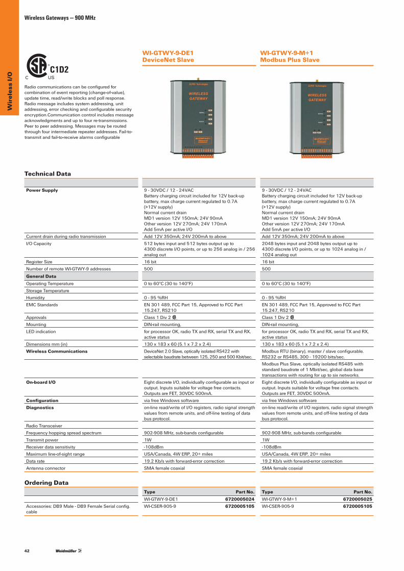
42
Wir
eles
s I/
OWireless Gateways — 900 MHz
WI-GTWY-9-DE1 DeviceNet Slave
WI-GTWY-9-M+1 Modbus Plus Slave
Technical Data
Power Supply
Current drain during radio transmissionI/O Capacity
Register SizeNumberofremoteWI-GTWY-9addresses
General DataOperating TemperatureStorage TemperatureHumidityEMC Standards
ApprovalsMountingLEDindication
Dimensionsmm(in)Wireless Communications
On-board I/O
ConfigurationDiagnostics
Radio TransceiverFrequency hopping spread spectrumTransmit powerReceiver data sensitivity Maximumline-of-sightrangeDatarateAntennaconnector
Ordering Data
Accessories:DB9Male-DB9FemaleSerialconfig.cable
9-30VDC/12-24VAC Batterychargingcircuitincludedfor12Vback-upbattery,maxchargecurrentregulatedto0.7A (>12Vsupply) Normalcurrentdrain MD1version12V150mA;24V90mA Otherversion12V270mA;24V170mA Add5mAperactiveI/OAdd12V350mA;24V200mAtoabove512bytesinputand512bytesoutputupto 4300discreteI/Opoints,orupto256analogin/256analog out16bit500
0to60°C(30to140°F)
0-95%RHEN301489,FCCPart15,ApprovedtoFCCPart15.247,RS210Class1Div2
C US
DIN-railmounting,forprocessorOK,radioTXandRX,serialTXandRX, active status130x183x60(5.1x7.2x2.4)DeviceNet2.0Slave,opticallyisolatedRS422withselectablebaudratebetween125,250and500Kbit/sec.
EightdiscreteI/O,individuallyconfigurableasinputoroutput.Inputssuitableforvoltagefreecontacts. OutputsareFET,30VDC500mA.viafreeWindowssoftwareon-lineread/writeofI/Oregisters,radiosignalstrengthvaluesfromremoteunits,andoff-linetestingofdatabusprotocol.
902-908MHz,sub-bandsconfigurable1W-108dBmUSA/Canada,4WERP,20+miles19.2Kb/swithforward-errorcorrectionSMAfemalecoaxial
Type Part No.WI-GTWY-9-DE1 6720005024WI-CSER-905-9 6720005105
9-30VDC/12-24VAC Batterychargingcircuitincludedfor12Vback-upbattery,maxchargecurrentregulatedto0.7A (>12Vsupply) Normalcurrentdrain MD1version12V150mA;24V90mA Otherversion12V270mA;24V170mA Add5mAperactiveI/OAdd12V350mA;24V200mAtoabove2048bytesinputand2048bytesoutputupto 4300discreteI/Opoints,orupto1024analogin/1024 analog out16bit500
0to60°C(30to140°F)
0-95%RHEN301489,FCCPart15,ApprovedtoFCCPart15.247,RS210Class1Div2
C US
DIN-railmounting,forprocessorOK,radioTXandRX,serialTXandRX, active status130x183x60(5.1x7.2x2.4)ModbusRTU(binary),master/slaveconfigurable.RS232orRS485,300-19200bits/sec.ModbusPlusSlave,opticallyisolatedRS485withstandardbaudrateof1Mbit/sec,globaldatabasetransactionswithroutingforuptosixnetworks.EightdiscreteI/O,individuallyconfigurableasinputoroutput.Inputssuitableforvoltagefreecontacts. OutputsareFET,30VDC500mA.viafreeWindowssoftwareon-lineread/writeofI/Oregisters,radiosignalstrengthvaluesfromremoteunits,andoff-linetestingofdatabusprotocol.
902-908MHz,sub-bandsconfigurable1W-108dBmUSA/Canada,4WERP,20+miles19.2Kb/swithforward-errorcorrectionSMAfemalecoaxial
Type Part No.WI-GTWY-9-M+1 6720005025WI-CSER-905-9 6720005105
Radiocommunicationscanbeconfiguredforcombinationofeventreporting(change-of-value),updatetime,read/writeblocksandpollresponse.Radiomessageincludessystemaddressing,unitaddressing,errorcheckingandconfigurablesecurityencryption.Communication control includes message acknowledgmentsanduptofourre-transmissions.Peertopeeraddressing.Messagesmayberoutedthroughfourintermediaterepeateraddresses.Fail-to-transmitandfail-to-receivealarmsconfigurable
C1D2C US

43
Wir
eles
s D
ata
Mod
ems
Wireless Data Modems—Introduction
Wireless Data ModemsWirelessdatamodemsconnecttoserialorEthernetlinksand transmit the data wirelessly. The modem controls thewireless messages and data ports to provide a “transparent”datatransfer.
Wireless Ethernet Data ModemsTheWeidmullerWirelessEthernetModemsarearobust,license-freewireless802.11standardscomplianttransceivercapableofhighbandwidthcommunications.Theyareoptimizedforthroughputsofupto108Mbpswhichprovidesrobustandsecuretwo-waywirelesscommunicationsinchallengingindoorandoutdoorenvironmentstypicalofindustrial monitoring and control applications.
TheWeidmullermodemsoffernodetonodedeterministicmeshnetworkrepeatabilityforfurtherrangeandmultiplechannelspacingoptionstoincreasenetworkscalability.IntegratedModbusservercapabilityallowsseamlessI/OexpansionthroughtheuseofWI-I/O-EX-1-SExpansionunits.
Applications •IPCameras
• Roaming Vehicles •PLCCommunications •DataLoggerCommunications
• Serial and Ethernet Communications
•AgricultureSprayerControl• Water/ Waste Water Systems
•SCADANetworks
Features •802.11b/gand802.11aStandardCompliantOptions
902–928MHz;2.412–2.472GHz(802.11b/g); 5.18–5.825GHzFrequency(802.11a)
•Upto108MbpsDataThroughout •TransmitandReceiveAntennaDiversity •AccessPoint/ClientandBridge/RouterConfiguration •SerialClient/Server/MulticastModbusTCPto
RTU Gateway •SpanningTree(SelfHealing)Support •DeterministicAPtoAPMeshNetworkRepeatability •FastRoamingforAPtoAPHandover •IEEE802.11iSecure128-bitAESEncryption(WPA2) •MACandIPAddressFiltering •DigitalI/OChannelTransfer •ConfigurableSettingsforHighNoiseEnvironments •Over-The-AirNetworkDiagnosticsandConfiguration •VLANTaggingSupportedforBridgingand
Routing Modes
Wireless Serial Data ModemsTheWeidmullerWirelessSerialModemisanRS232orRS485datamodemthatenablescosteffective,two-waycommunicationsbetweenserialdevicessuchasPLCs,RTUs and other industrial machinery to host monitoring and control systems.
Offeringscalabilityfromsimpletocomplexdeployments,coupleddataratesupto500kbpswithlowlatencyperformancemakethemidealfordemandingModbusorProfibusapplications.Reliabilityismaximizedthroughinterferenceimmunefrequencyhoppingspreadspectrumtechnology while security is assured via data encryption to theAES256-bitstandard.
Applications •SCADASystems •PumpControlNetworks • Water/Wastewater •PLC/RTUInterfaces • Serial Output Instruments •BuildingAutomation/Security •EmbeddedMachineControl
Features •902–928MHz;2.401–2.4835GHzFrequency •USBinterfaceforeaseofconfiguration •Reducedtransmissionlatencyforhighspeedcontrol •Superiorreceiversensitivityandrejectiontocut
throughinterference •AdjustableoutputRFpowertokeepsignalswithin
your plant •VoltageTestPointforRSSImeasurement •SleepModeandFrequencyBlocking

44
Wir
eles
s D
ata
Mod
ems
Wireless Data Modems — 900 MHz and 2.4 GHz
C1D2C US
WI-MOD-9-SER-D Serial 900Mhz
WI-MOD-24-SER-D Serial 2.4GHz
Technical DataRadio Transceiver
TransmissionFrequency-USA/CanadaTransmitPowerModulationReceiver SensitivityExpectedline-of-sightrange,dependingon local conditionsRFDataTransmissionRateRangemaybeextendedby:
Serial Ports
Serial SettingsRS232ConnectionRS485 Connection
Protocols & Configuration
SystemAddressProtocolsSupportedUserConfigurationConfigurationParametersSecurityGeneral Data
PowerSupplyNormalcurrentdrainCurrent when transmittingLow power mode current drainOperating TemperatureHumidityWeightEMC StandardsRF (Radio)Approvals
MountingDimensions mm (in)Antenna connectionHousingTerminalBlocksReportedDiagnosticsLEDindicationNetworkManagementDiscreteOutput
Ordering Data
FrequencyHoppingSpreadSpectrum(FHSS)902–928MHz10mWto1W(0-30dBm)GFSK&MSK-96dBm,100dBm,-105dBM@900MHz900Mhz:64km(40miles)
900MhzBand:500kbps,250kbps,125kbpsAbilitytoconstructcomplexnetworksusingmultiplerepeatersandroamingfeatures
Baudrate,databits,stopbits,parity,flowcontrolEIA-232viaterminalblockEIA-485viaterminalblockwithselectable termination resistor
4.2x10⁹possibleaddressesModbusRTU,DF1,ProfibusUSBInterfaceMaster/Slave,Repeater,SerialDataItemsAES128,192and256-bit
9-30VDC,overvoltageandreversewiringprotected150mA@24VDC(900Mhz)200mA@24VDC(900MHz)
-40to70°C(-40to158°F)10% to 90% non-condensing240g(0.55lbs)FCCPart15;EN301489FCCPart15.247;ETSIEN300-328cUL,ClassIDiv2,GroupsA,B,C,D,TempCode:T5ATEXZone2,EExnLIICT5II3G,IECEXExnLIICT5EN/UL60950-1(pending)DIN-railmounting116mmx60mmx66mm(4.57”x2.36”x2.60”)SMAFemalecoaxialPlasticwithaluminumbase,IP20rated
16-22AWG(16-20AWGforpower)RF,SerialRFLink,RFTX&RX,RS232TX&RX,RS485TX&RXVia master radio to all remotesRFLinkStatus0.5A@30VDCRelay
Type Part No.
WI-MOD-9-SER-D 6720005055
FrequencyHoppingSpreadSpectrum(FHSS)2.401–2.4835GHz1–100mW(0–20dBm)GFSK&MSK-92dBm,-98dBm,[email protected]:12km(7miles)
2.4GHzBand:250kbps,125kbps,19.2kbpsAbilitytoconstructcomplexnetworksusingmultiplerepeatersandroamingfeatures
Baudrate,databits,stopbits,parity,flowcontrolEIA-232viaterminalblockEIA-485viaterminalblockwithselectable termination resistor
4.2x10⁹possibleaddressesModbusRTU,DF1,ProfibusUSBInterfaceMaster/Slave,Repeater,SerialDataItemsAES128,192and256-bit
9-30VDC,overvoltageandreversewiringprotected100mA@24VDC(2.4GHz)125mA@24VDC(2.4GHz)
-40to70°C(-40to158°F)10% to 90% non-condensing240g(0.55lbs)FCCPart15;EN301489FCCPart15.247;ETSIEN300-328cUL,ClassIDiv2,GroupsA,B,C,D,TempCode:T5ATEXZone2,EExnLIICT5II3G,IECEXExnLIICT5EN/UL60950-1(pending)DIN-railmounting116mmx60mmx66mm(4.57”x2.36”x2.60”)SMAFemalecoaxialPlasticwithaluminumbase,IP20rated16-22AWG(16-20AWGforpower)RF,SerialRFLink,RFTX&RX,RS232TX&RX,RS485TX&RXVia master radio to all remotesRFLinkStatus0.5A@30VDCRelay
Type Part No.
WI-MOD-24-SER-D 6720005056
Serial Only Data
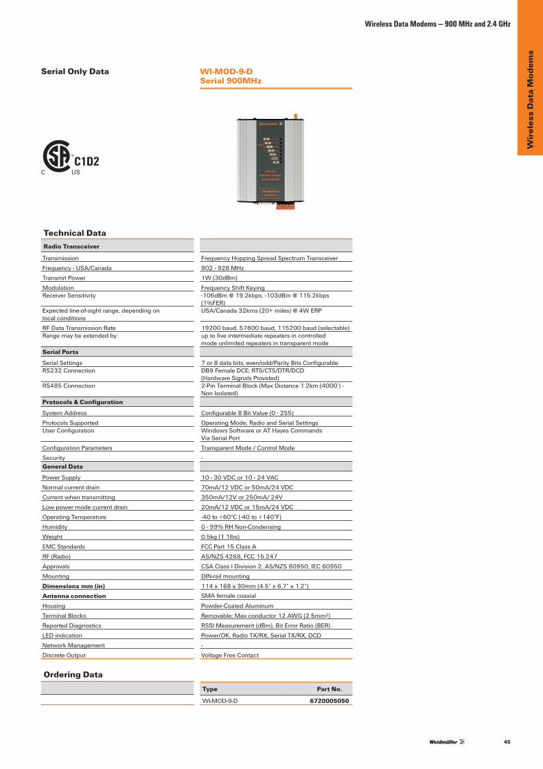
45
Wir
eles
s D
ata
Mod
ems
Wireless Data Modems — 900 MHz and 2.4 GHz
Technical DataRadio Transceiver
TransmissionFrequency-USA/CanadaTransmitPowerModulationReceiver Sensitivity
Expectedline-of-sightrange,dependingon local conditionsRFDataTransmissionRateRangemaybeextendedby:
Serial Ports
Serial SettingsRS232Connection
RS485 Connection
Protocols & Configuration
SystemAddressProtocolsSupportedUserConfiguration
ConfigurationParametersSecurityGeneral Data
PowerSupplyNormalcurrentdrainCurrent when transmittingLow power mode current drainOperating TemperatureHumidityWeightEMC StandardsRF (Radio)ApprovalsMountingDimensions mm (in)Antenna connectionHousingTerminalBlocksReportedDiagnosticsLEDindicationNetworkManagementDiscreteOutput
Ordering Data
WI-MOD-9-D Serial 900MHz
FrequencyHoppingSpreadSpectrumTransceiver902-928MHz1W(30dBm)[email protected],[email protected](1%FER)USA/Canada32kms(20+miles)@4WERP
19200baud,57600baud,115200baud(selectable)uptofiveintermediaterepeatersincontrolled mode unlimited repeaters in transparent mode
7or8databits,even/odd/ParityBitsConfigurableDB9FemaleDCE;RTS/CTS/DTR/DCD (HardwareSignalsProvided)2-PinTerminalBlock(MaxDistance1.2km(4000’)-NonIsolated)
Configurable8BitValue(0-255)OperatingMode,RadioandSerialSettingsWindowsSoftwareorATHayesCommands ViaSerialPortTransparent Mode / Control Mode-
10-30VDCor10-24VAC70mA/12VDCor50mA/24VDC350mA/12Vor250mA/24V20mA/12VDCor15mA/24VDC-40to+60°C(-40to+140°F)0-99%RHNon-Condensing0.5kg(1.1lbs)FCCPart15ClassAAS/NZS4268,FCC15.247CSAClassIDivision2,AS/NZS60950,IEC60950DIN-railmounting114x168x30mm(4.5”x6.7”x1.2”)SMAfemalecoaxial
Powder-CoatedAluminumRemovable;Maxconductor12AWG(2.5mm2)RSSIMeasurement(dBm),BitErrorRatio(BER)Power/OK,RadioTX/RX,SerialTX/RX,DCD-Voltage Free Contact
Type Part No.
WI-MOD-9-D 6720005050
C1D2C US
Serial Only Data
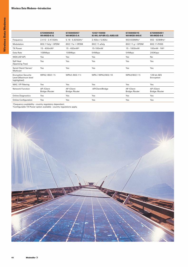
46
Wir
eles
s D
ata
Mod
ems
Wireless Data Modems—Introduction
6720005054WI-MOD-E-G
6720005057WI-MOD-E-A
1242110000IE-WL-AP-BR-CL-ABG-US
6720005015WI-MOD-945-E
6720005051WI-MOD-9-E
Frequency 2.412-2.472GHz 5.18-5.825GHz1 2.4Ghz / 5.8Ghz 902-928MHz1 902-928MHz1
Modulation 802.11b/g+OFDM 802.11a+OFDM 802.11a/b/g 802.11g+OFDM 802.11-FHSS
TXPower 15 - 400mW2 15 - 400mW2 15-100mW 15 - 1000mW 100mW - 1W2
DataRate 108Mbps 108Mbps 54Mbps 54Mbps 200Kbps
WDS(AP-AP) Yes Yes Yes Yes No
SelfHeal(Spanning Tree)
Yes Yes Yes Yes Yes
Serial Client/ Server/Multicast
Yes Yes Yes Yes Yes
Encryption Security Level (Maximum level highlighted)
WPA2/802.11i WPA2/802.11i WPA/WPA2/802.1X WPA2/802.11i 128bitAES Encryption
MAC/IPFiltering Yes Yes Yes Yes Yes
NetworkFunction AP/Client Bridge/Router
AP/Client Bridge/Router
AP/Client/Bridge AP/Client Bridge/Router
AP/Client Bridge/Router
OnlineDiagnostics Yes Yes Yes Yes Yes
OnlineConfiguration Yes Yes Yes Yes Yes
1Frequencyavailability-countryregulatorydependant. 2ConfigurableTXPoweroptionavailable-countryregulationsapply.

47
Wir
eles
s D
ata
Mod
ems
Wireless Data Modems — 900 MHz
C1D2C US
WI-MOD-9-E Serial and Ethernet 900Mhz (FHSS)
WI-MOD-945-E Serial and Ethernet 900MHz (DSSS)
Ethernet and Serial Data
Technical DataRadio TransceiverTransmissionFrequency-USA/CanadaTransmitPowerModulation
Receiver SensitivityChannel Spacing
RFDataTransmissionRate
Expectedline-of-sightrange,dependingonlocalconditions
Rangemaybeextendedby:
Ethernet/Serial PortEthernet
EmbeddedProtocols:
SerialRS232V.24DCE
RS485
Serial SettingsDataRate(Bps)
Protocols/ConfigurationSystemAddressProtocolssupported
Network/ConfigurableParameters
UserConfiguration
Security
BandwidthProtection
General DataAntennaconnection
Operating TemperatureHumidityPowerSupplyCurrentconsumptionIdle:Transmit:EMCRF (Radio)Approvals
MountingDimensions(LxWxH)mmWeightHousingMountingTerminalBlocksLEDindication
ReportedDiagnostics
Input/OutputConfigurableDI/DO/AI
Ordering Data
FrequencyHoppingSpreadSpectrumTransceiver902-928MHz0.1–1W(20–30dBm)configurableFrequencyShiftKeying
-108dBm@10-6BER16 x 50
19.2,57.6,115.2Kb/sorautorateselection
upto60miles/100kmline-of-sightusinghighgainantennas(*upto4WERPpermittedinUSA/Canada)Rangemaybeextendedusingrepeaterfeaturesuptofiveintermediaterepeatersincontrolledmodeunlimited repeaters in transparent mode
10/100baseT;AutoMDX Bridge/routerfunctionsworkwithallEthernetprotocolsTCP/IP,UDPARP,PPP,ICMP,HTTP,FTP,TFTP,TELNET
DB9FemaleDCE;RTS/CTS/DTR/DCD (HardwareSignalsProvided)2-PinTerminalBlock(ConfigurableTermination) Serialserver,PPP,ModbustoModbusTCPconversion7/8DataBits;Stop/Start/Parity(Configurable)1.2to115.2Kb/s
ESSID;1–31CharacterTextStringTCP/IP,UDP,ARP,Radius/802.1x,DHCP,DNS,PPP,ICMP,HTTP,FTP,TFTP,TELNET,MODBUS-RTUand MODBUS-TCPConfigurableasAccessPointorClient,BridgeorRouterPoint-to-point,Point-to-multipoint, userconfigurableaddressingRepeaterfunctionalityMACFiltering-whitelistorblacklist
RemoteAccess-Over-the-AirNetworkAccess-Ethernet
128bitAESencryption
MACAddress–Whitelist/BlacklistIPFiltering–Whitelist/Blacklist
SingleFemaleSMA50Ω
-40to60°C(-40to140°F)99% non-condensing9to30VDC;Under/OverVoltageProtection280mA(12V),150mA(24V)(1W)500mA(12V),300mA(24V)FCCCFR47Part15;EN301489-3;EN301489-5FCC15.247,RS210CSAClassIDivision2,AS/NZS60950,IEC60950
DIN-railmounting114x168x30mm(4.5”x6.7”x1.2”)<0.4kg/0.8lbPowder-CoatedAluminiumDIN-RailRemovable;Maxconductor12AWG(2.5mm2)Power/OK;RX;TX/Link;RS232;LAN;RS485;DigitalI/OSerialActivity,DigitalI/O,LAN10/100MbitLinkDiagnosticsavailablethroughwebpages
InputVoltage-FreeContactOutputFET30VDC500mA
Type Part No.
WI-MOD-9-E 6720005051
DirectSequenceSpreadSpectrum(DSSS)902–928MHz250mW(+24dBm)to1W(+30dBm)802.11gOrthogonalFrequencyData Modulation(OFDM)[email protected]@54Mbps(8%FER)9x1.25MHz;9x2.5MHz;4x5MHz; 4x10MHz;2x20MHz1–54Mbps “AutoMode”SelectsFastestRatePossible Relative to RSSI”6+miles@630mW/30Km(18mi.)@1W(*upto4WERPpermittedinUSA/Canada)RangemaybeextendedusingrepeaterfeaturesAbilitytoconstructcomplexnetworksusing multiplerepeatersandroamingfeatures
10/100BaseTRJ45,IEEE802.3compliant. Bridge/routerfunctionsworkwithallEthernetprotocolsTCP/IP,UDPARP,PPP,ICMP,HTTP,FTP,TFTP,TELNET, SNMP,RADIUS/802.1X,DHCP,OFDM
DB9FemaleDCE;RTS/CTS/DTR/DCD
2-PinTerminalBlock–Non-Isolated Serialserver,PPP,ModbustoModbusTCPconversion7/8DataBits;Stop/Start/Parity(Configurable)1200,2400,4800,9600,14400,19200,38400,57600,76800,115200,230400
ESSID;1–31CharacterTextStringTCP/IP,UDP,ARP,Radius/802.1x,DHCP,DNS,PPP,ICMP,HTTP,FTP,TFTP,TELNET,MODBUS-RTUand MODBUS-TCPAccessPoint/Client/Bridge/Router/VLANPoint-to-Point,Point-to-Multi-pointWirelessDistributionSystem(AP-APRepeater)ModbusTCP/RTUGatewaySerial Client/Server/MulticastSimultaneousRS232/485ConnectionEmbeddedModbusMaster/SlaveforI/OTransferUserConfigurableParametersvia HTTPSEmbeddedWebServer NetworkAccess-EthernetDataEncryption–802.11iwithCCMP128-bitAESSupportfor802.1xRadiusServerSecureHTTPProtocolMACAddress–Whitelist/BlacklistIPFiltering–Whitelist/BlacklistARP/GARPFiltering–Whitelist/Blacklist
2xFemaleSMAStandardPolarity50Ω Supports signal diversity or high-gain antenna-40to+60°C;-40to+140°F0–99%RHNon-condensing9to30VDC;Under/OverVoltageProtection270mA@12VDC;140mA@24VDC500mA@12V(+30dBm),250mA@24V(+30dBm)FCCPart15;EN301489–17;AS/NZSCISPR22EN300328;FCCPart15;RSS210CSAClassI,Division2;ATEX;IECExNAIIC;IEC60950(RoHSCompliant);cULusListed(pendingon1W)DIN-railmounting114x168x30mm(4.5”x6.7”x1.2”)0.5kg(1.1lb).Powder-CoatedAluminiumDIN-RailRemovable;MaxConductor12AWG(2.5mm2)Power/OK;RX;TX/Link;RS232;LAN;RS485;DigitalI/OSerialActivity,DigitalI/O,LAN10/100MbitLinkRSSIMeasurements(dBm)ConnectivityInformation/Statistics System Log FileInputVoltage-FreeContactOutputFET30VDC500mA
Type RF Power Part No.
WI-MOD-945-E 630mW 6720005015
WI-MOD-945-E-H 1W 6720005016

48
Wir
eles
s D
ata
Mod
ems
Wireless Data Modems — 2.4GHz/5.8GHz
WI-MOD-E-G Serial and Ethernet 2.4GHz
WI-MOD-E-A Serial and Ethernet 5.8GHz
Technical DataRadio TransceiverTransmissionFrequency-USA/CanadaTransmitPowerModulationReceiver SensitivityChannel SpacingRFDataTransmissionRate
Expectedline-of-sightrange,dependingonlocalconditionsRangemaybeextendedby:
Ethernet/Serial PortEthernet
EmbeddedProtocols:
SerialRS232V.24DCERS485
Serial SettingsDataRate(Bps)
Protocols/ConfigurationSystemAddressProtocolssupported
Network/ConfigurableParameters
UserConfiguration
Security
BandwidthProtection
General DataAntennaconnection
Operating TemperatureHumidityPowerSupplyCurrentconsumptionIdle:Transmit:EMCRF (Radio)Approvals
MountingDimensions(LxWxH)mmWeightHousingMountingTerminalBlocksLEDindication
ReportedDiagnostics
Input/OutputConfigurableDI/DO/AI
Ordering Data
DirectSequenceSpreadSpectrum(DSSS)2.412–2.472GHz15–400mW(datarateandcountry-specific)Orthogonalfrequencydatamodulation(OFDM)–100dBm@250kbps,74dBm@108Mbps(8%FER)5-MHzspacing(13channels,2.412–2.472GHz)1–108Mbps“AutoMode”selectsfastestratepossiblerelativetoRSSI6miles(10km)@400mWRangemaybeextendedusingrepeaterfeaturesAbilitytoconstructcomplexnetworksusingmultiplerepeatersandroamingfeatures
10/100BaseTRJ45,IEEE802.3compliant. Bridge/routerfunctionsworkwithallEthernetprotocolsTCP/IP,UDPARP,PPP,ICMP,HTTP,FTP,TFTP,TELNET, SNMP,RADIUS/802.1X,DHCP,OFDM
DB9FemaleDCE;RTS/CTS/DTR/DCD2-PinTerminalBlock–Non-Isolated Serialserver,PPP,ModbustoModbusTCPconversion7/8DataBits;Stop/Start/Parity(Configurable)1200,2400,4800,9600,14400,19200,38400,57600,76800,115200,230400
ESSID;1–31CharacterTextStringTCP/IP,UDP,ARP,Radius/802.1x,DHCP,DNS,PPP,ICMP,HTTP,FTP,TFTP,TELNET,MODBUS-RTUandMODBUS-TCPAccessPoint/Client/Bridge/Router/VLANPoint-to-Point,Point-to-Multi-pointWirelessDistributionSystem(AP-APRepeater)ModbusTCP/RTUGatewaySerial Client/Server/MulticastSimultaneousRS232/485ConnectionEmbeddedModbusMaster/SlaveforI/OTransferUserConfigurableParametersviaHTTPSEmbeddedWebServerNetworkAccess-EthernetDataEncryption–802.11iwithCCMP128-bitAESSupportfor802.1xRadiusServerSecureHTTPProtocolMACAddress–Whitelist/BlacklistIPFiltering–Whitelist/BlacklistARP/GARPFiltering–Whitelist/Blacklist
2xFemaleSMAStandardPolarity50ΩSupports signal diversity or high-gain antenna-40to60°C(-40to140°F)0-99%RHnon-condensing9to30VDC;Under/OverVoltageProtection270mA@12V(idle);140mA@24V(idle)470mA@12V(400mW),250mA@24V(400mW)FCCCFR47Part15;EN301489-3;EN301489-5FCC15.247,RS210CSAClassI,Division2;ATEX;IECExNAIIC;IEC60950(RoHSCompliant);cULusListedDIN-railmounting4.5"x5.5"x1.2"(114x140x30mm)1.0lb(0.45kg)Powder-CoatedAluminiumDIN-RailRemovable;Maxconductor12AWG(2.5mm2)Power/OK;RX;TX/Link;RS232;LAN;RS485;DigitalI/OSerialActivity,DigitalI/O,LAN10/100MbitLinkDiagnosticsavailablethroughwebpages
Input Voltage-Free Contact OutputFET30VDC500mA
Type Part No.
WI-MOD-E-G 6720005054
DirectSequenceSpreadSpectrum(DSSS)5.150–5.825GHz15–400mW(datarateandcountry-specific)Orthogonalfrequencydatamodulation(OFDM)-100dBm@250kbps,-74dBm@108Mbps(8%FER)20-MHzspacing(27channels,5.150–5.8GHz)6–108Mbps“AutoMode”selectsfastestratepossiblerelativetoRSSI3miles(5km)@400mWRangemaybeextendedusingrepeaterfeaturesAbilitytoconstructcomplexnetworksusingmultiplerepeatersandroamingfeatures
10/100BaseTRJ45,IEEE802.3compliant. Bridge/routerfunctionsworkwithallEthernetprotocolsTCP/IP,UDPARP,PPP,ICMP,HTTP,FTP,TFTP,TELNET, SNMP,RADIUS/802.1X,DHCP,OFDM
DB9FemaleDCE;RTS/CTS/DTR/DCD2-PinTerminalBlock–Non-Isolated Serialserver,PPP,ModbustoModbusTCPconversion7/8DataBits;Stop/Start/Parity(Configurable)1200,2400,4800,9600,14400,19200,38400,57600,76800,115200,230400
ESSID;1–31CharacterTextStringTCP/IP,UDP,ARP,Radius/802.1x,DHCP,DNS,PPP,ICMP,HTTP,FTP,TFTP,TELNET,MODBUS-RTUandMODBUS-TCPAccessPoint/Client/Bridge/Router/VLANPoint-to-Point,Point-to-Multi-pointWirelessDistributionSystem(AP-APRepeater)ModbusTCP/RTUGatewaySerial Client/Server/MulticastSimultaneousRS232/485ConnectionEmbeddedModbusMaster/SlaveforI/OTransferUserConfigurableParametersviaHTTPSEmbeddedWebServerNetworkAccess-EthernetDataEncryption–802.11iwithCCMP128-bitAESSupportfor802.1xRadiusServerSecureHTTPProtocolMACAddress–Whitelist/BlacklistIPFiltering–Whitelist/BlacklistARP/GARPFiltering–Whitelist/Blacklist
2xFemaleSMAStandardPolarity50ΩSupports signal diversity or high-gain antenna-40to+60°C;-40to+140°F0-99%RHNon-condensing9to30VDC;Under/OverVoltageProtection270mA@12VDC;140mA@24VDC470mA@12V(400mW),250mA@24V(400mW)FCCPart15;EN301489–17;AS/NZSCISPR22EN300328;FCCPart15;RSS210CSAClassI,Division2;ATEX;IECExNAIIC;IEC60950(RoHSCompliant);cULusListedDIN-railmounting4.5"x5.5"x1.2"(114x140x30mm)1.0lb(0.45kg)Powder-CoatedAluminiumDIN-RailRemovable;MaxConductor12AWG(2.5mm2)Power/OK;RX;TX/Link;RS232;LAN;RS485;DigitalI/OSerialActivity,DigitalI/O,LAN10/100MbitLinkRSSIMeasurements(dBm)ConnectivityInformation/Statistics System Log FileInput Voltage-Free ContactOutputFET30VDC500mA
Type Part No.
WI-MOD-E-A 6720005057
Ethernet and Serial Data
Wi-Fi
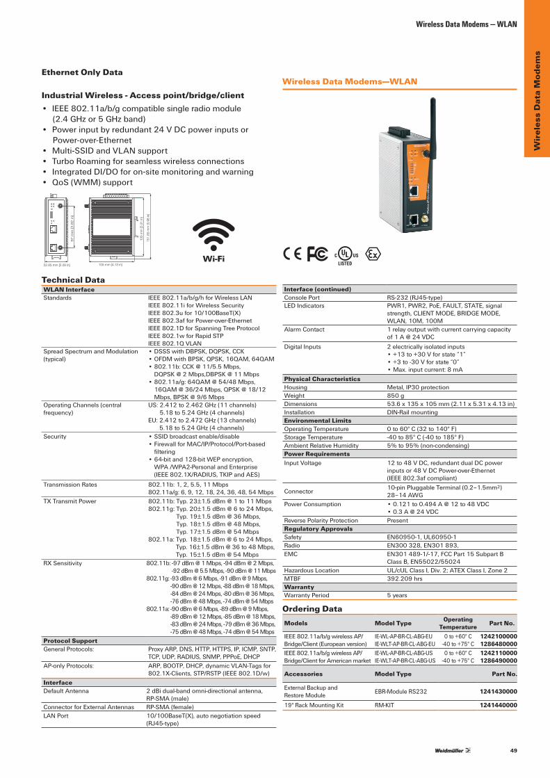
49
Wir
eles
s D
ata
Mod
ems
Wireless Data Modems — WLAN
• IEEE802.11a/b/gcompatiblesingleradiomodule (2.4GHzor5GHzband)
• Powerinputbyredundant24VDCpowerinputsorPower-over-Ethernet
• Multi-SSIDandVLANsupport• TurboRoamingforseamlesswirelessconnections• IntegratedDI/DOforon-sitemonitoringandwarning• QoS (WMM) support
WLAN InterfaceStandards IEEE802.11a/b/g/hforWirelessLAN
IEEE802.11iforWirelessSecurityIEEE802.3ufor10/100BaseT(X)IEEE802.3afforPower-over-EthernetIEEE802.1DforSpanningTreeProtocolIEEE802.1wforRapidSTPIEEE802.1QVLAN
Spread Spectrum and Modulation (typical)
•DSSSwithDBPSK,DQPSK,CCK•OFDMwithBPSK,QPSK,16QAM,64QAM•802.11b:CCK@11/5.5Mbps, DQPSK@2Mbps,DBPSK@11Mbps
•802.11a/g:64QAM@54/48Mbps,16QAM@36/24Mbps,QPSK@18/12Mbps,BPSK@9/6Mbps
Operating Channels (central frequency)
US:2.412to2.462GHz(11channels) 5.18to5.24GHz(4channels)
EU:2.412to2.472GHz(13channels) 5.18to5.24GHz(4channels)
Security •SSIDbroadcastenable/disable•FirewallforMAC/IP/Protocol/Port-basedfiltering
•64-bitand128-bitWEPencryption, WPA/WPA2-PersonalandEnterprise (IEEE802.1X/RADIUS,TKIPandAES)
Transmission Rates 802.11b:1,2,5.5,11Mbps802.11a/g:6,9,12,18,24,36,48,54Mbps
TXTransmitPower 802.11b:Typ.23±[email protected]:Typ.20±1.5dBm@6to24Mbps,
Typ.19±1.5dBm@36Mbps, Typ.18±1.5dBm@48Mbps, Typ.17±1.5dBm@54Mbps
802.11a:Typ.18±1.5dBm@6to24Mbps, Typ.16±1.5dBm@36to48Mbps, Typ.15±1.5dBm@54Mbps
RXSensitivity 802.11b:-97dBm@1Mbps,-94dBm@2Mbps, [email protected],-90dBm@11Mbps
802.11g:-93dBm@6Mbps,-91dBm@9Mbps, -90dBm@12Mbps,-88dBm@18Mbps, -84dBm@24Mbps,-80dBm@36Mbps, -76dBm@48Mbps,-74dBm@54Mbps
802.11a:-90dBm@6Mbps,-89dBm@9Mbps, -89dBm@12Mbps,-85dBm@18Mbps, -83dBm@24Mbps,-79dBm@36Mbps,-75dBm@48Mbps,-74dBm@54Mbps
Protocol SupportGeneralProtocols: ProxyARP,DNS,HTTP,HTTPS,IP,ICMP,SNTP,
TCP,UDP,RADIUS,SNMP,PPPoE,DHCPAP-onlyProtocols: ARP,BOOTP,DHCP,dynamicVLAN-Tagsfor
802.1X-Clients,STP/RSTP(IEEE802.1D/w)InterfaceDefaultAntenna 2dBidual-bandomni-directionalantenna,
RP-SMA(male)ConnectorforExternalAntennas RP-SMA(female)LANPort 10/100BaseT(X),autonegotiationspeed
(RJ45-type)
Interface (continued)ConsolePort RS-232(RJ45-type)LEDIndicators PWR1,PWR2,PoE,FAULT,STATE,signal
strength,CLIENTMODE,BRIDGEMODE,WLAN,10M,100M
AlarmContact 1 relay output with current carrying capacity of1A@24VDC
DigitalInputs 2 electrically isolated inputs•+13to+30Vforstate“1”•+3to-30Vforstate“0”•Max.inputcurrent:8mA
Physical CharacteristicsHousing Metal,IP30protectionWeight 850 gDimensions 53.6x135x105mm(2.11x5.31x4.13in)Installation DIN-RailmountingEnvironmental LimitsOperating Temperature 0to60°C(32to140°F)Storage Temperature -40to85°C(-40to185°F)AmbientRelativeHumidity 5% to 95% (non-condensing)Power RequirementsInput Voltage 12to48VDC,redundantdualDCpower
inputsor48VDCPower-over-Ethernet (IEEE802.3afcompliant)
Connector 10-pinPluggableTerminal(0.2–1.5mm2) 28–14AWG
PowerConsumption •0.121to0.494A@12to48VDC•0.3A@24VDC
ReversePolarityProtection PresentRegulatory ApprovalsSafety EN60950-1,UL60950-1Radio EN300328,EN301893,EMC EN301489-1/-17,FCCPart15SubpartB
ClassB,EN55022/55024HazardousLocation UL/cULClassI,Div.2;ATEXClassI,Zone2MTBF 392.209hrsWarrantyWarrantyPeriod 5 years
Ordering DataModels Model Type Operating
Temperature Part No.
IEEE802.11a/b/gwirelessAP/Bridge/Client(Europeanversion)
IE-WL-AP-BR-CL-ABG-EUIE-WLT-AP-BR-CL-ABG-EU
0to+60°C-40to+75°C
12421000001286480000
IEEE802.11a/b/gwirelessAP/Bridge/ClientforAmericanmarket
IE-WL-AP-BR-CL-ABG-USIE-WLT-AP-BR-CL-ABG-US
0to+60°C-40to+75°C
12421100001286490000
Accessories Model Type Part No.
ExternalBackupand Restore Module EBR-ModuleRS232 1241430000
19"RackMountingKit RM-KIT 1241440000
105 mm [4.13 in]
135
mm
[5.3
1 in
]
52.85 mm [2.08 in]
151,
85 m
m [5
.98
in]
97 m
m [3.8
2 in
]
% \ T
Technical Data
Industrial Wireless - Access point/bridge/clientWireless Data Modems—WLAN
Ethernet Only Data
Wi-Fi

50
Wir
eles
s D
ata
Mod
ems
Wireless Data Modems - Licensed FrequenciesLicensedfrequencieshavemanyadvantagesandareidealforindustrialapplications.TheWeidmullerproductofferspowerfullong-rangecommunicationstoextendEthernetnetworksindifficult-to-reachlocations.Flexibleoptionsavailablesupport360to512MHz(MHz)aswellas930to960MHz(60MHz)configurations,providinguserswithanintegratedandcompleteindustrialEthernetinfrastructuresolution.
The FCC (United Stated) and Industry Canada (Canada) has informationtohelpyouthroughthelicensingprocess.Youcanfindthebasicinformationyouneedtobegintheprocess.IfyouareengagedinPublicSafetyRadioActivities,youcangodirectlyto:
FCC:http://wireless.fcc.gov/publicsafetyIndustry Canada:http://www.ic.gc.ca/eic/site/sd-sd.nsf/eng/home
LicenseesintheIndustrial/BusinessRadioPoolareissuedtoradiouserstosupportbusinessoperations.Theircommunicationssystemsareusedforsupportofday-to-daybusinessactivities,suchasdispatching,AVLanddivertingpersonnelorworkvehicles,coordinatingtheactivitiesofworkersandmachinesonlocation,orremotelymonitoringand controlling equipment with data radio modems.
Applications •RemoteWellHeadMonitoring •PipelineLeakDetection •PLCNetworks • Environmental Monitoring • Water Treatment Facilities •MiningOperationsInfrastructure •TankFarmMonitoring
TheWeidmullerWirelessEthernetModemisarobust,licensedandlicense-freewirelesstransceivercapableofultra-long range communications.
Withmodelsoperatingat360to512MHzand930to960MHzupto5.0W,themodemsareoptimizedforthroughputsofupto19.2kbps.Thisprovidesrobustandsecure two-way wireless communications in extremely challengingoutdoorenvironments;overobstructedpathstypicalofremotemonitoringandcontrolapplications.
CapableofoperatinginAccessPoint/Clientconfiguration,functioningasanetworkBridge/Router,orservingasaSerialServer(RS232/485),thedevicesuseover-the-airdatacompression to ensure maximum throughput. Integrated Modbusservercapabilityallowsseamlessintegrationwithsmartsensors,RTU’sorI/OexpansionthroughtheuseofWI-I/O-EX-1-SExpansionmodules.
Features •10mW–5WRFPower •AccessPoint/ClientandBridge/RouterConfiguration •SpanningTree(SelfHealing)Support •DesignedforIndustrial,HighNoiseEnvironments •Over-The-AirNetworkDiagnosticsandConfiguration •VLANTaggingSupportedforBridgingand
Routing Modes •NetworkManagementCapabilities •FrequenciesConfiguredViaBuilt-InWebserver
Wireless Data Modems — Licensed Frequencies
Aging Infrastructure
Process Control
Movable Machinery
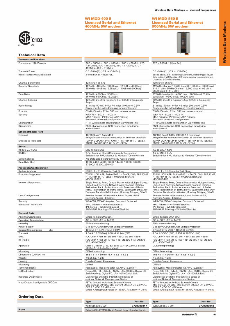
51
Wir
eles
s D
ata
Mod
ems
C1D2C US
WI-MOD-400-E Licensed Serial and Ethernet 400MHz 5W modem
WI-MOD-950-E Licensed Serial and Ethernet 900MHz 5W modem
Technical DataTransmitter/ReceiverFrequency-USA/Canada
TransmitPowerRadio Transceiver/Modulation
ChannelBandwidthReceiver Sensitivity
DataRates
Channel Spacing
Radio Range
ProtocolSecurity
ConfigurationDiagnostics
Ethernet/Serial PortEthernet
EmbeddedProtocols:
SerialRS232V.24DCERS485
Serial SettingsDataRate(Bps)
Protocols/ConfigurationSystemAddressProtocolsSupported
NetworkParameters
UserConfiguration
SecurityBandwidthProtection
General DataAntennaConnectionOperating TemperatureHumidityPowerSupplyCurrentConsumptionIdle:Transmit:EMCRF (Radio)
Approvals
MountingDimensions(LxWxH)mmWeightHousingMountingTerminalBlocksLEDIndication
ReportedDiagnostics
Input/OutputConfigurableDI/DO/AI
Ordering Data
Note
360–380MHz,380–400MHz,400–420MHz,420–440MHz,430–450MHz,450–470MHz,470–490MHz,490–512MHz0.5-5.0W(1)(+27to+37dBm)2-levelFSKor4-levelFSK
12.5kHz/25kHz12.5kHz:-100dBm(9600bps),-111dBm(4800bps)25.0kHz:-99dBm(19.2kbps),-110dBm(9600bps)
12.5kHz:4800bps,9600bps25.0kHz:9600bps,19.2kbps12.5kHz,25.0kHz(Supports5or6.25kHzFrequencySteps)31miles(50km)@5W/6miles(10km)@0.5W RangemaybeextendedusingrepeaterfeaturesCSMA/CAwith32bitCRCandauto-correctionWPAPSK-80211i-802.1x MACFiltering;IPFiltering;ARPFiltering PasswordprotectedconfigurationHTTPwithremoteconfigurationviawirelesslinkRSSI,channelnoise,BER,connectionmonitoring and statistics
10/100baseT;AutoMDX Bridge/routerfunctionsworkwithallEthernetprotocolsTCP/IP,UDPARP,PPP,ICMP,HTTP,FTP,TFTP,TELNET,SNMP,RADIUS/802.1X,DHCP,OFDM
DB9FemaleDCE2-PinTerminalBlock(ConfigurableTermination) Serialserver,PPP,ModbustoModbusTCPconversion7/8DataBits;Stop/Start/Parity(Configurable)1200,2400,4800,9600,14400,19200,38400, 57600,115200,230400
ESSID;1–31CharacterTextStringTCP/IP,UDP,ARP,Radius/802.1x,DHCP,DNS,PPP,ICMP,HTTP,FTP,TFTP,TELNET,MODBUS-RTUand MODBUS-TCPSinglePointtoPoint,CentralMasterwithMultipleSlaves,LargeFixedNetwork,NetworkwithRoamingStations,RedundantRadioPaths,AutomaticSelectionofRadioPaths,PrioritizationofTrafficFlows,BandwidthEfficiencyFeatures,BandwidthUtilization,Routing,Bridging,VLANRemoteAccess-Over-the-Air,LocalAccess-USB,NetworkAccess-EthernetWPA-PSK,WPA-Enterprise,PasswordProtectedMACAddress–Whitelist/Blacklist IPFiltering–Whitelist/Blacklist ARP/GARPFiltering–Whitelist/Blacklist
SingleFemaleSMA50Ω-30to60°C(-20to140°F)99% non-condensing9to30VDC;Under/[email protected];[email protected]@13.8V(5W);650mA@24V(5W)FCCCFR47Part15;EN301489-3;EN301489-5FCCCFR47Part90;ICRSS119;EN300113;EN300220;AS/NZS4295ClassI,Division2;IECEXZone2;ATEXZone2;EN/IEC60950-1;ULListed(pending)DIN-railmounting168x114x30mm(6.7”x4.5”x1.2”)<0.55kg/1.2lbPowder-CoatedAluminiumDIN-railRemovable;Maxconductor12AWG(2.5mm2)Power/OK;RX;TX/Link;RS232;LAN;RS485;DigitalI/O SerialActivity,DigitalI/O,LAN10/100MbitLinkDiagnosticsavailablethroughwebpagesoroptionalNetworkManagementSystemFETtoGroundtoActivateExternalCircuitsMaxVoltage30VDC,MaxCurrent500mAON2.0VDC, OFF3.0VDC,30VDCmax;SingleAnalogInputRange0-25mA,Accuracy+/-0.5%
Type Part No.
WI-MOD-400-E-5W 6720005017
Default450–470MHzBand.Consultfactoryforotherbands.
928–960MHz(UserSet)
0.5-5.0W(1)(+27to+37dBm)Basedon802.11MeshingStandard,operatingatlowerdatarates.HalfDuplexUHFradiosupportsoperationonLicensed900MHzbands.12.5kHz/25kHz12.5kHzChannel19,200baud@-100dBm;9600baud@-111dBm25kHzChannel19,200baud@-99dBm;[email protected],9600baud25kHzbandwidth-9600baud,19,200baud12.5kHz,25.0kHz(Supports5or6.25kHzFrequencySteps)31miles(50km)@5W/6miles(10km)@0.5W RangemaybeextendedusingrepeaterfeaturesCSMA/CAwith32bitCRCandauto-correctionWPAPSK-80211i-802.1x MACFiltering;IPFiltering;ARPFiltering PasswordprotectedconfigurationHTTPwithremoteconfigurationviawirelesslinkRSSI,channelnoise,BER,connectionmonitoring and statistics
10/100BaseTRJ45,IEEE802.3compliant. Bridge/routerfunctionsworkwithallEthernetprotocolsTCP/IP,UDPARP,PPP,ICMP,HTTP,FTP,TFTP,TELNET,SNMP,RADIUS/802.1X,DHCP,OFDM
1.2to230.4Kb/s1.2to230.4Kb/s Serialserver,PPP,ModbustoModbusTCPconversion
ESSID;1–31CharacterTextStringTCP/IP,UDP,ARP,Radius/802.1x,DHCP,DNS,PPP,ICMP,HTTP,FTP,TFTP,TELNET,MODBUS-RTUand MODBUS-TCPSinglePointtoPoint,CentralMasterwithMultipleSlaves,LargeFixedNetwork,NetworkwithRoamingStations,RedundantRadioPaths,AutomaticSelectionofRadioPaths,PrioritizationofTrafficFlows,BandwidthEfficiencyFeatures,BandwidthUtilization,Routing,Bridging,VLANRemoteAccess-Over-the-Air,LocalAccess-USB,NetworkAccess-EthernetWPA-PSK,WPA-Enterprise,PasswordProtectedMACAddress–Whitelist/BlacklistIPFiltering–Whitelist/BlacklistARP/GARPFiltering–Whitelist/Blacklist
SingleFemaleSMA50Ω-30to60°C(-20to140°F)99% non-condensing9to30VDC;Under/OverVoltageProtection270mA@12VDC;[email protected]@9VDC(5W);0.75A@30VDC(5W)FCCCFR47Part15;EN301489-3;EN301489-5FCCCFR47Part90;ICRSS119;EN300113;EN300220;AS/NZS4295UL Listed (pending)
DIN-railmounting168x114x30mm(6.7”x4.5”x1.2”)<0.55kg/1.2lbPowder-CoatedAluminiumDIN-railRemovable;Maxconductor12AWG(2.5mm2)Power/OK;RX;TX/Link;RS232;LAN;RS485;DigitalI/O SerialActivity,DigitalI/O,LAN10/100MbitLinkDiagnosticsavailablethroughwebpagesoroptionalNetworkManagementSystemFETtoGroundtoActivateExternalCircuitsMaxVoltage30VDC,MaxCurrent500mAON2.0VDC, OFF3.0VDC,30VDCmax;SingleAnalogInputRange0-25mA,Accuracy+/-0.5%
Type Part No.
WI-MOD-950-E-5W 6720005018
Wireless Data Modems — Licensed Frequencies
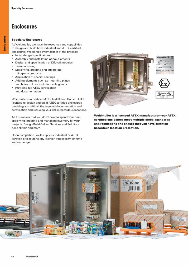
52
Encl
osur
esSpecialty Enclosures
Weidmuller is a licensed ATEX manufacturer—our ATEX certified enclosures meet multiple global standards and regulations and ensure that you have certified hazardous location protection.
T
Specialty EnclosuresAtWeidmuller,wehavetheresourcesandcapabilitiestodesignandbuildbothindustrialandATEXcertifiedenclosures.Wehandleeveryaspectoftheprocess:• Initialdesignspecifications• Assemblyandinstallationofboxelements• DesignandspecificationofDIN-railmodules• Terminal wiring• Specifying,orderingandintegrating
third-party products• Applicationofspecialcoatings• Addingelementssuchasmountingplates
andholesorknockoutsforcableglands• ProvidingfullATEXcertification
and documentation
WeidmullerisaCertifiedATEXInstallationHouse—ATEXlicensedtodesignandbuildATEXcertifiedenclosures,providing you with all the required documentation and certificationandreducingyourriskinhazardouslocations.
Allthismeansthatyoudon’thavetospendyourtimespecifying,orderingandmanaginginventoryforyourprojects.Design-Build-DeliverServicesandSolutions does all this and more.
Uponcompletion,we’llshipyourindustrialorATEXcertifiedenclosuretoanylocationyouspecify–ontime andonbudget.
Enclosures

53
Encl
osur
es
Pre-configured Wireless Enclosures
Ordering Data Part No. WirelessEthernetEnclosure–StainlessSteelSolution 6760004616Dimensionsmm/in(hxwxd) 458x382x205/18.03x15.04x8.07
Ordering Data Part No.WirelessEthernetEnclosure-PlasticSolution 6760004617Dimensionsmm/in(hxwxd) 356x305x212/14.02x12.01x8.35
TheEthernetsolutionisavailableinbotha stainless steel or plastic enclosure and featuresaWeidmullerwirelessEthernet(WiFi)2.4Ghzmodem,whichcanfunctionasanaccesspoint,bridge,clientorrouter.
Inadditiontothemodemtechnology,the enclosure comes complete with the followingcomponents:powersupply,circuitprotection,surgeprotection,terminalblocks,groundblocks,antenna,antennaconnectioncablesandthroughpanel cableglands.
Thiscomplete,preassembledsolutionprovidesallthenecessaryelementsforaremote wireless Ethernet installation.
Pre-configured Wireless EnclosuresWeidmullerispleasedtoofferthree pre-configuredandassembledWirelessEnclosure Solutions. These three wirelessenclosuresfeatureplasticormetal enclosures with either Wireless Ethernet Modems or Radio Frequency (RF) Transmitters/Receivers. Just connect power and your signals and you are wireless!
Features:• NEMA4XStainlessSteelEnclosure• 2.4GHz(WiFi)WirelessEthernetmodem• OperateasaClient/Bridge/AccessPoint/Router
with a 400mW transmit power• BuiltinSecurity/EncryptionincludingAES
andWEPwithmatchingantennaandallcabling• Assembled,wiredandtested!• Surge protection included• Transmitrangeupto3mileswithappropriateantenna• Datatransmissionratesupto54Mbps
Features:• NEMA4XPlasticEnclosure• 2.4GHz(WiFi)WirelessEthernetmodem• OperateasaClient/Bridge/AccessPoint/Router
with a 400mW transmit power• BuiltinSecurity/EncryptionincludingAES
andWEPwithmatchingantennaandallcabling• Assembled,wiredandtested!• Surge protection included• Transmitrangeupto3mileswithappropriateantenna• Datatransmissionratesupto54Mbps

54
Encl
osur
esPre-configured Wireless Enclosures
Ordering Data Part No.WirelessI/O900MHz-PlasticSolution 6760004618Dimensionsmm/in(hxwxd) 307x256x162/12.08x10.09x6.38
TheI/Oversioniscomprisedoftwopre-assembledplasticenclosures.Eachenclosurecontainsapowersupply,circuitprotection,surgeprotection,antenna,antennaconnectioncablesandterminalblocks.
Inadditiontothesecomponents,oneenclosurehouses a transmitter and the second enclosure houses a receiver. The transmitter and receiver operateon900MhzradiobandsandarepreconfiguredtosendandreceivemultipleI/O signals. The I/O solution can transmit and receive two digital signals and one analog signaloverarangeofseveralmiles.
Thisself-containedsolutionisdesignedforquickandeasyset-up.Thepre-installedterminalsmakeI/Oandpowerconnectionsfastandeasy,for“outofthebox”operation.
Features:• Twopre-assembledNEMA4xPlasticEnclosuresand
FullIP67Ingressprotection• 900MHz(FrequencyHopping)Transmitterand
Receiver with a 1W transmit power• PreconfiguredandmappedI/O
withmatchingantennaandallcabling• Surge protection included• Cableglandsincludedforsignalandpoweraccess• Assembled,wiredandtested!• Transmit range up to 20 miles with appropriate antenna• Transmitter accepts up to 1 analog and 2 digital intputs• Receiver accepts up to 1 analog and 2 digital outputs

55
Cel
lula
r – R
oute
rs
Typical Applications:• NetworkingWindTurbinesandSolarCollectors• ElectricityNetworkControl• TankFarmMonitoring• WaterDistributionNetwork• Environmental Monitoring
Applications for cellular routers are not designed for just one vertical market
Features Benefits
5BandMulticarrierCellularModem Speedsofupto21MbpsReceiverAntennaDiversity WeakSignalStrengthislessofanissueIntegratedVPNCapability Monitoring&ControlofCommunicationsIPsec&GRETunneling Ensures Secure TransmissionBuilt-inDHCPServer&PortForwarding SimplifiesNetworkingDualEthernetports AddsflexibilityOvertheAirNetworkDiagnostics&Configuration OptimizesOperationalPerformance
Connection of Communications NetworksMaximum security with the Industrial Ethernet RouterCommunicationnetworksusedforofficeapplicationsandforautomationareconverging.Theadvantagesthatresultfromthisprocessareputintopracticemoreandmorefrequentlybecausetheymakeproceduresmoretransparentandfacilitatedataexchangesubstantially.
Weidmuller’s Industrial Ethernet Router ensures that differentnetworksinteroperateinunisonandwithtop-level security.
Application example:Well maintenance and real time data collection. Cellulartomainoffice;WiFiconnectionlocallybetweenwells.
Secure Industrial Cellular Routers
CDMA Network
GSM Network
Internet
Plant Data Network
Control Center
Data Collection
Data Collection
Remote Pump StationPrimary CarrierSecondary Carrier
Cellular to operationscenter through theInternet
RTU via serial and electronicvalve control via WiFi with Weidmuller modems. Both arecellular to tower
RTU via serial and electronic valvecontrol via WiFi with Weidmullermodems. Both are cellular to tower
Two controls connected viaEthernet Weidmuller 4GRouter
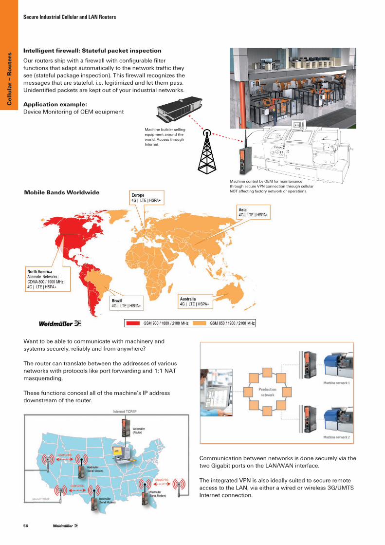
56
Cel
lula
r – R
oute
rs
Intelligent firewall: Stateful packet inspectionOurroutersshipwithafirewallwithconfigurablefilterfunctionsthatadaptautomaticallytothenetworktraffictheysee(statefulpackageinspection).Thisfirewallrecognizesthemessagesthatarestateful,i.e.legitimizedandletthempass.Unidentifiedpacketsarekeptoutofyourindustrialnetworks.
Application example:DeviceMonitoringofOEMequipment
Secure Industrial Cellular and LAN Routers
Wanttobeabletocommunicatewithmachineryand systemssecurely,reliablyandfromanywhere?
Theroutercantranslatebetweentheaddressesofvarious networkswithprotocolslikeportforwardingand1:1NAT masquerading.
Thesefunctionsconcealallofthemachine’sIPaddressdownstreamoftherouter.
CommunicationbetweennetworksisdonesecurelyviathetwoGigabitportsontheLAN/WANinterface.
TheintegratedVPNisalsoideallysuitedtosecureremoteaccesstotheLAN,viaeitherawiredorwireless3G/UMTSInternet connection.
Mobile Bands Worldwide
Machine control by OEM for maintenancethrough secure VPN connection through cellularNOT affecting factory network or operations.
Machine builder sellingequipment around theworld. Access throughInternet.

57
Cel
lula
r – R
oute
rs
• 2Gigabitports(LAN/WAN)• Integratedfirewall• NATmasquerading,1:1networkmappingandport
forwarding• RemoteaccessviaVPN(OpenVPN,IPsec,L2TP)• Keyswitchfunctionforactivation/deactivationofWAN/
VPNconnection• Variantwithintegrated3G/UMTSmodemforrapid,
Internet-basedwirelessaccess• Back-upandrecoveryofdeviceconfigurationusing
SIM card• FullLayer2/3Router
Gigabit Industrial Security Router
Technical dataModesIP-Router Staticordynamicrouting,supportingRIPv2/OSPFTransparentBridge 2-portswitchwithadditionallayer-2filterNetwork Services
•DHCPserver/DHCPrelay•DNSrelay•NTPclient•DynDNS(DHCPclientbyRFC2136)
Firewall•IPv4StatefulinspectionFirewall(incoming/outgoing)•NAT-Masquerading,1:1NAT,Portforwarding•Layer-2/3-Filter(VLANID,VLAN,QoStag, MACaddress,Ethertypeframe)
•“Autolearning”featuretocreatepacketfilterrules (analysisofnetworktraffic)
•Layer2/3-basedpacketprioritization (Ethernetframe,IPheader,VLANtag)
VPN
OpenVPN
•ConfigurableasOpenVPNserverorclient (Layer2andLayer3)
•AuthenticationwithX.509Certificates•TunnelsupportviaHTTPproxy•Maximumof10differentclientorserverconfigurations•Unlimitednumberofclientconnectionsinservermode
IPsec
•CanbeconfiguredasanIPsecserverorclient•PSKauthentication(userID,password) orX.509certificates
•Hardware-basedencryptionforfasterdatathroughput•Amaximumof64simultaneousconnections (subnettosubnetorasanIPsecserver)
• Encryption algorithms DES-56,3DES-168,AES128,AES192,AES-256
Management•ConfigurationviaWEBinterface(HTTP/HTTPS)•WebinterfaceinGermanorEnglish•Configurationsupportthroughdetailedhelp information(tooltip)
•Configurablemulti-useraccesswithdefinablerightsmask•SupportofSNMPv1/v2/v3,eventlog/syslog
Other
Modbus/TCP IntegratedModbusTCPServerforstatusqueries,and software-basedactivation/de-activationofVPNconnections
Diagnosis “RemoteCapture”featurefornetworkdiagnosticsviaa connectedPC(Wireshark)
Monitoring ClientMonitoring(viaICMP)withalarmfunction incaseoferror
InterfacesRJ45 ports 2x10/100/1000BaseT(X)USBport Optionforfutureexpansion
SCM card reader Saveandrestoreoftheconfigurationusingasmartcard (memory chip)
LEDindicators Signalingstatesforpower,status,cut,alert,activeVPNconnection and an active UMTS connection
Digitaloutputs
•“Alarm”—>Indicatesaconfigurablenetworkstatusorerror (24 V out)
•“VPN-active”—>IndicatesanactiveVPNconnection (24 V out)
Interfaces (continued)
Digitalinputs
• “Cut” —>Disconnectsphysically(linkdown)theWAN port (24 V)
•“VPN-initiate”—>Enablesapre-configuredVPN connection (24 V)
Resetbutton RestoringthefactorydefaultPower requirementsInput Voltage 1x24VDC(7to36volts)Current consumption max.600mA@24VDCTechnical data (housing)Housing Metal,IP30protection
Dimensions(WxHxD) 35x159x134mm(withoutantenna) 35x255x134mm(withUMTSSMAfemaleantenna)
Installation TS35Environmental LimitsOperating temperature –20°Cto+70°CStorage Temperature –20°Cto+85°CAmbienthumidity 6 to 90 % not condensingDSL and UMTS/HSPA
DSL ConnectiontotheDSLmodemviaLANorWANportFreeconfigurationofthePPPoElogin
DynDNS Support automatic registration
UMTS/3G
•Built-inquad-bandUMTS/HSPAmodem (onlyvariantIE-SR-2GT-UMTS/3G)
•21.1Mbpspeakdownlink,uplink5.8Mbpspeak•WCDMA850/1900/2100MHz GSM/GPRS/EDGE850/900/1800/1900MHz
•FCC,IC,CE,GCF,PTCRB,A-Tick,AT&T,Telstra,NTT, DoCoMo,Softbank,Bell
ApprovalsSecurity cULus Listed
EMCFCCPart15ClassA,EN55022ClassA,EN61000-4-2(ESD),EN61000-4-3(RS)EN61000-4-4(EFT),EN61000-4-5(Surge),EN61000-4-6(CS)
Shock DINEN60068-2-27Vibration DINEN60068-2-6WarrantyWarrantyPeriod 3years
Ordering dataModels Type Part No.LAN/WANrouter IE-SR-2GT-LAN 1345270000LAN/WANrouterwithintegratedUMTS/3Gmodem IE-SR-2GT-UMTS/3G 1345250000
Secure Cellular and LAN Routers
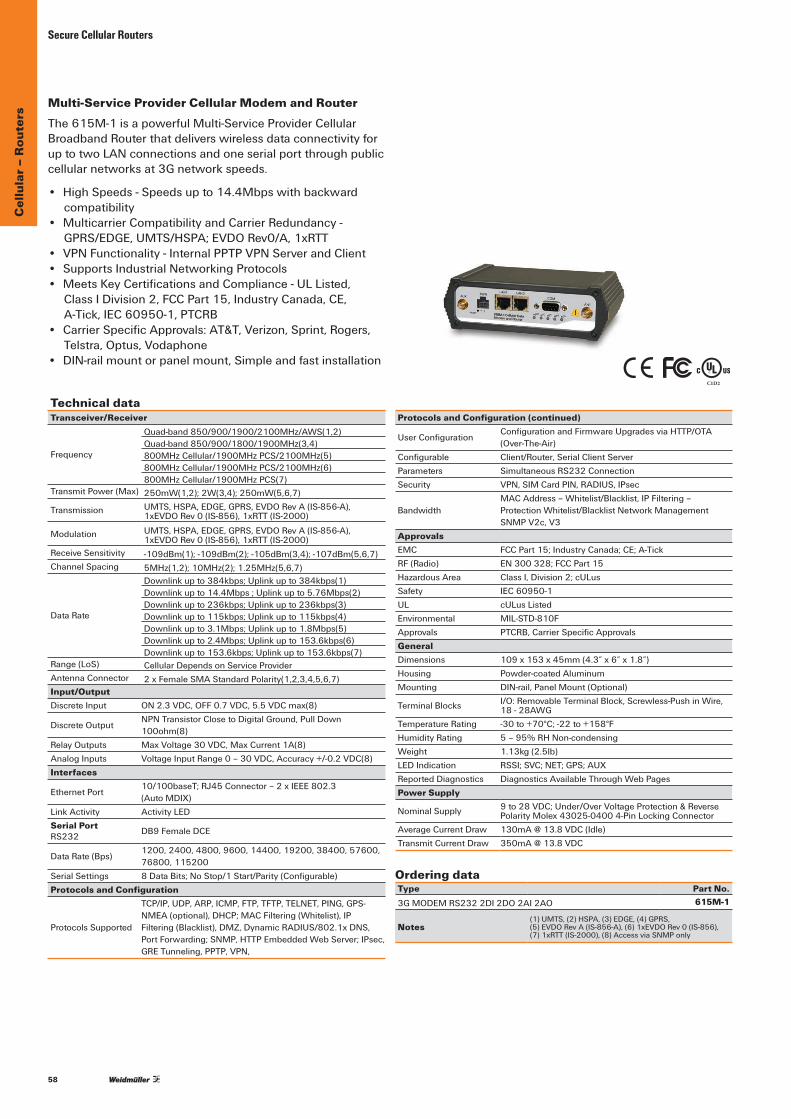
58
Secure Cellular Routers
Ordering dataType Part No.3GMODEMRS2322DI2DO2AI2AO 615M-1
Notes(1)UMTS,(2)HSPA,(3)EDGE,(4)GPRS,(5)EVDORevA(IS-856-A),(6)1xEVDORev0(IS-856), (7)1xRTT(IS-2000),(8)AccessviaSNMPonly
The615M-1isapowerfulMulti-ServiceProviderCellularBroadbandRouterthatdeliverswirelessdataconnectivityforuptotwoLANconnectionsandoneserialportthroughpubliccellularnetworksat3Gnetworkspeeds.
• HighSpeeds-Speedsupto14.4Mbpswithbackwardcompatibility
• MulticarrierCompatibilityandCarrierRedundancy- GPRS/EDGE,UMTS/HSPA;EVDORev0/A,1xRTT
• VPNFunctionality-InternalPPTPVPNServerandClient• SupportsIndustrialNetworkingProtocols• MeetsKeyCertificationsandCompliance-ULListed,
ClassIDivision2,FCCPart15,IndustryCanada,CE,A-Tick,IEC60950-1,PTCRB
• CarrierSpecificApprovals:AT&T,Verizon,Sprint,Rogers,Telstra,Optus,Vodaphone
• DIN-railmountorpanelmount,Simpleandfastinstallation
Multi-Service Provider Cellular Modem and Router
Technical dataTransceiver/Receiver
Frequency
Quad-band850/900/1900/2100MHz/AWS(1,2)Quad-band850/900/1800/1900MHz(3,4)800MHzCellular/1900MHzPCS/2100MHz(5)800MHzCellular/1900MHzPCS/2100MHz(6)800MHzCellular/1900MHzPCS(7)
TransmitPower(Max) 250mW(1,2);2W(3,4);250mW(5,6,7)
Transmission UMTS,HSPA,EDGE,GPRS,EVDORevA(IS-856-A),1xEVDORev0(IS-856),1xRTT(IS-2000)
Modulation UMTS,HSPA,EDGE,GPRS,EVDORevA(IS-856-A),1xEVDORev0(IS-856),1xRTT(IS-2000)
Receive Sensitivity -109dBm(1);-109dBm(2);-105dBm(3,4);-107dBm(5,6,7)Channel Spacing 5MHz(1,2);10MHz(2);1.25MHz(5,6,7)
DataRate
Downlinkupto384kbps;Uplinkupto384kbps(1)Downlinkupto14.4Mbps;Uplinkupto5.76Mbps(2)Downlinkupto236kbps;Uplinkupto236kbps(3)Downlinkupto115kbps;Uplinkupto115kbps(4)Downlinkupto3.1Mbps;Uplinkupto1.8Mbps(5)Downlinkupto2.4Mbps;Uplinkupto153.6kbps(6)Downlinkupto153.6kbps;Uplinkupto153.6kbps(7)
Range (LoS) CellularDependsonServiceProviderAntennaConnector 2xFemaleSMAStandardPolarity(1,2,3,4,5,6,7)Input/OutputDiscreteInput ON2.3VDC,OFF0.7VDC,5.5VDCmax(8)
DiscreteOutputNPNTransistorClosetoDigitalGround,PullDown100ohm(8)
Relay Outputs MaxVoltage30VDC,MaxCurrent1A(8)AnalogInputs VoltageInputRange0–30VDC,Accuracy+/-0.2VDC(8)Interfaces
EthernetPort10/100baseT;RJ45Connector–2xIEEE802.3 (AutoMDIX)
LinkActivity ActivityLEDSerial Port RS232 DB9FemaleDCE
DataRate(Bps)1200,2400,4800,9600,14400,19200,38400,57600,76800,115200
Serial Settings 8DataBits;NoStop/1Start/Parity(Configurable)Protocols and Configuration
ProtocolsSupported
TCP/IP,UDP,ARP,ICMP,FTP,TFTP,TELNET,PING,GPS-NMEA(optional),DHCP;MACFiltering(Whitelist),IPFiltering(Blacklist),DMZ,DynamicRADIUS/802.1xDNS,PortForwarding;SNMP,HTTPEmbeddedWebServer;IPsec,GRETunneling,PPTP,VPN,
Protocols and Configuration (continued)
UserConfigurationConfigurationandFirmwareUpgradesviaHTTP/OTA (Over-The-Air)
Configurable Client/Router,SerialClientServerParameters SimultaneousRS232ConnectionSecurity VPN,SIMCardPIN,RADIUS,IPsec
BandwidthMACAddress–Whitelist/Blacklist,IPFiltering–ProtectionWhitelist/BlacklistNetworkManagementSNMPV2c,V3
ApprovalsEMC FCCPart15;IndustryCanada;CE;A-TickRF (Radio) EN300328;FCCPart15HazardousArea ClassI,Division2;cULusSafety IEC 60950-1 UL cULus Listed Environmental MIL-STD-810FApprovals PTCRB,CarrierSpecificApprovalsGeneralDimensions 109x153x45mm(4.3”x6”x1.8”)Housing Powder-coatedAluminumMounting DIN-rail,PanelMount(Optional)
TerminalBlocks I/O:RemovableTerminalBlock,Screwless-PushinWire, 18-28AWG
Temperature Rating -30to+70°C;-22to+158°FHumidityRating 5–95%RHNon-condensingWeight 1.13kg(2.5lb)LEDIndication RSSI;SVC;NET;GPS;AUXReportedDiagnostics DiagnosticsAvailableThroughWebPagesPower Supply
NominalSupply 9to28VDC;Under/OverVoltageProtection&Reverse PolarityMolex43025-04004-PinLockingConnector
AverageCurrentDraw [email protected](Idle)TransmitCurrentDraw [email protected]
C1D2
Cel
lula
r – R
oute
rs

59
Cel
lula
r – R
oute
rs
• 2Gigabitports(LAN/WAN)• Integratedfirewall• NATmasquerading,1:1networkmappingand
portforwarding• Keyswitchfunctionforactivation/deactivationof
WAN/VPNconnection• Back-upandrecoveryofdeviceconfigurationusing
SIM card• FullLayer2/3Router
Gigabit Industrial Security Router
Technical dataModesIP-Router Staticordynamicrouting,supportingRIPv2/OSPFTransparentBridge 2-portswitchwithadditionallayer-2filterNetwork Services
•DHCPserver/DHCPrelay•DNSrelay•NTPclient•DynDNS(DHCPclientbyRFC2136)
Firewall•IPv4StatefulinspectionFirewall(incoming/outgoing)•NAT-Masquerading,1:1NAT,Portforwarding•Layer-2/3-Filter(VLANID,VLAN,QoStag, MACaddress,Ethertypeframe)
•“Autolearning”featuretocreatepacketfilterrules (analysisofnetworktraffic)
•Layer2/3-basedpacketprioritization (Ethernetframe,IPheader,VLANtag)
Management•ConfigurationviaWEBinterface(HTTP/HTTPS)•WebinterfaceinGermanorEnglish•Configurationsupportthroughdetailedhelpinformation
(tooltip) •Configurablemulti-useraccesswithdefinablerightsmask•SupportofSNMPv1/v2/v3,eventlog/syslog
OtherModbus/TCP IntegratedModbusTCPServerforstatusqueries
Diagnosis “RemoteCapture”featurefornetworkdiagnosticsviaa connectedPC(Wireshark)
Monitoring ClientMonitoring(viaICMP)withalarmfunction incaseoferror
InterfacesRJ45 ports 2x10/100/1000BaseT(X)USBport Optionforfutureexpansion
SCM card reader Saveandrestoreoftheconfigurationusingasmartcard (memory chip)
LEDindicators Signalingstatesforpower,status,cut,alert,activeVPNconnection and an active UMTS connection
Digitaloutputs “Alarm”—>Indicatesaconfigurablenetworkstatusor error (24 V out)
Digitalinputs “Cut” —>Disconnectsphysically(linkdown)the WANport(24V)
Resetbutton Restoringthefactorydefault
Power requirementsInput Voltage 1x24VDC(7to36volts)Current consumption max.600mA@24VDCTechnical data (housing)Housing Metal,IP30protection
Dimensions(WxHxD) 35x159x134mm(withoutantenna) 35x255x134mm(withUMTSantenna)
Installation TS35Physical DimensionsHousing Metal,IP30protectionDimensions(WxHxD) 35x159x134mmInstallation TS35Environmental LimitsOperating Temperature –20°Cto+70°CStorage Temperature –20°Cto+85°CAmbientHumidity 6 to 90 % not condensing
DSLConnectiontotheDSLmodemviaLANorWANportFreeconfigurationofthePPPoElogin
DynDNS Support automatic registrationApprovalsSecurity cULus Listed
EMCFCCPart15ClassA,EN55022ClassA, EN61000-4-2(ESD),EN61000-4-3(RS)EN61000-4-4(EFT),EN61000-4-5(Surge),EN61000-4-6(CS)
Shock DINEN60068-2-27Vibration DINEN60068-2-6WarrantyWarrantyPeriod 3yearsMTBF 135,270hrs
Ordering dataModels Type Part No.LAN/WANrouter (FirewallandNATOnly) IE-SR-2GT-FN 1489940000
Secure LAN Routers
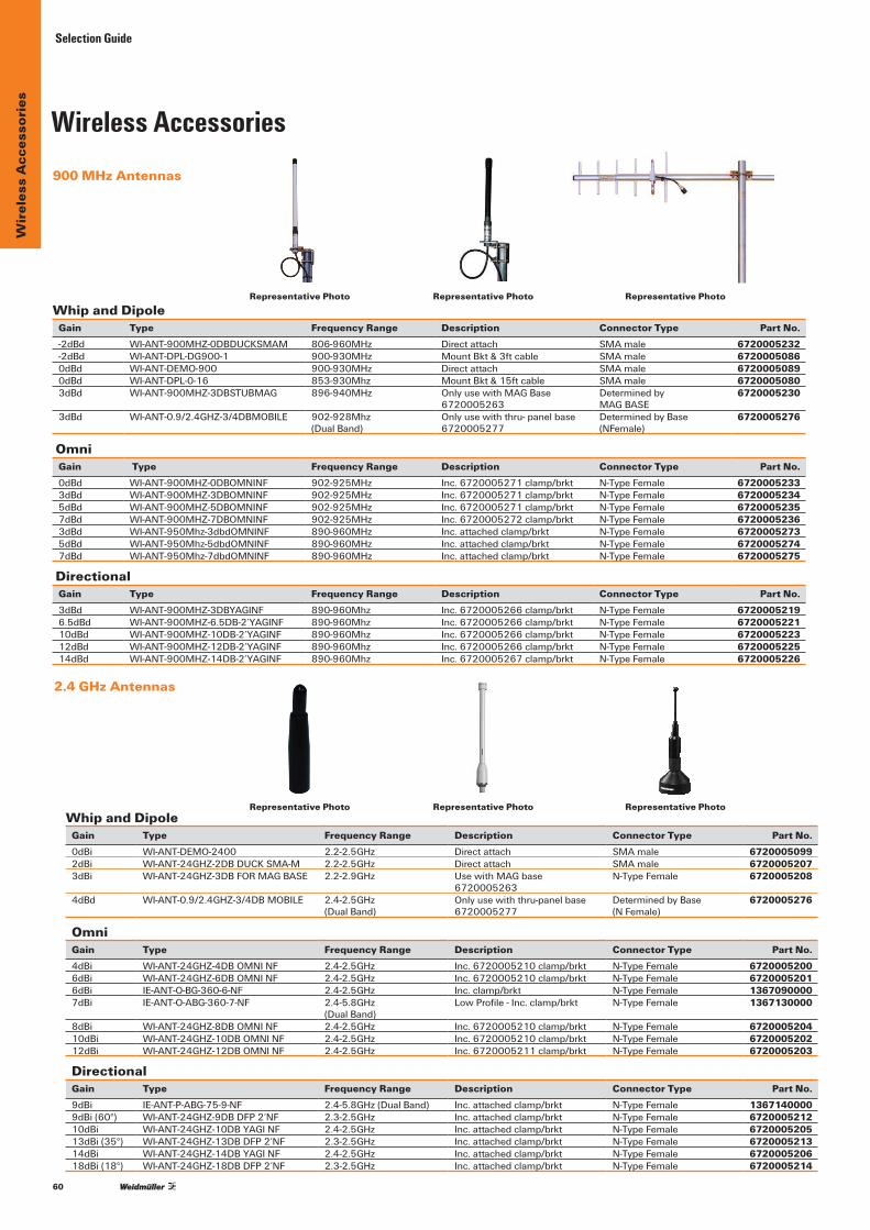
60
Wir
eles
s A
cces
sori
es Selection Guide
900 MHz Antennas
2.4 GHz Antennas
Whip and DipoleGain Type Frequency Range Description Connector Type Part No. -2dBd WI-ANT-900MHZ-0DBDUCKSMAM 806-960MHz Directattach SMAmale 6720005232 -2dBd WI-ANT-DPL-DG900-1 900-930MHz MountBkt&3ftcable SMAmale 6720005086 0dBd WI-ANT-DEMO-900 900-930MHz Directattach SMAmale 6720005089 0dBd WI-ANT-DPL-0-16 853-930Mhz MountBkt&15ftcable SMAmale 6720005080 3dBd WI-ANT-900MHZ-3DBSTUBMAG 896-940MHz OnlyusewithMAGBase
6720005263Determinedby MAGBASE
6720005230
3dBd WI-ANT-0.9/2.4GHZ-3/4DBMOBILE 902-928Mhz (DualBand)
Onlyusewiththru-panelbase 6720005277
DeterminedbyBase (NFemale)
6720005276
Omni Gain Type Frequency Range Description Connector Type Part No. 0dBd WI-ANT-900MHZ-0DBOMNINF 902-925MHz Inc.6720005271clamp/brkt N-TypeFemale 6720005233 3dBd WI-ANT-900MHZ-3DBOMNINF 902-925MHz Inc.6720005271clamp/brkt N-TypeFemale 6720005234 5dBd WI-ANT-900MHZ-5DBOMNINF 902-925MHz Inc.6720005271clamp/brkt N-TypeFemale 6720005235 7dBd WI-ANT-900MHZ-7DBOMNINF 902-925MHz Inc.6720005272clamp/brkt N-TypeFemale 6720005236 3dBd WI-ANT-950Mhz-3dbdOMNINF 890-960MHz Inc.attachedclamp/brkt N-TypeFemale 67200052735dBd WI-ANT-950Mhz-5dbdOMNINF 890-960MHz Inc.attachedclamp/brkt N-TypeFemale 67200052747dBd WI-ANT-950Mhz-7dbdOMNINF 890-960MHz Inc.attachedclamp/brkt N-TypeFemale 6720005275
Directional Gain Type Frequency Range Description Connector Type Part No. 3dBd WI-ANT-900MHZ-3DBYAGINF 890-960Mhz Inc.6720005266clamp/brkt N-TypeFemale 6720005219 6.5dBd WI-ANT-900MHZ-6.5DB-2’YAGINF 890-960Mhz Inc.6720005266clamp/brkt N-TypeFemale 6720005221 10dBd WI-ANT-900MHZ-10DB-2’YAGINF 890-960Mhz Inc.6720005266clamp/brkt N-TypeFemale 6720005223 12dBd WI-ANT-900MHZ-12DB-2’YAGINF 890-960Mhz Inc.6720005266clamp/brkt N-TypeFemale 6720005225 14dBd WI-ANT-900MHZ-14DB-2’YAGINF 890-960Mhz Inc.6720005267clamp/brkt N-TypeFemale 6720005226
Whip and DipoleGain Type Frequency Range Description Connector Type Part No. 0dBi WI-ANT-DEMO-2400 2.2-2.5GHz Directattach SMAmale 67200050992dBi WI-ANT-24GHZ-2DBDUCKSMA-M 2.2-2.5GHz Directattach SMAmale 67200052073dBi WI-ANT-24GHZ-3DBFORMAGBASE 2.2-2.9GHz UsewithMAGbase
6720005263N-TypeFemale 6720005208
4dBd WI-ANT-0.9/2.4GHZ-3/4DBMOBILE 2.4-2.5GHz (DualBand)
Onlyusewiththru-panelbase6720005277
DeterminedbyBase (NFemale)
6720005276
Omni Gain Type Frequency Range Description Connector Type Part No. 4dBi WI-ANT-24GHZ-4DBOMNINF 2.4-2.5GHz Inc.6720005210clamp/brkt N-TypeFemale 67200052006dBi WI-ANT-24GHZ-6DBOMNINF 2.4-2.5GHz Inc.6720005210clamp/brkt N-TypeFemale 67200052016dBi IE-ANT-O-BG-360-6-NF 2.4-2.5GHz Inc.clamp/brkt N-TypeFemale 13670900007dBi IE-ANT-O-ABG-360-7-NF 2.4-5.8GHz
(DualBand)LowProfile-Inc.clamp/brkt N-TypeFemale 1367130000
8dBi WI-ANT-24GHZ-8DBOMNINF 2.4-2.5GHz Inc.6720005210clamp/brkt N-TypeFemale 672000520410dBi WI-ANT-24GHZ-10DBOMNINF 2.4-2.5GHz Inc.6720005210clamp/brkt N-TypeFemale 672000520212dBi WI-ANT-24GHZ-12DBOMNINF 2.4-2.5GHz Inc.6720005211clamp/brkt N-TypeFemale 6720005203
Directional Gain Type Frequency Range Description Connector Type Part No. 9dBi IE-ANT-P-ABG-75-9-NF 2.4-5.8GHz(DualBand) Inc.attachedclamp/brkt N-TypeFemale 13671400009dBi(60°) WI-ANT-24GHZ-9DBDFP2’NF 2.3-2.5GHz Inc.attachedclamp/brkt N-TypeFemale 672000521210dBi WI-ANT-24GHZ-10DBYAGINF 2.4-2.5GHz Inc.attachedclamp/brkt N-TypeFemale 672000520513dBi(35°) WI-ANT-24GHZ-13DBDFP2’NF 2.3-2.5GHz Inc.attachedclamp/brkt N-TypeFemale 672000521314dBi WI-ANT-24GHZ-14DBYAGINF 2.4-2.5GHz Inc.attachedclamp/brkt N-TypeFemale 672000520618dBi(18°) WI-ANT-24GHZ-18DBDFP2’NF 2.3-2.5GHz Inc.attachedclamp/brkt N-TypeFemale 6720005214
Wireless Accessories
Representative Photo
Representative Photo
Representative Photo
Representative Photo
Representative Photo
Representative Photo
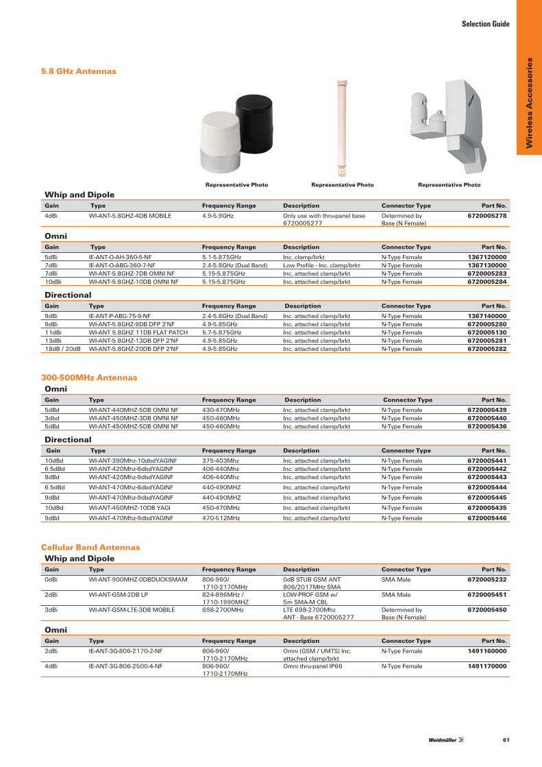
61
Wir
eles
s A
cces
sori
es
Selection Guide
5.8 GHz Antennas
300-500MHz Antennas
Cellular Band Antennas
Whip and DipoleGain Type Frequency Range Description Connector Type Part No. 4dBi WI-ANT-5.8GHZ-4DBMOBILE 4.9-5.9GHz Onlyusewiththru-panelbase
6720005277 Determinedby Base(NFemale)
6720005278
Omni Gain Type Frequency Range Description Connector Type Part No. 5dBi IE-ANT-O-AH-360-5-NF 5.1-5.875GHz Inc.clamp/brkt N-TypeFemale 13671200007dBi IE-ANT-O-ABG-360-7-NF 2.4-5.8GHz(DualBand) LowProfile-Inc.clamp/brkt N-TypeFemale 13671300007dBi WI-ANT-5.8GHZ-7DBOMNINF 5.15-5.875GHz Inc.attachedclamp/brkt N-TypeFemale 672000528310dBi WI-ANT-5.8GHZ-10DBOMNINF 5.15-5.875GHz Inc.attachedclamp/brkt N-TypeFemale 6720005284
DirectionalGain Type Frequency Range Description Connector Type Part No. 9dBi IE-ANT-P-ABG-75-9-NF 2.4-5.8GHz(DualBand) Inc.attachedclamp/brkt N-TypeFemale 13671400009dBi WI-ANT-5.8GHZ-9DBDFP2'NF 4.9-5.85GHz Inc.attachedclamp/brkt N-TypeFemale 672000528011dBi WI-ANT5.8GHZ11DBFLATPATCH 5.7-5.875GHz Inc.attachedclamp/brkt N-TypeFemale 672000513013dBi WI-ANT-5.8GHZ-13DBDFP2'NF 4.9-5.85GHz Inc.attachedclamp/brkt N-TypeFemale 672000528118dB/20dB WI-ANT-5.8GHZ-20DBDFP2'NF 4.9-5.85GHz Inc.attachedclamp/brkt N-TypeFemale 6720005282
Omni Gain Type Frequency Range Description Connector Type Part No. 5dBd WI-ANT-440MHZ-5DBOMNINF 430-470MHz Inc.attachedclamp/brkt N-TypeFemale 67200054393dbd WI-ANT-450MHZ-3DBOMNINF 450-460MHz Inc.attachedclamp/brkt N-TypeFemale 67200054405dBd WI-ANT-450MHZ-5DBOMNINF 450-460MHz Inc.attachedclamp/brkt N-TypeFemale 6720005436
Directional Gain Type Frequency Range Description Connector Type Part No. 10dBd WI-ANT-390Mhz-10dbdYAGINF 375-403Mhz Inc.attachedclamp/brkt N-TypeFemale 67200054416.5dBd WI-ANT-420Mhz-6dbdYAGINF 406-440Mhz Inc.attachedclamp/brkt N-TypeFemale 67200054429dBd WI-ANT-420Mhz-9dbdYAGINF 406-440Mhz Inc.attachedclamp/brkt N-TypeFemale 67200054436.5dBd WI-ANT-470Mhz-6dbdYAGINF 440-490MHZ Inc.attachedclamp/brkt N-TypeFemale 67200054449dBd WI-ANT-470Mhz-9dbdYAGINF 440-490MHZ Inc.attachedclamp/brkt N-TypeFemale 672000544510dBd WI-ANT-450MHZ-10DBYAGI 450-470MHz Inc.attachedclamp/brkt N-TypeFemale 67200054359dBd WI-ANT-470Mhz-9dbdYAGINF 470-512MHz Inc.attachedclamp/brkt N-TypeFemale 6720005446
Whip and Dipole Gain Type Frequency Range Description Connector Type Part No. 0dBi WI-ANT-900MHZ-0DBDUCKSMAM 806-960/
1710-2170MHz0dBSTUBGSMANT806/2017MHzSMA
SMAMale 6720005232
2dBi WI-ANT-GSM-2DBLP 824-896MHz/ 1710-1990MHZ
LOW-PROFGSMw/ 5mSMA-MCBL
SMAMale 6720005451
3dBi WI-ANT-GSM-LTE-3DBMOBILE 698-2700MHz LTE 698-2700Mhz ANT-Base6720005277
Determinedby Base(NFemale)
6720005450
OmniGain Type Frequency Range Description Connector Type Part No. 2dBi IE-ANT-3G-806-2170-2-NF 806-960/
1710-2170MHzOmni (GSM / UMTS) Inc. attachedclamp/brkt
N-TypeFemale 1491160000
4dBi IE-ANT-3G-806-2500-4-NF 806-960/ 1710-2170MHz
Omnithru-panelIP66 N-TypeFemale 1491170000
Representative Photo Representative Photo Representative Photo
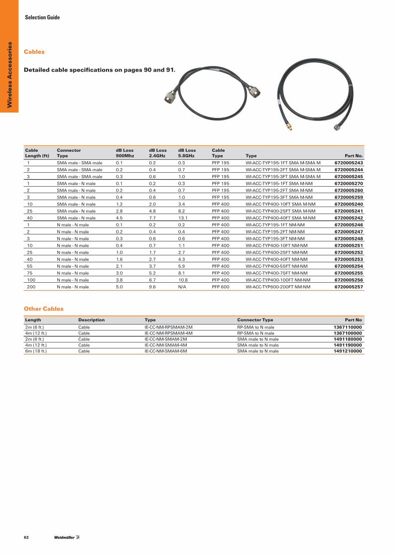
62
Wir
eles
s A
cces
sori
es Selection Guide
Cable Connector dB Loss dB Loss dB Loss Cable Length (ft) Type 900Mhz 2.4GHz 5.8GHz Type Type Part No.1 SMAmale-SMAmale 0.1 0.2 0.3 PFP195 WI-ACC-TYP195-1FTSMAM-SMAM 67200052432 SMAmale-SMAmale 0.2 0.4 0.7 PFP195 WI-ACC-TYP195-2FTSMAM-SMAM 67200052443 SMAmale-SMAmale 0.3 0.6 1.0 PFP195 WI-ACC-TYP195-3FTSMAM-SMAM 67200052451 SMAmale-Nmale 0.1 0.2 0.3 PFP195 WI-ACC-TYP195-1FTSMAM-NM 67200052702 SMAmale-Nmale 0.2 0.4 0.7 PFP195 WI-ACC-TYP195-2FTSMAM-NM 67200052603 SMAmale-Nmale 0.4 0.6 1.0 PFP195 WI-ACC-TYP195-3FTSMAM-NM 672000525910 SMAmale-Nmale 1.2 2.0 3.4 PFP400 WI-ACC-TYP400-10FTSMAM-NM 672000524025 SMAmale-Nmale 2.8 4.8 8.2 PFP400 WI-ACC-TYP400-25FTSMAM-NM 672000524140 SMAmale-Nmale 4.5 7.7 13.1 PFP400 WI-ACC-TYP400-40FTSMAM-NM 67200052421 Nmale-Nmale 0.1 0.2 0.2 PFP400 WI-ACC-TYP195-1FTNM-NM 67200052462 Nmale-Nmale 0.2 0.4 0.4 PFP400 WI-ACC-TYP195-2FTNM-NM 67200052473 Nmale-Nmale 0.3 0.6 0.6 PFP400 WI-ACC-TYP195-3FTNM-NM 672000524810 Nmale-Nmale 0.4 0.7 1.1 PFP400 WI-ACC-TYP400-10FTNM-NM 672000525125 Nmale-Nmale 1.0 1.7 2.7 PFP400 WI-ACC-TYP400-25FTNM-NM 672000525240 Nmale-Nmale 1.6 2.7 4.3 PFP400 WI-ACC-TYP400-40FTNM-NM 672000525355 Nmale-Nmale 2.1 3.7 5.9 PFP400 WI-ACC-TYP400-55FTNM-NM 672000525475 Nmale-Nmale 3.0 5.2 8.1 PFP400 WI-ACC-TYP400-75FTNM-NM 6720005255100 Nmale-Nmale 3.8 6.7 10.8 PFP400 WI-ACC-TYP400-100FTNM-NM 6720005256200 Nmale-Nmale 5.0 9.6 N/A PFP600 WI-ACC-TYP600-200FTNM-NM 6720005257
Detailed cable specifications on pages 90 and 91.
Cables
Other Cables
Length Description Type Connector Type Part No2m(6ft.) Cable IE-CC-NM-RPSMAM-2M RP-SMAtoNmale 13671100004m(12ft.) Cable IE-CC-NM-RPSMAM-4M RP-SMAtoNmale 13671000002m(6ft.) Cable IE-CC-NM-SMAM-2M SMAmaletoNmale 14911800004m(12ft.) Cable IE-CC-NM-SMAM-4M SMAmaletoNmale 14911900006m(18ft.) Cable IE-CC-NM-SMAM-6M SMAmaletoNmale 1491210000

63
Wir
eles
s A
cces
sori
es
Hardware
Description Type Part No.Reverse-PolaritySMAMale–SMAFemale WI-ACC-ADAPTRP-SMAM-SMAF 6720005289SMAmale-SMAmaleAdapter WI-ACC-ADAPTSMAM-SMAM 6720005290SMAfemale-SMAfemaleAdapter WI-ACC-ADAPTSMAF-SMAF 6720005291Nmale-NmaleAdapter WI-ACC-ADAPTNM-NM 6720005292Nfemale-NfemaleAdapter WI-ACC-ADAPTNF-NF 6720005293SMAfemale-NmaleAdapter WI-ACC-ADAPTSMAF-NM 6720005294SMAmale-NfemaleAdapter WI-ACC-ADAPTSMAM-NF 6720005295SMAfemale-SMAmaleAngledAdapter WI-ACC-ADAPTSMAF-SMAMANGL 6720005297
Description For use with Type Part No.DB9FemaleRJ45SerialConfigurationCable WI-I/O9-Lunits WI-CSER-RJ45 6720005108
Antenna Mounting Brackets AngledBracketfor4,6,and10dBi2.4MHzOmnis 2.4GHzantennas WI-ACC-24GHZ-4610DB-ANG-BRKT 6720005209 StraightBracketfor4,6,and10dBi2.4MHzOmnis 2.4GHzantennas WI-ACC-24GHZ-4610DB-STR-BRKT 6720005210 MountingBracketforpartnumber6720005203 2.4GHzantennas WI-ACC-24GHZ-12DB-STR-BRKT 6720005211 AntennaMAGBasewith12’SMAmalecable 2.4GHz&900MHzantennas WI-ACC-MAGBASE12RG58SMAMALE 6720005263 MountingBracketforparts6720005228and6720005229 900MHzantennas WI-ACC-900MHZ-OMNI-STR-BRKT 6720005268MountingBracketfor900MHz6.5,10,12dBdYagis 900MHzantennas WI-ACC-900MHZ-YAGI-STR-BRKT 6720005266 MountingBracketforpartnumber6720005226 900MHzantennas WI-ACC-900MHZ-14YAGI-STR-BRKT 6720005267 MountingBracketforpartnumbers6720005233, 6720005234,6720005235 900MHzantennas WI-ACC-900MHZ-035OMNI-STR-BRKT 6720005271 MountingBracketforpartnumber6720005236 900MHzantennas WI-ACC-900MHZ-7OMNI-STR-BRKT 6720005272 Thru-panelmountingbaseforlowprofileantennas 6720005276&6720005278 WI-ACC-BH-BASE5/8HOLENF 6720005277
Surge Protection & Bulkhead Mounts 125-1000MHzSurgePolyphaserNfemale-Nfemale Bulkhead&Surge≤1GHz WI-ACC-125-1000MHZSURGENF-NF 6720005261 2-6GHzSurgePolyphaserNfemale-Nfemale Bulkhead&Surge≥2GHz WI-ACC-2-6GHZSURGENF-NF 6720005262 BulkheadAdapterNfemale-Nfemale Bulkhead WI-ACC-BULK-ADAPTNF-NF 6720005250 BulkheadAdapterSMAfemale-SMAfemale Bulkhead WI-ACC-BULKSMAF-SMAF 6720005296 Class1Division1BulkheadSMAmale-SMAfemale Bulkhead WI-ACC-BULK-C1D1SMAM-SMAM 6720005298 Class1Division1BulkheadSMAmale-Nmale Bulkhead WI-ACC-BULK-C1D1SMAM-NM 6720005299 SMAmaletoSMAfemale<2.5Ghz(directradioconnection) 2.4GHz&900MHzantennas WI-DIV-CCMA 6720005111
Bandpass Filters Outdoorrated900MhzBandPassFilter 900MHzantennas WI-ACC900MHZBANDPASSFILTER 6720005120Outdoorrated2.4GhzBandPassFilter 2.4GHzantennas WI-ACC2.4GHZBANDPASSFILTER 6720005121Outdoorrated5.8GhzBandPassFilter 5.8GHzantennas WI-ACC5.8GHZBANDPASSFILTER 6720005122
Adapters
Selection Guide

64
Wir
eles
s A
cces
sori
esConnection Diagrams
Antenna
SMAmale
SMAfemale
SMAfemale
Direct Connect
Enclosure with C1D1 Bulkhead
C1D1Bulkhead
SMAmale
Radio
SMAmale
SMAmale
Radio
SMA femaleSMA maleC1D1 Bulkhead
SMA male to SMA female
SMA male
Typical wireless application in factory automation.
Connection Diagrams
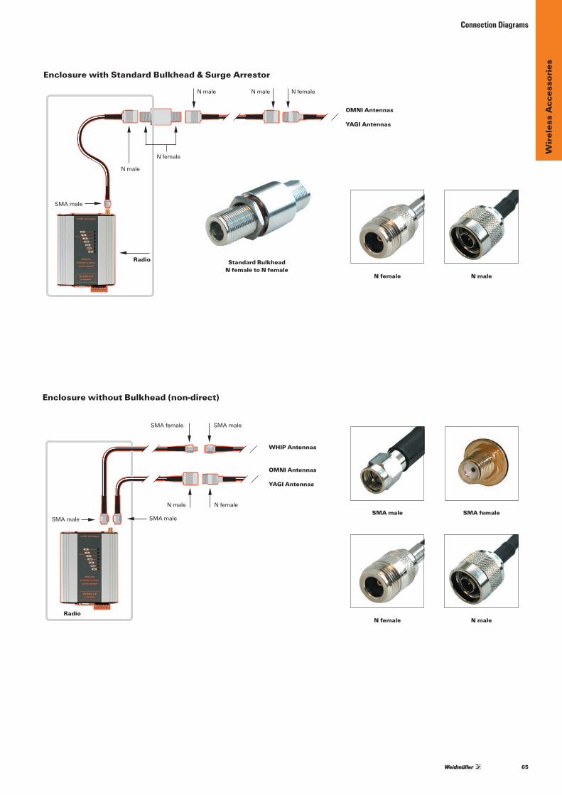
65
Wir
eles
s A
cces
sori
es
Connection Diagrams
Enclosure with Standard Bulkhead & Surge Arrestor
Enclosure without Bulkhead (non-direct)
Radio
OMNI Antennas
YAGI Antennas
WHIP Antennas
SMAmale
SMAfemale SMAmale
SMAmale
Nmale Nfemale
SMAmale
Radio
Nmale
Nmale
Nmale Nfemale
OMNI Antennas
YAGI Antennas
Nfemale
SMA femaleSMA male
N maleN female
N maleN female
Standard Bulkhead N female to N female
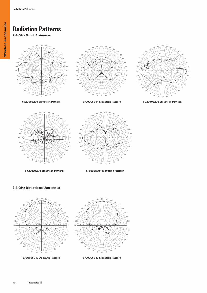
66
Wir
eles
s A
cces
sori
esRadiation Patterns
6720005212 Azimuth Pattern 6720005212 Elevation Pattern
10
190
20
200
30
210
40
220
50
230
60
240
70
250
80
260
90
270
100
280
110
290
120
300
130
310
140
320
150
330
160
340
170
350
180 0−25−25 −20−20 −15 01−51− 5−01− 05− 505
10
190
20
200
30
210
40
220
50
230
60
240
70
250
80
260
90
270
100
280
110
290
120
300
130
310
140
320
150
330
160
340
170
350
180 0−25−25 −20−20 −15 01−51− 5−01− 05− 505
6720005200 Elevation Pattern
10
190
20
200
30
210
40
220
50
230
60
240
70
250
80
260
90
270
100
280
110
290
120
300
130
310
140
320
150
330
160
340
170
350
180 0−30−30 −25−25 −20 51−02− 01−51− 5−01− 05−0
6720005201 Elevation Pattern
10
190
20
200
30
210
40
220
50
230
60
240
70
250
80
260
90
270
100
280
110
290
120
300
130
310
140
320
150
330
160
340
170
350
180 0−25−25 −20−20 −15 01−51− 5−01− 05− 505
6720005202 Elevation Pattern
10
190
20
200
30
210
40
220
50
230
60
240
70
250
80
260
90
270
100
280
110
290
120
300
130
310
140
320
150
330
160
340
170
350
180 0−25−25 −20−20 −15 01−51− 5−01− 05− 505
6720005203 Elevation Pattern
10
190
20
200
30
210
40
220
50
230
60
240
70
250
80
260
90
270
100
280
110
290
120
300
130
310
140
320
150
330
160
340
170
350
180 0−20−20 −15−15 −10 5−01− 05− 50 01510
6720005204 Elevation Pattern
10
190
20
200
30
210
40
220
50
230
60
240
70
250
80
260
90
270
100
280
110
290
120
300
130
310
140
320
150
330
160
340
170
350
180 0−25−25 −20−20 −15 01−51− 5−01− 05− 505
2.4 GHz Omni Antennas
2.4 GHz Directional Antennas
Radiation Patterns
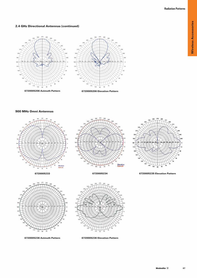
67
Wir
eles
s A
cces
sori
es
Radiation Patterns
6720005206 Azimuth Pattern 6720005206 Elevation Pattern
6720005234 6720005235 Elevation Pattern6720005233
10
190
20
200
30
210
40
220
50
230
60
240
70
250
80
260
90
270
100
280
110
290
120
300
130
310
140
320
150
330
160
340
170
350
180 0−20−20 −15−15 −10−10 −5−5 0 50 1510 0
10
190
20
200
30
210
40
220
50
230
60
240
70
250
80
260
90
270
100
280
110
290
120
300
130
310
140
320
150
330
160
340
170
350
180 0−20−20 −15−15 −10−10 −5−5 0 50 1510 0
6720005236 Azimuth Pattern 6720005236 Elevation Pattern
2.4 GHz Directional Antennas (continued)
900 MHz Omni Antennas
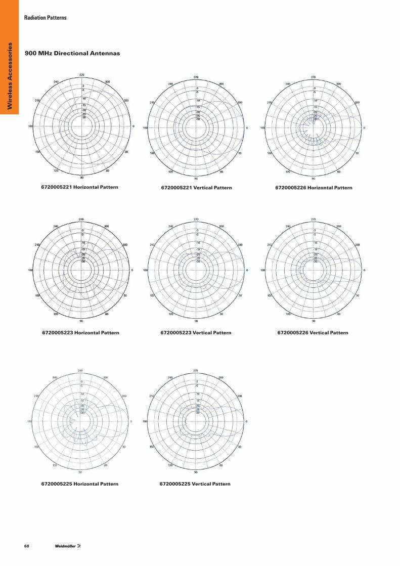
68
Wir
eles
s A
cces
sori
esRadiation Patterns
6720005221 Horizontal Pattern 6720005221 Vertical Pattern
6720005223 Horizontal Pattern
900 MHz Directional Antennas
6720005226 Horizontal Pattern
6720005223 Vertical Pattern 6720005226 Vertical Pattern
6720005225 Horizontal Pattern 6720005225 Vertical Pattern
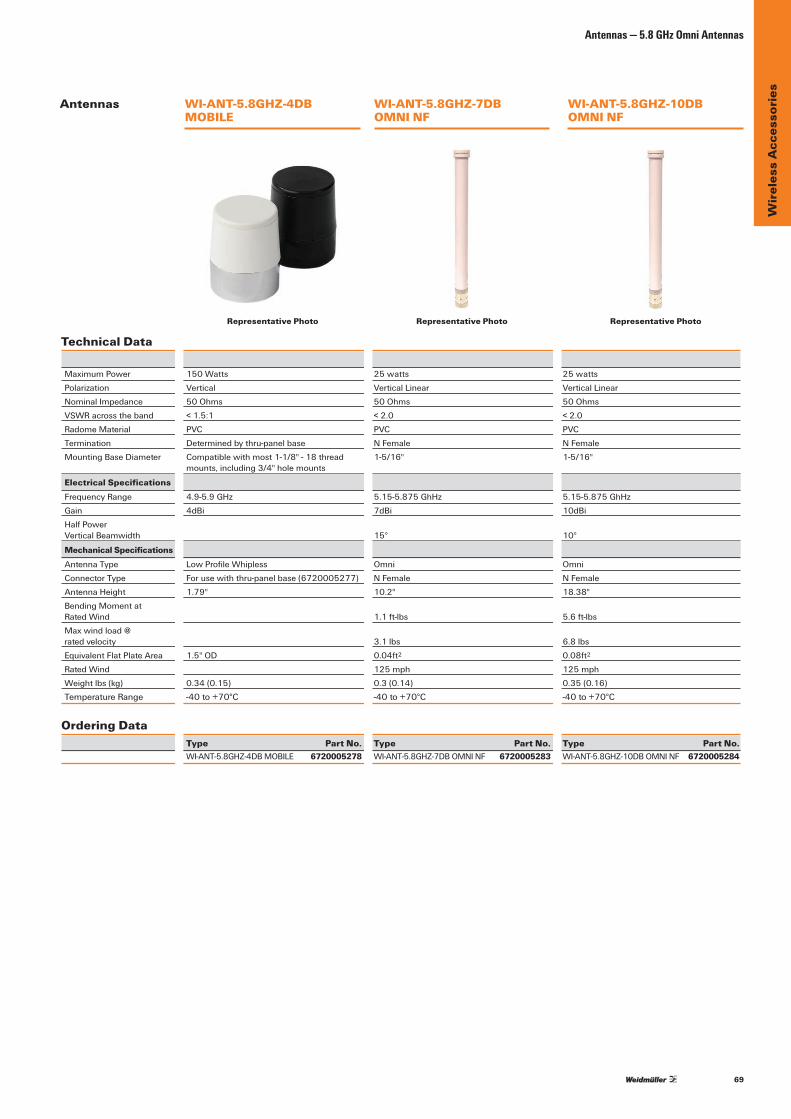
69
Wir
eles
s A
cces
sori
es
Antennas — 5.8 GHz Omni Antennas
Technical Data
MaximumPower 150Watts 25watts 25wattsPolarization Vertical VerticalLinear VerticalLinearNominalImpedance 50Ohms 50Ohms 50OhmsVSWRacrosstheband <1.5:1 <2.0 <2.0RadomeMaterial PVC PVC PVCTermination Determinedbythru-panelbase NFemale NFemaleMountingBaseDiameter Compatiblewithmost1-1/8"-18thread 1-5/16" 1-5/16" mounts,including3/4"holemounts
Electrical SpecificationsFrequencyRange 4.9-5.9GHz 5.15-5.875GhHz 5.15-5.875GhHzGain 4dBi 7dBi 10dBiHalfPower VerticalBeamwidth 15° 10°
Mechanical SpecificationsAntennaType LowProfileWhipless Omni OmniConnectorType Forusewiththru-panelbase(6720005277) NFemale NFemaleAntennaHeight 1.79" 10.2" 18.38"BendingMomentat RatedWind 1.1ft-lbs 5.6ft-lbsMax wind load @ ratedvelocity 3.1lbs 6.8lbsEquivalentFlatPlateArea 1.5"OD 0.04ft2 0.08ft2
Rated Wind 125 mph 125 mphWeightlbs(kg) 0.34(0.15) 0.3(0.14) 0.35(0.16)TemperatureRange -40to+70°C -40to+70°C -40to+70°C
Ordering Data Type Part No. Type Part No. Type Part No. WI-ANT-5.8GHZ-4DBMOBILE 6720005278 WI-ANT-5.8GHZ-7DBOMNINF 6720005283 WI-ANT-5.8GHZ-10DBOMNINF 6720005284
WI-ANT-5.8GHZ-4DB MOBILE
WI-ANT-5.8GHZ-7DB OMNI NF
WI-ANT-5.8GHZ-10DB OMNI NF
Antennas
Representative Photo Representative Photo Representative Photo

70
Wir
eles
s A
cces
sori
es
Antennas
Antennas — 5.8 GHz Omni Antennas
IE-ANT-O-AH-360-5-NF
Technical DataElectrical Data
Frequency (Mhz) 5150 - 5875 (Mhz)VSWR < 1.7Gain 5dBi3dBbeamwidth(horizontal) 360°3dBbeamwidth(vertical) 25°Fronttobackratio -Vertical electrical tilt 0°
General DataRadiation OmnidirectionalNominalImpedance 50 OhmPolarisation VerticalConnector type 1xN-TypefemaleConnector position BottomComposite power max. 6 W
Mechanical DataDimensions 160x16mm(HeightxDiameter)Weight 300gWind load frontal:7N@160km/h,lateral7N@
160Km/hMastDiametermin. 38.1mmMastDiametermax. 76.2 mm
Environmental LimitsEnvironmental Conditions outdoorOperating Temperature -45°Cto70°CStorage Temperature -45°Cto70°CIPRating IP64
Material DataRadome Color RAL9002(grey-white)Radome Material PPBackplate/baseplatematerial -
Ordering Data
Model 802.11a/hWirelessAntenna; Omni-directonal
Type IE-ANT-O-AH-360-5-NFPart No. 1367120000Note: Mounting material included
Representative Photo
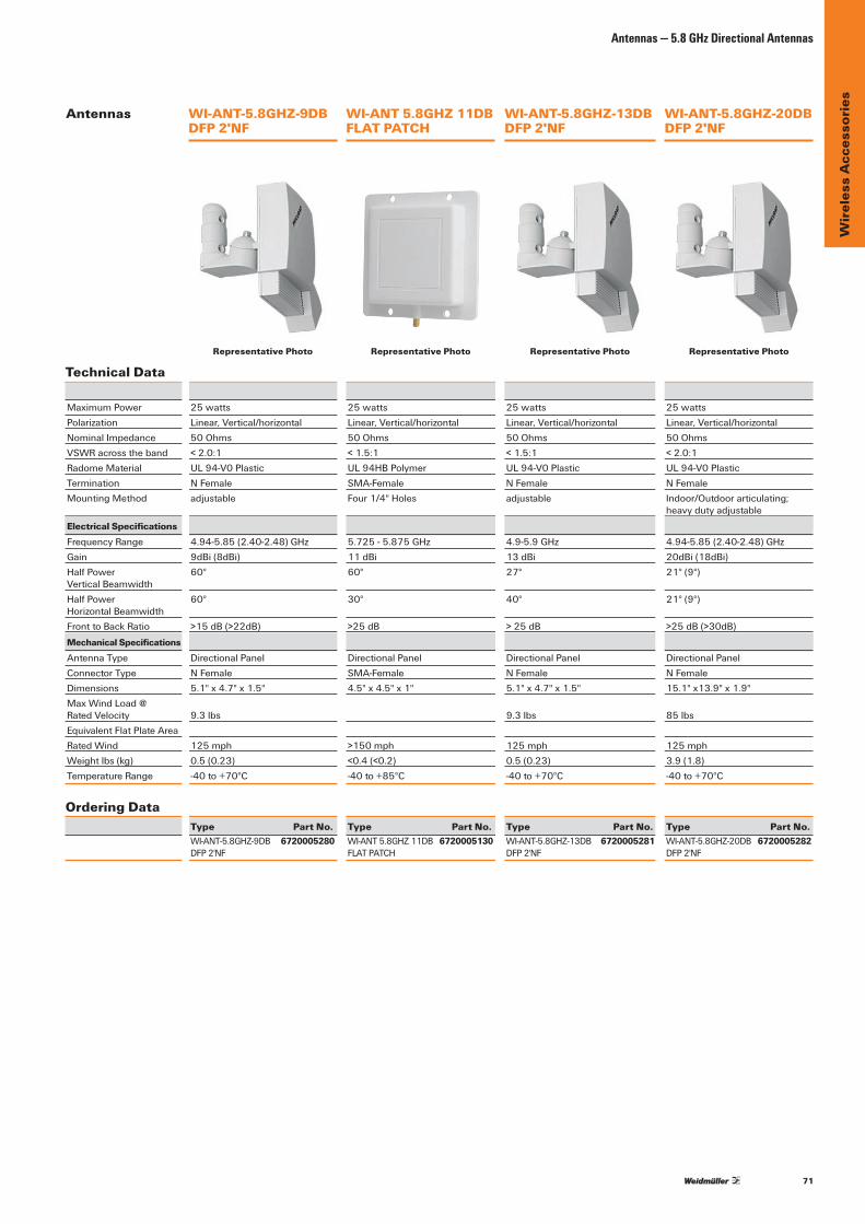
71
Wir
eles
s A
cces
sori
es
Antennas
Antennas — 5.8 GHz Directional Antennas
MaximumPower 25watts 25watts 25watts 25wattsPolarization Linear,Vertical/horizontal Linear,Vertical/horizontal Linear,Vertical/horizontal Linear,Vertical/horizontalNominalImpedance 50Ohms 50Ohms 50Ohms 50OhmsVSWRacrosstheband <2.0:1 <1.5:1 <1.5:1 <2.0:1RadomeMaterial UL94-V0Plastic UL94HBPolymer UL94-V0Plastic UL94-V0PlasticTermination NFemale SMA-Female NFemale NFemaleMountingMethod adjustable Four1/4"Holes adjustable Indoor/Outdoorarticulating; heavydutyadjustable
Electrical SpecificationsFrequencyRange 4.94-5.85(2.40-2.48)GHz 5.725-5.875GHz 4.9-5.9GHz 4.94-5.85(2.40-2.48)GHzGain 9dBi(8dBi) 11dBi 13dBi 20dBi(18dBi)HalfPower 60° 60° 27° 21°(9°) VerticalBeamwidthHalfPower 60° 30° 40° 21°(9°) HorizontalBeamwidthFronttoBackRatio >15dB(>22dB) >25dB >25dB >25dB(>30dB)Mechanical SpecificationsAntennaType DirectionalPanel DirectionalPanel DirectionalPanel DirectionalPanelConnectorType NFemale SMA-Female NFemale NFemaleDimensions 5.1"x4.7"x1.5" 4.5"x4.5"x1" 5.1"x4.7"x1.5" 15.1"x13.9"x1.9"Max Wind Load @ RatedVelocity 9.3lbs 9.3lbs 85lbsEquivalentFlatPlateArea RatedWind 125mph >150mph 125mph 125mphWeightlbs(kg) 0.5(0.23) <0.4(<0.2) 0.5(0.23) 3.9(1.8)TemperatureRange -40to+70°C -40to+85°C -40to+70°C -40to+70°C
Ordering Data Type Part No. Type Part No. Type Part No. Type Part No. WI-ANT-5.8GHZ-9DB 6720005280 WI-ANT5.8GHZ11DB 6720005130 WI-ANT-5.8GHZ-13DB 6720005281 WI-ANT-5.8GHZ-20DB 6720005282 DFP2'NF FLATPATCH DFP2'NF DFP2'NF
WI-ANT-5.8GHZ-9DB DFP 2'NF
WI-ANT 5.8GHZ 11DB FLAT PATCH
WI-ANT-5.8GHZ-13DB DFP 2'NF
WI-ANT-5.8GHZ-20DB DFP 2'NF
Technical DataRepresentative Photo Representative Photo Representative Photo Representative Photo

72
Wir
eles
s A
cces
sori
es
IE-ANT-P-ABG-75-9-NF IE-ANT-O-ABG-360-7-NF
Technical DataElectrical DataFrequency (Mhz) Band 1: 2400 - 2500 (Mhz) Band 1: 2400 - 2500 (Mhz)
Band 2: 5150 - 5875 (Mhz) Band 1: 5150 - 5875 (Mhz)Band 3:3400-3700(Mhz)Band 4: 4900 - 5470 (Mhz)Band 5:5470-5935(Mhz)
VSWR < 2 Band 1: < 1.8 Band 2: < 2Band 3: < 2Band 4: < 1.8Band 5: < 1.8
Gain 9dBiBand1/2 Band 1:6dBiBand 2:6dBiBand 3:7dBiBand 4:8dBiBand 5:8dBi
3dBbeamwidth(horizontal) 75°Band1;55°Band2 -3dBbeamwidth(vertical) 55°Band1/2 -Fronttobackratio 15dBBand1/2 -Vertical electrical tilt 0°Band1/2 -
General DataRadiation Directional OmnidirectionalNominalImpedance 50 Ohm 50 OhmPolarisation Vertical VerticalConnector type 1xN-Typefemale 1xN-TypefemaleConnector position Bottom BottomComposite power max. 10 W 75 W
Mechanical DataDimensions 101x80x35mm(HeightxWidthxDepth) 50.6x86mm(HeightxDiameter)Weight 110 g 300gWind load frontal:7N@160km/h,lateral7N@
160Km/hfrontal:10N@160km/h
MastDiametermin. 40 mm -MastDiametermax. 60 mm -
Environmental LimitsEnvironmental Conditions outdoor outdoorOperating Temperature -40°Cto80°C -40°Cto80°CStorage Temperature -40°Cto80°C -40°Cto80°CIPRating IP67 IP68
Material DataRadome Color RAL7044(grey) RAL7043(dark-grey)Radome Material PC ASA_SANBackplate/baseplatematerial - Stainless Steel
Ordering Data
Model 802.11a/b/g/hWirelessAntenna;Directional
802.11a/b/g/hWirelessAntenna; Omni-directonal
Type IE-ANT-P-ABG-75-9-NF IE-ANT-O-ABG-360-7-NFPart No. 1367140000 1367130000Note: Mounting material included Mounting material included
Antennas
Antennas — 5.8 GHz Directional Antennas
Representative Photo Representative Photo
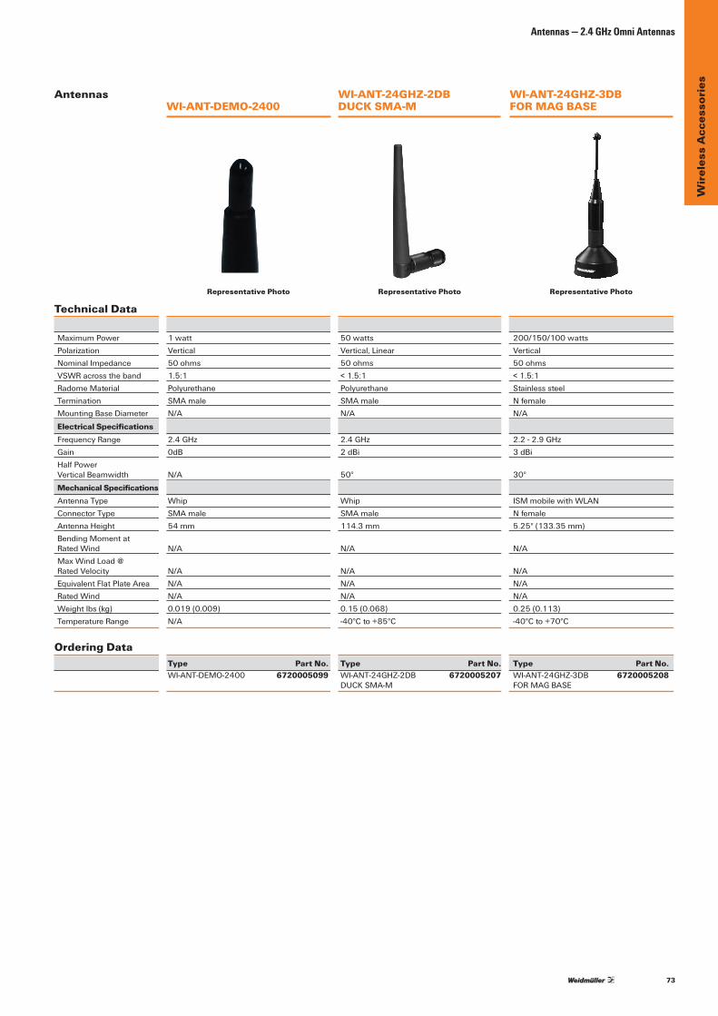
73
Wir
eles
s A
cces
sori
es
Antennas
Antennas — 2.4 GHz Omni Antennas
MaximumPower 1watt 50watts 200/150/100wattsPolarization Vertical Vertical,Linear VerticalNominalImpedance 50ohms 50ohms 50ohmsVSWRacrosstheband 1.5:1 <1.5:1 <1.5:1RadomeMaterial Polyurethane Polyurethane StainlesssteelTermination SMAmale SMAmale NfemaleMountingBaseDiameter N/A N/A N/A
Electrical SpecificationsFrequencyRange 2.4GHz 2.4GHz 2.2-2.9GHzGain 0dB 2dBi 3dBiHalfPower VerticalBeamwidth N/A 50° 30° Mechanical SpecificationsAntennaType Whip Whip ISMmobilewithWLANConnectorType SMAmale SMAmale NfemaleAntennaHeight 54mm 114.3mm 5.25"(133.35mm)BendingMomentat RatedWind N/A N/A N/AMax Wind Load @ RatedVelocity N/A N/A N/AEquivalentFlatPlateArea N/A N/A N/ARatedWind N/A N/A N/AWeightlbs(kg) 0.019(0.009) 0.15(0.068) 0.25(0.113)TemperatureRange N/A -40°Cto+85°C -40°Cto+70°C
Ordering Data Type Part No. Type Part No. Type Part No. WI-ANT-DEMO-2400 6720005099 WI-ANT-24GHZ-2DB 6720005207 WI-ANT-24GHZ-3DB 6720005208 DUCKSMA-M FORMAGBASE
WI-ANT-DEMO-2400WI-ANT-24GHZ-2DB DUCK SMA-M
WI-ANT-24GHZ-3DB FOR MAG BASE
Technical DataRepresentative Photo Representative Photo Representative Photo
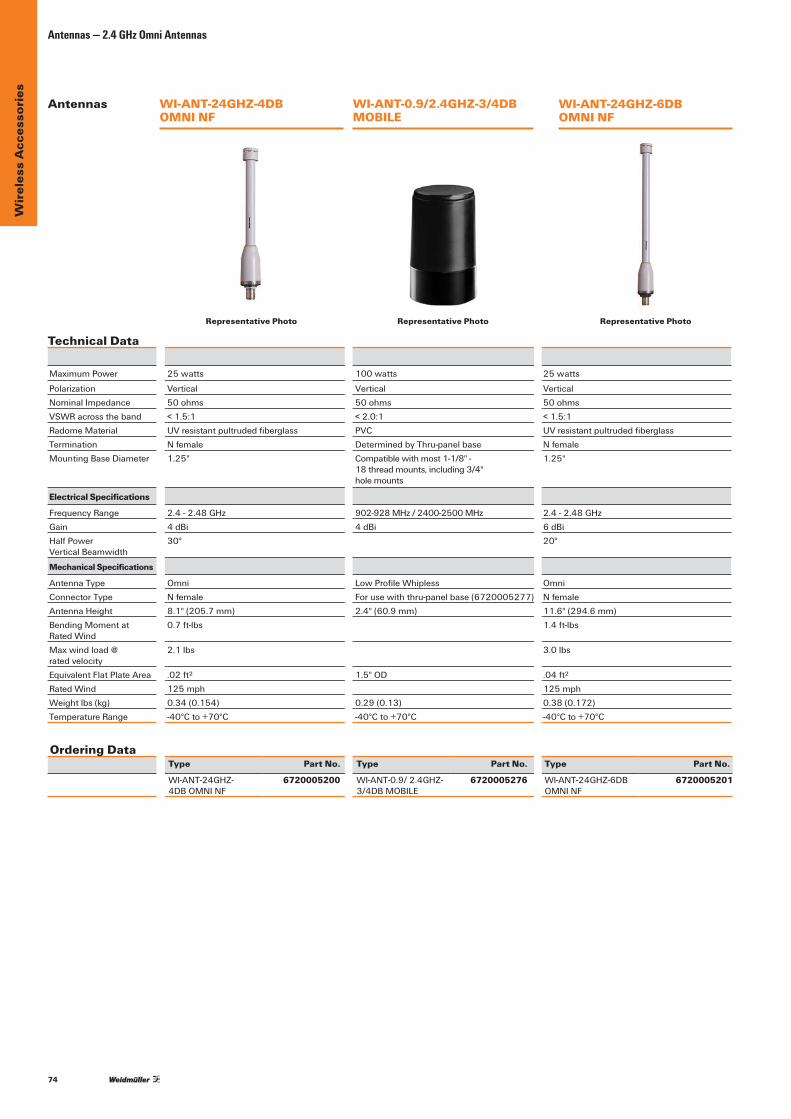
74
Wir
eles
s A
cces
sori
esAntennas — 2.4 GHz Omni Antennas
Ordering DataType Part No. Type Part No. Type Part No.
WI-ANT-24GHZ- 4DBOMNINF
6720005200 WI-ANT-0.9/2.4GHZ-3/4DBMOBILE
6720005276 WI-ANT-24GHZ-6DBOMNINF
6720005201
MaximumPower 25 watts 100 watts 25 watts
Polarization Vertical Vertical VerticalNominalImpedance 50 ohms 50 ohms 50 ohmsVSWRacrosstheband <1.5:1 <2.0:1 <1.5:1Radome Material UVresistantpultrudedfiberglass PVC UVresistantpultrudedfiberglassTermination Nfemale DeterminedbyThru-panelbase NfemaleMountingBaseDiameter 1.25" Compatiblewithmost1-1/8"-
18threadmounts,including3/4" hole mounts
1.25"
Electrical Specifications
Frequency Range 2.4-2.48GHz 902-928MHz/2400-2500MHz 2.4-2.48GHzGain 4dBi 4dBi 6dBiHalfPower VerticalBeamwidth
30° 20°
Mechanical Specifications
AntennaType Omni LowProfileWhipless OmniConnector Type Nfemale Forusewiththru-panelbase(6720005277) NfemaleAntennaHeight 8.1"(205.7mm) 2.4"(60.9mm) 11.6"(294.6mm)BendingMomentat Rated Wind
0.7ft-lbs 1.4ft-lbs
Max wind load @ rated velocity
2.1lbs 3.0lbs
EquivalentFlatPlateArea .02ft2 1.5"OD .04ft2
Rated Wind 125 mph 125 mphWeightlbs(kg) 0.34(0.154) 0.29(0.13) 0.38(0.172)Temperature Range -40°Cto+70°C -40°Cto+70°C -40°Cto+70°C
WI-ANT-24GHZ-6DB OMNI NF
WI-ANT-24GHZ-4DB OMNI NF
WI-ANT-0.9/2.4GHZ-3/4DB MOBILE
Technical DataRepresentative Photo
Antennas
Representative Photo Representative Photo

75
Wir
eles
s A
cces
sori
es
Antennas — 2.4 GHz Omni Antennas
Technical Data MaximumPower 25watts 25watts 25wattsPolarization Vertical Vertical VerticalNominalImpedance 50ohms 50ohms 50ohmsVSWRacrosstheband <1.5:1 <1.5:1 <1.5:1RadomeMaterial UVresistantpultrudedfiberglass UVresistantpultrudedfiberglass UVresistantpultrudedfiberglassTermination Nfemale Nfemale NfemaleMountingBaseDiameter 1.25" 1.25" 1.5"
Electrical SpecificationsFrequencyRange 2.4-2.48GHz 2.4-2.48GHz 2.4-2.5GHzGain 8dBi 10dBi 12dBiHalfPower VerticalBeamwidth 13° 9° 7° Mechanical SpecificationsAntennaType Omni Omni OmniConnectorType Nfemale Nfemale NfemaleAntennaHeight 20.2"(513.1mm) 36.0"(914.4mm) 44.0"(1118mm)BendingMomentat RatedWind 4.4ft-lbs 14.7ft-lbs 41ft-lbsMax Wind Load @ RatedVelocity 5.2lbs 10.1lbs 22.4lbsEquivalentFlatPlateArea .06ft2 .11ft2 .25ft2
Rated Wind 125 mph 125 mph 125 mph Weightlbs(kg) 0.50(0.226) 0.65(0.295) 3.00(1.400)TemperatureRange -40°Cto+70°C -40°Cto+70°C -40°Cto+70°C
Ordering Data Type Part No. Type Part No. Type Part No. WI-ANT-24GHZ-8DB 6720005204 WI-ANT-24GHZ-10DB 6720005202 WI-ANT-24GHZ-12DB 6720005203 OMNINF OMNINF OMNINF
WI-ANT-24GHZ-8DB OMNI NF
WI-ANT-24GHZ-10DB OMNI NF
WI-ANT-24GHZ-12DB OMNI NF
Antennas
Representative Photo Representative Photo Representative Photo
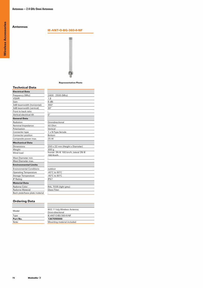
76
Wir
eles
s A
cces
sori
es
IE-ANT-O-BG-360-6-NF
Technical DataElectrical DataFrequency (Mhz) 2400 - 2500 (Mhz)VSWR 1.8Gain 6dBi3dBbeamwidth(horizontal) 360°3dBbeamwidth(vertical) 30°Fronttobackratio -Vertical electrical tilt 0°
General DataRadiation OmnidirectionalNominalImpedance 50 OhmPolarisation VerticalConnector type 1xN-TypefemaleConnector position BottomComposite power max. 25 W
Mechanical DataDimensions 250x22mm(HeightxDiameter)Weight 300gWind load frontal:3N@160km/h,lateral3N@
160Km/hMastDiametermin. -MastDiametermax. -
Environmental Limits
Environmental Conditions outdoorOperating Temperature -40°Cto80°CStorage Temperature -40°Cto80°CIPRating IP67
Material DataRadome Color RAL7035(lightgrey)Radome Material GlassFiberBackplate/baseplatematerial -
Ordering Data
Model 802.11b/gWirelessAntenna; Omni-directonal
Type IE-ANT-O-BG-360-6-NFPart No. 1367090000Note: Mounting material included
Antennas — 2.4 GHz Omni Antennas
Antennas
Representative Photo

77
Wir
eles
s A
cces
sori
es
Antennas
Antennas — 2.4 GHz Directional Antennas
Technical Data
MaximumPower 20watts 5watts 20wattsPolarization Linear Linear LinearNominalImpedance 50ohms 50ohms 50ohmsVSWRacrosstheband <1.6:1 <1.5:1 <1.6:1RadomeMaterial UVstableplastic UVstableplastic UVstableplasticCableLengthandtype 12"RG58/U 36"coax 12"RG58/UTermination Nfemale Nfemale NfemaleMountingMethod Indoor/outdoorarticulating;heavyduty heavydutyoutdoor Indoor/outdoorarticulating;heavyduty outdooradjustable adjustable outdooradjustable
Electrical SpecificationsFrequencyRange 2.3-2.5GHz 2.4-2.485GHz 2.3-2.5GHzGain 9dBi 10dBi 13dBiHalfPower HorizontalBeamwidth 60° 55° 35°HalfPower VerticalBeamwidth 60° 55° 35°FronttoBackRatio >15dB >23dB >18dBMechanical SpecificationsAntennaType DirectionalPanel DirectionalYagi DirectionalPanelConnectorType Nfemale Nfemale NfemaleDimensions 5.1"x4.7"x1.5" 4.5"x3" 8.8"x8.1"x1.6"Max Wind Load @RatedVelocity 9.3lbf 5.8lbf 27.9lbfEquivalentFlatPlateArea 0.060ft2 Rated Wind 125 mph 125 mph 125 mphWeightlbs(kg) 0.5(0.227) 1.0(0.5) 1.2(0.544)TemperatureRange -40°Cto+70°C -40°Cto+70°C -40°Cto+70°C
Ordering Data Type Part No. Type Part No. Type Part No. WI-ANT-24GHZ-9DB 6720005212 WI-ANT-24GHZ-10DB 6720005205 WI-ANT-24GHZ-13DB 6720005213 DFP2’NF YAGINF DFP2’NF
WI-ANT-24GHZ-9DB DFP 2’ NF
WI-ANT-24GHZ-10DB YAGI NF
WI-ANT-24GHZ-13DB DFP 2’ NF
Representative Photo Representative Photo Representative Photo
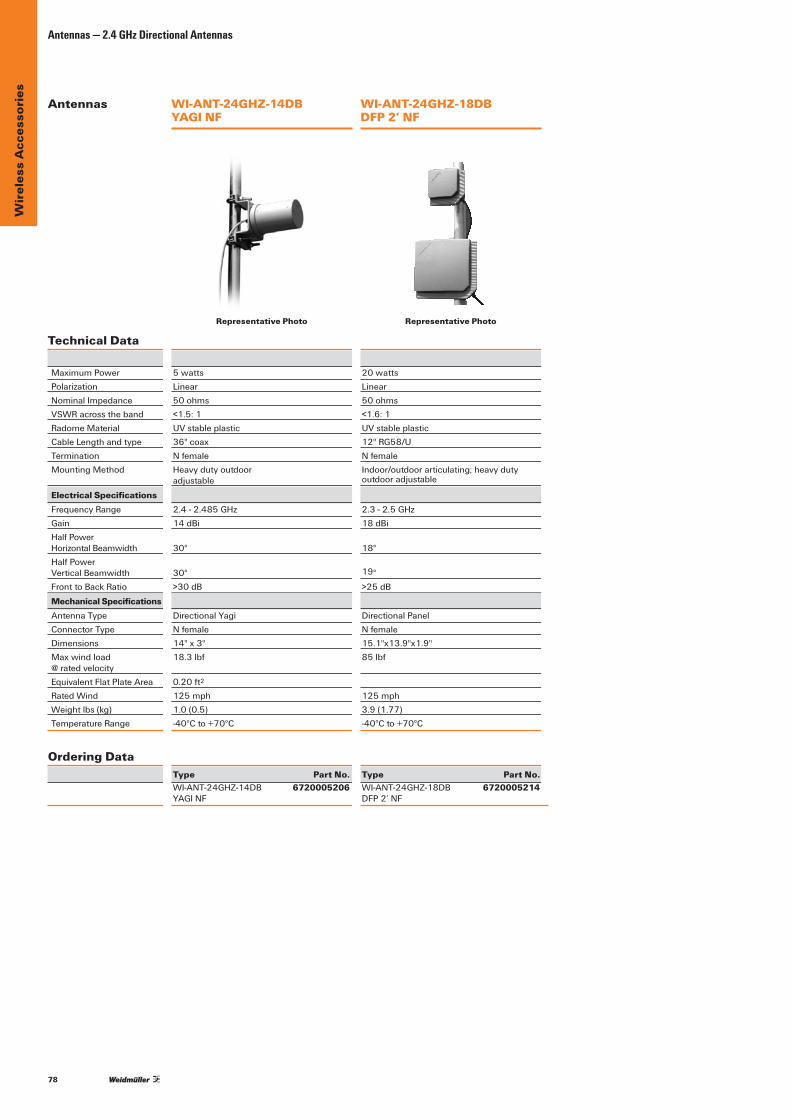
78
Wir
eles
s A
cces
sori
esAntennas — 2.4 GHz Directional Antennas
Technical Data
MaximumPower 5watts 20wattsPolarization Linear LinearNominalImpedance 50ohms 50ohmsVSWRacrosstheband <1.5:1 <1.6:1RadomeMaterial UVstableplastic UVstableplasticCableLengthandtype 36"coax 12"RG58/UTermination Nfemale NfemaleMountingMethod Heavydutyoutdoor Indoor/outdoorarticulating;heavyduty adjustable outdooradjustable
Electrical SpecificationsFrequencyRange 2.4-2.485GHz 2.3-2.5GHzGain 14dBi 18dBiHalfPower HorizontalBeamwidth 30° 18°HalfPower VerticalBeamwidth 30° 19°FronttoBackRatio >30dB >25dBMechanical SpecificationsAntennaType DirectionalYagi DirectionalPanelConnectorType Nfemale NfemaleDimensions 14"x3" 15.1"x13.9"x1.9"Maxwindload 18.3lbf 85lbf @ rated velocityEquivalentFlatPlateArea 0.20ft2
Rated Wind 125 mph 125 mphWeightlbs(kg) 1.0(0.5) 3.9(1.77)TemperatureRange -40°Cto+70°C -40°Cto+70°C
Ordering Data Type Part No. Type Part No. WI-ANT-24GHZ-14DB 6720005206 WI-ANT-24GHZ-18DB 6720005214 YAGINF DFP2’NF
WI-ANT-24GHZ-14DB YAGI NF
WI-ANT-24GHZ-18DB DFP 2’ NF
Antennas
Representative Photo Representative Photo
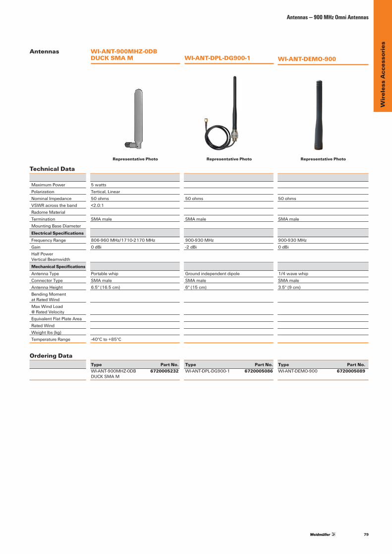
79
Wir
eles
s A
cces
sori
es
Antennas — 900 MHz Omni Antennas
Technical Data
MaximumPower 5watts Polarization Tertical,Linear NominalImpedance 50ohms 50ohms 50ohmsVSWRacrosstheband <2.0:1 Radome Material Termination SMAmale SMAmale SMAmaleMountingBaseDiameter
Electrical SpecificationsFrequencyRange 806-960MHz/1710-2170MHz 900-930MHz 900-930MHzGain 0dBi -2dBi 0dBiHalfPower VerticalBeamwidth Mechanical SpecificationsAntennaType Portablewhip Groundindependentdipole 1/4wavewhipConnectorType SMAmale SMAmale SMAmaleAntennaHeight 6.5"(16.5cm) 6"(15cm) 3.5"(9cm)BendingMoment at Rated Wind Max Wind Load @ Rated Velocity EquivalentFlatPlateArea Rated Wind Weightlbs(kg) TemperatureRange -40°Cto+85°C
Ordering Data Type Part No. Type Part No. Type Part No. WI-ANT-900MHZ-0DB 6720005232 WI-ANT-DPL-DG900-1 6720005086 WI-ANT-DEMO-900 6720005089 DUCKSMAM
WI-ANT-900MHZ-0DB DUCK SMA M WI-ANT-DPL-DG900-1 WI-ANT-DEMO-900
Antennas
Representative Photo Representative Photo Representative Photo
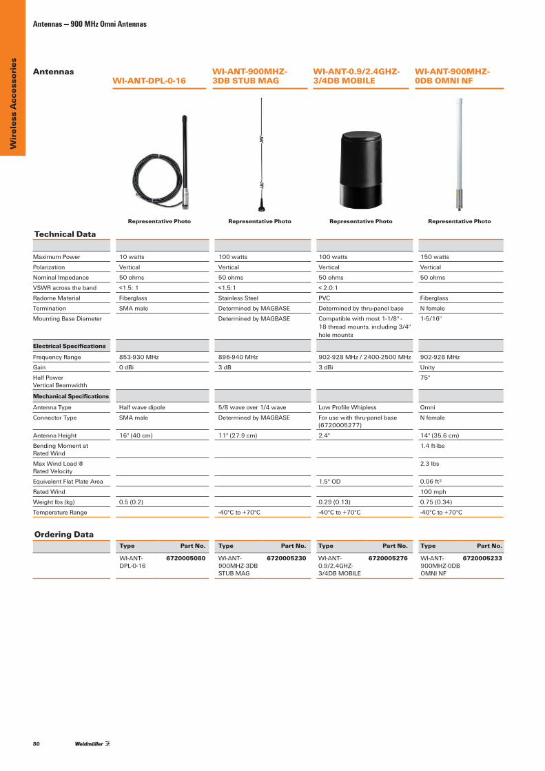
80
Wir
eles
s A
cces
sori
esAntennas — 900 MHz Omni Antennas
Ordering DataType Part No. Type Part No. Type Part No. Type Part No.
WI-ANT-DPL-0-16
6720005080
WI-ANT-900MHZ-3DBSTUB MAG
6720005230
WI-ANT-0.9/2.4GHZ-3/4DBMOBILE
6720005276
WI-ANT-900MHZ-0DBOMNINF
6720005233
Technical Data
MaximumPower 10 watts 100 watts 100 watts 150 watts
Polarization Vertical Vertical Vertical Vertical
NominalImpedance 50 ohms 50 ohms 50 ohms 50 ohms
VSWRacrosstheband <1.5:1 <1.5:1 <2.0:1
Radome Material Fiberglass Stainless Steel PVC Fiberglass
Termination SMAmale DeterminedbyMAGBASE Determinedbythru-panelbase Nfemale
MountingBaseDiameter DeterminedbyMAGBASE Compatiblewithmost1-1/8"- 18threadmounts,including3/4" hole mounts
1-5/16"
Electrical Specifications
Frequency Range 853-930MHz 896-940MHz 902-928MHz/2400-2500MHz 902-928MHz
Gain 0dBi 3dB 3dBi Unity
HalfPower VerticalBeamwidth
75°
Mechanical Specifications
AntennaType Halfwavedipole 5/8 wave over 1/4 wave LowProfileWhipless Omni
Connector Type SMAmale DeterminedbyMAGBASE Forusewiththru-panelbase(6720005277)
Nfemale
AntennaHeight 16"(40cm) 11"(27.9cm) 2.4" 14"(35.6cm)
BendingMomentat Rated Wind
1.4ft-lbs
Max Wind Load @ Rated Velocity
2.3lbs
EquivalentFlatPlateArea 1.5"OD 0.06ft2
Rated Wind 100 mph
Weightlbs(kg) 0.5 (0.2) 0.29(0.13) 0.75(0.34)
Temperature Range -40°Cto+70°C -40°Cto+70°C -40°Cto+70°C
WI-ANT-900MHZ- 3DB STUB MAG
WI-ANT-0.9/2.4GHZ-3/4DB MOBILE
WI-ANT-900MHZ-0DB OMNI NFWI-ANT-DPL-0-16
Antennas
Representative Photo Representative Photo Representative Photo Representative Photo

81
Wir
eles
s A
cces
sori
es
Antennas — 900 MHz Omni Antennas
WI-ANT-900MHZ-5DBD OMNI NF
WI-ANT-900MHZ-7DBD OMNI NF
WI-ANT-900MHZ-3DBD OMNI NF
Technical Data
MaximumPower 150watts 150watts 150wattsPolarization Vertical Vertical VerticalNominalImpedance 50ohms 50ohms 50ohmsVSWRacrosstheband RadomeMaterial Fiberglass Fiberglass FiberglassTermination Nfemale Nfemale NfemaleMountingBaseDiameter 1-5/16" 1-5/16" 1-5/16"
Electrical SpecificationsFrequencyRange 902-928MHz 902-928MHz 902-928MHzGain 3dB 5dB 7dBHalfPower VerticalBeamwidth 40° 22° 17° Mechanical SpecificationsAntennaType Omni Omni OmniConnectorType Nfemale Nfemale NfemaleAntennaHeight 23.25"(59.1cm) 48"(121.9cm) 96"(243.8cm)BendingMoment atRatedWind 4.7ft-lbs 14.2ft-lbs 62.5ft-lbsMax Wind Load @RatedVelocity 4.3lbs 8.0lbs 15.8lbsEquivalentFlatPlateArea 0.12ft2 0.22ft2 0.44ft2
Rated Wind 100 mph 100 mph 100 mphWeightlbs(kg) 1.25(0.57) 1.75(0.79) 4(1.81)TemperatureRange -40°Cto+70°C -40°Cto+70°C -40°Cto+70°C
Ordering Data Type Part No. Type Part No. Type Part No. WI-ANT-900MHZ-3DB 6720005234 WI-ANT-900MHZ-5DB 6720005235 WI-ANT-900MHZ-7DB 6720005236 OMNINF OMNINF OMNINF
Antennas
Representative Photo Representative Photo Representative Photo

82
Wir
eles
s A
cces
sori
esAntennas — 900 MHz Directional Antennas
Technical Data
MaximumPower 200watts 200watts 200wattsPolarization Linear Linear LinearNominalImpedance 50ohms 50ohms 50ohmsVSWRAcrosstheband <1.5:1 <1.5:1 <1.5:1RadomeMaterial Aluminum6061-T6 Aluminum6061-T6 Aluminum6061-T6Termination Nfemale Nfemale NfemaleMounting Method Includes mounting Includes mounting Includes mounting hardware hardware hardware
Electrical SpecificationsFrequencyRange 890-960MHz 890-960MHz 890-960MHzGain 3dBd 6.5dBd 10dBdHalfPower HorizontalBeamwidth 168° 100° 56°HalfPower VerticalBeamwidth 78° 62° 46°FronttoBackRatio >10dB >15dB >20dBMechanical SpecificationsAntennaType DirectionalYagi DirectionalYagi DirectionalYagiAntennaDimensions(LxW) 13"x6.8" 13"x6.8" 24"x6.8"Weightlbs(kg) 1.3(0.59) 2(0.9) 6.8(3.08)CrossSectionalArea 0.11ft2 0.12ft2 0.24ft2
Max Wind Load @RatedVelocity 2.75lbf 3lbf 6lbfRated Wind 125 mph 125 mph 125 mphElements 2 3 7CableType LMR400 RG213 RG213CableLength 2ft. 2ft. 2ft.ConnectorType Nfemale Nfemale NfemaleTemperatureRange -40°Cto+85°C -40°Cto+70°C -40°Cto+70°C
Ordering Data Type Part No. Type Part No. Type Part No. WI-ANT-900MHZ-3DB 6720005219 WI-ANT-900MHZ-6.5DB-2’ 6720005221 WI-ANT-900MHZ-10DB-2’ 6720005223 YAGINF YAGINF YAGINF
WI-ANT-900MHZ-3DBD YAGI NF
WI-ANT-900MHZ- 6.5DB-2’ YAGI NF
WI-ANT-900MHZ- 10DB-2’ YAGI NF
Representative Photo Representative Photo Representative Photo
Antennas
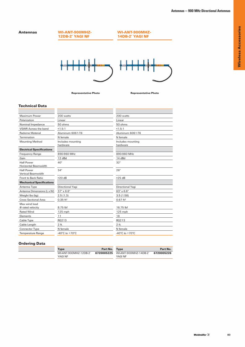
83
Wir
eles
s A
cces
sori
es
Antennas — 900 MHz Directional Antennas
Technical Data
MaximumPower 200watts 200wattsPolarization Linear LinearNominalImpedance 50ohms 50ohmsVSWRAcrosstheband <1.5:1 <1.5:1RadomeMaterial Aluminum6061-T6 Aluminum6061-T6Termination Nfemale NfemaleMounting Method Includes mounting Includes mounting hardware hardware
Electrical SpecificationsFrequencyRange 890-960MHz 890-960MHzGain 12dBd 14dBdHalfPower 40° 32° HorizontalBeamwidthHalfPower 34° 26° VerticalBeamwidthFronttoBackRatio >20dB >25dBMechanical SpecificationsAntennaType DirectionalYagi DirectionalYagiAntennaDimensions(LxW) 37"x6.6" 63"x6.6"Weightlbs(kg) 2.5(1.3) 3.5(1.58)CrossSectionalArea 0.35ft2 0.67ft2
Max wind load @ratedvelocity 8.75lbf 16.75lbfRated Wind 125 mph 125 mphElements 11 18CableType RG213 RG213CableLength 2ft. 2ft.ConnectorType Nfemale NfemaleTemperatureRange -40°Cto+70°C -40°Cto+70°C
Ordering Data Type Part No. Type Part No. WI-ANT-900MHZ-12DB-2’ 6720005225 WI-ANT-900MHZ-14DB-2’ 6720005226 YAGINF YAGINF
WI-ANT-900MHZ- 12DB-2’ YAGI NF
WI-ANT-900MHZ- 14DB-2’ YAGI NF
Representative Photo Representative Photo
Antennas

84
Wir
eles
s A
cces
sori
esAntennas — 900 MHz Omni (Licensed)
WI-ANT-950Mhz-3DBD OMNI NF
WI-ANT-950Mhz-5DBD OMNI NF
WI-ANT-950Mhz-7DBD OMNI NF
Antennas– 900 MHz Omni (Licensed)
Technical Data
MaximumPower 150 Watts 150 Watts 150 Watts
Polarization Vertical Linear Vertical Linear Vertical Linear
NominalImpedance 50 Ohms 50 Ohms 50 Ohms
VSWRacrosstheband <1.5:1(70MHz) <1.5:1(70MHz) <1.5:1(40MHz)
Radome Material 1.0”ODpultrudedwhitefiberglass 1.0”ODpultrudedwhitefiberglass 1.0”ODpultrudedwhitefiberglass
Termination NFemale NFemale NFemale
MountingBaseDiameter 1-5/16" 1-5/16" 1-5/16"
Electrical Specifications
Frequency Range 890-960MHz 890-960MHz 890-940MHz
Gain 3dBd 5dBd 7dBd
HalfPower VerticalBeamwidth
40° 22° 17°
Mechanical Specifications
AntennaType Omni Omni Omni
Connector Type NFemale NFemale NFemale
AntennaHeight 23" 48" 96"
BendingMomentat Rated Wind
4.7ft-lbs 14.2ft-lbs 62.5ft-lbs
Max Wind Load @ Rated Velocity
4.3lbs 8.0lbs 15.8lbs
EquivalentFlatPlateArea 0.12ft2 0.22ft2 0.44ft2
Rated Wind 100 mph 100 mph 100 mph
Weightlbs(kg) 1.25lbs 1.75lbs 4.00lbs
Temperature Range -40°Cto+70°C -40°Cto+70°C -40°Cto+70°C
Ordering DataType Part No. Type Part No. Type Part No.
WI-ANT-950Mhz-3DBD OMNINF
6720005273 WI-ANT-950Mhz-5DBD OMNINF
6720005274 WI-ANT-950Mhz-7DBD OMNINF
6720005275
Representative Photo Representative Photo Representative Photo

85
Wir
eles
s A
cces
sori
es
Antennas — 300-500 MHz
Antennas– 300-500 MHz
Technical Data
MaximumPower 250 Watts 250 Watts 250 Watts
Polarization Vertical Linear Vertical Linear Vertical Linear
NominalImpedance 50 Ohms 50 Ohms 50 Ohms
VSWRacrosstheband <1.5:1(70MHz) <1.5:1(10MHz) <1.5:1(10MHz)
Radome Material 2.0”ODpultrudedwhitefiberglass Pultrudedwhitefiberglass Pultrudedwhitefiberglass
Termination NFemale NFemale NFemale
MountingBaseDiameter 1-5/16" 1-5/16" 1-5/16"
Electrical Specifications
Frequency Range 430-470MHz 450-460MHz 450-460MHz
Gain 5dBd(7dBi) 3dBd 5dBd
HalfPower VerticalBeamwidth
18° 38° 27°
Mechanical Specifications
AntennaType Omni Omni Omni
Connector Type NFemale NFemale NFemale
AntennaHeight 83" 71" 77"
BendingMomentat Rated Wind
250ft-lbs 29.0ft-lbs 40.4ft-lbs
Max Wind Load @ Rated Velocity
45lbs 10.8lbs 12.6lbs
EquivalentFlatPlateArea 1.125ft2 0.30ft2 0.35ft2
Rated Wind 125 mph 100 mph 100 mph
Weightlbs(kg) 7.0lbs 4.0lbs 4.50lbs
Temperature Range -40°Cto+70°C -40°Cto+70°C -40°Cto+70°C
Ordering DataType Part No. Type Part No. Type Part No.
WI-ANT-440MHZ-5DBOMNINF
6720005439 WI-ANT-450MHZ-3DBOMNINF
6720005440 WI-ANT-450MHZ-5DBOMNINF
6720005436
WI-ANT-440MHZ-5DB OMNI NF
WI-ANT-450MHZ-3DB OMNI NF
WI-ANT-450MHZ-5DB OMNI NF
Representative Photo Representative Photo Representative Photo

86
Wir
eles
s A
cces
sori
esAntennas — 300-500 MHz
WI-ANT-390Mhz-10DBD YAGI NF
WI-ANT-420Mhz-6DBD YAGI NF
WI-ANT-420Mhz-9DBD YAGI NF
WI-ANT-470Mhz-6DBD YAGI NF
Technical Data
MaximumPower 250 Watts 150 Watts 150 Watts 150 Watts
Polarization Linear Linear Linear Linear
NominalImpedance 50 Ohms 50 Ohms 50 Ohms 50 Ohms
VSWRacrosstheband <1.5:1(70MHz) <1.5:1(34MHz) <1.5:1(34MHz) <1.5:1(40MHz)
Radome Material 3/8"solid6061-T6aluminum 3/8"solid6061-T6aluminum 3/8"solid6061-T6aluminum 3/8"solid6061-T6aluminum
Termination NFemale NFemale NFemale NFemale
MountingPipeDiameter 1-5/16" 1.9”OD 1.9”OD 1.9”OD
Electrical Specifications
Frequency Range 375-403MHz 406-440MHz 406-440MHz 440-480MHz
Gain 10dBd 6.5dBd 9dBd 6.5dBd
HalfPower VerticalBeamwidth
46° 62° 45° 62°
HalfPower HorizontalBeamwidth
52° 71° 52° 71°
FronttoBackRatio >20dB >15dB >15dB >15dB
Mechanical Specifications
AntennaType DirectionalYagi DirectionalYagi DirectionalYagi DirectionalYagi
Connector Type NFemale NFemale NFemale NFemale
AntennaLength(BoomOD) 44"x14.3" 22"(.75") 34"(.75") 22"(.75")
NumberofElements 7 3 5 3
BendingMomentatRatedWind
12.75ft-lbs 12.75ft-lbs 32.4ft-lbs 12.75ft-lbs
Max wind load @ rated velocity
20.84lbs 14.8lbs 24.2lbs 14.8lbs
EquivalentFlatPlateArea 0.53ft2 0.19ft2 0.31ft2 0.19ft2
Rated Wind 100 mph 125 mph 125 mph 125 mph
Weightlbs(kg) 3.5lbs 1.2lbs 2lbs 1.2lbs
Temperature Range -40°Cto+70°C -40°Cto+70°C -40°Cto+70°C -40°Cto+70°C
Ordering DataType Part No. Type Part No. Type Part No. Type Part No.
WI-ANT-390Mhz-10DBDYAGINF
6720005441 WI-ANT-420Mhz-6DBDYAGINF
6720005442 WI-ANT-420Mhz-9DBDYAGINF
6720005443 WI-ANT-470Mhz-6DBDYAGINF
6720005444
Antennas– 300-500 MHz
Representative PhotoRepresentative PhotoRepresentative PhotoRepresentative Photo
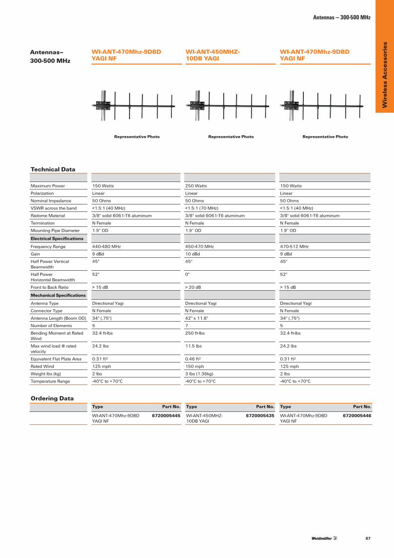
87
Wir
eles
s A
cces
sori
es
Antennas — 300-500 MHz
Technical Data
MaximumPower 150 Watts 250 Watts 150 Watts
Polarization Linear Linear Linear
NominalImpedance 50 Ohms 50 Ohms 50 Ohms
VSWRacrosstheband <1.5:1(40MHz) <1.5:1(70MHz) <1.5:1(40MHz)
Radome Material 3/8"solid6061-T6aluminum 3/8"solid6061-T6aluminum 3/8"solid6061-T6aluminum
Termination NFemale NFemale NFemale
MountingPipeDiameter 1.9”OD 1.9”OD 1.9”OD
Electrical Specifications
Frequency Range 440-480MHz 450-470MHz 470-512MHz
Gain 9dBd 10dBd 9dBd
HalfPowerVerticalBeamwidth
45° 45° 45°
HalfPower HorizontalBeamwidth
52° 0° 52°
FronttoBackRatio >15dB >20dB >15dB
Mechanical Specifications
AntennaType DirectionalYagi DirectionalYagi DirectionalYagi
Connector Type NFemale NFemale NFemale
AntennaLength(BoomOD) 34"(.75") 42"x11.8" 34"(.75")
NumberofElements 5 7 5
BendingMomentatRatedWind
32.4ft-lbs 250ft-lbs 32.4ft-lbs
Max wind load @ rated velocity
24.2lbs 11.5lbs 24.2lbs
EquivalentFlatPlateArea 0.31ft2 0.46ft2 0.31ft2
Rated Wind 125 mph 150 mph 125 mph
Weightlbs(kg) 2lbs 3lbs(1.36kg) 2lbs
Temperature Range -40°Cto+70°C -40°Cto+70°C -40°Cto+70°C
Ordering DataType Part No. Type Part No. Type Part No.
WI-ANT-470Mhz-9DBD YAGINF
6720005445 WI-ANT-450MHZ- 10DBYAGI
6720005435 WI-ANT-470Mhz-9DBD YAGINF
6720005446
WI-ANT-470Mhz-9DBD YAGI NF
WI-ANT-450MHZ- 10DB YAGI
WI-ANT-470Mhz-9DBD YAGI NF
Antennas– 300-500 MHz
Representative PhotoRepresentative Photo Representative Photo
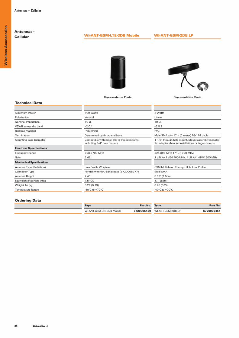
88
Wir
eles
s A
cces
sori
esAntennas — Cellular
WI-ANT-GSM-LTE-3DB Mobile WI-ANT-GSM-2DB LP
Technical Data
MaximumPower 100 Watts 8 Watts
Polarization Vertical Linear
NominalImpedence 50Ω 50Ω
VSWRacrosstheband <2.0:1 <2.5:1
Radome Material PVC(IP66) PVC
Termination Determinedbythru-panelbase MaleSMAc/w17ft(5meter)RG-174cable
MountingBaseDiameter Compatiblewithmost1/8”-8threadmounts, including3/4”holemounts
1-1/2”throughholemount.Mountassemblyincludesflatadaptershimforinstallationsorlargercutouts
Electrical Specifications
Frequency Range 698-2700MHz 824-896MHz1710-1990MHZ
Gain 3dBi 2dBi+/-1dB@900MHz,1dB+/-1dB@1800MHz
Mechanical Specifications
AntennaType(Radiation) LowProfileWhipless GSMMulti-bandThroughHoleLowProfile
Connector Type Forusewiththru-panelbase(6720005277) MaleSMA
AntennaHeight 2.4" 0.59"(1.5cm)
EquivalentFlatPlateArea 1.5"OD 3.1"(8cm)
Weightlbs(kg) 0.29(0.13) 0.45 (0.24)
Temperature Range -40°Cto+70°C -40°Cto+70°C
Ordering DataType Part No. Type Part No.
WI-ANT-GSM-LTE-3DBMobile 6720005450 WI-ANT-GSM-2DBLP 6720005451
Antennas– Cellular
Representative Photo Representative Photo
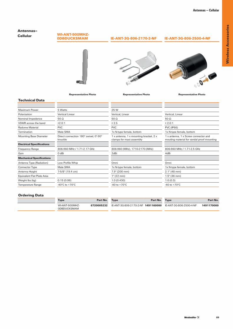
89
Wir
eles
s A
cces
sori
es
Antennas — Cellular
Technical Data
MaximumPower 5 Watts 25 W
Polarization Vertical Linear Vertical,Linear Vertical,Linear
NominalImpedence 50Ω 50Ω 50Ω
VSWRacrosstheband <2.0:1 < 2.5 <2.0:1
Radome Material PVC PVC PVC(IP66)
Termination MaleSMA 1xN-typefemale,bottom 1xN-typefemale,bottom
MountingBaseDiameter Directconnection180°swivel,0°-90°knuckle
1xantenna,1xmountingbracket,2xclampsformastassembly
1xantenna,1xScrewconnectorandmoutingmaterialforvandalproofmounting
Electrical Specifications
Frequency Range 806-960MHz/1.71-2.17GHz 806-960(MHz),1710-2170(MHz) 806-960MHz/1.71-2.5GHz
Gain 0dBi 2dBi 4dBi
Mechanical Specifications
AntennaType(Radiation) LowProfileWhip Omni Omni
Connector Type MaleSMA 1xN-typefemale,bottom 1xN-typefemale,bottom
AntennaHeight 7-5/8"(19.4cm) 7.9"(200mm) 2.1"(48mm)
EquivalentFlatPlateArea 1"(22mm) 1.5"(36mm)
Weightlbs(kg) 0.15 (0.06) 1.0(0.430) 1.0(0.3)
Temperature Range -40°Cto+70°C -40to+70°C -40to+70°C
Ordering DataType Part No. Type Part No. Type Part No.
WI-ANT-900MHZ-0DBDUCKSMAM
6720005232 IE-ANT-3G-806-2170-2-NF 1491160000 IE-ANT-3G-806-2500-4-NF 1491170000
WI-ANT-900MHZ-0DBDUCKSMAM
IE-ANT-3G-806-2170-2-NF
IE-ANT-3G-806-2500-4-NF
Antennas– Cellular
Representative Photo Representative Photo Representative Photo
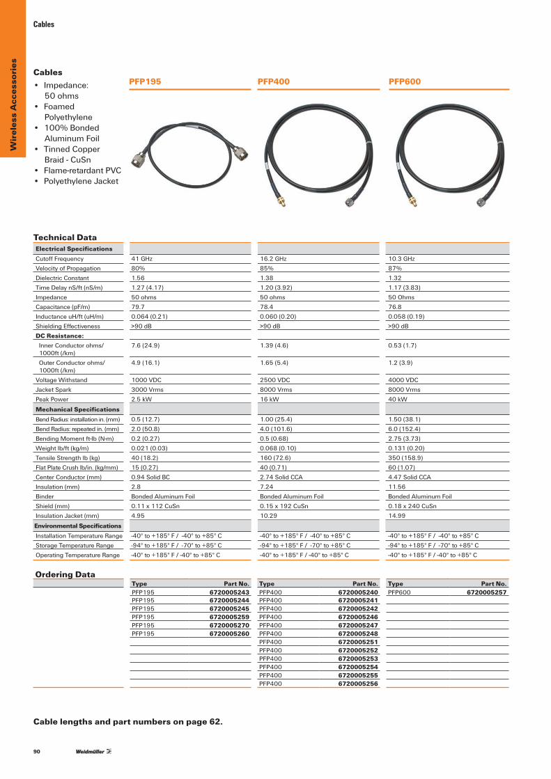
90
Wir
eles
s A
cces
sori
esCables
PFP400PFP195 PFP600Cables• Impedance:
50 ohms • Foamed
Polyethylene• 100%Bonded
AluminumFoil• Tinned Copper
Braid-CuSn• Flame-retardantPVC• PolyethyleneJacket
Technical DataElectrical SpecificationsCutoffFrequencyVelocityofPropagationDielectricConstantTimeDelaynS/ft(nS/m)ImpedanceCapacitance (pF/m)InductanceuH/ft(uH/m)ShieldingEffectivenessDC Resistance: Inner Conductor ohms/ 1000ft(/km)
Outer Conductor ohms/ 1000ft(/km)
Voltage WithstandJacketSparkPeakPower
Mechanical SpecificationsBendRadius:installationin.(mm)BendRadius:repeatedin.(mm)BendingMomentft-lb(N-m)Weightlb/ft(kg/m)TensileStrengthlb(kg)FlatPlateCrushlb/in.(kg/mm)Center Conductor (mm) Insulation (mm) BinderShield (mm) InsulationJacket(mm)
Environmental SpecificationsInstallation Temperature RangeStorage Temperature RangeOperating Temperature Range
41GHz80%1.561.27 (4.17)50 ohms79.70.064 (0.21)>90dB
7.6 (24.9)
4.9 (16.1)
1000VDC3000Vrms2.5kW
0.5 (12.7)2.0 (50.8)0.2 (0.27)0.021(0.03)40 (18.2)15 (0.27)0.94SolidBC2.8BondedAluminumFoil0.11 x 112 CuSn4.95
-40°to+185°F/-40°to+85°C-94°to+185°F/-70°to+85°C-40°to+185°F/-40°to+85°C
16.2GHz85%1.381.20(3.92)50 ohms78.40.060 (0.20)>90dB
1.39(4.6)
1.65 (5.4)
2500VDC8000 Vrms16kW
1.00 (25.4)4.0 (101.6)0.5 (0.68)0.068 (0.10)160 (72.6)40 (0.71)2.74SolidCCA7.24BondedAluminumFoil0.15 x 192 CuSn10.29
-40°to+185°F/-40°to+85°C-94°to+185°F/-70°to+85°C-40°to+185°F/-40°to+85°C
10.3GHz87%1.321.17(3.83)50 Ohms76.80.058 (0.19)>90dB
0.53(1.7)
1.2(3.9)
4000VDC8000 Vrms40kW
1.50(38.1)6.0 (152.4)2.75(3.73)0.131(0.20)350(158.9)60 (1.07)4.47SolidCCA11.56BondedAluminumFoil0.18 x 240 CuSn14.99
-40°to+185°F/-40°to+85°C-94°to+185°F/-70°to+85°C-40°to+185°F/-40°to+85°C
Cable lengths and part numbers on page 62.
Ordering DataType Part No. Type Part No. Type Part No.PFP195 6720005243 PFP400 6720005240 PFP600 6720005257PFP195 6720005244 PFP400 6720005241PFP195 6720005245 PFP400 6720005242PFP195 6720005259 PFP400 6720005246PFP195 6720005270 PFP400 6720005247PFP195 6720005260 PFP400 6720005248
PFP400 6720005251PFP400 6720005252PFP400 6720005253PFP400 6720005254PFP400 6720005255PFP400 6720005256
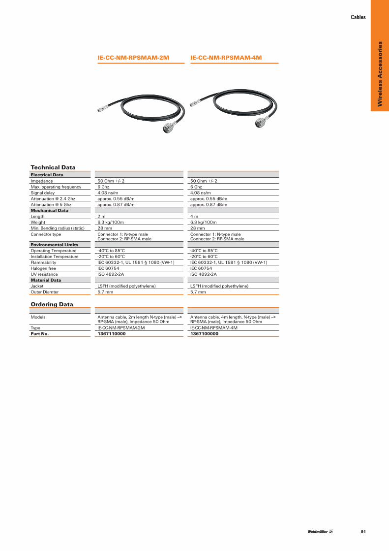
91
Wir
eles
s A
cces
sori
es
Cables
Technical DataElectrical DataImpedance 50Ohm+/-2 50Ohm+/-2Max.operatingfrequency 6 Ghz 6 GhzSignal delay 4.08 ns/m 4.08 ns/[email protected] approx.0.55dB/m approx.0.55dB/mAttenuation@5Ghz approx.0.87dB/m approx.0.87dB/mMechanical DataLength 2 m 4 mWeight 6.3kg/100m 6.3kg/100mMin.Bendingradius(static) 28 mm 28 mm Connector type Connector1:N-typemale
Connector2:RP-SMAmaleConnector1:N-typemaleConnector2:RP-SMAmale
Environmental LimitsOperating Temperature -40°Cto85°C -40°Cto85°CInstallation Temperature -20°Cto60°C -20°Cto60°CFlammability IEC60332-1,UL1581§1080(VW-1) IEC60332-1,UL1581§1080(VW-1)Halogenfree IEC 60754 IEC 60754UV resistance ISO4892-2A ISO4892-2AMaterial DataJacket LSFH(modifiedpolyethylene) LSFH(modifiedpolyethylene)OuterDiamter 5.7 mm 5.7 mm
Ordering Data
Models Antennacable,2mlengthN-type(male)--> RP-SMA(male),Impedance50Ohm
Antennacable,4mlength,N-type(male)-->RP-SMA(male),Impedance50Ohm
Type IE-CC-NM-RPSMAM-2M IE-CC-NM-RPSMAM-4MPart No. 1367110000 1367100000
IE-CC-NM-RPSMAM-2M IE-CC-NM-RPSMAM-4M

92
Wir
eles
s A
cces
sori
es
Description Stainlesssteel“L”bracketmountforwallor AluminumMFBmountbracket.Formounting HeavydutyMFBmountbracket pipemount.Formountingomnidirectional 1-1/4"diameterantennato2-1/2"maximum antennato2"maximumdiametermast. diametermast.
Type Part No. Type Part No. Type Part No. WI-ACC-24GHZ- 6720005209 WI-ACC-24GHZ- 6720005210 WI-ACC-24GHZ- 6720005211 4610DB-ANG-BRKT 4610DB-STR-BRKT 12DB-STR-BRKT
Description Lowfrequencymagneticmount Lightdutyparallelorperpendicularpipe Yagiclamp,fitsmastODof0.5-0.84". (forantennasoperating800-3000MHz) topipeclamp,fits1.5-2.4"to Mountstolegs,towers,accessories 1.5-2.4"ODpipewith1.25-2.4"OD
Type Part No. Type Part No. Type Part No. WI-ACC-MAGBASE12 6720005263 WI-ACC-900MHZ- 6720005268 WI-ACC-900MHZ- 6720005266 RG58SMAMALE OMNI-STR-BRKT YAGI-STR-BRKT
Description Yagiclamp,fitsmastODof0.75-1". AluminumMFBmountbracket. Heavydutyfiberglassbasestationmount. Mountstolegs,towers,accessorieswith Formounting1-5/16"diameterantennato Formountinganantennawith2-1/2" 1.25-2.4"OD 2-1/2"maximumdiametermast. maximumdiameteronto2-1/2"maximum diameter mast.
Type Part No. Type Part No. Type Part No. WI-ACC-900MHZ- 6720005267 WI-ACC-900MHZ- 6720005271 WI-ACC-900MHZ- 6720005272 14YAGI-STR-BRKT 035OMNI-STR-BRKT 7OMNI-STR-BRKT
Hardware — Mounts
WI-ACC-24GHZ- 4610DB-ANG-BRKT
WI-ACC-24GHZ- 4610DB-STR-BRKT
WI-ACC-24GHZ- 12DB-STR-BRKT
WI-ACC-MAGBASE 12 RG58 SMA MALE
WI-ACC-900MHZ- OMNI-STR-BRKT
WI-ACC-900MHZ- YAGI-STR-BRKT
WI-ACC-900MHZ- 14YAGI-STR-BRKT
WI-ACC-900MHZ- 035OMNI-STR-BRKT
WI-ACC-900MHZ- 7OMNI-STR-BRKT
Mounts
Ordering Data
Ordering Data
Ordering Data
Technical Data
Technical Data
Technical Data

93
Wir
eles
s A
cces
sori
es
Hardware — Surge Suppressors – Antenna Couplers
Technical Data
ConnectorFrequency RangeVSWRInsertion LossTurn-on
Ordering Data
NfemaletoNfemale125-1000MHz<1.1overfrequencyrange<0.1dBoverfrequencyrange600fbVDC+/-20%
Type Part No.WI-ACC-125-1000MHZ 6720005261 SURGENF-NF
NfemaletoNfemale2.0-6.0GHz1.3:10.1dB
Type Part No.WI-ACC-2-6GHZ 6720005262 SURGENF-NF
SMAMaletoSMAFemale<1200MHz
<0.2dBoverrange
Type Part No.WI-DIV-CCMA 6720005111 SMAM-SMAF
Technical Data
Maximum Fault VoltageMaximumAntennaPowerOutputMaximum CapacitanceFrequency RangeImpedenanceApproximateSignalAttenuation(1): @425MHz @915MHz @2.4GHzApproximateWeightHousingMaterialAmbientTemperatureRangeConnector
Approvals
Ordering Data
250VDC,250VAC50-60Hz2wattsor33dB5.64 nF260to2483MHz50 Ohms
0.6dB2.2dB2.6dB0.5lb(0.23kg)300SeriesStainlessSteel-40°/+85°CSMAmaletoSMAfemale
Class1Div1,groupA,B,C,D
Type Part No.WI-ACC-BULK-C1D1 6720005298 SMAM-SMAF
250VDC,250VAC50-60Hz2wattsor33dB5.64 nF260to2483MHz50 Ohms
3.2dB2.4dB4.1dB0.5lb(0.23kg)300SeriesStainlessSteel-40°/+85°CSMAmaletoNfemale
Class1Div1,groupA,B,C,D
Type Part No.WI-ACC-BULK-C1D1 6720005299 SMAM-NF
Antenna Coupler
WI-ACC-125-1000MHZ SURGE NF-NF
WI-ACC-2-6GHZ SURGE NF-NF
WI-DIV-CCMA SMA M – SMA F
WI-ACC-BULK-C1D1 SMA M - SMA F
WI-ACC-BULK-C1D1 SMA M - NF
Surge Suppressor

94
Wir
eles
s A
cces
sori
esHardware — Adapters
Adapter Adapter BarrelAdapterConnector SMAmaletoSMAmale SMAfemaletoSMAfemale NmaletoNmale
Type Part No. Type Part No. Type Part No. WI-ACC-ADAPT 6720005290 WI-ACC-ADAPT 6720005291 WI-ACC-ADAPT 6720005292 SMAM-SMAM SMAF-SMAF NM-NM
BarrelAdapter Adapter AdapterConnector NfemaletoNfemale SMAfemaletoNmale SMAmaletoNfemale
Type Part No. Type Part No. Type Part No. WI-ACC-ADAPT 6720005293 WI-ACC-ADAPT 6720005294 WI-ACC-ADAPT 6720005295 NF-NF SMAF-NM SMAM-NF
BulkheadAdapter RightAngleAdapterConnector SMAfemaletoSMAfemalewithD-flat SMAmaletoSMAfemale
Type Part No. Type Part No. WI-ACC-BULK 6720005296 WI-ACC-ADAPT 6720005297 SMAF-SMAF SMAF-SMAMANGL
WI-ACC-ADAPT SMA M - SMA M
WI-ACC-ADAPT SMA F - SMA F
WI-ACC-ADAPT NM - NM
WI-ACC-ADAPT NF - NF WI-ACC-ADAPT SMA F - NM
WI-ACC-BULK SMA F - SMA F
WI-ACC-ADAPT SMA F - SMA M ANGL
WI-ACC-ADAPT SMA M - NF
Adapters
Technical Data
Ordering Data
Ordering Data
Technical Data
Technical Data
Ordering Data

95
Wir
eles
s A
cces
sori
esFilters• Ultra-HighQuality
Microwave Cavity Filter
• Ultra Low Insertion Loss(0.5dBnominal)
• Industrial Grade• RuggedAluminum
WeatherproofConstructionforOutdoor or Indoor Use
Hardware — Filters
Technical DataElectrical SpecificationsCenter FrequencyBandwidthOutofBandRejection
Insertion LossPassbandRippleReturn LossImpedanceNumberofCavatiesPowerHandlingConnectorsOperating TempDimensionsmm(in)WeightKg(lbs.)
Ordering Data
915 Mhz35Mhz>40dB@815Mhz>[email protected]<0.25dB>15dB50 Ohms450 WattsNFemale(2)-40to85°C(-40to185°F)74 x 74 x 50 (2.9 x 2.9 x 1.9)0.38(0.84)
Type Part No.WI-ACC900MHZBAND 6720005120 PASSFILTER
2448MHz100 Mhz>80dB@<2000Mhz>60dB@>2700MHz0.25dB<0.25dB>15dB50 Ohms450 WattsNFemale(2)-40to85°C(-40to185°F)78x78x31(3.0x3.0x1.2)0.38(0.84)
Type Part No.WI-ACC2.4GHzBAND 6720005121 PASSFILTER
WI-ACC 900MHZ BAND PASS FILTER
WI-ACC 2.4GHZ BAND PASS FILTER
WI-ACC 5.8GHZ BAND PASS FILTER
5800MHz150MHz>6dB@5570Mhz>[email protected]<1.0dB>10dB50 Ohms450 WattsNFemale(2)-40to85°C(-40to185°F)58x58x28(2.3x2.3x1.1)0.31(0.69)
Type Part No.WI-ACC5.8GHZBAND 6720005122 PASSFILTER

96
Ethe
rnet
Basic Line — Unmanaged Switches
Unmanaged Fast Ethernet Switches• 10/100BaseT(X)(RJ45connector),100BaseFX
(multi/singlemode,SCorSTconnector)• Redundantdual12/24/48VDC,18to30VACpowerinputs• IP30aluminumhousing• Ruggedhardwaredesignwellsuitedforhazardouslocations
(ClassIDiv.2/ATEX)andmaritimeenvironments(DNV/GL)• -40to75°Coperatingtemperaturerange(Tmodels)
Formoreportcounts,pleaseseeWeidmullerIndustrialEthernetCatalogue:www.weidmueller.com
T ; u \ %
30.0 mm (1.2 in)
115.0 mm
(4.5 in)
50.0 mm (2.0 in)78.8 mm (3.1 in)
70.0 mm (2.8 in)IE-SW-BL05-
SeriesIE-SW-BL08-
Series
125.0 mm
(4.9 in)
Technical dataTechnologyStandards IEEE802.3for10BaseT
IEEE802.3ufor100BaseT(X)and100BaseFXIEEE802.3xforFlowControl
ProcessingType Store and ForwardFlow Control IEEE802.3xflowcontrol,backpressureflowcontrolSwitch PropertiesMACTableSize 1KPacketBufferSize 512KbitInterfaceFiberPorts 100BaseFXports
(SC/STconnector,multimode,singlemode)RJ45Ports 10/100BaseT(X)autonegotiationspeed,Full/Half
duplexmode,andautoMDI/MDI-XconnectionDIPSwitches Enable/DisablebroadcaststormprotectionLEDIndicators Power,10/100M(TPport),100M(fiberport)Optical Fiber
100BaseFXmultimode singlemode
Wavelength 1300nm 1310nmMax.TX -10dBm 0dBmMin.TX -20dBm -5dBmRXSensitivity -32dBm -34dBmLinkBudget 12dB 29dB
TypicalDistance 5km(50/125μmmultimodecable)4km(62,5/125μmmultimodecable)
40km(9/125μmsinglemodecable)
Saturation -6dBm -3dBmPower RequirementsInput Voltage 12/24/48VDC(9.6to60VDC),
18to30VAC(47to63Hz),redundant dual inputs
Input Current IESWBL055TX:0.1A@24VIESWBL05SC/ST/SCS:0.11A@24VIESWBL088TX:0.13A@24VIESWBL082SC/2ST:0.22A@24VIESWBL08SCS:0.17A@24V
OverloadCurrentProtection1.1AConnection 1removable4-contactterminalblockReversePolarityProtection PresentPhysical CharacteristicsHousing Aluminum,IP30protectionDimensions IIE-SW-BL05-Series:
30x115x70mm(1.18x4.52x2.76in)IE-SW-BL08-Series:50 x 115 x 70 mm (1.96 x 4.52 x 2.76 in)
Weight IE-SW-BL05-5TX:175gIE-SW-BL08-8TX:275g
Installation DIN-RailmountingEnvironmental LimitsOperating Temperature StandardModels:-10to60°C(14to140°F)
WideTemp.Models:-40to75°C(-40to167°F)Storage Temperature -40to85°C(-40to185°F)
Ordering Data
Port Variants Model TypeOperating Temperature Part No.
5 * RJ45 IE-SW-BL05-5TX -10to+60°C 1240840000IE-SW-BL05T-5TX -40to+75°C 1240850000
4*RJ45,1*SC-Multimode IE-SW-BL05-4TX-1SC -10to+60°C 1240890000IE-SW-BL05T-4TX-1SC -40to+75°C 1286550000
4*RJ45,1*ST-Multimode IE-SW-BL05-4TX-1ST -10to+60°C 1240880000IE-SW-BL05T-4TX-1ST -40to+75°C 1286540000
4*RJ45,1*SC-Singlemode IE-SW-BL05-4TX-1SCS -10to+60°C 1240870000
IE-SW-BL05T-4TX-1SCS-40to+75°C 12865300008 * RJ45 IE-SW-BL08-8TX -10to+60°C 1240900000
IE-SW-BL08T-8TX -40to+75°C 12865600006*RJ45,2*SC-Multimode IE-SW-BL08-6TX-2SC -10to+60°C 1240910000
IE-SW-BL08T-6TX-2SC -40to+75°C 12409200006*RJ45,2*ST-Multimode IE-SW-BL08-6TX-2ST -10to+60°C 1240930000
IE-SW-BL08T-6TX-2ST -40to+75°C 12865700007*RJ45,1*SC-Singlemode IE-SW-BL08-7TX-1SCS -10to+60°C 1240950000
IE-SW-BL08T-7TX-1SCS-40to+75°C 1286580000
AccessoriesModel Type Part No.
19''RackMountingKit RM-KIT 1241440000
Environmental LimitsAmbientRelativeHumidity 5 to 95 % (non-condensing) Regulatory ApprovalsSafety UL508HazardousLocation UL/cULClassI,Division2,GroupsA,B,CandD;
ATEXZone2,ExnCIICEMI FCCPart15,CISPR(EN55022)classAEMS EN61000-4-2(ESD),level3;
EN61000-4-3(RS),level3;EN61000-4-4(EFT),level3; EN61000-4-5(Surge),level3;EN61000-4-6(CS),level3; EN61000-4-8;EN61000-4-11
Maritime DNV,GL(IE-SW-BL05-4TX-1SCS/SC/ST:pending)Shock IEC 60068-2-27Freefall IEC60068-2-32Vibration IEC 60068-2-6MTBF (meantime between failures)Time 425,000hrsDatabase Telcordia(Bellcore),GBWarrantyWarrantyPeriod 5 years

97
Ethe
rnet
Basic/Value Line — Unmanaged Gigabit Switches
Unmanaged Gigabit Ethernet Switches• Fiber-opticoptionsforextendingdistanceandelectrical
noise immunity• Redundantdual12/24/48VDCpowerinputs• Relayoutputwarningforpowerfailureand
portbreakalarm• Broadcaststormprotection• Supportsjumboframetransmission(upto9.6KB)
Technical dataTechnologyStandards IEEE802.3for10BaseT
IEEE802.3ufor100BaseT(X)and100BaseFXIEEE802.3abfor1000BaseT(X)IEEE802.3zfor1000BaseXIEEE802.3xforFlowControl
ProcessingType Store and ForwardFlow Control IEEE802.3xflowcontrol,backpressure
flowcontrolSwitch PropertiesMACTableSize 8K
PacketBufferSize 1088Kbit(IE-SW-BL05-5GT), 1408Kbit(IE-SW-VL08-xGT)
Interface
FiberPorts 100/1000BaseSFPslot(IE-SW-VL08-6GT-2GS)
RJ45Ports 10/100/1000BaseT(X)autonegotiationspeed,Full/Halfduplexmode,andautoMDI/MDI-Xconnection
DIPSwitches Oneforportbreakalarm,oneforEnable/Disablebroadcaststormprotection
LEDIndicators PWR1,PWR2,FAULT,10/100/1000MAlarmContact 1 relay output with current carrying
capacityof1A@24VDCPower RequirementsInput Voltage 12/24/48VDC(9.6to60VDC),
redundant dual inputsInput Current IE-SW-BL05-5GT:0.20A@24V
IE-SW-VL08-8GT:0.32A@24VIE-SW-VL08-6GT-2GS:0.34A@24V
Connection 1removable6-contactterminalblockReversePolarityProtection PresentPhysical CharacteristicsHousing Metal,IP30protectionDimensions IE-SW-BL05-5GT:
35x130x105mm(1.37x5.12x4.13in)IE-SW-VL08-xGT: 53.6x135x105mm(2.11x5.31x4.13in)
Weight IE-SW-BL05-5GT:290gIE-SW-VL08-xGT:630g
Installation DIN-RailmountingEnvironmental LimitsOperating Temperature StandardModels:0to60°C(32to140°F)
WideTemp.Models:-40to75°C (-40to167°F)(onrequest)
Storage Temperature -40to85°C(-40to185°F)AmbientRelativeHumidity 5 to 95 % (non-condensing)Regulatory ApprovalsSafety UL508HazardousLocation UL/cULClassI,Division2,GroupsA,B,C,
andD;ATEXZone2,ExnCIICEMI FCCPart15,CISPR(EN55022)classA
Regulatory ApprovalsEMS EN61000-4-2(ESD),level3;
EN61000-4-3(RS),level3;EN61000-4-4(EFT),level3; EN61000-4-5(Surge),level3;EN61000-4-6(CS),level3
Maritime DNV,GLShock IEC 60068-2-27Freefall IEC60068-2-32Vibration IEC 60068-2-6MTBF (meantime between failures)Time 478,000hrs(IE-SW-BL05-5GTseries)
325,000hrs(IE-SW-VL08-XGTseries)Database Telcordia(Bellcore),
GB(IE-SW-VL08-xGTseries)WarrantyWarrantyPeriod 5 years
T ; u \ % 105.0 mm (4.1 in)105.0 mm (4.1 in) 53.6 mm (2.1 in) 35.0 mm (1.4 in)
130.0 mm
(5.1 in)
135.0 mm
(5.3 in)
IE-SW-BL05GT-SeriesIE-SW-VL08-xGT-Series
Ordering Data
Port Variants Model TypeOperating Temperature Part No.
5 * RJ45 10/100/1000BaseT(X)
IE-SW-BL05-5GT 0to+60°C 1241250000IE-SW-BL05T-5GT -40to+75°C 1286850000
8 * RJ45 10/100/1000BaseT(X)
IE-SW-VL08-8GT 0to+60°C 1241270000IE-SW-VL08T-8GT -40to+75°C 1286860000
6 * RJ45 10/100/1000BaseT(X),2Combo-Ports(10/100/1000BaseT(X)or100/1000BaseSFP)
IE-SW-VL08-6GT-2GS IE-SW-VL08T-6GT-2GS
0to+60°C 40to+75°C
1241280000 1286870000
AccessoriesModel Type Part No.
19''RackMountingKit RM-KIT 1241440000
Formoreportcounts,pleaseseeWeidmullerIndustrialEthernetCatalogue:www.weidmueller.com

98
Ethe
rnet
Optical Fiber100BaseFX
multimode singlemodeWavelength 1300nm 1310nmMax.TX -10dBm 0dBmMin.TX -20dBm -5dBmRXSensitivity -32dBm -34dBmLinkBudget 12dB 29dBTypicalDistance 5kma
40kmc4kmb
Saturation -6dBm -3dBma50/125μm,800MHz*kmfiberopticcable b62.5/125μm,500MHz*kmfiberopticcable c9/125μmsinglemodefiberopticcable
Power RequirementsInput Voltage 24VDC(12to45VDC),redundantdualinputsInput Current IE-SW-VL08M-8TX:0.26A@24V
IE-SW-VL08M-6TX-2ST/SC:0.35A@24VIE-SW-VL08M-5TX-3SC:0.32A@24V
Value Line — Managed Switches
Managed Entry-level Ethernet Switches• TurboRingandTurboChainwithfastrecoverytime
(under 20 ms)• IGMPsnooping,QoS,port-andtag-basedVLAN•ConfigurableerrormessagesviaSNMPtrap,e-mailor
relay output•User-friendlyweb-basedconfigurationandmanagement•ExternalBackupandRestoringModuleforeasysystem
reconfiguration(optionalaccessory)
Technical dataStandardsIEEE802.3for10BaseT•IEEE802.3ufor100BaseT(X)and100BaseFX•IEEE802.3xforFlowControl•IIEEE802.1DforSpanningTreeProtocol•IEEE802.1wforRapidSTP•IEEE802.1pforClassofService•IEEE802.1QforVLANTaggingProtocolsIGMPv1/v2•GMRP•GVRP•SNMPv1/v2c/v3•DHCPServer/Client•TFTP•SNTP•SMTP•RARP•RMON•HTTP•Telnet•Syslog•DHCPOption66/67/82•BootP•LLDP•Modbus/TCP•IPv6MIBMIB-II•Ethernet-LikeMIB•P-BRIDGEMIB•BridgeMIB•RSTPMIB•RMONMIBGroup1,2,3,9Flow ControlIEEE802.3xflowcontrol•backpressureflowcontrolSwitch PropertiesMACTableSize 8KPacketBufferSize 1MBitInterfaceFiberPorts 100BaseFXports(SC/STconnector)RJ45Ports 10/100BaseT(X)autonegotiationspeed,
Full/Halfduplexmode,andautoMDI/MDI-Xconnection
ConsolePort RS-232(RJ45connector)DIPSwitches TurboRing,Master,Coupler,ReserveLEDIndicators PWR1,PWR2,FAULT,MSTR/HEAD,
CPLR/TAIL,10/100MAlarmContact 1 relay output with current carrying capacity
of1A@24VDC
T ; u \ %
Ordering Data
Port Variants Model TypeOperating Temperature Part No.
8 * RJ45 IE-SW-VL08MT-8TX -40to+75°C 12409400005*RJ45,3*SC-Multimode IE-SW-VL08MT-5TX-3SC -40to+75°C 12409700006*RJ45,2*ST-Multimode IE-SW-VL08MT-6TX-2ST -40to+75°C 12409900006*RJ45,2*SC-SinglemodeIE-SW-VL08MT-6TX-2SCS-40to+75°C 1241020000
AccessoriesModel Type Part No.
ExternalBackupand Restore Module
EBR-ModulRS232 1241430000
19''RackMountingKit RM-KIT 1241440000
9.0 mm (0.4 in)
105.0 mm (4.1 in) 53.6 mm (2.1 in)
135.0 mm
(5.3 in)
Power Requirements (continued)OverloadCurrentProtection PresentConnection 1removable6-contactterminalblockReversePolarityProtection PresentPhysical CharacteristicsHousing Metal,IP30protectionDimensions 53.6x135x105mm
(2.11x5.31x4.13in)Weight IE-SW-VL08M-...8TX/6TX-2SC/
6TX-2ST:650gIE-SW-VL08M-5TX-3SC:890g
Installation DIN-RailmountingEnvironmental LimitsOperating Temperature -40to75°C(-40to167°F)Storage Temperature -40to85°C(-40to185°F)AmbientRelativeHumidity 5 to 95 % (non-condensing)Regulatory ApprovalsSafety UL508,UL60950-1,CSAC22.2No.60950-1,
EN60950-1HazardousLocation UL/cULClassI,Division2,GroupsA,B,C,andD;
ATEXZone2,ExnCIICEMI FCCPart15,CISPR(EN55022)classAEMS EN61000-4-2(ESD),level3;
EN61000-4-3(RS),level3;EN61000-4-4(EFT),level3;EN61000-4-5(Surge),level3;EN61000-4-6(CS),level3;EN61000-4-8
Maritime DNV,GLShock IEC 60068-2-27Freefall IEC60068-2-32Vibration IEC 60068-2-6MTBF (meantime between failures)Time IE-SW-VL08M-...Series:
363,000hrsDatabase Telcordia(Bellcore),GBWarrantyWarrantyPeriod 5 years
Formoreportcounts,pleaseseeWeidmullerIndustrialEthernetCatalogue:www.weidmueller.com
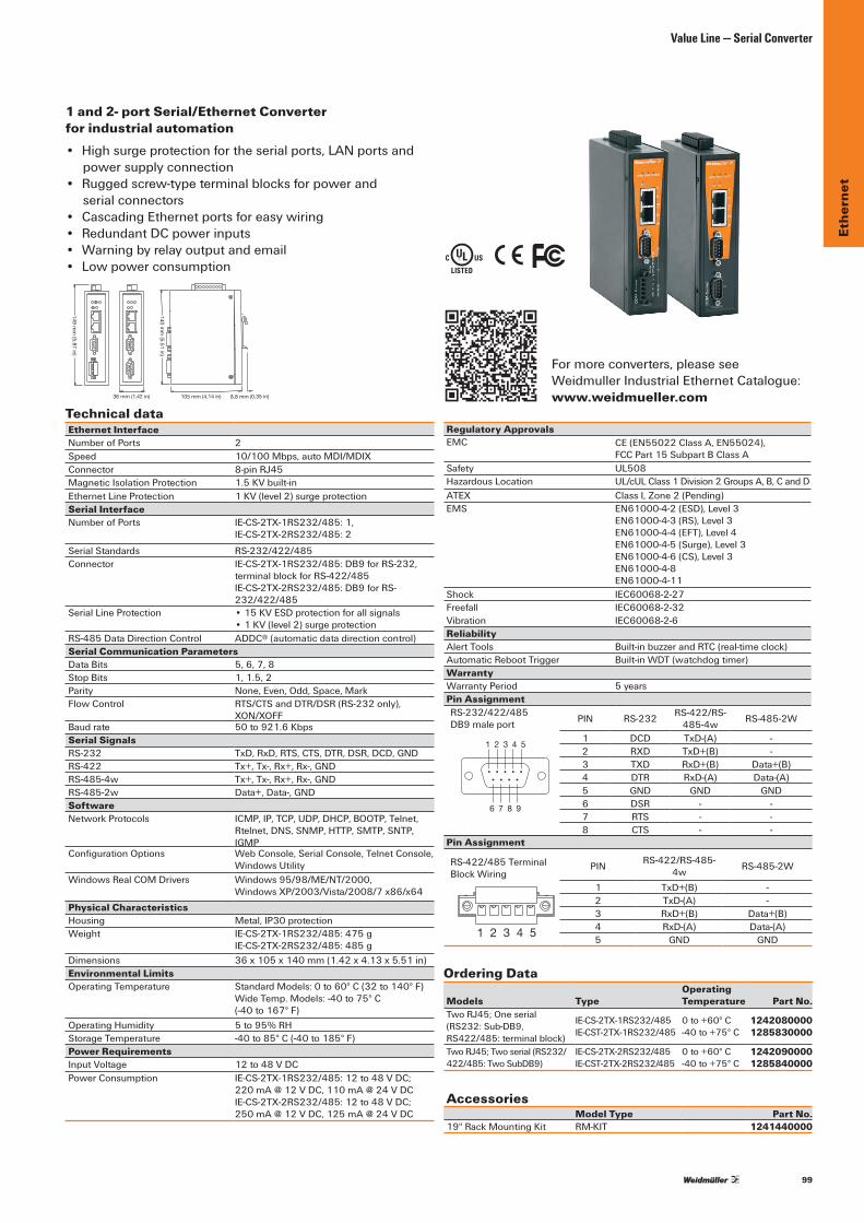
99
Ethe
rnet
Value Line — Serial Converter
1 and 2- port Serial/Ethernet Converter for industrial automation• Highsurgeprotectionfortheserialports,LANportsand
power supply connection• Ruggedscrew-typeterminalblocksforpowerand
serial connectors• CascadingEthernetportsforeasywiring• RedundantDCpowerinputs• Warningbyrelayoutputandemail• Low power consumption
Technical dataRegulatory ApprovalsEMC CE(EN55022ClassA,EN55024),
FCCPart15SubpartBClassASafety UL508HazardousLocation UL/cULClass1Division2GroupsA,B,CandDATEX ClassI,Zone2(Pending)EMS EN61000-4-2(ESD),Level3
EN61000-4-3(RS),Level3 EN61000-4-4(EFT),Level4 EN61000-4-5(Surge),Level3 EN61000-4-6(CS),Level3 EN61000-4-8 EN61000-4-11
Shock IEC60068-2-27Freefall IEC60068-2-32Vibration IEC60068-2-6ReliabilityAlertTools Built-inbuzzerandRTC(real-timeclock)AutomaticRebootTrigger Built-inWDT(watchdogtimer)WarrantyWarrantyPeriod 5 yearsPin Assignment
Ordering Data
Models TypeOperating Temperature Part No.
TwoRJ45;Oneserial (RS232:Sub-DB9,RS422/485:terminalblock)
IE-CS-2TX-1RS232/485 IE-CST-2TX-1RS232/485
0to+60°C -40to+75°C
1242080000 1285830000
TwoRJ45;Twoserial(RS232/422/485:TwoSubDB9)
IE-CS-2TX-2RS232/485IE-CST-2TX-2RS232/485
0to+60°C -40to+75°C
1242090000 1285840000
AccessoriesModel Type Part No.
19''RackMountingKit RM-KIT 1241440000
\ %
105 mm (4.14 in) 8.8 mm (0.35 in)
140 mm
(5.51 in)
36 mm (1.42 in)
149 mm
(5.87 in)
Ethernet InterfaceNumberofPorts 2Speed 10/100Mbps,autoMDI/MDIXConnector 8-pin RJ45MagneticIsolationProtection 1.5KVbuilt-inEthernetLineProtection 1KV(level2)surgeprotectionSerial InterfaceNumberofPorts IE-CS-2TX-1RS232/485:1,
IE-CS-2TX-2RS232/485:2
Serial Standards RS-232/422/485Connector IE-CS-2TX-1RS232/485:DB9forRS-232,
terminalblockforRS-422/485 IE-CS-2TX-2RS232/485:DB9forRS-232/422/485
SerialLineProtection •15KVESDprotectionforallsignals •1KV(level2)surgeprotection
RS-485DataDirectionControl ADDC® (automatic data direction control)Serial Communication ParametersDataBits 5,6,7,8StopBits 1,1.5,2Parity None,Even,Odd,Space,MarkFlow Control RTS/CTSandDTR/DSR(RS-232only),
XON/XOFFBaudrate 50to921.6KbpsSerial SignalsRS-232 TxD,RxD,RTS,CTS,DTR,DSR,DCD,GNDRS-422 Tx+,Tx-,Rx+,Rx-,GNDRS-485-4w Tx+,Tx-,Rx+,Rx-,GNDRS-485-2w Data+,Data-,GNDSoftwareNetworkProtocols ICMP,IP,TCP,UDP,DHCP,BOOTP,Telnet,
Rtelnet,DNS,SNMP,HTTP,SMTP,SNTP,IGMP
ConfigurationOptions WebConsole,SerialConsole,TelnetConsole, Windows Utility
WindowsRealCOMDrivers Windows95/98/ME/NT/2000, WindowsXP/2003/Vista/2008/7x86/x64
Physical CharacteristicsHousing Metal,IP30protectionWeight IE-CS-2TX-1RS232/485:475g
IE-CS-2TX-2RS232/485:485gDimensions 36x105x140mm(1.42x4.13x5.51in)Environmental LimitsOperating Temperature StandardModels:0to60°C(32to140°F)
WideTemp.Models:-40to75°C (-40to167°F)
OperatingHumidity 5to95%RHStorage Temperature -40to85°C(-40to185°F)Power RequirementsInput Voltage 12to48VDCPowerConsumption IE-CS-2TX-1RS232/485:12to48VDC;
220mA@12VDC,110mA@24VDC IE-CS-2TX-2RS232/485:12to48VDC; 250mA@12VDC,125mA@24VDC
PIN RS-232 RS-422/RS-485-4w RS-485-2W
1 DCD TxD-(A) -2 RXD TxD+(B) -3 TXD RxD+(B) Data+(B)4 DTR RxD-(A) Data-(A)5 GND GND GND6 DSR - -7 RTS - -8 CTS - -
1 2 3 4 5
6 7 8 9
RS-232/422/485DB9maleport
PIN RS-422/RS-485-4w RS-485-2W
1 TxD+(B) -2 TxD-(A) -3 RxD+(B) Data+(B)4 RxD-(A) Data-(A)5 GND GND
1 2 3 4 5
RS-422/485 TerminalBlockWiring
Pin Assignment
Formoreconverters,pleasesee WeidmullerIndustrialEthernetCatalogue:www.weidmueller.com
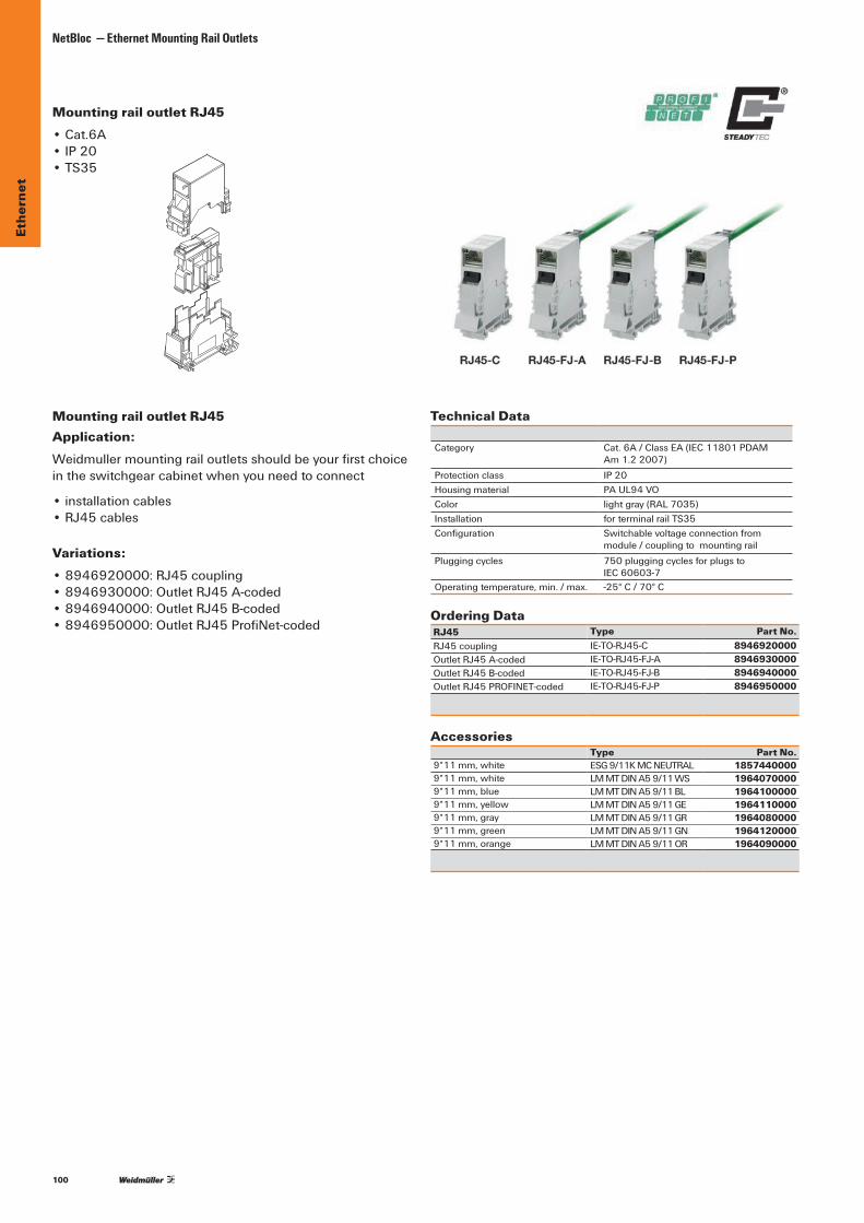
100
Ethe
rnet
NetBloc — Ethernet Mounting Rail Outlets
Mounting rail outlet RJ45 •Cat.6A•IP20•TS35
Mounting rail outlet RJ45
Ordering DataRJ45 Type Part No.RJ45 coupling IE-TO-RJ45-C 8946920000OutletRJ45A-coded IE-TO-RJ45-FJ-A 8946930000OutletRJ45B-coded IE-TO-RJ45-FJ-B 8946940000OutletRJ45PROFINET-coded IE-TO-RJ45-FJ-P 8946950000
Accessories Type Part No.9*11mm,white ESG9/11KMCNEUTRAL 18574400009*11mm,white LMMTDINA59/11WS 19640700009*11mm,blue LMMTDINA59/11BL 19641000009*11mm,yellow LMMTDINA59/11GE 19641100009*11mm,gray LMMTDINA59/11GR 19640800009*11mm,green LMMTDINA59/11GN 19641200009*11mm,orange LMMTDINA59/11OR 1964090000
Technical Data
Category Cat.6A/ClassEA(IEC11801PDAM Am1.22007)
Protectionclass IP20Housingmaterial PAUL94VOColor lightgray(RAL7035)Installation forterminalrailTS35Configuration Switchablevoltageconnectionfrom
module / coupling to mounting railPluggingcycles 750pluggingcyclesforplugsto
IEC60603-7Operatingtemperature,min./max. -25°C/70°C
Application:Weidmullermountingrailoutletsshouldbeyourfirstchoiceintheswitchgearcabinetwhenyouneedtoconnect
•installationcables•RJ45cables
Variations:•8946920000:RJ45coupling•8946930000:OutletRJ45A-coded•8946940000:OutletRJ45B-coded•8946950000:OutletRJ45ProfiNet-coded
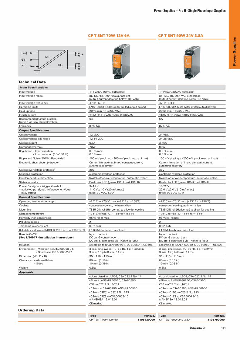
101
Pow
er S
uppl
ies
Power Supplies — Pro H—Single Phase Input Supplies
Technical Data Input SpecificationsInput voltageInput voltage range
InputvoltagefrequencyHarmoniclimitsHolduptimeInrush currentRecommendedCircuitbreaker, Curve1orfuse,slowblowtypeEfficiency
Output SpecificationsOutput voltageOutputvoltageadj.rangeOutput currentOutput power max.Regulation–Inputvariation
–Loadvariation(10–100%)RippleandNoise(20MHzBandwidth)Electronic short circuit protection
Output overvoltage protectionOverload protectionOvertemperature protectionStatus indicatorPowerOKsignal–triggerthreshold: –activeoutputsignal:(referenceto–Vout) –relayoutput
General SpecificationsOperating temperature rangeCoolingMountingStorage temperatureHumidity(noncondensing)PollutiondegreeTemperaturecoefficientReliability,calculatedMTBF@25°Cacc.toIEC61709RemoteOn/Off (See LIT0917 - Installation Instructions)
IsolationEnvironment–Vibrationacc.IEC60068-2-6
–Shockacc.IEC60068-2-27Dimension(WxDxH)Clearances–Above/Below
–SidesWeight
Approvals
Ordering Data
115VAC/230VACautoselect85-132/187-264VACautoselect (outputcurrentderatingbelow100VAC)47Hz-63HzEN61000-3-2,ClassA(forlimitedoutputpower)20msmin.115/230VAC<12A@115VAC;<20A@230VAC6A
87% typ.
12VDC12-14VDC6.5A70W 0.5 % max. 0.5 % max.100mVpk-pktyp.(200mVpk-pkmax.atImax)CurrentlimitationatImax.,constantcurrent, automatic recovery20Velectronic overload protectionSwitchoffatovertemperature,automaticrestartDualcolorLED(green:DCok;red:DCoff)9–11V 11.0V±1.0V(20mAmax.) rated:30VDC/1.0A
–25°Cto+70°Cmax.(–13°Fto+158°F)convectioncooling,nointernalfanTS35DIN-rail(Horizontal)toallowforcooling–25°Cto+85°C(–13°Fto+185°F)95%rel.Hmax.20.02%/K>1.8Millionhours,max.loadbyext.contact. DCon:-Scontactopen DCoff:-Sconnectedvia1Kohmto-VoutaccordingtoIEC/EN60950-1,UL60950-1,UL5083axis,sinesweep,10–55Hz,1g,1oct/min 3axis,15ghalfsine,11ms35x110x110mm80mm(3.15in) 10mm(0.39in)0.5kg
cULusListedtoUL508,CSAC22.2No.14cRUustoANSI/UL60950,CSA60950CSAtoC22.2No.107.1cCSAustoCSA60950,ANSI/UL60950cCSAusC1D2toC22.2No.213cCSAusC1Z2toCSA60079-15 &ANSI/ISA12.012.01CEmarked
Type Part No.CPTSNT70W12V6A 1105430000
AC
DC
L (+) +
- PE
N ( -
115VAC/230VACautoselect85-132/187-264VACautoselect (outputcurrentderatingbelow100VAC)47Hz-63HzEN61000-3-2,ClassA(forlimitedoutputpower)20msmin.115/230VAC<12A@115VAC;<20A@230VAC6A
87% typ.
24VDC24-28VDC3.75A90W 0.5 % max. 0.5 % max.100mVpk-pktyp.(200mVpk-pkmax.atImax)CurrentlimitationatImax.,constantcurrent, automatic recovery35Velectronic overload protectionSwitchoffatovertemperature,automaticrestartDualcolorLED(green:DCok;red:DCoff) 18-22 V 22.0V±2.0V(10mAmax.) rated:30VDC/1.0A
–25°Cto+70°Cmax.(–13°Fto+158°F)convectioncooling,nointernalfanTS35DIN-rail(Horizontal)toallowforcooling–25°Cto+85°C(–13°Fto+185°F)95%rel.Hmax.20.02%/K>1.8Millionhours,max.loadbyext.contact. DCon:-Scontactopen DCoff:-Sconnectedvia1Kohmto-VoutaccordingtoIEC/EN60950-1,UL60950-1,UL5083axis,sinesweep,10–55Hz,1g,1oct/min 3axis,15ghalfsine,11ms35x110x110mm80mm(3.15in) 10mm(0.39in)0.5kg
cULusListedtoUL508,CSAC22.2No.14cRUustoANSI/UL60950,CSA60950CSAtoC22.2No.107.1cCSAustoCSA60950,ANSI/UL60950cCSAusC1D2toC22.2No.213cCSAusC1Z2toCSA60079-15 &ANSI/ISA12.012.01CEmarked
Type Part No.CPTSNT90W24V3.8A 1105790000
CP T SNT 70W 12V 6A CP T SNT 90W 24V 3.8A

102
Pow
er S
uppl
ies
Power Supplies — PROeco—Single Phase Input Supplies
PRO ECO 120W 24V 5APRO ECO 72W 24V 3A
Technical DataInputRated input voltageACinputvoltagerangeACfrequencyrangeDCinputvoltagerangeACcurrentconsumptionDCcurrentconsumptionInputfuse(internal)/inrushcurrentRecommendedback-upfuse
OutputRated output voltageOutput voltageRamp-uptime/residualripple,switchingpeaksRated output current @ Urated
Continuousoutputcurrent@24VDCCapacitive loadProtectionagainstreversevoltagesfromtheloadProtectionagainstinternalsurgevoltageSignallingDCOKAlarmError
Voltage monitoring / no-voltage contact / contact loadOn/OffrelayGeneral dataEfficiencyPowerloss@idling/nominalloadEarth discharge currentPowerfactor(approx.)Mainsbuffering@Irated
ParallelconnectionoptionHeightxwidthxdepth/weightApprovalsApprovalsConnection dataConductor connection systemNumberofterminalsWirecross-section,rigidmin/max mm²Wirecross-section,flexiblemin/max mm²Wirecross-section,AWG/kcmil min/maxMin./max.tighteningtorquerange NmStripping length mm
Ordering Data
Note
100…240VAC85…264VAC(Derating@100VAC)47…63Hz80…370DC(Derating@120VDC)0.55A@230VAC/[email protected]@370VDC/0.68A@120VDCYes / max. 402A/DI,Safetyfuse6A,Char.B,Circuitbreaker2...4A,Char.C,Circuitbreaker
24VDC±1%22...28VDC(adjustableviapotentiometeronfront)<100ms/<50mVSS@24VDC,IR3Aupto55°C3A@55°C,2.25A@70°CUnrestricted30…35VDC35VDC
LEDGreen(Uoutput>21.6VDC)LEDYellow(Ioutput >90%IR )LEDRed(Overload,overtemperature,short-circuit,Uoutput<20.4VDC)
Yes/NOcontact/max.30VAC/DC1A
Outputvoltage>21.6VDC/<20.4VDC
>87%@230VAC&3A4 W / 9.5 W<1mA>0.42@230VAC/>0.45@115VAC>100ms@230VAC/>20ms@115VACyes,max.5125/34/100mm/0.5kg
CE,TÜV(EN/IEC60950-1),cULusInput OutputScrew connection Screw connection3forL/N/PE 5(13,14,+,--)0.5/6 0.5/60.5/2.5 0.5/2.526/12 26/120.5/0.6 0.5/0.66 6
Type Qty. Part No.PROECO72W24V3A 1 1469470000Theinternalvaristorfoundinaswitch-modepowerunitdoesnot replace the necessary surge protection in a system.
100…240VAC85…264VAC(Derating@100VAC)47…63Hz80…370DC(Derating@120VDC)1.26A@230VAC/[email protected]@370VDC/1.16A@120VDCYes / max. 404A/DI,Safetyfuse6A,Char.B,Circuitbreaker3...5A,Char.C,Circuitbreaker
24VDC±1%22...28VDC(adjustableviapotentiometeronfront)<100ms/<50mVSS@24VDC,IR5Aupto55°C5A@55°C,3.75A@70°CUnrestricted30…35VDC35VDC
LEDGreen(Uoutput>21.6VDC)LEDYellow(Ioutput>90%IR )LEDRed(Overload,overtemperature,short-circuit,Uoutput<20.4VDC)
Yes/NOcontact/max.30VAC/DC1A
Outputvoltage>21.6VDC/<20.4VDC
>87%@230VAC&5A4 W / 15 W<1mA>0.47@230VAC/>0.56@115VAC>80ms@230VAC/>20ms@115VACyes,max.5125/40/100mm/0.6kg
CE,TÜV(EN/IEC60950-1),cULusInput OutputScrew connection Screw connection3forL/N/PE 6(13,14,+,+,--)0.5/6 0.5/6 0.5/2.5 0.5/2.526/12 26/120.5/0.6 0.5/0.66 6
Type Qty. Part No.PROECO120W24V5A 1 1469480000Theinternalvaristorfoundinaswitch-modepowerunitdoesnot replace the necessary surge protection in a system.
+
––
1314
L (+)
N (–)
PE DCAC
Pay attention to polarity of DC connection
++––
1314
L (+)
N (–)
PE DCAC
Pay attention to polarity of DC connection
PROeco
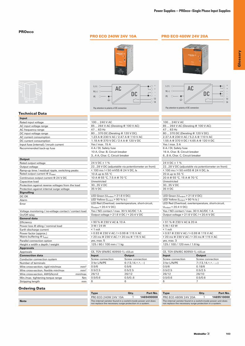
103
Glo
ssar
y
Power Supplies — PROeco—Single Phase Input Supplies
PRO ECO 480W 24V 20APRO ECO 240W 24V 10A
Technical DataInputRated input voltageACinputvoltagerangeACfrequencyrangeDCinputvoltagerangeACcurrentconsumptionDCcurrentconsumptionInputfuse(internal)/inrushcurrentRecommendedback-upfuse
OutputRated output voltageOutput voltageRamp-uptime/residualripple,switchingpeaksRated output current @ Urated
Continuousoutputcurrent@24VDCCapacitive loadProtectionagainstreversevoltagesfromtheloadProtectionagainstinternalsurgevoltageSignallingDCOKAlarmError
Voltage monitoring / no-voltage contact / contact loadOn/OffrelayGeneral dataEfficiencyPowerloss@idling/nominalloadEarth discharge currentPowerfactor(approx.)Mainsbuffering@Irated
ParallelconnectionoptionHeightxwidthxdepth/weightApprovalsApprovalsConnection dataConductor connection systemNumberofterminalsWirecross-section,rigidmin/max mm²Wirecross-section,flexiblemin/max mm²Wirecross-section,AWG/kcmil min/maxMin./max.tighteningtorquerange NmStripping length mm
Ordering Data
Note
100…240VAC85…264VAC(Derating@100VAC)47…63Hz80…370DC(Derating@120VDC)1.23A@230VAC/[email protected]@370VDC/2.4A@120VDCYes/max.15A4A/DI,Safetyfuse10A,Char.B,Circuitbreaker3...4A,Char.C,Circuitbreaker
24VDC±1%22...28VDC(adjustableviapotentiometeronfront)<100ms/<50mVSS@24VDC,IR10Aupto55°C10A@55°C,7.5A@70°CUnrestricted30…35VDC35VDC
LEDGreen(Uoutput>21.6VDC)LEDYellow(Ioutput >90%IR )LEDRed(Overload,overtemperature,short-circuit,Uoutput<20.4VDC)Yes/NOcontact/max.30VAC/DC1AOutputvoltage>21.6VDC/<20.4VDC
>90%@230VAC&10A3W/24W<1mA>0.93@230VAC/>0.99@115VAC>20ms@230VAC/>20ms@115VACyes,max.5125/60/100mm/1kg
CE,TÜV(EN/IEC60950-1),cULusInput OutputScrew connection Screw connection3forL/N/PE 6(13,14,+,+,--)0.5/6 0.5/60.5/2.5 0.5/2.526/12 26/120.5/0.6 0.5/0..66 6
Type Qty. Part No.PROECO240W24V10A 1 1469490000Theinternalvaristorfoundinaswitch-modepowerunitdoesnot replace the necessary surge protection in a system.
100…240VAC85…264VAC(Derating@100VAC)47…63Hz80…370DC(Derating@120VDC)2.37A@230VAC/[email protected]@370VDC/4.65A@120VDCYes/max.3A6A/DI,Safetyfuse16A,Char.B,Circuitbreaker6…8A,Char.C,Circuitbreaker
24VDC±1%22...28VDC(adjustableviapotentiometeronfront)<100ms/<50mVSS@24VDC,IR20Aupto55°C20A@55°C,15A@70°CUnrestricted30…35VDC35VDC
LEDGreen(Uoutput>21.6VDC)LEDYellow(Ioutput>90%IR )LEDRed(Overload,overtemperature,short-circuit,Uoutput<20.4VDC)Yes/NOcontact/max.30VAC/DC1AOutputvoltage>21.6VDC/<20.4VDC
>91%@230VAC&20A5W/43W<1mA>0.97@230VAC/>0.99@115VAC>20ms@230VAC/>20ms@115VACyes,max.3125/100/120mm/1.6kg
CE,TÜV(EN/IEC60950-1),cULusInput OutputScrew connection Screw connection3forL/N/PE 7(13,14,+,+,-,-,-)0.5/6 0.18/60.5/2.5 0.5/2.526/12 26/100.5/0.6 0.5/0.66 7
Type Qty. Part No.PROECO480W24V20A 1 1469510000Theinternalvaristorfoundinaswitch-modepowerunitdoesnot replace the necessary surge protection in a system.
PROeco
++––
1314
L (+)
N (–)
PE DCAC
Pay attention to polarity of DC connection
++–––
1314
L (+)
N (–)
PE DCAC
Pay attention to polarity of DC connection

104
Glo
ssar
yGlossary
GlossaryACK Acknowledgment.
Access point Anaccesspointistheconnectionthattieswirelesscommunicationdevicesintoanetwork.Alsoknownasabasestation,theaccesspointisusuallyconnectedtoawirednetwork.
Antenna Gain Antennaedon’tincreasethetransmissionpower,butfocusthesignalmore.Soinsteadoftransmittingineverydirection(includingtheskyandground)antennafocusthesignalusuallyeithermorehorizontallyorinoneparticulardirection.Thisgainismeasuredindecibels.
Bandwidth Theamountof“transportation”spaceanInternetuserhasatanygiventime.
Bridge Ahardwarecomponentusedtoconnecttwoormorenetworksegmentswhicharephysically and logically separated.
Collision avoidance Anetworknodecharacteristicforproactivelydetectingthatitcantransmitasignalwithoutrisking a collision.
Crossover cable Aspecialcableusedfornetworkingtwocomputerswithouttheuseofahub.CrossovercablesmayalsoberequiredforconnectingacableorDSLmodemtoawirelessgatewayoraccesspoint.Insteadofthesignalstransferringinparallelpathsfromonesetofplugstoanother,thesignals“crossover.”Ifaneight-wirecablewasbeingused,forinstance,thesignalwouldstartonpinoneatoneendofthecableandenduponpineightattheotherend.They“cross-over”fromonesidetothe other.
CSMA/CA CSMA/CAisa“listenbeforetalk”methodofminimizing(butnoteliminating)collisionscausedbysimultaneoustransmissionbymultipleradios.IEEE802.11statescollisionavoidancemethodratherthancollisiondetectionmustbeused,becausethestandardemployshalfduplexradios—radioscapableoftransmissionorreception—butnotbothsimultaneously.UnlikeconventionalwiredEthernetnodes,aWLANstationcannotdetectacollisionwhiletransmitting.Ifacollisionoccurs,thetransmittingstationwillnotreceiveanACKnowledgepacketfromtheintendedreceivestation.Forthisreason,ACKpacketshaveahigherprioritythanallothernetworktraffic.Aftercompletionofadatatransmission,thereceivestationwillbegintransmissionoftheACKpacketbeforeanyothernodecanbegintransmittinganewdatapacket.Allotherstationsmustwaitalongerpseudorandomizedperiodoftimebeforetransmitting.IfanACKpacketisnotreceived,thetransmittingstationwillwaitforasubsequentopportunitytoretrytransmission.
CSMA/CD AmethodofmanagingtrafficandreducingnoiseonanEthernetnetwork.Anetworkdevicetransmitsdataafterdetectingthatachannelisavailable.However,iftwodevicestransmitdatasimultaneously,thesendingdevicesdetectacollisionandretransmitafterarandomtimedelay.
DHCP AutilitythatenablesaservertodynamicallyassignIPaddressesfromapredefinedlistandlimittheirtimeofusesothattheycanbereassigned.WithoutDHCP,anITManagerwouldhavetomanuallyenterinalltheIPaddressesofallthecomputersonthenetwork.WhenDHCPisused,wheneveracomputerlogsontothenetwork,itautomaticallygetsanIPaddressassignedtoit.
Dial-up Acommunicationconnectionviathestandardtelephonenetwork,orPlainOldTelephoneService(POTS).
DNS AprogramthattranslatesURLstoIPaddressesbyaccessingadatabasemaintainedonacollectionofInternetservers.TheprogramworksbehindthescenestofacilitatesurfingtheWebwithalphaversusnumericaddresses.ADNSserverconvertsanamelikemywebsite.comtoaseriesofnumberslike107.22.55.26.EverywebsitehasitsownspecificIPaddressontheInternet.
DSL Varioustechnologyprotocolsforhigh-speeddata,voiceandvideotransmissionoverordinarytwisted-paircopperPOTS(PlainOldTelephoneService)telephonewires.
Encryption key Analphanumeric(lettersand/ornumbers)seriesthatenablesdatatobeencryptedandthendecryptedsoitcanbesafelysharedamongmembersofanetwork.WEPusesanencryptionkeythatautomaticallyencryptsoutgoingwirelessdata.Onthereceivingside,thesameencryptionkeyenablesthecomputertoautomaticallydecrypttheinformationsoitcanberead.
Firewall Keepsunauthorizedusersoutofaprivatenetwork.Everythingenteringorleavingasystem’sinternalnetworkpassesthroughthefirewallandmustmeetthesystem’ssecuritystandardsinordertobetransmitted.Oftenusedtokeepunauthorizedpeoplefromusingsystemsconnectedtothe Internet.

105
Glo
ssar
y
Glossary
Hub AmultiportdeviceusedtoconnectPCstoanetworkviaEthernetcablingorviaWiFi.Wiredhubscanhavenumerousportsandcantransmitdataatspeedsrangingfrom10Mbpstomultigigabytespeedspersecond.Ahubtransmitspacketsitreceivestoalltheconnectedports.Asmallwiredhubmayonlyconnect4computers;alargehubcanconnect48ormore.
HZ Theinternationalunitformeasuringfrequency,equivalenttotheolderunitofcyclespersecond.Onemegahertz(MHz)isonemillionhertz.Onegigahertz(GHz)isonebillionhertz.ThestandardUSelectricalpowerfrequencyis60Hz,theAMbroadcastradiofrequencybandis535—1605kHz,theFMbroadcastradiofrequencybandis88—108MHzandwireless802.11bLANsoperateat2.4 GHz.
IEEE InstituteofElectricalandElectronicsEngineers,NewYork,www.ieee.org.Amembershiporganizationthatincludesengineers,scientistsandstudentsinelectronicsandalliedfields.Ithasmorethan300,000membersandisinvolvedwithsettingstandardsforcomputersandcommunications.
Infrastructure mode AclientsettingprovidingconnectivitytoanAP.AscomparedtoAd-Hocmode,wherebyPCscommunicatedirectlywitheachother,clientssetinInfrastructureModeallpassdatathroughacentralAP.TheAPnotonlymediateswirelessnetworktrafficintheimmediateneighborhood,butalsoprovidescommunicationwiththewirednetwork.SeeAd-HocandAP.
I/O Thetermusedtodescribeanyoperation,programordevicethattransfersdatatoorfromacomputer.
Internet appliance AcomputerthatisintendedprimarilyforInternetaccessissimpletosetupandusuallydoesnotsupportinstallationofthird-partysoftware.Thesecomputersgenerallyoffercustomizedwebbrowsing,touch-screennavigation,e-mailservices,entertainmentandpersonalinformationmanagement applications.
IP AsetofrulesusedtosendandreceivemessagesattheInternetaddresslevel.
IP (Internet Protocol) Technologythatsupportsvoice,dataandvideotransmissionviaIP-basedLANs,WANsandthe telephony Internet.ThisincludesVoIP(VoiceoverIP).
IP address A32-bitnumberthatidentifieseachsenderorreceiverofinformationthatissentacrosstheInternet.AnIPaddresshastwoparts:anidentifierofaparticularnetworkontheInternetandanidentifieroftheparticulardevice(whichcanbeaserveroraworkstation)withinthatnetwork.
IPX-SPX IPX,shortforInternetworkPacketExchange,anetworkingprotocolusedbytheNovellNetWareoperatingsystems.LikeUDP/IP,IPXisadatagramprotocolusedforconnectionlesscommunications.Higher-levelprotocols,suchasSPXandNCP,areusedforadditionalerrorrecoveryservices.SequencedPacketExchange,SPX,atransportlayerprotocol(layer4oftheOSIModel)usedinNovellNetwarenetworks.TheSPXlayersitsontopoftheIPXlayer(layer3)andprovidesconnection-orientedservicesbetweentwonodesonthenetwork.SPXisusedprimarilybyclient/serverapplications.
ISA Atypeofinternalcomputerbusthatallowstheadditionofcard-basedcomponentslikemodemsandnetworkadapters.ISAhasbeenreplacedbyPCIandisnotverycommonanymore.
ISDN AtypeofbroadbandInternetconnectionthatprovidesdigitalservicefromthecustomer’spremisestothedial-uptelephonenetwork.ISDNusesstandardPOTScopperwiringtodelivervoice,dataorvideo.
ISO Network Model AnetworkmodeldevelopedbytheInternationalStandardsOrganization(ISO)thatconsistsofsevendifferentlevels,orlayers.Bystandardizingtheselayersandtheinterfacesinbetween,differentportionsofagivenprotocolcanbemodifiedorchangedastechnologiesadvanceorsystemsrequirementsarealtered.Thesevenlayersare:Physical,DataLink,Network,Transport,Session,PresentationandApplication.
LAN AsystemofconnectingPCsandotherdeviceswithinthesamephysicalproximityforsharingresourcessuchasanInternetconnection,printers,filesanddrives.
MAC Address AMACaddress,shortforMediaAccessControladdress,isauniquecodeassignedtomostforms ofnetworkinghardware.Theaddressispermanentlyassignedtothehardware,solimitingawirelessnetwork’saccesstohardware--suchaswirelesscards--isasecurityfeatureemployedbyclosedwirelessnetworks.Butanexperiencedhacker--armedwiththepropertools--canstillfigureoutanauthorizedMACaddress,masqueradeasalegitimateaddressandaccessaclosednetwork.
Everywireless802.11devicehasitsownspecificMACaddresshard-codedintoit.Thisuniqueidentifiercanbeusedtoprovidesecurityforwirelessnetworks.WhenanetworkusesaMACtable,onlythe802.11radiosthathavehadtheirMACaddressesaddedtothatnetwork’sMACtablewouldbeabletogetontothenetwork.

106
Glo
ssar
yGlossary
Modbus Modbusisaserialcommunicationsprotocolforusewithitsprogrammablelogiccontrollers(PLCs).Simpleandrobust,ithassincebecomeadefactostandardcommunicationprotocol,anditisnowamongstthemostcommonlyavailablemeansofconnectingindustrialelectronicdevices.
Modbus RTU Thisisusedinserialcommunication&makesuseofacompact,binaryrepresentationofthedataforprotocolcommunication.TheRTUformatfollowsthecommands/datawithacyclicredundancycheckchecksumasanerrorcheckmechanismtoensurethereliabilityofdata.ModbusRTUisthemostcommonimplementationavailableforModbus.AModbusRTUmessagemustbetransmittedcontinuouslywithoutinter-characterhesitations.Modbusmessagesareframed(separated)byidle(silent) periods.
Modbus TCP AlsocalledModbusTCP/IP.ThisisaModbusvariantusedforcommunicationsoverTCP/IPnetworks,connectingoverport502.Itdoesnotrequireachecksumcalculationaslowerlayersalreadyprovidechecksumprotection.
NAT NetworkAddressTranslation:AnetworkcapabilitythatenablesahousefulofcomputerstodynamicallyshareasingleincomingIPaddressfromadial-up,cableorxDSLconnection.NATtakesthesingleincomingIPaddressandcreatesnewIPaddressforeachclientcomputeronthenetwork.
NIC AtypeofPCadaptercardthateitherworkswithoutwires(Wi-Fi)orattachestoanetworkcabletoprovidetwo-waycommunicationbetweenthecomputerandnetworkdevicessuchasahuborswitch.MostofficewiredNICsoperateat10Mbps(Ethernet),100Mbps(FastEthernet)or10/100Mbpsdualspeed.High-speedGigabitand10GigabitNICcardsarealsoavailable. SeePCCard.
OFDM Orthogonalfrequency-divisionmultiplexing(OFDM)isamethodofencodingdigitaldataonmultiplecarrierfrequencies.OFDMhasmanyadvantagesoverDSSS(morebandwidthoverlessspectrum,bettermulti-pathimmunity,betterDopplershiftimmunityandgreaterresiliencetointerference.)TheradiosuseDSSSwhendowngradedtodataratesof:1,2,5.5and11Mbps.OFDMisusedwhentheradioistransmittingatdataratesof6,9,12,18,24,36,48and54Mbps.The data rate depends on the RSSI.
Proxy server Usedinlargercompaniesandorganizationstoimprovenetworkoperationsandsecurity,aproxy serverisabletopreventdirectcommunicationbetweentwoormorenetworks.Theproxyserverforwardsallowabledatarequeststoremoteserversand/orrespondstodatarequestsdirectlyfromstored remote server data.
RJ-45 StandardconnectorsusedinEthernetnetworks.EventhoughtheylookverysimilartostandardRJ-11telephoneconnectors,RJ-45connectorscanhaveuptoeightwires,whereastelephoneconnectorshaveonlyfour.
Receive Sensitivity Theminimumsignalstrengthrequiredtopickupasignal.Higherbandwidthconnectionshavelessreceivesensitivitythanlowerbandwidthconnections.
Router AdevicethatforwardsdatafromoneWLANorwiredlocalareanetworktoanother.
Server Acomputerthatprovidesitsresourcestoothercomputersanddevicesonanetwork.Theseincludeprintservers,Internetserversanddataservers.Aservercanalsobecombinedwithahubor router.
Site survey Theprocesswherebyawirelessnetworkinstallerinspectsalocationpriortoputtinginawirelessnetwork.Sitesurveysareusedtoidentifytheradio-andclient-usepropertiesofafacilitysothataccesspointscanbeoptimallyplaced.
SSL Commonlyusedencryptionschemeusedbymanyonlineretailandbankingsitestoprotectthefinancialintegrityoftransactions.WhenanSSLsessionbegins,theserversendsitspublickeytothebrowser.Thebrowserthensendsarandomlygeneratedsecretkeybacktotheserverinordertohaveasecretkeyexchangeforthatsession.
SNR SignaltoNoiseRatio.Thenumberofdecibelsdifferencebetweenthesignalstrengthandbackgroundnoise.

107
Glo
ssar
y
Glossary
Subnetwork Foundinlargernetworks,thesesmallernetworksareusedtosimplifyaddressingbetween or Subnet numerouscomputers.Subnetsconnecttothecentralnetworkthrougharouter,huborgateway. EachindividualwirelessLANwillprobablyusethesamesubnetforallthelocalcomputersittalksto.
Switch Atypeofhubthatefficientlycontrolsthewaymultipledevicesusethesamenetworksothateachcanoperateatoptimalperformance.Aswitchactsasanetworkstrafficcop:ratherthantransmittingallthepacketsitreceivestoallportsasahubdoes,aswitchtransmitspacketstoonlythe receiving port.
TCP AprotocolusedalongwiththeInternetProtocol(IP)tosenddataintheformofindividualunits(calledpackets)betweencomputersovertheInternet.WhileIPtakescareofhandlingtheactualdeliveryofthedata,TCPtakescareofkeepingtrackofthepacketsthatamessageisdividedintoforefficientroutingthroughtheInternet.Forexample,whenawebpageisdownloadedfromawebserver,theTCPprogramlayerinthatserverdividesthefileintopackets,numbersthepacketsandthenforwardsthemindividuallytotheIPprogramlayer.AlthougheachpackethasthesamedestinationIPaddress,itmaygetrouteddifferentlythroughthenetwork.Attheotherend,TCPreassemblestheindividualpacketsandwaitsuntiltheyhaveallarrivedtoforwardthemasasinglefile.
TCP/IP TheunderlyingtechnologybehindtheInternetandcommunicationsbetweencomputersinanetwork.Thefirstpart,TCP,isthetransportpart,whichmatchesthesizeofthemessagesoneitherendandguaranteesthatthecorrectmessagehasbeenreceived.TheIPpartistheuser’scomputeraddressonanetwork.EverycomputerinaTCP/IPnetworkhasitsownIPaddressthatiseitherdynamicallyassignedatstartuporpermanentlyassigned.AllTCP/IPmessagescontaintheaddressofthedestinationnetworkaswellastheaddressofthedestinationstation.ThisenablesTCP/IPmessagestobetransmittedtomultiplenetworks(subnets)withinanorganizationorworldwide.
Transmit Power ThepowerusuallyexpressedinmWordbthatthewirelessdevicetransmitsat.
VoIP VoicetransmissionusingInternetProtocoltocreatedigitalpacketsdistributedovertheInternet.VoIPcanbelessexpensivethanvoicetransmissionusingstandardanalogpacketsoverPOTS(PlainOld Telephone Service).
VPN AtypeoftechnologydesignedtoincreasethesecurityofinformationtransferredovertheInternet.VPNcanworkwitheitherwiredorwirelessnetworks,aswellaswithdial-upconnectionsoverPOTS.VPNcreatesaprivateencryptedtunnelfromtheenduser’scomputer,throughthelocalwirelessnetwork,throughtheInternet,allthewaytothecorporateserversanddatabase.
WAN AcommunicationsystemofconnectingPCsandothercomputingdevicesacrossalargelocal,regional,nationalorinternationalgeographicareaAlsousedtodistinguishbetweenphone-baseddatanetworksandWi-Fi.PhonenetworksareconsideredWANsandWi-FinetworksareconsideredWirelessLocalAreaNetworks(WLANs).
WEP BasicwirelesssecurityprovidedbyWi-Fi.Insomeinstances,WEPmaybeallahomeorsmall-businessuserneedstoprotectwirelessdata.WEPisavailablein40-bit(alsocalled64-bit),orin 108-bit(alsocalled128-bit)encryptionmodes.As108-bitencryptionprovidesalongeralgorithm thattakeslongertodecode,itcanprovidebettersecuritythanbasic40-bit(64-bit)encryption.
Wi-Fi WirelessFidelity:Aninteroperabilitycertificationforwirelesslocalareanetwork(LAN)productsbasedontheInstituteofElectricalandElectronicsEngineers(IEEE)802.11standard.

108
Notes

Industrial Data Connectivity
Wireless I/O and Ethernet ConnectivityCatalog
Weidmüller – Partner in Industrial Connectivity
As experienced experts we support our customers and partners around the worldwith products, solutions and services in the industrial environment of power,signal and data. We are at home in their industries and markets and know thetechnological challenges of tomorrow. We are therefore continuously developinginnovative, sustainable and useful solutions for their individual needs. Together weset standards in Industrial Connectivity.
Weidmüller Interface GmbH & Co. KGKlingenbergstraße 1632758 Detmold, GermanyT +49 5231 14-0F +49 5231 [email protected]
Weidmuller, Canada10 Spy Court Markham, Ontario L3R 5H6Telephone: (800) 268-4080Facsimile: (877) 300-5635Email: [email protected]: www.weidmuller.ca
Weidmuller, MexicoBlvd. Hermanos Serdán 698, Col. San Rafael Oriente Puebla, Puebla, Mexico C.P. 72029 Telephone: 01 222 2686267Facsimile: 01 222 2686219Email: [email protected]: www.weidmuller.com.mx
Weidmuller, United States821 Southlake Blvd. Richmond, Virginia 23236Telephone: (800) 849-9343Facsimile: (804) 379-2593Email: [email protected]: www.weidmuller.com
Order number: 2001460000/01/2015/2000
Cata
logW
ireles
s I/O
and E
ther
net C
onne
ctivit
y
12