Wilhelm Weber's Main Works on Electrodynamics Translated ...
249
Wilhelm Weber’s Main Works on Electrodynamics Translated into English Volume I: Gauss and Weber’s Absolute System of Units Edited by Andre Koch Torres Assis
-
Upload
khangminh22 -
Category
Documents
-
view
2 -
download
0
Transcript of Wilhelm Weber's Main Works on Electrodynamics Translated ...

Assis
Wilh
elm W
eber’s M
ain W
or ks on E
le ctrodyn
amics
Volum
e IA
peiron
Wilhelm Weber’s Main Works on Electrodynamics Translated into English
Volume I: Gauss and Weber’sAbsolute System of Units
Edited by Andre Koch Torres Assis
This is the first of 4 volumes of the book “Wilhelm Weber’s Main Works on Electrodynamics Translated into English”.
It begins with Gauss's work on the absolute measure of the Earth's magnetic force. In this work Gauss introduced the absolute system of units in which electromagnetic magnitudes were measured based on the dimensions of length, mass and time (specifically millimeter, milligram and second). In particular, he obtained absolute measures of the Earth's magnetic force and of the magnetic moment of a magnetized bar. As he acknowledged in the paper, he was assisted by Wilhelm Weber in many ways.
This volume also contains translations of other papers by Gauss, Weber and Wöhler up to 1842. They deal with the Magnetic Association created by Gauss and Weber, their instruments to perform high precision magnetic measurements including the unifilar and bifilar magnetometers, the composition of galvanic piles and the electrochemical equivalent of water. A large portion of Weber's work in physics was to implement and extend the absolute system of units. In particular, he created methods to effectively obtain high precision absolute measures of electric charge, electric current, electromotive force and resistance.
About the Editor: Prof. Andre Koch Torres Assis has been working on Weber’s law applied to electromagnetism and gravitation for more than 30 years: https://www.ifi.unicamp.br/~assis
978-1-987980-23-3

Wilhelm Weber’s MainWorks on Electrodynamics
Translated into English
Volume I: Gauss and Weber’s Absolute System of Units
edited by André Koch Torres Assis
Apeiron
Montreal

Published by C. Roy Keys Inc.4405, rue St-DominiqueMontreal, Quebec H2W 2B2 Canadahttp://redshift.vif.com
First Published 2021
Library and Archives Canada Cataloguing in Publication
Title: Wilhelm Weber’s main works on electrodynamics translated into English / edited by André Koch Torres Assis.Names: Weber, Wilhelm Eduard, 1804-1891, author. | Assis, André Koch Torres, 1962- editor.Description: Includes bibliographical references and indexes. | Contents: Volume I: Gauss and Weber’s Absolute System of Units Identifiers: Canadiana (print) 20210279079 | Canadiana (ebook) 20210279095 | ISBN 9781987980233 (v. 1 ; softcover) | ISBN 9781987980240 (v. 1 ; PDF)Subjects: LCSH: Electrodynamics.Classification: LCC QC631 .W4313 2021 | DDC 537.6—dc23
Front cover of Volume I: The picture on the cover of Volume I shows Carl Friedrich Gauss(1777-1855) and his collaborator Wilhelm Weber (1804-1891). Source: Friedrich Zöllner, Wis-senschaftliche Abhandlungen, Volume 2, Part I (L. Staackmann, Leipzig, 1878), frontispiece.

Wilhelm Weber’s Main Works on
Electrodynamics Translated into English
Volume I: Gauss and Weber’s
Absolute System of Units
Edited by Andre Koch Torres Assis

2

Contents
1 General Introduction 71.1 Weber’s Life and Works . . . . . . . . . . . . . . . . . . . . . . . . . . . . . 81.2 Weber’s Elektrodynamische Maassbestimmungen . . . . . . . . . . . . . . . . 81.3 Practical Aspects of the Project . . . . . . . . . . . . . . . . . . . . . . . . 91.4 Acknowledgments . . . . . . . . . . . . . . . . . . . . . . . . . . . . . . . . 10
2 Introduction to Volume I 13
3 Some Personal Notes from the Translators 153.1 Why Did I Decide to Work in this Project of the English Translation of We-
ber’s Main Works on Electrodynamics . . . . . . . . . . . . . . . . . . . . . 153.2 Why to Work for the Spreading of Weber’s Ideas . . . . . . . . . . . . . . . 203.3 How We Got Interested in Weber’s Electrodynamics . . . . . . . . . . . . . 213.4 Participating in the Weber Project . . . . . . . . . . . . . . . . . . . . . . . 233.5 Buried Treasure in Weber’s Research . . . . . . . . . . . . . . . . . . . . . . 253.6 Some Personal Notes . . . . . . . . . . . . . . . . . . . . . . . . . . . . . . . 273.7 Weber and the Manhattan Project: How I Learned about Weber’s Electrody-
namics . . . . . . . . . . . . . . . . . . . . . . . . . . . . . . . . . . . . . . 283.7.1 Moon’s Model of the Nucleus . . . . . . . . . . . . . . . . . . . . . . 29
4 Wilhelm Weber’s Works Translated into English, French and Portuguese 31
5 [Gauss, 1832, Abstract of the Paper:] Intensitas vis magneticae terrestris admensuram absolutam revocata 37
6 Editor’s Introduction to Gauss’ Work on the Absolute Measure of theEarth’s Magnetic Force 47
7 [Gauss, 1833] The Absolute Measure of the Earth’s Magnetic Force 497.1 . . . . . . . . . . . . . . . . . . . . . . . . . . . . . . . . . . . . . . . . . . 527.2 . . . . . . . . . . . . . . . . . . . . . . . . . . . . . . . . . . . . . . . . . . 537.3 . . . . . . . . . . . . . . . . . . . . . . . . . . . . . . . . . . . . . . . . . . 547.4 . . . . . . . . . . . . . . . . . . . . . . . . . . . . . . . . . . . . . . . . . . 557.5 . . . . . . . . . . . . . . . . . . . . . . . . . . . . . . . . . . . . . . . . . . 557.6 . . . . . . . . . . . . . . . . . . . . . . . . . . . . . . . . . . . . . . . . . . 567.7 . . . . . . . . . . . . . . . . . . . . . . . . . . . . . . . . . . . . . . . . . . 577.8 . . . . . . . . . . . . . . . . . . . . . . . . . . . . . . . . . . . . . . . . . . 587.9 . . . . . . . . . . . . . . . . . . . . . . . . . . . . . . . . . . . . . . . . . . 60
3

7.10 . . . . . . . . . . . . . . . . . . . . . . . . . . . . . . . . . . . . . . . . . . 61
7.11 . . . . . . . . . . . . . . . . . . . . . . . . . . . . . . . . . . . . . . . . . . 62
7.12 . . . . . . . . . . . . . . . . . . . . . . . . . . . . . . . . . . . . . . . . . . 65
7.13 . . . . . . . . . . . . . . . . . . . . . . . . . . . . . . . . . . . . . . . . . . 65
7.14 . . . . . . . . . . . . . . . . . . . . . . . . . . . . . . . . . . . . . . . . . . 65
7.15 . . . . . . . . . . . . . . . . . . . . . . . . . . . . . . . . . . . . . . . . . . 66
7.16 . . . . . . . . . . . . . . . . . . . . . . . . . . . . . . . . . . . . . . . . . . 67
7.17 . . . . . . . . . . . . . . . . . . . . . . . . . . . . . . . . . . . . . . . . . . 69
7.18 . . . . . . . . . . . . . . . . . . . . . . . . . . . . . . . . . . . . . . . . . . 70
7.19 . . . . . . . . . . . . . . . . . . . . . . . . . . . . . . . . . . . . . . . . . . 71
7.20 . . . . . . . . . . . . . . . . . . . . . . . . . . . . . . . . . . . . . . . . . . 72
7.21 . . . . . . . . . . . . . . . . . . . . . . . . . . . . . . . . . . . . . . . . . . 72
7.22 . . . . . . . . . . . . . . . . . . . . . . . . . . . . . . . . . . . . . . . . . . 74
7.23 . . . . . . . . . . . . . . . . . . . . . . . . . . . . . . . . . . . . . . . . . . 75
7.24 . . . . . . . . . . . . . . . . . . . . . . . . . . . . . . . . . . . . . . . . . . 77
7.25 . . . . . . . . . . . . . . . . . . . . . . . . . . . . . . . . . . . . . . . . . . 77
7.26 . . . . . . . . . . . . . . . . . . . . . . . . . . . . . . . . . . . . . . . . . . 78
7.27 . . . . . . . . . . . . . . . . . . . . . . . . . . . . . . . . . . . . . . . . . . 80
7.28 . . . . . . . . . . . . . . . . . . . . . . . . . . . . . . . . . . . . . . . . . . 80
8 [Gauss, 1837] Introduction to the Results of the Observations Made bythe Magnetic Association in the Year 1836 81
9 [Weber, 1837a] Remarks on the Arrangement of Magnetical Observatories,and Description of the Instruments to be Placed in Them 85
9.1 Remarks on the Separate Parts of the Magnetic Observatory, and of the Mag-netic Instruments . . . . . . . . . . . . . . . . . . . . . . . . . . . . . . . . . 90
9.2 Explanation of Plate III . . . . . . . . . . . . . . . . . . . . . . . . . . . . . 94
9.3 Expense of Building and Furnishing a Magnetic Observatory . . . . . . . . . 99
10 [Weber, 1837b] Description of a Small Portable Apparatus for Measuringthe Absolute Intensity of Terrestrial Magnetism 103
10.1 The Parts of the Small Apparatus . . . . . . . . . . . . . . . . . . . . . . . 104
10.2 Observations to be Made with This Apparatus . . . . . . . . . . . . . . . . 105
10.2.1 The Experiments of Deflection . . . . . . . . . . . . . . . . . . . . . 105
10.2.2 Experiments of Vibration . . . . . . . . . . . . . . . . . . . . . . . . 106
10.3 Application of the Observations . . . . . . . . . . . . . . . . . . . . . . . . . 107
10.4 Calculation, According to the Above Rules, of the Observations Made withthe Small Measuring Apparatus . . . . . . . . . . . . . . . . . . . . . . . . . 116
10.5 Examination of the Result . . . . . . . . . . . . . . . . . . . . . . . . . . . . 119
10.6 On the Advantages of the Dimensions Selected for the Small Measuring Ap-paratus . . . . . . . . . . . . . . . . . . . . . . . . . . . . . . . . . . . . . . 120
11 [Gauss, 1838] On a New Instrument for the Direct Observation of theChanges in the Intensity of the Horizontal Portion of the Terrestrial Mag-netic Force 123
4

12 [Weber, 1838] Observations on the Arrangement and Use of the BifilarMagnetometer 13512.1 General Observations . . . . . . . . . . . . . . . . . . . . . . . . . . . . . . 13612.2 On the Separate Parts of the Bifilar Magnetometer . . . . . . . . . . . . . . 14312.3 On the Use of the Bifilar Magnetometer . . . . . . . . . . . . . . . . . . . . 146
13 [Weber, 1839] On a Transportable Magnetometer 15113.1 General Remarks . . . . . . . . . . . . . . . . . . . . . . . . . . . . . . . . . 15213.2 Description of the Several Parts . . . . . . . . . . . . . . . . . . . . . . . . . 15513.3 Examples of Observations and Measurements . . . . . . . . . . . . . . . . . 157
13.3.1 Measurement of the Absolute Declination . . . . . . . . . . . . . . . 15713.3.2 Observation of the Variations of Declination . . . . . . . . . . . . . . 16113.3.3 Absolute Measure of the Intensity . . . . . . . . . . . . . . . . . . . 162
14 [Wohler and Weber, 1841] Composition of Galvanic Piles 183
15 [Weber, 1841a] Measurement of Strong Galvanic Currents with Low Re-sistance According to Absolute Measure 187
16 [Weber, 1841b] On the Electrochemical Equivalent of Water 195
17 [Weber, 1842] Measurement of Strong Galvanic Currents According toAbsolute Measure 201
18 Gauss and Weber’s Absolute System of Units and Its Difference to theModern “Gaussian” System of Units 20718.1 The Absolute System of Units of Gauss and Weber . . . . . . . . . . . . . . 20718.2 The CGS System of Units . . . . . . . . . . . . . . . . . . . . . . . . . . . . 20918.3 The Confusion Created by the so-called “Gaussian” System of Units . . . . 210
Bibliography 213
5

6

Chapter 1
General Introduction
A. K. T. Assis1
Wilhelm Eduard Weber (1804-1891) was one of the main scientists of the XIXth century.From 1831 onwards he worked in close collaboration with Carl Friedrich Gauss (1777-1855).This book contains the English translation of his main works on electrodynamics.
The main goal of these translations is to make Weber’s works known to a larger audience,especially those who can not read German. It is addressed to the students and scientists whowish to develop Weber’s electrodynamics and applications of his force law to gravitation.
It is also intended for the readers willing to know more about the absolute system ofunits introduced by Gauss and Weber. Another goal is to allow a better appreciation ofthe high precision instruments and observational techniques developed by Gauss and Weberduring the XIXth century. James Clerk Maxwell (1831-1879), for instance, described in hisTreatise on Electricity and Magnetism the experimental contributions of Gauss and Weberwith the following words:2
The introduction, by W. Weber, of a system of absolute units for the measurementof electrical quantities is one of the most important steps in the progress of thescience. Having already, in conjunction with Gauss, placed the measurement ofmagnetic quantities in the first rank of methods of precision, Weber proceeded in hisElectrodynamic Measurements3 not only to lay down sound principles for fixing theunits to be employed, but to make determinations of particular electrical quantitiesin terms of these units, with a degree of accuracy previously unattempted. Both theelectromagnetic and the electrostatic systems of units owe their development andpractical applications to these researches.
1Homepage: www.ifi.unicamp.br/~assis2[Max54, Vol. 2, Article 545, pp. 193-194].3Maxwell was referring to a set of Memoirs written by Weber under the general title of Elektrodynamische
Maassbestimmungen. The title of the Sixth Memoir published in 1871, [Web71], received this translation asElectrodynamic Measurements when it was published in 1872, [Web72].
7

1.1 Weber’s Life and Works
Wilhelm Eduard Weber was born in 1804 and died in 1891. He signed his papers as WilhelmWeber. Weber’s complete works were published in six volumes between 1892 and 1894.4
The earliest obituaries and biographies appeared in 1891-1892.5 Important ones are thoseof Heinrich Weber (1839-1928),6 nephew of Wilhelm Weber and editor of some volumesof his collected works; and Eduard Riecke (1845-1915),7 who became Weber’s successor atGottingen’s University. The most complete biographical studies are those of Widerkehr.8
Important works about his life, his collaboration with Gauss, his instruments and mea-surements, his electrodynamic theory and his scientific activities in general have been pub-lished by several authors.9
Some experimental techniques utilized by Gauss and Weber were discussed by FriedrichWilhelm Georg Kohlrausch (1840-1910), the son of Weber’s collaborator Rudolf HermannArndt Kohlrausch (1809-1858).10
There are some excellent homepages with a huge material about Ampere and Gauss whichhave a direct connection with Weber’s electrodynamics.11 Many publications on Ampere,Gauss and Weber were published in the Mitteilungen der Gauss-Gesellschaft, related to theGauss Society in Gottingen.
1.2 Weber’s Elektrodynamische Maassbestimmungen
Weber wrote eight major Memoirs under the general title Elektrodynamische Maassbestim-mungen.12 This title has received different English translations:
• electrodynamic measurements,13
4[Web92e], [Web92d], [Web93b], [Web94d], [WW93] and [Web94c].5[F.91], [Ano91] and [Ano92].6[Web92a], [Web92b], [Web92c] and [Web93a].7[Rie92].8Especially: [Wie60] and [Wie67]. See also [Wie64], [Wie73], [Wie82], [Wie88], [Wie90], [Wie91], [Wie92],
[Wie93c], [Wie93b], [Wie93a], [Wie94], [Wie97], [Wie04], [Wie07] and [Wie08].9[Dor07], [Sch36], [Hes55], [Kir56] with English translation in [Kir57], [Ros56], [Hes61], [Woo62], [O’R65,
volume 2, Chapter 11], [Woo68], [Bie71], [Mol72], [Mil72], [Whi73, Chapter 7], [Cla76], [Rei77], [Can78],[Woo81], [Wis81], [D’A81], [Ros81], [Ass92], [Har82, pp. 32, 96 and 103–107], [Fri82], [Bev83], [Bev84],[Buc84], [Buc85], [JM86], [Ath89], [Ath89], [Arc89], [Mey90], [Mar90], [Sch93b], [Sch93a], [Wie93b], [Bev93],[Dar93a], [Dar93b], [Ass94], [Bev94], [Gra94], [Ass95], [Bev95], [Ten96], [Hec96b], [Hec96a], [D’A96], [Dar96],[Ole96], [GG96], [Ten97b], [Ten97a], [Hec97], [Gib97], [Ass98], [BA98], [Ass99a], [Ass99b], [Glu99], [Hec00],[D’A00], [Dar00], [BA01], [Gar01], [Hec01], [Kar02], [Lin05], [Wol05], [Tim05], [Pic06], [Lin06], [Men06],[AH07], [Hec07b], [Hec07a], [AH09], [Kra10], [AC11], [AWW11], [Hee11], [Rei11], [Kra12], [RR12], [AH13],[Ass13], [Rei13], [Ass14a], [AWW14], [RR14], [Rib14], [Bev14], [GT14], [Ass15], [BA15], [AC15], [Men15],[JM17], [RR17], [AWW18], [Cah18], [Buc20], [Fer20], [Tom20], [BW21b] with English translation in [BW21a],[Wis21], [Hun21] etc.
10[Koh83] and [Koh10].11Ampere et l’Histoire de l’Electricite: www.ampere.cnrs.fr; Gauss Society Gottingen: http://www.
gauss-gesellschaft-goettingen.de/gauss-e.htm and The Complete Correspondence of Carl Friedrich
Gauss: https://gauss.adw-goe.de. See also [Blo05], [Gaua] and [Gaub].12[Web46], [Web52b], [Web52a], [KW57], [Web64], [Web71], [Web78] and [Web94a].13[Web71] with English translation in [Web72], [Kir49, p. 510] with English translation in [Kir50, p. 465],
[Web53, p. 163] and [Web66d, p. 163], [Max73, Vol. 2, Article 545, p. 179] and [Max54, Vol. 2, Article 545,pp. 193-194], [Ano92], [Kir56] with English translation in [Kir57, pp. 623 and 625], [Hec07b] and [Wis21, p.36].
8

• on the measurement of electro-dynamic forces,14
• electrodynamic determinations,15
• determinations of electrodynamic measure,16
• electrodynamic determinations of measure,17
• electrodynamic measure determinations,18
• determinations of electrodynamic units.19
In French it was translated as “Mesures electrodynamiques”.20
The word “Maass”, nowadays written as “Maß”, can be translated as: measurement,measure, dimension, standard etc.
The word “bestimmungen” can be translated as: determinations, regulations, stipula-tions, specifications etc.
The word “Maassbestimmungen” can be translated as: measurements, measure determi-nations, determinations of measure etc.
In this book we decided to adopt the translation of Elektrodynamische Maassbestim-mungen as that utilized during Weber’s lifetime, namely, Electrodynamic Measurements. Hissixth Memoir had been published in 1871: Elektrodynamische Maassbestimmungen insbeson-dere uber das Princip der Erhaltung der Energie.21 It was translated by George Carey Foster(1835-1919) and published in the Philosophical Magazine of 1872: Electrodynamic measure-ments — Sixth memoir, relating specially to the principle of the conservation of energy.22 Inthis book we will also specify in the title of each of the 8 major Memoir to which one it refersto, just as was made by Foster in the title of the English translation of this sixth Memoir.
1.3 Practical Aspects of the Project
Beyond Weber’s main papers on electrodynamics, some other translations by scientists re-lated to Weber’s works were also included in this project. There are papers by Carl FriedrichGauss, Gustav Kirchhoff (1824-1887), Johann Christian Poggendorff (1796-1877), Carl Got-tfried Neumann (1832-1925) and Francois Felix Tisserand (1845-1896). They were includeddue to the mutual impact between their researches and those of Wilhelm Weber. It is thenpossible to have a better idea of the development of Weber’s law applied to electrodynamicsand gravitation during the XIXth century.
Two groups of translations were included in this project. The first one were those pub-lished during the XIXth century. In this case I typed myself all papers in the text editor
14[Web48a] with English translation in [Web52d], [Web66f] and [Web19].15[Kir57b, p. 194] with English translation in [Kir57a, p. 394].16[JM86, Vol. I, p. 140] and [JM17, p. 159], [Web46] with English translation in [Web07], [Web94b] with
English translation in [Web08] and [Wis21, p. 36].17[Hec96b, pp. 31-32].18[Dar00, p. 56].19[Jac06, p. 113].20[Web46] with partial French translation in [Web87].21[Web71].22[Web72].
9

LaTeX. When necessary I made some modifications in these translations by comparing themwith the original German texts. I pointed out the relevant changes in footnotes.
The second group is related to translations made from the 1990’s onwards. In this lastcase I had a direct personal contact, at least by e-mail, either with the translators or withthe editors of the translations. I received most of the translations of this second group typedin the text editor Word. In these cases I first converted the text content into LaTeX. I thentyped in LaTeX the formulas and mathematical symbols in the middle of the sentences,the mathematical equations, the numerical tables and inserted all figures, footnotes andreferences. I checked the English translation and suggested some modifications. Only aftermyself and the translator (and/or editor) reached an agreement on the final version, wasit posted online in my homepage in PDF format. The same happened when I received thetranslations typed directly into LaTeX. The translations presented in this book are the latestversions. There are improvements in the footnotes etc. relative to the versions posted in myhomepage.
The words between square brackets, [ ], were introduced by myself or by the translatorsin order to clarify the meaning of some sentences.
I inserted footnotes with similar content in different Chapters. This was done on purpose.This information will then be available to readers interested in any specific work which canbe read independently from the other Chapters.
A great effort has been spent trying to locate and list relevant references which werementioned directly or indirectly by Weber. Sometimes he quoted a single name. I then triedto locate whom this person might had been and which papers of this scientist might Weber bereferring to. This information was gathered on the footnotes contained in each translation.Whenever possible I tried to insert complete references with the full name of the Journal,full title of the paper, first and last pages etc. I also tried to quote all translations knownto me of any specific reference in different languages. These references help to contextualizeWeber’s influences, methods, contacts and researches.
Obviously all remaining mistakes in both groups of papers are my own responsibility,as I typed almost everything into LaTeX. Errors are unavoidable in such a huge project.Comments and suggestions for improvement are most welcome. I would also like to continueworking on this project by making available English translations of other papers by Weberwhich have not been contemplated in the present edition. People interested in translatingother works along these lines can reach me easily by e-mail.
I hope these English translations of Weber’s main works on electrodynamics will help tobring his amazing theory and experiments to the knowledge of a larger audience. It can thenbe further developed and brought once more to the forefront of modern science.
1.4 Acknowledgments
My gratitude goes mainly to my colleagues who understood the importance of this project,made the translations and helped to edit the works presented in this book: Laurence Hecht,David H. Delphenich, Urs Frauenfelder, Joa Weber, Peter Marquardt, Hermann Hartel,Jonathan Tennenbaum and Peyman Ghaffari. Without their support this book would neverbe published.
I thank 21st Century Science Associates and its Editor-in-Chief Jason Ross for the per-mission to include in this book the English translations of the papers by Gauss and Weber
10

which were published in 21st Century Magazine and in their homepage.23
I would like to thank as well several other colleagues for their suggestions, references,ideas, support and encouragement: Karin Reich, Gudrun Wolfschmidt, Martin Tajmar,Elena Roussanova, Simon Maher, Christof Baumgartel, Frederick David Tombe, ElisabethBecker-Schmollmann, Gilberto Orengo, Decio Schaffer, Robert W. Gray, Alan Aversa, Alexan-der Unzicker, Kjell Prytz, Jan Rak, Karel Janecek, Reiner Ziefle, Wallace Thornhill, TimHooker, Lucy Wyatt, Thomas Herb, David de Hilster, John Lord, Karl-Heinz Glassmeier,Mathias Hufner, Orges Leka, Joao Paulo Martins de Castro Chaib, Fabio Menezes de SouzaLima, Paulo Henrique Dias Menezes, Arthur Baraov, Pietro Cerreta, Riccardo Urigu, ChuckStevens, Wallace do Couto Boaventura, Danny Augusto Vieira Tonidandel, Marcos CesarDanhoni Neves, Daniel Gardelli, Domingos Soares, Arden Zylberstajn, Fernando Lang daSilveira, Lucio Costa, Breno Arsioli Moura, Jose Emılio Maiorino, Elizabeth Silber, HannesTager, Amitabha Ghosh, Julian Barbour, Christine Blondel, Bertrand Wolff, Ana PaulaBispo da Silva, Daniel dos Anjos Silva, Frederico Ayres de Oliveira Neto, Mario Novello,Haroldo Fraga Campos Velho, Kathryn Olesko, Yuri Heymann, Joerg Fischera, Juan MunozMadrid, David Bower, Ismo V. Lindell, Ovidio Bucci, John Plaice, Klaus Hentschel, Tony C.Scott, Markus Wirz, John Eastmond, Jose Manuel Ferreiros Dominguez, Bernard Guy, Koenvan Vlaenderen, Kirk McDonald, Rolf Laeuppi, Franz Pichler, Samer al Duleimi, Greg Volk,Mario Wingert, Michael D. Godfrey, Jocelyne Lopez, David Dameron, Mario J. Pinheiro,Hermann Borotschnig, Mischa Moerkamp, Mario Natiello, Julio Akashi Hernandes, SimonBrunnquell, Andreas Otte, Max Tran, Konstantinos Kifonidis, Hans Gunter Dosch, AlbertGerard Gluckman, Steve Hutcheon, Christian Ucke, Hartwig Thim, Steffen Kuhn, FrierichSteinle, Peter Heering, Rainer Muller, Sahand Tokasi, Cesar Pagan, Joachim Schlichting,Matthias Heumesser, Kai Cieliebak, Stefan Suhr, Marcelo Bueno, Dario Thober, ManfredPohl, Andreas Schuldei, Fritz A. Krafft, Wolfgang Engelhardt, Osvaldo Pessoa Jr., AlvaroVannucci, Ibere Caldas, Edmundo Capelas de Oliveira, Peter Puschnig, Michael de Carvalho,Pieter Jacqmaer, Matthias Dorries, Helmut Hansen, Juan Manuel Montes Martos, Joao JoseCaluzi, Karl-Heinz Schlote, Junichiro Fukai, Wolfgang R. Dick and Neal Graneau.
Roy Keys, the Editor of Apeiron, has been a supporter for many years. Without hisencouragement some of my books might not have been published. He was very receptive tothis particular project.
I wish to thank the Institute of Physics of the University of Campinas — UNICAMP,which gave the necessary support for undertaking this work. I thank also the Alexandervon Humboldt Foundation of Germany for three Research Fellowships which allowed me tostudy German at the Goethe Institute in Gottingen (from April to July 2001) and to workat the Institute for the History of Natural Sciences of Hamburg University (from August2001 to November 2002 and from February to May 2009) and at the Dresden University ofTechnology (from April to June 2014). I made extremely important personal contacts andcollected considerable bibliographic material for this project during these research stays inGermany.
23http://21stcenturysciencetech.com and http://21sci-tech.com/translation.html
11

12

Chapter 2
Introduction to Volume I
A. K. T. Assis24
The picture on the cover of Volume 1 shows Carl Friedrich Gauss (1777-1855) and hiscollaboratorWilhelmWeber (1804-1891). It comes from the frontispiece of the second volumeof a book by Friedrich Zollner (1834-1882) containing the collection of his papers.25 Zollnerexplained the origins of these pictures and mottos on pages v-vii of his book.26
This first Volume begins with Gauss’ work on the absolute measure of the Earth’s mag-netic force. It was announced in 1832 and the full paper in Latin circulated in small editionin 1833. The first complete German translation appeared in 1833, although the originalpaper in Latin was published only in 1841. In this work Gauss introduced the absolute sys-tem of units in which electromagnetic magnitudes were measured based on the dimensionsof length, mass and time (specifically millimeter, milligram and second). In particular, heobtained absolute measures of the Earth’s magnetic force and of the magnetic moment of amagnetized bar. As he acknowledged in the paper, he was assisted by Weber in many ways.Weber had obtained the professorship of physics at Gottingen University in 1831 under therecommendation of Gauss.
This volume also contains translations of other papers by Gauss, Weber and Wohlerup to 1842. They deal with the Magnetic Association created by Gauss and Weber, theirinstruments to perform high precision magnetic measurements including the unifilar andbifilar magnetometers, the composition of galvanic piles and the electrochemical equivalentof water. A large portion of Weber’s works in physics was to implement and extend the ab-solute system of units. In particular, he created methods to effectively obtain high precisionabsolute measures of electric charge, electric current, electromotive force and resistance.
24Homepage: www.ifi.unicamp.br/~assis25[Zol78].26See also [Fer07].
13

14

Chapter 3
Some Personal Notes from theTranslators
3.1 Why Did I Decide to Work in this Project of the
English Translation of Weber’s Main Works on E-
lectrodynamics
Andre Koch Torres AssisInstitute of Physics ‘Gleb Wataghin’University of Campinas — UNICAMP
13083-859 Campinas, SP, BrazilE-mail: [email protected]
Homepage: www.ifi.unicamp.br/~assis
I decided to work on this project because I believe in Weber’s electrodynamics and want tomake it better known to a larger audience.
I discovered Weber’s electrodynamics in Whittaker’s book A History of the Theories ofAether and Electricity which I read for the first time in 1985.27 Since then I learned manyproperties of Weber’s force which were in agreement with my physical intuition. I also sawhow powerful it was. Details and references of what I will say here can be found in Weber’sworks and in my books quoted below.
Weber published his force law in 1846. He unified Coulomb’s force between electrifiedparticles (1785), Ampere’s force between current elements (1822 and 1826), and Faraday’slaw of induction (1831). Ampere’s force is a central force, pointing along the straight lineconnecting the current elements, no matter the directions of the electric currents in theseelements. It also complies with Newton’s action and reaction law, just like Coulomb’s forceand Newton’s law of gravitation (1687).28 Weber’s force between two electrified particles isalways along the straight line connecting them. It complies with Newton’s action and reac-
27[Whi73].28Isaac Newton (1642-1727). See [New34] and [New99]. Portuguese translation in [New90], [New08] and
[New10].
15

tion law in the strong form. It is a generalization of coulomb’s force. It depends not only onthe distance r between the interacting particles, but also on their relative velocity dr/dt andon their relative acceleration d2r/dt2. It can be deduced from a velocity dependent potentialenergy which was also introduced by Weber in 1848. It complies with conservation of linearmomentum, angular momentum and energy. The whole of electrostatics (Coulomb’s forceand Gauss’ law) is contained in Weber’s law. Ampere’s force between current elements canalso be deduced from Weber’s law. The circuital magnetic law can also be deduced fromWeber’s force, including the displacement current. Weber succeeded in deducing Faraday’slaw of induction from his force. The first quantitative connection between optics and elec-trodynamics originated also in Weber’s electrodynamics. This was the result of Weber andKohlrausch’s measurement of a fundamental constant which Weber had introduced in hisforce. The result of their measurement was published in 1855, 1856 and 1857. In 1857 Kirch-hoff and Weber deduced independently from one another the complete telegraph equationby taking into account (in modern terms) not only the resistance and capacitance of thewire, but especially its self-inductance. Both of them worked with Weber’s electrodynamics.Their works were published in 1857 and 1864. They showed, in particular, that when theresistance of the wire was negligible, the telegraph equation reduced to the wave equation.The velocity of propagation of an electric wave along the wire was then shown to be inde-pendent of the cross section of the wire, of its conductivity and of the density of electricityalong the surface of the wire. Its value was equal to the known light velocity in vacuum.This remarkable result of Weber’s electrodynamics indicated for the first time in the historyof physics a direct and quantitative connection between electrodynamics and optics.
During my undergraduate and graduate studies in physics I was introduced to the so-called Lorentz force. As usually mentioned in the textbooks, if an electrified particle withcharge q is moving with velocity ~v in the presence of an electric field ~E and a magneticfield ~B, then the Lorentz force ~F acting on this charge is given by ~F = q ~E + q~v × ~B. Thetextbooks usually do not specify the meaning of this velocity. Is it the velocity of the chargeq relative to what? This force can only be applied or utilized when we know the meaning ofthis velocity. When I discovered that nowadays this velocity ~v is interpreted as the velocity ofthe charge q relative to the observer, I did not accept it. This interpretation was against myphysical intuition, after all the charge q is not interacting with the observer. It is interactingwith other electrified particles.
Let me clarify my point of view with an analogy. Consider a scientist on Earth studyingthe orbit of a satellite of Jupiter. According to Newton’s law of gravitation, in the analysis ofthis problem the relevant parameter specifying the orbit and its properties is the distance rbetween the the center of the satellite and the center of Jupiter, and not the distance betweenthe satellite and the observer on Earth. In the future we may conclude that the gravitationalforce depends not only on the position of the bodies, but also on their velocities. In thisspecific example, I believe that the orbit of the satellite and its properties would then dependon its velocity relative to Jupiter, dr/dt, but not on its velocity relative to the observer onEarth.
Weber’s law called my attention due to its philosophically appealing properties, namely, itacts along the straight line connecting the interacting particles and it complies with Newton’saction and reaction law. Moreover, it depends only on the distance r between the interactingparticles, their relative radial velocity dr/dt and their relative radial acceleration d2r/dt2.These are intrinsic properties of the system. The observer (or frame of reference) does notmatter for the values of r, dr/dt and d2r/dt2. These magnitudes have the same values in all
16

frames of reference, even for non-inertial reference frames. Later on I called them relationalmagnitudes.
Further discussions of these topics can be found in Sections 3.1 (Multiple Definitionsof the Field Concept), 3.2 (These Different Field Definitions Contradict One Another), 15.5
(Origins and Meanings of the Velocity ~v which Appears in the Magnetic Force q~v× ~B), and inAppendix A (Relational Magnitudes) of the book Relational Mechanics and Implementationof Mach’s Principle with Weber’s Gravitational Force.29 In Section 15.5 I discuss the fourdifferent definitions of the velocity ~v utilized in the magnetic force as given by (a) J. C.Maxwell; (b) J. J. Thomson and O. Heaviside; (c) H. A. Lorentz; and (d) A. Einstein. Thesedefinitions are different from one another. Therefore, although the mathematical expressionof this force may be the same for these authors, their force laws are also different from eachother. These forces do not belong to the same theory, but to four different theories.
My initial approach was to extend Weber’s law to gravitation. That is, to supposethat Newton’s force of gravitation should be complemented by a term depending on therelative velocity between the interacting masses and another term depending on the relativeacceleration between them. I only began to work seriously with Weber’s law at the end of the1980’s when I succeeded in implementing mathematically Mach’s principle with Weber’s forceapplied to gravitation.30 It was then possible to show that kinematically equivalent motionswere also dynamically equivalent, a very intuitive result. Newton’s bucket experiment couldbe explained not only with the bucket and water spinning together relative to a stationarybackground of distant matter, but also with the bucket and water stationary, while thedistant bodies in the universe were spinning together around the axis of the bucket. Bothpoints of view led to the same curvature of the water in the bucket, provided the relativerotation between the bucket and the set of distant bodies was the same in both cases.Likewise Foucault’s pendulum experiment could be explained not only with the diurnalrotation of the Earth relative to the stationary background of distant matter, but also witha stationary Earth, while the distant bodies in the universe were spinning daily around theEarth’s axis. It was also possible to deduce Newton’s second law of motion from Weber’s lawapplied to gravitation, coupled with the principle of dynamical equilibrium. According to thisprinciple, the sum of all forces acting on any body is always zero in all frames of reference.
Since my first paper in 1989, I published several books dealing directly with Ampere’selectrodynamics and Weber’s law applied to electromagnetism and gravitation:
• Weber’s Electrodynamics.31
• Relational Mechanics.32
• Inductance and Force Calculations in Electrical Circuits.33
• The Electric Force of a Current: Weber and the Surface Charges of Resistive Conduc-tors Carrying Steady Currents.34
29In English: [Ass14a]. In Portuguese: [Ass13].30[Ass89].31In English: [Ass94]. In Portuguese: [Ass92], [Ass95] and [Ass15].32In English: [Ass99a]. In Portuguese: [Ass98] and [Ass99b].33In English: [BA01]. In Portuguese: [BA98] and [BA15].34In English: [AH07]. In Portuguese: [AH09]. In German: [AH13].
17

• Ampere’s Electrodynamics — Analysis of the Meaning and Evolution of Ampere’sForce between Current Elements, together with a Complete Translation of His Master-piece: Theory of Electrodynamic Phenomena, Uniquely Deduced from Experience.35
• Weber’s Planetary Model of the Atom.36
• Relational Mechanics and Implementation of Mach’s Principle with Weber’s Gravita-tional Force.37
My papers on these subjects can be found in my homepage.
I always had a great interest in the history of science and I wished to read Weber’soriginal works. But at that time I still did not know German. For many years I had torely on English translations of Weber’s works of 1848 and 1871,38 on English translationsof two papers of 1857 by Kirchhoff on the propagation of electromagnetic signals alongconducting wires utilizing Weber’s law,39 and on secondary sources by other authors. Thesecond paper by Kirchhoff was translated at my request by the late Peter Graneau (1921-2014) with whom I had worked for one year in Boston, USA, from 1991 to 1992, supportedby a research fellowship given by FAPESP (Sao Paulo Research Foundation, Brazil).40
In 2000 I received the invitation from the late Karl-Heinrich Wiederkehr (1922-2012)and Karin Reich to work at the Institute for the History of Natural Sciences of HamburgUniversity.41 Herr Wiederkehr had written the main biography of Weber.42 I then began tostudy German for one semester in my University. I received a fellowship from the Alexandervon Humboldt Foundation of Germany in order to develop the project “Weber’s Law Appliedto Electromagnetism and Gravitation”. Before the beginning of the project, HumboldtFoundation gave me the opportunity to take part on an intensive 4 months course of Germanat the Goethe Institute in Gottingen. It was fascinating to finally learn German, especiallystudying at the city where Gauss and Weber spent most of their careers. I worked withK. H. Wiederkehr and K. Reich in Hamburg from August 2001 to November 2002. Duringthis period I read most of the 6 volumes of Weber’s collected works. One of the jewelsI discovered was his pioneering calculation of the distribution of charges spread along thesurface of resistive conductors carrying steady currents, a subject on which I had beenworking for several years. In 2007 I published in collaboration with J. A. Hernandes a bookdiscussing Weber’s calculations.43
It was during this period of 2001-2002 while in Hamburg that I first had the idea of thisproject of an English translations of Weber’s main works on electrodynamics. I knew thatmany students and scientists around the world could not read German and would be in thesame situation that I had experienced for many years. It seemed to me that the neglect ofWeber’s electrodynamics during the whole of the XXth century was largely due to the lack
35In English: [AC15]. In Portuguese: [AC11].36In English: [AWW11]. In Portuguese: [AWW14]. In German: [AWW18].37In English: [Ass14a]. In Portuguese: [Ass13].38[Web48a] with English translation in [Web52d], [Web66f] and [Web19]; and [Web71] with English trans-
lation in [Web72].39[Kir57b] and [Kir57c] with English translations in [Kir57a] and [GA94], respectively.40[AG95], [AG96], see also [Ass14b].41[ARW02], [AW03] and [ARW04].42[Wie60] and [Wie67].43[AH07] with Portuguese translation in [AH09] and German translation in [AH13].
18

of knowledge about his original works. An English translation of his main works might helpenormously to bring his ideas once more to the forefront of modern science.
In this period I also met personally Laurence Hecht at Gottingen University Faculty ofPhysics when we both were given a tour by Professor G. Beuermann of the rooms where someof the original equipment used by Gauss and Weber in their electrodynamic experimentsare preserved.44 I helped him to edit the first English translation of Gauss’ fundamentalwork introducing the absolute system of units in magnetism.45 I also helped him to editand publish Weber and Kohlrausch’s 1856 paper on the amount of electricity which flowsthrough the cross-section of the circuit in galvanic currents.46 Both of these papers hadbeen translated by the late S. P. Johnson.47 I also helped him to edit Weber’s first and lastmajor Memoirs on Elektrodynamische Maassbestimmungen during 2007-2008 and the projectfinally began.48
I returned to Hamburg University once more from February to May 2009. This time Iworked with K. H. Wiederkehr and Gudrun Wolfschmidt on the project “Weber’s PlanetaryModel of the Atom” which gave rise to a book with the same title.49
From April to June 2014, I worked with Martin Tajmar at Dresden University of Tech-nology on the project “Exploring the Effective Inertial Mass of Particles”.50
In all these occasions I was supported by the Alexander von Humboldt Foundation ofGermany with Humboldt Research Fellowships. I was always extremely well received, had allthe necessary scientific support from these Universities, made many friends and importantpersonal contacts. During these three research periods in Germany I could read and collecta huge amount of material which has been essential for the development of this project.
I have always been involved in many professional activities simultaneously. Only from2018 onwards could I devote most of my time to this project of the English translation ofWeber’s main works on electrodynamics. Happily I could find many competent colleagueswho could see the importance of these translations and helped me to make it succeed.
Weber’s electrodynamics disappeared from the textbooks and from the consciousness ofthe scientific community during the whole XXth century. I was happy to discover it inWhittaker’s book. I was also very fortunate when I decided to work with it as applied toelectromagnetism and gravitation. This conscious choice was a turning point in my scientificcareer. It made all the difference in my professional life. Since then I have been fighting everysingle day against the establishment and in favour of my physical intuitions. I have beenvery satisfied with my decision. I feel myself completely realized scientifically and believethat I accomplished much more than I ever dreamt of as a student.
With the help of my colleagues, I now share with all of you Weber’s works translatedinto English. You can then learn Weber’s electrodynamics from his own words. I hope thatby seeing the great importance of his works, you will also follow along his footsteps, writingresearch papers and textbooks, teaching it to your students, extending and developing histheory and experiments as applied to electromagnetism and gravitation.
44See https://www.uni-goettingen.de/en/47114.html and http://physicalisches-cabinet.uni-
goettingen.de. See also [Beu d] and [Beu97].45[Gau94] with English translation in [Gau03] and Portuguese translation in [Ass03b].46[WK56] with English translation in [WK03] and Portuguese translation in [WK08]. See also [Ass03a].47[Joh97].48[Web46] with a partial French translation in [Web87] and a complete English translation in [Web07];
and [Web94b] with English translation in [Web08].49[AWW11] with Portuguese translation in [AWW14] and German translation in [AWW18].50[TA15b] with German translation in [TA15c], [TA15a], [TA16], [AT17] and [AT19].
19

3.2 Why to Work for the Spreading of Weber’s Ideas
Hermann HartelGuest scientist at
ITAP - Institute for Theoretical Physics and AstrophysicsUniversity Kiel, Germany
E-mail: [email protected]://www.astrophysik.uni-kiel.de/~hhaertel/index_e.htm
During all the time when studying physics and later when trying to improve the teachingof physics, I struggled with the topic “electromagnetic induction”, based on Faraday’s lawand the Lorentz force. I never really understood this topic, I finally accepted it — withreluctance and displeasure. It made me feel more and more uncomfortable over the years,especially at times when I was supposed to teach it to students and once again found outfrom the achieved learning outcomes that I had failed.
Explanation of induction in the traditional way does not create clarity, nor does it givethe impression of being understood. The essential learning success is normally to be able topredict the direction of the induced current using the right-hand rule.
Now in my old age I started working on this material again, inspired by a reference tothe works of Wilhelm Weber published in 1846. My work on this topic was initially based onthe question: Could it be that there is an alternative to a knowledge such as Faraday’s lawand the Lorentz force, which has been known and universally recognized for more than 150years? And should this alternative even have certain advantages, above all didactic ones?
To my astonishment, my initial skepticism waned to the extent that I realized how allknown induction phenomena could be explained in a uniform and transparent way based onWeber’s approach.
To change long lasting knowledge like Faraday’s flux law and Lorentz approach willcertainly take a long time. But being retired and without any other obligations, I am gladto have the opportunity to help spreading Weber’s ideas.
20

3.3 How We Got Interested in Weber’s Electrodynam-
ics
Urs Frauenfelder1 and Joa Weber2
1 - Mathematisches InstitutUniversitat AugsburgAugsburg, Germany
E-mail: [email protected]
2 - Institute of MathematicsUniversity of Campinas — UNICAMP
13083-859 Campinas, SP, BrazilE-mails: [email protected] and [email protected]: https://freedom-and-science.neocities.org
We are working in Symplectic geometry. This is the geometry which lies behind Hamiltoniandynamics in particular Celestial mechanics. Our research topic in Symplectic geometry isFloer homology. An important ingredient in Floer homology is that physical orbits canbe described variationally as critical points of an action functional. This is also known asprinciple of least action although this name is a bit misleading, since in many cases thephysical orbits are not minima of the action but instead of that saddle points. Now thereis a fascinating interplay between critical points and topology. You can see this already infinite dimensions. If you look at a sphere in front of you, the height has a maximum and aminimum but no saddle point. If instead of that you look at a tyre or more mathematicallyspeaking a torus, you see not only a maximum and a minimum of the height but also twosaddle points. The difference is that the tyre has a hole but the sphere has no one. Ifyou have more holes the topology gets more complicated and this forces more saddle points,which for the action functionals in classical mechanics correspond to physical solutions. Floerhomology studies this connection between the number of holes and dynamics.
Urs Frauenfelder was researching on the question what happens to Floer homology, whenyou consider functionals with delay. This happens if the particles do not interact instanta-neously but with some retardation. He was collaborating with Joa Weber on this questionand we wanted to know historically in which context such functionals showed up. In this wayhe discovered the paper from 1868 of Carl Neumann “Die Prinzipien der Elektrodynamik”,in which Carl Neumann derived Weber’s law from a delayed functional.51 It was not only anamusing coincidence that Joa Weber had the same family name as Wilhelm Weber, althoughhe does not seem to be related to him, but also that Joa Weber is working at the Univer-sity of Campinas as Andre. This was in 2019 and the three of us had the idea to organizean Advanced School at UNICAMP bringing together mathematicians and physicists.52 The
51[Neu68] with English translation in [Neu20].52https://freedom-and-science.neocities.org/M/20-WED/WED.html
21

public interest in the recorded videos is overwhelming.53
The first time Urs Frauenfelder heard of Weber’s electrodynamics was when he still was astudent at ETH in Zurich and Peter Graneau gave a talk on “Newtonian Electrodynamics”.54
Through personal discussions with Andre and his books we got a much clearer insight into thetragic history of Wilhelm Weber’s electrodynamics. Although our own research is motivatedby completely different questions then the ones of Wilhelm Weber, his work is still inspiringus and we are convinced that through its study we can get a deeper understanding of ourworld full of riddles.
53https://www.youtube.com/channel/UCOIeUkMqXstDrJKAsn11UgA/videos?view=0&sort=p54See, for instance, [GG96].
22

3.4 Participating in the Weber Project
Peter MarquardtE-mail: [email protected]
In the scene of non conformists I am a late comer. Paul Wesley (1921 - 2007) was myticket to the world of serious critics concerning physics in general and electromagnetism inparticular.55 During the twelve years I exchanged and shared dissident views of physics withhim, he became my favorite physics teacher. George Galeczki (1945 - 2016),56 working atthe same institute for experimental physics as I during the late 80ies, was my first sourceto vast material disproving special relativity, quickly convincing me to join the dissidents.George had been in contact with Paul Wesley before and encouraged me to attend a privatemeeting organized by Halton Arp in Munich.57 After meeting Paul there I was introducedto a world of critical thinkers hitherto unknown to me. Some of these have been active fora long time before me. Owing to their previous work I am the lucky one to find himself ona well prepared road for adopting a distant view of physics.
In the years to come I attended a couple of workshops in Cologne (organized by George),in Lanzarote in 2002 (my first encounter with Andre Assis) and in the USA (organized bythe then Natural Philosophy Alliance). I unlearned more of orthodox physics, among whichthe one and only officially accepted electrodynamics (Maxwell’s) that eventually was to pavethe path to special relativity.
Mainly from Paul I leaned that Maxwell, the one kind of electromagnetism in officialuse, is defective in many ways in spite of its impressive performance. It owes its fameto usual dogmas like exclusively admitting transverse (= Lorentz) forces and transverseelectromagnetic waves. Based on two faulty assumptions (Faraday’s induction and the Biot-Savart force, theories lacking consistence and unsuited for radiation), the Maxwell successto yield waves must be attributed to mathematical manipulation, not to a physical basis.When the sources (needed to define the E and B fields) are dismissed for free space we areleft with a situation similar to the grin of Lewis Carroll’s Cheshire Cat when the cat is gone.The grin is enough for mathematicians to carry on, a valuable lesson teaching us that acorrect result is by no means sufficient to prove a theory right.
Critical inspection of the sources prior to Maxwell reveal more consistent but vastlyneglected models for interacting charges. Two main actors, practically ignored by main-stream scientists, deserve special attention: Andre Marie Ampere (whom Maxwell called the“Newton of electricity”)58 and Wilhelm Eduard Weber, both underrated and hence under-represented in the standard literature.
Ampere plays second fiddle in the orchestra of physics (if the establishment lets him playat all). His longitudinal forces, although experimentally established,59 are excluded frommainstream textbooks and lectures. Same with Weber’s merits - in my student time, lectureson electromagnetism never mentioned Weber, not even for his determination of c togetherwith Kohlrausch. Just the SI unit named after him survived, 1 Wb = 1 Vs. Weber’s workhad been neglected by the establishment mainly because his theory did not deliver waves. It
55See https://www.jamespaulwesley.org.56See [Gal93] and [GM95].57See [Arp87], [Arp98] with Portuguese translation in [Arp01]. See also https://www.haltonarp.com.58[Max54, Vol. 2, Article 528, page 175].59[Gra94].
23

can, however, be extended to a field theory with retardation and radiation covering Maxwell’sas a limited special case and it can be shown to yield Ampere’s force.60 This brings us toa real gem we find among Weber’s prophetic ideas: He may be considered the father ofthe dynamic (i.e. velocity dependent) potential that enriches the static Cavendish-Coulombpotential by an additional term V 2/2c2 with far reaching consequences: This generalizationgives a (velocity)2 term its own life as potential, including our ubiquitous friend, the notoriousc2. Weber’s dynamic potential is a historical action-at-a-distance model, also applicable togravitation complying with Mach’s Principle.61
What about Weber and c2? The most famous formula of all science, attributed to you-know-who, can be traced back to Weber’s writings.62 It is especially this trophy that hadintrigued me. That famous c2 invades so many formulae and topics of physics before 1905.Yet it is officially regarded as a medal of special relativity, but, in fact, disproves the dogmaof the observer related constant c. Paul Wesley refers to c2 as “Weber’s cosmological con-dition”,63 the physical background of the unique global reference for light propagation thatdefines the only inertial system we have. There is indeed a lot about Weber that waits to bediscovered or rediscovered.
With his importance both in experiment and theory and with his contributions to mea-surements and units (cgs, still used by some) Weber was a multi talented all round physicist.It is a matter of scientific honesty to put the spotlight on him in order to get (or regain) theofficial reception he deserves. Making Weber accessible to a broad community is a must.
In early 2020, Andre Assis had asked me to participate in the translators’ job. I felthonored, but looking through the pages of “my” part written in typical 19th language,somewhat strange even for Germans, I was almost discouraged. Weber, a child of his time,wrote in a somewhat circumstantial and cryptic style. Those mile long sentences looked likemore than just the challenge to unravel their grammar. Moreover, the translation was tostick as closely to the original language in order to convey as much of Weber as possible. Butthen, seeing there was already so much work done in this huge project by other translators,I would feel guilty not making an effort; so I joined the project... Eventually it proved to bean exciting and most rewarding adventure.
The present choice from the phenomena investigated by Weber, oscillations, were tobecome my part in the great adventure of preparing his writings for an international public.
Considering Weber’s essay “Elektrodynamische Maassbestimmungen insbesondere uberelektrische Schwingungen”,64 we may rightfully ask whether Tesla’s pioneering work waspossible without Weber’s pioneering work. Likewise, his co-operation with Gauss on thetelegraph opened the door to a new era of technology including hitherto unknown effectssuch as the skin effect.
The more I went into my part of the task the more it fascinated me. I’m positive I sharethis fascination with all others who translated and with all who will have access to Weber’sworks on a more international stage. It provides a welcome invitation to get back to thesources for the sake of critical thinking.
Cologne, April 2021
60[Wes91] and [WM06].61[Ass89] and [Wes91].62[GG93].63[Wes01].64[Web64] with English translation in [Web21a].
24

3.5 Buried Treasure in Weber’s Research
David H. DelphenichE-mail: [email protected]
Homepage: www.neo-classical-physics.info/index.html
On the surface of things, the series of articles by Wilhelm Weber on electrodynamical mea-surements would appear to have a largely historical significance to them. After all, theyare primarily concerned with Nineteenth Century experimental technology and laboratorytechniques. As such, one would expect that the advancement of experimental technologywould render the discussion essentially obsolete at this point in the history of physics.
However, it is in the discussion of the theoretical basis for the experiments that Weberdiscusses a problem that rarely gets posed in the current era, and with rather intriguingresults. That is the problem of how one would correct Coulomb’s law of electrostatics forthe relative motion of the interacting charges.
In its static form, that law expresses the force F of mutual attraction or repulsion of twoelectric charges q1 and q2 at points P1 and P2 in space that are separated by a distance of rin the form:
F(P1, P2) =q1q2r2
r(P1, P2) ,
in which r(P1, P2) represents the unit vector that points from P1 to P2. However, sincethe law pertains to only electrostatics, there is an implicit constraint imposed upon thelaw, namely, that the distance r must be constant in time, which is essentially a rigidityconstraint.
Although one can configure experimental arrangements in which the interacting chargesare forcibly constrained to remain at fixed points in space, nonetheless, that scenario does notexhaust the set of experimentally-realizable possibilities. Indeed, the scattering of charges byother charges is a common situation in which one must consider the relative motion of chargesthat are otherwise free to move in space. Thus, the question arises of whether the force ofmutual attraction or repulsion is not just a function of the distance between the charges,but also their state of relative motion, i.e., position, velocity, acceleration, etc. Interestingly,that problem of electrodynamics never seems to be posed in modern discussions of classicalelectromagnetism, which simply goes directly from electrostatics to magnetostatics in mostcases.
Intuitively, one knows that the relative motion of charges will generate magnetic fields,which will exert forces on currents (i.e., moving charges). Hence, there is a ring of plausibilityto the idea that perhaps Coulomb’s law is fundamentally incomplete in that it does notinclude the state of relative motion of the interacting charges. Here is where Weber takesone step further and derives an expression for the force of mutual attraction/repulsion thatincludes contributions from the relative velocity v and acceleration a, namely, he derives thefollowing expression for the magnitude of that force in terms of the magnitudes v0 and a ofv and a, respectively:65
65Although Weber did not originally identify the coefficients in his expression with c2/2 and c2, where c
25

F (r, v, a) =q1q2r2
(
1− 1
2
v20c2
+ar
c2
)
.
Here is where things get intriguing. If one recalls the formula from elementary kinematicsthat relates the change in speed over distance when one assumes that acceleration is constant,namely:
v2 = v20 + 2ar ,
where v0 is the initial speed and v is the speed after the distance r has been traversed, thenone sees that if one assumes that the acceleration a is actually negative, then the term inparentheses above will take the form:
1− 1
2
v2
c2.
Now, compare that to the expression for the distance r when one introduces the correctionfrom special relativity that accounts for the apparent contraction of length under relativemotion:
r
(
1− v2
c2
)−1/2
.
That would imply that 1/r2 would have to be corrected to:
1
r2
(
1− v2
c2
)
,
which differs from Weber’s expression only by the somewhat-peculiar replacement of c withc/√2.Of course, Weber’s work predated the theory of special relativity by several decades, so
there is something prescient about the result above in that sense. Furthermore, it had theintriguing consequence that since the correction term can vanish, and in fact, when v = c/
√2,
one way of characterizing the speed of light is that it is associated with a relative speed atwhich the electrical force of mutual attraction/repulsion must vanish. That is a consequencethat never gets mentioned in the standard treatments of relativistic electrodynamics.
If one recalls that the roots of the theory of relativity were in the limits of Maxwell’stheory of electromagnetism, such as Einstein’s discussion of the electrodynamics of movingbodies or Poincare’s theory of the electron, then perhaps it would be fruitful for theoreticalphysics to revisit those roots in light of Weber’s observation.
is the speed of light in vacuo, he did eventually come to that conclusion.
26

3.6 Some Personal Notes
Peyman Ghaffari1,2
1 - IMAAC-next, Tech Park of FuerteventuraPuerto del Rosario, Las Palmas 35600, Spain
2 - Center for Research and Development in Mathematics and ApplicationsDepartment of Mathematics, University of Aveiro
3810-193 Aveiro, PortugalE-mail: [email protected]
I am working in the field of mathematical epidemiology trying to understand the dynamicsof infectious diseases spreading in a network or society. This also includes application ofOptimal Control Theory on deterministic and stochastic epidemiological models describingspreading of mosquito transmitted Vector-borne Diseases using numerical methods. Otherscientific interests include: Complex Systems, Self-Organization, Fractional Derivatives andNeuronal Networks.
I received my Ph.D. in Mathematical-Physics (Non-linear Dynamics and Complex Sys-tems) at Imperial College (London) after finishing my M.S. (German Diploma in Physics)in Theoretical Plasma Physics at University of Dusseldorf (Germany). After completing myPhD, I worked as an industrial consultant many years outside academia, which helped meto develop a different perspective towards science.
Being always interested in History of Science, I discovered a paper of Prof. Andre KochTorres Assis in Internet a few years ago. I was stunned to hear about the Weber Electro-dynamics for the first time. Unfortunately, this topic is not taught anymore at universitiesand is not included in University Curriculum.
Weber’s approach is in my opinion of great value (even if the theory shows to be wrongin future experiments) for the understanding of the history of Electrodynamics. I am happyto contribute as translator of Weber’s work into English for broader audience helping redis-covering this neglected piece of research.
27

3.7 Weber and the Manhattan Project: How I Learned
about Weber’s Electrodynamics
Laurence HechtE-mail: [email protected]
I learned about Ampere’s and Weber’s electrodynamics from an unusual man who had earnedPhDs in both physical chemistry and physics at the University of Chicago in the 1930s. Dr.Robert James Moon (1911-1989) was also an important figure in the Manhattan Project, inpart because in 1935 he had built the 50-inch cyclotron, later used in the atomic research,to qualify for his PhD in physical chemistry under William Draper Harkins.66
The story of that cyclotron is not well known, but it played an essential role in achievingcriticality in the first atomic pile that was built under the football field at the Universityof Chicago. I learned a lot about this one evening in 1985, when Dr. Moon and Dr. ErichBagge, who was Werner Heisenberg’s assistant on the German effort to achieve a nuclearexplosive device, met over my dinner table in Leesburg, Virginia. Like the Americans, theGermans had first sought to use a carbon moderator to absorb the unwanted fast neutronsand leave the slower ones required for fission of the U-235 isotope.
Both the Germans and the Americans had faced the same problem: that to effectivelyabsorb the high-energy neutrons, the carbon blocks must be extremely pure. The Germanfailure to solve it caused them to shift to heavy water as a moderator which required anenormous amount of electrical energy that had to be obtained from Norwegian hydroelectriccapacity. That was one of many problems that delayed the German development of the bomb,and Bagge, who it appeared had not shared Heisenberg’s reservations about developing theweapon, was very curious to learn how the Americans had done it. Moon, then age 74, wasa willing storyteller, while Bagge, the same age, was all ears.
The Chicago branch of the Manhattan project was using carbon blocks produced inthe refractory ovens of the main steelworks of the city. Moon suspected that it had to beimpurities in those carbon blocks that prevented the moderator from working effectively.Using charged particles produced by his cyclotron he probed the blocks to find how long theneutrons lasted inside, and eventually found that the impurities were concentrated in theouter layers, apparently migrating there during the heating of the blocks. When the blockswere machined down, a very dirty job that left all those involved with the appearance ofcoalminers, they became effective moderators. Some modifications in the production processat Chicago’s South Works steel plant, and careful testing of each block with the cyclotron,then allowed the Chicago pile to go “critical.”
The remarkable thing about that cyclotron, as Moon later told me, was that he haddesigned it using the Weber electrodynamics. He spoke often of the importance of Ampereand Weber’s work. Unfortunately he died in 1989 before I was able to undertake a seriousstudy of these topics. Conversations with him often went well beyond my experience andscientific knowledge, but he would patiently answer any question asked of him, and I avidlypursued them up to the very outer edge of my comprehension at the time. All that I
66[MH36b] and [MH36a].
28

recall of any specificity concerning the cyclotron was that he had studied the first cyclotronproduced by E. O. Lawrence a year or two earlier and made modifications in the semi-circularelectrodes, known as “dees,” which greatly increased the power of the accelerator.
Later I learned from a letter-to-the-editor of Physics Today (August 1984, p. 73) thatMoon had actually proposed the concept of the synchrotron at a University of Chicagoseminar in 1939 where the discovery of nuclear fission and the possibilities of a nuclear bombwere first broached by Sam Allison, physicist and later director of the secret MetLab during1943-44. As Franklin Offner, later of Northwestern University recounted it:67
Moon said to me, “People say that there is a relativistic limit to the power of acyclotron, due to defocusing with the relativistic increase in mass. But I think itwould be easy to overcome this by just frequency modulating the Ds to keep up withthe particle mass.”
Curiously, Moon’s decision to build the cyclotron developed out of a long-term programto achieve thermonuclear fusion that he had worked out with Dr. Harkins not long afterarriving at Chicago in 1930.
A few years after Moon’s death in 1989, I was able to devote some time to a studyof Ampere’s and Weber’s electrodynamics. My initial study of Weber relied largely uponthe Sixth Memoir which was one of the few works then available in English.68 It tookseveral readings and finally a study of the First Memoir translated by my friend Susan P.Johnson,69 before I felt I truly understood what I came to call the Ampere-Gauss-Weberelectrodynamics.
But even before I had attained a more complete understanding, several things stood outprominently in the Sixth Memoir. Using our modern terminology, Weber had conceptuallyidentified, no later than 1871, the proton-electron mass ratio, the classical electron radius, thenuclear radius, and a plausible configuration for proton or electron pairs. He also discusseda limiting relative velocity, c (=
√2 × the speed of light) for two charged particles, the value
of which had already been derived in experiments with Kohlrausch more than a decadeearlier.70
That was more than enough to provoke my abiding interest in Weber, along with agrowing sense of injustice over how these profound discoveries had been relegated to thedustbin of scientific history.
3.7.1 Moon’s Model of the Nucleus
Moon had first sparked my curiosity about Ampere and Weber’s contribution to electrody-namics in 1981, when I collaborated with him in teaching science classes at a youth summercamp. I attempted, with occasional success, to spark some interest in geometry with a classon construction of the Platonic and Archimedean solids. He focused on teaching Ampere’sdiscoveries in electrodynamics, using four simple experiments which he felt best encompassedAmpere’s discoveries: the straight wire, parallel wires, twisted wires, and the solenoid.
As it happened, we were there at different times during the summer, so our paths didnot cross much. But four years later, when I saw him again, he showed me something
67[OM84].68[Web71] with English translation in [Web72].69[Web46] with partial French translation in [Web87] and a complete English translation in [Web07].70[KW57] with English translation in [KW21].
29

truly remarkable: a model of the atomic nucleus using a nested structure of four of the fivePlatonic solids to represent the elements to palladium, and a similar, twinned structure toportray those up to uranium. I first wrote this up in an article published in 1988 titled “TheGeometric Basis for the Periodicity of the Elements.”71 Over the following decades, as Icame to better grasp the Weber electrodynamics, and particularly the concept of a dynamicstable structure of paired charged particles, which I came to call the “Weber pair,” I madeseveral new attempts at these geometric constructions.72
As Moon later recounted it,73 the idea had come to him in 1985 while considering theimplications of Klaus von Klitzing’s experiments demonstrating the quantization of the Hallresistance at extremely low temperature and high magnetic field. Over that summer or earlyfall Moon had also read Johannes Kepler’s extraordinary work, Mysterium Cosmographicum,in which a similar structure of nested Platonic solids accounted for the distances of the planetsfrom the Sun. Von Klitzing’s work was in the news at the time as he had been awarded theNobel prize for physics that same year.74 Somehow, the confluence of these two scientificcontributions, separated in time by nearly 400 years, produced this result.
It will take me too far afield to go into the further developments of Moon’s nuclear modeland how I came to understand the contribution of Weber’s electrodynamics to his thinking,long after his death in 1989. Moon left little record of his own work in this regard. Thatwas partly due to an innate modesty, but also I believe to a life-altering experience he oncedescribed vividly to me that happened to him in August of 1945.
Moon, along with many of the young scientists involved in the secret research of theManhattan Project, had been deeply concerned throughout the project, and even before itsstart, over whether, as he put it, mankind was ready for the unleashing of such enormousforce as was contained within the atomic nucleus. He was a signer of the July 17, 1945petition drafted by Leo Szilard of the Chicago MetLab, pointing out the enormous moralrisk associated with atomic weaponry and calling upon President Harry Truman to foregouse of the atomic bomb against Japan until the terms to be imposed upon surrender weremade public in detail, and Japan were still to refuse to accept them.
Two days after the bombing of Hiroshima, the members of the MetLab team at Chicagowere assembled and shown the aerial reconnaissance photographs of what remained of thecity. The images produced moral horror in many, some to the point of retching and otherphysical symptoms. Moon said that he resolved at that point to cease active research innuclear physics. His subsequent work included the development of the first scanning x-ray microscope, researches in the action potential of the nerve, and studies of the agingbrain. He continued teaching physics at Chicago, and in 1958 wrote a proposal (unfunded)for the investigation of the interaction between a steady current and a stationary electriccharge using a newly improved quartz fiber torsion microbalance.75 Yet although he alwaysencouraged me in my curiosity to understand and develop his ideas on atomic structure, Ilong suspected that his reluctance to publish on the topic stemmed from that August 1945trauma.
May 6, 2021
71[Hec88].72[HS04].73[Hec04].74[Moo04b].75[Moo04a].
30

Chapter 4
Wilhelm Weber’s Works Translatedinto English, French and Portuguese
A. K. T. Assis76
I present in this Chapter the main contents of a paper published in 2010 with updatedreferences.77 The latest versions of some of these translations can be found in the presentbook on Wilhelm Weber’s Main Works on Electrodynamics Translated into English. Not allworks listed here have been included in the present book. I then considered that it wouldbe relevant to list all of these works here.
Wilhelm Eduard Weber (1804-1891) was one of the main scientists of the XIXth century.His complete works were published in 6 volumes between 1892 and 1894.78 Here I quotehis works and letters known to me which have been translated into English, French andPortuguese.
The joint book of Wilhelm Weber and his brother, the anatomist Eduard Friedrich Weber(1806-1871), originally published in 1836, has recently been translated into English:
• German: Mechanik der menschlichen Gehwerkzeuge. Eine anatomisch-physiologischeUntersuchung.79
English: Mechanics of the Human Walking Apparatus.80
Between 1836 and 1841 C. F. Gauss (1777-1855) and Weber edited six joint works,published between 1837 and 1843, containing the results of the observations made by theGerman Magnetic Association, with an addendum.81 The first joint work has already beentranslated into English and French:
• German: Resultate aus den Beobachtungen des magnetisches Vereins im Jahre 1836.82
76Homepage: www.ifi.unicamp.br/~assis77[Ass10].78[Web92e], [Web92d], [Web93b], [Web94d], [WW93] and [WW94].79[WW94].80[WW92].81[GW37], [GW38a], [GW39b], [GW40b], [GW41a], [GW43] and [GW40a].82[GW37].
31

English: Results of the observations made by the Magnetic Association in the year1836.83
French: Sur le magnetisme terrestre et sur l’association pour les observations mag-netiques.84
Some specific works of Weber translated into English and French can be cited:
1. German: Bemerkungen uber die Einrichtung magnetischer Observatorien und Beschrei-bung der darin aufzustellenden Instrumente.85
French: Remarques sur l’etablissement des observatoires magnetiques, et descrip-tion des instrumens a y placer.86
First English translation: Remarks on the construction of magnetic observatoriesand the instruments which they should contain.87
Second English translation: Remarks on the arrangement of magnetical observa-tories, and description of the instruments to be placed in them.88
2. German: Beschreibung eines kleinen Apparats zur Messung des Erdmagnetismus nachabsolutem Maass fur Reisende.89
French: Description d’un petit appareil portatif pour les voyageurs, et destine auxmesures absolues du magnetisme terrestre.90
English: Description of a small portable apparatus for measuring the absoluteintensity of terrestrial magnetism.91
3. German: Bermerkungen uber die Einrichtung und den Gebrauch des Bifilar-Magneto-meters.92
English: Observations on the arrangement and use of the bifilar magnetometer.93
4. German: Das transportable Magnetometer.94
English: On a transportable magnetometer.95
5. German: Erlauterungen zu den Terminszeichnungen und den Beobachtungszahlen.96
Partially translated into English: An extract from remarks on the term-observationsfor 1839, of the German Magnetic Association.97
83[GW41b] and [GW66].84[GW38b].85[Web37a].86[Web38c].87[GW39a].88[Web41f].89[Web37b].90[Web38b].91[Web41a].92[Web38a].93[Web41d] and [Web66b].94[Web39].95[Web41e] and [Web66c].96[Web40].97[Web41b] and [Web66a].
32

An extremely rich exchange of letters between Gauss and Weber which took place in1845 has been recently translated into English:98
• German: Zur Elektrodynamik.99
English: Text of the Gauss-Weber correspondence.100
Weber wrote eight major Memoirs between 1846 and 1878 under the general title Elec-trodynamic Measurements (Elektrodynamische Maassbestimmungen).101 The Eighth Memoirwas published only posthumously in his collected works.
All of these eight major Memoirs have already been translated. Here I quote their titlesas published in this book, namely:
1. First Memoir in German: Elektrodynamische Maassbestimmungen — Uber ein allge-meines Grundgesetz der elektrischen Wirkung.102
English: Electrodynamic Measurements, First Memoir, relating specially to a Gen-eral Fundamental Law of Electric Action.103
Partially translated into French: Mesures Electrodynamiques.104
2. Second Memoir in German: Elektrodynamische Maassbestimmungen insbesondereWiderstandsmessungen.105
English: Electrodynamic Measurements, Second Memoir, relating specially to Mea-sures of Resistance.106
3. Third Memoir in German: Elektrodynamische Maassbestimmungen insbesondere uberDiamagnetismus.107
English: Electrodynamic Measurements, Third Memoir, relating specially to Dia-magnetism.108
4. Fourth Memoir in German by R. Kohlrausch and W. Weber: ElektrodynamischeMaassbestimmungen insbesondere Zuruckfuhrung der Stromintensitats-Messungen aufmechanisches Maass.109
English: Electrodynamic Measurements, Fourth Memoir, specially Attributing Me-chanical Units to Measures of Current Intensity.110
98[Ten96], [Hec96b] and [Hec96a].99[Gau45] and [Gaub].
100[GW96].101[Web46], [Web52b], [Web52a], [KW57], [Web64], [Web71], [Web78] and [Web94b].102[Web46].103[Web07].104[Web87].105[Web52b].106[Web21b].107[Web52a].108[Web21c].109[KW57].110[KW21].
33

5. Fifth Memoir in German: Elektrodynamische Maassbestimmungen insbesondere uberelektrische Schwingungen.111
English: Electrodynamic Measurements, Fifth Memoir, relating specially to Elec-tric Oscillations.112
6. Sixth Memoir in German: Elektrodynamische Maassbestimmungen insbesondere uberdas Princip der Erhaltung der Energie.113
English: Electrodynamic Measurements, Sixth Memoir, relating specially to thePrinciple of the Conservation of Energy.114
7. Seventh Memoir in German: Elektrodynamische Maassbestimmungen insbesondere u-ber die Energie der Wechselwirkung.115
English: Electrodynamic Measurements, Seventh Memoir, relating specially to theEnergy of Interaction.116
8. Eighth Memoir in German: Elektrodynamische Maassbestimmungen insbesondere uberden Zusammenhang des elektrischen Grundgesetzes mit dem Gravitationsgesetze.117
English: Electrodynamic Measurements, Eighth Memoir, relating specially to theConnection of the Fundamental Law of Electricity with the Law of Gravitation.118
In 1848 Weber published an abridged version of his First major Memoir. This work of1848 is extremely important as he introduced here for the first time his potential energywhich is a function not only of the distance between the interacting electrified particles, butalso of their relative radial velocity. This paper has also been translated into English:
• German: Elektrodynamische Maassbestimmungen.119
English: On the measurement of electro-dynamic forces.120
Three of his works related specifically to diamagnetism have already been translated intoEnglish. One is a paper of 1848:
• German: Uber die Erregung und Wirkung des Diamagnetismus nach den Gesetzeninducirter Strome.121
English: On the excitation and action of diamagnetism according to the laws ofinduced currents.122
111[Web64].112[Web21a].113[Web71].114[Web72].115[Web78].116[Web21d].117[Web94b].118[Web08].119[Web48a].120[Web52d], [Web66f] and [Web19].121[Web48b].122[Web52c] and [Web66e].
34

The second one is a paper of 1852, which is an abridged version of Weber’s Third majorMemoir on Electrodynamic Measurements:
• German: Ueber den Zusammenhang der Lehre vom Diamagnetismus mit der Lehrevon dem Magnetismus und der Elektricitat.123
English: On the connexion of diamagnetism with magnetism and electricity.124
The last one is a letter of September 25, 1855, from Weber to John Tyndall (1820-1893)related to the theory of diamagnetism:
• English: On the theory of diamagnetism — Letter from Professor Weber to Prof.Tyndall.125
A paper of 1851 on the measurement of electric resistance according to an absolutestandard has been translated into English in 1861:
• German: Messungen galvanischer Leitungswiderstande nach einem absolutem Maasse.126
English: On the measurement of electric resistance according to an absolute stan-dard.127
A joint paper by Weber and Rudolf Kohlrausch (1809-1858) of 1856 has recently beentranslated into English and Portuguese:
• German: Uber die Elektricitatsmenge, welche bei galvanischen Stromen durch denQuerschnitt der Kette fliesst.128
English: On the amount of electricity which flows through the cross-section of thecircuit in galvanic currents.129
Portuguese: Sobre a quantidade de eletricidade que flui atraves da secao reta docircuito em correntes galvanicas.130
Weber’s aphorisms published only posthumously have recently been translated into En-glish:131
• German: Aphorismen.132
English: Aphorisms.133
123[Web52e].124[Web53] and [Web66d].125[Web55].126[Web51].127[Web61].128[WK56].129[WK03].130[WK08].131[Ten97b].132[Web94a].133[Web97].
35

36

Chapter 5
[Gauss, 1832, Abstract of the Paper:]Intensitas vis magneticae terrestris admensuram absolutam revocata
Carl Friedrich Gauss134,135
Feb. 14, 1833. — The following announcement was made from the Chair:
“His Royal Highness the President has received from Professor Gauss the abstract of apaper read by him at the meeting of the Royal Society at Gottingen, on the 15th of Decemberlast, entitled ‘Intensitas vis magneticae terrestris ad mensuram absolutam revocata.’ Mr.Gauss’s views possessing considerable interest, His Royal Highness is desirous that theyshould be made known to the Fellows of the Royal Society; but as the original paper will notbe printed for many months, and the abstract which appeared in the Gottingische gelehrteAnzeigen is in a language not generally understood in this country, His Royal Highnesshas requested your Foreign Secretary to translate it; and I am commanded to desire yourSecretary to read the same to the present meeting.
“In deviating thus far from the usual routine of the business of the Royal Society, HisRoyal Highness is actuated by a wish to promote the reciprocal and early communication ofnew and important discoveries and views in science, between our own and the other Societiesof Europe, devoted, like this, to ‘the improvement of natural knowledge’.
“Communications of this nature, however, cannot of course be admitted into your Trans-actions; but the publication, from time to time, of your Proceedings, affords a happy meansof giving them general circulation; and thus the rapid propagation of much valuable infor-mation will be effected, which otherwise, if not absolutely lost to us, would, at least, longremain unknown to the British scientific public.”
The following is the abstract of Professor Gauss’s Memoir:
134[Gau32] with English translation in [Gau33a] and [Gau37a], see also [Rei02, pp. 138-150].135The Notes by A. K. T. Assis are represented by [Note by AKTA:].
37

Of the three elements which determine the manifestation of terrestrial magnetism ina given place, viz. Declination, Inclination, and Intensity, the first soonest engaged theattention of philosophers, the second much later, and the third has only at a very recentperiod become an object of investigation and experiment. This progressive interest is chieflyto be accounted for by the circumstance, that while the variation of the compass offered thegreatest interest, as applied to the purposes of navigation and geodesic operations, the dipwas looked upon as more nearly allied to it than was the intensity of terrestrial magnetism.To the natural philosopher, those three elements are absolutely of the same import, inasmuchas our knowledge of the general system of terrestrial magnetism will ever remain imperfect,until an equal share of attention has been bestowed on its separate branches.
For the first light thrown upon this subject we are indebted to the Baron Humboldt,whose attention was particularly directed to it during all his travels, and who has furnisheda considerable series of observations, from which the gradual increase of this intensity, fromthe magnetic equator of the earth towards the magnetic poles, has been deduced.136 Manyobservers have since followed the footsteps of that great naturalist; and almost every partof the world to which, in recent times, travellers have penetrated, has furnished its quotaof materials, from which already Hansteen (to whom this branch of philosophical inquiry isunder great obligation) has been enabled to attempt the construction of an iso-dynamicalchart.137
The mode adopted in all these observations consists in disturbing the equilibrium ofone and the same magnetic needle in places the comparative intensity at which is to bedetermined, and in exactly measuring the duration of its oscillations. This duration isindeed, caeteris paribus,138 dependent on the magnitude of the arc; but in such a manner,that however small the arc becomes, it still approaches a determined limit, loosely called theduration,139 and to which, the arc of oscillation being known, the really observed durationmay easily be reduced. The intensity of terrestrial magnetism is thus inversely proportionalto the square of the duration of oscillation of the same needle,140 or directly so to the squareof the number of oscillations in a given time; and the result relates to the whole force, or tothe horizontal portion of it, according as the needle has been caused to vibrate, in the planeof the magnetic meridian, round a horizontal axis, or, in a horizontal plane, round a verticalaxis.
It is evident that the admissibility of this method entirely rests on the assumption of theunchanged magnetic state of the needle employed. If a properly-magnetized and carefully-preserved needle of good hardened steel be made use of for the experiments, and these do nottake up too long a space of time, the danger to be apprehended from such alteration may not,indeed, be considerable; and the observer may rest the more satisfied in this respect, if, onreturning to the first place, he find the time of the vibration to be the same; but experienceteaches us that this result cannot by any means be calculated upon; neither can it be denied,that in resorting to such a proof we are only reasoning in a circle. It was known indeed,long ago, that both the declination and inclination in the same place are far from being
136[Note by AKTA:] Alexander von Humboldt (1769-1859). See: [Hum01], [HB04], [HB05], [Hum29b],[Hum29a], [MB91] and [MKSG10].137[Note by AKTA:] Christopher Hansteen (1784-1873). See: [Han25], [Han27] and [RR15].138[Note by AKTA:] Ceteris paribus is a Latin phrase that is commonly translated as “all else being equal”.139[Note by AKTA:] In German: Schwingungsdauer. This expression can also be translated as “period of
oscillation”.140[Note by AKTA:] That is, inversely proportional to the square of the period of oscillation of the same
needle.
38

invariable; that both of them, in the course of time, undergo very considerable progressivevariations, independently of those periodical ones by which the nicety of observation isaffected in different seasons and parts of the day. It is, therefore, no matter of doubtthat the intensity of terrestrial magnetism must likewise be subject to them; indeed, theperiodical diurnal variations are clearly perceptible in delicate observations. Hence, even if,after a considerable lapse of time, the same time of vibration is again observable in a givenplace, we are not, on that account, warranted in ascribing this circumstance to anything buta casual compensation of the variations which the intensity of the magnetism of the earthin that place, and the magnetic state of the needle itself, may have experienced during thatinterval. But even allowing the certainty of the comparative method to be only diminishedto a certain degree, not entirely annulled, provided too long a space of time do not intervene,that mode, at all events, becomes entirely useless in cases where it is required to ascertainwhat changes the intensity of terrestrial magnetic force undergoes in a given place during avery long interval. This question, of considerable interest in a scientific point of view, must,therefore, remain unanswered until the merely comparative method shall be superseded byone which reduces the intensity of terrestrial magnetism to unities141 perfectly determinedand manifest, and entirely independent of the individual nature of the needles employed inthe experiments.
It is not difficult to lay down the theoretical principles on which such an independentmethod is to be founded. The time of oscillation of a given needle depends on three quan-tities; namely, the intensity of the terrestrial magnetism, the static momentum of the freemagnetism in the needle, and the momentum of the inertia of this needle. The last of themmay readily be ascertained by suitable methods; and thus, from the observed duration ofthe oscillation, is deduced, not the quantity of the intensity of the terrestrial magnetism, butthe product of this quantity into the static momentum of the free magnetism in the needle.But it is impossible to separate these two factors from one another, unless observations ofquite a different kind be superadded, that involve a different combination of them; and thisend is attained by the use of a second needle, which, in order to ascertain the ratio of theseforces, is subjected both to the influence of the magnetism of the earth and to that of thefirst needle. These two effects do, indeed, partly depend on the magnetic state of the secondneedle; but, by suitably conducting the experiments, the observer may eliminate that state,inasmuch as the ratio of both forces becomes the more independent of it, the greater thedistance of the two needles from one another is assumed. Here, however, it is obviouslynecessary, at the same time, to consider the position relative to the magnetic meridian, ofthe magnetic axes of both needles, and of that of the straight line connecting their centres,as also the magnetic state of the first needle; all which cannot be subjected to computationunless we know the law of the force exerted on each other by two elements of free magnetism,or, in other words, with which, according as they are of the same or different denominations,they repel or attract each other. Tobias Mayer had already conjectured this law to be thesame with that of general gravitation, i.e. that the force is in the inverse ratio of the squareof the distance.142 Coulomb and Hansteen have endeavoured experimentally to confirm thisconjecture;143 and the fact is now completely established by the experiments detailed in
141[Note by AKTA:] In German: Einheiten.142[Note by AKTA:] Tobias Mayer (1723-1762). Gauss is referring to Mayer’s 1760 work, [May72], [Hei82,
pp. 83-85] and [Hei99, pp. 91-93].143[Note by AKTA:] Charles Augustin de Coulomb (1736-1806). See: [Cou88] with German translation in
[Cou90] and a partial English translation in [Cou35]; [Pot84]; [Gil71b] and [Gil71a]. See also: [Han19].
39

Professor Gauss’s forthcoming memoir. This law, however, only relates to the elementaryeffect; for the computation of the total effect of a magnetic body on another, as soon as thenature of the distribution of free magnetism in these bodies is accurately known, becomes aproblem purely mathematical, and consequently remains dependent on their casual individ-ual nature; but the greater the distance, the less the influence of this individuality becomes;and if the distance be very great, we may, caeteris paribus, assume (as indeed follows fromthe above principle,) the total effect to be inversely proportional to the cube of the distance.The product of this cube into the fraction which expresses the ratio of the effect of the firstneedle, and of the terrestrial magnetism on the second needle, will therefore, as the distancescontinually increase, tend to a determined limit. A proper combination of observations atseveral judiciously selected distances will, being mathematically treated, make us acquaintedwith that limit, from which may be deduced the ratio of those two quantities the productof which was derived from the observed times of vibration. The combination of both resultswill then obviously give those two quantities themselves.
The experiments for comparing the effects of the magnetism of the earth, and of thefirst needle on the second, suspended by a thread, may be conducted in two different ways;inasmuch as the latter may be observed either in a state of motion or of rest. The formeris best effected by placing the first needle in the magnetic meridian of the second, wherebythe time of a vibration of the latter is either increased or diminished, according as polesof the same or of different names are opposed to each other. The comparison of the timeof vibration thus changed, with that occasioned by terrestrial magnetism alone, or rather,the comparison of an increased with a diminished one (under opposite directions of the firstneedle), will then readily lead to the ratio sought. The second mode is that of placing thefirst needle in such a manner that the direction of its influence on the second makes an anglewith the magnetic terrestrial meridian; then the angle of deviation from the meridian, in astate of equilibrium, will equally lead to the knowledge of the ratio sought.144 And here, too,it is more advantageous to compare with each other two opposite deviations, under oppositepositions of the first needle. The most advantageous position of this needle is along a straightline drawn through the middle of the second and perpendicular to the magnetic meridian.The first mode agrees upon the whole with that proposed some years ago by Poisson;145 butthe experiments, as far as we have any record of them, made by some natural philosopherswith a view to apply that mode, have either entirely failed, or their results can at best beconsidered only as imperfect approximations.
Professor Gauss, who has made frequent trials of both those modes of proceeding, issatisfied that the second is, on many accounts, far preferable to the first.
The real difficulty consists in this, that other elements depending on the individual natureof the needles, enter, as well as the value of the limit, into the influences observed. That effectis represented by a series which proceeds by the negative powers of the distance, beginningfrom the third; where, however, the following terms become more considerable as the distanceis smaller. Now those following terms are to be eliminated by means of several observations;but a slight acquaintance with the theory of elimination easily convinces us that unavoidableerrors of observation will never fail to endanger the exactness of the results, as the number
144[Note by AKTA:] In German: der Ablenkungswinkel von dem Meridian, im Zustande des Gleichgewichts,
fuhrt dann gleichfalls zur Kenntniss des verlangten Verhaltnisses. It was translated as: “when the angle ofdeviation from the meridian, in a state of equilibrium, will equally lead to the knowledge of the ratio sought.”Probably the word “when” was a misprint of “then” (dann in German).145[Note by AKTA:] Simeon Denis Poisson (1781-1840). See: [Poi25a] and [Poi25b].
40

of coefficients to be eliminated is greater; so that their number need not be very considerableto render the results of computation entirely useless. No precision, therefore, in the resultscan be expected, unless such considerable distances are employed as will make the seriesrapidly converge, and a few terms of it suffice. But in this case the effects themselves aretoo small to be determined with exactness by our present means of observation; and thusthe ill success of the experiments hitherto made is readily explained.
However easy, therefore, in theory the methods of reducing the intensity of terrestrialmagnetism to absolute unities146 may appear, yet their application will ever remain precari-ous until magnetic observations have attained to a much higher degree of precision than theyhave hitherto possessed. It is with this view that Professor Gauss has followed up severalideas long ago entertained by him relative to the improvement of our means of observing;confidently expecting that magnetic observations will, ere long,147 be carried to a degreeof perfection nearly, if not altogether, equal to that of the most delicate astronomical ob-servations. The expectation has been answered by the result. Two apparatus fitted up inthe observatory of Gottingen, and which have been employed for making the observations,of which several are given in his memoir, leave nothing to desire but a suitable localitycompletely secured from the influence of iron and currents of air.
The following short abstract from the detailed description of the two apparatus and theireffect, given in the memoir itself, will no doubt be acceptable to naturalists interested inthis kind of research. Professor Gauss has generally employed needles (if prismatic bars ofsuch strength may be designated by that name) of nearly a foot in length, weighing eachabout one pound. They are suspended by an untwisted thread of 21
2feet in length, composed
of thirty-two threads of raw silk, and thus able to carry even double that weight withoutbreaking. The upper end of the thread is tortile, and the degree of torsion is measured bymeans of a divided circle. To the south or the north end of the needle (according as thelocality renders either the one or the other more convenient), a plane mirror is fixed, thesurface of which, by means of two adjusting screws, may be placed perpendicular to the axisof the needle; but scrupulous attention need not be paid to this adjustment, as any deviationmay most exactly be measured by the observations themselves, and taken into account aserrors in collimation. The needle thus balanced is enclosed in a wooden cylindrical box,which, besides the small aperture in the lid for the passage of the thread, has a larger onein the side, which is rather higher and wider than the mirror already mentioned.
Opposite to the mirror, a theodolite is placed, the vertical axis of which is in the samemagnetic meridian with the thread of suspension, and at a distance from it of about sixteenParisian feet. The optical axis of the telescope is placed rather higher than the needle, andinclined in the vertical plane of the magnetic meridian, so as to be directed towards thecentre of the mirror on the needle.
To the stand of the theodolite is fixed a horizontal scale of four feet in length, dividedinto single millimetres: it makes a right angle with the magnetic meridian. That point ofthe scale which is situated in the same vertical plane with the optical axis of the telescope,and which, for the sake of brevity, may be denominated the zero point, is marked out by afine thread of gold depending from the middle of the objectglass, and charged with a weight.The scale is fixed at such a height that the image of a portion of it is seen in the mirrorthrough the telescope, the eye-glass of which is adjusted accordingly. At the opposite sidefrom the needle, in the same vertical plane, and at a distance from the telescope equal to
146[Note by AKTA:] In German: absolute Einheiten.147[Note by AKTA:] That is, soon or quickly.
41

that of the image, a mark is fixed, serving every instant to ascertain the unchanged positionof the theodolite.
It is obvious, that if all these conditions be fulfilled, the image of the zero point on thescale will appear exactly on the optical axis of the telescope, and that, so far as an object ofknown azimuth is visible at the place of the theodolite, we may, by means of this instrument,immediately find the absolute magnetic declination. If, on the other hand, those conditionsare only partially fulfilled, then, generally speaking, the image, not of the zero point, but thatof another point of the scale, will appear on the optical axis; and if the horizontal distanceof the scale from the mirror have been measured with exactness, it will be easy to reduce theamount of the divisions of the scale to the corresponding angle, and thus to correct the resultfirst obtained. By turning the needle in the stirrup (so that the upper surface becomes thelower), the amount of the error of collimation of the mirror may be ascertained with greatease and precision. In both the apparatus, one part or division of the scale is equal to nearlytwenty-two seconds; an interval which even the least practised eye may easily subdivide intoten parts.
By this mode of operating, therefore, the direction of the needle and its variations aredetermined with the greatest possible precision. It is by no means necessary always to waittill it is at rest; as the two elongations to the right and the left may be observed with greataccuracy, and their combination, properly managed, will indicate the corresponding point ofrest with equal precision. During the antemeridional hours, when the daily variation is mostrapid, this may be followed almost from one minute of time to the other.
Of equal importance is this mode of proceeding for observing the duration of the vibra-tions.148 The passage of the vertical thread in the telescope before a fixed point of the scale(properly speaking, the reverse is the case), may, even if the whole deviation only amount toa few minutes, be observed with such a degree of precision as never to leave any uncertaintyamounting to the tenth of a second in time. The considerable duration of a vibration (about14 seconds in the most intensely magnetized needles), and the slow degrees by which the arcdecreases, are productive of other important advantages: only a few vibrations are requiredto enable us to determine the time of one vibration with such accuracy, that, though theneedle be left to itself for one or even several hours, no doubt will remain on the mind of theobserver as to the number of oscillations performed during the interval of his absence. Wemay commence with vibrations so small (such, for instance, as those with which we generallyleave off,) that the reduction to infinitely small vibrations becomes almost imperceptible; andyet, after an interval of six and more hours, the vibrations are still found sufficiently greatto admit of having their beginnings observed with all requisite precision.
In cases where anomalies still appear in the observations (which, however will prove sotrifling, that with the common means they would have been altogether imperceptible,) theyare solely to be ascribed to the current of air which, in the locality where the experimentswere made, could not be altogether avoided. To remedy this inconvenience the aperture ofthe box might be closed by a plane glass; but none perfectly true was within the author’sreach, neither could it have been made use of without an inconvenient loss of light.
To the enumerated advantages of this method another may be added, which is, that theobserver constantly remains at a great distance from the needle, while in the old mode ofproceeding his proximity to it was unavoidable; so that, even if enclosed in a glazed case, itwas exposed to the disturbing influence which might be exerted upon it by the warmth of
148[Note by AKTA:] In German: fur die Beobachtung der Schwingungsdauer. That is, for the observationof the period of oscillation.
42

the body, or that of the lamp, by the iron or even the brass which the experimenter mighthappen to carry about him.
The advantages of stout heavy needles over those of diminutive size, which have beenmade use of for most magnetical observations, particularly those relating to the time of vi-bration, are dwelt upon by Professor Gauss; he has since successfully employed one weighingupwards of two pounds, and expresses his conviction, that if needles of from four to sixpounds in weight were used, on which slight currents of air would cease to exert any percep-tible influence, magnetic observations might attain an exactness and precision unsurpassedby the most delicate astronomical observations. Much stronger threads would indeed berequired for suspension, the torsion of which would produce greater reaction; but whateverthe strength of the thread may be, the force of torsion149 must always, and may without anydifficulty, be taken into account with the greatest exactness.
The two apparatus may likewise be made use of for another purpose, which, though notimmediately connected with the principal subject of the memoir, may still be adverted to inthis place. They are the most sensible and convenient galvanometers both for the strongestand weakest energies of the galvanic current. To measure the strongest, it is only requiredto bring the conducting wire single, and at a considerable distance (at least several feet),into the magnetic meridian below or above the needle; for very weak energies a multiplieris wound round the box containing the needle. Some of the experiments were made with amultiplier of 68 circumvolutions, producing a length of wire equal to 300 feet. No pair oflarge plates is requisite; a pair of small buttons, or even simply the ends of two differentmetallic wires dipped in acidulated water, produce a current indicated by the movementof the image along many hundred parts of the scale; but on using a pair of plates of verymoderate dimensions, the image of the whole scale, as soon as the circuit is completed,is seen rapidly to dart through the field of vision of the telescope. It is obvious that bythis method the measurement of galvanic forces may be conducted with a degree of easeand precision unattainable by the hitherto employed laborious modes by means of observedtimes of vibration; and it is literally true that by it we are enabled to follow from second tosecond the gradual decrease of the intensity of a galvanic current, which, it is well known, ismore rapid in the beginning. If, in addition, instead of the single, a double (astatic) needle isused,150 no degree of electro-magnetic energy will be found too small to admit of being stillmeasured with the utmost precision. Here, therefore, a wide field is opened to the naturalistfor most interesting investigation.
Not a small portion of this unpublished memoir of Prof. Gauss is taken up by the devel-opement of the mathematical theory; and also by various methods peculiar to the author,such as the determination of the momentum of inertia of the vibrating needle, indepen-dently of the assumption of a regular figure; by his experiments with a view to establishthe above-mentioned fundamental law for the magnetic effects; and, finally, by the detailsof the experiments to determine the value of the intensity of terrestrial magnetism, of whichlast the following may be given as the results, as far as they relate to the intensity of the
149[Note by AKTA:] In German: Torsionskraft.150[Note by AKTA:] The adjective “astatic” is used in physics with the meaning of something having no
tendency to take a definite position or direction. An astatic needle can be a combination of two parallelmagnetized needles having equal magnetic moments, but with their poles turned opposite ways, that is, inantiparallel position. The arrangement protects the system from the influence of terrestrial magnetism. Itwas invented by Ampere, [Amp21] and [LA98]. An earlier system composed of a single magnetized needlehad also been created by Ampere, [Amp20b, p. 198] with Portuguese translation in [CA09, p. 133], [Amp20a,p. 239] and [Amp, p. 2], see also [AC15, p. 57].
43

horizontal part of that force.
I. May 21 1.7820II. May 24 1.7694III. June 4 1.7713IV. June 24-28 1.7625V. July 23, 24 1.7826VI. July 25, 26 1.7845VII. Sept. 9 1.7764VIII. Sept. 18 1.7821IX. Sept. 27 1.7965X. Oct. 15 1.7860
For unities, the millimetre, the milligramme, and the second in time have been adopted.The manner in which the measurement of the intensity has been determined by them cannothere be specified: the numbers, however, remain the same, provided the unity of space, andthat of weight (properly speaking, unity of masses), are changed in the same proportion.These experiments vary partly with regard to the greater or less degree of care with whichthey were conducted, partly with regard to the places in which they were made, and to theneedles employed.
The experiments VII, VIII, IX, were in every respect performed with all the precisionwhich the apparatus in the present state admits of, and the distances were measured withmicroscopic exactness. In experiments IV, V, VI, X, some operations have been performedwith rather less care; and the first three experiments are still less perfect in this respect.
The needles employed in the first eight experiments were not indeed the same, but theywere nearly alike in size and weight (the latter between 400 and 440 grammes); the principalneedle in experiment X weighs 1062 grammes; experiment IX on the other hand was made,with a much smaller needle (weight 55 grammes), merely for the sake of ascertaining thedegree of precision, which, all other precautionary means being alike, may be attained inusing a needle of such small dimensions: the result of this experiment is therefore much lessto be depended upon.
Experiments VII to X were made in one and the same place in the observatory; thepreceding ones in other places in the same observatory, and in apartments of the author’sdwelling-house. No perfectly pure results therefore could be derived from these latter experi-ments, inasmuch as the iron in those localities, and particularly in the observatory, becomingitself magnetic by the magnetism of the earth, would necessarily react upon the needle, andconfound its influence with that of the terrestrial magnetism. Such places, indeed, wereuniformly chosen in which neither fixed nor moveable masses of iron were near; neverthe-less, even the more distant ones may not have been altogether without their effect uponthe operations. However, on casting a look over the different results, it appears probable,that in no one of those localities, the modification of the terrestrial magnetism produced byextraneous influence exceeds the hundredth part of the whole. But results commensurate tothe precision belonging to this mode can only be expected in a locality entirely free from theinfluence of iron.
In order to obtain the intensity of the whole force of the terrestrial magnetism, thenumbers found are to be multiplied by the secant of the inclination. Mr. Gauss intends ata future period also to treat this element according to peculiar methods; in the mean timehe merely mentions that on June the 23rd he has found 68 22′ 52′′ with the inclinatorium
44

of the University collection of instruments, — a result which, as the observation was madein the observatory, and therefore not without the reach of local interference, may possiblyrequire to be rectified by other observations.
45

46

Chapter 6
Editor’s Introduction to Gauss’ Workon the Absolute Measure of theEarth’s Magnetic Force
A. K. T. Assis151
Gauss’ work on the absolute measure of the Earth’s magnetic force was announced withan abstract of the full paper at the Koniglichen Societat der Wissenschaften zu Gottingenin December 1832, see Chapter 5.
The original paper in Latin was published only in 1841, although a preprint appearedalready in 1833 in small edition.152 Several translations have been published. There aretwo German versions, one translated by J. C. Poggendorff published in 1833, the second onetranslated by A. Kiel with notes by E. Dorn and published in 1894; a French version byArago in 1834; two Russian versions, one by A. N. Drasusov of 1836 and another one by A.N. Krylov in 1952; an Italian version by P. Frisiani in 1837; an English extract was publishedin 1935, while a complete English translation by S. P. Johnson (1995) was published in 2003;and a Portuguese version translated by A. K. T. Assis in 2003.153
Although the original paper was published only in 1841, I am considering here that itbecame known in 1833 since a preprint circulated in small edition and a full translation intoGerman was published in 1833.
The title of the English extract published in 1935 was “The absolute measure of magneticforce”.154 The title of the English version of 1995 was “The intensity of the Earth’s magneticforce reduced to absolute measurement”.155 The title of the English version appearing inthis book has been chosen as “The absolute measure of the Earth’s magnetic force”.
The English version presented in this book is based on the translation from the Germanby the late Susan P. Johnson (1995).156 It was edited by Laurence Hecht and A. K. T. Assis.
151Homepage: www.ifi.unicamp.br/~assis152[Gau41a] and [Rei19].153[Gau33b], [Gau34c], [Gau36a], [Gau37c], [Gau94], [Gau35], [Gau52], [Gau75], [Gau03] and [Ass03b].154[Gau35].155[Gau03].156[Gau94] with English translation in [Gau03], see also [Joh97].
47

48

Chapter 7
[Gauss, 1833] The Absolute Measureof the Earth’s Magnetic Force
Carl Friedrich Gauss157,158
[The treatise “Intensitas vis magneticae terrestris ad mensuram absolutam revocata”was read by Gauss at the Gottingen Gesellschaft der Wissenschaften (Royal ScientificSociety) on December 15, 1832, and printed in Volume 8 of the Treatises of thisSociety, pp. 3-44.159
The translation from the Latin to the German was provided by Herr Oberlehrer Dr.Kiel in Bonn. Edited by E. Dorn, Leipzig, Wilhelm Engelmann Verlag, 1894.]160
For the complete determination of the Earth’s magnetic force at a given location, threeelements are necessary: the deviation (declination) or the angle between the plane, in whichit acts, and the meridian plane; the inclination of the direction to the horizontal plane;finally, third, the strength (intensity). The declination, which is to be considered as the mostimportant element in all applications to navigation and geodesy, has engaged astronomersand physicists from the beginning, who for a century, however, have given their constantattention to the inclination as well. In contrast, the third element, the intensity of theterrestrial magnetic force, which is surely just as worthy a subject of science, remained fullyneglected until more recent times. Humboldt rendered the service, among so many others,of having been first to direct his attention to this subject, and in his travels assembled alarge array of determinations concerning the relative strength of terrestrial magnetism, whichyielded the result of a continuous increase in this strength from the magnetic equator towardthe pole.161 A great many physicists have trod in the footsteps of that great natural scientist,
157The English version presented in this book is based on the translation from the German text, [Gau94],by the late Susan P. Johnson (1995), [Gau03], see also [Joh97]. It was edited by Laurence Hecht and A. K.T. Assis.158Carl Friedrich Gauss’ Notes are represented by [Note by CFG:]; the Notes by E. Dorn, the Editor of
Gauss’ work published in German in 1894, are represented by [Note by ED:]; while the Notes by A. K. T.Assis are represented by [Note by AKTA:].159[Note by AKTA:] [Gau41a].160[Note by AKTA:] This Note appeared on the 1894 publication of the German translation of this work,
[Gau94, p. 49].161[Note by AKTA:] See footnote 136 on page 38.
49

and have already brought together such a large array of determinations, that Hansteen, highlydistinguished for his knowledge of terrestrial magnetism, has recently been able to publisha comprehensive isodynamic map.162
The method applied in all these investigations consists of observing either the lengthof time it takes for one and the same magnetized needle to perform the same number ofoscillations at different locations, or the number of oscillations of the same needle withinthe same time period, and the strength is assumed to be proportional to the square of thenumber of oscillations in a given length of time: in this way all the intensities are comparedwith one another, when an inclination-needle, suspended at the center of gravity, oscillateson a horizontal axis perpendicular to the magnetic meridian, or the horizontal components,when a horizontal needle swings on a vertical axis. The latter mode of observation leads togreater precision, and the results emerging from it can, after ascertaining the inclination,easily be related to the total intensities.
It is evident that the reliability of this procedure depends on the assumption, that thedistribution of free magnetism in the particles of the needle used in this comparison remainsunchanged during the individual experiments; that is, if the magnetic force of the needle hadundergone any sort of weakening in the course of time, it would subsequently oscillate moreslowly, and the observer, who has no knowledge of such an alteration, would attribute toolow a value to the strength of the terrestrial magnetism for the subsequent location. If theexperiments span only a moderate period of time and a needle manufactured of well-temperedsteel and carefully magnetized is used, a significant weakening of the force is not especiallyto be feared; moreover, the uncertainty will be still further decreased, if several needles areemployed for comparison; finally, this assumption will be relied upon more confidently, if itis found, after returning to the first location, that the duration of the needle’s oscillationhas not changed. Yet whatever precautions may be taken, a slow weakening of the force ofthe needle can scarcely be prevented, and thus such conformity after a longer absence canseldom be expected. Therefore, in comparing intensities for widely distant locations on theEarth, precision of the degree we must desire cannot be attained.
After all, this disadvantage in the method is less consequential, so long as it is only a mat-ter of comparison of simultaneous intensities or intensities corresponding to time periods notremote from one another. But because experience has taught us, that both the declinationand inclination undergo continuous changes at a given location, it cannot be doubted, thatthe intensity of terrestrial magnetism is subject to analogous secular changes, as it were. Itis evident that, as soon as this question arises, the method described above loses all utility.And yet it would be extraordinarily desirable for the progress of science, that this highlyimportant question be fully settled, which certainly cannot occur, if another method doesnot replace that purely comparative one, which is independent from the random inequalitiesof the needles, and the intensity of the Earth’s magnetism is reduced to fixed units andindependent measure.163
It is not difficult, to specify the fundamental theoretical principles, on which such a long-desired method must be based. The number of oscillations, which a needle carries out in agiven length of time, depends on the intensity of the Earth’s magnetism, as well as the stateof the needle, namely on the static moments164 of the elements of free magnetism containedin it and on its moment of inertia. Because this moment of inertia can be ascertained
162[Note by AKTA:] See footnote 137 on page 38.163[Note by AKTA:] In German: auf feststehende Einheiten und unabhangige Maasse zuruckfuhrt.164[Note by AKTA:] In German: von dem statischen Momente.
50

without difficulty, it is evident that observation of the oscillations would provide us with theproduct of the intensity of the Earth’s magnetism into the static moment of the needle’smagnetism: but these two magnitudes cannot be separated, if observations of another kindare not made in addition, which yield a different relationship between them. This goal canbe attained, if a second needle is added as an auxiliary and is exposed to the influence ofthe Earth’s magnetism and of the first needle, in order to ascertain the relation of these twoforces to each other. Each of the two effects will of course depend on the distribution ofthe free magnetism in the second needle: but the second will further depend on the stateof the first needle, the distance between the midpoints, the position of the straight linesconnecting their midpoints, and finally on the laws of magnetic attraction and repulsion.Tobias Mayer had been the first to advance the suggestion,165 that this law accords with thelaw of gravitation, insofar as those forces also decrease by the square of the distance: theexperiments by Coulomb and Hansteen have given this suggestion great plausibility,166 andthe latest experiments elevate it beyond any doubt. But it is well to consider, that this lawrefers only to the individual elements of free magnetism; the total force of a magnetic bodywill be completely different, and, given very great distances, as can be deduced from just thatlaw, will be very nearly proportional to the inverse relationship of the cube of the distance,so that, other conditions being equal, the action of the needle multiplied by the cube of thedistance, given ever-increasing distances, approaches a definite limit. This limiting value, assoon as a definite length is taken as the unit, and the distances are expressed numerically,will be of the same type as the action of the Earth’s force167 and comparable with it.
By means of experiments appropriately constructed and performed, the limiting valueof this relationship can be determined. Since the limit contains only the static moment ofthe magnetism of the first needle, then the quotient of this moment divided by the intensityof the terrestrial magnetism will be obtained; if they are now compared with the alreadyascertained product of these magnitudes, it will serve to eliminate this static moment, andwill yield the value of the intensity of the terrestrial magnetism.
With regard to the possible ways to test the actions of terrestrial magnetism and ofthe first needle on the second needle, a twofold path is open, since the second needle canbe observed either in a state of motion or in a state of equilibrium. The first methodconsists of observing this second needle’s oscillations, while the action of the terrestrialmagnetism is associated with the action of the first needle. This first needle must be setup at a suitable distance such that its axis lies in the magnetic meridian going through themidpoint of the oscillating needle: thereby the oscillations are either accelerated or retarded,according to whether unlike or like poles are turned toward each other, and the comparisonof either the oscillation times for each of the two positions of the first needle with eachother, or the oscillation time of one of the two positions with the oscillation time which(after the distancing of the first needle) takes place under the exclusive action of the Earth’smagnetism, will show us the relation of this force to the action of the first needle. In thesecond method, the first needle is placed so that the direction of its force, which it exertson the location of the second, freely suspended, needle, forms an angle (for example, a rightangle) with the magnetic meridian; by this means the second needle itself will be deflectedout of the magnetic meridian, and from the magnitude of the deviation, one can infer therelation between the terrestrial magnetic force and the influence of the first needle.
165[Note by AKTA:] See footnote 142 on page 39.166[Note by AKTA:] See footnote 143 on page 39.167[Note by AKTA:] That is, the Earth’s gravitational force.
51

By the way, the first method essentially coincides with that proposed some years agoby Poisson.168 But the experiments carried out by certain physicists according to this for-mulation, at least so far as I know, either totally miscarried, or can at most be consideredimperfect approximations.
The actual difficulty lies in the fact that from the observed influences of the needle atmoderate distances, a limit must be calculated, which bases itself on, in a sense, an infinitelygreat distance, and that the eliminations necessary for this purpose are all the more disturbedby the smallest errors in observation, indeed rendered totally useless, the more that unknown[quantities], which depend on the specific condition of the needle, must be eliminated: thecalculation can only be reduced to a small number of unknowns, however, when the influencesoccur at distances, which in relation to the length of the needle become rather large, andtherefore they themselves become very small. Yet, in order to measure such small influencesthe practical expedients employed up to now are insufficient.
I recognized, that I had to turn my efforts above all toward discovering new expedients,whereby the alignments of the needle could be observed and measured with far greaterprecision than before. The labors undertaken to this purpose, which were pursued for severalmonths, and in which I was assisted by Weber in many ways,169 have led to the desired goal,to the extent that they not only did not disappoint expectations, but far exceeded them; andthat nothing more remains to be desired, in order to make the precision of the experimentsequivalent to the acuteness of astronomical observations, but a site fully protected from theinfluence of nearby iron and air currents. Two pieces of equipment were put at our disposal,which are distinguished no less by their simplicity than by the precision they afford. I mustreserve their description for another time, while I submit to the physicists in the followingtreatise the experiments carried out to date in our observatory toward determining terrestrialmagnetic intensity.170
7.1
To explain magnetic phenomena, we assume two magnetic fluids: one we call north, theother south. We presuppose, that the elements of the one fluid attract those of the other,and that on the other hand, two elements of the same fluid mutually repel each other, andthat each of the two forces alters in inverse relation to the square of the distance. It will beshown below that the correctness of this law was itself confirmed by our observations.
These fluids do not occur independently, but only in association with the ponderableparticles of such bodies which take on magnetism, and their actions express themselveseither when they put the bodies into motion or they prevent or transform the motion, whichother forces acting on these bodies, e.g. the force of gravity, would elicit.
Hence the action of a given amount of magnetic fluid on a given amount of either thesame or the opposite fluid at a given distance is comparable to a given motive force, i.e.with the action of a given accelerating force on a given mass, and since the magnetic fluidsthemselves can be known only through the effects, which they bring forth, the latter mustdirectly serve to measure the former.
168[Note by AKTA:] See footnote 145 on page 40.169[Note by AKTA:] Wilhelm Eduard Weber (1804-1891).170[Note by AKTA:] A general discussion of this method can be found in Chapter 59 (Measurement of
horizontal intensity of the Earth’s magnetism by Gauss’s method) of Friedrich Kohlrausch’s book, [Koh83].
52

In order, however, that we may be able to reduce this measurement to definite concepts,units must above all be established for three kinds of magnitudes, namely, the unit of dis-tance, the unit of ponderable mass, and the unit of accelerating forces. For the third, theforce of gravity at the locus of observation can be assumed: if, however, this is not suitable,the unit of time must also enter in, and for us that accelerating force will be = 1, which,within the time unit, produces a change of velocity of the body in the direction of its motion,which is equivalent to the unit.
Correspondingly, the unit of the amount of north fluid will be that whose repulsive forceon another like it, and whose existing amount of motive force in the unit of distance = 1,i.e. the action of an accelerating force = 1 on a mass = 1; the same will be true of a unit ofthe amount of south fluid; in this definition, clearly the active fluid, as well as that which isbeing acted on, must be thought of as, at bottom, concentrated in physical points. Beyondthis, however, it must be assumed, that the attraction between given quantities of differentkinds of fluids at a given distance is equal to the repulsion between the same respectivequantities of the same kind of fluid. Hence the effect of a quantity m of north magnetic fluidon a quantity m′ of the same fluid at distance r (each of the two fluids being assumed tobe concentrated as at one point) will be expressed as mm′
rr, or it is equivalent to a motive
force = mm′
rr, which acts in the direction of the first against the second fluid, and evidently
this formula holds true in general, when, as from now on we wish to stipulate, a quantityof southern fluid will be considered as negative, and a negative value of the force mm′
rrwill
signify attraction.
Hence if equal quantities of north and south fluid are found simultaneously at one physicalpoint, no action at all will arise; if, however, the amounts are unequal, only the excessof the one which we wish to term free magnetism (positive or negative) will come underconsideration.
7.2
To these fundamental presumptions we must add still another, which is confirmed at all timesby experience, namely, that every body, in which magnetic fluid occurs, always contains anequal amount of each of the two. Experience even shows that this assumption is to beextended to the smallest particle of such a body, which can still be differentiated by oursenses. Yet, according to what we have emphasized at the end of the preceding Section,an action can only be present insofar as some separation of the fluids takes place, so thatwe must necessarily assume, that this occurs through such small interstices, that they areinaccessible to our measurements.
A magnetizable body must thus be conceived of as the union of innumerable particles, ofwhich each contains a certain quantity of north magnetic fluid and an equally large amountof south, specifically, so that they are either homogeneously mixed together (the magnetismis latent), or have undergone a lesser or greater separation (the magnetism is developed),a separation, however, which can never involve an overflow of fluid from one particle toanother. It makes no difference, whether one assumes, that a greater separation originatesfrom a greater amount of freed-up fluid or from a greater gap between them: it is evident,though, that, in addition to the size of the separation, its directionality must come intoconsideration at the same time, for it is according to whether or not this is in conformity inthe different particles of the body, that a greater or lesser total action can arise respecting
53

the points outside the body.Yet, however the distribution of free magnetism within the body may behave, one can
always insert in its place, as a result of a general theorem, according to a specific law, adifferent distribution on the surface of the body, which exerts fully the same outward forceas the first distribution, so that an element of magnetic fluid situated anywhere on theoutside experiences exactly the same attraction or repulsion from the actual distribution ofmagnetism inside the body, as from the distribution thought of as on its surface.171,172 Thesame fiction can be extended to two bodies, which, according to the proportion of the freemagnetism developed in them, act upon each other, so that for each of them the distributionthought of as on the surface can replace the actual internal distribution. In this way we canfinally give its true meaning to the common mode of speech, which, e.g., ascribes exclusivelynorth magnetism to the one end of a magnetized needle, and south magnetism to the other,since it is evident that this turn of phrase does not contradict the principle enunciated above,which is unconditionally demanded by other phenomena. But it may suffice to have notedthis in passing; we will discuss the principle itself more fully on another occasion, since it isnot required for present purposes.
7.3
The magnetic state of a body consists in the relation of the distribution of free magnetism inits individual particles. With regard to the variability of this state, we perceive an essentialdifference between the different magnetizable bodies. In some, e.g. in soft iron, that statechanges immediately as a result of the slightest force, and if this force ceases, returns to itsprevious state: in contrast, in others, especially tempered steel, the force must have attaineda certain strength, before it can elicit a perceptible change in the magnetic state, and ifthe force ceases, either the body remains in the transformed state, or at least it does notfully return to the previous one. Hence, in bodies of the first kind, the magnetic moleculesorder themselves in such a way that, between the magnetic forces, which originate partlyfrom the bodies themselves, partly from external sources, a complete equilibrium exists, orat least the state differentiates itself barely noticeably from that just described. In bodiesof the second kind, in contrast, the magnetic state can be lasting even without completeequilibrium between those forces, provided that stronger external forces remain distant.Even if the source of this phenomenon is unknown, it can nevertheless be represented, asif the ponderable parts of a body of the second kind counterpose to the movement of themagnetic fluids associated with it an obstacle akin to friction, a resistance, which in soft ironeither does not exist at all or is only very slight.
In theoretical investigation, these two cases require a completely different treatment; butin the present treatise, only bodies of the second kind will be spoken of: in the experimentswe want to talk about, the unchangeability of the state in the individual bodies will be afundamental assumption, and hence one must be on guard, during the experiments to bringother bodies, which could alter this state, into too close proximity.
Yet a certain source of change is at hand, to which the bodies of the second kind arealso subjected, namely, heat. Experience indubitably teaches us that the magnetic state of a
171[Note by ED:] Cf. Gauss, General Principles..., Section 36. Works, vol. V, p. 240 (also Ostwald’sClassics, No. 2, p. 49).172[Note by AKTA:] [Gau40, p. 240 of Vol. V of Gauss’ Werke] with English translation in [Gau43, p.
195].
54

body changes with its temperature, yet in such a way that, if the body is not immoderatelyheated, it returns to its former magnetic state when its former temperature returns. Thisfunction is to be determined by means of suitable experiments, and if observations at differenttemperatures are undertaken as part of an experiment, they will be above all reducible toone and the same temperature.
7.4
Independently of the magnetic forces, which we see sufficiently proximate individual bodiesexert upon each other, another force acts upon the magnetic fluids, which, since it manifestsitself everywhere on Earth, we ascribe to the globe itself, and hence we term it terrestrialmagnetism. This force expresses itself in a dual way: bodies of the second kind, in whichmagnetism is excited, are, if supported at the center of gravity, turned toward a definitedirection: in bodies of the first kind, in contrast, the magnetic fluids are automaticallyseparated by that force, a separation which can be made very noticeable, if one choosesbodies of appropriate shape and puts them in an appropriate location. Each of the twophenomena will be explained by the conception, that at any arbitrary locus, that forcedrives the north magnetic fluid in a definite direction, and drives the south magnetic fluid,on the other hand, with equal strength in the opposite direction. The direction of theformer is always understood, if we speak of the direction of terrestrial magnetism; hence itwill be determined both by the inclination to the horizontal plane as by the deviation of thevertical plane, in which it acts, from the fixed meridian plane; the later is called the magneticmeridian plane. The intensity of terrestrial magnetism, however, is to be measured by themotive force which it exerts on the unit of the free magnetic fluid.
This force is not only different at different spots on the Earth, but also changeable at thesame spot, in the course of centuries and years, as well as in the course of decades and hours.This changeability has indeed long been known with regard to direction; but with regard tointensity, until now it has only been possible to observe it in the course of the hours of oneday, since we had no experimental device designed for longer periods of time. The reductionof the intensity to absolute measure173 will in future provide remedies for this deficiency.
7.5
In order to subject the action of terrestrial magnetism on magnetic bodies of the second kind(from now on, those are always the kind to consider) to calculation, such a body is conceivedof as divided into infinitely small parts; let dm be the element of free magnetism in a particle,whose coordinates in relation to three fixed planes, perpendicular to each other, in the body,may be designated x, y, z: the elements of the south fluid we take to be negative. Then itis clear, first of all, that the integral taken for the entire body (even for every measurablepart of the body), is
∫
dm = 0. We wish to further specify∫
xdm = X ,∫
ydm = Y and∫
zdm = Z, which magnitudes may designate the moments of free magnetism174 in relationto the three orthogonal-planes or in relation to the axes perpendicular to them. Since underthe assumption, that a refers to an arbitrary constant magnitude,
∫
(x− a)dm will be = X ,it is evident, that the moment in relation to a given axis depends only on its direction, but
173[Note by AKTA:] In German: auf absolutes Maass.174[Note by AKTA:] In German: die Momente des freien Magnetismus.
55

not on its origin. If we draw a fourth axis through the origin of the coordinates, which formswith the first [three axes] the angles A, B, C, the moment of the elements dm in relation tothis axis will be = (x cosA+y cosB+z cosC)dm, and further the moment of free magnetismin the body as a whole
= X cosA+ Y cosB + Z cosC = V .
If we assume
√
(XX + Y Y + ZZ) =M
and
X =M cosα ; Y =M cos β ; Z =M cos γ ,
and draw a fifth axis, which forms the angles α, β, γ with the first three axes, and with thefourth [axis] the angle ω, then, since as a consequence of these assumptions
cosω = cosA cosα + cosB cos β + cosC cos γ ,
V will be = M cosω. We call this fifth axis simply the magnetic axis of the body, and weassume that its direction is part of the positive value of the root
√
(XX + Y Y + ZZ). Ifthe fourth axis coincides with this magnetic axis, the moment becomes V = M , which isclearly the greatest of all moments: the moment in relation to an arbitrary other axis isfound, by multiplying this greatest moment (which, so that ambiguity need not be feared,can simply be called the moment of magnetism)175 with the cosine of the angle between itand the magnetic axis. The moment in relation to an arbitrary axis perpendicular to themagnetic axis will = 0, but will be negative in relation to that axis which forms an obtuseangle with the magnetic axis.
7.6
If a force of constant intensity and direction acts on the individual particles of the magneticfluid, the total resultant force on the body can easily be inferred from the principles of statics,since in the bodies under consideration these particles have lost their state of fluid to someextent, and form a fixed mass with the ponderable body. On an arbitrary magnetic particledm the motive force = Pdm may act in a direction D (where for the molecule of south fluidthe negative sign as such signifies the opposite direction); let A and B be two points on thebody lying in the direction of the magnetic axis, and their distance = r, positively taken,when the magnetic axis is directed from A toward B: then one easily sees, that if two newforces are added to these forces, each = PM
r, of which the one acts on A in direction D, the
other on B in the opposite direction, there will be an equilibrium among all these forces.Therefore the former forces will be equivalent to two forces = PM
r, of which one acts on B
in direction D, the other on A in the opposite direction, and clearly these two forces cannotbe united into one.
If, in addition to force P , another similar force P ′ acts in direction D′ on the magneticfluids of the body, then they can be replaced by two others, which act either on the same
175[Note by AKTA:] In German: das Moment des Magnetismus. This expression can also be translated asthe magnetic moment.
56

points A and B or more generally on other points A′ and B′, provided only that A′B′ islikewise a magnetic axis, and, if the distance is made A′B′ = r′, these forces must of course= P ′M
r′, and must act on B′ in direction D′, on A′ in the opposite direction. The same holds
true of several forces.To the terrestrial magnetic force can safely be ascribed, within a such a small space as
that occupied by the body subjected to the experiment, an intensity and direction that areeverywhere constant, though variable with time; thus, what we have just said can be appliedto it [the terrestrial magnetic force]. However, it can be advantageous, to separate it rightat the outset into two forces, a horizontal = T and a vertical = T ′, which in our region isdirected downward. Since, in case one wants to use for the latter two others acting on pointsA′ and B′, it is permissible to arbitrarily posit point A′ and also the interval A′B′ = r′,we want to choose A′ for the center of gravity, and, denoting by p the weight of the body,i.e. the motive force of gravity on its mass, we say that T ′M
p= r′. Hereby the effect of
force T ′ is released into a force = p directed upward on A′, and into another of the samemagnitude directed downward on B′, and since further the former is clearly cancelled by theforce of gravity itself, the effect of the vertical component is simply reduced to the transferof the center of gravity from A′ to B′. Moreover, it is clear, that for those regions, where theterrestrial magnetic force forms an acute angle with the vertical force, or, in other words,where its vertical part pushes the magnetic north-fluid upward, a similar shift of the centerof gravity occurs from the magnetic axis to the south pole.
In this way of thinking, it is self-evident that, whatever sort of experiments may beconducted with a magnetized needle in a single magnetic state, it is impossible to inferthe inclination from this alone, but the locus of the actual center of gravity must alreadybe known by some other means. This locus is ordinarily determined before the needle ismagnetized; but this practice is not reliable enough, since as a rule a steel needle alreadytakes on magnetism, though weakly, while it is being manufactured. It is therefore necessaryfor the determination of inclination to induce another shift of the center of gravity by meansof an appropriate alteration in the magnetic state of the needle. In order that this differ asmuch as possible from the first, it will be necessary to reverse the poles, by means of which adouble shift is obtained. However, shifting the center of gravity even in needles which havethe most suitable form and are saturated with magnetism, cannot exceed a certain limit,which equals roughly 0.4 mm in our region, and in regions, where the vertical force is atits greatest, it remains below 0.6 mm; from that you can see at the same time, an as greatmechanical fineness is required in the needle that is to serve to determine the inclination.
7.7
When any point C of a magnetic body is assumed to be fixed, the necessary and sufficientcondition for equilibrium, is that a plane laid through C, the center of gravity and themagnetic axis coincides with the magnetic meridian, and that, moreover, the moments, withwhich the terrestrial magnetic force and the center of gravity seek to rotate around pointC, cancel each other: the second condition proceeds from the fact that, if T denotes thehorizontal part of the terrestrial magnetic force and i the inclination of the magnetic axistoward the horizontal plane, TM sin i is the product of the weight of the body at the distanceof the displaced center of gravity B′ of the vertical line drawn through C: clearly this distancemust lie on the north or south side, according to whether i is an elevation or depression, andfor i = 0, B′ lies in this vertical line itself. If the body is already moved around this vertical
57

line so that the magnetic axis reaches into the vertical plane, whose magnetic azimuth, i.e.its angle with the northerly part of the magnetic meridian (arbitrarily taken as positivetoward east or toward west) = u, then the terrestrial magnetism will exert a force on thebody revolving around the vertical axis, which strives to decrease the angle u and whosemoment will be = TM cos i sin u, and the body will perform oscillations around this axis,whose duration can be calculated according to known methods. Namely, if K denotes themoment of inertia of the body in relation to the axis of oscillation (i.e., the sum of theponderable molecules multiplied by the square of the distance from the axis), and, as usual,denotes as π the half-circumference for radius = 1, then the duration of an infinitely smalloscillation will be176
= π
√
K
TM cos i,
namely, in the case that it is based upon the magnitudes T andM as unit of the acceleratingforce, which in the time-unit produces the velocity = 1: the reduction of finite oscillations toinfinitely small ones will be calculable in a similar way for the oscillations of the pendulum.Hence, if the duration of one infinitely small oscillation is found from observation to = t, wewill have the equation:
TM =ππK
tt cos i,
and when, moreover, as we always assume from now on, the body is suspended in such away that the magnetic axis is horizontal:
TM =ππK
tt.
If one would rather assume gravity as unit of the accelerating forces, one must divide thatvalue by ππl, where l denotes the length of the simple seconds pendulum, so that altogetherone would have:
TM =K
ttl cos i
or for our case
TM =K
ttl.
7.8
When these sorts of experiment are performed on magnetized needles, suspended by a verticalthread, then the reaction, which is exerted by the torsion, cannot be neglected in more refinedexperiments. We want to identify two horizontal diameters in such a thread, the one, D, atthe lower end, where the needle is attached, parallel to the magnetic axis of the needle, theother, E, at the upper end, where the thread is secured, and in fact E would be parallel with
176[Note by AKTA:] Gauss and Weber utilized the old French definition of the period of oscillation t whichis half of the English definition of the period of oscillation T , that is, t = T/2, [Gil71a, pp. 154 and 180].For instance, the period of oscillation for small oscillations of a simple pendulum of length ℓ is T = 2π
√
ℓ/g,
where g is the local free fall acceleration due to the gravity of the Earth, while t = T/2 = π√
ℓ/g.
58

D if the thread were not twisted. We want to assume, that E forms the angle v with themagnetic meridian, while D, or the magnetic axis, forms the angle u with the meridian; then,experience shows that the torsional force177 will be proportional to the angle v − u, at leastapproximately: hence we will posit the moment, with which this force seeks to make angleu equal to angle v, as = (v − u)Θ.178 Since the moment of terrestrial magnetic force, whichstrives to decrease angle u, is now = TM sin u, the condition for equilibrium is contained inthe equation:
(v − u)Θ = TM sin u ,
which allows for more real solutions, the smaller Θ is in comparison with TM : however, solong as only small values of u are dealt with, instead of this equation one can safely take thefollowing one:
(v − u)Θ = TMu
or
v
u=TM
Θ+ 1 .
In our apparatus, the upper end of the thread is fastened to a movable arm, which holdsan indicator playing on the periphery of a circle divided into degrees. Hence even if thecollimation error (i.e., the point corresponding to the value v = 0) is still not known withsufficient precision, nevertheless this pointer indicates the difference for each second valuefrom v on: just as another part of the apparatus provides the difference between the values ofu, corresponding to the equilibrium condition, with the greatest precision, and it is clear, thatthe value of TM
Θ+ 1 will be obtained from the division of the difference between two values
of v by the difference between the corresponding values of u. If there is a somewhat longerperiod of time between the experiments conducted for this purpose, it will be necessary,in order to achieve the utmost precision, to take note of the daily change in the magneticdeclination, which is easily accomplished with the help of simultaneous observations on asecond apparatus, in which the upper end of the thread remains unaffected: it is hardlynecessary to recall, that the distance between the two apparatus must be large enough, sothat they cannot significantly interfere with each other.
In order to show how great a refinement these sorts of observations permit, we introducean example from the daily log book. On September 22, 1832, pending the collimation error,the following declinations u and angle v179 were observed:
Experiment Time First Needle Second Needleu v u
I 9h 33’ am + 0o 4’ 19.5” 300o + 0o 2’ 12.1”II 9h 57’ − 0o 0’ 19.6” 240o + 0o 1’ 37.7”III 10h 16’ − 0o 4’ 40.5” 180o + 0o 1’ 18.8”
Hence the declinations of the first needle, related to the position of the first observation,are as follows:
177[Note by AKTA:] In German: Torsionskraft.178[Note by AKTA:] The constant Θ is called the torsion coefficient of the thread or its torsion constant.179[Note by CFG:] Both elements expand from left to right.
59

I u = 0o 4’ 19.5” v = 300o
II +0o 0’ 14.8” 240o
III −0o 3’ 47.2” 180o
From this emerges the value of the fraction TMΘ
from the combination of observations
I and II ............ 881.7II and III .......... 891.5I and III ........... 886.6.
The daily changes in the magnetic declination are decreased by the torsion in the propor-tion of 1 to n
n+1where TM
Θis set = n, a change which, if we use threads of such low torsion
as the foregoing example shows, can be considered as insignificant. So far as the durationof the (infinitely small) oscillations, it can easily be concluded from the dynamic principles,that it is decreased by the torsion in proportion of 1 to
√
nn+1
. Actually, this relates tothe case where v = 0. The formulas would hold true, however, in general, if we positedTM cos uo
Θwherein we denote the value of u by uo, which corresponds to the equilibrium: but
the difference will certainly be insignificant.
7.9
The coefficient Θ depends essentially on the length, the thickness, and the material of thethread, and additionally in metallic threads on the temperature, in satin threads on thehumidity: in contrast, it seems to depend not at all, in the former case (perhaps also inthe latter, if they are single threads) on the weight they bear. The situation is differentwhen the satin threads are multiplex, as they must be to hold heavy needles: in this caseΘ increases with the suspended weight, yet it remains far smaller than the value of Θ for ametallic thread of exactly the same length and load capacity. Thus, through a very similarmethod to that developed in the previous Section (although with a different thread anda different needle), the value of n = 597.4 is found, while the thread holds a needle withthe usual equipment alone, where the total weight was 496.2 g; in contrast = 424.8, whenthe weight was increased to 710.8 g, or in the first case it was Θ = 0.0016740TM , in thesecond case Θ = 0.0023542TM . The thread, whose length was 800 mm, is composed of 32individual threads,180 which individually hold almost 30 g securely and are arranged so thatthey undergo an equal tension. Moreover, it is probable, that the value of Θ consists of aconstant element and an element proportional to the weight, and that the constant part willequal the sum of the values of Θ for the individual simple threads. Under this hypothesis(which as of now is not adequately substantiated by experiments), 0.0001012 TM is foundas the constant value for the example above, and thus 0.00000316 TM as the value of Θ fora simple thread. With recourse to the soon to develop value of TM , it will be calculatedfrom this hypothesis, that the resistance of a single thread, wound around a curve equal tothe radius (57o 18′), is equivalent to the gravity of a milligram pressing on the arm of a leverwith the length of approximately 1/17 mm.
180[Note by CFG:] Strictly speaking, these threads are not really simple, but merely the kind that are soldas un-spun.
60

7.10
If the oscillating body is a simple needle of regular form and homogeneous mass, the momentof inertiaK can be calculated according to known methods. If, e.g., the body is a right-angledparallelepiped, whose sides are a, b, c, whose density = d and whose mass is q, thus = abcd,the moment of inertia will be = (aa+bb)q/12 in relation to an axis going through the midpointand parallel to side c: and since in magnetic needles of such a shape, the side which is parallelto the magnetic axis, namely a, is usually far longer than b, it will, moreover, suffice for crudeexperiments to makeK = aaq/12. But in more refined experiments, even if a simple needle isused, we would hardly be allowed the comfortable assumption of a completely homogeneousmass and a completely regular shape, and for those of our experiments in which, not asimple needle, but a needle involving more complex equipment, it is altogether impossible,to ascertain the state of affairs through such a calculation, and a different procedure wassought for the precise determination of the moment K.
To the needle was attached a wooden crossbeam, on which two equal weights hung, bymeans of which very fine spikes exerted pressure on points A and B of the beam: these pointswere on a horizontal straight line, in the same vertical plane as the axis of suspension, andwere equidistant from it on both sides. If the mass of each of the two weights is denoted by pand the distance AB by 2r, then by adding this apparatus the moment K will be increasedby the magnitude C+2prr, where C is the sum of the moment of the beam in relation to theaxis of suspension, and the moment of the weights in relation to the vertical axis throughthe spikes and the center of gravity. Hence, if the oscillations of the un-weighted needle andthe needle weighted at two different distances, are observed, namely, for r = r′ and r = r′′,and the duration of oscillations (after they are reduced to infinitely small amplitudes andfreed from the effect of torsion) respectively = t, t′, t′′, are found, then from combining theequations:
TMtt = ππK
TMt′t′ = ππ (K + C + 2pr′r′)
TMt′′t′′ = ππ (K + C + 2pr′′r′′)
the three unknowns TM , K and C can be determined. We will attain still greater precision,if, for several values of r, namely r = r′, r′′, r′′′ and so forth, we observe the associatedduration of oscillations t′, t′′, t′′′, and so forth, and, according to the method of least squares,determine the two unknowns x and y such that:
t′ =
√
r′r′ + y
x
t′′ =
√
r′′r′′ + y
x
t′′′ =
√
r′′′r′′′ + y
x
and so forth.
61

By this means we obtain:
TM = 2ππpx
K + C = 2py .
Regarding this method, the following is to be observed:I. If a not too smooth needle is used, it suffices, to simply place the wooden beam on
it. If, however, the surface is very smooth, so that friction cannot retard the sliding of thebeam, it is necessary, so that the whole apparatus may move like a single fixed body, toconnect the beam more securely to the rest of the apparatus. In both cases, care should betaken, that points A and B are located with sufficient precision in a horizontal straight line.
II. Since the ensemble of such experiments requires several hours, the variability of theterrestrial magnetism within this time span, at least if the greatest precision is desired,cannot be neglected. Hence, before the elimination is undertaken, the observed times mustbe reduced to a constant value of T , e.g. to the mean value, corresponding to the firstexperiment. For this purpose, simultaneous observations of another needle (just as in Section8) are necessary: if these observations have as the duration of one oscillation for the meantime of the single experiment respectively = u, u′, u′′, u′′′ and so forth, then instead ofusing the observed values t′, t′′, t′′′ and so forth for the calculation, ut′
u′, ut′′
u′′, ut′′′
u′′′, and so
forth respectively are used.III. A similar comment holds true with regard to the variability of M , which comes from
the change in temperature, if that occurs during the experiment. But it is clear that thejust-described reduction already includes this improvement in and of itself, if each of thetwo needles is subject to the same temperature, and is influenced in the same way by sucha change.
IV. If the task is only to ascertain the value of TM , clearly the first experiment issuperfluous. Yet it will be useful to conjoin to the experiment conducted with a weightedneedle another with an un-weighted needle, in order for the value of K to be obtained at thesame time, so that it can be taken as a base for these experiments which are performed atanother time with the same needle, since it is evident that this value remains constant, evenwhen T and M undergo a change over time.
7.11
To better explain this method, we include here an example from the large quantity of appli-cations. The experiment conducted on September 11, 1832, yielded the following Table:
62

Experiment Simultaneous oscillationsof the first needle of the second needle
Load One oscillation One oscillationI r = 180 mm 24.63956′′ 17.32191′′
II r = 130 mm 20.77576′′ 17.32051′′
III r = 80 mm 17.66798′′ 17.31653′′
IV r = 30 mm 15.80310′′ 17.30529′′
V Without load 15.22990′′ 17.31107 ′′
Times were observed on a clock which every day lost 14.24′′ mean time, and each ofthe two weights weighed 103.2572 g; the distances r in millimeters were determined withmicroscopic precision; the duration of an oscillation, which was ascertained from at least 100oscillations (in the fifth experiment, even from 677 for the first needle), had already beenreduced to infinitely small curves: moreover, these reductions were insignificant, because ofthe very small amplitude of the oscillations181 which it is possible to apply to our apparatuswithout detriment to the greatest precision. We wanted to reduce these oscillation times, firstto the mean value of TM , which took place during the fifth experiment, under applicationof the rules in Paragraph II above;182 then to the values, which would have resulted without
torsion, through multiplication by√
n+1n
where n in the four first experiments = 424.8, in
the fifth experiment = 597.4 (compare Section 9); finally to the mean solar time throughmultiplication by 864.00
86385.76; our results were:
I. 24.65717 ′′ = t′ for r′ = 180 mmII. 20.79228′′ = t′′ for r′′ = 130 mmIII. 17.68610′′ = t′′′ for r′′′ = 80 mmIV. 15.82958′′ = t′′′′ for r′′′′ = 30 mm
V. 15.24515′′ = t for the unloaded needle.
If we take the second, the millimeter and the milligram for the units of time, distance andmass, so that p = 103257.2, we infer from combining the first experiment with the fourth:
TM = 179, 641, 070 ; K + C = 4, 374, 976, 000 ,
and then from the fifth experiment
K = 4, 230, 282, 000 and likewise C = 144, 694, 000 .
When, however, it is desired to take into account all the experiments, the method ofleast squares is the most convenient in the following way. We proceed from the approximatevalues of the unknowns x and y, which emerge from the combination of the first and fourthexperiments, and, designating the still-to-be- added corrections by ξ and η, we say:
x = 88.13646 + ξ
181[Note by CFG:] Thus the amplitude of the oscillations in the first experiment was 0o 37 ′ 26′′ at thebeginning, 0o 28′ 34′′ at the end; in the fifth experiment 1o 10′ 21′′ at the beginning, after 177 oscillations0o 45′ 35′′, and after 677 oscillations 0o 6′ 44′′.182[Note by AKTA:] See page 62.
63

y = 21184.85 + η .
From this are derived as calculated values the times t′, t′′, t′′′, t′′′′ by familiar methods:
t′ = 24.65717− 0.13988ξ + 0.00023008η
t′′ = 20.78731− 0.11793ξ + 0.00027291η
t′′′ = 17.69121− 0.10036ξ + 0.00032067η
t′′′′ = 15.82958− 0.08980ξ + 0.00035838η ,
whose comparison with the observed values, treated according to the method of least squares,yields the results:
ξ = −0.03230 ; η = −12.38 ;
x = 88.10416 ; y = 21172.47 .
From this finally results
TM = 179, 575, 250 , K + C = 4, 372, 419, 000 ,
and then with addition of the first experiment:
K = 4, 228, 732, 400 , C = 143, 686, 600 .
I next present a comparison of the times calculated from the corrected values of themagnitudes x, y, with the observed values.
Experiment Calculated time Observed time DifferenceI 24.65884′′ 24.65717 ′′ +0.00167 ′′
II 20.78774 20.79228 −0.00454III 17.69046 17.68610 +0.00436IV 15.82805 15.82958 −0.00153
In Gottingen, we set the length of the simple seconds pendulum = 994.126mm, hence theweight, measured by that unit of the accelerating forces, which underlies the preceding calcu-lations, = 9, 811.63; thus if we prefer to take gravity itself as the unit, then TM = 18, 302.29:this number expresses the number of milligrams, whose pressure under the influence of grav-ity on a lever of the length of one millimeter is equivalent to the force with which theterrestrial magnetism seeks to turn that needle around the vertical axis.
64

7.12
After we have completed the determination of the product of the horizontal components T ofthe terrestrial magnetic force into the magnetic momentM of the given needle,183 we proceedto the second part of the experiment, namely, to the determination of the quotientM/T . Wewill accomplish this by comparing the action of this needle on another needle with the effectof terrestrial magnetism on the very same needle; specifically, this will be observed, as wasalready discussed in the introduction, either in a state of motion or in a state of equilibrium;we have repeatedly investigated each of the two methods: but for several reasons the latteris preferable by far to the former, and thus we will confine the investigation here to that one,while the first can be dealt with in a similar way without difficulty.
7.13
The conditions of equilibrium in a movable body, on which arbitrary forces act, can easilybe brought together in one single formula by means of the principle of virtual displacements:namely, the sum of the products of any one force multiplied into the projection of an infinitelysmall displacement of its working point on the direction of force, must be so constituted thatit can attain a positive value for no virtual movement, i.e., a movement complying with theconditions, so that, if the virtual movements are possible collectively in opposite directions,that aggregate, which we wish to designate dΩ, is = 0 for any virtual movement.
The movable body we consider here is the magnetic needle, which is connected at a pointG to a revolving thread, fastened at the top. This thread merely prevents the distance ofpoint G from the fixed end of the thread from becoming greater than the length of thethread, so that here, too, as in the case of a completely free body, the position of the bodyin space depends on six variables and further the equilibrium itself on six conditions. Since,however, the solution of the problem is only to serve to determine the fraction M/T , itsuffices to consider that virtual movement, which occurs in the rotation around the verticalaxis intersecting G; and it is evident that such an axis can be considered as fixed, andonly the angle between the vertical plane, in which the magnetic axis is located, and themagnetic meridian plane, as variable. We will take this angle from the north side of themeridian toward the east and designate it u.
7.14
We will conceive the volume of the movable magnetic needle as divided into infinitely smallelements, letting the coordinates of an arbitrary element be x, y, z, while e is the element offree magnetism contained in it. We place the origin of the coordinates in the arbitrary pointh inside the needle on the vertical line going through G; the axis of the coordinates x andy is to be horizontal, the former in the magnetic meridian directed toward the north, thelatter toward the east; the coordinate z is directed upwards. Then the effect of the terrestrialmagnetism on the element e yields the element Tedx of dΩ.
In a similar way, the volume of the second fixed needle is divided into infinitely smallelements, and any element may conform to the coordinates X , Y , Z, and the amount Eof free magnetism; finally, r would be =
√
(X − x)2 + (Y − y)2 + (Z − z)2. Under this
183[Note by AKTA:] In German: das magnetische Moment M der gegebenen Nadel.
65

condition, the action of element E on element e yields the contribution eEdr/rn to the sumdΩ, if the power rn of the distance r is assumed to be inversely proportional. If we denote byN the value of u which corresponds to the untwisted state of the thread, then the moment ofthe torsional force of the thread can be expressed as Θ(N − u). This force can be conceivedin such a way, as if the tangential force = Θ(N − u)/D acted on each end of a horizontaldiameter of the thread placed through G, where D denotes this diameter, and it is easilyseen, that from this as element of the sum dΩ is derived: Θ(N − u)du.
The weight of the particles of the needle clearly does not contribute to the sum dΩ, sinceonly u is variable; therefore we have the equation:
dΩ =∑
Tedx+∑ eEdr
rn+Θ(N − u)du ,
in which the summation in the first term relates to all elements e, in the second to allcombinations of the individual e with the individual E. Hence it is clear, that the conditionof stable equilibrium consists in
Ω =∑
Tex−∑ eE
(n− 1)rn−1− 1
2Θ(N − u)2
becoming a maximum.
7.15
It suits our purpose, to always construct the experiments so that the magnetic axis of eachof the two needles is horizontal, and that both needles are approximately at the same height;hence we wish to confine further calculations to these preconditions.
We will relate the coordinates of the points of the first needle to fixed axes in the needle,which also still intersect point h; that is, the first axis would lie in the direction of themagnetic axis, the second horizontal and to the right of the first, the third vertical anddirected upward; the coordinates of the element e in relation to these axis would be a, b, c.Likewise A, B, C would be the coordinates of element E in relation to similarly fixed axesin the second needle, which intersect this needle at a point H : we select this point close tothe center of the needle and at the same height as point h.
The position of point H would of course be most conveniently determined by the distancefrom point h and the direction of the straight line associated with it, if it is a matter of onlyone experiment: since, however, for our purpose several experiments are always necessary,which are related to different positions of point H , all of which certainly lie in the samestraight line, yet not necessarily in a line through point h, it is better to construct thedemonstration from the very beginning, in such a way that the system of such experimentsdepends on one single unknown. Hence we wish to relate point H to an arbitrary point h′ inthe same horizontal plane, which lies near h and whose coordinates may be α, β, 0, and wishto make the distance h′H = R and the angle of the lines h′H with the magnetic meridian= ψ. If we now denote the angle of the magnetic axis of the second needle with the magneticmeridian by U , then we will have:
x = a cosu− b sin u
y = a sin u+ b cosu
66

z = c
X = α+R cosψ + A cosU − B sinU
Y = β +R sinψ + A sinU +B cosU
Z = C .
Thus everything is in place for developing the sum dΩ and the fraction dΩdu, which has to
disappear for the equilibrium state.
7.16
First, will
∑
Tex = T cosu∑
ae− T sin u∑
be = mT cosu ,
if we denote by m the moment of the free magnetism of the first needle∑
ae, since∑
be is= 0: the element of dΩ
du, which derives from the first term of Ω, will be = −mT sin u.
If, for the sake of brevity, we say:
k = α cosψ + β sinψ + A cos(ψ − U) +B sin(ψ − U)− a cos(ψ − u)− b sin(ψ − u)
l = [α sinψ − β cosψ + A sin(ψ − U)−B cos(ψ − U)− a sin(ψ − u)
− b cos(ψ − u)]2 + (C − c)2 ,
thus rr will be = (R + k)2 + l.Since for exploitable experiments R must be far larger than the dimensions of each of the
two needles, the magnitude 1rn−1 can be expanded into the quickly convergent series:
R−(n−1) − (n− 1)kR−n +
(
nn− n
2kk − n− 1
2l
)
R−(n+1)
−(
1
6(n3 − n)k3 − 1
2(nn− 1)kl
)
R−(n+2) + ... ,
whose law, if it were worth the effort, could be easily specified. The individual terms of thesum
∑
eErn−1 , which derives from inserting the values of the magnitudes k and l, will contain
a factor of the form:
∑
eEaλbµcνAλ′
Bµ′
Cν′ ;
67

this is equal to the product of the factors eaλbµcν and EAλ′
Bµ′
Cν′ , which respectively dependon the magnetic state of the first and second needles. Taking this into consideration, whatwe may establish confines itself to the equations:
∑
e = 0 ,∑
ea = m ,∑
eb = 0 ,∑
ec = 0 ,
∑
E = 0 ,∑
EA =M ,∑
EB = 0 ,∑
EC = 0 ,
where we denote by M the moment of the free magnetism of the second needle. In thespecial case, that the shape of the first needle (the moveable one) and the distributionof magnetism in the longitudinal direction are symmetrical, so that two elements alwayscorrespond, for which a and e have equivalent opposite values b and c, then, as soon asthe midpoint coincides with point h,
∑
eaλbµcν will always = 0 for a direct value of thenumber λ + µ + ν, and similarly for the second needle, if the shape and the distribution ofmagnetism is symmetrical in relation to point H . Hence, in general, in the sum
∑
eEr(n−1) the
coefficients of the powers R−(n−1) and R−n disappear; in the special case, where each of thetwo needles is symmetrically shaped and symmetrically magnetized, while at the same timethe midpoint of the first, h and h′, coincide, and likewise the midpoint of the second and Hcoincide, then the coefficients of the powers R−(n+2), R−(n+1), R−(n+6) and so forth will alsodisappear; every time those conditions occur very approximately, they must at least be verysmall. The major term, which is derived from the elaboration of the second element of Ω,namely from −
∑
eE(n−1)r(n−1) will be:
= −1
2R−(n+1)
(
n∑
eEkk −∑
eEl)
= mMR−(n+1) (n cos(ψ − U) cos(ψ − u)− sin(ψ − U) sin(ψ − u)) .
From this it follows, that the element of dΩ/du, which corresponds to the influence of thesecond needle, can be expressed by the following series:
fR−(n+1) + f ′R−(n+2) + f ′′R−(n+3) + ... ,
in which the coefficients contain rational functions of the cosine and sine of the angles ψ,u, U and the magnitudes are α, β, and beyond that, contain constant magnitudes, whichdepend on the magnetic state of the needle; specifically, they will be:
f = mM (n cos(ψ − U) sin(ψ − u) + sin(ψ − U) cos(ψ − u)) .
The complete elaboration of the following coefficients f ′, f ′′ and so forth is not necessaryfor our purpose; it suffices to remark that
1) in the case of complete symmetry, the just-indicated coefficients f ′, f ′′ and so forthdisappear;
2) if the remaining magnitudes remain unchanged and is increased by two right angles(or, the same thing, if the distance R is taken from the same, backwards-extended straightline on the other side of point h′), the coefficients f, f ′′, f ′′′′ and so forth preserve theirvalues, while f ′, f ′′′, f ′′′′′ and so forth take on opposite values, or that the series turns into
fR−(n+1) − f ′R−(n+2) + f ′′R−(n+3) − ... ;
68

this is easily inferred from the fact that by means of this change in ψ, k becomes −k, but lis not transformed.
7.17
The condition that the movable needle not be revolved around the vertical axis by thecombination of forces is thus summed up in the following equation:
0 = −mT sin u+ fR−(n+1) + f ′R−(n+2) + f ′′R−(n+3) + ...−Θ(u−N) .
Since it can easily be effected, that the value of N , if not = 0, is at least very small, andalso u, for the experiment at hand, remains within narrow limits, then, without having tofear significant error, for the term Θ(u − N) one can use Θ sin(u − N), all the more so, asΘmT
is a far smaller fraction. Let uo be the value of u, which corresponds to the equilibriumof the first needle in the absence of the second, or let
mT sin uo +Θ sin(uo −N) = 0 ;
from this easily follows
mT sin u+Θ sin(u−N) = (mT cosuo +Θcos(uo −N)) sin(u− uo) ,
where, in place of the first factor, mT + Θ can be adopted without reservation. Thus ourequation becomes:
(mT +Θ) sin(u− uo) = fR−(n+1) + f ′R−(n+2) + f ′′R−(n+3) + ...
If we keep only the term fR−(n+1), the solution is within reach, namely, we have
tan(u− uo) =
mM (n cos(ψ − U) sin(ψ − uo) + sin(ψ − U) cos(ψ − uo))R−(n+1)
mT +Θ+mM (n cos(ψ − U) cos(ψ − uo)− sin(ψ − U) sin(ψ − uo))R−(n+1)
where in the denominator of the element, which contains the factor R−(n+1), we can suppressor affirm, with just the same correctness:
tan(u− uo) =mM
mT +Θ[n cos(ψ − U) sin(ψ − uo)
+ sin(ψ − U) cos(ψ − uo)]R−(n+1) = FR−(n+1) .
However, when we want to take into account the further terms, then it is clear, that tan(u−uo) can be expanded into a series of the following form:
tan(u− uo) = FR−(n+1) + F ′R−(n+2) + F ′′R−(n+3) + ... ,
in which, as a slight reflection shows, the coefficients F, F ′, F ′′ and so forth up to thecoefficients of the power R−(2n+1) respectively result inclusively from
69

f
mT +Θ,
f ′
mT +Θ,
f ′′
mT +Θ, and so forth ,
by means of changing u into uo from the following term on, however, new elements will enter,which for our purpose we need not pursue more precisely. For the rest, it is manifest thatu − uo can be expanded into a series of a similar form, which, up to the power R−(3n+2),coincide with the series for tan(u− uo).
7.18
It is now clear that, if the second needle is set up at different points on the same straight line,so that ψ and U retain their value, while R alone is changed, and the deviation of the move-able needle from the equilibrium position, whereby the second needle is displaced, namely,the angle u−uo is observed, from this it follows that the values of the coefficients F, F ′, F ′′
and so forth, as many as are still significant, can be ascertained through elimination; by thismeans we will obtain the equation:
M
T=
(
1 +Θ
Tm
)
F
n cos(ψ − U) sin(ψ − uo) + sin(ψ − U) cos(ψ − uo)
in which the value of the magnitude ΘTm
can be found by the method we demonstrated inSection 8. For a more convenient demonstration, however, it will be useful to observe thefollowing:
I. In place of the comparison of u with uo it is preferable to compare the two oppositedeviations with each other, by reversing the position of the second needle, namely, so thatR and ψ remain unchanged and the angle U is increased by two right angles. If the valuesof u corresponding to these positions are denoted by u′ and u′′, then in the case of completesymmetry u′′ precisely = −u′, if uo were = 0. But it is superfluous, to anxiously keep tothese conditions, since it is clear that u′ and u′′ are determined by similar series, in which thefirst terms have precisely opposite values, and further also 1
2(u′ − u′′), likewise tan 1
2(u′ − u′′)
by a similar series, in which the coefficient of the first term is precisely = F .
II. It will be still better, always to combine every four experiments, also after the angleis changed by two right angles or the distance R has been taken on the other side. If thetwo latter experiments correspond to the values u′′′ and u′′′′, then the difference (u′′′−u′′′′)/2will be expressed by a similar series, whose first term likewise will have a coefficient = F . Itshould be noted (which follows readily from the foregoing) that, if n were an odd number,the coefficients F, F ′′, F ′′′′, and so forth would be precisely the same to infinity in anyseries for u′ − uo and u′′′ − uo, and the coefficients F ′, F ′′′, F ′′′′′ and so forth would beprecisely opposite to infinity, and the same for u′′ − uo and u′′′′ − uo, so that in the series foru′−u′′+u′′′−u′′′′ the alternate term would disappear. But in the case of actual reality, wheren = 2, such a relationship between the series for u′ − uo and u′′′ − uo is, generally speaking,not strictly present, since, for the power R−6, coefficients which are not precisely oppositealready arise; however, it can be shown, that for this term as well a complete cancellationoccurs in the combination u′−u′′+u′′′−u′′′′, so that tan 1
4(u′−u′′+u′′′−u′′′′) has the form:
LR−3 + L′R−5 + L′′R−7 + ...
70

or, more generally, if we leave the value of n undetermined for the time being, the followingform:
LR−(n+1) + L′R−(n+3) + L′′R−(n+5) + ... ,
where L = F .III. It will be useful to choose the angles ψ and U in such a way that small errors occurring
in the process of measurement itself, do not significantly change the value of F . For thispurpose, the value of U for a given value of ψ must be posited in such a way, that F will bea maximum; namely, it must be
cot(ψ − U) = n tan(ψ − uo) .
Then
F = ± mM
mT +Θ
√
(nn sin(ψ − uo)2 + cos(ψ − uo)2) .
The angle ψ is to be chosen, however, such that this value of F becomes either a maximumor a minimum: the former occurs for ψ − uo = 90o or 270o, in which case
F = ± nmM
mT +Θ,
the latter occurs for ψ − uo = 0 or 180o, where
F = ± mM
mT +Θ.
7.19
Hence two methods are available which are best suited to carrying out our task. Theirelements are shown in the following schema.
First Method.
The midpoint and the axis of the second needle lie in the straight line perpendicular tothe magnetic meridian.184
Deflection Position of the needle Midpoint toward North pole towardu = u′ ψ = 90o U = 90o East Eastu = u′′ ψ = 90 U = 270 East Westu = u′′′ ψ = 270 U = 90 West Eastu = u′′′′ ψ = 270 U = 270 West West
Second Method.
184[Note by CFG:] More precisely, to the vertical plane, which corresponds to the value u = uo, i.e. in whichthe magnetic axis finds itself in equilibrium, when the second needle is not there. For the rest, in practice,the difference can be safely ignored, both because of the smallness and directly because of the relationshipswe discussed in Paragraph III above.
71

The midpoint of the second needle lies in the magnetic meridian.
Deflection Position of the needle Midpoint toward North pole towardu = u′ ψ = 0o U = 270o North Westu = u′′ ψ = 0 U = 270 North Eastu = u′′′ ψ = 180 U = 90 South Westu = u′′′′ ψ = 180 U = 90 South East
If we set 14(u′ − u′′ + u′′′ − u′′′′) = v and
tan v = LR−(n+1) + L′R−(n+3) + L′′R−(n+5) + ... ,
then for the first method
L =nmM
mT +Θ,
for the second
L =mM
mT +Θ.
7.20
From the theory of elimination it will easily be concluded, that the calculation is moreimprecise because of the unavoidable errors in observation, the more coefficients must bedetermined by elimination. Therefore the method set forth in Section 18, II185 is greatly tobe prized, because it suppresses the coefficients R−(n+2), R−(n+4). In the case of completesymmetry, these coefficients would of course fall out by themselves, but it would be toouncertain to rely upon that case occurring. Moreover, a small deviation from the symmetrywould have a far lesser influence in the first method than in the second, and if at least care istaken that point h′, from which the distances will be measured, lies with sufficient precision inthe magnetic meridian going through point h, there will scarcely be a significant differencebetween u′ − u′′ and u′′′ − u′′′′. However, things stand otherwise in the second method,especially if the apparatus requires an eccentric suspension. This method, whenever spacedoes not permit observations from both sides, will always attain far less precision. Moreover,the first method is also especially preferable, because it yields a value of L twice as large asthe second, since in the case of reality n = 2. If, by the way, one wants to discard, as muchas possible in the second method, the term dependent on R−(n+2) in the case of the eccentricsuspension, point h′ should be chosen, so that the midpoint of the needle (for u = uo) liesin the center between h and h′: the computation which showed this, however, I must omitfor the sake of brevity.
7.21
In the foregoing computations, we have left the exponent n undetermined: during the daysfrom June 24 to June 28, 1832, we carried out two series of experiments, under extension to
185[Note by AKTA:] See page 70.
72

the greatest distances as the room permitted, through which it is shown most intelligibly,which values Nature demands. In the first series, the second needle (according to the methodin Section 19) was placed in a straight line perpendicular to the magnetic meridian, in thesecond series, the midpoint of the needle was itself placed in the meridian. Here is anoverview of these experiments, in which the distances R are expressed in fractions of metersand the values of the angle (u′ − u′′ + u′′′ − u′′′′)/4 are denoted for the first series by v, forthe second by v′.
R v v′
1.1 m 1o 57 ′ 24.8′′
1.2 1 29 40.51.3 2o 13′ 51.2′′ 1 10 19.31.4 1 47 28.6 0 55 58.91.5 1 27 19.1 0 45 14.31.6 1 12 7.6 0 37 12.21.7 1 0 9.9 0 30 57.91.8 0 50 52.5 0 25 59.51.9 0 43 21.8 0 22 9.22.0 0 37 16.2 0 19 1.62.1 0 32 4.6 0 16 24.72.5 0 18 51.9 0 9 36.13.0 0 11 0.7 0 5 33.73.5 0 6 56.9 0 3 28.94.0 0 4 35.9 0 2 22.2
Even a superficial glance shows that for larger values, the numbers in the second columnnearly twice as big as the numbers of the third, and also the numbers in each row approximatethe inverse of the cube of the distances, so that no doubt can remain as to the accuracy ofthe value n = 2. In order to confirm this law still further by means of specific experiments,we have dealt with all the numbers according to the method of least squares, from whichthe following values of the coefficients emerged:
tan v = 0.086870R−3 − 0.002185R−5
tan v′ = 0.043435R−3 + 0.002449R−5 .
The following overview shows the comparison of the values computed by this formulawith the observed values.
73

Computed values.R v Difference v′ Difference
1.1 m 1o 57 ′ 22.0′′ +2.8′′
1.2 1 29 46.5 −6.01.3 2o 13′ 50.4′′ +0.8′′ 1 10 13.3 + 6.01.4 1 47 24.1 + 4.5 0 55 58.7 + 0.21.5 1 27 28.7 −9.6 0 45 20.9 −6.61.6 1 12 10.9 −3.3 0 37 15.4 −3.21.7 1 0 14.9 −5.0 0 30 59.1 −1.21.8 0 50 48.3 + 4.2 0 26 2.9 −3.41.9 0 43 14.0 + 7.8 0 22 6.6 + 2.62.0 0 37 5.6 + 10.6 0 18 55.7 + 5.92.1 0 32 3.7 + 0.9 0 16 19.8 + 4.92.5 0 19 2.1 −10.2 0 9 38.6 −2.53.0 0 11 1.8 −1.1 0 5 33.9 −0.23.5 0 6 57.1 −0.2 0 3 29.8 −1.04.0 0 4 39.6 −3.7 0 2 20.5 + 1.7
7.22
The foregoing experiments were mainly undertaken with the intention of securing the lawof magnetic action against any doubt, and further, of examining how many terms of theseries are to be taken into account, and what degree of precision the experiments permit.They have shown that, if we do not make the distances smaller than four times the lengthof the needle, two terms suffice.186 Furthermore, the differences which the computation hasyielded, may in no way be simply held to be observational errors: several precautionarymeasures, from whose application a greater conformity may be expected, were at that timenot yet in readiness. These include corrections for the hourly variability of the intensity of theterrestrial magnetism, of which heed must be taken in using another needle for comparison,according to the method we have spoken of in Section 10. However, so that one gets to knowthe value of the terrestrial magnetism, insofar as it can be inferred from these experiments,we append a synopsis of the remaining experiments in this group.
The value of the fraction ΘTm
for the first needle and the thread on which it hangs, isascertained by the method described in Section 8 to be = 1
251.96.
From this comes the result:
M
T= 0.0436074 .
This number is based on the meter as the unit of length. If we prefer to take themillimeter, this number should be multiplied by the cube of 1, 000, so that
M
T= 43, 607, 400 .
186[Note by CFG:] The length of the needles used in these experiments was approximately 0.3 m; if wehad tried to include the term R−7 in the computation, the precision would have been decreased rather thanincreased.
74

For the second needle, experiments were performed on June 28 resembling those we havedescribed for another needle in Section 11; millimeters, milligrams, and the seconds of themean sun time are taken as units, resulting in:
TM = 135, 457, 900 ,
and from this, by eliminating the magnitude M ,
T = 1.7625 .
7.23
If experiments are performed to determine the absolute value T of the terrestrial magnetism,it is of great significance to take care that the entirety of these experiments be completedwithin not too long a time span, so that no significant change in the magnetic state of theneedles used in the experiments is to be feared. It is recommended, that in observing thedeviations of the movable needle, the first procedure in Section 20 alone be applied, afteronly two different distances are appropriately chosen, assuming that two terms of the seriessuffice. We choose as an example one of several applications of this method, namely, the oneto which the most exacting care was devoted, by measuring the distances with microscopicprecision.
The experiments were performed on September 18, 1832, with two apparatus, which wewish to denote by A and B, and specifically with three needles, denoted 1, 2, 3. Needles 1and 2 are the same ones referred to as first and second in Section 11. The experiments aredivided into two parts.
First the simultaneous oscillations of needle 1 in apparatus A and needle 2 in apparatusB were observed. As the duration of an oscillation, reduced to infinitely small amplitudes,resulted
for needle 1....... 15.22450′′
for needle 2....... 17.29995′′,
the former for 304 oscillations, the latter for 264 oscillations.Next, needle 3 was suspended in apparatus A, while needle 1 was placed in the straight
line perpendicular to the magnetic meridian, eastward and also west and on both sides in adouble manner, and the deviation of needle 3 for the single position of needle 1 was observed.This experiment, which was repeated for two different distances R, gave the following valuesof the angle v, whose significance is the same as in Section 19 and Section 21:
R = 1.2 m v = 3o 42′ 19.4′′
R′ = 1.6 m v′ = 1o 34′ 19.3′′
During this experiment, too, the oscillations of needle 2 in apparatus B were observed.The mean time corresponded to the value, computed from 414 oscillations, of the oscillationduration for infinitely small curves = 17.29484.
The time periods were observed on a clock, whose daily retardation was 14.24′′. IfM andm denote the moment of the free magnetism for needle 1 and 3, and Θ the torsion constant
75

of the threat in apparatus A, while it held needle 1 or 3 (whose weight is almost identical),then we have:
Θ
TM=
1
597.4,
as in Section 11,
Θ
Tm=
1
721.6;
because needle 3 was more strongly magnetized than needle 1.
The moment of inertia of needle 1 was already known from earlier experiments (seeSection 11), which had yielded: K = 4228732400, in which millimeter and milligrams weretaken as the units.
The change in the thermometer in both rooms where the apparatuses were installed, wasso slight during the entire period of the experiments, that it is superfluous to consider it.
We now wish to proceed to the computation of these experiments, in order to infer fromit the intensity T of the terrestrial magnetism. The variation in the oscillations of needle 2indicate a slight change in this intensity: hence, in order for us to speak of a definite value,we will reduce the observed duration of the oscillations of the first needle to the mean state ofthe terrestrial magnetism during the second part of the observations. This duration requiresstill another reduction on account of the retardation of the clock, and a third on account ofthe torsion of the thread. In this way the reduced duration of one oscillation produced:
= 15.22450× 17.29484
17.29995· 86400
86385.76·√
598.4
597.4= 15.23500′′ = t .
From this follows the value of the product
TM =ππK
tt= 179, 770, 600 .
The slight difference between this value and the one in Section 11 found on September 11,is to be ascribed to the change in the terrestrial magnetism and also to the change in themagnetic state of the needle.
From the observed deviations we derive:
F =R′5 tan v′ − R5 tan v
R′R′ − RR= 113, 056, 200 ,
if we take the millimeter as the unit, and thence
M
T=
1
2F
(
1 +Θ
Tm
)
= 56, 606, 437 .
Finally, the comparison of this number with the value of TM yields
T = 1.782088
as value of the intensity of the horizontal terrestrial magnetic force on September 18 at 5o’clock.
76

7.24
The foregoing experiments were made at the Astronomical Observatory,187 where the locationfor the apparatus was sought out in such a way that iron was kept away from the vicinityas much as possible. Nevertheless, it cannot be doubted, that the iron masses, which wereabundantly distributed in the walls, windows, and doors of the building, indeed, even theiron components of the large astronomical instruments, in which magnetism is induced by theterrestrial magnetic force, exert an in no way insignificant effect on the suspended needles.The forces arising from this alter not only the direction, but also the intensity of the terrestrialmagnetism by a small amount, and our experiments do not provide the pure value of theintensity of the terrestrial magnetism, but the value modified for the locus of apparatus A.As long as the iron masses remain in place and the elements of the terrestrial magnetismitself (namely, the intensity and direction) do not change very considerably, this modificationmust remain significantly constant, but what magnitude is reached, is indeed unknown up tonow; nevertheless, I am scarcely inclined to believe, that this exceeds one or two hundredthsof the total value. However, it should not be difficult to determine the magnitudes, at leastapproximately, by means of experiments, namely, through observation of the simultaneousoscillations of two needles, of which the one would be at the usual locus of observation,the other meanwhile at a rather great distance from the building and from other disturbingmasses of iron, and which then would have to exchange places. But up to now it was notpossible to carry out this experiment. The safest remedy, however, must be to construct aspecial building devoted to magnetic observations, which as a result of royal graciousnesswill soon be erected, and from whose construction iron is to be altogether excluded.
7.25
In addition to the experiments described, we have carried out many other similar experi-ments, even if we took less care with the earlier ones. It will, nevertheless, be of interest hereto assemble the results in a Table, in which, however, those results are ignored, which be-fore the installation of the more refined apparatus, were obtained by means of other, cruderadjuncts to needles of the most disparate dimensions, although all of them have provided atleast an approximation of reality. Through repeated experiments, the following successivevalues of T resulted:
Number Time, 1832 TI May 21 1.7820II May 24 1.7694III June 4 1.7713IV June 24-28 1.7625V July 23, 24 1.7826VI July 25, 26 1.7845VII September 9 1.7764VIII September 18 1.7821XI September 27 1.7965X October 15 1.7860
187[Note by AKTA:] In German: Sternwarte.
77

Experiments V-IX were performed together in the same place, but I-IV in different places;experiment X is actually a composite, since the deviations were observed at the usual place,but the oscillations at another place. In experiments VII and VIII, an almost equal precisionwas applied; in experiments IV, V, VI and X, however, a somewhat lesser precision, andin experiments I-III a far lesser. In experiments I-VIII, in fact, different needles were used,although they had the same weight and the same length (the weight was between 400 g and440 g); experiment X, in contrast, used a needle, whose weight was 1, 062 g and whose lengthwas 485 mm. Experiment IX was only undertaken in order to see what degree of precisioncan be attained by means of a very small needle. The weight of the needle employed wasonly 58 g, otherwise, however, the precision was no less than in experiments VII and VIII.There exists no doubt, that the refinement of the observations will be significantly increased,when still heavier needles are used, e.g. needles weighing up to 2, 000 or 3, 000 g.
7.26
If the intensity T of the terrestrial magnetic force is expressed by a number k, then thisis based on a certain unit V , namely, a force that is the same as the other force, whoseconnection with the other directly given units is certainly contained in the above, but ina somewhat complicated way: therefore, it will be worth the trouble, to demonstrate thisconnection here anew, in order to show with elementary clarity, what change the number kundergoes, if we start with other units instead of the original units.
To establish unit V , one must proceed from the unit of free magnetism M188 and theunit of distance R, and we make V equal to the force exerted by M at distance R.
As unit M , we have assumed that quantity of magnetic fluid, which elicits, in an equallylarge quantity M at distance R, a motive force (or, if one prefers, a pressure), which isequivalent to that W , which serves as the unit, i.e., equivalent to the force, which theaccelerating force A taken as the unit exerts on the mass P taken as the unit.
To establish unit A, two paths are available: namely, A can either be derived from asimilar immediately given force, e.g. from the gravity at the locus of observation, or fromthe effect of A, which manifests itself in the movement of bodies. The second method, whichwe followed in our calculations, requires two new units, namely, the unit of time S and theunit of velocity C, so that that accelerating force is taken as the unit which, if it acts in timeS, elicits the velocity C; finally, for the latter, that velocity is assumed, which correspondsto uniform movement through space R in time S.
Thus it is clear, that the unit V depends on three units, either R, P , A or R, P , S.If we now assume that in place of units V , R, M , W , A, P , C, S, others are taken: V ′,
R′, M ′, W ′, A′, P ′, C ′, S ′, which are connected with each other like the previous ones, andthat the terrestrial magnetism will be expressed by the use of the measure V ′ through thenumber k′, then it is to be investigated, how this relates to k.189
If we say:
V = vV ′
R = rR′
188[Note by CFG:] It will scarcely be necessary to recall, that the earlier denotation given to the lettersstops here.189[Note by AKTA:] That is, it is to be investigated how this number k′ relates to number k.
78

M = mM ′
W = wW ′
A = aA′
P = pP ′
C = cC ′
S = sS ′ ,
then v, r, m, w, a, p, c, s will be absolute numbers, and
kV = k′V ′ or kv = k′ ,
v =m
rr,
mm
rr= w = pa ,
a =c
s,
c =r
s.
From the combination of these equations we find:
I. k′ = k
√
p
rss
II. k′ = k
√
pa
rr.
As long as we keep to the path we have followed in our observations, we are obliged touse the first formula: if, for example, we assume the meter and the gram as units instead ofmillimeters and milligrams, then r will be = 1
1000, p = 1
1000, thus k = k′; if the Paris line and
the Berlin pound [are the units], then we will have: r = 12.255829
, p = 1467711.4
, consequently
k′ = 0.002196161k ,
and thus, e.g., experiment VIII gives the value T = 0.0039131.
If one prefers to follow another path, and assumes gravity as the unit of the acceleratingforce, then, for the Gottingen Observatory, a will = 1
9811.63; then, if we keep the millimeter
and milligram, the numbers k are to be multiplied by 0.01009554 and the alteration of theformer unit is to be handled according to formula II.
79

7.27
The intensity of the horizontal terrestrial magnetic force T is to be multiplied by the secantof the inclination, in order to yield the total intensity. The fact that the inclination isvariable in Gottingen and has undergone a diminution in the recent period, has been shownby the observations of Humboldt, who in the month of December 1805 found the value of69o 29′, but in the month of September 1826 found 68o 22′ 26′′. Likewise I found on June23, 1832, with the help of the same Inclinatorium which M. Mayer once used, 68o 22′ 52′′,which seems to signify a retardation in the decline; yet I am inclined to put less trust in thisobservation, not only because of the imperfection of the instrument, but also because of thecircumstance, that the observation performed in the observatory was not adequately securedfrom disturbance by iron masses. However, these factors will also gain greater precision infuture.
7.28
In this treatise, we have followed the generally accepted manner of explaining magneticphenomena, not only because it is completely adequate, but also because it progresses infar simpler computations than the other view, which ascribes magnetism to galvano-electriccurrents around the particles of the magnetic body;190 it was our intention, neither to confirmnor to refute this view, which, to be sure, recommends itself in several respects; this wouldhave been inopportune, since the law of mutual effect among the elements of such currentsdoes not yet seem to be sufficiently investigated. Whichever view is accepted, in the futureas well, for magnetic and electromagnetic phenomena: the first theory [of currents] mustalways lead to the same results as the usual theory, and what is developed on the basis ofthe usual theory in the foregoing treatise, will be in a position to be changed merely in form,but not in essentials.
190[Note by AKTA:] Gauss is referring to the hypothesis of molecular currents developed by Andre-MarieAmpere (1775-1836) between 1820 and 1827, see Chapter 5 (Ampere’s Conception of Magnetism) of [AC15].Ampere’s masterpiece was published in 1826, [Amp26] and [Amp23]. There is a complete Portuguese
translation of this work, [Cha09] and [AC11]. Partial English translations can be found at [Amp65] and[Amp69]. Complete and commented English translations can be found in [Amp12] and [AC15].A huge material on Ampere and his force law between current elements can be found in the homepage
Ampere et l’Histoire de l’Electricite, [Blo05].
80

Chapter 8
[Gauss, 1837] Introduction to theResults of the Observations Made bythe Magnetic Association in the Year1836
Carl Friedrich Gauss191,192
Being the First Annual Report of the Magnetic Association
Among the numerous phaenomena of terrestrial magnetism, with which we can onlybecome acquainted by continued observations, accurately performed at various points of theearth’s surface, none are in need of a more rigorously systematized cooperation of observers,than the irregular variations to which we find this force to be subject. It is sufficientlywell known that the Variation, the Dip, and without doubt the Intensity also, (althoughwith respect to the latter, which has but recently been admitted into the circle of inquiries,sufficient observations are still wanting) continually undergo changes — secular changes,which attract our attention only after long intervals of time, but which eventually becomevery considerable, — and periodical changes, varying according to the yearly and dailyperiod. But for these regular changes, a rigorously systematized cooperation of observers,at various stations, is not essentially necessary, although highly desirable for the purpose ofhastening the extension of our knowledge; in these points, every observer, even independentlyof others, may contribute useful additions.
Such, however, is not the case with respect to the irregular variations to which only of lateyears a larger share of attention has been devoted. Hiorter and Celsius observed, nearly acentury ago, that during the appearance of an aurora borealis, the magnetic needle undergoesirregular and, frequently, very great oscillations; and this was subsequently confirmed bynumerous observations made by others. Hence it might have been concluded, that the sameforces which produce the phaenomenon of an aurora borealis act also at the same time uponthe magnetic needle; and further, that this action must extend to very considerable distances,
191[Gau37b] with English translation in [Gau41b] and [GW66]; and French translation in [Gau38a].192The Notes by A. K. T. Assis are represented by [Note by AKTA:].
81

since the northern lights are generally visible over a wide circuit. We obtain a still greaternotion of the wide extension of the activity of these forces from the remark of M. Arago,that frequently on the same days, when he had observed at Paris violent disturbances of theregular movement of the magnetic needle, northern lights, not visible above the horizon ofParis, had been seen at distant places.
The irregularities in the phaenomena of terrestrial magnetism, the frequent occurrenceof which had also been observed, especially by Humboldt in his numerous observations ofthe diurnal and horary oscillations of the magnetic needle, thus obtained a peculiar interest.Though the facts which had been remarked, neither proved that all irregular oscillationsof the needle are contemporaneous with the northern lights, nor precluded the possibility,that many, perhaps most of them, have merely local causes, yet it was scarcely possible tomistake the evidence of the not unfrequent action, over a wide extent, of great natural forces,which, if they could not yet be investigated in their sources, offered at least a worthy objectof natural inquiry, in respect to the relations of their activity and extent.
Superficial and merely accidental recognitions of such relations can bring us no nearer tothis goal: in order to attain it, many such phaenomena must be contemporaneously followedup in accurate detail at numerous stations, and their time and magnitude closely ascer-tained and measured. For this purpose, however, previously concerted plans are essentiallynecessary among those observers who have suitable means at their disposal.
The celebrated philosopher to whom we are indebted for so many additions to our knowl-edge of terrestrial magnetism was also here the first to lead the way. M. von Humboldt causedto be erected in Berlin, towards the end of the year 1828, a small house, free from iron, —placed in it a variation compass constructed by Gambey, — and concerted with possessorsof similar instruments at various places, some of which were very distant, regular observa-tions of the magnetic variation on fixed days. Eight terms in the year were agreed upon,each of forty-four hours, during which the variation was to be noted from hour to hour;at some places observations were made within still narrower limits of time, viz. at everyhalf-hour, or every twenty minutes. The details will be found in the nineteenth volume ofPoggendorff’s Annalen der Physik, p. 361;193 and in the same journal are also the observa-tions which, according to this agreement, were made at the appointed terms, in the years1829 and 1830, in Berlin, Freiberg, St. Petersburg, Kasan, and Nicolajef, together with thegraphical representations of three of them.
In the Gottingen magnetic observatory, which was built in the year 1833, and in whichthe magnetic apparatus is entirely different in construction from any previously employed,these term-observations were made for the first time on the 20th and 21st of March, 1834;corresponding observations were made in Berlin; but at Gottingen the observations weremade every ten minutes, and in Berlin only every hour. Those at Berlin exhibited severalconsiderable movements, which were found also in the Gottingen observations; while theselatter exhibited in the intervening times a great number of movements which, of course,were entirely wanting in those made at Berlin. The question, whether the greater part of thefluctuations observed in Gottingen had been merely local, remained therefore still undecided.
The following term of the 4th and 5th of May, 1834, brought with it the decision. Theintervening periods were more limited, the observations being made every five minutes,which gave to the results a considerably more definite character. No corresponding obser-vations with Gambey’s apparatus during this term, or in any subsequent ones, have beenpublished. On the other hand, M. Sartorius, who had taken an active part in the March
193[Note by AKTA:] [DH30].
82

term-observations at Gottingen, and who, being on the point of undertaking a journey of sev-eral years to Italy, had provided himself with an apparatus similar to the one at Gottingen,but of smaller dimensions, made with it careful and complete observations, at short inter-vals, during the May term, at Waltershausen, in Bavaria, about twenty German miles fromGottingen. A concordance surprisingly great was manifested, not only in the larger, buteven in almost all the smaller oscillations, so that in fact nothing remained which could bejustly ascribed to local causes.
During the three following terms, i.e. in June, August, and September, 1834, the obser-vations were continued at Gottingen in exactly the same way; and the number of observersat other places, with apparatus either the same or of similar construction, was continu-ally on the increase. Professor Encke, having become acquainted, from personal inspection,with the arrangements in Gottingen, ordered provisionally a similar apparatus of smallerdimensions for Berlin. M. Sartorius observed with his instrument during all the terms whencircumstances allowed, viz. in June at Frankfort, and in September at Bramberg, in theprovince of Salzburg. Observations were also made in Leipzig, Copenhagen, and Brunswick,with instruments exactly resembling those of Gottingen. The result of the correspondingobservations was quite similar to that above mentioned of the May term. Almost all thenumerous movements observed at Gottingen occurred in the observations at other places,and although in varied relative magnitudes, yet with a concordance which did not admit ofmistake.
In order to obtain further undeniable proof respecting this remarkable result, ProfessorWeber, being then at Leipzig, arranged that corresponding observations should be made atthat place and at Gottingen, and certain hours of the forenoon, noon, and evening of the 1stand 2nd of October were fixed upon for the purpose. These observations, made by highlyexperienced observers, and with the greatest care, were published entire in Poggendorff’sAnnalen der Physik, vol. xxxiii. p. 426,194 and elucidated by graphic representations. Thenecessity now became evident of observing the phaenomena at much shorter intervals thanHumboldt had chosen. We observed during some of the appointed terms at intervals of threeminutes, and some other observers did the same. As, however, several of the cooperatorsadhered to the five minute intervals, and as these in ordinary cases fully suffice, we subse-quently, for the sake of uniformity, adopted this as a general rule. But as such small intervalsrender the labour incomparably more troublesome than the noting from hour to hour, es-pecially in cases in which only a small number of persons can take part, it was necessary,in order to ensure the stability of the Association, to diminish both the number, and theduration of the terms. The number has since been fixed at six in a year, and the duration ofeach term at twenty-four hours. To each principal term two subordinate terms were added.Other details will be found in the sequel.
The observations have continued uninterruptedly, according to this plan, at Gottingen,and also at a constantly increasing number of other stations. Apparatus of the same or ofsimilar construction to those in Gottingen, are employed in Altona, Augsburg, Berlin, Bonn,Brunswick, Breda, Breslau, Cassel, Copenhagen, Dublin, Freiberg, Gottingen, Greenwich,Halle, Kassan, Cracow, Leipzig, Milan, Marburg, Munich, Naples, St. Petersburg, andUpsala. From eight of these places no observations have yet come to our knowledge; and,in some others, the participation in the observations, from extrinsic circumstances, has nothitherto been uninterrupted and regular.
Some terms of the earlier period of the Association have been published in graphic rep-
194[Note by AKTA:] [Gau34b].
83

resentations in Schumacher’s Astronomische Nachrichten, and in Poggendorff’s Annalen derPhysik. The participation having so much increased, the time appeared to have arrivedfor taking into consideration a regular publication, in order that the abundant collectionof fruitful facts might be made the common property of that portion of the public whichis interested in these researches. What we now offer may be considered as the first annualreport since the Association has attained a certain extent. From the year 1837, the resultsof each term will be made public as soon as they can be brought together in a sufficientlyperfect manner.
The observations, and their graphical representation, will not merely be accompaniedby those explanations and remarks which relate immediately to themselves; but we shalllikewise add other memoirs, in which various subjects belonging to the wide field of terrestrialmagnetism — the instruments, their use and manipulation, and various applications — willfind a place.
With regard to the immediate object of the labours of our Association, the variationsof the magnetic Declination, I may be allowed to add one more remark. If, as cannot bedoubted, the two other elements of the terrestrial magnetic force, the Inclination and theIntensity, are subject to similar changes, the question may be asked, why such careful labourhas been devoted to the first element, in preference, and hitherto exclusively?
The knowledge of the variations and the disturbances of the magnetic Declination pos-sesses in fact a very great practical interest. To the mariner, and the surveyor, it must be ofconsiderable importance to know the frequency and magnitude of the disturbances to whichthe compass is liable, even were it only to learn what degree of confidence he might place inits indications. For geodesical purposes the future progress of these inquiries may probablydo much more. If it is once established that the irregular disturbances are never, or veryseldom, merely local, — but that they constantly, or almost always, occur contemporane-ously, and with almost equal magnitude, over great districts, the means are furnished todivest them almost entirely of any injurious practical effect. The surveyor need only makeall his operations with the compass accurately according to time, and cause contemporane-ous observations to be made at some other not very distant place; and it will be easy toeliminate the effects of these disturbances by comparison, just as travelling observers rendertheir barometrical determinations of height independent of the irregular variations of thebarometer, by comparative observations at fixed stations. Of course this has no reference todisturbances of the compass by mineralogical causes.
The preference given to the Declination over the other elements of terrestrial magnetismis less however to be ascribed to these motives than to the present state of our means.The investigation of the laws of nature has for the philosopher its own value and its ownreward; and a peculiar charm surrounds the recognition of measure and harmony in thatwhich at first sight appears wholly irregular. In following the constantly varying changesof the Declination, the apparatus at present employed leaves, as to certainty and precision,nothing more to wish; but the same cannot be said of the present means of observationof the other two elements. The time is therefore not yet come for including the latter inthe circle of combined inquiry; as soon, however, as the means of observation shall be sofar perfected, that we can recognise with certainty, follow with ease, and measure withaccuracy, the variations, and chiefly the rapidly varying changes, in the other two elementsof terrestrial magnetism, these variations will have the same claims on the united activity ofnatural inquirers as the variations of the declination now possess. We venture to hope thatthis day is not far distant.
84

Chapter 9
[Weber, 1837a] Remarks on theArrangement of MagneticalObservatories, and Description of theInstruments to be Placed in Them
Wilhelm Weber195,196
The instruments with which the observations were made, which are to be mentionedin these pages, differ in many respects from all previously employed, and a more accurateknowledge of their construction is indispensable, in order to judge of the results obtainedwith them. It is true, that what the public have already been made acquainted with onthis subject, in former memoirs and notices197,198,199 might be sufficient; yet the perfect andaccurate delineation of these instruments, which we shall give in this place, will render themeasily understood, and will, besides, have the advantage that any clever artist can workfrom it with certainty. Instruments on the plan here represented have been made for Bonn,Dublin, Freiberg, Greenwich, Kasan, Milan, Munich, Naples, and Upsala, by Meyersteinof Gottingen;200 and those for Gottingen, by Apel, and those for Cracow, Leipzig, andMarburg, by Breithaupt of Cassel, are almost perfectly similar. The description of thesmaller instruments which have been employed at some places will be here omitted, sincetheir use has been proved to be less proper, and only to be justified when local circumstanceshinder the erection of larger apparatus. Nor will any mention be made of larger instruments,because if they are to fulfil all purposes, they require a proportionally larger place of reception
195[Web37a] with English translations in [Web41f], [GW66] and [GW39a]; and French translation in[Web38c].196The Notes by E. Riecke, the editor of the second volume of Weber’s Werke, are represented by [Note
by ER:]; the Notes by Wilhelm Weber are represented by [Note by WW:]; the Notes by W. Francis, thetranslator of Weber’s paper, are represented by [Note by WF:]; while the Notes by A. K. T. Assis arerepresented by [Note by AKTA:].197[Note by WW:] In the memoir, Intensitas vis magnetica terrestris ad mensuram absolutam revocata;
auctore, C. F. Gauss, Gottingae, 1833; further, in the Gottingischen gelehrten Anzeigen, 1832, p. 2011,1835, p. 345, and in Schumacher’s Jahrbuche, 1836, p. 1.198[Note by ER:] Gauss’ Werke, Vol. V, pp. 79, 293, 528 and 315.199[Note by AKTA:] See Chapters 5, 6 and 7. See also [Gau35b], [Gau35a], [Gau36b] and [RR13, p. 238].200[Note by AKTA:] Moritz Meyerstein (1808-1882). See [Hen04], [Hen05], [Hen07] and [Hen20].
85

than has hitherto been anywhere assigned to this object.A long quadrangular room201,202 which extends about eleven metres in the direction of
the magnetic meridian, is best suited for the reception of magnetic instruments. It is notnecessary that the side walls should be parallel with this meridian; they may form an anglewith it, as is the case, for instance, at Gottingen, where they are in the direction of theastronomical meridian, which at present forms with the magnetic an angle of 181
2degrees.
The room must be well lighted, principally from the east and west, and more particularlyat the end where the theodolite or the telescope, together with the scale, are to be placedfor observation. The room should be protected from currents of air, for which purpose, adouble door, and sometimes even double windows, are necessary; and there must be a solidfoundation, upon which a theodolite and clock may be erected. It is also necessary that,from the place of the theodolite telescope, a distant object, the azimuth of which is knownor may be accurately determined, may be seen through one of the windows. The floor inthe neighbourhood of the instruments, i.e. near the centre of the room, must contain noiron, nor must any object containing that metal be brought near them. It is even desirablethat the entire building, even as to its side walls and roof, should contain no iron; but it isunnecessary to be so cautious as to fear placing a clock, or a theodolite with steel pivots,at a distance of from five to six metres from the instrument. The influence of the steelparts, if they are magnetic, may be approximately deduced by calculation, and is found tobe much too small to be sensible at those distances. Small pieces of iron outside the roomhave still less influence. If, however, there were in the neighbourhood large masses of iron,especially very long iron bars, (such as iron railings), although their influence would be verysmall, yet it should not be totally neglected. If they are at a distance of a hundred feetfrom the observatory, they offer no important impediment, at least if they are fixed. Such alocality is sufficient for measuring the Declination and Intensity, and also for observing theirchanges. Measurements of the Inclination may be performed in the same locality, but not,however, without interrupting the other observations. It therefore appears convenient, whencircumstances permit, to assign a separate locality for measurements of the Inclination, whichmay be at no great distance from the first-named room. Where no absolute measurementsare made, but only the changes of Declination observed at the fixed terms, such a roomsuffices, even should it contain much iron within and without its walls, provided that allthe iron remains unmoved during the observations. The room of the Gottingen magneticobservatory is figured in Plate I;203 and the ground-plan in Figure 1 of Plate II, and the siteplan in Figure 2 of Plate II.
201[Note by WW:] The numbers appearing here refer to the following remarks about the individual partsof the magnetic observatory and the magnetic instruments.202[Note by AKTA:] This footnote was not translated in [Web41f].203[Note by AKTA:] The picture of this footnote appeared in the cover of the Magazine of Science, and
School of Arts from October 22, 1842, Vol. 4, Number 30:
86

This Magazine also included a description of the Magnetic Observatory at Gottingen, [Ano42].
87

For the purpose of setting up the instruments, a line should be drawn on the floorrepresenting the magnetic meridian, which line must pass nearly through the middle of theroom, and terminate at the southern or northern end of it, where a firm foundation mustbe made for the theodolite and clock. When this foundation has been prepared, and thetheodolite placed upon it, let a scale be first attached to the stand of the telescope, so thata plumb-line let fall from the object glass of the telescope passes freely before the scale.The scale must be horizontal and at right angles with the magnetic meridian; it must becapable of being raised or lowered at pleasure, and must be bisected by the magnetic meridianpassing through the optical axis of the telescope. Next let fall a plumb-line from the ceiling
88

to the floor, in such manner that the plane of the magnetic meridian passing through thisplumb-line may contain the optical axis of the telescope; and when the magnetometer204 issuspended by the plumb-line, the distances of the reflecting plane of the magnetometer (seemirror and mirror-holder) from the scale and from the telescope, may be together equal tothe distance of the telescope from a point on the opposite wall, which is to serve as a mark,to which the telescope may be directed. At the point of the ceiling whence the plumb-line islet fall, the suspender of the magnetometer, together with the elevating screw and suspensionthread, must be fixed. Let a weight be provisionally attached to the thread suspended fromthe elevating screw, in the manner of a plumb-line; adjust the suspender on the ceiling untilthe thread coincides with the plumb-line, making the length of the suspender parallel to thenorth or south wall of the room. After this, measure the height of the suspender, of thetelescope, and of the scale from the ground. From the first height, subtract half the sum ofthe two latter, and form a thread of parallel fibres of raw silk (Koconfaden), whose length isequal to this difference, and which is sufficiently strong to carry the magnetometer, and onekilogramme of additional weight. The upper extremity of this thread is to be fastened to thescrew, and the lower to the stirrup, (Shiffchen), in which the magnet bar is placed. A widebox is placed under the magnet bar, at the bottom of which are two cushions, upon whichthe magnet bar would fall, in case the raw silk fibres should break, without endangering themirror attached to the front extremity of the magnet bar.
After these preparations the more accurate measurements may be commenced. Theseare:
1. To place the magnetic axis of the magnet in a horizontal direction, and the mirrorperpendicular to it; or to measure the small angle which the axis of the mirror forms withthe magnetic axis.
2. When the magnet is in its mean direction, to bring the force of torsion of the threadto zero, or to measure the small remaining torsion. (Vide seq. torsion bar.)
3. To determine the ratio of the moment of torsion of the thread, and the magneticmoment of the bar, in a deflection. (Vide seq. stirrup and torsion circle.)
4. To ascertain by measurement the place for the mark on the wall opposite to thetelescope.
The apparatus is then ready for measurements of the Declination. These consist:1. In the measurement of the azimuth of the mark.2. In determining the values of the parts of the scale.3. In observing the vibrations and elongations. (Vide seq. quieting bar.)More accurate directions for the execution of all the measurements here mentioned will
be given in the sequel.For the measurements of Intensity measuring scales are required, by which the position of
the deflecting bar is determined. These measuring scales may be laid horizontally and parallelto the magnetic meridian, on both sides of the box in which the magnetometer is included,in such manner that lines connecting the corresponding points of the two measuring scalesshall be horizontal, and at right angles with the magnetic meridian. The scales should beplaced at such height that the deflecting bar placed on them stand at an equal height withthe vibrating bar. When this is not the case, the vertical distance between the deflecting barsituated on the measuring scales and the vibrating bar must be measured. The measuringscales must be about 5 to 6 metres in length, and should project an equal distance north andsouth beyond the magnetometer. If the width of the room allow, it is advantageous to add
204[Note by AKTA:] The name magnetometer has been given by Gauss, [Gau36b, p. 332 of Gauss’ Werke].
89

a third measuring scale horizontally and at right angles with the two former. It may passunder the box of the magnetometer, in such manner that it would be met by a plumb-line letfall from the middle between the centres of suspension and gravity of the vibrating bar. Themeasuring scales must be so arranged as to allow of displacing them longitudinally, in orderto dispose them in such manner, that the deflecting bar, situated at corresponding points,in front and in rear, may produce the same amount of deviation. After these preparations,the measurement of the Intensity consists,
1. In determining the moment of inertia of the deflecting bar. (Vide seq. weights andweight-holder.)
2. In measuring the time of vibration205 of the deflecting bar.3. In measuring the deflection of a suspended auxiliary bar produced by the deflecting
bar, at two different distances of the latter, in a south and north, or east and west directionfrom the magnetometer.
To this general view of the arrangements of the magnetical observatory, and of the ap-paratus to be placed therein, may be added the following remarks on the separate parts ofboth.
9.1 Remarks on the Separate Parts of the Magnetic
Observatory, and of the Magnetic Instruments
1. The room. — Plates I and II are a perspective view and a ground-plan of the room.In the first the southern wall is supposed to be removed; in front, on the right, is seen,a, the foundation for the theodolite; b, the stand of the theodolite; c, the theodolite; d,the scale attached to the stand; e, the plumb-line suspended from the centre of the objectglass. Near to it is stationed the clock, f , a line drawn from the theodolite telescope to themark designated by the arrow on the opposite wall, would represent the magnetic meridian.Towards the centre the suspender of the magnetometer is fixed to the ceiling; from this issuspended the thread carrying the stirrup, in which is placed the magnet bar, to the anteriorextremity of which the mirror is fastened vertically. The distance of the mirror from thetelescope and its distance from the centre of the scale, (before which passes a plumb-line letfall from the theodolite telescope,) are, together, equal to the distance of the telescope fromthe mark.
2. The theodolite. — For observing the changes of declination, a telescope, having motionin a vertical plane, so that it may from time to time be directed either towards the mirroror towards the mark, is quite sufficient. This movement serves to ascertain and verify thestability of the telescope. For absolute measurements of declination a theodolite is employedinstead of such a telescope. As the divisions of a scale divided into millimetres must notonly be seen but even their subdivisions estimated, it is necessary that, at a distance offive metres of the scale and of the telescope from the mirror, the telescope should possess amagnifying power of at least thirty.
3. The clock. — All observations must be made accurately to time, for which purposea clock which beats seconds must stand near the observer, with its face towards him. Achronometer may serve the purpose.
4. The magnetometer. — Besides a clock and a theodolite, which must be supposedpresent in all establishments where magnetic observations are to be executed in the most
205[Note by AKTA:] In German: Schwingungsdauer.
90

perfect manner, the magnetometer consists of the following parts, which are necessary formeasurements of declination: — the magnet bar, the stirrup with its torsion-circle, thesuspender with screw and suspension thread, the mirror and mirror-holder, the torsion-bar,the scale, and the quieting bar; to which must be added, for measurements of intensity, themeasuring scales, the deflecting bar, the weights, and the weight-holder. The magnet bar,in its connexion with the stirrup and the torsion-circle, (which again is connected by thesuspension thread with the suspender,) and with the mirror and mirror-holder, is representedin Plate III, Figures 3 and 5.206
5. The scale. — Figure 10 gives a specimen of the scales hitherto employed,207 whichmust be at least one metre in length. M. Rittmuller of Gottingen has lithographed such ascale, and has had it printed on white card-paper.
6. The plumb-line at the object glass of the telescope. — A fine wire of dark colour witha weight at its lower extremity, is fastened in such manner to the upper rim of the objectglass, that it hangs correctly over its centre. In order to fix this wire, the small notchesof the grooved frame of the object glass may be used; or a ring, constructed specially forthis purpose, may be slid over the frame, having two slits diametrically opposite each other.The upper slit serves for the fastening of the wire, and the ring is so arranged that the wirepasses freely through the lower. If we now view the image of the scale in the mirror throughthe telescope, we see at the same time the image of this wire projected on the white surfaceof the scale, and can thus find that point of the scale which lies in the vertical plane of theoptical axis of the telescope. The spot where the prolonged plumb-line touches the groundis carefully marked, and serves as a means of testing the immobility of the theodolite stand.
7. The mirror and mirror-holder. — The mirror of the magnetometer must be perfectlyplane, because otherwise, with a magnifying power of 30, the image of the scale wouldbe indistinct. The plane mirrors from Utzschneider’s optical manufactory in Munich havehitherto proved the best. The mirror should be somewhat broader than it is high, as, by thevibration of the magnet bar, the right and left side of the mirror alternately enters the fieldof the telescope. The best dimensions of the mirror are from 50 to 70 millimetres in height,and from 70 to 100 in breadth. In measuring the distance of the mirror from the scale andfrom the mark, the refraction of the rays of light at the anterior surface of the glass mustbe considered: that plane is the reflecting plane which is equidistant from the anterior andposterior surfaces of the mirror. The mirror is fixed to that end of the magnet bar whichis turned towards the telescope, and must form with it so solid a system that no reciprocaldisarrangement of either may be feared during the experiment, although the magnet barbe taken out of the stirrup and replaced in it in a reversed position. Moreover, the mirrormust have such a position relatively to the bar, that the normal of the mirror shall be quite,or very nearly, parallel to the magnetic axis of the bar. The mirror holder represented atFigure 4 may serve both these purposes;208 its frame is attached by screws to the bar. Theframe-work supporting the mirror may be turned by screw motion round two rectangularaxes, by which it may be brought into the required position.
8. The suspender, elevating screw, and suspension thread. — It is very advantageous tofix to the ceiling the thread, which is to carry the magnet bar, as by this it is sufficientlyinsulated from the floor and protected from all shaking, and because a proper length may
206[Note by AKTA:] Plate III appears on page 101. Figure 3 appears separately on page 96 and Figure 5on page 98.207[Note by AKTA:] See page 99.208[Note by AKTA:] See page 97.
91

in this manner be given to the thread. If, for the support of the magnetometer, we employ,not a metal wire, (the elasticity of which for an equal tenacity is almost ten times greaterthan that of one formed of silk fibres,) but a thread composed of parallel fibres of raw silk,it lengthens greatly, especially at first; and it is therefore requisite from time to time toraise it, so that the magnet bar and the mirror fixed to it may regain their original height.In raising the thread it is necessary that it should not be displaced in a lateral direction.A screw may be employed for this purpose, in the grooves of which the thread lies, andupon which it can be wound up still further, while the end of the screw works into a fixednut. The groove in which the thread places itself, by the turning forwards of the screw,takes then, of itself, (from the advance of the whole screw) the place which the verticallysuspended line had before occupied. The fixed nut, with solid rest, through which the screwpin passes freely, is let into a wooden slider which is mortised into a large plank fixed tothe ceiling, and can slide therein in a direction parallel with the north or south wall of theroom. If the position of the magnetic meridian should change in the lapse of time in anyconsiderable degree, this slider will serve to retain the magnetometer in the meridian of thetelescope. After such a sliding of the suspender on the ceiling, which need be performedbut very seldom, it is necessary to place on the opposite wall a new mark, to which thetelescope may be directed without departure from the meridian. The thread to which themagnet bar is suspended consists of 200 parallel fibres of raw silk, each of which wouldsupport thirty grammes without breaking. The weight which this thread has usually tosustain amounts to nearly 2000 grammes, to which, in the measurements of Intensity, twoweights of 500 grammes are added when determining the moment of inertia of the magneticbar. The thread, therefore, never carries more than half the weight with which it wouldbreak. It is about two metres long, and has a torsion force, the moment of which amounts,for small deviations, to about the 1000th part of the magnetic [torsion] force. The threadmay be prepared by winding a single fibre twenty-five times round two glass tubes, distantfrom each other about four times the intended length of the thread; the two ends of the fibreare then tied firmly together, and the twenty five-fold skein,209 thus formed, is stretched bydrawing the two glass tubes further from each other. A small hook, carrying a weight, is thenattached to the skein, midway between the two tubes, which are then raised and broughttogether, and the two loops are united in one. Thus a hundred-fold thread is prepared,which forms a loop at top and bottom, and which, being again brought together in a similarmanner, forms the thread to which the magnet bar is suspended.
9. The stirrup and torsion-circle. — The force of torsion of the thread to which themagnet bar is suspended must not be entirely neglected in absolute measurements of dec-lination and intensity, even though this thread be very long and fine. In order to measurethe magnitude of this force, and to diminish its influence, so that the thread in the meanposition of the magnet bar may be brought to its natural position when its moment of torsionis zero, it is necessary to be able to turn the thread, at one of its two extremities, rounditself, in such manner that the angle of torsion may thereby be measured. In order to havethe means of effecting this at hand, the apparatus for this purpose must be at the lowerextremity of the thread; but, that the magnet bar may not be turned with it, the stirrup iscomposed of two parts, an alidade and a circle, which revolve only round a common verticalaxis. The alidade supports the magnet bar, and is itself supported by the circle; the circleis provided with a pivot which passes through the alidade, and has, at its upper extremity,two hooks to receive the pin fixed to the thread. With this arrangement of the stirrup, it is
209[Note by AKTA:] In German: Ring.
92

important that the alidade in which the magnet bar lies should rest on the rim of the circle;otherwise, the friction, taking place near the axis of rotation, would produce a displacementof the parts relatively to each other, in consequence of the impulse arising from the vibratingbar. Moreover, the stirrup is so constructed that the magnet bar fits in either on its broador narrow side. This is done for the purpose of determining accurately, by observations ofdeclination in any of the various positions of the magnet bar in the stirrup, the position ofthe mirror relatively to the magnetic axis of the bar.
10. The box and the measuring scales. — The box which protects the magnetometer fromthe influence of currents of air is constructed so as to afford ready access to the instrumentwithin. It forms a cylinder of 800 millimetres in diameter, and 300 in height. The cylindricalform is given to it for this reason; in the measurement of intensity, in order to ascertainthe moment of inertia, a wooden rod 700 millimetres in length is placed at right angles onthe magnet bar of 600 millimetres in length, and this rod, to which weights are suspended,must find a place in the box along with the magnet bar, and must vibrate freely. In order toperform these experiments with convenience, it is also requisite that the box should admit ofbeing entirely opened at the top, and of being tightly closed again, so that there should onlyremain an aperture at the top for the suspension thread, and one for the mirror at the side.The latter may be closed with a small wooden slider, to exclude air when not observing. Thebox is closed above by two semicircular lids, which must fit exactly, one of which is providedwith a small aperture for the thread. This aperture is not situated in the centre of the circleformed by the two semicircular lids, but is so placed that the thread passing freely throughit, the mirror of the magnet bar may hang close before the aperture in the side of the box.This arrangement is necessary, in order that a small aperture may suffice to allow the lightto pass from the scale to the mirror, and from that to the telescope. Around the case arefixed the measuring scales on which may be placed a second magnet bar to the south ornorth, to the east or west of the magnetometer, at prescribed distances and in a prescribedposition, deflecting the suspended bar from the magnetic meridian.
11. The torsion-bar and deflecting bar. — That the thread to which the magnet bar issuspended is without torsion in the mean position of the latter, is recognised thus: a brassbar of equal length and breadth, and of nearly equal weight, as the suspended magnet bar,having a small magnet inserted in it (in order somewhat to shorten the duration of thevibration due to the elasticity of the thread) is placed in the stirrup instead of the magnetbar. If the thread is without torsion, the magnetic axis of the small magnet will be in thesame line as that of the larger bar was. In order to test this accurately, the auxiliary bar must,like the principal bar, be provided with a mirror and a mirror-holder. For measurements ofintensity a second magnet bar of like dimensions to the principal bar is required, which mayalso be placed in the stirrup instead of the latter, in order to observe its vibrations, and tomeasure its moment of inertia. The same bar, however, must also serve as a deflecting bar,and for this purpose it is fitted into a small wooden case, which is bounded exteriorly byeven surfaces and straight edges parallel to its magnetic axis, in order to give it its placequickly and accurately on the measuring scales.
12. The weights and weight-holders. — For measurements of intensity it is requisitethat the deflecting bar may also be vibrated, and its moment of inertia thus deduced. Forthis purpose a thin wooden rod is placed across the vibrating magnet bar, and two equalweights are suspended, at various distances from each other, successively on both sides ofthe magnet bar. In order to mark the points of suspension, and to determine accuratelytheir mutual distances, both weights, each of which amounts to 500 grammes, are provided
93

with a small capsule. The capsule is placed on a fine point, projecting from the wooden rod.There must be several such projecting points at 50 millimetres distance from one another,with the exception of the two central ones, which are situated at 100 millimetres from eachother. These distances must be measured with microscopical accuracy.
13. The quieting bar. — In order to perform the observations promptly and accurately,it is of importance to be able to moderate at pleasure the vibrations of the magnet bar;for instance, when measuring the duration of vibrations, to make the commencing arc nogreater than 2 or 3 degrees, and in observing changes of direction, to make the arc as small aspossible, never allowing it to exceed 2 or 3 minutes. This end is attained with the quietingbar, in the use of which every observer must practise himself. It is a magnetic bar halfthe length and breadth, and four times lighter than the principal bar. When this bar isheld by the observer behind the theodolite in a horizontal position, and at a right anglewith the magnetic meridian, it will cause at this distance (about 5 meters), if it is stronglymagnetized, a deviation of about one minute, westerly if its north pole is held easterly,and vice versa. This deviation becomes smaller in proportion as the bar is removed fromthe horizontal position, and disappears entirely with its approach to the vertical position.No inconvenience is therefore occasioned by such a bar standing by the wall or near theclock case (as in Plates I and II), till wanted. The use of the quieting bar in magneticmeasurements is manifold; and it is important, in order to attain perfect and skilful facilityin the performance of these experiments, to become accurately acquainted with its mode ofoperation. A separate article will therefore be allotted subsequently to the explanation ofthe rules and laws for its various uses and modes of action.
Finally, the building may be situated in the neighbourhood of other buildings without anyinjury to the observations. The magnetic observatory in Gottingen, for instance, could not,without causing many difficulties, be situated far from the astronomical observatory. Themagnetometer is stationed about 60 metres westward of the astronomical observatory. Atthis distance moderate magnetic forces exercise so small an influence on the magnetometer,that it has been found unobjectionable to erect in a room of the astronomical observatory anauxiliary magnetic apparatus, which is of very essential service in absolute measurements.
More accurate directions will be given subsequently for determining the influence of adistant magnet, according to its force and position relatively to the magnetometer; andwill especially serve this purpose, that when several magnetical apparatus (for instance, aprincipal magnetometer, an auxiliary magnetometer, and an inclinatorium) are to be fixedin neighbouring buildings, a positive conviction may be acquired, that their influence oneach other is harmless, or, if this should not be the case, that their effect may be reduced tocalculation.
9.2 Explanation of Plate III
In this plate the several parts of the magnetometer are represented, with the exception ofthe clock, theodolite, measuring scales, the box, the torsion and quieting bar, which partlyrequire no particular representation, and in part have been already shown on a smaller scale,in Plates I and II. On the other hand, the arrangement of the suspender with the elevatingscrew, the stirrup with the torsion-circle, the mirror-holder, with its corrections, the weightsand the weight-holder, stand in need of a more accurate representation, which is given fromvarious sides in this plate, on a scale of half their actual magnitude. The stirrup, the torsion-circle, and the magnet bar in its place, have been represented in three different positions
94

— from the west, from the south, and from above; the mirror-holder, and the suspender,with the elevating screw, have been figured from two sides — from the west, and from thesouth. In the south view of the stirrup, with the torsion-circle and the magnet bar in itsplace, is shown the manner in which the weight-carrier may be placed on the magnet bar ina west and east direction, and the two weights, each of half a kilogramme, suspended to thepoints with which it is furnished, for the purpose of determining, in absolute measurementsof intensity, the moment of inertia of the vibrating portion of the magnetometer. To spareroom on the plate, the two views of the bearer, with the elevating screw, have been placedin the upper series, close to one another, but this has prevented the bringing of the twointo the correct position relatively to the vibrating portion of the magnetometer suspendedfrom them. It is, however, easily seen how the view of the suspender, with the elevatingscrew in Figure 1,210 is connected with that of the stirrup, torsion-circle, magnet bar, andmirror holder in Figure 3 if we attend to the commencement indicated in Figure 1 and thetermination indicated in Figure 3 of the vertical line connecting them. These two Figuresrepresent the main parts of the magnetometer in a westerly view. In the same manner Figure2 and Figure 6 are connected,211 and represent the instrument as observed from the southernposition. In Figure 6 the mirror-holder has been taken off from the southern extremity of themagnet bar, so that it might not conceal the stirrup situated behind it, and is representedby itself in Figure 4. In the westerly view, Figure 3, the small notch in the stirrup into whichthe weight-carrier fits, is merely indicated; while in the southern view, Figure 6, it is shownas fitted into the notch, and placed on the magnet bar, and the two half kilogrammes it isto bear are suspended from its points.
Figure 1 presents a view of the suspender, with the screw and suspension thread, fromthe west.
AA is a board fixed to the ceiling; BB two parallel wooden rods glued to it, betweenwhich a slider, DD, may be moved from east to west; it is supported by two projecting parts,CC; the brass nut, E, through which the elevating screw passes in a direction from east towest, is fixed with screws to the slider; F is the screw head at the western extremity, whichin this Figure hides the screw; G is the suspension thread attached to the screw.
210[Note by AKTA:] See page 95.211[Note by AKTA:] See pages 96 and 98.
95

Figure 2 represents a view from the south, of the same suspender, with the screw andthread.
AA here, is the longitudinal section of the board fixed to the ceiling; BB is the rodglued to this board on the north side; CC the support of the slider; it is furnished at theedge with a scale, for the adjustment of the slider; DD the longitudinal view of the slider,to which the copper nuts E and E ′ are fixed with screws. Through these nuts passes theelevating screw, the head of which is represented by F . This screw passes through the nutE, and is kept in its place by the nut H . Near to the second nut E ′ the screw changes intoa smooth cylinder which passes through a smooth aperture of the nut E ′. At the end of thethread of the screw the suspension thread G is fastened, and lies in the grooves, in which itcontinues to the centre, and there falls perpendicularly, bearing at its lower end the stirrupof the magnetometer. When the thread is to be raised, the nut H is loosened, and the screwturned by the screw head F into the required position.
Figure 3 presents a view, from the west, of the vibrating portion of the magnetometer.
It consists of two eyes, AA, of which the posterior is concealed in this Figure by theanterior. The lower end of the thread G is fastened to a pin fixed under them. To thispart of the magnetometer belongs also the torsion-circle BB, upon which the stirrup CCCCrests; the magnet bar DD, and the mirror-holder E, with two frames FF , HH , and theclamps KK, serving to receive the mirror. With the exception of the magnet bar, whichalone weighs 1700 grammes, and of the mirror, which must be of such thickness that it maynot bend, all the other parts are constructed of thin brass, so as to increase the moment ofinertia of the magnetometer as little as possible. The thread supporting the stirrup is notfastened immediately to it, but to a pin which fits below the staples AA, so that withoutunfastening it may be disengaged from the stirrup. The pin is provided with two smallpoints, at a distance of about 40 millimetres from each other, which fit into two depressionson the staples AA. The torsion circle BB is furnished with a vertical pivot, the upper end ofwhich supports the staples AA, and is surrounded by the rotating stirrup. The stirrup itselfrests upon the periphery of the torsion circle, but is prevented from turning by its friction
96

against it. At the end of the magnet bar DD is observed the mirror-holder, which at E formsa sheath incasing the magnet bar, to which it can be tightly fastened by screws. To thissheath is attached a frame FF ′ turning round a vertical axis. Small pressing and tighteningscrews, which serve for placing and fixing this frame, are behind it in this view, and thereforeare not seen. With this first frame EF ′, turning round a vertical axis, is connected a secondframe HH , turning round a horizontal axis at F ′, which can be adjusted to the first bymeans of the screws shown above. The clamps which are to receive the mirror are attachedto this second frame. Three such clamps exist; but in this Figure only two, K and K ′, arevisible, while the third is covered by the second at K ′.
Figure 4 serves to give a more distinct view of all the parts of the mirror-holder, which,here seen from the south, are severally better seen than in the foregoing view from the west.
Each part is designated by the same letter. The rectangle seen between E and E ′′ isthe transverse section of the sheath inclosing the magnet bar, to which it is firmly screwed.This case has on one of its sides two projections, E ′E ′, which form the vertical (horizontalin the Figure) axis of the frame FFF ′F ′. Opposite, near E ′′, is a third projection, againstwhich the screws act, which serve for placing and holding fast this first frame. A horizontal(in our Figure vertical) axis is attached to this first frame at F ′F ′, around which the secondframe HHHH can revolve. Opposite to this axis both frames have small projections, whoserelative distance can be adjusted by pressing and tightening screws. Three small incisionsare shown, HH , HH , HH , into which three small sliders can be inserted and fastened.This arrangement serves the purpose of adjusting the space necessary for the reception ofthe mirror. These three small sliders terminate at their southern extremity, in three smallvertical circular surfaces, on which the edges of the mirror are placed; while the head of ascrew, whose grooves fit into the sliders beneath the edge of the mirror, press on its frontsurface. In this Figure the sliders themselves are not seen, but merely the heads of the threescrews, which fit into and conceal them.
After these explanations of the first Figures, a few short remarks respecting the otherswill suffice.
97

Figure 5. In this view of the stirrup, torsion-circle, magnet bar, and mirror-holder, seenfrom above, the torsion circle is more distinctly presented to view, as also the form of thestirrup.
In the centre of the circle is also visible the end of the pivot passing through the alidade,and the double staple attached to it, with its two pivot holes. The brass pin, whose pointsfit into these holes, is removed, for the sake of perspicuity. In this Figure, moreover, is seenhow the mirror is fastened to the mirror holder.
Figure 6. In this Figure, which has often been referred to previously, is chiefly seen inwhat manner the points of the pin, to which the suspension thread is fastened, fit into theholes of the staples, which latter are connected by a centre-piece provided with a squareaperture in its own centre, into which the 4-sided pin of the torsion circle is inserted, andheld fast by a screw.
Since the stirrup, together with the magnet bar, must be raised when the latter has to beinverted for the purpose of finding its magnetic axis, the pin to which the thread is fastenedwould then fall out, but for a small spring beneath, which is visible in this Figure, and whichthen retains the pin in its position. The wooden rod, above 700 millimetres in length, whichin this Figure is laid across the centre of the magnet bar, and serves for the support of twohalf-kilogrammes which are to increase the moment of inertia of the magnet bar, is furnishedwith 6 points, on which the two weights can be placed at different distances. The two centralpoints are at a distance of 100, the next two at a distance of 400, and the extreme points at adistance of 700 millimetres from each other. The first and last are fixed; the two intermediateones can be taken out and placed in other notches, situated at distances of from 50 to 50millimetres asunder. The distances of all these points must be measured with microscopicalaccuracy.
Figures 7, 8, and 9 represent the pin to which the thread is fastened, seen from one side,from above, and from below.
98

The first view exhibits the two points with which this pin fits into the holes of thestaples of the torsion circle, as also the spring which retains it when the stirrup is raised,and the thread loosened. The second view shows the narrow, round aperture through whichthe thread passes and is held together. The third view exhibits an oval aperture, which isbisected by a round transverse pin. The thread is wound round this latter, and drawn tight,after having been longitudinally drawn through a loop formed by its inferior extremity.
Figure 10, gives a representation of the scale which is fixed below the theodolite, and thereflected image of which is observed with the theodolite telescope.
By employing an astronomical telescope (which, with a similar object-glass, is preferable,for clearness and definition, to the terrestrial telescope) the scale is inverted, so that thefigures stand above the divisions, while, in our Figure, they are situated beneath them.
9.3 Expense of Building and Furnishing a Magnetic
Observatory
The expenses consist in the cost of the building and the instruments. That of the buildingis not everywhere the same; at Gottingen, it amounted to 798 dollars,212 Prussian currency.A part of the costs were occasioned by the exclusion of iron in the nails, locks, hinges, andfastenings of all kinds, all of which are of copper.
The costs of the instruments, as supplied by Meyerstein of Gottingen, who has hithertomade the greatest number of such instruments, are as follows:
1. An 8-inch theodolite: 150 Dollars.
2. A seconds clock: —
212[Note by WF:] The Prussian current dollar is equal to three shillings.
99

3. A stand for the theodolite: 7 Dollars.4. A scale, with frame: 1 Dollar.5. The illuminating apparatus: 11 Dollars.6. The suspender, with slider and screw: 8 Dollars.7. The stirrup, with torsion circle: 15 Dollars.8. A 4-lb. principal bar, with its case; a 4-lb. auxiliary bar, and a 1-lb. quieting bar: 7
Dollars.9. A brass torsion bar, with magnets inlaid: 9 Dollars.10. Two mirror-holders, with adjustments and mirrors: 43 Dollars.11. A weight-holder, with two half kilogrammes with hooks: 7 Dollars.12. A case with glass lid: 16 Dollars.13. Three measuring scales, 6 metres long: 4 Dollars.
100

101

102

Chapter 10
[Weber, 1837b] Description of a SmallPortable Apparatus for Measuring theAbsolute Intensity of TerrestrialMagnetism
Wilhelm Weber213,214
Among the numerous applications of the magnetometer,215 the most important is that ofmeasuring the absolute intensity of the earth’s magnetic force, as described in the memoirentitled, Intensitas vis magnetica terrestris ad mensuram absolutam revocata; Auctore CaroloFriderico Gauss: Gottingen, 1833.216,217 Frequent mention will be made in the course of thiswork of this application of the magnetometer, which enables us to compare numericallywith one another the results of experiments made in the most distant parts of the globe, atdifferent epochs, and with apparatus not previously compared. Everything necessary to beknown for these experiments, as well as everything that may serve to facilitate them, willbe communicated from time to time. Results of such absolute measurements will also benoticed, and their value shown in establishing, on a scientific basis, the science of galvanism.
These important absolute measurements can be performed with the accuracy they deserveonly with the magnetometer, and, indeed, only in a completely furnished observatory. Fewsuch observatories, however, exist at present, and few philosophers, therefore, have thesemeans at their disposal; while there are many who take an interest in the results, anddesire to be enabled to form such an opinion concerning them as can hardly be satisfactorilyobtained without actually taking part in the observations and calculations, even though lessminute and accurate. The simple means which it is the object of this chapter to describe may
213[Web37b] with English translation in [Web41a] and French translation in [Web38b].214The Notes by Wilhelm Weber are represented by [Note by WW:]; the Notes by E. Riecke, the editor of
the second volume of Weber’s Werke, are represented by [Note by ER:]; the Notes by Carl Friedrich Gauss(quoted by Weber in this article) are represented by [Note by CFG]; while the Notes by A. K. T. Assis arerepresented by [Note by AKTA:].215[Note by AKTA:] A detailed description of the magnetometer can be found in [Web37a] with English
translations in [Web41f], [GW66] and [GW39a]; and French translation in [Web38c].216[Note by ER:] Gauss’ Werke, Vol. V, p. 79.217[Note by AKTA:] See Chapters 5, 6 and 7.
103

be procured by every person. The description and mode of employing them are with the morepropriety given here, because these pages are intended not merely for the limited numberof those who participate in the simultaneous observations, but for all who are engaged ininvestigating the laws of magnetic phenomena.
Those less delicate instruments which were employed for magnetic measurements beforethe invention of the magnetometer, may not only be used for the same purposes as formerly,but may also be applied to those absolute measurements of intensity which owe their originto the invention of the magnetometer. It is true that these instruments are far from affordingsuch accurate results as the magnetometer; but the results they give are more easily obtained.On this account they have not lost all their value by the later invention; they may still beusefully employed, though in a more limited sphere. Wherever, from want of means or time,or from any other circumstances, magnetometers cannot be employed, these instrumentsmay still be used with advantage. This will be the case most frequently in voyages andjourneys to remote parts of the world. It is true that magnetometers may be carried onjourneys, as was done by M. von Waltershausen and Dr. Listing in their Italian tour;218 butthis is only possible for those who are highly favoured by external circumstances; and it istherefore not to be expected that many will follow this praiseworthy example. If, therefore,we wish to collect observations from the whole surface of the earth, we must be content withsuch as are not made with magnetometers; and it is important to extend the application ofportable instruments to the absolute measurement of the intensity, which has been hithertoperformed with the magnetometer only. The difference in respect to accuracy between theabsolute measures with such instruments and those made with the magnetometer, is nearlythe same as between measurements of declination with the two kinds of instruments. Askilful hand will be able to obtain useful results even with the smaller apparatus; and itappears desirable, therefore, that it should be extensively employed.
We shall consider successively,1. The parts of the small apparatus.2. The observations to be made with it.
3. The application of the observations.4. The calculations required.5. The result of the calculation.
6. The advantages, in point of accuracy, of the dimensions adopted in the apparatus.
10.1 The Parts of the Small Apparatus
In addition to a clock or chronometer, this apparatus consists of three parts:
1. A small compass needle.2. A small magnet bar, which may be suspended to a silk thread, and vibrated.3. A measuring scale 1 metre in length.
The needle of the compass from which the present description is taken was 60 millimetresin length, and the arc was divided to whole degrees only. In order that so small a compassshould lead to useful results, it is necessary that the observer should be able to estimatewith certainty the 10th part of a degree.219 The needle may be somewhat larger; but the
218[Note by AKTA:] Wolfgang Sartorius von Waltershausen (1809-1876) and Johann Benedict Listing (1808-1882).219[Note by WW:] This estimation, which under other circumstances is easy to accomplish, presents in this
104

reasons, which render it advisable that it should never exceed 100 millimetres, will be givenat the conclusion of this chapter.
The small magnet bar was 101 millimetres in length, 1712in breadth, and 142 grammes
in weight; it may be vibrated by suspending it to a silk thread bound crossways round themiddle of the bar. It is advantageous that it should be made an exact parallelopiped, inorder that, its weight and dimensions being known, its moment of inertia may be calculated.It may also be provided at the middle with a small hole, through which a sewing needle maybe passed, in which case it is merely necessary to draw the suspension thread through theeye of the needle; it is better to make the small bar precisely 100 millimetres in length.
The breadth of the measuring scale must be such as to allow of the compass being placedon its centre; this scale need only be divided to 50 millimetres.
This simple apparatus is sufficient for the absolute measure of the magnetic intensity. Itis furnished by M. Meyerstein,220 of Gottingen, for 9 dollars and a half, (of course, exclusiveof the time-piece); so that this mode of measuring the intensity requires less expense thanany other magnetic determination. It is also very portable and convenient for travellers. Theapparatus is to be placed on a table in the middle of a room, avoiding all iron in the neigh-bourhood; large iron rails, even at some distance, must be carefully avoided. Arrangementsmay also easily be made for employing it in the open air.
10.2 Observations to be Made with This Apparatus
These are of two kinds: 1. The experiments of deflection. 2. The experiments of vibration.
10.2.1 The Experiments of Deflection
The measuring scale is placed horizontally, and at right angles to the magnetic meridian,with its zero point towards the east, and the needle in the centre. The small magnet bar isto be placed successively as follows:
1. With its north end to the east, on the zero point of the scale: if the length of the smallmagnet bar is 100 millimetres, its centre will then be over the division 50mm of the scale.The needle will be deflected towards the east, and its position, u0, is observed.
2. The south end is then substituted for the north end. The needle is deflected to thewest, and its position, u′0, observed.
3. The north end of the magnet bar is placed towards the east, on the division 100millimetres. The needle is deflected easterly, and its position, u1, observed.
4. The bar is again reversed, end for end. The needle is deflected westerly, and itsposition, u′1, observed.
5. The north end of the magnet bar is placed towards the east, upon the division 150millimetres. The needle is deflected easterly, and its position, u2, observed.
6. The bar is again reversed, and the needle deflected westerly, and its position, u′2,observed.
case some difficulty, arising from the point [tip] of the magnetic needle being usually at a little distance fromthe divided arc: to get over this difficulty the following method is adopted: a mirror is laid horizontally onthe table before the needle, and the eye, before it reads off the position of the needle, must be so placed thatthe prolongation of the needle would bisect the reflected image of the eye.220[Note by AKTA:] See footnote 200 on page 85.
105

7. The north end of the magnet bar is placed towards the east, upon the division 750millimetres. The needle is deflected easterly, and its position, u′′2, observed.
8. The bar is reversed. The needle is deflected westerly, and its position, u′′′2 , observed.
9. The north end of the magnet is placed towards the east, on the division 800 millimetres.The needle is deflected easterly, and its position, u′′1, observed.
10. The bar is reversed. The needle is deflected westerly, and its position, u′′′1 , observed.
11. The north end of the magnet bar is placed towards the east, on the division 900millimetres. The needle is deflected easterly, and its position, u′′0, observed.
12. The bar is reversed. The needle is deflected westerly, and its position, u′′′0 , observed.
These twelve observations may all be completed in half an hour.
10.2.2 Experiments of Vibration
The small magnet bar is to be suspended horizontally by a silk thread, to be set in vibration,and its time of vibration observed in the usual manner, which needs no further descriptionhere. The time of vibration may be determined by these experiments, with sufficient preci-sion, in a quarter of an hour.
Taking together all the observations which are necessary for a complete measure of theabsolute intensity, and allowing a quarter of an hour for arranging the apparatus and sus-pending the magnet bar, the experimental part of the determination can be completed in onehour. The observer may give his determination greater certainty and accuracy by repetition.
The following observations made with this instrument at Gottingen are given as anexample.
Gottingen, January 18, 1837.
1. Experiments of deflection.
1. u0 − u′0 = 239′
2. u1 − u′1 = 4742′
3. u2 − u′2 = 7148′
4. u′′2 − u′′′2 = 6921′
5. u′′1 − u′′′1 = 4612′
6. u′′0 − u′′′0 = 2227′
In these experiments, the distance, R, of the centre of the small magnet bar from thecentre of the compass, was successively,
1. R0 = 450 mm2. R1 = 350 mm3. R2 = 300 mm4. R2 = 300 mm5. R1 = 350 mm6. R0 = 450 mm
2. Experiments of Vibration.
106

No. Clock Time Number of Vibrations Their Interval.0. 0′ 3.25′′
1. 9, 90′′ 1 6.65′′
2. 16.65′′ 2 13.40′′
3. 23.35′′ 3 20.10′′
4. 30.00′′ 4 26.75′′
5. 36.65′′ 5 33.40′′
6. 43.30′′ 6 40.05′′
7. 50.00′′ 7 46.75′′
8. 56.70′′ 8 53.45′′
9. 1′ 3.30′′ 9 60.05′′
10. 9.80′′ 10 66.55′′
11. 16.55′′ 11 73.30′′
12. 23.30′′ 12 80.05′′
13. 29.90′′ 13 86.65′′
14. 36.65′′ 14 93.40′′
15. 43.15′′ 15 99.90′′
16. 49.80′′ 16 106.55′′
17. 56.65′′ 17 113.40′′
18. 2′ 3.25′′ 18 120.00′′
19. 9.95′′ 19 126.70′′
20. 16.70′′ 20 133.45′′
21. 23.35′′ 21 140.10′′
22. 30.00′′ 22 146.75′′
Sum 253 1687.40′′
Consequently the time t of one vibration:
t = 6.67′′ .
10.3 Application of the Observations
A general and intelligible view of the application of these observations, without enteringinto theoretical considerations, will be best given by extracting certain passages from amemoir in Schumacher’s Jahrbuch for 1836, entitled, “Ueber Erdmagmetismus und Magne-tometer;”221,222 and adding the mathematical expressions of the laws there given verbally.
“The square of the number of vibrations made by a magnetic needle in a given time,is a measure of the intensity of the earth’s magnetism which depends on the needleemployed. The individual properties of the needle have a two-fold influence: — first,by the greater or less magnetic force which it possesses; and secondly, by the effectof its form and weight on the time of vibration. The elimination of the latter effectpresents no difficulty. The influence of the earth’s magnetism on the magnetism ofthe needle produces a force or moment of rotation when the needle is not in themagnetic meridian: this moment of rotation is greater, the more the needle deviates
221[Note by ER:] Gauss’ Werke, Vol. V, p. 315.222[Note by AKTA:] [Gau36b].
107

from the magnetic meridian; and is greatest when the needle is at right angles tothat meridian. This maximum of effect is always to be understood when the momentof rotation simply is spoken of; it may be represented by a given weight acting ona lever of given length, and consequently by a number, if the weights and lengthsare expressed in numbers, according to arbitrary units. Now this moment of rotationand the time of vibration are very simply connected, by means of an intermediatequantity, dependent on the figure and weight of the needle, called its moment ofinertia, and which may be calculated according to known rules. If the needle is not aperfectly regular body, or if it carries any appendage when in vibration, other meansare required for the determination of its moment of inertia, the description of whichwould lead us too far; suffice it to say, that it is always possible. The moment ofinertia then being known, the moment of rotation produced by the earth’s magnetismon the magnetism of the needle, may be concluded from the observed time of thevibration of the needle.”
If we designate by the letter C, the moment of inertia, after it has been multiplied byπ2, i.e., 9.8696... and divided by twice the height of the fall of a heavy body in the unit oftime, we may conclude from C, and from the observed time of vibration t,223 the greatestmoment of rotation caused by the earth; it is
=C
t2.
“It is possible to determine the moment of rotation by direct experiment, withoutobserving the time of vibration. An apparatus, expressly adapted to this purpose, hasbeen recently placed in the Gottingen Astronomical Observatory, and is susceptibleof great accuracy; but for the present purpose it is unnecessary to dwell on this point.
“The moment of rotation, produced by the earth’s magnetism on a given needle,offers a new way of measuring the force of the earth’s magnetism, or, to speak moreaccurately, a new form of the previous mode of measurement, over which it has thisadvantage, that one portion of the individuality of the needle is thereby removed. Themeasurement is still dependent on the remaining peculiarity of the needle, namely,its own magnetism; and as soon as we can reduce this to an absolute measure, theforce of terrestrial magnetism itself may also be reduced to an absolute measure; forwe have only to divide the number which expresses the moment of rotation by thenumber which measures the magnetism of the needle. In fact, one unit of measureof the earth’s magnetism is attributed to a force that is thought to be similar toit, whose action on the unit of magnetism of the needle consists in a moment ofrotation, measured by the force which the unit of weight exerts on a lever of the unitof length.”224
223[Note by AKTA:] In German: Schwingunsdauer. This expression can also be translated as the “periodof oscillation”. See also footnote 176 on page 58.224[Note by AKTA:] The last sentence reads in the original as follows:“In der That ist dann der Abmessung des Erdmagnetismus als Einheit eine solche diesem ahnlich gedachte
Kraft unterlegt, deren Wirkung auf eine Einheit des Nadel-Magnetismus in einem Drehungsmoment besteht,welches durch den Druck der Gewichtseinheit auf einen hebelarm von der Lange der Raumeinheit gemessenwird.”This sentence was translated by W. Francis as follows, [Web41a, p. 72]:
108

If, therefore, T signifies the terrestrial magnetism, and M the magnetism of the needle,or of the vibrating bar,225
T =C
t2 ·M (I.)
“We might be inclined to suppose that the weight which a magnetic needle can carrywould afford a standard by which the force of magnetism developed in the needlemight be estimated; but a closer examination will show that this method is quiteunavailing for our purpose. The determination itself is incapable of much precision;for repeated experiments give very different results; but there is a still more importantobjection: the capability of sustaining weight has no necessary connexion with themagnitude of the development of magnetism in the needle, in the sense in whichit must here be understood. The moment of rotation is due to the magnetism ofall the parts of the needle, upon which the terrestrial magnetism acts equally, andin parallel directions. The sustaining power, on the contrary, is chiefly due to themagnetism situated in the ends nearest to the weight, which, moreover, is modifiedevery moment by the reciprocal action of the magnet-bar and the suspended iron.
“A magnetic needle, at a given place, acts on every point of space, in an amount anddirection determined by its distance and position. In the immediate neighbourhoodits action is strong, but very unequal on different parts; at great distances the actionis weak, but almost uniform in strength and direction within a moderate space. Thegreater the distance, the nearer the law of the force approaches to a rule, which isvery simple, and is completely given by theory: we may limit ourselves here to theconsideration of a single case, which is sufficient for our purpose.
“Let NS be a fixed magnet in a horizontal position; it is required to find its influenceon a second needle, ns, suspended to a thread; the relative position of the two needlesbeing shown in the annexed Figure:
“The action of the first needle upon the second will consist in imparting to it atendency to turn in the direction indicated by the arrows, the letters N , n designatingthe North poles, and S, s the South poles. The moment of rotation is expressed bya number, exactly in the same way that the action of terrestrial magnetism on a
“In fact, the earth’s magnetism is measured by a force equal to itself, whose action on the unit of magnetismof the needle consists in a moment of rotation, measured by the force which the unit of weight exerts on alever of the unit of length.”I replaced this translation by the one appearing in the text.A needle with one unit of magnetism has one unit of magnetic moment.
225[Note by AKTA:] That is, M is the magnetic moment of the needle.
109

needle vibrating freely has been indicated above. The magnitude of the momentof rotation depends, however, on the distance, and on the magnetic force in bothneedles.226 Thus for example (supposing the distances to be sufficiently great), atequal distances it would be augmented six-fold, by doubling the magnetism of one ofthe needles and trebling that of the other.
“The effect depends on the distance in such manner, that, at twice the distance theeffect will be 1
8th, and at three times the distance 1
27th of the effect produced at the
simple distance; bearing in mind, however, that this law is correct only for very greatdistances, and cannot be extended to small ones. As all distances, when referredto a selected unit, can be expressed by numbers, this law may be expressed thus:‘the moment of rotation, multiplied by the cube of the distance, is constant for verygreat distances.’ This product may be termed with propriety the moment of rotationreduced to the unit of distance; remembering that, according to the remark abovemade, the actual moment of rotation at the unit of distance, when the distance issmall, may differ considerably from the reduced moment. This, however, does notprevent us from employing the reduced moment of rotation as a measure of themagnetism of the needles, and from considering as unity, the magnetism of thatneedle, which imparts to another needle, (of equal magnetism, and in the givenposition) a reduced moment of rotation equal to the effect of the unit of weighton the arm of a lever whose length is the unit of distance.”227
If we represent, according to this established unity, the magnetism of the needle by m,that of the bar by M , the distance (supposed considerable) between them by R, and themoment of rotation exerted by the bar on the needle by f , the reduced moment of rotationis
mM = fR3 .
The position of the bar relatively to the needle, assumed in this case, did not in fact existin the Gottingen experiments, but a different position represented in the annexed figure.
However, the same thing is true of the two positions, with this single difference, that fhas a different value, which we shall designate by F . In the Memoir “Intensitas,” etc.,228 it
226[Note by AKTA:] In German: von der Starke des Magnetismus in beiden Nadeln. That is, the torquedepends not only on the distance between both needles, but also on their magnetic moments, or on thestrength of magnetism in both needles.227[Note by AKTA:] A needle with one unit of magnetism has one unit of magnetic moment.228[Note by AKTA:] See Chapters 5, 6 and 7.
110

is proved that
F = 2f ,
so that,
mM =FR3
2(II.)
It is to this second case that the formulae, hereafter to be mentioned, will refer, asapplicable to the Gottingen observations.
“In this way therefore we have a complete and precise idea of the measure of themagnetic force of a magnetized needle. A needle of twofold power will impart to oneequally magnetized a reduced moment of rotation = 4; and generally, when we knowthe number for the reduced moment of rotation which a needle imparts to anotherneedle equally magnetized, we have the absolute measure of the power of magnetismin each needle; it being the square root of that number.
“There only remains then, in order to be able to reduce the force of terrestrialmagnetism to absolute measures, to give some method by which the moment ofrotation which a needle produces in a similar one at considerable distance, (and inthe position represented in the Figure) may be determined with precision. A greatdifficulty might at first appear, from a circumstance purposely omitted in what hasbeen already said, viz. the impossibility of observing this very weak action of theneedle NS upon the needle ns, (which we will for a time suppose to be magnetizedexactly as strongly as NS); since it cannot be withdrawn from the omnipresent, andmuch more powerful action of the earth’s magnetism. But this very circumstanceaffords the means of an easy solution. Let us suppose that in our Figure the straightline, from the centre of the magnet NS, through the needle ns, coincides with themagnetic meridian; in this position the terrestrial magnetic force will not act at all onthe needle ns. As soon, however, as the moment of rotation which NS exerts on nsbegins to act, ns will be deflected from its original position, and set in motion; butthe more it deviates on account of this movement from its first position, the morestrongly does the earth’s magnetism tend to bring it back to its former position.The needle consequently performs vibrations about a line, which is no longer in thedirection of the magnetic meridian itself, but is more or less inclined to it. This lineis the position of equilibrium of the needle ns, which it assumes when the vibrationshave ceased. This direction is evidently that of the resultant of the two forces, viz.the earth’s magnetism, and the magnetism of the needle NS. According to thewell-known laws of statics, the proportion of the strength of these forces, which isalso the proportion of the moments of rotation produced by them, may consequentlybe determined from the angle of deviation, i.e. from the difference between the twopositions of repose of ns, when it is subjected to the action of both the forces; andwhen NS is removed.
“Here then arises another important remark; namely, that the angle of deviation ofthe needle ns is quite independent of its magnetism; as any increase in that respectevidently causes both moments of rotation to increase in the same proportion. Weare thus freed from the necessity of fulfilling the difficult condition of equality in themagnetism of the two needles.”
111

If we represent the deflection by v, — the greatest moment of rotation exerted by theearth on the needle (according to the measure fixed for the terrestrial magnetism) by mT ,— and by F , the moment of rotation exerted by the magnetism of the bar (M) on themagnetism of the needle (m) at the distance R; the forces exerted by the earth, and bythe bar, on the needle, are to each other in the proportion of the cosine to the sine of thedeflection v; and the moments of rotation, mT and F being also in the same relation to eachother,
mT : F = cos v : sin v ,
i.e.
mT =F
tan v. (III.)
If we divide the equation (II.) by (III.) we obtain
mM
mT=FR3 · tan v
2F,
whence the independence of the deflection v, both of the magnetism of the needle m, and ofthe moment of rotation F , is evident of itself, and we have the following simple result:
M
T=R3 · tan v
2(IV.)
“The determination of the intensity of the magnetism of the globe is therefore reducedto two principal operations.
“I. To observe the time of vibration of a needle NS, and to deduce from thence themoment of rotation which the terrestrial magnetism exerts on it.”
This moment of rotation will be expressed by the product MT , and calculated by theequation (I.)
T =C
M · t2 , or MT =C
t2,
in which C represents the moment of inertia of the bar, multiplied by the number, π2, or9.8696... and divided by the double of the space of the fall of a heavy body in the unit oftime.
“II. A second needle, ns, being suspended: its position is observed; first, when subjectto the influence of the earth’s magnetism alone; and secondly, after NS has beenplaced at a considerable distance, as represented in the Figure. Then calculate fromthe difference between the two positions, or from the deflection, what fraction of theforce of the earth’s magnetism, the magnetic force of the needle NS, corresponds toat the selected distance. An equal fraction of the moment of rotation, found in (I.)gives the moment of rotation which the needle NS at that distance would impart toa similar one; this result, multiplied by the cube of the distance, gives the reducedmoment of rotation; the square root of this gives the force of the needle NS inabsolute measure: and finally, the number found in (I.) divided by this square root,gives the expression for the absolute measure of the earth’s magnetism.”
112

The ratio which the force of the bar on the needle (at the given distance R) bears to thatof the earth’s magnetism is expressed by the quotient
F
mT,
and according to equation (III.)
mT =F
tan v, or
F
mT= tan v .
But according to equation (II.)
mM =FR3
2, or
F
mT=
2M
R3T.
This fraction taken from the torque calculated according to equation (I.)
MT =C
t2,
i.e.
2M
R3T·MT =
C
t2· tan v ,
makes known to us the maximum moment of rotation which the bar with the magnetismM would exert on a similar bar at the distance R; for this maximum, according to thefundamental laws of magnetism, must be 2M2
R3 ; and the above equation, gives
2M2
R3=C
t2· tan v .
This result, multiplied by the cube of the distance R, gives double the reduced momentof rotation
2M2 =CR3 tan v
t2.
The square root of the half gives the force of the bar in absolute measure
M =1
t
√
CR3 · tan v2
. (V.)
If, finally, we divide by the moment of rotation exerted by the earth on the needle,calculated according to equation (I.)
MT =C
t2,
we obtain
T =1
t
√
2C
R3 tan v, (V I.)
and this number expresses the absolute measure of the earth’s magnetism.
113

“This appears the most easily understood exposition which can be given, withoutthe use of mathematical signs, of the possibility of expressing the force of the earth’smagnetism by a number which shall be perfectly independent of the individuality ofthe magnetic bars employed. In the actual application some points will appear in asomewhat different form, without, however, affecting in the least the nature of themethod; and it will, besides, be necessary to take into consideration several collateralcircumstances. We will add a few remarks on one or two circumstances.
“In speaking of the units to be employed in the measurements, mention was madeonly of a unit of distance and a unit of weight. But it should not be overlooked, thata certain weight, (a gramme, for instance,) does not mean, in this case, the quantityof ponderable matter which bears this name, and which is everywhere the same, —but the force which this quantity of matter exerts at the place of observation, underthe influence of gravitation. It is well known that the force of gravity is not absolutelythe same at different places; and if we chose the force of a gramme for our unit ofweight, the intensity of the earth’s magnetism would not be accurately measured byone standard at various places. The accuracy with which these measurements maynow be made is such that this difference must not be neglected. The most simpleway of meeting this difficulty is to reduce the force of gravity itself to an absolutequantity, by adopting as its measure the double height of descent in the unit of time,(for instance, a second,) and by expressing the force by the product of the massinto the number which measures the force of gravity. In this manner other numbersare obtained, both for the force of the magnetic needle employed, and for that ofthe earth’s magnetism;229 which numbers are based on three units, i.e., a unit ofdistance, a unit of time, and a unit of mass — instead of resting on the two unitsbefore spoken of.”
In calculating the numbers M and T according to equations (V.) and (VI.)
M =1
t
√
CR3 · tan v2
,
T =1
t
√
2C
R3 tan v,
the value ascribed to the constant C was
C =π2
g·K ,
in which π represented the known number 3.14159...; g, double the space of descent in theunit of time; K, the moment of inertia of the vibrating bar. The new numbers are obtainedfrom the same equations, by ascribing to C the value
C = π2K .
“One main difficulty in the application of this method consists in the fact, that theabove-mentioned law holds good, namely, that the action of a magnetic needle is
229[Note by CFG:] They are to the previous numbers in the proportion of the square root of the numberwhich measures the force of gravity to unity.
114

inversely as the cube of the distance, with sufficient accuracy only for very greatdistances, and where the effects are too small to be determined with precision bydirect observation. At moderate distances the variations from the law become veryperceptible; but theory teaches that these very differences are subject to rule; andmathematics afford us the means of recognising, and almost wholly eliminating them,by the combination of experiments made at various moderate distances.”
For the purpose of showing the application of the small measuring apparatus to theabove-mentioned observations, we shall give lastly, in a few words, the necessary process ofcorrection. This is threefold:
1. Instead of the values given by direct observation for the deflexions v0, v1, v2, etc.,of the needle by the magnet bar acting at various distances, R0, R1, R2, etc., the followingcombined values are to be taken:
v0 =1
4(u0 − u′0 + u′′0 − u′′′0 )
v1 =1
4(u1 − u′1 + u′′1 − u′′′1 )
v2 =1
4(u2 − u′2 + u′′2 − u′′′2 )
etc.
2. To the approximate values of M/T , which were obtained by equation (IV.)
M
T=R3 tan v
2,
the following corrections are added:
Approximate value of M/T . Correction.R3
0 tan v02
− LR2
0R3
1 tan v12
− LR2
1R3
2 tan v22
etc. − LR2
2etc.
3. As the number of the measured dimensions R0, R1, R2, etc. and v0, v1, v2, etc., isgreater than is required for the determination of the unknown quantities L and M/T , therules of the calculus of probabilities are employed in order to obtain from them the mostprobable values of those quantities. These rules are as follows.
From the quantities R0, R1, R2, etc., v0, v1, v2, etc., we must calculate the followingexpressions:
tan v0R3
0
+tan v1R3
1
+tan v2R3
2
+ etc. = A ,
tan v0R5
0
+tan v1R5
1
+tan v2R5
2
+ etc. = A′ ,
1
R60
+1
R61
+1
R62
+ etc. = B ,
115

1
R80
+1
R81
+1
R82
+ etc. = B′ ,
1
R100
+1
R101
+1
R102
+ etc. = B′′ ;
thence we shall have the most probable value of230
L =1
2· AB
′ −A′B
B′2 − BB′′,
M
T=
1
2· A
′B′ −AB′′
B′2 − BB′′= r .
From this, and equation (I.)
MT =C
t2,
we obtain
M =1
t
√rC , (V II.)
T =1
t
√
C
r. (V III.)
The experiments with the small measuring apparatus may be calculated according tothese laws and formulae, and the absolute magnetism of the bar and that of the earthdetermined.
10.4 Calculation, According to the Above Rules, of
the Observations Made with the Small Measur-
ing Apparatus
The experiments were, 1st, those of deflection, which gave the values of u0 − u′0, u1 − u′1,u2 − u′2, u
′′2 − u′′′2 , u
′′1 − u′′′1 , u
′′0 − u′′′0 , and the corresponding values of R, viz. R0, R1, R2, R2,
R1, R0. We calculate from these the values of v0, v1, v2, corresponding to R0, R1, R2; andhence the values of A, A′, B, B′, B′′, which are simple functions of the six quantities, v0, v1,v2; R0, R1, R2. And lastly, the value of r is deduced from the quantities A, A′, B, B′, B′′, ofwhich it is a function. Thus, the value of r is obtained by calculation from the experimentsof deflection.
230[Note by AKTA:] In the English translation the next two equations were written as:
L =1
2· AB
′ −A′B
B′2 −B′′2,
M
T=
1
2· A
′B′ −AB′′
B′2 −B′′2= r .
116

2nd. From the experiments of vibration the value of the time of vibration t is found:having thus the values of r and t, it is only required, for the purposes of the travellingobserver, to calculate
1
t√r;
for this value is proportional to the number, which expresses the absolute terrestrial mag-netism, and consequently suffices for the comparison of the absolute intensity of all placeswhere such experiments may be performed. Such a comparison is usually the only objectsought by the travelling observer. It may sometimes, however, be desirable to obtain notonly comparisons of the absolute intensity at various places, but the absolute intensity itself;the apparatus may be lost on a voyage, and be replaced by a new one; and it then becomesnecessary, in order to compare the two series of results obtained with instruments whichcannot be compared together, to calculate the moment of inertia of the magnet bar, thetime of vibration of which had been observed, and to extract its square root. The productof the quantity 1
t√rinto the square root, and into the number π = 3.14159... gives a number
expressing the earth’s magnetism in absolute measure.On this account it is advantageous that the bar should be an accurate parallelopiped,
because in such case the moment of inertia can be deduced for the present purpose directlyfrom the weight p, the length a, and the breadth b of the bar. For it is well known thatthe square a2 + b2 of the diagonal of the superficies of the parallelopiped, multiplied by themass p of the weight, and divided by 12, gives the moment of inertia sought, in the case inwhich the bar shall have been suspended by the centre of that superficies. Consequently inthe equations (VII.) and (VIII.)
C = 9.8696 · a2 + b2
12· p .
If we compare the observations above mentioned with these formulae, it will be seenthat the following quantities have been directly measured, and the following values foundfor them:
u0 − u′0 = 239′
u1 − u′1 = 4742′
u2 − u′2 = 7148′
u′′2 − u′′′2 = 6921′
u′′1 − u′′′1 = 4612′
u′′0 − u′′′0 = 2227′
R0 = 450 mm
R1 = 350 mm
R2 = 300 mm
117

t = 6.67′′
a = 101.0 mm
b = 17.5 mm
p = 142000 milligrammes.
From these may next be calculated,
v0 =1
4(239′ + 2227′) = 1124.00′
v1 =1
4(4742′ + 4612′) = 2328.50′
v2 =1
4(7148′ + 6921′) = 3517.25′ .
If now we take the second and the millimetres as the fundamental units of time and spacein our calculation, we may deduce from the ascertained values of R0, R1, R2, v0, v1, v2, thefollowing values of A, A′, B, B′, B′′, viz.
A =tan 1124′
4503+
tan 2328.5′
3503+
tan 3517.25′
3003=
385.54
1010;
A′ =tan 1124′
4505+
tan 2328.5′
3505+
tan 3517.25′
3005=
384.86
1015;
B =1
4506+
1
3506+
1
3006=
2.0362
1015;
B′ =1
4508+
1
3508+
1
3008=
2.0277
1020;
B′′ =1
45010+
1
35010+
1
30010=
2.0855
1025.
From these r is calculated:231
r =1
2· 385.54 · 2.0855− 384.86 · 2.0277
2.0362 · 2.0855− (2.0277)2· 105
or232
231[Note by AKTA:] In the English translation the next equation appeared as:
r =1
2· 385.54 + 2.0855− 384.86 + 2.0277
2.0362 + 2.0855− (2.0277)2· 105 .
232[Note by AKTA:] In the original German text we have r = 8765000. Due to a misprint in the Englishtranslation, [Web41a], this value appeared as r = 87650000. We inserted here the original value.
118

r = 8765000 .
Finally, from this value of r, and from that of t, determined by observation, may bededuced the value:
1
t√r=
1
6.67 ·√8765000
=5.0641
105.
This number suffices for the comparison of all intensities measured with the same instrument,however the magnetic condition of the apparatus may have varied.
Further, the number T , which expresses in absolute measure the resulting intensity ofthe earth’s magnetism, may be ascertained by deducing from the observations the value ofC, and multiplying the former number by its square root. C is calculated from the observedvalues of a, b, and p, the mass of the milligramme being taken as the unity of mass:233
C = 9.8696 · 1012 + 17.52
12· 142000 = 0.12272 · 1010
whence T is deduced
T = 5.0641 ·√0.12272 = 1.774 .
10.5 Examination of the Result
This number 1.774, expressing the intensity of terrestrial magnetism on the 18th of January,1837, possesses, as an absolute measure, the advantage of being directly comparable with theresults obtained in July 1834 with the magnetometer of the Gottingen Magnetic Observatory,published in the Gottingen gelehrten Anzeigen of that year. They will be found in part128,234,235 (with the account of the newly-constructed building, and of the instruments, aswell as of the first experiments performed there). They are as follow:
July 17 1.7743July 20 1.7740July 21 1.7761.
Two apparatus destined for the same purpose can hardly be more dissimilar than thesmall apparatus above described, and the magnetometer. It results from the comparison, thatthe intensity of the terrestrial magnetism in Gottingen has undergone hardly any alterationfrom 1834 to 1837.
We have also a direct comparison of this number obtained for Gottingen with the result ofobservations with a third apparatus, differing widely from both the others made at Munich,
233[Note by AKTA:] Due to a misprint in the English translation, [Web41a], the next equation appeared as
C = 9.8696 +1012 + 17.52
12+ 142000 = 0.12272 + 1010
.We replaced it by the original equation.
234[Note by ER:] Gauss’ Werke, Vol. V, p. 524.235[Note by AKTA:] [Gau34a, p. 524 of Gauss’ Werke].
119

April 1st, 1836, viz. 1.905, and with the number found for Milan, with the magnetometer ofthat place, in October, 1836, viz. 2.01839.
To gain a clear idea of the import of these numbers, the determination and application ofwhich have been hitherto under consideration, imagine a number of small steel bars, perfectlyalike, and each weighing about 21
2grammes, or 1
6of an ounce. Imagine further a balance, of
which the length of the arms bears to 1 metre the same proportion that 1 metre bears to thespace of descent in 1 second (204 millimetres nearly); suppose one of these steel bars to beattached in a parallel direction to the horizontal beam of the balance, in such manner thatthe equilibrium is not thereby disturbed. Then render all the steel bars (including the oneattached to the balance) equally magnetic,236 and to such a degree that when another of theirnumber is placed vertically beneath the scale at the distance of 1 metre from the attachedmagnet bar, 1
1000th of a milligramme must be placed in the scale to preserve equilibrium.
When the magnetism of all the bars has been regulated in this manner, place one of thebars horizontally, and at right angles to a small compass needle, 1 metre from the centre ofthe needle beneath, taking care that as the compass needle is deflected from the magneticmeridian, the bar be also turned so that they may preserve their rectangular position. Lastly,calculate how many such bars are required that their united force may deflect the compassneedle 90; the number of bars gives the terrestrial magnetism in thousandths of its absolutemeasure.
We may conceive in like manner the number which represents the absolute measure ofthe terrestrial magnetism to represent the number of these bars reckoned in thousands, theforces of which must be united to cause, at a distance of a metre, a deviation of 90. Thiswould require at
Gottingen the force of 1775 bars,Munich the force of 1905 bars,Milan the force of 2018 bars.
10.6 On the Advantages of the Dimensions Selected
for the Small Measuring Apparatus
Before concluding this article, we have to discuss the accuracy of which the absolute mea-surement of intensity with the apparatus described is susceptible, and on what it is founded.It has been already remarked, that the absolute intensity can be measured with the accu-racy it deserves only with the magnetometer. It is therefore unnecessary to state that suchextreme accuracy cannot be attained with the small apparatus. And in order to obtain withit a good approximation, it must combine all the advantages of which it is susceptible.
The difficulty of an accurate measurement of intensity, with other instruments than themagnetometer, is thus stated in the memoir “On Terrestrial Magnetism and the Magnetome-ter:”237,238
“In all cases, if the elimination is to be satisfactory, the experiments must not beperformed at too small distances; consequently the effects are always comparatively
236[Note by AKTA:] In German: gleich stark magnetisch. That is, all bars magnetized with the samestrength.237[Note by ER:] Gauss’ Werke, Vol. V, p. 332.238[Note by AKTA:] [Gau36b, p. 332 of Gauss’ Werke].
120

small, and the means previously in use are inadequate to measure them with thenecessary precision. It is this difficulty which has called for, and has given rise tothe construction of a new apparatus, which may with propriety receive the nameof magnetometer, since it serves to execute, with an accuracy equaling that of themost delicate astronomical determinations, all measurements — both of the force ofmagnetic needles, and of the intensity of the earth’s magnetism (at least its horizontalportion). — The (horizontal) direction of the earth’s magnetic force is determinedaccurately with it to within one or two seconds of arc; the commencement andtermination of a vibration is observed with it to within a few hundredths of a secondof time, and consequently more accurately than the passage of stars behind the wiresof a transit.”
There are two circumstances, chiefly, on which the accuracy of an absolute measurementof intensity depends; first, the magnitude of the deflection produced; secondly, the delicacyof the instrument in measuring this deflection. In constructing an apparatus for this purposewe may therefore follow two different paths: we may either make the amount of deflectionthe main object, and pay only as much attention to the means of measurement as may beconsistent therewith; — or we may attend chiefly to accuracy in the means of measurement,and let the amount of the deflection be the second object. The latter plan leads to muchgreater accuracy than the former, for this reason: the amount of deflection soon attains alimit, on account of the necessary condition of a considerable distance between the deflectingbar and the needle, so that the deflection produced must always be small. If, however, allpretensions to great accuracy of measurement are relinquished at the outset, by making themagnetic needle play on a pivot, instead of suspending it by a silk thread, the friction ofthe point renders fineness of measurement quite illusory, and the former much less advan-tageous plan is the only one that remains open; the endeavour must then be to adopt thearrangements and proportions best suited to produce the greatest possible deflection.
This is the express object of the small size of the apparatus described, and not merely torender it light and convenient of transport.
That the small size of the apparatus does actually allow of a great amount of deflectionis evident by the result; for in the experiments above mentioned all the measured anglesexceeded 22: it is easy to explain the reason.
1. The distance of the deflecting bar from the needle must be relatively great, but neednot be absolutely so: it must at least be three or four times greater than the length of thedeflecting bar, or of the magnetic needle.
2. By diminishing in proportion all the linear dimensions of the apparatus (viz. thedimensions of the magnets, and their distance apart), the angular magnitudes, of which thedeflection is one, remain unchanged; therefore such proportional reduction in the size of theapparatus causes no loss in the amount of the deflection to be measured.
3. But if instead of diminishing in equal proportion all the linear dimensions of theapparatus, we diminish only the length of the magnets and their distance apart, the breadthand thickness of the deflecting bar being little or not at all diminished, then we even gain anincrease in the angular magnitudes, and it only remains to know how far this increase maybe carried.
The limit depends on a single circumstance, viz. on the breadth and thickness of thedeflecting bar, with a given length. Experience has shown, that neither the breadth nor thethickness of the bar ought to exceed the eighth part of its length. It follows that the greatestdeflection may be produced by a magnet bar, of which the breadth and the thickness are
121

equal, and of which the length is eight times greater than either, and acting upon a magneticneedle, placed at a distance equal to three or four times the length of the bar; the length ofthe needle must not exceed that of the bar.
From this rule then we obtain the most advantageous dimensions of such an apparatus,by knowing the limit in respect to thickness, which is determined by the nature of the steel.
The thickness of the bar must not amount to much more than 1212millimetres, as other-
wise the steel cannot be properly hardened and magnetized throughout. We thence obtainthe following dimensions of the deflecting bar, as those which combine the greatest advan-tages, namely, for its breadth and thickness 121
2millimetres, and for its length 100 mil-
limetres. We have also the length of the magnetic needle 100 millimetres, and the smallestadmissible distance between them, 300 millimetres.
By following these rules we obtain an apparatus, with which, in mean latitudes, thesmallest deflections to be measured exceed 22, as in the experiments related. At greaterdistances from the magnetic poles of the earth, this deflection becomes somewhat smaller;nearer to the magnetic poles it is much larger. Therefore, if these deflections can be accu-rately measured to within a tenth part of a degree, a final result can be obtained to withinthe 200th part of the force itself; since all other measurements required in the determinationof the absolute intensity can be made with greater accuracy. This result, it is true, is farinferior to that which can be obtained with the magnetometer; but such results may still beof great utility in the absence of more accurate determinations.
122

Chapter 11
[Gauss, 1838] On a New Instrumentfor the Direct Observation of theChanges in the Intensity of theHorizontal Portion of the TerrestrialMagnetic Force
Carl Friedrich Gauss239,240,241
It is well known that for the perfect determination of the terrestrial magnetic force at agiven place, three elements are required; and, in general, the Declination, Inclination, andIntensity are selected for the purpose. Although this choice is the most simple in conception,it is not only allowable, but in many respects it may be advisable, to adopt a differentcombination. In practical as well as in theoretical respects, it is far more advantageous toconsider the horizontal portion of the terrestrial force separately, and to imagine it in twoelements, the direction (declination) and the intensity. If we add to these, as a third element,— either the intensity of the vertical force, or the inclination, — the intensity of the totalforce, if desired, may be directly obtained.
With respect to the two elements of the horizontal force, with which alone we are hereconcerned, all the questions which occur in regard to the declination are completely met bythe magnetometer which has been in use since 1833.242,243 This instrument serves with acertainty, convenience, and accuracy that leaves nothing more to be wished; not only for thedetermination of the absolute value of the declination, but also for following its regular andaccidental changes, from year to year, from month to month, from hour to hour, — nay,
239[Gau38b] with English translation in [Gau41c].240The Notes by C. F. Gauss are represented by [Note by CFG:]; the Notes by Richard Taylor, the editor
of the Scientific Memoirs where this translation has been published, are represented by [Note by RT:]; whilethe Notes by A. K. T. Assis are represented by [Note by AKTA:].241[Note by CFG:] This essay contains the essential content of the lecture I gave at the public meeting of
the Royal Society of Sciences (Koniglichen Societat der Wissenschaften) on September 19, 1837.242[Note by RT:] Scientific Memoirs, part V, pp. 25 et seq.243[Note by AKTA:] [Web37a] with English translations in [Web41f], [GW66] and [GW39a]; and French
translation in [Web38c].
123

from one minute to the other. This magnetometer also determines, in absolute measure, theintensity of the horizontal portion of the earth’s magnetic force, — which was, in fact, theobject which first gave rise to its construction: it does not, however, by any means, solvethis problem perfectly in all respects.
The application of the magnetometer to determine the magnetic intensity is founded on acombination of several operations, one of which consists in observing the time of vibration244
of a needle. But this operation, from its very nature, requires a considerable time, as thenumber of vibrations from which we deduce the duration of a single vibration ought not to betoo small. Now, supposing the magnetic intensity to be constant during the period employedin the observation, the resulting time of vibration will correspond truly to the intensity; butif the latter has varied in the interval, the time of vibration will only correspond to its meanvalue. Whatever changes may have taken place during the interval are entirely concealed fromus, the instrument giving only average values. If, in order to approximate more closely, wewere to choose shorter intervals, or to base the results upon a smaller number of vibrations, weshould sacrifice accuracy and certainty, and be in danger of considering errors of observationas anomalies in the intensity.
But the more interesting the magnetic disturbances in short intervals appeared, — asshown by the experiments of last year, in regard to the declination only, — the more impor-tant it was to possess a means by which the effects of similar disturbances in the intensitymight be followed and measured with the same ease, certainty, and accuracy.
We have already seen that the unfitness of the method hitherto employed for this purposeconsists in the circumstance, that it is based on observations of the times of vibration, which,from their very nature, must always require a long interval. Now the time of vibrationserves in this case only to determine indirectly the moment of rotation245 which the earth’smagnetism imparts to the needle when it is not situated in the magnetic meridian. If, then,we can determine accurately this moment of rotation in a direct manner without observationsof vibration, and if we can measure its variation with accuracy, quickness, and certainty, ourmain object is attained. The method to be described for this purpose rests on the followingbasis.
The necessary conditions of equilibrium of a body of any form suspended to two threads,— its parts being supposed, in the first instance, subject to gravity alone, and firmly con-nected with each other, — may be thus briefly described: the vertical passing through thecentre of gravity of the body, and the straight lines coinciding with the threads, are in oneplane, and are either parallel with each other, or intersect in a fixed point. In all cases,therefore, in the position of equilibrium, the two threads and the centre of gravity are in onevertical plane. To give precision to our ideas, it may be supposed that the two threads areof equal length; that the two upper points of connexion are at the same height, and thattheir distance apart is the same as that of the two lower points; and lastly, that the twolatter form with the centre of gravity an equiangular triangle. Under these suppositions, ina state of equilibrium, the two threads will hang vertically, and a third vertical line, midwaybetween them, will pass through the centre of gravity of the body. If we remove the bodyfrom this position by means of a rotation around the last-named line, the two threads willno longer be vertical, nor will they be in one plane, and at the same time the body will besomewhat raised. There arises consequently a tendency to return to the former position,with a moment of rotation, which may, with sufficient accuracy, be regarded as proportional
244[Note by AKTA:] In German: Schwingungsdauer.245[Note by AKTA:] In German: Drehungsmoment.
124

to the sine of the deviation from the position of rest, and which is, therefore, greatest whenthe deviation amounts to 90 degrees. This maximum effect is always understood when themoment of rotation is spoken of; it may also be regarded as the force by which the bodyis retained in equilibrium by its mode of suspension, and which, for shortness, I shall callthe directive force of suspension.246 The magnitude of this force depends, 1st, on the lengthof the suspending threads; 2nd, on their distance apart; 3rd, on the weight of the body;being inversely proportional to the length of the threads, and directly as the square of theirdistance apart, and as the weight of the body. If the above suppositions are not fulfilled, theexpression for the directive force is more complicated, and the reaction of the threads againstthe torsion also renders a small modification necessary. Means are not wanting to enable usto determine by experiment, with the greatest accuracy, the magnitude of the directive force.If the body is left to itself, after having been made to deviate from its position of equilibrium,it will vibrate with the greatest regularity, the middle of the vibrations coinciding with thisposition, and the duration depending on the magnitude of the directive force and on themoment of inertia of the body.
If we further suppose a horizontal magnet bar to form a part of the suspended body, asecond directive force is exerted, and the phaenomena depend on the combinations of thetwo forces, according to the known laws of statics. There are, in this point of view, threecases to be distinguished, according as the two positions of the body, in which it would bein a state of equilibrium arising from either of the two forces acting singly, either coincide,— or are opposite, — or form an angle with each other. It is easily seen that the differencebetween these three cases rests on the relation of the two angles, which the straight linejoining the two lower points of connexion of the thread forms with the magnet bar; andwhich the straight line joining the two upper points of suspension forms with the magneticmeridian. If we imagine the body in that position of equilibrium which is due solely to themode of suspension, the magnet bar must be, in the first of our three cases, in the magneticmeridian, and in its natural position (i.e. the north pole towards the north); in the secondcase, it must be in the magnetic meridian, but in the reverse position; and in the third case,it must form an angle with the magnetic meridian. For the sake of brevity, I will call thesethree positions of the magnet bar, the direct, the reverse, and the transverse positions.
In the direct position, the action of terrestrial magnetism on the magnet bar does notchange the position of equilibrium corresponding to the mode of suspension; but the appa-ratus is retained in the same position by an increased force, which is the sum of the twodirective forces.
In the reverse position, the equilibrium does not cease, but it is only stable when the mag-netic directive force is smaller than the directive force arising from the mode of suspension;and the body is then only retained in this position by a force which is the difference betweenthe two directive forces. If the magnetic directive force were the greater, the equilibriumwould be unstable, and the body once disturbed from that position would not return to it,but would depart further and further from it, and only come to rest in the opposite position,in which the bar is in its natural position in space, but the suspending threads cross oneanother.
Finally, in the third case, where the two directive forces form an angle with each other,the conflict of these forces will end in an intermediate position, where, on the one hand,
246[Note by AKTA:] In German: Man kann dasselbe auch als das Maass einer Kraft ansehen, mit welcher
der Korper vermoge der Aufhangungsart in seiner Gleichgewichtsstellung zuruckgehalten wird, und die ich
der Kurze wegen die aus der Aufhangungsart entspringende Directionskraft nennen will.
125

the bar will not be in the meridian, and, on the other, a straight line through the lowerpoints of connexion of the threads will not be parallel to a straight line through the upperpoints. This intermediate position, and the force by which the apparatus is retained in it,obey the statical laws of the composition of two forces. It will now be easily seen, that if theapparatus presents the means of measuring the angle between the three positions in question,the relation of the two component directive forces may be calculated, and consequently, wecan express in absolute measure the magnetic directive force, if the force arising from themode of suspension is also known in absolute measure. Thus our problem is solved. It ismost advantageous to dispose the magnet bar relatively to the other parts of the apparatus,so that it shall form, in the mean position of equilibrium, nearly a right angle with themagnetic meridian, to which case the term transverse position is chiefly applicable. By thismeans, the deviation of the threads from their position in one plane is greatest, and theresult is therefore most accurate; and a small change in the magnetic declination, arisingfrom hourly or accidental fluctuations, has no perceptible influence on the position. On thecontrary, every change in the intensity of terrestrial magnetism affects the position directly,and can at once be recognised and measured with the same ease, quickness, and accuracy asthe changes of declination are by the ordinary magnetometer.
I had many years ago ascertained the practical applicability of this mode of determination,by preliminary experiments with an apparatus (very rough it is true) to which I have alludedin my Memoir on Terrestrial Magnetism and on the Magnetometer.247 Recently, however, Ihave had a more perfect apparatus constructed, and have suspended it in the astronomicalobservatory, in the spot previously occupied by the magnetometer with the bar of 25lbs.weight. After what has been said, a few words will suffice for the description of this apparatus.It is suspended by two steel wires 17 feet in length, or, to speak more accurately, by a singleone, the extremities of which are attached to the apparatus beneath, whilst, above, thecentre of the wire passes over two cylinders which keep it at a proper distance apart (about112inch); by this arrangement the two wires have, of themselves, an equal tension. The
suspension is above the ceiling of the room, and the wires hang freely through a circularaperture (31
2inches wide) in the ceiling. The interval of the wires, both above and below,
can be increased or diminished at pleasure. The apparatus suspended to the wires consistsof four principal parts. The first, to which the wires are affixed, is an horizontal circulardisk, 4 inches in diameter, divided on silver into quarter degrees. The second part consistsof an alidade, concentric with the circle, and rotating on its limb, and having two verniersindicating minutes; a strong rod, perpendicular to the plane of the circle, is firmly connectedwith the alidade, and to this is fixed a very perfect circular mirror 11
2inch in diameter,
in which may be seen, through a telescope placed at the distance of 16 feet, the image ofa portion of an horizontal scale, divided in millimetres, fixed below the telescope. In thismanner every change in the position of the circle may be seen and measured; small changesdirectly, and with great accuracy by the divisions of the scale seen in the telescope; andgreater ones by combining a movement of the alidade and reading off the verniers. Thethird portion of the apparatus is a stirrup situated beneath the circle, being a double frame,in which the fourth constituent part, a 25-pound magnet bar, is inserted. This stirrup haslikewise a rotatory motion round the centre of the circle, and is provided with two indexesapplied to the limb of the circle, by which the amount of the rotation can be measured to aminute.
If now we place the stirrup so that the apparatus preserves the same position of equilib-
247[Note by AKTA:] [Gau36b, p. 19 of Schumacher’s Jahrbuch fur 1836 and p. 327 of Gauss’ Werke].
126

rium, whether the magnet bar be in the stirrup, or a non-magnetic body of equal weight, wehave the first or the second of the positions distinguished above, according as the magnetbar is in the direct or in the reverse position. The first affords no particularly importantpractical application; and the advantage of the second is connected with the condition, thatthe magnetic directive force be somewhat less than the directive force due to the mode ofsuspension. With our apparatus the proportion of these forces is at present nearly as tento eleven: the resulting directive force is consequently only the tenth part of the magneticdirective force. We have consequently in this case an arrangement analogous to an astaticmagnetic needle;248 and every extraneous force that disturbs the direction of the ordinaryneedle is indicated here by a tenfold greater effect than would take place in the case of sus-pension by a single thread; and, as will be easily perceived, in the opposite direction. Thisthen affords, among other things, the solution of a problem which has been often attemptedwithout success, viz. that of representing the daily and hourly changes of the magneticdeclination under a magnified form. Numerous simultaneous observations of this kind, madewith this apparatus, and with the magnetometer of the observatory, have afforded the mostsatisfactory results. This application, however, has lost much of its importance from theintroduction of the declination magnetometer, which gives the minutest changes with all theaccuracy that can be desired.
This and other applications of the instrument, with the bar in the reverse position, towhich I shall hereafter return, must, however, be considered as of minor importance; theemployment of the apparatus in the third or transverse position for observations of theintensity being far more important. If in proceeding from the direct position the magneticbar is deflected from the magnetic meridian by turning the stirrup, the whole apparatus, inorder to regain its equilibrium, must turn back through a certain angle corresponding to theproportion of the two directive forces; the difference of the two angles will be the deviationof the magnetic bar from the magnetic meridian when in the position of equilibrium; and itmay easily be arranged so that this deviation shall amount to nearly 90 degrees, and thusthe advantages previously spoken of be gained. In this position the apparatus is peculiarlywell adapted for observing changes of the intensity, which are immediately indicated bychanges of position. In regard to such changes as only take place in long intervals, severalcircumstances must be attended to; for instance, it is requisite that from time to time weexamine, by known and appropriate means, whether and to what extent the magnetism ofthe bar may have changed; the variations of temperature must also be considered, both intheir effect on the magnetic state of the bar, and on the interval and length of the suspendingwires, and, consequently, on the directive force arising from the mode of suspension. But withrespect to the irregular changes of the intensity in short intervals, this apparatus performsthe same service as the magnetometer does in respect to similar changes of the declination;and the mode of observation with both instruments is the same. The changes of intensity areobtained, expressed in parts of the scale, which, however, may easily be reduced to fractionsof the intensity itself. Under the present relations of the apparatus, the 22,000th part of theentire intensity answers to one division of the scale.
The experiments hitherto made with the apparatus, comprising as yet but a very shortperiod, have already indicated some important results.
In the first place, the observations indicate the regular changes dependent on the time ofday, which, it is true, are as frequently intermixed with irregular ones as in the declination; todiscriminate between them with certainty will require observations continued for years. If I
248[Note by AKTA:] See footnote 150 on page 43.
127

may venture, from the very little experience hitherto gained, to express a supposition ratherthan a result, the regular change seems to consist in this, — that the intensity decreases inthe hours of the forenoon, so that it attains its minimum one or two hours before mid-day,and then again increases. In order, however, to obtain provisionally the quantitative ratio,I have noted the position in the morning at 10, and in the afternoon at 3, on thirty daysin August, 1837. The result was, that on twenty-six days, the intensity was greater in theafternoon than in the morning, and less on only four days; the mean difference amountingto 39 parts of the scale, or somewhat more than the 600th part of the entire intensity. Onmost of these days the apparatus was also noted in the morning at 9 o’clock; of twenty-eightdays, there were twenty-three on which the intensity was still at this hour greater than anhour later, and the reverse was found to be the case on five days only; the mean difference,however, amounted in this case only to 111
2divisions of the scale, or somewhat more than
the 2000th part of the entire intensity.
Secondly, several very extensive series of observations prove that irregular, and, at times,very considerable disturbances, and varying in short intervals of time, occur not less fre-quently in the intensity than in the declination, as analogy would have led us to expect.Uninterrupted series of some length have been made on these occasions simultaneously withthe intensity apparatus, and with the magnetometer of the observatory; 1st, on the 15thJuly, 1837, from 6 A.M. to 6 P.M.; 2ndly, in the usual magnetic term of the 29th and 30thJuly; and 3rdly, during the extra term of the 31st August and 1st September; the observa-tions being made at every five minutes. In comparing the two series, it is observable, thatwhere the declination was violently disturbed, in general great disturbances also occur inthe intensity.249
By the representation of the changes of the declination and of the intensity in two distinctcurves, as is done for the November term in the first Part of the Plate,250 we are far fromobtaining so perfect an image of the course of the disturbances as by their combination in asingle curve.
249[Note by CFG:] In a similar way, and with the same result, observations were also subsequently madewith both apparatus in the term of 13th to 14th November.250[Note by RT included at the end of this English translation:] The graphical representations of the changes
in the direction and intensity of the horizontal force at Gottingen in the terms of July 29-30, Aug. 31—Sept.1, and Nov. 13-14, 1837, referred to in the preceding memoir, page 259 [of Volume 2 of Taylor’s ScientificMemoirs where this English translation was published], are contained in the Resultate aus den Beob. for1837. As our purpose is rather that of illustration than of record, it has appeared sufficient to give one ofthese plates; and we have selected for the purpose that of the term of November 13-14, appointed expresslyon those days, on account of the great number of falling stars which had been observed in them in precedingyears. Part 1 of the Plate, represents the changes of the Intensity in the upper line, and of the Declination inthe lower. The justice of the remark, in p. 259, will be at once recognised, namely, that, when considerablechanges take place in the one element, they are usually accompanied by considerable changes in the other.Part 2 represents the changes of both elements united in one curve, and affords an illustrative delineationof the variation of the horizontal portion of the earth’s magnetic force. To avoid the confusion arising fromtoo repeated involutions of the curve, it is divided into three separate portions, and in each of these half thecurve is drawn in an unbroken line, and half in a dotted line.M. Gauss remarks, that “the observations during this term of Nov. 13-14 do not present greater dis-
turbances than had been noticed in many of the terms at other seasons of the year. On the precedingand following evenings, very great and rapidly varying changes took place in the declination; but these areknown to be the general accompaniments of the Aurora Borealis, which was extremely brilliant on those twonights.” — Edit.
128

A complete representation of the terrestrial magnetic force (i.e., its horizontal portion)at each moment, is given by a single straight line, of which the length is proportional tothe intensity, and the angle which it forms with a fixed line is equal to the declination. Torepresent the force in several successive moments, the same point of commencement of thedifferent straight lines is preserved, and the terminal points alone exhibited; these are notedwith the corresponding times, and are united by a line (Plate, part 2). The radii themselvesare not drawn, and even the common point of commencement, to obtain anything like aconvenient scale, must always be situated far beyond the drawing. This leads us to a newpoint of view, from which we may consider such changes of the two magnetic elements. Infact, they are the two horizontal components of that always comparatively small disturbingforce, to which the mean terrestrial magnetic force is at each moment subject, resolved intotwo directions — one in the magnetic meridian, and the other perpendicular to it. Thesecond component is given directly by the magnetometer, the first by the new apparatus;for which reason both must be reduced to a common measure before the drawing.
In applying this very illustrative mode of representation, it must be remembered thatthe course of the changes during a whole day cannot be represented in one drawing withoutconfusion, if there are frequent and quickly varying changes, as the curve would present toomany convolutions: it is necessary, therefore, in such case, to make separate drawings forshorter intervals.
If we compare the new apparatus and the magnetometer, we find that the two, withrespect to some purposes, serve reciprocally to render each other complete; but, in otherrespects, have one and the same application. For the determination of the absolute decli-nation, the magnetometer alone is applicable, and not the new apparatus. The changes ofthe declination, and especially the quickly varying changes, may be followed with both. Fordetermining the absolute intensity, both apparatus may be employed, although the use of the
129

magnetometer is somewhat less complicated than the sole employment of the new instrumentwould be; but the former of itself can only give the mean value of the intensity for a certaininterval, and the quickly varying changes are entirely overlooked with this instrument, whilethe new instrument indicates them most satisfactorily. For all other purposes — for instance,for comparing magnetic bars with one another in respect to their magnetic strength, — andin connexion with a multiplier, for galvanometrical and telegraphical purposes, — both arealike useful. With respect to the two last applications, the new apparatus has an importantadvantage, in its being in our power, as above mentioned, to render it as nearly astatic asmay be desired. A few instances of the sensibility of the apparatus as a galvanometer maybe here noticed. The multiplier surrounding the magnetic bar contains 610 coils of copperwire covered with silk, and the galvanic current has to pass through a length of wire of morethan 6000 feet. This length increases to 13,000 feet if the current at the same time is broughtfrom the physical cabinet. In general, however, other apparatus are brought into connexionwith the chain,251 so that in many experiments the whole length of wire amounts to 40,000feet, or nearly two German miles. By far the greatest portion of this wire is very thin; andthis length, in so far as the force of the current is affected by it, is equivalent to a wireabout eight German miles in length, of the thickness of the connecting wire between theAstronomical Observatory and the Physical cabinet. Notwithstanding this long chain, eventhe weakest galvanic forces give the heavy magnetic bar a deflection not merely perceptible,but sufficing for accurate measurements. This applies to thermo-galvanism, respecting whichmany philosophers have the erroneous notion that it cannot pass through a very long chain.With the arrangements at Gottingen, and on the application of a thermo-galvanic apparatusof peculiar construction, the effect is produced merely by touching the connecting pointswith the finger.
The application to the common electricity of friction gives rise to another interesting ob-servation. It is known that Colladon discovered, by experiments which were at first doubted,but subsequently confirmed by Faraday, that the common electricity of friction, conductedthrough a multiplier, deflects the needle in the same manner as a hydro-galvanic current.Faraday was the first to prove that, in a very powerful electrical battery, no more electricityis developed than very weak hydro-galvanic means of excitation propel in a few secondsthrough a conducting wire of moderate length. Both the reality and the small amount of theelectromagnetic action of machine electricity were experimentally confirmed several yearsago with the apparatus here; it appeared, however, worth while to repeat these experimentswith the aid of the new and much more sensitive apparatus. Instead of discharging a Leydenjar, or a battery of jars, by a wire chain (as Colladon and Faraday did), only the conductorand the rubber of an electric machine in the Physical Cabinet were connected with the wirechain passing to the Astronomical Observatory, which was 13,000 feet in length, includingthe multiplier. The electrical machine was then turned with uniform velocity; when thiswas done with a velocity of one revolution to a second, the five-and-twenty-pound magnetbar in the new apparatus in the Astronomical Observatory was thereby kept at a deflectioncorresponding to 144 parts of the scale (somewhat more than 50 minutes), — the deflectionbeing positive or negative according to the direction in which the current passed through themultiplier. The experiments showed as much regularity as could be wished. But the circum-stance especially remarkable is that the electromagnetic effect remained the same even whenthe length of the chain was increased to above a German mile by the introduction of otherapparatus. This might seem to be an essential difference from other currents, excited either
251[Note by AKTA:] In German: Kette. This word may also be translated as “circuit” or “electric circuit”.
130

hydro-galvanically, thermo-galvanically, or by induction; the intensity of which, indicatedby the magnitude of the electro-magnetic effects, becomes constantly smaller the longer theconducting apparatus; but I find in it a striking confirmation of the theory, according towhich the unequal intensity, indicated by the unequal electro-magnetic action of two gal-vanic currents, is nothing more than the unequal quantity of electricity passing througheach section of the conducting apparatus in a fixed time. With other modes of excitation, agiven electromotive force developes less electricity in a given time, the greater the oppositionmade to the current by the longer chain; in our experiment, on the contrary, the quantity ofelectricity in motion depends merely on the play of the machine, and all electricity passingto the conductor in the form of sparks must traverse the whole chain, be it long or short, inorder to equalize itself with the opposite electricity from the rubber.
In order to demonstrate the preference due to the new apparatus over the magnetometerin electro-magnetic telegraphy, we must first consider somewhat more closely the manner ofproducing telegraphic signs, by means of galvanic currents.
As soon as it was known that the action of a voltaic pile propagated itself through avery long chain, the inference seemed obvious that these natural forces might be employedfor telegraphic purposes; and, thirty years ago,252 when but a small portion of the galvanicactions were known, Sommering proposed the evolution of gas for the purpose. The magneticactions of galvanic currents, which were subsequently discovered, are far better adapted forcomplicated signals; yet it is surprising, that since Oersted’s discovery,253 many years elapsedbefore any one seems to have thought of applying them to this purpose. It is true that itwas not possible to form a well grounded opinion of their applicability on a large scale,without an accurate quantitative knowledge of the decrease in force of galvanic currents,resulting from the length and quality of the conducting wires; on which subject, beforeOhm and Fechner, very imperfect and erroneous notions were entertained. With a viewchiefly to the performance, on a large scale, of similar experiments on the law of the forceof galvanic currents under different circumstances, a connecting wire was established in1833 between the Astronomical Observatory and the Physical Cabinet; the merit of theexecution of this difficult project is due only to Prof. Weber.254 This chain was from thevery beginning frequently employed for telegraphic signals; not merely for simple ones inthe daily comparison of the clocks, but complicated signals were also tried for the sake ofexperiment, and the possibility of communicating letters, words, and whole phrases, was even
252[Note by CFG:] I have learnt from a note communicated to me by von Humboldt, that Betancourt had,ten years before, laid down a wire from Aranjuez to Madrid, by means of which telegraphic signals couldbe effected by the discharge of a Leyden flask. Although no detailed account of the result appears to beknown, there can be no doubt of the success of such an experiment, if properly performed; but such a methodmust always have been limited to conveying an affirmative or negative reply to a few previously-concertedquestions.253[Note by AKTA:] Hans Christin Ørsted (1777-1851). See [Oer20b], [Oer20a], [Oer20c], [Oer65], [Ørs86]
and [Ørs98]. See also [Fra81] and [Rei13].254[Note by AKTA:] Wilhelm Weber and Gauss invented in 1833 the world’s first operational electromag-
netic telegraph, [LB67, Section 66: Gauss and Weber’s telegraph, pp. 41-42], [Ano89], [Fey33a], [Fey33b],[Wie60, Chapter 5, pp. 17-20], [Wie67, pp. 85-90], [Tim05], [Wol05], [MRGL10] and https://www.
uni-goettingen.de/de/historische-sammlung/47114.html. It was a 3 km long twin lead connectingGottingen University, where Weber was Professor of Physics, with the Astronomical Observatory (Stern-warte), directed by Gauss. This telegraph worked based on Faraday’s law of induction discovered two yearsearlier, [Far32a] with German translation in [Far32b] and [Far89], and with Portuguese translation in [Far11]:
131

then an ascertained fact.255,256 In these experiments an hydro-galvanic current was employed,excited only by very weak means, viz. a single or a double pair of plates, and unacidulatedwater; I shall not, however, stop here to describe the method then employed, as I have sincesubstituted for it one entirely different. In the first method there was this inconvenience; thatwith our simple chain and the arrangement of the apparatus then adopted, (such experimentsbeing merely a subordinate object) no more than two letters could be signaled in a minute.Even with the new arrangement expressly formed for the purpose, this velocity (which isobviously unconnected with the length of the chain, or the distance apart of its extremities)could not be considerably increased as long as only a simple chain was employed, though itwould be increased to a very high degree with a compound one; but there was no sufficientreason in this case for establishing a chain of the latter kind, as there could be no doubt asto the result, and its real scientific value would have borne no proportion to the expense.
But the laws of induction have led me to a quite different method, in which a simplechain has been employed for more than two years, with complete success, for a much morerapid telegraphing. It will be the more allowable to dwell longer on this subject, as hithertoI have published no details concerning it. I have elsewhere described,257 ,258 many years ago,the apparatus which I term inductor. I must however remark, that instead of the inductor
255[Note by CFG:] The first public notice of these experiments is in the Gott. gelehrten Anzeige, 1834, Aug.9, p. 1273. See Schumacher’s Jahrbuch for 1836, p. 38.256[Note by AKTA:] [Gau34a] and [Gau36b, p. 38 of Schmacher’s Jahrbuch and p. 339 of Gauss’ Werke].257[Note by CFG:] Gott. gelehrten Anzeige, 1835, p. 351; Schumacher’s Jahrbuch for 1836, p. 41.258[Note by AKTA:] [Gau35b, p. 351] and [Gau36b, p. 41 of Schumacher’s Jahrbuch and p. 341 of Gauss’
Werke].
132

of 1050 coils described in the first notice, and of that subsequently increased to 3537 coils,the present one consists of 7000 coils, — the length of the wire alone amounting to morethan 7000 feet. By a very simple manipulation with this inductor, (viz. by removing itquickly from a double magnet bar, on which it is at first placed, and then bringing it backimmediately to its former position, without reversing it,) two powerful opposite galvaniccurrents are caused to pass through the conducting wire, one quickly after the other, andeach lasting only an extremely short time. The effect of these two currents upon a magnetbar surrounded by a multiplier, and situated anywhere in the chain, consists in this: that itproduces for a moment a very quick velocity, which is immediately destroyed. The needle,therefore, makes a very rapid but small movement either to the right or to the left, accordingas may be desired, and then is immediately at rest. It is evident that the changes of suchrapid movements may be combined in various ways, and may be employed for signalingletters. Some degree of practice will of course be required to give the signals rapidly andprecisely on the one hand, and on the other to read them with ease and certainty; but evenby unpractised persons, about seven letters can easily be signaled in one minute, as manyexperiments have shown. If, instead of manipulation, appropriate mechanical arrangementswere adopted, the velocity and precision would undoubtedly be considerably increased.
It is precisely in this kind of telegraphing that the new apparatus possesses a considerableadvantage over the magnetometer; and for the following reasons. Although the two oppositeimpulses, of which one simple signal consists, are exactly equal in force, — and consequentlythe second destroys just as much velocity as the first produced, — yet the needle cannotbe in perfect quiescence between the signals, because this perfect quiescence is only possiblewhen the needle is in its natural position of equilibrium. Even if it is in this position previousto a signal, it is somewhat disturbed therefrom by the signal itself, and the directive forceacting on the needle causes it to tend to return. Though a single signal causes only a veryslight movement, yet a considerable disturbance from the natural position of equilibrium willarise from the accumulation of a great number of signals; and the result will be so muchmotion between the signals that they will lose somewhat of their sharpness of expression.It will easily be seen, on consideration, that under circumstances otherwise similar, thisdisadvantage is greater when the needle employed has a short interval of vibration, thanwhen it has a long one. Its effect is greater, therefore, on the magnetometer in the MagneticObservatory, than on the 25-lb. needle suspended in the Astronomical Observatory; andis least of all on the new apparatus, when its magnet bar, by being placed in the reverseposition, is converted almost into an astatic needle. Thus, even when the needle is ata considerable distance from its position of equilibrium, the comparatively weak directiveforce, with which it tends to return to that position, does not produce in it any movementswhich can materially disturb the signals, while the current in the multiplier acts as stronglyon the needle, and consequently produces quite as rapid movements, as if it belonged to anordinary magnetometer.
A peculiar apparatus, which I have lately caused to be constructed, is highly useful inpreventing the disadvantages and inconveniences arising from untimely vibratory motions,both in this kind of telegraphing, and in many other applications of magnetic apparatus. Igive it the name of a damper, as its action consists in entirely destroying, in a very shorttime, vibratory motions, which would otherwise be continued for several hours. The damperconstructed at first for the magnetometer in the magnetic observatory produced this effectin a very high degree, so that the greatest vibratory motions disappeared entirely in a fewminutes. A similar arrangement can be applied to any vibrating needle, to the magnetometer,
133

and to the new apparatus here treated of; and will certainly form an essential part of everyapparatus which is to be employed for telegraphing by the method described above. A morecomplete explanation of this apparatus would, however, lead us too far from our presentsubject.
No particular name has been as yet given to the new apparatus. From its chief applicationit might be termed an Intensitometer. But as it is applicable to as many and as accuratemagnetic measurements as the magnetometer, it has perhaps an equal claim to the name.The essential difference is, that the new apparatus is suspended by two threads, by which anew directive force is obtained with which the magnetic force is commensurable. The otherdifferences, viz. in the mode of attaching the mirror, and in the means of measuring therelative amount of rotation of the several parts of the instrument, are conditions necessarilyarising from the objects to be obtained. The new apparatus may therefore be termed a bifilaror bipensil-magnetometer, to distinguish it from the older instrument, the simple or unifilarmagnetometer. I may express my conviction, that its more extended use, and especiallyits employment, conjointly with the declination magnetometer, in the term observations, atstations widely remote from each other, will be soon followed by an important progress inour knowledge of the disturbances of the earth’s magnetism.
134

Chapter 12
[Weber, 1838] Observations on theArrangement and Use of the BifilarMagnetometer
Wilhelm Weber259,260
After the full development in the preceding article261,262 of the principle of the bifilarmagnetometer, and of all that is essentially necessary for its construction and application,an exact drawing of the instrument will be particularly interesting. The drawing (Plate onpages 136 and 149) is so accurate that any skilful artist can work from it. The followingobservations are added with a view of rendering the drawing still more intelligible, and offacilitating the adjustment of the instrument by other observers, as far as may be done bysuch directions.
259[Web38a] with English translation in [Web41d] and [Web66b].260The Notes by E. Riecke, the editor of the second volume of Weber’s Werke, are represented by [Note by
ER:]; the Notes by Wilhelm Weber are represented by [Note by WW:]; while the Notes by A. K. T. Assisare represented by [Note by AKTA:].261[Note by ER:] Ueber ein neues, zunachst zur unmittelbaren Beobachtung der Veranderungen in der
Intensitat des horizontalen Theiles des Erdmagnetismus bestimmtes Instrument. Resultate, 1837, I, p. 1.Gauss’ Werke, Vol. V, p. 357.262[Note by AKTA:] [Gau38b] with English translation in [Gau41c].
135

12.1 General Observations
The height and other dimensions of the Gottingen Astronomical Observatory, where the in-strument figured has been established, allowed of large size in the instrument, and thereforea 25 pound bar very powerfully magnetized was employed. At other places it will perhapsbe necessary to employ smaller dimensions, and we shall notice at the conclusion the differ-ence in the cost produced by diminishing the size. Large dimensions are generally, however,more to be recommended for the bifilar magnetometer than for the unifilar, for the followingreasons: 1st, because no proportionate increase in the price is occasioned, as the principalexpense arises from the fine division of the circle and from the mirror; and since the latter isnot attached to the end of the magnet bar, it is not requisite that its size should be increasedwith that of the bar; 2nd, because the enlargement of the instrument does not require anyconsiderable enlargement of the room; which would be the case with the unifilar magne-tometer, on account of the experiments of deflection in the measurements of the absoluteintensity; 3rd, because the magnet bar need very rarely be removed from the stirrup; andtherefore the size of the bar produces no inconvenience in its use, which would be the caseto a certain extent with the other magnetometer. It does not follow that a bar of exactlyfive-and-twenty-pounds’ weight, such as we have used, must be employed; one of ten poundswill suffice for the most delicate measurements, and even one of four pounds might answer.The small bars have only one advantage over larger ones, in the greater facility of impartingto them a strong degree of magnetism; and this is only of importance where powerful meansof exciting magnetism by friction are wanting.
With respect to a suitable locality, a room similar to that employed for the unifilarmagnetometer is all that is requisite, even if a bar of 25 pounds is employed. The breadth of
136

the room may even be less, and its length may form any angle with the magnetic meridian,because the mirror in this case is not attached to the extremity of the magnetic bar, but tothe stirrup at the centre of the bar, and it can be turned in any direction. A considerableheight is requisite, so that the interval of the two threads or wires to which the instrumentis suspended may be sufficient for convenient measurement without rendering the directiveforce263 too great. As it is rare that a room is sufficiently high, it is advisable to pierce theceiling, and to carry the wires as high as the roof will allow. In regard to the height, it is oflittle consequence whether a heavy or light bar be placed in the stirrup, supposing only bothbars to be proportionally magnetized, and both to be much heavier than the stirrup. It isnot necessary to construct a separate building free from iron for the bifilar magnetometer,as is done for the other magnetometer; it may be placed, as is the case at Gottingen, in themiddle of a room in a building from which iron has not been excluded: it is sufficient toremove all iron from the immediate neighbourhood of the instrument: it is best, however,to place it in the magnetic observatory which contains the other magnetometer, if the roomis large enough and adapted for the purpose. If, for instance, the changes of the declinationand of the intensity are to be observed simultaneously during the terms, a double number ofobservers is necessary if the apparatus are in different buildings. But if both are in one largeroom, and so arranged that, whilst the magnetometers are at a sufficient distance asunder,the theodolites with which the observations are made are situated near one another, oneclock may serve both observers, and one practised observer may observe alternately withboth instruments, allowing an interval of two minutes. The two magnetometers may beso placed relatively to each other in a large room, that the mean declination may remainunaltered, and the changes of the declination and of the intensity be only so far affected, thatthe determination of the value of the divisions of the scale is somewhat different from what itwould otherwise have been. This is the case when the pillar supporting the theodolites formswith the two magnetometers a triangle, of which one side (viz. that between the pillar andthe declination-magnetometer) is situated in the magnetic meridian, while the other side,viz. the line which connects the central points of the two magnetometers, forms an angle of3515′52′′ with the magnetic meridian.264
263[Note by AKTA:] The concept of “Direktionskraft” (directive force) was introduced by Gauss in 1838,[Gau38b, p. 4] with English translation in [Gau41c, p. 254], see footnote 246 on page 125. Alternativetranslations: force of direction, directing force or directional force264[Note by WW:] Prof. Gauss has given, in a very simple geometrical construction, the complete solution
of the problem of the reciprocal action of two magnets at a great distance, in any given position relativelyto each other. It is as follows:
Let A be the centre of a small magnet, ns; AB the prolongation of ns; C a particle of free magnetism ofthe other bar; ACB a right angle; AD = 1
3AB; then CD is the direction of the force which acts upon C,
when C is a north magnetic particle; (when C is a south magnetic particle, the direction of the force is, on
137

The height of suspension, which is of such great importance for the objects of this in-strument, renders it very desirable that access to the points of suspension should be rarelyor never required. Even in the construction of the unifilar magnetometer it was noticedthat it would be convenient that the torsion circle, of which frequent use is made, shouldbe fixed to the stirrup of the magnetometer instead of to the ceiling. The same object hasbeen considered in the construction of the bifilar magnetometer, where, on account of the
the contrary, in the prolongation of DC beyond C) CD
AD· Mm
AC3 is the magnitude of the force, M designating themagnetism of ns, and m the magnetism at C. This simple proposition, which is useful in numberless cases, isespecially applicable to this case, in which the most advantageous reciprocal position of the magnetometersto be placed in the same room is required; i.e. that position in which they will least disturb each other, andin which, whatever slight disturbance may be produced can easily be brought into calculation as a correction.The application of Gauss’s proposition to our case shows that in the position above described, 1st, the mean
declination remains unchanged; 2nd, the value of the divisions of the scale, not only for the variations of thedeclination, but also of the intensity, are only altered in so far as the directive force of the two apparatusundergoes a change; for the value of the divisions of the scale changes with the directive force, and in thesame proportion. This may all be seen from the geometrical construction of the reciprocal action of twomagnets at a great distance, without its being necessary to give a detailed development of the theory of thetwo magnetometers.The first assertion is evident from the consideration of the above Figure, where A is the central point of
the intensity-bar ns, C the central point of the declination-bar situated in the line CD, CD the magneticmeridian, and where the straight line AC, which connects the centres of the two bars, forms the angleACD = 3515′52′′ with the magnetic meridian CD, — or, more accurately, forms such an angle, ACD, that
sinACD =
√
1
3,
cotACD =√2 ,
cscACD =√3 .
According to the above proposition, CD is the direction of the force which acts on the declination-bar C,for if ACB = 90, AD = 1
3AB. This latter case is the actual one, because CD is perpendicular to AB (the
magnetic axis of the declination-bar must be situated in the magnetic meridian, and the magnetic axis AB,of the intensity-bar must be placed perpendicularly to it); then AC being the half diameter, AD is the sineof ACD, AB the secant of BAC, or the cosecant of ACD; consequently,
AD : AB = sinACD : cscACD =
√
1
3:√3 = 1 : 3 .
The direction of the force with which the intensity-bar acts on the declination bar is therefore that of themagnetic meridian CD: it may consequently have some influence on the time of vibration of the declination-bar, the directive force of which is somewhat changed by it; but it will exert no influence on its direction, solong as this direction coincides with the assumed mean meridian CD: the deviations from it will, however,be somewhat diminished or increased by this force, according as it acts conjointly with, or in oppositionto, the terrestrial magnetic force; but even this is provided for if we alter the value in arc of the divisionsof the scale, in which the deviations from the mean meridian are expressed proportionately to the force ofdirection, i.e. by
√2
AC3· Mm
Tm,
where, according to the above proposition,
Mm
AC3·√2 =
Mm
AC3· cotACD =
CD
AD· Mm
AC3,
designates themagnitude of the directive force produced by the intensity-bar, and Tm designates the directiveforce of the earth.
138

greater height of suspension, it was of much more consequence. To make it quite unnecessaryto go to the ceiling in the case of the bifilar magnetometer, several other arrangements arerequisite at the stirrup. The screws, for instance, which serve to lengthen and shorten thewires, have to be fixed to the stirrup instead of the ceiling. They are very clearly markedin Figures 1, 2 and 3 of the Plate, where it is seen how they are connected with the circleon which the stirrup is placed, and arranged in the same way as the elevating screw of theunifilar magnetometer, so that the wires may be lengthened or shortened without any lateraldisplacement.
The latter assertion, in so far as it relates to the changes of the intensity, is proved by letting fall aperpendicular on CA at C, which intersects the prolongation of the line CD at E.
It then results from the similarity of the triangles ACD, ABC, EAD, ECA, that ED = 1
3EC, because
AD was equal to 1
3AB; consequently, if CD is bisected in F , CF = 1
3CE. Now, as all that has been said
of A, AB, C, ABC, AD, and CD, is true also of C, CE, A, CAE, CF , and AF , it results that AF is thedirection, and AF
CF· Mm
AC3 is the magnitude of the force with which the declination-bar acts on the intensity-bar.If now we resolve this force into a force acting in its magnetic axis, by multiplying the entire force by thefraction AD/AF , and into a force perpendicular to it (towards the magnetic meridian) by multiplying theentire force by the fraction DF/AF , we obtain for the first the value
AD
AF· AFCF
· Mm
AC3=
AD
CF· Mm
AC3=
Mm
AC3·√2 ;
and for the latter the value
DF
AF· AFCF
· Mm
AC3=
DF
CF· Mm
AC3=
Mm
AC3,
since 2CF = CD = AD√2, or AD/CF =
√2, and CF = DF .
The force Mm
AC3
√2 directly changes the directive force of the intensity-bar in its transversal position. This
force Mm/AC3 would alter its position if the effect were not counteracted by a suitable change in thesuspension, so that the bar should remain unmoved in its transversal position. In the latter case it istrue that the force Mm/AC3 no longer comes into consideration; but the changed suspension has certainlysome influence on the directive force, and consequently on the value of the divisions of the scale. This,however, does not require any separate calculation, being included in the calculation of the directive forcefrom the given suspension, — a problem which belongs to the Theory of the Bifilar Magnetometer, whichwill subsequently be developed.
139

140

141

It is also necessary to be able to bring the two wires closer to, or further from each other,at the stirrup, so as to increase or diminish their directive force at pleasure. Although it ismost simple that the two wires which support the instrument should be always equi-distantabove and below, and that whenever it is desired to increase or diminish the directive force,they should be moved through an equal quantity at both extremities, it is by no meansnecessary. The change in the interval of the wires may be effected below only, but in suchcase to a greater degree. The apparatus figured is, in fact, so arranged, that, with a mean
142

distance of the upper ends, every necessary increase or diminution of the directive force canbe produced by a displacement of the suspension screws at the stirrup; however, for thesake of completeness, the apparatus is provided with an arrangement at top for an equaldisplacement of the two cylinders, over which the wire is conducted, and by which its twovertical suspended ends are kept separate from each other; so that, if it is desired, the upperdistance may always be rendered equal to the lower. In case it is not desired to retain thepower of making this upper displacement, these two cylinders may be united into one rollerof a suitable diameter, and the axis of this roller, like that of a friction wheel, may be allowedto run on wheels, so as to diminish the friction, and cause the two wires to have an equaltension; — a point which is of great importance in absolute determinations.
12.2 On the Separate Parts of the Bifilar Magnetome-
ter
The description of the individual parts of the bifilar magnetometer is reduced almost whollyto a description of the stirrup, because it unites nearly all the parts which in the unifilarmagnetometer are distributed among the stirrup, the ceiling, and the extremity of the bar. Itis also unnecessary to speak of the theodolite and its stand, the clock, the scale, or the mark,as all these have been treated of in the account of the former instrument in the Resultatenetc. from last year, pp. 14-19.265,266 But as so many arrangements are united in the stirrup,its construction requires to be particularly explained. The Plate gives three different viewsof the instrument, of the natural size, and as arranged for the 25 pound bar; the small andcompound parts have been represented in a separate section, so as to exhibit their interiormechanism.
It requires an attentive consideration on account of the many important parts compressedinto so small a space at the stirrup: a clear comprehension of its mechanism will be obtainedwhen we know the various concentric rotations which are performed at the stirrup, — themode of checking and measuring these, — and their objects. The rotations are the following.
1. Of the mirror on its pivot; — the whole of the other portions of the instrument re-maining unchanged.
2. Of the mirror, with its pivot and alidade, on the circle to which the suspension-screwsof the wires are fixed, and on which the stirrup and its alidade rest.
3. Of the stirrup with its alidade, on the circle on which it rests.
In order to complete the view of all the rotations, we may here add,
4. That of the two upper extremities of the wire around one another, i.e. around thesame axis as that on which the other rotations take place.
The first rotation will be sufficiently intelligible from Figures 1 and 3 of the Plate. Thearrangement is simple, because its amount does not require to be measured. Its object is
265[Note by ER:] W. Weber’s Werke, Vol. II, pp. 2-6.266[Note by AKTA:] [Web37a, pp. 14-19 of the Resultate aus den Beobachtungen des magnetischen Vereins
im Jahre 1836 and pp. 2-6 of Weber’s Werke] with English translation in [Web41f] and [GW39a]; and withFrench translation in [Web38c].
143

merely to allow of perfect freedom in fixing the theodolite; the axis of the mirror can alwaysbe made to revolve, to suit the position of the telescope and the scale, wherever they maybe placed. The image of the scale which appears in the mirror serves itself to regulate therotation, and no further arrangement for measuring it is required. A screw, as exhibited inthe Figures 1 and 3, fixes the mirror in its position.
For the second rotation, the three pieces, the mirror, the pivot, and its alidade, are firmlyconnected as one piece, and revolve together in the cavity of the circle; they are represented,together with the latter, in a cross section, at Figure 4.
The mirror is placed on the upper end of the pivot B at A; C is the alidade of the pivot;D is the circle. The only essential difference between the second rotation and the first is thatin the second the angular amount can be measured. As the revolving alidade of the pivot,situated beneath the circle, embraces at its two extremities the edge of the circle, it formson its upper and graduated surface two verniers,267 the inner margins of which lie close tothe outer margin of the divided circle. A clamp, by which the alidade of the pivot can bepressed firmly against the circle, is seen in the section at E, Figure 4.
The second rotation alone would be sufficient if there were at no time an impedimentto its use. The verniers on the alidade of the pivot come in certain cases beneath, and arehidden by the alidade of the stirrup. In the instrument represented in the Plate much carehas been employed to restrict this within very narrow limits, as will be plainly perceived inFigure 2; but, in order to meet the rare cases in which it does still occur, without having toalter the position of the theodolite, both rotations may be employed at the same time, so asto free the indices without turning the mirror from the scale.
The third rotation is that of the stirrup with its alidade, on the circle upon which itrests. The directive force of the wires acts immediately on the circle to which the suspensionscrews are fixed: the directive force of magnetism acts immediately on the stirrup in which
267[Note by AKTA:] In German: Nonien. “Nonius” is a measuring instrument used in navigation andastronomy. It was named in honour of its inventor, the Portuguese scientist Pedro Nunes (1502-1578),written in Latin as Petrus Nonius. The nonius was created as a system for taking finer measurements oncircular instruments such as the astrolabe. The system was adapted into the Vernier scale by the Frenchscientist Pierre Vernier (1580-1637).
144

the magnet-bar is placed. When, therefore, these two directive forces form an angle with eachother, the two parts upon which they act will have a tendency to move in opposite directions.That no such displacement of the parts may occur, they are made to slide on each otherwith so much friction, that the two directive forces, when forming a large angle with eachother, may not be able to overcome it. For a similar reason it was provided in the unifilarmagnetometer that the alidade of the stirrup should be placed on the outermost margin ofthe circle, so that the friction produced by its pressure might act with the greatest leverage.The same has been done with the bifilar magnetometer, where this provision is much moreessential and important, the forces which tend to displace the two parts being much morepowerful. Further, we must be able to measure with great exactness this rotation, on whichdepends the angle which the two directive forces form with each other. The simplicity ofconstruction of the bifilar magnetometer consists chiefly in this circumstance, that the samecircle and graduation serve for measuring both the second and the third rotation. For thisreason the alidade of the stirrup is also furnished with two noniuses.268 The instrumentconsists, therefore, of a circle with two alidades, which may be used independently of eachother. In order that this independent use may never cause the two alidades to interfere, theone is situated beneath, and the other above the circle. But since each alidade is providedwith two noniuses, and all four are to move on the divided limb of the circle, which is itsupper surface, the inferior alidade embraces the margin of the circle and forms noniuseswhich abut at the outer margin, whilst those of the upper alidade, in order not to come inconflict with those of the lower, abut on the inner margin. The noniuses of the upper alidadecan thus pass by those of the lower one, and even an interval may exist between them, which,however, must be smaller than the length of the divisions on the circle. Thus the graduationof the circle serves two purposes, the one not interfering with the other, only it cannot serveboth purposes at the same time, as the figures must be covered either by the noniuses of theone or of the other alidade, according as they are inside or outside of the graduation. Forthis reason the figures are placed alternately on the inner and on the outer side, as exhibitedin the Plate, Figure 2.
The fourth rotation is that of the two upper ends of the wires. No mechanical arrangementis required for this rotation; but the bearer on the ceiling, by which the wires are carriedand adjusted, is turned by the hand. As the bearer must be fixed to the ceiling, no use isordinarily made of this rotation; but it is so arranged in the first instance as to be in the mostconvenient position for all purposes. That position may be regarded as most convenient inwhich the lower ends of the wire interfere least with the mirror which is situated betweenthem. It will be evident that, in the various uses to which this instrument is applied, if thebearer is not moved, the lower ends of the wire are brought into various positions, while themirror retains its position between them nearly unchanged, being always directed towardsthe scale. The two wires, for instance, will sometimes be in one vertical plane throughouttheir whole length; sometimes they perform part of a revolution round each other, and avertical plane drawn through them will form with the former one an angle, which is, however,always less than 90 degrees. If it be now so arranged that in the first case the plane of thewires coincides with the vertical plane of the optical axis of the telescope, the one wire passesjust as far from the mirror in front as the other does behind, and both wires are as far aspossible from the mirror. If the instrument is then arranged for the other use, the wiresare brought nearer to the mirror, but not so as to touch it, even if the mirror were larger
268[Note by AKTA:] In German: Nonien. Previously this expression had been translated as “verniers”, seefootnote 267.
145

than the intervening space, because the rotation does not amount to 90. It is always lessthan 90, because the directive force arising from the suspension must be greater than themagnetic directive force; hence the moments of rotation arising from the two forces will onlyequilibrate when the wires undergo a smaller rotation than the magnetic axis; and since thelatter, in the transverse, must be 90 from its natural position, it follows that the rotationof the wires must be less than 90.
12.3 On the Use of the Bifilar Magnetometer
I shall in conclusion briefly notice the series of experiments which must be performed infixing and adjusting the apparatus.
1. The clock, the theodolite, and the scale are fixed, and a plumb-line dropped from thecentre of the object-glass across the scale. The theodolite is to be leveled.
2. The telescope is directed to the opposite wall, on which there is a mark, serving todesignate the terminal point of the optical axis. The scale is placed perpendicularly to thevertical plane of that axis.
3. A place is sought in the vertical plane of the optical axis for the mirror, the distancesof which from the centre of the object-glass, and from the division of the scale across whichthe plumb-line is suspended, are, together, equal to the distance of the mark from the centreof the object-glass. The horizontal plane of this point must bisect the plumb-line from thecentre of the object-glass. A plumb-line is let fall from the ceiling through this point.
4. The bearer is either fixed to the ceiling, or perpendicularly above a hole made throughthe ceiling, from 80 to 100 millimetres wide; so that the ends of a thread passed over it, andextended by small weights, pass freely through the aperture, and are both situated in thevertical plane of the optical axis of the telescope.
5. One end of a steel wire, sufficiently strong to carry half the weight of the instrumentwithout danger of breaking, is fastened to one end of the thread, and drawn up to the bearerby drawing the other end of the thread down (care being taken that the wire and the threadshould always be extended in a straight line); it is passed over the two cylinders of the bearer,and drawn down; the thread is then removed, and the two ends of the wire, weighted, areleft to hang freely until they have assumed their natural position.
6. The two ends of the wire are cut off about 100 or 150 millimetres below the placewhere the magnetometer is to be suspended, and are fixed to the suspension screws. Thestirrup thus carried is then, with the help of the screws, wound up into its proper position.
7. A box, sufficiently large to contain the magnet-bar, is placed underneath to protectthe instrument in case the wires should break, and to prevent currents of air. This box isclosed on all sides. Its lid consists of two halves, which fit close, and leave only one roundaperture, through the centre of which the pivot passes; the upper end of the pivot carriesthe mirror, which must be above the box. The two wires having the mirror between thempass through the same aperture. This circular aperture is usually closed by two semicircularflaps, in which there are small slits for the pivot and the wires.
8. Before the magnet bar is laid in the stirrup, a weight of the same size, but unmagnetic,is placed therein, and the wires are suffered to arrange themselves in their natural position,in which both are in one vertical plane throughout their whole length. The alidade of thestirrup is then brought as exactly as possible into the mean magnetic meridian from whichthe changes of variation are to be measured. The other alidade on the pivot of the mirror
146

should be so fixed as to form a right angle with the alidade of the stirrup, in order that thenoniuses may be far apart. The weight in the stirrup is moved until the mirror is situatedexactly between the two wires, when the axis of the mirror should be very nearly horizontal.Employ the first rotation to direct the mirror towards the scale, without disturbing thealidade. If the scale does not appear in the telescope, it will be seen by the naked eye a littleabove or beneath, and may be brought into the field by the help of a light running weightplaced on the stirrup. The first observation is then performed, and the position of the scaledetermined.
9. The time of vibration for determining the directive force of the wires may be observedbefore the magnet-bar is inserted, and again with a known increase of the moment of inertia.It is better, however, to perform this experiment somewhat later, when the distance ofthe wires from each other has been accurately adjusted, in case this distance has not beenpreviously determined by calculation, and regulated accordingly.
10. The magnet-bar is then placed in the reverse position, (north towards the south)and the position of the scale again observed: this ought to agree with the observation (8.) Ifthe two readings do not coincide, agreement must be attained by merely turning the stirrupwith its alidade. The coincidence of the two readings proves that the magnetic axis of thebar is situated in the magnetic meridian. The less the directive force arising from the modeof suspension exceeds the magnetic directive force, (see 8.), the more delicate is this test, sothat it may be impossible to obtain a perfect coincidence of the two readings; a differenceof a few divisions of the scale may then be considered as unimportant. The influence ofthe hourly variations must be attended to, by making continued observations with a secondapparatus of the same kind, or by making continued observations of the time of vibrationwith a common magnetometer.
ll. The time of vibration, t, is observed in this reverse position.12. The magnet-bar is then placed in its natural position, (north towards the north,) by
turning the stirrup with its alidade exactly 180 degrees; the time of vibration, τ , is againobserved. Then the magnetic directive force, M , is to the directive force arising from themode of suspension, S, in the ratio
M : S = t2 − τ 2 : t2 + τ 2 .
When this proportion deviates much from unity, the wires must be brought nearer to ormoved further from each other, until the altered directive force of the wires exceeds but littlethe magnetic directive force; for instance, by about the tenth part of the latter, like it didafter the previous treatise.269,270 This is the case in the Gottingen magnetometer.
13. Seek the angle z, the sine of which is
sin z =t2 − τ 2
t2 + τ 2.
Turn the alidade of the stirrup (say in the direction of the daily motion of the sun) 90 − z,and turn the alidade of the pivot of the mirror in the opposite direction through the angle z.The equilibrium is then disturbed: the wires can no longer remain in their natural position,but must turn the circle to which they are fixed (and thus the whole instrument) exactlythrough the angle z, in the direction of the daily revolution of the sun. In this new position
269[Note by ER:] Resultate. 1837. I, p. 8. Gauss’ Werke, Vol. V, p. 363.270[Note by AKTA:] [Gau38b] with English translation in [Gau41c].
147

the equilibrium may be re-established, since the bar makes with its former position an angle(90− z)+ z = 90, while the wires have only been turned through the angle z at their lowerends. It follows, thence, that if the wires were previously in their natural position, and ifthe magnetic axis of the bar was situated in the magnetic meridian, the opposite momentsof rotation arising from the two forces M and S are to each other in the proportion
M sin 90 : S sin z .
But as
M : S = t2 − τ 2 : t2 + τ 2 ,
sin z =t2 − τ 2
t2 + τ 2,
sin 90 = 1 ,
the equality of these opposite moments of rotation, or the equilibrium of the instrumentin this position, is the result. Whether the true position of equilibrium coincide with thecalculated one or not, is proved immediately by an observation of the scale, which ought tobe the same as before. For the mirror has been turned (together with the whole apparatus)the angle z in the direction of the daily motion of the sun; but having been turned by itsindependent motion the same angle z in the opposite direction, it consequently retains itsfirst position, and the point of the scale is unchanged.
14. If, however, the observation shows an alteration of the scale, it follows that thesupposition in the first experiment — of the magnetic axis of the bar being in the magneticmeridian — was not accurately fulfilled. The amount of the error can be calculated, andthe experiments repeated. This calculation will be still more accurate and certain, if acorresponding experiment has been previously made, proceeding precisely as described in(13.), only making all the rotations in the contrary direction.
15. When the required coincidence has been obtained, the magnetometer remains inits transverse position. Its time of vibration is then, according to a simple theorem, thegeometrical mean between the times of vibration t and τ , and the observations of changes ofintensity can be arranged like those of the changes of declination. The changes of intensityare obtained in divisions of the scale. If we desire to convert them into fractions of the entireintensity, these are obtained by multiplying the arc value of the scalar divisions (expressedin parts of the radius) by
cot z =2tτ
t2 − τ 2;
for the value in arc of the parts of the scale, expressed in parts of the radius, gives immediatelythe changes of intensity in parts of the directive force, which, under the prescribed conditions,is S cos z. If we divide this directive force by the whole intensity, i.e., by S sin z, we obtain bymultiplying the value of the arc by the quotient, cot z — the changes of intensity in fractionsof the whole intensity.271
271[Note by AKTA:] A final Section of this paper with the costs of the bifilar magnetometers of varioussizes, as supplied by Mr. Meyerstein of Gottingen, has not been translated.
148

149

150

Chapter 13
[Weber, 1839] On a TransportableMagnetometer
Wilhelm Weber272,273
[This article is translated partly from the Resultate aus den Beobachtungen desmagnetischen Vereins im Jare 1838, and partly from manuscript communicationsfrom M. Weber to Major Sabine.]274
A small travelling apparatus for the absolute measurement of the force of the earth’smagnetism has been described in the Resultate for 1836.275,276 That apparatus was not amagnetometer, but rather served as an illustration of the mode in which this measurement,which had previously been executed only with a magnetometer, might be made with anordinary compass needle.
The degree of accuracy attainable with such a small apparatus, and the occasions onwhich it ought to be employed, were examined in the memoir referred to. But for the limi-tation imposed by the want of time, or by other external circumstances, it would of coursebe always preferable to use the magnetometer; the small apparatus being only intended toserve as a substitute, on occasions when the use of the more perfect instrument is imprac-ticable. It is very desirable to reduce the number of such occasions as much as possible, bydevising means of removing the difficulties which often oppose themselves to the use of themagnetometer; and this will appear the more desirable, the more we consider the great dif-ference in the degree of precision attainable by the two instruments; and the more we reflecton the importance that would be given to a class of observations in which magnetometershave not hitherto been used, (namely, those made during distant and extensive journeys andvoyages,) if they could be rendered susceptible of a higher degree of accuracy, certainty, andcompleteness.
272[Web39] with English translation in [Web41e] and [Web66c].273The Notes by Wilhelm Weber are represented by [Note by WW:]; the Notes by Eduard Riecke, the editor
of the second volume of Weber’s Werke are represented by [Note by ER:]; the Notes by Richard Taylor, theeditor of the English translation of Weber’s paper, are represented by [Note by RT:]; while the Notes by A.K. T. Assis are represented by [Note by AKTA:].274[Note by AKTA:] This text appeared on page 565 of [Web41e], referring to Edward Sabine (1788-1883).275[Note by RT:] Translated in the Scientific Memoirs, Part V.276[Note by AKTA:] [Web37b] with English translation in [Web41a] and French translation in [Web38b].
151

If the final aim of such observations were simply that of constructing magnetic maps onwhich no ulterior investigation was to be based, the degree of exactness to which such mapsshould be carried might be arbitrarily determined; and possibly such an amount of accuracyas can be obtained without the use of magnetometers might be deemed sufficient. But ifthese maps are not themselves the final object sought, — if they are to form the basis ofa new investigation, — if determinate rules and laws are to be recognised, — if the mapsare to serve as the means of comparing experiment with the general theory of the earth’smagnetism, — and if the elements of the theory are to be deduced from them, — then thedegree of accuracy to be demanded is no longer arbitrary, but is determined by the natureof the subject. A minor degree of accuracy, such as these maps now possess, has, it is true,served for a first attempt at such a comparison; but in order that they may afford an adequatebasis for an amended calculation, they must receive a higher degree of exactness. Such isnow the great purpose of the magnetic observations to be made in distant expeditions, andit is this which now gives to such expeditions peculiar importance and value.
But the greater the importance which thus attaches to such voyages and observations, inconsequence of the demands of theory, the more essential it becomes to examine what theyare capable of affording.
Magnetic observations may be made at places widely remote from each other, either atthe same time or nearly so, or alternately, so as to lessen the errors occasioned by regardingthem as simultaneous. At all the stations, or at the more important at any rate, the ob-servations may be continued with regularity for at least one or more weeks, so as to affordmean values freed in some measure from disturbing influences. But it is still more desirableto give to such expeditions the advantage of the recent improvements, by furnishing themwith magnetometers. This would probably be best accomplished, by the persons who un-dertake magnetic expeditions making themselves thoroughly acquainted, both theoreticallyand practically, with the whole subject of magnetometric measurements, as they would thenbe able to devise for themselves the best travelling arrangements. But as there are notmany opportunities of acquiring this knowledge, the following memoir may be interestingand useful to persons who cannot study the subject more thoroughly in other ways.
I proceed to describe a transportable magnetometer, which, as it unites all the advan-tages proper to magnetometers, with facility of management and compendious construction,appears well adapted for magnetic expeditions and journeys, and is not more inferior tothe magnetometers of fixed observatories, than good portable astronomical instruments areto the larger ones used in fixed astronomical observatories. I shall first give some generalremarks on this instrument; then a description of its several parts; and lastly, observationsof the Declination, and its Variations, made simultaneously with the transportable magne-tometer and with that of the Gottingen Observatory, and a measurement of the Intensitymade for the purpose of exhibiting its capability in that respect.
13.1 General Remarks
The transportable magnetometer, figured in half size in Figure 1 of the Plate requires ingeneral but few explanations, as it is only essentially distinguished from other magnetometersby its small size, and by its more compendious construction.277
277[Note by AKTA:] A larger plate appears on page 181.
152

All the observations which are made with the larger magnetometers may also be madewith the one under consideration; so that the absolute declination, the variations of the dec-lination, and the absolute horizontal intensity, can all be measured by it. Since, like largermagnetometers, it is finally provided with a multiplier, all galvanic experiments can be madewith it, and even, if a small rotation-inductor is used and the earth’s magnetism is induced,the absolute inclination measurement can also be made.278 The variations of the horizontalintensity can also be observed, by suspending the bar employed in the experiments of deflec-tion, as a bifilar magnetometer. The exactness with which these various measurements canbe made is much greater than has yet been attained in travelling observations; it suffices forall the purposes of magnetic travellers; and it admits of as much accuracy and certainty, inproportion to its size, as do the largest magnetometers.
The results obtained with the large instrument used in the Gottingen Magnetic Obser-vatory may be depended upon almost to the immediate readings, which are to 1/10 of adivision of the scale, or to 2 seconds of arc. This supposes the scale to be at least five metersfrom the mirror of the magnetometer, as otherwise the arc value of the divisions of the scale(which are one millimeter long), would be greater. Such a distance would not answer injourneys, as much time would be lost in bringing all the parts of the instrument into theirproper positions. For travelling purposes, the distances ought to be limited so as to admit ofthe whole apparatus being placed on a table, and they should therefore be about four timesless. Consequently, in lieu of the 8-inch theodolite, which is required to do full justice to thegreat magnetometers, one of about three or four inches may be used without disadvantage,being at once more convenient and more economical, and still allowing the measurements tobe depended upon to within from 10 to 20 seconds of arc. In considering the subject further,it will be seen, that admitting the necessity in the travelling apparatus of diminishing the
278[Note by AKTA:] This last sentence was not translated into [Web41e].
153

observation distance, a diminution in the size of the magnetometer (which would not beadmissible under other circumstances), does in no degree detract from the accuracy of theobservations. For with a distance four times less, the degree to which the reading can bedepended on (and which it is desired to preserve), is not affected, though the proportion ofthe magnetic force of the magnetometer279 to external disturbing influences be lessened inthe same proportion. It may be assumed, that the magnetic force decreases as the cube ofthe linear dimensions of the bar, and external disturbing influences as the square, whenceit follows that the bar may be made four times less without diminishing the dependenceto be placed on the readings (which is to about the one tenth part of one division of thescale). If, with this diminution, other arrangements are adopted for guarding against ex-ternal disturbing influences more carefully than has been hitherto found necessary with thelarger magnetometers, there will be no material disadvantage in pushing the diminution insize somewhat further, having in such case only to preserve the degree of dependence whichmay be placed on the readings. In fact, the length of the bar of 600 millimeters has beenreduced to 100 millimeters; and observation has shown that the readings may be equallydepended upon; with this difference only, that the divisions, as read off, have a four timesgreater value of arc than in the case of the larger magnetometers, so that one division of thescale is equivalent to 80 seconds of arc instead of 20 seconds.
Hence it appears, that by suitable arrangements, all the advantages of the magnetometermay be secured to magnetic expeditions; of course, without that highest degree of preci-sion attainable only in fixed observatories, where nothing is wanting in construction andarrangement.
The instrument to be described affords these advantages in respect to the absolute dec-lination and its variations, and still more in respect to the absolute measurement of thehorizontal intensity; for in the Resultate for 1836, p. 88,280,281 it has been shown, that ifboth bars are six times smaller, the deflecting bar may be brought six times nearer to themagnetometer, without its being necessary to take more exactly into account the distribu-tion of free magnetism in the bars. If, then, the length and breadth be diminished, andthe thickness be left unaltered, (the large bars are 600 mm long, 36 mm broad, and 9 mmthick; and the small bars 100 mm long, 9 mm broad, and 9 mm thick,) it follows that asmuch may be gained in the small magnetometer, by increasing the angular deflection, as islost by diminishing the distance of observation. In fact, the experiments of deflection admitof a precision which leaves nothing to be desired, and which harmonizes perfectly with thedegree of accuracy which is known to be of easy attainment in the experiments of vibration.
Of course the small magnetometer must be constructed in such a manner that all its partsmay form a solid whole, so that their relative position may not be liable to be disarranged bypacking, unpacking, or putting up. It must be possible both to set the magnet bar at liberty,and to secure it again while in its case, as is done in the common compass, and the torsion ofthe thread must not be altered in so doing; the access of air must be quite cut off even fromthe mirror, which may be observed through a thin plate of mica, if a piece of plane glassground parallel is not to be obtained. It is very advantageous to make the case entirely ofcopper, and even of strong copper-plates, not only for the sake of the increased solidity given
279[Note by AKTA:] Der magnetischen Kraft des Magnetometers. That is, the magnetic moment of themagnetometer.280[Note by ER:] Wilhelm Weber’s Werke, Vol. II, p. 41.281[Note by AKTA:] [Web37b, p. 88 of the Resultate and p. 41 of Weber’s Werke] with English translation
in [Web41a, p. 86] and French translation in [Web38b].
154

to the whole apparatus, but also because the case will thus act on the inclosed magnet as adamper, and all the measurements may be made with much greater rapidity. The instrumentmust be so strong and solid, even when used in the open air, that it may carry two arms,which serve for placing the deflecting bar at equal measured distances east and west. Thesearms being correctly placed, all the preparations for the experiments of deflection whichwould otherwise be necessary, — namely, placing the measuring bars horizontally, and ina direction perpendicular to the magnetic meridian, and finding the corresponding pointson either side of the magnetometer, — are spared, and the experiments are rendered mucheasier, and require less time.
13.2 Description of the Several Parts
Figure 1 represents the vertical section of the magnetometer in the direction of the magneticmeridian.
The magnetic bar which forms the needle is bored throughout its length, and the openingwhich is turned towards the telescope is provided with a lens, in the focus of which at theother end there is a cross of wires. This cross of wires is seen in the telescope, when (as isrequired for determining the true azimuth in the measurement of the absolute declination)it is adjusted to distant objects, and then directed to the lens. This arrangement wasproposed by Airy,282 to make it possible to dispense with the mirror, and to be able to make,with the same telescope, and without displacing the eye-glass, the astronomical, geodesical,and magnetical observations required in measuring the absolute declination. In making thismeasurement the needle must be reversed; but in the reversal the optical axis must not alterits relative position in respect to the needle; this is effected in the closed case by means of akey, turned on the outside, and causing the needle inside to perform half a revolution roundits axis of length. But this arrangement is inapplicable to observations which require greatchanges in the position of the needle, as in the experiments of vibration and deflection inthe measurement of the absolute intensity. It therefore appeared advantageous to employalso a mirror, placed in the same manner as in the bifilar magnetometer, close to the axis ofrotation of the needle, and above the copper case, and available however great the deflectionsmay be.
The copper case is seen to have three openings: the first is into a space containing themirror, and closed towards the theodolite by a plate of glass, through which the light canpass, in the direction shown in the plate from the scale, to the mirror, and thence back tothe telescope of the theodolite. The other two openings are nearly at the same height asthe magnetic needle and the telescope of the theodolite. The light entering through one ofthese apertures illuminates the cross of wires which is stretched across the hindmost endof the hollow needle, passes on to the lens at the other end, and thence, parallel to thehorizontal direction marked in the Figure, to the telescope of the theodolite with whichthe cross of wires is observed. The needle, bored throughout its length, is made accuratelycylindrical, and is inclosed in a cylindrical brass box, on the under surface of which are twosmall projections which fit into two cavities in the copper case when the suspension threadof the needle is let down. The brass box can be fixed in this position by two screws broughtthrough the upper part of the copper case: the box being thus held fast, the needle may firstbe drawn out through the opening in the back of the case, and a brass cylinder of the same
282[Note by AKTA:] George Biddell Airy (1801-1892).
155
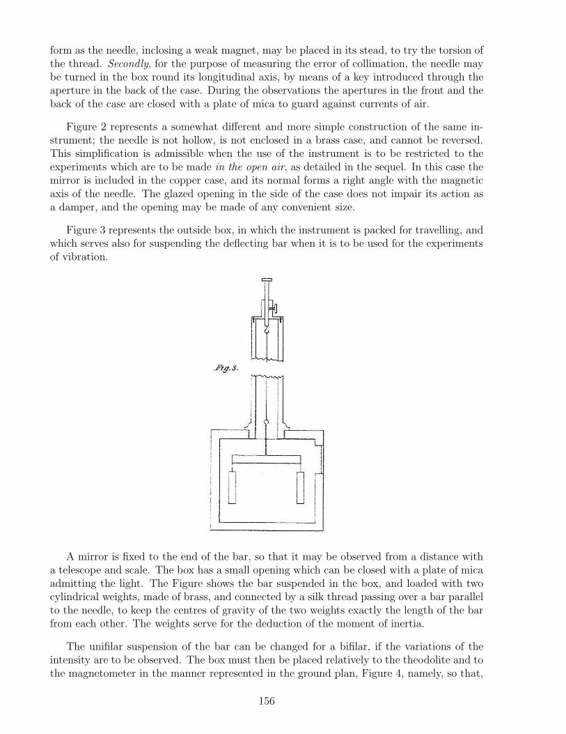
form as the needle, inclosing a weak magnet, may be placed in its stead, to try the torsion ofthe thread. Secondly, for the purpose of measuring the error of collimation, the needle maybe turned in the box round its longitudinal axis, by means of a key introduced through theaperture in the back of the case. During the observations the apertures in the front and theback of the case are closed with a plate of mica to guard against currents of air.
Figure 2 represents a somewhat different and more simple construction of the same in-strument; the needle is not hollow, is not enclosed in a brass case, and cannot be reversed.This simplification is admissible when the use of the instrument is to be restricted to theexperiments which are to be made in the open air, as detailed in the sequel. In this case themirror is included in the copper case, and its normal forms a right angle with the magneticaxis of the needle. The glazed opening in the side of the case does not impair its action asa damper, and the opening may be made of any convenient size.
Figure 3 represents the outside box, in which the instrument is packed for travelling, andwhich serves also for suspending the deflecting bar when it is to be used for the experimentsof vibration.
A mirror is fixed to the end of the bar, so that it may be observed from a distance witha telescope and scale. The box has a small opening which can be closed with a plate of micaadmitting the light. The Figure shows the bar suspended in the box, and loaded with twocylindrical weights, made of brass, and connected by a silk thread passing over a bar parallelto the needle, to keep the centres of gravity of the two weights exactly the length of the barfrom each other. The weights serve for the deduction of the moment of inertia.
The unifilar suspension of the bar can be changed for a bifilar, if the variations of theintensity are to be observed. The box must then be placed relatively to the theodolite and tothe magnetometer in the manner represented in the ground plan, Figure 4, namely, so that,
156

according to the rule laid down in the Resultate for 1837, p. 22,283,284 the line connecting themiddle of the bar with the middle of the magnetometer needle may form with the magneticmeridian an angle of 3516′. Thus observations of the variations of the declination and ofthe intensity may be conveniently combined in this manner by travelling observers.
13.3 Examples of Observations and Measurements
13.3.1 Measurement of the Absolute Declination
This measurement resolves itself into three parts: 1. The determination of torsion. 2. Theazimuthal determination of the magnetic axis. 3. The azimuthal determination of the truemeridian. By the azimuth of a direction is here understood the angle formed by two verticalplanes, one in the direction in question, and the other in the direction of the optical axis of
283[Note by ER:] Wilhelm Weber’s Werke, Vol. II, p. 45.284[Note by AKTA:] [Web38a, p. 22 of the Resultate and p. 45 of Weber’s Werke] with English translation
in [Web41d, p. 270] and [Web66b].
157

the telescope of the theodolite, the alidade being placed on the zero point of the circle.
1. Determination of Torsion
This determination consists of the measurement of the force of torsion, and of the angle oftorsion.
Force of Torsion
There belong to the magnetometer two needles, the magnetic and the torsion needle,which may be suspended to the same thread, and which differ in the proportion of theirmagnetic moments (M , m). Designating by T the horizontal part of the earth’s magneticforce, the force of torsion is to be compared with the force MT , as well as with the forcemT .
Comparison with the Force MT
In order to reduce the observations to the same time, the declination was observed in themagnetic observatory simultaneously with both the observations.
Reading Observation of the Observation Radius Reducedof the position of the in the in parts ObservationTorsion Magnetometer Magnetic of theCircle by the Scale Observatory Scale3556′ 275.67 1829′49′′ 2174 275.671756′ 237.06 1830′42′′ 237.31
Hence the force of torsion is given in parts of MT
=57.295
180· 38.362174
=1
178.
158

Comparison with the force mT
Reading Observation of the Differences Mean Radius inof the position of the divisions ofTorsion Magnetometer the ScaleCircle by the Scale26915′ 270.77
160.9832954′ 109.79
171.1226915′ 280.91 167.69 2243.5
168.7332954′ 112.18
169.9426915′ 282.12
Hence the force of torsion is given in parts of mT
=57.295
60.65· 167.692243
=12.563
178.
Angle of Torsion
Observation of the Radius inposition of the divisions ofMagnetometer the Scaleby the Scale
Magnetic needle 292.902174
Torsion needle 328.67
The distances of the observed divisions of the scale from the zero point of torsion beingdesignated by x and y, then x is the angle of torsion sought, expressed in divisions of thescale; and for determining x we have the following equations:
292.90− x = 328.67− y
12.563x = y .
Hence the angle of torsion in divisions of the scale is found,
x = 3.09 ,
in seconds of arc
x =3.09
2174· 206265′′ = 293′′ .
From this determination of the force and of the angle of torsion, the correction on accountof torsion to be applied in measuring the declination is found
159

=1
178· 293′′ = 1.65′′ .
This correction is so small that it may be wholly neglected; the more so, as, during the timeoccupied in the measurement, the declination itself altered two divisions of the scale, so thatthe angle of torsion for the time of this measurement almost wholly disappeared.
2. Azimuthal Determination of the Magnetic Axis
In order to reduce the observations to the same time, the declination was observed simulta-neously in the magnetic observatory.
Time: Azimuth Observation Reduced Azimuth1839, of the in the Azimuth of the
April 11 Collimation Magnetic MagneticLine Observatory Axis
Before reversal 11h 0m 13122′43′′ 1826′26′′ 13120′0′′
13141′29.5′′
After reversal 11h 37.5m 1322′59′′ 1829′9′′ 1322′59′′
3. Azimuthal Determination of the True North
Three visible objects were observed, the positions of which, in respect to the GottingenObservatory, are given by geodesical measurements.
Designation Distance from the Observatory Observed Azimuth of theof the Objects South West Azimuth true NorthHohehagen +6060.00 +12447.70 3358′50′′
Gartenhaus +289.28 −27.54 31517′5′′ 1506′14′′
Jacobithurm −710.70 +500.49 11715′15′′
As there is no correction to be applied on account of torsion, we obtain immediatelyfrom hence the westerly declination, by deducting the azimuth of the magnetic axis from theazimuth of the true north.
1506′14′′ − 13141′29.5′′ = 1824′44.5′′ ,
This result corresponds to 11h 37.5m, 11th April 1839. The declination observed at the sametime in the magnetic observatory was
1829′9′′ ,
showing a difference of −4′24.5′′, which probably is only in part due to error of observation,and is in part caused by the influence of the copper case surrounding the magnetometer,which may not be wholly free from iron. Repeated measurements, and comparisons withthe observations in the magnetic observatory, may serve to deduce such an influence if itexists, so that it may be taken into account in future measurements. A second measurementactually gave a similar result, namely,
1839, April 13 In the open air In the magnetic observatory10h 31′ 1818′0′′ 1823′36′′
160

showing a difference of −5′36′′. The mean influence of the copper case in this instrumentmay therefore be taken as = −5′.
13.3.2 Observation of the Variations of Declination
On the 15th April 1839, from 5h 25m to 7h 27.5m, the variations of declination were ob-served alternately, with the magnetometer in the Gottingen Observatory, and with the smallmagnetometer. In the following Table the four first columns show the immediate results ofobservation with the two apparatus. In the final column the observations with the smallmagnetometer are reduced according to the proportion of the value of the scale divisions.The two series of observations are exhibited graphically in Figure 5, for the purpose ofcomparison. It may be seen from this example that the observations of the variations ofdeclination can be made with a portable magnetometer with much accuracy.
1839 Magnetic 1839 Transportable MagnetometerApril 13 Observatory April 13 Reading Reduced Value
A x B = 895 + 3.25(x− 244.2)5h 25m 896.00 5h 27.5m 244.95 897.445h 30m 895.56 5h 32.5m 244.20 895.005h 35m 894.66 5h 37.5m 244.97 897.505h 40m 896.47 5h 42.5m 245.20 898.255h 45m 899.56 5h 47.5m 246.18 901.445h 50m 899.52 5h 52.5m 245.78 900.145h 55m 898.78 5h 57.5m 246.02 900.916h 0m 900.57 6h 2.5m 247.35 905.246h 5m 905.95 6h 7.5m 248.04 907.486h 10m 908.00 6h 12.5m 249.77 913.106h 15m 916.77 6h 17.5m 251.77 919.606h 20m 920.00 6h 22.5m 251.77 919.606h 25m 919.66 6h 27.5m 251.56 918.926h 30m 916.63 6h 32.5m 250.70 916.126h 35m 912.72 6h 37.5m 250.96 916.976h 40m 917.66 6h 42.5m 251.74 919.516h 45m 927.35 6h 47.5m 254.32 927.897h 0m 941.27 7h 2.5m 260.79 948.927h 5m 959.33 7h 7.5m 265.71 964.917h 10m 964.53 7h 12.5m 261.27 950.487h 15m 936.38 7h 17.5m 254.34 927.957h 20m 922.80 7h 22.5m 251.75 919.547h 25m 914.42 7h 27.5m 250.09 914.14
161

13.3.3 Absolute Measure of the Intensity
The measurement of the intensity divides itself into four parts.285 1. The determination oftorsion. 2. Of the moment of inertia of the deflecting bar. 3. The experiments of deflection.4. The experiments of vibration. I will confine myself in this place, for the sake of brevity, totwo parts, viz. the determination of the moment of inertia, and the experiments of deflection,which are especially instructive towards a knowledge of the instrument. The determinationof torsion has been already spoken of in the measurement of declination, and the experimentsof vibration are so simple and so well known, that it is sufficient to give their results.
1. Determination of the Moment of Inertia
The deflecting bar is suspended to a thread or wire, and is then vibrated: 1) without aweight; 2) with a weight, the moment of inertia of which is known.
285[Note by AKTA:] Friedrich Kohlrausch discussed an example of the measurement of the horizontalintensity of the Earth’s magnetism with Weber’s portable magnetometer, [Koh83, pp. 172-173].
162

Vibrations without a weightNumber of Time Arc of Reduced timeVibrations Vibration of Vibration
0 7h 20m 51.27s 856′
26 7h 23m 45.49s 840′ 6.698′′
61 7h 27m 39.92s 88′ 6.695′′
115 7h 33m 41.64s 722′ 6.696′′
151 7h 37m 42.80s 656′ 6.695′′
186 7h 41m 37.19s 632′
Vibrations with a weight0 2h 18m 35.57s 816′ 12.058′′
46 2h 27m 50.45s 658′ 12.039′′
125 2h 43m 41.76s 54′ 12.019′′
200 2h 58m 43.31s 320′
Hence the mean time of vibration without a weight is = 6.696′′, and with a weight12.039′′. For determining the moment of inertia of the weight we have the following data: 1)the length l of the deflecting bar, or the distance apart of the threads which hang from itstwo ends and support two equal cylindrical weights; 2) the mass 2p; 3) the radius r of thetwo cylinders.
l = 93.42 mm ,
2p = 50000.00 mg ,
r = 4.60 mm .
If the mass of the cylinder were concentrated in its axis, its moment of inertia would be
1
2l2p = 109091000 .
If the cylinders revolved only round their own axis, their moment would be
r2p = 529000 .
Their moment in the above experiments is to be taken as equal to the sum of
1
2l2p+ r2p = 109620000 .
Whence therefore the moment of inertia of the oscillating bar may be obtained from theequation
MT =π2K
t2=π2(K +K ′)
t′2,
where K ′ signifies the known, and K the desired moment of inertia, t′ the time of vibrationwith a weight, and t the time of vibration without a weight, consequently
K = 49103000 .
163

In these experiments the needle was suspended to a thread in which the force of torsion wasso small as to be insensible. The same series of experiments was repeated with the needlesuspended by a wire in which the force of torsion was much greater; the result was almostthe same as before, namely,
K = 49044000 .
Finally, in order to furnish a check, the deflecting bar was weighed, and its length and radiuswere exactly measured:
Weight p′ = 66670 mg
Length l = 93.42 mm
Radius r = 5.45 mm ,
whence its moment of inertia may be calculated. Supposing perfect internal homogeneity,
K =1
12l2p′ +
1
4r′
2p′ = 48982000 .
The accordance of all these experiments sufficiently shows that the moment of inertia of evensuch small bars may be determined with great precision.
164

2. Experiments of Deflection
1839, February 13 Readings Double DeflectionDistance in North In divisions ArcMillimeters Pole of the scale values−556.75 E. 372.95
240.62W. 132.33 241.03 530.3′
241.45E. 373.78
−453.25 E. 475.91447.55
W. 28.36 447.89 109.3′
448.22E. 476.58
+453.25 E. 480.04448.21
W. 31.83 448.32 1011.2′
448.44E. 480.27
+556.75 E. 375.93240.87
W. 135.06 240.82 530.0′
240.76E. 375.82
Hence the simple deflections v0, v1 are obtained for the distances R0, R1 (without regardto signs)
v0 = 245′4.5′′ , for R0 = 556.75
v1 = 55′7.5′′ , for R1 = 453.25 .
Consequently, if tan v be developed according to the powers of R,
tan v = 8305800R−3 − 4081300000R−5
whence (see Intensitas Vis Magneticae, Sections 21, 22),286
M
T= 4152900 .
With the comparatively great distance of the deflecting bar from the needle (equal tofrom 5 to 6 times the length of the needle), the determination of the coefficient of thesecond member of this equation (which is to be divided by the 5th power of the distance) isuncertain, and it is therefore better to disregard it. We then obtain for M/T two values,
286[Note by AKTA:] See Chapters 5, 6 and 7, especially Sections 7.21 and 7.22.
165

R30 tan v0 = 4146600
R31 tan v1 = 4143200 ,
viz. the mean of which may be taken, consequently,
M
T= 4144900 ,
which differs but little from the above value.If to the results obtained we add lastly the time of vibration t, which was found to be287
t = 60.586′′ , 288
and if we assume K = 49073500, we obtain
MT =π2K
t2= 13195000 ,
consequently
T = 1.7842 .
We are not enabled to test and compare this result further, as a simultaneous mea-surement with the large magnetometer could not be executed at that time. When a newmeasurement of the earth’s magnetic force is made in the Gottingen Observatory, the op-portunity of comparison thus afforded will not be neglected.289
—————————–
The improvements, (represented in Figures 2, 6, 7, 8,) which, since the above was written,I have caused to be made in the transportable magnetometer, are designed to facilitate theuse of the instrument in the open air, as in travelling it will be rare to meet with a suitablebuilding free from iron for the execution of absolute measurements. It is not absolutelynecessary that the whole of the observations for these purposes should be made in the openair; and on account of the liability to interruption from weather, it is desirable to reduce thenumber requiring this exposure as much as possible. In the improved construction I havegiven great care and consideration to this part of the subject, and have found it possibleto arrange the observations in such manner that the greater part may be made in a room,including those which would be made to the greatest disadvantage in the open air.290
287[Note by AKTA:] In the English translation the next value of the time of vibration t was written as:
t = 6′′ · 0586 .
We wrote its value according to the original German text, namely, t = 60.586′′.288[Note by WW:] The bar having been magnetized afresh for the experiments of vibration and deflection,
had a shorter time of vibration than in the previous experiments on the moment of inertia.289[Note by AKTA:] This is the end of Weber’s 1839 paper, [Web39], with the exception of a last paragraph
on the cost of these instruments, which has not been translated. The following text comes from manuscriptcommunications from Wilhelm Weber to Edward Sabine (1788-1883), [Web41e] and [Web66c].290[Note by AKTA:] A larger plate appears on page 182.
166

Figure 6 represents the tripod stand, on which the measuring apparatus, Figure 7, andthe magnetometer, Figure 2, are to be placed and levelled, as shown in Figure 8.291
The measuring apparatus, Figure 7, required for the deflection experiments, consists of acopper-plate fitting on the tripod, and carrying the supporters of the deflecting-bar; each ofthese is formed of two converging tubes connected at their extremities, from whence proceedsa third tube provided with a graduation, and on this the deflecting-bar is to be placed: thistube forms also the reading telescope, and has the reading scale attached to it.
Figure 8 represents the magnetometer placed on the measuring apparatus, which restsitself upon the tripod: the needle is suspended in a copper case, which acts as a damper inchecking the vibrations. The mirror close below the needle is directed to the east. The wholeof the eastern side of the copper case can be removed, to give access to the screw to whichthe suspension is fastened, and by which the inclination of the mirror may be corrected. Inthe middle of this side is an opening closed by a piece of plane glass, making a small anglewith the vertical, in order that the reading telescope, which is directed to the mirror behindthe glass, may not see a double image of the scale.
For the measurement of the absolute intensity the deflection experiments alone require tobe made in the open air; the remainder may be made in a room if more convenient; for if themagnetism of the needle, which can be ascertained in a room, be known, the intensity of theearth’s magnetism may be calculated from that of the needle, and from the experiments ofdeflection made in the open air.292 It should be noticed, however, that the determination ofthe magnetism of the needle in such cases requires a complete measurement of the intensityto be gone through, including both the experiments of deflection and those of vibration,with and without the weights. The magnetism of the needle should also be determined
291[Note by AKTA:] These Figures appear on page 173 and the following.292[Note by WW:] The experiments of vibration might be made in the open air instead of those of deflection;
but in such case the instrument would afford less certainty and less convenience.
167

either shortly before, or shortly after, the deflection experiments in the open air, because itis liable to alteration: and the temperature in the room and in the air should be as nearlythe same as possible.
The experiments of deflection in the open air require only a solid foundation, on whichthe tripod may be placed and levelled; the measuring apparatus, resting on it, carries thedeflecting bar, the telescope, and the scale, each in its due position relatively to the others;and the whole system can be turned upon the tripod without their displacement. The coppercase of the magnetometer fits into the depression ab, Figure 8, by which its position is fixedrelatively to all the other parts. The whole instrument is then turned on the tripod until themiddle of the scale is seen in the reading telescope, and it is then ready for the deflectionexperiments.
The vernier of the deflecting bar being placed on the zero point of the graduation ofthe measuring apparatus, the deflection of the needle is observed. The deflecting bar is thenreversed, and the observation repeated. The bar is then removed to the end of the measuringapparatus, and the vernier set to 1000 mm of the graduated scale, when the deflected positionof the needle is again observed before and after the reversal of the bar. Let the four observeddeflections be called m, m′, n, n′, — the absolute intensity of the magnetism of the needle,previously observed in a room,M , — and the arc-value of a division of the scale, determinedalso in a room (the torsion being taken into account), α, — then the absolute horizontalintensity of the earth’s magnetism will be
I =2
5003· M
tan v,
where
v =1
2arctan
1
2(m−m′ + n− n′)α .
This simple formula may be employed, because the small dimensions of the needle andbar, relatively to their distance apart, renders the next member (having the fifth power ofthe distance in the denominator) insensible.
Figure 10 represents the theodolite used in observing the declination and its variations;293
it is provided with a verification telescope, having a small scale at the end: a larger scale isplaced above the theodolite, perpendicular to the optical axis of the principal telescope.
The observation of the absolute declination may be divided into those parts which mustbe made in the open air, and those which may be made in a room. Figure 11 represents in Athe cross-section of the tube of the magnetometer telescope, and in BC the scale; between Aand BC is a transparent space; the theodolite must be so placed that the observer may lookwith the verification telescope through the space D towards the mirror of the magnetometerneedle, and perceive the image of the scale attached to that telescope; he must first observethe position of the needle by this scale, and thence determine the angle φ (Figure 12), whichthe optical axis of the verification telescope makes with the normal to the mirror of themagnetometer; he must then bisect objects of known azimuth with the principal telescopeof the theodolite, and thence find the angle ψ, corresponding on the divided limb to thedirection of the principal telescope relatively to the north.294
293[Note by AKTA:] This Figure 10 appears on page 179.294[Note by AKTA:] These Figures appear on page 179 and the following.
168

These are all the observations required to be made in the open air in determining thedeclination. The angle χ, Figure 12, corresponding, on the graduated limb, to the parallelposition of the optical axes of the two telescopes of the theodolite, can be ascertained in aroom; as can also the angle ρ which the magnetic meridian makes with the normal of themirror belonging to the needle. Hence we obtain
(χ−ψ) the angle which the optical axis of the verification telescope makes with the truemeridian.
(χ−ψ)−φ, the angle which the mirror-normal of the needle makes with the true meridian.ρ−(χ−ψ)− φ the angle which the magnetic meridian makes with the true meridian.The angle χ is found by placing a plane mirror before the verification telescope, and
viewing in the telescope the reflected image of a vertical thread suspended over the middleof the object glass; a vertical thread is also suspended over the middle of the principaltelescope, and the telescope adjusted to its reflected image; the reading on the circle givesthe angle χ, supposing the collimation error of the principal telescope to remain unalteredwhen the eye-piece is adjusted to distant objects; otherwise the alteration must be soughtby reversing the telescope, and applied as a correction to the reading on the circle.
The angle ρ is determined by directing the principal telescope of the theodolite from B(Figure 12) to C, a second needle suspended in the wooden case, as represented in Figure 3;the verification telescope is directed on the first needle A, in the copper case as in the openair.
The needle C is furnished either with a collimator or a mirror, and is capable of reversal.The direction of its magnetic axis is next to be found, i.e. the angle µ, to which the theodolitemust be adjusted, in order that the optical axis of its principal telescope may be parallel withthe direction of the magnetic axis of the needle C, whence the angle ρ (= π − (χ− φ) + µ)is obtained, if the two needles A and C are sufficiently distant apart to exert no sensibleinfluence on each other, so that their magnetic axes may be regarded as parallel. But if thisbe not the case, it is easy to determine the angle ν formed by the magnetic axes of the twoneedles,295 ,296 and to add it as a correction to the value, as above, of ρ; i.e.
ρ = π − (χ− φ) + µ+ ν .
The suspension of the needle in the wooden case is so contrived, that it may be usedeither as an unifilar or as a bifilar magnetometer. This contrivance is represented in Figure9.297 The variations of the declination and of the horizontal intensity can thus be observedat the same time; the former with the magnetometer in the copper case, and the latter
295[Note by WW:] From the propositions contained in the Resultate for 1837, page 22 et seq., it follows thatif ABC = 90, ACB = α, and AC = ν, and if m and m′ denote respectively the magnetism of the needlesA and C,
ν =3
2sin 2α · m−m′
r3T.
The value of m and m′ must be determined by the deflections δ and δ′ of a compass needle placedsuccessively east and west at the distance d, namely
m
T=
δd3
2,
m′
T=
δ′d3
2.
296[Note by AKTA:] [Web38a, p. 22 of the Resultate and p. 45 of Weber’s Werke] with English translationin [Web41d, p. 270] and [Web66b].297[Note by AKTA:] This Figure 9 appears on page 178.
169

with the magnetometer in the wooden case. In preparing for the latter observations, thetelescope of the theodolite is to be directed perpendicularly to the magnetic meridian, and themagnetometer in the wooden case is to be placed in the same direction. The time of vibrationt of the needle, with the unifilar suspension, must be determined, if not already known, whichit will generally be, from the experiments of vibration belonging to the measurement of theabsolute intensity. The unifilar suspension must then be changed for the bifilar withoutaltering the direction of the magnetic axis, and the time of vibration must be observed afresh,the distance apart of the suspension threads being increased until t′ is about = 0.6871t. Thetorsion circle must then be turned until the middle of the scale appears in the field of viewof the telescope, and the time of vibration t′′ observed. The magnetometer is then in thetransversal position proper for observing the variations of intensity, and the value of the scaledivisions may easily be calculated from the observed times of vibration t, t′, t′′; namely, ifσ denote the arc-value of a division of the scale in parts of radius, the value of a division ofthe scale, in parts of the whole horizontal intensity, is
t2
t′′2· σ =
√
(
1− 2t′2
t2
)
· t2
t′2· σ .
————————————-
Explanation of the Figures
Figure 1 a, b, c, d is a vertical longitudinal section of the copper case of the magnetometer,with the needle e, f suspended by a silk thread g, h.
170

The needle is seen to be pierced through its length, and provided at the extremity f witha lens; it is inclosed in a copper tube k, l, m, n, and can be turned by means of a key o,p, which is accessible by an opening in the copper case. In doing this the copper tube isheld by two screws q, r, and two projections s, t. The mirror u, v is seen above the coppercase, near the axis of rotation of the needle. A dotted line indicates how the telescope of thetheodolite, Figure 10, is directed, both to the needle and to the lens at its end f , and alsoto the mirror u, v.
171

It is also seen how the inclination of the mirror may be regulated by the screw w, thatthe image of the scale placed above the telescope at a, Figure 10, may appear in the field ofview. This Figure is half the size of the instrument itself.
Figure 2 represents a magnetometer, which differs from the one just described in notbeing adapted for complete measurements of the declination. The collimator is omitted, andthe needle cannot be reversed. The mirror a, b, c, d is inclosed in the copper case, and isparallel to the plane of the magnetic meridian; the inclination of the mirror is regulated bythe screw at e; the copper case forms an unbroken damper round the needle, except at theaperture for the suspension thread; the mirror is observed through a glass plate in one ofthe sides of the copper case. This Figure is also half size.
172

Figure 3 a, b, c, d, e represents the wooden case, in which either of the instruments shownin Figures 1 and 2 are packed for travelling.
173

The lid, with the tube a, b, c which is fastened to it, is taken off, the instrument placedinside, and the box closed again. When observations are made, this box serves for suspendinga second needle, the time of vibration of which is required for the measurement of the absoluteintensity; this second needle f , g is provided at both ends with mirrors, one of which servesfor observing the scale. The needle rests on two supports h, k, attached to a small measuringbar m, n, over which passes a thread carrying the weights p, q, which serve to increase themoment of inertia of the oscillating needle. The needle can be turned in the supports h, k,and may be reversed; rendering it available, in absolute measurements of the declination, asan auxiliary needle, when the instrument represented in Figure 2 is used, the needle of whichis not reversible. For this purpose, instead of a needle with a mirror, one with a collimator,Figure 13, may be placed in h, k. It consists of a magnetic steel tube a, b, c, d, carrying atthe end a, c, an achromatic object-glass; and at its other extremity a sliding tube of brass e,f , g, h, provided with a glass micrometer in the focus of the object-glass. It will be seen alsoby Figure 3 that this needle is suspended to two threads, the upper points of attachment ofwhich are r and s. The threads are conducted over a roller z to give them equal tension, andare united in one from u to v, forming an unifilar suspension, which may be converted intoa bifilar by opening out the apparatus α, β, γ, δ, which is done by pressing down the knob
174

w by the screw t, and disengaging the threads from the pins x, y, as represented in Figure9. Figure 3 is also half size.
Figure 4 A, is the theodolite carrying two telescopes and two scales; one telescope andone scale serve for observing the unifilar magnetometer B, and the other telescope and scalefor observing the bifilar magnetometer C. The Figure gives the angles which the instrumentsought to form with each other.
Figure 5 is a graphical representation of the variations of the declination observed on the13th of April, 1839, at Gottingen, simultaneously in the magnetic observatory, and with thetransportable magnetometer.
175

Figure 6 is the tripod on which the magnetometer, Figure 2, is placed and levelled.
Figure 7 is the apparatus required for the experiments of deflection. a, b, c, d is a copperdisc which fits on to the tripod, Figure 6; e, f , g, h, and k, l, m, n, are arms screwed to thecopper disc at e, f and k, l; one arm carries the telescope p, q, to which the scale r, s isattached, and upon which the deflecting bar u, v is to be laid; the other arm carries a tubeon which the deflecting bar is also laid, but which could not be conveniently represented inthe Figure. Between e, f and k, l the magnetometer (Figure 2) is placed.
176
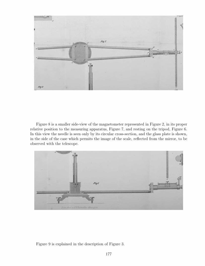
Figure 8 is a smaller side-view of the magnetometer represented in Figure 2, in its properrelative position to the measuring apparatus, Figure 7, and resting on the tripod, Figure 6.In this view the needle is seen only by its circular cross-section, and the glass plate is shown,in the side of the case which permits the image of the scale, reflected from the mirror, to beobserved with the telescope.
Figure 9 is explained in the description of Figure 3.
177

Figure 10 represents the theodolite with the verification telescope: two scales are seen,one of which, a, is applied in such manner that its middle corresponds to the prolongationof the vertical axis of rotation of the theodolite; the other, b, c, is attached in front of theobject-glass of the verification telescope. It is very narrow, in order to intercept the lesslight.
178

Figures 11, 12 and 13 are explained in the text.
179

180

181

182

Chapter 14
[Wohler and Weber, 1841]Composition of Galvanic Piles
[Friedrich Wohler and Wilhelm Weber]298,299,300,301
Professors Wohler302 and Weber informed the Konigl. Gesellschaft der Wissenschaften(Royal Society of Sciences), together with some remarks, about a discovery made by Profes-sor Poggendorff303 on the composition of galvanic piles and submitted them to the Konigl.Akademie der Wissenschaften zu Berlin (Royal Academy of Sciences of Berlin) on April 29thof this year.304
It is known that in order to produce the greatest galvanic effects, it is no longer necessaryto use giant devices that are as uncomfortable as they used to be, but that in recent timesone has learned to achieve the same effects with small and convenient devices. The bestperformance is shown by a pile, described by Mr. Grove,305 where small clay cells, thewalls of which are permeated with liquid, are filled with ordinary nitric acid and externallysurrounded with dilute sulphuric acid. In the former liquid platinum plates are immersed,amalgamated zinc plates are immersed in the latter, and the necessary connections are madewith strong copper wires (see Poggendorff’s Annalen 1839, Vol. 48, p. 300; 1840, Vol. 49,p. 511).306 The cost of the platinum plates has hitherto limited the use of these otherwisepowerful and comfortable piles; therefore it will be pleasant for those who, for this reason,could not obtain these plates, that Professor Poggendorff has used iron plates instead ofplatinum plates with almost the same success.
298[WW41c] with English translation in [WW20]. See also [WW41a] and [WW41b].299Translated by H. Hartel, [email protected] and http://www.astrophysik.uni-kiel.de/
~hhaertel/index_e.htm. Edited by A. K. T. Assis. We thank Robert W. Gray and Steffen Kuhn forrelevant suggestions.300The Notes by A. K. T. Assis are represented by [Note by AKTA:].301[Note by AKTA:] The names of the authors appear only in the first paragraph of this paper.302[Note by AKTA:] Friedrich Wohler (1800-1882).303[Note by AKTA:] Johann Christian Poggendorff (1796-1877) edited the Annalen der Physik und Chemie
from 1824 to 1876, where many of Weber’s papers were published. The modern Annalen der Physik is thesuccessor to this Journal.304[Note by AKTA:] See also [Pog40].305[Note by AKTA:] The Grove voltaic cell, element, battery or pile was named after its inventor, William
Robert Grove (1811-1896), [Gro39].306[Note by AKTA:] [Gro39] and [Sch40].
183

“Now I am concerned,” writes Professor Poggendorff on May 1 of this year, “thecells with two liquids that seem to deserve the most attention and are still not muchexamined. I have made about 50 such cells and found that almost all of them havethe invaluable advantage of giving a constant current, so you can make accuratemeasurements... I want to tell you only one thing of practical use, namely that in theGrove-cell you can replace the expensive platinum with iron, steel or cast iron as longas you take concentrated fuming acid (acidum nitricum fumans) instead of theusual nitric acid. You can even dilute this fuming acid with 11
4part of ordinary nitric
acid, or to the extent that the iron is not yet attacked. The latter is necessary; if youtake the acid too weak, the iron will be violently attacked. In the acid of the specifiedconcentration, the iron remains as bright as the platinum. Here are the elements ofthe aforementioned cells for smoking concentrated nitric acid and sulphuric acid with4 parts of water. The zinc was amalgamated.”
Electromotive force Resistancezinc and platinum 100.00 13.120
zinc and iron 78.62 11.275zinc and steel 86.99 12.927
zinc and cast iron 89.63 12.913
“From the resistance come here 4.36 (inch nickel silver wire with 1/6 line diameter)on the closing wire.”307
“So you see, with the same plate size you can get 9/10 of the effect of the Grove-cell with iron. The missing tenth can easily be replaced by enlarging the plates.Incidentally, the current is just as constant as with the Grove-cell.”
In response to the above notification, Messrs. Wohler and Weber immediately made sev-eral attempts to confirm the given information, which at the same time yielded the curiousresult that a very strong current is produced if you immerse only iron in both liquids andalso interchange the amalgamated zinc plate dipped in dilute sulphuric acid with an ironplate. This latter plate, because it cannot be amalgamated, was attacked by the sulphuricacid under a weak development of hydrogen gas. This, however, did not impair the effect;rather, it turned out that the effect of this cell was just as constant as Grove’s cell. Thiscell, composed just of iron and two liquids, that gives such powerful effects, is of interestfor the theory of the pile in general and for the study of the galvanic properties of iron inparticular. Cells have already many times been put together in which two identical metalsare combined with two different liquids, for instance by Becquerel and De la Rive, of whichFechner gives a list in the Repertorium der Experimentalphysik (Repertory of ExperimentalPhysics), p. 454 and following;308 but it seems that only the existence and direction of thecurrent attracted interest, but the further use and investigation were prevented by the weak-ness and inconsistency of the effect. Such a strong and constant effect as the one described[here], is new. It makes these types of cells really useful, capable of close examination, anddeserve special attention. Two pairs, where each plate was only about 3 square inches insurface area, caused thin platinum wires to glow and were sufficient to vigorously decompose
307[Note by AKTA:] In German: Vom Widerstand kommen hier 4,36 (Zoll Neusilberdraht von 1/6 LinieDurchmesser) auf den Schliessungsdraht.308[Note by AKTA:] [Bec29, pp. 14-18], [dlR29, p. 102] and [Fec32, pp. 454-455].
184

water. Certainly, this subject deserves to be pursued further, unless Professor Poggendorffhas perhaps already extended his much more extensive investigation to this topic.
The weak development of hydrogen gas at the iron plates immersed in the dilute sulphuricacid can be easily avoided by using a tinned iron sheet, which in this regard does the sameservice as amalgamated zinc; it even seems to be preferable to the latter because it is thin anddurable, while the zinc becomes brittle due to mercury and easily loses part of its amalgam,which, as a gray powder, covers the surface of the plate or settles in the acid, thus weakeningthe effect of the pile.
185

186

Chapter 15
[Weber, 1841a] Measurement ofStrong Galvanic Currents with LowResistance According to AbsoluteMeasure
Wilhelm Weber309,310,311,312
It has happened several times in the article on magnetic friction313,314 that it was impor-tant to determine the intensity of a galvanic current based on an absolute measure in order tobe able to compare it with the intensity of other currents under any conditions. For instance,when an iron wheel was magnetized by a galvanic current to measure its magnetic friction,it was of interest to measure more closely the current that had produced this effect. For thispurpose, the procedure that Faraday has indicated in the seventh series of his experimentalinvestigations on electricity (Philosophical Transactions for 1834 and Poggendorff’s Annalen1834, Vol. 33, pp. 316 ff.),315 could have easily been used. In this procedure the strength ofthe current is measured by the amount of water it decomposes in a given time. However, ifthe current had been passed through a water decomposition apparatus, it would have beensignificantly weakened, which should not be the case in those attempts which required anundiminished current.
It happens quite often that the measurement of the absolute current intensity by theamount of decomposed water is not permissible because of the necessary conduction of thecurrent through a water decomposition apparatus. This is especially the case when simple
309[Web41c] with English translation in [Web20a].310Translated by H. Hartel, [email protected] and http://www.astrophysik.uni-kiel.de/
~hhaertel/index_e.htm. Edited by A. K. T. Assis. We thank Robert W. Gray for relevant suggestions.311The Notes by H. Weber, the editor of the third volume of Weber’s Werke, are represented by [Note by
HW:]; the Notes by Wilhelm Weber are represented by [Note by WW:]; while the Notes by A. K. T. Assisare represented by [Note by AKTA:].312[Note by AKTA:] The importance of this paper has been discussed by F. Kohlrausch and K. H.
Wiederkehr, [WK68].313[Note by HW:] Wilhelm Weber’s Werke, Vol. II, p. 200.314[Note by AKTA:] [Web41g].315[Note by AKTA:] [Far34b] with German translation in [Far34a].
187

circuits are used, where a very strong current through that apparatus is so weakened thatthere is no water decomposition and therefore there can be no question of measuring thedecomposed water. In such cases a different method must be used, where the current isonly passed through thick316 and short copper wires, which do not increase the resistancenoticeably.
Instead of the method specified by Faraday, the following very simple method was usedfor the above experiments where a certain piece of the thick current carrying wire waspassed in a straight line at some distance from a magnetic needle, so that the latter deviatedconsiderably from the magnetic meridian, while the rest of the circuit was positioned insuch a large distance to the needle that its effects did not need to be considered. From themeasured deflection of the needle and taking into account the length and position of theactive conducting wire as well as the absolute intensity of the Earth’s magnetism at thepoint of observation, an absolute determination of the intensity of the galvanic current ispossible — as has been given on p. 49 of the Resultaten des magnetischen Vereins im Jahre1840.317,318 Incidentally, this method has the advantage that it allows for the determinationof the absolute current intensity for every moment, while when using Faraday’s method onlymean results are obtained for longer periods of time. Experiments can also be carried outwhere the intensity of one and the same current is measured simultaneously according tothis and Faraday’s method, and thereby a comparison of the units on which both methodsare based would be possible; this comparison, however, is not necessary for the absolutedetermination of the current intensity. Such a comparison is only necessary when using anordinary galvanometer, which consists of a magnetic needle provided with a multiplier andwhich is not directly suitable to obtain absolute determinations, as Jacobi did in Poggendorf’sAnnalen, Vol. 48.319
Given the frequently occurring need to determine the absolute intensity of galvanic cur-rents in simple circuits, and with Faraday’s method failing, an instrument which is con-structed according to the principles mentioned above and which leads directly to the goalcan be of great use, which is why some explanations are given here about its most advanta-geous facility and about some measurements made with it.
The instrument is constructed more appropriately, the greater the distance of the currentcarrying wire compared to the needle length, because then the distribution of the magnetismin the needle does not need much consideration; all this under the assumption that thisgreater distance leads to a deflection of the needle which can be observed with sufficientaccuracy. From this the advantage is self-evident if the current carrying wire, instead ofbeing guided in a straight line past the needle (which was just done in the above-mentionedattempts in the absence of a proper instrument and merely for the sake of easier execution),it will be guided in a wide vertically directed circle all around the needle. With the samedeflection, the distance of all parts of the current carrying wire can then be much larger.320
In addition, if the conductor forms exactly a vertical circle around the center of the needle, itbecomes very simple and easy to calculate the absolute intensity of the galvanic current fromthe observed deflection of the needle. This circular shape of the conductor has finally the
316[Note by AKTA:] In German: Starke.317[Note by HW:] Wilhelm Weber’s Werke, Vol. II, pp. 202 and 203.318[Note by AKTA:] [Web41g, pp. 202-203 of Weber’s Werke].319[Note by AKTA:] [Jac39].320[Note by AKTA:] That is, the distance of any portion of the circular wire to the needle can be much
larger than the distance of the straight wire to the needle in the previous case.
188

special advantage that the rest of the conductor can be positioned very easily so that it hasno noticeable influence on the needle. For this [purpose,] it is only necessary to put the twoconductors, which feed the current in and out, very close to each other, where their effectson the needle mutually cancel. The first pieces of the conducting wires, starting at the ring,should best be conducted through two copper tubes, one enclosing the other but isolatedfrom each other, as shown in Figures 1 to 4. The cross section of the circular conductor mustbe so large that its resistance is imperceptible.
I had an instrument set up following this description, where the copper ring was 19812
millimeter in diameter and the cross-section of which was 30 square millimeters. This ringwas cut open at the bottom and one end was soldered to the feeding-in and the otherend to the feeding-out conductor. These conductors, plugged into tubes, one plucked intoanother but insulated, led the current 100 millimeter down to two 4 millimeter thick, 1 meterlong conducting wires, which run close to each other to two mercury cups, which could beconnected to the two plates of the galvanic circuit. The magnetic needle stood in the middleof the circle on a wooden plate attached to the circle. The circle itself stood on a woodentripod with set screws. The length of the needle was 50 millimeter and it moved on a circulararc divided into degrees. The use of the instrument requires no explanation. The calculationof the absolute intensity from the observed deflection of the needle consists in multiplying
189

the tangent of the deflection angle by a constant number which is derived from the sizeof the copper ring and from the absolute horizontal intensity of the Earth’s magnetism atthe observation site. If R (= 99.125 mm) denotes the radius of the ring, T (= 1.7833) thehorizontal intensity of the Earth’s magnetism (in Gottingen),321 then that constant factoris:
1
π· RT = 56.2675 .
If ϕ denotes the observed deflection, then the desired absolute intensity of the measuredcurrent is:
1
π· RT · tanϕ = 56.2675 · tanϕ .
For more convenient use, a Table can easily be set up, which shows directly the desired valueof the absolute current intensity for each observed value of ϕ. One will not be able to carryout such absolute measurements as easily and quickly with any other instrument as withthis one.
One word remains to be said about the unit of measure of the current intensity on whichthis calculation is based. That current is assumed to be the unit of measure if, by flowingaround the unit area, acts in the same way as the unit of free magnetism which is defined inthe Intensitatis vis magneticae.322,323,324,325
It should also be noted that the observations are greatly facilitated if the compass isprovided with a damper, which causes it to come to rest quickly. For more precise mea-surements it would be necessary to exchange the compass with a small magnetometer, buta much larger copper circle would have to be used, even if the needle was very short, andwould only be for instance 60 to 80 millimeter long. The deflection of the needle when mea-suring strong currents would then still be measurable if the copper ring would also be 600millimeter in diameter.
Some measurements made with this instrument may now be cited. To assess the greatesteffects that can be produced with galvanic currents, it is important to measure the currentintensities of the simple circuits without noticeably increasing the resistance they have dueto the conductive wires. This measurement then gives directly the maximum of the currentintensity, which can be approached by increasing the number of plate pairs in case the
321[Note by AKTA:] As first measured by Gauss, with Weber’s help, in his work on the intensity of theEarth’s magnetic force reduced to absolute measure, see Chapters 5, 6 and 7.322[Note by AKTA:] See Chapters 5, 6 and 7.323[Note by WW:] Note that this current is half as strong compared to a current whose measurement (see
page 49 above) was based on a current exerting the unit of torque [or moment of force] on the magneticneedle, given the unit of length of the conductor and [the unit] of distance from the magnetic needle, and[also] given the unit of free magnetism in the needle. This arises easily from the basic law of galvanism, asstated in Section 1 of the Allgemeine Lehrsatze in the previous volume of the Resultate and has already beenmentioned here on page 48.324[Note by HW:] See Wilhelm Weber’s Werke, Vol. II, pp. 202 and 203; and Gauss’ Werke, Vol. V, p.
198.325[Note by AKTA:] [Web41g, pp. 48-49 of the Resultate aus den Beobachtungen des magnetischen Vereins
im Jahre 1840 and pp. 202-203 of Weber’s Werke]. The Allgemeine Lehrsatze mentioned by Weber refersto Gauss’ work “Allgemeine Lehrsatze in Beziehung auf die im Verkehrten Verhaltnisse des Quadrats derEntfernung wirkenden Anziehungs- und Abstossungs-krafte”, [Gau40, p. 198 of Gauss’ Werke], with Englishtranslation in [Gau43]: “General propositions relating to attractive and repulsive forces acting in the inverseratio of the square of the distance”.
190

current has to overcome a larger resistance. The following Table shows the results of thesemeasurements for 5 simple circuits of various sizes and compositions:
Indication of Observed Calculated absolutethe circuit deflection intensity
A. 722′ 173.52B. 7815′ 270.52C. 6640′ 130.44D. 542′ 77.54E. 732.5′ 184.52
The following should be noted about the size and composition of these circuits:A was a Daniell’s cell,326 where the copper area touched by the copper vitriol solution
was 9 square decimeter. The copper vitriol solution, as well as the water surrounding theamalgamated zinc rod, was mixed with 10 percent sulphuric acid.
B was a Grove’s cell.327 A platinum beaker with a surface area of 1.9 square centimeterwas filled with ordinary nitric acid, while a small porous clay pot filled with dilute sulphuricacid stood in the middle and an amalgamated zinc rod was immersed in the latter. Thesulphuric acid was mixed with 80 percent water.
C was a cell according to Professor Poggendorf328 with an iron plate in smoking nitricacid, instead of the platinum plate in ordinary nitric acid from Grove’s column. Nitric acidtouched the iron plate from both sides, but the total contact area was only 3/4 decimeter.The sulphuric acid surrounding the clay pot and in which an amalgamated zinc cylinder wasimmersed was diluted with 90 percent water.
D was a cell of the same size and composition as the previous one, with the only differencethat the zinc plate of the previous cell immersed in dilute sulphuric acid was also replacedby an iron plate. Attention has already been drawn to the fact that only one metal is neededfor the strong currents that arise here (Gottinger gel. Anz. 1841, 81. Stuck).329,330
E finally was a cell according to Professor Bunsen in Marburg.331 A coal cylinder made ofhard coal and cokes, which was permeated with nitric acid, was immersed in dilute sulphuricacid with a surface area of 1 7
10square decimeter and surrounded by a zinc cylinder at a short
distance. The sulphuric acid was diluted with 90 percent water.The above results are the largest which were obtained when testing several cells of the
same construction. Four examples were tested from the first, fourth and fifth type, twoexamples from the third type and only one example from type two. The greatest differencein these repetitions occurred with the fifth type and was probably due to the often imperfectconduction of the electricity from the coal into the copper wire. The other 3 cells had givenabout half the current as the one above.
The strongest current among those measured here was obtained in the above experimentswith the Grove circuit, whose intensity was found = 270.52. Such a current, if it passed
326[Note by AKTA:] The Daniell voltaic cell or element was named after its inventor, John Frederic Daniell(1790-1845).327[Note by AKTA:] See footnote 305 on page 183.328[Note by AKTA:] See footnote 303 on page 183.329[Note by HW:] Wilhelm Weber’s Werke, Vol. III, p. 4.330[Note by AKTA:] [WW41c, p. 4 of Weber’s Werke]. See also [WW41a] and [WW41b].331[Note by AKTA:] The Bunsen voltaic cell or element was named after its inventor, Robert Wilhelm
Eberhard Bunsen (1811-1899).
191

unimpeded through water, would decompose 2.536 milligram water every second, or developabout 43
4cubic centimeter of detonating gas,332 as will be shown in the following article.333
If such a current encompasses a square meter of area, it exerts just as great magnetic forcesat a distance as a very strong steel magnet weighing 676.3 gram (where you can count 400[absolute] units of measure of magnetism on 1 milligram of steel).
Thin platinum wires are often used to estimate by their glow the intensity of the current.A measurement showed that a clear, daytime glow of a 2/15 millimeter thick platinum wirewas produced by a current whose absolute intensity was = 20. In order to get hold of theamount of heat released in such a wire, a 281
2millimeter long piece of that 2/15 millimeter
thick platinum wire was passed through 114 grams of distilled water. The heat released inthe water by a galvanic current which was conducted through this wire was shared with thesurrounding water and could be measured by the temperature increase of the water in whicha thermometer was immersed. The same current, which caused the heating of the wire andof the water, was conducted through the copper circle of the galvanometer and deflectedthe magnetic needle, placed at the center, from the magnetic meridian. The following Tableshows the results of such a series of measurements, where the initial temperature of the waterwas 15 centigrade.
Time Deflection Water-Temperature11′0′′ 5230′ 21.511′30′′ 5230′ 22.013′30′′ 5130′ 23.015′0′′ 5130′ 24.017′0′′ 520′ 25.019′50′′ 5150′ 26.020′30′′ 5120′ 27.022′30′′ 510′ 28.024′30′′ 5030′ 28.526′0′′ 5010′ 29.029′0′′ 4920′ 30.0
The difference x between the initial temperature of the water and the temperature aftert minutes can then be determined as:
x = 0.95 · t− 0.015 · t2 ,from which it follows that if the heat development in the wire is proportional to the currentintensity,334 a current whose intensity is = 1 would heat the described platinum wire during 1minute so that the temperature of 1 gram of water would rise by 1.4 centigrade. If the wirewas cut inside the water, the deflection of the needle was zero, to prove that no measurablepart of the current was flowing through the water.
It is to be hoped that in experiments with strong galvanic currents, their absolute intensityis always measured and stated in a similar manner as described here, in order to make the
332[Note by AKTA:] In German: Knallluft. See [Pat17, p. 142].333[Note by AKTA:] [Web41h] with English translation in [Web20b], see also [Web42d].334[Note by AKTA:] As a matter of fact, James Prescott Joule (1818-1889) discovered also in 1841 that
the heat which is evolved is proportional to the square of the intensity of the current, multiplied by theresistance of the wire, [Jou41]. A detailed analysis of Joule’s paper can be found in [MS20].
192

results obtained under different conditions comparable by different observers and to be ableto check their agreement.
193

194

Chapter 16
[Weber, 1841b] On theElectrochemical Equivalent of Water
Wilhelm Weber335,336,337,338,339
After Faraday’s numerous experiments,340 there seems to be no doubt that in the eventof chemical decomposition by the galvanic current, for each body the decomposed massof the same to the related quantity of current, i.e. to the amount of electricity passedthrough the cross-section of the circuit during the decomposition, is in constant proportionno matter how the galvanic current is produced and in what state the decomposed body maybe. The other equally important result found by Faraday must be added to this importantlaw saying that chemically equivalent masses of different bodies need the same amount ofelectricity (equal quantities of current) to decompose them. For example, 9 grams of waterand 36.5 grams of hydrochloric acid are chemically equivalent masses and, according toFaraday, need equal amounts of electricity to be decomposed to oxygen and hydrogen gas,and chlorine and hydrogen gas, respectively. If one then speaks of electricity as of a bodythat combines with other bodies (with the constituents of the decomposed body) accordingto their chemically determined equivalent relationships, and if one assumes a certain quantity(positive or negative) of electricity as a measure, and then determines the masses of otherbodies which combine with it, then Faraday calls the latter electrochemical equivalents todistinguish them from the chemical equivalents to which they are proportional. The chemicaland electrochemical equivalents differ only in the various measures on which they are based,namely on the unit of mass341 of oxygen (or hydrogen) for those, and on the unit of mass
335[Web41h] with English translation in [Web20b]. See also [Web42d].336Translated by H. Hartel, [email protected] and http://www.astrophysik.uni-kiel.de/
~hhaertel/index_e.htm. Edited by A. K. T. Assis. We thank Robert W. Gray for relevant suggestions.337The Notes by H. Weber, the editor of the third volume of Weber’s Werke, are represented by [Note by
HW:], while the Notes by A. K. T. Assis are represented by [Note by AKTA:].338[Note by HW:] Results from the Observations of the Magnetic Association in 1840, edited by Karl
Friedrich Gauss and Wilhelm Weber, Leipzig, 1841, p. 91-98 and Annalen der Physik und Chemie, editedby J. C. Poggendorff, Volume 55, Leipzig, 1842, pp. 181-189.339[Note by AKTA:] The importance of this paper has been discussed by F. Kohlrausch and K. H.
Wiederkehr, [WK68].340[Note by AKTA:] Michael Faraday (1791-1867). See [Far33] and [Far34a], with German translations in
[Far34c] and [Far34b], respectively.341[Note by AKTA:] In German: Masseneinheit.
195

of electricity for these. Faraday himself has not specified the mass of electricity, whichhe accepts as a unit. However, if one wanted to take the mass which combines with themass unit oxygen (or hydrogen) in water to form oxygen gas (or hydrogen gas), the twotypes of equivalent masses would be completely identical. Therefore, if electrochemicallyequivalent masses are to mean something different than chemically equivalent masses, theymust be measured according to another fundamental unit342 of electricity, which is derivedfrom another class of electrical effects. The class of the magnetic effects of electricity ingalvanic currents is the most suitable for this, since these effects have been reduced toabsolute measures in the teaching of magnetism and precise measurement methods havebeen developed for them.
As absolute measure of electricity (positive or negative or both together) is taken hereafterto be the amount of electricity that has to go through the cross-section of a conductor inthe time unit (second), which limits the unit area in one plane, to produce in the distanceidentical effects as the absolute basic unit of free magnetism.343
It will now be of particular interest, based on this absolute measure of electricity, todetermine the electrochemical equivalent of any body, e.g. that of water, from which it isthen easy to derive the electrochemical equivalents of other bodies according to the lawsdiscovered by Faraday with the help of their chemically determined equivalents to whichthey are proportional. The determination of the electrochemical equivalent of water on thebasis of the measure of electricity specified above is now to be the subject of this article.
For this purpose, it is necessary to observe any measurable magnetic effect of the galvaniccurrent while a certain quantity of water is being decomposed. To do so, neither the effectof the current on the Pouillet’s sine-galvanometer, nor on the tangent-galvanometer fromNervander can be used, because these instruments though they can give correct comparisonsof the current intensities, they cannot give absolute determinations.344 The instrumentdescribed in the previous article345,346 therefore seems to be the only instrument suitable forthis task. Indeed, this is the easiest and most convenient method if it is not about finermeasurements, and even these could be carried out with this instrument if it would be usedin the finer manner specified above,347,348 namely with a very large copper circle and a verysmall needle, hung on a thread, like in a magnetometer, and provided with a mirror so thatit can be observed with a telescope and a scale.
In the absence of the finer version of such an instrument, I have used an instrument basedon other principles and intended for other purposes, of which I should briefly mention whatis necessary for the present purpose. When applying this instrument, no magnetic needle isused, but only the conductor of the galvanic current itself.
A copper wire, isolated with silk and of known length is carefully wound on a cylindrical
342[note by AKTA:] In German: Grundmaasse. This expression can also be translated as “basic unit” or“basic dimension”.343[Note by AKTA:] That is, as a magnetic dipole with a magnetic moment = 1. The axis of this dipole
must be considered orthogonal to the current loop.344[Note by AKTA:] In German: Sinus-Boussole and Tangenten-Boussole. The tangent galvanometer was
invented by Johan Jakob Nervander (1805-1848) and the sine galvanometer by Claude Servais MathiasPouillet (1790-1868), [Ner33], [Pou37] and [Sih21]. Friedrich Kohlrausch discussed measurement of currentswith the tangent and sine galvanometers, [Koh83, Chapters 64 and 65, pp. 188-192].345[Note by HW:] Wilhelm Weber’s Werke, Vol. III, p. 8.346[Note by AKTA:] [Web41c, p. 8 of Weber’s Werke].347[Note by HW:] In the same place, p. 10.348[Note by AKTA:] [Web41c, p. 10 of Weber’s Werke].
196

coil349 of a certain diameter, so that all turns come very close to a system of concentriccircles. The area of these circles can be equated with the area covered by the wire, which isbased on the length of the wire, the diameter of the coil and the number of turns. This canbe easily calculated, and will be denoted by S.
The two ends of the wire lead to two small mutually insulated metallic hooks on the coil,to which two other not overspun fine wires are attached, on which the entire coil of wire issuspended in a bifilar manner.
The bifilar suspension of the coil on the latter two wires has a dual purpose: firstly, thesame as with the bifilar-magnetometer,350 in order to obtain a certain directive force351 Dand then to determine all the forces acting on the coil and trying to turn it. Although thisdirective force could be calculated from the length of the suspension wires, their spacingand the weights they carry (insofar as their own elasticity does not have to be taken intoaccount), the same can be found more precisely through the experiments specified in theIntensitas352 for determining the moment of inertia, which can be referred to here.
Secondly, these two suspension wires have the special purpose that they form the bridgethrough which the current is fed both from the outside to the wire and back again, withoutthe slightest impairment of the mobility of the coil, as would be the case if you need metaltips attached to the coil and dipped into mercury wells where the inevitable friction doesnot allow measurements.
The bifilar suspension ensures that even when the current passes through the coil, itsposition and the vibrations can be observed with the same freedom as the position and thevibrations of the bifilar magnetometer. It is therefore permitted to use the same fine toolsfor their observation, namely to attach a mirror to the coil and to observe the image of adistant scale with a telescope. In this way, the path to the finest galvanic measurements ispaved without using magnetic needles.
It is easy to first set up the tripod on which the coil is suspended so that the coilmaintains the same position when a current of any strength is passed through the coil,sometimes forward and sometimes backward, and then to rotate the whole system around avertical axis by 90. Then the instrument for the execution of our measurement is prepared.
The measurement then consists in the fact that the same current, which decomposes thewater in the water decomposition apparatus, is passed through our instrument, where theforce of the horizontal part of the earth’s magnetism causes a deflection. This deflectionmust be observed closely in short intervals during the duration of the water decomposition.It is then easily understood that the absolute intensity G of the galvanic current for anymoment in time while the deflection ϕ is observed is given by the following equation:
STG = D tanϕ ,
where T denotes the absolute horizontal intensity of the earth’s magnetism at the observationsite. If T is known and S and D are exactly determined, as stated above, the intensity Gcan be calculated from the observed deflection ϕ. From all their values for the time intervalt where the water decomposition occurred, the amount of electricity E that passed through
349[Note by AKTA:] In German: Einer cylindrischen Rolle. The word “Rolle” can also be translated as“roll”, “bobbin” or “pulley”.350[Note by AKTA:] See [Web38a] with English translation in [Web41d] and [Web66b]; see also [Web94c].351[Note by AKTA:] See footnotes 246 and 263 on pages 125 and 137.352[Note by AKTA:] See Chapters 5, 6 and 7.
197

the coil and was used for the decomposition of the water can be determined with greataccuracy through
E =
∫
Gdt ,
according to the absolute units specified above. If we hereby divide the amount of the decom-posed water W expressed in milligrams, the quotient W/E gives the amount of water whichis decomposed by the absolute amount of electricity specified, i.e. the desired electrochemicalequivalent of water.
After this description of the measurement method used, the results of the measurementscan be briefly summarized.
The wire wound on the coil formed 1130 turns; the periphery of the coil was 164 millime-ters; the length of the wire 253 600 millimeters. This results in S:
S = 4 638 330 square millimeters.
The moment of inertia K of the coil was found according to known regulations:
K = 779 400 000 .
The period of oscillation t,353 which changed somewhat with temperature, was
for the first and second measurement t = 8.0702” 118 111 000 ,for the third and second measurement t = 8.0803” 117 817 000 ,for the forth and fifth measurement t = 8.0904” 117 523 000 ,
from which the values of the directive force π2K/t2 follows,354 given in the last column.At the time of these experiments in Gottingen, the absolute horizontal intensity T of
the earth’s magnetism could be measured after an almost simultaneous measurement in themagnetic observatory with the result355
T = 1.7833 ;
however, these observations were not made in an iron-free establishment, but in a room ofthe astronomical observatory356 where there was a great deal of iron at moderate distances.The horizontal intensity at this observation point was therefore compared with that in themagnetic observatory by means of comparative measurements, and the absolute intensity ofthe earth’s magnetism for the place where the experiments were carried out resulted in:
T = 1.7026 .
Finally, the simultaneous observation of the water decomposition apparatus and thegalvanometer in the five measurements gave the following results:
353[Note by AKTA:] In German: Die Schwingusdauer t. See also footnote 176 on page 58.354[Note by AKTA:] Weber is here utilizing the equation of motion of a rigid body as τ = −Dϕ = Kϕ,
where K is the moment of inertia of the body, τ = −Dϕ is the torque or rotational moment acting on itwhen it suffers a deflection ϕ, while D is the directive force acting on the body.355[Note by AKTA:] As first measured by Gauss with Weber’s help in 1832, see Chapters 5, 6 and 7.356[Note by AKTA:] In German: Sternwarte.
198

Decomposed Water Time interval for Amount of electricityin milligrams the decomposition based on absolute measures
1. 14.2346 1168” 1522.442. 14.2026 1280” 1504.923. 14.0872 1137.5” 1506.464. 14.0812 1154” 1501.435. 13.9625 1263” 1484.90
From this it follows for the electrochemical equivalent of water the following five results:
0.009 350 −0, 000 0260.009 437 +0,000 0610.009 351 −0, 000 0250.009 337 −0, 000 0390.009 403 +0,000 027
therefore as a mean value 0.009 376.357
The differences between the individual measurements from this mean are noted in thelast column.
It should be added that the amount of the decomposed water was determined as usual,from the volume of the evolved gases, and both gases were collected and measured. In orderto avoid the absorption of the gases by the water, the former was collected over a mercurytrough, which Professor Wohler358 was kind enough to lend. The water to be decomposedconsisted of a few drops, which, mixed with sulfuric acid, occupied the sealed end of an S-shaped tube (and represented the function of a retort). The atmospheric air was completelyexcluded. Two platinum wires, which were melted into the tube and passed through thewater without touching one another, were used to conduct the galvanic current through thewater. The decomposition of water had started long before the start of the measurement.The gas was measured [while it was] humid. The walls of the tube in which it was collectedhad been moistened with distilled water before being filled with mercury. The influence oftemperature and barometer readings were also taken into account properly. The observationswere all carried out jointly by Professor Ulrich359 and the undersigned.
As for the result itself, the consistency between the five measurements can be seen asa new confirmation of the Faraday theorem that the same amount of electricity is alwaysneeded to decompose the same amount of water. If conditions permit in the future, to makethat confirmation even more striking, these measurements will be repeated under even moremodified conditions. Similar measurements will also be made for other bodies instead ofwater, e.g. will be carried out with hydrochloric acid.
If one finally compares the result of these measurements with those of the previousarticle360,361 on the maximum of the current intensity of different columns, one obtains, as
357[Note by AKTA:] From this mean value we obtain 1/0.009376 = 106.655 ≈ 106 2
3. In later works Weber
will utilize this value 106 2
3whenever referring to the electrolytic unit of current. See, for instance, [WK56,
p. 600 of Weber’s Werke] with English translation in [WK03, p. 290] and Portuguese translation in [WK08,p. 96]; [KW57, pp. 614, 649 and 650 of Weber’s Werke] with English translation in [KW21, p. 8]; [Web62,p. 88 of Weber’s Werke]; and [Web64, p. 165 of Weber’s Werke] with English translation in [Web21a].358[Note by AKTA:] Friedrich Wohler (1800-1882).359[Note by AKTA:] Georg Karl Justus Ulrich (1798-1879).360[Note by HW:] Wilhelm Weber’s Werke, Vol. III, p. 10.361[Note by AKTA:] [Web41c, p. 10 of Weber’s Werke].
199

already mentioned there, knowledge about the rate of water decomposition which can beachieved with the galvanic current under particularly favourable conditions. From this itcan be judged whether the galvanic current is a practical tool for the production of oxygenand hydrogen gas. It requires no further discussion that the collected result are useful in theexperiments made with Faraday’s Volta-electrometer for determining the absolute amountsof electricity more precisely, and for concluding the magnetic effects that could be produced.
200

Chapter 17
[Weber, 1842] Measurement of StrongGalvanic Currents According toAbsolute Measure
Wilhelm Weber362,363,364,365
The instrument366 which is to be used for this measurement is set up in such a way thatthe current remains noticeably the same, it may or may not be passed through the instrumentfor the purpose of the measurement. This important point of measuring the current withoutdecreasing it, when it is used, is achieved by making the resistance of the measuring devicenegligible compared to the remaining resistance of the circuit.
The instrument therefore consists, as Figure 1 shows, of a single thick copper ring,367
which is set up in the plane of the magnetic meridian, and in its axis a small magneticneedle is located (the length of which is only about the fourth part of the ring diameter).The supply and removal of the current368 is set up in such a way that only the current whichgoes through the ring can act on the needle, as can be easily understood from the illustrationin Figures 1, 2, 3 and 4.369
362[Web42b] with English translation in [Web20c].363Translated by H. Hartel, [email protected] and http://www.astrophysik.uni-kiel.de/
~hhaertel/index_e.htm. Edited by A. K. T. Assis. We thank Robert W. Gray for relevant suggestions.364The Notes by H. Weber, the editor of the third volume of Weber’s Werke, are represented by [Note by
HW:]; the Notes by Wilhelm Weber are represented by [Note by WW:]; while the Notes by A. K. T. Assisare represented by [Note by AKTA:].365[Note by AKTA:] The importance of this paper has been discussed by F. Kohlrausch and K. H.
Wiederkehr, [WK68].366[Note by AKTA:] Prof. Karin Reich called my attention of a paper by Weber dealing with this instrument
which is not contained in Weber’s Werke: [Web42c].367[Note by AKTA:] In German: aus einem einzigen starken Kupferrringe.368[Note by AKTA:] In German: Die Zuleitung und Ableitung des Stroms.369[Note by AKTA:] Further details of this instrument and its utilization can be found in [Web41c] with
English translation in [Web20a].
201

This setup of the instrument does not need any further explanation, since it essentiallycorresponds to the setup of a tangent galvanometer,370 as it has already been used frequently.It should therefore only be shown in more detail how one can use it to determine the strengthof a galvanic current according to absolute measure, which is easily accomplished if oneassumes as known the Gaussian method of measuring magnetism according to absolutemeasure (see Ann., Vol. 28, pp. 241, 591).371
Just like the moment of a magnet, the moment of a closed galvanic circuit can also bemeasured in absolute units (if the Earth’s magnetism is known) from the deflection of amagnetic needle from the magnetic meridian caused by the current. Essentially the samerules must be observed here as there in order to obtain a safe and precise result.
If the moment of a magnet is to be measured, the deflection of a needle is observed attwo different distances from the magnet. It is assumed that the magnet is always positionedin the horizontal plane of the needle and perpendicular to the magnetic meridian, and thatits extended axis meets the centre of the needle. The deflection should be observed 4 timesat every distance, where the magnet should be positioned now to the East, now to the Westof the needle and its North pole should turn now to the East, now to the West. Let the
370[Note by AKTA:] See footnote 344 on page 196.371[Note by AKTA:] Weber is quoting here Gauss’ work on the intensity of the Earth’s magnetic force
reduced to absolute measure, [Gau33b]. See Chapters 5, 6 and 7.
202

mean values of the deflection found for the distances R and R′ be v and v′. Now put:
tan v =L
R3+L′
R5,
tan v′ =L
R′3+
L′
R′5.
This can be accepted if R and R′ are so large compared to the length of the magnet and theneedle, that the terms of the series which contain the 7th or higher order of R and R′ canbe neglected. By eliminating L′ one obtains from this:
L =R5 tan v − R′5 tan v′
R2 −R′2,
where v, v′, R and R′ are known by measurements. The theory has proven that the followingrelation exists between the calculated value of L and the desired moment M of the magnet:
L =2M
Tor M =
1
2LT ,
where T denotes the horizontal intensity of the Earth’s magnetism in absolute measure.
This method, presumed to be known, of measuring the moment of a bar magnet accordingto absolute measure, could be applied directly to the measurement of the moment of a closedgalvanic circuit, if this complete circuit did not occupy a larger space than the magnet, andthereby would cause at the same distance an equally large deflection of the needle. Butsince these two conditions cannot be met at the same time, the following modification of themethod can be accepted when it is applied to galvanic circuits.
The galvanic current is passed through a large and thick copper ring positioned in theplane of the magnetic meridian. The supply of the current to the ring is done through a longand thick copper rod, the discharge of the current is through a copper tube that surroundsthe rod without touching it. The magnetic needle is set up in such a way that it is at equaldistance from all parts of the ring; the centre of the needle lies in the axis of the ring eitherat its centre or near to it, so that the current flows almost all the way around the needle.
Let the point A in Figure 5 be the centre of the ring, AB its axis, AC = y its radius; theintensity of the current is called g.
5
Let a North magnetic element µ be located on the axis at the distance AB = x fromthe centre. If the current g passes through the ring element ydϕ at point C (from back tofront in the Figure), µ will be moved from B to D and this motion will be perpendicular tothat plane through B and through the ring element at C. The magnitude of this moving
203

force is directly proportional to the product gµydϕ and inversely proportional to the square(x2 + y2) of the distance CB,372 or it can be expressed through
fgµydϕ
x2 + y2,
where f denotes a constant factor. If one decomposes this force BD along the direction ofthe ring axis by multiplying that value by y/
√
x2 + y2, which gives fgµy2dϕ/(x2 + y2)3/2,the resultant of the force is obtained with which all elements ydϕ of the circular current tryto move the element µ in the direction of the axis, [namely:]
=2πfgµy2
(x2 + y2)3/2.
The forces perpendicular to the direction of the axis cancel each other.If one compares this force with that which an infinitely small magnet, whose axis coincides
with the direction AB and whose moment is M , at the distance CB =√
x2 + y2 from theelement µ located in B, would exert, [namely:]
=2Mµ
(x2 + y2)3/2,
(see Gauss in the Resultaten des magnetischen Vereins fur das Jahr 1840, p. 26 and thefollowing, and the article: “Bemerkungen uber die Wirkungen eines Magnetes in die Ferne”(Remarks on the actions of a magnet at a distance),373 ,374 so you can see that both expressionsbecome identical for
M = πfgy2 .
If, in analogy with the magnetic moment, πfgy2 is called the moment of the galvanic cir-cular current, and denoting it with G, then G can be determined by deflection experimentsaccording to absolute measure, just like M . If one denotes by u the observed deflection375
of a magnetic needle in A, with u′ the observed mean deflection of the same in B and B′
(where B′A = BA), and sets y = R,√
x2 + y2 = R′, it follows in a similar way:
tanu =L
R3+L′
R5,
tanu′ =L
R′3+
L′
R′5.
It follows by elimination of L′:
L =R5 tan u−R′5 tanu′
R2 − R′2=
2G
T,
or
372[Note by WW:] The sine of the angle that CB makes with the direction of the ring element in C shouldbe added as a factor, which in our case is equal to 1 because that angle is a right one.373[Note by HW:] Gauss’ Werke, Vol. V, p. 427 and Wilhelm Weber’s Werke, Vol. II, p. 242.374[Note by AKTA:] [Gau41d, pp. 26 and the following of the Resultate and pp. 427 and the following of
Gauss’ Werke] and [Web42a].375[Note by WW:] It is assumed here that each deflection observation is repeated after the current in the
ring has been reversed.
204

G =1
2
R5 tan u− R′5 tan u′
R2 − R′2· T = πfgR2 .
From this one finally finds the searched intensity g of the current when one determines theunit on which its determination is based. If one takes that current intensity as the unit,376
whereby the current, when it circulates in the plane the unit of an area, exerts the same actionat a distance as the unit of free magnetism, then the indeterminate factor f is determined,because then at the same time the intensity g = 1, the moment G = 1 and the area πR2 = 1,from which the value of f results:
f = 1 ;
it follows
g =LT
2πR2,
where L can be calculated from the measured quantities u, u′, R, R′.This determination of the absolute intensity of the galvanic current becomes even easier
if the length of the needle can be neglected compared to the diameter of the circle, becauseone can then restrict oneself to the first term in the series expansion for tan u:
tanu =L
R3or L = R3 tanu .
One then only needs to measure the deflection u when the needle is in the center of the circleand then get
g =1
2πRT tan u .
This approximation formula can still be regarded as sufficient even for measurementsof higher quality, if the length of the needle does not exceed the fourth or fifth part of thediameter, as one can convince oneself if one carries out the observations completely, as statedabove, and then compares the results of the approximation formula with the result of themore precise calculation.
The accuracy of the result finally depends on the accuracy with which the deflection uis measured. If the error du is made in this measurement, an error is caused in the currentintensity calculated from it, which is in parts of the total intensity = 2du/ sin 2u. Thiserror has a minimum for u = 45. From this follows the rule for the construction of theinstrument that the copper ring is of the most advantageous size when the current to bemeasured produces a deflection of 45, which is the case only with strong currents.
376[Note by AKTA:] That is, g = 1.
205

206

Chapter 18
Gauss and Weber’s Absolute Systemof Units and Its Difference to theModern “Gaussian” System of Units
A. K. T. Assis377
18.1 The Absolute System of Units of Gauss and We-
ber
In December 1832 C. F. Gauss announced a paper on the intensity of the Earth’s magneticforce reduced to absolute measure to the Royal Society of Sciences in Gottingen. The originalpaper in Latin was published only in 1841, although a preprint appeared already in 1833 insmall edition. Several translations have been published since 1833, see Chapters 5, 6 and 7.
In this work Gauss introduced the so-called absolute system of units. Wilhelm Weberbegan to work with Gauss in Gottingen in 1831, when he was hired as Professor of physics ofthe University. Gauss mentioned in his 1833 paper that he was assisted by Weber in manyways in his experiments.
It is difficult to maintain unaltered over long periods of time the properties of any magnet,like its degree of magnetization. The same can be said of the magnetic properties of anystandard or even of the Earth itself. In order to circumvent this problem, Gauss proposedto base the definition and measurement of the magnetic properties of magnets and of theEarth on the mechanical standards and units of measurement of length, mass and time. Thisapproach is the essence of the absolute system of units. Let us see how this system worksfor magnetic poles and electric charges.
To Gauss the basic mechanical units of length, mass and time were the millimeter (mm),the milligram (mg) and the second (s):378
If we take the second, the millimeter and the milligram for the units of time, distanceand mass, [...]
[...]
377Homepage: www.ifi.unicamp.br/~assis378[Gau03, Section 11, p. 14 and Section 22, p. 25].
207

[...] millimeters, milligrams, and the seconds of the mean sun time are taken as units,[...]
In this work Gauss also discussed how to convert these units into other units.Weber also utilized in his works these three basic mechanical units of millimeter, milligram
and second.379
As regards the force law, Gauss380 andWeber381 utilized Newton’s second law of motion382
in the form
f =d(mv)
dt= ma . (18.1)
Here f is the net force acting on a mass m moving with velocity v relative to an inertialframe of reference, t is time and a = dv/dt is the acceleration of the mass m relative to thisinertial frame of reference.
Therefore, one unit of force acting constantly on one unit of mass (1 mg) would produceone unit of acceleration (1 mm/s2), that is, its velocity would change one unit in one unitof time:
f = 1 mg × 1mm
s2= 1
mg ·mms2
. (18.2)
In the modern International System of Units MKSA (based on the meter (m), kilogram(kg), second (s) and Ampere (A)), this absolute unit of force can be expressed as:
f = 1mg ·mm
s2= 1× 10⁻⁹ kg ·m
s2= 1× 10⁻⁹ N . (18.3)
That is, one absolute unit of force is equivalent to 10−9 newtons.Isaac Newton in 1687 expressed his gravitational force between two particles with masses
m1 and m2 separated by a distance r saying in words that it was proportional to m1m2/r2.
Coulomb in 1785 expressed his electric force between two particles electrified with charges q1and q2 separated by a distance r saying in words that it was proportional to q1q2/r
2. Analo-gously, he expressed his force between two magnetic centers of force (with pole strengths p1and p2) separated by a distance r saying that it was proportional to p1p2/r
2.Gauss383 and Weber384 changed this procedure and utilized equalities instead of propor-
tionalities. The gravitational, electric and magnetic forces f were then written as, respec-tively:
f =m1m2
r2, (18.4)
f =q1q2r2
, (18.5)
f =p1p2r2
. (18.6)
379See, for instance, pages 65, 297, 593, 600, 607, 618, 648, 650, 653, 656 and 662 of Volume 3 of Weber’sWerke, [Web93b].380[Gau03, Sections 1 and 26].381[Web93b, pp. 297, 600, 607, 618, 648, 650, 653, 656 and 662].382See footnote 28 on page 15.383[Gau03, Sections 1 and 26] and [Gau43, Section 1, p. 153].384[Web93b, pp. 157, 237, 244, 366, 667-668].
208

Here I will consider specifically the electric charge, although similar reasoning might beapplied to the gravitational mass and to the magnetic pole. One unit electric charge is thatamount concentrated on a particle which exerts one unit of force (1 mg ·mm/s2) in an equalamount of electric charge concentrated on another particle separated from the first one byone unit of distance (1 mm). Let us express this unit electric charge by q1 = q2 = q. FromEquation (18.5) one obtains:
q = r√
f = 1 mm
√
1mg ·mm
s2= 1
mm3/2mg1/2
s. (18.7)
Weber and R. Kohlrausch, for instance, expressed equations (18.5) and (18.7) in wordsas follows:385
The unit of electrical fluid is determined in electrostatics by means of the force, withwhich the free electricities act on each other at a distance. If one imagines two equalamounts of electricity of the same kind concentrated at two points, whose distanceis the unit of length, and if the force with which they act on each other repulsively,is equal to the unit of force, then the amount of electricity found in each of the twopoints is the measure or the unit of free electricity
Coulomb’s law in the International System of Units MKSA is written as:
f =q1q24πεo
1
r2. (18.8)
Here the force f is expressed in newtons, N, the charges q1 and q2 are expressed in coulombs,C, the distance r is expressed in meters, m, while εo = 8.85×10⁻¹² C2N−1m−2 is the so-calledpermittivity of free space.
How many coulombs are there in 1 absolute unit of charge? The simplest way to answerthis question is to consider two equal charges q1 = q2 = q separated by 1 absolute unitof distance, r = 1 mm = 10−3 m, exerting on one another 1 absolute unit of force, f =1 mg ·mm/s2 = 1× 10⁻⁹ N . Equation (18.8) then yields for this case:
q = 3.3× 10⁻¹³ C . (18.9)
That is, a charge of 3.3 × 10⁻¹³ C is equivalent to 1 absolute unit of charge q =1 mm3/2mg1/2s−1.
18.2 The CGS System of Units
In 1873 the British Committee for the Selection and Nomenclature of Dynamical and Elec-trical Units decided to adopt the absolute system of units introduced by Gauss and Weber.This committee was composed by W. Thomson (Lord Kelvin), G. C. Foster, J. C. Maxwell,G. J. Stoney, F. Jenkin, Siemens, F. J. Bramwell and Everett. However, through the sug-gestion of W. Thomson, it changed the basic units of mass, length and time. Instead ofGauss and Weber’s millimeter, milligram and seconds, they adopted the centimeter, gramand second. The initial letters of these units gave rise to the so-called CGS system of units:386
385[WK56, p. 11] and [WK03, p. 288].386[Tho74].
209

We accordingly recommend the general adoption of the Centimetre, the Gramme,and the Second as the three fundamental units; and until such time as special namesshall be appropriated to the units of electrical and magnetic magnitude hence derived,we recommend that they be distinguished from “absolute” units otherwise derived,by the letters “C.G.S.” prefixed, these being the initial letters of the names of thethree fundamental units.
As regards the unit of force, they introduced the dyne, namely:387
As regards the name to be given to the C. G. S. unit of force, we recommend thatit be a derivative of the Greek δυναµις. The form dynamy appears to be the mostsatisfactory to etymologists. Dynam is equally intelligible, but awkward in sound toEnglish ears. The shorter form, dyne, though not fashioned according to strict rulesof etymology, will probably be generally preferred in this country. Bearing in mindthat it is desirable to construct a system with a view to its becoming international, wethink that the termination of the word should for the present be left an open question.But we would earnestly request that, whichever form of the word be employed, itsmeaning be strictly limited to the unit of force of the C. G. S. system—that is tosay, the force which, acting upon a gramme of matter for a second, generated avelocity of a centimetre per second.
Therefore, expressing one unit of force of the CGS system in the International System ofUnits MKSA yields:
f = 1g × 1cm
s2= 1 dyne = 1× 10⁻⁵kg ·m
s2= 1× 10⁻⁵ N . (18.10)
That is, while one unit of force in Gauss and Weber’s absolute system is equivalent to 10−9 N ,one unit of force in the CGS system is equivalent to 10−5 N .
In 1881 the First International Electrical Congress held in Paris resolved to endorse thesethree fundamental units of the CGS system. Among the participants of this Congress wereClausius, Helmholtz, William Thomson (Kelvin) and Tyndall. The first resolution of thisCongress reads as follows:388
1o On adoptera pour les mesures electriques les unites fondamentales: centimetre,masse du gramme, second (C. G. S.).
18.3 The Confusion Created by the so-called “Gauss-
ian” System of Units
In modern times the most common systems of units are the International System of UnitsMKSA and the so-called “Gaussian” System of Units, which is based on CGS units. This so-called “Gaussian” system of units appears in many modern textbooks on electromagnetism,always associated with the basic CGS units of length, mass and time given by the centimeter,gram and second.389 The name “Gaussian” system of units seems to be due to Helmholtz and
387[Tho74].388[Con82, p. 42].389[Jac75, p. 820, Table 4], [Gri89, p. 518, Table B.1], [HM95, p. 2] and [PM13, p. 764].
210

his student Hertz in the 1880’s, when they utilized the expressions “Gauss units”, “Gaussianunits”, “Gauss’s system of units” or “absolute Gauss’s measure”.390 Sometimes this systemof units is also called “Gaussian-CGS units”.
The electrostatic force between two charges in this “Gaussian” system is also given byEquation (18.5).
How many coulombs are there in 1 “Gaussian” unit of charge? The simplest way toanswer this question is to consider two equal charges q1 = q2 = q separated by 1 unit ofdistance in the “Gaussian” system, r = 1 cm = 10−2 m, exerting on one another 1 dyne offorce, f = 1 g · cm/s2 = 1 dyne = 1 × 10⁻⁵ kg ·m/s2 = 1 × 10⁻⁵ N . Equation (18.8) thenyields for this case:
q = 3.3× 10⁻¹⁰ C . (18.11)
That is, a charge of 3.3 × 10⁻¹⁰ C is equivalent to 1 “Gaussian” unit of charge q =1 cm3/2g1/2s−1.
Therefore, while one unit of charge in the absolute system of units of Gauss and Webercorresponds to 3.3×10⁻¹³ C, one unit of charge in the “Gaussian” system of units correspondsto 3.3× 10⁻¹⁰ C.
There are two main aspects which should be emphasized here, discussed below under (I)and (II).
(I) Although Gauss had initiated the measurement of terrestrial magnetism and of barmagnetism utilizing only units of length, mass and time, this whole research project ofabsolute measures was carried out by Wilhelm Weber. Weber utilized these three mechanicaldimensions to effectively measure electric charges, electric currents, electrical resistance andelectromotive force. He published these absolute measurements in his celebrated series ofeight major Memoirs on Electrodynamic Measurements (Elektrodynamische Maassbestim-mungen).391
Maxwell, for instance, described Weber’s contributions in his Treatise on Electricity andMagnetism with the following words:392
The introduction, by W. Weber, of a system of absolute units for the measurementof electrical quantities is one of the most important steps in the progress of thescience. Having already, in conjunction with Gauss, placed the measurement ofmagnetic quantities in the first rank of methods of precision, Weber proceeded in hisElectrodynamic Measurements393 not only to lay down sound principles for fixing theunits to be employed, but to make determinations of particular electrical quantitiesin terms of these units, with a degree of accuracy previously unattempted. Both theelectromagnetic and the electrostatic systems of units owe their development andpractical applications to these researches.
Therefore, it would be more appropriate to utilize the joint names of Gauss and Weberwhenever referring to the absolute system of units.
390[Hel82], [Her00, pp. 138 and 199] and [Car15, p. 18].391[Web46], [Web52b], [Web52a], [KW57], [Web64], [Web71], [Web78] and [Web94b]; with English transla-
tions in [Web07], [Web21b], [Web21c], [KW21], [Web21a], [Web72], [Web21d] and [Web08], respectively.392[Max54, Vol. 2, Article 545, pp. 193-194].393Maxwell was referring to a set of Memoirs written by Weber under the general title of Elektrodynamische
Maassbestimmungen. The title of the Sixth Memoir published in 1871, [Web71], received this translation asElectrodynamic Measurements when it was published in 1872, [Web72].
211

(II) The so-called “Gaussian” system of units is based on the CGS system of units.Therefore its basic units of length, mass and time are the centimeter, the gram and thesecond. This fact creates a lot of confusion as Gauss and Weber always considered themillimeter, the milligram and the second as the basic units of length, mass and time in theirabsolute system of units. For instance, while one unit of charge in the absolute system ofGauss and Weber is equivalent to q = 3.3 × 10⁻¹³ C, one unit of charge in the “Gaussian”system of units is equivalent to q = 3.3× 10⁻¹⁰ C.
I present here three suggestions to avoid this confusion and to clarify the situation:
• The expression “absolute system of units” should be reserved for the system of mea-surements introduced by Gauss and Weber. In this system all electric and magneticproperties are reduced to measurements of length, mass and time. In particular, thebasic units of length, mass and time must be the millimeter, milligram and second.
• The names Gauss, Weber, Gaussian or Weberian should not be utilized when referringto any system of measurements based on CGS units.
• Moreover, the joint names of Gauss and Weber should be utilized whenever referringto the absolute system of units.
212

Bibliography
[AC11] A. K. T. Assis and J. P. M. d. C. Chaib. Eletrodinamica de Ampere: Analisedo Significado e da Evolucao da Forca de Ampere, Juntamente com a TraducaoComentada de Sua Principal Obra sobre Eletrodinamica. Editora da Unicamp,Campinas, 2011.
[AC15] A. K. T. Assis and J. P. M. C. Chaib. Ampere’s Electrodynamics — Analy-sis of the Meaning and Evolution of Ampere’s Force between Current Elements,together with a Complete Translation of His Masterpiece: Theory of Electrody-namic Phenomena, Uniquely Deduced from Experience. Apeiron, Montreal, 2015.Available at www.ifi.unicamp.br/~assis.
[AG95] A. K. T. Assis and P. Graneau. The reality of Newtonian forces of inertia.Hadronic Journal, 18:271–289, 1995.
[AG96] A. K. T. Assis and P. Graneau. Nonlocal forces of inertia in cosmology. Foun-dations of Physics, 26:271–283, 1996.
[AH07] A. K. T. Assis and J. A. Hernandes. The Electric Force of a Current: Weber andthe Surface Charges of Resistive Conductors Carrying Steady Currents. Apeiron,Montreal, 2007. Available at www.ifi.unicamp.br/~assis.
[AH09] A. K. T. Assis and J. A. Hernandes. A Forca Eletrica de uma Corrente: Webere as Cargas Superficiais de Condutores Resistivos com Correntes Constantes,volume 73 of Colecao Academica. Edusp and Edufal, Sao Paulo and Maceio,2009.
[AH13] A. K. T. Assis and J. A. Hernandes. Elektrischer Strom und Oberflachenladungen:was Wilhelm Weber schon vor mehr als 150 Jahre wußte. Apeiron, Montreal,2013. German translation by H. Hartel. Available at www.ifi.unicamp.br/
~assis.
[Amp] A.-M. Ampere. Analyse des memoires lus par M. Ampere a l’Academie desSciences, dans les seances des 18 et 25 septembre, des 9 et 30 octobre 1820. 20pages. Reprint of Annales Generales des Sciences Physiques, Vol. 6, pp. 238-257(1820).
[Amp20a] A.-M. Ampere. Analyse des memoires lus par M. Ampere a l’Academie desSciences, dans les seances des 18 et 25 septembre, des 9 et 30 octobre 1820.Annales Generales des Sciences Physiques, 6:238–257, 1820.
213

[Amp20b] A.-M. Ampere. Suite du Memoire sur l’Action mutuelle entre deux couranselectriques, entre un courant electrique et un aimant ou le globe terrestre, etentre deux aimants. Annales de Chimie et de Physique, 15:170–218, 1820.
[Amp21] A.-M. Ampere. Suite de la Note sur un Appareil a l’aide duquel on peut verifiertoutes les proprietes des conducteurs de l’electricite voltaıque, decouvertes parM. Ampere. Annales de Chimie et de Physique, 18:313–333, 1821.
[Amp23] A.-M. Ampere. Memoire sur la theorie mathematique des phenomenes electro-dynamiques uniquement deduite de l’experience, dans lequel se trouvent reunisles Memoires que M. Ampere a communiques a l’Academie royale des Sciences,dans les seances des 4 et 26 decembre 1820, 10 juin 1822, 22 decembre 1823, 12septembre et 21 novembre 1825. Memoires de l’Academie Royale des Sciencesde l’Institut de France, 6:175–387, 1823. Despite this date, the work was onlypublished in 1827.
[Amp26] A.-M. Ampere. Theorie des Phenomenes Electro-dynamiques, UniquementDeduite de l’Experience. Mequignon-Marvis, Paris, 1826.
[Amp65] A.-M. Ampere. On the Mathematical Theory of Electrodynamic Phenomena,Experimentally Deduced. In R. A. R. Tricker, Early Electrodynamics — TheFirst Law of Circulation, pages 155–200, New York, 1965. Pergamon. PartialEnglish translation by O. M. Blunn of Ampere’s work “Memoire sur la theoriemathematique des phenomenes electro-dynamiques uniquement deduite de l’ex-perience”, Memoires de l’Academie royale des Sciences de l’Institut de France,Vol. 6, pp. 175-387 (1823), issued 1827.
[Amp69] A. M. Ampere. The solenoid. Circuits and magnetic shells. In W. F. Magie,editor, A Source Book in Physics, pages 456–460, New York, 1969. McGraw-Hill.Extracts from “Theorie des phenomenes electrodynamiques uniquement deduitede l’experience,” Paris, 1826.
[Amp12] A.-M. Ampere. Mathematical Theory of Electrodynamic Phenomena, UniquelyDerived from Experiments. Translated by M. D. Godfrey. Available at https://archive.org/details/AmpereTheorieEn and https://sites.google.com/
site/michaeldgodfrey/physics-information-and-communication, 2012.
[Ano42] Anonymous. Arrangement of magnetic observations. Magazine of Science, andSchool of Arts, 4(30):234–235, 1842. Issue of October 22, 1842.
[Ano89] Anonymous. Gauss and the electric telegraph. Popular Science Monthly, 34:396–399, 1889. Available at https://en.wikisource.org/wiki/Popular_Science_Monthly/Volume_34/January_1889/Gauss_and_the_Electric_Telegraph.
[Ano91] Anonymous. Obituary. Professor Wilhelm Weber. The Electrician, 27:245–246,1891.
[Ano92] Anonymous. Sketch of William Edward Weber. Popular Science Monthly,40:548–553, 1892. Available at https://en.wikisource.org/wiki/Popular_
Science_Monthly/Volume_40/February_1892/Sketch_of_William_Edward_
Weber.
214

[Arc89] T. Archibald. Energy and the mathematization of electrodynamics in Germany,1845-1875. Archives Internationales d’Histoire des Sciences, 39:276–308, 1989.
[Arp87] H. Arp. Quasars, Redhsifts and Controversies. Interstellar Media, Berkeley, 1987.
[Arp98] H. Arp. Seeing Red — Redshifts, Cosmology and Academic Science. Apeiron,Montreal, 1998.
[Arp01] H. Arp. O Universo Vermelho: Desvios para o Vermelho, Cosmologia e CienciaAcademica. Editora Perspectiva, Sao Paulo, 2001. Portuguese translation by A.K. T. Assis and D. S. L. Soares.
[ARW02] A. K. T. Assis, K. Reich, and K. H. Wiederkehr. Gauss and Weber’s creationof the absolute system of units in physics. 21st Century Science & Technology,Vol. 15, No. 3:40–48, 2002.
[ARW04] A. K. T. Assis, K. Reich, and K. H. Wiederkehr. On the electromagnetic andelectrostatic units of current and the meaning of the absolute system of units —For the 200th anniversary of Wilhelm Weber’s birth. Sudhoffs Archiv, 88:10–31,2004.
[Ass89] A. K. T. Assis. On Mach’s principle. Foundations of Physics Letters, 2:301–318,1989.
[Ass92] A. K. T. Assis. Curso de Eletrodinamica de Weber. Setor de Publicacoes do Insti-tuto de Fısica da Universidade Estadual de Campinas — UNICAMP, Campinas,1992. Notas de Fısica IFGW Numero 5. Available at www.ifi.unicamp.br/
~assis and www.bibliotecadigital.unicamp.br/document/?down=60362.
[Ass94] A. K. T. Assis. Weber’s Electrodynamics. Kluwer, Dordrecht, 1994. Nowadaysthis book is available through Springer. Doi: 10.1007/978-94-017-3670-1.
[Ass95] A. K. T. Assis. Eletrodinamica de Weber — Teoria, Aplicacoes e Exercıcios.Editora da Universidade Estadual de Campinas — UNICAMP, Campinas, 1stedition, 1995.
[Ass98] A. K. T. Assis. Mecanica Relacional. Editora do Centro de Logica, Epistemologiae Historia da Ciencia da UNICAMP/FAPESP, Campinas, 1998. Available atwww.ifi.unicamp.br/~assis.
[Ass99a] A. K. T. Assis. Relational Mechanics. Apeiron, Montreal, 1999. Available atwww.ifi.unicamp.br/~assis.
[Ass99b] A. K. T. Assis. Uma Nova Fısica. Editora Perspectiva, Sao Paulo, 1999.
[Ass03a] A. K. T. Assis. On the first electromagnetic measurement of the velocity of lightby Wilhelm Weber and Rudolf Kohlrausch. In F. Bevilacqua and E. A. Gian-netto, editors, Volta and the History of Electricity, pages 267–286. Universitadegli Studi di Pavia and Editore Ulrico Hoepli, Milano, 2003.
215

[Ass03b] A. K. T. Assis. Traducao de uma obra de Gauss. Revista Brasileira de Ensinode Fısica, 25:226–249, 2003. Paper in Portuguese: “Translation of a work byGauss”.
[Ass10] A. K. T. Assis. Wilhelm Weber’s works translated into English. 21st CenturyScience & Technology, Vol. 22, No. 4:67–69, 2010.
[Ass13] A. K. T. Assis. Mecanica Relacional e Implementacao do Princıpio de Mach coma Forca de Weber Gravitacional. Apeiron, Montreal, 2013. Available at www.
ifi.unicamp.br/~assis.
[Ass14a] A. K. T. Assis. Relational Mechanics and Implementation of Mach’s Principlewith Weber’s Gravitational Force. Apeiron, Montreal, 2014. Available at www.ifi.unicamp.br/~assis.
[Ass14b] A. K. T. Assis. Text in memory of Peter Graneau (1921-2014). Infinite Energy,114:14–15, 2014.
[Ass15] A. K. T. Assis. Eletrodinamica de Weber: Teoria, Aplicacoes e Exercıcios. Edi-tora da Unicamp, Campinas, 2nd edition, 2015.
[AT17] A. K. T. Assis and M. Tajmar. Superconductivity with Weber’s electrodynamics:the London moment and the Meissner effect. Annales de la Fondation Louis deBroglie, 42:307–350, 2017.
[AT19] A. K. T. Assis and M. Tajmar. Rotation of a superconductor due to electromag-netic induction using Weber’s electrodynamics. Annales de la Fondation Louisde Broglie, 44:111–123, 2019.
[Ath89] W. A. Atherton. Gauss and Weber: An unlikely partnership. Electronics andWireless World, 95:521–522, 1989.
[AW03] A. K. T. Assis and K. H. Wiederkehr. Weber quoting Maxwell. Mitteilungen derGauss-Gesellschaft, 40:53–74, 2003.
[AWW11] A. K. T. Assis, K. H. Wiederkehr, and G. Wolfschmidt. Weber’s Planetary Modelof the Atom, volume 19 of Nuncius Hamburgensis — Beitrage zur Geschichteder Naturwissenschaften. Tredition Science, Hamburg, 2011. Edited by G. Wolf-schmidt.
[AWW14] A. K. T. Assis, K. H. Wiederkehr, and G. Wolfschmidt. O Modelo Planetario deWeber para o Atomo. Apeiron, Montreal, 2014. Available at www.ifi.unicamp.br/~assis.
[AWW18] A. K. T. Assis, K. H. Wiederkehr, and G. Wolfschmidt. Webers Planeten-Modelldes Atoms. Apeiron, Montreal, 2018. Translated by H. Hartel. Available at www.ifi.unicamp.br/~assis.
[BA98] M. Bueno and A. K. T. Assis. Calculo de Indutancia e de Forca em CircuitosEletricos. Editora da UFSC and Editora da UEM, Florianopolis and Maringa,1st edition, 1998.
216

[BA01] M. d. A. Bueno and A. K. T. Assis. Inductance and Force Calculations in Elec-trical Circuits. Nova Science Publishers, Huntington, New York, 2001.
[BA15] M. Bueno and A. K. T. Assis. Calculo de Indutancia e de Forca em CircuitosEletricos. Apeiron, Montreal, 2nd edition, 2015. Available at www.ifi.unicamp.br/~assis.
[Bec29] Becquerel. Memoire sur l’electro-chimie et l’emploi de l’electricite pour opererdes combinaisons. Annales de Chimie et de Physique, 41:5–45, 1829.
[Beu97] G. Beuermann. Greetings from Gottingen on Gauss-Weber article. 21st CenturyScience & Technology, 10(1):5, 1997.
[Beu d] G. Beuermann, s. d. Die Sammlung historischwer physikalischer Apparate. Avail-able at https://www.uni-goettingen.de/en/47114.html.
[Bev83] F. Bevilacqua. The Principle of Conservation of Energy and the History ofClassical Electromagnetic Theory. La Goliardica Pavese, Pavia, 1983.
[Bev84] F. Bevilacqua. History of electrodynamics: W. Weber and R. Clausius onthe principle of conservation of energy. In Rend. Accad. Naz. Sci. XL Mem.Sci. Fis. Natur., editor, Proceedings of the Fifth National Congress on the His-tory of Physics, pages 217–225, Rome, 1984. Available at https://media.
accademiaxl.it/memorie/S5-VIX-P1-2-1985/Bevilacqua217-225.pdf.
[Bev93] F. Bevilacqua. Helmholtz’s Ueber die Erhaltung der Kraft: the emergence ofa theoretical physicist. In D. Cahan, editor, Hermann von Helmholtz and theFoundations of Nineteenth-Century Science, pages 291–333, Berkeley, 1993. Uni-versity of California Press.
[Bev94] F. Bevilacqua. Theoretical and mathematical interpretations of energy conserva-tion: the Helmholtz-Clausius debate on central forces 1852-5. In L. Kruger, edi-tor, Universalgenie Helmholtz: Ruckblick nach 100 Jahren, pages 89–106, Berlin,1994. Akademie Verlag.
[Bev95] F. Bevilacqua. The emergence of theoretical physics in the second half of the19th century. In R. Zwilling, editor, Natural Sciences and Human Thought, pages13–36, Berlin, 1995. Springer.
[Bev14] F. Bevilacqua. Energy: learning from the past. Science & Education, 23:1231–1243, 2014. Doi: 10.1007/s11191-014-9690-1.
[Bie71] K. -R. Biermann. Der Brief Alexander von Humboldts an Wilhelm Weber vonEnde 1831 — ein bedeutendes Dokument zur Geschichte der Erforschung desGeomagnetismus. Monatsberichte der Deutschen Akademie der Wissenschaftenzu Berlin (DDR), 13, Heft 3:234–242, 1971.
[Blo05] C. Blondel, 2005. Ampere et l’Histoire de l’Electricite. Site of the CNRS coordi-nated by Christine Blondel. Available at www.ampere.cnrs.fr.
[Buc84] J. Z. Buchwald. The Creation of Scientific Effects: Heinrich Hertz and ElectricWaves. The University of Chicago Press, Chicago, 1984.
217

[Buc85] J. Z. Buchwald. From Maxwell to Microphysics — Aspects of ElectromagneticTheory in the Last Quarter of the Nineteenth Century. The University of ChicagoPress, Chicago, 1985.
[Buc20] O. M. Bucci. Electromagnetism without fields: from Ørsted through Ampereto Weber. IEEE Antennas & Propagation Magazine, 62:128–137, 2020. Doi:10.1109/MAP.2020.2998847.
[BW21a] C. Blondel and B. Wolff. Ampere’s force law: an obsolete formula? Translatedby A. Butrica. Available at www.ampere.cnrs.fr/parcourspedagogique, 2021.
[BW21b] C. Blondel and B. Wolff. La force d’Ampere, une formule obsolete? Availableat www.ampere.cnrs.fr/parcourspedagogique, 2021.
[CA09] J. P. M. d. C. Chaib and A. K. T. Assis. Sobre os efeitos das correntes eletricas(segunda parte) — Traducao da primeira obra de Ampere sobre eletrodinamica.Revista Brasileira de Historia da Ciencia, 2:118–145, 2009.
[Cah18] D. Cahan. Helmholtz: A Life in Science. The University of Chicago Press,Chicago, 2018.
[Can78] K. L. Caneva. From galvanism to electrodynamics: the transformation of Germanphysics and its social context. Historical Studies in the Physical Sciences, 9:63–159, 1978.
[Car15] N. Carron, 2015. Babel of units. The evolution of units systems in classicalelectromagnetism. Available at https://arxiv.org/abs/1506.01951.
[Cha09] J. P. M. d. C. Chaib. Analise do Significado e da Evolucao do Conceitode Forca de Ampere, juntamente com a Traducao Comentada de sua Princi-pal Obra sobre Eletrodinamica. PhD thesis, University of Campinas — UNI-CAMP, Campinas, Brazil, 2009. Supervisor: A. K. T. Assis. Available atwww.ifi.unicamp.br/~assis and http://repositorio.unicamp.br/jspui/
handle/REPOSIP/277326.
[Cla76] P. Clark. Elkana on Helmholtz and the conservation of energy. The BritishJournal for the Philosophy of Science, 27:165–176, 1976.
[Con82] Congres International des Electriciens, 1882. G. Masson. Paris.
[Cou88] C. A. Coulomb. Second memoire sur l’electricite et le magnetisme. Ou l’ondetermine, suivant quelles loix le fluide magnetique, ainsi que le fluide electrique,agissent, soit par repulsion, soit par attraction. Memoires de l’Academie royaledes Sciences. Annee 1785, 88:578–611, 1788. Published in 1788. Reprinted in A.Potier (ed.), Collection de Memoires relatifs a la Physique, Volume 1: Memoiresde Coulomb, pp. 116-146 (Gauthiers-Villars, Paris, 1884).
[Cou90] C. A. Coulomb. Zweite Abhandlung uber die Elektricitat und den Magnetismus.In W. Konig, editor, Vier Abhandlungen uber die Elektricitat und den Mag-netismus von Coulomb, pages 12–42. Wilhelm Engelmann, Leipzig, 1890. Ueber-setzt von W. Konig.
218

[Cou35] A. Coulomb. Second memoir on electricity and magnetism. In W. F. Magie,editor, A Source Book in Physics, pages 413–420, New York, 1935. McGraw-Hill.Original publication in French in 1788.
[D’A81] S. D’Agostino. Weber and Maxwell on the discovery of the velocity of lightin nineteenth century electrodynamics. In M. D. Grmek, R. S. Cohen, andG. Cimino, editors, On Scientific Discovery, pages 281–294, Dordrecht, 1981.Springer. Boston Studies in the Philosophy of Science, Vol. 34. Translated by J.A. Boffa. Doi: 10.1007/978-94-010-1284-3 14.
[D’A96] S. D’Agostino. Absolute systems of units and dimensions of physical quantities:a link between Weber’s electrodynamics and Maxwell’s electromagnetic theoryof light. Physis, 33:5–51, 1996.
[D’A00] S. D’Agostino. A History of the Ideas of Theoretical Physics: Essays on theNineteenth and Twentieth Century Physics. Kluwer, Dordrecht, 2000. Volume213 of the Boston Studies in the Philosophy of Science.
[Dar93a] O. Darrigol. The electrodynamic revolution in Germany as documented by earlyGerman expositions. Archive for the History of Exact Sciences, 45:190–280, 1993.
[Dar93b] O. Darrigol. The electrodynamics of moving bodies from Faraday to Hertz.Centaurus, 36:245–260, 1993.
[Dar96] O. Darrigol. The electrodynamic origin of relativity theory. Historical Studies inthe Physical and Biological Sciences, 26:241–312, 1996.
[Dar00] O. Darrigol. Electrodynamics from Ampere to Einstein. Oxford University Press,Oxford, 2000.
[DH30] H. W. Dove and A. v. Humboldt. Correspondirende Beobachtungen uber dieregelmaßsigen stundlichen Veranderungen und uber die Perturbationen der mag-netischen Abweichung im mittleren und ostlichen Europa; gesammelt und ver-glichen von H. W. Dove, mit einem Vorwort von Alexander von Humboldt. An-nalen der Physik und Chemie, 19:357–391, 1830.
[dlR29] A. de la Rive. Untersuchungen uber die Ursachen der sogenannten Contactelek-tricitat. Annalen der Physik und Chemie, 15:98–121, 1829.
[Dor07] N. E. Dorsey. Biographical sketch of Wilhelm Eduard Weber. Ter-restrial Magnetism and Atmospheric Electricity, 12:125–128, 1907. Doi:10.1029/TE012i003p00125.
[F.91] G. C. F. Wilhelm Eduard Weber. Nature, 44:229–230, 1891. Doi:10.1038/044229b0. The author of this obituary was George Carey Foster (1835-1919).
[Far32a] M. Faraday. Experimental researches in electricity. Philosophical Transactions,122:125–162, 1832. Read November 24, 1831. Reprinted in Great Books of theWestern World, R. M. Hutchins (editor), (Encyclopaedia Britannica, Chicago,1952), Vol. 45: Lavoisier, Fourier, Faraday. Pp. 265-285, §1-139.
219

[Far32b] M. Faraday. Experimental-Untersuchungen uber Elektricitat. Annalen derPhysik und Chemie, 25:91–142, 1832.
[Far33] M. Faraday. Experimental researches in electricity. Fifth series. Philosophi-cal Transactions, 123:675–710, 1833. Read June 20, 1833. Reprinted in GreatBooks of the Western World, R. M. Hutchins (editor), (Encyclopaedia Britan-nica, Chicago, 1952), Vol. 45: Lavoisier, Fourier, Faraday. Pp. 327-346, §450-563.
[Far34a] M. Faraday. Experimental researches in electricity. Seventh series. Philosophi-cal Transactions, 124:77–122, 1834. Read January 23, February 6 and 13, 1834.Reprinted in Great Books of the Western World, R. M. Hutchins (editor), (En-cyclopaedia Britannica, Chicago, 1952), Vol. 45: Lavoisier, Fourier, Faraday. Pp.361-390, §661-874.
[Far34b] M. Faraday. Von der elektro-chemischen Zersetzung — Fortsetzung. Annalender Physik und Chemie, 33:301–331 and 433–451, 1834.
[Far34c] M. Faraday. Von der elektrochemischen Zersetzung. Annalen der Physik undChemie, 32:401–453, 1834.
[Far89] M. Faraday. Experimental-Untersuchungen uber Elektricitat, volume I. Springer,Berlin, 1889. Deutsche Uebersetzung von S. Kalischer.
[Far11] M. Faraday. Pesquisas experimentais em eletricidade. Caderno Brasileiro deEnsino de Fısica, 28:152–204, 2011. Portuguese translation by A. K. T. Assisand L. F. Haruna. Doi: 10.5007/2175-7941.2011v28n1p152.
[Fec32] G. T. Fechner. Repertorium der Experimentalphysik: enthaltend eine vollstandigeZusammenstellung der neuern Fortschritte dieser Wissenschaft; Als Supplementzu neuern Lehr- und Worterbuchern der Physik, volume 1. Leopold Voss, Leipzig,1832.
[Fer07] J. Ferreiros. The rise of pure mathematics as arithmetic with Gauss. In C. Gold-stein, N. Schappacher, and J. Schwermer, editors, The Shaping of Arithmetic af-ter C. F. Gauss’s Disquisitiones Arithmeticae, pages 207–240. Springer, Berlin,2007.
[Fer20] J. Ferreiros. Gauss and the mathematical background to standardisation. Journalof History of Science and Technology, 14:32–51, 2020.
[Fey33a] E. Feyerabend. Der erste praktisch verwendete elektrische Telegraph. Tech-nikgeschichte, 22:83–87, 1933.
[Fey33b] E. Feyerabend. Der Telegraph von Gauss und Weber im Werden der elektrischenTelegraphie. Reichsportminsterium, Berlin, 1933.
[Fra81] O. I. Franksen. H. C. Ørsted — A Man of the Two Cultures. Strandbergs Forlag,Birkerød, 1981.
220
[Fri82] H. Fricke. Two rival programmes in 19th. century classical electrodynamics:action-at-a-distance versus field theories. PhD thesis, The London School ofEconomics and Political Science, London, 1982. Available at http://etheses.lse.ac.uk/3430/.
[GA94] P. Graneau and A. K. T. Assis. Kirchhoff on the motion of electricity in conduc-tors. Apeiron, 19:19–25, 1994.
[Gal93] G. Galeczki. The ultimate speed and Weber’s potential. Physics Essays, 6:448–450, 1993.
[Gar01] E. Garber. The Language of Physics: The Calculus and the Development ofTheoretical Physics in Europe, 1750-1914. Springer Science, New York, 2001.
[Gaua] C. F. Gauss. Gauss-Gesellschaft e. V. [Gauss Society] Gottingen. Founded inMay 17, 1962. Homepage: http://www.gauss-gesellschaft-goettingen.de/gauss-e.htm.
[Gaub] C. F. Gauss. The complete correspondence of Carl Friedrich Gauß. Site of theDepartment “Digital Library” of the State and University Library in Gottingenon behalf of the Academy of Sciences in Gottingen. The metadata of the lettershave been made available by Prof. Dr. Menso Folkerts. Available at https://
gauss.adw-goe.de.
[Gau32] C. F. Gauss. Anzeige der “Intensitas Vis Magneticae Terrestris ad MensuramAbsolutam Revocata”. Gottingische gelehrte Anzeigen, 205-207:2041–2058, 1832.Vol. 205 from December 24, 1832, pp. 2041-2048; Vols. 206 and 207 from De-cember 27, 1832, pp. 2049-2058. Reprinted in C. F. Gauss’s Werke, Vol. 5, pp.293-304 (Koniglichen Gesellschaft der Wissenschaften, Gottingen, 1867). Cor-rected version in: Astronomische Nachrichten 10, 1833, Nr. 238, pp. 349-360:Anzeige der Abhandlung des Herrn Hofraths Gauß: Intensitas vis magneticaeterrestris ad mensuram absolutam revocata.
[Gau33a] C. F. Gauss. [abstract of the paper:] intensitas vis magneticae terrestris admensuram absolutam revocata. Philosophical Magazine, 2:291–299, 1833.
[Gau33b] C. F. Gauss. Die Intensitat der erdmagnetischen Kraft, zuruckgefuhrt auf abso-lutes Maass. Annalen der Physik und Chemie, 28:241–273 and 591–615, 1833.Translated by J. C. Poggendorff.
[Gau34a] C. F. Gauss. 128. Stuck. Den 9. August 1834. Gottingische gelehrte Anzeigen,2:1265–1274, 1834. Reprinted in C. F. Gauss’s Werke, Vol. 5, pp. 519-525(Koniglichen Gesellschaft der Wissenschaften, Gottingen, 1867).
[Gau34b] C. F. Gauss. Beobachtungen der magnetischen Variation in Gottingen undLeipzig, am 1. und 2. October 1834. Annalen der Physik und Chemie, 33:426–433, 1834. Reprinted in C. F. Gauss’s Werke, Vol. 5, pp. 525-528 (KoniglichenGesellschaft der Wissenschaften, Gottingen, 1867).
[Gau34c] C. F. Gauss. Mesure absolue de l’Intensite du Magnetisme terrestre. Annales deChimie et de Physique, 57:5–69, 1834.
221

[Gau35a] C. F. Gauss. Bericht von neuerlich in Gottingen angestellten magnetischenBeobachtungen. Annalen der Physik und Chemie, 34:546–556, 1835.
[Gau35b] C. F. Gauss. Berichte uber die in dem magnetischen Observatorium, und inVerbindung damit anderwarts gemachten Beobachtungen. Gottingische gelehrteAnzeigen, 1:345–357, 1835. 36. Stuck der Gottingische gelehrte Anzeigen, den 7.Merz 1835. Reprinted in C. F. Gauss’s Werke, Vol. 5, pp. 528-536 (KoniglichenGesellschaft der Wissenschaften, Gottingen, 1867).
[Gau36a] C. F. Gauss, 1836. Ob ismerenii zemnago magnitizma. (Soc[inenie] Karl[a]Frid[richa] Gaussa). Per[evel] A. Drasusov. Ucenyja zapiski Imperatorskago uni-versiteta cast 11, 1836, Nr. 7 (Januar), str. 3-22; Nr. 8 (Februar), str. 246-271;Nr. 9 (Marz), str. 341-381.
[Gau36b] C. F. Gauss. Erdmagnetismus und Magnetometer. In H. C. Schumacher, editor,Jahrbuch fur 1836, pages 1–47. J. G. Cotta’schen, Stuttgart, 1836. Reprintedin C. F. Gauss’s Werke, Vol. 5, pp. 315-344 (Koniglichen Gesellschaft der Wis-senschaften, Gottingen, 1867).
[Gau37a] C. F. Gauss. [abstract of the paper:] intensitas vis magneticae terrestris ad men-suram absolutam revocata. Abstracts of the Papers Printed in the PhilosophicalTransactions of the Royal Society of London, from 1830 to 1837 inclusive, 3:166–174, 1837.
[Gau37b] C. F. Gauss. Einleitung. In C. F. Gauss and W. Weber, editors, Resultate aus denBeobachtungen des magnetischen Vereins im Jahre 1836, volume I, pages 3–12.Dieterichschen Buchhandlung, Gottingen, 1837. Reprinted in C. F. Gauss’s Wer-ke, Vol. 5, pp. 345-351 (Koniglichen Gesellschaft der Wissenschaften, Gottingen,1867).
[Gau37c] C. F. Gauss. Misura assoluta dell’ intensita della forza magnetica terrestre.Effemeridi astronomiche di Milano, primo supplemento:3–132, 1837. Tradotta ecommentata da P. Frisiani.
[Gau38a] C. F. Gauss. Sur le magnetisme terrestre et sur l’association pour les observationsmagnetiques — Preface. In A. Quetelet, editor, Correspondance Mathematiqueet Physique, pages 41–49. Societe Belge de Librairie, Bruxelles, 1838. Tome X etTome Second de la Troisieme Serie.
[Gau38b] C. F. Gauss. Ueber ein neues, zunachst zur unmittelbaren Beobachtung derVeranderungen in der Intensitat des horizontalen Theils des Erdmagnetismusbestimmtes Instrument. In C. F. Gauss and W. Weber, editors, Resultate ausden Beobachtungen des magnetischen Vereins im Jahre 1837, volume II, chap-ter I, pages 1–19. Dieterichschen Buchhandlung, Gottingen, 1838. Reprinted inCarl Friedrich Gauss Werke, Vol. 5, pp. 357-373 (Koniglichen Gesellschaft derWissenschaften, Gottingen, 1867).
[Gau40] C. F. Gauss. Allgemeine Lehrsatze in Beziehung auf die im VerkehrtenVerhaltnisse des Quadrats der Entfernung wirkenden Anziehungs- undAbstossungs-krafte. In C. F. Gauss and W. Weber, editors, Resultate aus den
222

Beobachtungen des magnetischen Vereins im Jahre 1839, volume IV, chapter I,pages 1–51. Weidmannschen Buchhandlung, Leipzig, 1840. Reprinted in CarlFriedrich Gauss Werke, Vol. 5, pp. 195-242 (Koniglichen Gesellschaft der Wis-senschaften, Gottingen, 1867).
[Gau41a] C. F. Gauss. Intensitas vis magneticae terrestris ad mensuram absolutam revo-cata. Commentationes Societatis Regiae Scientiarum Goettingensis Recentiores,8:3–44, 1841. Delivered before the Society in 15 December 1832. Reprinted in C.F. Gauss’sWerke, Vol. 5, pp. 79-118 (Konigliche Gesellschaft der Wissenschaften,Gottingen, 1867).
[Gau41b] C. F. Gauss. Introduction. In R. Taylor, editor, Scientific Memoirs, Vol. 2,pages 20–25, London, 1841. Richard and John E. Taylor. Translated by Mr. W.Francis. The translation has been revised by Professor Lloyd and Major Sabine.
[Gau41c] C. F. Gauss. On a new instrument for the direct observation of the changes in theintensity of the horizontal portion of the terrestrial magnetic force. In R. Taylor,editor, Scientific Memoirs, Vol. 2, pages 252–267, London, 1841. Richard andJohn E. Taylor. From the Resultate aus den Beobachtungen des magnetischenVereins im Jahre 1837, Volume II, Chapter I, pp. 1-19.—Herausgegeben vonCarl Friederich Gauss und Wilhelm Weber. Gottingen, 1838. Translated by Mr.William Francis, and revised by Major Sabine and Professor Lloyd.
[Gau41d] C. F. Gauss. Vorschriften zur Berechnung der magnetischen Wirkung, welcheein Magnetstab in der Ferne ausubt. In Resultate aus den Beobachtungendes magnetischen Vereins im Jahre 1840, volume V, chapter II, pages 26–34. Weidmannschen Buchhandlung, Leipzig, 1841. Reprinted in Carl FriedrichGauss Werke, Vol. 5, pp. 427-435 (Koniglichen Gesellschaft der Wissenschaften,Gottingen, 1867).
[Gau43] C. F. Gauss. General propositions relating to attractive and repulsive forcesacting in the inverse ratio of the square of the distance. In R. Taylor, editor,Scientific Memoirs, Vol. 3, pages 153–196, London, 1843. Richard and John E.Taylor.
[Gau45] C. F. Gauss, 1845. Zur Elektrodynamik. Letter [20] from C. F. Gauss to W.Weber from March 19, 1845. Reprinted in Carl Friedrich Gauss Werke, Vol. 5,pp. 627-629 (Koniglichen Gesellschaft der Wissenschaften, Gottingen, 1867).
[Gau94] C. F. Gauss. Die Intensitat der erdmagnetischen Kraft auf absolutes Maasszuruckgefuhrt. In E. Dorn, editor, Ostwald’s Klassiker der exakten Wis-senschaften, Vol. 53. Wilhelm Engelmann Verlag, Leipzig, 1894. Translationby A. Kiel, notes by E. Dorn. Reprinted in: Carl Friedrich Gauss — Werke —Supplement — Band 3: Varia: 15 Abhandlungen in deutscher Ubersetzung. Miteiner Einleitung, einer Bibliographie und Registern herausgegeben von Karin Re-ich. Hrsg. von der Akademie der Wissenschaften zu Gottingen, UniversitatsverlagGottingen 2019, S. 533-594.
[Gau35] C. F. Gauss. The absolute measure of magnetic force. In W. F. Magie, editor,A Source Book in Physics, pages 519–524, New York, 1935. McGraw-Hill.
223

[Gau52] C. F. Gauss, 1952. Intensivnost semnoj magnitnoj sily, privedennaja k absoljut-noj mere. In: B. M. Janovskij (Hrsg): Karl Fridrich Gauss. Izbrannye trudy pozemnomu magnetizmu. Perevod A. N. Krylova. Moskau 1952, str. 23-75.
[Gau75] C. F. Gauss. Letter from Gauss to Schumacher, April 29, 1845. In Carl FriedrischGauss, Werke, Erganzungsreihe, Vol. V, Briefwechsel C. F. Gauss — H. C.Schumacher, Part 2, pages 436–440. Georg Olms Verlag, Hildesheim, 1975.
[Gau03] C. F. Gauss. The intensity of the earth’s magnetic force reduced to absolutemeasurement. Translated in 1995 from the German by Susan P. Johnson, editedby L. Hecht. Available since 2003 at http://21sci-tech.com/translation.
html, 2003.
[GG93] P. Graneau and N. Graneau. Newton Versus Einstein — How Matter Interactswith Matter. Carlton Press, New York, 1993.
[GG96] P. Graneau and N. Graneau. Newtonian Electrodynamics. World Scientific,Singapore, 1996.
[Gib97] P. Gibbs, 1997. Why is c the symbol for the speed of light? Availableat http://math.ucr.edu/home/baez/physics/Relativity/SpeedOfLight/c.html and http://vixra.org/abs/1901.0004.
[Gil71a] C. S. Gillmor. Coulomb and the Evolution of Physics and Engineering inEighteenth-Century France. Princeton University Press, Princeton, 1971.
[Gil71b] C. S. Gillmor. Coulomb, Charles Augustin. In C. C. Gillispie, editor, Dictionaryof Scientific Biography, Vol. 3, pages 439–447. Charles Scribner’s Sons, NewYork, 1971.
[Glu99] A. G. Gluckman. On W. E. Weber’s “Grundprincip der Elektrodynamik” andrelated earlier and contemporary studies. Physics Essays, 12:682–698, 1999.
[GM95] G. Galeczki and P. Marquardt. Uber die longitudinalen Ampereschen Krafte undWebers Elektrodynamik. Fusion, 16:15–17, 1995.
[Gra94] P. Graneau. Ampere-Neumann Electrodynamics of Metals. Hadronic Press, PalmHarbor, 2nd edition, 1994.
[Gri89] D. J. Griffiths. Introduction to Electrodynamics. Prentice Hall, Englewood Cliffs,2nd edition, 1989.
[Gro39] W. R. Grove. Volta’sche Saule von großser elektro-chemischer Kraft. Annalender Physik und Chemie, 48:300–304, 1839.
[GT14] K. H. Glassmeier and B. T. Tsurutani. Carl Friedrich Gauss - General Theoryof Terrestrial Magnetism - a revised translation of the German text. History ofGeo- and Space Sciences, 5:11–62, 2014. Doi: 10.5194/hgss-5-11-2014.
[GW37] C. F. Gauss and W. Weber. Resultate aus den Beobachtungen des magnetischesVereins im Jahre 1836, volume I. Dieterichschen Buchhandlung, Gottingen,1837.
224

[GW38a] C. F. Gauss and W. Weber. Resultate aus den Beobachtungen des magnetischesVereins im Jahre 1837, volume II. Dieterichschen Buchhandlung, Gottingen,1838.
[GW38b] C. F. Gauss and W. Weber. Sur le magnetisme terrestre et sur l’associationpour les observations magnetiques. In A. Quetelet, editor, CorrespondanceMathematique et Physique, pages 41–90. Societe Belge de Librairie, Bruxelles,1838. Tome X et Tome Second de la Troisieme Serie.
[GW39a] Gauss andWeber. Remarks on the construction of magnetic observatories and theinstruments which they should contain. The Annals of Electricity, Magnetism,& Chemistry; and Guardian of Experimental Science, 3:92–108, 1839.
[GW39b] C. F. Gauss and W. Weber. Resultate aus den Beobachtungen des magnetischesVereins im Jahre 1838, volume III. Dieterichschen Buchhandlung, Gottingen,1839.
[GW40a] C. F. Gauss and W. Weber. Atlas des Erdmagnetismus nach den Elementender Theorie Entworfen — Supplement zu den Resultaten aus den Beobachtungendes magnetisches Vereins unter Mitwirkung von C. W. B. Goldschmidt. Weid-mann’sche Buchhandlung, Leipzig, 1840. Reprinted in C. F. Gauss’s Werke, Vol.12, pp. 335-408 (Koniglichen Gesellschaft der Wissenschaften, Gottingen, 1929).
[GW40b] C. F. Gauss and W. Weber. Resultate aus den Beobachtungen des magnetischesVereins im Jahre 1839, volume IV. Weidmannschen Buchhandlung, Leipzig,1840.
[GW41a] C. F. Gauss and W. Weber. Resultate aus den Beobachtungen des magnetischesVereins im Jahre 1840, volume V. Weidmannschen Buchhandlung, Leipzig, 1841.
[GW41b] C. F. Gauss and W. Weber. Results of the observations made by the MagneticAssociation in the year 1836. In R. Taylor, editor, Scientific Memoirs, Vol. 2,pages 20–97, London, 1841. Taylor and Francis. Translated by Mr. W. Francis.The translation has been revised by Professor Lloyd and Major Sabine. Availableat https://www.biodiversitylibrary.org/bibliography/2501#/summary.
[GW43] C. F. Gauss and W. Weber. Resultate aus den Beobachtungen des magnetischesVereins im Jahre 1841, volume VI. Weidmannschen Buchhandlung, Leipzig,1843.
[GW66] C. F. Gauss and W. Weber. Results of the observations made by the MagneticAssociation in the year 1836. In R. Taylor, editor, Scientific Memoirs, Vol.2, pages 20–97, New York, 1966. Johnson Reprint Corporation. Translated byMr. W. Francis. The translation has been revised by Professor Lloyd and MajorSabine.
[GW96] C. F. Gauss and W. E. Weber. Text of the Gauss-Weber correspon-dence. 21st Century Science & Technology, 9(3):41–43, 1996. Letters tran-scribed from the German script by K. Krause and A. Hartmann. Edited byL. Hecht. English translation by Susan P. Johnson. Available at https://
225

21sci-tech.com/articles/Atomic_Science.pdf and https://archive.org/
details/WeberAmpereElectrodynamicsHistory.
[Han19] C. Hansteen. Untersuchungen uber den Magnetismus der Erde, volume I: Diemechanischen Erscheinungen des Magneten. Christiania, Kopenhagen, 1819.Translated by P. T. Hanson.
[Han25] C. Hansteen. Beobachtungen uber die Intensitat des Magnetismus im nordlichenEuropa. Annalen der Physik unc Chemie, 79:225–270 and 353–428, 1825.
[Han27] C. Hansteen. Isodynamische Linien fur die ganze magnetische Kraft. Annalender Physik und Chemie, 85:49–66 and 229–244, 1827.
[Har82] P. M. Harman. Energy, Force, and Matter — The Conceptual Development ofNineteenth-Century Physics. Cambridge University Press, Cambridge, 1982.
[HB04] A. v. Humboldt and J. B. Biot. Sur les variations du magnetisme terrestre adifferentes latitudes. Journal de Physique, de Chimie, d’Histoire Naturelle et desArts, 59:429–450, 1804.
[HB05] A. v. Humboldt and J. B. Biot. Ueber die Variationen des Magnetismus der Erdein verschidenen Breite. Annalen der Physik und Chemie, 20:257–298, 1805.
[Hec88] L. Hecht. The geometric basis for the periodicity of the elements. 21st CenturyScience & Technology, May-June:18–30, 1988. Available at https://21sci-
tech.com/Articles%202004/Spring2004/Periodicity.pdf.
[Hec96a] L. Hecht. Experimental apparatus and instrumentation. 21st Century Science& Technology, 9(3):35–40, 1996.
[Hec96b] L. Hecht. The significance of the 1845 Gauss-Weber correspondence. 21stCentury Science & Technology, 9(3):22–34, 1996. Available at https://
21sci-tech.com/articles/Atomic_Science.pdf and https://archive.org/
details/WeberAmpereElectrodynamicsHistory.
[Hec97] L. Hecht. Wilhelm Weber: giant of 19th century physics. 21st Century Science& Technology, 10(2):53–54, 1997.
[Hec00] L. Hecht. Science: to be, or not to be — or, how I discovered the swindle of specialrelativity. 21st Century Science & Technology, 12(4):2–4 and 7, 1999-2000.
[Hec01] L. Hecht. Should the law of gravity be repealed? The suppressed electrodynamicsof Ampere-Gauss-Weber. 21st Century Science & Technology, 14(1):2–7, 2001.
[Hec04] L. Hecht. The life and work of Dr. Robert J. Moon. 21st Century Science &Technology, Fall:8–20, 2004. Available at https://21sci-tech.com/Articles%202005/moon_F04.pdf.
[Hec07a] L. Hecht. The Ampere angular force and the Newton hoax. 21st Century Sci-ence & Technology, 20(1-2):53–55 and 71, 2007. This article also appearedin the Executive Intelligence Review, vol. 34, No. 15, April 13, 2007. Avail-able at http://21sci-tech.com/Subscriptions/Spring%202007%20ONLINE/
Spring-Summer_2007.pdf.
226

[Hec07b] L. Hecht. Wilhelm Weber defended. 21st Century Science & Technology,20(3):72, 2007. Available at https://21sci-tech.com/Subscriptions/Fall
%202007%20Online/Books.pdf.
[Hee11] P. Heering. Tools for investigation, tools for instruction: potential transforma-tions of instruments in the transfer from research to teaching. In P. Heeringand R. Wittje, editors, Learning by Doing, Experiments and Instruments in theHistory of Science Teaching, pages 15–30, Stuttgart, 2011. Franz Steiner.
[Hei82] J. L. Heilbron. Elements of Early Modern Physics. University of California Press,Berkeley, 1982.
[Hei99] J. L. Heilbron. Electricity in the 17th and 18th Centuries — A Study in EarlyModern Physics. Dover, New York, 1999.
[Hel82] H. Helmholtz. Ueber absolute Maasssysteme fur electrische und magnetischeGrossen. Annalen der Physik und Chemie, 17:42–54, 1882.
[Hen04] K. Hentschel. Leben undWerke des Instrumentmachers Moritz Meyerstein (1808-82). Einbecker Jahrbuch, 49:157–184, 2004.
[Hen05] K. Hentschel. Gaußens unsichtbare Hand: Der Universitatsmechanicus undMaschineninspector Moritz Meyerstein — Ein Instrumentbauer im 19. Jahrhun-dert. Abhandlungen der Gottinger Akademie der Wissenschaften, Gottingen,2005. Mathem.-Physik. Klasse, Reihe 3, Nr. 52.
[Hen07] K. Hentschel. Gauß, Meyerstein and Hanoverian metrology. Annals of Science,64:41–72, 2007.
[Hen20] K. Hentschel. The ‘invisible hand’ of Carl Friedrich Gauß— retracing thelife of Moritz Meyerstein, a 19th century instrument maker and Universitats-Mechanicus. In C. Forstner and M. Walker, editors, Biographies in the History ofPhysics: Actors, Objects, Institutions, chapter 2, pages 13–36. Springer, Berlin,2020. Translated by A. M. Hentschel.
[Her00] H. Hertz. Electric Waves. Dover, New York, 2nd edition, 1900.
[Hes55] M. B. Hesse. Action at a distance in classical physics. Isis, 46:337–353, 1955.
[Hes61] M. B. Hesse. Forces and Fields: A Study of Action at a Distance in the Historyof Physics. Thomas Nelson and Sons, London, 1961.
[HM95] M. A. Heald and J. B. Marion. Classical Electromagnetic Radiation. Saunders,Fort Worth, 3rd edition, 1995.
[HS04] L. Hecht and C. B. Stevens. New explorations with the Moon model. 21stCentury Science & Technology, Fall:58–73, 2004. Available at http://21sci-
tech.com/Articles%202005/MoonModel_F04.pdf.
[Hum01] A. v. Humboldt. Neue physikalische Beobachtungen im spanischen Amerika. AusBriefen an Fourcroy und Lalande. Annalen der Physik und Chemie, 7:329–347,1801.
227

[Hum29a] A. v. Humboldt. Beobachtungen der Intensitat magnetischer Krafte und dermagnetischen Neigung, angestellt in den Jahren 1798 bis 1803, von 48o 50’ N.B.bis 12o S.B. und 3o 2’ O.L. bis 106o 22’ W.L., in Frankreich, Spanien, den ca-narischen Inseln, dem atlantischen Ocean, America und der Sudsee. Annalen derPhysik und Chemie, 15:336–355, 1829.
[Hum29b] A. v. Humboldt. Ueber die Mittel, die Ergrundung einiger Phanomene des tel-lurischen Magnetismus zu erleichtern. Annalen der Physik und Chemie, 15:319–336, 1829.
[Hun21] B. J. Hunt. Imperial Science: Cable Telegraphy and Electrical Physics in theVictorian British Empire. Cambridge University Press, Cambridge, 2021.
[Jac39] M. Jacobi. Ueber das chemische und das magnetische Galvanometer. Annlender Physik und Chemie, 48:26–57, 1839. Mitgetheilt vom Hen. Verfasser aus denBullet. scient. der Petersburger Academie, T. V.
[Jac75] J. D. Jackson. Classical Electrodynamics. John Wiley & Sons, New York, secondedition, 1975.
[Jac06] M. W. Jackson. Harmonious Triads: Physicists, Musicians, and InstrumentMakers in Nineteenth-Century Germany. The MIT Press, Cambridge, 2006.
[JM86] C. Jungnickel and R. McCormmach. Intellectual Mastery of Nature — Theo-retical Physics from Ohm to Einstein, volume 1-2. University of Chicago Press,Chicago, 1986.
[JM17] C. Jungnickel and R. McCormmach. The Second Physicist: On the History ofTheoretical Physics in Germany. Springer, Cham, 2017.
[Joh97] L. Johnson. In memoriam: Susan P. Johnson. Executive Intelligence Review,24:58, 1997.
[Jou41] J. P. Joule. On the heat evolved by metallic conductors of electricity, and in thecells of a battery during electrolysis. Philosophical Magazine, 19:260–277, 1841.
[Kar02] M. Karn. Das erdmagnetische Observatorium in der Scheune: Messungen mitdem originalgetreuen Nachbau eines Magnetometers vom Gauß und Weber. Mit-teilungen der Gauss-Gesellschaft, 39:23–52, 2002.
[Kir49] G. Kirchhoff. Ueber eine Ableitung der Ohm’schen Gesetze, welche sich andie Theorie der Elektrostatik anschliesst. Annalen der Physik und Chemie,78:506–513, 1849. Reprinted in G. Kirchhoff’sGesammelte Abhandlungen (Barth,Leipzig, 1882), pp. 49-55.
[Kir50] G. Kirchhoff. On a deduction of Ohm’s law, in connexion with the theory ofelectrostatics. Philosophical Magazine, 37:463–468, 1850.
[Kir57a] G. Kirchhoff. On the motion of electricity in wires. PhilosophicalMagazine, 13:393–412, 1857. Available at https://archive.org/stream/
londonedinburghp13maga#page/392/mode/2up.
228

[Kir57b] G. Kirchhoff. Ueber die Bewegung der Elektricitat in Drahten. Annalen derPhysik und Chemie, 100:193–217, 1857. Reprinted in G. Kirchhoff’s GesammelteAbhandlungen (Barth, Leipzig, 1882), pp. 131-154.
[Kir57c] G. Kirchhoff. Ueber die Bewegung der Elektricitat in Leitern. Annalen derPhysik und Chemie, 102:529–544, 1857. Reprinted in G. Kirchhoff’s GesammelteAbhandlungen (Barth, Leipzig, 1882), pp. 154-168.
[Kir56] F. Kirchner. Uber die Bestimmung der Lichtgeschwindigkeit aus elektromagnetis-chen Messungen nach W. Weber und R. Kohlrausch. Die Naturwissenschaften,43:529–533, 1956.
[Kir57] F. Kirchner. Determination of the velocity of light from electromagnetic measure-ments according to W. Weber and R. Kohlrausch. American Journal of Physics,25:623–629, 1957. Translated by A. Akeley.
[Koh83] F. Kohlrausch. An Introduction to Physical Measurements — with appendiceson absolute electrical measurement, etc. J. & A. Churchill, London, 2nd edition,1883. Translated from the fourth German edition by T. H. Waller and H. R.Procter.
[Koh10] F. Kohlrausch. Lehrbuch der praktischen Physik. B. G. Teubner, Leipzig, 1910.Elfte, stark vermehrte Auflage des Leitfadens der praktischen Physik.
[Kra10] H. Kragh, 2010. Before Bohr: Theories of atomic structure 1850-1913. RePoSS:Research Publications on Science Studies # 10. Aarhus: Centre for Science Stud-ies, University of Aarhus, Denmark. Research group: History and philosophy ofscience.
[Kra12] H. Kragh. Zollner’s universe. Physics in Perspective, 14:392–420, 2012.
[KW57] R. Kohlrausch and W. Weber. Elektrodynamische Maassbestimmungen ins-besondere Zuruckfuhrung der Stromintensitats-Messungen auf mechanischesMaass. Abhandlungen der Koniglich Sachsischen Gesellschaft der Wis-senschaften zu Leipzig, mathematisch-physischen Classe, 3:221–292, 1857.Reprinted in Wilhelm Weber’s Werke, Vol. 3, H. Weber (ed.), (Springer, Berlin,1893), pp. 609-676.
[KW21] R. Kohlrausch and W. Weber, 2021. Electrodynamic measurements, especiallyattributing mechanical units to measures of current intensity. Third versionposted in February 2021 at www.ifi.unicamp.br/~assis. Translated by D. H.Delphenich and edited by A. K. T. Assis.
[LA98] E. K. Lauridsen and N. Abrahamsen. The history of astatic magnet systems andsuspensions. Centaurus, 40:135–169, 1998.
[LB67] D. Lardner and E. B. Bright. The Electric Telegraph. James Walton, London,3rd edition, 1867. A new edition revised and re-written by E. B. Bright.
[Lin05] I. V. Lindell. Evolution of electromagnetics in the 19th century. Advances inRadio Science, 3:23–25, 2005.
229

[Lin06] I. V. Lindell. Evolution of electromagnetics in the 19th century. In T. K. Sarkaret al., editor, History of Wireless, pages 165–188, New York, 2006. Wiley.
[Mar90] M. Marshall. The theme of quantification and the hidden Weber in the earlywork of Gustav Theodor Fechner. Canadian Psychology, 31:45–53, 1990.
[Max73] J. C. Maxwell. A Treatise on Electricity and Magnetism, volume I. ClarendonPress, Oxford, 1873.
[Max54] J. C. Maxwell. A Treatise on Electricity and Magnetism. Dover, New York, 1954.Unabridged republication of the third edition of 1891.
[May72] T. Mayer. The Unpublished Writings of Tobias Mayer, volume III: The Theoryof the Magnet and its Application to Terrestrial Magnetism. Vandenhoeck &Ruprecht, Gottingen, 1972. Edited and translated with introductions by E. G.Forbes.
[MB91] S. R. C. Malin and D. R. Barraclough. Humboldt and the Earth’s magnetic field.Quarterly Journal of the Royal Astronomical Society, 32:279–293, 1991.
[Men06] K. S. Mendelson. The story of c. American Journal of Physics, 74:995–997, 2006.Doi: 10.1119/1.2238887.
[Men15] K. S. Mendelson. On an early proposal for a unified system of units. AmericanJournal of Physics, 83:183–185, 2015. Doi: 10.1119/1.4896353.
[Mey90] J. Meya. Elektrodynamik im 19. Jahrhundert: Rekonstruktion ihrer Entwicklungals Konzept einer redlichen Vermittlung. Springer Fachmedien, Wiesbaden, 1990.
[MH36a] R. J. Moon and W. D. Harkins. The production of high velocity particles in acyclotron by the use of multiphase oscillators. Physical Review, 49:273, 1936.Doi: 10.1103/PhysRev.49.273.2.
[MH36b] R. J. Moon and W. D. Harkins. Use of multiphase oscillators with a cyclotron(Lawrence) for the production of high-velocity particles. Nature, 137:316–317,1936. Doi: 10.1038/137316b0.
[Mil72] J. D. Miller. Rowland and the nature of electric currents. Isis, 63:4–27, 1972.
[MKSG10] M. Mandea, M. Korte, M. Soloviev, and A. Gvishiani. Alexander von Humboldt’scharts of the Earth’s magnetic field: an assessment based on modern models.History of Geo- and Space Sciences, 1:63–76, 2010. Doi: https://www.hist-geo-space-sci.net/1/63/2010/.
[Mol72] A. P. Molella. Philosophy and nineteenth-century German electrodynamics: theproblem of atomic action at a distance. PhD thesis, Cornell University, 1972.
[Moo04a] R. J. Moon. Proposal for a fundamental experiment in electrodynamics. 21stCentury Science & Technology, Fall:46, 2004. Available at http://www.21sci-tech.com/Subscriptions/Archive/2004_F.pdf.
230

[Moo04b] R. J. Moon. ‘Space must be quantized’. 21st Century Science & Technology,Fall:26–27, 2004. Available at http://www.21sci-tech.com/Subscriptions/
Archive/2004_F.pdf.
[MRGL10] F. Martin-Rodriguez, G. B. Garcia, and M. A. Lires. Technological archaeology:technical description of the Gauss-Weber telegraph. In IEEE, editor, 2010 SecondRegion 8 IEEE Conference on the History of Communications, Madrid, 2010.Histelcon. Doi: 10.1109/HISTELCON.2010.5735309.
[MS20] R. A. Martins and A. P. B. Silva. Joule’s experiments on the heat evolved bymetallic conductors of electricity. Foundations of Science, pages 1–77, 2020. Doi:10.1007/s10699-020-09681-1.
[Ner33] J. J. Nervander. Memoire sur un Galvanometre a chassis cylindrique par lequelon obtient immediatement et sans calcul la mesure de l’intensite du courantelectrique qui produit la deviation de l’aiguille aimantee. Annales de Chimie etde Physique, 55:156–184, 1833.
[Neu68] C. Neumann. Die Principien der Elektrodynamik. Eine mathematische Unter-suchung. H. Laupp, Tubingen, 1868. Reprinted in Mathematische Annalen, Vol.17, pp. 400-434 (1880).
[Neu20] C. Neumann, 2020. Principles of electrodynamics. Posted in August 2020 at www.ifi.unicamp.br/~assis. Translated by Laurence Hecht and Urs Frauenfelder.Edited by A. K. T. Assis.
[New34] I. Newton. Mathematical Principles of Natural Philosophy. University of Cali-fornia Press, Berkeley, 1934. Cajori edition.
[New90] I. Newton. Principia — Princıpios Matematicos de Filosofia Natural. NovaStella/Edusp, Sao Paulo, 1990. Livro I: O Movimento dos Corpos. Portuguesetranslation by T. Ricci, L. G. Brunet, S. T. Gehring and M. H. C. Celia.
[New99] I. Newton. The Principia: Mathematical Principles of Natural Philosophy. Uni-versity of California Press, Berkeley, 1999. A new translation by I. B. Cohen andA. Whitman, assisted by J. Budenz.
[New08] I. Newton. Principia — Princıpios Matematicos de Filosofia Natural. Edusp,Sao Paulo, 2008. Livro II: O Movimento dos Corpos (em Meios com Resistencia).Livro III: O Sistema do Mundo (Tratado Matematicamente). Portuguese trans-lation by A. K. T. Assis.
[New10] I. Newton. Principia — Princıpios Matematicos de Filosofia Natural. Folha deSao Paulo, Sao Paulo, 2010. Livro III: O Sistema do Mundo (Tratado Matemati-camente). Colecao Folha de Sao Paulo: Livros que Mudaram o Mundo, Volume9. Portuguese translation by A. K. T. Assis.
[Oer20a] H. C. Oersted. Experiences sur l’effet du conflict electrique sur l’aiguille aimantee.Annales de Chimie et de Physique, 14:417–425, 1820.
231

[Oer20b] H. C. Oersted. Experiments on the effect of a current of electricity on the mag-netic needle. Annals of Philosophy, 16:273–277, 1820. Translated from a printedaccount drawn up in Latin by the author and transmitted by him to the Editorof the Annals of Philosophy.
[Oer20c] J. C. Oersted. Versuche uber die Wirkung des electrischen Conflicts auf dieMagnetnadel. Annalen der Physik und Chemie, 6:295–304, 1820. Translated byGilbert.
[Oer65] H. C. Oersted. Experiments on the effect of a current of electricity on the mag-netic needle. In R. A. R. Tricker, Early Electrodynamics — The First Lawof Circulation, pages 113–117, New York, 1965. Pergamon. Translation fromThomson’s Annals of Philosophy, October 1820. Translated from a printed ac-count drawn up in Latin by the author and transmitted by him to the Editor ofthe Annals of Philosophy.
[Ole96] K. M. Olesko. Precision, tolerance, and consensus: local cultures in Germanand British resistance standards. In J. Z. Buchwald, editor, Scientific Credibilityand Technical Standards in 19th and Early 20th Century Germany and Britain,pages 117–156. Springer, Dordrecht, 1996.
[OM84] F. F. Offner and E. M. McMillan. Birth of synchrotron. Physics Today, 37:73,1984.
[O’R65] A. O’Rahilly. Electromagnetic Theory — A Critical Examination of Fundamen-tals. Dover, New York, 1965.
[Ørs86] H. C. Ørsted. Experiencias sobre o efeito do conflito eletrico sobre a agulhamagnetica. Cadernos de Historia e Filosofia da Ciencia, 10:115–122, 1986. Trans-lated by R. d. A. Martins.
[Ørs98] H. C. Ørsted. Experiments on the effect of the electric conflict on the magneticneedle. In K. Jelved, A. D. Jackson, and O. Knudsen, editors, Selected ScientificWorks of Hans Christian Ørsted, pages 413–416. Princeton University Press,Princeton, 1998. Article originally written in Latin in 1820.
[Pat17] A. M. Patterson. A German-English Dictionary for Chemists. John Wiley &Sons, New York, 1917.
[Pic06] F. Pichler. Das Grundgesetz der Elektrodynamik von Weber: eine ubersicht zurhistorischen Entwicklung. In F. Pichler and M. v. Renteln, editors, Von Newtonto Gauss, pages 203–212. Trauner, Linz, 2006. Peuerbach Symposium 2006.
[PM13] E. M. Purcell and D. J. Morin. Electricity and Magnetism. Cambridge UniversityPress, Cambridge, 3rd edition, 2013.
[Pog40] J. C. Poggendorff. Ueber die galvanischen Ketten aus zwei Flussigkeiten undzwei einander nicht beruhrenden Metallen. Annalen der Physik und Chemie,49:31–72, 1840.
[Poi25a] Poisson. Solution d’un Probleme relatif au magnetisme terrestre. Annales deChimie et de Physique, 30:257–263, 1825.
232

[Poi25b] Poisson. Solution d’un Probleme relatif au Magnetisme terrestre. Connaissancedes Tems, ou des Mouvemens Celestes, a l’usage des Astronomes et des Naviga-teurs, por l’An 1828, pages 322–330, 1825. Paris.
[Pot84] A. Potier. Collection de Memoires relatifs a la Physique, volume 1: Memoires deCoulomb. Gauthiers-Villars, Paris, 1884.
[Pou37] Pouillet. Memoire sur la pile de Volta et sur la loi generale de l’intensite queprennent les courrants, soit qu’ils proviennent d’un seul element, soit qu’ils provi-ennnent d’une pile a grande ou a petite tension. Comptes Rendues de l’Academiedes Sciences de Paris, 4:267–279, 1837.
[Rei77] K. Reich. Carl Friedrich Gauß — 1777/1977. Heinz Moos Verlag, Munchen,1977.
[Rei02] K. Reich. Gauß’ Werke in Kurzfassung. Erwin Rauner, Augsburg, 2002. Al-gorismus, Studien zur Geschichte der Mathematik und der Naturwissenschaften,Vol. 39.
[Rei11] K. Reich. Alexander von Humboldt und Carl Friedrich Gauß als Wegbereiter derneuen Disziplin Erdmagnetismus. International Review for Humboldtian Studies,12:35–55, 2011.
[Rei13] K. Reich. Die Beziehungen zwischen Kopenhagen und Gottingen auf dem Gebietdes Erdmagnetismus: Ergebnisse einer Analyse der Briefe, die “Hans ChristianOersted” mit “Carl Friedrich Gauß” und “Wilhelm Weber” wechselte. SudhoffsArchiv, 97:21–38, 2013.
[Rei19] K. Reich, 2019. Die Intensitat der erdmagnetischen Kraft: Nr. 15, pp. xxxix-xlii. In Carl Friedrich Gauss — Werke — Supplement — Band 3: Varia: 15Abhandlungen in deutscher Ubersetzung. Mit einer Einleitung, einer Bibliogra-phie und Registern herausgegeben von Karin Reich. Hrsg. von der Akademie derWissenschaften zu Gottingen, Universitatsverlag Gottingen 2019, S. 533-594.
[Rib14] D. Ribeiro. Wilhelm Eduard Weber. Revista de Ciencia Elementar, 2:136, 2014.Doi: 10.24927/rce2014.136.
[Rie92] E. Riecke. Wilhelm Weber (geb. 24. October 1804, gest. 23. Juni 1891). Dieterich-sche Verlags-Buchhandlung, Gottingen, 1892. Rede gehalten in der offentlichenSitzung der K. Gesellschaft der Wissenschaften am 5. December 1891. Reprintedin Abhandlungen der Koniglichen Gesellschaft der Wissenschaften zu Gottingen,Vol. 38, pp. 1-44 (1892).
[Ros56] L. Rosenfeld. The velocity of light and the evolution of electrodynamics. Il NuovoCimento, Supplement to vol. 4:1630–1669, 1956. Reprinted in Cohen, R. S. andStachel, J. J. (eds.), Selected Papers of Leon Rosenfeld. Boston Studies in thePhilosophy of Science, Vol. 21. Springer, Dordrecht, Chapter 14, pp. 134-177.
[Ros81] L. Rosenfeld. Kirchhoff, Gustav Robert. In C. C. Gillispie, editor, Dictionary ofScientific Biography, Vol. 7, pages 379–383, New York, 1981. Charles Scribner’sSons.
233

[RR12] K. Reich and E. Roussanova. Carl Friedrich Gauß und Russland: Sein Briefwech-sel mit in Russland wirkenden Wissenschaftlern. de Gruyter, Berlin, 2012. In:Abhandlungen der Akademie der Wissenschaften zu Gottingen. Neue Folge, 16.
[RR13] K. Reich and K. Roussanova. Eine kritische Bestandsaufnahme der Werkaus-gabe von Carl Friedrich Gauß. Math Semesterber, 60:217–247, 2013. Doi:10.1007/s00591-012-0116-3.
[RR14] K. Reich and E. Roussanova. Gauss’ and Weber’s “Atlas of Geomagnetism”(1840) was not the first: the history of the geomagnetic atlases. Handbook ofGeomathematics, pages 1–32, 2014. Doi: 10.1007/978-3-642-27793-1 94-1.
[RR15] K. Reich and E. Roussanova. Carl Friedrich Gauss und Christopher Hansteen:Der Briefwechsel beider Gelehrten im historischen Kontext. De Gruyter, Berlin,2015.
[RR17] K. Reich and E. Roussanova. Krakau und Gottingen: Maximilian WeissesBeziehungen zu Carl Friedrich Gauß und Wilhelm Weber. Mitteilungen derGauss-Gesellschaft, 54:37–60, 2017.
[Sch40] C. F. Schonbein. Notizen uber eine Volta’sche Saule von ungewohnlicher Kraft.Annalen der Physik und Chemie, 49:511–514, 1840.
[Sch36] H. Schimank. Carl Friedrich Gauß und Wilhelm Weber. In W. Andreas andW. von Scholz, editors, Die Großen Deutschen, volume 3, pages 266–279. NeueDeutsche Biographie, 1936.
[Sch93a] W. Schreier. Die drei Bruder Weber und Gustav Theodor Fechner — Unter-suchungen zur medizinischen, Psycho- und technischen Physik. InternationalJournal of History and Ethics of Natural Sciences, Technology and Medicine,New Serie, Vol. 2:111–116, 1993.
[Sch93b] W. Schreier. Die Stellung der Gebruder Weber in der Geschichte der Medizin,Naturwissenschaften und Technik. In G. Berg, W. Eisenberg, W. Hergert, andW. Schreier, editors, II. Weber — Symposium Die Gebruder Weber — Wegbere-iter interdisziplinarer Forschung in Halle und Leipzig am 16. Oktober und 18.November 1993, pages 1–9. Fachbereich Physik der Martin-Luther-UniversitatHalle-Wittenberg und Wilhelm-Weber-Gesellschaft e. V., 1993.
[Sih21] A. Sihvola. Johan Jacob Nervander and the quantification of electric cur-rent. IEEE Antennas & Propagation Magazine, 63:123–128, 2021. Doi:10.1109/MAP.2020.3039803.
[TA15a] M. Tajmar and A. K. T. Assis. Gravitational induction with Weber’s force.Canadian Journal of Physics, 93:1571–1573, 2015. Doi: 10.1139/cjp-2015-0285.
[TA15b] M. Tajmar and A. K. T. Assis. Particles with negative mass: production, proper-ties and applications for nuclear fusion and self-acceleration. Journal of AdvancedPhysics, 4:77–82, 2015. Doi: 10.1166/jap.2015.1159.
234

[TA15c] M. Tajmar and A. K. T. Assis. Teilchen mit negativer Masse: Produktion, Eigen-schaften und Anwendungen fur die Kernfusion und die Selbst-Beschleunigung.Translated (2015) from the English by M. Pohl. Original paper: M. Tajmar andA. K. T. Assis, “Particles with negative mass: production, properties and appli-cations for nuclear fusion and self-acceleration,” Journal of Advanced Physics,Vol. 4, pp. 77-82 (2015). Available at www.ifi.unicamp.br/~assis, 2015.
[TA16] M. Tajmar and A. K. T. Assis. Influence of rotation on the weight of gyroscopesas an explanation for flyby anomalies. Journal of Advanced Physics, 5:176–179,2016. Doi: 10.1166/jap.2016.1233.
[Ten96] J. Tennenbaum. An introduction to ‘The significance of the 1845 Gauss-Webercorrespondence’. 21st Century Science & Technology, 9(3):2–5, 1996.
[Ten97a] J. Tennenbaum. Demonstrating Gauss and Weber’s magnetometer. 21st CenturyScience & Technology, 10(1):61–62, 1997.
[Ten97b] J. Tennenbaum. Wilhelm Weber’s ‘Aphorisms’ — On the hypotheses of temporalordering. 21st Century Science & Technology, 10(2):50–51, 1997.
[Tho74] W. Thomson et al. First report of the committee for the selection and nomen-clature of dynamical and electrical units. Report of the British Association forthe Advancement of Science (B. A. Report), pages 222–225, 1874.
[Tim05] A. Timm. Der elektromagnetische Telegraph von Gauß und Weber. GottingerBibliothekschriften, 30:169–187, 2005.
[Tom20] F. D. Tombe. The 1855 Weber-Kohlrausch experiment (the speed of light).The General Science Journal, 2020. Available at www.gsjournal.net/Science-Journals/Research%20Papers/View/7711.
[Web37a] W. Weber. Bemerkungen uber die Einrichtung magnetischer Observatorien undBeschreibung der darin aufzustellenden Instrumente. In C. F. Gauss and W. We-ber, editors, Resultate aus den Beobachtungen des magnetischen Vereins im Jahre1836, volume I, chapter I, pages 13–33. Dieterichschen Buchhandlung, Gottingen,1837. Reprinted in Wilhelm Weber’s Werke, Vol. 2, E. Riecke (ed.), (Springer,Berlin, 1892), pp. 3-19.
[Web37b] W. Weber. Beschreibung eines kleinen Apparats zur Messung des Erdmag-netismus nach absolutem Maass fur Reisende. In C. F. Gauss and W. Weber, edi-tors, Resultate aus den Beobachtungen des magnetischen Vereins im Jahre 1836,volume I, chapter IV, pages 63–89. Dieterichschen Buchhandlung, Gottingen,1837. Reprinted in Wilhelm Weber’s Werke, Vol. 2, E. Riecke (ed.), (Springer,Berlin, 1892), pp. 20-42.
[Web38a] W. Weber. Bemerkungen uber die Einrichtung und den Gebrauch des Bifilar-Magnetometers. In C. F. Gauss and W. Weber, editors, Resultate aus denBeobachtungen des magnetischen Vereins im Jahre 1837, volume II, chapter II,pages 20–37. Dieterichschen Buchhandlung, Gottingen, 1838. Reprinted in Wil-helm Weber’s Werke, Vol. 2, E. Riecke (ed.), (Springer, Berlin, 1892), pp. 43-57.
235

[Web38b] W. Weber. Description d’un petit appareil portatif pour les voyageurs, et destineaux mesures absolues du magnetisme terrestre. In A. Quetelet, editor, Corre-spondance Mathematique et Physique, pages 308–338. Societe Belge de Librairie,Bruxelles, 1838. Tome X et Tome Second de la Troisieme Serie.
[Web38c] W. Weber. Remarques sur l’etablissement des observatoires magnetiques, etdescription des instrumens a y placer. In A. Quetelet, editor, CorrespondanceMathematique et Physique, pages 49–71. Societe Belge de Librairie, Bruxelles,1838. Tome X et Tome Second de la Troisieme Serie.
[Web39] W. Weber. Das transportable Magnetometer. In C. F. Gauss and W. Weber, edi-tors, Resultate aus den Beobachtungen des magnetischen Vereins im Jahre 1838,volume III, chapter III, pages 68–85. Weidmannschen Buchhandlung, Leipzig,1839. Reprinted in Wilhelm Weber’s Werke, Vol. 2, E. Riecke (ed.), (Springer,Berlin, 1892), pp. 89-104.
[Web40] W. Weber. Erlauterungen zu den Terminszeichnungen und den Beobach-tungszahlen. In C. F. Gauss and W. Weber, editors, Resultate aus den Beobach-tungen des magnetischen Vereins im Jahre 1839, volume IV, chapter VIII, pages120–130. Weidmannschen Buchhandlung, Leipzig, 1840. Reprinted in WilhelmWeber’s Werke, Vol. 2, E. Riecke (ed.), (Springer, Berlin, 1892), pp. 182-189.
[Web41a] W. Weber. Description of a small portable apparatus for measuring the abso-lute intensity of terrestrial magnetism. In R. Taylor, editor, Scientific Memoirs,Vol. 2, pages 65–87, London, 1841. Taylor and Francis. From the Resultate ausden Beobachtungen des magnetischen Vereins im Jahre 1836, Volume I, Chap-ter IV, pp. 63-89. Translated by Mr. William Francis, and revised by Profes-sor Lloyd and Major Sabine. Available at https://www.biodiversitylibrary.org/bibliography/2501#/summary.
[Web41b] W. Weber. An extract from remarks on the term-observations for 1839, of theGerman Magnetic Association. In R. Taylor, editor, Scientific Memoirs, Vol.2, pages 587–588, London, 1841. Taylor and Francis. From the Resultate ausden Beobachtungen des magnetischen Vereins im Jahre 1839, Volume IV, Chap-ter VIII, pp. 120-130. Available at https://www.biodiversitylibrary.org/
bibliography/2501#/summary.
[Web41c] W. Weber. Messung starker galvanischer Strome bei geringem Widerstande nachabsolutem Maasse. In C. F. Gauss and W. Weber, editors, Resultate aus denBeobachtungen des magnetischen Vereins im Jahre 1840, volume V, chapter VIII,pages 83–90. Weidmannschen Buchhandlung, Leipzig, 1841. Reprinted in Wil-helm Weber’s Werke, Vol. 3, H. Weber (ed.), (Springer, Berlin, 1893), pp. 6-12.
[Web41d] W. Weber. Observations on the arrangement and use of the bifilar magnetometer.In R. Taylor, editor, Scientific Memoirs, Vol. 2, pages 268–280, London, 1841.Taylor and Francis. From the Resultate aus den Beobachtungen des magnetischenVereins im Jahre 1837, Volume II, Chapter II, pp. 20-37.—Herausgegeben vonCarl Friedrich Gauss und Wilhelm Weber. Gottingen, 1838. Translated by Mr.William Francis, and revised by Professor Lloyd and Major Sabine. Available athttps://www.biodiversitylibrary.org/bibliography/2501#/summary.
236

[Web41e] W. Weber. On a transportable magnetometer. In R. Taylor, editor, Scien-tific Memoirs, Vol. 2, pages 565–586, London, 1841. Taylor and Francis. Thisarticle is translated partly from the Resultate aus den Beobachtungen des mag-netischen Vereins im Jare 1838, Volume III, Chapter III, pp. 68-85, and partlyfrom manuscript communications from M. Weber to Major Sabine. Translationpresented by Major Sabine. Available at https://www.biodiversitylibrary.org/bibliography/2501#/summary.
[Web41f] W. Weber. Remarks on the arrangement of magnetical observatories, and de-scription of the instruments to be placed in them. In R. Taylor, editor, ScientificMemoirs, Vol. 2, pages 25–42, London, 1841. Taylor and Francis. From the Resul-tate aus den Beobachtungen des magnetischen Vereins im Jahre 1836, Volume I,Chapter I, pp. 13-33. Translated by Mr. William Francis, and revised by Profes-sor Lloyd and Major Sabine. Available at https://www.biodiversitylibrary.org/bibliography/2501#/summary.
[Web41g] W. Weber. Uber magnetische Friction. In C. F. Gauss and W. Weber, editors,Resultate aus den Beobachtungen des magnetischen Vereins im Jahre 1840, vol-ume V, chapter IV, pages 46–58. Weidmannschen Buchhandlung, Leipzig, 1841.Reprinted in Wilhelm Weber’s Werke, Vol. 2, E. Riecke (ed.), (Springer, Berlin,1892), pp. 200-211.
[Web41h] W. Weber. Ueber das elektrochemische Aequivalent des Wassers. In C. F.Gauss and W. Weber, editors, Resultate aus den Beobachtungen des magnetis-chen Vereins im Jahre 1840, volume V, chapter IX, pages 91–98. WeidmannschenBuchhandlung, Leipzig, 1841. Reprinted in Wilhelm Weber’s Werke, Vol. 3, H.Weber (ed.), (Springer, Berlin, 1893), pp. 13-18.
[Web42a] W. Weber. Bemerkungen uber die Wirkungen eines Magnetes in die Ferne.Annalen der Physik und Chemie, 55:33–42, 1842. Reprinted in Wilhelm Weber’sWerke, Vol. 2, E. Riecke (ed.), (Springer, Berlin, 1892), pp. 242-249.
[Web42b] W. Weber. Messung starker galvanischer Strome nach absolutem Maasse. An-nalen der Physik und Chemie, 55:27–32, 1842. Reprinted in Wilhelm Weber’sWerke, Vol. 3, H. Weber (ed.), (Springer, Berlin, 1893), pp. 19-23.
[Web42c] W. Weber. Uber ein neues Instrument zur Beobachtung galvanischer Strome.Amtlicher Bericht uber die neunzehnte Versammlung deutscher Naturforscherund Arzte zu Braunschweig im September 1841, pages 154–158, 1842. Availableat https://opacplus.bsb-muenchen.de/title/11134128.
[Web42d] W. Weber. Ueber das elektrochemische Aequivalent des Wassers. Annalen derPhysik und Chemie, 55:181–189, 1842. Reprinted in Wilhelm Weber’s Werke,Vol. 3, H. Weber (ed.), (Springer, Berlin, 1893), pp. 13-18.
[Web46] W. Weber. Elektrodynamische Maassbestimmungen — Uber ein allgemeinesGrundgesetz der elektrischen Wirkung. Abhandlungen bei Begrundung der Ko-niglich Sachsischen Gesellschaft der Wissenschaften am Tage der zweihundert-jahrigen Geburtstagfeier Leibnizen’s herausgegeben von der Furstlich Jablonows-kischen Gesellschaft (Leipzig), pages 211–378, 1846. Reprinted in Wilhelm We-ber’s Werke, Vol. 3, H. Weber (ed.), (Springer, Berlin, 1893), pp. 25-214.
237

[Web48a] W. Weber. Elektrodynamische Maassbestimmungen. Annalen der Physik undChemie, 73:193–240, 1848. Reprinted in Wilhelm Weber’s Werke, Vol. 3, H.Weber (ed.), (Springer, Berlin, 1893), pp. 215-254.
[Web48b] W. Weber. Uber die Erregung und Wirkung des Diamagnetismus nach denGesetzen inducirter Strome. Annalen der Physik und Chemie, 73:241–256, 1848.Reprinted in Wilhelm Weber’s Werke, Vol. 3, H. Weber (ed.), (Springer, Berlin,1893), pp. 255-268.
[Web51] W. Weber. Messungen galvanischer Leitungswiderstande nach einem absolutemMaasse. Annalen der Physik und Chemie, 82:337–369, 1851. Reprinted in Wil-helm Weber’s Werke, Vol. 3, H. Weber (ed.), (Springer, Berlin, 1893), pp. 276-300.
[Web52a] W. Weber. Elektrodynamische Maassbestimmungen insbesondere uber Dia-magnetismus. Abhandlungen der Koniglich Sachsischen Gesellschaft der Wis-senschaften zu Leipzig, mathematisch-physischen Classe, 1:485–577, 1852.Reprinted in Wilhelm Weber’s Werke, Vol. 3, H. Weber (ed.), (Springer, Berlin,1893), pp. 473-554.
[Web52b] W. Weber. Elektrodynamische Maassbestimmungen insbesondere Wider-standsmessungen. Abhandlungen der Koniglich Sachsischen Gesellschaft derWissenschaften zu Leipzig, mathematisch-physischen Classe, 1:199–381, 1852.Reprinted in Wilhelm Weber’s Werke, Vol. 3, H. Weber (ed.), (Springer, Berlin,1893), pp. 301-471.
[Web52c] W. Weber. On the excitation and action of diamagnetism accordingto the laws of induced currents. In R. Taylor, editor, Scientific Mem-oirs, Vol. 5, pages 477–488, London, 1852. Taylor and Francis. Trans-lated by W. Francis from Poggendorff’s Annalen, Jan. 7, 1848. Availableat https://archive.org/details/in.ernet.dli.2015.212784 and https://
www.biodiversitylibrary.org/bibliography/2501#/summary.
[Web52d] W. Weber. On the measurement of electro-dynamic forces. In R. Taylor, editor,Scientific Memoirs, Vol. 5, pages 489–529, London, 1852. Taylor and Francis.Available at https://archive.org/details/in.ernet.dli.2015.212784 andhttps://www.biodiversitylibrary.org/bibliography/2501#/summary.
[Web52e] W. Weber. Ueber den Zusammenhang der Lehre vom Diamagnetismus mit derLehre von dem Magnetismus und der Elektricitat. Annalen der Physik undChemie, 87:145–189, 1852. Reprinted in Wilhelm Weber’s Werke, Vol. 3, H.Weber (ed.), (Springer, Berlin, 1893), pp. 555-590.
[Web53] W. Weber. On the connexion of diamagnetism with magnetism and electricity. InJ. Tyndall and W. Francis, editors, Scientific Memoirs, Vol. on Natural Philoso-phy, pages 163–199, London, 1853. Taylor and Francis. Translated by J. Tyndall.Available at https://books.google.com.br/books?id=C1i4AAAAIAAJ&hl=pt-BR&source=gbs_navlinks_s.
238

[Web55] W. Weber. On the theory of diamagnetism — Letter from Professor Weber toProf. Tyndall. Philosophical Magazine, 10:407–410, 1855. Translated by J. Tyn-dall. Reprinted in J. Tyndall, Researches on Diamagnetism and Magne-crystallicAction including the Question of Diamagnetic Polarity (D. Appleton and Com-pany, New York, 1888), pp. 243-249.
[Web61] W. Weber. On the measurement of electric resistance according to an absolutestandard. Philosophical Magazine, 22:226–240 and 261–269, 1861. Translated byDr. E. Atkinson.
[Web62] W. Weber. Zur Galvanometrie. Abhandlungen der Koniglich Gesellschaft derWissenschaften zu Gottingen, mathematische Klasse, 10:3–96, 1862. Reprintedin Wilhelm Weber’s Werke, Vol. 4, H. Weber (ed.), (Springer, Berlin, 1894), pp.17-96.
[Web64] W. Weber. Elektrodynamische Maassbestimmungen insbesondere uber elek-trische Schwingungen. Abhandlungen der Koniglich Sachsischen Gesellschaft derWissenschaften zu Leipzig, mathematisch-physischen Classe, 6:571–716, 1864.Reprinted in Wilhelm Weber’s Werke, Vol. 4, H. Weber (ed.), (Springer, Berlin,1894), pp. 105-241.
[Web71] W. Weber. Elektrodynamische Maassbestimmungen insbesondere uber dasPrincip der Erhaltung der Energie. Abhandlungen der Koniglich SachsischenGesellschaft der Wissenschaften zu Leipzig, mathematisch-physischen Classe,10:1–61, 1871. Reprinted in Wilhelm Weber’s Werke, Vol. 4, H. Weber (ed.),(Springer, Berlin, 1894), pp. 247-299.
[Web72] W. Weber. Electrodynamic measurements — Sixth memoir, relating speciallyto the principle of the conservation of energy. Philosophical Magazine, 43:1–20 and 119–149, 1872. Translated by Professor G. C. Foster, F.R.S., from theAbhandlungen der mathem.-phys. Classe der Koniglich Sachsischen Gesellschaftder Wissenschaften, vol. x (January 1871).
[Web78] W. Weber. Elektrodynamische Maassbestimmungen insbesondere uber die En-ergie der Wechselwirkung. Abhandlungen der Koniglich Sachsischen Gesellschaftder Wissenschaften zu Leipzig, mathematisch-physischen Classe, 11:641–696,1878. Reprinted in Wilhelm Weber’s Werke, Vol. 4, H. Weber (ed.), (Springer,Berlin, 1894), pp. 361-412.
[Web87] W. Weber. Mesures electrodynamiques. In J. Joubert, editor, Collection deMemoires relatifs a la Physique, Vol. III: Memoires sur l’Electrodynamique, pages289–402. Gauthier-Villars, Paris, 1887.
[Web92a] H. Weber. Wilhelm Weber — Eine Lebensskizze. Deutsche Revue, 3:183–202,1892.
[Web92b] H. Weber. Wilhelm Weber — Eine Lebensskizze (Fortsetzung). Deutsche Revue,3:324–345, 1892.
[Web92c] H. Weber. Wilhelm Weber — Eine Lebensskizze (Schluß). Deutsche Revue,4:99–118, 1892.
239

[Web92d] W. Weber. Wilhelm Weber’s Werke, E. Riecke (ed.), volume 2, Mag-netismus. Springer, Berlin, 1892. Available at http://archive.org/details/wilhelmweberswe01fiscgoog.
[Web92e] W. Weber. Wilhelm Weber’s Werke, W. Voigt, (ed.), volume 1, Akustik,Mechanik, Optik und Warmelehre. Springer, Berlin, 1892.
[Web93a] H. Weber. Wilhelm Weber — Eine Lebensskizze. Trewendt, Breslau, 1893.
[Web93b] W. Weber. Wilhelm Weber’s Werke, H. Weber (ed.), volume 3, Galvanismusund Elektrodynamik, first part. Springer, Berlin, 1893. Available at http://
archive.org/details/wilhelmweberswe02fiscgoog.
[Web94a] W. Weber. Aphorismen. In H. Weber, editor, Wilhelm Weber’s Werke, Vol. 4,pages 630–632, Berlin, 1894. Springer.
[Web94b] W. Weber. Elektrodynamische Maassbestimmungen insbesondere uber denZusammenhang des elektrischen Grundgesetzes mit dem Gravitationsgesetze. InH. Weber, editor, Wilhelm Weber’s Werke, Vol. 4, pages 479–525, Berlin, 1894.Springer.
[Web94c] W. Weber. Ueber die Einrichtung des Bifilargalvanometers. In H. Weber, editor,Wilhelm Weber’s Werke, Vol. 4, pages 584–615, Berlin, 1894. Springer.
[Web94d] W. Weber. Wilhelm Weber’s Werke, H. Weber, (ed.), volume 4, Galvanismusund Elektrodynamik, second part. Springer, Berlin, 1894.
[Web66a] W. Weber. An extract from remarks on the term-observations for 1839, of theGerman Magnetic Association. In R. Taylor, editor, Scientific Memoirs, Vol. 2,pages 587–588, New York, 1966. Johnson Reprint Corporation.
[Web66b] W. Weber. Observations on the arrangement and use of the bifilar magnetometer.In R. Taylor, editor, Scientific Memoirs, Vol. 2, pages 268–280, New York, 1966.Johnson Reprint Corporation.
[Web66c] W. Weber. On a transportable magnetometer. In R. Taylor, editor, ScientificMemoirs, Vol. 2, pages 565–586, New York, 1966. Johnson Reprint Corporation.
[Web66d] W. Weber. On the connexion of diamagnetism with magnetism and electricity. InJ. Tyndall and W. Francis, editors, Scientific Memoirs, Vol. on Natural Philoso-phy, pages 163–199, New York, 1966. Johnson Reprint Corporation. Translatedby J. Tyndall.
[Web66e] W. Weber. On the excitation and action of diamagnetism according to the laws ofinduced currents. In R. Taylor, editor, Scientific Memoirs, Vol. 5, pages 477–488,New York, 1966. Johnson Reprint Corporation. Translated by W. Francis.
[Web66f] W. Weber. On the measurement of electro-dynamic forces. In R. Taylor, editor,Scientific Memoirs, Vol. 5, pages 489–529, New York, 1966. Johnson ReprintCorporation.
240

[Web97] W. Weber. Aphorisms. 21st Century Science & Technology, 10(2):52–53, 1997.English translation by J. Tennenbaum.
[Web07] W. Weber, 2007. Determinations of electrodynamic measure: concerning auniversal law of electrical action, 21st Century Science & Technology, postedMarch 2007, translated by S. P. Johnson, edited by L. Hecht and A. K. T.Assis. Available at http://21sci-tech.com/translation.html and www.ifi.
unicamp.br/~assis.
[Web08] W. Weber, 2008. Determinations of electrodynamic measure: particularly in re-spect to the connection of the fundamental laws of electricity with the law ofgravitation, 21st Century Science & Technology, posted November 2008, trans-lated by G. Gregory, edited by L. Hecht and A. K. T. Assis. Available at http://21sci-tech.com/translation.html and www.ifi.unicamp.br/~assis.
[Web19] W. Weber, 2019. On the measurement of electro-dynamic forces. Classics of Mea-sure no. 1. Second edition. Version of 21 February 2019. This English translationappeared originally in R. Taylor (editor), Scientific Memoirs, selected from theTransactions of Foreign Academies of Science and Learned Societies, Volume V,part 20, article 14 (London: Taylor and Francis, 1852). Available at www.sizes.com/library/classics/Weber1.pdf.
[Web20a] W. Weber, 2020. Measurement of strong galvanic currents with low resistanceaccording to absolute measure. Posted in July 2020 at www.ifi.unicamp.br/
~assis. Translated by H. Hartel. Edited by A. K. T. Assis.
[Web20b] W. Weber, 2020. On the electrochemical equivalent of water. Posted in April2020 at www.ifi.unicamp.br/~assis. Translated by H. Hartel. Edited by A. K.T. Assis.
[Web20c] W. Weber, 2020. Measurement of strong galvanic currents according to absolutemeasure. Posted in October 2020 at www.ifi.unicamp.br/~assis. Translatedby H. Hartel. Edited by A. K. T. Assis.
[Web21a] W. Weber, 2021. Electrodynamic measurements, especially on electric oscilla-tions. Third version posted in February 2021 at www.ifi.unicamp.br/~assis.Translated by P. Marquardt and edited by A. K. T. Assis.
[Web21b] W. Weber, 2021. Electrodynamic measurements, especially measures of resis-tance. Second version posted in February 2021 at www.ifi.unicamp.br/~assis.Translated by D. H. Delphenich and edited by A. K. T. Assis.
[Web21c] W. Weber, 2021. Electrodynamic measurements, especially on diamagnetism.Third version posted in February 2021 at www.ifi.unicamp.br/~assis. Trans-lated by U. Frauenfelder. Edited by U. Frauenfelder and A. K. T. Assis.
[Web21d] W. Weber, 2021. Electrodynamic measurements, especially on the energy ofinteraction. Fourth version posted in February 2021 at www.ifi.unicamp.br/
~assis. Translated by Joa Weber. Edited by A. K. T. Assis.
241

[Wes91] J. P. Wesley. Selected Topics in Advanced Fundamental Physics. Benjamin Wes-ley Publisher, Blumberg, 1991.
[Wes01] J. P. Wesley. The Weber cosmological condition and Wesley gravitation. PhysicsEssays, 14:160–163, 2001.
[Whi73] E. T. Whittaker. A History of the Theories of Aether and Electricity, volume 1:The Classical Theories. Humanities Press, New York, 1973.
[Wie60] K. H. Wiederkehr. Wilhelm Webers Stellung in der Entwicklung der Elek-trizitatslehre. Dissertation, Hamburg, 1960.
[Wie64] K. H. Wiederkehr. Aus der Geschichte des Gottinger Magnetischen Vereins undseiner Resultate. Nachrichten der Akademie der Wissenschaften in Gottingen,II. Mathematisch-Physikalische Klasse, 14:165–205, 1964.
[Wie67] K. H. Wiederkehr. Wilhelm Eduard Weber — Erforscher der Wellenbewegungund der Elektrizitat (1804-1891), volume 32 of Grosse Naturforscher, H. Degen(ed.). Wissenschaftliche Verlagsgesellschaft, Stuttgart, 1967.
[Wie73] K. H. Wiederkehr. Das bisher unbekannte Gauß-Gutachten zur Wiederbesetzungdes Gottinger Physiklehrstuhls 1831. Gauß-Gesellschaft, Mitteilungen, 10:32–47,1973.
[Wie82] K. H. Wiederkehr. Uber die Verleihung der Copley-Medaille an Gauß und dieMitarbeit Englands im Gottinger Magnetischen Verein. Gauß-Gesellschaft, Mit-teilungen, 19:15–35, 1982.
[Wie88] K. H. Wiederkehr. Zur Deutung magnetischer Phanomene im 19. Jahrhundert.Physikalische Blatter, 44:129–134, 1988.
[Wie90] K. H. Wiederkehr. Freunde und Forderer Bernhard Riemanns, Zwei Briefe ausseinen letzten Lebensjahren. Gauß-Gesellschaft, Mitteilungen, 27:75–85, 1990.
[Wie91] K. H. Wiederkehr. Faradays Feldkonzept und Hans Christian Oersted.Physikalische Blatter, 47:825–830, 1991.
[Wie92] K. H. Wiederkehr. Wilhelm Weber und die Entwicklung in der Geomagnetikund Elektrodynamik. Gauß-Gesellschaft, Mitteilungen, 29:63–72, 1992.
[Wie93a] K. H. Wiederkehr. Das Experiment von Wilhelm Weber und Rudolf Kohlrausch1855 und Maxwells elektromagnetische Lichttheorie. In W. Schroder, editor, TheEarth and the Universe (A Festschrift in honour of Hans-Jurgen Treder), pages452–463. Interdivisional Commission on History of the International Associationof Geomagnetism and Aeronomy, Bremen-Ronnebeck, 1993.
[Wie93b] K. H. Wiederkehr. W. Weber und die Entwicklung der Elektrodynamik. InG. Berg, W. Eisenberg, W. Hergert, and W. Schreier, editors, II. Weber —Symposium Die Gebruder Weber — Wegbereiter interdisziplinarer Forshcung inHalle und Leipzig am 16. Oktober und 18. November 1993, pages 39–54. Fach-bereich Physik der Martin-Luther-Universitat Halle-Wittenberg und Wilhelm-Weber-Gesellschaft e. V., 1993.
242

[Wie93c] K. H. Wiederkehr. Wilhelm Weber und die Entwicklung in der Geomagnetik undElektrodynamik. In G. Berg, W. Eisenberg, W. Hergert, and H. Thieme, edi-tors, I. Weber — Symposium anlaßlich des 100. Todestages W. Webers in Halleund Wittenberg am 20. und 21. Juni 1991, pages 1–14. Fachbereich Physik derMartin-Luther-Universitat Halle-Wittenberg und Wilhelm-Weber-Gesellschaft e.V., 1993.
[Wie94] K. H. Wiederkehr. Wilhelm Weber und Maxwells elektromagnetische Lichtthe-orie. Gesnerus, Part. 3/4, 51:256–267, 1994.
[Wie97] K. H. Wiederkehr. Carl Friedrich Gauss (1777-1855) und Wilhelm Weber (1804-1891). In K. v. Meyenn, editor, Die Grossen Physiker, Vol. 1, pages 357–370 and522–524. Verlag C. H. Beck, Munchen, 1997.
[Wie04] K. H. Wiederkehr. Ein bisher unveroffentlichter Brief von Rudolf Kohlrauschan Andreas v. Ettingshausen von 1854, das Kohlrausch-Weber-Experiment von1854/55 und die Lichtgeschwindigkeit in Wilhelm Webers Elektrodynamik. NTMInternational Journal of History and Ethics of Natural Sciences, Technology andMedicine, 12:129–145, 2004.
[Wie07] K. H. Wiederkehr. Uber Vorstellungen vom Wesen des elektrischen Stromes biszum Beginn der Elektronentheorie der Metalle. In G. Wolfschmidt, editor, “Esgibt fur Konige keinen besonderen Weg zur Geometrie” — Festschrift fur KarinReich, pages 299–308. Dr. Erwin Rauner Verlag, Augsburg, 2007.
[Wie08] K. H. Wiederkehr. Heinrich Hertz between the old electrodynamics andMaxwell’s theory. In G. Wolfschmidt, editor, Heinrich Hertz (1857-1894) andthe Development of Communication, pages 151–159. Schwerpunkt Geschichte derNaturwissenschaften, Mathematik und Technik, Hamburg, 2008. Nuncius Ham-burgensis: Beitrage zur Geschichte der Naturwissenschaften, Vol. 10.
[Wis81] M. N. Wise. German concepts of force, energy, and the electromagnetic ether:1845–1880. In G. N. Cantor and M. J. S. Hodge, editors, Conceptions of Ether —Studies in the History of Ether Theories 1740–1900, pages 269–307, Cambridge,1981. Cambridge University Press.
[Wis21] M. N. Wise. Does narrative matter? Engendering belief in electromagnetictheory. In M. Carrier, R. Mertens, and C. Reinhardt, editors, Narratives andComparisons: Adversaries or Allies in Understanding Science?, pages 29–62.Bielefeld University Press, Bielefeld, 2021.
[WK56] W. Weber and R. Kohlrausch. Uber die Elektricitatsmenge, welche bei galvanis-chen Stromen durch den Querschnitt der Kette fliesst. Annalen der Physik undChemie, J. C. Poggendoff (ed.), 99:10–25, 1856. Reprinted in Wilhelm Weber’sWerke, Vol. 3, H. Weber (ed.), (Springer, Berlin, 1893), pp. 597-608.
[WK68] W. Weber and R. Kohlrausch. Uber die Einfuhrung absoluter elektrischerMaße. In S. Balke, H. Gericke, W. Hartner, G. Kerstein, F. Klemm, A. Port-mann, H. Schimank, and K. Vogel, editors, Ostwalds Klassiker der exakten Wis-senschaften, new series, Vol. 5. Friedrich-Vieweg & Sohn, Braunschweig, 1968.Commented by F. Kohlrausch and K. H. Wiederkehr.
243

[WK03] W. Weber and R. Kohlrausch. On the amount of electricity which flows throughthe cross-section of the circuit in galvanic currents. In F. Bevilacqua and E. A.Giannetto, editors, Volta and the History of Electricity, pages 287–297. Univer-sita degli Studi di Pavia and Editore Ulrico Hoepli, Milano, 2003. Translatedby S. P. Johnson and edited by L. Hecht. Available at http://ppp.unipv.it/PagesIT/VoltaHistElecSec3Frame.htm and www.ifi.unicamp.br/~assis.
[WK08] W. Weber and R. Kohlrausch. Sobre a quantidade de eletricidade que flui atravesda secao reta do circuito em correntes galvanicas. Revista Brasileira de Historiada Ciencia, 1:94–102, 2008. Portuguese translation by A. K. T. Assis.
[WM06] J. P. Wesley and P. Marquardt. Light a Photon Flux and Other Topics. BenjaminWesley Publisher, Blumberg, 2006.
[Wol05] G. Wolfschmidt (ed.). Vom Magnetismus zur Elektrodynamik: anlaßlich des 200.Geburtstags von Wilhelm Weber (1804-1891) und des 150. Todestages von CarlFriedrich Gauss (1777-1855). Schwerpunkt Geschichte der Naturwissenschaften,Mathematik und Technik, Hamburg, 2005.
[Woo62] A. E. Woodruff. Action at a distance in nineteenth century electrodynamics.Isis, 53:439–459, 1962.
[Woo68] A. E. Woodruff. The contributions of Hermann von Helmholtz to electrodyna-mics. Isis, 59:300–311, 1968.
[Woo81] A. E. Woodruff. Weber, Wilhelm Eduard. In C. C. Gillispie, editor, Dictionary ofScientific Biography, Vol. 14, pages 203–209, New York, 1981. Charles Scribner’sSons.
[WW41a] F. Wohler and W. Weber. Neue galvanische Saule. Journal fur praktischeChemie, 23:313–316, 1841.
[WW41b] F. Wohler and W. Weber. Ueber eine neue Construction der Grove’schen Saulen.Annalen der Chemie und Pharmacie, 38:307–311, 1841. Reprinted in Polytech-nisches Journal, Vol. 81, pp. 273-275 (1841).
[WW41c] F. Wohler and W. Weber. Zusammensetzung galvanischer Saulen. Gottingischegelehrte Anzeigen, 1:801–804, 1841. 81. Stuck der Gottingische gelehrte Anzeigen,den 24. May 1841. Reprinted in Wilhelm Weber’s Werke, Vol. 3, H. Weber (ed.),(Springer, Berlin, 1893), pp. 3-5.
[WW93] E. H. Weber and W. Weber. Wilhelm Weber’s Werke, E. Riecke (ed.), vol-ume 5, Wellenlehre auf Experimente gegrundet oder uber die Wellen tropfbarerFlussigkeiten mit Anwendung auf die Schall- und Lichtwellen. Springer, Berlin,1893. Originally published in 1825. Available at http://archive.org/details/wilhelmweberswe00fiscgoog.
[WW94] W. Weber and E. Weber. Wilhelm Weber’s Werke, F. Merkel andO. Fischer (editors), volume 6, Mechanik der menschlichen Gehwerkzeuge.Eine anatomisch-physiologische Untersuchung. Springer, Berlin, 1894.Originally published in 1836. Available at http://archive.org/details/
wilhelmweberswe03fiscgoog.
244

[WW92] W. Weber and E. Weber. Mechanics of the Human Walking Apparatus. Springer,Berlin, 1992. Translated by P. Maquet and R. Furlong.
[WW20] F. Wohler and W. Weber, 2020. Composition of galvanic piles. Posted in August2020 at www.ifi.unicamp.br/~assis. Translated by H. Hartel and edited by A.K. T. Assis.
[Zol78] F. Zollner. Wissenschaftliche Abhandlungen, volume 2, Part I. L. Staackmann,Leipzig, 1878.
245

Assis
Wilh
elm W
eber’s M
ain W
or ks on E
le ctrodyn
amics
Volum
e IA
peiron
Wilhelm Weber’s Main Works on Electrodynamics Translated into English
Volume I: Gauss and Weber’sAbsolute System of Units
Edited by Andre Koch Torres Assis
This is the first of 4 volumes of the book “Wilhelm Weber’s Main Works on Electrodynamics Translated into English”.
It begins with Gauss's work on the absolute measure of the Earth's magnetic force. In this work Gauss introduced the absolute system of units in which electromagnetic magnitudes were measured based on the dimensions of length, mass and time (specifically millimeter, milligram and second). In particular, he obtained absolute measures of the Earth's magnetic force and of the magnetic moment of a magnetized bar. As he acknowledged in the paper, he was assisted by Wilhelm Weber in many ways.
This volume also contains translations of other papers by Gauss, Weber and Wöhler up to 1842. They deal with the Magnetic Association created by Gauss and Weber, their instruments to perform high precision magnetic measurements including the unifilar and bifilar magnetometers, the composition of galvanic piles and the electrochemical equivalent of water. A large portion of Weber's work in physics was to implement and extend the absolute system of units. In particular, he created methods to effectively obtain high precision absolute measures of electric charge, electric current, electromotive force and resistance.
About the Editor: Prof. Andre Koch Torres Assis has been working on Weber’s law applied to electromagnetism and gravitation for more than 30 years: https://www.ifi.unicamp.br/~assis
978-1-987980-23-3