Webasto BlueCool Classic (WBCC) Series Self-Contained ...
38
Webasto BlueCool Classic (WBCC) Series Self-Contained Marine Air Conditioning Systems Installation Instructions 06/2008 WBCL010500A
-
Upload
khangminh22 -
Category
Documents
-
view
0 -
download
0
Transcript of Webasto BlueCool Classic (WBCC) Series Self-Contained ...

Webasto BlueCool Classic (WBCC) SeriesSelf-Contained Marine Air Conditioning Systems
Installation Instructions
06/2008 WBCL010500A

• Diagnosis and repair of malfunctioning, non-functioning or damaged Webasto air conditioning systems requires special factory training, technical information, special tools and special equipment.
• ALWAYS carefully follow Webasto installation instructions and heed all WARNINGS.
• Improper installation voids all warranties on this product.

Webasto BlueCool Classic Series AC Systems Table of Contents
CONTENTS Page
LIMITED WARRANTY.............................................................................................................. 1Installation / Validation & Commissioning........................................................................ 1Limitations and Exclusions............................................................................................... 2Owners Responsibilities................................................................................................... 2
FOREWORD ............................................................................................................................ 3General .......................................................................................................................... 3Scope and Purpose ......................................................................................................... 3Safety and Important Information Symbols and their Meaning ........................................ 3IMPORTANT SAFETY INFORMATION................................................................................ 4
OVERVIEW .............................................................................................................................. 5Typical Installation........................................................................................................... 5Description and operation............................................................................................... 6
Self-Contained Air Conditioning Unit.................................................................................. 6Digital Display Panel............................................................................................................ 7
INSTALLATION ...................................................................................................................... 12Installation and Positioning of BlueCool Classic unit ...................................................... 12Installation and Positioning of Seawater Pump .............................................................. 12Air Ducting - Ventilation ............................................................................................... 15Standard Electrical Accessories...................................................................................... 17
Location digital display panel and external temperature sensor ......................................... 17
PROGRAMMING ................................................................................................................... 18Programming Access .................................................................................................... 18Accessing Hidden Programming.................................................................................... 18Re-initializing of Factory Default Settings ...................................................................... 19Blower Speed Setting Calibration.................................................................................. 22
TROUBLESHOOTING............................................................................................................. 23Routine Checks ............................................................................................................ 23Troubleshooting............................................................................................................ 23Visual Error Codes - Digital Display................................................................................ 24
SCHEMATICS......................................................................................................................... 28Wiring Diagram - BlueCool Classic TCC V3 ................................................................. 28Wiring Diagram - BlueCool Classic multiple unit, one pump ....................................... 29Wiring Diagram - BlueCool Classic Pump WB200 ........................................................ 30
TECHNICAL DATA ................................................................................................................ 31
HOW TO CHOOSE THE RIGHT BLUECOOL AIR CONDITIONER........................................... 32
THE RIGHT COOLING CAPACITY ......................................................................................... 33

LIMITED WARRANTY Webasto BlueCool Classic Series AC Systems
Webasto BlueCool® Classic Series AC Systems
LIMITED WARRANTYThe Webasto warranty policy is extended to cover Webasto Blue Cool products manufactured or supplied by Webasto AG, Business Unit Global Comfort Solutions, hereafter WAG-GCS, and is subject to qualifications indicated. The complete warranty policy is not described here, but available at your local Webasto subsidiairy.
WAG-GCS warrants for the period set forth below that products are free from defects and with good workmanship for their normal use and are only valid for all original components. The warranty shall not constitute a guarantee, unless explicitly specified as such in writing. The warranty is for the end-customer whereby it is administered and processed inside the WAG-GCS network of authorized dealers.
Webasto Warranty does not guarantee neither any timing for the repair nor any location where the repair should be performed. These two aspects will be the object of separate service agreements with annual fees.
Under this warranty and in accordance with Webasto Global Service & Warranty principles an authorised Webasto dealer or an authorised Webasto installer may have a statutory warranty claim within and outside the supply chain or reimbursement claims for zero-kilometre defects, but solely in accordance with the terms and conditions hereunder.
The quality and good operation of WAG-GCS Blue Cool Products are guaranteed by WAG-GCS for a period of two (2) years, starting from the date of installation, however with a maximum of three (3) years after date of WAG-GCS - invoicing. OEM installed equipment warranties begin with the first purchase of the vessel, not from the date of installation.
All parts for the WAG-GCS Blue Cool Products repaired / replaced under Warranty are guaranteed to be free from defects for 90 days or the remainder of the original term of warranty, whichever is longer.
While warranty is provided to the “end user”, it is to be administered and serviced through a Webasto Authorized Dealer in accordance with the Webasto warranty policy.To locate the nearest “Webasto Authorized Dealer” please call: • International: Webasto Product International at +31-(0)38-3371160 • USA: Webasto Product North America at (800) 860-7866 (toll free),
or visit our web site at: • www.webasto.com or • www.webasto.us
While this warranty covers parts and labor, if the air conditioner was self installed by the end user or someone other than a Webasto Authorized Dealer, the diagnosis and repair must be completed by a Webasto Authorized Dealer in order to receive compensation under the terms of this warranty.
Installation / Validation & Commissioning All Blue Cool Products have to be installed by authorized installers or this installation has to be reviewed and approved by an authorized installer.
All installation/application releases should be commissioned and validated according to Marine Commissioning & Validation (MCV) report and completely documented. In case of OEM installations this applies only for the first released representative applications.
The complete commissioning and validating procedure is described in Webasto’s Blue Cool Inter Company Warranty Manual.
1

Webasto BlueCool Classic Series AC Systems LIMITED WARRANTY
Limitations and Exclusions This warranty is limited to repair & replacement only. It does not cover:
• Damages incidental and or consequential to the failure of Webasto Blue Cool equipment
• Failure of the Blue Cool equipment due to normal wear, accident, misuse, abuse, lack of reasonable and necessary maintenance, unauthorized installation or repair by the end-customer, alterations, civil disturbance or act of God.
• Transportation damages. This should be claimed directly with the forwarding company.
• Repair costs due to failure of Blue Cool equipment due to negligence, improper installation or non-respecting the installation guidelines (installer fault) will be funded by repair country to repair dealer and charged to country of origin / original installer upon evidence collected/documented during repair (pictures highly recommended).
• Limited warranty is extended only to the original application and is not transferable.
• Any intervention by a third person or company not specifically and previously authorized by Webasto to repair work will void all Webasto warranty and will not be reimbursed by Webasto.
Owners Responsibilities 1) Perform Webasto recommended maintenance procedures as described in this document.
2) Proof of purchase is required for all units.
3) Ask the installer of your Webasto Blue Cool air conditioning system or your Webasto subsidiary for a copy of a Validation Report. Always keep a copy of the report together with the air conditioning installation.
THE WARRANTY DESCRIBED IN THIS POLICY SHALL BE IN LIEU OF ANY OTHER WARRANTY, EXPRESSED OR IMPLIED, INCLUDING BUT NOT LIMITED TO, ANY IMPLIED WARRANTY OF MERCHANTABILITY OR FITNESS FOR A PARTICULAR PURPOSE.
This warranty gives you specific rights and you may also have other rights which vary by State or Province.
2

FOREWORD Webasto BlueCool Classic Series AC Systems
3
FOREWORD
GeneralThe air conditioning units covered in this manual can be used to cool marine vessel cabins and cockpits. Installation accessories can be found in our Marine Catalogue.
Scope and PurposeThese installation instructions are intended to support the installation of self-contained air conditioners in marine vessels.
Acknowledged engineering conventions must be observed for the installation work.
Safety and Important Information Symbols and their Meaning
WarningThis symbol is used to highlight that non-compliance with instructions or procedures can result in serious injuries or death to personnel.
CautionThis symbol is used to highlight that non-compliance with instructions or procedures may cause damage to equipment.
AttentionThis symbol is used to highlight and draw specific attention to important information.
Flammable or CombustibleThis symbol is used to highlight and draw specific attention to flammable or combustible materials or risks.

Webasto BlueCool Classic Series AC Systems FOREWORD
IMPORTANT SAFETY INFORMATION Read Before Proceeding with Installation!
WARNING! • ALWAYS switch air conditioning units off during refueling or when in a refueling area.
CAUTION! • Location of wiring and control devices and installation of air ducting are important for proper
operation. Failure to comply with the installation instructions provided may result in poor operation or damage to air conditioner and vessel components.
• For information concerning special marine applications or marine applications you are not sure of, contact an authorized Webasto marine dealer or - Webasto Product International NL directly at:
+31-(0)38-3371160 (The Netherlands)
- Webasto Product N. A., Inc. directly at:
1-800-555-4518 (USA) or 1-800-667-8900 (Canada).
• To find an authorized Webasto marine installation center near you, please call - International: +31-(0)38-3371160 - USA: (800) 860-7866 (toll free), or visit our web site at - www.webasto.com or - www.webasto.us
ATTENTION It is the installer’s responsibility that the installation complies with all applicable local regulations. E.g. CE directives, American Boat & Yacht Council, U.S. Coast Guard regulations and general Air Conditioning and Refrigeration Industry (ARI) standards. Also, all relevant state and provincial licensing regulations if any, governing the installation and use of auxiliary heating devices in watercraft must be observed.
4

OVERVIEW Webasto BlueCool Classic Series AC Systems
OVERVIEW
Typical InstallationThe illustration below shows a typical installation of a self-contained air conditioning unit.
Figure 1 Typical Installation
A Self-contained Classic Unit B Digital Control Panel C Return Air Grille D Flexible Air Duct E Transition Box F Supply Air Grille G Sea Water Inlet H Sea Water Strainer
I Sea Water Pump J Closing Valve K Overboard Discharge L Water Hose M Electrical Control Box N Power Cable O Display Cable
5

Webasto BlueCool Classic Series AC Systems OVERVIEW
Description and operation
Self-Contained Air Conditioning Unit
ATTENTION All Webasto air conditioning units pump seawater around the condenser to aid in the cooling process.
Cooling CycleThe compressor compresses the refrigerant gas which is then condensed to liquid as it passes through the seawater cooled condenser. The liquid refrigerant is injected through a small nozzle and evaporates. This evaporation process produces the refrigeration effect. The evaporation takes place in a tubular finned coil (also called: evaporator coil). A blower forces the air through the evaporator coil. While passing through the evaporator the temperature of the air is lowered by approximately 15 °C (59 °F).
Heating Cycle (option)
ATTENTION The heat cycle becomes inefficient when the outside water temperature drops below 6 °C (43 °F) approx.
It is quite possible to produce heat with an air conditioning unit. For this purpose the unit shall be equipped with a 4-way reversed cycle valve (option). During the heat cycle the condenser effectively becomes the evaporator. It removes any available heat from the seawater and transfers it to the refrigerant. The finned evaporator becomes the condenser and produces heat to approx. 45/50 °C (113/122 °F).
Figure 2 Classic Unit
1
2
3
4
5
8
7
6
1 Evaporator Coil2 Blower Exit3 Condenser Exit4 Blower Motor
5 Optional reversed Cycle Valve (Cool / Heat)6 Stainless Steel Drain Pan7 Condenser Entry8 Compressor
6

OVERVIEW Webasto BlueCool Classic Series AC Systems
7
Digital Display Panel
All Webasto air conditioning units are controlled by a Digital Display <AIR CONTROL> which gives access to all functions necessary for the normal operation of the unit and attached accessories (blowers, pumps, etc.).In order to start the system you only need to press the <On/Off> key on the digital display. From there on the electronic control unit takes care of the progressive starting up of the air conditioning unit as well as its normal functioning.The digital display will show the present air temperature of the cabin in which the digital display is situated or where the main temperature sensor is located (in case it is placed in a different room). After a delay of approx. 20 seconds the display will indicate the cycle in which operation the unit will start i.e. <COOL> or <HEAT>. The choice will depend upon the setpoint temperature and the air temperature as measured by the external air temperature sensor.After a further delay of approx. 50 seconds the compressor(s) will start up and the normal operation cycle will begin.
Figure 3 Digital Display
1
2345
6
7
8
9
1 Temperature or Function Readout2 Set Point Modification Key (Sun Key)
- Press to read setpoint temperature - Hold to raise setpoint temperature.
3 Dedicated Blower Speed Key4 Set Point Modification Key (Snow Key)
- Press to read setpoint temperature - Hold to lower setpoint temperature.
5 Function Key - Allows access to secondary functions and programming
6 On/Off Key - Press to turn on - Press again to turn off.
7 Led indicating system working in heat mode8 Led indicating automatic cycle-switching is
active9 Led indicating system working in cool mode

Webasto BlueCool Classic Series AC Systems OVERVIEW
2004 Series Digital DisplayThe WEBASTO <AIR CONTROL> digital display gives access to information and controls at three distinct levels:
Immediate Access - Level 1
1. Room temperature readout in the main 4 LED display window
2. 3 small LED’s to the left indicating the operating cycle presently active: cool cycle only operation; automatic cycle (switching governed by the end user’s entered setpoint temperature); heat cycle only operation.
3. 2 setpoint keys give immediate access to the thermostatic setpoints for blower control (“Sun”and “Snow”keys). These keys are also used to alter programming values.
Secondary commands and info -Level 2The F/Blower key gives immediate access to a number of secondary commands which need to be accessed frequently for day to day operation. First access is to the blower speed control, then evaporator temperature readout, etc.
Programming Commands - Level 3A number of programming commands that do not need to be accessed for day-to-day operation are hidden and require a special procedure to enable access and modification (See Programming Access). An access code can be enforced to avoid accidental modification of programming values.
Startup delayAfter pushing the On/Off key the LED’s will display <On> while initializing the system. Push again to stop operation; the display will briefly show <Off> before extinction. The appropriate LED to the left (heat, cool, etc.) will come on after approx.15 seconds and compressor operation will start after approx.50 seconds. The seawater circulation pump will come on approx. 9 seconds before compressor startup.
Modification of setpoint temperatureThe setpoint temperature, i.e. the temperature desired by the operator for blower operation can be modified as following:
1. Press and hold one of the setpoint selector keys and wait until the new desired setpoint temperature is obtained.
2. Press <On/Off> key to memorize. The display will return to normal room temperature readout after approx. 5 seconds. Non-volatile memory keeps last settings.
Special Features - 2004 Series
A) Dedicated Blower speed key: The 2004 Digital Display provides for a dedicated blower speed key which allows you to cycle through the speed settings. The <F> key from 2004 onwards is only used for programming and setting purposes.
B) Self-priming pumps: WEBASTO Marine has developed a variable flow ultra-silent self-priming pump system. This will automatically adjust its flow rate to the real required capacity, i.e. during a hot sunny afternoon the pump will run at full speed, during the night it will slow down to minimum speed. This system is referenced: WEBASTO WB200; it is basically a DC pump with a special control unit between the TCC controller card and the pump allowing to adjust the pump speed as needed. The use of standard 115V/230VAC pumps is still possible without any restriction. Installation of WB200 pumps can be above the waterline to 250 mm approx.Flow rate varies between 6 and 12 L/min. approx.
8

OVERVIEW Webasto BlueCool Classic Series AC Systems
9
C) Automatic blank/sleep mode programmable time delay: Factory default:15minutes. While in blank/sleep mode the cycle LED flashes discretely every 20 seconds. To go back to normal operation push any key. D) Calibrate all blower speed settings in real time mode: It is possible to calibrate all speed settings (1 to 5) before actually putting the system into service (See Blower Speed Setting Calibration).
CAUTION! Never program speeds so low that the blower is in danger of stopping or will not restart at that setting. This will inevitably entail motor winding burnout and will not be covered by the WEBASTO warranty.
E) Automatic Deicing Control: During intermediate seasons (spring, autumn) when moderate temperature conditions prevail, there is a definite risk of icing the evaporator coil in cool mode and pressure safety cut-outs in heat mode. To allow maximum blower speed variation and still function within a normal operating window, the TCC card is equipped with a second temperature sensor which reads the exact evaporator coil temperature. Whenever coil temperature approaches the danger zone, blower speed is increased to half speed; if that is not sufficient the micro-processor will stop compressor operation for pre-determined intervals and will resume normal operation when coil temperature has moved back to within normal operating values. This feature is completely transparent to the end user. When this happens, code <tA11> can be seen in the display instead of evaporator coil temperature. Press <F> key (5) to read out evaporator coil temperature or code <tA11>.
F) Infrared Remote Control: Infrared remote control can be obtained as an option. This remote control is based on the standard protocols also used by TV and other appliances. Although the WEBASTO controls have been chosen so as to avoid interference with most TV models, the end user should be aware that in certain cases interference may occur with TV sets or other appliances. In general, it is therefore advisable to avoid locating a WEBASTO Air Control panel next to other appliances using infrared control units.
G) Access Code: The end user can deny access to all program settings by introducing an access code (see Programming Access - code <b>). Blower speed and setpoints always remain accessible. Once an access code is validated, the digital panel will show <CODE> if the end user tries to access functions other than blower speed or setpoint. To gain full access push the sun key to reach the code value as programmed and push the F/Blower key again to gain access to full program settings.
Secondary CommandsThe <F> key gives immediate access to settings and displays necessary for day-to-day operation. When pushing the <F> key you will see a code which indicates the setting or the present value.
The following is a list of commands / displays In order of appearance:

Webasto BlueCool Classic Series AC Systems OVERVIEW
Table 1 Secondary Commands
Command Display Readout Setting(s)
Blower speed control < b A> (0,1,2,3,4,5) A = automatic blower speed adjusted to temperature differential.1 to 5 = manual speed control Note: Speed control is in real time mode i.e.changes are effective immediately without any validation procedure.
ATTENTION The following functions need validation before a new value is accepted. Press the <F> key and go to the next function line. Validation will occur automatically when the display goes back to room temperature readout. Validation can be forced by pushing the On/Off key while in F mode. and is confirmed by the message <MEMO>.
Evaporator coil temperature <E10.2> (10.2 °C) <E38.4> (38.4 °F)
Example (depends on setting °C or °F)
ATTENTION The following functions do not appear in case the Digital Display Panel has been code locked. To access these functions, see Programming Access
Cycle mode choice <F 3> (1 to 4) The following cycle modes can be chosen manually:1 = cool cycle only2 = heat cycle only3 = automatic cycle switching with reversible compressor4 = automatic cycle switching without reversible compressor
AC Voltage readout < U232> (232 Volts) Example
Manual on/off Compressor 1 <1C01> <1C01> = Compressor 1 on<1C00> = Compressor 1 off
Startup Priority Compressors 1 to 4 (only for slave Classic units)
<P123> <P123> = 1, 2, 3, 4; <P341> = 3, 4, 1, 2 <P A> = automatic priority rotation; when in this priority mode, the starting order will be changed every restart after a thermostatic cut-out.
Time delay between compressor startup (only for slave Classic units)
<L 9> (9 seconds) programmable from 1 to 9 seconds
Automatic dehumidification while absent
<d 0> 0 = non active - factory default1 = 1 cycle per 24H 2 = 2 cycles per 24H 3 = 3 cycles per 24H
Display time of secondary functions (F/Blower key) by periods of 20 seconds
<t 1> factory default setting = 1 (for 20 seconds)
10

OVERVIEW Webasto BlueCool Classic Series AC Systems
11
Central Blower ControlThe central <AIR CONTROL> digital display also directly controls the blower of the evaporator. For all WBCC systems, there are two modes of blower control and operation: thermostatic interruption of blower operation as soon as the desired setpoint temperature has been reached; un-interrupted blower operation regardless of thermostatic compressor control. The choice between these two functioning modes can be programmed directly by the end user. The digital control is initially programmed by the manufacturer in second - i.e. un-interrupted blower operation. Blower control can be manual with 5 different speed levels or automatic; in this case blower speed will be governed by the temperature differential with the setpoint temperature.

Webasto BlueCool Classic Series AC Systems INSTALLATION
INSTALLATION
Installation and Positioning of BlueCool Classic unit Location: BlueCool Classic units are designed to be installed in any convenient location. The unit is normally placed in the living areas. The unit will produce condensation so a drain line from the drain pan is needed in these installations. The space around the unit can be insulated to reduce noise if desired. The unit is internally cooled and does not require additional ventilation. The location selected should provide for access to refrigerant, seawater, and electrical connections and be accessible for service. It should be installed on a flat, horizontal surface away from direct spray from engine air intakes or water wash-down.
Location checklist • Adequate space for access to refrigerant, seawater and electrical connections.• Accessible for service and maintenance.• Flat, horizontal surface.• Away from direct spray from engine air intakes or water wash-down. • Don’t place a return air grille directly opposite the finned coil surface of an evaporator.
See Air Ducting - Ventilation, section “5) Return Grill Offset”.
Mounting the Classic unit: Orient the unit so the refrigerant, electrical connections and service ports are accessible. Use “L” brackets to bolt the unit down. Fasten the mounting base pan securely in such a way that the unit can be removed for future service if need be. Do not remove any covers, caps or fittings that may expose any wiring or refrigerant. Only remove these items when you are ready to complete the installation or for service purposes. Removal of any covers may result in damage to the electrical components. Removal of the caps or fittings may result in refrigerant loss.
Installation and Positioning of Seawater Pump1) Seawater cooling: The seawater system shall consist of a scoop-type thru-hull fitting, water shut-off valve or seacock, strainer, seawater pump, water hose and overboard discharge fitting. Water shut-off valve at thru-hull fitting is for safety and maintenance. If more than one Classic unit is using a single seawater pump, a water manifold and pump relay are also needed.
Install the pump/strainer assembly in such a manner that a natural gentle upwards slope exists from the sea-cock to the pump itself. See Figure 4.
Make sure that pump/strainer are accessible for service and maintenance.
ATTENTION It is strongly recommended to install air-bleeder systems both in the suction line as well as immediately after the discharge outlet of the pump. The advice is especially valid for pumps WB250/350/1000. The WB1500/2000 and Calpeda pumps 0.5HP to 1HP generally will not require a bleeder system to ensure proper operation.
It is strongly recommended to install a water scoop at the entry of the sea-cock and directed towards the bow of the boat so that at speed positive pressure builds up in the supply line to the seawater pump.
12

INSTALLATION Webasto BlueCool Classic Series AC Systems
13
Figure 4 Self-priming Seawater Pump WB200
2) Seawater cooling exits: Provide for a separate seawater exit for each air conditioning unit installed even if only one pump provides cooling for all units. Introduce shut-off valves for each unit if 1 pump provides cooling for more than 1 air conditioning unit. This will allow easy priming of the circuit and also calibration of the seawater flow for each air conditioning unit in case of imbalance in the water tubing lengths.
3) Evaporator coils: The finned coils of the evaporators and/or air-handlers are fragile. If the fins are damaged during installation, take care to re-align them to ensure proper air-flow.
4) Air-ducts: Flexible air-ducts need to be of good quality with sufficiently strong steel or plastic reinforcement. Do not restrict air flow by bending the air-ducts too tightly or by accidental local deformation. Do not install air ducts of excessive lengths (> 2.5 m); the pressure loss and consequent reduction of air-flow will seriously diminish the efficiency of the installation.
TO OVER-BOARD OUTLET APPROX. 10 CMS ABOVE WATER-LINE
MAY BE PLACED 25 CMS ABOVE WATERLINESPECIAL MEMBRANE SELFPRIMING PUMPS
SEA-WATER STRAINER
CLAM-SHELL TYPE THRU-HULL FITTINGWITH SLOTS DIRECTED TOWARDS BOW TO OBTAIN POSITIVE PRESSURE IN SUCTION LINE
NOTE: KEEP ALL PIPING AS SHORT AS POSSIBLE WITHOUT KINKS OR SYPHONS
WATER-LINE
PUMPS TO BE MOUNTED VERTICALLY WITH PUMP HEAD FACINGS DOWNWARDS

Webasto BlueCool Classic Series AC Systems INSTALLATION
Figure 5 Centrifugal Seawater Pump
TO OVER-BOARD OUTLET APPROX. 10 CMS ABOVE WATER-LINE
INSTALLATION OF BLEEDER ADVISABLE
CENTRIFUGAL NON-SELFPRIMING PUMPS
SITUATED MINIMUM 25 CMS BELOW WATERLINE
SEA-WATER STRAINER
SUCTION GENTLY UPWARDS TOFACILITATE PRIMING
CLAM-SHELL TYPE THRU-HULL FITTINGWITH SLOTS DIRECTED TOWARDS BOW TO OBTAIN POSITIVE PRESSURE IN SUCTION LINE
NOTE: KEEP ALL PIPING AS SHORT AS POSSIBLE WITHOUT
KINKS OR SYPHONS
WATER-LINE
14

INSTALLATION Webasto BlueCool Classic Series AC Systems
15
Air Ducting - Ventilation1) Minimum Air Grill Sections: In order to obtain an acceptable noise level at max. blower speed certain requirements regarding grill and duct sections should be observed. Also, the size of the transition box behind the supply air grill is important. See Table 2 to select correct grill sections according to BTU rating.
2) Duct Type: To avoid accidental crushing, flexible air-ducts should be of high quality with sufficiently strong steel spiral reinforcement. Spiral type ducts should be extended to their maximum possible length to obtain max. interior smoothness. For very long duct sections preference should be given to rigid ducts (in PVC for example) which offer a far greater smoothness than flexible spiral type ducting and therefore will greatly reduce internal friction. For very short lengths non-insulated ducts may be used. Over greater lengths it is advisable to use insulted type ducts to avoid condensation on the outside of the air-ducts.
Table 2 Air Duct Requirements
AIR HANDLER-WBCC MODEL
SUPPLY AIR GRILLMODEL/SECTION
RETURN AIR GRILLMODEL/SECTION
DUCT DIAM.<1.8 m (6 ft.) DUCT Length
DUCT DIAM.>1.8 m (6 ft.) DUCT Length
4,000/4,500
BTU 1 x 8x4” 150 cm² 1 x 12x5” 325 cm² 80 mm (3”) 100 mm (4”)
6,000 BTU 1 x 10x4” 190 cm² 1 x 11x8” 490 cm² 100 mm (4”) 125 mm (5”)
9,000 BTU 1 x 12x4” 235 cm² 1 x 11x8” 490 cm² 100 mm (4”) 125 mm 5”)
12,000 BTU 1 x 10x5” 250 cm² 1 x 14x7” 550 cm² 125 mm (5”) 150 mm (6”)
16,000 BTU 1 x 12x6” 390 cm² or 2 x 10x4” 380 cm²
1 x 14x10” 800 cm² 125 mm (5”) 150 mm (6”)
24,000 BTU 2 x 10x5” 500 cm² 1 x 14x12” 1,000 cm² 2 x 125 mm (5”) 2 x 150 mm (6”)
32,000 BTU 2 x 12x5” 650 cm² 2 x 14x10” 1,600 cm² 2 x 125 mm (5”) 2 x 150 mm (6”)
NOTE: For duct lengths over 1.80 m, it may be possible to use the nominal duct diameter (for example 100 mm - 6,000 BTU model), if instead of spiral type flexible ducts, rigid perfectly smooth interior ducts are used.

Webasto BlueCool Classic Series AC Systems INSTALLATION
3) Blower Outlets: 90° turns with flexible ducts directly from blower outlets should be avoided at all costs as they introduce severe restrictions in the air flow. All WEBASTO blowers (except on 24,000 BTU models) can be rotated through 45° steps so as to obtain a straight-line outlet from the blower. See Figure 6 for approved installation.
Figure 6 Rotating Blower Outlet
4) Transition Boxes: Transition boxes behind supply air grills essentially serve the following purpose: Serve as an expansion volume for the air-flow to be reduced in velocity and therefore reduce air noise when crossing the outlet louvres. It follows therefore that the depth of the transition box is an important factor to allow dispersion of the air flow. The table (see Figure 7) gives the necessary information as to the minimum dimensions advisable for such transition boxes.
Figure 7 Transition Box Information
5) Return Grill Offset: It is best to avoid placing a return air grill directly opposite the finned coil surface of an air-handler. This will inevitably allow propagation of direct blower or compressor motor noise through the grill. Always try to offset the grill so the return air does not flow directly to the coil inlet. This will lower direct noise propagation significantly.
Air Flow
Air Flow
Blower Rotated to Minimize Friction Losses
DUCT DIAM. 80 mm (3”) 100 mm (4”) 125 mm (5”) 150 mm (6”)
MINIMUM VALUE OF “H”100 mm (4”)
120 mm (4¾”) 140 mm (5½”) 165 mm (6½”)
Deflection curve for longitudinal entry transition boxes
H
H
16
INSTALLATION Webasto BlueCool Classic Series AC Systems
17
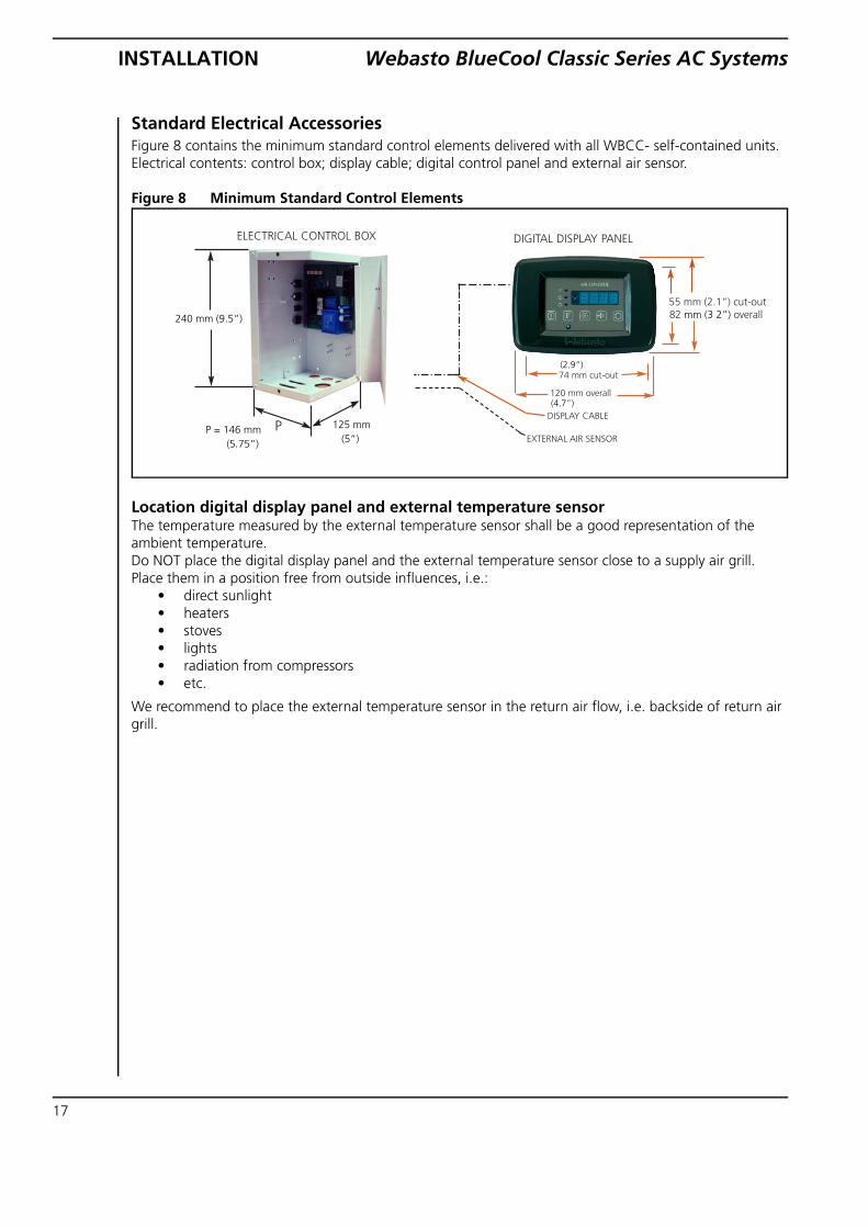
Standard Electrical AccessoriesFigure 8 contains the minimum standard control elements delivered with all WBCC- self-contained units. Electrical contents: control box; display cable; digital control panel and external air sensor.
Figure 8 Minimum Standard Control Elements
Location digital display panel and external temperature sensor The temperature measured by the external temperature sensor shall be a good representation of the ambient temperature. Do NOT place the digital display panel and the external temperature sensor close to a supply air grill. Place them in a position free from outside influences, i.e.:
• direct sunlight• heaters• stoves• lights• radiation from compressors• etc.
We recommend to place the external temperature sensor in the return air flow, i.e. backside of return air grill.

Webasto BlueCool Classic Series AC Systems PROGRAMMING
PROGRAMMING
Programming Access Entering Programming Mode
To enter programming mode:
1. Turn on the unit by pressing the <On / Off> key (5).
2. Raise or lower the setpoint temperature to 29 °C (84 °F) or 15 °C (59 °F).
3. Turn off system by pressing the <On / Off> key (5).
ATTENTION The first time you press the On / Off key after raising or lowering the setpoint the display may read “MEMO”, if so press the On / Off key again and the unit will turn off.
Figure 9 Using Digital Display to Access Programming
Accessing Hidden ProgrammingTo gain access to the hidden programming functions proceed as following:
1. Raise setpoint to value, i.e. 29 °C (84 °F) (or alternatively to lowest value i.e. 15 °C (59 °F)) - push <On/Off> key (5) to extinguish digital display.
2. Press <snow> and <sun> keys (3) simultaneously for approx. 3 seconds until the word “CODE” is visible on the display (1).
3. Press and hold the <sun> key (2) until 64 appears on the display (1) and then press the <F> key (4). Now you are in the deep programming mode.
4. You see to the left of the display window a single number code indicating the programming line presently valid and to the right the programming value.
5. To go to the next programming line, push the <F> key (4).
ATTENTION If you modify the programming value of any line, you need to validate this new value by pushing the <F> key again to move to the next line. This step will validate and memorize the changes made.
1
4 235
18

PROGRAMMING Webasto BlueCool Classic Series AC Systems
19
Re-initializing of Factory Default SettingsIt is possible to force the program to reinitialize all program values to factory default settings by the following procedure:
1. When reading the <b> line as above (through the 29 °C (84 °F) setpoint), push the <sun> key until the program version starts to flash. Keep the <sun> key pushed down until the display shows <init>.
2. Leave programming mode by pushing <On/Off> key - you are now back to the factory default settings.
Table 3 Description of Programming Codes - setpoint at 29 °C (84 °F)
Code #Factory Setting
Description Optional Settings
Functions accessible by raising the setpoint to 29 °C (84 °F)
Code <0> 00 °C (32 °F)
Lower setpoint temperature of the evaporator coil when in cool cycle. This value gives the compressor a cut-out point when the deicing mode is activated (in cool cycle).
Adjustment range: between -4 and +15 °C (25 and 59 °F)
Code <1> 05 °C (41 °F)
Higher setpoint temperature of deicing procedure. This value gives the restart point of the compressor after a thermostatic interruption when in deicing mode.
Adjustment range: between +2 and +18 °C (36 and 64 °F).
Code <2> 45 °C (113 °F)
Higher setpoint temperature of the “deicing” procedure in relation to the evap. coil temperature when in heat cycle (to avoid HP cut-outs). Gives the cut-out point of the compressor(s) when functioning in heat cycle. Setpoint temperature
Adjustment range: between 30 and 50° C (86 and 122° F).
Code <3> 38 °C (100 °F)
Lower setpoint temperature of coil temperature cut in when in heat cycle. Gives the cut in point of the compressor after an interruption (“deicing” procedure) when functioning in heat cycle. Setpoint temperature
Adjustment range: between 27 and 47 °C (81 and 117 °F)
Code <4> 0.0 Calibration of the evaporator coil temperature readout.
Adjustment range: between -9.9 and +9.9
Code <5> 15 Time delay in minutes before the digital display goes into blank/sleep mode. Cycle LED flashes discretely to indicate system is operational.
05 - 99 min.
Code <6> 01 First start up delay in seconds after connecting AC supply. To stage starting of several WBCC units when switching on AC supply after an interruption.
01 - 20 sec.
Code <7> 0.0 Calibration of room temperature readout. Adjustment range:between -9.9 and +9.9

Webasto BlueCool Classic Series AC Systems PROGRAMMING
Code <8> 00 Factory calibration of AC voltage 50 Hz as displayed on the digital panel when accessing the secondary commands - F/Blower key.
Adjustment range: between -30 and +20 Volt.
Code <9> 02 Time delay before restart in minutes after a compressor stop when in “deicing” procedure (both for cool and heat cycle).
01 - 99 min.
Code <A> 00 Factory calibration of AC voltage 60 Hz as displayed on the digital panel when accessing the secondary commands by the F key.
Adjustment range: between -30 and +20 Volt.
Code <b> 5.20 Program version 5.**
Code <c> 00 Pump <0> outlets on the TCC controller card non-regulated for standard 115V / 230V seawater pump.
For the use of the WEBASTO WB200 self-priming variable speed pump this code should be set to <1>. In that case the AC outlet is pulse hashed to enable variable pump speed.
Code <d> 12(V) Lower adjustment ceiling DC output for special self-priming pump.
Can be adjusted to higher ceiling (18V) - see also Code <E> hereafter.
Code <E> 18 (V) Higher adjustment ceiling DC output for special self-priming pump.
Can be adjusted downward to lower ceiling - see also Code <d> here-above.
Code <F> 01 Not available 00 - 01
Table 3 Description of Programming Codes - setpoint at 29 °C (84 °F)
Code #Factory Setting
Description Optional Settings
20

PROGRAMMING Webasto BlueCool Classic Series AC Systems
21
Table 4 Description of Programming Codes - setpoint at 15 °C (59 °F)
Code #Factory Setting
Description Optional Settings
Functions accessible when lowering the setpoint temperature to 15 °C (59 °F)
Code <0> 195V AC for 230V units
90V AC for 115V units
Low voltage cut-out value. Time delay is 5 seconds approx. i.e. the low voltage situation will have to persist during more than 5 seconds before cut-out occurs. After cut-out the electronic controller resets and will start a new cycle. So a renewed attempt to start the compressor will occur after approx. 90 seconds. During low voltage cut-out the display panel will show the 3 letters <AAA>.
Note: Compressor manufacturers decline all responsibility for defects resulting from operating the compressors below recommended voltage levels.Do not lower factory settings.
Code <1> 00 Infrared remote control 00 = Infrared remote control disabled (in this mode no interference is possible with other Infrared commands)
01 = Infrared remote control active
Code <2> 01 Blower type: Centrifugal or Crossflow. 01 = all blower models
Code <3> 01 Blower Settings: 01 = Uninterrupted blower operation regardless of the thermostatic control.
00 = Thermostatic control of blower operation, i.e. blower operation will be interrupted thermostatically when reaching the appropriate setpoint.
Code <4> 01 Choice between integrated air sensor and external air sensor: 01 = air sensor integrated in digital display.
00 = external air sensor
Code <5> 00 Celsius or Fahrenheit display 00 = Celsius 01 = Fahrenheit
Code <6> 70 Setting speed level 5 (max.) 01 - 70 See note a).
Code <7> 40 Setting speed level 4 01 - 70 See note a).
Code <8> 35 Setting speed level 3 01 - 70 See note a).
Code <9> 29 Setting speed level 2 01 - 70 See note a).
Code <A> 23 Setting speed level 1 (min.) 01 - 70 See note a).

Webasto BlueCool Classic Series AC Systems PROGRAMMING
Note a): Ensure re-start! Check if blower starts running at lowest speed setting to avoid motor damage.
Blower Speed Setting CalibrationEnter programming mode with setpoint at 15 °C (59 °F); proceed to following line, i.e. line <6> = speed 5 (max). The blower will start to function as soon as you access code <6>. Alter value to the right of code <6> and blower speed will immediately change in real time. When satisfied go to following line <7> = speed 4 and do the same. Proceed until lowest speed No. 1 and go back again to speed No. 5 if not satisfied. When all speeds are programmed according to need, validate by pushing <On/Off> key (<MEMO> will be displayed briefly).
Code <b> 64 Access code for programming mode.Note: If the system is locked and the access code cannot be found, you can access the programming line by using the factory code number: 64
00 = No access code required. 01 to 99 = access code/number activated.
Code <c> 01 Duration in minutes of heat cycle operation under the dehumidifying cycle.
01 - 99 min.
Code <d> 01 Duration in minutes of cool cycle operation under the dehumidifying cycle.
01 - 99 min.
Table 4 Description of Programming Codes - setpoint at 15 °C (59 °F)
Code #Factory Setting
Description Optional Settings
22
TROUBLESHOOTING Webasto BlueCool Classic Series AC Systems
23
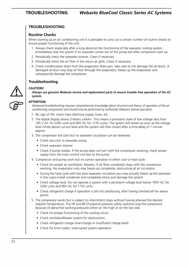
TROUBLESHOOTING
Routine Checks When starting up an air conditioning unit it is advisable to carry out a certain number of routine checks to ensure proper functioning of the unit:
1. Always check (especially after a long absence) the functioning of the seawater cooling system. Immediately stop the system if no seawater comes out of the pump exit after compressor start up.
2. Periodically check the seawater strainer. Clean if necessary.
3. Periodically check the air filter in the return air grills. Clean if necessary.
4. Check condensation drain from the evaporator drain pan, take care to not damage the air-ducts. A damaged air-duct may stop air flow through the evaporator, freeze up the evaporator and subsequently damage the compressor.
Troubleshooting
CAUTION! Always use genuine Webasto service and replacement parts to ensure trouble-free operation of the AC system.
ATTENTION Advanced troubleshooting requires comprehensive knowledge about structure and theory of operation of the air conditioning components and should only be performed by authorized Webasto trained specialists.
1. No sign of life: check main electrical supply, fuses, etc.
2. The digital display shows 3 letters <AAA>. This means a persistent state of low voltage (less than 195 V AC for 230V units and 90V AC for 115V units). The system will restart as soon as the voltage level climbs above cut-out level and the system will then restart after a time-delay of 1 minute approx.
3. The compressor will start but no seawater circulation can be observed:
• Check sea-cock to seawater pump.
• Check seawater strainer.
• Check if pump rotates. If the pump does not turn with the compressor working, check power supply from the main control unit box to the pump.
4. Compressor and pump work but no correct operation in either cool or heat cycle:
• Check for proper air ventilation, blowers. If air flow completely stops with the compressor working, the evaporator coils may freeze up completely, obstructing all air circulation.
• During the heat cycle with too slow seawater circulation you may actually freeze up the seawater in the cupro-nickel condenser and completely block and damage the system.
• Check voltage level. Do not operate a system with a persistent voltage level below 195V AC for 230V units and 90V AC for 115V units.
• Check refrigerant charge if operation is still not satisfactory, after having checked all the above points.
5. The compressor works but is subject to intermittent stops without having attained the desired setpoint temperature. The HP and BP (if present) pressure safety switches stop the compressor because of abnormal working pressures either on the high or on the low side.
• Check for proper functioning of the cooling circuit.
• Check ventilator/blower system for obstructions.
• Check refrigerant charge (over-charge or insufficient charge level).
• Check for Error codes / interrupted system operation.

Webasto BlueCool Classic Series AC Systems TROUBLESHOOTING
6. The heat cycle takes very long to get started. Normal if the seawater temperature is very low. If seawater temperature drops below approx. 6 °C (43 °F) the heat cycle becomes much less effective and takes long to get properly started.
Visual Error Codes - Digital DisplayThe following malfunctions will be displayed directly on the digital display by a code and will be followed by a system halt. Whenever any of these codes appear the system is stopped for approx. 60 seconds and then a restart is attempted. If for more than 30 minutes the same malfunction occurs, the system will be stopped completely and the error code will become steady. No more restarts will be attempted and the user will have to re-set the system by pushing the <On/Off> switch or by temporarily cutting out the AC supply to the system
Code A01 to A08: Pressure safety cut-out of compressors 1 to 4.The HP and BP (if present) safety controls are directly controlled by the micro-processor including the time-delays for restart, etc. See note *) Standard TCC controller cards have only 1 outlet for 1 single compressor. However the embedded micro-processor program can operate up to 4 WBCC units from 1 single controller card. This special controller card can be obtained on special request but is not standard delivery.
ATTENTION *) Models WBCC5 to 12 do not have a low pressure safety switch (BP); therefore if you see a A01 warning on such
model, it can only be an electrical connection problem on the 3 pole HP/BP connector on the TCC controller card. Check that the connector is properly seated and that the BP strap is properly tightened.
If any of these error codes appear too frequently and no appropriate action can be taken with the available means on board, it is necessary to call a specialist.
Do not insist with manual restarts in such case as this may cause major damage to the principal components (compressors, pumps, etc.)
24

TROUBLESHOOTING Webasto BlueCool Classic Series AC Systems
25
Table 5 Failurecode
Description Possible cause Solution
<AAA> Low Voltage Low voltage cut-out. Power supply was over 5 sec lower than controller setting. Probably caused by long length power supply cable or overload.
Check setting, default 195 V. Don't set below 195 V to avoid damages to the compressor or to expire warranty. Improve power supply.
<A01> Low pressure cut-out compressor 1 (Classic > 20,000 BTU)
Defective pressure sensor or open/short circuit.
Check wiring or replace pressure sensor on Schrader valve.
COOLING MODE: Insufficient air flow.
Check air flow. ΔT evaporator in/out minimum 4K.
HEATING MODE:Insufficient seawater flow or seawater too cold (temperature below 6 °C or 43 °F). Blocked sea-water strainer or not primed.
Check discharge water volume. V= 8 l/min (or > 30,000 BTU V= 18 l/min). ΔT in/out minimum 4K. When T seawater < 4 °C: preheating necessary. Clean strainer and bleed seawater circuit.
Lack of refrigerant. Refrigerant leak check.
<A02> High pressure cut-out compressor 1
Defective pressure sensor or open/short circuit.
Check sensor and wiring. Replace sensor on Schrader if necessary.
COOLING MODE:Insufficient seawater cooling.Blocked seawater strainer or not primed.
Check discharge water volume. V= 8 l/min (or > 30,000 BTU V= 18 l/min). Clean strainer and bleed sea-water circuit.
HEATING MODE:Insufficient air flow.
Check air-flow. ΔT evaporator in/out minimum 4K.
<A03> to <A08>
Not used for BlueCool Classic units.
<A09> Cabin temperature sensor failure (internal and external)
Broken internal or external temperature sensor, open/short circuit, not present or programmed wrong.
Replace sensor or controller. In case of external sensor try to reprogram to internal sensor first to determine failure.
<A10> Evaporator temperature sensor failure.
Defective evaporator sensor or open/short circuit.
Check wiring or replace sensor. Water infiltration (condense) can cause a read-out derivation or erratic functioning before an error code occurred.
<CA11> All compressors manually off.
Compressor(s) programmed not active in controller setting.
Check settings. At least one compressor should be programmed active. C01=ON C00=OFF
Webasto BlueCool Classic Series AC Systems TROUBLESHOOTING
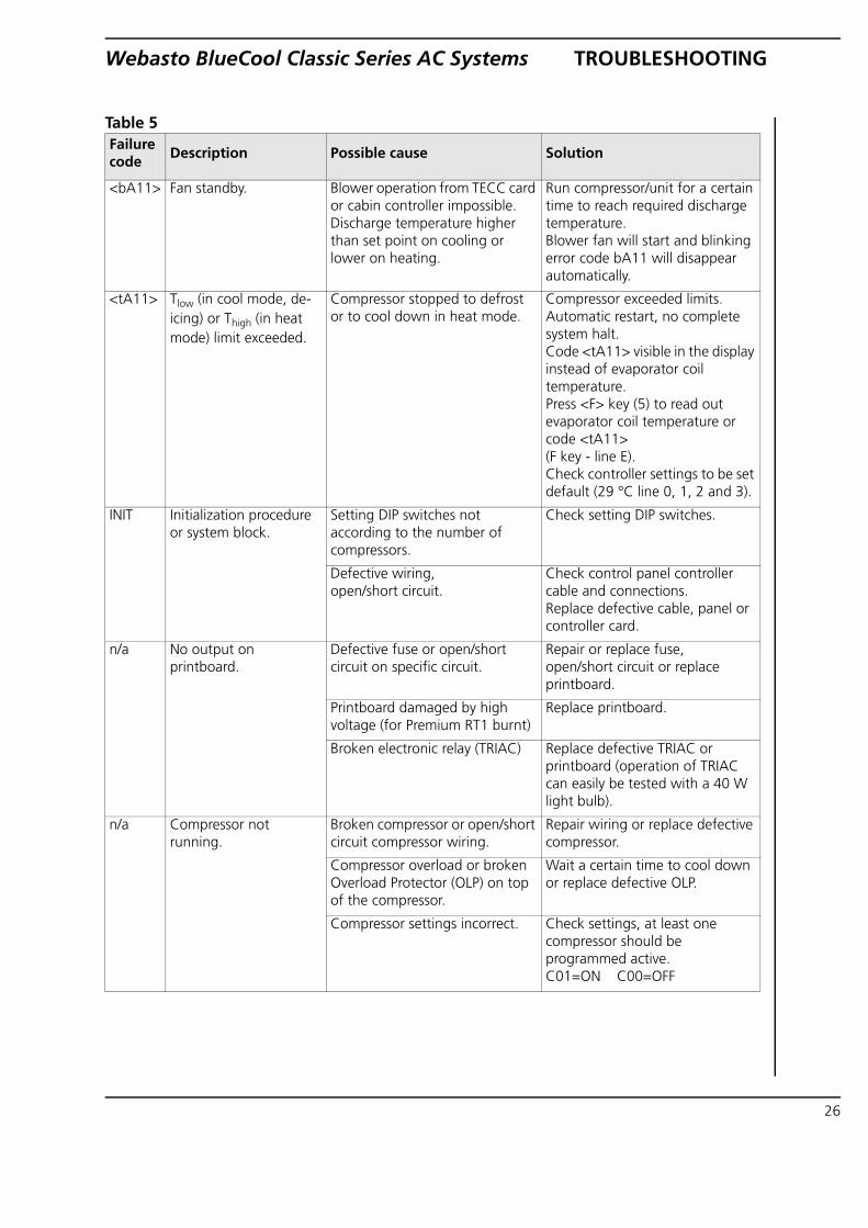
<bA11> Fan standby. Blower operation from TECC card or cabin controller impossible. Discharge temperature higher than set point on cooling or lower on heating.
Run compressor/unit for a certain time to reach required discharge temperature. Blower fan will start and blinking error code bA11 will disappear automatically.
<tA11> Tlow (in cool mode, de-icing) or Thigh (in heat mode) limit exceeded.
Compressor stopped to defrost or to cool down in heat mode.
Compressor exceeded limits. Automatic restart, no complete system halt.Code <tA11> visible in the display instead of evaporator coil temperature.Press <F> key (5) to read out evaporator coil temperature or code <tA11>(F key - line E). Check controller settings to be set default (29 °C line 0, 1, 2 and 3).
INIT Initialization procedure or system block.
Setting DIP switches not according to the number of compressors.
Check setting DIP switches.
Defective wiring, open/short circuit.
Check control panel controller cable and connections. Replace defective cable, panel or controller card.
n/a No output on printboard.
Defective fuse or open/short circuit on specific circuit.
Repair or replace fuse, open/short circuit or replace printboard.
Printboard damaged by high voltage (for Premium RT1 burnt)
Replace printboard.
Broken electronic relay (TRIAC) Replace defective TRIAC or printboard (operation of TRIAC can easily be tested with a 40 W light bulb).
n/a Compressor not running.
Broken compressor or open/short circuit compressor wiring.
Repair wiring or replace defective compressor.
Compressor overload or broken Overload Protector (OLP) on top of the compressor.
Wait a certain time to cool down or replace defective OLP.
Compressor settings incorrect. Check settings, at least one compressor should be programmed active. C01=ON C00=OFF
Table 5 Failurecode
Description Possible cause Solution
26

TROUBLESHOOTING Webasto BlueCool Classic Series AC Systems
27
n/a No or insufficient cooling or heating performance.
Bad air flow or water flow, filthy or blocked circulation.
Ensure air or water flow (see A01 and/or A02).
Lack of refrigerant. Lack of refrigerant mostly recognized by a low static pressure before start-up and non-fluctuating LP associated with a low HP pressure reading. Check for refrigerant leaks, repair if necessary and charge required amount of refrigerant.
Oil lock. Operate the unit in heat cycle. Intervention by a refrigerant specialist might be necessary. Technical Memo available.
Blocked refrigerant circuit. (Drier, capillary or expansion valve).
To be determined by a refrigerant specialist. Technical Memo available.
Bad compressor. To be determined by a refrigerant specialist.
n/a Pumps running continuously.
When additional relays are used to operate pumps a small leaking current from the printboard may operate the relay continuously.
Remove R56 + C24 and/or R57 + C27 from the printboard.
n/a Inaccurate temperature read-out of room / ambient temperature or evaporator temperature.
Temperature sensor not installed on the right position, interference by environment or read-out deviation.
Check for interference by direct sunlight or heat radiation from components near to the sensor.Calibrate sensor.Replace defective sensor.
Table 5 Failurecode
Description Possible cause Solution

Webasto BlueCool Classic Series AC Systems SCHEMATICS
SCHEMATICS
Wiring Diagram - BlueCool Classic TCC V3 br bl br bl br bl sw wssw sw rt gr ge
bl br sw gn
bl ws
Fuse
s:
F1 p
rint
315m
A
(115
V 6
30m
A)
F2 f
an 3
.15A
F3
val
ve 3
.15A
F4
pum
p 1
SW 3
.15
A
C
able
col
ours
bl
br
ge
gn
gr
rt sw
w
s
blue
br
own
yello
w
gree
n gr
ey
red
blac
k w
hite
4-w
ay r
ev. v
alve
Blo
wer
Seaw
ater
pu
mp
115/
230V
AC
sw
itch
bo
ard
Pres
sure
sw
itch
es
LP o
nly
for 1
6,00
0BT
U
and
mor
e
Ru
n c
apac
ito
r
Star
t ca
pac
ito
r (o
nly
for
16,0
00BT
U
and
mor
e)
Cap
acito
r an
d re
sist
or p
ump
*)
Dis
play
Exte
rnal
air
tem
p.
sens
or
Evap
orat
or t
emp.
se
nsor
compfan valve pump
Cap
acito
r an
d re
sist
or p
ump
*)
*)In
cas
e a
rela
y is
use
d, t
he
cont
rolle
r sh
ould
be
with
out
rela
ted
capa
cito
r an
d re
sist
or
28

SCHEMATICS Webasto BlueCool Classic Series AC Systems
Wiring Diagram - BlueCool Classic multiple unit, one pump
IMPO
RTA
NT
The
TCC
con
trol
ler
card
of
each
uni
t sh
ould
be
with
out
capa
cito
r an
d re
sist
or a
t th
e re
late
d ou
tput
. Re
mov
e if
nece
ssar
y!
Co
mm
on
sea
wat
er
pu
mp
TCC
pu
mp
ou
tlet
un
it 1
115/
230V
AC
sw
itch
bo
ard
TCC
pu
mp
ou
tlet
un
it 2
TCC
pu
mp
ou
tlet
un
it 3
TCC
pu
mp
ou
tlet
un
it 4
29

Webasto BlueCool Classic Series AC Systems SCHEMATICS
Wiring Diagram - BlueCool Classic Pump WB200
bl br
IMPO
RTA
NT
For p
rope
r ope
ratio
n TC
C c
ontr
olle
r se
ttin
gs a
t se
tpoi
nt 2
9°C
, lin
e <
c>
mus
t be
set
at
01
Seaw
ater
pu
mp
TCC
pu
mp
ou
tlet
C
able
col
ours
bl
br
bl
ue
brow
n
Dis
play
compfan valve pump
Exte
rnal
air
tem
p.
sens
or
Evap
orat
or t
emp.
se
nsor
FUSE
/ V
OLT
AG
E SE
TTIN
G:
30

TECHNICAL DATA Webasto BlueCool Classic Series AC Systems
TECHNICAL DATA
* has to be doubled for the 115V versions.
* has to be doubled for the 115V versions.
Model WBCC5 WBCC6.5 WBCC7 WBCC9 WBCC12
Performance [BTU / kW] 5,000 / 1.5 6,500 / 1.9 7,000 / 2 9,000 / 2.6 12,000 / 3.5
Voltage230V / 115V
50-60Hz / 60Hz115V60 Hz
230V50-60Hz
230V / 115V50-60Hz / 60Hz
230V / 115V50-60Hz / 60Hz
Power consumption / start [A] *
2.1 / 5 2.8 / 6 2.8 / 6 3.2 / 7.5 4.3 / 9
Net weight [kg 23 24 24 25 26
Seawater min. flow rate [l/min]
8 8 8 8 10
Blower output [m3/h] 275 275 275 400 500
ø condenser water connection [mm]
16 16 16 16 16
Dimensions (LxDxH) [mm]
421x285x295 421x285x295 421x285x295 445x385x310 442x455x310
ø air outlet [mm] 100 100 100 100 125
Suggested breaker [A] * 8 10 10 12 16
Model WBCC16 WBCC20 WBCC24 WBCC30
Performance [BTU / kW] 16,000 / 4.7 20,000 / 5.8 24,000 / 7 30,000 / 8.8
Voltage230V / 115V
50-60Hz / 60Hz230V
50-60Hz230V
50-60Hz230V
50-60HzPower consumption / start [A] * 5.5 / 12 6.5/ 14 8 / 18 9.5 / 22
Net weight [kg 33 34 45 50
Seawater min. flow rate [l/min] 12 14 15 18
Blower output [m3/h] 625 625 2 x 500 2 x 550
ø condenser water connection [mm]
16 16 16 16
Dimensions(LxDxH) [mm]
442x455x330 463x455x385 456x510x400 456x610x400
ø air outlet [mm] 125 125 2 x 125 2 x 125
Suggested breaker [A] * 20 20 28 32
31

Webasto BlueCool Classic Series AC Systems CHOOSE THE RIGHT BLUECOOL
CHOOSE THE RIGHT BLUECOOL How to choose the right BlueCool air conditioner? Example: You own a yacht and would like to aircondition a room of 5 m (length) x 5 m (width) x 2 m (height).
Step 1
Determine the category of the cabin. We give an example for a cabin with an average glass area, for example a deck saloon.
Category 2
Step 2
Determine the net volume of the room (5m x 5m x 2m = 50 m3; subtract 20% for
furniture in the room; 50 m3 - 10 m3 = 40 m3; If you want to air condition the whole boat, please calculate the sum of your rooms).
40 m3
Step 3
Determine the climate region where you spend most of your time. For example the Mediterranean Sea is a “normal region” in the climate category.
Normal region
Step 4
Result: You need an air conditioning system with a 20,000 BTU cooling performance. 20,000 BTU
Step 5
Depending on the demands you can decide on a BlueCool Classic, Select or Premium with a cooling capacity of 20,000 BTU.
WBCC 20/D
Volume
of the rooms
[m3]*
10
20
30
40
50
60
70
80
90
100
110
120
130
140
150
160
170
180
190
200
Category 2
average glas area
cabins partly below deck
[500 BTU/m3]
region:
normal cold hot
5,000 3,750 6,250
10,000 7,500 12,500
15,000 11,250 18,750
20,000 15,000 25,000
25,000 18,750 31,250
30,000 22,500 37,500
35,000 26,250 43,750
40,000 30,000 50,000
45,000 33,750 56,250
50,000 37,500 62,500
55,000 41,250 68,750
60,000 45,000 75,000
65,000 48,750 81,250
70,000 52,500 87,500
75,000 56,250 93,750
80,000 60,000 100,000
85,000 63,750 106,250
90,000 67,500 112,500
95,000 71,250 118,750
100,000 75,000 125,000
Step 2
Step 1
Step 3
Step 4
NOTE:
For precise BTU calculation, please refer to our dedicated BTU calculation tool. See our technical web site: http://dealers.webasto.com or http://www.techwebasto.com
32

THE RIGHT COOLING CAPACITY Webasto BlueCool Classic Series AC
33
THE RIGHT COOLING CAPACITY
*(length x width x height)
For extreme climatic conditions such as the Persian Gulf with sea-water temperatures of 32 °C and air temperatures of 40 °C, you have to add 25 to 30 % onto the calculated figure. It is also recommended that the condenser is increased in size.

Webasto Product International NL Constructieweg 47 NL - 8263 BC Kampen The Netherlands
Phone: +31 (0) 38 337 11 37 Fax: +31 (0) 38 332 51 81 E-mail: [email protected] Internet: http://www.webasto.com
http://dealers.webasto.com
Webasto Product N.A., Inc.15083 North RoadFenton, MI 48430
Technical Assistance HotlineUSA: (800) 555-4518Canada: (800) 667-8900
Internet: http://www.webasto.us http://www.techwebasto.com
Subject to change
Webasto AG Global Comfort Solutions © 2008 All Right Reserved ID
ENT.
-NR.
WBC
L010
500A