Wearable Computer - CiteSeerX
44
1 Informatique Signaux et Systèmes de Sophia Antipolis Preliminary training report Wearable Computer Supervisor: Jean-Yves TIGLI Daniel CHEUNG-FOO-WO Taining from March to June 2004
-
Upload
khangminh22 -
Category
Documents
-
view
0 -
download
0
Transcript of Wearable Computer - CiteSeerX

1
Informatique Signaux et Systèmes de Sophia Antipolis
Preliminary training report
Wearable Computer
Supervisor:
Jean-Yves TIGLI
Daniel CHEUNG-FOO-WO
Taining from March to June 2004

2
Résumé
Les systèmes de traitement de l'information sont aujourd'hui en pleine transition entre
l'ordinateur de bureau et les systèmes mobiles de traitement de l'information. La mobilité de l'utilisateur offre des perspectives qui dépassent en grande partie la possibilité de transporter un ordinateur pour des tâches traditionnelles ou spécifiques mais permet des usages encore insoupçonnés: un ordinateur aidant un utilisateur mobile dans toutes ces activités. De tels systèmes mobiles de traitement de l'information sont recueillis sous le terme générique: "wearable computer" ou ordinateur corporel en français.
Dans ce contexte "wearable computer", l'objet de nos travaux est de mettre en place une technique de programmation particulière d'applications. En effet si l'on utilise une approche classique par assemblage de composants logiciels, plus l'application sera complexe, plus son adaptation au contexte sera compliquée voire ingérable. Nous proposons donc le concept de programmation orientée comportement ou "Behavioral Programming", et d'utiliser le maximum des potentiels des langages orientés objets. L'originalité de ce concept se situe au niveau de la méthode de conception d'une application. En effet on ne va plus manipuler les objets en les assemblant les uns aux autres mais plutôt considérer des collections d'objets particuliers ("comportementaux") capables d'exhiber une partie des comportements de l'application finale.
Il ne s'agira alors plus de décomposer une application par un assemblage d'objets mais de la présenter sous forme d'une collection d'objets comportementaux dont on pourra étudier l'exécution concurrente fonction de leurs "caractéristiques".
Pendant ce stage, un formalisme autour du "behavioral computing" a été mis en place afin de dégager les propriétés d'un telle approche et ensuite d'évaluer ses performances et son apport.

3
Acknowledgements
I would like to thank my supervisor Jean-Yves Tigli for his advices, his support and for
everything. I would like to thank the Wcomp team of this year for their remarks.
Special thanks go to Michel Riveill and the Rainbow team.
4
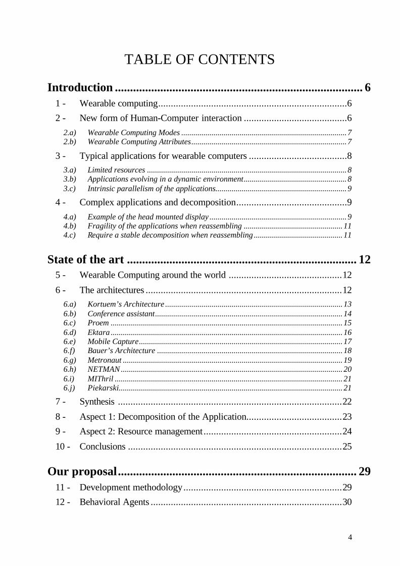
TABLE OF CONTENTS
Introduction .................................................................................. 6
1 - Wearable computing...........................................................................6
2 - New form of Human-Computer interaction .........................................6
2.a) Wearable Computing Modes .................................................................................. 7 2.b) Wearable Computing Attributes............................................................................. 7
3 - Typical applications for wearable computers .......................................8
3.a) Limited resources ................................................................................................... 8 3.b) Applications evolving in a dynamic environment................................................... 8 3.c) Intrinsic parallelism of the applications................................................................. 9
4 - Complex applications and decomposition............................................9
4.a) Example of the head mounted display .................................................................... 9 4.b) Fragility of the applications when reassembling ................................................. 11 4.c) Require a stable decomposition when reassembling ............................................ 11
State of the art ............................................................................ 12
5 - Wearable Computing around the world .............................................12
6 - The architectures ..............................................................................12
6.a) Kortuem’s Architecture ........................................................................................ 13 6.b) Conference assistant............................................................................................. 14 6.c) Proem ................................................................................................................... 15 6.d) Ektara ................................................................................................................... 16 6.e) Mobile Capture..................................................................................................... 17 6.f) Bauer’s Architecture ............................................................................................ 18 6.g) Metronaut ............................................................................................................. 19 6.h) NETMAN .............................................................................................................. 20 6.i) MIThril ................................................................................................................. 21 6.j) Piekarski............................................................................................................... 21
7 - Synthesis .........................................................................................22
8 - Aspect 1: Decomposition of the Application......................................23
9 - Aspect 2: Resource management.......................................................24
10 - Conclusions .....................................................................................25
Our proposal............................................................................... 29
11 - Development methodology...............................................................29
12 - Behavioral Agents ............................................................................30

5
13 - Complex application and simple integration ......................................31
14 - Limits of the approach......................................................................32
15 - Resource management......................................................................32
16 - Resource manager based on filters ....................................................34
17 - Experimentation...............................................................................35
17.a) Hardware Architecture..................................................................................... 35 17.b) Software Architecture....................................................................................... 36
Conclusions and perspectives.................................................... 38
18 - New limits of the approach...............................................................38
18.a) Influence of the implicit interactions ................................................................ 38 18.b) What are the resources? ................................................................................... 38 18.c) How to capture implicit resources? ................................................................. 38 18.d) Behavioral agent properties............................................................................. 38
19 - Phd at Rainbow, BDI/CSTB.............................................................39
References ................................................................................... 40

6
III... IIINNNTTTRRROOODDDUUUCCCTTTIIIOOONNN
111 --- WWWeeeaaarrraaabbbllleee cccooommmpppuuutttiiinnnggg
The wearing of digital and full- function computing devices began to be supported in the early 1990s. The Wearable Group of Carnegie Mellon University was the first to investigate the use of these devices. At this time, wearable computers were viewed as assistants for maintaining large vehicles in general such as aircrafts. Experiments were conducted by students in actual workplaces.
At the same time at the Media Laboratory of the Massachusetts Institute of Technology other students were operating. They styled themselves “borgs” and viewed wearable computers as consumer products designed to upgrade the lives of those who wore them. For instance, they got interested in memory support applications and innovative uses such as business e-cards exchange when the wearers shook hands. In that latter case they used the conductivity of the skin as a network medium to transmit data.
By the late 90s, the two groups were collaborating. They made wearable computers a viable academic discipline. Commercial companies had begun to show interest. With miniaturized hardware and sophisticated software, wearable computing became prevalent.
For example the European project 2WEAR has published on this topic a paper entitled “Futuristic Application Environment” analyzing more than ten applicable scenarios for futuristic applications for mobile computers.
But three questions must be kept in mind when reading further this paper further. How should a wearable computer be programmed? What is the difference between a wearable computer and a desktop computer or a personal digital assistant (PDA)? How can a wearable computer help people in everyday life?
222 --- NNNeeewww fffooorrrmmm ooofff HHHuuummmaaannn---CCCooommmpppuuuttteee rrr iiinnnttteee rrraaaccctttiiiooonnn
Wearable computing facilitates a new form of interaction between human and computer. It consists of a small body-worn device that should be constantly ready and accessible. Consequently the new computational architecture becomes different from that of hand held devices, laptops or PDAs.
7
Computer
User
UnrestrictiveEnvironment/User
ComputerUser
Obs
erva
ble C
ontrollable
Computer/Environment
Unmopolising
Attentive Communicative
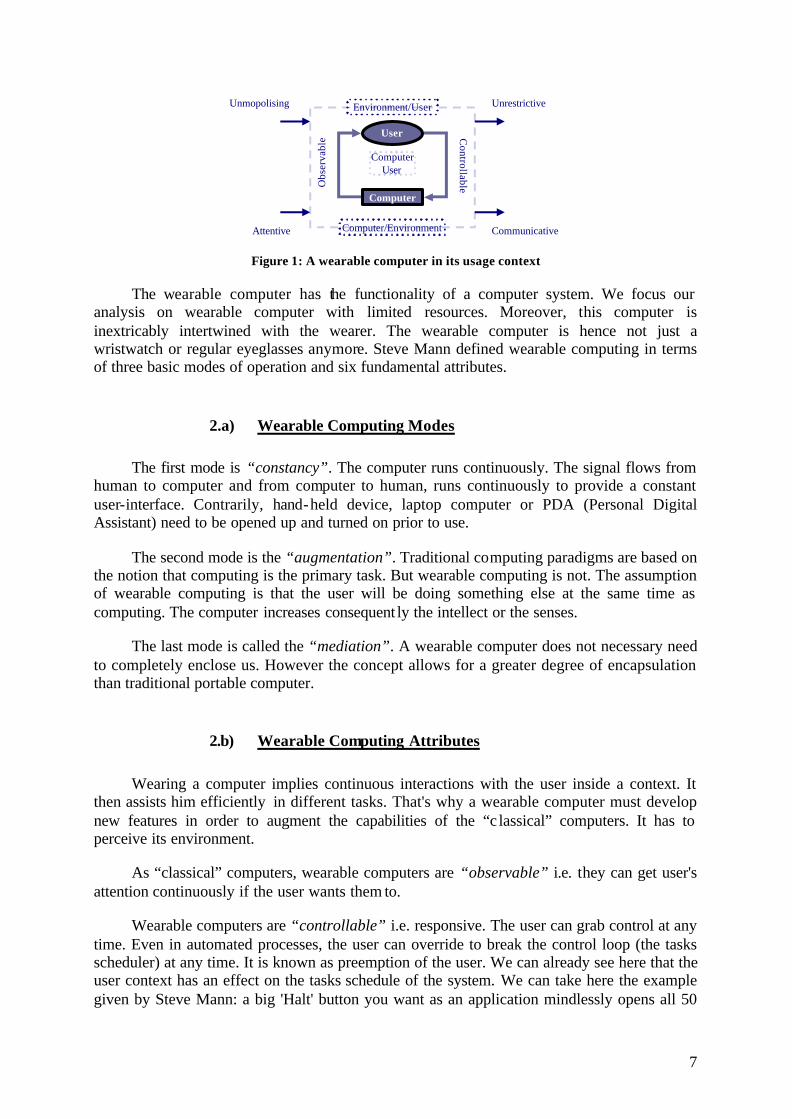
Figure 1: A wearable computer in its usage context
The wearable computer has the functionality of a computer system. We focus our analysis on wearable computer with limited resources. Moreover, this computer is inextricably intertwined with the wearer. The wearable computer is hence not just a wristwatch or regular eyeglasses anymore. Steve Mann defined wearable computing in terms of three basic modes of operation and six fundamental attributes.
2.a) Wearable Computing Modes
The first mode is “constancy”. The computer runs continuously. The signal flows from human to computer and from computer to human, runs continuously to provide a constant user-interface. Contrarily, hand-held device, laptop computer or PDA (Personal Digital Assistant) need to be opened up and turned on prior to use.
The second mode is the “augmentation”. Traditional computing paradigms are based on the notion that computing is the primary task. But wearable computing is not. The assumption of wearable computing is that the user will be doing something else at the same time as computing. The computer increases consequent ly the intellect or the senses.
The last mode is called the “mediation”. A wearable computer does not necessary need to completely enclose us. However the concept allows for a greater degree of encapsulation than traditional portable computer.
2.b) Wearable Computing Attributes
Wearing a computer implies continuous interactions with the user inside a context. It then assists him efficiently in different tasks. That's why a wearable computer must develop new features in order to augment the capabilities of the “c lassical” computers. It has to perceive its environment.
As “classical” computers, wearable computers are “observable” i.e. they can get user's attention continuously if the user wants them to.
Wearable computers are “controllable” i.e. responsive. The user can grab control at any time. Even in automated processes, the user can override to break the control loop (the tasks scheduler) at any time. It is known as preemption of the user. We can already see here that the user context has an effect on the tasks schedule of the system. We can take here the example given by Steve Mann: a big 'Halt' button you want as an application mindlessly opens all 50

8
documents that were highlighted when you accidentally pressed 'Enter'.
There are four new flow paths associated with this human-machine interaction. These paths are specific attributes of wearable computing and are described in what follows.
The “Unmonopolizing” attribute consists in freeing the user's attention, keeping him aware of its environment. It does not cut the user off the outside world. It is definitely not a virtual reality game or the like. It is then built with the assumption that computing will be a secondary activity. Ideally, it would provide enhanced sensory capabilities. Conversely, it may however mediate (increase, change or decrease) the sensory capabilities, deliberately or not.
The wearable computer should stay “attentive” to the environment. Many synonyms are used to qualify such an attribute such as “context-aware”, “multi-modal” or “multi-sensory”. As a result, this ultimately gives the user increased situational awareness.
The “unrestrictive” attribute is linked to the user. It means that the user can use his wearable computer while doing other tasks: jogging or shopping, for example.
Finally, a wearable computer should be “communicative”. This attribute means that it can be used as a communication medium between humans. This definition can be generalized to inter-computer or -human communication, which is not mentioned in Steve Mann's paper.
In short, all these properties make sense for studying wearable computers with limited resources because those kinds of computers can be as small as possible. Rudimentary electronic components can be integrated in a small surface. People can wear them without feeling embarrassed.
333 --- TTTyyypppiiicccaaalll aaappppppllliiicccaaattt iiiooonnnsss fffooorrr wwweeeaaarrraaabbbllleee cccooommmpppuuuttteee rrrsss
Wearable-computer applications are different from common applications for desktop computers or PDAs. In this section we analyse those differences.
3.a) Limited resources
The resources cannot be neglected anymore. They must be managed. This kind of system where hardware and software capacity limits is not neglected is called a critical system. The resources are limited. By limited resources we mean that the battery level is limited, the central unit process (CPU) frequency is low and the amount of memory is reduced. Indeed memory capacity cannot be neglected anymore. We should mention here that there is no hard disk drive. These limitations are accompanied by a constant changing environment.
3.b) Applications evolving in a dynamic environment
The user is mobile and consequently the environment becomes dynamic. Because of the
9
mobility of the user, a wearable computer should take two aspects into account :
The first aspect is linked to the usage mode i.e. it is no question of displaying information to the user when this last is busy doing another task which require him to be visually attentive. The information should be given through an auditory manner.
The second important aspect is that the environment should be taken into account. Because of the dynamic aspect of the environment, a wearable computer should not be unaware of this aspect of the environment. But your desktop computer or even your personal digital assistant (PDA) ignores it. This dynamicity implies the common usage of sensing application that are usually independent.
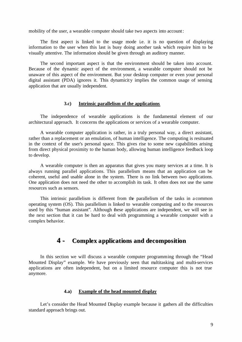
3.c) Intrinsic parallelism of the applications
The independence of wearable applications is the fundamental element of our architectural approach. It concerns the applications or services of a wearable computer.
A wearable computer application is rather, in a truly personal way, a direct assistant, rather than a replacement or an emulation, of human intelligence. The computing is resituated in the context of the user's personal space. This gives rise to some new capabilities arising from direct physical proximity to the human body, allowing human intelligence feedback loop to develop.
A wearable computer is then an apparatus that gives you many services at a time. It is always running parallel applications. This parallelism means that an application can be coherent, useful and usable alone in the system. There is no link between two applications. One application does not need the other to accomplish its task. It often does not use the same resources such as sensors.
This intrinsic parallelism is different from the parallelism of the tasks in a common operating system (OS). This parallelism is linked to wearable computing and to the resources used by this “human assistant”. Although these applications are independent, we will see in the next section that it can be hard to deal with programming a wearable computer with a complex behavior.
444 --- CCCooommmpppllleeexxx aaappppppllliiicccaaattt iiiooonnnsss aaannnddd dddeeecccooommmpppooosssiiittt iiiooonnn
In this section we will discuss a wearable computer programming through the “Head Mounted Display” example. We have previously seen that multitasking and multi-services applications are often independent, but on a limited resource computer this is not true anymore.
4.a) Example of the head mounted display
Let’s consider the Head Mounted Display example because it gathers all the difficulties standard approach brings out.

10
It consists in scrolling an image on the screen of the head mounted display (a little display mounted on standard glasses). When you change the orientation of your head the image scrolls. You can navigate for instance in your gallery of pictures. You can also zoom on the image by modifying the distance between your hands which should be opposite each other. The zoom function can be switched off thanks to a button hidden in your hand. Another button enables you to see the next picture.
This application can be implemented with standard components. We did it using the Javabeans standard which allows us to point out the different problems we faced.
We have a total of ten components: Component name Description
Switch The switch component is the component representing the hardware button switching on/off the zoom function.
Distance The Dist component is the component that gives the distance information from the hardware sensor.
Orientation The Comp component is the component that gives the orientation information from the compass sensor.
Next The next component gives the “next image please” information from the button sensor.
Acquisition 1 (period = t1) This component fetches an information every t1 seconds
Acquisition 2 (period = t2) See Acquisition 1.
Filter 1 (gain = G1) This component gives a filtered value of its input according to the gain G1.
Filter 2 (gain = G2) See Filter 1.
ON-OFF This component propagates the input information to the output if a certain signal is present.
Image Transformer This component loads an image and transforms it by zooming or scrolling.
HMD This represents the Head Mounted Display screen.
Orientation
HMD
Acquisition
Entry point
Acquisition
Entry point
Filter Filter
Distance
Acquisition
Entry point
Acquisition
Entry point
Parameters Parameters
Image Transformer
ON-OFF
Switch Next Figure 2: Scrolling Picture Viewer Application
The application consists in two execution flows, one is acquiring the distance information, filtering it and giving it to the Image Transformer, and he other acquires the orientation information. The Distance information can be switched off.

11
4.b) Fragility of the applications when reassembling
The problem is that following the state of the system the values of the filter gain change. That depends on the system load (CPU load), the acquisition accuracy and the zoom activation. Indeed, two independent applications at first glance are interacting implicitly when they are put together on the computer.
4.c) Require a stable decomposition when reassembling
So if we want to make it dynamic we should add a new component to manage those values. Consequently this simple application becomes more complex. Each evolution and “functional adding” will cost a lot in the graph complexity. Let’s have a glance at the literature side to see how those implicit interactions are tackled. This will be the subject of the next section.

12
IIIIII... SSSTTTAAATTTEEE OOOFFF TTTHHHEEE AAARRRTTT
The goal of this section is to discuss what has been proposed in the literature in terms of architectures for wearable computers. We are going to study them to find out how implicit interactions (introduced in the last section) are tackled.
111 --- WWWeeeaaarrraaabbbllleee CCCooommmpppuuutttiiinnnggg aaarrrooouuunnnddd ttthhheee wwwooorrrlllddd
This does not claim to cover all the laboratories of wearable computing and all the contribution but only the main ones.
University of South Australia
University of Oregon
MIT
CMU
GeorgiaTech
Toronto
I3S
IIT
LUT
UK
Here is the legend of the map: Toronto University of Toronto (Canada) MIT Massachusetts Institute of Technology CMU Carnegie Mellon University GeorgiaTech Georgia Institute of technology I3S Informatique, Signaux et Systèmes Sophia Antipolis IIT Institut für Informatik, Technishe Universit ät München LUT Luleå University of Technology
222 --- TTThhheee aaarrrccchhhiiittteeeccctttuuurrreee sss
Here is a list of the main architectures for wearable computers. This table represents them in a chronological manner.

13
Year 1996 2000 2001 2002 2003
Conference assistant MIThril
Proem Mobile capture Metronaut
Architectures Kortuem’s
Ektara Bauer NETMAN Piekarski’s
The following architectures will be analyzed conforming to IEEE 1641 concerning software architecture recommendations. For each architecture, we will distinguish the components, connectors, interfaces and the constraints (regrouped in a part called “Architecture”). What matters in architecture is the viewpoint and the requirements and objectives of the created system. That’s why a first paragraph entitled “Specificities” exists. The “Contribution” part exposes the main views of the particular point of view exposed in each section.
2.a) Kortuem’s Architecture
Kortuem’s architecture [23] for wearable computers was developed in the University of Oregon by Gerd Kortuem himself in 1996.
ResourceManager
Local Resources
Application
Inputdevice
Event bus
Inputdevice
Inputdevice
Inputdevice
Application
ResourceManager
Remote Resources
SPECIFICITIES
It allowed the use of multiple configurations of the wearable system with standard devices such as keyboards, mice or voice recognition devices. It allowed the control of the availability of some resources and was aware of the applicative tasks (which Kortuem miscalled the “user's task” – confusing with user’s activity) i.e. application running on the computer. The system was aware of the attached hardware devices as well and also supported access to remote resources as a way to limit on-board resources.
ARCHITECTURE
Kortuem introduced two major aspects of wearable computer systems such as the input-output transformation (i.e. for instance, the transformation from sensor inputs to data that can be visualized on a display or synthesized to hearing the message contained in the data) and a resource manager.
He proposed the following architecture which is composed of five component types.

14
Component types Function Characteristics Output devices Sources of events Exactly one output port for sending events Input devices Asynchronous event receivers An input port Applications one input and one output port Event buses unlimited number of input and outputs Resource Manager
Kortuem’s architecture was based on only one connector type: Connector Function Characteristics Unbuffered event pipe two distinct ends (top and bottom)
Kortuem’s architecture was ruled by a set of constraints: Constraints Description Event buffer Events that are not read by a component are lost Top The top side of a connector can only be connected to an output port of a component. Bottom The bottom side can only be connected to an input port of a component. Cycle Cycles are prohibited
No interfaces are discussed in Kortuem’s architecture.
CONTRIBUTION
The advantages were that components were independent from each other (component independence). The use of event buses made it possible to configure the system at runtime (runtime configuration) and the simplicity made it possible to reason about performance of the system (performance analysis). The resource manager goal was to provide a unified interface to access heterogeneous resources (unified resources), a means to use remote resources, a querying capability of resource availability and, finally, a way to save resource for an application. Component independence Runtime configuration Performance analysis Software unified resources
2.b) Conference assistant
Conference assistant [14] was developed in GeorgiaTech by Anind Dey, Daniel Salber, Gregory Abowd and Masayasu Futakawa in 1999.
Conferenceassistant application
Specificspace
Specificserver
Userserver
Widgets
User space
Recommendinterpreter
Widgets
SPECIFICITIES
The Conference Assistant was a mobile prototype fitted with a context-aware application. It aimed at assisting conference attendees. A strong relationship between context-awareness and wearable computing was applied to the Conference Assistant. The application

15
used a wide variety of contexts and enhanced user interactions with both the environment and the other users if any.
ARCHITECTURE
He proposed the following architecture which is composed of five component types. Component types Function Characteristics Conference Assistant Application This specific component captures the
questions from the audience member.
Specific Server Storing relevant information from the widgets ()
User server Storing personal information from the widgets (location, level of interest)
Widget It captures the context. For instance, relevant slides, location, time, the audience member identity (specific space) OR location and interest (user space)
Recommend Interpreter It locates interesting presentation.
Neither connectors nor interfaces are discussed in Dey’s paper.
CONTRIBUTION
Dey separated the concept of sensing and of using context, aggregation, and abstraction (separation of contextual concerns). That made it easier to build and modify complex context-aware applications.
Separation of contextual concerns
2.c) Proem
[29] has been developed by Gerd Kortuem, Steve Fickas and Zary Segall in Wearable Computing Research Group, Department of Computer and Information Science, University of Oregon in 2000.
CapabilityManager
Application Application
UserManager
NeightborhoodManager
SessionManager
DeviceInterface
Applications Interface
CapabilityManager
Application Application
UserManager
NeightborhoodManager
SessionManager
Applications Interface
Device 1 Device 2
SPECIFICITIES
Proem is an open software framework for building applications that support ad-hoc collaboration of wearable users. Common tasks of such applications are tackled and a set of common services is identified. They propose concrete collaboration architecture and discuss its properties. Kortuem is conscious that wearable computing facilitates a new form of human-computer comprising a small body-worn computer that is always ready and accessible. In this respect, new computational framework, see architecture differs from standard hand

16
held devices, laptops or PDAs.
ARCHITECTURE
The core of the architecture is fourfold: Component types Function Characteristics Session Manager It maintains the collaboration sessions. Services for creating, joining, leaving,
closing and restoring collaboration sessions. User Manager Contains user’s identity. Capability Manager Contains information about the device
capabilities. Supported collaboration and installed applications.
Neighborhood Manager Contains information about nearby devices plus their capabilities.
Up-to-date information.
In this architecture the following interfaces are provides: Interfaces Function Characteristics Application Interface It provides the services required by the
applications running on the device. Functionality exposition.
Device Interface It provides the functionality to nearby wearable devices.
Capability-Manager functionality exposition.
No connectors are discussed in this architecture.
CONTRIBUTION
Kortuem, here, aligning to Mann’s vision of wearable computing, finally separated finally his previous resource manager into four different managers (separation of management concerns): resource connection, resource identity, resource capability and resource availability.
Separation of management concerns Connection Identity Capability Availability
2.d) Ektara
Ektara [19] has been developed in the Media Laboratory, Massachusetts Institute of Technology by Richard DeVaul and Alex “Sandy” Pentland in 2000.
Context AwareInteraction
Manager
ContextualInformation
Service
PercaptualContextEngine
Dynamic DecentralizedResource Discovery
SPECIFICITIES
It is a distributed computing architecture for building context-aware ubiquitous and wearable computing applications (UWC). In this field, the critical required features include:
Features Details

17
Centralized Management For competing demands for the user’s attention Decentralized contextual resource discovery Uniform and decentralized storage of contextual information Flexible context sensing and classification Usage of heterogeneous sensors
ARCHITECTURE
Here is a description of the architecture’s functional components: Component types Function
Context-Aware Interaction Manager (CAIM) provides a uniform framework for interaction between applications and the user
The dynamic decentralized resource discovery framework (DDRD) UWC applications and services to find and use resources that match semantic descriptions of functionality and context.
Contextual Information Service (CIS)
A stick-e notes like context framework for documents is combined with the idea of a distinguished context for servers and a distributed contextual resource discovery mechanism to address the needs for a general-purpose distributed contextual information service
The perceptual context engine (PCE) is a means of turning raw sensor data and other sources of information into symbolic context descriptions
Neither connectors nor interfaces are explicitly given.
CONTRIBUTION
The main contribution resides in the outlined requirements that are important considerations for the development of real UWC applications.
Centralized Management Decentralized Discovery Decentralized Storage Heterogeneous sensors
2.e) Mobile Capture
[4] has been developed in the GeorgiaTech by Lyons in 2001.
Server
Start Client
Log Application
Audio Client X Client
Extra Client
SPECIFICITIES
This architecture has been designed to study the interaction between a mobile user and a wearable computer. It allows to examine direct interactions as well as contextual information the user perceives during their interaction. Some potential studies might include determining the effect of user movement on input and output devices (effect of sitting, standing and walking on entering data to the machine). What is interesting in that architecture is how Lyons managed to capture information from the context.
ARCHITECTURE
To extract information from the context, they used a server-client mechanism. Hence, they can capture the user’s interactions with the wearable. Component types Function Characteristics Server Records the event data sent by the attached
clients Collect data.

18
Start Client Generates events to tell the server when to start logging
Log an application behavior or the user’s input
Audio Synchronization Client Controls the video synchronization X Protocol Client Intercepts X protocol Extra Clients Generate events (Button of a twiddler)
CONTRIBUTION
Apart from log analyzing contribution and wearable studies, this paper tackled the issues of separating the environment sensing into various categories: control (Start client), auditory (Audio Client), visual (X Client) and sense of touch (Extra Client) which are proper to human senses (human-like management separation).
Human-like management separation
2.f) Bauer’s Architecture
[15] has been developed in the IITU by Bauer in 2001.
Module
Module
Service Service
ServiceManager
Ability Need
Device
Application
SPECIFICITIES
Bauer’s approach deals with presenting a network-centered approach for the design of wearable computers. His approach considers a wearable computer as a network of modules. For him, a module can be mobile and worn or be stationary in the user’s environment. Each is independent (software and hardware) but provides specific functionality for the system (separation of concerns in functionalities). Here is a table regrouping his main objectives. Objectives Description Tool metaphor Specific functionality hardware box (voice recognition or microphone) Comfort and economy Dynamic integration Services in the user environment can be integrated and used. Resource sharing Inside a team, each wearer can have special modules that can be shared to the team. Off-the-shelf modules For the actors of the development, software components for building quickly new system
configurations.
ARCHITECTURE
The architecture of Bauer expresses two points of view: Functional and Implementation-oriented. Here are the functional components of the architecture: Component types Description Applications Standalone functionality for the user Modules From the user’s point of view, “atom” of a wearable computer. Needs Service interaction (need another device to work) Abilities Service interaction (can execute task for another device)

19
Here are the Implementation-oriented components of the architecture: Component types Belongs to Functional component: Description Service Manager Module Establish collaboration between with the other modules Service Module Piece of software running on a module, provides a certain functionality. Device Local hardware component
CONTRIBUTION
The contribution of Bauer results in providing a separation of functionalities (functional decomposition) which is not yet a behavioral decomposition of Brooks; but the operational mode of operation is sensibly quite the same. The global application is still monolithic although it depends on the availability of the needs of the modules. The resource manager is also built in a entire block.
Functional decomposition
2.g) Metronaut
[20] has been developed by Asim Smailagic and Richard Martin at the engineering design research center of Carnegie Mellon University in 2002.
Metronaut
SkyTel PagingNetwork
SkyTel NetworkInterface
Application
ServerApplication
SPECIFICITIES
Metronaut architecture allows information capture, position sensing communication, energy economy and an electronic integration. Its application consists in negotiating schedule and guiding visitors to the CMU campus.
ARCHITECTURE
Here are the components of the Metronaut architecture. Component types Description Metronaut Ground-based networked server system SkyTel paging network SkyTel network interface
CONTRIBUTION
The contribution of Metronaut is rather situated in energy consumption reduction for limited resources wearable computers. This software architecture is centralized in a pager and the development of applications is ad hoc.
Centralized software architecture

20
2.h) NETMAN
[30] has been developed by Gerd Kortuem, Martin Bauer and Zary Segall in the University of Oregon in 2002.
ApplicationModule
ApplicationManager
ApplicationModule
ApplicationModule
Session Manager
SPECIFICITIES
NETMAN is a wearable “groupware” system designed to enhance the communication and cooperation of highly mobile network technicians. It provides technicians in the field with:
1] The capabilities for real-time audio-conferencing
2] Transmission of video images back to the office
3] And context-sensitive access to a shared notebook.
An infrared location-tracking device allows for the automatic retrieval of notebook entries depending on the user’s current location. The NETMAN architecture is based on a distributed software infrastructure.
ARCHITECTURE
The software architecture consists of three components: Component types Description Application Manager GUI that replaces the default desktop by a kind of WUI (Wearable User Interface) Application Modules It is an independent software entity that plugs into the Application Manager (Example:
Camera Viewer, Emailer, User Manager…) Session Manager Setup the network connections for audio and video between two machines.
CONTRIBUTION
Because of the characteristics and limitations of the input devices of the wearable computer, Kortuem finally abandoned some features typical of current GUI interfaces, most notably desktop-metaphor and the concept of movable and resizable windows. Although successful for desktop computers, they seem inappropriate for wearable computers with limited screen space and restricted input device options.
Kortuem does not neglect resource limitation this time which is often simply ignored by authors. His proposition for that issue is to base his approach on the notion of remote sensing. But this notion has already been tackled in 1998 by Bauer and Kortuem himself. Because of the multitude of existing architectures and perhaps of the impossibility of classifying them for wearable computers, it is very difficult to propose a stable architecture in wearable computing.
Original Inputs Resource limitation

21
2.i) MIThril
[16] has been developed by Rich DeVaul, Michael Sung, Jonathan Gips, Alex “Sandy” Pentland at the Media Laboratory of the MIT in 2003.
SPECIFICITIES
MIThril is an attempt to remedy the human factors and robustness problems plaguing wearable computing research. The MIThril 2003 is an architecture that combines sensor/peripheral interconnection bus (I2C) and a distributed sensing and classification to facilitate the development of distributed real-time multimodal and context-aware application.
MIThril has evolved into PDA-centric components because of the large number of components which have made it difficult to build and maintain more than a half dozen units, and the high level of hardware expertise. Hoarder system has been a solution but the interaction, communications and signal processing capabilities were limited.
ARCHITECTURE
The MIThril 2003 architecture comprises: Component types Description MIThril Real Time Context Engine An architecture for the development and implementation of real-time context classifiers for
wearable applications. (Examples of class: standing, walking, running) Enchantment Whiteboard IPC system Based on a client/server model. Clients post and read structured information on a whiteboard
server. The difference with blackboard is that the processes are operating is parallel on the data whereas in blackboard systems, the blackboard manager directs control to knowledge source modules that in turn post data to the central repository. It shares the properties of coordination languages (Linda, LIME…), but it uses symbolic links instead of replication.
Enchantment Signal real-time machine learning
Distribution and processing of digital signals. (signal producers or consumers: sensors, feature extractors, filters, regression systems).
CONTRIBUTION
In this architecture, wearable computing concerns are well separated into different components. The idea of using a whiteboard for communication between the processes is brilliant. The system is almost perfect.
But one problem still persists. Enchantment runs on top of non-real- time linux kernels and employs a multi-hop, distributed organization. Hence latencies are additive. Time stamping becomes mandatory. In this architecture, the activities for sensing the context are not controlled.
The context classifier has four stages to interpret the context or to make a decision: sensing, feature extractor, modeling and inference. The inference stage is based on the Bayesian inference system only use for complex interpretation and decision making. This last stage is only implemented in Matlab.
Context aware Whiteboard usage Context interpretation Decision making
2.j) Piekarski
[26] has been developed by Wayne Piekaski, Bruce Thomas, David Hepworth, Bernard Gunther and Victor Demczuk at the school of computer and information science – Wearable

22
computer lab University of South Australia, in 2003.
SPECIFICITIES
This architecture had for objective the use of wearable computers and augmented reality in an outdoor environment. It aims at building a multimedia system that combines video, sound, and the real world for the user.
ARCHITECTURE
Piekarski developed a modular software archit ecture to the support navigation task. The used architecture is the traditional client/server one. The type of connectors used in that architecture is data-driven. Component types Description Sound/Watchdog Monitors the variables in the system and emits sounds when a value exceed a threshold Web Give information (location and orientation) about the wearable from a web browser DIS Distributed Interactive Simulation LSAP Land Situational Awareness Picture System
CONTRIBUTION
It uses a layered implementation to ease application development and to give a degree of device independence.
Layered implementation
333 --- SSSyyynnnttthhheeesssiiisss
Here are the definitions of the criteria used to build the synthesis of the studied architectures. We can find the name of the criterion that will be used in the following synthesis tables. Those name are shortcuts chosen to be as small as possible but still readable. We can also find the criterion column which states the long name of the criterion, and just after this column, we can find a brief description of its meaning. Name Criterion Description OrIO Original Input Output It means that non standard inputs or outputs are used in the hardware architecture.
That can be sensors or embedded specific networks STD Standard Standard such as left disk space or file existence Resource
availability Orig Original Original such as the presence of sensors App Application aware It is aware of the running applications and considers them to make decisions UserAct User’s activity It is aware of the user’s activity Hard Attached hardware It is aware of attached hardware-devices RemAcc Remote access It can access remote resources Context Context aware It uses a context-aware application
AS Application and sensing This is the separation of the concerns of the architecture AA Applications among
them “
ASA Application, Sensing and Activity
“
RM Resource Management Separation
“
Separation of concerns
S Sensing separation of concerns
CI Context interpretation DM Decision making
The next table gathers the various responses to the criteria above for the studied architectures. On the top side we will find all the criteria enounced before and on the left side,

23
we can find the architectures. Architecture OrIO STD Orig App UserAct Hard RemAcc Context AS AA ASA RM S CI DM Kortuem X X X X X X X Conference Assistant
X X X X X X
Proem X X X Ektara X X X X X X X X X X X Mobile Capture
X X X X X X
Bauer X X X X X X X X X Metronaut X X X NETMAN X X X X X X X X MIThril X X X X X X X X X Piekarski X X X
This table will be interpreted according to two aspects of those architectures: “decomposition of the global application” and “resource management”. For each aspect, we will give a weight to each criterion (when this weight is null, we have simply omitted it). Then, the results will be regrouped in a first synthesis table which will give the total number of points for all architectures.
This total will reflect the degree of accordance between the aspect and the architecture. And finally, with that degree of accordance, we will conclude about the usability of those main architectures for our wearable computers with limited resources.
444 --- AAAssspppeeecccttt 111::: DDDeeecccooommmpppooosssiiittt iiiooonnn ooofff ttthhheee AAAppppppllliiicccaaatttiiiooonnn
Here is a cloud representing the position of the architectures listed below concerning the degree of decomposition of the application for wearable computer. The criteria which were used to give a mark for application decomposition are as following.
Context AS AA ASA RM S TotalKortuem 1 1Conference Assistant 1 1 1 1 4Proem 1 1Ektara 1 1Mobile Capture 1 1 2Bauer 1 1 1 3Metronaut 0NETMAN 1 1 2MIThril 1 1 1 3Piekarski 0
Figure 3 : Decomposition of the global application details

24
Kortuem
Conference assistant
Proem Ektara
Mobile capture
Bauer
Metronaut
NETMAN
MIThril
Piekarski0
1
2
3
4
5
6
Architectures
Deg
ree
of d
ecom
posi
tion
Figure 4: Application Decomposition
555 --- AAAssspppeeecccttt 222::: RRReeesssooouuurrrccceee mmmaaannnaaagggeeemmmeeennnttt
Here is a cloud representing the position of the architectures listed below concerning the degree of management of the resources for wearable computer. The criteria which were used to give a mark for resource management are as following.
OrIO STD Orig App UserAct Hard RemAcc Context CI DI TotalKortuem 1 1 1 1 1 1 6Conference Assistant 1 1 1 2Proem 1 1Ektara 1 1 1 1 1 1 1 1 8Mobile capture 1 1 1 1 4Bauer 1 1 1 1 1 1 6Metronaut 1 1 1 3NETMAN 1 1 1 1 1 1 6MIThril 1 1 1 1 1 5Piekarski 1 1 1 3
Figure 5 : Resource Management, evaluation details

25
Kortuem
Conference assistant
Proem
Ektara
Mobile capture
Bauer
Metronaut
NETMAN
MIThril
Event-casting
0
1
2
3
4
5
6
7
8
9
10
Architectures
Deg
ree
of m
anag
emen
t
Figure 6 : Evaluation of the management of the resources
666 --- CCCooonnncccllluuusssiiiooonnnsss
DISPERSION OF ARCHITECTURES IN DECOMPOSITION
At a first glance, we can observe that the application-decomposition aspect is dispersed. Some applications such as Ektara or Kortuem are rather monolithic compared to the Conference Assistant for instance. But in the details, it is not only a matter of running application but also a matter of resource sensing and resource control (such as the control of the activity of a running application).
DISPERSION OF ARCHITECTURES IN RESOURCE MANAGEMENT
We can see that the resource management aspect is also dispersed. Some applications such as Proem or Conference Assistant are rather monolithic in their management compared to the Kortuem for instance. In the details, this comparison includes all the resources needed to be taken into account for a wearable computer.
INTERPRETATION OF THOSE DISPERSIONS: BECAUSE OF THE SPEC IFICITY OF EACH APPLICATION
The reason is rather simple. Most of the architectures developed since the early 90s were specific to a given wearable application. Let’s remember the students at Carnegie Mellon designing wearables for aircraft maintenance or even the cyborgs at the MIT.
Some rare designers such as Kortuem, have studied the way to create a kind of generic architecture for wearable computers. His first attempt was a success for the management of
26
the resources but a mess globally for application decomposition.
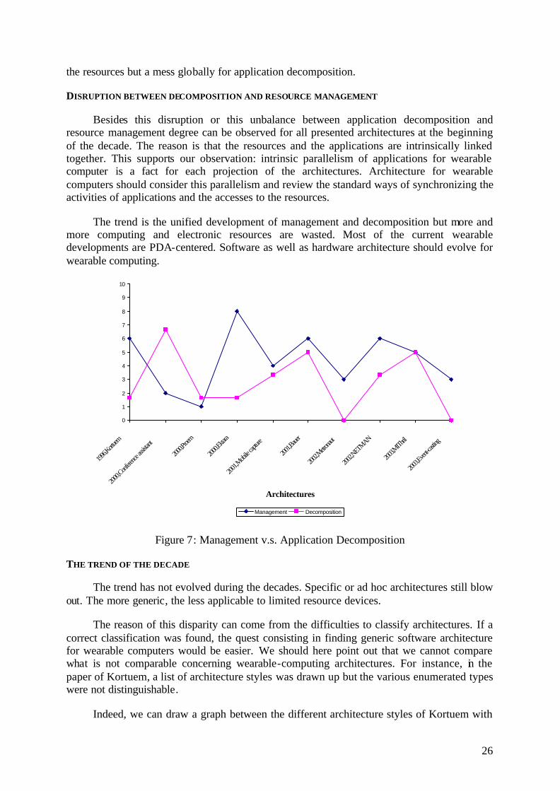
DISRUPTION BETWEEN DECOMPOSITION AND RESOURCE MANAGEMENT
Besides this disruption or this unbalance between application decomposition and resource management degree can be observed for all presented architectures at the beginning of the decade. The reason is that the resources and the applications are intrinsically linked together. This supports our observation: intrinsic parallelism of applications for wearable computer is a fact for each projection of the architectures. Architecture for wearable computers should consider this parallelism and review the standard ways of synchronizing the activities of applications and the accesses to the resources.
The trend is the unified development of management and decomposition but more and more computing and electronic resources are wasted. Most of the current wearable developments are PDA-centered. Software as well as hardware architecture should evolve for wearable computing.
0
1
2
3
4
5
6
7
8
9
10
1996,K
ortuem
2000,C
onfere
nce ass
istant
2000,P
roem
2000,E
ktara
2001,M
obile c
apture
2001,B
auer
2002,M
etronau
t
2002,N
ETMAN
2003,M
IThril
2003,E
vent-ca
sting
Architectures
Management Decomposition
Figure 7: Management v.s. Application Decomposition
THE TREND OF THE DECADE
The trend has not evolved during the decades. Specific or ad hoc architectures still blow out. The more generic, the less applicable to limited resource devices.
The reason of this disparity can come from the difficulties to classify architectures. If a correct classification was found, the quest consisting in finding generic software architecture for wearable computers would be easier. We should here point out that we cannot compare what is not comparable concerning wearable-computing architectures. For instance, in the paper of Kortuem, a list of architecture styles was drawn up but the various enumerated types were not distinguishable.
Indeed, we can draw a graph between the different architecture styles of Kortuem with

27
semantic links « may be implemented with » and « more abstract representation than » (This will be tackled in the section below). That’s the reason why we cannot classify the architectures into those categories. Once again, without a clear classification of architecture styles, the balance between application decomposition and the management of the resources cannot be reached. Moreover, the rapid development of applications will be slowed down because of the specific problems (management or decomposition) for a given architecture.
KORTUEM 'S STYLES ANALYSIS
Kortuem discussed an aspect of software architecture research which he thought was most relevant to his goal of finding a design methodology for wearable computer software in 1996. Hence, architectural styles provide a means to capture and codifying common patterns of system organization.
The identification of the architectural styles is the purpose of software architectural research [Garlan]. A style is a family of architectures which share a common vocabulary of components and connectors and which meet a set of common constraints. [Shaw] Alternatively, styles can be seen as sets of constraints that define valid architectural compositions. Once a set of styles has been identified it can be used by the designer to generate alternative architectures.
Kortuem has categorized the styles using those terms: Pipe & filter Object Oriented Event Based Domain specific Layered Repositories Rule based Process Control Distributed Main program / subroutines State transition diagram Heterogeneous
The problem is that some are missing and this classification does not take into account the abstraction level. Unfortunately architectures can be at the same time Object Oriented and Event Based.
Pipe & Filter Event based
Layered
Rule based
Distributed
State transition diagramObject Oriented
Domain specific
Repositories
Process control
Main program/subroutines
Heterogeneous
can be implemented with
is more abstract than
Legend
Abstraction levels
There remain few architectural patterns such as repositories, pipe and filter or event based. We can observe that the most accurate style of architecture for wearable computing

28
concern is the heterogeneous style. We believe that this is not surprising because the intrinsic parallelism of the application requires a complex management organization which cannot be easily done using only one specific style. We propose to apply a separated-concern methodology in a heterogeneous architecture for wearable computers with limited resources.

29
IIIIIIIII... OOOUUURRR PPPRRROOOPPPOOOSSSAAALLL
After this state of the art, we can see that decomposing the system is mandatory to be able to cope with intrinsic parallelism of wearable computing. Hence, our proposal consists in decomposing the application into independent processes called “behavioral agents” and in managing the resources at the lowest and most detailed level as possible in order to implement it on limited resource devices.
111 --- DDDeeevvveeelllooopppmmmeee nnnttt mmmeeettthhhooodddooolllooogggyyy
We should here recall the notion of “task achieving” introduced by Brooks for robotic applications. Brooks’ argumentation justifies a new mode of development: “Behavior-based mobile robots.” This problem is important because wearable computers should react in the same way a robot does. Indeed, they should be autonomous and make decisions according to the context surrounding them. The first complex system to tackle the behaviors of robots as a complete system operating in the real world was Stanford's Shakey, constructed in the 1970s, but in those days the problem of finding a coherent, structured, and not overly complex way of implementing purposeful behavior in a robot had not been made so explicit.
The original design tried to make complete plans which were executed by low level control routines, but this proved too unreliable, due to all sorts of simple problems developing at execution time which the planner had not considered, and the run-time system couldn't cope with. Although simple, these problems were at such a low level of detail that enhancing the planner to cope with them would have added very considerably to its complexity, so they chose the simpler approach of adding higher level control modules with small degrees of coping ability.
Even such a simple strategy as trying again when something failed coped with a useful amount of errors. This was before the classical symbolic approach had acquired the momentum it was later to develop, and this was seen at the time as an obvious engineering solution of no special theoretical import.
From implementing complete systems in simplified worlds, they shifted to implementing realistically complex fragments of complete systems. This change constituted a major paradigm shift. Rodney Brooks of MIT was the first roboticist to investigate this approach explicitly (i.e. with conscious and explicitly-stated awareness that he was doing so) by means of experimental implementations.
Brooks adopted this basic kind of notion, calling it a ``task-achieving behavior'', but refused to embed it in the classical hierarchical structure, which he criticized for its fragility and computational complexity. Instead he preferred to experiment with what he called the “subsumption architecture”, in which the behaviors were implemented on separate circuit cards with simple four-wire interconnections which were cross-coupled with inhibitory and

30
hallucinatory links in a manner loosely suggested by neurons in biological systems. This was Brooks's view in 1986 [5]. He disagreed with robotics research program, and developed the behavior-based assembly.
We have that same argumentation for wearable computing. To simplify the problem, our purpose is not the autonomous and intelligence for the moment. But it is only the assistance of the wearable computer and humanistic intelligence [Steve Mann] i.e. for computing undecidable decisions, the system calls the user. For wearable computing the unit of division called “task achieving behavior” by Brooks, is called “behavioral agent” in our architecture. The next section will explain in detail how it is constituted.
222 --- BBBeeehhhaaavvviiiooorrraaa lll AAAgggeeennntttsss
A behavioral agent can be a task, a service and so on. It is a code plus an execution flow (a thread). It is an assembly of functional components that is strongly connected to the physical inputs and outputs of the system. In fact, a behavioral agent is a chain of execution we do not interact with other behavioral agents. This solution prevents new functionalities to alter the execution of the system. Thus behavioral agents are independent entities of the critical system.
Behavior1
Behavioral agents
resources resources
Behavior2resources resources
Behaviornresources resources Figure 8: Behavioral agent list in a wearable system
Each behavioral agent is likely to exhibit a set of activities (list represented by the vertical arrow in Figure 8), each element of the list corresponding to a thread, exclusive with each other within a given behavioral agent, and propagating a control flow to its interconnected functional components. Let us note that, for each behavioral agent, a “NAC” (no activity) activity allows to freeze the agent.
Behavioral components are autonomous in that they do not interact directly with each other. This allows selecting any activity for each behavioral agent without having to worry about any possible dependency between those components, as opposed to more classical approaches. The interactions that would though be necessary, such as access conflicts to resources of the critical system, are the deferred and managed by the resource manager.

31
Behavior (Localisation)1
Behavioral agent Example: Localisation of relevant places
resource(GPS)
resource(LCD)
Décomposition
AcquisitionGPS LCD
Point d’entrée
Association
Messages
Figure 9: A behavioral agent decomposition
Its projection in terms of assembly of components is as following:
4] One or more Head methods
5] Assembly of passive components
6] One execution flow (thread) which can be activated or not on a head method at a
time.
In that case, it is a component which can be activated and which is independent. There is no explicit dependence with the other components. Let’s examine now the consequence of that kind of implementation on the complexity of application.
333 --- CCCooommmpppllleeexxx aaappppppllliiicccaaattt iiiooonnn aaannnddd sssiiimmmpppllleee iiinnnttteeegggrrraaattt iiiooonnn
In a first approximation, the structure of a complex application becomes naturally a collection of behavioral agents and not a graph of components (see Figure 8). Consequently we obtain the reflexivity property of the agents of the system i.e. the collection of agents is not ordered. So any agent can be installed in the system at any time. Moreover, no configuration of the agent is necessary when putting it inside the system.
1221 aanApplicatioaanApplicatio +=+
Figure 10: Reflexivity
The underlying explanation resides in the fact that we have included a new actor in our architecture. This actor is the integrator whose task will consist in managing the requirements of each agent. The next section will discuss those limits.

32
444 --- LLLiiimmmiiitttsss ooofff ttthhheee aaapppppprrroooaaaccchhh
The limits of this approach are characterized by the conflicts between the behavioral agents. Two agents 1a and 2a can share implicitly some resources.
For instance, 1a sends a message. So does 2a , and only one message can be displayed at a time on the resource ( )1HMDr representing the Head Mounted Display.
The solution consists in creating a new component for the global architecture: the resource manager. The resource manager should have two vocations. First, it should manage the conflicts between the behavioral agents concerning the resources that are shared among agents. Secondly, it should manage the conflicting shared resources and the activity of the agents.
Behavior
Behavior
1
2
Behavior
Behavior
1
2
Conflicts Management Activity Management
The activities of the agents are particular resources that need to be allocated. These can be assimilated to the threads of the system. The activation of this or that activity depends on the environment of the wearable-computer system.
555 --- RRReeesssooouuurrrccceee mmmaaannnaaagggeeemmmeeennnttt
In this section, we will discuss of how the resources are managed in the system. The management explanation will be divided into two parts: first we will explain the global purpose of a resource manager and then describe the details of our contribution called “the filter-based resource manager”. For each part, two aspects will be considered: one aspect will be concentrated on the functional description of the components and the second aspect will consider formalism. This formalism will help to simplify the implementation of the toolkit for that architecture. It describes the detailed links between the different components. We also describe the connectors used in this architecture in mathematical terms.
GENERAL DESCRIPTION
The resource manager will deal with decisions to be taken according to the global application behavior. This decisional level of the resource manager is intended to deal with the global activity of the system. It is the central part of the complex critical systems we are designing.
The decisional level is made of two parts: the abstract model of its environment and the division process itself. The agent interface is the connection between the manager and the

33
output of the behavioral agents. Through this interface, the agents are capable of sending messages to the different resources. The resource interface is the system-external connection and activity representation. It is directly connected to the resources of the environment. The environment interface is the abstract model of the environment.
The abstract model of the decisional level environment is made of two separate sets: input data and output data. We will see that these data do not need the same processing.
The abstract model of the data describes the environment context. We consider as input, any data that represents the state of the global system: both the environment and the driven system. We represent the set of all possible input data as the following Cartesian product:
lWWI ××= Κ0 , where iW are the definition sets of the input data.
Nevertheless, it is interesting and necessary for formal modeling issue, to reduce the number of the possible states of such a structure. Hence, we avoid taking into account the large number of all the data possible values but consider only a more restricted number of values corresponding to an meaningful evaluation of these values.
In our architecture a set of preprocessing reduces the input data cardinality. Finally the data iw can then be represented by a variable with in possible states. The induced events correspond to data modifications. The definition set of the input-data abstract model, is the Cartesian product:
[ ] [ ]lnnI ΚΚΚ 11 1 ××=
i. HOW DOES IT WORK?
The purpose of the resource manager is to map the different outputs of the agents to the real resources. Its job consists in managing the conflicts between the different proposals of the behavioral agents. Those proposals have attributes that allow the resource manager to take decisions.
FORMALISM
i. THE AGENT ACTIVITIES
The activity of the system is the current activity of a behavioral agent. Each agent i has a set of activities maa ,,1 Κ , ka being the kth activity of the ith agent. The Cartesian product:
[ ] [ ]pmmO ΚΛΚ 11: 1 ××
is the finite structure of all the system output data. The reduction of the output-data number of value, contrary to the input data, is not a significant problem here, because the number of the activities of a component is in general very limited. A component is attributed at least two activities “activated agent” (A) and “non activated agent” (NA) and can possess one be two additional activities.
ii. AGENT OUTPUTS
The outputs of the agents are put in the set called O.

34
=
np
p
O Μ1
, where ip is the proposal of the ith agent and n the number of agents.
A proposal comes from an agent to write a certain value to a specific resource with a set of constraints kcC = .
( )Cvalueresourceagentp i ,,,=
Constraints written ic are a list of named attributes to help the resource manager to take decision. A constraint is qualified with a name and a value.
( )
( )
=
valuenameconstra
valuenameconstra
c i
,int_
,int_
Μ
iii. RESOURCES
Each resource is defined by a definition set of all the possible values that can be taken. A physical resource with the identifier ‘id’ is noted )(idr . So is an activity with the identifier ‘id’ noted )(ida .
Hence the resources are noted in the vector Q below. Let’s call the resource set Ω such as Ω∈Q .
=
OR
A
Q where
=
)(
)1(
Ana
a
A Μ with An , the total number of agent activities,
=
)(
)1(
Rnr
r
R Μ with Rn , the total number of physical resources of the system.
666 --- RRReeesssooouuurrrccceee mmmaaannnaaagggeeerrr bbbaaassseee ddd ooonnn fff iiilllttteee rrrsss
GENERAL REPRESENTATION
The internal working of the resource manager will consist in implementing filters to take decisions. A filter, according to the state of the resources (so the environment), will decide which proposal to keep and which to throw away. This is the functionality of a “logical filter”. The temporal filter will consider the time to take its decisions. A final particular filter type consists in guarantying that only one proposal for a particular resource will be used. It is called unicity filter. It is used for scheduling the behavioural agents and for resolving the output conflicts on shared resources when writing.

35
FORMALISM
A filter takes its inputs from the resources
=
OR
A
Q and produces a vector containing
the same information for each resource:
''
'
OR
A
. A filter is then a linear application that can be
noted: '
Fα
Ω→Ω. F can be seen as an endomorphism on the resource space. In practice, it
is used in the matrix form. This matrix can have variable elements.
777 --- EEExxxpppeee rrriiimmmeee nnntttaaattt iiiooonnn
The experimentation consisted in implementing the application of scrolling image using the behavior programming style.
7.a) Hardware Architecture
The hardware architecture is composed of 3 I2C sensors (CMPS03, PCF8574 and SRF08) that are connected to the microcontroller (PIC) on its I2C bus. The controller is configured as the master of the bus. The Head Mounted Display is connected to the PDA via a SVGA wire. The PDA is then connected to the microcontroller via the RS232 serial port. The connection speed is set to 56kbps.
Resources
MicrocontrollerPIC 16 F 873
Orientation
2 buttons
Distance
I2C
I2C
I2C
Display Resource
Head MountedDisplayPDA
RS 232
Timer Interrupt
Digital CompassCMPS03
I2C Address: 96
Parallel IO PortPCF8574
I2C Address: 56
Range FinderSRF08
I2C Address: 112
The role of the PDA in this architecture is to stock images and to project them on the SVGA Head Mounted Display.

36
7.b) Software Architecture
The Image Transformer is an application written in Java on the PDA which waits for commands on the serial port. Those commands consist in zooming and scrolling.
The behavioral architecture is implemented in the flash memory of the microcontroller. The architecture is previously designed using the Beanbox of Wcomp 1.0 [22]. The Beanbox has been modified to generate C source code for the microcontroller.
So each component is graphically manipulated in the development environment. For the behavioral application in the microcontroller, the design is as simple as in Figure 11.
Orientation
Next
OnOff
DistanceOrientation
Next
Start
Distance
Image Transformer
Figure 11: Scrolling application in behavioral programming
The application is not yet finished. We need to indicate how the resources will be managed. The resource manager is composed of three filter types: The image transformer filter, the start/stop filter and the unicity filter.
Resources
Distance
Orientation
Next
OnOff
Orientation
Next
Start
Distance
OrientationNext
OnOff
Distance
Start/Stop Filter
Resources (t)
ImageTransformer
Image Transformer Filter
Resources (t+1)
Unicity Filter
Conflicts
Activities
Figure 12: Resource Manager for scrolling application
The Image transformer filter will fusion the output of the behavioural agents Distance and Orientation into a message for the image transformer. The Start/Stop filter will switch on or off the activities of the following agents: Distance, Orientation and Next. The unicity filter will select the next active agent according to their priority.

37
The resources are noted ( )ORAQ ,,= column vector where A represents the activities of the agents (distance, orientation, next, OnOff), R represents the physical resources (distance, start, next, image transformer) and O the outputs of the agents (distance, orientation, next, OnOff).
The different filters are 1313× matrices.
Distance
Orientation
Next
OnOff
Filter (g1) Normalizer
Filter (g2) Normalizer
Interpreter
Switcher
Figure 13: Decomposition of the agents
The filters components with their gain (g1 and g2) are just Kalman filters to smooth the incoming values. They give the result to the Normalizer which will adjust the values between 0 and 100. The interpreter will just copy its input (0 – button not pushed or 1 – button pushed) to its output. The switcher will do the same thing. Those components were very easy to be implemented on the microcontroller.
38
IIIVVV... CCCOOONNNCCCLLLUUUSSSIIIOOONNNSSS AAANNNDDD PPPEEERRRSSSPPPEEECCCTTTIIIVVVEEESSS
111 --- NNNeeewww llliiimmmiiitttsss ooofff ttthhheee aaapppppprrroooaaaccchhh
The system is operational. It allows us to manipulate unsuspected resources such as implicit interactions that can come. For example, the Head Mounted Display in its behavioral architecture implementation version has two implicit interactions. How can we manage them in the integration? Consequently, four problems arise: ‘what are the influence of the implicit interactions?’, ‘is there a global definition of the resources?’, ‘how to capture implicit resources?’ and ‘what about behavioral agent properties?’.
1.a) Influence of the implicit interactions
Can we discover the laws governing the battery-energy consumption according to the activities of the behavioral agents? Those laws would describe the influence (or implicit interaction) of the behavioral agents on some resources such as battery energy or even the behavior of the user.
1.b) What are the resources?
A second important axis is what the resources are. The resource notion will join the notion of context, in the larger sense. Everything that can be manipulated by the resource manager is a potential resource, the context belongs to it: the user-, the system- and the environment-state. For the moment, it is clear that we are not yet ready to define this aspect.
1.c) How to capture implicit resources?
The last important point is that today we have worked on explicit resources i.e. resources that are directly usable from the output of the behavioral agents. Clearly, the global system has a large number of resources which need to be fetched and transformed.
The energy for instance is not necessarily explicitly given by the system. And so, we should work on components which will allow us to observe the resources that are not directly observable.
1.d) Behavioral agent properties
Behavioral agents use only input and output from sensors or apparatus. The resource

39
manager controls their activity according to the state of the environment. To simplify some concepts such as virtual inputs managed by the system, we may imagine putting some properties to the behavioral agents which will be managed by the resource manager. But how can we evaluate a priori the properties of the behavioral agents? How can we export them so that the integrator might manage his application without modifying the body of the behavioral agents?
222 --- PPPhhhddd iiinnn III333SSS,,, BBBDDDIII///CCCSSSTTTBBB
It deals with calm technology applied to buildings. Indeed, the intelligent building “Calm Technology” [Weiser Reference] is the resources of the system. The behavioral agents of the system are distributed inside the building. Hence the equipment is a resource manager which automatically manages automatically the activation and deactivation of the behavioral agents according to my mood and globally to the context.

40
VVV... RRREEEFFFEEERRREEENNNCCCEEESSS
Wearable computers [1] Steve Mann, Wearable Computing as means for personal empowerment, the 1998
International Conference on Wearable Computing ICWC-98, Fairfax VA, Mai 1998. [2] Mikael Drugge, Marcus Nilson, Kare Synnes, Peter Parnes, Eventcasting with Wearable
Computer [3] Christopher E. Carr, Steven J Schwartz, Ilia Rosenberg, A Wearable Computer for
Support of Astronaut Extravehicular Activity [4] Kent Lyons, Thad Starner, Mobile Capture for Wearable Computer Usability Testing [5] Starner T., Augmented Reality Through Wearable Computing, vol. 6, n°4, pp. 386-398, 1997. [6] Starner T., Weaver J., and Pentland A., A Wearable Computer Based American Sign
Language Recognizer, ISWC '97, Cambridge, Massachusetts, 1997. [7] Ockerman J.J., Najjar L.J., and Thompson J.C., Wearable Computers for Performance
Support: Initial Feasibility Study, ISWC '97, Cambridge, Massachusetts, 1997. [8] Starner T., The Challenges of Wearable Computing, (Georgia Institute of Technology), in
IEEE Micro, 2001. Generative programming [9] Janos Sztipanovits, Gabor Karsai, Generative Programming for Embedded Systems,
Generative Programming and Component Engeneering, ACM SIGPLAN/SIGSOFT Conference, GPCE 2002, Pittsburgh, PA, USA, October 2002, Proceedings.
Architectures [10] Bass, Clements, Kazman, Software Architecture in Practice (2nd edition), Book, Addison-
Wesley 2003. [11] Medvidovic N., Taylor R. N., Whitehead E. J., Jr. Formal Modeling of Software
Architectures at Multiple Levels of Abstraction. In proceedings of the California Symposium CSS96, Los Angeles, CA, Avril 1996.
[12] Brooks, R.A., "How to build complete creatures rather than isolated cognitive simulators," in K. VanLehn (ed.), Architectures for Intelligence, pp. 225-239, Lawrence Erlbaum Associates, Hillsdale, NJ, 1991
[13] Todd Mills, Matthew Burnside, John Ankorn, Srinivas Devadas, A proxy-based architecture for secure networked wearable devices
[14] Anind K. Dey, Daniel Salber, Gregory D. Abowd, Masayasu Futakawa, The conference assistant: Combining Context-Awareness with Wearable Computing
[15] Martin Bauer, Bernd Brügge, Gudrun Klinker, Asa MacWilliams, An Architecture Concept for Ubiquitous Computing Aware Wearable Computer

41
[16] DeVaul R., Sung M., Gips J., Pentland A., MIThril 2003: Applications and Architecture, ISWC’03, 2003.
[17] Muller H., Randell C., An Event-Driven Sensor Architecture for Low Power Wearables,
In: ICSE 2000, Workshop on Software Engineering for Wearable and Pervasive Computing, pages 39--41. ACM/IEEE, Juin 2000.
[18] D Cheung-Foo-Wo and J-Y Tigli et M. Riveill. Architecture orientée composant et interactions implicites, application aux ordinateurs corporels. In Cepadues, editor, Premières Journées Francophones: Mobilité et Ubiquité 20, 1-3 juin 2004.
[19] Richard W. DeVaul, Alex Pentland, The Ektara Architecture: The Right Framework for Context-Aware Wearable and Ubiquitous Computing Applications.
[20] Asim Smailagic, Richard Martin, Metronaut : A Wearable Computer with Sensing and Global Communication Capabilities
[21] F. Grillon. Behavioral architecture. DEA Réseau et Systèmes Distribués, Université de Nice - Sophia Antipolis, sept 2003.
[22] D. Cheung, J. Fuchet, F. Grillon, G. Joulié, and J-Y. Tigli. Wcomp: Rad toolkit for wearable computer based on java. In IEEE SMC 2003, 2003.
[23] Kortuem G., Software Architecture And Wearable Computing, Internal Report: University of Oregon, 1996.
[24] 1997 Steve Fickas, Gerd Kortuem, Zary Segall. Software Organization for Dynamic and Adaptable Wearable Systems. Proceedings First International Symposium on Wearable Computers (ISWC'97), Oct 13-14, 1997, Cambridge, Mass.
[25] Gerd Kortuem, Zary Segall, Martin Bauer. Context-Aware, Adaptive Wearable Computers as Remote Interfaces to 'Intelligent' Environments. Proceedings Second International Symposium on Wearable Computers (ISWC'98) , Oct 19-20, 1998, Pittsburgh, PA.
[26] Wayne Piekarski, Bruce Thomas, David Hepworth, Bernard Gunther, Victor Demezuk, An architecture for Outdoor Wearable Computers to Support Augmented Reality and Multimedia Applications, Australia.
[27] Zary Segall, Andrew Fortier, Gerd Kortuem, Jay Schneider, Sean Workman. "Multishelf: An Experiment in Peer-to-Peer Infomediation". Proceedings 2002 International Conference on Peer-to-Peer Computing (P2P2002), Linköping, Sweden
[28] Gerd Kortuem, Jay Schneider, Jim Suruda, Steve Fickas, Zary Segall. When Cyborgs Meet: Building Communities of Cooperating Wearable Agents. Proceedings Third International Symposium on Wearable Computers (ISWC'99), 18-19 October, 1999, San Francisco, California.
[29] Gerd Kortuem, Steve Fickas, Zary Segall. Architectural Issues in Supporting Ad-Hoc Collaboration with Wearable Computers. Proceedings the 22th International Conference on Software Engineering (ICSE 2000), 2000, Limerick, Ireland.
[30] Gerd Kortuem, Martin Bauer, Zary Segall. NETMAN: The design of a Collaborative Wearable Computer System. ACM Journal on Mobile Networks and Applications (MONET), Volume 4, Number 1, pp. 49-58, 1999.
Embedded systems

42
[31] Yau-Tsun Steven Li, Sharad Malik, Andrew Wolfe, Performance Estimation of Embedded Software with instruction Cache Modeling
[32] Mike Jichen, Amie Souter, Program Analisys and Optimization for Embedded Systems [33] Paul Caspi, Embedded Control : From Asynchrony to Synchrony and Back [34] Ramesh Yerraballi, Real-Time Operating Systems : An Ongoing Review [35] Catherine Lingxia Wang, Bo Yao, Yang Yang, Zhengyong Zhu, A survey of embedded
operating system [36] Charra Oliver, Conception de noyaux de systèmes embarqués reconfigurables, Thèse -
Université Joseph Fourier – Grenoble 1, LSR-IMAG, projet SARDES. Contextes [37] Gaëtan Rey, Joëlle Coutaz, James L. Crowley, The contextor : a computational model for
contextual information [38] Joëlle Coutaz, Gaëtan Rey, Foundations for a thery of contextors Temps-Réel [39] Timothy H. Harrison, David L. Levine, Douglas C. Schmidt, The Design and Performance
of a Real-Time CORBA Event Service, August 1997. [40] Ichiro Satoh, Mario Tokoro, Semantics for a Real-Time Object-Oriented Programming
Language.

43
VVVIII... AAANNNNNNEEEXXXEEESSS
Figure 14: The Head Mounted Display and its PDA
Figure 15: The microcontroller
Figure 16: The Range Finder
Figure 17: The compass

44
Figure 18: Designing an application in Wcomp 1.0