WB087 Toohey Road Salisbury Water Booster Electrical ...
400
QUEENSLAND URBAN UTILITIES TOOHEY ROAD, SALISBURY WATER BOOSTER PUMP STATION WB087 ELECTRICAL SWITCHBOARD OPERATION AND MAINTENANCE MANUAL Developed by: J & P RICHARDSON INDUSTRIES CAMPBELL AVENUE WACOL QLD 4076 ABN 23 001 952 325 ACN 001 952 325 Ph. (07) 3271 2911 Fax. (07) 3271 3623 WB087 Toohey Road Salisbury Water Booster Electrical Switchboard OM Manual Q-Pulse Id TMS994 Active 10/12/2014 Page 1 of 400
-
Upload
khangminh22 -
Category
Documents
-
view
0 -
download
0
Transcript of WB087 Toohey Road Salisbury Water Booster Electrical ...

QUEENSLAND URBAN UTILITIES
TOOHEY ROAD, SALISBURY
WATER BOOSTER
PUMP STATION WB087
ELECTRICAL SWITCHBOARD
OPERATION AND MAINTENANCE MANUAL
Developed by:
J & P RICHARDSON INDUSTRIES CAMPBELL AVENUE
WACOL QLD 4076
ABN 23 001 952 325 ACN 001 952 325
Ph. (07) 3271 2911 Fax. (07) 3271 3623
WB087 Toohey Road Salisbury Water Booster Electrical Switchboard OM Manual
Q-Pulse Id TMS994 Active 10/12/2014 Page 1 of 400

CONTENTS
1.0 INTRODUCTION
1.1 Operating Instructions
2.0 DESCRIPTION OF OPERATION
2.1 Mode Selection 2.2 Manual Control 2.3 Automatic Control
3.0 PUMPS
4.0 ELECTRICAL EQUIPMENT TECHNICAL INFORMATION
5.0 QA DOCUMENTATION
6.0 SWITCHBOARD WORKS TEST RESULTS
7.0 ELECTRICAL DRAWINGS
8.0 SERVICE AND MAINTENANCE
WB087 Toohey Road Salisbury Water Booster Electrical Switchboard OM Manual
Q-Pulse Id TMS994 Active 10/12/2014 Page 2 of 400

411I OD ID ID ID 110
C1,1-111,(1);1:1,1),1,1,1717i)
I. Introduction
WB087 Toohey Road Salisbury Water Booster Electrical Switchboard OM Manual
Q-Pulse Id TMS994 Active 10/12/2014 Page 3 of 400

)11,1111111111111171111fli
III ID ID WB087 Toohey Road Salisbury Water Booster Electrical Switchboard OM Manual
Q-Pulse Id TMS994 Active 10/12/2014 Page 4 of 400

J & P Richardson Industries Pty Ltd
1.0 INTRODUCTION
These operating instructions cover the Toohey Road, Salisbury pumping station electrical equipment supplied by J & P Richardson Industries Pty Ltd in 2010.
1.1 Operating Instructions
Normal operation of the pumping station is in the automatic mode with control by means of a Master Programmable Logic Controller (PLC), which receives level signals from the Level Measurement System in the wet well/Electronic Level Relays/Float Switches.
Manual operation control of the station is available by means of selector switches on the motor control switchboard.
File: Swbd Manual Revision 0 Date:11/3/2010
WB087 Toohey Road Salisbury Water Booster Electrical Switchboard OM Manual
Q-Pulse Id TMS994 Active 10/12/2014 Page 5 of 400

ell III ID
2. Description of Operation
WB087 Toohey Road Salisbury Water Booster Electrical Switchboard OM Manual
Q-Pulse Id TMS994 Active 10/12/2014 Page 6 of 400

1111110 1111111111111111111
WB087 Toohey Road Salisbury Water Booster Electrical Switchboard OM Manual
Q-Pulse Id TMS994 Active 10/12/2014 Page 7 of 400

J & P Richardson Industries Ply Ltd
2.0 DESCRIPTION OF OPERATION
2.1 Mode Selection
The station can be operated either automatically or manually with mode selection being made by means of the mode selector switches mounted on each pump section of the switchboard. These selector switches are designated with the following mode selections AUTO-OFF-MAN.
2.2 Manual Control
Each pumping unit can be run in manual control from the motor control centre by: -
a). Selecting the "MAN" setting on the "MODE SELECTOR SWITCHES" as described in Clause 2.1.
b). Starting by "START" pushbutton. c). Stopping by "STOP" pushbutton.
N.B. DO NOT LEAVE IN MANUAL WHILE STATION UNATTENDED
2.3 Automatic Control
For automatic control of the station: -
a). The "MODE SELECTOR SWITCHES" on the switchboard should be in the "AUTO" position.
b). The "DUTY SELECTOR SWITCH" should be set to provide the desired pump operation sequence. The "DUTY SELECTOR SWITCH" is marked: -
1-2 2-1
The pumps should be alternated at regular intervals to ensure that each pump unit has a reasonably equal running time. The total running hours of each pump unit is displayed on the hour meter located on each pump section of the switchboard.
c). The automatic Duty Selection is done via the PLC software. Refer PLC SOFTWARE Section for details. The total running hours of each pump unit is displayed on the hour meter located on each pump section of the switchboard.
d). The automatic starting and stopping of the pumps is controlled by signals from Master PLC.
For NORMAL OPERATION, each of the pump selector switches should have "AUTO" mode selected.
In the AUTOMATIC mode the selected Duty Pump unit will start automatically as preset by the level in the wet well. In the event of the duty pump not being capable of supplying enough flow to continue draining the wet well and the well level rises to a second preset level, then the Standby Pump unit will automatically start, to provide additional pumping. The supplementary pump unit also takes over for the respective pump duty on the occurrence of one the Duty Pump unit failing.
File: Swbd Manual Revision 0 Date:11/3/2010
WB087 Toohey Road Salisbury Water Booster Electrical Switchboard OM Manual
Q-Pulse Id TMS994 Active 10/12/2014 Page 8 of 400

sdwnd E
ID
CIM,111t11,0,0111,1041,11,WAMOMP
GI ID ID
WB087 Toohey Road Salisbury Water Booster Electrical Switchboard OM Manual
Q-Pulse Id TMS994 Active 10/12/2014 Page 9 of 400

ID ID MI WB087 Toohey Road Salisbury Water Booster Electrical Switchboard OM Manual
Q-Pulse Id TMS994 Active 10/12/2014 Page 10 of 400

J & P Richardson Industries Pty Ltd
3.0 PUMPS
SUPPLIER: Grundfos
Ph: (07) 5540 6700 Fax: (07) 5540 6710
MODEL: Hydro MPC-E 4xCRE32 -1 2.2kW
File: Swbd Manual Revision 0 Date:II/3/2010
WB087 Toohey Road Salisbury Water Booster Electrical Switchboard OM Manual
Q-Pulse Id TMS994 Active 10/12/2014 Page 11 of 400

GRUNDFOS INSTRUCTIONS
BoosterpaQ - Hydro MPC
C) Installation and operating instructions
BE >THINK >INNOVATE 4antiNI 131 PC:10 4)<
WB087 Toohey Road Salisbury Water Booster Electrical Switchboard OM Manual
Q-Pulse Id TMS994 Active 10/12/2014 Page 12 of 400

LIMITED WARRANTY
Products manufactured by GRUNDFOS PUMPS CORPORATION (Grundfos) are warranted to the original user only to be free of defects in material and workmanship for a period of 24 months from date of installation, but not more than 30 months from date of manufacture. Grundfos' liability under this warranty shall be limited to repairing or replacing at Grundfos' option, without charge, F.O.B. Grundfos' factory or authorized service station, any product of Grundfos' manufacture. Grundfos will not be liable for any costs of removal, installation, transportation, or any other charges which may arise in connection with a warranty claim. Products which are sold but not manufactured by Grundfos are subject to the warranty provided by the manufacturer of said products and not by Grundfos' warranty. Grundfos will not be liable for damage or wear to products caused by abnormal operating conditions, accident, abuse, misuse, unauthorized alteration or repair, or if the product was not installed in accordance with Grundfos' printed installation and operating instructions.
To obtain service under this warranty, the defective product must be returned to the distributor or dealer of Grundfos' products from which it was purchased together with proof of purchase and installation date, failure date, and supporting installation data. Unless otherwise provided, the distributor or dealer will contact Grundfos or an authorized service station for instructions. Any defective product to be returned to Grundfos or a service station must be sent freight prepaid; documentation supporting the warranty claim and/or a Return Material Authorization must be included if so instructed.
GRUNDFOS WILL NOT BE LIABLE FOR ANY INCIDENTAL OR CONSEQUENTIAL DAMAGES, LOSSES, OR EXPENSES ARISING FROM INSTALLATION, USE, OR ANY OTHER CAUSES. THERE ARE NO EXPRESS OR IMPLIED WARRANTIES, INCLUDING MERCHANTABILITY OR FITNESS FOR A PARTICULAR PURPOSE, WHICH EXTEND BEYOND THOSE WARRANTIES DESCRIBED OR REFERRED TO ABOVE.
Some jurisdictions do not allow the exclusion or limitation of incidental or consequential damages and some jurisdictions do not allow limit actions on how long implied warranties may last. Therefore, the above limitations or exclusions may not apply to you. This warranty gives you specific legal rights and you may also have other rights which vary from jurisdiction to jurisdiction.
2
WB087 Toohey Road Salisbury Water Booster Electrical Switchboard OM Manual
Q-Pulse Id TMS994 Active 10/12/2014 Page 13 of 400

CONTENTS 9.7.6 Setting of influence function (4.1.3.2) 35
1. Symbols used in this document Page
4
9.7.7 Primary sensor (4.1.4) 9.7.8 Clock program (4.1.6) 9.7.9 Proportional pressure (4.1.7)
35 36 36
2. Scope of these instructions 4 9.7.10 S-system configuration (4.1.8) 37 3. Product description 4 9.7.11 Pump cascade control (4.2) 37
4. Nameplate 5 9.7.12 Min. time between start/stop (4.2.1) 38
5. Software label 6. Type key 6.1 Examples of control variants
5
6
6
9.7.13 Max. number of starts/hour (4.2.1) 9.7.14 Standby pumps (4.2.3) 9.7.15 Forced pump changeover (4.2.4) 9.7.16 Pump test run (4.2.5)
38 38 39 39
7. Installation 9 9.7.17 Pilot pump (4.2.6) 40 7.1 Mechanical installation 9 9.7.18 Pump stop attempt (4.2.7) 40 7.1.1 Location 9 9.7.19 Pump start and stop speed (4.2.8) 41 7.1.2 Pipework 9 9.7.20 Min. performance (4.2.9) 41 7.1.3 Foundation 9 9.7.21 Compensation for pump start-up time (4.2.10) 42 7.1.4 Vibration dampers 9 9.7.22 Secondary functions (4.3) 42 7.1.5 Expansion joints 9 9.7.23 Stop function (4.3.1) 42 7.2 Electrical installation 10 9.7.24 Soft pressure build-up (4.3.3) 44 7.3 Start-up 10 9.7.25 Emergency run (4.3.5) 45 8. Control panel 12 9.7.26 Digital inputs (4.3.7) 45 8.1 Display (pos. 1) 12 9.7.27 Functions of digital inputs (4.3.7.1) 46 8.1.1 Menu line 12 9.7.28 Analog inputs (4.3.8) 46 8.1.2 Top line 12 9.7.29 Analog inputs (4.3.8.1 to 4.3.8.7) 47 8.1.3 Graphical illustration 12 9.7.30 Analog inputs and measured value 8.1.4 Scroll bar 12 (4.3.8.1.1 to 4.3.8.7.1) 47 8.1.5 Bottom line 12 9.7.31 Digital outputs (4.3.9) 48 8.2 Buttons and indicator lights 13 9.7.32 Functions of digital outputs (4.3.9.1 to 4.3.9.16) 48 8.2.1 Arrow to the right (pos. 2) 13 9.7.33 Min., max. and user-defined duty (4.3.14) 49 8.2.2 Help (pos. 3) 13 9.7.34 Min. duty (4.3.14.1) 49 8.2.3 Up and down (pos. 4 and 5) 13 9.7.35 Max. duty (4.3.14.2) 49 8.2.4 Plus and minus (pos. 6 and 7) 13 9.7.36 User-defined duty (4.3.14.3) 50 8.2.5 Esc (pos. 8) 13 9.7.37 Pump curve data (4.3.19) 50 8.2.6 Home (pos. 9) 13 9.7.38 Control source (4.3.20) 51
8.2.7 Ok (pos. 10) 13 9.7.39 Fixed inlet pressure (4.3.22) 52 8.2.8 Indicator lights (pos. 11 and 12) 13 9.7.40 Flow estimation (4.3.23) 52 8.2.9 Contrast (pos. 13) 13 9.7.41 Monitoring functions (4.4) 52 8.2.10 Back light 13 9.7.42 Dry-running protection (4.4.1) 53
9. Functions 14 9.7.43 Dry-running protection with pressure/level switch
9.1 Tree of functions 14 (4.4.1.1) 53
9.2 Overview 17 9.7.44 Dry-running protection with pressure transmitter
9.3 Description of functions 19 (4.4.1.2) 54
9.4 Status (1) 19 9.7.45 Dry-running protection with level transmitter (4.4.1.3) 54
9.4.1 Current alarms (3.1) 19 9.7.46 Min. pressure (4.4.2) 55
9.4.2 System (1.2) 19 9.7.47 Max. pressure (4.4.3) 55
9.4.3 Operating mode (1.2.1) 20 9.7.48 External fault (4.4.4) 56
9.4.4 Setpoint (1.2.2) 20 9.7.49 Limit 1 and 2 exceeded (4.4.5 and 4.4.6) 56
9.4.5 Setpoint influence (1.2.3) 20 9.7.50 Pumps outside duty range (4.4.7) 57
9.4.6 Measured values (1.2.4) 21 9.7.51 Pressure relief (4.4.8) 57
9.4.7 Analog inputs (1.2.5) 21 9.7.52 Functions, CU 351 (4.5) 58
9.4.8 Pump 1...6 (1.3 to 1.8) 21 9.7.53 Display language (4.5.1) 58
9.5 Operation (2) 21 9.7.54 Display units (4.5.2) 59
9.5.1 Operation (2) 22 9.7.55 Date and time (4.5.3) 60
9.5.2 System operating mode (2.1.1) 22 9.7.56 Passwords (4.5.4) 60
9.5.3 Control mode (2.1.2) 23 9.7.57 Ethernet (4.5.5) 60
9.5.4 Setpoints (2.1.3) 25 9.7.58 GENIbus number (4.5.6) 61
9.5.5 Individual pump control (2.1.4) 25 9.7.59 Software status (4.5.9) 61
9.5.6 Setting of individual operating mode 9.8 Data communication 62
(2.1.4.1 to 2.1.4.6) 26 9.8.1 Ethernet 62
9.6 Alarm (3) 27 9.8.2 GENIbus 64
9.6.1 Alarm status (3) 27 10. External variable frequency drive 65 9.6.2 Current alarms (3.1) 32 10.1 VLT 2800 65 9.6.3 Alarm log (3.2) 32 10.2 Danfoss VLT 8000 factory settings 66 9.7 Settings (4) 32 10.3 Danfoss VLT 8000 extended menu programming 66 9.7.1 Primary controller (4.1) 33 10.4 Danfoss VLT 8000 factory settings 67 9.7.2 PI controller (4.1.1) 33 10.5 Danfoss VLT 8000 extended menu programming 67 9.7.3 Alternative setpoints (4.1.2) 33 10.6 Baldor Smart motor settings 68 9.7.4 Alternative setpoints 2 to 7 (4.1.2.1 to 4.1.2.7) 34 10.7 VLT FC 202 69 9.7.5 External setpoint influence (4.1.3) 34
3
WB087 Toohey Road Salisbury Water Booster Electrical Switchboard OM Manual
Q-Pulse Id TMS994 Active 10/12/2014 Page 14 of 400

11. Fault finding chart 70
12. Maintenance 71
12.1 Pumps 71
12.2 Motor bearings 71
12.3 CU 351 71
13. Frost protection 71
14. Taking out of operation 71
15. Technical data 71
15.1 Pressure 71
15.2 Temperature 72 15.3 Relative humidity 72 15.4 Sound pressure 72
16. Electrical data 72
17. Related documents 72
18. Disposal 72
Warning Prior to installation, read these installation and operating instructions. Installation and operation must comply with local regulations and accepted codes of good practice.
1. Symbols used in this document
Caution
Note
Warning If these safety instructions are not observed, it may result in personal injury!
If these safety instructions are not observed, it may result in malfunction or damage to the equipment!
Notes or instructions that make the job easier and ensure safe operation.
2. Scope of these instructions These installation and operating instructions apply to Grundfos Hydro MPC booster systems.
Hydro MPC is a range of factory-assembled booster systems, ready for installation and operation.
4
3. Product description As standard, Hydro MPC booster systems consist of two to six CR(E) pumps coupled in parallel and mounted on a common base frame with all the necessary fittings and a control panel.
A diaphragm tank is required in most installations. Note
5 4
Fig. 1 Hydro MPC booster system
Pos. Description Quantity
1 Control panel 1
2 Nameplate 1
3 Suction manifold (stainless steel) 1
4 Isolating valve 2 per pump
5 Base frame (stainless steel) 1
6 Non-return valve 1 per pump
7 Discharge manifold (stainless steel) 1
8 Pressure transmitter/pressure gauge 2
9 Pump 2 - 6
WB087 Toohey Road Salisbury Water Booster Electrical Switchboard OM Manual
Q-Pulse Id TMS994 Active 10/12/2014 Page 15 of 400

Hydro MPC booster systems are divided into seven groups based on control variant:
Control variant Description
-E Two to six CRE pumps
ED Two CRE pumps and up to four constant speed CR
- pumps
ES One CRE pump and up to five constant speed CR
- pumps
-EF Two to six CR pumps connected to external variable frequency drives (VFD)
Two CR pumps connected to external variable -EDF frequency drives and up to four constant speed CR
pumps
Up to six CR pumps connected to an external variable -F frequency drive. The speed-controlled operation
alternates between the pumps.
-S Two to six constant speed CR pumps
See also section 6.1 Examples of control variants.
Hydro MPC booster systems always includes application- optimised software for setting the booster system to the application in question.
4. Nameplate The nameplate of the booster system is fitted on the base frame. See position 2 in fig. 1.
Type: (2
Model: ?..2)
Serial No.: (2)
Mains supply: 0 Max. oper. press.: 0 PSI
O Max.: 0 GPM
T Medium: OT H Min.: (:) ft.
Number P
HP Un V
Fixed speed pumps: 0 0 0 E-pumps: 0 0 0 Pilot Pump: 0 0 Order No.: 0 Options: 0
0 Encl. Type: NEMA / PN 0 Weight: 0 lbs.
0 0
C 0 0 0 Assembled in US
US LISTED
N FOZ
Fig. 2 Nameplate
Pos. Description
1 Type designation 2 Model
3 Serial number
4 Supply voltage
5 Maximum operating pressure in PSI
6 Liquid temperature in °F
7 Maximum flow rate in GPM
8 Minimum head in feet 9 Number of fixed speed and/or auxiliary pumps
10 Motor power in HP for fixed speed pumps
11 Nominal voltage in volts for fixed speed pumps
12 Number of E-pumps
13 Motor power in HP for E-pumps
14 Nominal voltage in volts for E-pumps
15 Number of pilot pumps
16 Motor power in HP for pilot pump
17 Nominal voltage in volts for pilot pump
18 Order number
19- Options
24
25 Enclosure type
26 Weight in lbs
27 Approval marks
28 Production location & date code
5. Software label The software label is placed on the back of the CU 351 controller.
1. Control MPC 3. Hydro MPC GIRUNMFOSVX 0 0
2. C-MPC options 4. H-MPC options 5. Pump data
0 0
CONFIGURATION STEPS . PLEASE FOLLOW THE NUMBERS 96556126
Fig. 3 Software label
Pos. Description
1 Control MPC - GSC file number
2 Control MPC options - GSC file numbers
3 Hydro MPC - GSC file number
4 Hydro MPC options - GSC file numbers
5 Pump data - GSC file numbers
Note A GSC (Grundfos Standard Configuration) file is a
configuration data file.
5
WB087 Toohey Road Salisbury Water Booster Electrical Switchboard OM Manual
Q-Pulse Id TMS994 Active 10/12/2014 Page 16 of 400

6. Type key
Example Hydro MPC -ED 2 CRE 5-10 1 CR 5-10 3x460 V, 60Hz
Type range
Subgroups: Pumps with integrated variable frequency drive: -E, -ED, -ES Pumps with external VFD: -EF, -EDF, -F
Constant speed pumps (start/stop): -S
Number of pumps with integreted:variable:frequeriq'drie:end pumj:itype
Number of constant speed pumps and pump type
Supply.yoltage,:frequericjr
6.1 Examples of control variants
Booster systems with motors that include an integrated variable frequency drive (CRE)
Hydro MPC-E Hydro MPC-ED Hydro MPC-ES
Hydro MPC booster system with three CRE pumps.
One CRE pump in operation.
H
Hset
Three CRE pumps in operation.
The MPC-E system maintains a constant pressure through continuous adjustment of the speed of the pumps. The system performance is adjusted to the demand through cutting in/out the required number of pumps and through parallel control of the pumps in operation. Pump changeover is automatic and depends on load, operating hours and fault. All pumps in operation will run at equal speed.
Hydro MPC booster system with two CRE Hydro MPC booster system with one CRE pumps and one constant speed CR pump. pump and two constant speed CR pumps.
One CRE pump in operation.
H
Hset
Two CRE pumps and one constant speed CR pump in operation.
H
Hset
The MPC-ED system maintains a constant pressure through continuous adjustment of the speed of two CRE pumps, while the CR pump is constant speed. One CRE pump always starts first. If the pressure cannot be maintained by the pump, the second CRE pump will be cut in. If the two CRE pumps cannot maintain the pressure, the CR pump will be cut in.
Pump changeover is automatic and depends on load, operating hours and fault.
One CRE pump in operation.
H
Hset
a
One CRE pump and two constant speed CR pumps in operation.
H
Hset
a
The MPC-ES system maintains a constant pressure through continuous adjustment of the speed of the CRE pump. The other pumps are cut in/out according to demand to achieve a performance corresponding to the consumption.
The CRE pump always starts first. If the pressure cannot be maintained by the pump, one or both CR pumps will be cut in.
Changeover among the constant speed pumps is automatic and depends on load, operating hours and fault.
6
WB087 Toohey Road Salisbury Water Booster Electrical Switchboard OM Manual
Q-Pulse Id TMS994 Active 10/12/2014 Page 17 of 400

Booster systems with motors connected to external variable frequency drive (VFD)
Hydro MPC-EF Hydro MPC-EDF Hydro MPC-F
Hydro MPC booster system with three CR pumps connected to external variable frequency drives in the control panel.
One CR pump in operation.
a
Three CR pumps in operation.
a
rn
(0 7, rn
The MPC-EF system maintains a constant pressure through continuous adjustment of the speed of the pumps. The system performance is adjusted to the demand through cutting in/out the required number of pumps and through parallel control of the pumps in operation. Pump changeover is automatic and depends on load, operating hours and fault. All pumps in operation will run at equal speed.
Hydro MPC booster system with two CR pumps connected to external frequency converters in the control cabinet and one constant speed CR pump.
One CR pump connected to an external variable frequency drive in operation.
H
Hset
a
Two CR pumps connected to external variable frequency drives and one constant speed CR pump in operation.
H
Hset
a
The MPC-EDF system maintains a
constant pressure through continuous adjustment of the speed of two CR pumps connected to external variable frequency drives, while the third CR pump is
constant speed.
One CR pump connected to an external variable frequency drive always starts first. If the pressure cannot be maintained by the pump, the second CR pump connected to an external variable frequency drive will be cut in. If the pressure cannot be maintained by the two pumps, the constant speed CR pump will be cut in.
Pump changeover is automatic and depends on load, operating hours and fault.
Hydro MPC booster system with three CR pumps connected to an external frequency converter in the control cabinet. The speed-controlled operation alternates between the pumps.
One CR pump connected to an external variable frequency drive in operation.
H
Hset
a
One CR pump connected to an external variable frequency drive and two constant speed CR pumps in operation.
H
Hset
a 0
The MPC-F system maintains a constant pressure through continuous adjustment of the speed of the CR pump connected to the external variable frequency drive. The speed-controlled operation alternates between the pumps. One CR pump connected to the external variable frequency drive always starts first. If the pressure cannot be maintained by the pump, one or two constant speed CR pumps will be cut in.
Pump changeover is automatic and depends on load, operating hours and fault.
7
WB087 Toohey Road Salisbury Water Booster Electrical Switchboard OM Manual
Q-Pulse Id TMS994 Active 10/12/2014 Page 18 of 400
Booster system with constant speed pumps (on/off)
Hydro MPC-S
Hydro MPC booster system with three constant speed CR pumps.
One constant speed CR pump in operation.
'H
Hslop
Hset DAM. =NEIL
Three constant speed CR pumps in operation.
Hydro MPC-S maintains a pressure differential through cutting in/out the required number of pumps. The operating range of the pumps will lie between Hset and Hstop (cut-out pressure). Pump changeover is automatic and depends on load, operating hours and fault.
8
WB087 Toohey Road Salisbury Water Booster Electrical Switchboard OM Manual
Q-Pulse Id TMS994 Active 10/12/2014 Page 19 of 400

7. Installation
Warning
Installation and operation must comply with local regulations and accepted codes of good practice.
Before installation check that
the booster system corresponds to the one ordered.
no visible parts have been damaged.
7.1 Mechanical installation 7.1.1 Location
The booster system must be installed in a well ventilated room to ensure sufficient cooling of the motors and control panel.
Hydro MPC is not designed for outdoor installation unless protected and must not be exposed to direct sunlight.
The booster system must have a 3 feet clearance in front and on the two sides for inspection and dismantling.
7.1.2 Pipework
Arrows on the pump base show the direction of flow of water through the pump.
The pipework connected to the booster system must be of adequate size. The pipes are connected to the manifolds of the booster system. Either end can be used. Apply sealing compound to the unused end of the manifold and fit the screw cap. For manifolds with flanges, fit a blanking flange with gasket.
To achieve optimum operation and minimise noise and vibration, it may be necessary to consider vibration dampening of the booster system.
Noise and vibration are generated by the rotations in the motor and pump and by the flow in pipework and fittings. The effect on the environment is subjective and depends on correct installation and the state of the other parts of the system.
If booster system is to be installed where first customer on the line is close to the booster system, it is advisable to fit expansion joints on the suction and discharge pipes to prevent vibration being transmitted through the pipework.
Note
3 3
Fig. 4 Sketch showing the position of expansion joints, pipe supports and machine shoes
Pos. Description
1 Expansion joint
2
3 Machine shoe
Pipe support and good location for system isolation valve (not shown)
Note Expansion joints, pipe supports and machine shoes shown in the figure above are not supplied with a standard booster system.
All nuts should be checked and re-tightened if necessary prior to start-up.
The pipes must be fastened to parts of the building to ensure that they cannot move or be twisted.
7.1.3 Foundation
The booster system should be positioned on an even and solid surface, for instance a concrete floor or foundation. If the booster system is not fitted with machine shoes, it must be bolted to the floor or foundation.
Note As a rule the weight of a concrete foundation should be 1.5 x the weight of the booster system.
7.1.4 Vibration dampers To prevent the transmission of vibrations to buildings, it imay be necessary to isolate the booster system foundation from building parts by means of vibration dampers.
The right damper varies from installation to installation, and a
wrong damper may increase the vibration level. Vibration dampers should therefore be sized by the supplier of vibration dampers. If the booster system is installed on a base frame with vibration dampers, expansion joints should always be fitted on the manifolds. This is important to prevent the booster system from "hanging" in the pipework.
7.1.5 Expansion joints Expansion joints are installed to
absorb expansions/contractions in the pipework caused by changing liquid temperature
reduce mechanical strains in connection with pressure surges in the pipework
isolate mechanical structure-borne noise in the pipework (only rubber bellows expansion joints).
Note Expansion joints must not be installed to compensate for inaccuracies in the pipework such as center displacement of flanges.
Fit expansion joints at a distance of minimum 1 to 1 1/2 times the nominal flange diameter from the manifold on the suction as well as on the discharge side. This prevents the development of turbulence in the expansion joints, resulting in better suction conditions and a minimum pressure loss on the pressure side. At high water velocities (> 10 ft/sec) it is advisable to install larger expansion joints corresponding to the pipework.
Fig. 5 Examples of rubber bellows expansion joints without and with limit rods
Expansion joints with limit rods can be used to minimise the forces caused by the expansion joints. Expansion joints with limit rods are always recommended for flanges larger than 6 inches. The pipework should be anchored so that it does not stress the expansion joints and the pump. Follow the supplier's instructions and pass them on to advisers or pipe installers.
9
WB087 Toohey Road Salisbury Water Booster Electrical Switchboard OM Manual
Q-Pulse Id TMS994 Active 10/12/2014 Page 20 of 400
7.2 Electrical installation
Warning The electrical installation should be carried out by an authorized person in accordance with local regulations and the relevant wiring diagram.
The electrical installation of the booster system must comply with enclosure class IP54.
Make sure that the booster system is suitable for the electricity supply to which it is connected.
Make sure that the wire cross-section corresponds to the specifications in the wiring diagram.
The connection of the electrical supply, transmitters and external monitoring equipment must be carried out by an authorized electrician in accordance with the NEC, local regulations and the BoosterpaQ wiring diagram.
Ensure that the Hydro MPC controls and the pumps are suitable for the electricity supply on which they will be used (see Technical Data). Please read the wiring diagram carefully. According to the NEC, if the motors cannot be seen from the control panel, they must be fitted with a disconnect switch.
Any BoosterpaQ that utilizes a variable frequency drive (E, ED, ES, EF, EDF, F) should be connected to an electrical supply with all phase lines electrically symmetrical with respect to ground. A "four wire wye" electrical supply with line impedance between 0.5% - 3% is recommended. If a variable frequency drive is
connected to a delta transformer or if line impedance is not within the recommended 0.5% - 3%, the drive may not operate correctly and may not provide optimum performance (excessive faults, erratic behavior, or complete failure). Ask your power company or electrician to determine what type of electrical supply is present. Generator supplied power must meet public utility power quality standards.
7.3 Start-up 1. Have a qualified person check for proper power supply and
plumbing connections. Make sure the main power is off.
2. Check that the air pre-charge in the diaphragm tank is 0.7 times the required discharge pressure set-point (0.9 times for MPC-S systems). System pressure must not be applied to the tank connection during the tank precharge process. If water is supplied to the tank from the system, close the tank valve and bleed off the pressure in the tank before the pressurizing process.
Prime the system as follows 3. Suction pressure system (pumps are flooded at least as high
as the highest part of the pumps)
- close all discharge manifold pump isolation valves and open all inlet manifold pump isolation valves
- open the vent plug on top of each pump. It is a small hex head screw in a large vent plug. Air and water will escape from the pump through a small hole in the large vent plug. When the air is out and water is flowing steadily, tighten the small hex head screw on the vent plug to stop the flow.
If you are filling an empty piping system, do not allow the pumps to run with the discharge valves wide open as cavitation may occur.
Note
10
4. Suction lift system (the water source is below the pumps or does not flood the pumps to the highest point on the pumps).
- close all discharge manifold pump isolation valves and open all inlet manifold pump isolation valves
- for suction lift applications, a foot valve must be placed on the inlet piping at the water source (tank, etc). If there is a fill point above the highest point of the pumps, you may fill the system from this point. If there is no fill point above the highest point of the pumps, remove the large vent plug on
each pump. Fill each pump until the water is up to the vent plug, then replace the vent plugs.
5. Ensure all circuit breakers are in the "on" position.
6. Make sure the discharge manifold pump isolation valves are closed. Switch on main power.
Caution The pumps may start at this time.
7. At this time "Start-up wizard" may now be ran. Step 8 can be skipped upon completion of "Start-up wizard". If "Start-up wizard" could not be ran or already ran proceed to step 8.
8. Run the "Start-up wizard" again by performing the following: Move top line display to "Settings". If prompted for password enter "6814", next move down to "Functions, CU 351" and press the "OK" button. Now move down to "Run wizard again" and press the "OK" button.
9. Vent the system by opening the vent plug on each pump (as in Step 3, while the pump is running starting in step 18 of the "Start-up wizard".). Venting with the pumps running ensures all air is removed from the suction piping. Do not run the system with the discharge manifold pump isolation valves closed more than five minutes to prevent over-heating of the pump liquid.
10.As pumps stop, check pump rotation. Repeat as necessary. If
the area is dark, a flashlight may be required, or remove a
coupling guard on each pump for better visibility. Disconnect the main power when removing coupling guards.
Warning Do not touch the couplings while the pumps are turning as injury may result. Replace all coupling guards after the rotation check. Disconnect main power when removing and replacing coupling guards (or open service disconnect switches if this option was supplied).
If the rotation is incorrect on any 3 phase pumps, switch any 2
of the 3 power main wires supplied to the control panel (L1, L2, L3). If that doesn't correct the rotation, call your Grundfos representative.
Note If you are filling an empty piping system, do not allow the pumps to run with the discharge valves wide open as cavitation may occur.
11.Upon completion of venting pumps and checking for correct rotation you are now ready to bring the BoosterpaQ into normal operation. With the discharge manifold isolation valves still closed, partially open each pump discharge isolation valve to allow water to enter into the discharge piping of the BoosterpaQ. Continue the process of filling the discharge piping until discharge piping pressure is approximately at the desired Setpoint pressure of the BoosterpaQ.
12.0pen the discharge manifold isolation valves for each pump completely. System is now ready for operation.
It may be necessary to clear alarms in the fault log. Follow the steps in paragraph sections 9.6 to clear alarms.
WB087 Toohey Road Salisbury Water Booster Electrical Switchboard OM Manual
Q-Pulse Id TMS994 Active 10/12/2014 Page 21 of 400

INSTALLATION AND STARTUP NOTES
11
WB087 Toohey Road Salisbury Water Booster Electrical Switchboard OM Manual
Q-Pulse Id TMS994 Active 10/12/2014 Page 22 of 400

8. Control panel The control panel in the front cover of the control cabinet features a display, a number of buttons and two indicator lights. The control panel enables manual setting and monitoring of the performance of the Hydro MPC.
Fig. 6 Control panel
Key
Pos. Description
1 Display
2 Arrow to the right
3 Help
4 Up
5 Down
6 Plus
7 Minus
8 Esc
9 Home
10 Ok
11 Indicator light, operation (green)
12 Indicator light, fault (red)
13 Contrast
12
8.1 Display (pos. 1)
D
Status 1 salvo
Operation
P1.1: 4.2bar
SP: 5.0 bar
0% 0%
100%
4.2bar
Ouertem erature 64
System Normal CU 351
Pump 1 Stop Auto
'Pump 2 Stop Auto
Pump 3 Normal Auto
2007-11.26 16 45
Fig. 7 Display design
8.1.1 Menu line
The menu line (A) is illustrated in fig. 7.
The display has four main menus:
1- A
1-- B
C
Status: Indication of system status
Operation: Change of operating parameters such as setpoint (password option)
Alarm: Alarm log for fault finding
Settings: Change of settings (password option)
8.1.2 Top line
The top line (B) is illustrated in fig. 7.
The top line shows
the display number and title (left side)
the selected menu (left side)
the symbol d in case of alarm (right side)
the symbol El if the service language has been selected (right side).
8.1.3 Graphical illustration The graphical illustration (D) may show a status, an indication or other elements, depending on the position in the menu structure.
The illustration may show the entire system or part of it as well as various settings.
8.1.4 Scroll bar
If the list of illustration elements exceeds the display, the symbols and will appear in the scroll bar to the right. Use the
and Q buttons to move up and down in the list.
8.1.5 Bottom line
The bottom line (C) shows the date and time.
WB087 Toohey Road Salisbury Water Booster Electrical Switchboard OM Manual
Q-Pulse Id TMS994 Active 10/12/2014 Page 23 of 400

8.2 Buttons and indicator lights The buttons (pos. 2 to 10 in fig. 6) on the CU 351 are active when they are illuminated.
8.2.1 Arrow to the right (pos. 2)
Press the 0 button to move to the next menu in the menu structure. If you press 0 when the Settings menu is highlighted, you go to the Status menu.
8.2.2 Help (pos. 3)
When the button is illuminated, a help text applying to the current display will appear if the button is pressed.
Close the text by pressing the button.
8.2.3 Up and down (pos. 4 and 5)
Press the O and 0 buttons to move up and down in lists.
A text can be selected when it is in a box.
If a text is marked and the 0 button is pressed, the text above will be marked instead. If the 0 button is pressed, the text below will be marked.
If the 0 button is pressed in the last line in the list, the first line will be marked.
If the 0 button is pressed in the first line in the list, the last line will be marked.
8.2.4 Plus and minus (pos. 6 and 7)
Use the -0 and Q buttons to increase and reduce values. A value is activated when the ak button is pressed.
8.2.5 Esc (pos. 8)
Use the button to go one display back in the menu.
If a value has been changed and the e button is pressed, the new value will not be saved. For further information, see section 8.2.7 Ok (pos. 10).
If the OK button is pressed before the button, the new value will be saved. For further information, see section 8.2.7 Ok (pos. 10).
8.2.6 Home (pos. 9)
Press the a button to return to the Status menu.
8.2.7 Ok (pos. 10)
Use the e button as an enter button.
The ck button is also used to start the setting of a value.
If a value has been changed and the ok button is pressed, the new value will be activated.
8.2.8 Indicator lights (pos. 11 and 12)
The Hydro MPC control panel incorporates a green and red indicator light.
The green indicator light is on when the Hydro MPC is in
operation.lt is flashing if the Hydro MPC has been set to stop.
The red indicator light is on if there is an alarm or a warning. The fault can be identified from the alarm list.
8.2.9 Contrast (pos. 13)
The contrast in the display can be changed by means of the button:
1. Press
2. Adjust the contrast with 0 and Q. 8.2.10 Back light If no button is touched for 15 minutes, the back light of the panel will be dimmed, and the first display in the Status menu will appear.
Press any button to re-activate the back light.
13
WB087 Toohey Road Salisbury Water Booster Electrical Switchboard OM Manual
Q-Pulse Id TMS994 Active 10/12/2014 Page 24 of 400

9. Functions
9.1 Tree of functions
1. Status
Status
2. Operation
2 Operation
3. Alarm
3 Alarm status
-3.1 Current alarms X2.1 Further settings
1_3.1.1 Current alarms -2.1.1 System operating mode 3.1 Current alarms
-1.2 System -2.1.2 Control mode 3.2 Alarm log
-1.2.1 Operating mode -2.1.3 Setpoints
-1.2.2 Setpoint -2.1.4 Individual pump control
-1.2.3 Setpoint influence L 2.1.4. Pump 1...6
-1.2.4 Measured values
-1.2.5 Analog inputs
-1.3 Pump 1
-1.4 Pump 2
-1.5 Pump 3
-1.6 Pump 4
-1.7 Pumps -1.8 Pump 6
Key to the four main menus, Status, Operation, Alarm and Settings
!Status
The Status menu shows alarms and the status of system and pumps. Note: No settings can be made in this menu.
lOperation:
In the Operation menu, the most basic parameters can be set, such as setpoint, operating mode, control mode and individual pump control.
iAlarm
The Alarm menu gives an overview of alarms and warnings. Alarms and warnings can be reset in this menu.
,Settings
In the Settings menu, it is possible to set various functions: Primary controller Setting of alternative setpoints, external setpoint influence, primary sensor, clock program, proportional pressure and S-system configuration.
Pump cascade control Setting of min. time between start/stop, max. number of starts/hour, number of standby pumps, forced pump changeover, pump test run, pilot pump, pump stop attempt, pump start and stop speed, min. performance and compensation for pump start-up time. Secondary functions Setting of stop function, soft pressure build-up, digital and analog inputs, digital outputs, emergency run, min., max. and user-defined duty, pump curve data, flow estimation, control source and fixed inlet pressure. Monitoring functions Setting of dry-running protection, min. and max. pressure, external fault, limit 1
and 2 exceeded, pumps outside duty range and pressure relief. Functions, CU 351 Selection of service language, main language and units. Setting of date and time, passwords, Ethernet connection, GENIbus number and software status.
14
Continued on page 15
WB087 Toohey Road Salisbury Water Booster Electrical Switchboard OM Manual
Q-Pulse Id TMS994 Active 10/12/2014 Page 25 of 400

Continued from page 16 4. Settings - 4.1 Pnmary controller
-4,1.1 -4.1.2
-4.1.3
PI controller
Altemative setpoints
Altemative setpoints 2...7
External setpoint influence
L-4.1.3.1 Set the influence function
Setting of influence function
-4.1.4 Primary sensor
-4.1.6 Clock program
-4.1.7 Proportional pressure
-4.1.8 S-system configuration
-4.2 Pump cascade control
4.2.1 Min. lime between start/stop
Max. number of starts/hour
-4.2.3 Standby pumps
-4.2.4 Forced pump changeover
-4.2.5 Pump test run
-4.2.6 Pilot pump
-4.2.7 Pump stop attempt
-4.2.8 Pump start and stop speed
-4,2.9 Min. performance
-4.2.10 Compensation for pump start-up time
-4.3 Secondary functions
-4.3.1 Stop function
Stop parameters
-4.3.3 Soft pressure build-up
4.3.5 Emergency run
-4.3.7 Di ital inputs
Function, 011..013 (CU 351), [10. 12, 141
Function, D11..019 (10 351-41), [10...461
Function, 011..DI9 (10 351 -42),(10...46)
-4.3.8 Analog inputs
-Setting, analog input A11..A13 (CU 351), [51, 54, 57)
L-Function, A11...A13 (CU 351), (51, 54, 571
-4.4
-Setting, A11..Al2 (10 351-41), [57, 60)
L-Function, A11..Al2 (10 351-41), (57, 601
-Setting, A11..Al2 (10 351-42), [57, 60)
L-Function, A11..A2 (10 351-42), (57, 601
-4.3.9 Di Rai outputs
Function, 001 and D02 (CU 351), [71, 74)
Function, 001...007 (10 351-41), [77_88) Function, 001...007 (10 351-42), (77...881
-4.3.14 Min., max. and user-defined duty
4.3.14.1 Min. duty
4.3.14.2 Max. duty
4.3.14.3 User-defined duty
-4.3.19 Pump curve data
1-4.3.23 Flow estimation
-4.3.20 Control source
-4.3.22 Fixed inlet pressure
-4.3.23 Flow estimation
Monitoring functions
-4.4.1 Dry-running protection
-4.4.1.1 PressureAevel switch
-4.4.1.2 Measurement, inlet pressure
-4.4.1.3 Measurement, tank level
-4.4.2 Min. pressure
-4.4.3 Max. pressure
-4.4.4 External fault
-4.4.5 Limit 1 exceeded
-4.4.6 Limit 2 exceeded
-4.4.7 Pumps outside duty range
-4.4.8 Pressure relief
15
WB087 Toohey Road Salisbury Water Booster Electrical Switchboard OM Manual
Q-Pulse Id TMS994 Active 10/12/2014 Page 26 of 400

Continued from page 16
16
4. Settings 4.5 Functions, CU 351
Change language
Run wizard again
=4.5.1 Display
-4.5.2 Display
to service language (GB)
language
units
-4.5.2.1 Units for pressure
-4.5.2.2 Units for differential pressure -4.5.3 Date and time
-4.5.2.3 Units for head -4.5.4 Password
-4.5.2.4 Units for level -4.5.5 Ethernet
-4.5.2.5 Units for flow rate -4.5.6 GENIbus number
-4.5.2.6 Units for volume -4.5.9 Software status
-4.5.2.7 Units for specific energy
-4.5.2.8 Units for temperature
C 4.5.2.9 Units for power
4.5.2.10 Units for energy
WB087 Toohey Road Salisbury Water Booster Electrical Switchboard OM Manual
Q-Pulse Id TMS994 Active 10/12/2014 Page 27 of 400

9.2 Overview
Section Display and display number See page
19.4,Status (1) 19
9.4.1 Current alarms (3. 1) 19
9.4.2 System (1.2) 19
9.4.3 Operating mode (1.2.1) 20
9.4.4 Setpoint (1.2.2) 20
9.4.5 Setpoint influence (1.2.3) 20
9.4.6 Measured values (1.2.4) 21
9.4.7 Analog inputs (/. 2. 5) 21
9.4.8 Pump 1...6 (1.3 to 1.8) 21
F9.5 Operation (2) 21
9.5.1 Operation (2) 22
9.5.2 System operating mode (2.1.1) 22
9.5.3 Control mode (2.1.2) 23
9.5.4 Setpoints (2.1.3) 25
9.5.5 Individual pump control (2.1.4) 25
9.5.6 Setting of individual operating mode (2.1.4.1 to 2.1.4.6) 26
19,,6A/arm '(3)
9.6.1 Alarm status (3) 27
9.6.2 Current alarms (3.1) 32
9.6.3 Alarm log (3.2) 32
19.'7 Settings (4) x. 32
9.7.1 Primary controller (4.1) 33
9.7.2 PI controller (4. /. /) 33
9.7.3 Alternative setpoints (4.1.2) 33
9.7.4 Alternative setpoints 2 to 7 (4.1.2.1 to 4.1.2.7) 34
9.7.5 External setpoint influence (4.1.3) 34
9.7.6 Setting of influence function (4.1.3.2) 35
9.7.7 Primary sensor (4.1.4) 35
9.7.8 Clock program (4.1.6) 36
9.7.9 Proportional pressure (4.1.7) 36
9.7.10 S-system configuration (4.1.8) 37
9.7.11 Pump cascade control (4.2) 37
9.7.12 Min. time between start/stop (4.2.1) 38
9.7.13 Max. number of starts/hour (4.2.1) 38
9.7.14 Standby pumps (4.2.3) 38
9.7.15 Forced pump changeover (4.2.4) 39
9.7.16 Pump test run (4.2.5) 39
9.7.17 Pilot pump (4.2.6) 40
9.7.18 Pump stop attempt (4.2.7) 40
9.7.19 Pump start and stop speed (4.2.8) 41
9.7.20 Min. performance (4.2.9) 41
9.7.21 Compensation for pump start-up time (4.2.10) 42
9.7.22 Secondary functions (4.3) 42
9.7.23 Stop function (4.3.1) 42
9.7.24 Soft pressure build-up (4.3.3) 44
9.7.25 Emergency run (4.3.5) 45
9.7.26 Digital inputs (4.3.7) 45
9.7.27 Functions of digital inputs (4.3.7.1) 46
9.7.28 Analog inputs (4.3.8) 46
9.7.29 Analog inputs (4.3.8.1 to 4.3.8.7) 47
9.7.30 Analog inputs and measured value (4.3.8.1.1 to 4.3.8.7.1) 47
9.7.31 Digital outputs (4.3.9) 48
9.7.32 Functions of digital outputs (4.3.9.1 to 4.3.9.16) 48
9. 7.33 Min., max. and user-defined duty (4.3.14) 49
9.7.34 Min. duty (4.3.14.1) 49
17
WB087 Toohey Road Salisbury Water Booster Electrical Switchboard OM Manual
Q-Pulse Id TMS994 Active 10/12/2014 Page 28 of 400

Section Display and display number See page
9.7.35 Max. duty (4.3.14.2) 49
9.7.36 User-defined duty (4.3.14.3) 50
9.7.37 Pump curve data (4.3.19) 50
9.7.38 Control source (4.3.20) 51
9.7.39 Fixed inlet pressure (4.3.22) 52
9.7.40 Flow estimation (4.3.23) 52
9.7.41 Monitoring functions (4.4) 52
9.7.42 Dry-running protection (4.4.1) 53
9.7.43 Dry-running protection with pressure/level switch (4.4.1.1) 53
9.7.44 Dry-running protection with pressure transmitter (4.4.1.2) 54
9.7.45 Dry-running protection with level transmitter (4.4.1.3) 54
9.7.46 Min. pressure (4.4.2) 55
9.7.47 Max. pressure (4.4.3) 55
9.7.48 External fault (4.4.4) 56
9.7.49 Limit 1 and 2 exceeded (4.4.5 and 4.4.6) 56
9.7.51 Pressure relief (4.4.8) 57
9.7.52 Functions, CU 351 (4.5) 58
9.7.53 Display language (4.5.1) 58
9.7.54 Display units (4.5.2) 59
9.7.55 Date and time (4.5.3) 60
9.7.56 Passwords (4.5.4) 60
9. 7. 57 Ethernet (4.5.5) 60
9.7.58 GENIbus number (4.5.6) 61
9. 7. 59 Software status (4.5.9) 61
18
WB087 Toohey Road Salisbury Water Booster Electrical Switchboard OM Manual
Q-Pulse Id TMS994 Active 10/12/2014 Page 29 of 400

9.3 Description of functions The description of functions is based on the four main menus of the CU 351 control unit: Status, Operation, Alarm and Settings. The functions apply to all control variants unless otherwise stated.
9.4 Status (1)
The first status display is shown below. This display is shown when the Hydro MPC is switched on, and it appears when the buttons of the control panel have not been touched for 15 minutes.
Fig. 8 Status
- 2007-11-26 16.40
Description No settings can be made in this menu.
The current value (process value, PV) of the control parameter, usually the discharge pressure, is shown in the upper right corner (G) together with the selected setpoint (SP) (H).
The upper half of the display (A) shows a graphic illustration of the Hydro MPC booster system and part of the system. The selected measuring parameters are shown with sensor symbol and current value.
In the middle of the display, an information field (I) is shown if any incidents occur.
The lower display half (B) shows
the latest current alarm, if any, and the fault cause together with the fault code in brackets
system status with current operating mode and control source
pump status with current operating mode and manual/auto.
If a fault has occurred, the symbol ct will be shown in the alarm line (C) together with the cause and fault code, for instance Limit 2
exceeded (191).
If the fault is related to one of the pumps, the symbol d will also be shown in front of the status line (D) of the pump in question. At the same time, the symbol 4 will be flashing instead of the pump symbol (E). The symbol d will be shown to the right in the top line of the display (F). As long as a fault is present, this symbol will be shown in the top line of all displays.
To open a menu line, mark the line with 0 or Q , and press
e.
Note
The display makes it possible to open status displays showing
current alarms
system status
status of each pump.
9.4.1 Current alarms (3.1)
5734.0 1:41711714.
3.1- Current alarms
Alarm Isattr'453
- -d Press toll to reset alarms. lescl returns to the previous display.
&Pump 1
Overload 1481
Occurred at Disappeared at
2007-11-26 16:41
2007-11-26 16.41
Fig. 9 Current alarms
Description In this display, current unreset alarms and warnings are shown.
For further information, see sections 9.6.2 Current alarms (3.1) and 9.6.3 Alarm log (3.2).
9.4.2 System (1.2)
MEM= I hatirnsettingO 12 -System
rent operating mode
rum
rent control mode
elected setpoint urrent setpoint urrent value
trot source: System controlled from
urther information:
Normal
CU 351
Closed loop
5.0bar 5.0bar 5.0bar
CU 351
Setpoint Setpoint influence Measured values Analog inputs
'2007-11-26 1626
Fig. 10 System
Description This display shows the current operational state of the Hydro MPC booster system. It is possible to go to subdisplays showing details.
The display makes it possible to open specific displays about
operating mode
setpoint
setpoint influence
measured values
analog inputs.
19
WB087 Toohey Road Salisbury Water Booster Electrical Switchboard OM Manual
Q-Pulse Id TMS994 Active 10/12/2014 Page 30 of 400

9.4.3 Operating mode (1.2.1)
atalliVer-atk,n Atarrk 12.1. Opetating mese
rent operating mode rom
Normal
CU 351
Ming mode, all control sources: trot source Operating mode Selected
CU 351 Normal
Bus Normal
200711.26 1626
Fig. 11 Operating mode
Description Here the operating mode of the Hydro MPC booster system is shown as well as from where the Hydro MPC is controlled.
Operating modes Hydro MPC has six operating modes: 1. Normal
The booster system adapts its performance to the requirement.
2. Max. The pumps run at a constant high speed. Normally, all pumps run at maximum speed.
3. User-defined The pumps run at a constant speed set by the user. Usually it
is a performance between Max. and Min.
4. MTh.
The pumps run at a constant low speed. Normally, one pump is running at a speed of 70 %.
5. Stop All pumps have been stopped.
6. Emergency run The pumps run according to the setting made in the display Emergency run (4.3.5).
The performance required in the operating modes Max., Min., User-defined and Emergency run can be set in the Settings menu. See sections 9.7.33 Min., max. and user-defined duty (4.3.14) and 9.7.25 Emergency run (4.3.5).
The current operating mode can be controlled from four different sources: Fault, External signal, CU 351 and Bus.
Control source Hydro MPC can be set to remote control via an external bus (option). In this case, a setpoint and an operating mode must be set via the bus.
In the Settings menu, it is possible to select whether the CU 351 or the external bus is to be the control source.
The status of this setting is shown in the display Operating mode.
20
9.4.4 Setpoint (1.2.2)
Status fix7T3t11-71iiigialgitiSet 122 - Setpoint
From
.etpoint 351
CU 351
Open loop Closed loop Selected
No 1 70% No 2 70% No 3 70% No 4 70% No 5 70% No 6 70% No 7 70%
Setpoint, bus 0%
5.0bar 3.0bar 3.Obar 3.0bar 3.Obar
3.0bar 3.Obar
0.Obar
2007-11-26 1626
Fig. 12 Setpoint
Description This display shows the selected setpoint and whether it comes from the CU 351 or an external bus.
The display also shows all seven possible setpoints from CU 351
(for closed- and open-loop control). At the same time, the selected setpoint is shown.
As it is a status display, no settings can be made.
Setpoints can be changed in the Operation menu.
9.4.5 Setpoint influence (1.2.3)
212.1087111[PftTnirt;,,SOITMS 111
123 -setpoint innu-ensi
trot mode
acted setpoilt Closed loop
5.0bar
nfluenced by:
External setpoint influence --% Low flow boost 0.0 bar
Proportional pressure
ent setpoint 5.0bar
2007-11-26 1626
Fig. 13 Setpoint influence
Description The selected setpoint can be influenced by parameters. The parameters are shown as percentage from 0 to 100 % or as a
pressure measured in bar. They can only reduce the setpoint, as the influence in percentage divided with 100 is multiplied with the selected setpoint:
Setpoint (I) 1011(2) x current(SP) Setpoint selected infi'
The display shows the parameters influencing the selected setpoint and the percentage or value of influence.
Some of the possible parameters can be set in the display External setpoint influence (4.1.3). The parameter low flow boost is set as an on/off band as a percentage of the setpoint set in the display Stop function (4.3.1). The parameter is set as a
percentage in the display Proportional pressure (4.1.7).
Finally the resulting current setpoint (SP) is shown.
WB087 Toohey Road Salisbury Water Booster Electrical Switchboard OM Manual
Q-Pulse Id TMS994 Active 10/12/2014 Page 31 of 400
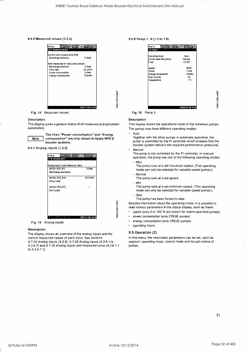
9.4.6 Measured values (1.2.4)
tatus gulwth. 1.2.4 - Ineasuiea oatues
Current control parameter (PU):
Discharge pressure 5.0bar
Other measured or calculated values: Discharge pressure Flow rate Power consumption Energy consumption
5.0bar 20.3m3,11
3.2 kW
702 kWh
2007-11-26 162-
Fig. 14 Measured values
Description This display gives a general status of all measured and calculated parameters.
Note The lines "Power consumption" and "Energy consumption" are only shown in Hydro MPC-E booster systems.
9.4.7 Analog inputs (1.2.5)
EIMMoper 773-tion 1.2.5- Analog inputs
alog inputs and measured value:
All (CU 351), (51)
(Discharge pressure)
5.0bar
012 (CU 351), (54)
(Flow rate)
013 (CU 351), (57)
(Not used)
20.3m3ki
2007-11-26 1626
Fig. 15 Analog inputs
Description The display shows an overview of the analog inputs and the current measured values of each input. See sections 9.7.28 Analog inputs (4.3.8), 9.7.29 Analog inputs (4.3.8.1 to
4.3.8.7) and 9.7.30 Analog inputs and measured value (4.3.8.1.1 to 4.3.8.7.1).
9.4.8 Pump 1...6 (1.3 to 1.8)
Status
Operating mode
Current operating mode
From
Speed
Power
Energy consumption Hour counter Temperature
Auto Normal
CU 351
88% 1.7 kW
22k1Th
Oh
2008.01-30 112
Fig. 16 Pump 1
Description This display shows the operational state of the individual pumps.
The pumps may have different operating modes:
Auto Together with the other pumps in automatic operation, the pump is controlled by the PI controller which ensures that the booster system delivers the required performance (pressure).
Manual The pump is not controlled by the PI controller. In manual operation, the pump has one of the following operating modes:
- Max. The pump runs at a set maximum speed. (This operating mode can only be selected for variable-speed pumps.)
- Normal The pump runs at a set speed.
- The pump runs at a set minimum speed. (This operating mode can only be selected for variable-speed pumps.)
- Stop The pump has been forced to stop.
Besides information about the operating mode, it is possible to read various parameters in the status display, such as these:
speed (only 0 or 100 % are shown for mains-operated pumps)
power consumption (only CR(I)E pumps)
energy consumption (only CR(I)E pumps)
operating hours.
9.5 Operation (2)
In this menu, the most basic parameters can be set, such as setpoint, operating mode, control mode and forced control of pumps.
21
WB087 Toohey Road Salisbury Water Booster Electrical Switchboard OM Manual
Q-Pulse Id TMS994 Active 10/12/2014 Page 32 of 400

9.5.1 Operation (2)
A
C
ttmti-.):;21tirtY'l
cutreht control parameter (Pu) -
stirta 5.0bar
Selected setpoint: Setpoint 1
5.0bar
16.0 bar
0.0bar
Current setpoint (SP):
5.0bar
Set set .oint 1 closed 5.0bar
Operating mode:
Further settings
Normal
Stop
2007-11.26 16 26
Fig. 17 Operation
Description The column shows the setting range. In closed-loop control, it
corresponds to the range of the primary sensor, here 0-16 bar. In
open-loop control, the setting range is 0-100 %.
At the left hand of the column, the selected setpoint 1 (A) is shown, i.e. the value set in the display. At the right hand of the column, the current setpoint (B) is shown, i.e. the setpoint acting as reference for the PI controller. If no kind of external setpoint influence has been selected, the two values will be identical. The current measured value (discharge pressure) is shown as the grey part of the column (C). See sections 9.7.5 External setpoint influence (4.1.3) and 9.7.6 Setting of influence function (4.1.3.2).
Below the display is a menu line for setting of setpoint 1 and selection of operating mode, including the operating modes Normal and Stop. It is possible to select further settings: system operating mode, control mode, setpoints for closed and open loop as well as individual pump control.
Setting range
Setpoint:
Closed-loop control: Measuring range of the primary sensor
Open-loop control: 0-100 %
Setting via control panel
Setpoint:
1. Mark the Operation menu with 0. 2. Mark Setpoint 1 with 0 or 0 . Set the value with
0 3. Save with ok
Operating mode:
1. Mark the Operation menu with 0 .
2. Mark o erating mode Normal or Stop with 0 or 0 Save with c( .
Further settings: 1. Mark the Operation menu with 0 2. Mark Further settings with 0 or 0 , and press ok .
3. Select one of the settings below with 0 or 0 , and press ok
Factory setting The setpoint is a value suitable for the Hydro MPC booster system in question. The factory setting may have been changed in the start-up menu.
9.5.2 System operating mode (2.1.1)
Operating mode:
Normal
Max.
User-defined Min.
Stop
Emergency
Set Min., Max. and User-defined duty: Min.
Max.
User-defined Emergency
Fig. 18 System operating mode
Description Hydro MPC can be set to six different operating modes. Normal is the typical setting. See section 9.4.3 Operating mode (1.2.1).
The performance of the operating modes Max., Min., User- defined and Emergency run can be set in the Settings menu.
In the display shown, it is possible to go directly to the Settings menu in order to set the pump performance or the setpoint.
Setting range
It is possible to select the operating modes Normal, Max., Min., User-defined, Stop and Emergency run.
Setting via control panel
1 Mark the Operation menu with 0 .
2. Mark Further settings with 0 or 0 , and press e. 3. Mark System operating mode with 0 or 0, and press
ok
4. Select the desired operating mode by marking one of the lines with check boxes with Q or 0, and press (3.
5. In order to set the performance in min., max., user-defined duty or emergency run, mark the desired line at the bottom of the display, and press e.
&or See sections 9.7.33 Min., max. and user-defined duty (4.3.14) and 9. 7. 25 Emergency run (4.3.5).
Factory setting Normal.
system operating mode (see section 9.5.2)
control mode (see section 9.5.3)
setpoints (see section 9.5.4)
individual pump control (see section 9.5.6).
22
WB087 Toohey Road Salisbury Water Booster Electrical Switchboard OM Manual
Q-Pulse Id TMS994 Active 10/12/2014 Page 33 of 400

9.5.3 Control mode (2.1.2) Open loop In open-loop control, the pumps run at a fixed speed.
Operation
Control mode:
C The pump speed is calculated from the performance set by the user (0-100 %). The pump performance in percentage is proportional with the flow rate.
Closed loop 171 Open-loop control is usually used when the booster system is Open loop controlled by an external controller which controls the
performance via an external signal. The external controller could for instance be a building management system connected to the Hydro MPC. In such cases, the Hydro MPC is like an actuator. See figs 22 and 23.
2007-11-26 16 2
Fig. 19 Control mode
Description There are two control modes, namely closed and open loop.
Examples:
Closed loop The typical control mode is closed loop where the built-in PI
controller ensures that the booster system delivers the discharge pressure required (setpoint). The performance is based on the setpoint set for closed loop. See figs 20 and 21.
Fig. 20 Booster system controlled by built-in PI controller (closed loop)
P [bar]
Setpoint
Time [sec]
Fig. 21 Regulation curve for closed loop
Setting via control panel
1. Mark the Operation menu with 0. 2. Mark Further settings with 0 or , and press ok .
3. Mark Control mode with 0 or 0 , and press ok .
4. Select Closed loop with 0 or CI, and press C). 5. Set the setpoint. See sections 9.5.4 Setpoints (2.1.3) and
9.5.1 Operation (2).
Fig. 22 Booster system with external controller (open loop)
Flow rate [gpm]
0 5
Input [ %] from external controller
Fig. 23 Regulation curve for open loop
Flow rate [gpm]
100
75
50
25
/ L 1/
Flow rate - - Pump 1
Pump 2
5 50 70.7 86.6 100
- - - Pump 3
Pump 4
Input ( %) from external controller
Fig. 24 Regulation curve for Hydro MPC-E in open loop
23
WB087 Toohey Road Salisbury Water Booster Electrical Switchboard OM Manual
Q-Pulse Id TMS994 Active 10/12/2014 Page 34 of 400

Flow rate [gpm]
100
75
50
25
5
Flow rate - - Pump 1
Pump 2 - - - - Pump 3
Pump 4
50 70.7 86.6 100 Input [%] from external controller
Fig. 25 Regulation curve for Hydro MPC-ED in open loop
Flow rate [gpm]
100
75
50
25
Flow rate - - - Pump 1
Pump 2 - - - - Pump 3
Pump 4
5 50 70.7 86.6 100 Input [%) from external controller
Fig. 26 Regulation curve for Hydro MPC-ES in open loop
Flow rate [gpm]
100
75
50
25
5 50 70.7 86.6 100
Flow rate Pump 1
Pump 2
Pump 3
Pump 4
Input [ %] from external controller
Fig. 27 Regulation curve for Hydro MPC-S in open loop
24
Correlating open loop input setpoint percentage with number of pumps in operation. Example: MPC system with (4) pumps
Setpoint 0% to 5% = All pumps stopped
One pump operation from setpoint from 5% to J (1- pump /4- pumps) = 50%
Two pump operation from 50% to J (2-pump/4-pumps) =
70.7%
Three pump operation from 70.7% to NI (3-pumps/4-pumps) =
86.6%
Four pump operation from 86.6% to 100%
For staging pumps off the cut-out is 2% less then cut-in. Example: staging from 4-pump to 3-pump operation will occur at 84.6% reference signal.
Setting range These settings must be made in connection with open loop:
stop of the Hydro MPC booster system
selection of control mode Open loop
setting of setpoint 1, open loop
setting of external setpoint influence
selection of operating mode Normal.
Setting via control panel To set an external control source to control the Hydro MPC booster system, proceed as follows:
1. Mark the Operation menu with 0. 2. Mark the operating mode Stop with 0 or 0 , and press
ok . The check mark in the right box shows that the operation has been stopped.
3. Mark Further settings with 0 or 0 , and press e 4. Mark Control mode with 0 or 0 , and press ok .
5. Select Open loop with 0 or 0, and press ok .
6. Return by pressing twice.
7. Mark Set setpoint 1, open loop with 0, or O. 8. Set the setpoint to 100 % with 0 , and save with ok .
9. Mark the Settings menu with 0 .
10.Mark Primary controller with 0 or , and press e. 11.Mark External setpoint influence with 0 or 0 , and press
12.Mark Go to setting of analog input with 0 or 0 , and press e.
13.Select the analog input with 0 or 0 , and press e 14.Select the range of the analog input with 0 or 0 , and
press C). The selection is indicated by a check mark.
15.Mark Measured input value with 0 or 0 , and press ok
Now the display 4.3.8.1.1 appears.
16.Select 0-100 % signal with 0 or 0 , and press ok .
17.Press to return to display 4.3.8.1. 18.Set the minimum sensor value with 0 or Q, and save with
19.Set the maximum sensor value with 0 or 0, and save with ok
-
20.Return by pressing twice.
21.Mark Input value to be influenced by with Q or O , and press 0 .
22.Mark 0-100 % signal with 0 or 0 , and press ok .
23.Return with .
24.Mark Set the influence function with 0 or 0 , and press ok . For details, see section 9.7.6 Setting of influence
function (4.1.3.2).
25.Mark the menu line for number of points with Q or 0 , and press co.
WB087 Toohey Road Salisbury Water Booster Electrical Switchboard OM Manual
Q-Pulse Id TMS994 Active 10/12/2014 Page 35 of 400

26.Select the required number of points with 0 or 0, and save with e.
27.Mark External input value (point 1) with e or 0 .
28.Set the value of the external input value with 0 or 0, and save with e.
29.Mark Reduce setpoint to (point 1) with 0 or 0 .
30.Set the value as a percentage with 0 or 0, and save with ok
'
31.Repeat 27 to 31 for all chosen points.
32.Return with
33.Mark Filter time with , set the time in seconds with 0 or 0, and save with
34.Mark Activated with Q or O , and press O. The check mark in the right box shows that the function has been activated.
35.Return by pressing c) twice.
36.Mark the Operation menu with 0 .
37.Mark the operating mode Normal with Q or Q^ , and press e. The check mark in the right box shows that the operation
is normal. The booster system can now be controlled by an
external controller.
Factory setting Closed-loop control.
9.5.4 Setpoints (2.1.3)
tatus .1.3-Setpoints
Operation Mine battfrigi
Set the setpoints. Closed loop:
Setpoint 1 5.0bar Setpoint 2
Setpoint 3
Setpoint 4
Setpoint S
Setpoint 6
Setpoint 7
Open loop: Setpoint 1
Setpoint 2
Setpoint 3
Setpoint 4
Setpoint 5
3.0bar 3.0bar 3.0bar 3.0bar 3.0bar 3.0bar
70% 70% 70% 70% 70%
Setpoint 6 70% Setpoint 7 70%
Fig. 28 Setpoints
Description In addition to the primary setpoint 1 (shown in the display 2 in the Operation menu), six alternative setpoints can be set for closed- loop control. It is furthermore possible to set seven setpoints for open-loop control.
As described in sections 9.7.3 Alternative setpoints (4.1.2) and 9.7.4 Alternative setpoints 2 to 7 (4.1.2.1 to 4.1.2.7), it is possible to activate one of the alternative setpoints by means of external contacts.
Setting range The setting range of setpoints for closed-loop control depends on the range of the primary sensor. See section 9.7.7 Primary sensor (4.1.4).
In open loop control, the setting range is 0 - 100 %.
Setting via control panel 1. Mark the Operation menu with 0 .
2. Mark Further settings with 0 or 0 , and press e. 3. Mark Setpoints with 0 or 0 , and press 0 .
4. Select the setpoint with 0 or 0 .
5. Set the setpoint with -0 or 0, and press
Factory setting Setpoint 1 for closed-loop control is a value suitable for the Hydro MPC in question.
The alternative setpoints for closed-loop control are 3 bar.
All setpoints for open-loop control are 70 %.
9.5.5 Individual pump control (2.1.4)
.1.4 .1110WidUal pomp control
Select the pump:
battings
Pump 1 Auto Stop Pump 2
Pump 3
Auto Auto
Fig. 29 Individual pump control
Normal
Normal
Description It is possible to change the operating mode from automatic operation to one of the manual operating modes.
Auto
The pumps are controlled by the PI controller, ensuring that the booster system delivers the required performance (pressure).
Manual
The pump is not controlled by the PI controller, but set to one of the following manual operating modes:
Max. The pump runs at a set maximum speed. (This operating mode can only be selected for variable-speed pumps.)
Normal The pump runs at a set speed.
Min. The pump runs at a set minimum speed. (This operating mode can only be selected for variable-speed pumps.)
Stop The pump has been forced to stop.
Pumps in manual operation are not part of the normal pump cascade and speed control. The manual pumps are a
"disturbance" of the normal control of Hydro MPC.
If one or more pumps are in manual operation, Hydro MPC may not be able to deliver the set performance.
There are two displays for the function. In the first display, the pump to be set is selected, and in the next display, the operating mode is selected.
Setting range All pumps can be selected.
Setting via control panel 1. Mark the Operation menu with Q. 2. Mark Further settings with 0, or 0 , and press co .
3. Mark Individual pump control with 0 or 0 , and press ok
'
4. Select the pump with 0 or 0, and press Ot .
25
WB087 Toohey Road Salisbury Water Booster Electrical Switchboard OM Manual
Q-Pulse Id TMS994 Active 10/12/2014 Page 36 of 400

9.5.6 Setting of individual operating mode (2.1.4.1 to 2.1.4.6)
Status 2.1A.1 - Pump
Operation
erating mode, pump 1
Auto VI
Manual
anal: Max.
Normal
Setpoint, manual operation Min.
Stop
0 0%
0 0
11111111111111111=13:0 Fig. 30 Setting of individual operating mode
Description This display is shown for the individual pumps and makes it
possible to set an operating mode.
Setting range
It is possible to select Auto or Manual as well as the operating mode of the pump for manual operation - Max., Normal, Min. or Stop. For mains-operated pumps only Normal or Stop can be selected.
Setting via control panel
1. Mark the Operation menu with 0 .
2. Mark Individual pump control with 0 or 0, and press
0 '
3. Select the pump with 0 or O, and press Ct. 4. Mark Auto or Manual with 0 or 0, and press CI .
5. Manual: Select the operating mode with 0 or 0, and press ok .
6. Normal: Mark Setpoint with 0 or 0 .
Set the speed of the variable-speed pump with C) or CI ,
and press ok .
Factory setting Auto.
26
WB087 Toohey Road Salisbury Water Booster Electrical Switchboard OM Manual
Q-Pulse Id TMS994 Active 10/12/2014 Page 37 of 400

9.6 Alarm (3)
The Alarm menu gives an overview of alarms and warnings. In this menu, it is possible to reset alarms and to see the alarm log.
9.6.1 Alarm status (3)
tatuatIca) 3- Alarti Milos
Alarm rettr4s.
Further information about alarms, go to:
Current alarms Alarm log
Fig. 31 Alarm status
Description A fault gt in the Hydro MPC booster system or one of the components monitored can cause an alarm C) or a warning Q. Besides the fault signal via the alarm/warning signal relay and the red indicator light on the CU 351, an alarm can also cause a
change of operating mode, for instance from Normal to Stop. A
warning only causes a fault indication.
The table shows the possible causes of fault together with an alarm code number, and whether they result in an alarm or a
warning. It also shows to what operating mode the booster system changes in case of alarm, and whether restart of the booster system and reset of the alarm is manual or automatic.
The table also shows that the reaction to some of the fault causes mentioned can be set in the Settings menu. See sections 9.7.24 Soft pressure build-up (4.3.3) and 9.7.41 Monitoring functions (4.4) to 9.7.51 Pressure relief (4.4.8).
Fault ,
O E
rn _
of C
cu
0 0
o cr)
C co 13 .0 o E
a)
rn C
ar rn
.c C 2
a)
co E
0
E
Water shortage Auto 206
Water shortage 0 Stop Man/auto X 214
Pressure high Stop Auto 210
Pressure low Auto
X 211 C) Stop Man
Pressure relief 6 Auto X 219
Alarm, all pumps C) Stop Auto 203
External fault 6 Auto
X 3 C) Stop Man
Dissimilar sensor signals 6 Auto 204
Fault, primary sensor 0 Stop Auto 89
Fault, sensor Auto 88
Communication fault Auto 10
Phase failure Auto 2
Undervoltage, pump Auto 7, 40,
42, 73
Overvoltage, pump & Auto 32
Overload, pump Auto 48, 50,
51,54 Overtemperature, pump
Auto 64,
65, 67
Other fault, pump Auto 76, 83
Internal fault, CU 351 ,L Auto 72, 83, 157
Internal fault, 10 351 0 Stop Auto 83, 157
VFD not ready Auto 213
Fault, Ethernet 8 Auto 231, 232
Limit 1 exceeded 80 Man/auto X 190
Limit 2 exceeded 00 Man/auto X 191
Pressure build-up fault 8 0 Man/auto X 215
Pumps outside duty range 6 Man/auto X 208
Pilot pump fault 6 Auto 216
27
WB087 Toohey Road Salisbury Water Booster Electrical Switchboard OM Manual
Q-Pulse Id TMS994 Active 10/12/2014 Page 38 of 400

Alarm (3) continued
M PC alarm indication "Protocol description"
Alarm Associated
code device and Description/cause Remedy device no.
Reset Alarm/warning typel Action type2
1. Phase failure, pump 2 Pump 1-6
1. Check that all three power supply phases are within a 15 V window.
Auto Warning.
2. Undervoltage
7 Pump 1-6
HSD = hardware shut- down.
There has been a fault, and the permissible number of restarts for the fault type has been exceeded.
a) Fault in power supply.
a) Terminal box defective.
1. Restore power supply.
2. Replace terminal box. Auto Warning.
3. Undervoltage, pump 40 Pump 1-6
a) Power supply voltage 1. Bring voltage back to
is too low at start. prescribed level.
4. Undervoltage, pump a) Faulty power supply 1. Restore proper power
42 Pump 1-6 at the time of staging on a pump.
supply.
5. Undervoltage, pump
73 Pump 1-6
a) Low supply voltage.
b) Power supply failure 1. Restore proper power while motor is supply.
running.
6. Overvoltage, pump 32 Pump 1-6
a) Supply voltage is too 1
high at start. . Bring voltage back to
prescribed level.
7. Overload, associated device 48 Pump 1-6
a) Heavy overload has caused software shutdown (SSD).
. Check and possibly reduce load.
Auto Warning.
Auto Warning.
Auto Warning.
Auto Warning.
Auto Warning,
8. Overload, associated device
50 Pump 1-6
a) MPF = motor protection function. The built-in motor 1. Check and possibly protection has reduce load/improve detected a sustained cooling. overload (MPF 60 sec. limit)>
Auto Warning.
9. Overload, associated device
51 Pump 1-6
a) Heavy overload (Imax. very high). Pump blocked at start.
1. Unblock the pump. Auto Warning,
10. Overload, associated a) The built-in motor device protection has
54 Pump 1-6 detected a transitory overload (MPF 3 sec. limit).
1. Check and possibly reduce load/improve cooling
Auto Warning,
11. Over temperature, pump a) PTC sensor in the 65 Pump 1-6 motor has signalled
over temperature.
1. Check and possibly reduce load/improve cooling.
Auto Warning.
12. Over temperature, pump
a) Terminal box has 67 Pump 1-6 indicated over
temperature.
1. Check and possibly reduce load/improve cooling. (Temperature during operation can be read via PC Tool E- products.)
Auto Warning
28
WB087 Toohey Road Salisbury Water Booster Electrical Switchboard OM Manual
Q-Pulse Id TMS994 Active 10/12/2014 Page 39 of 400

MPC alarm indication "Protocol description"
Alarm Associated
code device and Description/cause device no.
Remedy Reset Alarm/warning typel Action type2
13. Other fault, associated device
76 Pump 1-6
a)
14. Limit 1 exceeded
190 Measured parameter
a)
15. Limit 2 exceeded
191 Measured parameter
a)
16. Pressure relief 219 System
a)
17. Pressure build-up fault
215 System
a)
18. Pumps outside duty range 208 System
a)
19. Pilot pump fault 216 Pilot pump a)
Internal communication error has occurred in the pump.
Try to reset the fault:
1. Switch off the supply power.
2. Wait until all diodes are out.
3. Switch on the supply power.
If this does not remedy the fault, replace the terminal box.
Auto Warning
The measured parameter has exceeded the limit set.
1. Remove the cause of the Auto/ Alarm/warning
fault. manual Stop/
unchanged.
The measured parameter has exceeded the limit set.
1. Remove the cause of the Auto/ Alarm/warning
fault. manual Stop/
unchanged,
The monitored 1. Reduce the pressure to
pressure could not be reduced sufficiently.
below the limit. Auto
Warning Unchanged
The pressure set cannot be reached within the configured time.
1. Check limit and pipes. Auto/
manual
Alarm/warning Stop/
unchanged
The pump is running outside the defined 1. Check the system. range.
Auto/ Warning manual Unchanged
Pilot pump fault 1. Check wires.
2. Check the pump. Auto Warning
29
WB087 Toohey Road Salisbury Water Booster Electrical Switchboard OM Manual
Q-Pulse Id TMS994 Active 10/12/2014 Page 40 of 400

MPC alarm indication "Protocol description"
Alarm Associated
code device and Description/cause device no.
Remedy Reset Alarm/warning typel Action type2
20. Water shortage, level 1
"Water shortage, level 1
a) The pre-pressure (or the level in the
206 feed tank) is below its programmable warning limit.
21. Water shortage, level 2
*Water shortage, level 2 214
22. Discharge pressure high Pressure above max. 210 pressure
23. Discharge pressure low 'Pressure below min. 211
pressure
24. All pumps in alarm All pumps in alarm
203
25. External fault signal 'External fault signal
003
System
a) The pre-pressure (or the level in the feed tank) is below its programmable warning limit.
b) The pre-pressure switch detect water shortage.
a) The system pressure is above the programmable high- pressure alarm limit.
a) The system pressure is below the programmable low- pressure alarm limit.
1. Check the actual and the corresponding settings.
2. Check the sensor/switch, wiring and input according to the wiring diagram.
3. Check the sensor/switch.
Auto Warning
Unchanged
Auto/ Manual
Alarm Stop
Auto/ Manual
Warning Unchanged
Alarm Fast stop (over rule min. seq.
time)
Auto/ Alarm/Warning
Manual Stop/
Unchanged
a) All pumps, set to Auto, is stopped on account of pump alarm
Troubleshoot according to the alarm message/code: 1. System
2. Pumps installed Use fault fault finding for the pump.
b) Pumps are not indicating alarm
Check the Genibus wires eg. connection, polarisation.
Auto Alarm Stop
a) External fault digital input activated.
1. Check the external signal source.
2. Check the digital input according to the wiring diagram
Auto/ Manual
Alarm/Warning Stop/
Unchanged
26. Inconsistency between sensors *Inconsistency between sensors
204
a) Primary
sensor and/or redundant
sensor
Primary feedback sensor value (pressure) is
inconsistent with redundant feedback sensor value.
1. Check the wiring and input according to the wiring diagram.
2. Check the sensor output according to the measured value.
Auto Warning
Unchanged
27. Primary sensor 'Closed loop feedback sensor signal fault
089 Primary sensor
a) A fault in the sensor assigned to the feed back control is
detected.
1. Check the wiring and input according to the wiring diagram.
2. Check the sensor output according to the measured value.
b) Error in the settings Check the primary sensor of the sensor which is settings assigned to the regulator.
28. Sensor fault *General (measurement) sensor signal fault
088 CU 351
10 351 as 10 module
a) The signal 1.
(ex. 4-20 mA) from one of the analog sensors is outside the 2. selected signal range.
Check the wiring and input according to the wiring diagram.
Check the sensor output according to the measured value
Auto
Alarm Stop
Warning Unchanged
30
WB087 Toohey Road Salisbury Water Booster Electrical Switchboard OM Manual
Q-Pulse Id TMS994 Active 10/12/2014 Page 41 of 400

MPC alarm indication "Protocol description"
Alarm Associated
code device and Description/cause device no.
Remedy Reset Alarm/warning typel Action type2
29. CU 351 internal fault 'Real time clock out of order
a) The real-time clock in Replace the CU 351 157 CU 351 is out of
order.
30. Ethernet fault `Ethernet: No address 231 from DHCP server
31. Ethernet fault 'Ethernet: Auto disabled 232 due to misuse
32. FLASH parameter verification error *FLASH parameter verification error
CU 351
a) No address from DHCP server
a) Auto-disabled due to misuse
1. Communication error.
2. Please contact the system integrator.
a) Verification error in
083 CU 351 FLASH memory
Replace the CU 351
33. 10 351 internal fault `Hardware fault type 2
080 10 351
a) 10 351 pump module See current alarms and hardware fault identify the faulty 10 351
module from the alarm message and replace the module.
b) 10 351 I/O module hardware fault
34. VFD not ready *VFD not ready
213 Pump 1-6 CU 351
1. Check for VFD alarm a) The VFD signal relay
do not release the 2. Check the wiring and
VFD for operation input according to the wiring diagram.
35. Communication fault *Pump communication fault
010 Pump 1-6
10 351
a) No GeniBus communication with a
device connected to CU 351
See actual alarms and identify the faulty device from the alarm message. 1. Check power supply
2. Check GeniBus cable connection
3. Check, with R100, that the device GeniBus no. is
correct.
36. Device alarms From device
Pump 1-6 a) The device is in alarm
See actual alarms and identify the faulty device from the alarm message. 1. Fault find according to
the service instruction for the device.
Auto Warning
Unchanged
1)
2)
Reset type is either fixed as "Auto acknowledge" (Auto) or can be programmed to be Auto or manual ackknowledge (Auto/Man)'.
Programmable action types:
- Go to operating mode "Stop" (no delay (<0.5 s) between pump disconnections).
- Go to operating mode "Min".
- Go to operating mode "User-defined".
- Go to operating mode "Max".
- Set pumps in source mode "Local". - No action (warning only)
31
WB087 Toohey Road Salisbury Water Booster Electrical Switchboard OM Manual
Q-Pulse Id TMS994 Active 10/12/2014 Page 42 of 400

9.6.2 Current alarms (3.1)
Statu;,Z1715eerition'ii 3.1-Current alarms
Alarm Teti Ais71
Press tokl to reset alarms. lescl returns to the previous display.
&urnp 1
Overload 1481
Occurred at Disappeared at
2007-11-26 16A1
2007-11-261641
Fig. 32 Current alarms
Description This submenu shows the following:
Warnings 8 caused by faults that still exist.
Warnings caused by faults that have disappeared, but the warning requires manual reset.
Alarms ® caused by faults that still exist.
Alarms 0 caused by faults that have disappeared, but the alarm requires manual reset.
All warnings and alarms with automatic reset are automatically removed from the menu when the fault has disappeared.
Alarms requiring manual reset are reset in this display by pressing ok . An alarm cannot be reset until the fault has disappeared.
For every warning or alarm, the following is shown:
Whether it is a warning or an alarm ®. Where the fault occurred: System, Pump 1, Pump 2, etc.
In case of input-related faults, the input is shown.
What the cause of the fault is, and the alarm code in brackets: Water shortage (214), Max. pressure (210), etc.
When the fault occurred: Date and time.
When the fault disappeared: Date and time. If the fault still exists, date and time are shown as --...--.
The latest warning/alarm is shown at the top of the display.
9.6.3 Alarm log (3.2)
The alarm log can store up to 24 warnings and alarms.
tutus Operatiiiri' Alarm settings" 32 - etanntog
8Pump Overload 148)
Occurred at 2007-11-26 16:41
Disappeared at - --
8System water shortage 1214)
Occurred at 2007-11-26 16:39
Disappeared at 2007-11-26 16:39
Fig. 33 Alarm log
32
Description Here warnings and alarms are shown.
For every warning or alarm, the following is shown:
Whether it is a warning & or an alarm ®. Where the fault occurred. System, Pump 1, Pump 2, etc.
In case of input-related faults, the input is shown.
What the cause of the fault is, and the alarm code in brackets: Water shortage (214), Max. pressure (210), etc.
When the fault occurred: Date and time.
When the fault disappeared: Date and time. If the fault still exists, date and time are shown as --...--.
The latest warning/alarm is shown at the top of the display.
9.7 Settings (4)
Operatten alarm -Settings
Select the submenu:
Settings
Primary controller Pump cascade control Secondary functions Monitoring functions Functions, CU 351
1111111111111=1= Fig. 34 Settings
In the Settings menu, it is possible to set the following functions: Primary controller Setting of PI controller, alternative setpoints, external setpoint influence, primary sensor, clock program, proportional pressure and S-system configuration. Pump cascade control Setting of min. time between start/stop, max. number of starts/ hour, number of standby pumps, forced pump changeover, pump test run, pilot pump, pump stop attempt, pump start and stop speed, min. performance and compensation for pump start-up time. Secondary functions Setting of stop function, soft pressure build-up, digital and analog inputs, digital outputs, emergency run, min., max. and user-defined duty, pump curve data, flow estimation, control source and fixed inlet pressure. Monitoring functions Setting of dry-running protection, min. and max. pressure, external fault, limit 1 and 2 exceeded, pumps outside duty range and pressure relief. Functions, CU 351 Selection of service language, main language and units. Setting of time and date, passwords, Ethernet connection, GENIbus number and software status.
Usually, all these functions are set correctly when the Hydro MPC is switched on. It is only necessary to make settings in this menu if the functionality is to be expanded with for instance alternative setpoints or setpoint influence, or if the settings of the CU 351 are to be adjusted.
WB087 Toohey Road Salisbury Water Booster Electrical Switchboard OM Manual
Q-Pulse Id TMS994 Active 10/12/2014 Page 43 of 400

9.7.1 Primary controller (4.1)
rixaeato'r 4.1 - Pomatq controller
Settings
-tact the submenu:
PI controller Alternative setpoints External setpoint influence Primary sensor Clock program Proportional pressure S-system configuration
200711.26.16 26
Fig. 35 Primary controller
Description In this menu section, it is possible to set the functions related to the primary controller. It is only necessary to make settings in this menu if the functionality is to be expanded with for instance alternative setpoints, external setpoint influence, clock program or proportional pressure. The following menus can be selected:
PI controller
Alternative setpoints
External setpoint influence
Primary sensor
Clock program
Proportional pressure
S-system configuration.
9.7.2 PI controller (4.1.1)
Statu5 4.1.1.- PI controller
SettIngs
Set the PI controller. If inverse control is required, gain Kp must be negative:
1031111111111111 Integral time Ti 1.05
2007-11-26 1626
Fig. 36 PI controller
Description Hydro MPC includes a standard PI controller which ensures that the pressure is stable and corresponds to the setpoint.
It is possible to adjust the PI controller if a faster or slower reaction to changes of consumption is required.
A faster reaction is obtained if Kp is increased and Ti is reduced.
A slower reaction is obtained if Kp is reduced and T1 is increased.
Setting range Gain Kp: -30 to 30. Note: For inverse control, set Kp to a negative value.
Integral time Ti: 0.1 to 3600 seconds.
Setting via control panel 1. Mark the Settings menu with 0 .
2. Mark Primary controller with O or O , and press ok .
3. Mark PI controller with 0 or 0 , and press e. 4. Select the gain (Kr) with 0 or Q . Set the value with 0 or
0, and save with e .
Note: Usually it is not necessary to adjust Kp.
5. Select the integral time (Ti) with 0 or 0 . Set the time with 0 or 0 , and press ok .
Factory setting Kp: 0.5
Ti: 1 second
9.7.3 Alternative setpoints (4.1.2)
talus - Operation; .12- ntrernanue setpoints
Set alternative setpoint
Settings
Setpoint 2
Setpoint 3
Setpoint 4
Setpoint 5
Setpoint 6
Setpoint 7
2007-11.26 16
Fig. 37 Alternative setpoints
Description This function makes it possible to select up to six setpoints (No 2
to 7) as alternatives to the primary setpoint (No 1). The primary setpoint (No 1) is set in the Operation menu. Every alternative setpoint can be addressed manually to a
separate digital input (DI). When the contact of the input is
closed, the alternative setpoint applies.
If more than one alternative setpoint has been selected and they are activated at the same time, the CU 351 selects the setpoint with the lowest number.
Setting range Six setpoints, No 2 to 7.
33
WB087 Toohey Road Salisbury Water Booster Electrical Switchboard OM Manual
Q-Pulse Id TMS994 Active 10/12/2014 Page 44 of 400

Factory setting
No alternative setpoints have been selected.
9.7.4 Alternative setpoints 2 to 7 (4.1.2.1 to 4.1.2.7)
OperatioritiAlarm,t,h,, 4.1 2.1. Alternative setpoints
Settings
elect digital input for setpoint 2:
Go to sett of tal ' t
t setpoint:
Setpoint 2, closed loop 3.0bar
Setpoint 2, open loop 7096
20029126 1626
Fig. 38 Alternative setpoints 2 to 7
For each alternative setpoint, select the digital input to activate the setpoint.
It is possible to set a setpoint for closed loop and for open loop.
Setting via control panel
1. Mark the Settings menu with 0 .
2. Mark Primary controller with 0 or 0 , and press e. 3. Mark Alternative setpoints with 0 or O , and press e 4. Select the alternative setpoint with 0 or O , and press
5. Mark Go to setting of digital input with 0 or CI , and press ok
Now the display Digital inputs (4.3.7) appears. Set the input and return with .
6. Mark the menu line of the setpoint (closed or open loop) with 0 or C. 7. Set the required setpoint with 0 or Q and save with Ot .
Set both setpoints if Hydro MPC is to be controlled both in open and closed loop.
Factory setting No alternative setpoints have been set.
9.7.5 External setpoint influence (4.1.3)
settings
Setpoint influence: Deactivated Activated 0
The analog input for the influence parameter must be set to activate the function:
6o to setting of analog input
Input value to be influenced by
(Flow rate(
The influence function must be set to activate the function:
Set the influence function
Low-pass filtering of influence signal: Filer time Os
2007.11.26 162
Fig. 39 External setpoint influence
34
Description This function makes it possible to adapt the setpoint by letting measuring parameters influence the setpoint. Typically an analog signal from a flow or temperature transmitter, or a similar transmitter.
As an example, the setpoint can be adapted to parameters that can influence the discharge pressure or temperature of the system. The parameters which influence the performance of the booster system are shown as a percentage from 0 to 100 %. They can only reduce the setpoint, as the influence as a percentage divided with 100 is multiplied with the setpoint:
Setpoint (1) o Infl.(2).... current(SP) Setpoint selected " Inn'
The influence values can be set individually.
A low-pass filter ensures smoothing of the measured value which influences the setpoint. This results in stable setpoint changes.
Setting range The following parameters can be selected.
0-100 % signal
Inlet pressure
Discharge pressure
External pressure
Differential pressure, pump
Differential pressure, external
Flow rate
Tank level, discharge side
Tank level, suction side
Flow pipe temperature
Return pipe temperature
Ambient temperature Return pipe temperature, external Differential temperature.
Setting via control panel 1. Mark the Settings menu with 0 .
2. Mark Primary controller with 0 or CI , and press ok .
3. Mark External setpoint influence with CI or CI , and press ok
4. Mark Input value to be influenced by with NO or 0 , and press 0 .
Now a list of available parameters appear.
5. Mark the parameter which is to influence the setpoint with 0 or 0 , and press ok .
6. Return with 0 7. Mark Set the influence function with 0 or 0 , and press
e. For details, see section 9.7.6 Setting of influence function (4.1.3.2).
8. Mark the menu line for number of points with 0 or CI , and press e.
9. Select the required number of points with 0 or 0 , and save with e.
10.Mark External input value (point 1) with 0 or 0 .
11.Set the value of the external input value with 0 or , and save with 0,
12.Mark Reduce setpoint to (point 1) with 0 or 0 .
13.Set the value as a percentage with 0 or 0, and save with
cp. 14.Repeat points 8 to 13 for all desired parameters. 15.Return with
16.Mark-Filter time with 0 or -0 or 0, and save with
, set the time in seconds with
WB087 Toohey Road Salisbury Water Booster Electrical Switchboard OM Manual
Q-Pulse Id TMS994 Active 10/12/2014 Page 45 of 400

17.Mark Activated with 0 or O , and press 0. The check mark in the right box shows that the function has been activated.
Factory setting Setpoint influence is not activated.
9.7.6 Setting of influence function (4.1.3.2)
tatus COeration
.1.3 2.Sethng of influence function
Set the influence function
Settings
Select the number of points 12 to 81
on the influence curve: 4
Point
1 External input value 10.0m,M Reduce setpoint to 12%
2 External input value 20.0m% Reduce setpoint to 40%
3 External input value 30.0m3ch
Reduce setpoint to 50% 4 External input value
Reduce setpoint to
4o.on134,
100%
11111111Millii= Fig. 40 Setting of influence function
Description In this menu, you select the relation between the measuring parameter which is to influence the setpoint and the desired influence as a percentage.
The relation is set by entering values in a table with maximum eight points by means of the control panel.
Example with four points:
Setpoint influence [ %)
100
80
60
40
20
50
0 [m3/h)
Fig. 41 Relation between setpoint influence and flow rate
The control unit of the Hydro MPC draws straight lines between the points. A horizontal line is drawn from the minimum value of the relevant sensor (0 m3/h in the example) to the first point. This is also the case from the last point to the sensor's maximum value (example 50 m3/h).
Setting range Two to eight points can be selected. Each point contains the relation between the value of the parameter which is to influence the setpoint and the influence of the value.
Setting via control panel
1. Mark the Settings menu with 0 .
2. Mark Primary controller with or O , and press Go .
3. Mark External setpoint influence with 0 or 0, and press ok
4. Mark Set the influence function with e or 0, and press e
5. Mark the menu line for number of points with 0 or 0, and press e .
6. Select the required number of points with 0 or 0, and save with ok .
7. Mark External input value (point 1) with O or
8. Set the value of the external input value with 0 or 0, and save with 2k.
9. Mark Reduce setpoint to (point 1) with 0 or O. 10.Set the value as a percentage with 0 or 0 , and save with e 11.Repeat points 7 to 10 for all desired parameters.
Factory setting External setpoint influence is not activated.
9.7.7 Primary sensor (4.1.4)
titus Oper-ati&. 4larm 4.1A - Pftinanisensa
Settings
The analog input for the control parameter rust be set to activate the function:
Go to setting of analog input
Select the control parameter:
Discharge pressure Cif t. pressure, external Dif. f . pressure, pump
Series 2000, dill. pressure External pressure Cliff. pressure, inlet Off pressure, outlet Flow rate Series 2000, flow rate Flow pipe temperature Return pipe temperature
Fig. 42 Primary sensor
0
0
I
Description In this display, select the control parameter of Hydro MPC and the sensor to measure the value.
Usually, the control parameter is the discharge pressure which is
measured by a sensor fitted on the discharge manifold and connected to analog input All of the CU 351.
If another control parameter is selected, the sensor must be connected to A13 (CU 351) which is then set to one of the chosen parameters listed below.
Setting range Discharge pressure (factory setting)
Differential pressure, external
Differential pressure, pump
Series 2000, differential pressure
External pressure
Differential pressure, inlet Differential pressure, outlet
Flow rate
Series 2000, flow rate Flow pipe temperature
Return pipe temperature
Differential temperature
Ambient temperature
Return pipe temperature, external
0-100 % signal
Not used.
35
WB087 Toohey Road Salisbury Water Booster Electrical Switchboard OM Manual
Q-Pulse Id TMS994 Active 10/12/2014 Page 46 of 400

From factory the discharge pressure sensor is connected to All (CU 351). If one of the above parameters is selected, the sensor in question must be connected to Al3 (CU 351) and set in order to function as the primary sensor.
Setting via control panel
1. Mark the Settings menu with 0 .
2. Mark Primary controller with 0 or O , and press e. 3. Mark Primary sensor with 0 or O , and press ok
.
4. Mark Go to setting of analog input with 0 or 0 , and press e. Now the display Analog inputs (4.3.8) appears. Select the analog input (Al) for the primary sensor, and set the parameters for this sensor. Return to display Primary sensor (4.1.4) with e.
5. Select the control parameter for the primary sensor with 0 or and press ().
If the primary parameter is discharge pressure, All (CU 351) must be set to this parameter. If the primary parameter is external pressure or flow rate, Al3 (CU 351) must be set to this parameter.
Factory setting The primary parameter is discharge pressure. The sensor is
connected to All (CU 351).
9.7.8 Clock program (4.1.6)
Note
Settings 4.1.6- Clock program
Activated
1 Sat. to Sun.
2 Mon. to Fri.
3 Deactivated 4 Deactivated 5 Deactivated 6 Deactivated 7 Oeactivated 8 Deactivated 9 Deactivated
0 00:00 4.0bar 00:00 5.0bar
2007-12-20
U
15 :04
Fig. 43 Clock program
Description With this function, it is possible to set setpoints and day and time for their activation. It is also possible to set day and time for stop of the Hydro MPC system.
If the clock program is deactivated, the setpoint of the program will remain active.
Setting range Activation of the function.
Activation and setting of event.
Setting via control panel
1. Mark the Settings menu with 0 .
2. Mark Primary controller with 0 or 0 , and press e. 3. Mark Clock program with 0 or 0 , and press e. 4. Mark event 1 with 0 or 0 , and press 0 .
36
Deactivated Activated
Operating mode:
Normal
Stop Setpoint, closed loop 4.0bar
Time: Hours 00
Minutes 00
h4Onday
Tuesday Wednesday Thursday Friday Saturday Sunday Daily
to Fri simmarsicliti 5. Mark operating mode Normal or Stop with (9 or 0 , and
press . (If Stop is selected, point 7 is skipped.)
6. Mark Setpoint, closed loop with 0 or r9 . Set the pressure with 0 or and save with e.
7. Mark Time (hours, minutes) with 0 or 0 .
8. Set the time with C.) or 0 , and save with
9. Mark day of week on which the settings are to be activated with 0 or , and press ok .
10.Mark Activated with 0 or 0 , and press e .Return with 0 .
12.Mark Activated with 0 or 0 , and press ok . The check mark in the right box shows that the function has been activated.
13.Repeat points 4 to 11 if several events are to be activated. Note: Up to ten events can be set.
Factory setting The function is deactivated.
9.7.9 Proportional pressure (4.1.7)
CoratIon 4.1.1; Proportional pressure
Proportional pressure:
Settings
Deactivated Activated
Adaptation:
Linear Square
Influence at 0 flow 90%
Fig. 44 Proportional pressure
Description The function can only be activated in pressure-controlled systems and automatically adapts the setpoint set to the current flow rate. The adaptation can be linear or square. See fig. 45.
WB087 Toohey Road Salisbury Water Booster Electrical Switchboard OM Manual
Q-Pulse Id TMS994 Active 10/12/2014 Page 47 of 400

- Pump curve
Setpoint - Resultant setpoint, linear - --Resultant setpoint, square
0
Starting point of proportional pressure control (Influence at 0 flow = x % of Hset)
Fig. 45 Proportional pressure
The function has these purposes:
to compensate for pressure losses
to reduce the energy consumption
to increase the comfort for the user.
Setting range Activation of the function.
Selection of control mode.
Setting of setpoint influence.
Setting via control panel 1. Mark the Settings menu with 0 .
2. Mark Primary controller with 0 or 0 , and press co. 3. Mark Proportional pressure with 0 or 0 , and press 0. 4. Mark Activated with 0 or 0 , and press ok . The check
mark in the right box shows that the function has been activated.
5. Mark Adaptation, linear or square with 0 or 0 , and press e.
6. Mark Influence at 0 flow with 0 or 0 . Set the value with 0 or 0, and save with c). Factory setting The function is deactivated.
9.7.10 S-system configuration (4.1.8)
Settings
Select the fixed-speed control type: Normal NI Inverse
Set the on off band for fixed-speed control. The value is a percentage of the sensor range.
Start/stop band 9.8%
Fig. 46 S-system configuration
Description The function makes it possible to invert the control of mains- operated pumps (Hydro MPC-S). That is to set whether pumps are to be started or stopped depending on the current value.
A start/stop band must be set in order to use this function. See fig. 47.
Normal control: A pump is stopped when the current value becomes higher than Hset + start/stop band. And a pump is started when the current value becomes lower than Hset.
See fig. 47.
Inverse control: A pump is started when the current value becomes higher than Hset + start/stop band. And a pump is
stopped when the current value becomes lower than Hset.
See fig. 47.
Normal control
H [m]
Hset
Inverse control
H [m]
Pump stops Pump starts
Start/stop band Start /stop band
Hset Pump starts Pump stops
Time [sec] Time [sec]
Fig. 47 Normal and inverse control
Setting range
Selection of configuration (normal or inverse control).
Setting of start/stop band.
Setting via control panel 1. Mark the Settings menu with 0 .
2. Mark Primary controller with 0 or 0 , and press e. 3. Mark S-system configuration with 0 or 0 , and press
ok
4. Mark Inverse with C) or 0 , and press e. 5. Mark Start/stop band with 0 or 0 . Set the value 0 with
or 0 , and save with e. Factory setting Normal.
9.7.11 Pump cascade control (4.2)
Fara716WaFic 4.2 -Ptimpcascacecontrot
Settings
-lect the submenu:
IMICIErt1=11112E71111111 Max. number of starts.ohour Standby pumps Forced pump changeover Pump test run
Pilot pump Pump stop attempt Pump start and stop speed Min. performance Compensation for pump start-up time
2007.11-26 1626
Fig. 48 Pump cascade control
37
WB087 Toohey Road Salisbury Water Booster Electrical Switchboard OM Manual
Q-Pulse Id TMS994 Active 10/12/2014 Page 48 of 400

In this menu section, it is possible to set the functions connected to pump cascade control. The following menus can be selected:
Min. time between start/stop
Max. number of starts/hour
Standby pumps
Forced pump changeover
Pump test run
Pilot pump
Pump stop attempt
Pump start and stop speed
Min. performance
Compensation for pump start-up time.
9.7.12 Min. time between start/stop (4.2.1)
Status CIPWborigaarna 4.2.1.- min. time and max number of starts
Settings
-et the min. time between start/stop and max. ber of startshour:
Min. time between start/stop Is
Max. number of starts,hour 200
2007-11-26 1626
Fig. 49 Min. time between start/stop
Description This function ensures a delay between the starting/stopping of one pump and the starting/stopping of another pump.
The purpose is to prevent hunting when pumps start and stop continuously.
Setting range
From 1 to 3600 seconds.
Setting via control panel
1. Mark the Settings menu with 0 .
2. Mark Pump cascade control with 0 or O , and press
3. Mark Min. time between start/stop with 0 or O , and press e.
4. Mark Min. time between start/stop with 0 or 0 , and press e.
5. Set the required minimum time with 0 or 0, and save with
Factory setting Minimum time between start/stop of pumps:
Hydro MPC-E and -EF: 1 second
Other variants: 5 seconds
38
9.7.13 Max. number of starts/hour (4.2.1)
Statuf CIPe'rrstW*iTiliffhl 4.2.1 Min time arm max number Of starts.
Settings
t the min. time between start/stop arid max. ber of startsMour:
Min. time between start/stop is
Max. number of startsMour 200
nor-n.561626
Fig. 50 Max. number of starts/hour
Description This function limits the number of pump starts and stops per hour for the complete system. It reduces noise emission and improves the comfort of booster systems with mains-operated pumps.
Each time a pump starts or stops, the CU 351 calculates when the next pump is allowed to start/stop in order not to exceed the permissible number of starts per hour.
The function always allows pumps to be started to meet the requirement, but pump stops will be delayed, if needed, in order not to exceed the permissible number of starts per hour.
The time between pump starts must be between the minimum time between start/stop, see section 9.7.12, and 3600/n, n being the set number of starts per hour.
Setting range
1 to 1000 starts per hour.
Setting via control panel 1. Mark the Settings menu with 0 .
2. Mark Pump cascade control with O or (:), and press 0 3. Mark Max. number of starts/hour with 0 or 0 , and press
4. Mark Max. number of starts/hour with 0 or O , and press
5. Set the permissible number of starts per hour with 0 or -0, and save with ok .
Factory setting
Hydro MPC-E and -EF: 200 starts per hour
Other variants: 100 starts per hour
Note This function has no influence on Stop function (4.3.1).
9.7.14 Standby pumps (4.2.3)
WB087 Toohey Road Salisbury Water Booster Electrical Switchboard OM Manual
Q-Pulse Id TMS994 Active 10/12/2014 Page 49 of 400

Settings
Set the number 01 standby pumps:
Number of standby pumps 0
2007.11-26 162
Fig. 51 Standby pumps
Description This function makes it possible to limit the maximum performance of the Hydro MPC, by selecting one or more pumps as standby pumps.
If a three-pump system has one standby pump, maximum two pumps are allowed to be in operation at a time.
If one of the two pumps in operation has a fault and is stopped, the standby pump will be started. The performance of the booster system is thus not reduced.
The status as standby pump alternates between all pumps.
Setting range The number of possible standby pumps in a Hydro MPC booster system is equal to the total number of pumps in the system minus 1.
Setting via control panel
1. Mark the Settings menu with 0 .
2. Mark Pump cascade control with 0 or 0 , and press
3. Mark Standby pumps with 0 or 0 , and press e. 4. Select the number of standby pumps with 0 or 0 , and
save with e. Factory setting The number of standby pumps is set to 0, i.e. function is
deactivated.
9.7.15 Forced pump changeover (4.2.4)
ititus .' Operatic, 2.4 Foic ea pump ceingeouer
Forced pump changeover.
Deactivated (-3 Activated
Time of day fix changeover: Hours
Minutes
Fig. 52 Forced pump changeover
03
00
Description This function ensures that the pumps run for the same number of operating hours.
In certain applications, the requirement remains constant for long periods and does not require all pumps to run. In such situations, pump changeover does not take place naturally, and forced pump changeover may thus be required.
Once every 24 hours, the CU 351 checks if any pump running has a larger number of operating hours than pumps that are stopped. If this is the case, the pump will be stopped and replaced by a
pump with a lower number of operating hours.
Setting range The function can be activated/deactivated. The hour of the day at which the changeover is to take place can be set.
Setting via control panel 1. Mark the Settings menu with 0 .
2. Mark Pump cascade control with 0 or 0 , and press
3. Mark Forced pump changeover with 0 or 0 , and press
4. Mark Activated with 0 or 0 , and press 0. The check mark in the right box shows that the function has been activated.
5. Mark Time for changeover with 0, and press e. 6. Set the time with 0 or 0 , and save with ok .
Factory setting The function is activated. The time is set to 03:00.
9.7.16 Pump test run (4.2.5)
tatims Operation
4 2.6 - Pumitest run
Select interval:
et tings
Not used
Once every 24 hours
Once every 48 hours
Once a week
Fig. 53 Pump test run
O
2007-11-26 162
Description This function is primarily used in situations where the forced pump changeover is deactivated, and/or if the Hydro MPC is set to operating mode Stop, for instance in a period when the system is not needed. In such situations, it is important to test the pumps regularly.
The function ensures that
pumps do not seize up during a long standstill due to deposits from the pumped liquid.
the pumped liquid does not decay in the pump.
trapped air is removed from the pump.
The pumps start automatically one by one and run for five seconds.
39
WB087 Toohey Road Salisbury Water Booster Electrical Switchboard OM Manual
Q-Pulse Id TMS994 Active 10/12/2014 Page 50 of 400

Note Pumps in the operating mode Manual are not included in the test run. If there is an alarm, the test run will not be carried out.
Setting range
Not used.
Once every 24 hours.
Once every 48 hours.
Once a week.
Setting via control panel
1. Mark the Settings menu with 0 .
2. Mark Pump cascade control with 0 or O , and press
0 3. Mark Pump test run with 0 or 0 , and press e. 4. Select the interval with 0 or 0 .
5. Activate the function with 0 .
Factory setting Test runs are set to once every 24 hours.
9.7.17 Pilot pump (4.2.6)
;91:t2p, Settings
The digital output for the pilot pump must be set to control the pilot pump:
6o to setting of digital output
The digital input for the pilot pump must be set to detect it the pilot pump is ready or not:
Go to setting of digital input
Fig. 54 Pilot pump
Description The function controls a pilot pump via a digital output. The pilot pump takes over the operation from the main pumps in periods when the consumption is so small that the stop function of the main pumps is activated. See section 9.7.23 Stop function (4.3.1).
Via a digital input, the operational state of the pilot pump is
monitored, i.e. whether it is operational or in a fault condition.
The purpose is to
save energy
reduce the number of operating hours of the main pumps.
If the pilot pump cannot keep the pressure by itself, one or more main pumps are started. If only one main pump is started and runs on/off operation, the pilot pump remains cut in. If one or more main pumps run continuously, the pilot pump is cut out.
Note If the setpoint of the main pumps is changed, the setpoint of the pilot pump must be changed too.
Setting range See section 9.7.31 Digital outputs (4.3.9).
See section 9.7.26 Digital inputs (4.3.7).
40
Setting via control panel
1. Mark the Settings menu with 0 .
2. Mark Pump cascade control with e or 0 , and press ok
3. Mark Pilot pump with 0 or 0 , and press uk
4. Mark Go to setting of digital output with 0 or 0 , and press ok .
5. Select a digital output with 0 or 0 , and press 0. 6. Mark Pilot pump control with 0 or 0 , and save with
7. Return by pressing 0 twice.
8. Mark Go to setting of digital input with 0 or 0 , and press e.
9. Select a digital input 0 or 0 , and press e. 10.Mark Pilot pump fault with 0 or 0 , and save with e. Factory setting The function is deactivated.
9.7.18 Pump stop attempt (4.2.7)
Settings
Periodic pump stop attempt: Deactivated Activated
Type of stop attempt: Sett learning Fixed interval
Interval between stop attempts 120s
Fig. 55 Pump stop attempt
Description The function makes it possible to set automatic stop attempts of a
pump when several pumps are running. It ensures that the optimum number of pumps is always running, in terms of energy consumption. At the same time, the purpose is to avoid disturbances in connection with automatic stop of pumps.
Stop attempts can either take place with a fixed interval set under Interval between stop attempts or by self learning. If self learning is selected, the interval between stop attempts will be increased if repeated attempts to stop the pump fail.
Setting via control panel 1. Mark the Settings menu with 0 .
2. Mark Pump cascade control with 0 or 0 , and press
3. Mark Pump stop attempt with 0 or 0 , and press e. 4. Mark Self learning or Fixed interval with 0 or 0 , and
press 0. 5. If Fixed interval is selected: 6. Mark Interval between stop attempts with 0 or 0 .
7. Set the interval with 0 or , and save with .
8. Mark Activated with 0 or 0 , and press c). The check mark in the right box shows that the function has been activated.
Factory setting The function is activated.
WB087 Toohey Road Salisbury Water Booster Electrical Switchboard OM Manual
Q-Pulse Id TMS994 Active 10/12/2014 Page 51 of 400

9.7.19 Pump start and stop speed (4.2.8)
Description The function controls the starting and stopping of pumps. There are two options:
1. Use calculated speed This function ensures that the optimum number of pumps is
always running at a desired duty point, in terms of energy consumption. The CU 351 calculates the required number of pumps and their speed. This requires that the differential pressure of the pump is measured by a differential pressure sensor or separate pressure sensors on the inlet and discharge side. When calculated speed has been selected, the CU 351
ignores the percentages set. 2. Use fixed speed
The pumps are started and stopped at speeds set by the user.
1. Use calculated speed
giriSlrelrilbeergtiori 4.2.8 Pump start and stop speed
ect how to start and stop a pump: Use calculated speed Use fixed speed
tart next pump at this speed: 1-> 2
2 -> 3
3 -> 4
4 -> 5
5 -> 6
Stant pump stop at: 1 -> 0
2 -> 1
3 -> 2
4 -> 3
5 -> 4
6 -> 5
75% 75% 75% 98% 98%
40% 40% 40% 40% 40% 40%
Fig. 56 Calculated pump start and stop speed
Setting via control panel 1. Mark the Settings menu with 0 .
2. Mark Pump cascade control with 0 or 0 , and press
e. 3. Mark Pump start and stop speed with 0 or 0 , and press
ok
4. Mark Use calculated speed with 0 or 0 , and press e. 2. Use fixed speed
opsWtii;Warnil Set
28; Ptimp start ana stop speea
Setect how to start and stop a pump:
logs
Use calculated speed Use fixed speed
Start next pump at this speed: 1-> 2
2 -> 3
3 -> 4
4 -> 5
5 -> 6
terstant pump stop at: 1 -> 0
2 -> 1
3 -> 2
4 -> 3
5 -> 4
6 -> 5
E1
98% 98% 98% 98% 98%
40% 40% 40% 40% 40% 40%
200791.26':t62
Fig. 57 Fixed pump start and stop speed
Setting via control panel 1. Mark the Settings menu with .
2. Mark Pump cascade control with 0 or 0 , and press
3. Mark Pump start and stop speed with 0 or 0 , and press ok
4. Mark Use fixed speed with 0 or 0 , and press e. 5. Mark Start of next pump at: 1->2 with 0 or 0 , and press
ok
6. Set the speed as percentage with 0 or 0, and save with ok . Set the other pumps in the same way.
7. Mark Instant pump stop at: 1->0 with 0 or 0 , and press
e. 8. Set the speed as percentage with 0 or 0, and save with
0. Set the other pumps in the same way.
Factory setting The function is set to calculated speed.
9.7.20 Min. performance (4.2.9)
tatti; ,OperatiOn Alarni
2.9 - ten. pertormance
Settings
Enter the minimum performance for closed-loop operation.
Number of pumps at minimum performance in
closed loop: Number of pumps:
Speed of variable-speed pumps at minimum
performance in closed loop: Speed 25%
iiMEMIZEM= Fig. 58 Min. performance
Description This function ensures circulation in a system. Note that the stop function, if activated, can influence this function. See section 9.7.23 Stop function (4.3.1). Examples:
If 0 or 1 pump has been selected as a minimum, the stop function can stop the pump if there is no or a very small consumption.
If two or more pumps have been selected as a minimum, the stop function is not active.
Setting via control panel 1. Mark the Settings menu with 0. 2. Mark Pump cascade control with 0 or 0 , and press
ok
3. Mark Min. performance with 0 or 0 , and press e. 4. Set Number of pumps with 0 or 0 , and save with e. 5. Mark Speed with 0 or 0 . Set the speed with 0 or 0 ,
and save with e. Factory setting The number of pumps is set to 1. The speed in closed loop is set to 25 %.
41
WB087 Toohey Road Salisbury Water Booster Electrical Switchboard OM Manual
Q-Pulse Id TMS994 Active 10/12/2014 Page 52 of 400

9.7.21 Compensation for pump start-up time (4.2.10)
Vit6;7?:,:oc x.2.10: Compinsation tor pump star t:tilitinie
ter the time it takes a fixed-speed pump to start up and reach full performance:
2007.1126 1626
Fig. 59 Compensation for pump start-up time
Description The function is used for the system types -ES, -ED, -F and -EDF.
The purpose is to avoid disturbances when a mains-operated pump with fixed speed is started. The function compensates for the time it takes a mains-operated pump to reach its full performance after start. The start-up time of the mains-operated pump must be known.
Setting via control panel 1. Mark the Settings menu with 0 .
2. Mark Pump cascade control with Q or O , and press e 3. Mark Compensation for pump start-up time with 0 or
0 , and press e. 4. Set the start-up time with 0 or 0, and save with e. Factory setting The start-up time is set to 0 seconds.
9.7.22 Secondary functions (4.3)
fah-A-Maeration Alarm
.3-Secondary functions
Select the submenu:
Settings
Stop function Soft pressure build-up Emergency run
Digital inputs Analog inputs Digital outputs Kin., max. and user-defined duty Pump curve data Control source Fixed inlet pressure Flow estimation
2007-11-2616 26
Fig. 60 Secondary functions
Description Functions that are secondary in relation to the normal operation of the Hydro MPC booster system can be set in this display. Secondary functions are functions that offer additional functionality.
42
The display makes it possible to open specific displays regarding:
Stop function (4.3.1)
Soft pressure build-up (4.3.3)
Digital inputs (4.3.7)
Analog inputs (4.3.8)
Digital outputs (4.3.9)
Emergency run (4.3.5)
Min., max. and user-defined duty (4.3.14)
Pump curve data (4.3.19)
Flow estimation (4.3.23)
Control source (4.3.20)
Fixed inlet pressure (4.3.22).
9.7.23 Stop function (4.3.1)
latLIS (Veinier% .3.1. Stop funclion
top function: Deactivated Activated
n
the stop function is to be controlled by a flow switch, the input for the switch must be set:
Go to setting of digital input
f the stop function is to be based on direct flow measurement, the input for the flow sensor must be set:
Go to setting of analog' nput
Set the desired oNoff band in 9'o of the current setpoint:
On/off band 25%
Set flow stop parameters: Go to setting of flow stop parameters
Fig. 61 Stop function
Description This function makes it possible to stop the last pump if there is no or a very small consumption. The purpose is to
save energy
prevent heating of shaft seal faces due to increased mechanical friction as a result of reduced cooling by the pumped liquid
prevent heating of the pumped liquid.
The description of the stop function applies to all Hydro MPC booster systems with variable-speed pumps. Hydro MPC-S will have on/off control of all pumps as described in section 6.1 Examples of control variants.
H
Hset
°min
On/off control
Normal operation
Fig. 62 On/off band
WB087 Toohey Road Salisbury Water Booster Electrical Switchboard OM Manual
Q-Pulse Id TMS994 Active 10/12/2014 Page 53 of 400

When the stop function is activated, the operation of Hydro MPC is continuously monitored to detect a low flow rate. When the CU 351 detects no or a low flow rate (Q < ()min), it
changes from constant-pressure operation to on/off control of the last pump in operation.
Before stopping, the pump increases the pressure to a value corresponding to Hset + 0.5 x on/off band. The pump is restarted when the pressure is Hset - 0.5 x on/off band. See fig. 63.
[psi)
Stop .
Start
A: Normal operation B: Pressure boosting C: Stop
Time [sec) Stop = Hset + 0.5 x on/off band
Start = Hset - 0.5 x on/off band
Fig. 63 On/off operation
The flow rate is estimated by the CU 351 when the pump is in the stop period. As long as the flow rate is lower than Qmin, the pump will run on/off. If the flow rate is increased to above ()min, the
pump returns to normal operation, Hset. Hset is equal to the current setpoint. See section 9.4.4 Setpoint (1.2.2).
Detection of low flow rate Low flow rate can be detected by means of
direct flow measurement with a flowmeter or flow switch
estimation of flow rate by measurement of current pressure and speed.
If the booster system is not connected to a flowmeter or flow switch, the stop function will use the estimating function.
If the detection of low flow rate is based on flow estimation, a
diaphragm tank of a certain size and with a certain precharge pressure is required.
Diaphragm tank size
Recommended diaphragm tank size [gallons] Pump type
-E -ED -ES -EF -EDF -F -S
CR(E) 3 4.4 4.4 4.4 4.4 4.4 4.4 20
CR(E) 5 4.4 4.4 4.4 4.4 4.4 4.4 34
CR(E) 10 10.2 10.2 10.2 10.2 10.2 10.2 62
CR(E) 15 34 34 34 34 34 34 211
CR(E) 20 34 34 34 34 34 34 211
CR(E) 32 44 44 44 44 44 44 317
CR(E) 45 86 86 86 86 86 86 528
CR(E) 64 132 132 132 132 132 132 1056
CR 90 132 132 132 1056
Precharge pressure Hydro MPC-E, -ED, -ES, -EF, -EDF and -F: 0.7 x setpoint.
Hydro MPC-S: 0.9 x setpoint.
During each flow estimation (every 2 minutes), the estimating function will disturb the discharge pressure by ±10 % of the setpoint. If this disturbance is not acceptable, the stop function must be based on direct flow measurement with a flowmeter or flow switch.
The minimum flow rate can be set, i.e. the flow rate at which the booster system changes to on/off control of the last pump in
operation.
If both a flowmeter and a flow switch are connected, the changeover to on/off control is determined by the unit first indicating low flow rate.
Setting range
On/off band: 5 to 30 %
Min. flow rate: 2 to 50 % of the nominal flow rate (0nom) of one of the pumps. (Can only be set if direct flow measurement by means of flowmeter has been selected.)
Setting via control panel
System without flow switch or flowmeter 1. Mark the Settings menu with 0 .
2. Mark Secondary functions with 0 or 0 , and press a. 3. Mark Stop function with 0 or 0 , and press 0. 4. Mark Activated with 0 or 0 , and press 0.
The activation is indicated by a check mark in the box.
5. Mark On/off band with 0 or O .
6. Set the on/off band with 0 or 0 , and save with e. 7. Mark Go to setting of flow stop parameters with 0 or 0 ,
and press ok
Now the display below is shown.
Operation:
r m t
Stop parameters:
Settings
Enerou-savino mode Medium flow highest comfort level Customised settings
Fig. 64 Stop parameters
8. Select one of the stop parameters with or 0 , and save with e. If Customised settings are selected, the parameters shown in fig. 65 must be set. See examples below.
43
WB087 Toohey Road Salisbury Water Booster Electrical Switchboard OM Manual
Q-Pulse Id TMS994 Active 10/12/2014 Page 54 of 400

taros ematian .3.1.1 Siopparainters
Stop parameters: Energy-saving mode
Medium flow Highest comfort level
Settings
0 0
Customised settings I?)
Delta pressure for gradient 5.9%
Delta lime for gradient (pump
stopped)
Delta time for gradient (pump running)
Speed reduction 8%
1.55
2.05
Fig. 65 Customised settings
Note
2007.11-26 -te2-
Rule of thumb: Speed reduction = 2 x delta pressure for gradient.
Example 1: Increasing the stop limit, Qmin (high flow limit) Increase the delta pressure for gradient.
Reduce the delta time for gradient (pump stopped).
Reduce the delta time for gradient (pump running).
Increase the speed reduction.
Example of increased stop limit
Parameter
Delta pressure for gradient
Delta time for gradient (pump stopped)
Delta time for gradient (pump running)
Speed reduction
Value
6 %
1.5 sec
2.0 sec
10 %
Example 2: Reducing the stop limit, Qmin (low flow limit) Reduce the delta pressure for gradient.
Increase the delta time for gradient (pump stopped).
Increase the delta time for gradient (pump running).
Reduce the speed reduction.
Example of reduced flow limit
Parameter
Delta pressure for gradient
Delta time for gradient (pump stopped)
Delta time for gradient (pump running)
Speed reduction
Value
3% 15.0 sec
25.0 sec
6%
Note The stop limit depends on the tank size.
System with flow switch Make the following additional settings:
1. Mark Go to setting of digital input with 0 or C.), and press e. Now the display Digital inputs (4.3.7) appears.
2. Select the digital input where the flow switch is connected with 0 or 0 , and press ok .
3. Mark Flow switch with 0 or 0 , press ok and return with
Note An open contact indicates low flow.
System with flowmeter Make the following additional settings:
44
1. Mark Go to setting of analog input with , and press ok . Now the display Analog inputs (4.3.8) appears.
2. Select the analog input where the flowmeter is connected, and set up the input for the flowmeter by selecting Flow rate.
3. Return to Stop function by pressing twice. 4. Mark Stop limit with 0 or 0 .
5. Set the value with 0 or 0, and save with ok
Factory setting The function is activated.
On/off band: 25 %
Min. flow rate: 30 % of the nominal flow rate of one pump
9.7.24 Soft pressure build-up (4.3.3)
Opecatton ,Alarmktat 4.3.3 Soft pressure build-up
Settings
oft pressure build-up 111MIZEI Activated
acing phase:
Speed
Number of pumps
Filing pressure 1.0bar
Max. time Ens
0
70%
.x. time reaction: Warning
Alarm * stop
assure build-up phase: Ramp time 105
2007.11.26 16 26
Fig. 66 Soft pressure build-up
Description The function ensures a smooth start-up of systems with for instance empty pipes.
Start-up takes place in two phases. See fig. 67.
1. Filling phase. The pipework is slowly filled with water. When the pressure sensor of the system detects that the pipework has been filled, phase two begins.
2. Pressure build-up phase. The system pressure is increased until the setpoint is reached. The pressure build-up takes place over a ramp time. If the setpoint is not reached within a given time, a warning or an alarm can be given, and the pumps can be stopped at the same time.
H [psi 1. Filling phase 2. Pressure build-up phase
Filling time Ramp time
Fig. 67 Filling and pressure build-up phases
WB087 Toohey Road Salisbury Water Booster Electrical Switchboard OM Manual
Q-Pulse Id TMS994 Active 10/12/2014 Page 55 of 400

Setting range Activation of the function.
Setting of pump speed.
Setting of number of pumps.
Setting of filling pressure.
Setting of maximum filling time.
Setting of warning or alarm + stop. Setting of ramp time for the pressure build-up phase.
Setting via control panel 1. Mark the Settings menu with 0 2. Mark Secondary functions with 0 or O , and press e. 3. Mark Soft pressure build-up with 0 or 0 , and press
4. Mark Speed with 0 or 0 .
5. Set the value with 0 or 0, and save with
6. Mark Number of pumps with 0 or 0 .
7. Set the value with 0 or 0 , and save with
8. Mark Filling pressure with 0 or 0 .
9. Set the value with 0 or (-) , and save with
10.Mark Max. time with 0 or 0 .
11.Set the value with 0 or Q, and save with 0 .
12.Mark Warning or Alarm + stop with e or 0 , and press ok
ok
C9
13.Mark Ramp time with 0 or O .
14.Set the value with 0 or 0, and save with ok .
15.Mark Activated, and press 0. Factory setting The function is deactivated.
9.7.25 Emergency run (4.3.5)
Settings 4.3S- Emeigency run
digital input may be used to activate rgency run.
Go to self of .
digital output may be activated in case of mergency run:
Go to setting of digital output
Setpoint, emergency run 3.0bar
2007.11-26 16 26
Fig. 68 Emergency run
Description When this function has been activated, the pumps will keep running regardless of warnings or alarms. The pumps will run
according to a setpoint set specifically for this function.
Caution In case of sensor fault, both main and standby pumps will run at 100 % speed!
Setting range Setting of digital input (9.7.26 Digital inputs (4.3.7)).
Setting of digital output (9.7.31 Digital outputs (4.3.9)). Setting of setpoint for emergency run.
Setting via control panel
1. Mark the Settings menu with 0
2. Mark Secondary functions with 0 or 0 , and press ok .
3. Mark Emergency run with 0 or 0 , and press a . 4. Mark Go to setting of digital input with 0 or 0 , and
press e Select a digital input with e or 0 , and press 0.
6. Mark Emergency run with 0 or 0 , and save with a 7. Return by pressing e twice.
8. Mark Go to setting of digital output with 0 or 0 , and press 0 .
9. Select a digital output with 0 or 0 , and press a . 10.Mark Emergency run with 0 or 0 , and save with e 11.Return by pressing twice.
12.Mark Setpoint, emergency run with 0 or O. 13.Set the value with 0 or 0, and save with e
Note When this function has been set as described above, it can also be activated via the display System operating mode (2.1.1).
9.7.26 Digital inputs (4.3.7)
Z3136 Operation illaral 4.3.70ional inputs
Digital inputs and related functions:
Set trigs
Ott (CU 3511, (101 (External start/stool
DI2 (CU 3511,1121 (Orli-running protection]
0I3 (CU 3511,1141 (Not used)
2007.11-26 16 2
Fig. 69 Digital inputs
Description In this menu, the digital inputs of the CU 351 can be set. Each input, except D11, can be activated and related to a certain function.
As standard, the Hydro MPC has three digital inputs. If the Hydro MPC incorporates an 10 351B module (option), the number of digital inputs is 12.
In the display, all digital inputs are shown so that their physical position in the Hydro MPC can be identified.
Example DI1 (10 351-41), [1O]:
OH: Digital input No 1
(10 351-41): 10 351, GEN1bus number 41
[10]: Terminal No 10
For further information on the connection of various digital inputs, see the wiring diagram supplied with the control cabinet.
Setting range The digital input to be set is selected in the display Digital inputs (4.3.7).
Note DM (CU 351) cannot be selected.
Setting via control panel 1. Mark the Settings menu with 0
45
WB087 Toohey Road Salisbury Water Booster Electrical Switchboard OM Manual
Q-Pulse Id TMS994 Active 10/12/2014 Page 56 of 400

2. Mark Secondary functions with 0 or 0 , and press e 3. Mark Digital inputs 0 or 0 , and press 0. 4. Select the digital input with 0 or 0 , and press e. 9.7.27 Functions of digital inputs (4.3.7.1)
Stalir511`10PeriffOh AIWA 4.3.7.1 - Functions of motet inputs
unction, 012 (CU 3511:
>et fines
112=1111111111111117 13
Min, duty Max, duty User-defined duty External fault Dry-running protection Flow switch Reset of alarm
Emergency run
Piot pump fault Alternative setpoint 2
Alternative setpoint 3
Alternative setpoint 4
Alternative setpoint 5
Alternative setpoint 6
Alternative setooint 7
0 0 0
n0
0 0 0
2007.11.26 16-26
Fig. 70 Functions of digital inputs
Description In the displays 4.3.7.1, a function can be related to the digital inputs.
Setting range
It is possible to select one function in each display:
Function Contact activated
Not used
Min. duty = Operating mode Min.
Max. duty = Operating mode Max.
User-defined duty = Operating mode User-
defined
External fault = External fault
Dry-running protection = Water shortage
Flow switch = Flow rate > Set switch
value
Reset of alarm = Reset alarms
Emergency run = Operating mode
Emergency run
Pilot pump fault = Pilot pump fault
Alternative setpoint 2
Alternative setpoint 3
Alternative setpoint 4
Alternative setpoint 5
Alternative setpoint 6
Alternative setpoint 7
= Setpoint 2 selected
= Setpoint 3 selected
= Setpoint 4 selected
= Setpoint 5 selected
= Setpoint 6 selected
= Setpoint 7 selected
See the relevant sections for further information about the functions.
Generally, a closed contact activates the function selected.
46
Setting via control panel 1. Mark the Settings menu with 0 2. Mark Secondary functions with 0 or 0 , and press 0. 3. Mark Digital inputs with 0 or 0 , and press 0 .
4. Select the digital input with 0 or 0 , and press e 5. Select the desired function with 0 or 0 , and activate it
with e. The activation is indicated by a check mark in the box.
Factory setting
Digital input Function
Dll (CU 351) [10] External start/stop. Open contact = stop. Note: Input No 1 cannot be changed.
DI2 (CU 351) [12]
Monitoring of water shortage (dry-running protection). Open contact = water shortage (if the Hydro MPC is supplied with this option).
Note Monitoring of water shortage requires a pressure switch connected to the Hydro MPC.
9.7.28 Analog inputs (4.3.8)
Stotts. Operation
4.3 e-Analog inputs
Settings
Analog inputs and measured value:
On (CU 3511,1511 (Discharge pressure)
012 161.13511,1541
Al3 (CV 3511, (571
(Flow rate)
(Not used'
2007-11-26 16 26
Fig. 71 Analog inputs
Description In this display, the analog inputs of the Hydro MPC can be set.
Each input can be activated and related to a certain function.
As standard, the Hydro MPC has three analog inputs. If the Hydro MPC incorporates an 10 351B module (option), the number of analog inputs is 5.
In the display, all analog inputs are shown so that their physical position in the Hydro MPC can be identified. A redundant primary sensor can be fitted as back-up for the primary sensor in order to increase reliability and prevent stop of operation.
Note If two sensors are to be redundant, each must have a separate analog input.
Example All (CU 351) [51]:
All: (CU 351):
[51]:
Analog input No 1
CU 351
Terminal No 51
WB087 Toohey Road Salisbury Water Booster Electrical Switchboard OM Manual
Q-Pulse Id TMS994 Active 10/12/2014 Page 57 of 400

Note
Setting range In the display Analog inputs (4.3.8), the analog input to be set is selected.
Setting via control panel
1. Mark the Settings menu with 0. 2. Mark Secondary functions with 0 or 0 , and press 0. 3. Mark Analog inputs with Q or 0 , and press e. 4. Select the analog input with 0 or 0 , and press e. 9.7.29 Analog inputs (4.3.8.1 to 4.3.8.7)
4.18.1:analog inputs
Setting, all (CU 3511,1511
Settings
0-20 mA n 4-20 mA
0-10 U
Not used
Measured input value
Range:
Min.
Max.
lI
(Discharge pressure)
0.0bar
16.0bar
IMEIMEMMIEMilinn Fig. 72 Analog inputs
Description In the displays 4.3.8.1 to 4.3.8.7, analog inputs can be set. Each display is divided into three parts:
Setting of input signal, for instance 4-20 mA
Measured input value, for instance discharge pressure
Measuring range of the sensor/signal transmitter, for instance 0-16 bar.
Setting range
It is possible to set the following parameters in each display:
Not used
Range of input signal, 0-20 mA, 4-20 mA, 0-10 V
Measured input value
Sensor range.
Setting via control panel
1. Mark the Settings menu with (:). 2. Mark Secondary functions with 0 or 0 , and press e 3. Mark Analog inputs with 0 or 0 , and press ok .
4. Select the analog input with se or Q , and press 0. 5. Mark the setting of the analog input with 0 or 0 , and
activate it with e. The activation is indicated by a check mark in the box.
If an analog input is deactivated, the display will only show the top part, i.e. the setting of the analog input. If the input is activated, the middle part, "Measured input value", is shown. This makes it possible to relate a function to the analog input in another display. When the analog input has been related to a function, CU 351 will return to the display for setting of analog inputs.
Factory setting
Analog input Function
All (CU 351) [511
Al2 (CU 351) [54)
Al3 (CU 351) [57)
Discharge pressure
Tank precharge pressure (if Hydro MPC is supplied with measurement of tank precharge pressure)
Redundant primary sensor (if Hydro MPC is supplied with this option)
9.7.30 Analog inputs and measured value (4.3.8.1.1 to 4.3.8.7.1)
Operation .3.8.1.1-Mato) inputs art measures value
Function, All (CU 3511:
lettings
Not used n (4 0-100 % signal Inlet pressure Discharge pressure External pressure Dill. pressure, pump
Flow rate Tank level, discharge side Tank level, suction side System pressure Dill. pressure, external Tank precharge pressure Dill. pressure, inlet Dill. pressure, outlet Return pipe temp., external Flow oioe terreemme
Fig. 73 Analog inputs and measured value
Description In the display Analog inputs and measured value (4.3.8.1.1 to 4.3.8.7.1), a function can be related to the individual analog inputs.
Setting range It is possible to select one function per analog input.
Not used
0-100 % signal
Inlet pressure
Discharge pressure
External pressure
Differential pressure, pump
Flow rate
Tank level, discharge side
Tank level, suction side
System pressure
Differential pressure, external
Tank precharge pressure
Differential pressure, inlet
Differential pressure, outlet
Return pipe temperature, external Flow pipe temperature
Return pipe temperature
Differential temperature
Ambient temperature
Power, pump 1 to 6
Power, VFD.
47
WB087 Toohey Road Salisbury Water Booster Electrical Switchboard OM Manual
Q-Pulse Id TMS994 Active 10/12/2014 Page 58 of 400

Setting via control panel
1. Mark the Settings menu with 0 .
2. Mark Secondary functions with 0 or 0 , and press ,c). 3. Mark Analog inputs with 0 ore , and press e. 4. Select the analog input with 0 or 0 , and press e. 5. Set the range of the analog input with 0 or 0 , and press
The activation is indicated by a check mark.
6. Mark Measured input value with f or 0 , and press 0. Now the display 4.3.8.1.1 appears.
7. Select the input with 0 or , and press 0 .
8. Press to return to display 4.3.8.1.
9. Set the minimum sensor value with 0 or 0, and save with
10.Set the maximum sensor value with 0 or 0 , and save with ok
9.7.31 Digital outputs (4.3.9)
7.;tt:,416 4.3,9-Digital outputs
Settings
ratan outputs and function:
001 (CU 35111711 (Alarm, system)
002 (01 3511.1741 (Operation, System)
2007-11-29 1526
Fig. 74 Digital outputs
Description In this display, the digital relay outputs of the Hydro MPC can be
set. Each output can be activated and related to a certain function.
As standard, the Hydro MPC has two digital outputs.
If the Hydro MPC incorporates an 10 3518 module (option), the number of digital outputs is 9.
In the display, all digital outputs are shown so that their physical position in the Hydro MPC can be identified.
Example 001 (10 351-41) [71]:
001 Digital output No 1
(10 351-41) 10 351B, GENIbus number 41
[71] Terminal No 71
For further information on the connection of various digital outputs, see the wiring diagram supplied with the CU 351.
Setting range In the display Digital outputs (4.3.9), the digital output to be used is selected.
48
9.7.32 Functions of digital outputs (4.3.9.1 to 4.3.9.16)
Status Operakdn:?,Rlarnl Settings 4.3.9.1- FunitiOn of digital outputs
1 (CU 351), (711 is signalling: 1131.1 Operation, system Alarm, system IJ Warning, system 0 Ready, system 0 Water shortage 0 !Ain. pressure 0 Max. pressure Emergency run Pilot pump control 0 Pressure relief valve 0 Pump outside duty range 0 Operation, pump(s)
Operation, pump 1 0 Operation, pump 2
Operation. (sumo 3
0 n
2007.12-20 1505
Fig. 75 Functions of digital outputs
Description In the displays Functions of digital outputs (4.3.9.1 to 4.3.9.16), a
function can be related to the individual outputs.
Setting range It is possible to select one function in each display:
No function
Operation, system Alarm, system Warning, system
Ready, system
Water shortage
Min. pressure
Max. pressure
Emergency run
Pilot pump control
Pressure relief valve
Operation, pump 1 to 6
Alarm, pump 1 to 6
Alarm, limit 1 exceeded
Warning, limit 1 exceeded
Alarm, limit 2 exceeded
Warning, limit 2 exceeded.
Setting via control panel 1. Mark the Settings menu with 01. 2. Mark Secondary functions 0 with or 0 , and press e. 3. Mark Digital outputs with 0 or 0 , and press e. 4. Select the digital output with 0 or 0 , and press e. 5. Mark the desired function with 0 or 0 , and activate it with
cs The activation is indicated by a check mark in the box.
Factory setting
Digital output Function
001 (CU 351) [71] Alarm, system
002 (CU 351) [74] Operation, system
WB087 Toohey Road Salisbury Water Booster Electrical Switchboard OM Manual
Q-Pulse Id TMS994 Active 10/12/2014 Page 59 of 400

9.7.33 Min., max. and user-defined duty (4.3.14)
Aaiun OPWariiiim Settings .3.14 min., max. and useriletined duty
The desired pump performance for Min., Max. and User-defined duty can be set here.
Select an operating mode, end set the function: Min. duty Max. duty Set User-defined duty
IMMOMMIMM=MEt Fig. 76 Min., max. and user-defined duty
Description Hydro MPC is usually controlled in a closed loop to maintain a
discharge pressure. In certain periods, it may be necessary to let the booster system run in open loop at a set pump performance.
Setting range The CU 351 makes it possible to change between three operating modes:
1. Min. duty (4.3.14.1).
2. Max. duty (4.3.14.2).
3. User-defined duty (4.3.14.3).
r Note For each of these modes, the number of operating pumps and the pump performance (speed) can be set.
9.7.34 Min. duty (4.3.14.1)
S-1=_,,0 Operation Alarm 4.3.14.1 min. duty
Settings
et the desired pump performance for min. duty
. of pumps in operation, min. duty:
Number of L -IV 5 in ation
peed of variable-speed pumps in operation: Speed 70%
2007-11-26 16 26
Fig. 77 Min. duty
Description In all booster systems apart from Hydro MPC-S, minimum duty is
only possible for variable-speed pumps. In Hydro MPC-S systems, only the number of pumps running at 100 % speed can be set.
Setting range Number of pumps in operation.
Speed as percentage (25 to 100 %) for variable-speed pumps.
Setting via control panel
1. Mark the Settings menu with C). 2. Mark Secondary functions with 0 or 0 , and press e. 3. Mark Min., max. and user-defined duty with 0 or C.), and
press 0 4. Mark Min. duty with 0 or 0 , and press ok .
5. Mark Number of pumps in operation, min. duty with 0 or
6. Set the number with 0 or C) , and save with 0 .
7. Mark Speed with (9 or Q .
8. Set the value with 0 or 0 , and save with ok .
Factory setting Number of pumps in operation during min. duty: 1
Speed as percentage for variable-speed pumps: 70
9.7.35 Max. duty (4.3.14.2)
0941,4 Operation Marro
4.3.14.2max.duty
Settings
et the desired pump performance for max. duty
umber of pumps in operation at 100 % speed, ax. duty: Number of LLLs in -ration 3
. 2007-11-26 16 26
Fig. 78 Max. duty
Description The function makes it possible for a set number of pumps to run at maximum performance when the function is activated.
Setting range In this display, the number of pumps to run in the operating mode Max. can be set. All pumps run at 100 % speed.
Setting via control panel
1. Mark the Settings menu with 01. 2. Mark Secondary functions with 0 or 0 , and press ok
.
3. Mark Min., max. and user-defined duty with 0 or 0 , and press 0.
4. Mark Max. duty with 0 or 0 , and press 9. 5. Mark Number of pumps in operation at 100 % speed, max.
duty with O or 0 .
6. Set the number with 0 or Q , and save with ok
Factory setting
Number of pumps in operation All pumps (except standby during max. duty: pumps)
49
WB087 Toohey Road Salisbury Water Booster Electrical Switchboard OM Manual
Q-Pulse Id TMS994 Active 10/12/2014 Page 60 of 400

9.7.36 User-defined duty (4.3.14.3)
et the desired pump performance for sec-defined duty.
ber of pumps in operation, user-defined ut :
Number of ..- awn 0
eed of variable-speed wags in operation: Speed 70%
2007-11.26 16:26
Fig. 79 User-defined duty
Description In this display, it is possible to set a user-defined performance, typically a performance between min. and max. duty.
The function makes it possible to set a pump performance by selecting the number of pumps to run and the speed of variable- speed pumps.
This function primarily selects the variable-speed pumps. If the number of selected pumps exceeds the number of variable-speed pumps, mains-operated pumps are started too.
Setting range Number of pumps in operation.
Speed as percentage for variable-speed pumps. Note: In Hydro MPC booster systems with only variable-speed pumps, the speed can be set between 25 and 100 %; in booster systems with both variable-speed pumps and mains- operated pumps the speed can be set between 70 and 100 %.
Setting via control panel
1. Mark the Settings menu with 0 .
2. Mark Secondary functions with e or 0 , and press e. 3. Mark Min., max. and user-defined duty with 0 or O , and
press e. 4. Mark User-defined duty with 0 or 0 , and press ok .
5. Mark Number of pumps in operation, user-defined duty with 0 or 0 .
6. Set the number with 0 or 0 , and save with e. 7. Mark Speed with e or Q .
8. Set the value with 0 or 0, and save with ok .
Factory setting The function is not activated, as the following has been set:
Number of pumps in operation during user-defined duty: 0
50
9.7.37 Pump curve data (4.3.19)
StatUS Operations ,i,Cilaral Ptiiip mire data
Settings
Nominal flow rate Morn 10 0m3,1-1
Nominal head Hnom Max. head Hmax
Max. flow rate Oman
tor data: Power, 00, 100 % speed Power, 00, 50 % speed Nominal power Pnom
Flow estimation
48m 61m
0.0m3/n
0.00kUJ
0.00kw 0.00kle
2007-11-26 1826
Fig. 80 Pump curve data
Description The CU 351 has a number of functions using these pump data:
Nominal flow rate, Qnom, in m3/h
Nominal head, FInorm in metres
Max. head, Hmax, in metres
Max. flow rate, Qmax, in m3/h
Power, Q0, 100 % speed, in kW
Power, Q0, 50 % speed, in kW
Nominal power, Pnom, in kW.
Note
Note
Grundfos can supply hydraulic data for CR, CRI, CRE and CRIE pumps where GSC files can be downloaded directly to the CU 351.
The electrical data, "Power, QO, 100 % speed" and "Power, QO, 50 % speed" must be entered manually.
For Grundfos E-pumps, the data of input power (P1) must be entered.
The data are read by means of the pump performance curves which can be found in WebCAPS on Grundfos' homepage, www.grundfos.com. See examples in figs 81 to 84.
If WebCAPS is not accessible, try to bring a pump into the three duty points: Power, QO, 100 % speed, Power, QO, 50 % speed and Nominal power, Pnom. Read the power values in displays 1.3 to 1.8, depending on the pump. See section 9.4.8 Pump 1...6 (1.3 to 1.8).
()nom Qmax
Fig. 81 Reading of Qnom, Hnom Hmax and Qmax (WebCAPS)
WB087 Toohey Road Salisbury Water Booster Electrical Switchboard OM Manual
Q-Pulse Id TMS994 Active 10/12/2014 Page 61 of 400

Fig. 82 Reading of Power, 00, 100 % speed (WebCAPS)
V1121111 -Art
Fig. 83 Reading of Power, QO, 50 % speed (WebCAPS)
Fig. 84 Reading of Nominal power, Pnom (WebCAPS)
Note Qnom and Hnom are the rated duty point of the pumps and usually the duty point with the highest efficiency.
Setting via control panel 1. Mark the Settings menu with 0 .
2. Mark Secondary functions with 0 or 0 , and press ok
3. Mark Pump curve data with 0 or 0 , and press e. 4. Mark Nominal flow rate Qnom with 0 or 0 .
5. Set the value with 0 or 0 , and save with 0. 6. Mark Nominal head Ham, with 0 or 0 .
7. Set the value with 0 or Q, and save with ok .
8. Mark Max. head Hmax with 0 or 0 .
9. Set the value with 0 or 0, and save with ok
10.Mark Max. flow rate Qmax with 0 or 0 .
11.Set the value with 0 or 0, and save with ok
12.Mark Power, Q0, 100 % speed with 0 or 0 .
13.Set the value with 0 or 0 , and save with 0. 14.Mark Power, Q0, 50 % speed with 0 or 0 .
15.Set the value with 0 or Q, and save with 0. 16.Mark Nominal power Pnom with 0 or 0 .
17.Set the value with 0 or 0, and save with olc .
9.7.38 Control source (4.3.20)
Select from where the system is to be
From the CU 351
From bus
Fig. 85 Control source
Description Hydro MPC can be remote-controlled via an external bus connection (option). See section 9.8.2 GENIbus. Control of the Hydro MPC can also take place via the bus connection. For further information, see section 9.8 Data communication.
In this display, the control source, CU 351 or the external bus connection, is selected.
Setting via control panel
1. Mark the Settings menu with 0. 2. Mark Secondary functions with 0 or 0 , and press ok
3. Mark Control source with 0 or 0 , and press 0. 4. Select the desired control source with 0 or 0 , and save
with O. Factory setting The control source is CU 351.
51
WB087 Toohey Road Salisbury Water Booster Electrical Switchboard OM Manual
Q-Pulse Id TMS994 Active 10/12/2014 Page 62 of 400

9.7.39 Fixed inlet pressure (4.3.22)
Status OweratIon.Z, Alarm, .
4.3.22 . Fixed inlet pressure
Setting
ixed inlet pressure:
Activated El
at fixed inlet pressure: Fixed inlet pressure 0.0bar
200711.26 1626
Fig. 86 Fixed inlet pressure
Description If the Hydro MPC has a fixed inlet pressure, it can be entered in
this display so that the CU 351 can optimise the performance and control of the booster system.
Setting range
A fixed inlet pressure can be set, and the function can be activated/deactivated.
Setting via control panel 1. Mark the Settings menu with 0 .
2. Mark Secondary functions with 0 or 0 , and press ok .
3. Mark Fixed inlet pressure with 0 or 0 , and press ok .
4. Set the inlet pressure with 0 or 0, and save with 6). 5. Mark Activated with 0 or 0 , and press The
activation is indicated by a check mark in the box.
Factory setting The function is deactivated.
9.7.40 Flow estimation (4.3.23)
(1PeratiOri'' ?.Alarm
.3.23 Min estimation
Settings
Activate one or more methods for functions that use pump curve data:
2nd order OH polynomial
5th order OH Polynomial
Power polynomial, OP
Head loss in non-return valve at nominal pump flow rate:
Head loss
Fig. 87 Flow estimation
Om
20071220 150
Description As described in section 9.7.37 Pump curve data (4.3.19), the CU 351 can optimise operation according to performance curves and motor data. In this display, curve types are selected which the CU 351 will use for the optimisation if they are available.
At large flow rates, there may be a considerable head loss between the pump discharge flange and the pressure sensor.
52
The loss is caused by non-return valves and pipe bends. To
improve the flow estimation of the system, it is necessary to compensate for the difference between the measured and the actual differential pressure across the pump. This is done by entering the head loss in non-return valves and pipe bends at the rated flow rate of one pump.
Setting range 2nd order OH polynomial
5th order QH polynomial
Power polynomial, QP
Head loss.
Note It is possible to select several curve types, as the CU 351 makes a priority based on the data available.
Setting via control panel 1. Mark the Settings menu with 0 .
2. Mark Secondary functions with e or 0 , and press (3 3. Mark Flow estimation with 0 or 0 , and press co .
4. Select the curve type by marking one of the lines at the selection box with Q or 0 , and press e.
Factory setting All polynomials are selected.
9.7.41 Monitoring functions (4.4)
Siatiis Pit&M.
4.4 monitoring functions
Settings
elect the submenu:
Or -runnino otection Min. pressure Max. pressure External fault Limit 1 exceeded Limit 2 exceeded Pumps outside duty range
Pressure relief
200711-26 16:26
Fig. 88 Monitoring functions
Description Hydro MPC has a series of functions that constantly monitor the operation of the booster system.
The primary purpose of the monitoring functions is to ensure that faults do not damage pumps or the system.
Setting range The following functions can be selected:
Dry-running protection (4.4.1)
Min. pressure (4.4.2)
Max. pressure (4.4.3)
External fault (4.4.4)
Limit 1 and 2 exceeded (4.4.5 and 4.4.6)
Pumps outside duty range (4.4.7)
Pressure relief (4.4.8).
Setting via control panel 1. Mark the Settings menu with (). 2. Mark Monitoring functions with 0 or 0 , and press 3. Select the function with 0 or 0 , and press 0.
ok
WB087 Toohey Road Salisbury Water Booster Electrical Switchboard OM Manual
Q-Pulse Id TMS994 Active 10/12/2014 Page 63 of 400
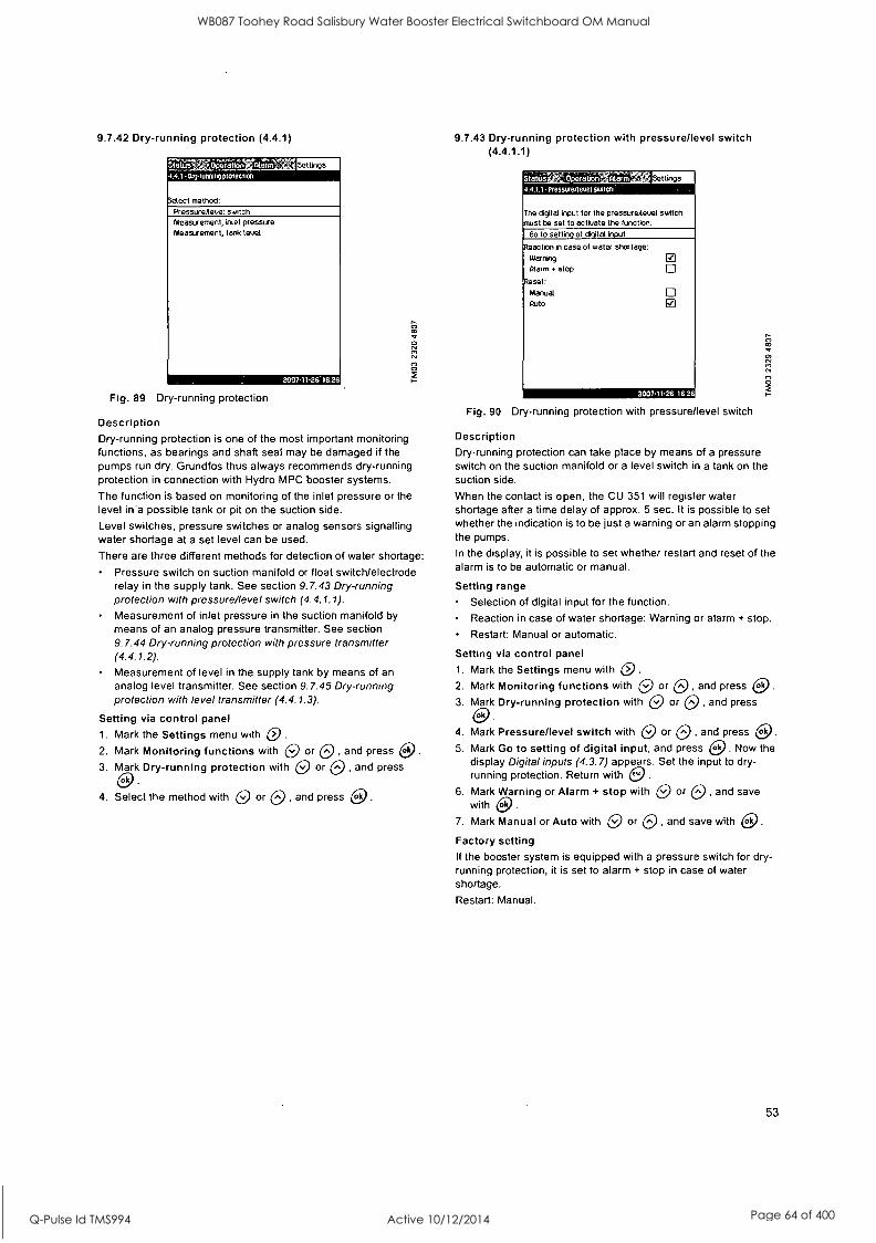
9.7.42 Dry-running protection (4.4.1)
talus [lactation Iiia .4.101y-running protection
Select method:
PressureAevel switch Measurement, inlet pressure Measurement, tank level
Fig. 89 Dry-running protection
Description Dry-running protection is one of the most important monitoring functions, as bearings and shaft seal may be damaged if the pumps run dry. Grundfos thus always recommends dry-running protection in connection with Hydro MPC booster systems.
The function is based on monitoring of the inlet pressure or the level in 'a possible tank or pit on the suction side.
Level switches, pressure switches or analog sensors signalling water shortage at a set level can be used.
There are three different methods for detection of water shortage:
Pressure switch on suction manifold or float switch/electrode relay in the supply tank. See section 9.7.43 Dry-running protection with pressure/level switch (4.4.1.1).
Measurement of inlet pressure in the suction manifold by means of an analog pressure transmitter. See section 9.7.44 Dry-running protection with pressure transmitter (4.4.1.2).
Measurement of level in the supply tank by means of an analog level transmitter. See section 9.7.45 Dry-running protection with level transmitter (4.4.1.3).
Setting via control panel 1. Mark the Settings menu with GI .
2. Mark Monitoring functions with 0 or 0 , and press e. 3. Mark Dry-running protection with 0 or 0 , and press
ok
4. Select the method with 0 or 0 , and press e.
9.7.43 Dry-running protection with pressure/level switch (4.4.1.1)
taros Operation tdarm 4.1.1- Piiisure/level wilco
The digital input for the pressureAevel switch must be set to activate the function:
Go to setting of digital input
Reaction in case of water shortage:
Warning
Alarm + stop
Reset:
Manual Auto a
iiilMENEEMEEM Fig. 90 Dry-running protection with pressure/level switch
Description Dry-running protection can take place by means of a pressure switch on the suction manifold or a level switch in a tank on the suction side.
When the contact is open, the CU 351 will register water shortage after a time delay of approx. 5 sec. It is possible to set whether the indication is to be just a warning or an alarm stopping the pumps.
In the display, it is possible to set whether restart and reset of the alarm is to be automatic or manual.
Setting range Selection of digital input for the function.
Reaction in case of water shortage: Warning or alarm + stop.
Restart: Manual or automatic.
Setting via control panel
1. Mark the Settings menu with i0 .
2. Mark Monitoring functions with 0 or CI , and press e. 3. Mark Dry-running protection with 0 or 0 , and press
4. Mark Pressure/level switch with Q or Q , and press O. 5. Mark Go to setting of digital input, and press e. Now the
display Digital inputs (4.3.7) appears. Set the input to dry- running protection. Return with e .
6. Mark Warning or Alarm + stop with 0 or 0 , and save with 0.
7. Mark Manual or Auto with 0 or 0 , and save with ok .
Factory setting If the booster system is equipped with a pressure switch for dry- running protection, it is set to alarm + stop in case of water shortage.
Restart: Manual.
53
WB087 Toohey Road Salisbury Water Booster Electrical Switchboard OM Manual
Q-Pulse Id TMS994 Active 10/12/2014 Page 64 of 400

9.7.44 Dry-running protection with pressure transmitter (4.4.1.2)
Settings 4.4.1.2 Measurement, inlet pressure
g-running protection: 12115111110 Activated
The analog input for the measurement of inlet essure trust be set to activate the function: Go to setting of analog' nput
let pressure level: warning
Warm stop
arm reset: Manual Auto
-Thar
Obar
2007.1126 16 26
Fig. 91 Dry-running protection with pressure transmitter
Description Dry-running protection can take place by means of a pressure transmitter measuring the inlet pressure.
It is possible to set two levels of inlet pressure: Warning and alarm + stop.
In the display, it is possible to set whether restart and reset of the alarm is to be automatic or manual.
Setting range Selection of analog input for the function.
Activation of the function.
Inlet pressure level for warning.
Inlet pressure level for alarm + stop.
Restart: Manual or automatic.
Setting via control panel
1. Mark the Settings menu with 0 2. Mark Monitoring functions with O or O , and press e .
3. Mark Dry-running protection with 0 or 0 , and press
4. Mark Measurement, inlet pressure with 0 or 0 , and press e.
5. Mark Go to setting of analog input, and press e. Now the display Analog inputs (4.3.8 appears. Set the input to Inlet pressure, and save with ok . Return with e.
6. Mark Activated with 0 or , and press e. 7. Mark Warning with 0 or 0 Set the level with 0 or 0,
and save with ok .
8. Mark Alarm + stop with CI or 0 . Set the level with 0- or
0, and save with e .
9. Mark Manual or Auto with 0 or 0 , and save with e If one of the levels is not required, the level value must be the minimum value of the inlet pressure transmitter. This deactivates the function.
Note
Factory setting If the booster system is supplied with a pressure transmitter on the suction side, the transmitter has been set.
The warning level is 0.5 bar and the alarm level 0.2 bar. The function is activated.
Restart: Manual.
54
9.7.45 Dry-running protection with level transmitter (4.4.1.3)
il'Otfii/111111111 4.4.13 - MeaSurement, sang level
Settings
Activated 0 he analog input for the measurement of tank evel must be set to activate the function: Go to setting of analog input
ante level: Warning
Alarm stop
arm reset: Manual
Auto
-100.0m -100.0m
200711.26 1626
Fig. 92 Dry-running protection with level transmitter
Description Dry-running protection can take place by means of a level transmitter measuring the level in a tank on the suction side.
It is possible to set two levels: Warning and alarm + stop.
In the display, it is possible to set whether restart and reset of alarms is to be automatic or manual.
Setting range Selection of analog input for the function.
Activation of the function.
Tank level for warning.
Tank level for alarm + stop.
Restart: Manual or automatic.
Setting via control panel 1. Mark the Settings menu with 0 .
2. Mark Monitoring functions with 0 or 0 , and press e. 3. Mark Dry-running protection with 0 or 0 , and press
ok
4. Mark Measurement, tank level with 0 or 0 , and press
0 5. Mark Go to setting of analog input, and press e. Now the
display Analog inputs (4.3.8) appears. Set the input to Tank level, suction side. Return with e.
6. Mark Activated with 0 or 0 , and press e. 7. Mark Warning with e or 0 . Set the level with 0 or 0 ,
and save with e. 8. Mark Alarm + stop with 0 or 0 Set the level with 0 or
, and save with e. 9. Mark Manual or Auto with 0 or 0 , and save with e. Factory setting The function is deactivated.
WB087 Toohey Road Salisbury Water Booster Electrical Switchboard OM Manual
Q-Pulse Id TMS994 Active 10/12/2014 Page 65 of 400

9.7.46 Min. pressure (4.4.2)
sigus Oweiti/.7 4.42- maipressure
Settings
- toning of min. pressure:
Activated 0 discharge pressure sensor must be sal fore the function can be activated:
Go to setting of analog input
. pressure
arm + stop at min. pressure
ore delay of function at start-up Time delay of function during
eration
0.0 bar
0 305
105
2007-11-26' 16 26
Fig. 93 Min. pressure
Description The discharge pressure can be monitored so that the CU 351 can react if the pressure becomes lower than a set minimum level for an adjustable time.
The minimum pressure can be monitored if a fault indication is
required in situations where the discharge pressure becomes lower than the set minimum pressure. It is possible to set whether the indication is to be just a warning or an alarm stopping the pumps. This may be desirable if Hydro MPC is used for an irrigation system where a very low discharge pressure may be due to pipe fracture and thus an extraordinarily high consumption and a very low counter- pressure. In such situations, it is desirable that the booster system stops and indicates alarm. This situation will require a
manual reset of alarms.
It is possible to set a start-up delay ensuring that the Hydro MPC can build up pressure before the function is activated. It is also possible to set a time delay, i.e. for how long time the discharge pressure may be lower than the set minimum pressure before the alarm is activated.
Setting range Activation of the function.
Minimum pressure level within the range of the primary sensor.
Activation of stop when the pressure falls below the minimum pressure.
Time delay at start-up.
Time delay during operation.
Setting via control panel
1. Mark the Settings menu with 0 .
2. Mark Monitoring functions with C.) or 0 , and press a. 3. Mark Min. pressure with 0 or 0 , and press a. 4. Mark Activated with 0 or 0 , and press to to activate/
deactivate the function.
5. Mark Min. pressure with L9 or 0 . Set the pressure with 0 or 0, and save with 0. 6. Mark Stop at min. pressure with 0 or 0 , and press a
to activate/deactivate the function.
7. Mark Time delay of function at start-up with 0 or 0 . Set the time with 0 or 0, and save with 0.
8. Mark Time delay of function during operation with 0 or . Set the time with 0 or 0, and save with ok
.
Factory setting The function is deactivated.
9.7.47 Max. pressure (4.4.3)
Sfatuat4 OperationAlarm, 4.4,3 maxpressure
'41 settngs
1:2121MITN1IIIIN Activated
discharge pressure sensor must be set fore the function can be activated:
Go to setting of analog input
-x. pressure 16.0 bar
'eset: Manual
Auto
2007-11-26 1626
Fig. 94 Max. pressure
Description The discharge pressure can be monitored so that the CU 351 can react if the pressure becomes higher than a set maximum level.
In certain installations, a too high discharge pressure may cause damage. It may therefore be necessary to stop all pumps for a
short period if the pressure is too high.
It is possible to set whether the Hydro MPC is to restart automatically after the pressure has dropped below the maximum level, or if the system must be reset manually. Restart will be delayed by an adjustable time. See section 9.7.12 Min. time between start/stop (4.2.1).
Setting range Activation of the function.
Maximum pressure level within the range of the primary sensor.
Manual or automatic restart after fault.
Setting via control panel 1. Mark the Settings menu with 0 .
2. Mark Monitoring functions with 0 or 0 , and press ek .
3. Mark Max. pressure with O or 0 , and press a. 4. Mark Activated with 0 or 0 , and press a to activate/
deactivate the function.
5. Mark Max. pressure with 0 or 0 . Set the pressure with 0 or , and save with a. 6. Mark Manual or Auto with 0 or 0 . Activate the function
with co.
Factory setting The function is deactivated.
55
WB087 Toohey Road Salisbury Water Booster Electrical Switchboard OM Manual
Q-Pulse Id TMS994 Active 10/12/2014 Page 66 of 400

9.7.48 External fault (4.4.4)
44. External taint Settings
The digital input for the external fault signal must be set to activate the function:
Go to setting of digital input
Time delay, fault indication
Reaction in case of fault: Warning
55
E l
Alarm and change of operation mode to:
Stop Min.
Max.
User-defined
Reset: Manual
Auto
Fig. 95 External fault
Ij
Description The function is used when the CU 351 is to be able to receive a
fault signal from an external contact. In case of external fault, the CU 351 indicates warning or alarm. In case of alarm, the booster system changes to another manual operating mode, for instance Stop.
Setting range Selection of digital input for the function.
Setting of time delay from closing of the contact until the CU 351 reacts.
Reaction in case of external fault: Warning or alarm and change of operating mode.
Restart after alarm: Manual or automatic.
Setting via control panel 1. Mark the Settings menu with 0. 2. Mark Monitoring functions with 0 or 0 , and press co 3. Mark External fault with 0 or 0 , and press e .
4. Mark Go to setting of digital input with 0 or 0 , and press 0. Now the display Digital inputs (4.3.7) appears. Set the input to External fault. Return with .
5. Mark Time delay, fault indication with 0 or 0 . Set the time with 0 or 0, and save with co.
6. Mark Warning with 0 or 0 if only a warning is required in
case of external fault. Activate the function with 0. 7. Select operating mode with 0 or 0 if the booster system
is to give alarm and change operating mode in case of external fault. Activate the function with ok
.
8. Mark Manual or Auto with 0 or 0 . Activate the function with e.
Factory setting The function is deactivated. If the function is activated, the following values have been set from factory:
Time delay: 5 seconds.
Operating mode in case of alarm: Stop.
Restart: Manual.
56
9.7.49 Limit 1 and 2 exceeded (4.4.5 and 4.4.6)
as - Lad fexceenen Settings
itoring of limit:
Activated
The analog input for the control parameter st be set to activate the function:
Go to setting of analog input
t value to be monitored
Limit type: Min. limit
Max. limit
Set delays Set warning limit
Set alarm limit
(Not used)
0
'2007-11-26'1626
Fig. 96 Limit 1 exceeded
Description With this function, the CU 351 can monitor set limits of analog values. It will react if the values exceed the limits. Each limit can be set as a maximum or minimum value. For each of the monitored values, a warning limit and an alarm limit must be defined.
The function makes it possible to monitor two different locations in a pump system at the same time. For instance the pressure at a consumer and the pump discharge pressure. This ensures that the discharge pressure does not reach a critical value.
If the value exceeds the warning limit, a warning is given. If the value exceeds the alarm limit, the pumps are stopped.
A delay can be set between the detection of an exceeded limit and the activation of a warning or an alarm. A delay can also be set for resetting a warning or an alarm.
A warning can be reset automatically or manually.
It is possible to set whether the system is to restart automatically after an alarm, or if the alarm must be reset manually. Restart can be delayed by an adjustable time. It is also possible to set a start- up delay ensuring that the system reaches a steady state before the function becomes active.
Setting range Activation of an analog input for the function.
Selection of the measured value to be monitored.
Setting of limit type (min./max.).
Setting of warning limit.
Setting of alarm limit.
Setting via control panel
Note Analog inputs must be correctly set before the function is activated. See section 9.7.28 Analog inputs (4.3.8).
1. Mark the Settings menu with 0 2. Mark Monitoring functions with e or 0 , and press 04 3. Mark Limit 1 exceeded or Limit 2 exceeded with 0, or 0 ,
and press e. 4. Mark Go to setting of analog input with O or 0 , and
press 0 .
5. Select the analog input with 0 or 0 , and press e. 6. Mark the setting of the analog input with 0 or 0 , and
activate it with 0 .
The activation is indicated by a check mark in the box.
WB087 Toohey Road Salisbury Water Booster Electrical Switchboard OM Manual
Q-Pulse Id TMS994 Active 10/12/2014 Page 67 of 400

7. Mark Measured value with 0 or 0 , and press ok . Now the display 4.3.8.1.1 appears.
8. Select the input with C) or 0 , and press ok
9. Press 0 to return to display 4.3.8.1.
10.Set the minimum sensor value with 0 or 0 , and save with ok
11.Set the maximum sensor value with 0 or 0, and save with ok
12.Return by pressing e twice.
13.Mark Measured value to be monitored with CI or 0 ., and press 0.. Select the input with 0 or 0 , and press 6
14.Return with e. 15.Mark Min. limit or Max. limit with 0 or O., and press
ok
16.Mark Set delays with 0 or 0 , and press e 17.Mark Time delay of function at start-up with 0 or 0 . Set
the time with 0 or Q, and save with ok .
18.Mark Time delay of function during operation with 0 or 0 . Set the time with 0 or 0, and save with e. 19.Mark Time delay of function at reset with 0 or 0 . Set
the time with 0 or Q, and save with e. 20.Return with .
21.Mark Set warning limit with 0 or 0 , and press e. 22.Mark Activated with 0 or 0 , and press ok
.
23.Mark Warning limit with 0 or 0 . Set the value with 0 or 0, and save with ok .
24.Mark Manual or Auto with 0 or 0 . Activate the function with ok .
25.Return with
26.Mark Set alarm limit with 0 or O , and press 0. 27.Mark Activated with 0 or CI , and press e. 28.Mark Alarm limit with 0 or 0 . Set the value with 0 or
, and save with O. 29.Mark Manual or Auto with e or 0 . Activate the function
with c9 30.Return with e. 31.Mark Activated with 0 or 0 , and press e to activate
the function.
Factory setting The function is deactivated.
9.7.50 Pumps outside duty range (4.4.7)
Status ".OpeiafionAla'na 4.4.7 Pumps outsiceauty lenge
Settings
'toning, pumps outside duty range:
2007-11-26,1626
Fig. 97 Pumps outside duty range
Description The function gives a warning if the duty point of the pumps moves outside the defined range. For instance, if the inlet pressure becomes lower than a minimum permissible value, thus causing a
risk of cavitation for some pump types.
The warning is given with a set time delay. It is possible to set whether the warning is to be reset automatically or manually when the duty point comes within the defined duty range. It is
also possible to set a relay output to be activated when the warning is given, and to be deactivated when the warning is reset.
This function requires that the discharge pressure and the inlet pressure (either measured or configured) or the differential pressure of the pumps is monitored, and that CU 351 contains valid pump data from either a GSC file or from manual input. See section 9.7.37 Pump curve data (4.3.19).
Setting range Activation of the function.
Setting of manual or automatic reset.
Setting of warning delay.
Setting via control panel 1. Mark the Settings menu with 0 2. Mark Monitoring functions with 0 or 0 , and press e. 3. Mark Pumps outside duty range with 0 or 0 , and press
ok
4. Mark Manual or Auto with 0 or 0 , and activate the function with e.
5. Mark Warning delay with 0 or 0 . Set the time with 0 or 0, and save with ok .
6. Mark Activated with 0 or 0 , and press 0 to activate the function.
Factory setting The function is deactivated.
9.7.51 Pressure relief (4.4.8)
Operation 'Mann 4.8 Pressure relief
Monitoring of pressure:
Settings
Deactivated P1 Activated
A digital output must be set to control the valve: So to setting of digital output
Pressure to be monitored (System pressure)
Set the Limits:
Valve opening pressure Band, valve opening pressure
Warning:
Deactivated Activated Delay
Fig. 98 Pressure relief
Ober
Obar
is 2007-11-26 162-
57
WB087 Toohey Road Salisbury Water Booster Electrical Switchboard OM Manual
Q-Pulse Id TMS994 Active 10/12/2014 Page 68 of 400

Description The purpose of the function is to reduce the pressure in the pipework by opening a solenoid valve if it exceeds a set limit. If the pressure is not reduced within a given time, the solenoid valve will be closed, and a warning can be given.
P [psi]
Valve opening pressure
1: Solenoid valve opens.
2: Solenoid valve closes. 3: Solenoid valve opens. 4: Warning is activated.
5: Solenoid valve closes, and warning is reset.
2 3 4 5
Band t.
Valve opening pressure minus band
Fig. 99 Pressure relief
Warning delay
Setting range
Setting of digital output.
Setting of pressure to be monitored.
Setting of valve opening pressure.
Setting of band for valve opening pressure.
Setting of warning or alarm.
Activation of the function.
Time [sec]
Setting via control panel
1. Mark the Settings menu with 0 2. Mark Monitoring functions with 0 or 0 , and press ok .
3. Mark Pressure relief with 0 or 0 , and press e. 4. Mark Go to setting of digital output with 0 or 0 , and
press ok .
5. Select a digital output with 0 or 0 , and press e. 6. Mark Pressure relief with 0 or O , and save with ok .
7. Return by pressing twice.
8. Mark Pressure to be monitored with 0 or 0 , and press
9. Mark Discharge pressure, System pressure or External pressure with 0 or 0 , and save with e.
10.Return with (3. 11.Mark Valve opening pressure with 0 or . Set the
pressure with 0 or 0, and save with
12.Mark Band, valve opening pressure with pressure with 0 or 0, and save with
13.Mark Warnin , Deactivated or Activated with 0 or O ,
and press (29. 14.Mark Delay with e or 0 . Set the time with 0 or 0,
and save with 0 . (Only to be set if warning has been activated.)
15.Mark Activated with e or 0 , and press e activate the function.
. Set the
Factory setting The function is deactivated.
58
9.7.52 Functions, CU 351 (4.5)
019 W; Operatbn''sOlarm 4.5 Functions, CU 351
Settings
The display language can be changed to the service la .e English
Change language to the service I- age (English) 0
The start-up wizard can be re-activated if eeded Run wizard again
ther settings related to CU 351:
Display language
Units bate and time
Password Ethernet MMus number
Software status
21307.11-26 16-26
Fig. 100 Functions, CU 351
Description In this submenu, it is possible to make the basic settings of the CU 351.
CU 351 comes with most of these settings, or they are made at start-up and normally not to be changed.
The service language, English, can be activated for service purposes. If no buttons are touched for 15 minutes, the display will return to the language selected at start-up or to the language set in section 9.7.53 Display language (4.5.1).
If the service language is selected, the symbol will be shown to the right of the top line of all displays.
Setting range
Activation of service language, British English.
Note
Re-activation of start-up wizard. (After start-up, the wizard is inactive.)
Selection of display language.
Selection of display units.
Setting date and time.
Selection of password for the menus Operation and Settings. Setting of Ethernet communication.
Setting of GENIbus number.
Reading of software status.
9.7.53 Display language (4.5.1)
01.14:ition.
4.5.1 - Display language
elect language: British English
German
Danish
Spanish
Finnish
French
Greek
Italian
Dutch Polish
Portuguese Russian Swedish Chinese
Korean
Settings
0 0 0 0 0 0
apane
Fig. 101 Display language
WB087 Toohey Road Salisbury Water Booster Electrical Switchboard OM Manual
Q-Pulse Id TMS994 Active 10/12/2014 Page 69 of 400

Description Here the language for the CU 351 display is selected.
Setting range British English
German Danish
Spanish
Finnish
French
Greek
Italian
Dutch
Polish
Portuguese
Russian
Swedish
Chinese
Korean
Japanese
Czech
Turkish.
Setting via control panel
1. Mark the Settings menu with 0 .
2. Mark Functions, CU 351 with O or O , and press e. 3. Mark Display language with 0 or O , and press co. 4. Select language with 0 or 0 , and save with ok .
Factory setting The display language is English. It can be changed at start-up.
9.7.54 Display units (4.5.2)
Opwatioa .5 2- Display units
Select unit standard:
Settings
SI units El US units
Units can be selected for specific parameters: Pressure Differential pressure Head
Level Flow rate Uolume
Specific energy
Temperature Power
Energy
200711.26 162
Fig. 102 Display units
Description In this display, it is possible to select units for the various parameters.
As basic setting, it is possible to select between SI and US units.
It is also possible to select other units for the individual parameters.
Setting range
Parameter Basic setting
Possible units SI US
Pressure bar psi kPa, MPa, mbar, bar, m, psi
Differential pressure kPa, MPa, mbar,
m psi bar, m, psi
Head m ft m, cm, ft, in
Level m ft m, cm, ft, in
Flow rate m3 /h m3/s, m3/h, I/s, gpm,
gpm yd
3/s, yd
3/min, yd
3/h
Volume m3 gal I, m3, gal, yd3
Specific energy kWh/m3, Wh/gal,
kWh/m3 Wh/gal Wh/kgal, BTU/gal, HPh/gal
Temperature °C °F K, °C, °F
Differential temperature K K K
Power kW HP W, kW, MW, HP
Energy kWh, MWh, BTU,
kWh kWh HPh
Note If units are changed from SI to US or vice versa, all individually set parameters will be changed to the basic setting in question.
Setting via control panel
1. Mark the Settings menu with 0 .
2. Mark Functions, CU 351 with Q or 0 , and press 0 3. Mark Units with 0 or 0 , and press ok .
4. Select the unit with 0 or 0 , and save with e . A check mark shows that the unit has been selected.
5. Select the measuring parameter with NO or es , and press ok to open the display for the measuring parameter.
See the example.
Tatr; Opertbn Mara .5 2.1- Usit/ 101 pressate
Units, pressure:
Settings
kPa n MPa
mbar
bar
PSI 0
MOIMEN=M:== Fig. 103 Example of selection of display units
6. Select the unit with 0 or 0 , and save with 0. A check mark shows that the unit has been selected.
Factory setting CU 351 has been set to US units from factory.
59
WB087 Toohey Road Salisbury Water Booster Electrical Switchboard OM Manual
Q-Pulse Id TMS994 Active 10/12/2014 Page 70 of 400

9.7.55 Date and time (4.5.3)
ifatits 41.1ationrithito 45.3 -Date and time
Settings
et date: ..M1111111/1 Month 11
Year 2007
,et tine: Hours 16
Minutes 26
elect date-time format: 2005-09-27 13:49 27-09-2005 13:49 927/2005 1:49pm
First day of week: Sunday Monday
lI
IZI
2007.11-26 16 26
Fig. 104 Date and time
Description In this display, date and time are set as well as how they are to be shown in the display.
The clock has a built-in rechargeable voltage supply which can supply the clock for up to 20 days if the voltage supply to the Hydro MPC is interrupted.
If the clock is without voltage for more than 20 days, it must be set again.
Setting range The date can be set as day, month and year. The time can be set as a 24-hour clock showing hours and minutes.
There are three formats.
Examples of format
2005-09-27 13:49
27-09-2005 13:49
9/27/2005 1:49pm
It is also possible to select if Sunday or Monday is to be the first day of week.
Setting via control panel 1. Mark the Settings menu with 0 .
2. Mark Functions, CU 351 with 10 or 0 , and press 0 3. Mark Date and time with or O , and press e 4. Mark Day, Month and Year with 0 or O , and set the date
with 0 or 0. Save with co. 5. Mark Hours and Minutes with Q or 0 , and set the time
with 0 or 0. Save with e. 6. Select the format with 0 or 0 , and save with ok .
7. Mark First day of week, Sunday or Monday with 0 or 0 ,
and save with ok
Factory setting Local time.
Note
60
If the booster has been without voltage for more than 20 days since it left the factory, the clock may have returned to the original setting: 01 -01- 2005 0:00.
Date and time may have been changed during the setting of Hydro MPC.
There is no automatic changeover to/from daylight-saving time.
9.7.56 Passwords (4.5.4)
iitat7).r.lgKerttwir'Aii(etia 4.6.4 PiiiSwOra
Settings
Password, Operation menu: 171=111111111INNEINI
Activated Enter password
Password, Settings menu: Deactivated Activated Enter password 1 2 3 4
1 2 3 4
200791-28 .1626
Fig. 105 Passwords
Description In this display it is possible to limit the access to the Operation and Settings menus by means of a password. If the access is limited, it is not possible to view or set any parameters in the menus.
The password must consist of four digits and may be used for both menus.
Note If you have forgotten the password(s), contact Grundfos.
Setting via control panel 1. Mark the Settings menu with 0 .
2. Mark Functions, CU 351 with 0 or 0 , and press
3. Mark Password with 0 or 0 , and press e. 4. Mark the password to be activated, and press e. 5. Mark Enter password, and press c).
Now the first digit of the password is flashing. 6. Select the digit with 0 or 9 , and save with ok .
Now the second digit of the password is flashing.
7. Repeat points 4 to 6 if it is necessary to activate the other password.
Factory setting Both passwords are deactivated. If a password is activated, the factory setting will be "6814".
9.7.57 Ethernet (4.5.5)
ok
Stet' eperatior-:41:31m1 '31a Settings
IP address 192 168 0 102
Subnet mask 255 255 255 0
Standard gateway 192 168 0 2
AC address 50 60 70 80 90
Reset the Ethernet password by pressing (ok)
20071 E.26 1626
Fig. 106 Ethernet
WB087 Toohey Road Salisbury Water Booster Electrical Switchboard OM Manual
Q-Pulse Id TMS994 Active 10/12/2014 Page 71 of 400
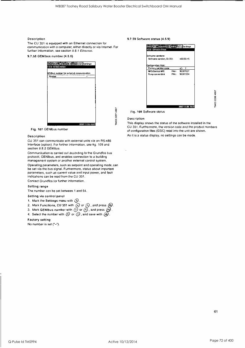
Description The CU 351 is equipped with an Ethernet connection for communication with a computer, either directly or via Internet. For further information, see section 9.8.1 Ethernet.
9.7.58 GENIbus number (4.5.6)
*taws, 2i,'OrxriMiiCarm
0EN1bus number for external communication
Number
IMOMMON Fig. 107 GENIbus number
Description CU 351 can communicate with external units via an RS-485 interface (option). For further information, see fig. 109 and section 9.8.2 GENIbus.
Communication is carried out according to the Grundfos bus protocol, GENIbus, and enables connection to a building management system or another external control system.
Operating parameters, such as setpoint and operating mode, can be set via the bus signal. Furthermore, status about important parameters, such as current value and input power, and fault indications can be read from the CU 351.
Contact Grundfos for further information.
Setting range The number can be set between 1 and 64.
Setting via control panel 1. Mark the Settings menu with 0. 2. Mark Functions, CU 351 with 0 or es , and press GI 3. Mark GENIbus number with O or O , and press e. 4. Select the number with 0 or 0 , and save with efc
Factory setting No number is set ("-").
9.7.59 Software status (4.5.9)
stews WeVorir aaim 4.s2-sottillare status
Settings
,ftware versions Software version, CU 351: v00.00.45
figuration files: Factor version code 43 7
fi4PCkontrol MPC
Pump curve data PIN. 95307027 PAN. 96307224
2007-11,2616:27
Fig. 108 Software status
Description This display shows the status of the software installed in the CU 351. Furthermore, the version code and the product numbers of configuration files (GSC) read into the unit are shown.
As it is a status display, no settings can be made.
61
WB087 Toohey Road Salisbury Water Booster Electrical Switchboard OM Manual
Q-Pulse Id TMS994 Active 10/12/2014 Page 72 of 400

9.8 Data communication CU 351 is equipped with a hardware enabling communication with external units, such as a computer, via an external GENIbus or Ethernet connection.
Third party gateway
Grundfos G100 gateway
External GENIbus connection External I GENIbus module I (factory option)
Ethernet connection
Fig. 109 Data communication via external GENIbus and Ethernet connection
9.8.1 Ethernet
Ethernet is the most widely used standard for local networks (LAN). The standardisation of this technology has created some of the easiest and cheapest ways of creating communication between electrical units, for instance between computers or between computers and control units.
The web server of the CU 351 makes it possible to connect a
computer to the CU 351 via an Ethernet connection. The user interface can thus be exported from the CU 351 to a computer so that the CU 351 and consequently the Hydro MPC booster system can be monitored and controlled externally.
Grundfos recommends that you protect the connection to the CU 351 according to your safety requirements in consultation with the system administrator.
In order to use the web server, you must know the IP address of the CU 351. All network units must have a unique IP address in
order to communicate with each other. The IP address of the CU 351 from factory is 192.168.0.102.
Alternatively to the factory-set IP address, it is possible to use a
dynamic assignment of IP address. This is possible by activating a DHCP (Dynamic Host Configuration Protocol) either directly in
the CU 351 or via the web server. See the example in fig. 110.
Note
62
Internet
-ijralERreriori' 4.5.5 Einetne4;
Host name
Use OHCP
IP address sublet mask
Standard gateway
RAPC address
192 168 0 102
255 255 255 0
192 168 0 2
50 60 70 80 90 OR
Reset the Ethernet password by pressing (ok)
1=31:1EIM Fig. 110 Example of setting of Ethernet
Dynamic assignment of an IP address for the CU 351 requires a
DHCP server in the network. The DHCP server assigns a number of IP addresses to the electrical units and makes sure that two units do not receive the same IP address.
A traditional Internet browser is used for connection to the web server of the CU 351.
If you want to use the factory-set IP address, no changes are required in the display. Open the Internet browser and enter the IP address of the CU 351.
WB087 Toohey Road Salisbury Water Booster Electrical Switchboard OM Manual
Q-Pulse Id TMS994 Active 10/12/2014 Page 73 of 400

In order to use dynamic assignment, the function must be activated. Click e Use DHCP in the menu line. A check mark next to the menu line shows that activation has been made. After activation in the display, open the Internet and enter the host name of the CU 351 instead of the IP address. The Internet browser will now try to connect to the CU 351. The host name can be read in the display, but can only be changed by either a GSC- file (configuration file) or via a web server. See Change of network setting on page 63.
Note To use DHCP, a host name is required.
This is the first display shown when connecting to the CU 351.
Fig. 111 Connection to CU 351
Factory setting User name:admin Password: admin
When user name and password have been entered, a Java Runtime Environment application starts up in the CU 351, provided that it has been installed on the computer in question. If this is not the case, but the computer is connected to Internet, then use the link on the screen to download and install the Java Runtime Environment application.
Fig. 112 Display with link to the Java Script® program
The Java Runtime Environment application will then export the CU 351 user interface (including display and operating panel) to the computer screen. It is now possible to monitor and control the CU 351 from the computer.
Fig. 113 Network setting
Change of network setting When connection to the web server of the CU 351 has been established, it is possible to change the network setting.
Fig. 114 Change of network setting
1. Press the icon >Network admin. 2. Enter the changes.
3. Press Submit to activate the changes.
63
WB087 Toohey Road Salisbury Water Booster Electrical Switchboard OM Manual
Q-Pulse Id TMS994 Active 10/12/2014 Page 74 of 400

Change of password
Fig. 115 Change of password
1. Press the icon >Change password. 2. Enter the new password.
3. Press Submit to activate the new password.
9.8.2 GENIbus
By installing a GENIbus module it is possible to connect a CU 351 to an external network. The connection can take place via a
GENIbus-based network or a network based on another protocol via a gateway. See fig. 109. For further information, contact Grundfos.
The gateway may be a Grundfos G100 gateway or a third party gateway. For further information on the G100 gateway, see the G100 data booklet (publication number V7139522).
64
WB087 Toohey Road Salisbury Water Booster Electrical Switchboard OM Manual
Q-Pulse Id TMS994 Active 10/12/2014 Page 75 of 400

10. External variable frequency drive External variable frequency drives used in Hydro MPC booster system variants -F, -EF and -EDF come with the manufacturer's factory settings. See tables below.
At start-up, the factory settings must be changed to the Grundfos settings in the tables below.
In order not to affect the functions of the CU 351 at optimum operation, only the parameters shown should be adjusted. Other parameters should be as set from factory.
10.1 VLT 2800
Press [QUICK MENU] + [+] to access all parameters.
Parameter
Factory setting Grundfos setting
Function Value or number in the display of VLT Function Value or number
in the display of VLT
2 Local/remote operation Local/remote operation 0
3 Local reference Local reference Default
101 Torque characteristics Torque characteristics 2
102 Motor power Motor power Motor nameplate in kW
103 Motor voltage Motor voltage Motor nameplate
104 Motor frequency Motor frequency Motor nameplate, Hz
105 Motor current Motor current Motor nameplate, SFA
106 Rated motor speed Rated motor speed Motor nameplate RPM
107 Automatic motor adaptation Automatic motor adaptation 2
128 Thermal motor protection Thermal motor protection 4
204 Minimum reference Minimum reference 20 Hz
205 Maximum reference Maximum reference 60 Hz
206 Ramp type Ramp type 2
207 Ramp up time Ramp up time 1.5 sec
208 Ramp down time Ramp down time 3 sec
214 Reference function Reference function 2
215 Preset reference Preset reference 100
302 Digital input Digital input 7
304 Digital input Digital input 0
305 Digital input6 Digital input6 24
323 Relay output Relay output 1
406 Automatic restart time Automatic restart time 10 sec
411 Switching frequency Switching frequency 4500
* Thermistor function used for thermal protection of LC filter.
** For information about languages available, see relevant docu- mentation. - Use data from the Hydro MPC booster set.
Factory setting of VLT 2800
To recall the factory settings of all parameters, follow one of the procedures below:
1. Set the parameter 620 to (3).
2. Disconnect the power supply.
3. Re-connect the power supply.
4. All parameters are now factory-set except from the fault log.
Or
1. Disconnect the power supply.
2. Press and hold [QUICK MENU] + [+] + [CHANGE DATA] and re-connect the power supply.
All parameters are now factory-set, including the fault log.
65
WB087 Toohey Road Salisbury Water Booster Electrical Switchboard OM Manual
Q-Pulse Id TMS994 Active 10/12/2014 Page 76 of 400

10.2 Danfoss VLT 8000 factory settings Press [EXTEND MENU] to access all parameters.
Parameter Function Grundfos setting
Value
001 Language English 0
002 Motor power Motor nameplate
003 Motor voltage Motor nameplate
004 Motor frequency Motor nameplate
005 Motor current Motor nameplate (SFA)
006 Motor speed Motor nameplate (RPM)
201 Minimum frequency 20 Hz
202 Maximum frequency 60 Hz
207 Ramp up time 1.5 sec
208 Ramp down time 3 sec
323 Relay 1 function Ready signal 1
326 Relay 2 function Running 3
10.3 Danfoss VLT 8000 extended menu programming
Parameter Function Grundfos setting
Value
007 Large readout Frequency [Hz] 3
008 Small display readout Motor voltage [V] 16
009 Small display readout Motor current 5
010 Small display readout Power [Hp] 6
101 Torque characteristics VT low 2
113 Motor Preheater DC Current 0%
117 Motor Thermal Protection ETR Trip 1 4
208 Automatic ramp-down Disable 0
210 Reference type External/preset 2
302 Pin 18 Start 1
303 Pin 19 Reverse and start 2
304 Pin 27 Safety interlock 3
308 Pin 53 Reference 1
309 Term. 53, min. scaling 0.0 V
310 Term. 53, max. scaling 10 V
325 Relay 01, off delay 1 sec.
400 Reset function Automatic reset x 10 6
401 Automatic restart time 5 sec.
407 Switching frequency 4500
408 Interference reduction method Fixed switching freq. 0
016 Lock for data change Locked 1
66
WB087 Toohey Road Salisbury Water Booster Electrical Switchboard OM Manual
Q-Pulse Id TMS994 Active 10/12/2014 Page 77 of 400

10.4 Danfoss VLT 8000 factory settings Press [EXTEND MENU] to access all parameters.
Parameter Function Grundfos setting
Value
001 Language English 0
002 Motor power Motor nameplate
003 Motor voltage Motor nameplate
004 Motor frequency Motor nameplate
005 Motor current Motor nameplate (SFA)
006 Motor speed Motor nameplate (RPM)
201 Minimum frequency 20 Hz
202 Maximum frequency 60 Hz
207 Ramp up time 1.5 sec
208 Ramp down time 3 sec
323 Relay 1 function Ready signal 1
326 Relay 2 function Running 3
10.5 Danfoss VLT 8000 extended menu programming
Parameter Function Grundfos setting
Value
007 Large readout Frequency [Hz] 3
008 Small display readout Motor voltage [V] 16
009 Small display readout Motor current 5
010 Small display readout Power [Hp] 6
101 Torque characteristics VT low 2
113 Motor Preheater DC Current 0%
117 Motor Thermal Protection ETR Trip 1 4
208 Automatic ramp-down Disable 0
210 Reference type External/preset 2
302 Pin 18 Start 1
303 Pin 19 Reverse and start 2
304 Pin 27 Safety interlock 3
308 Pin 53 Reference 1
309 Term. 53, min. scaling 0.0 V
310 Term. 53, max. scaling 10 V
325 Relay 01, off delay 1 sec.
400 Reset function Automatic reset x 10 6
401 Automatic restart time 5 sec.
407 Switching frequency 4500
408 Interference reduction method Fixed switching freq. 0
016 Lock for data change Locked 1
67
WB087 Toohey Road Salisbury Water Booster Electrical Switchboard OM Manual
Q-Pulse Id TMS994 Active 10/12/2014 Page 78 of 400

10.6 Baldor Smart motor settings
Section Parameter Grundfos setting
Value
Level 2 blocks
Output limts Min. output frequency 12 Hz
Output limts Max. output 60 Hz
Output limts PK current limit Max. of drive
Output limts PWM frequency 6 kHz
Miscellaneous Restart aut/man Auto
Motor data Motor voltage 230 V
Motor data Motor rated amps SFA on nameplate
Level 1 blocks
Preset speed Preset speed #1 60 Hz
Accel Accel #1 CR 3 - CR 10
CR 15 - CR 90
Decel rate Decel #1 CR 3 - CR 10
CR 15 - CR 90
1.5 sec.
2.0 sec.
3.0 sec.
4.0 sec.
Output Opto output #1 Ready
Input Operating mode #1 2 wire / 7 spd
Input ANA CMD select Pot. / 0-10 V
V/Hz and Boost V/Hz profile 67% sqr. law
68
WB087 Toohey Road Salisbury Water Booster Electrical Switchboard OM Manual
Q-Pulse Id TMS994 Active 10/12/2014 Page 79 of 400

10.7 VLT FC 202
Press [EXTEND MENU] to access all parameters.
Parameter Function Grundfos setting
Value
001 Language English 0
002 Motor Speed Unit Hz 1
003 Regional Settings North America 1
020 Display Line 1.1 Small Power [hp] 1611
021 Display Line 1.2 Small Motor Voltage 1612
022 Display Line 1.3 Small Motor Current 1614
023 Display Line 2 Large Frequency 1615
024 Display Line 3 Large Speed [RMP] 1617
100 Configuration Mode Open Loop 0
103 Torque Characteristics Variable Torque 1
121 Motor Power [HP] Nameplate
122 Motor Voltage Nameplate
123 Motor Frequency Nameplate
124 Motor Current Nameplate
125 Motor Nominal Speed Nameplate
190 Motor Thermal Protection ETR trip 1 4
302 Minimum Reference 0.000 Hz
303 Maximum Reference 60.000 Hz
304 Reference Function Sum 0
310 Preset Reference 100.00%
313 Reference Site Remote 1
341 Ramp 1 Ramp up Time 1.50 s
342 Ramp 1 Ramp down Time 3.00 s
412 Motor Speed Low Limit [Hz] 0.0 Hz
414 Motor Speed High Limit [Hz] 60.0 Hz
419 Max Output Frequency 65.0 Hz
511 Terminal 19 Digital Input Start reversing 11
513 Terminal 29 Digital Input Preset reference on 15
540.0 Function Relay Drive ready 2
542.0 Off Delay, Relay 2.00 s
610 Terminal 53 Low Voltage 0.00 V
611 Terminal 53 High Voltage 10.00 V
614 Terminal 53 Low Ref. / Feedb. 20.000 Hz
615 Terminal 53 High Ref. / Feedb. 60.000 Hz
1400 Switching Pattern 60 AVM 0
1401 Switching Frequency 5.0 kHz 7
Factory setting of VLT FC 100
To recall the factory settings of all parameters, follow one of the
procedures below:
1. Select parameter 14-22.
2. Press [OK].
3. Select "Initialisation" (for NLCP select "2").
4. Press [OK].
5. Disconnect the power supply.
6. Reconnect the power supply.
7. All parameters are now factory-set, except RFI 1, protocol, address, baud rate, minimum response delay, maximum response delay, maximum inter-char delay, operating data, historic log and fault log.
Or
1. Disconnect the power supply.
2. Press and hold [STATUS] + [MAIN MENU] + [OK] and reconnect the power supply.
3. All parameters are now factory-set, except operating hours, the number of power-ups and overtemp's and overvolt's.
69
WB087 Toohey Road Salisbury Water Booster Electrical Switchboard OM Manual
Q-Pulse Id TMS994 Active 10/12/2014 Page 80 of 400

11. Fault finding chart
Warning Before making any connections in pumps, terminal boxes or breaker cabinet, make sure that the electricity supply has been switched off for at least 5 minutes and that it cannot be accidentally switched on.
Fault Possible cause Remedy
Pumps do not run when started.
Current pressure is higher than or equal to Wait until the pressure has dropped, or lower the
the setpoint. pressure on the discharge side of the Hydro MPC, and check that the pumps start.
Electricity supply disconnected. Connect the electricity supply.
Main switch cut out. Cut in the main switch.
Main switch is defective. Replace the main switch.
Motor protection is activated. Contact Grundfos.
Motor is defective. Repair or replace the motor.
Pressure transmitter fault - Pressure transmitter is defective.
Replace the pressure transmitter. Transmitters with 0-20 mA or 4-20 mA output signals are monitored by the Hydro MPC.
- Cable is broken or short-circuited. Repair or replace the cable.
The pumps start, but stop immediately. The operating pressure Dry running or no inlet pressure. is not reached.
Re-establish the supply of water to the Hydro MPC. When the inlet pressure has been re-established, the pumps will restart after 15 seconds.
The Hydro MPC is stopped and cannot restart.
Pressure transmitter fault - Pressure transmitter is defective.
Replace the pressure transmitter. Transmitters with 0-20 mA or 4-20 mA output signals are monitored by the Hydro MPC.
- Cable is broken or short-circuited. Repair or replace the cable.
CU 351 fault - Electricity supply disconnected.
Connect the electricity supply.
- CU 351 defective. Contact Grundfos.
Inlet pressure is too low.
Unstable water delivery from Suction pipe or pumps partly blocked by Hydro MPC (applies to unstable water impurities. supply).
Check the suction pipe and possible suction strainer.
Clean the suction pipes, strainer or pumps.
Pumps suck air. Check the suction pipe for leakages.
Pressure transmitter defective. Replace the transmitter.
The valves are closed. Open the valves.
Suction pipe or pumps blocked by impurities.
Clean the suction pipe or pumps.
Pumps are running, but deliver no Non-return valve blocked in closed position.
Clean the non-return valve. The non-return valve water. must move freely.
Suction pipe leaky. Check the suction pipe for leakages.
Air in suction pipe or pumps. Vent and prime the pumps. Check the suction pipe for leakages.
The Hydro MPC is unable to reach the setpoint.
Too high consumption. - Reduce consumption (if possible). - Install a bigger Hydro MPC booster system.
Too many standby pumps selected.
Pipe fracture or leakage in the system.
Reduce the number of standby pumps.
Check the system, and repair damages, if necessary.
Leakage from the shaft seal. Shaft seal is defective. Replace the shaft seal.
Height adjustment of pump shaft inaccurate. Readjust the shaft height.
Noise.
The pumps are cavitating. Clean the suction pipe/pumps and possibly the suction strainer.
The pumps do not rotate freely (friction resistance) due to inaccurate height adjustment of the pump shaft.
Readjust the shaft height.
Very frequent starts and stops. Wrong diaphragm tank precharge pressure. Set correct precharge pressure.
70
WB087 Toohey Road Salisbury Water Booster Electrical Switchboard OM Manual
Q-Pulse Id TMS994 Active 10/12/2014 Page 81 of 400

12. Maintenance
Warning Before starting work on the pumps, make sure that the electricity supply has been switched off. Lock the main switch with a padlock to ensure that it cannot be accidentally switched on.
12.1 Pumps Pump bearings and shaft seal are maintenance-free.
12.2 Motor bearings Motors without grease nipples are maintenance-free.
Motors with grease nipples should be lubricated with a high- temperature lithium-based grease. See the instructions on the fan cover of Grundfos motors.
In the case of seasonal operation (motor is idle for more than 6
months of the year), it is recommended to grease the motor when the pump is taken out of operation.
12.3 CU 351
The CU 351 is maintenance-free. It must be kept clean and dry.
Protect it against direct sunlight. Furthermore, the CU 351 must not be outside the ambient temperature range. See section 15. Technical data.
13. Frost protection Pumps which are not being used during periods of frost should be drained to avoid damage.
Drain the pump by loosening the vent screw in the pump head and by removing the drain plug from the base.
Warning Care must be taken to ensure that the escaping water does not cause injury to persons or damage to the motor or other components. In hot water installations, special attention should be paid to the risk of injury caused by scalding hot water.
Do not tighten the vent screw and replace the drain plug until the pump is to be used again.
14. Taking out of operation Switch off the main switch to take the booster system out of operation.
Warning The conductors in front of the main switch are still energised. Lock the main switch with a
padlock to ensure that it cannot be accidentally switched on.
Individual pumps are taken out of operation by switching off the corresponding motor-protective circuit breaker, automatic circuit breaker or fuse.
15. Technical data
15.1 Pressure
Inlet pressure Hydro MPC booster sets can operate with a positive inlet pressure (precharged pressure system) or with a negative inlet pressure (i.e vacuum at the inlet manifold).
Calculation of the inlet pressure is recommended when
water is drawn through long pipes,
water is drawn from depths,
inlet conditions are poor.
Note
In this installation and operating instruction the term 'inlet pressure' is defined as the pressure/ vacuum which can be measured immediately before the booster set.
To avoid cavitation, make sure that there is a minimum inlet pressure on the suction side of the booster set. The minimum inlet pressure in bar can be calculated as follows:
H = P b
-NPSH-H f -H
v -Hs
Pb = Barometric pressure in feet (33.9 feet at sea level). In
closed systems, Pb indicates system pressure in feet.
Ht = Friction loss in suction piping in feet. (At the highest flow the pump will be delivering).
= Vapor pressure in feet.
NPSH = Net Positive Suction Head in feet. NPSH can be read from the NPSH curve at the maximum capacity at which the pump will run. (See installation and operating instructions for CR, CRI, CRN).
Hs = Safety margin = minimum 2 feet.
If "H" is calculated as positive, the pump can operate at a suction of maximum "H" feet. If "H" is calculated as negative, an inlet pressure (psia) of minimum "H" feet is required.
Maximum inlet pressure
Pump Maximum inlet pressure
[psi]
160 Hz ''""
CR(E) 5-7 145
CR(E) 10-3 116
CR(E) 15-3 145
CR(E) 20-3 145
CR(E) 32-2 58
CR(E) 45-2-1 145
CR(E) 64-2-1 145
CR 90-2-1 218
Note
The maximum inlet pressure is determined by the construction of the pump, such as bearing pressure. For information about other CR pump sizes, see WebCAPS on www.grundfos.com.
Operating pressure As standard the maximum operating pressure is 230 psi (16 bar].
On request, Grundfos offers Hydro MPC booster systems with a
maximum operating pressure higher than 230 psi (16 bar).
71
WB087 Toohey Road Salisbury Water Booster Electrical Switchboard OM Manual
Q-Pulse Id TMS994 Active 10/12/2014 Page 82 of 400

15.2 Temperature Liquid temperature: Ambient temperature:
32 °F to +158 °F
32 °F to +104 °F
15.3 Relative humidity Max. relative humidity: 95 %
15.4 Sound pressure For sound pressure level, see the installation and operating instructions for the CR pumps.
The sound pressure level for a number of pumps can be calculated as follows:
Lmax
Lmax =
Lpump =
n =
Lpump + (n - 1) x 3
Maximum sound pressure level.
Sound pressure level for one pump.
Number of pumps.
16. Electrical data
Supply voltage See nameplate of the Hydro MPC.
Backup fuse See the wiring diagram supplied with the Hydro MPC.
Digital inputs
Open circuit voltage:
Closed circuit current:
Frequency range:
Note
24 VDC
5 mA, DC
0-4 Hz
All digital inputs are supplied with PELV voltage (Protective Extra-Low Voltage).
Analog inputs
Input current and voltage: 0-20 mA 4-20 mA 0-10 V
Tolerance:
Repetitive accuracy:
Input resistance, current:
Input resistance, voltage, CU 351:
Input resistance, voltage, 10 351:
±3.3 % of full scale
±1% of full scale
< 250
10 kfl ±10 %
> 50 kc2± 10 %
Supply to sensor: 24 V, maximum 50 mA,
short-circuit protected
Note
72
All analog inputs are supplied with PELV voltage (Protective Extra-Low Voltage).
Digital outputs (relay outputs)
Maximum contact load:
Minimum contact load:
240 VAC, 2 A
5 VDC, 10 mA
All digital outputs are potential-free relay contacts.
Some outputs have a common C terminal. For further information, see the wiring diagram supplied with the Hydro MPC.
Inputs for PTC sensor/thermal switch For PTC sensors to DIN 44082. Thermal switches can also be connected.
Note
Open circuit voltage:
Closed circuit current:
Note
12 VDC ±15 %
2.6 mA, DC
Inputs for PTC sensors are electrically separated from the other inputs and outputs of the Hydro MPC.
17. Related documents Further product information about Hydro MPC booster systems can be found in the following documents.
All documents are available in WebCAPS on Grundfos' homepage, www.grundfos.com.
Title Frequency Publication
number
!Product Gyide
Grundfos Hydro MPC
Grundfos CR,CRI,CRN
60 Hz L-BPQ-PG-01
60 Hz L-CR-PG-001
Installation' and operating instructions
CR, CRI, CRN 60 Hz
CRE, CRIE, CRNE, CRKE, SPKE, MIRE, CHIE
60 Hz
L-CP-TL-003
L-MLE-TL-02
Se'rviCe dOcuMentation. .,
Service instructions
Service kit catalog
lOthe'r:.doumentation
Wiring diagram**
50/60 Hz 96646712
50/60 Hz 96488862
Only relevant for Hydro MPC-E, -ED and -ES booster systems.
A wiring diagram is supplied with the booster system.
18. Disposal This product or parts of it must be disposed of in an
environmentally sound way:
1. Use the public or private waste collection service.
2. If this is not possible, contact the nearest Grundfos company or service workshop.
Subject to alterations.
WB087 Toohey Road Salisbury Water Booster Electrical Switchboard OM Manual
Q-Pulse Id TMS994 Active 10/12/2014 Page 83 of 400

U.S.A. Canada GRUNDFOS Pumps Corporation 17100 West 118th Terrace Olathe, Kansas 66061 Phone: +1-913-227-3400 Telefax: +1-913-227-3500
GRUNDFOS Canada Inc. 2941 Brighton Road Oakville, Ontario L6H 6C9 Phone: +1-905 829 9533 Telefax: +1-905 829 9512
Mexico Bombas GRUNDFOS de Mexico S.A. de C.V. Boulevard TLC No. 15 Parque Industrial Stiva Aeropuerto Apodaca, N.L.C.P. 66600 Phone: +52-81-8144 4000 Telefax: +52-81-8144 4010
Addresses revised 22.09.2005
WB087 Toohey Road Salisbury Water Booster Electrical Switchboard OM Manual
Q-Pulse Id TMS994 Active 10/12/2014 Page 84 of 400

BE >THINK >INNOVATE > Being responsible is our foundation
Thinking ahead makes it possible Innovation is the essence
L-BPQ-TL-01 10/08
Repl. L-BPG-TL-01 03/08 US
www.grundfos.com GIRILJNIEDIFC05"X
WB087 Toohey Road Salisbury Water Booster Electrical Switchboard OM Manual
Q-Pulse Id TMS994 Active 10/12/2014 Page 85 of 400

OD el OD ID ID
falA111.11111100tilliiiiimmltu
4. Electrical Equip. Technical Info.
WB087 Toohey Road Salisbury Water Booster Electrical Switchboard OM Manual
Q-Pulse Id TMS994 Active 10/12/2014 Page 86 of 400

MO
1111111 flITITITI1111111111
WB087 Toohey Road Salisbury Water Booster Electrical Switchboard OM Manual
Q-Pulse Id TMS994 Active 10/12/2014 Page 87 of 400

J & P Richardson Industries Pty Ltd
4.0 ELECTRICAL EQUIPMENT TECHNICAL INFORMATION
1 MAIN SWITCHES
2 CIRCUIT BREAKERS / CIRCUIT BREAKER CHASSIS / CONTACTORS
3 FUSES
4 RELAYS
5 SOFT STARTER
6 INSTRUMENTS
7 PUSHBUTTONS /SWITCHES
8 TERMINALS
9 EARTH / NEUTRAL LINKS
10 POWER SUPPLY
11 POWER QUALITY
12 ACCESSORIES
13 TELEMETRY EQUIPMENT
File: Swbd Manual Revision 0 Date:11/3/2010
WB087 Toohey Road Salisbury Water Booster Electrical Switchboard OM Manual
Q-Pulse Id TMS994 Active 10/12/2014 Page 88 of 400

J & P Richardson Industries Pty Ltd
1 Main Switches
TERASAKI - S125CJ80125 - Normal Supply Main Switch
TERASAKI - S125CJ803 125 - Generator Supply Main Switch
SUPPLIED BY: NHP ELECTRICAL ENGINEERING PRODUCTS Pty. Ltd.
16 Riverview Place, Murarrie 4172, Queensland AUSTRALIA
PHONE: (07) 3909 4999 FAX: (07) 3399 9712
File: Swbd Manual Revision 0 Date:I1/3/2010
WB087 Toohey Road Salisbury Water Booster Electrical Switchboard OM Manual
Q-Pulse Id TMS994 Active 10/12/2014 Page 89 of 400

TERAS i AKI
Ppqrnnx Terhno Tem eak MCCB's
Thermal magnetic type
S125NJ
36kA Current rating: 12.5 - 125A
Approvals and Tests: Standards AS/NZS 3947-2, and IEC60947-2
Interrupting capacity:
Voltage Icu Ics AC use 380/400 36 36 DC use 250V 25 19
Trip unit: Adjustable thermal (0.63 Ir to 100% Ir) and adjustable magnetic (6 Im to 12 Im)
Dimensions (mm) Poles 3 4 H 155 155 W 90 120 D (less toggle) 68 68 Toggle cut-out Standard DIN
Ampere Rating NRC
Adj. Ir 1)
Min - Max. Adj. Im I)
Min - Max. Cat. No.
20 12.5 - 20 120 - 240 S125 NJ 3
S125 NJ 4 20 20
32 20 - 32 192 - 384 S125 NJ 3 32 S125 NJ 4 32
50 32 - 50 300 - 600 S125 NJ 3 50 S125 NJ 4 50
63 40 - 63 378 - 756 S125 NJ 3 63 S125 NJ 4 63
100 63 - 100 600 - 1200 S125 NJ 3 100 S125 NJ 4 100
125 80 - 125 750 - 1500 S125 NJ 3 125 S125 NJ 4 125
1) NRC: Nominal rated current Adj. Ir. Adjustable thermal setting Adj. Im: Adjustable magnetic setting
Replaces: XS125NJ, Note: check exact ratings or dimenions to suit your application requirement
Price Schedule T2 I 9
WB087 Toohey Road Salisbury Water Booster Electrical Switchboard OM Manual
Q-Pulse Id TMS994 Active 10/12/2014 Page 90 of 400

1111111111111111111111111111eififif fiatikILIATali111
' i ,
TEMBREAK 2 MCCBs QI OPERATING CHARACTERISTICS
THERMAL MAGNETIC CHARACTERISTICS 125A Frame MCCBs
Time/current characteristic curves
El 25-NJ, S125-NJ, S125-GJ
Magnetic trip current-
so
384±77 240±48....
50
30
20
0
''50.125Alnun 20'32Aima.1
0.0
0.6 0.5 0.4
0.3
0.2
C.1
006 0.00 0.02
0.03
0.02
C.01 0006
0.006 0.cco
2 8 ? ? § § ???.?
Adjustable, setting range; 01 magnetic
11 1
I-
tT
a 15
Time/current characteristic curves
H125-NJ, L125-NJ
Magnetic trivdurrent
1200±240
.756±151 600±120 384±77 240 48
A A ?, § § A§A§ § 121 anzmialsa-amm
Beyond the StandardTM TeitiRreak page:*221
WB087 Toohey Road Salisbury Water Booster Electrical Switchboard OM Manual
Q-Pulse Id TMS994 Active 10/12/2014 Page 91 of 400

' I I
TEMBREAK 2 MCCBs
OPERATING CHARACTERISTICS LET-THROUGH PEAK CURRENT CHARACTERISTICS S125-NE 240V AC S160-NF. 240V AC.
30.
200
3 -
Nov. ...Creak 2 -
i<OVAC 040.101 II.0091, 00alccurrent
I
1
1
1
i 1 . ...L. 1
10 20 30 50 130 200 300
Prospective short circuit current in RMS sym.(kA)
E125-NJ, S125-NJ, S125-GJ. 440V AC.
0.3
i4:12:11N2
V22291,.... '0 v/120,A. or yAc:44:1:.: -Cl.0ype ',Am I
H0.1.117., , .
'
2 3 S
1254-500 :
1.
I I I 11
-
!: .11 0100380-4 15V..151,.A/0IOV-
2 .0 W0A. h, I 5..; 2.510.400.-
.0 ,....y.:380-115V. 50k204402 i ;
20 70 0 100
Prospective short circuit current in RMS syrn.tkA)
200 300
Pee-34 TemBreak Beyond the StandardTM
r 200
1 00
0
3
111 :0.1.ak 2
1.rip 13011e1...inft Peal,
10 20 30 50 100 200 300
Prospective short circuit current in RMS sym.(kA)
S125-NJ, S125-GJ. 690V AC.
0.
111.91 ,11,222. 0.111400
C LIMO iyo Max : peak NO m45C5
2 3 5 10
Prospective short circuit current in MRS syrn.(kA)
WB087 Toohey Road Salisbury Water Booster Electrical Switchboard OM Manual
Q-Pulse Id TMS994 Active 10/12/2014 Page 92 of 400

TEMBREAK 2 MCCBs
INSTALLATION INSULATION DISTANCE IN mm (AT 440V AC MAXIMUM)
Type B1 B2
E125 NJ 50 10 ; 10 0 25
S125 NF 50 10 10 25
S125 NJ 50 10 10 25
S125 GJ 75 45 25 0 25
H125 NJ 100 80 60 0 50
L125 NJ 100 80 60 50
S160 NF 50 40 30 0 25
S160 NJ 50 40 30 0 25
S160 GJ 100 80 60 0 50
H160 NJ 100 80 60 0 50
L160 NJ 100 80 I 60 0 50
E250 NJ 50 40 ; 30 0 25
S250 NJ 50 40 30 0 25
S250 GJ 100 80 30 0 25
S250 I PE 100 80 60 0 50
H250 NJ 100 80 60 0 50
H250 NE 100 80 60 0 50
L250 NJ 100 80 60 0 50
E400 NJ 100 80 40 0 30
S400 I CJ 100 80 40 0 30
S400 NJ 100 80 40 0 30
S400 GJ 100 80 40 0 30
S400 GE 100 80 40 0 30
H400 NJ 120 120 80 0 80
H400 NE 120 120 80 0 80
L400 , NJ 120 120 80 0 80
L400 NE 120 120 80 80
E630 NE 120 100 80 80
S630 CE 120 100 80 0 80
S630 GE 120 100 80 0 80
1)
11)
j 11)
1)
*(1)
*Note: (1) Insulate the exposed conductor until it overlaps the moulded case at the terminal, or the terminal cover.
page 78 Beyond; the Stnaardrm
WB087 Toohey Road Salisbury Water Booster Electrical Switchboard OM Manual
Q-Pulse Id TMS994 Active 10/12/2014 Page 93 of 400
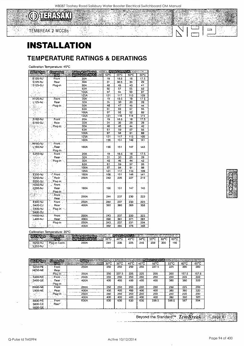
It m
TEMBREAK 2 MCCBs
INSTALLATION TEMPERATURE RATINGS & DERATINGS Calibration Temperature: 45°C
MCC8 Type Connection A -6
RatingaLcalrbralion tern eriair 50°C)
f(ateatCurren 50°C 55°C
,(A) 60°C 65°C
E125-NJ S125-NJ
. S125-GJ
Front. '
Rear Plug-in
20A 19 18.5 18 17.5
32A 31 30.5 30 29
50A 48 45 43 41
63A 100A
60 97
57 94
55
90 52 87
125A 121 117 113 109 H125-NJ L125-NJ
Front Rear'
Plug-in
20A 19 18.5 18 17.5 32A 31 30 29 28 50A 48 47 45 44
63A 61 59 57 55 100A 97
---121- 95 118
92 -114
89 111 125A ----
5160-NJ S160-GJ '
Hi6o-NJ L160,NJ -
Front 1 Rear
' plug-in ,,
- 7Front , Rear Plug-in
20A 19 18.5 18 17.5 32A 31 30 29 28 50A 48 46 44 42 63A 61 59 57 55 100A 97 94 91 88 125A 121 117 113 109 160A
160A
156
156
151
151
146
147
141
143
E250-NJ . .
Front '
Rear Plug-in ,
20A 19 18.5 18 17.5 32A 31 30 29 28 50A 48 46 44 42 63A 61 59 57 55 100A 97 94 91 88 125A 121 117 113 109
E250-NJ '
S250-NJ S250-GJ
.-' Front ,
' Rear 1 Plug-in
., Front . Rear
Plug:in Front ',
.
' Rear
160A 156 151 146 141
250A 243 235 227 219
H250-NJ ,
-L250-NJ 160A
250A
156
244
151
237
147
230
143
223
E400-NJ S400-CJ S400-NJ S400-GJ
" Front .
, Rear' ,
, Plug-in - ,
' .. '
250A 244 237 230 223 400A 390 380 369 358
H400-NJ. L400-NJ
Front . Rear '
250A 243 237 230 223 400A 390 381 371 361
Plug-in 250A 243 237 231 224 400A 392 384 376 368
Calibration Temperature: 30°C
MCC8 Type Connection Rating ,.atcalibration Rated:Cur ent.:(A) , ,
,
., T" e - tem eratilie 30°0 35°C 40°C 45°C 50°C 55°C 60°C 65°C - H250-NJ Plug-in Conn.. 250A 244 236 225 219 209 200 190 ' 't_250-NJ -
_
CCBT '
,. 50°C 55°C 60°C 65°C 30°C 35°C 40°C 45°C S250-PE Front 250A- 250 250 250 250 237.5 225 200 200 H250-NE Rear
Plug-in 250A 250 237.5 225 225 200 200 157.5 157.5 S400-NE , `, Front . , 250A 250 250 250 250 250 250 225 200 S400-GE Rear. ' ---- 400A ---- 400 400 400 400 400 380 360 320
- '-Plug-in 11400-NE Front 250A 250 250 250 250 250 250 225 200 L400-NE Rear 400A 400 400 400 400 400 380 360 320
Plug-in , 250A 250 250 250 250 250 250 225 200 400A 400 400 400 400 400 380 360 320
E630-NE Front 630A 630 630 630 630 598.5 598.5 567 504 S630-CE Rear S630-GE
Beyond the StandardTM TemB,eak page 81
WB087 Toohey Road Salisbury Water Booster Electrical Switchboard OM Manual
Q-Pulse Id TMS994 Active 10/12/2014 Page 94 of 400

. II i i ,
. , .
. ,
....
, -
,
. ..
TEMBREAK 2 MCCBs \I I 1
DIMENSIONS E125-NJ, S125-NJ, S125-GJ ASL: Arrangement Standard Line Irj: Handle Frame Centre Line
Front connected
3P
Irritee,;r_rmX)
I 11
60 90
Mount'
4P
hole I 0 1
120
Preparation of conductor
09
1A8 Sc,
17(maa.) 1040.15
M4x0.7 Mounting screw
08.5
With terminal bars (optional)
3P
LINA
arum
16
LIIF op
27.2 3.2
27.2
Drilling plan
3P
30
4P
Rear connected
op
It Stud can be turned 45"or 90'
Drilling plan
3P
It
aP
It
Panel Cutout (Front view)
3P 4P
122
Panel emu dimensions shown give an allowance 01 1.01010 around the handle escutcheon.
Front connected with Motor Operator
3P 4P
Mount
. , §
hole
45 5
I rat knob
Connector lu
154
Frnro panel t2
M8 screw r-
28 as.)
Preparation of conductor
o9
17(max.) mas.t5
AlOrnling screw
Drilling plan
3P aP
It
L
M400 7
aPP
Panel hinge position (hatching area) bottom view
1 ,11 I AIM aIMIIIIIIIIIIMIIIKf3111.11
Rear connected with Motor Operator
154
Front eel t2 /MoC4plate
72max.
Pad
Connector plug
R3(Lnaz.)
M4X 7
Mounting screw
Drilling plan
3P 4P
Die M400.7
4P
3P
It
'in
45 I
so
Panel cutout dimensions shown give an allowance ol 1.5mm around the handle escutcheon.
Beyond the StandardTM '7:entBreak page 85
WB087 Toohey Road Salisbury Water Booster Electrical Switchboard OM Manual
Q-Pulse Id TMS994 Active 10/12/2014 Page 95 of 400

TEMBREAK 2 MCCBs
APPLICATION DATA SELECTIVITY (DISCRIMINATION) AND CASCADE
Selectivity The principle of Selectivity (Discrimination) is based upon an analysis of several circuit breaker characteristics. These include time-current (tripping) curves, peak-let-through current (I,.0 and energy let-through (I2t).
The figures stated give the maximum selectivity level with the two nominated breakers in series under short-circuit conditions. For an indication on selectivity under overloads refer to the circuit breaker tripping/characteristic curves, or use the NHP Tem Curve selectivity analysis software package.
Selectivity can be enhanced beyond the breaking capacity of the downstream breaker provided it is backed up by an appropriately selected upstream breaker, which should not trip (unlatch) under the stated short circuit current.
Cascade Cascading is achieved by using an upstream device to assist (back-up) a
downstream device in clearing a fault current. This principal is necessary should the downstream device be required to clear a prospective short circuit current greater than the devices' breaking capacity.
In most cascading applications it is generally necessary for the upstream breaker to trip (unlatch), as well as the downstream breaker to give adequate back-up protection. As such, cascade is commonly used in feeding and protecting non-essential loads, such as basic lighting.
For more information on selectivity and cascading please refer to the latest NHP Part C catalogue.
WB087 Toohey Road Salisbury Water Booster Electrical Switchboard OM Manual
Q-Pulse Id TMS994 Active 10/12/2014 Page 96 of 400

Selectivity & Cascade Tables @ 400 / 415 V
Upstream MCCBs
Downstream kA MCCBs (RMS
CL
Csl CO
70
1.1.1 z 0. 1
125
O
V)
50
I IL 1.1.4 I IL Z Z 1 Z O 0 I 0 I C9 CT = 2;
1
, t:,
125 200 1 36
E125N.1, 25 25/25 ;:'''.25(65 25%36 '25/50 :25/65 25/85 25/36 :25/25
S125NJ 36 .36%36 i .36'./i5 36%50 - 36/65 36/85 364125 36/36 36/36
S125Gj 65 65/65 .65/125 50%50 65/70 65/1125-= 65'4150 X36/36 50/50
H125Nj 125 70/70 125/125 50/50 70/70 125/125 125/200 36/36 5.9(50
S 1 6ONJ 36 t
36/50 36/65 .36/85 '3641251 36/36 36/50
S160G<.(< , 65 50/50 65/70 :654125' 'fi54150 r..36/36 50(50
H16ONJ 125 I 125/125 125/200' 36/36 50/50
E25ONJ 25 25/65 ',25/85 1;25/36 25/25
S25ONJ 36 36/85 364125 i., 36/36 36/36
S250GJ 65 1 654125 654150 :36/36 50/50
S250P E 70 404125 '70/150.1 36/36 50/50
H250NJ 125 125/125 1 5/2001': 36/36 50/50
H250PE 125 125/125 125/200 '16/36 50/50
E400NJ - 25 ' ? t ;19/25 0/25
S400CJ 36 10/36 10/36
S400N E 50 .
10/36 10/50
$400NJ 50 r 10/36 10/36
S400GJ 70 1 - r 10/36 10/50
141400NJ..:..
H4OONE
E630NE
(6306E
S63OGE '
X S630C/ .
XS630Nj'
125 ;'::10/36
10%36
.10 /50
19(50 125
36 ...._.
70
45
65
...-
.,
-
XS630 PJ:. 85
XS630 E:. 50 ,
XH630SE:. 65
XH630P.E- 65
WOW' .... 65 ;
XS800SE 50
XJ800Pj.. .. 85
X H800SF.i. 65 ,
XI-4800P E 65
X S1250SE 65
151600SE ' 85 1
Selectivity /'Cascade
W u., I , I La . 1 C7) .... CI) V) V) = 0 ,=, 0 0 0 = . ,., .-, ,,, .. .. ,.. 0 0 0 p 0.1 c.,, 0 0 Li,
(v., ,J, CO CO co 1- .- r Cg CJ 0 ...I CO = _, CO J V) V) V) U7 1- X X I- X I- X X X
70 125 50 65 125 85 125 100 85 85
'25/50 '425/25 25(36 `:25/36 25/65 25%25 25(25 -"25/25 25/25 25/25
136/65 36/36 36/50 36/36 116%36 36/36 36%36 36/36 36%36 36/36
;-'65:(70 :65/65 65/50 65/65 65/65, ';"65/65 65/65 :65/65 65(65 65/65
70/70 70%70 50/50 65/65 ' 65/65 85/50 '85/50 100/100 85/85 85/85
-16/50 36/36 36/36 36/65 36165 "36/36 '36/36 36%36 36/36 36/36
65/70 "'.65(65 '50%50 50%65" 50%65 '65(65 :65/65 65/65 '65(65 65/65
7,0/70 70/70 50%50 50%65 :'50%65 ' 85%65 85/65 100/100 85/85 85/85
25/50 25/25 i: 25/25 -,25/50 25%50 .',25%25 25/25 25/25 25/25 .25/25. 16/65 ;36/36 :: 36136 '36(36 36/36 '36136 36136 .:36/36 36/36 36/36
65/70 :65(65 50%50 50/65 50/65 :65/65 .65/65 65/65 65/65 65/65
;;:70/70 :;,70(70 :50%50 "50/65 :50/65 .. 70/70 70/70 70170 70170 ;70/70
176/70 :70(70 50%50 50/65 56/65 '85%85 85/85 100/100 85/85 85/85
'70/70 ' 70/70 ' 50/50 50/65 _50/65, 85/85 85/85 100/100 85/85 85/85
'1 0/50 =--'10(36 <25/25 25/25 ' 25/36 125/25 :. 25/25 ' 25/36 '25125 ":25/25
10%65 ' ipto .2'136 25/36 -- 25/50 36/36 ::36/36 36/50 36/36 36/36
:10/50 -. 10(50 25/50 25(50. 25150 ;50%50 50(50 56/50 .50(50 :50%50
`. 10%70 -.<<',10(65 25/50 25/50 25/65 50%50 50/50 . :50/65 50/50 50/50
-`10/70 ".; 10/.70 ,25/50 25/50 25/65 70%36 70(36 70/85 70/70 70(70.
16/70 t10p 0 25/50 25/65 25(65 ' )25/85 125/85 125/100 125/85 1.25/85 " 4 _
10/70 10/70 25/50 25165 25/65 125/85 125/85 125/100 125/85 125/85
25136 25/36 :: 25/36 36/36 36/36 36736 36/36 36/36
25150 25/50 25/50 50/50 :;50/50 -56/50 750/50 50/50 ,--- 4-
< 1 70/70 70/70 70p0 70/70 70(70
" 36/ '1 1---
45 ' 30/45 30/46 35/45 35%45
',. 1 , 30/65 30/65 30/65 35/65 36%65
30185 . 30/85 ' 30/85 35/85 35/85
130%65 :'.30/65 30785 : 30/85 : 30%85
1 30(65 30/65 30(85 30/85 30/85
1
30/65 30/65 30/85 30785 30%85
%,15/65 15/65 ,20/65 35/65 35'165
15/.50 '15/50 20(50 35/50 35(50
.15/85- 15/85 -20/85 35/85 ,35/85
'::45/65 15/65 20165 '-'35/65 35(65
15/65 15/65 20(65 <35/65 .35765
4 1 20/65 35%65 35%65
35/85 '. 35/85
WB087 Toohey Road Salisbury Water Booster Electrical Switchboard OM Manual
Q-Pulse Id TMS994 Active 10/12/2014 Page 97 of 400
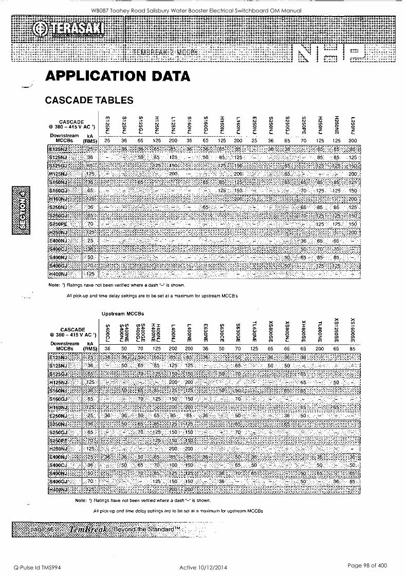
APPLICATION DATA
CASCADE TABLES
CASCADE CO 380 - 415 V A C ' )
Downstream kA MCCBs (RMS)
m Ri c, ,.._
25
ci..2
IV (l c... 2
36
cn
rt t.3
c..
x, IV ''' c
125
m 'V cl
200
Cl,
;) 2
36
En
.74
e,
65
x CIt
2 ,...
125
m a) 2 c
200
m (n 'en '4 2 2 c ,...
25 36
rcn,
m 2 c
65
(in, . 5,3
m
70
x 1.);
2 c
125
IT.,
....,,
-i m
125
r- 1`..)
2 c
200 65
1E125NJ ' -
f S125NJ
, 25
36
-; -
36 ,
- 36
50
65
85
85
125
36 '
- 36 '
50
65
85
'85
125
- 36
- - 36 ..
- - ,
- 65
85
65
85
85 1 125 .
IS125GJ '65t - -- -125 150 - 125 '' 150 , 65 125 ' 125 150,1
!H125NJ - 125 - - - , - 200 - - - 200 - - 65 - - - 200
LS160NJ' 36 -
65 - - 65' :
- '--
- '- -
7 .
'- 65
- -85
125
`' 125 = , ' 65 -,65 85 ''85 125
!S160GJ 150 - - - 70 125 125 150
IH16ONJ :125 - -, - L 200 1
IS250NJ 65 85 85 125 '
[S250GJ :
1S250PE
65
70
= - - -
- - - - -
- -
- -
- -
, -.
- - .
- .70
- 125
125
125' ,
125
150
150 )
1H250NJ _- . ' 125 - _ - - - ,'.... , - . 200
IE400NJ - - - - 36 65 65 - 6 S400CJ- t , 3 ` 50, 70 - 70 ' - -
1S4OONJ 50 - - - - - - - - 50' -65 85 85 - S400GJ a 70 50 . -, ' 125 125-
IH400NJ - - - - - - Note: ') Ratings have not been verified where a dash "-" is shown.
All pick-up and time delay settings are to be set at a maximum for upstream MCCB's
Upstream MCCBs
CASCADE @ 380 - 415 V AC')
Downstream kA MCCBs (RMS)
fn 4, O c(?)
c...
to cn 4, .12. a° 2 2
fl,
in (I) 4> A 00 e.) 2 c.m
I x A 4 Oa 2 2 mc-c-m
m .o. a 2
r A 0 2
m 0) ca 2 mmmmmr_mmmm
to cn 0) 0) Ca ca <(. E
-I m 0) Ca 2
X cn CO a 5;
X X (n x co Co 0 a 2 fi;
x -I Cn m - CO 1.7 0, ,.. 2 5:,
x Cn - a) o (T)
36 50 70 125 200 200 36 50 70 125 65 65 65 200 65 85
IE125NJ 25 36 36,- 50 65 85 85 36 50' - 36 36 ' 36 , --- ' - t IS125NJ 36 - 50 65 85 125 125 - - - 65 - 50 50 - - - -- IS125GJ ' 65 - - 70 125 150 150 50 70 .' - -- '65 - '
111125NJ 125 - - - - 200 200 . - 65 - 50 - 1S16ONJ 36 50 '65, 85 125 125, - 50 50 ' - 65 65 __ ., _
:S160GJ 65 - - 70, 125 150 150 - - 70 - - - - - - 1H160N4,
tE25ONJ
125
25
' - 36
- ,
36
- 50
- .
65 85
200
85
'- '
36
- , - - -
- ' 65' 36 50
- 65
- - - - - 50
IS>25ONJ- 36 50 65 85 125 125 65. - 65 . - - -' 1S250GJ 65 - - 70 125 150 150 - - 70 - - - - - - - 1S250k ,:- 70 - , 125 . 150
-
- 150 . --. - - - ___:___ - - i H25ONJ 125 - - -
_
- 200 -200 -- - - - - - E400NJ 25 36 36 50 65 85 65 36 50 36 - , 36 --' 36
1S400CJ 36 - 50 65 70 100 100 - - 65 50 - - - 50 - 50
S400NJ 50' ,70 85 125 125 36 70 65 - - 50, 65 65
S400GJ 70 - - 125 150 150 36 - - - - - 50 - - 36 85 i
H400NJ', 125 - , 200 200 - - ' - . -
`page 46 '
Note: ') Ratings have not been verified where a dash "-" is shown.
All pick-up and time delay settings are to be set at a maximum for upstream MCCBs
em- #realt- Beyond the StandardTM
WB087 Toohey Road Salisbury Water Booster Electrical Switchboard OM Manual
Q-Pulse Id TMS994 Active 10/12/2014 Page 98 of 400

TEMBREAK 2 MCCBs
APPLICATION DATA
SELECTIVITY AND CASCADE TEMBREAK 2 MCCBs AND DIN-T / SAFE-T MCBs
SELECTIVITY / CASCADE @ 415V AC
Downstream Amp MCB rating
kA (RMS)
Upstream MCCB
m to WM CO rn N (1) CP 2 ni u u a 4=. 4, 0 o
al o o 0 a Z OZ Z 2 0 0 Z
C c- C
25 36 65 36 65 36 70 125
iDTCB6 , ': 2-20 6 - 118/18 25/25 35/35 35/35 35/35 - - - ,
i 25-63 6 118/18 20/25 20/25 30/30 30/30 - - - IDTCB10 , , 05 - 32 10 118/18 30/30 30/50 35/35 40/50 35/35 40/50 40/50
40-63 10 118/18 20/25 25/25 30/30 30/30 30/30 30/30 30/30
DSRCBH J_ 1DSRCD
:05.-32
4 40
10 , 118/18
10 118/18
30/30
20/25
30/50
25/25
35/35
30/30
40/50
30/30
35/35
30/30
40/50 40/505
30/30 30/30
Din-T1 OH1 80-125 10 -1,4/18 4/25 4/25 15/15 15/15 10/10 10/10 - I DTCH15 0 5 - 32 15 118/18 30 30/50 35/35 40/50 35/35 40/50 40/50
1Safe-T
40 .7 63 :15 118/18 , 20 25/25 30/30 30/30 30/30 30/30 30/30
s 16-20 6 , 3/10 3/10- 3/10 - - - - - SRCB 16-20' 6 1'3/10 3/10 3/10 -
Guide XX / YY
Selectivity Cascade
Notes: All figures stated are at 400/415 V AC.
Beyond the StandardTM Ted/Pre/4k,, page 47.
WB087 Toohey Road Salisbury Water Booster Electrical Switchboard OM Manual
Q-Pulse Id TMS994 Active 10/12/2014 Page 99 of 400

B
TEMBREAK 2 MCCBs
APPLICATION DATA
MOTOR STARTING TYPE 1 CO-ORDINATION TABLES
Short-Circuit Co-Ordination Motor Starting Table
Type '1' Terasaki MCCB's & Sprecher + Schuh KT7's DOL starting 50/65 kA @ 400/415 V to AS/NZS 60947.4.1
Terasald Combinations i
Motor Size (kW)
Approx. amps 13,
400/415 V (A) ,MCCB Contactor
0.37 1.1 XM3OPB/1.4 CA7-9
0.55 1.5 XM3OPB/2 .CA7 -9 i
0.75 1.8 XM3OPB/2.6 ' CA7-9 I
1.1 2.6 XM30P13/4.0, CA7-9 - I
1.5 3.4 XM301.19/5 . ' CA7-9
2.2 4.8 XM3OPE3/8 - CA7-9
3 6.5 XM30P6/10 CA7-9
4 8.2 XM30143/12, CA7-9
5.5 11 S1256J/20 ' CA7-12 . '
7.5 14 S125GJ/20 , CA7 -16
11 21 S125GJ/32. CA7-23
15 28 S1256..1/50 CA7-30 ' -
18.5 34 S125GJ/50 CA7 -37
22 40 S125GJ/63 CA7-43
30 55 S125GJ/100 .CA7 -60
37 66 ',: S125GJ/1910 CA7-72
45 80 .S125GJ/125 CA7-85
55 100 -, S125GJ/125 CA6-110
5 130 S250PE/250 .. 'CA6=140
0 155 S250PE/250 - CA6-180 I
10 200 S250PE./250 . 'CA6-210 '
32 225 S400GE/400 CA6-210
60 270 , S400GE/400 -CA6-300 I
00 361 S400GE/400 CA6-420 I
Notes: Thermal or electronic overload relays may be used. XM3OPB MCCB's can be replaced with 5125GJ/20 it required. Combinations based on the thermal overload relay tripping before the circuit. breaker at overload currents up to the motor locked rotor current.
-.:134de Teipgreak- 'Beyond the tàndàrdTM
I Terasaki Combinations Sprecher .. Schuh Combinations
Overload ,
IReley'' :' Thermal
. Setting. (A) ,
KT7 Circuit Breaker
Contactor
;CT 7 -24" ' 1.0 1.6 KTA7-25S-1.0A CA7-9
fCT 7-24 . . .1.0 - 1.6 ' KTA7-25S-1.6A CA7-9
!CT 7-24 . .1.6 - 2.4 KTA7- 25S -2.5A CA7-9
[CT 7-24 KTA7-25S-2.5A CA7-9
;CT 7-24 2.4 4.0. KTA7-25S-4.0A CA7-9
ICT 7-24 4.0 - 6.0 ' KTA7-25S-6.3A CA7-9
[CT 7-24 .. 6.0 -10 KTA7-25S-6.3A CA7-9
iCT7-24,, 6.0' 10, KTA7-25S-10A CA7-9
;CT 7,24 .:. ilti' 16 KTA7-25H-16A CA7-12
,CT 7-24 10 - 16 KTA7-25H-16A CA7-16
;CT 7.24 , , 16 -24 " KTA7-45H-20A CA7-23
ici- 7-45 KTA7-45H-32A CA7-30
16i- 7-45- . ......i0.- 45' KTA7-45H-45A CA7-37
;CT 7-45 :'30 - 45 KTA7-45H-45A CA7-43
ICI 7-75 45 = 60 KTA3-100-63A CA7-60
;CT 7-75, . - 60 - 75 KTA3-100-90A CA7-72
1CT 7-100: - 70, 90 KTA3-100-90A CA7-85
ICU, 1-11/12 - 20', 180- KTA3-160S-100A CA6-110
ICEF 1-11/12 ' -0.. 180 KTA3-160S-160A CA6-140
;CEF 1-11/12 20 '- 180 KTA3-160S-160A CA6-180
ldEF 1-41/42 -:160 =400 ... KTA3-250S-200A CA6-210
ICEF1;41/42: ' 160 -400. .: KTA3-250S-250A CA6-250
!CEF 1:41/42. 190 :400 KTA3-4005 -320A CA6-300
ICEF 1-41/42 160 =400 KTA3-400S-400A CA6-420
WB087 Toohey Road Salisbury Water Booster Electrical Switchboard OM Manual
Q-Pulse Id TMS994 Active 10/12/2014 Page 100 of 400

,.. TERASAKI .....nior-tection,a,ho.4gy
TEMBREAK 2 MCCBs i..._ j N 1
t= \ = APPLICATION DATA
MOTOR STARTING TYPE 2 CO-ORDINATION TABLES
Short-Circuit Co-Ordination DOL Motor Starting Table
Type '2' Terasakl MCCB's & Sprecher + Schuh KT7's DOL starting 50/65 kA @ 400/415 V to AS/NZS 60947.4.1
Terasaki Combination
Motor Size (kW)
Approx. amps 0 400/415 V (A)
MCCB Contactor 1
0.37 1.1 XM30Pf3/1.4 CA7-9 1
0.55 1.5 XM3OPB/2 CA7 -9. ,
0.75 1.8 XM3OPB/2.6' CA7-9
1.1 2.6 XM3OPB/4.0 CA7-16 1
1.5 3.4 XM3OPB/5 CA7-16 1
2.2 4.8 XM3OPB/8 CA7-16 1
3 6.5 XM3OPB/10 , ' CA7-30 1
4 8.2 XM3OPB/12 CA7-30
5.5 11 S125GJ/20 CA7-30 1
7.5 14 S125GJ/20 CA7-30 1
11 21 S125GJ/32 CA7-30
15 28 S125GJ/50 CA7:43 1
18.5 34 S125GJ/50 CA7-43 1
22 40 S125GJ/63 CA7-43 ' 1
30 55 S125GJ/100 CA7-72
37 66 S125GJ/100 'CA7-72",
45 80 ' S125GJ/125 CA6-105 , 1
55 100 S250PE/160 CA6-105.5 1
75 130 S250PE/250 CA6-140 1
90 155 S250PE/250 CA6-170 1
110 200 S250PE/250 CA6-210 3
132 225 S400PE/400 CA6-210 1
160 270 S400PE/400 CA6-300 1
200 361 ,,S400PEJ400 ' CA6-,'120 1
Notes: Thermal or electronic overload relays may be used. XM3OPB combinations can be replaced with S125GJ/20 and CA7.30 if required. Combinations based on the thermal overload relay tripping before the circuit breaker at overload currents up to the motor locked rotor current.
I
j -. Terasaki Combinations Sprecher + Schuh Combinations
;Overload. ,
;Relay Thermal Setting (A)
KT7 Circuit Breaker
Contactor
1CT 7-24 1.0 - 1.6 KTA7- 25S -1A CA7-9
,;CT 7-24 ,,',, 1.0.1.1.6 KTA7-25S-1.6A CA7-9
1CT 7-24 '' ' .1.6 -2.4 , KTA7-25S-2.5A CA7-9
1CT7-24 . 2.4 -4.0 KTA7-25S-2.5A CA7-9
ICT 7-24 2.4 - 4.0 KTA7-25S-4A CA7-9
1CT.7-24 4.0 - 6.0 KTA7 -25S -6.3A CA7-9
1CT 7-24. :. 6.0 - 10 KTA7-25S-6.3A CA7-9
;CT 7 -24 ' 6.0 - 10 KTA7-25S-10A CA7-9
1CT 7-24 10 - 16 KTA7-25H-16A CA7-12
1CT 7-24 10.7 16 .. KTA7-25H-16A CA7-16
ICI 7-24 16- 24...;. KTA7-45H-20A CA7-23
CT 7-45 18 - 36 KTA7-45H-32A CA7-30
ICT.7-45 ' 30 - 45 KTA7-45H-45A CA7-37
1CT 7-45 . . 30 - 45 KTA7-45H-45A CA7-43
1CT7-75 .:45 - 66 :, KTA3-100-63A CA7-60
}CT 7-75 KTA3-100-90A CA7-72
(CT 7-100 70 - 90 KTA3-100-90A CA7-85
!GEE 1-11/12 20-180 KTA3-160S-100A CA6-110
ICU 1-11/12 20 ='186 ,. .
20 - 180 .
.
KTA3-160S-160A
KTA3-160S-160A
CA6-140
CA6-180 ICEF1,11/12:-': ,
(CEF 1-41/42 : ' 160 -'400 KTA3- 250S -200A CA6-210
10EF 1-41/42 160 - 400 KTA3-250S-250A CA6-250
10EF 1-41/42 160 - 400 KTA3- 400S -320A CA6-300
10EF1 =41/42 . '': 160'400. KTA3-400S-400A CA6-420
Beyond the StandardTm Tentlilietth
WB087 Toohey Road Salisbury Water Booster Electrical Switchboard OM Manual
Q-Pulse Id TMS994 Active 10/12/2014 Page 101 of 400
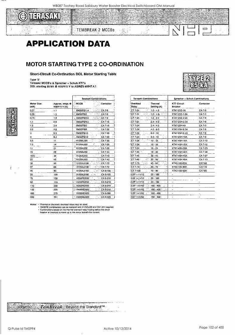
I
TEMBREAK 2 MCCBs
APPLICATION DATA
MOTOR STARTING TYPE 2 CO-ORDINATION
Short -Circuit Co-Ordination DOL Motor Starting Table
Type '2' Terasakl MCCB's & Sprecher + Schuh 107's DOL starting 85 kA @ 400/415 V to AS/NZS 60947.4.1
' Terasaki Conthinations
Motor Size (kW)
Approx. amps 0 400/415 V (A)
MCCB - ' Contactor
0.37 1.1 XM3OPB/1.4 CA 7-9
0.55 1.5 XM3OPB/2 . 'CA,7 -9 .
0.75 1.8 XM3OPB/2.6 - CA 7-9
1.1 2.6 XM3OPB/4.0 CA 7-16
1.5 3.4 -XM3OPB/5 CA 7-16
2.2 4.8 XM3OPB/8 CA 7-30
3 6.5 XM3OPB/10 .. . CA 7-30
4 8.2 XM3OPB/12 CA 7-30
5.5 11 H125NJ/20 CA 7-30
7.5 14 H125Nj/20 CA 7-30 i
11 21 H125NJ/32 CA 7-30
15 28 H125NJ/50 - CA 7-43
18.5 34 H125NJ/50 CA 7-43
22 40 ' Ij1125NJ/63 CA 7-43'
30 55 . H125NJ/100 CA 7-72
37 66 H125NJ/100 ''. CA 7-72
45 80 H125NJ/160 .CA 6-105
55 100 H16ONJ/160- - CA 6-105
75 130 .'H250PE/250 " !. CA 6-210
90 155 H250PE/250 ' - CA 6 -210. i
110 200 H250PE/250 CA 6-210 1
132 225 1-1400NE/400' ' CA 6-210
160 270 H400NE/400 . , CA 6-300
200 361 H400NFJ400 -CA 6-420 I
Notes: Thermal or electronic overload relays may be used. XM3OPB combinations can be replaced with H125GJ/20 and CA7-30 if required. Combinations based on the thermal overload relay tripping before the circuit
breaker at overload currents up to the motor locked rotor current.
page 50 ' TemB,Tivitic Beyond the StanderdTm' , -
I Terasaki Combinations Sprecher + Schuh Combinations
i :Overload Thermal Relay , Setting (A) '
KT7 Circuit Breaker
Contactor
CT 7-24 1.0 - 1.6 KTA7-25S-1A CA 7-9
!CT 7-24 ,
1.0 - 1.6 KTA7-25S-1.6A CA 7-9
!CT 7-24 1.6 - 2.4 KTA7-25S-2.5A CA 7-9
iCT 7-24 - 2.4 - 4.0 KTA7-25H-2.5A CA 7-9
!CT 7-24 2.4 - 4.0 KTA7-25H-4A CA 7-9
ICT 7-24 4.0 - 6.0 KTA7-25H-6.3A CA 7-9
CT 7-24 , 6.0 - 10 KTA7-25H-6.3A CA 7-9
;CT 7-24
ICT 7-24
KTA7-25H-10A CA 7-9
KTA7-45H-16A CA 7-12
ICT 7-24 KTA7-45H-16A CA 7-16
;CT 7-24 16 - 24 KTA7-45H-20A CA 7-23
CT 7-45 ' 18 --30, KTA7-45H-32A CA 7-30
ICT 7-45 . 30 - 45 . KTA7-45H-45A CA 7-37
iCT 7-45 30 - 45' KTA7-45H-45A CA 7-43
CT 7-75 45 - 60 KTA3-100-63A CA7-60
ICT.7-75'; 60 - 75 KTA3-100-90A CA7-72
!CT 7-100 70 - 90 KTA3-100-90A CA7-85
ICEF-1-11/12 ' 20 - 180 -
ICEF 1-11/12 20 - 180
iCEF 1-11/12 20 - 180 - -
ICEF 1-41/42 .160 - 400 - -
ICEF 1-41/42 160 - 400
!CEF 1-41/42 160 - 400
ICEF 1-41/42 160 - 400 -
WB087 Toohey Road Salisbury Water Booster Electrical Switchboard OM Manual
Q-Pulse Id TMS994 Active 10/12/2014 Page 102 of 400
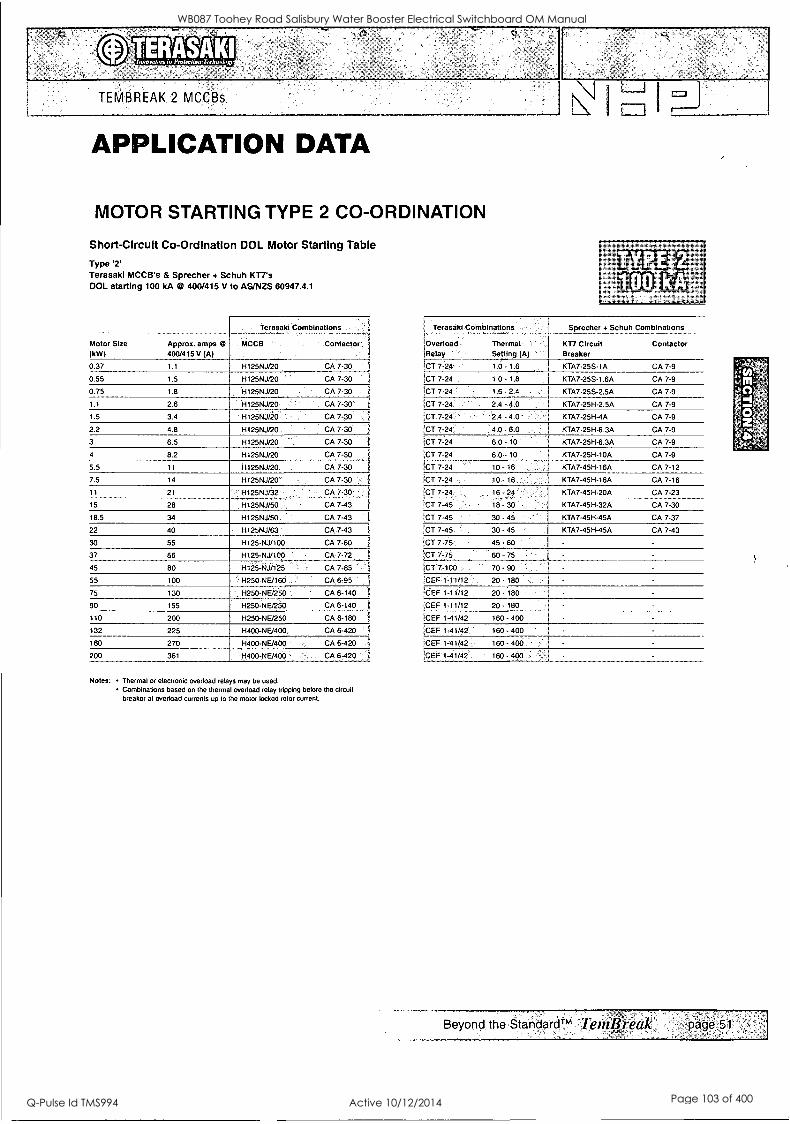
TEMBREAK 2 MCCBs.
APPLICATION DATA
MOTOR STARTING TYPE 2 CO-ORDINATION
Short-Circuit Co-Ordination DOL Motor Starting Table
Type '2' Terasaki MCCB's & Sprecher + Schuh KT7's DOL starting 100 kA @ 400/415 V to AS/NZS 60947.4.1
Terasaki Combinations
Motor Size (kW)
Approx. amps 0 400/415 V (A)
MCCB ' Contactor ,
0.37 1.1 H125NJ/20 CA 7-30
0.55 1.5 H125NJ20 ' ' CA 7-30
0.75 1.8 , H125NJ/20 CA 7-30
1.1 2.6 H125NJ/20 CA 7-30
1.5 3.4 H125NJ/20 CA 7-30
2.2 4.8 1-1125NJ20 CA 7 -30
3 6.5 H125NJ/20 CA 7-30
4 8.2 H125NJ/20 CA 7-30 i
5.5 11 H125N..1/20. CA 7-30 1
7.5 14 H125NJ/20' CA 7-30 ..,
11 21 '' H125NJ/32 , CA 7-30
15 28 H125NJ/50 ., CA 7-43
18.5 34 H125NJ/50. ' CA 7-43 1
22 40 H125NJ/63 ' CA .7-43 1
30 55 H125-NJ/100 CA 7-60 i
37 66 H125-NJ/100 . . I CA 7-72 1
45 80 H125 -NJ /125 CA 7-85 '1
55 100 H250-NE/160 CA 6-95 1
75 130 ' H250- NE/250 CA 6-140
90 155 H250-NE/250 CA 6-140 1
110 200 H250-NE/250 CA 6-180 1
132 225 H400-NE/400, CA 6-420 1
160 270 H400-NE/400 CA 6-420 1
200 361 'H400-NE/400 ' ,, CA 6-420
Notes: Thermal or electronic overload relays may be used. Combinations based on the thermal overload relay tripping before the circuit breaker at overload currents up to the motor locked rotor current.
Terasaki Combinations
,Overload Thermal 'Relay Setting (A)
Sprecher + Schuh Combinations
KT7 Circuit Breaker
Contactor
{CT 7-24 1.0 1.6 KTA7-255-1A CA 7-9
1CT 7-24 1.0. 1.6 KTA7-255-1.6A CA 7-9
!CT 7-24 1.6 - 2.4 KTA7 -25S -2.5A CA 7-9
!CT 7-24 2.4 -4.0 KTA7-25H-2.5A CA 7-9
CT 7-24 .2.4 .4.0 KTA7-251-1-4A CA 7-9
CT 7-24 4.0. 6.0 KTA7-25H-6.3A CA 7-9
'CT 7-24 6.0 - 10 KTA7-251-1-6.3A CA 7-9
',CT 7-24 6:0- 10 KTA7-25H-10A CA 7-9
(CT 7-24 10 - 16 KTA7-45H-16A CA 7-12
CT 7-24 10. 16 KTA7-45H-16A CA 7-16
CT 7-24
!CT 7-45 '
16 - 24 KTA7-45H-20A CA 7-23
KTA7-45H-32A CA 7-30
!CT 7-45 30 -45 KTA7-45H-45A CA 7-37
!CT 7-45. 30 - 45 KTA7-45H-45A CA 7-43
;CT 7-75 45 - 60 - -
!CT 7-75 60 - 75 -
iCT 7-100 70 - 90
10EF 1-11/12 20.180 idEF 1-11/12 20. .180 -
,CEF 1-11/12 20. 180
10EF 1-41/42 160.400 - -
CEF 1-41/42 160.400 - -
iCEF 1-41/42 160 - 400
',CEF 1-41/42 160.400 -
Beyond the StandardTM Tentlireak. page 51:
WB087 Toohey Road Salisbury Water Booster Electrical Switchboard OM Manual
Q-Pulse Id TMS994 Active 10/12/2014 Page 103 of 400

TEMBREAK 2 MCCBs I
OPERATING CHARACTERISTICS THERMAL MAGNETIC PROTECTION Adjustment Dials
0.63 0 0.8
0 6
k (xi n) (x1 n)
1. /R is the thermal element adjustment dial and is used to set the rated current to match the conductor rating.
/R can be set between 0.63 and 1.0 times I.
2. L is the magnetic element adjustment dial and is used to set the short circuit tripping threshold to suit the application.
L can be set between 6 and 12 times In on 125A and 400A frame models.
L can be set between 6 and 13 times I, on 250A frame models with ratings of 160A, 200A and 250A.
L can be set between 6 and 12 times In on 250A frame models with ratings of 125A and less.
Mode s, Types and Rated Currents of Thermal Elements
Model Itp Current Ratingiln#9 S125 ...2.-Nr : 16, 20;257'32,40, 50,63, 80,100, 125
E125 -NJ, 20, 32,50, 63, 100, 125 ' '
S125- - --NJ --- 20,32, 50, 63,100,125 - - --
S125 .. - .
--GJ .. ' 20,32 50 63-100 125
H125 -NJ -,'20,:3250, 63, 100, 125
'L125 -NJ 26;32, 50, 63,_100, 125
S160 -NF 16, 20, 25, 32, 40, 50, 63, 80, 100, 125 160
S160 -NJ 0, 32, 50, 63, 100, 125, 160
S160 -GJ , , 50, 63,100, 125, 160
H160 -NJ ! 160
L160 -NJ -:160 E250 -NJ 7 20, 32, 50, 63, 100, 125, 160;:200, 250
S250 -NJ . 160, 200, 250
S250 -GJ : 160, 200,-250
H250 , 160,1250_1* .
'L250' -NJ ' ; 160, 250 7
.
t400 -NJ '256, 400
S400 -6J ' 256, 4ixi
S400 ' -NJ , '';. 280, 400
.S400 -GJ' . . 250;400
H400 -NJ 250, 400
1400 :NJ 250, 400 ,
. M.
Beyond the StandardTm TertiBreok. pa;ge:23-
WB087 Toohey Road Salisbury Water Booster Electrical Switchboard OM Manual
Q-Pulse Id TMS994 Active 10/12/2014 Page 104 of 400
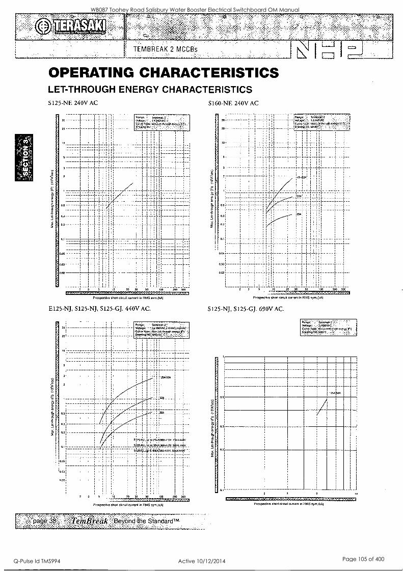
°
TEMBREAK 2 MCCBs
OPERATING CHARACTERISTICS LET-THROUGH ENERGY CHARACTERISTICS S125-NE 240V AC
30
0.'
0 3 5
1 I 1 i
. :
i
i 1 3 3 3
. : .. I 1 I i I
0.02
I I I
I I
Apo ;e. ieintreek I 240V51.'
NO
1 I Hi; I
w 20 30 50 100 200 300
Prospective short circuit current in RMS sym.(k.A)
E125-NJ, S125-NJ, S125-GJ. 440V AC.
10
0
0.3
2
. .
S160-NF. 240V AC
10
.5
o3
0.2
0.05
0.03
Come 7.rtitireik 2 , ..;33 24DYAC
mnp3303.5,15
I I
i I
I .
0 35 30 50 CO 200 300
.1
Prospective shn.: ^.:3c.:0 current in RMS sym.(kA)
S125-NJ, S125-GJ. 690V AC.
Range Tert111.0.0 Range 1013 en. Voltage 3/n05.0. Vellagr 43311CVAC,3115VAC,41050.0 ,Curve Type Wile. 2 2.73 Me .0 .1) Cu.re Ivpr .1:3.1.c...facugh 000, 9 , Crewing NO M451?
I I
1 1 1
I I
3 3 3 3
2 3 5 io
Prospective shun cocOlt current in RMS syni.(kA)
O wsiorato. 35v. 15,./.1.54v
41, 300A ;5.3,, :5 21.3. :4. Ziit 653...r380-4351 501,44.0
. . .
30 50
3 3
150 200 300
page 38 TemBreak Beyond the Standardim
-4
1250000
0.31
0.2
31 5 14f4},NM Prospective short cirCuit current in RMS sym.(kA)
WB087 Toohey Road Salisbury Water Booster Electrical Switchboard OM Manual
Q-Pulse Id TMS994 Active 10/12/2014 Page 105 of 400

J & P Richardson Industries Pty Ltd
2 Circuit Breakers / Circuit Breaker Chassis / Contactors
TERASAKI - DTCB15 320C - Pump 1,2,3,4 Circuit Breaker c/w DTLDC
TERASAKI - DTCB10306C - Station Mains Phase Failure Circuit Breaker & DC Power Supply
TERASAKI - DSRCBH-16-30A - 15A GPO Circuit Breaker
TERASAKI DSRCBH-10-30A - RTU Laptop GPO Circuit Breaker
TERASAKI - DTCB10106C - SW/BD Internal Lighting Circuit Breaker
TERASAKI - DTCB10104C - Grundfos Controller Circuit Breaker
TERASAKI - DSRCBH-06-30A - Sump Pump Circuit Breaker
SUPPLIED BY: NHP ELECTRICAL ENGINEERING PRODUCTS Pty. Ltd.
16 Riverview Place, Murarrie 4172, Queensland AUSTRALIA
PHONE: (07) 3909 4999
FAX: (07) 3399 9712
File: Swbd Manual Revision 0 Date:11/3/2010
WB087 Toohey Road Salisbury Water Booster Electrical Switchboard OM Manual
Q-Pulse Id TMS994 Active 10/12/2014 Page 106 of 400
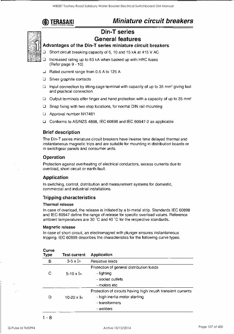
TP.A.s419 Miniature circuit breakers
Din-T series General features
Advantages of the Din-T series miniature circuit breakers Li Short circuit breaking capacity of 6, 10 and 15 kA at 415 V AC
D Increased rating up to 63 kA when backed up with HRC fuses (Refer page 9 - 10)
Li Rated current range from 0.5 A to 125 A
LI Silver graphite contacts
D Input connection by lifting cage terminal with capacity of up to 35 mm2 giving fast and practical connection
I:I Output terminals offer finger and hand protection with a capacity of up to 35 mm2
ILI Snap fixing with two stop locations, for normal DIN rail mounting
Li Approval number N17481
Li Conforms to AS/NZS 4898, IEC 60898 and IEC 60947-2 as applicable
Brief description The Din-T series miniature circuit breakers have inverse time delayed thermal and instantaneous magnetic trips and are suitable for mounting in distribution boards or in switchgear panels and consumer units.
Operation Protection against overheating of electrical conductors, excess currents due to overload, short circuit or earth fault.
Application In switching, control, distribution and measurement systems for domestic, commercial and industrial installations.
Tripping characteristics Thermal release In case of overload, the release is initiated by a bi-metal strip. Standards IEC 60898 and IEC 60947 define the range of release for specific overload values. Reference ambient temperatures are 30 °C and 40 °C for the respective standards.
Magnetic release In case of short circuit, an electromagnet with plunger ensures instantaneous tripping. IEC 60898 describes the characteristics for the following curve types:
Curve Type Test current Application
B 3-5 x In Resistive loads
Protection of general distribution loads
C 5-10 x In - lighting
- socket outlets
- motors etc
Protection of circuits having high inrush transient currents
D 10-20 x In - high inertia motor starting
- transformers
- welders
1 - 8
WB087 Toohey Road Salisbury Water Booster Electrical Switchboard OM Manual
Q-Pulse Id TMS994 Active 10/12/2014 Page 107 of 400

T_E.Aggg Miniature circuit breakers
Din-T series General features
Handle Sealable and padlockable with quick-make and quick-break type mechanism. The handle is sealable in ON and OFF position. Due to the free-tripping mechanism, the MCB contacts open through overload or short circuit even when the handle is sealed in the ON position on all types.
Input terminal (`OFF' side) Box terminal with lifting screw for copper and aluminium conductors: max. capacity 1 x 35 mm2 or 2 x 16 mm2.
When unscrewing the screw, the head lifts; however, on pushing the screw head, the box terminal opens. This system enables the MCBs to be linked with a cable and fork or pin type bus comb. The MCB is delivered with a half open box terminal and a lifted screw head.
Output terminal (`ON' side) Box terminal with captive terminal screw for copper and aluminium conductors: max. 1 x 35 mm2 or 2 x 16 mm2.
The box terminals are always delivered in the open position. Output terminal screw has IP 20 protection against direct finger contact by standard design.
Arc chamber Contains arc extinction plates, (de-ionising type) designed to break up and dissipate the arc which is generated during interruption of all types of faults.
Electromagnet Operating the plunger which opens the contacts instantaneously.
Arc magnetic blowout system Short circuit currents do not flow through the bi-metal but are directed by the blowout magnet in such a way that the arc is transferred to a special arc runner, therefore taking the bi-metal out of the circuit, which ensures the thermal trip characteristics remain unchanged after an MCB has been exposed to a fault current.
O This combination of the electromagnet (with a plunger rapidly opening the contacts), the blowout magnet and the arc chamber, results in an extremely high short circuit breaking capacity, and very low let through energy.
Snap-on clip for DIN rail mounting This special flexible system gives ease of mounting and positioning of the MCB on DIN rail.
Catalogue number structure for Din-T MCBs (6, 10, 10H & 15)
DTCB i X X 1 X X X I X
onstant 1 Short circuit I Polarity -11 ir Current I Curve capacity (A) 1
I I (A) type
NHP DIN I 6 6000 05 0.5 - 1 pole B 3 In 5 In
01 1 --------- format 10 10000 2 2 pole ' 02 2 1 LC 5 In - 10 In
J
10H 10000 3 3 pole 11 03 3 04 4 I
D 10 In - 20 In
15 15000 1N 1P + N j i 06 6
DC 6000 4 3P + N ! I 10 10 13 13 Etc
1 - 9
WB087 Toohey Road Salisbury Water Booster Electrical Switchboard OM Manual
Q-Pulse Id TMS994 Active 10/12/2014 Page 108 of 400

ligig.4.19 Miniature circuit breakers
Din-T6 series 2-63 A 6 kA 'C' curve
Standard AS/NZS 4898
Li Approval No. N17481
Li Current range 2-63 amps 1, 2 and 3 pole
J Sealable and lockable handle
DIN rail mounting
Padlockable in OFF position
F.3 Suits CD type chassis
Li General purpose light and power distribution
Curve type: C (5 - 10 In) Single pole
In (A) Cat. No. Price $ In (A) Cat. No. Price $
2 ' DTCB6102C ' 35.00 i 20 DTCB6120C ' 35.00 :
4 -DTCB6104C l 35.00;! 25 DTCB6125C ' 35.00 ;
6 'DTCB6106C 35.00;; 32 4
DTCB6132C. 35.00
10 DTCB6110C ; 35.001 40 :DTCB6140C 35.00 ;
13 DTCB6113C 35.001 50 DTCB6150C ' 35.001
16 DTCB6116C 35.00 63 DTCB6163C 35.001
Double pole
2 i = DTCB6202C ' 110.00-; 20 :OTCB6220C , 110.00;
4 1 DTCB6204C i 110.001 25 DTCB6225C 110.001
6 ' DTCB6206C '1 ! 110.00 ' 1
32 DTCB6232C ; 110.00 ]
10 a DTCB6210C 1 110:001 40 DTCB6240C : 110.00 1
13 i 0 DTCB6213C 1 110.001 50 DTCB6250C 110.001
16 1 DTCB6216C 110.00', 63 DTCB6263C - 110:001
Triple pole
2 'DTCB6302C ; 140.001 20 DTCB6320C ' : 140.00i
4 DT,CB6304C ,i 140:001 DTCB6325C;;-,,,. 140* 6 , :DTCB6306C ' 140X10 I 32 DTC B63326' '', , ), 146061
10 D7-0631 oc I 146;00 40 DTCB6340C - :! 1,46:06
13 i DTCB631'3C' ' , 1 140.001 50 DTCB6350C ' 140.001 - .1
16 DTCB6316C 14000 i 63 ' DTCB6363C . 146.:00.!
Notes: The LINE-side is the OFF or bottom of the MCB, and connects to CD chassis tee-offs. Suitable for the following side mounted accessories:- - AUX/ALM switches - refer page 1 - 31
- Shunt trip - refer page 1 - 30 - UVT Trip - refer page 1 - 30 - Clip-on RCD module - refer page 1 - 23 - Din-Safe-M module - refer page 1 - 23 - Din-T terminals and accessories - refer page 1 - 35
Available on indent only
1 - 10 GST not included price.schedulefriLi
WB087 Toohey Road Salisbury Water Booster Electrical Switchboard OM Manual
Q-Pulse Id TMS994 Active 10/12/2014 Page 109 of 400

TP14§4.1.9 Miniature circuit breakers
Din-T6 series 2-63 A 6 kA 13' curve J Standard AS/NZS 4898
LI Approval No. N17481
LI Current range 2-63 amps 1, 2 and 3 pole
Li Sealable and lockable handle
U DIN rail mounting
Padlockable in OFF position
J Suits CD type chassis
Li Motor starting and transformer applications
Curve type: D (10 - 20 In) Single pole
In (A) Cat. No. Price $ In (A) Cat. No. Price $
2 DTCB6102D 40.001 20 DTCB6120D 1- 40.01
4 DTCB6104D ' 1 40.00 i 25 DTCB6125D , '
i
40.00
6 CiTaB6106ti : 40.00 i 32 : DTCB6132D 40.001
10 DTCB6110D 40.001 40 DTCB6140D , ,1 40.001
13 I DTCB6113D 40.00 50 DTCB6150D , 40.001
16 DTCB6116D . 40.00 63 DTCB6163D , i
40.00 1
Double pole
2 . DTCB6202D i 120.00 20 _ .. .
:', 13:TCB6220D ; 120.00::
4 , . DTCB6204D i 120.001 25 DTCB6225D 120:001
6 DTCB6206D 120.001 32 , . DTCB6232D ' 120.0 1
10 ' kif C B 62 I 0 CV ' - a'
120.00! 40 ' , DTCB6240D 120.00
13 120.001 50 DTCB6250D ' 120.001 I DTCB621313 "
16 DTCB6216D 1 120.001 63 - DTCB6263D - ' 120.001
Triple pole
2 Di-06302D -'! 105.001 20 DTC146320D 165.001
4 DTCB6304D , 165.00 1 25 DTCB6325D 1 166.00i
6 ' DTCB6306D '.: 155.001 32 1
DTCB6332D : 165,001
10 DTCB6310D ' 165.001 40 DTCB6340D 165.001
13 155,00. 50 'DTC36350D- ' 166.001 n DTCB63136; -`` 1
16 1
' DTCB6316D 165.00.; 63 1, DTCB6363D , .. 165.001
Notes: The LINE-side is the OFF or bottom of the MCB, and connects to CD chassis tee-offs. Suitable for the following side mounted accessories:- - AUX/ALM switch - refer page 1 - 31. - Shunt trip - refer page 1 - 30 - UVT trip - refer page 1 - 30 - Clip-on RCD module - refer page 1 - 23 - Din-T terminals and accessories - refer page 1 - 35 Di Available on indent only.
GST not included 1 - 11
WB087 Toohey Road Salisbury Water Booster Electrical Switchboard OM Manual
Q-Pulse Id TMS994 Active 10/12/2014 Page 110 of 400

714§.4.41 Miniature circuit breakers Din-T6 series 6-32 A
1P+N (switched neutral) 6 kA 'C' curve Li Standard AS/NZS 4898 IEC 60898
Li Approval No. N17481
Li Current range 6-32 amps
C curve tripping characteristic
lcu = los = 6 kA
13 1 pole + 1 switched neutral pole 1) 2)
Li Single width module 18 mm wide
Li Voltage rating 230 V AC
D Terminal cap. Flexible/rigid cable: 10-16 mm2 3)
Li DIN rail mounting
C3 Sealable and lockable toggle
Padlockable in OFF position
Li General purpose light and power distribution
Curve type: C (5 -10 In) Single module width
In (A) Cat. No. 1) 4) Price $
6 _ "
CB61NO6C 140.00
10 I '-DTC186iNlOC I 140,00';
16 ' DTCB61N16C '; 140.00:
20 i :4 DTCB61,N20b 140.001
25 - -
r:DTCB61N25C 1_ 140.00: , 32 II- DTCB61N32C ' 140.001
18 ---- Dimensions (mm)
70 -- 44
I 1
45 ;
Notes: ') DTCB61N types have 1 protected switched pole and 1 unprotected switched neutral pole
2) The neutral pole contacts in a DTCB61N are early make/late break type 3) DTCB61N types are not suitable for CD chassis mounting °) Standard Din-T accessories are not suitable for DTCB61N MCB's Miscellaneous Din-T terminals and accessories - refer page 1- 35 E Available on indent only.
90
1 - 12 GST not included 1,,Price..schedule 71',A
WB087 Toohey Road Salisbury Water Booster Electrical Switchboard OM Manual
Q-Pulse Id TMS994 Active 10/12/2014 Page 111 of 400
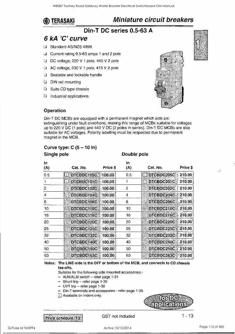
e TE.RAMICJ Miniature circuit breakers
Din-T DC series 0.5-63 A 6 kA 'C' curve Li Standard AS/NZS 4898
LI Current rating 0.5-63 amps 1 and 2 pole
Li DC voltage, 220 V 1 pole, 440 V 2 pole
Li AC voltage, 230 V 1 pole, 415 V 2 pole
11 Sealable and lockable handle
Li DIN rail mounting
Ci Suits CD type chassis
Li Industrial applications
Operation
Din-T DC MCBs are equipped with a permanent magnet which aids arc extinguishing under fault conditions, making this range of MCBs suitable for voltages up to 220 V DC (1 pole) and 440 V DC (2 poles in series). Din-T DC MCBs are also suitable for AC voltages. Polarity labelling must be respected due to permanent magnet in the MCB.
Curve type: C (5 -10 In)
Single pole
In (A) Cat. No. Price $
Double pole
In (A) Cat. No. Price $
0.5 1 'IbtolitDC105C 100:001 0.5 1 DTCBDC205C, : 210.001
1 1 =DT6BDC10,1C 100.00 / 1 1 DTCBDC2011C , 210.00
2 DTCBDC102C .i 100.00 1 2 DTCBDC202t f 210.00 1
4 DTCEiDC104C- i 100.00 1 4 DTCBDC204C 210.00
6 DTCBDC106C 1
100.00 1 6 DTCBDC206C I 210.001
10 DTCB,DC110C 100.00 1 10 DTCBDC210C :1210.00 I
16 , DTCBDC116C 100.0.0 i 16 DTCBDC216C 210.00
20 DTCBDC120C 100.001 20 DTCBDC220C 1- 210.00/
25 DTCBDC125C . 100.00 25 DTCBDC225C -'; 210.001
32 DTCBDC132C 100.00 i 32 ' DTCBDC232C ', 210.00
40 DTCBDCi 4OC 100.001 40 DTCBDC240C , 210.00
50 DTCBDC150C 100.00 1 50 DTCBDC250C ' 210.00
63 DTCBDC163C , 100.00 63 DTCBDC263C 210.00
Notes: The LINE-side is the OFF or bottom of the MCB, and connects to CD chassis tee-offs. Suitable for the following side mounted accessories:- - AUX/ALM switch - refer page 1-31
- Shunt trip - refer page 1-30 - UVT trip - refer page 1-30 - Din-T terminals and accessories - refer page 1-35
aj Available on indent only.
LPriCe schedule GST not included 1 -13
WB087 Toohey Road Salisbury Water Booster Electrical Switchboard OM Manual
Q-Pulse Id TMS994 Active 10/12/2014 Page 112 of 400

URg419 Miniature circuit breakers
Din-T1OH series 80-125 A 10 kA 4C' Curve 7.5 kA `13' Curve LI Standard AS/NZS 3947 - 2 [
L Cl Current range 80 - 125 amps 1, 2, 3 and 4 pole
.
LI Module width = 27 mm
DIN rail mounting
Cl Suits CDH hybrid type chassis
Industrial applications
Curve type: C (5 -10 In) Single pole
In (A) Cat. No. Price $
Double pole
In (A) Cat. No. Price $
80 DINT10H180t 145.00li 80 -DINT1OH280C 365.00
100 DINT1OH1100C 145.001 100 *DINT10H2100C 365.00
'125 DINT1OH1125C 200.00 125 DINT1OH2125C 415.00
Triple pole Four pole') 80 DINT101-1380C 370.001 80 U DINT10H480C 650.001
100 J:DINT:103109c. 370.001 100 U=.DINTI.OH4i00C.,1 650.001
125 'INT1OH3125C 525-00' 125 N ;p4fitti-4125C;1 780.001
Curve type: D (10 - 20 In) Single pole
In (A) Cat. No. Price $
Double pole
In (A) Cat. No. Price $
80 B DINT1OH180D 205.00 80 U DINT1OH280D 390.00
100 [El DINT1OH11006 205.00I 100 U DINT1OH2100D 390.00
125 DINT1OH1125D 235.001 125 U DINT10-12125D- 510.001
Triple pole Four pole 1)
80 DINT1OH380D 555.001 80 B DINT1OH480D 750.001
100 DINT1OH3100D , 555.001 100 DINT1OH4100D 750.001
125 DINT1OH3125D ; 660.00 125 B DINT1OH4125D :1040.001
Notes: The LINE-side is the OFF or bottom of the MCB, and connects to CDH chassis tee-offs. Din-T1OH MCBs do not fit CD chassis with 18mm pole pitch ') All poles include overcurrent and short circuit protection. Suitable for the following side mounted accessories:- - AUX/ALM switch - refer page 1-31
- Shunt trip - refer page 1-30 - Din-T terminals and accessories - refer page 1-35 II Available on indent only.
1 - 14 GST not included I Price scheduleLtl_
WB087 Toohey Road Salisbury Water Booster Electrical Switchboard OM Manual
Q-Pulse Id TMS994 Active 10/12/2014 Page 113 of 400

TIERAWI Miniature circuit breakers Din-T10 series 6-63 A
10 kA B' curve Standard AS/NZS 4898
Approval No. N17481
Current range 6-63 amps 1, 2, and 3 pole
Sealable and lockable handle
DIN rail mounting
Padlockable in OFF position
Suits CD type chassis
Resistive load applications
Curve type: B (3 -5 In)
In (A) Cat. No. ') 1 Pole Price $
2 Pole 3 Pole Price $ Price $
6 DTCB10 .-:0613 60.00 0 175 00 I 205.00'
10 DTCB10 10B i 1 so:go 205.00 ' 0 175.00
13 DTCB10 13B - - ' : 60.00 175.00 I 205.00
16 ' DTCB10' ' 16B 60.00 - 11 175.00 205.00
20 ' DTCB19,, 20B - 60.00 El 175.00 : 205.00
25 DTCB10 ^L 2513- ' 0 205.00 I 6090 i 175.00
32 ', DTCB10'_ 32B, : 0 60.00 [2 175.00 0 205.00
40 :,, DTCB10 ,:40B ' 0 20500 7: i 79.00 I 245.00
50 ': DTCB10 50B , M 220.00 M 305.00 I 90.00
63 , . DTCB10 l 63B : i 105.00 1 235.00 i ,340.09,-
Notes: The LINE-side is the OFF or bottom of the MCB, and connects to CD chassis tee-offs. ') Insert No. of poles into cat. No. space marked '-' eg. DTCB10 3 20B = 3 P
Suitable for the following side mounted accessories:- - AUX/ALM switch - refer page 1 - 31
- Shunt trip - refer page 1 - 30 - UVT trip - refer page 1 - 30 - Clip-on RCD module - refer page 1 - 23 - Din-T terminals and accessories - refer page 1 - 35 M Available on indent only.
Price schedule GST not included 1-15
WB087 Toohey Road Salisbury Water Booster Electrical Switchboard OM Manual
Q-Pulse Id TMS994 Active 10/12/2014 Page 114 of 400

WW1! Miniature circuit breakers Din-T10 series 0.5-63 A
10 kA `CY curve D Standard AS/NZS 48983)
D Approval No. N17481
Li Current range 0.5-63 amps 1, 2, 3 and 4 pole
Li Sealable and lockable handle
Li DIN rail mounting
LI Padlockable in OFF position
D Suits CD type chassis
Li General purpose light and power distribution
Curve type: C (5 - 10 In)
In (A) Cat. No. ') 1 Pole Price $
2 Pole Price $
3 Pole 4 Pole Price $ Price $ 2)
0.5 DTCB10 2 05C 50.00 155.00 180.00 205.00
1 DTCB16_ 01C ' - 50.00 155.00 180.00 ,205.00 '
2 ' DTCB1 ci _ 02C 50.00 155.00 180.00 205.00
3 DTCB10 2 03C - 50.00 155.00 180.00 205.00
4 - DTCB10 04C ' 50.00 155.00 180.00 205.00
6 ^ - DTCB10 66C 50.00 155.00 180.00 205.00
10 DTCB10 -2 10Q 50.00 155.00. 180.00 ' ..,?o5.00
13 1 DTCB10 13C 50.00 166.00 , 180.00 '205.00
16 oll-cplo __'-i 6C 50.00 155.00 180.00 205.00
20 DTCB10 20C 1 50.00 155.00 180.00 205.00
25 DTCB10 25C -1 50.00 155.00 , 180.00 205.00
32 .. 'DTCB10 _ 32C 50.00 155.00 180.00 205.00 ,
40 'DTCB10 40C 50.00 155.00 180.00 205.00
50 DTCB10 _ 50C ' i 50.00 155.00 180.00 205.00 , !
63 - DTCB1 O't 63C 1, 50.00 155.00 180.00 205.00 :
Notes: The LINE-side is the OFF or bottom of the MCB, and connects to CD chassis tee-offs. ') Insert No. of poles into cat. No. space marked '_' eg. DTCB10 3 20C = 3P 2) All poles include overcurrent and short circuit protection 3) A range of UL standard MCBs is available on indent. (ref: DTCBUL10_ _ _C) Suitable for the following side mounted accessories:- - AUX/ALM switch - refer page 1-31
- Shunt trip - refer page 1-30 - UVT trip - refer page 1-30 - Clip-on RCD module - refer page 1-23 - Din-T terminals and accessories - refer page 1-35
Available on indent only.
1 - 16 GST not included Price schedule 'Ti' r
WB087 Toohey Road Salisbury Water Booster Electrical Switchboard OM Manual
Q-Pulse Id TMS994 Active 10/12/2014 Page 115 of 400

( TER.A4.1S1 Miniature circuit breakers
Din-T10 series 0.5-63 A 10 kA 'D' curve
Li Standard AS/NZS 4898
U Approval No. N17481
U Current range 0.5-63 amps 1, 2, 3 and 4 pole
D Sealable and lockable handle
U DIN rail mounting
Padlockable in OFF position
Suits CD type chassis
U Motor starting and transformer applications
Curve type: D (10 - 20 In)
In (A) Cat. No. ') 1 Pole Price $
2 Pole 3 Pole 4 Pole Price $ Price $ Price $
2)
0.5 DTCB10 :_ 05D fil 55.00 Li 170.00 II '195.00 205.00
1 DTCB10 OlD 55.00 170.00 a 195.00 205.00
2 DTCB10 020 ' : 55.00 , 170.00 205.00 1 195.00
4 ' DTCB10 04D ' : 55.00 170.00 195.00 : 205.00
6 DTCB10 _1 06D 55.00 170.00 195.00 0 205.00
10 pTcBto 100 5500 , : 170.00 195.00 1_ D 205.00
13 DTC1319 136 55.00 170.00 195.00 i 1 205.00
16 DTCB1 C._ 16D 55.00 --* 170.00 195.00 .
0 205.00
20 DTCB10 _ 20D , 55.00 170.00 . 195.00 D 205.00
25 DTCB10 _ 25D 55.00 170.00 195.00 0 205.00
32 DTCB10 _ 32D 55.00 " : 170.00 195.00 - 0 205.00
40 DTCB10 - 40D 55.00 195.00 235.00 ' 305:00
50 DTCB10 50D ' 5500 , 230.00. 340.00 - 043500 63 ' DTCB10 _ 63D -`,, , 1 55.00 270.00 390.00 1 510.00
Notes: The LINE-side is the OFF or bottom of the MCB, and connects to CD chassis tee-offs. ') Insert No. of poles into cat. No. space marked eg. DTCB10 3 20D = 3P.
2) All poles include overcurrent and short circuit protection. Suitable for the following side mounted accessories:- - AUX/ALM switch - refer page 1-31
- Shunt trip - refer page 1-30 - UVT trip - refer page 1-30 - Clip-on RCD module - refer page 1-23 - Din-T terminals and accessories - refer page 1-35
Available on indent only.
rPrice schedalo,31: GST not included 1 - 17
WB087 Toohey Road Salisbury Water Booster Electrical Switchboard OM Manual
Q-Pulse Id TMS994 Active 10/12/2014 Page 116 of 400

Miniature circuit breakers
Din-T15 series 6-63 A 15 kA, 20 kA, 25 kA, 50 kA 'C' curve
Standard AS/NZS 3947 - 2
L:1 Current rating 6-63 amps 1, 2, 3 and 4 pole
Li Sealable and lockable handle
D DIN rail mounting
L.1 Suits CD type chassis
LI Industrial applications
Curve type: C (5 -10 In)
In (A) Cat. No. 1)
1 Pole Price $
2 Pole 3 Po e Price $ Price $
4 Pole Price $ 2)
6 -DTCB15 06C 120.0 340.00 0 395.00 220.00
10 .,DTCB15 10C 120.90 340.00 0 395.00 220.00
13 , DTCB1,5 13C ,:0 120.00 395.00' 220.00 340.00
16 . DTCB15 16C ' 120.00 340.00 0 395.00 1 220.00
20 . DTCB15 _ 20C 120.00 340.00 0 395.00 220.00
25 DTCB15 _ 25C E 120:00 340.00 0 395.00 220.00
32 - 1 DTCB15_ 32C 120.00 ' 340.00 0 395.00 220.00
40 DTCB15 _'40C 120.00 a 220:00 340.00 1 395.00
50 DTCB15 50C 120.00 340.00 0 395.60 220.00
63 '-'2-'DTCB15 -63C - i20.:00 / 34ci.p9 395.00 IN 220.00
Short circuit capacity
In (A) No. poles Voltage (V) Icu (kA) 3)
6-25
132-40 I
I
50-63
1 240 25
2-4 240 50
415 25
1 240 20
2-4-' - .240 40
415 20
1 240 15
2-4 240 30
415 15
Notes: The LINE-side is the OFF or bottom of the MCB, and connects to CD chassis tee-offs. I Insert No. of poles into Cat. No. space marked eg. DTCB15 3 20C = 3P.
2) All poles include overcurrent and short circuit protection. 3) Ics = 50 % Icu. Suitable for the following side mounted accessories:- - AUX/ALM switch - refer page 1-31
- Shunt trip - refer page 1-30 - UVT trip - refer page 1-30 - Clip-on RCD module - refer page 1-23 - Din-T terminals and accessories - refer page 1-35
Available on indent only. III
1 - 18 GST not included ,
Price sChedule..1111'
WB087 Toohey Road Salisbury Water Booster Electrical Switchboard OM Manual
Q-Pulse Id TMS994 Active 10/12/2014 Page 117 of 400

TPIMAIII Residual current device
Din-Safe safety switches (RCCB) U Standard AS/NZS 61008
U Approval No. N17482
U Current ratings 40, 63, 80 and 100 amps
Li 2 and 4 pole configuration
U Accepts Din-T side mounting accessories
Li Handle sealable and padlockable
2 pole modules Amp Phase Trip rating Voltage Config. Sens. (mA) Cat. No.
40 240 V 1P+N 30 DSRCD-2-40-3e)
100 0 DSRCD-2-40-10e)
300 111 DSRCD2-40-300 -1
63 240 V 1 P +N 30 DSRCD-2-63-301)
80 240 V 1P+N 30 bSFICD-2-80-301
100 DSR6D-2:80-1001)
300 ii DSRCD-2-80-300
Instantaneous tripping type
Price $
1 180.00
# 225.00
250.00
215.00
1 255.00
295.00
320.00
2 pole modules 40 ms delayed, selective type
300 ,DSRCD-2-63-300-S
2 pole modules High immunity type 40 240 V 1P+N 30 DSRCD-2-40-30-Al
63 240 V 1P+N 30 DSRC.pt2.63-30 7AI
63 240 V 1P+N 100 DSRCD-2-63-100=S
4 pole modules Instantaneous tripping type
215.00
255,00.1
275.00
285:001
40 415 V 3P+N 30 DSRCD-4-40-301 245.00
100 I DSRCD-4-40-100 260.001
300 DSCRD4-40-360 280.001
63 415 V 3P+N 30 ' DSRCD-4-633e) 265.001
100 1 DSRCD-4-63-1001 290.001
80 415 V 3P+N 30 i DSRCD-4-80-30 295.00
100 DSRCD-4-86-1001) 360.001
100 415 V 3P+N 30 DSRCD-4-100-3e) i 415.001
100 , DSRCD-4-100-100 i 420.001
300 DSRCD-4-100-300 420.001
500 ' DSRCD-4-100-500 425.00
4 pole modules High immunity type 40 415 V 3P+N 30
,
DSRCD-4-40-30=Al 265.001
63 415 V 3P+N 30 DSRCD-4-63-30-Al 295.00 4 pole modules 40 ms delayed, selective type
63 415 V 3P+N 100 = DSRCD:4-63-100S 1 340.00
300 0 DSRCD-4-63-300S 1 345.00 1
100 415 V 3P+N 100 ' DSRCD-4-100-100S i 460.00 1
300 ,0 DSRCD-4-100-300S 1 470.001
Notes: Refer next page.
GST not included 1 - 19 I Price,schedule Tad
WB087 Toohey Road Salisbury Water Booster Electrical Switchboard OM Manual
Q-Pulse Id TMS994 Active 10/12/2014 Page 118 of 400

TgRAsirill Residual current device
Din-Safe safety switches (RCCB)
Connection Details
RCCB 2P
110/240
® ®
NUI
®_®
4P (240/415V)
® ®
gar
GI
RCCB 4P
3P (240/415V)
® [
ILO
1® ®
2P (240V)
0 0 ° 0 ®[ kW
3 5
3".'6';`,,,,Z..7".71.' -,- -, ...
]® 0 0 0
Circuit Diagrams
1/2 3/4
2/1 4/3
Dimensions (mm)
-- 36
®o @
®
72
]® ® ® ®
2/1 4/3 6/5 N
70 44
Notes: ') Insert 'A' at end of catalogue number for type A RCD e.g. DSRCD-2-40-30A. For pricing please contact NHP.
Available on indent only.
1 - 20
WB087 Toohey Road Salisbury Water Booster Electrical Switchboard OM Manual
Q-Pulse Id TMS994 Active 10/12/2014 Page 119 of 400

TglgA.KI Residual current device
Din-Safe single pole width residual current circuit breaker (RCBO)
U Standard AS/NZS 61009 10 kA LLI Approval No. N17482 LI One module wide (18 mm) U Short circuit, overcurrent and earth leakage protection LI Short circuit capacity 10 kA U Sensitivity 10 and 30 mA Li Suits CD chassis LI Type 'A' RCD
Curve type: C (5 -10 In)
Short Trip In Modules Voltage circuit sens.
cap. (kA) (mA) (A) (18mm) (AC) Cat. No. 1) 2) Price $
6 1 240 10 30 DSRCBH-06-30A 275.001
10 1 240 10 30 DSRCBH-10-30A 275.001
16 1 240 10 30 DSRCBH-16-30A 275.001 20 1 240 10 30 : DSRCBH-20-30A 275.001 25 1 240 10 30 DSRCBH-25-30A 275.001 32 1 240 10 30 DSRCBH-32-30A
E
275.001 40 1 240 10 30 DSRCBH- 40.30A 275.001
6 1 240 10 10 D DSRCBH-06-10A 320.00,'1
10 1 240 10 10 DSRCBH-10-10A S 320.001 16 1 240 10 10 DSRCBH-16-10A 320.00.1
20 1 240 10 10 DSRCBH-20-10A 1 320.00i 25 1 240 10 10 0 DSRCBH-:251;10A 320.001 32 1 240 10 10 12 DSRCBH-321 OA 320.001 40 1 240 10 10 DSRCBH-40:1 OA 320.00I
Notes: The LINE-side is the OFF or bottom of the MCB, and connects to CD chassis tee-offs. ') Neutral not switched. 2) Will not accept Din-T side mounting accessories.
Available on indent only.
Dimensions (mm) Connection Diagram N flying lead (black)
LOAD
Neutral bar
Earth bar
L FE flying lead (white)
(Earth reference)
WARNING! Disconnect N&L
and both flying leads before Insulation test
L 240V- (Power supply)
Note: Nuisance tripping may be experienced in VFD and motor starting applications refer NHP.
Pric_e_s_chedute 73' GST not included 1 -21
WB087 Toohey Road Salisbury Water Booster Electrical Switchboard OM Manual
Q-Pulse Id TMS994 Active 10/12/2014 Page 120 of 400

T Residual current device
Din-Safe MCB (RCBO) D Standard AS/NZS 61009 10 kA J Approval No. N17482 IJJ Voltage rating 110/240 V AC D Interrupting capacity 10 kA U Switched neutral
Din-Safe MCB is a combined MCB/RCD providing overload, short circuit and earth leakage protection in the one integral unit.
Curve type: C (5 -10 In)
In (A)
No. of Voltage Poles (AC)
Trip sens.
Phase (mA) Cat. No. Price $
6 2 110/240 1 P +N 30 DSR61-06-30 205.00
10 2 110/240 1P+N 30 DSRCB-10:301) j ,205.00^
16 2 110/240 1P+N 30 DSRCB-16-301) 205.00
20 2 110/240 1P+N 30 DSRCB-20-30',1) 205.00 ,
25 2 110/240 1P+N 30 DSRCB- 25 -30') 205.00
32 2 110/240 1P+N 30 DSRCB-32-30'1 205.00,
40 2 110/240 1P+N 30 DSRCB-40-301) i 205.00
6 2 110/240 1P+N 10 1 DSRCB-06-10A°2) 225.00
10 2 110/240 1 P +N 10 DSRCB-10-10A 2) ' E. 225.00
16 2 110/240 1P+N 10 DSRCB-1,6-10A 2) ' 225.00
20 2 110/240 1P+N 10 DSRCB-20-,10A,2) 225.00
10 2 110/240 1P+N 100 DSRCB-10-100 1 1. 225.00
16 2 110/240 1P+N 100 DSRCOL16-1001) j 225.00
20 2 110/240 1P+N 100 DSRCBL20-1001) .225.00
Din-Safe MCB with pigtail (RCBO) D Voltage rating 110/240 V AC
U Approval No. N17482 D Interrupting capacity 10 kA
Un-switched neutral
Complete with revised terminal configuration and neutral pigtail, will fit standard Din-T 3 ph chassis.
Curve type: C (5 - 10 In) In No. of Voltage (A) Poles (AC) Phase
Trip sens. (mA) Cat. No. ') Price $
6 2 110/240 1 P +N 30 DSRCB- 06 -30P 225.00
10 2 110/240 1P+N 30 DSRCB-10-30P 225.00
16 2 110/240 1P+N 30 DSRCB-16-30P 225.00
20 2 110/240 1P+N 30 -DSRCB-20-30P , 225.00'1
25 2 110/240 1P+N 30 DSRCB25-30P 225.00,
32 2 110/240 1P+N 30 DSRCB-32-30P 225.00 I
40 2 110/240 1P+N 30 DSRCB-40-30P , 225.00
Notes: ') Insert 'A' at end of catalogue number for type A RCD e.g. DSRCB-20-30A. For pricing please contact NHP.
2) Type A RCD
a Available on indent only.
1 - 22 GST not included Price schedule
WB087 Toohey Road Salisbury Water Booster Electrical Switchboard OM Manual
Q-Pulse Id TMS994 Active 10/12/2014 Page 121 of 400
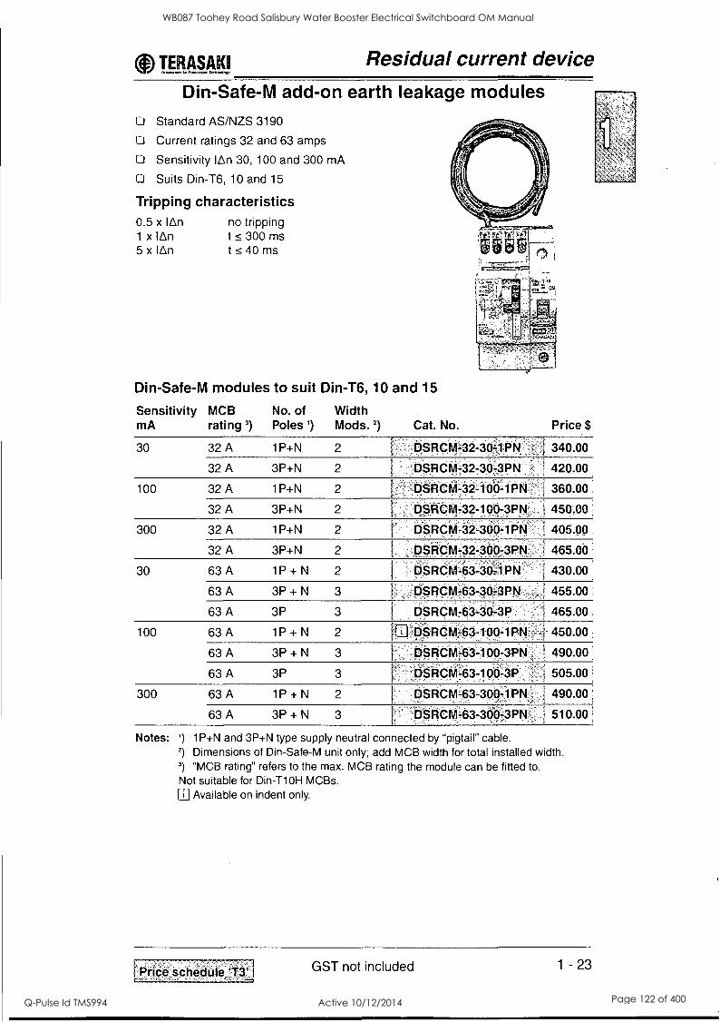
0 TIMM Residual current device
Li
Li
Li
CI
Din-Safe-M add-on earth leakage modules Standard AS/NZS 3190
Current ratings 32 and 63 amps
Sensitivity lAn 30, 100 and 300 mA
Suits Din-T6, 10 and 15
Tripping characteristics 0.5 x lAn 1 x 'An 5 x lAn
no tripping t < 300 ms t <40 ms
Din-Safe-M modules to suit Din-T6, 10 and 15
Sensitivity MCB No. of Width mA rating 3) Poles ') Mods.2) Cat. No. Price $
30 32 A 1P+N 2 DSRCM-32-30=1PN - ! 340.00
32 A 3P+N 2 DSRCM-32-30-3PN 1 420.00
100 32 A 1P+N 2 DSRCM-32-100-1PN 360.00
32 A 3P+N 2 DSR-CM-32-100-3PN' 450.00 = ,
300 32 A 1P+N 2 DSRCM-32-300-1PN 405.09
32 A 3P+N 2 DSRCM-32-300-3PN 465 00
30 63 A 1P + N 2 DSRCM-63-30-1PN 430.00
63 A 3P + N 3 DSRCM-63-30-3PN 455.00
63 A 3P 3 DSRCM-63-30-3P 465.00
100 63 A 1P + N 2 1 ' DSRCM-63-100-1PN 450.00
63 A 3P + N 3 , DSRCM-63-100-3PN 490.00
63 A 3P 3 . DSRCM-63-100-3P 505.00
300 63 A 1P + N 2 DSRCM-63-300-1PN , 490.00 '
63 A 3P + N 3 DSRCM-63-300-3PN ; 510.00
Notes: ') 1P+N and 3P+N type supply neutral connected by "pigtail" cable. 2) Dimensions of Din-Safe-M unit only; add MCB width for total installed width. 3) "MCB rating" refers to the max. MCB rating the module can be fitted to.
Not suitable for Din-T1OH MCBs. Available on indent only.
Priceschedule.73'' GST not included 1 - 23
WB087 Toohey Road Salisbury Water Booster Electrical Switchboard OM Manual
Q-Pulse Id TMS994 Active 10/12/2014 Page 122 of 400

TP.A.§41 Residual current device
Din-Safe-M modules to be combined with Din-T MCBs
Din-Safe-M modules are an earth leakage module only. To complete the functional unit a Din-T6, Din-T10 or Din-T15 MCB must be added as shown.
Din-Safe-M space requirements
Type Without MCB fitted neutral not switched
MCB fitted neutral not switched
MCB fitted neutral switched
1 P + N 32/63 A 2 modules (36 mm) 3 modules (54 mm) 4 modules (72 mm)
3P + N 32 A 2 modules (36 mm) 5 modules (90 mm) 6 modules (108 mm)
3P + N 63 A 3 modules (54 mm) 6 modules (108 mm) 7 modules (126 mm)
3P 63 A 3 modules (54 mm) 6 modules (108 mm) N/A
Operation The combined Din-T MCB/Din-Safe-M earth leakage module has two operating toggles which indicate the reason for the trip action taking place.
LI When an overload or short circuit occurs the Din-T MCB will operate. In this case the Din-Safe-M toggle will remain in the ON position.
If an earth leakage fault occurs both toggles will move to the OFF position. In
order to reset the MCB the Din-Safe-M unit must be reset first.
L In both instances - if the cause of the trip operation has not been rectified, a trip operation will occur as soon as the MCB is turned to the ON position. The trip free mechanism of the MCB ensures that a successful trip operation takes place even when the toggle is held in the ON position.
Assembly D Place the MCB and Din-Safe-M unit on a flat surface. Be sure that both the
MCB and the Din-Safe-M toggles are in the ON position. Li Slide the two units towards each other inserting the connecting bars or links into
the MCB tunnel terminal, ensuring no undue pressure is applied to the metal tripping pin of the Din-Safe-M unit.
Li Push in the connecting clips, locking the unit together.
Li Check that the MCB trips when the toggle on the Din-Safe-M is moved to the OFF position.
D Tighten the busbar connections between the MCB and the Din-Safe-M and fit the insulating cover supplied.
3 If the pigtail and N connections are reversed, the breaker will trip as soon as load is energised. Reset Din-Safe-M module before switching MCB 'ON'.
Li In the case of a three phase 3 wire system (no neutral) use 3 phase models. 3P+N models will operate satisfactorily but test button will only function if neutral pigtail is connected.
1 - 24
WB087 Toohey Road Salisbury Water Booster Electrical Switchboard OM Manual
Q-Pulse Id TMS994 Active 10/12/2014 Page 123 of 400

T...W.M.K1 Residual current device
Din-Safe-M modules to be combined with Din-T MCBs
Testing The MCB/Din-Safe-M combination must be connected with the line conductors to the LINE side (OFF/Bottom side) of the MCB and the load conductors connected to the Din-Safe-M terminals. The MCB/Din-Safe-M combination must be tested with the supply connected before connecting the load. First switch the Din-Safe-M unit 'ON' then the MCB. When the test button is pressed, both handles should trip. It is recommended that the test button is operated periodically to test the detection and tripping functions of the combined unit.
Li Both 1 P +N and 3P+N models have a neutral pigtail connection. 3P modules have no neutral connection at all.
Din-Safe-M 1P+N with 1 pole MCB Din-Safe-M 1P+N with 2 pole MCB (neutral not switched) switching active and neutral
LOA te k
NEUTRAL
PIGTAIL
00 N L
Din -Safe -M
HEARTH
POLE
MC9
I- I
V
OIT
Din-Safe-M 3P+N with 3 pole MCB (neutral not switched)
LOAD
@OGG N LI L7 LS
®® ® Din-Scle-M
3 Po E
MCB 11
® ® e
Din-Safe-M 3P+N with 4 pole MCB switching active and neutral
LOAD
0000 N IL L7 13
Din-Solc-M
II
a a 4 FOLE
M
a 8
@
eeee
Connection diagram 1 PHASE N L
3 PHASE N L, L, 13
Load
PHASE
I PHASE
I
I
I I
N I, 1, 1, N L
- - 1-
u u
jEARTLI
1 - 25
WB087 Toohey Road Salisbury Water Booster Electrical Switchboard OM Manual
Q-Pulse Id TMS994 Active 10/12/2014 Page 124 of 400

T RAM Accessories Mounting on the left-hand side
4 x DTAUXAL/G
00 0
a 00 00
1=3
2 x DTAUXAL/G Motor
0 0 Din-T
6
10 15
Note: The above accessories will not fit to Din-Ti OH MCBs. Refer to pages 1 - 30 and 1 - 31 for suitable shunts and auxiliaries.
WB087 Toohey Road Salisbury Water Booster Electrical Switchboard OM Manual
Q-Pulse Id TMS994 Active 10/12/2014 Page 125 of 400

TITAYYSI Accessories
Din-T 8
10 15
Din-Safe Safety
Switches
Din-Safe MCEls
(Double Pole)
O 0
O 0
O 0
O 0
Mounting on the right-hand side
4 x DTAUXAL/G Shunt UVT
00 00
Motor 2 x DTAUXAL/G
DTPBS
Note: DSRCBH - Single pole RCD/MCB will not accept side mounted accessories. DINTMS - Main switches will accept side mounting auxiliary contacts only.
1 - 27
WB087 Toohey Road Salisbury Water Booster Electrical Switchboard OM Manual
Q-Pulse Id TMS994 Active 10/12/2014 Page 126 of 400

TE.PAPAK! Accessories Mounting of add-on devices onto
MCBs, RCCBs and RCBOs
Di n-T, DC,
Type/Description 6, 10, 15
DTAUXAL L - R
Signal or AUX contact
DTAUXALG
Signal or AUX contact, gold
DSRCB, Din-T DSRCD 10H all types DSRCM
Change -over
DINTMS switch
R R L - R I L - R
R L - R
DINT1OHHS
Signal or AUX + AUX contact
DTPBS
Panelboard switch
R
DINTSHT
Shunt trip
DTSHT
Shunt trip
DTUVT
Undervoltage trip
DTMD
Motor operator
L = Left mounting
- R
L.-
L
R
R
L - R R
R = Right mounting
1 - 28
WB087 Toohey Road Salisbury Water Booster Electrical Switchboard OM Manual
Q-Pulse Id TMS994 Active 10/12/2014 Page 127 of 400

Miniature circuit breakers Din-Safe MCBs (RCBO)
El Standard AS/NZS 61009
Approval N17482
Short circuit, overcurrent and earth leakage protection 13 Handle sealable and padlockable
El DIN Rail mounting
Din-Safe MCB with pigtail
No of Poles
Amp rating (A)
Voltage (V)
Short circuit (kA)
Trip Sens.
Phase ') (mA) Cat. No
2 6 110/240 10 1+N 30 rjAiaairtli); 2 10 110/240 10 1+N 30 k:'15'Sfi6.B:ii.)3,44,i,,
2 16 110/240 10 1+N 30 -4-SRC61630P;3,--,14
2 20 110/240 10 1+N 30 t-4 2 25 110/240 10 1+N 30 .;gkei25310'01 2 32 110/240 10 1+N 30
2 40 110/240 10 1+N 30 °OSRC84'd30P s," Din-Safe MCB standard terminal configuration
Amp Short Trip No of rating Voltage circuit Sens.
Poles (A) (V) (kA) Phase ') (mA) Cat. No ')
2 6 110/240 10 1+N 10 F!6Sge60:60A;
2 6 110/240 10 1+N 30 :,,pDSRC7R0630
2 10 110/240 10. 1+N 10 ASRPB.10.1X,,,,,
2 10 110/240 10 1+N 30 '.1DSR631030!
2 10 110/240 10 141 100 p-- r....,r..., . ,' ..,
YrDSR6B1p1Or
2 16 110/240 10 1+N 10 lisitilail*. 2 16 110/240 10 1+N 30 iski160,k,
2 16 110/240 10 1+N 100 4DiriOA6W, Wtt
2 20 110/240 10 1+N 10 . 40 ,. ',3£' ,,.4i si, ''."
2,DSBC8201011
2 20 110/240 10 1+N 30 ..216S16.2..0i0..741
2 20 110/240 10 1+N 100 ..11,7DSifEB2D100'
2 25 110/240 10 1+N 30 plDSREB2530 A
2 32 110/240 10 1+N 30 L-A/S103"2:370:-
2 40 110/240 10 1+N 30
.,- 5bAtB4D3b .
Application Din-Safe MCB is a combined MCB/RCD proViding thermal overload, short circuit and earth leakage protection in the one integral unit.
Din-Safe MCBs are suitable for use in residential, commercial and light industrial applications.
Terminal configuration
PIGTAIL
(LOAD) NEUTRA
NEUTRAL
(LOAD) L
0 0 N
01,1= ACTIVE (g'
NEUTRAL ACTIVE (LOAD) (LOAD)
0 na Li N
0 0 NEUTRAL ACTIVE
UN[) (l NE)
DIN-Safe NCB with neutral pigtail
suits standard 3 phase chassis
DIN-Safe MCB
standard terminal configuration
Characteristics El Width: 2 modules.
El For type AC residual currents.
E3 Rated voltage: 110/240 V/50-60 Hz.
El Tripping characteristics of MCB part:
IEC 60848 - C curve.
El Short circuit capacity: 10 kA.
El Terminal capacity: 25 mrn2.
El High immunity to transient current.
El Profile as per Din-T MCB.
El Test button for periodic testing.
Notes: ') Unprotected neutral, not switched. ') Unprotected neutral, switched. ') Fits Din-T chassis (special configuration)
refer page TBA. 1 Some type mir RCDs are stocked. Refer NHP.
Nuisance tripping may be experienced in VFD
and motor starting applications refer NHP.
Available on indent only.
WB087 Toohey Road Salisbury Water Booster Electrical Switchboard OM Manual
Q-Pulse Id TMS994 Active 10/12/2014 Page 128 of 400

TER SA Innovators In l'rorertIon Aschnnlog,
Din-T MCBs + RCDs Technical data
What is an RCD?
The RCD (Residual Current Device) is a device intended to protect people against indirect contact, the exposed conductive parts of the installation being connected to an appropriate earth electrode. it may be used to provide protection against fire hazards due to a persistent earth fault current, without operation of the overcurrent protective device.
RCDs having a rated residual operating current not exceeding 30 mA are also used as a means for additional protection in case
of failure of the protective means against electric shock (direct contact).
Working Principle
The main components of an RCD are the following:
The core transformer: which detects the earth fault current.
The relay: when an earth fault current is detected, the relay
reacts by tripping and opening the contacts.
El The mechanism: element to open and close the contacts
either manually or automatically.
LSI The contacts: to open or close the main circuit.
The RCD constantly monitors the vectorial sum of.the current passing through all the conductors. In normal conditions the vectorial sum is zero (I142-0) but in case of an earth fault, the vectorial sum differs from zero (I1+I2-Id), this causes
the actuation of the relay and therefore the release of the main contacts.
Test resistor -
Secbridary windin0
Test -button
MRS r.61
-Contacts
Tripping rneripcl.a oil n gism
transformer and primary winding.
Definitions related to RCDs
RCCB = Residual Current Circuit Breaker without overcurrent protection.
RCBO = Residual Current Circuit Breaker with overcurrent protection.
Breaking capacity
A value of AC component of a prospective current that an RCCB
is capable of breaking at a stated voltage under prescribed conditions of use and behaviour.
Residual making and breaking capacity (IAm)
A value of the AC component of a residual prospective current which an RCCB can make, carry for its opening time and break under specified conditions of use and behaviour.
Conditional residual short-circuit current (lAc) A value of the AC component of a prospective current which an RCCB protected by a suitable SCPD (short-circuit protective device) in series, can withstand, under specific conditions of use and behaviour.
Conditional short-circuit current (Inc) A value of the AC component of a residual prospective current which an RCCB protected by a suitable SCPD in series, can withstand, under specific conditions of use and
behaviour.
Residual short-circuit withstand current
Maximum value of the residual current for which the operation of the RCCB is ensured under specified conditions, and above which the device can undergo irreversible alterations.
Prospective current
The current that would flow in the circuit, if each main
current path of the RCCB and the overcurrent protective device (if any) were replaced by a conductor of negligible impedance.
Making capacity
A value of AC component of a prospective current thatan RCCB is capable to make at a stated voltage under prescribed conditions of use and behaviour.
Open position
The position in which the predetermined clearance between open contacts in the main circuit of the RCCB is secured.
Closed position
The position in which the predetermined continuity of the main circuit of the RCCB is secured.
Tripping time The time which elapses between the instant when the residual operating current is suddenly attained and the instant of arc extinction in all poles.
Residual current (I.An)
Vector sum of the instantaneous values of the current flowing in the main circuit of the RCCB.
Residual operating current
Value of residual current which causes the RCCB to operate under specified conditions.
Rated short-circuit capacity (Icn) Is the value of the ultimate short-circuit breaking capacity assigned to the circuit breaker. (Only applicable to RCBO)
Conventional non-tripping current (Int) A specified value of current which the circuit breaker is capable of carrying fora specified time without tripping. (Only applicable to RCBO)
Conventional tripping current (It) A specified value of current which causes the circuit breaker to trip within a specified time. (Only applicable to RCBO)
WB087 Toohey Road Salisbury Water Booster Electrical Switchboard OM Manual
Q-Pulse Id TMS994 Active 10/12/2014 Page 129 of 400

TE ASAK11 Inrroovemr3 in Prunwient 7i,iumfo
Din-T MCBs + RCDs Technical data
Tripping current as a function of the frequency All RCDs are designed to work at frequencies of 50-60 Hz, therefore to work at different values, we must consider the variation of the tripping sensitivity according to the tables below. It should be taken into consideration that there is a no tripping risk when pushing
the test-button, due to the fact that such action is made by means of an internal resistor with a fixed value.
RCBO DSRCB ')
ftWA0 toyoz: foflizj. 5 26-641i,
30 mA 0.62 0.65 0.80 0.91 1.24 1.55 1.88
100, mA 0.74 0.71 0.80 0.95 1.16 1.38 1.59
300 mA 0.80 0.74 0.80 0.97 1.19 1.44 1.64
500 mA 1.10 0.81 0.80 0.89 1.18 1.38 1.68
ffi.W44.4: 30 mA 8.17 3.13 0.75 1.70 3.10 3.52 3.67
100 mA 6.81
6.20
4.34
2.71
2.16
0.75
0.75
1.43
0.49
2.35
0.87
2.58
0.74
0.62
2.71
300 mA 0.95
500 mA 1.53 0.75 0.39 0.59 0.64
Notes: ') The standard NHP/Terasaki type is the "type AC" in Australia, Type "A" in New Zealand.
1 The standard NHP/Terasaki DSRCBH single pole RCBO is "type A" in Australia and New Zealand.
The numbers in the table above are multipliers, e.g. A "DSRCD" at 50 hz has an 0.8 multiplier. Therefore a 30 mA, "type AC" RED will trip at (0.8 x 30 mA) 24 mA.
Power losses The power losses are calculated by means of measuring the voltage drop between the incoming and the outgoing terminal of the device at rated current. Power loss per pole;
RCBO-DinSafe MCB DSRCB
FTATAJ177:-, 1
125 53 16.5 11.9 9,8 7.1 5.6 4.7 3.6
2.0 1.9 1.6 2.0 2.5 2.8 3.5 4.8 5.8
WB087 Toohey Road Salisbury Water Booster Electrical Switchboard OM Manual
Q-Pulse Id TMS994 Active 10/12/2014 Page 130 of 400
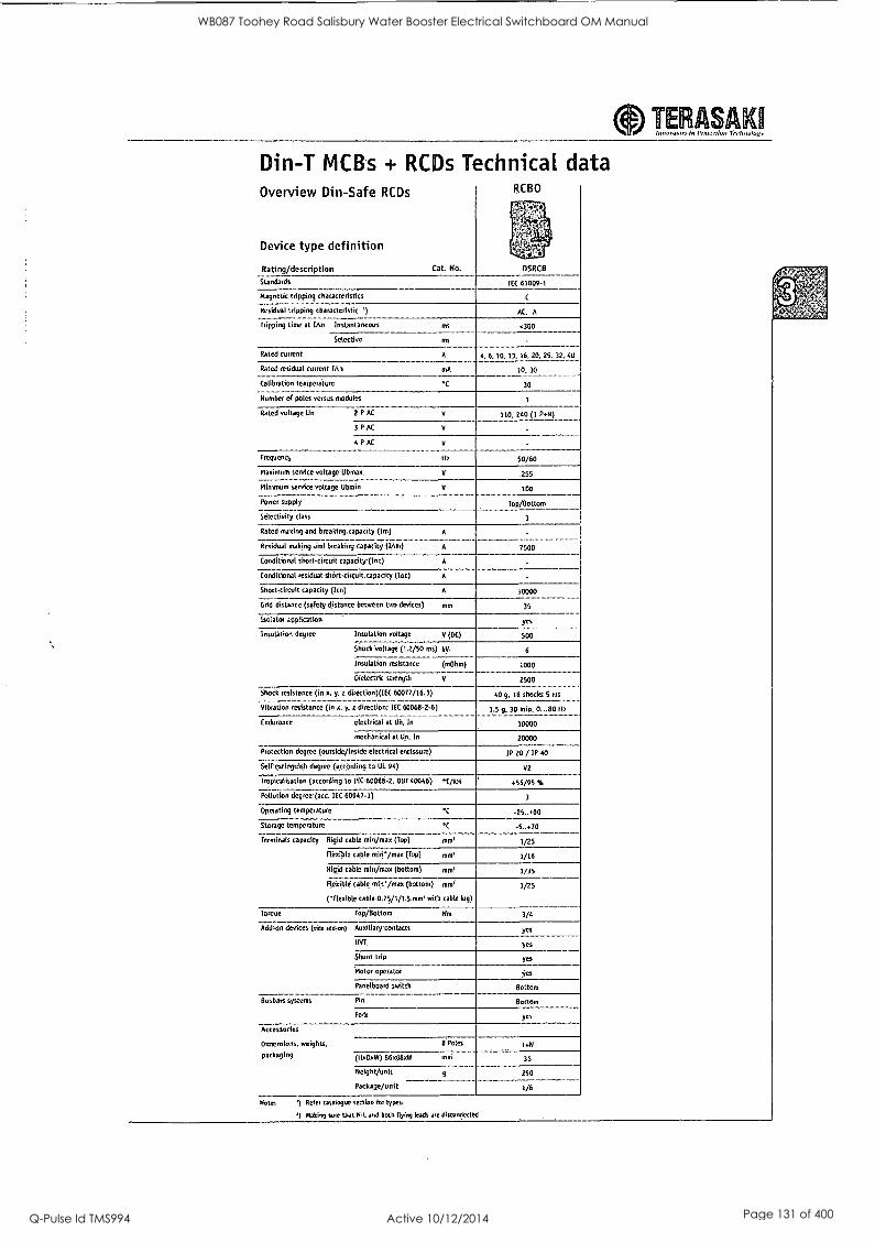
TERASAK11 Imrovahsr, In.Praterdoll Tiehriologr
Din-T MCBs + RCDs Technical data Overview Din-Safe RCDs
Device type definition
Rating/description Cat. No.
KUSU
., , .
DSRCB
Standards ITC 61009-1
Magnetic tripping characteristics C
Residual tripping characteristic ') AC, A
Tripping time at Inn Instantaneous ms .300
Selective no
Rated current A 4, 6, 10. 13, 16. 20, 25, 32. 40
Rated residual current [An mA 10, 30
Calibration temperature C 10
Number of poles versus modules 1
Rated voltage Un 2 P AC V 110. 240 (1 2.6)
3 P AC V
4 P AC V
Frequency Itz 50/60
Maximum service voltage Ubmax V 255
Minimum service voltage Ubmin V 100
Power supply Top/Bottom
Selectivity class 3
Rated making and breaking capacity (Im) A -
7500 Residual nsakingand breaking capacity (lAm) A
Conditional short-circuit capacity (Inc) A .
Conditional residual short-circuit capacity (IAc) A .
Short,circuit capacity (Ice) A 10000
Grid distance (safety distance between two devices) nrnr 35
Isolator application Yes
Insulation degree Insulation voltage V (DC) 500
Shock'voltage (1.2/50 ms) ky 6
Insulation resistance (mOhm) 1000
Dielectric strength V 2500
Shock resistance (in x, y, z directionMEC 60077/16.3) 40 g, 18 shocks 5 ms
Vibration resistance (in x, y. z direction: IEC 60068-2-6) 1.5 9. 30 min, 0...80 rlz
Endurance electrical at Uri, In 10000
mechanical at Un. In 20000
Protection degree (outside/inside electrical enclosure) IP 20 / IP 40
Self-extinguish degree (accerding to UL 94) 02
Tropmalisation (according to MC 60068-2, DIN 40046) *URN .55/95 V.
Pollution degree (acc. TEC 60947.1) 1
Operating temperature °C -25...60
Storage temperature °C -5..+70
Terminals capacity Rigid cable min/max (Top) nine 1/25
Flexible table min/max (Top) mmr 1/16
Rigid cable min/max (bottom) mrn' 1/35
flexible cable min'/max (bottom) mil
(flexible cable 075/1/1.5 mm' with cable lug)
1/25
Torque Top/Bottom Nm 3/4
Add-on devices (side add,.on) Auxiliary contacts Yes
1191 yes
Shunt trip yes
Motor operator yes
Panelboard switch Bottom
Busbam-systems Pin Bottom
Fork yes
Accessories
Oimensions, weights, 0 Poles 1.14
packaging (11x0xW) 86068011 nun 36
weight/unit g
Package/unit
250
1/6
Note: ') gee, catalogue section for types.
Making SUre that Ill and both flying leads are disconnected.
WB087 Toohey Road Salisbury Water Booster Electrical Switchboard OM Manual
Q-Pulse Id TMS994 Active 10/12/2014 Page 131 of 400

J & P Richardson Industries Pty Ltd
3 Fuses
NHP - 63amp 63ms Fuse
SUPPLIED BY: NHP ELECTRICAL ENGINEERING PRODUCTS Pty. Ltd. 16 Riverview Place, Murarrie 4172, Queensland AUSTRALIA
PHONE: (07) 3909 4999 FAX: (07) 3399 9712
File: Swbd Manual Revision 0 Date:11/3/2010
WB087 Toohey Road Salisbury Water Booster Electrical Switchboard OM Manual
Q-Pulse Id TMS994 Active 10/12/2014 Page 132 of 400

L_
0 SS
"t..-" - =. ,. - ..
- y
- - - -
Ai 4,....-
bs:.-. -!...2i, 1......,774.f....;:::--- ..._...e.,,- Ni 4:74:2,.....L.:±e=1-7
. -=.1..::z.::: / -....-
--I
....r..4. _ i....,, ..> ... . e - -- - : -.::- -r--: - 1
\ " - -.--'4. ' - '' ra 7-7. -'- -..., . .....'-.7°S_,"."- 1&g;,,,-...;--,... - 7 - ' - - .,..-7,:._:,_-,; - . - -: f- --'."- - 1."-
,- re. ree ..1. 6.-- -_,_ .r.--V..- 1-4 . r
_ -'..7.1141Z1,_2-1.2:7,-
....71'..-.7 e ....
:. ,... ,,,,...,...
.--.----.,
-
-
-- : '71.0nE
0
WB087 Toohey Road Salisbury Water Booster Electrical Switchboard OM Manual
Q-Pulse Id TMS994 Active 10/12/2014 Page 133 of 400
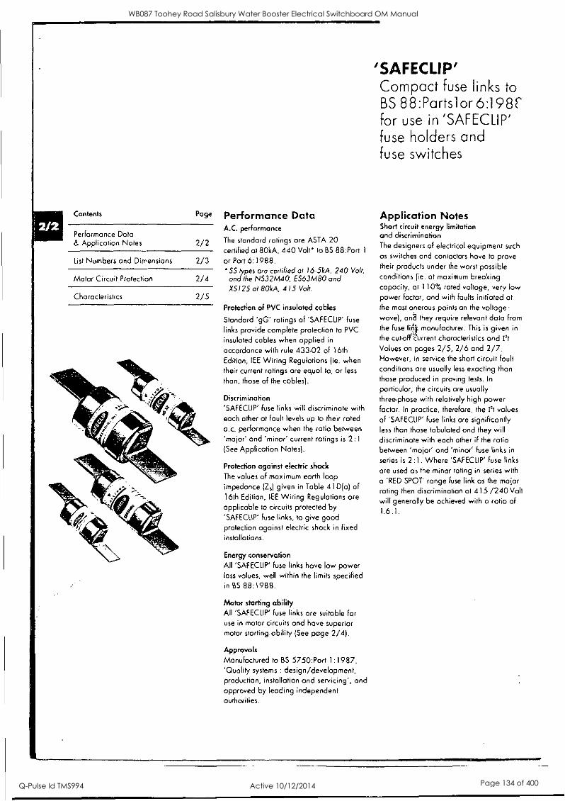
Contents Page
Performance Data & Application Notes 2/2
List Numbers and Dimensions 2/3
Motor Circuit Protection 2/4
Characteristics 2/5
Performance Data A.C. performance
The standard ratings are ASTA 20 certified at 80kA, 440 Volt* to BS 88:Part 1
or Part 6:1988. SS types are certified at 16.5kA, 240 Volt, and the NS32M40, ES63M80 and XS125 at 80kA, 415 Volt.
Protection of PVC insulated cables
Standard 'gG' ratings of 'SAFECLIP' fuse
links provide complete protection to PVC
insulated cables when applied in
accordance with rule 433.02 of 16th
Edition, IEE Wiring Regulations (ie. when their current ratings are equal to, or less
than, those of the cables).
Discrimination
'SAFECLIP' fuse links will discriminate with each other at fault levels up to their rated a.c. performance when the ratio between 'major' and 'minor' current ratings is 2:1 (See Application Notes).
Protection against electric shock
The values of maximum earth loop impedance (4) given in Table 41D(o) of 16th Edition, IEE Wiring Regulations are applicable to circuits protected by
'SAFECLIP' fuse links, to give good protection against electric shock in fixed installations.
Energy conservation All 'SAFECLIP' fuse links have low power loss values, well within the limits specified in BS 88:1988.
Motor starting ability All 'SAFECLIP' fuse links are suitable for use in motor circuits and have superior motor starting. ability (See page 2/4).
Approvals Manufactured to BS 5750:Part 1:1987, 'Quality systems : design/development, production, installation and servicing', and approved by leading independent authorities.
'SAFECLIP' Compact fuse links to BS 88:Parts] or 6:198r for use in 'SAFECLIP' fuse holders and fuse switches
Application Notes Short circuit energy limitation and discrimination The designers of electrical equipment such
as switches and contactors have to prove their products under the worst possible
conditions (ie. at maximum breaking capacity, at 110% rated voltage, very low
Power factor, and with faults initiated at the most onerous points on the voltage wove), ana they require relevant data from the fuse lin manufacturer. This is given in
the cut-orCurrent characteristics and I2t
Values on pages 2/5, 2/6 and 2/7. However, in service the short circuit fault conditions are usually less exacting than
those produced in proving tests. In
particular, the circuits ore usually three-phose with relatively high power factor. In practice, therefore, the Pt values
of 'SAFECLIP' fuse links are significantly less than those tabulated and they will discriminate with each other if the ratio between 'major' and 'minor' fuse links in
series is 2:1. Where 'SAFECLIP' fuse links
are used as the minor rating in series with
a 'RED SPOT' range fuse link as the major rating then discrimination at 415 /240 Volt
will generally be achieved with a ratio of 1.6:1.
WB087 Toohey Road Salisbury Water Booster Electrical Switchboard OM Manual
Q-Pulse Id TMS994 Active 10/12/2014 Page 134 of 400

Applications
Equipment Refer to Fuse link type Publication accommodated in equipment number for details SS NS ES XS OS
'SAFECLIP' HRC Fuse holders and Fuse banks IEF/402 'SAFECLIP' Distribution Fuse boards IEF/403 'SAFECLIP' Fuse Combination Units - Type MSS IEF/498 'SAFECLIP' Wall Mounting Fuse Combination Units - Type WMS IEF/503 ;
'SAFECLIP' Panel boards IEF/450 Type MST100 Fuse switch IEF/404 Type WM1003N Wall Mounting Fuse Switch IEF/503
List Numbers and Dimensions
D
A
E ti
KI
A
G
Figure 1 Figure 2
I t --r F
1E
list number prefix
SS
NS
ES
XS t
OS
Current rating
Amp
Figure number
Dimensions in millimetres
A B D max max max
E F N
2*, 4*, 6, 10, 16, 20 1 25 14.5 51 11 0.8 3.6 2, 4, 6, 10, 16, 20, 25, 32, 32M40* 1 35.5 14.5 62 11 0.8 3.6 40, 50, 63, 63M80* I 39 17.5 69 15 1.25 3.6 20*, 32*, 63*, 80*, 100*, 125* 1 39 26.4 80 19 1.6 3.6
A BD E F G H K
80*, 100*, 100M125* 2 58 26.4 90.5 12.7 1.2 73 5.2 27.8 These types are ASTA Certified to 8S 88:Port 1: 1988
t Intermediate and minor rating are also available down to 2 Amp.
WB087 Toohey Road Salisbury Water Booster Electrical Switchboard OM Manual
Q-Pulse Id TMS994 Active 10/12/2014 Page 135 of 400

Motor Circuit Protection Select HRC fuse links to protect 3-phase motor circuits as follows: 1) Obtain motor full load current from
Table I .
2) The following motor starting conditions are assumed:
Direct -On -Line:
Up to 1 kW: 5 x FLC for 5 secs.
1.1 to 7.5 kW: 6 x FIC for 10 secs.
7.6 to 55 kW: 7 x FIC for 10 secs.
Assisted Start:
Up to 1 kW: 2.5 x FIC for 20 secs.
Greater than 1 kW: 3.5 x FLC for
20 secs.
3) Choose the recommended fuse link for the motor FLC and starting condition from Table 2 (DOL start) or Table 3
(assisted start).
4) Ensure voltage rating of fuse link is
adequate for the application (See page 2/2).
The recommended fuse link ratings apply for up to 8 starts per hour under stated
starting conditions. They may need to be
adjusted if any of the following conditions occur singly or in combination:
a) Starting currents in excess of assumed values.
b) Longer starting times than those stated.
c) Large number of starts per operating cycle.
d) High enclosure temperature.
Table 1 Full load currents of typical 3-phase induction motors at voltages shown
Motor rating
kW HP 220
0.37 0.55 0.75 1.1
1.5
2.2 3
4
5.5 7.5
11
15
18.5
22
30 37 45 55
0.5 0.75 1
1.5
2
3
4
5.5 7.5
10
15
20 25 30 40 50 60 75
2.0 2.7 3.9 4.7 6.5 9.3
12
15.4
20.7 28
39.1
52.8 66 77
103
Voltage
380 415 440
1.15 1.05 1.0
1.6 1.5 1.4
2.3 2.0 1.9
2.8 2.5 2.4
3.8 3.5 3.3 5.4 5.0 4.7 7.1 6.5 6.1
9.0 8.4 7.9 11.9 11 10.3
16.1 14.4 14
231 21 19.8
30'5 28 26.4 3r 35 33
45 41 39 60 55 52 75 69 65 87 80 75
107 98 92
Table 2 Direct-on-line starting
Motor FLC Fuse Current Rating
Amp From to Amp
Fuse Type
0 0.7 0.8 1.4
1.5 2.0 2.1 3.0 3.1 6.1
6.2 9.0 9.1 11
11.1 14.4 14.5 18
18.1 22 22.1 28 28.1 38 38.1 53 53.1 72 28.1 45 45.1 58 58.1 80
2
4
6
10
16
20 25
32
40' 50 ES3
63
802
100 XS
125
80 100 05
100M125
NS3
1) NS32M40 is alternative fuse type if FLC does not exceed 32 Amp & voltage is
415 Volt or less. 2) ES63M80 is olternative fuse type at 415
Volt or less. 3) XS fuse links are also available in-minor
ratings below 80 Amp.
Table 3 Assisted starting (star/delta, etc.) *
Motor FLC Fuse Current Rating
Amp From to
0 1.4
1.5 2.1
2.2 3.1
3.2 5.5 5.6 10
10.1 14
14.1 18
18.1 22
22.1 32
32.1 40 40.1 51
51.1 80 80.1 100
100.1 125
Amp
2
4
10
16
20 25 32
401
50 63 802
100 125
Fuse Type
N53
ES3
OS or XS
XS
* The assisted starting recommendations apply for ambient temperatures up to 35°C. At hyher temperatures, some ratings may nee to be deroted. Consult GEC ALSTHOM Low Voltage , Equipment Limited for further information'
WB087 Toohey Road Salisbury Water Booster Electrical Switchboard OM Manual
Q-Pulse Id TMS994 Active 10/12/2014 Page 136 of 400

Characteristics 'SAFECUP'
Type SS
Time/Current Characteristics 6.20 Amp
'SAFECUP'
Type SS
Cut-off Current Characteristics 6-20 Amp
20000
10.000
1.000
100
01
001
0005
z
LL
0
01
IIIIIIISIIIIE1111111281=11111111C1 i011101 ====. IIMEMMENIMMI
=MIM.../111=1. W=IMM.... =Win
1111111111111111111111111111 mamas =mvxmo=13
W1111111111111111V1M1111111111111=11MIIIIIM EMI= M
=nM
:WM= wineasamimmimmusitrai. waling 111
111111WallitlilliN11111111111 iill IIIMINIIMI Aimminismat-aimmusavarnami IMMIWIESIMINIIMMIIMINEMIIIIMMI=1=111111
1111.111.1111115.11111fablifilliriaMillinin
1111101111111111111111111111111111111MIMMI1111111118111.
MililalliMINME10 =. NIMMOINIMINLOMMIM=ElgelirtTell IMMIl%Sala MEWS IhinialmallEMMINIUMINCIANN rn ==":".7====:=1::====
10 100
RMS SYMMETRICAL PROSPECTIVE CURRENT IN AMPERES
1.000
II ./d011111 IMMIIM1MIIP%aMi al murr..--amralm 10 =way
MIIIIII.Pr..1111111PilltilM=MMII =WM IIIIMIIMMIIIIMR1111=1/1111111111%1 6 ME= IIIIMMIIMIMIIIMMINUJIPP" rinHlll _.III 111111
WA111111111§101111111111111101 PA! it
20 16
10 to
PROSPECTIVE CURRENT kA (RmS SYMMETRICALI
100
WB087 Toohey Road Salisbury Water Booster Electrical Switchboard OM Manual
Q-Pulse Id TMS994 Active 10/12/2014 Page 137 of 400
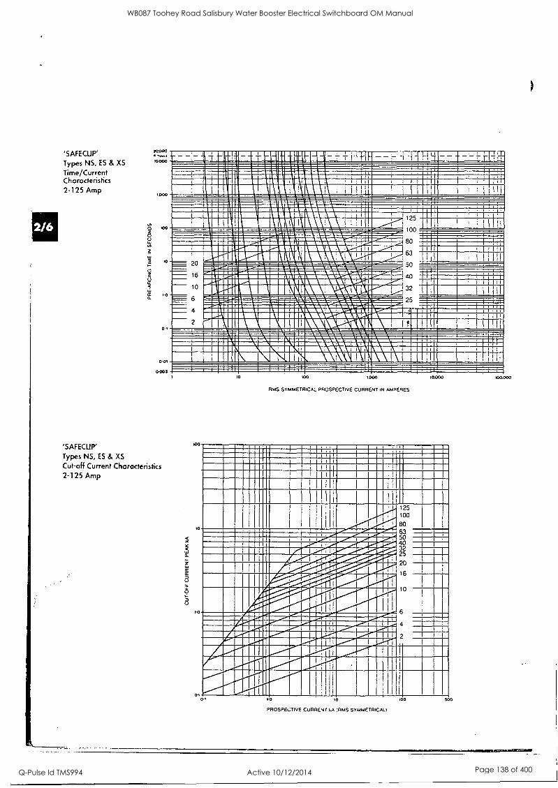
'SAFECLIP'
Types NS, ES & X5
Time/Current Characteristics 2125 Amp
'---. 10.000 - - - 111111181111111111111111111111=111111111=10111101MMINI
I 1 11 al I ! I : I f I
. 1 I I
' t 1
I I I i I 1 I
111111111111WIRIMEN i
imarimic mu. 111111111111111111111M1111
IIIIMITEILIIIIIIIIIMUNIMMI 1125
. OPP' ' ; , 1
.0
...._...._ i 00 ____.. .,..=.........-_.....,.......w.....n........---..=;.....-
,011iOfM1IlIlMlIIlIr.!.'!/1llII!t MM. ........_
MOI1/4411MMIlIWZMIIMUILAIMINE' ......"War...
MIIMININIMM1111111MSENV111MMINHIZI/ 80 i
, I
..aillialagillairdareiralarirridW ! ! 1 - 63 1 1 I I
........---:.............-....................-....=.- -AnMa7r;.:i"Zai:Z:&srsvaZra"MraroWr- minimpermiummosimisminumoulsme.sdailissi..- 1111EM111111111111111111M1111111111111111111111111MMINIIPP'"
Ingaillinin
A ---m-7..--=- liall....-
50
16 - 10 -7---- 6
4
.40 WIWI
lialilWirnater ' 111111111MIIIINNIEN I il 32
'7"7-'==11101111M ilEt .m.::::::4M-= 11Milit1IMINSIIIIIIIIINIONIII111111=MMILVIIIIMICIIIIMMINSW:walML IMMUMMMIMMOMMENIMMOLIMOLIIMMUIDMIMMUMUNIMMUMEMINAMINI IEWEINSURIMMariiinaWkirainarallMiliniiiniiiii/MAMMEMMU 111WINIMIMILHEIMPAWINIMIUG1111
W.= =IBM .-.7.. ..... 25 113111.fmell1111
1111 1
======.-..,-........-. ,...........wor.,Bg.=..t'r..e7rnr:=....o.....=".=......Z. =4.4.4.4111worommuomaiemaisumatamiesuavamnimmowtozasammErm MUMILIMMININNEMMILIMISEMMIRIMMIMORIMAMINaggi -.......7-...=.................7.....-.-.................
NIMINUNI11111111111011101111111MIERVIIIIMMIIIMNIIIIMINIIIII 0 m 11111111111113SEUE111M11111101111111 ;
i 1 I
0-005
'SAFECUP'
Types N5, ES & XS
Cut-off Current Characteristics 2125 Amp
100
10
yo
10 100
RMS SYMMETRICAL PROSPECTIVE CURRENT IN AMPERES
10.000
MINIMIIIMIIII 11111M1111111
INIM1111=111111MIIIIIMINSIO1 INUMMUMMIIIMIMIIIMMIMMIN MIMI ! 1
I I
!
1 I
IIIIIIMMIIMIIIMIUMAIMIIIP
I
d1101
125 100
80 mmmuawamsitssmmw--IswP^-...dmr-..oa wimosominmemtiNUPimsratiffiwo! 63
cr, INIIIMMOMPIIIIIIINMENWMIIIIII0.1111110-..del ,," NIIMMISIIIIIIIMIIMPIIIIPP-dlIMOPP- 25 IIIMIMIWIP.-.
1111110.P.OP.
-tea:.
,, .,
Mdl
20
16 I IFW.e.SMOSIM iir,----...,i0 ._.........., ............,.......... MI .AMAIENP/U11101MINNIPP--.1111
i1
MMIUM1121
4 WrIntPria.11.1111.111/nPlialMnrdilli FAMIMMIMIIIIIIIIIIIIIIMMAS11111111%11111UI All Oral
4E110111111MillffrallMill
w'' 1111111 PrllIPP' I
I
1
1 i
10 10
PROSPECTIVE CURRENT kA IRMS SYMMETRICAL)
100 500
100.000
WB087 Toohey Road Salisbury Water Booster Electrical Switchboard OM Manual
Q-Pulse Id TMS994 Active 10/12/2014 Page 138 of 400

'SAFECUP' Types NS, ES & XS Current
I2t Values* Rating
Amp
Pre-Arcing /211.
(A2 Sec)
Total I2t (A2 Sec)
2 1.5 16
4 7.0 75
6 22 200
10 90 440 16 300 1300
20 520 2200 25 900 3000 32 1100 4000 40 2400 12000 50 3200 15000 63 5400 25000 80 8000 45000
100 15000 68000 125 32000 145000
Type OS
Time/Current Characteristics 80-125 Amp
atunimmodiallhommualsio: IIIIIMMIIM111111111111111111111111111111111
1111111111111111111111111111
Iminesemimies=somism
In1111111111111111 ...T.Z1======== mauls awn umemmEmmtainimus 11111111111LINIIIMIIIIIINNINI
114111111111111MOR
11111111/1111
111111111111111litll...1111
........___41MIN MINIUMMINIIIIMMILIISIMMININ111111MIMMININ
111111111111111111711111111
11111111111111111111
100M 25
RMS SYMMETRICAL PROSPECTIVE CURRENT IN AMPERES
Type 05 Cut-off Current Characteristics 80-125 Amp
100
100M125 100
80 Imusumomil IIIIM/111111111%1115011 BMW IIMMEMOMINMEMAIMPPMINWIIMMOINNOMMIN
NIMINIMMIUMKEPPMIIPP" "."..11111111M 111111111111MIPP"-Adr"-IIIMIIIINIMIIIIIIIIIIM101111111111
Type OS
I2t Values*
1-0 10
PROSPECTIVE CURRENT kA RMS SYMMETRICAL/
TOO
Current Rating
Amp
Pre-Arcing 12,
(A2 Sec)
Total I2t (A2 sec)
12, values at 440 Volt when tested under 8588 conditions. XS125 at 415 Volt.
80 14000 40000
100 17000 60000
100M125 32000 128000
WB087 Toohey Road Salisbury Water Booster Electrical Switchboard OM Manual
Q-Pulse Id TMS994 Active 10/12/2014 Page 139 of 400

J & P Richardson Industries Pty Ltd
4 Relays
CRITEC - DAR-275V - Surge Diverter Alarm Relay
SUPPLIED BY: ERICO 6 Chilvers Road, Thornleigh 2120, New South Wales AUSTRALIA
PHONE: (02) 9479 8500 FAX: (02) 9484 9188
CROMPTON INSTRUMENTS - 252-PSGW - Station Mains Phase Failure Relay
SUPPLIED BY: CROMPTON INSTRUMENTS 31 Brennan Street, Bellbird Park 4300, Queensland AUSTRALIA
PHONE: (07) 3818 6493 FAX: (07) 3818 6659
FINDER - 38.51 24VDC - Pump Manual Run Relay
SPRECHER & SCHUH - CS7C - 40E24V - All Pumps Stop Relay c/w - CS7-PV-20
SUPPLIED BY: NHP ELECTRICAL ENGINEERING PRODUCTS Pty. Ltd. 16 Riverview Place, Murarrie 4172, Queensland AUSTRALIA
PHONE: (07) 3909 4999 FAX: (07) 3399 9712
MULTITRODE - MRTA-5 - Level Relays
MULTITRODE - 0.2/1-'x' - Single Point Probes
SUPPLIED BY: MULTITRODE Pty. Ltd. 130 Kingston Road, Underwood 4119, Queensland AUSTRALIA
PHONE: (07) 3808 4011 FAX: (07) 3808 0011
File: Swbd Manual Revision 0 Date:11/3/2010
WB087 Toohey Road Salisbury Water Booster Electrical Switchboard OM Manual
Q-Pulse Id TMS994 Active 10/12/2014 Page 140 of 400

0111, DA
DIN Decoupling Inductor/ DINLINE Alarm Relay & Surge Counter
Decoupling inductors are installed between spark gap and MOV protection devices to help ensure correct coordination. As the decoupling inductors are installed in series with the load, two units are available, a compact unit for circuits up to 35A and a larger unit for 63A circuits.
The DAR (DINLINE Alarm Relay) can be connected to TDF units to provide potential free change-over alarm contacts. The TDS SC (Surge Counter) unit is
designed to provide visual indication of the number of surges registered. It uses a current `sansformer through which the ground conductor :onnecting to one, or all, of the surge protection nodules is fed. Current diverted by the operation of the surge module, which exceeds a 300A trip threshold, will be registered on the counter.
Asia/Australia Europe
Latin America
Use for decoupling of spark gaps and MOVs - allowS correct' coordination of different SPD technologies
35 mm2tunnel terminals -accepts large cable size
63A model features top and bottom terminals - flexible installation
The DINLINE Alarm Relay (DAR) is used with TDF products where alarm contacts are required for remote signaling
The Tps-SC Surge Counter provides a norresettable record of the number of surges diverted
DDI 35
DDI 63
DDI 63
Model DDI 35 DDI 63 DAR275V TDS SC
1701250 Item Number for Europe 700465 700475 700900 Nominal Voltage Un 20- 110V - - -, 100-240V- - System Compatibility(1) TN C, TN -S, TN-C-S & TT
Max. Cont. Operating Voltage tic 500V- 200V--- 275V Stand-off Voltage 275V Operating Current @ Un 20mA -
Frequency 0 to 60Hz -
Max. Line Current I, 35A @ 40°C 63A @ 40°C Temperature Increase 45° C @ max line current (Id
Inductance 7.5pH 4.5m0
15pH
1.71n0 - Resistance
Technology CT - trip threshold 300A 8/20ps Red/Green LEDs
Change-over contact' Maximum count 9999 Non-resettable
Status
Dimensions 2 M. 90 mm x 68 mm x 36 mm
(3.5" x 2.6" x 1.4") approx. 4 M. 90 mm x 68 mm x 72 mm
(3.5" x 2.6" x 2.8") approx.
2 M.
90 mm x 68 mm x 36 mm
(3.5" x 2.6" x 1.4") (excluding CT)
Weight 0.45 kg (1 Ib) approx. 1 kg (2.2 Ib) approx. 0.2 kg (0.44 Ib)
Enclosure DIN 43 880, UL94V-0 thermoplastic, IP 20 (NEMA 1)
Connection 535 mm' (#2AWG) solid 525 mm' (#4AWG) stranded
1 mm' to 6 mmi(#18AWG to #10)
Mounting 35 mm top hat DIN rail
Back-up Overcurrent Protection 35A l 63A I -
Temperature -40°C to +70°C (-40°F to +158°F) -35°C to +55°C (-311 to +131°F) Humidity 0% to 90% Approvals CE CSA22.2
C -Tick, AS 3260, CE
-
(1) Form C = Change-over contact (Form C dry contact), 400V-/3A 1 mm' to 6 mm' (#18AWG to #10AWG) connecting wire
40 www.erico.com
WB087 Toohey Road Salisbury Water Booster Electrical Switchboard OM Manual
Q-Pulse Id TMS994 Active 10/12/2014 Page 141 of 400
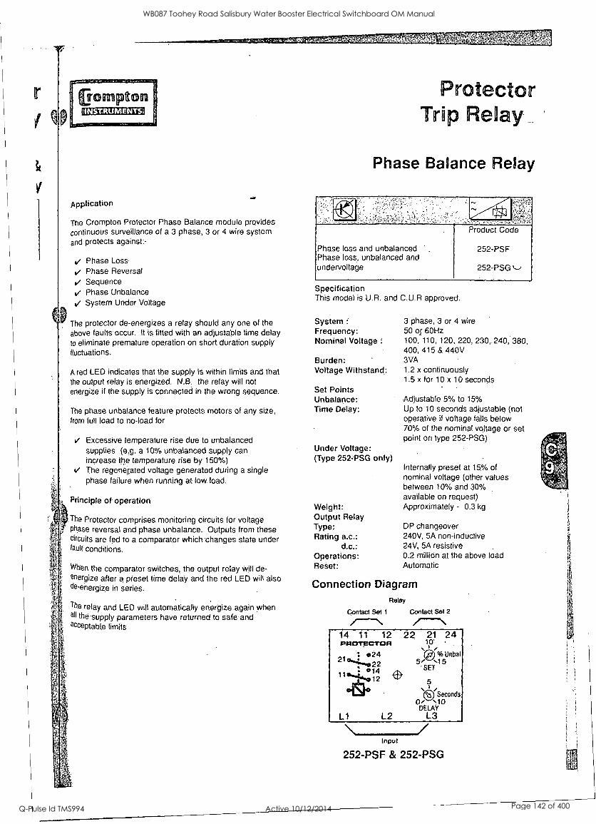
`.1-.7;i:ire, Alt
Application
The Crompton Protector Phase Balance module provides
continuous surveillance of a 3 phase, 3 or 4 wire system and protects against:-
Phase Loss Phase Reversal Sequence Phase Unbalance
System Under Voltage
The protector de-energizes a relay should any one of the
above faults occur. It is fitted with an adjustable time delay to eliminate premature operation on short duration supply fluctuations.
A red LED indicates that the supply is within limits and that the output relay is energized. N.B. the relay will not energize if the supply is connected in the wrong sequence.
The phase unbalance feature protects motors of any size, from full load to no-load for
Excessive temperature rise due to unbalanced supplies (e.g. a 10% unbalanced supply can increase the temperature rise by 150%) The regener,ated voltage generated during a single phase failure when running at low load.
Principle of operation
The Protector comprises monitoring circuits for voltage phase reversal and phase unbalance. Outputs from these circuits are fed to a comparator which changes state under fault conditions.
When the comparator switches, the output relay will de- energize after a preset time delay and the red LED will also de-energize in series.
The relay and LED will automatically energize again when all the supply parameters have returned to safe and acceptable limits
Protector Trip elay
Phase Balance Relay
Phase loss and unbalanced Phase loss, unbalanced and undervoltage
Product Code
252-PSF
252-PSG
Specification This model is U.R. and C.U.R approved.
System Frequency: Nominal Voltage :
Burden: Voltage Withstand:
Set Points Unbalance: Time Delay:
Under Voltage: (Type 252-PSG only)
Weight: Output Relay Type: Rating a.c.:
d.c.: Operations: Reset:
3 phase, 3 or 4 wire 50 of 60Hz 100, 110, 120, 220, 230,.240, 380, 400, 415 & 440V 3VA 1.2 x continuously 1.5 x for 10 x 10 seconds
Adjustable 5% to 15% Up to 10 seconds adjustable (not operative if voltage falls below 70% of the nominal voltage or set point on type 252-PSG)
Internally preset at 15% of nominal voltage (other values between 10% and 30% available on request) Approximately - 0.3 kg
DP changeover 240V, 5A non-inductive 24V, 5A resistive 0.2 million at the above load Automatic
Connection Diagram Relay
Contact Set 2 Contact Set 1
14 11 12 PROTECTOR
21 024
L1 L2
22 21 24 to
%Unbal 5/ 15
'SET
5
Seconds 0/ '10
DELAY L3
Input
252-PSF & 252-PSG
WB087 Toohey Road Salisbury Water Booster Electrical Switchboard OM Manual
Q-Pulse Id TMS994 Active 10/12/2014 Page 142 of 400

J & P Richardson Industries Pry Lid
5 Soft Starter
EMOTRON - MSF 2.0 - Pump Soft Starter c/w 01-2138-00 - Remote Keypad Mounting Kit
SUPPLIED BY: SIEMENS 153 Campbell Street , Bowen Hills 4006, Queensland AUSTRALIA
PHONE: (07) 3332 8300 FAX: (07) 3332 8301
File: Swbd Manual Revision 0 Date:11/3/2010
WB087 Toohey Road Salisbury Water Booster Electrical Switchboard OM Manual
Q-Pulse Id TMS994 Active 10/12/2014 Page 143 of 400

Valid for the following Soft starter Models: MSF-017 to MSF-I400
MSF SOFT STARTER
INSTRUCTION MANUAL
Document number: 01- 1363 -01 Edition: r3
Date of release: 2003-02--03 10 Copyright Emotion AB 2000 Emotron retain the right to change speci6cations and illustrations in the text, without prior notification. The contents of this document may not be copied without the explicit permission of Emotron AB,
WB087 Toohey Road Salisbury Water Booster Electrical Switchboard OM Manual
Q-Pulse Id TMS994 Active 10/12/2014 Page 144 of 400
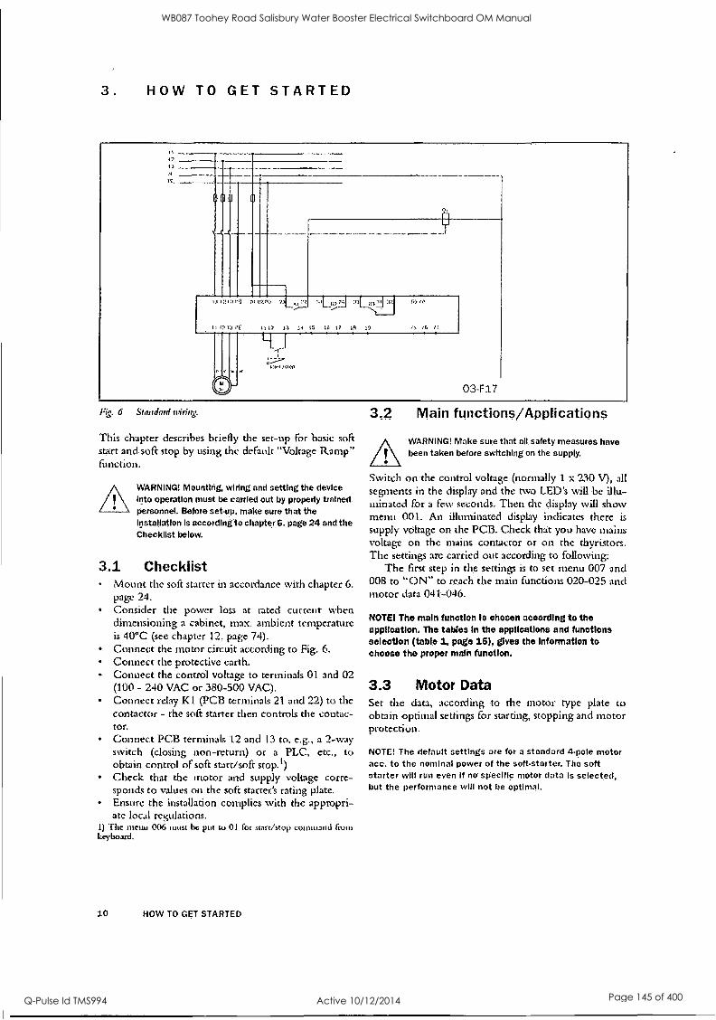
3. HOW TO GET STARTED
II 11113 l Fj f 111V511
11 12 1.3 r.
R7.7.21 11: ,,41:1 5970
11 13 13 ;4 15 10 17 19 13 ,11 IG
03-F17
1."&. 6 Standard wiring.
This chapter describes briefly the set-up For basic soft start and soft stop by using the default "Voltage Ramp" function.
WARNING! Mounting, wiring and setting the device into operation must be carried out by properly trained personnel. Before set-up, make sure that the Installation is according to chapter 6. page 24 and the Checklist below.
3.1 Checklist Mount the soft starter in accordance with chapter 6. page 24. Consider the power loss at rated current when dimensioning a cabinet, rnax ambient temperature is 40 °C (see chapter 12. page 74). Connect the motor circuit. according to Fig. 6. Connect the protective earth. Connect the control voltage to terminals 01 and 02 (100 - 240 VAC or 380-500 VAC). Connect relay KI (PCB terminals 21 and 22) to the contactor - the soft starter then controls the contac- tor. Connect PCB terminals 12 and 13 to, e.g., a 2-way switch (closing non-return) or a PLC, etc., to obtain control of soft start/soft stop.') Check that the motor and supply voltage corre- sponds to values on the soft starter's rating plate. Ensure the installation complies with the appropri- ate local regulations.
.t) The menu 006 1111155 be put to 01 for starr/stop conuttatul froni keyboard.
10 HOW TO GET STARTED
3.2 Main functions/Applications
WARNING! Make sure that all safety measures have been taken before switching on the supply.
Switch on the control voltage (normally 1 x 230 V), all segments in the display and the two LED's will be illu- minated for a few seconds. Then the display will show menu 001. An illuminated display indicates there is
supply voltage on the PCB. Check that you have mains voltage on the mains contactor or on the thyristors. The settings arc carried out according to following:
The first step in the settings is to set menu 007 and 008 to "ON" to reach the main functions 020-025 and motor data 041-046.
NOTE The main function Is chosen according to the application. The tables in the applications and functions selection (table 1, page 15), eves the Information to choose the proper main function.
3.3 Motor Data Set the data, according to the motor type plate to obtain optimal settings for starting, stopping and motor protection.
NOTE! The default settings are for a standard 4-pole motor ace. to the nominal power of the soft-starter. The soft starter will run even If no specific motor data is selected, but the performance will not be optimal.
WB087 Toohey Road Salisbury Water Booster Electrical Switchboard OM Manual
Q-Pulse Id TMS994 Active 10/12/2014 Page 145 of 400
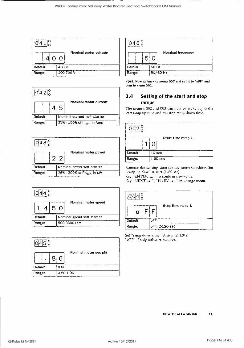
0 Nominal motor voltage
Default: 400 V
Range: 200-700 V
0 4 2 0 0
4 5 Nominal motor current
Default: Nominal current soft starter
Range: 25% - 150% of insoft in Amp
0 4
Nominal motor power
2121 Default: Nominal power soft starter
Range: 25% - 300% of Pnft in kW
lo 141g
4 5 0 Nominal motor speed
Default: Nominal speed soft starter
Range: 500-3600 rpm
014 5 0 0
8 Nominal motor cos phi
Default: 0.86
Range: 0.50-1.00
[61
Nominal frequency
Default: 50 Hz
Range: 50/60 Hz
NOTE! Now go back to menu 007 and set It to 'oF'F" and then to menu 001.
3.4 Setting of the start and stop ramps
The menu's 002 and 003 can now he set to adjust the start ramp up time and the stop ramp down time.
00 2 g
1101
Default: 10 sec
Start time ramp 1
Range: 1-60 sec
Estimate the starting-time for the motor/machine. Set "ramp up time" at start (1-60 sec). Key "ENTER. " to confirm new value. Key "NEXT -4. ", "PREV 4- " to change menu.
010 4 0 0
o F
Stop time ramp 1
Default: oFF
Range: oFF. 2-120 sec
Set "ramp down time" at stop (2-120 s).
"oFF" if only soft start requires.
HOW TO GET STARTED 11
WB087 Toohey Road Salisbury Water Booster Electrical Switchboard OM Manual
Q-Pulse Id TMS994 Active 10/12/2014 Page 146 of 400

3.5 Setting the start command As default the start command is set for remote opera- tion via terminal 11, 12 and 13. For easy commission- ing it is possible to set the start command on the start key on the keyboards. This is set with menu 006.
[61o161(,),
Selection of control mode
Default: 2
Range: 1,2,3
Menu 006 must be set to 1 to be able to operate from keyboard.
NOTE! Factory default setting Is remote control (2).
To start and stop from the keyboard, the "START/ STOP" key is used.
To reset from the keyboard, the "ENTER / RESET" key is used. A reset can he given both when the motor is running and when the motor is stopped. A reset by the keyboard will not start or stop the motor.
3.6 Viewing the motor current Set the display to menu 005. Now the Motor current can be viewed on the display.
0 5 0 0
RMS current read-out
Default:
Range: 0.0-9999 Amp.
NOTE! The menu 005 can be selected at any time when the motor Is running.
12 HOW TO GET STARTED
3.7 Starting
WARNING! Make sure that all safety measures have been taken before starting the motor In order to avoid personal Injury.
Start the motor by pressing the "START/STOP" key on the keyboard or through the remote control, PCB terminal 11, 12 and 13. When the start command is
given, the MAVIS contactor will be activated by relay K.1
(PC:13 terminal 21 and 22), and the motor then starts softly.
Current (A)
FLC
03-F116
Time
Fig 7 Examplc of start ramp with main fimrtioa voltage ramp.
WB087 Toohey Road Salisbury Water Booster Electrical Switchboard OM Manual
Q-Pulse Id TMS994 Active 10/12/2014 Page 147 of 400

4. APPLICATIONS AND FUNCTIONS SELECTION
This chapter is a guide to select the correct soft starter rating and the selection of the Main function and addi- tional functions for each different application.
To make the right choice the following tools arc used:
The norm AC53a. This norm helps selecting the soft starter rating with regard to duty cycle, starts per hour and maximum starting current. The Application Rating List. With this list the soft starter raring can be selected depending on the kind of application used. The list use 2 levels of the AC53a norm. See table 1, page 15. The Application Function List. This table gives an complete overview of most common applications and duties. For each applica- tions the menu's that can be used are given. See table 2, page 17. Function and Combination matrix. With these tables it is easy to see which combina- tions of Main and additional functions are possible, see table 3, page .19 and table 4, page 19.
4.1 Soft starter rating according to AC53a
The 1EC947-4-2 standard for electronic starters defines AC53a as a norm for dimensioning of a soft starter.
The MSF soft starter is designed for continuous running. In the Applications table (table 1, page 15) two levels of AC53a are given. This is also given in the technical data tables (see chapter 12. page 74).
21.03; AC53a 5 - 30 : 50 - 10
IWYNA,
Starts per hour
On-load factor (en-load duty cycle as percent. age of operation cycle)
Start time (seconds)
Start current (multiple of FLC)
Rated FLC (Full Load Current) of starter under prescribed condi- tions
Fig. 8 Rating example AC53a.
The above example indicates_ a current rating of 210 Amps with a start current ratio of 5.0 x FLC (1050A) for 30 seconds with a 50% duty cycle and 10 starts per hour.
NOTE! If more than 10 starts/hour or other duty cycles are needed, please contact your supplier.
Starts per hour
Star t
Duration
Run I hoc
Time
TIME
Duty Cycle = (Start Duration r Run Time)
(Start Duration Run Time 4 Oft Time) tos-reol
Fig. .9 Duty cycle, non bypass.
4.2 Soft starter rating according to AC53b
This norm is made for Bypass operation. Because the MSF soft starter is designed for continuous operation this norm is not used in the selection tables in this chapter.
a. : AC-53b I : 0 '440
Off time (seconds between starts)
Start time (seconds)
Start current (multiple of (CI.) Rated RC (Full Load Cur- rent) of starter under prescribed conditions
Fig. 10 Raring example
U...I
D C_)
Start Duration
Off Time
TIME (034151,)
Fig. 11 Duty cycle, bypassed
The above example indicates a current rating of 210 Amps with a start current ratio of 5.0 x FLC (1050A) for 30 seconds with a 24-minute period between starts.
APPLICATIONS AND FUNCTIONS SELECTION 13
WB087 Toohey Road Salisbury Water Booster Electrical Switchboard OM Manual
Q-Pulse Id TMS994 Active 10/12/2014 Page 148 of 400

4.3 MSF Soft starter ratings According to the norms AC53a and AC53b a soli starter can have many current ratings.
NOTE! Because the MSF soft starter Is designed for continuous operation the norm AC53b Is not used In the application rating list.
With help of the Application Rating List with typical starting currents and categories in the ACS3a level (see table 1, page 15 and table 2, page 17) it is easy to select the proper soft starter rating with the application.
The Application Rating List uses two levels for the AC53a norm:
AC53a 5.0-30:5040 (heavy duty) This level will be able to start all applications and follows directly the type number of the soft starter. Example: MSF 370 is 370 Amps FLC and then 5
time this current in starting. AC 53a 3.0-30:50-10 (normal /light duty) This level is for a bit lighter applications and here the MSF can manage a higher FLC. Example: MSF 370 in this norm manage 450 Amps FLC and the 3 times this current in starting
NOTE! To compare Soft Starters its important to ensure that not only FLC (Full Lond Current) Is compared but also that the operating parameters are Identical.
4.4 The Application Ratings List Table 1 gives the Application Ratings List. With this list the rating for the soft starter and Main Function menu can be selected.
Description and use of the table: Applications. This column gives the various applications. If the machine or application is not in this list, try to iden- tify a similar machine or application. Win doubt pleas contact your supplier. AC53a ratings. The rating according to AC53a norm is here classi- fied in 2 ratings. The first for normal/light duty (3.0-30:50-10) and the second for heavy duty (5.0-30:50-10) Typical Starting current. Gives the typical starting current for each applica- tion Main Function menu. The Main Function menu is advised here. "25;=1", means: program selection 1 in menu 25. Stop function. Gives a possible Stop function if applicable. "36;=1 / 38-40", means: program selection 1 in menu 36, also menus 38 to 40 can be selected.
14 APPLICATIONS AND FUNCTIONS SELECTION
EXAMPLE: Koller Mill:
This is an application for heavy duty, Typical starting current of 450%. Main function Torque ramp start (menu 25) will give the best results. Stop function Dynamic Brake (menu 36, selection 1) can be used. As well as the Slow Speed at start and stop (menu 38-40) can be used for better start and stop per- formance.
WB087 Toohey Road Salisbury Water Booster Electrical Switchboard OM Manual
Q-Pulse Id TMS994 Active 10/12/2014 Page 149 of 400

'Ma, lLr;iuw List
Applications AC53a 3.0-30:50-10 (normal/light)
AC 53a 5.0-30:50-10
(heavy)
Typical starting
current %
Main function Menu nr.
Stop function Menu nr.
General & Water
Centrifugal Pump
Submersible Pump
Conveyor
Compressor: Screw
Compressor, Reciprocating
Fan
Mixer
Agitator
x 300 22 22
x 300 22 22
x 300-400 25; =1 36:=1 / 38-40
x 300 25
x 400 25; =1
x 300 25:=2 x 400-450 25:=1 -
x 400 25 ; =1 -
Metals & Mining
Belt Conveyor
Dust Collector
Grinder
Hammer Mill
Rock Crusher
Roller Conveyor
Roller Mill
Tumbler
Wire Draw Machine
x 400 25:=1 36:=1 / 38.40
x 350 25:=1
x 300 25:=1 36:=1
x 450 25:=1 36; =2
x 400 25:=1 .
x x 350 25:=1 36:=1 / 3840 x 450 25; =1 36; =1 or 2
x 400 25;=1 -
x 450 25; =1 36:=1 or 2
Food Processing
Bottle Washer
Centrifuge
Dryer
Mill
Palletiser
Separator
Slicer
x 300 25;=2 x 400 25;=-1 36:=1 or 2
x 400 25:=2
x 450 25:=1 36;=1 or 2
x 450 25;=1
x 450 25;=1 36; =1 or 2
x 300 25:=1
Pulp and Paper
Re-Pulper
Shredder
Trolley
x 450 25;=1
x 450 25; =1
x 450 25; =1
Petrochemical
Ball Mill
Centrifuge
Extruder
Screw Conveyor
x 450 25;=1
x 400 25:=1 36:=1 or 2
x 500
400
25:=1
25:=1. x
Transport & Machine Tool
Ball Mill
Grinder
Material Conveyor
Pallet iser
Press
Roller Mill
Rotary Table
Trolley
Escalator
x 450 25:=1
x 350 25:=1 36:=1
x 400 25:=1 36:=1 / 38-40
x 450 25:=1
x 350 25:=1
x 450 25:=1
x 400 25:=1 36:=1 / 38-40
x 450 25:=1
x 300.400 25:=1
Lumber & Wood Products
Bandsaw
Chipper
Circular Saw
Debarker
Planer
Sander
x 450 25:=1 36;=1 or 2
x 450 25:=1 36:=1 or 2
x 350 25:=1 36;=1 or 2
a 350 25;=1 36;=1 or 2
x 350 25:=1 36:=1 or 2
x 400 25:=1 36; =1 or 2
APPLICATIONS AND FUNCTIONS SELECTION 15
WB087 Toohey Road Salisbury Water Booster Electrical Switchboard OM Manual
Q-Pulse Id TMS994 Active 10/12/2014 Page 150 of 400

4.5 The Application Functions List This list gives an overview of many different applica- tions/duties and a possible solution with one of the many MSF fUnctions.
Description and use of the table: Application /Duty. This column gives the various applications and level of duty. If the machine or application is not in this list, try to identify a similar machine or application. If in doubt pleas contact your supplier. Problem. This column describes possible problems that are familiar for this kind of application. Solution MSF. Gives the possible solution for the problem using one the MSF function. Menus. Gives the menu numbers and selection for the MSF function. "25;=1", means: program selection 1 in menu 25. "36;=-4 / 34,35", means: program selection I in menu 36, menus 34 and 35 are related to this func- tion.
16 APPLICATIONS AND FUNCTIONS SELECTION,
WB087 Toohey Road Salisbury Water Booster Electrical Switchboard OM Manual
Q-Pulse Id TMS994 Active 10/12/2014 Page 151 of 400

5. OPERATION OF THE SOFT STARTER
Fig. 12 IVISF soft starter models.
5.1 General description of user interface
WARNING! Never operate the soft starter with removed front cover.
To obtain the required operation, a number of parame- ters must be set in the soft starter.
Setting/configuration is done either from the built- in keyboard or by a computer/control system through the serial interface or bus (option). Controlling the motor i.e. start/stop, selection of parameter set, is done either from the keyboard, through the remote control inputs or through the serial interface (option).
Setting
WARNING! Make sure that all safety measures have
been taken before switching on the supply.
Switch on the supply (normally 1 x 230 V), all seg- ments in the. display will light up for a few seconds. Then the display will show menu 001. An illuminated display indicates there is supply voltage on the PCB.
Check that you have voltage on the mains contactor or on the thyristors. To be able to use all extended functions and optimize of the performance, program the motor data.
5.2 PPU unit
03-F28
1
la B. a °o ::::,), ,...
8. a VALUE
01 InRUIP. allaSea 02 Stest, anal( 03 Step, o.m 04 SW. amp!) 06 CumlAir ...le. 00 Contr0.005 07 Ea WO. Antian.
B. Et La 1.11 fit
....) chop. taw. 5) tot.)
/ / /I A30
, Z -/. - Z
,START'
/4-7-77 100
.. Z I__ / 4- -+
NEXT STOP ,,.
/ / / / PREY
. .... + ENTER
11111 RESET
Fig. 13 PPU unit.
The programming and presentation unit (PPU) is
build-in operator panel with two light emitting diodes, three + four seven-segment LED-displays and a key- board.
OPERATION OF THE SOFT STARTER 21
WB087 Toohey Road Salisbury Water Booster Electrical Switchboard OM Manual
Q-Pulse Id TMS994 Active 10/12/2014 Page 152 of 400

5.3 LED display The two light emitting diodes indicates start/stop and running motor/machine. When a start command is
given either from the PPU, through the serial interface (option) or through the remote control inputs, the start/stop-LED will be illuminated.
At a stop command the start/stop-LED \vill switch oft When the motor is running, the running-LED is
flashing during ramp up and down and is illuminated continuously at full motor voltage.
Voltage
Running-LEO, flashing
Start/stop- LECkon
Running- LED.Cri
Running-LED, flash ng'
StarUsterp- LED,otf
Time
Running- LED,olf
Fit,. 14 LED indication at dijiyent operation situation.
5.4 The Menu Structure The menus are organised in a simple one level structure with the possibility to limit the number of menus that are reachable by setting the value in menu 007 to "oFF" (factory settingj. With this setting only the basic menus 001, 002, 003, 004, 005, 006 and 007 can be reached.
This to simplify the setting when only voltage start/ stop ramps are used.
If menu 007 is in "on" and menu 008 "oFF" it is
possible to reach all viewing menus and alarm lists as well.
Key lock status
RMS currents and voltages in each phase
Viewed soft starter data
Reset to' factory settings
Serial communication 1
111.114)
Initial voltage
002 Start ramp time Step down voltage at stop
00i1stb13 ramp time
r005 8MS current 1 6001Control mode
Menu expander
008 Menu expander
Automatic return menu
"JOG" enable
105
103-1041
Run at F1 &F4 alarm I 101-1021
Machine protection 1 089-0991
Main supply protection F081-0431
Motor protection 1 071 -077551
Dual ramp start/stop 011-0141
1 018-0181 lnit ial and end torque at start
020-0251Main functions
1 030.0401 Additional functions
Nominal motor parameters
Relay K1 &K2 functions
Analogue output
Digital input
Parameter set
Fig 15 Alont structure.
22 OPERATION OF THE SOFT STARTER
WB087 Toohey Road Salisbury Water Booster Electrical Switchboard OM Manual
Q-Pulse Id TMS994 Active 10/12/2014 Page 153 of 400

5.5 The keys The function of the keyboard arc based on a few simple rules. At power up menu 001 is shown automatically. Use the "NEXT " and "PREV -4- "keys to move between menus. To scroll through menu numbers, press and hold either the "NEXT " or the "PREV
" key. The "+" and "-" keys arc used to increase respectively decrease the value of setting. The value is
flashing during setting. The "ENTER " key con- firms the setting just made, and the value will go from flashing to stable. The "START/STOP" key is only used to start and stop the motor/machine. The 110j and [] keys are only used fOr JOG from the keyboard. Please note one has to select enable in menu 103 or 104, sec § 7.25, page 61.
flthk j The keys
Start/stop motor operation. [START
STOP i
Display previous menu. I ....... PREV
Display next menu. [NEXT
Decrease value of setting.
Increase value of setting.
OMB
[ ÷ Confirm setting just made. Alarm reset.
ENTER 410Ba
RESET
JOG Reverse
JOG Forward
'Ed* 6 CourroVmodr$
5.6 Keyboard lock .The keyboard can be locked to prohibit operation and parameter setting by an unauthorised. Lock keyboard by pressing both keys "NEXT -6.- " and "ENTER
" for at least 2 sec. The message Loc' will display when locked. To unlock keyboard press the same 2
keys "NEXT --* " and "ENTER 4_1" for at least 2
sec. The message 'link,' will display when unlocked. in locked mode it is possible to view all parameters
and read-out, but it is forbidden to set parameters and to operate the soft starter from the keyboard.
The message ' -Loc' will display if trying to set a
parameter or operate the soft starter in locked mode. The key lock status can be read out in menu 221.
Locked keyboard Info
2210
no Default: no
Range: no. YES
no Keyboard is not locked
YES Keyboard is locked
5.7 Overview of soft starter opera- tion and parameter set-up.
Tible with the possibilities to operate and set para- meters in soft starter.
Control mode is selected in menu 006 and Parame- ter set is selected in menu 061. For the keyboard lock function, see § 7.30, page 65.
Operation/ Set-up
Control mode
Start/Stop JOG fwd/rev Alarm reset
Setting of parameters
Parameter set with external selection
Menu 061=0
Parameter set with Internal selection
Menu 061=1-4
Keyboard Menu 006=1
Unlocked keyboard.
Keyboard Keyboard Keyboard ----- Keyboard
Locked _______ _________ - __ -_ -- _____
Remote Menu 006=2
Unlocked Unlocked keyboard Remote Remote Remote and
keyboard Remote Keyboard
Locked keyboard
Remote Remote Remote Remote ------
Serial comm. Menu 006=3
Unlocked keyboard Serial comm Serial comm Serial comm.
and keyboard ------ Serial comm
Locked keyboard
Serial comm Serial comm Serial comm ------ Serial comm
OPERATION OF THE SOFT STARTER 23
WB087 Toohey Road Salisbury Water Booster Electrical Switchboard OM Manual
Q-Pulse Id TMS994 Active 10/12/2014 Page 154 of 400

6. INSTALLATION AND CONNECTION
Mounting, wiring and setting the device into operation most he carried out by trained personnel (electricians specialised in heavy current technology):
In accordance with the local safety regulations of the electricity supply company. In accordance with DIN VDE OM for setting up heavy current plants.
Care must be taken to ensure that personnel do not come into contact with live circuit components.
WARNING! Never operate the soft starter with removed front covet
6.1 Installation of the soft starter in a cabinet
When installing the soft starter: Ensure that the cabinet will he sufficiently ventilated, after the installation. Keep the minimum free space, see the tables on page 25. Ensure that air can flow freely from the bottom to the top.
NOTE! When Installing the soft starter, make sure It does not come Into contact with live components. The heat generated must be dispersed via the cooling fins to prevent damage to the thyristors (free circulation of air).
MSF-017 to MSF-835 soft. starters are all delivered as
enclosed versions with front opening. The units have bottom entry for cables etc. see Fig. 25 on page 29 and Fig. 27 on page 31. MSF-1000 and MSF-1400 are delivered as open chassis.
NOTE! The soft starter should be wired with shielded con- trol cable to fulfill EMC regulations acc. to § 1.5, page 6.
NOTE! For UL-approval use 75°C Copper wire only.
MSF-017 to MSF-250
Fig. 16 MSF-017 to MSF-250 dimensions.
24 INSTALLATION AND CONNECTION
rig. 17 Hole patter,: for il4SF-017 to il4SF-250 (backside view).
034'122_1
18 Hole pattern for114ST-170 to A4S17-250 with upper 11101/11ling bracket instead of !)1N -rail.
WB087 Toohey Road Salisbury Water Booster Electrical Switchboard OM Manual
Q-Pulse Id TMS994 Active 10/12/2014 Page 155 of 400

MSF-017 to MSF-250
Tilde 7 AIS1- -01 7 to MSF-250.
MSF model
Class Connection Conv./ Fan
Dimension HxWxD (mm)
Hole dist. w1 (mm)
Hole dist. hi (mm)
Dlam./ screw
Weight (kg)
-017, -030 -045, -060, -075, -085
-110, -145
-170, -210. -250
IP 20
IP 20
IP 20
IP 20
Busbars
Busbars
Busbars
Busbars
Convection
Fan
Fan
Fan
320x126x260
320x126x260
400x176x260 500x260x260
78.5
78.5
128.5
208.5
265
265
345
445
5.5/M5
5.5/M5
5.5/M5 5.5/M5
6.7
6.9
12.0
20
1:Jblr S MSF-01710 Al.SP.250
MSF model
Minimum
above 1)
free space
below
(mm):
at side
Dimension Connection busbars Cu
Tightening torque for bolt (Nm)
Cable PE-cable Supply and PE
-017, -030, -045 100 100 0 15x4 (M6), PE (M6) 8 8 0.6 -060, -075, -085 100 100 0 15x4 (M8), PE (M6) 12 8 0.6
-110445 100 100 0 20x4 (M10), PE (M8) 20 12 0.6
-170, -210, -250 100 100 0 30x4 (M10). PE (M8) 20 12 0.6
1) Above: wall-soft starter or soft starter-soft starter
MSF-310 to MSF-1400
'Ethic 9 MSF-310 to MSF -1400 src Fig. 20 or, page 26.
MSF model
Class Connection Corm/ Fan
Dimension HxWxD (mm)
Hole dist. wl (mm)
Hole dist. h1 (mm)
Dlam./ screw
Weight (kg)
-310 IP 20 Busbars Fan 532x547x278 460 450 8.5/M8 42
-370, -450 IP 20 Busbars Fan 532x547x278 460 450 8.5/M8 46
-570 IP 20 Busbars Fan 687x640x302 550 600 8.5/M8 64
-710 IP 20 Busbars Fan 687x640x302 550 600 8.5/M8 78
-835 IP 20 Busbars Fan 687x640x302 550 600 8.5/M8 80
-1000, -1400 !POO Busbar Fan 900x875x336 Fig 23 8.5/M8 175
1:,ble 10 MS12-.110 to MS1:- 1400.
MSF model
Minimum free space (mm): Dimension Connection, busbars Al
Tightening torque for bolt (Nm)
above 1) below at side Cable PE-cable Supply and PE
-310, -370, -450 -570, -710, -835 -1000, -1400
100
100
100
100
100 100
0
0
100
40x8 (M12) 40x10 (M12) 75x 10 (M12)
50
50
50
12
12
12
0.6 0.6 0.6
1) Above: Wall-soft starter or soft starter-soft starter
INSTALLATION AND CONNECTION 25
WB087 Toohey Road Salisbury Water Booster Electrical Switchboard OM Manual
Q-Pulse Id TMS994 Active 10/12/2014 Page 156 of 400

Fig 19 MSF -310 to MSF -8.35.
Fig. 20 Hole pattern for StfeW attachment, MSF-310 ro MS17-835. Hole distance (nun).
26 INSTALLATION AND CONNECTION
MSF e t
-310 to -450 44 39
-570 to -835 45.5 39
Observe that the t vo supplied mom Ling hooks (see S 1.8, page 7 and Fig. 2 on page 7 must be used for mounting the soft starter as upper support (only MSF- 31.0 to MSF-835).
Fig. 21 Mistral- distances :14.517 -310 to MSP -835,
'Ethic 11 Busbar didamet
MSF model Mt. hl (mm)
Dist. wl (mm)
DIst. w2 (mm)
Dist. w3 (mm)
-310 to -450
-570 to -835
-1000 -1400
104
129
33
35
55
206
239.5
322.5
379
444
590.5
WB087 Toohey Road Salisbury Water Booster Electrical Switchboard OM Manual
Q-Pulse Id TMS994 Active 10/12/2014 Page 157 of 400

L
F
F
0
875
F. 22 MST: -100010 -1400
825
0
0
590.5 5
0
O
ei
03-F1.3
Fig. 23 Hole partcrrr bli S bar :111.51' -1000 to -1400.
INSTALLATION AND CONNECTION 27
WB087 Toohey Road Salisbury Water Booster Electrical Switchboard OM Manual
Q-Pulse Id TMS994 Active 10/12/2014 Page 158 of 400

6.2 Connections
Fig. 24 Connection of MSF-017 to -085.
Connection of MSF-017 to MSF-085
Device connections I. Protective earth, (PE), Mains supply, Motor
(on the right and left inside of the cabinet) 2. Protective earth, (PE), Control voltage 3. Control voltage connection 01, 02 4. Mains supply LI, 12, L3
5. Motor power supply Tl, T2, T3 6. Current transformers (possible to mount outside
for bypass sec § 7.12, page 43) 7. Mounting of EMC gland for control cables
28 INSTALLATION AND CONNECTION
WB087 Toohey Road Salisbury Water Booster Electrical Switchboard OM Manual
Q-Pulse Id TMS994 Active 10/12/2014 Page 159 of 400

_I_. giffigig6 CID CI CI
171:g. 25 Comteciott of msr-r I0 to 1145F-145.
Connection of MSF-110 to MSF-145
Device connections 1. Protective earth, (PE), Mains supply, Motor
(on the left inside of the cabinet) 2. Protective earth _L (PE), Control voltage 3. Control voltage connection 01, 02 4. Mains supply Ll, L2, L3 5, Motor power supply T1, T2, T3 6. Current transformers (possible to mount outside
for bypass sec Q 7.12, page 43) 7. Mounting of EMC gland for control cables
INSTALLATION AND CONNECTION 29
WB087 Toohey Road Salisbury Water Booster Electrical Switchboard OM Manual
Q-Pulse Id TMS994 Active 10/12/2014 Page 160 of 400

o - 3 2
UUU UULJULJU
HEHHITHEE n IIIIII 111111W111111
03-F104
1B1
6
1
uuuuuuuuuuuuuuu . .
I Ii 161---1 [ ig - ...._
CC LJ Lri I Li 1 l I 1
0
--,,i.: -. 0 11
NPA MS K"NW* I.:It:mak:2
.2iii Cliir; iinmia NM .:--.-.:1
'., ill LIMMOMMPII .....IPP--
11. 0 ,..1, ..
INIL...?....
Ti I Wee ,:-..-0:- 1"
la !
:,.
i
V .
ic . el.
li10!U!OEdE[dW 0 O
5
4
1
Fig. 26 Cowl:Trim of iliSF-170 to MSF-250
Connection of MSF-170 to MSF-250
Device connections 1. Protective earth, (PE), Mains supply, Motor
(on the left inside of the cabinet) 2. Protective earth J.- (PE), Control voltage 3. Control voltage connection 01, 02 =1, Mains supply Ll, L2, L3 5. Motor power supply Tl, T2, T3 6. Current transformers (possible to mount outside
for bypass see S 7.12, page 43) 7. Mounting of EMC gland for control cables
30 INSTALLATION AND CONNECTION
WB087 Toohey Road Salisbury Water Booster Electrical Switchboard OM Manual
Q-Pulse Id TMS994 Active 10/12/2014 Page 161 of 400

Fig. 27 Con:Jailor, of msr- 170 to MSF-1400.
Connection of MSF -310 to MSF -1400
Device connections 1. Protective earth, 4- (PE), Mains supply and
Motor 2. Protective earth, 4_ (PE), Control voltage 3. Control voltage connection 01, 02
4. Mains supply LI, L2, L3
5. Motor power supply Tl, T2, T3
6. Current transformers (possible to mount outside for bypass see 5 7.12, page 43)
7. Mounting of EMC gland for control cables
INSTALLATION AND CONNECTION 31
WB087 Toohey Road Salisbury Water Booster Electrical Switchboard OM Manual
Q-Pulse Id TMS994 Active 10/12/2014 Page 162 of 400

6.3 Connection and setting on the PCB control card
IA* 28 Connections on ihc PC13, control card.
Vac 12 PCB Tilmiliols
Terminal Function Electrical characteristics 01
Supply voltage 100-240 VAC ±10%/380.500 VAC ± 10% 02 PE Gnd
11 Digital inputs for start/stop and reset. 0-3 V --> 0; 8-27 V-> 1. Max. 37 V for 10 sec.
Impedance to 0 VDC: 2.2 Kt 12
13 Supply/control voltage to PCB terminal 11 and 12, 10 k5-2 potentiometer. etc.
+12 VDC ±5%. Max. current from +12 VDC: 50mA. Short circuit proof.
14 Remote analogue input control, 0.10 V, 2-10 V, 0-20 mA and 4-20 mA/digital input.
Impedance to terminal 15 (0 VDC) voltage signal.; 125 kt), current signal: 100 U.
1.5 GND (common) 0 VDC
16 Digital inputs for selection of parameter set.
0-3 V --> 0; 8.27 V--> 1. Max. 37 V for 10 sec. hived- ance to 0 VDC: 2.2 kfL 17
18 Supply/control voltage to PCB terminal 16 and 17, 10 kfl potentiometer, etc.
+12 VDC ±5%. Max. current from +12 VDC = 50mA. Short circuit proof.
19 Remote analogue output control Analogue Output contact: 0-1.0.V. 2-10V; min load impedance 70052 0-20mA and 4-20mA;max load impedance 75011
21. Programmable relay K1. Factory setting is "Opera- tion" indication by closing terminal 21 - 22.
1-pole closing contact, 250 VAC 8A or 24 VDC 8A resistive, 250 VAC, 3A inductive. 22
23 Programmable relay K2. Factory setting is 'Full volt- age" indication by closing terminal 23-24.
1-pole closing contact, 250 VAC 8A or 24 VDC 8A resistive, 250 VAC, 3A inductive. 24
31 Alarm relay K3, closed to 33 at alarm. 1-pole change over contact, 250 VAC 8A or 24 VDC 8A resistive, 250 VAC. 3A inductive. 32 Alarm relay K3, opened at alarm.
33 Alarm relay K3, common terminal. 69-70 PTC Thermistor input Alarm level 2.4 Itc2 Switch back level 2.2 ka
71-72* Clickson thermistor Controlling soft starter cooling fine temperature MSF-310 - MSF1400
7374* NTC thermistor Temperature measuring of soft starter cooling fine
75 Current transformer input, cable S1 (blue) Connection of L1 or T1 phase current transformer
76 Current transformer input, cable S1 (blue) Connection of L3, T3 phase (MSF 017 - MSF 250) or L2. 12 phase (MSF 310 - MSF 1400)
77 Current transformer Input, cable S2 (brown) Common connection for terminal 75 and 76
78* Fan connection 24 VDC
79* Fan connection 0 VDC
*Internal connection, no customer use.
32 INSTALLATION AND CONNECTION
WB087 Toohey Road Salisbury Water Booster Electrical Switchboard OM Manual
Q-Pulse Id TMS994 Active 10/12/2014 Page 163 of 400

6.4 Minimum wiring
LI. L2 L3 Pt
00
100.440- si.O%
PE
Li 2L3 PE 01.02 PC 21 K1 22 23LK
4 33TH3 211 32 69 70
Ti 72 13 PE 11 12 13 14 15 16 17 18 19 75 76 77
O
44_1
star I /stop
03-F25
Fig. 29 11,7ring-circuit, "'Minimum wiring'.
The figure above shows the "minimum wiring". See S 6.1, page 24, for tightening torque for bolts etc. I. Connect Protective Earth (PE) to earth screw
marked 4- (Pp. 2. Connect the soft starter between the 3-phase mains
supply and the motor. On the soft starter the mains side is marked LI, L2 and L3 and the motor side with Ti, T2 and- T3.
3. Connect the control voltage (100-240 VAC) for the control card at terminal 01 and 02.
4. Connect relay K1 (terminals 21 and 22) to the con- trol circuit.
5. Connect PCB terminal 12 and 13 (PCB terminal 11-12 must be linked) to, e.g. a 2-position switch (on/oFF) or a PLC, etc., to obtain control of soft start/stop. (For start/stop command from keyboard menu 006 must be set to 01).
6. Ensure the installation complies with the appropri- ate local regulations.
NOTE! The soft starter should be wired with shielded control cable to fulfill EMC regulations acc. to § 1.5, page 6.
NOTE! If local regulations say that a mains contactor should be
used, the K1 then controls it. Always use standard commercial, slow blow fuses, e.g. type g1, gG to protect the wiring and prevent short circuiting. To protect the thyristors against short. circuit currents, superfast semiconductor fuses can be used If
preferred. The normal guarantee Is valid even If superfast semiconductor fuses are not used. All signal Inputs and outputs are galvanically Insulated from the mains supply.
INSTALLATION AND CONNECTION 33
WB087 Toohey Road Salisbury Water Booster Electrical Switchboard OM Manual
Q-Pulse Id TMS994 Active 10/12/2014 Page 164 of 400

6.5 Wiring examples Fig. 30 gives an wiring example with the following functions.
Analogue input control, sec § 7.7, page 40 Parameter set selection, see § 7.20, page 54 Analogue output, see § 7.18, page 52 PTC input, see § 7.21, page 55
For more information see § 6.3, page 32.
CI
L2
H
PC
11713 C 0102Pt 23 " 22
11 72 73 PC 1.112 13 14 15
231_,,...2...2A 33L;11.1
16 17 la 19
3' 69 70
76 77 75
992
.:%-- cut /slop P51. Perornolcitai PSt PS2
0700 000o 1
z closed coca
PIC Ar4/ocve, O.
2.107
An :dovecot ()V
0000 cissoo
4 closed dosed
0.300,4
03-F18
Fig, .30 Analogue input contwl, parameter set, analogue output and PTC inpnt.
LI
12
3 1(
PC
0
1, 213P0 010397 4722 231 H214 33 433 12 69 70
7 1 1 2 ( 3 71 . 11 13 13 14 15 16 11 111 16 75 76 77
-1-3,
sort :stop
03-F20
Jr', 37 Poneardireverse wiring circuit.
34 INSTALLATION AND CONNECTION
WB087 Toohey Road Salisbury Water Booster Electrical Switchboard OM Manual
Q-Pulse Id TMS994 Active 10/12/2014 Page 165 of 400

7. FUNCTIONAL DESCRIPTION SET-UP MENU
This chapter describes all the parameters and functions in numerical order as they appear in the MSE Table 1.3
gives an overview of' the menus, sec also Chapter 13. page 79 (set-up menu list).
Yid le 13 Set-up ,Wernt
Menu number
Parameter group Menu numbers See §
Basic functions 001-008 Basic
Ramp up /down parameters 001-005 7.1
Start/Stop/Reset command 006 7.2
Menu Expansion 007-008 7.3
Extended functions 011-199
Voltage control dual ramp 011-014 7.4
Torque control parameters 016-018 7.5
Main functions 020-025 7.6 - 7.10
Additional functions 030-036 7.11 - 7.14
Slow speed and Jog functions 037-040, 57-58, 103-104
7.15, 7.19, 7.25
Motor Data Setting 041-046 7.16
Outputs Relays 051-052 7.17
Analogue output 054-056 7.18
Input Digital input 057-058 7.19
Parameter set selection 061 7.20
Motor protection 071-075 7.21
Main protection 081-088 7.22
Application protection 089-099 7.23
Resume alarms 101; 102 7.24
Auto return menu 105 7.26
Factory defaults 199 7.28
View functions 201-915
Main view 201-208 7.29
RMS current per phase 211-213 7.29
RMS voltage per phase 214-216 7.29
Keyboard lock status 221 7.30
Alarm list 901-915 7.31
FUNCTIONAL DESCRIPTION SET-UP MENU 35
WB087 Toohey Road Salisbury Water Booster Electrical Switchboard OM Manual
Q-Pulse Id TMS994 Active 10/12/2014 Page 166 of 400

7.1 Ramp upidown parameters
Fig. 32 Mom numbers for start/stop ramps, tallied voltage at start rind titp down voltage at stop.
Determine the starting time for the motor/machine. When setting the ramp times for starting and stopping, initial voltage at start and step down voltage at stop, proceed as follow:
0 011 ° 0
3 0 Setting the initial voltage at start ramp 1
Default: 30%
Range: 25 - 90% U Set the initial voltage. Normally the factory setting, 30% of U, is a suitable choice.
Setting of start ramp 1
0 0
r_____. 10 Default: 10 sec
Range: 1-60 sec
Set "Ramp up time" at start.
-0-1-0- Pi 0°
1 0 0 Setting of step down voltage stop ramp 1
Default: 100%
Range: 100-40% of Un
Step down vo tage at stop can be used to stop smoothly.
36 FUNCTIONAL DESCRIPTION SET-UP MENU
1 I 141(0)
o F F
Setting of stop ramp 1
Default: oFF
Range: oFF, 2-120 sec
oFF Stop ramp disabled
2-120 Set "Ramp down time" at stop
7.1.1 RMS current [OM
010 5 0°
1 --1
I 1
RMS current
Default: -- Range: 0.0-9999Amp
Read-out of the RMS motor current.
NOTE! This is the same readout as function 201, see § 7.28, page 63.
WB087 Toohey Road Salisbury Water Booster Electrical Switchboard OM Manual
Q-Pulse Id TMS994 Active 10/12/2014 Page 167 of 400

7.2 Start/stop/reset command Start/stop of the motor and reset of alarm is done either from the keyboard, through the remote control inputs or through the serial interface (option). The remote control inputs start/stop/reset (PCB terminals 11. 12 and 13) can be connected for 2-wire or 3-wire control.
006 g
Selection of control mode
2 Default: 2
Range: 1,2,3
1
START/STOP/RESET command via the keyboard. - Press the "START/STOP" key on
the keyboard to start and stop the soft starter.
- Press "ENTER/RESET" key to reset a trip condition.
2
Via Remote control. START/STOP/ RESET commands. The following control methods are possible: - 2-wire start/stop with automatic
reset, see. § 7.2.1, page 37. - 2-wire start/stop with separate
reset, see § 7.2.2, page 37. - 3-wire start/stop with automatic
reset at start, see § 7.2.3, page 37.
WARNING! The motor will start If terminals 11, 12, 13 Is In start position.
3
START/STOP/RESET commands via serial interface option. Read the operating instruction supplied with this option.
NOTE! A reset via the keyboard will not start or stop the motor.
NOTEI Factory default setting Is 2, remote control.
-16 start and stop from the keyboard, the "START! STOP" key is used.
To reset from the keyboard, the "ENTER i-Ji RESET" key is used. A reset can be given both when the motor is running and when the motor is stopped. A reset from the keyboard will not start or stop the motor.
7.2.1 2-wire start/stop with automatic reset at start
12 13
Start/ Reset
43417 \ Stop
p11
F. 114:;441c; u 071
L) t 1 1 cs
Closing PCB terminals 12 and 13, and a juniper between terminal 11 and 12. will give a start com- mand. Opening the terminals will give a stop. If PCB terminals 12 and 13 is closed at power up a start com- mand is given (automatic start at power up). When a
start command is given there will automatically be a
reset.
7.2.2 2-wire start/stop with separate reset
Closing PCB terminals 11, 12 and 13 will give a start and opening the terminals 12 and 13 will give a stop. If PCB terminals 12 and 13 arc closed at power up a start command is given (automatic start at power up). When PC13 terminals 11 and 13 are opened and closed again a
reset is given. A reset can be given both when_ the motor is running and stopped and doesn't affect the start/stop.
7.2.3 3-wire start/stop with automatic reset at start.
PCB terminal l2 and 13 are normally closed and PCB terminal 11 and 13 are normally open. A start com- mand is given by momentarily closing P03 terminal 11 and 13. To stop, PCB terminal 12 and 13 are momentarily opened.
When a start command is given there will automat- ically he a reset.. There will not he an automatic start at power up.
FUNCTIONAL DESCRIPTION SET-UP MENU 37
WB087 Toohey Road Salisbury Water Booster Electrical Switchboard OM Manual
Q-Pulse Id TMS994 Active 10/12/2014 Page 168 of 400

7.3 Menu expansion setting. In order to use the viewing menus and/or the extended functions menu 007 must be set to "On", then one reach read out of the viewing menus 207- 915. To be able to set any extended functions in the menus 011-199 menu 008 must be set to "on" as well.
lb 0 71°
r
oFF Selecting of extended functions and viewing functions
Default: oFF
Range: oFF, on
oFF Only function 1-7 are visible
on - View functions 201-915 are visible - Extended functions (menu 008) selectable
018 ° 0
o FF Selecting of extended functions
Default: oFF
Range: oFF, on
oFF Only view function 201-915 are visi- ble.
on All the function menus are visible
NOTE! Menu 007 must be "on".
7.4 Voltage control dual ramp To achieve even smoother ramps at start and or stop, a
dual ramp can be used.
Fig. 33 Menu numbers for dual voltage tamp at start/stop, initial voltage at start and step down-voltage at stop.
The settings are carried out by beginning with the set- tings in menus 001-004 and 007-008 and proceed with the following steps:
38 FUNCTIONAL DESCRIPTION SET-UP MENU
piiiii 0 _i... __. 0
9 01
Setting the initial voltage at start ramp 2
Default: 90%
Range: 30-90% Un
Set the start voltage for start ramp 2. The initial voltage for start ramp 2 is limited to the initial volt- age at start (menu 001), see § 7.1, page 36.
1 ,
0 0
FF Setting of start ramp 2
Default: oFF
Range: oFF, 1-60 sec
oFF Start ramp 2 disabled
1-60 Set the start ramp 2 time. A dual voltage ramp is active.
011 0°
40 Setting of step down voltage In stop ramp 2
Default: 40%
Range: 100-40% Ur,
Set the step down voltage for stop ramp 2. The step down voltage for stop ramp 2 is limited to the step down voltage at stop (menu 003).
011 4 g
-- --- oFF
--- Setting of stop ramp time 2
Default: oFF
Range: oFF, 2-120 sec
oFF Stop ramp 2 disabled
160 Set the stop ramp 2 time. A dual voltage stop ramp is active.
WB087 Toohey Road Salisbury Water Booster Electrical Switchboard OM Manual
Q-Pulse Id TMS994 Active 10/12/2014 Page 169 of 400

7.5 Torque control parameters 7.6 Current limit (Main Function) See also 6 7.10, page 42 and chapter 4. page 13 for more information on the Torque control setting.
10160
1
I 1 Initial torque at start
0 Default: 10
Range: 0 - 250% of Tn
Insert initial torque at start in percent of nominal shaft torque (Tn), see chapter 13. page 79.
0 1 ° 0
1 5 End torque at start
0! Default: 150
Range: 50 - 250% of Tn
Insert end torque at start in percent of nominal shaft torque.
0180
I
0 End torque at stop
Default: 0
Range: 0 - 100% of Tn
Insert end torque at stop in percent of the nominal motor torque.
The Current Limit function is used to limit the current drawn when starting (150 - 500% of In). This means that current limit is only achieved during set start-lip tnne.
TWo kinds of current limit starts arc available. Voltage tamp with a limited current. If current is below set current limit, this start will act exactly as a voltage ramp start. Current limit start. The soft starter will control the current up to set current limit immediately at start, and keep it there until the start is completed or the set start-up time expires.
Sec Fig. 34 Current limit.
NOTEI Make sure that nominal motor current In menu 042 is correctly inserted.
7.6.1 Voltage ramp with current limit The settings arc carried out in three steps: 1. Estimate starting-time for the motor/machine and
select that time in menu 002 (see 5 7.1, page 36). 2. Estimate the initial voltage and select this voltage in
menu 001 (see 5 7.1, page 36). 3. Set the current limit to a suitable value e.g. 300% of
In in menu 020.
[012mg Voltage ramp with current
o F
limit at start
Default: oFF
Range: oFF, 150 - 500% In
oFF Voltage Ramp mode with current limit disabled. Voltage Ramp ena- bled.
150-500 Current limit level in Voltage ramp mode.
NOTE! Only possible when Voltage Ramp mode is enabled. Menus 021-025 must be "oFF".
Current
Current limit at start
Voltage ramp
Time a
03-F109
Fix. 34 Current limit
FUNCTIONAL DESCRIPTION SET-UP MENU 39
WB087 Toohey Road Salisbury Water Booster Electrical Switchboard OM Manual
Q-Pulse Id TMS994 Active 10/12/2014 Page 170 of 400
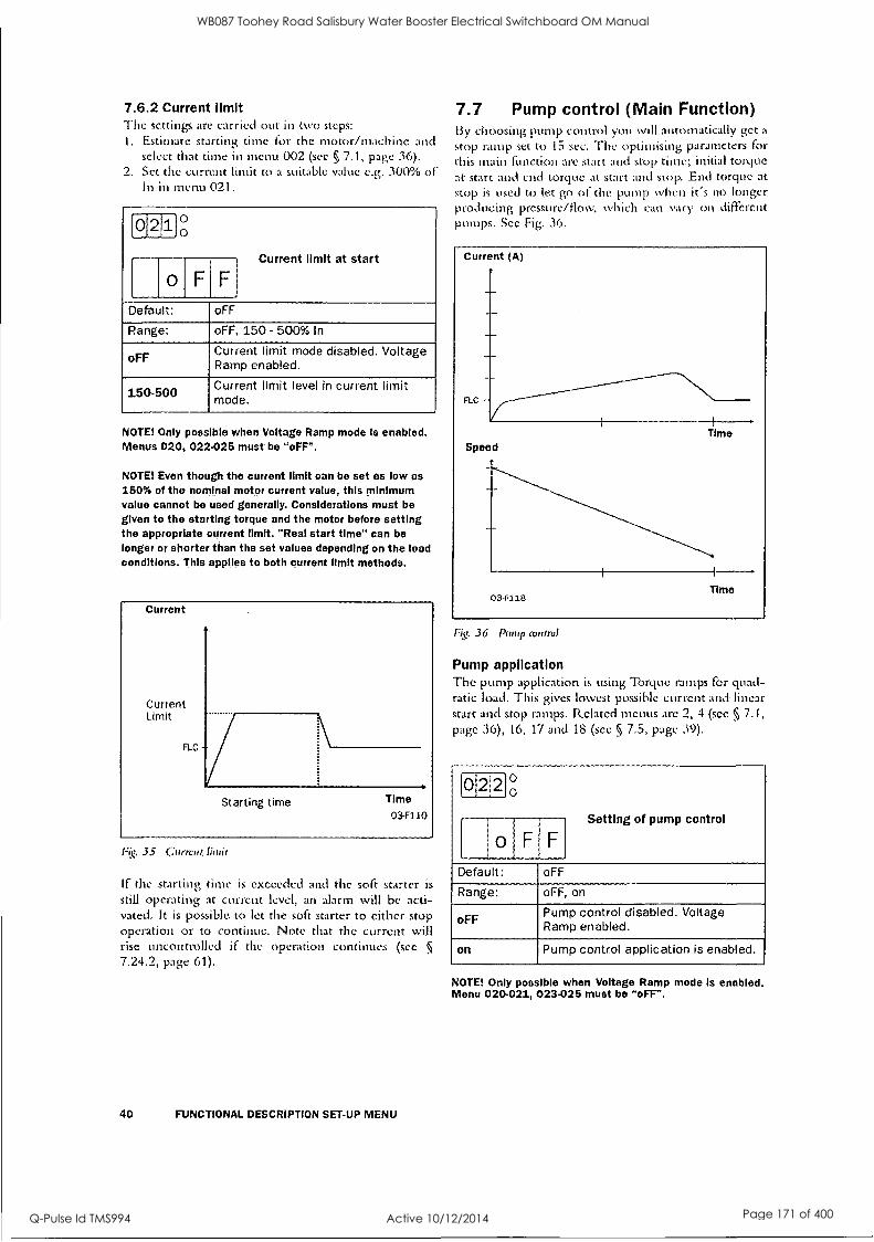
7.6.2 Current limit The settings are carried out in two steps: I. Estimate starting time for the motor/machine and
select that time in menu 002 (sec § 7.1, page 36). 2. Set the current limit to a suitable value e.g. 300% of
In in menu 021.
0 2 110°
o F
Current limit at start
Default: oFF
Range: oFF, 150 - 500% In
o FF Current limit mode disabled. Voltage Ramp enabled.
150-500 Current limit level in current limit mode.
NOTE! Only possible when Voltage Ramp mode Is enabled. Menus 020, 022.026 must be "oFF".
NOTE! Even though the current limit can be set as low as 150% of the nominal motor current value, this minimum value cannot be used generally. Considerations must be given to the starting torque and the motor before setting the appropriate current limit. "Real start time" can be longer or shorter than the set values depending on the load conditions. This applies to both current limit methods.
Current
Current Limit
FLC
Starting time Time
03-F110
Fig, 35 Current, Ihnit
If the starting time is exceeded and the soft starter is
still operating at current level, an alarm will be acti- vated. It is possible, to let the soft starter to either stop operation or to continue. Note that the current will rise uncontrolled if the operation continues (see 5
7.24.2, page 61).
40 FUNCTIONAL DESCRIPTION SET-UP MENU
7.7 Pump control (Main Function) 13y choosing pump control you will automatically get a
stop ramp set to 15 sec. The optimising parameters for this main function arc start and stop time; initial torque at start and end torque at start and stop. End torque at stop is used to let go of the pump when it's no longer producing pressure/flow, which can vary on different pumps. See Fig. 36.
Fig. 36 Pump control
Pump application The pump application is using TOrque ramps for quad- ratic load. This gives lowest possible current and linear start and stop ramps. Related menus arc 2, 4 (sec §, 7.1, page 36), 16, 17 and 15 (see 5 7.5, page 39).
01212 g
I
1
o F F
Setting of pump control
Default: oFF
Range: oFF, on
oFF Pump control disabled. Voltage Ramp enabled.
on Pump control application is enabled.
NOTE! Only possible when Voltage Ramp mode is enabled. Menu 020-021, 023-025 must be "oFF".
WB087 Toohey Road Salisbury Water Booster Electrical Switchboard OM Manual
Q-Pulse Id TMS994 Active 10/12/2014 Page 171 of 400

7.8 Analogue Input Control (Main Function)
Soft starting and soft stopping can also be controlled via the Analogue Input Control (0-10 V, 2-10 V, 0-20 mA and 4-20 mA). This control makes it possible to con- nect optional ramp generators or regulators.
After the start command, the motor voltage is con- trolled through the remote analogue input.
WARNING! The remote analogue control may not be used for continuous speed regulation of stand- ard motors. With this type of operation the in- crease In the temperature of the motor must be taken Into consideration.
To install the analogue input control, proceed by: 1. Connect the, ramp generator or regulator to termi-
nal 14 (4.) and 15 ().
Fig. 37 Wiring for iinalogur input.
2. Set Jumper J1 on the PCB control card to voltage (U) or current control (1) signal position, see Fig. 38 and Fig. 24 on page 28. Factory setting is voltage (U).
Fig. 38 Setting voltage or current for analogue input.
r012P1g
o I
FIF i
Selection of Analogue Input control
Default: oFF
Range: oFF, 1, 2
oFF Analogue input disabled. Voltage Ramp enabled.
1 Analogue input is set for 0-10V/ 0-20mA control signal
2 Analogue input is set for 2-10V/ 4-20mA control signal.
NOTE! Only possible when Voltage Ramp mode is enabled. Menu 020-022, 024, 026 must be "oFF"
7.9 Full voltage start, D.O.L. (Main Function)
The motor can be accelerated as if it WaS connected directly to the mains. For this type of operation:
Check whether the motor can accelerate the required load (D.O.L.-start, Direct On Line start). This function can be used even with shorted thyristors.
0'2 I
4 ° 0
o F F
Setting of D.O.L start
Default: oFF
Range: oFF, on
oFF D.O.L. start disabled. Voltage Ramp enabled.
on D.O.L. start enabled
NOTE! Only possible when Voltage Ramp mode Is enabled. Menu 020-023, 025 must be "oFF".
6-7xInorn
etc
Time
03-F115
Fig. 39 Full voltage start.
FUNCTIONAL DESCRIPTION SET-UP MENU 41
WB087 Toohey Road Salisbury Water Booster Electrical Switchboard OM Manual
Q-Pulse Id TMS994 Active 10/12/2014 Page 172 of 400

7.10 Torque control (Main function) This main function can be used to make a start accord- ing to a pre-defined torque reference curve. Two dif- ferent load characteristics, linear and square, are possible to select.
At start/stop the torque controller will follow the selected characteristic.
A torque start/stop behaviour can be seen in Fig. 40.
A perfect start and stop with torque ramps have a
good linearity of current. To optimise this, use the set- ting of initial torque (menu 16) and end torque (menu 1$). See also § 7.5, page 39.
Example: Default for initial torque is 10% so if starting a more heavy load this will result in a small current peak in beginning of ramp. By increasing this value to 30/ 70% the current peak will not appear.
The end torque is increased mainly if the applica- tion has a high inertial load., like planers, saws and centrifuges. A current peak will appear in the end of ramp because the load is pushing the speed more or less by itself. By increasing this level to 150-250% the current will be linear and. low.
(0121510
Torque control at start/stop
o F F
Default: oFF
Range: oFF, 1, 2
oFF Torque control is disabled Voltage Ramp enabled.
1 Torque control with linear torque characteristic
2 Torque control with square torque characteristic
NOTE Torque control mode Is only possible when Voltage Ramp mode Is enabled (menu 020-024 are 'oFF").
Torque
2.5T,;-
2 T
1.5 T
0.5 Tr,
End torque
Nominal Torque
1 Linear
2 Square
Initial torque - Star t time
1
End torque at stop
Stop time Time
034'37
Fig. 40 Torque control at start /stop.
Time 03-F113 03-F114
Fig. 41 Current and speed in torque control.
42 FUNCTIONAL DESCRIPTION SET-UP MENU
WB087 Toohey Road Salisbury Water Booster Electrical Switchboard OM Manual
Q-Pulse Id TMS994 Active 10/12/2014 Page 173 of 400

7.11 Torque boost The Thrque Booster enables a high torque to be obtained by providing a high current during 0.1 - 2 sec at start. This enables a soft start oldie motor even if the break away torque is high at start. For example in crushing mills applications etc.
When the torque booster function has finished, starting continues according to the selected start mode.
Torque boost Current limit
Full speed Load current
03-F40 Time
Fig. .42 The pritrriple of the lat.-Tie Booster when starting the
motor in voltage ramp wade.
See 4.6, page 19, which main function that can he
used with the torque boost.
0 30 0 0
0 1 F
Torque boost active time
,
,
Default: oFF
Range: oFF, 0.1 - 2 sec
oFF Torque boost disabled
0.1-2.0 Set the Torque boost time.
0310
,
, 3 010 Torque boost current limit
Default: 300
Range: 300 - 700% of In
The Torque boost current controller use selected value as the motor current reference.
NOTE! Check whether the motor can accelerate the load with "Torque booster", without any harmful mechanical stress.
7.12 Bypass In cases of high ambient temperatures or other reason it may sometimes be necessary to use a by-pass contactor to minimize the power loss at nominal speed (see Tech- nical Data). By using the built-in Full Voltage Relay function an external contactor can be used to Bypass the soft starter when operating at nominal speed.
Bypass contactor can also be used if soft stop is
required. Normally a Bypass contactor is not necessary as the device is designed for continues running condi- tions, see Fig. 29 on page 33 for wiring example.
NOTE! If one like to use the alarm functions, the extended functions or the viewing functions the 2-pcs current transformers must be mounted outside the soft start as shown In Fig. 44 and Fig. 45 on page 46. For this purpose an optional extension cable for the current transformers Is
available. Code No 01-2020-00.
032 g
I
OIFIF Setting of Bypass
Default: oFF
Range: oFF, on
oFF Bypass disabled
on
Bypass enabled. Program either relay K1 or K2 to function 2 to control the bypass con- tactor, see menu 51/52.
CAUTION! If the current transformers are not mounted as In Flg. 43 on page 44 and § 6.2, page 28, the alarm and viewing functions will not work. Do not forget to set menu 032 to ON, otherwise there will be an F12 alarm and at the stop command will be a freewheeling stop.
For further information see chapter 6.2 page 28.
FUNCTIONAL DESCRIPTION SET-UP MENU 43
WB087 Toohey Road Salisbury Water Booster Electrical Switchboard OM Manual
Q-Pulse Id TMS994 Active 10/12/2014 Page 174 of 400

L1
L2
13
PE
11 12 L3 PE 01 02 PE 21 3 K224 3 3 69 70
T1 T2 T3 PE 11 12 13 14 15 16 17 18 19 75 76 77
o start /stop
11 T./ i3 E
gtorent tre storrner position onnec Ion
or MSF.017 to A1Sf250. see -ig. 44.
for RISF310 to At SF..1400, ;roe Fig. 45.
03-F19
Fig. 43 Bypass wiring example MSF 310-1400.
44 FUNCTIONAL DESCRIPTION SET-UP MENU
WB087 Toohey Road Salisbury Water Booster Electrical Switchboard OM Manual
Q-Pulse Id TMS994 Active 10/12/2014 Page 175 of 400

Ti
SOFTSTARTER
T2
Blue to terminal 75
Brown to terminal 77
U V
MOTOR
T3
Blue to terminal 76
Brown to terminal 77
03-F56_1
Fig. 44 Current transformer position when Bypass ArISF-017 to MSF-250.
SOFTSTARTER
Blue to terminal 75
St k.
T2 T3 Blue to terminal 76
NNN U
Brown to terminal 77
V
MOTOR
Brown to terminal 77
W
03-F57...1
Fig. 45 Cumin transformer position Oren Bypass MSF-310 to MSF- 1400.
FUNCTIONAL DESCRIPTION SET-UP MENU 45
WB087 Toohey Road Salisbury Water Booster Electrical Switchboard OM Manual
Q-Pulse Id TMS994 Active 10/12/2014 Page 176 of 400

7.13 Power Factor Control During operation, the soft starter continuously moni- tors the load on the motor. Particularly when idling or when only partially loaded, it is sometimes desirable to improve the power factor. If Power factor control (PFC) is selected, the soft starter reduces the motor voltage when the load is lower. Power consumption is
reduced and the degree of efficiency improved.
Setting of PFC
033
o F
,
Fl Default: oFF
Range: oFF, on
oFF PFC disabled
O11
PFC enabled. The Full voltage relay function does not work.
NOTE! If the PFC is used the EMCdirectIve is not fulfilled.
7.14 Brake functions There are two built in braking methods for applications were the normal stop ramp is not enough.
Dynamic DC-brake Increases the braking torque by decreasing speed. Soft brake Gives a high torque at the start of the braking and then also increasing torque by decreasing speed.
In both methods the MSF detects when the motor is
standing still, so rotating in wrong direction is avoided.
Dynamic Vector Brake Possible to stop motors with high inertia loads from close to synchronous speed. At 70% of the nominal speed a DC-brake is acti- vated until the motor is standing still or the selected Braking Time has expired (see menu 34, next
Page). No contactor needed. For extra safety, the soft starter has a digital input signal for monitoring standstill so that at real motor standstill will stop the output voltage immediately (see § 7.19, page 53).
Soft, brake Even very high inertia loads can be stopped The Soft brake is a controlled reversing of the motor as the MSF measures the speed during brak- ing. Two contactors are needed which can be placed on the in- or output of the soft starter. On the input the first contactor is connected to relay Ki which is
also used as a mains contactor. At 30% of the nominal speed a DC-brake is acti- vated until the motor is standing still or the selected Braking Time has expired (menu 34, next page).
46 FUNCTIONAL DESCRIPTION SET-UP MENU
For extra safety, the soft starter has a digital input signal for monitoring standstill. So that the output voltage is stopped immediately (sec menu 57-58, §
7.19, page 53).
See Fig. 47 on page 47 for the following set-up sequence:
Soft brake is activated if menu 36=2 and menu 34 has a time selected (see next page). Menu 51 and 52 are automatically set to 5 and 4 to get the correct relay functions on K.1 and K2 (see §
7.17, page 51). Relay KI should be used to connect a contactor for supply Ll, L2,13 to MSF or motor. Relay K2 is used to connect phase shifting contac- tor to change Li, L2 and 13 to MSF or motor. At start KI is activated and connects LI, L2. L3 then the motor starts. At stop K1 opens and discon- nects Li, L2, and L3 and after is K2 connects with the other phase sequence and the braking of the motor is active.
NOTE! Soft brake uses both programmable relays. For other functions, see also the function table In chapter 7. page 35.
NOTE! For several start/stops it Is recommend to use the PTC input.
A WARNING! If the Soft Brake function has been selected once and after that the Bypass function
' is selected, then the relay functions on K1 and K2 remain In the Soft Brake functionality. Therefore It
Is necessary to change the relay functions In menu 51-52 manually to the Bypass functions (see § 7.17, page 51) or reset to default In menu 199 (see § 7.26, page 63) and select the Bypass function again.
FON41°0
o F F
Braking time
Default: oFF
Range: oFF, 1- 120 sec
oFF Brake function disabled
1-120 Brake time
Torque
Softbrake
Dynamic DC
Nom. speed 03-F121
1:4!. 44 fItakiirq rhut:
WB087 Toohey Road Salisbury Water Booster Electrical Switchboard OM Manual
Q-Pulse Id TMS994 Active 10/12/2014 Page 177 of 400

Braking Strength
1 0 0 Default: 100
Range: 100 - 500%
036 ° 0
Brake method
Default: 1
Range: 1, 2
Dynamic vector brake, active
2 Soft brake active
11
L2
L3
N
PE
Q1 (twd)
Q2(rev)
U
L1 L2 L3 PE 01 02 PE 2 K1 22 23 K2 24 31 32 69 70
It T2 T3 PE 11 12 .13 14 15 16 17 18 19 75 76 77
14,1 II
0 stmt /stop
f.
03-F106
Fig. 47 Sofi brake wiring example.
FUNCTIONAL DESCRIPTION SET-UP MENU 47
WB087 Toohey Road Salisbury Water Booster Electrical Switchboard OM Manual
Q-Pulse Id TMS994 Active 10/12/2014 Page 178 of 400

7.15 Slow speed and Jog functions The soft starter is able to run the motor at a fixed slow speed for a limited period of time.
The slow speed will be about 14% of the full speed in the forward direction and 9% in the reverse direc- tion.
The following fimctions arc possible: Slow speed controlled by an external signal. The digital input is used to run at slow speed at a
start or stop command for a selected number of pulses (edges) generated by an external sensor (photo cell, micro switch, etc.). See § 7.19, page 53 for more instructions. Slow Speed during a selected time period. The slow speed will he active after a stop command for a selected time period. See 5 7.19, page 53 for more instructions. Slow Speed using the "JOG"-commands. The slow Speed can be activated via the JOG keys on the keyboard or externally via the analogue input. Sec § 7.25, page 61 for more instructions.
7.15.1 Slow speed controlled by an external signal:
With these setting it is possible to have an external pulse or edge signal controlling the time that the Slow Speed is active either after a Start command or a Stop command or at both commands. The following menu's are involved:
Menu Function, See page
57 Digital input selection page 53
58 Pulse selection page 53
37 Slow speed torque page 49
38 Slow speedtime at start page 49
39 Slow speed time at stop page 49
40 DC-Brake at slow speed page 49
Installation is as follows: 1. Set the analogue input selection for Slow Speed
operation. Menu 57=2. See 5 7.19, page 53. See Fig. 37 on page.41 for a wiring example.
2. Select in menu 38 (see § 7.152, page 49) the Slow Speed at Start time. This time will now be the abso- lute maximum time for Slow Speed to be active after a start command, in case the external signal will not appear.
3. Select in menu 39 (see 5 7.15.2, page 49) the Slow Speed at Stop time. This time will now be the abso- lute maximum time for Slow Speed to be active after a stop conunand, in case the external signal will not appear.
4. Select in menu 57 (sec § 7.19, page 53) the number of edges to be ignored by the Slow Speed input, before a start or stop is executed at slow speed. The edges are generated by an external sensor (photo cell, micro switch, etc.).
48 FUNCTIONAL DESCRIPTION SET-UP MENU
The Slow Speed torque (menu 37) and DC-Brake after Slow Speed (menu 40) can he selected if needed. (see § 7.15.4, page 49).
When the number °ledges exceeds or the time expire, a start according to selected main function is made.
At stop, the motor will murip down (if selected) and DC brake (if selected) before a slow speed forward at stop will begin. Slow speed will last as long as the number of edges on the external input is below param- eter value in menu 036 and the max duration time doesn't expires. When the number of edges exceeds or the time expire, a stop is made.
In Fig. 48 on page 48 the selected number of edges are 4. It is recommended to select DC-brake (se 5 7.14, page 46) before a slow speed at stop if it is a high inertia load. See Fig. 29 on page 33 for wiring diagram. In case one use DC-brake, see § 7.15.4, page 49.
d
Slow RUPIlp tins rull voitoge Vetsd at matt "'""rag ta start
Slott consnond
CIAVied
CA11:11111i 14,011 U S:11113i
;- Romp lithe &OW PI stop spood inc Wine a[ luep DC.Istoice
Tune when S4:041 is ieflOted
03444
Fig. 48 Slow speed controlled by an external signal.
This additional function can be used together with most of the main functions (see § 4.6, page 19).
loldN ° , 0
Slow speed torque
i
Default: 10
Range: 10-100
Select the magnitude of the slow speed torque.
WB087 Toohey Road Salisbury Water Booster Electrical Switchboard OM Manual
Q-Pulse Id TMS994 Active 10/12/2014 Page 179 of 400

7.15.2 Slow speed during a selected time It is possible to have a slow speed in forward direction before a start and after a stop. The duration of the slow speed is selectable in menus 038 and 039.
It is recommended to select DC brake (see § 7.14, page 46) before a slow speed at stop if it is a high inertia load. This slow speed function is possible in all control modes, keyboard, remote and serial communication.
[01318 g
oF Fl Slow speed time at start
Default: oFF
Range: off, 1- 60 sec
oFF Slow speed at start is disabled
1-60 Set slow speed time at start.
roidiq
1
Slow speed time at stop
[ 0.1 F I ,
I
Default: oFF
Ranger oFF, 1 - 60 sec
OFF Slow speed at stop is, disabled
1-60 Set stow speed time at stop.
0.14 nr,
Speed
ttotnia.4 sp.-, n
Slow 50....td
f ....:vaed Rang RI at Ftal app Koala tatta Staa: apaad Tam, takstas t Sta. I tanning IA stop. Ira et :ton
SIOD
sluttne DC
commancl Stopped 03..F41 Slap caaattand
Fig. 49 Slow speed .at start /.crop during a selected time.
The Slow speed torque (menu 37) and the DC-Brake after Slow speed (menu 40, §, 7.15.4, page 49) can be selected if needed.
7.15.3 Jog Functions The Jog commands can he used to let the motor run at a Slow speed (forward or reverse) as long as the Jog command is active.
The Jog commands can be activated in 2 different ways:
Jog keys The Jog-Forward and Jog-reverse keys on the con- trol panel. The keys can he programmed separate for each function. See § 7.25, page 61 for more instructions External Jog command The external command is given via terminal 14 at the digital input. Only 1 fimction (forward or reverse) can be programmed to the digital input at the time. See § 7.19, page 53 for more instructions.
7.15.4 DC-brake after slow speed at stop [040) A DC-brake after a slow speed at stop is possible to have, i.e. for a, high inertia load or for a precise stop.
The current is controlled and the reference value for the normal DC-brake fianction is used (see 5 7.15.4, page 49). The duration for the DC-brake is possible to select.
This DC-brake function is not applied when the "JOG rArj " and "JOG " keys are used.
0140 0
0 F
DC-Brake at slow speed
F
Default: oFF
Range: oFF, 1-60
oFF DC-brake after slow speed at stop disabled.
1-60 DC-brake duration time after slow speed at stop.
FUNCTIONAL. DESCRIPTION SET-UP MENU 49
WB087 Toohey Road Salisbury Water Booster Electrical Switchboard OM Manual
Q-Pulse Id TMS994 Active 10/12/2014 Page 180 of 400

7.16 Motor data setting The first step in the settinp is to set menu 007 and 008 to "on" to be -able to reach the menus 041-046 and enter the motor data.
NOTE! The default factory settings are for a standard 4-pole motor ace. to the nominal current and power of the soft starter. The soft starter will run even If no specific motor data Is selected, but the performance will not be optimal.
r0 4,1 °0
14 0 0 Nominal motor voltage
Default: 400 V
Range: 200-700 V
Make sure the soft starters maximum voltage rat- ing is suitable for chosen motor voltage.
014 2 0 0
Nominal motor current
Default: Nominal soft, starter current
Range: 25% - 150% of lnsoft in Amp.
ibil4T*0)
7. Nominal motor power
Default: Nominal soft starter power
Range: 25% - 300% of Pnsoft in kW
0 44 O
0
1 4 0 Nominal motor speed
Default: Nnsoft in rpm
Range: 500-3600 rpm
60 FUNCTIONAL DESCRIPTION SET-UP MENU
[614150
0. 6 Nominal motor cos phi
Default: 0.86
Range: 0.50-1.00
0 4 0 0
Nominal frequency
Default: 50 Hz
Range: 50/60 Hz
NOTE! Now go back to menu 007, 008 and set It to "oFF"
and then to menu 001.
WB087 Toohey Road Salisbury Water Booster Electrical Switchboard OM Manual
Q-Pulse Id TMS994 Active 10/12/2014 Page 181 of 400

7,17 Programmable relay K1 and K2 The soft starter has three built-in auxiliary relays, K3 (change over contacts), is always used as an alarm relay. The other two relays, K1 and K2 (closing contacts), arc programmable.
K I and K2 can be set to either "Operation", "Full Voltage" or "Pre-alarm" indication. If DC-brake is
chosen the relay K2 will be dedicated to this function.
Motor voltageU N
Function Operation
Run
Function Fullvolt age
1Time
Time
Time
II .44 al I
i Starting time voltage
Full
Stopping time
Start delay 0,1sec.
Fig, 50 Start/stop sequence and relay fraction "Operation." and "Full votive".
051 0°
Setting of K1 indication
Default: 1
Range: 1, 2, 3, 4, 5.
K1 is set for "Operation"
2 K1 is set for "Full Voltage"
3 K1 is set for "Power pre-alarm"
4 No function
5 K1 is set for "Run"
052 g
2 Setting of K2 indication
Default: 2
Range: 1, 2, 3, 4, 5
1 K2 is set for "Operation"
2 K2 is set for "Full Voltage"
3 K2 is set for "Power pre-alarm"
4 K2 is set for "Softbrake"
5 K2 is set for "Run"
WARNING! If the Soft Brake function has been selected once and after that the Bypass function Is selected, then the relay functions on 1(1. and 1(2
remain in the Soft Brake functionality. Therefore it is necessary to change the relay functions in menu 61-62 manually to the Bypass functions (see §
7.12, page 43) or reset to default In menu 199 (see § 7.28, page 63) and select the Bypass function again.
FUNCTIONAL DESCRIPTION SET-UP MENU 51
WB087 Toohey Road Salisbury Water Booster Electrical Switchboard OM Manual
Q-Pulse Id TMS994 Active 10/12/2014 Page 182 of 400

7.18 Analogue output The soft starter can present current, voltage and power on an analogue output terminal, for connection to a
recording instrument or a PLC. The output can be
configured in 4 different ways, 0-10V, 2-10V, 0-20mA or 4-20 mA. To install the instrument proceed as follows:
1. Connect the instrument to terminal 19 (+) and 15 (-).
F. 5I Wiring for analogue output.
2. Set Jumper J2 on the PCB board to voltage (U) or current (1) signal position. Factory setting is voltage (U). Sec Fig. 52 on page 52 and Fig. 24 on page 28.
Fig. 52 Se tin.s, of ctirreni or voltage output.
3. Set the parameter in menu 054.
[015 4 g
0 Analogue output
Default: oFF
Range: oFF, 1, 2
oFF Analogue ouput is disabled
1 Analogue output is set to 0-10V/0-20mA
2 Analogue output is set to 0-10V/4-20mA
52 FUNCTIONAL DESCRIPTION SET-UP MENU
4. Choose a read-out value in menu 055
PP151g
1 Analogue output value
Default:
Range: 1, 2, 3
I. RMS current, default range 0-5x In
2 Line input RMS voltage, default range 0-720V
3 Output shaft power, default range 0-2xPn
5. Set analogue output gain to adjust the range of cho- sen analogue. output value in incurs 056.
0 5 6 0 0
1 o Analogue output gain
Default: 100%
Range: 5.150%
Example on settings:
Set value (scale usenie Pscaie
100% 0-5x1r, 0-720V 0-2x13,-,
50% 0-2.5x1, 0-360V 0-Pa
WB087 Toohey Road Salisbury Water Booster Electrical Switchboard OM Manual
Q-Pulse Id TMS994 Active 10/12/2014 Page 183 of 400

7.19 Digital input selection The analogue input can be used as a digital input. This is programmed in Menu 57. There arc 4 dill rent func- tions;
Rotation sensor input (Or braking functions. See 5 7.14, page 46. Slow speed external controlled. See § 7.15.1, page 48. Jog functions. forward or reverse enabled. Sec § 7.25, page 61.
Fig. 53 shows how to set the input for voltage or cur- rent control, with jumper J1 the control board. The default setting for J1 is voltage control.
Fig. 53 Setting off 1 for current or voltage control.
Fig. 54 shows a wiring example for the analogue input as it is used for digital input.
Fig. 54 Wiring for slow speed external input.
NOTEI If the Main Function Analogue control Is program- med (see § 7.8, page 41) the analogue Input can not be
used for digital signal Input. The menu 57 is then automatically set to OFF.
0 5 7 ° 0
Digital
0 1 F Input selection
Default: oFF
Range: oFF, 1-4
oFF No digital input control
1 Rotation sensor for brake functions
2 Slow speed function
3 Jog forward command
4 Jog reverse command
NOTE! Jog forward, reverse has to be enabled, see § 7.25, page 61.
Depending on the selection made in menu 57, menu 58 is used to program the number of the edges. The edges can be generated by an external sensor (photo cell, micro switch etc.).
0 8 ° o
Digital input pulses
Default: 1
Range: 1-100
If Menu 57=1 A positive or negative edge at analogue input from a rotation sensor will give a signal to stop the braking voltage. If Menu 57=2 The number of edges to be ignored by the slow speed input, before a start or stop is executed at slow speed.
FUNCTIONAL DESCRIPTION SET-UP MENU 53
WB087 Toohey Road Salisbury Water Booster Electrical Switchboard OM Manual
Q-Pulse Id TMS994 Active 10/12/2014 Page 184 of 400

7.20 Parameter Set Parameter Set, an important function which can be handy when using one soft starter to switch in and start different motors, or working under variable load con- ditions. For example; starting and stopping conveyor belts with different weight on the goods from time to ci me.
For sets of parameters can he controlled either from the keyboard, the external control inputs or the serial interface (option). lip to 51 different parameters can be set for each Parameter Sec.
1
Parameter Set 4
1
Parameter Set 3
Parameter Set 2
001, 002, 003, 004, 006, 011, 012, 013, 014, 016, 017, 020, 021, 022, 023, 024, 025, 030, 031, 032. 033, 034, 035, 036, 037. 038, 039, 040, 041, 042, 043, 044, 045, 055, 056, 057, 058, 074, 075, 081, 082, 083, 084, 085, 086, 091, 092, 093, 094, 095 096, 097, 098, 099, 101, 102. 103, 104
03-148
Common for all parameter set
007, 008, 046, 051, 052, 061, 071, 072, 088, 089, 105, 111, 112, 113, 114, 199, 206
Fig. 55 Parameter overview
When 'Parameter set' in menu 061 is set to 0 (external selection), only parameters in Menu 006 (Control mode) and 061 (Parameter set) can he changed. All other parameters are not allowed to change.
it is possible to change parameter set at stop and at full voltage running.
54. FUNCTIONAL DESCRIPTION SET-UP MENU
folsdril ° 0
,
Parameter set
Default: 1
Range: 0, 1, 2, 3, 4
0 Parameter set are selected by the external input 16 and 17 (see below).
1, 2, 3, 4 Selection of parameter set 1-4.
Fig. 56 Connection of external control inputs.
Parameter Set PS1 (16-18) PS2 (17-18)
1 Open Open ') Closed Open 3 Open Closed 4 Closed Closed
WB087 Toohey Road Salisbury Water Booster Electrical Switchboard OM Manual
Q-Pulse Id TMS994 Active 10/12/2014 Page 185 of 400

7.21 Motor protection, overload (F2 alarm)
In many cases it is convenient to have a complete starter. The soft starter have a possibility to use either an input PTC signal from the motor, an internal ther- mal model of the motor for thermal protection or both together at the same time. Slight overload for long time and several overloads of short duration will be detected with both methods.
0-17 Fir 0
[ Motor PTC Input
Default: no
Range: no, YES
no Motor PTC input is disabled
YES
Motor PTC input is activated: - Connect the PTC to terminals 69
and 70, see table 12, page 32 and § Fig. 30. page 34.
- A to hot motor will give an F2 alarm. The alarm can only be reset- ted after cooling down of the motor.
NOTE! Open terminals will give an F2 alarm immediately. Make sure the PTC Is always connected or the terminals are shorted.
NOTE! The internal motor thermal protection will still generate an alarm if it is not selected oFF.
1°171210
Internal motor thermal protection
[ 1 0 Default: 10
Range: oFF, 2-40 sec
oFF Internal motor protection is disabled.
240
Selection of the thermal curve according to Fig. 57 - Check that menu 042 is set to the
proper motor current (see § 7.16, page 50).
- If the current exceeds the 100% level an F2 alarm is activated.
- The motor model thermal capacity must cool down to 95% before reset can be accepted.
- Used thermal capacity in menu 073 in § 7.21, page 55.
NOTE! If 'Bypass' Is used check that the current trans- formers are placed and connected correctly (see Fig. 43 on
page 44).
CAUTION! Used thermal capacity is set to 0 if the control board loses its supply (terminal 01 and 02). This means that the Internal thermal model starts with a 'cold' motor, which perhaps In reality Is not the case. This means that the motor can be
overheated.
Overload time sec 100000
10000
1000 -
100
10
1
Fig. 57 'The theonal (taw
i LEA M ilk."L=mr.SE Cii."4=11%M=IMECCIMI MIIM...N111111
"--441110=IWIlk77-----twalra-=L-T1---:=.19 11111111111111.."4111111111111101111161118 617.1.11111111111... `411111112011111...
a
1
40s 30s
. 20s
lOs
5s
2s
Current (x In
10 03-F50
m)
FUNCTIONAL. DESCRIPTION SET-UP MENU 55
WB087 Toohey Road Salisbury Water Booster Electrical Switchboard OM Manual
Q-Pulse Id TMS994 Active 10/12/2014 Page 186 of 400
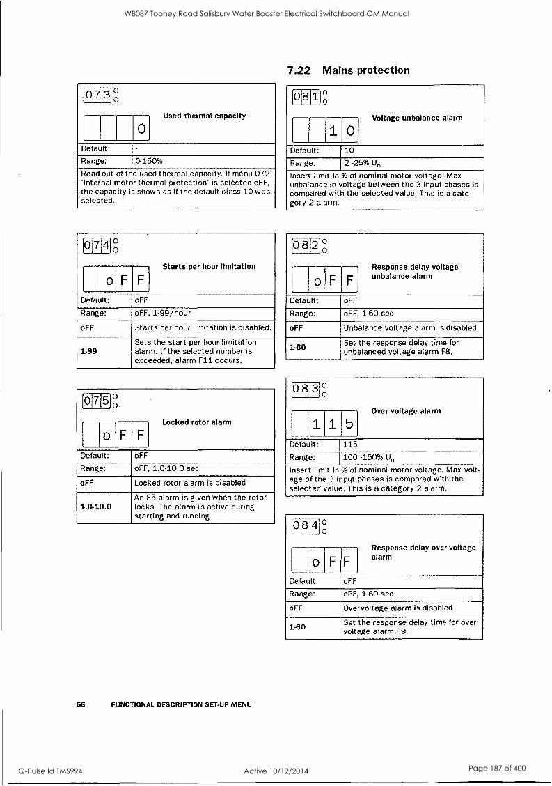
loi71310
[ 0
Used thermal capacity
Default: -
Range: 0-150%
Read-out of the used thermal capacity. If menu 072 'Internal motor thermal protection' is selected oFF, the capacity is shown as if the default class 10 was selected.
017 4 ° o
o F FI Starts per hour limitation
Default: oFF
Range: oFF, 1-99/hour
oFF Starts per hour limitation is disabled.
1-99 Sets the start per hour limitation alarm. If the selected number is exceeded, alarm F11 occurs.
017 5 0°
o F F
Locked rotor alarm
Default: oFF
Range: oFF, 1.0-10.0 sec
oFF Locked rotor alarm is disabled
1.0-10.0 An F5 alarm is given when the rotor locks. The alarm is active during starting and running.
56 FUNCTIONAL DESCRIPTION SET-UP MENU
7.22 Mains protection
08 1 ° o
11 i
0 Voltage unbalance alarm
Default: 10
Range: 2 -25% Un
Insert limit in % of nominal motor voltage. Max unbalance in voltage between the 3 input phases is compared with the selected value. This is a cate- gory 2 alarm.
0 8 2 ° o
o F F
Response delay voltage unbalance alarm
Default: oFF
Range: oFF, 1-60 sec
oFF Unbalance voltage alarm is disabled
1-60 Set the response delay time for unbalanced voltage alarm F8.
0830
1
1 1 1 5 Over voltage alarm
Default: 115
Range: 100 -150% Un
Insert limit in % of nominal motor voltage. Max volt- age of the 3 input phases is compared with the selected value. This is a category 2 alarm.
(01841° 0
delay
o F F
Response over voltage alarm
Default: oFF
Range: oFF, 1-60 sec
oFF Overvoltage alarm is disabled
1-60 Set the response delay time for over voltage alarm F9.
WB087 Toohey Road Salisbury Water Booster Electrical Switchboard OM Manual
Q-Pulse Id TMS994 Active 10/12/2014 Page 187 of 400

10181510
o F F
Under voltage alarm
Default: 85
Range: 75400 Un
Insert limit in % of nominal motor voltage. Min volt- age of the 3 input phases is compared with the selected value. This is a category 2 alarm.
i 0-8 - I 61 0°
F , Response delay under
F voltage alarm
Default: oFF
Range: oFF, 1-60 sec
oFF Under voltage alarm is disabled
1-60 Set the response delay time for under voltage alarm F10
10187 g
_ Ell Phase sequence
Default:
Range: L123, L321
L123 is the direct phase sequence. L321 is the reverse phase sequence.
01818 0 0
o F F
Phase reversal alarm
Default: oFF
Range: oFF, on
oFF Phase reversal alarm is disabled
on
Sets the phase reversal Alarm. - Switch on the power supply first.
The phase sequence is stored as the correct sequence.
- Sets the menu 088 to "on". - Any reversal of phase sequence will
cause alarm F16.
NOTE! The actual phase sequence can be viewed In menu 87.
7.23 Application protection (load monitor)
7.23.1 Load monitor max and min/protection (F6 and F7 alarms)
MSF has a built in load monitor based on the output shaftpower. This is a unique and important function which enables protection of machines and processes driven by the motor connected to the soft starter. Both a Min and Max limit is possible to select.
In combination with the pre-alarm function, see
5 7.23.2, page 58, this create a powerful protection. An auto set function is also included for an automatic set- ting of the alarm limits. A start-up delay dine can be selected to avoid undesired alarms at start-up, see Fig. 58 on page 60.
NOTE! The load monitor alarms are all disabled during a
stop ramp.
018 9]°
I
1 1 0 Auto set power limits
Default: no
Range: no. YES
no Auto set is disabled
YES Auto set is activated if ENTER is pressed.
0900
0 Output shaftpower In %
Default:
Range: 0-200%
Measured output shaftpower in % of nominal motor power.
NOTE! System must be In full voltage running before an
auto set Is permitted.
The actual power is regarded as 1.00xPact. The set levels are
Power max alarm 1611140921: 1.15xP actual Power IllaX pre-alarm limit[094 1.100 actual Power min pre-alarm limit[0961: 0.90xP actual Power min alarm limit[098): 0.85xP actual
A successful auto set shows a message 'Set' for 3 s and if something goes wrong a message 'no' will be showed.
FUNCTIONAL DESCRIPTION SET-UP MENU 57
WB087 Toohey Road Salisbury Water Booster Electrical Switchboard OM Manual
Q-Pulse Id TMS994 Active 10/12/2014 Page 188 of 400

0 91 °°
-T- - -- 1
I
-----
1 --- --
0 Start delay power limits
Default: 10 sec
Range: 1-250 sec
From start co remand during selected delay time, all power load monitor alarms and pre-alarms are disa- bled.
0 9 ° o
1151 ) Max power alarm limit
Default: 115
Range: 5-200% Pn
Insert limit in % of nominal motor power. The actual power in % of nominal motor power, could be read out in menu 090. If output shaft power exceeds selected limit, an F6-alarm occurs after the response delay time. The 'Auto set' function in menu 089, affect this limit even if the alarm is set "oFF" in menu 093. This is a category 1 alarm.
0 9 3 ° o
o F F
Response delay max alarm
Default: oFF
Range: oFF, 0.1-25.0 sec
oFF Max Alarm is disabled.
0.1-25.0 Sets the response delay of the Max Alarm level.
SS FUNCTIONAL DESCRIPTION SET-UP MENU
7.23.2 Pre-alarm It could be usetiil to know if the load is changing towards a load alarm limit. It is possible to insert both a
Max and Min pre-alarm limit based on the motor out- put shaft power. lithe load exceeds one of these limits, a pre-alarm condition occurs.
it should be noted that it is not normal alarms. They will not be inserted in the alarm list, not activat- ing the alarm relay output, not displayed on the display and they will not stop operation. But it is possible to activate relay K I or K2 if a pre-alarm condition occurs. To have pre-alarm status on any of these relays, select value 3 in menu 051 or 052 (sec § 7.17, page 51).
A start-up delay time can be selected in menu 091 to avoid undesired pre-alarms at start-tip. Note that this time is also shared with power Max and Min alarms.
NOTE! The pre-alarm status is always available on the serial communication.
0 9 4 ° o
limit
1 I
1 1 0 I
Max power pre-alarm
Default: 110
Range: 5 -200% Pn
Insert limit in % of nominal motor power. The actual power in % of nominal motor power, could be read out in menu 090. If output shaft power exceeds selected limit, a pre-alarm occurs after the respon- se delay time. The 'Auto set' function in menu 089, affect selected limit even if the pre-alarm is set "oFF" in menu 095.
0950
o F 1 Max pre-alarm response
delay
Default: oFF
Range: oFF, 0.1 - 25.0 sec
oFF Max Pre-Alarm is disabled.
0.1-25.0 Sets the response delay of the Max Pre-Alarm level.
WB087 Toohey Road Salisbury Water Booster Electrical Switchboard OM Manual
Q-Pulse Id TMS994 Active 10/12/2014 Page 189 of 400

(o[61610
19 °1
Min power pre-alarm limit
Default: 90%
Range: 5 -200% Pn
Insert limit in% of nominal motor power. The actual power in % of nominal motor power, could be read out in menu 090. If output shaft power goes below selected limit, a pre-alarm occurs after the response delay time. The 'Auto set' function in menu 089, affect selected limit even if the pre- alarm is set "oFF" in menu 097.
0 911 g
o F
Min pre-alarm response delay
F
Default: oFF
Range: oFF, 0.1 - 25.0 sec
oFF Min Pre-Alarm is disabled.
0.1-25.0 Sets the response delay of the Min Pre-Alarm level. The Min Pre-alarm is disabled during a stop ramp down.
Min power alarm limit
0 9j8 0 0
----- -- -- -- ------.
i8. 5 Default: 85
Range: 5-200% Pn
Insert limit in % of nominal motor power. The actual power in % of nominal motor power, could be read out in menu 090. If output shaft power goes below selected limit, an F7-alarrn occurs after the response delay time. The 'Auto set' function in menu 089, affect this limit even if the alarm is set 'oFF' in menu 099. This is a category 1 alarm.
161 19j° 1 0
o1FF Min alarm response delay
Default: oFF
Range: oFF, 0.1-25.0 sec
oFF Min. Alarm is disabled
0.1 -25.0. Sets the response delay of the Min Alarm level. The Min alarm is disa- bled during a stop ramp down.
FUNCTIONAL DESCRIPTION SET-UP MENU 59
WB087 Toohey Road Salisbury Water Booster Electrical Switchboard OM Manual
Q-Pulse Id TMS994 Active 10/12/2014 Page 190 of 400

cr)
92 Max Alarm (115%)
Start ramp
94 Max Pre-alarm (110%)
100% Default:PNONi or
Autoset.PMOM ENTARY
96 Min Pre-alarm (90%)
98 Min Alarm (85%)
Max Alarm 193 Resvr Delay (1s)
Max Pre-alarm
Min Pre-alarm
Min. Alarm
Under load situation Overload situation
95 Response Delay (1s)
97 Response Delay (1s)
93 REEF E Delay (1s)
95 Response Delay (Is)
91 Start Delay(10s)
03-F96
WB087 Toohey Road Salisbury Water Booster Electrical Switchboard OM Manual
Q-Pulse Id TMS994 Active 10/12/2014 Page 191 of 400
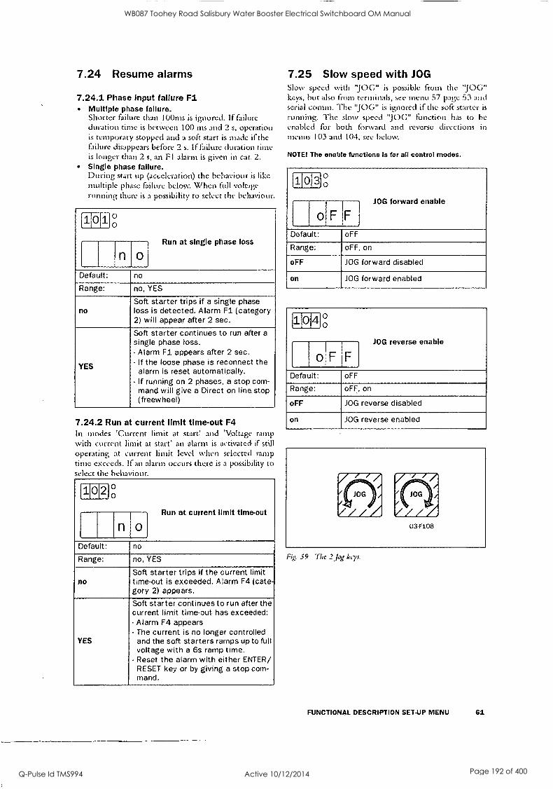
7.24 Resume alarms
7.24.1 Phase Input failure Fl Multiple phase failure. Shorter failure than 100ms is ignored. If failure duration time is between 100 ins and 2 s, operation is temporary stopped and a soft start is made if the failure disappears before 2 s. if failure duration time is longer than 2 s, an F I alarm is given in cat. 2. Single phase failure. During start up (acceleration) the behaviour is like multiple phase failure below When full voltage running there is a possibility to select the behaviour.
1101° i 0
) Run at single phase loss
0 I
Default: no
Range: no, YES
no Soft starter trips if a single phase loss is detected. Alarm Fl (category 2) will appear after 2 sec.
YES
Soft starter continues to run after a
single phase loss. - Alarm Fl appears after 2 sec. - If the loose phase is reconnect the
alarm is reset automatically. - If running on 2 phases, a stop com-
mand will give a Direct on line, stop (freewheel)
7.24.2 Run at current limit time-out. F4 In modes 'Current limit at stare and 'Voltage ramp with current limit at start' an alarm is activated, if still operating at current limit level when selected ramp time exceeds. If an alarm occurs there is a possibility to select the behaviour.
1 0J2 0 0
limit
njo Run at current time-out
Default: no
Range: no, YES
no Soft starter trips if the current limit time-out. is exceeded. Alarm F4 (cate- gory 2) appears.
YES
Soft starter continues to run after the current limit time-out has exceeded: - Alarm F4 appears - The current is no longer controlled
and the soft starters ramps up to full voltage with a 6s ramp time.
- Reset the alarm with either ENTER/ RESET key or by giving a stop com- mand.
7.25 Slow speed with JOG Slow speed with "JOG" is possible from the "JOG" keys, but also from terminals, see menu 57 page 53 and serial comm. The "JOG" is ignored if the soft starter is
running. The slow speed "JOG" function has to he
enabled for both forward and reverse directions in menus 103 and 104, see below.
NOTE! The enable functions Is for all control modes.
(103)0
1
0 JOG forward enable
Default: oFF
Range: oFF, on
oFF JOG forward disabled
on JOG forward enabled
1 4 °o
1 .
o,F F
JOG reverse enable
Default: oFF
Range: oFF, on
oFF JOG reverse disabled
on JOG reverse enabled
Fig. 59 The 2 jog keys.
FUNCTIONAL DESCRIPTION SET-UP MENU 61
WB087 Toohey Road Salisbury Water Booster Electrical Switchboard OM Manual
Q-Pulse Id TMS994 Active 10/12/2014 Page 192 of 400

7.26 Automatic return menu often it is desirable to have a specific menu on the dis- play during operation, i.e. IL MS current or power con, sumption. The Automatic return menu fiinction gives the possibility to select any menu in the menu system.
The menu selected will come. up on the display after 60 sec. if no keyboard activity. The alarm messages
(F1 -F16) have a priority over menu 105 (as they have for all menus).
1011 5 °
F
1 Automatic return menu
F '
Default: oFF
Range: oFF, 1-999
1-999 Pressing "+"/"-" will lead through the menu system.
7.27 Communication option, related Parameters
The following parameters have to be set-up: - Unit address.
- Baud rate. - Parity - Behaviour when contact broken.
Setting up the communication parameter must he
made in local 'Keyboard control' mode. See §, 7.2, page 37.
111 °
I
1
1 1 Serial comm unit address
Default: 1
Range: 1-247
This parameter will select the unit address.
1120
I 9.6 Serial comm baudrate
Default: 9.6
Range: 2.4, 4.8, 9.6, 19.2, 38.4 kBaud
This parameter will select the baudrate.
62 FUNCTIONAL DESCRIPTION SET-UP MENU
- ---- Serial comm parity
11 ° 0
------- 0
Default: 0
Range: 0.1
This parameter will select the parity. 0 No parity. 1 Even parity.
Serial comm. broken alarm If control mode is 'Serial comm. control' and no con- tact is established or contact is broken the Soft starter consider the contact to be broken after 15 sec, the soft starter can act in three different ways:
I Continue without any action, at all. 2 Stop and alarm after 15 sec.
3 Continue and alarm after 15 sec.
If an alarm occurs, it is automatically reset if the com- munication is re-established. It is also possible to reset
the alarm from the soft starter keyboard.
114 ° 0
Serial comm. contact Interrupted
Default: 1
Range: oFF, 1, 2
This parameter will control the behaviour in the soft starter when the serial comm. is interrupted. oFF No alarm and continue operation. 1 Alarm and stop operation. 2 Alarm and continue operation.
WB087 Toohey Road Salisbury Water Booster Electrical Switchboard OM Manual
Q-Pulse Id TMS994 Active 10/12/2014 Page 193 of 400

7.28 Reset to factory setting [199] When selecting reset to factory settings:
All parameters in all parameter sets will have default factory settings. Menu 001 will appear on the display. Note that the alarm list, the power consumption and the operation: time will not have default set- tings.
1'19 9 ° o
n o Reset to factory settings
Default: no
Range: no, YES
no No reset
YES Reset all functions to the factory defaults incl. all 4 Parameter Sets.
NOTE! Reset to factory settings Is not allowed at run.
7.29 View operation
General The soft start includes as standard a numerous metering functions which eliminates the need of additional transducers and meters.
Measured values - Current RMS 3-phase current and per phase
- Voltage RMS 3-phase voltage and per phase
- Output shaft power /torque kW/Nm - Power factot - Power consumption in kWh - Operation time in hours
Viewing of the measured values. After setting motor data, and extended functions one can set menu 008 in oFF and will then automatically move to menu 201, the first menu viewing the, meas- ured values and thus eliMinate to scroll through menu Oil to menu 199.
2 ,
01 ° 0
i . 0
RMS current
Default -
Range: 0.0 - 9999Amp
Read-out of the RMS motor current.
NOTE! Thls is the same read-out as menu 005 see § 7.1.1, page 36.
2 0i2 0
0.0 RMS main voltage
Default: -
Range: 0-720V
The RMS input main voltage.
203 o o
0. 0 Output motor shaftpower
Default: -
Range: -9999 -+9999kW
Viewing will show negative value if generator mode.
204 ° o
1
--------- 0 0
.1
Power factor
Default: -
Range: 0.00-1
View the actual power factor.
NOTE! The power factor viewing will not work at bypass even If the current transformers are mounted outside the soft start.
1210 oo
N. 0 0 0 Total power consumption
Default:
Range: 0.000 -2000MWh
View the tota power consumption.
FUNCTIONAL DESCRIPTION SET-UP MENU 63
WB087 Toohey Road Salisbury Water Booster Electrical Switchboard OM Manual
Q-Pulse Id TMS994 Active 10/12/2014 Page 194 of 400

[21016
No1 Reset of power consumption
Default: no
Range: no, YES
no No reset of power consumtion.
YES Reset power consumption in menu 205 to 0.000.
216710 ..... ..-..J , 0
I
0. ,
Motor shaft torque
Default: -
Range: -9999'- + 9999Nm
Viewing will show negative value if generator mode.
210 E3' ° o
1 0 I I 1
Operation time
Default: -
Range: Hours
Operation time is calculated when the soft starter is in RUN mode. After 9999 hours the display will show two values. Example: 12467 hours shows 1 1 sec
2467 5sec
21-11-110
0. RMS current in phase L1
0 Default: -
Range: 0.0 - 9999A trip
View the current in phase L1.
64 FUNCTIONAL DESCRIPTION SET-UP MENU
I 1
12
0. 0 RMS current In phase
Default: -
Range: 0.0- 9999Amp
View the current in phase L2.
F2Ti. 31g
0.0 RMS current in phase L3
Default: -
Range: 0.0 - 9999Amp
View the current in phase L3.
2 1 4 g
Main voltage L1-L2
Default: -
Range: 0-720V
View main voltage L1-L2.
215 Main voltage L1-L3
Default: -
Range: 0 - 720V
View main voltage L1-L3.
1211 6 0°
L2-13
I
Main voltage
Default: -
Range: 0 - 720V
View main voltage L2-L3.
WB087 Toohey Road Salisbury Water Booster Electrical Switchboard OM Manual
Q-Pulse Id TMS994 Active 10/12/2014 Page 195 of 400

7.30 Keyboard lock The keyboard can be locked to prohibit operation and parameter setting by an unauthorised. Lock keyboard by pressing both keys "NEXT " and "ENTER
" for at least 2 sec. The message '- Lac' will display when locked. To unlock keyboard press the same 2 keys "NEXT " and "ENTER " for at least 2 sec. The message 'unto' will display when unlocked.
In locked mode it is possible to view all parameters and read-out, but it is forbidden to set parameters and to operate the soft starter from the keyboard.
The message '-Loc' will display if trying to set a
parameter or operate the soft starter in locked mode. The key lock status can be read out in menu 221.
2210
I
I
n 1 o Locked keyboard Info
Default: no
Range: no. YES
no Keyboard is not locked
YES Keyboard is locked
7.31 Alarm list The alarm list is generated automatically. It shows the latest 15 alarms (F I - F16). The alarm list can be useful when tracing a failure in the soft starter or its control circuit. Press key 'NEXT " or "PREV " to reach the alarm list in menus 901-915 (menu 007 has to be ON).
9 011 o o
Fill Default:
1
-
Range: F1 -F16
View actual. alarm
FUNCTIONAL DESCRIPTION SET-UP MENU 65
WB087 Toohey Road Salisbury Water Booster Electrical Switchboard OM Manual
Q-Pulse Id TMS994 Active 10/12/2014 Page 196 of 400
8. PROTECTION AND ALARM
The soft starter is equipped with a protection system for the motor, the machine and for the soft starter itself. Three categories of alarm are available:
Category 1 Alarm that stops the motor and need a separate reset before a new start can he accepted. Category 2 Alarm that stops the motor and accepts a new start command without any separate reset. Category 3 Alarm that continues to run the motor.
All alarm, except pre-alarm, will activate the alarm relay output K3, flash a red fault number on the display and it will also be placed in the alarm list. As long as the alarm is active, the display is locked in the alarm indication.
The relay output 1C3 can be used in the control cir- cuit for actions needed when alarm occurs.
If more than one alarm. is active, it is the last alarm that is presented on the display.
8.1 Alarm description
8.1.1 Alarm with stop and requiring a separate reset
Operation will stop for a category I alarm. A separate reset is needed before a new start command is accepted. It is possible to reset from keyboard (pushing "ENTER/RESET") regardless of selected control mode. It is also possible to reset the alarm from the actual control mode (i.e. if control mode is serial com- munication, a reset is possible to do from serial com- munication).
A reset is accepted first when the alarm source goes back to normal.
When a reset is made, the alarm relay output K3 is deactivated, the alarm indication on the display disap- pear and the original menu shows.
After a reset is made the system is ready for a new start command.
8.1.2. Alarm with stop and requiring only a new start command
Operation will stop for a category 2 alarm. A restart can be done and at the same time the alarm relay out- put K3 is deactivated, the alarm indication on the dis- play disappear and the original menu shows.
It is still possible to reset the alarm in the same way as for category 1 alarms (see 8.1.1), if a start is not required at the time.
66 PROTECTION AND ALARM
8.1.3 Alarm with continue run Operation will continue run for a category 3 alarm. Some different reset behaviour is possible (see remarks for the specific alarms in 5 8.2, page 67).
Automatic reset when the alarm source goes back to normal. Automatic reset when a stop command is given. Manual reset during run.
When the reset occurs, the alarm relay output K3 is deactivated, the alarm indication on the display disap- pear and the original menu shows.
WB087 Toohey Road Salisbury Water Booster Electrical Switchboard OM Manual
Q-Pulse Id TMS994 Active 10/12/2014 Page 197 of 400

8.2 Alarm overview
Display Indication Protective function Alarm category Remark
Fl Phase input failure.
Cat 3. Run with auto reset,
Single phase failure when full voltage running if menu 101 'Run at phase loss' = YES. If the fault phase comes back, an automatic reset is made.
Cat 2. Stop with reset in start. Multiple phase failure or single phase failure when not full voltage running or if menu 101 ' Run at phase loss' = no.
F2 Motor protection, overload.
Cat 1. Stop with manual reset.
If menu 071 'Motor PTC input' = YES, cool down the motor. If menu 071 'Motor PTC input' = no, the internal model has to 'cool' down.
F3 Soft start overheated Cat 1. Stop with manual reset. If not cooled down, a reset will not be accepted.
F4 Full speed not reached at set current limit and start time.
If menu 102 'Run at current limit time-our = no. Cat 2. Stop with reset in start.
The current limit start is not corn- pleted.
If menu 102 'Run at current limit time-out' = YES. Cat 3. Run with manual reset.
When start time expired, a 6 sec ramp is used to reach full voltage, without control of the current. Reset the alarm with either a manual reset or a stop command.
F5 Locked. rotor. Cat 1. Stop with manual reset. Motor and/or machine protection.
F6 Above max power limit. Cat 1. Stop with manual reset. Machine protection.
F7 Below min power limit. Cat 1. Stop with manual reset. Machine protection.
F8 Voltage unbalance. Cat 2. Stop with reset in start. Motor protection.
F9 Over voltage. Cat 2. Stop with reset in start. Motor protection.
F10 Under voltage. Cat 2. Stop with reset in start. Motor protection.
Fll Starts / hour exceeded. Cat 2. Stop with reset in start. Motor and/or machine protection.
F12 Shorted thyristor. Cat 3. Run with manual reset.
When stop command comes, the stop will be a 'Direct On Line' stop, and the soft starter will be resetted. After this fault it is possible to start only in 'Direct On Line' mode. One or more thyristors probably damaged.
F13 Open thyristor. Cat 1. Stop with manual reset. One or more thyristors probably dam- aged.
F14 Motor terminal open. Cat 1. Stop with manual reset. Motor not correctly connected.
F15 Serial communication broken.
If menu 114 Serial comm. con- tact broken = 1. Cat 2. Stop with reset in start.
Serial communication broken will stop operation. Run from keyboard if nec- essary.
If menu 114 Serial comm. con- tact broken = 2. Cat 3. Run with auto reset.
Serial communication broken will not stop operation. Stop from keyboard if necessary.
F16 Phase reversal alarm. Cat 1. Stop with manual reset. Incorrect phase order on main voltage input.
PROTECTION AND ALARM 67
WB087 Toohey Road Salisbury Water Booster Electrical Switchboard OM Manual
Q-Pulse Id TMS994 Active 10/12/2014 Page 198 of 400

9. TROUBLE SHOOTING
9.1 Fault, cause and solution
Observation Fault Indication Cause Solution
The display is not illuminated. None No control voltage. Switch on the control voltage.
The motor does not run.
Fl (Phase input failure)
Fuse defective. Renew the fuse.
No mains supply. Switch the main supply on.
F2 (Motor protection, overload)
Perhaps PTC connection. Perhaps incorrect nominal motor current inserted (menu 042).
Check the PTC input if PTC protec- tion is used. If internal protection is used, per- haps an other class could be used (menu 072). Cool down the motor and make a reset.
F3 (Soft start overheated)
Ambient temperature to high. soft starter duty cycle exceeded. Perhaps fan failure.
Check ventilation of cabinet. Check the size of the cabinet. Clean the cooling fins. If the fan(s) is not working cor- rest, contact your local MSF sales outlet.
F4 (Full speed not reached at set current limit and start time)
Current limit parameters are perhaps not matched to the load and motor.
Increase the starting time and/or the current limit level.
F5 (Locked rotor)
Something stuck in the machine or perhaps motor bearing fail- ure.
Check the machine and motor bearings. Perhaps the alarm delay time can be set longer (menu 075).
F6 (Above max power limit) Overload
Over load. Check the machine. Perhaps the alarm delay time can be set longer (menu 093).
F7 (Below min power limit). Under load
Under load. Check the machine. Perhaps the alarm delay time can be set longer (menu 099).
F8 (Voltage unbalance) Main supply voltage unbalance. Check mains supply.
F9 (Over voltage) Main supply over voltage. Check mains supply.
F10 (Under voltage) Main supply under voltage. Check mains supply.
F11 (Starts/ hour exceeded)
Number of starts exceeded according to menu 074.
Wait and make a new start. Perhaps the number of starts / hour could be increased in menu 074.
113 (Open thyristor) Perhaps damaged thristor ps a damagy.
Make a reset and a restart. If the same alarm appears immediately, contact your local MSF sales out- let.
(Motor terminal open) Open motor contact, cable or motor winding.
If the fault is not found, reset the alarm and inspect the alarm list. If alarm larm 112 is found, a thyristor is probably shorted. Make a restart. If alarm F14 appears immediately, contact your local MSF sales outlet.
68 TROUBLE SHOOTING
WB087 Toohey Road Salisbury Water Booster Electrical Switchboard OM Manual
Q-Pulse Id TMS994 Active 10/12/2014 Page 199 of 400

Observation Fault Indication Cause Solution
The motor does not run.
F15 (Serial communication bro- ken)
Serial communication broken.
Make a reset and try to establish contact. Check contacts, cables and option board. Verify - System address (menu 111).
Baudrate (menu 112). - Parity (menu 113). If the fault is not found, run the motor with keyboard control if urgent (set menu 006 to "1"). See also manual for serial communica- tion.
F16 (Phase reversal)
Incorrect phase sequence on main supply. Switch L2 and L3 input phases.
- - - -
Start command comes perhaps from incorrect control source. (I.e. start from keyboard when remote control is selected).
Give start command from correct source (menu 006).
-Loc System in keyboard lock. Unlock keyboard by pressing the keys 'NEXT' and 'ENTER' for at least 3 sec.
The motor is run- ging but an alarm is given.
Fl (Phase input failure)
Failure in one phase. Perhaps fuse defective.
Check fuses and mains supply. Deselect 'Run at single phase input failure' in menu 101., if stop is desired at single phase loss.
F4 (Full speed not reached at set current limit and start time)
Current limit parameters are perhaps not matched to the load and motor.
Increase the starting time and/or the current limit level. Deselect 'Run at current limit time-out' in menu 102, if stop is desired at current limit time-out.
112 (Shorted thyristor)
Perhaps a damaged- thyristor.
When stop command is given, a free wheel stop is made. Make a reset and a restart. If alarm 114 appears immediately, contact your local MSF sales outlet. If it is urgent to start the motor, set soft starter in 'Direct On Line' (menu 024). It is possible to start in this mode,
By pass contactor is used but menu 032 'Bypass' is not set to "on".
Set menu 032 'Bypass' to "on".
F15 (Serial communication bro- ken)
Serial communication broken.
Make a reset and try to establish contact. Check contacts, cables and option board. Verify - System address (menu 111). - Baudrate (menu 112). - Parity (menu 113). If the fault is not found, run the motor with keyboard control if urgent, see also manual for serial communication.
TROUBLE SHOOTING 69
WB087 Toohey Road Salisbury Water Booster Electrical Switchboard OM Manual
Q-Pulse Id TMS994 Active 10/12/2014 Page 200 of 400

Observation Fault Indication Cause Solution
The motor jerks etc.
When starting, motor reaches full speed but it jerks or vibrates.
If 'Torque control' or 'Pump con- trol' is selected, it is necessary to input motor data into the sys- tem.
Input nominal motor data in menus 041-046. Select the proper load characteristic in menu 025. Select a correct initial- and end torque at start in menus 016 and 017. If 'Bypass' is selected, check that the current transformers are correct connected.
Starting time too short. Increase starting time.
Star brig voltage incorrectly set. Adjust starting voltage.
Motor too small in relation to rated current of soft starter.
Use a smaller model of the soft starter.
Motor too large in relation to load of soft starter. Use larger model of soft starter.
Starting voltage not set correctly
Readjust the start ramp.
Select the current limit function.
Starting or stopping time too long, soft does not work.
Ramp times not set correctly. Readjust the start and/or stop ramp time.
Motor too large or too small in relation to load. Change to another motor size.
The monitor funs- tion does riot work. No alarm or pre-alarm
It is necessary to input nominal motor data for this function . Incorrect alarm levels.
Input nominal motor data in menus 041.046. Adjust alarm levels in menus 091 - 099. If 'Bypass' is selected, check that the current transformers are correct con- nected.
Unexplainable alarm. F5, F6, F7, F8. F9, F10 Alarm delay time is to short.
Adjust the response delay times for the alarms in menus 075, 082, 084, 086, 093 and 099.
The system seems locked in an alarm.
F2 (Motor protection, overload)
PTC input terminal could be open. Motor could still be to warm. If internal motor protection is used. the cooling in the internal model take some time.
PTC input terminal should be short circuit if not used. Wait until motor PTC gives an OK (not over- heated) signal. Wait until the internal cooling is done. Try to reset the alarm after a while,.
F3 (Soft start overheated)
Ambient temperature. to high. Perhaps fan failure.
Check that cables from power part are connectedin terminals 073, 074, 071 and 072. MST-017 to MSF5 should hand short circuit between 071 and 072. Check also that the fan(s) is rotat- ing.
Parameter will not be accepted.
. . . _ lithe menu number is one of 020 - 025, only one can bee selected. In other words only one main mode-is possible at a time.
Deselect the other main mode before selecting the new one.
If menu 061, 'Parameter set' is set to "0", the system is in a remote parameter selection mode. It is now impossible to change most of the parameters.
Set the menu 061, 'Parameter set' to a value between "1" - '4" and then it is possible to change any parameter.
During acceleration, decelera- tion, slow speed, DC brake and Power factor control mode, it is impossible to change parame- ters.
Set parameters during stop or full voltage running.
If control source is serial comm., it is impossible to change parameters from key- board and vice versa.
Change parameters from the actual control source.
Some menus include only read out values and not parameters.
Read-out values can not be alte- red. In table 13. page 35, read-out menus has '---' in the factory set- ting column.
-Loc Keyboard is locked. Unlock keyboard by pressing the keys 'NEXT' and 'ENTER' for at least 3 sec.
70 TROUBLE SHOOTING
WB087 Toohey Road Salisbury Water Booster Electrical Switchboard OM Manual
Q-Pulse Id TMS994 Active 10/12/2014 Page 201 of 400

10. MAINTENANCE
In general the soft starter is maintenance free. There are however some things which should be checked regu- larly. Especially if the surroundings are dusty the unit should be cleaned regularly.
WARNING! Do not touch parts Inside the enclosure of the unit when the control and motor voltage Is
switched on.
Regular maintenance Check that nothing in the soft starter has been dam- aged by vibration (loose screws or connections). Check external wiring, connections and control signals. Tighten terminal screws and bushar bolts if necessary. Check that PCB boards, thyristors and cooling fin are free from dust. Clean with compressed air if necessary. Make sure the PCB boards and thyristors are undamaged. Check for .signs of overheating (changes in colour on PCB boards, oNidation of solder points etc.). Check that the temperature is within permissible
Check that the cooling fan/s permit free air flow Clean any external air filters if necessary.
In the event of fault or if a fault cannot be cured by using the fault-tracing table in chapter 9. page 68.
MAINTENANCE 71
WB087 Toohey Road Salisbury Water Booster Electrical Switchboard OM Manual
Q-Pulse Id TMS994 Active 10/12/2014 Page 202 of 400

11. OPTIONS
The following= option arc available. Please contact your supplier for more detailed information.
11.1 Serial communication For serial communication the MODBUS RTU (R.S232/RS485) option card is available order number: 01-1733-00.
Fig. 60 Option R5232/485
11.2 Field bus systems Various option Cards are available for the following bus systems:
PRORBUS DP order number: 01-1734-01 Device NET, order number: 01-1736-01 LONWORKS: 01-1737-01 HP 10: 01-1738-01 INTERBUS -S: 01-1735-01
Each system has his own card. The option is delivered with an instruction manual containing the all details for the set-up of the card and the protocol for program- ming.
Fig. 61 Option Prolibus
72 OPTIONS
11.3 External PPU. The external PPU option is used to move the PPU (keyboard) from the soft starter to the -filint of a panel door or control cabinet.
The maximum distance between the soft starter and the external PPU is 3 m. The option can be Factory mounted (01-2138-01) or it can be built in later (01-2138-00). For both versions instruction /data sheet are available.
Fig. 62 Shows an example of the External PPU after it has been built in.
11.3.1 Cable kit for external current transformers
This kit is used for the bypass fimction, to connect the external current transformers more easy. order number: 01-2020-00.
Fig. 63. Cable kit
WB087 Toohey Road Salisbury Water Booster Electrical Switchboard OM Manual
Q-Pulse Id TMS994 Active 10/12/2014 Page 203 of 400
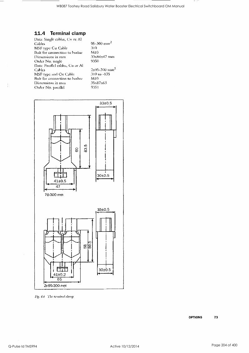
11.4 Terminal clamp Data: Single cables, Cu or Al Cables MSF type Cu Cable Bolt for connection to busbar Dimensions in min Order No. single Data: Parallel cables, Cu or Al Cables MSF type and Cu Cable Bolt For connection to btisbar DittlellSk OW In tom Order No: parallel
95-100 nun2 310 MIO 33x84A7 mm 9350
205-300 inm2 310 to -835 M10 35x87x65 9351
Fig. 64 f1,c terwith2tdartip.
OPTIONS 73
WB087 Toohey Road Salisbury Water Booster Electrical Switchboard OM Manual
Q-Pulse Id TMS994 Active 10/12/2014 Page 204 of 400

12. TECHNICAL DATA
3x200-525 V 60/60 Hz Model MSF017 MSF-030 MSF-045 MSF-060
Soft starter rating according to AC36a, see °hooter 4. page 13
5.0.30:5040 heavy
3.0-30:6040 normal/light
6.0-30:6040 heavy
3.030:60-10 normal/light
6.0-30:50-10 heavy
3,0-30:6040 normal/light
5.0-30:50-10 heavy
3.030:5040 normal/light
Rated current of soft starter (A) 17 22 30 37 45 60 60 72
Recommended motor size (kW) for 400 V 7.5 11 15 18.5 22 30 30 37
Recommended motor size (kW) for 525 V 11 15 18.5 22 30 37 37 45
Order number: supply voltage (100.240V) 01-1301:01 01-1302-01 0.1-1303-01 01430401
Order number: supply voltage (380-500V) 01-1301-02 01-1302-02 014303-02 01-1304-02
3x200-690V 50/60Hz Model MSF-017 MSF-030 MSF046 MSF-060
Rated current of soft starter (A) 17 22 30 37 45 60 60 72
Motor power for 690V 15 18.5 2 2 30 37 55 55 75' I
01-1324-01 Order number: supply voltage (100-240V) 01-1321-01 01-1322-01 01-1323-01
Order number: supply voltage (380.500V) 011321-02 01-1322-02 01-1323-02 01-1324-02
Electrical Data
Recommended wiring fuse (Al 1) 25/50 1 32 35/80 I 50 50/125 J 80 63/160 I 100
Semi-conductor fuses, if required 80 A 125 A 160 A 200 A
Power loss at rated motor load (W) 50 I 70 90 I 120 140 1 180 180 J 215
Power consumption control card 20 VA 20 VA 25 VA 25 VA
Mechanical Data
Dimensions in mm HxWx0 320x126x260 320x 126x 260 320x 126x 260 320x 126x 260
Mounting position (Vertical/Horizontal) Vertical Vertical Vert. or iloriz. Vert, or Horiz.
Weight (kg) 6.7 6.7 6.9 6.9
Connection busbars Cu. (bolt) 1504 (MO) 15x4 (MO) 15x4 (M6) 15x4 (M8)
Cooling system Convection Convect len Fan Fan
General Electrical Data
Number of fully controlled phases 3
Voltage tolerance control Control +/- 10%
Voltage tolerance motor Motor 200-525 +/- 10%/200.690 + 5%, -10%
Recommended fuse for control card (A) Max 10 A
Frequency 50/60 Hz
Frequency tolerance +/ 10%
Relay contacts 3 x 8A. 250 V resistive load. 3A 2SOVAC inductive (PF=0.4)
Typo of protection/Insulation
Type,of casing protection IP 20
Other General Data
Ambient temperatures
In operation 0,- 40 °C
Max. e.g. at 50% IN 50 °C
In storage (-25) - (+70) °C
Relative air humidity 95%, non -condensing
Max. altitude without derating (See separate: Technical information 151) 1000 m
Norma/Standards, Conform to: IEC 947-4-2, EN 292, EN 60204, UL5O8
EMC. Emission EN 50081-2, (EN 50081-1 with bypass contactor)
EMC, Immunity EN 50082-2
1) Recommended wiring fuses for: Heavy (first column): ramp/direct start Normal /light (second column): ramp start
NOTES Short circuit withstand MSF017-060 6000 nes A when used with K5 or RKS fuses.
*2-polc mow!
74 TECHNICAL DATA
WB087 Toohey Road Salisbury Water Booster Electrical Switchboard OM Manual
Q-Pulse Id TMS994 Active 10/12/2014 Page 205 of 400

3x200-625 V 60/60 Hz Model MSF-075 MSF085 MSF.110 MSF-146
Soft starter rating according to AC35a, see chapter 4. page 19
5.0-30:5040 heavy
3.0-30:5040 normnlilight
6.0-30:5040 heavy
3.0-30:60-10 normal/light
5.0.90:6040 heavy
3.0-30:6040 normal/light
6.0-30:5040 heavy
3.0-30:6040 normal/light
Rated current of soft starter (A) 75 85 85 96 110 134 145 156
Recommended motor size (kW) for 400 V 37 45 45 55' 55 75 75
Recommended motor size (kW) for 525 V 45 55 55 75* 75 90 90 110
Order number for supply voltage (100-240 V) 01-1305-01 01-1306-01 01-1307-01 01-1308-01
Omer number for supply voltage (380-550 V) 01-1305-02 01-1306-02 01430702 01-1308-02
3x200-690 V 50/60 Hz Model IVISF-075 NISF-085 MSF-110 MSF-145
Rated current of soft starter (A) 75 85 85 90 110 134 145 156
Motor power for 690V 55 75 75 90 90 110 132 160*
Older number for supply voltage (100-240 V) 01-1325-01 01-1326.01 01-1327-01 01. 1328-01
Order number for supply voltage (380-550 V) 01-1325-02 01. 1326-02 01-1327-02 01-132802
Electrical Data
Recommended wiring fuse (A) 1) 80/200 I 100 100/250 I 125 125/315 I 180 160/400 I 200
Semi-conductor fuses, if required 250 A 315 A 350 A 450 A
Power loss at rated motor load 1W) 230 I 260 260 I
290 330 1 400 440 I 470
Power consumption control card 25 VA 25 VA 25 VA 25 VA
Mechanical Data
Dimensions in mm HxWx0 320x126x260 320x126x260 400x176x260 400x176x260
Mounting position (Vertical/Horizontal) Vert. or Horiz. Vert. or Horiz. Vert. or Horiz. Vert. or Horiz.
Weight (kg) 6.9 6,9 12 12
Connection. busbars Cu, (bolt) - 15x4 (M8) 15x4 (M8) 20x4 (M10) 20x4 0110)
Cooling system Fan Fan Fan Fan
General Electrical Data
Number of fully controlled Phases 3
Voltage tolerance control Control +/- 10%
Voltage tolerance motor Motor 200.525 +/ 10%/200-690 -t- 5%. -10%
Recommended fuse for control card (A) Max 10 A
Frequency 50/60 Hz
Frequency tolerance +/- 10%
Relay contacts 8A. 250,V resistive load, 3A. 250 V inductive load (PF=0.4)
Type of protection/Insulation
Type of casing protection I
IP 20
Other General Data
Ambient temperatures In operation 0 - 40 °C
Max. e.g. at 80% IN 50 °C
In storage (-25) - (+70) °C
Relative air humidity 95%, non-condensing
Max. altitude without derating (See separate: Technical information 151) 1000 in
Norms/Standards; Conform to: IEC 947.4-2, EN 292, EN 602041, UL508
EMC, Emission EN 50081-2, (EN 50081-1 with bypass contactor)
EMC, Immunity EN 50082-2
1) Recommended wiring fuses tor: Heavy (first column): ramp/direct start Normal/Light (second column): ramp start
NOW Short oirouit withstand MSF07544510000 rms'A when used with K5 or RKS fuses.
* 2 -pole motor
TECHNICAL DATA 75
WB087 Toohey Road Salisbury Water Booster Electrical Switchboard OM Manual
Q-Pulse Id TMS994 Active 10/12/2014 Page 206 of 400

3x200-525 V 50/60 Hz Model MSF-170 MSF-210 MSF-250 MSF-310 MSF-370
Soft Matter rating according to AC36a, see chapter 4. page 13
5.0-30:
heavy
3.0-30:
normal/light
5.0-30:
heavy
3.0-30: 604.0
normal /light
6.0-30: 60-10 heavy
3.0-30: 50-10
normal/light
6.0-30: 60-10 heavy
3.0-30: 60.10
normal /light
5.0-30: 60-10 heavy
3.0-30: 50-10
normal/light
Rated current of soft starter (A) 170 210 210 250 250 262 310 370 370 450
Recommended motor size (kW) for 400 V 90 110 110 132 132 160' 160 200 200 250
Recommended motor size (kW) for 525 V 110 132 132 160 160 200 200 250 250 315
Order no. for supply voltage (100-240V) 01. 1309-11 01-1310-11 01-1311-11 01-1312-01 01.131301
Order no. for supply voltage (380.550V) 01-1309-12 01-1310-12 01.1311-12 01-1312-02 01-1313-02
3x200-690 V 50/60 Hz Model MSF170 MSF-22.0 MSF-250 MSF-310 MSF.370
Rated current of soh starter (A) 170 210 210 1 250 250 262 310 370 370 450
Motor power for 690 v 160 200 200 I 250 250 250 315 355 355 400
Order no. for supply voltage (100.240V) 01-132901 01. 1330-01 01133101 01-1332-01 01-1333-01
Order no. for supply voltage (380-550V) 01.1329-02 014330-02 01-133102 01-133202 01. 1333-02
Electrical Data
Recommended wiring (use (A) 1) 200/4001 200 250/4001 315 250/500 315 315/6301 400
800 A
400/8001 500
1000 A Semi-conductor fuses, if required 700 A 700 A 700 A
Power loss at rated motor load (W) 510 630 630 1 750 750 W 930 1 1100 1100 1 1535
Power consumption control card 35 VA 35 VA 35 VA 35 VA 35 VA
Mechanical Data
Dimensions mm HxWxO incl. brackets 500x260x260 500x260x260 500x260x260 532x547x 278 532x 547x 278
Mounting position (Vertical/Horizontal) Vert. or Hartz. Vert. or Horiz. Vert. or Hort/ Vert. or itoriz. Vert. or Horiz.
Weight (kg) 20 20 20 ' 42 46
Connection, Busters Al /Cu (bolt) 30x4 (M10) 30x4 (M10) 30x4 t M10) 40x8 (M12) 40x8 (M12)
Cooling system Fan Fan Fan Fan Fan
General Electrical Data
Number of fully controlled phases 3
Voltage tolerance control Control +/- 10%
Voltage tolerance motor Motor 200.525 +/- 10%/200-690 + 5%. -10%
Recommended fuse for control card (A) Max 10 A
Frequency 50/60 Hz
Frequency tolerance +1- 10%
Relay contacts 8A. 250 V resistive load, 3A. 250 V inductive load (PF.0.4)
Type of protection/Insulation
Type of casIng'protection. I
IP 20
Other General bag
Ambient temperatures In operation 0 - 40 °C
Max. e.g. at 80% IN 50'C
In storage (-25) (+70) °C
Relative air humidity 95%, non-condensing
Max. altitude without Berating (See separate: Technical information 151) 1000 m
Norms/Standards, Conform to: IEC 947.4-2, EN 292. EN 60204-1. (01508, only MSF-170 to MSF-250)
EMC. Emission EN 50081-2, (EN 50081-1 with bypass contactor)
EMC. Immunity EN 50082-2
11 Recommended wiring fuses'for: Heavy (first column): ramp/direct start NormaViIght (second column): ramp start
NOTEI Short circuit withstand 613F170.250 18000 ems A when used with K6 or RK6 fuses.
* 2-pole motor
76 TECHNICAL DATA
WB087 Toohey Road Salisbury Water Booster Electrical Switchboard OM Manual
Q-Pulse Id TMS994 Active 10/12/2014 Page 207 of 400

3x200-525V 60/60Hz Model MSF-450 MSF-570 MSF-710 MSF-835 MSF 1000 MSF-1400
Soft starter rating according to AC36a, see chapter 4. page 13
6.0-30:
heavy
3.0-30: 60-10
norma/ tight
6.0-30:
'' heavy
3.0-30: 50.10
normal/ lied
6.0-30:
;;;,.. 3.0-30: 50.10
normal/ light
6.0-30:
"
3.0-30: 60-10
norrnal/ light
6.0-30: 60-10 heavy
3.0-30:
5""0 normal/ light
6.0-30: 60-10 heavy
3.0-30: 60-10
norrnal/ light
Rated current of soft starter (A) 450 549 570 710 710 835 835 980 1000 1125 1400 1850
Recommended motor size (kW) for 400 V 250 315 315 400 400 450 450 560 580 630 800 930
Recommended motor size (kW) for 525 V 315 400 400 500 500 560 600 630 660 710 1000 1250
Omer no. for supply voltage (100-240V) 01-1341-01 01-1315-01 01-1316-01 01.1317-01 01-1318-01 01-1319-01
Order no. for supply voltage (380.550V) 01-1314.02 01-1310.02 01-1316.02 01-1317-02 01-1318-02 01-131902
3x200-690V 50/60Hz Model MSF -450 N1SF-570 MSF-710 MSF-835 MSF 1000 MSF -1400 Rated current of soft starter (A) 450 549 570 640 710 835 835 880 1000 1125 1400 1524
Motor power for 690V 400 560 560 830 710 800 800 1000 1120 1400 1600
Order no. for supply voltage (100.240V) 01-1334-01 01-1335.01 01-1338-01 01-1337-01 01-1338-01 01-1339-01
Order no. for supply voltage (380.550V) 01-1334-02 01-133502 01-1336-02 01-1337-02 01-1338.02 01-1339-02
Electrical Data
Recommended wiring fuse (A 1) 500/1 K 1 630 630/1 hi 800 800/1 k I 1 k 1 11/1.2k1 1 k 1k/1.4 11 1.2 k 1.4 k/1.81 1.8 k
Semi-conductor fuses, if required 1250 A 1250 A 1.800 A 2500 A 3200 A 4000 A
'Poway loss at rated motor load (W) 1.400 I 1730 1700 1 2100 2100 1 2500 2500 I 2875 3000 1 3375 4200 I 4950
Power consumption control card 35 VA 35 VA 35 VA 35 VA 35 VA 35 VA
Mechanical Data
Dimensions mm HxWx0 incl. brackets 532x547x278 687x640x302 687 ;640x302 687x640x302 90058755336 900x875x336
Mounting position (yortical/ilorizontel) Vert. or Horiz. Vert. or lionz, Vert. or NOti2. Vert. or Hertz. Vert. or Heriz. Vert. or Hartz,
Weight (Kg) 46 64 78 80 175 175
Connection, Busbars Al (bolt) 40x8 (M12) 40x10 (M12) 40x 10(M12) 40x10 (M12) 75x10 (M12) 75x 10(M12)
Cooling system Fan Fan Fan Fan Fan Fan
General Electrical Data
Number Of fully controlled phases 3
Voltage tolerance control Control +/- 10%
Voltage tolerance motor Motor 200-525 +/- 1014/200-690 + 5%. -.10%
Recommended fuse for control card (A) Max 10 A
Frequency 50/60 Hz
Frequency tolerance -1/- 10%
Relay contacts SA, 250 V resistive load. 34. 250 V inductive load (PF.0,4)
Typo otptection/Insulation
Type of casing protection I
IP00 1
IP 20
Other General Data
Ambient temperatures In operation 0 - 40 C Max. e.g. at 80%1N 50 C In storage I.25) - (470) C
Relative air humidity. 95%, non-condensing
Max. altitude without Berating (See separate: Technical information 151) 1.000 m
Norrns/Standards..Conform to: IEG 947-4.2, EN 292, EN 60204-1
EMC, Emission EN 50081-2. (EN 50081-1 with bypass contactor)
EMC, Immunity EN.50082-2
1) RecomMended wiring fuses for: Heavy (firSt column): ramp/direct Start Normal/Light (second column): ramp start
TECHNICAL DATA 77
WB087 Toohey Road Salisbury Water Booster Electrical Switchboard OM Manual
Q-Pulse Id TMS994 Active 10/12/2014 Page 208 of 400

Semi-conductor fuses Always use standard commercial fuses to protect the wiring and prevent short circuiting. To protect the thy- ristors against short-circuit currents, superfast semicon- ductor fuses can be used if. preferred (e.g. Bussmann type FWP or similar, see table below).
The normal guarantee is valid even if superfast semiconductor fuses are not used.
Type FWP Bussmann fuse
A 12t (fuse) x 1000
MSF-017 80 2.4
M SF-030 125 7.3
M SF-045 150 11.7
M SF-060 200 22
MSF-075 250 42.5
MSF-085 300 71.2
MSF-110 350 95.6
MSF-145 450 137
MSF-1708 700 300
MSF-2108 700 300
MSF-250B 800 450
M SF-310 800 450
MSF-370 1000 600
M SF-450 1200 2100
MSF-570 1400 2700
MSF-710 1800 5300
MSF-835 2000
MSF-1000 2500
MSF-1400 3500
78 TECHNICAL DATA
WB087 Toohey Road Salisbury Water Booster Electrical Switchboard OM Manual
Q-Pulse Id TMS994 Active 10/12/2014 Page 209 of 400

13. SET-UP MENU LIST
enu number Function/Parameter Range Par.set Factory
setting Value Page
001 Initial voltage at start 25 - 90% of U 1 - 4 30 page 36
002 Start time ramp 1 1- 60 sec 1 - 4 10 page 36
003 Step down voltage at stop 100 - 40% U 1 - 4 100 page 36
004 Stop time ramp 1 oFF, 2 - 120 sec 1- 4 oFF page 36
005 Current 0.0 - 9999 Amp ------- - page 36
006 Control mode 1, 2, 3 1 - 4 2 page 37
007 Extended functions & metering oFF, on ---- oFF page 38
008 Extended functions OFF, on - - oFF page 38
011 Initial voltage start ramp 2 30 - 90% U 1 - 4 90 page 38
012 Start time ramp 2 oFF, 1- 60 sec 1- 4 oFF page 38
013 Step down voltage stop ramp 2 100 - 40% U 1 - 4 40 page 38
014 Stop time ramp 2 oFF, 2. 120 sec 1. 4 oFF page 38
016 Initial torque at start 0. 250% Tn 1 - 4 10 page 39
017 End torque at start 50 - 250% Tn 1 - 4 150 page 39
018 End torque at stop 0-100% Tn 1 - 4 0 page 39
020 Voltage ramp with current limit at start oFF, 150 - 500% In 1 - 4 oFF page 39
021 Current limit at start oFF, 150 - 500% In 1 - 4 oFF page 40
022 Pump control oFF, on 1 - 4 oFF page 40
023 Remote analogue control oFF, 1, 2 1 - 4 oFF page 41
024 Full voltage start D.O.L oFF, on 1- 4 oFF page 41
025 Torque control oFF, 1, 2 1 - 4 oFF page 42
030 Torque boost active time oFF, 0.1 - 2.0 sec 1 - 4 oFF page 43
031 Torque boost current limit 300 -700%1,, 1 - 4 300 page 43
032 Bypass oFF, on :L - 4 oFF page 43
033 Power Factor Control PFC oFF, on 1 - 4 oFF page 46
034 Brake active time oFF, 1 - 120 sec 1 - 4 oFF page 47
035 Braking strength 100 - 500% 1 - 4 100 page 47
036 Braking methods 1, 2 1 - 4 1 page 47
037 Slow speed torque 10 - 100 1 - 4 10 page 49
038 Slow speed time at start oFF, 1 - 60 sec 1 - 4 oFF page 49
039 Slow speed time at stop oFF, 1 - 60 sec 1 - 4 oFF page 49
040 DC-Brake at slow speed oFF, 1-60 sec 1 - 4 oFF page 49
041 Nominal motor voltage 200 - 700 V 1 - 4 400 page 50
042 Nominal motor current 25-15 0% mp
In sort in A
1 - 4 1,50, in Amp page 50
043 Nominal motor power 25 - 300% of Pnsott in kW 1 - 4 Pnft in kW page 50
044 Nominal speed 500 - 3600 rpm 1- 4 Nnsari in rpm page 50
045 Nominal power factor 0.50 - 1.00 1 4 0.86 page 50
046 Nominal frequency 50, 60 Hz - 50 page 50
SET-UP MENU LIST 79
WB087 Toohey Road Salisbury Water Booster Electrical Switchboard OM Manual
Q-Pulse Id TMS994 Active 10/12/2014 Page 210 of 400

Menu number
Function/Parameter Range Par.set Factory setting
Value Page
051 Programmable relay K1 1, 2, 3, (4), 5 1 page 51
052 Programmable relay K2 1, 2, 3, 4, 5 ---- 2 page 51
054 Analogue output oFF, 1, 2 1 - 4 oFF page 52
055 Analogue output value 1, 2, 3 1 - 4 1 page 52
056 Scaling analogue output 5 - 150% 1- 4 100 page 52
057 Digital input selection oFF, 1, 2, 3, 4 1 - 4 oFF page 53
058 Digital input pulses 1-100 1 - 4 1 page 53
061 Parameter set 0, 1, 2, 3, 4 ------- 1 page 54
071 Motor PTC input no, YES ------- no page 55
072 Internal motor thermal protection class oFF, 2 - 40 sec ----- 10 page 55
073 Used thermal capacity 0- 150% ------- -- - - - - -- page 55
074 Starts per hour limitation oFF, 1- 99/hour 1 - 4 oFF page 55
075 Locked rotor alarm oFF, 1.0 - 10.0 sec 1 4 oFF page 55
081 Voltage unbalance alarm 2 - 25% Un 1. 4 10 page 56
082 Response delay voltage unbalance alarm oFF, 1 - 60 sec 1 - 4 oFF page 56
083 Over voltage alarm 100 - 150% U1, 1 - 4 115 page 56
084 Response delay over voltage alarm off, 1- 60 sec 1- 4 off page 56
085 Under voltage alarm 75 -100%14 1 - 4 85 page 57
086 Response delay under voltage alarm oFF, 1 - 60 sec 1 - 4 oFF page 57
087 Phase sequence L123, L321 ------ - page 57
088 Phase reversal alarm oFF, on - - - -- oFF page 57
089 Auto set power limits no, YES ------- no page 57
090 Output shaft power 0.0 - 200.0% Pn -- page 57
091 Start delay power limits 1 - 250 sec 1 - 4 10 page 58
092 Max power alarm limit 5 - 200% Pn 1 - 4 115 page 58
093 Max alarm response delay oFF, 0.1 - 25.0 sec 1 - 4 oFF page 58
094 Max power pre-alarm limit 5 - 200% Pn 1 - 4 110 page 58
095 Max pre-alarm response delay oFF, 0.1- 25.0 sec 1 - 4 oFF page 58
096 Min pre-alarm power limit 5 - 200% Pn 1 - 4 90 page 58
097 Min pre-alarm response delay oFF, 0.1 - 25.0 sec 1- 4 oFF page 59
098 Min power alarm limit 5 - 200%Pn 1 - 4 85 page 59
099 Min alarm response delay oFF, 0.1. 25.0 sec 1- 4 oFF page 59
101 Run at single phase input failure no. YES 1 - 4 no page 61
102 Run at current limit time-out no, YES 1 - 4 no page 61
103 Jog forward enable oFF, on 1 - 4 oFF page 61
104 Jog reverse enable oFF, on 1 - 4 oFF page 61
105 Automatic return menu off, 1.999 ------ oFF page 62
111 Serial comm. unit address 1 - 247 ------- 1 page 62
112 Serial comm. baudrate 2.4 - 38A kBaud ------- 9.6 page 62
80 SETUP MENU LIST
WB087 Toohey Road Salisbury Water Booster Electrical Switchboard OM Manual
Q-Pulse Id TMS994 Active 10/12/2014 Page 211 of 400

enu nMumber
Function/Parameter Range Par.set Factory set ting .
Value Page
113 Serial comm. parity 0, 1 -------- 0 page 62
114 Serial comm. contact broken oFF, 1, 2 ------ 1 page 62
199 Reset to factory settings no, YES no page 63
201 Current 0.0 - 9999 Amp . page 63
202 Line main voltage 0 . 720 V ----- page 63
203 Output shaft power -9999 - 9999 kW ------- ----- page 63
204 Power factor 0.00 - 1.00 - page 63
205 Power consumption 0.000 - 2000 MWh ------ _ __. page 63
206 Reset power consumption no, YES ------ no page 64
207 Shaft torque -9999 - 9999 Nm page 64
208 Operation time Hours ------ - - page 64
211 Current phase L1 0.0 - 9999 Amp - --------- page 64
212 Current phase L2 0.0 - 9999 Amp ------ ........__. page 64
213 Current phase L3 0.0. 9999 Amp --- -- -- page 64
214 Line main voltage L1 - L2 0 - 720 V ------ ------- page 64
215 Line main voltage L1 - L3 0 - 720 V ---- page 64
216 Line main voltage L2 - L3 0 - 720 V - -------- page 64
221 Locked keyboard info no, YES -- - no page 65
901 Alarm list, Latest error Fl - 116 - - - - -- -- page 65
902 -915 Alarm list, Older error in chronological order Fl - 116 _ _ ._ _ page 65
Explanation of units: U Input line voltage Un Nominal motor voltage. In Nominal motor current. Pn Nominal motor power. Nn Nominal motor speed. Tn Nominal shaft torque. lnsoft Nominal current soft starter. Pnsoft Nominal power-soft starter. Nnsoft Nominal speed soft starter.
Calculation, shaft torque
T
60A-211)
NOTE! The six main functions for motor control, menus 020-025, can only be selected one at a time.
SET-UP MENU LIST 81
WB087 Toohey Road Salisbury Water Booster Electrical Switchboard OM Manual
Q-Pulse Id TMS994 Active 10/12/2014 Page 212 of 400
14, INDEX
Numerics 2-wire start/stop 3-wire start/stop
A
Above max power limit Alarm category Alarm list
Alarm reset Ambient temperatures . 10, 20, 77 analogue control Analogue input Analogue output Analogue output gain Analogue output value Auto set power limits automatic reset Automatic return menu
B
Basic parameter setting Below min power limit Brake method Braking. Strenght Braking time I3usbars
Bypass Bypass contactor
C
Cabinet Checklist Clickson thcrntistor Combination matrix Complaint Confirm setting Connections Control mode Control voltage control voltage Control voltage connection Cooling fins cos phi Current Current in phase LI
Current in phase L2
Current in phase L3
Current limit Current limit time-out Current transformer
D
D.O.L start DC-brake DC-Brake at slow speed Decrease value Decrease value of setting
82 INDEX
17
67 67
65 23
74, 75,
32 32, 41
32, 52 52 52 57
37 62
10 67 47 47 46
25, 26
43 44
10
32 19
7
23 28, 32 23, 37
32 33
28, 31
24 50
63
64 64
64 39 61
45
41
46 49 23 23
Device connections 28, 31
different operation situation 22 Digital inputs 32 Dimension 25.74 DIN VIDE 0100 24
Direct On Line start 41
Dismantling 2
Display next window 23 Display previous window 23 Dual voltage ramp 38
E
Electrical characteristic 32 Electrical Data 74, 75, 76, 77 EMC 74, 73, 76, 77
Emergency 2
End torque 39
F
Factory settings 63
Features 9
Forward/reverse 34
Free circulation of air 24 frequency 50
Frequency inverter 20 Front cover 21
Full speed not reached 67
Full voltage 51
Full voltage start 41
Function 79
G
General Data 74 General description 21
H
Heat dissipation )0 High ambient temperatures 43
Increase value 23
Increase value of setting 23 Initial torque 39
Initial voltage at start tamp 1 36 Initial voltage at start ramp 2 38
INSPECTION AT DELIVERY 7
Installation 24
tnsulation test 20
,1
JOG Forward 23,61 JOG fivd/rev 23
JOG Reverse 23,61 Jumper J 41
Jumper J2 52
K
Keyboard 23
Keyboard lock keys
L
LED display Live circuit components Load monitor Locked rotor Low load
M
Main &unctions
Mains contactor Mains supply Mains voltage MAINTENANCE Matrix Max power alarm limit Max power pre-alarm limit Max pre-alarm response delay
Mechanical Data 74, 75, Menu
001
002 003 004 005 006 007 008 011 012 013 014 016 017 020 021 022 023 024 025 030 031 032 033 034 035 036 037 038 039 040 041 042 043 044 045 046
23, 65 23
22 24
57
67 20
81
10
28, 31
10
71
19
58 ..... 58
58 76, 77
36 11, 36
36 11, 36 12, 36 12, 37
38 38 38 38 38
38 39 39 39 40 40 41
41
42 43 43 43 46 46
47 47 48 49 49 49
11, 50 50
11, 50 11, 50 11, 50 11,50
WB087 Toohey Road Salisbury Water Booster Electrical Switchboard OM Manual
Q-Pulse Id TMS994 Active 10/12/2014 Page 213 of 400

051 052 054 055 056 057 058 061
071 072 073 074 075 081 082 083 084 085 086 087 088 089 090 091 092 093 094 095 096 097 098 099 101
102
103
104 105 199
201 202 203 204 205 206 207 208 211 212 213 214 215 216 221 901 RMS current read-out
Menu expansion Menu Structure MM alarm response delay Min power alarm limit Mill power pre-alarm limit Min pre -alarm response delay Minimum free space Motor
51
51
52 52 52 53
53 54 55
55 56
56 56 56 56
56
56 57
57 57
57
57
57 58
58
58
58 58
59
59 59
61
61
61
61
62 63
63 63 63 63 63 64 64 64 64 64 64 64 64 64
23,65 65 12
38 22 59 59 59 69
24, 25 31
Motor current Motor data
Motor power Motor power supply Motor protection, overload Motor shaft torque Motor speed Motor terminal open Motor voltage MOUNTING MOUNTING/WIRING
N
Next Nominal frequency Nominal motor cos phi Nominal motor current Nominal motor power Nominal motor speed Norms /Standards 74, 75, NTC thermistor
0 Open thyristor Operation Operation time Operation/Sec-up Operator panel Output motor shaftpower Output shaftpower Over voltage
Parallel Parallel cables Parameter. Parameter Set PFC Phase compensation capacitor ..... Phase input failure Phase loss
Phase reversal alarm Phase sequence Pole-changing contactor Potentiometer Power consumption Power factor Power Factor Control Power loss PPU unit Pre-alarm Prevent damage to the thyristors Previous Programmable relay Programming and presentation (PPU) protection/insulation ... 74, 75, Protective earth PTC PTC Thermistor input Pump control
50 50
50 28, 31
55, 67 64
50 67 50 24 24
23
11
11
11
1
76, 77 32
67 51
63, 64
21
63 57, 63 56, 67
20 73
79
32, 54
46 20 67
6l 67 57
20
32
63
63
46 10
21
51, 58 .... 24
23
51
unit 21
76, 77 28, 31
55 12 40
Q Quick Set-up
R
Rating plate 10
Recyclable material 2
Regular maintenance 71
Relay K1 32, 51
Relay K2 32 Relay K3 32 Remote 23 Reset 23 reset Response delay max alarm 58 RMS current 16, 63 RMS main voltage 63
Rotating loads 20 Running motors 20 Running -LED 22
$ Safety 2, 6 Safety measures 10
Scrapping Selection of control mode 12 Semiconductor fuses 33, 78 Serial conun. 23 Serial communication broken 67
Shaftpower 57, 63 Shielded motor cable 20 Shorted thyristor 67 Simple soft start and soft stop 10
Slip ring motors 90 Slow blow fuses 33 Slow speed time at start 49 Slow speed time at stop 49 Slow speed torque 48
Small motor 20 Softbrake 51
Softstart overheated 67 Spare parts standard coirunereial fuses 78 Standard wiring 10, 33 Standards 6
Seta command 22 Saar delay power limits 58 Start ramp 1 16 Start ramp 2 38 Start the motor 12
Start time ramp 11
Start/Stop 12,23 Start/stop combination 19
Start/stop/reset from keyboard 12
Start/stop-LED 92
Starting 12
STARTING/OPERATING 79 Starts per hour 67 Starts per hour limitation 56 Step down voltage in stop ramp 2 38 Step down voltage stop ramp 1 36 Stop command 22 Stop ramp 1 36
INDEX 83
WB087 Toohey Road Salisbury Water Booster Electrical Switchboard OM Manual
Q-Pulse Id TMS994 Active 10/12/2014 Page 214 of 400

Stop ramp time 2 38 Stop time ramp l I 1
storage 7
Supply voltage switch
12, 74 2
Switch the device off 2 Switch-off procedures 2
TECHNICAL DATA 74 Terminal 12 Terminal clamp 78 Terminals Thermal capacity 56 Thermal protection 55 Tightening torque 25 Torque boost active time 43 Torque boost current limit 43 Torque booster 43 Torque control 42 Trained personnel 2, 10
Transport . 7 TROUBLESHOOTING 68 Two speed motor
U
Under voltage 57, 67
Unpacking 7
V
VIEW OPERATION 63 Voltage 63 Voltage unbalance 56, 67
Weight 74 Wiring circuit Wiring example 34
84 INDEX
WB087 Toohey Road Salisbury Water Booster Electrical Switchboard OM Manual
Q-Pulse Id TMS994 Active 10/12/2014 Page 215 of 400

J & P Richardson Industries Po; Ltd
6 Instruments
DAN FOSS - MBS 3000 060C-103 - Pressure Transmitter
SUPPLIED BY: Danfoss (Australia) Pty Ltd. Unit 3/8 Navigator Place, Hendra 4011, Queensland AUSTRALIA
PHONE: (07) 3630 1899 FAX: (07) 3630 2122
CONTROL LOGIC - TH635 - Pump Hour Runmeter
SUPPLIED BY: CONTROL LOGIC QLD 34 Thompson Street, Bowen Hills 4006, Queensland AUSTRALIA
PHONE: (07) 3252 9611
FAX: (07) 3252 8776
File: Swbd Manual Revision 0 Date:11/3/2010
WB087 Toohey Road Salisbury Water Booster Electrical Switchboard OM Manual
Q-Pulse Id TMS994 Active 10/12/2014 Page 216 of 400

Data sheet MBS 3000 pressure transmitter for industrial applications
Introduction Designed for use in severe industrial environments
Enslosure and wetted parts of acid- resistant stainless steel (AISI 316L)
All standard output signals: 4-20 mA, 0-5 V,
1-5 V,1 -6 V, 0-10 V
A wide range of pressure and electrical connections
Temperature compensated and laser calibrated
Typical applications: - Pumps - Compressors - Pneumatics - Water treatment
Dimensions
Orderin Type code Page 4 8 2 5 7 1 3
AMP Superseal 1.5 series (male)
AMP Econoseal J series (male)
IEC 947-5-2 M12x1, 4-pin
ISO 15170-A1-3.2-Sn (Bayonet plug)
DIN 43650, Pg 9 2 m screened cable
Ordering
23
,T, 11
51-1
1/4- 18 NPT 1/2 - 14 NPT DIN 3852-E-G1/4 Gasket:
DIN 3869-14
G' /4A (EN 837)
G (EN 837)
G 1hA (EN 837)
Type code page 4
AC04 y AC08 GB04 ABO4 ABO6 ABO8
CDantossAlS 11-2002 DKACT.PD.P20.K2.02 520B1374
WB087 Toohey Road Salisbury Water Booster Electrical Switchboard OM Manual
Q-Pulse Id TMS994 Active 10/12/2014 Page 217 of 400

Data sheet Pressure transmitter for industrial application MBS 3000
Technical data Main specifications Pressure connections see page 1
Measuring ranges [bar] 0-1 0-1.6 0-2.5 0-4 0-6 0-10 0-16 0-25 0-40 0-60 0-100 0-160 0-250 0-400 0-600
Output signals 4-20 mA 0-5 V 1-5 V 1-6 V 0-10 V
Electrical connections see page 3
Performance (IEC 770)
Accuracy t0.5% FS (typ.) ±1% FS (max.)
Non-linearity (best fit straight line) 5 ±0.5% FS
Hysteresis and repeatability < ±0.1% FS
Thermal zero point shift .5 ±0.1% FS/10K (typ.) 5 ±0.2% FS/10K (max.)
Thermal sensitivity (span) shift 5 ±0.1% FS/10K (typ.) 5. ±0.2% FS/10K (max.)
Response time < 4 ms
Overload pressure 6 x FS (max. 1500 bar)
Burst pressure 6 x FS (max. 2000 bar)
Durability, P: 10-90% FS >10x106 cycles
Electrical specifications Nom. output signal (short-circuit protected)
4- 20 mA 0-5, 1-5, 1-6 V d.c. 0-10 V d.c.
Supply voltage [U9], polarity protected 9 32 V d.c. 9 -) 30 V d.c. 15 30 V d.c.
Supply - current consumption - 55 mA 58 mA
Supply voltage dependency 5 ±0.05% FS/10 V
Current limitation (linear output up to 1.5x nom. range) 34 mA (typ.) -
Output impedance - 52552
Load [RL] (load connected to OV) RL 5 (1.18-9V)/0.02 RL 10 kit RL 1516.2
Environmental conditions Medium temperature range -40 +85°C
Ambient temperature range (depending on electrical connection) see page 3
Compensated temperature range 0 --) +80°C
Transport temperature range -50 -4 +85°C
EMC - Emission EN 61000-6-3
Electrostatic discharge Air mode 8 kV EN 61000-6-2
Contact mode 4 kV EN 61000-6-2
- EMC Immunity RF field 10 V/m, 26 MHz - 1 GHz EN 61000-6-2
conducted 10 Vr,,, 150 kHz - 30 MHz EN 61000-6-2
Transient burst
surge
4 kV (CM),Clamp EN 61000-6-2
1 kV (CM,DM), Rg = 4251 EN 61000-6-2
Insulation resistance > 100 MO at 100 V d.c.
Mains frequency test 500 V, 50 Hz SEN 361503
Vibration stability Sinusoidal 15.9 mm-pp, 5Hz-25Hz
IEC 60068-2-6 20 g, 25 Hz - 2 kHz
Random 7.5 g ,,,,, 5 Hz - 1 kHz IEC 60068-2-34, IEC 60068-2-36
Shock resistance Shock 500 g / 1 ms IEC 60068-2-27
Free fall IEC 60068-2-32
Enclosure (depending on electrical connection) see page 3
Mechanical characteristics
Materials Wetted parts DIN 17440-1.4404 (AISI 316 L)
Enclosure DIN 17440-1.4404 (AISI 316 L)
Electrical connections see page 3
Weight (depending on pressure connection and electrical connection) 0.2-0.3 kg
2 DKACT.PD.P2O.K2.02 Danfoss 11 -2002
WB087 Toohey Road Salisbury Water Booster Electrical Switchboard OM Manual
Q-Pulse Id TMS994 Active 10/12/2014 Page 218 of 400

Data sheet Pressure transmitter for industrial application MBS 3000
Electrical connections Type code, page 4
1 2 5 7 8 3
DIN 43650, Pg 9
.... ,
AMP Econoseal J series (male)
,------ni tied MN!)
IEC 947-5-2 M12x1
/^-- I
1111.1311
IkkAll=f
ISO 15170-A1-3.2-Sn (Bayonet plug)
1
/A
AMP 1.5
\,' , -
Superseal series (male)
I f) -4r_
N.,,,,,,,.'
2 m screened cable
li
tO
,..= r.
I
A,
m 21 .- 111
mn -0
r i
Ambient temperature
-40 --) + 85 °C -40 --) + 85 °C -25 -) +85 °C -40 -4 +85 °C -40 -> +85 °C -30 -) +85 °C
Enclosure
IP 65 IP 67 IP 67 IP 67 / IP 69K IP 67 IP67
Materials
Glass filled polyamid, PA 6.6
Glass filled polyamid, PA 6.6"
Nickel plated brass, CuZn/Ni
Glass filled polyester, PBT
Glass filled polyamid, PA 6.62)
Polyolifin cable with PE shrinkage tubing
Electrical connection, 4-20 mA output (2 wire)
Pin 1: +supply Pin 2: _ supply Pin 3: Not used Earth: Connected to MBS housing
Pin 1: +supply Pin 2: +supply Pin 3: Not used
Pin 1: +supply Pin 2: Not used Pin 3: Not used Pin 4: _ supply
Pin 1: +supply Pin 2: _ supply Pin 3: Ventilation Pin 4: Not used
Pin 1: +supply Pin 2: +supply Pin 3: Not used
Brown wire: +supply Black wire: _ supply Red wire: Not used Orange: Not used Screen: Not connected to MBS housing
Electrical connection, 0-5V 1-5V, 1-6V, 0-10V output
Pin 1: +supply Pin 2: _ supply Pin 3: Output Earth: Connected to MBS housing
Pin 1: +supply Pin 2: _ supply Pin 3: Output
Pin 1: +supply Pin 2: not used Pin 3: Output Pin 4: _ supply
Pin 1: +supply Pin 2: Output Pin 3: Ventilation Pin 4: -supply
Pin 1: +supply Pin 2: _ supply Pin 3: Output
Brown wire: Output Black wire: _ supply Red wire: + supply Orange: Not used Screen: Not connected to MBS housing
') Female plug: Glass filled polyester, PBT 2) Wire: PETFE (teflon)
Protection sleeve: PBT mesh (polyester)
C Danfoss 11-2002 DKACT.PD.P20.K2.02 3
WB087 Toohey Road Salisbury Water Booster Electrical Switchboard OM Manual
Q-Pulse Id TMS994 Active 10/12/2014 Page 219 of 400

Data sheet Pressure transmitter for industrial application MBS 3000
Ordering of standard MBS 3000 with DIN 43650 plug Pg 9
Pressure connection
Pressure range Pe
Type Code no
G V. A
(EN 837)
0 - 1 bar MBS 3000 1011-1 A604 060G1113
0 - 1.6 bar MBS 3000 1211-1 A604 06061429
0 - 2.5 bar MBS 3000 1411-1 A604 060G1122
0 - 4 bar MBS 3000 1611-1 ABO4 06061123
0 - 6 bar MBS 3000 1811-1 ABO4 06061124 0 - 10 bar MBS 3000 2011-1 A504 06061125
0 - 16 bar MBS 3000 2211-1 ABO4 06061133
0 - 25 bar MBS 3000 2411-1 ABO4 06061430 0 - 40 bar MBS 3000 2611-1 ABO4 06061105
0 - 60 bar MBS 3000 2811-1 ABO4 06061106
0 - 100 bar MBS 3000 3011-1 ABO4 06061107
0 - 160 bar MBS 3000 3211-1 ABO4 06061112
0 - 250 bar MBS 3000 3411-1 ABO4 06061111
0 - 400 bar MBS 3000 3611-1 ABO4 060G1109
0 - 600 bar MBS 3000 3811-1 ABO4 06061110
Ordering of special versions MBS 3000
I I I
Pressure connection(see page 1) A B 0 4 Measuring G 1/4 A (EN 837)
range A B 0 6 G 3/8 A (EN 837) 0 - 1 bar 1 0 A B 0 8 G V, A (EN 837) 0- 1.6 bar 1 2 A C 0 4 1/4 -18 NPT 0 - 2.5 bar 1 4 A C 0 8 ... 1/2-14 NPT 0 - 4 bar 0 - 6 bar 0- 10 bar
1 6 18 2 0
G B 0 4 ... DIN 3852-E-G1/4, Gasket: DIN 3869-14 NBR
0 - 16 bar 2 2 0 - 25 bar 2 4 0 - 40 bar 2 6 0 - 60 bar 2 8 0- 100 bar 30 Electrical connection (see pages 1 and 3) 0- 160 bar 32 Plug, DIN 43650, Pg 9 0 - 250 bar 34 *)Plug, AMP Econoseal, J series, male, 0 - 400 bar 36 excl. female plug 0 - 600 bar 3 8 Screened cable, 2 m
*)Plug, IEC 947-5-2, M12 x 1, male, excl. female plug
Pressure reference
Plug ISO 15170-A1-3.2-Sn, male, excl. female plug
Gauge (relativ) Absolute
*) Plug, AMP Superseal 1.5 series male, excl. female plug
Gauge versions only available as sealed gauge versions
Output signal 4 - 20 mA 0- 5V 1- 5V 1- 6V 0 - 10 V
Dantoss can accept no responsibility for possible errors in catalogues, brochures and other printed material. Dantoss reserves the right to alter its products without notice. This also applies to products already on order provided that such alterations can be made without subsequential changes being necessary in specifications already agreed. All trademarks in this material are property of the respective companies. Dantoss and the Dantoss logotype are trademarks of Dantoss A/S. All rights reserved.
DK-6430 Nordborg Denmark
4 DKACT.PD.P20.K2.02 ©Dantoss 11-2002
WB087 Toohey Road Salisbury Water Booster Electrical Switchboard OM Manual
Q-Pulse Id TMS994 Active 10/12/2014 Page 220 of 400

Panasonic 5deas for Me
57.5 2.264
24 mm inch
.945
48 1.890
TH64 series (with reset button)
TH63 series (without reset button)
RoHS Directive compatibility information http://www.nais-e.com/
Features 1. Compact to save panel space The 24 x 48 mm hour meters are just half the DIN 48 x 48 stan- dard size. They help save the panel space.
UL File No.: E42876 GSA File No.: LR39291 E 2. Reset button The hour meters can be reset to zero (TH64 series). 3. Wide-ranging measurement display The measurement can be displayed from 0.1 hour up to 99999.9 hours (TH63 series). The dial size is the same as that of 48 x 48 DIN size hour meters (TH14 and TH24 series). 4. Easy to install The flat terminals (#187) are used for easier wiring. There is no need to undo the lock spring. 5. High-performance sync motor with 50/60 Hz selector The noise-resistant, accurately turning motor is employed to provide for longer period of measurement. The power frequency can be selected for 50 or 60 Hz.
6. Rotary indicator The rotary indicator makes one turn every 72 seconds for moni- toring. 7. Compliant with UL, CSA and CE.
Typical applications Management of small generators and food processing machines; hour counting for leased equipment; maintenance management of various equipment, etc.
?ecifications Ratedoperating -viiltage .- 12 V'AC,24 .V AC, 48V AC;i1-00-VAt ,:"1 10 V1,1,0,i1:1-5 to 120V Ac, 200,V AC 220.V2AC; 240,1rAG' -Allowable`operating.voltage range 85 to 115% of rated operating voltage
Rated frequency 50/60 Hz (selectable by switch)
Counting range - ' . 0 to 99999.9 hours (TH63 series) 0 to 9999.9 hours (TH64 series)
Minimum time display 0.1 hours (6 min)
Rated power consumption Approx. 1.5 W
'Insulation resistance (Initial value)' Min. 100 MD, Between live and dead metal parts (At 500 V DC)
Breakdown voltage (Initial value) 2,000 Vrms, Between live and dead metal parts
Max temperature rise 55°C 131°F
Vibration resistance- Functional 10 to 55 Hz: 1 cycle/min double amplitude of 0.5 mm (10 min on 3 axes)
Shock resistance - Functional Min 98 m/s (10 G} (4 times on 3 axes)
Destructive Min 980 m/s' (100 G) (5 times on 3 axes)
Ambient temperature -10 to +50°C +14 to +122°F Ambient humidity Max. 85% RH (non-condensing)
Weight Approx. 80 g 2.82 oz
Product types ' Type Operating voltage Part number Operating-voltage Part number periting voltage ' Part number]
TH63, series -
(without reset button)
100V AC TH631 24V AC TH634 115 to 120V AC TH637 200V AC TH632 48V AC TH635 220V AC TH638 12V AC TH633 110V AC TH636 240V AC TH639
TH64 series (with reset button)
100V AC TH641 24V AC TH644 115 to 120V AC TH647 200V AC TH642 48V AC TH645 220V AC TH648 12V AC TH643 110V AC TH646 240V AC TH649
Notes) 1. Only the metallic-looking (silver) panel mounting type is available. 2. Standard products are UL-recognized as well as CSA-certified. There is no need to add "U" at the end of the part number. Just specify the
standard part number when ordering.
All Rights Reserved © COPYRIGHT Matsushita Electric Works, Ltd.
WB087 Toohey Road Salisbury Water Booster Electrical Switchboard OM Manual
Q-Pulse Id TMS994 Active 10/12/2014 Page 221 of 400

TH63TH64 Applicable standard
Safety standard : EN61010-1 Pollution Degree 2/Overvoltage,,Calegory II
(EMI)EN61000-6-4 Radiation interference electric field strength EN55011 Groupl ClassA Noise terminal voltage EN55011 Group1 ClassA (EMS)EN61000-6-2 Static discharge immunity EN61000-4-2 4 kV contact
8 kV air RF electromagnetic field immunity EN61000-4-3 10 V/m AM modulation (80 MHz to 1 GHz)
EMC ' EFT/B immunity 10 V/m pulse modulation (895 MHz to 905 MHz)
EN61000-4-4 2 kV (power supply line) Surge immunity EN61000-4-5 1 kV (power line) Conductivity noise immunity EN61000-4-6 10 V/m AM modulation (0.15 MHz to 80 MHz) Power frequency magnetic field immunity EN61000-4-8 30 A/m (50 Hz) Voltage dip/Instantaneous stop/Voltage fluctuation immunity EN61000-4-11 10 ms, 30% (rated voltage)
100 ms, 60% (rated voltage) 1,000 ms, 60% (rated voltage) 5,000 ms, 95% (rated voltage)
Dimensions
Reset button (only for TH64 type)
24 .945
HOUR ittETER
LAMM] [i]
Rotary indicator
48 4.5 1.890 .177
Frequency selector lever / No.187 quick connect terminal
53 2.087
66 2.598
mm inch General tolerance: ±0.5 ±.020
Wiring diagram
Operating power supply
Panel cutout dimensions
Panel (thickness: 1 to 9 mm .039 to .354 inch
For .anel thickness of
5 to 9 mm .197 to .354 inch)
Mountin (included)
mm inch
sprin
Mounting 1. Cut a 22.213 x 451.6 mm (.874112 x
1.772124 inch) opening in the panel. 2. Swing the mounting spring to the rear
of the hour meter and fit the hour meter into the panel opening. (There is no need to detach the mounting spring from the hour meter.) If the panel is 5 to 9 mm .197 to .354 inch thick, move the mounting spring to the other hole toward the rear of the hour meter.
3. Swing the mounting spring to the front of the hour meter to secure the hour meter to the panel.
4. Wire the supplied quick connectors and connect to the hour meter. Be sure to use the supplied insulating sleeves to cover the connectors.
All Rights Reserved © COPYRIGHT Matsushita Electric Works, Ltd.
WB087 Toohey Road Salisbury Water Booster Electrical Switchboard OM Manual
Q-Pulse Id TMS994 Active 10/12/2014 Page 222 of 400

PRECAUTIONS IN USING THE HOUR METERS 1. Frequency setting Frequency is specified for AC motor-driven hour meters. Before installing, be sure to check your local power frequency. 2. Connections TH13,23,14,24,40,50,63,64
'''."----,,,... For measuring energized time of load For measuring operation time of load
Single phase - - slcho (Linked
Hour meter ,,,,,,,,,,,.
Load Lora:11
Three phases - --
vSvrti:cciluiLcitrIPed Hour meter H Hour motet 1 -. Load Load
Note) Make the connection with the accompanying flat connector first and then with the hour meter's terminal (#187). In such case, be sure to cover the connec- tion with the accompanying insulating sleeve.
TH70, TH8
Note) Solder the lead wires in position.
3. Safety precautions Do not use the hour meters in the following places. Where ambient temperature is below -10° or above +50°C In wet, dusty or gaseous environments Where exposed to vibrations and shocks Outdoors, or where exposed to rain or direct sunlight
4. Compliant with CE. LH2H Ambient conditions:
Overvoltage category III, contamination factor 2, indoor use. Ambient temperature and humidity -10 and +55°C and 35% to 85 %RH respectively.
TH13, 23, 14, 24, 40, 50, 63, 64 Ambient conditions:
Overvoltage category II, contamination factor 2, indoor use. Ambient temperature and humidity -10 and +50°C and below 85%RH respectively.
5. Reset-type hour meter Precautions for use If the number indications are off before use, press the reset button and confirm that all zeroes ("0") are displayed. Resetting caution Exercise due caution as an insufficient amount of pressure on the reset button may result in abnormal readings.
6. Acquisition of CE marking Please abide by the conditions below when using in applica- tions that comply with EN 61010-1/IEC 61010-1 1) Ambient conditions
Overvoltage category II, pollution level 2
Indoor use Acceptable temperature and humidity range: -10 to +55°C, 35 to 85%RH (with no condensation at 20°C) Under 2000 m elevation
2) Use the main unit in a location that matches the following conditions.
There is minimal dust and no corrosive gas. There is no combustible or explosive gas. There is no mechanical vibration or impacts. There is no exposure to direct sunlight. Located away from large-volume electromagnetic switches and power lines with large electrical currents.
3) Connect a breaker that conforms to EN60947-1 or EN60947- 3 to the voltage input section.
4) Applied voltage should be protected with an overcurrent pro- tection device (example: T 1A, 250 V AC time lag fuse) that conforms to the EN/IEC standards. (Free voltage input type)
All Rights Reserved © COPYRIGHT Matsushita Electric Works, Ltd.
WB087 Toohey Road Salisbury Water Booster Electrical Switchboard OM Manual
Q-Pulse Id TMS994 Active 10/12/2014 Page 223 of 400

J & P Richardson Industries Ply Ltd
7 Pushbuttons / Switches
SPRECHER & SCHUH - D7P-F3-PX10 - Start Pushbutton(Green)
SPRECHER & SCHUH - D7P-F4-PX10 - Stop Pushbutton(Red)
SPRECHER & SCHUH - D7P-MT34-PXOIS - All Stop Pushbutton c/w D7- 15YE112
SPRECHER & SCHUH - D7P-F6-PX10 - Stop Pushbutton(Blue)
SPRECHER & SCHUH - D7P-F6-PX10 - Stop Pushbutton(Yellow)
SUPPLIED BY: NHP ELECTRICAL ENGINEERING PRODUCTS Pty. Ltd. 16 Riverview Place, Murarrie 4172, Queensland AUSTRALIA
PHONE: (07) 3909 4999 FAX: (07) 3399 9712
KRAUS & NAIMER - CA10-A220-600-FTZ- Station Local / Remote Switch
SUPPLIED BY: KRAUS & NAIMER Pty. Ltd. 22 Brookes Street, Bowen Hills 4006, Queensland AUSTRALIA
PHONE: (07) 3252 8344 FAX: (07) 3252 1497
File: Swbd Manual Revision 0 Date:11/3/2010
WB087 Toohey Road Salisbury Water Booster Electrical Switchboard OM Manual
Q-Pulse Id TMS994 Active 10/12/2014 Page 224 of 400

D7P-F3-PX10
D7M-F4-MX01
D7P-E4-PX01
D7P-E402-PX01
137M-F301-MX10
schuosprec h her+
gli
D7 Control. and indication products 22.5 mm Complete panel mounted standard operators
Non-Illuminated momentary pushbuttons
Bil Metal or plastic options
111 Improved momentary action for fast response
IA Low mounting depth from panel
Pushbuttons
Description
With Green insert
With Red insert
With Blue insert
Contact Plastic body Cat. No. ')
Metal body Price S Cat. No. ')
1;161601::0(6..14
774:4444.t1011,
Extended pushbutton Plastic body Description. Contact Cat. No. ')
With Red insert ..g.lnitrE4LPX0
Price
Dimensions in (mm)
Metal body Price S Cat. No. ')
.7M=E0MX0V4
Price $
With Red insert labelled "stop"
Non-Illuminated momentary pushbuttons with labelled inserts
Laser etched markings for improved abrasion resistance
ji Dimensions n (mm)
Pushbuttons Plastic body Metal body
Description Contact Cat. No. ') Price $ Cat. No. ') Price $ .-.4,r4fR,,,....,,.rA, 1... ,.,.
With Green insert labelled "Start" _r____ 1;.0,51FI.Q1i-P.g:17,0, . D ZitT,F3 0,1A99,..0 IZ, ''`''=
With Red insert labelled "Stop" ---,4--- DIFIF402=1?)( "bifili:424iitil ir:;:?-?;:f." ,,... ;,.4,,..,
With Blue insert labelled "Reset ____-,_ l'i 7P;F667=4PX>1 PYItiF091i.t7i,*;Pkj"
Note: ') Add suffix "bx" for special box/hang-sell packaging eg: D7P-F3-PX1Obx
Price Schedule 'A2' GST not included
_ - Dimensions in (mm)
2 - 5
WB087 Toohey Road Salisbury Water Booster Electrical Switchboard OM Manual
Q-Pulse Id TMS994 Active 10/12/2014 Page 225 of 400

I D C
CA4/CA4-1 CAD11/CAD12
Type Angles Stages
S00 9
CL4 SOO 8 CA10-CA25 SO 12 CA10S-CA25S SO 60°
SO 12 CL10 SO 10 CA10B-CA25B S1 12
S1 12
S1 60° S2 12
C315 S3 12 S2 12
S3 12
2
WB087 Toohey Road Salisbury Water Booster Electrical Switchboard OM Manual
Q-Pulse Id TMS994 Active 10/12/2014 Page 226 of 400

Function/Type
I
Escutch. l
I Handle
, , .
Code Stages Double Latching
Connection Diagram
L350 L630 L1000 L1250
1°
L351 L631 L1001 L1251
,Alik4- IT 211" "~
.2-
,,_
L1600 .
'4240L600 A291:600 A2927600
4 I G 8 I 0 12 0 T I 1
16 32 48
0 ,,
4 .-4
; ce 1
: ,5=
L2000 A290=600 '
5 G 10 0 \'r \'t
20 40
° .
0 4 I e I
L350/L351 ' A220=606= 'A221 -600 A222-600
'
.A220-600 0,
-6A221-6000= A222 '
2 4 6 8 - 2 4 6
2 4 5 7 8 10 II
i'l Y \ii 11 3 6 9 12
0 , 2
V e ce
te 1
1\1 ) 2 10 18 26
L400 ° , ,
V e eo ce- e
L600 ,A220=600, A22f.2I600
- .
A223-600
3 6 9 0 12 0
3 9 15 21 27 33 39 45
i\fl ji II Y 2 " 26 39
°' 2
V g- e e o'
L630/L631 :A220-600 :A221-600 A222-600
4 8 12 0
2 0 5 7 8
1 1 I
I I I
. , 2
V te go. e
L800 ,A2207'600; ' A221-600 '
4 8 12 IP
I 9 17 25 33 41
1\ti 1fl il 15 32 48
°. 2
V re e e
L1000/L1001 A220t600I A221-600
6 12 0
1 2 4 5
\i 1 \t l'
3 6
°. V
' ce Qe
L1200 _A220-600. 6 1 1
I \t 24
°. 2
V re`
L1250/L1251
L1600
A220-600
A220=600
8
8 |
Ir 7 32
°. 2
v . .
0 ; re
L2000 A220-600
..
. .
_
.
10 1
t 18
'4, , 2
V , ,w; I
I
.
.
26 0
WB087 Toohey Road Salisbury Water Booster Electrical Switchboard OM Manual
Q-Pulse Id TMS994 Active 10/12/2014 Page 227 of 400

Z6
Z Z
ZZ
06/Z3 06/ZZ
Z3
ZZ
06/ZZ ocr ez
ZZ
ZZ
ww
/9i.
ZZ/9 I.
ZZ/9 I.
ZZ/9 L
ww
A-EHJ 61,1J
,
A-17SA
'A-171J Vld
A-Z1J ?id
A-ZSA ZS A
A-61J -
Eld .
A- [1J Lid
.A7 I- SJ ,
LSd
0
0
0
0
0
0
0
0
,.
-
< -
tt.
'
1.'
.
Dibitant
t
g 1.1
ow ......
,,,
_ -
- -
,. -
' -
,
1.
,
.........- -
a tzmi
kloftr, '
) ;1.0i, --,-,i,
..,
... .,,,, VI ao,
- 1 II 44
ono SEVO
-01. VO -CIVO
no I.-WO
17V3 apoo sleup.wal
WB087 Toohey Road Salisbury Water Booster Electrical Switchboard OM Manual
Q-Pulse Id TMS994 Active 10/12/2014 Page 228 of 400

J & P Richardson Industries Ply Ltd
8 Terminals
PHOENIX CONTACT - UT4-HESI LED 24 (5x20) - Fused Terminal with LED 24v
PHOENIX CONTACT - M205 - Fuse Cartridges
PHOENIX CONTACT - UT4-MT P/P - Disconnect Terminals
PHOENIX CONTACT - UT4-MTD-PE/S - Earth Terminals
PHOENIX CONTACT - UBE - Group Marker Carrier
PHOENIX CONTACT - PS6 - Test Plug Adaptor
PHOENIX CONTACT - SZS 0.6 x 3.5 - Screw Driver
PHOENIX CONTACT - FBS - Plug-In Bridge
PHOENIX CONTACT - MSTB 2.5/20-ST-5.08 - Disconnect Plugs
PHOENIX CONTACT - MSTB 2.5/10-ST-5.08 - Disconnect Plugs
PHOENIX CONTACT - UMSTBVKZ 2.5/20-G-5.08 - Disconnect Blocks
PHOENIX CONTACT - UMSTBVKZ 2.5/10-G-5.08 - Disconnect Blocks
PHOENIX CONTACT - KGS-MSTB 2.5/20 - Cable Housing
PHOENIX CONTACT - KGS-MSTB 2.5/10 - Cable Housing
PHOENIX CONTACT - CP-MSTB + CR-MSTB - Coding Pins
SUPPLIED BY: PHOENIX CONTACT Pty. Ltd.
2/20 Graystone Street, Tingalpa 4173, Queensland AUSTRALIA
PHONE: (07) 3890 4255 FAX: (07) 3890 3834
File: Swbd Manual Revision 0 Date:11/3/2010
WB087 Toohey Road Salisbury Water Booster Electrical Switchboard OM Manual
Q-Pulse Id TMS994 Active 10/12/2014 Page 229 of 400

UT 4-HESI (5X20)
Order No.: 3046032
http://eshop.phoenixcontact.de/phoenix/treeViewClick.do?UlD=3046032
rri PHOENIX Lld CO INTAa Extract from the online catalog
Fuse modular terminal block, Connection method: Screw connection, Cross section: 0.14 mm2- 6 mm2, AWG: 26 - 10, Nominal current: 6.3 A, Nominal voltage: 500 V, Width: 6.2 mm, Fuse type: G / 5 x 20, Fuse type: Glass, Mounting type: NS 35/7,5, NS 35/15, Color: black
Conirnercial:dati:
EAN ' 4017918956578
Pack 50 pcs.
Customs tariff 85369010
Weight/Piece 0.018103 KG
Catalog page information Page 44 (CL-2009)
PlOdupt notes
WEEE/RoHS-compliant since: 01/01/2003
http:// . :
Voivw.doi;VnloaeLphoenixcontaat.tom Please note that the flata given here has been taken from the online catalog. ForcomprehensiVe: information and data, please refer to the user documentation. The General Terms and COnditions Use apply to Internet:doVVnlOads.
Technical: data
General
Number of levels
Number of connections
Color
2
black
PHOENIX CONTACT GmbH & Co. KG http://www.phoenixcontact.de
Page 1 / 5
May 6, 2009
WB087 Toohey Road Salisbury Water Booster Electrical Switchboard OM Manual
Q-Pulse Id TMS994 Active 10/12/2014 Page 230 of 400

UT 4-HESI (5X20) Order No.: 3046032 http://eshop.phoenixcontact.de/phoenix/treeViewClick.do?UlD=3046032
Insulating material
Inflammability class acc. to UL 94
Dimensions
Width
Length
Height NS 35/7,5
Height NS 35/15
Technical data
Fuse
Fuse type
Rated surge voltage
Pollution degree
Surge voltage category
Insulating material group
Connection in acc. with standard
Nominal current IN
Nominal voltage UN
Connection data
Conductor cross section solid min.
Conductor cross section solid max.
Conductor cross section stranded min.
Conductor cross section stranded max.
Conductor cross section AWG/kcmil min.
Conductor cross section AWG/kcmil max
Conductor cross section stranded, with ferrule without plastic sleeve min.
Conductor cross section stranded, with ferrule without plastic sleeve max.
Conductor cross section stranded, with ferrule with plastic sleeve min.
Conductor cross section stranded, with ferrule with plastic sleeve max.
2 conductors with same cross section, solid min. 1 0.14 mm2
2 conductors with same cross section, solid max. ; 1.5 mm2
PA
VO
6.2 mm
57.8 mm
73 mm
80.5 mm
G/ 5 x 20
Glass
4 kV
3
III
I I
IEC 60947-7-3
6.3 A
500 V (if used as fuse terminal block)
500 V (if used as disconnect terminal block)
0.14 mm2
6 mm2
0.14 mm2
26
10
0.14 mm2
4 mm2
0.14 mm2
4 mm2
PHOENIX CONTACT GmbH & Co. KG http://www.phoenixcontact.de
Page 2 / 5
May 6, 2009
WB087 Toohey Road Salisbury Water Booster Electrical Switchboard OM Manual
Q-Pulse Id TMS994 Active 10/12/2014 Page 231 of 400
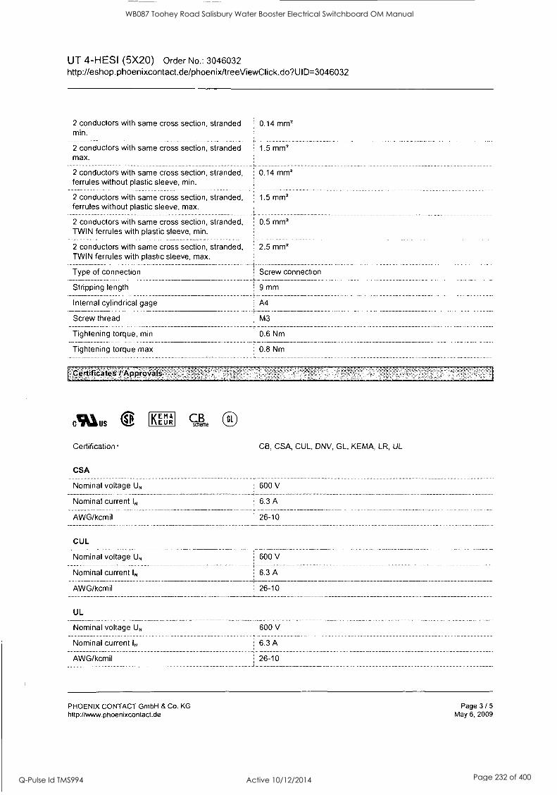
UT 4-HESI (5X20) Order No.: 3046032 http://eshop.phoenixcontact.de/phoenix/treeViewClick.do?UlD=3046032
2 conductors with same cross section, stranded 0.14 mm2 min.
2 conductors with same cross section, stranded 1.5 mm2 max.
2 conductors with same cross section, stranded, 0.14 mm2 ferrules without plastic sleeve, min.
2 conductors with same cross section, stranded, 1.5 mm2 ferrules without plastic sleeve, max.
2 conductors with same cross section, stranded, 0.5 mm2 TWIN ferrules with plastic sleeve, min.
2 conductors with same cross section, stranded, TWIN ferrules with plastic sleeve, max.
Type of connection
Stripping length
Internal cylindrical gage
Screw thread
Tightening torque, min
Tightening torque max
Certificates / Approvals
Ala us SP
Certification
CSA
Nominal voltage UN
Nominal current IN
AWG/kcmil
CUL
Nominal voltage UN
Nominal current IN
AWG/kcmil
UL
Nominal voltage UN
Nominal current IN
AWG/kcmil
2.5 mm2
Screw connection
9 mm
A4
M3
0.6 Nm
0.8 Nm
KEMA EUR cchlie Gl
CB, CSA, CUL, DNV, GL, KEMA, LR, UL
600 V
6.3 A
26-10
600 V
6.3 A
26-10
600 V
6.3 A
26-10
PHOENIX CONTACT GmbH & Co. KG http://www.phoenixcontact.de
Page 3 / 5
May 6, 2009
WB087 Toohey Road Salisbury Water Booster Electrical Switchboard OM Manual
Q-Pulse Id TMS994 Active 10/12/2014 Page 232 of 400

UT 4-HESI (5X20) Order No.: 3046032 http://eshop.phoenixcontact.de/phoenix/treeViewClick.do?Ul D=3046032
Drawings
Application drawing
Fuse terminal blocks in interconnected arrangement, block consisting of 5 fuse terminal blocks
Circuit diagram
O O
I
Fuse terminal block in single arrangement, block consisting of one fuse terminal block and 4 feed-through terminal blocks
PHOENIX CONTACT GmbH & Co. KG http://www.phoenixcontact.de
Page 4 / 5 May 6, 2009
WB087 Toohey Road Salisbury Water Booster Electrical Switchboard OM Manual
Q-Pulse Id TMS994 Active 10/12/2014 Page 233 of 400

UT 4-MT CX ) 0 BD gairA% Please note that the data given here has been taken from the online catalog. For comprehensive information and data, please refer to the user documentation at http://www.download.phoenixcontact.com. The General Terms and Conditions of Use apply to Internet downloads.
Extract from the online catalog
- 4* Universal terminal block with screw connection, cross Cis =ate / section: 0.14 - 4 mm2, AWG: 26 - 10, width: 6.2 mm,
Order No.
Ord designation
color: Gray
3046139
UT 4-MT
EAN 4017918975562
Pack 50 Pcs.
Customs tariff 85369010
Catalog page information Page 20 (NTK-2005)
Technical data
General Number of levels 1
Number of connections 2
Color gray
Insulating material PA
Inflammability class acc. to UL 94 VO
PHOENIX CONTACT GmbH & Co. KG
http://www.phoenixcontact.com
Page 1/7 Aug 12, 2005
WB087 Toohey Road Salisbury Water Booster Electrical Switchboard OM Manual
Q-Pulse Id TMS994 Active 10/12/2014 Page 234 of 400

UT 4-MT 0 C____30 EllzoliVIZ a )O Dimensions Width 6.2 mm
Length 56.8 mm
Height NS 35/7,5 47.5 mm
Height NS 35/15 55 mm
Technical data Maximum load current 16 A
Rated surge voltage 8 kV
Contamination class 3
Surge voltage category III
Insulating material group
Connection in acc. with standard IEC/ DIN VDE
Nominal current IN 16 A
Nominal voltage UN 500 V
Open side panel nein
Connection data Conductor cross section, rigid min. 0.14 mrn2
Conductor cross section, rigid max. 6 mm2
Conductor cross section flexible min. 0.14 mm2
Conductor cross section, flexible max. 4 mm2
Conductor cross section AWG/kcmil min. 26
Conductor cross section AWG/kcmil max 10
Conductor cross section flexible, with ferrule without 0.25 mm2
plastic sleeve min.
Conductor cross section flexible, with ferrule without 4 mm2
plastic sleeve max.
Conductor cross section flexible, with ferrule with plastic 0.25 mm2 sleeve min.
Conductor cross section flexible, with ferrule with plastic 4 mm2
sleeve max.
2 conductors with same cross section, solid min. 0.14 mm2
2 conductors with same cross section, solid max. 1.5 mm2
2 conductors with same cross section, flexible, min. 0.14 mm2
2 conductors with same cross section, flexible max. 1.5 mm2
2 conductors with same cross section, flexible, TWIN 0.5 mm2
ferrules with plastic sleeve, min.
2 conductors with identical cross section, flexible TWIN 2.5 mm2 ferrules with plastic sleeve, max.
2 conductors with same cross section, flexible, ferrules 0.25 mm2
without plastic sleeve min.
2 conductors with same cross section, flexible, ferrules 1.5 mm2 without plastic sleeve, max.
Type of connection Screw connection
Stripping length 9 mm
Internal cylindrical gage A4
Screw thread M 3
Tightening torque, min 0.6 Nm
PHOENIX CONTACT GmbH & Co. KG http://www.phoenixcontact.com
Page 2/7 Aug 12, 2005
WB087 Toohey Road Salisbury Water Booster Electrical Switchboard OM Manual
Q-Pulse Id TMS994 Active 10/12/2014 Page 235 of 400

UT 4-MT OC:i0111=`&0=0 Certificates
CUL Nominal voltage UN 600 V
Nominal current IN 16 A
AWG/kcmil 26-10
UL Nominal voltage UN 600 V
Nominal current IN 16 A
AWG/kcmil 26-10
PHOENIX CONTACT GmbH & Co. KG
http://www.phoenixcontact.com Page 3/7 Aug 12, 2005
WB087 Toohey Road Salisbury Water Booster Electrical Switchboard OM Manual
Q-Pulse Id TMS994 Active 10/12/2014 Page 236 of 400

UT 4-MT
Drawings
Circuit diagram
Approval logo
IND us
PHOENIX CONTACT GmbH & Co. KG http://www.phoenixcontact.com
WB087 Toohey Road Salisbury Water Booster Electrical Switchboard OM Manual
Q-Pulse Id TMS994 Active 10/12/2014 Page 237 of 400

UT 4-MT )(DEINN11140=C)
Accessories
Item Designation Description
Assembly 0801762 NS 35/ 7,5 CU UNPERF DIN rail, material: Copper, unperforated, height 7.5 mm, width
2000MM 35 mm, length: 2 m
1207640 NS 35/ 7,5 PERF 755MM NS 35 DIN rail, height 7.5 mm, length 755 mm
1207653 NS 35/ 7,5 PERF 955MM NS35 DIN rail, height 7.5 mm, length 955 mm
1207666 NS 35/ 7,5 PERF 1155MM NS 35 DIN rail, height 7.5 mm, length 1155 mm
0801733 NS 35/ 7,5 PERF 2000MM DIN rail, material: Steel, perforated, height 7.5 mm, width 35 mm, length: 2 m
0801681 NS 35/ 7,5 UNPERF 2000MM DIN rail, material: Steel, unperforated, height 7.5 mm, width 35 mm, length: 2 m
1201756 NS 35/15 AL UNPERF 2000MM
DIN rail, deep-drawn, high profile, unperforated, 1.5 mm thick, material: Aluminum, height 15 mm, width 35 mm, length 2 m
1201895 NS 35/15 CU UNPERF DIN rail, material: Copper, unperforated, 1.5 mm thick, height 15 2000MM mm, width 35 mm, length: 2 m
1207679 NS 35/15 PERF 755MM NS 35 DIN rail, height 15 mm, length 755 mm
1207682 NS 35/15 PERF 955MM NS 35 DIN rail, height 15 mm, length 955 mm
1207695 NS 35/15 PERF 1155MM NS 35 DIN rail, height 15 mm, length 1155 mm
1201730 NS 35/15 PERF 2000MM DIN rail, material: Steel, perforated, height 15 mm, width 35 mm, length: 2 m
1201714 NS 35/15 UNPERF 2000MM DIN rail, material: Steel, unperforated, height 15 mm, width 35 mm, length: 2 m
1201798 NS 35/15-2,3 UNPERF DIN rail, material: Steel, unperforated, 2.3 mm thick, height 15
2000MM mm, width 35 mm, length: 2 m
Bridges 3030336 FBS 2-6 Plug-in bridge for cross-connections in the terminal center, 2-
pos., color: Red
3030242 FBS 3-6 Plug-in bridge for cross-connections in the terminal center, 3- pos., color: Red
3030255 FBS 4-6 Plug-in bridge for cross-connections in the terminal center, 4- pos., color: Red
3030349 FBS 5-6 Plug-in bridge for cross-connections in the terminal center, 5- pos., color: Red
3030271 FBS 10-6 Plug-in bridge for cross-connections in the terminal center, 10- pos., color: Red
3030365 FBS 20-6 Plug-in bridge for cross-connections in the terminal center, 20- pos., color: Red
3047060 RB UT 10-(2,5/4) Reducing bridge, for connection from UT 10 to UT 4 or UT 2,5
PHOENIX CONTACT GmbH & Co. KG
http://www.phoenixcontact.com Page 5/7 Aug 12, 2005
WB087 Toohey Road Salisbury Water Booster Electrical Switchboard OM Manual
Q-Pulse Id TMS994 Active 10/12/2014 Page 238 of 400

UT 4-MT )0 Ilcomfra 0 DO Marking 0811228 X-PEN 0,35
1051016 ZB 6,LGS:FORTL.ZAHLEN
5060935 ZB 6/VVH-100:UNBEDRUCKT
1050499 ZB 6:SO/CMS
Marker pen without ink cartridge, for manual labeling of markers, labeling extremely wipe-proof, line thickness 0.35 mm
Zack strip, 10-section, printed horizontally: with the numbers, 1-
10, 11-20 etc. up to 991-1000, color: white
Zack strip, unprinted: For individual labeling with M-PEN, ZB-T or CMS system, large batch, sufficient for labeling 1000 terminal blocks, for a terminal width of 6.2 mm, color: White
Zack strip, 10-section, divisible, special printing, marking according to customer requirements
Plug/Adapter 0201689
0201676
0201663
0201744
MPS-IH BU
MPS-IH RD
MPS-IH WH
MPS-MT
3030925 PAI-4
3030996 PS-6
Test plug, consisting of: Metal part for 2.3 mm diameter socket hole
Test adapter, for 4 mm diameter test plug PS and safety test plug, makes contact in the bridge shaft
Modular test plug, for individual assembly of test plug strips, for UT, ST, DT and QT terminal blocks, can be labeled with ZBF 6, color: Red
Tools 1205053 SZS 0,6X3,5 Screwdriver, bladed, matches all screw terminal blocks up to 4.0
mm2 connection cross section, blade: 0.6 x 3.5 mm, without VDE approval
PHOENIX CONTACT GmbH & Co. KG http://www.phoenixcontact.com
Page 6/7 Aug 12, 2005
WB087 Toohey Road Salisbury Water Booster Electrical Switchboard OM Manual
Q-Pulse Id TMS994 Active 10/12/2014 Page 239 of 400

MPHNIX Lk/COCENTACT Extract from the online catalog
MSTB 2,5/10-ST-5,08
Order No.: 1757093
The figure shows a 10-position version of the product
http://eshop.phoenixcontact.de/phoenix/treeViewClick.do?UlD=1757093
Plug component, Nominal current: 12 A, Rated voltage (111/2): 320 V, Pitch: 5.08 mm, Color: green, Metal surface: Sn
l'Commerci'af data
GTIN (EAN)
sales group
Pack
Customs tariff
Weight/Piece
Catalog page information
4017918029623
E111
50 pcs.
85366990
0.01727 KG
Page 198 (CC-2009)
iProciuct notes
WEEE/RoHS-compliant since: 01/01/2003
http // www.download.phoenixcontact.cbm Please note that-the data giVen here has been taken from the Online icatalog. , Fori,Comprehehskie informatiOn and data, please refer to the'uer documentation. The General Terms and ConditionS' of Use apply to Internet downloads:
TecIMICal data
Dimensions / positions
Pitch
Dimension a
Number of positions
Screw thread
Tightening torque, min
5.08 mm
45.72 mm
10
M3
0.5 Nm
PHOENIX CONTACT Inc., USA http://www.phoenixcon.com
Page 1 / 8
Jun 30, 2010
WB087 Toohey Road Salisbury Water Booster Electrical Switchboard OM Manual
Q-Pulse Id TMS994 Active 10/12/2014 Page 240 of 400

MSTB 2,5/10-ST-5,08 Order No.: 1757093 http://eshop.phoenixcontact.de/phoenix/treeViewClick.do?UlD=1757093
Tightening torque max
Technical data
Insulating material group
Rated surge voltage (111/3)
Rated surge voltage (111/2)
Rated surge voltage (11/2)
Rated voltage (111/2)
Rated voltage (11/2)
Connection in acc. with standard
Nominal current IN
Nominal voltage UN
Nominal cross section
Maximum load current
Insulating material
Inflammability class acc. to UL 94
Internal cylindrical gage
Stripping length
Nominal voltage, UUCUL Use Group B
Nominal current, UUCUL Use Group B
Nominal voltage, UUCUL Use Group D
Nominal current, UUCUL Use Group D
Connection data
Conductor cross section solid min.
Conductor cross section solid max.
Conductor cross section stranded min.
Conductor cross section stranded max.
Conductor cross section stranded, with ferrule without plastic sleeve min.
Conductor cross section stranded, with ferrule without plastic sleeve max.
Conductor cross section stranded, with ferrule 0.25 mm2 with plastic sleeve min.
Conductor cross section stranded, with ferrule ! 2.5 mm2 with plastic sleeve max.
0.6 Nm
I
4 kV
4 kV
4 kV
320 V
630 V
EN-VDE
12A
250 V
2.5 mm2
12 A (with 2.5 mm2 conductor cross section)
PA
VO
j A3
7 mm
250 V
12A
1 300 V
10A
0.2 mm2
2.5 mm2
0.2 mm2
2.5 mm2
0.25 mm2
2.5 mm2
Conductor cross section AWG/kcmil min. 1 24
Conductor cross section AWG/kcmil max 1 12
PHOENIX CONTACT Inc., USA http://www.phoenixcon.com
Page 2 / 8
Jun 30, 2010
WB087 Toohey Road Salisbury Water Booster Electrical Switchboard OM Manual
Q-Pulse Id TMS994 Active 10/12/2014 Page 241 of 400

MSTB 2,5/10-ST-5,08 Order No.: 1757093 http://eshop.phoenixcontact.de/phoenix/treeViewClick.do?UlD=1757093
2 conductors with same cross section, solid min. 0.2 mm2
2 conductors with same cross section, solid max. 1 1 mm2
2 conductors with same cross section, stranded 0.2 mm2 min.
2 conductors with same cross section, stranded 1.5 mm2 max.
2 conductors with same cross section, stranded, 0.25 mm2 ferrules without plastic sleeve, min.
2 conductors with same cross section, stranded, 1 mm2 ferrules without plastic sleeve, max.
2 conductors with same cross section, stranded, 0.5 mm2 TWIN ferrules with plastic sleeve, min.
2 conductors with same cross section, stranded, 1.5 mm2 TWIN ferrules with plastic sleeve, max.
Minimum AWG according to UUCUL
Maximum AWG according to UUCUL
30
12
Certificate Apjarbial
Anus usie
Certification
CSA
Nominal voltage UN
Nominal current IN
AWG/kcmil
CUL
Nominal voltage UN
Nominal current IN
AWG/kcmil
UL
Nominal voltage UN
Nominal current IN
AWG/kcmil
CB, CSA, CUL, GOST, UL, VDE-PZI
300 V
10A
28-12
300 V
10A
30-12
300 V
10A
30-12
PHOENIX CONTACT Inc., USA http://www.phoenixcon.com
Page 3 / 8
Jun 30, 2010
WB087 Toohey Road Salisbury Water Booster Electrical Switchboard OM Manual
Q-Pulse Id TMS994 Active 10/12/2014 Page 242 of 400

MSTB 2,5/10-ST-5,08 Order No.: 1757093 http://eshop.phoenixcontact.de/phoenix/treeViewClick.do?UlD=1757093
Item
Bridges
Designation
1733172 EBP 3- 5
1733185
1733198
1733208
General
EBP 4- 5
! EBP 5- 5
EBP 6- 5
1733169 1 EBP 2- 5
KGS-MSTB 2,5/10 1783740
Marking
1051993 B-STIFT
0805108 i SK 5,08/2,8:50
0804293 I SK 5,08/3,8:FORTL.ZAHLEN
0803883
Plug/Adapter
SK U/2,8 WH:UNBEDRUCKT
Description
Insertion bridge, fully insulated, for plug connectors with 5.0 or 5.08 mm pitch, no. of positions: 3
Insertion bridge, fully insulated, for plug connectors with 5.0 or 5.08 mm pitch, no. of positions: 4
Insertion bridge, fully insulated, for plug connectors with 5.0 or 5.08 mm pitch, no. of positions: 5
Insertion bridge, fully insulated, for plug connectors with 5.0 or 5.08 mm pitch, no. of positions: 6
1 Insertion bridge, fully insulated, for plug connectors with 5.0 or 5.08 mm pitch, no. of positions: 2
. .
Cable housing, Number of positions: 10, Dimension a: 50 mm, Color: green
Marker pen, for manual labeling of unprinted Zack strips, smear- ; proof and waterproof, line thickness 0.5 mm
Marker card, special printing, self-adhesive, labeled acc. to customer requirements, 14 identical marker strips per card, max. 25-position labeling per strip, color: White
, .
Marker card, printed horizontally, self-adhesive, 12 identical decades marked 1-10, 11-20 etc. up to 91-(99)100, sufficient for 120 terminal blocks
Unprinted marker cards, DIN A4 format, pitch as desired, self- 1 adhesive, with 50 stamped marker strips, 185 mm strip length, can
be labeled with the CMS system or manually with the M-PEN
1734634
Tools
CP-MSTB
1205053 1 SZS 0,6X3,5
Keying profile, is inserted into the slot on the plug or inverted header, red insulating material
Screwdriver, bladed, matches all screw terminal blocks up to 4.0 mm2 connection cross section, blade: 0.6 x 3.5 mm, without VDE approval
PHOENIX CONTACT Inc., USA http://www.phoenixcon.com
Page 4/8 Jun 30, 2010
WB087 Toohey Road Salisbury Water Booster Electrical Switchboard OM Manual
Q-Pulse Id TMS994 Active 10/12/2014 Page 243 of 400

MSTB 2,5/10-ST-5,08 Order No.: 1757093 http://eshop.phoenixcontact.de/phoenix/treeViewClick.do?UlD=1757093
Additional products
Item Designation
General
1823927 ICC 2,5/10-STZ-5,08
1762457 , MDSTB 2,5/10-G1-5,08
1762583 MDSTBV 2,5/10-G1-5,08
1770795
1757323
1768024
1765030
MSTB 2,5/10-G-5,08-LA
MSTBA 2,5/10-G-5,08
MSTBA 2,5/10-G-5,08-LA
MSTBHK 2,5/10-G-5,08
1788800 MSTBVK 2,5/10-G-5,08
1788619 MVSTBU 2,5/10-GB-5,08
1769544 j SMSTB 2,5/10-G-5,08
1767452 SMSTBA 2,5/10-G-5,08
3002034 f UK 3-MSTB-5,08
Description
Plug component, Nominal current: 12 A, Rated voltage (111/2): 320 V, Pitch: 5.08 mm, Color: green, Metal surface: Sn, Corresponding male crimp contacts with current [A] and conductor cross section range [mml data: 10A/ICC -MT 0,5-1,0 (3190577); 10A/ICC-MT 0,5-1,0 BA (3190603); 12A/ICC-MT 1,5-2,5 (3190580); 12A/ICC- MT 1,5-2,5 BA (3190593). BA = Bandkontakte
Header, Nominal current: 10 A, Rated voltage (111/2): 320 V, Pitch: 5.08 mm, Color: green, Metal surface: Sn, Assembly: Soldering, In combination with MVSTB or FKCV plug components, both an MVSTBW (or FKCVW) and an MVSTBR plug (or FKCVR) must be used. Combination with TMSTBP plug components is not possible!
Header, Nominal current: 10 A, Rated voltage (111/2): 320 V, Pitch: 5.08 mm, Color: green, Metal surface: Sn, Assembly: Soldering, In combination with MVSTB or FKCV plug components, both an MVSTBW (or FKCVW) and an MVSTBR plug (or FKCVR) must be used. Combination with TMSTBP plug components is not possible!
Header, Nominal current: 12 A, Rated voltage (111/2): 320 V, Pitch: 5.08 mm, Assembly: Soldering
Header, Nominal current: 12 A, Rated voltage (111/2): 320 V, Pitch: 5.08 mm, Color: green, Metal surface: Sn, Assembly: Soldering
Header, Nominal current: 12 A, Rated voltage (111/2): 320 V, Pitch: 5.08 mm, Assembly: Soldering
Plug component, Nominal current: 12 A, Rated voltage (111/2): 320 V, Pitch: 5.08 mm, Color: green, Metal surface: Sn, Assembly: DIN rail
Plug component, Nominal current: 12 A, Rated voltage (111/2): 320 V, Pitch: 5.08 mm, Color: green, Metal surface: SnAssembly: DIN
I rail
Plug component, Nominal current: 12 A, Rated voltage (111/2): 320 V, Pitch: 5.08 mm, Color: green, Metal surface: Sn, Assembly: Direct mounting
Header, Nominal current: 12 A, Rated voltage (111/2): 320 V, Pitch: 5.08 mm, Color: green, Metal surface: Sn, Assembly: Soldering
Header, Nominal current: 12 A, Rated voltage (111/2): 320 V, Pitch: 5.08 mm, Color: green, Metal surface: Sn, Assembly: Soldering
Feed-through modular terminal block, Type of connection: Special and hybrid connection, Screw connection, Cross section: 0.2 mm2- 4 mm2, AWG 24 - 12, Width: 5.08 mm, Color: gray, Mounting type: NS 32, NS 35/15, NS 35/7,5
PHOENIX CONTACT Inc., USA http://www.phoenixcon.com
Page 5 / 8
Jun 30, 2010
WB087 Toohey Road Salisbury Water Booster Electrical Switchboard OM Manual
Q-Pulse Id TMS994 Active 10/12/2014 Page 244 of 400

MSTB 2,5/10-ST-5,08 Order No.: 1757093 http://eshop.phoenixcontact.de/phoenix/treeViewClick.do?UlD=1757093
3002076
3002102
UK 3-MVSTB-5,08
UK 3-MVSTB-5,08-LA 24RD
Feed-through modular terminal block, Nominal current: 12
A, Nominal voltage: 250 V, Cross section: 0.2 mm2 - 4 mm2,
AWG: 24 - 12, Mounting type: NS 32, NS 35/15, NS 35/7,5, Pitch: 5.08 mm, Width: 5.1, Color: gray
Feed-through modular terminal block, Nominal current: 12
A, Nominal voltage: 250 V, Cross section: 0.2 mm2 - 4 mmz, AWG: 24 - 12, Mounting type: NS 32, NS 35/15, NS 35/7,5, Pitch: 5.08 mm, Width: 5.08, Color: gray
3002063 UK 3-MVSTB-5,08/EK Feed-through modular terminal block, Nominal current: 12 A, Nominal voltage: 250 V, Cross section: 0.2 mm2 - 4 mm2, AWG: 24 - 12, Mounting type: NS 35/7,5, NS 35/15, NS 32, Pitch: 5.08 mm, Width: 5.1, Color: blue
3002131 UK 3D-MSTBV-5,08 Feed-through modular terminal block, Type of connection: Special and hybrid connection, Screw connection, Cross section: 0.2 mm2- 4 mm2, AWG 24 - 12, Width: 5.08 mm, Color: gray, Mounting type: NS 32, NS 35/15, NS 35/7,5
3002144 UK 3D-MSTBV-5,08-LA 24RD Feed-through modular terminal block, Type of connection: Screw 1 connection, Screw connection, Number of positions: 1, Cross
section: 0.2 mm2 - 4 mm2, AWG 24 - 12, Width: 5.1 mm,
Color: gray, Mounting type: NS 32, NS 35/15, NS 35/7,5
3002173 i UK 3D-MSTBV-5,08/EK Feed-through modular terminal block, Type of connection: Screw connection, Screw connection, Cross section: 0.2 mm2 - 4 mm2, AWG 24 - 12, Width: 5.1 mm, Color: blue, Mounting type: NS 32, NS 35/15, NS 35/7,5
2770888 I UKK 3-MSTB-5,08 End cover, Nominal current: 12 A, Nominal voltage: 250 V, Cross 1 section: 0.2 mm2 - 4 mm2, AWG: 24 - 12, Mounting type: NS
35/7,5, NS 35/15, NS 32, Pitch: 5.08 mm, Width: 5.08, Color: gray
1876615 UKK 3-MSTB-5,08-PE Feed-through modular terminal block, Nominal current: 12
A, Nominal voltage: 320 V, Cross section: 0.2 mm2 - 4 mm2,
AWG: 24 - 12, Mounting type: NS 35/7,5, NS 35/15, NS 32, Pitch: 5.08 mm, Width: 5.08, Color: green-yellow
2770846 j UKK 3-MSTBVH-5,08 Feed-through modular terminal block, Nominal current: 12
A, Nominal voltage: 250 V, Cross section: 0.2 mm2 - 4 mm2,
AWG: 24 - 12, Mounting type: NS 35/7,5, NS 35/15, NS 32, Pitch: 5.08 mm, Width: 5.08, Color: gray
1788198 UMSTBVK 2,5/10-G-5,08 Plug component, Nominal current: 12 A, Rated voltage (111/2): 320 V, Pitch: 5.08 mm, Color: green, Metal surface: Sn, Assembly: DIN rail
1873016 ZFKK 1,5-MSTBV-5,08 Feed-through modular terminal block, Connection method: Special and hybrid connection, MSTB plug entry, Cross section: 0.2 mm2 - 2.5 mm2, Width: 5.1 mm, Color: gray
PHOENIX CONTACT Inc., USA http://www.phoenixcon.com
Page 6 / 8 Jun 30, 2010
WB087 Toohey Road Salisbury Water Booster Electrical Switchboard OM Manual
Q-Pulse Id TMS994 Active 10/12/2014 Page 245 of 400
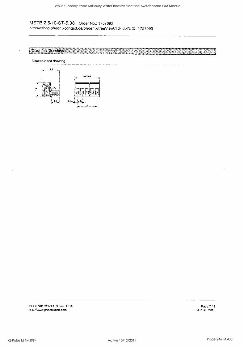
MSTB 2,5/10-ST-5,08 Order No.: 1757093 http://eshop.phoenixcontact.de/phoenix/treeViewClick.do?UlD=1757093
I Diagrams/Drawings
Dimensioned drawing
PHOENIX CONTACT Inc., USA http://www.phoenixcon.com
Page 7 / 8
Jun 30, 2010
WB087 Toohey Road Salisbury Water Booster Electrical Switchboard OM Manual
Q-Pulse Id TMS994 Active 10/12/2014 Page 246 of 400

FBS 10-8
Order No.: 3030323
http://eshop.phoenixcontact.de/phoenix/treeViewClick.do?UlD=3030323
PHCENIX CONTACT
Extract from the online catalog
Cross connector/jumper for modular terminal block, Number of positions: 10, Color: red
Comniercial da6
EAN 4017918188634
Pack 10 pcs.
Customs tariff 85389099
Weight/Piece 0.01955 KG
Catalog page information Page 330 (CL-2009)
ropluCt notes.
WEEE/RoHS-compliant since: 01/01/2003
http // Www download phoenixcontact com Please note that the data given here has been taken from the
I online catalog For comprehensive information and data, please refer to the user documentation The General Terms and Conditions of Use apply to Internet downloads
PHOENIX CONTACT GmbH & Co. KG http://www.phoenixcontact.de
Page 1 / 2
Oct 23, 2009
WB087 Toohey Road Salisbury Water Booster Electrical Switchboard OM Manual
Q-Pulse Id TMS994 Active 10/12/2014 Page 247 of 400

PINCENIX CONTACT
Extract from the online catalog
SZF 1- 0,6X3,5
Order No.: 1204517
http://eshop.phoenixcontact.de/phoenix/treeViewClick.do?UlD=1204517
Screwdriver, blade: 0.6 x 3.5 x 100 mm, length 180 mm
tOmmerciaLdaii
GTIN (EAN) 4017918018948
sales group C200
Pack 10 pcs.
Customs tariff 82054000
Weight/Piece 0.0368 KG
Catalog page information Page 8 (NTK-2010)
,Technical dati
F.PITclict mites
WEEE/RoHS-compliant since: 11/01/2008
t
I littlb ii -.: ' '
www download phoenixcontact corn PleaSe note that the-data given-
' here'has been ,taken from the online catalog -for comprehensive,, information and data, please refer -,
l to the user documentation The -
General Terms and Conditions of- --
I Use apply to Internet downloads -
General
Length (b)
Width (a)
Design
181 mm
26 mm
Phillips
PHOENIX CONTACT Inc., USA http://www.phoenixcon.com
Page 1 / 3
Jun 30, 2010
WB087 Toohey Road Salisbury Water Booster Electrical Switchboard OM Manual
Q-Pulse Id TMS994 Active 10/12/2014 Page 248 of 400

SZF 1-0,6X3,5 Order No.: 1204517 http://eshop.phoenixcontact.de/phoenix/treeViewClick.do?UlD=1204517
Blade thickness
Blade width
Blade height
Weight
Test standard
Certificates i Approvals
0.6 mm
3.5 mm
100 mm
34 g
DIN 5264
Certification
Diagrams/Drawings .,
Dimensioned drawing
0,6.1 1. J 3,5
GOST
PHOENIX CONTACT Inc., USA http://www.phoenixcon.com
Page 2 / 3
Jun 30, 2010
WB087 Toohey Road Salisbury Water Booster Electrical Switchboard OM Manual
Q-Pulse Id TMS994 Active 10/12/2014 Page 249 of 400

PS-6/2,3MM RD
Order No.: 3038736
The illustration shows the version PS-5/2,3 MM RD
http lleshop.phoenixcontact.de/phoenix/treeViewClick.do?UlD.3038736
PHCENIX CONTACT
Extract from the online catalog
Test plugs, Color: red
Comniercial,data
GTIN (EAN) 4017918904166
sales group A691
Pack 10 pcs.
Customs tariff 85369010
Weight/Piece 0.00143 KG
Catalog page information Page 449 (CL-2009)
rProduct,note-si::
WEEE/RoHS-compliant since: 01/01/2003
http // ' - .
www download phoenocContact corn Please note thatthe data
,here- has been taken from the online catalog For comprehensive
'InfOrmation and data, please refer to the user doCumentation The General Terms and Conditions of Use apply to Internetclownloads
PHOENIX CONTACT Inc., USA http://www.phoenixcon.com
Page 1 / 2
Jun 30, 2010
WB087 Toohey Road Salisbury Water Booster Electrical Switchboard OM Manual
Q-Pulse Id TMS994 Active 10/12/2014 Page 250 of 400

MPHCENIX Lid CO INTACT Extract from the online catalog
UBE/D + ES/KMK 3
Order No.: 1004076
http://eshop.phoenixcontact.de/phoenix/treeViewClick.do?UlD=1004076
Terminal strip marker carriers for marking terminal group, for mounting on the terminal strip NS 32 or NS 35/7.5, lettering field size: 40 x 17 mm
Commercial data
EAN
Pack
Customs tariff
Weight/Piece
Technical data
General
Color
Base element material
Inflammability class acc. to UL 94
Ambient temperature (operation)
Components
4017918011888
10 pcs.
85369010
0.0105 KG
PTO
WEEE/RoHS-compliant since: 03/18/2004
http // www download phoenixcontact corn Please note that the data given here has been taken from the
! online catalog For comprehensive information and data, please refer to the user documentation The General Terms and COnditions of Use apply to Internet doWnkiads
gray
PA
V2
-40 °C ... 100 °C
free from silicone and halogen
PHOENIX CONTACT GmbH & Co. KG http://www.phoenixcontact.de
Page 1 / 2
May 7, 2009
WB087 Toohey Road Salisbury Water Booster Electrical Switchboard OM Manual
Q-Pulse Id TMS994 Active 10/12/2014 Page 251 of 400

UT 4-MTD
Order No.: 3046184
http://eshop.phoenixcontact.de/phoenix/treeViewClick.do?UlD=3046184
PNCENIX CONTACT
Extract from the online catalog
Feed-through modular terminal block, Type of connection: Screw connection, Cross section: 0.14 mm2 - 6 mm2, AWG 26 - 10, Width: 6.2 \U.,, mm, Color: gray, Mounting type: NS 35/7,5, NS 35/15
Commercial. iata
EAN ' 4017918956592
Pack 50 pcs.
Customs tariff 85369010
Weight/Piece 0.011431 KG
Catalog page information Page 56 (CL-2009)
Technical data
EP,roduct.pojeal.:.:
WEEE/RoHS-compliant since: 01/01/2003
http // www download phoenixcontact com Please note -that the data given '
here haS been taken from the online catalog For comprehensive information and data, please refer to the user documentation The _
General Terms and Conditions of Use apply to Internet downloads
General
Number of levels
Number of connections
Color
2
gray
PHOENIX CONTACT Deutschland GmbH http://www.phoenixcontact.de
Page 1 / 7
Mar 24, 2010
WB087 Toohey Road Salisbury Water Booster Electrical Switchboard OM Manual
Q-Pulse Id TMS994 Active 10/12/2014 Page 252 of 400

UT 4-MTD Order No.: 3046184 http://eshop.phoenixcontact.de/phoenix/treeViewClick.do?UlD=3046184
Insulating material
Inflammability class acc. to UL 94
Dimensions
Width
Length
Height NS 35/7,5
Height NS 35/15
Technical data
Maximum load current
Rated surge voltage
Pollution degree
Surge voltage category
Insulating material group
Connection in acc. with standard
Nominal current IN
Nominal voltage UN
Open side panel
PA
VO
6.2 mm
57.8 mm
47.5 mm
55 mm
41 A (with 6 mm2 conductor cross section)
8 kV
3
III
IEC 60947-7-1
32 A
Connection data
Conductor cross section solid min.
Conductor cross section solid max.
Conductor cross section stranded min.
Conductor cross section stranded max.
Conductor cross section AWG/kcmil min.
Conductor cross section AWG/kcmil max
0.14 mm2
6 mm2
0.14 mm2
6 mm2
26
10
Conductor cross section stranded, with ferrule 0.14 mm2 without plastic sleeve min.
Conductor cross section stranded, with ferrule 4 mm2 without plastic sleeve max.
Conductor cross section stranded, with ferrule with plastic sleeve min.
Conductor cross section stranded, with ferrule 4 mm2 with plastic sleeve max.
0.14 mm2
2 conductors with same cross section, solid min. 0.14 mm2
2 conductors with same cross section, solid max. 1.5 mm2
2 conductors with same cross section, stranded min.
0.14 mm2
PHOENIX CONTACT Deutschland GmbH http://www.phoenixcontact.de
Page 2 / 7
Mar 24, 2010
WB087 Toohey Road Salisbury Water Booster Electrical Switchboard OM Manual
Q-Pulse Id TMS994 Active 10/12/2014 Page 253 of 400

UT 4-MTD Order No.: 3046184 http://eshop.phoenixcontact.de/phoenix/treeViewClick.do?UlD=3046184
2 conductors with same cross section, stranded 1 1.5 mm2 max.
2 conductors with same cross section, stranded, 1 0.5 mm2 TWIN ferrules with plastic sleeve, min.
2 conductors with same cross section, stranded, TWIN ferrules with plastic sleeve, max.
2 conductors with same cross section, stranded, 0.14 mm2 ferrules without plastic sleeve, min.
2 conductors with same cross section, stranded, 1.5 mm2
ferrules without plastic sleeve, max.
Type of connection
Stripping length
Internal cylindrical gage
Screw thread
Tightening torque, min
Tightening torque max
2.5 mm2
Screw connection
9 mm
A4
M3
0.6 Nm
0.8 Nm
Certificates rApFirOVals
CSII US e4
Certification
Certification Ex:
CSA
Nominal voltage UN
Nominal current IN
AWG/kcmil
CUL
Nominal voltage UN
Nominal current IN
AWG/kcmil
UL
Nominal voltage UN
Nominal current IN
clfe3me
CB, CSA, CUL, DNV, GL, LR, UL, VDE-PZI
IECEx, KEMA-EX
600 V .t.
30 A
26-10
600 V
30 A
26-10
600 V
30 A
AWG/kcmil 26-10
PHOENIX CONTACT Deutschland GmbH http://www.phoenixcontact.de
Page 3 / 7
Mar 24, 2010
WB087 Toohey Road Salisbury Water Booster Electrical Switchboard OM Manual
Q-Pulse Id TMS994 Active 10/12/2014 Page 254 of 400

UT 4-MTD Order No.: 3046184 http://eshop.phoenixcontact.de/phoenix/treeViewClick.do?UlD=3046184
Accessories
Item Designation Description
Assembly
3022276 CLIPFIX 35-5 Snap-on end bracket, for NS 35/7.5 or NS 35/15 DIN rail, can be fitted with Zack strip ZB 5 and ZBF 5, terminal strip marker KLM 2 and KLM, parking facility for FBS...5, FBS...6, KSS 5, KSS 6, width: 5,15 mm, color: gray
3047141 D-UT 2,5/4-TWIN End cover, Width: 2.2 mm, Color: gray
0801762 NS 35/ 7,5 CU UNPERF DIN rail, material: Copper, unperforated, height 7.5 mm, width 35 2000MM mm, length: 2 m
1207640 NS 35/ 7,5 PERF 755MM NS 35 DIN rail, height 7.5 mm, length 755 mm
1207653 NS 35/ 7,5 PERF 955MM NS35 DIN rail, height 7.5 mm, length 955 mm
1207666 NS 35/ 7,5 PERF 1155MM NS 35 DIN rail, height 7.5 mm, length 1155 mm
0801733 NS 35/ 7,5 PERF 2000MM DIN rail, material: Steel, galvanized and passivated with a thick layer, perforated, height 7.5 mm, width 35 mm, length: 2 m
0801681 NS 35/ 7,5 UNPERF 2000MM DIN rail, material: Steel, unperforated, height 7.5 mm, width 35 mm, length: 2 m
1201756 NS 35/15 AL UNPERF 2000MM DIN rail, deep-drawn, high profile, unperforated, 1.5 mm thick, material: Aluminum, height 15 mm, width 35 mm, length 2 m
1201895 NS 35/15 CU UNPERF 2000MM DIN rail, material: Copper, unperforated, 1.5 mm thick, height 15 mm, width 35 mm, length: 2 m
1207679 NS 35/15 PERF 755MM NS 35 DIN rail, perforated, height 15 mm, length 755 mm
1207682 NS 35/15 PERF 955MM NS 35 DIN rail, perforated, height 15 mm, length 955 mm
1207695 ; NS 35/15 PERF 1155MM NS 35 DIN rail, perforated, height 15 mm, length 1155 mm
1201730 NS 35/15 PERF 2000MM DIN rail, material: Steel, perforated, height 15 mm, width 35 mm, length: 2 m
1201714 ; NS 35/15 UNPERF 2000MM DIN rail, material: Steel, unperforated, height 15 mm, width 35 mm, length: 2 m
1201798 NS 35/15-2,3 UNPERF 2000MM DIN rail, material: Steel, unperforated, 2.3 mm thick, height 15 mm, width 35 mm, length: 2 m
Bridges
3030336 FBS 2-6 Cross connector/bridge, Number of positions: 2, Color: red
3030242 FBS 3-6 Cross connector/bridge, Number of positions: 3, Color: red
3030255 FBS 4-6 Cross connector/bridge, Number of positions: 4, Color: red
3030349 FBS 5-6 Cross connector/bridge, Number of positions: 5, Color: red
3030271 FBS 10-6 Cross connector/bridge, Number of positions: 10, Color: red
3030365 FBS 20-6 Cross connector/bridge, Number of positions: 20, Color: red
3032224 FBS 50-6 Cross connector/bridge, Number of positions: 50, Color: red
PHOENIX CONTACT Deutschland GmbH http://www.phoenixcontact.de
Page 4 / 7
Mar 24, 2010
WB087 Toohey Road Salisbury Water Booster Electrical Switchboard OM Manual
Q-Pulse Id TMS994 Active 10/12/2014 Page 255 of 400

UT 4-MTD Order No.: 3046184 http://eshop.phoenixcontact.de/phoenix/treeViewClick.do?UlD=3046184
3047060
Marking
1051993
0811228
1051016
1051032
1051029
1051045
1050499
RB UT 10-(2,5/4)
B-STIFT
X-PEN 0,35
ZB 6,LGS:FORTL.ZAHLEN
ZB 6,LGS:GLEICHE ZAHLEN
ZB 6,QR:FORTL.ZAHLEN
ZB 6,QR:GLEICHE ZAHLEN
ZB 6:SO/CMS
1051003 ZB 6:UNBEDRUCKT
Plug/Adapter
0201731 MPS-IH BK
0201702 j MPS-IH GN
0201676 MPS-IH RD
0201663 MPS-IH WH
0201744 MPS-MT
3030925 PAI-4
3030996 I PS-6
Tools
1205053 SZS 0,6X3,5
Cross connector/bridge, Number of positions: 2, Color: red
Marker pen, for manual labeling of unprinted Zack strips, smear- ; proof and waterproof, line thickness 0.5 mm
Marker pen without ink cartridge, for manual labeling of markers, labeling extremely wipe-proof, line thickness 0.35 mm
Zack strip, 10-section, printed horizontally: with the numbers, 1-10, 11-20 etc. up to 991-1000, color: white
Zack marker strip, labeled horizontally: 10-section, with identical numbers, 1/1/1, 2/2/2 etc. up to 1000/1000/1000, color: white
Zack strip, 10-section, printed vertically: with consecutive numbers, 1-10, 11-20 a.s.o. up to 991-1000, color: white
Zack marker, labeled vertically: 10-section, with identical numbers, 1/1/1, 2/2/2 etc. up to 1000/1000/1000, color: White
Zack strip, 10-section, divisible, special printing, marking according to customer requirements
Zack strip, unprinted, strips with 10 labels for individual labeling with M-PEN or CMS system, for terminal block width: 6.2 mm, color: white
Insulating sleeve, for MPS metal part, Color: black
Insulating sleeve, for MPS metal part, Color: green
Insulating sleeve, Color: red
Insulating sleeve, for MPS metal part, Color: white
Metal part
Test adapter, Color: gray
Test adapter, Color: red
Screwdriver, bladed, matches all screw terminal blocks up to 4.0 mm2 connection cross section, blade: 0.6 x 3.5 mm, without VDE approval
Circuit diagram
PHOENIX CONTACT Deutschland GmbH http://www.phoenixcontact.de
Page 5 / 7
Mar 24, 2010
WB087 Toohey Road Salisbury Water Booster Electrical Switchboard OM Manual
Q-Pulse Id TMS994 Active 10/12/2014 Page 256 of 400

Module no:0921011 Labelld :0921011 Operator:Phoenix 15:22:45, Donnerstag, 28. Juni 2001
ST-SI-UK 4
Light Current Description indicator --"[mA]
Voltage [V AC/DC]
Fuse plug, for x 20 mm, 26.5
cartridge fuse inserts 5
mm high, color: black
Fuse plug, as above, however with light indicator:
5 -15
15 - 30
2-7.5
3.5 - 7.5
30 - 60 2.5 - 5.5
110 -250 0.5-1
Type Order No Era Pkt
ST-SI-UK 4 !max.: 6.3 A 1)2) 09 21 01 1 50
ST-SILED 12-UK 4
Imax.: 6.3 A 1)2) 09 21 02 4 50
ST-SILED 6.3A1)2) 09 21 03 7 50 24-UK 4
ST-SILED 6.3A1)2) 09 21 04 0 50 60-UK 4
ST-SILA 6.3A1)2) 09 21 05 3 50 250-UK 4
TetiMical data
Insulation material
Inflammability class acc. to UL 94
Temperature indices RTI / Ti
Approval data (UL and CSA)
Nom. voltage / nom. current
1) With single arrangements. 2) Max. power dissipation see info.
PA
V2
130 / 120
UL: [V] / 300 / 6.3 [A]
CSA: [V] / 300 / 10 [A]
Phoenix Contact Elektronischer Katalog Page 1 / 1
WB087 Toohey Road Salisbury Water Booster Electrical Switchboard OM Manual
Q-Pulse Id TMS994 Active 10/12/2014 Page 257 of 400

MPHCENIX CO AC
Extract from the online catalog
SZF 1-0,6X3,5
Order No.: 1204517
http://eshop.phoenixcontact.de/phoenix/treeViewClick.do?Ul D=1204517
Screwdriver, blade: 0.6 x 3.5 x 100 mm, length 180 mm
tOmmercial data,
GTIN (EAN) 4017918018948
sales group C200
Pack 10 pcs.
Customs tariff r 82054000
Weight/Piece 0.0368 KG
Catalog page information ; Page 8 (NTK-2010)
[Product notes
WEEE/RoHS-compliant since: 11/01/2008
http:// wwwdownload.Rhoenixccintact:com,,: Please-note that the data given
:here:has been taken from the catalog. For coMprehensive
'information and data, please:refer to the user documentation. The General Terms and conditions of USe 'apply to Internet:downloads:
Tecnnicardata-
General
Length (b)
Width (a)
Design
181 mm
26 mm
Phillips
PHOENIX CONTACT Inc., USA http://www.phoenixcon.com
Page 1 / 3
Jun 30, 2010
WB087 Toohey Road Salisbury Water Booster Electrical Switchboard OM Manual
Q-Pulse Id TMS994 Active 10/12/2014 Page 258 of 400

SZF 1-0,6X3,5 Order No.: 1204517 http://eshop.phoenixcontact.de/phoenix/treeViewClick.do?UlD=1204517
Blade thickness
Blade width
Blade height
Weight
Test standard
0.6 mm
3.5 mm
100 mm
34 g
DIN 5264
Certificates / Approvals
Cgu.
Certification
Diagrani&Drawings
GOST
Dimensioned drawing
0,61 1
I. 3,5
PHOENIX CONTACT Inc., USA http://www.phoenixcon.com
WB087 Toohey Road Salisbury Water Booster Electrical Switchboard OM Manual
Q-Pulse Id TMS994 Active 10/12/2014 Page 259 of 400

SZF 1-0,6X3,5 Order No.: 1204517 http://eshop.phoenixcontact.de/phoenix/treeViewClick.do?UlD=1204517
Addres
PHOENIX CONTACT Inc., USA 586 Fulling Mill Road Middletown, PA 17057,USA Phone (800) 888-7388 Fax (717) 944-1625 http://www.phoenixcon.com
© 2010 Phoenix Contact Technical modifications reserved;
PH NIX COPTAC1
PHOENIX CONTACT Inc., USA http://www.phoenixcon.com
Page 3 / 3
Jun 30, 2010
WB087 Toohey Road Salisbury Water Booster Electrical Switchboard OM Manual
Q-Pulse Id TMS994 Active 10/12/2014 Page 260 of 400
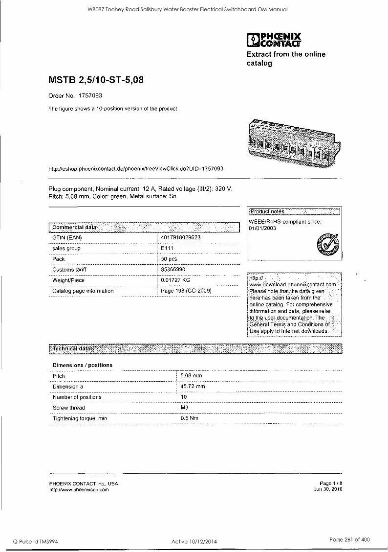
MSTB 2,5/10-ST-5,08
Order No.: 1757093
The figure shows a 10-position version of the product
http://eshop.phoenixcontact.de/phoenix/treeViewClick.do?Ul D=1757093
MPHCENIX LidCONTACT Extract from the online catalog
Plug component, Nominal current: 12 A, Rated voltage (111/2): 320 V,
Pitch: 5.08 mm, Color: green, Metal surface: Sn
Commercial 'data
GTIN (EAN)
sales group
Pack
Customs tariff
Weight/Piece
Catalog page information
4017918029623
E111
50 pcs.
85366990
0.01727 KG
Page 198 (CC-2009)
FProducfnotes.
WEEE/RoHS-compliant since: 01/01/2003
http:// vvv.m.download.phoenixcontact.com Please note that the data given here has been taken from the online catalog. For comprehensive information and data, please refer to the user documentation. The. General Terms and Conditions of Use apply to fl:,krnet downloads.
TeChnicalfilata
Dimensions / positions
Pitch
Dimension a
Number of positions
Screw thread
Tightening torque, min
5.08 mm
45.72 mm
1 10
M3
0.5 Nm
PHOENIX CONTACT Inc., USA http://www.phoenixcon.com
Page 1 / 8
Jun 30, 2010
WB087 Toohey Road Salisbury Water Booster Electrical Switchboard OM Manual
Q-Pulse Id TMS994 Active 10/12/2014 Page 261 of 400

MSTB 2,5/10-ST-5,08 Order No.: 1757093 http://eshop.phoenixcontact.de/phoenix/treeViewClick.do?UlD=1757093
Tightening torque max
Technical data
Insulating material group
Rated surge voltage (111/3)
Rated surge voltage (111/2)
Rated surge voltage (11/2)
Rated voltage (111/2)
Rated voltage (11/2)
Connection in acc. with standard
Nominal current IN
Nominal voltage UN
Nominal cross section
Maximum load current
Insulating material
Inflammability class acc. to UL 94
Internal cylindrical gage
Stripping length
Nominal voltage, UUCUL Use Group B
Nominal current, UUCUL Use Group B
Nominal voltage, UUCUL Use Group D
Nominal current, UUCUL Use Group D
Connection data
Conductor cross section solid min.
Conductor cross section solid max.
Conductor cross section stranded min.
Conductor cross section stranded max.
0.6 Nm
4 kV
4 kV
4 kV
320 V
630V
EN-VDE
12A
250V
2.5 mm2
12 A (with 2.5 mm2 conductor cross section)
PA
VO
A3
7 mm
250V
12A
300 V
10 A
0.2 mm2
2.5 mm2
0.2 mm2
2.5 mm2
Conductor cross section stranded, with ferrule I 0.25 mm2 without plastic sleeve min.
Conductor cross section stranded, with ferrule without plastic sleeve max.
Conductor cross section stranded, with ferrule with plastic sleeve min.
Conductor cross section stranded, with ferrule with plastic sleeve max.
2.5 mm2
0.25 mm2
2.5 mm2
Conductor cross section AWG/kcmil min. I 24
Conductor cross section AWG/kcmil max 12
PHOENIX CONTACT Inc., USA http://www.phoenixcon.com
Page 2 / 8
Jun 30, 2010
WB087 Toohey Road Salisbury Water Booster Electrical Switchboard OM Manual
Q-Pulse Id TMS994 Active 10/12/2014 Page 262 of 400

MSTB 2,5/10-ST-5,08 Order No.: 1757093 http://eshop.phoenixcontact.de/phoenix/treeViewClick.do?UlD=1757093
2 conductors with same cross section, solid min. 0.2 mm2
2 conductors with same cross section, solid max. I 1 mm2
2 conductors with same cross section, stranded 0.2 mm2 min.
2 conductors with same cross section, stranded 1.5 mm2 max.
2 conductors with same cross section, stranded, ferrules without plastic sleeve, min.
2 conductors with same cross section, stranded, ferrules without plastic sleeve, max.
2 conductors with same cross section, stranded, 0.5 mm2 TWIN ferrules with plastic sleeve, min.
0.25 mm2
1 mm2
2 conductors with same cross section, stranded, 1.5 mm2 TWIN ferrules with plastic sleeve, max.
Minimum AWG according to UUCUL
Maximum AWG according to UUCUL
30
12
[Certipcates / Approvals
cilia us E4 /..)x clte
Certification
CSA
Nominal voltage UN
Nominal current IN
AWG/kcmil
CUL
Nominal voltage UN
Nominal current IN
AWG/kcmil
UL
Nominal voltage UN
Nominal current IN
AWG/kcmil
CB, CSA, CUL, GOST, UL, VDE-PZI
300 V
10A
28-12
300V
10A
30-12
300 V
10A
30-12
PHOENIX CONTACT Inc., USA http://www.phoenixcon.com
Page 3 / 8
Jun 30, 2010
WB087 Toohey Road Salisbury Water Booster Electrical Switchboard OM Manual
Q-Pulse Id TMS994 Active 10/12/2014 Page 263 of 400
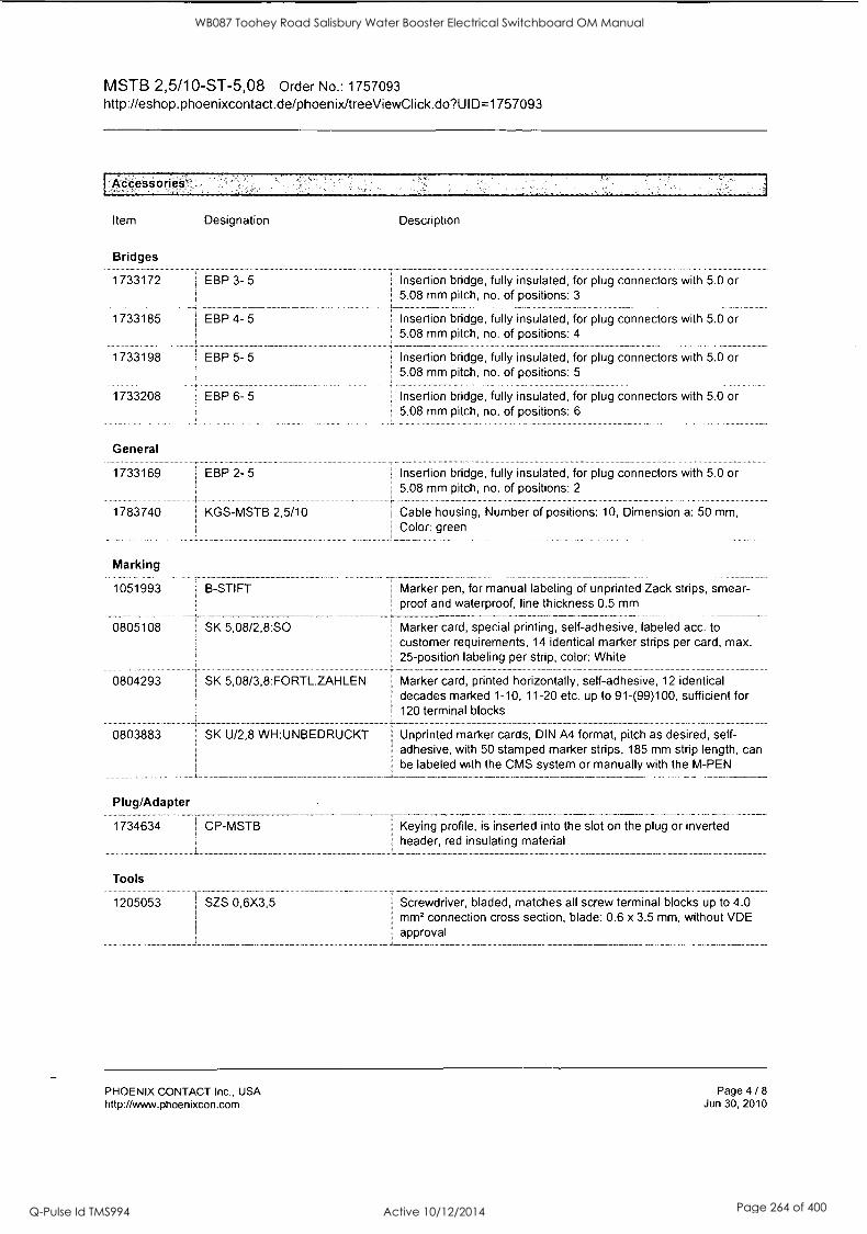
MSTB 2,5/10-ST-5,08 Order No.: 1757093 http://eshop.phoenixcontact.de/phoenix/treeViewClick.do?UlD=1757093
Accesiories
Item Designation
Bridges
1733172 EBP 3- 5
1733185 EBP 4- 5
1733198 EBP 5- 5
1733208
General
1733169
1783740
Marking
EBP 6- 5
EBP 2- 5
KGS-MSTB 2,5/10
Description
I Insertion bridge, fully insulated, for plug connectors with 5.0 or 5.08 mm pitch, no. of positions: 3
Insertion bridge, fully insulated, for plug connectors with 5.0 or 5.08 mm pitch, no. of positions: 4
Insertion bridge, fully insulated, for plug connectors with 5.0 or 5.08 mm pitch, no. of positions: 5
Insertion bridge, fully insulated, for plug connectors with 5.0 or 5.08 mm pitch, no. of positions: 6
Insertion bridge, fully insulated, for plug connectors with 5.0 or 5.08 mm pitch, no. of positions: 2
Cable housing, Number of positions: 10, Dimension a: 50 mm, Color: green
1051993 B-STI FT Marker pen, for manual labeling of unprinted Zack strips, smear- ; proof and waterproof, line thickness 0.5 mm
0805108 SK 5,08/2,8:SO I Marker card, special printing, self-adhesive, labeled acc. to customer requirements, 14 identical marker strips per card, max. 25-position labeling per strip, color: White
0804293 SK 5,08/3,8:FORTL.ZAHLEN I Marker card, printed horizontally, self-adhesive, 12 identical decades marked 1-10, 11-20 etc. up to 91-(99)100, sufficient for 120 terminal blocks
0803883 SK U/2,8 WH:UNBEDRUCKT Unprinted marker cards, DIN A4 format, pitch as desired, self- ! adhesive, with 50 stamped marker strips, 185 mm strip length, can
be labeled with the CMS system or manually with the M-PEN
Plug/Adapter
1734634
Tools
1205053
CP-MSTB
SZS 0,6X3,5
Keying profile, is inserted into the slot on the plug or inverted header, red insulating material
Screwdriver, bladed, matches all screw terminal blocks up to 4.0 mm2 connection cross section, blade: 0.6 x 3.5 mm, without VDE approval
PHOENIX CONTACT Inc., USA http://www.phoenixcon.com
Page 4 / 8 Jun 30, 2010
WB087 Toohey Road Salisbury Water Booster Electrical Switchboard OM Manual
Q-Pulse Id TMS994 Active 10/12/2014 Page 264 of 400

MSTB 2,5/10-ST-5,08 Order No.: 1757093 http://eshop.phoenixcontact.de/phoenix/treeViewClick.do?UlD=1757093
Additional nrotincts
Item Designation
General
1823927 1 ICC 2,5/10-STZ-5,08
1762457 MDSTB 2,5/10-G1-5,08
Description
Plug component, Nominal current: 12 A, Rated voltage (111/2): 320 V, Pitch: 5.08 mm, Color: green, Metal surface: Sn, Corresponding male crimp contacts with current [A] and conductor cross section range [mml data: 10A/ICC-MT 0,5-1,0 (3190577); 10A/ICC-MT 0,5-1,0 BA (3190603); 12A/ICC-MT 1,5-2,5 (3190580); 12A/ICC- MT 1,5-2,5 BA (3190593). BA = Bandkontakte
Header, Nominal current: 10 A, Rated voltage (111/2): 320 V, Pitch: 5.08 mm, Color: green, Metal surface: Sn, Assembly: Soldering, In combination with MVSTB or FKCV plug components, both an MVSTBW (or FKCVW) and an MVSTBR plug (or FKCVR) must be used. Combination with TMSTBP plug components is not possible!
1762583 MDSTBV 2,5/10-G1-5,08 1 Header, Nominal current: 10 A, Rated voltage (111/2): 320 V, Pitch: 5.08 mm, Color: green, Metal surface: Sn, Assembly: Soldering, In combination with MVSTB or FKCV plug components, both an MVSTBW (or FKCVW) and an MVSTBR plug (or FKCVR) must be used. Combination with TMSTBP plug components is not possible!
Header, Nominal current: 12 A, Rated voltage (111/2): 320 V, Pitch: 5.08 mm, Assembly: Soldering
1757323 MSTBA 2,5/10-G-5,08 Header, Nominal current: 12 A, Rated voltage (111/2): 320 V, Pitch: 5.08 mm, Color: green, Metal surface: Sn, Assembly: Soldering
1768024 MSTBA 2,5/10-G-5,08-LA 1 Header, Nominal current: 12 A, Rated voltage (111/2): 320 V, Pitch: 5.08 mm, Assembly: Soldering
1765030 MSTBHK 2,5/10-G-5,08 I Plug component, Nominal current: 12 A, Rated voltage (111/2): 320 V, Pitch: 5.08 mm, Color: green, Metal surface: Sn, Assembly: DIN
I rail
1770795 MSTB 2,5/10-G-5,08-LA
1788800 MSTBVK 2,5/10-G-5,08
1788619 MVSTBU 2,5/10-GB-5,08
1769544 SMSTB 2,5/10-G-5,08
1767452
3002034 1 UK 3-MSTB-5,08
SMSTBA 2,5/10-G-5,08
Plug component, Nominal current: 12 A, Rated voltage (111/2): 320 V, Pitch: 5.08 mm, Color: green, Metal surface: Sn, Assembly: DIN rail
Plug component, Nominal current: 12 A, Rated voltage (111/2): 320 V, Pitch: 5.08 mm, Color: green, Metal surface: Sn, Assembly: Direct mounting
Header, Nominal current: 12 A, Rated voltage (111/2): 320 V, Pitch: 5.08 mm, Color: green, Metal surface: Sn, Assembly: Soldering
Header, Nominal current: 12 A, Rated voltage (111/2): 320 V, Pitch: 5.08 mm, Color: green, Metal surface: Sn, Assembly: Soldering
Feed-through modular terminal block, Type of connection: Special and hybrid connection, Screw connection, Cross section: 0.2 mm' - 4 mrn2, AWG 24 - 12, Width: 5.08 mm, Color: gray, Mounting type: NS 32, NS 35/15, NS 35/7,5
PHOENIX CONTACT Inc., USA http://www.phoenixcon.com
Page 5 / 8 Jun 30, 2010
WB087 Toohey Road Salisbury Water Booster Electrical Switchboard OM Manual
Q-Pulse Id TMS994 Active 10/12/2014 Page 265 of 400

MSTB 2,5/10-ST-5,08 Order No.: 1757093 http://eshop.phoenixcontact.de/phoenix/treeViewClick.do?Ul D=1757093
3002076 I UK 3-MVSTB-5,08 Feed-through modular terminal block, Nominal current: 12
A, Nominal voltage: 250 V, Cross section: 0.2 mm2 - 4 mm2, AWG: 24 - 12, Mounting type: NS 32, NS 35/15, NS 35/7,5, Pitch: 5.08 mm, Width: 5.1, Color: gray
3002102 I UK 3-MVSTB-5,08-LA 24RD I Feed-through modular terminal block, Nominal current: 12
A, Nominal voltage: 250 V, Cross section: 0.2 mm2 - 4 mm2, AWG: 24 - 12, Mounting type: NS 32, NS 35/15, NS 35/7,5, Pitch: 5.08 mm, Width: 5.08, Color: gray
Feed-through modular terminal block, Nominal current: 12 A, Nominal voltage: 250 V, Cross section: 0.2 mm2 - 4 mm2, AWG: 24 - 12, Mounting type: NS 35/7,5, NS 35/15, NS 32, Pitch: 5.08 mm, Width: 5.1, Color: blue
3002131 UK 3D-MSTBV-5,08 Feed-through modular terminal block, Type of connection: Special and hybrid connection, Screw connection, Cross section: 0.2 mm2 - 4 mm2, AWG 24 - 12, Width: 5.08 mm, Color: gray, Mounting type: NS 32, NS 35/15, NS 35/7,5
Feed-through modular terminal block, Type of connection: Screw connection, Screw connection, Number of positions: 1, Cross section: 0.2 mm2 - 4 mm2, AWG 24 - 12, Width: 5.1 mm, Color: gray, Mounting type: NS 32, NS 35/15, NS 35/7,5
3002173 I UK 3D-MSTBV-5,08 EK Feed-through modular terminal block, Type of connection: Screw
3002063 UK 3-MVSTB-5,08/EK
3002144 I UK 3D-MSTBV-5,08-LA 24RD
2770888 ' UKK 3-MSTB-5,08
1876615 UKK 3-MSTB-5,08-PE
2770846 UKK 3-MSTBVH-5,08
1788198 j UMSTBVK 2,5/10-G-5,08
1873016 ZFKK 1,5-MSTBV-5,08
connection, Screw connection, Cross section: 0.2 mm2 - 4 mm2, AWG 24 - 12, Width: 5.1 mm, Color: blue, Mounting type: NS 32, NS 35/15, NS 35/7,5
End cover, Nominal current: 12 A, Nominal voltage: 250 V, Cross section: 0.2 mm2 - 4 mm2, AWG: 24 - 12, Mounting type: NS 35/7,5, NS 35/15, NS 32, Pitch: 5.08 mm, Width: 5.08, Color: gray
Feed-through modular terminal block, Nominal current: 12
A, Nominal voltage: 320 V, Cross section: 0.2 mm2 - 4 mm2, AWG: 24 - 12, Mounting type: NS 35/7,5, NS 35/15, NS 32, Pitch: 5.08 mm, Width: 5.08, Color: green-yellow
Feed-through modular terminal block, Nominal current: 12
A, Nominal voltage: 250 V, Cross section: 0.2 mm2 - 4 mm2, AWG: 24 - 12, Mounting type: NS 35/7,5, NS 35/15, NS 32, Pitch: 5.08 mm, Width: 5.08, Color: gray
Plug component, Nominal current: 12 A, Rated voltage (111/2): 320 V, Pitch: 5.08 mm, Color: green, Metal surface: Sn, Assembly: DIN rail
Feed-through modular terminal block, Connection method: Special and hybrid connection, MSTB plug entry, Cross section: 0.2 mm2 - 2.5 mm2, Width: 5.1 mm, Color: gray
PHOENIX CONTACT Inc., USA http: / /www.phoenixcon.com
Page 6 / 8
Jun 30, 2010
WB087 Toohey Road Salisbury Water Booster Electrical Switchboard OM Manual
Q-Pulse Id TMS994 Active 10/12/2014 Page 266 of 400

MSTB 2,5/10-ST-5,08 Order No.: 1757093 http://eshop.phoenixcontact.de/phoenix/treeViewClick.do?UlD=1757093
1,Diagrams/Drawings
Dimensioned drawing
PHOENIX CONTACT Inc., USA http://www.phoenixcon.com
Page 7 / 8
Jun 30, 2010
WB087 Toohey Road Salisbury Water Booster Electrical Switchboard OM Manual
Q-Pulse Id TMS994 Active 10/12/2014 Page 267 of 400

FBS 10-8
Order No.: 3030323
http lleshop.phoenixcontact.de/phoenix/treeViewClick.do?UlD=3030323
MPHCEMIX LidCOPMILT Extract from the online catalog
Cross connector/jumper for modular terminal block, Number of positions: 10, Color: red
`Commercral "data,
EAN 4017918188634
Pack 10 pcs.
Customs tariff I 85389099
Weight/Piece 0.01955 KG
Catalog page information Page 330 (CL-2009)
[Product notes
WEEE/RoHS-compliant since: 01/01/2003
http: // wWw.download:phoenbccontact.corn Please note that'the data given here has been taken from the.
:online catalog. FOr Comprehehafve -informetion and:data, pleaSe', refer to the user documentation The Gerteral Terms and Conditions of :Use apply to .Interhet downloads.
PHOENIX CONTACT GmbH & Co. KG http://www.phoenixcontact.de
Page 1 / 2
Oct 23, 2009
WB087 Toohey Road Salisbury Water Booster Electrical Switchboard OM Manual
Q-Pulse Id TMS994 Active 10/12/2014 Page 268 of 400

PS-6/2,3MM RD
Order No.: 3038736
The illustration shows the version PS-5/2,3 MM RD
http://eshop.phoenixcontact.de/phoenix/treeViewClick.do?UlD=3038736
MPHCENIX CONTACT
Extract from the online catalog
Test plugs, Color: red
Commercialdata
GTIN (EAN) 4017918904166
sales group A691
Pack 10 pcs.
Customs tariff 85369010
Weight/Piece 0.00143 KG
Catalog page information Page 449 (CL-2009)
Product notes
WEEE/RoHS-compliant since: 01/01/2003
http:// viww.doyvnload.phoenixcontact.com Please note that the data given here has beeh taken frorn the online catalog. For comprehensive information and data, please refer to the user documentation. The General Terms and Conditions of Use apply to Internet downloads
PHOENIX CONTACT Inc., USA http://www.phoenixcon.com
Page 1 / 2
Jun 30, 2010
WB087 Toohey Road Salisbury Water Booster Electrical Switchboard OM Manual
Q-Pulse Id TMS994 Active 10/12/2014 Page 269 of 400
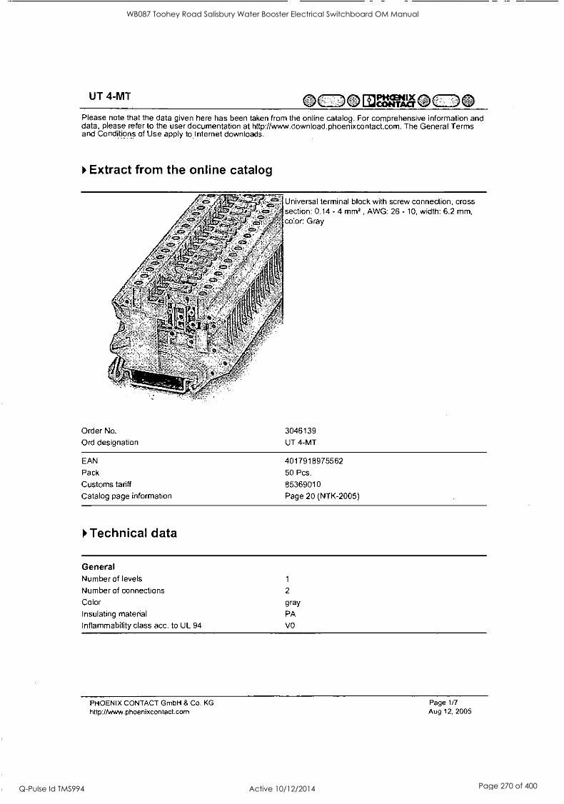
UT 4-MT =0111MIcr."(0 Please note that the data given here has been taken from the online catalog. For comprehensive information and data, please refer to the user documentation at http://www.download.phoenixcontact.com. The General Terms and Conditions of Use apply to.Internet downloads.
Extract from the online catalog
4Cii 4M,
- et, s ; 7:"
rt:ZZ, CK> ^
^ ISS1 ' 7 . 4-- 112), -'
' - ,
, N.,
t"r
' - '1°;" , 114'
Order No.
Ord designation
Universal terminal block with screw connection, cross section: 0.14 - 4 mm2 , AWG: 26 - 10, width: 6.2 mm, color: Gray
3046139
UT 4-MT
EAN 4017918975562
Pack 50 Pcs.
Customs tariff 85369010
Catalog page information Page 20 (NTK-2005)
Technical data
General Number of levels 1
Number of connections 2
Color gray
Insulating material PA
Inflammability class acc. to UL 94 VO
PHOENIX CONTACT GmbH & Co. KG http://www.phoenixcontact.com
Page 1/7 Aug 12, 2005
WB087 Toohey Road Salisbury Water Booster Electrical Switchboard OM Manual
Q-Pulse Id TMS994 Active 10/12/2014 Page 270 of 400

UT 4-MT OCDOESVA`cr"0=0 Dimensions Width 6.2 mm
Length 56.8 mm
Height NS 35/7,5 47.5 mm
Height NS 35/15 55 mm
Technical data Maximum load current 16 A
Rated surge voltage 8 kV
Contamination class 3
Surge voltage category III
Insulating material group
Connection in acc. with standard IEC/ DIN VDE
Nominal current IN 16 A
Nominal voltage UN 500 V
Open side panel nein
Connection data Conductor cross section, rigid min. 0.14 mm2
Conductor cross section, rigid max. 6 mm2
Conductor cross section flexible min. 0.14 mm2
Conductor cross section, flexible max. 4 mm2
Conductor cross section AWG/kcmil min. 26
Conductor cross section AWG/kcmil max 10
Conductor cross section flexible, with ferrule without 0.25 mm2
plastic sleeve min.
Conductor cross section flexible, with ferrule without 4 mm2 plastic sleeve max.
Conductor cross section flexible, with ferrule with plastic 0.25 mm2
sleeve min.
Conductor cross section flexible, with ferrule with plastic 4 mm2
sleeve max.
2 conductors with same cross section, solid min. 0.14 mm2
2 conductors with same cross section, solid max. 1.5 mm2
2 conductors with same cross section, flexible, min. 0.14 mm2
2 conductors with same cross section, flexible max. 1.5 mm2
2 conductors with same cross section, flexible, TWIN 0.5 mm2
ferrules with plastic sleeve, min.
2 conductors with identical cross section, flexible TWIN 2.5 mm2
ferrules with plastic sleeve, max.
2 conductors with same cross section, flexible, ferrules 0.25 mm2 without plastic sleeve min.
2 conductors with same cross section, flexible, ferrules 1.5 mm2 without plastic sleeve, max.
Type of connection Screw connection
Stripping length 9 mm
Internal cylindrical gage A4
Screw thread M 3
Tightening torque, min 0.6 Nm
PHOENIX CONTACT GmbH & Co. KG http://www.phoenixcontact.com
Page 2/7 Aug 12, 2005
WB087 Toohey Road Salisbury Water Booster Electrical Switchboard OM Manual
Q-Pulse Id TMS994 Active 10/12/2014 Page 271 of 400
UT 4-MT OCD01:11=71%0=0
Certificates
CUL Nominal voltage UN 600 V
Nominal current IN 16 A
AWG/kcmil 26-10
UL Nominal voltage UN 600 V
Nominal current IN 16 A
AWG/kcmil 26-10
PHOENIX CONTACT GmbH & Co, KG
http://www.phoenixcontact.com
Page 3/7 Aug 12, 2005
WB087 Toohey Road Salisbury Water Booster Electrical Switchboard OM Manual
Q-Pulse Id TMS994 Active 10/12/2014 Page 272 of 400

UT 4-MT
1*Drawings
0=0E1=00=0
Circuit diagram
Approval logo
imin US
PHOENIX CONTACT GmbH & Co. KG http://www.phoenixcontact.com
Page 4/7 Aug 12, 2005
WB087 Toohey Road Salisbury Water Booster Electrical Switchboard OM Manual
Q-Pulse Id TMS994 Active 10/12/2014 Page 273 of 400

UT 4-MT OCDO EIMAI§OC_DO
to Accessories
Item Designation Description
Assembly 0801762 NS 35/ 7,5 CU UNPERF DIN rail, material: Copper, unperforated, height 7.5 mm, width
2000MM 35 mm, length: 2 m
1207640 NS 35/ 7,5 PERF 755MM NS 35 DIN rail, height 7.5 mm, length 755 mm
1207653 NS 35/ 7,5 PERF 955MM NS35 DIN rail, height 7.5 mm, length 955 mm
1207666 NS 35/ 7,5 PERF 1155MM NS 35 DIN rail, height 7.5 mm, length 1155 mm
0801733 NS 35/ 7,5 PERF 2000MM DIN rail, material: Steel, perforated, height 7.5 mm, width 35 mm, length: 2 m
0801681 NS 35/ 7,5 UNPERF 2000MM DIN rail, material: Steel, unperforated, height 7.5 mm, width 35 mm, length: 2 m
1201756 NS 35/15 AL UNPERF 2000MM
DIN rail, deep-drawn, high profile, unperforated, 1.5 mm thick, material: Aluminum, height 15 mm, width 35 mm, length 2 m
1201895 NS 35/15 CU UNPERF DIN rail, material: Copper, unperforated, 1.5 mm thick, height 15 2000MM mm, width 35 mm, length: 2 m
1207679 NS 35/15 PERF 755MM NS 35 DIN rail, height 15 mm, length 755 mm
1207682 NS 35/15 PERF 955MM NS 35 DIN rail, height 15 mm, length 955 mm
1207695 NS 35/15 PERF 1155MM NS 35 DIN rail, height 15 mm, length 1155 mm
1201730 NS 35/15 PERF 2000MM DIN rail, material: Steel, perforated, height 15 mm, width 35 mm, length: 2 m
1201714 NS 35/15 UNPERF 2000MM DIN rail, material: Steel, unperforated, height 15 mm, width 35 mm, length: 2 m
1201798 NS 35/15-2,3 UNPERF DIN rail, material: Steel, unperforated, 2.3 mm thick, height 15
2000MM mm, width 35 mm, length: 2 m
Bridges 3030336 FBS 2-6 Plug-in bridge for cross-connections in the terminal center, 2-
pos., color: Red
3030242 FBS 3-6 Plug-in bridge for cross-connections in the terminal center, 3- pos., color: Red
3030255 FBS 4-6 Plug-in bridge for cross-connections in the terminal center, 4- pos., color: Red
3030349 FBS 5-6 Plug-in bridge for cross-connections in the terminal center, 5- pos., color: Red
3030271 FBS 10-6 Plug-in bridge for cross-connections in the terminal center, 10- pos., color: Red
3030365 FBS 20-6 Plug-in bridge for cross-connections in the terminal center, 20- pos., color: Red
3047060 RB UT 10-(2,5/4) Reducing bridge, for connection from UT 10 to UT 4 or UT 2,5
PHOENIX CONTACT GmbH & Co. KG http://www.phoenixcontact.com
Page 5/7 Aug 12, 2005
WB087 Toohey Road Salisbury Water Booster Electrical Switchboard OM Manual
Q-Pulse Id TMS994 Active 10/12/2014 Page 274 of 400

UT 4-MT 0=0 EUM1NOCDO Marking 0811228
1051016
5060935
1050499 ZB 6:SO/CMS
X-PEN 0,35
ZB 6,LGS:FORTL.ZAHLEN
ZB 6/WH-100:UNBEDRUCKT
Marker pen without ink cartridge, for manual labeling of markers, labeling extremely wipe-proof, line thickness 0.35 mm
Zack strip, 10-section, printed horizontally: with the numbers, 1-
10, 11-20 etc. up to 991-1000, color: white
Zack strip, unprinted: For individual labeling with M-PEN, ZB-T or CMS system, large batch, sufficient for labeling 1000 terminal blocks, for a terminal width of 6.2 mm, color: White
Zack strip, 10-section, divisible, special printing, marking according to customer requirements
Plug/Adapter 0201689
0201676
0201663
0201744
MPS-IH BU
MPS-IH RD
MPS-IH WH
MPS-MT
3030925 PAI-4
3030996 PS-6
Test plug, consisting of: Metal part for 2.3 mm diameter socket hole
Test adapter, for 4 mm diameter test plug PS and safety test plug, makes contact in the bridge shaft
Modular test plug, for individual assembly of test plug strips, for UT, ST, DT and QT terminal blocks, can be labeled with ZBF 6,
color: Red
Tools 1205053 SZS 0,6X3,5 Screwdriver, bladed, matches all screw terminal blocks up to 4.0
mm2 connection cross section, blade: 0.6 x 3.5 mm, without VDE approval
PHOENIX CONTACT GmbH & Co. KG http://www.phoenixcontact.com
Page 6/7
Aug 12, 2005
WB087 Toohey Road Salisbury Water Booster Electrical Switchboard OM Manual
Q-Pulse Id TMS994 Active 10/12/2014 Page 275 of 400

PHCENIX CONTACT
Extract from the online catalog
UT 4-MTD ;.
Order No.: 3046184 va,
http://eshop. phoenixcontact.de/phoenix/treeViewClick.do?Ul D=3046184
Feed-through modular terminal block, Type of connection: Screw connection, Cross section: 0.14 mm2 - 6 mm2, AWG 26 - 10, Width: 6.2 mm, Color: gray, Mounting type: NS 35/7,5, NS 35/15
Commercial data
EAN 401 7918956592
Pack 50 pcs.
Customs tariff 85369010
Weight/Piece J 0.011431 KG
Catalog page information I
Page 56 (CL-2009)
rproduct-notes. .7.77.771 WEEE/RoHS-compliant since: 01/01/2003
.http:// wmN.download:phoenixcontact.com Please note that the data given here has been taken:ffom the online catalog. For comprehensive information and data, please refer to theusersdoCOmentatidnThe: General Terms and Conditions of Use apply to Internet doWnloads.
Technical data
General
Number of levels
Number of connections
Color
1
I 2
gray
PHOENIX CONTACT Deutschland GmbH http://www.phoenixcontact.de
Page 1 / 7
Mar 24, 2010
WB087 Toohey Road Salisbury Water Booster Electrical Switchboard OM Manual
Q-Pulse Id TMS994 Active 10/12/2014 Page 276 of 400
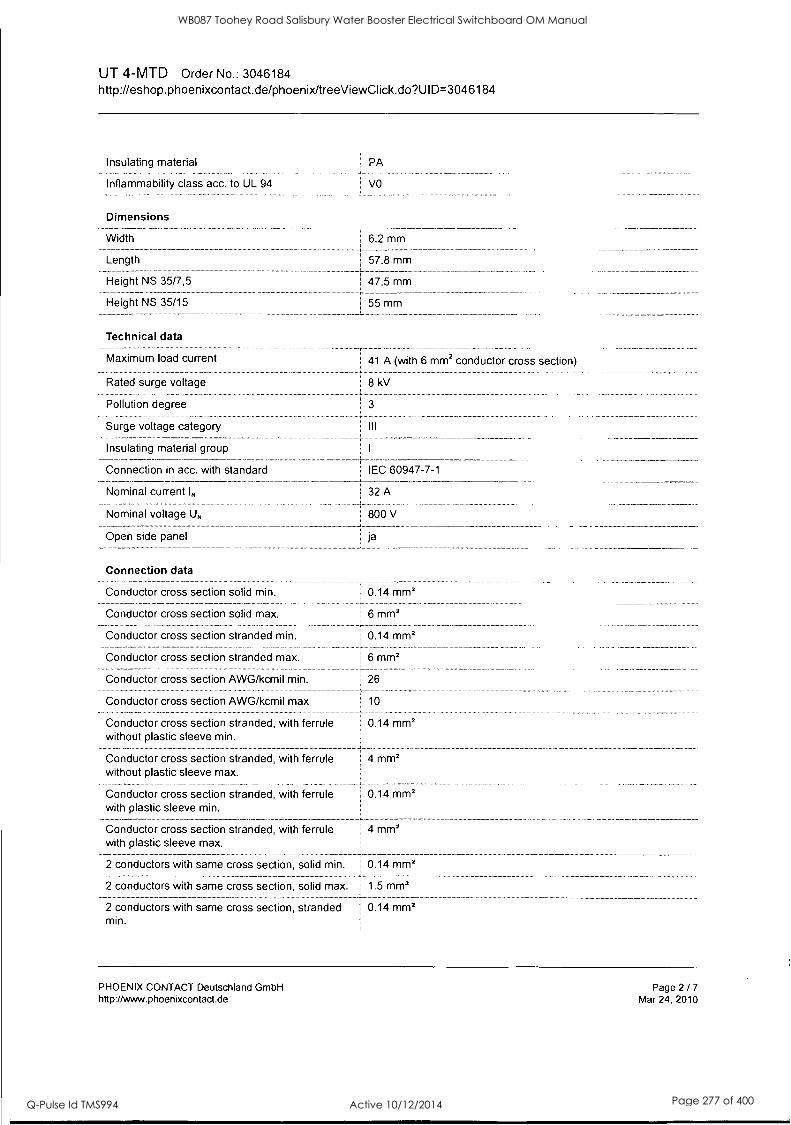
UT 4-MTD Order No.: 3046184 http://eshop.phoenixcontact.de/phoenix/treeViewClick.do?UlD=3046184
Insulating material
Inflammability class acc. to UL 94
Dimensions
Width
Length
Height NS 35/7,5
Height NS 35/15
Technical data
Maximum load current
Rated surge voltage
Pollution degree
Surge voltage category
Insulating material group
Connection in acc. with standard
Nominal current 1,,
Nominal voltage UN
Open side panel
PA
VO
6.2 mm
57.8 mm
47.5 mm
55 mm
41 A (with 6 mm2 conductor cross section)
8 kV
3
III
!EC 60947-7-1
32 A
800 V
ja
Connection data
Conductor cross section solid min. 1 0.14 mmz
Conductor cross section solid max. 6 mmz
Conductor cross section stranded min. 1 0.14 mm2
Conductor cross section stranded max. 6 mm2
Conductor cross section AWG/kcmil min. 26
Conductor cross section AWG/kcmil max 10
Conductor cross section stranded, with ferrule 0.14 mm2 without plastic sleeve min.
Conductor cross section stranded, with ferrule 4 mm2 without plastic sleeve max.
Conductor cross section stranded, with ferrule 0.14 mm2 with plastic sleeve min.
Conductor cross section stranded, with ferrule 4 mm2 with plastic sleeve max.
2 conductors with same cross section, solid min.
2 conductors with same cross section, solid max. 1.5 mm2
0.14 mm2
2 conductors with same cross section, stranded 1 0.14 mm2 min.
PHOENIX CONTACT Deutschland GmbH http://www.phoenixcontact.de
Page 2 / 7
Mar 24, 2010
WB087 Toohey Road Salisbury Water Booster Electrical Switchboard OM Manual
Q-Pulse Id TMS994 Active 10/12/2014 Page 277 of 400

UT 4-MTD Order No.: 3046184 http://eshop.phoenixcontact.de/phoenix/treeViewClick.do?UlD=3046184
2 conductors with same cross section, stranded 1.5 mm2 max.
2 conductors with same cross section, stranded, 0.5 mm2 TWIN ferrules with plastic sleeve, min.
2 conductors with same cross section, stranded, 2.5 mm2 TWIN ferrules with plastic sleeve, max.
2 conductors with same cross section, stranded, 0.14 mm2 ferrules without plastic sleeve, min.
2 conductors with same cross section, stranded, 1.5 mm2 ferrules without plastic sleeve, max.
Type of connection
Stripping length
Internal cylindrical gage
Screw thread
Tightening torque, min
Tightening torque max
Screw connection
9 mm
A4
M3
0.6 Nm
0.8 Nm
Certificates.! Approvais,
Ccia US el Certification
Certification Ex:
CSA
Nominal voltage UN
Nominal current IN
AWG/kcmil
CUL
Nominal voltage UN
Nominal current IN
AWG/kcmil
UL
Nominal voltage UN
Nominal current IN
AWG/kcmil
cDne GL
CB, CSA, CUL, DNV, GL, LR, UL, VDE-PZI
IECEx, KEMA-EX
600 V
30 A
26-10
600 V
30 A
26-10
600 V
30 A
26-10
PHOENIX CONTACT Deutschland GmbH http://www.phoenixcontact.de
Page 3 / 7
Mar 24, 2010
WB087 Toohey Road Salisbury Water Booster Electrical Switchboard OM Manual
Q-Pulse Id TMS994 Active 10/12/2014 Page 278 of 400

UT 4-MTD Order No.: 3046184 http://eshop.phoenixcontact.de/phoerthdtreeViewaick.do?UlD=3046184
,ACcessories
Item
Assembly
3022276
Designation
CLIPFIX 35-5
Description
Snap-on end bracket, for NS 35/7.5 or NS 35/15 DIN rail, can be fitted with Zack strip ZB 5 and ZBF 5, terminal strip marker KLM 2 and KLM, parking facility for FBS...5, FBS...6, KSS 5, KSS 6,
: 1 width: 5,15 mm, color: gray :
3047141 |
D-UT 2,5/4-TWIN 1 End cover, Width: 2.2 mm, Color: gray :
0801762 NS 35/ 7,5 CU UNPERF 1 DIN rail, material: Copper, unperforated, height 7.5 mm, width 35 2000MM mm, length: 2 m
1207640 NS 35/ 7,5 PERF 755MM 1 NS 35 DIN rail, height 7.5 mm, length 755 mm
1207653 NS 35/ 7,5 PERF 955MM 1 NS35 DIN rail, height 7.5 mm, length 955 mm
1207666 NS 35/ 7,5 PERF 1155MM 1 NS 35 DIN rail, height 7.5 mm, length 1155 mm
0801733 NS 35/ 7,5 PERF 2000MM 1 DIN rail, material: Steel, galvanized and passivated with a thick , i layer, perforated, height 7.5 mm, width 35 mm, length: 2 m
0801681 NS 35/ 7,5 UNPERF 2000MM 1 DIN rail, material: Steel, unperforated, height 7.5 mm, width 35
,
i mm, length: 2 m
1201756 NS 35/15 AL UNPERF 2000MM I DIN rail, deep-drawn, high profile, unperforated, 1.5 mm thick, i material: Aluminum, height 15 mm, width 35 mm, length 2 m
1201895 NS 35/15 CU UNPERF 2000MM 1 DIN rail, material: Copper, unperforated, 1.5 mm thick, height 15 1 mm, width 35 mm, length: 2 m
1207679 NS 35/15 PERF 755MM I NS 35 DIN rail, perforated, height 15 mm, length 755 mm
1207682 NS 35/15 PERF 955MM NS 35 DIN rail, perforated, height 15 mm, length 955 mm
1207695 NS 35/15 PERF 1155MM 1 NS 35 DIN rail, perforated, height 15 mm, length 1155 mm
1201730 NS 35/15 PERF 2000MM 1 DIN rail, material: Steel, perforated, height 15 mm, width 35 mm, 1 length: 2 m
1201714 NS 35/15 UNPERF 2000MM DIN rail, material: Steel, unperforated, height 15 mm, width 35 I mm, length: 2 m
1201798 NS 35/15-2,3 UNPERF 2000MM DIN rail, material: Steel, unperforated, 2.3 mm thick, height 15
mm, width 35 mm, length: 2 m
Bridges
3030336 FBS 2-6 Cross connector/bridge, Number of positions: 2, Color: red
3030242 FBS 3-6 I Cross connector/bridge, Number of positions: 3, Color: red
3030255 FBS 4-6 Cross connector/bridge, Number of positions: 4, Color: red
3030349 FBS 5-6 Cross connector/bridge, Number of positions: 5, Color: red
3030271 FBS 10-6 Cross connector/bridge, Number of positions: 10, Color: red
3030365 FBS 20-6 1 Cross connector/bridge, Number of positions: 20, Color: red
3032224 FBS 50-6 1 Cross connector/bridge, Number of positions: 50, Color: red
PHOENIX CONTACT Deutschland GmbH http://www.phoenixcontact.de
Page 4 / 7
Mar 24, 2010
WB087 Toohey Road Salisbury Water Booster Electrical Switchboard OM Manual
Q-Pulse Id TMS994 Active 10/12/2014 Page 279 of 400

UT 4-MTD Order No.: 3046184 http://eshop.phoenixcontact.de/phoenix/treeViewClick.do?UI D=30461 84
3047060 RB UT 10-(2,5/4)
Marking
1051993
0811228
1051016
1051032
1051029
1051045
B-STIFT
X-PEN 0,35
ZB 6,LGS:FORTL.ZAHLEN
ZB 6,LGS:GLEICHE ZAHLEN
ZB 6,QR:FORTL.ZAHLEN
ZB 6,QR:GLEICHE ZAHLEN
1050499 ! ZB 6:SO/CMS
1051003
Plug/Adapter
0201731
0201702
0201676
0201663
0201744
3030925
3030996
Tools
ZB 6:UNBEDRUCKT
MPS-IH BK
MPS-IH GN
MPS-IH RD
MPS-IH WH
MPS-MT
PAI-4
PS-6
1205053 SZS 0,6X3,5
Cross connector/bridge, Number of positions: 2, Color: red
Marker pen, for manual labeling of unprinted Zack strips, smear- ! proof and waterproof, line thickness 0.5 mm
Marker pen without ink cartridge, for manual labeling of markers, labeling extremely wipe-proof, line thickness 0.35 mm
Zack strip, 10-section, printed horizontally: with the numbers, 1-10, 11-20 etc. up to 991-1000, color: white
Zack marker strip, labeled horizontally: 10-section, with identical numbers, 1/1/1, 2/2/2 etc. up to 1000/1000/1000, color: white
Zack strip, 10-section, printed vertically: with consecutive numbers, 1-10, 11-20 a.s.o. up to 991-1000, color: white
Zack marker, labeled vertically: 10-section, with identical numbers, 1/1/1, 2/2/2 etc. up to 1000/1000/1000, color: White
Zack strip, 10-section, divisible, special printing, marking according to customer requirements
Zack strip, unprinted, strips with 10 labels for individual labeling with M-PEN or CMS system, for terminal block width: 6.2 mm, color: white
Insulating sleeve, for MPS metal part, Color: black
Insulating sleeve, for MPS metal part, Color: green
Insulating sleeve, Color: red
Insulating sleeve, for MPS metal part, Color: white
Metal part
Test adapter, Color: gray
Test adapter, Color: red
Screwdriver, bladed, matches all screw terminal blocks up to 4.0 mm2 connection cross section, blade: 0.6 x 3.5 mm, without VDE approval
iagrams rawipgs,
Circuit diagram
0
PHOENIX CONTACT Deutschland GmbH http://www.phoenixcontact.de
Page 5 / 7
Mar 24, 2010
WB087 Toohey Road Salisbury Water Booster Electrical Switchboard OM Manual
Q-Pulse Id TMS994 Active 10/12/2014 Page 280 of 400

UT 4-MTD Order No.: 3046184 http://eshop.phoenixcontact.de/phoenix/treeViewClick.do?UlD=3046184
Approbationslogos (EX-Bereich)
PHOENIX CONTACT Deutschland GmbH http://www.phoenixcontact.de
Page 6 / 7
Mar 24, 2010
WB087 Toohey Road Salisbury Water Booster Electrical Switchboard OM Manual
Q-Pulse Id TMS994 Active 10/12/2014 Page 281 of 400

Ertionwc Extract from the online catalog
UBE/D + ES /KM K 3
Order No.: 1004076
http://eshop.phoenixcontact.de/phoenix/treeViewClick.do?UlD=1004076
Terminal strip marker carriers for marking terminal group, for mounting on the terminal strip NS 32 or NS 35/7.5, lettering field size: 40 x 17 mm
ommercial data
EAN 4017918011888
Pack 10 pcs.
Customs tariff 85369010
Weight/Piece 0.0105 KG
[Product notes
WEEE/RoHS-compliant since: 03/18/2004
http:// wwiv.download.phoenixcontact.com Please note that the data given here has been taken from'the online catalog. For comprehensive information and data, please refer
.to the user documentation: The General Terms and Conditions of Use apply to Internet downloads.
General
Color
Base element material
Inflammability class acc. to UL 94
Ambient temperature (operation)
Components
gray
PA
V2
-40 °C ... 100 °C
free from silicone and halogen
PHOENIX CONTACT GmbH & Co. KG http://www.phoenixcontaade
Page 1 / 2
May 7, 2009
WB087 Toohey Road Salisbury Water Booster Electrical Switchboard OM Manual
Q-Pulse Id TMS994 Active 10/12/2014 Page 282 of 400

UT 4-HESI (5X20)
Order No.: 3046032
http://eshop.phoenixcontact.de/phoenix/treeViewClick.do?UlD=3046032
rn PH CE NIX Lid CCP NTACT Extract from the online catalog
Fuse modular terminal block, Connection method: Screw connection, Cross section: 0.14 mm2- 6 mm2, AWG: 26 - 10, Nominal current: 6.3 A, Nominal voltage: 500 V, Width: 6.2 mm, Fuse type: G / 5 x 20, Fuse type: Glass, Mounting type: NS 35/7,5, NS 35/15, Color: black
Commercial data
EAN
Pack
Customs tariff
Weight/Piece
Catalog page information
1 4017918956578
50 pcs.
85369010
0.018103 KG
Page 44 (CL-2009)
iProduct notes
WEEE/RoHS-compliant since: 01/01/2003
http:// www.download.phoenixcontact.com Please note that the data given here has been taken from the online catalog. For comprehensive information and data, please refer to the user documentation. The General Terms and Conditions of Use apply to Internet downloads.
Technical data
General
Number of levels
Number of connections
Color
2
black
PHOENIX CONTACT GmbH & Co. KG http://www.phoenixcontact.de
Page 1 / 5
May 6, 2009
WB087 Toohey Road Salisbury Water Booster Electrical Switchboard OM Manual
Q-Pulse Id TMS994 Active 10/12/2014 Page 283 of 400

UT 4-HESI (5X20) Order No.: 3046032 http://eshop.phoenixcontact.de/phoenix/treeViewClick.do?U10=3046032
Insulating material
Inflammability class acc. to UL 94
Dimensions
I PA
VO
Width ! 6.2 mm
Length 57.8 mm
Height NS 35/7,5 I 73 mm
Height NS 35/15 80.5 mm
Technical data
Fuse
Fuse type
Rated surge voltage
Pollution degree
Surge voltage category
Insulating material group
Connection in acc. with standard
Nominal current IN
Nominal voltage UN
G/5x20
Glass
4 kV
3
I III
IEC 60947-7-3
6.3 A
500 V (if used as fuse terminal block)
500 V (if used as disconnect terminal block)
Connection data
Conductor cross section solid min. 0.14 mm2
Conductor cross section solid max. 1 6 mm2
Conductor cross section stranded min.
Conductor cross section stranded max.
Conductor cross section AWG/kcmil min.
Conductor cross section AWG/kcmil max
Conductor cross section stranded, with ferrule without plastic sleeve min.
Conductor cross section stranded, with ferrule without plastic sleeve max.
Conductor cross section stranded, with ferrule with plastic sleeve min.
Conductor cross section stranded, with ferrule with plastic sleeve max.
0.14 mm2
6 mm2
26
10
0.14 mm2
4 mm2
0.14 mm2
4 mm2
2 conductors with same cross section, solid min. 1 0.14 mm2
2 conductors with same cross section, solid max. I 1.5 mm2 _ _
PHOENIX CONTACT GmbH & Co. KG http://www.phoenixcontact.de
Page 2 / 5
May 6, 2009
WB087 Toohey Road Salisbury Water Booster Electrical Switchboard OM Manual
Q-Pulse Id TMS994 Active 10/12/2014 Page 284 of 400

UT 4-HESI (5X20) Order No.: 3046032 http://eshop.phoenixcontact.de/phoeribdtreeViewClick.do?UlD=3046032
2 conductors with same cross section, stranded min.
0.14 mm2
2 conductors with same cross section, stranded 1.5 mm2 max.
2 conductors with same cross section, stranded, i 0.14 mm2 ferrules without plastic sleeve, min.
2 conductors with same cross section, stranded, 1 1.5 mm2 ferrules without plastic sleeve, max.
2 conductors with same cross section, stranded, I 0.5 mm2 TWIN ferrules with plastic sleeve, min.
2 conductors with same cross section, stranded, 2.5 mm2 TWIN ferrules with plastic sleeve, max.
Type of connection I Screw connection
Stripping length
Internal cylindrical gage
Screw thread
Tightening torque, min
Tightening torque max
9 mm
A4
M3
0.6 Nm
0.8 Nm
Certificates tApkovals
KEMA eva us SP EUR grne Gl
CB, CSA, CUL, DNV, GL, KEMA, LR, UL Certification
CSA
Nominal voltage UN 600 V
Nominal current IN 6.3 A
AWG/kcmil 26-10
CUL
Nominal voltage UN 600 V
Nominal current IN 6.3 A -}-
AWG/kcmil 26-10
UL
Nominal voltage UN I 600 V
Nominal current IN 6.3 A
AWG/kcmil 26-10
PHOENIX CONTACT GmbH & Co. KG http://www.phoenixcontact.de
Page 3 / 5
May 6, 2009
WB087 Toohey Road Salisbury Water Booster Electrical Switchboard OM Manual
Q-Pulse Id TMS994 Active 10/12/2014 Page 285 of 400

UT 4-HESI (5X20) Order No.: 3046032 http://eshop.phoenixcontact.de/phoenix/treeViewClick.do?UlD=3046032
Application drawing
[1] [I]
Fuse terminal blocks in interconnected arrangement, block consisting of 5 fuse terminal blocks
Circuit diagram
I I [1] I
Fuse terminal block in single arrangement, block consisting of one fuse terminal block and 4 feed-through terminal blocks
PHOENIX CONTACT GmbH & Co. KG http://www.phoenixcontact.de
Page 4 / 5
May 6, 2009
WB087 Toohey Road Salisbury Water Booster Electrical Switchboard OM Manual
Q-Pulse Id TMS994 Active 10/12/2014 Page 286 of 400

J & P Richardson Industries Ply Lid
9 Earth / Neutral Links
DORE - 165E6 -6 Hole Earth Link
DORE - 165N6 -6 Hole Neutral Link
SUPPLIED BY: Dore Electrics 20 Devlan Street, Manfield 4122, Queensland AUSTRALIA
PHONE: (07) 3349 5300 FAX: (07) 3349 5344
CLIPSAL - L7- Filtered Supply Neutral Link
SUPPLIED BY: Clipsal Electrical Accessories 919 Nudgee Road, Nudgee
4014, Queensland AUSTRALIA PHONE: (07) 267 8044 FAX: (07) 398 8753
File: Swbd Manual Revision 0 Date:! 1 /3/2010
WB087 Toohey Road Salisbury Water Booster Electrical Switchboard OM Manual
Q-Pulse Id TMS994 Active 10/12/2014 Page 287 of 400

DORE ELECTRICS
EARTH & NEUTRAL BARS 165
EARTH LINKS - 2 MAIN SCREWS FOR 165 AMP CABLE - 2 SCREWS PER TUNNEL FOR 16MM CABLE
EN1
1/7/98
PART No. -._
. No. OF HOLES TRADE PRICE
165E6 6 7.80
165E12 12 10.50
165E18 18 15.20
165E24 24 18.00
165E30 30 __ _ 22.80 . 165E36 36 , 30.00
165E42 42 34.00
165E48 48 37.20
165E54 54 44.00
165E60 60 47.00
165E72 72 52.00
165E80 80 58.00
165E8'4 84 60.00
NEUTRAL LINKS - 2 MAIN SCREWS FOR 165 AMP CABLE - 1 SCREW PER TUNNEL FOR 16MM CABLE
165N6 6 7.60
165N12 12 10.20
165N18 18 14.88
165N24 24 17.60
165N30 30 22.80
165N36 36 , 29.36
165N42 42 33.20
165N48 48 36.20
165N54 54 43.00
165N60 60 45.80
165N72 72 50.80
165N80 80 5 6.60
165N84 84 58.60
MTG. FEET E/N FEET FIT ALL SIZES
SALES TAX 22% -- ,iOT INCLUDED.
PRICES SUBJECT TO CHANGE WITHOUT NOTICE.
$1.10 EACH
SCHEDULE 1
PG 18
WB087 Toohey Road Salisbury Water Booster Electrical Switchboard OM Manual
Q-Pulse Id TMS994 Active 10/12/2014 Page 288 of 400
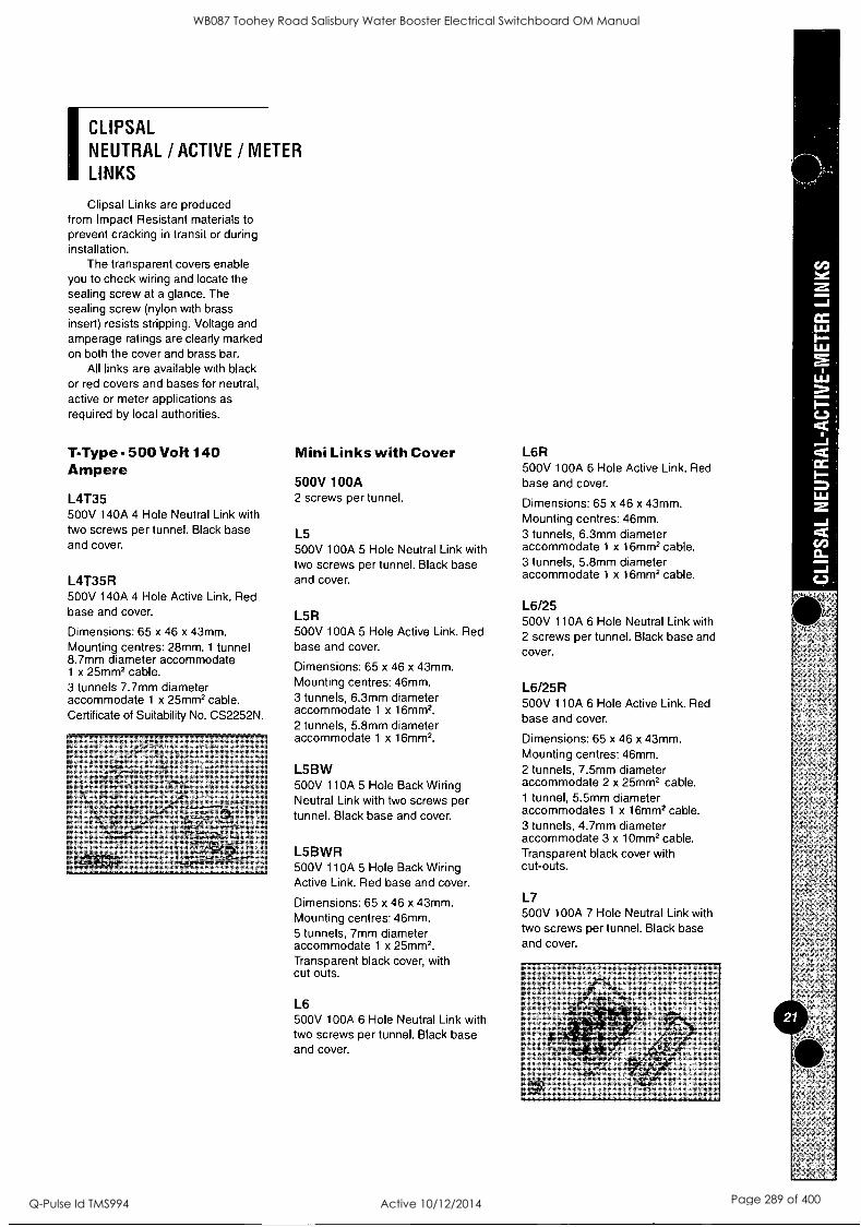
ICLIPSAL NEUTRAL /ACTIVE /METER LINKS
Clipsal Links are produced from Impact Resistant materials to prevent cracking in transit or during installation.
The transparent covers enable you to check wiring and locate the sealing screw at a glance. The sealing screw (nylon with brass insert) resists stripping. Voltage and amperage ratings are clearly marked on both the cover and brass bar.
All links are available with black or red covers and bases for neutral, active or meter applications as required by local authorities.
T-Type- 500 Volt 140 Ampere
L4T35 500V 140A 4 Hole Neutral Link with two screws per tunnel. Black base and cover.
L4T35R 500V 140A 4 Hole Active Link. Red base and cover.
Dimensions: 65 x 46 x 43mm. Mounting centres: 28mm. 1 tunnel 8.7mm diameter accommodate 1 x 25mm2 cable. 3 tunnels 7.7mm diameter accommodate 1 x 25mm2 cable. Certificate of Suitability No. CS2252N.
Mini Links with Cover
500V 100A 2 screws per tunnel.
L5 500V 100A 5 Hole Neutral Link with two screws per tunnel. Black base and cover.
L5R 500V 100A 5 Hole Active Link. Red base and cover.
Dimensions: 65 x 46 x 43mm. Mounting centres: 46mm. 3 tunnels, 6.3mm diameter accommodate 1 x 16mm2.
2 tunnels, 5.8mm diameter accommodate 1 x 16mm2.
L5BW 500V 110A 5 Hole Back Wiring Neutral Link with two screws per tunnel. Black base and cover.
L5BWR 500V 110A 5 Hole Back Wiring Active Link. Red base and cover.
Dimensions: 65 x 46 x 43mm. Mounting centres: 46mm. 5 tunnels, 7mm diameter accommodate 1 x 25mm2. Transparent black cover, with cut outs.
L6 500V 100A 6 Hole Neutral Link with two screws per tunnel. Black base and cover.
L6R 500V 100A 6 Hole Active Link. Red base and cover.
Dimensions: 65 x 46 x 43mm. Mounting centres: 46mm. 3 tunnels, 6.3mm diameter accommodate 1 x 16mm2 cable. 3 tunnels, 5.8mm diameter accommodate 1 x 16mm2 cable.
L6/25 500V 110A 6 Hole Neutral Link with 2 screws per tunnel. Black base and cover.
L6/25R 500V 110A 6 Hole Active Link. Red base and cover.
Dimensions: 65 x 46 x 43mm. Mounting centres: 46mm. 2 tunnels, 7.5mm diameter accommodate 2 x 25mm2 cable. 1 tunnel, 5.5mm diameter accommodates 1 x 16mm2 cable. 3 tunnels, 4.7mm diameter accommodate 3 x 10mm2 cable. Transparent black cover with cut-outs.
L7 500V 100A 7 Hole Neutral Link with two screws per tunnel. Black base and cover.
WB087 Toohey Road Salisbury Water Booster Electrical Switchboard OM Manual
Q-Pulse Id TMS994 Active 10/12/2014 Page 289 of 400

L7R 500V 100A 7 Hole Active Link. Red base and cover.
Dimensions: 65 x 46 x 43mm. Mounting centres: 46mm. 3 tunnels, 6.3mm diameter accommodate 1 x 16mm2 cable. 4 tunnels, 5.8mm diameter accommodate 1 x 16mm2 cable.
L7BW 500V 100A 7 Hole Back Wiring Neutral Link with two screws per tunnel. Black base and cover.
L7BWR 500V 100A 7 Hole Active Link. Red base and cover.
Dimensions: 65 x 46 x 43mm. Mounting centres: 46mm. 2 tunnels, 6.3mm diameter accommodate 1 x 16mm2 cables. 5 tunnels, 5.8mm diameter accommodate 1 x 16mm2 cables. Transparent black cover, with cut-outs.
L8 500V 100A 8 Hole Neutral Link with two screws per tunnel. Black base and cover.
Dimensions: 86 x 57 x 40mm. Mounting centres: 59 x 67mm. 3 tunnels, 6.3mm diameter accommodate 1 x 16mm2 cable. 5 tunnels, 5.8mm diameter accommodate 1 x 16mm2 cable. Transparent black cover with cut-outs.
L10 500V 100A 10 Hole Neutral Link with two screws per tunnel.
3 tunnels, 6.3mm diameter accommodate 1 x 16mm2 cable. 7 tunnels, 5.8mm diameter accommodate 1 x 16mm2 cable. Dimensions: 86 x 57 x 40mm.
L1OBW 500V 100A 10 Hole Back Wiring Neutral Link with two screws per tunnel.
Dimensions: 86 x 57 x 40mm.
L12 500V 100A 12 Hole Neutral Link with two screws per tunnel.
2 tunnels, 6.3mm diameter accommodate 1 x 16mm2 cable. 4 tunnels, 5.5mm diameter accommodate 1 x 16mm2 cable. 6 tunnels, 4.5mm diameter accommodate 1 x 10mm2 cable. Dimensions: 86 x 57 x 40mm.
L14 500V 100A 14 Hole Neutral Link with two screws in 8 tunnels and one screw in 6 tunnels.
2 tunnels, 6.3mm diameter accommodate 1 x 16mm2 cable. 6 tunnels, 5.5mm diameter accommodate 1 x 16mm2 cable. 6 tunnels, 4.5mm diameter accommodate 1 x 16mm2 cable. Dimensions: 86 x 57 x 40mm.
L16 500V 100A 16 Hole Neutral Link with two screws in 6 tunnels and one screw in 10 tunnels.
2 tunnels, 6.3mm diameter accommodate 1 x 16mm2 cable. 4 tunnels, 5.5mm diameter accommodate 1 x 16mm2 cable. 10 tunnels, 4.5mm diameter accommodate 1 x 10mm2 cable. Dimensions: 86 x 57 x 40mm.
L18 500V 100A 18 Hole Neutral Link with two screws in 6 tunnels and one screw in 12 tunnels.
2 tunnels, 6.3mm diameter accommodate 1 x 16mm2 cable. 4 tunnels, 5.5mm diameter accommodate 1 x 16mm2 cable. 12 tunnels, 4.5mm diameter accommodate 1 x 10mm2 cable. Dimensions: 86 x 57 x 40mm.
, -
Catalogue Number
4.7mm' for 10mm2
cable
6.3mm for 16mm2
cable
5.7mm for 16mm2
ceble;'
7mm for 25Mm2-
cable
L5 L5BW L6 16/25 L7
.
''L7BW
D
Catalogue 6.3mm 5.5mm 4.,5irlin Number fOr 16rnm2' for 16mm2 for 10mm2
cable cable 'cable
L8 L10 L1OBW L12 L14 L16 L18
10 12
WB087 Toohey Road Salisbury Water Booster Electrical Switchboard OM Manual
Q-Pulse Id TMS994 Active 10/12/2014 Page 290 of 400

J & P Richardson Industries Ply Ltd
10 Power Supply
POWERBOX - PB251-24CM-CCT - RTU Power Supply 24VDC 10A
SUPPLIED BY: POWERBOX AUSTRALIA Pty Ltd. 433 Logan Road, Stones Corner 4120, Queensland AUSTRALIA
PHONE: 3394 8372 FAX: 3394 8373
File: Swbd Manual Revision 0 Date:II/3/2010
WB087 Toohey Road Salisbury Water Booster Electrical Switchboard OM Manual
Q-Pulse Id TMS994 Active 10/12/2014 Page 291 of 400
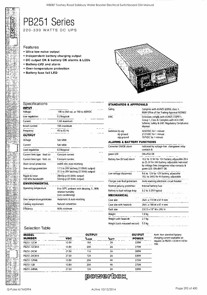
PB251 Series 220-330 WATTS DC UPS
Features Ultra-low noise output Independent battery charging output DC output OK & battery OK alarms & LEDs Battery-LVD and alarm Over-temperature protection Battery fuse fail LED
Specffications INPUT Voltage:
Line regulation:
Current:
Inrush current:
Frequency:
OUTPUT
Voltage
Current
190 to 264 vac, or 190 to 400VDC
0.2%typical
1.4A maximum
10A maximum .....
45 to 65 Hz
See table
See table
Load regulation
Current limit type - load cct
Current limit type - batt. cct
Short circuit protection
Over-voltage protection
Ripple & noise
100 MHz bandwidth
ENVIRONMENTAL
0.5%typical
Constant current
Constant current
Indefi nice, auto-resetting
17.5 to 20V latching (13.8Vdc output) 31.5 to 39V latching (27.6Vdc output)
28mVp-p (13.8Vdc output) 55mVp-p (27.6Vdc output)
Operating temperature
Over-temperature protection
0 to 70°C ambient with derating, 5...90% relative humidity (non-condensing)
Automatic & auto-resetting
Cooling requirement Natural convection
Efficiency
Selection Table
80% minimum
STANDARDS & APPROVALS
Safety
EMC
Complies with AS/NZS 60950, class 1,
NSW Office of Fair Trading Approval N20602
Emissions comply with AS/NZS CISPR11,
Group 1, Class B. Complies with ACA EMC
Scheme, Safety & EMC Regulatory Compliance
Marked
Isolation i/p-o/p i/p-ground o/p-ground
4242VDC for 1 minute 2121VDC for 1 minute 707VDC for 1 minute
- - ALARMS & BATTERY FUNCTIONS
Converter ON/OK alarm Indicated by voltage-free changeover relay
contacts &
green LED ON=PSU OK
Battery low (& fuse) alarm 10.2 to 12.6V for 12V battery, adjustable 20.4
to 25.2V for 24V battery, adjustable Indicated by voltage-free changeover relay contacts &
green LED: ON=BATT OK
Low voltage disconnect 9.6 to 12V for 12V battery, adjustable 19.2 to 24V2 for 4V battery, adjustable
Charger over-load protection Auto-resetting electronic circuit breaker
Reverse polarity protection
Battery to load voltage drop
MECHANICAL _ .
Case size
Case size with heatsink
Internal battery fuse
0.2 to. 0.25V typical
264 L x 172 W x 67 H mm
264 Lx 186W x 67 H mm
Rack size 232 D x 19" W x 2RU H
Weight 1.9 kg
Weight with heatsink 2.1 kg
Weight (rack mounted version) 5.5 kg
MODEL NUMBER PB251-12CM
OUTPUT OUTPUT Note: Non standard battery
VDC 13.8V
(LOAD 'BATT POWER charging current available on
16A 2A 220W request. ie PB251-12CM-H-10 for 10A.
PB251-12CM-H 13.8V 20A 2A 275W
PB251-24CM 27.6V 11A 2A 300W
PB251-24CM-H 27.6V 12A 2A 330W
PB251-12RML 13.8V 20A 4A 275W
PB251-128 13.8V 20A 4A 275W
PB251-24RML 27.6V 12A 2A 330W
powsuirinla,
WB087 Toohey Road Salisbury Water Booster Electrical Switchboard OM Manual
Q-Pulse Id TMS994 Active 10/12/2014 Page 292 of 400

PB251 Series 275-330 WATTS DC UPS
Technical Illustrations
P B2 51 t*CM (-H) M EC KA NICAL OUTLINE
0EAT5471::P825 I only
NOTES:
I. SlcultingCentreS: Suolie fix KI.Naitre S ardard IGSLBOInn) *Wray: 25 4N SOwn
2. 243 Orel ck,./Iholto on balern of bine. 5 o Mord 130* 11Ornrncer0 AtenTtle: 22I x 80 nmIcentres
3. AC Min: I OAC 111 s 1 2C603203awinla 4. Ot4p4 and tottery 4W P1.99121e Satyr Terninal Bbd
StitliLla fa up to 4 so rnrnnie.
5. APPTIP 611' PW994,1t ScreveTa-niraleb.d. watora opt. 1.514 nunwie
80 80 SurdNOVoNling N
100 221
2
a
i
I
254
Pi 1 .11
r.
...
Ni
26.7.:; ,.,-6
euSI
24 1
264
8
ffEcrromai
4
=
8
428.00
TOP 2,10
OUT PUT ill ATTER T ER VI N.1 TIONS
1S4 4
Wi
"7:7_(-1.trEd
ALARM TER /ANI.P.110,IS
01.4..K..20PK.K_V2
I 7 2
186 (P8251.04-11 Orly)
PB251-"RML & -12B MECHANICAL OUTLINE
0 0 El 0
Pomp sum,
0 PC OT
0 sPiii.mr Of.
0
.0 . k. .
0
0 0 ,01T4GT 10A0 (Mg NI BATTERY CORM 1 0 451 50 483.00
FRONT VIEW
11171:1111:11:11:11
C11150001:10
O
O
REAR VIEW (PB251, RML)
U
0
0 a
00 COO
0
o o o
o
0 4=1-
REAR VIEW (P8251 I 8)
NOTES:
I. 2RU x 19' rack enclosure per IEC 297
2. Mounting slots are suitable for M6 hardware.
3. Input connector is a 10A Class 11E( 60320 inlet_
4. 2 meter IEC mains cord with Australian plug A supplied with unit.
5. P8251 -128 alarm terminal is D8 2S lemak. 6. P8251.128 output and battery connector is Hirose pn. HS 28R -4A.
Mating connector is Hirose pn. HS 28P-9A (not suppEwth.
7. P8 251,3ML alarm and output terminals are M3.5 screws
suitable for ring or fork lugs up to 8 rum wide.
0
P8251,1ML ALARM AND OUTPUT TERMINALS
a I a I ra q3I e a NO E 1 NC INC C INC 1
DC OE BATT OK
ale ale a
j. 2_ u__! LOAD 3ATTERYl
PS251.128 OUTPUT & BATTERY CONNECTOR
PINI: OUTPUT
OUTPUT
P1113: BATTERY
PIN4: BATTERY
P8251 -128 ALARM CONNECTOR
Your dependable power partner - www.powerbox.com.au
PIN I: COMMON
0 PIN 6: DC OK (NC)
PIN 15: BATTERY OK (NO)
WB087 Toohey Road Salisbury Water Booster Electrical Switchboard OM Manual
Q-Pulse Id TMS994 Active 10/12/2014 Page 293 of 400

J & P Richardson Indusiries Pry Lid
1 I Power Quality
CRITEC - TDS 1100 SR 277 - Surge Diverter
CRITEC - TDF-10A-240V - Surge Reduction Filter RTU
SUPPLIED BY: ERICO 6 Chilvers Road, Thornleigh 2120, New South Wales AUSTRALIA
PHONE: (02) 9479 8500 FAX: (02) 9484 9188
File: Swbd Manual Revision 0 Date:11/3/2010
WB087 Toohey Road Salisbury Water Booster Electrical Switchboard OM Manual
Q-Pulse Id TMS994 Active 10/12/2014 Page 294 of 400

e . - 0 . I e -
D
D ::1 e
-
I
.
. -
I ' , e
:
I - a 0 0
0 " 0 .
0 , 0. - 0. 0
O ' . . tAt,1
CRITEC® TDS1100 TDS Surge Diverter
TDS1100 Series
Surges and voltage transients are a major cause of expensive electronic equipment failure and business disruption. Damage may result in the loss of capital outlays, such as computers and communications equipment, as well as consequential loss
of revenue and profits due to unscheduled system down-time.
The TDS1100 series of surge suppressors provide economical and reliable protection from voltage transients on power distribution systems. They are conveniently packaged for easy installation on 35 mm DIN rail within main distribution panelboards.
CRITEC® TD technology helps ensure reliable and continued operation during sustained and abnormal over-voltage events. Internal thermal disconnect devices
help ensure safe or at end-of-life. A visual indicator flag provides user-feedback in the event of such operation. As standard, the TDS1 100 provides a set of voltage-free contacts for remote signaling that maintenance is due.
The convenient plug-in module, and separate base design, facilitates replacement of a failed surge module without needing to undo installation wiring.
WB087 Toohey Road Salisbury Water Booster Electrical Switchboard OM Manual
Q-Pulse Id TMS994 Active 10/12/2014 Page 295 of 400

ESE CRITEC TDS1100 TDS Surge Diverter
TDS1100 Series
Model , TDS11002SR:150 120-150V-
TDS.14002SR240 220-240V-
TDS:11002SR277 240-277V-
TDS11002SR560 480-560V- Nominal Volt... L,,
Max. Cont. Opr-ating VlItage ' /c .
.170V-- : , 275V- 320V,-. 610V- Stand off Voltage 240V- 440V- 480V- 700V- Frequency 0 - 100Hz
Short Circuit Current Rating Isc 25kAIC Required Back-up Fti-e 125AgL 'if supply > 100A Technology Used TD with thermal disconnect ',Pititection , *
i.J._,I:A 8/20ps Maximum Dischaig,. .-_.:f ft'. IL illi......
Nominal Discharge Cthrentln 90kA 8/20ps I 40kA 8/20p j 40kA 8/20p 40kA 8/20ps Single mode (L-G, L-N or N-G) Protection Modes
Voltage Protection Level Up .© 3kA < 400V, < 700V < 800V <,1.6kV, Voltage Protection Level Up CO 20kA < 650 < 1000 < 1.1kV < 2kV
arms:an r i n motors., ,,,°,,,...-..
Li- h ,H1_ it / rE,I,
Change -c. E 250V max 1.5 mm (#14AWG) termina !
Status Indication
Physical;Data . ,.i Dimensions
ma:: 2 modules wide, 90 mm x 68 mm x 35 mm
Weight 0.24 kg- -:approx.
Enclosure DIN 43 880, UL94V-0 thermoplastic, IP 20 (NEMA-1)
Connection s35 mrn' (#2AWG)5olid s25 rnm2(#4AWG) stranded
Mounting 35 mm top hat DIN rail
Temperature 1C°C to +80°C (-40°F to +176°F, Humidity 0 to 90%
Approvals CE, IEC'' 61643-1, UL® 1449 Pending .
Surge Rated to Meet IEC 6164' I Class Land ll .. ANSI/IEEE 062A1-1991 Cat A,,Cat B, Cat C ,:--
Ordering Information
'DESCRIPTION .
TDS1102SR150 TDS Surge Diveriti, Ut. 170V, In 50kA, ImaA 100kA, ReiikAe
.TDS1102SR240 ;IDS SurgeDivertti, Lic 275V, In.40kA, Imax 100kA, Reiiiote
TDS Surge Diverter, Uc 320V, In 40kA, 'max 100kA, Remote TDS1102SR277
TDS:1102SR560 TDS -Surge Diverter, 11c 610V, In 40kA,,Imax,100kA, .Rernote,,
TDS150150M 150V Replacement Surge Module
TDS150240M.: , 240V Replacement airge,ModUle .. ,
TDS150277M 277V Replacement Surge Module
TDS150560M,- 560V ReplaCement Surge Module
Due to a policy of continual product development, specifications are subject to change without notice.
WARNING ERICO products shall be installed and used only as indicated in ERICO's product instruction sheets and training materials. Instruction sheets are available at www.erico.com and from your ERICO customer service representative. Improper installation, misuse, misapplication or other failure to completely follow ERICO's instructions and warnings may cause product malfunction, property damage. serious bodily injury and death.
IEC is a registered service mark of Independent Electrical Contractors, Inc.
UL is a registered trademark of The Underwriters Laboratories, Inc.
Copyright 02005 ERICO International Corporation. All rights reserved. CADDY. CADWELD, CRETEC, ERICO, ERITECH, ERIFLEX, and LENTON are registered trademarks of ERICO International Corporation.
www.erico.com
E5555 E 711.T06ENWW 004W86
WB087 Toohey Road Salisbury Water Booster Electrical Switchboard OM Manual
Q-Pulse Id TMS994 Active 10/12/2014 Page 296 of 400

J & P Richardson Industries Ph: Ltd
12 Accessories
CLIPSAL - 15/15+90B (SHROUD) - 1 Phase Outlet 15A
CLIPSAL - 15+449A+449AP - Laptop GPO
SUPPLIED BY: Clipsal Electrical Accessories 919 Nudgee Road, Nudgee 4014, Queensland AUSTRALIA
PHONE: (07) 267 8044 FAX: (07) 398 8753
MENNEKES - 3658 (3P+N+E 63A) -3 Phase N&E Appliance Inlet, Generator Power - c/w 40787 - Protective Cover
SUPPLIED BY: DSKH Australia Pty Ltd. Unit 4/5 Cessna Drive, Caboolture 4510, Queensland AUSTRALIA
PHONE: 1800 010 113
FAX: 1800 010 118
CORTEC - VPCI-110 OR 111 - Corrosion Inhibitor
SUPPLIED BY: CORTEC CORPORATION Pty Ltd. Unit 2/33 Gympie Way, Willetton 6155, Western Australia AUSTRALIA
PHONE: 9457 7796 FAX: 9457 7147
MOORE INDUSTRIES - ECT/4-20mA/4-20mA - Signal Isolators, 2 Wire Input Loop
SUPPLIED BY: MOORE INDUSTRIES PACIFIC Inc. 320 Boundary Road, Spring Hill 4000, Queensland AUSTRALIA
PHONE: 3230 5692 FAX: 3230 5656
ADAM - 6017- Remote I/O 8AI 2d0 Modbus/TCIP
SUPPLIED BY: Advantech Co. Ltd. Unit 1/14 Leighton Place, Hornsby 2077, New South Wales AUSTRALIA
PHONE: 1300 308 351
File: Swbd Manual Revision 0 Date:11/3/2010
WB087 Toohey Road Salisbury Water Booster Electrical Switchboard OM Manual
Q-Pulse Id TMS994 Active 10/12/2014 Page 297 of 400
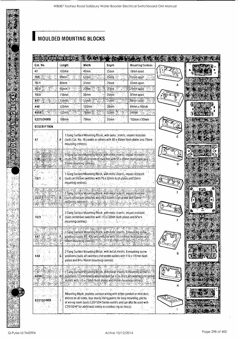
MOULDED MOUNTING BLOCKS
IVIOULDED'IVIOUNTING'BIOCKS .i';';'
Cat. No. Length Width Depth Mounting Centres
------------ /- A
i
B
- ' 1) f
47 103mm 49mm 25mm 78mm apart
708 99mm 52mm , 25mm 55mm apart , " -
.,,,,,,,f ,-,,, ':, ; .,....;_,
70/1 - 80mm - 37mm 25mm . , 55mm apart .-..-:
, 70/2 -- . - . -0Onlm..--, -- - 3imm' , - ° , 25mm ' . -
.
:70inm apart ,
70/0 '.' 116tOm -- 36mm . - 25mm . -97mm apart
447 ,''' - ; . 119thin - 52mm - '-'25mni - - ' ' 98mm apart
448 120mm --". 120mm ' , ' : 28mm -- 84mm x 46mm 0
t t,
'''1--
4:19A':, ' ' -122mm 78m m : ' ' 32mm , 84mm 4..
C2015D4M0
DESCRIPTION
198mm 79inm ' - . 25mm ' -155mm x 50mm, ' "---0.---... re'
-.4' +.1.----,
.....-,;.w.,....g... .. --- - 3013-- '
>_,gg ,
'11; ,.. ,,,. ---.' ;,.. ' ' ''.;.q. ' .- ' ,..
'..--. 4 gi,--... , ,,,,,,
- .- - , .
.- .! .
.
47 ' ' A
1Gang Surface Mounting Blodk, with metal inserts, impact resistant --
(suits Cat. No. 16 combs or others with 98 x 45mm flush plates and 78mm
mounting centres). '
.
.
7 OB :."=:; ,
- B
_ , - 2- , - . _ - . --r_ .- -, ,-- . - -
1 Gang Surface Mounting BloCk,with metal inserts, impact resistant o 1 ' ,
(suit's 31B, 32B and brands of switches with 95 x 48mm flush plates and ° : .
, 55mm mounting centres) . ., . . ,
1. ,: - S., ,.:`,:f? . '' '
--,-.
w- efli, " 4'1 ' ' '0 't'
' ' -IV 0
, ' il,..; 4, :::'-' '!'
7,0/1 s ' , C
1 Gang Surface Mounting Block, with metal inserts, impact resistant
(suits arChitFave switches with 76 x 32mm flush plates and 55mm '
. . -
mounting centres). ° . -- - - -
c. /, )1 am*
E
41111111-21-'7"
letw%
I _.'""; ' 4
G
i.,.:,
4:
: 7"'''
11-
- -
, -',;;. - ,,,,,, -.
Li" IA ,
',-- qt, _ 6 .._
°.,,,-
'
'.;
'17s1
to,
.;.
70/2 , -,
'
D
2 Gang Surface Mounting Block, with metal inserts, impact resistant .L ' '.
(suits architrave switches with 86"x 32mm flush plates and 70mm " - ,
mounting centres) , .- . °. -°:-
70/3 ' '
3 Gang Surface Mounting Block, with metal inserts, impact resistant . _.,
(suits architrave switches with 113 x 32mm flush plates and97mm
Mounting centres). .""- ' ' . "-, . : ' , - '° -
447 -,,f '
. ,-. , ,-, . F
"98mm
. .
, 1 Gang Surface Mounting Block, with metal inserts, 3 mounting screw ' ' °
positions (suits 40, 400 aid switches With 115 x 48mm flush plates and 1
mounting centres) ' . ' °: ,, -:'! °", ° ;,.- -.,,...; -, :
& Id ' . - .,.
, - ,, -
r e-,,- g, ... .
, g
r, ,,,, ... 1 k. ..; 448 , G
2 Gang Surface Mounting Block, with metal inserts, 8 mounting screw- "- .
positions (suits all switches and socket outlets with 115 x 115mm flush . ...
plates and 84'X46mm mounting centres). - ' , ' °--.-
i", ,.h ,i'449A',.* .. '
- ,.-..,,!1,
.449k4, H
,. t .. . ,_ ..,.
1 Gang Surface Mounting Block, with metal' inserts, 6 mounting screw ' : ,
positions, 12 combined'cableYconduit cut-outs (sUitsallswitchesand socket
Outlets with 115 x 73mm flush plates and 84mm mounting cerities)
.- I:--- __ f .
H
C2015D4MB,
..
; .
Mounting Block, enables surface wiring with either conduit or mini duct,
entries on all sides four sturdy fixing points for easy mounting plenty -
of wiring room (suits-C2015D4 Series outlets and can also be used with '
. C2015D4P for additional safety on conducting surfaces). - - .
.,......% kii L P* 2015D4MB ...,,,.1 -- .
N;;
WB087 Toohey Road Salisbury Water Booster Electrical Switchboard OM Manual
Q-Pulse Id TMS994 Active 10/12/2014 Page 298 of 400

CEE plugs and inlets 16A up to 125A Other voltages and frequencies available on request.
single part body, screw terminals
, IP 44
I ii,g4S,Ig:tref7-37'W' ithareZAT screwless with insulation displacement technique
L IP 44
single part body, screw terminals
64 IP 67
gr.reiatilrinaa with rubberised grip area,
for toughest conditions
..,:,....,.. ......,.......-,..,
_ii1O.Ni, AIM 16 247 16 250 16 256 32 259 32 262 32 268
;7400V : 248 249..fr' 251 252:i 257 4;35 260 261N
..,, 263 26.4: 269 43
16
16
16
32
32
32
947 948 - 951 - - Jpq 711 712 - 717 719-
34g
16
16
16
32
32
32
66 1P67
with screw terminals, central fixing, 61 mm 0 mounting hole
277 280 286 289 292
298
278
281
287
290
293
299
.Z.'4,411 288M! 29141ii
294'24
!Er:17'A 63
63.
63 125
-12'5
*1'25
331)
13201
13204 13210 13215 13217 13223
13202 13205 13211
13216 13218 13224
1320',..1 13206- 132-121
132.19g'i 132254
As IP 44
EalriinWitit`
As IP 44
51170174.7,i4ta1rp:TATT4
with hinged lid
16
1,6
32- 32
-32
As IP 44
Rargiknte.cilifat-"W,
IP 44
1.001-,Ci),-V474,1r1Pliku
6
400V4 919 924
_931r4 9-4
:16; 843 i
&16:
844
802
- 800 4
, 80.1,1"11
803
804,°;1
lk :16 ;5.7
32
461P 67
392 398 401
404 410
393 .
399 402
405 411
394'4'4
400 A .40314 4061
400V 810 812 -l'',-A3, - 837 813,'A - - 816 817 - 838 819cr::: - 82,1:L;
Mal inv-itTIM ;,',1.6. 825 826 ','
-1-,( - 839
00: - _ '
32 831 - 840 - -
400V
8271 -
834
split body, -1118XI
screw 16
terminals 16
32
its IP 44 32
ErtideArtaltiP 7'""-TZ-Tr7tE.
with rubberised grip area, for toughest conditions
A\ IP 44
Kid? with external
,Litglalart 147 148 149,7
151 15253
1.N 159 160
163 - .1,Pf
`..=+.1...
'E=1 13101 13102
13105 13111 03'
;125 1125' ., ;125
L=1-11(3 v,
strain relief ,, 16 3794 le 1 3807
3819 ;.:32j.34 3829
3839
itSJ 3851
EA,W1...,310.W 3 1410 1411
891
3312 3981 3980 - 3306 - 3646 : 3987.4 - 3424 32,66,.:i3
64 IP 67
13180.' 13112d
3796 3811
3823 3830 3844 3855
gRAIFOLIWeigrAtjs 111.,r100`.
with screw terminals, central fixing, 70 mm 0 mounting hole
As iP 44
offigftwiwiutiriwts
t."141, t6,
A\ IP 44
66 IP 67
Ar,...agtahrmtuntegagAsts .
As IP 44
64 IP 67
16
932
:97 935 938
939 - - 1
."j33.5
PEO4 ..1940 3,0 348';,"'M
16
:1153.
;1251 ft 25.
41.
331
334 340
343 346 352
1216
355
359
362 366
1,63
63
11-2 5
7,§1" 822
332 335 341
344 347 353
1107 356 360
363 367
1981 :
1984 410 168N,
=2:1 = illam,---"CW/7117
, .33 ',3:' 835 836 ,;- 6 44 - 3704 -3656.
= _ - 3658 11125.` El - 3665 - 3413 3583 '.'.*
125 - -- 1983
WB087 Toohey Road Salisbury Water Booster Electrical Switchboard OM Manual
Q-Pulse Id TMS994 Active 10/12/2014 Page 299 of 400

CEE connectors 16A up to 125A 63A: SoftCONTACT, 125A: TorsionSpringCONTACT
Other voltages and frequencies available on request.
single part body, screw mf terminals
1
509 .512 518 521
4 524
KIX .30v
th IP 44 530
onnectors Statairi",WgragreNTA screwless with tih.103M 11 V
insulation displacement technique
ne0tor,s,tiAreol?'i- single part body, screw terminals
66 IP 67
onnectorsigowgrireFLXWM. with rubberised grip area,
for toughest conditions
979
725
510 513 519 522 5
5 1
L Fit400VIN
400VIR
Ceo,Aneftp.,6,ITT:0-FOr77.-
split body, screw terminals
Pr ME r J EKES® Plugs for the world
,ee, IP 44
on et o s Rowe TOR,%tr
with rubberised grip area,
for toughest x. conditiohs
17
WINO m 4 v .m.230NrAttir400V.4 179
121
180 193
122 125
:?:531 14101 14102 14105 14111
ri'400V
661.114,411 rPe
767 31 539 540 542 543
414 00V17
548 551
554
560
549 552
555 561
54441
AN, IP 44
FC7c=t17.1;wer:ICiP with external strain relief
L'Ags 11' 1 ov 3859 3869 3879 3887 3896 3905
16 IP 67
ItAURPORM19011n3OV N4001/3
'Powe rTO P Xtra
14201
14204
14210 14215 14217 14223
14202 14205 14211
14216 14218 14224
ZE:
;44206 14212
16 IP 67
fAn ledrconnediarT1'?
4\ IP 44
23 r , 400V8 3860 3873 3883 3888 3899 3909
-3W ,13/3711
3861
PowerTOP Xtra is rubberised for the best grip. Improved impact resistance even under humid conditions. Highly heat-resistant contact carrier, frame terminals, cable gland and sealing, strain relief and protection against kinking. Enclosure with thread lock, two safety slides and plugs with nickel-plated contacts. Connectors 63A with SoftCONTACT and 125A with TorsionSpringCONTACT.
Sta rTO P®
with SafeCONTACT, screwless with insulation displacement technique, cable gland with seal-
ing, strain relief and protection against kinking, 2-part enclosure with thread and locking slider.
SoftCONTACT
TorsionSpringCONTACT
7
WB087 Toohey Road Salisbury Water Booster Electrical Switchboard OM Manual
Q-Pulse Id TMS994 Active 10/12/2014 Page 300 of 400

VpClim EMITTING SYSTEMS & ELECTRONIC PRODUCTS
CF)-1 1 0 Emitter, Patented
PRODUCT DESCRIPTION Cortec® VpCI -1 10 emitters are designed to provide corrosion protection for metal components and parts enclosed in non-ventilated control boxes, cabinets, or tool boxes up to 10 cubic feet (283 liters) in volume. The Vapor phase Corrosion Inhibitor (VpCI) emits vapors which form a molecular layer on internal metal surfaces to protect critical, complex, and expensive electronic equipment and other metal components during operation, shipping, or storage. VpCI-110 is a small foam emitter through which corrosion inhibitors are slowly released, and moisture and air pollutants can enter to be
absorbed. It provides long-term protection against corrosion even in the presence of adverse conditions including salt, moisture, airborne contaminants, H2S,
503, NH3, and others.
TYPICAL APPLICATIONS VpCI -1 10 can be effectively used for:
Operations, packaging, and storage electrical equipment Marine navigation and communication electronic equipment Aerospace electrical controls Electric motors
Switching equipment Fuse boxes and power boxes Medical equipment Electrical wireways and terminal boxes Scientific and measuring instruments Telecommunications equipment Remote electronics devices Tool-boxes, parts-storage, and other containers holding metals
FEATURES Economical to use Provides continuous protection for up to 24 months during operation and/or shutdown Effective in polluted and humid environments Does not interfere with electrical, optical, or mechanical performance Multimetal protection Quick and easy installation Non-toxic and safe to handle Compact and space-saving Free of nitrites, halogens, and phosphates No spraying, wiping, or dipping required Low VOC values Meets Southern California Clean Air Act and other National and local regulations Self-stick back Self-stick date label Accepted by FDA for corrosion protection of electrical and electronic equipment within food processing plants Canadian Food Inspection Agency acceptance for indirect food contact NSN 6850-01-456-2971 Conforms to MILI-22110C Federal Standard 101, Ardec Technical Report 99- 05, Picatinny Arsenal, New Jersey, USA
aniL e.= r e CORPORATION
erelaarrnemay San VpCIN MCfoThamoiaOces
© EC
WB087 Toohey Road Salisbury Water Booster Electrical Switchboard OM Manual
Q-Pulse Id TMS994 Active 10/12/2014 Page 301 of 400

METHOD OF APPLICATION VpCI -1 10 is extremely simple and convenient to install. The device should be installed at the earliest possible time. Simply select a space within enclosure where corrosion protection would be useful. Verify the surface is
clean and free of debris. Peel off the protective peel strip from the bottom of the device and attach it to the clean surface.
VpCI -1 10 emitters can be installed in any position. For volumes greater than 10 cubic feet (283 liters), use more than one device. If the enclosure is not totally airtight, or if the access doors are opened frequently, replace the Vp0-110 device more often than every 2 years. After periods of heavy maintenance replace the device. For additional protection spray the enclosure very lightly with ElectriCorr® VpCI-238 or VpCI -239.
SPECIFICATIONS Packaging
Protection
Standard Size
12 individually wrapped emitters per carton up to 10 ft3 (283 liters) per device Foam device with adhesive backing 2.5" D x 2" H
(6.4 cm D x 5 cm H)
FOR INDUSTRIAL USE ONLY
KEEP OUT OF REACH OF CHILDREN
KEEP CONTAINER TIGHTLY SEALED
NOT FOR INTERNAL CONSUMPTION
CONSULT MATERIAL SAFETY DATA SHEET FOR MORE INFORMATION
LIMITED WARRANTY All statements. technical inforrnolion end recommendations contained herein are based on tests Cod. Corpootion believes to be reliable, but the accuracy or completeness thereof is not guaranteed.
Cod. Corporation warrants Cod." products will be free from defects when shipped to customer. Con. Corporation's obligation undo this warronty shall be limited to replacement of product that proves to be defective. To obtain replocernent product under this warranty, the customer must notify Conec Corporation of the claimed defect within six months after shipment of product in customer. All freight charges for replacement products shall be paid by customer.
Con. Corporation shall have no liability for any injury, loss or domoge *rising out of the use of or the inability to use the produds.
BEFORE USING, USER SHALL DETERMINE THE SUITABILITY OF THE PRODUCT FOR ITS INTENDED USE, AND USER ASSUMES ALL RISK AND LIABILITY WHATSOEVER IN CONNECTION THEREWITH. No representation or recommendation not contained herein shall have any force or eff act unless in o written document signed by on officer of Corox Corporation.
THE FOREGOING WARRANTY IS EXCLUSIVE AND IN LIEU OF ALL OTHER WARRANTIES, EXPRESS, IMPLIED OR STATUTORY, INCLUDING WITHOUT LIMITATION ANY IMPLIED WARRANTY OF MERCHANTABILITY OR OF FITNESS FOR A PARTICULAR PURPOSE. IN NO CASE SHALL CORTEC CORPORATION BE UABLE FOR INCIDENTAL OR CONSEQUENTIAL DAMAGES.
Distributed by:
CORTEC CORPORATION
&At:mart* Sab itrerftrC, riereteie
4119 White Bear Parkway, St. Paul, MN 55110 USA Phone (651) 429-1100, Fax (651) 429-1122 Toll Free (800) 4-CORTEC, E-mail [email protected] Internet http: / /www.CortecVCl.com
printed on recycled paper 10 100% post consumer Revised 3/3/09. Cofer Corporation 2001-7009. All rights reserved. Supersedes: 5/31/06 EledriCorr° and Cortec ore trademarks of Con. Corporation
0 2009. Cotton Corporation. All Rights Reserved. Copying of these materials in any (Om without the writucn authorization of Conec Corporation is strictly prohibited.
WB087 Toohey Road Salisbury Water Booster Electrical Switchboard OM Manual
Q-Pulse Id TMS994 Active 10/12/2014 Page 302 of 400

ADAM6015 ADAM-6017 ADAM-6018
7-ch Isolated RTD Input Module 8-ch Isolated Analog Input Module with 2-ch DO
8-ch Isolated Thermocouple Input Module with 8-ch DO
rittit ri
WO& 6995 17C E FCC 1:11
Specifications Analog Input
Channels 7 (differential)
Input Impedance > 10 Mil Input Connections 2 or 3 wire
Input Type PI, Balco and Ni RTD
RID Types and Temperature Ranges
Pt 100 -50° C - 150° C
0° C - 100° C
0° C - 200° C
0° C - 400° C
-200° C - 200° C
P11000 -40° C - 160° C
Supports both IEC 60751 ITS90 (0.03851 ca/i2/ °C)
and JIS C 1604 (0.03916 f2/i2/°C) Balco 500 -30° C - 120° C
Ni 518 -80° C - 100° C
0° C - 100° C
Accuracy ± 0.1 % or better
Span Drift ± 25 ppm/° C
Zero Drift ± 6 pV/° C
Wire Burn-out Detection
Ordering Information ADAM-6015 7-eh Isolated RTD Input
Module
ADAM-6017 CE FCC
Specifications Analog Input
Channels 8 (differential)
Input Impedance > 10 Mf2 (voltage)
120 II (current)
mV, V, mA
t150 mV, ±500 mV, ±1 V
±5 V, ±10 V, 0-20 mA,
4-20 mA
±0.1% or Better (voltage)
±0.2% or Better (current)
±25 ppm/° C
±6 pVr C
Input Type
Input Range
Accuracy
Span Drift
Zero Drift
Digital Output
Channels 2
Open Collector to 30 V, 100 mA max. load
Power Dissipation 300 mW for each module
Ordering Information ADAM-6017 8-ch Isolated Al with 2-ch
DO Module
ADANI C E FCC
Specifications Analog Input
Channels
Input Impedance
Input Type
Thermocouple Type and Range:
J 0 - 760° C
K 0 - 1,370° C
T -100 - 400° C
E 0 - 1,000° C
R 500 - 1,750° C
S 500 - 1,750° C
B 500 - 1,800° C
8 (dillerenlial)
>10 Mf2
Thermocouple
Accuracy ±0.1% or Better
Span Drift ±25 ppm/° C
Zero Drift ±6 tiV/° C
Wire Burn-out Detection
Digital Output
Channels 8
Open Collector to 30 V, 100 mA max. load
Power Dissipation 300 mW for each module
Ordering Information ADAM-6018 8-ch Isolated
Thermocouple Input w/
8D0
Common Specifications General
LAN 10/100Base-T(X)
Power Consumption 2 W IQ 24 Voc
Connectors 1 x RJ-45 (LAN), Plug-in
screw terminal block (I/O
and power)
Watchdog System (1.6 second)
and Communication
(programmable)
Power Input 10 - 30 VDc
Supports Peer-to-Peer
Supports GCL
Supports Modbus/TCP, TCP/IP, UDP and
HTTP Protocols
Analog Input
Resolution 16 -bit Sampling Rate 10 sample/second (total)
CMR @ 50/60 Hz 90 dB
NMR @ 50/60 Hz 60 dB
Protection Over Voltage ±35 Voc
Protection Isolation Protection 2,000 Vec
Built-in TVS/ESD Protection
Power Reversal Protection
Environment
Operating -10 - 70° C
Temperature
Storage Temperature -20 - 80° C
Humidity (Operating) 20 - 95% RH
(non-condensing)
Humidity (Storage) 0 - 95% RH
(non-condensing)
711111111rW ̀ Onl'inelt Mafi a www.advantech.com/products
WB087 Toohey Road Salisbury Water Booster Electrical Switchboard OM Manual
Q-Pulse Id TMS994 Active 10/12/2014 Page 303 of 400

Ili MOORE INDUSTRIESWORLDWIDE
ECT-DIN
Description
to
costs.
Output-Loop (12-42Vdc)
Input-Loop (5.5VIp)
Line/Mains
Features
environments.
COUS 1.1.
E
206-710-09F
WB087 Toohey Road Salisbury Water Booster Electrical Switchboard OM Manual
Q-Pulse Id TMS994 Active 10/12/2014 Page 304 of 400

ECT-DIN
POWERED
+24V ISOLATOR
opt° isolation
RECEIVER 4-20mA TRANSMITTER
+ 4V
ISOLATED 4-20mA
IN
SUPPLY
XMITTER
maximum)
INTEGRATOR
PID
4-20mA
ECT
- PS
4-20mA
PS
DCS
XMITTER
+ 24V +
ECT DCS
isolefion
ps -4- 24V +
PS
WB087 Toohey Road Salisbury Water Booster Electrical Switchboard OM Manual
Q-Pulse Id TMS994 Active 10/12/2014 Page 305 of 400

ECT-DIN
Performance
Protection:
Performance (continued) Overrange:
Ambient Conditions
scale Burden:
0.02A
Limiting:
= ohms
Ambient Conditions
(Continued)
Adjustments Span:
ECT 4-20MA
0-10V ohms
12-42DC DIN
Powered) 0-150AC Isolator/Converter
0-5AAC supply
FLB2
WB087 Toohey Road Salisbury Water Booster Electrical Switchboard OM Manual
Q-Pulse Id TMS994 Active 10/12/2014 Page 306 of 400

ECT-DIN
NON-
XMITTER
NON- ISOLATED
mA
-IN
ECT RECEIVER
+OUT +
ISOLATED mA
' i
.
... ECT
.....
fmcarmunts I .
ECT °-2:-----
....
acoalosnlil ejnia
. ECT r-9.-----
- I. ICCel MILCIF;j
mi.
- -- ECT H._ H M.
1111"° ElHocusurFA
otmon
,,, ,', All ,. f.o ,. 0 0 0 : 0 0
ZED MOORE) INOUSTRIS
8
WB087 Toohey Road Salisbury Water Booster Electrical Switchboard OM Manual
Q-Pulse Id TMS994 Active 10/12/2014 Page 307 of 400

ECT-DIN -- Performance Accuracy:
Ripple:
Burden:
Performance (continued)
Limiting:
Ambient Conditions
Ambient Conditions
(Continued)
30V/m@20-1000MHz
Adjustments Trim:
Weight
. :.': -: L..7., -, - ,-
ECT
Powered) Isolator/ Converter
into 5.5VLP
WB087 Toohey Road Salisbury Water Booster Electrical Switchboard OM Manual
Q-Pulse Id TMS994 Active 10/12/2014 Page 308 of 400

ECT-DIN
IMPORTANT:
NON- ISOLATED
XMITTER
+IN
NON- ISOLATED
mAN
-IN
1
ECT
CT/PT OUT
A 4 sworn
CT/PT -OUT
POWER
NON- ISOLATED
\ XMITTER
+OUT ECT
isolason
RECEIVER -4II +TX
NON- ISOLATED
mAN
ISOLATED 4-20mA
+IN -OUT
NON- ISOLATED
XMITTER
A OUT RECEIVER
N
NON- ISOLATED
mAN
-IN
ECT
tf7-{
POWER
ISOLATED 4-20mA
A OUT
B OUT
-OUT
ISOLATED 4-20mA
RECEIVER 2
NON- ISOLATED
XMITTER
A IN OUT
NON- ISOLATED
mNV
+OUT RECEIVER
ISOLATED
isamion mA NON-
ISOLATED
XMITTER -OUT
POWER
A IN
8 W
NON- ISOLATED
mAN
ECT ISOLATED 4-20mA
A OUT
+OUT
DCS
POWER
OUT
ISOLATED 4-20mA
WB087 Toohey Road Salisbury Water Booster Electrical Switchboard OM Manual
Q-Pulse Id TMS994 Active 10/12/2014 Page 309 of 400

ECT-DIN
Performance Stability:
Isolation:
output
Ripple:
Performance (continued)
Ambient Conditions
Overrange:
maximum
Effect:
maximum
Ambient Conditions
(Continued)
Adjustments
Weight
10V/m@20-1000MHz
20-1000MHz
Zero:
ECT 4-Wire CHANNEL:
4-20MA CHANNEL: 4-20MA
24DC, 117AC,
DIN
Isolator/ 1-5V 0-10V 0-10V into
230AC, -TX
Converter
Externally-
CHANNELS:
CHANNELS: 2X1-5V minimum vibration
2X4-20MA 2X0-10V minimum
2x1-5V
available)
2X4-20MA -EP
housing)
WB087 Toohey Road Salisbury Water Booster Electrical Switchboard OM Manual
Q-Pulse Id TMS994 Active 10/12/2014 Page 310 of 400
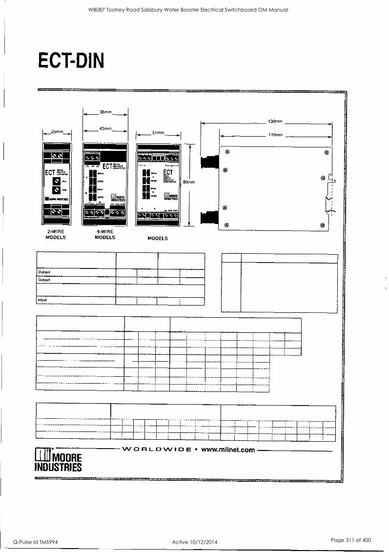
ECT-DIN
36mm
45mm
2-WIRE MODELS
4-WIRE MODELS
51mm
12110,10012121 L--
ECT =MAL =LOOM
IUMOORE
ACC ONO
01101401110211313
MODELS
80mm
130mm
110mm
Output
Output
Input
Rii °MOORE INDUSTRIES
WORLDWIDE www.miinet.com
...nuousw
WB087 Toohey Road Salisbury Water Booster Electrical Switchboard OM Manual
Q-Pulse Id TMS994 Active 10/12/2014 Page 311 of 400
J & P Richardson Industries Ply Ltd
13 Telemetry Equipment
LOGICA CMG -MD3311EAL/271D-0-7- Telemetry Unit
SUPPLIED BY: LOGICA 349 Coronation Drive, Milton 4064, Queensland AUSTRALIA
PHONE: 3327 5222 FAX: 3217 8955
POWER BOX - PBIH-24129-CC - Radio 24V / 13.8VDC Converter
SUPPLIED BY: POWERBOX AUSTRALIA Pty Ltd. 433 Logan Road, Stones Corner 4120, Queensland AUSTRALIA
PHONE: 3394 8372 FAX: 3394 8373
YUASA - UXHSO-12 - Batteries
SUPPLIED BY: YUASA Pty Ltd 37-65 Cobalt Street, Carole Park
4300, Queensland AUSTRALIA PHONE: 1300 364 877 FAX: 3361 6705
WAVECOM - GSM Modem
WAVECOM - GSM Antenna
SUPPLIED BY: InterCEL Pty Ltd 33 Glenvale Cres, Musgrave Victoria AUSTRALIA
PHONE: (03) 9239 2000 FAX: (03) 9561 2614
TRIO - DR900-07A02-DO - Radio
TRIO - YAGI ANTYAI3A809B - Antenna
SUPPLIED BY: TRIO DATACOM 41 Aster Avenue, Currum Downs 3201, Victoria AUSTRALIA
PHONE: 8773 0100
FAX: 9775 0606 POLYPHASER CORP. - IS-SONX-C2 - Radio Coax Surge Protection Unit
SUPPLIED BY: RF Industries 30 Rauberbs Road, Banyo 4014, Queensland AUSTRALIA
PHONE: (07) 3261 9400 FAX: (07) 3522 5505
File: Swbd Manual Revision 0 Date:11/3/2010
WB087 Toohey Road Salisbury Water Booster Electrical Switchboard OM Manual
Q-Pulse Id TMS994 Active 10/12/2014 Page 312 of 400

WB087 Toohey Road Salisbury Water Booster Electrical Switchboard OM Manual
Q-Pulse Id TMS994 Active 10/12/2014 Page 313 of 400

BATTERY CHARGERS
Yuasa Smart Shot Automatic 12V 1.5 Amp 5 Stage Battery Charger
Port No. YUA1201501
Yuasa's Automatic 12V 1.5 Amp battery charger incorporates superior 5 stage charging technology. This high power unit provides error proof operation to fully
charge sealed maintenance free and conventional lead acid batteries
Provides up to 16 volts to enable recovery of sulfated batteries during pre-qualification stage
28 day Charge Recycle - re-evaluates battery status for long term storage
Designed to prevent overcharging
AC power LED indicator
Charging and float mode LED display
Reverse polarity protection
Spark-free operation
Battery accessory leads and fused ring connectors included
Steel construction for durability
3 year limited warranty
Yuasa Smart Shot 900 Automatic 12V 900mA Battery Charger
Pori No. YUA I 200901
Yuasa's Automatic 900mA 12V battery charger is the industry's most powerful plug-in wall charger. Combining the latest technology and a host of user-friendly features, this compact, high-power unit provides optimum amperage return
and is designed to fully charge and maintain conventional and sealed maintenance free batteries.
Fully automatic three level charge cycle for effective charging
Reaches 14.4 volts peak, then automatically switches to float
Designed to prevent overcharging
AC power LED indicator
Charging and float mode LED display
Reverse polarity protection
Spark-free operation
Durable construction for longer life
Battery accessory leads and fused ring connectors included
12 ft. output cord
3 year limited warranty
ilnek4sit
WB087 Toohey Road Salisbury Water Booster Electrical Switchboard OM Manual
Q-Pulse Id TMS994 Active 10/12/2014 Page 314 of 400

PREFACE: A Practical Understanding of Lead Acid Batteries 2
SECTION ONE: Battery Basics and Safety About this book 3 About YUASA 3 Features and Benefits 4 The Lead Acid Battery 5-6 The Yuasa Battery Line 7 Yuasa's Conventional Battery 7 Yu Micron Battery 7 Yu Micron CX Battery 8 Sealed (MF) VRLA and High Performance Batteries 8 Battery Safety 9
SECTION TWO: Selecting and Installing a New Battery Selecting the Proper Battery 10 About Sensors 11
Battery Activation for Conventional and Yu Micron Types 12 Activating Standard Batteries 12
SECTION THREE: Inspecting, Testing and Charging The Discharge - Charge Cycle 13 Reasons for Self-discharge 14-15 Ampere-Hour and Cold Cranking Amps 16 Inspecting a Battery 16-17 Battery Testing Devices 17 Battery Testing 18 Chargers and Charging 19-20 Charging a New Standard Battery 20-21 Quick Charges 21
SECTION FOUR: Maintenance and Storage Monthly Maintenance for Conventional and Yu Micron Types 22 Storage 22 Sulfation and Freezing 22-23
SECTION FIVE: Sealed VRLA Batteries New Generation Battery Technology 24 Sealed VRLA Battery Construction 24 Features 24-25 How a Sealed VRLA Battery Differs from Conventional Types 25 Activation and Installation 26 To Activate a Sealed VRLA Battery 26-27 Measuring Voltage 28 Discharge Characteristics 29 Self-discharge 30 Choosing a Charger 30 Charging a Newly Activated Sealed VRLA Battery 31
Routine Charging 32 Charging Instructions for Sealed VRLA Batteries with Voltage of 11.5 or Less 33 Routine Maintenance for Sealed VRLA Batteries 33
GLOSSARY 34-40
WB087 Toohey Road Salisbury Water Booster Electrical Switchboard OM Manual
Q-Pulse Id TMS994 Active 10/12/2014 Page 315 of 400

D
A Practical Understanding of Lead Acid Batteries
Lead acid batteries are relatively simple in design. Dissimilar metal plates are immersed in an electrolyte solution consisting of sulfuric acid and water. These are then insulated from each other with a permeable, non-conductive material, which allows the transfer of ions. The transfer of ions occurs during the discharge and recharge of the battery. Also occurring is the change in specific gravity or density of the electrolyte. During the discharge period, sulfuric acid is drawn from the electrolyte into the pores of the plates. This reduces the specific gravity of the electrolyte and increases the concentration of water. During the recharge, this action is reversed and the sulfuric acid is driven from the plates,
back into the electrolyte, increasing the specific gravity.
During the discharge, lead sulfate is being formed on the battery plates. Although this is the normal activity within the battery during discharge, a timely recharge is
required to drive out the sulfuric acid into the electrolyte. Without this recharge, the lead sulfate will continue to
develop and become difficult if not impossible to breakdown during recharge. Once this advanced sulfation develops, permanent capacity loss or total failure of the battery is likely. Besides the sulfation concerns, many other detrimental actions are taking place inside the battery while in a discharged condition.
The corrosive effect on the lead plates and connections within the battery is greatly increased due to the reduced specific gravity of the electrolyte. The corrosion of the
plates will typically result in a gradual reduction in performance followed by battery failure. The corrosion associated with the inter cell connectors and the connecting welds will in many instances result in a sudden battery failure. The corroded connector may have sufficient integrity to support low drain accessories such as lights and instruments, but lack the necessary strength to provide the high discharge current required to start the vehicle. This corrosive effect can also dissolve the lead into solution, which in turn may compromise the plate insulators and result in micro shorts. Another condition that frequently occurs in a discharged battery is freezing. In a deeply discharged battery, the electrolyte has a
reduced specific gravity and becomes a higher percentage of water than sulfuric acid. During this condition, the battery may freeze at temperatures as high as 32°F. The electrolyte in a fully charged battery will not freeze in temperatures down to -65°F.
Deep discharge can be created by a multitude of conditions, but the predominant reason is neglect. During long periods of storage, the battery state of charge must be checked and maintained per the battery manufacturers recommendations. Other conditions that can drain the battery are inoperative or inadequate charging systems on vehicles, parasitic or key off drains, loose or dirty terminal connections, etc. Although many of these conditions can be corrected, often the problems you cannot correct may be overcome by a periodic charging schedule. You can establish a routine by which you check and charge your battery or choose to permanently attach a Yuasa Automatic Charger while the vehicle is not in use.
When charging your battery, always refer to the instructions on both the battery and the charger. While maintaining your battery at a full state of charge will insure optimum life, overcharging may significantly reduce it. With a conventional type battery that offers access to the cell compartments, the periodic addition of distilled water may be required. Water loss is normal in
these batteries through the process of electrolysis and evaporation. Low electrolyte levels that expose the lead plates to the air will result in permanent damage to the
battery. Maintain the electrolyte levels above the minimum fill lines on the battery and at or below the maximum line. A sealed VRLA (Valve Regulated Lead Acid) battery should be maintained with the same care as a conventional type battery with the exception of the addition of distilled water. Sealed VRLA batteries have a predetermined quantity of electrolyte added at the factory or in the field using the acid bottle specified for the battery. Once activated, the battery is permanently sealed and must never be opened.
A little bit of care and understanding of how your battery operates and is maintained will insure maximum service life.
WB087 Toohey Road Salisbury Water Booster Electrical Switchboard OM Manual
Q-Pulse Id TMS994 Active 10/12/2014 Page 316 of 400

to)
Battery Basics and Safety
About this book ,,..
If you're looking-far more than eve6,daj? information about batteries, read on . .
Maybe you're a retailer, the expert. whose, battery knowledge and recommendations' guide ..
customers every day -Perhaps you are a technician or dealer - the person vehicle
,. owners turn; ta 'with questions Or maAie 'you're-an' enthusiast set on "knowing everything ' , ..
bike . _about your bike and how to keep it running.
Whatever your reason for wanting Jo boost your' battery IQ, YUASA is Pleased to provide ,.. .. , , , ..
this copy of the ultimate battery book .
It's in=de$tli inforMaticiii: haw 4,-citte-rieSork, maintenance aiia;i'ri.-Stallattoil tips and how
to get maximum power and life from your battery We'll- talk aboat;chargers and:tester's' Ok course; we'll also fill you in On the-complete line of YUASA.batte chargers and accessories
About YUASA
The first thing you need to know about batteries is YUASA -You' might say that when it Comes
to,powersportsVehicle batteries, we wrotethe-bookl We're the largest manufacturer and distributor
of ,small engine starting 'batteries in North America:
if you purchased a motorcycle, snowmobile; personal watercraft, ATV, riding mower orgar'clen
tractor manufactured in the U S, chances are the battery that starts it was made by Yuasa, In
fact, our batteries are original equipment in.just about every major make of powersports vehicles
If you've bought a replacement battery for your powersports vehicle, most likely it was made by
Yuasa Altogether, we manufacture approximately three million batteries a year for. small
engine starting applications at our Reading, Pennsylvania plant.
WB087 Toohey Road Salisbury Water Booster Electrical Switchboard OM Manual
Q-Pulse Id TMS994 Active 10/12/2014 Page 317 of 400

0
tit
Battery Basics and Safety
Features and Benefits Component ,-:' Features Benefits
Cast Grid Special Grid Design Severe vibration resistance & improved conductivity
Active Material Proprietary Formulation Reduced shedding, maximum utilization, & long service life
Pasted Plates Specified Thickness & Weight
Ensures vibration resistance through precise compression & proper service life through specified active material balance
Dried-Charged Plates
Tank Formed & Dried Plates
Properly dried plates in a sealed battery have a virtually limitless shelf-life, while
still retaining 70-80% state of charge when filled with acid
Top Lead Connections
Through-Partition-Construction, Large Straps
Shorter current path for increased electrical conductivity & higher starting
currents, heavier parts for maximum durability
Case-Cover Seal
Thermal Bonded Plastic Air tight seal to prevent air ingress & acid seepage
Terminal- Cover Seal
Patented Poly-Seal Terminal
Eliminates acid seepage, reduces corrosion, & extends battery life
Case & Cover Polypropylene Superior resistance to gasoline & oil, impact resistant in extreme
weather conditions
Additive Sulfate Stop (Some models)
Sulfate stop added to reduce the solubility of lead into the acid, which then reduces
battery sulfation potential
Yu Micron
Separator Leaf Separator Polyethylene leaf with glass mat sheet bonded for compression to withstand
severe vibration conditions
YTX
Separator Absorbed Glass Mat Absorbs acid while creating cell compression for extreme vibration resistance
Top Lead Alloy Calcium Alloy Increased weld strength & severe vibration resistance
Vent System Valve & Flame Arrestor Valve relieves excess pressure to prevent bursting, flame arrestor frit prevents
internal combustion
High PerfOrtnance Maintenance Free
Grid System Computer-Designed Radial Grids
Increased conductivity for higher starting wattage, increased vibration resistance
Separator Puncture Resistant AGM Material
High puncture resistant separator for increased service in high vibration applications
WB087 Toohey Road Salisbury Water Booster Electrical Switchboard OM Manual
Q-Pulse Id TMS994 Active 10/12/2014 Page 318 of 400

z
UI
Battery Basics and Safety
The Lead Acid Battery Let's look first at battery basics: what battery is and how it works.
a Starting your vehicle depends on a battery.
Lead acid batteries are used as a power source for vehicles that demand a constant and uninterruptible source of energy. Just about every vehicle today does. For example, street motorcycles need lights that operate when the engine isn't running. They get it from the battery. Accessories such as clocks and alarms are battery-driven.
Technically speaking, the battery is an electrochemi- cal device that converts chemical energy to electrical energy. The first thing you notice inside a battery is
the cells. Each cell has about two volts (actually, 2.12 to 2.2 volts, measured on a DC scale). A 6- volt battery will have three cells. A 12-volt battery, six cells.
Standard Features HEAT SEALED CASE TO COVER protects against seepage and
corrosion - bonded unit gives extra strength.
PATENTED SEALED POST prevents acid
seepage, reduces
corrosion - extends
battery life.
THRU-PARTITION CONSTRUCTION provides shorter current path with less resistance than
"over the partition" construction - you get more
cranking power when you need it!
POLYPROPYLENE COVER AND CONTAINER gives greater resistance to gas and oil - and impact in extreme weather conditions!
SPECIAL SEPARATOR provides high cranking power.
SPECIAL ACTIVE MATERIAL is compounded to
withstand vibration, prolong battery life
and dependability.
SPECIAL GRID DESIGN withstands severe vibration, assures maximum conductivity.
HEAVY DUTY GLASS MAT resists shedding of active material even
under severe vibration.
WB087 Toohey Road Salisbury Water Booster Electrical Switchboard OM Manual
Q-Pulse Id TMS994 Active 10/12/2014 Page 319 of 400

V eao
Battery Basics and Safety
The cells consist of lead plates that are positive and negative charged. Inside the cell they're stacked alter- nately - negative, positive, negative. Insulators or sep-
arators - usually fiberglass or treated paper - are placed between the plates to prevent contact. Cranking current increases as the plate surface area in the bat- tery increases - the more plates in a cell, or the larger the plates, the greater the current capacity (or flow of electricity). Typically, capacity increases as the amount of active material increases in the battery.
The alternate plates in each cell are connected at the
top into two groups, one positive and one negative. Each cell's groups of plates are then connected in series - positive to negative - to those in the next cell.
Basically, that's the internal hardware. Next, a solution of sulfuric acid and distilled water - the electrolyte - is
added. And the action starts. A reaction between the lead plates and the electrolyte sets off a chemical change. This in turn creates the electrical charge in a
battery.
That's the process, in a nutshell, that makes every battery work. So, are all batteries the same?
Obviously not. Actually, there can be a number of differ- ences, and they go far beyond things like box size or terminal location. That's true for different brands, as well as for different lines produced by the same manufacturer. Take two types of YUASA batteries, for example: our Conventional and Yu Micron batteries.
What's different? First there's cranking power: YuMicron has more because YuMicron batteries boost plate surface area with thin, high-tech separators that make room for two extra plates in each cell. YuMicron also has a special intercell connector that minimizes resistance to further maximize power. It has a special glass mat that resists
vibration damage.
Just for the record, let's state how the Conventional and YuMicron batteries aren't different: they're both lead-anti- mony batteries, for openers (other batteries in YUASA's line, including the YuMicron CX, use lead-calcium tech- nology). They have certain things in common that we think should be part of every battery: like sealed posts to resist corrosion, tough polypropylene covers and contain- ers, and heat sealed construction for a strong, bonded unit. And both share certain design features, like special separators and through-partition construction.
Now, does all this mean YuMicron is automatically a bet- ter choice than the conventional battery? Of course not.
It all depends on what you need to do. Some of the YuMicron features might not be a big deal to a lawn trac- tor owner, but a feature like our unique cover design that minimizes electrolyte spillage is going to be really important to the guy on a watersport vehicle or ATV.
Each YUASA line of batteries has its unique features that account for differences in price and differences in
performance - and that's what makes it the right battery for a particular vehicle. Buy what you need. Don't pay for what you don't need.
POINTS TO REMEMBER
A battery converts chemical energy ̀ to electrical energy.
71 Each cell has approximately 2,volts:3 cells for a 6-volt battery, 6 cells for.'a 12.volt battery.
1 Inside each cell are electrically charged positive and negative lead plates, isolated from each other by separators. Chemical action between plates and electrolyte creates an electrical charge.
Current is the flow of electricity..
WB087 Toohey Road Salisbury Water Booster Electrical Switchboard OM Manual
Q-Pulse Id TMS994 Active 10/12/2014 Page 320 of 400

z
f.0 Battery Basics and Safety
The YUASA battery line... The right battery for the right job - that's where it all starts. YUASA's comprehensive line has the right small engine starting battery... whatever the vehicle, however tough the application.
YUASA's Conventional Battery
\.:11 ,pia -14
YuMicron
MAIK is u""
yiyiAL,CL2 pAit1C t);9-L
The industry standard for motorcycles, snowmobiles and riding mowers, our Conventional Battery is anything but conventional. This workhorse is engineered to protect against seepage and corro- sion... withstand vibration... and deliver high cranking power, even when the weather's dealing its worst. It's the rugged, reliable and dependable battery that customers are looking for!
These features are built into our conventional manifold vented battery... and every battery in the YUASA line:
* Patented separators provide high cranking power * Through-partition construction delivers
maximum power Unique sealed posts resist corrosion - for longer battery life Polypropylene cover and container resist damage from gas, oil, impact Heat-sealed, bonded unit construction protects against seepage and corrosion
Personal watercraft, snowmobiles and ATVs make special demands - and YUASA's YuMicron Battery meets them head-on. The high-tech, power-boosting design also makes YuMicron ideal for accessory-laden touring bikes and modified machines.
Heavy duty glass mat resists vibration damage Special thin YuMicron Separator packs in extra plates, delivers up to 30% more cranking power than conventional types Through-the-wall intercell connector minimizes internal resistance, maximizes power
O Sulfate Stop curbs plate sulfation - and provides longer life
WB087 Toohey Road Salisbury Water Booster Electrical Switchboard OM Manual
Q-Pulse Id TMS994 Active 10/12/2014 Page 321 of 400

Battery Basics and Safety
Yu Micron CX
For top power, less maintenance and longer life, Yu Micron CX is the battery of choice. The first motorcycle battery built on lead-calcium technology, Yu Micron CX is specially designed for today's big, complex machines, where higher cranking power is a must. It delivers all the
features of the standard Yu Micron - plus...
Unique CX design for higher cold cranking amps Lead-calcium technology reduces water loss - and servicing - by 66% compared to lead antimony And, CX substantially reduces self-discharge - for longer time between charges
Sealed (MF) VRLA and High Performance
Sealed (MF) VRLA (Valve Regulated Lead Acid) means a battery that's perfect for people who have better things to do than battery maintenance! Our permanently sealed VRLA battery never needs refilling; however, it still needs periodic charging. Ideal for motorcycles, scooters, ATVs, riding mowers and personal watercraft.
Spill-proof design means virtually no possibility of leaks
Advanced lead-calcium technology pumps up
starting power Sulfation retardant dramatically reduces battery-killing plate sulfation And, sealed VRLA batteries hold voltage longer and need less charging in standby or storage mode High Performance version provides greater cranking power with 12 extra plates per battery
WB087 Toohey Road Salisbury Water Booster Electrical Switchboard OM Manual
Q-Pulse Id TMS994 Active 10/12/2014 Page 322 of 400

0
Ef)
Battery Basics and Safety
Battery Safety As with anything, with batteries you have to know what you're doing. Batteries can be dangerous. But they don't have to be if some simple safety precautions are followed.
Basically, working with batteries poses two hazards: potentially explosive gases that are given off during charging, and sulfuric acid, which is very corrosive.
Here's an 8-point list that'll help keep those hazards under control:
1. ABSOLUTELY NO SMOKING, SPARKS OR OPEN FLAMES AROUND BATTERIES. Batteries can produce hydrogen and oxygen; if they ignite the battery can rupture.
2. On conventional batteries, loosen vent caps when charging and ventilate the entire charging area. A build-up of hydrogen and oxygen levels in the battery - or in the room where it's being charged - can create a hazard.
3. If a battery feels hot to the touch during charging, stop charging and allow it to cool before resuming. Heat damages the plates, and a battery that's too hot can rupture.
4. Never put the red sealing cap back on the battery once you take it off. If you do, gases trapped inside can explode. Make sure the vent tube isn't kinked or blocked, for the same reason.
5. Properly connect charger to battery: positive to positive, negative to negative. Unplug the charger or turn it off before you disconnect the leads; that cuts down on the chance of sparks.
6. Always wear eye protection, protective gloves and protective clothing.
7. Clean up acid spills immediately, using a water and baking soda solution to neutralize (1 lb. baking soda in 1 gal. water).
8. Make sure acid container is clearly marked and the work area is well lighted.
If sulfuric acid is swallowed or splashed in the eyes, take immediate action. While the diluted sulfuric acid used as electrolyte can burn the skin, this type of injury is generally less serious. Sulfuric acid in the eyes can cause blindness. Serious internal injuries or death can result from ingesting sul- furic acid.
Antidotes: External - flush with water. Internal - drink large quantities of milk or water,
followed by milk of magnesia, vegetable oil or beaten eggs. Call a poison control center or doctor immediately.
Eyes - flush for several minutes with water, get immediate medical attention.
POINTS TO4EMEMBER- ,
:73 Ventilate battery',, charging area. Charging gives off gases - no smoking, sparks or flames. Safety glasses or face shields, protect against eye damage.
Li Acid swallowed or in the eyes requires immediate antidotes and medical care. All, safety considerations are important... review them frequently.
WB087 Toohey Road Salisbury Water Booster Electrical Switchboard OM Manual
Q-Pulse Id TMS994 Active 10/12/2014 Page 323 of 400

Selecting and Installing a (u) New Battery Selecting the Proper Battery Selecting the right battery is an important decision. You'd be amazed how often the "problem" with a battery is that it's the wrong one for the application.
To make doubly sure you're on track, you'll need one of two things - either the latest YUASA Battery Specifications and Applications book, or the original equipment (OE) microfiche. Of course, you can always go to the old battery you're replacing. The trick, though, is to make sure it's the original. Otherwise, you may be simply repeating the same problem that caused the bat- tery to need replacing.
OK, let's say you're replacing the battery on an '81 Kawasaki -a KZ1000-C Police, 1000cc.
Referring to the YUASA Battery Specifications and Applications book, you first look under the Kawasaki listing. Then find the right engine size - 1000cc, where you find the KZ1000-C Police. You're looking for an '81, so the place to be is '80 to '81. The chart on this page shows what it looks like.
If this were a sensor-equipped battery - which it isn't - the applications book would mark it with a footnote (t). That tells you to order it with a sensor.
What's the right battery? You'll see there are three of them: a High Performance Maintenance Free YTX2OHL-BS, a
Maintenance Free VRLA YTX20L-BS, and a YuMicron YB16L-B battery. Any of these will do fine. If your machine has increased compression modifications to the engine, for example, you might want the additional
POINTS TO REMEMBER.
cranking power. And if the added benefit of never adding water again appeals to you, go with the High Performance Maintenance Free or the Maintenance Free
VRLA style batteries.
A few words of advice: always double-check that you have the right battery for your application before you charge and install it. If you have any questions, check out our website at www.yuasabatteries.com or contact us toll free at 1-866-431-4784.
Warning: In the event you want to upgrade to a sealed VRLA battery, please ensure you have the proper charging voltage. Always refer to your service manual.
IV' L...... II
cc Model Year
" ',...
TORCY
petiolifgrnhance
Maintenance
Free
- W.. ,11k 4., ,I. , r
- -
Maintenance
Free Yukon VRLA
:
Conventional
KAWASAKI
1000 121000-P Poke '02,03
1,21ocio-F, Police 12-'01
YTX28HL-8S
YTX2OHL-BS ' YfX201 8S
Y1X201.8S ' -
YI318L A
Y8161.8-
-
121000C Poke '80-'81 YTX2OHL-8S * YTX201-8 ' 02100 -C Police, 21-R 78-79
121000. LTD 77-'80
1Q1000-F ST, Shaft 79-10
071000-6 Classic '80
h21000. LTD, CSR '81-13
1Q1000-R Replica '82283
Z1000 D3-'04
YTX14AHL-BS
YTX14AHL BS
YWOHL-8S ' YTX14A141-8S
YTX28HL-138*
YTX20HL-8S *
YTY201.8S "
YIVOL 8S ' Y1X201 8S ' YT09-8S
Y8141 A2
Y8141-112
Y816L 8
Y8141-A2
Y818L A
YB18L -A
-
-
-
-
-
.0 Check current Applications Book or microfiche for right replacement battery.
O There may be two or more "right" batteries - choose by performance needs.
O Double check numbers before activation and installation.
WB087 Toohey Road Salisbury Water Booster Electrical Switchboard OM Manual
Q-Pulse Id TMS994 Active 10/12/2014 Page 324 of 400

2 U sea
Selecting and Installing a New Battery
About Sensors Many of today's motorcycles use batteries equipped with sensors. They're either built in the battery, or packed with it.
A sensor is a "low fuel" warning light. It tells you when you're getting low - in this case, on electrolyte. The sensor causes a warning light to flash, signaling that it's time to add water to the battery. The cutaway views below show what a sensor looks like.
Sensors are sort of particular: they don't go with just any battery. Which means it's important to replace the old battery and sensor with the correct YUASA sensor battery listed in the applications book. So, sensor rule
one is this: replace both battery and sensor at the same time.
"But the sensor's original equipment," you say. Doesn't matter. Being OE doesn't mean it 's OK in another man- ufacturer's battery. In fact, OE sensor plugs vary consid- erably in length, size and diameter. A plug that's too long can short out a battery and mess up the electrical system. If the plug's short, the warning light will flash way too early.
Note, too, that even YUASA's sensor batteries are not interchangeable; they have different vent locations, sen- sor wire lengths and diameter of cylinder connectors.
CUT-AWAY VIEW OF SENSOR,
0
COVER ..
MAX
ACID LEVEL
MIN "tlE- LEAD
'POINTS TO REMEMBER
Replace battery and sensor at same time. 71 Original, equipment sensor isn't "OK" for a new battery.
Sensor batteries and sensors are not interchangeable - check APplications Book.
WB087 Toohey Road Salisbury Water Booster Electrical Switchboard OM Manual
Q-Pulse Id TMS994 Active 10/12/2014 Page 325 of 400

BM tft
Selecting and Installing a New Battery
Battery Activation for Conventional and Yu Micron Types Sealed at the factory, a new YUASA battery has an indefinite shelf life as long as it remains sealed, with the red cap in place, and is stored at room tempera- ture. Once it's unsealed, a battery should be activated, charged and installed. The plates of an unsealed, uncharged battery begin to oxidize. That makes it more difficult to charge later. (We talk more about sulfation later in this book.) And if it's charged and sits
around, it starts to discharge and sulfate; how fast depends on temperature.
Here are the steps for activating most batteries, including YUASA's Conventional, Yu Micron, Yu Micron CX. (Sealed VRLA - YT or YI - batteries are activated differently, see page 26.)
Activating Standard Batteries
1. Right before adding electrolyte, remove filling plugs. Also remove the sealing tube - the red
cap - and throw it away. (Putting this cap back on after the battery's filled with acid can cause an explosion.)
2. Place battery on a
level surface. Fill battery with electrolyte (a sulfuric acid dilution with a specific
gravity of 1.265). Do not use water or any other liquid to activate.
Electrolyte should be between 60°F and 86°F before filling. Fill to UPPER LEVEL as indicated on battery.
NOTE: Never activate a battery on the vehicle. Electrolyte spillage can cause damage.
3. Let battery stand for at least 30 minutes. Move or gently tap the battery so that any air bubbles between the plates will be expelled. If acid level has
fallen, refill with acid to upper level.
4. A battery must be completely charged before installation. Charge for three to five hours at the current equivalent of 1/10 of its rated capacity found in the
Yuasa Applications Book.
YUMICRON Battery Specifications
BATTERY
TYPE
CAPACITY
AH
(10H-R)
DIMENSIONS - INCHES
(i 1/16 IN)
YB2.5L-C 2.5 3 3/16 23/4 4 1/8
YB2.5L-C-1 2.5 3 3/16 23/4 4 1/8
Rated YB3L-A 3 3 7/8 2 1/4 4 3/8
Capacity YB3L-B 3 3 7/8 21/4 4 3/8
YB4L-A 4 4 3/4 23/4 3 5/8
YB4L-B 4 4 3/4 2 3/4 3 5/8
YB5L-B 5 4 3/4 2 3/8 51/8
5. During charging, batteries can spit electrolyte out the open vent. Take care to loosely refit vent caps.
6. Check during initial charging to see
if electrolyte level has
fallen, and if so, fill with acid to the UPPER LEVEL. After adding, charge for another hour at some
rate as above to mix water and acid. Note: this is the last time electrolyte should be added, but distilled water should be added as required.
7. When charging's done, replace plugs firmly. Do not apply excessive pressure. Finger tighten only. Do not over-tighten.
8. Wash off spilled acid with water and baking soda solution, paying particular attention that any acid is
washed off the terminals. Dry the battery case.
WB087 Toohey Road Salisbury Water Booster Electrical Switchboard OM Manual
Q-Pulse Id TMS994 Active 10/12/2014 Page 326 of 400
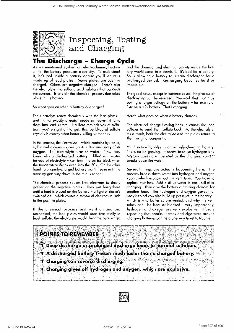
Inspecting, Testing and Charging
441
The Discharge - Charge Cycle As we mentioned earlier, an electrochemical action within the battery produces electricity. To understand it, let's look inside a battery again: you'll see cells made up of lead plates. Some plates are positive charged. Others are negative charged. There's also the electrolyte - a sulfuric acid solution that conducts the current. It sets off the chemical process that takes place in the battery.
So what goes on when a battery discharges?
The electrolyte reacts chemically with the lead plates - and it's not exactly a match made in heaven: it turns them into lead sulfate. If sulfate reminds you of sulfa- tion, you're right on target: this build-up of sulfate crystals is exactly what battery-killing sulfation is.
In the process, the electrolyte - which contains hydrogen, sulfur and oxygen - gives up its sulfur and some of its
oxygen. The electrolyte turns to water. Now you know why a discharged battery - filled with water instead of electrolyte - can turn into an ice block when the temperature drops even into the 20s. On the other hand, a properly-charged battery won't freeze until the
mercury gets way down in the minus range.
The chemical process causes free electrons to slowly gather on the negative plates. They just hang there until a load is placed on the battery -a light or starter's
switched on - which causes a swarm of electrons to rush
to the positive plates.
If the chemical process just went on and on, unchecked, the lead plates would soon turn totally to lead sulfate, the electrolyte would become pure water,
POINTS TO. REMEMBER
ri Deep discharge or prolonged discharge leads to harmful sulfation.
ri A discharged battery freezes much faster than a charged battery.
I:1 Charging can reverse discharging.
n Charging gives off hydrogen and oxygen, which are explosive.
and the chemical and electrical activity inside the bat- tery would come to a standstill. It's bad for a battery. So is allowing a battery to remain discharged for a
prolonged period. Recharging becomes hard or impossible.
The good news: except in extreme cases, the process of discharging can be reversed. You work that magic by putting a larger voltage on the battery - for example, 14v on a 12v battery. That's charging.
Here's what goes on when a battery charges:
The electrical charge flowing back in causes the lead sulfates to send their sulfate back into the electrolyte. As a result, both the electrolyte and the plates -return to their original composition.
You'll notice bubbles in an actively-charging battery. That's called gassing. It occurs because hydrogen and oxygen gases are liberated as the charging current breaks down the water.
Several things are actually happening here. The process breaks down water into hydrogen and oxygen vapor, which escapes out the vent tube. You have to replace that loss. Add distilled water to each cell after charging. Then give the battery a "mixing charge" for another hour. The hydrogen and oxygen gases that are given off can also build up pressure in the battery - which is why batteries are vented, and why the vent tubes can't be bent or blocked. Very importantly, hydrogen and oxygen are very explosive. It bears repeating that sparks, flames and cigarettes around charging batteries can be a one-way ticket to trouble.
WB087 Toohey Road Salisbury Water Booster Electrical Switchboard OM Manual
Q-Pulse Id TMS994 Active 10/12/2014 Page 327 of 400

z Inspecting, Testing and Charging
Reasons for Self-discharge Batteries have a natural tendency to discharge. There are a number of reasons why: self-discharge, high temperatures, drain from electrical accessories on a
vehicle, and short trips that aren't enough to recharge the battery.
Months'on Storage Shelf
2 4 6 8 ,10 16 :'18
40
vi 60
o. 80
0 , E 1004-
lead- Calcium
Lead-Antiniony
Self-Discharge: Self-discharge goes on all the time. It's a battery fact of life that they get weaker from "just sit-
ting." How rapidly batteries self-discharge depends, first of all, on battery type. Lead-calcium batteries, such as
YUASA's CX, YT, YI, discharge more slowly than conven- tional batteries. At room temperature lead-calcium dis- charges at 1/300 volt per day. Conventional lead-anti- mony batteries discharge at 1/100 volt per day.
Temperature: Outside temperature plays a big part, too. As the mercury goes up, batteries discharge faster.
Particularly in hot climates, that can mean trouble: every 18°F doubles the discharge rate, so a battery at 95°F discharges twice as fast as one at 77°F. And temperatures
Days Stored - -
From 100% Charged to 100% Discharged .0, 100.. 200 300.400 500 600 700:800 WO 1000
104°F
a t 77°F Pniffit-----7-1
32°F
1
Lead-Antimony P1 Lead-Calcium
of 130°F are battery-killing. Been in a closed-up garage or storage building on a hot summer day recently? In
many parts of the country, it's no trick for inside tempera- tures to reach that.
Accessories: Electrical accessories on some of today's newer and bigger bikes - clocks and computer memory, for example - will discharge the battery continuously, even when the ignition's off. The drain can be consider- able. You can find out the drain, in milli-amperes, by disconnecting the negative terminal and putting a multimeter in line. It should look like this:
Checking Current Drain Negative Battery Cable
Motorcycle Battery
Keep in mind that at the same time accessories are draw- ing on the battery, the battery's self-discharging, too. The charts below show how fast a battery is discharged by self-discharge and by current drain:
Multimeter
Approx. Number of Days From100%
Temperature - Charged to 100% Discharged
Lead=Antimony Lead-Calcium Battery Battery
104°F
77°F
32°F
100 Days
200 Days
550 Days
Curvont li
300 Days
600 Days
950 Days
4ir3O-NISIL-A) Days From s'' Days From
Discharging 100% Charged to 100% Charged to Ampere' 50% Discharged 100% DisCharged
7 mA
10 mA
15 mA
20 mA
30 mA
60 Days
42 Days
28 Days
21 Days
14 Days
119 Days
83 Days
56 Days
42 Days
28 Days
WB087 Toohey Road Salisbury Water Booster Electrical Switchboard OM Manual
Q-Pulse Id TMS994 Active 10/12/2014 Page 328 of 400

Inspecting, Testing and Charging
12 Dayix x_24 Hotirs-i- 8 64:AH'
'8 64 AH - 20 AH1Y50-NOL2A1='41.0%:A:Vailable Capaiity'
12 Days - 200 Days -to 100% Loss ='6.0% Available Capacity
'Current Drain :''..--,43.0%'Available Capciiity
Self-discharge :71-6.0% AVailable Capacity
Loss in 12 Dayi, 49.0%vailable Capacity
Let's see what happens as the two work together to discharge a battery:
The battery, starting out 100% charged, has a 30mA discharge rate from electrical accessories on the motorcycle.
At an average outdoor temperature of 77°F a lead- antimony battery loses about half its capacity in only 12 days due to the combination of self-discharge and current drain. In another 12 days, it's completely dead. In other words, it doesn't take long for the dou- ble whammy of self-discharge/accessory drain to knock out a battery for good.
If current drain is measurable when the motorcycle is
.POINTS TO-REMEMBER
turned off, you can do one of two things: disconnect the battery when the vehicle is in storage, or charge the battery every two weeks to a full charge. However, cycling - or continually recharging the battery - will shorten its life. Check the battery's condition with either a hydrometer or voltmeter (or a multimeter). The
section on Testing a Battery has details.
Short Trips: What if you use the vehicle now and then - a couple of times a week for errands, or even daily for a short trip to work?
You can't assume that occasional use or short trips (under 15 or 20 miles) will keep the battery charged. In fact, they're probably going to add to drain, because the bike's charging system doesn't have enough time to make up for losses from normal starting and self-discharge. You're going to have to charge the battery more often. Maybe every month or so, depending on temperature.
Does the surface the vehicle's parked on, or a battery's sitting on, contribute to how well it holds a charge? You sometimes hear "experts" say parking on concrete will accelerate discharge. Bet them it's not so. Then collect. Concrete, macadam, wood, dirt, stones, sand - makes no difference. A battery discharges at the same rate, no matter what surface it's on.
And here's a hint: if a battery suddenly dies and there's no apparent reason for it, check the electrical system before you buy a new battery. One of life's little let- downs is to shell out dollars for a new battery when you didn't need to - and then still have the problem.
71 Conventional lead-antimony batteries discharge @ 1/100 volt per day.
3 Lead-calcium batteries discharge more slowly @ 1/300 volt per day.
3 Higher. temperatures mean faster discharge.
Ii Temperatures over 130°F kill batteries.
71 Self-discharge and short trips, cause drain. 3 The more electrical accessories you add to a bike, the greater the
current drain.
WB087 Toohey Road Salisbury Water Booster Electrical Switchboard OM Manual
Q-Pulse Id TMS994 Active 10/12/2014 Page 329 of 400
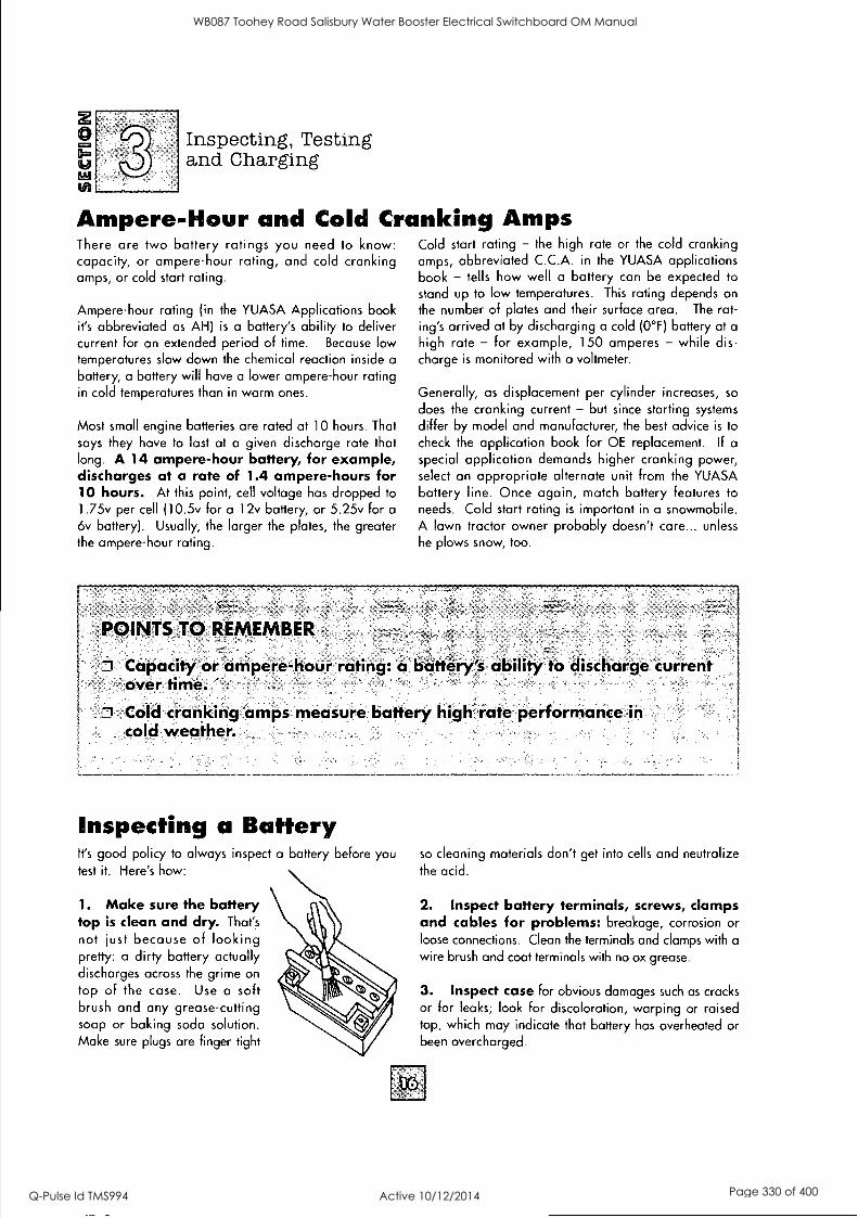
17=3
Eli
Inspecting, Testing and Charging
Ampere-Hour and Cold Cranking Amps There are two battery ratings you need to know: capacity, or ampere-hour rating, and cold cranking amps, or cold start rating.
Ampere-hour rating (in the YUASA Applications book it's abbreviated as AH) is a battery's ability to deliver current for an extended period of time. Because low temperatures slow down the chemical reaction inside a
battery, a battery will have a lower ampere-hour rating in cold temperatures than in warm ones.
Most small engine batteries are rated at 10 hours. That says they have to last at a given discharge rate that long. A 14 ampere-hour battery, for example, discharges at a rate of 1.4 ampere-hours for 10 hours. At this point, cell voltage has dropped to
1.75v per cell (10.5v for a 12v battery, or 5.25v for a
6v battery). Usually, the larger the plates, the greater the ampere-hour rating.
Cold start rating - the high rate or the cold cranking amps, abbreviated C.C.A. in the YUASA applications book - tells how well a battery can be expected to
stand up to low temperatures. This rating depends on the number of plates and their surface area. The rat- ing's arrived at by discharging a cold (0°F) battery at a
high rate - for example, 150 amperes - while dis- charge is monitored with a voltmeter.
Generally, as displacement per cylinder increases, so
does the cranking current - but since starting systems
differ by model and manufacturer, the best advice is to check the application book for OE replacement. If a
special application demands higher cranking power, select an appropriate alternate unit from the YUASA battery line. Once again, match battery features to needs. Cold start rating is important in a snowmobile. A lawn tractor owner probably doesn't care... unless he plows snow, too.
POINTS TO REMEMBER
Capacity or ampere-hour rating: a battery's ability to discharge current over time.
Cold cranking amps measure battery high rate performance in cold weather.
Inspecting a Battery It's good policy to always inspect a battery before you test it. Here's how:
1. Make sure the battery top is clean and dry. That's
not just because of looking pretty: a dirty battery actually discharges across the grime on
top of the case. Use a soft brush and any grease-cutting soap or baking soda solution. Make sure plugs are finger tight
so cleaning materials don't get into cells and neutralize the acid.
2. Inspect battery terminals, screws, clamps and cables for problems: breakage, corrosion or loose connections. Clean the terminals and clamps with a
wire brush and coat terminals with no ox grease.
3. Inspect case for obvious damages such as cracks or for leaks; look for discoloration, warping or raised top, which may indicate that battery has overheated or been overcharged.
WB087 Toohey Road Salisbury Water Booster Electrical Switchboard OM Manual
Q-Pulse Id TMS994 Active 10/12/2014 Page 330 of 400

2
4.9
Inspecting, Testing and Charging
4. Check electrolyte level and add distilled water if necessary. Don't add acid - only water. Before any tests, charge the battery so the water and electrolyte mix.
POINTS TO REMEMBER
Inspect before you test. II Dirt on top of case causes discharge. 0 Look for obvious damage to battery and connectors. 0 Add water if electrolyte is low. 71 Make sure vent tube is clear.
5. Check the vent tube. Make sure-it's not kinked, pinched or otherwise obstructed. On a motorcycle, it
should exit away from the drive chain and from below the swing arm. Small cuts in the tube near the battery vent are OK; they're an "emergency escape" for gas in
case the tube becomes obstructed.
Battery Testing Devices How much of a charge does a battery have? There are two easy and reliable ways to find out: 1) a hydrometer, which comes in floating ball and calibrated float types, or 2) a voltmeter (or multimeter, which gives DC voltage readings).
Which is best?
If you're choosing between two hydrometers, opt for the calibrated float type. It gives you an exact specific gravity reading (that is, the density of the
electrolyte compared to water); that's much more accurate than floating balls. For readings on calibrated float and floating ball hydrometers, see "Methods of Checking Battery Condition" chart on the next page.
A voltmeter or multimeter can be used where a hydrometer can't. Most sealed VRLA or low maintenance batteries have to be tested with a voltmeter.
Hydrometer
Yuasa Multimeter
Battery testing requires a voltmeter that can measure DC voltage. Remember to always connect a voltmeter parallel to the circuit being tested, observing polarity; otherwise, the pointer will travel in the wrong direction. It's a good idea to periodically check a
voltmeter against another one of known accuracy.
WB087 Toohey Road Salisbury Water Booster Electrical Switchboard OM Manual
Q-Pulse Id TMS994 Active 10/12/2014 Page 331 of 400

2
(LP 15E!
Inspecting, Testing and Charging
Battery Testing There are two types of battery tests: unloaded and loaded. An unloaded test is made on a battery without discharging current. It's simplest and most commonly used. If you need a precise reading, loaded testing is the
answer. It's more accurate.
UNLOADED TESTING: Check charge condition using either a hydrometer or voltmeter. With a voltmeter, voltage readings appear instantly to show the state of charge. Remember to hook the positive lead to the battery's positive terminal, and the negative lead to the negative terminal.
A hydrometer measures the specific gravity of each cell.
The specific gravity tells the degree of charge; generally, a specific gravity of about 1.265 to 1.280 indicates a full charge. A reading of 1.230 to 1.260 indicates the battery should be charged before testing. The chart below shows the charge level as
measured by syringe float hydrometer, digital voltmeter and five-ball hydrometer.
.
State'of? iti4e, -,' ''.Digital .hcFfgf,°_:- Hydrometer Voltmeter'
- . ..5-Ball Hydroineter.
100% Charged
w/Sulfate Stop
100% Charged
75% Charged
50% Charged
25% Charged
0% Charged
1.280
1.265
1.210
1.160
1.120
less than 1.100
12.80v
12.60v
12.40v
t 12.10v
p 11.90v
less than 11.80v
5 Balls Floating
4 Balls Floating
3 Balls Floating
2 Bolls Floating
1 Balls Floating
0 Balls Floating
.
A battery's specific gravity changes with temperature. Ideally, readings should be taken at 77°F. Is it really going to matter if you're off a couple of degrees one way or another? Probably not. If you're working somewhere
that's uncomfortably hot or cold, it's time to use the old conversion factors: add .001 to the specific gravity read- ing for each 3°F above 77°F or subtract .001 from the specific gravity reading for each 3°F below 77°F. Cell voltage can be found by adding .84 to the specific gravity.
Note, too, that YUASA's "Sulfate Stop," a chemical addi- tive that increases battery life by drastically reducing sul-
fate buildup, changes the specific gravity readings; they'll be higher than with ordinary batteries.
Test sealed VRLA types with a voltmeter or multimeter. If the stabilized open circuit voltage is
below 12.5v, the battery needs charging. For a stabilized open circuit reading, first allow the battery to remain in
an open circuit condition for at least 1 - 2 hours.
LOADED TESTING: There are two types of loaded tests
for motorcycle batteries. You'll need a voltmeter or multi- meter.
Low-load test: Basically, this means turning on the bike's lights and taking a voltage reading at the battery. Remember, hook positive (+) to positive (+), negative (-) to negative (-). The battery in a 12v system should have at least 11.5v DC with the lights on. A 6v system should have at least 5.75v DC. If voltage drops below these lev-
els, it's time to charge.
High-rate discharge test: This is the best test of bat- tery condition under a starting load. Use a load testing device that has an adjustable load. Apply a load of three times the ampere-hour rating.
At 14 seconds into the test, check battery voltage: a
good 12v battery will have at least 10.5v, and a good 6v battery, at least 5.25v. If the reading's low, charge.
POINTS TO REMEMBER
Use a voltmeter or hydrometer to test state of charge. CI In extreme cold or heat, you'll have to adjust hydrometer readings. n Battery can, be tested with or without electrical load applied. El Unloaded testing is simplest. 1 Applying a load and reading voltage atbattery is more accurate.
WB087 Toohey Road Salisbury Water Booster Electrical Switchboard OM Manual
Q-Pulse Id TMS994 Active 10/12/2014 Page 332 of 400

0 ato
Inspecting, Testing and Charging
Chargers and Charging There's a simple rule of thumb about batteries, and if you're a dealer or a mechanic, you know that people ignore it all the time: for a battery to operate the way it's
supposed to, it has to be fully charged before it's used... and kept fully charged throughout its life.
A charger basically brings a new battery, or a battery that has been discharged, to full capacity. Plugged into a
wall socket, it sends direct current, flowing in the opposite direction of the discharge, into the battery.
Charging actually reverses the destructive chemical process that goes on as a battery discharges: the lead plates and electrolyte, which were being transformed into lead sulfate and water, are restored to their original composition. If a battery has been damaged - for example, it's badly sulfated, or the plates have been damaged from overheating or freezing - it may not accept a charge.
TYPES OF CHARGERS: There are five basic types of battery chargers. With all of them, hook the positive charger lead to the positive battery terminal, and the negative to the negative. Some chargers on the market deliver a low charging voltage that can't fully charge the battery; avoid them if you're buying a charger. A 12 volt, 900 mA charger will meet most needs.
Of course, too much of a charge can be a problem, too - it can "cook" a battery. For small engine starting batter- ies, don't use a charge greater than 2 to 2.5 amps for maintenance purposes. A badly discharged battery with very high internal resistance may never accept a charge from a standard charger. It would then require special charging equipment.
ALWAYS OBSERVE PROPER SAFETY PRECAUTIONS WHEN CHARGING BATTERIES
TRICKLE CHARGER: This is the charger a consumer - as opposed to a battery retailer or garage - will usually have. It charges the battery at a fixed rate. Different ampere-hour batteries have different charge rates. For most motorcycle and other small engine start- ing batteries, charge them at 1 /10 of the rated ampere-hour values in the Yuasa Applications Book, see example on page 12 for ratings.
Battery voltage increases with the amount of charge. Find charging time for a completely discharged battery by multiplying the ampere-hour rating by 1.3 when charging with standard current. The chart on page 21 shows the approximate time needed to fully charge lead-antimony batteries using a trickle or taper charger.
The chart on page 32 shows the approximate time needed to fully charge sealed VRLA batteries.
Test the battery during charging, and continue charg- ing until all cells are gassing. Use either a voltmeter (or multimeter) or hydrometer. The specific gravity of the electrolyte in all cells in a fully-charged battery should come to at least 1.265 in a conventional bat- tery and 1.280 in a YuMicron and sealed VRLA battery with Sulfate Stop.
-:Electrolyte Temperature:- State
of ' Charge ot&' Icx&'
YuMicron Conventional. YuMicron Conventional
80°F 40 °F
1 28/ 129
75% 1 22/ 1 21/ 1 23/ 1 22/ 123 122 124 123
AssrAssi
50% 1 17/ 1 16/ 1 18/ 1 17/ 118 117 119 i 1 18
25% 113/ 112/ 1 14/ 113/ 114 113 115 114
0% 1.11/ 1.10/ or less or less
1.12/ 1.11/ or less I I or less
I
During charging, check the electrolyte level periodically and add water - preferably distilled - to keep the electrolyte level up to the line. if the battery becomes hot to the touch, stop charging. Resume after it has cooled.
Note that permanently sealed batteries - YUASA's sealed VRLA battery, for example - generally can be test-
ed only with a voltmeter or multimeter. These batteries are fully charged when the voltage peaks and then begins to fall.
Unless using an automatic charger, do not hook a battery to a trickle charg- er and leave it unchecked for longer than overnight. After about eight hours maxi- mum, careful monitoring is
required.
Caps need to be replaced finger tightened after charging's done.
WB087 Toohey Road Salisbury Water Booster Electrical Switchboard OM Manual
Q-Pulse Id TMS994 Active 10/12/2014 Page 333 of 400

Eft
Inspecting, Testing and Charging
TAPER CHARGER: Similar to the trickle charger, the automatic taper charger charges at a fixed voltage. As the battery's voltage increases with the amount of charge, the current drops accordingly.
A drawback of both the automatic taper and trickle chargers is speed... they don't have it. As the chart on
page 21 shows, it can take days to bring a discharged battery up to 100%. Here, too, check batteries for over- heating as they charge.
CONSTANT CURRENT CHARGER: A professional- quality charger, the constant current makes charging simple. It maintains a constant supply of current to the battery at all levels of charging. You select the charging current. As the battery voltage increases with the amount of charge, this charger automatically increases the charging voltage to maintain the current output.
CHARGER /MAINTAINER: This type of charger monitors the voltage constantly during charging and
POINTS TO REMEMBER
standby modes. When battery voltage reaches a speci-
fied low level, the charger/maintainer then delivers a full
charge. Then when the battery gets to the specified volt-
age, it automatically drops to a float charge.
HIGH RATE CHARGER: Not for use with small engine
starting batteries. They force a high current into the bat- tery, which can lead to overheating and plate damage.
State of Sealed CX & Charge VRLA Yu Micron Conventioncd
100% 13.0v
75% 12.8v
50% 12.5v
25% 12.2v
0% 12.0v or less
12.6v
12.4v
12.1v
11.9v
11.8v or less
Fully charge battery when new and keep it fully charged.
J Test charging batteries as necessary for overheating, water and state of charge.
Trickle and taper chargers are generally slow.
Constant current and pulse chargers are professional quality.
3 High rate charger can cause battery damage.
Charging a New Standard Battery The most important thing to remember about charging a
new battery is do it!
A battery out of the box with only adding electrolyte is
approximately 80% charged. Our recommendation is to
initial charge, bringing the battery to 100% before use.
This completes the electrochemical process. However, a
long ride with a regulated charging system may also bring the battery's capacity to a higher level.
Note: See "Section 5" for charging sealed VRLA batteries.
WB087 Toohey Road Salisbury Water Booster Electrical Switchboard OM Manual
Q-Pulse Id TMS994 Active 10/12/2014 Page 334 of 400

Pal V/
Inspecting, Testing and Charging
The rule of thumb is to charge a new battery for three to five hours at a rate equal to 1/10 of its rated capacity. But
there are a lot of exceptions to that rule, as this table shows:
Quick Charges
What about quick charging? The quick answer is
don't. We don't recommend it, and here's why: only the surface area of the battery plates can be quick charged. A lower current charges the battery more uniformly. That means better performance. Also, excessive charging rates increase the chance of overheating, which can mean battery damage.
_,Battery Tipes -12N12 12N14 1%18;
75%
50%
25%
0%
75%
50%
25%
0%
-ApproximateCharge Times (Hours) Using a "Trickle" (0.25 Amp) Charger
13
25
38
50
-
APproximate`Charge Times (Hoqs) Using a Amp Taper Charger
23
45
68
90
6
11
15
20
7
13
18
23
10
19
27
35
Approximate Charge Times (Hours) Using a 1 AMp Constant Current Charger
3
6
9
13
REMEMBER
4
9
13
18
6
11
17
23
,
'10: A, new "battery after:CictiNiOtion.ii'amirokimately, 80%-charged. , . . ,
,
0 Initial charging is-always recommended. NEVER quick chargé.
w at -a rated a Charge a- ne battery ata rate equal to 1/10 of i ts capaCity., , .
WB087 Toohey Road Salisbury Water Booster Electrical Switchboard OM Manual
Q-Pulse Id TMS994 Active 10/12/2014 Page 335 of 400

2 Maintenance and Storage
03)
Monthly Maintenance for Con Batteries don't demand a lot of attention. But not giving your battery the attention it needs can leave you stranded... or poorer by the cost of a new battery.
How often should you maintain a battery? About monthly under usual conditions. However, recharging is necessary when lights get dim, when the starter sounds weak, or when the battery isn't used for more than two weeks.
Important as it is, there's really not much to battery maintenance. Basically, just follow the procedure out- lined in the section "Inspecting a Battery."
That means:
Check electrolyte level.
Keep the top free of grime. Check cables, clamps and case for obvious damage or loose connections.
o Clean terminals and connectors as necessary.
Make sure exhaust tube is free of kinks or clogs.
Replace caps, finger tighten only.
Then, test the battery with either a hydrometer or volt- meter. Keep it charged to 100%.
Storage If the vehicle is in storage or used infrequently, disconnect the battery cable. That eliminates drain from electrical equipment. Check battery every two weeks and charge as necessary.
ventional and Yu Micron Types For extended storage, remove the battery from the vehicle and charge to 100%. Charge the battery every month if
stored at temperatures below 60°F. Charge every two weeks if stored in a warm area (above 60°F). Make sure
batteries are stored out of reach of children.
Sulfation and Freezing Two of the biggest battery killers - sulfation and freez- ing - aren't a problem if the battery is properly main- tained and water level is kept where it should be.
Sulfation: This happens because of 1) continuous dis- charging, or 2) low electrolyte levels.
Let's back up just a minute: we said earlier that dis- charge turns the lead plates into lead sulfate. This lead sulfate is actually a crystal. If the discharge continues uninterrupted, the sulfate crystals grow and blossom into sulfation - and a problem. The section titled "Reasons for Self-discharge" has the gory details.
Much the same happens if the fluid level is too low, which exposes the plates to air. Then the active lead material oxidizes and sulfates, and it doesn't take long before it won't hold a charge. (Low electrolyte levels cause another problem, too: acid in the electrolyte becomes more concentrated, causing material to cor- rode and fall to the bottom. In sufficient quantity, it will short out the battery.)
Keeping a battery charged, disconnecting the battery cable during storage, and keeping electrolyte levels up eliminate the problem. For added protection, YUASA's Yu Micron, Yu Micron CX
and Sealed VRLA batteries are treated with a special chemical formula called "Sulfate Stop." This dramatically reduces sulfate crystal buildup on plates. The result: longer battery life.
How good is Sulfate Stop?
We simulated a constant discharge condition on two batteries with a 10-watt bulb.
Even after being totally drained for a week, the battery with Sulfate Stop made a 90% recovery.
The untreated battery: useless.
WB087 Toohey Road Salisbury Water Booster Electrical Switchboard OM Manual
Q-Pulse Id TMS994 Active 10/12/2014 Page 336 of 400

VI
Maintenance and Storage
Freezing: It shouldn't bother you - unless a battery is
inadequately charged. Looking one more time at the
discharge process, remember that electrolyte acid becomes water as discharge occurs. Now, it takes Arctic temperatures
to freeze acid. But water... as we all know, freezing starts
at 32°F. A sign of this is mossing - little red lines on the
plates. Freezing can also crack the case and buckle the
plates, which means the battery is permanently damaged.
A fully-charged battery can be stored at sub- freezing temperatures with no damage. As the
chart at right shows, it takes -75°F to freeze electrolyte in
a charged battery. But at just a couple degrees below freezing - at +27°F - a discharged battery's electrolyte turns to ice. That's a difference of more than 100°F between the low temperatures a charged and discharged battery can stand.
, -
POINTS TO REMEMBER'
0. Monthly maintenance an:die-Sting are a must: - ,
At temperatures such as these, incidentally, the self- discharge rate of a battery is so low that a recharge usually isn't needed for months. But to stay on the safe side, test.
Frooxing Specific- Gravity of Eledrolyte Freezing point_
1.265 -75°F
1.225 -35°F
1.200 -17°F
1.150 + 5°F
1.100 +18°F
1.050 +27°F
1 Most important: make surebattery is charged and fluid level is correct.
ID Disconnect cables or,pull battery for storage.
Keep fully charged to prevent sulfation and freezing.
WB087 Toohey Road Salisbury Water Booster Electrical Switchboard OM Manual
Q-Pulse Id TMS994 Active 10/12/2014 Page 337 of 400

(69
tei)
New Generation Battery Technology
Sealed VRLA Batteries
Yuasa's innovative sealed VRLA (Valve Regulated Lead Acid) batteries are a new generation made possible by advanced gas recombinant technology. These include the YT and YI series batteries. We refer to them as "sealed VRLA batteries" here.
Sealed VRLA batteries are easy to activate and maintain. But, keep these points in mind:
1. There are important differences in activating a sealed VRLA battery. Be sure to follow the instructions in this section.
2. While Yuasa sealed VRLA batteries dramatically reduce the need for maintenance, they do need periodic charging. It's important to remember this and to know how to go about it.
3. When considering upgrading to a sealed VRLA battery that did not come OE in your vehicle, check to make sure your charging system has a regulated output between 14.0 - 14.8v.
Let's take a closer look at Yuasa's innovative sealed
VRLA batteries... and what makes them special.
Features
The sealed VRLA battery is the battery for vehicles that may be stored for long periods (riding mowers, personal watercraft, or scooters or cycles during the off-season, for example), or where spills could be a problem (ATVs or personal watercraft). YUASA's sealed VRLA batteries deliver:
O No topping - Fill it just once, to activate. No need to check electrolyte level or add water ever again.
o Reduced self-discharge - Grids manufactured from a special lead-calcium alloy hold the charge longer - a real plus with storage or occasional use.
o Easy, instant activation - The "one-push" electrolyte container makes filling a snap.
Enhanced safety - A safety valve vents gases produced by overcharging. In case of fire, the flame arrestor disk minimizes explosion risk.
SEALED VRLA BATTERY CONSTRUCTION
PATENTED SEALED POST prevents acid seepage, reduces corrosion - extends battery life.
SAFETY VALVE/ FLAME ARRESTOR relieves excess pressure.
THRU-PARTITION CONSTRUCTION provides shorter current path with less
resistance than "over the partition" construction - you get more cranking power when you need it!
HEAT SEALED CASE TO COVER protects against seepage and corrosion - bonded unit gives extra strength.
POLYPROPYLENE COVER AND CONTAINER assures reserve electrolyte capacity for cooler operating temperatures, gives greater resistance to gas and oil - and impact in extreme conditions!
SPECIAL ACTIVE MATERIAL is compounded to withstand vibration, prolong battery life and dependability.
SPECIAL GRID DESIGN withstands severe vibration, assures maximum conductivity.
SPECIAL SEPARATOR makes the battery spill-proof. Valve regulated design eliminates water loss and the need to refill with acid.
WB087 Toohey Road Salisbury Water Booster Electrical Switchboard OM Manual
Q-Pulse Id TMS994 Active 10/12/2014 Page 338 of 400
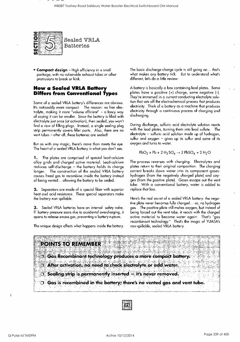
z
sz
Sealed VRLA Batteries
Compact design - High efficiency in a small
package, with no vulnerable exhaust tubes or other protrusions to break or kink.
How a Sealed VRLA Battery Differs from Conventional Types
Some of a sealed VRLA battery's differences are obvious. It's noticeably more compact. The reason: no free elec-
trolyte, making it more "volume efficient" - a fancy way of saying it can be smaller. Since the battery is filled with electrolyte just once (at activation), then sealed, you won't find a row of filling plugs. Instead, a single sealing plug strip permanently covers filler ports. Also, there are no vent tubes - after all, these batteries are sealed!
But as with any magic, there's more than meets the eye.
The heart of a sealed VRLA battery is what you don't see.
1. The plates are comprised of special lead-calcium alloy grids and charged active material. Lead-calcium reduces self-discharge - the battery holds its charge longer. The construction of the sealed VRLA battery causes freed gas to recombine inside the battery instead of being vented... allowing the battery to be sealed.
2. Separators are made of a special fiber with superior heat and acid resistance. These special separators make the battery non-spillable.
3. Sealed YRLA batteries have an internal safety valve. If battery pressure soars due to accidental overcharging, it
opens to release excess gas, preventing a battery rupture.
The unique design affects what happens inside the battery.
POINTS TO REMEMBER
The basic discharge-charge cycle is still going on... that's what makes any battery tick. But to understand what's different, let's do a little review:
A battery is basically a box containing lead plates. Some plates have a positive (+) charge, some negative (-). They're immersed in a current-conducting electrolyte solu- tion that sets off the electrochemical process that produces electricity. Think of a battery as a machine that produces electricity through a continuous process of charging and discharging.
During discharge, sulfuric acid electrolyte solution reacts with the lead plates, turning them into lead sulfate. The
electrolyte - sulfuric acid solution mode up of hydrogen, sulfur and oxygen - gives up its sulfur and some of its
oxygen and turns to water.
Pb02 + Pb + 2 H2 SO4 2 PbSO4 + 2 H20
The process reverses with charging. Electrolytes and plates return to their original composition. The charging current breaks down water into its component gases: hydrogen (from the negatively charged plate) and oxy- gen (from the positive plate). Gases escape out the vent tube. With a conventional battery, water is added to replace that loss.
Here's the real secret of a sealed VRLA battery: the nega- tive plate never becomes fully charged... so, no hydrogen gas. The positive plate still makes oxygen, but instead of being forced out the vent tube, it reacts with the charged active material to become water again. That's "gas recombinant technology." That's the magic of YUASA's non-spillable, sealed VRLA battery.
Gas Recombinant technology produces a more compact batte
After` activation, no need to check electrolyte or add, water.
O Sealing strip is permanently inserted'- its never removed.
Gas is recombined in the battery; there's no vented gas and vent tube.
WB087 Toohey Road Salisbury Water Booster Electrical Switchboard OM Manual
Q-Pulse Id TMS994 Active 10/12/2014 Page 339 of 400

Sealed VRLA Batteries
Activation and Installation Activating sealed VRLA batteries is easy, although a little
different from conventional activation. For problem-free start-up and operation, follow the procedure outlined here. A few things to keep in mind before you get rolling:
O Store the battery in a cool, dry place out of direct sunlight.
* Do not remove the foil sheet covering the filler port until activation.
o After removing the electrolyte container cap strip, do not peel, pierce or otherwise open the sealed electrolyte receptacles. Don't separate the individual cells.
o Read electrolyte handling instruction and precautions on the label.
ELECTROLYTE FOR YTX12-BS BATTERY
POISON Sum*, L.
O Use only the electrolyte container that comes with the battery. Sealed VRLA battery electrolyte is a higher concentration of sulfuric acid. All sealed
VRLA battery electrolyte containers aren't the same.
Each contains the proper amount of electrolyte for its
specific battery.
* Always wear plastic gloves and protective eyewear. No Smoking, see page 9 for full safety
instructions.Of course, don't forget safety precautions when storing or handling electrolyte solution.
To Activate a Sealed VRLA Battery 1. Place the battery on a level surface. Battery must be
out of the vehicle.
2. Remove electrolyte container from vinyl bag. Remove
the strip of caps. Put the strip aside - you'll use this later as the battery sealing plug. Use only the dedicated container that comes with the battery. It con- tains the proper amount of electrolyte for your specific model - important to service life and operation. Do not pierce or otherwise open the sealed cells of the electrolyte
container. Do not attempt to separate individual cells.
3. Place electrolyte container, sealed top of the cells down, into the filler ports of the battery. Hold the container level,
push down to break the seals. You'll see air bubbles as the
ports fill. Do not tilt the electrolyte container.
Warning: Improper activation or excessive overchargering (possibly by equipment failure) could cause damage to the battery or vehicle by forcing acid out of the safety vent.
Save this strip
See next page.
WB087 Toohey Road Salisbury Water Booster Electrical Switchboard OM Manual
Q-Pulse Id TMS994 Active 10/12/2014 Page 340 of 400

Sealed VRLA Batteries
4. Check the electrolyte flow. Keep the container in place for 20 minutes or longer until it empties completely. If no air bubbles are coming up from the filler ports, or if container cells haven't emptied completely, tap the container a few times. Don't remove the contain- er from the battery until it's empty. The battery requires all the electrolyte from the container for proper operation. Make sure the electrolyte container empties completely.
5. Remove the container. For batteries 3 - 12 AH, let stand for at least 30 minutes. For batteries greater than 12 AH, allow the battery to stand a minimum of 1 HOUR. This allows the electrolyte to permeate into the plates for optimum performance. Yuasa sealed VRLA batteries have the amp hours printed right on the front of the battery.
Place cap strip loosely over filling holes
6. Newly activated sealed VRLA batteries require an initial charge. After adding electrolyte, a new battery is approximately 80% charged. Place cap strip loosely over the filling holes as shown in drawing above. Immediately charge your battery after the "stand" period, to bring it to a full state of charge. See "Charging a Newly Activated Sealed VRLA Battery" on page 31.
After charging is completed, press down firmly with both hands to seat the caps (don't pound or hammer).
The battery is sealed. There is no need to remove the strip of caps or add electrolyte for the life of the battery.
7. The graph below shows an open circuit voltage characteristic of a sealed VRLA battery just after the elec- trolyte is filled.
If the battery is only filled with electrolyte, but not being given a supplementary charge, the open circuit voltage will be somewhere around 12.5 to 12.6v, as shown in the graph below. The reasons for the voltage being low are that:
o The capacity reached by filling with electrolyte is about 80% of the fully charged capacity.
The electrolyte around the plates gets its
concentration lowered temporarily.
Characteristics
6
Standin Time (minutes
Remember: unlike a conventional
battery, the sealed VRLA battery won't
be topped off during its life. Never pry off
sealing caps: it's dangerous and
damaging.
WB087 Toohey Road Salisbury Water Booster Electrical Switchboard OM Manual
Q-Pulse Id TMS994 Active 10/12/2014 Page 341 of 400
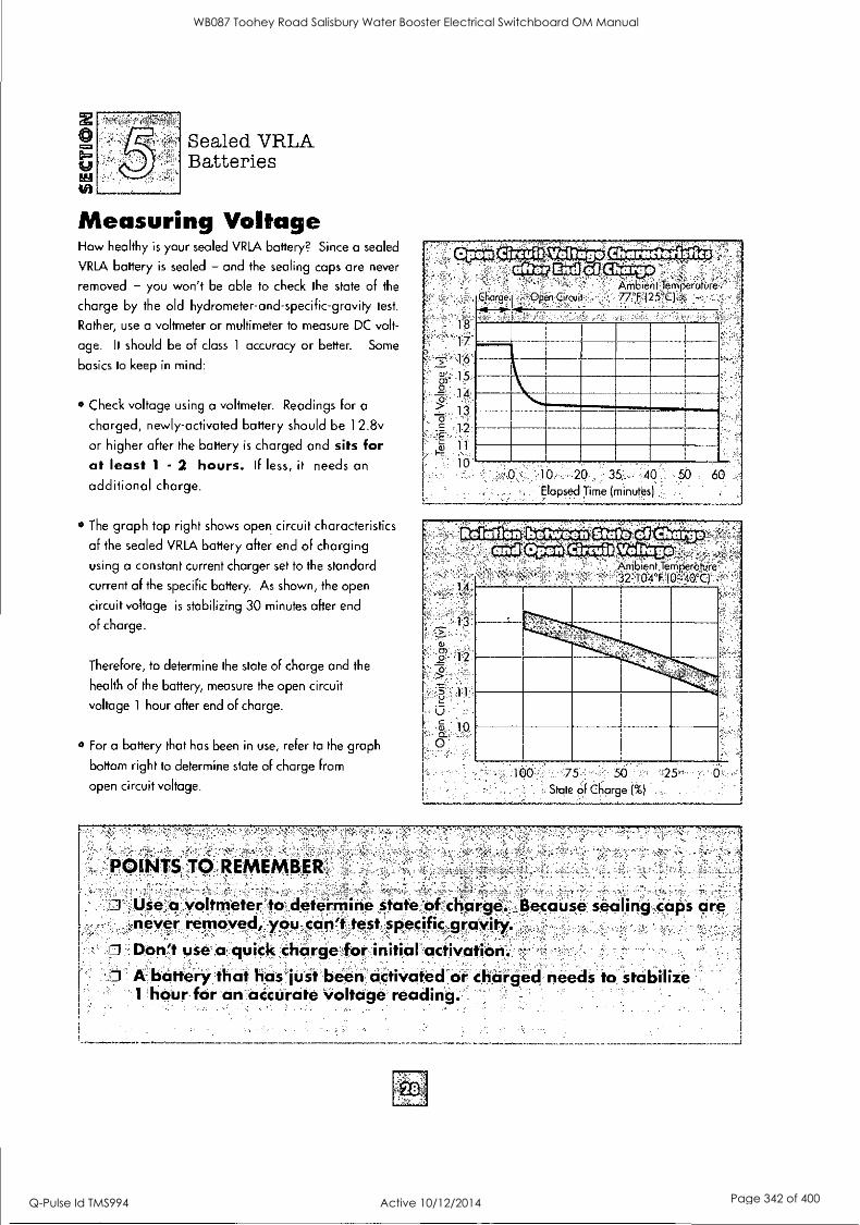
Ed
Sealed VRLA Batteries
Measuring Voltage How healthy is your sealed VRLA battery? Since a sealed
VRLA battery is sealed - and the sealing caps are never
removed - you won't be able to check the state of the
charge by the old hydrometer-and-specific-gravity test.
Rather, use a voltmeter or multimeter to measure DC volt-
age. It should be of class 1 accuracy or better. Some
basics to keep in mind:
Check voltage using a voltmeter. Readings for a
charged, newly-activated battery should be 12.8v
or higher after the battery is charged and sits for at least 1 - 2 hours. If less, it needs an
additional charge.
The graph top right shows open circuit characteristics
of the sealed VRLA battery after end of charging
using a constant current charger set to the standard
current of the specific battery. As shown, the open
circuit voltage is stabilizing 30 minutes after end
of charge.
Therefore, to determine the state of charge and the
health of the battery, measure the open circuit
voltage 1 hour after end of charge.
o For a battery that has been in use, refer to the graph
bottom right to determine state of charge from
open circuit voltage.
POINTS TO, REMEMBER,
cMCrilIttf Ambient Ternpe rcst'ure -
Charge I Open Circuit 77°F (25°C)
18
17
-5- 1-6
0,a, 15
4 14
1,3
12
11
10 10 20 35 40 50 60 Elapsed Time (minutes
O Use a voltmeter to determine state of charge. Because sealing caps are never removed, you can't test specific gravity.
O Don't use a quick charge for initial activation. I A battery that has just been activated or charged needs to stabilize
1 hour for an accurate voltage reading.
WB087 Toohey Road Salisbury Water Booster Electrical Switchboard OM Manual
Q-Pulse Id TMS994 Active 10/12/2014 Page 342 of 400

z EL° a
tit
Sealed VRLA Batteries
Discharge Characteristics Think about what types of vehicles a sealed VRLA battery
goes into: most aren't like the family car, driven day-in, day-out. They're probably used once in a while, or
maybe even stored for weeks or months at a time.
That demands a special kind of battery - one with
extra power to reliably start that engine, every time. In
YUASA's sealed VRLA batteries, the plate groups are spe-
cially designed to deliver that. The graph to the right
shows the increase in discharge time of a sealed VRLA
battery compared to a conventional Yumicron battery at both cold and room temperatures. The graph below
shows the cold temperature performance of the sealed
VRLA battery as the load increases. "C" equals the
Amp Hour Capacity Rating of the battery.
10
2
20A Discharge Charactenstics
-L-- Sealed VRLA - Conventional
{ 14°F (-10°C) 77°F (25°C)
1 2 3 4
Discharge Duration (minute)
' C =-10 hOli-ArEit6 capacity)
01C
(10 hour rate discharge characteristics)
Starting the engine is a big part of the battery's job, but
not all. Electrical accessories and safety systems - lights
and horn - need a stable supply of electricity. Now you're concerned with the battery's "low rate discharge
characteristics." This steady, low rate discharge is
measured in "10-hour rate discharge." The graph above shows the discharge characteristics of YUASA's
YT or YI sealed VRLA batteries at different current rates.
Note that battery capacity is a function of the current
being used (or discharge current) x time.
WB087 Toohey Road Salisbury Water Booster Electrical Switchboard OM Manual
Q-Pulse Id TMS994 Active 10/12/2014 Page 343 of 400

U to)
Sealed VRLA Batteries
Self-discharge Constant self-discharge is a fact of life for all batteries. They lose strength as they sit there doing nothing. The good news is that lead-calcium technology in a sealed VRLA battery slows down the self-discharge process substantially. Conventional lead-antimony batteries discharge at about 1/100 volt a day... the lead-calci- um sealed VRLA battery, 1/300 volt per day. Looking at it another way, a conventional battery fully charged and stored for a month will lose roughly a third of its
charge; the sealed VRLA battery handled the same way would lose about 10%.
Remember, too, ambient temperature affects battery dis- charge. Higher the temperature, quicker the discharge - for all batteries.
So, the sealed garage or storage shed with the sun beat- ing down on it isn't doing any favors to the battery in
your vehicle. Excessive heat will prematurely shorten the life of the battery.
Some people figure sealed VRLA batteries are so good, there's no need to worry about routine charges. Flattering, but wrong. Forgetting routine charging can mean a one-way ticket to the battery graveyard.
POINTS TO REMEMBER
0 "High rate diicharge" sealed VRLA batteries deliver extra starting powe'r. 0 Lead-calcium technology substantially slows self-discharge. 1 Routine charging is required to maintain a full charge.
Lead-calcium technology definitely slows self-discharge, but a combination of heat and idleness will still drain a
sealed VRLA battery, like the conventional one. You'll find step-by-step charging instructions later in this section.
Rolastion
100
90
G. 80 a:
cw 70
.E a
,60 ce
50
40 0
Sealed VRLA Standard - - 32°F
I (0°C)
32°F
(0°C)
77°F (25°C)
77°F (25°C)
104°F (40°C)
04°F 1 l'
(40°C)
2
Storage Period (month)
Choosing a Charger Match your sealed VRLA battery to the right charger. The wrong one can cause permanent damage and poor performance.
Yuasa offers a complete line of chargers to activate and maintain your battery to factory specifications.
0 Do not use a larger than recommended amp charger to
reduce charging time. That permanently damages the battery and voids the warranty.
o To find recommended current output in amps, divide battery amp hour capacity rating by 10. Example: 14 AH ÷ 10 = 1.4 amp current.
Yuasa sealed VRLA batteries have the amp hours printed right on the front of the battery. If you're not sure, refer to application manuals at the dealer. Select the charger that comes closest to the value of that figure.
Yuasa 900 mA Yuasa 1.5 Amp Automatic Charger Automatic Charger
WB087 Toohey Road Salisbury Water Booster Electrical Switchboard OM Manual
Q-Pulse Id TMS994 Active 10/12/2014 Page 344 of 400

Sealed VRLA Batteries
Charging a Newly Activated Sealed VRLA Battery Sealed VRLA batteries require an initial charge. If you are using a constant current charger, refer to the standard (STD.) charging method printed on the battery. If you are
using an automatic type taper charger, check to make sure that the charger current (amps) is equal to or greater than
the standard (STD.) charging method listed on the battery.
CHARGING INSTRUCTIONS FOR NEWLY ACTIVATED SEALED VRLA BATTERIES
THIS IS A SEALED BATTERY; THE SEALING CAPS SHOULD BE CONSIDERED PERMANENTS' DO NOT REMOVE THE CAPS TO ADD WATER OR TO CHARGE THE BATTERY; CHARGE AT
CHARGING 12V AT THE AMPERAGE AND HOURS STATED BELOW.
METHOD STD.: 1.8A x 5-10h or QUICK:9.0A x 1.0h
These batteries are a sealed VRLA construction - which means: NEVER REMOVE THE SEALING STRIP AFTER CHARGING IS COMPLETED!
If the battery gets very hot to the touch, cease charging and allow battery to cool down.
Check voltage using a voltmeter. Readings for a charged, newly-activated battery should be 12.8v or higher after the battery is charged and sits for at least 1 - 2 hours.
If less, it needs an additional charge.
Yuasa Automatic Chargers and Accessories are the safest and most convenient method for error proof charging and battery maintenance.
WB087 Toohey Road Salisbury Water Booster Electrical Switchboard OM Manual
Q-Pulse Id TMS994 Active 10/12/2014 Page 345 of 400

U tft
Sealed VRLA Batteries
Routine Charging The single most important thing to maintaining a sealed
VRLA battery is don't let it sit discharged: keep it fully charged. A sealed VRLA motorcycle battery should be kept to near fully charged for peak performance. In fact, it can need charging more often
than a car battery because it's probably not used routinely
and, therefore, not "automatically" charged.
Use the following guidelines for boost charge. Always verify battery condition before charging, and 30 minutes
after charging.
A fully charged battery should read 12.8v or higher after
battery has been off the charger 1 - 2 hours.
State"
'
OVERCHARGING CAN HARM YOUR BATTERY BEYOND
RECOVERY.
A word on overcharging: don't. Because of the charac- teristics of a sealed VRLA battery, too much of a boost
charge will decrease the volume of electrolyte. The
longer the overcharge time, the greater the drop in elec-
trolyte - and starting power.
Water can't be added to the sealed VRLA battery to make up
the difference. Overcharging can warp plates, making future charging difficult or impossible. Watch charging times
carefully, or ideally, use a Yuasa Automatic Charger. Always
stop charging if the battery becomes really warm to the
touch. Let it cool down 6 - 12 hours and resume charging.
Voltcige' Charge Time* "
Action, "(Using a constant_ , `current charger
@ std. amps specified on,theisaftery)
100%
75% -100%
50% - 75%
25% - 50%
0% - 25%
12 8v - 130v
12 5v - 128v
12.0v - 12.5v
11.5v - 12.0v
11.5v or less
(see special instructions
on page 33)
None Check at 3 months
from date of manufacture
May need slight
charge, if no charge given,
check in 3 months
Needs charge
Needs charge
Needs charge
At least 13 hours verify state
of charge
20 hours
* Charging times can vary depending on type o charger. Follow the charger's instructions.
Caution: Always wear safety glasses and charge in a ventilated area. If battery gets really warm to the touch, discontinue charging and allow battery to cool down. No sparks, flames or smoking when charging.
WB087 Toohey Road Salisbury Water Booster Electrical Switchboard OM Manual
Q-Pulse Id TMS994 Active 10/12/2014 Page 346 of 400

U Sealed VRLA Batteries
Charging Instructions for Sealed VRLA Batteries with Voltage of 1 1.5 or Less Batteries with voltage below 11.5v may require special equipment and procedures to recharge.
In charging an overdischarged battery having a terminal voltage of 11.5v or lower, its internal resistance may be
too high to charge at a normal charge voltage. Therefore, it may be necessary to raise the voltage of
the battery initially (25v as a maximum), and charge
How to determine battery condition after boost charge. Determine the condition of a sealed VRLA battery at
least 1 - 2 hours after the charge by measuring the
terminal voltage according to the table below.
Criteria Judgement
12.8v or higher Good
12.0 -12.8v or lower Charge insufficient Recharge
12.0v or lower Unserviceable Replace
Adjust voltage so that current will be at standard amps after 5 minutes.
for approximately 5 minutes. If the ammeter shows no change in current after 5 minutes, you need a new
battery.
Current flowing into the battery at high voltage can
become excessive. Monitor amperage and adjust voltage
as necessary to keep current at the battery's standard amp rating. Charge for approximately 20 hours.
Routine Maintenance for Sealed VRLA Batteries Check voltage periodically using a voltmeter.
Recommended every 3 months from date of activation,
or 3 months from date of manufacture for batteries
activated at the factory. Keep in mind, higher storage
temperatures cause faster self-discharge and require
checking more often.
If you plan to store your vehicle for an extended time,
make sure your battery is fully charged.
Fully charged should read 12.8v - 13.0v after standing
1 - 2 hours.
When a battery is in storage, check and charge it if
the voltage drops below 12.5v for YTX batteries.
Beyond that, maintenance is the same as for any battery,
except you don't have to worry about electrolyte:
Keep the battery top free of grime.
Check cables, clamps and case for obvious damage or loose connections.
Clean terminals and connectors as necessary.
For storage, pull battery or disconnect battery cable.
4C I
WB087 Toohey Road Salisbury Water Booster Electrical Switchboard OM Manual
Q-Pulse Id TMS994 Active 10/12/2014 Page 347 of 400

Acid Sulfuric acid, used to describe the electrolyte or liquid in a cell.
Active Materials Materials in a battery that react chemically to pro- duce electrical energy: they are lead peroxide (positive) and sponge lead (negative).
Activation Making a dry cell func- tional by adding electrolyte.
AGM Absorbed glass mat.
Air Oxidized A charged negative plate that has been removed from electrolyte and permitted to discharge in an air atmosphere. Plates must then be recharged before they are capable of producing useful electrical energy.
Alloy A combination of two or more metals. See Antimonial Lead Alloy and Calcium Lead Alloy.
Ambient Temperature The sur- rounding temperature, usually refers to room temperature.
Alternating Current A pulsating electric current in which direction of flow is rapidly changed, so the termi- nal becomes in rapid succession posi- tive, then negative. Abbreviated AC.
Ammeter An instrument for measur- ing electrical current.
Ampacity Current carrying capacity in amperes.
Ampere The unit of electrical current equal to the steady state current pro- duced by one volt applied across a resistance of one ohm.
Ampere-Hour A measure of the volume of electricity, being one ampere for one hour. It is used to express battery capacity, and is regis- tered by an ampere-hour meter; it can be obtained by multiplying the current in amperes by length of time that the current is maintained.
Ampere-Hour Capacity The number of ampere-hours that can be delivered by a storage battery under specified conditions as to temperature, rate of discharge and final voltage.
Ampere-Hour Efficiency The electrochemical efficiency of a storage battery expressed as the ratio of ampere-hours output to the ampere- hours input required for recharge.
Ampere-Hour Meter An instru- ment that registers the quantity of elec- tricity in ampere-hours.
Anode An electrode through which current enters any non-metallic con- ductor. Specifically, an electrolytic anode is an electrode at which nega- tive ions are discharged, positive ions are formed, or at which other oxidiz- ing reactions occur.
Antimonial Lead Alloy A commonly used alloy in battery castings. The percentage of antimo- ny varies from 1/2% to 12%. Other substances are present in small quan- tities, either as inescapable impurities or by design to improve the proper- ties of the cast part.
Antimony A hard, brittle, silver- white metal with a high luster from the arsenic family.
Assembly 1. Combining various parts into a finished battery. 2. Any particular arrangement of cells, con- nectors and terminals to form a bat- tery.
Automotive Battery SIJ battery of 3 or 6 cells used for starting, lighting and ignition of cars, trucks, buses, etc.
Average Voltage A storage bat- tery's average value of voltage during a period of charge or discharge.
Battery (Storage) A connected group of two or more storage cells.
Common usage applies this term to a
single cell used independently.
Bridge The ribbed supporting struc- ture in the bottom of a battery contain- er that provides sediment space under the elements, thereby preventing short circuits.
Burning Welding together two or more lead or lead alloy parts such as plates, straps, connectors.
Burning Center The center-to-cen- ter distance between adjacent plates of the same polarity.
Burning Stick A lead or lead alloy stick used as a supply of joining mater- ial in lead burning.
Cadmium A metallic element highly resistant to corrosion, used as a pro- tective plating on certain parts and fit- tings.
Cadmium Electrode A third elec- trode for separate measurements of the electrode potential of positive and negative plate groups.
Calcium Lead Alloy A lead base alloy that is sometimes used for battery parts in place of antimonial lead alloys.
Capacity See Ampere Hour Capacity.
Capacity Test A test that dis- charges the battery at constant current at room temperature to a cutoff volt- age of usually 1.75 volts/cell.
Cast Forming a molten substance into a shape by introducing the mate- rial into a mold and allowing it to solidify.
Casting A metallic item, such as one or more grids, straps or connectors, formed by pouring a molten substance into a mold and allowing it to solidify.
WB087 Toohey Road Salisbury Water Booster Electrical Switchboard OM Manual
Q-Pulse Id TMS994 Active 10/12/2014 Page 348 of 400

Cast-On Strap A multiple connec- tor that had been cast onto the plates directly in a combination mold/burn- ing jig; contrasts with burning of plates and prefabricated straps.
Cathode An electrode through which current leaves any non-metallic conductor. Specifically, an electrolytic cathode is an electrode at which posi- tive ions are discharged, or negative ions are formed, or at which other reducing actions occur.
Cell (Primary) A cell designed to produce electric current through an electrochemical reaction that is not effi- ciently reversible and hence the cell, when discharged, cannot be efficiently recharged by an electric current.
Cell (Storage) An electrolytic cell for generation of electric ener- gy, in which the cell after discharge may be restored to a charged con- dition by an electric current flowing in a direction opposite to the flow of current when the cell discharges.
Charged A storage cell at maxi- mum ability to deliver current. The positive plates contain a maximum of lead oxide and a minimum of lead sulfate, and the negative plates contain a maximum of sponge lead and a minimum of sul- fate, and the electrolyte is at maxi- mum specific gravity.
Charged and Dry A battery assembled with dry,charged plates and no electrolyte.
Charged and Wet A fully- charged battery containing elec- trolyte and ready to deliver current.
Charging The process of con- verting electrical energy to stored chemical energy. In the lead acid battery, it converts lead sulfate in the plates to lead peroxide (posi- tive) or lead (negative).
Charging Rate The current, expressed in amperes, at which a bat- tery is charged.
Circuit A system of electrical compo- nents through which an electric current is intended to flow. The continuous path of an electric current.
Cold Crank Test A test that applies a high rate of discharge to a battery at 0°F, and the 30 second cell voltage must be above 7.2v.
Constant Current Charge A charge that maintains the current at a
constant value. For some types of batteries this may involve two rates, called a starting and a finishing rate.
Constant Potential Charge or Constant Voltage Charge A charge that holds the voltage at the terminals at a constant value.
Container Housing for one or more cells, commonly called a "jar."
Cover The lid of an enclosed cell, generally made of the same material as the container and through which the posts and vent plug extend.
Cover Inserts Lead or lead alloy rings molded or sealed into the cell cover, and that the element posts are burned to, thereby creating an effec- tive acid creep-resistant seal.
Creepage Travel of electrolyte up the surface of electrodes of other parts of the cell above the level of the main body of the electrolyte.
Curing Chemical conversion process that changes lead oxides and sulfuric acid to mixtures of basic lead sulfates, basic lead carbonates, etc., which consequently forms the desired structures of lead or lead sulfate on negative and positive plates during formation.
Current The time rate of flow of electricity, normally expressed as
amperes, like the flow of a stream of water.
Cut-Off Voltage See Final Voltage.
Cutting (of acid) Dilution of solu-
tion of sulfuric acid to a-lower concen-
tration.
Cycle A discharge and its subse-
quent recharge.
Cycle Service Battery operation that continuously subjects a battery to
successive cycles of charge and dis- charge, e.g., motive power service.
Deep Discharge Removal of up to
80% of the rated capacity of a cell or battery.
Dielectric Test An electric test per-
formed on jars, containers and other insulating materials to determine their dielectric breakdown strength.
Diffusion The intermingling or distri-
bution of particles or molecules of a
liquid.
Direct Current A one-direction cur-
rent. Abbreviated DC.
Discharge Conversion of a battery's
chemical energy into electrical energy.
Discharged A storage cell when, as
a result of delivering current, the plates
are sulfated, the electrolyte is exhaust-
ed, and there is little or no potential difference between the terminals.
Discharge Rate Any specified amperage rate at which a battery is discharged.
WB087 Toohey Road Salisbury Water Booster Electrical Switchboard OM Manual
Q-Pulse Id TMS994 Active 10/12/2014 Page 349 of 400

GLOSSARY
Dry Charged Battery plates that have been subjected to the dry charg- ing process.
Dry Charging Manufacturing process in which tank-formed battery plates are washed free of acid and then dried.
Efficiency The ratio of the output of a cell or battery to the input required to restore the initial state of charge under specified conditions of tempera- ture, current rate and final voltage.
Electrode A conductor through which current passes in or out of a cell.
Electrode (Electrolyte) Potential The difference in potential between the electrode and the immediately adja- cent electrolyte, expressed in terms of some standard electrode potential dif- ference.
Electrolysis Electrochemical reac- tion that causes the decomposition of a compound.
Electrolyte Any substance that dis- associates into two or more ions when dissolved in water. Solutions of elec- trolyte conduct electricity and are decomposed by it. For batteries, elec- trolyte implies a dilute solution of sulfu- ric acid.
Electromotive Force (EMF) Electrical pressure or potential, expressed in volts.
Element An assembly of a positive plate group, negative plate group and separators.
End Gravity The specific gravity of a cell at the end of a prescribed dis- charge.
Energy Density Ratio of battery energy content in watt hours to battery weight in volume.
Envelope A separator folded and wrapped around a battery plate dur- ing assembly.
Equalizing Charge An extended charge given to a storage battery to ensure complete restoration of active materials in all the plates of the cells.
Expander An ingredient in the neg- ative paste that delays shrinking and solidifying of the sponge lead of the finished plate, thereby enhancing neg- ative plate capacity.
Ferroresonant Charger A con- stant volt power supply containing a special transformer-capacitor combi- nation that changes operating charac- teristics as the draw is varied, ensuring that voltage output remains constant.
Filling Gravity The specific gravity of acid used to fill batteries.
Final Voltage The cut-off voltage of a battery. The prescribed voltage reached when the discharge is consid- ered complete.
Finishing Rate The rate of charge, in amperes, to which charging current is reduced near the end of the charge for some tyoes of batteries to prevent gassing anc temperature rise.
Fixed Resistance Discharge Discharge of a cell or battery through a fixed resistive load, the current being allowed to fall off as the terminal volt- age decreases.
Float Plate A pasted plate.
Float Charging A recharge at a very low rate, accomplished by con- nection to a buss whose voltage is
slightly higher than the open circuit voltage of the battery.
Foot Projections from the grid at the bottom edge, used to support the plate group.
Formation or Forming Charge An initial charging process that elec- trochemically converts the raw paste of the plates into charged active material,
lead peroxide in the positive plates and sponge lead in the negative plates.
Formed Plates that have undergone formation.
Freshening Charge A charge given batteries in storage to replace the standing loss and ensure that every plate is periodically brought up to full charge.
Full Charge Gravity Specific gravity of the electrolyte when cells are Fully charged and properly leveled.
Gang Vent Vents for usually six adjacent cells that are connected to a common manifold.
Gassing Bubbles from gases being released at one or more of the elec- trodes during electrolysis.
Glass Mat Fabric made from glass fibers with a polymeric binder such as styrene or acrylic which is used to help retain positive active material.
Gravity Specific gravity.
Gravity Drop The number of points reduction or drop of specific gravity of the electrolyte from cel discharge.
Grid A metallic framework used in a battery for conducting electric current and supporting the active material.
Group One or more plates of one type - positive or negative - burned to a post or strap.
H2504 Sulfuric Acid.
High Rate On charge, any rate higher than the normal finishing rate.
Hydration (Lead) Reaction between water and lead or lead com- pounds. Gravities lower than those found in discharged cells are apt to produce hydration, which appears as a white coating on plate groups and separators in a cell.
WB087 Toohey Road Salisbury Water Booster Electrical Switchboard OM Manual
Q-Pulse Id TMS994 Active 10/12/2014 Page 350 of 400

Hydrometer A device used to mea- sure density or specific gravity of elec- trolyte solutions.
Hydroset Curing process for plates that oxidizes the lead paste, reducing free lead to a few percent of total.
Initial Voltage The closed circuit voltage at the beginning of a dis- charge. It is usually measured after current has flowed for a period suffi- cient for the voltage rate of change to
become practically constant.
Insert A bushing of lead or lead alloy molded or sealed into cell covers, and to which the post is burned to create a creep-resistant, cover-to-post seal.
Intercell Connector Conductor of lead or lead alloy used to connect two battery cells.
Internal Resistance Resistance within a cell or battery to the flow of electric current, measured by the ratio of the change in voltage to a specified change in current for a short period of time.
Jar Housing, or container, for one or more cells.
Jar Formation Forming of plates in
the cell jar.
Jumper A short length of conductor used to connect or cut out part of an electrical circuit.
Kilovolt One thousand volts.
Kilowatt One thousand watts.
Kilowatt Hours A measure of ener- gy or work accomplished, being 1000 watt hours.
Lead (Pb) Chemical element used in
lead acid batteries.
Lead Burning Welding of lead or alloy parts.
Lead Hydrate A white lead com- pound formed by reaction of very dilute electrolyte or water and metallic lead or lead alloys.
Lead Oxide A general term for any of the lead oxides used to produce bat- teries.
Lead Peroxide A brown lead oxide which is the positive material in a fully formed positive plate.
Lead Plated Part Hardware that has a thin protective layer of lead elec- trode deposited on the surface.
Lead Sponge The chief component of the active material of a fully-charged negative plate.
Lead Sulfate A compound that results from the chemical action of sul-
furic acid on oxides of lead or on lead metal.
Level Lines Horizontal lines molded or painted near tops of battery contain- ers indicating maximum and minimum electrolyte levels.
Litharge A yellow-red oxide of lead sometimes used in making active material.
Local Action A battery's loss of oth- erwise usable chemical energy by cur- rents that flow within the cell of a bat- tery regardless of its connection to an external circuit.
Loss of Charge Capacity loss in a cell or battery standing on open circuit as a result of local action.
Lug A portion of the grid used for sup- port of the plate group, usually a hang- ing lug on the top edge of the grid. Also, a tab on the grid used for connec- tion of plate to strap and other plates.
Machine Casting A fully or semi- automatic grid or small parts casting operation.
MF (Maintenance Free Battery) A VRLA sealed absorbed glass mat (AGM) battery.
Manual Discharge Capacity test
in which the operator disconnects the battery from the test load after all cells have reached the prescribed final volt- age. With fixed resistance loads, boost cells are used to keep the dis- charge rate fairly constant as the test
cell voltages drop rapidly near the final voltage. Electronic load manual discharges generally do not require boost cells.
Microporous Separator A veneer or grooved-type separator made of any material that has many microscopically small pores.
Milliampere One thousandth of an ampere.
Millivolt One thousandth of a volt.
Modified Constant Voltage Charge A charge in which charging current voltage is held substantially constant while a fixed resistance is
inserted in the battery circuit, produc- ing a rising voltage characteristic at the battery terminals as the charge progresses.
Mold A cast iron or steel form used to produce a casting of definite shape or outline.
Mold Coat A spray applied to metal molds that acts as a release agent and an insulator against rapid heat transfer.
Moss Lead crystals that can grow at high current density areas of negative plates- along edges, at feet or at plate lugs- and cause short circuiting.
Negative Plate The grid and active material that current flows to from the external circuit when a battery is dis- charging.
WB087 Toohey Road Salisbury Water Booster Electrical Switchboard OM Manual
Q-Pulse Id TMS994 Active 10/12/2014 Page 351 of 400

GEOSSARY
Negative Terminal The terminal from which current flows through the external circuit to the positive terminal when the cell discharges.
OHM A unit of electrical resistance.
Oil of Vitriol Concentrated commer- cial sulfuric acid, abbreviated OV or O.V.
Open Circuit The state of a battery when not connected to either a charg- ing source or a load circuit.
Open Circuit Voltage The voltage at a battery terminal when no appre- ciable current is flowing.
Oxide (of lead) A compound of lead and oxygen in one of several pro- portions used to prepare battery paste.
Panel A casting consisting of two or more grids made simultaneously in a single mold.
Pb Chemical symbol for lead.
PbO Chemical symbol for litharge.
Pb02 Chemical symbol for lead per- oxide.
Pellet The portion of pasted material contained in a grid section framed by adjacent horizontal and vertical mem- bers exclusive of forming bars.
Peroxide See Lead Peroxide.
Pig A cast bar of lead or lead alloy.
Pig Lead A grade of highly refined, unalloyed lead.
Plate A pasted grid.
Plate Centers Distance between center lines of adjoining plates of opposite polarity in a cell. One half the size of a strap center upon which the plates of like polarity are burned.
Polarization Change in voltage at terminals when a specified current is
flowing; equal to the difference between the actual and the equilibrium (constant open circuit condition) poten- tials of the plates, exclusive of the inter- nal resistance drop.
Porosity The ratio of open spaces or voids in a material to the volume of its
mass.
Positive Plates The grid and active materials of a storage battery from which current flows to the external cir- cuit when the battery is discharging.
Positive Terminal The terminal that current flows toward in the external cir- cuit from the negative terminal.
Post Terminal or other conductor that connects the plate group strap to the outside of the cell.
Pure Lead Pig Lead.
Rated Capacity Ampere hours of discharge that can be removed from a
fully charged cell or battery, at a specif- ic constant discharge rate at a specified temperature and at a specified cut-off voltage.
Rate of Charge See Starting Rate and Finishing Rate.
Raw Plate An unformed plate.
Rectifier A device that converts alter- nating (ac) current into unidirectional (dc) current because of a characteristic that permits appreciable flow of current in only one direction.
Red Lead A red oxide of lead used in making active material.
Reference Electrode Electrode used to measure acid concentration or plate state of charge.
Resistance The opposition of a con- ductor to the passage of an electrical current, usually expressed in ohms.
Resistor A device used to introduce
resistance into an electrical circuit.
Retainer A sheet of glass mat, per- forated or slotted rubber, plastic or some other material installed on each face of the positive plates in certain types of cells, to deter loss of active material.
Reversal A change in the normal polarity of a cell or battery.
Rib A vertical or nearly vertical ridge of a grooved separator or spacer.
Secondary Lead Reclaimed as
opposed to virgin lead.
Sediment The sludge or active material shed from plates that drops to the bottom of cells.
Sediment Space The portion of a container beneath the element; sedi- ment from the wearing of the plates collects here without short-circuiting.
Self-discharge Loss of charge due to local action.
Separator A device in a storage battery that prevents metallic contact between plates of opposite polarity in
a cell.
Series Cells All cells in a battery other than pilot cells. They are so
called because the cells are usually connected in series.
Series Parallel Connection Cells arranged in a battery so two or more strings of series connected cells, each containing the same number of cells, are connected in parallel; this increas- es battery capacity.
WB087 Toohey Road Salisbury Water Booster Electrical Switchboard OM Manual
Q-Pulse Id TMS994 Active 10/12/2014 Page 352 of 400

GLOSSARY
Short Circuit Current The current that flows when the two terminals of a cell or battery are inadvertently con- nected to each other.
Side Terminal SLI battery design with two through-the-container current connections on one side instead of two posts on top.
SU Battery A battery for automotive use in starting, lighting and ignition.
Sliver, Slyver Extremely fine paral- lel glass fibers used in retainers next to positive plates to retard shedding.
Smelting The primary process for recovering lead and antimony from scrapped batteries and scrap from bat- tery manufacture.
Soaking A manufacturing process following pasting that soaks certain types of lead plates in sulfuric acid. This provides a protective surface and also sulfate helpful in container and tank formation.
Soda Ash Sodium Carbonate (Na2CO3) used in neutralizing sulfuric acid in spills or effluents.
Spa !ling Shedding of active material, usually from positives, during formation due to incomplete or improper plate curing.
Sponge Lead (Pb) A porous mass
of lead crystals and the chief material of a full-charged negative plate.
Stacking A cell assembly operation, alternately piling plates and separators in a burning box prior to attachment of straps and posts.
Standard Battery Any of Conventional, Yu Micron or Yu Micron CX batteries consisting of flooded elec- trolyte and cell accessible construction.
Standing Loss Loss of charge by an idle cell or battery, resulting from local action.
Starting Rate A beginning charg- ing rate that does not produce gassing or temperatures in excess of 110°F.
State of Charge The amount of electrochemical energy left in a cell or battery.
Strap Precast or cast-on piece of lead or lead alloy used to connect plates into groups and to connect groups to the post.
Strap Center Spacing between cen-
ters of adjacent plates in a group.
Stratification Layering of high spe-
cific gravity electrolyte in lower por- tions of a cell, where it does not circu- late normally and is of no use.
Sulfated A plate or cell whose active materials contain an apprecia- ble amount of lead sulfate.
Sulfation Formation of lead sulfate on a plate or cell as a result of dis- charge, self-discharge or pickling.
Sulfuric Acid (H2SO4) The princi- pal acid compound of sulfur, sulfuric acid in dilute and highly pure form is
the electrolyte of lead acid storage cells.
Tack Burn A shallow burn used to
tack together two lead parts.
Tank Formation Electrolytic pro- cessing of plates prior to assembly in
large tanks of acid.
Temperature Correction In stor-
age cells, specific gravity and charg- ing voltage vary inversely with temper- ature, while the open circuit voltage varies directly though slightly with tem-
perature.
Terminals The points on a battery to
which the external circuit is connected.
Terminal Cable A length of insulat- ed cable, one end connected to the battery terminal post, and the other fit- ted with a plug, receptacle, lug or other device for connection to an external circuit.
Top Pour A method of casting in which molten metal is poured, usual- ly by hand, into a top gated mold.
Treeing Growth of a lead dendrite or filament through a crack or hole of a separator, short-circuiting the cell.
Trickle Charge A low-rate contin- uous charge approximately equal to a battery's internal losses and capa- ble of maintaining the battery in a fully-charged state.
TVR A temperature compensating voltage relay used in charging equipment.
Unformed A plate that has not been electrolytically formed.
Useful Acid The acid above the lower edges of the plates that takes part in the discharge reactions that occur within a cell.
Vent An opening that permits the escape of gas from a cell or mold.
Vent Plug The seal for the vent and filling well of a cell cover, con- taining a small hole for escape of gas.
Vent Well The hole or holes in a cell cover that allow fluids to be checked, electrolyte to be added, and gas to escape. The vent plug fits into the vent well.
Verticals The members in a plate grid.
Volt The unit of measurement of electromotive force, being the force needed to send a current or one ampere through a conductor with a resistance of one ohm.
WB087 Toohey Road Salisbury Water Booster Electrical Switchboard OM Manual
Q-Pulse Id TMS994 Active 10/12/2014 Page 353 of 400

GEOSSARY
Volt Efficiency The ratio of the average voltage of a cell or battery during discharge to the average volt- age during subsequent recharge.
Voltage The difference in electrical potential that exists between the ter- minals of a cell or battery or any two points of an electrical circuit.
Voltage Range The difference between maximum and minimum cell voltages within a battery or string of cells when all cells are charging and discharging.
Voltmeter An instrument for mea- suring voltage.
VRLA (Valve Regulated Lead Acid) Sealed batteries which fea- ture a safety valve venting system designed to release excessive internal pressure, while maintaining sufficient pressure for recombination of oxygen and hydrogen into water.
Watering Adding water to battery electrolyte to replace loss from elec- trolysis and evaporation.
Watt A unit of electric power, equal to a current of one ampere under one volt of pressure.
Watthour A unit of electrical ener- gy or work, equal to one watt acting for one hour.
Watthour Capacity The num- ber of watthours a storage battery can deliver under specific conditions of temperature, rate of discharge and final voltage.
Watthour Efficiency A storage battery's energy efficiency expressed as ratio of watthour output to the watthours of the recharge.
Watthour Meter An electric motor that measures and registers electrical energy in watthours.
Wet Shelf Life The time a wet sec- ondary cell can be stored before its
capacity falls to the point that the cell cannot be easily recharged.
WB087 Toohey Road Salisbury Water Booster Electrical Switchboard OM Manual
Q-Pulse Id TMS994 Active 10/12/2014 Page 354 of 400

Jumper Cables Port No. YUAOOACCO7
Easy to use, easy to store
Convenient storage bag
Heavy duty, 8 ft., 8-gauge cables won't stiffen or freeze
Tangle resistant, encased rubber grips for safer use
BATTERY ACCESSORIES
Battery Tester Port No. YUA0OBTY01
Developed exclusively for the
Powersports industry
Determines accurate battery status in seconds
Single load, dynamic resistance technology minimizes battery drain during test
Tests both charged and dis charged batteries accurately
1 year limited warranty
Port No. YUAOOACCO2
Pori No. YUAOOACCO4
Battery Accessory Lead
and Fused Ring Connectors Simple, quick connection
Can be used with Yuasa's 1.5 Amp and 900 mA chargers for applications ranging from motorcycles, automobiles and personal watercraft to ATVs, snowmobiles and riding mowers
Battery Analyzer Port No. YUAOOACCO6
Easy installation
Shows battery condition at the push of a button
Offers the confidence of knowing when your battery is
fully charged
Digital Multimeter Port No. YUAOOACCO5
Simple to use
Easy and accurately measures current,voltage and resistance
Eliminates the guesswork when your battery needs recharging
A must for checking maintenance free batteries as well as
conventional batteries
90 day limited warranty
Syringe Hydrometer Port No. YUAMHYDRO
Shows exact specific gravity reading on conventional battery's condition
WB087 Toohey Road Salisbury Water Booster Electrical Switchboard OM Manual
Q-Pulse Id TMS994 Active 10/12/2014 Page 355 of 400

A le FIAAV
WV:MN `41e0q1,4:14g"
YUASA P.O. Box 14715
Reading, PA 19612-4715
Telephone: 1-866-431-4784 Fax: 610-929-1295
yuasabatteries.com
FORM NO. YUA-069 (Rev. 4/04) PG - 10,000 PRINTED IN U.S.A.
WB087 Toohey Road Salisbury Water Booster Electrical Switchboard OM Manual
Q-Pulse Id TMS994 Active 10/12/2014 Page 356 of 400

WMOD2B Dual Band 900/1800 MHz GSM Modem
Transmit or Receive Voice , Fax, Data and SMS Text Messages
Dual Band - Operates on Cellnet, Vodafone, 1 to 1 or Orange networks
Mains or 5-32 vDC power supply
Small, lightweight, robust construction
Specification
Standard Dual Band EXtended GSM 900 MHz Dims 4 (2W) and GSM 1600 MHz Class! (1W)
Interface Serial interface RS232 V.24N.28 AUtobaigling function, .
AT command:set based on V.25ter and GSM 07.05 &:07.07 .
SMS : SMS MobileOriginatec (MO) and Mobile Terminated (MT). Mode Text 8 , i:,bi.i:Oo:inf to point_ Cell broadcasL '
In aCcordance:wIth GSM 07.05.
D a ,
Asynchronous:2400, 4800, 9600 and 14400 bitsls'.., Transparent and Non Transparent mode ,_
In Non Transparent Mode only 300, 1200, 1200/75 bauds. ,
(P STN) Mode .1 KHz (PSTN) arid V110 (ISDN). 3
Fax =
blists GSM teleservICe 62iri Transparent Mode.
, .
Olass 2. Groupe 3 compatible:
Audio , Half Rate I Full Rate / EnhOced Ftil Rate. AccesSortes (optibhsy. handset and car4dL
.- Dimensions 98x54x25 mm (excluding connectors) Overall dimensions : ,, 110X54x25 mm
Weight : , < 130 granis.
Volume : 13.23 cm3 Hotiairig, : , Aluminium profiled
Micro-FitTM connector
Front ca SUB HD connector
LED
Back cap SMA connector
xtractible SIM holder
UK / Europe / USA Office Tel: +44 (0)8700 434040
,I Fax: +44 (0)8700 434045 ' E-mails - [email protected]
120-122 King Street ,Broughty Ferry, Dundee, Scotland UK. DD5 1EW
Measurement > Control > Data Acquisition
Web Site: www.omniinstruments.co.uk
Australia Asia Pacific Office Tel +61 (0)894 888 960 Fax +61 (0)894 888 965
[email protected] PO Box 105, Leederville Western Australia, 6902
WB087 Toohey Road Salisbury Water Booster Electrical Switchboard OM Manual
Q-Pulse Id TMS994 Active 10/12/2014 Page 357 of 400

o Serfies Data a no Modem DR900 - Digital Radios Trio DataCom c D Series are high performance cost effective data radio modems designed as
an alternative to hard wired data transport. Transmit your data over radio with a /idly integrated data radio modem designed for fixed point-to-point and point-lo-multipoint applications.
The D Series is available as either a half duplex or a full duplex* 853-929 MHz +/- 5MHz
radio, including a fully integrated 4800 / 9600 bps data modem. These units operate equally
well in either a stand-alone configuration, or as part of a large communication system.
This complete package forms an attractively priced product for the transmission of data over
radio in fixed applications thus providing a viable alternative to costly networks of buried media.
Features:
Fully integrated half and full duplex' radio and modem
Transparent and non-intrusive remote diagnostic facilities
(Optional)
Inbuilt data routing and multiplexing capabilties, multi-port
operation
Simultaneous deliVery-pf multiple protocols using Trio.;DataCom's
unique MultiStreamTm technology
Digital Signal PrOcessing (DSP) modem
,Selectable 300-19,200 bps asynchronous RS232 user interface
Built-in antenna diptexer'
Integrated, supervisory data channel
Unique collision avoidance facility, for unsolicited report-by-
exCeption
Software selectable configuration parameters
Internaf fepeater operation
Housed in.an,attractive yet robust metal enclosure
Range of,aricillary equipment - full duplex base / repeater stations
and hot-standby base station
Radio
The D Series radio has been designed to meet worldwide
regulatory guidelines, including FCC, and has adjustable power
output up to 5 Watts. This fully synthesised radio is programmable
in 6.25/7.5 kHz increments to accommodate various worldwide
channel spacings. The receiver section has a wide tuning range
with an excellent signal-to-noise ratio. Exceptional frequency
stability is achieved by intelligent microprocessor controlled
temperature compensation. An extended operating temperature
range of -30 to 60°C makes the unit ideal for commercial and
industrial applications.
Modem
The in-built modem includes a custom DSP developed for data
communications over narrow band radio systems.
This system offers minimum occupied bandwidth and optimal data
integrity (using the standard HDLC protocol with CCITT CRC error
detection) inhibiting the transfer of any rogue unwanted data
caused by interference or squelch headers / tails.
The Trio DataCom DSP provides:
- the interface between the asynchronous RS232 user
communication and the synchronous radio link layer.
- an inbuilt multipexer / router which allows for simultaneous
transportation of multiple protocols over the one radio network
designs products & SO/Uti
Applications The D Series is ideal for use in a variety of sophisticated and
critical SCADA and Distributed Information Systems, where
complex routing of multiple data protocols and remote diagnostics
and wireless network management are important factors.
Remote units and a number of full duplex base station / repeater
models, suitable for a variety of requirements, make up the
D Series. At the top of the range, the DH model is a genuine,
duplicated hot standby base for systems where nothing short of
ultra reliability is acceptable.
Telemetry Systems - Utilities (Gas, Water, Electricity), Railways,
Mining, Telecommunications, Industry. Where network status,
system control, data collection and fault conditions are required.
Transaction Processing - Point of Sale Credit Terminals, Stock
Control, Direct Order, Banks, Building Societies. Stock Brokers,
Gambling Organizations, etc, where Point of Sale, inventory, credit,
or transaction data requires collection and distribution.
Common Carrier Data Services - The high speed, low cost and
spectrum efficiency of this device make it well suited to all forms of
common carrier data networking.
Alarm Monitoring - Fire. Power, Intrusion & Essential Services
Alarm Reporting.
87.5 Aveslable for DR900 furl duplex 1 W version (853 s 5 MHz 929: 5 MHz)
WB087 Toohey Road Salisbury Water Booster Electrical Switchboard OM Manual
Q-Pulse Id TMS994 Active 10/12/2014 Page 358 of 400

D Series - Data Radio Modem DR900 - Digital Radios
Configuration configuration using Trio's D Series programming software
IRProg) is completely Windows° based for all parameters, such
as: frequency, transmitter power, digital mute level, PTT timer,
system configurations, port settings.
Network Management & Diagnostic (optional)
A large distributed network, or even a simple point-to-point link,
requires comprehensive fault reporting and diagnostics to ensure a
high level of availability. Trio D Series data radio modem products
offer sophisticated in-built diagnostics using the optional TViewTM
software. This capability allows the customer to remotely monitor
and maintain their system, minimising the likelihood of failures, by
pointing out component degradation and decreasing the time to
diagnose and repair. There is no necessity to visit the master
station or interfere with the host data integrity, other than additional
data transfer. For further details, consult the TView data sheet.
Specifications:
Frequency Range** [Channel Selection Frequency Splits
Frequency Stability f. is
:Half / Full Duplex Data Rate(rf)
t Configuration
TX=PoWer
Modulation QcCuPied Bandwidth
'Tx Attach Time .Tirneout Timer,. 'Tx Spurious -
853-929.MHz +/- 5MHz Fully prograrVmable 76 MHz Tx/kx frequency split available
'..including simplex ±1ppm (-10 to 60°C ambient, opt -30 to 70°C) 1-ligher. frequency stability: options are available due to intelligent OroCe.SSOI:coritrolled temperature compensatioriz --- <=:100m/annurn half duplex or full duplex* 4800 1 9600.bPs -
All configuration via WindoWs softWare -
5 W (+37:dBm) or.1 W* (+30 dBm) (sciftwarCprogramtable)- Narrow band digital filtering binary GMSK Meets various international regulatory guidelines for point-to-point and point-to-multipeint , 1 rriSecond ,
Programmable"1-255 seconds 5=:165 clf3m
Sensitivity Blocking:- Intermbdulation Spurious Response Select and Desense AFC Tracking Mute
-115 dBm for-12 dB SINAB > 75 dB (EIA) <= 70 dB (EIA) <=70,dB (EIA) 70 dB (EIA). ±3 kHz tracking @-90 dBm/attack time <10 mS Programmable digital mute
Available for DR900 full duplex 1 W version (853 5 MHz / 929 x 5 MHz)
" Various sub-frequency bands available.
Collision Avoidance A unique fully integrated, yet independent, low speed supervisory
data channel embedded within the primary bit-stream provides
collision avoidance facilities which are transparent to the user. The
use of this feature makes this product ideally suited for reliable,
error free data transmissions between stations in high density point-
to-multipoint data networks.
The benefits include:
- Multiple asynchronous applications operating on the one radio
channel.
- Enhanced performance of report-by-exception networks.
Related Products Base Stations (DB900)
Hot Standby Base Station (DH900)
9 Port Stream Router Multiplexer (MSR)
Network Management and Diagnostic Software (TViewTM)
D Series Programming Software (DRProgm)
User. Data Port Antenna Power
2 x DB9.RS232 female ports SMAlemalebulkhead(optional.N) :2 pin Icy:king. Mating connector supplied
MODEM
Data Serial Port /#1
Data Serial Port #2
Data Sterage. Channel Data. Rate Bit Error Rate
Collision.AvoidanC'e
MultiStreamTM
Full duplex DB9 RS232. DCE (modern, bps asynchronous, hardware/scry.,re
handshaking Full duplex; DS9RS232, 300 -9600 bOs
asynchronous, sOftWareshandshaking ,On-board RAM 4800 /.9600 bps, full duplex < 1x10:6@,-108 dBm (4800 bps)
1x10g"-105 dBm (9600 bps) Trio DataCom's unique superviSory Channel': C/DSMA,collision aVoidariCe system Trio DateCom's unique simtiltaneduS delivery of multiple:data .Streams,(protocole)''
:Power Supply. Transmit CUrrent
Receive CUrrent Dirriensions Weight
Now Model codes previously known as sacd3R are now depicted as DRxxx.
designs p rod u cts & S / /ions
13 8 Vdc nominal (11-16 Vdc) 600 mA max. @ 1 W 1700 mA max. @ 5 W 175 mA 260 x 161 x 65 mm (robust metal enclosure 1.3 kg
Local regulatory conditions may determine the suitability of individual versions in ddlerent countries. It is The responsibilty of the buyer to confirm these regulatory conditions.
Performance data indicates typical values related to the described unit. Information subject to change without notice.
0 Copyright 200a Trio DataCom Pty Ltd. All rights reserved. Issue 11104
TRIO DATACOIVI 41 Aster Avenue Carrum Downs VIC Australia 3201
T +613 9775 0505 F +613 9775 0606 E [email protected] www.trio.com.au
OFi r C,
WB087 Toohey Road Salisbury Water Booster Electrical Switchboard OM Manual
Q-Pulse Id TMS994 Active 10/12/2014 Page 359 of 400

Explanatory Notes
Lightning Protection Lightning damages equipment at radio communications sites every day. Although lightning is a DC pulse, the time from zero current to peak current can be very fast.. When lightning energy travels through a coaxial cable, there is a slight propagation delay that occurs due to the unbalanced inductances of the shield and centre conductor, arid the centre conductor's capacitive relationship through the dielectric to the shield. The higher-frequency shield energy will arrive at the equipment first, followed by the centre conductor energy. Since the pulse energy arrives at different times, a differential voltage occurs. A properly designed coaxial protector equalises this potential difference, which prevents current flow and therefore damage to the site's equipment.
However, the choice of a standard gas tube type coaxial protector without DC blocking may not offer the user complete protection. The fast rise-time lightning pulse can produce over 1000 Volts across the gas tube before the gas can ionise and become conductive. Since there is no DC blocking mechanism, this high voltage is-applied directly to the equipment input before the gas tube turns on.
A quarter wave. stub coaxial protector creates a band-pass filter, at a frequency determined by the length of the quarter wave coaxial section from the horizontal centre conductor to the grounded base. However, if the equipment input is DC-shorted, the quarter wave stub can allow significant divided DC and low frequency energy to flow towards the equipment input.
A "DC blocking mechanism" inside the protector (no DC continuity through the protector) will prevent harmful levels of throughput energy from reaching the equipment. RFI stocks and distributes the patented PolyPhaser DC-blocked coaxial protector line, which has the lowest throughput specifications in the industry. There is also a series of PolyPhaser coaxial protectors that block DC in the RF path to the equipment, and either inject, pass through, or pick off a specified DC voltage on the feeders.coaxial cable centre conductor. This series of protectors is particularly suited to applications requiring DC to be passed up the coaxial feeder cable to power tower-top amplifier electronics.
Remember that no matter how good your lightning protector is, it's not a fuse. It still needs to be correctly installed and connected to a suitable grounding system. RFI offers a
complete range of products to protect your system, including the coaxial protector, grounding rods, copper strapping and grounding kits for the feeder cables.
www.rfi.com.au Vv.
RFI 193
WB087 Toohey Road Salisbury Water Booster Electrical Switchboard OM Manual
Q-Pulse Id TMS994 Active 10/12/2014 Page 360 of 400
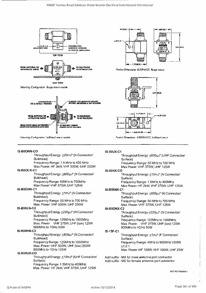
.44.12,1 STAREESS STEIL KOZTAYAILt IKOWNOI TO tIOVIN. C404.94004C
I
TRAM AHTEXNA (TE ANIONUTED SVOCIE
TOP VIEW
SIDE VIEW
11.4' 11I111V C VW*11.11kNi (larg 11*.C.114 kftldtik
to it Pi Chl elID
Mounatvg CooN9un:Mon: bAt.ead mount mcx_441.1
Peal'ov Prit4PWorw 15'.50N4<;s0, 63i/geAmovni
1,144.3,11 . 1.139
ko-,-.223117.1!1-12.1
hook! am rains. Eulth*exi
IS-B5OHN-CO Throughput Energy: <20mJ* (N Connector! Bulkhead) Frequency Range: 1.5 MHz to 400 MHz Max Power: HF 3kW, VHF 500W, UHF 250W
IS-B5OLN-C1 Throughput Energy: <600pJ* (N Connector! Bulkhead.) Frequency Range: 50MHz to 700MHz Max Power: VHF 375W, UHF 125W
IS-B5OHN-C1 Throughput Energy: <1mJ* (N Connector/ Bulkhead) Frequency. Range: 50 MHz to 700 MHz Max. Power: VHF 500W, UHF 250W
IS-B5OLN-C2 Throughput Energy <220pJ* (N Connector/ Bulkhead) Frequency Range: 125MHz to 1000MHz Max. Power VHF 375W, UHF (low) 125W 900MHz to 1GHz 501
IS-B5OHN-C2 Throughput Energy: <800pJ* (N Connector! Bulkhead) Frequency Range: 125MHz to 1000MHz Max. Power:VHF 500W, UHF (low) 250W 800MHz to 1GHz 125W
IS-B5OUX-CO Throughput Energy: <10mJ* (UHF Connector/ Surface) Frequency Range: 1.5MHz to 400MHz Max. Power: HF 2kW, VHF 375W, UHF 125W
IS-50UX-C1 Throughput Energy: <600pJ* (UHF Connector/ Surface) Frequency Range: 50 MHz to 700 MHz Max Power:VHF 375W, UHF 125W
IS-50NX-CO Throughput Energy: <10mJ* (N Connector/ Surface) Frequency Range: 1.5MHz to 400MHz Max Power: HF 2kW, VHF 375W, UHF 125W
IS-B5ONX-C1 Throughput Energy: <600pJ* (N Connector/ Surface) Frequency Range: 50 MHz to 700 MHz Max. Power: VHF 375W, UHF 125W
IS-B5ONX-C2 Throughput Energy <220pJ* (N Connector/ Surface) Frequency Range: 125MHz to 1000MHz Max. Power VHF 375W, UHF (low) 125W 800MHz to 1GHz 50W
IS- 75F -C1 Throughput Energy: <1mJ* (F Connector/ Surface) Frequency Range: 4MHz to 900MHz VSWR <1.2:1 Max. Power: HF 100W, VHF 100W, UHF 25W
Add suffix - MA for male antenna port connector Add suffix - ME for female antenna port connector
DOC REF:P838328-1
WB087 Toohey Road Salisbury Water Booster Electrical Switchboard OM Manual
Q-Pulse Id TMS994 Active 10/12/2014 Page 361 of 400

111) II
5 QA Documentation
-------
WB087 Toohey Road Salisbury Water Booster Electrical Switchboard OM Manual
Q-Pulse Id TMS994 Active 10/12/2014 Page 362 of 400

B
1
WB087 Toohey Road Salisbury Water Booster Electrical Switchboard OM Manual
Q-Pulse Id TMS994 Active 10/12/2014 Page 363 of 400

J & P Richardson Industries Pty Ltd
5.0 QA DOCUMENTATION
File: Swbd Manual Revision 0 Date:11/3/2010
WB087 Toohey Road Salisbury Water Booster Electrical Switchboard OM Manual
Q-Pulse Id TMS994 Active 10/12/2014 Page 364 of 400

J. & P. RICHARDSON INDUSTRIES PTY LTD 114 Campbell Avenue, WACO!, QED 4076
1h: (07) 3271 2911 - Fax: (07) 3271 3623
E-mail: jprapr.cormau
SWITCHBOARD ELECTRICAL INSPECTION & TEST REPORT
Form No.1'101918
Page 1 of 6
Customer Narne: /3,,R <1. 84 Aje c, r7 c 0,......14._ .c. -,
Project: 7a-,,,4,tc.-y R2) 8,0.5-,---te JPR Job No: /1 c 3 7 Item: (00e7 Constructed b : 1.--i. ,..c., t
Elli,roas:,s,1 :441.4.0:- 1.,,
Tested b : A iiz, row iear7,:orkos:ou Date: /6- -42 67
legammeapwitaims Main Functional Unit/s Qty Size Fuses /O/L Fuse Fittings
. ... . Qty Size Fuse Size .V
ircult LireaKers
Neutral Earthing C.T.s Meters Contactors Overloads Relays Timers
Size OIL Reqd
Checked
Qt
Control Switches Push Buttons Pilot Lights Transformers
Qty
Qty Qty
Qty Qt Qty
Qty Qty Qt
Rating Rating Rating Rating Ratin
Voltage Function Voltage Volta e
ATTNFD/Soft Starter DC Su )l
Terminals Engraving Cabling - Busbars Escutcheons / Shrouds S.A. Metering CTs S.A Meterin Links S.A. Meters JPR Label
Qty Qty
Type Type T .e
Rating Rating Rating Ratin Rating. Ratin Sizc Size Size Size
Material
Function Function Voltage Volta e
Function Volta e
ID ID ID ID
IP ratin Ratiry
Fitted Le end. Card
Stain cd
Correct. PLC/Telemetry Power Monitor Rcla MO: -e_rii/Vitganr IP Sealing Door Latches/Hinges Ventilation Circuit Schedule
Size Ratin
Safet Stkr
Function
Terminal Tightness Busbar System Earth Continuity Cubicle Cleaned Paint Finish Intact Polarity Check Function
Rating V-- Qty ..""_,, Type V Operation
Required ../ Type / Operation Required Fitted checked
111 III W.'
.-., ,"OrrMr
Power Clearan.ces Body to E
R R Power.
Control Joints
Doors to E
W - W Control w -
Result ID
Panels to E
13 - B
PLC/Telem Continuity Check R - R
nixie %ils- 'cam '' ,..9fM, VT.
441,4r 1.
B - B N - N
-45aS -t1t, ."-,,samos
WB087 Toohey Road Salisbury Water Booster Electrical Switchboard OM Manual
Q-Pulse Id TMS994 Active 10/12/2014 Page 365 of 400

J. & P. RICARDSON INDUSTRIES PTV LTD 114 Campbell Avenue. WAC01. Q1.1) 4076
II: (07) 3271 2911 - Fam (07) 3271 3623
E-01411: jprapr4,00.40
SWITC:DBOARD CONTINUITY & INSULATION 'FEST REPORT
From N. F1019/9 Nu 1,016
Customer Name: 'j13 PE C fry CG7Z-IA,C4-4"- Project: .74e,ey 647i) tio7.EW JPR Joh No: P-110 331 Switchboard: vvoiy-?. Constructed by: PI , LA (.4-0,/,..:17 Tested by A vAky Date:
.:;.: :01Y1711,SWWiM=5T'-':::i".' '...., ' .. ,,.:,'0:T From To Red White Blue Neutral
Sketch:
26m1-167..., : .-t=igli,.4',-7,-135-2,51NROT,19.8101.sgst71-04sficAt2NOVE'41.5:1'4491L - - ,t, :...t..--;:i,?!'.:;4i.....-.-Aati;I:a. Designation 1000 V Test (MCI) 2.5 kV Test ( lmin ) 1000 V Test (MS1)
Red to Earth 3-ctO White to Earth
Blue to Earth 6--" Neutral to Earth Red to White Red to Blue White to Blue
Continents:
WB087 Toohey Road Salisbury Water Booster Electrical Switchboard OM Manual
Q-Pulse Id TMS994 Active 10/12/2014 Page 366 of 400

J. & P. RICHARDSON INDUSTRIES PTY LTD 114 Campbell Avenue, WACOL Q1..0 4076
Ph: (07) 3271 2911 - Fax: (07) 3271 3623
E-mail: jpr(ii)jpr.com.au
SWITCHBOARD ELECTRICAL INSPECTION & TEST REPORT EARTH LEAKAGE TEST
Form No. F1019/8
Page 5 or 6
Customer Name: a gisa A,,,,,4- etr7 Cc'-lx-Cg-- JPR Job No: /44 3'337 Item: tiMia?' 7 Constructed by: /1. .4:Awe...ay Tested by: 4 . vii /ft/ IDate: / Test Unit IMegger RCD1730 /'''' [Other I
i ciatiBledke . Phace , qvated.quitliti)
. ' .(titNitg0
:-. , r''' ,, ,- :44.,
?..%V.1:4k 4.
- - ^.^.. i , -,-g,,V8S. *Triprelititi" NOtt.,19,524:
4ia ,, x`"41
.';:t.Arlt.:: .
-
V c,.-,- r ... - :1,...., 4, -4FripiTime'-
-
Comments
.2X .-- ,2.... 9 ....s
cz pc, c-i 3 c? 2- icr 3 2-2_
Q. I ,...,, - P
Comments:-
WB087 Toohey Road Salisbury Water Booster Electrical Switchboard OM Manual
Q-Pulse Id TMS994 Active 10/12/2014 Page 367 of 400

FILE: EMC0381/13I, 03/01/03 PAGE 1 OF 1
JOB SAFETY ANALYSIS
LIVE LOW VOLTAGE WORK
TESTING SWITCHBOARDS AND CONTROL PANELS WITHIN OUR MANUFACTURING PREMISES
APPROVED BY: Eric McCulloch (INTISO)
LOCATION: WACOL WORKSHOP DATE: ?.?././.?-.1.'Ef
AUTHORISATIONS
Authorisation from person in charge
YES
PERSONAL PROTECTIVE EQUIPMENT
Long cotton clothing d YES Insulating work gloves in test gf YES
Insulating mats / covers in test YES
Switchboard rescue kit in test 0 YES
TASK
LIVE LOW VOLTAGE WORK
TESTING SWITCHBOARDS AND CONTROL PANELS WITHIN OUR MANUFACTURING PREMISES
OPTION
OPTION
Isolation points identified and accessible Work area clear of obstructions
Unauthorised access prevented to work area
P.P.E. is fit for purpose
Test equipment is fit for purpose
Written authority to proceed has been obtained from a person-in charge JPR authorisation to conduct live work is current
o Approved dedicated power supply only used for testing.
Approved dedicated power supply in current test
(A) RCD protected outputs used at power supply
> RCD protection checked daily prior to use
> Safety Observer is / is not required
(B) Non RCD protected outputs used at power supply > Supervisor consulted prior to use
> Safety Observer is in attendance
YES
V YES
YES
II YES
Pi/ YES
YES
YES
YES
O YES
E/ YES
fl YES
YES
YES
O YES
YES
I understand and am fully aware of the requirements of this job safety analysis.
Signatures: 2. 3.
4 5.
WB087 Toohey Road Salisbury Water Booster Electrical Switchboard OM Manual
Q-Pulse Id TMS994 Active 10/12/2014 Page 368 of 400

41110 ID 411, 4111
6. Switchboard Works Test Results
WB087 Toohey Road Salisbury Water Booster Electrical Switchboard OM Manual
Q-Pulse Id TMS994 Active 10/12/2014 Page 369 of 400

1111111,1111111111111111111'
WB087 Toohey Road Salisbury Water Booster Electrical Switchboard OM Manual
Q-Pulse Id TMS994 Active 10/12/2014 Page 370 of 400

J & P Richardson Industries Pty Ltd
6.0 SWITCHBOARD WORKS TEST RESULT
File: Swbd Manual Revision 0 Date:11/3/2010
WB087 Toohey Road Salisbury Water Booster Electrical Switchboard OM Manual
Q-Pulse Id TMS994 Active 10/12/2014 Page 371 of 400

ELECTRICAL INSTALLATION AND MAINTENANCE
24 HOUR BREAKDOWN SERVICE
POWER RETICULATION
ITCHBOARD SIGN AND
MANUFACTURE
P. IC S IN ST S LT A C.N. 001 952 325
114 CAMPBELL AVENUE, WACOL, BRISBANE, OLD. 4076
Telephone: (07) 3271'2911 - All Hours Facsimile: (07) 3271 3623
ELECTRICAL CONTRACTORS & ENGINEERS
INDUSTRIAL - COMMERCIAL - MINING
CERTIFICATE OF COMPLIANCE
CONTRACT NUMBER BW.70103-06/07 ORDER No: 70103-007 JPR JOB No: C30337
CONTROL PANEL FOR WB087 DRAWINGS 486/4/9-0082-001 TO -016 AMEND. C INCLUSIVE
J&P Richardson Industries Pty. Ltd. certify that the above listed control panel has been tested in accordance with the job specification and the as built drawings on the date recorded on the quality assurance documentation for this control panel.
Yours faithfully, ELECTRICAL J & P RICHARDSON INDUSTRIES PTY LTD ENGINEERING, PROCESS SOFTWARE AND DESIGN SERVICES
SHEETMETAL FABRICATION
MUNICIPAL PUMPING INSTALLATIONS
HIGH VOLTAGE INSTALLATIONS
ITCHBOARD MANAGER
File Name:- wb087 certificate of compliance
GOLD COAST PH: (07) 5591 6340 SUNSHINE COAST PH: (07) 5476 5133 TOOWOOMBA PH: (07) 4659 9900
-A Family owned company providing Electrical Services since 1958." FORM F 1025
WB087 Toohey Road Salisbury Water Booster Electrical Switchboard OM Manual
Q-Pulse Id TMS994 Active 10/12/2014 Page 372 of 400

J. & P. RICHARDSON DURRES PTY. LTD. A.B.N. 23 001 952 325 Lic. No. 758
ELECTRICAL CONTRACTORS and ENGINEERS TELEPHONE: 3271 2911 (All hours) 114 CAMPBELL AVENUE - WACOL, BRISBANE Q 4076
DOCKET No.
CUSTOMER:
ADDRESS:
70-0?/C`i
DAY: *CA/ DATE: / k. cit
EMP. No. 2.1/
K 7999
,...,,JOB NUMBER
W ti NHOMS 11
0 -1 7, -I WORK START TIME
NORMAL
RISK MANAGEMENT HAS BEEN CARRIED OUT IN ACCORDANCE WITH: RISK ASSESS SAFETY PLAN
1 have carried out the work listed & I confirm it complies with
Good Work Practices, Our Quality Goals & to Customer's Satisfaction.
H
izoe#,Pt0-.e. city/' e7-e
c)K
Customer's Authorisation for live work:
/01,4 44 es 4-
REPORT PROMPTLY ANY
CONDITION LIABLE TO
CAUSE AN ACCIDENT
REMEMBER
YOU AREor RESPONSIBLE
FOR YOUR SAFETY
TIME CLO
n (A-n./ %y -ic7s7 cc i/W .--/APC)4/1 54m
Customer's Signature Employee Signature:
Refer to Customer Copy for General Terms and Conditions of Supply
WORK
TRAVEL
W 7_,42.0 To j S.() 0 To
48m
42m
10 UNITS PER HR.
12m
18m
36m 24m 30m
ENT BY:
FIRS. MIN,
To
UNITS
To To To
SERVICE CALL - APP BY - ENDORSEE-
CALL OUT - COST SECTION - SERVICE
FOLLOW UP CA SS
DRIVER FATIGUE MANAGEMENT UNIT No. Over 12 Tonne GVM
Driving Time Driving Time Total Hours Start Finish Start Finish
Farm No. F1024/4 June 09 e Copyright 2008
CERTIFICATE OF TESTING & SAFETY
I certify that the electrical work liSted has been tested in accordance with the prescribed procedure and that such work complies in every respect with the requirements of the Electrical Safety Regulation 2002. The electrical equipment listed to the extent that it is affected by the above electrical work, is electrically sate.
Electrical Licence No:
Signature of Electrical Worker:
WB087 Toohey Road Salisbury Water Booster Electrical Switchboard OM Manual
Q-Pulse Id TMS994 Active 10/12/2014 Page 373 of 400

P09 J & P RICHARDSON INDUSTRIES MI
J. & P. RICHARDSON INDUSTRIES PTY LTD 114 Campbell Avenue, WACOL. QLD 4076
Ph: (07) 3271 2911 - Far: (07) 3271 3623
E-mail: [email protected]
TO
Form No. F1017/3
A ,Sec..7-Tu.)A)
of SWITCHBOARD & SHEETMETAL INSPECTION REPORT
Customer Name: C C Item: v\i, 6 oa-7 Tootee,-/ wi3 TeR abiric
Job No: C 30,S37 Drawin No:
cb2 / /0 CORRECTIVE ACTION
REQUEST OR COMMENTS
PRODUCT INSPECTED TASK DATE
DETAIL
Design Documents
Drafting Documents
Sheettnetal Switchboard. (Refer F1018 for details) Doors.
Cell/Panels
ainting
Process
Min DFT (40 STD)
Cure Test
Colour Exterior
Colour Internal
Colour Panels
Powder / Wet
Cubicle Erection
Electrical Fitout (In accordance with drawings
Inspection & Test
(Refer to F1019)
,cking
ornments:
et5S
,-;-MWERMA Affix Status Here: -
Yellow Awaiting Inspection
Green Inspection & Test Passed
Red Inspection & Test Failed, Awaiting Rectification
WB087 Toohey Road Salisbury Water Booster Electrical Switchboard OM Manual
Q-Pulse Id TMS994 Active 10/12/2014 Page 374 of 400

.1. & P. RICHARDSON INDUSTRIES PTY LTD 114 Campbell Avenue, WACOL Q1,1) 4076
Ph: (07) 3271 2911 - Fax: (07) 3271 3623
E-mail: jprgipneom.au
SWITCHBOARD & SHEETMETAL INSPECTION REPORT
Form No. F1017/3
Customer Name: 3265/Qat Cay Cau/vaL Job No: S 30337 )4 30337 Item: W43 o8-7 'TcciiE1 D
14) /TER &OSIER_ ru 10$ 9 NG 5k,tftc.1-1AAte. b.
Drawing &*5---
DATE
No: Ca)33-7/A0
PASS /
FAIL
CORRECTIVE ACTION REQUEST 017 COMMENTS
TASK PRODUCT
DETAIL INSPECTED
B Y
Design Documents S kT 10 io o8 Drafting Documents
Sheetmetal (Refer F1018 for details)
Switchboard Atli
Doors u
V Cell/Panels }
tinting
Process
MM DFT (40 STD)
Cure Test
Colour Exterior .
Colour internal
Colour Panels
Powder 11 Wet
/
364 tilL ASV 364.0 Cini.`ni ifff illirffir
,
.
al GC wile Cubicle Erection-
- , Electrical Fitout
(In accordance with drawings) M. Z-../P44-Jz...ay
Inspection & Test
(Refer to 4' 1.0 I 9)
4. VAR.- 1 / er /9/95.9
Packing ....aka .4.7","
. ;.+Intnents:
book CNER F ige",0-40pEASE: Ly CT PA 1 'lc R 6 D .
tar ' , g autrski //01,..-p," / e /1 0
-, -44/30,w.k,ii.o.:4:iiiitiftwo:*o70,04-v,sliitigigihr?.p..4.s. ovii,goigi* Affix Status Here: -
Yellow Awaiting Inspection
Green Inspection & Test Passed
Red Inspection & Test Failed, Awaiting Rectification
WB087 Toohey Road Salisbury Water Booster Electrical Switchboard OM Manual
Q-Pulse Id TMS994 Active 10/12/2014 Page 375 of 400

a
J. &. P. RICHARDSON INDUSTRIES PTY. LTD. 114 Campbell Avenue, WACOL QLD 4076
P11: (07)3271 2911 1ia: (07) 3271 3623 E-mail: jpr®Jpr.contau
1
SWnrra ()ART) / SiffE3'114kTA TNSPF,MON eiffrKLYST
FormNo. F1018/2
. . _
CLIENT: Jgai 6/4"-/b..'_ el ry eff,tritie/4_. JOB NO *. -,; 7 PRODUCT DF,SCREPTION: - Iii'' 00 7 7-z-4.24/,,,,,v go
....?,
DRAWING & SCHEDULE NUMBERS
' C'O'> o ,. i- e -a-- 0 Mei)
CONSTRUCTION QUALITY commiANck
WITH DRAWINGS REMAR1CS OR
GOOD POOR YES NO. ACTION
1. Folds -1 Welds
3. Edges/File
4. Gauge
5. Material L/
6. Ventilation Openings / Filter Bracket
7. Equipment Mounting Arrangement
8.. Doors Stiffened
9. .. Escutcheons and Lexan Covers
10. Cable Saddles
11. Grinding
12. Door Stays Fitted
A . Earth Studs
14. Rubber Retainer
15. Drawing Holder
16. Hat Sections
17.. Locking Bars Fitted
18. Eternal Crevice Welded, and Ground
19. Legend Cards
20. Genersil Conditions Satisfactory
21. Cabinet Clean ,
34b Name and Number Marked
INSPECTED BY: -a-7.---- DA.TE: /4--/ 0 -0
AFFIX STATUS HERE Yellow Awaiting Inspection Green Inspeeted/Testcd Passed Red Inspected/Tested Awaiting Rectification
WB087 Toohey Road Salisbury Water Booster Electrical Switchboard OM Manual
Q-Pulse Id TMS994 Active 10/12/2014 Page 376 of 400

GI
7. Electrical Drawings
WB087 Toohey Road Salisbury Water Booster Electrical Switchboard OM Manual
Q-Pulse Id TMS994 Active 10/12/2014 Page 377 of 400

41. 410
iiiiIIIMIHMI11111111
WB087 Toohey Road Salisbury Water Booster Electrical Switchboard OM Manual
Q-Pulse Id TMS994 Active 10/12/2014 Page 378 of 400

J & P Richardson Industries Ply Ltd
7.0 ELECTRICAL DRAWINGS
File: Swbd Manual Revision 0 Date:11/3/2010
WB087 Toohey Road Salisbury Water Booster Electrical Switchboard OM Manual
Q-Pulse Id TMS994 Active 10/12/2014 Page 379 of 400

WB087 Toohey Road Salisbury Water Booster Electrical Switchboard OM Manual
Q-Pulse Id TMS994 Active 10/12/2014 Page 380 of 400

A
B
E
F
G
H
2 3 5 6 7 9 10 11 12 13 14 15 18
ig
I I
iIIIIIIIIII BRISBANE
WB087 TOOHEY RD, SALISBURY
WATER BOOSTER SITE COVER SHEET
/ ELECTRICAL DRAWINGS INDEX
DWG N°. TITLE SHEET REVISIONS L860 /9-0082-001 ELECTRICAL DRAWING INDEX 01 A 5 C
LSE/L/9-00E2-002 BLOCK DIAGRAM 02 A B C
EFs/E./9_0052_003 AC POWER DISTRIBUTION SCHEMATIC DIAGRAM 03 A B C
L06/L /9-0082-001. PUMPS POWER S CONTROL SCHEMATIC DIAGRAM Of. A B C
1.6/L/9-0002-005 DC POWER D S'RIBUTION SCHEMATIC DIAGRAM OS A B C
1.06/L/9-0002-006 COMmON CONi POLS SCHEMATIC DIAGRAM 06 A 6 C
L06/L/9-0002-007 RIG DiGJAL .NUTS TERMINATION DIAGRAM 07 A B C
( LBO/L/9-0092-008 RTU 0 Cr: AL OUTPUTS E. ANALOG INPUTS TERM NATION DIAGRAM 00 A B C
L86/L /9-0082-009 PUMPS CON-:ROL 7ERMINATION DIAGRAM 09 A
A
6
B
C
C ( L86a/9-0082-010 SWITCHBOARD EQUIPMENT LIST 10
06/L/9-0082-011 SWITCHBOARD CABLE SCHEDULE 11 A B C
L8E/L/9-0082-012 SWITCHBOARD LABEL SCHEDULE 12 A B C
LE6R. /9-0082-013 SWITCHBOARD CONSTRUCTION NOTES Ey DETA.LS 13 A B C
1.06/1./9-0082-01L SWITCHBOARD CONSTRUCTION DETAILS -1. A B C ( L86/1./9-0082-015 SWITCHBOARD GENERAL ARRANGEMENT 15 A B C
( L8e/L/9-0082-016 SITE LAyOU" 16 A B C
( LE6/1J9-0082-017 spare
L86/4/9-0082-018 spare ( LH/L/9-0082-019 spare ( LF6/L /9-0002-020 spare
(
(
.( S
ELECTRICAL AS BUILT DETAILS REV COMPANY -
_ CONTRACTOR LICENCE No. -
ELECTRICIAN DATE: -
r STANDARD VARIABLES N.
DESCRIPTION VALUES WATER BOOSTER PLANT ID WBOE7
MAIN FLOP/METER ID, F0105
PRESSURE INLET ID. PRESSURE UL.:_E I ,D POO9L, P0095
STREETNAME, SUBURB TOOHEY RD, SALISBURY
DRAWING NUMBER 1.06/i. /9-0082
SUPPLY AUTHORITY POLE Nc 2L118
INCOMING MAINS SUPPLY CABLE s:;---.7 16 MM
MAIN EARTHING CABLE sqmm 6 MM
CT METERING ISOLATOR 80A A, DINTMS0C3
NORMAL SUPPLY MAIN SW,-Cr- 80A, XS125CJ80
GENERATOR SUPPLY MAN SW ",-- BOA, XS125C.:80
Grundf cs PumpSei Assn Par \.,:. CRE45-2
PUMP KW RATING 11, 2, 3. ,:::
PUMP CIRCUIT BREAKER H. 2, 3, I- E,
2 2 NW 12 2 ,.W 122,04
DTCB15320C 12,1C3S.:2CC 101:B15320C
2 2 ',..,4
01(51",:201
PUMP MOTOR SUPPLY CABLE s(E"- V'. 2, 3. LE 51 5) num 3C.E 25 ,,,- 31E 125 mra 3C-E 25 mm 3CE
MAIN FLOWMETER RANGE T B A.
RADIO DR900-06A02-DO
. .
c, . STANDARD DESIGN OPTIONS
OPTION DESCRIPTION FITTED
Al PUMP 3 FITTED YES Mr] A2 PUMp L FIT7t2 "ES M
TLiY.n-5-nT7ED ,35--. NO A3
D D sT r Cn,'ME TER-HET TED 6,--;=-2 NO A-S..-S L
C1 MET R T Li YE S DM ',D'A DIG P.:5..K-' NO :=1.
I Di GSM MODEM YES I>L1
TACO '..CDE_'.. i'L....'.,S NO DC
E TRIO RADIO YES CNSTJ
Ti PUMP BOX SUMP PUMP YES IIT:g]
±R-P4-T-SlzdivtP-E-1,,,,M-P ,'''. NO -9-2
C",_:17. H:='.-2 NO Ci BO;', VENTILATION-PAN
. .
A
B
C
0;
E
F
I
V GI )0
II
O. I
0 I
HI ,
/B\ Sheet 01 ,
ISSUED FOR CONSTRUCTION C 18/02/09I RE-ISSUED FOR CONSTRUCTION I OPM AW FUNDING
EXTERNAL ( ) ._.A.
DRAFTED P. NA c, stet rt Original Signed by A.Witihoft
DESIGN
8895 04/07/2008
R.P.E.Q. No. DATE
04107/2008
R.P.E.Q. No. DATE _A...CLIENT
Original signed by F.Fomailer 04/07/2008
PRINCIPAL DESIGN MANAGER DATE - -4` _- r,"."-P' - tilt &AO sati6A746
SITE
VVE1087 1-CIC:31-1Elr RID VVAMER BOOSTER.
-A-__
TITLE
ELECTRICAL DRAWING INDEX
SHEET No. 1
A 05/08, REDRAWN ISSUED FOR CONSTRUCTION DPM AW DESIGN W.O. No. DRAFTING CHECK 1 p, i-lagueat BRISBANE WATER DRAWING Na. No : AMEND.
486/4/9-0082-001. C - 0 09.08 ISS 1-1 EC) RC. IR. -1- a NI ID E Ft 1 DPM CONSTRUCTION W.O. NoLi
FUNDED BY B.C.C. (v)
CAD FILE 490082set_A.dwg Original Signed by R.Janfada
DESIGN CHECK
_ Original signed by P.Sheniff
DELEGATE
04/07/2008
DATE No: DATE i AMENDMENT DRN. APD. -A. B.C.C. FILE No. .1\
2 3 4 6 7 8
0.1194 WATER supPy2tz onyi,roszyg piuns191a,tnyahl WATERWETNORKSIW)3087 'Foamy PAConseuctic41490082saLCAsyg Loll Saved by 002670 on Friday. 20 Fa.ary 2009 2.2748 PM
12 13 14 15 16
WB087 Toohey Road Salisbury Water Booster Electrical Switchboard OM Manual
Q-Pulse Id TMS994 Active 10/12/2014 Page 381 of 400

WB087 Toohey Road Salisbury Water Booster Electrical Switchboard OM Manual
Q-Pulse Id TMS994 Active 10/12/2014 Page 382 of 400

E
F
H
2 3 4 6 7 8 10 11 12 13 14 15 18
WATER BOOSTER SWITCHBOARD
NOTE
do.,b,e nes nd,ca'e oper2for,nierface
NORMAL IMIRG COMPARTMENT POWER COMP CONTROL COMPARTMENT
-I5V AC 10kA
(80AAISOL
KWH 1
GENSEI
MAIN MTS SWITCH
COAA
60A
EARTH tONG
SDI
SuRGE PROTN
WATER IN
iLVDC GATT
AN-ENNA
ONO
SURGE . I
- RADIO I
SEI PSi
AC
FIL
PAIR L
2LV DC
SUPPLY
2L0vac/24vdc
MPG A )1
Grundfos
AL ARM
RLY
SOAR
7
t113
2LVDC
Grundf es 0100
MOnbus. HC.- WAY
6A/ BA/
-1 1-
P H A SE I ,
FAIL RE_As'
2A/ 20A/ n
C
C
(
C
C Sc., \IP H
E EVE',
AUTO
VFD
C
WA' H BOOSTER PUMP BOX
REV
ELECTRICAL AS BUILT DETAILS COMPANY -
CONTRACTOR LICENCE No. -
ELECTRICIAN - DATE: -
I
20A/
GEN1b.,s GENIbus
PSR I/L MAN Rd\ - MAN RUN
2 2 kW .
2 2 kW
PLO/SKI
>1
GSM
AN ENNA
-
I GSM
MODEM
L 0:AL / TIMBrE
SE_ECTOR
2LVOC
RTU D I H
1
(----..,----v--Th,--- ; \ 1 L../
I-- ( I ) 4----,,::: , ) -,,
0 I
.
I I
E 1 )DI(3.- AL DIGIT AL
2L VD: ( , !NPUIS OUTPUTS
C ,
( 1 ,/, ) 711 I
I' I
I
20A/ n 20A/
VFD
0FNIbus
PSR IT L- MAN RUN
22 kW
-1 1GENIbus
VFD PSR I/L n MAN RUN
22 kW
PL,
POui 94*
IGRUNDFOS CRE45-2
I s / / / / LA.= j
I . . 1 1
P, P2 P3 PSR IL
r7
Pi.
goego 1-1
' ( / I ;
PI P2 P3 PL.
MAN RUN
C PUMP mOTOR V=Ds./
'..-----N\ ---",--- -, (REMOVED. c!RE SW \
ACONIACIS. J \--"-_,....._.........-/
1-77 WATER OUT - -
WATER BOOSTER 1./m
FLCWVE1ER P''
C
C
C
C
C
C
C(
S-N =.;-ZE SW
'RI/OFF/CONTROL VflflT SELECTOR
/43 R.2".P BOX
\ AT1ON
PB
POMP
V! P`,"
Sheet 02 ISSUED FOR CONSTRUCTION
C 11562X61 RE-ISSUED FOR CONSTRUCTION 1 DPM AVV FUNDING DRAFTED 1 F..IVIcsstosart
A 105/081 REDRAWN ISSUED FOR CONSTRUCTION 1 DPAI !AVV DESIGN W.O. No. 1 DRAFTING CHECK 1 o.
0 109.0E11 ISS U a C7 FOR c -r88 NJ C3 E IR 1 DPN : CONSTRUCTION W.O. 90.1 CAD FILE 1490082sol_A.dwg
No.! DATE! AMENDMENT 1 DRN. / AND. FUNDED BY 8.C.C. 1.1 EXTERNAL ( 1 B.C.C. FILE No. I
Original Signed by A.Witthoft
DESIGN
Original Signed by R.Janfada
DESIGN CHECK
8895 04/07/2008
R.P.E.Q. No. DATE
04/07/2008
RP.E.O. No. DATE
Original signed by F.Fornasier 04/07/2008
PRINCIPAL DESIGN MANAGER DATE
Original signed by P.Sheniff 04/07/2008
CLIENT DELEGATE DATE erTia4NE WATER
SITE TITLE VV 087 MC) CD I-1 B Y" F E WT IR. BOOSTER FL. BLOCK DIAGRAM
SHEET No. 2
BRISBANE WATER DRAWING No.
486/4/9-0082-002 AMEND.
C
2 3 4 6 7 8 9 10
G:1194 WATER SUPP1266 0ral:m0162A wA TERWEI1VO.S1W8087 Toonay RCAConstruceonIA900626c_C.
12 13 14
Lam Sand by 0626700, Fn., 20 Fbruary 2009 2.2746 Pm
15 16
A
B
C
D
E
F
WB087 Toohey Road Salisbury Water Booster Electrical Switchboard OM Manual
Q-Pulse Id TMS994 Active 10/12/2014 Page 383 of 400

18
jD
E
G
2 3 4 5 6 7 8 10 11 12 13 14 15 16
3 PHASE C5VAC SUPPLY FROM POLE No 2L1TE
CABLE SIZE 16 ,1M
N P w P,
miR6 SOLAToR 80A
1 I
PENERGE X 1 LOCKABLE 11 D:RECE mETERING
ETEr,,NCT: COYPARTMENT
MEN LINK
FT SR1,2,3 610
oli
CI
512
ETA 80kA
ii IS MANUAL TRANSFER SWITCH
02 NCRmAL SUPPLY GEN SUPPLY miUN SW-TEA MAIN SWI EH
500 800 ING1E 7. tNOTE i 71
GENERA i OR EXTERNAL CONNECTION PLUG
{
Iro
5A
620
621
622
. 09n 610 //9
(EA = 3OrnA
Er
o_
S i A ION MANS POWER FAILURE RELAY OCT 05E?
( GP^ IN P CUBELE (LAPTOP)
-(. GPO .N 13 s'R.BGTION CUBICLE
NOTES I INCOMING MAIN, GENERATOR, E. DIST BOARD CIRCUIT BREAKERS SHALL BE SHROUDED ON BOTH LINE E LOAD SIDES
2 CIRCU11. BREAKER RATINGS TO SUIT FAULT LEVEL 2. LOAD ENSURE TYPE 2 CO-ORDINATION WITH CONTACTORS 2. OVERLOADS TO IBC NLT-L-i
3 ALL MIRES C CABLE CORES ARE FERRULED WITH GRAFOPLAST 512000 COMPATIBLE LABELLING
623 SF1
FT CRJEC ism,-
FIL TER I
l 11- _I
- I
'
.,-:' , , i T ' - : TS:
z.,_
i.)
SDI
AC POWE:R
sLisT,3E
502
0: \.(E ERc I JET
020 624
RTL; LL VDT POWER SUPPLY RT.- 05E12
! I
\/ : '
LS.Di2!
SC SD.
5D23
1:ARY Av LA N20
52 A
c
-50- li
,,..---o
, ,,,. LA
625
- !.- , 1/2I
:
- - I 623 - -:_-.---0 i
022 626
GRuNDFOS rlYDRC MPC
C-2RUNDFOS G'00 GATEWAY oF Gs H=.
SURGE DiVEP TER AND FIL EP. OK 1 REF TEE'?
N
0102. 4A N22
0/02- :
i
623 023 627 ...---° LA 1833
SLR-' 010 650
651 1 FLUORO IN CUBICLE REF
BA
) .012 639 P-012 10,4 OGELL T. )
PUM- oc..3X 7- -C , ----1--, NI3
) EA = 30(EA SUMP PL,MP _7 ....-- ..
LPUMP BOX N - A" 0 5 5 MP PUMP ) ) ) )
).---"
' - - - _ - . . " . - - - - " , . . . - - " , - - - - " , - - " , - - , E N A W
CON T.NuEC ON S
ELECTRICAL AS BUILT DETAILS REV COMPANY -
CONTRACTOR LICENCE No. -
1
ELECTRICIAN - DATE: -
; C 160209 1/090-ISSUED FOR CONSTRUCTION DPM FUNDING
A 105/06 REDRAWN ISSUED FOR CONSTRUCTION DPM AW DESIGN W.O. No
0 109.06 I 2020 U EC) F Ft TENDER 88 I'4 DPM CONSTRUCTION W.O. No.
DRAFTED 1
DRAFTING CHECK
CAD FILE
No DATE AMENDMENT DRN. APD. FUNDED BY B.C.C. (,) EXTERNAL ( )
1 2 I
3 4
B.C.C. FILE No. 1
C
C
C REMOVED PUMP BOX
LIGHTING & VENTILATION F.
PUMP STOP PS
ADDED SUMP PUMP
Mosta rt Original Signed by A.WIttholt 8895 04/07/2009f Original signed by F.Fmnasler 04/07/2008 SITE TITLE W13087, -1-001-1EY IRID AC POWER DISTRIBUTION u DESIGN RP.E.Q. No, DATE PRINCIPAL DESIGN MANAGER DATE Pi i5 vviocraFt Escpcis-ra SCHEMATIC DIAGRAM 490082set_A.dwg Original Signed by R.Janlada 04/07/2009 Original signed by P.Sherriff 04/07/2008 ugtiti
BRISBANE .,DESIGN CHECK RP.E.O. No. DA CLIENT DELEGATE DATE
6 7 8 -
I CriENE
VDF TERMINAL
PLC /R3L; MARSH FUSE TERM
o PLC /P'S MARSH LINK TERM
-C,-- CPSCONNECT PLUG
RTU
D"-". ) DIG.T! AL 'NRU1
< > OiC2:T AL OUTPUT
),1102 1 ANALOG INPUT
1 101-15 -11; ANALOG OUTPUT
Sheet 03 ISSUED FOR CONSTRUCTION
SHEET No. 3
BRISBANE WATER DRAWING No.
486/4/9-0082-003 AMEND.
0:1194 WATER SUPP,268 0ral94,916248 Pl0.,Ebcalcal4 . WATERWETWORKS1W8087 TRolley Rd1C0ns.c8on1490082set C.0.9 Lam Saved by
12 13 14 15 _ 062670 on Fnday. 20 Feduary 2009 227,18 PM
16
WB087 Toohey Road Salisbury Water Booster Electrical Switchboard OM Manual
Q-Pulse Id TMS994 Active 10/12/2014 Page 384 of 400

I A
,C
F
G
H
4 3 3 F ALA. 8 in 10 10
CONTINUED FROM 03 E N
Pi- VFD
03 ,
1 LI
I
/ 1 io
'j-°- 1
L2 I ( P } ... --( 1 Ei
- \ I
L 3
204
3 v
Gn a PE
PUMPS STOP PLY REF 01. Fil=1
ITO 3 PSR-2 I '
II
3 :I /10 ,21, /
RTJ DO MAN RUN PLY P/RUN REF 06 ht. '
(A REMOVED Sil FIRE SW )
1
C 1
11 DIII P1 PAuL 1 0- !
-3, REF 05 02
ORLINDFOSS ERE 32-i 22 NW
Si hr//s!£0
1! 2,db 3 ONO (frame!)
II 281 0,g,t a! inpu;
II 'WI) E 38t,
FAULT NE) ,,
vn ,, C X - P1
A FROM MPC
WI:
GENIbLs PS/-EN REF OS h6 1 sh O,
Po
/ /1 i/n
( 6,
P2- VFD
i
Li 1
r , p,- IN
L 2
\ - I L3 I
I
PE
120 Pdh , C P2 iwr, 0 , '-ii -- I
PUMPS STOP PLY i
il II \ _t:, REF 01. Fi 13 ,-__-0 \ 2 St af i /st op
29!//1 ii!: i!..,;. -0 ! II '..i GND {frame!
iii nii3A i - /, 1 7E -I i Op/ c/ ,npui
II I
\ I
\ I
50
GRUNDFOSS ERE 32-1
2 2 44,1
I RFU DO MAN RUN RLY , p2RLJN REF 05 HI- '--
------ /------N.---,,,,---_, (AEMOVED S11 I
FIRE SW ) N....-- ..._......._....------'
WI: FROM MP( f
REF 05 HE 1
P2 A
L.,
PEP 05
On). 3' WO I
l' MC-
11 -, 11 i'' i FAULT IT-HI
FT /, EX-P2 : Ti I A WA 4
I !! r-E, -a Y GEN1bus PS/-TN
1
05 PO
4 !
\ 41 W17 "
(--n ' ..-.1--- --.___' 1-.1 20A \ I
Go
\ p w B
PUMPS STOP PLY REF 0/- ,T13
PSR-1.
RTU DO MAN RUN PLY p3puN REF 05/1. ..e.......0
(APEMOVED C FIRE SW )
...-..."...,_....."..,__,...........4
POM MPC WI:
REF 05161 Sh
iv ELECTRICAL AS BUILT DETAILS COMPANY -
CONTRACTOR LICENCE No.
ELECTRICIAN - DATE: -
Li.: 020/h
127_ 11
!,/ 0 :1
21 /-ALL. 12
RE, 05 02
loIn
iE
D113.
P 3-6/F D
MLT
L2
L3
PE
GRUNDFOSS (RE 32-1
2 2 NW
2 s. c iis. cp
GNO (frame)
i ;EA I
z! !nr,u;
:11,/h
FAULT (NCI 3E/,
3C //71 TX-PT
I
v I
PUMPS
071 A 'dr, A
GENibus P5/- 35
BOOSTER ?LIMP Nol 2 2 ',14
(ClosedrRunPerrn,)
(Ciosed.,RunpMaY.Speed
(Oper,,NormaIRTUcont roll
(Open,Faulti
N4 BOOS TER PUMP No?
2 kW
(E138.00,RurParniu1
Tfleseb,Run@maYSpeed) TOpen,N0rrniPI..2.:(_,-.roT)
TOpri,Fact TT
BOOSTER PUMP No3 22 NW
IT tos ed,RunPMax Spee.d)
TOpen:NcernaiRi Uc not roll
(Open .=;:ault I
N RW
05 Pc GRUNDFC1SS
/ - III 1 CRE32-1
/: e44 7 2 kW
i°-- / - IlL2
I / ---,IP .PL -.' - f '---EL - - - - -- - -NL3
6 204 41
1
U fr
N 0r PC
iz 0 I'dh ----- -- PUMPS STOP PLY pcp_s
12,.. I \ il 5 T.A 1E4
REF 0 I. Hili F. 06 A Z 1 __,....0 0' \ 112 St4,474StoP 12'. II II \
TOT 2//u , 2e, ,
0- ! - I' - 3 ONG If ramel
11. 2 ?Et, ,1 25t, 0- ' - 1 D!gl; a! nput 127 I' II
II 1[
II 1:
-%13,1 DIU 3',/r,
RIU DO MAN RUN RLY pt.RUN REF 06 '
(A, E MOFVIRE S/.1
FROM MR( wt,
REF 0602 I 0154
P3 FAULT 31 '
- 32
,,17i!
WT
4uLL (NCI
REF 0516 " ON nos PS/-EN
C
C
C
/TO.
REMOVED PUMP BOX PUMP
Si OP PB
ADDED SUMP PUMP LEVEL
PLY
RUMPS
I. V DC POWER SP.'"' 110-
REF 007
PS/ (ST ( ) "1-0
0001/ TITIiTOII (30:311:(003=5 a os: 0 PUMP 3/0/
DO DS2 T ,
Eo. ,s DS i 0 , 0 0 O ITT-
TO ' -04
. 1 Eil(r HA , (. 36F ".!....."-:"----..__- PL °/ .0. 17) PIT LEVEL R(/- AY
( PROBE 300 'or AEOK._ PIT FLOOR LEVEL, 1 i(
REF 05 Ell.
__
5E1' 06 02 Pi. k
1 11 !!:!'.!
..._,,.........",....-;,......./ -,- j
(......_../..-/..___/.._, - - -- ' L.--)
S TOP ALL PUMPS RELAY REF 06 02, 04 01. El, 0/.33. 0:. 0.
SECURITY E LIGHTING NE_ A' REF 03 FL. 0502
BOOS' ER PL2,-P Nc.T.
7
osecT,RurPe!-Tr!,,I
ICtosed:RL,npMaxSpee0: TOper,Norma!R T UT CS' roI)
LEGEND
VOF iERM;NAL
PLC /RI U MARS, FUSE 11L-1-7,7,
0 PLC/P. MARSH L''6% TERM
DISCONNECT PLQC3
Riu
011-0, )
Ill-02
E,61Ciri AL OCP,..,
ANALOG APu
401-02 II ANALOG Cif' PU-
Sheet 04 ISSUED FOR CONSTRUCTION
C 18/07./09
A 05/08 '
0 09.08
No. DATE
RE-ISSUED FOR CONSTRUCTION DPM AVV FUNDING DRAFTED P. NA as ta rt Original Signed by A.Witthoft
DESIGN
8895 04/07/2008
R.P.E.O. No. GATE
Original signed by F.Fornasier 04/07/2008
PRINCIPAL DESIGN MANAGER DATE i 6 :..., U 4' '?
"7-' III 10111
SITE
VV E9087 -1-00 I-1 El' RID VVATER BO cls-ra Fk
TITLE
PUMPS POWER & CONTROL SCHEMATIC DIAGRAM
SHEET No. 4
AMEND.
C REDRAWN ISSUED FOR CONSTRUCTION DPM AW DESIGN W.O. No. DRAFTING CHECK
; 1.... I-lag u a BRISBANE WATER DFtAWING No.
486/4/9-0082-004 ISSLJEC3 Pol.:. -r i!!..s cl.st DPM CONSTRUCTION W.O. No., CAD FILE 1490082sot_A.dwg Original Signed by R.Jardada
AOESIGN CHECK
-- 04/07/2008
R.P.E.O, No. DATE
Original signed by P.Sherriff
CLIENT DELEGATE
04/07/2008
DATE AMENDMENT DEN. APD.A.FUNOED BY B.C.C. (v) EXTERNAL ( ) B.C.C. FILE No. BRISBANE
9 10
GA,Cie WA, ER SLIPP1260 12010,62ee PIw,mE4nc$3. WATERWERV0.S1WB082 moray Rd1Coaslmclien 490082sei_Cdwg Last Sawed by 062670 on Foiday. 20 February 2009 2:27,48 PM
11 12 13 14 15 16
A
B
E
F
WB087 Toohey Road Salisbury Water Booster Electrical Switchboard OM Manual
Q-Pulse Id TMS994 Active 10/12/2014 Page 385 of 400
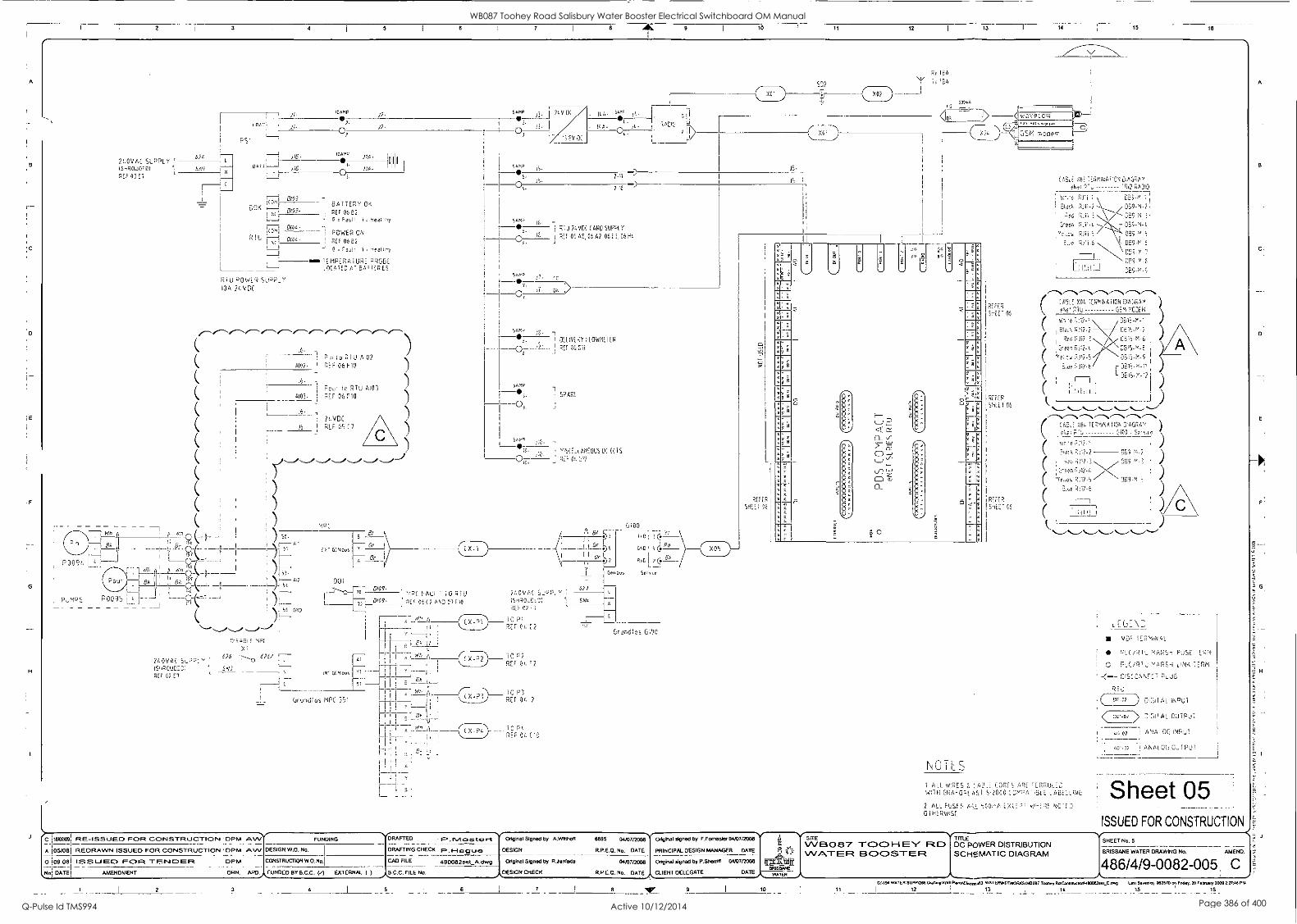
8
D
1E
F
H
2 3 4 8 7 8 9 I
To 12 15 16
200VAC SUPPLY ISHRUDEDI 0E5 0317
Pt.,NIPS
1
i
i
i
,
!,
0 ( __ ,_ --- J
M A 444r( 0
='_ ,
0095 E - - C (--.- 1
:71
674
500/
I '
o Quo
ps
1/.
11,
J;(3.
L., A
LJ
BOK
R
.10 1- 1
L±;
(CMI
I I
'0007 02.
003-
0/03-
DIG/ .
0/04
1:5U POWER SUPP_Y /OA 2I.VDC
/2.
11A 10
114-
OAT TERY OK
0E5 0502 - 0 4 Fault. A Heai'hy
POWER ON
R 04E2
o Fauli, i
moo TEMPERATURE PROSE CLUED AT GA]
P o RTU
4102. ' REF 06 F10
4102
16. - Foul i 0 RTU 4103
6103. 1 REF 06 HO
2c.VD(
)6- RLF (7
054401 'OFT
21.0VAC C,P:7-, ' 6,26 4241,
ISHRCUDED; SA'! REF 0717
1
EX1
001
72
.40w j3. I 20001 .
500P
05_ '
"3 EV 0.1
/0 A . ,4m= 10.
- (44- .L. A
2-/7 I)
002 .
4. 0 XO?
15.
2.10 -)
04MP 16.
FLU 2LVDC CARD SUPPLY 6 10 j
REF 0043, AS. 06 41, 00E3, 0640
7. CI- GA 0,,
5000 e.
54-M
00
I DELIVERY FLOWME TER
I 0,011
SPARE
5015A - e;c
.0 ',SCE _ LANEOUS 1015
RET st
51
1
Or
0109. 627 :-AuL -0 RP.) 2/.0VAC
0/09- 01c 001? AND 07110 (05005,DA:;; 1 SNZ I ,
71/ 02 =3
rn A . P'
' )- REF 00 C2 E
C3100
1,01
GND ,1 :4 Ed
0,0 I 2 (1'.
Gen Du, SP, re
01, II
' A
p
IN; 5:7,4D, I Y,
A ( TO P3
Os 1
df) r O Pt.
- - X REF 00 C C;
I E Et L;
Grundf as MPC 351
Grundics C110i.?
REFER
SHEET 06
1
0N,A 1
<D'A --q w cv et. ,At IA- 1:-
a t 2
: s ,
z
. 7 ' '9 8
. 08
a 7
a 9 8
a 9
xr '
a .1.
- a a
r-r- , ,.
a 4
a A :.
a ; .
-0 a s ,
s -
_
.
-
a
1
,554
0_
l.f)
..?:
< -'",-
-/
-i
'''-' Z
0
.
-, E
,-.4
I
0
0-4
E
. a
Q s
9 ' 7 i 1
9 v
7 a
7 '
5 a
s
L-11 9 a , i ,
v g a
; ; r--3-
s
....-1-
N 71 LT
REFER
S'nEi. 105
REFER
55(1106
REC'ER
!SHOE' 06
;AE: 401 TERM/NH//ON DIAGRAM
eNe TAO!()
I R111-2. / DES-M-21
Red R111-1 Coo-V, 31
Creep.
ve,tcv:
Etue RoTJO DE3-N-6
N.
III I
7-1 DE]9-m-E
DEC-P-;
C
] ALL WIRES F. ALE CORI S ARE FERRULED 14/111-i GRA=GPL AS] 52000 C31':=4, rEiLE ASE:_LINC:
2 ALL FUSES 4I,/ LX/E,' VP-ERE
0 iHERvhSE
LEY_ \"::
vDt= iER`4,NAL
PLC/RIO MAPS,-; FUSE 'ERM
CD PLC /CC' O MARSH oN'K ;F,' DISC ONNEC HUG
qr, 0042 D/(11/'L INPUT
> L'''.3I'AL OUTPUT
ANALOG INPUT
5,0.17 ANALOG C0TPUT
Sheet 05 1
ISSUED FOR CONSTRUCTION
c limos! RE-ISSIJEO FOR CONSTRUCTION ' DPM /WV A 105/081 REDRAWN ISSUED FOR CONSTRUCTION OPM ...kW DESIGN W.O. No.
FUNDING
o lostoei issuegp RC) ITE rervoaFt OPM CONSTRUCTION W.O. No.1
901 DATE I AMENDMENT DRN. APILAFUNDEO BY B.C.C. (r) EXTERNAL ( )
2 3
DRAFTED R.F1,trt DRAFTING CHECK . 1. t-I g u Ea
CAD FILE 490082set_A.Mmg
B.C.C. FILE No.
4 5 6
Original Signed by A.WItthoft
DESIGN
Original Signed by R.Jardada
\DESIGN CHECK
7
8895 04/07/2008
R.P.E.O. No. DATE
Cul/072008
R.P.E.O. No. GA
8
Original signed by F.Fornasier 04/070008
PRINCIPAL DESIGN MANAGER DATE
Original signed by P.Shea-riff 04/0702008
JCLIENT DELEGATE
ineitt DATE
9 I
10
SITE WB087 To:DOI-1El( RID WATER FR BOOSTER
11
TITLE
DC POWER DISTRIBUTION SCHEMATIC DIAGRAM
SHEET No. 5
BRISBANE WATER DRAWING No. AMEND.
486/4/9-0082-005 C G1194 WATER SUPP268 Oratring1624 Pia.s0Ekicacalk3. WATERWEIWORKSWI13087 Toohay RdConahrcIonM90092ser_C..., Las, nosed by 052670 on Friday. 20 February 2009 217:40 PM
12 13 ._L 14 15 16
A
B
C.
D
E
F
G
H
WB087 Toohey Road Salisbury Water Booster Electrical Switchboard OM Manual
Q-Pulse Id TMS994 Active 10/12/2014 Page 386 of 400

A
18 1
C
E
F
G
H
J
1
2 3 4 5 7 9 10 11
I
12 13 14 15
RTU D;CDT \l'UTS
2 /VDC POWER SUPPLY -
REFER SHEET 05 C7
?A I 16. I .1,5-
F-!, 07 P1-,9 (16
1 0 0/00- PSR- 0106- 0100 0160 DI-00 J-- PUMP STOP RELAY RE= 01. H13
1 0101. PFRS-i ...----°
0101- 0 0/0/ 0/6/ 4-( DI-02
01-01 ..\- RSE3FA07310E3N H//NS POWER
o
/ O p(17
3
%----C
OS 05 P'-07 I OW, SADR- 0101- 0102
OS
SURGE 0,VERT'R ANO FIL TER 00 RE= C33.1,
500 J 0103- 0103 0163
DI-07 )-----\ RTU EA' 1ERY OK
. 1
10 P1-01. 00 ' ' RE7 05 53 R I U 1 0104- 0104 0 r DI FL \-- RTC! CONTROL POWER
12 05-1- _J REF 05 C3
). 0106.
t ° 15
1 0107. C I ' 0 L 0 c S10
0 . C
0107-
0
0 /5
00 1/6 015
0167
0000:: 60150
FIRE HUGE
ST ii I LJS
D1,07
Ci
06 "- %-Li 01-00 )-- STATION LOCAL REMOTE SWITCH 07
_}
REF' Ot H13
MODE SELEC -ED
1
- ,0105. S-R- I 0105-
REM LOC 0106- le.
1 i7 ' iS OE .---
(31,5' D108- O
0108 (. D166 ...1 ( DI OS; 1)- CONTROL MODE SE! EC TED
..-0 . Di" t4-,1 DI os .)- MPC FAUL
1,-Thr \IT-N".."Th."--/'\,Th,--"--,"-\,-7..fir,-"N,ICN --/-LN-=w"\---7,67.N"-\,---'--'---\,--N
.----° D1
L 5110- 0_0110 0110 Al-L 01- 0 , t ° 16 .
R'- i
RE= 0/. C - ...15 7-.%.--i:Au-S"--.H36 i-122 \'- . -. 0E= C!;CO/2..--"''...---'''---'...---'
0112.
77 7-;
o 0/13 0/13- 0113 D113
1 29 "-7/.-F ALL. T 30 P1-10
1 0 ono D114- 0114 D114 01-1 31 32 P1-15
005. 0115- o 0115
53 01. Pi- i0
P-0 0117- 0112 r DI-12 J- 01-/3
7.5 Pi-I3
35
37
0/17.
39
a 0115.
0/19. .-c t 3
05
-0 1.7
5,
2/.VDT POWER SUPPLY -
S'-..En 05 (7
16 i6-
Dr2 .
0171.
0172 .
0173.
RT, D'( - A. 0,.:TPUTS
P2 FAUL
REF 00 /01.
PC FAIL ;
REF Oc
PC 'Au, i
PEF 00/? 01/5
DI 15 )-1 RESERVD FOR 115 =AUL1
012- C011 r._ 012 - OW
36 .1-19 CM
0116 , 0116 o 30 PL-01
0117 , o 00 60-02
o U- 07 f70-03
o C. 0 ). P i.-0i.
05
50
52
011,5
D119
0170
0121
0122
P/..05
C- Pt-05
0123
C-
0/17
0//S
0119
0170
0/2/
0122
P0-07
D173
DI 167)-----7 5PAR
/
20
21
72
DI-22 23
D1-17 )-1 SPARE
cpA:z:
01-/S SPAR'
DI-20 }-1 SPARE
SPARE
7-
D1-18
01-2/
I
01 -23 ;
2LVDC POWER SUPPLY -
REFER SHEET 05 C7
____ 4 051.2'0 7 -. 001 24 I/ 2,4 16, I I .16- ---, -
P2-09 53 50 i
P'RUN 0 0__ Po ,.- , YAN,A, RUN COMMAND 55
L j 56, REF 00 C 3
0002 P2RLJN
2C2 NC 57 ,,CE P,..,..7.1 r:32 YAN..,A,_ RUN COMMAND
I,_ j 7P :RUN
0003
7,C3 NC 59 -i P LRCM 60 00- 00
0 1 -'-YR . 7. YANJAL RuN COMMAND P2-00
0
ci. .> ,A DON 0000
0i
17,v.: 0 0 is'A \ _A_ RUN COMMAND 0 0
0005 n___.! 51 5- :1). - 0, s7uMP P5 MANUAL RUN COMMAND ___(,,r 6,--- ,A 0005 ..) P2-05
0 ' - - - /i7C: NC 63 (..."-\----N.---\,--\"--7---";""'-""v"-"\/-"/-"..
-( ::- : C- E > 306 N C. -
D0(6 Xi
E6 1 R'.:
.
0-3'. ' A -..\
) Co 07:.> /.4 0007 -') 0007 0 ---"----.-------,---,,-fiss.-i,"SZL..--",.._........._.........._."...._,
L _ _ _ "307 NC --
92.07 57 ES'
7`,. D005 -.) 0005 o -- /0035 NC P2-00 69 70
0- S.7A3-
c, D001
P2-01 _ 30 N.
DC'C'' P2-02
0001
2/. '!OE POWER SUPPLY -
REFER SHEET 0S07
I 1
?/S 0 71 '72
173
0 170
76
PROMATIC IC
FLOWMEIER SENSOR
02
FLOWMETER PIT
M D CC
DELIVERY FLOWMEIFF- EHPROMATIl, EU
FLOWMEIER To
H° Jj2i 1,-; 7,57;
LI ,
RTU ANALO(2.1NP,JTS
4.100A ""-nA .4100, 1/00- 26. ! A -- VERY
77 P3-01 0. 0,3WME I ER
77T 0100- 0 010.0 C
0/09
70,
[- .4. 1 21-VDC SUPPLY
I
2 ./.7-
REF 05 D7
(IT Li LI
A
ANALOG .NPUT S
par I of EIRUNDFOS MPC.
INLET PRESURE SENSOR
poll of GRUNDFOS PUMP PAK
1.2004 1. 20,1
I I
J6- A,, p, . 4157-0 3 ,
56 L_ 106 1'
OU'LE1 PRESoSC SENSES
par of GRUNDFOS P,,MP PAK
1 0-21,4
)6103-A r.,, 0 `-/-----7' [; ICS 1
a
S`°" 1101
79
o 1/101.
BO
P0-03
( P3-00
4101.
4101
RESERVED FOR
% A,0" OW ZONE OWMEIE
Al0- 6 -
107 102.
-102- A102-
L
07 P3-06 3-
) ) )
50103. 0- (..,-. 4I".-% 7 A :73------- '-' :1,-
A/01- A103- 0103-
80 2300. F-
y..--/,-----,
) 05
(... ,4104
P3-09
) 0 A104- A104.
06 P3-'0 5-
1/01- .1-4-1, A!cL SP ARE.
500r:14 A 105,
'67
SE
A/05. ( %-, A'FT -- SPARE
110.5- Al415,-
(
NOTES
1 ALL WIRES 31 CABLE CORES ARE FERRULED WITH GRAFOPL AS' S 2000 COPATIELE LABELLING
2
0/ HER WISE
ARE '300,-;A EXCE,' W--ERE NOD
LEGPND
vDE TERMINAL
RLE/RTu MARSH FUSE TERM
0 PLC /R iL) MARSH LINK TERM
DISCONNECT PLUG
RiU
001-02
0101AL ARG:
0 0.7 AL OuTPUT
ANALOG INPUT
II 00/-72 11 ANALOG CNPL
Sheet 06 ISSUED FOR CONSTRUCTION
C 1'642* RE-ISSUED FOR CONSTRUCTION DPM A41 A 105/081 REDRAWN ISSUED FOR CONSTRUCTION OPMI^WA :SIGN W.O. No.
FUNDING
0 109.081 ISSLJEC) FOR -TEP4C3EF2
Not DATEI AMENDMENT
1 PM 1 IC MSTRUCTION W.O. No.I
DRN. 1 APD,FINDED BY B.C.C.
DRAFTED Mosta r-t DRAFTING CHECK II...I-lag woo
CAD FILE 490082set_A.dwg
EXTERNAL ( ) FILE NO. '
3 I
4 1
5 6
Original Signed by A.Witthog 8895 04/07/2008
DESIGN R.P.E.O. No. DATE
Original Signed by R.Janfada 04/07/2008
_,.DESIGN CHECK R.P.E.O. No, DATE_,CLIENT DELEGATE
Original signed by F.Fomasler 04/07/2008
PRINCIPAL DESIGN MANAGER DATE
Original signed by P.Sheniff 04/07/2008
7 8 Nor 9 10
SITE WB087 -1-001-16-Y FID VVATER EIC0CDSTER
TITLE COMMON CONTROLS SCHEMATIC DIAGRAM
SHEET No. 6
BRISBANE WATER DRAWING No,
486/4/9-0082-006 AMEND.
DATE
1./ IS' WATER SUPPS288 Drelttn02411PLynslEtacy,,,,s3 WATERWETWCIRKS1WB087 Tooltay RrAConseuctionl4900825at_Cstwg Last Sweat by 052670 an Fridays 20 February 2005 21748 PM
11 12 13 14 15 16
WB087 Toohey Road Salisbury Water Booster Electrical Switchboard OM Manual
Q-Pulse Id TMS994 Active 10/12/2014 Page 387 of 400

3 4 7 8 9 10 11 12 13 14 15 18
RTU
eNE I REFER SILT OF
2
3
COM
10
17
15
IV
16
(OM
or ./16. = v;
I 2L-VDC.
1/3/7/3
SHEE I 05
DISCONNECT
PLUG 1
D100 CY r
gY 3- D:01
0107 ay
0:71 91
01 -C 5
0105 CY *-C 6
c=0 7. 1A;
A 1 = 5 I
1 c=c ;- or "CA. '
LI I " v, A c_70.
I SA
1. c=0 -
Li, 1 = (. S.'
S-
A
1 A =0' 7_
A 1 E c=0 0-
. 1 ,.=1, S. ',A
Fl = E-
. CO 10
310. or 31A- VI
Ji. Cd
J1- o Cr
if. or JO- VI
J5.
35- V.
JO. Cr
J0- VI
J7- Cr
17- VI
38- Cr
18- v,
PO, or
J/0- vi
fl cr 1LA:=J, vt JO, vi
; 7:0 D/00. ay ! 0 g y D/00 H-- 0/00-9/>
CY D/6 0501- 91> gY c=c7
QV 0102- CY> , 0103. gy
0103, :1 D303-0y> 0103.. Cy
CY 0/04 0100 - 01> 0105. gY
7 DAS 5; 1 0/05- ci> c-c 0/00. 91\
SO 0)05 0100- c.,/ S
0°7' " 7 0/07- 9i/ (.7
0/08. gy
y 0105- DIOS- gy> 0109.01
Cy DAS 9 -- 0_ c 7: 0109-0 0110. CY
9Y 0110- of
part of
H,f7(------(C )-
0:00
0177 ;-C Cy
9
1101 Yr 9Y -C ;0
0109
0110
(2111
0117
0113
0112
7115
) 011.100
17
19
10
21
27
7:
EOM
c-1.7
1i
CY
gY
C-17.
011( 9Y
D111
2
Dill cy
DIII CY
01210 II -C 91
11;171 05 y
21/1
(091195(0 ON Oil ea
-C 6
217-(CM s
1766E91
SmEE: 05
---r.: 0111. 3Wn
ay _:7
Dal- 380 76 --- - 0112. 3.,,it,
co.":: i, ;
51 0112 ----- -./.,-, 0112- 351
Diii .11/0
SY OIL. D113- 351.. ..) r r_Q- ....- ' '../ part of
, - Dig 3:://, CC -P L )---- 0 0 1"
L1, 011, - DliO - 3E1 D ;12 p.3r 1 o I
D115. 3 10
\ c c :: 135 y 0115 0115- 383, ) 0 M52/
1
1
-a_ DISCONNECT
PLUG L
9Y !
. _
C. C 95 0120- -
91 0/21- C C
gy
C Ii 0,2., 7
1Pt S1s1 13 FOR PLO/SOT CODING PINS;
C 16=91 RE-ISSUED FOR CONSTRUCTION DPM AN/VV.-- FUNDING
A 05/081 REDRAWN ISSUED FOR CONSTRUCTION OPM AW DESIGN W.O. No. .
0 09.081 I 2020 U 880 FOUR T 88 NI CD E FO 1 DPM CONSTRUCTION W.O. No.
No DATE AMENDMENT I DRN. I APD. FUNDED BY B.C.C. (/) EXTERNAL ( )
JO., or 36- o,
(00I ON
5/113/00
RAFTED 11. . IV1clata rt DRAFTING CHECK p u a CAD FILE 490082set_A.dwg
B.C.C. FILE No.
2 3 4 6
C" 27 01 DI.;
(CV ON
0100-
0100-
0101.
030/-
0/02.
042-
0103.
0)03-
0100 .
0/00 -
0101.
0105 -
V/ ICH:HARD
PSR-1 PUMPS STOP ?Sul TON OK
PFRF-1 STATION MAINS POWER 00
SURGE DIVERTER OK
P59-2
REM LOC C. 1
0306- SiO I
FCC 0/07.
0 , I a FIRE MODE SELECTED
N-- 005117-. l' 00 HI 0 1 i .0- FSW CONTROL MODE SELECTED \--TC-07/0 S'l
0/02; D.01
----C>.-1 MPC OK
( \-- 01.'"...!--N
FLOODED DD;1°01 LR I-
\-----"____)%,_.).,_.)_..."...,_..."..._...)".)
11'.jd BATTERY SYSTEM OK
RTLI POWER OK
ALL DOORS CLOSED
REMOTE CONTROL SELECTED
P5/
R U POWER SUPPE Y
100 2050C
POWER BOX P525I-20CM
Original Signed by A.Wiltholt 8895 04/07/2008'. Original signed by F.Fomasler 04/07/2008- TIV7-17-LE WB087 HEN' F:20 RTU DIGITAL INPUTS DESIGN R.P.E.O. No. DATE PRINCIPAL DESIGN MANAGER DATE 'PI 7 \`
1- '''' VVAMEF2 BOOSTER TERMINATION DIAGRAM Original Signed by R.Janfada 04107/20013 Original signed by P.Sherriff 04/07/2008 MIA
BRISBANE .ADGN CHECK FLP.E.O. No. DA-I_AE CLIENT DELEGATE DATE/ \_,_N,,vg).(_,N,
7 8
7, I CLII
LEGEND
-c--
s I
CAB,_E _7;.;;NT
DISCONNECT ",
FUSE :LP' NA
I c0150 5 I DISCONVC CT , ;R,INAL
NOTES ALL WIRES X CAB.: S 11RE TERRULED
WITH GR000",AS 52001 CE'PAT-BLE LABELLING
2 ALL FUSES ARE SCC-A XCF". W-ERE NOTED OTHERWIS
Sheet 07 ISSUED FOR CONSTRUCTION
SHEET No. 7
BRISBANE WATER DRAWING No.
486/4/9-0082-007 AMEND.
C 0:1194 WATER SUpp,9a8 0n1500,924 Flen1Eleceice43. WATERWETWOR6SW/B087 Toohey Ra1Consevcion.190082ses_Lawg Last Saved try 062070 on Friday, 20 February 2009 227:40
12 13 14 1 16
A
B
C
D:
WB087 Toohey Road Salisbury Water Booster Electrical Switchboard OM Manual
Q-Pulse Id TMS994 Active 10/12/2014 Page 388 of 400

2 3 4 5 7 10 12 13 14 15
SWITHBOARC ;LLD
C000-3'900 STII 07
-1 I
r"---
000
eNE,
REFER Si-T
2
031
DOD
DOD
000
DOS
006
DOD
000
0. NC
C0
CON NC
(00, 00
1'( (00
\:(( 00 nG
(00
( 1.01
din 0
DISCONNECT
PLUG 2 000
I I
A. or 001400 or F-C9 00124 V i,' '5:
) 1 0000 Or
1
cy DOI-4-0M -
I 0000 I' C7c) 5'5'
C000. Sr
.45-
En PIRUN PLIMP1 MANUAL RUN COMMAND
-I gy !-4!, 0001 I C=0 '667
0000- gy
El 2
00(/ 0001. gy
1 00/2 I--(2 0007 + SS
D001- gy L J-1 P2RUN PUMF-2 MANUAL RUN COMMAND
2 " (-- co 59 0Dgf'22:
gy Li" ( `";RUN PUMP3 MANUAL RUN COMMAND
I 900i I ' 000: ' c=c) 65?
D003 gy 9? 0003- gy
FE; LSI Pi.RUN PUMP/ MANL.A PTItrommANr1
0004 !---+ 666 :: ,...--,,,...-A.,,,--, ,.-,.....-..,,---,/,-- 4,----/ -e"---".....--,.....-,
) 1 20(1
D005 : ir 0005. cY
QV QV
'I 9005 I 0/ ' CL-0 55
r--)
, : 6 ( 0005- gy L. DIS.AELE MP( COMmAND A\ co 0/ 0006 +
! C-C 5? 1
56 ,
1 300
2 NV 0 Y 1_(...s gy
13007 65
1 ---'---,._...,..__/.._/._.",...._."-..__.,',---,--,--,'--/----j 69
TO I
A 00.
4/00-
A10'
A10'-
002-
,492 7 0107-
) J
C
C
( 13 r /5.
(:?:%A,d 1108.227A TI)
'1. C11,76
I Y 1, )
r17.13 1.3
ioe scr I
i , -,,"\ - ' }
,.:7-- -:,,-0
,
1,--: Th,, (-,,--------
- C
( Y AI0 3-A 51` ;';),
( )
!!:!.!: S!" ii FOR PLU/SAT COOING PINS) ( I
I
1 C ;
i
I
.,..._,...)
I ( )--"%."-A-- v, ! /41-24 i 46-
or 7411201 _ ,i'.--.1, 35. or
( ) I /4124 V 73_ Ali 74 V
All. i4/ 7, k ( ) i-c7c,
I-C '
ay
0/ ir/i()"01 :----='-': r' TA ( e 26-
11.
) ( aY ) A100A
60 24 v '
< ! 4100
) z I-( '
i); All :1 I= 77 9:(1-Are)i!4-/e" ,.......,7>fsb yP d s ,.........s 1 I 6 ',I m 6 ; e r ( )
I ( 7.
,,,,_
,.., __(_t.
ay 7A: r--_--7e-i 6102- 2
i ( I
PSI EARTH
-III z . A103. -gY C... =... -7=----. -3 =i
6/63- ) ) I---<++ 6 0Y 2
1=1 AIOS 'Y 1---,.", 9
1 ' i0 )
ESFU 00,5P 07 1 ; c _
0103 3 . I 0103-
FOOL TY
,, v
I , -4 c
9/ , __.1
1 ) A10515 Ain I-57- ' 2
gg'oy'flY 6'6A//1000;./.5.9 -1 . --I- i8 E7A5 \ -.) ( )
Mgt 0 0/01-
I (-f-. (,,ri.
7---i -- " I
1 ( ) lio = ( ' ( )
! ( 1 ( (
i ) 1 (
2e --Ir 1
= ( 1
) ( )
DISCONNECT
PLUG 3
0E1 055E
C
C
[ H PROMATIC 10
FLOWME iER 1;:
S-. "3 TOR PLG/SKT CODING,' \SI
JAI <FfSVMP(
Fr 5i A102-A ( 5, I A10.,- A
Foul ,-, 741- )4 V ( c
o
7- .-e-;-H 57I-I r'_m`) UNDco Ili
E - .5%, Par )
Scr n.
Wri
EA r P'' ,
5rr IL
DELIVERY OWMETER
PROMATIC 10
'1.0WmE0E0 SENSOR
PL. 0 \A/Mti TER PIT
L
LEGEND
CABLE IDENT11,1EP
DISCONNECT PLUG
5 I FUSE TERMINA-
I co S I DiSCONNECI LINK 1ERMiNAL
\GTES ALL WIRES 8 CABLE CORES ARE FERRULED
Y/1, H GRAFOPLAS1 512000 COMPATIBLE LABELLING
2 AL, FUSES ARE 500mA EXCEPT WHERE NOTED
Sheet 08 ISSUED FOR CONSTRUCTION
C 1602109 RE- ISSUED FOR CONSTRUCTION 1 DPM 1 AVV FUNDING
A 05/08 REDRAWN ISSUED FOR CONSTRUCTION 1 DPM I AW DESIGN W.O. No.
0;09.081 ISSUED FOR -FENDER I OPM ; CONSTRUCTION W.O. No.,
No! DATE.; AMENDMENT l
ORN. I
APO,,AFUNDED BY B.C.C. (.1 EXTERNAL ( )
2
DRAFTED F. . Mosta t Original Signed by A.WIttboa
DRAFTING CHECK F.. 1-1.a9 LA ea DESIGN
CAD FILE 490082set_A.dwg Original Signed by R.Janlada
B.C.C. FILE No. ,ADESIGN CHECK
6895 04/07/2008 Original signed by F.Fornasier 00072008 II
R.P.E.O. No, DATE PRINCIPAL DESIGN MANAGER DATE
04/072008 Original signed by P.Sherrif( 0037/2008
R.P.E.O. No. DATE CLIENT DELEGATE DATE WATER
10
SITE WBO87 -rc,CD1-1EY RID WATER BOOSTER
TITLE RTU DIGITAL OUTPUTS & ANALOG INPUTS TERMINATION DIAGRAM
SHEET No. 8
BRISBANE WATER DRAWING No. AMEND.
486/4/9-0082-0081 C 69194 WATER SUPP,268 Onnung162.1 PlensiE42.893. WATERWETWOR051W3013 Todmy ROTosa9920,99900829M_C.9909 L.. 0.0 by 062670 on FoOgy. 20 NARA, 2009 727:45 PM
11 I
12 13 I 14 15 16
WB087 Toohey Road Salisbury Water Booster Electrical Switchboard OM Manual
Q-Pulse Id TMS994 Active 10/12/2014 Page 389 of 400

A
B
IC
D
E
F
L
G
H
2 3 4 5 7 46. 9 10 11 12 13 14 15
C '110208, 1,002-ISSUED FOR CONSTRUCTION DPM I ALVV FUNDING DRAFTED F.. NA s t4a rt A 05/08 REDRAWN ISSUED FOR CONSTRUCTION DPM ; AVV DESIGN W.O. No. DRAFTING CHECK F.. hi 0
0 ;09.08 I SS Li EC) FOR -I- 88 NI C3 E R DPM. CONSTRUCTION W.O. No.I CAD FILE 490082set_A.dwg
No. DATE AMENDMENT DRN. APD. FUNDED BY B.C.C. (/) EXTERNAL 9 ) A.B.C.C. FILE No.
2 3 4 I
5 6
057 f
REF EL t-111 055
I POP
/10
(091 00
5// 11 01
SW:-CHBOARD
052 D52 DS:.
i,..-.,..-Th/----N.--Thvtv---N.----N,----N,--Th,,,--Th ...--- -- cL 0 - r 0_,
IPL)24ER BOX) 1
AVERS ,L,SED
"...ft/7 ....,,,r ,,,, ._./"-..."'"="N-....."s.----/,:-.--- "..y- 1
1
EL) P
-:.---. -/\"--"'..-.."...,V,..._/,...j"...__/,.._,."....._.,%.....""---V--''..--,/..._.../..._./
\_____,.
OVER FOR 100-111
117
REF 01. EON
12
120
175
REF EL 20
I 122
130
113
114
N) 116
LE5
REF N. 5,01
;37
it5 REF 01017 140
I 742
117
liE 1/9
120
121
177
/1 121
125
125
177
120
129
/30
Original Signed by A.VArtholt 8895 04/07/2006
DESIGN R.P.E.O. No, DATE
Original Signed by RJanfada 04/07/2006
%Eh/ '
110 1)/i,
2,;) vcD 270 1E4
1.dh - /511p
L "9 c
; 2 ,In), II, RAME) 05u ft-
K 117 25,, 25.,)
1
Te/r,
oi, AJL MI
/ 754 )
/ 170 1W,, 217/)
/75 /3 112S. Js.,op
120
S 050 II iFRAm'E
0117 JO;
; (SC; 0112-
150
------H::
. ' I! i S' ar is op
130 lel
_ H
2//N - Di c ,.-21 ,,,,J, 10 - '1
N-
I/O id;:
145 ;5= -
I/O JWS
1" 75/ 16.
004. :WA ml
0114 INC1 \,
Original signed by F.Fomaskx 04/07/2008 i SITE VV 0 8 7 TOG) I-1 BY F1D
TITLE PUMPS CONTROL
PRINCIPAL DESIGN MANAGER DATE Il WATER BOOSTER TERMINATION DIAGRAM Origi& signed by P.Sheriff 04/07/2003
21ri.
II fflit II
j.,_........ABWATER DESIGN ChlE0),1/4.<1.1, CLIENT DELEGATE DATE
7 8 IV_ 10
PLVIP
' iVD CteseS,RunDu-H
(VED CIssc,drmaxSpeecII
(VFD DO Open)Fault)
PUMP 2
IVFD DI Clasec)RunPer-m,
1\'O Di CiQsed.MaxSpesc.11
(VFD DO Open,Fav1;;
PUMP 3
!VFD DI Closed,RunPerfnir I
(VFD DI CleseMaxSpeetil th
s (VD DO OpenF uit)
PUMP 0
IV:=D DI Closed,RunPErmi I
iVFD Closed,May.Speed
WED DO Oper,Fauill
Sheet 09 ISSUED FOR CONSTRUCTION
SHEET No. 9
BRISBANE WATER DRAWING No. l AMEND.
486/4/9-0082-0091 C GA194 WATER SUPPN268 Ondeno1624 PlanSSEacelcan) . WATERY< TWORNSM8087 Toohey RraCons0u000n,490082sat_C.
11 12 13 14
Last Saab by 062670 on Friday. 20 February 2009 2:2748 PM
15 16
WB087 Toohey Road Salisbury Water Booster Electrical Switchboard OM Manual
Q-Pulse Id TMS994 Active 10/12/2014 Page 390 of 400

C
.0
E
F
H
10 11 12 13 14 15 16
,;(m. r( 0003/10100 MAN0101 11/RER CAT ALOGUE Nie PEMARKS,
iERNG 4131P, 304 A
I E C3Y SE. RIP T1G0 044,31 1,3 (09(2 I CA 1 =L0500 No 1117 430riS
3E085314 7.6103040 53
(31 NORMAL SUPPLY 0.430 5311(13 904 A 1100531333 03173E130 11
00 6(3(00 (04 SUPPir MAN 30001.6 304 A
((PUMP I (10(81 BREAKER /0 A (491101 LOCK 000
P00P (P.11111 39EAKER 20 (4/111/3 LOCK DOG
PUMP 3 (10(411 4011419 10 A (A/1101 10(K 000
TIRA.SAKI 051250110
110158333 01(0153001 FLU 10334 704 "0" tetve
iERASAKI 013E153701 D3L0( 10'01 39 104
1E9000333 0100163701 DELO( 111.4 1' MA "D" curve
(3/9094 391101 BREAKER 24 A .34331101 ((133 306 ((94 0733, 41(4101100( 716D1 1133A 08001 "01 ctrre
RESERVED
9
10
12
13
03 P33430 (436 OLY 4 CC 91013531Pa r (13
333 5WE0 G/01100011 BREAKER
013 SWED INE LIGH1ING CIRCUIT BREAKER
1110ASAKi
130438333
IERA5AK1
0110101061 3(3380/18 C curve
(50(00-1-1(0 1(5019(11 30e1.8 RED
(I (0103(11 10331 IP 61 "V curve
1312 PUMP BOX 500P PU/9 3000011 ERE AKER 10945441 I 004(0,-.-0:-3(..4 1054 1P 61 00m4 9(0
35 1 19646 03(0 3P 0115 1004 719051/1
1 16 3 EUS (OMB MAIN TERMINALS
01 POWER SAJP9I 12EU 401033431
ai; SU060 DIVERIERS 0E1,1r i393011 10E133E9
GRUNDFOSE 0/1 CIO(" 44(43309
TERA$AKI
TERASAKI
iERASAKI
(304.54K;
21/061
33seen,
11334 IP 44 "E" nerve
6304 IP LA "E" curve
2.,:aw.00L; 10330 121 tA
011 69430705.35 6100 0031111 BREAKER
INSULATED 0P 005 10140
BUS (090 MAIN TERMINALS.
1E9054331 0'1110104( 10334 iP 44 "(- corre
iE81539I 1(1031 1 POLE
3E0450331 011633 351erem
73 3 11 - SURGE 010339100 [1030,i FLEES NrIP 13121P 6305
13 SURGE 1311/30100 (2.37E3 45 113
31 3 SURGE 43000( 0/ A; A310, 7017' 5118 (933(1 1340 77E0
12 1 SURGE 91011(1100 (313(5 P10 10033 173 -'ee4 2400
30
3; 1 ST A1100 MAINS 'PHASE 1 41,093 03,3, Ay . 43-rts, (200P9(0 103(0050035 752 PSC.'
37
35
39
40
41
47
43
, Le.
LS
MAIN 33303901 (INK
MAIN EARTH LINO
INSTRUMENT 01033111633
/IL IERED SUPPL Y NEUTRAL 3100
PHASE OUTLE 3 (54
FUSES 933010003
85 3 5101-1 ALL PUMPS /001(03 306 - SI EPRE:HE1 $1/109 (35971153; 310025
66
17
53
19
70
17
71
73
11
77
73
/191 - SUMP PUMP iEVEL 9014/ 61113 itTRODE MIR MD(
I -.33-- r 3`.3413r137,34.9/16. ---3-633,-.....1.11343-11"..01-i u
(06 EA.U. (0.1,11
0911111 7:40-3
091 ELEE 0,3,12
ELIPSAL
1119541 '5/'593133 15-3301.1111
050183E4
INSULATED
INSULAIED
79
10
11
33
311.
16
14
19
90
Si
37
93
34
35
36
351/0/:-013103 (00'4,71. AY
511 EIRE 0001 SW13133
310 .33431033 0141/R10031 30 13i3
311( 33(4 5Dili:1
/RALIS 1 541037
KRAUS 1 9010,32
0E, 71 -220241/ (33 /4 016 70024501
(A011 1P65 ENGRAVE 'FIR; 011 C(51101
(1011 35694140 '10(4. 91 011.'
FLOWMEIER
GRUND10.5 PUMP (031RO, 949E.
GRUNDF OS CA TE WA/
161:19i5 0 HAUSER /110711 113 10 E/1511616
600501 OS MP( PART OF GRUNDFOS HYDROPAK
000613905 600 PARE Of 3034130105 EirDROPAK
01
91
39
300
910 POWER SUPPLY (4/01 '11
19L390 199 0103
RAM 2403,3,3003 01-5i
GSM - it.V1900C 133601 R
TER1ES
639 90009
630 (0114( 44 30455 05r3540
RADIO
101
101
100
3 PHASE NV APPL3A331 ALE 51 4 6E5 POWER ME9001:03 3131
47
43
3.0
50
57
33 I PUMPS STOP QUAY - PEP
53 1 PUMPS STOP RELAY AGY. (0541 0,0(33
55 I PUMP 104,5003 /90 PEI 0_I ',IRON
1 PUMP 7 MANUA! RUN 0E347 r".750N
57 I pump 3 MANUAL PUN R1,4" 919.01,
3223NE Ow 10730 9-21:1 re ..TiPr
5/01-0000 5013(7 I cs 71 46320
0100(3019 45(3310 (5 7 9v 20
NHP FINDER 3391(0773
1031P FIND: 33 5' it V4(
33(19 1(6009 1(1 7043
103
101
107
/47E1- 74(61
9DS 101121A( 1
10004114E ENERGIES
9010-74176
10 410/MV-13
041E4 02:137-17
43/103100 50801013
Ri INNSIR;IS IL02000
ANTENNA
RADIO COAX 50961 D11:13
ANIENNA MASI
0010 EAGLE (1611339)10; 3 44.3 50 53"
1040 (ABLE I 1713098, AO Y(7
CO40 PLUG
101
, 109
110
112
113
DIN 9111 016 0 240131 R31,4' 115
2
7
SW/BD DOOR /37 /7 5W1-3635
30W5350L111470101-'01
(05905101/ INH0,101.
404 ELO(K 2 Ill 111
033 9411 MG 11/0 24 0 RE,/,/ 3 117
DIN RAR 6136 11/0 131/ 031,01 II)
DIN RAO 101(3 11/0 it V 03.0° 110
1---,7 1 DISABLE 0191 0(117- 0' 39913003/ 1 33 5' 23.001 /C 03 RAI1 111(3 13/0 715 9.0,0" )
II SI
1 "
C 1161:0/09 RE-ISSUED FOR CONSTRUCTION OPM I AWN/ FUNDING _ .
A 105/081 REDRAWN ISSUED FOR CONSTRUCTION DPP4 I AW DESIGN W.O. No.
0 100.081 issueaD F'c)FR rr.iQF8 DPMI CONSTRUCTION W.O. No.!
NoI DATE I AMENDMENT ORN. I APO. FUNDED BY B.C.C. (.1 EXTERNAL ( )
2
320
121
177
ill I?'
DRAFTED staso ,-t 1t
Original SIgned by A.W99108
DRAFTING CHECK ps.1-4 g taa DESIGN
CAD FILE 490082set_A.dwg
B.C.C. FILE No. I
Original Signed by R.Janlada
DESIGN CHECK
TRIO
3210
POI. YPHASEP. (00'
(19300106401-00 10900-06107-00
1001 4131110A1
1S-3004-01
1,2 N Series ccerie,,,,
0W3D 001101/
1010
1/ INDUS IRIES
RE 3005101E5
20 1130U53910.5
0651 - SMA - rrige - 0 5n
(1(3.00
N Ser,e6 (MALE)
000
RAN 10 SURGE 01010114
SURGE DIVER IER '0 1931304
(330510
101790
(09111
50707
( ADEI
0911-110 OR Ili
7 091 9.40
PROM AP (0030015
11E63 Clir DE SC Ri/ T1ON
11E
0 A 0,5 A CIL 30130 Sc 4,3,c0
I ,
114
119 ,
1
i
3311E1330800 11101104L0 ,
1
130 1 2. 30530 1E90NA, 5 ,. I ,1i'2 740 3131(11109 P330110/ (001413 033-1IESI 1E074 13,73.0 1
33(0 21 (050 CARIRIDGES '330(0(01031403 0105 RA 3335 /35 PEOuiRE6'
301 95 0151060E13 110030;5 PHOENIX EONT Ai 3 ,i13-01 P/9
11(0 5 1 AR iii 13,100.3A,3 P0016310 (001401 u1463Eu.ous
3334 1 GROUP 0493132 (733/330 P33001117 (0514(1 1150
00' 2 1E53 PLUO 404P,OR 110011010 (03( 4(1 13.0
i 130 7 1 SERE 01 DRIVER PHOENIX (ONE A( i 545 0 6 :3 3 5
;30 3, Lei , PLUCHIN BRIDGE 833012910 (01014(1 1E5 03 5(943034
131
132
133
.
333 1 0,3E000117 93005 PHGE mr. 10414(1 15 iii 25/70-5' .5 31
135
111 3 13'3(ON6EE1 (LOCKS PHOENIX CON: 411 1105101/132E/71 -6 500
131
131 0 I 141313 3301151013 91300010 ( (2113 A( I 3363-15102 5/11
139
130 0 300396 /395 /HOENE< (ON1 AC i CP-0514 i CR -015' 0
141
,
3,42
133
134
1 135
131
133
3,5
140 ,
151
157 K'-"","-N/--N/'''-'NK'ThK"-NK--N3''-''N.K"-N3'4-',3'""Thi/"-'/"-NK--N/--'`v"--"%3'-'NK"-''K''-'%/''-`,---"N/--N -"N
,
154 ( 1
SOF PUMP NON-3010100014t0 3E4 0611( i 1951 i 131P5AL 4' 5 -, 3.31 (OMR:gig )- 0R0110105 3541 4010 2401/A( 5,1033 PUMP 5460D7053 ' Er 5 '1 3..11 CONIRA(1 OR )
151 \--3'6r-, N. --, sr.-, \ --,,...-/..--,,.--, ̀34 ..--33N-1-3"..--- N.-, N. --i"..--/"..-."3,-,N3.4.-- N. --/ - ---33 st. --/ \--K3 '64.-"4---- 1 156
151
153
150
15C
,
L . -
Sheet 10 ISSUED FOR CONSTRUCTION
8895 04/07/2008V. Onglnal Oared by F.Fomasior 04/07/2038 TI-VTLE SHEET No. 10 WB087 "TCC01-1E'Y RC) SWITCHBOARD EQUIPMENT LIST WATER BOOSTER
04/07/2008 ffiekIA R.P.E.O. No, DATE
R.P.E.O, No. DATE PRINCIPAL DESIGN MANAGER DATE
Original signed by P.Shoniff 04/07/2008
CLIENT DELEGATE DATE WATER
BRISBANE WATER DRAWING No. I AMEND.
486/4/9-0082-010 ' C
3 I
4 6 7 8
GA194 WATER SUPPV60 Dralbr1,90248 Plans5lecrolcs63. WATERWETWORKS8W3060 Toonay RdifenmesctionM90062sel_C.dwo LAM Saved by 062670 on Friday. 20 Fetreary 2009 12246 PM
9 3
10 11 I 12 13 14 15 16
WB087 Toohey Road Salisbury Water Booster Electrical Switchboard OM Manual
Q-Pulse Id TMS994 Active 10/12/2014 Page 391 of 400

2 3 4 5 2 13 14 15 I 16
(
CABLE NG S.'. Al US SIZE :ORES I YPE LENGTH lirT FROM :C CABLE ;U\ C 'ON NCTES
P01 NE W 16 MMmm' LC PVC/CU/PVC ENERGE X Supply POINI SztchpoarO Incoming Mains Suppiy
P02 NEW 6 liMmm' 1( Eading W,re S., chboard ta,;i-. se Main Earth
P-P1 NEW 2 5nm 3( .E PVC/PVC Sw.,:hboard Booster Pump i Mo or Pump I - 3 Phase suppq
P-P2 NEW 2 5mm' 3( -C PVC /PVC 5,,,t(nPoard Booster Pump 2 Mob or Pump 2 - 3 Phase suppty
P-P 3 NEW 2 Smir., 3( E PVC/PVC Swichboard Boo 5 er Pump 3 Motor Pump 3 - 3 Phase supply
P- Pc NEW 2 5mm.' 3( .2 PVC/PVC S,.,;(hboard Boos: er Pump L Mot or Pump C - 3 Phase supply
---"Ny-Nve-N---,..,^,s..---N.---- .---N.---",--- ".. --- \ -^,..-Th.^. -"t. ."-"%,-----,M----...-- ,---N.-- - ----.--"/"...--,...."..---.--","Th,Th.--.em"",--- \ ---\,---"N -Th.----,-"Th.
P-012 NEW 2 5mri,' 23 -E PVC/PVC .5wichboard Sump Pump Sump Pump - Single Phase -- %.. ___...._....- -__--- ......_......-..----- .._... .---..._..., .---...-, 1/4-......-, ... _.... ...._...-,..__-.....-., .---...._......--, ...--..,...---.-..- ._....- ._.......__...._...---..._.-- ._.... . __..._...... ...--, %... ...- ̀ ..-...., '1/4.._....
CEr...2.:.;%,......-4.1...---N _....5;e...--... ....-4.41/...--,s.. ,..-`44,1:X,-..,v,..-,s/...-,v,.....,v,...-.N.,..--;,4,....-....,s,..-,,,,,.-,%,,,,s7..-.....v..1-34.j.j.,. '-:..,,,' ,.....-...,,,i/--..,,....--,,,,,...---N,..--N.,.---,,,',,,,.1- ,..--N/--.,,,....-...s.,.....-N.....-.,,,v...--Nv..---Nr--N '
PLR NEW Vendor Vendor Sw.i(nbcaro Mut hi rode Probe n:ludes (able Pd level high Alum (Probe 300mm Above Pt (lore Level) ) 4..,.._,..."....__-"...,,,__.",.... *1/4.___...A.,_../ 4........../1/4....--"...-.-'..--.../1/4.--, ..._/N,____,.._./...._/...,...,......./...._ '.._..../....-../..-../%6.-/%.--,..--/..--/.-/...---/
C -Pi NEW 1 (mm? (PR PVC/PVC Switchncard Pump box Pumpi Pump 1 (onlrol E In'eloC.,s
(-PP NEW 10-,m, (PR PVC/PVC Swiicnboard Pump Box Pump 2 Pump 2 Corti-01 1 in!erlocks
( -P3 NEW 1 Norm' 3PR PVC/PVC Swtchboard Pump Box Pump 3 Pump 3 (onrol 3. Inie-lecks
LPL NEW 0,7," (PP PVC/PVC Smtchboard Pump No Pump I. Pump I. (onftol C Inier;ocks
,..........,-- ,.....-.24,Z.,!--..... ,....-S.' 7!._-...... .......Uk....-......ys.........,_.....,s ,.....--..,..-ki.--.,.-..--..--...,v.--....%;;,LB....s-zsw>.--...--..--..,.,.--.--,?.s (C-1 NEW 1P.P REXON 820 Sw,i(hboarc - VP( GEN,bus 0111 6100 GENIbus 0 PIN via 6100
,,,,...........,,,..(,...._...".__...,...._..../...,..., ...,,,,_.......-1/4.__.,...._...,___,......,./......(,,,___ , a C X - P 2 NEW 1PR REXON 220 Swit c,boa,d - V,Pl. GEN:b...,s Pump Egy Pump 2 GENlbus - Pump?
X-03 NEW ,p. REXON 820 Sw,hbcard - 142( ',.::: \ ,.,,, Pp Er:, Pp 3 GEN!Dus - Pcmp3
C X -P L NEW (PR REXON 820 Sw Ichboaro - 221 G', N Duo Pump Box Pump L GENibus - Pl,rnp.".
I-PIN NEW 1PR Vendor Switchboa,0, - MP: Su( no Pressure I raosmitler Suctco Pressure
(-POUT NEW Vendor SwilcnDca-ci - MP( Delivery Pressure I ransmit ter Delivery Pressure
iPM.(3-1 NEW Vendor Vendor S..;thboa'd - 110,r,2F ' ,.. Flowmeer Delivery I 3,....--el er
(FM-0-2 NEW Vendor Vendor Swiic',Pearo - F IC...me' er ;:. Flowmeer 71. en;
X01 NEW COAX RG52. Sw:;chboard - RADIX Sm:thboard - Surge Diverier SO? l o t ,
X02 NEW COAX RG213 Switchboara - SURGE IVER I ER 582 Switchboard - Antenna '-,c ReAp 0'1 ee,, (Eer.e"
X03 NEW CPR SCR LAIN Swi;(nboard - R I; Switchbpard - Rad.o 'ric ReC
,.........11-"--Nr--4,'Arhelr.--,,,,,....-N,..--...,4
X05 NEW
" / . P R . SCR CA16 S.,:itchboai-c: - Rid Swikhboard - G100 1'.0( `...'' 2 )
1/
NOTE:
1 ; 'HE CONTRACTOR IS RESPONSIBLE IN DE ERMINING THE
A,..;Al -.A.ELE LENGTHS REQUIRED ON SITE
2 512 MASS CABLE FOR !ENG n OF CABLE PUN 'ROM ENEGEX POINT OF SUPPLY TO SWITCHBOARD
3 CAC. C . TINGTHS TO BE MARKED UP ON AS BUB I S
Sheet 11
ISSUED FOR CONSTRUCTION
C 11602/091 RE-ISSUED FOR CONSTRUCTION 1 01.6.4 1 AW A 105/081 REDRAWN ISSUED FOR CONSTRUCTION 1 DPAI AW 0 109.081 I S.S FCDFL -ren.upal !DPMI No] DATE I AMENDMENT I ()RN. I APO.
FUNDING
DESIGN W.O. No.
CONSTRUCTION W.O. No.
FUNDED BY B.C.C. (r) EXTERNAL ( )
DRAFTED F..IVIOstart DRAFTING CHECK H.1-1 g u es
CAD FILE 4900132se1_A.dwg
B.C.C. FILE No.
Original Signed by A.WIttholt 8895 04/07/2008
DESIGN R.P.E.O. No. DATE
Original Signed by R.Janlada 04/07/2008
DESIGN CHECK R.P.E.O. No. DATE
Original signed by F.Foinaslar 04/0712008
PRINCIPAL DESIGN MANAGER DATE
Original signed by P.Sherriff 04/0712008
CLIENT DELEGATE DATE
2 3 4 5 6 7 a "T- 9 lo
BRISBANE
WATER
SITE
VV 13 0 8 7 'T C:1 C3 I-1 V FID WATER BCD0s-ratR.
TITLE CABLE SCHEDULE
SHEET No. 11
BRISBANE WATER DRAWING No.
486/4/9-0082-011 AMEND.
C
11
GAISa WATER SUPP268 Draleng16248 Lans1Ele,,,,W. WATERWEIWEBRAmB082 7.h., R.Cons.c6.4900823 t_C.dwa Last Saved by 062870 an Friday. 20 FebNary 2009 2.2748 PM
12 13 14 15 16
A
Rb
DI
E
N
.! I
CT
N
XC
WB087 Toohey Road Salisbury Water Booster Electrical Switchboard OM Manual
Q-Pulse Id TMS994 Active 10/12/2014 Page 392 of 400

2 3 4 5 7 a 10 11 12 13 14 15 18
I T E M 9 I OPT: DESERT. P'ION LABEL T LABE: 1 S. 3 IP NE(ESSARXI i Ey i -ETD,' MA-ETRIAL / FOTOUR I ITEM. 9 OT , DESERTPTTON LABE, LABEL 71 3 oF RYT TEXT TTEIGHT MATE:AA. / EVES
07 ENERGE X SURF, X NORMAL SUPPE . MAIN S WIT (1 ,Elm o T.TAFFOL' T:
33/5//5
lOrtm 1,,ArFo: Y 1 a
55 ALL PUMPS STOP PUSHBUT TON STOP ALL PUMPS
r x -EDA AL LABE,_ '
1,---","--",---'4./11-,----N./-11',"---N../-1-`,"--"xj-Th./Th4;"--N.,--N.K-1-NK---------N/1-,.."Th.----Ns."--\,--",,,
03 GLNERATOR LIPPE . MAIN SSATCH
GENERATOR SURPt X TPLATTEOLYTE
trur,
OA i BOOS i ER RUMP No i
PUMP CIRCUIT BREAKER
.9/W/6 Li. iIIAEFOLYIE . ,. ABEI
1 ;E:(' if XI RANT FILL Si °D-
. I
riTi3Hi LEI TERAD
A 7 PUMP CIRCUIT BREAKER BOOS IFP PUMP No 7
Ot tcc IRAFFDLYIE Lc, W/B/W
I A I WEO.E1 70mm DIA, ISOT.ES 1 I
1 1
Ot 3 I AT RUMP CPC TAT BREAKER BOOSTER PUMP No 3
OS
L nm TRAFROL,TE
tror, W/E/W O. . gil1 TOrr.H. SOT20
OT. t AC PUMP CIRCUIT BREAKER BOOSTER PUMP-No.
05
LAA TRAFFOLYTE lOrom DIA, 10079 '
04 S A; G I WABSM, C
Emm
THIS SPE IS MCAPORE' XTT T KORK ETEN-ROL
Olt, 7SELTCO : 2
7 : PmASE FAILURE CI 4-(1:11 BREAKER
E SW BO DPOs CIRCA i BRE AKEP
Ph ASE FAILURE 1 DC POWER SUPPLY
OE
SWOLD G90
09
Lam IRAFFaylE PLEASE INFORM 'T-P. OPERA-OR ETTORE ISOLA TiNG PUMPS OR STATION I
Lr,,m W/DTPA'
TRAFFOLYTI
trnm W/SPA'
3 I PLEASE (HEE! TmAT P-E E-47:EEN S IN REm.OTE no: 1 z.,,,, "LIFO PE \Mt:15F. I.:A
El4E, POTS7 I i
9 SARA LIGHTING (IPLEUTT BREAKER SWO.D LIGHTING 1RAFFOLXTE
0.10
LfIlm
Unrn /B/W W
1
I
) T)
A PUMP BOX FLOODED REL AY LP LW' T RAFFOIXIE
W/E/W i
17 RUMP 60-Z SU PUMP (11,-(Gli BREAKER PuMP BOX SUMP RUMP TRAFFOLYTE
MP isrom W/E/W
1
T.-...- %.4.L..-KST....../-./%-..-..-'...--- ....--TAx..-.."..--/..-.--- ....-....--"\-...."...-....-/ .-../ -1.x..-1...."7...--/ :1/4-.--../1/44..-HK.-.../%4.-../.........,..._...." H : MAN SW.-TEHT.S. lErom Bit:, i ---1
17'7,70
SPARE tom IPTAFOLYIE T T. SPARE CIRC Uti EREAKER
Elit Amm W/D/W 19 STAITCHEOARD LIGHTIND ELONTROL FONT A( TOR LC! tom
TRATTEFOL Xi: DTSIRD'u:TEN TEDARG ier:o. DIxe-. 150,25 :
I ii FIRE MODE CELE( TOR STAIICH EIRE MODE LP,
THArrul f IL
W/E/ST:
.
1
7t AV POWER SOPA'. WM '1 : V POWER SUPPLY CIRCUIT BREAKER
070 tan TRAFFOLXTE
TyPE/W 332 STATION LOCAL /REMOTE SELECTOR SWITCH (ON TROL MODE
TRAFF-Ot Y1E tr....m
W/E/W ,
T T PE COWTT:OT SW': 10, EAR, ISO. 70 I -
TE : SURD:- DIVERT EP RR AY CIRCUIT 'BREAKER SURGE DIYERTER RELAY
0.71
tcm TRAFFOIXTE
'416/W
:
EPATPT NE- "O:-.-, . ' OLN C
1
1 ET, 120,20 T A
GRUDFOS API o GUN RVOS APE CIRCUIT BREAKER
N
077
Istur
LMM
TRAFFOL Xil
PIANOS GTOO 70 : GRUM:T:0S GM oh'cula BREAKER
073
trin LLIM
TRAFFVYTE
.10E/W ES DELIVERY FLOWMETER TR.ANSMII TER OELtypix ELOWME TER tom
1RASFOLYTE
W/E/W M
1 SuPPL, A.,:-CR'i" ME L39NE TO,' :31.30, ne:.7o
N DANDER T.:59 1 10mc
!
Poo TOOT7C I 1
0 , DANGER . i SOGRE.ES OF S5PR: X I Cr ,n NON I
720,7E
:
I 1
i
I
I
E X i ERNA. i ABE.S. ic.c. 11-ITH :TA GPADE STAINLESS STEEL .
ETXED WITH mT 3"; 51 MOSS STEEL ME I Al THREADS
SURGE DIY:PIER FUSES 75 SURGE DIVERT:ER FUSES
S'A TED NOM LAE S'OE
n, mAN ,,w ri-, Ian IdIrl
TRAFFOLXit
W/B/W . R/W/R
93 RTUALOVAE/AVE POWf q SUPI.V %LVY.
'4ER CM^
DETAIL 0
IRA:PG:YEE 3: SURGE DIVERTERS TIGHTWAD ARRESTORS /cc P.A. TOL X T C
, .
. SURGE DIVERTER ALARM. RELAY LOAN LIMM
LMM
i "1 Af Fa (II W/E/S/
9, TEL EME TRY AR T PT Am
37 STURGE ALA '1 F IL iER PITJ 5UmGE
REDU( FIL TER
ton 4mm
' !',AfF01.Yif W/R/W
95 E RAVE C VI T3 EVOL SONVERTER i.r./.? 'la
CONVERTER RAG 0
LMM TRATrOLYTE
tr.H. W/E/5/
0 ,
ION -- - ' " 4'79TuKT-T.",',9'1,L70
''''' "'6,,,&'.:4,-- - ',=,' ,a-';',.4:::,:frtrpc '''.1- .,!!----,.,-:::: -';',5-,-'- ' PHASE E Alt UP.: RELAY
S1A 1 ION
IL
MAINS
POWER FA - PERS
IRA'FrayiE tmm NAV; 97 54E1E0 FuTT:TRx A tn., TRAFF-01 X I E
e Tr. '''R T
c :::0
Vs ,
.
SE MO DEM TRAFFOL YEE 0 A i ,
-t- ''...-.,..
_I
100 E RADIO TRAF/W FOL Y if .' ,. .7., . ,,...,
.,-.' . *.
W/E fra.i4t.a.... Y2,41; ,.. :-R. ,1. , , ...-4.4 ..2.,--...5-11%-",:. .r.F......,k,..."47,14=i--Atl'
... A N N NEUTRAL LINK
35 MAtti EARTH LINK
MAIN NEUTRAL
MAIN EARTH
tom
tr.
IRIIIPOLYii 'AVB/W
i RAFE-01.9i(
5//03PN
IN E RADIO COAX SURGE PRATE( I ION RAH S,RET: RRVL: ' c.,N ismm IR AFFOLX1E
_ ...
W//W
IS::: "Li4l. :Tt
5'. TNS IRUMENT EARTH LINK INSTRUMENT EARTH tom TRAFFOLYTE
W/B/W
:- ;TERI D SUPPLY 0(010/A LNK Fit ! X ERE° 5UPPL
NEUTRAL
I lam Limn
TRAFEOCNE
'4 IL:ISS
ILL.T;
;
- -,:- .., .
. . P :AP 10GPO LAPTOP GPO ONLY TRAFEO LYIE
. ' DENERAIOR POWER COME; ilON SOCK: i GENERATOR
MANE( liOH
5co. 5mm
i RAFFDLY i E
W/E/51 TERM:NAL HEADER
R'o RVET.RT /gr.. 1,ATTFOL X It Lrom CITY COLJIACIL TERMINAL H;ADER
DE'A \RCS tmrr
I
1RAFFOLYTE
tr,m : 5//E/W BRISBANIE
IERMAAL TTEADEP VS -4::---3.-S. LMm IRL::OVIE
NAL HEAD CP.
po,::::: No._ 's 4 '
Lmr,
tram
",,AFFCI.YIE
I 5//8/14' Phone
iETio
4'111111 II1/2'1 3403 8888 L
.. ' RUMPS EMS-PG STOP RELAY ESA tmoi
IT RAFF00TE
:. r=cM R RE PS MANUAL AN ANY MProm UN t T RAF FoLyiE
Sx'/B/W 3 L _. A' j- SA.'ETY SIGN - DANGER EI ECTR L AL F_OUIPMENT el(
HE AC E3 LABEL Ilmiomer Sec imr.1 mEN BT-N: S
TRAFEOL Xi: W/E/W 280x.90..(i--- ,. / .d.rnrn FIXING HOLES) A LUNIm,v RCWOLTR COATED WHIT:
HEADER L AO.:EL iM.ANSioicA SeLiTor:1 woo.: EN, R' R .S.....:::-V.: Scm i RAFFOI 'NE
W/E/Vi SCREEN PRINTED - AN! .i-F;AF : T I , 'MIN A I E
HEADER LABEL TABore (coo Brea1ers) 12 \ -T -R. : /,,,,
5Tmem
TRAFEOLXIE
APIA I R-.-E :SSUED BY BW TO SWF., YA \_'/AL 1 UREP, . _
HEADER L Ar:f I. !Above (coo Breaers) Emm
ErEPT
TRAFF01. YEE
W/EPK
" Sheet 12 I ISSUED FOR CONSTRUCTION
C 16/02/09 RE-ISSUED FOR CONSTRUCTION I DPM I AVV FUNDING DRAFTED IF. . INA ost.art Odginal Signed by A.Winhoft 8895 04/07/2008
DESIGN RP.E.O. No. DATE
Original signed by F.Fomasier 04/07/2008
PRINCIPAL DESIGN MANAGER DATE i
i7/ Y.-, '-j '-'
MIIIA6 BRISBANE
SITE W13087 -I- C30 I-1 El' RID VViajr FL Boos-raiR
TITLE SWITCHBOARD LABEL SCHEDULE
SHEET N. 12
R. _F-1 a g ._, 0 . . _ _ _ _
A 05/08 REDRAWN ISSUED FOR CONSTRUCTION I DPM I AVV DESIGN W.O. No. -r DRAFTING CHECK BRISBANE WATER DRAWING No. I AMEND.
486/4/9-0082-0121 C Odginal signed by P.Sheoiff 04/070008
CLIENT DELEGATE DATE
0 :09.013 I S.S Li EC:. F OR TE Ni ID 88 Fz 1 DPM CONSTRUCTION W.O. No.!
,
CAD FILE 490082selA.dwg Original Signed by R.Jantada 04/070008
DESIGN CHECK FtP.E.O. No. DAlEj,.. nil DATE AMENDMENT I DEN. I APD. FUNDED BY B.C.C. (a') EXTERNAL ( ) B.C.C. FILE No. " ..A. A.
2 3 4 7 8
GAI94 WATER SUP1,268 00104916248 161666,64616063 WMERWERV0R169/W8007 760662 6.6C6661.666.6490062611..C.dw9 1.611 Saved by 002670 on Friday. 20 FaMvary 21:09 2:27411 PM
9 I 10 11 12 13 I
14 15 16
WB087 Toohey Road Salisbury Water Booster Electrical Switchboard OM Manual
Q-Pulse Id TMS994 Active 10/12/2014 Page 393 of 400

B
C
H
2 3 4 5 8 7 8 9 10 11 12 13 14 18
CONS..;( 2]ON
in-tie constrvlior. :577 Marine grade Alum efbm if32511
Pin tic onsrroc on 200)60 c narnel 5061 26 (fade Amoinium
oclded -Pulse NIG 0 -2(6 weided with all visible seams and joints f illy welded
free from sptatt er are ground smooth woe-e needed
erna! GM'S and tofees fit fed won Emka 102.1-207 self grip seal
' D. rfandles f.tted where ,nclicated or 2'ne osaw,ngs
NS Earth studs fIxed to the int ernor Cl Ell doors and htnged escutcheons
and on adacent cubicle .nt crier surf aces
Door in f f Priers. door stays. cable straps and co(-men; hofders or fittea
acorn snow, on no drawings
Door stif f eners to Pe S/Steel and of sutfqent $'-enoln to prevent being
def ormed when subjected to reasonable toads Min.nun 3mm S/St eel
Ltf -0`f (Oyer S and mot,,nimig panes fixed with ME stuos 0 nrome acorn nut s
Gland ;oldies manulac lured iron Onto Bakelite
bland plate openings rent arced with 25xlirrim fla; aluminum bar (De ad F
Cable glands to be fitted with compression scte installed w!thin cubicle On a,, Gl
bland plate seals at tached to cubicle not gland plate
Gland plate tomes are 001 more than 100 fir apa-'
Oland prates are NOI o be split
f)rovide Shrouding so all fee parts to IP70 where regL CO r
Humeri fexternall Seiectrix H15500ss- 326. Stainiess S-ee.
Star washers lulled under all none screws
00000 eSruirneons i xed with Enka 1/0 'u-rt 21,00 u1.2
Doors 2 0.3
Dif-ak Swing Handle 207-9295 St a:n.ess See.
Select nx 1107.U123 (pi cam
2.0C,wood 71 bard l Lomb
Enika 20=9-03 roller rod
4ey (odes DOOR 1 P.(095A. DOOR 3 76=96A0
Doors ?
Seiectr.x Swing Handle 1101-SSC1-326 Stainless See.
Seiec t 2107-0123 (Xi can
Inca 2009-2:3 roller rod
ENE 01:20X paolock =5min brass pin humbler KPY SoIlS
DPER02tNG PARAMETERS
St rdard OS .i=39
:prrert I. Frequency Al `Al-
P.ated Operational Voltage De L'S hAl
Paloa ion Voltage Or 660 V
Rai ad Auxiliary Voltage e 210 VA: / 71. VD(
rirl: eel Current (Main Bus) .f,oc ANDS
Snort C.r(aa Current 1st 57 a0
D,raion of 1st 2 sec
Degree of Protection 3510 AS 2939
Measure of Protection by barriers
and enclosures
Service ion/ens Z., doors
Nass Sr or leer, rfg 2000,g
6orms of Segregation Form
Ea-thing System T0-5
A indent 1 emperat ure =VI Ma:,
PAINTING
Al...minium Surf ace Preparation
rem smooth all exposed welds, clean, des.caie, eon deg-ease an swrf aces
Surf aces pretreatment in accordance with AS 2S60 0 AS 371S. us,no
Novox. CF acid etch cleaner, Novacoat 12 crvars on cea' -g 6 c.ea- ,%2SeS
Apply DULUX ALPHA TECH 3000 powder :oaf to -nanbf ac'L-e- s ecc-,re.at one
1001112 0 E X i ERNAL COMPONENTS S - DULlA L'ee, :366A11 Ire" `," so
'N'i:R!C;R 11(MS (mounting panels, esculct,ecns et; 2 1..; E-.7' W- l322501
mi,..num Dry ;Ara thickness all surfaces 50 mar ore
C '1502,09I RE-ISSUED FOR CONSTRUCTION 10PM AW/I A I05/08I REDRAWN ISSUED FOR CONSTRUCTION OPM1.4 AW DESIGN W.O. No.
o 109.081 isst_sec) Fc)Ft -rniuDeFt. ilDPM
Not DATE, AMENDMENT ORN. APO.
At 17 u NO
Alf wring me be PVC VS0 0i0 0/do brace with tinned conductor
(or mci and ifisiremeeIe,on w.roG,oas ilerrpIe copper (ender %ore, and is :my rodeo as deladed beloc numbered each end and terminated by Ian use of
appropriate pre-insulated crimp lugs or ens
Separate lugs or pins shall be used me each c enduci or
Not more than ;we wires snail be connected 20 any ; ermmal
Not more lhan one wire shah be connected 00 or-*' side of any tunnel type I ern;nal
Wnere multiple connections are required on tit-2ne1 'emit-lats. proprnet Cry ermnal
u/-s shall be used
, Power wiring to be minimum 2 Ssomm stranded copper conductors, phase
colour coded as detailed below
Control wiring to be minimum 10sqmati flexible copper conduc tors,
colour coded as detailed below
Low level control signals to be roinirrliffn 0 Ssgmm flexible copper conauc 'ors
colour coded as detailed below
= -20mA analog sIgnals On; ernat 0 external! wren in snielded Gain minimum site 0 5sgmr6,
overall screened, and earthed ai one end only
All 200VAC IerrielatS Inc at ed ;r, roe RID or PLC set lions snail 00 sni-ouded and iane;fed
- Danger 200002'
Earth cables minimum 2 5sgrnm iexib.e
Doors and hinged escutcheons bonded w2th =sorom flex.Ple earth strib
Wire numbering will be equal 'o brafop,ast 512000 system
Wire numbers are readable of; mc r,20 '001:010 10100 as
Color 01 00 wiring beyond final f use/l.,1, to be Grey
= 2222
1-1
LOLOUR CODE
Phase wiring (AD 1.C1
Potential Melertnq (MA i5 VAC)
Current Metering (Secondary!
200 VAC Control Active
200 VAC Neutral
2= VDC Positive supplies
20 VDC Negative supplies
20/21 Wiring (Diner than supplies) C-ey
Red Wrlite. Ewe
Red White, Blue, Black
Red Wh,;e. Dlue, Grey
Red
Black
0-ange
Violet
RID 2. PLC Wiring
Elec trode Wiring
Intrinsically sale wiring
Eartn
Door 0 Escutcheon Earth Bonds
brey
Saimon
BloP
cl:erlYe110.4
L'eer/Yet,o,
LABELS
Internal labels W/B/W engraved t-a`f o;yte :0 ciii21 schedule
Warnmg labels R/W/R engraeed to.yte
Main swilch labels
Pump CO labels
Compartment labels
Warning labels
mAIN 20rorn
100A 4- 0mm
2 Ssomm (min;
i Ss:pm
2 Swim
iOsomm
20somm
lOsomm
2 °vitro Osdrm
O Ssernm
I Osomm
Sulfur)
25sonrn lirin;
5.Girel
Material (rat fele': Colour B/W/E'
PUMP Nol D" Material Iraf f °hie
(20 1- 'ma Colour W/B/W'
lOiren Material Stainless Scpt
L'5V t Material irarroi,:o (Clete- R/W/R
r:,01361 0.50 5,(mm te
Internal labels secured by 613 crrc--e pla,eo "eta! threads
CB's to be identif led won platy-dual .aoe,s as per label schedule
Labels obstructed d by swtichboof d w.r.ng re relocated to adjacent duc
Labels secured by 113 nylon ;needs The duct lid is secured by a s '.e a one corner
External labels secured by M.', ess steel metal threads
FUNDING DRAFTED
2 3
CONSTRUCTION W.O. No.I
FUNDED BY B.C.C.
I P. rVi <>stoat rt Original Signed by A.WItthoft
DRAFTING CHECK DESIGN
8895 04/07/2008 Original signed by FFornasier 04/07/2008 \ R.P.E.O. No. DATE
,ERM2NAL 01 00-1 i I l
01000
[7QrIl!h1117111111-,//; r71111111(AMC,,,(z.,,Arr77/7:\/.01111,A,
NPLUG 2
iERNINAL BLOCK IERKNAL BL06.K 3 I I
I .1 1 11.1 ! TT w7:% H 11 11 IFITH !
0000 3 N PLUG L / RTU DiSCONNECT PLUGS CODING
PIN CODING DE I AILS
L=72
0
-Li
DETAIL M
SU3-LIS R.BUTION BOARD
ARRANGEMENT V
CA!) FILE I 490082set_A.dwg
EXTERNAL ( ) J,B.C.C. FILE No.
4 5
Original Signed by R.Janfada
DESIGN CHECK
7
PRINCIPAL DESIGN MANAGER DATE
04,07rz00e Original signed by P.Showiff 04/07/2008
R.P.E.O. No. DATE LIENT DELEGATE BRISBANE
TE
8 9 10
r
0,0Pr.wIL SwePLO1 IGEwEro IC; SuPero' :owoo, SwITO, y.,N SW Ca
,
o FLowmETER
"PC
61
)
Lj Sn-dud behind
`.11 ?,F own ;
C
HIWICHEON LAYC,'
DETAIL S
Sheet 13 ISSUED FOR CONSTRUCTION
WI3087 1-001-1EY RID A/p.TEF IBCDC:is-r-
TITLE SWITCHBOARD CONSTRUCTION NOTES & DETAILS
SHEET No. 13
BRISBANE WATER DRAWING No. AMEND,
486/4/9-0082-013: C 0,1194 WATER SuPP126a Ormning16248 Fiaw0Ele0004.3. WATERWETWORKSWV006) Toolwy RdConswci00i490082.1C.Wog Lest Saved by 062670 01 Cr/day. 20 Faim.aw 2039 2:25,4 RIA
12 13 14 15 18
WB087 Toohey Road Salisbury Water Booster Electrical Switchboard OM Manual
Q-Pulse Id TMS994 Active 10/12/2014 Page 394 of 400

A
B
C
Io
E
F
G
H
2 3 4 5 6 7 8 10 12 13 14 15 16
DCCR
0 0
CUD Et E
z Door Sea ErnOa 1011-001 (POD Set' C3rD Spa]
DETAIL A
I DOOR SE ALI
Corn DaH.r.un- Sun Sneld Snnsbe,000r-ereOAusVR
CREOLE
crV Al .:0.v,, DOSS mImI aHernal Enread ME
MC r 35 Ysteet But ion Head Sooner Screws 1/. 3,6 Siii eel sorm; B (tam (05,01
Seudely ,Pla DOSS in; o pos,Hon
Nc:e Sc. ews Ale 001 o penetrate cubcIe metalwork
DETAIL B
(SUN SHIELD MUNI INCE ID SIDES, REAR AND DOORS)
(e---
e"--",---,"--- -..., \
V----- e----,-,1---, 0.---",.1" ---,1---,er---- I",..e","","--'ee-",e-","----
( . I ..,,rloozrd Cucicle
( I
II
:611n, n 1661660ab6
( ( ( ( ( i _ - AiLm.rEarn En,' in (me cnated wiln
Etu-nas, ( FEED C 0 2I i a, Ecor} or
Goner eqoat :01 bum', surf ace
tole-an %a;er;roof D,IR f I i, coanng
( ..----"'---(
- Neop-ene GasNel
7 I
60, .tde 'X 3f=ra thrr all ro,nc
AionnAlro Champ; (Par; No 6161 161
11010 down bco, 00P cc, inernal tom, :'
caw 50,50 square ca. washers
PLINTH
DETAIL El
;PE INi (-1 FIXING DETAIL)
_ if C 0,0e
saa,
$. arof a,'-' no 000m
..3_ 3'53/sfeai saode
r
I I
.rtnt.T.FT.
DETAII N
(A:PAl. SUi-PORT BRA1.61E HASPS DPILLEI.:
IA3
id) apRt,
n'd So100l stre,
spat r,
Ordl Bao `ff., 3,5 sf0,00 buttcn hearf sure, stre, IL ..z,ers
NE VU,oeo.at;rrnoe ,a,er
3005 S/S DAR IdA66P
POUNDED TOP END I WELDED TO (OVER
i70,i2OrDEPTHai 6 S/S (OVER
9:NuED TO CUBICLE VIA BLOCS PINiCI VASES
DEPTH 90nn FOR GEN INLE
DE=i3i 50=== FOR FIRE SWITCH
i
17
/1
IC SW' C! A. SE.;
)
:q,5 A. 6:A.',. -1,50 ) BOUNDED I(0 IA- : %.
WLE2 .0 ;.',:.' ) ) - - \ - 3 )
DETAIL F-2
SwIft i DEN INLET - HINGED DADLOCKAOL)
SUNROOF
2 OFF MEx20 S/S BA; ION HO SCREWS, DIAGONALLY OPPOS.TE
CUBICLE AtX
.
)
) )
1 )
Fl I 1 r---1
) , 1----!
3,
PLINTH ) ) )
DETAIL 6 ) ICABLE GLAND INSTALLATION OL I AiLl
) )
(tool Ai 61,1mora Sc Roof slopmg from f rorf on rear
Ii
( t
iS 61 Atun rorn boss ( cer,a1101ernal'tNeead ME
'60xSO,E,mm Alurntnium atnqj, posiiion
DETAIL C
ISO ROOF 110100 D C I AU TOFU MF,x2e S/S BUi iON ND DIAGONALLY OPPOSIIE)
Note Svews are 'lei 10 0105105 1001111 fneRlwor'..
6 0` f ME. S/S 11101 screws
CISM Ani pool
SWITCHBOARD
M20 f hreaGee 25rm plpe utty Sea! we!c;eP SWE.
20ince PVC Cable Gland
DETAIL X
IGSM AN)ENNA MOUNTING DETAIL)
Doc, :HE finer
,Va'0' 000, 5, 'free
frfrqr
105
L__ Hinge
MD/DO S/S E°CBOLS O'0EE0NA.: OPROSIEE
/B\ Floor
..e2t
Ti 0.10:116
I
CUBICLE
VT
Droll =4 loam//n hole on ;op Con, (ucHle C angle
Alommum Son Roof storrIng Iron Iron; 12 rear
iOrC.0,Carra Alorman Angle ...eloed 0,0 roostflon
,c) p.55 :Karat Inrernal threaci MI
26, ;Eta' e
welled 1005510 Drava-, Ingress of ,2t,r
DETAIL D
EYE DOLT F,XINC, DEE I A E. 2 OFF M3:20 s/s DIAGONALLY OPPOSIIE
(REPLACE EYEBOLTS WITH M8y.S0 s/s DUE TON SCREWS Al SFIEI
- (Orlinuous seal
Inspei3011 pla'e 6,7 / CE.5 CEE '.1--II II
1 11J , it 22
I 'C...% Reinf °tong Dar 25,1061, I
ian ,ong 6000 0 11
DE
(010 LA?' SL))),)CT. Sr-ELF)
_ Weld bar irao cosoion M6 21 316 S/steel Cu; or ^ea:, Drrenn
cfri 316 Simeel Ha; 'washe6 securing Insp.?: ion pia; r at 110,..ne'va.s
Note Screws are not to penetrate re,nfor(,g Par
DETAIL F
(INSPECTION PEACE 110100 DE I Ar.:
Door sHifner
.S.u0D0r, 5101110
reed 005,1.00
) Y
==.1.0
Oil able glands tnsralled ern =Dress!. Seal 102,e0 war, ,a EUDICIF
SUN SENELD
1REFEP OEIAIL 51
0/ I
NJ\ Si' i9
I , I
SI
DETAIL K
10000 SUN SHIELD B E E APJ
50
All 3rnm neoprene clone' wee7. ;11,-h E. Eleggel
1111005 316 s/steEt r ' %. 1.0110 washers)
DL /\,
(AERIAL FLANGE \ ' NE. I
Sheet 14 ISSUED FOR CONSTRUCTION
C 118s 2A91 RE-ISSUED FOR CONSTRUCTION 1DPA4 1 AVV FUNDING DRAFTED R . \./Ictst4st rt Original Signed by A.Winnoft 8895 04/070008 Original signed by F.Fornasier 04/07/2008
A 105/081 REDRAWN ISSUED FOR CONSTRUCTION DPM 0RW DESIGN W.O. No. DRAFTING CHECK p. g R.P.E.O. No. DATE PRINCIPAL DESIGN MANAGER DATE
No! DATE1
0 109.081 ISSLJEID FOR TEN IDE IR
AMENDMENT
DPM CONSTRUCTION W.O. No.! CAD FILE 490082set_A.dwg Original Signed by FLJanfada
DESIGN
04/07/2008 Original signed by P.Sherriff 04/07/2008w,itgeght aruss7wa
I DRN. APDAFUNDED BY B.C.C. (.1 EXTERNAL ( ) A13.C.C. FILE No. DESIGN CHECK FLP.E.O. No. DAI.A. CLIENT DELEGATE DATE
SITE VV 0 8 7 -r4c cp Ft. ID vv,ocrei BcDos-rcFt
2 3 4 6 7 9 10 11
TITLE SWITCHBOARD CONSTRUCTION DETAILS
SHEET No. 14
BRISBANE WATER DRAWING No. I AMEND,
486/4/9-0082-014 C 9. WATER SUPP,266 Ekena,0248 lansEbtIntelaWAMRWEIWORKSIWB087 Toohey RenConstrucearM90062set_C.0+.0 Last Saved by 002670 Or1 Friday. 20 February 2009 2:27.00 PM
12 13 14 15 16
A
D
WB087 Toohey Road Salisbury Water Booster Electrical Switchboard OM Manual
Q-Pulse Id TMS994 Active 10/12/2014 Page 395 of 400

A
:0
E
F
'1H
300
300030.50 BATTERY (OXPAP.ITIENT ENEERNAITY DENIED
WITT. i NTETTNAL INTEL i S.F.P11010 VENT
(Pe ISOTETO LID INSGE cua.ca OLIR;10.210 le 6,SKF.1:0 S/S S(PEN F040 AT T00 CEPS
5 7 8 9 10 12 I 13 14 15 16
RADO
)
E-0
) ) ) 0
FRONT /\\ ) DOOR REMOVED
)
RHS PANEL
B )
C°
2
P
AN 111NNA LONE 1050) DAL MAS:. LAE ',AP q": COAX
FABLE & SUPPLIED ODSE 'UR R
HiiED ON SITE
IL LI L. __44441441++1. rri,
9 NiR041. SUPPOPT
ANAL-LIES 3001+" ,EN Pit5L A
E
DEIAL. N
L ONE. PSI JNION .ANTISEn ON Aii iNPEADS
:ONE, El DOTE
AERIAL F AN0i
Di TAR P -
A
ER
C:== T =5
DE TAIL 0
I
LAPTOP SUPPORT SHELF
WORKKG HEIGHT OF 1010.Pc
(LOU/LAO INSIDE DOOR
MEER DETAIL HI
SUN SHIELD
IREEEP DETAIL DUI
DO A AG POE T
270H.EFF,E00
FRONT
00.30 PSI DU(
HE
L EI
NOTES P5( SHE
REAR
DOOR [SLUE AEON REMOVED
SUNROOF FIXING Z REFER DETAILS & D
AT-71
TL-T" \.-..."
MI
J
000P i ..f.Y RC iSgE.
H = NI
IT
II '
-TT T
T
I i I
0
DETAIL a
DL I All F
SUN SHTELD
liTiFEPT TX 'Alt DIEU
J.---.....-
...........,-..." ̀.-.. -../-..--..">"----."".-T"
-
i T
''''.--,
IT
M 1
,,,o
Ili} r
REAR
DOuDle P.Pgeu -
: . 1 il.TH 11: TiP . Y'er."'N'er-;-7:4I' Lib'
. ENERCHN
T----1 P
(."-,,----,j8 1
d
i
;GTE. MOOS SMILE:
RIGHT SIDE VIEW
DOOR E SUN SHIELD REMOVED
0
_
u0OD 1 LNE ,GE .L PNOLOcf. II
LE= n = DL TAN T3
SUN ST-'410
107E5 ELFIN DS.TT
DOOR E PEED TOE'
'd LUTE SW
d DETAIL R
I
= 1 = DETAIL C
OiTA110. C P = = N =
i
1
1 GEN PM T 1,
TT OITATT P
I
7E:0
) )
1. ) / ) ) ) ) ,,,,,..,,:,- .71 ) 1
,
) --- -1---,
. ) ..:1
)
'.---(
)
IPEFiP CIPIT iii
,..!,
PF
SUN Erilli)ITLIN6
(.../
(L
c........t. M II ) (
( ( )
) ._..."-.....,,--, '... r. '..,S) A A A
0: I ATT
EN= I
C _
Ii
F
L
'Ft= rY.3.7.117-E. ) )
)
) L_
11=-7;
) I
ESCUTHEON LAYaL:7
T ii . M V, (APE
:LEL T 0, ANT: Ha 15 - 6A0.15INSPEEIIONCFES 110 1/1 CYER Y41E10(01011
(0iF0P Di I Alt i
ocoR C C C c,* Cocc 0 C
.c..coCe
SEC- C\ 3 :3
) 77) 1_ ;75_
) ) _
)
RIGHT SIDE VIEW
C 0 C C C C CT C
C 0 0 CC C C C
S- 0T>
,,i
.ET, 4. PT Li ..4 .4
.' ,.), ,1 c
/14 Fe. Fi ...., ....
.,.. e; (
<
,/
$ 0'''' , '' \'''''
( 4'' ' / <
(........ COCCOCCC .S'.'4:.' ''''.9.'' \09.S'(P;'..'.' 'cl\
CCOCCCCC )
(.
(
CABLE ETR _LO- ) ( (.
NY P PEPE= Di TAIT 0 )
NI"' ,,-...., ''''-" ',..--, ,,-....,,A._.,,,-",..-.."
Sheet 15 ISSUED FOR CONSTRUCTION
C 050201 RE-ISSUED FOR CONSTRUCTION 1 DPM A" FUNDING DRAFTED
. .
A 05/081 REDRAWN ISSUED FOR CONSTRUCTION 1 DPM 1 AW DESIGN W.O. No. DRAFTING CHECK
oi09.081 ISSUED c:,Ft -ren,c) 1 DPM CONSTRUCTION W.O. No. CAD FILE
Noll DATE1 AMENDMENT 1
DRN. APD."FUNDED BY B.C.C. (/) EXTERNAL B.C.C. FILE No.
2 - 1 3 4 5
P. NA rz. stirs. rt Original Signed by A.VArthoft 8895 04/07/2008 Original signed by F.Fomasier 04/07/2008
u es DESIGN FLP.E.O. No. DATE PRINCIPAL DESIGN MANAGER DATE i
490082Set_A.dwg Original Signed by R.Jardada 04/07/2008 Original signed by P.Shernff 04/07/2008 hp m i ,---
eFuseme I..DESIGN CHECK R.P.E.Q. No. DIIE..,..CLIENT DELEGATE DATE
6 7 8 ' 9 10
SITE
VS/13087 1-001-16V 1=21:1
vviccrEIR. BaDCDs-raFt
11
TITLE
SWITCHBOARD GENERAL ARRANGEMENT
SHEET No. 15
BRISBANE WATER DRAWING No. AMEND.
486/4/9-0082-015 C .i\
.11. WATM SO.. 0.1.011. PY.Elealalia WATOWIETWOMIVIION7 ro:Iwy lithComina.2.800151.L.C.Ag Law 11.. try 06270 en ibay. 20 Few, 709 277,1.8 %hi
12 13 i
14 '
15 16
A
C
E
F
G
CO
H
c'ser
a
ft; I
CO
A
WB087 Toohey Road Salisbury Water Booster Electrical Switchboard OM Manual
Q-Pulse Id TMS994 Active 10/12/2014 Page 396 of 400

B
C
D
E
F
H
n
2 3 4 5 8 7 9 10 11 12 13 14 15 I
18
NOTE
CONDUITS =OR ELEC'R,C AL C ES S-TALL BE
'ORANGE' AND OP -E,H1RC C;RADE
2 CONDUITS FOR P-ONE L,NE (ABLE SHALL BE PVC
"WHITE" COLOR ADJROVED BY ir_S"--Z A
EXISTING .FLO,A,ME'ER SENSCR
C-
1N;ENNA ACRE 4A; BAST, t(INEUA (AP, (AR; SE AND :CA>: (AEI; S
SVPPLIZE LOOSE EY SAND IIANVAC IUSES B "LEL: DAN
'\EIVLLY VOL TED ID CONCR: IL S, AD
ANCHOR EDE TS S SO SD GAL WAS"ERS -- ONE PER INTERNAL CORNER C.
REFER SAT TA DEAR E"
MAIN CABLE PIT
'ACCI CABLEMATE
(NW LOCAELF.
SCORE OF NEW WORK
, c - PO,A'ER - "x"CO (jPVC GRANGE)
/- c- --- INS1R - ixiTO IUPVC GRANGE) CONDUITS )--..---,-,--....---\ SWE0 TO cuMR BOX APPROX SE M )---- ,-
,-,--, (5 2500 x 1500 x 2501HK ).-...)
GRADE ;-C, ..",_,N,.:,- r- (5
CONCRETE PL'N' -.. ) c- c-
c- ( i
) c- / C-c-c
c- (.. ) --------..,,,,.,....,.
1: I- )
(rc- ( ) ( ( 1 r 1.)
,,,,X//
( I )-. / 7/ ( -- CA I )
ING
REMOVE EXISTING RTU g BASE
.....- ) EXIST1NC:
EXIS' (
l L 1 )) wE0,93
). SWITCHBOARD ) ) ( '
I i e-,-," I C
LOCATED CENTRALLY REMOVE 'I\>) wE30;i7 ) L.L. . \
c OVER SWE CABLE PC
) ) ( )
\ ( ) (
( ) (
( 1 1
( ) 1500 1 ) POwER - IxE0 luP.,-(....oR,ANGE)
( 1 ASIR - "x25 IUPVC 0,-.1 A '.:Ci.lsTr----'-'''-'.---.----..--(. 1---.
( ) ( ) TELS-:,A IFUTUREI - lx25 CURVE WHITE) CONDUITS EXISTING CONCRETE RATH (
I ) P11 TO SWOG APPROX 3 VI
( ) ( ) ( ) C
EXISTING ENERGEX POLE 21.115 SI
NE II GP.\G'OSS (xcRE 32-, ACOUS".: BOX
))
EXISTING CONCRETE KERB
Iiii4+114114#4#
I I
SWITCHBOARD LOCATED CENTRALY OVER SWE CABLE P
l __,,)
I 'X_Zz / \".' i.,\ \ .'\ r1.7V--1- (-, ELECTRICAL CONDUITS
/ ., y / / \\ /, \ 7 /' .\\/\ ,N
Ce -;\
S
-- :ARIH:NGT.00 "CLIPSAL EP2fi" LINE TAP NY/ABED 10Cam BELOW (0951(1;05 E0A LID
f CPiCAL INS 1 ALL ATION CONTRACTOR
AWED CABLE PIT
'AC 0 (AELEMATE :6H"
/B\
r 91 MESH tOrnin COVER
30P Of SEAS 2Ornm
AEOVE GROUND LEVEL
L .>/:\;/7 \'7
\;\ / /\/> /// A
/N\ '
SAND DAD
OS COMPAC TED
- ( ON( RE I FLOOR
ID ENSURE DRAINAGE TO MAIN PIT
1- cD; VAT,: :5
SW .;--:;CA1.) SLAB SOE cEf-,1!CNA.
TflCHEV flfl Fl _ 7\ IJ
err Cr r
MA'S CABLE PIT
(-A'E(-CONDi,i,ITS
LOCATED CENTRALLY OVER SWE CABLE RIC
0
SWITC HBOARD
A;
EARTH POD CONNECTION 500 SC NE ERE FLUSH MICA SLAB
23mm CONDuil 10 SWED PIT
500
'750
)
2500
r HBOARD SLAB DE TA
Bali' EDOS'EP
(M:PRO
Sheet 16 ISSUED FOR CONSTRUCTION
C 160289 FEE-ISSUED FOR CONSTRUCTION I DPM AVV
A 05/08 REDRAWN ISSUED FOR CONSTRUCTION DPM I AVV
0 .09.08' ISSLJECI FOR DPM I
No. DATE AMENDMENT
FUNDING
DESIGN W.O. No.
CONSTRUCTION W.O. No.
DRAFTED Neloste. r-t DRAFTING CHECK
CAD FILE 490082set_A.dwg DIRN. I APD.AFUNDED BY B.C.C. (/) EXTERNAL ( B.C.C. FILE No.
wo
2 3 4 5
Original Signed by A.WBthOO 8895 04/0712008
DESIGN
Original Signed by R.Janfada
_...A.DESIGN CHECK
7
Original signed by F.Fornasier 04/072008
R.P.E.O. No, DATE PRINCIPAL DESIGN MANAGER DATE
04/0772008 Original signed by P.Sherriff 04/0772008
RP.E.O. No, DATI.A.FLIENT DELEGATE
8 9
-S
ORISOBISO DATE w...R
SITE
VV 130 8 7 T C) CD 1-I E R WATER B C)CD
10 11
TITLE
SWITCHBOARD SITE ARRANGEMENT
SHEET No. 16
BRISBANE WATER DRAWING No, AMEND.
486/4/9-0082-016, C Oen. Wnn, Inolingtitan Plenaloced.3 WAI0SMETWOR.1.00117 roe, lanConInonno49COINetpann. Lug Ilmnma toy 01112570 en Ma... Fean.0*0C0/7 221.41
12 13 14 15 16
A
a;
DI
E
F,
WB087 Toohey Road Salisbury Water Booster Electrical Switchboard OM Manual
Q-Pulse Id TMS994 Active 10/12/2014 Page 397 of 400

GO III
TIffiffliffifittaffETISTE
I
Service and Maintenance
WB087 Toohey Road Salisbury Water Booster Electrical Switchboard OM Manual
Q-Pulse Id TMS994 Active 10/12/2014 Page 398 of 400

PIM 11111114 111111111111
WB087 Toohey Road Salisbury Water Booster Electrical Switchboard OM Manual
Q-Pulse Id TMS994 Active 10/12/2014 Page 399 of 400

I & P Richardson Industries Ply Ltd
8.0 SERVICE AND MAINTENANCE
This product is designed to operate under specific environmental, supply and load conditions. Should these conditions change, consult a licenced electrician or electrical engineer before operating this product.
These procedures are to be performed only by a licenced electrician as they may expose live equipment.
The Switchgear and Controlgear Assembly is essentially maintenance free, however the following safety measures and routine maintenance is recommended.
Where fitted, ensure cabinet vents and filters are clear and clean. During operation, ensure all doors and covers are secure and closed. All faults are to be investigated and repaired by an appropriately licenced electrician. All components to be operated in accordance with manufacturers data. The protective devices within switchboards are designed to operate in the event of a short circuit or overload condition. In the event of these devices operating under such conditions the device or devices must be inspected and tested by a
suitably trained person to ascertain its condition prior to reconnecting the protective device to the supply.
Periodic checks should ensure
The switchboard is clean and free of any contaminants, which could reduce the insulation properties of the switchboard. All entries are sealed to ensure no vermin can enter. There is no evidence of overheating, arcing or moisture. The earthing system is maintained and is adequate to allow correct operation of protective devices. Insulation resistance is maintained to appropriate levels. Check terminations for correct tension. Test operation of protective devices. Re-calibrate instrument loops as required.
Refer to AS-CONSTRUCTED electrical drawings for details of protection equipment settings.
No special tools or equipment are required to perform routine maintenance.
File: Swbd Manual Revision 0 Date:l 1 /3/2010
WB087 Toohey Road Salisbury Water Booster Electrical Switchboard OM Manual
Q-Pulse Id TMS994 Active 10/12/2014 Page 400 of 400