WARNER ELECTRIC - Industrial Trading
24
SERVO CONTROLS STEPPER CONTROLS VOLTAGE CONDITIONING ENGINEERED SYSTEMS AC/DC DRIVES Quadraline 7000 DC Drives WARNER ELECTRIC
-
Upload
khangminh22 -
Category
Documents
-
view
0 -
download
0
Transcript of WARNER ELECTRIC - Industrial Trading

SERVO CONTROLS STEPPER CONTROLS VOLTAGE CONDITIONING ENGINEERED SYSTEMS AC/DC DRIVES
Quadraline 7000DC Drives
SUPPORTED BY DANA CORPORATION
The Warner Electric Motors and Controls Division of Dana Corporation is a global leader in the engineer-ing and manufacturing of motor and control products for industrial applications. All Warner Electricproducts and services are backed by highly specialized engineers and service people who can help solveyour production challenges. Warner Electric’s capabilities and products have improved operations forhundreds of companies around the world.
Warner Electric® stepper motors and controls, servo motors and controls, voltage conditioning products,engineered systems, and AC/DC drives are available worldwide through an extensive authorized distribu-tor network. These distributors provide convenient service by offering technical support, replacementparts, and literature, as well as an extensive inventory of off-the-shelf models for the fastest possibledelivery and service. Call your nearest distributor for ordering and application information.
IN U.S.A. AND CANADAWARNER ELECTRIC MOTORS AND CONTROLS DIVISION
Sales: 734-669-4700
Customer Service: 800-787-3532
Product Application: 800-787-3532
Product Literature Request: 800-787-3532
Fax: 800-766-6366 or 860-589-2136
Web Site: www.warnernet.com
WARNER ELECTRIC MOTORS AND CONTROLS DIVISIONDivision Office640 Avis Drive, Suite 200Ann Arbor, MI 48108
C3003 9/99©1999 Warner Electric Division
Printed in U.S.A.
Bristol Plant383 Middle StreetBristol, CT 06010
International - EuropeLausanne, SwitzerlandLa PierreireCH-1029 Villars-Ste-Croix,Switzerland
Systems Center13500-J South Point Blvd.Charlotte, NC 28273
WARNER ELECTRIC
Quadraline 7000 Cover 3/25/05, 1.081

ADDITIONAL WARNER ELECTRIC DC DRIVES & CONTROLS
M4000 Digital 3-Phase DC Drives DS9000 Digital Drive Speed Controller
The M4000 Series Digital 3-Phase DC Drive is aprogrammable, microprocessor based variable speed DCdrive. It allows keypad control of each parameter. Digitalreadout provides on-line monitoring of drive operation.Ideal for many drive applications including wire andcable, packaging/converting, machinery and materialhandling. Improved circuit board technology has addedstandard features, including serial communications and afield-weakening controller for constant power andextended speed range applications.
The DS9000 Digital Speed Controller features long termspeed accuracy, control and stability. It offers 16-bitmicroprocessor based, AC or DC drive control, ± .01%accuracy, digital master or follower, analog or digitalinput, and two selectable sets of programmable param-eters. Front panel controls include a 4-digit LED readout,keypad controls and four LED status indicators.
BRONCO® II and Washdown Series DC Drives
Designed for tough rugged applications, BRONCO® II DCDrives feature speed regulation ± 0.5 – 1%, dual voltageinput (115/230 VAC), output 90 or 180 VDC, ¼ to 2 HP,circuit protection, torque control, local or remote operatorcontrol, open chassis, field programmable jumpers,control relay with 3-wire start/stop circuit, jog atpotentiometer speed, cast aluminium enclosure – NEMA4, NEMA 12, and NEMA 4X. Maximum and minimumspeed adjustments.
SE2000 DC Drives
This non-regenerative DC drive is designed to controlshunt wound or permanent magnetic field DC motorsfrom ¼ to 5 HP. It offers isolated 4-20mA or 0-10 VDCcontrol signal, tachometer generator feedback, circuitprotection, diagnostic capabilities, control relay, torqueand slope control, and overcurrent protection. Jumperselectable to program drives for specified motor orapplication. Horsepower range 115 VAC to 230 VAC.Open chassis available and UL listed.
*Contact Warner Electric for information on our complete line of AC Drives
Recommended Spare Parts
Part NumberDescription Q7002 Q7005 Q7006
Control Board Assembly* SPC35933–00 SPC35933–00 SPC35933–00
Line Fuse (F1, F2) PFU1017–01 PFU1017–00 PFU1010–00226636-001 226636-000 104364-022(Buss JJN–30A) (Buss JJN–60A) (MDA–15A)
Control Fuse (F3) PFU1004–00 PFU1004–00 PFU1004–00(AGC.25A) (AGC.25A) (AGC.25A)
SCR Module SPATY4018–00 SPATY4017–00 –
Field Bridge 226122-000 PDI5005–00 PDI5005–00 –
MOV 202956-014 PSU2002–00 PSU2002–00 –
Power Board Assembly – – SPC36019–00
Zero Position Dancer Q7999–05 Q7999–05 Q7999–05Control Board Assembly
External Signal Option Q7999–01 Q7999–01 Q7999–01Control Board Assembly
Fault Module Option Q7999–02 Q7999–02 Q7999–02Control Board Assembly
Independent Accel/Decel Option Q7999–03 Q7999–03 Q7999–03Option Control Board AssemblyAC/Pulse Tach Feedback Q7999–04 Q7999–04 Q7999–04Control Board Assembly
* When replacing the Control Board Assembly, it is essential that all ofthe set-up jumpers and adjustment potentiometers on the new boardare identical to those on the board being replaced. It may benecessary to re-adjust the potentiometers on the new board for correctoperation. See Section 3.0 of this Manual.
RecommendedSpare Parts
ServiceServiceIt is intended that theQuadraline 7000 should beserviced by replacing majorsub-assemblies. The Replace-ment Parts List lists all of thesub-assemblies required toservice Quadraline 7000drives. It is recommended thatusers keep these parts readilyavailable to support the drive’scritical applications.For additional assistanceor the name of yourclosest authorized servicecenter, contact WarnerElectric Motors and Controlscustomer service at (800)787-3532.
Warner Electric
Quadraline 7000
21
Quadraline 7000
Quadraline 7000 Cover 3/25/05, 1.092
Quadraline 7000
Quadraline 7000Quadraline 7000
Quadraline 7000
1
Contents
Contents
Features and Benefits . . . . . . . 2
Applications . . . . . . . . . . . . . . . 4
Specifications . . . . . . . . . . . . . 5
How to Order . . . . . . . . . . . . . . 6
Selection Information . . . . . . . 7
Zero PositionDancer Control . . . . . . . . . . . . 8
Options—
Installation . . . . . . . . . . . . . . 9Bipolar Isolation . . . . . . . . . 10
Fault Module . . . . . . . . . . . 11Independent AccelerationDeceleration . . . . . . . . . . . 12
A/C Pulse TachFeedback . . . . . . . . . . . . . . 13
Remote OperatorStations . . . . . . . . . . . . . . . . . 14
Isolation Transformers . . . . . 14
Standard DC Motors . . . . . . . 15
Dimensions . . . . . . . . . . . . . . 18
Connection Diagrams . . . . . . 19
Adjustment Locations . . . . . . 20
Recommended SpareParts . . . . . . . . . . . . . . . . . . . 21
Service . . . . . . . . . . . . . . . . . 21
20
L2
DC motorarmature90 VDC
DC MOTORCONTROLLER
A1
A2
F1
F2
L1 Line input115 VAC
DC motorshunt field100 VDC
L2
DC motorarmature90 VDC
DC MOTORCONTROLLER
A1
A2
F1
F2
L1 Line input115 VAC
DC motorshunt field50 VDC
L2
DC motorarmature180 VDC
DC MOTORCONTROLLER
A1
A2
F1
F2
L1 Line input230 VAC
DC motorshunt field200 VDC
L2
DC motorarmature180 VDC
DC MOTORCONTROLLER
A1
A2
F1
F2
L1 Line input230 VAC
DC motorshunt field100 VDC
p 137 pt helv; .5 line
R1 R2 R3 R4 R5 R6 R7
R8 R9
R69A
1 2 3 4 5 6
TB1
J1J2 SW1Tach
Range
7V50V
Speed
Torque Tach
Arm Accel
AccelJ3
Bias(Factory
set)J4
AccelRange
A=.3-3 secB=3-30 sec
J5
60 HZ50 HZ
7 8 8 9 10
TB1
R103
R76A
P4 ED CB A
J6CurrentRange
Offset(Factory set)
Line Voltage Select
J9
P1 J11
P3J10
115V 230V 230V 115V
90V 180V
P2
Shunt Field Connections for DC Motors
R1–Max speedR2–IR compR3–Fwd accelR4–Rev accelR5–Fwd I limitR6–Rev I limitR7–ResponseR9–Zero Speed
Connections for a DC motor with a90 VDC armature and 100 VDCshunt field.
Connections for a DC motor with a180 VDC armature and 100 VDCshunt field.
Connections for a DC motor with a180 VDC armature and 200 VDCshunt field.
Connections for a DC motor with a90 VDC armature and 50 VDCshunt field.
ConnectionDiagrams
AdjustmentLocations
Quad7 spreads 3/25/05, 1.161

Quadraline 7000
Quadraline 7000Quadraline 7000
Quadraline 7000
2
The Quadraline 7000 series is afull wave, regenerative DC drivedesigned to operate shunt woundor permanent magnet DC motorsfrom 1/4 HP to 5 HP.Regenerative drives are the idealanswer for:
• Maintaining motor speedwhen an overhauling loadattempts to increase themotor speed
• Providing continuousbraking torque with no powerdissipation
• Repeatable, controllablebraking to rest
• Rapid, repetitive reversal ofmotor rotation
The Quadraline 7000 models arepacked with features, designedand manufactured to the highestquality standards and availablefrom your local Warner ElectricMotors and Controls distributor atan economical price.
Designed for either permanentmagnet or wound field motorsField supply is standard.Allows use of a wide range ofmotors.
Full wave four quadrantoperationProvides smooth motoring orbraking torque in either directionof rotation.
Selectable featuresSelected by programmingjumpers to program drives forspecific motor or application:AC Supply– selects 115V or
230 VACCurrent Scaling– selects current
range to match control to aparticular motor HP Rating
Speed Feedback– selectsarmature voltage feedback ortach–generator feedback forimproved speed holding
Acceleration/Deceleration Time–selects range for adjustmentcontrol up to 30 secs
Torque or Speed Control– selectsmode of either motor speed ormotor torque controlled byoperator’s potentiometer
AC Supply Frequency– allowsdrive to be operated on 50 Hzor 60 Hz supply
High-response driveWide band width allows unit toreplace expensive servo drives insome applications.
Regenerative brakingMotor acts as a generator andprovides braking torque.The braking energy is returned tothe AC power line, not dissipatedas heat.
Electronic reversingAllows rapid and continuouscycling without any moving partsin the control.
No mechanical contactorsrequired.
UL® Listed RatingsHorsepower range115 VAC 1/4–1 HP230 VAC 1/2–5 HP150% full load current availablefor 1 minute.
AdjustmentsCustomer adjustments to matchcontrol to application:Maximum speed– limits speed
available at operator’s controlForward Acceleration– sets time
to reach full speed in forwarddirection– is also reversedeceleration time
Reverse Acceleration– sets timeto reach full speed in reversedirection—is also forwarddeceleration time
IR Compensation– improvesmotor speed regulation inarmature feedback mode
Forward Current Limit– setsmaximum current available inforward direction to limit motoroverload
Reverse Current Limit– setsmaximum current available inreverse direction to limit motoroverload
Response– sets responsecharacteristic of control forhigher performanceapplications
ProtectionInput AC line fuses protectcontrol from line or load faults.
MOV’s protect unit from voltagetransients on AC power line.Optional features include:• NEMA 4/12 enclosure
• Fault module• Bi-polar isolated input module
• Independent Individual controlof forward accel and decel andreverse accel and decel rates
• AC pulse tach feedback
Features andBenefits
19
L2
TB2
1
2
34 5
GND
A2
A1 F1
F2
115/230 VAC
++
– ––
HEATSINK ASSY.
1 2 3 4 5 6
4
6
7
8
+
DC
tach
100
VD
C m
ax.
Spe
ed a
dj.
Fw
d (+
)
CW
W
CCW
Rev
. (–)
7 8 9 10 11
9
1011
66
3
3
TB17V
50V
J1
Arm
SWI
Tach
115V
230V
230V
115V
J9 J1090V
J11180V
CONTROL PC BD.
Sta
rt
Sto
p
P1
P2
A1 A2 F1 F2L1
ConnectionDiagrams
Notes:1. Ground control per local and
national codes.
2. Customer supplied line fuses;size for protection of AC linewiring and transformer perlocal and national codes.
3. Programming jumpers J9,J10, and J11 on control boardmust be positioned for 115 or230 VAC line.
4. Polarity shown is for positivespeed reference voltage atTB1–4 (fwd direction).
5. For PM motors, noconnection is necessary to F1and F2.
6. DC tachometer (7VDC/1000RPM or 50 VDC/1000 RPM)is optional; when used, selecttach feedback mode (SW1)and tach voltage level (J1).
7. Speed adjust potentiometer:2KΩ to 10KΩ.
8. Selector switch determinesdirection of motor rotation.For Bi-directional operationwithout switch. Connect CCWpotentiometer lead to TB1–6.
9. TB1–7 and 8 must beconnected together to enablecontrol; jumper is factoryinstalled. Open this circuit todisable control.
10. Start (n.o.) and stop (n.c.)momentary pushbuttons areused for conventional 3-wirecontrol. If 2-wire control isrequired, connect maintainedswitch or contact betweenTB1–9 and TB1–11.
11. If motor thermostat (P1, P2) isavailable, connect in serieswith stop pushbutton asshown.
Quad7 spreads 3/25/05, 1.162

Quadraline 7000
Quadraline 7000Quadraline 7000
Quadraline 7000
3
Feature PackedFull wave 4-quadrant operationProvides smooth motoring orbraking torque in either directionof rotation.
7 Selectable performancefeatures
• 115V/230V AC Input• Accel/Decel Range• Internal/External Jog Reference• HP Select• Overcurrent Trip Select –Timed/Instantaneous/Disable• Motor Field Type –PM or Shunt Wound• Feedback Type
High-response driveWide-band width allows unit toreplace expensive servo drives insome applications.
Electronic reversing
Regenerative brakingMotor acts as a generator andproduces braking torque.
7 Control adjustmentsMax. speed, forward and reverseacceleration, IR compensation,forward and reverse current limit,response characteristic.
For use with shunt wound orpermanent magnet DC motors
Complete electrical protection
1/4 to 5 HP150% full load current availablefor 1 min.
Features andBenefits
115/230 VAC Input
Positioning accuracy4 quadrant control providespositioning easily adapted tospecific programming needs.
Total controlControlled acceleration anddeceleration. Smooth, consistent,accurate…ideal for webtensioning applications.
*Chassis or NEMA 4/12 enclosure
* Listed
* Listed for use in Canada
*All units except Q7006
18
7.375 9.1259.50
.375
10.2511.75
.75 .218 Dia. (4)
8.00
9.000
9.625
.187 Dia. (2)
.187 x .375 slot (2)
5.503.375
8.7509.50
10.25 13.00
7.5628.375
.218 Dia. (4)
Enclosed Q7002/7005 Series
Dimensions are listed in inches.
Dimensions are listed in inches.
Dimensions Chassis
Q7006 Series Q7002/7005 Series
Quad7 spreads 3/25/05, 1.173
Quadraline 7000
Quadraline 7000Quadraline 7000
Quadraline 7000
4
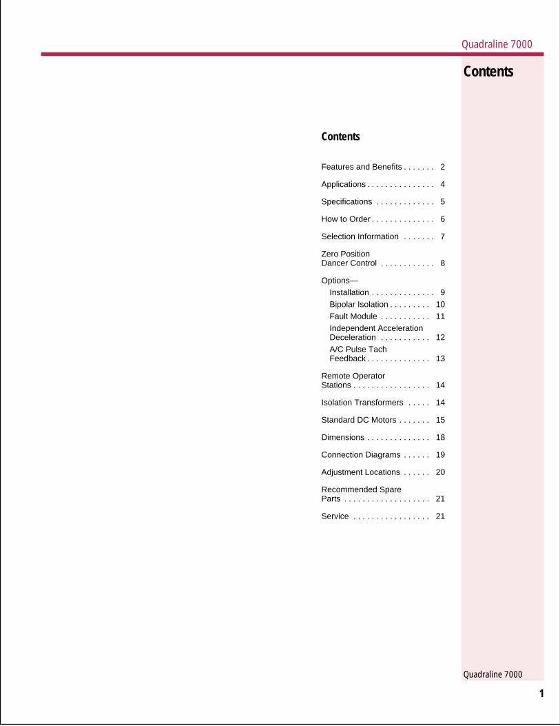
Material Handling• Controlled acceleration• Controlled deceleration
• Bi-directional
• Precise positioning accuracy
Applications
Machine Tools• 4 quadrant control allows
positioning easily adapted tospecific program needs
Web Processing• Accurate web or material
tensioning
• Zero position dancer (P.I.D.Gain Control)
• Smooth and consistent controlin process, and during un-windor wind-up
Robotics• Economical alternative to
sophisticated Servo control inless demanding applications
• Chassis mount for easyintegration in customer controlpanel
17
StandardDC Motors
DC Motors1/4 to 1 Horsepower 90 VDC Armature – 100/50 VDC SHUNT WOUND FIELD – 1750 RPM – Totally Enclosed
NEMA Model NumberHP Motor Frame Enclosure ‘C’ Motor Motor with 7 VDC
Type Size Face without 7 VDC/1000 RPM TachometerTachometer Tachometer Kit
(mounted)
1/4 B 413D FC 56C MOD1211700 MOD1211731 TAC 4001–001/2 B 420D FC 56C MOF1211700 MOF1211731 TAC 4001–003/4 B 428D FC 56C MOG1211700 MOG1211731 TAC 4001–001 B 535D FC 56C MOH1211700 MOH1211731 TAC 4007–00
Note: All motors are capable of 20:1 constant torque speed range.
DC Motors1/2 to 5 Horsepower 180 VDC Armature – 200/100 VDC SHUNT WOUND FIELD – 1750 RPM – Totally Enclosed
NEMA Model NumberHP Motor Frame Enclosure ‘C’ Motor Motor with 7 VDC
Type Size Face without 7 VDC/1000 RPM TachometerTachometer Tachometer Kit
(mounted)
1/2 B 420D FC 56C MOF2211700 MOF2211731 TAC 4001–003/4 B 428D FC 56C MOG2211700 MOG2211731 TAC 4001–001 G 146ATC FC 140TC MOH2210800 MOH2210831 TAC 4001–02
B 535D FC 56C MOH2211800 MOH2211831 TAC 4007–01G L182ACY NV 180C MOH2110100 MOH2110131 TAC 4002–03
1-1/2 G 148ATC FC 140TC MOI2210800 MOI12210831 TAC 4004–02G L186ACY NV 180C MOI2110100 MOI2110131 TAC 4002–03B 636D FC 180C MOI2211400 MOI2211431 TAC 4001–15
2 G 149ATC FC 140TC MOJ2210800 MOJ12210831 TAC 4004–02B 646D FC 180C MOJ2211400 MOJ2211431 TAC 4001–15G L186ACY NV 180C MOJ2110100 MOJ2110131 TAC 4002–03
3 G 189ATC NV 180TC MOK2110100 MOK2110131 TAC 4002–03G 1412ATC FC 140C MOK2210800 MOK2210831 TAC 4004–02B 7544D FC 210C MIK2211100 MOK2211131 TAC 4001–06
5 G CD2110ACY* NV 210C MOL2110700 MOL2110731 TAC 4002–03B 9143D* FC 256UCZ MOL2211100 MOL2211131 TAC 4001–08
*These motors have 1-1/8" shaft diameter.
Note: All motors are capable of 20:1 constant torque speed range.
Quad7 spreads 3/25/05, 1.174

Quadraline 7000
Quadraline 7000Quadraline 7000
Quadraline 7000
5
Q7006
Q7002
Q7005
Specification Q7006 Q7002 Q7005
Horsepower Range115V 1/8–1/2 1/4–1 HP Not Used230V 1/4–1 1/2–2 HP 3–5 HP
AC Line Input Voltage 115 or 230 V ±10% 115 or 230 V ±10% 115 or 230 V ±10%
AC Line Frequencey 50/60 Hz ± 2 Hz 50/60 Hz ± 2 Hz 50/60 Hz ± 2 HzSingle Phase Single Phase Single Phase
115 VAC SupplyArmature Voltage 0–90 VDC 0–90 VDC Not ApplicableField Voltage 50/100 VDC 50/100 VDC Not Applicable
230 VAC SupplyArmature Voltage 0–180 VDC 0–180 VDC 0–180 VDCField voltage 100/200 VDC 100/200 VDC 100/200 VDC
Service Factor 1.0 1.0 1.0
Duty Continuous Continuous Continuous
Maximum Load Capacity 150% for 1 min. 150% for 1 min. 150% for 1 min.Line Protection Fuses Fuses Fuses
U.L. Listed No Yes Yes
Operating ConditionsAmbient Temperature
Chassis Model 0–55° C 0–55° C 0–55° CEnclosed Model N.A. 0–40° C 0–40° C
Relative Humidity .................................................... 5–95% non-condensing ......................................................
Altitude ......................................................................... to 3300 ft. (1000m).........................................................
Performance CharacteristicsSpeed Range 50:1 50:1 50:1
Speed Regulation (% of motor base speed) for 95% load changeArm. Voltage Feedback................................... ±1% to ± 2% (depending on motor) .............................................Tach. Feedback ................................... ±1/2 to 1% (depending on tach generator) .............................................
Acceleration (forward or reverse)Range A ..................................................... Linear .3–3 seconds (to full speed) ...........................................Range B .................................................... Linear 3–30 seconds (to full speed) ...........................................
AdjustmentsCurrent Range
(nominal–adjustable to 150%) 1.0, 1.5, 2.0, 3.0 2, 3, 4, 6, 10, Amps 15, 25 Amps5.0 Amps
Maximum Speed ................................................. 70–105% of motor base speed ...............................................
IR Compensation .............................................................. Adjustable .................................................................
Options DescriptionIsolated Input Bipolar, input–output with selectable inputs for 0 to ±10 VDC, 0 to ±14 VDC,
0 to ±100 VDC, 1 to 5mA or 4 to 20mAFault Module Contact outputs—trips on overcurrent, overvoltage or field loss
Independent Acceleration/ Forward acceleration, forward deceleration, reverse acceleration, reverseDeceleration Control deceleration, 4 potentiometersAC/Pulse Tach Feedback Converts signals from AC tachometer or pulse generator to direction sensitive
DC voltage for improved speed regulation
Specifications
16
StandardDC Motors
DC Motors1/4 to 1 Horsepower 90 VDC Armature – PERMANENT MAGNET FIELD – 1750 RPM – Totally Enclosed
NEMA Model NumberHP Motor Frame Enclosure ‘C’ Motor Motor with 7 VDC
Type Size Face without 7 VDC/1000 RPM TachometerTachometer Tachometer Kit
(mounted)
1/4 G 56HAA NV 56C MOD6110210 N/A N/AB 320P NV 56C MOD6211200 MOD6211231 TAC 4001–13
1/2 G 56KAA FC 56C MOF6210210 N/A N/AB 336P NV 56C MOF6211200 MOF6211231 TAC 4001–13
3/4 G 56PAA FC 56C MOG6210210 N/A N/AB 428P FC 56C MOG6211100 MOG6211131 TAC 4001–00
1 G 56SAA FC 56C MOH6210210 N/A N/AB 435P FC 56C MOH6211100 MOH6211131 TAC 4001–00
Note: All motors are capable of 20:1 constant torque speed range.
DC Motors1/2 to 5 Horsepower 180 VDC Armature – PERMANENT MAGNET FIELD – 1750 RPM – Totally Enclosed
NEMA Model NumberHP Motor Frame Enclosure ‘C’ Motor Motor with 7 VDC
Type Size Face without 7 VDC/1000 RPM TachometerTachometer Tachometer Kit
(mounted)
1/2 G 56KAA FC 56C MOF7210210 N/A N/AB 336P NV 56C MOF7111100 MOF7111131 TAC 4001–13
3/4 G 56PAA FC 56C MOG7210210 N/A N/AB 336P NV 56C MOG7211100 MOG7211131 TAC 4001–10
1 G 146ATC FC 140TC MOH7210800 MOH7210831 TAC 4004–02G 56SAA FC 56C MOH7210210 N/A N/AB 435P FC 56C MOH7211100 MOH7211131 TAC 4001–00
1-1/2 B 536P FC 140TC MOI7211100 MOI7211131 TAC 4007–01G 148ATC FC 140TC MOI7210800 MOI7210831 TAC 4004–02
2 B 548P FC 140TC MOJ7211100 MOJ7211131 TAC 4007–01G 149ATC FC 140TC MOJ7210800 MOJ7210831 TAC 4004–02
3 G 1412ATC FC 140TC MOK7210800 MOK7210831 TAC 4004–02B 649P FC 180TC MOK7211100 MOK7211131 TAC 4001–15
5 B 681P FC 180TC MOL7211100 MOL7211131 TAC 4001–15
Note: All motors are capable of 20:1 constant torque speed range.
Quad7 spreads 3/25/05, 1.175

Quadraline 7000
Quadraline 7000Quadraline 7000
Quadraline 7000
6
1. DC Motor ControllerSelect HP and AC input voltage.The AC input voltage willdetermine motor armature andfield voltage.
AC Input Motor VoltageVoltage Arm/Field
115V 90V Arm50/100V Field
230V 180V Arm100/200V Field
Now select drive configuration,chassis or enclosure. If enclo-sure, do you want a blank frontcover or operators controls?Determine which operators arerequired (i.e., run/jog, auto/manual) and whether they will beon a remote operators station oron the drive enclosure. From thelist of standard option boards,select those required for yourapplication.
2. DC MotorWith the motor voltage specifiedby the AC input voltage selectedabove, now determine permanentmagnet or shunt wound, framesize, enclosure type (TEFC orTENV), C face, and whether atachgenerator will be required.
3. Remote (ROS) OperatorStation
If a remote operators station willbe used, select which operatorswill be used, and the NEMArating required.
4. Isolation TransformerSelect KVA of transformer whenrequired by adding the total HP ofall drives to be connected to thetransformer. Then select modelnumber by primary input voltageand secondary output voltage.
5. Options/AccessoriesA. Determine which options are
required for your applications.This could include speed and/or load meters.
B. Options may be mounted bythe factory or field installed.
ExampleA conveyer requires a 1 HP DCmotor, 1750 RPM, shunt woundfield, TEFC enclosure and a7V/1000RPM tachometer. TheDC drive will be chassis mount,230 VAC single phase input, tobe operated from a ROS. ROS toinclude forward and reverse,start/stop and a speed potentio-meter. Isolation transformer froma 230 VAC input is required. Theuser would also like fault outputcontacts to activate othermachine control.
Item Qty Part No.
1 1 Q7006–22 1 MOH22108313 1 R10024 1 TRS21–0205 1 (included as a
part of item 1)
In determining the componentsthat comprise a drive system, thefollowing selections must bemade for features and options.
How to Order
15
StandardDC Motors
How to OrderSelection charts for DC motors,available from Warner ElectricMotors and Controls, are listed onthe following pages. For morecomplete specifications anddimensional information, contactWarner Electric Motors andControls customer service.
Motor chart specify:HorsepowerMotor Type (Manufacturer)
B=BaldorG=General Electric
Frame SizeMotor Enclosure
TE=Totally EnclosedTEFC=Fan CooledTENV=Non Ventilated
‘C’ Face Size(For use with Single PhaseControllers only)
Armature VoltageModel Number
Motor with Tachometer(mounted)Motor without TachometerTachometer Kit
Non-Listed MotorsNon-listed motors are available,but specific information isrequired.1. Motor horsepower2. RPM3. Frame size4. Volts, armature5. Volts, field or PM6. Enclosure7. Conduit location, F1, F2 etc.8. Thermostat9. Accessory endshield
10. ‘C’ face11. Delivery requirements12. Special application or
environmental considerationsand other importantinformation.
Quad7 spreads 3/25/05, 1.176

Quadraline 7000
Quadraline 7000Quadraline 7000
Quadraline 7000
7
OptionsDescription Factory Field
Installed InstalledM/N Suffix Kits M/N
Isolated Input—Bipolar,input-output with selectableinputs for 0 to ± 10 VDC, 0 to ± 14VDC, 0 to ± 100 VDC, 1 to 5mAor 4 to 20 mA.
Fault Module—Contact outputs-trips on overcurrent,overvoltage or field loss.
Independent Accel/DecelControl—Forward accel,forward decel, reverse accel,reverse decel, 4 potentiometers
AC/Pulse Tach Feedback—Converts signals from ACtachometer or pulse generator todirection sensitive DC voltage forimproved speed regulation
Mounting and connecting Nothardware for 2 option kits Required Q7098-00
Pivot Point Sensor(for use w/zero position – APT 2043-00Dancer controlled models)
Quadraline 7000 Series
Input HP Basic On/Off External Signal Zero PositionLine Dancer Control
Voltage Chassis NEMA NEMA Chassis NEMA NEMA Chassis NEMA4/12 4/12 w/ 4/12 4/12 w/ 4/12
Operators Operators
115 VAC 1/8–1/2 Q7006 N/A N/A Q7006–1 N/A N/A Q7006–5 N/A1 Phase
230 VAC 1/4–1 Q7006 N/A N/A Q7006–1 N/A N/A Q7006–5 N/A1 Phase
115 VAC 1/4–1 Q7002 Q7022 Q7032 Q7002–1 Q7022–1 Q7042–1 Q7002–5 Q7022–51 Phase
230 VAC 1/2–2 Q7002 Q7022 Q7032 Q7002–1 Q7022–1 Q7042–1 Q7002–5 Q7022–51 Phase
230 VAC 3–5 Q7005 Q7025 Q7035 Q7005–1 Q7025–1 Q7045–1 Q7005–5 Q7025–51 Phase
SelectionInformationInput
Line
Run/Jog–Forward/ReverseIncludes power unit, control logicand enclosure if specified with orwithout operator devices.Operator devices include: Start-Stop switch, Run-Jog switch,Forward-Reverse switch, singleturn Speed Setting Potentiometerand Power Light.
External SignalIncludes power unit, controllogics, isolated signal followeraccepting 4–20 mA, 1– 5mA, 0–± 10 VDC, 0– ± 14 VDC or 0–± 100 VDC reference signalinputs and enclosure if specifiedwith or without operator devices.Operator devices include: Start-Stop switch, Run-Jog switch,Forward-Reverse switch, Auto-Manual switch, single turn SpeedSetting Potentiometer, and PowerLight.
Zero Position Dancer ControlFor tension applications such asan unwind, rewind or tensioninfeed with a zero position danceror load cell includes PID function.This feature is used in specialapplications usually involvingweb-processing equipment.
–1 Q7999–01
.
–2 Q7999–02
–3 Q7999–03
–4 Q7999–04
14
Remote Operator Stations (ROS)
Function ModelNumber
Start-Stop Switch (2)Run-Jog SwitchForward-Reverse Switch R1000Auto-ManswitchSingle Turn Speed Pot
Start-Stop Switch (2)Run-Jog Switch R1001Auto-Man SwitchSingle Turn Speed Pot
Start-Stop Switch (2)Forward-Reverse Switch R1002Run-Jog SwitchSingle Turn Speed Pot
Start Pushbutton (1)(3)Stop Pushbutton R8005Single Turn Speed Pot
RemoteOperatorStations
Isolation Transformers
Single phase NEMA I Enclosed, Dry Type, No Taps, 60 Hz
HP KVA Primary Secondary Model NumberVoltage Voltage
1/4 1/2 120/240 120/240 TRS21-005
1/2 1 120/240 120/240 TRS21-010
3/4 11/2 120/240 120/240 TRS21-015
1 2 120/240 120/240 TRS21-020
11/2 3 240/480 120/240 TRS42-030
2 5 240/480 120/240 TRS42-050
3 71/2 240/480 120/240 TRS42-075
5 10 240/480 120/240 TRS42-100
For dimensions and connection information, contact Warner Electric Motors and Controls customer service.
IsolationTransformers
Note:(1) NEMA 12 Enclosed with wiring to operators.(2) NEMA 4/12 Enclosed with wiring to terminal strips.(3) For non-reversing application only.
Quad7 spreads 3/25/05, 1.177

Quadraline 7000
Quadraline 7000Quadraline 7000
Quadraline 7000
8
ZeroPositionDancerControl
Connection Diagram
1. General DescriptionThe zero position dancer optionboard provides dancer control foreither an unwind, rewind or in-feed tension control systems. In adancer system, closed loopcontrol is accomplished becausethe web completes the pathbetween the motor and thedancer. With the zero positiondancer option board, (hereafterreferred to as the ZPD Board) thedancer remains in a fairlyconstant position throughout therun.
The purpose of the ZPD board isto stabilize the system and keepthe dancer in a fixed position,thus maintaining tension within agiven tolerance range.
The pivot-point sensor, coupledto the pivot point of the dancerarm, generates a signal to theZPD board signifying the positionof the dancer arm and thedirection and velocity of anydancer arm movement. TheDancer Position potentiometeradjusts the dancer zero pointelectrically within the control.Terminals are provided for a
remotely mounted DancerPosition potentiometer.
The adjustments contained onthe ZPD board enable the systemto be fine tuned to the exactparameters of the application toprovide optimum control andstability.
2. Specifications• Dancer pot (Pivot point sensor)
1k OHM min., 20k OHM max.M/N APT 2043-00
DancerRoll
PivotPointSensor
Winder
Motor
1 2 3 4 5 6
TB1
7 8 9 10 11
TB1
L1 L2GND A1 A2 F1 F2
Q7000 Heatsink Assembly
Q7000 Control Board
TP11
TP10
TP2
TP1
TP3
U1 U2 U3
01
2
3
4 56
GainVR2 01
2
3
4 56
Dancer PositionVR1
J6
U4
TP4 TP
9TP8
VR5
R5
R2
R4
R6
R10R28R26
VR4
VR6
DerivativeGain
TP6TP
5
R24R23
ProportionalGain
TP7
R33
DerivativeGain
O
P
I
SW1
Open
123
T856
T856
T856
1
2
3
1
2
3
4
5
6
7
8
9
+
-
A B C
J54TB54L52
A B C D
J53
A B
J52
L51
R51
L52
R52
OSR
53P50
R50
OT
R54
CG
R55
CO
R56
1 2 3 4 5 6 7 8 9
CO
M +
–
J4
D51 TB50TB52
+
+
C2
+
C4
01
11
L1
L2
115V
TB53
J50 230V J51 115V
Z1RC1
F1
13
OptionsA/C PulseTachFeedback
1. General DescriptionThe AC/Pulse Tach Option boardallows the use of either an ACtachometer or a magnetic pulsetach for speed feedback to theQ7000. A ring tach, such as theMTK series used with the DS9000 Digital Front End, can beused. The standard drive requiresa DC analog tachometer 7 VDC/1000 RPM, or 50 VDC/1000RPM, if a tachometer is to beused. If an encoder is to be used,please consult Seco Electronicsfor adjustment.
2. SpecificationsInput Signal• Primarily designed for 60 pulse
per revolution pulsetachometers. Maximumfrequency input is 3600 Hz.Minimum frequency for fulloutput voltage is 1200 Hz.
• Maximum voltage 100V.
Output signal
• 0 to 10 VDC.
Component Location
Notes:1. Place jumper J1 in 7V position.2. Select tach feedback mode. (SWI)3. Adjust R42, max. speed to set
maximum motor speed. (R1, max.speed on Q7000 control boardshould be set fully CCW)
3
3
1
321
21
AC Tach60 Pulse/Rev
3600 RPM Max
R40Offset
R42Max Spd
VIn V Out
AC/PULSE TACHFEEDBACK OPTION
ComTB40
T
TB41
P40
P4
Max SpdR1
SW1
Tach
ArmTB17V
50V
J1
Q7000 CONTROL BOARD
1
2
Connection Diagram
AC Pulse Tach Feedback
OffsetAdjustment
InputSignal
fromPulse/Tach
Max Spd
OutputSignal
Ribbon Cable to Q7000
MaximumSpeedAdjustment
TB41
1 U3
1 U7
161
1 U8
1 U2
1 U1
1 U5
P40TP40
1 TB40
OffsetR40
VIn
Com
1 U6
R42
VOut
1
Quad7 spreads 3/25/05, 1.178

Quadraline 7000
Quadraline 7000Quadraline 7000
Quadraline 7000
9
InstallationEach version of the Q7000control except the Q7006 hasprovision for mounting up to twooption boards. Q7006 units haveroom for one option board. If oneoption board is fitted it will be inpostion A in Figure A. Thesecond option board will be fittedin position B. Reference Figure A.
A. For field installation of oneoption, the correct mountinghardware will be supplied withthe option kit.
OptionsFactory orFieldInstalled
B. For field installation of twooptions, an additionalmounting kit Q7098–00 forlocation B is required.
Location B
Location A
P4
Logic Board
12
2
1
2
1
Q7000 CONTROL BOARD
ACCEL/DECELOPTION BOARD
P20
P4
J3
A
A
AB
J20
TB20OperatingMode BControlSwitch(Optional)
ForwardDeceleration
Adjust
ForwardAcceleration
Adjust
ReverseAcceleration
Adjust
ReverseDeceleration
Adjust
OperatingModeSelection
OperatingMode BControl
Ribbon Cableto Q7000 Control Board
TimeRangeSelectF .3–3 sec.S 3–30 sec.
FwdDecel
FwdAccel
RevAccel
RevDecel
R20 R21 R22 R23CW CW CW CW
1 1 1U1 U4 U3
C7
J21 J22 J23 J24
P20
J20 TB20
1 16
F F F F
AB 1
S S S S
IndependentAccelerationDeceleration
1. General DescriptionThe standard Q7000 Series DCcontroller has a single forwardacceleration adjustment pot andsingle reverse accelerationadjustment pot. The ForwardAcceleration pot also sets theacceleration rate in the forwarddirection, and the deceleration ratein the reverse direction, i.e. both ofthese rates will be the same.Conversely, the Reverse Accelera-tion pot also sets the decelerationrate in the Forward direction,again, both rates are the same.
Two modes of Accel/Decel controlcan be programmed with thisoption.
The first, or Mode A, provides twoacceleration adjustment pots andtwo decelation adjustment pots.This allows for independentadjustment of the forward acceler-ation rate, forward decelerationrate, reverse acceleration rate andreverse deceleration rate.
The second, Mode B, allows twodifferent Accel/ Decel rates to beselected by an outside sourcedcontact closure. Like the BasicQuadraline 7000 the ForwardAcceleration and ReverseDeceleration rates are identicalas are the Reverse Accelerationand Forward Deceleration rates.The Mode B difference allows theability to switch through contactchange from either of two sets ofadjustments, thereby giving twoentirely different rates rather thanthe single rate allowed with thebasic Quadraline 7000 controller.
The adjustment setting foracceleration determines theamount of time the motorcontroller will take to drive themotor from standstill or zerospeed up to maximum speed.The adjustment setting fordeceleration determines the timethe motor controller will take tobrake the moter from maximumspeed to zero.
2. SpecificationsA. Accel/Decel Time Range:
Jumper Selectable for eachpot(J21–J24)F Range .3–3 seconds (zeroto full speed)S Range 3–30 seconds (zeroto full speed)
B. Operating Modes:Jumper Selectable (J20)A Mode:Acceleration Forward R21Deceleration Forward R20Acceleration Reverse R22Deceleration Reverse R23
B Mode:Pot operation in the B Modeis controlled by a contactclosure or jumper on TB20.
OptionsIndependentAccelerationDeceleration
IndependentAccelerationDeceleration
Notes:1. Jumper J3 on Q7000 control board
must be placed in the “center”position as shown for properoperation of accel/decel optionboard.
2. Reference section 2.b fordescription of operation modes.
Connection Diagram
Component Location
Quad7 spreads 3/25/05, 1.179

Quadraline 7000
Quadraline 7000Quadraline 7000
Quadraline 7000
10
Component Location
Connection Diagram
1. If optional trim pot is used,remove jumper from TB41–3and 4.
2. Mounted on the enclosuredoor of External SignalModels equipped with thisprovision.
OptionsBipolarIsolation
1. General DescriptionThe Bipolar Isolation OptionBoard provides an isolatedinterface between the Q7000 andReference control signals. TheOption Board mounts easily tothe Q7000 Control Board viastand-offs and a ribbon cable.
2. SpecificationsInput Signals:Current Voltage1–5mA DC 0 to ±10 VDC4–20mA DC 0 to ±14 VDC
0 to ±100 VDCOutput voltage:
0 to ±10 VDC
Operation and AdjustmentJumper Selection
Select input rangeFor voltage input, connectinput wires to the V IN andCOM (common) positions onTB40. Jumper J40 as follows:
Jumper VoltagePosition Input
Range
0–10 VDC 0 to ±10 VDC0–14 VDC 1 to ±14 VDC0–100 VDC 0 to ±100 VDC
For current input, connect inputwires to the I IN and COM(common) positions on TB40.Jumper J40 as follows:
Jumper Position1–5mA DC4–20mA DC
Ensure Jumper J41 is inpostion A.
BI-PolarIsolationOptionDC Voltage Input
DC Current Input
Input Common
Speed
CWREV
FWD
MAN
AUTO
TBI
3 4 5 6
P40
P4
3
2
1
TB41
TB40
3
2
1
4
Trim(Optional)
1
CW
W
CCW
V Out
Q7000 CONTROL BOARD
2
OffsetAdjustment
RangeSelectionJumper
MinimumSpeed
Adjustment
MaximumSpeedAdjustment
OptionalTrim Pot
OutputSignal
Ribbon Cable to Q7000
InputSignal
OffsetR40
R41
R42
TrimCW
W
CCWV
Out
TB411
1
11
11
11
1
1
1 16
U8U7
U3
U6U5
U2U1
U4
P40TP40
TB40 J40
IIn
VIn
Com
Min Spd Max Spd
0-10V0-14V0-100V1-5MA4-20MA
Bipolar IsolationBipolar Isolation
11
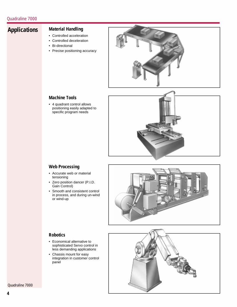
Fault RelayContact
Fault Module
Fault Trip Level Adjustment:Overvoltage Overcurrent
OvercurrentIndication LED
Fault TripIndication LEDsOV – OvervoltageFL – Field LossOC – Overcurrent
Remote ResetQuick Connect
OvercurrentTrip Select:A – TimedB – Instantaneous
Motor FieldInput
Connect inSeries withMotor Field
Motor Field Select:– Permanent Magnet (PM)– Shunt Wound (SH)
Ribbon Cableto Q7000
FaultRelay
OvercurrentIndication
K30
+24V
K30
P30
TP30
Com
1 16
J30PMSH
OverVoltage
OverCurrent
TP32
R30 R31
U2 U3 U4 U5
TP33
U1
K30
FaultModule
1 1 1 1 1
TripTP31
OC OV FL OC
Reset
SW30
P31
P32
B AJ31Local
Reset
U6
1 TB31
Field
12
TB30123456789
Sto
p
TB30
Sta
rt
P31
P32
RemoteReset
(Optional)
MotorFieldTB31
P30
P4
F1 F21
2
F1 F2
1
2
3
4
5
6
7
8
9
FAULTMODULE
2
3
1
4
Q7000POWER COMPONENTASSEMBLYQ7000 CONTROL BOARD
TB19 10 11
1. General DescriptionThe Fault Module Option Boardprovides adjustable overvoltageand overcurrent as well as fieldloss protection for the Q7000series of DC motor controllers.The overcurrent protection canbe jumpered for either instant-aneous overcurrent trip or timedovercurrent trip. (An overload willeventually cause an overcurrenttrip with the time to trip decreas-ing as the current level increaseswhen the timed mode isselected.) An open collectortransistor output is provided toindicate when an overload ispresent. Four Red LED’s are onthe board, to indicate overcurrenttrip, overvoltage trip, field losstrip, and overload.
Two form C contacts are providedfrom the fault relay that changestate in the event of a fault trip.An on-board reset pushbutton orquick connect connections areprovided for resetting the driveafter a fault occurs. When a faultoccurs, the drive is disabled,turning off the SCR power bridge,the motor will coast to a stop. Ifthe fault relay contacts are wiredinto the stop circuitry, the Stop/Start relay in the Quadraline 7000controller will drop out.
2. SpecificationsA. Adjustable Instantaneous or
Timed Overcurrent Trip.Current trip setting 30 to150% rated current.
B. Adjustable Overvoltage Trip.Voltage trip setting 10 to150% rated voltage.
C. Field Loss, detects loss offield current.
D. Fault Relay, with 2 form Ccontacts, that is energizedwhen power is applied and nofaults are present.
E. Open Collector Outputsignifying an overcurrentcondition is present. Timedovercurrent trip will occur ifthe overload remains(Overcurrent LED D30indicates output is on.) Thiscircuit can handle 250mA (24VDC max.) when the output ispulled down to zero during anoverload.
F. Four Red LEDs1. Overcurrent Trip2. Overcurrent voltage3. Field Loss Trip4. Overcurrent Present
Component Location
OptionsFaultModule
Fault Module
Connection Diagram Notes:1. Fault relay contacts are shown in
trip or power off condition.Connect contact in series with stopcircuit as shown to activate stopfunction when trip occurs. If thisconnection is not made, control isdisabled when trip occurs and willstart when trip circuit is reset.
2. No connection is required for PMmotor.
3. Close contacts to reset trip circuit.4. Overcurrent indication: Open
collector output sinks up to 250mAif current exceeds overcurrentlevel. (24 VDC max.)
Quad7 spreads 3/25/05, 1.1810
Quadraline 7000
Quadraline 7000Quadraline 7000
Quadraline 7000
10
Component Location
Connection Diagram
1. If optional trim pot is used,remove jumper from TB41–3and 4.
2. Mounted on the enclosuredoor of External SignalModels equipped with thisprovision.
OptionsBipolarIsolation
1. General DescriptionThe Bipolar Isolation OptionBoard provides an isolatedinterface between the Q7000 andReference control signals. TheOption Board mounts easily tothe Q7000 Control Board viastand-offs and a ribbon cable.
2. SpecificationsInput Signals:Current Voltage1–5mA DC 0 to ±10 VDC4–20mA DC 0 to ±14 VDC
0 to ±100 VDCOutput voltage:
0 to ±10 VDC
Operation and AdjustmentJumper Selection
Select input rangeFor voltage input, connectinput wires to the V IN andCOM (common) positions onTB40. Jumper J40 as follows:
Jumper VoltagePosition Input
Range
0–10 VDC 0 to ±10 VDC0–14 VDC 1 to ±14 VDC0–100 VDC 0 to ±100 VDC
For current input, connect inputwires to the I IN and COM(common) positions on TB40.Jumper J40 as follows:
Jumper Position1–5mA DC4–20mA DC
Ensure Jumper J41 is inpostion A.
BI-PolarIsolationOptionDC Voltage Input
DC Current Input
Input Common
Speed
CWREV
FWD
MAN
AUTO
TBI
3 4 5 6
P40
P4
3
2
1
TB41
TB40
3
2
1
4
Trim(Optional)
1
CW
W
CCW
V Out
Q7000 CONTROL BOARD
2
OffsetAdjustment
RangeSelectionJumper
MinimumSpeed
Adjustment
MaximumSpeedAdjustment
OptionalTrim Pot
OutputSignal
Ribbon Cable to Q7000
InputSignal
OffsetR40
R41
R42
TrimCW
W
CCWV
Out
TB411
1
11
11
11
1
1
1 16
U8U7
U3
U6U5
U2U1
U4
P40TP40
TB40 J40
IIn
VIn
Com
Min Spd Max Spd
0-10V0-14V0-100V1-5MA4-20MA
Bipolar IsolationBipolar Isolation
11
Fault RelayContact
Fault Module
Fault Trip Level Adjustment:Overvoltage Overcurrent
OvercurrentIndication LED
Fault TripIndication LEDsOV – OvervoltageFL – Field LossOC – Overcurrent
Remote ResetQuick Connect
OvercurrentTrip Select:A – TimedB – Instantaneous
Motor FieldInput
Connect inSeries withMotor Field
Motor Field Select:– Permanent Magnet (PM)– Shunt Wound (SH)
Ribbon Cableto Q7000
FaultRelay
OvercurrentIndication
K30
+24V
K30
P30
TP30
Com
1 16
J30PMSH
OverVoltage
OverCurrent
TP32
R30 R31
U2 U3 U4 U5
TP33
U1
K30
FaultModule
1 1 1 1 1
TripTP31
OC OV FL OC
Reset
SW30
P31
P32
B AJ31Local
Reset
U6
1 TB31
Field
12
TB30123456789
Sto
p
TB30
Sta
rt
P31
P32
RemoteReset
(Optional)
MotorFieldTB31
P30
P4
F1 F21
2
F1 F2
1
2
3
4
5
6
7
8
9
FAULTMODULE
2
3
1
4
Q7000POWER COMPONENTASSEMBLYQ7000 CONTROL BOARD
TB19 10 11
1. General DescriptionThe Fault Module Option Boardprovides adjustable overvoltageand overcurrent as well as fieldloss protection for the Q7000series of DC motor controllers.The overcurrent protection canbe jumpered for either instant-aneous overcurrent trip or timedovercurrent trip. (An overload willeventually cause an overcurrenttrip with the time to trip decreas-ing as the current level increaseswhen the timed mode isselected.) An open collectortransistor output is provided toindicate when an overload ispresent. Four Red LED’s are onthe board, to indicate overcurrenttrip, overvoltage trip, field losstrip, and overload.
Two form C contacts are providedfrom the fault relay that changestate in the event of a fault trip.An on-board reset pushbutton orquick connect connections areprovided for resetting the driveafter a fault occurs. When a faultoccurs, the drive is disabled,turning off the SCR power bridge,the motor will coast to a stop. Ifthe fault relay contacts are wiredinto the stop circuitry, the Stop/Start relay in the Quadraline 7000controller will drop out.
2. SpecificationsA. Adjustable Instantaneous or
Timed Overcurrent Trip.Current trip setting 30 to150% rated current.
B. Adjustable Overvoltage Trip.Voltage trip setting 10 to150% rated voltage.
C. Field Loss, detects loss offield current.
D. Fault Relay, with 2 form Ccontacts, that is energizedwhen power is applied and nofaults are present.
E. Open Collector Outputsignifying an overcurrentcondition is present. Timedovercurrent trip will occur ifthe overload remains(Overcurrent LED D30indicates output is on.) Thiscircuit can handle 250mA (24VDC max.) when the output ispulled down to zero during anoverload.
F. Four Red LEDs1. Overcurrent Trip2. Overcurrent voltage3. Field Loss Trip4. Overcurrent Present
Component Location
OptionsFaultModule
Fault Module
Connection Diagram Notes:1. Fault relay contacts are shown in
trip or power off condition.Connect contact in series with stopcircuit as shown to activate stopfunction when trip occurs. If thisconnection is not made, control isdisabled when trip occurs and willstart when trip circuit is reset.
2. No connection is required for PMmotor.
3. Close contacts to reset trip circuit.4. Overcurrent indication: Open
collector output sinks up to 250mAif current exceeds overcurrentlevel. (24 VDC max.)
Quad7 spreads 3/25/05, 1.1810

Quadraline 7000
Quadraline 7000Quadraline 7000
Quadraline 7000
9
InstallationEach version of the Q7000control except the Q7006 hasprovision for mounting up to twooption boards. Q7006 units haveroom for one option board. If oneoption board is fitted it will be inpostion A in Figure A. Thesecond option board will be fittedin position B. Reference Figure A.
A. For field installation of oneoption, the correct mountinghardware will be supplied withthe option kit.
OptionsFactory orFieldInstalled
B. For field installation of twooptions, an additionalmounting kit Q7098–00 forlocation B is required.
Location B
Location A
P4
Logic Board
12
2
1
2
1
Q7000 CONTROL BOARD
ACCEL/DECELOPTION BOARD
P20
P4
J3
A
A
AB
J20
TB20OperatingMode BControlSwitch(Optional)
ForwardDeceleration
Adjust
ForwardAcceleration
Adjust
ReverseAcceleration
Adjust
ReverseDeceleration
Adjust
OperatingModeSelection
OperatingMode BControl
Ribbon Cableto Q7000 Control Board
TimeRangeSelectF .3–3 sec.S 3–30 sec.
FwdDecel
FwdAccel
RevAccel
RevDecel
R20 R21 R22 R23CW CW CW CW
1 1 1U1 U4 U3
C7
J21 J22 J23 J24
P20
J20 TB20
1 16
F F F F
AB 1
S S S S
IndependentAccelerationDeceleration
1. General DescriptionThe standard Q7000 Series DCcontroller has a single forwardacceleration adjustment pot andsingle reverse accelerationadjustment pot. The ForwardAcceleration pot also sets theacceleration rate in the forwarddirection, and the deceleration ratein the reverse direction, i.e. both ofthese rates will be the same.Conversely, the Reverse Accelera-tion pot also sets the decelerationrate in the Forward direction,again, both rates are the same.
Two modes of Accel/Decel controlcan be programmed with thisoption.
The first, or Mode A, provides twoacceleration adjustment pots andtwo decelation adjustment pots.This allows for independentadjustment of the forward acceler-ation rate, forward decelerationrate, reverse acceleration rate andreverse deceleration rate.
The second, Mode B, allows twodifferent Accel/ Decel rates to beselected by an outside sourcedcontact closure. Like the BasicQuadraline 7000 the ForwardAcceleration and ReverseDeceleration rates are identicalas are the Reverse Accelerationand Forward Deceleration rates.The Mode B difference allows theability to switch through contactchange from either of two sets ofadjustments, thereby giving twoentirely different rates rather thanthe single rate allowed with thebasic Quadraline 7000 controller.
The adjustment setting foracceleration determines theamount of time the motorcontroller will take to drive themotor from standstill or zerospeed up to maximum speed.The adjustment setting fordeceleration determines the timethe motor controller will take tobrake the moter from maximumspeed to zero.
2. SpecificationsA. Accel/Decel Time Range:
Jumper Selectable for eachpot(J21–J24)F Range .3–3 seconds (zeroto full speed)S Range 3–30 seconds (zeroto full speed)
B. Operating Modes:Jumper Selectable (J20)A Mode:Acceleration Forward R21Deceleration Forward R20Acceleration Reverse R22Deceleration Reverse R23
B Mode:Pot operation in the B Modeis controlled by a contactclosure or jumper on TB20.
OptionsIndependentAccelerationDeceleration
IndependentAccelerationDeceleration
Notes:1. Jumper J3 on Q7000 control board
must be placed in the “center”position as shown for properoperation of accel/decel optionboard.
2. Reference section 2.b fordescription of operation modes.
Connection Diagram
Component Location
Quad7 spreads 3/25/05, 1.179

Quadraline 7000
Quadraline 7000Quadraline 7000
Quadraline 7000
8
ZeroPositionDancerControl
Connection Diagram
1. General DescriptionThe zero position dancer optionboard provides dancer control foreither an unwind, rewind or in-feed tension control systems. In adancer system, closed loopcontrol is accomplished becausethe web completes the pathbetween the motor and thedancer. With the zero positiondancer option board, (hereafterreferred to as the ZPD Board) thedancer remains in a fairlyconstant position throughout therun.
The purpose of the ZPD board isto stabilize the system and keepthe dancer in a fixed position,thus maintaining tension within agiven tolerance range.
The pivot-point sensor, coupledto the pivot point of the dancerarm, generates a signal to theZPD board signifying the positionof the dancer arm and thedirection and velocity of anydancer arm movement. TheDancer Position potentiometeradjusts the dancer zero pointelectrically within the control.Terminals are provided for a
remotely mounted DancerPosition potentiometer.
The adjustments contained onthe ZPD board enable the systemto be fine tuned to the exactparameters of the application toprovide optimum control andstability.
2. Specifications• Dancer pot (Pivot point sensor)
1k OHM min., 20k OHM max.M/N APT 2043-00
DancerRoll
PivotPointSensor
Winder
Motor
1 2 3 4 5 6
TB1
7 8 9 10 11
TB1
L1 L2GND A1 A2 F1 F2
Q7000 Heatsink Assembly
Q7000 Control Board
TP11
TP10
TP2
TP1
TP3
U1 U2 U3
01
2
3
4 56
GainVR2 01
2
3
4 56
Dancer PositionVR1
J6
U4
TP4 TP
9TP8
VR5
R5
R2
R4
R6
R10R28R26
VR4
VR6
DerivativeGain
TP6TP
5
R24R23
ProportionalGain
TP7
R33
DerivativeGain
O
P
I
SW1
Open
123
T856
T856
T856
1
2
3
1
2
3
4
5
6
7
8
9
+
-
A B C
J54TB54L52
A B C D
J53
A B
J52
L51
R51
L52
R52
OS
R53
P50
R50
OT
R54
CG
R55
CO
R56
1 2 3 4 5 6 7 8 9
CO
M +
–
J4
D51 TB50TB52
+
+
C2
+
C4
01
11
L1
L2
115V
TB53
J50 230V J51 115V
Z1RC1
F1
13
OptionsA/C PulseTachFeedback
1. General DescriptionThe AC/Pulse Tach Option boardallows the use of either an ACtachometer or a magnetic pulsetach for speed feedback to theQ7000. A ring tach, such as theMTK series used with the DS9000 Digital Front End, can beused. The standard drive requiresa DC analog tachometer 7 VDC/1000 RPM, or 50 VDC/1000RPM, if a tachometer is to beused. If an encoder is to be used,please consult Seco Electronicsfor adjustment.
2. SpecificationsInput Signal• Primarily designed for 60 pulse
per revolution pulsetachometers. Maximumfrequency input is 3600 Hz.Minimum frequency for fulloutput voltage is 1200 Hz.
• Maximum voltage 100V.
Output signal
• 0 to 10 VDC.
Component Location
Notes:1. Place jumper J1 in 7V position.2. Select tach feedback mode. (SWI)3. Adjust R42, max. speed to set
maximum motor speed. (R1, max.speed on Q7000 control boardshould be set fully CCW)
3
3
1
321
21
AC Tach60 Pulse/Rev
3600 RPM Max
R40Offset
R42Max Spd
VIn V Out
AC/PULSE TACHFEEDBACK OPTION
ComTB40
T
TB41
P40
P4
Max SpdR1
SW1
Tach
ArmTB17V
50V
J1
Q7000 CONTROL BOARD
1
2
Connection Diagram
AC Pulse Tach Feedback
OffsetAdjustment
InputSignal
fromPulse/Tach
Max Spd
OutputSignal
Ribbon Cable to Q7000
MaximumSpeedAdjustment
TB41
1 U3
1 U7
161
1 U8
1 U2
1 U1
1 U5
P40TP40
1 TB40
OffsetR40
VIn
Com
1 U6
R42
VOut
1
Quad7 spreads 3/25/05, 1.178

Quadraline 7000
Quadraline 7000Quadraline 7000
Quadraline 7000
7
OptionsDescription Factory Field
Installed InstalledM/N Suffix Kits M/N
Isolated Input—Bipolar,input-output with selectableinputs for 0 to ± 10 VDC, 0 to ± 14VDC, 0 to ± 100 VDC, 1 to 5mAor 4 to 20 mA.
Fault Module—Contact outputs-trips on overcurrent,overvoltage or field loss.
Independent Accel/DecelControl—Forward accel,forward decel, reverse accel,reverse decel, 4 potentiometers
AC/Pulse Tach Feedback—Converts signals from ACtachometer or pulse generator todirection sensitive DC voltage forimproved speed regulation
Mounting and connecting Nothardware for 2 option kits Required Q7098-00
Pivot Point Sensor(for use w/zero position – APT 2043-00Dancer controlled models)
Quadraline 7000 Series
Input HP Basic On/Off External Signal Zero PositionLine Dancer Control
Voltage Chassis NEMA NEMA Chassis NEMA NEMA Chassis NEMA4/12 4/12 w/ 4/12 4/12 w/ 4/12
Operators Operators
115 VAC 1/8–1/2 Q7006 N/A N/A Q7006–1 N/A N/A Q7006–5 N/A1 Phase
230 VAC 1/4–1 Q7006 N/A N/A Q7006–1 N/A N/A Q7006–5 N/A1 Phase
115 VAC 1/4–1 Q7002 Q7022 Q7032 Q7002–1 Q7022–1 Q7042–1 Q7002–5 Q7022–51 Phase
230 VAC 1/2–2 Q7002 Q7022 Q7032 Q7002–1 Q7022–1 Q7042–1 Q7002–5 Q7022–51 Phase
230 VAC 3–5 Q7005 Q7025 Q7035 Q7005–1 Q7025–1 Q7045–1 Q7005–5 Q7025–51 Phase
SelectionInformationInput
Line
Run/Jog–Forward/ReverseIncludes power unit, control logicand enclosure if specified with orwithout operator devices.Operator devices include: Start-Stop switch, Run-Jog switch,Forward-Reverse switch, singleturn Speed Setting Potentiometerand Power Light.
External SignalIncludes power unit, controllogics, isolated signal followeraccepting 4–20 mA, 1– 5mA, 0–± 10 VDC, 0– ± 14 VDC or 0–± 100 VDC reference signalinputs and enclosure if specifiedwith or without operator devices.Operator devices include: Start-Stop switch, Run-Jog switch,Forward-Reverse switch, Auto-Manual switch, single turn SpeedSetting Potentiometer, and PowerLight.
Zero Position Dancer ControlFor tension applications such asan unwind, rewind or tensioninfeed with a zero position danceror load cell includes PID function.This feature is used in specialapplications usually involvingweb-processing equipment.
–1 Q7999–01
.
–2 Q7999–02
–3 Q7999–03
–4 Q7999–04
14
Remote Operator Stations (ROS)
Function ModelNumber
Start-Stop Switch (2)Run-Jog SwitchForward-Reverse Switch R1000Auto-ManswitchSingle Turn Speed Pot
Start-Stop Switch (2)Run-Jog Switch R1001Auto-Man SwitchSingle Turn Speed Pot
Start-Stop Switch (2)Forward-Reverse Switch R1002Run-Jog SwitchSingle Turn Speed Pot
Start Pushbutton (1)(3)Stop Pushbutton R8005Single Turn Speed Pot
RemoteOperatorStations
Isolation Transformers
Single phase NEMA I Enclosed, Dry Type, No Taps, 60 Hz
HP KVA Primary Secondary Model NumberVoltage Voltage
1/4 1/2 120/240 120/240 TRS21-005
1/2 1 120/240 120/240 TRS21-010
3/4 11/2 120/240 120/240 TRS21-015
1 2 120/240 120/240 TRS21-020
11/2 3 240/480 120/240 TRS42-030
2 5 240/480 120/240 TRS42-050
3 71/2 240/480 120/240 TRS42-075
5 10 240/480 120/240 TRS42-100
For dimensions and connection information, contact Warner Electric Motors and Controls customer service.
IsolationTransformers
Note:(1) NEMA 12 Enclosed with wiring to operators.(2) NEMA 4/12 Enclosed with wiring to terminal strips.(3) For non-reversing application only.
Quad7 spreads 3/25/05, 1.177

Quadraline 7000
Quadraline 7000Quadraline 7000
Quadraline 7000
6
1. DC Motor ControllerSelect HP and AC input voltage.The AC input voltage willdetermine motor armature andfield voltage.
AC Input Motor VoltageVoltage Arm/Field
115V 90V Arm50/100V Field
230V 180V Arm100/200V Field
Now select drive configuration,chassis or enclosure. If enclo-sure, do you want a blank frontcover or operators controls?Determine which operators arerequired (i.e., run/jog, auto/manual) and whether they will beon a remote operators station oron the drive enclosure. From thelist of standard option boards,select those required for yourapplication.
2. DC MotorWith the motor voltage specifiedby the AC input voltage selectedabove, now determine permanentmagnet or shunt wound, framesize, enclosure type (TEFC orTENV), C face, and whether atachgenerator will be required.
3. Remote (ROS) OperatorStation
If a remote operators station willbe used, select which operatorswill be used, and the NEMArating required.
4. Isolation TransformerSelect KVA of transformer whenrequired by adding the total HP ofall drives to be connected to thetransformer. Then select modelnumber by primary input voltageand secondary output voltage.
5. Options/AccessoriesA. Determine which options are
required for your applications.This could include speed and/or load meters.
B. Options may be mounted bythe factory or field installed.
ExampleA conveyer requires a 1 HP DCmotor, 1750 RPM, shunt woundfield, TEFC enclosure and a7V/1000RPM tachometer. TheDC drive will be chassis mount,230 VAC single phase input, tobe operated from a ROS. ROS toinclude forward and reverse,start/stop and a speed potentio-meter. Isolation transformer froma 230 VAC input is required. Theuser would also like fault outputcontacts to activate othermachine control.
Item Qty Part No.
1 1 Q7006–22 1 MOH22108313 1 R10024 1 TRS21–0205 1 (included as a
part of item 1)
In determining the componentsthat comprise a drive system, thefollowing selections must bemade for features and options.
How to Order
15
StandardDC Motors
How to OrderSelection charts for DC motors,available from Warner ElectricMotors and Controls, are listed onthe following pages. For morecomplete specifications anddimensional information, contactWarner Electric Motors andControls customer service.
Motor chart specify:HorsepowerMotor Type (Manufacturer)
B=BaldorG=General Electric
Frame SizeMotor Enclosure
TE=Totally EnclosedTEFC=Fan CooledTENV=Non Ventilated
‘C’ Face Size(For use with Single PhaseControllers only)
Armature VoltageModel Number
Motor with Tachometer(mounted)Motor without TachometerTachometer Kit
Non-Listed MotorsNon-listed motors are available,but specific information isrequired.1. Motor horsepower2. RPM3. Frame size4. Volts, armature5. Volts, field or PM6. Enclosure7. Conduit location, F1, F2 etc.8. Thermostat9. Accessory endshield
10. ‘C’ face11. Delivery requirements12. Special application or
environmental considerationsand other importantinformation.
Quad7 spreads 3/25/05, 1.176

Quadraline 7000
Quadraline 7000Quadraline 7000
Quadraline 7000
5
Q7006
Q7002
Q7005
Specification Q7006 Q7002 Q7005
Horsepower Range115V 1/8–1/2 1/4–1 HP Not Used230V 1/4–1 1/2–2 HP 3–5 HP
AC Line Input Voltage 115 or 230 V ±10% 115 or 230 V ±10% 115 or 230 V ±10%
AC Line Frequencey 50/60 Hz ± 2 Hz 50/60 Hz ± 2 Hz 50/60 Hz ± 2 HzSingle Phase Single Phase Single Phase
115 VAC SupplyArmature Voltage 0–90 VDC 0–90 VDC Not ApplicableField Voltage 50/100 VDC 50/100 VDC Not Applicable
230 VAC SupplyArmature Voltage 0–180 VDC 0–180 VDC 0–180 VDCField voltage 100/200 VDC 100/200 VDC 100/200 VDC
Service Factor 1.0 1.0 1.0
Duty Continuous Continuous Continuous
Maximum Load Capacity 150% for 1 min. 150% for 1 min. 150% for 1 min.Line Protection Fuses Fuses Fuses
U.L. Listed No Yes Yes
Operating ConditionsAmbient Temperature
Chassis Model 0–55° C 0–55° C 0–55° CEnclosed Model N.A. 0–40° C 0–40° C
Relative Humidity .................................................... 5–95% non-condensing ......................................................
Altitude ......................................................................... to 3300 ft. (1000m).........................................................
Performance CharacteristicsSpeed Range 50:1 50:1 50:1
Speed Regulation (% of motor base speed) for 95% load changeArm. Voltage Feedback................................... ±1% to ± 2% (depending on motor) .............................................Tach. Feedback ................................... ±1/2 to 1% (depending on tach generator) .............................................
Acceleration (forward or reverse)Range A ..................................................... Linear .3–3 seconds (to full speed) ...........................................Range B .................................................... Linear 3–30 seconds (to full speed) ...........................................
AdjustmentsCurrent Range
(nominal–adjustable to 150%) 1.0, 1.5, 2.0, 3.0 2, 3, 4, 6, 10, Amps 15, 25 Amps5.0 Amps
Maximum Speed ................................................. 70–105% of motor base speed ...............................................
IR Compensation .............................................................. Adjustable .................................................................
Options DescriptionIsolated Input Bipolar, input–output with selectable inputs for 0 to ±10 VDC, 0 to ±14 VDC,
0 to ±100 VDC, 1 to 5mA or 4 to 20mAFault Module Contact outputs—trips on overcurrent, overvoltage or field loss
Independent Acceleration/ Forward acceleration, forward deceleration, reverse acceleration, reverseDeceleration Control deceleration, 4 potentiometersAC/Pulse Tach Feedback Converts signals from AC tachometer or pulse generator to direction sensitive
DC voltage for improved speed regulation
Specifications
16
StandardDC Motors
DC Motors1/4 to 1 Horsepower 90 VDC Armature – PERMANENT MAGNET FIELD – 1750 RPM – Totally Enclosed
NEMA Model NumberHP Motor Frame Enclosure ‘C’ Motor Motor with 7 VDC
Type Size Face without 7 VDC/1000 RPM TachometerTachometer Tachometer Kit
(mounted)
1/4 G 56HAA NV 56C MOD6110210 N/A N/AB 320P NV 56C MOD6211200 MOD6211231 TAC 4001–13
1/2 G 56KAA FC 56C MOF6210210 N/A N/AB 336P NV 56C MOF6211200 MOF6211231 TAC 4001–13
3/4 G 56PAA FC 56C MOG6210210 N/A N/AB 428P FC 56C MOG6211100 MOG6211131 TAC 4001–00
1 G 56SAA FC 56C MOH6210210 N/A N/AB 435P FC 56C MOH6211100 MOH6211131 TAC 4001–00
Note: All motors are capable of 20:1 constant torque speed range.
DC Motors1/2 to 5 Horsepower 180 VDC Armature – PERMANENT MAGNET FIELD – 1750 RPM – Totally Enclosed
NEMA Model NumberHP Motor Frame Enclosure ‘C’ Motor Motor with 7 VDC
Type Size Face without 7 VDC/1000 RPM TachometerTachometer Tachometer Kit
(mounted)
1/2 G 56KAA FC 56C MOF7210210 N/A N/AB 336P NV 56C MOF7111100 MOF7111131 TAC 4001–13
3/4 G 56PAA FC 56C MOG7210210 N/A N/AB 336P NV 56C MOG7211100 MOG7211131 TAC 4001–10
1 G 146ATC FC 140TC MOH7210800 MOH7210831 TAC 4004–02G 56SAA FC 56C MOH7210210 N/A N/AB 435P FC 56C MOH7211100 MOH7211131 TAC 4001–00
1-1/2 B 536P FC 140TC MOI7211100 MOI7211131 TAC 4007–01G 148ATC FC 140TC MOI7210800 MOI7210831 TAC 4004–02
2 B 548P FC 140TC MOJ7211100 MOJ7211131 TAC 4007–01G 149ATC FC 140TC MOJ7210800 MOJ7210831 TAC 4004–02
3 G 1412ATC FC 140TC MOK7210800 MOK7210831 TAC 4004–02B 649P FC 180TC MOK7211100 MOK7211131 TAC 4001–15
5 B 681P FC 180TC MOL7211100 MOL7211131 TAC 4001–15
Note: All motors are capable of 20:1 constant torque speed range.
Quad7 spreads 3/25/05, 1.175

Quadraline 7000
Quadraline 7000Quadraline 7000
Quadraline 7000
4
Material Handling• Controlled acceleration• Controlled deceleration
• Bi-directional
• Precise positioning accuracy
Applications
Machine Tools• 4 quadrant control allows
positioning easily adapted tospecific program needs
Web Processing• Accurate web or material
tensioning
• Zero position dancer (P.I.D.Gain Control)
• Smooth and consistent controlin process, and during un-windor wind-up
Robotics• Economical alternative to
sophisticated Servo control inless demanding applications
• Chassis mount for easyintegration in customer controlpanel
17
StandardDC Motors
DC Motors1/4 to 1 Horsepower 90 VDC Armature – 100/50 VDC SHUNT WOUND FIELD – 1750 RPM – Totally Enclosed
NEMA Model NumberHP Motor Frame Enclosure ‘C’ Motor Motor with 7 VDC
Type Size Face without 7 VDC/1000 RPM TachometerTachometer Tachometer Kit
(mounted)
1/4 B 413D FC 56C MOD1211700 MOD1211731 TAC 4001–001/2 B 420D FC 56C MOF1211700 MOF1211731 TAC 4001–003/4 B 428D FC 56C MOG1211700 MOG1211731 TAC 4001–001 B 535D FC 56C MOH1211700 MOH1211731 TAC 4007–00
Note: All motors are capable of 20:1 constant torque speed range.
DC Motors1/2 to 5 Horsepower 180 VDC Armature – 200/100 VDC SHUNT WOUND FIELD – 1750 RPM – Totally Enclosed
NEMA Model NumberHP Motor Frame Enclosure ‘C’ Motor Motor with 7 VDC
Type Size Face without 7 VDC/1000 RPM TachometerTachometer Tachometer Kit
(mounted)
1/2 B 420D FC 56C MOF2211700 MOF2211731 TAC 4001–003/4 B 428D FC 56C MOG2211700 MOG2211731 TAC 4001–001 G 146ATC FC 140TC MOH2210800 MOH2210831 TAC 4001–02
B 535D FC 56C MOH2211800 MOH2211831 TAC 4007–01G L182ACY NV 180C MOH2110100 MOH2110131 TAC 4002–03
1-1/2 G 148ATC FC 140TC MOI2210800 MOI12210831 TAC 4004–02G L186ACY NV 180C MOI2110100 MOI2110131 TAC 4002–03B 636D FC 180C MOI2211400 MOI2211431 TAC 4001–15
2 G 149ATC FC 140TC MOJ2210800 MOJ12210831 TAC 4004–02B 646D FC 180C MOJ2211400 MOJ2211431 TAC 4001–15G L186ACY NV 180C MOJ2110100 MOJ2110131 TAC 4002–03
3 G 189ATC NV 180TC MOK2110100 MOK2110131 TAC 4002–03G 1412ATC FC 140C MOK2210800 MOK2210831 TAC 4004–02B 7544D FC 210C MIK2211100 MOK2211131 TAC 4001–06
5 G CD2110ACY* NV 210C MOL2110700 MOL2110731 TAC 4002–03B 9143D* FC 256UCZ MOL2211100 MOL2211131 TAC 4001–08
*These motors have 1-1/8" shaft diameter.
Note: All motors are capable of 20:1 constant torque speed range.
Quad7 spreads 3/25/05, 1.174

Quadraline 7000
Quadraline 7000Quadraline 7000
Quadraline 7000
3
Feature PackedFull wave 4-quadrant operationProvides smooth motoring orbraking torque in either directionof rotation.
7 Selectable performancefeatures
• 115V/230V AC Input• Accel/Decel Range• Internal/External Jog Reference• HP Select• Overcurrent Trip Select –Timed/Instantaneous/Disable• Motor Field Type –PM or Shunt Wound• Feedback Type
High-response driveWide-band width allows unit toreplace expensive servo drives insome applications.
Electronic reversing
Regenerative brakingMotor acts as a generator andproduces braking torque.
7 Control adjustmentsMax. speed, forward and reverseacceleration, IR compensation,forward and reverse current limit,response characteristic.
For use with shunt wound orpermanent magnet DC motors
Complete electrical protection
1/4 to 5 HP150% full load current availablefor 1 min.
Features andBenefits
115/230 VAC Input
Positioning accuracy4 quadrant control providespositioning easily adapted tospecific programming needs.
Total controlControlled acceleration anddeceleration. Smooth, consistent,accurate…ideal for webtensioning applications.
*Chassis or NEMA 4/12 enclosure
* Listed
* Listed for use in Canada
*All units except Q7006
18
7.375 9.1259.50
.375
10.2511.75
.75 .218 Dia. (4)
8.00
9.000
9.625
.187 Dia. (2)
.187 x .375 slot (2)
5.503.375
8.7509.50
10.25 13.00
7.5628.375
.218 Dia. (4)
Enclosed Q7002/7005 Series
Dimensions are listed in inches.
Dimensions are listed in inches.
Dimensions Chassis
Q7006 Series Q7002/7005 Series
Quad7 spreads 3/25/05, 1.173

Quadraline 7000
Quadraline 7000Quadraline 7000
Quadraline 7000
2
The Quadraline 7000 series is afull wave, regenerative DC drivedesigned to operate shunt woundor permanent magnet DC motorsfrom 1/4 HP to 5 HP.Regenerative drives are the idealanswer for:
• Maintaining motor speedwhen an overhauling loadattempts to increase themotor speed
• Providing continuousbraking torque with no powerdissipation
• Repeatable, controllablebraking to rest
• Rapid, repetitive reversal ofmotor rotation
The Quadraline 7000 models arepacked with features, designedand manufactured to the highestquality standards and availablefrom your local Warner ElectricMotors and Controls distributor atan economical price.
Designed for either permanentmagnet or wound field motorsField supply is standard.Allows use of a wide range ofmotors.
Full wave four quadrantoperationProvides smooth motoring orbraking torque in either directionof rotation.
Selectable featuresSelected by programmingjumpers to program drives forspecific motor or application:AC Supply– selects 115V or
230 VACCurrent Scaling– selects current
range to match control to aparticular motor HP Rating
Speed Feedback– selectsarmature voltage feedback ortach–generator feedback forimproved speed holding
Acceleration/Deceleration Time–selects range for adjustmentcontrol up to 30 secs
Torque or Speed Control– selectsmode of either motor speed ormotor torque controlled byoperator’s potentiometer
AC Supply Frequency– allowsdrive to be operated on 50 Hzor 60 Hz supply
High-response driveWide band width allows unit toreplace expensive servo drives insome applications.
Regenerative brakingMotor acts as a generator andprovides braking torque.The braking energy is returned tothe AC power line, not dissipatedas heat.
Electronic reversingAllows rapid and continuouscycling without any moving partsin the control.
No mechanical contactorsrequired.
UL® Listed RatingsHorsepower range115 VAC 1/4–1 HP230 VAC 1/2–5 HP150% full load current availablefor 1 minute.
AdjustmentsCustomer adjustments to matchcontrol to application:Maximum speed– limits speed
available at operator’s controlForward Acceleration– sets time
to reach full speed in forwarddirection– is also reversedeceleration time
Reverse Acceleration– sets timeto reach full speed in reversedirection—is also forwarddeceleration time
IR Compensation– improvesmotor speed regulation inarmature feedback mode
Forward Current Limit– setsmaximum current available inforward direction to limit motoroverload
Reverse Current Limit– setsmaximum current available inreverse direction to limit motoroverload
Response– sets responsecharacteristic of control forhigher performanceapplications
ProtectionInput AC line fuses protectcontrol from line or load faults.
MOV’s protect unit from voltagetransients on AC power line.Optional features include:• NEMA 4/12 enclosure
• Fault module• Bi-polar isolated input module
• Independent Individual controlof forward accel and decel andreverse accel and decel rates
• AC pulse tach feedback
Features andBenefits
19
L2
TB2
1
2
34 5
GND
A2
A1 F1
F2
115/230 VAC
++
– ––
HEATSINK ASSY.
1 2 3 4 5 6
4
6
7
8
+
DC
tach
100
VD
C m
ax.
Spe
ed a
dj.
Fw
d (+
)
CW
W
CCW
Rev
. (–)
7 8 9 10 11
9
1011
66
3
3
TB17V
50V
J1
Arm
SWI
Tach
115V
230V
230V
115V
J9 J1090V
J11180V
CONTROL PC BD.
Sta
rt
Sto
p
P1
P2
A1 A2 F1 F2L1
ConnectionDiagrams
Notes:1. Ground control per local and
national codes.
2. Customer supplied line fuses;size for protection of AC linewiring and transformer perlocal and national codes.
3. Programming jumpers J9,J10, and J11 on control boardmust be positioned for 115 or230 VAC line.
4. Polarity shown is for positivespeed reference voltage atTB1–4 (fwd direction).
5. For PM motors, noconnection is necessary to F1and F2.
6. DC tachometer (7VDC/1000RPM or 50 VDC/1000 RPM)is optional; when used, selecttach feedback mode (SW1)and tach voltage level (J1).
7. Speed adjust potentiometer:2KΩ to 10KΩ.
8. Selector switch determinesdirection of motor rotation.For Bi-directional operationwithout switch. Connect CCWpotentiometer lead to TB1–6.
9. TB1–7 and 8 must beconnected together to enablecontrol; jumper is factoryinstalled. Open this circuit todisable control.
10. Start (n.o.) and stop (n.c.)momentary pushbuttons areused for conventional 3-wirecontrol. If 2-wire control isrequired, connect maintainedswitch or contact betweenTB1–9 and TB1–11.
11. If motor thermostat (P1, P2) isavailable, connect in serieswith stop pushbutton asshown.
Quad7 spreads 3/25/05, 1.162

Quadraline 7000
Quadraline 7000Quadraline 7000
Quadraline 7000
1
Contents
Contents
Features and Benefits . . . . . . . 2
Applications . . . . . . . . . . . . . . . 4
Specifications . . . . . . . . . . . . . 5
How to Order . . . . . . . . . . . . . . 6
Selection Information . . . . . . . 7
Zero PositionDancer Control . . . . . . . . . . . . 8
Options—
Installation . . . . . . . . . . . . . . 9Bipolar Isolation . . . . . . . . . 10
Fault Module . . . . . . . . . . . 11Independent AccelerationDeceleration . . . . . . . . . . . 12
A/C Pulse TachFeedback . . . . . . . . . . . . . . 13
Remote OperatorStations . . . . . . . . . . . . . . . . . 14
Isolation Transformers . . . . . 14
Standard DC Motors . . . . . . . 15
Dimensions . . . . . . . . . . . . . . 18
Connection Diagrams . . . . . . 19
Adjustment Locations . . . . . . 20
Recommended SpareParts . . . . . . . . . . . . . . . . . . . 21
Service . . . . . . . . . . . . . . . . . 21
20
L2
DC motorarmature90 VDC
DC MOTORCONTROLLER
A1
A2
F1
F2
L1 Line input115 VAC
DC motorshunt field100 VDC
L2
DC motorarmature90 VDC
DC MOTORCONTROLLER
A1
A2
F1
F2
L1 Line input115 VAC
DC motorshunt field50 VDC
L2
DC motorarmature180 VDC
DC MOTORCONTROLLER
A1
A2
F1
F2
L1 Line input230 VAC
DC motorshunt field200 VDC
L2
DC motorarmature180 VDC
DC MOTORCONTROLLER
A1
A2
F1
F2
L1 Line input230 VAC
DC motorshunt field100 VDC
p 137 pt helv; .5 line
R1 R2 R3 R4 R5 R6 R7
R8 R9
R69A
1 2 3 4 5 6
TB1
J1J2 SW1Tach
Range
7V50V
Speed
Torque Tach
Arm Accel
AccelJ3
Bias(Factory
set)J4
AccelRange
A=.3-3 secB=3-30 sec
J5
60 HZ50 HZ
7 8 8 9 10
TB1
R103
R76A
P4 ED CB A
J6CurrentRange
Offset(Factory set)
Line Voltage Select
J9
P1 J11
P3J10
115V 230V 230V 115V
90V 180V
P2
Shunt Field Connections for DC Motors
R1–Max speedR2–IR compR3–Fwd accelR4–Rev accelR5–Fwd I limitR6–Rev I limitR7–ResponseR9–Zero Speed
Connections for a DC motor with a90 VDC armature and 100 VDCshunt field.
Connections for a DC motor with a180 VDC armature and 100 VDCshunt field.
Connections for a DC motor with a180 VDC armature and 200 VDCshunt field.
Connections for a DC motor with a90 VDC armature and 50 VDCshunt field.
ConnectionDiagrams
AdjustmentLocations
Quad7 spreads 3/25/05, 1.161

ADDITIONAL WARNER ELECTRIC DC DRIVES & CONTROLS
M4000 Digital 3-Phase DC Drives DS9000 Digital Drive Speed Controller
The M4000 Series Digital 3-Phase DC Drive is aprogrammable, microprocessor based variable speed DCdrive. It allows keypad control of each parameter. Digitalreadout provides on-line monitoring of drive operation.Ideal for many drive applications including wire andcable, packaging/converting, machinery and materialhandling. Improved circuit board technology has addedstandard features, including serial communications and afield-weakening controller for constant power andextended speed range applications.
The DS9000 Digital Speed Controller features long termspeed accuracy, control and stability. It offers 16-bitmicroprocessor based, AC or DC drive control, ± .01%accuracy, digital master or follower, analog or digitalinput, and two selectable sets of programmable param-eters. Front panel controls include a 4-digit LED readout,keypad controls and four LED status indicators.
BRONCO® II and Washdown Series DC Drives
Designed for tough rugged applications, BRONCO® II DCDrives feature speed regulation ± 0.5 – 1%, dual voltageinput (115/230 VAC), output 90 or 180 VDC, ¼ to 2 HP,circuit protection, torque control, local or remote operatorcontrol, open chassis, field programmable jumpers,control relay with 3-wire start/stop circuit, jog atpotentiometer speed, cast aluminium enclosure – NEMA4, NEMA 12, and NEMA 4X. Maximum and minimumspeed adjustments.
SE2000 DC Drives
This non-regenerative DC drive is designed to controlshunt wound or permanent magnetic field DC motorsfrom ¼ to 5 HP. It offers isolated 4-20mA or 0-10 VDCcontrol signal, tachometer generator feedback, circuitprotection, diagnostic capabilities, control relay, torqueand slope control, and overcurrent protection. Jumperselectable to program drives for specified motor orapplication. Horsepower range 115 VAC to 230 VAC.Open chassis available and UL listed.
*Contact Warner Electric for information on our complete line of AC Drives
Recommended Spare Parts
Part NumberDescription Q7002 Q7005 Q7006
Control Board Assembly* SPC35933–00 SPC35933–00 SPC35933–00
Line Fuse (F1, F2) PFU1017–01 PFU1017–00 PFU1010–00226636-001 226636-000 104364-022(Buss JJN–30A) (Buss JJN–60A) (MDA–15A)
Control Fuse (F3) PFU1004–00 PFU1004–00 PFU1004–00(AGC.25A) (AGC.25A) (AGC.25A)
SCR Module SPATY4018–00 SPATY4017–00 –
Field Bridge 226122-000 PDI5005–00 PDI5005–00 –
MOV 202956-014 PSU2002–00 PSU2002–00 –
Power Board Assembly – – SPC36019–00
Zero Position Dancer Q7999–05 Q7999–05 Q7999–05Control Board Assembly
External Signal Option Q7999–01 Q7999–01 Q7999–01Control Board Assembly
Fault Module Option Q7999–02 Q7999–02 Q7999–02Control Board Assembly
Independent Accel/Decel Option Q7999–03 Q7999–03 Q7999–03Option Control Board AssemblyAC/Pulse Tach Feedback Q7999–04 Q7999–04 Q7999–04Control Board Assembly
* When replacing the Control Board Assembly, it is essential that all ofthe set-up jumpers and adjustment potentiometers on the new boardare identical to those on the board being replaced. It may benecessary to re-adjust the potentiometers on the new board for correctoperation. See Section 3.0 of this Manual.
RecommendedSpare Parts
ServiceServiceIt is intended that theQuadraline 7000 should beserviced by replacing majorsub-assemblies. The Replace-ment Parts List lists all of thesub-assemblies required toservice Quadraline 7000drives. It is recommended thatusers keep these parts readilyavailable to support the drive’scritical applications.For additional assistanceor the name of yourclosest authorized servicecenter, contact WarnerElectric Motors and Controlscustomer service at (800)787-3532.
Warner Electric
Quadraline 7000
21
Quadraline 7000
Quadraline 7000 Cover 3/25/05, 1.092

SERVO CONTROLS STEPPER CONTROLS VOLTAGE CONDITIONING ENGINEERED SYSTEMS AC/DC DRIVES
Quadraline 7000DC Drives
SUPPORTED BY DANA CORPORATION
The Warner Electric Motors and Controls Division of Dana Corporation is a global leader in the engineer-ing and manufacturing of motor and control products for industrial applications. All Warner Electricproducts and services are backed by highly specialized engineers and service people who can help solveyour production challenges. Warner Electric’s capabilities and products have improved operations forhundreds of companies around the world.
Warner Electric® stepper motors and controls, servo motors and controls, voltage conditioning products,engineered systems, and AC/DC drives are available worldwide through an extensive authorized distribu-tor network. These distributors provide convenient service by offering technical support, replacementparts, and literature, as well as an extensive inventory of off-the-shelf models for the fastest possibledelivery and service. Call your nearest distributor for ordering and application information.
IN U.S.A. AND CANADADistributed by ELECTRO SALES CO., INC.
Sales and Quote: 617-666-0500
Customer Service: 800-787-3532
Product Application: 800-787-3532
Product Literature Request: 800-787-3532
Fax: 617-628-2800
Web Site: www.electrosales.com/warner
WARNER ELECTRIC MOTORS AND CONTROLS DIVISIONDivision Office640 Avis Drive, Suite 200Ann Arbor, MI 48108
C3003 9/99©1999 Warner Electric Division
Printed in U.S.A.
Bristol Plant383 Middle StreetBristol, CT 06010
International - EuropeLausanne, SwitzerlandLa PierreireCH-1029 Villars-Ste-Croix,Switzerland
Systems Center13500-J South Point Blvd.Charlotte, NC 28273
W
AR
N
E
R E
L
E
CTR
IC
Quadraline 7000 Cover 3/25/05, 1.081