
WAPCOS LIMITED (A Government of India Undertaking ...
266
WAPCOS LIMITED (A Government of India Undertaking) Corrigendum No. 2 “Construction of Office cum Residential Complex for Narcotics Control Bureau at Lucknow, Uttar Pradesh ”. Following changes have been made in the tender document: 1. The revised Bill of Quantities is attached as Appendix ‘A’. 2. List of Makes and Specifications for HVAC and Fire Fighting is attached as Appendix ‘B’. All other terms & conditions shall remain unchanged. Addl. Chief Engineer (Projects) Date: 20/08/2016 Corrigendum No. 2 to Tender No. WAP/PMD/2016-17/12 dated 29.07.2016 for the work of Page 1 of 266
-
Upload
khangminh22 -
Category
Documents
-
view
2 -
download
0
Transcript of WAPCOS LIMITED (A Government of India Undertaking ...

WAPCOS LIMITED (A Government of India
Undertaking)
Corrigendum No. 2
“Construction of Office cum Residential Complex for Narcotics Control Bureau at Lucknow,
Uttar Pradesh”.
Following changes have been made in the tender document:
1. The revised Bill of Quantities is attached as Appendix ‘A’.
2. List of Makes and Specifications for HVAC and Fire Fighting is attached as Appendix ‘B’.
All other terms & conditions shall remain unchanged.
Addl. Chief Engineer (Projects)
Date: 20/08/2016
Corrigendum No. 2 to Tender No. WAP/PMD/2016-17/12 dated 29.07.2016 for the work of
Page 1 of 266

TENDER NO: WAP/PMD/2016-17/12
WAPCOS Limited
CONSTRUCTION OF OFFICE CUM RESIDENTIAL COMPLEX FOR NARCOTICS CONTROL BUREAU AT LUCKNOW, UTTAR PRADESH
TENDER NO: WAP/PMD/2016-17/12
APPENDIX ‘A’
SCHEDULE OF QUANTITIES
Page 2 of 266

S. NO. DESCRIPTION OF ITEM AMOUNT (Rs.)
I CIVIL WORKS
II PLUMBING WORK
a INTERNAL PLUMBING
b EXTRNAL PLUMBING
III ELECTRICAL WORK
a INTERNAL ELECTRICAL WORK
b EXTRANAL ELECTRICAL WORK
IV FIRE FIGHTING
V HVAC
TOTAL AMOUNT
CONSTRUCTION OF OFFICE CUM RESIDENTIAL BUILDINGS FOR NCB ATLUCKNOW.
Page 3 of 266

TENDER NO: WAP/PMD/2016-17/12
CIVIL WORKS
SCHEDULE OF QUANTITIES
Page 4 of 266

(In Fig.) (In Words)
A 2.0 EARTH WORKS
1.0 2.6 Earth work in excavation by mechanical means (Hydraulic
excavator) / manual means over areas (exceeding 30cm in depth.
1.5m in width as well as 10 Sqm on plan) including disposal of
excavated earth, lead upto 50m and lift upto 1.5m, disposed earth
to be levelled and neatly dressed.
2.6.1 All kinds of soils Cum 573.56
2 2.8 Earth work in excavation by mechanical means (Hydraulic
excavator) / manual means in foundation trenches or drains (not
exceeding 1.5 m in width or 10 sqm on plan), including dressing of
sides and ramming of bottoms, lift upto 1.5 m, including getting
out the excavated soil and disposal of surplus excavated soil as
directed, within a lead of 50m.
a 2.8.1 All kinds of soil Cum 2720.68
3 2.26 Extra for every additional lift of 1.5 m or part thereof in.
2.26.1 All kinds of soils Cum 267.21
4 2.25 Filling available excavated earth (excluding rock) in trenches,
plinth, sides of foundations etc. in layers not exceeding 20cm in
depth, consolidating each deposited layer by ramming and
watering, lead up to 50 m and lift upto 1.5 m.
Cum. 3418.94
5 2.27 Supplying and filling in plinth with river sand under floors
including, watering, ramming consolidating and dressing
complete. Cum 249.46
PROJECT: CONSTRUCTION OF OFFICE Cum RESIDENTIAL BUILDING FOR NCB AT LUCKNOW
CLIENT : NARCOTICS CONTROL BUREAU
BOQ - CIVIL WORKS
Sl.
No.
DSR 2014 DESCRIPTION UNIT QTY. RATE (In Rs.) AMOUNT
(In Fig.)
Page 5 of 266

(In Fig.) (In Words)
Sl.
No.
DSR 2014 DESCRIPTION UNIT QTY. RATE (In Rs.) AMOUNT
(In Fig.)
6 2.31 Clearing jungle including uprooting of rank vegetation, grass,
brush wood, trees and saplings of girth upto 30 cm measured at a
height of 1 m above ground level and removal of rubbish upto a
distance of 50 m outside the periphery of the area cleared.
100 Sqm 20.74
6 2.34 Supplying chemical emulsion in sealed containers including
delivery as specified
2.34.1 Chlorpyriphos/ Lindane emulsifiable concentrate of 20% litre 127.00
Anti termite treatment
7 2.35 Diluting and injecting chemical emulsion for POST-
CONSTRUCTIONAL anti-termite treatment (excluding the cost of
chemical emulsion) :
2.35.3 Treatment of soil under existing floors using chemical emulsion @
one litre per hole, 300 mm apart including drilling 12 mm
diameter holes and plugging with cement mortar 1 :2 (1 cement :
2 Coarse sand) to match the existing floor :
2.35.3.1 With Chlorpyriphos/Lindane E.C. 20% with 1% concentration.
Sqm 1272.90
B 4.0 CONCRETE WORKS
1 4.1 Providing and laying in position cement concrete of specified
grade excluding the cost of centering and shuttering - All work up
to plinth level :
4.1.5 1:3:6 (1 Cement : 3 fine sand : 6 graded stone aggregate 20 mm
nominal size) Cum 26.10
4.1.8 1:4:8 (1 cement : 4 coarse sand : 8 graded stone aggregate 40 mm
nominal size) Cum 383.82
2 4.12 Extra for providing and mixing water proofing material in cement
concrete work @ 1kg per 50kg of cement.
per bag of
50KG of
cement 50.00
Page 6 of 266

(In Fig.) (In Words)
Sl.
No.
DSR 2014 DESCRIPTION UNIT QTY. RATE (In Rs.) AMOUNT
(In Fig.)
3 4.17 Making plinth protection 50mm thick of cement concrete 1:3:6 (1
cement :3 coarse sand : 6graded stone aggregate 20mm nominal
size) over 75mm bed by dry brick ballast 40mm nominal size well
rammed and consolidated and grouted with fine sand including
finishing the top smooth Sqm 386.99
C 5.0 REINFORCED CEMENT CONCRETE WORK
1 5.9 Centering and shuttering including strutting, propping etc. and
removal of form for :
5.9.1 Foundations, footings, bases of columns, etc. for mass concrete.
Sqm 601.85
5.9.2 Walls (any thickness) including attached pilasters, butteresses,
plinth and string courses etc. Sqm 799.07
5.9.3 Suspended floors, roofs, landings, balconies and access platform.
Sqm 4673.92
5.9.4 Shelves (Cast in situ) Sqm 91.46
5.9.5 Lintels, beams, plinth beams, girders, bressumers and cantilevers
Sqm 5325.55
5.9.6 Columns, Pillars, Piers, Abutments, Posts and Struts. Sqm 2854.81
5.9.7 Stairs, (excluding landings) except spiral-staircases. Sqm 280.54
5.9.9 Arches, domes, vaults up to 6 m span Sqm 10.00
5.9.15 Small lintels not exceeding 1.5m clear span, moulding as in
cornices, window sills, string courses, bands, copings, bed plates,
anchor blocks and the like. Sqm 153.27
5.9.16 Edges of slabs and breaks in floors and walls
5.9.16.1 Under 20 cm wide metre 1803.62
5.9.19 Weather shade, Chajjas, corbels etc., including edges. Sqm 254.76
5.9.21Lintels, beams, plinth beams, girders, bressumers and cantilevers.
with water proof ply 12 mm thickSqm
59.62
2 5.22 Reinforcement for R.C.C. work including straightening, cutting,
bending, placing in position and binding all complete upto plinth
& above plinth level.
5.22.6 Thermo-Mechanically Treated bars. kg 289851.12
Page 7 of 266

(In Fig.) (In Words)
Sl.
No.
DSR 2014 DESCRIPTION UNIT QTY. RATE (In Rs.) AMOUNT
(In Fig.)
3 5.33 Providing and laying in position machine batched and machine
mixed design mix M-25 grade cement concrete for reinforced
cement concrete work, using cement content as per approved
design mix, including pumping of concrete to site of laying but
excluding the cost of centering, shuttering, finishing and
reinforcement, including admixtures in recommended
proportions as per IS: 9103 to accelerate, retard setting of
concrete, improve workability without impairing strength and
durability as per direction of Engineer-in-charge.
(Note :- Cement content considered in this item is @ 330 kg/Cum.
Excess/less cement used as per design mix is payable/recoverable
separately).
5.33.1 All works upto plinth level. CUM 67.06
5.33.2 All works above plinth level upto floor V level. CUM 30.95
Page 8 of 266

(In Fig.) (In Words)
Sl.
No.
DSR 2014 DESCRIPTION UNIT QTY. RATE (In Rs.) AMOUNT
(In Fig.)
4 5.40 Providing and laying in position ready mixed M-25 grade concrete
for reinforced cement concrete work, using fly ash and cement
content as per approved design mix, and manufactured in fully
automatic batching plant and transported to site of work in transit
mixer for all leads, having continuous agitated mixer,
manufactured as per mix design of specified grade for reinforced
cement concrete work, including pumping of R.M.C. from transit
mixer to site of laying, excluding the cost of centering, shuttering,
finishing and reinforcement, including cost of admixtures in
recommended proportions as per IS : 9103 to accelerate / retard
setting of concrete, improve workability without impairing
strength and durability as per direction of the Engineer - in -
charge. NOTE- (1) Cement content considered in this item is @
330 kg/Cum. Excess/ less cement used as per design mix is
payable/ recoverable separately. (2) Fly ash conforming to grade I
of IS 3812 (Part-1) only be used as part replacement of OPC as per
IS : 456. Uniform blending with cement to be ensured in
accordance with clauses 5.2 and 5.2.1 of IS:456 -2000 in the items
of BMC and RMC.
(3) In case,PPC cement is used, the cement content considered in
this item is @ 330 kg/cum excluding Fly ash content in the PPC
cement. Excess/less cement excluding Fly ash used as oer design
mix is payable/recoverable separately.
i 5.40.1 All works upto plinth level. Cum 921.89
ii 5.40.2 All works above plinth level upto floor V level. Cum 1554.03
5 5.34 Extra for providing richer mixes at all floor levels.
Note:- Excess/less cement over the specified cement content
used is payable /recoverable separately.
5.34.1 Providing M-30 grade concrete instead of M-25 grade BMC/RMC.
(Note:- Cement content considered in M-30 is @ 340 kg/Cum).
Cum 986.95
Page 9 of 266

(In Fig.) (In Words)
Sl.
No.
DSR 2014 DESCRIPTION UNIT QTY. RATE (In Rs.) AMOUNT
(In Fig.)
6 5.35 Add for using extra cement in the items of design mix over and
above the specified cement content therein. quintal 1678.50
7 5.38 Extra for R.C.C./ B.M.C/ R.M.C. work above floor V level for each
four floors or part thereof. Cum 364.12
D 6.0 BRICK WORK
1 6.1 Brick work with common burnt clay F.P.S. (non modular) bricks of
class designation 7.5 in foundation and plinth in:
6.1.1 Cement mortar 1:4 (1 cement : 4 coarse sand) Cum 54.87
2.0 6.4 Brick work with F.P.S. bricks of class designation 75 in
superstructure above plinth level up to floor V level in all shapes
and sizes in :
6.4.2 Cement mortar 1:6 (1 cement : 6 coarse sand) Cum 95.62
3 6.38 Providing and laying autoclaved aerated cement blocks masonry
with 100/200 mm thick AAC blocks in super structure above plinth
level up to floor V level in cement mortar 1:4 (1 cement : 4 coarse
sand ). The rate includes providing and placing in position 2 Nos 6
mm dia M.S. bars at every third course of masonry work.
Cum 925.75
4 6.5 Extra for brick work / AAC block masonry / Tile brick masonry in
superstructure above floor V level, for each four floors or part
thereof by mechanical means. Cum 203.19
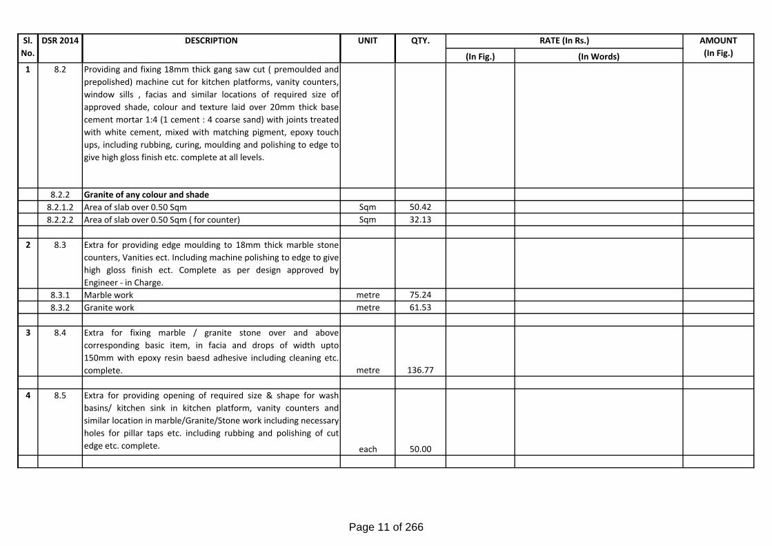
E 8.0 MARBLE & GRANITE WORK
Page 10 of 266
(In Fig.) (In Words)
Sl.
No.
DSR 2014 DESCRIPTION UNIT QTY. RATE (In Rs.) AMOUNT
(In Fig.)
1 8.2 Providing and fixing 18mm thick gang saw cut ( premoulded and
prepolished) machine cut for kitchen platforms, vanity counters,
window sills , facias and similar locations of required size of
approved shade, colour and texture laid over 20mm thick base
cement mortar 1:4 (1 cement : 4 coarse sand) with joints treated
with white cement, mixed with matching pigment, epoxy touch
ups, including rubbing, curing, moulding and polishing to edge to
give high gloss finish etc. complete at all levels.
8.2.2 Granite of any colour and shade
8.2.1.2 Area of slab over 0.50 Sqm Sqm 50.42
8.2.2.2 Area of slab over 0.50 Sqm ( for counter) Sqm 32.13
2 8.3 Extra for providing edge moulding to 18mm thick marble stone
counters, Vanities ect. Including machine polishing to edge to give
high gloss finish ect. Complete as per design approved by
Engineer - in Charge.
8.3.1 Marble work metre 75.24
8.3.2 Granite work metre 61.53
3 8.4 Extra for fixing marble / granite stone over and above
corresponding basic item, in facia and drops of width upto
150mm with epoxy resin baesd adhesive including cleaning etc.
complete. metre 136.77
4 8.5 Extra for providing opening of required size & shape for wash
basins/ kitchen sink in kitchen platform, vanity counters and
similar location in marble/Granite/Stone work including necessary
holes for pillar taps etc. including rubbing and polishing of cut
edge etc. complete. each 50.00
Page 11 of 266

(In Fig.) (In Words)
Sl.
No.
DSR 2014 DESCRIPTION UNIT QTY. RATE (In Rs.) AMOUNT
(In Fig.)
5 8.10 Providing and fixing stone slab with table rubbed, edges rounded
and polished, of size 75x50 cm deep and 1.8 cm thick, fixed in
urinal partitions by cutting a chase of appropriate width with
chase cutter and embedding the stone in the chase with epoxy
grout or with cement concrete 1:2:4 (1 cement : 2 coarse sand : 4
graded stone aggregate 6 mm nominal size) as per direction of
Engineer-in-charge and finished smooth.
8.10.2 Granite Stone of approved shade Sqm 4.95
6 8.11 Providing and fixing machine cut, mirror / eggshell polished ,
Granite stone work for wall lining (veneer work) including dado,
skirting, risers of steps etc., in required design and pattern
wherever required, stones of different finished surface texture,
on 12 mm (average) thick cement mortar 1:3 (1 cement : 3 oarse
sand) laid and jointed with white cement slurry @ 3.3 kg/Sqm
including pointing with white cement slurry admixed with
pigment of matching shade, including rubbing, curing, polishing
etc. all complete as per Architectural drawings, and as directed by
the Engineer-in-Charge. a. 18 mm thick Granite stone slab any
colour etc.
Sqm 0.00
7 16.1 Preparation and consolidation of sub grade with power road roller
of 8 to 12 tonne capacity after excavating earth to an average of
22.5 cm. depth, dressing to camber and consolidating with road
roller including making good the undulations etc. and re-rolling
the sub grade and disposal of surplus earth lead upto 50 metres.
Sqm 1025.75
8 16.3.9 Supplying and stacking & filling good earth at site including
royalty & carriage up to 5 KM complete. Cum 348.63
Page 12 of 266

(In Fig.) (In Words)
Sl.
No.
DSR 2014 DESCRIPTION UNIT QTY. RATE (In Rs.) AMOUNT
(In Fig.)
9 16.19 Supplying at site Angle iron post & strut of required size including
bottom to be split and bent at right angle in opposite direction for
10 cm length and drilling holes upto 10 mm dia. etc. complete.
KG 714.24
10 16.43 Providing and laying design mix cement concrete of M-30 grade,
in roads/ taxi tracks/ runways, using cement content as per design
mix, using coarse sand and graded stone aggregate of 40 mm
nominal size in appropriate proportions as per approved &
specified design criteria, providing dowel bars with sleeve/ tie
bars wherever required, laying at site, spreading and compacting,
mechanically by using needle and surface vibrators, levelling to
required slope/ camber, finishing with required texture, including
steel form work with sturdy M.S. channel sections, curing, making
provision for contraction/ expansion, construction & longitudinal
joints ( 10 mm wide x 50 mm deep) by groove cutting machine,
providing and filling joints with approved joint filler and sealants,
complete all as per direction of Engineer-in-charge (Item of joint
fillers, sealants, dowel bars with sleeve/ tie bars to be paid
separately)
16.43.2 Cement concrete manufactured in automatic batching plant (RMC
plant) i/c transportation to site in transit mixer.
Cum 153.86
11 16.44 Extra for providing and mixing hardening compound of apprOved
quality as per manufacturer's specification in cement
concrete……. (Fosroc-or equivalent -Nitoflor.LH @ 12 Sqm/Ltr)
litre 85.48
12 16.45 Providing and fixing in position pre-moulded joint filler in
expansion joints.
per cm
depth per
cm width
per m length 817.25
Page 13 of 266

(In Fig.) (In Words)
Sl.
No.
DSR 2014 DESCRIPTION UNIT QTY. RATE (In Rs.) AMOUNT
(In Fig.)
13 16.68 Providing and laying 60mm thick factory made cement concrete
interlocking paver block of M -30 grade made by block making
machine with strong vibratory compaction and of approved size
and design/ shape laid in required colour and pattern over and
including 50mm thick compacted bed of course sand, filling the
joints with fine sand etc. all complete as per the direction of
Engineer-in-charge.
SQM 633.26
14 16.69 Providing and laying at or near ground level factory made kerb
stone of M-25 grade cement in position to the required line, level
and curvature jointed with cement mortar 1:3 (1 cement: 3 coarse
sand) including making joints with or without grooves (thickness
of joints except at sharp curve shall not to more than 5mm)
including making drainage opening wherever required complete
etc. as per direction of Engineer-in-charge (length of finished kerb
edging shall be measured for payment). (Precast C.C. kerb stone
shall be approved by Engineer-in-charge).
Cum 19.23
15 16.47 Painting runway/taxi track/apron marking with adequate nos of
coats to give uniform finish with road marking paint of superior
make as approved by the Engineer-in-charge, i/c cleaning the
surface of all dirt, scales, oil, grease and other foreign material
etc. and lining out complete.
16.47.1 New work (Two or more coats) Sqm 483.73
Page 14 of 266

(In Fig.) (In Words)
Sl.
No.
DSR 2014 DESCRIPTION UNIT QTY. RATE (In Rs.) AMOUNT
(In Fig.)
16 16.53 Providing and fixing concertina coil fencing with punched tape
concertina coil 600 mm dia 10 metre openable length ( total
length 90 m), having 50 nos rounds per 6 metre length, upto 3 m
height of wall with existing angle iron 'Y' shaped placed 2.0 m or
3.00 m apart and with 9 horizontal R.B.T. reinforced barbed wire,
stud tied with G.I. staples and G.I. clips to retain horizontal,
including necessary bolts or G.I. barbed wire tied to angle iron, all
complete as per direction of Engineer-in-charge, with reinforced
barbed tape(R.B.T.) / Spring core (2.5mm thick) wire of high
tensile strength of 165 kg/ sq.mm with tape (0.52 mm thick) and
weight 43.478 gm/ metre (cost of M.S. angle, C.C. blocks shall be
paid separately)
rmt 249.00
17 16.78 Construction of granular sub-base by providing close graded
Material conforming to specifications, mixing in a mechanical mix
plant at OMC, carriage of mixed material by tippers to work site,
for all leads & lifts, spreading in uniform layers of specified
thickness with motor grader on prepared surface and compacting
with vibratory power roller to achieve the desired density,
complete as per specifications and directions of Engineerin-
Charge.
16.78.1 With material conforming to Grade-I (size range 75 mm to 0.075
mm) having CBR Value-30 Cum 307.73
16.78.3 With material conforming to Grade-III (size range 26.5 mm to
0.075 mm ) having CBR Value-20 Cum 153.86
Page 15 of 266

(In Fig.) (In Words)
Sl.
No.
DSR 2014 DESCRIPTION UNIT QTY. RATE (In Rs.) AMOUNT
(In Fig.)
18 16.81 Providing and erecting 2.00 metre high temporary barricading at
site as per drawing/ direction of Engineer-in-Charge which
includes writing and painting, arrangement for traffic diversion
such as traffic signals during construction at site for day and night,
glow lamps, reflective signs, marking, flags, caution tape as
directed by the Engineer-in- Charge. The barricading provided
shall be retained in position at site continuously i/c shifting of
barricading from one location to another location as many times
as required during the execution of the entire work till its
completion. Rate include its maintenance for damages, painting,
all incidentals, labour materials, equipments and works required
to execute the job. The barricading shall not be removed without
prior approval of Engineer-in-Charge. (Note :- One time payment
shall be made for providing barricading from start of work till
completion of work i/c shifting. The barricading provided shall
remain to be the property of the contractor on completion of the
work)
mtr 250.00
19 16.87 Providing and laying gang saw cut 30 mm thick, mirror polished
pre moulded and pre polished machine cut granite stone of
required size and shape o f approved shade, colour and texture in
footpath, flooring in road side plazas and similar locations, laid
over 20mm thick base of cement mortar 1:4 (1cement : 4 coarse
sand) including grouting the joints with white cement mixed with
matching pigment, epoxy touch ups etc. complete as per direction
of Engineer-in-Charge.
16.87.1 Area less than 0.50 Sqm. Sqm 749.37
F 9.0 WOOD & PVC WORK
Frame
Page 16 of 266

(In Fig.) (In Words)
Sl.
No.
DSR 2014 DESCRIPTION UNIT QTY. RATE (In Rs.) AMOUNT
(In Fig.)
1 9.1 Providing wood work in frames of doors, windows, clerestory
windows and other frames, wrought framed and fixed in position
with hold fast lugs or with dash fasteners of required dia & length
( hold fast lugs or dash fastener shall be paid for separately).
9.1.1 Second class teak wood Cum 3.40
Door Shutter
2 9.20 Providing and fixing ISI marked flush door shutters conforming to
IS : 2202 (Part I) decorative type, core of block board construction
with frame of 1st class hard wood and well matched teak 3 ply
veneering with vertical grains or cross bands and face veneers on
both faces of shutters.
9.20.1 35 mm thick including ISI marked Stainless Steel butt hinges with
necessary screws Sqm 621.37
3 9.23 Extra for providing lipping with 2nd class teak wood battens 25
mm minimum depth on all edges of flush door shutters (over all
area of door shutter to be measured). Sqm 621.37
4 9.36 Providing and fixing specified wood frame work consisting of
battens 50x25 mm fixed with rawl plug and drilling necessary
holes for rawl plug etc. including priming coat complete
9.36.1 Kiln seasoned and chemically treated hollock wood Cum 0.38
5 9.48 Providing and fixing M.S. grills of required pattern in frames of
windows etc. with M.S. flats, square or round bars etc. including
priming coat with approved steel primer all complete.
9.48.1 Fixed to steel windows by welding kg 3849.70
Page 17 of 266

(In Fig.) (In Words)
Sl.
No.
DSR 2014 DESCRIPTION UNIT QTY. RATE (In Rs.) AMOUNT
(In Fig.)
6 9.53 Providing 40x5 mm flat iron hold fast 40 cm long including fixing
to frame with 10 mm diameter bolts, nuts and wooden plugs and
embedding in cement concrete block 30x10x15cm 1:3:6 mix (1
cement : 3 coarse sand : 6 graded stone aggregate 20mm nominal
size). Each 1958.00
7 9.64 Providing and fixing ISI marked 85x42mm oxidised M.S. pull bolt
lock conforming to IS : 7534 with necessary screws bolts, nut and
washers etc. complete. each 36.00
8 9.79 Providing and fixing special quality bright finished brass cupboard
or ward robe locks with four levers of approved quality including
necessary screws etc. complete.
9.79.2 50 mm each 44.00
9 9.80 Providing and fixing 50 mm bright finished brass cup board or
wardrobe knob of approved quality with necessary screws.
each 88.00
10 9.83 Providing and fixing IS : 3564 marked Aluminium die cast body
tubular type universal hydraulic door closer with necessary
accessories and screws etc. complete. EACH 278.00
11 9.97 Providing and fixing aluminium tower bolts ISI marked anodised
(anodic coating not less than grade AC 10 as per IS : 1868 )
transparent or dyed to required colour or shade with necessary
screws etc. complete :
i 9.97.1 300x10 mm EACH 712.00
ii 9.97.5 100x10 mm EACH 690.00
12 9.98 Providing and fixing aluminium pull bolt lock, ISI marked, anodised
(anodic coating not less than grade AC 10 as per IS : 1868)
transparent or dyed to required colour and shade, with necessary
screws bolts, nut and washers etc. complete.
EACH 40.00
Page 18 of 266

(In Fig.) (In Words)
Sl.
No.
DSR 2014 DESCRIPTION UNIT QTY. RATE (In Rs.) AMOUNT
(In Fig.)
13 9.100 Providing and fixing aluminium handles of approved make
anodized (anodic coating not less than grade AC 10 as per IS :
1868) transparent or dyed to required colour or shade with
necessry screws etc. complete.
9.100.1 125 mm EACH 712.00
9.100.2 100mm EACH 690.00
14 9.101 Providing and fixing aluminium hanging floor door stopper ISI
marked anodised (anodic coating not less than grade AC 10 as per
IS : 1868) transparent or dyed to required colour and shade with
necessary screws etc. complete.
9.101.1 Single rubber stopper EACH 278.00
15 9.103 Providing & fixing bright finished brass 100 mm mortice latch and
lock ISI marked with six levers and a pair of anodised (anodic
coating not less than grade AC 10 as per IS :1868) aluminium lever
handles with necessary screws etc. complete.
EACH 248.00
16 9.114 Providing and fixing magnetic catcher of approved quality in
cupboard / ward robe shutters, including fixing with necessary
screws etc. complete.
9.114.2 Double strip (horizontal type) each 44.00
17 9.121 Providing and fixing Fiber Glass Reinforced plastic (FRP) Door
Frames of cross-section 90 mm x 45 mm having single rebate of
32 mm x 15 mm to receive shutter of 30 mm thickness .The
laminate shall be moulded with fire resistant grade unsaturated
polyester resin and chopped mat. Door frame laminate shall be 2
mm thick and shall be filled with suitable wooden block in all the
three legs. The frame shall be covered with fiber glass from all
sides. M.S. stay shall be provided at the bottom to steady] the
frame. metre 163.35
Page 19 of 266

(In Fig.) (In Words)
Sl.
No.
DSR 2014 DESCRIPTION UNIT QTY. RATE (In Rs.) AMOUNT
(In Fig.)
18 9.122 Providing and fixing to existing door frames.
9.122.2 30 mm thick Fiberglass Reinforced Plastic (F.R.P.) flush door
shutter in different plain and wood finish made with fire retardant
grade unsaturated polyester resin, moulded to 3 mm thick FRP
laminate all around, with suitable wooden blocks inside at
required places for fixing of fittings and polyurethane foam (PUF)/
Polystyrene foam to be used as filler material throughout the
hollow panel, casted monolithically with testing parameters of
F.R.P. laminate conforming to table - 3 of IS: 14856, complete as
per direction of Engineer-in-charge.
Sqm 51.98
19 9.123 Providing and fixing factory made door frame (single rebate)
made out of single piece extruded solid PVC foam profile with
homogenous fine cellular structure having smooth outer integral
skin having 62 mm width & 32 mm thickness, frame will be mitred
& Jointed with self driven self tapping screws of size 38 mm x 4
mm & PVC solvent cement , including fixing the frame to wall with
suitable dia & length anchor fastener as per manufacturer’s
specification and direction of Engineer-in-charge.
metre 212.85
Page 20 of 266

(In Fig.) (In Words)
Sl.
No.
DSR 2014 DESCRIPTION UNIT QTY. RATE (In Rs.) AMOUNT
(In Fig.)
20 9.124 Providing and fixing factory made 30 mm thick door shutter made
of solid PVC foam profile. The styles & rails shall be of size 75 mm
x 30 mm having wall thickness 5 mm. The styles, top & bottom
rails shall have one side wall thickness of 15 mm integrally
extruded on the hinge side of the profile for better screw holding
power. The styles and rails shall be reinforced with M.S. tubes of
size 33 mm x 17 mmx 1 mm, painted with primer , all four corners
of reinforcement to be welded or sealed. Solid PVC extruded
bidding (push fit type) will be set inside the styles and the rails
with a cavity, to receive single piece extruded 5 mm PVC sheet as
panel. The styles and rails will be mitred cut and joint with the
help of PVC solvent cement & self driven self tapping screws.
Single piece extruded solid PVC lock rail of size 100 mm x 30 mm
with wall thickness 5 mm & 15 mm integrally extruded in the
middle of the lock rail & fixed with styles with the help of PVC
solvent cement & self driven self tapping screws of size 1e
work)lending with cement to be ensured in accordance with
clauses 5.2 and 5.2.1 of IS:456 -20
9.124.1 Non decorative finish. Sqm 67.73
21 9.127 Providing & Fixing decorative high pressure laminated sheet of
plain / wood grain in gloss / matt / suede finish with high density
protective surface layer and reverse side of adhesive bonding
quality conforming to IS : 2046 Type S, including cost of adhesive
of approved quality.
9.127.2 1.0 mm thick Sqm 292.56
Page 21 of 266

(In Fig.) (In Words)
Sl.
No.
DSR 2014 DESCRIPTION UNIT QTY. RATE (In Rs.) AMOUNT
(In Fig.)
22 9.129 Providing and fixing cup board shutters 25 mm thick, with Pre-
laminated flat pressed three layer particle board or graded wood
particle board IS: 12823 marked, exterior grade (Grade l Type ll),
having one side decorative lamination and other side balancing
lamination, including IInd class teak wood lipping of 25 mm wide
x12 mm thick with necessary screws and bright finished stainless
steel piano hinges, complete as per direction of the Engineer-in-
Charge
Sqm 127.23
G 10.0 STEEL WORK
1 10.5 Providing and fixing 1mm thick M.S. sheet door with frame of
40x40x6 mm angle iron and 3 mm M.S. gusset plates at the
junctions and corners, all necessary fittings complete, including
applying a priming coat of approved steel primer.
10.5.1 Using M.S. angels 40x40x6 mm for diagonal braces Sqm 5.76
2 10.14 Providing and fixing pressed steel door frames conforming to IS:
4351 manufactured from commercial mild steel sheet of 1.60 mm
thickness including hinges, jamb, lock jamb, bead and if required
angle threshold of mild steel angle of section 50x25mm, or base
ties of 1.60 mm pressed mild steel welded or rigidly fixed
together by mechanical means, including M.S. pressed butt
hinges, 2.5mm thick with mortar guards, lock strike-plate and
shock absorbers as specified and applying a coat of approved steel
primer after pre-treatment of the surface as directed by Engineer-
in-charge:
10.14.1 Profile B
10.14.1.1 Fixing with adjustable lugs with split end tail to each jamb. metre 959.55
10.14.3 Profile E
10.14.3.1 Fixing with adjustable lugs with split end tail to each jamb metre 338.80
Page 22 of 266

(In Fig.) (In Words)
Sl.
No.
DSR 2014 DESCRIPTION UNIT QTY. RATE (In Rs.) AMOUNT
(In Fig.)
3 10.11 Providing and fixing factory made ISI marked steel glazed doors,
windows and ventilators side /top /centre hung with beading and
all members such as F7D, F4B, K11 B and K12 B etc. complete of
standard rolled steel sections, joints mitred and flash butt welded
and sash bars tenoned and riveted, including providing and fixing
of hinges, pivots, including priming coat of approved steel primer ,
but excluding the cost of other fittings, complete all as per
approved design (sectional weight of only steel members shall be
measured for payment).
10.11.1 Fixing with 15x3 mm lugs 10 cm. long embedded in cement
concrete block 15x10x10 cm of C.C. 1:3:6 (1 Cement : 3 coarse KG 8057.76
4 10.25 Steel work welded in built up sections/ framed work including
cutting, hoisting, fixing in position and applying a priming coat of
approved steel primer using structural steel etc. as required
10.25.1 In stringers, treads, landings etc. of stair cases including use of
chequered plate wherever required, all complete. KG 550.00
10.25.2 In gratings, frames, guard bar, ladder, railings, brackets, gates and
similar works. KG 6025.06
5 10.27 Providing and fixing carbon steel galvanised ( minimum coating 5
micron) dash fastener of 10 mm dia double threaded 6.8 grade
(yield strength 480 N/mm2), counter sunk head, comprising of 10
m dia polyamide PA 6 grade sleeve, including drilling of hole in
frame , concrete/ masonry, etc. as per direction of Engineer-in-
charge.
10.27.5 10 x 160 mm Each 179.00
Page 23 of 266

(In Fig.) (In Words)
Sl.
No.
DSR 2014 DESCRIPTION UNIT QTY. RATE (In Rs.) AMOUNT
(In Fig.)
6 10.28 Providing and fixing stainless steel (Grade 304) railing made of
Hollow tubes, channels, plates etc., including welding, grinding,
buffing, polishing and making curvature (wherever required) and
fitting the same with necessary stainless steel nuts and bolts
complete, i/c fixing the railing with necessary accessories &
stainless steel dash fasteners, stainless steel bolts etc., of
required size, on the top of the floor or the side of waist slab with
suitable arrangement as per approval of Engineer-in-charge, (for
payment purpose only weight of stainless steel members shall be
considered excluding fixing accessories such as nuts, bolts,
fasteners etc.).
KG 1612.95
7 10.29 Providing & fixing fly proof wire gauze to windows, clerestory
windows & doors with M.S. Flat 15x3m and nuts & bolts
complete.
10.29.1 Galvanised M.S. Wire gauze with 0.63 mm dia wire and 1.4 mm
aperture on both sides Sqm 228.61
8 10.30 Providing & fixing glass panes with putty and glazing clips in steel
doors, windows, clerestory windows all complete.
10.30.1 With 4.0 mm thick glass panes. Sqm 228.61
9 19.15 Providing M.S. foot rests including fixing in manholes with
20x20x10 cm cement concrete blocks 1:3:6 (1 cement : 3 coarse
sand : 6 graded stone aggregate 20 mm nominal size) as per
standard design :
19.15.1 With 20x20 mm square bar each 54.00
10 19.18 Supplying and fixing C.I. cover without frame for manholes :
19.18.1 455 x 610 mm rectangular C.I. cover (light duty) the weight of the
cover to be not less than 23 kg each 2.00
Page 24 of 266

(In Fig.) (In Words)
Sl.
No.
DSR 2014 DESCRIPTION UNIT QTY. RATE (In Rs.) AMOUNT
(In Fig.)
11 19.19 Providing M.S. foot rests including fixing in manholes with
20x20x10 cm cement concrete blocks 1:3:6 (1 cement : 3 coarse
sand : 6 graded stone aggregate 20 mm nominal size) as per
standard design :
19.19.1 L D- 2.5
19.19.1.1 Rectangular shape 600x450 mm internal dimensions each 2.00
19.19.3 H D - 20
19.19.3.1 Circular shape 560 mm internal diameter each 2.00
H 11.0 FLOORING WORK
1 11.4 52 mm thick cement concrete flooring with concrete hardener
topping, under layer 40 mm thick cement concrete 1:2:4 (1
cement : 2 coarse sand : 4 graded stone aggregate 20 mm
nominal size) and top layer 12 mm thick cement hardener
consisting of mix 1:2 (1 cement hardener mix : 2 graded stone
aggregate 6 mm nominal size) by volume, hardening compound
mixed @ 2 litre per 50 kg of cement or as per manufacturer’s
specifications. This includes cost of cement slurry, but excluding
the cost of nosing of steps etc. complete.
Sqm 169.35
2 11.6 Cement plaster skirting up to 30 cm height, with cement mortar
1:3 (1 cement : 3 coarse sand), finished with a floating coat of
neat cement.
11.6.1 18 mm thick Sqm 6.78
3
11.14
Extra for laying terrazo flooring on staircase treads not exceeding
30 cm in width, including cost of forming, nosing etc. sqm
29.90
Page 25 of 266

(In Fig.) (In Words)
Sl.
No.
DSR 2014 DESCRIPTION UNIT QTY. RATE (In Rs.) AMOUNT
(In Fig.)
4 11.15 Crazy marble stone flooring, including filling the gaps with light
shade pigment with white cement marble powder mixture (3
parts of white cement : 1 part of marble powder) by weight in
proportion of 4:7 (4 cement marble powder mix : 7 white, black or
white and black marble chips of sizes from 1 mm to 4 mm nominal
size by volume), with under layer 25 mm thick cement concrete
1:2:4 (1 cement : 2 coarse sand : 4 graded stone aggregate 12.5
mm nominal size), including rubbing, polishing and cement slurry
etc. complete :
11.15.1 18 mm thick crazy marble stone white, black or as specified sqm 75.99
5 11.26 Kota stone slab flooring over 20 mm (average) thick base laid over
and jointed with grey cement slurry mixed with pigment to match
the shade of the slab including rubbing and polishing complete
with base of cement mortar 1 : 4 (1 cement : 4 coarse sand) :
11.26.1 25 mm thick. Sqm 1368.64
6 11.27 Kota stone slabs 25 mm thick in risers of steps, skirting, dado and
pillars laid on 12 mm (average) thick cement mortar 1:3 (1 cement
3 coarse sand) and jointed with grey cement slurry mixed with
pigment to match the shade of the slabs, including rubbing and
polishing complete. Sqm 23.20
7 11.31 Extra for pre finished nosing in treads of steps of Kota stone/ sand
stone slab. rmt 125.55
8 11.32 Extra for Kota stone/ sand stone in treads of steps and risers using
single length up to 1.05 metre. sqm 32.95
Page 26 of 266

(In Fig.) (In Words)
Sl.
No.
DSR 2014 DESCRIPTION UNIT QTY. RATE (In Rs.) AMOUNT
(In Fig.)
9 11.36 Providing and fixing Ist quality ceramic glazed wall tiles
conforming to IS: 15622 (thickness to be specified by the
manufacturer), of approved make, in all colours, shades except
burgundy, bottle green, black of any size as approved by Engineer-
in-Charge, in skirting, risers of steps and dados, over 12 mm thick
bed of cement mortar 1:3 (1 cement : 3 coarse sand) and jointing
with grey cement slurry @ 3.3kg per Sqm, including pointing in
white cement mixed with pigment of matching shade complete.
Sqm 1324.58
10 11.38 Providing and laying Ceramic glazed floor tiles 300x300 mm
(thickness to be specified by the manufacturer) of 1st quality
conforming to IS : 15622 of approved make in all colours, shades,
expect White, Ivory, Grey, Fume Red Brown, laid on 20 mm thick
Cement Mortar 1: 4 (1 Cement : 4 Coarse sand ) including pointing
the joints with white cement and matching pigments etc.,
complete. Sqm 1542.24
11 11.45 Providing and laying 500x500x40 mm thick Turf paver (Turfpave
XD) on 150 mm thick sub grade of compacted bed of 20 mm thick
nominal size stone aggregate and base course and filling with 150
mm thick jamuna sand, including spreading, well ramming,
consolidating and finishing smooth etc. all complete as per
direction of Engineer-in-charge.
sqm 225.00
12 11.41 Providing and laying vitrified floor tiles in different sizes (thickness
to be specified by the manufacturer) with water absorption less
than 0.08% and conforming to IS : 15622, of approved make, in all
colours and shades, laid on 20mm thick cement mortar 1:4 (1
cement : 4 coarse sand), including grouting the joints with white
cement and matching pigments etc., complete.
11.41.2 Size of Tile 600x600 mm Sqm 567.47
Page 27 of 266

(In Fig.) (In Words)
Sl.
No.
DSR 2014 DESCRIPTION UNIT QTY. RATE (In Rs.) AMOUNT
(In Fig.)
13 11.46 Providing and laying Vitrified tiles in different sizes (thickness to
be specified by manufacturer), with water absorption less than
0.08 % and conforming to I.S. 15622, of approved make, in all
colours & shade, in skirting, riser of steps, over 12 mm thick bed
of cement mortar 1:3 (1 cement: 3 coarse sand), including
grouting the joint with white cement & matching pigments etc.
complete.
11.46.2 Size of Tile 600x600 mm Sqm 96.41
I 12.0 ROOFING
1 12.21 Providing and laying gola 75x75mm in cement concrete M15
grade including finishing with cement mortar 1:3 (1 cement : 3
fine sand) as per standard design.
12.21.1 in 75x75 mm deep chase. metre 569.25
2 12.22 Making khurras 45x45 cm with average minimum thickness of
5mm cement concrete 1:2:4 (1 cement : 2 coarse sand : 4 graded
stone aggregate of 20 mm nominal size) over P.V.C. sheet 1 m x1
m x 400 micron, finished with 12 mm cement plaster 1:3 (1
cement : 3 coarse sand) and a coat of neat cement, rounding the
edges and making and finishing the outlet complete.
Each 30.00
3 12.41 Providing and fixing on wall face unplasticised Rigid PVC rain
water pipes conforming to IS : 13592 Type A, including jointing
with seal ring conforming to IS : 5382, leaving 10 mm gap for
thermal expansion, (i) Single socketed pipes.
12.41.2 110 mm diameter rmt. 448.70
4 12.42 Providing and fixing on wall face unplasticised - PVC moulded
fittings/ accessories for unplasticised Rigid PVC rain water pipes
conforming to IS : 13592 Type A, including jointing with seal ring
conforming to IS : 5382, leaving 10 mm gap for thermal
expansion.
Page 28 of 266

(In Fig.) (In Words)
Sl.
No.
DSR 2014 DESCRIPTION UNIT QTY. RATE (In Rs.) AMOUNT
(In Fig.)
12.42.1 Coupler
12.42.1.2 110 mm Each 68.00
12.42.5 Bend 87.5°
12.42.5.2 110 mm bend Each 34.00
12.42.6 Shoe (Plain)
12.42.6.2 110 mm Shoe Each 68.00
J 13.0 FINISHING WORK
1 13.4 12 mm cement plaster of mix :
13.4.1 1:4 (1 cement: 4 coarse sand) Sqm 4191.18
2 13.5 15 mm cement plaster on rough side of single or half brick wall of
mix :
13.5.2 1:6 (1 cement: 6 coarse sand) Sqm. 4825.67
3 13.6 20 mm cement plaster of mix :
13.6.1 1:4 (1 cement: 4 coarse sand) Sqm. 5351.49
4 5.30 Add or deduct for plaster drip course/ groove in or moulding to
R.C.C. projections.plastered surface metre 1919.48
5 13.16 6 mm cement plaster of mix :
13.16.1 1:3 (1 cement: 3 fine sand) Sqm. 4552.04
6 13.18 Neat cement punning. Sqm. 4552.04
7 13.21 Extra for providing and mixing water proofing material in cement
plaster work in proportion recommended by the manufacturers.per bag of
50KG Cement
Used in Mix 2916.57
8 13.22 Extra for plastering exterior walls of height more than 10 m from
ground level for every additional height of 3 m or part thereof.
Sqm. 3068.85
Page 29 of 266

(In Fig.) (In Words)
Sl.
No.
DSR 2014 DESCRIPTION UNIT QTY. RATE (In Rs.) AMOUNT
(In Fig.)
9 13.26 Providing and applying plaster of paris putty of 2 mm thickness
over plastered surface to prepare the surface even and smooth
complete. Sqm 4547.00
10 13.41 Distempering with oil bound washable distemper of approved
brand and manufacture to give an even shade
13.41.1 New work (two or more coats) over and including priming coat
with cement primer. sqm 270.62
11 13.45 Finishing walls with textured exterior paint of required shade :
13.45.1 New work (Two or more coats applied @ 3.28 ltr/10 Sqm) over
and including base coat of water proofing cement paint applied @
2.20kg/10 Sqm. Sqm 1293.98
12 13.47 Finishing walls with Premium Acrylic Smooth exterior paint with
Silicone additives of required shade :
13.47.1 New work (Two or more coats applied @ 1.43 ltr/ 10 sqm over
and including priming coat of exterior primer applied @ 2.20 kg/
10 sqm) Sqm 2487.37
13 13.72 Washed stone grit plaster on exterior walls height upto 10 metre
above ground level, in two layers, under layer 12 mm cement
plaster 1:4 (1 cement : 4 coarse sand ), furrowing the under layer
with scratching tool,applying cement slurry on the under layer @
2 Kg of cement per squaremetre, top layer 15 mm cement plaster
1:1/ 2:2 (1 cement: 1/2 coarse sand : 2 stone chipping 10 mm
nominal size), in panels with groove all around as per approved
pattern, including scrubbing and washing the top layer with
brushes and water to expose the stone chippings ,complete as per
specification and direction of Engineer-in- charge (payment for
provoding grooves shall be made separately).
Sqm. 384.07
Page 30 of 266

(In Fig.) (In Words)
Sl.
No.
DSR 2014 DESCRIPTION UNIT QTY. RATE (In Rs.) AMOUNT
(In Fig.)
14 13.73 Forming groove of uniform size in the top layer of washed stone
grit plaster as per approved pattern using wooden battens, nailed
to the under layer,
including removal of wooden battens, repair to the edges of
panels and finishing the groove complete as per specifications and
direction of the Engineer-in-charge :
13.73.1 15 mm wide and 15 mm deep groove metre 252.99
15 13.80 Providing and applying white cement based putty of average
thickness 1 mm, of approved brand and manufacturer, over the
plastered wall surface to prepare the surface even and smooth
complete Sqm 12118.44
16 13.81 Distempering with 1st quality acrylic distemper, having VOC
(Volatile Organic Compound ) content less than 50 grams/ litre, of
approved brand and m anufacture, including applying additional
coats wherever required, to achieve even shade and colour.
13.81.2 Two coats Sqm 7851.50
17 13.82 Wall painting with acrylic emulsion paint, having VOC (Volatile
Organic Compound ) content less than 50 grams/ litre, of
approved brand and manufacture, including applying additional
coats wherever required, to achieve even shade and colour.
13.82.2 Two coats Sqm 4807.22
15 13.84 Painting with synthetic enamel paint, having VOC (Volatile
Organic Compound) content less than 150 grams/ litre, of
approved brand and manufacture, including applying additional
coats wherever required to achieve even shade and colour.
13.84.2 Two coats Sqm 2561.94
Page 31 of 266

(In Fig.) (In Words)
Sl.
No.
DSR 2014 DESCRIPTION UNIT QTY. RATE (In Rs.) AMOUNT
(In Fig.)
16 13.85 Applying priming coats with primer of approved brand and
manufacture, having low VOC (Volatile Organic Compound )
content.
13.85.1 With ready mixed pink or grey primer on wood work (hard and
soft wood) having VOC content less than 50 grams/ litre
Sqm 579.98
13.85.2 With ready mixed red oxide zinc chromatic on steel / iron works
having VOC content less than 250 grams/ litre Sqm 1981.97
13.85.3 With water thinnable cement primer on wall surface having VOC
content less than 50 grams/litre Sqm 15487.31
K 21.0 ALUMINIUM WORK
1 21.1 Providing and fixing aluminium work for doors, windows,
ventilators and partitions with extruded built up standard tubular
sections/appropriate Z sections and other sections of approved
make conforming to IS: 733 and IS : 1285, fixed with rawl plugs
and screws or with fixing clips, or with expansion hold fasteners
including necessary filling up of gaps at junctions, at top, bottom
and sides with required PVC/neoprene felt etc. Aluminium
sections shall be smooth, rust free, straight, mitred and jointed
echanically wherever required including cleat angle, Aluminium
snap beading for glazing / paneling, C.P. brass / stainless steel
screws, all complete as per architectural drawings and the
directions of Engineer-in-charge. Glazing and paneling to be paid
for separately) :
21.1.1 For fixed portion.
21.1.1.2 Powder coated aluminium (minimum thickness of powder coating
50 micron) KG 4436.19
Page 32 of 266

(In Fig.) (In Words)
Sl.
No.
DSR 2014 DESCRIPTION UNIT QTY. RATE (In Rs.) AMOUNT
(In Fig.)
21.1.2 For shutters of doors, windows & ventilators including providing
and fixing hinges/ pivots and making provision for fixing of fittings
wherever required including the cost of EPDM rubber / neoprene
gasket required (Fittings shall be paid for separately)
21.1.2.2 Powder coated aluminium (minimum thickness of powder coating
50 micron) KG 938.41
2 21.2 Providing and fixing 12 mm thick prelaminated particle board flat
pressed three layer or graded wood particle board conforming to
IS: 12823 Grade l Type ll, in panelling fixed in aluminum doors,
windows shutters and partition frames with C.P. brass / stainless
steel screws etc. complete as per architectural drawings and
directions of engineer-in-charge.
21.2.2 Pre-laminated particle board with decorative lamination on both
sides SQM 9.12
3 21.3 Providing and fixing glazing in aluminium door, window, ventilator
shutters and partitions etc. with EPDM rubber / neoprene gasket
etc. complete as per the architectural drawings and the directions
of engineer-in-charge . (Cost of aluminium snap beading shall be
paid in basic item):
21.3.1 With float glass panes of 4.0 mm thickness Sqm 363.84
21.3.2 With float glass panes of 5.50 mm thickness Sqm 9.12
4 21.8 Filling the gap in between aluminium frame and adjacent
RCC/Brickwork/ Stone Work by providing weather silicon sealant
over backer rod of approved quality as per architectural drawings
and direction of Engineer-in-charge
21.8.1 Upto 5mm depth and 5mm width metre 1475.80
Page 33 of 266

(In Fig.) (In Words)
Sl.
No.
DSR 2014 DESCRIPTION UNIT QTY. RATE (In Rs.) AMOUNT
(In Fig.)
5 26.1 Providing and supplying aluminium extruded tubular and other
aluminium sections as per the architectural drawings and
approved shop drawings, the aluminium quality as per grade 6063
T5 or T6 as per BS 1474,including super durable powder coating of
60-80 microns conforming to AAMA 2604 of required colour and
shade as approved by the Engineer-in-Charge. (The item includes
cost of material such as cleats, sleeves, screws etc. necessary for
fabrication of extruded aluminium frame work. Nothing extra
shall be paid on this account).
Kg 3081.33
6 26.2 Designing, fabricating, testing, protection, installing and fixing in
position semi (grid) unitized system of structural glazing (with
open joints) for linear as well as curvilinear portions of the
building for all heights and all levels, including:
a) Structural analysis & design and preparation of shop drawings
for the specified design loads conforming to IS 875 part III (the
system must passed the proof test at 1.5 times design wind
pressure without any failure), including functional design of the
aluminum sections for fixing glazing panels of various thicknesses,
aluminium cleats, sleeves and splice plates etc. gaskets, screws,
toggles, nuts, bolts, clamps etc., structural and weather silicone
sealants, flashings, fire stop (barrier)- Cum-smoke seals,
microwave cured EPDM gaskets for water tightness, pressure
equalisation & drainage and protection against fire hazard
including:
Page 34 of 266

(In Fig.) (In Words)
Sl.
No.
DSR 2014 DESCRIPTION UNIT QTY. RATE (In Rs.) AMOUNT
(In Fig.)
b) Fabricating and supplying serrated M.S. hot dip galvanised /
Aluminium alloy of 6005 T5 brackets of required sizes, sections
and profiles etc. to accommodate 3 Dimentional movement for
achieving perfect verticality and fixing structural glazing system
rigidly to the RCC/ masonry/structural steel framework of building
structure using stainless steel anchor fasteners/ bolts, nylon
seperator to prevent bimetallic contacts with nuts and washers
etc. of stainless steel grade 316, of the required capacity and in
required numbers.
c) Providing and filling, two part pump filled, structural silicone
sealant and one part weather silicone sealant compatible with the
structural silicone sealant of required bite size in a clean and
controlled factory / work shop environment , including double
sided spacer tape, setting blocks and backer rod, all of approved
grade, brand and manufacture, as per the approved sealant
design, within and all around the perimeter for holding glass.
d) Providing and fixing in position flashings of solid aluminium
sheet 1 mm thick and of sizes, shapes and profiles, as required as
per the site conditions, to seal the gap between the building
structure and all its interfaces with curtain glazing to make it
watertight.
Page 35 of 266

(In Fig.) (In Words)
Sl.
No.
DSR 2014 DESCRIPTION UNIT QTY. RATE (In Rs.) AMOUNT
(In Fig.)
e) Making provision for drainage of moisture/ water that enters
the curtain glazing system to make it watertight, by incorporating
principles of pressure equalization, providing suitable gutter
profiles at bottom (if required), making necessary holes of
required sizes and of required numbers etc. complete. This item
includes cost of all inputs of designing, labour for fabricating and
installation of aluminium grid, installation of glazed units, T&P,
scaffolding and other incidental charges including wastages etc.,
enabling temporary structures and services, cranes or cradles etc.
as described above and as specified. The item includes the cost of
getting all the structural and functional design including shop
drawings checked by a structural designer, dully approved by
Engineer-in-charge. The item also includes the cost of all mock
ups at site, cost of all samples of the individual components for
testing in an approved laboratory, field tests on the assembled
working structural glazing as specified, cleaning and protection till
the handing over of the building for occupation. In the end, the
Contractor shall provide a water tight structural glazing having all
the performance characteristics etc. all complete as required, as
per the Architectural drawings, as per item description, as
specified, as per the approved shop drawings and as directed by
the Engineerin-Charge.
Note:- 1. The cost of providing extruded aluminium frames,
shadow boxes, extruded aluminium section capping for fixing in
the grooves of the curtain glazing and vermin proof stainless steel
wire mesh shall be paid for separately under relevant items under
this subhead. However, for the purpose of payment, only the
actual area of structural glazing (including width of grooves) on
the external face shall be measured in Sqm. up to two decimal
places.
Page 36 of 266

(In Fig.) (In Words)
Sl.
No.
DSR 2014 DESCRIPTION UNIT QTY. RATE (In Rs.) AMOUNT
(In Fig.)
Note:-2. The following performance test are to be conducted on
structural glazing system if area of structural glazing exceeds 2500
Sqm from the certified laboratories accreditated by
NABL(National Accreditation Board for Testing and Calibration
Laboratories), Department of Science & Technologies, India. Cost
of testing is payable separately. The NIT approving authority will
decide the necessity of testing on the basis of cost of the work,
cost of the test and importance of the work. Performance Testing
of Structural glazing system Tests to be conducted in the NBL
Certified laboratories
1. Performance Laboratory Test for Air Leakage Test (-50pa to –
300pa) & (+50pa to +300pa) as per ASTM E-283-04 testing
method for a range of testing limit 1 to 200 mVhr”
2. Static Water Penetration Test. (50pa to 1500pa) as per ASTME-
331- 09 testing method for a range up to 2000 ml.”
3. Dynamic Water Penetration (50pa to 1500pa) as per AAMA
501.01- 05 testing method for a range upto 2000 ml”
4. Structural Performance Deflection and deformation by static air
pressure test (1.5 times desing wind pressure without any failure)
as per ASTME- 330-10 testing method for a range upto 50 mm”
26.2.1
5. Seismic Movement Test (upto 30 mm) as per AAMA 501.4-09
testing method for Qualitative test” Tests to be conducted on site
6. Onsite Test for Water Leakage for a pressure range 50 kpa to
240 kpa (35psi) upto 2000ml” Sqm 308.13
Page 37 of 266

(In Fig.) (In Words)
Sl.
No.
DSR 2014 DESCRIPTION UNIT QTY. RATE (In Rs.) AMOUNT
(In Fig.)
7 26.6 Providing and supplying Spandrel Glass Panels comprising of 6
mm thick heat strengthened monolithic float glass of approved
colour and shade with reflective soft coating on surface # 2 of
approved colour and shade so as to match the colour and shade
of the IGUs in the vision panels etc., all complete for the required
performances as specified, as per the Architectural drawings, as
per the approved shop drawings, as specified, and as directed by
the Engineer-in-Charge. For payment, only the actual area of glass
on face # 1 of the glass panels (but excluding the area of grooves
and weather silicone sealant) provided and fixed in position, shall
be measured in sqm.(Payment for fixing of Spandrel Glass Panels
in the curtain glazing is included in cost of relevent Item*). (i)
Coloured tinted float glass 6mm thick substrate with reflective
soft coating on face # 2, having properties as visible Light
transmittance (VLT) of 25 to 35%, Light reflection internal 10 to
15%, light reflection external 10 to20%, shading coefficient (0.25-
0.28) and U value of 3.0 to 3.3 W/m2 degree K etc. The properties
of performance glass shall be decided by technical sanctioning
authority as per the site requirement.
Sqm 308.13
8 26.7 Designing, fabricating, testing, installing and fixing in position
Curtain Wall with Aluminium Composite Panel Cladding, with
open grooves for linear as well as curvilinear portions of the
building, for all heights and all levels etc. including:
a) Structural analysis & design and preparation of shop drawings
for pressure equalisation or rain screen principle as required,
proper drainage of water to make it watertight including checking
of all the structural and functional design.
Page 38 of 266

(In Fig.) (In Words)
Sl.
No.
DSR 2014 DESCRIPTION UNIT QTY. RATE (In Rs.) AMOUNT
(In Fig.)
b) Providing, fabricating and supplying and fixing panels of
aluminium composite panel cladding in pan shape in metalic
colour of approved shades made out of 4mm thick aluminium
composite panel material consisting of 3mm thick FR grade
mineral core sandwiched between two Aluminium sheets (each
0.5mm thick). The aluminium composite panel cladding sheet
shall be coil coated, with Kynar 500 based PVDF / Lumiflon based
fluoropolymer resin coating of approved colour and shade on face
# 1 and polymer (Service) coating on face # 2 as specified using
stainless steel screws, nuts, bolts, washers, cleats, weather
silicone sealant, backer rods etc.
Page 39 of 266

(In Fig.) (In Words)
Sl.
No.
DSR 2014 DESCRIPTION UNIT QTY. RATE (In Rs.) AMOUNT
(In Fig.)
26.7.1 c) The fastening brackets of Aluminium alloy 6005 T5 / MS with
Hot Dip Galvanised with serrations and serrated washers to arrest
the wind load movement, fasteners, SS 316 Pins and anchor bolts
of approved make in SS 316, Nylon separators to prevent bi-
metallic contacts all complete required to perform as per
specification and drawing The item includes cost of all material &
labour component, the cost of all mock ups at site, cost of all
samples of the individual components for testing in an approved
laboratory, field tests on the assembled working curtain wall with
aluminium composite panel cladding, cleaning and protection of
the curtain wall with aluminium composite panel cladding till the
handing over of the building for occupation. Base frame work for
ACP cladding is payable under the relevant aluminium item.s The
Contractor shall provide curtain wall with aluminium composite
panel cladding, having all the performance characteristics all
complete, as per the Architectural drawings, as per item
description, as specified, as per the approved shop drawings and
as directed by the Engineer-in-Charge. However, for the purpose
of payment, only the actual area on the external face of the
curtain wall with Aluminum Composite Panel Cladding (including
width of groove) shall be measured in Sqm. up to two decimal
places.
Sqm 2159.03
L 22.0 WATER PROOFING
Page 40 of 266

(In Fig.) (In Words)
Sl.
No.
DSR 2014 DESCRIPTION UNIT QTY. RATE (In Rs.) AMOUNT
(In Fig.)
1 22.3 Providing and laying water proofing treatment to vertical and
horizontal surfaces of depressed portions of W.C., kitchen and the
like consisting of :
(i) Ist course of applying cement slurry @ 4.4 Kg/Sqm mixed with
water proofing compound conforming to IS 2645 in
recommended proportions including rounding off junction of
vertical and horizontal surface. (ii) IInd course of 20mm cement
plaster 1:3 (1 cement : 3 coarse sand) mixed with water proofing
compound in recommended proportion including rounding off
junction of vertical and horizontal surface. (iii) IIIrd course of
applying blown or residual bitumen applied hot at 1.7 Kg. per Sqm
of area. (iv) IVth course of 400 micron thick PVC sheet. (Overlaps
at joints of PVC sheet should be 100 mm wide and pasted to each
other with bitumen @ 1.7 Kg/Sqm.)
Sqm 205.07
2 22.7 Providing & laying integral cement based water proofing
treatment including preparation of surface as required for
treatment of roofs, balconies, terraces etc consisting of following
operations: a) Applying a slurry coat of neat cement using
2.75kg/Sqm of cement admixed with water proofing compound
confirming to IS. 2645 and approved by Engineer-in-charge over
the RCC slab including adjoining walls upto 300mm height
including cleaning the surface before treatment. b) Laying brick
bats with mortar using broken bricks/brick bats 25mm to 115mm
size with 50% of cement mortar 1:5 (1 cement : 5 coarse sand )
admixed with water proofing compound confirming to IS : 2645
and approved by Engineer-in-charge over 20 mm thick layer of
cement of 1:5 ( 1 cement : 5 coarse sand ) admixed with water
proofing compound confirming to IS : 2645 and approved by
Engineer-in-charge to required slope and treating similarly the
Page 41 of 266

(In Fig.) (In Words)
Sl.
No.
DSR 2014 DESCRIPTION UNIT QTY. RATE (In Rs.) AMOUNT
(In Fig.)
adjoining walls upto 300mm height including rounding of
junctions of walls and slabs. c) After two days of proper curing
applying a second coat of cement slurry using 2.75kg/Sqm of
cement admixed with water proofing compound confirming to IS :
2645 and approved by Engineer-in-charge. d) Finishing the surface
with 20 mm thick jointless cement mortar 1:4 (1 cement : 4
coarse sand ) admixed with water proofing compound confirming
to IS : 2645 and approved by Engineer-in-charge including laying
glass fibre cloth of approved quality in top layer and finally
finishing the surface with trowel with neat cement slurry and
making pattern of 300x300 mm square 3mm deep. e) The whole
terrace so finished shall be flooded with water for a minimum
period of two weeks for curing and for final test. All above
operations to be done in order and as directed and specified by
the Engineer-in-charge:
22.7.1 With average thickness of 120mm and minimum thickness at
khurra as 65mm. Sqm 1393.18
Page 42 of 266

(In Fig.) (In Words)
Sl.
No.
DSR 2014 DESCRIPTION UNIT QTY. RATE (In Rs.) AMOUNT
(In Fig.)
3 22.20 Providing and laying APP (Atactic Polypropylene Polymer)
modified prefabricated five layer 3 mm thick water proofing
membrane, black finished reinforced with non-woven polyester
matt consisting of a coat of bitumen primer for bitumen
membrane @ 0.40 litre/sqm by the same membrane manufacture
of density at 25°C, 0.87-0.89 kg/litre and viscocity 70-160 cps.
Over the primer coat the layer of membrane shall be laid using
Butane Torch and sealing all joints etc, and preparing the surface
complete. The vital physical and chemical parameters of the
membrane shall be as under : Joint strength in longitudinal and
transverse direction at 23°C as 650/ 450N/5cm. Tear strength in
longitudinal and transverse direction as 300/250N. Softening
point of membrane not less than 150°C. Cold flexibility shall be
upto -2°C when tested in accordance with ASTM, D -5147. The
laying of membrane shall be got done through the
authorisedapplicator of the manufacturer of membrane :
22.20.1 3 mm thick sqm 212.60
4 22.21 Extra for covering top of membrane with Geotextile, 120 gsm non
woven, 100% polyester of thickness 1 to 1.25 mm bonded to the
membrane with intermittent touch by heating the membrane by
Butane Torch as per manufactures recommendation.
sqm 212.60
I NS-01 Providing and fixing GI hexagonal chicken wire mesh of size 12mm
x22g at the junction of disimilar surfaces of brick masonry wall
and R C C column by beams and the like including necessary nails
for fixing etc, complete all as per specification and direction of
Engineer-in -charge for all floor at all heights.
Rmt 707.53
Page 43 of 266
(In Fig.) (In Words)
Sl.
No.
DSR 2014 DESCRIPTION UNIT QTY. RATE (In Rs.) AMOUNT
(In Fig.)
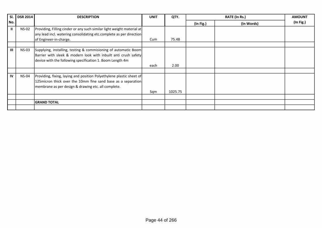
II NS-02 Providing, Filling cinder or any such similar light weight material at
any lead incl. watering consolidating etc.complete as per direction
of Engineer-in-charge. Cum 75.48
III NS-03 Supplying, installing, testing & commisioning of automatic Boom
Barrier with sleek & modern look with inbuilt anti crush safety
device with the following specification 1. Boom Length 4m
each 2.00
IV NS-04 Providing, fixing, laying and position Polyethylene plastic sheet of
125micron thick over the 10mm fine sand base as a separation
membrane as per design & drawing etc. all complete.
Sqm 1025.75
GRAND TOTAL
Page 44 of 266

TENDER NO: WAP/PMD/2016-17/12
INTERNAL PLUMBING
SCHEDULE OF QUANTITIES
Page 45 of 266

In Fig. In words
12.41
Providing and Fixing on wall face unplasticised-Rigid PVCrain water pipes conforming to IS: 13592 Type A includingjointing with seal ring conforming to IS: 5382 leaving 10mmgap for thermal expansion.Single socketed pipes
12.41.1 75mm dia Metre 31.00
12.41.2 110mm dia Metre 542.20
12.42
Providing and Fixing on wall face unplasticised PVCmoulded fittings/accessories for unplasticised Rigid PVCrain water pipes conforming to IS:13592 Type A includingjointing with seal ring conforming to IS:5382 leaving 10mmgap for thermal expansion.
12.42.5 Bend 87.5 degree
12.42.5.2 110mm bend Each 24.00
12.42.6 Shoe (Plain)
12.42.6.2 110 mm shoe Each 24.00
12.42.4 Single tee without door
12.42.4.2 110 x110x110mm Each 24.00
12.44Providing and Fixing to the inlet mouth of rain water pipecast iron grating 15 cm diameter and weighing not less than440 grams.
Each 24.00
17.1
Providing and Fixing water closet squatting pan (Indian typeW.C. pan ) with 100mm sand cast Iron P or S trap, 10 litrelow level white P.V.C. flushing cistern, including flush pipe,with manually controlled device (handle lever) conforming toIS : 7231, with all fittings and fixtures complete includingcutting and making good the walls and floors whereverrequired :
17.1.1 White Vitreous china Orissa pattern W.C. pan of size580x440mm with integral type foot rests. Each 47.00
CONSTRUCTION OF OFFICE CUM RESIDENTIAL BUILDINGS FOR NCB AT LUCKNOW.
BILL OF QUNATITIES (INTERNAL PLUMBING)
Rate (In Rs)(DSR-14) DESCRIPTION UNIT TotalQuantity Amount (In Rs)
Page 46 of 266

BILL OF QUNATITIES (INTERNAL PLUMBING)
Rate (In Rs)(DSR-14) DESCRIPTION UNIT TotalQuantity Amount (In Rs)
17.2
Providing and fixing white vitreous china pedestal type watercloset (European type W.C. pan) with seat and lid, 10 litrelow level white P.V.C. flushing cistern, including flush pipe,with manually controlled device (handle lever), conforming toIS : 7231, with all fittings and fixtures complete, includingcutting and making good the walls andfloors wherever required
17.2.1 W.C. pan with ISI marked white solid plastic seat and lid Each 22.00
17.7
Providing and Fixing wash basin with C.I. brackets, 15 mmC.P. brass pillar taps,32 mm C.P. brass waste of standardpattern, including painting of fittings and brackets, cuttingand making good the walls wherever require :
17.7.1 White Vitreous China Wash basin size 630x450 mm with apair of 15 mm C.P. brass pillar taps. Each 72.00
17.34 Providing and fixing toilet paper holder .
17.34.1 C.P. brass Each 22.00
17.72
Providing and fixing PTMT towel ring trapezoidal shape 215mm long,200 mm wide with minimum distances of 37 mmfrom wall face withconcealed fittings arrangement ofapproved quality and colour, weighingnot less than 88 gms.
Each 66.00
17.73Providing and Fixing PTMT towel rail complete with bracketsfixed to wooden cleats with CP brass screws with concealedfitting arangement of approved quality colour and make
17.73.2600 mm long towel rail with total length of 645 mm, width 78mm and effective height of 88 mm, weighing not less than190 gms.
Each 38.00
17.10
Providing and Fixing Salem Stainless Steel A ISI 304 (18/8)kitchen sink as per IS: 13983 with CI brackets and stainlesssteel waste with plug 40mm including painting of fittings andbrackets, cutting and making good the walls whereverrequired.
17.10.1.3 Kitchen sink with drain board 510x1040 mm bowl depth200mm. Each 32.00
Page 47 of 266

BILL OF QUNATITIES (INTERNAL PLUMBING)
Rate (In Rs)(DSR-14) DESCRIPTION UNIT TotalQuantity Amount (In Rs)
17.8
Providing and fixing white vitreous china battery basedinfrared sensor operated urinal of approx. size 610 x 390 x370 mm having pre & post flushing with water (250 ml & 500ml consumption), having water inlet from back side,including fixing to wall with suitable brackets all as permanufacturers specification and direction of Engineer-in-charge.
Each 12.00
8.1
Providing and fixing stone slab with table rubbed, edgesrounded and polished, of size 75x50 cm deep and 1.8 cmthick, fixed in urinal partitions by cutting a chase ofappropriate width with chase cutter and embedding thestone in the chase with epoxy grout or with cement concrete1:2:4 (1 cement : 2 coarse sand : 4 graded stone aggregate6 mm nominal size) as per direction of Engineer-in-chargeand finished smooth.
8.10.1 White Agaria Marble Stone Each 12.00
17.71
Providing and Fixing PTMT liquid soap container 109mmwide, 125mm high and 112mm distance from wall ofstandard shape with bracket of the same materials with snapfittings of approved quality colour and make, weighing notless that 105gms
Each 68.00
18.8
Providing and Fixing chlorinated Polyvinyl chloride (CPVC)pipes, having thermal stability for hot & cold water supplyincluding all CPVC plain & brass threaded fittings i/c fixingthe pipe with clamps at 1.0m spacing. This includes jointingof pipes & fittings with one step CPVC solvent cement andthe cost of cutting chases and making good the sameincluding testing of joints complete as per direction ofEngineer in Charge.Concealed work including cutting chases and makinggood the walls etc.
18.8.1 15 mm nominal outer dia pipes Metre 352.00
18.8.2 20 mm nominal outer dia pipes Metre 168.85
18.8.3 25 mm nominal outer dia pipes Metre 81.70
18.8.4 32 mm nominal outer dia pipes Metre 35.50
18.10Providing and Fixing GI pipes complete with GI fittingsand clamps, including cutting and making good walls etc.(internal work).Exposed on walls
Page 48 of 266

BILL OF QUNATITIES (INTERNAL PLUMBING)
Rate (In Rs)(DSR-14) DESCRIPTION UNIT TotalQuantity Amount (In Rs)
18.10.1 15mm dia nominal bore Metre 2.10
18.10.2 20mm dia nominal bore Metre 147.25
18.10.3 25mm dia nominal bore Metre 158.45
18.10.4 32mm dia nominal bore Metre 312.40
18.10.5 40mm dia nominal bore Metre 110.65
18.10.6 50mm dia nominal bore Metre 221.85
18.16 Providing and Fixing brass stop cock of approved quality
18.16.1 15mm nominal bore Each 6.00
18.16.2 20mm nominal bore Each 13.00
18.17 Providing and Fixing gun metal gate valve with CI wheel ofapproved quality (screwed end).
18.17.1 25mm nominal bore Each 33.00
18.17.2 32mm nominal bore Each 28.00
18.17.3 40mm nominal bore Each 14.00
18.17.4 50mm nominal bore Each 20.00
18.18 Providing and fixing ball valve (brass) of approved quality,High or low pressure, with plastic floats complete :
18.18.3 25mm dia nominal bore Metre 6.00
18.21 Providing and Fixing unplastcised PVC connection pipe withbrass unions:
18.21.2.1 45 cm length ( 15mm nominal bore) Each 314.00
18.38 Painting GI pipes and fittings with enamel paint over a readymixed priming coat, both of approved quality for new work.
18.38.1 15mm dia nominal bore Metre 2.10
18.38.2 20mm dia nominal bore Metre 147.25
18.38.3 25mm dia nominal bore Metre 158.45
Page 49 of 266

BILL OF QUNATITIES (INTERNAL PLUMBING)
Rate (In Rs)(DSR-14) DESCRIPTION UNIT TotalQuantity Amount (In Rs)
18.38.4 32mm dia nominal bore Metre 312.40
18.38.5 40mm dia nominal bore Metre 110.65
18.38.6 50mm dia nominal bore Metre 221.85
18.48
Providing and placing on terrace (at all floor levels)polyethylene water storage tank, ISI : 12701 marked, withcover and suitable locking arrangement and makingnecessary holes for inlet, outlet and overflow pipes butwithout fittings and the base support for tank.
Per Ltr. 2000.00
18.49 Providing and Fixing CP brass bib cock of approved qualityconforming to IS:8931.
18.49.1 15mm nominal bore Each 66.00
18.53 Providing and Fixing CP brass angle valve for basin mixerand geyser points of approved quality conforming to IS:8931
18.53.1 15mm nominal bore Each 314.00
18.58 Providing and Fixing PTMT grating of approved quality andcolour.
18.58.1.2 125mm nominal dia Each 164.00
18.64 Providing and fixing PTMT swivelling shower, 15 mmnominal bore, weighing not less than 40 gms Each 38.00
18.65Providing and Fixing PTMT soap Dish Holder having lengthof 138mm, breadth 102mm, height of 75mm with concealedfitting arrangements. Weighing not less than 106 gms.
Each 38.00
12.22
Making khurras 45x45 cm with average minimum thicknessof 5 cm cement concrete 1:2:4 (1 cement : 2 coarse sand : 4graded stone aggregate of 20 mm nominal size) over P.V.C.sheet 1 m x1 m x 400 micron, finished with 12 mm cementplaster 1:3 (1 cement : 3 coarse sand) and a coat of neatcement, rounding the edges and making and finishing theoutlet complete.
Each 24.00
19.1
Providing, laying and jointing glazed stoneware pipes classSP-1 with stiff mixture of cement mortar in the proportion of1:1 (1 cement : 1 fine sand) including testing of joints etc.complete :
Page 50 of 266

BILL OF QUNATITIES (INTERNAL PLUMBING)
Rate (In Rs)(DSR-14) DESCRIPTION UNIT TotalQuantity Amount (In Rs)
19.1.2 150mm dia Metre 46.50
19.2
Providing and laying cement concrete 1:5:10 (1 cement: 5coarse sand : 10 graded stone aggregate 40mm nominalsize) all round sw pipes including bed concrete as perstandard design
19.2.2 150mm dia Metre 46.50
19.7
Constructing brick masonry manhole in cement mortar 1:4(1 cement :4 coarse sand) RCC top slab with 1:2:4 mix (1cement :2 coarse sand :4 graded stone aggregate 20mmnominal size), foundation concrete 1:4:8 mix (1 cement :4coarse sand :8 graded stone aggregate 40mm nominal size)inside plastering 12mm thick with cement mortar 1:3 (1cement :3 coarse sand) finished with floating coat fo neatcement and making channels in cement concrete 1:2:4 (1cement :2 coarse sand :4 graded stone aggregate 20mmnminal size) finished with a floating coat of neat cementcomplete as per standard design.
19.7.1
Inside size 90x80cms and 45cms deep including CI coverwith frame (light duty) 455x610mm internal diamensionstotal weight of cover and frame to be not less than 38 kg(weight of cover 23 kg and weight of frame 15kg).
19.7.1.1 With FPS bricks of class designation 75(i) For Sewer Line Each 24.00
19.4
Providing and fixing square mouth SW gully trap grade 'A'complete with CI grating brick masonry chamber with watertight CI cover with frame of 300x300mm size (inside) theweight of cover to be not less than 4.50 kg and frame to benot less than 2.70 kg as per standard design.
19.4.1.1 100x100mm size P type with FPS 1st Class bricks. Each 24.00
19.27
Constructing brick mansonry road gully chamber 50x45x60cm with bricks of 1st class in cement mortar 1:5 (1 cement :5 fine sand) including 500x450mm precast R.C.C. horizontalgrating with frame complete as per standard design:
19.27.1 With FPS bricks (1st Class) Each 20.00
Page 51 of 266

BILL OF QUNATITIES (INTERNAL PLUMBING)
Rate (In Rs)(DSR-14) DESCRIPTION UNIT TotalQuantity Amount (In Rs)
19.32
Making soak pit 2.5 m diameter 3.0 metre deep with 45 x 45cm dry brick honey comb shaft with bricks and S.W. drainpipe 100 mm diameter, 1.8 m long complete as per standarddesign.
19.32.1 With common burnt clay F.P.S. (non modular) bricks ofclass designation 7.5 Each 5.00
NS--1Providing and Fixing GI pipes complete with GI fittingsand clamps, including cutting and making good walls etc.(internal work).
65mm dia nominal bore Metre 10.50
NS--2 Providing and Fixing gun metal gate valve with CI wheel ofapproved quality (screwed end).
65mm dia nominal bore Metre 10.50
NS--3Supply, Installation, Testing & Commissioning 15mm C.Pbrass 2 way bib cock complete, including cutting and makinggood the walls wherever required.
Each 22.00
2 way Bib Cock with wall Flange
NS--4
Supply, Installation, Testing & Commissioning C.P castbrass double coat hook fixed to wooden / PVC cleats withC.P. brass screws Each 22.00
NS--5
Providing & Fixing of C.P. brass shower assembly ofapproved equivalent comprising of one no. heavy type C.P.bath spout or equivalent), one no. concealed 3-way Divertershower arm and shower rose, all complete including cuttingand making good the wall wherever required.
Each 38.00
NS--6
Providing, fixing, testing and commissioning pressurizedelectric water heater of approved make confirming to BSCode with copper sheet container, 25 mm thick insulation,stove enamelled M.S. jacket thermostatically controlledimmersion heater with pilot neon lamp, suitable length ofelectrical cable and 15 amp 3 pin plug top, complete in allrespect.
Each 7.00
NS--7
Providing and fixing 6mm thick bevelled edge plate glassmirror of approved quality with 6mm thick marine ply backingfixed to wooden cleats with CP brass screws andwashers.(Including s/s studs for fixing the glass)
Each 58.00
Page 52 of 266

BILL OF QUNATITIES (INTERNAL PLUMBING)
Rate (In Rs)(DSR-14) DESCRIPTION UNIT TotalQuantity Amount (In Rs)
NS--8
Supply, Installation, Testing & Commissioning stainless steelcockroch trap consisting of 0.45 mm thick inner and outercup and 1.00 mm thick top grating (Jali) with ring to be fixedinside ‘P’ traps with cement concrete.
110x110 mm Each 24.00
NS--9 Supply, Installation, Testing & Commissioning CP Healthfaucet with 1.0 metre and CP Flexible Tube & wall hook. Each 22.00
NS--10Providing, fixing, testing and commissioning of C.P brasssink mixer with regular swinging spout, wall mounted withconnecting legs & flanges.
Each 56.00
NS--11Providing, fixing, testing and commissioning of C.P brasscentral hole basin mixer without pop up waste system with450 mm long braided hoses.
Each 72.00
NS--12 Providing and fixing recess soap dish Each 38.00
NS--13
Providing and Fixing uPVC pipes type -B conforming to IS:13592 for soil, waste and vent pipes including all fittingsrubber ring type (plain or with access door) e.g. bends,junctions, cowls, offsets, access pieces, clean out plug,jointing with rubber ring joints with lubricant etc. fixed withclamps to walls with cement concrete 1:2:4 blocks completein all respects.For soil, waste and vent pipes
110mm OD Metre 1245.75
NS--14
Providing, fixing, jointing and testing in position the followinguPVC pipes conforming to IS 4985 of 6 kg/sqcm pressurerating including all fittings, solvent weld joints, testingcomplete for drainage system cut to required length to belaid under floor including covering all around with cementconcrete and making good the same complete as required.
For waste pipes
40mm OD (6 kg pressure) Metre 136.94
50mm OD (6 kg pressure) Metre 93.75
63mm OD (6 kg pressure) Metre 150.75
Page 53 of 266

BILL OF QUNATITIES (INTERNAL PLUMBING)
Rate (In Rs)(DSR-14) DESCRIPTION UNIT TotalQuantity Amount (In Rs)
NS--15
Providing and Fixing 110x110 mm uPVC 'P' trap with 2-3inlets required size ftting with seal 50 mm of self cleansingdesign floor/urinal trap without vent suspended withsupporting clamp or in sunken portion including cutting andmaking good the walls and floors wherever requiredcomplete in all respects.a) 110 x110 mm outlet Each 97.00
NS--16Providing and Fixing uPVC floor drain of following sizeinlet and outlet including cutting and making good the wallsand floors wherever required complete in all respects.
a) 110 x63mm outlet Each 67.00
NS--17
Providing & fixing PVC inlet fitting with one or more inletsfabricated from 110 mm outer dia UPVC pipe and solventwelded sockets and fixed to UPVC Trap and set in cementconcrete as per drawing complete
Each 97.00
NS--18 Providing and fixing forged brass auto air vent valve 10 PNrating including all fitting & accessories.
15 mm dia Each 14.00
NS--19Supply, Installation, Testing & Commissioning C.P. brassBottle trap 32 / 40mm dia. with 75 mm clear water seal fittedwith built-in Air Admittance valve of adequate capacity.
Each 116.00
NS--20
Providing and fixing END CAP or Clean Out Plug (Ceilingor Floor) with suitable inset keys for opening, male threadedjoint with socket fixed to uPVC/SCI pipe complete in allrespects.
6.00
110 mm OD pipe size Each 40.00
GRAND TOTAL
Page 54 of 266

TENDER NO: WAP/PMD/2016-17/12
EXTERNAL PLUMBING
SCHEDULE OF QUANTITIES
Page 55 of 266

In Fig. In wordsSUB HEAD-I (A)- WATER SUPPLY - EXTERNAL WORK(SCHEDULED ITEMS)
1 18.12 Providing and fixing G.I. pipes complete with G.I. fittingsincluding trenching and refilling etc. (external work)
a) 18.12.3 25mm dia nominal bore Metre 80
b) 18.12.4 32mm dia nominal bore Metre 70
c) 18.12.5 40mm dia nominal bore Metre 120
d) 18.12.6 50mm dia nominal bore Metre 45
2 18.40 Painting G.I. pipes and fittings with two coats of anti-corrosive bitumastic paint of approved quality.
a) 18.40.3 25mm dia nominal bore Metre 80
b) 18.40.4 32mm dia nominal bore Metre 70
c) 18.40.5 40mm dia nominal bore Metre 120
d) 18.40.6 50mm dia nominal bore Metre 45
3 18.32
Constructing brick masonry chamber 30x30x50cms insidewith 1st class brick work in cement mortar 1:5 (1 cement : 5fine sand) for stop cock with CI surface box 100x100x75mm (inside) with hinged cover fixed in cement concreteslab 1:2:4 mix (1 cement : 2 coarse sand : 4 graded stoneaggregate 20mm nominal size)necessary excavationfoundation concrete 1:5:10 (1 cement : 5 fine sand : 10graded stone aggregate 40mm nominal size) and insideplastering with cement mortar 1:3 (1 cement 3 coarse sand)12mm thick finished with a floating coat of neat cementcomplete as per standard design.
a) 18.32.1 With FPS bricks Each 2
CONSTRUCTION OF OFFICE CUM RESIDENTIAL BUILDINGS FOR NCB AT LUCKNOW.BILL OF QUNATITIES (EXTERNAL PLUMBING)
Rate (In Rs)Amount (In Rs)Total
QuantityUNITDESCRIPTIONDSR-14Item NOSN
Page 56 of 266

In Fig. In words
Rate (In Rs)Amount (In Rs)Total
QuantityUNITDESCRIPTIONDSR-14Item NOSN
4 18.33
Constructing mansonry Chamber 60x60x75 cm, inside with75 class designation brick work in cement mortar 1:4 (1cement : 4 coarse sand) for sluice valve with C.I. Surface box100mm. Top diameter,160 mm bottom diameter and 180 mmdeep (inside) with chained lid and RCC top slab 1:2:4 mix (1cement :2 coarse sand :4 graded stone aggregate 20 mmnominal size) necessary excavation foundation 1:5:10 (1cement : 5 fine sand : 10 graded stone aggregate 40 mmnominal size) and inside plastering with cement mortar 1:3 (1cement : 3 coarse sand) 12 mm thick finished with a floatingcoat of neat cement complete as per standard design:
a) 18.33.1 With F.P.S bricks Each 2
5.0 18.41 Providing and filling sand of grading zone V or coarser gradeall-round the G.I. pipes in external work.
a) 18.41.3 25mm dia nominal bore Metre 80
b) 18.41.4 32mm dia nominal bore Metre 70
c) 18.41.5 40mm dia nominal bore Metre 120
d) 18.41.6 50mm dia nominal bore Metre 45
GARDEN HYDRANT (SCHEDUELD ITEMS)
6 18.17 Providing and fixing gunmetal gate valve with CI wheel ofapproved quality (screwed end).
a) 18.17.1 25mm nominal bore Each 16
7 18.31Providing and fixing CI sluice valves (with C.I. wheel)complete with bolts, nuts, rubber insertions etc.(the tailpieces if required will be paid separately):
a) 18.31.1.2 100 mm dia (PIN 1.6) Each 4
Page 57 of 266

In Fig. In words
Rate (In Rs)Amount (In Rs)Total
QuantityUNITDESCRIPTIONDSR-14Item NOSN
8 18.32
Constructing brick masonry chamber 30x30x50cms insidewith 1st class brick work in cement mortar 1:4 (1 cement : 4fine sand) for stop cock with C.I. surface box 100x100x75mm(inside) with hinged cover fixed in cement concrete slab 1:2:4mix (1 cement : 2 coarse sand : 4 graded stone aggregate20mm nominal size), i/c necessary excavation, foundationconcrete 1:5:10 (1 cement : 5 fine sand : 10 graded stoneaggregate 40mm nominal size) and inside plastering withcement mortar 1:3 (1 cement : 3 coarse sand) 12mm thick,finished with a floating coat of neat cement complete as perstandard design:
a) 18.32.1 With common burnt clay F.P.S. (non modular) bricks of classdesignation 7.5 Each 6
9 18.34
Constructing masonry Chamber 90x90x100 cm inside, inbrick work in cement mortar 1:4 (1 cement : 4 coarse sand)for sluice valve,with C.I. surface box 100 mm top diameter,160 mm bottom diameter and 180 mm deep (inside) withchained lid and RCC top slab 1:2:4mix (1 cement : 2 coarsesand : 4 graded stone aggregate 20 mm nominal size ), i/cnecessary excavation, foundation concrete 1:5:10 (1 cement: 5 fine sand : 10 graded stone aggregate 40 mm nominalsize) and inside plastering with cement mortar 1:3 (1 cement : 3coarse sand) 12 mm thick, finished with a floating coat ofneat cement complete as per standard design :
Each 6
SUB HEAD-I (B)- WATER SUPPLY - EXTERNAL WORK(NON SCHEDULED ITEMS)
10 NS--1
Providing and fixing MS puddle flanges of required size with5mm thick MS plate including necessary welding as perdetails shown on drawings and directions of Engineer-in-charge for water tanks.
a) 32mm dia (4mm wall thickness) Each 8
b) 40mm dia (4mm wall thickness) Each 4
c) 50mm dia (4mm wall thickness) Each 6
d) 65mm dia (4mm wall thickness) Each 6
Page 58 of 266

In Fig. In words
Rate (In Rs)Amount (In Rs)Total
QuantityUNITDESCRIPTIONDSR-14Item NOSN
e) 80mm dia (4mm wall thickness) Each 6
11 NS--2
Providing and laying uPVC pressure pipes as per IS:4985 ofas specified pressure in Kg/Sqcm pressure rating includingall fittings, solvent weld joints, testing and necessary earthwork.
a) 25mm ( 10kg/cm2) Metre 370
b)32mm ( 10kg/cm2) Metre 120
c) 40 mm ( 10 kg/cm2) Metre 80
d) 110 mm ( 10kg/cm2) Metre 20
SUBHEAD-II-(A) : SEWERAGE (SCHEDULED ITEMS)
12 2.10
Excavating trenches of required width for pipes, cables etc.including excavation for sockets and dressing of sides,ramming of bottoms, depth upto 1.5m including getting outthe excavated soil, and then returning the soil as required, inlayers not exceeding 20cm in depth including consolidatingeach deposited layer by ramming, watering etc. anddisposing of surplus excavated soil as directed, within a leadof 50m.
a) 2.10.1 All kinds of soil
b) 2.10.1.2 Pipes, cables etc. exceeding 80mm dia but not exceeding300mm dia. Metre 220
13 19.1
Providing, laying and jointing glazed stoneware pipes classSP-1 with stiff mixture of cement mortar in the proportion of1:1 (1 cement : 1 fine sand) including testing of joints etc.complete :
a) 19.1.2 150mm dia Metre 125
b) 19.1.3 200mm dia Metre 120
14 19.2
Providing and laying cement concrete 1:5:10 (1 cement: 5coarse sand : 10 graded stone aggregate 40mm nominalsize) all round sw pipes including bed concrete as perstandard design
a) 19.2.2 150mm dia Metre 125
Page 59 of 266

In Fig. In words
Rate (In Rs)Amount (In Rs)Total
QuantityUNITDESCRIPTIONDSR-14Item NOSN
b) 19.2.3 200mm dia Metre 120
15 19.9
Constructing brick masonry circular type manhole 0.91 minternal dia at bottom and 0.56m dia at top in cement mortar1:4 (1 cement :4 coarse sand), in side cement plaster 12 mmthick with cement mortar 1:3 (1 cement : 3 coarse sand)finished with a floating coat of neat cement, foundationconcrete 1:3:6 mix (1 cement : 3 coarse sand : 6 gradedstone aggregate 40 mm nominal size), and makingnecessary channel in cement concrete 1:2:4 (1 cement : 2coarse sand : 4 graded stone aggregate 20 mm nominalsize) finished with a floating coat of neat cement, all completeas per standard design :
a) 19.9.1
0.91 m deep with S.F .R.C. cover and frame (heavy duty ,HD-20 grade designation) 560 mm internal diameterconforming to I.S. 12592, total weight of cover and frame tobe not less than 182 kg., fixed in cement concrete 1:2:4 (1cement : 2 coarse sand : 4 graded stone aggregate 20 mmnominal size) including centering, shuttering all complete.(Excavation, foot rests and 12mm thick cement plaster at theexternal surface shall be paid for separately) :
b) 19.9.1.1 With common burnt clay F .P .S. (non modular) bricks ofclass designation 7.5 Each 12
16 19.10 Extra depth for circular type manhole 0.91m internal dia (atbottom) beyond 0.91 m to 1.67 m
a) 19.10.1 With common burnt clay F .P .S. (non modular) bricks ofclass designation 7.5 Metre 10
17 19.11
Constructing brick masonry circular manhole 1.22 m internaldia at bottom and 0.56 m dia at top in cement mortar 1:4 (1cement :4 coarse sand) inside cement plaster 12 mm thickwith cement mortar 1:3 (1 cement : 3 coarse sand) finishedwith a floating coat of neat cement foundation concrete 1:3:6(1 cement : 3 coarse sand : 6 graded stone aggregate 40mm nominal size) and making necessary channel in cementconcrete 1:2:4 (1 cement : 2 coarse sand : 4 graded stoneaggregate 20 mm nominal size) finished with a floating coatof neat cement, all complete as per standard design :
Page 60 of 266

In Fig. In words
Rate (In Rs)Amount (In Rs)Total
QuantityUNITDESCRIPTIONDSR-14Item NOSN
a) 19.11.1
1.68 m deep with SFRC Cover and frame (heavy duty HD-20grade designation) 560 mm internal diameter conforming toI.S. 12592, total weight of cover and frame to be not lessthan 182 kg. fixed in cement concrete 1:2:4 (1 cement : 2coarse sand : 4 graded stone aggregate 20 mm nominalsize) including centering, shuttering all complete.(Excavation, foot rests and 12 mm thick cement plaster atthe external surface shall be paid for separately) :
b) 19.11.1.1 With common burnt clay F .P .S. (non modular) bricks ofclass designation 7.5 Each 10
18 19.15
Providing M.S. foot rests including fixing in manholes with20x20x10 cm cement concrete blocks 1:3:6 (1 cement:3coarse sand :6graded stone aggregate 20 mm nominal size)as per standard design
a) 19.15.1 With 20x20 mm square bar Each 200
SUBHEAD-III-(A) : DRAINAGE (SCHEDULED ITEMS)
19 2.10
Excavating trenches of required width for pipes, cables etc.including excavation for sockets and dressing of sides,ramming of bottoms, depth upto 1.5m including getting outthe excavated soil, and then returning the soil as required, inlayers not exceeding 20cm in depth including consolidatingeach deposited layer by ramming, watering etc. anddisposing of surplus excavated soil as directed, within a leadof 50m.
2.10.1 All kinds of Soil
a) 2.10.1.2 Pipes, cables etc. exceeding 80mm dia but not exceeding300mm dia. Metre 230
20 19.9
Constructing brick masonry circular type manhole 0.91 minternal dia at bottom and 0.56m dia at top in cement mortar1:4 (1 cement :4 coarse sand), in side cement plaster 12 mmthick with cement mortar 1:3 (1 cement : 3 coarse sand)finished with a floating coat of neat cement, foundationconcrete 1:3:6 mix (1 cement : 3 coarse sand : 6 gradedstone aggregate 40 mm nominal size), and makingnecessary channel in cement concrete 1:2:4 (1 cement : 2coarse sand : 4 graded stone aggregate 20 mm nominalsize) finished with a floating coat of neat cement, all completeas per standard design :
Page 61 of 266

In Fig. In words
Rate (In Rs)Amount (In Rs)Total
QuantityUNITDESCRIPTIONDSR-14Item NOSN
a) 19.9.1
0.91 m deep with S.F .R.C. cover and frame (heavy duty ,HD-20 grade designation) 560 mm internal diameterconforming to I.S. 12592, total weight of cover and frame tobe not less than 182 kg., fixed in cement concrete 1:2:4 (1cement : 2 coarse sand : 4 graded stone aggregate 20 mmnominal size) including centering, shuttering all complete.(Excavation, foot rests and 12mm thick cement plaster at theexternal surface shall be paid for separately) :
b) 19.9.1.1 With common burnt clay F .P .S. (non modular) bricks ofclass designation 7.5 Each 16
21 19.10 Extra depth for circular type manhole 0.91m internal dia (atbottom) beyond 0.91 m to 1.67 m
a) 19.10.1 With common burnt clay F .P .S. (non modular) bricks ofclass designation 7.5 Metre 10
22 19.11
Constructing brick masonry circular manhole 1.22 m internaldia at bottom and 0.56 m dia at top in cement mortar 1:4 (1cement :4 coarse sand) inside cement plaster 12 mm thickwith cement mortar 1:3 (1 cement : 3 coarse sand) finishedwith a floating coat of neat cement foundation concrete 1:3:6(1 cement : 3 coarse sand : 6 graded stone aggregate 40mm nominal size) and making necessary channel in cementconcrete 1:2:4 (1 cement : 2 coarse sand : 4 graded stoneaggregate 20 mm nominal size) finished with a floating coatof neat cement, all complete as per standard design :
a) 19.11.1
1.68 m deep with SFRC Cover and frame (heavy duty HD-20grade designation) 560 mm internal diameter conforming toI.S. 12592, total weight of cover and frame to be not lessthan 182 kg. fixed in cement concrete 1:2:4 (1 cement : 2coarse sand : 4 graded stone aggregate 20 mm nominalsize) including centering, shuttering all complete.(Excavation, foot rests and 12 mm thick cement plaster atthe external surface shall be paid for separately) :
b) 19.11.1.1 With common burnt clay F .P .S. (non modular) bricks ofclass designation 7.5 Each 9
23 19.15
Providing M.S. foot rests including fixing in manholes with20x20x10 cm cement concrete blocks 1:3:6 (1 cement:3coarse sand :6graded stone aggregate 20 mm nominal size)as per standard design.
a) 19.15.1 With 20x20 mm square bar Each 150
Page 62 of 266

In Fig. In words
Rate (In Rs)Amount (In Rs)Total
QuantityUNITDESCRIPTIONDSR-14Item NOSN
24 19.6
Providing and laying non pressure NP2 class (light duty) RCCpipes with collars jointed with stiff mixture of cement mortar inthe proportion of 1:2 (1 cement : 2 fine sand) includingtesting of joints etc. complete.
a) 19.6.2 150mm dia RCC pipe Metre 60
b) 19.6.3 250mm dia RCC pipe Metre 170
25 19.27
Constructing brick mansonry road gully chamber 50x45x60cm with bricks of 1st class in cement mortar 1:5 (1 cement :5 fine sand) including 500x450mm precast R.C.C. horizontalgrating with frame complete as per standard design:
a) 19.27.1 With FPS bricks (1st Class) Each 15
SUBHEAD-IV-(A) : PUMPS & EQUIPMENTS (NON-SCHEDULED ITEMS)PUMPS & EQUIPMENTS
26 NS--3
Design, manufacture, supplying, fixing in position, testingand commissioning of the following front operated cubicletype, front access 2mm thick mild steel sheet, free standing,dust and vermin proof, switchboard with IP42 protection withhinged and lockable doors complete with interconnections,tinned copper crimping lugs, bonding to earth and painting,suitable for use at 415 volts, 3 phase 4 wire 50 Hz systemand suitable for a fault level of 25 MVA symmetrical at 415volts.All switchboards shall have provision for entry of cables fromthe top or bottom as required.All live accessible parts shall be shrouded and all equipmentshall be finger touch proof. The busbars insulation shall bewith heat shrinkable sleeves. SMC/DMC shrouds andbusbar supports shall be used. Padlocking facility shall beprovided on all outgoing feeders doors and switch handlesshall be locakble in OFF position.
Page 63 of 266

In Fig. In words
Rate (In Rs)Amount (In Rs)Total
QuantityUNITDESCRIPTIONDSR-14Item NOSN
SUMP PUMPSINCOMINGa) 1 No. 63 amps TPN MCCBb) 1 No. square flush mounting 0-500 volts scaled voltmeterwith three way and OFF switch.c) Three phase indicating lights.BUS BARElectrolytic high conductivity three phase and neutral bus barrated at 60 amps having a current density of 1 amp perSqmm suitable to with stand symmetrical fault level of 25MVA at 415 volts. The neutral bus bar is to be of 100%capacity.OUTGOING UNITSa) 1 Nos 15 amps SP MCBs; one for each pump.b) 1 Nos. fully automatic DOL starters with push buttons andON/OFF indicating lights and overload relays (L & T MK 1 orMLO or equivalent) c) 1 Nos. rotary selector switch forselecting mode of operation i.e. auto/manual/off.c) One single phase preventors.d) 1 No. square flush mounting 0-15 amps scaled ammeterswith three way and OFF selector switch.The motor control panel shall be prewired with colour codedwires with identification labels complete in all respects asrequired.
Each 1
27 NS-4
Supplying, installing, testing and commissioning MS duelmedia filter fabricated with MS plate 6mm thick for shell and8mm thick for dished ends complete with GI face piping, withscrewed joints, valves, rotameter, pressure gauges withisolation valves with other accessories as required andconforming to but not limited the following:Test pressure 5 kg/sqcm.Diameter 500 mmHOS 2000 mmDesign for filteration rate 17.5KL/hr/sqm.Filter media as per manufacturer's designAnthracite depth 300 mmPainting:Internal: Two coats of anticorrosive bitumastic paint.<br>External: Two coats of ready mixed primer of red oxide andfinished with two or more coats of enamel paint of approvedshade.
Each 1
Page 64 of 266

In Fig. In words
Rate (In Rs)Amount (In Rs)Total
QuantityUNITDESCRIPTIONDSR-14Item NOSN
28 NS-5
Supplying, installing, testing and commissioning MSActivated carbon filter fabricated with MS plate 6mm thick forshell and 8mm thick for dished ends complete with GI facepiping, with screwed joints, valves, rotameter, pressuregauges with isolation valves with other accessories asrequired and conforming to but not limited the following:Test pressure 5 kg/sqcm.Diameter 500 mmHOS 2000 mmDesign for filteration rate 17.5KL/hr/sqm.Filter media as per manufacturer's designAnthracite depth 300 mmPainting:Internal: Two coats of anticorrosive bitumastic paint.External: Two coats of ready mixed primer of red oxide andfinished with two or more coats of enamel paint of approvedshade.
Each 1
29 NS--6
Supply installation, testing and commissioning MS rubberlined brine tank(1000 lit. cap.) fabricated with 5 mm thick MSplate and lined with 4 mm thick rubber duly tested by sparktest and certified for proper lining including brine deliverypipes and inclusive of stirrer etc., complete in all respect.
Each 1
30 NS-7
Providing, fixing, testing & commissioning of MSRL watersoftening plant (suitable for 5.0 Kg/Sqcm working pressure)complete with initial charge with T-40 NA Resin, multiportvalve with built in ejector for controlling all operations),regeneration system and HDPE tank, pressure gauge atinlet, outlet and back wash (each with isolation cock), valves,fittings and water hardness testing kit & associated works.Softener shall be suitable for the following duty:Working pressure 5.0Kg/Sq.cm.Capacity : 1.0LPSInlet Water Hardness :600 PPMOutlet Water Hardness : 40-50 PPM
Each 1
Page 65 of 266

In Fig. In words
Rate (In Rs)Amount (In Rs)Total
QuantityUNITDESCRIPTIONDSR-14Item NOSN
31 NS-8 All piping work, Butterfly valves, non-return valves, cables ,G.I. earthing, cable trays, level controller etc., comlete job. L-S 1
32 NS--9
Providing and fixing horizontical/vertical monobloccentrifugal pumping set with mechanical seal C.I.volute andbronze impeller connected to a TEFC induction motorsuitable for 400/440 volts, 3 phase, 50 cycles A.C. supplywith 150 mm dia pressure gauge with gunmetal isolationcock, vibration eliminating for each pump includingnecessary structual supports, clamps, bolts, nuts washersand 1:2:4 PCC foundations.a) Dom. Water transfer pumpLocation - Plant Room (1W+1SB)Capacity 90 lpmHead 60 mHP 5 ( Approx)
Each 1
b) Filter Feed PumpLocation - Plant Room (1W+1SB)Capacity 110 lpmHead 20 m
Each 1
SUBHEAD-V-(A) : RECHARGE PIT (SCHEDULED ITEMS)
33 24.1
Boring/drilling bore well of required dia for casing/ strainerpipe, by suitable method prescribed in IS: 2800 (part I),including collecting samples from different strata, preparingand submitting strata chart/ bore log, including hire & runningcharges of all equipments, tools, plants & machineriesrequired for the job, all complete as per direction of Engineer -in-charge, upto 90 metre depth below ground level.
24.1.1 All type of soil
24.1.1.1 300 mm dia. Meter 150
34 24.3
Supplying, assembling, lowering and fixing in vertical positionin bore well, unplasticized PVC medium well casing (CM)pipe of required dia, conforming to IS: 12818, includingrequired hire and labour charges, fittings & accessories etc.all complete, for all depths,as per direction of Engineer -in-charge.
24.3.3 200 mm nominal size dia. Meter 120
Page 66 of 266

In Fig. In words
Rate (In Rs)Amount (In Rs)Total
QuantityUNITDESCRIPTIONDSR-14Item NOSN
35 24.4
Supplying, assembling, lowering and fixing in verticalposition in bore well unplasticized PVC medium well screen(RMS) pipes withribs, conforming to IS: 12818, including hire& labour charges, fittings & accessories etc. all complete, forall depths, as per direction of Engineer-in-charge.
24.4.3 200 mm nominal size dia. Meter 40
36 24.5
Supplying, filling, spreading & leveling stone boulders of sizerange 5 cm to 20 cm, in recharge pit, in the requiredthickness, for all leads & lifts, all complete as per direction ofEngineer-in-charge.
cum 40
37 24.6
Supplying, filling, spreading & leveling gravels of size range 5mm to 10 mm, in the recharge pit, over the existing layer ofboulders, in required thickness, for all leads & lifts, allcomplete as per direction of Engineer-in-charge.
cum 40
38 24.7
Supplying, filling, spreading & leveling coarse sand of sizerange 1.5 mm to 2 mm in recharge pit, in required thicknessover gravel layer, for all leads & lifts, all complete as perdirection of Engineer -in-charge.
cum 40
39 24.8
Gravel packing in tubewell construction in accordance withIS: 4097,including providing gravel fine/ medium/ coarse, inrequired grading & sizes as per actual requirement, allcomplete as per direction of Engineer-in-charge.
cum 40
40 24.12
Development of tube well in accordance with IS : 2800 (partI) and IS: 11189, to establish maximum rate of usable wateryield without sand content (beyond permissible limit), withrequired capacity air compressor, running the compressor forrequired time till well is fully developed,measuring yield ofwell by “V” notch method or any other approvedmethod,measuring static level & draw down etc. by step drawdown method,collecting water samples & getting tested inapproved laboratory, i/c disinfection of tubewell, all complete,including hire & labour charges of air compressor, tools &accessories etc., all as per requirement and direction ofEngineer-in-charge.
20.00 hour
41 24.13
Providing and fixing suitable size threaded mild steel cap orspot welded plate to the top of bore well housing/ casingpipe, removable as per requirement, all complete for borewellof:
24.13.1 100 mm nominal size dia each 1
Page 67 of 266

In Fig. In words
Rate (In Rs)Amount (In Rs)Total
QuantityUNITDESCRIPTIONDSR-14Item NOSN
42 24.14Providing and fixing M.S. clamp of required dia to the top ofcasing/housing pipe of tubewell as per IS: 2800 (part I),including necessary bolts & nuts f required size complete.
24.14.1 100 mm clamp each 1
43 24.15Providing and fixing Bail plug/ Bottom plug of required dia tothe bottom of pipe assembly of tubewell as per IS:2800 (partI).
24.15.3 200 mm dia each 1
SUBHEAD-V-(A) : RECHARGE PIT (NON-SCHEDULEDITEMS)
44 NS-10
Providing all material & constructing brick masonary rechargepit of 3m dia x 4.0 m depth with brick work in cement mortar1:4 ( 1 cement : 4 coarse sand) with 100mm dia weep holesat side walls @ 500 mm vertically & horizontally center tocenter, 200 mm thick RCC top slab in cement concrete (1:2:4) along with periferial & two nos. of intermediate RCC beamsof size 250 x 450mm R/ F of slab 12 mm tor steel at bottomand 10 mm at topwith a spacing of 125 mm c/c, 4 nos 16 mmtor steel bars at bottom & 2 nos. 12 mm tor steel bars at topfor beams with 8 mm stirrups @ 150 mm c/c, 2 nos. heavyduty SFRC cover of 560 mm dia,poly propelene coated rungs@ 300 mm c/c embeded in CC ( 1 : 2 : 4 ) blocks of 200 x200 x 200 mm, 150 mm thick PCC in 1: 4 : 8 below footingwith 150 mm projection, internal & external plaster in CM 1 :4, necessary excavation, backfilling & disposal of surplusearth upto a lead of 50m complete in all respect includingdrilling percolation Bore Hole of 200/250 mm dia upto 50meter depth with Inlet Water Hardness :600 PPMOutlet Water Hardness : 40-50PPM
each 1
Page 68 of 266

In Fig. In words
Rate (In Rs)Amount (In Rs)Total
QuantityUNITDESCRIPTIONDSR-14Item NOSN
45 NS-11
Providing and constructing brick masonry desilting chamberof size 200x150xupto300 cms depth inside with 75 classdesignation brick work 345mm/230mm thick in cementmortar 1:4 (1cement:4 coarse sand) with weep holes allaround , SFRC cover heavy duty 560mm dia and 150 mmthick R.C.C. top slab 1:2:4 mix(1 Cement : 2 coarse sand : 4graded stone aggregate 20mm nominal size) includingnecessary excavation, back filling, disposal of surplus earthas directed, foundation concrete 1:5:10 mix (1 cement : 5 finesand : 10 graded stone aggregate 40mm nominal size) belowmasonry walls with 150mm projection at either side includingnecessary baffle wall inside(as per std. drawing) ,excavation,back filling and disposal of surplus earth upto alead of 200 mtr., poly propelene coated rungs @ 300 mmc/c.
each 1
BORE WELL (SCHEDULE ITEM)
46 24.1
Boring/drilling bore well of required dia for casing / strainerpipe, by suitable method prescribed in IS:2800 (part I),including collecting samples from different strata, preparingand submitting strata chart/ bore log, including hire & runningcharges of all equipments, tools, plants & machineriesrequired for the job, all complete as per direction of Engineer -in-charge, upto 90 metre depth below ground level.
24.1.2 Rocky strata including Boulders
24.1.2.1 300mm dia Metre 115
47 24.2
Boring/drilling bore well of required dia for casing / strainerpipe, by suitable method prescribed in IS:2800 (part I),including collecting samples from different strata, preparingand submitting strata chart/ bore log, including hire & runningcharges of all equipments, tools, plants & machineriesrequired for the job, all complete as per direction of Engineer -in-charge, beyound 90 metre & upto 150 metre depth belowground level.
24.2.2 Rocky strata including Boulders
24.2.2.1 300mm dia Metre 90
48 24.3
Supplying, assembling, lowering and fixing in vertical positionin bore well, unplasticized PVC medium well casing (CM)pipe of required dia, conforming to IS: 12818, includingrequired hire and labour charges, fittings & accessories etc.all complete, for all depths, as per direction of Engineer-in-charge.
Page 69 of 266

In Fig. In words
Rate (In Rs)Amount (In Rs)Total
QuantityUNITDESCRIPTIONDSR-14Item NOSN
24.3.1 100 mm nominal size dia Metre 10
49 24.4
Supplying, assembling, lowering and fixing in vertical positionin bore well unplasticized PVC medium well screen (RMS)pipes with ribs conforming to IS: 12818, including hire andlabour charges, fittings & accessories etc. all complete, for alldepths, as per direction of Engineer-in-charge.
24.4.1 100 mm nominal size dia Metre 6
50 24.8
Gravel packing in tubewell construction in accordance withIS: 4097, including providing gravel fine/ medium/ coarse, inrequired grading & sizes as per actual requirement, allcomplete as per direction of Engineer- in -charge.
Cum. 100
51 24.12
Development of tube well in accordance with IS:2800 (part I)and IS: 11189, to establish maximum rate of usable wateryield without sand content (beyond permissible limit), withrequired capacity air compressor, running the compressor forrequired time till well is fully developed, measuring yield ofwell by ''V'' notch method or any other approved method,measuring static level & draw down etc. by step draw downmethod, collecting water samples & getting tested inapproved laboratory, i/c disinfection of tubewell, all complete,including hire & labour charges of air compressor, tools &accessories etc., all as per requirement and direction ofEngineer-in-Charge.
Hour 80
52 24.13
Providing and fixing suitable size threaded mild steel cap orspot welded plate to the top of bore well housing/ casingpipe, removable as per requirement, all complete for borewellof:
24.13.2 150 mm dia each 1
TOTAL DSR ITEMSTOTAL NON-DSR ITEMS
GRAND TOTAL
Page 70 of 266

TENDER NO: WAP/PMD/2016-17/12
INTERNAL ELECTRICAL
SCHEDULE OF QUANTITIES
Page 71 of 266

In Fig. In words
INTERNAL ELECTRIFICATION WORKS :
POINT WIRING IN STEEL CONDUIT:
1 1.1
Wiring for light point/ fan point/ exhaust fan point/ call bell point with 1.5sq.mm FRLS PVC insulated copper conductor single core cable in surface/ recessed medium class PVC conduit, with modular switch, modularplate, suitable GI box and earthing the point with 1.5 sq.mm. FR PVCinsulated copper conductor single core cable etc as required.
a) 1.10.1 Group A Points 604b) 1.10.3 Group C Points 423
2 1.11
Wiring for twin control light point with 1.5 sq.mm FRLS PVC insulatedcopper conductor single core cable in surface / recessed medium classPVC conduit, 2 way modular switch, modular plate, suitable GI box andearthing the point with 1.5 sq.mm. FRLS PVC insulated copper conductorsingle core cable etc as required.
Points 6
PROJECT: CONSTRUCTION OF OFFICE CUM RESIDENTIAL BUILDINGS FOR NCB AT LUCKNOW
BILL OF QUANTITIES (INTERNAL ELECTRIFICATION)
SR. NO DSR-2014 DESCRIPTION UNIT TotalQuantity
Rate (In Rs)Amount (In Rs)
_1 _
2 1.11
Wiring for twin control light point with 1.5 sq.mm FRLS PVC insulatedcopper conductor single core cable in surface / recessed medium classPVC conduit, 2 way modular switch, modular plate, suitable GI box andearthing the point with 1.5 sq.mm. FRLS PVC insulated copper conductorsingle core cable etc as required.
Points 6
CIRCUIT & SUBMAINS WIRING:
3 1.12
Wiring for light/ power plug with 2X4 sq. mm FRLS PVC insulatedcopper conductor single core cable in surface/ recessed medium class PVCconduit along with 1 No 4 sq. mm FRLS PVC insulated copper conductorsingle core cable for loop earthing as required.
Mtrs. 2025
4 1.14
Wiring for circuit/ submain wiring along with earth wire with the
following sizes of FR PVC insulated copper conductor, single
core cable in surface/ recessed medium class PVC conduit as required
a) 1.14.22x 2.5 sq. mm+1x 2.5 Sq. mm for earth wire (Circuit wiring from DB toswitch board & UPS power points)
Mtrs. 1100
b) 1.14.32 x 4.0 sq. mm + 1 x 4.0 Sq. mm for earth wire (for circuit/ submain)
Mtrs. 110
c) 1.14.4 2 x 6.0 sq. mm + 1 x 6.0 Sq. mm for earth wire (for 1 phase DB) Mtrs. 175
d) 1.14.5 2 x 10 sq. mm + 1 x 10 Sq. mm for earth wire (for 1 phase DB) Mtrs. 206
e) 1.14.9 4 x 6.0 sq. mm + 2 x 6.0 Sq. mm for earth wire (for 3 phase DB) Mtrs. 37
_1 _Page 72 of 266

In Fig. In wordsSR. NO DSR-2014 DESCRIPTION UNIT Total
Quantity
Rate (In Rs)Amount (In Rs)
f) 1.14.10 4 x 10.0 sq. mm + 2 x 10.0 Sq. mm for earth wire (for 3 phase DB) Mtrs. 325
g) 1.14.11 4 x 16.0 sq. mm + 2 x 16.0 Sq. mm for earth wire (for 3 phase DB) Mtrs. 37
5) 1.17Supplying and drawing following sizes of FRLS PVC insulated copperconductor, single core cable in the existing surface/ recessed steel/ PVCconduit as required.
a) 1.17.11.5 Sqmm
Mtrs. 40
b) 1.17.22 x 1.5 Sqmm
Mtrs. 280
FITTINGS AND ACCESSORIES:
6 1.24Supplying and fixing following modular switch / socket on the existingmodular plate & switch box including connection but exculding modularplate etc. as required.
_2 _
6 1.24Supplying and fixing following modular switch / socket on the existingmodular plate & switch box including connection but exculding modularplate etc. as required.
a) 1.24.15/6 Amps switch
Nos. 55
b) 1.24.22 way 5/6 Amps switch
Nos. 4
c) 1.24.315/16 Amps switch
Nos. 4
d) 1.24.43 pin 5/6 Amps socket outlet
Nos. 107
e) 1.24.56 pin 15/16 Amps socket outlet
Nos. 4
f) 1.27.46module (200 mm x 75 mm) for 2nos. 6A socket with switch assembly
Nos. 52
7 1.34Supplying and fixing Brass Batten/ Angle holder including connectionsetc. as required.
Nos. 132
8 1.31 S/F light plug point modular type accessories :
a) 1.31
Supplying and fixing suitable size GI box with modular plate and cover infront on surface or in recess, including providing and fixing 3 pin 5/6amps modular socket outlet and 5/6 amps modular switch, connection,painting etc. as required.
Nos. 371
9.0 1.32 S/F power plug point modular type accessories :
_2 _Page 73 of 266

In Fig. In wordsSR. NO DSR-2014 DESCRIPTION UNIT Total
Quantity
Rate (In Rs)Amount (In Rs)
a) 1.32
Supplying and fixing suitable size GI box with modular plate and cover infront on surface or in recess, including providing and fixing 6 pin 5/6 &15/16 amps modular socket outlet and 15/16 amps modular switch,connection etc. as required.
Nos. 296
10.0 1.41
Installation, testing and commissioning of pre-wired, fluorescent/ compactfluorescent fitting of all types, complete with all accessories and lamp etc.,wiring connection with 1.5 sq. mm FR PVC insulated in flexible conduit,copper conductor, single core cable and earthing etc. as required.
each 800
11.0 2.18
Supplying and fixing 20 amps, 240 volts, SPN industrial type, socketoutlet, with 2 pole and earth, metal enclosed plug top alongwith 20 amps“C” curve, SP, MCB, in sheet steel enclosure, on surface or in recess, withchained metal cover for the socket out let and complete with connections,testing and commissioning etc. as required.
Nos. 13
12.0 2.2
Supplying and fixing 32 amps, 415 volts, TPN industrial type, socketoutlet, with 4 pole and earth, metal enclosed plug top alongwith 20 amps“C” curve, TP, MCB, in sheet steel enclosure, on surface or in recess, withchained metal cover for the socket out let and complete with connections,testing and commissioning etc. as required.
Nos. 4
_3 _
12.0 2.2
Supplying and fixing 32 amps, 415 volts, TPN industrial type, socketoutlet, with 4 pole and earth, metal enclosed plug top alongwith 20 amps“C” curve, TP, MCB, in sheet steel enclosure, on surface or in recess, withchained metal cover for the socket out let and complete with connections,testing and commissioning etc. as required.
Nos. 4
13.00DSR CIVIL 2013
Item no: 10.18
Providing and fixing circular/ Hexagonal cast iron or M.S. sheet box forceiling fan clamp, of internal dia 140 mm, 73 mm height, top lid of 1.5mm thick M.S. sheet with its top surface hacked for proper bonding, toplid shall be screwed into the cast iron/ M.S. sheet box by means of 3.3 mmdia round headed screws, one lock at the corners. Clamp shall be made of12 mm dia M.S. bar bent to shape as per standard drawing.
Nos. 131
14.00 1.45
Installation, Testing & Commissioning of Ceiling fan , including wiringthe down rods of standard length (upto 30 cm.) with 1.5 sq.mm. PVCinsulated, FR copper conductor, single core cable including providing andfixing phenolic laminated sheet cover on the fan box etc. as required.
Nos. 131
15 1.25Supplying and fixing Stepped type modular fan regulator on theexisting modular plate & switch box including connections but excludingmodular plate etc as required.
Nos. 131
16 1.5Installation of exhaust fan/ bracket upto 450mm sweep in the existingopening, including making good the damage, connections, testing,commissioning etc. as required.
Nos. 69
17.00 1.51Extra for fixing the Louvers/ shutters complete with frame for exhaust fansof all sizes.
Nos. 69
_3 _Page 74 of 266

In Fig. In wordsSR. NO DSR-2014 DESCRIPTION UNIT Total
Quantity
Rate (In Rs)Amount (In Rs)
18.00 1.49Numbering of ceiling fan / exhaust fan / flourescent fittings as required.
Nos. 1027
DISTRIBUTION BOARDS & MCB's:
19 2.7
Supplying and fixing following way prewired SP&N MCB distributionboard of steel sheet for 240 volts on surface/ recess complete with loosewire box, terminal connectors for all incoming and outgoing circuits, dulyprewired with suitable size FR PVC insulated copper conductor up toterminal blocks, tinned copper bus bar, neutral link, earth bar, din bar,detachable gland plate, interconnections, powder painted includingearthing etc. as required. (But without MCB/ RCCB/ Isolator)
a) 2.7.4 2+4 way (6way), Double door Nos. 11
b) 2.7.5 2+8 way (10way), Double door Nos. 2
c) 2.7.6 2+12 way (14way), Double door Nos. 4
20 2.8
Supplying and fixing following way prewired TP&N MCB distributionboard of steel sheet for 415 volts on surface/ recess complete with loosewire box, terminal connectors for all incoming and outgoing circuits, dulyprewired with suitable size FRLS PVC insulated copper conductor up toterminal blocks, tinned copper bus bar, neutral link, earth bar, din bar,detachable gland plate, interconnections, powder painted includingearthing etc. as required.(But without MCB/ RCCB/ Isolator)
_4 _
20 2.8
Supplying and fixing following way prewired TP&N MCB distributionboard of steel sheet for 415 volts on surface/ recess complete with loosewire box, terminal connectors for all incoming and outgoing circuits, dulyprewired with suitable size FRLS PVC insulated copper conductor up toterminal blocks, tinned copper bus bar, neutral link, earth bar, din bar,detachable gland plate, interconnections, powder painted includingearthing etc. as required.(But without MCB/ RCCB/ Isolator)
a) 2.8.66 way (4+18) Double door
Nos. 2
b) 2.8.78 way (4+24) Double door
Nos. 23
c) 2.8.812 way (4+36) Double door
Nos. 4
21.00 2.1
Supplying and fixing 5 amps to 32 amps rating, 240/415 volts, "C" curve,miniature circuit breaker suitable for inductive load of following poles inthe existing MCB DB complete with connections, testing andcommissioning etc. as required.
a) 2.10.1Single pole
Nos. 785
b) 2.10.2Single pole and neutral
Nos. 4
_4 _Page 75 of 266

In Fig. In wordsSR. NO DSR-2014 DESCRIPTION UNIT Total
Quantity
Rate (In Rs)Amount (In Rs)
c) 2.10.3Double pole
Nos. 15
22.00 2.12Supplying and fixing following rating, double pole, 240 volts, isolator inthe existing MCB DB complete with connections, testing andcommissioning etc. as required.
a) 2.12.140Amp
Nos. 1
b) 2.12.263Amp
Nos. 1
23.00 2.13Supplying and fixing following rating, four pole, 415 volts, isolator in theexisting MCB DB complete with connections, testing and commissioningetc. as required.
a) 2.13.140 amps
Nos. 2
_5 _
b) 2.13.263 amps
Nos. 2
24.00 2.11Supplying and fixing single pole, blanking plate in the existing MCB DBcomplete etc. as required.
Nos. 36
25.00 2.14
Supplying and fixing following rating, double pole, (single phase andneutral) 240 volts, residual current circuit breaker (RCCB) having asensitivity current upto 300 milliamperes in the existing MCB DBcomplete with connection, testing and commissioning etc. as required.
a) 2.14.240 amps (300mA )
Nos. 17
b) 2.14.363 amps (300mA )
Nos. 70
_5 _Page 76 of 266

In Fig. In wordsSR. NO DSR-2014 DESCRIPTION UNIT Total
Quantity
Rate (In Rs)Amount (In Rs)
26 2.9
Supplying and fixing following way prewired vertical type TP&N MCBdistribution board of steel sheet for 415 volts on surface/ recess completewith loose wire box of sheet steel, dust protected, duly powder painted,inclusive of 200 amps tinned copper bus bar, common neutral link, earthbar, din bar for mounting MCB's, terminal connectors for all incoming andoutgoing circuits, duly prewired with adequate size of FR PVC insulatedcopper conductor upto the terminal connector/ neutral link, earthing etc asrequired (But without MCB/ RCCB/ Isolator). (Note : Prewired verticaltype MCB TPDB is normally used where 3 phase outlets are required.)
a) 2.9.812 way Double door
Nos. 1
27 2.2
Providing and fixing following rating and breaking capacity and poleMCCB in existing cubicle panel board including drilling holes in cubiclepanel, making connections, etc. as required. (note: for vertical TPN DBitem no. 1.18.8)
2.2.1100 Amp, 16 KA,TPMCCB
No 1
_6 _
2.2.1100 Amp, 16 KA,TPMCCB
No 1
LV SERVICES
CABLE T.V. SYSTEM WIRING
28 1.24.6Supplying and fixing of Modular type TV Co-axial socket outlet in theexisting modular MS / GI sheet box and cover plate inculadingconnections etc complete as required:-
Nos. 73
29
Supply and drawing co-axial TV cable RG-6/RG-11 grade, 0.7mm solidcopper conductor PE insulated, shielded with fine tinned copper braid andprotected with PVC sheath in the existing surface/ recessed steel/ PVCconduit as required:
a) 1.19TV Cable RG-6
Mtrs. 950
30 1.22
Supply & fixing of metal box of following sizes (nominal size) on surfaceor in recess with suitable or in recess with suitable size of pheoniclaminated sheet cover infron including painting etc. as required.
a) 1.22.4150mm X 150mm X 60mm deep metal box
Nos. 16
_6 _Page 77 of 266

In Fig. In wordsSR. NO DSR-2014 DESCRIPTION UNIT Total
Quantity
Rate (In Rs)Amount (In Rs)
31 1.24Supplying and fixing following modular switch / socket on existingmodular plate and switch box including connections but excludingmodular plates etc. as required.
a) 1.24.7Telephone socket outlet
Nos. 120
32 1.18.2Supply and drawing 2 pair 0.5sq mm FR PVC insulated annealed cooperconductor, unarmored telephone cable in existing surface/ recessed steel /PVC conduit as required:
Mtrs. 1600
33 1.53Supply & drawing of UTP 4 pair CAT 6 LAN cable in existing surface/recessed steel/ PVC conduit as required.
Mtrs. 1253
CONDUITS:
34 1.21
Supplying and fixing of following sizes of medium class PVC conduitalongwith accessories in surface/ recess incuding painting in case ofsurface conduit, or cutting the wall and making good the same in case ofrecessed conduit as required.(Used for TV/DATA/ telephone points)
a) 1.21.120 mm
Mtrs. 950
_7 _
a) 1.21.120 mm
Mtrs. 950
b) 1.21.225 mm
Mtrs. 270
c) 1.21.332 mm
Mtrs. 170
d) 1.21.440 mm
Mtrs. 80
e) 1.21.550 mm
Mtrs. 40
METAL BOXES:
35 1.22Supplying and fixing of following sizes (Nominal Size) on surface or inrecess with suitable size of phenolic laminated sheet cover in the frontincluding painting etc. as required:-
a) 1.22.5180 mm X 100 mm X 60 mm deep
Nos. 10
b) 1.22.8200 mm X 150 mm X 75 mm deep
Nos. 9
_7 _Page 78 of 266

In Fig. In wordsSR. NO DSR-2014 DESCRIPTION UNIT Total
Quantity
Rate (In Rs)Amount (In Rs)
c) 1.22.10200 mm X 250 mm X 75 mm deep
Nos. 2
36 1.27Supplying and fixing following size / modules GI box along withmodular base and cover plate for modular switches including necessarycadium plated screws in recessed etc. as required.(TV/ DATA/ telephone points)
a) 1.27.12 module (75 mm x 75 mm)
Nos. 251
b) 1.27.23 module (100 mm x 75 mm)
Nos. 4
c) 1.27.34 module (125 mm x 75 mm)
Nos. 4
37.0 1.2
Supplying and fixing of following sizes of steel conduit along withaccessories in surface/recess including painting in case of surface conduit,or cutting the wall and making good the same in case of recessed conduitas required.
_8 _
37.0 1.2
Supplying and fixing of following sizes of steel conduit along withaccessories in surface/recess including painting in case of surface conduit,or cutting the wall and making good the same in case of recessed conduitas required.
a) 1.20.120mm
Mtrs. 750
b) 1.20.225mm
Mtrs. 200
c) 1.20.332mm
Mtrs. 50
38.0 1.17Supplying and drawing following sizes of FRLS PVC insulated copperconductor, single core cable in the existing surface/ recessed steel/ PVCconduit as required.
a) 1.17.11.5 Sqmm
Mtrs. 50
b) 1.17.22 x 1.5 Sqmm
Mtrs. 1150
c) 1.17.33 x 1.5 Sqmm
Mtrs. 100
39 1.21
Supplying and fixing of following sizes of medium class PVC conduitalong with accessories in surface/recess including cutting the wall andmaking good the same in case of recessed conduit as required.
_8 _Page 79 of 266

In Fig. In wordsSR. NO DSR-2014 DESCRIPTION UNIT Total
Quantity
Rate (In Rs)Amount (In Rs)
a) 1.21.120mm
Mtrs. 750
b) 1.21.225mm
Mtrs. 250
c) 1.21.332mm
Mtrs. 100
40.00 NS-1Supplying and fixing following rating, Single/ double/ three pole, 230/415 volts, MCB "C" curve in the existing MCB DB complete withconnections, testing and commissioning etc. as required.
a)40 amps TP MCB
Nos. 7
b)63 amps TP MCB
Nos. 26
c)40 amps DP MCB
Nos. 13
_9 _
c)40 amps DP MCB
Nos. 13
41 NS-2
Supply, receiving material at site, unpacking, handling, storing,assembling, installation, testing & commissioning of following lightfixtures complete of approved make as per specification with all fitting,accessories with existing internal wiring of the building along withsuitable hangers, Junction Box, Hardware, Starter, Connector etc.
a)Surface mounted-6W LED sleek round down lighting fixture complete inall respect. No 50
b)Surface mounted-18W LED 4ft batten tube lighting fixture complete in allrespect. No 125
c)Recessed mounted - 24W LED _2'X2' lighting fixture complete in allrespect. No 33
d)Recessed mounted - 8W LED square shaped down lighting fixturecomplete in all respect. No 59
e)Surface mounted-9W Bluk head with retrofit CFL lamp complete in allrespect. No 23
f)Surface mounted-5W LED 1ft batten tube lighting fixture used for mirrorlight complete in all respect. No 46
g)Recessed mounted - 6W LED sleek round down lighting fixture completein all respect. No 174
_9 _Page 80 of 266

In Fig. In wordsSR. NO DSR-2014 DESCRIPTION UNIT Total
Quantity
Rate (In Rs)Amount (In Rs)
h)Recessed mounted - 36W LED _2'X2' lighting fixture complete in allrespect. No 153
i)Recessed mounted - 12W LED sleek round down lighting fixturecomplete in all respect. No 29
FANS
42 NS-3
Supply, fixing and installing the 1200 mm diameter, three blade, singlephase, 230 volt AC, 50 Hz, ceiling fan complete with the motor, startingcapacitor, fan assembly, hang pipe, top bottom domes, regulator, rubberbush, required hardware etc. The work involves the assembly, testing,installation from the ceiling, connecting and commissioning of the fan atsite.
Nos. 127
43 NS-4
Supply, fixing and installing the 1400 mm diameter, three blade, singlephase, 230 volt AC, 50 Hz, ceiling fan complete with the motor, startingcapacitor, fan assembly, hang pipe, top bottom domes, regulator, rubberbush, required hardware etc. The work involves the assembly, testing,installation from the ceiling, connecting and commissioning of the fan atsite.
Nos. 4
_10 _
43 NS-4
Supply, fixing and installing the 1400 mm diameter, three blade, singlephase, 230 volt AC, 50 Hz, ceiling fan complete with the motor, startingcapacitor, fan assembly, hang pipe, top bottom domes, regulator, rubberbush, required hardware etc. The work involves the assembly, testing,installation from the ceiling, connecting and commissioning of the fan atsite.
Nos. 4
44 NS-5Supply, fixing and installing the 400 mm wall mounted bracket fan singlephase, 230 volt AC, 50 Hz, complete with required hardware etc. Nos. 8
45 NS-6Supply, fixing & installing the 300mm diameter single phase, 230 V AC,50 Hz exhaust fan for toilets complete with motor, capacitor, fan assemblymounting frame & louvers.
Nos. 62
TELEPHONE & DATA SYSTEM CONDUITING & CABLINGONLY
46 NS-7
Supplying, installation, testing & commissioning of telephone tag blockof KRONE connection type main telephone tag block of following sizes insheet metal enclosure of suitable dimensions fabricated out of 16 SWGMS sheet with cable key lock, hinged type cover including termination oftelephone cables, painting of box etc. complete as required.
50 pair telephone tag blockNo. 1
10 pair telephone tag blockNo. 5
_10 _Page 81 of 266

In Fig. In wordsSR. NO DSR-2014 DESCRIPTION UNIT Total
Quantity
Rate (In Rs)Amount (In Rs)
47 NS-8
Supply & drawing High Conductivity Solid Annealed Bare Copperindustrial Telephone (Switchboard) Cables with High DensityPolyethylene Insulation, Paired, Polyester and Sheathed with High OxygenIndex, Fire Retardant, PVC Compound, Grey Outer Sheath generallyconforming ITD Specification multicore armoured taped telephone cablesof 0.50 mm size in existing hume pipe/ sleeve pipe or direct in ground offollowing size.
a)50 pair
Mtrs. 90
b)10 pair
Mtrs. 100
48 NS-9Supply & Fixing of Single Faceplate Shall be Dual Port of (RJ45) squareplate.
Nos 68
FIRE ALARM SYSTEM
49 NS-10
Supplying, installation, fixing, testing and commissioning of'Microprocessor based intelligent Analog Addressable 1 loop expandabletype fire alarm control panel capable of taking up to 125 detectors and 125per loop other devices like MCPs, hooters, control modules, audio-visualas required.
_11 _
49 NS-10
Supplying, installation, fixing, testing and commissioning of'Microprocessor based intelligent Analog Addressable 1 loop expandabletype fire alarm control panel capable of taking up to 125 detectors and 125per loop other devices like MCPs, hooters, control modules, audio-visualas required.
Nos. 1
50 NS-11Supply, installation, fixing, testing and commissioning of sensor(intelligent addressable smoke detector), complete in all respect.
Nos. 77
51 NS-12intelligent addressable common base
Nos. 1
52 NS-13Supply, installation, fixing, testing and commissioning of multi mode heatsensor (intelligent addressabletype), complete in all respect.
Nos. 26
53 NS-14Supply, installation, fixing, testing and commissioning of responseindicator lamp assembly mounted on walls/partitions etc. in dust tightenclosures, complete as required.
Nos. 45
54 NS-15Supply, installation, fixing, testing and commissioning of Manual callpoint ABS plastic body (Break glass) to initiate audio visual alarm as perspecifications complete.
Nos. 12
55 NS-16Supply, installation, testing and commissioning of Fire Alarm Hooterhaving an audible range of 25 meters. Mtr 12
56.00 NS-17Providing and fixing in position the following G.I. flexible conduitsincluding all accessories.
a)1.6mmwall thickness 20mm dia
Mtrs. 100
_11 _Page 82 of 266

In Fig. In wordsSR. NO DSR-2014 DESCRIPTION UNIT Total
Quantity
Rate (In Rs)Amount (In Rs)
CCTV SYSTEM
57 NS-18
Supplying, installation, fixing, testing and commissioning of 16 ch Linux,H. 264 V series DVR with 960 H D1/ CIF rec. resolutions, 1 HDD slotsupports upto 4 TB, RS 485 x 1 & USBx2, Audio : 2x1, VGA, CVBS,HDMI, 3G dongle supported complete in all respect.
Nos. 2
58 NS-19
1/3" CCDsensor, PAL:976H * 496 (V), 0.1 Lux/ F1.2 (0Lux, IR ON),internal sync., 10~15 Meters (With 24 units IR LED), 800 TVL VADALIR DOME CAMERA. 800 TVL FIXED METAL IR DOME CAMERA
Nos. 27
59 NS-20
1/3" CCDsensor, PAL:976H * 496 (V), 0.1 Lux/ F1.2 (0Lux, IR ON),internal sync., 10~15 Meters (With 24 units IR LED), 700 TVL VADALIR DOME CAMERA. 700 TVL FIXED METAL IR Bullet CAMERA
Nos. 4
60 NS-212 TB Sata HDD
Nos. 2
61 NS-224 Amp power supply for 4 camers
Nos. 8
62 NS-23CABLE RG59 with power
Nos. 31
_12 _
62 NS-23CABLE RG59 with power
Nos. 31
63 NS-24Installation of software & setting of internet Iphone live watching fromanywhere complete in all respect. LOT 1
64 NS-2521" Color flat panel LCD Monitor,500TVL, 800 x 600 resolution, inputs.230VAC/50 Hz. At security control room
Nos. 2
TOTAL DSR ITEMSTOTAL NON-DSR ITEMS
GRAND TOTAL
_12 _Page 83 of 266

TENDER NO: WAP/PMD/2016-17/12
EXTERNAL ELECTRICAL
SCHEDULE OF QUANTITIES
Page 84 of 266

In Fig. In words
1.0 HT SECTION _SUB-STATION EQUIPMENT
1.1 NS-1 HT 11KV 2 POLE STRUCTURE
Supply, installation, testing & commissioning of two 11Mtr. pole structure,11KV with cross arms, suitable clamps, insulators, disc insulators, 11KVlightning arrestors, complete stay with insulator & wire, foundations, gangoperated air break switch with extended handle, 11KV drop out fuses. Thisshall have termination arrangement for outgoing through HT XLPE cable ofsuitable size and necessary 6 inches dia GI pipe shall be provided for cablesupport complete in every way.
Set
1
1.2 NS-2 HT METERING UNIT
Supply of Indoor metering unit with assembling, wiring, connecting, testingand commissioning of cubicle type 11KV metering panel fabricated out of14 gauge CRCA sheet steel, free standing floor readable dust and verminproof with arrangement for sealing the covers and doors, reinforcement ofsuitable size angle iron, channel T section or flats wherever necessary.Cable gland plate shall be provided on bottom of the metering panel. Panelshall be treated with all anti corrosion process before powder coating. panelcomprises of the following: (Approved as per SEB)
UNIT
PROJECT: CONSTRUCTION OF OFFICE CUM RESIDENTIAL BUILDINGS FOR NCB AT LUCKNOW.
BILL OF QUANTITIES (EXTERNAL ELECTRIFICATION)
SR. NO DSR-2014 DESCRIPTION QUANTITY
Rate (In Rs)Amount (In Rs)
_1 _
Supply of Indoor metering unit with assembling, wiring, connecting, testingand commissioning of cubicle type 11KV metering panel fabricated out of14 gauge CRCA sheet steel, free standing floor readable dust and verminproof with arrangement for sealing the covers and doors, reinforcement ofsuitable size angle iron, channel T section or flats wherever necessary.Cable gland plate shall be provided on bottom of the metering panel. Panelshall be treated with all anti corrosion process before powder coating. panelcomprises of the following: (Approved as per SEB)
a)*/5A 5VA 0.5 class indoor type cast resin CT {* Suitable for 200 KW(MD)} -3No.
b)3Phase 11KV/110 Volt, PT, Class 0.5, 50 VA burden Cast resin dry type PT-1No.
c)(Meter to be supplied by SEB) digital electronic trivector meter with MDIaccuracy 0.5 -1No.
d) TTB with wiringe) CT & PT to be tested & approved by State electricity authority
Metering unit shall be approved for installation for local electricityauthority.(FINAL CT RATIO SHALL BE FINALIZED IN CONSULTATION WITHSEB) Set
1
1.3 NS-3 250KVA PACKAGE SUB-STATION
_1 _
Page 85 of 266

In Fig. In wordsUNITSR. NO DSR-2014 DESCRIPTION QUANTITY
Rate (In Rs)Amount (In Rs)
Supply, receiving, storing, inspection, handling, assembling, installation incorrect aligned position,effecting proper connections, testing andcommisioning of Outdoor type package type substation with continuousrating 250 KVA, Step Down, 11/0.433 kV oil filled Off load tap changertransformer with 4 mm thick beae and 2 mm thick wall of eachcompartment with compartment, with IP 54 for HT & LT compartment andIP 23 for transformer compartment, with naturally cooled type canopy (HotGalvanized Steel), required capicity power pack and the followingspecifications confirming to IS:1180 Part -I (2014) , IS: 2026 & ECBC.
Package substation will have the following equipments-
A)NON-Extensible single way,11 KV , RN6C (2 isolators, 1 VCB circuitbreaker),TYPE:- Free standing, Metal Clad, VCB insulated Ring master with 1No.630A VCB Circuit Breaker.
a) Self Powered Relay. Type IDMT, Merlin Gerin type VIP300
b)Ring switches and T OFF VCB circuit breaker with Integrated EarthingSwitches
c) Live Cable Indicator for Ring Switches- Providedd) Padlocking Facility-Provided
_2 _
c) Live Cable Indicator for Ring Switches- Providedd) Padlocking Facility-Providede) Shunt trip coil rating- 230V AC.f) Padlocking facility
B)
11KV/433V, 250kVA three phase, Dyn11, Hermetic Technology Oil TypeDistribution Transformer, OFF LOAD Tap Changer and +5% to -05% inseven steps on HT side, CU winding Oil type Transformer with accessoriesas per latest IS :1180 part-I 2014 & technical specification laid with tenderdoc.
C) LV Compartment:-Outgoing:-
1 no. TPN 630A TP MF ACB with variable current setting with 36KAmicroprocessor base releases for overcurrent, shortcircuit and earth faulthaving trip indications.
All civil works such as PCC/RCC foudation, Platform, Fencing, Fillingtrench and pedestals etc will remian in civil scope.
- Other items such as- 1 Lot of control wiring- 1 Set of designation plates Nos. 1
2.0 NS-4 M.V. PANEL BOARDS
_2 _
Page 86 of 266

In Fig. In wordsUNITSR. NO DSR-2014 DESCRIPTION QUANTITY
Rate (In Rs)Amount (In Rs)
Supply, Installation, Testing, Commissioning of 350 MVA rupturingcapacity of indoor type of totally enclosed type fabricated out of 14 SWGMS sheet with MS 100 mm channel base frame free standing type weather,dust and vermin proof by provision of gasket beneath all cover and doorsuitable for operation on 3 phase 4 wire 433 volt.50 Hz, AC supply.Thepanel shall incorporate bus bar chamber with aluminium bus bar extensibleon either side in uniform rectangular section.The connections between busbars and ACB/ MCCB switches shall be fully insulated supported onhygroscopic insulated and covered with heat shrinkable colour codedsleeves. The panel shall incorporate the following panel mountingincluding connections, interconnections with proper earthing terminals,danger plate, painting etc. complete as required.
All MCCB shall be with Rotary handle.Cable entry shall be as per Site conditions.The following provisions shall be required to be made in the switchboarddetailed below:The Switchboard shall have provision for entry of all XLPE cables/bus ductfrom the top/bottom as required.
_3 _
The Switchboard shall have provision for entry of all XLPE cables/bus ductfrom the top/bottom as required.
All live accessible parts shall be shrouded and all equipment shall be fingertouch proof. The busbar insulation shall be with heat shrinkable sleeves.SMC/DMC shrouds and busbar supports shall be used.
Suitable tinned aluminium extension links for incoming/outgoing cablesshall be provided wherever required.
Control circuits includes breaker control switch, auto manual selectorswitch, TIMER, control wiring, Auxiliary contactors MCB’s as required atsite.
All the incomer breakers shall be interlocked with B/C to avoid paralleloperation if specifiedAll incomers 4 Pole MCCB's having microprocessor based release shallhave neutral CT.
All fault level breaking capacity indicates shall be Ics value at 415 volts.
All MCCB shall have variable current/ overload settings.Space Heater/ light/air filter shall be provided for each verticalcompartment.Padlocking facility shall be provided on all outgoing feeders.All ACB’s shall have all standard accessories such as CT’s, Arc Chute,Safety Shutters etc.Link and drops from MCCB shall be designed for full rated current ofMCCB ratings at same current density as of Main Bus Bar.All incomer MCCB shall be Micro-Processor based (O/L, S/C & E/Fprotection).1) All MCCBs should be Ics = Icu rated only.2) TP+N =Triple Pole and Neutral Link ( isolable neutral)
_3 _
Page 87 of 266

In Fig. In wordsUNITSR. NO DSR-2014 DESCRIPTION QUANTITY
Rate (In Rs)Amount (In Rs)
2.1 MAIN LT PANEL SUITABLE FOR 25 KA AT 415 VOLT
a) INCOMINGS FROM TRANSFORMER :
One (1) No.630 Amps 415 volt 25 KA 4P MCCB with rotary handle.
Microprocessor release having inbuilt overload protection with time delay,short circuit protection with time delay and instantaneous alongwith earthfault protection with time delay and veriable current/ overload setting.
3 nos cast resin current transformer of 500 / 5 ratio class 1.0 for metering,15 VA Burden.MFM Digital meter 415 V AC C.T.ratio 500/5 Auxiliary 230 V AC 96 X 96meter with display showning all power parameters (V,F,I, KWh, KVAh, Pfetc.)1 set of three R Y B indicating lampsRed / green with ON / OFF indicating lamps.Illuminated Push button for healthy circuit1 no. of CTs epoxy cast 500/5, 15 VA Burden for APFC relay.
4 mode spark gap surge suppressor for 100KA with appropriate fuses
Terminal to receive 2X 185sqmm / 1X 300 amp Al. XLPE cables
_4 _
Terminal to receive 2X 185sqmm / 1X 300 amp Al. XLPE cables
b) INCOMING FROM DG SET
One (1) No.250 Amps 415 volt 25 KA 4P MCCB with rotary handle.
Microprocessor release having inbuilt overload protection with time delay,short circuit protection with time delay and instantaneous alongwith earthfault protection with time delay.
3 nos cast resin current transformer of 250 / 5 ratio class 1.0 for metering,15 VA Burden.MFM Digital meter 415 V AC C.T.ratio 250/5 Auxiliary 230 V AC 96 X 96meter with display showning all power parameters (V,F,I, KWh, KVAh, Pfetc.)1 set of three R Y B indicating lampsRed / green with ON / OFF indicating lamps.Illuminated Push button for healthy circuitTerminal to receive 1X 185sqmm or 1X150 amp Al. XLPE cables
c) AUTO CHANGE OVER SYSTEM
Incomer of DG set & incomer from Mains are followed with 200A 4Ppower contactor with interlocking to avoid parallel operation of DG &Mains and auto change over from Mains to DG & DG to mains in case ofmains failure & retain the mains power in normal condition.
d) BUSBAR
_4 _
Page 88 of 266

In Fig. In wordsUNITSR. NO DSR-2014 DESCRIPTION QUANTITY
Rate (In Rs)Amount (In Rs)
MAINS BUS- One set of Electrolytic high conductivity aluminium threephase and neutral busbars rated at 700 amps throughout having a currentdensity of 1 amp per sq mm suitable to with stand symmetrical fault levelof 35 MVA at 415 volts. The neutral busbar is to be of 100% capacity.
DG BUS - One set of Electrolytic high conductivity aluminium three phaseand neutral busbars rated at 300 amps throughout having a current densityof 1 amp per sq mm suitable to with stand symmetrical fault level of 35MVA at 415 volts. The neutral busbar is to be of 100% capacity.
e) OUTGOING UNITS
2 nos. 250 amps 25 kA (Ics = Icu) 415 volt grade TP+N MCCB withovercurrent and short circuit thermal magnetic releases & ON indication.
2 nos. 200 amps 25 kA (Ics = Icu) 415 volt grade TP+N MCCB withovercurrent and short circuit thermal magnetic releases & ON indication.
3 nos. 160 amps 25 kA (Ics = Icu) 415 volt grade TP+N MCCB withovercurrent and short circuit thermal magnetic releases & ON indication.
3 nos. 125 amps 25 kA (Ics = Icu) 415 volt grade TP+N MCCB withovercurrent and short circuit thermal magnetic releases & ON indication.
_5 _
3 nos. 125 amps 25 kA (Ics = Icu) 415 volt grade TP+N MCCB withovercurrent and short circuit thermal magnetic releases & ON indication.
4 nos. 100 amps 25 kA (Ics = Icu) 415 volt grade TP+N MCCB withovercurrent and short circuit thermal magnetic releases & ON indication.
3 nos. 63 amps 25 kA (Ics = Icu) 415 volt grade TP+N MCCB withovercurrent and short circuit thermal magnetic releases & ON indication.
1 no. 40 amps 18 kA (Ics = Icu) 415 volt grade TP+N MCCB withovercurrent and short circuit thermal magnetic releases & ON indication.
f) Capacitor Panel-85 KVAR
Supply, Testing, Commissioning of Automatic Capacitor Control Panelwith 85 KVAR capacitors comprising of (2 x 20 KVAR + 3 x 10 KVAR + 2x 5 KVAR+ 2 x 3/2 KVAR) units in a bank formation to achieveAutomatic operation. The Panel shall be fabricated out of 2 mm thick sheetsteel, dust & vermin proof and channel iron frame work of cubicleconstruction suitable to with stand a fault level of 25KA at 415 volts, 3phase, 50 Hz AC supply including interconnection, wiring, painting,earthing, labeling and providing danger plates etc. as per specifications andequipped as follows:-
_5 _
Page 89 of 266

In Fig. In wordsUNITSR. NO DSR-2014 DESCRIPTION QUANTITY
Rate (In Rs)Amount (In Rs)
Capacitor - Power capacitors (HEAVY DUTY) shall be suitable for480volts, 3 phase, 50 Hz. Complete with discharge resistance as per IS13340 / 41. Dielectric medium shall be MPP (Metalized Polypropylene).
12 Stages programmable microprocessors based APFC relay with LCDDisplay to sense the power factor and give phased impulses to contactorcoils for switching ON &n OFF the required no. of Capacitors.
Capacitor bank must be designed to withstand system over voltage,increased voltage dute to series reactor and harmonics.1 No. 200A TP MCCB (covered in outgoing of main LT panel)300A TP aluminium bus bars - 1 Set.One set of (2 Nos.) LED type ON/ OFF indicating lamps with 2 A SP MCBsfor protection.Power factor meter with Automatic P.F.C.R. & CT for unbalanced load - 1Set.
Control Fuses with base:-2 nos. 63 A TP 25 kA, (Ics = Icu).3 nos. 32 A TP 25 kA, (Ics = Icu).
_6 _
3 nos. 32 A TP 25 kA, (Ics = Icu).2 nos. 25 A TP 25 kA, (Ics = Icu).2 nos. 16 A TP 25 kA, (Ics = Icu).ON/ OFF push buttons (9 nos. ON & 9 nos. OFF)
Contactors:Capacitor Duty Contactor with O/L relay for 20 KVAR -2 NoCapacitor Duty Contactor with O/L relay for 10 KVAR -3 NosCapacitor Duty Contactor with O/L relay for 5 KVAR -2 NosCapacitor Duty Contactor with O/L relay for 3/2 KVAR -2 NosON/OFF indication lights for each unit- 7 sets.Auto-Manual Switch - 1 No.P.F sensing cable & control MCB- Lot.Time delay relay resistance, aux, relays A/M selector switch and necessarycontrol for above.
85 KVAR capacitors comprising of (2 x 20 KVAR + 3 x 10 KVAR + 2 x 5KVAR+ 2 x 3/2 KVAR) units (Bank shall be with stand system overvoltage increased due to series reactor and harmonics).
Sets
1
2.2 NS-5 OFFICE BUILDING- L&P PDB
a) INCOMING
1 no. 200 amps 25 kA (Ics = Icu) 415 volt grade 4P MCCB withovercurrent, short circuit & earth fault micro processor based releases &ON/ OFF indication, R/Y/B indication with control MCB & 1 no. MFMshowing all parameters with matching cast resin CT's & control MCB's.
_6 _
Page 90 of 266

In Fig. In wordsUNITSR. NO DSR-2014 DESCRIPTION QUANTITY
Rate (In Rs)Amount (In Rs)
b) BUSBARElectrolytic high conductivity aluminium three phase and neutral busbarsrated at 300 amps having a maximum current density of 1.0 amp per sq.mmsuitable to with stand symmetrical fault level of 25 M.V.A at 415 volts. Theneutral busbar is to be of 100% capacity.
c) OUTGOING UNITS6 nos. 63 amps 10 kA (C curve) 230 volt grade 4P MCB .5 nos. 40 amps 10 kA (C curve) 230 volt grade 4P MCB .1 no. 40 amps 10 kA (C curve) 230 volt grade 4P MCB . No. 1
2.3 NS-6 LIFT PANEL - 1 & 2
a) INCOMING1 Nos. 100 amps 415 volt grade TP+N ISOLATOR.
b) BUSBARElectrolytic high conductivity aluminium three phase and neutral busbarsrated at 150 amps having a maximum current density of 1.0 amp per sq.mmsuitable to with stand symmetrical fault level of 25 M.V.A at 415 volts. Theneutral busbar is to be of 100% capacity.
_7 _
Electrolytic high conductivity aluminium three phase and neutral busbarsrated at 150 amps having a maximum current density of 1.0 amp per sq.mmsuitable to with stand symmetrical fault level of 25 M.V.A at 415 volts. Theneutral busbar is to be of 100% capacity.
e) OUTGOING UNITS
3 nos. 63 amps 25 kA (Ics = Icu) 415 volt grade TP+N MCCB withovercurrent and short circuit thermal magnetic releases & ON indication.
three (3) nos. 63 amps DP MCB 10 KA. No. 2
2.4 NS-7 FEEDER PILLAR (OUTDOOR TYPE)
Supply, installation, testing and commissioning of front operated, frontaccess, totally enclosed, free standing, dust and vermin proof Panel with IPsuitable for outdoor duty ( ingress protection), fabricated from 2 mm thickCRCA sheets, with hinged, gasketted and lockable doors including the costof interconnections, copper crimping lugs, brass glands, bonding to earthand painting, suitable for use at 415 volts, 3 phase 4 wire 50 Hz system with25 MVA rupturing capacity at 415 volts complete as per specifications, asrequired and as below.
a) INCOMING
1 no. 40 amps 25 kA (Ics = Icu) 415 volt grade TP+N MCCB withovercurrent and short circuit thermal/ magnetic releases complete with.
ON/ OFF indicating lamp (LED type) with MCB.
b) BUS-BARElectrolytic high conductivity aluminium three phase and neutral busbarsrated at 100 amps having a maximum current density of 1.0 amp per sq.mmsuitable to with stand symmetrical fault level of 25 M.V.A at 415 volts. Theneutral busbar is to be of 50% capacity.
_7 _
Page 91 of 266

In Fig. In wordsUNITSR. NO DSR-2014 DESCRIPTION QUANTITY
Rate (In Rs)Amount (In Rs)
c) OUTGOING UNITS4 nos. 25 amps 10 kA C curve 230 volt grade DP MCB with DP powercontactor having ON/OFF with timer complete in all respect.1 nos. 40amps 10 kA C curve 415 volt grade TP MCB with overcurrentand short circuit thermal magnetic releases.2 nos. 40amps 10 kA C curve 230 volt grade DP MCB with overcurrentand short circuit thermal magnetic releases.3 nos. 25amps 10 kA C curve 230 volt grade DP MCB with overcurrentand short circuit thermal magnetic releases. Set
1
2.5 NS-8 METER BOARD
Supplying, Fabricated, Installation, Testing & commissioning of Metal cladLT cubical wall/Floor mounted self supported totally enclosedcompartmentalized separate compartment for each Meter with 1 No. TPNMCB earth bus & studs as required having padlock and sealingarrangement for each compartment, dust and vermin proof IP-52 protectionmade of 1.6 mm thick CRCA sheet steel duly powder coated for indoorapplication having arrangement for incoming/outgoing cable termination,earthing, insulated aluminium Bus Bar 3 phase 4 wire of suitable size in aseparate chamber, suitable for 415V 3 phase 50 Hz AC supply dulyprewired with 10 sq.mm Copper wire, from in-comer MCB to bus bar andupto connectors mounted in an integrated loose wire box suitable forfollowing mountings and switchgear accessories. (suitable for 4 Nos. Threephase + 1 No. Single Phase Single source energy meter).
_8 _
Supplying, Fabricated, Installation, Testing & commissioning of Metal cladLT cubical wall/Floor mounted self supported totally enclosedcompartmentalized separate compartment for each Meter with 1 No. TPNMCB earth bus & studs as required having padlock and sealingarrangement for each compartment, dust and vermin proof IP-52 protectionmade of 1.6 mm thick CRCA sheet steel duly powder coated for indoorapplication having arrangement for incoming/outgoing cable termination,earthing, insulated aluminium Bus Bar 3 phase 4 wire of suitable size in aseparate chamber, suitable for 415V 3 phase 50 Hz AC supply dulyprewired with 10 sq.mm Copper wire, from in-comer MCB to bus bar andupto connectors mounted in an integrated loose wire box suitable forfollowing mountings and switchgear accessories. (suitable for 4 Nos. Threephase + 1 No. Single Phase Single source energy meter).
a) INCOMINGOne (1) No. 100Amps 10 KA 415 volt grade TP MCCB with short circuitthermal & magnetic releases complete with.ON/ OFF indicating lamp (LED type) with MCB.
b) BUS-BAR
Electrolytic high conductivity aluminium three phase and neutral busbarsrated at 150 amps throughout having a current density of 1 amp per sq mmsuitable to with stand symmetrical fault level of 25 MVA at 415 volts. Theneutral busbar is to be of 50% capacity.
c) OUTGOING :-
9 Nos. meter chambers each of having 6mm thick bakelite sheet and sealing& locking arrangement, suitable for fixing of 10Amp to 40Amp Threephase digital electronic KWH meter supplied by developer complete withinternal wiring for the same. (Size of Meter chambers shall be as per normsof local electricity authority)
Set
2
2.6 NS-9 METER BOARD
_8 _
Page 92 of 266

In Fig. In wordsUNITSR. NO DSR-2014 DESCRIPTION QUANTITY
Rate (In Rs)Amount (In Rs)
Supplying, Fabricated, Installation, Testing & commissioning of Metal cladLT cubical wall/Floor mounted self supported totally enclosedcompartmentalized separate compartment for each Meter with 1 No. TPNMCB earth bus & studs as required having padlock and sealingarrangement for each compartment, dust and vermin proof IP-52 protectionmade of 1.6 mm thick CRCA sheet steel duly powder coated for indoorapplication having arrangement for incoming/outgoing cable termination,earthing, insulated aluminium Bus Bar 3 phase 4 wire of suitable size in aseparate chamber, suitable for 415V 3 phase 50 Hz AC supply dulyprewired with 10 sq.mm Copper wire, from in-comer MCB to bus bar andupto connectors mounted in an integrated loose wire box suitable forfollowing mountings and switchgear accessories. (suitable for 4 Nos. Threephase + 1 No. Single Phase Single source energy meter).
a) INCOMINGOne (1) No. 100Amps 10 KA 415 volt grade TP MCCB with short circuitthermal & magnetic releases complete with.ON/ OFF indicating lamp (LED type) with MCB.
b) BUS-BAR
_9 _
b) BUS-BARElectrolytic high conductivity aluminium three phase and neutral busbarsrated at 150 amps throughout having a current density of 1 amp per sq mmsuitable to with stand symmetrical fault level of 25 MVA at 415 volts. Theneutral busbar is to be of 50% capacity.
c) OUTGOING :-
2 Nos. meter chambers each of having 6mm thick bakelite sheet and sealing& locking arrangement, suitable for fixing of 10Amp to 60Amp Threephase digital electronic KWH meter supplied by developer complete withinternal wiring for the same. (Size of Meter chambers shall be as per normsof local electricity authority)
Set
1
3.0 LT CABLES & ACCESSORIES
3.1 L.T. CABLE & TERMINATIONS
3.1.1 NS-10Supplying of following sizes of 1.1 KV grade multicore aluminium/ copperconductor XLPE insulated armoured/ unarmoured cable conforming toIS:7098 (Part - I) complete with all amendments etc. as required.
a) 3.5CX 185sqmm AL XLPE arm. CableMtrs.
150
b) 3.5CX 150sqmm AL XLPE arm. CableMtrs.
50
c) 3.5CX 120sqmm AL XLPE arm. CableMtrs.
50
_9 _
Page 93 of 266

In Fig. In wordsUNITSR. NO DSR-2014 DESCRIPTION QUANTITY
Rate (In Rs)Amount (In Rs)
d) 3.5CX 50sqmm AL XLPE arm. CableMtrs.
85
e) 4CX 16sqmm AL XLPE arm. CableMtrs.
100
f) 4CX 10sqmm AL XLPE arm. CableMtrs.
50
g) 4CX 6sqmm AL XLPE arm. CableMtrs.
500
h) 4CX 6sqmm CU stranded PVC arm. CableMtrs.
50
i) 3CX 6sqmm CU stranded PVC arm. CableMtrs.
50
j) 3CX 2.5sqmm CU stranded PVC arm. CableMtrs.
50
3.1.2 9.1Supplying and making end termination with brass compression gland andaluminium/ copper lugs for following size of PVC insulated and PVCsheathed / XLPE aluminium conductor cable of 1.1 KV grade as required.
_10 _
3.1.2 9.1Supplying and making end termination with brass compression gland andaluminium/ copper lugs for following size of PVC insulated and PVCsheathed / XLPE aluminium conductor cable of 1.1 KV grade as required.
a) 9.1.27 3.5CX 185sqmm AL XLPE arm. CableSet
4
b) 9.1.26 3.5CX 150sqmm AL XLPE arm. CableSet
2
c) 9.1.25 3.5CX 120sqmm AL XLPE arm. CableSet
2
d) 9.1.22 3.5CX 50sqmm AL XLPE arm. CableSet
4
e) 9.1.33 4CX 16sqmm AL XLPE arm. CableSet
6
f) 9.1.32 4CX 10sqmm AL XLPE arm. CableSet
12
g) 9.1.32 4CX 6sqmm AL XLPE arm. CableSet
32
h) NS-11 4CX 6sqmm CU stranded PVC arm. CableSet
2
i) NS-12 3CX 6sqmm CU stranded PVC arm. CableSet
2
j) NS-13 3CX 2.5sqmm CU stranded PVC arm. CableSet
2
3.2 LAYING OF LT CABLES
_10 _
Page 94 of 266

In Fig. In wordsUNITSR. NO DSR-2014 DESCRIPTION QUANTITY
Rate (In Rs)Amount (In Rs)
3.2.1 7.1
Laying of one number PVC insulated and PVC sheathed / XLPE powercable of 1.1 KV grade of following size direct in ground includingexcavation, sand cushioning, protective covering and refilling the trench etcas required.
a) 7.1.1 Upto 35 sq. mmMtrs.
500
b) 7.1.2 above 35 sqmm & Upto 95 sq. mmMtrs.
25
c) 7.1.3 above 95 sqmm & Upto 185 sq. mmMtrs.
150
3.2.2 7.5Laying of one number PVC insulated and PVC sheathed / XLPE powercable of 1.1 KV grade of following size in the existing RCC/ HUME/METAL pipe as required.
a) 7.5.1 Upto 35 sq. mmMtrs.
50
b) 7.5.2 Above 35 sq. mm and upto 95 sq. mmMtrs.
40
_11 _
b) 7.5.2 Above 35 sq. mm and upto 95 sq. mmMtrs.
40
c) 7.5.3 Above 95 sq. mm and upto 185 sq. mmMtrs.
50
3.2.3 7.8Laying and fixing of one number PVC insulated and PVC sheathed / XLPEpower cable of 1.1 KV grade of following size on cable tray as required.
a) 7.8.1 Upto 35 sq. mm (clamped with 1mm thick saddle)Mtrs.
250
b) 7.8.2Above 35 sq. mm and upto 95 sq. mm (clamped with 25x3mm MS flatclamp) Mtrs.
20
c) 7.8.3Above 95 sq. mm and upto 185 sq. mm (clamped with 25/40x3mm MS flatclamp) Mtrs.
50
3.3 CABLE TRAY
3.3.1
Supply and installing following size of perforated pre-painted MS cabletray with perforation not more than 17.5% in convenient section, joinedwith connectors, suspended from the ceiling with M.S. suspendersincluding bolts & nuts, painting suspender etc as required.
4.1
a) 4.1.1 100mm width x 50mm depth x 1.6mm thicknessMtrs.
5
b) 4.1.2 150mm width x 50mm depth x 1.6mm thicknessMtrs.
10
_11 _
Page 95 of 266

In Fig. In wordsUNITSR. NO DSR-2014 DESCRIPTION QUANTITY
Rate (In Rs)Amount (In Rs)
c) 4.1.4 300mm width x 50mm depth x 1.6mm thicknessMtrs.
20
3.3.2 4.2
Supply and installing following size of perforated pre-painted MS cabletray bends with perforation not more than 17.5% in convenient section,joined with connectors, suspended from the ceiling with M.S. suspendersincluding bolts & nuts, painting suspender etc as required.
a) 4.2.1 100mm width x 50mm depth x 1.6mm thicknessEach
1
b) 4.2.2 150mm width x 50mm depth x 1.6mm thicknessEach
2
c) 4.2.4 300mm width x 50mm depth x 1.6mm thicknessEach
1
3.3.3 4.3
Supply and installing following size of perforated pre-painted MS cabletray reducers with perforation not more than 17.5% in convenient section,joined with connectors, suspended from the ceiling with M.S. suspendersincluding bolts & nuts, painting suspender etc as required.
_12 _
3.3.3 4.3
Supply and installing following size of perforated pre-painted MS cabletray reducers with perforation not more than 17.5% in convenient section,joined with connectors, suspended from the ceiling with M.S. suspendersincluding bolts & nuts, painting suspender etc as required.
a) 4.3.1 100mm width x 50mm depth x 1.6mm thicknessEach
1
b) 4.3.2 150mm width x 50mm depth x 1.6mm thicknessEach
2
c) 4.3.4 300mm width x 50mm depth x 1.6mm thicknessEach
1
3.3.4 4.4
Supply and installing following size of perforated pre-painted MS cabletray Tee's with perforation not more than 17.5% in convenient section,joined with connectors, suspended from the ceiling with M.S. suspendersincluding bolts & nuts, painting suspender etc as required.
a) 4.4.1 100mm width x 50mm depth x 1.6mm thicknessEach
0
b) 4.4.2 150mm width x 50mm depth x 1.6mm thicknessEach
1
c) 4.4.4 300mm width x 50mm depth x 1.6mm thicknessEach
0
_12 _
Page 96 of 266

In Fig. In wordsUNITSR. NO DSR-2014 DESCRIPTION QUANTITY
Rate (In Rs)Amount (In Rs)
3.3.5 14.13Providing, laying and fixing following dia G.I. pipe (medium class) inground complete with G.I. fittings including trenching (75 cm deep)and re-filling etc as required
a) 14.13.1 50 mm diaMtrs.
10
b) 14.13.2 80 mm diaMtrs.
5
c) 14.13.3 100 mm diaMtrs.
5
d) 14.13.4 150 mm diaMtrs.
5
3.3.6 14.14
Providing, laying and fixing following dia RCC pipe NP2 class (light duty)in ground complete with RCC collars, jointing with cement mortar 1:2 (1cement : 2 fine sand) including trenching (75 cm deep) and refilling etc asrequired.
a) 14.14.1 100 mm diaMtrs.
10
b) 14.14.2 150 mm diaMtrs.
5
_13 _
b) 14.14.2 150 mm diaMtrs.
5
c) 14.14.3 250 mm diaMtrs.
20
d) 14.14.4 300 mm diaMtrs.
10
3.3.7 NS-14
Supply and laying of double wall corrugated (DWC) HDPE pipe below 0.6m in ground following size outer dia. in 6 mtrs straight lengthwise with onecoupler for every 6 mtr. Length. This includes brick work and otherarrangements required to secure the pipe as per specifications, drawingsand stipulations of tender documents and as per approved cable route planfor road crossing / platform / track crossing culverts and station area as perinstruction of engineer-in-charge.
a) 77 mm dia PipeMtrs.
10
b) 120 mm dia PipeMtrs.
15
c) 77 mm dia Pipe couplerNos.
5
d) 120 mm dia Pipe couplerNos.
5
4.0 H.T. CABLE & ACCESSORIES
4.1 NS-15 HT CABLE
_13 _
Page 97 of 266

In Fig. In wordsUNITSR. NO DSR-2014 DESCRIPTION QUANTITY
Rate (In Rs)Amount (In Rs)
Supply of following 11 KV grade multicore Aluminium conductor XLPE(E) insulated cable, insulation screening with extruded semi conductingcompound in combination with copper tape armoured cores laid up, innersheath of PVC tape, galvanised steel flat strip armoured and overall PVCsheathed cable conforming to IS: 7098 (Part - II) and complete with alllatest amendments etc. complete as required.
a) 3 C x 70 Sq. mm Mtrs. 10
4.2 NS-16 HT CABLE LAYING
a)
Laying of one number XLPE power cable of grade 11 KV of size 120Sq.mm but not exceeding 400 Sq.mm direct in ground includingexcavation, sand coushioning, protective covering and riffiling the trenchetc. as required. Mtrs
5
b)Laying of one number XLPE power cable of grade 11 KV of size 120Sq.mm but not exceeding 400 Sq.mm in the existing RCC / HUME /Metal Pipe as required. Mtrs.
2
_14 _
b)Laying of one number XLPE power cable of grade 11 KV of size 120Sq.mm but not exceeding 400 Sq.mm in the existing RCC / HUME /Metal Pipe as required. Mtrs.
2
c)Laying of one number XLPE power cable of grade 11 KV of size 120Sq.mm but not exceeding 400 Sq.mm in the existing masonary open ductas required. Mtrs.
3
4.3 HT TERMINATIONS
4.3.1 10.4
supplying and making indoor cable end termination with heat shrinkablejointing kit complete with all accessories including lugs suitable forfollowing size of 3 core, XLPE aluminium conductor cable of 11 KV gradeas required :
b) 10.4.1 3 C x 70Sq. mmSets
3
4.3.2 10.5
Supplying and making outdoor cable end termination with heat shrinkablejointing kit complete with all accessories including lugs suitable forfollowing size of 3 core, XLPE aluminium conductor cable of 11 KV gradeas required :
b) 10.5.1 3 C x 70 Sq. mmSets
1
5.0 EARTHING SYSTEM
_14 _
Page 98 of 266

In Fig. In wordsUNITSR. NO DSR-2014 DESCRIPTION QUANTITY
Rate (In Rs)Amount (In Rs)
5.1 NS-17
Supply, installaion, testing & commissioning of UL listed and CPRI testedaccording to IEC 62561-2 copper bonded steel electrode of 17.2 mm dia.With a min. coating thickness of 250 microns and length of 3000mm. 25kgs of earth enhancing compound tested as per IEC 62561-7 needs to beconsidered to fill the 100mm augered hole surrounding to the electrode.Therate shall include excavation of earth, filling with back fill compoundcomplete with chamber & cover. The Complete installation shall be as perthe drawing and technical specifications.
Each
20
5.2 5.2
Earthing with G.I. earth pipe 4.5 metre long, 40 mm dia includingaccessories, and providing masonry enclosure with cover plate havinglocking arrangement and watering pipe etc. with charcoal/ coke and salt asrequired. Each
5
5.3 5.4
Earthing with G.I. earth plate 600 mm X 600 mm X 6 mm thick includingaccessories, and providing masonry enclosure with cover plate havinglocking arrangement and watering pipe of 2.7 metre long etc. with charcoal/coke and salt as required. Set
2
5.4 5.6
Earthing with copper earth plate 600 mm X 600 mm X 3 mm thickincluding accessories, and providing masonry enclosure with cover platehaving locking arrangement and watering pipe of 2.7 metre long etc. withcharcoal/ coke and salt as required. Set
RO
_15 _
5.4 5.6
Earthing with copper earth plate 600 mm X 600 mm X 3 mm thickincluding accessories, and providing masonry enclosure with cover platehaving locking arrangement and watering pipe of 2.7 metre long etc. withcharcoal/ coke and salt as required. Set
RO
5.5 5.7Supplying and laying 6 SWG G.I. wire at 0.50 metre below ground level forconductor earth electrode, including connection/ termination with GIthimble etc. as required. Mtrs.
50
5.6 5.8
Supplying and laying 25 mm X 5 mm copper strip at 0.50 metre belowground as strip earth electrode, including connection/ terminating with nut,bolt, spring, washer etc. as required. (Jointing shall be done by overlappingand with 2 sets of brass nut bolt & spring washer spaced at 50mm)
Mtrs.
20
5.7 5.9
Supplying and laying 25 mm X 5 mm G.I strip at 0.50 metre below groundas strip earth electrode, including connection/ terminating with G.I. nut,bolt, spring, washer etc. as required. (Jointing shall be done by overlappingand with 2 sets of G.I. nut bolt & spring washer spaced at 50mm)
Mtrs.
20
5.8 5.1Providing and fixing 25 mm X 5 mm copper strip in 40 mm dia G.I. pipefrom earth electrode including connection with brass nut, bolt, spring,washer excavation and re-filling etc. as required. Mtrs.
100
5.9 5.11Providing and fixing 25 mm X 5 mm G.I. strip in 40 mm dia G.I. pipe fromearth electrode including connection with G.I. nut, bolt, spring, washerexcavation and re-filling etc. as required. Mtrs.
50
5.10 5.12Providing and laying earth connection from earth electrode with 6 SWG diaG.I. Wire in 15 mm dia G.I. pipe from earth electrode including connectionwith G.I. thimble excavation and re-filling as required.
Mtrs.
50
5.11 5.13Providing and laying earth connection from earth electrode with 4.00 mmdia copper wire in 15 mm dia G.I. pipe from earth electrode includingconnection with copper thimble excavation and re-filling as required.
Mtrs.
10
_15 _
Page 99 of 266

In Fig. In wordsUNITSR. NO DSR-2014 DESCRIPTION QUANTITY
Rate (In Rs)Amount (In Rs)
5.12 5.14Providing and fixing 25 mm X 5 mm copper strip on surface or in recess forconnections etc. as required. Mtrs.
10
5.13 5.15Providing and fixing 25 mm X 5 mm G.I. strip on surface or in recess forconnections etc. as required. Mtrs.
50
5.14 5.16Providing and fixing 6 SWG dia G.I. wire on surface or in recess for loopearthing as required. Mtrs.
50
5.15 5.18Providing and fixing 6 SWG dia G.I. wire on surface or in recess for loopearthing along with existing surface/ recessed conduit/ submain wiring/cable as required. Mtrs.
100
5.17 NS-18 EARTHING CONDUCTORS
Supply, straightening, shaping, laying under ground/ laying on a cable tray/laying in cement concrete trench the following sizes of hot dippedgalvanised iron conductor. The work is inclusive of providing clampingwith the trays/ on the sides of the trenches, making joints where everrequired (All joints of Earthinfg Except machine end shall be properlywelded .There should not be any nut bolts to be used) and providing thehardware and the terminating the hardware and the termination to theequipment/ earthing station/ etc.
_16 _
a) - 32 mm x 5 mm GI flat Mtrs. 80
b) - 8 guage GI wireMtrs.
800
c) - 32 mm x 5 mm copper flat Mtrs. 80
6.0 SAFETY EQUIPMENT
Supplying and erection of the following equipment at suitable place in thesub-station building as required:-
6.1 NS-194 nos. of M.S bucket of 20 liters capacity painted with red oxide paint &lettered as 'Fire' with White and red mounted on freestanding stand, asrequired including filling with dry sand. Sets.
2
6.2 NS-20First aid box as approved by St.John Ambulance Brigade /Indian Red Crosssociety conforming to IS : 2217 - 1963. Nos.
1
6.3 NS-21Shock treatment chart duly mounted on a wooden frame with glass on, asrequired in 2 languages (Hindi & English). Nos.
1
6.4 NS-22Rubber mat 1 Mt. mm wide and 2.0mm thick to withstand 1.1 KVdielectric strength as per IS 15652 2006. Mtr.
3
6.5 NS-23Rubber mat 1 Mt. mm wide and 2.5mm thick to withstand 11 KV dielectricstrength as per IS 15652 2006. Mtr.
1
6.6 NS-24 Providing 11 KV tested Hand Gloves. Pair 1
_16 _
Page 100 of 266

In Fig. In wordsUNITSR. NO DSR-2014 DESCRIPTION QUANTITY
Rate (In Rs)Amount (In Rs)
6.7 NS-25Supply and fixing of Carbon Dioxide fire extinguishers of 4.5 Kg eachmounted on wall hooks as per IS 2878-1976. Nos
1
6.8 NS-26Supply and fixing of Dry Chemical fire extinguishers 4 Kg. As per IS:2171-1976 mounted on wall hooks. Nos
1
6.9 2.21
Providing and fixing MV danger notice plate of 200 mm x 150 mmmade of mild steel at least 2mm thick & vitreous enamelled white onboth sides and with inscription in signal red colour on front side asrequired.
Nos.
2
6.10 2.22Providing and fixing HT danger notice plate 250 mm x 200 mm made ofmild steel at least 2mm thick & vitreous enamelled white on both sidesand with inscription in signal red colour on front side as required.
Nos.
1
8.0 EXTERNAL LIGHTING WORKS
8.1 NS-27 SUPPLY OF POLES
Supply, erection , wiring, connection, testing and commissioning ofexternal boundary lighting system conforming to the technicalspecifications & drawings forming part of this document. The work foreach light point comprises of: - 7.0meter long MS tubular pole (the Poleshall have three sections of dia 114.3mm x 3.65mm, dia 88.9mm x 3.25mm& dia 76.1mm X 3.25mm of 4.0m, 1.5m & 1.5m length high respectivelyincluding SINGLE Arm & its bracket. Weighing 73Kgs (as per IS 27131980 of pole code 410 SP 2) + end bracket wt.5Kg. /mtr. + base plate 300 X300 X 6mm plate Wt 7Kg. + Nipple Wt. 0.8kgm. Fixture will come at topof the pole along with reducer.
Nos.
9
_17 _
8.1 NS-27 SUPPLY OF POLES
Supply, erection , wiring, connection, testing and commissioning ofexternal boundary lighting system conforming to the technicalspecifications & drawings forming part of this document. The work foreach light point comprises of: - 7.0meter long MS tubular pole (the Poleshall have three sections of dia 114.3mm x 3.65mm, dia 88.9mm x 3.25mm& dia 76.1mm X 3.25mm of 4.0m, 1.5m & 1.5m length high respectivelyincluding SINGLE Arm & its bracket. Weighing 73Kgs (as per IS 27131980 of pole code 410 SP 2) + end bracket wt.5Kg. /mtr. + base plate 300 X300 X 6mm plate Wt 7Kg. + Nipple Wt. 0.8kgm. Fixture will come at topof the pole along with reducer.
Nos.
9
8.2 11.3Erection of metallic pole of following length in cement concrete 1:3:6 (1cement : 3 coarse sand : 6 graded stone aggregate 40 mm nominal size)foundation including excavation and refilling etc. as required.
11.3.2 Above 6.5 metre and upto 8.0 metre Nos. 9
8.3 NS-28
Supplying and fixing of 200 mm x 160 mm x 98 mm (inner size) Pole Boxmade of polysterene thermoplastic having shock proof, weather proof, rustproof, water proof (conforming to IP-65) enclosure having suitable sizeknock outs for cable entry in surface/recess of wall or on existing pole with2 Nos. of G.I. Clamps including 6A SPMCB & 3 Nos. Connectors suitablefor 6/ 16/25 sq.mm XLPE insulated cable for looping in and out withbranch out suitable for 2.5 sq.mm PVC insulated Wire includinginterconnections etc. as required. (CAPE make)
Nos.
9
8.4 NS-29 EXTERNAL LIGHT FIXTURES:
_17 _
Page 101 of 266

In Fig. In wordsUNITSR. NO DSR-2014 DESCRIPTION QUANTITY
Rate (In Rs)Amount (In Rs)
Supplying, installation, testing and commissioning of following lightfixtures complete with choke, lamp and mounting arrangement, otheraccessories etc. complete as required on site for Gate / Boundary / PoleLights.
a) 40W LED GATE Lightnig fixture complete in all respect. No 10b) 45W LED Street Lightnig fixture complete in all respect. No 9c) 60W LED flood light light fixture complete in all respect. No 5
8.5 NS-30
Supply & erection of Cable termination Box, underwater/ under ground/buried outdoor duty , dust & vermin proof, weather proof IP 67/68complete with terminations strip / terminal for 4Cx cable of size 6Sqmm to16Sqmm cables & other items such as control wiring, ferrules, bus barsleeves etc. Nos.
15
9.0 PASSANGER LIFTS
9.1 NS-31
Goods Elevator in lift shaft ,Capacity 0.5 Ton. elevator with variablevoltage variable frequency drive & ACU having a speed of 0.5 metre/ secand travel height of (G+5) with 6 Stops and Microprocessor based controlsuitable for operation on 415 V, 50 Hz, 3 phase A.C. electric supply asrequired & Intirior finish & Other Requiretments as per specifications,including free mentinence period of Three (3) years.
Each
1
_18 _
9.1 NS-31
Goods Elevator in lift shaft ,Capacity 0.5 Ton. elevator with variablevoltage variable frequency drive & ACU having a speed of 0.5 metre/ secand travel height of (G+5) with 6 Stops and Microprocessor based controlsuitable for operation on 415 V, 50 Hz, 3 phase A.C. electric supply asrequired & Intirior finish & Other Requiretments as per specifications,including free mentinence period of Three (3) years.
Each
1
9.2 NS-32
PASSANGER Elevator in lift shaft 13 passenger/ 884Kg. elevator withvariable voltage variable frequency drive & ACU having a speed of 1.5metre/ sec and travel height of (G+5) with 6 Stops and Microprocessorbased control suitable for operation on 415 V, 50 Hz, 3 phase A.C. electricsupply as required & Intirior finish & Other Requiretments as perspecifications, including free mentinence period of Three (3) years.
Each
1
9.3 NS-33
PASSANGER Elevator in lift shaft 8 passenger/ 544Kg. elevator withvariable voltage variable frequency drive & ACU having a speed of 1.5metre/ sec and travel height of (G+4 ) with 8 Stops and Microprocessorbased control suitable for operation on 415 V, 50 Hz, 3 phase A.C. electricsupply as required & Intirior finish & Other Requiretments as perspecifications, including free mentinence period of Three (3) years.
Each
2
10.0 D.G. SETS SUPPLY & ERECTION WORK
_18 _
Page 102 of 266

In Fig. In wordsUNITSR. NO DSR-2014 DESCRIPTION QUANTITY
Rate (In Rs)Amount (In Rs)
NOTE: 1)Copper & GI Earthing pits for DG Sets shall be part of Electrical Tenderpackage. Contractor shall be coordinated with the Electrical Contractor.
2)The electrical power cabling/ Bus duct from alternator to the panel will becarried out by other agencies. However the DG control cabling from theDG to the DG Panel will be carried out by the DG vendor.
3)The contractor shall appoint an experienced full time engineer throughoutthe installation period till the set is handed over. One month maintenancefrom the date of commissioning shall be carried out by the DG vender.
4)The contractor shall carry out the control cabling from the engine controlpanel to the breakers in the main panel.
5)Connecting block with wiring diagram shall be provided in the DG Panelfor integrating with the EB Panel.
6)PLC Based Auto Start, Auto Changeover, Auto Load Balancing shall bepart of Main MV Panel.
10.1 NS-34 100 KVA DG SET
Supply & commisioning of following rating, 415 V, 3 Phase, 4-wire, 50 Hzat 0.8 p.f. silent diesel generator set with acoustically treated cannopysuitable for AMG & all control & operations shall be conduct in MAIN LTPANEL with Radiator cooling, alternator, of suitable rating 415 Volts at1500 RPM, 3 phase, 50Hz AC supply with 0.80 lagging power factor at40°C 50% RH & at 1000 Mtrs. MSL, 24 V batteries, charger with batteryleads, one 990 ltr day fuel Tank, Residential silencer and AVM Pads, allaccessories as specified in the specifications, including first fill of lube oilproviding common base plate, anti vibration isolators, cable terminationadopter box, drip trays, foundation bolts, glands, nuts etc. as required for acomplete installation.
_19 _
Supply & commisioning of following rating, 415 V, 3 Phase, 4-wire, 50 Hzat 0.8 p.f. silent diesel generator set with acoustically treated cannopysuitable for AMG & all control & operations shall be conduct in MAIN LTPANEL with Radiator cooling, alternator, of suitable rating 415 Volts at1500 RPM, 3 phase, 50Hz AC supply with 0.80 lagging power factor at40°C 50% RH & at 1000 Mtrs. MSL, 24 V batteries, charger with batteryleads, one 990 ltr day fuel Tank, Residential silencer and AVM Pads, allaccessories as specified in the specifications, including first fill of lube oilproviding common base plate, anti vibration isolators, cable terminationadopter box, drip trays, foundation bolts, glands, nuts etc. as required for acomplete installation.
1 Radiator cooling system.2 Fly Wheel to suit flexible/rigid coupling with guard.3 Fly wheel housing complete with starter gear ring and coupling.4 Fuel hoses & base fuel tank.5 Governor.6 Air Cleaner with Vacuum Indicator.7 Fuel and Lub Oil Filter.8 By pass filter9 Corrosion inhibitor coolant.
10 Fuel Pump PT Type.11 Lub Oil Pump.12 Electric Starter 24 Volts DC.
13Battery Charging Alternator with Built-in-regulator - 24 Volts, 30 Amps.With MS battery stand complete with insulated mattings and instrumentpanel comprising of switch with key & battery charging voltmeter.
_19 _
Page 103 of 266

In Fig. In wordsUNITSR. NO DSR-2014 DESCRIPTION QUANTITY
Rate (In Rs)Amount (In Rs)
14
Residential Silencer (as per CPCB-II norms including baffle plates and75mm thick glass/ mineral wool insulation complete with wire meshchicken mesh and 26 gauge aluminium cladding from engine upto silencer,supporting arrangement complete as required). with dry exhaust manifold.
15 i) Expansion below fabricated out of SS sheet.16 ii) Flue pipe of required size from DG set flue outlet upto Silencer.17 Lube oil pressure gauge18 Water temperature gauge19 Safety control for low lube oil pressure
20 Over speed and high cooling temperature with indication and tripping etc.
21 Alternator insulation Class "H" suitable to withstand tropical conditions.
22 Fabricated rigid common base frame with anti-vibration mountings.23 Vibration Isolator
24Adaptor box and extension of busbars for aluminium cable termination/busduct insulation as required.
25 Lub Oil Cooler.26 Flexible Pipe joints for Silencer.27 Anti Vibration Pads.
_20 _
27 Anti Vibration Pads.28 Droop setting for the synchronization.29 Naturally aspirated turbocharger as per manufacturer's specifications.30 suitable ACOUSTIC ENCLOSURE Rediator cooled diesel engine.3132 In-build AMF Logic Panel:-
33
AMF panel shall be provided with annunication windows for abnormalconditions. Push button for acknowledgement of alarms, alarm test andlamp test shall be provided on the panel. Abnormal conditions will beindicated by a blinking lamp with an alarm. After acknowledgeing thealarm, almp will be steady tell the fault is existing.
34 Metering35 Multifuntion Digital Electronic Meter36 DC ammeter37 DC Voltmeter38 Coolant temperature meter39 Oil pressure meter40 RPM meter41 Hour run meter42 Hot water Temperature4344 LED Indication (Visual only)45 DG supply ON/RUNNING46 Test Mode47 3 Nos. spare lights4849 Alarms (Visual & Audio)50 Mains failure51 Phase failure (DG supply)52 Low LUBE OIL Pressure (LLOP)53 High Coolant temperature
_20 _
Page 104 of 266

In Fig. In wordsUNITSR. NO DSR-2014 DESCRIPTION QUANTITY
Rate (In Rs)Amount (In Rs)
54 Over Load55 Engine Over speed56 Fault Shutdown57 DG set Emergency stopped58 Low Fuel59 Low Battery60 Canopy temperature high61 Space for one window6263 Controls64 Emergency Stop65 Test66 Lamp Test67 Cycle crank68 MB-2 Relay69 Complete in all respect & proper functioning with all routine tests.
100KVA, DG SetSet
1
10.2 EXHAUST PIPING
_21 _
10.2 EXHAUST PIPING
10.2.1 NS-35
Supply & Transportation, unloading, storing, handling, instalation, testing,commissioning of 5.2 mm thick exhaust Gas piping welded black with classB confirming to IS 3589 MS pipes including the cost of bends, pipesupports with AVM pads etc. and including the cost of thermal insulation
with 50 mm thick layers of LRB rock wool (not less than 100 Kg./ m3
provided with 26 SWG (0.80 mm thick) aluminium sheet claddingscomplete as per specifications, as required and as below.
a) 100 mm diaMtrs
5
10.2.2 Flexible Bellows For Exhaust System
NS-36 Supply and fixing of SS expansion joints for following exhaust pipes:
a) 100mm dia. NBNos.
2
10.3 FUEL SYSTEM
10.3.1 NS-37Supply of heavy duty Hand cranking oil pump with 3 mtr. Long flexibleoil hose. Nos.
1
_21 _
Page 105 of 266

In Fig. In wordsUNITSR. NO DSR-2014 DESCRIPTION QUANTITY
Rate (In Rs)Amount (In Rs)
10.3.2 NS-38
Supplying, installation, testing and commissioning of 990 Day Oil fuelsteel tank of under mentioned capacities made out of 5 mm thick M.S.sheet with float valve and low level alarm arrangement including fuel oilpiping up to the set valves etc. complete as required. Nos.
1
A separate Day oil tank shall be provided instead of Inbuilt fuel tank.
The Day oil tank shall be suitably treated with oil resistant paint / anticorrosive treatment on inside & outside surface respectively.
Tanks shall be provided with Low/ High Level Sensor and alarm indication.
The MS Piping shall be “Class-C” and shall be treated with anti corrosivetreatment.The fuel oil pump shall be installed on the Ground Floor complete withfoundations and will be common for both the DG sets.The Fuel transfer Pump shall be as per Relevant IS for this type ofapplication.
10.3.4 NS-39
Supply, laying testing and commissioning of Oil piping with class C MSpipes laid in existing masonry trenches/ hume pipes including the cost ofbends, flanges, gaskets supports, clamps etc. and including the cost ofsurface preparation of pipes, application of primer paint coat and polymeric4 mm thick tape (Pypekote 4 mm) and including the cost of hydraulictesting before wrapping of rust preventing tape complete as perspecification, as required and as below.
_22 _
10.3.4 NS-39
Supply, laying testing and commissioning of Oil piping with class C MSpipes laid in existing masonry trenches/ hume pipes including the cost ofbends, flanges, gaskets supports, clamps etc. and including the cost ofsurface preparation of pipes, application of primer paint coat and polymeric4 mm thick tape (Pypekote 4 mm) and including the cost of hydraulictesting before wrapping of rust preventing tape complete as perspecification, as required and as below.
a) 40 mm NB (Fill pipe) Mtr. 10b) 25 mm NB (Suction piping) Mtr. 50
10.3.5 NS-40Extra for item no. 3(b) & 3(c) above for laying of 1 no pipe class C inground including excavation, sand cushioning, brick protective coveringand refilling the trench etc. as required as detailed below.
a) 25 mm Mtr. 25b) 20 mm Mtr. 30
10.3.6 NS-41Supply, installation, testing and commissioning of piping accessoriescomplete as required and as below
a) 40 mm NB brass valves ball valve No 2b) 40 mm NB brass check valve No 2c) 40 mm NB brass Y strainer/bucket strainer No 4d) 25 mm NB ball valves No 4
11.0 UPS SYSTEM
_22 _
Page 106 of 266

In Fig. In wordsUNITSR. NO DSR-2014 DESCRIPTION QUANTITY
Rate (In Rs)Amount (In Rs)
11.1 NS-42 UPS set - 1 x 10KVA
Supply, Installation, Testing and Commissioning of micro processor based1 x 10 KVA at 0.99 power factor True Online Double Conversion UPSusing PWM IGBT technology. 3 Phase input 430v +10% -15% and inputfrequency 50 Hertz plus minus 10%, 3 phase input and 1 phase outputwith selection for 220 V AC. UPS operating in stand alone mode and eachcomprising of the following :
(a) 125% rated Rectifier cum charger unit + 100% rated inverter,integrated in UPS module
(b) IGBT Based rectifier for achieving THD<5% and Input power factorof greater than 0.99
(d ) 100% rated Inbuilt static switch at the inverter output(e) 100% rated Inbuilt static switch at the static bypass line(f) LCD Display(g) Suitable Rating moulded case circuit breaker for Batteries(h) Web-enabled Monitoring and Management through SNMP protocols formulti-OS environments.(i). UPS Overall Efficiency without transformer should be upto 94%
_23 _
(i). UPS Overall Efficiency without transformer should be upto 94%(j) Supplying and installing Built-in suitable air-circulating fan .
(k) Supply, Installation, Testing and Commissioning of sealed maintenanceValve Regulated Lead Acid (VRLA) batteries (minimum life 10 years) for 1x 10KVA UPS system, for providing 15 minutes backup to each 10 KVAUPS, 0.8 power factor.
(l) Supply / Fixing of battery racks to house SMF batteries for 1 x 10 KVAUPS system for 15 minutes backup alongwith inteconnecting links, BCBetc as required
(m) Battery Bank Flexibility required, customer should have flexibility ofoperating at 32,34,36,37,38,39,40 Batteries.
(n) UPS Should be provided with of Static Bypass Module having HighSwitching Frequency Microprocessor Based with built in TechnicalProtections like Short Circuit, Overload, High / Low Voltage cut offprotection of load from source inclusive of Bypass facility.
UPS SYTEM AS MENTIONED ABOVE. Sets. 1
TOTAL DSR ITEMSTOTAL NON-DSR ITEMS
GRAND TOTAL
_23 _
Page 107 of 266

TENDER NO: WAP/PMD/2016-17/12
FIRE FIGHTING
SCHEDULE OF QUANTITIES
Page 108 of 266

Item No Description Of Item
In Fig. In wordsI FIRE PUMPS & ACCESSORIES
Supply,Installations, Testing & Commissioning of :
NS-1 Diesel Engine Driven Fire Pumping set suitable for automatic operationconsisting of the following as per specifications:
a)
Horizontally mounted, centrifugal type single stage/multi-stage fire pumphaving cast iron body, bronze impeller, stainless steel shaft & capable ofdelivering 2280 lpm against a total head of 65 m complete withnecessary 'Y' strainer on the suction side and pressure gauge with stopcocks etc, on the delivery side including bypass arrangement (with 50mm dia G.M. stop valve and upto 5M G.I. Medium pipes) for periodicaltesting of the working of the pumping set as per TAC rules
b)
Water cooled TAC approved Diesel Engine suitable for developing atleast 1500/1800 RPM) for above pump complete with automaticstarting mechanism, batteries, automatic battery charger unit, flexiblecoupling with the pump, fuel tank, silencer, exhaust pipe & all standardaccessories as required as per TAC rules including earthling, mandatoryspares and tool kit.
c) Common bed plate for mounting Pump and Engine fabricated ofsuitable M.S.Channel as per manufacturer's recommendations.
d)Suitable Pump foundations as per manufacturer 's design and requirednumbers of Dunlop Anti-vibration (cushy foot) heavy duty mountingpads.
Each 1
NS-2Supplying, Installation, Testing and Commissioning of Electric DrivenTerrace Pump suitable for auto operation and consisting of following:complete in all respect as required.
Horizontal type, centrifugal end suction type pump of cast iron body &bronze impeller with stainless steel shaft, mechanical seal and flow of450 Ipm at 50 Mtr head confirming to IS:1520. motor control panel atterrace level and remote push button for OFF/ON operation in FireControl Room. (Fire pump on terrace)
Suitable HP (Minimum 5 HP) squirrel cage induction motor TEFC typesuitable for operation on 415 volts ± 10%, 3 phase 50 Hz. AC with IP 55class of protection for enclosure, horizontal foot mounted type with Class-'F' insulation, confirming to IS:325.
M.S. fabricated Common base frame, flexible coupling, coupling guard,foundation bolts and pressure gauge with valve etc. Suitable cementconcrete foundation duly plastered with anti vibration pads.etc. completeas per manufacturer's design & standards and as per detailedspecifications.(including all civil works)
Rate (In Rs)TotalQuantityUnit Amount (In Rs)
CONSTRUCTION OF OFFICE CUM RESIDENTIAL BUILDINGS FOR NCB AT LUCKNOW.
BILL OF QUNATITIES ( FIRE FIGHTING)
Page 109 of 266

Item No Description Of Item Rate (In Rs)TotalQuantityUnit Amount (In Rs)
Pump shall be enclosed with M.S. sheet to protect from weather atterrace at Type-II & Type-III Job 1
NS-3 Electrical Motor Driven Fire & sprinkler Pumping set suitable forautomatic operation consisting of the following as per the specifications.
a)
Horizontally mounted, centrifugal type single /Multi stage fire pumphaving cast iron body, bronze impeller, stainless steel shaft & capableof delivering 2280 LPM against a total head of 65 M complete withnecessary 'Y' strainer on the suction side and pressure gauge with GMcocks on the delivery side including bypass arrangement (with 50 mmball valve and upto 5M G.I. Medium pipes) for periodical testing of theworking of the pumping set as per TAC rules.
b)
Squirrel cage induction motor totally enclosed fan cooled type suitablefor 415 Volts ± 15%, 3 phase, 50 HZ A.C. supply of suitable for theabove pump coupled with flexible coupling including earthling as perrelevant Indian Standard & specifications.
c)Common bed plate for mounting Pump and Motor fabricated of Motorfabricated of suitable M.S. Channel as per manufacturer'srecommendations.
d) Suitable Pump-Foundations as per manufacturer's design and 4 nos.Dunlop (cushy foot) heavy duty Antivibration mounting pads. Each 2
NS-4
Electrical Motor Driven Automatic pressurisation (Jockey) pumping setconsisting of the following as per specifications. Horizontally mountedcentrifugal type single/multi-stage fire pump for building pressure lossdue to any leakage in the system and capable to deliver approx 180LPM against a total head of 65 M having cast iron body, bronze impeller,stainless steel shaft and complete with Pressure Gauge with G.M. stopvalve etc. on the delivery side including bypass arrangement (with 25mm dia. G.M. Stop Valve and upto 5 M.G.I. medium pipe) for periodicaltesting of the working of the pumping set.
a)
Squirrel cage induction motor totally enclosed fan cooled type suitablefor 415 Volts ± 15% 3 phase.50 hz A.C. supply of suitable for theabove pump with synchronous speed of 1500/3000 RPM confirming toIS: 325 & duly coupled with above pump coupled with flexible couplingincluding earthling as per relevant Indian Standard and specifications.
b) Common bed plate for mounting pump and motor fabricated of suitableM.S. channel as per manufacturer's recommendations.
c) Pump foundations as per manufacturer ' s design and required numbersof Dunlop Anti-vibration (cushy foot) heavy duty mounting pads. Each 1
Page 110 of 266

Item No Description Of Item Rate (In Rs)TotalQuantityUnit Amount (In Rs)
Note :
Contractor shall include in his rates for providing level controllers,ON/OFF Valve, pressure switches, wiring, cabling from levelcontroller / pressure switch to panel etc. complete as required tooperate the system automatic. Pump shall be protected againstrunning dry.
II FIRE FIGHTING SYSYTEM
NS-5
Supplying and fixing Single Headed Internal Hydrant Valve obliquepattern with instantaneous Stainless Steel coupling of 63 mm dia withcast iron wheel ISI marked, conforming to IS : 5290 (Type A), with 80mm dia flanged inlet, with ABS cap and chain complete with allaccessories etc. as required.
Each 6
NS-6
Supply, Installation, Testing and Commissioning of 100% synthetic flaxcanvas Non-percolating FIRE hose (Type A), I.S.I marked 63mm dia x15m long with stainless steel male & female couplings (ISI marked)bound & riveted to hose pipes with copper rivets and copper wire asrequired.
Each 12
NS-7Supplying and fixing Stainless Steel branch pipe with 20mm dia nozzleconforming to IS:903. suitable for installation connections to hosecoupling etc. as required.
Each 12
NS-8
Supplying and Fixing First Aid Hose Reel, wall mounting swinging typecomplete with drum & bracket of MS construction, spray painted in Postoffice Red, confirming to IS 884/1995 with upto date amendments,complete with the following as required.
(a) 36 Meter long 20 mm dia water hose Thermoplastic (Textile reinforced)Type - 2 as per IS : 12585
(b) 25 mm dia ball valve & nozzle.(c) Drum and brackets for fixing the equipments on wall.
(d) Connection from riser with stop valve (gun metal) & M.S. Pipe Each 11
NS-9 SITC weather proof M.S cabinet size 1200 mm x 2100 mm x 800mm
Supplying, installation, testing and commissioning of weather proof M.Scabinet size 1200 mm x 2100 mm x 600mm deep fabricated from1.6mm thick M.S. sheets and M.S angle 40mmx40mmx6mm completewith glass, locking arrangements to accommodate the following: -
a) Gunmetal single headed Hydrant valve - 1 No.b) Fire Hoses 63mm, 15 M long with accessories - 2 Nos.c) Short branch - 1 No.d) First Aid hose Reel - 1 No.e) Fire Extinguisher - 2 Nos.
Page 111 of 266
Item No Description Of Item Rate (In Rs)TotalQuantityUnit Amount (In Rs)
f) Fireman's Axe - 1 No.g) Pressure Gauge - 1 No.
The cabinet shall be painted with one coat of primer and 2 coats ofsynthetic enamel paint of approved shade.(including all civil works) Each 11
NS-10
Supplying, laying, fixing, testing and commissioning of following sizes(NB) of ISI marked heavy class M.S. pipes including cutting, threading,welding etc. and providing all fittings e.g. elbows, reducers, clamps,hangers, supports, flanges, gaskets, nuts, bolts and washers etc.including painting of pipes and fittings with red paint over a coat of readymixed primer, both of approved quality and shade including cutting holesand chases in brick or RCC walls/slabs and making good the same etc.complete in all respect as required.
a) 150 mm dia Metre 128
b) 100 mm dia Metre 95
c) 80 mm dia Metre 12
d) 65 mm dia Metre 97
e) 25 mm dia Metre 15
NS-11
Supplying, Installation, Testing and Commissioning of Butterfly valvesof PN 1.6 rating of following sizes with nitrile Bronze / G.M. seat duly ISImarked and stainless steel stem with lever/gear operation and cast ironbody in powder coated finish for fire fighting application complete in allrespects confirming to IS: 13095 as required.
a) 100 mm dia Each 2
a) 150 mm dia Each 2
NS-12
Providing, Installation, Testing and Commissioning of double flangedcast iron Non-Return Valve, PN 1.6 of following sizes confirming to IS :5312 complete with rubber gasket, Gl bolts, nuts, washers etc. asrequired.
a) 100 mm dia Each 1
a) 150 mm dia Each 2
Page 112 of 266

Item No Description Of Item Rate (In Rs)TotalQuantityUnit Amount (In Rs)
NS-13
Supplying and Fixing Orifice Plate made of 6 mm thick, upto 200 mmouter dia. stainless steel with orifice (internal dia.) of required size inbetween flange & landing valve of external and internal hydrant toreduce pressure to working pressure of 3.5 Kg / cm2 complete as perspecifications as required.
Each 12
NS-14
Supply, Installation, Testing and Commissioning of 150 mm dia Bourdentype, Stainless Steel dial type Pressure Gauge including brass isolationvalve and siphon pipe having calibration of 0 - 16 Kg / cm2
Each 7
NS-15 Supplying and Fixing of Fire Man's axe with heavy insulated rubber asper standard conforming to IS 926 Each 11
III (FIRE EXTINGUISHERS)
NS-16
Supply, installation, testing and commissioning of ISI marked (IS:15638)portable chemical fire extinguisher, water (gas pressure) type capacity 9litres with gun metal cap and nozzle and complete in all respectsincluding initial fill and wall suspension brackets as required as perspecifications.
Each 11
NS-17
Providing and fixing fire extinguisher of carbon dioxide type consisting ofbrand new high pressure steel cylinder bearing IS: 15683 mark andhaving the approval of controller of explosives Nagpur, wheel type valvebearing IS:3224 mark internal discharge tube, 1 meter long highpressure discharge hose, non conducting horn, suspension bracket, fullycharged bearing IS: making fixed to wall as directed.
4.5kg capacity cylinder Each 11
NS-18
Providing and fixing portable fire extinguisher, dry powder type (gascartridge) with cylinder initially fully charged with dry powder (ABC type)of 4 Kg. complete with standard discharge valve with tube, CI bracket forwall mounting etc. conforming IS : 15683:2006
Each 11
NS-19
Providing and fixing gunmetal collecting head with 63 mm diainstataneous type inlet and 150/100 mm dia flangfed outlet with built incheck valve for fire brigade connection to fire tank and fire risers (IS:904-1965) including 16 guage thick M.S. sheet enclosure stocve enameledwith 8 mm thick glass
a) Two way Each 1
b) Four way Each 1
Page 113 of 266

Item No Description Of Item Rate (In Rs)TotalQuantityUnit Amount (In Rs)
NS-20 Providing and fixing single acting air valve with screwed inlet 25 mm dia. Each 1
NS-21
Providing, fixing, testing & commissioning of MS air cushion tank on topof each riser fabricated from 6mm thick MS plate, 200 mm in diameterand 1.2 m in height with dished ends fabricated from 6 mm thick MSplate with Air release valve & stop cock, flanged inlet connection with allaccessories as required and conforming to IS 4736-1968. (The cushiontank should be suitable for rated working pressure.
Each 1
NS-22
Providing and fixing fire hose cabinet fabricated from 16 gauge M.S.Sheet with single or double glazed front door (with 4 mm thick glass) andlocking arrangement, painted fire red with stove enamelled paint "FIREHOSE" written on front including necessary supports approximate size.
a) 2100x1200x600 mm deep. Each 6
b) 900x600x300 mm deep.(EFH) Each 6
NS-23
Painting M.S. pipes and fittings two or more coats of synthetic enamelpaint of approved quality and shade over a coat of ready mixed redlead primer:
a) 150 mm dia Metre 128
b) 100 mm dia Metre 7
c) 80 mm dia Metre 7
d) 65 mm dia Metre 56
e) 25 mm dia Metre 8
NS-24
Providing and fixing heavy duty armoured cables 1.1 KVA gradeincluding necessary support clamps at ceiling level and connection lugscomplete in all respects.
power cable aluminium 3 core 6 sq.mm Metre 106
NS-25Providing and fixing lever operated sluice valve conforming to IS:14846-2000 including necessary companion flanges, bolts and nuts complete.
a) 100 mm dia Each 2
Page 114 of 266

Item No Description Of Item Rate (In Rs)TotalQuantityUnit Amount (In Rs)
b) 150 mm dia Each 2
IV SPRINKLER SYSTEM
NS-26
Supply, installation, testing and commissioning of MS Pipe class 'C'(heavy duty) conforming to IS:1239 including all accessories such asscrewed/welded joints, flanges, tees, reducers, structural steel supportsand clamps etc. including lift to all heights, welding, jointing, painting andinserted rubber gaskets, nuts, bolts etc. as required. Pipes shall bepainted with two coats of primer & two coats of post office red syntheticenamel paint over two coats of red oxide zinc chromate primer. Prior toapplication of primer surface to be cleaned including painting of legendsboth direction arrow as per approval of Project Manager and shall befixed in ceiling, walls, columns for all heights with hangers/supports andfasteners all as per drawing including chasing of walls/columns /ceilingetc. and making good the same as required. G.I. pipe/PVC sleeve ofsuitable higher size shall be provided whenever the pipes are crossingthe walls/floors and sealing the sleeves with glass wool in between & firesealant compound at either end all as per Project Manager/Consultantrequirement.
a) 25 mm dia Meter 504
b) 32 mm dia Meter 454
c) 40 mm dia Meter 227
d) 50 mm dia Meter 136
e) 65 mm dia Meter 418
f) 80 mm dia Meter 40
g) 100 mm dia Meter 20
Notes :
i) Pipes upto 50 mm dia shall be threaded joints, above 50 mm shall bewelded joints.
ii) For Pipe up to 50 mm dia standard threaded forged steel fitting and Pipeabove 50 mm dia standard MS fitting with welded joint shall be used.
iii) Steel Structural Supports are included in this item.
Page 115 of 266

Item No Description Of Item Rate (In Rs)TotalQuantityUnit Amount (In Rs)
iv)
G.I. pipe sleeve of suitable higher size shall be provided wherever thepipe are crossing the wall/floors and sealing the sleeves with glass woolin between and fire sealant compound at either end all as per ProjectManager's requirement.
NS-27Providing & fixing brass quartzoid sprinklers (approved)of 15 mm diasize, suitable for sustaining the pressure on the seat & water hammereffect. The type & temperature rating shall be as follows :
a) Pendent / Upright ( 68 deg.C) sprinkler quick response (UL Listed & FMApproved) Nos. 271
b) Sidewall extended coverage (68 deg.C) sprinkler quick response (ULListed & FM Approved) Nos. 18
NS-28
Providing and fixing of UL listed electrically operated flow indicatingswitch (vane type) of following diameter with threaded connection withflexible full bore paddle & NO/NC contact terminals as specifiedcomplete with all accessories and necessary wiring.
Nos. 5
NS-29Providing and fixing 25 mm dia inspecting & testing assembly withgunmetal valve, gunmetal sight glass(if required), bypass valve &connected to drain line.
Nos. 5
NS-30Providing & fixing cast iron flanged butterfly valve complete in allrespects confirming to IS :13095 as per standard design complete in allrespects.
a) 100 mm dia Nos. 5
b) 150 mm dia Nos. 5
NS-31
Providing and fixing copper conductor PVC covered controlcables from individual flow switches on each floor to annunciation panelinstalled in fire control room in basement including sleeves, cable clips,supports for horizontal runs making connection to each switchcomplete.
a) 4 core 2.5 Sqmm Mtr 125
NS-32
Supply, installation, testing and commissioning of Main Sprinkler Zonecontrol and indicating panel with audio visual alarm including power packand battery back-up for 10 Hrs capacity as required, the panels shallhave electronic circuitry and flashing audio / visual alarm system forsprinkler zones of following capacities: (Addressable Type)
Nos. 1
NS-33Supply, installation, testing and commissioning of Installation ControlValve with Gong Bell Unit with tapping, pipes, Valves, interconnectinghoses and pipings complete as required to make it operational.
Nos. 1
Page 116 of 266

Item No Description Of Item Rate (In Rs)TotalQuantityUnit Amount (In Rs)
V MISCELLANEOUS ITEMS
NS-34
Providing and fixing double flanged vertical air vessel fabricated shellfrom 8 mm thick & dished ends 10 mm thick M.S.plate, 450 mm dia and2.0 m high common for fire hydrant, sprinkler Diesel pump and jockeypumps complete with five numbers pressure switches to operate jockeyand main pumps at drop of pressure as given in the specifications.
Each 3
NS-35
Providing, laying, jointing and testing in trenches the following sizes ofMS/ GI class `C' (heavy class) pipes conforming to IS:1239 withaccessories like fittings including tees, elbows, reducers, flanges, rubbergaskets, G.I. nuts, bolts and washers including excavation in all kind ofsoil, refilling, ramming, shoring, removing the excavated surplusmaterial, providing adequate support to the pipe and making good thesame complete as required. Rate shall include for dewatering necessaryto execute the work. The pipe shall not be less than 1.0 m below groundlevel at any point.
a) 100 mm dia Meter 25
b) 150 mm dia Meter 170
NS-36
Providing and fixing resilient rubber neoprene lined style arch vibrationeliminators suitable for raw water upto 45 deg. C. temperature workingpressure upto 8 Kg/Sqcm
a) 100 mm dia Each 2
b) 150 mm dia Each 2
NS-37Providing and fixing UL/Fm listed powder coated finish Escutcheon platecomplete including fixing in position on pipe and ceiling complete in allrespects. (Size=15NB)
Providing and fixing UL/Fm listed SS braided flexible pipe withaccessories complete with all accessories specified in technicalspecifications(Size=15B)
a) 700mm Length Each 13
b) 1000mm Length Each 10
NS-38 Fire Fighting PanelIncoming:One (1) No. 400A, 4P MCCB (25kA).Metering & Indication:Combined Ammeter/Voltmeter with Selector Switch and 200/5A, CL-1,10VA CTs and 2A control MCB.Sets of phase indicating lamp with 2A control MCBs.
Page 117 of 266

Item No Description Of Item Rate (In Rs)TotalQuantityUnit Amount (In Rs)
Bus Bar:
Electrolytic high conductivity Aluminium three pole and neutral busbarsrated at 300 amps(after deration) having a maximum current density of0.8 amp per sq mm insulated with heat shrinkable PVC sleeves.
Outgoing:One(2) Nos. 125A TP+NL MCCB (25-KA).One (1) No. 20A, TPN MPCB (50kA).One(1) Nos. 125A TP+NL MCCB (25-KA).For Spare only.One (1) No. 20A, TPN MPCB (50kA). For Spare only.
The Switchboard shall be complete with all interconnections, risers,internal wiring, labels etc complete as required.
Fully automatic Star Delta starters (for 65 H.P. motors) with pushbuttons and on/off indicating lights with MN type relay, contactors,direct type ammeter (for 65 HP), single phase preventors for all motors,with selector switch and fuses overload relay as required.
Fully automatic DOL starters (for 5 H.P motors) with push buttons andon/off indicating lights with MN type relay, contactors, direct typeammeter (for 5 HP), single phase preventors for all motors, with selectorswitch and fuses overload relay as required.
65 HP - 2 Nos. Starter5 HP - 1 Nos. StarterSpare N.O. - N.C. contacts for each starter - 3Set.G.I. strip 25 x 3 mm throughout the length of MCC.All internal wiring with colour coding from incoming mains to variousswitchgear, starter, meter, indicating lamp and bus bar.
All starters shall be compatible for remote operation.All Switch gearsoffered must be compatible with the H.P. of the motors offered
Fire Fighting Panel described as above Set 2
TOTAL
Page 118 of 266
TENDER NO: WAP/PMD/2016-17/12
HVAC
SCHEDULE OF QUANTITIES
Page 119 of 266

In Fig. In words
Sub Head-1HVAC BOQ Based on DSR-2014Air Distribution:GSS Factory Fabricated Ducting:
1 16.12.1
Supply, installation, balancing and commissioning of Factory fabricated GSS sheet metalrectangular/round ducting complete with neoprene rubber gaskets, elbows, splitterdampers, vanes, hangers, supports etc. as per approved drawings and specifications offollowing sheet thickness complete as required.
a) 16.12.1.1 Thickness 0.63 mm sheet Sqm 350.00
b) 16.12.1.2 Thickness 0.80 mm sheet Sqm 85.00
c) 16.12.1.3 Thickness 1.0 mm sheet Sqm 35.00
d) 16.12.1.4 Thickness 1.25 mm sheet Sqm 5.00
PROJECT: CONSTRUCTION OF OFFICE CUM RESIDENTIAL BUILDINGS FOR NCB AT LUCKNOW.
BILL OF QUANTITIES (HVAC WORKS)
DESCRIPTIONDSR-14NO.S.No. QTY.UNITS
AIR CONDITIONING SYSTEM
Rate (In Rs) Amount (In Rs)
2 16.12.2 Site Fabricated GI DuctSupply, installation, balancing and commissioning of Site fabricated GSS sheet metalrectangular/round ducting complete with neoprene rubber gaskets, elbows, splitterdampers, vanes, hangers, supports etc. as per approved drawings and specifications offollowing sheet thickness complete as required.
a) 16.12.2.1Thickness 0.63 mm sheet
SMT 85
b) 16.12.2.2Thickness 0.80 mm sheet
SMT 45
c) 16.12.2.3Thickness 1.0 mm sheet
SMT 10
d) 16.12.2.4Thickness 1.25 mm sheet
SMT 10
GSS Duct Damper
3 16.13Supply, installation, testing and commissioning of GI volume control duct damper completewith neoprene rubber gaskets, nuts, bolts, screws linkages, flanges etc, as perspecifications.
SMT 5
4 16.15Supplying & fixing of powder coated extruded aluminium Supply Air Grills with aluminiumvolume control dampers as per specifications. SMT 12
5 16.16Supplying & fixing of powder coated extruded aluminium Return Air Grills with louvers butwithout volume control dampers complete as required. SMT 12
6 16.17Supplying, fixing testing commissioning of supply air diffusers of powder coated aluminiumwith aluminium volume control dampers with anti smudge ring & removable core. SMT 15
Page 120 of 266

In Fig. In wordsDESCRIPTIONDSR-14NO.S.No. QTY.UNITS Rate (In Rs) Amount (In Rs)
7 16.18Supplying, fixing testing commissioning of Return air diffusers of powder coated aluminiumwithout volume control dampers with anti smudge ring & removable core. SMT 15
NON - DSR ITEMS8 NS-1 Equipment ( VRF SYSTEM)
Supply, Installation, Testing & Commisssioning of air cooled variable refrigerant flowmodular type condensing units, each comprising of multiple scroll compressors withinverter driven, full charge of refrigerant gas (R-410a), lubricating oil and all accessories asper the specifications.The condensing units shall be suitable to work on cooling andHeating mode. The condensing units shall be suitable for operation on 415 ± 10% volts,50Hz, 3 phase AC power supply and the condensing units shall be of followingcapacities.
Variable Refrigerant Volume/Flow SystemVariable Refrigerant Volume /Flow system comprising of the following items:
9 NS-2 Outdoor Condensing Units for Indoor Units.Fully factory assembled, wired and tested Outdoor Condensing Units as per specificationsand as required to make the system complete. Independent outdoor units for eachfloor.combination as per specifications.
a)22 HP - First Floor
No. 1
b)20 HP - Second Floor
No. 1b)20 HP - Second Floor
No. 1
c)26 HP - Third Floor
No. 1
d)26 HP- Forth Floor
No. 1
Indoor Units ( With Remote & Refnet Joint)10 NS-3 Hi-Wall Type Unit with Heat Pump (With Wireless Remote)
a)0.82 TR
Nos. 1
11 NS-4 Indoor Units - Cassette Type Units (With Corded Remote)
a)1.32 TR
Nos. 2
b)1.65 TR
Nos. 5
c)2.08 TR
Nos. 1
d)2.64 TR
Nos. 1
12 NS-5 Indoor Units -Ceiling Mounted Duct Type Units (With Corded Remote)6.6 TR
Nos. 5
4.62 TRNos. 4
4.12 TRNos. 1
Page 121 of 266

In Fig. In wordsDESCRIPTIONDSR-14NO.S.No. QTY.UNITS Rate (In Rs) Amount (In Rs)
3.3 TRNos. 5
13 NS-6Supply,installation,testing & commissioning of main centralised controller with touchscreen Remote as per specifications to hook up indoor units as mentioned above as well"Special Conditions".
Nos. 1
Note : Electrical supply shall be provided by Electrical contractor to all VRV IDU Unit& Out door Unit.
14 NS-7 Weather Proof Isolators For outdoor UnitsWeather proof Isolator box with ELCB or equivalent of suitable ratings as per manufracturestandard near the outdoor units for power isolation for outdoor VRV condenser units. No. 4
15 NS-8 Copper Refrigerant Piping with InsulationSupply, Installation, Testing & Commissioning of high pressure copper refrigerantpiping suitable for R 410a refrigerant of suitable size as required and duly insulated with19mm/13mm thick closed cell nitrile rubber insulation in tubing form. ExternalRefrigerant piping shall be laid on GI covered cable trays. Piping inside occupiedspaces shall be supported using M S hangers duly painted with black enamel paint.Entire refrigerant piping work be carried out in accordance with thespecifications. Piping shall be of following sizes :
Pipe Size Min. Wall InsulationSize (O.D.) Thickness ThicknessSize (O.D.) Thickness Thickness
a)41.3 mm 1.43 mm 19 mm
Rmt 30
b)34.9 mm 1.21 mm 19 mm
Rmt 30
c)28.6 mm 0.99 mm 19 mm
Rmt 25
d)22.9 mm 0.80 mm 13 mm
Rmt 25
e)19.1 mm 0.80 mm 13 mm
Rmt 75
f)15.9 mm 1.00 mm 13 mm
Rmt 75
g)12.7 mm 0.80 mm 13 mm
Rmt 75
h) 9.5 mm 0.80 mm 13 mm
Rmt 90
i) 6.4 mm 0.80 mm 13 mm
Rmt 95
16 NS-9 Condensate Drain PipingSupply,installation,testing and commissioning of rigid UPVC piping complete with fittings,supports as per specifications and duly insulated with 9 mm thick closed cell nitrilerubber. Density of PVC pipe shall not be less than 10 kg / m3.
a)Ø 50mm dia
Rmt 20
Page 122 of 266

In Fig. In wordsDESCRIPTIONDSR-14NO.S.No. QTY.UNITS Rate (In Rs) Amount (In Rs)
b)Ø 40mm dia
Rmt 85
c)Ø 32mm dia
Rmt 75
d)Ø 25mm dia
Rmt 85
17 NS-10Providing & Fixing of M.S. Stands for VRV Outdoor units
kg 150
18 NS-11 HI-WALL SPLIT UNITS
Supply, Installation, Testing and Commissioning of split type airconditioning units,eachcomprising of an outdoor and a single indoor unit. Condensing unit shall be completewith hermatically sealed rotary/ scroll compressor/s, with aluminium fins, thermostaticexpansion valve and air cooled condenser with fan. Evaporating unit shall consist of a fansection with dynamically balanced centrifugal fan/s driven by FHP/ TEFC squirrel cageinduction motor, multirows deep cooling coil of copper tubes and aluminium fins etc.Enclosures shall be fabricated as specified. The evaporating unit shall be equippedwith synthetic fibre filters ,insulated drain pan, safety controls, thermostatall complete in a unit.
Supply, Installation, Testing and Commissioning of split type airconditioning units,eachcomprising of an outdoor and a single indoor unit. Condensing unit shall be completewith hermatically sealed rotary/ scroll compressor/s, with aluminium fins, thermostaticexpansion valve and air cooled condenser with fan. Evaporating unit shall consist of a fansection with dynamically balanced centrifugal fan/s driven by FHP/ TEFC squirrel cageinduction motor, multirows deep cooling coil of copper tubes and aluminium fins etc.Enclosures shall be fabricated as specified. The evaporating unit shall be equippedwith synthetic fibre filters ,insulated drain pan, safety controls, thermostatall complete in a unit.
The outdoor unit enclosure shall be factory painted to a smooth finish. The quotedprice shall be inclusive of MS base frame duly painted with black enamel paint formounting of condensing units. Ductable three phase units shall be complete with phasereversal kit and motor protection device.
a)a. 2 TR nominal capacity split unit with single
Nos. 1
' high wall type non-ductable indoor unit with cordless control.
b)b. 1.5 TR nominal capacity split unit with single
Nos 1
' high wall type non-ductable indoor unit with cordless control.
19 NS-12 STABILISERSSupply, Installation,Testing & Commissioning of automatic voltage stabilisers suitable foroperation on 140-280 V incoming supply with time delay relay for single phase splitunits.
a)a. 4 KVA Capacity
Nos. 2
20 NS-13
Supply, Installation , Testing & Commissioning of copper refrigerant piping completewith 13 mm thick closed cell elastomeric insulation material with Class "O" fire rating intubing form and Electrical work including power wiring associated with the abovesplit/Cassette units as required.
a)a. Pair of soft refrigerant piping duly insulated.
Rmt. 70
Page 123 of 266

In Fig. In wordsDESCRIPTIONDSR-14NO.S.No. QTY.UNITS Rate (In Rs) Amount (In Rs)
21 NS-14 INLINE FANSInstallation, testing and commissioning of INLINE FANS suitable for installing in anyposition in vertical or horizontal ducts. The casing shall be constructed of galvanised steel.The fan shall be DIDW with forward curve impeller fitted with maintenance free externalrotor motor. The motor upto 1000 CFM shall be suitable for 220±10% volt single phase 50cycles AC supply and above shall be suitable for 415 + 10% volt three phase SD cycles ACsupply. Fans shall be provided by speed regulator & Flexible canvass connection.
The fan shall have low sound level exceeding not more than 35 DBA at three metre distance.
Fan Capacity SP Electrical Area being TypeNo. (Cfm) (mmWG) Characteristics Extracted
a)IF3 300 15 220V/1 Ph Circular
No 5
b)IF4 250 15 220V/1 Ph Circular
No 5
22 NS-15
Supplying, installing, testing and commissioning of direct driven PROPELLER FANS forexhaust air as shown in drawings. Each fan shall be complete with permanent splitcapacitor or shaded pole motor, mounting plate, accessories like wire guard, bird screen andfixed louvers for weather protection as required. Fan selection arrangement and Electricalcharacteristics shall be as follows :
a) 450 mm dia 900 RPM fan suitable for 220±10% volts 50 cycles, 1 phase AC supply. No 2a) 450 mm dia 900 RPM fan suitable for 220±10% volts 50 cycles, 1 phase AC supply. No 2b) 375 mm dia 900 RPM fan suitable for 220±10% volts 50 cycles, 1 phase AC supply. No 2c) 225 mm dia 1450 RPM fan suitable for 220±10% volts 50 cycles, 1 phase AC supply. No 2d) 150 mm dia 1450 RPM fan suitable for 220±10% volts 50 cycles, 1 phase AC supply. No 23
AIR DISTRIBUTION
23 NS-16Supply,Installing,testing of fire retardant flexible canvass connector 150 mm deep withextruded G.I. Frame. Sqmt. 5
24 NS-17 Supply of spigots of different sizes to facilitate flexible duct connection.
a)a. 300mm dia
No 35
b)b. 250mm dia
No 25
c)c. 200mm dia
No 25
d)d. 150mm dia
No 20
25 NS-18
Supply, Installation, Testing and Commissioning of pre-insulated factory fabricated flexibleducts inner as well as outer skin constructed out of metalised (aluminium) polyesterlaminate fire rated conforming to specifications drawn. Ducts shall be of following sizes :
a)a. 150mm dia
RM 20
b)b. 100mm dia
RM 50
Page 124 of 266

In Fig. In wordsDESCRIPTIONDSR-14NO.S.No. QTY.UNITS Rate (In Rs) Amount (In Rs)
26 NS-19Supply, Installation and Testing of extruded aluminium powder coated air transfergrilles to be provided at toilet doors. Sqmtr. 2
27 NS-20Supply, Installation and Testing of extruded aluminium powder coated exhaust airDisc valve of 150 mm dia. for toilets. No. 48
28 NS-21Supply, installation, testing and balancing of Powder coated/Anodised extruded aluminiumconstruction inlet air louvers and volume damper for fresh air as per specifications andapproved shop drawings.
Sqmt. 3
29 NS-22Supply, installation, testing and balancing of Powder coated/Anodised extruded aluminiumconstruction louvers with bird screen for exhaust air as per specifications and approveddrawings.
Sqmt. 3
INSULATION
30 NS-23Supply & Application of acoustic lining/ internal thermal insulation of supply/return airducting with Open cell Nitrile Rubber insulation as per the specifications and drawings.
a. 10mm thick Sqmt. 75
31 NS-24
Supplying and fixing of following duct insulation with closed cell nitrile rubber (Class "O")insulation with applying two coats of cold setting adhesive (SR-505 compound). The Jointshall sealed with 50 mm wide and 3 mm thick self adhesive nitrile rubber tape insulationcomplete as per specifications and as required.
13 mm Thick Sqmt. 435
ELECTRICAL WORK FOR HVAC.
32 NS-25
Supply, laying, affecting connections and Testing of the following sizes of 1.1 KVCopper armoured PVC insulated cables. Cables shall be inclusive of allclamps,saddles,screws,cable identification tags, cable terminal joints including terminallugs, insulating tapes, affecting terminal connections/Earthing to the equipmentas per the specifications and as required.
a)Power Cable ( 3C X 2.5 Sq.mm) - VRV Indoor Unit
Rmt. 65
b)Power Cable ( 4C X 6 Sq.mm) - VRV Outdoor Unit
Rmt. 10
c)Power Cable ( 4C X 10 Sq.mm) - VRV Outdoor Unit
Rmt. 60
d)Power Cable ( 4C X 16 Sq.mm) - VRV Outdoor Unit
Rmt. 10
33 NS-26 Control & Transmission WiringProviding & fixing control cum transmission wiring of 2 core x 1.5 sqmm copper in suitablePVC conduits between indoor and outdoor unit. Rmt. 275
34 NS-27 MOTOR CONTROL CENTRES FOR AIR CONDITIONING (OUTDOOR UNITS)
Page 125 of 266
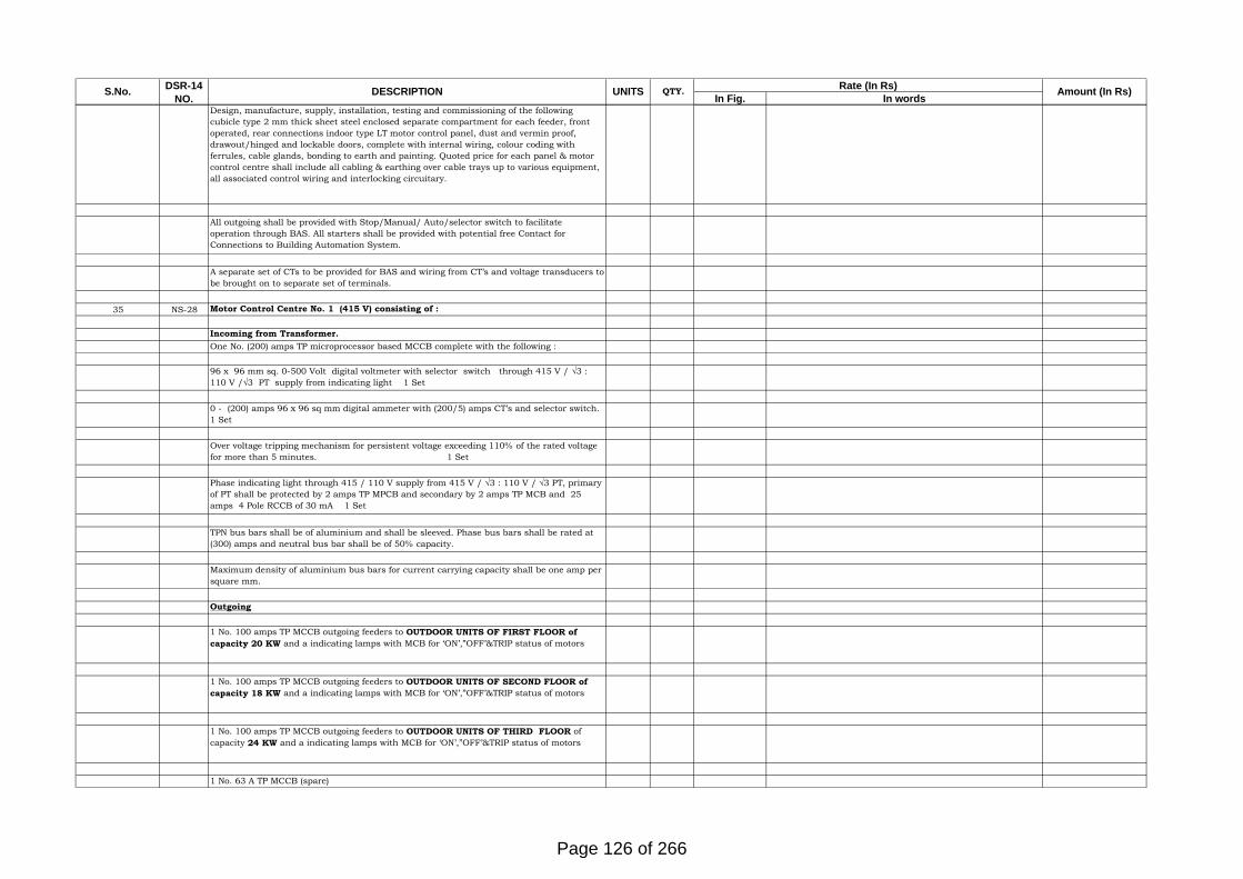
In Fig. In wordsDESCRIPTIONDSR-14NO.S.No. QTY.UNITS Rate (In Rs) Amount (In Rs)
Design, manufacture, supply, installation, testing and commissioning of the followingcubicle type 2 mm thick sheet steel enclosed separate compartment for each feeder, frontoperated, rear connections indoor type LT motor control panel, dust and vermin proof,drawout/hinged and lockable doors, complete with internal wiring, colour coding withferrules, cable glands, bonding to earth and painting. Quoted price for each panel & motorcontrol centre shall include all cabling & earthing over cable trays up to various equipment,all associated control wiring and interlocking circuitary.
All outgoing shall be provided with Stop/Manual/ Auto/selector switch to facilitateoperation through BAS. All starters shall be provided with potential free Contact forConnections to Building Automation System.
A separate set of CTs to be provided for BAS and wiring from CT’s and voltage transducers tobe brought on to separate set of terminals.
35 NS-28 Motor Control Centre No. 1 (415 V) consisting of :
Incoming from Transformer.One No. (200) amps TP microprocessor based MCCB complete with the following :
96 x 96 mm sq. 0-500 Volt digital voltmeter with selector switch through 415 V / √3 :110 V /√3 PT supply from indicating light 1 Set
0 - (200) amps 96 x 96 sq mm digital ammeter with (200/5) amps CT’s and selector switch.1 Set
Over voltage tripping mechanism for persistent voltage exceeding 110% of the rated voltagefor more than 5 minutes. 1 Set
Phase indicating light through 415 / 110 V supply from 415 V / √3 : 110 V / √3 PT, primaryof PT shall be protected by 2 amps TP MPCB and secondary by 2 amps TP MCB and 25amps 4 Pole RCCB of 30 mA 1 Set
TPN bus bars shall be of aluminium and shall be sleeved. Phase bus bars shall be rated at(300) amps and neutral bus bar shall be of 50% capacity.
Maximum density of aluminium bus bars for current carrying capacity shall be one amp persquare mm.
Outgoing
1 No. 100 amps TP MCCB outgoing feeders to OUTDOOR UNITS OF FIRST FLOOR ofcapacity 20 KW and a indicating lamps with MCB for ‘ON’,”OFF’&TRIP status of motors
1 No. 100 amps TP MCCB outgoing feeders to OUTDOOR UNITS OF SECOND FLOOR ofcapacity 18 KW and a indicating lamps with MCB for ‘ON’,”OFF’&TRIP status of motors
1 No. 100 amps TP MCCB outgoing feeders to OUTDOOR UNITS OF THIRD FLOOR ofcapacity 24 KW and a indicating lamps with MCB for ‘ON’,”OFF’&TRIP status of motors
1 No. 63 A TP MCCB (spare)
Page 126 of 266

In Fig. In wordsDESCRIPTIONDSR-14NO.S.No. QTY.UNITS Rate (In Rs) Amount (In Rs)
2 No. 100 A TP MCCB (spare)
Necessary cable alleys, space for spare switches, internal wiring, control wiring/cabling andcopper earthing of all equipment shall also be included. All switches and other componentsshall be motor duty rating.
Motor Control Centre No. 1 as described above.No. 1
Note: 1. MCCB’s shall be motor duty and suitable for 25 KA (ICS) fault current.2. 415 / 110 V suitable rating control transformer shall be provided for aux. Controlsupply.3. Panel Should be IP-65 rating as per outdoor type
Motor Control Centre No. 2 (415 V) consisting of :Incoming (From Transformer as well as DG sets)One No. (100) amps TP microprocessor based MCCB complete with the following :
96 x 96 mm sq. 0-500 Volt digital voltmeter with selector switch through 415 V / √3 :110 V /√3 PT supply from indicating light 1 Set
0 - (100) amps 96 x 96 sq mm digital ammeter with (100/5) amps CT’s and selector switch.1 Set0 - (100) amps 96 x 96 sq mm digital ammeter with (100/5) amps CT’s and selector switch.1 Set
Over voltage tripping mechanism for persistent voltage exceeding 110% of the rated voltagefor more than 5 minutes. 1 Set
Phase indicating light through 415 / 110 V supply from 415 V / √3 : 110 V / √3 PT, primaryof PT shall be protected by 2 amps TP MPCB and secondary by 2 amps TP MCB and 25amps 4 Pole RCCB of 30 mA 1 Set
TPN bus bars shall be of aluminium and shall be sleeved. Phase bus bars shall be rated at(400) amps and neutral bus bar shall be of 50% capacity.
Maximum density of aluminium bus bars for current carrying capacity shall be one amp persquare mm.
Outgoing
1 No. 100 amps TP MCCB outgoing feeders to OUTDOOR UNITS OF FOURTH FLOOR ofcapacity 24 KW and a indicating lamps with MCB for ‘ON’,”OFF’&TRIP status of motors
1 No. 100 A TP MCCB (spare)
Necessary cable alleys, space for spare switches, internal wiring, control wiring/cabling andcopper earthing of all equipment shall also be included. All switches and other componentsshall be motor duty rating.
Motor Control Centre No. 1 as described above.No. 1
1. MCCB’s shall be motor duty and suitable for 25 KA (ICS) fault current.
Page 127 of 266

In Fig. In wordsDESCRIPTIONDSR-14NO.S.No. QTY.UNITS Rate (In Rs) Amount (In Rs)
2. 415 / 110 V suitable rating control transformer shall be provided for aux. Controlsupply.3. Panel Should be IP-65 rating as per outdoor type
TOTAL SUB HEAD PART-1
Sub Head-2DSR 14
NO.DESCRIPTION
UNITS QTY.
NON - DSR ITEMSVENTILATION SYSTEM IN CASE OF FIRE AND PRESSURIZATION FANS.
1 NS-1
Supply, Installation, testing and commissioning of Tube AXIAL FANS for supply fresh airsuitable for installing in any position in Horizontal or vertical. The motor shall be suitablefor 415 V + 10% volts three phase 50cycle, AC supply and suitable for operating throughVFD. The motor selected shall be energy efficient having efficiency (Eff. class #1) at full loadranging between 82.5% to 92% in accordance with motor rating as per specification. The fanshall be low RPM and capacities based shall be as follows :All necessary indigenousaccessories such as cushy foot mounts for floor mounted fans, spring hangers for ceilinghung fans, heavy duty flexible connector .The fan shall be low RPM and capacities basedshall be as follows :
All fans shall have high efficiency (IE 2 type), low rpm (not exceeding 1000) Vendor to selectthe fan accordingly.SPACE SP (MM) CFM
a)Terrace 40 mm 6500
No 2
VENTILATION FANS
a)Terrace 40 mm 6500
No 2
b)Terrace 40 mm 7500
No 2
2 NS-2
Supplying, installing, testing and commissioning of AIR HANDLING UNITS ( FAN SECTIONS ONLY)withdouble skin construction as per specificatopns, each complete with squirrel cage induction motor (mountedinternally), airfoil centrifugal fan, belt drive and vibrations isolators.Motors (IE2) shall be suitable for 415 +-10% volts, 50 cycles , 3 phase AC supply. Fan static pressure shall be as indicated . Fan-motor assembly (aswhole) shall be statically & dynamically balanced to grade G6.3 as per ISO-1940/AMCA 204-3. All AHUS (Fansections) shall be suitable for outdoor duty and complete with duct flexible connections and volume controldamper . In additional all supply fans (SF) shall be provided with prefilter.
CFM SP (MM)
a)5000 45
No 4
ELECTRICAL WORK FOR PRESSURIZATION FANS.
3 NS-4 CONTROL PANELS FOR FANS
Design, manufacture, supply, installation, testing and commissioning of the followingcubicle type, dead front, sheet steel, wall mounted control panels, including anchoring intothe wall, wiring terminating into MCCB and copper earthing, in each panel shall be providedby the electrical contractor.
All outgoing shall be provided with Stop /Manual /Auto selector switch to facilitateoperation through BAS. All starters shall be provided with potential free Contact forConnections to Building Automation System.
All wiring and copper earthing of motors from the panel shall be included.
Page 128 of 266

In Fig. In wordsDESCRIPTIONDSR-14NO.S.No. QTY.UNITS Rate (In Rs) Amount (In Rs)
The panel shall include the following components & accessories.
a.MCCB as per the ratings given below, suitable for motor duty and able to withstand faultlevel of 20 KA.
b. DOL / SD starter as per HP gratings given.
c. Terminal block for power distribution as required.
d. Contractor, over load relay with built in single phasing protection.
e. Phase indicating lights and indicating light for `ON’ status.
f. 144 mm x 144 mm voltmeter and digital ammeter.
g. Time delay relay for delayed automatic restart of motor.
h.Wiring for microswitch for stopping the fan when fire damper closes (in case of Fan only).
i.For on/off/remote and local operation, 3 pole single throw switch shall be provided in eachpanel to facilitate override of the automatic operation.
j.All starters shall be provided with suitable potential free contract for connections to theBuilding Automation System.j.All starters shall be provided with suitable potential free contract for connections to theBuilding Automation System.
The number of control panels shall be as follows.
4 NS-530 amps MCCB, 7.5 - 3 HP DOL Starters
No. 8
TOTAL SUB HEAD PART-2GRAND TOTAL
Page 129 of 266

TENDER NO: WAP/PMD/2016-17/12
WAPCOS Limited
CONSTRUCTION OF OFFICE CUM RESIDENTIAL COMPLEX FOR NARCOTICS CONTROL BUREAU AT LUCKNOW, UTTAR PRADESH
TENDER NO: WAP/PMD/2016-17/12
APPENDIX ‘B’
LIST OF MAKES AND SPECIFICATIONS
(HVAC AND FIRE FIGHTING)
Page 130 of 266

Annexure ‘B’
WAPCOS Limited
A-71, 7th Floor,
Himalaya House, 23, Kasturba Gandhi Marg
New Delhi-110001
LIST OF MAKES (HVAC AND FIRE FIGHTING)
FOR
CONSTRUCTION OF OFFICE CUM RESIDENTIAL COMPLEX
FOR NARCOTICS CONTROL BUREAU AT LUCKNOW,
UTTAR PRADESH.
TENDER NO: WAP/PMD/2016-17/12
Page 131 of 266

1. HVAC:
S.No. Description Makes/Manufacturer
1. VRF/VRV AC System MITSUBISHI ELECTRIC /LG/DAIKIN/ HITACHI
2. Split AC System MITSUBISHI ELECTRIC /LG/DAIKIN/ HITACHI
3. Centrifugal Fans for ventilation
/ Air washer/ Scrubber Kruger/Nicotra/ Green heck/Air Flow
4. Tube Axial flow Fans Kruger/ Nicotra / Green heck/Air Flow
5. Inline Fans Kruger/Nicotra/ Green heck/Air Flow
6. Air Washer / Scrubber Ravi Aircon/Dynamic Engineerings/Zeco
7. G.I. Sheets Sail/ Tata/Jindal
8. Pre-Insulated Ducting Pal/ kingspan/ALP
9. Under Roof Insulation Pal/ kingspan/ALP
10. Factor Fabricated Ducting Rolastar/Zeco/Ductofab
11. Welding Roads Advani/L&T
12. Duct Support Hilti/ walraven/gripple
13. Anchor/Fastener Hilti/Fisher
14. Aluminum tape Johnson/Birla 3M
15. Grills/Diffusers/FireDampers
/ Louvers/Exhaust valve Crossair /Conaire/Caryaire/A Star
16. Heat Recovery unit Caryaire/VTS/Systemair
17. insulation/Acoustic Lining for
Ducting Supreme / paramount /Trocellene
18. insulation for refrigerant pipe Armacell / Urobatex /vidoflex
19. Copper refrigerant pipe Rajco/Mandev/Mahflow
20. UPVC drain piping Supreme/Astrals/Finolex
Page 132 of 266

21. canvas connection Mapro/Caryaire/ Conaire
22. propeller type exhaust fan Kruger/ havells/ Marathan/Orient/Usha/Bajaj
23. MCB Schneider (Multi-9)/ Legrand/ Siemens
24. MCCB Schneider (MG-NS Series)/ Siemens (3VM)/ L&T
(D-sine)
25. ACB Schneider (MG-NS Series)/ Siemens (3WT)/ L&T
(D-sine)
26. MV Contactors/Timer/ Starters L&T/ Siemens
27. Protective Relays L&T/ Siemens
28. All Meters Enercon/Neptune/ Siemens
29. Indication Lamps/Push Button L&T/ Schneider
30. Capacitor L&T/ Siemens/ Neptune
31. Terminal Blocks Elmex/Wago/Connect-Well
32. Selector Switch Kacee/L&T/BCH/Areva
33. Bus bar Jindal/ Indalco/ Century
34. LT Cables / Control Cables Skyton/ Finolex/polycab
35. PVC Conduits Precision/BEC
36. Paints Asian/Nerolac/Berger
37. Switch Socket Legrand (Mosaic)/ Anchor Woods
/ Schneider (Clipsal)
38. Cable Tray Slotco/ Pilco/ Needo
39. Cable Gland Stripwell/ Commet/ Siemens
40. MV Panels(TTA) Siemens Cpan/ ABB R2K/ Schneider Blockset
41.
Copper Conductor
Communication
/ Signal Cable
Bon Ton/Finolex/ Skytone/polycab
42. PVC Conduits Precision/BEC/ AKG
Page 133 of 266

43. GI Conduits BEC/ AKG/ Steel Craft
44. Motors Siemens/ ABB/ Crompton
45. PVC Pipes Finolex/ Prince/ Supreme
46. Precision AC Emerson/ Schneider
47. VFL TROX/Air Flow
48. Co censer GST(UTC)/ Conaire/Honey Well
49. Electrical Panel Krypton/Risha/KEPL
Page 134 of 266

2. FIRE FIGHTING:
S.No. Name of the Materials
Approved makes
1. Addressable
Networkable Panel
: Notifier / Siemens/ Honeywell / Edwards
2. Intelligent Addressable
Smoke Detectors
Optical Type + Multi
criteria
: Notifier / Siemens/ Honeywell / Edwards
3. Intelligent Addressable
Rate of Rise Heat
Detector
: Notifier / Siemens/ Honeywell / Edwards
4. CWZ Cable : Polycab / KEI / Lapp/ Skytone
5. Telephone cable : Lapp / Skytone
6. Addressable Duct
Detector Unit
: As per (1) above.
7. Input / Output Modules : By Parent Company Manufacturing Detectors / Panel
8. Manual Call Box : By Parent Company Manufacturing Detectors / Panel
9.
Strobe : UL Listed
10. EPABX : Siemens / Panasonic / BPL
11. Talk back Unit : Beetel / Tataphone / Siemens
12. PC / Monitor / keyboard : HP / Dell.
13. PA System : Bosch / Ahuja / System Sensor /HONEYWELL
14. Fault Isolator : Notifier / Siemens / Honeywell / Edwards
15 Response Indicator : Agni / GAC.
16. Conduit : BEC / AKG / Steelkraft.
Page 135 of 266

17. Pipes ( M S / G I ) : Tata / Jindal Hissar.
18. Ductile Pipes Electrosteel / Lanco
19. Hydrant valves, four way
Fire Brigade inlet &
shut off nozzle
Newage / Minimax / Eversafe
20. Rubber pipe for hose
reel
Mitras/Gates / Jyoti.
21. Sluice & non return
valves
Kirloskar / Kalpana /Sant
22. Pressure switch Indfoss / Switzer
23. Pressure Gauges BRC / HD.
24. Pump. Mather & Platt / Kirloskar / Grundfos
25. Motor. ABB / Siemens / Crompton Greaves / Kirloskar.
26. Enamel Painting of
pipes etc.
: Asian / Goodlas Nerolac / ICI / Berger.
27. Paint Primer. Asian / Jenson Nicholson / Berger.
28. Fasteners. Hilti / Fischer.
29. Weld Rods Advani / Esab.
30. Ball Valves. RB ( Italy ) / Bugatti / Zoloto/ Cim.
31. Fire Extinguishers
( Water type / 50 Kg
DCP / Ceiling mounted
DCP / AFFF )
Minimax / Ceasefire / Kanex
32. Fire Extinguishers
( ABC / CO2 )
Minimax / Ceasefire / Kanex
33. RRL Hose. Newage UL listed
34. Rubber Gaskets C I C / Varuna.
35. Engine : Cummins / Caterpillar / KOEL
Page 136 of 266

36. Hose Drum. : Newage/ Eversafe
37. Mechanical Seal. : Durametallic/ Sealol.
38. Strainer. Emerald / Grandprix.
39. Wafer type Non Return
Valves
C & R / Advance.
40. Sprinklers ( all types FM
approved ) ( including
rosette plate )
Tyco / Viking/HD
41. Installation Control
Valve
Tyco / HD /Viking.
42. Passive Fire Protection
Materials
Promat / Hilti / Ace.
43. Neulite Branch Pipe Newage / Minimax.
44. Flow Switch System Sensor / Potter.
45. Pipe fittings Unik / Saint / VS
46. Nuts & Bolts : Lakshmi / Unbrako.
47. Sprinkler Hanger
Supports
Chilly.
48. Signages Prolite
49. Air Vessel Locally fabricated
50. Power Cables Skytone / Finolex / Polycab..
51. Conduit ERW (ISI
marked).
BEC / AKG.
52. Contactors & Overload
Relays.
L&T / Siemens / GE Power
53. Fuse link Siemens / L&T / GE Power / C & S.
54. Voltmeter/Ammeter L&T / AE / IMP
55. CT/PT Transformer. : AE / Kappa / C & S
56. S.F. Unit : L&T / Siemens / GE / Controls & Switchgear
Page 137 of 266

57. Cable Trays. Slotco / Pilco.
58. Indicating Lamps L & T / Siemens / GE Power.
59. Electrical Pump Panels Advance / Diamond / Risha
3. MISC:
S.No. Name of the Materials
Approved makes
1. CCTV : UNIVERSE MICROSYSTEMS/ SONY/ BOSCH/
PELCO
3. SOLAR PANEL : Swayem Solar Swayem/ Casa Solar Energy
Page 138 of 266

WAPCOS Limited
A-71, 7th Floor, Himalaya House, 23, Kasturba Gandhi Marg
New Delhi-110001
HVAC SPECIFICATIONS
FOR
CONSTRUCTION OF OFFICE CUM RESIDENTIAL
COMPLEX FOR NARCOTICS CONTROL BUREAU AT
LUCKNOW, UTTAR PRADESH.
TENDER NO: WAP/PMD/2016-17/12
Page 139 of 266

1 of 37
Section: HVAC Specifications
HVAC SPECIFICATION
Page 140 of 266

2 of 37
Section: HVAC Specifications
PART I - AIRCONDITIONING SYSTEM
1.0 SYSTEM DESCRIPTION
1.1 All area
VRV system provides for air-conditioning for all area with multi indoor units with single outdoor
unit. Each indoor unit connected to dedicated outdoor units
1.2 Outdoor unit
Outdoor units for all area are located on terrace/stilt level.
1.3 The Refrigerant Piping
Insulated refrigerant piping interconnecting outdoor and indoor units shall be routed as shown in
layout drawing.
1.4 Drain Piping
Insulated drain piping shall be terminated at nearest drain point or nearby shaft through pipe
A) VARIABLE REGRIGERANT FLOW SYSTEM
1. SYSTEM
The Variable Refrigerant Flow (VRF /VRV R 410a refrigerant) System should be air cooled, Duct
type air conditioning systems consisting of modular condensing units connected to multiple indoor
units, each having the capability of individual set point control. Each modular condensing unit
should incorporate at least one inverter control scroll/Rotary compressors to obtain 10% to 100%
step less capacity control for enhanced Power saving. The indoor units should be provided with
Cordless Remote Control as a standard accessory.
The refrigerant piping shall be extendable minimum 150 m with 50 m level without any oil trap.
Ambient conditions.
2. OUTDOOR UNIT
2.1 The outdoor unit shall be a factory assembled unit housed in a sturdy weather proof casing
constructed form rust-proofed mild steel panels coated with a baked enamel finish. The ODU must
deliver 100% cooling capacity at 43 Deg C ambient Temperature.
Page 141 of 266

3 of 37
Section: HVAC Specifications
The outdoor unit shall have multiple scroll / Rotary compressors and be able to operate even in
case of breakdown of one of compressors.
The noise level shall not be more than 68 dB(A)at normal operation measured horizontally 1m
away and 1.5m above ground.
The outdoor unit shall be modular in design and shall be allowed for side by side installation.
2.2. Compressor
The compressor shall be of inverter type highly efficient hermetic Scroll/rotary capable of capacity
modulation. Each ODU should have 1 no. variable compressor upto 16 HP capacities, and 2 nos.
variable compressors upto 32 HP capacity.
2.3 Heat Exchanger
The heat exchanger shall be constructed with copper tubes mechanically bonded to aluminium fins
to form a cross fin coil. The aluminium fins shall be covered by anti-corrosion resin film. The
System must have sub-cooling heat exchanger further to Condenser to increase refrigerating effect
in Indoor units.
2.4 Fan Motor Speed Control
The condensing unit fan motors to have at least two speed operations to maintain constant head
pressure control in all ambient temperatures and modes of operation.
2.5. Refrigerant Circuit
The refrigerant circuit shall include an accumulator, liquid and gas shut off valves and a solenoid
valves
All necessary safety devices shall be provided to ensure the safety operation of the system.
2.6 Safety Devices
The following safety devices shall be part of the outdoor unit;
High Pressure Switch, Low Pressure Switch, Fan Motor Safety Thermostat, Over Current Relay,
etc.
2.7 Oil Recovery System
Page 142 of 266

4 of 37
Section: HVAC Specifications
Each unit shall be equipped, with an oil separator to ensure stable operation with long refrigerant
piping.
3. INDOOR UNIT
3.1 Indoor unit shall be mix-match of duct type . It shall have electronic control valve to control
refrigerant flow rate in response to load variations of the room. The fan shall be of the dual suction
multi blade type and statically and dynamically balanced to ensure low noise and vibration free
operation.
3.2 The address of the indoor unit shall be set automatically in case of individual and group
control. In case of centralized control, liquid crystal remote controller shall set it.
3.3 Electronic Expansion Valve
Each indoor unit shall be fitted with an electronic expansion valve to control the refrigerant flow in
response to the load variations in the room. The electronic expansion valve is to be controlled via a
computerized control sensing the return air temperature, refrigerant inlet and outlet temperatures.
During the cooling operation the electronic expansion valve shall control the refrigerant superheat
degree at the evaporator.
3.4 Indoor Unit Fans
Shall be direct driven of the DIDW multi-blade type, statically and dynamically balanced to ensure
low noise and vibration free operation. The noise level shall not exceed 45 dbA.
3.5 Cooling Coils
Shall be direct expansion, constructed from copper tubes expanded into aluminium fins to form a
rigid mechanical bond.
4. CABLING BEWTEEN INDOOR AND OUTDOOR UNITS
The cable between indoor and outdoor units shall run in PVC conduit.
5. REFRIGERANT PIPEWORK:
5.1 Scope of Refrigerant Piping work shall include Supply, installation, testing and
commissioning of all interconnecting pipe-work between the condensing unit & indoor units.
Refrigerant quality seamless copper tubes with brazed connections and the appropriate
Distribution joints and headers shall be used. The piping should be routed at site in such a manner,
that brazed joints in the Refrigeration Piping are kept to a minimum.
Page 143 of 266

5 of 37
Section: HVAC Specifications
5.2 Joint Orientation:
Proprietary distribution refrigeration pipe joints and headers shall be installed in an appropriate
orientation to enable correct distribution of refrigerant.
5.3 Cleanliness of Piping:
All pipe-work must be kept clean and free from contamination to prevent breakdown of the
system. All pipe ends shall be kept sealed until immediately prior to making a joint.
5.4 Pressure Testing:
After complete installation of refrigerant piping, it shall be pressure tested and repaired if
necessary and further pressure tested to 3,800 Pa, to hold for a minimum 24 hours with dry
nitrogen prior to insulating the joints. After satisfactory testing, the refrigerant pipe shall be
evacuated and dehydrated to (- 755 MM HG) and held for one to four hours depending on the pipe
length.
5.5 Refrigerant Charge
Refrigerant charge must be calculated based on the actual length of the refrigerant pipe work. The
refrigerant charging process must be carried out with an appropriate charging station.
5.6 Piping Insulation
All suction & liquid lines of the Refrigerant pipe work shall be insulated with nitrile rubber tube
insulation pipe sections as specified to avoid condensation. The exposed piping insulation shall
have glass cloth protection or any other protection.
5.7 Fixing Pipe Work & Electrical Conduit:
The insulated refrigerant piping and electrical conduit shall run on GI tray properly supported by
GI rods. The exposed tray on terrace shall be covered by open able GI covers.
Page 144 of 266

6 of 37
Section: HVAC Specifications
5.8 The OD & wall thickness of copper refrigerant piping shall be as follows:
Size Thickness Specification
6.4mm (1/4 in) 22 G C1220T-O (ANNEALED)
9.5mm (3/8 in) 22 G C1220T-O (ANNEALED)
12.7mm (1/2 in) 22 G C1220T-O (ANNEALED)
15.9mm (5/8 in) 22 G C1220T-O (ANNEALED)
19.1mm (3/4 in) 20 G C1220T-1/2 H (HALF-HARD)
22.2mm (7/8 in) 20 G C1220T-1/2 H (HALF-HARD)
28.6mm (1 1/8 in) 18 G C1220T-1/2 H (HALF-HARD)
34.9mm (1 1/4 in) 18 G C1220T-1/2 H (HALF-HARD)
6.0 DRAIN PIPING
6.1 The indoor units shall have uPVC drain pipe suitable for 10 kg/cm2.
6.2 The pipes shall be laid in proper slope for efficient drainage of condensate water.
6.3 Drain Pipe Insulation-
Drain pipes carrying condensate water shall be insulated with 6 mm/9mm Nitrile rubber insulation
as specified to avoid any condensation.
The joints shall be properly sealed with synthetic glue to ensure proper bonding of the ends.
7.0 TESTING
The units shall be tested for capacity and COP as per ARI conditions at manufactures premises
before delivery, Owners / their representative reserve the right to witness the tests.
Page 145 of 266

7 of 37
Section: HVAC Specifications
8.0 TESTING OF AIR-CONDITIONING SYSTEM
8.1 Routine and types tests for the various items of equipment shall be performed at the
contractor‟s works and test certificates furnished. Functional tests shall be conducted at site.
8.2 The performance tests to determine whether or not the full intent of the specification is
meant shall be conducted by the contractor. After notification to the employers that the
installation has been completed and the plant has run continuously for a period of at least one
weeks, the contractor shall conduct under the direction of the consultants and in the presence of
the employer‟s representatives such tests as specified to establish the capacity of various
equipment supplied and installed by the contractor.
8.3 The contractor shall operate, test and adjust the air conditioning appliances including
adjustment of regulators, dampers, etc,.
8.4 All test equipment, labour, operating personnel, oil and refrigerant required for these
tests shall be furnished by the contractor to enable the plant to be put in continuous running test
for a period of two days after all other tests and adjustments have been made. The performance
tests shall be conducted during peak summer and peak monsoon ,winter.
8.5 PROCEDURE
8.5.1 Design Conditions:
The inside and outside conditions will be recorded for 24 hours duration on hourly basis. The
outside and inside dry bulb and wet bulb temperatures shall be recoded by means of a sling
thermometer with mercury thermometers. The relative humidity shall be computed from the
psychometric chart. The inside dry bulb temperature and relative humidity shall fall within the
specified limits.
8.6 FUNCTIONAL TESTS
8.6.1 Electrical Equipment:
a) All the cables shall be tested for continuity and absence of cross phasing. Insulation
resistance between the phase conductors and the earth shall be measured shall with the help of a
500-V megger.
b) Motors:
i) Starter operation shall be checked for single phasing by removing one of the phases.
ii) Overload protection shall be checked by altering the starter thermal overload setting.
Page 146 of 266

8 of 37
Section: HVAC Specifications
TECHNICAL DATA
1 Variable Refrigerant Volume Air Cooled Units
1.1 Outdoor Units
a Make and Model
b. Type (Cooling or heat pump)
c Dimension of unit (Overall)
d. Actual capacity (TR) at specified conditions
e. Permissible length of refrigerant piping (m)
f. Type of compressor
g. No. of compressor (each unit)
h. Electrical characteristics
i. Power consumption at ARI conditions for each capacity
100% , 75%, 50% , 25%
1.2 Indoor Units
a. Manufacturer
b. Type
c Nominal capacity (TR)
d Airflow Min/Max (CFM)
e. Sound level (Hi/Lo)
f. Overall dimensions (L x W x H)
g. Unit weight (Kg)
h. Remote controller for each indoor unit (Yes/No)
Page 147 of 266

9 of 37
Section: HVAC Specifications
PART II – PRECISION AIR CONDITIONERS (PAC)
SCOPE OF WORK
The Scope of Work covers the supply, installation, commissioning and warranty of Precision Air
conditioner and services provided for the same.
1.1 SUMMARY
These specifications describe requirements for an environmental control system. The system shall be
designed to maintain temperature and relative humidity conditions.
GENERAL
The AC Units should have high sensible heat ratios, to match the low latent loads of Computer/Server
Rooms/ Switch room/UPS/VFD rooms. A Microprocessor controlled package AC system with R-
407C/410A refrigerant.
The Indoor unit complete with Scroll compressor with individual circuit (Mandatory), Evaporator
blower & coil, Heater, Humidifier, Microprocessor controller, electrical switchgear components and
Thermostatic expansion valve (TXV)/EEV and shall be housed in a single cabinet. The outdoor unit
shall be comprised of condenser fan, motor, fan speed controller (if applicable) & cooling coil.
1.2 DESIGN REQUIREMENTS
The environmental control system shall be a factory assembled unit. It shall be floor mounted,
optimized for maximum cooling capacity in a minimum footprint.
It shall be specifically designed for service from the front of the unit. The system shall be designed for
draw-through air arrangement to insure even air distribution to the entire face area of the coil. The
unit shall modulate cooling capacity and airflow based on requirements.
The unit shall be ready to allow the installation of shackles for top handling. Forklift handling should
be possible as well.
1.3 QUALITY ASSURANCE
The specified system shall be factory end line tested (functionality test) before shipment and designed
to meet CE requirements. The system shall be designed and manufactured according to world-class
quality standards. The manufacturer shall be ISO 9001 certified.
1.4 CABINET
The cabinet is manufactured from galvanized steel sheet, externally painted with Black 7021 colour
epoxy-polyester powder paint and assembled using stainless steel screws and high tensile rivets. The
rear and the fans section panels are double-skinned, with 20mm (frontal fan section panel with 40mm)
Class „O‟ (A1 EU) fireproof insulation sandwiched between the skins to reduce noise emission and
heat loss. The side panels, which are isolated from the inside of the unit to form a complete double-
skinned cabinet, the small service panel for electrical heaters, are also lined with 10mm Class „O‟ (A1
EU) fireproof insulation .
The frontal panel (s) are assembled on hinges to make the access easier; and can be opened by the fast
closing lock. The rear and side panels are screwed to the supports. The rear pane l(s) are screwed
directly to the frame.
1.5 AIRFLOW PATTERN
The unit takes the air from the top and deliver from the bottom or side supply top return. The unit is suited for
raised floor air delivery.
Page 148 of 266

10 of 37
Section: HVAC Specifications
1.6 COOLING CIRCUITS
One (Two) refrigeration circuit(s), (each) incorporating one (two) high efficiency, fully hermetic
Scroll compressor/s with crankcase heater, , liquid receiver with outlet service valve, safety valve,
filter drier, moisture indicating sight glass, liquid line solenoid and expansion valve to allow the
highest energy saving .
Each circuit is equipped with pre-set high pressure switch and low pressure transducer for protection
against high condensing and low evaporating temperatures. The low pressure transducer is managed
by microprocessor controller to avoid compressor cycling at high discharge pressures, the high
pressure switch is equipped with a manual reset.
The inclined evaporator coil is manufactured from copper tubes, mechanically bonded to hydrophilic
painted aluminium fins, with a stainless steel condensate drain pan. The large face area/low velocity
coil allows precise control of temperature and humidity during cooling and dehumidification, and is
designed to optimise fluid velocity and minimise pressure drop. The evaporator shall be staged coil to allow a maximum efficiency on partial loads.
The moisture indicating sight glass and liquid line solenoid valve for each circuit are mounted visible
from a service window, immediately accessible from the frontal door/s, to allow checking and
adjustment while the unit is in operation.
AIR-COOLED CONDENSER:
The Air-cooled condenser shall be the low profile, weatherproof type incorporating high efficiency,
direct drive, external rotor motors with axial blade fans & fan speed controller. The condenser shall be
constructed from heavy duty aluminum and corrosion resistant through special anti corrosive epoxy
coatings for any specific polluted areas. Heavy duty mounting legs and all assembly hardware shall be
included. Condensers shall be suitable for 24 hours operation and be capable of providing vertical or
horizontal discharge. The condenser shall be fully factory wired and require a 230 volt, single phase,
50 Hz electrical service. The high performance heat exchanger shall include mechanically expanded
cross-hatched copper tubes and louvered aluminum fins for maximum heat transfer.
REFRIGERANT PIPING
Each refrigerant circuit shall be suitable for operation on R-407C/410A and shall include the
following items:
i) Expansion valve with pressure equalization;
ii) Removable liquid line drier / filter.
iii) Liquid line sight glass with moisture indicator.
iv) Hand shut off valves.
1.7 FAN SECTION
The unit is fitted with one (two, three) direct-driven, high efficiency, single inlet, forward/backward
curved, centrifugal „plug‟ type innovating EC fan(s). The fan(s) have an impeller with curved blades
corrosion resistant made of fiberglass plastic/other material. The fan shall be low noise. static pressure
of fan not less than 250 Pascal.
The fan motors are Electronically Commutated, IP54, with internal protections, continuous speed
regulation via controller signal. The motor is three-phase with IP54 protection; provided with internal
thermal protection.
The fan wheel is statically and dynamically balanced; the bearings are self-lubricating.
Page 149 of 266

11 of 37
Section: HVAC Specifications
Between the fans shall be installed an “S” shape separator design to eliminate turbulence effects of
one fan to the others;
1.8 ELECTRICAL PANEL
The electrical panel, located at the front of the unit in a compartment isolated from the airflow,
contains the MCB‟s, contactors, transformers, controller PCB, overload relays etc. Each high voltage
system component is provided with an MCB over-current protective device. All high voltage
components are touch protected by means of a plastic cover. The electrical panel complies with the
IEC norm en60204-1.
Electrical power supply is 400V (±10%) / 3Ph / 50Hz (±2Hz) +N +E and are fitted with a mains
isolator, mechanically interlocked with the electrical panel cover.
1.9 HUMIDIFIER
The unit is fitted with an infrared humidifier suitable for use with water of varying degrees of
hardness. The humidifier is complete with a water inlet valve, and a maximum water level sensor; the
humidifier includes 3 high-intensity quartz lamps shine on water creating instantaneous moisture
using almost any water quality. The cleanable stainless steel humidifier pan is removable from front
of the unit. The humidifier pan shall be stainless steel and arranged to be removable without
disconnecting high voltage electrical connections. The complete humidifier section shall be pre-piped,
ready for field connection to water supply. The humidifier shall be equipped with an automatic water
supply system and shall have an adjustable water-overfeed to prevent mineral precipitation. A high-
water detector shall shut down the humidifier to prevent overflowing.
OR
The unit is fitted with an ultrasonic humidifier. The humidifier include water tank linked together and
used for the atomization and control of the supply water. The built-in tank comes complete with
solenoid valve and float switch for the control of the feed water that ensure preventive protection
against dry-running. The ultrasonic humidifier is controlled by a specific control ultrasonic humidifier
that includes a board and a display which allows displaying and modifying all the parameters of the
humidifier.
1.10 MICROPROCESSOR CONTROLLER
The Control System is microprocessor based, 32 bit RISC. It can be programmed to control the
function of every device within the unit via I/O. The controller allows setting and monitoring of the
following room parameters via a 3 button keypad:
Air Temperature
Temperature set-point
Temperature band
Humidity
Humidity set-point
Humidity band
The parameters are indicated using symbols and text on a back-lit, 3 digits Liquid Crystal Display.
Cooling and heating modes are also indicated on the LCD screen. Alarm conditions activate a visual
indicator. Three LED‟s indicate the unit status – „Power on‟ „Unit on‟ and „Warning/Alarm activated‟
The controller should be able to provides with the following functions: unit to unit Ethernet
connection to operate with multiple units, run/stand-by rotation, automatic changeover and parameter
sharing functions, external communications through BMS or Network Power monitoring solution,
sequential auto restart timer, with adjustable time delays to be applied to unit restart after a power
loss.
Page 150 of 266

12 of 37
Section: HVAC Specifications
The following warnings / alarms are included:
• High temperature
• Low temperature
• High relative humidity
• Low relative humidity
• Humidifier failure
• Fan failure
• Electrical heater high temperature (When applicable)
• Sensor failure
• Controller errors
Terminals are provided for remote start/stop control plus Volt-free „Common Alarm‟ and „Unit Run‟
indication. A buzzer provides audible indication of a „Warning‟ or „Alarm‟ condition.
1.11 HEATING / REHEATING
A. Electrical reheating/heating
The heating resistors are of a rigid design for extended operational life and are normally utilized to
maintain room dry-bulb conditions during a system call for dehumidification. Each stage of heaters is
made of finned armoured stainless steel AISI 304 to maintain a low surfaces power density. Ionization
effects are eliminated owing to the low heater surface temperature.
Heating control is of the ON-OFF type. The heaters are phase balanced and are provided with a
manual reset safety thermostat to disable them in the event of a high temperature.
The heating system also incorporates Miniature Circuit Breaker(s) which protect the heater(s) from
short circuits, should the harness be damaged accidentally.
1.12 AIR FILTRATION
The standard filtration grade is F5 (CEN EN779 – respectively corresponding to EU5 according to
Eurovent EU4/5). The F5 standard filters made by paper material and are completely recyclable.
The filter pleated structure gives high filtration efficiency, low pressure drop and permit to use the
filter without metallic or cardboard frame. The filter media is composed by fibre and latex.
They are easily accessed /replaced by opening the front panel(s).
The unit is fitted with a filter differential pressure switch, connected to the microprocessor controller
to provide „Filter Clogged‟ warning indication.
1.13 MONITORING
The unit shall also include IntelliSlot housing for up to two IS (Intelligent slot) Web cards or IS 485
cards, or one IS web and one IS 485 card.
IntelliSlot Web Card delivers SNMP and HTTP/Web-management capability for enhanced
The unit shall also include input for remote on-off and volt-free contacts for simple remote monitoring
of low and high priority alarms: high/low temperature, fan/control failure, and others are available.
Page 151 of 266

13 of 37
Section: HVAC Specifications
PART III - DUCTING
6.1 SCOPE
This chapter covers the general requirements for sheet metal ductwork for air distribution
with associated items such as air outlets and inlets, fresh air intake and fire dampers.
6.2 MATERIAL
6.2.1 RECTANGULAR DUCTS
i) All ducts shall be fabricated either from Galvanized Sheet Steel (GSS) conforming to
IS:277 or aluminum sheets conforming to IS:737. The steel sheets shall be hot dip
galvanized with coating of minimum 120 grams per square meter (GSM) of Zinc.
ii) The thickness of sheets for fabrication of rectangular ductwork shall be as under. The
thickness required corresponding to the longest side of the rectangular section shall be
applicable for all the four sides of the ductwork.
--------------------------------------------------------------------------------------------------------------------------
Longest side (mm) Minimum sheet thickness
-----------------------------------------------------------
For GSS For Aluminum
---------------------------------------------------------------------------------------------------------------------------
750 mm and below 0.63 0.80
751 mm to 1500 mm 0.80 1.00
1501 mm to 2250 mm 1.00 1.50
2251 mm &above 1.25 1.80
iii) All sheet metal connections, partitions and plenums required for flow of air through the
filters, fans etc. shall be at least 1.25 mm thick galvanized steel sheets, in case of G.I.
sheet ducting or 1.8 mm thick aluminum sheet, in case of aluminum sheet ducting and
shall be stiffened with 25mm x25 mm x 3 mm angle iron braces.
iv) Circular ducts, where provided shall be of thickness as specified in IS: 655 as amended
upto date.
DOCUMENTATION & MEASUREMENT OF DUCTING
All ducts fabricated and installed should be accompanied and supported by following
documentation:
For each drawing, all supply of ductwork must be accompanied by computer generated
detailed bill of materials indicating all relevant duct sizes, dimensions and quantities. In
addition, summary sheets are also to be provided showing duct area by gauge and duct size
range as applicable.
ii) Measurement sheet covering each fabricated duct showing dimensions and external
surface area along with summary of external surface area of duct gauge-wise
iii) All duct pieces to have a part number, which should correspond to the serial number,
assigned to it in the measurement sheet. The above system will ensure speedy and proper
site measurement, verification and approvals.
TESTING
After duct installation, total duct work (Air-conditioning and Mechanical Ventilation Ducts)
should be tested for leakage. The procedure for leak testing should be followed as per
SMACNA – “HVAC Air Duct Leakage Test Manual” (First Edition – 1985)
Page 152 of 266

14 of 37
Section: HVAC Specifications
6.2.3 ASSOCIATED ITEMS
A) Angle rods Supports:
i) Supply/return air outlets, FA grilles and accessories shall be constructed from extruded
aluminum sections.
ii) Flanges for matching duct sections, stiffening angles (braces) and supporting angles shall
be of rolled steel sections, and shall be of the following sizes.
---------------------------------------------------------------------------------------------------------------------------
Application Duct Width Angle size
---------------------------------------------------------------------------------------------------------------------------
Flanges Upto 1000 mm 35 mm x35 mm x 3 mm
1001mm to 2250 mm 40 mm x40 mm x 3 mm
More than 2250 mm 50 mm x50 mm x 3 mm
Bracings Upto 1000 mm 25 mm x25 mm x 3 mm
More than 1000 mm 40 mm x40 mm x 3 mm
Support angles Upto 1000 mm 40 mm x40 mm x 3 mm
1001 mm to 2250 mm 40 mm x40 mm x 3 mm
More than 2250 mm Size and type of RS section shall be
decided in individual cases
iii) Hanger rods shall be of mild steel and of at least 10 mm dia for ducts upto 2250 mm size
and 12 mm dia for larger sizes.
iv) All nuts, bolts and washers shall be zinc plated steel. All rivets shall be galvanized or shall
be made of magnesium-aluminum alloy. Self-tapping screws shall not be used.
B) Steel Wire Rope Hangers& Supports:
i) Wire Hangers shall be used to suspend all static HVAC Air Distribution services.
ii) Wire Hangers should consist of a pre-formed wire rope sling with a range of end fixings
to fit various substrates and service fixings, these include a ferruled loop, permanently
fixed threaded M6 (or M8, M10) stud, permanently fixed nipple end with toggle, at one
end or hook or eyelet, cladding hook, barrel, wedge anchor, eyebolt anchor or any other
end fixture type or size as per manufacturers recommendation and design. The end fixings
and the wire must be of the same manufacturer with several options available. The system
should be secured and tensioned with a Hanger self-locking grip at the other end. Once
the grip is locked for safety purpose unlocking should only be done by using a separate
setting key and should not be an integral part of the self-locking grip.Only wire and/or
supports supplied and/or approved, shall be used with the system.
iii) Wire Hangers should have been independently tested by Lloyds Register. APAVE, TUV,
UL NEBS, CSA, Chiltern International fire, ADCAS, Intertek, ECA, and SMACNA,
approved by ULC and CSA and comply with the requirements of DW/144 and BSRIA –
wire Rope Suspension systems.Wire rope should be manufactured to BSEN 12385: 2002
iv) The contractor shall select the correct specification of wire hanger to use for supporting
each particular service from table 1 below.Each size is designated with a maximum safe
working load limit (which incorporates a 5:1 safety factor).
v) The correct specification of wire hanger required is determined using the following
formula.
vi) Weight per meter of object suspended (kg) X distance between suspension points (m) =
weight loading per Hanger suspension point (kg).
vii) Where the installed wire rope is not vertical then the working load limit shall be reduced
in accordance with the recommendations give in the manufacturer‟s handbook.
Page 153 of 266

15 of 37
Section: HVAC Specifications
viii) The contractor shall select the correct length of wire rope required to support the
service. Lengths from 1-10m lengths. Specials can be made, check with manufacturer. No
in–line joints should be made in the rope.
Table. 1
Wire Hanger Safe Working Loads
size
minimum breaking load
of Wire Rope
working load limit
(kg/lbs)
No. 1 80kg/176 lbs 0-10 kg / 0-22 lbs
No. 2 260kg/572 lbs 10-45 kg / 23-100 lbs
No. 3 580kg/1276 lbs 45-90 kg / 101-200 lbs
No. 4 1500kg/3300 lbs 90-225 kg / 210-495 lbs
No. 5 2160kg/4752 lbs 225-325 kg / 496-715 lbs
No. 6 2500kg/5500 lbs 325-500 kg / 715-1100 lbs
ix) The standard range of Hanger Kits should contain galvanized high tensile steel wire rope
or stainless steel wire rope as per the application, the minimum specification is as above
and should be manufactured to BS 302 (1987), BSEN12385. Comply with manufacturer's
load ratings and recommended installation procedures.Note the testing is done to the
minimum breaking load of the wire thus giving a minimum safety factor of 5:1.
6.3 CONSTRUCTION
6.3.1 DUCTS
x) Ducts shall be fabricated at site or factory fabricated and shall be generally as per IS: 655
"Specifications for metal air ducts", unless otherwise deviated in these General
Specifications.
xi) The interior surfaces of the ducting shall be smooth.
xii) All the ducts upto 600mm longest side shall be cross broken between flanges by a single
continuous breaking. Ducts of size 600mm and above shall be cross broken by single
continuous breaking between flanges and bracings. Alternatively, beading at 300mm
centers for ducts upto 600mm longest side, and 100mm centers for ducts above 600mm
size shall be provided for stiffening.
xiii) As far as possible, long radius elbows and gradual changes in shape shall be used to
maintain uniform velocity accompanied by decreased turbulence, lower resistance and
minimum noise. The ratio of the size of the duct to the radius of the elbow shall be
normally not less than 1:1.5.
xiv) Flanged joints shall be used at intervals not exceeding 2500mm. Flanges shall be welded
at corners first and then riveted to the duct.
xv) Stiffening angles shall be fixed to the sides of the ducts by riveting at 1.2.5 meters from
joints for ducts of size 600mm to 1500mm, and 0.6mm from joints for ducts of size larger
than 1500mm. Bracings for ducts larger than 1500mm can alternatively be by/diagonal
angles.
xvi) Plenums for filters shall be complete with suitable access door of size 450mm x450mm.
6.3.2 AIR OUTLET AND INLETS (SUPPLY AND RETURN)
i) All air outlets and intakes shall be made of extruded aluminum sections &shall present a
neat appearance and shall be rigid with mechanical joints.
Page 154 of 266
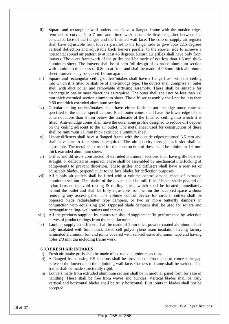
16 of 37
Section: HVAC Specifications
ii) Square and rectangular wall outlets shall have a flanged frame with the outside edges
returned or curved 5 to 7 mm and fitted with a suitable flexible gasket between the
concealed face of the flanges and the finished wall face. The core of supply air register
shall have adjustable front louvers parallel to the longer side to give upto 22.5 degrees
vertical deflection and adjustable back louvers parallel to the shorter side to achieve a
horizontal spread air pattern to at least 45 degrees. Return air grilles shall have only front
louvers. The outer framework of the grilles shall be made of not less than 1.6 mm thick
aluminum sheet. The louvers shall be of aero foil design of extruded aluminum section
with minimum thickness of 0.8mm at front and shall be made of 0.8mm thick aluminum
sheet. Louvers may be spaced 18 mm apart.
iii) Square and rectangular ceiling outlets/intakes shall have a flange flush with the ceiling
into which it is fitted or shall be of anti-smudge type. The outlets shall comprise an outer
shell with duct collar and removable diffusing assembly. These shall be suitable for
discharge in one or more directions as required. The outer shell shall not be less than 1.6
mm thick extruded section aluminum sheet. The diffuser assembly shall not be less than
0.80 mm thick extruded aluminum section.
iv) Circular ceiling outlets/intakes shall have either flush or anti smudge outer cone as
specified in the tender specifications. Flush outer cones shall have the lower edge of the
cone not more than 5 mm below the underside of the finished ceiling into which it is
fitted. Anti-smudge cones shall have the outer cone profile designed to reduce dirt deposit
on the ceiling adjacent to the air outlet. The metal sheet used for construction of these
shall be minimum 1.6 mm thick extruded aluminum sheet.
v) Linear diffusers shall have a flanged frame with the outside edges returned 3.5 mm and
shall have one to four slots as required. The air quantity through each slot shall be
adjustable. The metal sheet used for the construction of these shall be minimum 1.6 mm
thick extruded aluminum sheet.
vi) Grilles and diffusers constructed of extruded aluminum sections shall have grille bars set
straight, or deflected as required. These shall be assembled by mechanical interlocking of
components to prevent distortion. These grilles and diffusers shall have a rear set of
adjustable blades, perpendicular to the face blades for deflection purposes.
vii) All supply air outlets shall be fitted with a volume control device, made of extruded
aluminum section. The blades of the device shall be mill finish/ block shade pivoted on
nylon brushes to avoid rusting & rattling noise, which shall be located immediately
behind the outlet and shall be fully adjustable from within the occupied space without
removing any access panel. The volume control device for circular cutlets shall be
opposed blade radial/shutter type dampers, or two or more butterfly dampers in
conjunction with equalizing grid. Opposed blade dampers shall be used for square and
rectangular ceiling/ wall outlets and intakes.
viii) All the products supplied by contractor should supplement 'in performance by selection
curves of product ratings from the manufacturer.
ix) Laminar supply air diffusers shall be made of 2mm thick powder coated aluminum sheet
duly insulated with 5mm thick dosed cell polyethylene foam insulation having factory
laminated aluminum foil and joints covered with self-adhesive aluminum tape and having
holes 2/3 mm dia including frame work.
6.3.3 FRESH AIR INTAKES
i) Fresh air intake grills shall be made of extruded aluminum sections.
ii) A flanged frame using RS sections shall be provided on front face to conceal the gap
between the louvers and the adjoining wall face. Corners of frame shall be welded. The
frame shall be made structurally rigid.
iii) Louvers made from extruded aluminum section shall be in modular panel form for ease of
handling. These shall be free from waves and buckles. Vertical blades shall be truly
vertical and horizontal blades shall be truly horizontal. Butt joints in blades shall not be
accepted.
Page 155 of 266

17 of 37
Section: HVAC Specifications
iv) Additional intermediate equally spaced supports and stiffeners shall be provided to
prevent sagging/vibrating of the louvers, at not more than 750mm centers where the
louver's length is longer than 750rnm.
v) A bird wire screen made of 12 mm mesh in 1.6 mm steel wire held in angle or channel
frame shall be fixed to the rear face of the louver frame by screens.
6.4 FIRE DAMPERS
i) Fire dampers shall be provided in all the supply air ducts and return air ducts (where
provided), return air passage in the air-handling unit room and at all floor crossings.
Access door will be provided in the duct before each set of fire dampers.
ii) Fire dampers shall be multi blade louvers type. The blade should remain in the air stream
in Open position &shall allow maximum free area to reduce pressure drop &noise in the
air passage. The blades and frame shall be constructed with minimum 1.6mm thick
galvanized sheet &shall be factory fitted in a sleeve made out of 1.6mm galvanized sheet
of minimum 400mm long. It shall be complete with locking device, motorized actuator &
control panel.
iii) Fire dampers shall be motorized smoke &fire dampers type. It shall be supplied with
spring loaded UL stamped fusible link to close fire damper in the event of rise in duct
temperature. Fire damper shall also close on receipt of fire alarm signal to cut off air
supply instantaneously. An electric limit switch shall also be operated by the closing of
fire damper, which in turn shall switch off power supply to AHU blower motor as well as
strip heaters.
iv) Fire dampers shall be CBRI tested &certified for 90 minutes rating against collapse &
name penetration as per UL 555-1995(Under writers laboratories)
v) Fire dampers shall be compatible with the fire detection system of building & shall be
capable of operating automatically through an electric motor on receiving signal from fire
alarm panel.
vi) Necessary wiring from fire alarm panel up to AHU electric panel shall be provided by the
department & further from AHU electric panel to fire damper shall be provided by air
conditioning contractor.
VOLUME FLOW LIMITER (VFL)
General:
The design, construction, material and finishes of all the units shall be suitable for the
locations, climatic and operating conditions indicated in this specification and
drawings. The main objective of the VFL shall be to balance flow volume in
ventilation and air conditioning systems. Construction:
VFL should be made of high quality plastic material to UL94, V1 conforming to DIN4102,
fire rating Class B2. It should be mechanically powered, which shall include a control
damper, regulator spring and low friction, silicon free damper element. There should be a
provision of changing the flow setting at of the VFL, on site, incase required. Regulator
spring should be made of stainless steel. The regulation of the volume flow should be + 10
%, relative to maximum flow rate, in the pressure range from 30 to 300 Pa. It should be
tested for air handling and set to a reference volume flow in the factory. A lip seal
should be there to ensure a snug fit between the VFL and the round duct. It should
have the provision to be installed in any orientation.
Page 156 of 266

18 of 37
Section: HVAC Specifications
Installation:
Install air terminals units in positions shown in the drawings. Align and level all units. Fix all
units in the round ducts, by sliding it in the ducts on locations as shown on drawings. Ensure
adequate space is available around the units to allow inspection and maintenance of all
components in accordance with the manufacturer‟s recommendation. Stickers should be
affixed to the outside of the air duct in an easily visible position, so that the location of the
VFL‟s can be found, if required in future. Co-ordination of air terminal location shall be made
with the ceiling pattern, to ensure easy access in the future. Manufacturer‟s recommendations
on installation shall be followed. Commissioning:
Carry out static check on units, settings of volume flow, to ensure conditions are safe prior to
startup. Operate units to ensure all control components function correctly. The main objective
of the VFL shall be to balance flow volume in ventilation and air conditioning systems.
6.6 ACOUSTIC LINING AND INSULATION
i. SCOPE:
Supply and fix thermal insulation for ducting and equipment‟s as per the
specification described in this section.
ii. MATERIALS OF INSULATION:
Thermal insulation material for Duct insulation shall be closed cell cross linked polyethylene
foam. Thermal conductivity of the insulation material shall not exceed 0.032 W/moK at an
average temperature of 25oC. Density of the material shall be 25-30 Kg/m3. The product
shall have temperature range of –40 oC to 105oC. The insulation material shall be fire rated
for Class 1 as per BS 476 Part 6: 1989 for fire propagation test and as per BS 476 Part 7, 1987
for surface spread of flame test. Water vapour permeability as per DIN 52615 shall not
exceed 0.15ng/Pa.Sec.m.
Thermal conductivity of the material shall not be affected by ageing, as per DIN 52616. The
material must be tested for ageing effect in an acredited laboratory for a minimum
period of five years to satisfy the ageing criteria.
The smoke density of the material as per AS-1530.3 shall not exceed 1. There shall be no
toxicity in the emitted smoke, both under flaming and non-flaming conditions, as per AITM
3.000 (1993).
iii. PIPING INSULATION:
Insulation material shall be Closed Cell Elastomeric Nitrile Rubber.
Insulation material shall be self seal tubes.
Thermal conductivity of insulation material shall not exceed 0.035 W/(m.K) at mean
temperature of 0C as per EN ISO 8497.
Moisture Diffusion Resistance Factor or „µ‟ value of insulation material shall be minimum
Page 157 of 266

19 of 37
Section: HVAC Specifications
The insulation material shall be FM (Factory Mutual)
Density of insulation material shall be between 40 to 55 Kg/m3.
The insulation material shall be dust and fibre free.
The insulation material shall withstand maximum surface temperature of +105 Deg.C and
minimum surface temperature of 0 Deg.C
The material shall have ODP (Ozone Depletion Potential) and GWP (Global Warming
Potential) of Zero.
Thickness of the insulation shall be as specified for the individual application.
The insulation material - tubes shall be fully factory (machine) slit along each length with two
strips of double sided self adhesive tape pre-applied to each open slit surface. The self tape
adhesive shall be solvent free acrylic with high initial tack and high peel strength.
Out door pipe insulation should be protected by glass cloth or other weather proof protection
material for long lasting.
a) The thickness of piping insulation for various pipe sizes shall be as given below:
For refrigerant pipes of dia. 15to19 mm, 13mm thick Nitrile Rubber Insulation
For refrigerant pipes of dia. 22 mm - 38 mm , 19mm thick Nitrile Rubber Insulation
For refrigerant pipes of dia. 6to12 mm, 9mm thick Nitrile Rubber Insulation
For Drain pipes of dia. 20 mm- 50 mm , 6/9mm thick Nitrile Rubber Insulation
6.7 INSTALLATION OF METALLIC DUCT
6.7.1 DUCTING
i) The fabrication and installation shall be in a workman like manner. Duct work shall be
rigid and straight without kinks.
ii) All exposed ducts within the conditioned space shall have slip joints. Flanged joints shall
not be used.
iii) All joints shall be airtight.
iv) Ducts shall be supported independently from the building structure and adequately, to
keep the ducts true to shape. The support spacing shall be not more than 2m. Where ducts
cannot be suspended from ceiling, wall brackets or other suitable arrangements, as
approved by the Engineer-in-charge shall be adopted. Neoprene or other vibration
isolation packing of minimum 6mm thickness shall be provided between the ducts and the
angle iron supports/brackets. Vertical duct work shall be suitably supported at each floor
by steel structural members.
v) Where metal ducts or sleeves terminate in woodwork, tight joints shall be made by means
of closely fitting heavy flanged collars. Where ducts pass through brick or masonry
openings, wooden frame work shall be provided within the openings and the crossing
ducts shall be provided with heavy flanged collars on either side of the wooden frame
work, so that duct crossing is made leak-proof.
vi) Duct connections to the air-handling unit shall be made by inserting a double canvas
sleeve 100 mm long. The sleeve shall be securely bonded and bolted to the duct and unit
casing.
vii) Dampers shall be provided in branch duct connections for proper volume control and
balancing the air quantities in the system, whether indicated in the drawings or not.
Suitable links, levers and quadrants shall be provided for proper operation, control and
setting of the dampers. Every damper shall have an indicating device clearly showing the
position of the dampers at all times.
Page 158 of 266

20 of 37
Section: HVAC Specifications
viii) Where electrical heaters are mounted in the duct, these shall be of low temperature totally
enclosed type fitted with radiation fins. A removable panel for access to the heaters shall
be provided in the duct. Any hole in the duct for electrical wiring must be provided with
suitable bushes to avoid leakage. 6 mm thick asbestos board lining shall be provided all
around the inside of the duct for a distance of 30cm on either side of the electrical heaters.
A manually reset thermostatic safety switch shall be provided near the duct section
having heaters. In addition, the heaters must be interlocked with the connected fan motor
of the AHU.
6.7.2 AIR OUTLETS AND INLETS
i) The locations of the air outlets and intakes are shown in the tender drawings and
necessary openings and the wooden framework for fixing the grilles shall be provided by
the air conditioning contractor. The location of these outlets/ inlets is subject to change
and the approval of the Engineer-in-Charge shall be obtained before finally fixing the
grilles/diffusers in position.
ii) In installing fresh air intakes, no fixing device shall be visible from the face of the frame.
Where louvers are to be fixed in masonry or concrete, fixing shall be with either
expanding plugs or rawl plugs. Where the louvers are to be fixed in steel or wood, non-
ferrous screws or bolts shall be used.
iii) Supply air outlets and return air intakes shall be anodized/ powder coated aluminum to
the desired color to match the surroundings wall/ceiling. The fresh air intakes shall be
anodized/ powder coated aluminum as approved by the Engineer-in-Charge. The paint
color shall be approved by the Engineer-in-Charge.
iv) All damages to the finish of the structure during the installation work shall be made good
by the air-conditioning contractor before handing over the installation to the Department.
6.8 BALANCING
The entire air distribution system shall be balanced with the help of an anemometer. The
measured air quantities at fan discharge and at the various outlets shall be within ±5
percent of those specified/ quoted. Branch duct adjustments shall be permanently
marked after the air balancing is completed so that these can be restored to their
correct position if disturbed at any time.
6.9 MEASUREMENT
i) Duct measurements (for insulated ducts) shall be taken before application of insulation.
ii) Duct work shall be measured section wise on the basis of external surface area by
multiplying the axial length from flange face to flange face for each section by the
corresponding duct perimeter in the centre of that section length.
iii) Uniformly tapering straight sections shall also be measured as in (ii) above. However, for
special pieces like tees, bends etc. area computations for surface areas shall be done as
per the shape of such pieces.
iv) The quoted unit rate for external surfaces of ducts shall include all wastage allowances,
flanges, gaskets for joints, vibration isolators, bracings, hangers and supports, inspection
chambers/access panels, splitter dampers with quadrants and levers for position
indication, turning vanes, straightening vanes, and all other accessories required to
complete the duct installation as per the specifications. These accessories shall not be
separately measured.
v) Grilles and diffusers (except linear diffusers) shall be measured by the cross sectional
areas, perpendicular to the airflow, and excluding the flanges. Volume control dampers,
where provided shall not be separately accounted for.
vi) Linear diffusers shall be measured by linear measurements only, and not by cross
sectional areas, and shall exclude flanges for mounting of the linear diffusers. The supply
air plenum for linear diffusers shall be measured as described above for ducting.
Page 159 of 266

21 of 37
Section: HVAC Specifications
vii) Fire dampers shall be measured by their cross sectional area perpendicular to the direction
of the airflow. Quoted rates shall include the necessary collars and flanges for mounting,
inspection pieces with access door, fusible link/solenoid with wiring, but excluding the
fire detectors, etc.
7.0 FACTORY FABRICATED PRE-INSULATED DUCTING
The Phenolic panels shall be manufactured of CFC free closed cell phenolic foam
protected with 28 micron aluminum foil facing reinforced with fibreglass scrim on both
sides.
The thermal conductivity shall not be more than 0.020 W/m and the density of the
phenolic foam shall not be less than 55-60kg/m3.
The compressive strength shall not be less than 295kN/m2 and the flexural strength shall
be an average of 1423kN/m2 when tested with ASTM C203.
The Ducting System complies with the following tests to British, European and American
standards as required by the Building Regulations:
Fire
BS 476 Part 6 Fire Propagation
BS 476 Part 7 Surface Spread of Flame
Performance results in the above tests achieve a Class O rating, as required by the
Building Regulations.
Smoke
BS 6401 Smoke Opacity
The Mean Optical Density (flaming mode) = 7
The Mean Optical Density (non-flaming mode) = 1
Reaction to Fire Classification
EN 13501: C – S2, Do
Fire and Smoke Developed Index
UL 181
Performance results in the above tests achieve a Class A rating according to NFPA 101
Life and Safety Code.
A Phenolic panel duct shall be tested for air leakage by BSRIA Laboratory confirmed
performance to DW 144 Class C (high pressure) standards.
Phenolic foam ducting system has fully complied with NFPA 90A, USA Standard for the
Installation of Air-conditioning and Ventilation System.
Ductworks shall be installed using supports, as described in DW144 & according to
manufacturer‟s requirements. Maximum distance between supports not exceeds:
4000mm for ducts with section not exceeding 1200 x 1000mm.
2000mm for ducts with section exceeding 1200 x 1000mm.
7.1 BALANCING
The entire air distribution system shall be balanced with the help of an anemometer. The
measured air quantities at fan discharge and at the various outlets shall be within ±5
percent of those specified/ quoted. Branch duct adjustments shall be permanently
marked after the air balancing is completed so that these can be restored to their
correct position if disturbed at any time.
Page 160 of 266

22 of 37
Section: HVAC Specifications
PART IV - MECHANICAL VENTILATION SYSTEM
11.1 SCOPE
This chapter includes supply air fan, exhaust air fan. Specification for all associated
works such as ducting and plumbing, works etc. are same as for air-conditioning
works covered under this part and all associated electrical works to be considered
from electrical specifications.
11.2 CENTRIFUGAL FANS
11.2.1 DIDW FANS
i) Centrifugal fans shall be of double-width, double-inlet construction, with bearing on both
sides, complete with access door, squirrel-cage induction motor, V-belt drive, belt guard
etc.
ii) Housing shall be of heavy gauge sheet steel in welded construction. It shall be rigidly
reinforced and supported by structural angles. Split casing shall be provided on larger
sizes of fans. However neoprene/ asbestos packing shall be provided throughout split
joints to make it airtight. 1.2 mm galvanized wire mesh inlet guard, of 5cms sleeves shall
be provided on both inlets. Housing shall be provided with access door with quick
locking tension handles and neoprene gasket. Rotation arrow shall be clearly marked on
the housing.
iii) Fan wheel shall be backward curved non-overloading type unless otherwise specified.
Fan wheel and housing shall be statically and dynamically balanced. Fan outlet velocity
shall not exceed 610 meters per minute.
iv) Shaft shall be constructed of steel, turned, ground and polished.
v) Bearings shall be of the sleeve/ball bearing type mounted directly on the fan housing.
Bearing shall be self-aligned, oil grease packed, pillow block type.
vi) Drive to fan shall be provided from 3 phase electric motor through belt with adjustable
motor sheave and belt guard. Belt shall be of the oil resistant type. The number of belts
shall be not less than two.
vii) The fan motor shall be totally enclosed fan cooled squirrel cage induction motor with IP-
54 protections & selected for quiet running. The motor shall be suitable for operation on
415 ± 10%V, 3 phase, 50 Hz, A.C. supply. The motor shall conform to IS: 325. "Three
phase induction motors" having class F insulation. The Fan motor shall be energy
efficient with efficiency level of IE-3 or EFF1 whichever is more efficient and it shall
be ECBC compliant. viii) Motor starter shall be in accordance with Electrical specifications.
11.3 AXIAL FLOW FANS
i) Casing shall be constructed of heavy gauge sheet steel. Casing shall be provided with
hinged door enabling easy replacement of wheel, shaft and bearings. A small inspection
door with handle and neoprene gasket shall also be provided. Casing shall have flanged
connection on both ends for ducted applications. Support brackets for ceiling suspension
shall be welded to the casing for connection to hanger bolts.
Straightening vanes shall be aerodynamically designed for maximum efficiency by
converting velocity pressure to static pressure potential and minimizing turbulence.
Casing shall be de-rusted, cleaned, primed and finish coated with enamel paint.
ii) Rotor hub and blades shall be of cast aluminum, or cast steel construction. Blades shall be
die-formed aero foil shaped for maximum efficiency and shall vary in twist and width
from hub to tip to effect equal air distribution along the blade length. Fan blade mounting
on the hub shall be statically and dynamically balanced. Extended grease leads for
Page 161 of 266

23 of 37
Section: HVAC Specifications
external lubrication shall be provided. The fan pitch control may be manually read just
able at site, upon installation, for obtaining actual airflow values, as specified.
iii) Motor shall be of 3 phase squirrel-cage totally enclosed, fan cooled type. Motor and
starter shall be in accordance with Electrical specifications. The speed of fan shall not
exceed 1000 RPM for fans with impeller diameter above 450mm, and 1450RPM for fans
with impeller diameter of 450mm and less. The Fan motor shall be energy efficient
with efficiency level of IE-3 or EFF1 whichever is more efficient and it shall be
ECBC Compliant.
iv) Drive
FOR DUCT/WALL MOUNTED FAN:
For duct/wall mounted fans the impeller shall be mounted directly on the motor. Drive
unit and impeller shall be totally enclosed inside the duct.
FOR FLOOR/CEILING MOUNTED FAN:
The fan shall be provided with belt drive and adjustable motor sheave, standard sheet
steel belt guard with vented front for heat dissipation. Belt shall be of the oil resistant
type.
v) Vibration Isolation
Base shall be provided for each fan. Base for both fan and motor shall be built as an
integral part and shall be mounted on a concrete foundation through cushy foot vibration
isolators. The concrete foundations shall be at least 15 cm above the finished floor level
and shall be further isolated from the structural floor through 5 cm. Thick layers of sand
all around, topped with bitumen. In case ceiling hung fan within the ceiling shall be
provided Vibration Isolation Suspension (VIS) shall be provided in each of string.
vi) All the fans operating only in case of Smoke/ Fire shall be without the straightening vanes
whereas all the other fans shall be with the straightening vanes. All the Fans with
Straightening Vanes shall not have noise level more than 75 DB at 3 meter distance from
source and all the Fans without Straightening Vanes shall not have noise level more than
85 DB at 3 meter distance from source. All the noise levels shall be selected and checked
at room conditions.
vii) The fans should be AMCA certified for air performance and the fan should be selected
for maximum efficiency. The Tube axial fans without Vanes should be AMCA certified
for sound performance. All the fans for exhaust purpose should be rated for a minimum of
250 Deg C for a minimum of 2 Hrs. applications.
11.4 PROPELLER FANS
i) Propeller fans shall be direct-driven, three or four blade type, mounted on a steel mounting
plate with orifice ring.
ii) Mounting plate shall be of heavy gauge sheet steel construction, streamlined venturi inlet
(reversed) for supply applications. The mounting size shall suit the fan size.
iii) Fan blades shall be constructed of aluminium or steel. Fan hub shall be of heavy welded
steel construction with blades bolted to the hub. Fan blades and hub assembly shall be
statically and dynamically balanced at the factory.
Page 162 of 266

24 of 37
Section: HVAC Specifications
iv) Motor shall be standard (easily replaceable) single phase, permanent split capacitor or
shaded pole for small sizes, totally enclosed with pre-lubricated sleeves or ball bearings,
designed for quiet operation with a maximum speed of 1000 RPM for fans of 32 cm. dia or
larger and 1440 rpm for fans of 31 cm. dia and smaller. Motors for larger fans shall be
suitable for 415 ± 10% volts, 50 cycles, 3 phase, power supply. Motors shall be suitable for
either horizontal or vertical services, as indicated in drawing/ schedule of quantities. The fan
motor shall be energy efficient.
v) The following accessories may be required and provided with propeller fans, as indicated in
the tender specifications.
a) Wire guard on inlet side and bird screen at the outlet.
b) Gravity operated louver shutters built into a steel frame.
c) Regulators for controlling fan speed for single phase fan motors.
11.5 PAINTING
All equipment shall be supplied with the manufacturer's standard finished painting.
12 CO SENSOR FOR VENTILATION FANS
The CO Sensor shall be microprocessor based device. The CO detector shall sense the level
of carbon monoxide particle in the air of parking area and shall transmit the proportional
signal to Main controller for the control of ventilation / exhaust equipment and shall provide
early warning of hazardous concentration of Carbon monoxide. The detector shall cover
minimum range of 0 - 250 PPM for solid state and 0 – 500 PPM for electro chemical state.
The detector shall have Led indicator.
The detector shall operate in the temperature range of 0 - 50 Deg.C and humidity range of
95 %.
The detector shall be calibrated as per field conditions.
The detector shall have 2 LEDs for normal and failure indication.
Accuracy level in the range of +/- 1% to be maintained.
Any voltage transformation required shall be part of scope.
Sensor capable to sense co level and sed command to operate normal /smoke fan.
13 AIR WASHERS
13.1 The packaged air washers shall be of G.I. Sheet metal constructions and shall include fan
section, cooling pad section, motor drive etc.
Enclosure/Housing
13.1.1 The enclosure shall be Single skin design with the main frame work made of GI structural
section.
13.1.2 The panels shall be of 1.6mm dully painted GI sheet
13.1.3 The front panels shall be easily openable for servicing the fan and motor.
13.1.4 The opening for access doors and gaps between sections shall be provided with the neoprene
rubber gaskets fixed in grooves in the extruded sections.
Page 163 of 266

25 of 37
Section: HVAC Specifications
13.1.5 The panels shall be fixed to the frame work with self tapping stainless steel screws and both
ends of the screw shall be provided with rubber caps.
13.1.6 The access door to fan section is to be provided with a switch to shut off the fan when the
door is to be opened.
13.2 Fan Section
The impellers of the blowers of fans shall be of G.I sheets, double inlet forward / backward
curved centrifugal design, both statically and dynamically balanced. The fan housing shall be
of sturdy construction made from 16 G G.I sheet with smooth air inlets. The fans shall be
mounted on properly aligned shafts and mounted on self aligning bearing blocks. The casing
of the fan section shall be made 16 G G.I sheets suitably reinforced to provide rigidity. The
frame work shall either be folded G.I sheets or of hot dipped Galvanized Angle Iron. The fan
section shall be complete with multi „V‟ belt drive, belt guard and adjustable motor mounting
base for mounting motor inside the fan section.
13.3 Cooling Pad
The cooling pads shall be honey comb design to provide extended and sufficient wetted
surface to give a water absorbing efficiency of at least 90% at air velocity of 500 fpm
(2.5m/s). The cooling pads shall be made of acetate paper / cellulose. The cross section and
depth shall be sufficient for specified efficiency. The cooling pad section shall be 16 G G.I
provided with one set of air filters. It shall be complete with galvanized angle supports for
mounting the pads and a water distribution through the uniform supply of water over the
entire surface.
13.4 Water Sump
The water sump below the pad section shall be of 3 mm thick MS, with 2mm FRP reinforced
inside. The tank shall be complete with make-up, overflow, and quick fill and drain
connections. A float valve shall be provided for makeup water line.
13.5 The pump set shall be of monobloc construction, with end suction and top discharge flanged
connections, cast iron impellor and casing all mounted directly on a squirrel cage, drip droof
induction motor.
13.6 Miscellaneous
Necessary accessories shall be provided for air washers, wherever required for proper
efficient operation and shall also include then following.
13.6.1 PVC eliminator to avoid water drift fixed to the cooling pad housing and tank.
13.6.2 Necessary G.I piping/PVC for water circulation.
13.6.3 Vibration isolators for the Blowers & Pumps.
13.6.4 Hardware like Nuts, bolts, shims etc., as required for the grouting /assembly of Equipment.
13.6.5 Float valve in the water tank, along with quick fill connection.
13.6.6 Gate valves in drain; make up, quick fill line etc, as required.
Page 164 of 266

26 of 37
Section: HVAC Specifications
13.6.7 Built in isolator switches for the fan and pump motor set and wiring from the isolator
upto the respective motors. Toggle switch for pump on /off
13.6.8 Necessary arrangement to be made in case access door open, fan motor should stop
automatically.
14.0 KITCHEN SCRUBBER
14.1 The packaged scrubber shall be of G.I sheet metal casing with air intake section, scrubber
section, fan section with drive motor etc.
14.2 Enclosure/Housing : The housing shall be Single casing in16 gauge GSS
14.3 Air Intake Section : Air intake shall consist of I6G GI removable wire mess filter
section.
14.4 Scrubber Section : The scrubber section shall consist of 3mm thick MS plate tank hot
dipped galvanized, brass nozzles, GI pipe spray headers internal GI
distribution plate 4 bend PVC eliminators
14.5 Fan Section : The impellers of blower shall be GI sheet double inlet double width
backward curved centrifugal design with GI sheet housing (16G) and
air inlets. The fan frame work shall be made of folder GI sheets or of
hot dipped angle. The fan section will be complete in the V-belt drive
belt guard and adjustable mounting base inside in fan section.
14.6 Miscellaneous : Necessary accessories shall be provided as required and
shall Include in following
14.6.1 Necessary GI/Pvc piping for water circulation
14.6.2 Vibration isolators for blower and pump
14.6.3 Float valve in water connection, and drain connection
14.6.4 Gate valves in drain, makeup, quite fell as required
14.6.5 Necessary arrangement to stop fan motor in case door is open
14.6.5 Toggle switch for pump On/off.
15 Limitation
The air velocity limits are as follows:-
i) Velocity across cooling pads scrubber shall not exceed 2.54 M/s (500 FPM).
ii) Velocity at blower outlet shall not exceed 10.16 M/s (2000 FPM)
Page 165 of 266

27 of 37
Section: HVAC Specifications
16. HEAT RECOVERY UNITS
a. SCOPE
The scope of this section comprises of the supply of double-skin “Heat recovery Units is
conforming to the following specifications.
b. TYPE
The Heat recovery units shall be two stream units in double skin construction thermal break,
comprising of supply air section, return air section and Heat Recovery Section. The supply air
section shall include Inspection Section.
c. CAPACITY
The Heat recovery units shall be of such capacities and static pressures as mentioned in the
Bill of Quantities.
d. CASING
The housing/ casing of the heat recovery unit shall be of double skin construction. The
housing shall be so made that it can be delivered at site in total semi knocked down conditions
depending upon the requirements. The main framework shall be of suitable structural
sections. The entire framework shall be assembled using mechanical joints to make a sturdy
and strong framework for various sections. Framework of all heat recovery units shall be
made of thermal break hollow extruded aluminum profile. In case of HRU casing design with
no contact between inner and outer surface, thermal break profiles can be avoided.
Double skin panels shall be minimum 25mm thick made of 0.8mm (Both inner and outer
Sheets) with polyurethane foam insulation of density not less than 38 kg/cum injected in
between by injection moulding machine. These panels shall be joined and connected to the
framework/ supports with soft rubber gasket in between (if necessary) to make the joints
airtight and low air leakage potential. The gaskets shall be inserted within groove in extruded
aluminum profile of the framework. For units installed outdoor, the thickness of double skin
panels shall be minimum 40 mm.
Frame work for each section shall also be joined together to make the joints air tight. Suitable
doors with nylon handles and all access panels should be openable with allen key/ suitable
locking arrangement. Aluminium die-cast powder coated/ Nylon hinges & latches shall be
provided for access to various panels for maintenance. However, AHU in the form of
complete single unit shall also be acceptable with access door(s) for maintenance to various
sections. The entire housing shall be mounted on galvanized steel channel frame work made
out of G.I. sheet of thickness not less than 2mm. For higher capacity AHUs hot dip
galvanized steel channel framework made of minimum 3 mm thick G.S. sheet shall be used.
The Inspection and access panels shall be hinged type. The hinges shall be casted, powder
coated Zinc alloy. Flushed Locks and Handles shall be of galvanized steel. Other panels will
be screwed on to the frame with sealant and soft rubber gasket thus making the joints air tight.
All screws used for panel fixing shall be covered with PVC caps.
Special gaskets and seals shall be used on inspection doors and to create separation between
the airstreams to ensure negligible air leakage and mixing.
e. SUPPLY AIR SECTION
The supply air section shall comprise of the following:-
i. FAN SECTION
Page 166 of 266
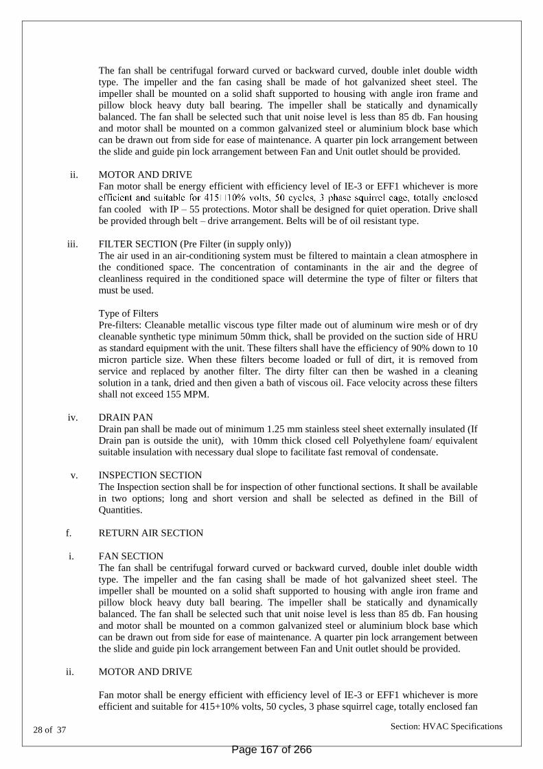
28 of 37
Section: HVAC Specifications
The fan shall be centrifugal forward curved or backward curved, double inlet double width
type. The impeller and the fan casing shall be made of hot galvanized sheet steel. The
impeller shall be mounted on a solid shaft supported to housing with angle iron frame and
pillow block heavy duty ball bearing. The impeller shall be statically and dynamically
balanced. The fan shall be selected such that unit noise level is less than 85 db. Fan housing
and motor shall be mounted on a common galvanized steel or aluminium block base which
can be drawn out from side for ease of maintenance. A quarter pin lock arrangement between
the slide and guide pin lock arrangement between Fan and Unit outlet should be provided.
ii. MOTOR AND DRIVE
Fan motor shall be energy efficient with efficiency level of IE-3 or EFF1 whichever is more
fan cooled with IP – 55 protections. Motor shall be designed for quiet operation. Drive shall
be provided through belt – drive arrangement. Belts will be of oil resistant type.
iii. FILTER SECTION (Pre Filter (in supply only))
The air used in an air-conditioning system must be filtered to maintain a clean atmosphere in
the conditioned space. The concentration of contaminants in the air and the degree of
cleanliness required in the conditioned space will determine the type of filter or filters that
must be used.
Type of Filters
Pre-filters: Cleanable metallic viscous type filter made out of aluminum wire mesh or of dry
cleanable synthetic type minimum 50mm thick, shall be provided on the suction side of HRU
as standard equipment with the unit. These filters shall have the efficiency of 90% down to 10
micron particle size. When these filters become loaded or full of dirt, it is removed from
service and replaced by another filter. The dirty filter can then be washed in a cleaning
solution in a tank, dried and then given a bath of viscous oil. Face velocity across these filters
shall not exceed 155 MPM.
iv. DRAIN PAN
Drain pan shall be made out of minimum 1.25 mm stainless steel sheet externally insulated (If
Drain pan is outside the unit), with 10mm thick closed cell Polyethylene foam/ equivalent
suitable insulation with necessary dual slope to facilitate fast removal of condensate.
v. INSPECTION SECTION
The Inspection section shall be for inspection of other functional sections. It shall be available
in two options; long and short version and shall be selected as defined in the Bill of
Quantities.
f. RETURN AIR SECTION
i. FAN SECTION
The fan shall be centrifugal forward curved or backward curved, double inlet double width
type. The impeller and the fan casing shall be made of hot galvanized sheet steel. The
impeller shall be mounted on a solid shaft supported to housing with angle iron frame and
pillow block heavy duty ball bearing. The impeller shall be statically and dynamically
balanced. The fan shall be selected such that unit noise level is less than 85 db. Fan housing
and motor shall be mounted on a common galvanized steel or aluminium block base which
can be drawn out from side for ease of maintenance. A quarter pin lock arrangement between
the slide and guide pin lock arrangement between Fan and Unit outlet should be provided.
ii. MOTOR AND DRIVE
Fan motor shall be energy efficient with efficiency level of IE-3 or EFF1 whichever is more
efficient and suitable for 415+10% volts, 50 cycles, 3 phase squirrel cage, totally enclosed fan
Page 167 of 266

29 of 37
Section: HVAC Specifications
cooled with IP – 55 protections. Motor shall be designed for quiet operation. Drive shall be
provided through belt – drive arrangement. Belts will be of oil resistant type. The drive and
motor shall be provided outside the air path.
The tank shall be of stainless steel sheet of thickness not less than 1.2mm, having necessary
arrangement for inlet water with float valve over flow and drain arrangement.
g. HEAT RECOVERY SECTION
The Heat Recovery section shall include enthalpy Plate and shall have minimum recovery of
75 % of total heat, i.e both sensible and latent(each being 75 %). The recovery of sensible
and latent shall be equal. Necessary computerized selection of the plate should be provided
alongwith the bid to justify the same.
h. HEAT RECOVERY UNIT SPECIFICATIONS:
a) quick and efficient uptake of thermal energy.
b) sufficient mass for optimum heat transfer
c) maximum sensible heat recovery at a relatively low rotational speed of 20 to 25 rpm.
Non metallic substrates made from paper, plastic, synthetic or glass fibre media, will
therefore, not be acceptable.
The support shall not be made from any material which is combustible or supports
combustion like synthetic fibrous media.
The plate has to be certified as per DIN EN ISO 846 with 0% fungal and bacterial growth at
95% Relative humidity and above.
The plate should be AHRI & UL certified
Pressure drop:
The presure drop across the rotary heat exchanger shall not exceed 0.1 inch for every 100
FPM face velocity, or part thereof, for the minimum stated/ required latent recoveries /
efficiencies
Page 168 of 266

30 of 37
Section: HVAC Specifications
PART V - INSPECTION, TESTING AND COMMISSIONING
12.1 SCOPE
This chapter covers initial inspection and testing of compressor, condenser, IDU and ODU at
manufacturer's works, initial inspection of other equipments/ materials on receipt at site, final
inspection testing & commissioning of all equipment at site &description of testing
requirements & procedure.
12.2 INITIAL INSPECTION AT MANUFACTURER'S WORKS
12.3 INITIAL INSPECTION AT SITE
12.3.1 DUCTING
i) The sheet used for ducting shall be checked for physical test at site. The physical test
should include the sheet thickness and bend test as per relevant IS specifications.
ii) Zinc coating of GSS sheet as mentioned in the tender documents may be got tested from a
laboratory to verify that same meets the contract requirements.
12.3.5 Electric motors should be of specified make, manufacturer's test certificate for electric motor
shall be furnished.
12.3.7 INSULATION AND ACOUSTIC LINING
i) Physical verification for thickness and make should be made as per contract before
application of insulation.
ii) Manufacturer's test certificate for density should be furnished. Note: Accuracy of testing
instruments shall be as mentioned in the final inspection procedure.
Page 169 of 266

31 of 37
Section: HVAC Specifications
APPENDIX-F
PROFORMA FOR SCHEDULE OF TECHNICAL PARTICULARS
(A) SCROLL COMPRESSOR:
1. Manufacturer
2. Model
3. Type
(a) Refrigerant
(b) Weight of refrigerant per unit
4. Operating speed (RPM)
5. Type of drive and speed ratio
6. Out put in TR and input power consumption in KW, at the selected operating
conditions % of Load Input
7. Type of capacity control
8. Capacity control range
9. Type of lubrication
10. Operating weight (Kg.)
11. Overall dimensions of the machine
12. Compressor motor
i) Make
ii) Rated output
iii) Working voltage range.
iv) Type of enclosure
v) Class of insulation
vi) Speed
vii) Full load current
viii) Starting current
ix) Efficiency
x) Power factor
xi) Temperature rise over ambient of 45 deg C.
13. List of Safeties/protection provided.
i) Motor over current
ii) Over voltage
iii) Under voltage
Iv) Single cycle dropout/ intermittent power loss
v) Baring oil high temperature
vi) Low evaporator refrigerant temperature
vii) High condenser refrigerant pressure
viii) High motor temperature
ix) Prolonged surge in compressor
x) Compressor starter faults
xi) Star-to-start and stop-to-stop timers for motor protection against rapid
recycling
xii) Low lubricating oil pressure
14. Details of all the functions of Microprocessor control system are to be enclosed.
Whether enclosed- Yes/No.
Page 170 of 266

32 of 37
Section: HVAC Specifications
(B) CONDENSER:
1. Manufacturer
2. Type of fins.
3. Pressure drop at above velocity
4. Condensing Temp (deg C)
5. Tube material
6. Tube outside diameter (mm)
7. Tube thickness (mm)
8. Tube surface. inside (sq.m.)
9. Tube surface. outside (sq.m.)
(C) ELECTRICAL
1. Motors (Give separate particulars for each application)
(i) Manufacturer
(ii) Type and frame reference
(iii) Rated output (KW)
(iv) Range of working voltage (V)
(v) No. of phases
(vi) Rated frequency
(vii) Rated speed (RPM)
(viii) Full load current (amps)
(ix) Class of insulation
(xi) Type of bearings
2. Motor starters (Give separate particulars for each application):
(i) Manufacturer
(ii) Type
(iii) Rating
(iv) Whether the following protections are provided
(a) Over load
(b) Under voltage
(c) Single phase prevention (for 3phase motor starters)
3. Switch board:
(i) Manufacturer
(ii) Type
4. Circuit Breaker
(i) Manufacturer
(ii) Type
(iii) Rated normal current (amps)
(iv) Short circuit ratting (MVA)
(v) Whether following are provided
(a) OIL trip
(b) ElF trip
(c) Under voltage trip
5. Measuring Instruments:
(i) Manufacturer
(ii) Range
(iii) Dial size
(iv) Glass Index
Page 171 of 266

33 of 37
Section: HVAC Specifications
(D) CONTROLS:
1. Make and type of thermostats
2. Make and type of humidistats
3. Make and type of damper motor
4. Make and type of other control components
(E) INSULATION (For each application)
1. Manufacturer
2. Material and density
3. „K' value at 10 deg C mean temperature
4. Thickness.
Page 172 of 266

34 of 37
Section: HVAC Specifications
APPENDIX-G PROFORMA FOR RESU & NOTES ON TEST INSTRUMENTS AND CAPACITY COMPUTATIONS
S.NO. ITEM TEST RESULTS
1 Ambient Conditions D.B Temp. -deg C
W.B Temp -deg C
%RH
2 Compressors R.P.M
Suction Pressure -Kg/Sq.cm
Discharge pressure -Kg/Sq.cm
Oil pressure -Kg/Sq.cm
3 Compressor Motors R.P.M
Voltage -Volts
Current
(i)at 100% load -amps
(ii)at partial load
(a) -amps
(b) -amps
(c) -amps
4 Fresh Air intakes Face area -sq.m
Air quantity -Cu.m/min
5 Room Conditions At The Working Plane(No.
of Readings Should Be Taken And Average
Out)
Temperature
D.B -deg C
W.B -deg C
Page 173 of 266

35 of 37
Section: HVAC Specifications
APPENDIX-H
MAINTENANCE
The section covers the maintenance schedule during warranty period and 1 yrs subsequent to
the warranty period.
The maintenance provided during the warranty period shall be fully comprehensive and shall
include but not limited to all equipments, labour part and emergency calls providing and site
response within 24 hours. However during the maintenance period after the warranty is over,
the materials shall be arranged by the department if any replacement is warranted. However
consumable materials shall be arranged by the department during 6 yrs period including that
of warranty period.
The maintenance shall also include a minimum of 12 monthly preventive maintenance visits
by qualified personnel who are thoroughly familiar with the type of equipment and system
provided for this project.
Page 174 of 266

36 of 37
Section: HVAC Specifications
ADDITIONAL CONDITIONS
1.0 GENERAL
1.1 This specification covers manufacture, testing as may be necessary before dispatch, delivery
at site, all preparatory work, assembly and installation, final testing, commissioning,
operation & maintenance of plant for six years including one year guarantee period for the
following work.
1.2 Name of Work: OFFICE OF NCB
1.3 The work shall be executed as per Above given specifications, CPWD General Specifications
for HVAC Works 2004, CPWD General Specifications for Electrical Works Part I, II &IV as
amended upto date, relevant IE rules, relevant IS and as per directions of Engineer-in-Charge.
These additional specifications & conditions are to be read in conjunction with above and in
case of variations; specifications given in the Additional specifications & conditions shall
apply. However, nothing extra shall be paid on account of these as the same are to be read
along with schedule of quantities for the work.
2.0 INSPECTION AND TESTING
Initial Inspection at works and final inspection and testing at site shall be carried out as per
chapter XII, CPWD General Specification for HVAC works 2004 as amended to date.
3.0 COMPLIANCE WITH REGULATIONS AND INDIAN STANDARDS, INDEMNITY
& INSURANCE
All works shall be carried out in accordance with relevant regulation, both statutory and those
specified by the Indian Standards as detailed in Para __ &__ of CPWD General Specifications
for HVAC work -2004.
4.0 OPERATION & MAINTENANCE
The maintenance during one year warranty period &subsequent five years shall be as per
appendix H. A separate supplementary agreement shall be made with the successful tenderer
for sub head "Operation and Maintenance (for 6 years including one year guarantee period)"
of schedule of work. The payment for operation & maintenance shall be made monthly after
the end of each month.
Page 175 of 266

37 of 37
Section: HVAC Specifications
INTRODUCTION AND SCHEME
1.0 INTRODUCTION
The proposed OFFICE is to be located at LUCKNOW, UTTAR PRADESH.
2.0 DESIGN DATA
2.1 OUTSIDE CONDITIONS
DB(°C) WB(°C)
a) Summer 42.2 23.8
b) Monsoon 33.3 28.8
c) Winter 6.0 5.2
2.2 INSIDE DESIGN CONDITIONS (Summer & Monsoon)
DB(°C) RH(%)
a) OFFICES AREA 23.8 50-60
b) DATA CENTER 21 45-55
2.3 Fresh air quantity for air-conditioned areas shall be considered from ASHRAE.
2.4 MECHANICAL VENTILATION SYSTEM
Plant Room & Pump Room : 15 air changes per hour
Panel Room : 15 air changes per hour
Toilet & Pantry : 10 air changes per hour
3.0 SCHEME
The scope of this tender document is to install followings:
Main AC plant including VRV piping
Low side HVAC system
Electrical provisions and Refrigerant and drain piping, Ventilation system.
The HVAC system comprises of VRV type air conditioning system including ventilation
system for OFFICE, ventilation system for parking, service area & precision Ac for data
centre.
VRV system shall consist of ODU, IDU condensate drain water piping, , Exhaust fans, heat
recovery units, ducting etc.
4.0 DRAWINGS
4.1 Following drawings are enclosed
a) HVAC System layouts
b) VRV SLD
c) HVAC electrical Panels SLD
4.2 No other drawings shall be made available. The contractor may visit the site or discuss with
Engineer-in-charge for any other site particular that he may need before submitting the tender.
4.3 Drawings have been prepared showing the areas to be Air conditioned & space allocated for
the equipment. The equipment offered should be checked &confirmed by tenderer.
Page 176 of 266

38 of 37
Section: HVAC Specifications
4.4 The above drawings represent a feasible scheme. Equipment layout, VRV piping scheme,
duct layout, sizes of grilles etc. shown in the drawings can be rearranged/ changed as per site/
Architectural requirements in consultation and with prior approval of Engineer-in-charge.
4.5 These are not working drawings. The contractor shall prepare detailed working drawings
&execute the work as per working drawings approved by the Engineer-in-charge.
Page 177 of 266

Section: Fire Fighting Specifications
WAPCOS Limited
A-71, 7th Floor, Himalaya House, 23, Kasturba Gandhi Marg
New Delhi-110001
FIRE FIGHTING SPECIFICATIONS
FOR
CONSTRUCTION OF OFFICE CUM RESIDENTIAL COMPLEX
FOR NARCOTICS CONTROL BUREAU AT LUCKNOW,
UTTAR PRADESH.
TENDER NO: WAP/PMD/2016-17/12
Page 178 of 266

Section: Fire Fighting Specifications
SPECIFICATIONS
1.0 Scope of Work 1.1 The scope of work for the Work consists of the following, but is not limited to the
same : 1.1.1 Hydrant System consisting of Internal Hydrant Risers cum Down Commer,
External Hydrant Ring, Hydrant Stations with all accessories such as Hydrants, Hoses, First Aid Hose Reel, Branch Pipe etc.
1.1.2 Pumping System consisting of Hydrant Pump, Sprinkler Pump, engine operated
Standby Pump, Jockey Pump and equipments such as Valves, strainers, piping. Instrumentation and Motor Starting System.
i. Sprinkler System for the Building. All areas shall be protected by Sprinkler System.
ii. Supply of Fire Extinguishers.
iii. Exit Signages.
iv. Providing cable seals and fire barriers.
v. Taking Approval from Local Fire Authority for the works of Fire Fighting and Fire Alarm Systems carried out by the Contractor.
Page 179 of 266

Section: Fire Fighting Specifications
1.2 HYDRANT SYSTEM 1.2.1 The Assembly Building shall be protected by Internal Hydrants on all Floors. 1.2.2 On each Floor with each Riser there shall be a Hydrant Station having one
number Hydrant, 2 nos. RRL Hose and a Branch Pipe. The Hydrant Station shall also be provided with a First Aid Hose Reel consisting of a 36 metre length 20 mm dia double braided rubber hose wound on a drum bracket with aluminium alloy bracket and piping. This set shall be connected to the Hydrant Riser through a 25 mm dia Ball Valve.
1.2.3 The Terrace shall have an Air Vessel with drain and Pressure Guage to absorb
pressure surges and water hammer effect when any of the main pumps start. 1.2.4 All internal piping shall be Mild Steel and shall have welded jointing for pipes
above 50 mm dia. External pipe shall be galvanised iron and treated for corrosion. 1.3 PUMPING SYSTEM 1.3.1 To cater for the Hydrant and Sprinkler Systems, the following pumps are being
provided :
No.
Pump Type
Discharge
Drive
1.
Hydrant Pump
2850 LPM
Electric
2.
Sprinkler Pump
2850 LPM
Electric
3.
Jockey Pump 2 nos
180 LPM
Electric
1.3.2 Other than the Sprinkler Pump, all other Pumps shall be able to feed both the
Hydrant and Sprinkler System. 1.3.3 Each Pump shall have a Gate Valve on the Suction Side as well as Gate Valve
and Non Return Valve on the Delivery Side. The Delivery of each Pump shall be connected to the Common Delivery Header.
1.3.4 The Pumps shall be single stage type coupled to motor and at 1450 RPM. The
Diesel Engine driven pump shall be 1450 RPM. The Engine shall be multi cylinder Heat Exchanger cooled type. All Pumps shall have mechanical seal.
1.3.5 There shall be common Strainers on the Suction manifold with stainless steel
mesh to segregate the debris. The Strainers shall have top lift removable flange for cleaning.
1.3.6 An Air Vessel shall be provided in the Pump House, one for the Hydrant System
and one for the Sprinkler System. The Air Vessel shall be partly filled with water and shall provide for dampening effect to prevent water hammer when the Pump starts. The Air Vessel shall be provided with pipe spool piece on which pressure switches shall be fitted. The Pressure Switches shall be connected to the Starter on the Pump Starter Panel. Terrace Pump shall also be provided with Air Vessel.
Page 180 of 266

Section: Fire Fighting Specifications
1.4 SPRINKLER SYSTEM 1.4.1 The Sprinkler System shall have an independent Main Pump, with the Engine
driven pump being common for Hydrant System. The Sprinkler Pump shall be of 2850 LPM. There shall be a common tank for Hydrant and Sprinkler System.
1.4.2 Installation Control Valve shall be provided in the Pump House. 1.4.3 The Installation Control Valve shall be UL listed and have a turbine operated
gong that shall operate an audible alarm in case of a sprinkler discharge. 1.4.4 Each floor shall be provided with Flow Switches. Flow Switches shall be
connected to the Fire Alarm System.
Page 181 of 266

Section: Fire Fighting Specifications
SPECIFICATIONS FOR FIRE PROTECTION WORKS 2.0 FIRE PUMPS 2.1 General 2.1.1 The Pumps shall be single stage designed for continuous operation and shall
have a continuously rising head characteristic without any zone of instability. 2.1.1 The head vs. capacity, input power vs. capacity characteristics, etc. shall match
to ensure load sharing and trouble free operation throughout the range. 2.1.1 In case of accidental reverse flow through the pump the driver shall be capable of
bringing the pump to its rated speed in the normal direction from the point of maximum possible reverse speed.
2.1.4 The motor shall have a 15% margin of power rating over the rated pump input
power. 2.1.5 In case the Pump & Motor are from different manufacturers, the contractor under
this specification shall assume full responsibility in the operation of the pump and the drive as one unit.
2.1.6 The pump shall be capable of a minimum of 150 percent of rated capacity at a
total head of not less than 65 percent of the total rated head. The total shut-off head shall not exceed 120 percent of total rated head on the pump.
2.1.7 An automatic air release valve shall be provided to vent air from the pump. This
valve shall be located at the highest point in the discharge line between the pump and the discharge check valve.
2.1.8 Pumps coupled with motor on a common platform shall perform smoothly without
any excessive noise or vibration. 2.2 Pumps Casing 2.2.1 The casing shall be capable of withstanding to the maximum pressure developed
by the pump at the pumping temperature. 2.3 Impeller 2.3.1 The impeller shall be of stainless steel and the bush shall also be of stainless
steel. 2.4 Pump 2.4.1 The pumps shall be horizontal type split casing. 2.4.2 The impeller shall be secured to the shaft and shall be retained against
circumferential movement by keying, pinning or lock rings. 2.4.3 All screwed fastners shall tighten in the direction of normal rotation.
Page 182 of 266

Section: Fire Fighting Specifications
2.4.4 All Pumps shall be provided with Mechanical Seal. 2.5 Shaft 2.5.1 Shaft size shall be selected on the basis of maximum combined shear stress. 2.5.2 The shaft shall be of stainless steel ground and polished to final dimensions and
shall be adequately sized to withstand all stresses from rotor weight, hydraulic loads, vibrations and torques coming in during operation.
2.5.3 Length of the shaft sleeves must extend beyond the outer faces of gland packing
or seal and plate so as to distinguish between the leakage between shaft and shaft sleeve.
2.5.4 Shaft sleeves shall be securely fastened to the shaft to prevent any leakage or
loosening. Shaft and shaft sleeve assembly should ensure concentric rotation. The sleeve shall be of stainless steel.
2.6 Pump Shaft-Motor Shaft Coupling 2.6.1 All shafts shall be connected with adequately sized flexible couplings of suitable
approved design. Necessary guards shall be provided for the couplings. 2.7 Base Plate 2.7.1 A common base plate mounting both for the pump and drive shall be provided.
The base plate shall be of rigid construction, suitably ribbed and reinforced. 2.7.2 Base plate and pump supports shall be so constructed and the pumping unit so
mounted as to minimise misalignment caused by mechanical forces such as normal piping strain, hydraulic piping thrust etc.
2.8 Vibration & Balancing 2.8.1 The rotating elements shall be so designed to ensure least vibration during start
and throughout the operation of the equipment. All rotating components shall be statically and dynamically balanced at workshop. All pumps shall be fitted with rubber expansion joints on suction and discharge sides and anti vibration mounting on foundation.
2.9 Instruction Manual & Tools/Spares 2.9.1 A comprehensive instruction manual shall be provided by the contractor
indicating detailed requirements for operation, dismantling and periodic operation and maintenance procedures.
Page 183 of 266

Section: Fire Fighting Specifications
2.10 INSTALLATION OF PUMPSETS 2.10.1 Foundation: 2.10.1.1 A solid vibration free and levelled foundation of concrete shall be made. The foundation
shall depend upon the size and weight of the motor pumpset and the nature of the ground
2.10.2 Erection: 2.10.2.1 Only lifting eyebolt shall be used to lift the motor. Ensure the eyebolt is fully tightened in
the threaded hole and shoulder of eyebolt butts with the surface of the hole. Avoid jerks and jolts to the motor to avoid bearing getting damaged.
2.10.2.2 Motor should be mounted on the flat baseplates. The motor should be raised by atleast
15 mm to allow freed passage of air underneath for better cooling. 2.10.3 Alignment: 2.10.3.1 Flexible coupled motors shall require an accurate alignment as solid coupled machines.
Use Feeler Guage and Dial Guage during motor-pumpset alignment. The gap between the faces of two half couplings should be maintained by 0.05 mm. Check the Angular and Radial Alignment, the trenches should be within 0.05 mm to 0.1 mm.
2.10.4 Earthing: 2.10.4.1 The motor body should be effectively and securely earthed by fixing copper or aluminium
strip on the foot by the earthing screw provided. The other end of the strip shall be connected to the earthing system. If 3 1/2 or 4 core cables are used for power supply the earthing core of the cable should be connected to the earthing terminal provided inside the terminal box.
2.10.5 Cable Termination: 2.10.5.1 All terminal nuts and fixing bolts shall be fully tightened. Use correct size of cable
corresponding to the current rating of the motor. Larger cable would need bigger cable socket, which may result in lesser clearance between terminals. The minimum safe clearance between phase to phase to earth is 10 mm as per Standard.
2.10.5.2 It is to be ensured that the gland is holding the cable tightly and there is no appreciable
gap left between the gland packing and the cable. 2.10.6 Induction Resistance: 2.10.6.1 All new motors or where an existing motor has been stored for any length of time in damp
situation, the insulation resistance of the windings both between Phase and to Earth should be taken by means of 500 volts DC Megger. The insulation resistance should not be lower than 1 Mega Ohm when the motor is cold.
Page 184 of 266
Section: Fire Fighting Specifications
2.10.7 Installation and Foundation: 2.10.7.1 Pump when properly installed and when given reasonable care and maintenance, should
operate satisfactorily for a long period. 2.10.7.2 The pump should be as near the liquid source as practical so that a short direct suction
pipe may be used. 2.10.7.3 It should be placed so that it will be accessible for inspection during operation. Provide
necessary floor space around for inspection and servicing. 2.10.7.4 The foundation should be sufficiently substantial to absorb vibration / normal shock and
to form a permanent rigid support to the full area of base plate. 2.10.7.5 The foundation template with hanging foundation bolts, sleeves and washers shall be
placed in position over the pit and shuttering fixed around it. The bolt,washer and sleeve should be free from oil and may be provided with a mixture of neat cement.
2.10.7.6 The purpose of the sleeve is to allow movement of the bolts for final positioning to
register with the bolt holes in the base plate). 2.10.7.7 The concrete should be 1:2:4 mix. Contact faces of the forms and pit should be wetted
before pouring concrete. The pouring of concrete should be continuous and should be completed in one operation.
2.10.7.8 The foundation should extend atleast 15 cm beyond each side. The depth and side
extensions should be suitably increased for locations having poor soil conditions. 2.10.7.9 The foundation should be cured for atleast 7 days before the equipment is put on it. Keep
the foundation wet for the entire setting period of 28 days. 2.10.8 Levelling and Alignment: 2.10.8.1 Remove the template and mount the complete unit with the baseplate on the foundation. 2.10.8.2 Secure enough rectangular steel blocks, strips and pack them under baseplate on each
side of the foundation bolt so that the baseplate is clear from the foundation surface by 2 cms to 4 cms.
2.10.8.3 Adjust the metal supports until the shafts of the pump and driver are level. Have the
coupling halves disconnected and check the flange faces as well as the machined suction and discharge connections of the pump for horizontal and vertical positions by means of machinist's level. Correct the position,if necessary, by adjusting the metal supports under the baseplate. Tighten by hand all the bolts by means of nuts and lock washer.
A. A flexible coupling should not be used to compensate for misalignment of the pump and
driver shafts. 2.10.8.5 The coupling halves are to be disconnected during the levelling process and they are to
remain disconnected till the final check is made after the pipe connections are made. 2.10.8.6 After each change during alignment it is necessary to recheck the alignment both angular
and parallel.
Page 185 of 266

Section: Fire Fighting Specifications
2.10.9 Grouting: 2.10.9.1 With the correct alignment and after the concrete foundation has set, the foundation bolts
should be tightened evenly but not too firmly, leaving the steel packing in place. Recheck for level and alignment and correct.
2.10.9.2 Mix the grout, using 1 volume of cement to 2 volumes of sharp clean sand, pour the grout
through the space between the drain planking and the baseplate. 2.10.9.3 When the grout has hardened,usually about 48 hrs after pouring,tighten foundation bolts
fully. 2.10.10 Check for level and alignment. 2.10.10.1 Starting of Motor: 2.10.10.2 Disconnect coupling of motor side to coupling of pump side. 2.10.10.3 Check supply voltage which should be same as per rated voltage of the motor as marked
on the name plate. 2.10.10.4 Check all external connections, rating of fuse,setting of protective devices to ensure that
they are correct and as per the relevant connection diagram. 2.10.10.5 Check ball and roller bearings and bearing housing to ensure that they are correctly
charged with grease. For replenishing, if necessary, fresh grease of lithium base should be used. Lithium base grease should conform to Grade 2 of IS:1002.
2.10.10.6 For first starting, stop the motor immemdiately. After starting if there is no fault signs, start
the motor for some time and check all electric and mechanical connections. 2.10.10.7 Check direction of rotation before coupling to a load. Direction of rotation can be reversed
by interchanging any two line lead. 2.10.10.8 After the motor has started the following shall be checked : 2.10.10.9 Check that there is no abnormal vibration of the motor while it is running on load and
noise of the bearing. 2.10.10.10 Check the full load current drawn by motor in all three phases. A motor should never be
allowed to operate on higher current than stated in the name plate.
Page 186 of 266

Section: Fire Fighting Specifications
3.0 ELECTRIC MOTORS 3.1 The motor shall be designed not to draw starting current more than 3 times
normal running current. It shall be designed for continuous full load duty. The motor shall be full load duty & shall be capable of handling the required starting torque of the pumps. Speed of motor shall be compatible with the speed of the pump.
3.2 The cooling fans shall be directly driven from the motor shaft. 3.3 Motors shall be enclosed type and shall have a dust tight construction with
suitable means of breathing and of drainage to prevent accumulation of water from condensation.
3.4 All components shall be of adequate mechanical strength and robustness and
shall be constructed of metal unless otherwise approved. 3.5 The rating and design shall conform to relevant IS specification. 3.6 The motors shall be Squirrel Cage TEFC Induction type. 3.7 The motors shall be wound for Class-F insulation, and the winding shall be
vacuum impregnated with head and moisture resisting varnish, and glass wool insulated to withstand tropical conditions.
3.8 Two independent earth points shall be provided on opposite sides of the motor
for bolted connections. 3.9 415 Volt power terminals shall be suitable for receiving 1.1 kv grade armoured
power cables. 3.10 The cable boxes and terminations shall be designed to enable easy
disconnection and replacement of cables. 3.11 Motor shall be suitable for +/- 10% variation in voltage and +/- 3 % variation in
frequency.
Page 187 of 266

Section: Fire Fighting Specifications
4.0 DIESEL ENGINE 4.1 General 4.1.1 The diesel engine shall be of multicylinder type four stroke cycle with mechanical
(airless) injection, cold starting type. 4.1.2 The engine shall be designed with regard to ease of maintenance, repair,
cleaning and inspection. This will also provide interchangeability of parts. 4.1.3 All parts susceptible to temperature changes shall have tolerance for expansion
and contraction without resulting in leakage, misalignment of parts or injury to parts. 4.2 Starting 4.2.1 The engine shall be capable of both automatic and manual start. Generally the
engine shall start automatically, but in case of the auto-start system failure the engine shall be capable of manual start. Engine shall be able to start without any preliminary heating of combustion chamber; cranking mechanism shall also be provided. All controls / mechanisms which have to be operated in the starting process, shall be within easy reach of the operator. A day oil tank of adequate capacity constructed in M S sheet shall be provided as per manufacturer's guide line.
4.2.2 A high torque D.C. motor charged by battery shall initiate automatic start of diesel
engine. The battery shall hold adequate retainable charge to provide the starting of the diesel engine. Starting power will be supplied from one set of storage batteries. The battery capacity shall be adequate for ten consecutive starts without recharging with a cold engine under full compression.
4.2.3 The battery shall be used for no other purpose other than starting of the engine
and shall be fully charged at all times with provision for trickle & boost chargers. After start of the engine the charger shall be disconnected, the battery being fed from the engine dynamo.
4.3 Governing System 4.3.1 The engine shall have a speed control device which will control the speed under
all conditions of load. The governor shall be suitable for operation without external power supply.
4.3.2 The Governor shall offer following features: 4.3.2.1 An adjustable governor to regulate engine speed within a range of 10% between
shut-off and maximum load conditions of the pumps. The governor shall be set to maintain rated pump speed at maximum pump load.
4.3.2.2 An over speed shutdown device to shutdown the engine at a speed
approximately20% above rated engine speed with manual reset, so that the automatic engine controller will indicate an over speed signal until the device is manually reset to normal operating position.
Page 188 of 266

Section: Fire Fighting Specifications
4.4 Fuel System 4.4.1 The diesel engine is to run on High Speed Diesel, the tank provided being
enough to hold the volume required for 6 hours(minimum) continuous operation. The Day Oil Tank shall be supplied by the Engine Manufacturer. The Tank shall be of M S sheet of thickness approved by the Engine Manufacturer with an internal lead sheet lining to prevent contact between tank and oil.
4.4.2 Tank shall have indications for Low Fuel Level, Float Switch, Fuel Level Indicator
with Shut Off Nozzle and shall be duly calibrated. 4.5 Engine cooling System 4.5.1 The Diesel Engine shall be cooled by Heat Exchanger and the Contractor shall
make arrangements for continuous supply of such water from Underground Tank and provided with pressure reducing arrangement.
4.6 Accessories 4.6.1 The engine shall be mounted on a base plate of fabricated steel construction.
Adequate access shall be provided to the big end and main bearings, camshaft and governor drives, water jackets etc.
4.6.2 The engine shall have a base plate made from M S sections. There shall be
reasonable space at the big end, camshaft, water jackets, governor drives and main bearings.
4.6.3 The engine shall be provided with intake and discharge duct work, inlet filter and
silencer, outlet muffler, expansion joints, dampers etc. as necessary for efficient operation. Intake air should be taken from inside the building in which the engine is located, but the exhaust should be discharged into the air at a location as desired by the Owner.
4.6.4 The engine shall have two number batteries of 180 Ah each and consisting of 25
plates each. 4.7 Instrumentation 4.7.1 The diesel engine shall be provided with adequate instrumentation. The gauges
etc. as required are provided for in the Engine Panel.
Page 189 of 266
Section: Fire Fighting Specifications
5.0 CONTROL PANEL 5.1 General 5.1.1 The Panel shall be fabricated with 16 SWG for Doors and Covers and 14 SWG
for frame and of CRCA M.S. Sheet Construction with Red Oxide Primer and finally with approved colour paint to be stove enamalled. The busbar shall be of aluminium with PVC sleeving of appropriate colour code, have a minimum current carrying capacity of 400 Amps. Colour shade shall be RAL 7032 as per DIN and shall be powder coated.
5.1.2 The Panel should be cubical compartmentalised type with separate cable
chamber & Busbar Chamber. The Control terminals & Power terminals should be separated and necessary ferrule markings, Colour code shall be followed. A space for 300 mm shall be provided at the Bottom of the panel and necessary M.S. channel for the foundation shall be provided. The ammeter & voltmeter shall be 96 mm sq. size and all the HRC fuses rupturing capacity should not be less than 80 K.A.
5.1.3 The Busbar calculation shall be made for 1 Amp / mm2 for Aluminium. The
necessary interlocks shall be provided as per system description. The fuse switch/switch fuse unit shall be IS:4064-1978 and HRC fuse links shall be IS:2208-1962 or IS:9224-1979.
5.1.4 The Contractor shall submit the drawings, interconnections diagram for approval
of the Client/Consultant. Drawings shall indicate cable inlets, outlets, chamber dimensions and front and side elevations. Further, the Contractor shall also submit complete schematic of the electrical circuits for all pumps from the point of cable entry upto supply to the pumps. This drawing shall take into account all fuses, contactors, switches, meters etc.
5.1.5 The apparatus and circuits in the panels shall be so arranged as to facilitate their
operation and maintenance and at the same time to ensure the necessary degree of safety.
5.1.6 Provision shall be made in the panel for terminating the incoming cables as
required in the single line diagram. Only Top entries shall be permitted and all cables shall be provided with cable terminations.
5.1.7 Provision shall also be made for permanently earthing the frames and other
metal parts of the switchgear by two independent connections. 5.1.8 Equipment shall conform to the latest applicable Standards as mentioned . In
case of conflict between the Standards and this specification, this specification shall govern.
IS:13947 (Part 2&5), 1993 - Low voltage switchgear & cntrol gears
IS:2147, 1966- Degree of protection
IS:13947 (Part 4, Sec.I),1993 BS:60947-4-1, 1992:IEC:158 - Contactor for voltage not exceeding
1000V AC.
IS:375, 1993- Marking and arrangement of bus bars
Page 190 of 266

Section: Fire Fighting Specifications
IS:694, 1990 & IS:8130, 1984- PVC Insulated cables and aluminium conductor IS:1248,1991- Direct acting electrical indicating
instruments
IS:13703, 1991 - Low voltage fuses
IS:13118 (All parts), 1991 - Alternating current circuit breakers
IS:2705 (Part 1 to 4), 1992- Current transformers
IS:3156 (Part 1 to 3), 1992- Voltage transformers 5.1.9 CONSTRUCTIONAL FEATURES 5.1.9.1 Switchgear panel shall be:
a) of the metal enclosed, indoor, floor mounted modular type
b) made up of the requisite vertical sections
c) of dust and vermin proof construction
d) provided with a degree of protection of IP-52
e) easily extendable on both sides by the addition of vertical sections after removing the ends covers.
f) provided with a metal sill frame made of structural steel channel section properly drilled
for mounting the Switchgear along with necessary mounting hardware. Hardware shall be zinc plated and passivated.
g) provided with labels on the front indicating the switchgear designation.
h) provided with cable entry facilities at top with 3mm thick removable gland plates and
necessary cable glands. For 1 core cables these plates shall be non-magnetic.
i) of uniform height of not more than 2450mm
j) of single front execution
k) provided with neoprene gaskets all round the perimeter of adjacent panels, panel and
base frame, removable covers and doors.
l) provided with aluminium busbars running at the top or bottom, as required, all along the
length of the switchgear in a separate sheet steel enclosure.
5.1.9.2 Operating devices shall be incorporated only in the front of the Switchgear.
Page 191 of 266

Section: Fire Fighting Specifications
5.1.9.3 The switchgear shall be provided into distinct vertical sections each comprising:
a) A completely metal enclosed busbar compartment running horizontally.
b) Individual feeder modules arranged in multi-tier formation. It is essential that the modules
are integral multiples of the basic unit size to provide for flexibility in changes, if any, at
site.
c) Enclosed vertical busbars serving all modules in the vertical section. For safety isolation
of the vertical bus bars, insulating barrier with cut-outs shall be provided to allow the
power stab contacts to engage with vertical busbars.
d) A vertical cable alley covering the entire height. The cable alley shall be minimum 200mm
wide for motor control modules and 500 mm wide for circuit breaker controlled modules.
e) A horizontal separate enclosure for all auxiliary power and control buses, as required,
shall be located so as to enable easy identification, maintenance and segregation from
the main power buses. Tap-off connections from these buses shall be arranged
separately for each vertical section.
5.1.9.4 Each vertical section shall be equipped with space heaters which may be located
in the cable alley.
5.1.9.5 One metal sheet shall be provided between two adjacent vertical sections
running to the full height of the switchgear except for the horizontal busbar compartment.
However, each shipping section shall have metal sheets at both ends.
5.1.9.6 All equipment associated with a single circuit shall be housed in a separate
module compartment of the vertical section. The compartment shall be sheet steel
enclosed on all sides and the rear, with the withdrawable units in position or removed,
except on the cable alley side. A plate cover with a slot to permit wiring connections shall
be provided on the side corresponding to the cable alley. The front of the compartment
shall be provided with a hinged door.
5.1.9.7 For draw out type, modules, only the handles of control and selector switches,
push buttons, knobs and cut-outs for lamps and meters shall be arranged on the front doors of the respective compartments to permit operation without opening the door. On circuit breaker controlled circuits, protective relays shall be mounted on the front door of the compartment. All other equipment pertaining to a circuit shall be mounted on the withdrawable chassis. All cut-outs shall be provided with gaskets for the purpose of dust-proofing.
5.1.9.8 Current transformers shall not be directly mounted on the buses. Current
transformers on circuit breaker controlled circuits shall be mounted on the fixed portion of the compartment.
Page 192 of 266

Section: Fire Fighting Specifications
5.1.9.9 In breaker compartments, suitable barriers shall be placed between circuit breakers and all control, protective and indication circuit equipment including instrument transformers. External cable connections shall be carried out in separate cable compartments for power and control cables.
5.1.9.10 After isolation of power and control connections of a circuit, it shall be possible to safely
carry out maintenance in a compartment with the busbars and adjacent circuits live. 5.1.9.11 The withdrawl chassis shall move on suitable guides and on suitably plated steel or
stainless steel rollers or balls to facilitate easy withdrawal. 5.1.9.12 Cable alleys shall be provided with suitable hinged doors. It shall be possible to safely
carry out maintenance of cable connections to any one circuit with the busbars and adjacent live circuits . Adequate number of slotted cable support arms shall be provided for dressing the cables.
5.1.9.13 All doors shall be provided with concealed type hinges and captive screws with
padlocking arrangement. 5.1.9.14 The withdrawable chassis housing circuit breakers shall be of the fully drawout type. 5.1.9.15 The withdrawable chassis housing feeder control and motor control equipment not
incorporating circuit breakers shall be of the fully-drawout, or fixed type. 5.2 Diesel Pump Panel:
The Panel should consist of the following: 5.2.1 Battery : 5.2.1.1 It should be lead acid of minimum 180 Ah capacity. 5.2.2 Engine Instruments and Control Panel: 5.2.2.1 It shall be complete with required connections to set and comprising: 5.2.2.2 Water temperature gauge (dial type) 5.2.2.3 Lubrication oil pressure gauge. 5.2.2.4 Lubrication oil Temperature gauge. 5.2.2.5 RPM indicator. 5.2.2.6 Automatic Start Stop Device. 5.2.2.7 Manual: The Engine can be manually operated by means of Push Buttons. 5.2.2.8 Start Stop and Failure Control Device. 5.2.2.9 Start key for manual starting. 5.2.2.10 Stop Push Button for manual stopping of engine.
Page 193 of 266

Section: Fire Fighting Specifications
5.2.2.11 Starting failure indication by lamp and Horn Unit. 5.2.2.12 Engine temperature very high indication by audio alarm. 5.2.2.13 Lubrication oil Pressure low indication by audio alarm and automatic stopping of engine. 5.2.2.14 Engine over speed indication by red lamp with engine over speeding audio alarm. 5.2.2.15 Engine set in operation indication by green lamp. 5.2.2.16 Mains supply available indicated by yellow lamp. 5.2.2.17 Push Button for Audio Alarm reset. 5.2.2.18 Push Button Failure Indication by lamps. 5.3 Power Cable:
The Power Cables shall be PVC insulated PVC sheathed aluminium conductor armoured cable conforming to IS:1554-1988 (Part - I) with upto date amendments or revision. The cable shall be laid directly in ground,pipes,masonry ducts,cable tray surface of wall etc.as shown on drawings.
5.3.1 The cable shall satisfy the following tests as per relevant IS codes : 5.3.1.1 Insulation Resistance Test (Sectional) and overall). 5.3.1.2 Continuity Resistance Test. 5.3.1.3 Earth Continuity Test. 5.3.2 All tests shall be carried out in accordance with relevant Indian Standard Code of
Practice and Indian Electricity Rules. The contractor shall provide necessary instruments, equipments and labour for conducting the above tests and shall bear all expenses of conducting such tests.
5.4 Cable Tray: 5.4.1 The cable tray shall be fabricated out of slotted/perforated MS Sheets as channel
sections, single or double bended. The channel sections shall be supplied in convenient lengths and assembled at side to the desired lengths. The Cable Tray shall be fabricated from cold rolled MS sheets of 2 mm thickness.
5.4.2 The jointing between the sections shall be made with coupler plates of the same
material and thickness as the channel section. Two coupler plates, each of minimum 200 mm length, shall be bolted on each of the two sides of the channel section with 8mm dia round headed bolts, nuts and washers. In order to maintain proper earth continuity bond, the paint on the contact surfaces between the coupler plates and cable tray shall be scrapped and removed before the installation.
5.4.3 Factory fabricated bends, reducers, tee/cross junctions etc. shall be provided as
per good engineering practice. The radius of bends, junctions etc. shall not be less than the minimum permissible radius of bending of the largest size of cable to be carried by
Page 194 of 266
Section: Fire Fighting Specifications
the cable tray. 5.4.4 The entire tray and the suspenders shall be painted with two coats of red oxide
primer paint after removing the dirt and rust and finished with two coats of spray paint of approved make synthetic enamel paint.
5.4.5 The cable tray shall be bonded to the earth terminal of the switch bonds at both
ends. 5.4.5 Cable tray shall be supported by 10 mm dia MS Rods at interval of 100 cm by
using dash fasteners. 5.5 Earthing 5.5.1 All equipments installed shall be earthed by making proper connection by means
of copper cables / wires to the main earthing system.
Page 195 of 266

Section: Fire Fighting Specifications
5.6 Pump Automation
The operation of the Fire Pumps actuated through pressure guages shall be as follows :
Sl No
Pump
Start
Stop
1.
Jockey Pump
5.0 M
2
6.0 M
2
2.
Hydrant Pump
4.0 M
2
Manual
3.
Sprinkler Pump
3.0 M
2
Manual
4.
Standby Pump
2.0 M
2
Manual
Page 196 of 266

Section: Fire Fighting Specifications
6.0 CODES AND STANDARDS FOR PUMPS AND MOTORS 6.1 PUMPS 6.1.1 The pumps shall perform to the standards and codes as given below: 6.1.2 IS:1520 Horizontal centrifugal pumps for clear, cold and
fresh water. 6.1.3 BS:599 Methods of testing pumps. 6.1.4 PTC:8 ASME Power Test Codes - Centrifugal Pumps. 6.2 MOTOR 6.2.1 The following codes shall be applicable for the motor. 6.2.2 IS:325 Induction motors, three-phase 6.2.3 IS:900 Induction motors, installation and maintenance,
code of practice for 6.2.4 IS:7816 Guide for testing insulation resistance of rotating
machines. 6.2.5 IS:4029 Guide for testing three phase induction motors. 6.2.6 IS:3043 Code of practice for earthing. 6.2.7 Further to those stated above, the design, manufacture, installation and
performance of motors shall conform to the latest Indian Electricity Act and Indian Electricity Rules. The motor shall also be acceptable to the Tariff Advisory Committee.
Page 197 of 266

Section: Fire Fighting Specifications
7.0 FIRE FIGHTING ACCESSORIES 7.1 Piping 7.1.1 Pipes of the following types (depending upon the description of item) shall be
used: 7.1.2 MS / GI pipes conforming to IS:1239, ISI marked ( heavy / medium grade, as
required ) for pipes of sizes 150mm NB and below) suitably treated on the out side to prevent soil corrosion as per IS:10221.
7.1.3 Piping ( for Pipes upto 150 mm dia )
The pipes shall be manufactured by Electric Resistant Welded ( ERW ) / High Frequency Induction Welding or Hot Finished Welded process. The sulphur and phosphorus requirements in steel shall not be more than 0.05 percent each. The tubes shall be manufactured from hot rolled steel skelps / strips conforming to IS :10748.
The following manufacturing tolerances shall be permitted on the tubes and sockets : Thickness : Shall not be less than 10 percent. Weight : Shall not vary by more than 10 percent either way.
The pipes shall satisfy the following table with regard to diameter, thickness and weight of tube.
Screwed tubes shall be supplied with threads as per IS:554. Each tube shall be tested for hydrostatic test for leak tightness as an in process test at the manufacturer's works. The finished pipe shall be tested for Tensile Strength, Elongation, Bend Test and Flattening Test.
7.1.4 Piping ( for Pipes from 150 mm dia onwards )
The pipes shall be manufactured by Electric Resistant Welded ( ERW ) Electric Fusion Welding or Induction Welding process. The sulphur and phosphorus requirements in steel shall not be more than 0.05 percent each. The tubes shall be manufactured from hot rolled steel skelps / strips conforming to IS :10748 by butt welding longitudionally or spirally. The weld shall be continuous. The pipes shall conform to the Tensile Test, Hydraulic Pressure Test and Mechanical Tests as per IS:3589. The pipes shall also conform to the requirements of the Outside pipe dias as laid down in IS : 3589. The tolerances on the pipe body shall not vary more than 0.75 percent of that prescribed in the above mentioned Code. All pipes shall be of minimum 6 mm wall thickness. Pipes shall be supplied with bevel edging.
7.1.5 MS / GI pipe upto 150 mm dia shall have all fittings as per IS:1239,part II (heavy
grade) while pipes above 150 mm dia shall be as per IS:3589 inclusive of IS marking. 7.1.6 For MS / GI pipes upto 50 mm dia screwed jointing shall be adopted, while for
pipes above 50 mm dia welded or flanged connections shall be used. Only electro galvanised nuts / bolts shall be used.
Page 198 of 266

Section: Fire Fighting Specifications
7.1.7 The different type of pipes / fittings shall conform to the following:
Type of Pipe / (Dia)
Size
Grade
Ends / Fitting
Code
M S / GI Pipes
Upto 50 mm dia
Heavy
Screwed
IS:1239 (Part I)
G I Fittings
- do -
Heavy
- do -
M S / G I Pipes
Above 50 mm dia and upto 150 mm dia
Heavy
Bevel, Butt Welded, 3 layers
IS:1239 (Part I)
M S Fittings
- do -
Heavy, machine formed from IS marked Heavy Grade Pipes
- do -
M S Pipes
Above 150 mm dia
6 mm wall thickness
Bevel, Butt welded, 3 layers
IS:3589
M S Fittings
- do -
Schedule 40
- do -
IS:3589.
7.1.8 Hangers and supports shall be capable of carrying the sum total of all
concurrently acting loads. They shall be designed to provide the required supporting effects and allow pipelines movements as necessary. All guides, anchors, braces, dampeners, expansion joints and structural steel to be attached to the building / structure, trenches etc shall be provided by the Contractor. Hangers and components for all piping shall be approved by the Engineer in Charge. Hangers / supports to be used shall be as per the drawing enclosed. Anchoring fasteners shall be rated to take minimum 0.4 ton load and shall be as per approved make. Hangers shall be at 3.0 M intervals. Additional supports shall be provided at bends etc. Angles for pipe supports should not be less than 40 x 40 x 6 mm size. Cutting shall be by gas cutter. All cut edges and weld surfaces shall be grounded to a smooth finish.
7.1.9 The piping system and components shall be capable of withstanding 150 per
cent of the working pressure including water hammer effects and test pressure upto 12.0 kg/cm
2.
7.1.10 Flanged joints shall be used for connections to vessels, equipment, flanged
valves and also on suitable straight lengths of pipeline of strategic points to facilitate erection and subsequent maintenance work.
7.1.11 All welding shall be carried out by a certified welder only. The Contractor must
produce the Welder's Certificate. 7.1.12 All pipe to pipe weld edges shall be bevel finished to a clean edge by a electric
grinder. A requisite gap determined by the thickness of the weld electrode shall be given between the joints before start of welding.
Page 199 of 266

Section: Fire Fighting Specifications
7.1.13 Weld Electrodes shall be of approved make, of grade and type as suitable for the
job. This shall be satisfied by the Consultant before start of work. 7.1.14 Joints shall be given a first weld in full width without burrs on the full dia of the
pipe. Welding shall be carried out vertically from the surface to be welded. Weld fluxes shall not be so plastic such as to fall or drip down.
7.1.15 After application of first coat the weld shall be ground and then another layer of
welding shall take place. The weld shall also be cleaned by grinding. Similarly, a third weld shall also be applied.
7.1.16 All pipe cutting shall be by oxy acetylene gas welding only. The cut surface shall
be cleaned and ground by a electric grinder before further welding. 7.1.18 For supports angle pieces shall be cut by oxy acetylene gas and cleaned by
electric grinder. All cutting for bolt inserts shall be by electric drill.
7.2 . Ductile Iron pipes and fittings 7.2.1 The spun iron fire pipes where specified shall be Centrifugally cast (Spun) Ductile
iron, Pressure pipe as per IS: 8329 and classified as K-12. The specials for ductile iron pipes shall be as per IS:9523 and classified K-12.
7.2.2 The jointing shall be done with push on flexible joints, the spigot ends shall be
suitably chamfered or rounded off to facilitate smooth entry of pipe in the socket fitted with the rubber gasket.
7.2.3 Ductile iron pipes shall be jointed by means of flanges cast on where required
e.g. near sluice valves, connection of G.I. risers with CI pipes, etc.. The jointing material used between flanges of pipes shall be compressed fiber board shall be impregnated with chemically neutral mineral oil and shall have a smooth and hard surface. Its weight per m2 shall be not less than 112 gm/mm thickness.
7.2.4 Thrust blocks of cement concrete 1:2:4 (1 cement : 2 coarse sand : 4 graded
stone aggregate of 20mm nominal size) shall be constructed on all bends. 7.2.5 After a new pipes has been laid, jointed and back filled (or any valved section
thereof), it shall be subjected to pressure test at a pressure of at least double the maximum working pressure.
7.2.6 Where any section of a main is provided with concrete thrust blocks or
anchorages, the pressure test shall not be made unit at least five days have elapsed after the concrete its cast, if rapid hardening cement has been used in these blocks or anchorages, test shall not be made until at least two days have elapsed. Prior to testing, enough back fill shall be placed over the pipe line to resist upward thrust. All thrust blocks forming part of the finished line shall have been sufficiently cured and no temporary bracing shall be used. The open end of the section shall be sealed temporarily with an end cap having an outlet which can serve as an air relief vent or for filling the line, as many be required. The blind face of the end cap shall be properly braced during testing by screw jacks and wooden planks or steel plate.
Page 200 of 266

Section: Fire Fighting Specifications
7.3 Valves 7.3.1 Sluice valves / Butterfly valves / Ball Valves will be used for isolation of flow in
pipe lines For sizes upto 50 mm, gate valves shall be outside screw rising spindle type and shall be as per IS: 778 Class-I and Class-II, as applicable. For sizes 80 mm to 300 mm, gate valve shall be as per IS: 780, PN=1.0 and shall be of outside screw and non rising type and cast iron double flanged. The valves shall, however, be tested to PN:1.6.
7.3.2 Gate valves shall be provided with a hand wheel arrangement. Gate valves shall
have back setting bush to facilitate gland renewal during full open condition. 7.3.3 Non-return valves shall be cast iron spring action swing check type. An arrow
mark in the direction of flow shall be marked on the body of the valve. These valves shall conform to IS:5312. The flap shall be of cast iron and flap seat ring of leaded gun metal.
7.3.4 Valves below 50 mm size shall have screwed ends while those of 50 mm and
higher sizes shall have flanged connections. Drain lines will have valves for draining. 7.4 Hydrant 7.4.1 Hydrant valve shall be as per IS : 5290 of stainless steel. The valve shall be
oblique type complete with hand wheel, quick coupling connection, spring and blank cap as per I.S.:5290. The hydrant shall be fixed on Hydrant Riser through a 80 mm dia spool piece, at approx. 1.2 mtr from floor level. The Hydrant shall be IS marked. Orifice plate in 6 mm thick stainless steel with orifice of 32 / 40 / 50 mm dia shall be provided with each Hydrant.
i. The Hydrant shall be constructed from gun metal as per IS, and finished to a smooth
polish on screwed ends. The Hydrant shall have screwed inlet of 75 mm dia, flanged type with 4 nos holes. The outlet shall be 63 mm female instantaneous oblique type. The spindle shall be of gun metal with cast iron wheel. The Hydrant shall have a PVC plug with chain fixed to the main body of the Hydrant. The Hydrant shall conform to IS:5290. The Hydrant shall be tested to 25 kg / cm
2 test pressure. All threaded joints shall be
sealed with Holdtite. The lug shall be wing type.
Page 201 of 266

Section: Fire Fighting Specifications
7.5 First Aid Hose Reel 7.5.1 The Hose Reel shall be drum type with hub wheel ties. The supply pipe shall be
of aluminium alloy and be a part of the suspension assembly. The drum shall rotate freely on the assembly. The drum shall be fabricated from GI sheet of minimum 18 guage thickness.
7.5.2 The hose reel shall be directly tapped from the riser through a 25 mm dia pipe,
the drum and the reel being firmly held against the wall by use of dash fasteners. The Hose Reel shall be swinging type (180 degrees) and the entire Drum, Reel etc shall be as per and IS:884 including marking. The rubber tubing shall be of IS:444 marked and rayon double braided. The nozzle shall be 6 mm dia ABS plastic rotating head shut off type. A Ball Valve shall be used to shut off the water supply to the Hose Reel.
7.6 External Hose Cabinets 7.6.1 Each hydrant / Fire Brigade inlet shall be housed in a Hose Cabinet of 0.6 M x
0.45 M x 0.3 M. The Hydrant Cabinet shall hold single headed hydrant, 2 nos.Hoses and 1 no. Branch pipes or Fire Brigade Inlets.
7.6.2 The cabinet shall be of 3 mm thick aluminium sheets with 25 x 25 aluminium
framing members. The sheet shall be rivetted to the frame. The Box shall have a single shutter with glass of 8 mm thickness.
7.6.3 The aluminium work shall be powder coated with red paint. The words "Yard
Hydrant", "Hydrant" etc. shall be painted in white (or red on the glass) in 75 mm high letters. The hose box shall be lockable with socket spanner. All horizontal surfaces shall be sloped adequately with water discharge holes. Vents shall also be located on sides of the Hose Box.
7.6.4 A brick pedestal with brick wall complete with plaster shall also be constructed for
supporting the hose box. All surfaces shall be plastered with 1 : 4 ratio ( 1 cement : 4 fine sand ) mortar.
7.7 Fire Brigade Inlet 7.7.1 Fire Brigade Inlet Connection shall be taken directly to the Riser. It shall
comprise of four instanteous male inlet coupling with plug and steel chain. The Inlet shall have a dual plate wafer type non return valve and a Butterfly Valve on the line upto the Riser. The Fire Brigade Inlet shall be complete with necessary components like special fittings of medium quality MS bends, flanged tees etc. The plug shall be of moulded P V C.
7.7.2 Fire Brigade Inlet for Tank Filling by Fire Brigade shall be four way with gun
metal instanteous male inlet coupling connection for connection with Fire Brigade vehicles.
7.7.3 The inlets shall be provided with ABS Quality by Plastic Blank caps with chain
and arrangement for attaching the blank cap & chain to the FB inlet.
Page 202 of 266

Section: Fire Fighting Specifications
7.8 System Drainage 7.8.1 The system shall be provided with suitable drainage arrangements with GI piping
of 40 mm dia, complete with all accessories, and provided with 40 mm dia ball valve. 7.9 Valve Pits 7.9.1 A masonary pit of internal dimension 1.0 x 1.0 x 1.0M depth shall be built to
accommodate each of the valves placed externally. Walls shall be of 75 class designation brick work in cement mortar 1:5 (1 cement:5 fine sand) with 116 kg CI manhole cover with frame (500 cm internal dia). The Top Slab RCC shall be of 1:2:4 mix (1 cement : 2 coarse sand : 4 grraded same aggregate 20 mm nominal size) and inside plastering with cement mortal 1:3 (1 cement : 3 coarse sand) 12 mm thick. The man hole chamber shall be internally finished with commercial grade white glazed tiles.
7.10 Pressure Gauge 7.10.1 The Pressure Gauge shall be constructed of die cast aluminium. It shall be
weather proof with an IP 55 enclosure. It shall be a stainless steel Bourden tube type Pressure Gauge with a scale range from 0 to 16 Kg / CM square and shall be constructed as per IS: 3624.
7.11 Painting 7.11.1 All Hydrant and Sprinkler pipes shall be painted with post office red colour paint.
All pipes shall first be cleaned throughly before application of primer coat. After application of primer coat two coats of enamel paint shall be applied. Each coat shall be given minimum 24 hours drying time. No thinners shall be used. Wherever required all pipe headers shall be worded indicating the direction of the pipe and its purpose such as " TO RISER NO. 1 " etc. All necessary protection to adjacent objects shall be taken by the Contractor. Flanges, Nuts, bolts, Gate and Non Return Valves shall not be painted.
7.12 Butterfly Valve 7.12.1 The Butterfly Valve shall be suitable for waterworks and tested to minimum of 20
kg / sq cm pressure. The Valves shall fulfil the requirements of AWWA ( American Water Works Association ) C 504, API 609 and MSS-SP-67.
7.12.2 The body shall be of cast iron to IS:210 in circular shape and of high strength to
take the minimum water pressure of 20 kg / cm2. The disc shall be heavy duty ductile iron
with anti corrosive epoxy or nickel coating. 7.12.3 The valve seat shall be of high grade nitrile rubber and shall be teflon coated or
silicon coated. The Valve in closed position shall have complete contact between the seat and the disc throughout the perimeter. The elastomer rubber shall have a long life and shall not give away on continuous applied water pressure. The shaft shall be of EN 8 grade carbon steel.
7.12.4 The Valve shall be fitted between two flanges on either side of pipe flanges. The
Valve edge rubber shall be projected outside such that they are wedged within the pipe
Page 203 of 266

Section: Fire Fighting Specifications
flanges to prevent leakages. The flap shall be of ductile iron and nylon coated. 7.12.5 The Valves shall be supplied with manual gear operated opening / closing
system by lever as required by the specifications. 7.13 Couplings 7.13.1 Couplings shall be of stainless steel, machined and polished to requirements.
Both Male and female couplings shall be fitted into each other smoothly and without any unnecessary force. Couplings shall IS:903 marked with the name of the manufacturer. The coupling shall be tested to 25 kg / cm
2 test pressure. The Male couplings shall be
provided with lugs for inserting female coupling. The lugs of the coupling shall be wing type.
7.14 Branch Pipe / Neulite 7.14.1 The Multi purpose Branch Pipe shall be constructed from Gunmetal / aluminium
alloy and finished to a smooth polish. The Branch shall have hook for control and grip type handle for holding. The Branch pipe shall be able to give straight stream, high pressure fog, jet and shut off, all provided by the operation of the handle - lever. The Fog Nozzle shall be as per IS:903. The Branch Pipe shall be tested to 20 kg / cm
2 pressure.
7.15 Air Vessel 7.15.1 The Air Vessel shall be provided to compensate for slight loss of pressure in the
system and to provide an air cushion for counter acting pressure surges whenever the pumping set comes into operation. It shall be normally partly full of water, the remaining being filled with air which will be under compression when the system is in normal operation. Air vessel shall be fabricated from 8 mm thick MS plate with dished ends and suitable supporting legs. It shall be provided with a 100 mm dia flanged connections from pump, one 50 mm drain with valve, one water level guage and 25 mm sockets for pressure switches. The air vessel shall be hydraulically tested to 20.0 kg / cm
2 pressure
for 30 minutes. All Valves shall be Ball Valves in gunmetal. 7.15.2 The Vessel shall be at least 1.5 M long ( excluding dished ends ) and shall be of
150 mm dia.
Page 204 of 266

Section: Fire Fighting Specifications
8.0 SPRINKLER SYSTEM 8.1 Pendant type Sprinkler Head 8.1.1 Sprinkler heads shall be of quartzoid bulb type with bulb, valve assembly, yoke
and the deflector. The sprinkler shall be of approved make and type with 15 mm nominal dia outlets.
8.1.2 The bulb shall be made of corrosion free material strong enough to withstand
any water pressure likely to occur in the system. The bulb shall shatter when the temperature of the surrounding air reaches at 68
o / 79
o C. Certificate from manufacturer
is to be submitted. 8.1.3 The nominal bore shall be 15 mm dia and colour of liquid shall be Red / Yellow. 8.1.4 The Sprinkler head shall be FM approved. 8.1.5 The sprinklers below false ceiling shall also be provided with a double plate
captive rosette assembly to seal the junction between the between the pipe and the false ceiling.
8.2 Upright type Sprinkler Head 8.2.1 Upright sprinkler heads shall be similar to Pendent type in material construction
and performance but designed to throw water Droplets upwards in umbrella fashion,to cool the underside of ceiling and exitinguish any fire involving combustibles above false ceiling.
8.2.2 The Sprinkler head shall be from Approved Makes and FM approved. The
nominal bore shall be 15 mm dia and the colour of liquid shall be red. 8.3 Powder coated Sprinkler with Powder coated Twin plate Rosette 8.3.1 The Sprinkler Head shall be same as Pendant type above but powder coated
white. The Sprinkler head shall be provided with a double plate powder coated rosette that shall seal the gap between the false ceiling and the sprinkler head.
8.3.2 The adjustment allowable shall be 12 mm. The lower part shall have flared ends
that shall fit tightly into the upper piece. The sprinkler shall be FM approved.
Page 205 of 266

Section: Fire Fighting Specifications
8.4 Installation Control Valve for Sprinkler 8.4.1 The Installation Control Valve shall be double seated clapper type check valve.
The Body and cover shall be made from Cast Iron to ASTM A 126B. The seat and seat clamp shall be made from brass as per ASTM B16. The sealing to the seat shall be neoprene gasket.
8.4.2 It shall be vertically mounted and the direction of water travel shall be indicated
on the surface. It shall be rated to 12 Kg / cm2.
8.4.3 A By-pass check valve shall be fitted to adjust minor and slow variations in water
pressure for balancing so as to avoid any false alarm. 8.4.4 A brass strainer shall also be provided at the point of water supply to the Alarm
gong. A Retarding Chamber shall also be provided. The Chamber shall be able to balance the water pressure in case of water line surges.
8.4.5 Each Installation Control Valve shall have two sets of Pressure Gauges with
brass ball valve type shut off. 8.4.6 A Water Motor Alarm. shall also be provided. This shall be mechanically
operated by discharge of water through an impeller. The drive bearing shall be weather resistant. A strainer shall be provided on line before the nozzle. The Gong piece shall be constructed from brass to ASTM B16. The Housing and Housing Cover shall be pressure die cast aluminium.
8.5 Flow Switch 8.5.1 Flow switch shall have a paddle made of flexible material of the width to fit within
the pipe bore. The terminal box shall be mounted over the paddle / pipe through a connecting socket. The Switch shall be potential free in either N O or N C position as required. The switch shall be able to trip and make / break contact on the operation of a single sprinkler head. The terminal box shall have connections for wiring to the Annunciation Panel. The seat shall be of stainless steel. The Flow Switch shall have IP:55 protection.
8.5.2 The Flow Switch shall work at a minimum flow rate of 100 LPM. Further, it shall
have a 'Retard' to compensate for line leakage or intermittent flows. 8.6 Extended Coverage Sidewall Sprinkler 8.6.1 The intent of use of this Sprinkler Head is to reduce piping within office and shop
spaces as well as to provide complete sprinkler coverage. 8.6.2 The Sprinkler head shall be fast response quartzoid bulb type with bulb, valve
assembly, yoke and top mounted deflector. The sprinkler shall be of approved make and type with 20 mm nominal dia outlet. The water spray shall be equally distributed along the axis of the sprinkler head with a minimum reach of 6.0 M at 3 kg / cm
2 pressure.
Page 206 of 266

Section: Fire Fighting Specifications
8.6.3 The bulb shall be made of corrosion free material strong enough to withstand any water pressure likely to occur in the system. The bulb shall shatter when the temperature of the surrounding air reaches at 68
o C.
8.6.4 The nominal bore shall be 20 mm dia and colour of liquid shall be Red. 8.6.5 The Sprinkler head shall be approved by FM with 'EC' stamped on the deflector
along with the direction of flow.
Page 207 of 266

Section: Fire Fighting Specifications
9.0 Codes & Standards 9.1 The following codes and standards and their subsequent modifications shall
apply for the design, manufacture, shop testing, erection, fabrication at site, testing and trial operation of piping, valves and specialities requirements :
9.1 IS:554. Dimensions for pipe threads where pressure
tight joints are required on the threads. 9.2 IS:638. Sheet rubber jointing and rubber insertion
jointing. 9.3 IS:778 Copper alloy gate, globe and check valves for
water work purposes. 9.4 IS:780. Sluice valves for water-works purposes (50 mm
to 300 mm). 9.5 IS:901. Couplings, double male and double female,
intantaneous pattern for fire fighting. 9.6 IS:1239 Mild steel tubes, tubulars and other wrought
(Part I & II) steel fittings. 9.7 IS:884. Swinging type wall mounted hose reel with
drum, 9.8 IS:388. hose tubing. 9.9 IS:4038 Foot valves for water-works purposes. 9.10 IS:5290 Landing valves. 9.11 IS:10221 Anti corrosion treatment for underground MS
pipes. 9.12 IS:5312 Swing check type reflux (non-return) valves. 9.13 Rules for Automatic sprinkler installation & Tariff Advisory Committee.
Page 208 of 266
Section: Fire Fighting Specifications
SPECIFICATIONS FOR FIRE ALARM SYSTEM
Scope :
The scope of work includes the following :
1. Intelligent Addressable Fire Detection System.. i) Emergency Talk Back System. ii) Emergency Public Address System. iii) The Contractor shall get the Fire Alarm System approved from the Local Fire Authority
without any cost to the Owner. System Description
The Buildings shall be provided with an Intelligent Addressable Fire Alarm Panel located on the Main Level. Intelligent Addressable Fire alarm System with Photo Electric Multi Criteria Detectors in all air conditioned areas. Areas not directly air conditioned such as store rooms shall also be provided with smoke detectors. Areas above the false ceiling shall be provided with Heat Detectors.
Provision of Vesda System : In large volumesAssembly Halls, Central Hall, Auditorium etc. Provision of Multi Criteria Smoke cum Heat Detectors in areas : All air conditioned areas including rooms, corridors, store rooms. Provision of Heat Detectors : Areas open to the atmosphere and not air conditioned such as entry areas or staircases. AHU Rooms. Above false ceiling. Provision of Manual Call Box : At all staircases entry points on all levels. Internal areas in corridors etc. Other areas where Call Point is required as per code. Provision of Hooter cum Strobe: At staircases. All corridors and public areas shall be provided hooters.
Page 209 of 266

Section: Fire Fighting Specifications
Large Rooms At locations desired by Client / Codes. Provision of Sounder based Detectors: VIP Rooms and areas. Provision of Repeater panels: One no per Floor near staircases. Provision of Fault Isolators : Inbuilt with Detectors. Provision of Input Modules: For NO / NC signal from Flow Switches of Sprinklers. Provision of Output Module: For tripping AHUs.
For initiating Hooter cum Strobe. Not more than 2 Hooter cum Strobe per Module. Output Modules shall be programmable to allow operation only in area of fire.
. Provision of Response Indicators: For Detectors above false ceiling. Provision of Duct Detector : For air sampling for return air of AHUs. Provision of Speakers : Provided in the common areas.
Page 210 of 266

Section: Fire Fighting Specifications
10.0 INTELLIGENT ADDRESSABLE FIRE ALARM SYSTEM 10.1 Scope of Work 10.1.1 The Design consists of a multi loop Intelligent Addressable Fire Alarm System
with the Panels located on the Ground Floor along with accessories such as Sensors, Call Points, and Alarm signals located as per drawing.
10.1.2 The Building shall have an Intelligent Addressable Fire Alarm System for all
areas from Ground Floor onwards. The System shall have Class A Wiring. Field Devices shall include Sensor Devices, Manual Call Box, Input Card ( from Flow Switch and Magnetic Contact ), Output Modules to switch off AHUs etc. Strobes and shall be provided with Output Module on common areas. Fault Isolators shall be provided as required.
10.1.3 The scope of work under this head shall include designing, supplying and
installing of Intelligent Addressable Fire Detection cum Alarm System for the Building and shall cover areas marked by the line diagram plus any other area which may be decided subsequently, to be protected by the Fire Alarm system. The work under this system shall consist of furnishing all materials, equipments and appliances and labour necessary to install the said System, complete with Detectors, Panel, Speakers, Manual Push Button Stations, Input Modules, Output Modules, Relays etc for disconnecting other systems such as A H Us and electric supply etc.
10.1.4 It shall include laying of cabling ducts, conduits and power supply etc, necessary
for installation of the System with supply of detectors of appropriate type as indicated in the specification and Schedule of Quantities. Any openings / chasing in the wall / ceiling required to be made for the installation shall be made good in appropriate manner.
10.2.0 Design Description 10.2.1 The System shall have a multi loop panel and distributed as per drawing. All
Devices shall be connected directly to the Loop. The P A System shall be independent from the Fire Alarm System.
10.2.2 Loop cabling shall be A class. 10.2.3 The Panel shall have necessary Logic Software and Hardware built into it for
time delay starting of strobe and for hooters. Further, AHUs of each Floor shall be shut off only when any detector on that floor operates an alarm.
Page 211 of 266

Section: Fire Fighting Specifications
10.3.0 Specification: 10.3.1 The design, supply and installation and testing of the entire fire alarm system
shall conform to EN 54 or NFPA 72. The detectors shall conform to relevant codes for Fire Alarm Systems.
10.3.2 A general line diagram showing the circuit, and spacing of detectors is enclosed.
However, this line diagram is mainly for guidance of the Bidders and wherever it may be at variance with the EN 54 or NFPA 72, the latter shall be followed.
10.4.0 Intelligent Addressable type Rate of Rise type Heat Detector 10.4.1 The Heat Detector shall be Intelligent Addressable detector with its own
manually-set digital code and be able to give a single digitised output to the Fire Alarm Panel regarding its condition. The Detector shall employ the thermistor priciple for heat sensing and the fixed temperature setting shall be at 57
o Centigrade. It shall be able to
communicate with the Fire Alarm Panel by the electrical pulses emitted from the Panel. The microprocessor within the detector shall independently employ programmable algorithms to dynamically examine smoke values and initiate an alarm based on that data.
10.4.2 The detector shall be capable of carrying out independent fire detection
algorithms. The fire programmable detection algorithm shall measure sensor signal dimensions, time patterns and shall be able to combine different fire parameters to increase reliability and distinguish real fire conditions from nuisance alarms. Signal patterns that are not typical of fires shall be eliminated by inbuilt software filters.
10.4.3 The detector shall have a separate means of displaying communication and
alarm status. Each detector shall be individually programmed to operate at different sensitivity settings ( those operating in offices and those in corridors ).
10.4.4 The detector shall have a micro processor that shall have n environmental compensation
algorithm, which shall identify and set ambient thresholds based on environmental conditions. The detector shall continually monitor the environmental impact of temperature, humidity, other contaminates as well as detector aging. This shall employ digital compensation to adapt the detector to 24 hour long period environmental changes. The detector shall monitor the environmental compensation value and alert the system operator when the detector approaches the threshold of the threshold considered for the environment. The micro processor shall have differential sensing algorithms which shall provide a constant differential between selected detector sensitivity and the approved sensitivity level. The approved sensitivity information shall be updated and permanently
stored at the detector everyday.
10.4.5 The Base of the Detector shall be interchangeable with other Smoke Detectors
and the construction shall be of poly carbonate or any approved proprietory flame retardant material. LEDs shall be provided to indicate locally alarm condition. The enclosure shall meet IP 22 protection grade.
10.4.6 The Detector shall meet the requirements of NFPA / EN 54 and shall be
specifically approved by UL / LPCB / VDS. It shall be possible to test the Detector's working both from the Panel as well as locally by means as designed by the Bidder. The approved coverage per Detector for unhampered areas shall not be less than 50 M
2.
Page 212 of 266

Section: Fire Fighting Specifications
10.4.7 The detector shall be protected from reverse polarity or faulty zone wiring. It shall also be possible to test the detector in the field through use of magnet or test devices. The circuitry shall be solid state devices and sealed to prevent damage from dust, dirt or humidity. The circuitry shall be protected against usual electrical transients and electromagnetic interference.
10.4.8 Each Detector shall be provided with a Fault Isolator which shall be able to detect wire short circuit / loose wiring and similar conditions and shall be able to isolate that segment from the circuit, so that the rest of the circuit continues to operate.
10.4.9 The Fault Isolators shall operate in pairs in any loop and whenever any short
circuit occurs between any two of them, both immediately shall switch to an open circuit state and isolate the length of wiring between them. The Isolators should automatically return to the closed circuit as soon as the short circuit is corrected.
10.4.10 The Fault Isolator shall limit the number of modules or detectors that may be rendered
inoperative by a short circuit fault on the loop. When a wire-to-wire short occurs, the Fault isolator shall automatically disconnect that part of the circuit. When the short circuit condition is corrected, the Unit shall automatically reconnect the isolated section.
10.5.0 Intelligent Addressable Photo Electric type Smoke Detector 10.5.1 The Photo Electric Smoke Detector has an optical sensing chamber that
operates on the light scattering principle and responds to those particles that form optically dense smoke. When smoke enters the sensing chamber it scatters light which is recieved by a photo cell. The signal is amplified and digitised for reception by the Panel. The Detector shall activate on receiving smoke particles in the 0.5 to 10 micro metre range. The detector shall be completely solid state with L E D indication at the base. The microprocessor within the detector shall independently employ programmable algorithms to dynamically examine smoke values and initiate an alarm based on that data.
10.5.2 The detector shall be capable of carrying out independent fire detection
algorithms. The fire programmable detection algorithm shall measure sensor signal dimensions, time patterns and shall be able to combine different fire parameters to increase reliability and distinguish real fire conditions from nuisance alarms. Signal patterns that are not typical of fires shall be eliminated by inbuilt software filters.
10.5.3 The detector shall have a separate means of displaying communication and
alarm status. Each detector shall be individually programmed to operate at different sensitivity settings ( those operating in offices and those in corridors ).
10.5.4 The detector shall have a micro processor that shall have n environmental compensation
algorithm, which shall identify and set ambient thresholds based on environmental conditions. The detector shall continually monitor the environmental impact of temperature, humidity, other contaminates as well as detector aging. This shall employ digital compensation to adapt the detector to 24 hour long period environmental changes. The detector shall monitor the environmental compensation value and alert the system operator when the detector approaches the threshold of the threshold considered for the environment. The micro processor shall have differential sensing algorithms which shall provide a constant differential between selected detector sensitivity and the approved sensitivity level. The approved sensitivity information shall be updated and permanently
stored at the detector everyday.
Page 213 of 266

Section: Fire Fighting Specifications
10.5.5 The detector shall be able to sense incipient fire by detecting the presence of visible and invisible products of combustion. The light source intensity shall automatically adjust to compensate for possible effects of dirt and dust accumulation in the sensor/lens. The Smoke density in the chamber shall be measured by a optical system built within the detector. The detection principle shall employ a multiple light pulse coincidence circuit in order to prevent the false alarms. The detector shall be provided with response indicator ( LED ) and the sensitivity of the detector shall not vary with change in ambient temperature, humidity, pressure of voltage variation.
10.5.6 Neither its performance shall be affected by air current upto 10 mtr per second.
The detector shall be suitably protected against dust accumulation / ingress. All detectors shall be identical in construction design and characteristic to facilitate easy replacement. The detector housing shall be damage resistant made of polycarbonate or proprietory self extinguishing material. The detector shall have a screen to prevent entry of insects into the sensor.
10.5.7 The coverage per smoke detector shall be upto a minimum of 80 M
2. This
coverage area will reduce depending upon structural configurations or partitions etc. It shall be possible to connect Smoke Detector with Heat Detector or Manual Push Buttons in the same circuit. The sensitivity of detector shall be set adjusted by the supplier to suit the site requirement.
10.5.8 It shall have in-built safety device to monitor the removal and pilferage of the
detector. The detector also must have facility for remote indication. 10.5.9 The Base of the Detector shall be interchangeable with other Smoke or Heat
Detectors. The enclosure shall meet IP 40 protection grade. 10.5.10 The Detector shall meet the requirements of NFPA / LPCB and be approved by
UL / LPCB VdS. It shall be possible to test the Detector's working both from the Panel as well as locally by means as designed by the Bidder.
10.5.11 It shall be possible to mount the detectors in Duct Casting Units for sampling of
Supply Air from the A H Us. 10.5.12 Each Detector shall be provided with a Fault Isolator which shall be able to detect
wire short circuit / loose wiring and similar conditions and shall be able to isolate that segment from the circuit, so that the rest of the circuit continues to operate.
10.5.13 The Fault Isolators shall operate in pairs in any loop and whenever any short
circuit occurs between any two of them, both immediately shall switch to an open circuit state and isolate the length of wiring between them. The Isolators should automatically return to the closed circuit as soon as the short circuit is corrected.
10.5.14 The Fault Isolator shall limit the number of modules or detectors that may be rendered
inoperative by a short circuit fault on the loop. When a wire-to-wire short occurs, the Fault isolator shall automatically disconnect that part of the circuit. When the short circuit condition is corrected, the Unit shall automatically reconnect the isolated section.
10.6.0 Fire Alarm System 10.6.1 The Fire Alarm System shall conform to NFPA 72 / EN 54 in respect of design
and installation, and it shall give Audio / Visual Alarm signals when the temperature in case of Heat Detector or smoke density in case of Ionisation or Photo Electric Detector
Page 214 of 266

Section: Fire Fighting Specifications
exceeds the pre-set limit. The system shall give pin point location of fire with warning system and voice communication for commands and instruction if required. All Panels shall have 16 bit processors.
10.6.2 The System shall be Computer aided micro processor based with central control
and monitoring facility. The basic function of the System shall be to be able to achieve pin point location of alarm indication. Secondary functions such as pre warning of possible alarm situation, self diagnosis, checking upon faulty detectors and switching on / off of unrelated activities such as A H Us or Power Supply shall also be possible in this System. In case of more than one panel, all panels shall have peer to peer communication. Both panels shall be independant in operation for the area it serves. Master - slave configuration shall not be acceptable.
10.6.3 Each Loop shall have a minimum capacity of 120 detectors in a circuit. The Fire
Alarm Panel itself shall have have the mother boards / transponders / interface of each zone built-in.
10.6.4 Annunciation ( Hooter Alarm ) facility shall also be inbuilt into the Panel, the
Panel being able to initiate alarm signal for any particular set - in this case a floor - hooter as required. The signal shall be transferred to the relevant channel in the P A System.
10.6.5 The system shall be fully supervised for all fault conditions with distinctive alarms
operated for fault and fire conditions. Test push buttons / features shall be provided to test the electronic circuits and detector conditions.
10.6.6 The Panel shall be so programmed that when a particular detector or group of
detectors give a fire signal the Panel should be able to trip an individual A H U automatically. The respective Loop Card shall be so programmed that in case of Fire conditions in a area air conditioned by an AHU the Panel shall be able to trigger a Relay through the Output Card that shall shut off the AHU through an additional Contactor provided in the AHU Panel by the AC Contractor.
10.6.7 The Basic System Functional Operation shall be as follows : 10.6.8 The Panel LED shall flash and Panel piezo-electric signal in the control panel shall actuate. 10.6.9 The LCD display shall indicate all information associated with the fire alarm condition,
including the type of alarm point and its location within the protected premises. 10.6.10 The Panel shall log the information associated with the fire alarm control panel condition,
along with the time and date of occurrence. 10.6.11 All system output programs assigned via control-by-event/ logic equations to be activated
by the particular point in alarm shall be initiated. 10.7.0 Addressable Manual Call Box 10.7.1 Manual Push Button shall be of Break Glass or Pull down type units, completely
encased in a plastic housing with provision for cable or conduit coupling. The Manual Push Button shall have the word prescribed in clear bold letters on facia window "In Case of Fire Break Glass / Pull Down".
Page 215 of 266

Section: Fire Fighting Specifications
10.7.2 The Manual Call Box Station shall be fully addressable with its own set code and operated by digitised signals sent from the Panel. The Voltage range shall be from 15 V to 28 V. It shall have protection as per IP 33. For exposed areas in Upper Concourse IP55 Manual Call Boxes shall be provided.
10.8.0 Addressable Fire Alarm Control Panel 10.8.1 The Fire Alarm Control Panel shall be micro processor based fully Intelligent
Addressable Analogue Control Unit which shall control all Intelligent Addressable detectors, Manual Call Stations and Switching Systems ( for disconnecting A H U and power supply ) connected to it and outher Input Devices such as Magnetic Contacts and Flow Switches.
10.8.2 All addressable units shall be connected to the Panel through the Loop Cards
and shall be addressed through individualised numbers. The Panel shall be able to obtain analogue value / percentage obscuration value for all detectors in the circuit through a pulsed digitalised current data. The Panel shall be able to analyse all analogue inputs from all addressable units, and through its own software and ambient level screening the Panel shall be able to identify Fire, possible Fire or Fault conditions. The Unit supervision shall be dynamic and continuous.
10.8.3 The Fire Alarm Panel shall itself have all Loop Cards in it. No isolated mother
board or transponder is being considered. Each Loop shall have a capacity of 120 detectors.
10.8.4 The Panel shall also give adequate warning signal whenever there is dust
accumulation in detectors, and upto the point of its replacement it should be possible to change the level of ambient alarm calibration condition either by the use of software programme operable by the Owner or by resetting the detector.
10.8.5 Short circuiting, loose wiring or missing units shall also be be reported at the
Panel with pin point or segment-wise location. In such cases, the System through the use of Fault Isolators shall be able to isolate that segment between the two fault Isolators.
10.8.6 The Panel shall have a minimum 2 x 40 character Liquid Crystal Display
Alpha - Numeric type on it to indicate immediately all conditions. In case of testing of the System from the Panel, the Display shall be able to give status of analogue value of all detectors being tested. The Panel shall also be able to carry out continuous self monitoring when in normal condition.
10.8.7 The Panel shall have either an in-built or external printer coupled to the Panel
which shall log all events with time. The printout shall clearly indicate the event - Fire / Pre Alarm / Fault etc, the Unit address and time.
10.8.8 The Panel shall also be able to discriminate between false alarms and fire
conditions, as well as priority selection of alarm address in case alarm activates in two or more remotely located Units simultaneously. In such cases, the Manual Call Box shall be reported first, group of sequencially laid detectors ( in one room for example ) second and a detector with the greatest obscuration over a period of time third.
10.8.9 The Panel shall also be able to actuate Switches automatically in case of Fire
condition, that of A H Us and Power Supply. The Bidder will be required to design and install the System in operation in coordination with the relevant Contractors. The Bidder
Page 216 of 266

Section: Fire Fighting Specifications
will not be allowed to charge extra on this account, and such charges shall be included in his package.
10.8.10 In this respect the Bidder is required to take note of Clause relating to cutting off
of AHUs given above. The Bidder shall indicate in his Bid what facilities shall need to be provided by the Client for completion of this mechanism.
10.8.11 The System shall be fail safe and adequate safe guards should be under taken
that in the event of a failure of a part of the System it shall not handicap the complete System. The Mother Board shall be of Modular Construction.
10.8.12 The Bidder shall undertake the responsibility of the complete installation,
commissioning, user trials, training and maintainance of the System as required. The Bidder shall take all responsibility for preparation and installation of System Soft Ware into the Panel. The Soft Ware shall be such so as to be easily operated by the Owner's Personnel, is secured against Software errors, ability to be upgradable so as to incorporate more Detector Units or replacement / changing of Detector Units, can incorporate more features at a later date such as Illumination Control, Security etc.
10.8.13 The Panel shall have its own Battery Back up. The Battery shall be of sealed
maintenance free type of capacity minimum 25 Ah capacity. 10.8.14 The Panel shall be totally enclosed dust and vermin proof type made of minimum
18 guage dust inhibited sheet with even baked finish. The panel shall be of completely solid state design.
10.8.15 The logic circuitry shall be based on high noise immunity solid state hardware
employing modular construction. Logic cards shall be of epoxy fibre glass construction. 10.8.16 The System shall meet the EN 54 / NFPA 72 standards and all equipments
excluding cabling and wiring shall be listed with UL / LPCB / VdS. 10.8.17 The Panel shall have software to cater to the change over of any of the operating
Loop Cards to an extra Loop Card. Other software necessary to actually change the terminals of a Loop from an existing Loop Card to the extra Loop Card shall be carried out at site as and when required. Charges for such soft ware, loading, test run etc. shall be indicated when required.
10.8.18 Peer to peer communication between panels shall be provided with event of each panel
being provided on the other panel. 10.8.19 The Panel shall also have programmable Automatic Day / Night Sensitivity Adjustment,
Drift Compensation by which the detector’s sensitivity threshold level due to dust shall be automatically adjusted over time. The panel shall also upload / download System Database to PC Computer. The System shall also allow Walk Test.
10.8.20 The Fire Alarm Control Panel shall be capable of supporting interactive Colour Graphics
Package complete with history logging. All the zone shall be displayed with colour coded graphics that indicate the status of each zone and its location.
10.8.21 The Main Processor Central Processing Unit shall communicate with, monitor, and
control all other modules within the control panel. Removal, disconnection or failure of any control panel module shall be detected and reported to the system display by the
Page 217 of 266

Section: Fire Fighting Specifications
central processing unit. The CPU shall contain and execute all control-by-event/ logic programs for specific action to be taken if an alarm condition is detected by the system.
10.9.0 Power Supply 10.9.1 The control panel shall derive 230 Volts power from main supply. A standby
power supply shall be immediately available in the event of failure of normal supply and shall automatically be connected so as to maintain the equipment in condition such that fire alarm originating from the operation of detector can be given.
10.9.2 Suitable arrangements shall be incorporated to prevent secondary batteries from
discharging through the charging equipment in the event of its breakdown or a failure in the supply.
10.9.3 Necessary automatic changeover from normal to standby DC supply in case of
main supply failure shall be provided by the Contractor. 10.9.4 In addition to the batteries, a battery charger suitable for operation on the
auxiliary power shall be supplied. The capacity of the charger shall be such that the same can boost charger the battery (within 8 hrs) while supplying the rated load of the fire detection and annunciation system. Facilities shall be provided to limit the voltage supplied to fire detection and alarm system to their rated values during the time of boost charging. The charger shall normally supply the battery trickle charging current and the DC load of the fire detection and alarm system. In case the AC supply on the input side of the charger fails the necessary power for the complete fire detection and alarm system including P A shall be supplied by the battery.
10.9.5 Switches, fuses, overloaded devices, voltmeter, ammeter and earth fault
indicating device shall be furnished for the power supply system. 10.9.6 Visible and audible annunciation for troubles or failure in the power supply
system like "Charger Failure", "Battery Low Voltage", etc shall be provided. 10.9.7 Battery earth / fault indication / annunciation shall be included in the panel. 10.9.8 The electronic cards to be used in the battery chargers shall be of PCB type with
male /female type plug-in contacts 10.9.9 Automatic boost / trickle charging facility shall be included in chargers. 10.10. Intelligent Addressable Multi Criteria Photo Electric cum Heat Detector 10.10.1 The Detector shall be provided with both Smoke and Heat Sensor. The Photo Electric
part shall have an optical sensing chamber that operates on the light scattering principle and responds to those particles that form optically dense smoke. When smoke enters the sensing chamber it scatters light which is recieved by a photo cell. The signal is amplified and digitised for reception by the Panel. The Detector shall activate on receiving smoke particles in the 0.5 to 10 micro metre range. The detector shall be completely solid state with L E D indication at the base. The microprocessor within the detector shall independently employ programmable algorithms to dynamically examine smoke values and initiate an alarm based on that data.
Page 218 of 266

Section: Fire Fighting Specifications
10.10.2 The detector shall be capable of carrying out independent fire detection algorithms. The
fire programmable detection algorithm shall measure sensor signal dimensions, time patterns and shall be able to combine different fire parameters to increase reliability and distinguish real fire conditions from nuisance alarms. Signal patterns that are not typical of fires shall be eliminated by inbuilt software filters.
10.10.3 The detector shall have a separate means of displaying communication and alarm status.
Each detector shall be individually programmed to operate at different sensitivity settings ( those operating in offices and those in corridors ).
10.10.4 The detector shall have a micro processor that shall have n environmental compensation
algorithm, which shall identify and set ambient thresholds based on environmental conditions. The detector shall continually monitor the environmental impact of temperature, humidity, other contaminates as well as detector aging. This shall employ digital compensation to adapt the detector to 24 hour long period environmental changes. The detector shall monitor the environmental compensation value and alert the system operator when the detector approaches the threshold of the threshold considered for the environment. The micro processor shall have differential sensing algorithms which shall provide a constant differential between selected detector sensitivity and the approved sensitivity level. The approved sensitivity information shall be updated and permanently
stored at the detector everyday.
10.10.5 The Heat Sensor shall consist of a thermistor for heat sensing and the fixed
temperature setting shall be at 57o Centigrade.
10.10.6 The detector shall be able to sense incipient fire by detecting the presence of
visible and invisible products of combustion and shall actuate on rate of heat rise increasing over the factory set threshold. The light source intensity shall automatically adjust to compensate for possible effects of dirt and dust accumulation in the sensor/lens. The Smoke density in the chamber shall be measured by a optical system built within the detector. The detection principle shall employ a multiple light pulse coincidence circuit in order to prevent the false alarms.
10.10.7 The detector shall be provided with response indicator ( LED ) and the sensitivity
of the detector shall not vary with change in ambient temperature, humidity, pressure of voltage variation.
10.10.8 Neither its performance shall be affected by air current upto 10 mtr per second.
The detector shall be suitably protected against dust accumulation / ingress and it shall be free from maintenance and functional test at intervals. All detectors shall be identical in construction design and characteristic to facilitate easy replacement. The detector housing shall be damage resistant made of polycarbonate or proprietory self extinguishing material. The detector shall have a screen to prevent entry of insects into the sensor.
10.10.9 The coverage per smoke detector shall be upto a minimum of 80 M
2. This
coverage area will reduce depending upon structural configurations or partitions etc. It shall be possible to connect Smoke Detector with Heat Detector or Manual Push Buttons in the same circuit. The sensitivity of detector shall be set adjusted by the supplier to suit the site requirement.
10.10.10 It shall have in-built safety device to monitor the removal and pilferage of the detector.
The detector also must have facility for remote indication. The Base of the Detector shall
Page 219 of 266

Section: Fire Fighting Specifications
be interchangeable with other Smoke or Heat Detectors. The enclosure shall meet IP 40 protection grade.
10.10.11 The Detector shall meet the requirements of NFPA / EN 54 and be approved by UL /
LPCB / VdS. It shall be possible to test the Detector's working both from the Panel as well as locally by means as designed by the Bidder.
10.10.12 Each Detector shall be provided with a Fault Isolator which shall be able to detect wire
short circuit / loose wiring and similar conditions and shall be able to isolate that segment from the circuit, so that the rest of the circuit continues to operate.
10.10.13 The Fault Isolators shall operate in pairs in any loop and whenever any short circuit
occurs between any two of them, both immediately shall switch to an open circuit state and isolate the length of wiring between them. The Isolators should automatically return to the closed circuit as soon as the short circuit is corrected.
10.10.14 The Fault Isolator shall limit the number of modules or detectors that may be rendered
inoperative by a short circuit fault on the loop. When a wire-to-wire short occurs, the Fault isolator shall automatically disconnect that part of the circuit. When the short circuit condition is corrected, the Unit shall automatically reconnect the isolated section.
10.110.0 Conduits 10.11.1 These shall be 16 G. Mild Steel Welded and having perfectly circular tubing and
capable of being cleaned and tight fitting joints. Conduits shall be laid either surface or in recessed as required and it shall be protected from rust by one coat of iron oxide, and one coat of Red Enamel Paint.
10.11.2 Above false ceiling cables shall be drawn off from the conduits laid on the slab.
The cables shall be drawn through flexible P V C conduits including all necessary supports, clamps etc as required.
10.11.3 Where conduits have to be installed under R C C slabs, the Bidder shall use drill
guns and P V C dash fasteners for screwing of saddles for exposed conduits. 10.12.0 Addressable Switch ( Output Module ) 10.12.1 The Switches shall be addressable and commandable Units controlled from the
Fire Alarm Panel that shall automatically energise circuits to disable electrical circuits for A H Us or Power Supply etc.
10.12.2 The Bidder shall take note of relevant Clauses given above. He shall be required
to specifically inform the Owner about what facilities he shall require from the Owner or the Air Conditioning Agency working at site for tripping off the A H Us.
10.12.3 The Switch shall also be used to operate a group of strobes or a group of
electronic hooters through the use of a Power Supply Unit, or shall operate a Magnetically operated Door Closing Device by de magnetising the unit.
Page 220 of 266

Section: Fire Fighting Specifications
10.13.0 Addressable Duct Casting Unit 10.13.1 The Duct Casting Units are to be directly installed in the air conditioning ducts for
detecting any hazardous quantity of products of combustion being carried through the ducts.
10.13.2 The complete unit shall consist of aluminium or poly carbonate housing to
accomodate a Ionisation or Optical Detector with plug - in facility and sampling tubes, one for air inlet and the other as the air outlet.
10.13.3 The Inlet tube shall extend into and across the duct width ( from 0.5 metre to 3.0
metre ), the outlet tube shall be of fixed length of 7.5 cm length. 10.13.4 When the A H U blower fans shall operate a continuous cross sectional sampling
of air from the duct shall flow through the housing containing the detector. The outlet tube shall return the sampled air into the duct.
10.13.5 The functional requirements of the Duct Casting Unit shall be : 10.13.5.1 Uniform Sensitivity - irrespective of air velocity - upto 1200 metres per minute. 10.13.5.2 It shall function on the Venturi principle, with aluminium venturi tubes. 10.13.5.3 The Duct Casting Unit shall be compact, easy to install and with the facility to dismantle
the cover or detector for maintainance purposes. 10.13.6 The housing shall be mounted outside the duct, the probe tubes shall be inserted
through the duct by cutting precision sized holes into it and sealed with rubber gaskets. 10.13.7 The Duct Casting Unit shall be UL / LPCB approved. 10.14.0 Cables and Wires 10.14.1 Cables shall be Zero Halogen FRLS stranded and insulated for armoured and
unarmoured. The conductor shall be stranded shielded as required copper conductor. 10.14.2 The entire installation shall be tested to Electricity Rules and as per IS:732 (
1973 ) with amendments. The cables shall be laid as per IS:1255 ( 1967 ). 10.14.3 Loop cabling shall be 2 core 1.5 sq mm stranded copper conductor cable. 10.14.4 All terminals shall be done with thimbles and ferrules. 10.15.0 Sounder Base 10.15.1 Specific Detectors as per the requirements given in the drawings and schedule of
Quantities shall have Sounder Bases. On activation of the specific Detector on which the Sounder is mounted, the Sounder shall initiate beeping. The Sounder shall be activated only after the detector crosses the Alarm threshold, and not the Pre Alarm level. The Sounder circuit shall be solid state and its Power Driver shall be derived from the available power in the Intelligent Addressable circuit or through an independent power supply circuit. The Sounder shall work on 24 Volts. The Sounder Output shall be 50 dB
Page 221 of 266

Section: Fire Fighting Specifications
minimum. 10.15.2 In case of the Sounder, the Detector's performance shall not be disabled on
account of the Sounder being disabled. The Detector shall still be able to communicate directly with the Panel.
10.15.3 In case the Bidder is unable to provide a single unit of Addressable, Intelligent
Detector with Sounder Base, then he shall quote for the above as given below :
Detector with Sounder Base : Intelligent Addressable Detector with Output Card or Device, Electronic Sounder and necessary hard wiring to make a complete unit.
10.16.0 Response Indicator 10.16.1 Response Indicator shall be fabricated from 16 gauge M.S fabricated box or in
aluminium casing. The Response Indicator shall glow clearly in case the detector to which it is connected gives an alarm signal. The word "FIRE" shall be clearly written on the visible face of the box. There shall be two numbers of red LEDs to compensate for fusing of either LED.
10.17.0 Repeater Panel 10.17.1 The Repeater Panel shall be provided with an LCD Display Unit of 2 lines of 40
characters that shall provide alpha numeric information on the fire / fault signal with zone number.
10.17.2 For accessing the LCD display a keypad operation shall be provided. The keypad
shall have Help Menu and other functions controlled from either Function Keys or by a combination of keypad numbers. By using the Keypad one can scroll through the event list for at least a month.
10.17.3 The Processor shall be rugged with non volatile memory. Due to voltage fluctuations and
change from normal to standby current there shall be no variation in the software or programmed logic sequence. The Repeater Panel shall be provided with a Buzzer / Sounder to indicate Alarm, which shall generate automatically in case of an alarm in the area to which the Repeater Panel is connected / programmed.
10.18.0 Addressable Input / Interface Module 10.18.1 The Input Module shall be used to receive signals from the NO / NC contacts
such as Flow Switches. They shall also be able to be connected directly to a batch of Conventional Detectors and shall power the conventional detectors through it. Power Supply Unit, if necessary, shall be included in the cost of the Input Module itself. Power Supply Unit shall include Rectifier and Step Down Transformer, as applicable.
10.19 Personal Computer
10.19.1 The P C shall be a personal computer (PC) based central, with full 32 bit processor (Intel Pentium Core 4 Duo or higher), 2.4 GHz minimum clock speed, minimum
Page 222 of 266

Section: Fire Fighting Specifications
of 8 GB of RAM, 40GB ESDI hard disk drive, 19” TFT Monitor, high performance video graphics array (VGA) driver, high speed DVD-R/RW and all other miscellaneous components to meet the highest specifications. Notwithstanding the foregoing guidelines, the Work Station shall be to the latest state-of-the-art performance for similar systems and shall be operated by the use of an optical mouse connected to the station without the need of keyboard entry.
10.19.2 The PC shall be configured such that external media of any kind may not be
loadable at Operator level which could pose the threat of external virus infection or compromise the operating system.
10.19.3 A Keyboard having 101-keys which includes f such listing is in e ull upper/lower
case ASCII keyset, a numeric keypad, dedicated cursor control keypad, and a minimum of 30 programmable function keys.
10.20 Telephone Exchange
i. An EPABX shall be used to communicate between the different floors and the Fire
Control Room. The works shall comprise the supply, delivery, installation and commissioning of a PABX System including the Exchange, telephone set, all interconnecting cables, and back-up batteries, charger and associated works.
ii. The system shall be fully digital and employ stored program control, distributed
processing, universal port. The equipment shall be modular in design with all components mounted on printed circuit boards (PCBs) which can be easily inserted into and removed from their respective positions in the equipment.
10.21.0 Amplifier 10.21.1 The Amplifier shall be of 4 x 240 Watts capacity. All terminals shall be soldered firmly on
to solder tags or terminated on good quality connector strips. The Amplifiers shall be Multi Channel Mixing type and capable of running on 240 V AC or 12 / 24 V DC. The Amplifier shall have Dual Tone Control, Level Indicators and cater to complete frequency range.
10.21.2 The Amplifier shall be Rack Mounted within the housing of the Fire Alarm Panel. It shall
have Microphone Channel Volume Control, Microphone / Auxillary Selector, Volume, Bass and Treble Control with LED type level Bargraph. It shall be provided with 2 Channels.
10.21.3 The Audio Signal Quality shall have a Frequency Response from 80 Hz to 20,000 Hz.
Distortion shall be less than 5 %.
Page 223 of 266

Section: Fire Fighting Specifications
SPECIFICATIONS
1.0 Scope of Work 1.1 The scope of work for the Work consists of the following, but is not limited to the
same : 1.1.1 Hydrant System consisting of Internal Hydrant Risers cum Down Commer,
External Hydrant Ring, Hydrant Stations with all accessories such as Hydrants, Hoses, First Aid Hose Reel, Branch Pipe etc.
1.1.2 Pumping System consisting of Hydrant Pump, Sprinkler Pump, engine operated
Standby Pump, Jockey Pump and equipments such as Valves, strainers, piping. Instrumentation and Motor Starting System.
1.1.3 Sprinkler System for the Building. All areas shall be protected by Sprinkler System. 1.1.4 Supply of Fire Extinguishers. 1.1.5 Exit Signages. 1.1.6 Providing cable seals and fire barriers. 1.1.7 Taking Approval from Local Fire Authority for the works of Fire Fighting and Fire Alarm
Systems carried out by the Contractor.
Page 224 of 266

Section: Fire Fighting Specifications
1.2 HYDRANT SYSTEM 1.2.1 The Assembly Building shall be protected by Internal Hydrants on all Floors. 1.2.2 On each Floor with each Riser there shall be a Hydrant Station having one
number Hydrant, 2 nos. RRL Hose and a Branch Pipe. The Hydrant Station shall also be provided with a First Aid Hose Reel consisting of a 36 metre length 20 mm dia double braided rubber hose wound on a drum bracket with aluminium alloy bracket and piping. This set shall be connected to the Hydrant Riser through a 25 mm dia Ball Valve.
1.2.3 The Terrace shall have an Air Vessel with drain and Pressure Guage to absorb
pressure surges and water hammer effect when any of the main pumps start. 1.2.4 All internal piping shall be Mild Steel and shall have welded jointing for pipes
above 50 mm dia. External pipe shall be galvanised iron and treated for corrosion. 1.3 PUMPING SYSTEM 1.3.1 To cater for the Hydrant and Sprinkler Systems, the following pumps are being
provided :
No.
Pump Type
Discharge
Head
Drive
1.
Hydrant Pump
2850 LPM
88 Electric
2.
Sprinkler Pump
2850 LPM
88 Electric
3.
Standby Pump
4500 LPM
88 Diesel Engine
4.
Jockey Pump 2 nos
180 LPM
88 Electric
1.3.2 Other than the Sprinkler Pump, all other Pumps shall be able to feed both the
Hydrant and Sprinkler System. 1.3.3 Each Pump shall have a Gate Valve on the Suction Side as well as Gate Valve
and Non Return Valve on the Delivery Side. The Delivery of each Pump shall be connected to the Common Delivery Header.
1.3.4 The Pumps shall be single stage type coupled to motor and at 1450 RPM. The
Diesel Engine driven pump shall be 1450 RPM. The Engine shall be multi cylinder Heat Exchanger cooled type. All Pumps shall have mechanical seal.
1.3.5 There shall be common Strainers on the Suction manifold with stainless steel
mesh to segregate the debris. The Strainers shall have top lift removable flange for cleaning.
1.3.6 An Air Vessel shall be provided in the Pump House, one for the Hydrant System
and one for the Sprinkler System. The Air Vessel shall be partly filled with water and shall provide for dampening effect to prevent water hammer when the Pump starts. The Air Vessel shall be provided with pipe spool piece on which pressure switches shall be fitted. The Pressure Switches shall be connected to the Starter on the Pump Starter Panel. Terrace Pump shall also be provided with Air Vessel.
Page 225 of 266

Section: Fire Fighting Specifications
1.4 SPRINKLER SYSTEM 1.4.1 The Sprinkler System shall have an independent Main Pump, with the Engine
driven pump being common for Hydrant System. The Sprinkler Pump shall be of 2850 LPM. There shall be a common tank for Hydrant and Sprinkler System.
1.4.2 Installation Control Valve shall be provided in the Pump House. 1.4.3 The Installation Control Valve shall be UL listed and have a turbine operated
gong that shall operate an audible alarm in case of a sprinkler discharge. 1.4.4 Each floor shall be provided with Flow Switches. Flow Switches shall be
connected to the Fire Alarm System.
Page 226 of 266
Section: Fire Fighting Specifications
SPECIFICATIONS FOR FIRE PROTECTION WORKS 2.0 FIRE PUMPS 2.1 General 2.1.1 The Pumps shall be single stage designed for continuous operation and shall
have a continuously rising head characteristic without any zone of instability. 2.1.1 The head vs. capacity, input power vs. capacity characteristics, etc. shall match
to ensure load sharing and trouble free operation throughout the range. 2.1.1 In case of accidental reverse flow through the pump the driver shall be capable of
bringing the pump to its rated speed in the normal direction from the point of maximum possible reverse speed.
2.1.4 The motor shall have a 15% margin of power rating over the rated pump input
power. 2.1.5 In case the Pump & Motor are from different manufacturers, the contractor under
this specification shall assume full responsibility in the operation of the pump and the drive as one unit.
2.1.6 The pump shall be capable of a minimum of 150 percent of rated capacity at a
total head of not less than 65 percent of the total rated head. The total shut-off head shall not exceed 120 percent of total rated head on the pump.
2.1.7 An automatic air release valve shall be provided to vent air from the pump. This
valve shall be located at the highest point in the discharge line between the pump and the discharge check valve.
2.1.8 Pumps coupled with motor on a common platform shall perform smoothly without
any excessive noise or vibration. 2.2 Pumps Casing 2.2.1 The casing shall be capable of withstanding to the maximum pressure developed
by the pump at the pumping temperature. 2.3 Impeller 2.3.1 The impeller shall be of stainless steel and the bush shall also be of stainless
steel. 2.4 Pump 2.4.1 The pumps shall be horizontal type split casing. 2.4.2 The impeller shall be secured to the shaft and shall be retained against
circumferential movement by keying, pinning or lock rings. 2.4.3 All screwed fastners shall tighten in the direction of normal rotation.
Page 227 of 266

Section: Fire Fighting Specifications
2.4.4 All Pumps shall be provided with Mechanical Seal. 2.5 Shaft 2.5.1 Shaft size shall be selected on the basis of maximum combined shear stress. 2.5.2 The shaft shall be of stainless steel ground and polished to final dimensions and
shall be adequately sized to withstand all stresses from rotor weight, hydraulic loads, vibrations and torques coming in during operation.
2.5.3 Length of the shaft sleeves must extend beyond the outer faces of gland packing
or seal and plate so as to distinguish between the leakage between shaft and shaft sleeve.
2.5.4 Shaft sleeves shall be securely fastened to the shaft to prevent any leakage or
loosening. Shaft and shaft sleeve assembly should ensure concentric rotation. The sleeve shall be of stainless steel.
2.6 Pump Shaft-Motor Shaft Coupling 2.6.1 All shafts shall be connected with adequately sized flexible couplings of suitable
approved design. Necessary guards shall be provided for the couplings. 2.7 Base Plate 2.7.1 A common base plate mounting both for the pump and drive shall be provided.
The base plate shall be of rigid construction, suitably ribbed and reinforced. 2.7.2 Base plate and pump supports shall be so constructed and the pumping unit so
mounted as to minimise misalignment caused by mechanical forces such as normal piping strain, hydraulic piping thrust etc.
2.8 Vibration & Balancing 2.8.1 The rotating elements shall be so designed to ensure least vibration during start
and throughout the operation of the equipment. All rotating components shall be statically and dynamically balanced at workshop. All pumps shall be fitted with rubber expansion joints on suction and discharge sides and anti vibration mounting on foundation.
2.9 Instruction Manual & Tools/Spares 2.9.1 A comprehensive instruction manual shall be provided by the contractor
indicating detailed requirements for operation, dismantling and periodic operation and maintenance procedures.
Page 228 of 266

Section: Fire Fighting Specifications
2.10 INSTALLATION OF PUMPSETS 2.10.1 Foundation: 2.10.1.1 A solid vibration free and levelled foundation of concrete shall be made. The foundation
shall depend upon the size and weight of the motor pumpset and the nature of the ground
2.10.2 Erection: 2.10.2.1 Only lifting eyebolt shall be used to lift the motor. Ensure the eyebolt is fully tightened in
the threaded hole and shoulder of eyebolt butts with the surface of the hole. Avoid jerks and jolts to the motor to avoid bearing getting damaged.
2.10.2.2 Motor should be mounted on the flat baseplates. The motor should be raised by atleast
15 mm to allow freed passage of air underneath for better cooling. 2.10.3 Alignment: 2.10.3.1 Flexible coupled motors shall require an accurate alignment as solid coupled machines.
Use Feeler Guage and Dial Guage during motor-pumpset alignment. The gap between the faces of two half couplings should be maintained by 0.05 mm. Check the Angular and Radial Alignment, the trenches should be within 0.05 mm to 0.1 mm.
2.10.4 Earthing: 2.10.4.1 The motor body should be effectively and securely earthed by fixing copper or aluminium
strip on the foot by the earthing screw provided. The other end of the strip shall be connected to the earthing system. If 3 1/2 or 4 core cables are used for power supply the earthing core of the cable should be connected to the earthing terminal provided inside the terminal box.
2.10.5 Cable Termination: 2.10.5.1 All terminal nuts and fixing bolts shall be fully tightened. Use correct size of cable
corresponding to the current rating of the motor. Larger cable would need bigger cable socket, which may result in lesser clearance between terminals. The minimum safe clearance between phase to phase to earth is 10 mm as per Standard.
2.10.5.2 It is to be ensured that the gland is holding the cable tightly and there is no appreciable
gap left between the gland packing and the cable. 2.10.6 Induction Resistance: 2.10.6.1 All new motors or where an existing motor has been stored for any length of time in damp
situation, the insulation resistance of the windings both between Phase and to Earth should be taken by means of 500 volts DC Megger. The insulation resistance should not be lower than 1 Mega Ohm when the motor is cold.
Page 229 of 266

Section: Fire Fighting Specifications
2.10.7 Installation and Foundation: 2.10.7.1 Pump when properly installed and when given reasonable care and maintenance, should
operate satisfactorily for a long period. 2.10.7.2 The pump should be as near the liquid source as practical so that a short direct suction
pipe may be used. 2.10.7.3 It should be placed so that it will be accessible for inspection during operation. Provide
necessary floor space around for inspection and servicing. 2.10.7.4 The foundation should be sufficiently substantial to absorb vibration / normal shock and
to form a permanent rigid support to the full area of base plate. 2.10.7.5 The foundation template with hanging foundation bolts, sleeves and washers shall be
placed in position over the pit and shuttering fixed around it. The bolt,washer and sleeve should be free from oil and may be provided with a mixture of neat cement.
2.10.7.6 The purpose of the sleeve is to allow movement of the bolts for final positioning to
register with the bolt holes in the base plate). 2.10.7.7 The concrete should be 1:2:4 mix. Contact faces of the forms and pit should be wetted
before pouring concrete. The pouring of concrete should be continuous and should be completed in one operation.
2.10.7.8 The foundation should extend atleast 15 cm beyond each side. The depth and side
extensions should be suitably increased for locations having poor soil conditions. 2.10.7.9 The foundation should be cured for atleast 7 days before the equipment is put on it. Keep
the foundation wet for the entire setting period of 28 days. 2.10.8 Levelling and Alignment: 2.10.8.1 Remove the template and mount the complete unit with the baseplate on the foundation. 2.10.8.2 Secure enough rectangular steel blocks, strips and pack them under baseplate on each
side of the foundation bolt so that the baseplate is clear from the foundation surface by 2 cms to 4 cms.
2.10.8.3 Adjust the metal supports until the shafts of the pump and driver are level. Have the
coupling halves disconnected and check the flange faces as well as the machined suction and discharge connections of the pump for horizontal and vertical positions by means of machinist's level. Correct the position,if necessary, by adjusting the metal supports under the baseplate. Tighten by hand all the bolts by means of nuts and lock washer.
2.10.8.4 A flexible coupling should not be used to compensate for misalignment of the pump and
driver shafts. 2.10.8.5 The coupling halves are to be disconnected during the levelling process and they are to
remain disconnected till the final check is made after the pipe connections are made. 2.10.8.6 After each change during alignment it is necessary to recheck the alignment both angular
and parallel.
Page 230 of 266

Section: Fire Fighting Specifications
2.10.9 Grouting: 2.10.9.1 With the correct alignment and after the concrete foundation has set, the foundation bolts
should be tightened evenly but not too firmly, leaving the steel packing in place. Recheck for level and alignment and correct.
2.10.9.2 Mix the grout, using 1 volume of cement to 2 volumes of sharp clean sand, pour the grout
through the space between the drain planking and the baseplate. 2.10.9.3 When the grout has hardened,usually about 48 hrs after pouring,tighten foundation bolts
fully. 2.10.10 Check for level and alignment. 2.10.10.1 Starting of Motor: 2.10.10.2 Disconnect coupling of motor side to coupling of pump side. 2.10.10.3 Check supply voltage which should be same as per rated voltage of the motor as marked
on the name plate. 2.10.10.4 Check all external connections, rating of fuse,setting of protective devices to ensure that
they are correct and as per the relevant connection diagram. 2.10.10.5 Check ball and roller bearings and bearing housing to ensure that they are correctly
charged with grease. For replenishing, if necessary, fresh grease of lithium base should be used. Lithium base grease should conform to Grade 2 of IS:1002.
2.10.10.6 For first starting, stop the motor immemdiately. After starting if there is no fault signs, start
the motor for some time and check all electric and mechanical connections. 2.10.10.7 Check direction of rotation before coupling to a load. Direction of rotation can be reversed
by interchanging any two line lead. 2.10.10.8 After the motor has started the following shall be checked : 2.10.10.9 Check that there is no abnormal vibration of the motor while it is running on load and
noise of the bearing. 2.10.10.10 Check the full load current drawn by motor in all three phases. A motor should never be
allowed to operate on higher current than stated in the name plate.
Page 231 of 266

Section: Fire Fighting Specifications
3.0 ELECTRIC MOTORS 3.1 The motor shall be designed not to draw starting current more than 3 times
normal running current. It shall be designed for continuous full load duty. The motor shall be full load duty & shall be capable of handling the required starting torque of the pumps. Speed of motor shall be compatible with the speed of the pump.
3.2 The cooling fans shall be directly driven from the motor shaft. 3.3 Motors shall be enclosed type and shall have a dust tight construction with
suitable means of breathing and of drainage to prevent accumulation of water from condensation.
3.4 All components shall be of adequate mechanical strength and robustness and
shall be constructed of metal unless otherwise approved. 3.5 The rating and design shall conform to relevant IS specification. 3.6 The motors shall be Squirrel Cage TEFC Induction type. 3.7 The motors shall be wound for Class-F insulation, and the winding shall be
vacuum impregnated with head and moisture resisting varnish, and glass wool insulated to withstand tropical conditions.
3.8 Two independent earth points shall be provided on opposite sides of the motor
for bolted connections. 3.9 415 Volt power terminals shall be suitable for receiving 1.1 kv grade armoured
power cables. 3.10 The cable boxes and terminations shall be designed to enable easy
disconnection and replacement of cables. 3.11 Motor shall be suitable for +/- 10% variation in voltage and +/- 3 % variation in
frequency.
Page 232 of 266

Section: Fire Fighting Specifications
4.0 DIESEL ENGINE 4.1 General 4.1.1 The diesel engine shall be of multicylinder type four stroke cycle with mechanical
(airless) injection, cold starting type. 4.1.2 The engine shall be designed with regard to ease of maintenance, repair,
cleaning and inspection. This will also provide interchangeability of parts. 4.1.3 All parts susceptible to temperature changes shall have tolerance for expansion
and contraction without resulting in leakage, misalignment of parts or injury to parts. 4.2 Starting 4.2.1 The engine shall be capable of both automatic and manual start. Generally the
engine shall start automatically, but in case of the auto-start system failure the engine shall be capable of manual start. Engine shall be able to start without any preliminary heating of combustion chamber; cranking mechanism shall also be provided. All controls / mechanisms which have to be operated in the starting process, shall be within easy reach of the operator. A day oil tank of adequate capacity constructed in M S sheet shall be provided as per manufacturer's guide line.
4.2.2 A high torque D.C. motor charged by battery shall initiate automatic start of diesel
engine. The battery shall hold adequate retainable charge to provide the starting of the diesel engine. Starting power will be supplied from one set of storage batteries. The battery capacity shall be adequate for ten consecutive starts without recharging with a cold engine under full compression.
4.2.3 The battery shall be used for no other purpose other than starting of the engine
and shall be fully charged at all times with provision for trickle & boost chargers. After start of the engine the charger shall be disconnected, the battery being fed from the engine dynamo.
4.3 Governing System 4.3.1 The engine shall have a speed control device which will control the speed under
all conditions of load. The governor shall be suitable for operation without external power supply.
4.3.2 The Governor shall offer following features: 4.3.2.1 An adjustable governor to regulate engine speed within a range of 10% between
shut-off and maximum load conditions of the pumps. The governor shall be set to maintain rated pump speed at maximum pump load.
4.3.2.2 An over speed shutdown device to shutdown the engine at a speed
approximately20% above rated engine speed with manual reset, so that the automatic engine controller will indicate an over speed signal until the device is manually reset to normal operating position.
Page 233 of 266

Section: Fire Fighting Specifications
4.4 Fuel System 4.4.1 The diesel engine is to run on High Speed Diesel, the tank provided being
enough to hold the volume required for 6 hours(minimum) continuous operation. The Day Oil Tank shall be supplied by the Engine Manufacturer. The Tank shall be of M S sheet of thickness approved by the Engine Manufacturer with an internal lead sheet lining to prevent contact between tank and oil.
4.4.2 Tank shall have indications for Low Fuel Level, Float Switch, Fuel Level Indicator
with Shut Off Nozzle and shall be duly calibrated. 4.5 Engine cooling System 4.5.1 The Diesel Engine shall be cooled by Heat Exchanger and the Contractor shall
make arrangements for continuous supply of such water from Underground Tank and provided with pressure reducing arrangement.
4.6 Accessories 4.6.1 The engine shall be mounted on a base plate of fabricated steel construction.
Adequate access shall be provided to the big end and main bearings, camshaft and governor drives, water jackets etc.
4.6.2 The engine shall have a base plate made from M S sections. There shall be
reasonable space at the big end, camshaft, water jackets, governor drives and main bearings.
4.6.3 The engine shall be provided with intake and discharge duct work, inlet filter and
silencer, outlet muffler, expansion joints, dampers etc. as necessary for efficient operation. Intake air should be taken from inside the building in which the engine is located, but the exhaust should be discharged into the air at a location as desired by the Owner.
4.6.4 The engine shall have two number batteries of 180 Ah each and consisting of 25
plates each. 4.7 Instrumentation 4.7.1 The diesel engine shall be provided with adequate instrumentation. The gauges
etc. as required are provided for in the Engine Panel.
Page 234 of 266

Section: Fire Fighting Specifications
5.0 CONTROL PANEL 5.1 General 5.1.1 The Panel shall be fabricated with 16 SWG for Doors and Covers and 14 SWG
for frame and of CRCA M.S. Sheet Construction with Red Oxide Primer and finally with approved colour paint to be stove enamalled. The busbar shall be of aluminium with PVC sleeving of appropriate colour code, have a minimum current carrying capacity of 400 Amps. Colour shade shall be RAL 7032 as per DIN and shall be powder coated.
5.1.2 The Panel should be cubical compartmentalised type with separate cable
chamber & Busbar Chamber. The Control terminals & Power terminals should be separated and necessary ferrule markings, Colour code shall be followed. A space for 300 mm shall be provided at the Bottom of the panel and necessary M.S. channel for the foundation shall be provided. The ammeter & voltmeter shall be 96 mm sq. size and all the HRC fuses rupturing capacity should not be less than 80 K.A.
5.1.3 The Busbar calculation shall be made for 1 Amp / mm2 for Aluminium. The
necessary interlocks shall be provided as per system description. The fuse switch/switch fuse unit shall be IS:4064-1978 and HRC fuse links shall be IS:2208-1962 or IS:9224-1979.
5.1.4 The Contractor shall submit the drawings, interconnections diagram for approval
of the Client/Consultant. Drawings shall indicate cable inlets, outlets, chamber dimensions and front and side elevations. Further, the Contractor shall also submit complete schematic of the electrical circuits for all pumps from the point of cable entry upto supply to the pumps. This drawing shall take into account all fuses, contactors, switches, meters etc.
5.1.5 The apparatus and circuits in the panels shall be so arranged as to facilitate their
operation and maintenance and at the same time to ensure the necessary degree of safety.
5.1.6 Provision shall be made in the panel for terminating the incoming cables as
required in the single line diagram. Only Top entries shall be permitted and all cables shall be provided with cable terminations.
5.1.7 Provision shall also be made for permanently earthing the frames and other
metal parts of the switchgear by two independent connections. 5.1.8 Equipment shall conform to the latest applicable Standards as mentioned . In
case of conflict between the Standards and this specification, this specification shall govern.
IS:13947 (Part 2&5), 1993 - Low voltage switchgear
& cntrol gears
IS:2147, 1966 - Degree of protection
IS:13947 (Part 4, Sec.I),1993
Page 235 of 266

Section: Fire Fighting Specifications
BS:60947-4-1, 1992:IEC:158 - Contactor for voltage not exceeding 1000V AC.
IS:375, 1993 - Marking
and arrangement of bus bars
IS:694, 1990 & IS:8130, 1984 - PVC Insulated cables and
aluminium conductor
IS:1248,1991 - Direct
acting electrical indicating instruments
IS:13703, 1991 - Low voltage fuses
IS:13118 (All parts), 1991 - Alternating current
circuit breakers
IS:2705 (Part 1 to 4), 1992 - Current transformers
IS:3156 (Part 1 to 3), 1992 - Voltage transformers 5.1.9 CONSTRUCTIONAL FEATURES 5.1.9.1 Switchgear panel shall be:
a) of the metal enclosed, indoor, floor mounted modular type
b) made up of the requisite vertical sections
c) of dust and vermin proof construction
d) provided with a degree of protection of IP-52
e) easily extendable on both sides by the addition of vertical sections after removing the ends covers.
f) provided with a metal sill frame made of structural steel channel section properly drilled
for mounting the Switchgear along with necessary mounting hardware. Hardware shall be zinc plated and passivated.
g) provided with labels on the front indicating the switchgear designation.
h) provided with cable entry facilities at top with 3mm thick removable gland plates and
necessary cable glands. For 1 core cables these plates shall be non-magnetic.
i) of uniform height of not more than 2450mm
j) of single front execution
Page 236 of 266

Section: Fire Fighting Specifications
k) provided with neoprene gaskets all round the perimeter of adjacent panels, panel and
base frame, removable covers and doors.
l) provided with aluminium busbars running at the top or bottom, as required, all along the
length of the switchgear in a separate sheet steel enclosure.
5.1.9.2 Operating devices shall be incorporated only in the front of the Switchgear.
5.1.9.3 The switchgear shall be provided into distinct vertical sections each comprising:
a) A completely metal enclosed busbar compartment running horizontally.
b) Individual feeder modules arranged in multi-tier formation. It is essential that the modules
are integral multiples of the basic unit size to provide for flexibility in changes, if any, at
site.
c) Enclosed vertical busbars serving all modules in the vertical section. For safety isolation
of the vertical bus bars, insulating barrier with cut-outs shall be provided to allow the
power stab contacts to engage with vertical busbars.
d) A vertical cable alley covering the entire height. The cable alley shall be minimum 200mm
wide for motor control modules and 500 mm wide for circuit breaker controlled modules.
e) A horizontal separate enclosure for all auxiliary power and control buses, as required,
shall be located so as to enable easy identification, maintenance and segregation from
the main power buses. Tap-off connections from these buses shall be arranged
separately for each vertical section.
5.1.9.4 Each vertical section shall be equipped with space heaters which may be located
in the cable alley.
5.1.9.5 One metal sheet shall be provided between two adjacent vertical sections
running to the full height of the switchgear except for the horizontal busbar compartment.
However, each shipping section shall have metal sheets at both ends.
5.1.9.6 All equipment associated with a single circuit shall be housed in a separate
module compartment of the vertical section. The compartment shall be sheet steel
enclosed on all sides and the rear, with the withdrawable units in position or removed,
except on the cable alley side. A plate cover with a slot to permit wiring connections shall
be provided on the side corresponding to the cable alley. The front of the compartment
shall be provided with a hinged door.
5.1.9.7 For draw out type, modules, only the handles of control and selector switches,
push buttons, knobs and cut-outs for lamps and meters shall be arranged on the front doors of the respective compartments to permit operation without opening the door. On
Page 237 of 266

Section: Fire Fighting Specifications
circuit breaker controlled circuits, protective relays shall be mounted on the front door of the compartment. All other equipment pertaining to a circuit shall be mounted on the withdrawable chassis. All cut-outs shall be provided with gaskets for the purpose of dust-proofing.
5.1.9.8 Current transformers shall not be directly mounted on the buses. Current
transformers on circuit breaker controlled circuits shall be mounted on the fixed portion of the compartment.
Page 238 of 266

Section: Fire Fighting Specifications
5.1.9.9 In breaker compartments, suitable barriers shall be placed between circuit breakers and all control, protective and indication circuit equipment including instrument transformers. External cable connections shall be carried out in separate cable compartments for power and control cables.
5.1.9.10 After isolation of power and control connections of a circuit, it shall be possible to safely
carry out maintenance in a compartment with the busbars and adjacent circuits live. 5.1.9.11 The withdrawl chassis shall move on suitable guides and on suitably plated steel or
stainless steel rollers or balls to facilitate easy withdrawal. 5.1.9.12 Cable alleys shall be provided with suitable hinged doors. It shall be possible to safely
carry out maintenance of cable connections to any one circuit with the busbars and adjacent live circuits . Adequate number of slotted cable support arms shall be provided for dressing the cables.
5.1.9.13 All doors shall be provided with concealed type hinges and captive screws with
padlocking arrangement. 5.1.9.14 The withdrawable chassis housing circuit breakers shall be of the fully drawout type. 5.1.9.15 The withdrawable chassis housing feeder control and motor control equipment not
incorporating circuit breakers shall be of the fully-drawout, or fixed type. 5.2 Diesel Pump Panel:
The Panel should consist of the following: 5.2.1 Battery : 5.2.1.1 It should be lead acid of minimum 180 Ah capacity. 5.2.2 Engine Instruments and Control Panel: 5.2.2.1 It shall be complete with required connections to set and comprising: 5.2.2.2 Water temperature gauge (dial type) 5.2.2.3 Lubrication oil pressure gauge. 5.2.2.4 Lubrication oil Temperature gauge. 5.2.2.5 RPM indicator. 5.2.2.6 Automatic Start Stop Device. 5.2.2.7 Manual: The Engine can be manually operated by means of Push Buttons. 5.2.2.8 Start Stop and Failure Control Device. 5.2.2.9 Start key for manual starting. 5.2.2.10 Stop Push Button for manual stopping of engine.
Page 239 of 266

Section: Fire Fighting Specifications
5.2.2.11 Starting failure indication by lamp and Horn Unit. 5.2.2.12 Engine temperature very high indication by audio alarm. 5.2.2.13 Lubrication oil Pressure low indication by audio alarm and automatic stopping of engine. 5.2.2.14 Engine over speed indication by red lamp with engine over speeding audio alarm. 5.2.2.15 Engine set in operation indication by green lamp. 5.2.2.16 Mains supply available indicated by yellow lamp. 5.2.2.17 Push Button for Audio Alarm reset. 5.2.2.18 Push Button Failure Indication by lamps. 5.3 Power Cable:
The Power Cables shall be PVC insulated PVC sheathed aluminium conductor armoured cable conforming to IS:1554-1988 (Part - I) with upto date amendments or revision. The cable shall be laid directly in ground,pipes,masonry ducts,cable tray surface of wall etc.as shown on drawings.
5.3.1 The cable shall satisfy the following tests as per relevant IS codes : 5.3.1.1 Insulation Resistance Test (Sectional) and overall). 5.3.1.2 Continuity Resistance Test. 5.3.1.3 Earth Continuity Test. 5.3.2 All tests shall be carried out in accordance with relevant Indian Standard Code of
Practice and Indian Electricity Rules. The contractor shall provide necessary instruments, equipments and labour for conducting the above tests and shall bear all expenses of conducting such tests.
5.4 Cable Tray: 5.4.1 The cable tray shall be fabricated out of slotted/perforated MS Sheets as channel
sections, single or double bended. The channel sections shall be supplied in convenient lengths and assembled at side to the desired lengths. The Cable Tray shall be fabricated from cold rolled MS sheets of 2 mm thickness.
5.4.2 The jointing between the sections shall be made with coupler plates of the same
material and thickness as the channel section. Two coupler plates, each of minimum 200 mm length, shall be bolted on each of the two sides of the channel section with 8mm dia round headed bolts, nuts and washers. In order to maintain proper earth continuity bond, the paint on the contact surfaces between the coupler plates and cable tray shall be scrapped and removed before the installation.
5.4.3 Factory fabricated bends, reducers, tee/cross junctions etc. shall be provided as
per good engineering practice. The radius of bends, junctions etc. shall not be less than
Page 240 of 266

Section: Fire Fighting Specifications
the minimum permissible radius of bending of the largest size of cable to be carried by the cable tray.
5.4.4 The entire tray and the suspenders shall be painted with two coats of red oxide
primer paint after removing the dirt and rust and finished with two coats of spray paint of approved make synthetic enamel paint.
5.4.5 The cable tray shall be bonded to the earth terminal of the switch bonds at both
ends. 5.4.5 Cable tray shall be supported by 10 mm dia MS Rods at interval of 100 cm by
using dash fasteners. 5.5 Earthing 5.5.1 All equipments installed shall be earthed by making proper connection by means
of copper cables / wires to the main earthing system.
Page 241 of 266

Section: Fire Fighting Specifications
5.6 Pump Automation
The operation of the Fire Pumps actuated through pressure guages shall be as follows :
Sl No
Pump
Start
Stop
1.
Jockey Pump
5.0 M
2
6.0 M
2
2.
Hydrant Pump
4.0 M
2
Manual
3.
Sprinkler Pump
3.0 M
2
Manual
4.
Standby Pump
2.0 M
2
Manual
Page 242 of 266

Section: Fire Fighting Specifications
6.0 CODES AND STANDARDS FOR PUMPS AND MOTORS 6.1 PUMPS 6.1.1 The pumps shall perform to the standards and codes as given below: 6.1.2 IS:1520 Horizontal centrifugal pumps for clear, cold and
fresh water. 6.1.3 BS:599 Methods of testing pumps. 6.1.4 PTC:8 ASME Power Test Codes - Centrifugal Pumps. 6.2 MOTOR 6.2.1 The following codes shall be applicable for the motor. 6.2.2 IS:325 Induction motors, three-phase 6.2.3 IS:900 Induction motors, installation and maintenance,
code of practice for 6.2.4 IS:7816 Guide for testing insulation resistance of rotating
machines. 6.2.5 IS:4029 Guide for testing three phase induction motors. 6.2.6 IS:3043 Code of practice for earthing. 6.2.7 Further to those stated above, the design, manufacture, installation and
performance of motors shall conform to the latest Indian Electricity Act and Indian Electricity Rules. The motor shall also be acceptable to the Tariff Advisory Committee.
Page 243 of 266

Section: Fire Fighting Specifications
7.0 FIRE FIGHTING ACCESSORIES 7.1 Piping 7.1.1 Pipes of the following types (depending upon the description of item) shall be
used: 7.1.2 MS / GI pipes conforming to IS:1239, ISI marked ( heavy / medium grade, as
required ) for pipes of sizes 150mm NB and below) suitably treated on the out side to prevent soil corrosion as per IS:10221.
7.1.3 Piping ( for Pipes upto 150 mm dia )
The pipes shall be manufactured by Electric Resistant Welded ( ERW ) / High Frequency Induction Welding or Hot Finished Welded process. The sulphur and phosphorus requirements in steel shall not be more than 0.05 percent each. The tubes shall be manufactured from hot rolled steel skelps / strips conforming to IS :10748.
The following manufacturing tolerances shall be permitted on the tubes and sockets : Thickness : Shall not be less than 10 percent. Weight : Shall not vary by more than 10 percent either way.
The pipes shall satisfy the following table with regard to diameter, thickness and weight of tube.
Screwed tubes shall be supplied with threads as per IS:554. Each tube shall be tested for hydrostatic test for leak tightness as an in process test at the manufacturer's works. The finished pipe shall be tested for Tensile Strength, Elongation, Bend Test and Flattening Test.
7.1.4 Piping ( for Pipes from 150 mm dia onwards )
The pipes shall be manufactured by Electric Resistant Welded ( ERW ) Electric Fusion Welding or Induction Welding process. The sulphur and phosphorus requirements in steel shall not be more than 0.05 percent each. The tubes shall be manufactured from hot rolled steel skelps / strips conforming to IS :10748 by butt welding longitudionally or spirally. The weld shall be continuous. The pipes shall conform to the Tensile Test, Hydraulic Pressure Test and Mechanical Tests as per IS:3589. The pipes shall also conform to the requirements of the Outside pipe dias as laid down in IS : 3589. The tolerances on the pipe body shall not vary more than 0.75 percent of that prescribed in the above mentioned Code. All pipes shall be of minimum 6 mm wall thickness. Pipes shall be supplied with bevel edging.
7.1.5 MS / GI pipe upto 150 mm dia shall have all fittings as per IS:1239,part II (heavy
grade) while pipes above 150 mm dia shall be as per IS:3589 inclusive of IS marking. 7.1.6 For MS / GI pipes upto 50 mm dia screwed jointing shall be adopted, while for
pipes above 50 mm dia welded or flanged connections shall be used. Only electro galvanised nuts / bolts shall be used.
Page 244 of 266

Section: Fire Fighting Specifications
7.1.7 The different type of pipes / fittings shall conform to the following:
Type of Pipe / (Dia)
Size
Grade
Ends / Fitting
Code
M S / GI Pipes
Upto 50 mm dia
Heavy
Screwed
IS:1239 (Part I)
G I Fittings
- do -
Heavy
- do -
M S / G I Pipes
Above 50 mm dia and upto 150 mm dia
Heavy
Bevel, Butt Welded, 3 layers
IS:1239 (Part I)
M S Fittings
- do -
Heavy, machine formed from IS marked Heavy Grade Pipes
- do -
M S Pipes
Above 150 mm dia
6 mm wall thickness
Bevel, Butt welded, 3 layers
IS:3589
M S Fittings
- do -
Schedule 40
- do -
IS:3589.
7.1.8 Hangers and supports shall be capable of carrying the sum total of all
concurrently acting loads. They shall be designed to provide the required supporting effects and allow pipelines movements as necessary. All guides, anchors, braces, dampeners, expansion joints and structural steel to be attached to the building / structure, trenches etc shall be provided by the Contractor. Hangers and components for all piping shall be approved by the Engineer in Charge. Hangers / supports to be used shall be as per the drawing enclosed. Anchoring fasteners shall be rated to take minimum 0.4 ton load and shall be as per approved make. Hangers shall be at 3.0 M intervals. Additional supports shall be provided at bends etc. Angles for pipe supports should not be less than 40 x 40 x 6 mm size. Cutting shall be by gas cutter. All cut edges and weld surfaces shall be grounded to a smooth finish.
7.1.9 The piping system and components shall be capable of withstanding 150 per
cent of the working pressure including water hammer effects and test pressure upto 12.0 kg/cm
2.
7.1.10 Flanged joints shall be used for connections to vessels, equipment, flanged
valves and also on suitable straight lengths of pipeline of strategic points to facilitate erection and subsequent maintenance work.
7.1.11 All welding shall be carried out by a certified welder only. The Contractor must
produce the Welder's Certificate. 7.1.12 All pipe to pipe weld edges shall be bevel finished to a clean edge by a electric
grinder. A requisite gap determined by the thickness of the weld electrode shall be given between the joints before start of welding.
Page 245 of 266

Section: Fire Fighting Specifications
7.1.13 Weld Electrodes shall be of approved make, of grade and type as suitable for the
job. This shall be satisfied by the Consultant before start of work. 7.1.14 Joints shall be given a first weld in full width without burrs on the full dia of the
pipe. Welding shall be carried out vertically from the surface to be welded. Weld fluxes shall not be so plastic such as to fall or drip down.
7.1.15 After application of first coat the weld shall be ground and then another layer of
welding shall take place. The weld shall also be cleaned by grinding. Similarly, a third weld shall also be applied.
7.1.16 All pipe cutting shall be by oxy acetylene gas welding only. The cut surface shall
be cleaned and ground by a electric grinder before further welding. 7.1.18 For supports angle pieces shall be cut by oxy acetylene gas and cleaned by
electric grinder. All cutting for bolt inserts shall be by electric drill.
7.2 . Ductile Iron pipes and fittings 7.2.1 The spun iron fire pipes where specified shall be Centrifugally cast (Spun) Ductile
iron, Pressure pipe as per IS: 8329 and classified as K-12. The specials for ductile iron pipes shall be as per IS:9523 and classified K-12.
7.2.2 The jointing shall be done with push on flexible joints, the spigot ends shall be
suitably chamfered or rounded off to facilitate smooth entry of pipe in the socket fitted with the rubber gasket.
7.2.3 Ductile iron pipes shall be jointed by means of flanges cast on where required
e.g. near sluice valves, connection of G.I. risers with CI pipes, etc.. The jointing material used between flanges of pipes shall be compressed fiber board shall be impregnated with chemically neutral mineral oil and shall have a smooth and hard surface. Its weight per m2 shall be not less than 112 gm/mm thickness.
7.2.4 Thrust blocks of cement concrete 1:2:4 (1 cement : 2 coarse sand : 4 graded
stone aggregate of 20mm nominal size) shall be constructed on all bends. 7.2.5 After a new pipes has been laid, jointed and back filled (or any valved section
thereof), it shall be subjected to pressure test at a pressure of at least double the maximum working pressure.
7.2.6 Where any section of a main is provided with concrete thrust blocks or
anchorages, the pressure test shall not be made unit at least five days have elapsed after the concrete its cast, if rapid hardening cement has been used in these blocks or anchorages, test shall not be made until at least two days have elapsed. Prior to testing, enough back fill shall be placed over the pipe line to resist upward thrust. All thrust blocks forming part of the finished line shall have been sufficiently cured and no temporary bracing shall be used. The open end of the section shall be sealed temporarily with an end cap having an outlet which can serve as an air relief vent or for filling the line, as many be required. The blind face of the end cap shall be properly braced during testing by screw jacks and wooden planks or steel plate.
7.3 Valves
Page 246 of 266

Section: Fire Fighting Specifications
7.3.1 Sluice valves / Butterfly valves / Ball Valves will be used for isolation of flow in
pipe lines For sizes upto 50 mm, gate valves shall be outside screw rising spindle type and shall be as per IS: 778 Class-I and Class-II, as applicable. For sizes 80 mm to 300 mm, gate valve shall be as per IS: 780, PN=1.0 and shall be of outside screw and non rising type and cast iron double flanged. The valves shall, however, be tested to PN:1.6.
7.3.2 Gate valves shall be provided with a hand wheel arrangement. Gate valves shall
have back setting bush to facilitate gland renewal during full open condition. 7.3.3 Non-return valves shall be cast iron spring action swing check type. An arrow
mark in the direction of flow shall be marked on the body of the valve. These valves shall conform to IS:5312. The flap shall be of cast iron and flap seat ring of leaded gun metal.
7.3.4 Valves below 50 mm size shall have screwed ends while those of 50 mm and
higher sizes shall have flanged connections. Drain lines will have valves for draining. 7.4 Hydrant 7.4.1 Hydrant valve shall be as per IS : 5290 of stainless steel. The valve shall be
oblique type complete with hand wheel, quick coupling connection, spring and blank cap as per I.S.:5290. The hydrant shall be fixed on Hydrant Riser through a 80 mm dia spool piece, at approx. 1.2 mtr from floor level. The Hydrant shall be IS marked. Orifice plate in 6 mm thick stainless steel with orifice of 32 / 40 / 50 mm dia shall be provided with each Hydrant.
7.3.2 The Hydrant shall be constructed from gun metal as per IS, and finished to a smooth
polish on screwed ends. The Hydrant shall have screwed inlet of 75 mm dia, flanged type with 4 nos holes. The outlet shall be 63 mm female instantaneous oblique type. The spindle shall be of gun metal with cast iron wheel. The Hydrant shall have a PVC plug with chain fixed to the main body of the Hydrant. The Hydrant shall conform to IS:5290. The Hydrant shall be tested to 25 kg / cm
2 test pressure. All threaded joints shall be
sealed with Holdtite. The lug shall be wing type. 7.5 First Aid Hose Reel 7.5.1 The Hose Reel shall be drum type with hub wheel ties. The supply pipe shall be
of aluminium alloy and be a part of the suspension assembly. The drum shall rotate freely on the assembly. The drum shall be fabricated from GI sheet of minimum 18 guage thickness.
7.5.2 The hose reel shall be directly tapped from the riser through a 25 mm dia pipe,
the drum and the reel being firmly held against the wall by use of dash fasteners. The Hose Reel shall be swinging type (180 degrees) and the entire Drum, Reel etc shall be as per and IS:884 including marking. The rubber tubing shall be of IS:444 marked and rayon double braided. The nozzle shall be 6 mm dia ABS plastic rotating head shut off type. A Ball Valve shall be used to shut off the water supply to the Hose Reel.
7.6 External Hose Cabinets 7.6.1 Each hydrant / Fire Brigade inlet shall be housed in a Hose Cabinet of 0.6 M x
0.45 M x 0.3 M. The Hydrant Cabinet shall hold single headed hydrant, 2 nos.Hoses and 1 no. Branch pipes or Fire Brigade Inlets.
Page 247 of 266

Section: Fire Fighting Specifications
7.6.2 The cabinet shall be of 3 mm thick aluminium sheets with 25 x 25 aluminium framing members. The sheet shall be rivetted to the frame. The Box shall have a single shutter with glass of 8 mm thickness.
7.6.3 The aluminium work shall be powder coated with red paint. The words "Yard
Hydrant", "Hydrant" etc. shall be painted in white (or red on the glass) in 75 mm high letters. The hose box shall be lockable with socket spanner. All horizontal surfaces shall be sloped adequately with water discharge holes. Vents shall also be located on sides of the Hose Box.
7.6.4 A brick pedestal with brick wall complete with plaster shall also be constructed for
supporting the hose box. All surfaces shall be plastered with 1 : 4 ratio ( 1 cement : 4 fine sand ) mortar.
7.7 Fire Brigade Inlet 7.7.1 Fire Brigade Inlet Connection shall be taken directly to the Riser. It shall
comprise of four instanteous male inlet coupling with plug and steel chain. The Inlet shall have a dual plate wafer type non return valve and a Butterfly Valve on the line upto the Riser. The Fire Brigade Inlet shall be complete with necessary components like special fittings of medium quality MS bends, flanged tees etc. The plug shall be of moulded P V C.
7.7.2 Fire Brigade Inlet for Tank Filling by Fire Brigade shall be four way with gun
metal instanteous male inlet coupling connection for connection with Fire Brigade vehicles.
7.7.3 The inlets shall be provided with ABS Quality by Plastic Blank caps with chain
and arrangement for attaching the blank cap & chain to the FB inlet. 7.8 System Drainage 7.8.1 The system shall be provided with suitable drainage arrangements with GI piping
of 40 mm dia, complete with all accessories, and provided with 40 mm dia ball valve. 7.9 Valve Pits 7.9.1 A masonary pit of internal dimension 1.0 x 1.0 x 1.0M depth shall be built to
accommodate each of the valves placed externally. Walls shall be of 75 class designation brick work in cement mortar 1:5 (1 cement:5 fine sand) with 116 kg CI manhole cover with frame (500 cm internal dia). The Top Slab RCC shall be of 1:2:4 mix (1 cement : 2 coarse sand : 4 grraded same aggregate 20 mm nominal size) and inside plastering with cement mortal 1:3 (1 cement : 3 coarse sand) 12 mm thick. The man hole chamber shall be internally finished with commercial grade white glazed tiles.
7.10 Pressure Gauge 7.10.1 The Pressure Gauge shall be constructed of die cast aluminium. It shall be
weather proof with an IP 55 enclosure. It shall be a stainless steel Bourden tube type Pressure Gauge with a scale range from 0 to 16 Kg / CM square and shall be constructed as per IS: 3624.
Page 248 of 266

Section: Fire Fighting Specifications
7.11 Painting 7.11.1 All Hydrant and Sprinkler pipes shall be painted with post office red colour paint.
All pipes shall first be cleaned throughly before application of primer coat. After application of primer coat two coats of enamel paint shall be applied. Each coat shall be given minimum 24 hours drying time. No thinners shall be used. Wherever required all pipe headers shall be worded indicating the direction of the pipe and its purpose such as " TO RISER NO. 1 " etc. All necessary protection to adjacent objects shall be taken by the Contractor. Flanges, Nuts, bolts, Gate and Non Return Valves shall not be painted.
7.12 Butterfly Valve 7.12.1 The Butterfly Valve shall be suitable for waterworks and tested to minimum of 20
kg / sq cm pressure. The Valves shall fulfil the requirements of AWWA ( American Water Works Association ) C 504, API 609 and MSS-SP-67.
7.12.2 The body shall be of cast iron to IS:210 in circular shape and of high strength to
take the minimum water pressure of 20 kg / cm2. The disc shall be heavy duty ductile iron
with anti corrosive epoxy or nickel coating. 7.12.3 The valve seat shall be of high grade nitrile rubber and shall be teflon coated or
silicon coated. The Valve in closed position shall have complete contact between the seat and the disc throughout the perimeter. The elastomer rubber shall have a long life and shall not give away on continuous applied water pressure. The shaft shall be of EN 8 grade carbon steel.
7.12.4 The Valve shall be fitted between two flanges on either side of pipe flanges. The
Valve edge rubber shall be projected outside such that they are wedged within the pipe flanges to prevent leakages. The flap shall be of ductile iron and nylon coated.
7.12.5 The Valves shall be supplied with manual gear operated opening / closing
system by lever as required by the specifications. 7.13 Couplings 7.13.1 Couplings shall be of stainless steel, machined and polished to requirements.
Both Male and female couplings shall be fitted into each other smoothly and without any unnecessary force. Couplings shall IS:903 marked with the name of the manufacturer. The coupling shall be tested to 25 kg / cm
2 test pressure. The Male couplings shall be
provided with lugs for inserting female coupling. The lugs of the coupling shall be wing type.
7.14 Branch Pipe / Neulite 7.14.1 The Multi purpose Branch Pipe shall be constructed from Gunmetal / aluminium
alloy and finished to a smooth polish. The Branch shall have hook for control and grip type handle for holding. The Branch pipe shall be able to give straight stream, high pressure fog, jet and shut off, all provided by the operation of the handle - lever. The Fog Nozzle shall be as per IS:903. The Branch Pipe shall be tested to 20 kg / cm
2 pressure.
Page 249 of 266

Section: Fire Fighting Specifications
7.15 Air Vessel 7.15.1 The Air Vessel shall be provided to compensate for slight loss of pressure in the
system and to provide an air cushion for counter acting pressure surges whenever the pumping set comes into operation. It shall be normally partly full of water, the remaining being filled with air which will be under compression when the system is in normal operation. Air vessel shall be fabricated from 8 mm thick MS plate with dished ends and suitable supporting legs. It shall be provided with a 100 mm dia flanged connections from pump, one 50 mm drain with valve, one water level guage and 25 mm sockets for pressure switches. The air vessel shall be hydraulically tested to 20.0 kg / cm
2 pressure
for 30 minutes. All Valves shall be Ball Valves in gunmetal. 7.15.2 The Vessel shall be at least 1.5 M long ( excluding dished ends ) and shall be of
150 mm dia. 8.0 SPRINKLER SYSTEM 8.1 Pendant type Sprinkler Head 8.1.1 Sprinkler heads shall be of quartzoid bulb type with bulb, valve assembly, yoke
and the deflector. The sprinkler shall be of approved make and type with 15 mm nominal dia outlets.
8.1.2 The bulb shall be made of corrosion free material strong enough to withstand
any water pressure likely to occur in the system. The bulb shall shatter when the temperature of the surrounding air reaches at 68
o / 79
o C. Certificate from manufacturer
is to be submitted. 8.1.3 The nominal bore shall be 15 mm dia and colour of liquid shall be Red / Yellow. 8.1.4 The Sprinkler head shall be FM approved. 8.1.5 The sprinklers below false ceiling shall also be provided with a double plate
captive rosette assembly to seal the junction between the between the pipe and the false ceiling.
8.2 Upright type Sprinkler Head 8.2.1 Upright sprinkler heads shall be similar to Pendent type in material construction
and performance but designed to throw water Droplets upwards in umbrella fashion,to cool the underside of ceiling and exitinguish any fire involving combustibles above false ceiling.
8.2.2 The Sprinkler head shall be from Approved Makes and FM approved. The
nominal bore shall be 15 mm dia and the colour of liquid shall be red. 8.3 Powder coated Sprinkler with Powder coated Twin plate Rosette 8.3.1 The Sprinkler Head shall be same as Pendant type above but powder coated
white. The Sprinkler head shall be provided with a double plate powder coated rosette that shall seal the gap between the false ceiling and the sprinkler head.
Page 250 of 266

Section: Fire Fighting Specifications
8.3.2 The adjustment allowable shall be 12 mm. The lower part shall have flared ends that shall fit tightly into the upper piece. The sprinkler shall be FM approved.
8.4 Installation Control Valve for Sprinkler 8.4.1 The Installation Control Valve shall be double seated clapper type check valve.
The Body and cover shall be made from Cast Iron to ASTM A 126B. The seat and seat clamp shall be made from brass as per ASTM B16. The sealing to the seat shall be neoprene gasket.
8.4.2 It shall be vertically mounted and the direction of water travel shall be indicated
on the surface. It shall be rated to 12 Kg / cm2.
8.4.3 A By-pass check valve shall be fitted to adjust minor and slow variations in water
pressure for balancing so as to avoid any false alarm. 8.4.4 A brass strainer shall also be provided at the point of water supply to the Alarm
gong. A Retarding Chamber shall also be provided. The Chamber shall be able to balance the water pressure in case of water line surges.
8.4.5 Each Installation Control Valve shall have two sets of Pressure Gauges with
brass ball valve type shut off. 8.4.6 A Water Motor Alarm. shall also be provided. This shall be mechanically
operated by discharge of water through an impeller. The drive bearing shall be weather resistant. A strainer shall be provided on line before the nozzle. The Gong piece shall be constructed from brass to ASTM B16. The Housing and Housing Cover shall be pressure die cast aluminium.
8.5 Flow Switch 8.5.1 Flow switch shall have a paddle made of flexible material of the width to fit within
the pipe bore. The terminal box shall be mounted over the paddle / pipe through a connecting socket. The Switch shall be potential free in either N O or N C position as required. The switch shall be able to trip and make / break contact on the operation of a single sprinkler head. The terminal box shall have connections for wiring to the Annunciation Panel. The seat shall be of stainless steel. The Flow Switch shall have IP:55 protection.
8.5.2 The Flow Switch shall work at a minimum flow rate of 100 LPM. Further, it shall
have a 'Retard' to compensate for line leakage or intermittent flows. 8.6 Extended Coverage Sidewall Sprinkler 8.6.1 The intent of use of this Sprinkler Head is to reduce piping within office and shop
spaces as well as to provide complete sprinkler coverage. 8.6.2 The Sprinkler head shall be fast response quartzoid bulb type with bulb, valve
assembly, yoke and top mounted deflector. The sprinkler shall be of approved make and type with 20 mm nominal dia outlet. The water spray shall be equally distributed along the axis of the sprinkler head with a minimum reach of 6.0 M at 3 kg / cm
2 pressure.
Page 251 of 266
Section: Fire Fighting Specifications
8.6.3 The bulb shall be made of corrosion free material strong enough to withstand any water pressure likely to occur in the system. The bulb shall shatter when the temperature of the surrounding air reaches at 68
o C.
8.6.4 The nominal bore shall be 20 mm dia and colour of liquid shall be Red. 8.6.5 The Sprinkler head shall be approved by FM with 'EC' stamped on the
deflector along with the direction of flow. 9.0 Codes & Standards 9.1 The following codes and standards and their subsequent modifications shall
apply for the design, manufacture, shop testing, erection, fabrication at site, testing and trial operation of piping, valves and specialities requirements :
9.1 IS:554. Dimensions for pipe threads where pressure
tight joints are required on the threads. 9.2 IS:638. Sheet rubber jointing and rubber insertion
jointing. 9.3 IS:778 Copper alloy gate, globe and check valves
for water work purposes. 9.4 IS:780. Sluice valves for water-works purposes (50
mm to 300 mm). 9.5 IS:901. Couplings, double male and double female,
intantaneous pattern for fire fighting. 9.6 IS:1239 Mild steel tubes, tubulars and other wrought
(Part I & II) steel fittings. 9.7 IS:884. Swinging type wall mounted hose reel with
drum, 9.8 IS:388. hose tubing. 9.9 IS:4038 Foot valves for water-works purposes. 9.10 IS:5290 Landing valves. 9.11 IS:10221 Anti corrosion treatment for underground MS
pipes. 9.12 IS:5312 Swing check type reflux (non-return) valves. 9.13 Rules for Automatic sprinkler installation & Tariff Advisory Committee.
Page 252 of 266

Section: Fire Fighting Specifications
SPECIFICATIONS FOR FIRE ALARM SYSTEM
Scope :
The scope of work includes the following : 1. Intelligent Addressable Fire Detection System.. 2. Emergency Talk Back System. 3. Emergency Public Address System. 4. The Contractor shall get the Fire Alarm System approved from the Local Fire
Authority without any cost to the Owner. System Description
The Buildings shall be provided with an Intelligent Addressable Fire Alarm Panel located on the Main Level. Intelligent Addressable Fire alarm System with Photo Electric Multi Criteria Detectors in all air conditioned areas. Areas not directly air conditioned such as store rooms shall also be provided with smoke detectors. Areas above the false ceiling shall be provided with Heat Detectors.
Provision of Vesda System : In large volumesAssembly Halls, Central Hall, Auditorium etc. Provision of Multi Criteria Smoke cum Heat Detectors in areas : All air conditioned areas including rooms, corridors, store rooms. Provision of Heat Detectors : Areas open to the atmosphere and not air conditioned such as entry areas or staircases. AHU Rooms. Above false ceiling. Provision of Manual Call Box : At all staircases entry points on all levels. Internal areas in corridors etc. Other areas where Call Point is required as per code. Provision of Hooter cum Strobe: At staircases. All corridors and public areas shall be provided hooters. Large Rooms At locations desired by Client / Codes. Provision of Sounder based Detectors:
Page 253 of 266

Section: Fire Fighting Specifications
VIP Rooms and areas. Provision of Repeater panels: One no per Floor near staircases. Provision of Fault Isolators : Inbuilt with Detectors. Provision of Input Modules: For NO / NC signal from Flow Switches of Sprinklers. Provision of Output Module: For tripping AHUs.
For initiating Hooter cum Strobe. Not more than 2 Hooter cum Strobe per Module. Output Modules shall be programmable to allow operation only in area of fire.
. Provision of Response Indicators: For Detectors above false ceiling. Provision of Duct Detector : For air sampling for return air of AHUs. Provision of Speakers : Provided in the common areas.
Page 254 of 266

Section: Fire Fighting Specifications
10.0 INTELLIGENT ADDRESSABLE FIRE ALARM SYSTEM 10.1 Scope of Work 10.1.1 The Design consists of a multi loop Intelligent Addressable Fire Alarm
System with the Panels located on the Ground Floor along with accessories such as Sensors, Call Points, and Alarm signals located as per drawing.
10.1.2 The Building shall have an Intelligent Addressable Fire Alarm System for all
areas from Ground Floor onwards. The System shall have Class A Wiring. Field Devices shall include Sensor Devices, Manual Call Box, Input Card ( from Flow Switch and Magnetic Contact ), Output Modules to switch off AHUs etc. Strobes and shall be provided with Output Module on common areas. Fault Isolators shall be provided as required.
10.1.3 The scope of work under this head shall include designing, supplying and
installing of Intelligent Addressable Fire Detection cum Alarm System for the Building and shall cover areas marked by the line diagram plus any other area which may be decided subsequently, to be protected by the Fire Alarm system. The work under this system shall consist of furnishing all materials, equipments and appliances and labour necessary to install the said System, complete with Detectors, Panel, Speakers, Manual Push Button Stations, Input Modules, Output Modules, Relays etc for disconnecting other systems such as A H Us and electric supply etc.
10.1.4 It shall include laying of cabling ducts, conduits and power supply etc,
necessary for installation of the System with supply of detectors of appropriate type as indicated in the specification and Schedule of Quantities. Any openings / chasing in the wall / ceiling required to be made for the installation shall be made good in appropriate manner.
10.2.0 Design Description 10.2.1 The System shall have a multi loop panel and distributed as per drawing. All
Devices shall be connected directly to the Loop. The P A System shall be independent from the Fire Alarm System.
10.2.2 Loop cabling shall be A class. 10.2.3 The Panel shall have necessary Logic Software and Hardware built into it for
time delay starting of strobe and for hooters. Further, AHUs of each Floor shall be shut off only when any detector on that floor operates an alarm.
Page 255 of 266

Section: Fire Fighting Specifications
10.3.0 Specification: 10.3.1 The design, supply and installation and testing of the entire fire alarm system
shall conform to EN 54 or NFPA 72. The detectors shall conform to relevant codes for Fire Alarm Systems.
10.3.2 A general line diagram showing the circuit, and spacing of detectors is
enclosed. However, this line diagram is mainly for guidance of the Bidders and wherever it may be at variance with the EN 54 or NFPA 72, the latter shall be followed.
10.4.0 Intelligent Addressable type Rate of Rise type Heat Detector 10.4.1 The Heat Detector shall be Intelligent Addressable detector with its own
manually-set digital code and be able to give a single digitised output to the Fire Alarm Panel regarding its condition. The Detector shall employ the thermistor priciple for heat sensing and the fixed temperature setting shall be at 57
o Centigrade. It shall
be able to communicate with the Fire Alarm Panel by the electrical pulses emitted from the Panel. The microprocessor within the detector shall independently employ programmable algorithms to dynamically examine smoke values and initiate an alarm based on that data.
10.4.2 The detector shall be capable of carrying out independent fire detection
algorithms. The fire programmable detection algorithm shall measure sensor signal dimensions, time patterns and shall be able to combine different fire parameters to increase reliability and distinguish real fire conditions from nuisance alarms. Signal patterns that are not typical of fires shall be eliminated by inbuilt software filters.
10.4.3 The detector shall have a separate means of displaying communication and
alarm status. Each detector shall be individually programmed to operate at different sensitivity settings ( those operating in offices and those in corridors ).
10.4.4 The detector shall have a micro processor that shall have n environmental
compensation algorithm, which shall identify and set ambient thresholds based on environmental conditions. The detector shall continually monitor the environmental impact of temperature, humidity, other contaminates as well as detector aging. This shall employ digital compensation to adapt the detector to 24 hour long period environmental changes. The detector shall monitor the environmental compensation value and alert the system operator when the detector approaches the threshold of the threshold considered for the environment. The micro processor shall have differential sensing algorithms which shall provide a constant differential between selected detector sensitivity and the approved sensitivity level. The approved sensitivity information shall be updated and permanently stored at the detector
everyday.
10.4.5 The Base of the Detector shall be interchangeable with other Smoke
Detectors and the construction shall be of poly carbonate or any approved proprietory flame retardant material. LEDs shall be provided to indicate locally alarm condition. The enclosure shall meet IP 22 protection grade.
10.4.6 The Detector shall meet the requirements of NFPA / EN 54 and shall be
specifically approved by UL / LPCB / VDS. It shall be possible to test the Detector's working both from the Panel as well as locally by means as designed by the Bidder. The approved coverage per Detector for unhampered areas shall not be less than 50 M
2.
10.4.7 The detector shall be protected from reverse polarity or faulty zone wiring. It
shall also be possible to test the detector in the field through use of magnet or test devices. The circuitry shall be solid state devices and sealed to prevent damage from
Page 256 of 266

Section: Fire Fighting Specifications
dust, dirt or humidity. The circuitry shall be protected against usual electrical transients and electromagnetic interference.
10.4.8 Each Detector shall be provided with a Fault Isolator which shall be able to detect wire short circuit / loose wiring and similar conditions and shall be able to isolate that segment from the circuit, so that the rest of the circuit continues to operate.
10.4.9 The Fault Isolators shall operate in pairs in any loop and whenever any short
circuit occurs between any two of them, both immediately shall switch to an open circuit state and isolate the length of wiring between them. The Isolators should automatically return to the closed circuit as soon as the short circuit is corrected.
10.4.10 The Fault Isolator shall limit the number of modules or detectors that may be
rendered inoperative by a short circuit fault on the loop. When a wire-to-wire short occurs, the Fault isolator shall automatically disconnect that part of the circuit. When the short circuit condition is corrected, the Unit shall automatically reconnect the isolated section.
10.5.0 Intelligent Addressable Photo Electric type Smoke Detector 10.5.1 The Photo Electric Smoke Detector has an optical sensing chamber that
operates on the light scattering principle and responds to those particles that form optically dense smoke. When smoke enters the sensing chamber it scatters light which is recieved by a photo cell. The signal is amplified and digitised for reception by the Panel. The Detector shall activate on receiving smoke particles in the 0.5 to 10 micro metre range. The detector shall be completely solid state with L E D indication at the base. The microprocessor within the detector shall independently employ programmable algorithms to dynamically examine smoke values and initiate an alarm based on that data.
10.5.2 The detector shall be capable of carrying out independent fire detection
algorithms. The fire programmable detection algorithm shall measure sensor signal dimensions, time patterns and shall be able to combine different fire parameters to increase reliability and distinguish real fire conditions from nuisance alarms. Signal patterns that are not typical of fires shall be eliminated by inbuilt software filters.
10.5.3 The detector shall have a separate means of displaying communication and
alarm status. Each detector shall be individually programmed to operate at different sensitivity settings ( those operating in offices and those in corridors ).
10.5.4 The detector shall have a micro processor that shall have n environmental
compensation algorithm, which shall identify and set ambient thresholds based on environmental conditions. The detector shall continually monitor the environmental impact of temperature, humidity, other contaminates as well as detector aging. This shall employ digital compensation to adapt the detector to 24 hour long period environmental changes. The detector shall monitor the environmental compensation value and alert the system operator when the detector approaches the threshold of the threshold considered for the environment. The micro processor shall have differential sensing algorithms which shall provide a constant differential between selected detector sensitivity and the approved sensitivity level. The approved sensitivity information shall be updated and permanently stored at the detector
everyday.
10.5.5 The detector shall be able to sense incipient fire by detecting the presence of visible
and invisible products of combustion. The light source intensity shall automatically adjust to compensate for possible effects of dirt and dust accumulation in the sensor/lens. The Smoke density in the chamber shall be measured by a optical system built within the detector. The detection principle shall employ a multiple light pulse coincidence circuit in order to prevent the false alarms. The detector shall be
Page 257 of 266

Section: Fire Fighting Specifications
provided with response indicator ( LED ) and the sensitivity of the detector shall not vary with change in ambient temperature, humidity, pressure of voltage variation.
10.5.6 Neither its performance shall be affected by air current upto 10 mtr per
second. The detector shall be suitably protected against dust accumulation / ingress. All detectors shall be identical in construction design and characteristic to facilitate easy replacement. The detector housing shall be damage resistant made of polycarbonate or proprietory self extinguishing material. The detector shall have a screen to prevent entry of insects into the sensor.
10.5.7 The coverage per smoke detector shall be upto a minimum of 80 M
2. This
coverage area will reduce depending upon structural configurations or partitions etc. It shall be possible to connect Smoke Detector with Heat Detector or Manual Push Buttons in the same circuit. The sensitivity of detector shall be set adjusted by the supplier to suit the site requirement.
10.5.8 It shall have in-built safety device to monitor the removal and pilferage of the
detector. The detector also must have facility for remote indication. 10.5.9 The Base of the Detector shall be interchangeable with other Smoke or Heat
Detectors. The enclosure shall meet IP 40 protection grade. 10.5.10 The Detector shall meet the requirements of NFPA / LPCB and be approved
by UL / LPCB VdS. It shall be possible to test the Detector's working both from the Panel as well as locally by means as designed by the Bidder.
10.5.11 It shall be possible to mount the detectors in Duct Casting Units for sampling
of Supply Air from the A H Us. 10.5.12 Each Detector shall be provided with a Fault Isolator which shall be able to
detect wire short circuit / loose wiring and similar conditions and shall be able to isolate that segment from the circuit, so that the rest of the circuit continues to operate.
10.5.13 The Fault Isolators shall operate in pairs in any loop and whenever any short
circuit occurs between any two of them, both immediately shall switch to an open circuit state and isolate the length of wiring between them. The Isolators should automatically return to the closed circuit as soon as the short circuit is corrected.
10.5.14 The Fault Isolator shall limit the number of modules or detectors that may be
rendered inoperative by a short circuit fault on the loop. When a wire-to-wire short occurs, the Fault isolator shall automatically disconnect that part of the circuit. When the short circuit condition is corrected, the Unit shall automatically reconnect the isolated section.
10.6.0 Fire Alarm System 10.6.1 The Fire Alarm System shall conform to NFPA 72 / EN 54 in respect of
design and installation, and it shall give Audio / Visual Alarm signals when the temperature in case of Heat Detector or smoke density in case of Ionisation or Photo Electric Detector exceeds the pre-set limit. The system shall give pin point location of fire with warning system and voice communication for commands and instruction if required. All Panels shall have 16 bit processors.
10.6.2 The System shall be Computer aided micro processor based with central
control and monitoring facility. The basic function of the System shall be to be able to achieve pin point location of alarm indication. Secondary functions such as pre warning of possible alarm situation, self diagnosis, checking upon faulty detectors and switching on / off of unrelated activities such as A H Us or Power Supply shall also be possible in this System. In case of more than one panel, all panels shall have
Page 258 of 266

Section: Fire Fighting Specifications
peer to peer communication. Both panels shall be independant in operation for the area it serves. Master - slave configuration shall not be acceptable.
10.6.3 Each Loop shall have a minimum capacity of 120 detectors in a circuit. The
Fire Alarm Panel itself shall have have the mother boards / transponders / interface of each zone built-in.
10.6.4 Annunciation ( Hooter Alarm ) facility shall also be inbuilt into the Panel, the
Panel being able to initiate alarm signal for any particular set - in this case a floor - hooter as required. The signal shall be transferred to the relevant channel in the P A System.
10.6.5 The system shall be fully supervised for all fault conditions with distinctive
alarms operated for fault and fire conditions. Test push buttons / features shall be provided to test the electronic circuits and detector conditions.
10.6.6 The Panel shall be so programmed that when a particular detector or group
of detectors give a fire signal the Panel should be able to trip an individual A H U automatically. The respective Loop Card shall be so programmed that in case of Fire conditions in a area air conditioned by an AHU the Panel shall be able to trigger a Relay through the Output Card that shall shut off the AHU through an additional Contactor provided in the AHU Panel by the AC Contractor.
10.6.7 The Basic System Functional Operation shall be as follows : 10.6.8 The Panel LED shall flash and Panel piezo-electric signal in the control panel shall actuate. 10.6.9 The LCD display shall indicate all information associated with the fire alarm condition,
including the type of alarm point and its location within the protected premises. 10.6.10 The Panel shall log the information associated with the fire alarm control panel
condition, along with the time and date of occurrence. 10.6.11 All system output programs assigned via control-by-event/ logic equations to be
activated by the particular point in alarm shall be initiated. 10.7.0 Addressable Manual Call Box 10.7.1 Manual Push Button shall be of Break Glass or Pull down type units,
completely encased in a plastic housing with provision for cable or conduit coupling. The Manual Push Button shall have the word prescribed in clear bold letters on facia window "In Case of Fire Break Glass / Pull Down".
10.7.2 The Manual Call Box Station shall be fully addressable with its own set code
and operated by digitised signals sent from the Panel. The Voltage range shall be from 15 V to 28 V. It shall have protection as per IP 33. For exposed areas in Upper Concourse IP55 Manual Call Boxes shall be provided.
10.8.0 Addressable Fire Alarm Control Panel 10.8.1 The Fire Alarm Control Panel shall be micro processor based fully Intelligent
Addressable Analogue Control Unit which shall control all Intelligent Addressable detectors, Manual Call Stations and Switching Systems ( for disconnecting A H U and power supply ) connected to it and outher Input Devices such as Magnetic Contacts and Flow Switches.
10.8.2 All addressable units shall be connected to the Panel through the Loop Cards
and shall be addressed through individualised numbers. The Panel shall be able to
Page 259 of 266

Section: Fire Fighting Specifications
obtain analogue value / percentage obscuration value for all detectors in the circuit through a pulsed digitalised current data. The Panel shall be able to analyse all analogue inputs from all addressable units, and through its own software and ambient level screening the Panel shall be able to identify Fire, possible Fire or Fault conditions. The Unit supervision shall be dynamic and continuous.
10.8.3 The Fire Alarm Panel shall itself have all Loop Cards in it. No isolated mother
board or transponder is being considered. Each Loop shall have a capacity of 120 detectors.
10.8.4 The Panel shall also give adequate warning signal whenever there is dust
accumulation in detectors, and upto the point of its replacement it should be possible to change the level of ambient alarm calibration condition either by the use of software programme operable by the Owner or by resetting the detector.
10.8.5 Short circuiting, loose wiring or missing units shall also be be reported at the
Panel with pin point or segment-wise location. In such cases, the System through the use of Fault Isolators shall be able to isolate that segment between the two fault Isolators.
10.8.6 The Panel shall have a minimum 2 x 40 character Liquid Crystal Display
Alpha - Numeric type on it to indicate immediately all conditions. In case of testing of the System from the Panel, the Display shall be able to give status of analogue value of all detectors being tested. The Panel shall also be able to carry out continuous self monitoring when in normal condition.
10.8.7 The Panel shall have either an in-built or external printer coupled to the Panel
which shall log all events with time. The printout shall clearly indicate the event - Fire / Pre Alarm / Fault etc, the Unit address and time.
10.8.8 The Panel shall also be able to discriminate between false alarms and fire
conditions, as well as priority selection of alarm address in case alarm activates in two or more remotely located Units simultaneously. In such cases, the Manual Call Box shall be reported first, group of sequencially laid detectors ( in one room for example ) second and a detector with the greatest obscuration over a period of time third.
10.8.9 The Panel shall also be able to actuate Switches automatically in case of Fire
condition, that of A H Us and Power Supply. The Bidder will be required to design and install the System in operation in coordination with the relevant Contractors. The Bidder will not be allowed to charge extra on this account, and such charges shall be included in his package.
10.8.10 In this respect the Bidder is required to take note of Clause relating to cutting
off of AHUs given above. The Bidder shall indicate in his Bid what facilities shall need to be provided by the Client for completion of this mechanism.
10.8.11 The System shall be fail safe and adequate safe guards should be under
taken that in the event of a failure of a part of the System it shall not handicap the complete System. The Mother Board shall be of Modular Construction.
10.8.12 The Bidder shall undertake the responsibility of the complete installation,
commissioning, user trials, training and maintainance of the System as required. The Bidder shall take all responsibility for preparation and installation of System Soft Ware into the Panel. The Soft Ware shall be such so as to be easily operated by the Owner's Personnel, is secured against Software errors, ability to be upgradable so as to incorporate more Detector Units or replacement / changing of Detector Units, can incorporate more features at a later date such as Illumination Control, Security etc.
10.8.13 The Panel shall have its own Battery Back up. The Battery shall be of sealed
maintenance free type of capacity minimum 25 Ah capacity.
Page 260 of 266

Section: Fire Fighting Specifications
10.8.14 The Panel shall be totally enclosed dust and vermin proof type made of
minimum 18 guage dust inhibited sheet with even baked finish. The panel shall be of completely solid state design.
10.8.15 The logic circuitry shall be based on high noise immunity solid state hardware
employing modular construction. Logic cards shall be of epoxy fibre glass construction.
10.8.16 The System shall meet the EN 54 / NFPA 72 standards and all equipments
excluding cabling and wiring shall be listed with UL / LPCB / VdS. 10.8.17 The Panel shall have software to cater to the change over of any of the
operating Loop Cards to an extra Loop Card. Other software necessary to actually change the terminals of a Loop from an existing Loop Card to the extra Loop Card shall be carried out at site as and when required. Charges for such soft ware, loading, test run etc. shall be indicated when required.
10.8.18 Peer to peer communication between panels shall be provided with event of each
panel being provided on the other panel. 10.8.19 The Panel shall also have programmable Automatic Day / Night Sensitivity
Adjustment, Drift Compensation by which the detector’s sensitivity threshold level due to dust shall be automatically adjusted over time. The panel shall also upload / download System Database to PC Computer. The System shall also allow Walk Test.
10.8.20 The Fire Alarm Control Panel shall be capable of supporting interactive Colour
Graphics Package complete with history logging. All the zone shall be displayed with colour coded graphics that indicate the status of each zone and its location.
10.8.21 The Main Processor Central Processing Unit shall communicate with, monitor, and
control all other modules within the control panel. Removal, disconnection or failure of any control panel module shall be detected and reported to the system display by the central processing unit. The CPU shall contain and execute all control-by-event/ logic programs for specific action to be taken if an alarm condition is detected by the system.
10.9.0 Power Supply 10.9.1 The control panel shall derive 230 Volts power from main supply. A standby
power supply shall be immediately available in the event of failure of normal supply and shall automatically be connected so as to maintain the equipment in condition such that fire alarm originating from the operation of detector can be given.
10.9.2 Suitable arrangements shall be incorporated to prevent secondary batteries
from discharging through the charging equipment in the event of its breakdown or a failure in the supply.
10.9.3 Necessary automatic changeover from normal to standby DC supply in case
of main supply failure shall be provided by the Contractor. 10.9.4 In addition to the batteries, a battery charger suitable for operation on the
auxiliary power shall be supplied. The capacity of the charger shall be such that the same can boost charger the battery (within 8 hrs) while supplying the rated load of the fire detection and annunciation system. Facilities shall be provided to limit the voltage supplied to fire detection and alarm system to their rated values during the time of boost charging. The charger shall normally supply the battery trickle charging current and the DC load of the fire detection and alarm system. In case the AC supply
Page 261 of 266

Section: Fire Fighting Specifications
on the input side of the charger fails the necessary power for the complete fire detection and alarm system including P A shall be supplied by the battery.
10.9.5 Switches, fuses, overloaded devices, voltmeter, ammeter and earth fault
indicating device shall be furnished for the power supply system. 10.9.6 Visible and audible annunciation for troubles or failure in the power supply
system like "Charger Failure", "Battery Low Voltage", etc shall be provided. 10.9.7 Battery earth / fault indication / annunciation shall be included in the panel. 10.9.8 The electronic cards to be used in the battery chargers shall be of PCB type
with male /female type plug-in contacts 10.9.9 Automatic boost / trickle charging facility shall be included in chargers. 10.10. Intelligent Addressable Multi Criteria Photo Electric cum Heat Detector 10.10.1 The Detector shall be provided with both Smoke and Heat Sensor. The Photo Electric
part shall have an optical sensing chamber that operates on the light scattering principle and responds to those particles that form optically dense smoke. When smoke enters the sensing chamber it scatters light which is recieved by a photo cell. The signal is amplified and digitised for reception by the Panel. The Detector shall activate on receiving smoke particles in the 0.5 to 10 micro metre range. The detector shall be completely solid state with L E D indication at the base. The microprocessor within the detector shall independently employ programmable algorithms to dynamically examine smoke values and initiate an alarm based on that data.
10.10.2 The detector shall be capable of carrying out independent fire detection algorithms.
The fire programmable detection algorithm shall measure sensor signal dimensions, time patterns and shall be able to combine different fire parameters to increase reliability and distinguish real fire conditions from nuisance alarms. Signal patterns that are not typical of fires shall be eliminated by inbuilt software filters.
10.10.3 The detector shall have a separate means of displaying communication and alarm
status. Each detector shall be individually programmed to operate at different sensitivity settings ( those operating in offices and those in corridors ).
10.10.4 The detector shall have a micro processor that shall have n environmental
compensation algorithm, which shall identify and set ambient thresholds based on environmental conditions. The detector shall continually monitor the environmental impact of temperature, humidity, other contaminates as well as detector aging. This shall employ digital compensation to adapt the detector to 24 hour long period environmental changes. The detector shall monitor the environmental compensation value and alert the system operator when the detector approaches the threshold of the threshold considered for the environment. The micro processor shall have differential sensing algorithms which shall provide a constant differential between selected detector sensitivity and the approved sensitivity level. The approved sensitivity information shall be updated and permanently stored at the detector
everyday.
10.10.5 The Heat Sensor shall consist of a thermistor for heat sensing and the fixed
temperature setting shall be at 57o Centigrade.
10.10.6 The detector shall be able to sense incipient fire by detecting the presence of
visible and invisible products of combustion and shall actuate on rate of heat rise increasing over the factory set threshold. The light source intensity shall automatically adjust to compensate for possible effects of dirt and dust accumulation in the sensor/lens. The Smoke density in the chamber shall be measured by a optical
Page 262 of 266

Section: Fire Fighting Specifications
system built within the detector. The detection principle shall employ a multiple light pulse coincidence circuit in order to prevent the false alarms.
10.10.7 The detector shall be provided with response indicator ( LED ) and the
sensitivity of the detector shall not vary with change in ambient temperature, humidity, pressure of voltage variation.
10.10.8 Neither its performance shall be affected by air current upto 10 mtr per
second. The detector shall be suitably protected against dust accumulation / ingress and it shall be free from maintenance and functional test at intervals. All detectors shall be identical in construction design and characteristic to facilitate easy replacement. The detector housing shall be damage resistant made of polycarbonate or proprietory self extinguishing material. The detector shall have a screen to prevent entry of insects into the sensor.
10.10.9 The coverage per smoke detector shall be upto a minimum of 80 M
2. This
coverage area will reduce depending upon structural configurations or partitions etc. It shall be possible to connect Smoke Detector with Heat Detector or Manual Push Buttons in the same circuit. The sensitivity of detector shall be set adjusted by the supplier to suit the site requirement.
10.10.10 It shall have in-built safety device to monitor the removal and pilferage of the detector.
The detector also must have facility for remote indication. The Base of the Detector shall be interchangeable with other Smoke or Heat Detectors. The enclosure shall meet IP 40 protection grade.
10.10.11 The Detector shall meet the requirements of NFPA / EN 54 and be approved by UL /
LPCB / VdS. It shall be possible to test the Detector's working both from the Panel as well as locally by means as designed by the Bidder.
10.10.12 Each Detector shall be provided with a Fault Isolator which shall be able to detect
wire short circuit / loose wiring and similar conditions and shall be able to isolate that segment from the circuit, so that the rest of the circuit continues to operate.
10.10.13 The Fault Isolators shall operate in pairs in any loop and whenever any short circuit
occurs between any two of them, both immediately shall switch to an open circuit state and isolate the length of wiring between them. The Isolators should automatically return to the closed circuit as soon as the short circuit is corrected.
10.10.14 The Fault Isolator shall limit the number of modules or detectors that may be
rendered inoperative by a short circuit fault on the loop. When a wire-to-wire short occurs, the Fault isolator shall automatically disconnect that part of the circuit. When the short circuit condition is corrected, the Unit shall automatically reconnect the isolated section.
10.110.0 Conduits 10.11.1 These shall be 16 G. Mild Steel Welded and having perfectly circular tubing
and capable of being cleaned and tight fitting joints. Conduits shall be laid either surface or in recessed as required and it shall be protected from rust by one coat of iron oxide, and one coat of Red Enamel Paint.
10.11.2 Above false ceiling cables shall be drawn off from the conduits laid on the
slab. The cables shall be drawn through flexible P V C conduits including all necessary supports, clamps etc as required.
10.11.3 Where conduits have to be installed under R C C slabs, the Bidder shall use
drill guns and P V C dash fasteners for screwing of saddles for exposed conduits.
Page 263 of 266

Section: Fire Fighting Specifications
10.12.0 Addressable Switch ( Output Module ) 10.12.1 The Switches shall be addressable and commandable Units controlled from
the Fire Alarm Panel that shall automatically energise circuits to disable electrical circuits for A H Us or Power Supply etc.
10.12.2 The Bidder shall take note of relevant Clauses given above. He shall be
required to specifically inform the Owner about what facilities he shall require from the Owner or the Air Conditioning Agency working at site for tripping off the A H Us.
10.12.3 The Switch shall also be used to operate a group of strobes or a group of
electronic hooters through the use of a Power Supply Unit, or shall operate a Magnetically operated Door Closing Device by de magnetising the unit.
10.13.0 Addressable Duct Casting Unit 10.13.1 The Duct Casting Units are to be directly installed in the air conditioning ducts for detecting
any hazardous quantity of products of combustion being carried through the ducts.
10.13.2 The complete unit shall consist of aluminium or poly carbonate housing to
accomodate a Ionisation or Optical Detector with plug - in facility and sampling tubes, one for air inlet and the other as the air outlet.
10.13.3 The Inlet tube shall extend into and across the duct width ( from 0.5 metre to
3.0 metre ), the outlet tube shall be of fixed length of 7.5 cm length. 10.13.4 When the A H U blower fans shall operate a continuous cross sectional
sampling of air from the duct shall flow through the housing containing the detector. The outlet tube shall return the sampled air into the duct.
10.13.5 The functional requirements of the Duct Casting Unit shall be : 10.13.5.1 Uniform Sensitivity - irrespective of air velocity - upto 1200 metres per minute. 10.13.5.2 It shall function on the Venturi principle, with aluminium venturi tubes. 10.13.5.3 The Duct Casting Unit shall be compact, easy to install and with the facility to
dismantle the cover or detector for maintainance purposes. 10.13.6 The housing shall be mounted outside the duct, the probe tubes shall be
inserted through the duct by cutting precision sized holes into it and sealed with rubber gaskets.
10.13.7 The Duct Casting Unit shall be UL / LPCB approved. 10.14.0 Cables and Wires 10.14.1 Cables shall be Zero Halogen FRLS stranded and insulated for armoured
and unarmoured. The conductor shall be stranded shielded as required copper conductor.
10.14.2 The entire installation shall be tested to Electricity Rules and as per IS:732 (
1973 ) with amendments. The cables shall be laid as per IS:1255 ( 1967 ). 10.14.3 Loop cabling shall be 2 core 1.5 sq mm stranded copper conductor cable. 10.14.4 All terminals shall be done with thimbles and ferrules.
Page 264 of 266

Section: Fire Fighting Specifications
10.15.0 Sounder Base 10.15.1 Specific Detectors as per the requirements given in the drawings and
schedule of Quantities shall have Sounder Bases. On activation of the specific Detector on which the Sounder is mounted, the Sounder shall initiate beeping. The Sounder shall be activated only after the detector crosses the Alarm threshold, and not the Pre Alarm level. The Sounder circuit shall be solid state and its Power Driver shall be derived from the available power in the Intelligent Addressable circuit or through an independent power supply circuit. The Sounder shall work on 24 Volts. The Sounder Output shall be 50 dB minimum.
10.15.2 In case of the Sounder, the Detector's performance shall not be disabled on
account of the Sounder being disabled. The Detector shall still be able to communicate directly with the Panel.
10.15.3 In case the Bidder is unable to provide a single unit of Addressable,
Intelligent Detector with Sounder Base, then he shall quote for the above as given below :
Detector with Sounder Base : Intelligent Addressable Detector with Output Card or
Device, Electronic Sounder and necessary hard wiring to make a complete unit.
10.16.0 Response Indicator 10.16.1 Response Indicator shall be fabricated from 16 gauge M.S fabricated box or
in aluminium casing. The Response Indicator shall glow clearly in case the detector to which it is connected gives an alarm signal. The word "FIRE" shall be clearly written on the visible face of the box. There shall be two numbers of red LEDs to compensate for fusing of either LED.
10.17.0 Repeater Panel 10.17.1 The Repeater Panel shall be provided with an LCD Display Unit of 2 lines of
40 characters that shall provide alpha numeric information on the fire / fault signal with zone number.
10.17.2 For accessing the LCD display a keypad operation shall be provided. The
keypad shall have Help Menu and other functions controlled from either Function Keys or by a combination of keypad numbers. By using the Keypad one can scroll through the event list for at least a month.
10.17.3 The Processor shall be rugged with non volatile memory. Due to voltage fluctuations
and change from normal to standby current there shall be no variation in the software or programmed logic sequence. The Repeater Panel shall be provided with a Buzzer / Sounder to indicate Alarm, which shall generate automatically in case of an alarm in the area to which the Repeater Panel is connected / programmed.
10.18.0 Addressable Input / Interface Module 10.18.1 The Input Module shall be used to receive signals from the NO / NC contacts
such as Flow Switches. They shall also be able to be connected directly to a batch of Conventional Detectors and shall power the conventional detectors through it. Power Supply Unit, if necessary, shall be included in the cost of the Input Module itself. Power Supply Unit shall include Rectifier and Step Down Transformer, as applicable.
Page 265 of 266

Section: Fire Fighting Specifications
10.19 Personal Computer
10.19.1 The P C shall be a personal computer (PC) based central, with full 32 bit processor (Intel Pentium Core 4 Duo or higher), 2.4 GHz minimum clock speed, minimum of 8 GB of RAM, 40GB ESDI hard disk drive, 19” TFT Monitor, high performance video graphics array (VGA) driver, high speed DVD-R/RW and all other miscellaneous components to meet the highest specifications. Notwithstanding the foregoing guidelines, the Work Station shall be to the latest state-of-the-art performance for similar systems and shall be operated by the use of an optical mouse connected to the station without the need of keyboard entry.
10.19.2 The PC shall be configured such that external media of any kind may not be
loadable at Operator level which could pose the threat of external virus infection or compromise the operating system.
10.19.3 A Keyboard having 101-keys which includes f such listing is in e ull
upper/lower case ASCII keyset, a numeric keypad, dedicated cursor control keypad, and a minimum of 30 programmable function keys.
10.20 Telephone Exchange
1.20.1 An EPABX shall be used to communicate between the different floors and the Fire
Control Room. The works shall comprise the supply, delivery, installation and commissioning of a PABX System including the Exchange, telephone set, all interconnecting cables, and back-up batteries, charger and associated works.
1.20.2 The system shall be fully digital and employ stored program control, distributed
processing, universal port. The equipment shall be modular in design with all components mounted on printed circuit boards (PCBs) which can be easily inserted into and removed from their respective positions in the equipment.
10.21.0 Amplifier 10.21.1 The Amplifier shall be of 4 x 240 Watts capacity. All terminals shall be soldered firmly
on to solder tags or terminated on good quality connector strips. The Amplifiers shall be Multi Channel Mixing type and capable of running on 240 V AC or 12 / 24 V DC. The Amplifier shall have Dual Tone Control, Level Indicators and cater to complete frequency range.
10.21.2 The Amplifier shall be Rack Mounted within the housing of the Fire Alarm Panel. It
shall have Microphone Channel Volume Control, Microphone / Auxillary Selector, Volume, Bass and Treble Control with LED type level Bargraph. It shall be provided with 2 Channels.
10.21.3 The Audio Signal Quality shall have a Frequency Response from 80 Hz to 20,000 Hz.
Distortion shall be less than 5 %.
Page 266 of 266