
VRS-100 High Resistance Standard - EMIN
15
♦ PRECISION INSTRUMENTS FOR TEST AND MEASUREMENT ♦ Email: [email protected] TEL: (516) 334-5959 • FAX: (516) 334-5988 www.ietlabs.com IET LABS, INC. VRS High-Resistance Standards User and Service Manual
-
Upload
khangminh22 -
Category
Documents
-
view
1 -
download
0
Transcript of VRS-100 High Resistance Standard - EMIN

♦ PRECISION INSTRUMENTS FOR TEST AND MEASUREMENT ♦
Email: [email protected]: (516) 334-5959 • FAX: (516) 334-5988
www.ietlabs.comIET LABS, INC.
VRSHigh-Resistance Standards
User and Service Manual
VRSHigh-Resistance Standards
User and Service Manual
VRS im/August 2015
♦ PRECISION INSTRUMENTS FOR TEST AND MEASUREMENT ♦
Email: [email protected]: (516) 334-5959 • FAX: (516) 334-5988
www.ietlabs.comIET LABS, INC.

♦ PRECISION INSTRUMENTS FOR TEST AND MEASUREMENT ♦
Email: [email protected]: (516) 334-5959 • FAX: (516) 334-5988
www.ietlabs.comIET LABS, INC.
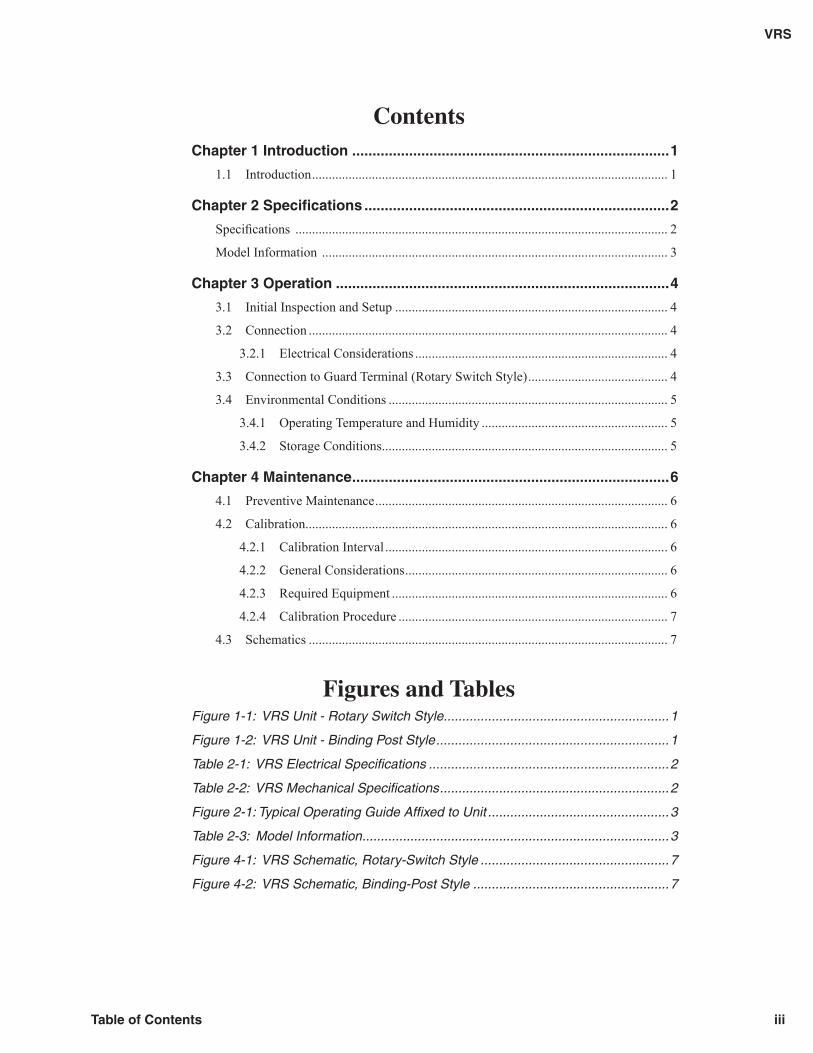
ContentsChapter 1 Introduction ..............................................................................1
1.1 Introduction ........................................................................................................... 1
Chapter 2 Specifi cations ...........................................................................2
Specifi cations ................................................................................................................ 2
Model Information ........................................................................................................ 3
Chapter 3 Operation ..................................................................................4
3.1 Initial Inspection and Setup .................................................................................. 4
3.2 Connection ............................................................................................................ 4
3.2.1 Electrical Considerations ............................................................................ 4
3.3 Connection to Guard Terminal (Rotary Switch Style) .......................................... 4
3.4 Environmental Conditions .................................................................................... 5
3.4.1 Operating Temperature and Humidity ........................................................ 5
3.4.2 Storage Conditions ...................................................................................... 5
Chapter 4 Maintenance ..............................................................................6
4.1 Preventive Maintenance ........................................................................................ 6
4.2 Calibration ............................................................................................................. 6
4.2.1 Calibration Interval ..................................................................................... 6
4.2.2 General Considerations ............................................................................... 6
4.2.3 Required Equipment ................................................................................... 6
4.2.4 Calibration Procedure ................................................................................. 7
4.3 Schematics ............................................................................................................ 7
Figures and TablesFigure 1-1: VRS Unit - Rotary Switch Style.............................................................1
Figure 1-2: VRS Unit - Binding Post Style ...............................................................1
Table 2-1: VRS Electrical Specifi cations .................................................................2
Table 2-2: VRS Mechanical Specifi cations ..............................................................2
Figure 2-1: Typical Operating Guide Affi xed to Unit .................................................3
Table 2-3: Model Information ...................................................................................3
Figure 4-1: VRS Schematic, Rotary-Switch Style ...................................................7
Figure 4-2: VRS Schematic, Binding-Post Style .....................................................7
iiiTable of Contents
VRS

This page is intentionally left blank
iv Table of Contents
VRS
Chapter 1
INTRODUCTION
1.1 Introduction
The VRS Series is an economical set of precision high resistance standards in one convenient enclosure. The resistors feature high stability, low temperature coeffi cient and low voltage coeffi cient.
The VRS is designed for calibration of megohm-meters and for general calibration and laboratory applications.
A wide range of values is available - from 1 kΩ to 10 TΩ. Operating voltages up to 10 kV may be specifi ed.
Leakage is kept to a minimum by the use of binding posts specially mounted on a Kel-F base.
The VRS Series comes in two available styles to best suit the application of the user. Performance of both styles is the same.
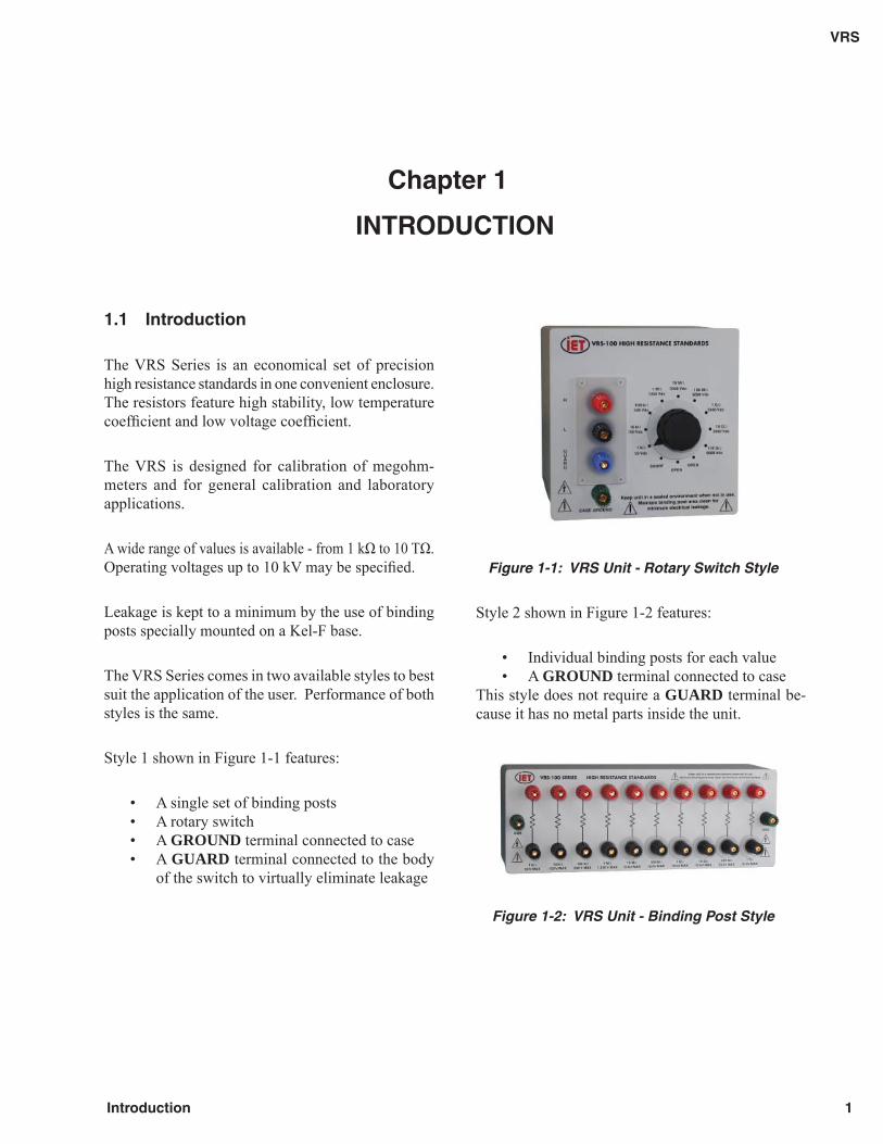
Style 1 shown in Figure 1-1 features:
• A single set of binding posts• A rotary switch• A GROUND terminal connected to case• A GUARD terminal connected to the body
of the switch to virtually eliminate leakage
Figure 1-1: VRS Unit - Rotary Switch Style
Style 2 shown in Figure 1-2 features:
• Individual binding posts for each value• A GROUND terminal connected to case
This style does not require a GUARD terminal be-cause it has no metal parts inside the unit.
Figure 1-2: VRS Unit - Binding Post Style
1
VRS
Introduction
Chapter 2
SPECIFICATIONS
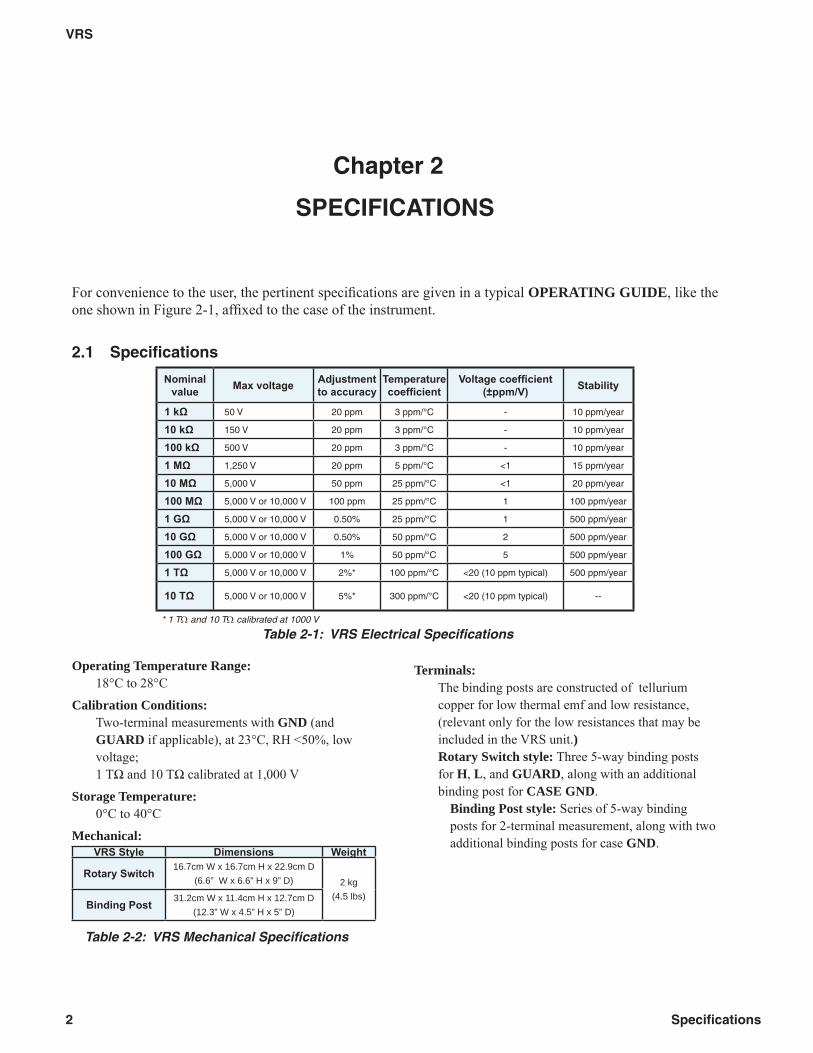
For convenience to the user, the pertinent specifi cations are given in a typical OPERATING GUIDE, like the one shown in Figure 2-1, affi xed to the case of the instrument.
2.1 Specifi cations
Operating Temperature Range:18°C to 28°C
Calibration Conditions:Two-terminal measurements with GND (and GUARD if applicable), at 23°C, RH <50%, low voltage;1 TΩ and 10 TΩ calibrated at 1,000 V
Storage Temperature:0°C to 40°C
Mechanical:VRS Style Dimensions Weight
Rotary Switch 16.7cm W x 16.7cm H x 22.9cm D(6.6” W x 6.6” H x 9” D) 2 kg
(4.5 lbs)Binding Post 31.2cm W x 11.4cm H x 12.7cm D
(12.3” W x 4.5” H x 5” D)
Table 2-2: VRS Mechanical Specifi cations
Terminals:The binding posts are constructed of tellurium copper for low thermal emf and low resistance, (relevant only for the low resistances that may be included in the VRS unit.)Rotary Switch style: Three 5-way binding posts for H, L, and GUARD, along with an additional binding post for CASE GND.
Binding Post style: Series of 5-way binding posts for 2-terminal measurement, along with two additional binding posts for case GND.
Nominal value Max voltage Adjustment
to accuracy Temperature coeffi cient
Voltage coeffi cient (±ppm/V) Stability
1 kΩ 50 V 20 ppm 3 ppm/°C - 10 ppm/year
10 kΩ 150 V 20 ppm 3 ppm/°C - 10 ppm/year
100 kΩ 500 V 20 ppm 3 ppm/°C - 10 ppm/year
1 MΩ 1,250 V 20 ppm 5 ppm/°C <1 15 ppm/year
10 MΩ 5,000 V 50 ppm 25 ppm/°C <1 20 ppm/year
100 MΩ 5,000 V or 10,000 V 100 ppm 25 ppm/°C 1 100 ppm/year
1 GΩ 5,000 V or 10,000 V 0.50% 25 ppm/°C 1 500 ppm/year
10 GΩ 5,000 V or 10,000 V 0.50% 50 ppm/°C 2 500 ppm/year
100 GΩ 5,000 V or 10,000 V 1% 50 ppm/°C 5 500 ppm/year
1 TΩ 5,000 V or 10,000 V 2%* 100 ppm/°C <20 (10 ppm typical) 500 ppm/year
10 TΩ 5,000 V or 10,000 V 5%* 300 ppm/°C <20 (10 ppm typical) --
* 1 TΩ and 10 TΩ calibrated at 1000 V
Table 2-1: VRS Electrical Specifi cations
2
VRS
Specifi cations
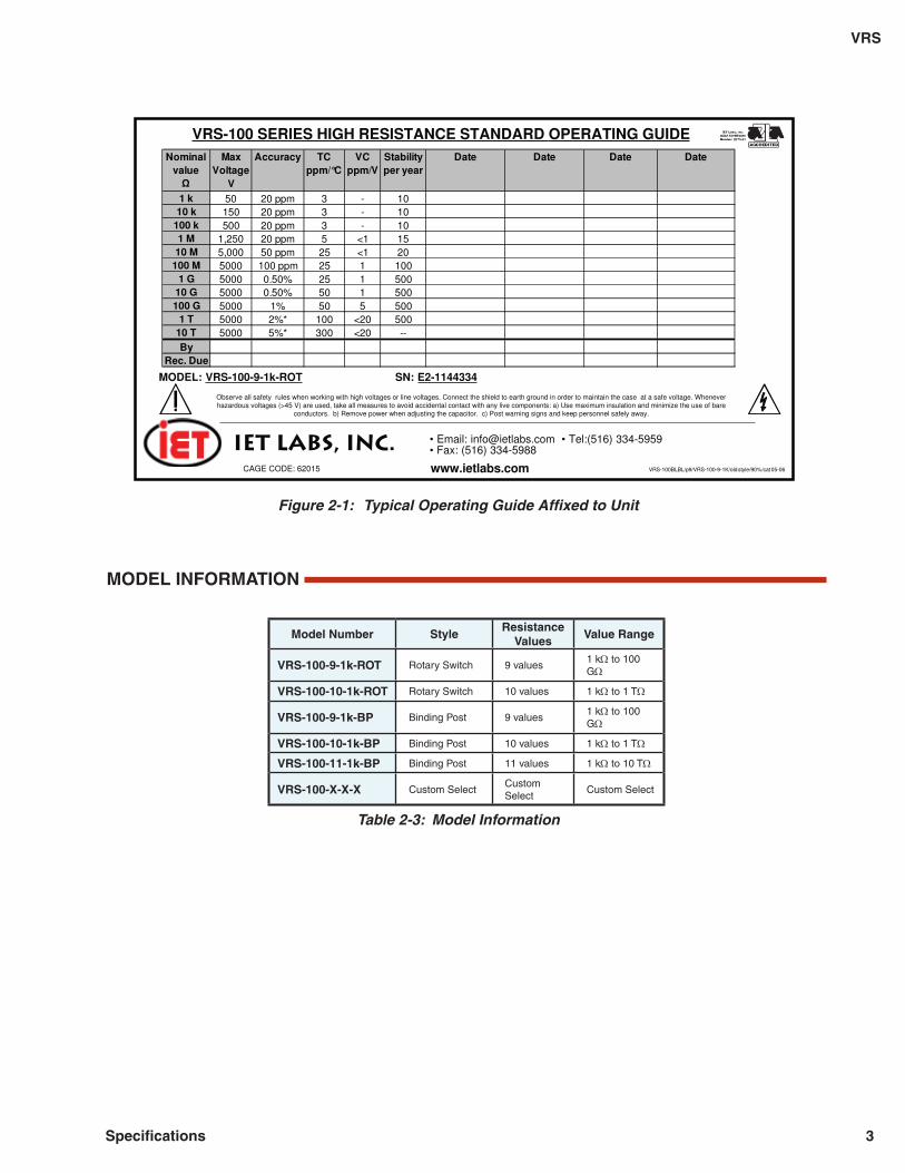
Figure 2-1: Typical Operating Guide Affi xed to Unit
MODEL INFORMATION
Model Number Style Resistance
Values Value Range
VRS-100-9-1k-ROT Rotary Switch 9 values 1 kΩ to 100 GΩ
VRS-100-10-1k-ROT Rotary Switch 10 values 1 kΩ to 1 TΩ
VRS-100-9-1k-BP Binding Post 9 values 1 kΩ to 100 GΩ
VRS-100-10-1k-BP Binding Post 10 values 1 kΩ to 1 TΩ
VRS-100-11-1k-BP Binding Post 11 values 1 kΩ to 10 TΩ
VRS-100-X-X-X Custom Select Custom Select
Custom Select
Table 2-3: Model Information
Observe all safety rules when working with high voltages or line voltages. Connect the shield to earth ground in order to maintain the case at a safe voltage. Wheneverhazardous voltages (>45 V) are used, take all measures to avoid accidental contact with any live components: a) Use maximum insulation and minimize the use of bare
conductors. b) Remove power when adjusting the capacitor. c) Post warning signs and keep personnel safely away.
MODEL: VRS-100-9-1k-ROT SN: E2-1144334
VRS-100BLBL/p9/VRS-100-9-1K/old style/90%/cat 05-06 www.ietlabs.com
IET LABS, INC. • Email: [email protected] • Tel:(516) 334-5959• Fax: (516) 334-5988
CAGE CODE: 62015
VRS-100 SERIES HIGH RESISTANCE STANDARD OPERATING GUIDENominal
value Max
Voltage V
Accuracy TC ppm/°C
VC ppm/V
Stability per year
1 k 50 20 ppm 3 - 1010 k 150 20 ppm 3 - 10
100 k 500 20 ppm 3 - 101 M 1,250 20 ppm 5 <1 1510 M 5,000 50 ppm 25 <1 20
100 M 5000 100 ppm 25 1 1001 G 5000 0.50% 25 1 500
10 G 5000 0.50% 50 1 500100 G 5000 1% 50 5 500
1 T 5000 2%* 100 <20 50010 T 5000 5%* 300 <20 --By
Rec. Due
Date Date Date Date
3
VRS
Specifi cations
Chapter 3
OPERATION
3.1 Initial Inspection and Setup
This instrument was carefully inspected before ship-ment. It should be in proper electrical and mechanical order upon receipt.
An OPERATION GUIDE is attached to the case of the instrument to provide ready reference to specifi ca-tions and calibration history. See Figure 2-1.
3.2 Connection
CAUTION
Keep unit in a sealed environment when not in use.
Do not handle binding post area with bare hands.
Maintain binding post area clean for minimum electrical leakage.
3.2.1 Electrical Considerations
The selected resistance is brought out using insulated, low-thermal-emf, binding posts labeled HI and LO.
A third terminal labeled GUARD is brought out for the rotary switch style; it interrupts and eliminates leakage to the switch body.
A fourth binding post labeled GND (Ground) is con-nected to the case and may be used accordingly as a guard or shield terminal.
3.3 Connection to Guard Terminal (Rotary Switch Style)
A GUARD terminal is brought out for the rotary switch style; it interrupts and eliminates leakage to the switch body. This terminal should be connected to the guard circuit or terminal of the measuring instrument. It may be also connected to the ground terminal of the test instrument if a guard terminal is not available on the instrument.
Refer to the instructions for the DMM or high resis-tance meter or bridge being used.
4
VRS
Operation
3.4 Environmental Conditions
3.4.1 Operating Temperature and Humidity
For optimal accuracy, use VRS models in an environ-ment of 23°C ±5°C. Because of the high resistances involved, RH should be <50%. The instrument should be allowed to stabilize at those temperatures after any signifi cant temperature variation.
3.4.2 Storage Conditions
The VRS Series should be maintained within the stor-age temperature range of 0°C to 40°C to maintain its accuracy within the specifi ed limits.
When not in use, the VRS unit should be stored in a sealed case or a plastic bag to minimize the intrusion of humidity and contaminants. A packet of desiccant should be placed in the container.
5
VRS
Operation
Chapter 4
MAINTENANCE
4.1 Preventive Maintenance
Keep the unit in a sealed clean enclosure with desic-cant at laboratory temperature and RH <50%. This will help prevent possible contamination and intrusion of moisture.
When necessary, the front panel should be cleaned to eliminate any leakage paths around the binding posts. To clean the front panel, wipe the front panel clean using alcohol and a lint-free cloth.
4.2 Calibration
4.2.1 Calibration Interval
The recommended calibration interval for the VRS Series is twelve (12) months.
CAUTION
Keep unit in a sealed environment when not in use.
Do not handle binding post area with bare hands.
Maintain binding post area clean for minimum electrical leakage.
4.2.2 General Considerations
Before starting the calibration procedure, you need to consider the following:
• Calibration environment should be 23°C and <50% RH.
• Test instruments should be suffi ciently more accurate than the VRS unit.
• The uncertainty of the measurement instru-ments has to be considered in the calibration to allow a band of uncertainty.
• The testing equipment and the VRS unit should stabilize at laboratory conditions for at least 24 hours.
• Use gloves when working inside the unit.• Proper metrology practices should be fol-
lowed to eliminate leakage.4.2.3 Required Equipment
Many combinations of standards, transfer standards, meters, and bridges may be used to calibrate this instrument. Possible choices include Resistance Standards or Transfer Standards for 1 kΩ, through 10 TΩ (or 10 TΩ).
IET options include:• HATS-Y• SRL Series
6
VRS
Maintenance
4.2.4 Calibration Procedure
To calibrate the VRS unit, proceed as follows:
1. Set up the calibration equipment in the resistance-measurement mode.
2. Measure leakage from every terminal (except GUARD) to GROUND.
The leakage should be >100 TΩ (>1 PΩ if the unit has a 1 TΩ step.)
3. If applicable, rotate the switch a few times in each direction.
4. Determine the allowable upper and lower limits for each resistance setting based on the specifi ed accuracy and the confi dence band.
Allow a confi dence band for the uncer-tainty of the measuring instrument and setup.
5. Confi rm that the resistances fall within these limits.
If any resistances fall outside these lim-its, the resistors may require service or replacement. Consult IET Labs.
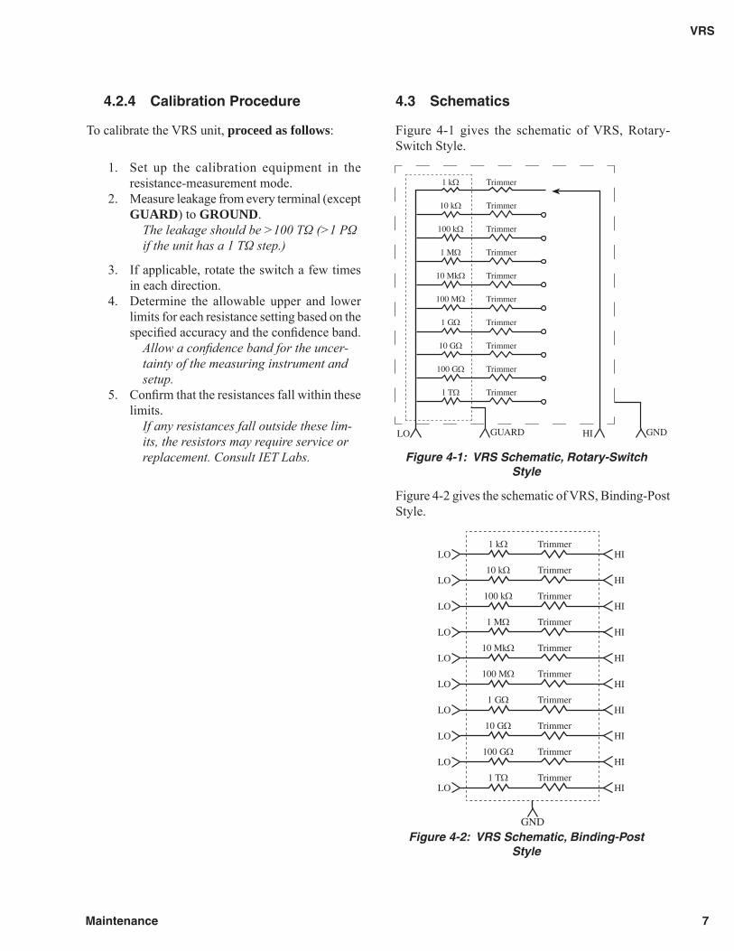
4.3 Schematics
Figure 4-1 gives the schematic of VRS, Rotary-Switch Style.
Figure 4-1: VRS Schematic, Rotary-Switch Style
Figure 4-2 gives the schematic of VRS, Binding-Post Style.
Figure 4-2: VRS Schematic, Binding-Post Style
1 kΩ
10 kΩ
100 kΩ
1 MΩ
10 MkΩ
100 MΩ
1 GΩ
10 GΩ
100 GΩ
1 TΩ
Trimmer
Trimmer
Trimmer
Trimmer
Trimmer
Trimmer
Trimmer
Trimmer
Trimmer
Trimmer
HILO GUARD GND
10 kΩ
100 kΩ
1 MΩ
10 MkΩ
100 MΩ
1 GΩ
10 GΩ
100 GΩ
1 TΩ
Trimmer
Trimmer
Trimmer
Trimmer
Trimmer
Trimmer
Trimmer
Trimmer
Trimmer
GND
1 kΩ TrimmerHI
HI
HI
HI
HI
HI
HI
HI
HI
HI
LO
LO
LO
LO
LO
LO
LO
LO
LO
LO
7
VRS
Maintenance