Votação Online Descentralizada
168
Votação Online Descentralizada ANDRÉ FILIPE GOMES DA SILVA outubro de 2021
-
Upload
khangminh22 -
Category
Documents
-
view
3 -
download
0
Transcript of Votação Online Descentralizada

Votação Online Descentralizada
ANDRÉ FILIPE GOMES DA SILVAoutubro de 2021
Decentralized Online Voting
André Silva
A dissertation submitted in partial fulfillment ofthe requirements for the degree of Master in InformaticsEngineering, Specialisation Area of Software Engineering
Supervisor: Dr. Nuno Bettencourt
Porto, October 17, 2021


iii
Abstract
Elections are crucial in any democratic nation. However, since election turnout levels in Europehave decreased in the last 25 years, studies have been conducted to understand the root causesof the problem and assess how voters could be convinced to vote.
This document focused on the voters’ convenience factor by first performing an empirical reviewon how election systems are implemented in Europe, which methods exist, and analyzing howremote voting is deployed across European nations. The scope of this work has then beennarrowed down to online voting.
This document has studied how ballot data decentralization could contribute to an acceptablesolution for online voting. As a result, the Solid project was studied to understand how it couldfit into such a solution so that it could be used to store ballots under the responsibility of theirrespective voters. Such a study involved the design and implementation of a proof of concept tounderstand the feasibility of Solid for decentralizing ballot data.
A survey was then conducted to evaluate the proof of concept from a voter perspective, havingpresented results that indicate that while online voting is deemed more convenient, respondentsdid not find significant value in storing ballots in a decentralized way using Solid.
Keywords: election, online voting, decentralization, Solid, data


v
Resumo
Eleições são um conceito crucial em qualquer nação democrática. No entanto, derivado doconstante aumento da abstenção nos países europeus nos últimos 25 anos, estudos têm sidofeitos no sentido de perceber quais os factores que causam este problema, e entender como é queos eleitores podem ser convencidos a votar.
Este documento é focado na conveniência do eleitor. Numa primeira fase, é feita uma revisãoempírica de como os sistemas eleitorais estão implementados na Europa, nomeadamente quemétodos existem e como se comparam entre si. De seguida, é feita uma análise em como avotação remota está implantada em alguns países europeus, sendo posteriormente direccionadade forma mais concreta para a votação online.
Este projeto procura estudar como é que os dados dos boletins de voto podem ser persistidosde forma descentralizada e se essa característica é viável no contexto de uma possível soluçãode votação online. Desta forma, o projecto Solid foi estudado para perceber se este poderia serenquadrado nessa solução, de forma a que os boletins de voto pudessem ser guardados sob aresponsabilidade dos seus respectivos eleitores. Esse estudo envolveu o desenho e implementaçãode uma prova de conceito que representasse essa solução.
Após o seu desenvolvimento, a prova de conceito foi alvo de uma experiência. Os inquiridosexperimentaram a solução e posteriormente responderam a um questionário sobre o funciona-mento da prova de conceito e sobre a votação online em geral. Os resultados indicam que emboraa votação online seja encarada como uma forma mais conveniente de votar do que presencial-mente, os inquiridos não valorizam significativamente a persistência de boletins de voto de formadescentralizada.


vii
Acknowledgement
First things first. I would like to thank all academic institutions that have welcomed me, namely:Escola EBI/JI da Barranha, Escola Profissional Ruiz Costa, ATEC - Academia de Formação,and ISEP - Instituto Superior de Engenharia do Porto. If I am at this point, it is also thanks tothese brilliant institutions.
Second of all, I would like to thank my supervisor, Professor Nuno Bettencourt, for his availabilityto guide me throughout this project, and also throughout my Internship Report in 2017. He willprobably be the only Professor I will not forget.
And last but not least, to the people who matter the most. I would like to thank my short butbeautiful family for supporting and encouraging my studies from the beginning, to my wonderfulwife who has remarkably supported me during this time, and to my friends that in some wayhave helped me but did not know that. You are the best.
When life gives you lemons, don’t expect it to make the lemonade for you.


ix
Contents
List of Figures xiii
List of Tables xvii
List of Source Code xix
List of Acronyms xxi
1 Introduction 11.1 Problem Background . . . . . . . . . . . . . . . . . . . . . . . . . . . . . . . . . . 11.2 Problem Statement . . . . . . . . . . . . . . . . . . . . . . . . . . . . . . . . . . . 21.3 Objectives . . . . . . . . . . . . . . . . . . . . . . . . . . . . . . . . . . . . . . . . 31.4 Hypothesis . . . . . . . . . . . . . . . . . . . . . . . . . . . . . . . . . . . . . . . 31.5 Research Questions . . . . . . . . . . . . . . . . . . . . . . . . . . . . . . . . . . . 31.6 Investigation Approach . . . . . . . . . . . . . . . . . . . . . . . . . . . . . . . . . 41.7 Document Structure . . . . . . . . . . . . . . . . . . . . . . . . . . . . . . . . . . 4
2 Context 72.1 On-Site Voting . . . . . . . . . . . . . . . . . . . . . . . . . . . . . . . . . . . . . 72.2 Remote Voting . . . . . . . . . . . . . . . . . . . . . . . . . . . . . . . . . . . . . 82.3 Internet/Online Voting . . . . . . . . . . . . . . . . . . . . . . . . . . . . . . . . . 92.4 Voting Methods Benefits and Drawbacks . . . . . . . . . . . . . . . . . . . . . . . 10
2.4.1 On-Site Voting . . . . . . . . . . . . . . . . . . . . . . . . . . . . . . . . . 102.4.2 Remote Voting . . . . . . . . . . . . . . . . . . . . . . . . . . . . . . . . . 112.4.3 Online Voting . . . . . . . . . . . . . . . . . . . . . . . . . . . . . . . . . . 122.4.4 Direct Comparison . . . . . . . . . . . . . . . . . . . . . . . . . . . . . . . 13
2.5 Case Study - Voting in Portugal . . . . . . . . . . . . . . . . . . . . . . . . . . . 132.5.1 On-Site Voting . . . . . . . . . . . . . . . . . . . . . . . . . . . . . . . . . 142.5.2 Remote Voting . . . . . . . . . . . . . . . . . . . . . . . . . . . . . . . . . 142.5.3 Voting Statistics . . . . . . . . . . . . . . . . . . . . . . . . . . . . . . . . 142.5.4 Impact of COVID-19 . . . . . . . . . . . . . . . . . . . . . . . . . . . . . . 15
2.6 Case Study - Voting in Estonia . . . . . . . . . . . . . . . . . . . . . . . . . . . . 162.6.1 On-Site Voting . . . . . . . . . . . . . . . . . . . . . . . . . . . . . . . . . 17

x
2.6.2 Remote Voting Methods . . . . . . . . . . . . . . . . . . . . . . . . . . . . 172.6.3 Voting Statistics . . . . . . . . . . . . . . . . . . . . . . . . . . . . . . . . 182.6.4 Online Voting . . . . . . . . . . . . . . . . . . . . . . . . . . . . . . . . . . 20
2.7 Summary . . . . . . . . . . . . . . . . . . . . . . . . . . . . . . . . . . . . . . . . 26
3 State Of The Art 273.1 Decentralized Web Models . . . . . . . . . . . . . . . . . . . . . . . . . . . . . . . 27
3.1.1 Solid . . . . . . . . . . . . . . . . . . . . . . . . . . . . . . . . . . . . . . . 283.1.2 Stacks . . . . . . . . . . . . . . . . . . . . . . . . . . . . . . . . . . . . . . 303.1.3 Elastos . . . . . . . . . . . . . . . . . . . . . . . . . . . . . . . . . . . . . 323.1.4 Decentralized Models Comparison . . . . . . . . . . . . . . . . . . . . . . 33
3.2 Data Security and Encryption . . . . . . . . . . . . . . . . . . . . . . . . . . . . . 343.2.1 Symmetric Ciphers . . . . . . . . . . . . . . . . . . . . . . . . . . . . . . . 353.2.2 Asymmetric or Public Key Ciphers . . . . . . . . . . . . . . . . . . . . . . 363.2.3 Irreversible Ciphers (Hashing) . . . . . . . . . . . . . . . . . . . . . . . . . 37
3.3 Methodologies . . . . . . . . . . . . . . . . . . . . . . . . . . . . . . . . . . . . . . 383.3.1 Innovation Process . . . . . . . . . . . . . . . . . . . . . . . . . . . . . . . 383.3.2 Business Model Canvas . . . . . . . . . . . . . . . . . . . . . . . . . . . . 393.3.3 Value Model Canvas . . . . . . . . . . . . . . . . . . . . . . . . . . . . . . 403.3.4 Function Analysis System Technique . . . . . . . . . . . . . . . . . . . . . 413.3.5 Technique of Order Preference by Similarity to Ideal Solution . . . . . . . 41
3.4 Technologies and Techniques . . . . . . . . . . . . . . . . . . . . . . . . . . . . . 433.4.1 Resource Description Framework . . . . . . . . . . . . . . . . . . . . . . . 433.4.2 OpenID Connect . . . . . . . . . . . . . . . . . . . . . . . . . . . . . . . . 443.4.3 WebID . . . . . . . . . . . . . . . . . . . . . . . . . . . . . . . . . . . . . . 453.4.4 WebID-OIDC . . . . . . . . . . . . . . . . . . . . . . . . . . . . . . . . . . 453.4.5 Outbox Pattern . . . . . . . . . . . . . . . . . . . . . . . . . . . . . . . . . 463.4.6 Hangfire . . . . . . . . . . . . . . . . . . . . . . . . . . . . . . . . . . . . . 473.4.7 CAP . . . . . . . . . . . . . . . . . . . . . . . . . . . . . . . . . . . . . . . 48
3.5 Summary . . . . . . . . . . . . . . . . . . . . . . . . . . . . . . . . . . . . . . . . 49
4 Analysis 514.1 Value . . . . . . . . . . . . . . . . . . . . . . . . . . . . . . . . . . . . . . . . . . 51
4.1.1 Innovation Process . . . . . . . . . . . . . . . . . . . . . . . . . . . . . . . 514.1.2 Perceived Value . . . . . . . . . . . . . . . . . . . . . . . . . . . . . . . . . 584.1.3 Value Proposition . . . . . . . . . . . . . . . . . . . . . . . . . . . . . . . 59
4.2 Requirements Engineering . . . . . . . . . . . . . . . . . . . . . . . . . . . . . . . 604.2.1 Functional Requirements . . . . . . . . . . . . . . . . . . . . . . . . . . . 604.2.2 Non-Functional Requirements . . . . . . . . . . . . . . . . . . . . . . . . . 614.2.3 Domain Conceptualization . . . . . . . . . . . . . . . . . . . . . . . . . . . 65

xi
4.3 Summary . . . . . . . . . . . . . . . . . . . . . . . . . . . . . . . . . . . . . . . . 67
5 Design 695.1 Ballot Ownership . . . . . . . . . . . . . . . . . . . . . . . . . . . . . . . . . . . . 695.2 Process View . . . . . . . . . . . . . . . . . . . . . . . . . . . . . . . . . . . . . . 705.3 Logical View . . . . . . . . . . . . . . . . . . . . . . . . . . . . . . . . . . . . . . 71
5.3.1 System Overview . . . . . . . . . . . . . . . . . . . . . . . . . . . . . . . . 715.3.2 Architecture . . . . . . . . . . . . . . . . . . . . . . . . . . . . . . . . . . 725.3.3 Architecture Comparison . . . . . . . . . . . . . . . . . . . . . . . . . . . 74
5.4 Physical View . . . . . . . . . . . . . . . . . . . . . . . . . . . . . . . . . . . . . . 765.5 User Story View . . . . . . . . . . . . . . . . . . . . . . . . . . . . . . . . . . . . 77
5.5.1 Mediation and Query/Command Separation . . . . . . . . . . . . . . . . . 785.5.2 UCO-1 - Create Election . . . . . . . . . . . . . . . . . . . . . . . . . . . . 785.5.3 UCO-2 - Trigger Vote Casting . . . . . . . . . . . . . . . . . . . . . . . . 805.5.4 UCV-1 - Authenticate . . . . . . . . . . . . . . . . . . . . . . . . . . . . . 825.5.5 UCV-2 - Vote . . . . . . . . . . . . . . . . . . . . . . . . . . . . . . . . . . 835.5.6 UCO-3 - Trigger Vote Tally . . . . . . . . . . . . . . . . . . . . . . . . . . 865.5.7 UCS-1 - Count submitted votes . . . . . . . . . . . . . . . . . . . . . . . . 87
5.6 Data Schema . . . . . . . . . . . . . . . . . . . . . . . . . . . . . . . . . . . . . . 885.7 Summary . . . . . . . . . . . . . . . . . . . . . . . . . . . . . . . . . . . . . . . . 89
6 Implementation 916.1 Adopted Technology Stack . . . . . . . . . . . . . . . . . . . . . . . . . . . . . . . 916.2 Messaging Configuration . . . . . . . . . . . . . . . . . . . . . . . . . . . . . . . . 926.3 Encryption . . . . . . . . . . . . . . . . . . . . . . . . . . . . . . . . . . . . . . . 936.4 Solution Structure and Cross-cutting Concerns . . . . . . . . . . . . . . . . . . . 946.5 Back-end Components . . . . . . . . . . . . . . . . . . . . . . . . . . . . . . . . . 96
6.5.1 Solid POD Provider . . . . . . . . . . . . . . . . . . . . . . . . . . . . . . 966.5.2 Shared Kernel . . . . . . . . . . . . . . . . . . . . . . . . . . . . . . . . . 976.5.3 Election API . . . . . . . . . . . . . . . . . . . . . . . . . . . . . . . . . . 986.5.4 Ballot Extractor . . . . . . . . . . . . . . . . . . . . . . . . . . . . . . . . 1046.5.5 Ballot Counter . . . . . . . . . . . . . . . . . . . . . . . . . . . . . . . . . 105
6.6 Use Case Implementation . . . . . . . . . . . . . . . . . . . . . . . . . . . . . . . 1066.6.1 Authentication (UCV-1) . . . . . . . . . . . . . . . . . . . . . . . . . . . . 1066.6.2 Creating an Election (UCO-1) . . . . . . . . . . . . . . . . . . . . . . . . 1076.6.3 Starting Vote Cast (UCO-2) . . . . . . . . . . . . . . . . . . . . . . . . . . 1076.6.4 Voting (UCV-2) . . . . . . . . . . . . . . . . . . . . . . . . . . . . . . . . 1096.6.5 Vote Tally (UCO-4) . . . . . . . . . . . . . . . . . . . . . . . . . . . . . . 1106.6.6 Viewing Results . . . . . . . . . . . . . . . . . . . . . . . . . . . . . . . . 111
6.7 Summary . . . . . . . . . . . . . . . . . . . . . . . . . . . . . . . . . . . . . . . . 112

xii
7 Evaluation 1137.1 Hypothesis . . . . . . . . . . . . . . . . . . . . . . . . . . . . . . . . . . . . . . . 1137.2 Indicators . . . . . . . . . . . . . . . . . . . . . . . . . . . . . . . . . . . . . . . . 1147.3 Technical Quality . . . . . . . . . . . . . . . . . . . . . . . . . . . . . . . . . . . . 114
7.3.1 Code Analysis . . . . . . . . . . . . . . . . . . . . . . . . . . . . . . . . . 1147.3.2 Unit Tests . . . . . . . . . . . . . . . . . . . . . . . . . . . . . . . . . . . . 1157.3.3 Integration Tests . . . . . . . . . . . . . . . . . . . . . . . . . . . . . . . . 115
7.4 Load Testing . . . . . . . . . . . . . . . . . . . . . . . . . . . . . . . . . . . . . . 1167.5 Scaling . . . . . . . . . . . . . . . . . . . . . . . . . . . . . . . . . . . . . . . . . . 118
7.5.1 Design Points . . . . . . . . . . . . . . . . . . . . . . . . . . . . . . . . . . 1197.5.2 Hypothesis Formulation . . . . . . . . . . . . . . . . . . . . . . . . . . . . 1197.5.3 Sample Data . . . . . . . . . . . . . . . . . . . . . . . . . . . . . . . . . . 1207.5.4 Result . . . . . . . . . . . . . . . . . . . . . . . . . . . . . . . . . . . . . . 120
7.6 Election Simulation and Survey . . . . . . . . . . . . . . . . . . . . . . . . . . . . 1217.6.1 Simulation Environment . . . . . . . . . . . . . . . . . . . . . . . . . . . . 1217.6.2 Survey Description . . . . . . . . . . . . . . . . . . . . . . . . . . . . . . . 1217.6.3 Survey Findings . . . . . . . . . . . . . . . . . . . . . . . . . . . . . . . . 122
7.7 Summary . . . . . . . . . . . . . . . . . . . . . . . . . . . . . . . . . . . . . . . . 124
8 Conclusion 1258.1 Goal Retrospective . . . . . . . . . . . . . . . . . . . . . . . . . . . . . . . . . . . 1268.2 Hypothesis . . . . . . . . . . . . . . . . . . . . . . . . . . . . . . . . . . . . . . . 1268.3 Research Questions . . . . . . . . . . . . . . . . . . . . . . . . . . . . . . . . . . . 1278.4 Limitations . . . . . . . . . . . . . . . . . . . . . . . . . . . . . . . . . . . . . . . 1288.5 Future Work . . . . . . . . . . . . . . . . . . . . . . . . . . . . . . . . . . . . . . 1298.6 Final Considerations . . . . . . . . . . . . . . . . . . . . . . . . . . . . . . . . . . 129
References 131
Appendices 137A Sonar Scan Results . . . . . . . . . . . . . . . . . . . . . . . . . . . . . . . . . . . 139B Election Simulation Survey . . . . . . . . . . . . . . . . . . . . . . . . . . . . . . 141C Session Guide . . . . . . . . . . . . . . . . . . . . . . . . . . . . . . . . . . . . . . 145

xiii
List of Figures
2.1 Typical Voting Process . . . . . . . . . . . . . . . . . . . . . . . . . . . . . . . . . 82.2 Portuguese Parliamentary Elections Overview . . . . . . . . . . . . . . . . . . . . 152.3 Portuguese Presidential Elections Overview . . . . . . . . . . . . . . . . . . . . . 152.4 Estonian Elections Turnout . . . . . . . . . . . . . . . . . . . . . . . . . . . . . . 182.5 Estonian Election Proportions of Online Voters Among Eligible . . . . . . . . . . 192.6 Estonian Election Proportions of Online Voters By Age Groups . . . . . . . . . . 192.7 Envelope Wrapping Scheme . . . . . . . . . . . . . . . . . . . . . . . . . . . . . . 212.8 Online Voting Process Flow and Actors . . . . . . . . . . . . . . . . . . . . . . . 222.9 Voting Identification and Execution . . . . . . . . . . . . . . . . . . . . . . . . . 232.10 Vote Registration . . . . . . . . . . . . . . . . . . . . . . . . . . . . . . . . . . . . 242.11 Voting Stage Components and Interactions . . . . . . . . . . . . . . . . . . . . . 24
3.1 Solid Architecture . . . . . . . . . . . . . . . . . . . . . . . . . . . . . . . . . . . 293.2 Stacks Data Storage Layered Architecture . . . . . . . . . . . . . . . . . . . . . . 313.3 Symmetric Encryption . . . . . . . . . . . . . . . . . . . . . . . . . . . . . . . . . 353.4 Symmetric Encryption . . . . . . . . . . . . . . . . . . . . . . . . . . . . . . . . . 363.5 Data Integrity using Digital Signatures . . . . . . . . . . . . . . . . . . . . . . . . 373.6 The Innovation Process . . . . . . . . . . . . . . . . . . . . . . . . . . . . . . . . 383.7 The New Concept Development (NCD) model . . . . . . . . . . . . . . . . . . . . 393.8 Value Model Canvas . . . . . . . . . . . . . . . . . . . . . . . . . . . . . . . . . . 403.9 Features of the Function Analysis System Technique (FAST) Diagram . . . . . . 423.10 WebID-OIDC Flow . . . . . . . . . . . . . . . . . . . . . . . . . . . . . . . . . . . 453.11 State-changing operation failing after a local transaction . . . . . . . . . . . . . . 463.12 Outbox pattern . . . . . . . . . . . . . . . . . . . . . . . . . . . . . . . . . . . . . 463.13 Separate Outbox process . . . . . . . . . . . . . . . . . . . . . . . . . . . . . . . . 473.14 Distributing Work in Hangfire . . . . . . . . . . . . . . . . . . . . . . . . . . . . . 483.15 CAP framework implementing the Outbox pattern . . . . . . . . . . . . . . . . . 48
4.1 FAST Diagram displaying causality relationships between option functions . . . . 584.2 Domain Model . . . . . . . . . . . . . . . . . . . . . . . . . . . . . . . . . . . . . 664.3 Election State Diagram . . . . . . . . . . . . . . . . . . . . . . . . . . . . . . . . 67

xiv
5.1 Activity Diagram of the whole election process . . . . . . . . . . . . . . . . . . . 705.2 System Overview . . . . . . . . . . . . . . . . . . . . . . . . . . . . . . . . . . . . 715.3 Architecture Alternative 1 . . . . . . . . . . . . . . . . . . . . . . . . . . . . . . . 735.4 Architecture Alternative 2 . . . . . . . . . . . . . . . . . . . . . . . . . . . . . . . 745.5 Deployment Diagram of the election system components . . . . . . . . . . . . . . 765.6 Architecturally-relevant Use Cases . . . . . . . . . . . . . . . . . . . . . . . . . . 785.7 Sequence Diagram for UCO-1 . . . . . . . . . . . . . . . . . . . . . . . . . . . . . 795.8 Sequence Diagram for retrieving all Candidates in UCO-1 . . . . . . . . . . . . . 795.9 Sequence Diagram for validating and persisting an election in UCO-1 . . . . . . . 805.10 Sequence Diagram for UCO-2 . . . . . . . . . . . . . . . . . . . . . . . . . . . . . 815.11 Sequence Diagram for UCO-2 - Change State . . . . . . . . . . . . . . . . . . . . 825.12 Sequence Diagram for UCV-1 . . . . . . . . . . . . . . . . . . . . . . . . . . . . . 835.13 Sequence Diagram for UCV-2 . . . . . . . . . . . . . . . . . . . . . . . . . . . . . 845.14 Sequence Diagram for UCV-2 - Handling the Command . . . . . . . . . . . . . . 855.15 Activity Diagram for UCV-2 - Storing ballot in Voter’s POD . . . . . . . . . . . 855.16 Sequence Diagram for UCO-3 - Trigger Vote Tally . . . . . . . . . . . . . . . . . 865.17 Activity Diagram for UCS-1 - Count submitted votes . . . . . . . . . . . . . . . . 875.18 Entity-Relationship Diagram for the Election DB . . . . . . . . . . . . . . . . . . 89
6.1 A consumer in the consumer group will never consume the same partition . . . . 936.2 Solution organization in Visual Studio . . . . . . . . . . . . . . . . . . . . . . . . 946.3 Package Diagram exhibiting the ElectionAPI internal multitier architecture . . . 986.4 Solid Voting Index Page . . . . . . . . . . . . . . . . . . . . . . . . . . . . . . . . 996.5 Class Diagram representing the Entity Model . . . . . . . . . . . . . . . . . . . . 1006.6 Repository Class Diagram . . . . . . . . . . . . . . . . . . . . . . . . . . . . . . . 1016.7 Gateway Class Diagram . . . . . . . . . . . . . . . . . . . . . . . . . . . . . . . . 1036.8 Solid Voting Login Page . . . . . . . . . . . . . . . . . . . . . . . . . . . . . . . . 1066.9 Community Solid Server Login Page . . . . . . . . . . . . . . . . . . . . . . . . . 1076.10 Page to Create an Election . . . . . . . . . . . . . . . . . . . . . . . . . . . . . . 1086.11 Election Listing Page . . . . . . . . . . . . . . . . . . . . . . . . . . . . . . . . . . 1086.12 Official POV (to the left) and Voter POV (to the right) of an Election in Vote
Casting . . . . . . . . . . . . . . . . . . . . . . . . . . . . . . . . . . . . . . . . . 1096.13 Vote Casting Successful Page . . . . . . . . . . . . . . . . . . . . . . . . . . . . . 1096.14 Election Results Page . . . . . . . . . . . . . . . . . . . . . . . . . . . . . . . . . 112
7.1 Throughput during the load test session . . . . . . . . . . . . . . . . . . . . . . . 1187.2 Pie chart representing the proportion of answers to the question "Do you think
the process to cast a ballot in the platform was easy and intuitive?" . . . . . . . 122

xv
7.3 Pie chart representing the proportion of answers to the question "Do you think theprocess to cast a ballot in the platform was more convenient than the traditionalon-site process?" . . . . . . . . . . . . . . . . . . . . . . . . . . . . . . . . . . . . 123
7.4 Pie chart representing the proportion of answers to the question "Do you think theprocess to cast a ballot in the platform was more convenient than the traditionalon-site process?" . . . . . . . . . . . . . . . . . . . . . . . . . . . . . . . . . . . . 123


xvii
List of Tables
2.1 Comparison between Voting Methods . . . . . . . . . . . . . . . . . . . . . . . . 13
3.1 Comparison of Data Decentralization Models . . . . . . . . . . . . . . . . . . . . 33
4.1 Adapted Fundamental Scale . . . . . . . . . . . . . . . . . . . . . . . . . . . . . . 544.2 Initial Weighted Decision Matrix X . . . . . . . . . . . . . . . . . . . . . . . . . . 554.3 Normalized Decision Matrix R . . . . . . . . . . . . . . . . . . . . . . . . . . . . 564.4 Weighted Normalized Decision Matrix V . . . . . . . . . . . . . . . . . . . . . . . 564.5 Calculated separation measures for each option . . . . . . . . . . . . . . . . . . . 574.6 Relative closeness to the ideal solution for each option . . . . . . . . . . . . . . . 574.7 User Stories . . . . . . . . . . . . . . . . . . . . . . . . . . . . . . . . . . . . . . . 614.8 Non-Functional Requirements (Functionality) . . . . . . . . . . . . . . . . . . . . 624.9 Non-Functional Requirements (Usability) . . . . . . . . . . . . . . . . . . . . . . 624.10 Non-Functional Requirements (Reliability) . . . . . . . . . . . . . . . . . . . . . . 634.11 Non-Functional Requirements (Performance) . . . . . . . . . . . . . . . . . . . . 634.12 Non-Functional Requirements (Supportability) . . . . . . . . . . . . . . . . . . . 644.13 Non-Functional Requirements (Design Constraints) . . . . . . . . . . . . . . . . . 644.14 Non-Functional Requirements (Implementation Constraints) . . . . . . . . . . . . 64
6.1 CSS POD creation endpoint . . . . . . . . . . . . . . . . . . . . . . . . . . . . . . 966.2 CSS POD data-managing HTTP Endpoints for storing election ballots . . . . . . 976.3 Election Results endpoint in Ballot Counter service . . . . . . . . . . . . . . . . . 105
7.1 Load Test Host Environment Specifications . . . . . . . . . . . . . . . . . . . . . 1177.2 Load Test Execution Results . . . . . . . . . . . . . . . . . . . . . . . . . . . . . 1177.3 Design Matrix for the Vote Tally experiment . . . . . . . . . . . . . . . . . . . . 1197.4 Obtained Process Times for Design Points 1 and 4 . . . . . . . . . . . . . . . . . 120


xix
List of Source Code
3.1 Resource Description Framework (RDF) syntax example . . . . . . . . . . . . . . 446.1 Example of file .csproj in BallotCounter project. . . . . . . . . . . . . . . . . . 956.2 Dependency Injection example in .NET . . . . . . . . . . . . . . . . . . . . . . . 956.3 Page Model Method Example . . . . . . . . . . . . . . . . . . . . . . . . . . . . . 996.4 CanChange method implementation at ReadyForVoteCastingState class. . . . . 1006.5 Mapping Classes to Tables in Entity Framework . . . . . . . . . . . . . . . . . . 1026.6 Publishing a submitted ballot event message using CAP . . . . . . . . . . . . . . 1036.7 Subscription Handler for Extracting Ballots from Solid PODs . . . . . . . . . . . 1046.8 Count Ballot Command Message . . . . . . . . . . . . . . . . . . . . . . . . . . . 1056.9 Trigger Vote Casting button . . . . . . . . . . . . . . . . . . . . . . . . . . . . . . 1086.10 Election API Tally Job . . . . . . . . . . . . . . . . . . . . . . . . . . . . . . . . . 1106.11 Getting election results from the Election Results DB . . . . . . . . . . . . . . . 1116.12 Joining results in Election API . . . . . . . . . . . . . . . . . . . . . . . . . . . . 1127.1 Integration Test to assert the Vote Casting process . . . . . . . . . . . . . . . . . 115


xxi
List of Acronyms
AAA Authentication, Authorization and Accounting.
ACID atomicity consistency isolation and durability.
ACP Access Control Policies.
AES Advanced Encryption Standard.
API Application Programming Interface.
CBC Cipher Block Chaining.
CTR Counter Mode.
DBaaS Database as a Service.
DDoS Distributed Denial of Service.
DES Data Encryption Standard.
DID Decentralized Identifier.
DSRM Design Science Research Methodology.
e-voting electronic voting.
ECB Electronic Code Book.
EU European Union.
FAST Function Analysis System Technique.
FFE Fuzzy Front End.
GDPR General Data Protection Regulation.
IPFS Inter Planetary File System.
ISP Internet Service Provider.
IV Initialization Vector.
JSON Javascript Object Notation.
JWT JSON Web Token.

xxii
MCDM Multi-Criteria Decision Making.
NCD New Concept Development.
NPPD New Product and Process Development.
OIDC OpenID Connect.
ORM Object-Relational Mapper.
OSI Open Systems Interconnection.
PII Personally Identifiable Information.
POD Personal Objects Datastore.
RDF Resource Description Framework.
REST Representational State Transfer.
SDK Software Development Kit.
SHA Secure Hash Algorithm.
TOPSIS Technique of Order Preference by Similarity to Ideal Solution.
UI User Interface.
UML Unified Modeling Language.
VPN Virtual Private Network.
W3C World Wide Web Consortium.
WAC Web Access Control.
WWW World Wide Web.
XML eXtended Markup Language.

1
Chapter 1
Introduction
The role of democracy in contemporary society is of the utmost importance. Despite its originsin Ancient Greece, democracy has had its time to set foot across the world, and specifically inPortuguese soil. It was only in the last century, after the coup-d’etat in 19741, that Portugal hasadopted this form of governing.
Nearly half a century later, after the foundation of democracy in Portugal, the main form ofcasting a ballot in Portuguese elections is based on in-person paper procedures. Apart fromsome minor attempts on introducing other ways to vote, other alternatives were never indeedconsidered by succeeding governments to replace or complement the current voting method.
1.1 Problem Background
In 2020, the COVID-19 pandemic hit this country and the whole world. Many global leadersworldwide decided to declare successive people lockdown procedures to prevent the virus spread.Even if the most notorious collateral damage was at an economic level, this pandemic and its con-sequential lockdown events also cause one to question the standard in-person voting methodology,because one of its consequences was the gathering and queuing of citizens at polling stations inorder to cast their ballots.
Under pressure, the Portuguese government has enabled other paper-based voting methods [1]like mail-in ballots, and opened additional polling stations, similar to what happened in theUnited States’ presidential elections in November of 2020.
Nevertheless, these methods always rely on physical attendance, which foster logistic and staffheadcount issues while never totally guaranteeing voters’ health protection, as well as causing anuncertainty in voting turnout levels [2]. Therefore, other long-lasting online voting methodologiesthat ensure the voters’ safety, preserve democracy-critical events like elections, and guaranteethe suffrage’s legitimacy, may be studied to complement the current voting methods.
1https://portugal.com/portugal-blogs/truth-25th-april

2 Chapter 1. Introduction
Electronic voting is not a brand-new concept. The first experience with electronic voting inPortugal occurred in 1997, followed by three other attempts in 2001, 2004, and 2005 [3, 4]. Theavailable technology constrained the terms of these experiments at the time, which despite itssignificant evolution, there was no significant research, news, or even interest in adopting ane-voting system to complement Portuguese elections.
Even after adopting an electronic citizen identification card system in 2007, which was basedon the aggregation of multiple cards from different Portuguese authorities such as the NationalHealth Service card (cartão de utente) and the Value Added Tax card (cartão de identificaçãofiscal), the voters’ number/card was not incorporated within it at the time. Years later, thevoters’ card was replaced by the electronic citizen card, but its digital features were never usedfor ballot casting.
1.2 Problem Statement
According to a study conducted by the European Commission in 2018 [4], one of the problemsof voting through the Internet is to ensure both voters’ privacy and identification at the sametime. Indeed, to check either that someone is allowed to vote and that they have not yet doneso requires the computer system to know who they are.
On the one hand, storing a ballot with personal information puts the whole voting process’ssecrecy at risk but can be used for auditing purposes. On the other hand, if the vote is savedwithout any personal information, even with an authorization system in place, there is no onehundred percent guarantee that it came from an allowed person, or even if a real person placedit at all.
Another concern of the European Commission study was that vote recounting could be challeng-ing to perform. Indeed, if no personal information is stored with each ballot, there is no traceback to its owner. Therefore, auditing the results may prove difficult to do. The same study in[4] also found an increase in voter turnout using internet voting, even if the previously examinedliterature had presented mixed results. Similarly, people in remote areas, with some disability,hospitalized, expats, among others, may significantly benefit from this method [5, 6].
As a result, one of the main problems in online voting could be described as how it is possibleto ensure every ballot’s legitimacy while protecting their secrecy at the same time. The latterfeature is known for being hard to accomplish in a digital world since tracking the averageInternet user’s steps is usually possible. Still, there are ways to hide a person’s identity online(e.g., Virtual Private Network (VPN)), but they clash with the need to consider legitimate votesonly.

1.3. Objectives 3
1.3 Objectives
Tim-Berners Lee, known for creating the World Wide Web, has been working on a new webdevelopment framework named Solid [7], which pursues online data privacy shielding. Thisframework enables web developers to build products with decoupled data from the applicationitself, empowering users to control their data.
Decentralization on the web is one option for achieving citizen privacy and security, mainly ifimplemented within Authentication, Authorization and Accounting (AAA)’s foundations.
This dissertation intends to study the viability of the usage of the Solid framework for electoralpurposes. A proof of concept regarding electoral data decentralization will be analyzed, designed,and implemented.
For this particular project, only secret universal elections whose votes all weigh the same willbe supported. The end goal is to check whether data decentralization can reduce voters’ dataprivacy issues while keeping the electoral process secure, capable of being audited, and overalllegitimate.
This proof of concept will follow good programming and engineering practices like SOLID prin-ciples.
1.4 Hypothesis
In order to establish a starting point for this project, the following hypothesis should be analyzedand verified:
• H1 - The developed online voting solution does not compromise vote confidentiality;
• H2 - The developed online voting solution is more convenient for eligible voters;
• H3 - The developed online voting solution can be scaled horizontally and provide betterperformance results.
1.5 Research Questions
Considering the objectives defined in section 1.3, it’s possible to define a set of research questionsthat will be analyzed and answered throughout this document:
1. RQ1 - Is it possible to have a decentralized online voting system, where voters own theirballots?
2. RQ2 - Can this solution contribute to the acceptance of online voting solutions in generalby society?

4 Chapter 1. Introduction
3. RQ3 - In the perspective of the end-user, could online voting system ever be implementedin Portugal?
1.6 Investigation Approach
As explained, this dissertation intends to research and design a solution to a problem in anefficient and effective manner. This type of investigation, in Information Systems, is compatiblewith design science methodologies, namely the Design Science Research Methodology (DSRM)[8], which provides a framework of patterns and practices that enable the researcher to con-duct their work more efficiently. This research method consists of six different stages, each onecomplementing its previous one:
• Problem Identification and Motivation, which should provide a background of thecurrent state of the art and define the motivation for the carried investigation. This concernis addressed in sections 1.1 and 1.2, followed by an analysis on on-site, remote and onlinevoting throughout chapter 2, proceeded by two case studies presented in the same chapter;
• Definition of Objectives that intend to solve the Problem. Objectives are classified asquantitative or qualitative, depending on the study at hand which, for this dissertation,will be qualitative. They are explained in section 1.3;
• Design and Development towards the Objective. First, a state-of-the-art investigationis performed in chapter 3, and then an analysis both on the solution value and on itsrequirements is presented in chapter 4;
• Demonstration of the outcomes. Chapter 5 takes up requirements declared on chapter 4to design a solution, and 6 uses the design artifacts produced to build a proof of concept;
• Evaluation of the demonstration by performing tests and experiments on the developedsolution. Those tests and their results are detailed in chapter 7;
• Communication of the results on chapter 8.
All stages of this approach will be clearly identified throughout this document.
1.7 Document Structure
This document is composed of a total of 8 chapters: introduction, context, state of the art,analysis, design, implementation, evaluation, and conclusion.
The introduction chapter states the problem and presents the objectives, hypothesis, and researchquestions that guided the project.

1.7. Document Structure 5
The context chapter provides a brief review of existing voting methods in Europe according tothe study in [4], and performs two case studies on two European nations, Portugal and Estonia,regarding their adoption of online voting, and analyzes the election turnout levels of each country.
State of the art starts with reviewing and analyzing current decentralization frameworks andplatforms and compares them regarding relevant factors for this project. Then, the chapter moveson with a brief overview of current encryption methods and concludes with a brief descriptionof methodologies followed and technologies adopted on this project.
The analysis chapter is divided into two sections. The first section studies the solution value byapplying value-seeking methodologies previously detailed in the state of the art chapter. The lastsection establishes the requirements to be fulfilled by the proof of concept and conceptualizes itsdomain by applying good software principles.
The design chapter follows up on the requirements previously established and brings forward twosystem architecture alternatives. Those alternatives are then compared, leading to the selectionof one of them and the reasoning behind it.
The implementation chapter describes the process involved in developing the proof of conceptand shows evidence of the carried work.
The evaluation chapter uses testing and experiments to evaluate the outcome of the implemen-tation.
Finally, the conclusion chapter summarizes the outcomes from all chapters, performs a retro-spective on the committed objectives, and answers the research questions established in theintroduction.


7
Chapter 2
Context
In contemporary democracies, voting is the right of every citizen and helps shape a country’sfuture. However, such an important event should not be taken for granted.
In the last years, concerns have been raising regarding the constant decrease in election turnoutlevels in Europe [9], which in turn may be exploited by extremist political parties to increasetheir presence [10]. Therefore, multiple studies have been conducted to understand the reasoningbehind abstention increase and to find new ways for people to vote.
Voting methods can be described as a way for authorized voters to cast a ballot. Usually, thereare two types: on-site and remote voting.
In on-site voting, the voter is generally preassigned to a specific polling station, usually the onecloser to its residence. By far, this is the most used method across European Union (EU) nations,and as a result, civilian voters in those countries are very familiar with it. Remote voting, onthe other hand, does not constrain the voter to a specific polling station. Instead, it providesthe citizen with the freedom to choose the location to cast the ballot.
In this section, a summary of the current voting methods will be presented. On-Site and remotevoting methods will be examined and compared amongst them, by analyzing their benefits anddrawbacks.
2.1 On-Site Voting
On-site voting can be defined by limiting the citizen’s vote process to a specific voting locationwithin the country. Before or during the election day, the voter inquires the election authorityregarding their preassigned location. If the voter does not change their address, the assignedpolling station typically does not change across elections. On-site voting can be performed in anorganized fashion, and it helps distribute voters across multiple polling stations, which will helporganize the vote counting and results communication [11, 12].

8 Chapter 2. Context
In most countries, the voting day for an election is defined months before. That gives time togather candidates or ideas, to prepare the election logistically and to give citizens time to thinkon the alternatives. On that day, the voter takes part in two moments of the voting process:voter registration and casting (Figure 2.1).
Ballots can be paper-based or electronic. In the last case, traditional voting booths are replacedby computer booths.
Figure 2.1: Typical Voting Process (from [13])
These two moments can be depicted in the perspective of the user as follows:
1. The voter arrives at the voting location, finds the polling station and waits for their turn;
2. The polling station president asks for the identification card and upon validation, gives thevoter one or more ballots, depending on the election type;
3. The voter heads to the booth, puts a cross at the desired option and folds the ballot intofour;
4. The voter either hands the folded ballot over to the president, who will put it in the ballotbox, or they put it themself, under supervision of the president. The citizen is given theiridentification card back.
After these two moments, polling sites are closed and the vote tally process is started. Ballotsare counted and the results are transmitted to the election officials usually in centralized electionheadquarters. This moment in the process is completely voter-independent, who does not playany role at this point.
2.2 Remote Voting
Interest in remote voting solutions has seemingly been increasing in the EU [4]. Before theCOVID-19 pandemic, the focus on that interest was mainly on the offered accessibility for sickpeople, who live in remote areas, and that are or live abroad. Essentially, the focus was on voterswho could not be present or did not want to be at a specific location on a specific day to casttheir ballot. This has been directly affecting turnout levels, which have been decreasing for thelast 25 years in the EU [9].

2.3. Internet/Online Voting 9
According to the authors in [4], there are seven legitimate identified ways to vote remotely. Theiradoption varies by country, but some are widely adopted.
• Voting by Post - voters receive or get the ballot and then send it through a postal service;
• Voting by Proxy - the vote is transmitted through a second party (usually anotherperson);
• Voting in-person from abroad - voters cast their ballot in-person at a polling stationthat is usually set up in an embassy or consulate;
• Special Polling Stations - voters cast their ballots in a location that is not an officialpolling station but is improvised to facilitate the vote for particular groups of voters thatwould otherwise be unable to vote (e.g., a prison, a hospital);
• Mobile Polling Stations - voters cast their ballot at another polling station upon previousapplication by the voter;
• Voting in another district - voters can freely cast their ballot at any polling station, orbe assigned another location by the election officials;
• Internet/Online voting - voters cast their digital ballot from a location of their choosingover the Internet.
The usage of remote voting methods varies significantly in the EU. For example, even thoughthere were experiments in Sweden and France, Estonia is the only country in the EU with anationwide implemented online voting system. These method variations may result from demo-graphic, cultural and sovereignty factors, which have been preventing the EU from proposing acommon approach to the availability of remote voting for their member states.
The next section will focus on Online Voting, which is the base for the analysis and implemen-tation of the project depicted in this document.
2.3 Internet/Online Voting
Online or Internet Voting is a remote voting method that can be defined as a type of electronicvoting (e-voting) “where votes are transferred via the Internet to a central counting server”[14]. The voter can cast a vote through computers or mobile devices connected to the Internetthat can be placed at any location, like homes, cybercafes, libraries, etc. Out of the remotemethods presented in section 2.2, only Online Voting is purely digital and not poll-site-based.The remaining methods are actually in-person voting, but with an added layer of flexibility.
Voting online can be described as a method whose goal is to modernise an ageing process ason-site paper ballot casting, to increase voter turnout among youngsters, and to enhance overallconvenience for voters. However, due to security and integrity constraints, this process cannot
10 Chapter 2. Context
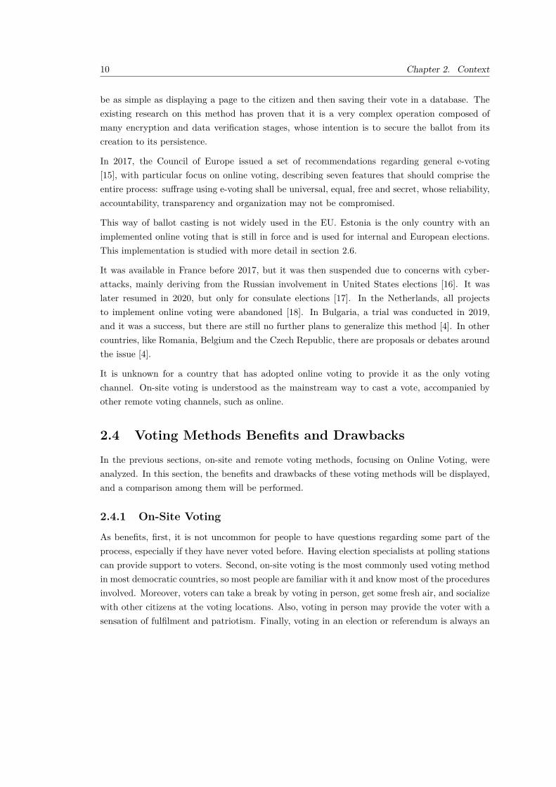
be as simple as displaying a page to the citizen and then saving their vote in a database. Theexisting research on this method has proven that it is a very complex operation composed ofmany encryption and data verification stages, whose intention is to secure the ballot from itscreation to its persistence.
In 2017, the Council of Europe issued a set of recommendations regarding general e-voting[15], with particular focus on online voting, describing seven features that should comprise theentire process: suffrage using e-voting shall be universal, equal, free and secret, whose reliability,accountability, transparency and organization may not be compromised.
This way of ballot casting is not widely used in the EU. Estonia is the only country with animplemented online voting that is still in force and is used for internal and European elections.This implementation is studied with more detail in section 2.6.
It was available in France before 2017, but it was then suspended due to concerns with cyber-attacks, mainly deriving from the Russian involvement in United States elections [16]. It waslater resumed in 2020, but only for consulate elections [17]. In the Netherlands, all projectsto implement online voting were abandoned [18]. In Bulgaria, a trial was conducted in 2019,and it was a success, but there are still no further plans to generalize this method [4]. In othercountries, like Romania, Belgium and the Czech Republic, there are proposals or debates aroundthe issue [4].
It is unknown for a country that has adopted online voting to provide it as the only votingchannel. On-site voting is understood as the mainstream way to cast a vote, accompanied byother remote voting channels, such as online.
2.4 Voting Methods Benefits and Drawbacks
In the previous sections, on-site and remote voting methods, focusing on Online Voting, wereanalyzed. In this section, the benefits and drawbacks of these voting methods will be displayed,and a comparison among them will be performed.
2.4.1 On-Site Voting
As benefits, first, it is not uncommon for people to have questions regarding some part of theprocess, especially if they have never voted before. Having election specialists at polling stationscan provide support to voters. Second, on-site voting is the most commonly used voting methodin most democratic countries, so most people are familiar with it and know most of the proceduresinvolved. Moreover, voters can take a break by voting in person, get some fresh air, and socializewith other citizens at the voting locations. Also, voting in person may provide the voter with asensation of fulfilment and patriotism. Finally, voting in an election or referendum is always an

2.4. Voting Methods Benefits and Drawbacks 11
essential duty in a citizen’s life, and voting on-site increases the sense of the importance of thewhole voting process, due to all visible infrastructure involved around the polling site.
As for drawbacks, while voting in person for the voter may be an overall small process, therequired infrastructure around it can be complex. Voting locations need to be defined, preparedand available in the election day, and election specialists, volunteers and assistants need to behired. These organization problems can be so difficult and costly to solve that municipalitiesmay attempt to converge voters at more centralized locations to save resources, which may leadto increased queue times and prevent voters from casting the ballot due to lack of transportationif the centralized location is too far from the voter’s residence. Furthermore, some people maynot make it to the polling station due to many factors, including sickness, living in remoteareas, imprisonment, or disabilities, which may decrease voter turnout. Moreover, if required,transporting ballots from polling sites to counting sites may introduce problems like ballot lossand manipulation. Finally, voting in person is very time consuming, mainly if the voting locationis far from the voter’s place or if there are long queues at polling stations. While usuallylegitimate, on-site voting can not be considered a convenient process compared with the othervoting methods.
2.4.2 Remote Voting
According to the study in [4], there are many identified benefits from remote voting, but thosevary among the available methods. Still, the main advantage among all methods is accessibilityand reduced limitations. These features are beneficial for people who live in remote areas, sick,imprisoned or simply unable to vote because of physical constraints.
In Postal Voting, ballot casting takes place in an uncontrolled environment, which may subjectthe voter to coercion. Moreover, there’s the possibility of vote interception and manipulation,damage, or even loss. It also would require an additional effort from postal services, which wouldlead to their disruption. In Proxy Voting, voting still takes place in a controlled environment,and no dependency on postal services exists, as the whole voting process would remain equivalentto on-site. However, this method breaks vote secrecy, and even if the chosen proxy is a person oftrust of the voter, nothing can prevent the former from ultimately changing the latter’s will. InVoting In-Person Abroad, voting also takes place in a controlled environment, but obviously,it only benefits voters who reside abroad. The benefits and drawbacks would be equivalent toon-site’s, with the addition of the possible distance the voter may have to travel to get to thepolling station if it is set far from their residence. In Special Polling Stations, apart from thevoter’s flexibility, it would also mean lower direct costs, since no travelling is necessary. However,it is tough to make this method available for a wide range of voters in logistical terms. Publicadministration costs are higher when compared to other methods. Finally, if the vote is castat a place where there are very few voters, the vote’s secrecy may be compromised. Finally, inMobile Polling Stations and Voting in another District, the main drawback is the lowered

12 Chapter 2. Context
flexibility for the voter compared with the other remote methods, since on-site voting is stillperformed.
2.4.3 Online Voting
This voting method has the most diverse beliefs and opinions concerning its usage, but they aremainly against its implementation because of some foundational problems.
First, online voting means that it will occur in an uncontrolled environment, like the voter’shome. Therefore, it is tough to ensure that the vote is cast from the identified voter and notfrom another individual. Additionally, voting outside a polling station may compromise theballot’s secrecy. Finally, it can be challenging to guarantee that voter computers are not infestedwith viruses or malware that may manipulate the votes or prevent them from reaching theelection servers.
Second, the possibility of cyber-attacks. Intents of this nature could cause problems with theballot casting process, making it unavailable or fraudulent, like changing voters options or modi-fying the ballot totals. There are at least three points of failure in an online voting method. Thefirst one and most vulnerable is the source device from where the ballot is cast, which as afore-mentioned explained, can modify or prevent the vote from leaving the computer. The secondexploit can occur in-transit through man-in-the-middle attacks, or over at the Internet ServiceProvider (ISP). Lastly, these criminals can target the central server to either block connections,like a Distributed Denial of Service (DDoS), or modify the persisted ballot totals.
Third, the voter’s trust in the method. According to a European survey carried in 2016 [19],71% of people agreed that some remote voting methods, including online voting, could benefitexpatriate citizens and decrease abstention levels. However, 61% also expressed concerns forpossible fraudulent activities that involved vote manipulation or denial, yet were divided aboutthe vote’s secrecy. Older survey respondents were more concerned than younger ones.
Nevertheless, many benefits arise from the online voting possibility. People who live in remoteareas, away from polling stations, may cast their vote. Also, disabled voters, people who arehospitalized or imprisoned, who live abroad, or elders would significantly have a possible wayto vote in a more convenient way. For voters who have an internet connection, they would beable to cast their ballot without needing to travel to a polling station, which would also meanlower costs for the voter. In terms of the counting process, it would be a lot easier and faster toperform.
Despite all these benefits, the foreseen advantage in voting online is to increase voter turnout.This feature is backed by the study conducted in [4], who in spite of the mixed results frompreviously studied literature, has concluded that due to its convenience, online voting wouldconvince people to vote.
2.5. Case Study - Voting in Portugal 13
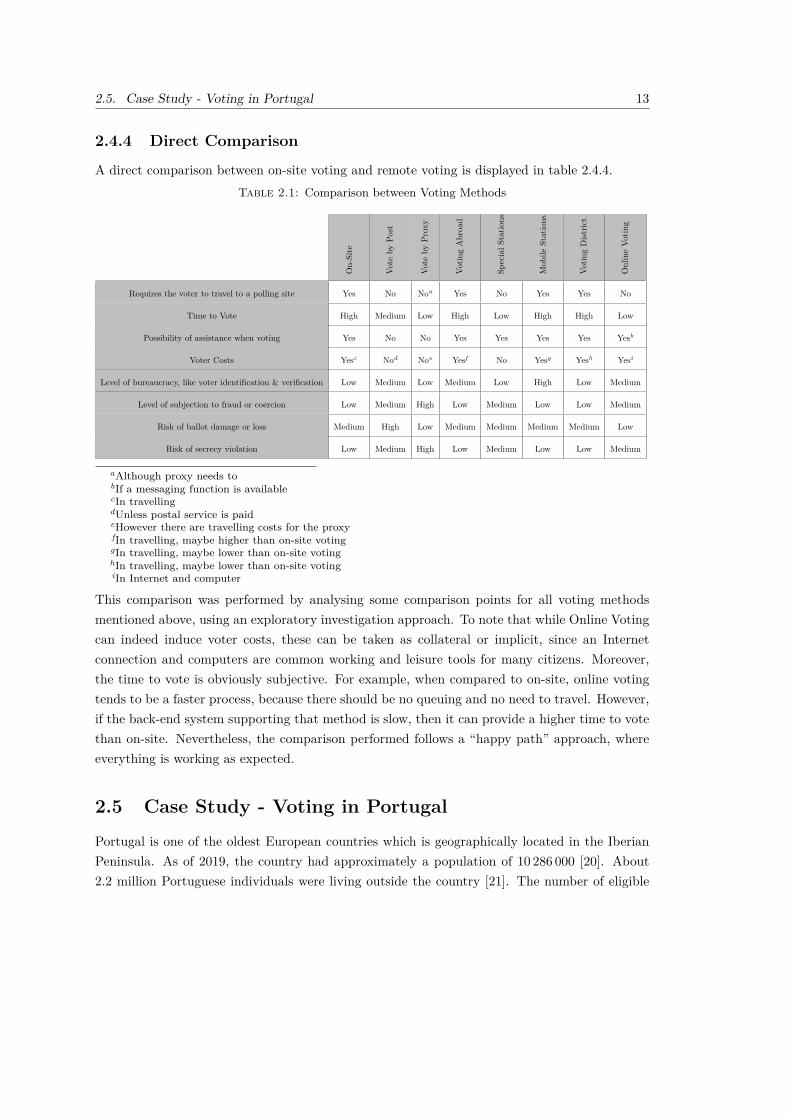
2.4.4 Direct Comparison
A direct comparison between on-site voting and remote voting is displayed in table 2.4.4.Table 2.1: Comparison between Voting Methods
On-Site
Vote
byPo
st
Vote
byPr
oxy
Votin
gAbroa
d
SpecialS
tatio
ns
Mob
ileStations
Votin
gDist
rict
OnlineVo
ting
Requires the voter to travel to a polling site Yes No Noa Yes No Yes Yes No
Time to Vote High Medium Low High Low High High Low
Possibility of assistance when voting Yes No No Yes Yes Yes Yes Yesb
Voter Costs Yesc Nod Noe Yesf No Yesg Yesh Yesi
Level of bureaucracy, like voter identification & verification Low Medium Low Medium Low High Low Medium
Level of subjection to fraud or coercion Low Medium High Low Medium Low Low Medium
Risk of ballot damage or loss Medium High Low Medium Medium Medium Medium Low
Risk of secrecy violation Low Medium High Low Medium Low Low Medium
aAlthough proxy needs tobIf a messaging function is availablecIn travellingdUnless postal service is paideHowever there are travelling costs for the proxyfIn travelling, maybe higher than on-site votinggIn travelling, maybe lower than on-site votinghIn travelling, maybe lower than on-site votingiIn Internet and computer
This comparison was performed by analysing some comparison points for all voting methodsmentioned above, using an exploratory investigation approach. To note that while Online Votingcan indeed induce voter costs, these can be taken as collateral or implicit, since an Internetconnection and computers are common working and leisure tools for many citizens. Moreover,the time to vote is obviously subjective. For example, when compared to on-site, online votingtends to be a faster process, because there should be no queuing and no need to travel. However,if the back-end system supporting that method is slow, then it can provide a higher time to votethan on-site. Nevertheless, the comparison performed follows a “happy path” approach, whereeverything is working as expected.
2.5 Case Study - Voting in Portugal
Portugal is one of the oldest European countries which is geographically located in the IberianPeninsula. As of 2019, the country had approximately a population of 10 286 000 [20]. About2.2 million Portuguese individuals were living outside the country [21]. The number of eligible
14 Chapter 2. Context
voters was exactly 10 857 196 in the last parliamentary elections in 2019 [22], and is composedby the sum of resident and non-resident Portuguese vote-eligible citizens.
Elections in Portugal are direct, meaning that no sense of electoral college exists. The minimumage to vote is 18. The voting process is entirely based on paper proceedings.
2.5.1 On-Site Voting
On-Site voting is the most common way to cast a vote. It can be performed at the assignedpolling station at election day, typically on a Sunday.
2.5.2 Remote Voting
There are no other voting alternatives for people residing in the country other than on-site. Theonly on-site method variant available is applicable to hospitalized or jailed voters at election day.In that case, they can vote in advance, usually one week before election day [23].
For people residing abroad, the only remote option available is Mobile Polling Stations (cf.section 2.2) [4], meaning that people who want to vote in another polling station are allowed todo so upon application and further authorization.
In Electronic or Online Voting, four trials were conducted in 1997, 2001, 2004, and 2005 [3, 4].Sixteen years later, there was no significant internal research, news, or even interest in adoptingan online voting system to complement Portuguese elections.
For people living abroad, the provided remote voting options depend on the election. In Presiden-tial and European elections, voting in the consulate/embassy is allowed, whereas postal vote isallowed in legislative elections, on which the voter sends the ballot using the post service. Theseoptions are only permitted for people registered on Portuguese foreign electoral lists and resideabroad at the election time [24]. Voting can then be performed by presenting the identificationnumber and the voting or citizen card.
2.5.3 Voting Statistics
Portugal provides its electoral statistics through PORDATA [25]. Participation rates in Portugalhave been continuously declining since 2005. Although the number of eligible voters as beenincreasing over time, the outcome in terms of turnout has not been reflecting that increase, quitethe contrary. In 2019, for the first time in parliamentary elections, the number of eligible voterswho sat the election out was higher than the number of actual voters (Figure 2.2).

2.5. Case Study - Voting in Portugal 15
1975 1976 1979 1980 1983 1985 1987 1991 1995 1999 2002 2005 2009 2011 2015 2019
2
4
6
8
10
Individu
als(in
millions)
EligibleVoters
Abstention
Figure 2.2: Portuguese Parliamentary Elections Overview (source: [25])
For Presidential elections, the situation is relatively less favourable in terms of abstention. Since2011, this criteria has been higher than the number of actual voters (Figure 2.3). In 2016, theturnout ratio was around 48% [26].
1976 1980 1986 1991 1996 2001 2006 2011 2016
2
4
6
8
10
Individu
als(in
millions)
EligibleVoters
Abstention
Figure 2.3: Portuguese Presidential Elections Overview (source: [25])
According to the analysed data and displayed plots, it is clear that turnout has been substantiallydecreasing over the years.
2.5.4 Impact of COVID-19
Since the COVID-19 outbreak, democratic governments across the EU have been struggling tokeep election processes legitimate and secure for its voters [27]. Furthermore, this is not only thecase for general elections. Assembly, parliament or legislative polls (depending on the country),whose voters are elected representatives (deputies, congressmen, parliament members), have also

16 Chapter 2. Context
been subject to suspensions, modifications, and limitations due to voters’ shortage caused bylockdown and health safety measures. Therefore, these extraordinary times led governmentsto “rethink how to keep legislative democracy working in emergencies and to explore remoteelectronic voting as a possible solution for legislative and committee votes” [27].
In the Portuguese Presidential Election of 2021, due to many concerns on the voters’ turnout andsafety, particularly the elderly, election officials commissioned special polling stations to daycarecentres [28] and expanded the mobility vote method to the remaining citizens with a renewedonline website for applications [29]. However, election officials took no measures to provide voterswho were infected or isolated a way to cast their ballot.
The mobility vote had mixed feelings in its implementation. The system was not ready for thealmost 250 000 voters who applied for that remote method. As a result, long queues were formedoutside polling stations, and voters sometimes had to wait more than two hours to vote [30].The author of this thesis also had the opportunity to watch, when waiting to vote at a pollingsite, at least 20 people giving up due to the long waiting times.
After the election night, it was clear that the pandemic had affected the turnout. With more than160 000 citizens infected with COVID-19 in election day [31], the turnout levels were below 40%[32], the lowest number ever achieved in Portuguese internal elections [25]. Expat abstention wasalso one of the highest achieved, around 98%. At the end of the night, the re-elected Presidentof the Republic of Portugal commented that remote voting, namely voting by post, should havebeen allowed and provided by the Office of Internal Affairs [33].
2.6 Case Study - Voting in Estonia
Once a member of the soviet union and now a full member of the EU, Estonia is a geographicallysmall country in the Baltic region with a population of approximately 1.3 million in 2021 [34].As a known example for its implementation of liberal politics, Estonia was the first nation toimplement an online voting system for internal elections [35].
Voting in Estonia follows the most accepted and used election principles on general elections[34]: (i) freedom of voting; (ii) capable of being performed by citizens or by any EU membercitizen in case of European parliamentary elections; (iii) uniformity of vote, meaning that onlyone vote per person is accepted and that all votes have equal weight; and (iv) vote secrecy andanonymity. Also, elections on Estonia are direct, meaning that no sense of electoral college exists.The minimum age to vote depends on the election type. Teenagers who are 16 or 17 years oldcan vote for local and European elections, but not for the parliament, which has an 18-year-oldlower limit.

2.6. Case Study - Voting in Estonia 17
2.6.1 On-Site Voting
On-site voting (using paper proceedings) (cf. section 2.1) can be performed at the assignedpolling station at election day, typically on a Sunday.
2.6.2 Remote Voting Methods
Estonia currently supports multiple remote voting channels, whose results are communicatedto the election day’s central election committee. These were all implemented to give the voterflexibility to cast the ballot and increase the overall turnout. Voting in advance is accepted,consisting of six voting days that typically start on the Monday before election day. Advancevoting is branched into multiple remote voting methods.
At least one voting district polling station is open in each rural municipality and city from thesixth to the third day before the election day (Monday through Thursday). All voters, includingvoters whose residency is in another electoral district, can vote. On the second day before theelection day (on Friday), polling places for all voting districts are opened for early voting and areopen until the day before the election day (until Saturday). On Friday and Saturday, electorscan only vote in their respective electoral districts [36]. This is an example of the Voting inanother district (cf. section 2.2) remote method.
Suppose the voter cannot vote at the electoral district’s polling place due to severe health issues,disability, advanced age, difficult road conditions, lack of transport, or any other valid reason.In that case, they may apply to vote at home or a specific location, like a hospital. Voting inanother location is only possible if the application has been submitted in advance. This type ofvoting occurs from the second day to the day before the election day (from Friday to Saturday)and on the day of the election (on Sunday) [36]. This is an example of the Special PollingStations (cf. section 2.2) remote method.
Both Estonian citizens who are either temporarily or permanently residing in a foreign countryhave the opportunity to vote. It is possible to vote by post, in diplomatic missions, and throughthe Internet. A voter seeking to vote by post must submit a written request to the Estoniandiplomatic mission or embassy. The same requirement applies to voters whose permanent resi-dence is still in Estonia but who are temporarily staying abroad. Voters who live permanentlyor temporarily abroad and who have not voted by post may do so on a diplomatic mission [36].These are examples of the Vote by Post (cf. section 2.2), Vote Abroad (cf. section 2.2) andOnline Voting (cf. section 2.2) remote methods.
All of the aforementioned remote methods, with the exception of Online Voting (cf. section2.2), are paper-based. However, the latter is also available for citizens residing in the country.The online voting period starts six days before election day, closing on the day before the election[36]. Online voting in Estonia was never a replacement for traditional on-site voting. Instead, itcomplements the existing voting process.

18 Chapter 2. Context
On election day, only the paper-ballot on-site voting method is allowed. Moreover, casting aballot at election day prevails over any previously released internet vote [36], since votes are onlyanonymized at the end of the vote casting stage (cf. section 2.6.4). This feature addresses theproblem of buying or enforcing a vote from a third-party individual.
2.6.3 Voting Statistics
Estonia provides electoral statistics from their dedicated website [36], promoting data analysisand comparison. In case of turnout, Estonians have had a relatively stable rate over the lastyears. In 2007, in the election that immediately succeeded the online voting trial, it was possibleto observe a significant bump in turnout, followed by a slight decrease in the two succeedingones. In case of parliamentary elections, they have always been stable since 2003, tending toslightly increase election after election. Finally, European elections present a mixed behaviour.Figure 2.4 displays the elections turnout rates since 1992, the year of Estonian independence.
1992 1993 1995 1996 1999 2002 2003 2004 2005 2007 2009 2011 2013 2014 2015 2017 20190
20
40
60
80
100
Year
Turnou
t(%
)
EuropeanParliamentary
Local
Figure 2.4: Estonian Elections Turnout (source: [36])
The first online voting trial occurred in 2005, and around 9 500 Estonian citizens opted to voteby the Internet in their local council elections [35], which only represented a proportion of 1.9%among eligible voters. Despite its initial low adherence number, this voting method was neversuspended or abandoned, increasing its usage during the years. Comparatively, according tothe official website for Estonian elections [36], the parliamentary elections of 2019 had a 43.7%proportion of online votes, which represented 247 232 ballots out of 565 045 total votes. A graphiccomparison of the proportion of online voters among total eligible voters across multiple Estonianelections is displayed in Figure 2.5.

2.6. Case Study - Voting in Estonia 19
Local2
005
Parliam
entary
2007
Europe
an2009
Local2
009
Parliam
entary
2011
Local2
013
Europe
an2014
Parliam
entary
2015
Local2
017
Parliam
entary
2019
Europe
an2019
0
10
20
30
40
50
1.95.5
14.7 15.7
24.321.2
31.2 30.5 31.7
43.746.7
1.95.5
14.7 15.7
24.321.2
31.2 30.5 31.7
43.746.7
Prop
ortio
n(%
)
Figure 2.5: Estonian Election Proportions of Online Voters Among Eligible (source: [36])
In terms of age groups, and according to the local parliamentary elections in 2019, adults from35 to 44 years old typically account for the most Internet voters, around 22%, closely followed by25 to 34-year- olds (21%) and 45 to 54-year-olds (19%). Young adults with ages between 18 and24 hold the least participation in online voting (7%). A bar chart representing these proportionsfor this and other elections is displayed on Figure 2.6.
18 to 24 25 to 34 35 to 44 45 to 54 55 to 64 65 to 74 750
20,000
40,000
60,000
Age Groups
Num
berof
votes
European 2019Parliamentary 2019
Local 2017Parliamentary 2015Parliamentary 2015
Figure 2.6: Estonian Election Proportions of Online Voters By Age Groups (source: [36])
20 Chapter 2. Context
2.6.4 Online Voting
Voting requirements are identical between on-site and online, with the latter also requiring theusage of a computer and the existence of an Internet connection. Moreover, the same votingprinciples apply, including authorization, secrecy, and votes’ integrity, which must be assured atall times. Otherwise, electronic ballots may be partially or integrally annulled by the committeein charge [37].
All Estonian citizens have an identification (ID) card equipped with digital capabilities throughits chip. To vote online, the voter needs it and a card reader to access the Estonian Electionswebsite [36] and download the voter application. The voter can then check the application’sauthenticity by either checking its digital signature or calculating the respective checksum andcomparing it with the one displayed in the companion fingerprint file.
One of the main differences between on-site voting and online voting is that the voter is authorizedto vote as many times as they want. However, only the last valid vote will be counted. Theelectronic ballot will also be annulled if the voter casts a ballot using on-site voting (cf. section2.6.1). According to Estonian election officials, these flexible measures intend to protect votersagainst any fraud or coercion [37]. Furthermore, the choice of the voter is only considered ifa legally accepted digital signature is used. The voter is also allowed to verify that the castballot has been successfully registered. In that case, they need to use another Internet-connecteddevice, like a smartphone, and install an application which will allow them to review the registeredvote. This measure enables the ballot-placing individual to check that their computer was notcompromised.
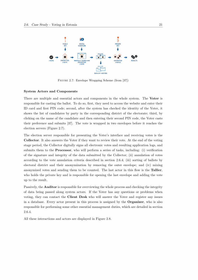
The electronic ballot itself is shielded using an asymmetric encryption algorithm (cf. section3.2.2), composed of a public and private key, and is wrapped around two digital envelopes, whichguard the voter’s identity [37]. The inner envelope contains the public key-encrypted vote, whilethe outer one is a digital signature that verifies the ballot integrity, and are then sent to electionservers. During the counting of votes, anonymous and mixed ballots are then decrypted withthe election-specific private key, succeeded by summarization and publication of the results. SeeFigure 2.7 for a graphical overview of the envelope wrapping process.
Variations
The first five user-end elections were relatively similar in terms of usability, with the only markeddifference being the amount of time required for e-voting: three days in 2005 and 2007; and sevendays in 2009, 2011 and 2013. Instead of voting via the web-embedded framework, e-voters had todownload a voting program from 2009. In 2013, the e-voting system was launched with a votingauthentication feature that allowed voters to check if their electronic vote was cast using a mobileor tablet. The following eight online voting-enabled elections relatively kept their behaviour [38].
2.6. Case Study - Voting in Estonia 21
Figure 2.7: Envelope Wrapping Scheme (from [37])
System Actors and Components
There are multiple and essential actors and components in the whole system. The Voter isresponsible for casting the ballot. To do so, first, they need to access the website and enter theirID card and first PIN code; second, after the system has checked the identity of the Voter, itshows the list of candidates by party in the corresponding district of the electorate; third, byclicking on the name of the candidate and then entering their second PIN code, the Voter caststheir preference and submits [37]. The vote is wrapped in two envelopes before it reaches theelection servers (Figure 2.7).
The election server responsible for presenting the Voter’s interface and receiving votes is theCollector. It also answers the Voter if they want to review their vote. At the end of the votingstage period, the Collector digitally signs all electronic votes and resulting application logs, andsubmits them to the Processor, who will perform a series of tasks, including: (i) verificationof the signature and integrity of the data submitted by the Collector; (ii) annulation of votesaccording to the vote annulation criteria described in section 2.6.4; (iii) sorting of ballots byelectoral district and their anonymization by removing the outer envelope; and (iv) mixinganonymized votes and sending them to be counted. The last actor in this flow is the Tallier,who holds the private key and is responsible for opening the last envelope and adding the voteup to the result.
Passively, theAuditor is responsible for overviewing the whole process and checking the integrityof data being passed along system actors. If the Voter has any questions or problems whenvoting, they can contact the Client Desk who will answer the Voter and register any issuesin a database. Every actor present in this process is assigned by the Organizer, who is alsoresponsible for performing some other essential management duties, which are detailed in section2.6.4.
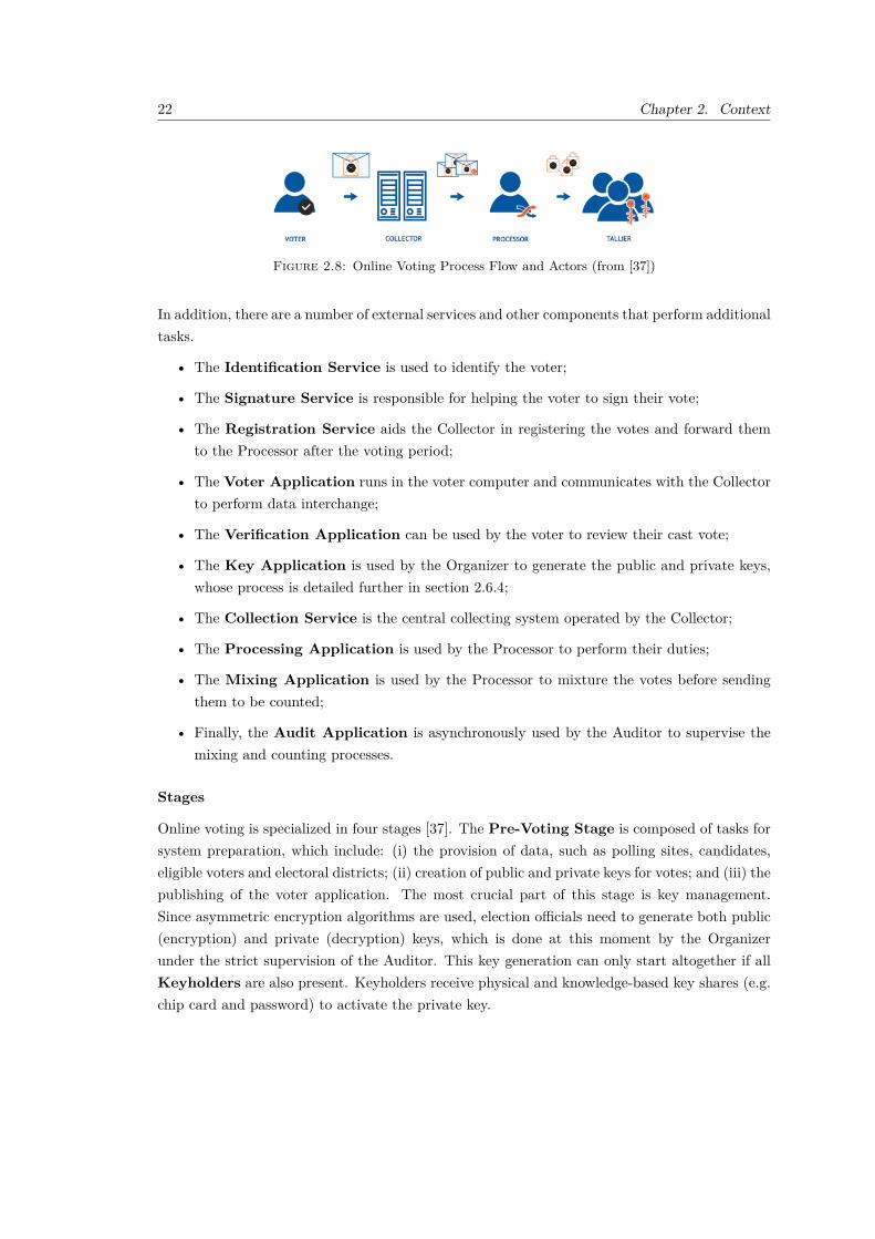
All these interactions and actors are displayed in Figure 2.8.
22 Chapter 2. Context
Figure 2.8: Online Voting Process Flow and Actors (from [37])
In addition, there are a number of external services and other components that perform additionaltasks.
• The Identification Service is used to identify the voter;
• The Signature Service is responsible for helping the voter to sign their vote;
• The Registration Service aids the Collector in registering the votes and forward themto the Processor after the voting period;
• The Voter Application runs in the voter computer and communicates with the Collectorto perform data interchange;
• The Verification Application can be used by the voter to review their cast vote;
• The Key Application is used by the Organizer to generate the public and private keys,whose process is detailed further in section 2.6.4;
• The Collection Service is the central collecting system operated by the Collector;
• The Processing Application is used by the Processor to perform their duties;
• The Mixing Application is used by the Processor to mixture the votes before sendingthem to be counted;
• Finally, the Audit Application is asynchronously used by the Auditor to supervise themixing and counting processes.
Stages
Online voting is specialized in four stages [37]. The Pre-Voting Stage is composed of tasks forsystem preparation, which include: (i) the provision of data, such as polling sites, candidates,eligible voters and electoral districts; (ii) creation of public and private keys for votes; and (iii) thepublishing of the voter application. The most crucial part of this stage is key management.Since asymmetric encryption algorithms are used, election officials need to generate both public(encryption) and private (decryption) keys, which is done at this moment by the Organizerunder the strict supervision of the Auditor. This key generation can only start altogether if allKeyholders are also present. Keyholders receive physical and knowledge-based key shares (e.g.chip card and password) to activate the private key.

2.6. Case Study - Voting in Estonia 23
The Voting Stage, where the actual voting occurs, is subdivided into additional steps. VoterIdentification is a crucial preliminary check of the individual’s authorisation to vote. Theauthentication process can be performed by combining the ID card with a predefined PIN code.Identification Service is used to ensure the authentication of the voter (Figure 2.9). The voter isthen allowed to vote, where they are presented with the candidates, making their choice (Figure2.9).
Figure 2.9: Voting Identification and Execution (from [37])
Vote Signing is performed after the voter chooses their option. The identity of the voter isnever used again after this point. The digitally signed envelope surrounding the vote ensuresits validity for future operations. The Signature Service is used to sign and validate the votingsignature before submission. The votes are registered by the Collector as they arrive, usingthe Registration Service. The latter also is responsible for confirming every encrypted voteand stamping a time-mark to its outer envelope (Figure 2.10). At the end of the election, theRegistration Service hands all its collected data to the Processor.

24 Chapter 2. Context
Figure 2.10: Voting Registration (from [37])
Optionally, the voter may want to verify the cast vote. They can do so using the VerificationApplication by installing it in another supported device. The Authentication Program receivesthe required information from the Voter Application for its operation by reading the QR code withthe smart device’s camera’s support. The Verification Application notifies the Voter, registeredin the Collection Service, of his preference.
The interaction of all components at the Voting Stage is displayed in Figure 2.11.
Figure 2.11: Voting Stage Components and Interactions (from [37])
The next stage is Processing - during this stage, a number of steps are performed:
• electronic votes are checked for their authenticity and integrity. The votes that match theones present in the data set received from the Registration Service are the result of thisstep;
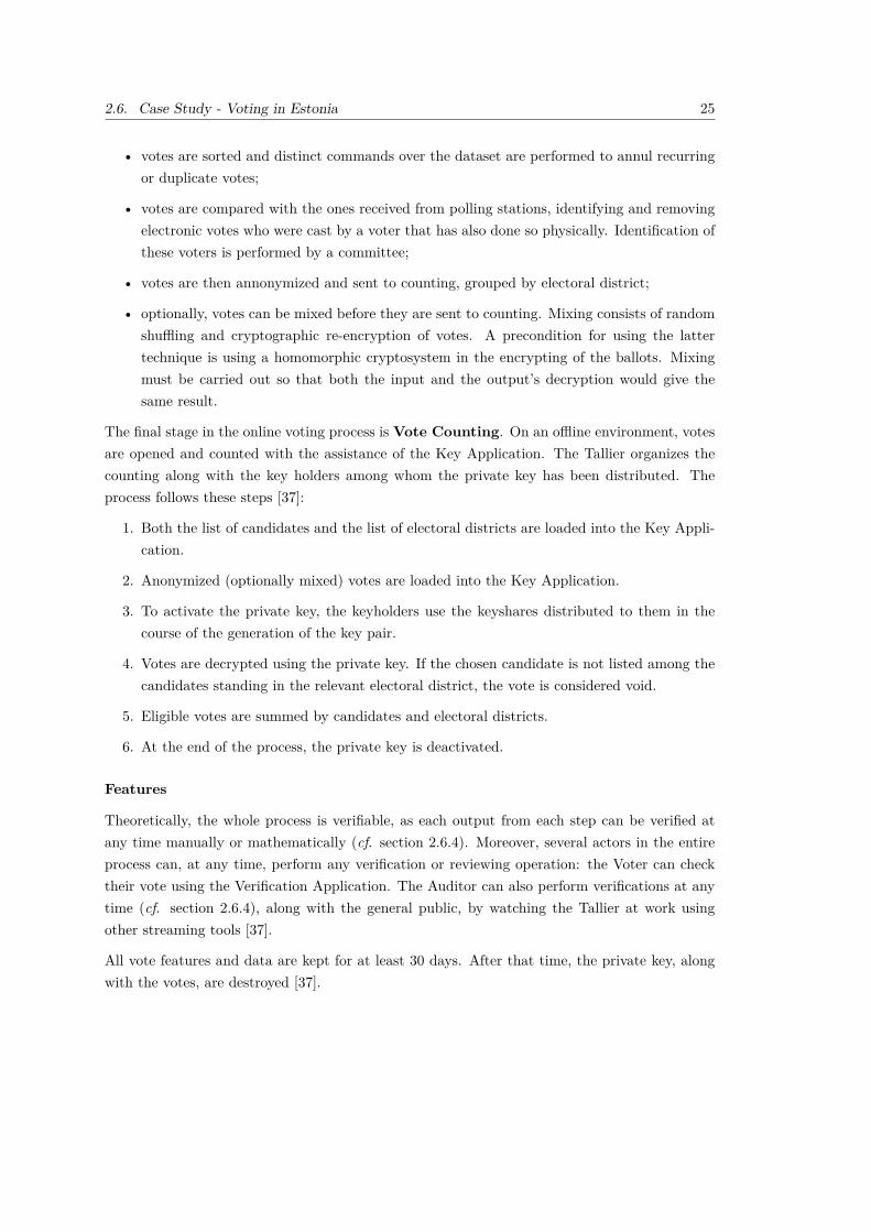
2.6. Case Study - Voting in Estonia 25
• votes are sorted and distinct commands over the dataset are performed to annul recurringor duplicate votes;
• votes are compared with the ones received from polling stations, identifying and removingelectronic votes who were cast by a voter that has also done so physically. Identification ofthese voters is performed by a committee;
• votes are then annonymized and sent to counting, grouped by electoral district;
• optionally, votes can be mixed before they are sent to counting. Mixing consists of randomshuffling and cryptographic re-encryption of votes. A precondition for using the lattertechnique is using a homomorphic cryptosystem in the encrypting of the ballots. Mixingmust be carried out so that both the input and the output’s decryption would give thesame result.
The final stage in the online voting process is Vote Counting. On an offline environment, votesare opened and counted with the assistance of the Key Application. The Tallier organizes thecounting along with the key holders among whom the private key has been distributed. Theprocess follows these steps [37]:
1. Both the list of candidates and the list of electoral districts are loaded into the Key Appli-cation.
2. Anonymized (optionally mixed) votes are loaded into the Key Application.
3. To activate the private key, the keyholders use the keyshares distributed to them in thecourse of the generation of the key pair.
4. Votes are decrypted using the private key. If the chosen candidate is not listed among thecandidates standing in the relevant electoral district, the vote is considered void.
5. Eligible votes are summed by candidates and electoral districts.
6. At the end of the process, the private key is deactivated.
Features
Theoretically, the whole process is verifiable, as each output from each step can be verified atany time manually or mathematically (cf. section 2.6.4). Moreover, several actors in the entireprocess can, at any time, perform any verification or reviewing operation: the Voter can checktheir vote using the Verification Application. The Auditor can also perform verifications at anytime (cf. section 2.6.4), along with the general public, by watching the Tallier at work usingother streaming tools [37].
All vote features and data are kept for at least 30 days. After that time, the private key, alongwith the votes, are destroyed [37].

26 Chapter 2. Context
The whole process is also configurable. Before the election begins, the Organizer is responsiblefor setting up the online voting features and may choose to change the cryptographic algorithmto be used (cf. section 2.6.4).
Equally, the secrecy of voting is ensured by the Voter’s encryption of their own vote. An asym-metric cryptographic algorithm is used so that another non-public key is necessary to performthe decryption. Cooperation between several key holders is needed to activate that key (cf. sec-tion 2.6.4). To ensure the votes’ secrecy, adding a random number (salt) to the ballot is directlyrequired, and it is done automatically by the application. Additionally, the Tallier only decodesanonymous votes (cf. section 2.6.4).
However, there may be setbacks. For instance, if the Organizer was not aware that compromisingflaws were found for a specific crypto algorithm, they may compromise the integrity of the wholeelection. It is crucial that the Organizer is a security expert who is always up-to-date with themost recent cyber-security discoveries. Moreover, the salt used to encrypt the vote should be acryptographically secure pseudorandom number.
All implemented components described in this section are publicly hosted at GitHub1. Mostcomponents are written in Java and Go programming languages.
2.7 Summary
In this chapter, on-site voting and remote voting methods were presented, along with onlinevoting. Sequentially, a comparison among all referred ballot-casting ways was performed, followedby two case studies, the first being about elections in Portugal and the last one in Estonia. Sincethe latter has a working online voting method implemented, its operation was detailed.
1https://github.com/vvk-ehk/ivxv

27
Chapter 3
State Of The Art
This chapter is divided in four sections. Due to its importance to this project, the first sectionis dedicated to decentralized web models and their respective comparison in terms of authenti-cation and security. A general introduction to data security and encryption is presented rightafter. Finally, it is followed by a brief overview of various methodologies and technologies usedthroughout this project’s conceptualization and development, which will be introduced in thesecond and third sections, respectively.
3.1 Decentralized Web Models
The Internet is a quasi-endless distributed network where users navigate freely.
In most websites, access to a particular feature or resource requires the user either to go throughan authentication or registration process, depending on already being enrolled or not. Afterthe user is registered, the organization behind the website usually persists the user data in itsown databases, which in turn may be used for other actions without the user’s awareness, sinceregistration forms and terms are often overseen due to their bureaucratic structure.
Moreover, big digital data enterprises often use tracking bots and cookies to trace and aggregateusers’ data and tendencies, which are then either sold to other companies or used to personalizethe advertisements exhibited in websites to lean towards the navigating user’s tastes [39].
In 2018, the EU launched the General Data Protection Regulation [40], constituted by laws tostraighten citizens’ online protection and privacy by limiting and regulating what companiescould do with its users’ data. Almost three years after its implementation, big data enterprisesare still profiting by using users’ data. Even if the user may now be more aware of the additionalusages of their data, the fact is that privacy consent forms that are spread among websites areusually easier to accept than to read or reject [41]. This leads to a negligent acceptance of theterms with no regards for consequences.

28 Chapter 3. State Of The Art
Decentralized web models have been purposed throughout recent years to provide a solutionto data replication and exploitation issues. The ultimate goal of these models is to give dataownership back to users, meaning that companies can use it to provide services or products toend-users without persisting or owning their data.
This section will describe and compare three developed decentralized web models in terms oftheir architecture and features.
3.1.1 Solid
Solid (derived from Social Linked Data) is an open-source, decentralized web platform createdby Tim Berners-Lee among other open-source developers. Berners-Lee is a notorious inventorand professor and is best known for the invention of the World Wide Web (WWW).
The project aims to “radically change the way Web applications work today, resulting in truedata ownership as well as improved privacy” [7]. Regardless of still being under active develop-ment and consolidation, the project has gained the interest of many developers and companiesworldwide, which led to the creation of a startup company, Inrupt1, to pursue both open-sourceand enterprise developments around the project. Moreover, this platform relies heavily on WorldWide Web Consortium (W3C) standards, which encourages companies and developers to supportthe project in their sites [42].
The central concept of Solid is the Personal Objects Datastore (POD), which represents thecomponent where resources are stored. These resources are pieces of personal information thatother applications may consume according to the user-defined authorization policies. Thesepolicies are granular, meaning that different applications may only access resources they havepreviously been given permission. This feature grants the user real data ownership and control,while at the same time promoting up-to-date personal information and data reuse [7].
PODs may be deployed by the users themselves or created on existing public POD providers.A user may create more than one POD, which may contain different information and accesslevels [42]. The main benefit of PODs is the complete personal data decoupling from third-partywebsites. Actions like registration and information updating are facilitated for users since datais entirely centralized in a self-maintainable location. However, from the applications’ point ofview, data is completely decentralized.
Architecture
Solid is a platform consisting of distributed components. As aforementioned, PODs store user-sensitive information which can then be managed by the users themselves or by applicationsoftware, depending on the granted access levels (Figure 3.1). The communication betweencomponents is based on Resource Description Framework (RDF) (cf. section 3.4.1) and Semantic
1https://inrupt.com/

3.1. Decentralized Web Models 29
Web technologies. Each POD is enriched with web capabilities using a Representational StateTransfer (REST) Application Programming Interface (API). Identity is controlled using RDFprofile documents stored in PODs, which are then accessed by applications either by directlyquerying the REST API or by using SPARQL if supported by the Solid server. SPARQL is asemantic query language that can use RDF capabilities to navigate through data stored locallyor remotely. Local data can be accessed by a simple query on the user’s pod, whereas remotedata may be retrieved by following links between the user POD and other users’ PODs [42].
Figure 3.1: Solid Architecture (source: [42])
Data Storage
Running data storage mechanism depends on the running Solid version. Enterprise Solid Server2
uses Postgres to store data, whereas the Node version3 uses the file system. Personally IdentifiableInformation (PII) is stored and categorized as RDF and non-RDF data (e.g., images, videos, text,...). RDF implies that data can be transmitted in different syntaxes, such as Turtle, JavascriptObject Notation (JSON) or RDFa. RDF is REST-friendly since it uses URLs everywhere, andoffers decentralized extensibility. This way, a set of applications can cooperate to share a newtype of data without any central authority having to approve it.
Authentication and Authorization
Solid provides an abstraction layer that allows users to identify themselves using multiple au-thentication methods. The method is chosen at the initial POD configuration stage and is keptthroughout POD’s lifetime. As of the time of writing, Solid supports two authentication modes,all based on WebID: WebID-TLS and WebID-OIDC (cf. section 3.4.4). The former is currentlybeing subject to deprecation because most modern browsers like Chrome and Edge removedsupport for client-side certificate key generation4, which is an essential feature for this method.
2https://inrupt.com/enterprise3https://github.com/solid/node-solid-server4https://caniuse.com/?search=keygen

30 Chapter 3. State Of The Art
Therefore, the latter is the default method when configuring a Solid Server right now.
It’s always the POD Owner’s responsibility to manage their resources’ access control policies.Solid’s authorization system determines whether someone has access to perform a given actionon a particular resource. There are two supported types of policy standards supported by Solid,Access Control Policies (ACP) andWeb Access Control (WAC)5. WAC was the first authorizationpolicy type to be supported, but is now considered insecure by W3C and therefore inappropriatefor production use.
3.1.2 Stacks
Stacks, previously known as Blockstacks, is an open-source network of decentralized apps andsmart contracts built on the blockchain using Bitcoin capabilities as the base. The networkintends to decentralize user data to give back control to its owner. Since this platform is entirelyBlockchain-oriented and thus wholly decoupled from a specific server or database, it significantlylimits the number of possible points of failure and dangers of a third-party data seize. Moreover,it would require a large amount of resources and time to tamper or steal data in the Blockchain[43], making this option to store data in a decentralized way very secure.
Data Storage
Data storage in Stacks is based upon three layers (Figure 3.2). The first layer is blockchain,which is great for asynchronously persisting and processing data in large quantities, but offerspoor performance in processing huge pieces of data.
As a result, Stacks only uses blockchain to store publicly-accessible data that Stacks calls Iden-tities, which comprises categories of data like domain names, usernames, or application names.These identities correspond to network/routing packets in the Open Systems Interconnection(OSI) model, which are then stored in the Atlas Peer Network, the second layer. Every corenode that joins the Stacks blockchain can obtain a full copy of this routing data, which is thenused to associate identities with a particular storage location in the final layer, the Gaia StorageSystem. It consists of a hub service and storage resource on a cloud software provider, whichcan be any commercial provider such as Azure, Google Cloud Platform, etc.
When an identity is created, a corresponding data store is associated with that identity onGaia. When a user logs into an application, the authentication process gives the application theURL of the Gaia hub, which then writes to storage on behalf of that user. Using this three-layered strategy, Stacks achieves much better performance and cost-efficiency than applicationsbuilt entirely on blockchain. The storage schema of Gaia follows a classic key-value persistenceschema.
5https://docs.inrupt.com/ess/security/authorization/

3.1. Decentralized Web Models 31
Figure 3.2: Stacks Data Storage Layered Architecture (source: [44])
Authentication and Authorization
Stacks provides a single authentication mechanism that resembles a typical client-server flowused in OAuth providers. However, the authentication action only takes place client-side. Apreviously-setup authenticator is used to exchange JSON Web Tokens (JWTs) via URL querystrings with the requester application [45].
When users choose to authenticate in an application, it sends a token to the authenticatorvia URL query string with an equally named parameter. When the authenticator receives therequest, it generates a response token for the application using a transient transit key. Thatkey’s scope is limited to that particular instance of the application, which in turn stores thatkey. The public portion of the transit key is passed in the request token. The authenticator usesthe key’s public component to encrypt a private one for the application, which is then returnedin the response [45]. It can then be used for three purposes:
• Create credentials that give the app access to a storage bucket in the user’s Gaia hub;
• End-to-end encryption of files stored for the application in the user’s Gaia storage;
• Cryptographic secret that applications can use to perform other cryptographic functions.

32 Chapter 3. State Of The Art
3.1.3 Elastos
Elastos is a blockchain-based data decentralization model, therefore running in a peer-to-peernetwork without any notion of a central server. This model’s primary goals are data protectionand copyright enforcement, providing a way for original authors to generate wealth from theirassets [46]. This vision has been materialized in a platform called Elastos Smart Web, which iscomprised by four components:
• Elastos Blockchain - enabling a trustworthy identifier to be assigned to each user by takingadvantage of the blockhain capabilities;
• Runtime - an operating system for virtual machines where applications that use this modelcommunicate in a peer-to-peer network;
• Carrier - a completely decentralised peer-to-peer platform that takes over network trafficbetween different virtual machines and exchanges information on behalf of applications;
• Software Development Kit (SDK) - used by applications to access information on users’behalf.
Data Storage
Elastos uses a storage architecture based on Inter Planetary File System (IPFS)6 called ElastosHive, which provides a decentralized storage solution for decentralized applications. Hive is aDatabase as a Service (DBaaS) that exposes an HTTP API for easier database access. Eachpersisted document is distributed across storage nodes in different regions of the world througha dedicated Hive network for higher data availability [47].
Authentication and Authorization
Elastos uses the power of blockchain to issue Decentralized Identifiers (DIDs) to validate useridentity. These DIDs are managed through a DID Sidechain, which is a separate blockchain thatinterchanges information with the main one (Elastos Blockchain). These identifiers are uniqueand universal, meaning that users using different applications can communicate seamlessly withone another. DIDs is composed of public and private keys, where each public key is linked to acorresponding private key used to sign transactions. This mechanism promotes authenticationbetween strangers and eliminates the need for a third party to confirm the transacting parties’identities [48].
One might wonder about the implications of storing sensitive and private content on a sidechain.However, content stored there can be encrypted, so that even if an individual traversed theblockchain, they would be unable to decrypt the actual content.
This authorization process works as follows [48]:6https://ipfs.io

3.1. Decentralized Web Models 33
1. Generate a private key, public key, and DID using the Sidechain;
2. Users sign their content using their private keys and use their public keys to verify thesignature, thus ensuring that their public keys and DID match;
3. Signed content is written to the DID Sidechain;
4. Said signed content is the property of a user and it can be provided to third parties asproof that the content does indeed belong to said user.
3.1.4 Decentralized Models Comparison
In this section, a comparison among the three previously decentralized data models will beperformed. Three main model features will guide this process: authentication, authorizationand data storage. This analysis is depicted in Table 3.1.
Table 3.1: Comparison of Data Decentralization Models
Solid Stacks Elastos
Authentication -How it works
Based on WebID-TLS and WebID-OIDC, using JWTsfor requesting data
Uses an authenti-cator to generateJWTs purely onclient-side
Uses DIDs to iden-tify the users, whichare composed ofpublic and privatekeys
Authentication -Supports multi-ple authenticationproviders
Yes No No
Authorization - Howit works
Uses ACPs config-ured by the user
Private keys only al-low access a specificGaia section
DIDs only allow theuser to access a spe-cific portion of theblockchain
Data Storage -Technology
Postgres or File Sys-tem
Gaia Hub, an off-chain architecture
Elastos Hive, basedon IPFS
Data Storage - En-cryption
Data may beencrypted depend-ing on the PODprovider
Encrypted usingpublic-private keys
Encrypted usingpublic-private keys

34 Chapter 3. State Of The Art
Solid Stacks Elastos
Data Storage - DataLocation
Within the POD
Blockchain for sim-ple data and CloudProviders for largedata
Blockchain
3.2 Data Security and Encryption
When talking about elections and election systems, it’s impossible not to think on security atboth infrastructure and data levels. If security policies are not carefully planned and designed,online voting can undermine the confidence in the whole electoral process.
Data security aims at preventing unwanted access, corruption, or theft of digital information overits entire lifespan. It is a notion that covers all aspects of information security, from hardwareto administrative policies and access control. The base for a robust data security program is theCIA triad: Confidentiality, Integrity, and Availability [49].
The Confidentiality aspect evaluates how information is kept secret. It can be achieved byencrypting data subject to storage or transfer across a communication channel. The biggestthreats to confidentiality are typically social engineering, communication interception, or usageof deprecated encryption algorithms [49].
The Integrity aspect assures that data is reliable and has not been tampered with, either tochange the encrypted contents of a message or to invalidate them. Typically, integrity is directlydependent upon confidentiality: first, data is hidden (confidentiality), and then you assure it isalways reliable (integrity) [49]. Both these aspects are based upon data cryptography.
Finally, the Availability aspect guarantees that one system can grant data access in a reasonableperiod. Avoiding single points of failure, data redundancy, failover policies and DDoS attackprotections are common ways to achieve availability [49]. This aspect is not directly tied todata encryption but to other mechanisms and procedures that assure data is accessible wheneverneeded.
Data encryption is the process of hiding data from third-party actors. It works by using one ormany complex mathematical algorithms known as data encryption ciphers, which transform plaintext data into an unrecognizable character sequence known as ciphertext [49]. An acceptableencryption system should be robust enough to sustain or invalidate attacks from a maliciousactor. This robustness is achieved by guaranteeing that ciphertext can never be decryptedwithout using the encryption key and assuring that two equal encryption inputs (i.e., plain data)never produce the same ciphertext under the same encryption key. Encryption is also used toverify data integrity, which ensures that one cyphertext resulted from the authentic original

3.2. Data Security and Encryption 35
message and therefore has not been tampered with or manipulated. Encryption systems can becategorized according to their key management, method or reversibility.
The following sub-sections will explore different cipher methods and highlight their differences.
3.2.1 Symmetric Ciphers
In a symmetric cipher, the encryption key is used to both encrypt and decrypt data [50], asshown on Figure 3.3. It is, therefore, a reversible encryption algorithm.
Figure 3.3: Symmetric Encryption (source: [50])
As long as the encryption key is not leaked to an unauthorized party, trusted actors can besure that they are communicating with one another or safely reading stored data. As a result,the major drawbacks of symmetric ciphers are how the encryption key can be kept safe amongauthorized actors and how it should initially be exchanged [50]. In the event of a malicious actorintercepting the key, the data communication or storage are said to be compromised since theactor can eavesdrop or tamper the information being exchanged or impersonate the legitimateparticipants [51].
Symmetric ciphers can be used to achieve confidentiality performantly, but they can’t be usedto perform data integrity checks.
Cipher Methods
Cipher methods represent how symmetric data encryption algorithms perform the conversion ofplaintext into ciphertext. There are two methods: block and stream ciphers, both being twoseparate routes to the same end goal.
In a block cipher, data gets encrypted in chunks. It gets plaintext messages broken down intofixed-size blocks before converting them into ciphertext using the encryption key. A streamcipher, on the other hand, breaks a plaintext message down into single bits, which are thenconverted individually into ciphertext using a different key [49].
Stream method usually produces ciphertext quickly since algorithms are linear in time complexityand constant in space complexity, but achieves low diffusion as a plaintext character is restrictedto a single cyphertext symbol [52]. In the block method, diffusion is greatly achieved since the

36 Chapter 3. State Of The Art
information of one character is diffused across several ciphertext symbols, since data is groupedin blocks, but it is slower to produce encrypted text.
Caesars’ cipher is known to be a streamed method, but most modern symmetric encryptionalgorithms are block methods, like Data Encryption Standard (DES) and Advanced EncryptionStandard (AES) (cf. section 3.2.1).
When working with block methods, is it crucial to select the right mode of operation, and alsopadding and Initialization Vector (IV) when the mode of operation demands one. A modeof operation defines how to use a cipher’s single-block operation to safely transform amountsof data greater than a block [53]. Examples of modes of operation are Electronic Code Book(ECB), Cipher Block Chaining (CBC) and Counter Mode (CTR).The IV doesn’t need to besecurely stored but should not be shared among different encryption sessions since it may turnthe ciphertext susceptible to dictionary attacks when encrypted under the same key [54]. Themost standard way to guarantee it doesn’t happen is to generate a cryptography-safe pseudo-random number and use it as the IV. It can then be prepended to the ciphertext.
Examples
An example of a symmetric algorithm is the DES, which was discontinued in favor of AES by theUnited States government7, since the former has a short 56-bit key size, making it susceptibleto brute-force attacks that can crack the key in a reasonable period. In 1999, a DES key wassuccessfully cracked in under a day8. The AES algorithm uses 128, 192 or 256 bit key sizes andit is unknown of any successful key crack attempt.
3.2.2 Asymmetric or Public Key Ciphers
Asymmetric ciphers are reversible algorithms that involve a pair of keys known as public andprivate keys. As their names imply, the public key can be freely shared with anyone, but theprivate key must be kept safe. Data is encrypted with the public key and can only be decryptedwith the corresponding private key (Figure 3.4). Both are generated at the same time. Publickey pairs can be of any size, but the most used ones are 1024 and 2048 bits [55].
Figure 3.4: Asymmetric Encryption (source: [55])
7https://csrc.nist.gov/projects/block-cipher-techniques8https://web.archive.org/web/20120503083539/http://www.toad.com/des-stanford-meeting.html

3.2. Data Security and Encryption 37
Asymmetric encryption is not appropriate for large amounts of data [55]. However, a hybridapproach may be used for these cases: information is encrypted using a symmetric encryptionkey, which is then encrypted using a public key and sent over along with the encrypted ciphertext.The receiver can then decrypt the symmetric key using the private key, and finally use it todecrypt the big cipher text.
The reverse of the flow in Figure 3.4 is also possible, i.e., data can be encrypted using the privatekey and decrypted with the public key. However, this is only desirable to verify data integrity,which is an aspect that is not achieved using symmetric ciphers. Integrity can be verified byusing the capabilities of hashing (cf. section 3.2.3) and the public-private key pair to producemessage digests or checksums called digital signatures (Figure 3.5). They assure non-repudiationof information [49].
Figure 3.5: Data Integrity using Digital Signatures (source: [51])
A hashed version of the plaintext is produced and then encrypted using the sender’s private key,which is then sent to the recipient. In turn, the recipient decrypts the received data using thepublic key of the sender. The recipient then uses the same hashing algorithm (whose informationis also sent in the digital signature) that generated the original hash to produce another hash ofthe same data. If both sent and generated hashes match, then data has not changed since it wassigned. However, if they don’t, then data may have been tampered with or the communicationschannel is not using a proper public-private key pair.
To avoid man-in-the-middle attacks, the public key should only be trusted when combined witha public key certificate, which certifies that the key being sent is authentic [49].
3.2.3 Irreversible Ciphers (Hashing)
The last type of ciphers to be presented are called irreversible, hashers or message digest algo-rithms. In this type of cryptography, for a given input the cipher will produce a hash code thatis practically infeasible to return to the original state. In short, this hash is a fingerprint of thedata [56].

38 Chapter 3. State Of The Art
Unlike encryptors, hashers should be deterministic, i.e., given the same input, the same hashshould be produced. Hashes should also be collision-free so that two different inputs will notproduce the same hash code. If data changes, the fingerprint will also change in unpredictableways. The hash cannot be used to deduce the content of the hashed data. A very common andwidely used example of a hasher is the Secure Hash Algorithm (SHA).
3.3 Methodologies
In this section, all methodologies that will be used throughout this project will be introducedand described. These methodologies can be described as forms to analyze a process, idea, andoverall concepts. Most of the methods presented are going to be used in the Value Analysis (cf.chapter 4).
3.3.1 Innovation Process
The innovation process is divided in three main components (Figure 3.6): Fuzzy Front End(FFE) or Front End of Innovation (FEI), New Product and Process Development (NPPD), andCommercialization [57].
Figure 3.6: The Innovation Process (source: [57])
The New Concept Development (NCD) model is an innovation evaluation process proposed byPeter Koen in his technical report [57] to provide a common language and insights for FFEactivities. FFE “presents one of the greatest opportunities for improving the overall innovationprocess” [57], and can be described as the stage that takes place before the formalization of theresult. This model (Figure 3.7) is comprised of three components: a component correspondingto the front-end innovation, which is divided into five elements; an engine that drives theseelements; and external influencing factors that affect and constrain the two other components.Instead of processes, the inner parts of the NCD model were explicitly designated as elements.This designation intends to discourage innovators to follow strict processes that may not applyto every situation [57].

3.3. Methodologies 39
Figure 3.7: The NCD model (source: [57])
The first element of the front-end innovation component is Opportunity Identification, where theorganization identifies the opportunities deemed worthy of investigation. The goals of the orga-nization essentially drive this identification. Innovators may use multiple tools and techniqueslike mind maps to expose and connect thoughts in a brainstorming session. The second elementis called Opportunity Analysis, where a translation between previously identified opportunitiesand business opportunities is performed, to assert that they are valid and minimally viable. Thefollowing element is called Idea Genesis. In this element, thoughts and connections betweenconcepts are ultimately transformed into a single concrete idea subject to exploration, analysisand enhancement [57]. The Idea Selection element consists of selecting the most promising ideasin terms of business value, viability and reliability. Finally, the Concept and Technology Devel-opment element involves developing a business case according to multiple factors and businessconstraints such as market potential, customer needs, competition, investment, and risk. Theentry points for this model are either Opportunity Identification or Idea Genesis [57].
The influencing factors component consists of multiple factors such as organizational vision,strategy, goals, mission, competition, capabilities and maturity of technologies involved. Thefinal component, the engine, is driven by the two aforementioned components and by the cultureof the organization.
3.3.2 Business Model Canvas
The business model canvas is a tool that describes and provides a visual representation of abusiness model [58]. It is divided in nine blocks, each holding a specific purpose:
• Customer Segments - defines the different groups of people or organizations an enterpriseaims to reach and serve;

40 Chapter 3. State Of The Art
• Value Propositions - describes the bundle of products and services that create value for aspecific Customer Segment
• Channels - describes how a company communicates with and reaches its Customer Segmentsto deliver a Value Proposition;
• Customer Relationships - describes the types of relationships a company establishes withspecific Customer Segments;
• Revenue Streams - represents the cash a company generates from each Customer Segment;
• Key Resources - describes the most important assets required to make a business modelwork;
• Key Activities - describes the most important things a company must do to make itsbusiness model work;
• Key Partnerships - describes the network of suppliers and partners that make the businessmodel work;
• Cost Structure - describes all costs incurred to operate a business model.
3.3.3 Value Model Canvas
The value model canvas is a value illustration template proposed by Alexander Osterwalder thatlinks and asserts that a product or service is well-positioned for its targeted customer segments[59]. This visual representation (Figure 3.8) aims to make value propositions visible and tangibleto facilitate their analysis.
Figure 3.8: Value Model Canvas (source: [59])

3.3. Methodologies 41
This model relates two business model canvas blocks (cf. section 3.3.2): Value Proposition andCustomer Segments. The former block is presented to the left and is called Value Map, whilethe latter is on the right, called Customer Profile. The arrows in-between them have an oppositedirection, meaning that needs of customers should make them seek the qualities present on theleft, while value propositions should seek to appease those needs. This bidirectional connectionis called Fit [59].
Individual blocks of this canvas can be described as such:
• Customer Jobs - describes the duty of customers in their personal and professional lives;
• Gains - enumerates what customers are seeking;
• Pains - describes bad outcomes related to customer jobs;
• Gain Creators - describes how a value offer creates customer gains;
• Products and Services - lists all value offers in the form of a product or service;
• Pain Relievers - expresses how the proposed value offers solves customer pains.
The filling of this representation is usually carried out from right to left since customer seg-ments’ profiling should be first performed by breaking down their characteristics into the blocksmentioned above, before making value propositions to fulfil those respective customers’ needs.
3.3.4 Function Analysis System Technique
Function Analysis System Technique (FAST) Diagrams provide a graphical representation of howfunctions are linked or work together in a system (product, or process) to deliver the intendedgoods or services. A function is defined as that which a product or process must do to makeit work and sell [60]. It is the original intent or purpose that a product, process or serviceis expected to perform. In FAST Diagrams (Figure 3.9), a function’s description is restrictedto a two-word format - an Active Verb + Measurable Noun, like Carry Load; Transmit Light;Generate Voltage; Project Image.
A FAST Diagram has two vertical scope lines, one on the extreme left and one on the extremeright, and everything included in the study lies inside them. Only primary and secondary func-tions and design objectives are shown inside [61]. Higher order and assumed functions are shownoutside them on the left and right, respectively. Every FAST Diagram has a critical path crossinghorizontally.
3.3.5 Technique of Order Preference by Similarity to Ideal Solution
Technique of Order Preference by Similarity to Ideal Solution (TOPSIS) is a Multi-CriteriaDecision Making (MCDM) method originally purposed by Hwang and Yoon in 1981 [62]. Thismethod discriminates positive and negative criteria, and through mathematical equations and

42 Chapter 3. State Of The Art
Figure 3.9: Features of the FAST Diagram (source: [60])
procedures, researchers are able to move closer to an ideal solution and farther from less-desirablesolutions [63]. TOPSIS requires all attributes and their respective weights to be presented innumeric values in a normalized scale. Criteria or attributes can be positive or negative, and itinfluences the outcome. The method can be applied by performing five sequential steps.
Let m be the number of options available, n the number of attributes/criteria to score, xij thescore of option i for criteria j in a matrix of scores X = (xij)m×n. Let also J be the set ofpositive attributes and J
′ the set of negative ones.
First Step
The first step in the TOPSIS method is to construct a normalized decision matrix R = (rij)m×n,which is the result of transforming attribute dimensions into non-dimensional ones, allowing forfurther comparisons to be performed [63]. This step can be accomplished using the expressionin equation 3.1.
rij = xij√(∑m
k=1 x2kj)
, i = 1, 2, ..., m , j = 1, 2, ..., n (3.1)
Second Step
After creating R, the second step is to build a weighted normalized decision matrix V = (vij)m×n
[63]. Assuming there is a weight wj for criteria j, then using equation 3.2.

3.4. Technologies and Techniques 43
vij = wjrij (3.2)
Third Step
The third step is determining the best solution (A∗) and worst solution (A′) by performingmaximum and minimum operations in vij , depending on whether they are positive or negativecriteria [63]. They can be calculated as displayed in equation 3.3.
A∗ = v∗1 , ..., v∗n, where v∗j = {〈max(vij) | j ∈ J〉 , 〈min(vij) | j ∈ J′〉}
A′
= v′
1, ..., v′
n, where v′
j = {〈min(vij) | j ∈ J〉 , 〈max(vij) | j ∈ J′〉}
(3.3)
Fourth Step
The fourth step is to calculate the separation measures for the positive alternative (S∗i ) and forthe negative alternative (S′
i) [63] (equation 3.4).
S∗i =√∑
(v∗j − vij)2, i = 1, ..., m
S′
i =√∑
(v′j − vij)2, i = 1, ..., m
(3.4)
Fifth Step
Lastly, in the fifth step the relative closeness to the ideal solution (C∗i ) is calculated [63], usingequation 3.5.
C∗i = S′
i
(S∗i + S′i)
, 0 ≤ C∗i ≤ 1 (3.5)
The set of solutions can then be ranked according to the descending order of C∗i , meaning thatthe option closer to 1 is the best solution [63].
3.4 Technologies and Techniques
In this section, a brief analysis on technologies and software techniques that will be used through-out this project will be presented.
3.4.1 Resource Description Framework
RDF is a standard model proposed in W3C for data exchange on the Web [64]. This modelprovides inter-operability between applications that exchange information on the Web. It works

44 Chapter 3. State Of The Art
by giving names to the relationship between things and the two ends of the link, creating triplesin the form of subject, predicate and object.
Considering the example of a sentence "John is the owner of http://www.isep.ipp.pt/Home/John",then the Subject/Resource portion is "http://www.isep.ipp.pt/Home/John", the Object/Literalis John and the Predicate that correlates both things is "Owner". These terms can be specifiedusing RDF (Listing 3.1).
1 <rdf:RDF >2 <rdf:Description about =" http: // www.isep.ipp.pt/Home/ Andre ">3 <s:Owner >John </ s:Owner >4 </ rdf:Description >5 </ rdf:RDF >
Listing 3.1: RDF syntax example
3.4.2 OpenID Connect
OpenID Connect (OIDC) is an interoperable authentication protocol based on the OAuth 2.0family of specifications. It uses straightforward REST with JSON message flows and lets de-velopers authenticate their users across websites and applications without owning or managingpassword files [65]. OIDC allows for clients of all types, including browser-based JavaScript andnative mobile apps, to launch sign-in flows and receive verifiable assertions about signed-in users’identity. Since user authentication data is centralized in an Authorization Server, OIDC allowsusers to reuse an existing account to sign in to multiple websites, without needing to create newpasswords for them.
This protocol is based on the interchange of ID Tokens9, typically JWTs, that contain claimsthat identify the user and their roles within a system. Some of the default claims are the tokenissuer (iss), which must match the identity provider; the subject (sub), which must be the user’sunique identifier; and the expiration time (exp), which tells applications when that particulartoken will expire.
The number of tokens returned by an OIDC application varies according to the applied autho-rization flow. For example, the Authorization Code flow10 typically consists of the exchange ofa code generated by the OIDC Identity Provider upon user consent for three tokens: an accesstoken, which is used by client applications to access a protected server application; an id token,which is typically more extensive than the access token in size and that provides more claims(ergo, user information) and is not used to access any protected API; and finally, a refresh tokenused to retrieve a new access token when the first one expires. For client applications, refreshtokens improve the authentication experience significantly since the user only authenticates once
9https://openid.net/specs/openid-connect-core-1_0.html#IDTokenValidation10https://auth0.com/docs/authorization/flows/authorization-code-flow

3.4. Technologies and Techniques 45
through the web authentication process, and subsequent re-authentication can occur withoutuser interaction.
3.4.3 WebID
A WebID is an HTTP URI which refers to an Agent (Person, Organization, Group, Device, etc).The result is an identifier that is used for applications to identify their users [66]. A WebID ProfileDocument must be available in turtle11. WebIDs can be used to build a Web of trust by allowingpeople to link together their profiles in a public or protected manner. It can then be used by aService to make authorization decisions, by allowing access to a resource depending on the prop-erties of the agent. An example of a WebID can be https://andre.isep.ipp.pt/profile/card#me orhttps://isep.ipp.pt/profile/andre/card#me.
3.4.4 WebID-OIDC
The WebID-OIDC protocol specifies the mechanism through which the WebID (cf. section3.4.3) is obtained from the OIDC (cf. section 3.4.2) ID Token and takes advantage of both thedecentralized WebID flexibility and the field-proven OpenID Connect security. WebID-basedprotocols use the WebID URI as a globally unique identifier. The WebID-OIDC protocol adds aprocedure to derive a WebID URI from an ID token (rather than the combination of the issuerand subject claims) [67]. This protocol’s flow is depicted in Figure 3.10.
Figure 3.10: WebID-OIDC Flow
11https://www.w3.org/TR/turtle/

46 Chapter 3. State Of The Art
3.4.5 Outbox Pattern
A challenge when implementing a message-driven architecture across multiple services is atom-ically updating the state in the local service database while resiliently publishing its relatedevent into the message broker, or saving another state in another service, somehow based ontransactions. Examples of such operations include persisting data to another database, callinganother service to send state data, or just simply sending an e-mail to a customer after an orderasynchronously. If saving state in the local database is possible, but then the next state-changingoperation fails (Figure 3.11), one way would be to undo the recent database changes, but whatif that fails too? The system will end up in an inconsistent state.
Figure 3.11: State-changing operation failing after a local transaction (from [68])
One approach to overcome this problem is by applying eventual consistency over a distributedtransaction mechanism. The Outbox is a type of Guaranteed Delivery pattern [68]. Whendistributed data persistence should be viewed as one transaction, the system should persistthe local changes and also save messages in the same database to serve as commands for theadditional actions that should be performed (Figure 3.12). The list of messages to be processedis called an Outbox, just like in the e-mail domain.
Figure 3.12: Outbox pattern (from [68])

3.4. Technologies and Techniques 47
The second element of the system should be a separate process that periodically checks thecontents of the Outbox and processes the messages (Figure 3.13).
Figure 3.13: Separate Outbox process (from [68])
After processing each message, the message should be marked as processed to avoid unnecessaryre-sending. Nevertheless, even designing this mark, that operation may fail as well, which willcause the next Outbox processing iteration loop to pick up that message again and re-send it.Therefore, this pattern delivers messages in an At Least Once12 fashion.
3.4.6 Hangfire
Hangfire13 is an open-source job manager for distributed .NET applications. This job managerdoes not run in a separate process. Instead, it is embedded into the service process by makinguse of its threads. This framework is intended to be used by any application that wants toperform background or scheduled work, whether in a single instance or in a multi-instance, scaledenvironment. That is because it uses a persistence mechanism (the Job Storage) to distributework among different instances of the application (Figure 3.14). Supported databases includeMicrosoft SQL Server, MySQL, MongoDB, and Redis.
12https://www.cloudcomputingpatterns.org/at_least_once_delivery/13https://www.hangfire.io/

48 Chapter 3. State Of The Art
Figure 3.14: Distributing Work in Hangfire14
Examples of requests where one might want to delegate additional processing to a backgroundjob involve operations that usually take a long time. Hangfire can also be used to implement theOutbox pattern (cf. section 3.4.5) to serve as the separate message processor.
3.4.7 CAP
CAP15 is a .NET Core library that transparently implements the Outbox pattern (cf. section3.4.5) by providing transaction capabilities that allow the system to store both the entity stateand a message under the same local transaction (Figure 3.15.
Figure 3.15: CAP framework implementing the Outbox pattern (from [69])
CAP can also be used as an event bus. An event bus is a software pattern where entities,services or handlers send events to a central broker, and all subscribers receive and process eventsasynchronously. An event bus is also a form of encapsulating the message broker connection using
15https://github.com/dotnetcore/CAP

3.5. Summary 49
abstractions so that changing a broker is only a matter of reconfiguring the system, minimizingthe code changes necessary to do so.
This library works with the two most used message brokers, Apache Kafka and RabbitMQ, andcan store the outbox in most database vendors, including Microsoft SQL Server, MySQL, andMongoDB.
3.5 Summary
This chapter discussed and presented the state-of-the-art and was divided into three sections.In the first section, data decentralization models were analyzed and compared among them. Inthe second section, there was a presentation of the different methodologies that are used in thisdocument. Finally, in the last section, technologies and concepts applied throughout this projectwere defined.
In the next chapter we will perform a value analysis on a possible electronic voting system usingSolid, and also evaluate the necessary requirements for the proof of concept.


51
Chapter 4
Analysis
This chapter provides an analytical overview of the problem stated in this document. Thisanalysis is divided in two perspectives. The first section is focused on the potential value broughtby an hypothetical online voting solution. The second section takes into account the results fromthe value analysis to provide the requirements engineering for the solution.
4.1 Value
Value Analysis is an organized and empirical method in which a concept, product, or service isanalyzed in terms of its value. This method seeks to increase the value of a product or serviceby minimizing production costs while maintaining the desired quality.
This section aims to analyze the value of this project. First, the front-end of innovation usingthe New Concept Development model, described in section 3.3.1, is detailed using the five FFEelements. Rightly after, the value concept is defined, and a value proposition is presented.
4.1.1 Innovation Process
In this section, the Peter A. Koen NCD model (cf. section 3.3.1) will be applied to translate apossible opportunity into an organizational concept capable of being explored. Since this projectrelies heavily on research and concept-proving, the innovation process area subject to analysiswill be the FFE.
Opportunity Identification
Voting turnout has been decreasing for the past 25 years in the EU [4], and most member nationshave failed to introduce significant changes to existing voting methods that could have changedthis fact. In parallel, today, society lives in an interconnected world. Smartphones, computers,and applications help many people by performing tasks that would otherwise be too tediousor repetitive to do by humans. There is no doubt that technology is here to stay and evolve.
52 Chapter 4. Analysis
However, little of that technology has been applied to provide a more convenient voting processfor citizens.
Technology can be used by a voting process in multiple ways, like adopting electronic booths atpolling stations. However, this project will focus on online voting (cf. section 2.3).
One EU member nation that has employed this voting method in their national voting systemis Estonia (cf. section 2.6). The country’s abstention levels are stable since the introduction ofonline voting in 2005 and contrast with the steep decline in voting interest in ex-USSR nationsover the last years [9]. Moreover, the turnout level is above an "established democracy"1 likePortugal, as seen in the carried case study (cf. section 2.5)
Opportunity Analysis
Voting turnout is impacted by many other factors [9], and therefore online voting is not a silverbullet that will always mean an abstention decrease. Nevertheless, according to the findings insection 2.4.3, introducing online voting could indeed have a positive impact on turnout. It willbenefit many citizens that today have difficulties reaching polling sites.
It is also essential to analyze the people’s trust in technology when applied to such delicatematters as elections. Most of the raised concerns involve vote manipulation or Voter coercion,as also studied in section 2.4.3. Nevertheless, it should be noted that online voting is a relativelynew concept when compared to on-site voting. Naturally, citizens see the latter as a more securemethod because of its strong establishment in election processes. However, no voting method is100% safe, and the traditional on-site voting process is also not perfect in this matter (cf. section2.4.1).
Looking at the case of Estonia (cf. section 2.6), online voting year-on-year adoption rates havebeen growing significantly (cf. figure 2.5), starting at 1.9% in 2005 and increasing all the way to46.7% adoption rate in 2019 European Elections.
However, looking at another online voting method implementation attempt, like the Dutch one[18], the pressure of a political group towards online voting banishment dictated the fall of themethod in the country. The group claimed that the system was unsafe and that there werefundamental design issues in its implementation. These unanswered claims led to the decreaseof Voters’ trust in the method and the failure of its countrywide adoption.
The conclusion that can be taken from this example is that technology must earn the citizens’respect and confidence by minimizing design and security flaws that could challenge the system’sadoption and settlement.
1https://eufactcheck.eu/factcheck/mostly-false-turnout-at-national-elections-in-europe-is-between-70-and-80-percent/

4.1. Value 53
To sum up, there are drawbacks in each voting method that could be further minimized byintroducing more ways to vote. According to the comparison performed in section 2.4.4, onlinevoting is one of the most convenient and safer processes out of the studied voting methods ifappropriately implemented.
Idea Genesis
In the last years, recurring problems with the way giant data companies like Google or Facebookhandle personal user’s data have triggered the development of multiple data decentralizationplatforms (cf. section 3.1). In these platforms, data is held within the user’s grasp and is usedby other decentralized applications (i.e., applications that use data decentralization platforms)by user’s demand and authorization.
By making use of these emerging platforms, Voters could have their ballots within their ownpossession, and at the end of the voting period, be consumed by a decentralized applicationcontrolled by election Officials that would gather all votes, remove personal information fromthem, assert their validity, and count them. Votes could be stored in Voter spaces either managedby them entirely, or in a private location issued by election authorities, which could be used forother documents and communications.
The usage of centralized servers to control the whole vote process, managed by election Officials,could be considered an alternative approach. This is how Estonia has implemented its onlinevoting process architecture (cf. section 2.6.4).
The third option could be a hybrid approach between the first two. The votes could be stored inmultiple servers distributed by electoral districts. At the end of voting casting, all ballot-storingservers would be queried to aggregate the results by a central counting server.
Idea Selection
In order to select the best idea, a MCDM algorithm will be used. For this particular project,TOPSIS (cf. section 3.3.5) was arbitrarily chosen. This method requires options, criteria, andcriterion weights to be defined.
The chosen options are the aforementioned ones (cf. section 4.1.1). Regarding criteria, everyoption must accomplish basic election system features: freedom of vote and Voter confidentiality.So they will not be used for decision-making.
The idea of a decentralized online voting system would mean that the Voter could be the actualowner of their ballots and allow them to be consumed for counting purposes by a central countingserver. This feature would also mean more responsibility for the Voter in keeping their ballotssafe, which may pose a risk since not all Voters are technologically-literate enough to ensure thesafety and availability of their information. This positive criterion is called ballot ownership andweighs 10%.

54 Chapter 4. Analysis
The second positive criterion subject to analysis is non-repudiation of information. Once a ballotis submitted, no actor other than legitimate ones should be able to manipulate or intercept itscontents. Particularly in a self-managed, decentralized ballot-storing approach, Voters’ technol-ogy literacy level is a critical factor. Voters should guarantee that their ballot is stored safely.This criterion weighs 25%.
The third positive criterion is related to system availability. Decentralized approaches tend toimpact the system uptime positively, but they may also negatively impact the vote-countingprocess if the platform hosting one or more ballots is down. As a result, the scoring of thiscriterion across available options should consider both availability variants, when applicable.This criterion weighs 20%.
The fourth positive criterion is related to system scalability, that is, the system’s ability to growand manage increased demand, whether it is predicted or not. Vote-casting (cf. figure 2.1)is a short-lived process where eligible Voters submit their ballots in parallel, thus increasingthe demand of the system. Therefore, a dedicated system for an election should be able toscale horizontally. While election surveys may help system administrators allocate the necessaryresources according to the surveyed turnout levels, it is impossible to predict the exact number ofusers using the system at once. While in vote casting, a system downtime may be unacceptablesince freedom of vote and election legitimacy can be considered compromised. This criterionweighs 25%.
The last and only negative criterion relates to costs of the whole infrastructure. Implementingand maintaining an election infrastructure can be quite expensive, especially in a distributedscenario. If the Voter stores their own ballots, then election Officials’ infrastructure costs canbe reduced since database space can be economized by election authorities. However, the Votermay face costs, depending on the decentralized platform used for ballot storing. This criterionweighs 20%.
Scores for each option-criterion pair will be given based on an adapted version of the FundamentalScale [70], explained in table 4.1.
Table 4.1: Adapted Fundamental Scale (adapted from [70])
Score Definition Explanation
1 Terrible Does not meet the criterion
3 Bad Meets the criterion inefficiently
5 Average Meets the criterion

4.1. Value 55
Score Definition Explanation
7 Good Meets the criterion efficiently with minor trade-offs
9 ExcellentAll criterion conditions are completely met in a veryefficient manner
2,4,6,8 Intermediate valuesIntermediate values between the two adjacent judg-ments
Using the aforementioned adapted fundamental scale, it is possible to elaborate the initialweighted decision matrix X (table 4.2).
Table 4.2: Initial Weighted Decision Matrix X
BallotOwn-ership(10%)
NonRepu-diation(25%)
SystemAvail-ability(20%)
SystemScala-bility(25%)
Costs(20%)
Centralized, election au-thority stores ballots
1 7 5 5 7
Decentralized, Voterstores own ballot
9 4 7 9 3
Decentralized, electionauthority stores ballots
3 5 7 7 8
It is possible to apply the required sequential method steps having the initial decision matrix.The first step is to transform matrix X into a normalized decision matrix R (cf. section 3.3.5).It is displayed in table 4.3. Values are rounded to three decimal places.

56 Chapter 4. Analysis
Table 4.3: Normalized Decision Matrix R
BallotOwn-ership(10%)
NonRepu-diation(25%)
SystemAvail-ability(20%)
SystemScala-bility(25%)
Costs(20%)
Centralized, election au-thority stores ballots
0.331 0.444 0.451 0.426 0.634
Decentralized, Voterstores own ballot
0.883 0.778 0.631 0.681 0.271
Decentralized, electionauthority stores ballots
0.331 0.444 0.631 0.596 0.724
The second step is to build a weighted normalized matrix V (cf. section 3.3.5), which is displayedin table 4.4. Values are rounded to three decimal places.
Table 4.4: Weighted Normalized Decision Matrix V
BallotOwn-ership(10%)
NonRepu-diation(25%)
SystemAvail-ability(20%)
SystemScala-bility(25%)
Costs(20%)
Centralized, election au-thority stores ballots
0.033 0.011 0.090 0.106 0.127
Decentralized, Voterstores own ballot
0.088 0.194 0.126 0.170 0.054
Decentralized, electionauthority stores ballots
0.003 0.111 0.126 0.149 0.145
The third step is to determine the best (A∗) and worst (A′) solutions/vectors. Its values areshown in equation 4.1. They were extracted from table 4.4 according to the criteria defined forthe algorithm (cf. section 3.3.5).

4.1. Value 57
A∗ = { 0.088, 0.194, 0.126, 0.170, 0.054 }
A′ = { 0.033, 0.111, 0.09, 0.106, 0.145 }(4.1)
Having calculated A∗ and A′ vectors, it is possible to proceed to the fourth step (cf. section3.3.5), whose result is the separation measures for both positive (S∗i ) and negative (S′
i) alternativevectors for each option. Both results are displayed in table 4.5. Values are rounded to threedecimal places.
Table 4.5: Calculated separation measures for each option
S∗i S′
i
Centralized, election authority stores ballots 0.131 0.016
Decentralized, Voter stores own ballot 0.116 0.151
Decentralized, election authority stores ballots 0.105 0.071
Finally, the method ends in step five (cf. section 3.3.5). It is necessary to calculate the relativecloseness to the ideal solution of each option (C∗i ) and find out which option is considered thebest. These values are displayed in table 4.6 and are rounded to three decimal places.
Table 4.6: Relative closeness to the ideal solution for each option
C∗i
Centralized, election authority stores ballots 0.110
Decentralized, Voter stores own ballot 0.566
Decentralized, election authority stores ballots 0.404
According to the results, the option to have a decentralized system where Voter storestheir own ballots is the best one, since it is closer to the ideal solution, according to its relativecloseness coefficient (0.566).
Concept and Technology Development
The solution to design and implement is expected to be a decentralized, distributed online voting(cf. section 2.3) system, using the Solid platform (cf. section 3.1.1).

58 Chapter 4. Analysis
In order to gather all concepts and link them by causality relationships, a FAST diagram (cf.section 3.3.4) was developed (figure 4.1). Due to this research’s empirical nature, this diagramhas helped understand the high-level steps necessary to guide the development of the selectedoption.
Figure 4.1: FAST Diagram displaying causality relationships between option functions
4.1.2 Perceived Value
The concept of “value” is entirely ambiguous and subjective, as its definition depends on thestakeholder [71] and the surrounding environment [72]. However, one famous attempt at definingvalue generically came from Dr. Ludwig Von Miss in 1949. He explained it as “the importancethat acting man attaches to ultimate ends” [72] and that it “is not intrinsic, it is not in things.It is within us; it is the way in which man reacts to the conditions of his environment” [72].Therefore, before creating value in a given context, it is essential that the term is ubiquitouslydefined and understood among context participants.
Value creation is thus the next natural step on an emerging opportunity. Some authors considerthe process of creating value a “trade-off between benefits and sacrifices perceived by customersduring a supplier’s offering” [73]. Moreover, value can be perceived differently by different cus-tomer groups and needs to be adapted accordingly.

4.1. Value 59
For this project, customers’ perceived value is an easier way to cast their votes in any remotelocation around the world and complete ballot ownership and control in a decentralized systemwhere Voters keep track of their data.
On-site voting (cf. section 2.1), being the most common way to vote in contemporary democ-racies, has not kept up with technology. People who present any motor disability, who arehospitalized, or that live in a remote area are prevented from casting a ballot at a specificlocation at a specific time (cf. section 2.4.3).
By introducing online voting (cf. section 2.3) to complement the on-site voting method, peopleare given the option to choose the way they want to vote in a flexible schedule, increasing theirelectoral freedom. Moreover, by allowing people to manage and hold their own ballots, thisfreedom may be increased. According to a European study [4], online voting can even contributepositively to turnout.
While these seem good reasons to adopt online voting, the fact is that there are drawbacks to it.Using this method, people would vote in an uncontrolled environment that could lead them tobe subject to coercion or compromise vote confidentiality or even be subject to cyber-attacks.
The trust of society in the method is also essential. As stated in a European survey in 2015 [19],61% of the inquired citizens expressed concern about possible vote manipulation other fraudulentactivities in online voting.
Lastly, online voting may face skeptical behaviors from more conservative political parties. Hence,it may cause some difficulty in the acceptance, legitimacy, and settlement of the voting method,which happened in the Netherlands [18].
These benefits and drawbacks are analyzed in detail in section 2.4.3 and also in the opportunityanalysis conducted in this chapter (cf. section 4.1.1).
4.1.3 Value Proposition
The value proposition describes the logic of what products and services are offered to the customer[74]. To perform this proposition, the value model canvas (cf. section 3.3.3) will be used. Thecanvas, starting from customer elements, will be presented and adapted to this particular project.
• Customer Gains
– Alternative ways to vote;
– Vote more conveniently;
– Participate in elections.
• Customer Pains
– Cannot vote at a specific location;

60 Chapter 4. Analysis
– Cannot vote in a specific day;
• Customer Jobs
– People who live in remote areas;
– People who are ill, imprisoned, living abroad or simply very busy;
– People who want to have control over their own data.
• Customer Pain Relievers
– Alternative way to vote;
– Vote more conveniently and flexibly;
– Participate in elections.
• Customer Gain Creators
– Voters own their ballots.
• Products and Services
– Decentralized Online Voting System.
4.2 Requirements Engineering
This section describes and analyses the requirement artifacts for the proposed solution. It startsby focusing on actors that take part in the system according to the functional requirements,presented as user stories. The section continues with an analysis on the non-functional require-ments, based on the FURPS+ model [75]. Finally, based on the previously described requirementconcepts, a domain model is presented and discussed.
4.2.1 Functional Requirements
Functional requirements describe the main features that will be made available for the proposedproof of concept. An actor performs all functional requirements. Two actors were identified: theVoter (V ), which is the person that submits ballots within the scope of the election, and theElection Official (O), that is responsible for managing the whole election process.
These functional requirements are displayed as user stories, which, contrary to use cases, aremore verbose and less granular, which are appropriate for this project since there are manygranular functionalities associated with an activity/story.
As a result, table 4.7 displays the user stories that were identified for the purposed system.

4.2. Requirements Engineering 61
Table 4.7: User Stories
User StoryIdentifier
Description
USV-1 As a Voter, I want to authenticate myself.
USV-2 As a Voter, I want to vote for a specific candidate for an election.
USO-1 As an Official, I want to create an election.
USO-2 As an Official, I want to start the election on my demand.
USO-3 As an Official, I want to interrupt the election on my demand.
USO-4 As an Official, I want to trigger the vote counting process.
USO-5 As an Official, I want to view the election results.
USO-6 As an Official, I want to archive the election.
USO-7 As an Official, I want to cancel the election.
Stories are labeled using an identifier in the format USA-n, where US stands for user story, A
is the acronym for the actor and n is an incremental number for the user story within the scopeof actor A.
4.2.2 Non-Functional Requirements
This section details the system’s non-functional requirements using the FURPS+ model [75],which consists of these quality factors: functionality, usability, reliability, performance, sup-portability, and system constraints related to design, implementation, interface, and physicalconstraints.
Non-functional requirements are labeled using an identifier in the format NFR-n, where NFRstands for non-functional requirement, C for category under the FURPS+ model, and n is anincremental number for the NFR.
Functionality
Functionality includes other main operations in the system that can be performed by multipleactors. Operations described in this segment pose a cross-cutting behavior [76]. Table 4.8represents the non-functional requirements related to functionality.
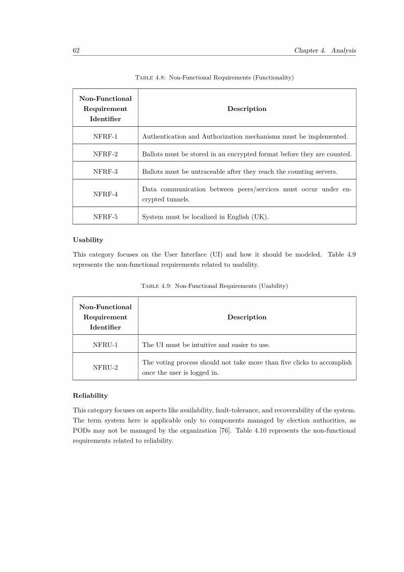
62 Chapter 4. Analysis
Table 4.8: Non-Functional Requirements (Functionality)
Non-FunctionalRequirementIdentifier
Description
NFRF-1 Authentication and Authorization mechanisms must be implemented.
NFRF-2 Ballots must be stored in an encrypted format before they are counted.
NFRF-3 Ballots must be untraceable after they reach the counting servers.
NFRF-4Data communication between peers/services must occur under en-crypted tunnels.
NFRF-5 System must be localized in English (UK).
Usability
This category focuses on the User Interface (UI) and how it should be modeled. Table 4.9represents the non-functional requirements related to usability.
Table 4.9: Non-Functional Requirements (Usability)
Non-FunctionalRequirementIdentifier
Description
NFRU-1 The UI must be intuitive and easier to use.
NFRU-2The voting process should not take more than five clicks to accomplishonce the user is logged in.
Reliability
This category focuses on aspects like availability, fault-tolerance, and recoverability of the system.The term system here is applicable only to components managed by election authorities, asPODs may not be managed by the organization [76]. Table 4.10 represents the non-functionalrequirements related to reliability.

4.2. Requirements Engineering 63
Table 4.10: Non-Functional Requirements (Reliability)
Non-FunctionalRequirementIdentifier
Description
NFRR-1 An error within a system component must not cause others to fail.
NFRR-2A crashed system component must be replaced by a new instance in lessthan two minutes.
NFRR-3 The system must be monitorable at all times.
Performance
Performance is related to time-measurable aspects of the application and how it handles differentusage loads [76]. Table 4.11 represents the non-functional requirements related to performance.
Table 4.11: Non-Functional Requirements (Performance)
Non-FunctionalRequirementIdentifier
Description
NFRP-1 The system must reply in under 200ms.
NFRP-2The system must be ready to support an elevated number of users atthe same time.
NFRP-3 Each system component must not exceed 2GB of RAM usage.
Supportability
This category represents how a system is concerned about language limitations, maintainabil-ity, adaptability, compatibility, and scalability [76]. Table 4.12 represents the non-functionalrequirements related to supportability.

64 Chapter 4. Analysis
Table 4.12: Non-Functional Requirements (Supportability)
Non-FunctionalRequirementIdentifier
Description
NFRS-1The system should be ready to easily introduce other types of voting/-suffrage, like where each vote weighs more than one vote or where eachperson can vote more than once.
NFRS-2 The system should provide support for multiple Pod providers.
NFRS-3 The system should be prepared to scale horizontally automatically.
Design Constraints
Design constraints limit the way a system is designed upfront [76]. Table 4.13 represents thenon-functional requirements related to design constraints.
Table 4.13: Non-Functional Requirements (Design Constraints)
Non-FunctionalRequirementIdentifier
Description
NFRDC-1 The ballot submitted by the Voter should be stored in their own POD.
Implementation Constraints
This category presents constraints to the development of the solution [76]. Table 4.14 representsthe non-functional requirements related to implementation constraints.
Table 4.14: Non-Functional Requirements (Implementation Constraints)
Non-FunctionalRequirementIdentifier
Description
NFRIC-1 Ballots should be anonymized before counting.

4.2. Requirements Engineering 65
Non-FunctionalRequirementIdentifier
Description
NFRIC-2No Voter personal data can be collected for purposes other than iden-tification, verification and vote casting, in accordance to the GeneralData Protection Regulation (GDPR).
NFRIC-3 The solution must have acceptance tests.
4.2.3 Domain Conceptualization
From its conception till its completion, an election is a process that is contributed by many differ-ent concepts: actors, roles, entities, and interactions among them. Consequently, the definitionof these concepts is critical for achieving a solution that meets the aforementioned requirements.
Election Model
The domain model in figure 4.2 represents all domain concepts/entities and their respective inter-relationships. These are the result of analysing all gathered functional requirements (cf. section4.2.1) and non-functional requirements (cf. section 4.2.2) for the proposed software solution. Anexplanation of the model will follow.
According to the functional requirements (cf. section 4.2.1), there are only two consideredUsers:the Voter and the Election Official. Voters are responsible for casting a Ballot for a specificElection they were previously enrolled in (cf. USV-2). The group of Voters enrolled in aparticular Election is called Electorate. This group is managed by the Official, who is alsoresponsible for creating (cf. USO-1) the Election and following it up.
Configuring an Election is a process that involves the following steps: (i) fill the basic detailsfor the election, like the election name, description, Vote Casting Schedule and the SuffrageType (cf. NFRS-1); (ii) gather Candidates for the Election, which can be political Parties orIndependent citizens; and (iii) group eligible Voters, creating the Electorate.
The Suffrage Type of an Election (cf. NFRS-1) will constrain the way it runs, the Candidatesavailable for picking, and all other Election features. For now, only Universal Suffrage will besupported.
Election States
The Election process is constituted by many stages (cf. figure 2.1), or Election States. Eachone represents a unique point in the Election and conditions the available operations at thattime.

66 Chapter 4. Analysis
Voter
Official
User
Ballot
ElectionElection Result
Candidate
Party
Election State
CreatedReady forBallot Casting
BallotCasting
Ready forVote Tally
BallotCounting
Ready forResults
Communication
Completed
Independent
Electorate
SuffrageType
Ballot Weight
Universal Suffrage
Vote CastingSchedule
1
11
1..*
1
1
0..*
1
1
1
1
0..*
1 11
0..*
1
1
1
1
1..*
1
0..*
1
1
1
1
1
11
1
of
defines
is
constrains
weighs
controls
composes
marks
manages
appears on
cast for
casts
corresponds to
part of
votes for
for
runs as
runs as
is
is
is in
is
is
is
is
isis
is
Figure 4.2: Domain Model
The regular path starts in the first stage, which is Created, which occurs right after the Officerhas filled in necessary Election information like name, schedule, Candidate list and Electorate(cf. USO-1). Then, when the Official triggers the vote casting process (cf. USO-3), the VoteCasting state is triggered and the Voter is allowed to vote (cf. USV-2).
At the end of this stage, which is determined by the Vote Casting Schedule’s end date, theElection will be at the Ready for Vote Tally, which means that Voters can no longer cast aballot and that the Ballot Counting stage can begin on demand by the Election Officer (cf.USO-4).
The Election comes to a close at steps Ready for Results Communication and Completedstates, where Election Results will be available for communication (cf. USO-5).

4.3. Summary 67
However, there may be any problem with the Election as ballots are being cast. In that case, theOfficer can halt the election (cf. USO-3), which in that case will be switched to the Interruptedstate, and then may progress to two states: either Vote Casting, if the Election can proceed, orCancelled, if the Election cannot continue (cf. USO-7).
The Official can also set the Election asArchived (cf. USO-6) if it is either Created or Completed,and Cancelled if the Election is at Ready for Vote Casting.
A state diagram displaying possible state transition pathways is shown in figure 4.3.
Created
Vote Casting
Ready for VoteCasting
Ready forResults
Communication
Completed
Vote Counting
Ready for VoteTally
Archived
Cancelled
Interrupted
Officer resumes election
Officer cancels the election
Officer archives Election
Officer archives Election Officer archives Election
Results are displayed
Schedule's end time is surpassed
Officer cancels the election
Officer interrupts
Schedule's start time is surpassed
Counting finishes
Officer starts Vote Counting
Schedule, Candidates and Electorate defined
Powered ByVisual Paradigm Community Edition
Figure 4.3: Election State Diagram
4.3 Summary
This chapter analyzed different points of view of this project. It began with a descriptive valueanalysis that aimed at finding out all inherent value concepts, and concluded with a requirementsengineering section where both functional and non-functional requirements were defined alongwith domain concepts and their interactions.
In the next chapter, a design proposition will be presented.


69
Chapter 5
Design
The focus of this chapter is to suggest, analyze and choose between different design alternativesthat fulfill the requirements defined on section 4.2.
To describe the software architecture and design, the "4+1" architectural model [77] will beadopted, with a combination of Unified Modeling Language (UML) notation throughout thedifferent views.
This chapter starts by analyzing ballot ownership, followed by presenting the logical view, whichwill focus on the analysis of different architectural design options and on all considerations takeninto account which will ultimately lead to an architecture adoption. It is followed up by therealization of each architecturally relevant user story and by an analysis of the deployment view.
5.1 Ballot Ownership
As seen in section 4.1.1, two ideas were very close in terms of ideal solutions for a decentralizedonline voting system using Solid: either the Voter is responsible for their ballot or the government.As a result, this responsibility entitlement will influence the system architecture. This aspectis particularly relevant when answering “how should we store submitted, not counted ballots?”.Votes will be stored in Solid PODs, and the number of Pods and their location will vary accordingto ballot ownership.
If the ballot is considered to be owned by the government, then maybe a single Pod hosted byelection authorities would suffice. Alternatively, to improve the system scalability and organi-zation, multiple PODs could be logically distributed by regional election areas, similar to thestandard ballot boxes used in on-site voting. In either option, as soon as the ballot is cast, thegovernment will own it for the rest of the election process. Moreover, the lack of distribution ofvotes may not be enough to be considered a decentralized system.
On the other hand, POD for each Voter will be necessary if the ballot is deemed the Voters’responsibility. In this alternative, each POD will contain one ballot for each election in which the
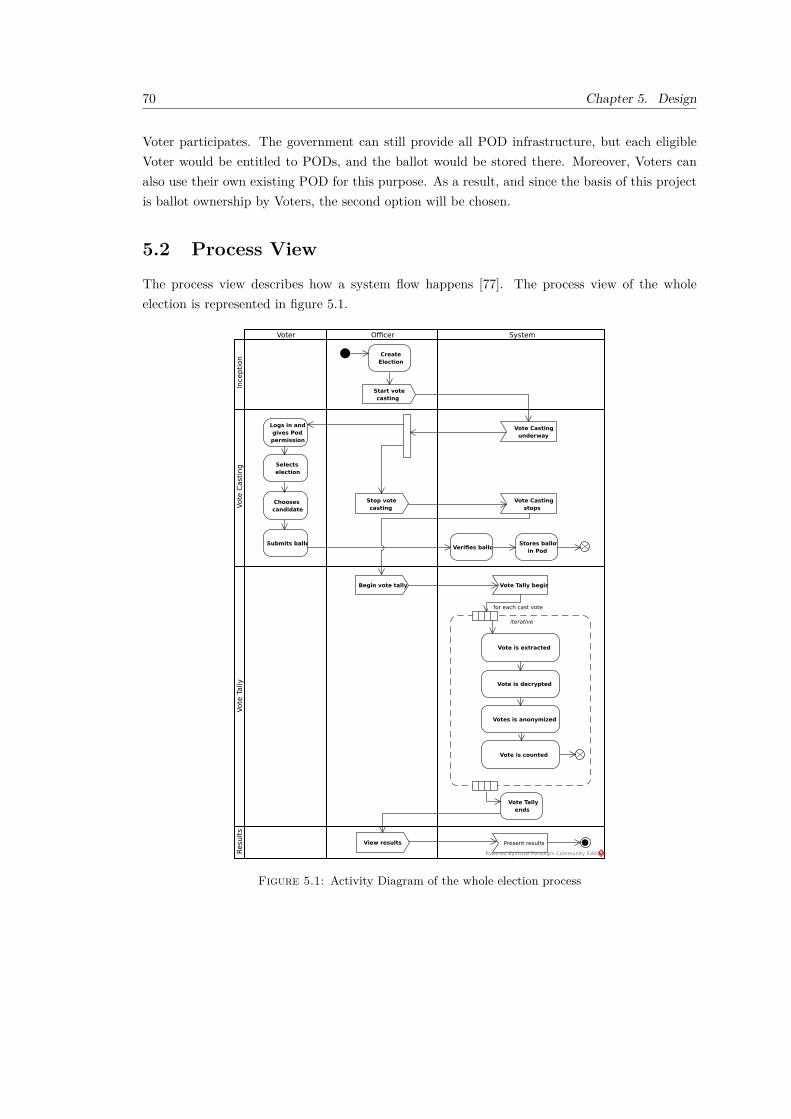
70 Chapter 5. Design
Voter participates. The government can still provide all POD infrastructure, but each eligibleVoter would be entitled to PODs, and the ballot would be stored there. Moreover, Voters canalso use their own existing POD for this purpose. As a result, and since the basis of this projectis ballot ownership by Voters, the second option will be chosen.
5.2 Process View
The process view describes how a system flow happens [77]. The process view of the wholeelection is represented in figure 5.1.
Ince
pti
on
Vote
Cast
ing
Vote
Tally
Voter Officer
Resu
lts
System
CreateElection
Logs in andgives Podpermission
Selectselection
Choosescandidate
Submits ballotVerifies ballot
Stores ballotin Pod
Start votecasting
Stop votecasting
Vote Castingunderway
Vote Castingstops
iterative
Vote is extracted
Vote is decrypted
Votes is anonymized
Vote is counted
Vote Tallyends
Begin vote tally Vote Tally begins
View results Present results
for each cast vote
Powered ByVisual Paradigm Community Edition
Figure 5.1: Activity Diagram of the whole election process

5.3. Logical View 71
This process view is a finer grained version of the process described in 2.1. By consideringfunctional and non-functional requirements, one can categorize the different activities intendedfor the system in those three stages. The first stage is Inception, where the Official will create andconfigure the election. Sometime after this action, the Official will trigger the casting process,after which Voters will be able to cast their ballots and, in parallel, the Official will be authorizedto stop the process. After that, the Official will trigger the Vote Tally process, where votes areretrieved, decrypted, anonymized and stored for further queries, which at the end will make upthe election result.
5.3 Logical View
The logical view is designed to identify and represent the required system components to fulfillboth functional and non-functional requirements [77]. In this section, two levels of granularitywill be explored: first, a higher level overview of the major system components will be presented,followed by a lower, second level representation of the sub-components included within eachmajor component.
5.3.1 System Overview
Analyzing both functional and non-functional requirements presented earlier (cf. section 4.2),it can be concluded that three major system components will be necessary to achieve a fullworking solution. First, a Browser component will be necessary in order to enable the Voter tobrowse elections according to the predefined electorate for the election (cf. figure 4.2). Second,it is required to have a component that can provide Solid Pods for each Voter (cf. section 5.1)to later store the ballot. And finally, the third system component is responsible for managingelections, coordinate the election process (cf. section 5.2) and provide the browser with theartifacts necessary to present a UI to both Voters and to the Official. This component will becalled Solid Voting and thus will be the name of the project.
Solid VotingBrowser
Solid Pod Provider
HTTP
API
Powered ByVisual Paradigm Community Edition
Figure 5.2: System Overview
The API connection displayed serves as a bi-directional communication channel. As stated earlierin this sub-section, the browser will retrieve the UI artifacts and initial data, and then submit

72 Chapter 5. Design
user-filled data back to the Solid Voting component. The Solid Pod Provider component hastwo links to the other components: a link to the Browser so that the Voter can give consent tothe Solid Voting component to write to the Voter’s POD, which is necessary as per the OIDCauthorization code flow (cf. section 3.4.4); and a link to the Solid Voting so that the latter canstore the ballot within PODs.
5.3.2 Architecture
The system must provide a front-end application used by the Official to view and submit allnecessary information to create an election. Produced data should be persisted in a databasecomponent to be easily retrieved throughout the two following stages. However and according tobest practices, this database should not be reachable through the front-end application. Instead,it should be hidden by a service that exposes an API, providing an extra layer of security,authorization, and data validation.
The system will need to provide a publicly accessible component that allows the Voter to au-thenticate and submit their ballot for the Vote Casting process. This component is performance-critical (cf. requirement NFRP-2), as thousands of users can access it at the same time. Inaddition, the Officer should have a way to view election metrics and indicators to overview thewhole process. Thus, they can detect any irregularity and ultimately interrupt the election asseen fit. Moreover, the system should encrypt ballots before transferring them to Voter PODs(cf. requirement NFRF-2).
In order to support the Vote Tally, the system should provide a way for the Officer to startthe counting process. Multiple counting components should accomplish this process, and theyshould communicate their progress as timely as possible to another component, which will showthe ballot counting stage evolution. Moreover, the system should shuffle ballots (like in theEstonian voting system) to decrease the chance of being traced back to the Voter.
By identifying these three stages along with their respective requirements, different architecturedesigns were conceived for analysis. This section will explore those alternatives and subsequentlyadopt one for the project.
Architecture Design Alternative One - Poll-Based Architecture
This architecture alternative is represented in Figure 5.3. In this proposal, the Officer andVoter interact with the system through an Election Public Web App. The officer will see anadministration panel that will allow him to manage elections and view their progress, while theVoter will see elections where they can vote.

5.3. Logical View 73
Solid Voting
Browser
Solid Voting UI
Election API
Ballot Counter
Results Service
<<database>>Election DB
<<database>>Election Results
DB
Solid Pod Provider
Voter's POD
Solid Pod UIHTTP
HTTP
TCP
EIAPI
MAPI
Powered ByVisual Paradigm Community Edition
Figure 5.3: Architecture Alternative 1
The Election API is the back-end service responsible for (i) managing election data, which ispersisted in the Election Database; (ii) receiving Voter ballots at vote casting; and (iii) coordi-nating the vote tally process, providing an API that the available Ballot Counter services willconsume to retrieve election data and information related to actual Voters.
The Ballot Counter service is responsible for retrieving ballots from the Voters’ PODs, verifyingtheir integrity, decrypting them, and submitting the anonymized ballots to the Results Service,which will count the received votes and persist them at the Results Database. Subsequently, theElection API will consume the Results Service to update its front-end with the status of theelection progress.
All APIs are synchronously called using HTTP. Therefore, for example, the Ballot Countercomponent will need to poll the Election API for elections that are in the Ballot Counting state(cf. section 4.2.3).
Architecture Design Alternative Two - Message-Based Architecture
This architecture alternative, represented in Figure 5.4, promotes a more distributed and asyn-chronous communication between components. The main characteristic of this architecture isthe component indirection achieved using a message, publish-subscribe based methodology. The

74 Chapter 5. Design
decoupling of some component calls also introduces extensibility points and deployment andscalability alternatives.
Solid Voting
Ballot Extractor
<<database>>Election DB
Ballot Counter<<database>>
Election Results DB
Election API
Message Broker
Browser
Solid Voting UI
Solid Pod Provider
Voter's POD
Solid Pod UI
HTTP
HTTP
Driver
Driver
Extract Ballot Command
Ballot Counted Event
Count Ballot Command
SOLID HTTP
produces
consumes
consumes
produces
consumes
produces
Powered ByVisual Paradigm Community Edition
Figure 5.4: Architecture Alternative 2
Moreover, the responsibility for extracting the ballot from PODs is segregated to a new servicecalled Ballot Extractor. In case there are multiple Extractor instances, work distribution is doneautomatically by the Message Broker. Therefore, instead of calling the Election API to obtainballot information, these Extractors will consume extraction commands produced by the APIwhen the Officer triggers the counting process. Each command shall relate to a single vote.
Identically, after ballot extraction, decryption and anonymization, the Extractor will producea command to instruct the Ballot Counter to count the respective vote. Ballot shuffling canalso be implemented more naturally and without much effort by using the message broker to dothat when distributing work among available Counters. The ballot count process will consist ofstoring each anonymized vote in the Election Results Database.
Lastly, the Ballot Counter service will expose an HTTP API so that the Election API can queryto obtain the estimated and final election results.
5.3.3 Architecture Comparison
While the poll-based alternative (cf. sub-section 5.3.2) and the message-based alternative (cf.sub-section 5.3.2) may fulfill both functional and non-functional requirements, there are majordifferences between these approaches. This sub-section aims to categorize and explain thosevariations across both alternatives and ultimately choose one of them.
Service Cohesion
It is safe to say that the poll-based alternative offers a higher level of coupling when comparedto alternative two. The first one concentrates work on fewer components, thus reducing the

5.3. Logical View 75
distribution of responsibilities. The Ballot Counter component has the additional responsibilityof extracting the ballot from the POD. The second alternative segregates those responsibilitiesto other components, which provide a more transparent ballot mixing without requiring anydevelopment, since the broker will do that automatically by randomly distributing the countingcommands among all Ballot Counter instances (assuming that there will be more than oneinstance). Moreover, by splitting responsibilities (in a logical way) among more components therequirements NFRR-1 and NFRR-2 are easier to fulfill.
Work Distribution
The poll-based alternative makes work distribution less natural than the message-based onebecause a work distribution algorithm must be implemented. In addition, this mechanism shouldconsider the number of Ballot Counter instances (cf. requirement NFRS-3) and assign workers toeach one of them. The message-based alternative takes advantage of message broker capabilitiesto do that. Each Ballot Counter or Extractor component will subscribe to a particular messagequeue, and upon message arrival, the broker will follow the message to a specific consumeraccording to its tested work distribution algorithm. This enhances modularity and increases thenumber of scale options to fulfill requirement NFRS-3.
Scalability
The message-based alternative facilitates the horizontal scalability of background processingcomponents (cf. requirement NFRS-3). A new Ballot Counter or Ballot Extractor componentcan be easily added to the system in case of need. The Election API can be scaled equally amongalternatives. To achieve that, a middleware component should be present between clients andthe API, like a proxy or load balancer, which is out of this project’s scope.
Extensibility
Asynchronous message processing enhances extensibility, i.e., if a new kind of component needsto consume a particular message to perform additional work like monitoring (cf. requirementNFRR-3), it can be safely added to the system without breaking the existing flows. The message-based alternative offers better extensibility capabilities.
Performance
Since the poll-based alternative uses fewer components and less data travelling to achieve therequirements, one may think at first glance that it should offer more performance than thesecond alternative. While that may be true for a small election scenario (thousands of votes),the enhanced horizontal scalability capabilities and automatic work distribution of the message-based alternative may increase the performance on more significant elections with millions ofballots and election data to process. This aligns better with the NFRP-2 requirement.

76 Chapter 5. Design
Security and Data Protection
In the message-based alternative, data tends to flow across more components, which can lowerdata security since it needs to travel more when compared to the first option. However, allthose components are not publicly accessible and should be behind protective components likefirewalls, and thus if the environment is considered secure, then the number of components datatravels through should not matter.
Development Time
Finally, the time to develop the message-based alternative should be longer than to build thepush-based one because it has more components and more interactions between components, notto mention different user interfaces for both Voters and Officers.
With these constraints and characteristics in mind, the message-based alternative was adopted.
5.4 Physical View
The physical view maps the software (components) to hardware (machines). It takes into accountall non-functional requirements which directly relate to hardware, such as availability, reliability,performance, and scalability (cf. section 4.2.2) [77]. Figure 5.5 represents a deployment diagramwhich composes the physical view of the system.
Personal Computer
Election Server
<<component>>Browser
Solid Voting UI
Solid Pod UI
Solid Pod Provider Server
<<component>>Solid Pod Provider
Voter's POD
Virtual Machine
Virtual Machine
Message Broker Runtime
Virtual Machine
Election API
Virtual Machine
BallotExtractor
Virtual Machine
Ballot Counter
Message Bus
Virtual Machine
Relational Database Runtime
Election DB
Virtual Machine
Document Database Runtime
Election Results DB
TCP
TCP
TCP
DriverDriver
HTTP
HTTP
Powered ByVisual Paradigm Community Edition
Figure 5.5: Deployment Diagram of the election system components

5.5. User Story View 77
Backend components Election API, Ballot Extractor, Ballot Counter, Message Bus, and bothdatabases ElectionResults DB and Election DB will be deployed to a single server using virtual-ization.
Databases were chosen according to the projected relational characteristics of data. Due to theintrinsic relationship between entities, a relational database was chosen to hold election-owneddata, including elections, election electorate, and election candidates (cf. section 5.6). On thecontrary, the Election Results DB will purely hold the anonymized ballots subject to queries tofind the election results. A single collection or table is sufficient to hold this information, andtherefore due to the non-relational aspect of the held data, a non-relational, document-baseddatabase can be applied for this purpose.
Although a service discovery1 component could provide centralized discovery capabilities, suchmechanism will not be considered for this proof of concept. Instead, all services will communicatedirectly with their dependencies and hold the necessary URIs to access them.
5.5 User Story View
In the use case view, a limited selection of functionality use cases is used to describe the systemdesign. Use cases are a representation of sequences and interactions between actors, services,components, and processes [77].
Having analyzed and provided three views that exhibit the system interactions from a higher-levelpoint of view, it is now important to analyze the relationships between the designed componentsand the system actors. To do that, it is necessary to analyze the functional requirements (cf.section 4.2.1). These have been formed as user stories, and typically they should be furtherfine-grained into use cases. However, for this section only architecturally-relevant use cases willbe considered. Use case relevance was defined for this project as an architecture-defining usecase that provides the most value for the business.
Figure 5.6 represents the relevant use cases extracted from their respective user stories. Usecases are labeled using an identifier in the format USA-n, where UC stands for use case, A isthe acronym for the actor and n is an incremental number for the user case within the scope ofactor A.
Use cases UCV-1 and UCV-2 are performed by the Voter and map directly to user stories UCV-1and USV-2, respectively. Likewise, UCO-2 and UCO-4 also map directly to their respective userstories (cf. USO-2 and USO-4). However, it is noticeable that there is one extra use case (UCS-1)that does not map to a specific user story. This use case is the result of unfolding the user storyUSO-4: although the Officer will be responsible for triggering the vote tally process, the actualprocess will be achieved separately. This means that the UCO-4 is fulfilled before the system
1https://microservices.io/patterns/server-side-discovery.html

78 Chapter 5. Design
UCV-1:Authenticate
UCV-2: Vote
UCO-1: CreateElection
UCS-1: Countsubmitted votes
UCO-2: TriggerVote Casting
UCO-4: TriggerVote Tally
Voter Official
<<Include>>
Powered ByVisual Paradigm Community Edition
Figure 5.6: Architecturally-relevant Use Cases
handles the first ballot. The include relationship describes the relationship between these twouse cases.
In the following subsections, all use cases shown in figure 5.6 will be depicted and their inter-actions with other components will be established in the form of activity diagrams. A sequencediagram will also be introduced for some use cases that require a finer-grained level of detail.
5.5.1 Mediation and Query/Command Separation
For this project, we will use the Mediator pattern [78] for two reasons: first, because it reduces thecoupling between the web framework and the domain, and last, because we may need to performthe same queries and commands in different situations. For example, to perform load testing orsimply checking data when developing, we will use a REST API provided by the Election API,which answers in JSON format. However, use cases themselves will be fulfilled through UI viewswhich will perform the same queries and commands, but the output format will be HTML.
In conclusion, it will be the responsibility of the Query or Command handler to process therequest and coordinate its fulfilment. These handlers are completely framework-agnostic andmay be used from different entry points.
5.5.2 UCO-1 - Create Election
The UCO-1 use case is performed by the Official and is the entry point for all other use cases.It is displayed as a sequence diagram in figure 5.7.

5.5. User Story View 79
ref
UCO1-2 : Persist Election
ref
UCO1-5 : Get all Candidates
query :Candidates
Query
command :CreateElection
Command
MediatorElectionControllerElection APISolid Voting UIOfficer
1.1.1.3: candidates
1.1.1.1:
1.1.1.2: Publish(query)
2.3: success2.2: 201 Created (election)
2.1.2: election2.1.1.3: election
2.1.1.2: Publish(command)
2.1.1.1:
2.1.1: Create(election)
2.1: POST /api/elections
2: submits name, schedules and candidates
1.3: view1.2: 200 OK (view) 1.1.2: view
1.1.1: CreateView()
1.1: GET /view/elections/new
1: access election creation UI
Powered ByVisual Paradigm Community Edition
Figure 5.7: Sequence Diagram for UCO-1
The Official wanting to create a new election accesses the Solid Voting UI and begins the process.Upon accessing the view that allows for the creation of elections, the system loads all availablecandidates (detailed in figure 5.8) and asks the Official to fill all election information, such asits name, description, the relevant schedules such as casting and tally start times, and choosesthe candidates from the list. Note that these scheduled times are merely informational, and asa result are not responsible for triggering any kind of action.
sdUCO1-5 : Get all Candidates
handler :GetCandidatesQueryHandler
r :CandidateRepository
Election DB
1.1.1.1.2: candidates1.1.1.1.1.2: candidates
1.1.1.1.1.1.2: candidates
1.1.1.1.1.1.1: select all candidates1.1.1.1.1.1: GetAll()
1.1.1.1.1: query
Powered ByVisual Paradigm Community Edition
Figure 5.8: Sequence Diagram for retrieving all Candidates in UCO-1
Upon submission, the system receives the request and performs two sequential domain actions(detailed in figure 5.9). After step 1.4, the system validates that all received candidate identifiersmap to an existing candidate. If this condition is not met for at least one candidate, the creationprocess fails. As for the last domain action, all existing Voters in the database are added to the

80 Chapter 5. Design
election. This logic simplifies the process, since the alternative would be the selection of eachVoter for the election. Instead, it is considered that all Voters in the database (pre-inserted in thedatabase) are voting-eligible, and therefore will be added to the just-created election electorate.
loop
[for each submitted candidate]
rc :CandidateRepository
rv :VoterRepository
Election DB
s : Created Entity State
r :ElectionRepository
e : Election
handler : CreateElectionHandler
1.4: Add(candidate)
1.3: candidate
1.2: Get(candidateID)
1.7.2: added1.7.1: validates
1.7: AddVoters(voters)
1.6: voters1.5.2: voters
1.5.1: select all voters
1.5: GetAll()
1.8.2: ok
1.8.1: insert e
2: create()
1.10: created1.9: e
1.8: Create(e)
1.1: create
1: command
Powered ByVisual Paradigm Community Edition
Figure 5.9: Sequence Diagram for validating and persisting an election in UCO-1
After filling the electorate, the election is persisted in the Election DB. If successful, a successview is displayed to the Official, and the election will then be displayed in the election list page.
5.5.3 UCO-2 - Trigger Vote Casting
The UCO-2 use case is also performed by the Official and happens sometime after UCO-1,preferably after the vote casting scheduled time. It is presented in sequence diagram in figure5.10.

5.5. User Story View 81
ref
UCO2 - PatchElection
command :PatchElectionCommand
query :FetchElectionsQuery
Mediator
ElectionControllerSolid Voting UIOfficial Election API
2.3: success
2.2: 200 OK
2.1.2: ok2.1.1.3: ok
2.1.1.2: Send(command)
2.1.1.1: create
2.1.1: Patch(document, id)
2.1: PATCH /apI/elections/{id}
2: triggers vote casting for election
1.3: shows elections
1.2: view1.1.2: view
1.1.1.3: elections
1.1.1.2: Send(query)
1.1.1.1:1.1.1: CreateView()
1.1: GET /view/elections
1: view elections
Powered ByVisual Paradigm Community Edition
Figure 5.10: Sequence Diagram for UCO-2
First, the Official is presented with all elections in the Created or Ready for Vote Casting states.Then, the Official selects an election and triggers the process. The Election API receives thatrequest as a patch document converts it to a command containing the patch document, and sendsit through the Mediator. In turn, the Command Handler receives the command (figure 5.11)and retrieves the election through the repository. If found, the handler will create an adapter totransform the patch document in a call to the election method responsible for transitioning theelection to the vote casting state. If such transition is possible (according to what is depictedin figure 4.3), the election updates the election state information, and the command calls therepository to update the entity in the database.
Additionally, and since the vote casting process should end automatically by considering thecasting end schedule time submitted in UCO-1, an asynchronous operation should be scheduledso that when such time is surpassed, the election can transition to the Ready For Vote Tallystate. Therefore, upon successfully saving the election state in the database, the system willschedule a job to run at the vote casting end date, responsible for transitioning the election tothe next state.

82 Chapter 5. Design
ref
UCO2 - PatchElection
Election APIOfficial Solid Voting UI ElectionController
Mediator
query :FetchElectionsQuery
command :PatchElectionCommand
2.1.1.1: create
1.1.1.1: create
2.3: success
2.2: 200 OK
2.1.2: ok2.1.1.3: ok
2.1.1.2: Send(command)
2.1.1: Patch(document, id)
2.1: PATCH /apI/elections/{id}
2: triggers vote casting for election
1.3: shows elections
1.2: view1.1.2: view
1.1.1.3: elections
1.1.1.2: Send(query)
1.1.1: CreateView()
1.1: GET /view/elections
1: view elections
Powered ByVisual Paradigm Community Edition
Figure 5.11: Sequence Diagram for UCO-2 - Change State
5.5.4 UCV-1 - Authenticate
The UCV-1 is a use case performed by the Voter whom is required to execute before being allowedto vote. The sequence diagram shown in figure 5.12 represents the interactions accomplishedduring the execution of this use case.
This flow is mainly constrained by the OIDC Authorization Code flow (cf. section 3.4.2). Theuser must first access the login page. Here, an option to sign in through the Solid Voting Provideris shown. The user accesses that link, redirecting him to the Solid Pod Provider UI, which theSolid Voting Provider renders. Next, the user enters the username and password associated withthe respective Pod and is asked to consent access to the Solid Voting application to write to thePod. The user accepts, is redirected back to the Solid Voting UI, and is logged in.
Two important JWT tokens are saved in a cookie: the access token, which is used to performrequests to both Election API and Solid Voting UI; and the refresh token, used to get a newaccess token when its expiration date is exceeded. The former token will be used later in usecase UCS-1 (cf. section 5.5.7).

5.5. User Story View 83
vr :VoterRepository
Solid Pod ProviderSolid Pod Provider UIAccountControllerElection APISolid Voting UIVoter
4.3.2.1: successful login message4.3.2: 200 OK
4.3.1.7: success view
4.3.1.6: Login(voter)
4.3.1.5: voter
4.3.1.3: parse token, extract webId
4.3.1.4: GetVoter(webId)
4.3.1.2: token
4.3.1.1: ExchangeCodeForToken(code)4.3.1: SignInCode()
4.3: POST /oidc/code4.2: code
4.1: consent application4: consents application
3.3: redirects user to consent view and asks for consent
3.2: ok
3.1: verify credentials3: submits username and password
2.3: redirects user to Pod Provider2.2: 301 Redirect
2.1.2: redirect action
2.1.1: SignInSolid()
2.1: GET /account/signin/solid
2: Login through Pod Provider
1.1.2: view
1.1.1: SignIn()
1.2: 200 OK
1.1: GET /account/signin
1.3: presents login view
1: wants to log in
Powered ByVisual Paradigm Community Edition
Figure 5.12: Sequence Diagram for UCV-1
Thanks to the OIDC authorization protocol supported by the Solid Provider, the authenticationat the Solid Voting component level is achieved by asserting that the WebID presented in theclaims of the access token matches the WebID of any Voter in the database. If such match ispossible, the Voter is logged in.
5.5.5 UCV-2 - Vote
The UCV-2 is the main use case performed by the Voter where he casts a ballot for the election.The sequence diagram shown in figure 5.13 represents the interactions accomplished during theexecution of this use case.
When the Voter wants to vote, the system displays a list of elections that the user is authorizedto vote on (i.e., is a member of their electorate). Next, the Voter selects an election and isredirected to a view where he views the candidates and selects one (or none). Finally, the Votersubmits this information back to the system.

84 Chapter 5. Design
ref
USV2 - Store ballot
command :SubmitBallotCommand
cquery :FetchCandidatesForElectionQuery
query :FetchElections
Query
Mediator
um :UserManager
ElectionControllerElection APISolid Voting UIVoter
3.1.2: view
3.3: success message
3.2: 200 OK
3.1.1.2.2: ok
3.1.1.2.1:3.1.1.2: Send(command)
3.1.1.1: create(ballot)
3.1.1: SubmitBallot(ballot)
3.1: POST /api/elections/{id}/ballot
3: chooses one and submits
2.3: displays candidates2.2: 200 OK
2.1.2: view2.1.1.3: candidates for election
2.1.1.2: Send(cquery)
2.1.1.1: create(id)
2.1.1: VoteElectionView(){}2.1: GET /view/elections/vote/{id}
2: selects an election
1.3: presents election list1.2: 200 OK 1.1.2: view
1.1.1.5: elections for voter
1.1.1.3: create(voter)
1.1.1.4: Send(query)
1.1.1.2: voter
1.1.1.1: GetLoggedInUser()1.1.1: VoteView()
1.1: GET /view/elections/vote
1: wants to vote
Powered ByVisual Paradigm Community Edition
Figure 5.13: Sequence Diagram for UCV-2
The system parses and validates the ballot (figure 5.14), creates a command to persist it andsends it through the mediator. The command handler handles the command, checks if the Voteris allowed to vote for that election, and calls an encryption provider to encrypt the vote.
In order to reduce the amount of work necessary in the Vote Tally process and increase theoverall system security, we will only consider ballots of Voters who have done so successfully.Therefore, such information needs to be persisted at this point in the Election DB. By updatingthe database and then sending the ballot to the Voter’s POD, we would need a distributedtransaction mechanism like a Two-phase commit (2PC) to ensure that a failure in storing theballot will revert changes in the database. However, such a mechanism is often regarded ascomplex.
Instead of considering these two operations as a distributed transaction, we will use the Outboxpattern (cf. section 3.4.5): the ballot will not be stored directly at this point, in favour of anevent containing the encrypted ballot, the WebID, the election ID and the Voter’s access tokenthat was obtained in UCV-1.

5.5. User Story View 85
ev : BallotSubmittedEvent
member : ElectorateMemberElectionDB
r :RequestContext
handler :SubmitBallotCommandHa
ndler
um :UserManager
er :ElectionRepository
election : Election state : ElectionState electorate : Electorate
er :ElectionRepository
1.12: ok
1.11: ok
1.9:
1.10: SaveEvent(ev)
1.8: ok
1.7.8: ok
1.7.7: Save(member)
1.7.6: Token = token
1.7.3: HasVoted = true
1.7.2: member
1.7.1: select Electorate Member for election, voter
1.6: ok
1.7.5: token
1.7.4: GetToken("refresh_token")
1.7: MarkVoted(election, voter)
1.5.4: true
1.5.3: IsIn(voter)
1.5.2: true
1.5.1: IsElectionCasting()
1.5: CastBallot(voter, command)
1.4: election
1.3: GetElection(id)
1.2: voter
1.1: GetLoggedInUser()
1: command
Powered ByVisual Paradigm Community Edition
Figure 5.14: Sequence Diagram for UCV-2 - Handling the Command
This event will be persisted to a separate table in ElectionsDB. Since this database ensuresatomicity consistency isolation and durability (ACID) properties (cf. section 5.6), we can wrapthe command and the flag that the Voter has successfully voted in a local transaction. The Voteris then notified of the success of the operation, and the command will be retrieved later on byan Election API worker thread that will consume the command and call the Solid Pod Providergateway to store the encrypted ballot. Activity diagram in figure 5.15 illustrates this interaction.
ReceiveBallotSubmittedEvent
Get Electorate Memberfrom the ElectionDB usingthe election id and voter id
contained in the event
Retrieve the token fromthe electorate member
Call the Solid PODprovider to store the ballot
Mark the event as handledin ElectionDB
Handle the event later
Successful?Successful?
YesYesNo No
Powered ByVisual Paradigm Community Edition
Figure 5.15: Activity Diagram for UCV-2 - Storing ballot in Voter’s POD
The Voter is authorized to vote as many times as desired, however the latest vote will alwaysreplace the previous one, similar to what is done in the Estonian election system (cf. section2.6.4).

86 Chapter 5. Design
5.5.6 UCO-3 - Trigger Vote Tally
The third use case performed by the Election Official may happen right after the job describedin the UCO-2 section (cf. section 5.5.3) changes the election state to Ready for Vote Tally. Thisuse case is very similar to the use case UCO-2 in terms of flow. The initial sequence diagramfor this action equals the one in figure 5.10. However, the “PatchElection” interaction use differsslightly. It is exhibited in figure 5.16.
job :StartVoteTallyJob
JobManager
newState : VoteTallyState
currentState : ElectionState
adapter :ElectionPatchAdapter
election : ElectionElection DB
er :ElectionRepository
handler :PatchElectionCommand
Handler
1.10: patched
1.9: enqueued
1.7: create(election)
1.8: Enqueue(job)
1.6.2: updated
1.6.1: update election
1.6: Update(election)
1.5: applied
1.4.1.3: SetState(newState)
1.4.1.2.2: ok
1.4.1.2.1: CanChange(newState)
1.4.1.1:
1.4.1.2: ChangeTo(newState)
1.4.1.4: changed
1.4.1: StartVoteCasting()1.4: Apply(document)
1.3: create(election)
1.2: election1.1.2: election
1.1.1: select from election where id = id1.1: GetElection(id)
1: command
Powered ByVisual Paradigm Community Edition
Figure 5.16: Sequence Diagram for UCO-3 - Trigger Vote Tally
First, the Official is presented with all elections in the Ready for Vote Tally state. Then, theOfficial selects an election and triggers the tally process. The Election API receives that requestas a patch document converts it to a command containing the patch document, and sends itthrough the Mediator. In turn, the Command Handler receives the command and retrieves theelection through the repository. If found, the handler will create an adapter to transform thepatch document in a call to the election method responsible for transitioning the election to thevote tally state. If such transition is possible (according to what is depicted in figure 4.3), theelection updates the election state information, and the command calls the repository to updatethe entity in the database.
In addition to this sequence, an asynchronous operation will be triggered in a background job

5.5. User Story View 87
to start the vote-counting process. This process is described in the UCS-1 use case realization(cf. section 5.5.7). It is important that both this asynchronous process and the previous entityupdate action be processed by the same transaction in order to achieve atomicity.
5.5.7 UCS-1 - Count submitted votes
The last architecturally relevant use case is vote counting. The Election Official initiates thisprocess upon triggering the vote tally and finishes when there are no more ballots left to count.The end artefacts of this use case will be the persisted ballots in a collection in the ElectionResults DB. Since this use case spans across multiple services in the Solid Voting component, anactivity diagram (figure 5.17) was elaborated to describe the interactions between the differentcomponents.
Ele
ctio
nA
PI
Ele
ctio
nD
BB
allo
tC
ounte
rB
allo
tExtr
act
or
Mess
age
Bro
ker
Ele
ctio
nR
esu
lts
DB
StartVoteTallyJobstarted
Get election andelectorate data
iterative
Create extractballot command
Produce amessage with that
command
Receive extractballot command
message
Consumecommandmessage
Retrieve theballot from thevoter's POD
Decrypt theballot
Create countballot
command
Receive countballot command
message
Consumecommandmessage
Persist ballotin database
Save ballot
for each voter that voted
Powered ByVisual Paradigm Community Edition
Figure 5.17: Activity Diagram for UCS-1 - Count submitted votes
Due to its asynchronous, message-based nature, all components are decoupled and do not com-municate directly. Instead, messages are created and produced to the Message Broker/Bus,propagating them to their respective consumers. The consumers will register themselves withthe Message Broker to consume the respective topics when they start.
The first action to happen occurs right after the job starts. The job was provided with theidentifier of the election subject to this process. Therefore, the first thing to do is extract theelection information and its electorate to find out who voted.
The Voter information resulting from this query is then iterated. This iteration will create acommand to tell the consumer that it should extract the ballot associated with that Voter, i.e.,

88 Chapter 5. Design
to that WebID, which is also a link to the POD where the ballot is stored. The command alsoholds the refresh token stored in the database when the user voted (cf. section 5.5.5).
The extract ballot command is then sent to the Message Broker, which sends it to the BallotExtractor service. The first action to perform upon handling the command is getting a newaccess token from the Solid Pod Provider associated to the Voter’s WebID. The service performsa new access token request to the provider using the respective refresh token.
The service will then attempt to retrieve the ballot from the provider, impersonating the PODowner (which had previously given consent) by passing the access token in the request. Ifthe request is successful, then the ballot is extracted from the response body, decrypted andassociated with a new command to be propagated to the message broker. In this new command,no association with the Voter shall exist. The purpose of this new command is to instruct theBallot Counter service to store the vote in the Election Results DB. Moreover, vote mixing willhappen naturally since the message will have a random identifier that will assign it to a randompartition in the message broker, thus causing the consumer to read messages in a random order.
The final step is to store the ballot in the database and is performed by the Ballot Counterservice that will consume the previous command, unwrap the decrypted, anonymized ballot andstore it in the Election Results DB.
5.6 Data Schema
In this section we will analyze how the data schema will be structured. The system will usetwo databases that are from two different types. For the Election DB component we will use arelational DBMS to achieve logical, rigid relationships between the entities due to their strongassociation characteristic. Therefore, it is essential to create a database schema to depict theseentities and their relationships. An entity-relationship diagram for the Election DB is displayedin figure 5.18.
The logic behind this ERD is as follows:
• An Election has a name and a description, is always in a state (cf. section 4.2.3), and hastwo important dates associated: the vote casting begin and end dates;
• A Voter is a citizen identified by its Citizen Id and by its WebID;
• An Election can have many Candidates, and those Candidates can run for many Elections,therefore an intermediate table Election Candidates must exist;
• Voters can vote for many elections, and an Election has many eligible Voters, which forma new intermediate table called the Electorate;
• Voters and the Election Official are represented as system Users and are discriminated bytheir Role;

5.7. Summary 89
Id varchar(30)
CitizenId integer(10)
WebId varchar(255)
Name varchar(30)
User
Id varchar(30)
Name varchar(100)
Description varchar(100)
CastingBeginsAt date
CastingEndsAt date
State integer(2)
Election
ElectionId varchar(30)
VoterId varchar(30)
HasVoted bit
RefreshToken varchar(max)
Electorate
Id varchar(30)
Name varchar(45)
LogoUrl varchar(100)
Type integer(1)
Candidate
ElectionId varchar(30)
CandidateId varchar(30)
Election CandidatesId varchar(30)
Name varchar(45)
Role
UserId varchar(30)
RoleId varchar(30)
User Role
Powered ByVisual Paradigm Community Edition
Figure 5.18: Entity-Relationship Diagram for the Election DB
• Each member of each election Electorate will have a flag indicating whether the Voter hasvoted for the election, and a refresh token populated during the vote cast (cf. section 5.5.5)that is used in the vote tally process (cf. section 5.5.7).
A simple collection to store the ballots for the Election Results database will be needed. Inorder to apply idempotency at the Ballot Counter service level, the propagated command toinstruct the service to store the ballot will have a command identifier attached. However, thiscommand identifier cannot be used to identify the Voter since, at this point, no Voter is associatedwith the ballot.
When consumed, the ballot will be extracted from the command message along with the com-mand identifier, which will be used as the id for the ballot collection upon persisting the corre-sponding data. Since the id column in this database has an associated unique index, no duplicateidentifiers can be added to the collection, causing the vote not to be replaced, achieving idem-potency.
5.7 Summary
This chapter looked into two possibilities for the system architecture and explained why themessage based alternative was the best option. Using the 4+1 Architectural model, we alsoanalyzed different layers and views of the system, including logical, physical, process and userstory views. The development view will be presented in the next chapter, along with otherimplementation details and the technologies involved in the proof of concept development.


91
Chapter 6
Implementation
The implemented solution consists of a proof of concept for a Decentralized Voting ElectionPlatform using personal Solid PODs as storage for election ballots. The adopted architecture (cf.section 5.3.2) has messages and asynchronous processing as first-class citizens, and therefore allcomponents communicate via a message broker. One of the benefits of an event message-basedarchitecture is the theoretically infinite possibility of adding more components and increasingexisting ones. Moreover, most components depicted in the Design chapter (cf. section 5.3.2) canbe considered microservices due to their limited responsibilities and size. Therefore, combining amicroservice design with a message based architecture is today’s finest aggregation for increasedscalability possibilities.
This chapter focuses on the implementation details of said proof of concept according to theAnalysis (cf. chapter 4) and Design (cf. chapter 5) chapters. This proof of concept will onlyconsider elections of universal suffrage type, where there is only one candidate list, like in aPresidential election.
The technology stack adopted for the project is introduced first, followed by a disclaimer onthe encryption methodology and the detail on the solution structure. Finally, implementationdetails of the development of each component are presented on this chapter, followed by thedevelopment of each use case.
6.1 Adopted Technology Stack
All microservices were implemented using ASP.NET backed by .NET 5, a field-tested open-source framework backed by the C# programming language. This framework offers a significantnumber of contributions from the community, has an extensive package library, and is globallyused by many organizations, plus happens to be the primary programming language of the authorand the one he works with every day. .NET 5 also features native dependency injection, so alldependencies are registered in the service registrar and resolved at runtime instead of being

92 Chapter 6. Implementation
created each time they are needed using the “new” command. This is particularly useful fortesting, since dependencies can be easily mocked.
The Election and Election Results databases, as stated previously in section 5.6, were placedin running instances of Microsoft SQL Server and MongoDB, respectively. Accesses to thesedatabases are abstracted, at the Election API level, by Entity Framework Core 5, and at theBallot Counter service by the official MongoDB driver for .NET.
The Message Broker component will have Apache Kafka1 as backing technology. According toConfluent, this is the most appropriate technology for messaging due to its unmatched perfor-mance with the leading competitor, RabbitMQ2[79]. In addition, Kafka allows developers toaccess stream history and linearly direct stream processing, while RabbitMQ design excels inuse cases that have specific routing requirements and per-message guarantees. For an ElectionSystem, performance is key and specific routing is not relevant, therefore Apache Kafka seemsthe optimal choice for the message broker component. A single instance of Kafka was sharedamong all microservices, according to the configuration designed in section 6.2. Ten partitionsfor each topic (to be described in this chapter) were shared among publishers and consumers.This value should be adjusted according to the number of instances of each microservice.
In order to deploy all microservices, databases, message broker, and the Solid Pod Provider, acontainer technology named Docker was used, precisely the Docker Compose specification andruntime. Using a single Docker Compose file, all previously mentioned components could belifted up or down and scaled on demand.
The decision to place both databases and the message broker running under a containerizedenvironment was purely based on the fact that this is a proof of concept. For a productionenvironment, such a configuration is not advisable due to the volatility of docker containers.
The implementation environment consisted of Visual Studio 2019 with container orchestrationsupport, Docker for Windows, Windows 10, and Google Chrome to view and debug the webpages. For reading and writing information to the database for debugging purposes, a freeversion of DBeaver3 was used for managing SQL Server, while Mongo Compass4 was used formanaging the Election Results DB.
6.2 Messaging Configuration
Since Kafka will be used as the message broker, its configuration must meet the functional andnon-functional requirements. Misconfiguration may lead to data being consumed more than
1https://kafka.apache.org/2https://www.rabbitmq.com/3https://dbeaver.io/4https://www.mongodb.com/products/compass

6.3. Encryption 93
once, for example, if two consumers consume the same message, which would cause erroneousresults.
In order to avoid data duplication, two aspects must happen at all times. The first aspect is thateach service has its consumer group (figure 6.1). This means that no matter how many serviceinstances are lifted, each one (i.e., each consumer) will not consume the same partition. Ofcourse, not consuming the same partition does not necessarily mean that the same message willnot be consumed more than once (after all, Kafka guarantees at least once delivery). However,since each message is propagated to one partition, placing each service instance in one consumergroup significantly avoids the risk of consuming a duplicate message.
Topic
Partition 2
Partition n
Consumer Group [each service]
service instance 1
service instance 2
service instance n
Partition 1
Powered ByVisual Paradigm Community Edition
Figure 6.1: A consumer in the consumer group will never consume the same partition
However, the risk is not null. As a result, the second aspect that must happen is data idem-potency: consuming the same message twice does not change the system’s state. This conceptcould be applied to all processing services (i.e., ballot extractor and counter services), but it isonly mandatory to happen in the Ballot Counter service since it is the one that will hold thedecrypted ballots.
6.3 Encryption
In previous chapters, encryption was always deemed essential for an election management system,and such fact is irrefutable. Moreover, non-functional requirement NFRF-2 requires ballots tobe encrypted before being stored in the Voter’s POD and could only be decrypted right beforethe vote tally process.
However, purely due to timing reasons, a deep analysis of the best encryption mechanism bytoday’s standards could not be performed. In section 3.2 a high-level overview of some encryptionmethods was presented. Nevertheless, such a view was not enough to come up with a properencryption methodology. Therefore, ballots will be stored in a plain base64 format in each Voter’s

94 Chapter 6. Implementation
POD for concept proving motivations only. However, future work must consider encryption.Furthermore, .NET is a framework that provides cryptography libraries out of the box, includingasymmetric and symmetric encryption method implementations developed by Microsoft. As aresult, the choice of .NET as a programming framework should not constrain the adoption ofany encryption algorithm. In conclusion, requirement NFRF-2 was not fulfilled in this proof ofconcept.
6.4 Solution Structure and Cross-cutting Concerns
All implemented system components were placed under the same solution file, which consists offive projects. Three of those projects represent the components described in the Logical Viewwith the same name (cf. section 5.4) and are developed in ASP.NET 5. There’s also a classlibrary project called SharedKernel which is detailed in sub-section 6.5.2. Finally, there’s also aproject called docker-compose which is an auxiliary .NET project for managing and debuggingall containerized system components using Visual Studio. The solution view is depicted in Figure6.2.
Figure 6.2: Solution organization in Visual Studio
This docker-compose project is composed by only two files: docker-compose.yml and docker-compose.override.yml. These files are responsible for orchestrating, coordinating and instantiat-ing containers for all system components, including databases (cf. section 6.1).
Package management is performed by NuGet, which is the official way of managing packagedependencies in .NET. Therefore, each project has a .csproj file written using eXtended MarkupLanguage (XML) where dependencies are registered along with other properties related to theproject itself (e.g., assembly name, namespace). An example of a .csproj for BallotCounterproject can be found in listing 6.1.
By using ASP.NET 5 to develop the service components, projects were automatically providedof default conventions for cross-cutting concerns. An example of such conventions is that eachservice project has an appsetting.json file written in plain JSON where all configurations aredeclared, including connections strings for databases, links to other services and general loggingor framework settings. This file is read upon service launch and is parsed to auxiliary classesthat allow for setting access at runtime.

6.4. Solution Structure and Cross-cutting Concerns 95
Elections API, Ballot Counter and Ballot Extractor services were also provided with a Dockerfile
out-of-the-box. This file instructs docker on how to build an image in order to create a containerinstance for each project. This file was automatically created by Visual Studio upon creatingeach project.
1 <Project Sdk=" Microsoft .NET.Sdk.Web">2
3 <PropertyGroup >4 <TargetFramework > netcoreapp5 .0 </ TargetFramework >5 </ PropertyGroup >6
7 <ItemGroup >8 <PackageReference Include =" Microsoft . VisualStudio . Azure . Containers . Tools . Targets "
Version =" 1.11.1 " />9 <PackageReference Include =" Microsoft . AspNetCore . Authentication . OpenIdConnect "
Version =" 5.0.9 " />10 <PackageReference Include =" DotNetCore .CAP" Version =" 5.1.3 " />11 <PackageReference Include =" DotNetCore .CAP. Dashboard " Version =" 5.1.3 " />12 <PackageReference Include =" DotNetCore .CAP. Kafka " Version =" 5.1.3 " />13 <PackageReference Include =" DotNetCore .CAP. InMemoryStorage " Version =" 5.1.3 " />14 </ItemGroup >15
16 <ItemGroup >17 <ProjectReference Include ="..\ SharedKernel \ SharedKernel . csproj " />18 </ItemGroup >19 </Project >
Listing 6.1: Example of file .csproj in BallotCounter project.
Dependency Injection is provided by the framework. It allows dependencies to be registered atruntime by declaring the abstraction and its implementation. It also features three dependencylifetimes, which constrain the lifetime of each dependency: the Singleton lifetime, which reusesthe same dependency instance throughout the application lifetime; the Scoped lifetime, whichreuses the same dependency within a determined scope, like when a request or message is received;and the Transient lifetime, which never reuses the same instance. An example of how to injectdependencies with a scoped lifetime is presented in listing 6.2.
1 services .AddScoped < ISolidPodGateway , SolidPodGateway >();2 services .AddScoped < IEncryptionProvider , NoEncryptionProvider >();3 services .AddScoped < ITokenService , TokenService >();4 services .AddScoped < ExtractBallotCommandHandler >();5
6 services . AddCap (cap =>7 {8 cap. UseKafka ( Configuration . GetConnectionString (" Kafka "));9 cap. UseDashboard ();
10 });
Listing 6.2: Dependency Injection example in .NET
Authentication and authorization concerns are also configured within Dependency Injection. Theframework provides multiple classes and options that allow the respective service to connect to

96 Chapter 6. Implementation
multiple authentication providers.
6.5 Back-end Components
In this section we will detail how each back-end component was implemented and/or configured.
6.5.1 Solid POD Provider
The Solid POD Provider is an external component dependency. It provides private PODs to theusers and allows client applications to write and retrieve resources from each POD. It shouldobey the Solid Protocol Specification5. This project will use the Community Solid Server6 (CSS)provider written in NodeJS. The Community Solid Server was designed to be flexible so thatdifferent configurations can be applied on-demand. Communication with the CSS happens viaan HTTP API detailed in the Solid specification7.
The first action necessary is to create a POD for each Voter. For this proof of concept, PODsare not created by any use case. This design decision is based on real-life scenario inception:each Voter should have a POD of his own previously created and configured before accessing theSolid Voting application. However, to be able to read and write ballot data from each Voters’POD, they need to exist. Therefore, POD creation for each Voter was achieved by performingdirect API calls to the CSS. The endpoint to create a POD for a user is detailed in Table 6.1.
Table 6.1: CSS POD creation endpoint
URL Verb Body (application/x-www-form-urlencoded)
/idp/register/ POST
• createWebId=on• register=on• createPod=on• podName={citizenId}• email={email}• password={password}
The podName=citizenId parameter is the relative location of the WebID (cf. section 3.4.3)which includes the Citizen Identifier. Therefore, a call to the POD creation endpoint withpodName=12345 to a CSS located in the URL https://solid-provider.com will produce theWebID https://solid-provider.com/12345/profile/card#me. This WebID is not returnedin the response but can inferred according to the Solid Specification Document. Therefore, after
5https://solid.github.io/specification/6https://github.com/solid/community-server7https://solid.github.io/specification/

6.5. Back-end Components 97
receiving a success response from that endpoint, the WebID inferred is used to create and savea Voter in the Election DB (cf. section 5.6).
Moreover, the CSS is designed to be the data storage for ballots (cf. section 5.2) in this project.Therefore, the CSS instance is contacted to store the ballot in the POD associated with the Voterupon vote casting. POD data-managing endpoints of the CSS HTTP API consist primarily offolders and files, i.e., the endpoint route will tell where the body of the HTTP request will besaved to. For example, a call to the endpoint /folder1/spec will copy the contents of the HTTPrequest body into a file named spec inside folder1.
With such convention in mind, two endpoints with the same URL but different HTTP Verbswere adopted for ballot storing (Table 6.2). These two endpoints are called by the Election APIwhen the Voter casts a ballot (cf. section 5.5.5).
Table 6.2: CSS POD data-managing HTTP Endpoints for storing election ballots
URL Verb Status Codes
{citizenId}/elections/{electionId}/ballot PUT 205, 400, 401
GET 200, 400
In addition, and since PODs are always private, CSS provides authentication capabilities usingOIDC standards (cf. section 3.4.2). Therefore, before calling these two endpoints, it is necessaryto obtain an access JWT token from the OIDC API embedded in the CSS instance and pass itin the Authorization header whenever a call to a private POD is made.
The Election API retrieves this information upon Voter login, and the access token returned bythe CSS instance is stored in the browser cookies, which are sent to the Election API server eachtime a request in the Solid Voting UI is performed. When the Election API needs to call the twoendpoints in table 6.2, it reads the access token received and puts it in the CSS request. Thesetokens’ sharing and exchange can only be possible because the CSS is the actual issuer of thetokens, and the Election API uses it to merely authenticate the user. More information abouthow to get an access token from the Solid Pod Provider is detailed in section 6.6.1.
6.5.2 Shared Kernel
The Shared Kernel project, as its name says, is a project that is shared among the ElectionAPI, Ballot Counter and Ballot Extractor components. Its main goal is to contain commonmodels and overall helper classes that are used by the three other components, including TokenManagement, Data Transfer Objects (DTOs), Encryption Providers, Commands, Events andKafka Topic Names.

98 Chapter 6. Implementation
This project is a class library, therefore it is not runnable. However, it allows the three com-ponents to share common functionality, avoiding code duplication and increasing the overallreusability and maintainability of the solution.
6.5.3 Election API
The Election API can be considered the system entry point. It is responsible for:
• Authenticating and Authorizing users;
• Managing Elections and Voters data (except ballots) - according to the data schema insection 5.6;
• Rendering the Solid Voting User Interface and sending it to the browser for visualizationand interaction;
• Coordinating all election processes (i.e., Election creation, Vote Casting, Vote Tally andResults Visualization);
• Delegate persistence of the Voter Ballot in the respective Solid Pod to the Pod Provider.
The internal structure of the Election API (represented in figure 6.3) is based on the traditionalmulti tier, three-layer client-server architecture consisting of the Presentation Layer, the BusinessLayer and Data Access Layer (DAL).
SolidVoting.Business SolidVoting.DataSolidVoting.Presentation
Powered ByVisual Paradigm Community Edition
Figure 6.3: Package Diagram exhibiting the ElectionAPI internal multitier architecture
The following subsections will provide a finer-grained view into each one of these layers.
Presentation Layer
The presentation layer was developed using a UI written in Razor Pages8, a server-side rendering,page-focused web framework. This service provides an HTTP API that produces and consumesJSON content that is used by the Solid Voting UI to communicate with the back-end. This APIis created transparently by ASP.NET, as each page is associated with a code-behind PageModel
class that contains methods that provide for getting and writing data to the server. Data ispropagated to the model layer using a Mediator, which is detailed and explained in section 5.5.1.An example of a method to get data from the server is presented in listing 6.3. The propertiesassigned in that method will be used by Razor to render the UI.
8https://docs.microsoft.com/en-us/aspnet/core/razor-pages

6.5. Back-end Components 99
1 public async Task < IActionResult > OnGet (Guid electionId )2 {3 this. Results = await this. _mediator .Send(new GetElectionResultsQuery ( electionId ));4 this. Election = _mapper .Map < ElectionDTO >( this. Results . Election );5
6 return Page ();7 }
Listing 6.3: Page Model Method Example
The UI itself features a very simple interface (cf. requirement NFRU-1)). A guest user doesnot see anything other than a button to log-in (figure 6.4), which makes the process simple andintuitive.
Figure 6.4: Solid Voting Index Page
Upon log-in, the Voter is presented with all available elections for him. The process of loggingin and viewing all elections will be detailed in sections 6.6.1 and 6.6.4.
Business Layer
The business layer is the service core. It contains all entities, relationships and validationsnecessary as per the requirements. The class diagram in figure 6.5 represents the entity modelextracted from the designed domain model (cf. figure 4.2) into classes. The access modifier formost attributes in the diagram is public for brevity purposes only, as they are actually fieldsbacked up by getters and setters. The state field is purposefully different in order to justify thecontainment link between Election and ElectionState.
The composition associations ending in the Election class provide an insight about the catego-rization of the classes on the other connection end. Both IElectionState and Schedules do notmake any contextual sense without an Election, therefore they are considered Value Objects. ACandidate and a Voter still are contextually valid without the presence of an Election, thereforethey can be considered as Entities and the the Election class has an aggregation relationshipwith them. The ElectorateVoter is the class representing a member of an electorate for anElection, thus the aggregation connections to that class and to Voter. The ElectionState
is a contained within the Election class so that it can directly access its private state field,delegating the responsibility of state transition to the ElectionState class only.

100 Chapter 6. Implementation
SolidVoting.Business.Models
+Id+Name : string+Description : string+Electorate : IEnumerable<Voter>+Candidates : IEnumerable<Candidate>+Schedules : ElectionSchedules-state : IElectionState
+AddVoter(Voter v)+AddCandidate(Candidate c)+Cancel()+Archive()+StartVoteTally()+FinishVoteTally()+SetReadyForVoteCasting()+StartVoteCasting()+StopVoteCasting()+Interrupt()+Resume()+IsAllowedToVote(Voter v)-setState(IElectionState state)
<<Entity>>Election
+Election : Election+Voter : Voter+HasVoted : bool+RefreshToken : string
<<Entity>>ElectorateVoter
+Name : string+CitizenId : int+WebId : string+ParticipatingIn : IEnumerable<Electi...
+PodProviderLink() : string+PodName() : string+PodFullUrl() : string
<<Entity>>Voter
~CanChange(IElectionState) : bool+Change(IElectionState)
<<abstract>><<Value Object>>ElectionState +Name : string
+Election : Election
+Change(IElectionState newState)
<<Interface>><<Value Object>>IElectionState
+Election : Election+Candidate : Candidate
<<Value Object>>ElectionBallot
+CastingBeginsAt+CastingEndsAt
<<Value Object>>ElectionSchedules
+Id : Guid+Name : string+CandidateType : CandidateType+RunningFor : IEnumerable<Election>
<<Entity>>Candidate
Powered ByVisual Paradigm Community Edition
Figure 6.5: Class Diagram representing the Entity Model
The concrete election states are not present in this diagram for brevity purposes. They allextend ElectionState and implement the abstract method CanChange. Each individual state isresponsible for checking whether the transition to the provided state is possible or not, accordingto the diagram in section 4.2.3. An example of the implementation of the CanChange method isdisplayed in listing 6.4.
1 protected override bool CanChange ( IElectionState toState )2 {3 return toState is VoteCastingState or CancelledState ;4 }
Listing 6.4: CanChange method implementation at ReadyForVoteCastingState class.
Data Access Layer
According to the component architecture (cf. section 5.3.2), data is distributed in three types ofstorage: in the Election DB, which the Election API directly accesses; in the Election Results

6.5. Back-end Components 101
DB, which requires a request from the Election API to the Ballot Counter service since thedatabase is not accessible by the former; and in the Solid POD held by the Solid Pod Provider.However, these data sites differ on one critical aspect: accessibility. The only data directlyaccessible by the Election API is stored in the Election DB, whereas all remaining data sitesrequire a request brokered by other system components. Therefore, the DAL was split into twoconcepts: for communication with the Elections DB, the Repository pattern was used, and theGateway9 pattern was used for all remaining cases.
Repositories for accessing the Election DB use the Object-Relational Mapper (ORM) EntityFramework Core 510, which enables database access using .NET objects and an API that trans-lates queries written in C# to SQL, and thus eliminates the need for most of the data-access codethat typically needs to be written. A Code-First approach was adopted, meaning that databasetables were generated from C# entity classes (described in the previous section 6.5.3) using theORM. Figure 6.6 represents the respective repository classes and interfaces.
SolidVoting.Business
+CreateAsync(Voter v, string password)+GetAsync(int citizenId) : Voter+GetFromWebIdAsync(string webId) : Voter+GetAllAsync() : IEnumerable<Voter>
<<Interface>>IVoterRepository
+CreateAsync(Election e) : Election+GetAsync(Guid id) : Election+GetAllAsync() : IEnumerable<Election>+UpdateAsync(Election e) : Election+MarkVotedAsync(Election e, Voter v)
<<Interface>>IElectionRepository
+GetAsync(Guid candidateId)+CreateAsync(Candidate candidate)
<<Interface>>ICandidateRepository
<<framework>>Entity Framework Core
DbContext
SolidVoting.Data
ApplicationDbContext
VoterRepository ElectionRepository CandidateRepository
Powered ByVisual Paradigm Community Edition
Figure 6.6: Repository Class Diagram
The VoterRepository, ElectionRepository and CandidateRepository both interact withthe ApplicationDbContext that is an extension of the framework-provided DbContext. TheApplicationDbContext contains DbSets for each SQL table represented in section 5.6. A DbSet
is an abstraction provided by the ORM that maps columns in each table to properties in eachentity, respectively. Therefore, data is extracted from the database and mapped to a specific
9https://martinfowler.com/articles/gateway-pattern.html10https://docs.microsoft.com/en-us/ef/core/

102 Chapter 6. Implementation
entity or entities, and their respective composite relationships (like Election with Voter) are lazy-loaded11: they are only loaded when or if needed. This avoids retrieving all information fromthe database in one go, which could introduce very heavy load.
Mapping columns/tables to properties/entities is sometimes not straightforward. That is thereason why Entity Framework provides a way to customize this mapping. It was necessary toperform this customization for some properties (Listing 6.5).
1 // (...)2
3 builder .Entity <Voter >()4 . HasIndex (v => v. CitizenId )5 . IsUnique (); // Create the index so there can never be two voters with the same citizen
ID6
7 builder .Entity <Election >()8 . Property (c => c. State )9 . HasColumnName (" ElectionState ")
10 . HasConversion ( state => state . GetType ().FullName ,11 str =>
( IElectionState ) Activator . CreateInstance ( Assembly . GetEntryAssembly (). GetType (str)))//Serialize the state as its type full name (with namespace ), and retrieving it is amatter of using reflection to create the type from the full name saved
12 . Metadata13 . SetPropertyAccessMode ( PropertyAccessMode . Property );// EF will populate the property and
not the field .14
15 builder .Entity <Election >()16 . HasMany (e => e. Electorate )17 . WithMany (v => v. ParticipatingInElections )18 . UsingEntity < ElectorateVoter >(19 entity => entity . HasOne (x => x. Voter ). WithMany () ,20 entity => entity . HasOne (x => x. Election ). WithMany ())21 . Metadata22 . SetPropertyAccessMode ( PropertyAccessMode . Field ); // EF will populate the private field
and not the property23
24 // (...)
Listing 6.5: Mapping Classes to Tables in Entity Framework
One of the main points of this listing is the mapping of the ElectorateVoter (cf. figure 6.5)in line 18, which represents the many-to-many intermediate table Electorate between theElection and the Voter. This conception allows for more direct queries, like retrieving allVoters of an election, or retrieve both entities at the same time, specially when the Voter castsa Vote. With one single query, it’s possible to get both the respective Election and the Voterinstances at the same time by using the ElectionId and the VoterId.
For gateways, there is no need for an ORM. A gateway simply encapsulates and performs requeststo external services using a plain HTTP Client. Figure 6.7 represents the respective classes andinterfaces.
11https://docs.microsoft.com/en-us/ef/core/querying/related-data/

6.5. Back-end Components 103
SolidVoting.Business
SolidVoting.Data
+CreatePodAsync(Voter v, string password)+SaveBallotAsync(ElectorateVoter ev, EncryptedBallot b, string accessToken)
<<Interface>>ISolidPodGateway
BallotCounterGateway
+GetCurrentAsync(Guid electionId) : IEnumerable<ElectionResultsDTO
<<Interface>>IElectionResultsGateway
CSSGateway
<<framework>>System.Http
HttpClient
Powered ByVisual Paradigm Community Edition
Figure 6.7: Gateway Class Diagram
The CreatePodAsync method is only used to seed the database with Voters for testing pur-poses. It calls the endpoint mentioned in section 6.5.1 to create a POD for the Voter. TheSaveBallotAsync method accepts an ElectorateVoter instance containing both the Election
and the Voter instances, the encrypted ballot and the access token of the Voter to access theSolid Pod. Both gateway implementations use the native .NET HttpClient to perform HTTPrequests.
Library Dependencies
For interacting with the Message Broker, this service uses CAP (cf. section 3.4.7). It abstractsthe communication channel and the type of the message broker, at the same time it improvesresiliency by applying the outbox pattern. CAP uses the same ApplicationDbContext instanceas the DAL, therefore guaranteeing that the same database will be used and that local transac-tions are possible. An example of publishing a message can be seen in listing 6.6. By default,CAP propagates messages in JSON format.
1 await _capPublisher . PublishAsync ( Topics . SubmittedBallotEvent , @event , new Dictionary <string ,string >
2 {3 { KafkaHeaders .KafkaKey , @event . GetKey () }4 }, cancellationToken );
Listing 6.6: Publishing a submitted ballot event message using CAP
This service also uses Hangfire (cf. section 3.4.6) to accomplish two types of asynchronousscheduled tasks: triggering vote cast and tally (the implementation of these processes will bedetailed in sections 6.6.3 and 6.6.5, respectively). A messaging solution could not be used todo this type of work because these tasks must happen at the scheduled time. Hangfire is suited

104 Chapter 6. Implementation
for this kind of work as it can trigger jobs at approximately the given schedule, depending onthe configured job fetch polling rate. By default, the polling rate is every 15 seconds, which isacceptable for this proof of concept, as it is only a small fraction of the global work to performand is a limitation of the adopted framework.
6.5.4 Ballot Extractor
This service is based on ASP.NET but can be considered a simple worker service with no func-tional web interface. This service scope is limited to the Vote Tally process (cf. section 5.5.7),and its responsibility is to receive commands from the ElectionAPI to extract ballots from eachVoter POD contained in the Solid POD Provider.
As a result of its limited scope and work disparity, the internal architecture for the service is notas layered when compared to the ElectionAPI. However essential to the system, it performs astraightforward task that can be performed using a few classes without the need to over-engineera multi-tier architecture.
This service uses the CAP library (cf. section 3.4.7) to subscribe to command messages propa-gated by the ElectionAPI, which then are processed by a subscription handler previously config-ured. This handler behaves just like exhibited in figure 5.17 and its code is displayed on listing6.7.
1 [ CapSubscribe ( Topics . ExtractBallotCommand )]2 public async Task HandleAsync ( ExtractBallotCommand command )3 {4 var encryptedBallot = await _gateway . ExtractBallotAsync ( command . ElectionId ,
command .WebId , command . RefreshToken );5
6 var ballot = await new BallotDecryptorAdapter (this. _encryptionProvider )7 . AdaptAsync ( encryptedBallot );8
9 var countCommand = new CountBallotCommand10 {11 Ballot = ballot12 };13
14 await _publisher . PublishAsync ( Topics . CountBallotCommand , countCommand , newDictionary <string , string >
15 {16 { KafkaHeaders .KafkaKey , countCommand . GetKey ()}17 });18 }
Listing 6.7: Subscription Handler for Extracting Ballots from Solid PODs
First, it gets the WebID from the command message, and then attempts to retrieve the ballotfrom the Solid Pod Provider inferred from the WebID. It then decrypts the message using anIEncryptionProvider interface implementation (which currently only retrieves the ballot frombase64, c.f. section 6.3), and creates a new command message that only contains the decrypted

6.5. Back-end Components 105
ballot content (thus decoupling the Voter’s identity from the ballot), and propagates it to themessage broker.
6.5.5 Ballot Counter
The Ballot Counter service is also a worker service (no functional user interface) that is respon-sible for storing the annonymized ballots in the Election Results DB. In order to access thedatabase, this service uses the official MongoDB driver which provides an abstraction over theconnection and offers mappings to C# objects. Since its job is also straightforward, its internalarchitecture is very simple, also relying on CAP (cf. section 3.4.7) to consume count ballotcommand messages (listing 6.8) from the respective topic in the message broker.
1 public class CountBallotCommand2 {3 public ElectionBallotDTO Ballot { get; set; }4
5 public Guid Id { get; set; }6
7 public string GetKey () => this.Id. ToString ();8 }9
10 public class ElectionBallotDTO11 {12 public Guid CandidateId { get; set; }13
14 public Guid ElectionId { get; set; }15 }
Listing 6.8: Count Ballot Command Message
From the received message, a new database object with only the ElectionId and CandidateId
is created and persisted to the repository. As stated in section 5.6, the command Id is used asthe identifier for the resulting row in the database collection. As a result, if for some reason thevote tally needs to be triggered again, the ballot will not be saved twice, since there’s an indexprotecting from a duplicate entry based on that Id.
However, unlike the worker Ballot Extractor service, this service provides an HTTP endpointthat allows the caller to retrieve the current election results. Detail on this endpoint is depictedin table 6.3.
Table 6.3: Election Results endpoint in Ballot Counter service
URL Verb
/api/election-results/{electionId} GET

106 Chapter 6. Implementation
The Election Identifier is retrieved from the endpoint route and is used to filter the results.Moreover, even if all ballots are not yet counted, this endpoint can return the results that areavailable at that point.
6.6 Use Case Implementation
The next subsections will present the User Interface and briefly describe each implemented usecase in this proof of concept.
6.6.1 Authentication (UCV-1)
The process of authenticating diverges depending on the system actor. Users click on the “Login”button and access the same page (figure 6.8), however the way to actually log-in is different.
Figure 6.8: Solid Voting Login Page
In order to authenticate as the election Official, the person in charge just needs to insert itsusername and password credentials in the respective login form fields. There shall only be oneelection Official for a whole election, and should be manually added to the database.
On the other hand, authenticating as a Voter requires an external login procedure involving hisSolid Pod. The guest wanting to authenticate as a Voter clicks on the “Solid Pod” button onthe same page (cf. figure 6.8) and is immediately redirected to the CSS login page (figure 6.9).
The user fills his Pod credentials and clicks “Log in”. He is then redirected back to the applicationwhere he is then authenticated aswell. This authentication action also stores the OIDC tokensfrom the Solid OIDC Provider in the cookies for the duration of the user session.

6.6. Use Case Implementation 107
Figure 6.9: Community Solid Server Login Page
Nevertheless, the user is only logged in if it had been previously registered in the database. Ifno Voter is found with the same WebID, the user is not logged in and a message “You are notregistered as a Voter.” is displayed.
6.6.2 Creating an Election (UCO-1)
Creating an election and therefore accessing the Election creation page is restricted to the ElectionOfficial. The Official navigates to the navbar and clicks on “Elections”. A list of all createdelections will appear, aswell as a button to create a new election. Clicking this button willexhibit the page in figure 6.10.
The Official needs to fill all fields. Additionally, a timezone belonging to the vote casting startand end times must also be selected. Upon filling all fields, the Official clicks the Submit button,and the Election is validated and created by the system. All available Voters in the databasewill be added as part of the electorate. A job will also be scheduled to run at the Vote CastingStart time selected to change the state of the Election from Created to Ready for Vote Casting.
6.6.3 Starting Vote Cast (UCO-2)
Upon reaching the Vote Casting Start Date and the job mentioned in the previous section 6.6.2changes the election state to Ready for Vote Casting, a button will appear at the Election listingpage (figure 6.11).

108 Chapter 6. Implementation
Figure 6.10: Page to Create an Election
Figure 6.11: Election Listing Page
Clicking this button will send a patch document to the back-end server to attempt to change thestate to VoteCasting (see listing 6.9), as designed in section 5.6.
1 public async Task < IActionResult > OnPostCast (Guid id)2 {3 var jsonPatchDocument = new JsonPatchDocument < ElectionDTO >();4 jsonPatchDocument . Replace (x => x.State , ElectionStateDTO . VoteCasting );5
6 await _mediator .Send(new PatchElectionCommand (id , jsonPatchDocument ));7
8 return RedirectToPage (" Index ");9 }
Listing 6.9: Trigger Vote Casting button
Upon successfully changing the state, the election is updated in the database and a job is sched-uled to run at the vote casting end time to stop the vote casting process. Voters are now able toVote, following the process described in section 5.2.

6.6. Use Case Implementation 109
6.6.4 Voting (UCV-2)
Throughout the vote casting process, two system actors can interact with an election. The Voter,unless the Election is interrupted or canceled, is allowed to vote during this time. Figure 6.12represents the points of view (POV) of each actor.
Figure 6.12: Official POV (to the left) and Voter POV (to the right) of an Election in Vote Casting
When the Voter clicks on “Vote”, he is redirected to the candidates view page where he ispresented with the names of the candidates that are running for this election (i.e, that werepreviously configured in the Election creation use case). The Voter chooses one and selects“Choose Candidate”. He is then presented with a modal box asking for confirmation, which upongetting it the system validates that the Voter is allowed to vote. The Voter, upon successfullyreceiving the confirmation from the system, is then presented again with the Election listingpage, but this time a message will tell the Voter that he has already cast a ballot (figure 6.13).
Figure 6.13: Vote Casting Successful Page

110 Chapter 6. Implementation
As noticeable, the “Vote” button is still active, since the Voter can vote as many times as hewants (cf. section 5.5.5). A subsequent vote will override the previous one.
6.6.5 Vote Tally (UCO-4)
Upon reaching the vote casting end time, the Election is transitioned to the Ready for VoteTally state. At this stage, Voters can no longer vote and the Election Official can trigger thetally process, which consists of transitioning the election to the Vote Tally state and enqueue ajob to start emitting commands to extract the ballots from the PODs of the electorate. Thisinformation is fetched in chunks so that the database is queried safely, because there can be alot of entries depending on how many Voters actually voted. Then for each Voter that voted, acommand message is sent to the message broker.
This job (listing 6.10) starts by fetching information about who voted for the Election by queryingthe database.
1 public async Task StartVoteTallyAsync ( PerformContext ctx , Guid electionId )2 {3 var page = 1;4
5 while (! ctx. CancellationToken . IsCancellationRequested )6 {7 var electorateVoters = await _dbContext . Electorates8 . Where (e => e. Election .Id == electionId )9 . Where (e => e. HasVoted )
10 . GetPagedAsync (page ++, pageSize );11
12 if (! electorateVoters . Results .Any ()) break ;13
14 foreach (var voter in electorateVoters . Results )15 {16 if (ctx. CancellationToken . IsCancellationRequested )17 {18 return ;19 }20
21 var command = new ExtractBallotCommand22 {23 ElectionId = voter . Election .Id ,24 WebId = voter . Voter .WebId ,25 RefreshToken = voter . RefreshToken26 };27
28 await _publisher . PublishAsync ( Topics . ExtractBallotCommand , command , newDictionary <string , string >
29 {30 { KafkaHeaders .KafkaKey , command . GetKey ()}31 });32 }33 }34 }
Listing 6.10: Election API Tally Job
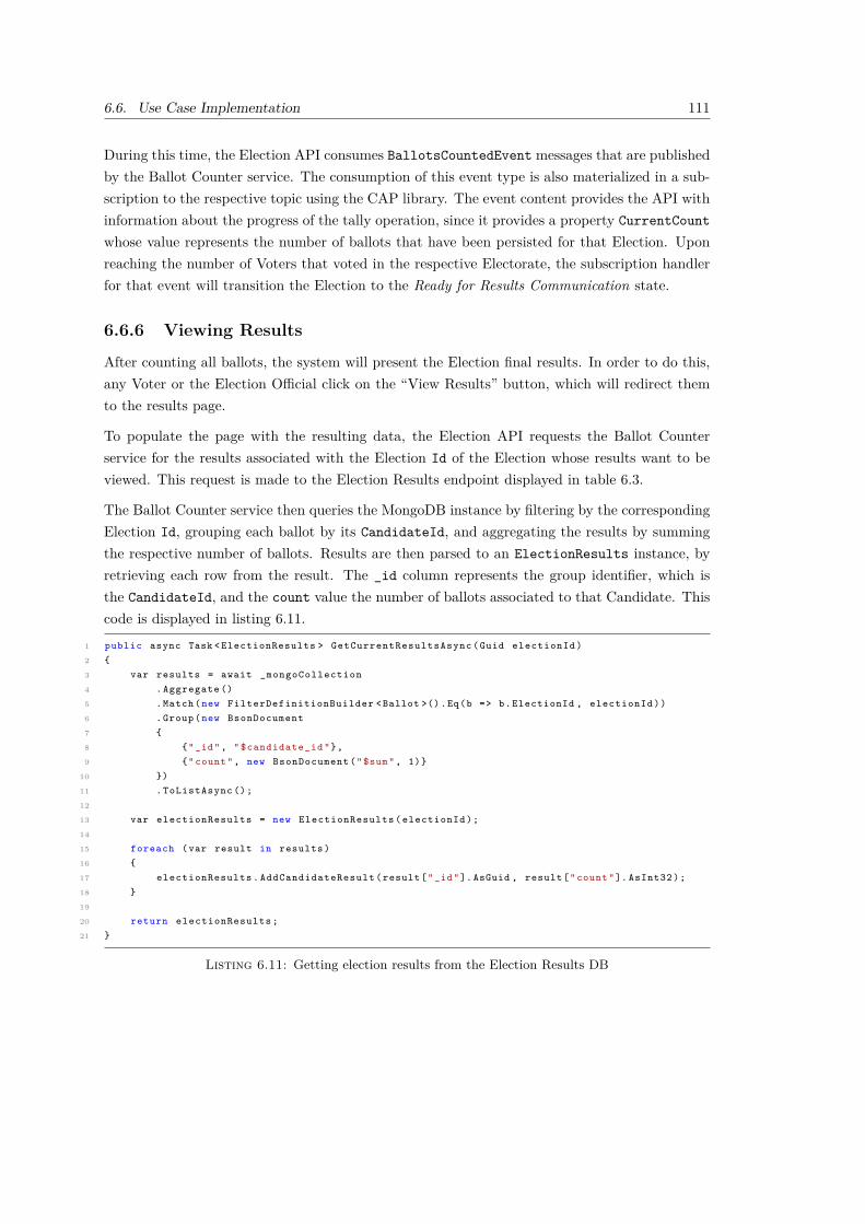
6.6. Use Case Implementation 111
During this time, the Election API consumes BallotsCountedEvent messages that are publishedby the Ballot Counter service. The consumption of this event type is also materialized in a sub-scription to the respective topic using the CAP library. The event content provides the API withinformation about the progress of the tally operation, since it provides a property CurrentCount
whose value represents the number of ballots that have been persisted for that Election. Uponreaching the number of Voters that voted in the respective Electorate, the subscription handlerfor that event will transition the Election to the Ready for Results Communication state.
6.6.6 Viewing Results
After counting all ballots, the system will present the Election final results. In order to do this,any Voter or the Election Official click on the “View Results” button, which will redirect themto the results page.
To populate the page with the resulting data, the Election API requests the Ballot Counterservice for the results associated with the Election Id of the Election whose results want to beviewed. This request is made to the Election Results endpoint displayed in table 6.3.
The Ballot Counter service then queries the MongoDB instance by filtering by the correspondingElection Id, grouping each ballot by its CandidateId, and aggregating the results by summingthe respective number of ballots. Results are then parsed to an ElectionResults instance, byretrieving each row from the result. The _id column represents the group identifier, which isthe CandidateId, and the count value the number of ballots associated to that Candidate. Thiscode is displayed in listing 6.11.
1 public async Task < ElectionResults > GetCurrentResultsAsync (Guid electionId )2 {3 var results = await _mongoCollection4 . Aggregate ()5 . Match (new FilterDefinitionBuilder <Ballot >().Eq(b => b. ElectionId , electionId ))6 . Group (new BsonDocument7 {8 {"_id", " $candidate_id "},9 {" count ", new BsonDocument ("$sum", 1)}
10 })11 . ToListAsync ();12
13 var electionResults = new ElectionResults ( electionId );14
15 foreach (var result in results )16 {17 electionResults . AddCandidateResult ( result ["_id"]. AsGuid , result [" count "]. AsInt32 );18 }19
20 return electionResults ;21 }
Listing 6.11: Getting election results from the Election Results DB

112 Chapter 6. Implementation
Upon provided with a response from the Ballot Counter service, the Election API will query theElection DB for all Candidates associated with the Election, and then performs an in-memory leftjoin operation with the results. The output of this operation is the association of each Candidateinstance with the number of ballots returned.
1 var result = new ElectionResult2 {3 Election = election ,4 CandidateVoteCount = (from candidate in election . Candidates5 join candidateResult in dtoResults . CandidateVoteCount on candidate .Id equals
candidateResult .Key into groupResult6 from candidateIdResult in groupResult . DefaultIfEmpty ()7 orderby candidateIdResult . Value descending8 select (candidate , candidateIdResult )). ToDictionary ( group => group .candidate , group
=> group . candidateIdResult . Value )9 };
Listing 6.12: Joining results in Election API
After performing the join operation, required data is obtained and the server renders the resultspage (figure 6.14).
Figure 6.14: Election Results Page
The Election is considered finished at this point, and a “Vote Tally is finished” message isdisplayed to the end user.
6.7 Summary
In this section, implementation details of the designed solution were presented. First, an overviewof the developed system components/services was provided, along with their intrinsic aspects.Further sections provided a glimpse on how each use case was developed. The next section willfocus on the evaluation of the implementation.
113
Chapter 7
Evaluation
Following the execution of the implementation, it is important to assess if the final result fulfillsinitial expectations, achieves the objectives set out, and solves the problem at hand.
This chapter presents the evaluation process performed onto the solution and the discussion ofthe outcomes. First, it identifies the hypothesis formulated for this project and describes allmethods and available indicators used to evaluate the solution derived from those hypothesis.Finally, those methods are executed, detailed and discussed.
After identifying evaluation indicators, the next step is to define a methodology to assess thehypothesis (cf. section 7.1) of this evaluation process. The adopted methodology can be definedas a gradual evolution of concerns. The first concern subject to evaluation is the technical qualityof the solution, followed by performance testing and ending with a simulated election processinvolving real end-users and surveying their subsequent impression of the application.
7.1 Hypothesis
An hypothesis consists of a supposition as a starting point for further investigation. As statedearlier in the first chapter (cf. section 1.4), the following hypothesis were identified:
• H1 - The developed online voting solution does not compromise vote confidentiality;
• H2 - The developed online voting solution is more convenient for eligible voters;
• H3 - The developed online voting solution can be scaled horizontally and provide betterperformance results.
Regarding the hypothesis H1 it is safe to assume, without any evidence, that it cannot be deemedas accepted for this project. Due to the decision to not implement an encryption mechanism (cf.section 6.3), vote confidentiality can never be achieved by saving the ballot in a plain format.However, the developed solution is extensible enough so that adding an encryption mechanismshould be very straightforward, since the design already introduced the necessary abstractions.
114 Chapter 7. Evaluation
Moreover, a brief study on data security and existing encryption types was performed in section3.2, which can be used as a starting point for the introduction of ballot cryptography.
Nevertheless, it is unfortunate that this hypothesis needs to be ruled out, although it can bereconsidered in the future if an encryption methodology is designed and implemented. As aresult, the next sections will focus on hypothesis H2 and H3 only.
7.2 Indicators
Indicators are essential when carrying on an evaluation process. They consist of measures thatcan be defined and extracted during and after the implementation of a solution. These indicatorspromote the identification of methods that can be used to test the hypothesis aforementioned(cf. section 7.1). These indicators are:
• Development Indicators - consisting of metrics that are used to evaluate the softwarequality, like identified bugs, technical debt, code smells, and code coverage;
• System Indicators - metrics about response or process times, are obtained by performingload tests to a non-scaled deployment environment, and then comparing the results afterscaling the system;
• End-User Indicators - are supplied by Voters after interacting with the application.
These indicators will be obtained by applying the methods described in the next section.
7.3 Technical Quality
Evaluated development indicators do not target any specific hypothesis but they are useful forunderstanding the level of richness of the solution. They are obtained by two different methods:test development, which contribute to the overall code coverage (cf. requirement NFRIC-3); andby gathering quality metrics from the code base.
7.3.1 Code Analysis
Codebase quality was evaluated with the help of SonarQube1. An instance of SonarQube com-munity edition was deployed in a container, and an analysis agent was attached to the solutionbuild, which uses instrumentation to send code data to the SonarQube instance, which ulti-mately produced a report containing multiple quantitative code metrics. Since no continuousdevelopment pipeline process was developed, the inspection agent analyzed the code in the de-velopment machine. The sonar analyzer presented results for the whole solution that can befound in appendix A.
1https://www.sonarqube.org/

7.3. Technical Quality 115
The only issues lifted by Sonar were related to SSL/TLS implementation. For development pur-poses, SSL self-signed certificates were installed locally on the development machine. However,for some unknown reason, some containers were not recognizing the validity of said self-signedcertificates. To overcome this problem, and for concept proving reasons only, .NET HTTP Clientinstances were configured to ignore the validation of those certificates. In the end, a sonar rulewas created to ignore those issues.
7.3.2 Unit Tests
Unit tests were developed for the application by using MSTest2 as the test runner, FluentAsser-tions3 as the assertion framework, and Moq4 as the class dependency mock library. These testswere constrained to the Business layer of the Election API.
All developed unit tests have a success rate of 100% and cover around 80% of code.
7.3.3 Integration Tests
Integration tests were implemented to ensure the integration of all system components andinternal service classes. These tests were categorized and separated depending on the electionstage (cf. section 5.2) subject to testing, since they rely on different system components thatalso have different presentation options.
The Election Inception and Vote Casting stages rely heavily on the user interface. Therefore,to simulate user interaction, tests on the UI were developed using all tools used for unit testing(cf. section 7.3.2) plus the Selenium Web Driver5. This framework provides browser automationAPIs that can simulate the interaction of an end-user. This interaction is performed by invokingHTML Document Object Model (DOM) elements by finding them either by a given attributeor by navigating the DOM tree using a XPath query, which can find any nested element. Thelisting 7.1 represents a vote casting stage integration test performed using the Selenium WebDriver.
1 [ TestMethod ]2 public async Task Voter_Votes_Successfully ()3 {4 var voter = voters . PickRandom ();5 var candidateToVoteVor = ( await
_dbContext . Elections . FindAsync ( election .Id)). Candidates . PickRandom ();6
7 /// (...) Login process ommitted for brevity8
9 _driver . FindElement (By.Name(" submit ")). Click ();10 _driver . FindElement (By. LinkText (" Elections ")). Click ();11 _driver . FindElement (
2https://docs.microsoft.com/en-us/dotnet/core/testing/unit-testing-with-mstest3https://fluentassertions.com/4https://github.com/moq/moq45https://www.selenium.dev/

116 Chapter 7. Evaluation
12 By. XPath ($"//a[ @href =’/ Elections /Vote? electionId ={ election .Id } ’][1]"))13 . Click ();14 _driver . FindElement (15 By. XPath ($"//a[@data - choice =’{ candidateToVoteVor .Id } ’][1]"))16 . Click ();17 _driver . FindElement (By. XPath ($"// input [ @value =’Yes ’][1] ")). Click ();18
19 var electorateVoter = await _dbContext . Electorates . FindAsync ( election .Id , voter .Id);20 electorateVoter . HasVoted . Should (). BeTrue ();21 electorateVoter . RefreshToken . Should (). NotBeEmpty ();22
23 var ballot = await SolidPodGatewayHelper . ExtractBallotAsync ( election .Id , voter .WebId ,electorateVoter . RefreshToken );
24 ballot . ElectionId . Should ().Be( election .Id);25 ballot . CandidateId . Should ().Be( candidateToVoteVor .Id);26 }
Listing 7.1: Integration Test to assert the Vote Casting process
On the other hand, the Vote Tally stage is completely done in the background and does notrely upon a UI. A set-up database seeding process is involved for these tests, filling the ElectionDB instance with POD-owning Voters, candidates, and an Election. Then for each candidate,a predictable result set is conceived so that Election results can be asserted. Finally, ballotsubmission commands are issued using the Mediator (cf. section 5.5.1), causing ballots to bepersisted according to the ballot casting process (cf. section 5.5.5). After persisting all votesand changing the election state to Vote Tally, testing can begin. Upon tally finish, the BallotCounter service is queried to view the Election results, which must be equal to the expectedresult set.
7.4 Load Testing
A load test is a software test that inflicts a determined number of requests upon a specific softwarecomponent to simulate a respective number of users and increase the overall system stress. Thetarget of the load test was the Vote Casting use case (cf. UCV-2), on which a considerablenumber of simultaneous users is projected to interact with the system (cf. requirement NFRP-2). In addition, the performed load tests will help understand if the requirement NFRP-1 wasfulfilled by the implementation of the solution.
The Vote Casting experience offered by the Solid Voting UI and respective Election API back-end processing can be considered an example of an open system model, where the system hasno control over the number of concurrent users [80]. Therefore, the load test must be written sothat it introduces user ramp-up capabilities to introduce an irregular request cadence.
Additionally, the load test must calculate execution metrics. To evaluate and assert requirementNFRP-1, the most useful metric is the 99th percentile, which indicates the maximum latency

7.4. Load Testing 117
bucket where 99% of the requests fall in. Using percentiles over simple means allows the resultsto disregard possible outliers.
The NBomber6 library was used to perform this load test. It provides multiple load testingfunctionality and is completely written in .NET. At the end of the test, it provides a visualreport written in HTML with metrics taken during its execution.
The environment machine used to perform the load test was a Personal Computer (PC) and hadthe specifications demonstrated in table 7.1.
Table 7.1: Load Test Host Environment Specifications
CPU RAM Operating System
Intel Core i7-7820HQ Hexa-core 16GB 2600 MHz Microsoft Windows 10 build 19043
The global load test profile performed two sequential tests. The first test injected 20 users persecond for one minute, while the second test randomly injected between 10 and 50 users persecond for another minute. In total, 2425 requests were performed during these two minutes,with a request per second (RPS) count of 20.2. Full results are displayed in table 7.2.
Requests Latency (ms) Latency Percentile (ms)
All Fail RPS Min Mean Max Std Dev 75th 95th 99th
2425 0 20.2 11.19 32.41 99 13.23 30.42 40.83 76.03
Table 7.2: Load Test Execution Results
The results demonstrated that even in a non-production environment like a PC, the system iscapable of handling an acceptable number of requests and keep the response time lower than200 milliseconds (cf. requirement NFRP-1) even in the maximum latency metric, which takesinto account outliers. The 99th percentile metric value showed that 99% of the requests have aresponse in under approximately 76 milliseconds, which corresponds to 38% of the 200 millisecondlimit.
Figure 7.1 represents a line plot displaying the requests per second metric over the load sessiontime. The plot was generated by NBomber after running both sequential load tests.
6https://nbomber.com/

118 Chapter 7. Evaluation
load RPS
00:00:1000:00:20
00:00:3000:00:40
00:00:5000:01:00
00:01:1000:01:20
00:01:3000:01:40
00:01:5000:02:00
0
10
20
30
40
0
10
20
30
40
50
duration
RPS
Figure 7.1: Throughput during the load test session
It is possible to view that after the first minute on the session, when the load test switches toa random ramp-up injection method, that the RPS value stops following a straight, predictableline to an unpredictable graph.
In conclusion, according to the load test performed, the system is capable of responding back tothe user in less than 200 milliseconds.
7.5 Scaling
The vote tally process involves multiple system components with multiple deployments andscaling capabilities. In order to understand how scaling the application impacts the vote tallyprocess and to check if hypothesis H3 can be accepted, an experimentation test was conducted.The steps of the experiment were:
• Create mocked candidates, voters, and an election;
• Use an excerpt of the integration test on listing 7.1 to simulate vote casting for each voter;
• Manually switching the election state in the database to ReadyForVoteTallyState;
• Manually trigger the Vote Tally process;
• Wait for its completion;
• Record the time taken to count all ballots.
A thousand ballots were considered for this experiment. The decision to use this value wasjustified by manually tweaking the number of ballots and visualising the system. Unfortunately,

7.5. Scaling 119
the hardware specifications of the testing environment did not allow for a much higher valuesince all containers were running on the same computer.
7.5.1 Design Points
The following two factors could be tested in this scaling experiment:
• F1 - Scaling the ballot extractor service up to 3 containers
• F2 - Scaling the ballot count service up to 3 containers
Since the number of factors is higher than one, the number of tests n that could be performedis n = 2k, where k is the number of factors, thus k = 2 and n = 4. The matrix in table 7.3represents the different tests that could be performed according to toggling each factor on or off.Each row is a design point, a + sign indicates that the factor is applied, and a − sign indicatesthe opposite.
Table 7.3: Design Matrix for the Vote Tally experiment
Design Point F1 - Ballot Extractor (3 containers) F2 - Ballot Counter (3 containers)
1 - -
2 + -
3 - +
4 + +
For brevity purposes, only design points 1 and 4 will be considered, since they represent theextreme design points for the considered factors.
7.5.2 Hypothesis Formulation
To check whether scaling the ballot handling components (i.e., Ballot Counter and Ballot Ex-tractor) can influence the overall vote tally process time or not, a new statistical hypothesis wasformulated from the initial hypothesis H3 and is stated in the equation 7.1. The Mean Timefor the vote tally process for a single Ballot Counter and Ballot Extractor instances is given byMTsingle and the Mean Time for the vote tally process for a scaled Ballot Counter and BallotExtractor environment is given by MTscaled.

120 Chapter 7. Evaluation
H0 : MTscaled = MTsingle
H1 : MTscaled < MTsingle
(7.1)
This hypothesis is oriented towards the left side of the distribution, causing the respective testto be considered one-tailed.
7.5.3 Sample Data
The experiment steps (cf. section 7.5) were executed five times for each considered design point.Table 7.4 represents the obtained results, given in a timestamp format (HH:mm:ss). The resultswere obtained by experimenting in the same environment used for the load tests (cf. section7.4).
Table 7.4: Obtained Process Times for Design Points 1 and 4
Iteration Design Point 1 Design Point 4
1 00:16:03 00:13:54
2 00:17:23 00:12:22
3 00:23:22 00:11:56
4 00:15:05 00:13:23
5 00:17:10 00:12:54
Mean 00:17:49 00:12:54
Variance 5.06× 10⁻⁶ 2.96× 10⁻⁷
7.5.4 Result
It was assumed that sample data was normal. Additionally, since data is unpaired, i.e., each oneof the two decision point samples is independent of the other, a t-test for unpaired samples wasperformed. The significance level value (p) used was 5%.
The p− value was calculated by using an Excel spreadsheet. The function used to perform thetest was T.TEST(D1:D5;P15:P19;1;3), where D1:D5 is the data range for the decision point1 sample, and P15:P19 is the data range for the decision point 4 sample. The third function

7.6. Election Simulation and Survey 121
parameter tells the function that it should follow a one-tail distribution, and the last parameterspecifies a two-sampled, unequal variance test type.
The p − value result was approximately 0.013, rounded to three decimal places. According tothis value, the null hypothesis can be rejected, since it is less than the significance level p.
Therefore, with a confidence level of 95%, it is safe to assume that scaling both componentsto three instances each did reduce the mean vote tally process time, and conclude that theapplication can be successfully scaled in favour of better results, therefore accepting hypothesisH3.
7.6 Election Simulation and Survey
The last evaluation method performed was a simulation of an election. A simulation is a time-lapse emulation of the functioning of a real-world process or system. This simulation was carriedon by inviting twenty Portuguese individuals (whose characterization is performed in section7.6.3) to participate in a fictional election whose purpose was to elect the “Hunger Games tributesfor District 12”. The session guide provided to each individual is exhibited in appendix C.
This simulation was part of a survey conducted to evaluate hypothesis H2. This inquiry focusedon gathering end-user indicators when using the Solid Voting platform, but also to collect theopinion of the user related to the research questions RQ2 and RQ3.
7.6.1 Simulation Environment
It was necessary to deploy all system components to a publicly accessible environment. It followedthe deployment diagram on the physical view of the design (cf. section 5.4). The Election Serverwas deployed to a Google Cloud Platform 7 (GCP) Computer Engine, which consists of a virtualmachine (VM) whose specifications can be configured on-demand. The machine type, in GCPterminology8, was e2-medium (2 vCPUs, 4 GB memory). The docker-compose file and remainingproject files were imported using Git. The Solid Pod Provider component was deployed to anHeroku dyno instance by importing its respective Docker image. Both machines (i.e., the Herokudyno and the GCP VM) could communicate amongst them.
7.6.2 Survey Description
The survey was divided into three pages. The first page collected data about the individual toperform sample profiling, including age group, gender, and computer knowledge. The secondpage asked individuals about their vote turnout and how they viewed the current paper ballotelections. Finally, individuals should answer the last page after performing the tasks in the
7https://cloud.google.com/8https://cloud.google.com/compute/docs/machine-types

122 Chapter 7. Evaluation
experiment guide (cf. appendix C). This page asked about the overall user experience using theplatform, whether individuals find value in the decentralization of the ballot, and if they thinkthat Portugal is ready to migrate from the current paper elections (cf. section 2.5) to a paperlesselection system.
All questions that require a qualitative question follow the Likert scale9. The survey structureis presented in appendix B.
7.6.3 Survey Findings
The listing below summarizes some of the characteristics of this survey sample:
• The sample is predominantly male (89.5%);
• The most common age group is between 21 and 35 years old (78.9%);
• Most surveyed individuals have voted electronically in an election or poll (73.7%);
• The majority of individuals describes their computer knowledge to be at least medium(94,7%).
• Most surveyed individuals always vote in official elections (68.4%);
• Sample is divided regarding the safety of the paper ballots or lack thereof (52.6% and 47,4%,respectively).
The survey found out that most people thought that the Solid Voting UI was easy and intuitiveto interact with (Figure 7.2).
36.8%
47.4%15.8%
0%0%
Strongly AgreeAgreeNeutralDisagreeStrongly Disagree
Figure 7.2: Pie chart representing the proportion of answers to the question "Do you think the processto cast a ballot in the platform was easy and intuitive?"
9https://conjointly.com/kb/likert-scaling/#administering-the-scale

7.6. Election Simulation and Survey 123
Additionally, most individuals answered that it was more convenient than on-site voting, withno one disagreeing about its convenience, but with some individuals voting as Neutral, whichcould mean that they do not find on-site voting inconvenient (figure 7.3).
31.5%
42.1%
26.3%
0%0%
Strongly AgreeAgreeNeutralDisagreeStrongly Disagree
Figure 7.3: Pie chart representing the proportion of answers to the question "Do you think the processto cast a ballot in the platform was more convenient than the traditional on-site process?"
The final question was not related to the experiment by itself. Instead, it asked the individualif they felt that the Portuguese election system was ready to go paperless by employing stateof the art technology. Answers to this question were very sparse, from one scale extreme to theother, but mainly were neutral or in disagreement with the sentence (figure 7.4).
10.5%
21.1%15.8%
47.4%
5.3%
Strongly AgreeAgreeNeutralDisagreeStrongly Disagree
Figure 7.4: Pie chart representing the proportion of answers to the question "Do you think the processto cast a ballot in the platform was more convenient than the traditional on-site process?"

124 Chapter 7. Evaluation
From the survey results, it is possible to conclude that the surveyed individuals appreciated thevalue of the proof of concept and that it is more convenient than on-site voting.
As a result, considering the survey findings, it is possible to deem the hypothesis H2 truthful.
7.7 Summary
This chapter was divided into six sections. The first section presented the hypothesis undertest, followed by a section that presented the list of indicators considered while evaluating thesolution.
The third section evaluated the technical quality of the solution, including unit and integrationtests, and overall code metrics.
The fourth section described the load testing methodology performed and presented the results.
The fifth section focused on system scaling and addressed hypothesis H3.
The last section gathered user indicators by simulating an election and surveying the participantsat the end of the session to gather feedback on the Vote Casting process implementation, and toassert hypothesis H2.
The next section will conclude the document by summarizing the work performed throughoutthis project, and review all hypothesis (cf. section 1.4) and research questions (cf. section 1.5)introduced earlier in the document.

125
Chapter 8
Conclusion
Elections are crucial in any democratic nation. However, since election turnout levels in Europehave decreased in the last 25 years [9], studies have been conducted to understand the root causesof the problem and assess how voters could be convinced to vote [4].
This document focused on the voters’ convenience factor by first performing an empirical revisionon how election systems are implemented in Europe, which methods exist, and analyzing howremote voting is deployed across European nations.
The scope of this thesis has then been narrowed down to online voting. Two case studies havebeen reviewed to understand how a country with a fully functional online voting system likeEstonia compares to a country like Portugal that currently has no intentions to implement sucha system. One of the main aspects of the Estonian case is that turnout has also decreased, butnot at the same pace as in Portugal. While this fact can have multiple explanations and causes, itis believed, according to studies performed, that improving the vote casting process conveniencefor voters may have a direct impact on voter turnout [4].
Additionally, this document has also studied how ballot data decentralization could contributeto an acceptable solution for online voting. As a result, the Solid project was studied to under-stand how it could fit into such a solution and how it could be used to store ballots under theresponsibility of their respective voters. This intermediate study process started by comparingSolid to other data decentralization projects and then analyzing its internal features to determinehow ballots would be stored and how they could be accessed in the vote tally process to gatherelection results.
In the sections that followed the Solid study, two architecture alternatives for a distributed onlinevoting proof of concept were analyzed and compared according to multiple criteria, which ledto the adoption of one of them and ultimately guided the system implementation. The maincharacteristic of the developed solution was that the system stores ballots in the Solid Pods ofthe respective voters and retrieves them later on to perform the vote tally process. This systemfeature contributes to a system where non-anonymized ballot data is decentralized.
126 Chapter 8. Conclusion
Evaluation of such a system involves multiple factors and indicators, which proved to be challeng-ing to retrieve and evaluate. The main challenge was setting up a working environment to hostload tests and simulations, since the solution consists of multiple components that must be prop-erly configured and installed to work. Moreover, these components take up computer resourceswhose availability was limited due to hardware constraints. Surprisingly, even with such con-straints in place, the system proved to be performant enough to fulfill the initial non-functionalperformance requirements.
This section concludes the present document by giving an overview of the achieved objectives,answering the research questions initially formulated, reporting the limitations and possible fu-ture work on the implemented solution, and providing a final appreciation statement about thewhole project.
8.1 Goal Retrospective
The main goal of this project was to have a working proof of concept that used a Solid-compliantPod provider to store non-anonymized ballots in secret universal elections. Moreover, the proof ofconcept had to comply with software good practices, including the adoption of SOLID principlesand evaluation methodologies that could assert the overall feasibility of the solution. As a resultof applying good software and design principles, the designed components are modular andextensible enough to introduce many possibilities for system scaling and work distribution.
Multiple functional and non-functional requirements (cf. sections 4.2.1 and 4.2.2) were createdduring the solution analysis, which guided the whole development process. Most determinedrequirements were achieved. However, some of them were either achieved partially or not at all.
The possibility to introduce other types of suffrage (cf. requirement NFRF-1) was considered inthe design process, but the implementation did not follow suit. This decision was based purelyon the re-prioritization of requirements due to time constraints.
GDPR compliance (cf. requirement NFRIC-2) was not achieved since, by the principles in theregulation, users should be able to delete their data whenever they want. However, this actionwas not materialized in a use case, nor was it developed.
In closing, considering all accomplished work, it is safe to claim that the main goal was suc-cessfully achieved with room for improvement, especially regarding ballot encryption and overallcode maintainability.
8.2 Hypothesis
In the introduction, three hypothesis were conceived (cf. section 1.4) to attest the feasabilityof the developed online voting solution. These were then tested in the Evaluation chapter (cf.

8.3. Research Questions 127
section 7.1) which also provided the test results. It is now possible to summarize the resultsobtained.
H1 - The developed online voting solution does not compromise vote confidentiality
This hypothesis was not tested because an encryption algorithm was not studied nor imple-mented. More information was provided in section 6.3. However, it is important to reassure thatthe system is ready to support any of the studied encryption types (cf. section 3.2) since ballotcryptography abstractions and flows were designed (cf. section 5.5.5) but not implemented.
H2 - The developed online voting solution is more convenient for eligible voters
From the gathered survey results (cf. section 7.6.3), it is possible to conclude that the surveyedindividuals appreciated the value of the proof of concept and that it is more convenient thanon-site voting.
H3 - The developed online voting solution can be scaled horizontally and providebetter performance results
This hypothesis was tested by formulating a sub-hypothesis that compared vote tally processmean times between scaled and non-scaled environments (cf. section 7.5). The results obtainedallow us to claim, with a confidence level of 95%, that scaling both components to three instanceseach did reduce the mean vote tally process time and conclude that the application can besuccessfully scaled in favour of better results.
8.3 Research Questions
This thesis was also guided by research questions whose answers were mainly sought by conduct-ing a survey (cf. section 7.6).
RQ1 - Is it possible to have a decentralized online voting system where voters owntheir ballots?
Yes, and the implemented proof of concept proves it.
RQ2 - Can this solution contribute to the acceptance of online voting solutions ingeneral by society?
The question “Do you value the data decentralization offered by the platform by saving your ballotin your POD?” asked in the survey performed got mixed answers. Out of the 20 individualsinquired, 42.2% of them did not find any value in having the ballot stored in the Pod or wereneutral about the matter. While this may indicate that the answer to this question is negative,

128 Chapter 8. Conclusion
it is believed that the solution has room for improvements (cf. section 8.5) that may ultimatelychange the perceived value.
RQ3 - In the perspective of the end-user, could an online voting system ever beimplemented in Portugal?
According to the conducted survey, the inquired exhibited a pessimistic view about a possibleevolution to a paperless election solution in Portugal. To the question, “Do you think Portugalis ready to adopt a paperless election system by employing state of the art technology?”, mostindividuals disagree (47.4%) about the overall country readiness to adopt other ways to performballot casting.
However, it is known that evolution is not immediate. Taking into consideration the Estoniancase study (cf. section 2.6.3), the adoption of online voting raised election after election, whichcan be perceived as a constant increase in the trust of the online voting system designed byEstonian authorities. Moreover, given the ongoing technological evolution, people are goingpaperless in many use cases that were once entirely paper-based.
As a result, it is believed that an online voting system could be implemented in Portugal sometimein the future.
8.4 Limitations
The implemented proof of concept is used merely to analyze the hypothesis of the applicabilityof a concept. Therefore, it is expected to have some technical and design limitations. These arelisted below:
• The UI does not allow for manual selection of voters. Instead, all registered voters aredeemed eligible when creating an election. Moreover, the system could also perform thisstep automatically but based on some criteria provided by the Official when creating anelection (e.g. this election is only available for registered voters who are aged 21 or more);
• The system does not encrypt ballots (cf. section 6.3);
• The system does not automatically retrieve a client identifier and secret from the PODProvider (i.e., OIDC dynamic client registration1). A client identifier and secret must bemanually obtained from the POD Provider and placed in the settings of each componentthat accesses it.
In terms of requirement limitations, requirement NFRF-4 was partially achieved since messagecommunications through the message broker were not encrypted using TLS. This decision wassustained because all components were deploying using docker-compose, which uses an internal
1https://openid.net/specs/openid-connect-registration-1_0.html

8.5. Future Work 129
network to provide inter-container communication capabilities. This network is not publiclyaccessible, and data does not leave the host server. In other deployment solutions that involvedeploying the message broker component to a separate machine, Kafka configuration may betweaked to restrict all plain-text communication.
The lack of cryptography to protect ballots (cf. requirement NFRF-2) was unfortunate, beingone of the main pitfalls of this project (cf. section 6.3). However, such concern also promotesfuture work on the implemented proof of concept, therefore encouraging its continuity.
8.5 Future Work
The realm of elections is rich in concepts, rules and exceptions, therefore it would be very difficultto have a fully-featured proof of concept. As a result, the developed solution has potential to beimproved, either by extending the requirements for a wider range of use cases, either by refiningthe existing functionalities.
• The system is only prepared to work with election types where votes are secret. In orderto support other types, the design can be reviewed to support more than one ballot type(i.e., anonymized and non-anonymized ballots);
• A ballot data protection methodology should be further analyzed and implemented. Apossible starting point would be the section 3.2 that resumes multiple encryption types;
• The designed solution only supports elections with one candidate list. Other types ofelections, like local elections that usually present multiple candidates for multiple townhalls, are not supported. However, supporting more election types (e.g. non-anonymizedballots, multiple candidate lists, different criteria that determine one or more electionwinners) is also possible to implement with an enriched domain model;
• Providing an ability to scale the service automatically by using a container orchestrationframework like Kubernetes2;
• Experimenting the solution with other Solid POD Providers.
8.6 Final Considerations
This project allowed the student to learn about a very complex process like elections, how theyare organized, the different pros and cons of each voting method, and the challenges that arisefrom the adoption of online voting.
This project was challenging and allowed the student to learn more about data centralizationand the privacy issues that arise from it. In addition, the time studying both the Solid project
2https://kubernetes.io/

130 Chapter 8. Conclusion
and other decentralization options was a neat experience that made the student step out of hiscomfort zone.
In conclusion, this thesis was the most extensive document that the student has written inEnglish, which was also challenging, but allowed for good learning experiences and for softwareengineering knowledge consolidation.

131
References
[1] Visão Magazine. Visão | Presidenciais: PS afasta adiar eleições mas defende mecanismospara facilitar voto. url: https://visao.sapo.pt/atualidade/politica/2021- 01-
08- presidenciais- ps- afasta- adiar- eleicoes- mas- defende- mecanismos- para-
facilitar-voto/.[2] Diário de Notícias. Rui Moreira defende adiamento de eleições presidenciais - DN. url:
https://www.dn.pt/politica/rui- moreira- defende- adiamento- de- eleicoes-
presidenciais-13209657.html.[3] Comissão Nacional de Eleições. Voto electrónico | Comissão Nacional de Eleições. url:
http://www.cne.pt/content/voto-electronico (visited on 01/09/2021).[4] Francisco Lupiáñez-Villanueva et al. Study on the Benefits and Drawbacks of Remote Vot-
ing. Tech. rep. 2018, p. 262. doi: 10.2838/677948.[5] Micha Germann. “Internet Voting and Expatriate Voter Turnout”. In: (Oct. 2020), pp. 1–
31. url: https://researchportal.bath.ac.uk/en/publications/internet-voting-
and-expatriate-voter-turnout.[6] Juha Mäenalusta and Heini Huotarinen. “The Election Information System in Finland in
2035 – A Lifecycle Study Technical lifecycle of the Election Information System”. In: June2019 (2019), pp. 3–7.
[7] MIT. Home · Solid. url: https://solidproject.org/ (visited on 12/22/2020).[8] Ken Peffers et al. “A design science research methodology for information systems re-
search”. In: Journal of Management Information Systems 24.3 (Dec. 2007), pp. 45–77.issn: 07421222. doi: 10.2753/MIS0742-1222240302. url: https://www.tandfonline.
com/doi/abs/10.2753/MIS0742-1222240302.[9] Abdurashid Solijonov. Voter Turnout Trends around the World. Tech. rep. 2016, p. 54.
url: https://www.idea.int/sites/default/files/publications/voter-turnout-
trends-around-the-world.pdf.[10] Philipp Dreyer and Johann Bauer. “Does voter polarisation induce party extremism? The
moderating role of abstention”. In: West European Politics 42.4 (2019), pp. 824–847. url:https://doi.org/10.1080/01402382.2019.1566852.
[11] YesElections. The Pros and Cons of On-Site Voting. 2019. url: https://www.yeselections.
com/blog/pros-cons-on-site-voting (visited on 01/24/2021).[12] K P Kaliyamurthie et al. Highly Secured Online Voting System over Network. Tech. rep.
url: www.indjst.org.

132 References
[13] Roger Jardí-Cedó et al. Study on poll-site voting and verification systems. Nov. 2012. doi:10.1016/j.cose.2012.08.001.
[14] The International Institute for Democracy and Electoral Assistance. Introducing ElectronicVoting: Essential Considerations. December. 2013, p. 39. isbn: 9789186565213. url: http:
/ / www . eods . eu / Flibrary / FIDEA . Introducing - Electronic - Voting - Essential -
Considerations.pdf.[15] Committee of Ministers. Recommendation CM/Rec(2017)5 of the Committee of Minis-
ters to member States on standards for e-voting. Tech. rep. 2017, pp. 1–7. url: https://
search.coe.int/cm/Pages/result%7B%5C_%7Ddetails.aspx?ObjectId=0900001680726f6f.[16] Leigh Thomas. France drops electronic voting for citizens abroad over cybersecurity fears.
2017. url: https : / / www . reuters . com / article / us - france - election - cyber -
idUSKBN16D233.[17] Ministry for Europe and Foreign Affairs. French citizens abroad – Approval of electronic
voting for consular elections. 2020. url: https : / / www . diplomatie . gouv . fr / en /
the- ministry- and- its- network/news/2020/article/french- citizens- abroad-
approval-of-electronic-voting-for-consular-elections-15 (visited on 01/25/2021).[18] Bart Jacobs and Wolter Pieters. “Electronic voting in the Netherlands: From early adoption
to early abolishment”. In: Lecture Notes in Computer Science (including subseries LectureNotes in Artificial Intelligence and Lecture Notes in Bioinformatics). Vol. 5705 LNCS.2009, pp. 121–144. isbn: 364203828X. doi: 10 . 1007 / 978 - 3 - 642 - 03829 - 7 _ 4. url:www.parlement.com,.
[19] TNS political & social. “Flash Eurobarometer 431”. In: (2015), pp. 1–17. url: https:
//ec.europa.eu/info/sites/info/files/2016-summary-flash-eurobarometer-431-
electoral-rights%7B%5C_%7Den.pdf.[20] PORDATA. PORDATA - Quadro Resumo. url: https://www.pordata.pt/Portugal/
Quadro+Resumo/Portugal-252268 (visited on 01/28/2021).[21] David Mandim. Há mais de 2,2 milhões emigrantes portugueses. Maioria está na Europa.
2017. url: https : / / www . dn . pt / portugal / interior / ha - mais - de - 22 - milhoes -
emigrantes-portugueses-maioria-esta-na-europa-9011743.html (visited on 01/28/2021).[22] PORDATA. Recenseados: total, por nacionalidade e por residência. 2019. url: https:
/ / www . pordata . pt / Portugal / Recenseados + total + +por + nacionalidade + e + por +
resid%7B%5C%5E%7Be%7D%7Dncia-2250 (visited on 01/28/2021).[23] E-Portugal. Votar - ePortugal.gov.pt. url: https://eportugal.gov.pt/cidadaos/votar
(visited on 03/03/2021).[24] Comissão Nacional de Eleições. Perguntas Frequentes: Votação no estrangeiro | Comissão
Nacional de Eleições. url: http://www.cne.pt/faq2/113/3 (visited on 02/20/2021).[25] PORDATA. Taxa de abstenção nas eleições para a Presidência da República: total, resi-
dentes em Portugal e residentes no estrangeiro. 2016. url: https://www.pordata.pt/
Portugal/Taxa+de+absten%7B%5Cc%7Bc%7D%7D%7B%5C~%7Ba%7D%7Do+nas+elei%7B%

References 133
5Cc%7Bc%7D%7D%7B%5C~%7Bo%7D%7Des+para+a+Presid%7B%5C%5E%7Be%7D%7Dncia+da+
Rep%7B%5C’%7Bu%7D%7Dblica+total++residentes+em+Portugal+e+residentes+no+
estrangeiro-2207 (visited on 01/25/2021).[26] PORDATA SGMAI. Taxa de abstenção nas eleições para a Assembleia da República: total,
residentes em Portugal e residentes no estrangeiro. 2016. url: https://www.pordata.pt/
Portugal/Taxa+de+absten%7B%5Cc%7Bc%7D%7D%7B%5C~%7Ba%7D%7Do+nas+elei%7B%
5Cc%7Bc%7D%7D%7B%5C~%7Bo%7D%7Des+para+a+Presid%7B%5C%5E%7Be%7D%7Dncia+da+
Rep%7B%5C’%7Bu%7D%7Dblica+total++residentes+em+Portugal+e+residentes+no+
estrangeiro-2207 (visited on 01/28/2021).[27] Aleksander Essex and Nicole Goodman. “Secure Online Voting for Legislatures”. In: Fifth
International Joint Conference on Electronic Voting. 2020.[28] RTP. Votação antecipada já começou. Idosos passam a poder votar nos lares. 2021. url:
https://www.rtp.pt/noticias/politica/votacao-antecipada-ja-comecou-idosos-
passam-a-poder-votar-nos-lares%7B%5C_%7Dn1288497.[29] Portuguese Office Of Internal Affairs.Voto Antecipado. 2021. url: https://www.votoantecipado.
mai.gov.pt/ (visited on 01/25/2021).[30] RTP. Presidenciais. Dia de voto antecipado com longas filas de espera. 2021. url: https:
//www.rtp.pt/noticias/politica/presidenciais-dia-de-voto-antecipado-com-
longas-filas-de-espera%7B%5C_%7Dv1290145 (visited on 01/25/2021).[31] Direcção Geral de Saúde. SITUAÇÃO EPIDEMIOLÓGICA EM PORTUGAL - 24/01/2021.
Tech. rep. 2021. url: https://covid19.min-saude.pt/wp-content/uploads/2021/01/
328%7B%5C_%7DDGS%7B%5C_%7Dboletim%7B%5C_%7D20210124.pdf.[32] Portuguese Office of Internal Affairs. Presidenciais 2021 - MAI. 2021. url: https://www.
presidenciais2021.mai.gov.pt/resultados/globais (visited on 01/25/2021).[33] Jornal de Negócios. Marcelo vai ser mais exigente com Governo e pugnar pelo voto postal -
Política - Jornal de Negócios. 2021. url: https://www.jornaldenegocios.pt/economia/
politica/detalhe/marcelo-vai-ser-mais-exigente-com-governo-e-pugnar-pelo-
voto-postal (visited on 01/25/2021).[34] Statistics Estonia. Population figure | Statistikaamet. 2020. url: https://www.stat.ee/
en/find-statistics/statistics-theme/population/population-figure (visited on01/26/2021).
[35] Laura Sheeter. BBC NEWS | Europe | Estonia forges ahead with e-vote. 2005. url: http:
//news.bbc.co.uk/2/hi/europe/4343374.stm (visited on 01/26/2021).[36] Estonian Elections Website. Statistics | Elections in Estonia. 2020. url: https://www.
valimised.ee/en/archive/statistics (visited on 01/26/2021).[37] State Electoral Office of Estonia. “General Framework of Electronic Voting and Implemen-
tation thereof at National Elections in Estonia”. In: State Electoral Office of Estonia June(2017), p. 21. url: https://www.valimised.ee/sites/default/files/uploads/eng/
IVXV-UK-1.0-eng.pdf.

134 References
[38] Kristjan Vassil et al. “The diffusion of internet voting. Usage patterns of internet voting inEstonia between 2005 and 2015”. In: Government Information Quarterly 33.3 (July 2016),pp. 453–459. issn: 0740624X. doi: 10.1016/j.giq.2016.06.007.
[39] Sylvia E Peacock. “How web tracking changes user agency in the age of Big Data: Theused user”. In: Big Data and Society 1.2 (July 2014), p. 205395171456422. issn: 20539517.doi: 10.1177/2053951714564228. url: http://journals.sagepub.com/doi/10.1177/
2053951714564228.[40] The European Parliament and the Council of the European Union. Regulation (EU) 2016/679
of the European Parliament and of the Council of 27 April 2016 on the protection of nat-ural persons with regard to the processing of personal data and on the free movement ofsuch data. 2016. url: https://eur-lex.europa.eu/legal-content/EN/TXT/PDF/?uri=
CELEX:32016R0679%7B%5C&%7Dfrom=ES.[41] Midas Nouwens et al. “Dark Patterns after the GDPR: Scraping Consent Pop-ups and
Demonstrating their Influence”. In: Conference on Human Factors in Computing Systems- Proceedings. Association for Computing Machinery, Jan. 2020. isbn: 9781450367080. doi:10.1145/3313831.3376321. arXiv: 2001.02479. url: http://arxiv.org/abs/2001.
02479%20http://dx.doi.org/10.1145/3313831.3376321.[42] Andrei Vlad Sambra et al. Solid: A Platform for Decentralized Social Applications Based
on Linked Data. Tech. rep. 2016. url: https://diasporafoundation.org.[43] Congcong Ye et al. “Analysis of security in blockchain: Case study in 51%-attack detecting”.
In: Proceedings - 2018 5th International Conference on Dependable Systems and TheirApplications, DSA 2018. Institute of Electrical and Electronics Engineers Inc., Dec. 2018,pp. 15–24. isbn: 9781538692660. doi: 10.1109/DSA.2018.00015.
[44] Stacks. Gaia | Stacks. 2020. url: https : / / docs . blockstack . org / build - apps /
references/gaia (visited on 02/09/2021).[45] Stacks. Authentication | Stacks. 2020. url: https://docs.blockstack.org/build-
apps/guides/authentication (visited on 02/11/2021).[46] Elastos Foundation. Elastos Whitepaper. Tech. rep. 2018. url: https://www.elastos.
org/downloads/elastos%7B%5C_%7Dwhitepaper%7B%5C_%7Den.pdf.[47] Elastos Foundation. Elastos Hive at Elastos Developer Documentation. 2020. url: https:
//developer.elastos.org/learn/hive/ (visited on 02/13/2021).[48] Elastos Foundation. DID Sidechain Core Service Article. 2020. url: https://elastos.
academy/decentralized-identifier-sidechain-2/ (visited on 02/13/2021).[49] Jorge Pinto Leite. “Administração de Sistemas (ASIST) Segurança informática. Crip-
tografia”. In: (2016).[50] IBM. Symmetric cryptography - IBM Documentation. url: https://www.ibm.com/docs/
en/ztpf/1.1.0.14?topic=concepts-symmetric-cryptography (visited on 08/27/2021).[51] IBM. Digital Signatures - IBM Documentation. url: https://www.ibm.com/docs/en/
ztpf/1.1.0.14?topic=concepts-digital-signatures (visited on 08/27/2021).

References 135
[52] Bill Young. Foundations of Computer Security Lecture 45: Stream and Block EncryptionLecture 45: 1 Stream and Block Encryption. url: https://www.cs.utexas.edu/%7B~%
7Dbyoung/cs361/lecture45.pdf (visited on 08/27/2021).[53] “ISO/IEC 10116:2006 – Information technology – Security techniques – Modes of operation
for an n-bit block cipher”. In: ISO Standards Catalogue (2006). url: https://www.iso.
org/standard/38761.html%20http://www.iso.org/iso/iso%7B%5C_%7Dcatalogue/
catalogue%7B%5C_%7Dtc/catalogue%7B%5C_%7Ddetail.htm?csnumber=38761.[54] CWE. CWE - CWE-329: Generation of Predictable IV with CBC Mode (4.5). 2021. url:
http://cwe.mitre.org/data/definitions/329.html (visited on 08/30/2021).[55] IBM. Public Key - IBM Documentation. url: https://www.ibm.com/docs/en/ztpf/1.
1.0.14?topic=concepts-public-key-cryptography (visited on 08/27/2021).[56] IBM. Data integrity and message digests - IBM Documentation. url: https://www.ibm.
com/docs/en/ztpf/1.1.0.14?topic=concepts-data-integrity-message-digests
(visited on 08/30/2021).[57] Peter Koen et al. “Providing clarity and a common language to the "fuzzy front end"”. In:
Research Technology Management 44.2 (2001), pp. 46–55. issn: 08956308. doi: 10.1080/
08956308.2001.11671418.[58] Alexander Osterwalder and Yves Pigneur. Business Model Generation. Vol. vol. 5. nº 7.
2010.[59] Alex Osterwalder et al. Value Proposition Design. Tech. rep., p. 54.[60] Borza John. “FAST Diagrames: The Foundation for Creating Effective Function Models”.
In: Trizcon 2011 (2011), pp. 1–10.[61] JA Rains. “What are the Functions of Function Analysis”. In: avaliable at: www. value-
foundation. org/PDFs/Function-of-Function-Analysis-Rains. pdf (2016).[62] Ching-Lai Hwang and Kwangsun Yoon. “Methods for Multiple Attribute Decision Making”.
In: 1981, pp. 58–191. doi: 10.1007/978-3-642-48318-9_3.[63] Majid Behzadian et al. A state-of the-art survey of TOPSIS applications. Dec. 2012. doi:
10.1016/j.eswa.2012.05.056.[64] RDF Working Group. RDF - Semantic Web Standards. 2014. url: https://www.w3.org/
RDF/%20http://www.w3.org/RDF/.[65] OpenID. OpenID Connect FAQ and Q&As | OpenID. 2021. url: https://openid.net/
connect/faq/ (visited on 02/14/2021).[66] Andrei Sambra, Henry Story, and Tim Berners-Lee.WebID 1.0. 2014. url: https://dvcs.
w3.org/hg/WebID/raw-file/tip/spec/identity-respec.html (visited on 02/14/2021).[67] Solid Project.WebID-OIDC Authentication Spec. 2020. url: https://github.com/solid/
webid-oidc-spec%7B%5C#%7Dwebid-provider-confirmation%20https://github.com/
solid/webid-oidc-spec (visited on 02/14/2021).[68] Kamil Grzybek. The Outbox Pattern - Kamil Grzybek. 2019. url: https://www.kamilgrzybek.
com/design/the-outbox-pattern/ (visited on 09/21/2021).

136 References
[69] Cesar de la Torre, Bill Wagner, and Mike Rousos. .NET Microservices: Architecture forContainerized .NET Applications. 2019, pp. 144–145.
[70] Thomas L. Saaty. “Fundamentals of the Analytic Hierarchy Process”. In: Springer, Dor-drecht, 2001, pp. 15–35. doi: 10.1007/978-94-015-9799-9_2. url: https://link.
springer.com/chapter/10.1007/978-94-015-9799-9%7B%5C_%7D2.[71] Wolfgang Ulaga and Andreas Eggert. “Relationship value and relationship quality: Broad-
ening the nomological network of business-to-business relationships”. In: European Journalof Marketing 40.3-4 (2006), pp. 311–327. issn: 03090566. doi: 10.1108/03090560610648075.
[72] Ludwig Von Mises. HUMAN ACTION A Treatise on Economics. 1998. isbn: 0945466242.url: www.mises.org.
[73] DavidWalters and Geoff Lancaster. “Implementing value strategy through the value chain”.In: Management Decision 38.3 (Apr. 2000), pp. 160–178. issn: 00251747. doi: 10.1108/
EUM0000000005344.[74] Otto Petrovic and Christian Kittl. Capturing the value proposition of a product or service.
Tech. rep.[75] Rafa E Al-Qutaish. “Quality Models in Software Engineering Literature: An Analytical
and Comparative Study”. In: Journal of American Science 6.3 (2010), pp. 166–175. url:http://[email protected].
[76] Peter Eeles and Strategic Services. “What , no supplementary specification ?” In: (2008),pp. 1–19. url: https://www.ibm.com/developerworks/rational/library/3975.html.
[77] Philippe Kruchten. “Architectural Blueprints—The "4+1" View Model of Software Archi-tecture”. In: IEEE Software 12.6 (1995), pp. 42–50.
[78] Erich Gamma et al. Design Patterns CD: Elements of Reusable Object-Oriented Software(Professional Computing). Prentice Hall, 1998, p. 395. isbn: 0201634988. url: https://
www.safaribooksonline.com/library/view/design-patterns-elements/0201633612/
pr02.html%20http://www.amazon.com/Design-Patterns-Object-Oriented-Professional-
Computing/dp/0201634988.[79] Alok Nikhil and Vinoth Chandar. Benchmarking Kafka vs. Pulsar vs. RabbitMQ: Which
is Fastest? 2020. url: https://www.confluent.io/blog/kafka-fastest-messaging-
system/ (visited on 09/22/2021).[80] Gatling. Gatling 3: Closed Workload Model Support - Gatling. 2018. url: https : / /
gatling . io / 2018 / 10 / gatling - 3 - closed - workload - model - support/ (visited on09/29/2021).

137
Appendices


139
Appendix A
Sonar Scan Results


141
Appendix B
Election Simulation Survey
First Page
1. Please tell us your age
• Less than 21 years old
• Between 21 and 35 years old
• Between 36 and 49 years old
• More than 49 years old
2. Gender
• Male
• Female
• Prefer not to say
3. How would you describe your computer knowledge?
• High
• Medium
• Low
4. Have you ever used a platform to vote in any kind of election or poll (like polly, doodle,etc)?
• Yes
• No
• Not sure
Second Page

142 Appendix B. Election Simulation Survey
1. How often do you vote in official elections?
• Always
• Sometimes
• Never
2. Do you think paper ballots are still safe when compared to existing technology? *
• Yes
• No
Third Page
After performing the tasks in the session guide in the link <link to session guide>, please answerthe following questions.
1. Do you think the process to cast a ballot in the platform was easy and intuitive?
• Strongly Agree
• Agree
• Neutral
• Disagree
• Strongly disagree
2. Do you think the process to cast a ballot in the platform was more convenient than thetraditional on-site process?
• Strongly Agree
• Agree
• Neutral
• Disagree
• Strongly disagree
3. Do you value the data decentralization offered by the platform by saving your ballot inyour own POD?
• Strongly Agree
• Agree
• Neutral
• Disagree

Appendix B. Election Simulation Survey 143
• Strongly disagree
4. Do you think Portugal is ready to adopt a paperless election system by employing state ofthe art technology?
• Strongly Agree
• Agree
• Neutral
• Disagree
• Strongly disagree


145
Appendix C
Session Guide