Vostro 5301 Setup and Specifications - Tgdd.vn
49
Vostro 5301 Setup and Specifications 1 Regulatory Model: P121G Regulatory Type: P121G002 October 2020 Rev. A00
-
Upload
khangminh22 -
Category
Documents
-
view
0 -
download
0
Transcript of Vostro 5301 Setup and Specifications - Tgdd.vn

Vostro 5301Setup and Specifications
1
Regulatory Model: P121GRegulatory Type: P121G002October 2020Rev. A00

Notes, cautions, and warnings
NOTE: A NOTE indicates important information that helps you make better use of your product.
CAUTION: A CAUTION indicates either potential damage to hardware or loss of data and tells you how to avoid
the problem.
WARNING: A WARNING indicates a potential for property damage, personal injury, or death.
© 2020 Dell Inc. or its subsidiaries. All rights reserved. Dell, EMC, and other trademarks are trademarks of Dell Inc. or its subsidiaries. Othertrademarks may be trademarks of their respective owners.

Set up your Vostro 5301About this task
NOTE: The images in this document may differ from your computer depending on the configuration you ordered.
Steps
1. Connect the power adapter and press the power button.
NOTE: All pictures shown are for illustration purposes only. Actual product may differ in color.
NOTE: To conserve battery power, the battery might enter power saving mode. Connect the power adapter and press
the power button to turn on the computer.
2. Finish operating system setup.
For Ubuntu:
Follow the on-screen instructions to complete the setup. For more information about installing and configuring Ubuntu, seethe knowledge base articles SLN151664 and SLN151748 at www.dell.com/support.
For Windows:
Follow the on-screen instructions to complete the setup. When setting up, Dell recommends that you:● Connect to a network for Windows updates.
NOTE: If connecting to a secured wireless network, enter the password for the wireless network access when
prompted.
● If connected to the internet, sign-in with or create a Microsoft account. If not connected to the internet, create anoffline account.
● On the Support and Protection screen, enter your contact details.
3. Locate and use Dell apps from the Windows Start menu—Recommended.
Table 1. Locate Dell apps
1
Set up your Vostro 5301 3

Table 1. Locate Dell apps
Resources Description
My Dell
Centralized location for key Dell applications, help articles, and other important information aboutyour computer. It also notifies you about the warranty status, recommended accessories, andsoftware updates if available.
SupportAssist
Pro-actively checks the health of your computer’s hardware and software. The SupportAssistOS Recovery tool troubleshoots issues with the operating system. For more information, see theSupportAssist documentation at www.dell.com/support.
NOTE: In SupportAssist, click the warranty expiry date to renew or upgrade your warranty.
Dell Update
Updates your computer with critical fixes and latest device drivers as they become available.For more information about using Dell Update, see the knowledge base article SLN305843 atwww.dell.com/support.
Dell Digital Delivery
Download software applications, which are purchased but not pre-installed on your computer.For more information about using Dell Digital Delivery, see the knowledge base article 153764 atwww.dell.com/support.
4 Set up your Vostro 5301

Views of Vostro 5301
Right
NOTE: All pictures shown are for illustration purposes only. Actual product may differ in color.
1. microSD-card slot
Reads from and writes to the microSD card. The computer supports the following card types:
● microSecure Digital (microSD)● microSecure Digital High Capacity (microSDHC)● microSecure Digital Extended Capacity (microSDXC)
2. Headset port
Connect headphones or a headset (headphone and microphone combo).
3. USB 3.2 Gen 1 port
Connect devices such as external storage devices and printers. Provides data transfer speeds up to 5 Gbps.
Left
NOTE: All pictures shown are for illustration purposes only. Actual product may differ in color.
1. Power-adapter port
Connect a power adapter to provide power to your computer.
2. Power connector LED/ Diagnostics LED3. HDMI port
Connect to a TV or another HDMI-in enabled device. Provides video and audio output.
4. USB 3.2 Gen 1 port
Connect devices such as external storage devices and printers. Provides data transfer speeds up to 5 Gbps.
5. USB 3.2 Gen 2 (Type-C) port with Power Delivery/DisplayPort
Connect peripherals such as external storage devices, printers, and external displays.
Supports Power Delivery that enables two-way power supply between devices. Provides up to 15 W power output thatenables faster charging.
2
Views of Vostro 5301 5

NOTE: A USB Type-C to DisplayPort adapter (sold separately) is required to connect a DisplayPort device.
Base
NOTE: All pictures shown are for illustration purposes only. Actual product may differ in color.
1. Left-click area
Press to left-click.
2. Touchpad
Move your finger on the touchpad to move the mouse pointer. Tap to left-click and two fingers tap to right-click.
3. Right-click area
Press to right-click.
4. Power button with optional fingerprint reader
Press to turn on the computer if it is turned off, in sleep state, or in hibernate state.
When the computer is turned on, press the power button to put the computer into sleep state; press and hold the powerbutton for 4 seconds to force shut-down the computer.
If the power button has a fingerprint reader, place your finger on the power button to log in.
NOTE: You can customize power-button behavior in Windows. For more information, see Me and My Dell at
www.dell.com/support/manuals.
6 Views of Vostro 5301

Display
NOTE: All pictures shown are for illustration purposes only. Actual product may differ in color.
1. Left microphone
Provides digital sound input for audio recording and voice calls.
2. Camera
Enables you to video chat, capture photos, and record videos.
3. Camera-status light
Turns on when the camera is in use.
4. Right microphone
Provides digital sound input for audio recording and voice calls.
Views of Vostro 5301 7

Bottom
1. Speaker grills
Provides audio output.
2. Fan vents
Provides for entry of air intake.
3. Service Tag label
The Service Tag is a unique alphanumeric identifier that enables Dell service technicians to identify the hardwarecomponents in your computer and access warranty information.
8 Views of Vostro 5301

Specifications of Vostro 5301
Dimensions and weightThe following table lists the height, width, depth, and weight of your Vostro 5301.
Table 2. Dimensions and weight
Description Values
Height:
Front height 14.00 mm (0.551 in.)
Rear height 15.90 mm (0.626 in.)
Width 306.00 mm (12.00 in.)
Depth 204.00 mm (8.03 in.)
Weight (maximum) ● UMA: 1.16 kg (2.56 lb)● DSC: 1.25 kg (2.75 lb)
NOTE: The weight of your computer depends on theconfiguration ordered and manufacturing variability.
ProcessorsNOTE: Global Standard Products (GSP) are a subset of Dell’s relationship products that are managed for availability and
synchronized transitions on a worldwide basis. They ensure the same platform is available for purchase globally. This allows
customers to reduce the number of configurations managed on a worldwide basis, thereby reducing their costs. They also
enable companies to implement global IT standards by locking in specific product configurations worldwide.
Device Guard (DG) and Credential Guard (CG) are the new security features that are only available on Windows 10 Enterprisetoday. Device Guard is a combination of enterprise-related hardware and software security features. When you configuretogether, it locks a device down so that it can only run trusted applications. Credential Guard uses virtualization-based securityto isolate secrets (credentials) so that only privileged system software can access them. Unauthorized access to these secretscan lead to credential theft attacks. Credential Guard prevents these attacks by protecting NT LAN Manager (NTLM) passwordhashes and Kerberos Ticket Granting Tickets.
NOTE: Processor numbers are not a measure of performance. Processor availability is subject to change and may vary by
region/country.
Table 3. Processors
Description Option one Option two
Processors 11th Generation Intel Core i5-1135G7 11th Generation Intel Core i7-1165G7
Wattage 15 W 28 W
Core count 4 4
3
Specifications of Vostro 5301 9

Table 3. Processors
Description Option one Option two
Thread count 8 8
Speed 2.4 GHz to 4.2 GHz 2.8 GHz to 4.7 GHz
Cache 8 MB 8 MB
Integrated graphics Intel Iris Xe Graphics Intel Iris Xe Graphics
ChipsetThe following table lists the details of the chipset supported by your Vostro 5301.
Table 4. Chipset
Description Values
Chipset Intel
Processor 11th Generation Intel Tiger Lake Core i5/i7
DRAM bus width 64-bit
Flash EPROM 32 MB
PCIe bus Up to Gen3
Operating systemYour Vostro 5301 supports the following operating systems:
● Windows 10 Home (64-bit)● Windows 10 Pro (64-bit)● Ubuntu 18.04 LTS (64-bit)
MemoryThe following table lists the memory specifications of your Vostro 5301.
Table 5. Memory specifications (continued)
Description Values
Memory slots Onboard system memory
Memory type Single-channel LPDDR4x soldered down
Memory speed 4267 MHz
Maximum memory configuration 16 GB
Minimum memory configuration 8 GB
Memory configurations supported ● 8 GB, 1 x 8 GB, LPDDR4, 4267 MHz● 16 GB, 2 x 8 GB, LPDDR4, 4267 MHz
10 Specifications of Vostro 5301

Table 5. Memory specifications
Description Values
● 16 GB, 1 x 16 GB, LPDDR4, 4267 MHz
Ports and connectorsTable 6. External ports and connectors
Description Values
External:
USB ● One USB 3.2 Gen 2 Type-C port with DisplayPort 1.2 andPower Delivery support (10 Gbps)
● Two USB 3.2 Gen 1 Type-A port with PowerShare (5Gbps)
Audio One headset (headphone and microphone combo) port
Video One HDMI 2.0 Port
Media card reader One microSD 3.0 card reader (integrated)
Power adapter port One 4.5 mm x 2.9 mm DC-in port
Table 7. Internal ports and connectors
Description Values
Internal:
M.2 ● One M.2 2230 slot for Wi-Fi● One M.2 2230/ 2280 slot for solid-state drive
NOTE: To learn more about the features of differenttypes of M.2 cards, see the knowledge base articleSLN301626.
Wireless moduleThe following table lists the Wireless Local Area Network (WLAN) module specifications of your Vostro 5301.
Table 8. Wireless module specifications
Description Option one Option two
Model number Qualcomm QCA61x4A (DW1820) (2x2)Wireless Adapter with Bluetooth 4.2
Intel Wi-Fi 6 AX201, 2x2, 802.11ax withBluetooth 5.0
Transfer rate ● 802.11ac - Up to 867 Mbps● 802.11n - Up to 450 Mbps● 802.11a/g - Up to 54 Mbps● 802.11b - Up to 11 Mbps
● 2.4 GHz 40M: Up to 574 Mbps● 5 GHz 80M: Up to 1.2 Gbps● 5 GHz 160M: Up to 2.4 Gbps
Frequency bands supported 2.4 GHz (802.11b/g/n) and 5 GHz(802.11a/n/ac)
2.4/5 GHz
Specifications of Vostro 5301 11

Table 8. Wireless module specifications
Description Option one Option two
Wireless standards ● 802.11a, 802.11b, 802.11g, 802.11nand 802.11ac
● Dual-mode Bluetooth 4.2, BLE (HWready, SW depends on OS)
IEEE 802.11a/b/g/n/ac/ax, 160MHzchannel use
Encryption ● 64-bit/128-bit WEP● AES-CCMP● TKIP
● 64/128-bit WEP● 128-bit AES-CCMP● TKIP
Bluetooth Bluetooth 5.0 Bluetooth 5.0
AudioThe following table lists the audio specifications of your Vostro 5301.
Table 9. Audio specifications
Description Values
Audio controller Realtek ALC3204
Stereo conversion Supported
Internal audio interface HD audio interface
External audio interface Universal Audio Jack
Number of speakers Two
Internal-speaker amplifier Supported (audio codec integrated)
External volume controls No hardware volume buttons, keyboard shortcut controls
Speaker output:
Average speaker output 2 W
Peak speaker output 2.5 W
Subwoofer output Not supported
Microphone Dual array microphone
StorageYour computer supports one of the following configurations:● M.2 2230 Class 35 SSD/SED● M.2 2280 Class 40 SSD/SED● M.2 2280 Intel Optane memory
Table 10. Storage specifications
Storage type Interface type Capacity
M.2 Intel Optane with Storage PCIe x4 NVMe 3.0 512 GB
12 Specifications of Vostro 5301

Table 10. Storage specifications
Storage type Interface type Capacity
M.2 Class 35 solid-state drive PCIe x4 NVMe 3.0 ● 128 GB● 256 GB● 512 GB
M.2 Class 40 solid-state drive PCIe x4 NVMe 3.0 ● 256 GB● 512 GB● 1 TB
Intel Optane Memory H10 with Solid State Storage(optional)Intel Optane Memory technology utilizes 3D XPoint memory technology and functions as a non-volatile storage cache/accelerator and/or storage device depending on the Intel Optane Memory installed in your computer.
Intel Optane Memory H10 with Solid State Storage functions as both a non-volatile storage cache/accelerator (enablingenhanced read/write speeds for hard-drive storage) and a solid-state storage solution. It neither replaces nor adds to thememory (RAM) installed on your computer.
Table 11. Intel Optane Memory H10 with Solid State Storage specifications
Description Values
Interface PCIe 3 x4 NVMe● One PCIe 3 x2 for Optane memory● One PCIe 3 x2 for solid-state storage
Connector M.2
Form factor 2280
Capacity (Intel Optane memory) Up to 32 GB
Capacity (solid-state storage) Up to 512 GB
NOTE: Intel Optane Memory H10 with Solid State Storage is supported on computers that meet the following requirements:
● 9th Generation or higher Intel Core i3/i5/i7 processors
● Windows 10 64-bit version or higher (Anniversary Update)
● Intel Rapid Storage Technology driver version 15.9.1.1018 or higher
Media-card readerThe following table lists the media cards supported by your Vostro 5301.
Table 12. Media-card reader specifications
Description Values
Media-card type One micro-SD 3.0 card
Media-cards supported Secure Digital (SD)
NOTE: The maximum capacity supported by the media-card reader varies depending on the standard of the media cardinstalled in your computer.
Specifications of Vostro 5301 13

KeyboardThe following table lists the keyboard specifications of your Vostro 5301.
Table 13. Keyboard specifications
Description Values
Keyboard type ● Standard spill resistant keyboard (Optional backlit)
Keyboard layout QWERTY/ KANJI
Number of keys ● United States and Canada: 81 keys● United Kingdom: 82 keys● Japan: 85 keys
Keyboard size X=18.07 mm key pitch
Y=18.07 mm key pitch
Keyboard shortcuts Some keys on your keyboard have two symbols on them.These keys can be used to type alternate characters or toperform secondary functions. To type the alternate character,press Shift and the desired key. To perform secondaryfunctions, press Fn and the desired key.
NOTE: You can define the primary behavior of thefunction keys (F1–F12) changing Function Key Behaviorin BIOS setup program.
CameraThe following table lists the camera specifications of your Vostro 5301.
Table 14. Camera specifications
Description Values
Number of cameras One
Camera type RGB HD camera
Camera location Front camera
Camera sensor type CMOS sensor technology
Camera resolution:
Still image 0.92 megapixel
Video 1280 x 720 (HD) at 30 fps
Diagonal viewing angle: 74.9 degrees
TouchpadThe following table lists the touchpad specifications of your Vostro 5301.
Table 15. Touchpad specifications
14 Specifications of Vostro 5301

Table 15. Touchpad specifications
Description Values
Touchpad resolution:
Horizontal 1229
Vertical 749
Touchpad dimensions:
Horizontal 105 mm (4.13 in.)
Vertical 65 mm (2.56 in.)
Touchpad gestures For more information about touchpad gestures availableon Windows 10, see the Microsoft knowledge base article4027871 at support.microsoft.com.
Power adapterThe following table lists the power adapter specifications of your Vostro 5301.
Table 16. Power adapter specifications
Description Option one Option two
Type 45 W 65 W
Connector dimensions:
External diameter 4.50 4.50
Internal diameter 2.90 2.90
Input voltage 100 VAC–240 VAC 100 VAC–240 VAC
Input frequency 50 Hz–60 Hz 50 Hz–60 Hz
Input current (maximum) 1.30 A 1.60 A
Output current (continuous) 2.31 A 3.34 A
Rated output voltage 19.50 VDC 19.50 VDC
Temperature range:
Operating 0°C to 40°C (32°F to 104°F) 0°C to 40°C (32°F to 104°F)
Storage -40°C to 70°C (-40°F to 158°F) -40°C to 70°C (-40°F to 158°F)
BatteryTable 17. Battery specifications
Description Values
Type 3-cell, 40 WHr, Polymer battery 4-cell, 53 WHr, Polymer battery
Voltage 11.40 VDC 15.2 VDC
Specifications of Vostro 5301 15

Table 17. Battery specifications
Description Values
Weight (maximum) 0.18 kg (0.4 lb) 0.235 kg (0.518 lb)
Dimensions:
Height 5.75 mm (0.23 in.) 5.75 mm (0.23 in.)
Width 184.1 mm (7.25 in.) 239.1 mm (9.41 in.)
Depth 90.73 mm (3.6 in.) 90.73 mm (3.6 in.)
Temperature range:
Operating 0 °C to 35 °C (32 °F to 95 °F) 0 °C to 35 °C (32 °F to 95 °F)
Storage -40 °C to 65 °C (-40 °F to 149 °F) -40 °C to 65 °C (-40 °F to 149 °F)
Operating timeVaries depending on operating conditions and can significantly reduce under certain
power-intensive conditions.
Charging time (approximate) 4 hours (when the computer is off) 4 hours (when the computer is off)
NOTE: Control the charging time, duration, start and end time, and so on usingthe Dell Power Manger application. For more information on the Dell PowerManger see, https://www.dell.com/support/home/product-support/product/power-manager/docs
Life span (approximate) 300 discharge/charge cycles 300 discharge/charge cycles
ExpressCharge Supported Supported
User replaceable No (FRU) No (FRU)
Coin-cell battery CR2032
NOTE: For batteries with the ExpressCharge feature, the battery will typically have at least an 80% charge after about an
hour of charging with the system off, and fully charged in about 2 hours with the system off.
Enabling ExpressCharge requires that both the computer and the battery used be ExpressCharge capable. If these
requirements are not met, ExpressCharge will not be enabled.
DisplayThe following table lists the display specifications of your Vostro 5301.
Table 18. Display specifications
Description Values
Display type Full High Definition (FHD)
Display-panel technology NA
Display-panel dimensions (active area):
Height 165.24 mm (6.5 in.)
Width 293.76 mm (11.57 in.)
Diagonal 337.82 mm (13.3 in.)
16 Specifications of Vostro 5301

Table 18. Display specifications
Description Values
Display-panel native resolution 1920 x 1080
Luminance (typical) 300 nits
Megapixels 2.07
Color gamut sRGB 95%
Pixels Per Inch (PPI) 166
Contrast ratio (min) 600:1
Response time (max) 35 ms
Refresh rate 60 Hz
Horizontal view angle +/-80°
Vertical view angle +/-80°
Pixel pitch 0.153 mm × 0.153 mm
Power consumption (maximum) 4 W
Anti-glare vs glossy finish Anti-glare
Touch options No
Fingerprint reader (optional)The following table lists the specifications of the optional fingerprint-reader of your Vostro 5301.
Table 19. Fingerprint reader specifications
Description Values
Fingerprint-reader sensor technology Capacitive
Fingerprint-reader sensor resolution 500 dpi
Fingerprint-reader sensor pixel size 64 x 80
GPU—IntegratedThe following table lists the specifications of the integrated Graphics Processing Unit (GPU) supported by your Vostro 5301.
Table 20. GPU—Integrated
Controller External display support Memory size Processor
Intel Iris Xe Graphics HDMI 2.0/ Display over USBType-C
Shared system memory 11th Generation Intel Corei5/i7
Specifications of Vostro 5301 17
GPU—DiscreteThe following table lists the specifications of the discrete Graphics Processing Unit (GPU) supported by your Vostro 5301.
Table 21. GPU—Discrete
Controller External display support Memory size Memory type
NVIDIA GeForce MX350 NA 2 GB GDDR5
Operating and storage environmentThis table lists the operating and storage specifications of your Vostro 5301.
Airborne contaminant level: G1 as defined by ISA-S71.04-1985
Table 22. Computer environment
Description Operating Storage
Temperature range 0 °C to 40 °C (32 °F to 104 °F) -40°C to 65°C (-40°F to 149°F)
Relative humidity (maximum) 10% to 90% (non-condensing) 10% to 95% (non-condensing)
Vibration (maximum)*0.66 GRMS 1.30 GRMS
Shock (maximum) 140 G† 160 G†
Altitude range 0 m to 3048 m (32 ft to 5518.4 ft) 0 m to 10668 m (32 ft to 19234.4 ft)
* Measured using a random vibration spectrum that simulates user environment.
† Measured using a 2 ms half-sine pulse when the hard drive is in use.
18 Specifications of Vostro 5301
System setupCAUTION: Unless you are an expert computer user, do not change the settings in the BIOS Setup program.
Certain changes can make your computer work incorrectly.
NOTE: Depending on the computer and its installed devices, the items listed in this section may or may not be displayed.
NOTE: Before you change BIOS Setup program, it is recommended that you write down the BIOS Setup program screen
information for future reference.
Use the BIOS Setup program for the following purposes:● Get information about the hardware installed in your computer, such as the amount of RAM and the size of the hard drive.● Change the system configuration information.● Set or change a user-selectable option, such as the user password, type of hard drive installed, and enabling or disabling
base devices.
Entering BIOS setup program
About this task
Turn on (or restart) your computer and press F2 immediately.
Navigation keysNOTE: For most of the System Setup options, changes that you make are recorded but do not take effect until you restart
the system.
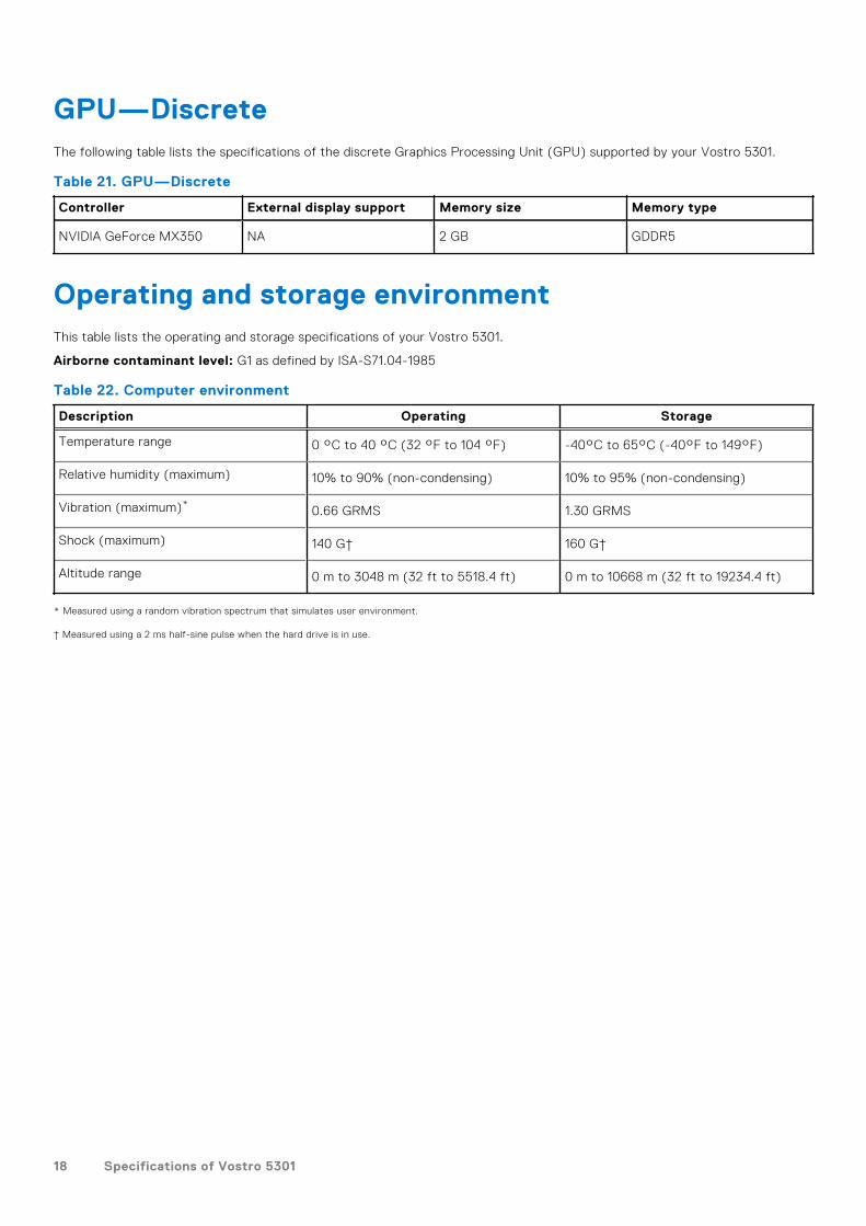
Table 23. Navigation keys
Keys Navigation
Up arrow Moves to the previous field.
Down arrow Moves to the next field.
Enter Selects a value in the selected field (if applicable) or followthe link in the field.
Spacebar Expands or collapses a drop-down list, if applicable.
Tab Moves to the next focus area.
NOTE: For the standard graphics browser only.
Esc Moves to the previous page until you view the main screen.Pressing Esc in the main screen displays a message thatprompts you to save any unsaved changes and restarts thesystem.
Boot SequenceBoot Sequence allows you to bypass the System Setup–defined boot device order and boot directly to a specific device (forexample: optical drive or hard drive). During the Power-on Self Test (POST), when the Dell logo appears, you can:● Access System Setup by pressing F2 key
4
System setup 19

● Bring up the one-time boot menu by pressing F12 key
The one-time boot menu displays the devices that you can boot from including the diagnostic option. The boot menu optionsare:
● Removable Drive (if available)● STXXXX Drive (if available)
NOTE: XXX denotes the SATA drive number.
● Optical Drive (if available)● SATA Hard Drive (if available)● Diagnostics
NOTE: Choosing Diagnostics, will display the SupportAssist diagnostics screen.
The boot sequence screen also displays the option to access the System Setup screen.
One time boot menuTo enter one time boot menu, turn on your computer, and then press F2 immediately.
NOTE: It is recommended to shutdown the computer if it is on.
The one-time boot menu displays the devices that you can boot from including the diagnostic option. The boot menu optionsare:
● Removable Drive (if available)● STXXXX Drive (if available)
NOTE: XXX denotes the SATA drive number.
● Optical Drive (if available)● SATA Hard Drive (if available)● Diagnostics
NOTE: Choosing Diagnostics, will display the SupportAssist diagnostics screen.
The boot sequence screen also displays the option to access the System Setup screen.
System setup optionsNOTE: Depending on this computer and its installed devices, the items that are listed in this section may or may not be
displayed.
Table 24. System setup options—System information menu
Overview
BIOS Version Displays the BIOS version number.
Service Tag Displays the Service Tag of the computer.
Asset Tag Displays the Asset Tag of the computer.
Ownership Tag Displays the ownership tag of the computer.
Manufacture Date Displays the manufacture date of the computer.
Ownership Date Displays the ownership date of the computer.
Express Service Code Displays the express service code of the computer.
Ownership Tag Displays the ownership tag of the computer.
Signed Firmware Update Displays whether the signed firmware update is enabled.
Battery Displays the battery health information.
Primary Displays the primary battery.
20 System setup
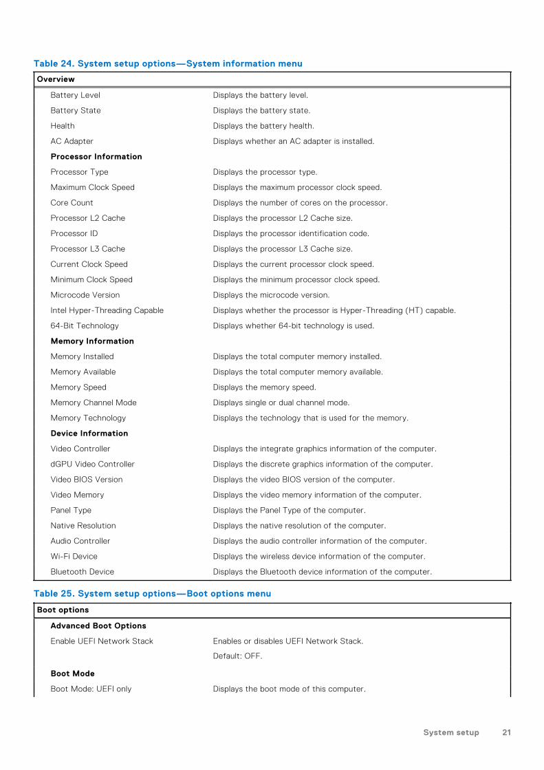
Table 24. System setup options—System information menu
Overview
Battery Level Displays the battery level.
Battery State Displays the battery state.
Health Displays the battery health.
AC Adapter Displays whether an AC adapter is installed.
Processor Information
Processor Type Displays the processor type.
Maximum Clock Speed Displays the maximum processor clock speed.
Core Count Displays the number of cores on the processor.
Processor L2 Cache Displays the processor L2 Cache size.
Processor ID Displays the processor identification code.
Processor L3 Cache Displays the processor L3 Cache size.
Current Clock Speed Displays the current processor clock speed.
Minimum Clock Speed Displays the minimum processor clock speed.
Microcode Version Displays the microcode version.
Intel Hyper-Threading Capable Displays whether the processor is Hyper-Threading (HT) capable.
64-Bit Technology Displays whether 64-bit technology is used.
Memory Information
Memory Installed Displays the total computer memory installed.
Memory Available Displays the total computer memory available.
Memory Speed Displays the memory speed.
Memory Channel Mode Displays single or dual channel mode.
Memory Technology Displays the technology that is used for the memory.
Device Information
Video Controller Displays the integrate graphics information of the computer.
dGPU Video Controller Displays the discrete graphics information of the computer.
Video BIOS Version Displays the video BIOS version of the computer.
Video Memory Displays the video memory information of the computer.
Panel Type Displays the Panel Type of the computer.
Native Resolution Displays the native resolution of the computer.
Audio Controller Displays the audio controller information of the computer.
Wi-Fi Device Displays the wireless device information of the computer.
Bluetooth Device Displays the Bluetooth device information of the computer.
Table 25. System setup options—Boot options menu
Boot options
Advanced Boot Options
Enable UEFI Network Stack Enables or disables UEFI Network Stack.
Default: OFF.
Boot Mode
Boot Mode: UEFI only Displays the boot mode of this computer.
System setup 21

Table 25. System setup options—Boot options menu
Boot options
Enable Boot Devices Enables or disables boot devices for this computer.
Boot Sequence Displays the boot sequence.
BIOS Setup Advanced Mode Enables or disables advanced BIOS settings.
Default: ON.
UEFI Boot Path Security Enables or disables the system to prompt the user to enter the Adminpassword when booting a UEFI boot path from the F12 boot menu.
Default: Always Except Internal HDD.
Table 26. System setup options—System Configuration menu
System Configuration
Date/Time
Date Sets the computer date in MM/DD/YYYY format. Changes to the date takeeffect immediately.
Time Sets the computer time in HH/MM/SS 24-hour format. You can switchbetween 12-hour and 24-hour clock. Changes to the time take effectimmediately.
Enable SMART Reporting Enables or disables SMART (Self-Monitoring, Analysis, and ReportingTechnology) during computer startup to report hard drive errors.
Default: OFF.
Enable Audio Enables or disables all integrated audio controller.
Default: ON.
Enable Microphone Enables or disables microphone.
Default: ON.
Enable Internal Speaker Enables or disables internal speaker.
Default: ON.
USB Configuration
Enable Boot Support Enables or disables booting from USB mass storage devices such as externalhard drive, optical drive, and USB drive.
Enable External USB Ports Enables or disables USB ports to be functional in an operating systemenvironment.
SATA Operation Configures operating mode of the integrated SATA hard drive controller.
Default: RAID. SATA is configured to support RAID (Intel Rapid RestoreTechnology).
Drives Enables or disables various onboard drives.
M.2 PCIe SSD-0/SATA-2 Default: ON.
SATA-0 Default: ON.
Drive Information Displays the information of various onboard drives.
Miscellaneous Devices Enables or disables various onboard devices.
Enable Camera Enables or disables the camera.
Default: ON.
Keyboard Illumination Configures the operating mode of the keyboard illumination feature.
Default: Disabled. The keyboard illumination will always be off.
22 System setup

Table 26. System setup options—System Configuration menu
System Configuration
Keyboard Backlight Timeout on AC Configures the timeout value for the keyboard when an AC adapter isconnected to the computer. The keyboard backlight timeout value is onlyeffect when the backlight is enabled.
Default: 10 seconds.
Keyboard Backlight Timeout on Battery Configures the timeout value for the keyboard when the computer is runningon battery. The keyboard backlight timeout value is only effect when thebacklight is enabled.
Default: 10 seconds.
Touchscreen Enables or disables the touchscreen for the operating system.NOTE: Touchscreen will always work in the BIOS setup irrespective of thissetting.
Default: ON.
Table 27. System setup options—Video menu
Video
LCD Brightness
Brightness on battery power Sets the screen brightness when the computer is running on battery power.
Brightness on AC power Sets the screen brightness when the computer is running on AC power.
EcoPower Enables or disables EcoPower which increases the battery life by reducing thescreen brightness when appropriate.
Default: ON.
Table 28. System setup options—Security menu
Security
Enable Admin Setup Lockout Enables or disables the user from entering BIOS Setup when an AdminPassword is set.
Default: OFF.
Password Bypass Bypass the System (Boot) Password and the internal hard drive passwordprompts during a system restart.
Default: Disabled.
Enable Non-Admin Password Changes Enables or disables the user to change the system and hard drive passwordwithout the need for admin password.
Default: ON.
Non-Admin Setup Changes
Allow Wireless Switch Changes Enables or disables changes to the setup option when an Administratorpassword is set.
Default: OFF.
Enable UEFI Capsule Firmware Updates Enables or disables BIOS updates through UEFI capsule update packages.
Computrace Enable or disable the BIOS module interface of the optional Computrace(R)Service from Absolute Software.
Intel Platform Trust Technology On Enables or disables Platform Trust Technology (PTT) visibility to the operatingsystem.
Default: ON.
System setup 23

Table 28. System setup options—Security menu
Security
PPI Bypass for Clear Commands Enables or disables the operating system to skip BIOS Physical PresenceInterface (PPI) user prompts when issuing the Clear command.
Default: OFF.
Clear Enables or disables the computer to clear the PTT owner information, andreturns the PTT to the default state.
Default: OFF.
Intel SGX Enables or disables the Intel Software Guard Extensions (SGX) to provide asecured environment for running code/storing sensitive information.
Default: Software Control
SMM Security Mitigation Enables or disables additional UEFI SMM Security Mitigation protections.
Default: OFF.
NOTE: This feature may cause compatibility issues or loss of functionalitywith some legacy tools and applications.
Enable Strong Passwords Enables or disables strong passwords.
Default: OFF.
Password Configuration Control the minimum and maximum number of characters that are allowed forAdmin and System passwords.
Admin Password Sets, Changes, or deletes the administrator (admin) password (sometimescalled the "setup" password).
System Password Sets, Changes, or deletes the system password.
Enable Master Password Lockout Enables or disables the master password support.
Default: OFF.
Table 29. System setup options—Secure Boot menu
Secure Boot
Enable Secure Boot Enables or disables the computer to boos using only validated boot software.
Default: OFF.
NOTE: For Secure Boot to be enabled, the computer needs to be in UEFIboot mode and the Enable Legacy Option ROMs option needs to be turnedoff.
Secure Boot Mode Selects the Secure Boot operation mode.
Default: Deployed Mode.
NOTE: Deployed Mode should be selected for normal operation of SecureBoot.
Table 30. System setup options—Expert Key Management menu
Expert Key Management
Enable Custom Mode Enables or disables the keys in the PK, KEK, db, and dbx security key databasesto be modified.
Default: OFF.
Custom Mode Key Management Selects the custom values for expert key management.
Default: PK.
24 System setup

Table 31. System setup options—Performance menu
Performance
Intel Hyper-Threading Technology Enables or disables the Intel Hyper-Threading Technology to use processorresources more efficiently.
Default: ON.
Intel SpeedStep Enables or disables the Intel SpeedStep Technology to dynamically adjustprocessor voltage and core frequency, decreasing average power consumptionand heat production.
Default: ON.
Intel TurboBoost Technology Enabled or disabled the Intel TurboBoost mode of the processor. If enabled,the Intel TurboBoost driver increases the performance of the CPU or graphicsprocessor.
Default: ON.
Multi-Core Support Changes the number of CPU cores available to the operating system. Thedefault value is set to the maximum number of cores.
Default: All Cores.
Enable C-State Control Enables or disables the CPU's ability to enter and exit low-power states.
Default: ON.
Table 32. System setup options—Power Management menu
Power Management
Wake on AC Enables the computer to turn on and go to boot when AC power is supplied tothe computer.
Default: OFF.
Auto on Time Enables the computer to automatically power on for defined days and times.
Default: Disabled. The system will not automatically power up.
Battery Charge Configuration Enables the computer to run on battery during power usage hours. Use thebelow options to prevent AC power usage between certain times of each day.
Default: Adaptive. Battery settings are adaptively optimized based on yourtypical battery usage pattern.
Enable Advanced Battery ChargeConfiguration
Enables Advanced Battery Charge Configuration from the beginning of theday to a specified work period. Advanced Battery Charged maximizes batteryhealth while still supporting heavy use during the work day.
Default: OFF.
Block Sleep Blocks the computer from entering Sleep (S3) mode in the operating system.
Default: OFF.
NOTE: If enabled, the computer will not go to sleep, Intel Rapid Start willbe disabled automatically, and the operating system power option will beblank if it was set to Sleep.
Enable USB Wake Support Enables the USB devices to wake the computer from Standby mode.
Default: OFF.
Enable Intel Speed Shift Technology Enables or disables Intel Speed Shift Technology support which enablesthe operating system to select the appropriate processor performanceautomatically.
Default: ON.
System setup 25

Table 32. System setup options—Power Management menu
Power Management
Lid Switch Enables the computer to power up from the off state whenever the lid isopened.
Default: ON.
Table 33. System setup options—Wireless menu
Wireless
Wireless Switch Determines which wireless devices can be controlled by the Wireless Switch.For Windows 8 systems, this is controlled by an operating system drive directly.As a result, the setting does not affect the Wireless Switch behavior.
NOTE: When both WLAN and WiGig are present, enable/disable controlsare tied together. Thus, they cannot be enabled or disabled independently.
WLAN Default: ON.
Bluetooth Default: ON.
Wireless Device Enable Enable or disable internal WLAN/Bluetooth devices.
WLAN Default: ON.
Bluetooth Default: ON.
Table 34. System setup options—POST Behavior menu
POST Behavior
Numlock Enable Enables or disables Numlock when the computer boots.
Default: ON.
Enable Adapter Warnings Enables the computer to display adapter warning messages during boot.
Default: ON.
Extend BIOS POST Time Configures the BIOS POST (Power-On Self-Test) load time.
Default: 0 seconds.
Fastboot Configures the speed of the UEFI boot process.
Default: Thorough. Performs complete hardware and configuration initializationduring boot.
Fn Lock Options Enables or disables the Fn lock mode.
Default: ON.
Lock Mode Default: Lock Mode Secondary. Lock Mode Secondary = If this option isselected, the F1-F12 keys scan the code for their secondary functions.
Pull Screen Logo Enabled or disabled the computer to display full screen logo if the image matchscreen resolution.
Default: OFF.
Warnings and Errors Selects an action on encountering a warning or error during boot.
Default: Prompt on Warnings and Errors. Stop, prompt and wait for user inputwhen warnings or errors are detected.
NOTE: Errors deemed critical to the operation of the computer hardwarewill always halt the computer.
Table 35. System setup options—Virtualization menu
26 System setup

Table 35. System setup options—Virtualization menu
Virtualization
Intel Virtualization Technology Enables the computer to run a virtual machine monitor (VMM).
Default: ON.
VT for Direct I/O Enables the computer to perform Virtualization Technology for Direct I/O (VT-d). VT-d is an Intel method that provides virtualization for memory map I/O.
Default: ON.
Table 36. System setup options—Maintenance menu
Maintenance
Asset Tag Creates a system Asset Tag that can be used by an IT administrator touniquely identify a particular system. Once set in BIOS, the Asset Tag cannotbe changed.
Service Tag Displays the Service Tag of the computer.
BIOS Recovery from Hard Drive Enables the computer to recover from a bad BIOS image, as long as the BootBlock portion is intact and functioning.
Default: ON.
NOTE: BIOS recovery is designed to fix the main BIOS block and cannotwork if the Boot Block is damaged. In addition, this feature cannot workin the event of EC corruption, ME corruption, or a hardware issue. Therecovery image must exist on an unencrypted partition on the drive.
BIOS Auto-Recovery Enables the computer to automatically recover the BIOS without user actions.This feature requires BIOS Recovery from Hard Drive to be set to Enabled.
Default: OFF.
Start Data Wipe CAUTION: This Secure Wipe Operation will delete information in away that it cannot be reconstructed.
If enabled, the BIOS will queue up a data wipe cycle for storage devices thatare connected to the motherboard on the next reboot.
Default: OFF.
Allow BIOS Downgrade Controls flashing of the system firmware to previous revisions.
Default: ON.
Table 37. System setup options—System Logs menu
System Logs
Power Event Log Displays Power events.
Default: Keep.
BIOS Event Log Displays BIOS events.
Default: Keep.
Thermal Event Log Displays Thermal events.
Default: Keep.
Table 38. System setup options—SupportAssist menu
SupportAssist
Dell Auto operating system RecoveryThreshold
Controls the automatic boot flow for SupportAssist System Resolution Consoleand for Dell operating system Recovery tool.
System setup 27

Table 38. System setup options—SupportAssist menu (continued)
SupportAssist
Default: 2.
SupportAssist operating system Recovery Enables or disables the boot flow for SupportAssist operating system Recoverytool in the even of certain system errors.
Default: ON.
Clearing BIOS (System Setup) and System passwords
About this task
To clear the system or BIOS passwords, contact Dell technical support as described at www.dell.com/contactdell.NOTE: For information on how to reset Windows or application passwords, refer to the documentation accompanying
Windows or your application.
28 System setup

Technology and componentsNOTE: Instructions provided in this section are applicable on computers shipped with Windows 10 operating system.
Windows 10 is factory-installed with this computer.
AudioThe following table lists the audio specifications of your Vostro 5301.
Table 39. Audio specifications
Description Values
Audio controller Realtek ALC3204
Stereo conversion Supported
Internal audio interface HD audio interface
External audio interface Universal Audio Jack
Number of speakers Two
Internal-speaker amplifier Supported (audio codec integrated)
External volume controls No hardware volume buttons, keyboard shortcut controls
Speaker output:
Average speaker output 2 W
Peak speaker output 2.5 W
Subwoofer output Not supported
Microphone Dual array microphone
Identifying the audio controller
Steps
1. On the taskbar, click the search box, and then type Device Manager.
2. Click Device Manager.The Device Manager window is displayed.
3. Expand Sound, video and game controllers to view the audio controller.
Changing the audio settings
Steps
1. On the taskbar, click the search box, and then type Audio.
2. Click Audio and change the audio settings as required.
5
Technology and components 29

Identifying the audio controller
Steps
1. On the taskbar, click the search box, and then type Device Manager.
2. Click Device Manager.The Device Manager window is displayed.
3. Expand Sound, video and game controllers to view the audio controller.
CameraThe following table lists the camera specifications of your Vostro 5301.
Table 40. Camera specifications
Description Values
Number of cameras One
Camera type RGB HD camera
Camera location Front camera
Camera sensor type CMOS sensor technology
Camera resolution:
Still image 0.92 megapixel
Video 1280 x 720 (HD) at 30 fps
Diagonal viewing angle: 74.9 degrees
Identifying the webcam in device manager
Steps
1. On the taskbar, click the search box, and then type Device Manager.
2. Click Device Manager.The Device Manager window is displayed.
3. Expand Camera Imaging Devices.
Starting the camera application
Steps
1. On the taskbar, click the search box, and then type Camera.
2. Click Camera.
30 Technology and components

DisplayThe following table lists the display specifications of your Vostro 5301.
Table 41. Display specifications
Description Values
Display type Full High Definition (FHD)
Display-panel technology NA
Display-panel dimensions (active area):
Height 165.24 mm (6.5 in.)
Width 293.76 mm (11.57 in.)
Diagonal 337.82 mm (13.3 in.)
Display-panel native resolution 1920 x 1080
Luminance (typical) 300 nits
Megapixels 2.07
Color gamut sRGB 95%
Pixels Per Inch (PPI) 166
Technology and components 31

Table 41. Display specifications
Description Values
Contrast ratio (min) 600:1
Response time (max) 35 ms
Refresh rate 60 Hz
Horizontal view angle +/-80°
Vertical view angle +/-80°
Pixel pitch 0.153 mm × 0.153 mm
Power consumption (maximum) 4 W
Anti-glare vs glossy finish Anti-glare
Touch options No
Adjusting the brightness
Steps
1. Right-click on your desktop and select Display settings.
2. Drag the Change brightness slider to adjust the brightness.
Alternatively, press F11 to decrease brightness and F12 to increase brightness.
Changing the screen resolution
Steps
1. Right-click on your desktop and select Display settings.
2. Select the appropriate resolution from the drop-down list.
3. Click Apply.
32 Technology and components

Rotating the display
Steps
1. Right-click on your desktop.
2. Select Display Settings.The Settings window is displayed.
3. From the Orientation drop-down list, select one of the following options:
● Landscape● Portrait● Landscape (flipped)● Portrait (flipped)
4. Click Apply.
Cleaning the display
About this task
CAUTION: Do not use substances such as alcohol, chemicals, or household cleaners for cleaning the display.
CAUTION: To avoid damaging the display, do not apply force when cleaning and wipe off any remaining liquid
after cleaning.
NOTE: A commercial display cleaning kit should be used for cleaning. If unavailable, use a soft, damp microfiber cloth lightly
sprayed with distilled water.
Technology and components 33

Steps
1. Turn off your computer and display before cleaning.
2. Gently wipe the display in circular motions to remove any dust or dirt particles.
3. Let the display dry thoroughly before turning it on.
GPU—IntegratedThe following table lists the specifications of the integrated Graphics Processing Unit (GPU) supported by your Vostro 5301.
Table 42. GPU—Integrated
Controller External display support Memory size Processor
Intel Iris Xe Graphics HDMI 2.0/ Display over USBType-C
Shared system memory 11th Generation Intel Corei5/i7
Identifying the display adapter
Steps
1. On the taskbar, click the search box, and then type Device Manager.
2. Click Device Manager.The Device Manager window is displayed.
3. Expand Display adapters.
Changing the display settings
Steps
1. On the taskbar, select Intel Graphics Command Center.
2. Click Display.
3. Change the display settings as required.
USBThe following table shows the USB ports available in your computer.
Table 43. USB ports and their locations
34 Technology and components

Table 43. USB ports and their locations
Ports Location
One USB 3.2 Gen 1 (Type-A) port Left side
One USB 3.2 Gen 1 (Type-A) port Right side
One USB 3.2 Gen 1 (Type-C) with DisplayPort 1.2 port Right side
Enabling or disabling the USB in BIOS setup program
Steps
1. Turn on or restart your computer.
2. Press F2 when the Dell logo is displayed on the screen to enter the BIOS setup program.The BIOS setup program is displayed.
3. On the left pane, select Settings > System Configuration > USB Configuration.The USB configuration is displayed on the right pane.
4. Select or clear the Enable External USB Port check box to enable or disable it, respectively.
5. Save the settings and exit.
Fixing a no-boot issue caused by USB-boot support
About this task
Sometimes the computer does not boot to the operating system when USB devices are connected to the computer duringstartup. This behavior occurs because the computer is looking for bootable files in connected USB devices.
Either disconnect USB devices before booting or follow these steps to fix the no-boot issue.
Steps
1. Turn on or restart your computer.
2. Press F2 when the Dell logo is displayed on the screen to enter the BIOS setup program.
NOTE: The F2 prompt indicates that the keyboard is initialized. This prompt can appear very quickly, so you must watch
for it, and then press F2. If you press F2 before the F2 prompt, this keystroke is lost. If you wait too long and the
operating system logo appears, continue to wait until you see the desktop. Then, turn off your computer and try again.
The BIOS setup program is displayed.
3. On the left pane, select Settings > System Configuration > USB Configuration.The USB configuration is displayed on the right pane.
4. Clear the Enable Boot Support check box to disable it.
5. Save the settings and exit.
Wireless moduleThe following table lists the Wireless Local Area Network (WLAN) module specifications of your Vostro 5301.
Table 44. Wireless module specifications (continued)
Description Option one Option two
Model number Qualcomm QCA61x4A (DW1820) (2x2)Wireless Adapter with Bluetooth 4.2
Intel Wi-Fi 6 AX201, 2x2, 802.11ax withBluetooth 5.0
Transfer rate ● 802.11ac - Up to 867 Mbps● 802.11n - Up to 450 Mbps
● 2.4 GHz 40M: Up to 574 Mbps● 5 GHz 80M: Up to 1.2 Gbps● 5 GHz 160M: Up to 2.4 Gbps
Technology and components 35

Table 44. Wireless module specifications
Description Option one Option two
● 802.11a/g - Up to 54 Mbps● 802.11b - Up to 11 Mbps
Frequency bands supported 2.4 GHz (802.11b/g/n) and 5 GHz(802.11a/n/ac)
2.4/5 GHz
Wireless standards ● 802.11a, 802.11b, 802.11g, 802.11nand 802.11ac
● Dual-mode Bluetooth 4.2, BLE (HWready, SW depends on OS)
IEEE 802.11a/b/g/n/ac/ax, 160MHzchannel use
Encryption ● 64-bit/128-bit WEP● AES-CCMP● TKIP
● 64/128-bit WEP● 128-bit AES-CCMP● TKIP
Bluetooth Bluetooth 5.0 Bluetooth 5.0
Media-card readerThe following table lists the media cards supported by your Vostro 5301.
Table 45. Media-card reader specifications
Description Values
Media-card type One micro-SD 3.0 card
Media-cards supported Secure Digital (SD)
NOTE: The maximum capacity supported by the media-card reader varies depending on the standard of the media cardinstalled in your computer.
Identifying the media-card reader
Steps
1. On the taskbar, click the search box, and then type Device Manager.
2. Click Device Manager.The Device Manager window is displayed.
3. Expand Universal Serial Bus controllers.
Browsing a media card
Steps
1. Insert the media card with the metal contacts facing down.The card will auto-play and a notification is displayed on the screen.
2. Follow the onscreen instructions.
36 Technology and components

KeyboardThe following table lists the keyboard specifications of your Vostro 5301.
Table 46. Keyboard specifications
Description Values
Keyboard type ● Standard spill resistant keyboard (Optional backlit)
Keyboard layout QWERTY/ KANJI
Number of keys ● United States and Canada: 81 keys● United Kingdom: 82 keys● Japan: 85 keys
Keyboard size X=18.07 mm key pitch
Y=18.07 mm key pitch
Keyboard shortcuts Some keys on your keyboard have two symbols on them.These keys can be used to type alternate characters or toperform secondary functions. To type the alternate character,press Shift and the desired key. To perform secondaryfunctions, press Fn and the desired key.
NOTE: You can define the primary behavior of thefunction keys (F1–F12) changing Function Key Behaviorin BIOS setup program.
Changing the keyboard language
Steps
1. Click Start .
2. Click Settings .
3. Click Time & language > Region & language.
4. Click Add a language.
5. Choose the language you want to add and select a country for the language.
6. Under Languages, click the language that you want to set as the default language.
7. Click Set as default.
Keyboard shortcuts of Vostro 5301
NOTE: Keyboard characters may differ depending on the keyboard language configuration. Keys used for shortcuts remain
the same across all language configurations.
Some keys on your keyboard have two symbols on them. These keys can be used to type alternate characters or to performsecondary functions. The symbol shown on the lower part of the key refers to the character that is typed out when the key ispressed. If you press shift and the key, the symbol shown on the upper part of the key is typed out. For example, if you press 2,2 is typed out; if you press Shift + 2, @ is typed out.
The keys F1-F12 at the top row of the keyboard are function keys for multi-media control, as indicated by the icon at thebottom of the key. Press the function key to invoke the task represented by the icon. For example, pressing F1 mutes the audio(refer to the table below).
However, if the function keys F1-F12 are needed for specific software applications, multi-media functionality can be disabledby pressing fn + esc. Subsequently, multimedia control can be invoked by pressing fn and the respective function key. Forexample, mute audio by pressing fn + F1.
Technology and components 37

NOTE: You can also define the primary behavior of the function keys (F1-F12) by changing Function Key Behavior in
BIOS setup program.
Table 47. List of keyboard shortcuts
Function key Redefined key (for multimedia control) Behavior
Mute audio
Decrease volume
Increase volume
Play/Pause
Toggle keyboard backlight
Decrease brightness
Increase brightness
Switch to external display
Print screen
Home
End
The fn key is also used with selected keys on the keyboard to invoke other secondary functions.
Table 48. List of keyboard shortcuts
38 Technology and components

Table 48. List of keyboard shortcuts
Function key Behavior
Pause/Break
Toggle scroll lock
System request
Open application menu
Toggle Fn-key lock
Toggle Battery charge LED and HDD LED behavior
Toggle Ultra performance mode
Emoji (Win + Period (.) or Win + Semicolon (;)
TouchpadThe following table lists the touchpad specifications of your Vostro 5301.
Table 49. Touchpad specifications
Description Values
Touchpad resolution:
Horizontal 1229
Vertical 749
Touchpad dimensions:
Horizontal 105 mm (4.13 in.)
Vertical 65 mm (2.56 in.)
Technology and components 39

Table 49. Touchpad specifications
Description Values
Touchpad gestures For more information about touchpad gestures availableon Windows 10, see the Microsoft knowledge base article4027871 at support.microsoft.com.
Identifying the touchpad
Steps
1. On the taskbar, click the search box, and then type Device Manager.
2. Click Device Manager.The Device Manager window is displayed.
3. Expand Mice and other pointing devices.
Touchpad gestures
For more information about touchpad gestures for Windows 10, see the Microsoft knowledge base article 4027871 atsupport.microsoft.com.
Power adapterThe following table lists the power adapter specifications of your Vostro 5301.
Table 50. Power adapter specifications
Description Option one Option two
Type 45 W 65 W
Connector dimensions:
External diameter 4.50 4.50
Internal diameter 2.90 2.90
Input voltage 100 VAC–240 VAC 100 VAC–240 VAC
Input frequency 50 Hz–60 Hz 50 Hz–60 Hz
Input current (maximum) 1.30 A 1.60 A
Output current (continuous) 2.31 A 3.34 A
Rated output voltage 19.50 VDC 19.50 VDC
Temperature range:
Operating 0°C to 40°C (32°F to 104°F) 0°C to 40°C (32°F to 104°F)
Storage -40°C to 70°C (-40°F to 158°F) -40°C to 70°C (-40°F to 158°F)
40 Technology and components

ChipsetThe following table lists the details of the chipset supported by your Vostro 5301.
Table 51. Chipset
Description Values
Chipset Intel
Processor 11th Generation Intel Tiger Lake Core i5/i7
DRAM bus width 64-bit
Flash EPROM 32 MB
PCIe bus Up to Gen3
Identifying the chipset
Steps
1. On the taskbar, click the search box, and then type Device Manager.
2. Click Device Manager.The Device Manager window is displayed.
3. Expand System devices.
MemoryThe following table lists the memory specifications of your Vostro 5301.
Table 52. Memory specifications
Description Values
Memory slots Onboard system memory
Memory type Single-channel LPDDR4x soldered down
Memory speed 4267 MHz
Maximum memory configuration 16 GB
Minimum memory configuration 8 GB
Memory configurations supported ● 8 GB, 1 x 8 GB, LPDDR4, 4267 MHz● 16 GB, 2 x 8 GB, LPDDR4, 4267 MHz● 16 GB, 1 x 16 GB, LPDDR4, 4267 MHz
Checking the system memory in Windows
Steps
1. Click Start .
2. Select Settings .
3. Click System > About.
Technology and components 41

Checking the system memory in BIOS setup program
Steps
1. Turn on or restart your computer.
2. Press F2 when the Dell logo is displayed to enter the BIOS setup program.
3. On the left pane, select Settings > General > System Information.The memory information is displayed on the right pane.
Testing memory using ePSA diagnostics
Steps
1. Turn on or restart your computer.
2. Press F12 after the Dell logo is displayed on the screen to access the boot menu.
3. Use the arrow keys to highlight the Diagnostics menu option and press Enter.
4. Follow the instructions on the screen to complete the ePSA Pre-boot System Assessment (PSA).
NOTE: If the operating system logo appears, wait until you see the desktop. Turn off your computer and try again.
42 Technology and components

SoftwareThis chapter details the supported operating systems along with instructions on how to install the drivers.
Operating system● Windows 10 Home (64-bit)● Windows 10 Pro (64-bit)● Ubuntu 18.04 LTS (64-bit)
Downloading the audio driver
Steps
1. Turn on your computer.
2. Go to www.dell.com/support.
3. Enter the Service Tag of your computer, and then click Submit.
NOTE: If you do not have the Service Tag, use the auto-detect feature or manually browse for your computer model.
4. Click Drivers & downloads.
5. Click the Detect Drivers button.
6. Review and agree to the Terms and Conditions to use SupportAssist, then click Continue.
7. If necessary, your computer starts to download and install SupportAssist.
NOTE: Review on-screen instructions for browser-specific instructions.
8. Click View Drivers for My System.
9. Click Download and Install to download and install all driver updates detected for your computer.
10. Select a location to save the files.
11. If prompted, approve requests from User Account Control to make changes on the system.
12. The application installs all drivers and updates identified.
NOTE: Not all files can be installed automatically. Review the installation summary to identify if manual installation is
necessary.
13. For manual download and installation, click Category.
14. Click Audio in the drop-down list.
15. Click Download to download the audio driver for your computer.
16. After the download is complete, navigate to the folder where you saved the audio driver file.
17. Double-click the audio driver file icon and follow the instructions on the screen to install the driver.
Downloading the graphics driver
Steps
1. Turn on your computer.
2. Go to www.dell.com/support.
3. Enter the Service Tag of your computer, and then click Submit.
6
Software 43

NOTE: If you do not have the Service Tag, use the auto-detect feature or manually browse for your computer model.
4. Click Drivers & downloads.
5. Click the Detect Drivers button.
6. Review and agree to the Terms and Conditions to use SupportAssist, then click Continue.
7. If necessary, your computer starts to download and install SupportAssist.
NOTE: Review on-screen instructions for browser-specific instructions.
8. Click View Drivers for My System.
9. Click Download and Install to download and install all driver updates detected for your computer.
10. Select a location to save the files.
11. If prompted, approve requests from User Account Control to make changes on the system.
12. The application installs all drivers and updates identified.
NOTE: Not all files can be installed automatically. Review the installation summary to identify if manual installation is
necessary.
13. For manual download and installation, click Category.
14. Click Video in the drop-down list.
15. Click Download to download the graphics driver for your computer.
16. After the download is complete, navigate to the folder where you saved the graphics driver file.
17. Double-click the graphics driver file icon and follow the instructions on the screen to install the driver.
Downloading the USB driver
Steps
1. Turn on your computer.
2. Go to www.dell.com/support.
3. Enter the Service Tag of your computer, and then click Submit.
NOTE: If you do not have the Service Tag, use the auto-detect feature or manually browse for your computer model.
4. Click Drivers & downloads.
5. Click the Detect Drivers button.
6. Review and agree to the Terms and Conditions to use SupportAssist, then click Continue.
7. If necessary, your computer starts to download and install SupportAssist.
NOTE: Review on-screen instructions for browser-specific instructions.
8. Click View Drivers for My System.
9. Click Download and Install to download and install all driver updates detected for your computer.
10. Select a location to save the files.
11. If prompted, approve requests from User Account Control to make changes on the computer.
12. The application installs all drivers and updates identified.
NOTE: Not all files can be installed automatically. Review the installation summary to identify if manual installation is
necessary.
13. For manual download and installation, click Category.
14. Click Chipset in the drop-down list.
15. Click Download to download the USB driver for your computer.
16. After the download is complete, browse the folder where you saved the USB driver file.
17. Double-click the USB driver file icon and follow the instructions on the screen to install the driver.
44 Software

Downloading the WiFi driver
Steps
1. Turn on your computer.
2. Go to www.dell.com/support.
3. Enter the Service Tag of your computer, and then click Submit.
NOTE: If you do not have the Service Tag, use the auto-detect feature or manually browse for your computer model.
4. Click Drivers & downloads.
5. Click the Detect Drivers button.
6. Review and agree to the Terms and Conditions to use SupportAssist, then click Continue.
7. If necessary, your computer starts to download and install SupportAssist.
NOTE: Review on-screen instructions for browser-specific instructions.
8. Click View Drivers for My System.
9. Click Download and Install to download and install all driver updates detected for your computer.
10. Select a location to save the files.
11. If prompted, approve requests from User Account Control to make changes on the system.
12. The application installs all drivers and updates identified.
NOTE: Not all files can be installed automatically. Review the installation summary to identify if manual installation is
necessary.
13. For manual download and installation, click Category.
14. Click Network in the drop-down list.
15. Click Download to download the WiFi driver for your computer.
16. After the download is complete, navigate to the folder where you saved the WiFi driver file.
17. Double-click the WiFi driver icon and follow the instructions on the screen to install the driver.
Downloading the media-card reader driver
Steps
1. Turn on your computer.
2. Go to www.dell.com/support.
3. Enter the Service Tag of your computer, and then click Submit.
NOTE: If you do not have the Service Tag, use the auto-detect feature or manually browse for your computer model.
4. Click Drivers & downloads.
5. Click the Detect Drivers button.
6. Review and agree to the Terms and Conditions to use SupportAssist, then click Continue.
7. If necessary, your computer starts to download and install SupportAssist.
NOTE: Review on-screen instructions for browser-specific instructions.
8. Click View Drivers for My System.
9. Click Download and Install to download and install all driver updates detected for your computer.
10. Select a location to save the files.
11. If prompted, approve requests from User Account Control to make changes on the system.
12. The application installs all drivers and updates identified.
Software 45

NOTE: Not all files can be installed automatically. Review the installation summary to identify if manual installation is
necessary.
13. For manual download and installation, click Category.
14. Click Chipset in the drop-down list.
15. Click Download to download the media-card reader driver for your computer.
16. After the download is complete, navigate to the folder where you saved the media-card reader driver file.
17. Double-click the media-card reader driver file icon and follow the instructions on the screen to install the driver.
Downloading the chipset driver
Steps
1. Turn on your computer.
2. Go to www.dell.com/support.
3. Enter the Service Tag of your computer, and then click Submit.
NOTE: If you do not have the Service Tag, use the auto-detect feature or manually browse for your computer model.
4. Click Drivers & downloads.
5. Click the Detect Drivers button.
6. Review and agree to the Terms and Conditions to use SupportAssist, then click Continue.
7. If necessary, your computer starts to download and install SupportAssist.
NOTE: Review on-screen instructions for browser-specific instructions.
8. Click View Drivers for My System.
9. Click Download and Install to download and install all driver updates detected for your computer.
10. Select a location to save the files.
11. If prompted, approve requests from User Account Control to make changes on the computer.
12. The application installs all drivers and updates identified.
NOTE: Not all files can be installed automatically. Review the installation summary to identify if manual installation is
necessary.
13. For manual download and installation, click Category.
14. Click Chipset in the drop-down list.
15. Click Download to download the chipset driver for your computer.
16. After the download is complete, browse the folder where you saved the chipset driver file.
17. Double-click the chipset driver file icon and follow the instructions on the screen to install the driver.
Downloading the network driver
Steps
1. Turn on your computer.
2. Go to www.dell.com/support.
3. Enter the Service Tag of your computer, and then click Submit.
NOTE: If you do not have the Service Tag, use the auto-detect feature or manually browse for your computer model.
4. Click Drivers & downloads.
5. Click the Detect Drivers button.
6. Review and agree to the Terms and Conditions to use SupportAssist, then click Continue.
7. If necessary, your computer starts to download and install SupportAssist.
46 Software

NOTE: Review on-screen instructions for browser-specific instructions.
8. Click View Drivers for My System.
9. Click Download and Install to download and install all driver updates detected for your computer.
10. Select a location to save the files.
11. If prompted, approve requests from User Account Control to make changes on the system.
12. The application installs all drivers and updates identified.
NOTE: Not all files can be installed automatically. Review the installation summary to identify if manual installation is
necessary.
13. For manual download and installation, click Category.
14. Click Network in the drop-down list.
15. Click Download to download the network driver for your computer.
16. After the download is complete, navigate to the folder where you saved the network driver file.
17. Double-click the network driver file icon and follow the instructions on the screen to install the driver.
Software 47

Getting help and contacting Dell
Self-help resourcesYou can get information and help on Dell products and services using these self-help resources:
Table 53. Self-help resources
Self-help resources Resource location
Information about Dell products and services https://www.dell.com/
Dell Support
Tips
Contact Support In Windows search, type Contact Support, and pressEnter.
Online help for operating system ● Windows: https://www.dell.com/support/windows● Linux: https://www.dell.com/support/linux
Troubleshooting information, user manuals, set upinstructions, product specifications, technical help blogs,drivers, software updates, and so on.
https://www.dell.com/support/home/
Dell knowledge base articles for various of system concerns: 1. Go to https://www.dell.com/support/home/?app=knowledgebase.
2. Type the subject or keyword in the Search box.3. Click Search to retrieve the related articles.
Learn and get more information about your product:● Product specifications● Operating system● Setting up and using your product● Data backup● Troubleshooting and diagnostics● Factory and system restore● BIOS information
Dell provides several online and telephone-based supportand service options. If you do not have an active Internetconnection, you can find contact information about yourpurchase invoice, packing slip, bill, or Dell product catalog.
● Select Detect Product.● Locate your product through the drop-down menu under
View Products.● Enter the Service Tag number or Product ID in the
search bar.● Once on product support page, scroll down to Manuals and
Documents section to preview all the Manuals, documents,and other information for your product.
7
48 Getting help and contacting Dell

Contacting DellDell provides several online and telephone-based support and service options. If you do not have an active Internet connection,you can find contact information about your purchase invoice, packing slip, bill, or Dell product catalog. Availability varies bycountry/region and product, and some services may not be available in your area. To contact Dell for sales, technical support, orcustomer service issues:
1. Go to https://www.dell.com/support/.2. Select your country/region from the drop-down menu on the lower right corner of the page.3. For customized support:
a. Enter your system Service Tag in the Enter your Service Tag field.b. Click submit.
● The support page that lists the various support categories is displayed.4. For general support:
a. Select your product category.b. Select your product segment.c. Select your product.
● The support page that lists the various support categories is displayed.5. For contact details of Dell Global Technical Support, see https://www.dell.com/contactdell.
NOTE: The Contact Technical Support page is displayed with details to call, chat, or email the Dell Global Technical
Support team.
NOTE: Availability varies by country/region and product, and some services may not be available in your area.
Getting help and contacting Dell 49