VOLUME II - Outagamie County
633
SPECIFICATIONS MANUAL OUTAGAMIE COUNTY ADMINISTRATION COMPLEX ADDITION AND REMODEL For APPLETON, WISCONSIN VOLUME II IMPORTANT NOTE: The drawings and the specifications together represent the Construction Documents, and as such, must be used together as the basis of design. The Contractor is specifically instructed not to limit their understanding of the scope of this project based upon the Specifications Index. The Contractor is responsible to review all information in both the drawings and specifications, and is therefore, required to provide all defined, and reasonably implied, scope of work no matter where it appears in the Construction Documents. In addition, the Contractor is to review any formally provided modifications, clarifications, addendums and/or other information and incorporate that information into the Contractor’s understanding of the scope of the project. MARCH 3, 2017 McM. No. O0002-6-16-00160 1445 MCMAHON DRIVE P.O. BOX 1025 NEENAH, WI 54956 54957-1025 ASF:lam PH. 920.751.4200 FX. 920.751.4284
-
Upload
khangminh22 -
Category
Documents
-
view
3 -
download
0
Transcript of VOLUME II - Outagamie County

SPECIFICATIONS MANUAL
OUTAGAMIE COUNTY
ADMINISTRATION COMPLEX
ADDITION AND REMODEL
For
APPLETON, WISCONSIN
VOLUME II
IMPORTANT NOTE: The drawings and the specifications together represent the Construction Documents, and as
such, must be used together as the basis of design. The Contractor is specifically instructed not to limit their
understanding of the scope of this project based upon the Specifications Index. The Contractor is responsible to
review all information in both the drawings and specifications, and is therefore, required to provide all defined, and
reasonably implied, scope of work no matter where it appears in the Construction Documents. In addition, the
Contractor is to review any formally provided modifications, clarifications, addendums and/or other information and
incorporate that information into the Contractor’s understanding of the scope of the project.
MARCH 3, 2017
McM. No. O0002-6-16-00160 1445 MCMAHON DRIVE P.O. BOX 1025
NEENAH, WI 54956 54957-1025
ASF:lam PH. 920.751.4200 FX. 920.751.4284

TABLE OF CONTENTS
VOLUME I
DIVISION 0 PROCUREMENT & CONTRACTING REQUIREMENTS
DIVISION 1 GENERAL REQUIREMENTS
DIVISION 2 EXISTING CONDITIONS
DIVISION 3 CONCRETE
DIVISION 4 MASONRY
DIVISION 5 METALS
DIVISION 6 WOOD, PLASTICS & COMPOSITES
DIVISION 7 THERMAL & MOISTURE PROTECTION
DIVISION 8 OPENINGS
DIVISION 9 FINISHES
DIVISION 10 SPECIALTIES
DIVISION 12 FURNISHINGS
DIVISION 13 SPECIAL CONSTRUCTION
DIVISION 14 CONVEYING EQUIPMENT
VOLUME II
DIVISION 21 FIRE PROTECTION
DIVISION 22 PLUMBING
DIVISION 23 HEATING, VENTILATING & AIR CONDITIONING (HVAC)
DIVISION 26 ELECTRICAL
DIVISION 27 COMMUNICATIONS
DIVISION 28 ELECTRONIC SAFETY & SECURITY
DIVISION 31 EARTH WORK
DIVISION 32 EXTERIOR IMPROVEMENTS
DIVISION 33 UTILITIES

DIVISION 21 – FIRE PROTECTION
ID\Spec\O0002\6-16-00160\Div 21\Index-21
SECTION 21 13 00.00 AUTOMATIC SPRINKLER SYSTEM

ID\Spec\O0002\6-16-00160\Div 21 21 13 00.00 - 1
SECTION 21 13 00.00
AUTOMATIC SPRINKLER SYSTEM
PART 1 - GENERAL
1.1 SCOPE OF WORK
A. This portion of the work must be performed by a State Licensed Fire Protection
CONTRACTOR, regularly engaged in the design, engineering, fabrication and
installation of automatic sprinkler and related fixed pipe fire protection systems. All
work must be performed by State Registered Journeyman Sprinkler Fitters and/or
apprentices working under the direct supervision of State Registered Journeyman
Sprinkler Fitters.
B. This CONTRACTOR shall furnish all engineering, materials, shop and field labor neces-
sary for a complete, approved and workable automatic sprinkler system to cover
throughout the entire building.
C. Automatic sprinkler requirements shall conform to NFPA 13, the standard for the
installation of sprinkler systems.
D. All hydraulic sprinkler calculations require a minimum of 5.0 psi safety factor.
E. All sprinkler heads shall be aligned, but centering in the ceiling tile is not required.
F. Locate all main and branch piping within each of the area roof joists. No piping shall be
installed below the joists.
G. Provide a clean agent fire suppression system per NFPA Standard, FM approved for data
center, unless walls have proper fire rating.
1.2 SHOP DRAWINGS
A. Provide drawings at minimum scale of 1/8” = 1’-0” for floor plans and ¼” = 1’-0” for
details, indicating water supply location and size, piping layout and size, sprinkler loca-
tions and type, hanger locations and type, lighting, ductwork, equipment locations and
type, valve locations and type, occupancy classes, hydraulic reference points, design
areas and discharge densities.
B. Provide hydraulic calculations for water supply and sprinkler systems. Include summary
sheet and detailed work sheets.
C. Shop drawings shall be submitted and approved by the local Authorities having
jurisdiction prior to submitting to the Engineer.

ID\Spec\O0002\6-16-00160\Div 21 21 13 00.00 - 2
1.3 SUBMITTALS
A. Submit drawings and calculations to the OWNER, OWNER’S insurance carrier and
ENGINEER/ARCHITECT. Copy ENGINEER/ARCHITECT with insurance carrier and
Fire Department letters of approval.
B. Submit product data for all piping, hangers, sprinklers, accessories and equipment.
Provide wiring diagrams for flow switches and equipment.
1.4 RECORD DRAWINGS
A. Maintain an up-to-date marked-up copy of “as built” drawings on site. At completion of
the project, provide two (2) sets of ‘hard’ copy drawings to the
ENGINEER/ARCHITECT. Provide electronic drawing file, compatible with AutoCAD
2015, to the ENGINEER / ARCHITECT for record purposes.
1.5 OPERATION & MAINTENANCE MANUALS
A. Provide four (4) hard cover 3-ring binders for all equipment, sprinkler heads, flow
alarms, and accessories. Include in each binder:
1. Reviewed product submittals.
2. Warranties.
3. Installation instructions, maintenance and operation information on all
equipment.
4. Spare parts list.
5. Test records.
6. Insurance Company and Fire Department approvals.
7. Copy of NFPA 25.
1.6 WATER SUPPLY DATA (HYD #891)
A. Flow test information obtained from the City of Appleton, dated 8/16/16, for the fire
hydrant located on 8th Street, 201’ e/o Elm Street.
B. Static Pressure: 58 psi.
C. Residual Pressure: 46 psi.
D. Flowing: 1,088 gpm.
1.7 WORK BY OTHERS
A. Electrical wiring by Electrical CONTRACTOR.
B. Painting of sprinkler piping by Painting CONTRACTOR. Sprinkler CONTRACTOR
shall cover sprinkler heads and Painting CONTRACTOR shall remove cover.

ID\Spec\O0002\6-16-00160\Div 21 21 13 00.00 - 3
C. A 6-inch ductile iron fire protection service will be provided by others, connecting from
existing Justice Center to Addition with a 6-inch flanged connection provided for the Fire
Protection CONTRACTOR. Reference fire protection drawing FP 210, for location.
1.8 SEALING & FIRE-STOPPING
A. Fire Protection CONTRACTOR shall reference the drawings for identification of fire
and/or smoke related floors and walls.
B. Penetrations of all fire rated assemblies shall be performed to provide a fire resistant
rating of, at least, equal to the hourly resistant rating of the floor, wall or partition. All
systems shall meet the test standards of ASTM E-814 and UL 1479, and utilize a UL
listed through penetration fire stop system. Utilize a system that is applicable to the
rating of the floor or wall loading penetrated.
C. Materials for fire-stopping shall consist of intumescent wrap-strips, intumescent fire-stop
collars, fire-stop putty, fire-stop mortar, or a combination of the systems, to provide a UL
listed system.
D. For non-fire rated floors and walls, caulk annular space to provide a smoke-proof and
water-proof penetration.
PART 2 - PRODUCTS
2.1 PIPE, FITTINGS, HANGERS, ALARMS, & ACCESSORIES
A. NFPA approved and UL/FM listed; installed per NFPA. CPVC pipe is not acceptable.
B. Provide an auxiliary ‘dry’ contact on each pressure switch, flow indicator and tamper
switch for connection to the fire alarm system.
2.2 SPRINKLER HEADS
A. Finished Ceiling Areas: Concealed with bright white cover plate.
B. Unfinished Areas: Upright with brass finish.
2.3 FIRE DEPARTMENT CONNECTION
A. Two-way inlet with double clappers, per NFPA 13 and the City of Appleton Fire
Department.

ID\Spec\O0002\6-16-00160\Div 21 21 13 00.00 - 4
2.4 SPARE PARTS
A. Furnish and install one (1) wall mounted, spare sprinkler head cabinet, each of which
shall contain six (6) pendant sprinklers, six (6) upright brass sprinklers and a special head
wrench. Spare sprinkler head cabinet shall be mounted as directed by the OWNER.
PART 3 – EXECUTION
3.1 TESTS & WARRANTY
A. Upon completion, the entire system including existing stairwell stand pipes shall be
subjected to a 2-hour, 200-psi hydrostatic pressure test in the presence of the
ENGINEER/ARCHITECT, OWNER’S representative, and the City of Appleton Fire
Department.
B. All leaks shall be repaired by the CONTRACTOR and the entire system, including labor
and materials, shall be warranted by the CONTRACTOR for a period of 1-year from the
date of acceptance by the OWNER/ARCHITECT or the OWNER’s representative.
C. CONTRACTOR’s Test Certificates shall be filled out in triplicate and shall be submitted
to the Fire Department, OWNER and OWNER’s insurance carrier.
END OF SECTION

DIVISION 22 – PLUMBING
ID\Spec\O0002\6-16-00160\Div 22\Index-22
SECTION 22 00 10.00 PLUMBING GENERAL PROVISIONS
SECTION 22 05 10.00 PIPE LINE TRENCHING AND BACKFILLING
SECTION 22 05 29.00 HANGERS AND SUPPORTS FOR PLUMBING PIPING EQUIPMENT
SECTION 22 05 53.00 IDENTIFICATION FOR PLUMBING PIPING AND EQUIPMENT
SECTION 22 07 19.00 PLUMBING PIPING INSULATION
SECTION 22 10 13.00 FACILITY FUEL PIPING
SECTION 22 11 13.00 FACILITY WATER DISTRIBUTION PIPING
SECTION 22 11 19.00 DOMESTIC WATER PIPING SPECIALTIES
SECTION 22 11 23.00 DOMESTIC WATER PUMPS
SECTION 22 13 13.00 FACILITY SANITARY SEWERS
SECTION 22 13 16.00 SANITARY WASTE AND VENT PIPING
SECTION 22 13 19.00 SANITARY WASTE PIPING SPECIALTIES
SECTION 22 14 13.00 FACILITY STORM SEWERS
SECTION 22 14 16.00 STORM AND CLEAR WATER PIPING
SECTION 22 14 23.00 STORM DRAINAGE PIPING SPECIALTIES
SECTION 22 30 00.00 PLUMBING EQUIPMENT
SECTION 22 40 00.00 PLUMBING FIXTURES

ID\Spec\O0002\6-16-00160\Div 22 22 00 10.00 - 1
SECTION 22 00 10.00
PLUMBING GENERAL PROVISIONS
PART 1 - GENERAL
1.1 SCOPE OF WORK
A. Plumbing work shall consist of sanitary and storm sewers, combination fire protection /
water service, natural gas, sanitary waste and vent, storm waste and vent, potable water,
insulation, excavation and backfill, fixtures, specialties, supports, concrete pads, and
accessories, for a complete and operational system. Perform all work in conformance
with the Drawings and Specifications, and Federal, State and local codes.
B. Make connections to and provisions for HVAC equipment, as shown on the Drawings.
1.2 UTILITIES
A. City of Appleton Director of Utilities, Chris Swan.
B. Cut, excavate, backfill and restore the roadway and right-of-way per the requirements of
the City of Appleton.
1.3 WORK BY OTHERS
A. Line voltage wiring by Electrical CONTRACTOR.
B. HVAC equipment.
C. Natural gas piping to HVAC equipment. Plumbing CONTRACTOR shall connect to
stub provided by HVAC CONTRACTOR, and make final connection to water heater.
1.4 VISIT TO SITE
A. CONTRACTOR shall visit building site and become thoroughly familiar with all
conditions affecting the work.
1.5 PERMITS, FEES, CODES & REGULATIONS
A. Comply with all Federal, State and Local codes, laws, regulations and requirements.
B. Plumbing permit fee and all fees associated with excavation in the right-of-way shall be
paid by the CONTRACTOR.

ID\Spec\O0002\6-16-00160\Div 22 22 00 10.00 - 2
C. CONTRACTOR shall obtain all permits and pay all fees associated with the work
involved.
D. CONTRACTOR shall coordinate the sewer and water tap with the City of Appleton and
pay all fees associated with the water and sewer connections.
1.6 STATE PLAN APPROVAL
A. Preparation of Drawings for State plan approval and plan approval fee will be performed
by ENGINEER / ARCHITECT, except for reduced pressure backflow preventer(s).
Approval and registration shall be by CONTRACTOR, per Paragraph 1.05.E.
1.7 INTENT OF DRAWINGS & SPECIFICATIONS
A. The Specifications and Drawings are intended to provide for a finished and complete
plumbing system. Incidental details not usually shown or specified, but necessary for
proper installation, are considered part of the Plumbing Scope Of Work.
B. Minor deviations from the drawings may be made to allow for better accessibility or rout-
ing. Change of magnitude will not be allowed, unless authorized by the ENGINEER /
ARCHITECT.
1.8 CUTTING & PATCHING
A. Plumbing CONTRACTOR shall be responsible for all cutting and core drilling for the
installation of this work. Carefully review the Drawings to confirm which walls, floors
and ceilings require core drilling or sleeving prior to erection; and coordinate with
General CONTRACTOR.
PART 2 - PRODUCTS
Not Applicable.
PART 3 - EXECUTION
3.1 RECORD DRAWINGS
A. Plumbing CONTRACTOR shall provide a marked-up set of Plumbing Drawings to the
ENGINEER / ARCHITECT that indicate dimensions and depths of buried piping, and
any piping, equipment or fixture changes from the Design Drawings.
END OF SECTION

ID\Spec\O0002\6-16-00160\Div 22 22 05 10.00 - 1
SECTION 22 05 10.00
PIPE LINE TRENCHING AND BACKFILLING
PART 1 - GENERAL
1.1 SECTION INCLUDES
A. Installing underground utilities using the open cut trenching method.
1.2 RELATED SECTIONS
A. Section 33 10 00.00 “Water Main”
B. Section 33 30 00.00 “Sanitary Sewerage”
C. Section 33 40 00.00 “Storm Sewerage”
1.3 MEASUREMENT PROCEDURES
A. Rock Excavation in Trenches
1. Measure 1 foot outside the wall lines of the manhole.
2. Measure a 30-inch width for pipe sized up to and including 12-inch pipe.
3. Measure the nominal inside pipe diameter plus 18-inches for pipes larger than
12-inches.
4. Measure to a maximum depth of 6-inches below the outside bottom of the pipe
barrel.
5. Measure 1 foot outside of the outside wall surfaces of manhole.
1.4 PAYMENT PROCEDURES
A. Include cost of trenching, backfilling, and compacting backfill in the unit price bid per
foot for the type of pipe installed.
B. Rock Excavation in Trenches
1. Pay per cubic yard of rock removed.
2. Additional rock removed for CONTRACTOR’s convenience will not be paid.
PART 2 – PRODUCTS
Not Applicable

ID\Spec\O0002\6-16-00160\Div 22 22 05 10.00 - 2
PART 3 – EXECUTION
3.1 PROTECTION OF EXISTING STRUCTURES & UTILITIES
A. Protect against damage surfaces and features, including buildings, pavements, trees and
shrubs, within and adjacent to the construction easement or right-of-way, which are to be
saved as indicated on the drawings or by the ENGINEER.
B. Support and protect existing gas pipes, water pipes, steam pipes, electric and telephone
other surface or subsurface structures, either of a private or of public ownership, whether
or not indicated or shown on the drawings. Perform such work at CONTRACTOR’S
expense, and according to their own drawings.
C. Contact public utilities for the location of their underground structures such as ducts,
mains or services for electric power, gas and telephone. Support above ground poles for
electric power, lighting and telephone wires and cables. If the CONTRACTOR damages
such utilities or subsurface structures, they shall make settlement with the OWNER(s) of
the utility (ies).
3.2 INTERFERENCE OF UNDERGROUND STRUCTURES
A. Notify ENGINEER and OWNER when an unknown underground structure is
encountered in the trench or tunnel of the proposed utility and because of interference
part or all of the structure requires relocation.
B. Notify the ENGINEER and the OWNER of underground structure of CONTRACTOR’S
desire to temporarily relocate such structure or to discontinue the service therein, and
receive from the OWNER of such underground structure permission for such relocation
or discontinuance of service if the relocation is to be made for CONTACTOR’S
convenience. Replace structure to original position and condition. Structure OWNER
may perform the work in connection with said relocation, discontinuance or replacement
at the CONTRACTOR’S expense.
C. Protect, support, or brace existing underground structures where the excavation of either
a trench or tunnel extends under or approaches it.
3.3 TRENCHING
A. Support tunnel sections exceeding 2 feet in length in accordance with the applicable
codes.
B. Excavate the maximum typical trench width from 2 feet above the top of the pipe to the
trench bottom to the outside diameter of the pipe plus 24-inches. Excavate wider to
facilitate trench shields or trench boxes, if applicable. Keep the trench walls vertical
whenever possible. Do not side slope or "bench down" in the trench where the trench is
excavated within a permanent pavement or where such side-sloping or benching would
encroach upon private property or endanger existing or future underground utilities or
structures.

ID\Spec\O0002\6-16-00160\Div 22 22 05 10.00 - 3
C. Excavate trenches straight between designated angle points to permit the pipe to be laid
straight and true to line and grade.
D. Where the normal trench width below 2 feet above the top of the pipe is exceeded for any
reason, except due to the use of tight sheeting, furnish an adequate section for the actual
trench width. Accomplish this by furnishing a stronger pipe, a concrete cradle, cap, or
envelope, whichever is an adequate section. You may use tight sheeting in lieu of a
stronger pipe section to maintain the required trench width for the required height and
depth. When the pipe specified is strong enough for the actual trench width, no further
provision is required for the greater trench width.
E. Excavate the trench to the required depth below the flow line (invert) of the pipe line
being constructed allowing for the thickness of the pipe and the depth required for
bedding. If the CONTRACTOR excavates too deep for underground mains, refill all
such excavated space with such material and in such manner as directed by the OWNER.
Refill the excavated space below the main(s) with special bedding if required by the
specifications.
F. Backfill as speedily as possible. Do not leave backfilling unfinished more than 100 feet
behind the completed pipe work unless permitted by the OWNER. Do not perform new
trenching when earlier trenches need backfilling or labor is needed to restore the surfaces
of streets or other areas to a safe and proper condition. Do not excavate more than one
(1) street crossing by the same trench at any one time. Install and maintain barricades
and warning devices around open trenches.
G. Place steel plates with minimum dimensions of 4' x 8' x 1" to bridge open trenches
crossing roadways. Secure the plates against the possibility of shifting or dropping into
the excavation. During winter months, do not leave these plates in the roadway overnight
unless approved by the OWNER.
H. Unstable Foundation
1. Remove and replace undesirable material below the trench bottom, manhole or
any structure, such as organic soils, etc., which cannot adequately support the
sewer, with crushed stone. OWNER will pay for additional excavation and stone
fill in accordance with the prices listed in the Schedule of Supplemental Unit
Prices. Where the distance to stable ground is excessive, the OWNER reserves
the right to order, in writing, as an extra, such other types of foundation as
deemed necessary.
2. Inform ENGINEER immediately, and later in writing, of all locations of unstable
trench conditions where additional stone fill is required.
I. Pipe Bedding Sections & Materials
1. Use one of the following bedding sections for pipe line construction, unless
otherwise stated in the Special Provisions.
2. Standard Section, Class C
a. Excavate trench to allow 4-inches of bedding material under the pipe
barrel and 3-inches of bedding material under the bell.

ID\Spec\O0002\6-16-00160\Div 22 22 05 10.00 - 4
b. Place and compact bedding material to springline of the pipe.
c. Place and compact excavated material to a point 2 feet above the top of
the pipe. Acceptable excavated material is free of stones larger than 2-
inches in diameter, sections of concrete, or any material considered
unsuitable for backfill by the ENGINEER.
d. Acceptable bedding material is shown in Table 33 05 22.00-2, Table 33
05 22.00-3 or Table 33 05 22.00-4 (located at the end of this section).
e. Fill excess depth with Class D concrete or crushed stone if excavation is
deeper than 6-inches below the pipe barrel.
3. Compacted Section, Class B
a. Excavate trench to allow 4-inches of bedding material under the pipe
barrel and 3-inches of bedding material under the bell.
b. Place and compact bedding material to a point 12-inches above the top of
the pipe.
c. Acceptable bedding material is shown in Table 33 05 22.00-2, Table 33
05 22.00-3 or Table 33 05 22.00-4 (located at the end of this section).
f. Fill excess depth with Class D concrete or crushed stone if excavation is
deeper than 6-inches below the pipe barrel.
4. Submit bedding material sieve analysis to ENGINEER prior to the beginning of
construction.
5. Provide up to an additional 3-inches of crushed stone below the 4-inch pipe
bedding as required to facilitate trench drainage in wet trench conditions.
Include in the unit price bid per foot of pipe line.
J. Backfilling Trenches
1. Excavated Material for Backfill
a. Acceptable excavated material: loam, clay or other materials that, in the
judgment of the ENGINEER, are suitable for backfilling.
b. Unacceptable backfill materials: vegetable or other organic matter, all
types of refuse, large pieces or fragments of concrete, large stones or
boulders and such other material as in the judgment of the ENGINEER
are unsuitable for backfilling, and frozen backfill.
c. Replace unacceptable excavated material with suitable clay, loam, or
gravel backfill upon the written order of the OWNER as an extra.
d. Backfill the trench section above the bedding section of all pipe lines to a
level 3 feet above the pipe with material free of any stones or concrete
larger than 3-inches in diameter.
e. Do not use excavated rock within 10 feet of any manhole.
2. Special Backfill
a. Backfill with special backfill under aggregate bases or paved surfaces.
b. Acceptable material:
1) Meets sieve analysis specified in Table 33 05 22.00-5.

ID\Spec\O0002\6-16-00160\Div 22 22 05 10.00 - 5
2) Consists of durable particles including unwashed bank-run sand
and crushed bank-run gravel.
3) Approved bedding material for sewer installation.
4) Material excavated from any sewer, water or force main trench
that, in the opinion of the ENGINEER, is found to meet the
requirements for special backfill.
c. Mechanically compact special backfill.
K. Surface Restoration
1. Restore the project area to a "before construction" condition. The opinion of the
OWNER is final in determining the condition of the project site restoration.
2. Restore asphalt, concrete or gravel surfaces in accordance with the requirements
of the base aggregates, asphaltic concrete paving, concrete pavements, concrete
curb & gutter, concrete sidewalk & driveway, and pavement and resurfacing
specifications.
3. Restore unpaved surfaces in accordance with the requirements of the landscaping
specification.
L. Compaction of Trench Backfill
1. Compaction Requirements (see Table 33 05 22.00-1, located at the end of this
section).
2. Acceptable Methods
a. Flooding or Jetting
1) Provide and purchase water.
2) Equip hose with regulating valve.
3) Furnish 1½-inch minimum diameter hose.
4) Furnish 1½-inch minimum diameter and 4-foot minimum length
nozzle.
5) Insert nozzle at maximum spacing of 3-feet.
b. Mechanical Compaction
1) Compact initial lift to 2 feet thick.
2) Compact subsequent lifts to 12-inches to 15-inches thick.
M. Notify ENGINEER and OWNER a minimum of 48 hours prior to commencing work.
3.4 PIPE BORING & JACKING
A. CONTRACTOR'S Option
1. For pipe installations shown as open cut, CONTRACTOR may bore or jack pipe
at CONTRACTOR’s expense unless specified elsewhere or indicated on the
drawings.

ID\Spec\O0002\6-16-00160\Div 22 22 05 10.00 - 6
2. Submit for review details giving the limits of the proposed jacking or boring, the
method and equipment to be used and the location of the shaft, pit or approach
tunnel.
3. Obtains permits and conform to the requirements of the railroad or highway
permit issued for this work.
B. Boring
1. Unless the City of Appleton has a preference, bore using one of the following
methods:
a. Push conduit pipe into the earth as the boring auger drills out the ground.
b. Drill hole through the earth and push the conduit pipe into the hole after
the drill auger has completed the bore.
2. Bore hole larger than the outside diameter of the bell of the pipe to be installed.
3. Boring without a casing pipe is limited to a maximum of 16 feet with no water
pipe joint permitted within the bore.
C. Jacking
1. Do not perform jacking: 1) in dry sand; 2) in gravelly soil known to contain large
boulders; 3) through fills where logs or stumps are known to exist; or 4) where it
is impractical to lower the water table below the excavation.
2. Test soil conditions by boring or sampling before deciding upon jacking in all
questionable soils.
3. Excavate approach trench into the fill, embankment or virgin soil far enough to
provide a jacking face of 3-feet or more above the pipe. Securely shore open
face to prevent slipping or raveling. Provide a sump for drainage of trench.
Provide a backstop of sufficient strength to take thrust of jack.
D. Casing Pipes
1. Meet the requirements of the City of Appleton.
E. Inserted Pipe
1. The carrier pipe shall be as specified in the Special Provisions, if applicable.
2. Support and brace sewer pipe to prevent shifting or flotation. Fill annular space
between carrier pipe and casing pipe with blown sand or cement grout.
3. Install inserted pipe to line and grade shown on the drawings or as directed by the
ENGINEER. Failure to install the casing pipe that permits installation of the
carrier pipe to the specified grade may be cause for rejection of the work.
4. Water Main:
a. Support carrier pipe with Pipe Line Seal & Insulator, Inc. (PSI)'s
stainless steel casing spacers.
b. Install spacers a maximum of 1 foot from ball and flange of each pipe.
c. Install spacers a maximum of 10 feet apart.
d. Do not fill annular space.
e. Install PSI, Model W, wrap-around casing end seal.

ID\Spec\O0002\6-16-00160\Div 22 22 05 10.00 - 7
3.5 ROCK REMOVAL
A. Rock Classification
1. Includes:
a. Solid or ledge rock, including shale and slate, sandstone or other hard
materials that are not decomposed, weathered, loose, layered or
shattered, and require the continuous use of pneumatic tools, drilling and
blasting, or heavy ripping.
b. Boulders and pieces of concrete or masonry exceeding 2,000 pounds in
weight, or one-half (½) cubic yard in volume.
2. Provide the ENGINEER sufficient notice (at least 24-hours) in order to make the
measurements necessary for volume computation.
B. Removal by Blasting
1. Comply with requirements of Wisconsin Administrative Code Section Ind. 5 and
local ordinances.
2. Damage to Existing Facilities
a. Remove damaged facilities and reconstruct them, or furnish materials
and perform such work or repairs or replacements as the OWNER may
order.
b. Repair or replace at own expense.
c. CONTRACTOR is responsible for any and all damages and claims
arising from such blasting or by accidental explosions, and for the
defense of all actions arising from such causes.
3. Blasting Subcontractor
a. Furnish a certificate of insurance to the OWNER for the limits specified
in the General Requirements.
b. Provide the OWNER proof that they have the proper Blasters' License
Classification, as defined in the Wisconsin Administrative Code
Department Of Commerce (DOC), Chapter Ind. 5.12 to perform the
work in this project.
C. Pre-Blast Survey
1. Perform a pre-blast survey on all buildings and improvements within and
adjacent to the area of rock removal.
2. Survey includes:
a. Videotapes or compact discs of improvements, building exteriors and
building interiors, where access can be obtained from property owners.
b. Inspection results and confirmation of contact with property owners.
3. Notify in writing each property owner located adjacent to an area to be blasted of
the proposed schedule for blasting at least 1-week prior to the date blasting is
ID\Spec\O0002\6-16-00160\Div 22 22 05 10.00 - 8
scheduled for that area. Provide ENGINEER and OWNER a copy of the
notification.
D. Blasting Requirements
a. Perform all blasting within public highway right-of-way either directly or under
direct supervision of a qualified blaster who has a currently effective Class IV
Blaster's License issued by the State of Wisconsin. Provide copies of the license
verifying class and issuance dates to the ENGINEER within 30-days of contract
award.
b. Comply with all state and federal codes applicable to the storage and use of
explosives and, particularly, to the Explosives and Blasting Codes as adminis-
tered by the Wisconsin Department Commerce (DOC), Chapter IND 5, Mine
Safety Section. [The provisions specified in the Federal (OSHA) Standards;
these specifications; and local codes and ordinances.] Copies of the code are
available from "WI Department of Administration, Document Sales and Distribu-
tion Section, 202 South Thornton Avenue, P.O. Box 7840, Madison, WI 53707-
7840”; “[email protected]”; or “http://www.doa.state.wi.us/section
detail.asp”.
c. Notify appropriate officials of the Mine Safety Section of the State of Wisconsin
DOC prior to any of the proposed blasting. Do not commence blasting until the
said department has indicated its approval or its non-objection.
d. Notify by contacting:
Wisconsin Department of Commerce
Mine Safety Section
201 East Washington Avenue, Room #103
Madison, WI 53703
Telephone: (608) 266-7529
e. Provide sufficient warning signs and devices and perform operations in a manner
to assure that persons and properties are protected from injury or damage
throughout all phases of the work.
f. Provide precautions against the use of radio-frequency devices in blasting
environments.
g. Confine blasting operations to hours approved by the OWNER. Do not perform
blasting over any weekend or on any holiday.
h. Notify public utilities, private or cooperatively owned utilities and the owner and
occupants of properties that might be affected by the work.
i. Signs for Blasting Areas
1) Consult the Institute of Makers of Explosives, Publication No. 20,
"Radio Frequency Energy, A Potential Hazard in the Use of Electric
Blasting Caps", for information on guidelines for safe operation. This
publication provides tables of recommended safety distances, which will
give the blaster a high degree of assurance that their blasting layout
should be safe against radio frequency (RF) initiation.
a) Blasting Zone Sign (W22-1)

ID\Spec\O0002\6-16-00160\Div 22 22 05 10.00 - 9
(1) Provide a BLASTING ZONE (1000) FT sign in advance
of the TURN OFF 2-WAY RADIO and END BLAST-
ING ZONE signs. Cover or remove the sign sequence
when there are no explosives in the area or the area is
otherwise secured.
b) Turn Off 2-Way Radio (W22-2)
(1) Provide TURN OFF 2-WAY RADIO sign in advance of
the BLASTING ZONE (1000) FT sign and END
BLASTING ZONE sign at least 1,000-feet from the
beginning of the blasting zone. Cover or remove the
sign sequence when there are no explosives in the area
or the area is otherwise secured.
c) End Blasting Zone (W22-3)
(1) Provide END BLASTING ZONE sign a minimum of
1,000-feet beyond the blasting zone.
E. Vibration Limitation & Recording
1. Furnish, install and operate instrumentation and provide a qualified blasting
specialist to supervise the installation of the instruments and interpret the
recorder results.
2. Submit plan for monitoring blasting operations to assure compliance with the
vibration limitation prior to commencement of the blasting operations. Include
the following in the plan:
a. Recommended vibration limitation.
b. Seismograph recordings of vibrations for each blasting occurrence.
c. Names of the trained personnel provided to operate the equipment and
interpret the recordings.
3. Proved blasting so that vibrations reaching adjacent structures and facilities are
within safe limits.
4. Monitor vibrations by measuring the peak particle velocity in the vicinity of
blasting. Peak particle velocity is the maximum of the three (3) velocity
components, measured in three (3) mutually perpendicular directions at any point
by an appropriate instrument. Do not exceed 2.0-inches per second peak particle
velocity on or at the structure closest to the point of blasting operations.
5. Measure the air blast pressure with an instrument making a permanent record for
each blast when blasting at the ground surface is conducted in the vicinity of a
structure susceptible to damage. Do not exceed 0.01 psi mean peak over-
pressure at the nearest structure or at the nearest project property line, except as
modified herein.
6. Blast Vibration Specialist
a. Supervise establishment of the program and initial operation of the
equipment.
b. Visit the job site at least once per week

ID\Spec\O0002\6-16-00160\Div 22 22 05 10.00 - 10
c. Inspect the recording program and interpretation of records.
d. Check the operations.
e. Provide the ENGINEER with a comprehensive written report of the
vibration measuring program and an analysis of the velocity and over-
pressure recordings within 30-days after completion of the blasting
operations,
7. Suspend blasting operations immediately in the event any recordings indicate that
the vibration limits are being exceeded. Report this Immediately to the
ENGINEER. Reduce the size of loads, use millisecond delay detonators, or take
other appropriate measures to reduce the resulting vibrations.
8. Provide results and interpretation of all blasting records to the ENGINEER
within 24-hours of blasting.
F. Blasting Records
1. Provide a record of each blast detonated and make records available to the
OWNER at all times. Include the following:
a. Depth of blast holes and the location of the blast point in relation to the
project stationing.
b. Type and strength of explosives, type of blasting caps and distribution of
delays used.
c. Vibration record.
d. Total explosive loading per round and per delay.
e. Comments by the blaster in charge regarding any misfires, unusual
results or unusual effects.
f. Date and exact fire and time of blast.
g. Name of person in responsible charge of loading and firing and blaster
permit number.
h. Signature and title of person making recording entries.
2. Any other records required by State in which the work is performed, and local
codes and regulations.
G. Provide personnel fully trained in their respective duties as part of the directional drilling
crew and in safety
H. Provide project specific training if any potential hazards may be encountered which have
not already been included in personnel’s training.
END OF SECTION

TABLE 33 05 22.00-1
Excavated Area
Percent Compaction
Fine-Grained Soil
Percent Compaction
Coarse-Grained Soil
Relative
Density *
Within 10' of building lines under
footings, floor slabs and structures
attached to buildings (i.e., walls,
stoops, steps); and the upper 4' or a
distance twice the trench width,
whichever is greater, of any trench
located under any concrete or asphalt
paved surfaces.
90%
95%
70%
10' beyond building lines under
walks, driveways, curbing, concrete
or asphalt paving; sub-grade
preparation; and the remaining sec-
tion of any trench located under
these paved surfaces.
80%
90%
60%
10' beyond building lines under
seeded, sodded and landscaped
areas, and any trench located under
these areas.
80%
90%
---
Coarse-grained soils are classified as those soils with more than 50% (by weight) larger than the No.
200 mesh sieve and with a plastic index less than 4.
Compaction requirements maximum density shall be determined by AASHTO Designation T99,
Method C, with replacement of the fraction of material retained in the 3/4-inch sieve with No. 4 to 3/4-
inch material.
* Minimum relative density requirements apply to coarse-grained soils and apply only in cases where
the percentage compaction requirements are not being reached.
TABLE 33 05 22.00-2
BEDDING MATERIAL FOR SEWERS 18-INCHES IN DIAMETER OR LESS
Crushed pit-run gravel, pea gravel or crushed stone chips shall conform substantially to these grading
requirements: (3/8-inch size).
Sieve Size Percentage Passing By Weight
1-inch
3/4-inch
3/8-inch
No. 4
No. 8
100
95-100
30-55
0-10
0-5

TABLE 33 05 22.00-4
BEDDING MATERIAL FOR WATER MAINS & FORCE MAINS
Bedding sand shall consist of durable particles ranging in size from fine to coarse in a substantially
uniform combination. Unwashed bank-run sand, rejected concrete sand and crushed bank-run gravel
will be considered generally acceptable under this specification. The presence of approximately 6% of
fine clay or loam particles is desirable, but clay or loam lumps are not permitted. The maximum
moisture content shall be 10%. Bedding sand shall conform substantially to these grading
requirements:
Sieve Size Percentage Passing By Weight
1-inch
No. 16
Material Finer Than No. 200
100
45-80
2-10
TABLE 33 05 22.00-5
REQUIREMENTS FOR SPECIAL BACKFILL
Sieve Size Percentage Passing By Weight
2-inch
3/4-inch
No. 4
No. 40
No. 200
95-100
70-100
35-65
15-45
5-15
ID\Spec\O0002\6-16-00160\Div 22 22 05 29.00 - 1
SECTION 22 05 29.00
HANGERS & SUPPORTS FOR PLUMBING PIPING & EQUIPMENT
PART 1 - GENERAL
1.1 SCOPE OF WORK
A. Equipment and pipe hangers, supports and associated anchors.
B. Sleeves and seals.
C. Flashing and sealing equipment and pipe penetrations.
1.2 RELATED WORK
A. Section 22 07 19.00 “Plumbing Piping Insulation.”
1.3 SUBMITTALS
A. Submit product data under provisions of Section 01 33 00.00 “Submittals.”
B. Indicate hanger and support framing, and attachment methods.
PART 2 - PRODUCTS
2.1 PIPE HANGERS & SUPPORTS
A. Hangers For Insulated Pipe Sizes ½ to 12-Inches: Carbon steel, adjustable, clevis; Cooper
B-Line, B3100.
B. Multiple Or Trapeze Hangers: Galvanized, 1-5/8” x 1-5/8”; Cooper B-Line, B24, 14
gauge Unistrut with Unistrut clamp at each hanger. Where copper or plastic pipes are
clamped to Unistrut, provide Cooper B-Line, BVT or BVP, VIBRA clamp, or equal.
C. Vertical Support: Steel riser clamp compatible with pipe material; PVC coated for plastic
and copper pipe.
D. Hangers For Non-Insulated Steel Pipe Sizes ½ to 12-Inches: Carbon steel, adjustable,
clevis; Cooper B-Line, B3100.
E. Copper Pipe Support - Non-Insulated: Carbon steel ring, adjustable, copper plated with
plastic coating; Cooper B-Line, B3170 CTC, or equal.

ID\Spec\O0002\6-16-00160\Div 22 22 05 29.00 - 2
F. Plastic Pipe Support - Non-Insulated: Carbon steel ring, adjustable, pre-galvanized,
plastic coated; Cooper B-Line, Figure 200 C, or equal.
G. Shield For Insulated Piping (2-inch & Smaller): 16-gauge galvanized steel shield over
insulation in 120° segments, minimum 12-inches long at pipe support.
H. Shields For Insulated Piping 2½-inches & Larger: Hard block non-conducting saddles in
90° segments, 12-inch minimum length, block thickness same as insulation thickness.
I. All hangers shall be oversized so that insulation extends continuous through hanger for
all insulated piping.
2.2 HANGER RODS
A. Steel Hanger Rods: Galvanized, threaded both ends or continuous threaded.
2.3 INSERTS
A. Malleable iron case with slotted cadmium plated threaded insert for hanger rod.
PART 3 - EXECUTION
3.1 MECHANICAL ANCHORS
A. All mechanical anchors for anchorage to concrete shall comply with American Concrete
Institute (ACI) 318, Appendix D, for use in cracked concrete.
3.2 INSERTS
A. Provide inserts for suspending hangers from reinforced concrete slabs and sides of rein-
forced concrete beams.
B. Provide hooked rod to concrete reinforcement section for inserts carrying pipe over
4-inches.
C. Where concrete slabs form finished ceiling, provide inserts to be flush with slab surface.
D. Where inserts are omitted, provide self-drilling anchor, expansion bolts or drill through
concrete slab from below, and provide thru-bolt with recessed square steel plate and nut
above flush with top, recessed into and grouted flush with slab.
3.3 PIPE HANGERS & SUPPORTS
A. Support piping, as follows:

ID\Spec\O0002\6-16-00160\Div 22 22 05 29.00 - 3
Pipe
Material
Pipe
Size
Max. Horizontal
Hanger Spacing
Hanger Rod
Diameter
Max. Vertical
Support Spacing
Steel ½" - 1¼"
1½" - 2"
2½" - 3"
4" - 6"
8"- 12"
14" - 18"
6'-6"
10'-0"
10'-0"
10'-0"
14'-0"
20'-0"
3/8”
3/8”
1/2"
5/8"
3/4"
7/8"
15'-0"
15'-0"
15'-0"
15'-0"
15'-0"
15'-0"
Copper ½" - 1¼"
1½" - 2"
2½" - 4"
5" - 6"
6'-0"
10'-0"
10'-0"
10'-0"
3/8"
3/8"
1/2”
5/8"
10'-0"
10'-0"
10'-0"
10'-0"
Plastic
PP-R
½" - 4"
6" - 8"
10" - 12"
4'-0"
4'-0"
4'-0"
3/8"
1/2"
5/8"
10'-0"
10'-0"
10'-0"
B. Install hangers to provide minimum 1½-inch space between finished covering and
adjacent work.
C. Place a hanger within 12-inches of each horizontal elbow.
D. Use hangers with 1½-inch minimum vertical adjustment.
E. Support vertical piping at every floor, and as scheduled.
F. Where several pipes can be installed in parallel and at same elevation, provide multiple or
trapeze hangers.
G. Support riser piping independently of connected horizontal piping.
H. At trapeze hangers, roof supports, and pipe supported by wall brackets, provide Unistrut
clamp or U-bolt pipe at each bracket or hanger. Unistrut clamps shall be of the same
material specified for channel system.
I. Provide hanger or floor stand on piping adjacent to each flexible connection to equipment
or pumps.
J. Review drawings for spacing of structural members and provide additional structural
supports, as required, so maximum hanger spacing is not exceeded.
END OF SECTION
ID\Spec\O0002\6-16-00160\Div 22 22 05 53.00 - 1
SECTION 22 05 53.00
IDENTIFICATION FOR PLUMBING PIPING & EQUIPMENT
PART 1 - GENERAL
1.1 SUBMITTALS
A. Submit product data as specified in Division 1.
1.2 DELIVERY, STORAGE & HANDLING
A. Deliver and store products under provisions of Division 1.
1.3 RELATED SECTIONS
A. Section 22 07 19.00 “Plumbing Piping Insulation.”
B. Section 22 11 13.00 “Facility Water Distribution Piping.”
C. Section 22 13 13.00 “Facility Sanitary Sewers.”
D. Section 22 14 13.00 “Facility Storm Sewers.”
PART 2 - PRODUCTS
2.1 PIPING IDENTIFICATION
A. All new piping exposed or in access spaces shall be identified at 20’- 0” intervals with
W.H. Brady labels, Series 946, vinyl film indoor/outdoor with pressure sensitive tape.
B. Wrap pipe with directional arrows at each end of the pipe marking tape.
C. All exterior buried services shall be marked with 6-inch wide polyethylene tape, Brady
Identoline, or equal, depicting name of service.
2.2 VALVE IDENTIFICATION
A. Identify each valve with 1½-inch brass tags with number and system; Brady, Series
23000, or equal. Coordinated with Owner’s existing chart numbering.
B. Provide two (2) copies of a typed chart on 8½” x 11” paper and one (1) plastic laminate
chart for mounting in the Mechanical Room, as designated.

ID\Spec\O0002\6-16-00160\Div 22 22 05 53.00 - 2
2.3 SEWER & WATER UTILITY TRACING
A. Trace non-metallic water or sewer pipe with #12 insulated copper wire. Color of tracer
wire is Green for sanitary sewer, Brown for storm sewer, Blue for potable water, and
Purple for non-potable water. Label tracer wire with stamped brass tag to identify
utility services: W for water, ST for storm, SAN for sanitary, FP for fire protection.
PART 3 - EXECUTION
3.1 IDENTIFICATION DEVICES
A. Provide identification devices per Manufacturer’s recommendations.
3.2 TRACE WIRE INSTALLATION
A. Bury tracer wire within 6-inches above pipe.
B. Bring tracer wire to the surface at a maximum of 400-foot intervals and protect the wire
at access points.
END OF SECTION

ID\Spec\O0002\6-16-00160\Div 22 22 07 19.00 - 1
SECTION 22 07 19.00
PLUMBING PIPING INSULATION
PART 1 - GENERAL
1.1 SCOPE OF WORK
A. Domestic Water Piping Insulation: Cold, Hot, Hot water re-circulating.
B. Roof drains, bowls and storm piping insulation.
1.2 RELATED WORK
A. Section 22 05 29.00 “Hangers & Supports For Plumbing Piping & Equipment.”
1.3 REFERENCES
A. ASTM C-177 - Steady State Thermal Transmission Properties By Means Of The
Guarded Hot Plate
B. ASTM C-518 - Steady State Thermal Transmission Properties By Means Of Heat-Flow
Meter.
C. ASTM E-84 - Surface Burning Characteristics Of Building Materials.
1.4 QUALITY ASSURANCE
A. Applicator: Company specializing in piping insulation application with 3-years
minimum experience.
1.5 SUBMITTALS
A. Submit product data as provided in Division 1.
B. Include product description, list of materials and thickness for each service, and
locations.
C. Submit Manufacturer’s installation instructions.
D. Submit Underwriters Laboratories (UL) listed system for penetrations through smoke
and/or fire-rated floors or walls.

ID\Spec\O0002\6-16-00160\Div 22 22 07 19.00 - 2
PART 2 - PRODUCTS
2.1 COLD WATER, HOT WATER, HOT WATER RE-CIRCULATING, ROOF DRAINAGE
A. Owens-Corning, heavy density, 2-piece, fiberglass, with ASJ/SSL-II jacket.
B. Insulate fittings with insulating cement to an equal thickness to the adjoining pipe insula-
tion. Alternatively, ‘Zeston’ style pre-molded PVC fittings may be used.
C. Thickness of insulation shall be 1-inch.
D. Insulation shall be tested in accordance with UL-723, with a fire hazard classification not
exceeding 25 flame spread or 50 smoke developed.
2.2 INSULATION JACKETING
A. Johns Manville, Ceel-Co, 300 Series PVC, or equal, 30-mil thickness, Glossy White
finish, with heavy-duty preformed PVC fittings.
PART 3 - EXECUTION
3.1 PREPARATION
A. Install materials after piping has been tested and approved.
3.2 INSTALLATION
A. Install materials in accordance with Manufacturer’s instructions.
B. Continue insulation with vapor barrier through penetrations and hangers. Insulation shall
be continuous through valves and unions.
C. Through fire-rated assemblies, provide an Underwriter’s Laboratory (UL) listed
insulation system, as required for the piping material and fire-rated assembly.
D. Insulate both horizontal and vertical roof drain piping.
E. For roof bowls, insulate with 1-inch Aerocel sheet insulation.
F. At hangers, where a continuous vapor barrier is maintained, provide a molded foam glass
insulation block on the bottom half of the pipe. Provide a 16-gauge saddle, 12-inches
long, over the pipe insulation between the jacket and the hanger.

ID\Spec\O0002\6-16-00160\Div 22 22 07 19.00 - 3
3.3 AIR PLENUM INSULATION
A. Insulation CONTRACTOR shall carefully review HVAC Drawings for piping to be
insulated in ventilation air plenum spaces.
B. All materials shall conform to Wisconsin Administrative Code, Comm 64.0602 for use in
air plenums.
3.4 INSTALLATION OF PVC JACKETING
A. Install jacketing and apply tension to all jacket joints by using elastic cord or duct tape to
ensure even spread of welding adhesive. Then, apply a bead of welding adhesive
1/8-inch in diameter under all overlapping joints and to the outside of overlaps and
feather the edge. Overlap adjacent pipe insulation approximately 1-inch and weld all
circumferential seams with adhesive. Overlap fitting cover to adjacent pipe insulation
jacketing and weld all longitudinal and circumferential seams with adhesive. For vertical
pipe, install seam facing wall. For horizontal pipes, install seam at the 10 o’clock or
2 o’clock position with seam facing toward wall surface. Overlap seams on horizontal
and vertical pipes to completely shed water.
END OF SECTION

ID\Spec\O0002\6-16-00160\Div 22 22 10 13.00 - 1
SECTION 22 10 13.00
FACILITY FUEL PIPING
PART 1 - GENERAL
1.1 SCOPE OF WORK
A. Submit product data, as specified in Division 1.
B. Include data on pipe, fittings, valves and accessories.
C. Submit Underwriter’s Laboratories (UL) listed fire-stopping system for penetrations
through fire-rated assemblies.
1.2 DELIVERY, STORAGE & HANDLING
A. Deliver and store products under provisions of Division 1.
1.3 RELATED SECTIONS
A. Section 22 05 29.00 “Hangers & Supports For Plumbing Piping & Equipment.”
1.4 REFERENCES
A. Section 22 05 29.00 “Hangers & Supports For Plumbing Piping & Equipment.”
B. Section 22 05 53.00 “Identification For Plumbing Piping & Equipment.”
C. NFPA 54 – National Fuel Gas Code.
PART 2 – PRODUCTS
2.1 NATURAL GAS – ABOVE GRADE
A. Black Steel Pipe (2-inch & Smaller): Schedule 40 – ASTM A-53; Black Malleable Iron
Threaded Fittings – Class 150, ASTM B-16.3.
B. (1” & Smaller): Gastite Flashshield CSST Tubing & Fittings – ASTM A240 Type 304
321 stainless steel with a jacket meeting ASTM E84.

ID\Spec\O0002\6-16-00160\Div 22 22 10 13.00 - 2
2.2 NATURAL GAS SHUT-OFF VALVE
A. Apollo, Model 80-100, bronze ball valve, threaded, 600 psig, WOG, 150 psi saturated
steam, UL listed for natural gas and LP gas, TFE seats and seals, zinc plated lever with
vinyl cover.
2.3 NATURAL GAS REGULATOR
A. Natural Gas Regulator rated at 0.64 cubic feet per hour, with an inlet pressure of 5 psi
and outlet pressure of 11-inch water column, CSA certified, factory installed over
pressure protection, lockup type.
PART 3 – EXECUTION
3.1 TESTING OF PIPING SYSTEMS
A. Test interior fuel gas piping to a minimum of 100 psi. Hold test for a minimum of 24-
hours.
3.2 SEALING & FIRE-STOPPING
A. Plumbing CONTRACTOR shall reference the drawings for identification of fire and/or
smoke related floors or walls.
B. Penetrations or installation within all fire rated assemblies shall be performed to provide
a fire resistant rating of at least equal to the hourly resistant rating of the floor, wall or
partition. All systems shall meet the test standards of ASTM E-814 and UL 1479, and
utilize a UL approved through penetration fire stop system, which is applicable to the
fire rated assembly material, pipe material, and classification of the fire rated assembly.
C. Materials for fire-stopping shall consist of intumescent wrap-strips, intumescent fire-stop
collars, fire-stop putty, fire-stop mortar, or a combination of the systems, to provide a UL
listed system.
D. For non-fire rated floors and walls, caulk annular space to provide a smoke-proof and
water-proof penetration.
3.3 PIPING IN AIR PLENUMS
A. Fuel gas piping shall not be installed in ventilation air plenums.
3.4 PRESSURE REGULATOR VALVE VENTING
A. Each pressure regulating valve vent shall be run individually to a point outside the

ID\Spec\O0002\6-16-00160\Div 22 22 10 13.00 - 3
building, and terminate with a screened vent cap. Locate vent terminal in accordance
with the National Fuel Gas Code and local utility.
END OF SECTION

ID\Spec\O0002\6-16-00160\Div 22 22 11 13.00 - 1
SECTION 22 11 13.00
FACILITY WATER DISTRIBUTION PIPING
PART 1 - GENERAL
1.1 SUBMITTALS
A. Submit product data, as specified in Division 1.
B. Include data on pipe, fittings, valves and accessories.
C. Submit Underwriter’s Laboratories (UL) listed fire-stopping system for penetrations
through fire-rated assemblies.
1.2 DELIVERY, STORAGE & HANDLING
A. Deliver and store products under provisions of Division 1.
1.3 RELATED SECTIONS
A. Section 22 05 10.00 “Pipeline Trenching, Backfilling & Compacting.”
B. Section 22 05 29.00 “Hangers & Supports For Plumbing Piping & Equipment.”
C. Section 22 05 53.00 “Identification For Plumbing Piping & Equipment.”
D. Section 22 07 19.00 “Plumbing Piping Insulation.”
1.4 REFERENCE STANDARDS
A. Pipe & Pipe Fittings For Water Supply Systems:
1. Made of a material that contains a weighted average of not more than 0.25
percent lead in the wetted surface material.
B. Plumbing fixture fittings that are end-point devices covered by the scope of NSF 61,
Section 9, and installed to supply water intended for human ingestion:
1. Conform to NSF 61, Section 9.

ID\Spec\O0002\6-16-00160\Div 22 22 11 13.00 - 2
PART 2 - PRODUCTS
2.1 EXTERIOR WATER SERVICE
A. Ductile Iron Water Main: Class 52, push joint, AWWA C-151 or ANSI A-21.51; Push
Joints & Mechanical Joints - AWWA C-111 or ANSI A-21.11; Fittings - Ductile iron or
cast iron; Mechanical Joint - AWWA C-110 or ANSI A-21.10; Linings - Cement mortar
with bituminous seal coat, AWWA C-104 or ANSI A-21.4; Bolts & Nuts - Core Blue.
B. PVC Water Main: DR-18, AWWA C-900; Push Joints - ASTM F-477 and D-3139;
Mechanical Joints - AWWA C-111 or ANSI A-21.11; Fittings - Ductile iron or cast iron;
Mechanical Joint - AWWA C-110 or ANSI A-21.10; Fitting Linings - Cement mortar
with bituminous seal coats, AWWA C-104 or ANSI 21.4; Bolts & Nuts - Core Blue.
2.2 FIRE PROTECTION / WATER MAIN ENTRANCE TO BUILDING
A. Slab On Grade - Horizontal Below Footing: Ductile iron, Class 52, AWWA C-151 or
ANSI A-21.51.
B. Vertical Riser Thru Floor: Ductile iron, Class 53, AWWA C-151 or ANSI A21.51,
flanged by plain-end pipe. Rod from elbow to flange above floor.
C. In-Bed Anchor Plates In Concrete Wall: Provide thrust-resistant from wall to flange.
2.3 DUCTILE IRON POLYETHYLENE ENCASEMENT
A. Polyethylene Wrap: 8.0 mil, AWWA C-105, adequately taped to encase all ductile iron
pipe, valves, ductile iron or cast iron fittings, and service connections.
2.4 WATER PIPE - ABOVE GRADE (3-inch & smaller)
A. Copper: Type L, hard drawn pipe - ASTM B-88; Wrought Iron Copper Fittings -
ANSI/ASME B-16.29 or cast brass fittings - ANSI/ASME B-16.23; Joints - ANSI/ASTM
B-32; Solder Grade - Lead free, or Viega Propress fittings.
B. Polypropylene-R; Aquatecknik fusion weld pipe and fittings, ASTM 2389-06, NSF 61
and 14. Piping shall be manufactured form PP-RCT 125.
2.5 WATER SHUT-OFF VALVE (3-inch & Smaller)
A. Apollo, 77FLF-100, brass threaded full port ball valve, 600 psig WOG, 150 psig
saturated steam, chrome plated ball, RPTFE seats and packing, zinc-plated lever with
vinyl cover.
B. Apollo, 77FLF-200 brass sweat full port ball valve, 600 psig WOG, chrome plated ball,
RPTFE seats and packing, zinc plated lever with vinyl cover.

ID\Spec\O0002\6-16-00160\Div 22 22 11 13.00 - 3
2.6 WATER BALANCING VALVE
A. Bell & Gossett: Circuit setter calibrated valve with brass body, 304 stainless steel ball,
differential pressure readout ports, memory stop, and calibrated nameplate.
2.7 WATER CHECK VALVE
A. Nibco, S-413-Y-LF/ T-413-Y-LF swing check, bronze body, soldered or threaded ends,
PTFE disk.
2.8 WATER / FIRE PROTECTION SERVICE VALVE
A. Cast Iron Gate Valve: Resilient wedge, mechanical joint, 200 psi working pressure,
AWWA C-509; non-rising stem, epoxy coated.
2.9 WATER SERVICE CORPORATION STOPS
A. Brass, no lead, as approved by Water Utility.
2.10 CURB STOPS
A. Brass, no lead, as approved by Water Utility.
2.11 CURB BOXES
A. Arch style telescoping curb box and lid, or as approved by Water Utility.
2.12 BURIED WATER INSULATION
A. Extruded polystyrene with 25 psi compressive strength.
2.13 UNDERGROUND WARNING TAPE
A. Polyethylene tape, 6-inch wide with over-coated graphics depicting name of buried
service; Brady Identoline, or equal.
PART 3 - EXECUTION
3.1 PREPARATION
A. Ream pipe and tube ends. Remove burrs.

ID\Spec\O0002\6-16-00160\Div 22 22 11 13.00 - 4
B. Remove scale and dirt on inside and outside before assembly.
C. Prepare piping connections to equipment with flanges or unions.
3.2 INSTALLATION
A. Provide non-conducting dielectric connections when joining dissimilar metals.
B. Provide approved adapters between piping of dissimilar metals.
3.3 APPLICATION
A. Install unions downstream of equipment or apparatus connections.
3.4 DISINFECTION OF DOMESTIC WATER PIPING SYSTEM
A. Prior to starting work, verify system is complete, flushed and clean.
B. Inject disinfectant (free chlorine in liquid, powder, tablet or gas form) throughout system
to obtain 50 to 80 mg/L residual.
C. Bleed water from outlets to ensure distribution and test for disinfectant residual at mini-
mum 15% of outlets.
D. Maintain disinfectant in system for 24-hours.
E. Flush disinfectant from system until residual is equal to that of incoming water or
1.0 mg/L.
F. Take samples no sooner than 24-hours after flushing from furthest outlet and from water
entry, and analyze in accordance with AWWA C-601. CONTRACTOR shall include
cost of analyzing water sample.
3.5 TESTING OF PIPING SYSTEMS
A. Test interior water piping to a minimum of 1½-times the maximum working pressure of
the system, or a minimum of 100 psi. Hold test for a minimum of 2-hours.
B. Hydrostatic Test (Fire Protection Service)
1. The hydrostatic testing of the completed water main shall conform to the condi-
tions and requirements for Flushing & Testing, per NFPA Standards for fire
sprinkler use. CONTRACTOR shall backfill the trench before commencing the
test. The test pressure of the water main shall be 200 psi for a test period of
2-hours. The allowable leakage shall not exceed that amount determined by the
following formula.

ID\Spec\O0002\6-16-00160\Div 22 22 11 13.00 - 5
L = SDP0.5
133,200
Where D = Nominal Pipe Diameter In Inches;
L = Allowable Leakage in Gallons/Hour;
P = Average Test Pressure (psi); and
S = Length Of Pipe To Be Tested.
2. The cost of the testing of the pipe lines shall be borne by the CONTRACTOR,
who must furnish all necessary equipment for the tests. The test shall be
performed in the presence of the ENGINEER / ARCHITECT or qualified
representative of the OWNER.
3.6 SEALING & FIRE-STOPPING
A. Plumbing CONTRACTOR shall reference the Drawings for identification of fire and/or
smoke related floors or walls.
B. Penetrations or installation within all fire rated assemblies shall be performed to provide
a fire resistant rating of at least equal to the hourly resistant rating of the floor, wall or
partition. All systems shall meet the test standards of ASTM E-814 and UL 1479, and
utilize a UL-approved through penetration fire stop system, which is applicable to the fire
rated assembly material, pipe material, and classification of the fire rated assembly.
C. Materials for fire-stopping shall consist of intumescent wrap-strips, intumescent fire-stop
collars, fire-stop putty, fire-stop mortar, or a combination of the systems, to provide a UL
listed system.
D. For non-fire rated floors and walls, caulk annular space to provide a smoke-proof and
water-proof penetration.
3.7 PIPING IN AIR PLENUMS
A. PVC, CPVC and PEX piping shall not be used in ventilation plenum spaces, including
plenum ceilings. CONTRACTOR shall carefully review HVAC Drawings and transition
to non-combustible material in ventilation plenum spaces and plenum ceilings.
3.8 DISINFECTION OF WATER MAINS
A. Disinfect all newly installed water main, appurtenances and services, in accordance with
ANSI/AWWA C-651.
B. Flush system within 24-hours after disinfection is completed.
C. Obtain water sample and perform test on sample. Minimum of one (1) test required.
D. Re-chlorinate, as required, if any sample tests are positive for coliform.

ID\Spec\O0002\6-16-00160\Div 22 22 11 13.00 - 6
3.9 WATER MAIN TESTING
A. Hydrostatic Test:
1. The hydrostatic testing of the completed water main shall conform to the condi-
tions and requirements of AWWA, Standard C-600. CONTRACTOR shall
backfill the trench before commencing the test. The test pressure of the water
main shall be 150 psi for a test period of 2-hours. The allowable leakage shall
not exceed that amount determined by the following formula.
L = SDP0.5
133,200
Where D = Nominal Pipe Diameter in Inches;
L = Allowable Leakage in Gallons/Hour;
P = Average Test Pressure (psi); and
S = Length of Pipe to be Tested.
2. The cost of the testing of the pipe lines shall be borne by the CONTRACTOR,
who must furnish all necessary equipment for the tests. The test shall be
performed in the presence of the ENGINEER / ARCHITECT or qualified
representative of the OWNER.
END OF SECTION

ID\Spec\O0002\6-16-00160\Div 22 22 11 19.00 - 1
SECTION 22 11 19.00
DOMESTIC WATER PIPING SPECIALTIES
PART 1 - GENERAL
1.1 SUBMITTALS
A. Submit product data, as specified in Division 1.
B. Include data on all specialties.
1.2 DELIVERY, STORAGE & HANDLING
A. Deliver and store products under provisions of Division 1.
1.3 RELATED SECTIONS
A. Section 22 11 13.00 “Facility Water Distribution Piping.”
1.4 REFERENCE STANDARDS
A. Water Supply Systems:
1. Pipes and pipe fittings for water supply systems shall be made of a material that
contains a weighted average of not more than 0.25% lead in the wetted surface
material.
B. Plumbing Fixture Fittings Which Are End-Point Devices:
1. Covered by the scope of NSF 61, Section 9.
2. Installed to supply water intended for human ingestion.
3. Conform to NSF 61, Section 9.
PART 2 - PRODUCTS
2.1 ACCESS PANELS
A. Milcor, or equal: Style M with 16 gauge steel door and frame with screw driver cam
locking device.
B. Refer to Architectural Room Finish Schedule for applicable style to match wall and ceil-
ing finish.

ID\Spec\O0002\6-16-00160\Div 22 22 11 19.00 - 2
2.2 DOUBLE CHECK BACKFLOW PREVENTER (VENDING EQUIPMENT)
A. Watts, 9-D.
B. Pipe drain port to nearest drain with air gap.
2.3 HOSE BIBBS
A. (HB-1) Watts, LFSC-6, faucet with ¾-inch NPT male inlet and ¾-inch hose thread outlet
with WattsLF88 hose thread vacuum breaker.
2.4 WATER HAMMER ARRESTOR
A. Watts, Series 15, M2, ½” – 1.”
2.5 WALL HYDRANT
A. Woodford, Model 65, frost-proof wall faucet with integral vacuum breaker.
B. Refer to Architectural Drawings for exterior wall dimensions.
2.6 MODULAR WALL & FLOOR SEALS
A. Thunderline Link Seal modular mechanical links with stainless steel hardware.
B. Thunderline, Century Line, high density polyethylene wall sleeve with water stop and
end caps.
2.7 THERMOMETER
A. Trerice, BX-91403-½, with A105 socket W/30°F to 180°F range.
2.8 PRESSURE GAUGE
A. Trerice, 500X, or equal, with phosphor bronze bourdon tubes, 4½-inch dial, cast
aluminum, Black finish, 0 to 200 range.
2.9 ¾-INCH HOSE VACUUM BREAKERS
A. Watts, Model LF8, brass body with hose thread inlet and outlet, ASSE 1011.

ID\Spec\O0002\6-16-00160\Div 22 22 11 19.00 - 3
2.10 THERMAL EXPANSION TANK
A. Therm-X-Trol, Model WX-5: ASME, thermal expansion tank.
2.11 TEMPERATURE MONITORING CONTROL
A. Heat Timer Corporation, Model TMC 926640-00: Control panel with set range of 30°F
to 250°F, NEMA 1 enclosure, temperature sensor, two (2) single-pole, double throw
outputs, LED digital thermometer and temperature sensor.
B. Magnatrol, Model 142S47MO, or equal: Full port solenoid valve, 180 psi operating
pressure, cast bronze body, 120-volt AC, normally closed with manual override.
2.12 WATER SOLENOID VALVE (DRUG TESTING STATIONS) 03.2.109 & 10.1.009
A. Asco, Model 8211; normally closed, brass body, Buna-N seating 120 volt, ½-inch – 1
1/4-inch threaded connection.
2.13 POINT OF USE THERMOSTATIC MIXING VALVE
A. Watts Model LF USG-B; lead free undersink guardian thermostatic mixing valve, brass.
PART 3 - EXECUTION
3.1 INSTALLATION
A. Install specialties in compliance with Manufacturer’s recommendations.
B. Install water piping specialties in accordance with Manufacturer’s recommendations.
Coordinate equipment located with piping, ductwork, conduit and equipment of other
trades to allow sufficient clearances. Locate specialties and arrange plumbing piping to
provide access space for servicing all components.
3.2 TEMPERATURE MONITORING SYSTEM
A. Adjust temperature monitoring system to shut off hot water to system at 115°F. Test
system by adjusting temperature of thermostatic mixing valve to 115°F and observing
shut down of system. Reset water heater to 110°F after test is completed. Instruct the
OWNER on operation of the temperature monitor system and procedure for resetting
system.

ID\Spec\O0002\6-16-00160\Div 22 22 11 19.00 - 4
3.3 POURED CONCRETE WALL PENETRATIONS
A. Poured concrete walls shall be sleeved, with Thunderline, Century Line, sleeves, with
space between sleeve and pipe sealed with link seal modular links. In lieu of sleeving
wall, the concrete wall may be core drilled and the annular space between pipe and wall
sealed with link seals on the interior and exterior surface of the wall.
END OF SECTION

ID\Spec\O0002\6-16-00160\Div 22 22 11 23.00 - 1
SECTION 22 11 23.00
DOMESTIC WATER PUMPS
PART 1 - GENERAL
1.1 SUBMITTALS
A. Submit product data, as specified in Division 1.
B. Include data on pipe, fittings, valves and accessories.
1.2 DELIVERY, STORAGE & HANDLING
A. Deliver and store products under provisions of Division 1.
1.3 RELATED SECTIONS
A. Section 22 11 13.00 “Facility Water Distribution Piping.”
PART 2 - PRODUCTS
2.1 HOT WATER RE-CIRCULATING PUMPS
A. Bell & Gossett ECOCIRC XL 36-45 115V single phase, multi-stage, high head
recirculating pump.
2.2 HOT WATER RE-CIRCULATING PUMP CONTROLLER
A. Integrate hot water re-circulating pump controls with building automation system.
PART 3 - EXECUTION
3.1 INSTALLATION
A. Install domestic water pumps in accordance with Manufacturer’s recommendations.
Coordinate equipment located with piping, ductwork, conduit and equipment of other
trades to allow sufficient clearances. Locate specialties and arrange plumbing piping to
provide access space for servicing all components.
END OF SECTION

ID\Spec\O0002\6-16-00160\Div 22 22 13 13.00 - 1
SECTION 22 13 13.00
FACILITY SANITARY SEWERS
PART 1 - GENERAL
1.1 SUBMITTALS
A. Submit product data, as specified in Division 1.
B. Include data on pipe and fittings.
1.2 DELIVERY, STORAGE & HANDLING
A. Deliver and store products under provisions of Division 1.
1.3 RELATED SECTIONS
A. Section 22 05 10.00 “Pipeline Trenching, Backfilling & Compacting.”
B. Section 22 05 53.00 “Identification For Plumbing Piping & Equipment.”
PART 2 - PRODUCTS
2.1 SANITARY SEWER
A. PVC: ASTM-3034, SDR 35, gasket joint with gasket joint fittings.
B. PVC: Schedule 40 pipe - ASTM D-1785; Schedule 40 DWV Fittings - ASTM D-2466;
Solvent Cement - Connections per ASTM D-2855.
2.2 SANITARY SEWER INSULATION
A. Extruded polystyrene with 25 psi compressive strength.
PART 3 - EXECUTION
3.1 SEWER TESTING
A. Test sanitary sewer by filling with water so that the highest point in the system is under a
10-foot head of water. Hold test for 15-minutes without a drop in water level.

ID\Spec\O0002\6-16-00160\Div 22 22 13 13.00 - 2
B. Alternately, test sanitary sewer by filling with compressed air to a pressure of 5 psi gauge
pressure. Hold test for 15-minutes without a loss of air pressure.
END OF SECTION

ID\Spec\O0002\6-16-00160\Div 22 22 13 16.00 - 1
SECTION 22 13 16.00
SANITARY WASTE & VENT PIPING
PART 1 - GENERAL
1.1 SUBMITTALS
A. Submit product data, as specified in Division 1.
B. Include data on pipe and fittings.
C. Submit Underwriter’s Laboratories (UL) listed fire-stopping system for penetrations
through fire-rated assemblies.
1.2 DELIVERY, STORAGE & HANDLING
A. Deliver and store products under provisions of Division 1.
1.3 RELATED SECTIONS
A. Section 22 05 10.00 “Pipeline Trenching, Backfilling & Compacting.”
B. Section 22 05 29.00 “Hanger & Supports For Plumbing Piping & Equipment.”
C. Section 22 05 53.00 “Identification For Plumbing Piping & Equipment.”
PART 2 - PRODUCTS
2.1 SANITARY WASTE & VENT - BELOW GRADE
A. PVC: Schedule 40 pipe - ASTM D-1785; Schedule 40 DWV Fittings - ASTM D-2466;
Solvent Cement - Connections per ASTM D-2855.
2.2 SANITARY WASTE & VENT - ABOVE GRADE
A. PVC: Schedule 40 pipe - ASTM D-1785; Schedule 40 DWV Fittings - ASTM D-2466;
Solvent Cement - Connections per ASTM D-2855.
2.3 VENTILATION AIR PLENUM SANITARY WASTE & VENT
A. Spears Labwaste, or equal: CPVC Schedule 40 pipe, ASTM F-2618; with DWV fittings -
ASTM D-3311. Solvent cement joints per ASTM F-2618.

ID\Spec\O0002\6-16-00160\Div 22 22 13 16.00 - 2
PART 3 - EXECUTION
3.1 SANITARY WASTE & VENT TESTING
A. Test sanitary waste and vent by filling with water so that the highest point in the system
is under a 10-foot head of water. Hold test for 15-minutes before the start of inspection.
The system shall be water tight throughout the system.
B. Alternately, test the sanitary waste and vent system by filling with compressed air to a
gauge pressure of 5 psi. Hold test for 15-minutes without introducing additional air.
3.2 SEALING & FIRE-STOPPING
A. Plumbing CONTRACTOR shall reference the Drawings for identification of fire and/or
smoke related floors or walls.
B. Penetrations or installation within all fire rated assemblies shall be performed to provide
a fire resistant rating of at least equal to the hourly resistant rating of the floor, wall or
partition. All systems shall meet the test standards of ASTM E-814 and UL 1479, and
utilize a UL approved through penetration fire stop system, which is applicable to the fire
rated assembly material, pipe material and classification of the fire rated assembly.
C. Materials for fire-stopping shall consist of intumescent wrap-strips, intumescent fire-stop
collars, fire-stop putty, fire-stop mortar, or a combination of the systems, to provide a UL
listed system.
D. For non-fire rated floors and walls, caulk annular space to provide a smoke-proof and
water-proof penetration.
3.3 PIPING IN AIR PLENUMS
A. PVC piping shall not be used in ventilation plenum spaces, including plenum ceilings.
CONTRACTOR shall carefully review HVAC Drawings and transition to non-combus-
tible material in ventilation plenum spaces and plenum ceilings.
END OF SECTION

ID\Spec\O0002\6-16-00160\Div 22 22 13 19.00 - 1
SECTION 22 13 19.00
SANITARY WASTE PIPING SPECIALTIES
PART 1 - GENERAL
1.1 SUBMITTALS
A. Submit product data, as specified in Division 1.
B. Include data on specialties in this section.
1.2 DELIVERY, STORAGE & HANDLING
A. Deliver and store products under provisions of Division 1.
PART 2 - PRODUCTS
2.1 FLOOR DRAINS
A. (FD-1) - Zurn, ZN-415-B with 6-inch round nickel bronze top. (Bathroom Groups)
B. (FD-2) - Zurn, Z-508-S, cast iron drain and grate with secondary strainer.
(Mechanical Rooms)
2.2 HUB DRAIN
A. (HD) - Pipe extended 1-inch above finished floor surface.
2.3 CLEAN-OUTS
A. (FCO-1) - Zurn ZN-1400 with nickel bronze top and neo-loc outlet.
B. (YCO) Lawn Areas - Sioux Chief, Series 858; PVC flush plug assembly on frost
sleeve over clean-out riser.
C. (YCO) Paved Areas - PVC frost sleeve over clean-out riser with Neenah Foundry, R-
5900-A, frame and lid, with 8-inch or 12-inch frost sleeve. Provide 6-inch thick
concrete pad to extend 8-inches beyond clean-out cover.
D. (WCO) - Sioux Chief, round, stainless steel, 16-gauge cover, with stainless steel
screw and 9-inch behind the wall bar.

ID\Spec\O0002\6-16-00160\Div 22 22 13 19.00 - 2
2.4 ACCESS PANELS
A. Milcor, or equal, Style M with 16 gauge steel door and frame with screw driver
locking device.
B. Refer to Architectural Room Finish Schedule for applicable style to match wall and
ceiling finish.
2.5 MODULAR WALL SEALS
A. Thunderline, Link Seal, modular mechanical links with stainless steel hardware.
B. Thunderline, Centuryline, high density polyethylene wall sleeve with water stop and
end caps.
2.6 BACKWATER VALVE
A. Spears, PVC backwater valve with EPDM valve seat and PVC extension and PVC
threaded plug assembly.
B. Zurn, ZANB-1463 round floor access cover.
C. Sleeve from valve to access cover with PVC pipe.
PART 3 - EXECUTION
3.1 INSTALLATION
A. Install specialties in compliance with Manufacturer's recommendations.
3.2 INSTALLATION OF FLOOR DRAINS
A. Unless otherwise specified, Plumbing CONTRACTOR shall set floor drains at eleva-
tions per the following chart:

ID\Spec\O0002\6-16-00160\Div 22 22 13 19.00 - 3
Room Type Drain Grate Elevation Floor Slope
Toilet Rooms ½” Below Finished
Floor
Slope Floor at 2’-0” Radius Around
Drain
Mechanical Rooms Varies Uniform, Continuous Slope Of Entire
Room at Not Less Than 1/8” Per Foot
Measured In Long Direction, Not to
Exceed 3/8” Per Foot In Short
Direction
3.3 POURED CONCRETE WALL PENETRATIONS
A. Poured concrete walls shall be sleeved with Thuderline, Centuryline sleeves, with annular
space between sleeve and pipe sealed with Link Seal modular links. In lieu of sleeving
wall, the concrete wall may be core drilled, and the annular space between pipe and wall
sealed with modular links on the interior and exterior surface of the wall.
END OF SECTION

ID\Spec\O0002\6-16-00160\Div 22 22 14 13.00 - 1
SECTION 22 14 13.00
FACILITY STORM SEWERS
PART 1 - GENERAL
1.1 SUBMITTALS
A. Submit product data, as specified in Division 1.
B. Include data on pipe and fittings.
1.2 DELIVERY, STORAGE & HANDLING
A. Deliver and store products under provisions of Division 1.
1.3 RELATED SECTIONS
A. Section 22 05 10.00 “Pipeline Trenching, Backfilling & Compacting.”
B. Section 22 05 53.00 “Identification For Plumbing Piping & Equipment.”
PART 2 - PRODUCTS
2.1 STORM SEWER
A. PVC: ASTM 3034, SDR 35 pipe with PVC gasket joint fittings.
B. PVC: Schedule 40 pipe – ASTM D-1785; Schedule 40 DWV Fittings – ASTM D-2466;
Solvent Cement – connections per ASTM D-2855.
C. RCP: Round concrete pipe – rated as Class V and ASTM C76.
2.2 STORM SEWER INSULATION
A. Extruded polystyrene with 25 psi compressive strength.

ID\Spec\O0002\6-16-00160\Div 22 22 14 13.00 - 2
PART 3 - EXECUTION
3.1 GENERAL
A. Install pipe and fittings in accordance with Reference Standards and Manufacturers
recommendations.
END OF SECTION

ID\Spec\O0002\6-16-00160\Div-22 22 14 16.00 - 1
SECTION 22 14 16.00
STORM & CLEAR WATER PIPING
PART 1 - GENERAL
1.1 SUBMITTALS
A. Submit product data, as specified in Division 1.
B. Include data on pipe and fittings.
C. Submit Underwriter’s Laboratories (UL) listed fire-stopping system for penetrations
through fire-rated assemblies.
1.2 DELIVERY, STORAGE & HANDLING
A. Deliver and store products under provisions of Division 1.
1.3 RELATED SECTIONS
A. Section 22 05 10.00 “Pipe Line Trenching, Backfilling & Compacting. “
B. Section 22 05 29.00 “Hangers & Supports For Plumbing Piping & Equipment.”
C. Section 22 05 53.00 “Identification For Plumbing Piping & Equipment.”
D. Section 22 07 19.00 “Plumbing Piping Insulation.”
PART 2 - PRODUCTS
2.1 STORM & CLEAR WATER WASTE & VENT - BELOW GRADE
A. PVC: Schedule 40 Pipe - ASTM D-1785; Schedule 40 DWV Fittings - ASTM D-2466;
Solvent Cement - Connections per ASTM D-2855.
2.2 STORM & CLEAR WATER WASTE & VENT - ABOVE GRADE
A. PVC: Schedule 40 Pipe - ASTM D-1785; Schedule 40 DWV Fittings - ASTM D-2466;
Solvent Cement - Connections per ASTM D-2855.

ID\Spec\O0002\6-16-00160\Div-22 22 14 16.00 - 2
PART 3 - EXECUTION
3.1 STORM & CLEAR WATER WASTE & VENT TESTING
A. Test storm and clear water waste and vent by filling with water so that the highest point
in the system is under a 10-foot head of water. Hold test for 15-minutes before the start
of inspection. The system shall be water tight throughout the system.
B. Alternately, test the storm and clear water waste and vent system by filling with
compressed air to a gauge pressure of 5 psi. Hold test for 15-minutes without introducing
additional air.
3.2 SEALING & FIRE-STOPPING
A. Plumbing CONTRACTOR shall reference the Drawings for identification of fire and/or
smoke related floors or walls.
B. Penetrations or installation within all fire rated assemblies shall be performed to provide
a fire resistant rating of at least equal to the hourly resistant rating of the floor, wall or
partition. All systems shall meet the test standards of ASTM E-814 and UL 1479, and
utilize a UL approved through penetration fire stop system, which is applicable to the fire
rated assembly material, pipe material, and classification of the fire rated assembly.
C. Materials for fire-stopping shall consist of intumescent wrap-strips, intumescent fire-stop
collars, fire-stop putty, fire-stop mortar, or a combination of the systems, to provide a UL
listed system.
D. For non-fire rated floors and walls, caulk annular space to provide a smoke-proof and
water-proof penetration.
3.3 PIPING IN AIR PLENUMS
A. PVC piping shall not be used in ventilation plenum spaces, including plenum ceilings.
CONTRACTOR shall carefully review HVAC Drawings and transition to non-combus-
tible material in ventilation plenum spaces and plenum ceilings.
END OF SECTION

ID\Spec\O0002\6-16-00160\Div 22 22 14 23.00 - 1
SECTION 22 14 23.00
STORM DRAINAGE PIPING SPECIALTIES
PART 1 - GENERAL
1.1 SUBMITTALS
A. Submit product data, as specified in Division 1.
B. Include data on specialties in this Section.
1.2 DELIVERY, STORAGE & HANDLING
A. Deliver and store products under provisions of Division 1.
PART 2 - PRODUCTS
2.1 CLEAN-OUTS
A. (FCO-1) - Zurn, ZN-1400 with nickel bronze top and neo-loc outlet.
B. (YCO) Lawn Areas - Sioux Chief, Series 858, PVC flush plug assembly on frost sleeve
over clean-out riser.
C. (YCO) - Paved Areas - PVC frost sleeve over clean-out riser with Neenah Foundry, R-
5900-A, frame and lid, with 8-inch or 12-inch frost sleeve. Provide 6-inch thick concrete
pad to extend 8-inches beyond clean-out cover.
D. (WCO) - Sioux Chief, round, stainless steel, 16-gauge cover, with stainless steel screw
and 9-inch behind the wall bar.
2.2 ROOF DRAIN
A. (RD) - Zurn, Z-100-EA-C cast iron roof drain body with adjustable extension assembly
and under-deck clamp.
2.3 SECONDARY ROOF DRAIN
A. (SRD) - Zurn, Z-100-EA-C-W4 cast iron roof drain with adjustable extension assembly,
under deck clamp, and 4-inch internal water dam.

ID\Spec\O0002\6-16-00160\Div 22 22 14 23.00 - 2
2.4 MODULAR WALL SEALS
A. Thunderline, Link Seal, modular mechanical links with stainless steel hardware.
B. Thunderline, Centuryline, high density polyethylene wall sleeve with waterstop and end
caps.
2.5 SECONDARY ROOF DRAIN DOWNSPOUT NOZZLE
A. Zurn Z199, rough bronze finish decorative downspout nozzle with threaded outlet and
flanges to secure to building.
2.6 OIL ALERT LIQUID LEAK DETECTOR
A. Dorlen Model OA-2100 Series Early Warning Leak Detection System, with remote
monitoring system, audible alarm, and internal battery backup (relays rated at 1 amp, 28v
DC).
2.7 BACKWATER VALVE
A. Spears, PVC backwater valve with EPDM valve seat and PVC extension and PVC
threaded plug assembly.
B. Zurn, Zanb – 1463 round floor access cover.
PART 3 - EXECUTION
3.1 INSTALLATION
A. Install specialties in compliance with Manufacturer’s recommendations.
3.2 POURED CONCRETE WALL PENETRATIONS
A. Poured concrete walls shall be sleeved with Thuderline, Centuryline sleeves, with annular
space between sleeve and pipe sealed with Link Seal modular links. In lieu of sleeving
wall, the concrete wall may be core drilled, and the annular space between pipe and wall
sealed with Link seals, on the interior and exterior surface of the wall.
END OF SECTION

ID\Spec\O0002\6-16-00160\Div 22 22 30 00.00 - 1
SECTION 22 30 00.00
PLUMBING EQUIPMENT
PART 1 - GENERAL
1.1 SUBMITTALS
A. Submit product data, as specified in Division 1.
B. Include data on all equipment.
C. Submit Manufacturer’s installation instructions.
1.2 DELIVERY, STORAGE & HANDLING
A. Deliver and store products under provisions of Division 1.
1.3 RELATED SECTIONS
A. Section 22 05 53.00 “Identification For Plumbing Piping & Equipment.”
PART 2 - PRODUCTS
2.1 WATER HEATER
A. A.O. Smith: Sealed combustion, natural gas water heater, 96% efficiency, 120,000 BTU
input, 60-gallon, glass-lined storage tank, solid state temperature and ignition control
with internal diagnostics, LED fault display, digital temperature display, and ASME
temperature and pressure relief valve.
B. Vent material and equivalent length, as recommended by Manufacturer.
C. Set water heater on 3½-inch thick concrete pad.
PART 3 - EXECUTION
3.1 INSTALLATION
A. Install plumbing equipment in accordance with Manufacturer’s recommendations.
Coordinate equipment located with piping, ductwork, conduit and equipment of other
trades to allow sufficient clearances. Locate equipment and arrange plumbing piping to
provide access space for servicing all components.

ID\Spec\O0002\6-16-00160\Div 22 22 30 00.00 - 2
3.2 GAS WATER HEATER INSTALLATION
A. Provide materials and vent inlet and exhaust, per Manufacturer recommendations.
B. Coordinate inlet and exhaust locations with HVAC air handling equipment intake air
locations. Maintain 20’-0” minimum distance from HVAC air intakes.
C. Provide 3½-inch thick concrete pad to extend 3-inches beyond edge of water heater.
D. Provide sanitary hub drain adjacent water heater and pipe condensation drain to hub
drain.
3.3 GAS WATER HEATER START-UP
A. CONTRACTOR shall retain the services of an authorized Factory Representative to
inspect the installation and place the water heater in operation. Representative shall
provide instruction to the OWNER on operation, maintenance and trouble-shooting of the
water heater. Representative shall provide a written report, which details the start-up
activities and instructions to the OWNER.
B. Start-up shall include adjustment of controls under actual or simulated load conditions.
Start-up and adjustment of system shall be performed after all piping, thermostatic
mixing valve and hot water re-circulating pumps are operating.
C. Set water heater temperature to 140ºF or as recommended by Manufacturer Representa-
tive.
3.4 GAS WATER HEATER INSTALLATION SEQUENCE
A. CONTRACTOR shall provide new gas water heater in the fourth floor Boiler Room
03.3.172. at onset of project including necessary routing of new piping and venting of
water heater to accomplish the switch over form existing gas water in the basement to the
new water heater and pumps on the fourth floor without interruption of domestic hot
water supply to the existing fixtures.
B. The existing gas water from the HHS North Building shall be moved to the ground
floor Mechanical Room of the Justice Center. This gas water heater will be utilized as a
temporary source of domestic hot water during construction while boiler work is
performed in the Justice Center.
C. At the completion of the boiler work, the temporary water heater shall be installed next to
the new gas water heater in Room 03.3.172.
END OF SECTION

ID\Spec\O0002\6-16-00160\Div 22 22 40 00.00 - 1
SECTION 22 40 00.00
PLUMBING FIXTURES
PART 1 - GENERAL
1.1 SUBMITTALS
A. Shop Drawings:
1. Submit product data, as specified in Division 1.
2. Include fixtures, sizes, utility sizes, trim and finishes.
B. Operation & Maintenance Data:
1. Submit operation and maintenance data, as specified in Division 1.
2. Include fixture trim exploded view and replacement parts list.
PART 2 - PRODUCTS
2.1 WATER CLOSET (WC-1)
A. Kohler, K-4405 Highline: White.
B. Kohler, K-4666-SC: White seat with self-sustaining check hinge.
C. Sloan, Solis 8111-1.28 solar powered high efficiency flush valve.
D. Mounting Height To Seat: 18.5-inches.
2.2 LAVATORY (L-1)
A. Kohler, K-2005-0; Kingston wall hung sink: White.
B. Symmons Ultra Sense, S-6080 battery powered faucet with temperature selection and
0.5 gpm aerator.
C. Kohler, K-13885: Off-set drain.
D. Kohler, K-8998: 1¼-inch chrome plated cast brass trap and tubing outlet.
E. Brasscraft, KTCR-19XC, or equal: Stops with loose key.
F. Brasscraft 1-12 AC, 3/8-inch O.D. chrome-plated riser.

ID\Spec\O0002\6-16-00160\Div 22 22 40 00.00 - 2
G. Thermostatic mixing valve, Watts Model LF USG-B.
H. McGuire, Pro-Wrap, or equal: Cover on offset drain, trap, and water supplies.
2.3 URINAL (U-1)
A. Kohler, K-4991-ET; Bardon: High efficiency wall hung urinal.
B. Sloan, Solis 8186-01.25 HEU, solar powered 0.125-gallon flush valve.
C. Zurn, or equal: Floor mounted plate type carrier system.
D. Mounting Height To Rim: 24-inches.
2.4 URINAL (U-2)
A. Kohler, K-4991-ET; Bardon: High efficiency wall hung urinal.
B. Sloan, Solis 8186-01.25 HEU, solar powered 0.125-gallon flush valve.
C. Zurn, or equal: Floor mounted plate type carrier system.
D. Mounting Height To Rim: 17-inches.
2.5 SERVICE SINK (SS-1)
A. E.L. Mustee, Model 63-M: 24” x 24” x 10” mop service basin.
B. Chicago, 897-CRCF, faucet with Quaturn compression cartridges, screw drive stops,
rough chrome plated, with E27JKCP vacuum breaker.
C. E.L. Mustee, 65.700, or equal: 5/8” x 31” hose with hose bracket.
2.6 SINKS (S-1)
A. Elkay, LRAD-191860: Stainless steel sink.
B. Symmons Dia Single Handle Kitchen Faucet S-2660.
C. Elkay LK-35: Stainless Strainer.
D. Nibco 4895 PVC: 1 ½ inch P-trap.
E. Brasscraft, KTSCR-19XC: Stops with loose key.
F. Brasscraft, 1-12 AC, 3/8-inch O.D. chrome-plated riser.

ID\Spec\O0002\6-16-00160\Div 22 22 40 00.00 - 3
2.7 SINKS (S-2)
A. Elkay, LRAD-331965PD: Stainless steel sink.
B. Symmons Dia Single Handle Kitchen Faucet S-2660.
C. Elkay, LK-35: Stainless strainer.
D. Nibco, 4895 PVC: 1½-inch P-trap.
E. Brasscraft, KTSCR-19XC: Stops with loose key.
F. Brasscraft, 1-12 AC, 3/8-inch O.D. chrome-plated riser.
2.8 SINKS (S-3) LAB
A. Elkay LRAD-252165LPD: Stainless steel sink.
B. Chicago 786-E7CP deck mounted 8” fixed centers concealed hot and cold water inlet
faucet.
2.9 SINKS (S-4) EXAM
A. Elkay LRAD-191860: Stainless steel sink.
B. Chicago 786-GNZFCXKCP: 1.6 GPM faucet with ceramic cartridges and laminar flow
spout.
2.10 ELECTRICAL WATER COOLER (EWC-1) & (EWC-2)
A. EWC-1: Elkay model LZS8WSLKm filtered single level refrigerated water cooler with
bottle filling station.
B. EWC-2: Elkay model E25TL8C, two station wall mount water cooler, barrier free.
PART 3 - EXECUTION
3.1 INSTALLATION
A. Install fixtures in accordance with Manufacturer’s recommendations.
B. Test all fixtures for leaks, and demonstrate operation to OWNER’s Representative.
END OF SECTION

DIVISION 23 – HVAC
ID\Spec\O0002\6-16-00160\Div 23\Index-23
SECTION 23 05 00.00 BASIC HVAC REQUIREMENTS
SECTION 23 05 12.00 HANGERS, SUPPORTS, AND ANCHORS
SECTION 23 05 13.00 MOTORS AND STARTERS
SECTION 23 05 14.00 VARIABLE FREQUENCY DRIVES
SECTION 23 05 15.00 VIBRATION ISOLATORS
SECTION 23 05 16.00 V-BELT DRIVES
SECTION 23 05 93.00 TESTING AND BALANCING
SECTION 23 07 00.00 HVAC INSULATION
SECTION 23 09 00.00 BUILDING AUTOMATION SYSTEM FOR HVAC
SECTION 23 09 93.00 CONTROL SEQUENCES
SECTION 23 20 01.00 PIPE AND PIPE FITTINGS
SECTION 23 20 02.00 HVAC VALVES
SECTION 23 20 03.00 RADIANT FLOOR HEATING SYSTEM
SECTION 23 20 04.00 PIPING SPECIALTIES
SECTION 23 20 05.00 WATER SPECIALTIES
SECTION 23 20 08.00 CHEMICAL WATER TREATMENT
SECTION 23 20 10.00 HVAC PUMPS
SECTION 23 31 00.00 DUCTWORK
SECTION 23 33 07.00 DUCTWORK ACCESSORIES
SECTION 23 34 00.00 FANS
SECTION 23 37 00.00 DIFFUSERS, GRILLES, AND REGISTERS
SECTION 23 64 15.00 CENTRIFUGAL CHILLER
SECTION 23 65 00.00 COOLING TOWERS
SECTION 23 73 13.00 AIR HANDLING UNITS
SECTION 23 82 01.00 HEATING AND COOLING TERMINAL UNITS

23 05 00 - 1
SECTION 23 05 00
BASIC HVAC REQUIREMENTS
PART 1 - GENERAL
1.1 RELATED DOCUMENTS
A. Drawings and General Provisions of the contract, including General and Supplementary Conditions and Division 1 specification sections apply to work of this Section.
1.2 GENERAL
A. Hereinafter, the term “Mechanical Contractor” shall be intended and interpreted as defining the term “Heating, Ventilating and/or Air Conditioning Contractor”.
B. Hereinafter, the terms “Mechanical System” and “Mechanical Equipment” shall be intended and interpreted as defining the terms “Heating, Ventilating and/or Air Conditioning System or Equipment”.
C. If the bidding documents contain conflicting information or discrepancies, the bidder shall base his bid upon the conflict or discrepancy which will result in the highest first cost.
D. The drawings are schematic in nature. All required ductwork and piping offsets, transitions, fittings, and supports shall be included in the base bid to accommodate actual field conditions. Final locations of all work shall be coordinated in the field and installed where directed by the Owner's Representative.
1.3 REFERENCE STANDARDS
A. Abbreviations of standards organizations referenced in other sections are as follows:
1. AABC - Associated Air Balance Council
2. ABMA - American Boiler Manufacturers Assoc.
3. ADC - Air Diffusion Council
4. AGA - American Gas Assoc.
5. AMCA - Air Movement & Control Assoc.
6. ANSI - American National Standards Institute
7. ARI - Air Conditioning & Refrigeration Institute
8. ASHRAE - American Society of Heating, Refrigerating and Air Conditioning Engineers
9. ASME - American Society of Mechanical Engineers

23 05 00 - 2
10. ASTM - American Society of Testing and Materials
11. AWWA - American Water Works Assoc.
12. AWS - American Welding Society
13. CGA - Compressed Gas Assoc.
14. CTI - Cooling Tower Institute
15. EPA - Environmental Protection Agency
16. GAMA - Gas Appliance Manufacturers Assoc.
17. IEEE - Institute of Electrical & Electronics Engineers
18. ISA - Instrument Society of America
19. MCA - Mechanical Contractors Assoc.
20. MICA - Midwest Insulation Contractors Assoc.
21. MSS - Manufacturer’s Standardization Society of the Valve & Fitting Industry, Inc.
22. NBS - National Bureau of Standards
23. NEBB - National Environmental Balancing Bureau
24. NEC - National Electric Code
25. NEMA - National Electrical Manufacturers Assoc.
26. NFPA - National Fire Protection Assoc.
27. SMACNA - Sheet Metal & Air Conditioning Contractors National Association, Inc.
28. UL - Underwriters Laboratories, Inc.
1.4 QUALITY ASSURANCE
A. Substitution of Materials: Refer to Section GC - General Conditions of the Contract.
B. Where equipment or accessories are used which differ in arrangement, configuration, dimensions, ratings, or engineering parameters from those indicated on the contract documents, the contractor is responsible for all costs involved in integrating the equipment or accessories into the system and for obtaining the performance from the system into which these items are placed. This may include changes found necessary during the testing, adjusting, and balancing phase of the project.

23 05 00 - 3
1.5 CONTINUITY OF EXISTING SERVICES
A. Refer also to Section GR - General Requirements.
B. Do not interrupt or change existing services without prior written approval from the Owner. When interruption is required, coordinate the down-time with the Owner to minimize disruption to his activities. Unless specifically stated, all work involved in interrupting or changing existing services is to be done during normal working hours.
1.6 PROTECTION OF FINISHED SURFACES
A. Refer also to Section GR - General Requirements
B. Furnish one can of touch-up paint for each different color factory finish which is to be the final finished surface of the product. Deliver touch-up paint with other “loose and detachable parts” as covered in the General Requirements.
1.7 CODES, PERMITS, TAXES AND CERTIFICATES OF INSPECTION AND APPROVAL
A. This system shall be installed in accordance with all national, state and local codes and regulations.
B. Mechanical equipment shall comply with the requirements of ASHRAE 90-1.
C. The Mechanical Contractor shall secure and pay for all permits, licenses and certificates of inspection applicable to this work.
D. The Mechanical Contractor shall pay for all taxes applicable to this work.
E. Copies of the certificates shall be included in the Operating and Maintenance Instructions.
1.8 SHOP DRAWINGS
A. The Mechanical Contractor will be held responsible for correction of work deemed necessary by the Engineer due to proceeding with the work without certified drawings that have the Engineer’s final approval.
B. Certified drawings shall include data on physical dimensions, gauges, materials of construction and capacities as follows:
1. All HVAC equipment.
2. Ductwork, flexible ductwork, and acoustical duct lining.
3. Piping systems.
4. Piping and water/steam specialties.
5. HVAC insulation.

23 05 00 - 4
6. Refrigerant specialties.
7. Temperature control system.
8. Testing and balancing reports.
C. Incomplete certified drawings will be disapproved.
D. Manufacturers shall check the plans and verify that their equipment can be installed in the space allotted and still have adequate room for servicing.
E. Approval of certified drawings describing equipment that cannot fit in the space allotted does not relieve the Mechanical Contractor from furnishing and installing equipment that will meet the space requirements.
F. Approval of certified drawings not fully describing or specifically stating all components of a major item or system shall not be construed to indicate that these items may be omitted or are not required. All components necessary to comply with the requirements of the system or the intent of the plans and specifications and all governing codes and regulations must be furnished and installed.
G. Approval of certified drawings covering equipment that does not meet the requirements of the plans and/or specifications does not relieve the Mechanical Contractor from furnishing and installing the equipment required.
H. Submit to Engineer for approval an electronic copy of manufacturer’s certified drawings in PDF format for all equipment. Drawings for the automatic controls shall include sequence description.
1.9 OPERATING AND MAINTENANCE INSTRUCTIONS
A. Refer also to Section GR - General Requirements.
B. Submit to Engineer for approval, an electronic copy of the complete operating and maintenance manual in PDF format.
C. Prepare and deliver to the Owner three hard copies of operating manuals along with the electronic PDF file.
D. Assemble material in three-ring or post binders, using an index at the front of each volume and tabs for each system or type of equipment. In addition to the data indicated in the General Requirements, include the following information:
1. Copies of all approved shop drawings.
2. Manufacturer’s wiring diagrams for electrically powered equipment.
3. Records of tests performed to certify compliance with system requirements.
4. Certificates of inspection by regulatory agencies.

23 05 00 - 5
5. Temperature control record drawings and control sequences.
6. Parts lists for manufactured equipment.
7. Valve schedules.
8. Lubrication instructions, including list/frequency of lubrication done during construction.
9. Warranties.
10. As-built drawings.
1.10 VISITING OF JOB SITE
A. The Mechanical Contractor is required to visit the premises and take note of all existing conditions which may affect his work; and he shall be responsible for knowledge of same in the preparation of his bid.
B. Lack of information on existing conditions shall not be allowed as a valid cause for additional compensation.
1.11 ASBESTOS NOTIFICATION
A. Portions of the existing equipment and piping within the project scope may contain asbestos bearing materials. If, during the construction of this project, work involving friable asbestos is suspected or encountered, the Owner or the Owner’s representative shall be notified immediately and the Owner, with his own forces or by separate contract, shall be responsible for complete investigation, removal and disposition of the friable asbestos hazard in accordance with applicable laws and regulations.
1.12 FINAL REQUIREMENTS
A. Materials, fittings, apparatus, fixtures, etc., not particularly specified or shown on plans but necessary to provide a first class mechanical system for the building, must be furnished notwithstanding such omission.
B. Oil from mechanical system must not be allowed to enter the boilers; the water must be drained by the Mechanical Contractor until all parts are free from oil, dirt or other foreign matter before returning to the boiler.
C. At the completion of the work, the entire plant must be delivered to the Owner in perfect working order with all joints tight, valves packed and adjusted.
D. All equipment utilizing air filtering equipment shall have all throwaway filters replaced with new filters and all permanent filter media thoroughly cleaned prior to presenting the system to the Owner for acceptance.
E. At project closeout, provide to the Owner two (2) extra sets of filters for all new and existing equipment utilizing air filtering equipment installed or modified as part of this project.

23 05 00 - 6
F. All air handling equipment shall be thoroughly cleaned on both the inside and outside of the unit casing prior to presenting the system to the Owner for acceptance.
G. Balance the entire air system to deliver and exhaust air quantities as designated, with allowable error of plus or minus 5%. Submit to the Engineer in triplicate, complete air and water balancing data sheets as hereinbefore specified.
H. All tests and trials of the entire system requested or directed by the Engineer must be made by the Mechanical Contractor free of charge before acceptance of the work.
I. Upon completion of the installation, but before final acceptance of the system, the Mechanical Contractor shall instruct the Owner on the care and operation of all parts of the system.
1.13 GUARANTEE
A. This Contractor guarantees all work, new material and apparatus to operate to the satisfaction of the Engineer for one year from the completion and acceptance of the system and must keep same in repair for said period, unless such defects are clearly the result of bad management after apparatus is out of his control.
B. The guarantee period shall start when the system has been accepted by the Engineer as being in working order.
C. Equipment warranties shall be effective from the date of substantial completion and acceptance. This Contractor shall provide factory start-up services for all equipment when available from the equipment manufacturer.
D. This Contractor guarantees the system to properly circulate hot water and chilled water to all parts of the system.
E. The ventilating system shall be guaranteed to deliver and exhaust amounts of air as noted on plan to within plus or minus 5%.
F. The temperature control system shall be guaranteed to maintain the temperatures at the instruments to within plus or minus one degree of their setting.
1.14 ALTERNATE BIDS
A. Alternate Bid H1
1. The Mechanical Contractor shall state the net addition to or deduction from the base bid for furnishing and installing an alternate air and dirt separator manufacturer in lieu of Spirovent as called out in Section 23 20 05.
B. Alternate Bid H2
1. The Mechanical Contractor shall state the net addition to or deduction from the base bid for furnishing and installing standard single compressor centrifugal chillers with variable frequency drive capacity control as manufactured by Trane CenTraVac, Carrier Aquaedge, Daikin WSC, or York YK in lieu of the base bid magnetic bearing chillers.

23 05 00 - 7
C. Alternate Bid H3
1. The Mechanical Contractor shall state the net addition to or deduction from the base bid for furnishing and installing standard dual compressor centrifugal chillers with variable frequency drive capacity control as manufactured by Trane, Carrier, Daikin, or York in lieu of the base bid magnetic bearing chillers.
D. Alternate Bid H4
1. The Mechanical Contractor shall state the net addition to or deduction from the base bid for furnishing and installing Johnson FX controls installed by HVA Products in lieu of the base bid Johnson Metasys system along with a head end package to integrate with the existing Johnson Metasys system.
PART 2 - PRODUCTS NOT USED
PART 3 - EXECUTION
3.1 DEMOLITION
A. Perform all demolition as indicated on the drawings to accomplish new work. Where demolition work is to be performed adjacent to existing work that remains in an occupied area, construct temporary dust partition to minimize the amount of contamination of the occupied space. Where pipe or duct is removed and not reconnected with new work, cap ends of existing services as if they were new work. Coordinate work with the Owner to minimize disruption to the existing building occupants.
B. All pipe, wiring and associated conduit, insulation, ductwork, and similar items demolished, abandoned, or deactivated are to be removed from the site by the Contractor. All piping and ductwork specialties are to be removed from the site by the Contractor unless they are dismantled and removed or stored by the Owner. All designated equipment is to be turned over to the Owner for his use at a place and time he so designates. Equipment not retained by the Owner shall be removed from the premises.
3.2 EQUIPMENT SUPPORTS
A. General:
1. Furnish and install all equipment supports as indicated or required for the installation of all mechanical equipment, including miscellaneous upper steel as required to frame into overhead construction for distribution of weight.
2. All equipment supports shall incorporate anti-vibration isolation, hanger assemblies, concrete inserts, etc., as required.
3. Concrete anchors shall be installed in predrilled holes. “Shot-in” anchors will not be acceptable.
4. All concrete anchor inserts shall be metallic. Non-metallic inserts will not be acceptable.

23 05 00 - 8
5. Concrete inserts shall be furnished and located by the Mechanical Contractor and set by the Contractor responsible for pouring the concrete.
6. Wood screws or toggle bolts shall be used for mounting equipment in frame construction.
7. Mechanical equipment shall not support or be supported by any active piping or ductwork.
B. Concrete Pads:
1. Shall be a minimum of 3-1/2" thick unless indicated otherwise.
2. Shall be sized for a minimum overlap of 3" on the exterior dimension of the unit mounted thereon.
3. Concrete pads shall be furnished and installed by the General Contractor.
C. Concrete Ground Support Pads:
1. Concrete ground support pads shall be reinforced to properly support the load and extend a minimum of 6" above adjoining grade.
2. Concrete ground support pads for the new cooling towers shall be furnished and installed, or extended, by the Mechanical Contractor.
D. Steel Supports:
1. Steel supports in the form of pipe stands, rails, suspension frames, brackets, braces, etc., shall be furnished and installed for mechanical equipment indicated and/or required to have steel supports.
2. Shall be constructed to properly support and distribute the load.
3. Shall incorporate anti-vibration devices, anti-sway bracing, saddles and anchoring plates as required.
4. May be constructed of steel pipe, I-beams, channels, angle iron, or threaded steel rods.
5. All permanent supports shall be welded.
6. Support members which must be moved may be bolted or threaded pipe.
7. All threaded rods and bolts shall have nuts welded to rods, threads peened, or double nuts.
E. Roof Curb Mounted Equipment:
1. Roof curbs shall be sized to accommodate the roof openings and curb flange of the equipment being mounted.

23 05 00 - 9
2. Roof curbs shall be constructed suitable to accommodate anchoring of the equipment being mounted with a minimum of 12” clearance from top of the roofing material to top of roof curb.
3. See Architectural plans for roof deck, type, pitch and insulation thickness.
4. Flashing and roof sealing of curbs including sealing of flashing flanges, cant strips, pitch seals at anchor bolts, etc., shall be by the Roofing Contractor.
5. Roof curbs shall be furnished and set in place by the Mechanical Contractor.
F. Support Blocks:
1. Support blocks for small equipment, piping, and/or ductwork shall be rubber support blocks with top channel where specifically indicated. Channel shall be secured to the tray with through bolts.
2. Dura-Blok or equal.
G. Finished Area Mechanical Equipment:
1. Wall and Floor Units:
a. Shall be set plumb and true.
b. Shall include all necessary flanges, trim strips, end closures, etc.
c. Shall be securely anchored in place.
d. Setting and anchoring shall be in accordance with manufacturers details and recommendations.
2. Finished Ceiling Mounted Units:
a. Shall have concealed steel supports as hereinbefore specified.
b. Flush and/or recessed equipment shall be supported from threaded hanger rods which can be drawn up to bring cabinet flush and/or tight to ceiling.
c. Recessed units shall be installed with recessing flanges furnished with the unit.
3.3 SLEEVES, OPENINGS, CUTTING AND PATCHING (NEW CONSTRUCTION)
A. Provisions for openings (except pipe sleeves) but including chases, holes and clearance through walls, floors, roof, ceilings and partitions shall be made in advance of construction of such parts of the building. These openings will be provided by Others during the construction of the building, but it shall be the responsibility of the Mechanical Contractor to furnish the applicable contractor with all opening dimensions where required for installing the mechanical work. These dimensions shall size and locate the openings.

23 05 00 - 10
B. If the Mechanical Contractor should neglect to inform the other Contractors of his opening requirements before that portion of the building construction has been completed, the Mechanical Contractor shall cut his own openings and provide framings and lintels as required. Before cutting or drilling, he must obtain permission from the Engineer and he shall repair any damage to his satisfaction. In event holes must be cut through reinforced concrete, drill carefully so as to avoid spalling and unnecessary damage or weakening of structural members. No chopping or breaking out permitted.
C. Precedence in installing equipment and piping in close quarters will be as determined by the Engineer but no contractor has exclusive right-of-way in installing his work.
D. Confer and cooperate with other Contractors and agree as to running of pipe lines and ducts subject to Engineer’s approval.
E. Pipe Sleeves:
1. The Mechanical Contractor shall furnish and install in place, pipe sleeves which shall be ½" larger in diameter than insulation on insulated pipe lines or ½" larger in diameter than the outside pipe diameter on uninsulated piping. The sleeves shall be of sufficient length to pass through the entire floor or wall construction. (In addition, where sleeves pass through equipment room floors, the top of the sleeves shall terminate at a minimum of 2" above the finished floor line.)
2. Where piping passes through floors, walls or decks of frame construction, sleeves shall be constructed of 22 gauge galvanized formed sheet steel. Piping passing through floors, walls or decks of masonry construction, shall have sleeves constructed of Schedule 40 wrought iron or steel pipe.
3. The Mechanical Contractor shall be responsible for the locating of all pipe sleeves.
4. Note:
a. Sleeves are not required for holes drilled in masonry or concrete construction except in equipment room floors.
b. The Mechanical Contractor shall be responsible for the water tightness of all openings through the roof, outside walls and equipment room floors required for the mechanical system.
F. Duct Sleeves:
1. The Mechanical Contractor shall furnish and install in place in equipment room floors duct sleeves which shall be ½” larger in each dimension than insulation on insulated ducts or ½” larger in each dimension than the outside of the duct on uninsulated ducts. The sleeves shall be of sufficient length to pass through the entire floor construction. The top of the sleeves shall terminate at a minimum of 2” above the finished floor line. Sleeves shall be set in place before final floor topping is poured.
2. Sleeves shall be constructed of 16 gauge galvanized formed sheet steel.
3. The Mechanical Contractor shall be responsible for the locating of all duct sleeves.

23 05 00 - 11
3.4 DUCT TRIM STRIPS
A. The Mechanical Contractor shall furnish and install finish trim strips of 20 gauge galvanized formed sheet steel or angle iron for all exposed ductwork wall penetrations.
3.5 CUTTING AND PATCHING (EXISTING CONSTRUCTION)
A. The Mechanical Contractor shall do all cutting and patching required to install all piping, ductwork, equipment, etc., for the mechanical system.
B. For the work in the HHS South building, the Mechanical Contractor shall remove and replace existing ceilings as required for the installation of the mechanical system.
C. The Mechanical Contractor shall do all patching required as a result of demolition work associated with the installation of the mechanical systems unless indicated otherwise.
D. All holes cut through reinforced concrete must be drilled carefully so as to avoid spalling and unnecessary damage or weakening of structural members. No chopping or breaking out permitted.
E. Furnish and install 22 gauge galvanized pipe sleeves for all piping except piping passing through drilled holes. Sleeves to be ½" larger in diameter than the insulation diameter, and of length to pass through the entire floor or wall construction.
F. Furnish and install lintels in all wall openings.
G. Furnish and install additional steel as required to frame all ductwork openings in floors and roofs. Provide watertight roof curbs for all roof mounted equipment.
H. Provide all cutting and patching required to move new mechanical equipment into the building.
I. All patching shall be done to restore the construction to its original conditions and acceptable in appearance to the Owner and Engineer.
J. Provide a weathertight seal on all openings through exterior walls and roof.
K. Provide a watertight seal on all openings through floors in and above finished areas.
3.6 PLUMBING CONNECTIONS
A. Plumbing Contractor:
1. Will provide a valved cold water supply within 10 ft. of each:
a. Automatic feed valve for hot water heating system.
b. Automatic feed valve for chilled water system.
c. Make-up valve to cooling tower.

23 05 00 - 12
2. Will provide drains and drain connections within 10 ft of each:
a. Air handling unit.
b. Room air conditioning units.
B. Mechanical Contractor:
1. Shall make final connections from services provided by the Plumbing Contractor (see above) to all mechanical equipment.
3.7 GENERAL
A. Equipment Access:
1. Install all piping, conduit, ductwork, and accessories to permit access to equipment for maintenance. Coordinate the exact location of wall and ceiling access panels and doors with other trades, making sure that access is available for all equipment and specialties.
B. Coordination
1. Verify that all devices are compatible for the surfaces on which they will be used. This includes, but is not limited to, diffusers, register, grilles, and recessed or semi-recessed heating and/or cooling terminal units installed in/on architectural surfaces.
2. Coordinate all work with other contractors prior to installation. Any installed work that is not coordinated and that interferes with other contractor's work shall be removed or relocated at the installing contractor's expense.
C. Lubrication
1. Lubricate all bearings with lubricant as recommended by the manufacturer before the equipment is operated for any reason. Once the equipment has been run, maintain lubrication in accordance with the manufacturer's instructions until the work is accepted by the Owner. Maintain a log of all lubricants used and frequency of lubrication; include this information in the Operating and Maintenance Manuals at the completion of the project.
END SECTION 23 05 00

23 05 12 - 1
SECTION 23 05 12
HANGERS, SUPPORTS AND ANCHORS
PART 1 - GENERAL
1.1 RELATED DOCUMENTS
A. Drawings and General Provisions of the contract, including General and Supplementary Conditions and Division 1 specification sections apply to work of this Section.
1.2 RELATED WORK
A. 23 07 00 HVAC Insulation
1.3 QUALITY ASSURANCE
A. Substitution of Materials: Refer to General Conditions of the Contract.
1.4 SHOP DRAWINGS
A. Include dimensions, capacities, materials of construction, weights, wiring diagrams and appropriate identification for all equipment in this Section.
1.5 DESIGN CRITERIA
A. Constructed in accordance with ASME.
PART 2 - PRODUCTS
2.1 GENERAL
A. Mechanical Contractor shall furnish all concrete inserts, expansion shields, hanger rods, beam clamps, etc., as required for support of all piping installed by him.
B. Beam clamps shall be forged steel concentric loaded type with tie rod to lock clamp in place for all piping 5” through 8”. C type clamps may be used for piping smaller than 5”.
C. Pipe support brackets and trapeze type hangers for piping shall be fabricated by the Mechanical Contractor.
D. All threaded support rod and bolts shall have either nuts welded to rods, threads peened or otherwise upset, or a double set of nuts to prevent unthreading of nuts.
E. All hanging equipment shall be suitable for piping supported.

23 05 12 - 2
2.2 PIPE HANGERS
A. Manufacturers: B-Line, Fee and Mason, Anvil International, Unistrut or approved equal. Grinnell figure numbers are listed below; equivalent material by other manufacturers is acceptable.
B. Furnish Grinnell Fig. 260 clevis type pipe hangers for all piping unless otherwise indicated.
C. Furnish Grinnell copper plated Fig CT-65 light duty adjustable wrought clevis copper tubing hangers for uninsulated copper tubing.
D. Furnish Grinnell Fig. 261 riser clamps to support vertical piping where required.
E. Furnish Grinnell pipe covering protection saddles at all hanger locations on insulated hot piping 1-1/2” and larger.
F. Furnish Grinnell Fig. 167 protection shields at all hanger locations on insulated piping smaller than 1-1/2”.
G. Furnish Grinnell Fig. 167 protection shields at all hanger locations on piping insulated with vapor barrier pipe covering.
H. Furnish Grinnell Fig. 171 single pipe roll for all individual run hot piping 8” diameter and larger. For hot piping 1-1/2” diameter and larger and grouped on trapeze hangers or brackets, use Grinnell Fig. 274 adjustable pipe rolls. Note: Pipe rolls shall not be used closer than 20 ft. to a horizontal elbow.
PART 3 - EXECUTION
3.1 INSTALLATION
A. Support all piping neatly and in an approved manner to allow for expansion, contraction and vibration. Piping shall be supported not more than 10 ft. between hangers and closer where required to prevent sagging or where required by local code, ordinance or the International Fuel Gas Code.
B. On hot piping, smaller than 1-1/2”, the hanger may be secured directly to the pipe and the pipe insulation surround the hanger. On hot piping, 1-1/2” and larger, the covering protection saddles specified above shall rest on the pipe insulation. On all cold piping with vapor barrier insulation, the hanger shall surround the outside of the pipe insulation and sheet metal protection shields specified.
C. Piping shall be anchored where indicated or required. Submit anchor drawings to the Architect for approval when directed.
END SECTION 23 05 12

23 05 13 - 1
SECTION 23 05 13
MOTORS AND STARTERS
PART 1 - GENERAL
1.1 RELATED DOCUMENTS
A. Drawings and General Provisions of the contract, including General and Supplementary Conditions and Division 1 specification sections apply to work of this Section.
1.2 RELATED WORK
A. 23 05 14 Variable Frequency Drives
B. 26 00 00 Electrical for Power Wiring
1.3 QUALITY ASSURANCE
A. Substitution of Materials: Refer to General Conditions of the Contract.
1.4 SHOP DRAWINGS
A. Include dimensions, capacities, materials of construction, weights, wiring diagrams and appropriate identification for all equipment in this Section.
1.5 REFERENCE STANDARDS
A. ANSI/IEEE 112 - Test Procedure for Polyphase Induction Motors and Generators
B. Constructed in accordance with ASME
C. ANSI/ NEMA MG-1 - Motors and Generators
D. ANSI/NFPA 70 - National Electrical Code
PART 2 - PRODUCTS
2.1 MOTOR REQUIREMENTS
A. All electric motors shall be NEMA standard motors rated as indicated on the motor starter schedule.
B. All motors 1 HP and larger shall meet or exceed requirements of ASHRAE 90.1.
C. All motors 1-1/2 HP and larger shall meet or exceed local utility requirements for high efficiency motors. Mechanical Contractor shall verify current requirements with utility.

23 05 13 - 2
D. All motors used on variable frequency drives must be suitable for use with the drive specified in Section 23 05 14, including but not limited to shaft grounding rings and motor cooling.
2.2 STARTING EQUIPMENT
A. Manufacturers: Allen-Bradley, Cutler Hammer, Eaton, Square D, General Electric, Franklin Control Systems, Taco, or ABB Control Inc.
B. All starters shall be NEMA standard sizes and all starting equipment shall be of the same manufacturer.
C. All starters, pushbuttons and selector switches shall have NEMA Type 1 enclosures.
2.3 STARTERS
A. All manual starters shall be two pole for single phase fractional horsepower service with lockable on-off switch, hand-off-auto, power-run-fault indication lights, electronic overload protection, control system contacts, auxiliary dry contacts, manual-auto reset selection, fault relay, status relay, and power failure return mode.
B. Except where indicated otherwise, all magnetic starters shall be combination type with circuit breaker across the line for three phase service with reset button in cover, pilot light, overload protection for each phase, undervoltage protection, missing phase protection, phase reversal, built-in control circuit transformer with 120 volt operating coils and hand-off-auto selector switch factory mounted in starter flange.
C. All starters shall be equipped with auxiliary contacts or control relays for equipment control interlocking as required.
PART 3 - EXECUTION
3.1 MECHANICAL CONTRACTOR
A. Shall furnish all starting equipment including selector switches, relays, etc. He shall turn all manual and magnetic starters over to the Electrical Contractor with complete instructions and wiring diagrams required for a complete installation. All other control equipment shall be turned over to the Temperature Control subcontractor for installation.
B. Shall furnish and install all control wiring.
C. Shall confirm voltage requirements with the Electrical Contractor prior to ordering equipment.
3.2 ELECTRICAL CONTRACTOR
A. Will furnish and install all fused and/or circuit breaker disconnect switches, except as indicated otherwise.

23 05 13 - 3
B. Will furnish and install all power wiring from panel board to motors and junction boxes in factory-assembled units.
C. Will install all starters in cooperation with and under the supervision of the Mechanical Contractor.
END SECTION 23 05 13

23 05 14 - 1
SECTION 23 05 14
VARIABLE FREQUENCY DRIVES
PART 1 - GENERAL
1.1 RELATED DOCUMENTS
A. Drawings and General Provisions of the contract, including General and Supplementary Conditions and Division 1 specification sections apply to work of this Section.
1.2 RELATED WORK
A. 23 05 13 Motors and Starters
B. 23 09 00 Building Automation System for HVAC
C. 26 00 00 Electrical
1.3 QUALITY ASSURANCE
A. Substitution of Materials: Refer to General Conditions of the Contract.
1.4 SHOP DRAWINGS
A. Include dimensions, capacities, materials of construction, weights, wiring diagrams and appropriate identification for all equipment in this Section.
1.5 DESIGN CRITERIA
A. Constructed in accordance with ASME, ANSI, INFPA 70 National Electrical Code.
B. Harmonic Distortion:
1. The adjustable frequency drive systems shall operate satisfactorily when connected to a bus supplying other solid state power conversion equipment which may be causing up to 10 percent total harmonic voltage distortion and commutation notches up to 36,500 volt microseconds, or when operated from the same bus.
2. Individual or simultaneous operation of the adjustable frequency drive systems shall not add more than 5 percent total harmonic voltage distortion to the normal bus, nor more than 10 percent while operating from the standby generator in accordance with IEEE 519, 1992.
3. Maximum total and individual harmonic current distortion limits for each odd harmonic shall not exceed those set forth by IEEE 519, Latest Edition.
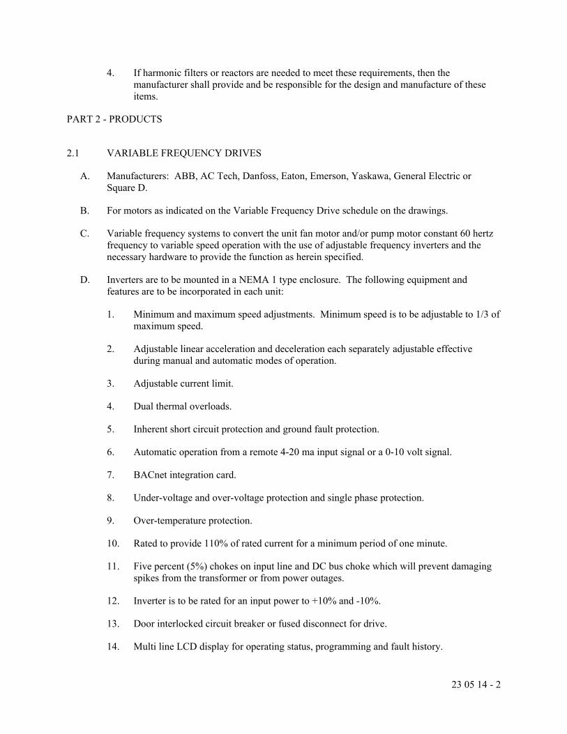
23 05 14 - 2
4. If harmonic filters or reactors are needed to meet these requirements, then the manufacturer shall provide and be responsible for the design and manufacture of these items.
PART 2 - PRODUCTS
2.1 VARIABLE FREQUENCY DRIVES
A. Manufacturers: ABB, AC Tech, Danfoss, Eaton, Emerson, Yaskawa, General Electric or Square D.
B. For motors as indicated on the Variable Frequency Drive schedule on the drawings.
C. Variable frequency systems to convert the unit fan motor and/or pump motor constant 60 hertz frequency to variable speed operation with the use of adjustable frequency inverters and the necessary hardware to provide the function as herein specified.
D. Inverters are to be mounted in a NEMA 1 type enclosure. The following equipment and features are to be incorporated in each unit:
1. Minimum and maximum speed adjustments. Minimum speed is to be adjustable to 1/3 of maximum speed.
2. Adjustable linear acceleration and deceleration each separately adjustable effective during manual and automatic modes of operation.
3. Adjustable current limit.
4. Dual thermal overloads.
5. Inherent short circuit protection and ground fault protection.
6. Automatic operation from a remote 4-20 ma input signal or a 0-10 volt signal.
7. BACnet integration card.
8. Under-voltage and over-voltage protection and single phase protection.
9. Over-temperature protection.
10. Rated to provide 110% of rated current for a minimum period of one minute.
11. Five percent (5%) chokes on input line and DC bus choke which will prevent damaging spikes from the transformer or from power outages.
12. Inverter is to be rated for an input power to +10% and -10%.
13. Door interlocked circuit breaker or fused disconnect for drive.
14. Multi line LCD display for operating status, programming and fault history.

23 05 14 - 3
15. The following door mounted devices:
a. Power “on” light.
b. Digital readout for speed, load, and input KW, and faults.
c. Manual/off/automatic selector switch.
d. Manual speed potentiometer or keypad adjustment for operation in the manual-normal mode.
e. Diagnostic readouts.
16. Floor stand mounting kit for free standing installation if field conditions require.
E. All components shall be pre-mounted and wired in a single enclosure. Each inverter and any associated hardware shall receive a minimum 8-hour test period in conjunction with a certified statement which indicates that all components of the unit have been tested prior to assembly. A full 3 year warranty on all parts and labor must be provided.
F. A field service engineer of the drive manufacturer is to be provided for a minimum of 8 hours for start-up assistance and training.
PART 3 - EXECUTION
3.1 GENERAL
A. Variable frequency drives shall be installed in accordance with manufacturer’s instructions, where indicated on the drawings. Install unit to allow adequate room for service.
B. All variable frequency drives shall be set in place by the Mechanical Contractor and wired by the Electrical Contractor.
C. All power wiring to the unit shall be by the Electrical Contractor, all control wiring shall be by the Temperature Control Subcontractor.
D. The manufacturer’s field service engineer shall record total harmonic distortion (THD) with the drives at 100% speed at time of start-up.
E. Provide separate conduits for input power, motor leads, and control wires.END SECTION 23 05 14

23 05 15 - 1
SECTION 23 05 15
VIBRATION ISOLATORS
PART 1 - GENERAL
1.1 RELATED DOCUMENTS
A. Drawings and General Provisions of the contract, including General and Supplementary Conditions and Division 1 specification sections apply to work of this Section.
1.2 RELATED WORK
A. 23 64 15 Centrifugal Chiller
B. 23 65 00 Cooling Towers
C. 23 73 13 Air Handling Units
D. 23 34 00 Fans
1.3 QUALITY ASSURANCE
A. Substitution of Materials: Refer to General Conditions of the Contract.
1.4 SHOP DRAWINGS
A. Include dimensions, capacities, materials of construction, weights, wiring diagrams and appropriate identification for all equipment in this Section.
PART 2 - PRODUCTS
2.1 GENERAL
A. All mechanical equipment shall be mounted on vibration isolators, unless otherwise indicated on the schedules, to prevent the transmission of vibration and mechanically transmitted sound to the building structure. Vibration isolators shall be selected in accordance with the equipment weight distribution so as to produce uniform deflection and deflections shall be as noted on the equipment schedules. Isolators shall be furnished by the mechanical equipment manufacturers.
2.2 VIBRATION ISOLATORS
A. Manufacturers: Amber Booth, Korfund, Mason Industries, Peabody/Kinetics, Vibration Eliminator or Vibro Acoustics.
B. Mounting Types as follows:
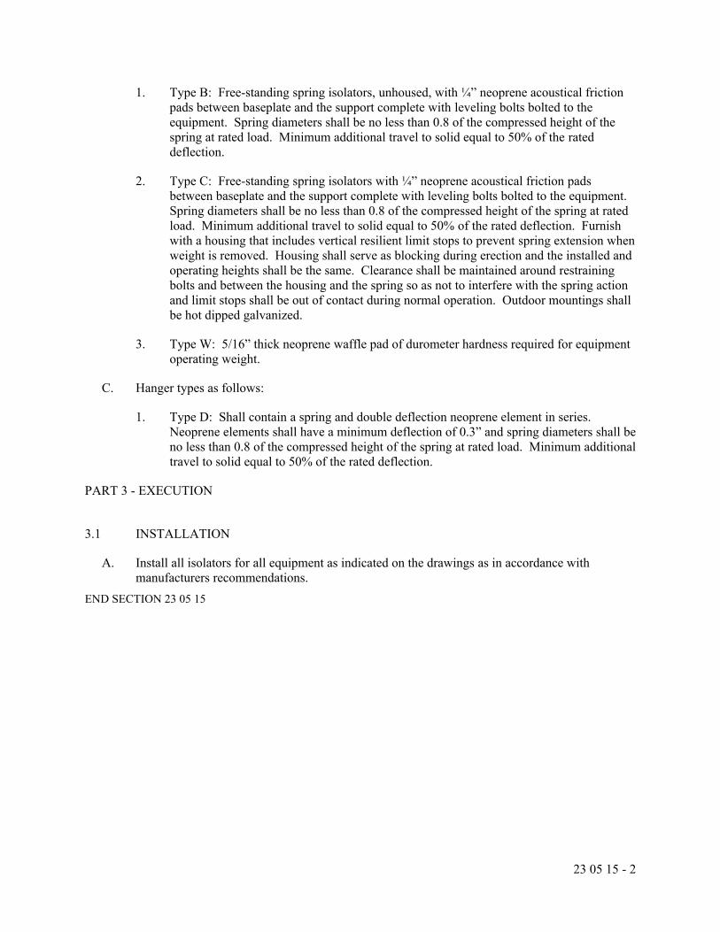
23 05 15 - 2
1. Type B: Free-standing spring isolators, unhoused, with ¼” neoprene acoustical friction pads between baseplate and the support complete with leveling bolts bolted to the equipment. Spring diameters shall be no less than 0.8 of the compressed height of the spring at rated load. Minimum additional travel to solid equal to 50% of the rated deflection.
2. Type C: Free-standing spring isolators with ¼” neoprene acoustical friction pads between baseplate and the support complete with leveling bolts bolted to the equipment. Spring diameters shall be no less than 0.8 of the compressed height of the spring at rated load. Minimum additional travel to solid equal to 50% of the rated deflection. Furnish with a housing that includes vertical resilient limit stops to prevent spring extension when weight is removed. Housing shall serve as blocking during erection and the installed and operating heights shall be the same. Clearance shall be maintained around restraining bolts and between the housing and the spring so as not to interfere with the spring action and limit stops shall be out of contact during normal operation. Outdoor mountings shall be hot dipped galvanized.
3. Type W: 5/16” thick neoprene waffle pad of durometer hardness required for equipment operating weight.
C. Hanger types as follows:
1. Type D: Shall contain a spring and double deflection neoprene element in series. Neoprene elements shall have a minimum deflection of 0.3” and spring diameters shall be no less than 0.8 of the compressed height of the spring at rated load. Minimum additional travel to solid equal to 50% of the rated deflection.
PART 3 - EXECUTION
3.1 INSTALLATION
A. Install all isolators for all equipment as indicated on the drawings as in accordance with manufacturers recommendations.
END SECTION 23 05 15

23 05 16 - 1
SECTION 23 05 16
V-BELT DRIVES
PART 1 - GENERAL
1.1 RELATED DOCUMENTS
A. Drawings and General Provisions of the contract, including General and Supplementary Conditions and Division 1 specification sections apply to work of this Section.
1.2 RELATED WORK
A. 23 34 00 Fans
1.3 QUALITY ASSURANCE
A. Substitution of Materials: Refer to General Conditions of the Contract.
1.4 SHOP DRAWINGS
A. Include dimensions, capacities, materials of construction, weights, wiring diagrams and appropriate identification for all equipment in this Section.
PART 2 - PRODUCTS
2.1 V-BELT DRIVES
A. Manufacturers: Browning or Woods.
B. Furnish for 7-1/2 HP and Smaller Motors:
1. Woods Type FHP or Browning Type LVP cast iron sheaves of size and number grooves required. Complete with adjustable flanges and locking devices.
C. Furnish for 10 HP through 30 HP Motors:
1. Woods Type SVS or Browning Type MVP cast iron sheave of size and number of grooves required. Complete with infinitely adjustable flanges and locking devices. All sheaves having 5 grooves or more shall be complete with companion sheaves with special wide groove spacing.
D. For all drives belt speed shall not exceed 5000 fpm, all sheaves shall be dynamically balanced, all sheaves shall be selected with a 1.5 minimum service factor and the center distances, arc of contact, ratio and belt type shall be as recommended by drive manufacturer.

23 05 16 - 2
PART 3 - EXECUTION
3.1 INSTALLATION
A. All sheaves shall be mounted on motors and fans and properly aligned in accordance with manufacturers instruction and belt installed with the tension as recommended.
END SECTION 23 05 16

23 05 93 - 1
SECTION 23 05 93
TESTING AND BALANCING
PART 1 - GENERAL
1.1 RELATED DOCUMENTS
A. Drawings and General Provisions of the contract, including General and Supplementary Conditions and Division 1 specification sections apply to work of this Section.
1.2 RELATED WORK
A. 23 09 00 Building Automation System for HVAC
PART 2 - PRODUCTS NOT USED
PART 3 - EXECUTION
3.1 GENERAL REQUIREMENTS
A. The Mechanical Contractor shall obtain the services of an NEBB or AABC certified independent subcontractor who specializes in and whose business is limited to testing, adjusting and balancing of air and water distribution systems. All tests shall be performed with recently calibrated instruments suitable for the test being performed. This subcontractor shall be responsible for complete testing, adjusting and balancing of the hydronic systems and all new and remodeled air moving systems.
B. Inspecting, Checking and Testing System:
1. Mechanical Contractor shall submit to the owner, in triplicate, at the completion of his work a certified statement signed by a principal of the firm stating that the system has been fully adjusted and balanced in accordance with requirements outlined and that all system components have been checked and tested, adjusted, and is operating properly as noted by plans and specifications. This statement shall be submitted before the system is presented to the Owner for final inspection.
3.2 PRE-CONSTRUCTION MEASURE AND RECORD
A. Measure and record existing air and hydronic data for existing equipment as noted on the demolition plans. See demolition plans for exact requirements and quantities.
3.3 HYDRONIC BALANCE
A. The balancing work shall include the compiling of data, submitting reports and performing the following tests:

23 05 93 - 2
1. Pumps
a. Design Data:
1) GPM.
2) RPM, BHP.
b. Installed Equipment:
1) Manufacturer, size.
2) Impeller diameter as shipped.
3) Impeller diameter after trimming for installed conditions.
4) Type drive.
5) Motor HP, volts, cycles and phase.
6) Full load amperes.
c. Field Test:
1) Discharge pressures: Full flow and no flow.
2) Suction pressures: Full flow and no flow.
3) Operating head and GPM.
4) Full flow amperes, no flow amperes.
5) Calculated BHP.
d. Primary water balancing shall be accomplished by trimming of the pump impeller. Fine balancing only will be permitted by means of triple duty and/or balancing valves.
2. Heating and Cooling Elements:
a. Design Data:
1) MBH specified, GPM specified.
2) GPM actual.
3) Element type specified.
b. Field Test:
1) Identify each element as to location.

23 05 93 - 3
2) Required water temperature drop.
3) Actual entering air and water conditions (temperature and GPM).
4) Adjust element until required temperature drop is obtained.
B. In addition to the above work, the contractor shall check operation of all automatic temperature control equipment; verify all setpoints and operations; and enlist the aid of the control contractor to make necessary adjustments where required.
C. The Contractor shall determine the minimum differential pressure setpoint required to obtain design flow rate at terminal units for each differential pressure sensor location and communicate each setpoint to the BAS Contractor.
3.4 AIR BALANCE WORK
A. The balancing work shall include, but not be limited to the following items:
1. The setting and adjusting of all dampers, deflecting vanes, discharge vanes and accessories to achieve indicated air distribution patterns in all parts of the air systems. Air quantities shall be as designated, with allowable error of plus or minus 5%.
2. The setting and adjusting of all belted fan speeds as may be required to attain proper total CFM deliveries, including the furnishing and installation of additional belts and drives as dictated by field conditions.
3. The inspection of the function and operation of all automatic controls to ensure proper operation and control cycles.
4. Submitting a report on each phase of the work.
5. Air balancing shall be accomplished with duct volume dampers and not dampers at the terminal outlets. Fine balancing will be permitted by means of terminal outlet dampers.
6. Record all test data in triplicate and submit to Architect.
7. Air System Balance:
a. With the air handling systems set to operate on minimum fresh air the Balancing Contractor shall perform the following tests and compile the following information:
1) Air Handling Equipment
a) Design Conditions:
i) CFM supply air.
ii) Static pressure.
iii) Motor HP

23 05 93 - 4
iv) CFM fresh air.
v) Fan RPM.
vi) Fan motor brake horsepower.
b) Installed Equipment:
i) Manufacturer.
ii) Size.
iii) Arrangement, discharge class.
iv) Motor HP, voltage, phase, cycles, full load amperes.
c) Field Test:
i) Fan speed.
ii) No load operating amperes.
iii) Fan motor operating amperes.
iv) Calculated BHP.
d) Test for Total Air:
i) Size of discharge and outside air ducts.
ii) Number of and location of velocity and pressure readings.
iii) Duct average velocity.
iv) Total CFM.
2) Individual Terminal Outlets:
a) Identify each supply outlet and exhaust as to location area and fan system.
b) Manufacturer and type.
c) Size.
d) Free area, core area or neck area.
e) Terminal factor.
f) Required FPM and test velocity.
g) Required CFM and test results.

23 05 93 - 5
b. In addition to the above work, check operation of all automatic temperature control equipment; verify all thermostat, aquastat, airstat, etc., setpoints and operations; and enlist the aid of the control subcontractor to make necessary adjustments where required.
END SECTION 23 05 93

23 07 00 - 1
SECTION 23 07 00
HVAC INSULATION
PART 1 - GENERAL
1.1 RELATED DOCUMENTS
A. Drawings and General Provisions of the contract, including General and Supplementary Conditions and Division 1 specification sections apply to work of this Section.
1.2 RELATED WORK
A. Duct Lining Section 23 31 00 Sheet Metal Work
1.3 QUALITY ASSURANCE
A. Substitution of Materials: Refer to General Conditions of the Contract.
1.4 SHOP DRAWINGS
A. Submit a schedule of all insulating materials to be used including adhesives, fastening methods, fitting material and intended use of each material. Include manufacturer’s data sheets indicating density, thermal characteristics, jacket type and manufacturer’s installation instructions.
1.5 DEFINITIONS
A. Concealed: shafts, furred spaces, space above finished ceilings, utility tunnels and crawl spaces. All other areas, including walk through tunnels shall be considered as exposed.
PART 2 - PRODUCTS
2.1 GENERAL
A. All insulation, facings, mastics and tapes installed within the building shall have a composite flame and smoke hazard rating as tested by procedure ASTM E-84-80, NFPA-255 and UL-723, not exceeding 25 flame spread or 50 smoke developed.
B. All insulation, facings, mastics, sealants and tapes shall be free of asbestos.
C. Duct insulation to be applied after duct tape and adhesive and/or duct sealant is applied by sheet metal contractor. Allow sufficient time for tape and adhesive to dry and/or duct sealant to cure before insulating ducts.
D. Repair all existing pipe and duct insulation damaged by installation of this system.

23 07 00 - 2
2.2 HOT PIPING
A. Type of piping and thickness:
1. Hot water supply and return piping (200 deg. F or less).
a. One and one-half inch (1-1/2”) thickness on piping 1-1/2” and less.
b. Two inch (2”) thickness on piping 2” and larger.
B. Owens-Corning Fiberglass ASJ/SSL-II, Manville, Certainteed or Knauf fiberglass pipe insulation molded to conform to the pipe and split for application.
C. Minimum R=4 per inch thickness.
D. Complete with flame retardant kraft reinforced foil all service white jacket. Jacket shall have a factory applied double pressure sensitive adhesive to adhesive closure flap. Circumferential end joints shall be sealed with self-sealing 3” wide kraft reinforced foil white butt strips.
E. All valve bodies, flanges, clamp type pipe couplings and fittings shall be wrapped with fiberglass blanket, or segments of pipe insulation securely tied in place to a thickness slightly greater than the adjoining insulation. Wrap Manville “Zerotape” over the insulation and finish with an open weave glass cloth imbedded in two coats of Benjamin Foster No. 30-36 or Childers CP-50 fire resistive white sealer.
F. Premolded one piece 25/50 rated PVC insulated fitting covers may be used in lieu of insulating cement and glass cloth at valve bodies, flanges, clamp type couplings and fittings. Factory pre-cut fiberglass insulation shall be applied to the fitting with the insulation tucked into the throat of the fitting and the edges of the adjacent pipe covering. The PVC cover shall be applied and secured by stapling and applying pressure sensitive tape over the staples and at the circumferential edges.
G. Vertical soft copper tubing concealed in building construction shall be covered with Armaflex AP, Aeroflex or Rubatex flexible, plenum rated, antimicrobial, closed cell elastomeric foam pipe insulation. All joints and seams are to be sealed with Armaflex 520 BLV low VOC adhesive or equal.
2.3 HOT EQUIPMENT
A. Type of Equipment:
1. Air and dirt separators.
B. One and one half inch (1-1/2”) thickness Owens-Corning Type 703, Manville, Certainteed or Knauf 3 lbs. per cu. ft. density fiberglass semi-rigid board insulation with factory applied aluminum foil reinforced kraft facing. Insulation shall be adhered to the surfaces with fire resistive adhesive (100% coverage). All edges and joints shall be sealed with 3” wide reinforced aluminum foil pressure sensitive joint sealing tape. All flaps shall be pasted and sealed with Benjamin-Foster No. 85-20 or Childers CP-82 fire resistive white adhesive. Completely cover the insulation with a heavy coat of Benjamin-Foster 30-36 Sealfas or Childers

23 07 00 - 3
CP-50. Imbed an open weave glass cloth and while still wet apply a finish coat of Benjamin-Foster 30-36 or Childers CP-50 fire resistive white sealer.
2.4 COLD PIPING
A. Type of piping and thickness.
1. Chilled water supply and return piping, suction diffusers and pump housings.
a. One and one-half inch (1-1/2”) thickness on all piping.
2. Exterior condenser water piping.
a. One and one-half inch (1-1/2”) thickness on all piping.
3. Refrigerant suction piping.
a. One and one half inch (1-1/2”) thickness on all piping.
4. Concealed copper or steel cooling coil condensate piping.
a. One inch (1”) thickness on all piping.
5. Water piping installed by this Contractor.
a. Three quarter inch (3/4”) thickness on piping 2” and less.
b. One inch (1”) thickness on piping 2-1/2” and larger.
B. Owens-Corning Fiberglas ASJ/SSL-II, Manville, Certainteed or Knauf fiberglass pipe insulation, molded to conform to the pipe and split for application.
C. Minimum R=4 per inch thickness.
D. Complete with flame retardant kraft reinforced foil all service white vapor barrier jacket. Jacket shall have a factory applied double pressure sensitive adhesive to adhesive closure flap. Circumferential end joints shall be sealed with 3” wide self-sealing kraft reinforced foil vapor barrier white butt strips.
E. All valve bodies, flanges, clamp type pipe couplings and fittings shall be wrapped with fiberglass blanket, or segments of pipe insulation securely tied in place to a thickness slightly greater than the adjoining insulation. Wrap Manville “Zerotape” over the insulation and finish with an open weave glass cloth imbedded in two coats of Benjamin Foster No. 30-36 or Childers CP-50 fire resistive white sealer.
F. Premolded one piece 25/50 rated PVC insulated fitting covers may be used in lieu of insulating cement and glass cloth at valve bodies, flanges, clamp type couplings and fittings. Factory pre-cut fiberglass insulation shall be applied to the fitting with the insulation tucked into the throat of the fitting and the edges of the adjacent pipe covering. The PVC cover shall be applied and secured by stapling and applying vapor barrier pressure sensitive tape over the staples and at the

23 07 00 - 4
circumferential edges. The tape shall have an overlap on itself of at least 2”. All seam edges of the cover shall be sealed with vapor barrier adhesive.
G. At each pipe hanger location, provide half-round, 6” long, hanger block at the bottom half of the piping in place of the pipe insulation. The hanger blocks shall be wood or asbestos free calcium silicate pipe insulation of the same thickness as the adjoining pipe insulation. The vapor barrier jacket shall be continuous through the hanger location and a 16 gauge 12” long galvanized sheet steel saddle shall be wrapped around the pipe insulation between the jacket and the hanger.
H. Entire installation shall be vapor proof. Any breaks, rips, tears or omission of vapor barrier shall be repaired.
2.5 PIPING EXPOSED WITHIN OCCUPIED SPACES
A. Cover pipe insulation installed exposed within occupied spaces with white semi-gloss 0.03” (30 mil) thick PVC covers and jackets. End to end joints must be lapped a minimum of 2” and be sealed with welding solvent recommended by jacket manufacturer. Lap slip joint ends 4” without fasteners where required to absorb expansion and contraction.
2.6 COLD EQUIPMENT
A. Type of equipment:
1. Air and dirt separators.
2. Strainers.
3. Pump housings.
4. Suction diffusers.
B. Armaflex AP, Aeroflex or Rubatex flexible, plenum rated, antimicrobial, closed cell elastomeric foam sheet insulation.
C. Cover equipment using 2” thick sheet insulation, cut and formed to fit over the equipment. All joints and seams are to be sealed with Armaflex 520 BLV low VOC adhesive or equal.
D. For suction diffusers and strainers where removal of the insulation is required for service access, seams at the point of required access shall be held in place with vapor proof tape. All other joints and seams shall be sealed with Armaflex 520 BLV low VOC adhesive or equal.
2.7 CONDENSER WATER AND TOWER MAKEUP WATER PIPING INSTALLED OUTSIDE OF THE BUILDING
A. Cover pipe insulation installed outside of the building with white semi-gloss or aluminum texture, ultraviolet inhibited, outdoor grade 13 ply Venture Clad 1579GCW, or Knauf Redi-Clad pipe insulation with self-bonding, cold weather adhesive backing. End to end joints must be lapped a minimum of 2” for a watertight installation.

23 07 00 - 5
2.8 DUCTWORK
A. Type of ductwork and type of insulation:
1. All fresh air intake ductwork. Rigid Board
2. All combustion air intake ductwork. Rigid Board
3. All exhaust air ductwork from automatic exhaust air damper or self-acting damper to roof or wall termination except acoustically lined ductwork. Rigid Board
4. All mixing plenum ductwork. Rigid Board
5. All supply air ductwork from each air conditioning unit installed within the mechanical equipment room (except acoustically lined ductwork). Rigid Board
6. All supply air ductwork from each air conditioning unit installed outside of the mechanical equipment room (except ductwork exposed within an air conditioned space and acoustically lined ductwork). Duct Wrap
B. Rigid Board insulation:
1. Minimum two and one half inch (2.5”) thick Owens-Corning, Manville, Certainteed or Knauf fiberglass duct insulation with factory applied aluminum foil reinforced kraft vaporproof facing.
2. Exposed duct flanges shall be covered with 3” wide strips of rigid duct insulation with a factory applied aluminum foil reinforced kraft vaporproof facing. The jacket shall extend beyond both sides of the insulation strip by a minimum of 2” to provide a pasting flap. These flaps shall be pasted and sealed with Benjamin Foster 85-20 adhesive.
3. The insulation shall be fastened to the duct with fire resistive adhesive (100% coverage) and Graham welding pins located on a maximum of 18” centers and not less than 3” from each edge or corner of the board. Stick-Klip fasteners may be used in lieu of welding pins providing they are installed in accordance with the manufacturers recommendations on a clean surface with Type S adhesive.
4. Completely cover all insulated ductwork with a heavy coat of Benjamin-Foster 30-36 Sealfas or Childers CP-50. Imbed an open weave glass cloth and while still wet apply a finish coat of Benjamin-Foster 30-36 or Childers CP-50 fire resistive white sealer.
5. Concealed Ductwork: Same as above except glass cloth and 2 coats of Benjamin Foster 30-36 or Childers CP-50 not required.
6. The entire assembly shall provide a minimum R=6 for all indoor ductwork.
7. The entire assembly shall provide a minimum R=10 for all outdoor ductwork.
C. Duct Wrap Insulation:

23 07 00 - 6
1. Minimum two and one half inch (2.5”) thick Owens-Corning, Manville, Certainteed or Knauf 0.75 lbs. per cu. ft. density fiberglass blanket type duct insulation with factory applied reinforced foil vapor barrier facing and a 2” stapling and taping flange.
2. Insulation shall be installed with facing outside so that tape flaps overlap at opposite end. Insulation shall be tightly butted. Seams shall be stapled 6” on center. Seal joints with pressure sensitive tape matching the facing.
3. Where rectangular ducts are greater than 24” in width insulation shall be secured to the bottom of the duct with mechanical fasteners spaced on 18” centers to prevent sagging of insulation.
4. Seal all tears, punctures and other penetrations of facing with tape or mastic to provide a vapor tight system installation.
5. The entire assembly shall provide a minimum R=6.
2.9 RIGID BOARD FOR RECESSES
A. For each convector and/or each cabinet heater recessed into exterior walls. Line back of recess with 1” thickness of Owens-Corning Type 705, Manville, Certainteed or Knauf 6 lbs. per cu. ft. density rigid board insulation. Fasten insulation to wall of recess with “Stick-Klip” fasteners spaced on 12” centers.
PART 3 - EXECUTION
3.1 INSTALLATION
A. Systems and/or equipment which is specified to be pressure tested or inspected shall not be insulated until testing and inspection has been successfully completed.
B. Insulation jackets and accessories shall only be installed under ambient temperatures recommended by the manufacturer of the material.
C. Install insulation with smooth and even surfaces and on clean, dry surfaces. Poorly fitted joints or use of filler in voids will not be accepted. Use full length material wherever possible.
END SECTION 23 07 00
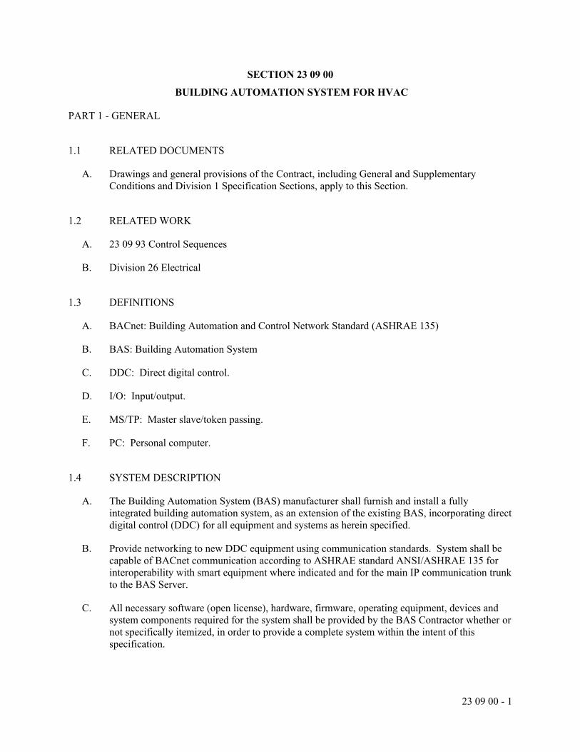
23 09 00 - 1
SECTION 23 09 00
BUILDING AUTOMATION SYSTEM FOR HVAC
PART 1 - GENERAL
1.1 RELATED DOCUMENTS
A. Drawings and general provisions of the Contract, including General and Supplementary Conditions and Division 1 Specification Sections, apply to this Section.
1.2 RELATED WORK
A. 23 09 93 Control Sequences
B. Division 26 Electrical
1.3 DEFINITIONS
A. BACnet: Building Automation and Control Network Standard (ASHRAE 135)
B. BAS: Building Automation System
C. DDC: Direct digital control.
D. I/O: Input/output.
E. MS/TP: Master slave/token passing.
F. PC: Personal computer.
1.4 SYSTEM DESCRIPTION
A. The Building Automation System (BAS) manufacturer shall furnish and install a fully integrated building automation system, as an extension of the existing BAS, incorporating direct digital control (DDC) for all equipment and systems as herein specified.
B. Provide networking to new DDC equipment using communication standards. System shall be capable of BACnet communication according to ASHRAE standard ANSI/ASHRAE 135 for interoperability with smart equipment where indicated and for the main IP communication trunk to the BAS Server.
C. All necessary software (open license), hardware, firmware, operating equipment, devices and system components required for the system shall be provided by the BAS Contractor whether or not specifically itemized, in order to provide a complete system within the intent of this specification.

23 09 00 - 2
1.5 SYSTEM PERFORMANCE
A. Comply with the following performance requirements:
1. Reporting Accuracy and Stability of Control: Report values and maintain measured variables within tolerances as follows:
a. Water Temperature: Plus or minus 1 deg F.
b. Water Flow: Plus or minus 5 percent of full scale.
c. Water Pressure: Plus or minus 2 percent of full scale.
d. Space Temperature: Plus or minus 1 deg F.
e. Ducted Air Temperature: Plus or minus 1 deg F.
f. Outside Air Temperature: Plus or minus 2 deg F.
g. Dew Point Temperature: Plus or minus 3 deg F.
h. Temperature Differential: Plus or minus 0.25 deg F.
i. Relative Humidity: Plus or minus 2 percent.
j. Airflow (Pressurized Spaces): Plus or minus 3 percent of full scale.
k. Airflow (Measuring Stations): Plus or minus 5 percent of full scale.
l. Airflow (Terminal): Plus or minus 10 percent of full scale.
m. Air Pressure (Space): Plus or minus 0.01-inch wg.
n. Air Pressure (Ducts): Plus or minus 0.1-inch wg.
o. Carbon Monoxide: Plus or minus 5 percent of reading.
p. Carbon Dioxide: Plus or minus 50 ppm.
q. Electrical: Plus or minus 5 percent of reading.
1.6 SUBMITTALS
A. Product Data:
1. Include manufacturer's technical literature for each control device and software. Indicate dimensions, capacities, performance characteristics, electrical characteristics, finishes for materials, and installation and startup instructions for each type of product indicated.
2. Where there are options on the accuracy, signals, covers, ranges, etc., indicate on the data sheet which options area being selected.

23 09 00 - 3
3. Schedule of dampers including size, leakage, and flow characteristics.
4. Schedule of valves including flow characteristics.
B. Shop Drawings:
1. Detail system assemblies and indicate device locations, wiring connections, associated control panel connections and sequence of operations to be executed by the DDC program.
2. Bill of materials for all devices, controller, accessories, and software indicating quantity, manufacturer, model number and description. The description shall include options that are chosen for that device, such as accuracy, signals, covers, ranges.
3. Schematic flow diagrams showing fans, pumps, equipment, coils, dampers, valves, and control devices.
4. Written description of sequence of operation.
C. Wiring Diagrams:
1. Power, signal, and control wiring, differentiating clearly between manufacturer-installed and field installed wiring.
D. DDC System Hardware:
1. Wiring diagrams for control units with termination numbers.
2. Schematic diagrams for control, communication, and power wiring, showing trunk data conductors and wiring between operator workstation and control unit locations.
E. Data Communications Protocol Certificates: Certify that each proposed DDC system component complies with ANSI/ASHRAE Standard 135 “BACnet – A Data Communication Protocol for Building Automation and Control Networks” where indicated.
F. Project Record Documents: Record actual locations of control components, including control units, thermostats, and sensors. Revise Shop Drawings to reflect actual installation and operating sequences.
G. Operation and Maintenance Data:
1. For HVAC instrumentation and control system to include in maintenance manuals. In addition to items specified elsewhere in Division 23 include the following:
a. Interconnection wiring diagrams with identified and numbered system components and devices.
b. Inspection period, cleaning methods, cleaning materials recommended, and calibration tolerances.

23 09 00 - 4
1.7 QUALITY ASSURANCE
A. Provide principal digital temperature control equipment and materials as manufactured by a single manufacturer.
B. All work shall be installed by mechanics, electricians and technicians directly employed by the BAS manufacturer or by an authorized independent manufacturer's field office.
C. The BAS manufacturer shall be responsible for the proper installation and operation of the BAS.
D. Use only UL labeled products which comply with NEMA Standards. Electrical components and installation to meet all requirements of the electrical sections (Division 26) of project specifications.
E. Comply with ANSI/ASHRAE Standard 135 “BACnet – A Data Communication Protocol for Building Automation and Control Networks” where indicated.
F. Store equipment and materials inside and protected from weather.
G. All materials and equipment used shall be standard components, regularly manufactured for HVAC applications. All systems and components shall have been thoroughly tested and proven in actual use.
H. The installation of the control system shall be performed under the direct supervision of the controls manufacturer with the shop drawings, flow diagrams, bill of materials, component designation or identification number and sequence of operation all bearing the name of the manufacturer. The installing manufacturer shall certify in writing, that the shop drawings have been prepared by the equipment manufacturer and that the equipment manufacturer has supervised their installation. In addition, the equipment manufacturer shall certify, in writing, that the shop drawings were prepared by their company and that all temperature control equipment was installed under their direct supervision.
I. BAS Contractor shall be responsible for all BAS and Temperature Control wiring and conduit for a complete and operable system.
J. BAS Contractor shall provide login information to the Engineer at project completion for a review of the graphical interface and monitoring of the installed system operation. The login shall be for viewing purposes only.
1.8 WIRING
A. All wiring and data cabling shall be done in accordance with all requirements or Division 26 as well as all local and national codes.
B. All electrical wiring required for electrical interlocking, fan timers, selector switches, speed switches, damper motors, control panels, etc., and all wiring required for the complete installation of the BAS shall be by the BAS Contractor. The only wiring by the Electrical Contractor shall be the primary power wiring from panelboards to starters and/or VFD’s and from starters and/or VFD’s to motors and power wiring to electrical resistance heating

23 09 00 - 5
equipment (see E-Series drawings). All other control-related power wiring for the complete mechanical system shall be by the BAS Contractor.
C. Power wiring for temperature control panels shall be furnished and installed by the BAS Contractor and shall be connected to separate circuit breakers at the nearest available panelboards. See Electrical drawings and coordinate with the Electrical Contractor.
D. Power shall be wired from emergency power equipment branch panels for control panels serving boilers, pumps, and other equipment on emergency power. See Electrical drawings and coordinate with the Electrical Contractor.
E. Data cabling for temperature control devices and/or panels shall be furnished and installed by the BAS Contractor and shall be connected to building data system routers and/or switches. Coordinate requirements with the data cabling contractor and the Owner’s I.T. manager.
1.9 COORDINATION
A. Coordinate location of thermostats, humidistats, and other exposed control sensors with plans and room details before installation.
B. Coordinate equipment with the Electrical Contractor to achieve compatibility with motor starters and annunciation devices.
1.10 WARRANTY
A. Provide all services, materials and equipment necessary for the successful operation of the entire BAS system for a period of one year after final acceptance of the system.
B. The adjustment, required testing, and repair of the system includes all computer equipment, transmission equipment and all sensors and control devices.
PART 2 - PRODUCTS
2.1 MANUFACTURERS
A. Base Bid: Johnson Metasys installed by Johnson Controls as an extension of the existing system.
B. Alt. Bid: Johnson FX installed by HVA Products.
2.2 BAS NETWORK
A. Provide a primary backbone network between the Building Level System Controllers, BAS Server and Operator Workstations based upon BACnet/IP. Ethernet Network switches shall be placed throughout the building as required.
B. Building Level System Controllers shall be used for the central plant and air handlers as indicated and shall reside on the backbone network.

23 09 00 - 6
C. The Building Level System Controllers shall be able to support one of several sub-network protocols that may be needed depending on the type of equipment or application.
D. Advanced Application Controllers and Application Specific Controllers can reside on the primary backbone network or on a sub-network.
E. Provide all communication media, data cabling, connectors, repeaters, bridges, switches, and routers necessary for the internetwork.
2.3 OPERATOR INTERFACES
A. Operator Workstation hardware (OWS):
1. Personal computer operator workstations shall be provided for command entry, information management, system monitor, alarm management and database management functions. All real-time control functions shall be resident in the Building Controllers to facilitate greater distribution, fault tolerance and reliability of the building automation control.
a. Furnish and install updated software and hardware as required to bring the existing OWS up to date with the latest versions of all applicable software.
B. Operator Interface Software:
1. Operator interface software shall minimize operator training through the use of user-friendly and interactive graphical applications, on-line help, and industry standard application software. Interface software shall simultaneously communicate with and share data between connected building level networks.
2. Provide a graphical user interface that shall minimize the use of keyboard through the use of a mouse or similar pointing device, with a "point and click" approach to menu selection and a “drag and drop” approach to inter-application navigation.
3. The navigation shall be user friendly by utilizing “forward & back” capability between screens and embedded hyperlinks to open graphics, documents, drawings, etc.
4. The software shall provide a multi-tasking type environment that allows the user to run several applications simultaneously.
5. The software shall provide, as a minimum, the following functionality:
a. Real-time graphical viewing and control of the BAS environment.
b. Reporting of both real-time and historical information.
c. Scheduling and override of building operations.
d. Collection and analysis of historical data.
e. Point database editing, storage and downloading of controller databases.
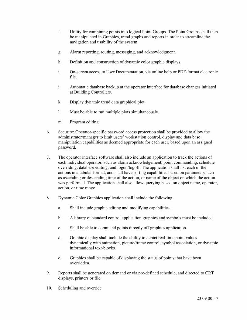
23 09 00 - 7
f. Utility for combining points into logical Point Groups. The Point Groups shall then be manipulated in Graphics, trend graphs and reports in order to streamline the navigation and usability of the system.
g. Alarm reporting, routing, messaging, and acknowledgment.
h. Definition and construction of dynamic color graphic displays.
i. On-screen access to User Documentation, via online help or PDF-format electronic file.
j. Automatic database backup at the operator interface for database changes initiated at Building Controllers.
k. Display dynamic trend data graphical plot.
l. Must be able to run multiple plots simultaneously.
m. Program editing.
6. Security: Operator-specific password access protection shall be provided to allow the administrator/manager to limit users’ workstation control, display and data base manipulation capabilities as deemed appropriate for each user, based upon an assigned password.
7. The operator interface software shall also include an application to track the actions of each individual operator, such as alarm acknowledgement, point commanding, schedule overriding, database editing, and logon/logoff. The application shall list each of the actions in a tabular format, and shall have sorting capabilities based on parameters such as ascending or descending time of the action, or name of the object on which the action was performed. The application shall also allow querying based on object name, operator, action, or time range.
8. Dynamic Color Graphics application shall include the following:
a. Shall include graphic editing and modifying capabilities.
b. A library of standard control application graphics and symbols must be included.
c. Shall be able to command points directly off graphics application.
d. Graphic display shall include the ability to depict real-time point values dynamically with animation, picture/frame control, symbol association, or dynamic informational text-blocks.
e. Graphics shall be capable of displaying the status of points that have been overridden.
9. Reports shall be generated on demand or via pre-defined schedule, and directed to CRT displays, printers or file.
10. Scheduling and override

23 09 00 - 8
a. Provide a calendar type format for simplification of time and date scheduling and overrides of building operations. Schedule definitions reside in the PC workstation and in the Building Controller to ensure time equipment scheduling when PC is off-line, PC is not required to execute time scheduling. Provide override access through menu selection, graphical mouse action or function key. Provide the following capabilities as a minimum:
1) Daily, Weekly, and Monthly schedules
2) Ability to combine multiple points into a logical grouping (Zone) for ease of scheduling (e.g., Building 1 lights)
3) Ability to combine multiple groups of points into a common collection (Event) for scheduling (e.g., Building 1 and Parking Lot A lights)
4) Schedule predefined reports that can be sent to a printer, hard drive location, or emailed.
11. Collection and Analysis of Historical Data
a. Provide trending capabilities that allow the user to easily monitor and preserve records of system activity over an extended period of time. Any system point may be trended automatically at time-based intervals or change of value, both of which shall be user-definable. Trend data shall be collected and stored on hard disk for future diagnostics and reporting.
b. Panels shall have a trending level above which the data will be automatically uploaded to the BMS server to prevent overwriting the data in the field panel.
c. Trend data reports shall be provided to allow the user to view all trended point data. Reports may be customized to include individual points or predefined groups of selected points.
d. Provide additional functionality that allows the user to view real-time trend data on trend graphical plot displays. The dynamic graphs shall continuously update point values. At any time the user may redefine sampling times or range scales for any point.
12. Dynamic Color Graphic Displays
a. Capability to create color graphic floor plan displays and system schematics for each piece of mechanical equipment, including, but not limited to, air handling units, chilled water systems, hot water boiler systems, and room level terminal units.
b. The operator interface shall have the ability allow users to access the various system schematics and floor plans via a graphical penetration scheme, menu selection, point alarm association, or text-based commands. Graphics software shall permit the importing of AutoCAD or scanned pictures for use in the system.

23 09 00 - 9
c. Dynamic temperature values, humidity values, flow values and status indication shall be shown in their actual respective locations within the system schematics or graphic floor plan displays, and shall automatically update to represent current conditions.
C. System Configuration & Definition
1. A “Collapsible tree” dynamic system architecture diagram/display application of the site-specific BMS architecture showing status of controllers, PC workstations and networks shall be provided. This application shall include the ability to add and configure workstations, Building Controllers, as well as third-party integrated components. Symbols/Icons representing the system architecture components shall be user-configurable and customizable, and a library of customized icons representing third-party integration solutions shall be included. This application shall also include the functionality for real-time display, configuration and diagnostics connections to Building Controllers.
2. Network wide control strategies shall not be restricted to a single Building Controller, but shall be able to include data from any and all other network panels to allow the development of Global control strategies.
3. Provide automatic backup and restore of all Building Controller databases on the workstation hard disk. In addition, all database changes shall be performed while the workstation is on-line without disrupting other system operations. Changes shall be automatically recorded and downloaded to the appropriate Building Controller. Changes made at the user-interface of Building Controllers shall be automatically uploaded to the workstation, ensuring system continuity.
4. System configuration, programming, editing, graphics generation shall be performed on-line.
5. User shall be able to edit point configuration online within a dedicated editor application that is part of the operator interface software. The editor shall allow the user to create, view existing, modify, copy, and delete points from the database.
6. The point editor shall have the capability to assign “informational text” to points as necessary to provide critical information about the equipment.
7. The point editor shall also allow the user to configure the alarm management strategy for each point. The editor shall provide the option for editing the point database in an online or offline mode with the Building Controllers.
8. Control program configuration shall be available to the user within a dedicated control program editor application included in the operator interface software. The editor shall allow for creation, modification and deletion of control programs. The editor shall include a programming assistance feature that interactively guides the user through parameters required to generate a control program. The editor shall also include the ability to automatically compile the program to ensure its compatibility with the Building Controllers. The editor shall provide the option for editing the control programs in an online or offline mode, and also the ability to selectively enable or disable the live program execution within the Building Controllers.

23 09 00 - 10
9. Users shall have the ability to view the program(s) that is/are currently running in a Building Controller. The display shall mark the program lines with the following: disabled, comment, unresolved, and trace bits.
D. Alarm Management
1. Provide alarm notifications for all major HVAC equipment including air handling units, heat pumps, chillers, boilers, pumps, fans, rooftop units, etc. Verify alarm notification requirements with the Owner. Typical alarm notifications shall include but not be limited to fan/pump failures, temperature setpoint failures, building pressure, hot water temperature, chilled water temperature, etc.
2. Alarm Routing shall allow the user to send alarm notification to selected printers, email addresses, text message addresses or workstation location(s) based on time of day, alarm severity, or point type.
3. Alarm messages shall be customizable for each point, or each alarm priority level, to display detailed instructions to the user regarding actions to take in the event of an alarm.
E. Remote notification of messages
1. Operator Interface software shall be configured to send out messages to phones, text messaging devices, and email accounts based on a point’s alarm condition.
2. System must be configurable to send messages to an escalation list so that if the first device does not respond, the message is sent on to the next device after a configurable time has elapsed.
3. Message detail shall be configurable on a per user basis.
2.4 REMOTE WEB APPLICATION OPERATOR INTERFACE
A. The BAS shall provide a web based graphical interface that allows users to access the BAS data via the Internet, extranet, or Intranet. The interface shall use HTML based ASP pages to send and receive data from the BAS to a web browser.
B. Furnish and install a web server computer complete with the most current operating system software.
C. Access to the web interface shall be password protected. A users rights and privileges to points and graphics shall be the same as those assigned at the OWS.
D. All graphics available at the OWS shall be available to users via a web browser.
E. The web-based interface shall provide the following functionality to users, based on their access and privilege rights:
F. Logon Screen – allows the user to enter their user name, password and Domain name for logging into the web server.

23 09 00 - 11
G. Alarm Display – a display of current BAS alarms to which the user has access shall be displayed. Users shall be able to acknowledge and erase active alarms, and link to additional alarm information including alarm messages, and informational and memo text. Any alarm acknowledgements initiated through the web interface shall be written to the BAS central workstation activity log.
H. Graphic Display – display of system graphics available in the BAS workstation shall be available for reviewing over the web browser. A graphic selector list shall allow users to select any graphics to which they have access. Graphic displays shall automatically refresh with the latest change of values. Users shall have the ability to command and override points from the graphic display as determined by their user accounts rights.
I. Point Details – users shall have access to point detail information including operational status, operational priority, physical address, and alarm limits, for point objects to which they have access rights.
J. Point Commanding – users shall be able to override and command points they have access to via the web browser interface. Any commands or overrides initiated via the web browser interface shall be written to the BAS central workstation activity log.
K. Remote Communications: Provide a communication port for connection to the BAS network for remote web based communications. Provide coordination with the Owner for addressing and router configuration on both ends of the remote network.
L. The web server licensing options shall allow concurrent access by 5 browser connections.
M. Internet connections, ISP services, as well as necessary firewalls or proxy servers shall be provided by the BAS Contractor for the duration of the warranty period as required to support the web access feature.
2.5 GRAPHICS
A. Floor Plan Graphics
1. The BAS contractor shall request floor plans to be used as a background for a floor graphic.
2. If the floor plan to too big for the Graphical screen, provide a zoom feature or breakdown the floor into areas.
3. The floor plan shall, at a minimum, indicate each zone temperature setpoint and current temperature.
B. Equipment Graphics
1. The BAS Contractor shall provide a graphical screen for each individual air handling unit, pumping system, heating system, cooling system and terminal unit. Each graphic shall accurately depict the system components in a schematic format and shall include the setpoint and actual condition of all available temperature, pressure, flow and status points in the system.

23 09 00 - 12
2. Adjustable or override points shall be clearly displayed and shall be capable of being adjusted without leaving the graphics page.
2.6 STANDARD APPLICATION PROGRAMS
A. Morning warm up:
1. The system shall start at a predefined time prior to the system entering the occupied cycle of operation to facilitate the raising or lowering of the building temperature to bring the building back to occupied temperature.
B. Optimal start:
1. The system shall calculate the optimal time to start the morning warm up process to assure that the building reaches occupied temperature as close to the occupied time as possible.
C. Scheduled occupied/unoccupied:
1. The system shall enter occupied or unoccupied cycle as determined by a time of day, day of week schedule.
D. Sensed occupied/unoccupied:
1. The system shall enter the occupied or unoccupied cycle as determined by a room occupancy sensor. The room occupancy sensor is furnished and installed by the Electrical Contractor. Interlock wiring between the sensor and the controller is furnished and installed by the BAS Contractor.
E. Enthalpy economizer:
1. Whenever the outdoor air total energy is below the return air total energy and there is a call for cooling the system shall allow the outside air dampers to modulate prior to allowing mechanical cooling to activate.
2. The outside air damper shall return to minimum whenever the outside air total energy is above the return air total energy.
F. Dead band:
1. Where used to control both heating and cooling, zone temperature controls shall provide a temperature range or dead band within which the supply of heating and cooling energy to the zone is capable of being shut off or reduced to a minimum.
G. Night set-back:
1. Whenever the system is in the unoccupied cycle the room heating temperature setpoint shall be set-back to a reduced night temperature. The night set-back temperature shall be globally or individually set through the BAS.
H. Night set-up:

23 09 00 - 13
1. Whenever the system is in the unoccupied cycle the room cooling temperature setpoint shall be set-up to an increased night temperature. The night set-up temperature shall be globally or individually set through the BAS.
I. Supply air reset:
1. The system shall reset the supply air temperature setpoint based on the reheat coil valve position of each vav box served by the system. The DDC control program shall reset the supply air temperature from 55 deg. F. to 65 deg. F. The supply air temperature setpoint shall be reset up whenever all reheat coil valves are open at least 15%, The supply air temperature setpoint shall be reset down whenever any one reheat coil valve is fully closed.
J. Static pressure reset:
1. The system shall reset the static pressure setpoint based on the damper position of each vav box served by the system. The DDC control program shall gradually reset the static pressure setpoint down whenever all vav boxes are no more than 75% open. The DDC control program shall gradually reset the static pressure setpoint up whenever any vav box reaches 90% open.
2. The static pressure shall reset between minimum and maximum setpoints in increments of .1” water column at 10 minute intervals. Obtain minimum and maximum static pressure setpoints from the balancing contractor.
K. Hot water reset:
1. The system shall reset the hot water temperature setpoint based on outside air temperature. As the outside air temperature drops the hot water temperature setpoint shall rise.
L. Chilled water reset:
1. The system shall reset the chilled water temperature setpoint based cooling coil valve position of each cooling unit served by the system. The DDC control program shall reset the chilled water supply temperature from 45 deg. F. to 55 deg. F. The chilled water supply temperature setpoint shall be reset up whenever all cooling coil valves are no more than 75% open. The chilled water supply temperature setpoint shall be reset down whenever any one cooling coil valve reaches 90% open.
2. The chilled water temperature shall reset between minimum and maximum setpoints in increments of 1 deg. F. at 10 minute intervals.
M. Pressure differential reset:
1. The system shall reset the pressure differential setpoint based on the automatic control valve position of each heating or cooling unit served by the system. The DDC control program shall gradually reset the pressure differential setpoint down whenever all control valves are no more than 80% open. The DDC control program shall gradually reset the pressure differential setpoint up whenever any one valve reaches 90% open.

23 09 00 - 14
2. The pressure differential setpoint shall reset between minimum and maximum setpoints in increments of .5 psig at 10 minute intervals. Obtain minimum and maximum pressure differential setpoints from the balancing contractor.
2.7 BUILDING LEVEL SYSTEM CONTROLLERS
A. Provide this type of controller for controlling:
1. Chiller Plant.
2. Boiler Plant.
3. Air Conditioning Units.
4. Integration to auxiliary systems such as Lighting, Power Monitoring, etc.
B. BACnet Compliance: Control units shall use ASHRAE 135 protocol.
C. Modular, comprising processor board with programmable, nonvolatile, random-access memory; and backup power source.
D. Units monitor or control each I/O point; process information; execute commands from other control units, devices, and operator stations; and download from or upload to operator workstation or diagnostic terminal unit.
E. Stand-alone mode control functions operate regardless of network status. Functions include the following:
1. Global communications.
2. Discrete/digital and analog I/O.
3. Monitoring, controlling, or addressing data points.
4. Software applications, scheduling, and alarm processing.
5. Testing and developing control algorithms without disrupting field hardware and controlled environment.
F. Local operator interface provides for download from or upload to operator workstation or diagnostic terminal unit.
G. I/O Interface: Hardwired inputs and outputs may tie into system through controllers.
1. Binary Inputs: Allow monitoring of on-off signals without external power.
2. Analog Inputs: Allow monitoring of low-voltage (0- to 10-V dc), current (4 to 20 mA), or resistance signals.
3. Binary Outputs: Provide on-off low-voltage signal, selectable for normally open or normally closed operation.

23 09 00 - 15
4. Analog Outputs: Provide modulating signal, either low voltage (0- to 10-V dc) or current (4 to 20 mA).
5. Universal I/Os: Provide software selectable binary or analog outputs.
2.8 ADVANCED APPLICATION CONTROLLERS
A. Provide this type of controller for controlling:
1. Packaged HVAC Units with integral BACnet controllers.
2. Miscellaneous small point count applications that require custom sequences
B. BACnet Compliance: Control units shall use ASHRAE 135 protocol.
C. Self-contained unit, comprising of processor board with programmable, nonvolatile, random-access memory; integral interface equipment; and backup power source.
D. Units monitor or control each I/O point; process information; execute commands from other control units, devices, and operator stations; and download from or upload to operator workstation or diagnostic terminal unit.
E. Stand-alone mode control functions operate regardless of network status. Functions include the following:
1. Global communications.
2. Discrete/digital and analog I/O.
3. Monitoring, controlling, or addressing data points.
4. Software applications, scheduling, and alarm processing.
5. Testing and developing control algorithms without disrupting field hardware and controlled environment.
F. I/O Interface: Hardwired inputs and outputs may tie into system through controllers.
1. Binary Inputs: Allow monitoring of on-off signals without external power.
2. Analog Inputs: Allow monitoring of low-voltage (0- to 10-V dc), current (4 to 20 mA), or resistance signals.
3. Binary Outputs: Provide on-off low-voltage signal, selectable for normally open or normally closed operation with three-position (on-off-auto) override switches and status lights.
4. Analog Outputs: Provide modulating signal, either low voltage (0- to 10-V dc) or current (4 to 20 mA).
5. Universal I/Os: Provide software selectable binary or analog outputs.

23 09 00 - 16
2.9 APPLICATION SPECIFIC CONTROLLERS
A. Provide this type of controller for controlling:
1. VAV boxes
2. Fan Powered boxes
3. Cabinet Heaters
4. Radiation
5. Fans
6. Remote point pickup
B. Controller:
1. Each Building Controller shall be able to communicate with application specific controllers (ASCs) over the subnetwork to control terminal equipment only.
2. Each ASC shall operate as a stand-alone controller capable of performing its specified control responsibilities independently of other controllers in the network.
3. Each ASC shall be a microprocessor-based, multi-tasking, real-time digital control processor.
4. Each ASC shall include all point inputs and outputs necessary to perform the specified control sequences. The ASC shall accept input and provide output signals that comply with industry standards. Controllers utilizing proprietary control output signals shall not be acceptable. Outputs utilized either for two-state, or proportional control, allowing for additional system flexibility.
5. Communication. Each controller shall perform its primary control function independent of the network and other controllers. Controllers that depend on communication to master controllers or revert to a fail-safe mode of operation during subnetwork interruption are not acceptable.
C. Control Algorithms. The controller shall receive its real-time data from the Building Controller time clock to ensure Secondary Network continuity. Each controller shall include algorithms incorporating proportional, integral and derivative (PID) gains for all applications. All PID gains and biases shall be field-adjustable at the operator workstation.
D. Control Applications. Operating programs shall be field-selectable for specific applications. In addition, specific applications may be modified to meet the user's exact control strategy requirements, allowing for additional system flexibility. Controllers that require factory changes of all applications are not acceptable.
E. Programmability. Application Specific Controllers shall be programmable, using software provided by the BMS manufacturer. Software shall be field-installable on any standard laptop or Portable Operator’s Terminal. Program language shall be text-based and allow up to 200 lines of code for programming. Programming shall allow for changing sequence of operation,

23 09 00 - 17
commanding and releasing points, additional monitoring, and command priority management within the Application Specific Controller.
F. Memory.
1. Provide each ASC with sufficient memory to accommodate point databases, operating programs, local alarming and local trending. All databases and programs shall be stored in non-volatile EEPROM, EPROM and PROM, or minimum of 72-hour battery backup shall be provided. The controllers shall be able to return to full normal operation without user intervention after a power failure of unlimited duration.
G. Upon replacement, new ASCs shall recover control function and site specific defaults automatically and resume normal operation.
2.10 ELECTRONIC SENSORS
A. Room Temperature Sensors
1. Flush Plate Temperature Sensors – Wired: Where called for in the sequences or on the drawings, provide sensors with stainless steel plate face flush mounted in the wall.
2. Plain Space Temperature Sensors – Wired: Where called for in the sequences or on the drawings, provide sensors with plain covers.
3. Digital Display Space Temperature Sensors – Wired: Where called for in the sequences or on the drawings, provide sensors with digital displays.
4. Wireless Space Temperature Sensors: Where called for in the sequences or on the drawings, provide wireless sensors with plain or digital display covers as indicated.
5. The sensing element for the space temperature sensors shall be thermistor type providing the following.
a. Element Accuracy: + /- 1.0°F
b. Operating Range: 55 to 95°F
c. Set Point Adjustment Range: 55 to 95°F
d. Calibration Adjustments: None required
e. Auxiliary Communications Port: As required
6. The digital display shall provide the following.
a. Display of temperature setpoint with numerical temperature values.
b. Display of room temperature with numerical temperature values.
c. Display of active occupied/unoccupied status.

23 09 00 - 18
d. Occupied/unoccupied override.
7. Wireless space temperature sensors shall be 10K Ohm Thermistor or equivalent type providing the following.
a. Accuracy: + .5°F
b. Operating Range: 55 to 95°F
c. Monitoring Range: 55 to 95°F
d. Battery life: Minimum 3 years
e. Auxiliary Communications Port: as required
8. All sensors shall be mountable to and fully covering a standard 2x4 electrical junction box without the need for an adapter wall plate.
9. Provide the following options as they are called for in the sequences or on the drawings:
10. Setpoint adjustment. The setpoint adjustment function shall allow for modification of the temperature by the building operators. Setpoint adjustment may be locked out, overridden, or limited as to time or temperature range through software by an authorized operator at any central workstation.
11. Occupied/unoccupied override. An override button shall initiate override of the night setback mode to normal (day) operation when activated by the occupant and enabled by building operators. The override shall be limited to two (2) hours (adjustable.) The override function may be locked out, overridden, or limited through software by an authorized operator at any central workstation.
B. Space Humidity Sensors
1. Space humidity sensors shall have the same appearance as the space temperature sensors. Humidity elements shall measure relative humidity with a +/- 2% accuracy over the range of 10 to 90% relative humidity. Humidity element shall be an IC (integrated circuit) sensing element. Humidity sensing elements shall be removable and field replaceable if needed.
C. Thermistor Temperature Sensors and Transmitters:
1. Accuracy: Plus or minus 0.5 deg. F at calibration point.
2. Insertion Elements in Ducts: Single point, 8 inches long; use where not affected by temperature stratification or where ducts are smaller than 9 sq. ft.
3. Averaging Elements in Ducts: 36 inches long, flexible; use where prone to temperature stratification or where ducts are larger than 10 sq. ft.
4. Insertion Elements for Liquids: Brass or stainless-steel socket with minimum insertion length of 2-1/2 inches.

23 09 00 - 19
5. Outside-Air Sensors: Watertight inlet fitting, shielded from direct sunlight.
D. Pressure Transmitters/Transducers:
1. Static-Pressure Transmitter: Nondirectional sensor with suitable range for expected input, and temperature compensated.
a. Accuracy: 2 percent of full scale with repeatability of 0.5 percent.
b. Output: 4 to 20 mA.
c. Building Static-Pressure Range: 0 to 0.25-inch wg.
d. Duct Static-Pressure Range: 0 to 5-inch wg.
2. Water Pressure Transducers: Stainless-steel diaphragm construction, suitable for service; minimum 150 psig operating pressure; linear output 4 to 20 mA.
3. Water Differential-Pressure Transducers: Stainless-steel diaphragm construction, suitable for service; minimum 150-psig operating pressure and tested to 300-psig; linear output 4 to 20 mA.
4. Differential-Pressure Switch (Air or Water): Snap acting, with pilot-duty rating and with suitable scale range and differential.
5. Pressure Transmitters: Direct acting for gas, liquid, or steam service; range suitable for system; linear output 4 to 20 mA.
E. Room sensor accessories include the following:
1. Insulating Bases: For sensors located on exterior walls.
F. CO2 SENSORS
1. Provide indoor air quality sensors to monitor Carbon Dioxide (CO2) and/or Volatile Organic Compound (VOC) levels.
2. The CO2 sensor shall be of microprocessor-based non-dispersive infrared type.
3. The CO2 sensors shall have no more than 1% drift during the first year of operation and minimal drift thereafter so that no calibration will be required.
4. The units shall be wall or duct mounted type as indicated on plans and in the sequence of operation.
5. Wall mounted sensors shall be provided with white plastic cover, without LED indicators.
6. Duct mounted sensors shall be provided without the need for a separate aspirator box.
7. The VOC sensor shall have automatic self calibrating capability to ensure accuracy.

23 09 00 - 20
8. The sensor shall meet the following requirements:
a. Operating voltage: 24 Vac +/- 20%
b. Frequency: 50/60 Hz
c. Power consumption: max. 6 VA
d. CO2 measuring range: 0 – 2000 ppm
e. Tolerance: +/- 100 ppm
f. Output: 0 – 10 Vac
g. Calibration: none required
h. VOC measurement range:0 – 10V VOC
2.11 DUCT SMOKE DETECTORS
A. Shall be UL listed of the solid state photoelectric type and shall operate on the light scattering photodiode principle. The detectors shall be designed to ignore invisible airborne particles or smoke densities that are below the factory set alarm point. No radioactive materials shall be used. Detector construction shall be of the split type, that is, mounting base with twist-lock detecting head. Contacts between the base and head shall be of the bifurcated type using spring-type, self-wiping contacts. Duct housing couplings shall be slotted to insure proper alignment of the sampling and exhaust tubes. Detector shall have an alarm LED visible through a transparent front cover.
B. Provide additional dry contact for fire alarm interface.
C. Installation must comply with NFPA-90A.
2.12 STATUS SENSORS
A. Status Inputs for Fans: Differential-pressure switch with pilot-duty rating and with adjustable range of 0- to 5-inch wg.
B. Status Inputs for Pumps: Differential-pressure switch with pilot-duty rating and with adjustable pressure-differential range of 8 to 60 psig, piped across pump.
C. Status Inputs for Electric Motors: Comply with ISA 50.00.01, current-sensing fixed- or split-core transformers with self-powered transmitter, adjustable and suitable for 175 percent of rated motor current.
D. Voltage Transmitter (100- to 600-V ac): Comply with ISA 50.00.01, single-loop, self-powered transmitter, adjustable, with suitable range and 1 percent full-scale accuracy.

23 09 00 - 21
E. Power Monitor: 3-phase type with disconnect/shorting switch assembly, listed voltage and current transformers, with pulse kilowatt hour output and 4- to 20-mA kW output, with maximum 2 percent error at 1.0 power factor and 2.5 percent error at 0.5 power factor.
F. Current Switches: Self-powered, solid-state with adjustable trip current, selected to match current and system output requirements.
G. Electronic Valve/Damper Position Indicator: Visual scale indicating percent of travel and 2- to 10-V dc, feedback signal.
H. Water-Flow Switches: Bellows-actuated mercury or snap-acting type with pilot-duty rating, stainless-steel or bronze paddle, with appropriate range and differential adjustment, in NEMA 250, Type 1 enclosure.
2.13 FREEZE PROTECTION THERMOSTATS
A. Snap-acting, single-pole, single-throw, automatic reset switch that trips if temperature sensed across any 12 inches of bulb length is equal to or below set point.
1. Bulb Length: Minimum 20 feet.
2. Quantity: One thermostat for every 20 sq. ft. of coil surface.
3. Location: Downstream face of the heating coil.
2.14 DAMPERS
A. Automatic dampers shall be furnished by the BAS Contractor but shall be set in place by the Mechanical Contractor. Dampers shall be of the balanced type with a maximum blade width of 8" and length of 48". Damper frames shall be galvanized sheet metal or aluminum with nylon or sintered bronze oil impregnated bearings.
B. Dampers for proportioning control shall have opposed blade action. Dampers for two position, open-closed control shall have parallel blade action.
C. Damper blades shall have interlocking edges with compressible seals on both blade edges and ends. Dampers, when closed, shall be guaranteed by the manufacturer not to leak air in excess of 6 CFM/sq. ft. at 4" water gauge static pressure.
2.15 ACTUATORS
A. Electronic Actuators: Direct-coupled type designed for minimum 60,000 full-stroke cycles at rated torque.
1. Valves: Size for torque required for valve close off at maximum pump dynamic differential pressure.
2. Dampers: Size for running torque calculated as follows:

23 09 00 - 22
a. Parallel-Blade Damper: 7 inch-lb/sq. ft. of damper.
b. Opposed-Blade Damper: 5 inch-lb/sq. ft. of damper.
c. Dampers with 2 to 3 inch wg of Pressure Drop or Face Velocities of 1000 to 2500 fpm: Increase running torque by 1.5.
d. Dampers with 3 to 4 inch wg of Pressure Drop or Face Velocities of 2500 to 3000 fpm: Increase running torque by 2.0.
3. Coupling: V-bolt and U-shaped, toothed cradle.
4. Overload Protection: Electronic overload or digital rotation-sensing circuitry.
5. Fail-Safe Operation: Mechanical, spring-return mechanism.
a. Heating valves shall be fail open.
b. Cooling valves shall be fail closed.
c. Outside air and exhaust air dampers shall be fail closed.
d. Return air dampers shall be fail open.
6. Power Requirements (Two-Position Spring Return): 24-V ac.
7. Power Requirements (Modulating): Maximum 10 VA at 24-V ac or 8 W at 24-V dc.
8. Proportional Signal: 2- to 10-V dc or 4 to 20 mA, and 2- to 10-V dc position feedback signal.
9. Temperature Rating: 40 to 104 deg. F.
10. Temperature Rating (Smoke Dampers): Minus 22 to plus 250 deg. F.
2.16 CONTROL VALVES
A. Control Valves: Factory fabricated, of type, body material, and pressure class based on maximum pressure and temperature rating of piping system, unless otherwise indicated.
B. Hydronic system globe valves shall have the following characteristics:
1. NPS 2” and Smaller: Class 125 and 250 degrees F bronze body, rising stem, renewable composition disc, and screwed ends with backseating capacity repackable under pressure.
2. NPS 2-1/2” and Larger: Class 125 iron body, bronze trim, rising stem, plug-type disc, flanged ends, and renewable seat and disc.
3. Internal Construction: Replaceable plugs, stainless-steel or brass seats.
4. Sizing: 3-psig maximum pressure drop at design flow rate.

23 09 00 - 23
5. Flow Characteristics: Two-way valves shall have equal percentage characteristics; three-way valves shall have linear characteristics.
6. Close-Off (Differential) Pressure Rating: Combination of actuator and trim shall provide minimum close-off pressure rating of 150 percent of total system (pump) head.
C. Butterfly Valves: 200-psig, 150-psig maximum pressure differential, cast-iron or ductile-iron body and bonnet, extended neck, stainless-steel stem, field-replaceable EPDM or Buna N sleeve and stem seals.
1. Body Style: Full lug
2. Disc Type: Nickel-plated ductile iron.
3. Sizing: 3-psig maximum pressure drop at design flow rate.
D. Terminal Unit Control Valves: Bronze body, bronze trim, two or three ports as indicated, replaceable plugs and seats, union, and threaded ends.
1. Rating: Class 125 for service at 125 psig and 250 deg F operating conditions.
2. Sizing: 3-psig maximum pressure drop at design flow rate, to close against pump shutoff head.
3. Flow Characteristics: Two-way valves shall have equal percentage characteristics; three-way valves shall have linear characteristics.
PART 3 - EXECUTION
3.1 GENERAL
A. All necessary equipment, labor and materials not specifically indicated or specified, but necessary to complete work, are to be provided as part of the contract.
B. Install all control equipment, accessories, wiring, and piping in a neat and workmanlike manner. All control devices must be installed in accessible locations.
C. All sensors and control devices that are to be installed within a classified/rated area shall be provided with the appropriate rating for the space in which they are located.
D. Provide all electrical relays and wiring, line and low voltage, for control systems, devices and components. Install all wiring in accordance with electrical sections (Division 26) of this specification and the National Electrical code.
E. Control panels serving equipment fed by emergency power shall also be served by emergency power.

23 09 00 - 24
3.2 INSTALLATION
A. Install software in control units and operator workstation(s). Implement all features of programs to specified requirements and as appropriate to sequence of operation.
B. Connect and configure equipment and software to achieve sequence of operation specified.
C. Verify location of thermostats, humidistats, and other exposed control sensors with drawings and room details before installation. Install devices per ADA requirements.
D. Install averaging elements in ducts and plenums in crossing or zigzag pattern.
3.3 ELECTRICAL WIRING AND CONNECTION INSTALLATION
A. All sensor and output wiring shall be shielded cable or per manufacturers specifications which must be furnished upon request.
B. The field wiring connections of all field-mounted sensors shall be adequately protected by a junction box mounted at the point of measurement.
C. In addition to requirements of electrical sections (Division 26), all exposed low voltage wiring (less than 120 V) provided by this Contractor shall be enclosed in conduit. All 120 volt wiring shall be enclosed in EMT conduit. No flexible conduit shall be allowed for 120 volt wiring.
D. Separate conduit systems shall be provided for low voltage and line voltage wiring.
E. All wiring and conduit shall be secured at regular intervals and run parallel with the lines of the building.
3.4 CONTROL VALVES
A. All temperature control valves furnished by the BAS Manufacturer are to be installed by the Mechanical Contractor under the coordinating control and supervision of the BAS Contractor in locations shown on plans or where required to provide specific sequence of control.
3.5 FIELD QUALITY CONTROL
A. Manufacturer's Field Service: Engage a factory-authorized service representative to inspect field-assembled components and equipment installation, including connections. Report results in writing.
B. Perform the following field tests and inspections and prepare test reports:
1. Operational Test: After electrical circuitry has been energized, start units to confirm proper unit operation. Remove and replace malfunctioning units and retest.
2. Test and adjust controls and safeties.

23 09 00 - 25
3. Test calibration of controllers by disconnecting input sensors and stimulating operation with compatible signal generator.
4. Test each point through its full operating range to verify that safety and operating control set points are as required.
5. Test each control loop to verify stable mode of operation and compliance with sequence of operation. Adjust PID actions.
6. Test each system for compliance with sequence of operation.
7. Test software and hardware interlocks.
C. DDC Verification:
1. Verify that instruments are installed before calibration, testing, and loop or leak checks.
2. Check instruments for proper location and accessibility.
3. Check instrument installation for direction of flow, elevation, orientation, insertion depth, and other applicable considerations.
4. Check instrument tubing for proper fittings, slope, material, and support.
5. Check flow instruments. Inspect tag number and line and bore size, and verify that inlet side is identified and that meters are installed correctly.
6. Check temperature instruments and material and length of sensing elements.
7. Check control valves. Verify that they are in correct direction.
8. Check DDC system as follows:
a. Verify that DDC controller power supply is from emergency power supply, if applicable.
b. Verify that wires at control panels are tagged with their service designation and approved tagging system.
c. Verify that spare I/O capacity has been provided.
D. Replace damaged or malfunctioning controls and equipment and repeat testing procedures.
3.6 ADJUSTING
A. Calibrating and Adjusting:
1. Calibrate instruments.
2. Make three-point calibration test for both linearity and accuracy for each analog instrument.

23 09 00 - 26
3. Calibrate equipment and procedures using manufacturer's written recommendations and instruction manuals. Use test equipment with accuracy at least double that of instrument being calibrated.
4. Control System Inputs and Outputs:
a. Check analog inputs at 0, 50, and 100 percent of span.
b. Check analog outputs using milliampere meter at 0, 50, and 100 percent output.
c. Check digital inputs using jumper wire.
d. Check digital outputs using ohmmeter to test for contact making or breaking.
e. Check resistance temperature inputs at 0, 50, and 100 percent of span using a precision-resistant source.
5. Flow:
a. Set differential pressure flow transmitters for 0 and 100 percent values with 3-point calibration accomplished at 50, 90, and 100 percent of span.
b. Manually operate flow switches to verify that they make or break contact.
6. Pressure:
a. Calibrate pressure transmitters at 0, 50, and 100 percent of span.
b. Calibrate pressure switches to make or break contacts, with adjustable differential set at minimum.
7. Temperature:
a. Calibrate resistance temperature transmitters at 0, 50, and 100 percent of span using a precision-resistance source.
b. Calibrate temperature switches to make or break contacts.
8. Stroke and adjust control valves and dampers without positioners, following the manufacturer's recommended procedure, so that valve or damper is 100 percent open and closed.
9. Stroke and adjust control valves and dampers with positioners, following manufacturer's recommended procedure, so that valve and damper is 0, 50, and 100 percent closed.
10. Provide diagnostic and test instruments for calibration and adjustment of system.
11. Provide written description of procedures and equipment for calibrating each type of instrument. Submit procedures review and approval before initiating startup procedures.
B. Adjust initial temperature and humidity set points. Adjust, calibrate, and fine tune circuits and equipment to achieve sequence of operation specified.

23 09 00 - 27
3.7 DEMONSTRATION
A. Engage a factory-authorized service representative to demonstrate and train Owner's maintenance personnel to adjust, operate, and maintain HVAC instrumentation and controls as specified below.
1. Train Owner's maintenance personnel on procedures and schedules related to startup and shutdown, troubleshooting, servicing, and preventive maintenance.
2. Schedule training with owner with at least 3 days' notice.
3. Provide operator training on data display, alarm and status descriptors, requesting data, execution of commands, and request of logs. Include a minimum of 12 hours' dedicated instructor time on-site.
4. Provide screen capture software with audio capture for Owner use.
5. Additional instruction time as deemed necessary by the Owner shall be obtained from the BAS Contractor on a negotiated basis with the Owner.
END SECTION 23 09 00

23 09 93 - 1
SECTION 23 09 93
CONTROL SEQUENCES
PART 1 - GENERAL
1.1 RELATED DOCUMENTS
A. Drawings and General Provisions of the contract, including General and Supplementary Conditions and Division 1 specification sections apply to work of this Section.
1.2 RELATED WORK
A. 23 09 00 Building Automation System
PART 2 - PRODUCTS NOT USED
PART 3 - EXECUTION
3.1 CABINET HEATER
A. Control programs
1. Scheduled occupied/unoccupied.
2. Dead band.
3. Night set-back.
B. Control devices for each unit.
1. Application Specific Controller.
2. Room temperature sensor – Plain cover type.
3. Two way heating coil valve and normally open two position operator.
4. Coil discharge air temperature senor.
5. Relay for fan motor control.
C. Control Sequence.
1. The DDC control program shall cycle the coil valve to maintain room temperature setpoint. The coil discharge air temperature sensor shall be mounted above the unit coil and shall start the unit fan motor on a rise in unit coil leaving air temperature.

23 09 93 - 2
3.2 FIN PIPE RADIATION
A. Control programs
1. Scheduled occupied/unoccupied.
2. Dead band.
3. Night set-back.
B. Control devices for each section of fin pipe.
1. Application Specific Controller.
2. Room temperature sensor – Plain cover type.
3. Two way heating coil valve and normally open modulating operator.
C. Control Sequence
1. The DDC control program shall modulate the valve to maintain room temperature setpoint.
2. Where fin pipe radiation serves a room or space with another heating source, the same room temperature sensor shall serve both. The fin pipe radiation valve shall open first and close last (heating mode only).
3. When the system is indexed to cooling mode or operating in a dehumidification mode, the fin pipe radiation valve shall remain closed and the terminal unit coil shall operate as the only source of heat or reheat.
3.3 FAN POWERED VARIABLE AIR VOLUME BOXES
A. Control programs
1. Sensed occupied/unoccupied.
2. Dead band.
3. Night set-back.
4. Night set-up.
B. Control devices for each unit.
1. Application Specific Controller.
2. Modulating damper actuator for vav damper in the unit.
3. Room temperature sensor – Digital display type.

23 09 93 - 3
4. Discharge air temperature sensor.
5. Two way heating coil valve and normally open modulating operator.
C. Relays for fan motor control.
1. Interlock with room occupancy sensor.
D. Control Sequence
1. The DDC control program shall modulate the VAV box actuator, unit fan motor and heating coil valve in sequence as required to maintain room temperature setpoint.
2. On a drop in room temperature below setpoint the air flow shall modulate from maximum to minimum air flow. On a further drop in room temperature the unit fan motor shall start and the heating coil valve shall modulate as required to maintain room temperature setpoint. On a rise in room temperature above setpoint the reverse shall occur.
3. Coordinate minimum and maximum air flow settings with the air balancing contractor.
4. Sensed Unoccupied Cycle:
a. Minimum ventilation settings shall be disabled and the VAV box shall be allowed to modulate to the fully closed position.
b. Note: Room temperature setpoint shall not be set back in the sensed unoccupied cycle.
3.4 VARIABLE AIR VOLUME BOXES
A. Control programs
1. Sensed occupied/unoccupied.
2. Dead band.
3. Night set-back.
4. Night set-up.
B. Control devices for each unit.
1. Application Specific Controller.
2. Modulating damper actuator for vav damper in the unit.
3. Room temperature sensor – Digital display type.
4. Discharge air temperature sensor.
5. Two way heating coil valve and normally open modulating operator.

23 09 93 - 4
6. Interlock with room occupancy sensor.
C. Control Sequence
1. The DDC control program shall modulate the VAV box actuator and heating coil valve in sequence as required to maintain room temperature setpoint.
2. On a drop in room temperature below setpoint the air flow shall modulate from maximum to minimum air flow. On a further drop in room temperature the heating coil valve shall modulate as required to maintain heating discharge air temperature as indicated in the plan schedules and the air flow shall modulate from minimum to maximum air flow as required to maintain room temperature setpoint. On a rise in room temperature above setpoint the reverse shall occur.
3. Coordinate minimum and maximum air flow settings with the air balancing contractor.
4. Sensed Unoccupied Cycle:
a. Minimum ventilation settings shall be disabled and the VAV box shall be allowed to modulate to the fully closed position.
b. Note: Room temperature setpoint shall not be set back in the sensed unoccupied cycle.
3.5 VARIABLE AIR VOLUME AIR CONDITIONING UNITS
A. Equipment served
1. AHU-10-1, AHU-10-2, AHU-10-3 and AHU-N2
2. VFD-1, 2, 4, 5, 7, 8, and 26
B. Control programs
1. Morning warm up.
2. Optimal start.
3. Scheduled occupied/unoccupied.
4. Supply air reset.
5. Static pressure reset.
6. Enthalpy economizer.
7. Night set-back.
8. Night set-up.
C. Control Devices

23 09 93 - 5
1. Building Level System Controller.
2. Outside air damper and normally closed modulating damper operator.
3. Return air damper and normally open modulating damper operator.
4. Normally open damper operator for face and by-pass dampers in the unit.
5. Two way heating coil valve and normally open modulating operator.
6. Two way cooling coil valve and normally closed modulating operator.
7. Relays for fan motor control.
8. Discharge air, return air and mixed air temperature sensors.
9. Return air humidity sensor.
10. CO2 sensor (return air)
11. Duct mounted static pressure sensor.
12. High limit static pressure sensor.
13. Smoke detector.
14. Filter air pressure drop differential sensor.
15. Fan status feedback.
16. Freeze protection thermostat.
D. Occupied Cycle
1. The unit fan motors shall start and the outside air and return air dampers shall slowly open to their minimum position whenever the unit is scheduled to the occupied cycle.
2. The DDC control program shall, in sequence, modulate the cooling coil valve, economizer dampers, face and by-pass dampers, and heating coil valve to maintain discharge air temperature setpoint as calculated by the supply air reset program.
3. Control of the face and by-pass dampers shall be arranged such that, when the mixed air temperature is above 40 deg. F., the face and by-pass dampers shall be in their full open face position while the heating coil valve is modulated to maintain setpoint. When the mixed air temperature is below 40 deg. F. the heating coil valve shall be fully open while the face and by-pass dampers are modulated to maintain discharge air temperature setpoint.
4. The DDC control program shall modulate the variable frequency drives serving the air conditioning unit to maintain duct static pressure setpoint as calculated by the static pressure reset program. Duct mounted static pressure sensor shall be located where indicated on the plan in the supply ductwork.

23 09 93 - 6
5. As the DDC control program modulates the variable frequency drives, the outside air damper shall also modulate to maintain a constant minimum flow of outside air as indicated on the plans.
E. Dehumidification Cycle
1. Whenever the return air humidity exceeds high limit setpoint the DDC control program shall override the supply air reset program and control to a constant 55 deg. F supply air temperature. VAV box heating coil control valves shall modulate as required to maintain room temperature setpoints.
2. When the return air humidity falls below high limit setpoint the DDC control program shall revert back to the normal supply air reset control.
F. Unoccupied Cycle
1. The fan motors shall cycle intermittently, at night set-back/set-up temperatures, with the outside air damper closed whenever any one of the room sensors calls for heating or cooling. VAV boxes shall be controlled by their respective DDC control program. When all zones have been satisfied the unit shall stop.
G. General
1. The outside air damper shall close whenever the unit fan motors are off.
2. The DDC control program shall modulate the heating coil valve as required to maintain low limit mixed air temperature (65 deg. F.) whenever the unit fan motors are off.
3. The auto reset freeze protection thermostat shall stop the unit fan motors and open the heating coil valve whenever the unit discharge temperature drops below 35 deg. F.
4. The outside air damper shall modulate toward the increased minimum position whenever the CO2 concentration exceeds setpoint (800 ppm)
5. The smoke detector shall be located in the return air duct and shall stop the unit fan motors whenever smoke is present.
6. The high limit static pressure sensor shall be located in the supply ductwork near the fan discharge. Upon a rise in static pressure above setpoint (5” W.C.) the DDC control program shall override the “occupied-unoccupied” schedule and stop the unit fan motors.
3.6 HOT WATER SYSTEM
A. Equipment served
1. P-7, 8, and 9
2. VFD-18, 19, 20, 21, 22, and 23
3. Existing boilers B-1, B-2 and B-3

23 09 93 - 7
4. IP-1, 2, and 3
B. Control programs
1. Hot water reset.
2. Pressure differential reset.
3. Scheduled occupied/unoccupied.
C. Control devices
1. Building Level System Controller.
2. Relays for pump start/stop control.
3. Relays for existing boiler/burner controls.
4. Pump status feedback.
5. System differential pressure sensor(s).
6. Two-way system bypass valve and modulating operator.
7. System flow sensor(s) indicated.
8. Two (2) 3-way modulating water temperature control valves as indicated.
9. Hot water inlet and outlet temperature sensors at each boiler.
10. Primary loop hot water supply and return temperature sensors.
11. Secondary loop hot water supply and return temperature sensors.
12. Outside air temperature sensor.
13. Boiler system emergency stop station (one per room entrance).
D. Control Sequence
1. The control shall function so that the lead secondary pump starts whenever the outside air temperature drops below setpoint or the system is scheduled to the occupied cycle or dehumidification mode of any air handling system. Upon failure of the lead pump the stand-by pump shall start. The lead pump shall rotate as required to maintain equal run time between the pumps.
2. System differential water pressure sensor(s) shall be located where indicated across supply and return mains. The DDC control program shall modulate the variable frequency drive serving the respective lead pump, and also bring on the lag pump as required, to maintain system differential water pressure setpoint as calculated by the pressure differential reset program.

23 09 93 - 8
3. System flow sensor(s) shall be located where indicated in the supply main(s). The DDC control program shall modulate the pump variable frequency drives and bypass valve as required to maintain minimum flow in the secondary piping system(s).
4. Each respective primary loop in-line pump shall start whenever it’s respective boiler fires. The in-line pump shall continue to operate for an adjustable time delay after the boiler shuts off. After the boiler shuts off, the respective in-line pump shall continue to operate at minimum speed.
5. The BAS Contractor shall install and wire all remote boiler sensors and boiler controllers as required.
6. The DDC control program shall enable the boilers whenever the secondary hot water pump is running. Once the boilers are enabled the boiler manufacturer’s controller shall provide all boiler control functions.
7. The boiler control program shall function so that one boiler is designated as the lead boiler. The lead boiler shall rotate as required to maintain equal run time across all boilers.
8. On a call for heat the lead boiler shall start and modulate the gas burner and modulate the secondary piping 3-way control valve as required to maintain primary return water temperature setpoint as calculated by the supply water reset program. Primary return water setpoint shall range from 130 deg. F (60 deg. F outside air temp.) to 180 deg. F (0 deg. F outside air temp.). As additional heating capacity is required additional boilers shall start and modulate in accordance with the manufacturer’s recommendations. The boilers shall be allowed to continue to operate at outside air temperatures above 60 deg. F whenever there is a call for dehumidification within the system.
9. The 3-way control valve located in the primary boiler piping shall modulate as required to maintain a minimum 170 degree F return water temperature to the boilers.
10. Each boiler shall be monitored for the temperature rise across the boiler. If the temperature rise exceeds high limit setpoint that boiler’s burner shall modulate back to maintain the temperature rise below setpoint.
11. Field locate boiler system emergency stop station(s) per CSD-1 requirements.
3.7 CHILLED WATER SYSTEM
A. Equipment served
1. WCC-1 and WCC-2
2. CT-1 and CT-2
3. P-1 through P-6
4. VFD-10 through VFD-17
B. Control programs

23 09 93 - 9
1. Pressure differential reset.
2. Chilled water reset.
3. Scheduled occupied/unoccupied.
C. Control devices (by BAS Contractor except as noted)
1. Advanced Application Controller.
2. BACnet controller (furnished with the chiller).
3. Relays for pump start/stop control.
4. Two-way chilled water system bypass valve and modulating operator.
5. Chilled water system flow sensor.
6. Pump status feedback.
7. System differential pressure sensor(s).
8. Chilled water supply and return temperature sensors.
9. Condenser water supply and return temperature sensors.
10. Three-way modulating tower bypass valve.
11. Outside air temperature sensor.
12. Flow switch furnished with the chiller and installed by the mechanical contractor.
D. Control Sequence
1. The control shall function so that the “lead” pump starts at minimum speed whenever the outside air temperature rises above setpoint and the DDC control program is scheduled to the occupied cycle. A flow switch furnished with the chiller senses flow and energizes the chiller. Upon failure of the lead pump, the stand-by pump shall start.
2. The pump shall continue to operate for an adjustable time delay after the chiller shuts off.
3. System flow sensor shall be located where indicated in the supply main. The DDC control program shall modulate the bypass valve as required to maintain minimum flow in the piping system. Coordinate minimum system flow setpoint with the chiller manufacturer.
4. System differential water pressure sensor(s) shall be located where indicated across supply and return mains. The DDC control program shall modulate the variable frequency drive serving the respective lead pump, and also bring on the lag pump as required, to maintain system differential water pressure setpoint as calculated by the pressure differential reset program.

23 09 93 - 10
5. The Advance Application Controller shall interface with the BACnet controller furnished with the chiller. The BAS Contractor shall map all input, output and alarm points to the OWS to allow remote supervision of all chiller operating parameters. All setpoints shall be able to be modified remotely through the OWS. The chiller manufacturer shall provide BACnet addresses to facilitate mapping of the points by the BAS Contractor.
6. The DDC control program shall enable the chiller whenever the chilled water pump is running. Once the chiller is enabled and flow is proven by the flow switch the chiller manufacturer’s controller shall manage all chiller control functions and cooling tower pumps, 3-way bypass valve, and fans.
7. The chiller control program shall function so that on a call for cooling the chiller shall start and modulate the internal variable frequency drives (sequence the stages of cooling) as required to maintain supply water temperature setpoint as calculated by the supply water reset program. The control program shall also modulate the condenser water pumps, 3-way bypass valve, and fans as required to maintain condenser water temperatures required by the chiller manufacturer. See Section 23 64 15.
3.8 ROOM AIR CONDITIONING UNIT
A. Control devices for each unit
1. Room thermostat furnished with the unit.
2. Interlock with remote mounted compressor condensing unit.
3. Digital room sensor.
B. Control Sequence
1. The room thermostat shall cycle the unit fan motor and stages of cooling as required to maintain room temperature setpoint.
2. The digital room sensor shall monitor the room temperature and send an alarm to the BAS whenever the room temperature rises above the high limit setpoint.
3.9 EXHAUST FANS - POWERED BUILDING RELIEF
A. Fans Served
1. RF-10-1 through RF-10-3 and RE-1
2. VFD-3, 6, 9 and 27
B. Control programs
1. Scheduled occupied/unoccupied.
C. Control devices for each unit.

23 09 93 - 11
1. Building Level Controller (shared with associated air handling unit).
2. Exhaust air damper and normally closed two-position damper operator.
3. Building static pressure sensors.
D. Control Sequence
1. The control shall function so that the exhaust air damper opens and the unit fan motor starts at minimum speed whenever the building static pressure rises above setpoint.
2. The DDC control program shall modulate the variable frequency drive serving the fan as required to maintain building static pressure setpoint. (+0.03” w.c., adj.)
3. On a drop in building static pressure below setpoint the fan shall stop and the exhaust air damper shall close. Provide a deadband to prevent frequent cycling of the fan.
4. The unit fan motor shall be off whenever its respective air conditioning unit stops.
5. Provide delayed action control logic and sensors in sufficient quantity to maintain consistent building pressure and limit excessive modulation of the fan.
3.10 ROOF EXHAUST FANS – SCHEDULED OCCUPIED/UNOCCUPIED
A. Fans served
1. RE-2 through RE-4.
B. Control programs
1. Scheduled occupied/unoccupied.
C. Control devices for each unit.
1. Application Specific Controller.
2. Fan status.
3. Relay for control of the exhaust air damper and damper operator furnished with the fan.
D. Control Sequence
1. The DDC control program shall open the exhaust air damper and start the unit fan motor whenever the system is scheduled to the occupied cycle.
3.11 ROOF EXHAUST FAN – ELEVATOR SHAFT
A. Fans served
1. RE-5 and RE-6
23 09 93 - 12
B. Control devices for each unit
1. Application Specific Controller.
2. Fan status.
3. Temperature sensor.
4. Humidity sensor.
5. Remote digital display module.
6. Relay for control of the exhaust air damper and damper operator furnished with the fan.
7. Install solid state speed control furnished with the fan.
C. Control Sequence
1. The DDC control program shall open the exhaust air damper and start the unit fan motor whenever the room temperature or room humidity rises above setpoint. Verify all setpoint requirements with the elevator manufacturer.
D. General
1. Install remote digital display module in the nearest electrical or mechanical room. Install temperature and humidity sensors within the elevator shaft. Provide signage adjacent to the remote digital display module in accordance with elevator manufacturer’s requirements.
3.12 CEILING EXHAUST FANS – OCCUPANCY SENSOR INTERLOCK
A. Fans served
1. CE-1, 2, 3, and 7
B. Control programs
1. Sensed occupied/unoccupied.
C. Control devices for each unit
1. Application Specific Controller.
2. Fan status.
3. Interlock with room occupancy sensor. Occupancy sensor furnished and installed by Division 26 Contractor.
4. Install solid state speed control furnished with the fan.
D. Control Sequence

23 09 93 - 13
1. The DDC control program shall start the unit fan motor whenever the occupancy sensor is activated.
3.13 CEILING EXHAUST FANS – TEMPERATURE CONTROL
A. Fans served
1. CE-4, 5, and 6
B. Control devices for each unit
1. Application Specific Controller.
2. Fan status.
3. Room temperature sensor – Plain type.
4. Install solid state speed control furnished with the fan.
C. Control Sequence
1. The DDC control program shall start the unit fan motor shall start whenever the room temperature rises above setpoint.
3.14 DESTRATIFICATION FANS
A. Fans served
1. DS-1 through DS-3.
B. Control devices for each unit.
1. Application Specific Controller.
2. Upper level space temperature sensor.
3. Relays for fan controller BAS interface (fan controller by fan mfr.)
4. Room temperature sensor – Plain cover type.
C. Control programs
1. Scheduled occupied/unoccupied.
D. Occupied Cycle
1. The DDC control program shall monitor the temperature near the ceiling as well as the room temperature in the occupied zone.

23 09 93 - 14
2. On a call for heat in the space the DDC control program shall compare the temperature near the ceiling with the room temperature. If the temperature near the ceiling is higher than the room temperature the DDC control program shall start the destratification fans as the first stage of heat.
3. After a time delay of 10 minutes (adj.), if there is still a call for heating, the radiant floor system and respective VAV box heating coil valves shall modulate open (see radiant floor and VAV box control). The destratification fans shall continue to run until there is a call for cooling from the system.
E. Unoccupied Cycle
1. The destratification fans shall be off when the system enters the unoccupied cycle.
2. On a call for heat in the space the DDC control program shall compare the temperature near the ceiling with the room temperature. If the temperature near the ceiling is higher than the room temperature the DDC control program shall start the destratification fans as the first stage of heat.
3. After a time delay of 30 minutes (adj.), if there is still a call for heating, the radiant floor system shall enter the unoccupied heating cycle (see radiant floor control). When the unoccupied room temperature setpoint has been satisfied the destratification fans shall stop.
3.15 RADIANT FLOOR
A. Equipment Served
1. IP-4
B. Control programs
1. Scheduled occupied/unoccupied.
2. Night set-back.
C. Control devices for each unit
1. Building Level System Controller
2. Three way heating coil valve and normally closed modulating operator.
3. Relays for pump motor control.
4. Outside air temperature sensor.
5. Radiant floor supply water temperature sensor.
6. Radiant floor return water temperature sensor.
7. Floor slab temperature sensor.

23 09 93 - 15
8. Room temperature sensor – Plain cover type.
9. Pump status feedback.
D. Control Sequence
1. The DDC control program shall start the in-line pump whenever the outside air temperature drops below 55°F and the system is indexed to the occupied cycle.
2. After the pump starts, the three-way valve shall modulate to maintain setpoint of the room sensor 70°F (adjustable).
3. The supply water temperature to the radiant floor slab shall not exceed 120°F (adjustable).
4. The 3-way valve shall stop flow to the radiant floor whenever the pump is off.
3.16 CHILLER ROOM VENTILATION
A. Equipment Served
1. Existing boiler/chiller room supply and exhaust fans
2. VFD-24 and VFD-25
B. Control devices for each unit
1. Building Level System Controller
2. Occupied-Unoccupied switch with pilot light.
3. Relays for fan motor control.
4. Refrigerant sensor.
5. Room temperature sensor – Plain cover type
C. Control Sequence
1. The DDC control program shall start the supply and exhaust fan motors at minimum speed and light the pilot light whenever the occupied-unoccupied switch is in “occupied” position.
2. The DDC control program shall start the supply and exhaust motors and increase fan speeds to maximum whenever the refrigerant sensor detects a refrigerant leak.
3. The DDC control program shall allow the unit fan motors to stop whenever the switch is in the “unoccupied” position and the refrigerant sensor does not detect a refrigerant leak.
4. The DDC control program shall start the supply and exhaust fan motors at minimum speed whenever the room temperature rises above setpoint. The control program shall

23 09 93 - 16
modulate the fan speeds as required to maintain room temperature setpoint. The fan motors shall be allowed to stop whenever the room temperature drops below setpoint.
3.17 EMERGENCY POWER
A. Existing boiler B-1 along with respective hot water system pumps IP-1, P-7, P-8 and P-9 will be connected to the emergency power system. Control panels serving the boiler plant shall be connected to emergency power equipment branch panels as required. Coordinate with the Electrical Contractor.
B. The pump variable frequency drives shall operate at minimum speed when operating on emergency power.
END SECTION 23 09 93

23 20 01 - 1
SECTION 23 20 01
PIPE AND PIPE FITTINGS
PART 1 - GENERAL
1.1 RELATED DOCUMENTS
A. Drawings and General Provisions of the contract, including General and Supplementary Conditions and Division 1 specification sections apply to work of this Section.
1.2 REFERENCE STANDARDS
A. ANSI B16.5 - Pipe Flanges and Flanged Fittings
B. ASTM A53 - Pipe, Steel, Black & Hot Dipped, Zinc Coated Welded & Seamless
C. ASTM B75 - Seamless Copper Tube
D. ASTM B88 - Seamless Copper Water Tube
E. ASTM B280 - Seamless Copper Tube for Air Conditioning and Refrigeration Field Service
F. ASTM D2513 - Thermoplastic Gas Pressure Pipe, Tubing & Fittings
1.3 QUALITY ASSURANCE
A. Order all Type E and Type S steel pipe with heat numbers rolled, stamped, or stenciled to each length or each bundle, depending on the size of the pipe, and in accordance with the appropriate ASTM specification.
B. All grooved joint couplings, fittings, valves and specialties shall be the products of a single manufacturer. Grooving tools shall be of the same manufacturer as the grooved components.
C. Order all copper water tube with each length marked with the name or trademark of the manufacturer and type of tube; with each shipping unit marked with the purchase order number, metal or alloy designation, temper, size, and name of supplier; all in accordance with ASTM B88.
D. Order all copper refrigeration tube with each shipping unit marked with the purchase order number, metal or alloy designation, temper, size, and name of supplier; with soft straight lengths or coils identified with a tag indicating that the product was manufactured in accordance with ASTM B280; and with each hard temper straight length identified throughout its length by a blue colored marking not less than 3/16 inch in height and a legend at intervals of not greater than three feet that includes the designation “ACR” and pipe outside diameter.
E. Any installed material not meeting the specification requirements must be replaced with material that meets these specifications without additional cost to the Owner.

23 20 01 - 2
1.4 DESIGN CRITERIA
A. Use only new material, free of defects, rust and scale, and meeting the latest revision of ASTM specifications as listed in this specification.
B. Construct all piping for the highest pressures and temperatures in the respective system in accordance with ANSI B31, but not less than 125 PSIG unless specifically indicated otherwise.
C. Non-metallic piping will be acceptable only for the services indicated. It will not be acceptable in occupied spaces and ventilation plenum spaces, including plenum ceilings.
D. Where weld fittings or mechanical grooved fittings are used, use only long radius elbows having a centerline radius of 1.5 pipe diameters.
E. Where ASTM A53 type F pipe is specified, ASTM A53 grade A type E or S, or ASTM A53 grade B type E or S may be substituted at Contractor’s option. Where ASTM A53 grade A pipe is specified, ASTM A53 grade B pipe may be substituted at Contractor’s option. Where the grade or type is not specified, Contractor may choose from those commercially available.
F. Where ASTM B88, type L hard temper copper tubing is specified, ASTM B88, type K hard temper copper tubing may be substituted at Contractor’s option.
1.5 WELDER QUALIFICATIONS
A. Welding procedures, welders, and welding operators for all building service piping to be in accordance with certified welding procedures of the National Certified Pipe Welding Bureau.
B. The Architect, Engineer or Owner reserves the right to test the work of any welder employed on the project, at the Contractor’s expense. If the work of the welder is found to be unsatisfactory, the welder shall be prevented from doing further welding on the project.
PART 2 - PRODUCTS
2.1 HEATING HOT WATER
A. Two inch (2”) and Smaller: ASTM A53, type F, standard weight (Schedule 40) black steel pipe with ASTM A126/ANSI B16.4, Class 125, standard weight cast iron threaded fittings.
B. Two and one-half inch (2-1/2”) and Larger: ASTM A53, standard weight (Schedule 40) black steel pipe with ASTM A234 grade WPB/ANSI B16.9 standard weight, ERW, carbon steel weld fittings.
C. Where vertical branch piping runs in general construction, provide single piece ASTM B-88 type “K” soft temper copper tubing. Wrought copper sweat fittings and silver soldered joints shall be used at connections to mains and to equipment.
D. The Contractor, at his option, may use ASTM B88 seamless, Type L, hard temper copper tube with ANSI B16.22 wrought copper solder-joint fittings or mechanical press couplings and fittings, Viega or Nibco, in lieu of steel pipe for all hot water piping 2” and smaller.

23 20 01 - 3
E. The Contractor, at his option, may use ASTM A53, Schedule 40 black steel pipe with mechanical grooved pipe connections for all hot water piping 2-1/2” and larger.
F. Hot water piping run below grade shall be pre-insulated steel piping as manufactured by Rovanco, or pre-approved equal, with 3” thick polyurethane foam insulation and PVC jacket. Installation of all piping and fittings shall be per manufacturer’s written instructions for a watertight installation.
2.2 CHILLED WATER
A. Two inch (2”) and Smaller: ASTM A53, type F, standard weight (Schedule 40) black steel pipe with ASTM A126/ANSI B16.4, class 125, standard weight cast iron threaded fittings.
B. Two and one-half inch (2-1/2”) and Larger: ASTM A53, standard weight (Schedule 40) black steel pipe with ASTM A234 grade WPB/ANSI B16.9 standard weight, ERW, carbon steel weld fittings.
C. The Contractor, at his option, may use ASTM B88 seamless, Type L, hard temper copper tube with ANSI B16.22 wrought copper solder-joint fittings or mechanical press couplings and fittings, Viega or Nibco, in lieu of steel pipe for all chilled water piping 2” and smaller.
D. The Contractor, at his option, may use ASTM A53, Schedule 40 black steel pipe with mechanical grooved pipe connections for all chilled water piping 2-1/2” and larger.
E. Chilled water piping run below grade shall be pre-insulated steel piping as manufactured by Rovanco, or pre-approved equal, with 3” thick polyurethane foam insulation and PVC jacket. Installation of all piping and fittings shall be per manufacturer’s written instructions for a watertight installation.
2.3 CONDENSER WATER
A. Two inch (2”) and Smaller: ASTM A53, type F, standard weight (Schedule 40) black steel pipe with ASTM A126/ANSI B16.4, class 125, standard weight cast iron threaded fittings.
B. Two and one-half inch (2-1/2”) and Larger: ASTM A53, standard weight (Schedule 40) black steel pipe with ASTM A234 grade WPB/ANSI B16.9 standard weight, ERW, carbon steel weld fittings.
C. The Contractor, at his option, may use ASTM A53, schedule 40 black steel pipe with mechanical grooved pipe connections for all condenser water piping 2-1/2” and larger.
D. Condenser water piping run below grade shall be pre-insulated steel piping as manufactured by Rovanco, or pre-approved equal, with 3” thick polyurethane foam insulation and PVC jacket. Installation of all piping and fittings shall be per manufacturer’s written instructions for a watertight installation.
2.4 MAKE-UP WATER
A. Extend from where left by the Plumbing Contractor with the same materials.

23 20 01 - 4
2.5 REFRIGERANT
A. ASTM B88 type L hard drawn copper tube, cleaned and capped in accordance with ASTM B280, and marked “ACR”, with ANSI B16.22 wrought copper or forged brass solder-type fittings.
2.6 DRAIN PIPING
A. ASTM A53 Schedule 40 galvanized steel pipe with ASTM A-47 Class 150 galvanized malleable iron screwed fitting. Galvanizing shall conform to ASTM A-153.
2.7 AIR VENTS
A. ASTM B-88 type “L” 1/8 nominal size copper tubing with wrought copper sweat fittings with 95/5 soldered joints.
2.8 UNIONS AND FLANGES
A. Two inch (2”) and Smaller: ASTM A197/ANSI B16.3 malleable iron unions with brass seats. Use black malleable iron on black steel piping and galvanized malleable iron on galvanized steel piping. Use unions of a pressure class equal to or higher than that specified for the fittings of the respective piping service.
B. Two and one-half inch (2-1/2”) and Larger: ASTM A181 or A105, grade 1 hot forged steel flanges of threaded, welding neck, or slip-on pattern and of a pressure class compatible with that specified for valves, piping specialties and fittings of the respective piping service. Use raised face flanges ANSI B16.5 for mating with other raised face flanges or equipment with flat ring or full face gaskets. Use ANSI B16.1 flat face flanges with full face gaskets for mating with other flat face flanges on equipment. Gasket material to be non-asbestos and suitable for pressures and temperatures of the piping system.
2.9 MECHANICAL GROOVED PIPE CONNECTIONS
A. Mechanical grooved pipe couplings and fittings, as manufactured by Victaulic, Tyco Grinnell, or Anvil Gruvlok fittings may be used with steel pipe on the systems indicated. Either cut-groove or equivalent roll-groove products are acceptable providing the system temperature and pressure requirements are met. Where ductile iron fittings are indicated, they shall conform to ASTM A536. Where forged steel fittings are indicated, they shall conform to ASTM A234, Grade WPB. Where factory fabricated steel fittings are indicated, they shall conform to ASTM A53, type F in sizes ¾” through 1-1/2” and type E or S, grade B in sizes 2” through 20”. Do not use fabricated fittings where malleable iron or forged steel fittings are available. Gaskets in all cases shall be EPDM suitable for temperatures to 230 degrees F.
B. Fittings and couplings must be suitable for the temperature and pressure involved. In no case is the final system to have a pressure rating of less than 250 PSIG at the design temperature of the fluid.

23 20 01 - 5
C. Acceptable fittings and couplings are listed below, based on Victaulic. When used on galvanized piping, fittings and couplings shall be galvanized. When used on black steel piping, fittings and couplings shall have an enamel coating.
D. Couplings: Couplings shall consist of two ductile iron housing segments, and shall conform to ASTM F1476 Standard Specification for the Performance of Gasketed Mechanical Couplings for Use In Piping Applications.
1. Rigid Type (Victaulic Style 107H or Style 07 Zero-Flex): Coupling housings shall be cast with offsetting, angle-pattern bolt pads to provide joint rigidity and support and hanging in accordance with ANSI B31.1 and B31.9.
2. Flexible Type (Victaulic Style 77 or 177): For use in locations where vibration attenuation and stress relief are required.
E. Flanges: Ductile iron Style 741 or W741 except at lug type butterfly valves where standard welding flanges shall be used.
F. Fittings: Ductile iron elbows and tees of the manufacturer’s standard line may be used in all sizes except bullhead tees will not be accepted. Factory fabricated steel fittings may be used in all sizes where fitting wall thickness conforms to standard weight pipe. Mechanical T Style 920/920N fittings with ductile iron housings may be used for up to 2” outlet size.
G. Expansion Joints: Credit for the inherent flexibility of mechanical grooved pipe connections when used for expansion joints may be allowed upon specific application by the Contractor. Request shall be made in writing and shall include service, location, line size, proposed application and supporting calculations for the intended service.
H. At Contractor’s option, three grooved piping flexible type couplings may be used at pump connections in lieu of flexible connectors.
PART 3 - EXECUTION
3.1 PREPARATION
A. Remove all foreign material from interior and exterior of pipe and fittings.
3.2 ERECTION
A. Install all piping parallel to building walls and ceilings and at heights which do not obstruct any portion of a window, doorway, stairway, or passageway. Where interferences develop in the field, offset or reroute piping as required to clear such interferences. In all cases, consult drawings for exact location of pipe spaces, ceiling heights, door and window openings or other details before installing piping.
B. Provide anchors, expansion joints, swing joints and/or expansion loops so that piping may expand and contract without damage to itself, equipment, or building.
C. Mitered ells, notched tees, bull-head tees, and orange peel reducers are not acceptable. On threaded piping, bushings are not acceptable.

23 20 01 - 6
D. “Weldolets” and “Threadolets” may be used for branch takeoffs up to one-half (1/2) the diameter of the main.
E. Install drains throughout the systems to permit complete drainage.
F. Do not route piping through transformer vaults or above transformers, panelboards, or switchboards, including the required service space for this equipment, unless the piping is serving this equipment.
G. Install all valves, control valves, and piping specialties, including items furnished by others, as specified and/or detailed. Make connections to all equipment installed by others where that equipment requires the piping services indicated in this section.
H. Caulk around all piping passing through all walls, ceilings and floors. For fire rated walls use United States Gypsum Thermafiber 4" thick and G.E. Pensil silicone foam sealant per plan detail. For non-rated walls fiberglass insulation may be used in lieu of the Thermafiber. For plenum walls, the penetration shall be treated as a one hour fire rated wall.
I. Install manual air vents at all high points within the hot water and chilled water systems.
J. Install a bronze coupler at all locations where copper and steel piping are to meet.
3.3 WELDED PIPE JOINTS
A. Make all welded joints by fusion welding in accordance with ASME Codes, ANSI B31, and State Codes where applicable.
B. Electrodes shall be Lincoln, or approved equal, with coating and diameter as recommended by the manufacturer for the type and thickness of work being done.
3.4 THREADED PIPE JOINTS
A. Use a thread lubricant or Teflon tape when making joints; no hard setting pipe thread cement or caulking will be allowed.
3.5 MECHANICAL GROOVED PIPE CONNECTIONS
A. Use pipe factory grooved in accordance with the coupling manufacturer’s specifications or field grooved pipe in accordance with the same specifications using specially designed tools available for the application.
B. Lubricate pipe and coupling gasket, align pipe, and secure joint in accordance with the coupling manufacturer’s specifications.
C. Support pipe as indicated in Section 23 05 12 of these specifications except as modified below. Support each horizontal pipe section at least once between couplings and whenever a change in direction of line flow takes place. Support vertical pipe at every other floor or every other pipe length, whichever is most frequent. Set the base of the riser or the base fitting on a pedestal or foundation.

23 20 01 - 7
D. Follow coupling manufacturer’s installation recommendations if they are more stringent than the above requirements.
E. The gasket shall be molded and produced by the coupling manufacturer of an elastomer suitable for the intended service.
3.6 COPPER PIPE JOINTS
A. Remove all slivers and burrs remaining from the cutting operation by reaming and filing both pipe surfaces. Clean fitting and tube with emery cloth or sandpaper. Remove residue from the cleaning operations, apply flux, and assemble joint. Use 95-5 solder or brazing to secure joint as specified for the specific piping service.
B. Follow mechanical press joint manufacturer’s installation recommendations for installation of all mechanical press couplings and fittings.
3.7 HOT WATER AND CHILLED WATER
A. Run water mains level or pitch horizontal mains up 1 inch in 40 feet in the direction of flow. Install manual air vents at all high points where air may collect. If vent is not in an accessible location, extend air vent piping to the nearest code acceptable drain location with vent valve located at the drain.
B. Below grade piping shall be completely covered horizontally with 2” thick rigid board insulation prior to backfilling.
C. Below grade piping shall be installed with the top of piping at 4’-0” below the grade surface. The Mechanical Contractor shall coordinate all final piping elevations with the General Contractor and all site piping and utility services.
D. Main branches and runouts to terminal equipment may be made at the side or bottom of the main provided that there are drain valves suitably located for complete system drainage and manual air vents are located as described above.
E. Connections at a main may be made with a tee and a 90 degree or 45 degree elbow.
F. Use a minimum of two elbows in each pipe line to a piece of terminal equipment to provide flexibility for expansion and contraction of the piping systems. Offset pipe connections at equipment to allow for service, such as removal of the terminal device.
G. Use eccentric fittings for changes in horizontal pipe sizes with the fittings installed for proper air venting. Concentric fittings may be used for changes in vertical pipe sizes.
3.8 MAKEUP WATER
A. Install where indicated and/or specified, including all valves, piping specialties and dielectric unions required for a functional system.

23 20 01 - 8
3.9 CHEMICAL TREATMENT
A. Install chemical treatment piping as indicated on the drawings, as detailed, and as recommended by the supplier of the chemical treatment equipment.
3.10 COOLING COIL CONDENSATE
A. Trap each cooling coil drain pan connection with a trap seal of sufficient depth to prevent conditioned air from moving through the piping. Extend drain piping to nearest code approved drain location. Construct trap with plugged tee for cleanout purposes as detailed.
3.11 REFRIGERANT
A. Refrigeration piping to be installed by firms who are experienced in installation of such piping and in accordance with the requirements of the Wisconsin Administrative Code Section Comm. 45.
B. All solder joints to be ASTM Grade 4 or 5 and have a melting point of approximately 1250 degrees F. Solder impurities shall not exceed 0.15%. Tubing to be new and delivered to the job site with the original mill end caps in place. Clean and polish all joints before soldering. Avoid prolonged heating and burning during soldering. Purge all lines with nitrogen during soldering. Provide manual shut-off and check valves as required.
C. Leak test the system by charging the system to a pressure of 10 PSIG with the same type of refrigerant that will be used in the system. Charge refrigerant into the system through a Sporlan catchall filter-drier. Increase pressure to 300 PSIG with dry nitrogen. Rap all joints with a mallet and check for leaks with an electric leak detector having a certified sensitivity of at least one ounce per year. Seal any leaks that may be found and retest.
D. After completion of the leak test, evacuate the system with a vacuum pump to 2.5mm Hg. absolute while the system ambient temperature is above 60F. Charge refrigerant into the system to 0 PSIG, then repeat evacuation to 2.5mm Hg. absolute. Allow system to stand evacuated for at least 12 hours. If no noticeable rise in pressure occurs, the system may be charged. Charge system with new refrigerant through charging valve and filter-drier until bubbles disappear from liquid line sight glass while compressor is in operation.
3.12 UNIONS, FLANGES AND MECHANICAL GROOVED PIPE COUPLINGS
A. Install a union, flange or mechanical grooved pipe coupling as required, at each automatic control valve and at each piping specialty or piece of equipment which may require removal for maintenance, repair, or replacement. Where a valve is located at a piece of equipment, locate the flange or union connection on the equipment side of the valve. Concealed unions, flanges or mechanical grooved pipe couplings are not acceptable.

23 20 01 - 9
3.13 PIPING SYSTEM LEAK TESTS
A. Verify that the piping system being tested is fully connected to all components and that all equipment is properly installed, wired, and ready for operation. If required for the additional pressure load under test, provide temporary restraints at expansion joints or isolate them during the test.
B. Conduct pressure test with test medium of air or water. If leaks are found, repair the area with new materials and repeat the test; caulking will not be acceptable.
C. Do not insulate pipe until it has been successfully tested.
D. For hydrostatic tests, use clean water and remove all air from the piping being tested by means of air vents or loosening of flanges/unions. Measure and record test pressure at the high point in the system.
E. For air tests, gradually increase the pressure to not more than one half of the test pressure; then increase the pressure in steps of approximately one-tenth of the test pressure until the required test pressure is reached. Examine all joints and connections with a soap bubble solution or equivalent method. The piping system exclusive of possible localized instances at pump or valve packing shall show no evidence of leaking.
F. Measure natural gas system test pressure with a water manometer or an equivalent device calibrated in increments not greater than 0.1 inch water column. System will not be approved until it can be demonstrated that there is no measurable loss of test pressure during the test period.
G. All piping except high pressure steam and high pressure condensate shall be tested with 100 PSIG pressure for a minimum of 8 hours. High pressure steam and high pressure condensate shall be tested at 250 PSIG for 8 hours.
3.14 CLEANING
A. Water Systems:
1. The hot water and chilled water systems shall be cleaned by using a solution of HOH Chemical Co. C-312 liquid cleaner and water in accordance with cleaner manufacturer’s directions.
2. Fill, vent and circulate the system with the solution, heating it to 160 deg. - 180 deg. F, if possible, and circulate at least 24 hours. If heat cannot be provided, dosage of C-312 should be doubled and cleaning solution circulated for 2 days.
3. After circulating, system shall be drained completely, flushed and refilled with fresh water. Before refilling, all strainer baskets shall be removed, cleaned if required, and remounted.
END SECTION 23 20 01

23 20 02 - 1
SECTION 23 20 02
HVAC VALVES
PART 1 - GENERAL
1.1 RELATED DOCUMENTS
A. Drawings and General Provisions of the contract, including General and Supplementary Conditions and Division 1 specification sections apply to work of this Section.
1.2 RELATED WORK
A. 23 09 00 Building Automation System for HVAC
1.3 QUALITY ASSURANCE
A. Substitution of Materials: Refer to General Conditions of the Contract.
1.4 SHOP DRAWINGS
A. Include dimensions, capacities, materials of construction, weights, wiring diagrams and appropriate identification for all equipment in this Section.
1.5 DESIGN CRITERIA
A. Where valves are specified for individual mechanical services (i.e., hot water heating, steam, etc.), all valves shall be of the same manufacturer.
PART 2 - PRODUCTS
2.1 HOT WATER AND COLD WATER VALVES
A. Manufacturers: Milwaukee Valve Co., Nexus, Nibco, Stockham, or Victaulic.
B. Ball Valves:
1. Two inch (2”) and smaller, Nibco, Milwaukee Valve Co., or Stockham. Complete with two piece bronze body, screwed connections, lever operated handle and stop, chrome plated bronze ball, reinforced Teflon seats and Teflon packing. All suitable for 600 PSI WOG and 150 PSI SWP.
C. Butterfly Valves:
1. Two and one-half inch (2½”) to 12”, Nibco, Milwaukee Valve Co., Stockham or Victaulic Vic300 MasterSeal. Complete with grooved ends or drilled and tapped lug

23 20 02 - 2
style ductile iron body, extended neck for insulation, stainless steel disc, stainless steel stem, EPDM pressure-responsive seat or liner, stem and body seals. All suitable for 200 PSI maximum working pressure and 250 deg. F maximum water temperature with bubble tight shut-off. Valves 6” and under shall have lever operators complete with position locking devices, position indicators and memory stop. 8” through 12” shall have enclosed worm gear and handwheel operators with memory stops and position indicators. Valves shall have adjustable pressure type packing glands as required by ASME.
D. Globe Valves:
1. One-half inch (½”) to 2”, Nibco T-235, Milwaukee Valve Co. 590 or Stockham B-22. Complete with bronze body, union bonnet, renewable seat and disc, packing, packing gland and handwheel. All suitable for 300 PSI WOG and 150 PSI SWP. Valves shall have adjustable pressure type packing glands as required by ASME.
2. Two and one-half inch (2½ ”) to 10”, Nibco F-781-B, Milwaukee Valve Co. F-2981 or Stockham G-512. Complete with cast iron body, bolted bonnet, renewable seat and disc, packing, packing gland, flanged ends, brass stem, body gasket and handwheel. All suitable for 200 PSI WOG and 125 PSI SWP. Valves shall have adjustable pressure type packing glands as required by ASME.
E. Lockshield Gate Valve:
1. Nibco T-134, Milwaukee Valve or Stockham. Complete with bronze body, union bonnet, solid wedge, lockshield and key. All suitable for 125 PSIG service. Valves shall have adjustable pressure type packing glands as required by ASME.
F. Drain Valves:
1. Three-quarter inch (¾”) Nibco T-585-70, Milwaukee Valve Co. BA-100 or Stockham S-216 ball valve. Complete with two piece bronze body, screwed connections, lever operated handle and stop, chrome plated bronze ball, reinforced Teflon seats and Teflon packing. All suitable for 600 PSI WOG and 150 PSI SWP. Fitted with hose thread adaptor and cap.
G. Gauge Valves:
1. One-quarter inch (¼”), Nibco T-235, Milwaukee Valve Co. 590 or Stockham B-22 globe valve. Complete with bronze body, union bonnet, renewable seat and disc, packing, packing gland and handwheel. All suitable for 300 PSI WOG and 150 PSI SWP.
2.2 CHECK VALVES
A. Manufacturers: Nibco, Metraflex, Muessco or Victaulic.
B. Two inch (2”) and smaller, Nibco T-480 or Muessco 203 non-slam silent check valve. Complete with bronze body, stainless steel stem and spring and Teflon or bronze seat and disc. All suitable for 250 PSI WOG and 125 PSI SWP.

23 20 02 - 3
C. Two and one-half inch (2½”) to 10”, Victaulic Series 716, Nibco W-960 or Muessco 71 non-slam wafer type silent check valve. Complete with iron body, welded-in nickel seat with elastomer disc coating or renewable bronze seat and disc and stainless steel spring. All suitable for 200 PSI WOG.
2.3 CALIBRATED BALANCING VALVES
A. Manufacturers: Armstrong, Bell & Gossett, Flow Design Inc., Hays Fluid Controls, Nibco, Taco, Tour & Anderson, or Victaulic.
B. Furnish valves with bronze body with brass ball, differential pressure taps, adjustment knob, indexing pointer and locking stops and positive shut-off. Internal seat rings, drain and purge connection and preformed polyurethane for valve body.
C. At Contractor’s option, factory pre-set automatic flow control valves may be used in lieu of manual balancing valves. Y-type body shall include flow-control cartridge, ball valve, pressure/temperature ports, and union-end connection. Cartridge design shall consist of a brass, stainless steel, or elastomeric diaphragm and polyphenylsulfone orifice plate. Manufacturer shall offer optional valve body style that allows for flow-control cartridge change-out. Hays, FDI, or Griswold.
2.4 GAS VALVES
A. Manufacturers: Walworth, Homestead, Nordstrom or approved equal.
B. Two inch (2”) and smaller lubricated plug valves complete with cast iron body, wrench operated and screwed ends suitable for 125 PSI service.
C. Two and one-half inch (2½”) and larger lubricated plug valves with cast iron body, wrench operated and flanged ends suitable for 125 PSI service.
PART 3 - EXECUTION
3.1 INSTALLATION
A. Properly align piping before installation of valves in an upright position; operators installed below the valves will not be accepted.
B. Install all temperature control valves.
C. Install valves in strict accordance with valve manufacturer’s installation recommendations. Do not support weight of piping system on valve ends.
D. Prior to flushing of piping systems, place all valves in the full open position.END SECTION 23 20 02

23 20 03 - 1
SECTION 23 20 03
RADIANT FLOOR HEATING SYSTEM
PART 1 - GENERAL
1.1 RELATED DOCUMENTS
A. Drawings and General provisions of the contract, including General and Supplementary Conditions and Division 1 specification sections apply to work of this Section.
1.2 RELATED WORK
A. 23 20 01 Pipe and Pipe Fittings
B. 23 20 05 Water Specialties
1.3 REFERENCES
A. ASTM F876 - Standard Specification for Crosslinked Polyethylene (PEX) Tubing
B. ASTM F877 - Crosslinked Polyethylene (PEX) Plastic Hot- and Cold-Water Distribution Systems
C. CSA-B137.5 - Cross-linked Polyethylene (PEX) Tubing Systems for Pressure Applications
D. DIN 4726 - German Standard for Plastic Piping Used in Warm Water Floor Heating Systems
1.4 SHOP DRAWINGS
A. Provide submittals and shop drawings in accordance with the General Requirements and as specified herein. Submit shop drawings indicating schematic layout of system, including equipment, critical dimensions and piping/slab penetration details as well as details for protecting exposed PEX piping.
B. Submit manufacturer's technical installation instructions.
C. Submit catalog data on all equipment, fittings, fasteners and associated items necessary for the installation of the piping and manifolds.
1.5 WARRANTY
A. The Radiant Floor Heating pipe manufacturer shall warrant the cross-linked polyethylene piping to be free from defects in material and workmanship for a period of twenty-five (25) years. Submitted Warranty documents must include a completed Site Inspection Report (SIR) in accordance with pipe manufacturer's installation recommendations. The design shall be

23 20 03 - 2
approved either by submittal or stamped by a registered engineer as being complete and accurate.
B. All manifolds and controls shall be warranted for 18 months and/or two heating seasons.
PART 2 - PRODUCTS
2.1 PIPING
A. All radiant floor heating piping shall be high density cross-linked polyethylene (PEX) with an approved cell classification in accordance with ASTM D3350. Pipe shall conform to ASTM F876 and CSA B137.5, and be certified by CSA or equivalent testing organization.
B. Piping shall be rated for 100 PSIG gauge pressure at 180 deg. F temperature and 80 PSIG gauge pressure at 200 deg. F temperature.
C. Piping shall have a co-extruded oxygen diffusion barrier capable of limiting oxygen diffusion through the pipe to less than 0.10 mg/l/day at 104 deg. F (40 deg. C) water temperature, in accordance with DIN 4726.
D. The minimum bend radius for cold bending of the pipe shall be not less than five (5) times the outside diameter. Bends with a radius less than this shall require the use of a bending template as supplied by the pipe manufacturer, and/or hot air.
2.2 FITTINGS
A. Fittings shall be manufactured of dezincification-resistant brass and shall be supplied by the piping manufacturer as part of a proven cataloged system. Manifold fittings to be compression nut style with split compression ring.
B. Fittings shall be certified to ASTM F877 and CSA B137.5 as part of the manufacturer's PEX piping system. Pipe couplings embedded within the thermal mass shall be EVERLOC cold-expansion compression-sleeve fittings.
2.3 MANIFOLDS
A. Distribution manifolds shall be manufactured of brass or copper and be supplied by the piping manufacturer as a proven cataloged part of the manufacturer's system.
B. Where required by design, brass manifolds shall be equipped with visual flow gauges, balancing and isolation valves for each circuit, isolation valves and fill ports. Manifolds to be supplied completely assembled.
C. Manifolds shall be concealed within a factory assembled cabinet with access doors.

23 20 03 - 3
PART 3 - EXECUTION
3.1 INSTALLATION
A. Install in accordance with manufacturer's published installation manual and/or published guidelines.
B. Route piping in orderly manner, according to layout and spacing shown in approved submittal drawings. All notes on drawings shall be followed.
C. At connections and fittings, use a plastic pipe cutter to ensure square and clean cuts, and joint pipes immediately or cap ends or pipe to seal from contaminants. Where fittings are installed within the thermal mass, they shall be wrapped in chloride-free tape or sealed within a heat-shrink material approved by the manufacturer.
D. Pipe should be dispensed using a suitable uncoiling device. Remove all twists prior to securing pipe. Pipe must lay flat on an even plane. Finished grade of a thermal mass must be a minimum of 3/4" above the top of PEX heating pipes. Fasten piping at no more than 3 feet intervals, being careful not to twist the pipe. In thin concrete slabs, it may be necessary to secure piping every 2 feet. Use only fasteners supplied or approved by the manufacturer of the PEX pipe.
E. Piping that must pass through expansion joints shall be covered in protective polyethylene convoluted sleeving (flexible conduit) extending 15 inches on each side of the joint. Sleeving must be secured on pipe to prevent movement during installation of thermal mass.
F. Where piping exits the thermal mass, a protective sleeving conduit shall be placed around the pipe, with the sleeve extending a minimum of 6 inches into the floor and existing by a minimum of 6 inches. For penetrations at manifolds, use rigid PVC bend supports secured in place to prevent movement.
G. At the time of installation of each circuit of pipe, connect the pipe to the correct manifold outlet and record pipe length for balancing. If manifold is not installed, cap the end of the pipe and label the pipe's circuit numbers along with S for supply and R for return. Connect pipes to manifold as soon as possible, and record circuit lengths. All circuits shall be labeled to indicate circuit length and serviced area.
H. The following precautions shall be taken in areas intended for carpet:
1. Notify carpet installer that radiant heating pipes have been installed.
2. Keep pipes 6 inches from all wall baseplates.
3. Install metal guards where pipe will pass through wall baseplates and where carpet tack strips will be installed.
I. The following precautions shall be taken in areas intended for hardwood flooring:
1. Ensure that nailing areas for hardwood flooring, if nailing is required, are clearly marked and known to hardwood installers.

23 20 03 - 4
J. The heating system should not be put into operation until the poured concrete thermal mass has cured a minimum of 28 days, unless otherwise specified and approved by thermal mass supplier. If it is necessary to operate the heating system to prevent freezing, a maximum flow temperature of 72 deg. F must not be exceeded while the thermal mass is curing. After curing, gradually increase the flow temperature by no more than 10 deg. F each day until system reaches the required operating temperature.
3.2 FIELD QUALITY CONTROL
A. Filling, Testing and Balancing: Tests of hydronic heating systems shall comply with local codes, and, where required, shall be witnessed by the building official. (Reference BOCA, ICBO, SBCCI or the acceptable code body for the jurisdiction.)
B. Pressure gauges used must show pressure increments of 1 PSIG and should be located at or near the lowest points in the distribution system.
C. Air Test:
1. Charge the completed, yet unconcealed pipes with air. Do not exceed 150 PSIG. Use liquid gas detector or soap solution to check for leakage at manifold connections.
D. Water Test:
1. Purge all air from pipes. Charge the completed, yet unconcealed pipes with water. Take necessary precautions to prevent water from freezing. Check the system for leakage, especially at all pipe joints.
2. Perform a preliminary pressure test pressurizing the system to the greater of 1.5 times the maximum operating pressure or 100 psi for 30 minutes. As the piping expands, restore pressure, first at 10 minutes into the test and again at 20 minutes. At the end of the 30 minute preliminary test, pressure must not fall by more than 8 PSIG from the maximum, and there shall be no leakage.
3. After performing the preliminary test, perform the main pressure test immediately. The main pressure test shall last 2 hours. The test pressure should be restored and must not fall more than 3 PSIG after 2 hours. No leakage should be detected.
4. Pressure shall be maintained and monitored during installation of the thermal mass. If any leak is detected during installation of thermal mass, leak must be found immediately and the area cleared for repair using manufacturer-approved repair coupling. Retest before covering repair.
5. Complete all inspection and test reports as supplied by the manufacturer of the system.END SECTION 23 20 03

23 20 04 - 1
SECTION 23 20 04
PIPING SPECIALTIES
PART 1 - GENERAL
1.1 RELATED DOCUMENTS
A. Drawings and General Provisions of the contract, including General and Supplementary Conditions and Division 1 specification sections apply to work of this Section.
1.2 RELATED WORK
A. 23 20 01 Pipe and Pipe Fittings
1.3 QUALITY ASSURANCE
A. Substitution of Materials: Refer to General Conditions of the Contract.
1.4 SHOP DRAWINGS
A. Include dimensions, capacities, materials of construction, weights, and appropriate identification for all equipment in this Section.
1.5 DESIGN CRITERIA
A. Constructed in accordance with ASME.
PART 2 - PRODUCTS
2.1 VIBRATION CONNECTORS
A. Manufacturers: Mason Industries Super Flex Type MFTNC, Metraflex DSRC, Proco model 242, or Amber Booth Style 4150.
B. Furnish connectors suitable for piping and service indicated. Complete with EPDM cover and liner molded in reinforcing ring between two spheres and ductile iron floating flanges.
2.2 PIPE SEALS
A. Manufacturers: Thunderline Corp., Metraflex Metraseal, or approved equal.
B. Furnish modular wall and casing type seals. Furnish model LS-200C for 1” and smaller pipe, model LS-300C for 1-1/4” through 5” diameter pipe and model LS-400C for 6” and larger pipe.

23 20 04 - 2
C. Each seal shall consist of neoprene rubber sealing links, Cathodic type pressure plates constructed of aluminum and hard coated with bolts of cadmium plated steel. Seals shall be air and water tight.
2.3 FLEXIBLE CONNECTORS
A. Manufacturers: American Brass, Mason Industries, Metraflex or Twin City hose.
B. Furnish stainless steel tubing and stainless steel wire braid covering for piping where indicated and as required by the equipment manufacturer. Connection shall be suitable for operation at pressure and temperature of system.
2.4 THERMOMETERS
A. Manufacturers: Weksler, Miljoco, Trerice or U.S. Gauge.
B. Furnish industrial type thermometers with separable sockets and provide extension necks on thermometers and sockets for piping with 2” or thicker insulation.
C. Thermometers shall be the adjustable angle type with black cast aluminum case and frame front, clear glass window, red appearing mercury tubes and bright finished metal scales with black etched figures and graduations. For hot water piping provide a 9” scale with 30 deg. F to 240 deg. F range and for chilled and condenser water piping provide 12” scale with 30 deg. F to 130 deg. F range.
2.5 PRESSURE GAUGES
A. Manufacturers: Weksler, Miljoco, Trerice or U.S. Gauge.
B. Furnish gauges with a minimum face diameter of 4-1/2”, with cast aluminum case with black finish and black finish case ring, white background and black figures on dial face, bronze bushing movement and for ranges as applicable.
2.6 PIPE CURB ASSEMBLIES
A. Manufacturers: Pate, Portals Plus or Vent Products.
B. Furnish each complete with galvanized steel insulated curb with integral baseplate, wood nailer, acrylic clad thermoplastic cover with graduated step boots with one boot for each pipe and stainless steel clamps. See architectural plans for roof deck type, pitch and insulation thickness.
2.7 PIPE SUPPORTS ON ROOF
A. Manufacturers: Dura-Blok or equal.
B. Furnish rubber support blocks with top channel. Channel to be secured to the tray with through bolts.

23 20 04 - 3
C. Install pipe supports in accordance with manufacturers recommendations.
D.
2.8 EQUIPMENT LABELS
A. Furnish three-layer plastic laminate equipment labels with engraved letters, 1/16 inch thickness, beveled edges and self-bonding adhesive backing.
1. Letter Color: Black.
2. Letter Height: 1/2 inch.
3. Background Color: White.
B. Label all major mechanical equipment, including:
1. Boilers.
2. Variable Frequency Drives.
3. Starters.
4. Pumps.
5. Chillers.
6. Cooling Towers.
7. Air Handling Units.
8. Room Air Conditioning Units
9. Fans.
2.9 EQUIPMENT MARKERS
A. Furnish clear adhesive label with black text at each VAV box and fan-powered VAV box location indicating VAV box tag number. Install on underside of nearest ceiling tee. Coordinate locations with the Owner.
2.10 PIPE BANDING
A. Manufacturers: W.H. Brady Co., Marking Services Inc. or Perma-Code B-350.
B. Furnish self-bonding pipe markers of colors in accordance with ASA Standard A-13.
C. Furnish marking as follows:
23 20 04 - 4
1. Hot water supply.
2. Hot water return.
3. Chilled water supply.
4. Chilled water return.
5. Condenser water supply.
6. Condenser water return.
7. Water piping.
2.11 VALVE IDENTIFICATION
A. Tag all valves in entire installation with brass tags stamped for clear identification. Provide four typewritten copies of valve schedule and necessary charts with one copy framed under glass. Schedule to show:
1. Valve number.
2. Size.
3. Manufacturer.
4. Type of valve.
5. Type of service.
6. Location.
PART 3 - EXECUTION
3.1 VIBRATION CONNECTORS
A. Install where indicated and as detailed on the drawings in accordance with manufacturers recommendations.
3.2 PIPE SEALS
A. Install where indicated on the drawings. Pipe sleeves shall be set in walls, floors and ceilings and cemented in place to receive pipe and the link pipe seal. Installation shall be made in accordance with manufacturer’s recommendations.
3.3 FLEXIBLE CONNECTORS
A. Install where indicated on the drawings in accordance with manufacturer’s recommendations.

23 20 04 - 5
3.4 THERMOMETERS
A. Install where indicated and detailed on the drawings. Thermometer shall be readable by a person standing on the floor.
3.5 PRESSURE GAUGES
A. Install where indicated and detailed on the drawings. Install a dampering device at the inlet of the gauge. Gauges shall be readable by a person standing on the floor.
3.6 PIPE CURB ASSEMBLIES
A. Install for all piping passing through roof.
3.7 EQUIPMENT LABELS
A. Secure equipment labels directly to equipment in a clearly visible location. For equipment in finished areas, label shall be on inside surface of access panel.
3.8 EQUIPMENT MARKERS
A. Install equipment markers on the ceiling grid directly below each terminal heat pump and as directed by the Owner.
3.9 PIPE BANDING
A. Install pipe markers every 20 ft. or less with directional flow arrow and proper marking. Application procedure shall be in accordance with manufacturer’s recommendations. Markings shall be securely adhered to pipe or outer insulation jacket. Incomplete or partially attached markers will not be accepted.
3.10 VALVE IDENTIFICATION
A. Secure valve tags to valves with heavy brass wire.END SECTION 23 20 04

23 20 05 - 1
SECTION 23 20 05
WATER SPECIALTIES
PART 1 - GENERAL
1.1 RELATED DOCUMENTS
A. Drawings and General Provisions of the contract, including General and Supplementary Conditions and Division 1 specification sections apply to work of this Section.
1.2 RELATED WORK
A. 23 20 01 Pipe and Pipe Fittings
1.3 QUALITY ASSURANCE
A. Substitution of Materials: Refer to General Conditions of the Contract.
1.4 SHOP DRAWINGS
A. Include dimensions, capacities, materials of construction, weights, wiring diagrams and appropriate identification for all equipment in this Section.
1.5 DESIGN CRITERIA
A. Constructed in accordance with ASME.
PART 2 - PRODUCTS
2.1 EXPANSION TANKS
A. Pressurized Expansion Tank:
1. Manufacturers: Amtrol, Armstrong, Bell & Gossett, Delta, Niles, Taco or Wessels.
2. ASME stamped for 125 PSIG working pressure.
3. Vertical pressurized steel tank.
4. Each complete with replaceable heavy duty butyl rubber bladder, 1-1/2" system connection, 3/4" drain connection, charging valve connection and lifting ring and floor mounting skirt for vertical mounting.

23 20 05 - 2
2.2 AUTOMATIC FEED VALVES
A. Manufacturers: Armstrong, Bell & Gossett, Caleffi, Thrush or Taco.
B. Furnish 3/4” size with brass body, brass mechanism and built in strainer and factory set for 30 PSIG initial pressure and 30 PSIG delivery pressure.
2.3 RELIEF VALVE
A. Manufacturers: Armstrong, Bell & Gossett, Thrush, Tyco/Kunkle, Taco or Watts.
B. Furnish ASME rated valve of size indicated with bronze body, steel spring, disc operated and factory preset at 100 PSIG.
2.4 AIR AND DIRT SEPARATORS
A. Manufacturers:
1. Base Bid: Spirotherm VDT/VHT.
2. Alt. Bid: Amtrol ADS, Armstrong DAS, Bell & Gossett CRS, Caleffi 546, Taco 4900 or Wessels WVA.
B. Furnish in-line air and dirt separator of size indicated with steel body, stainless steel air collector tube or coalescing medium, bottom collection chamber, top air tapping, minimum 1” bottom blow-down tapping with ball valve, top or bottom bolted removable section and removable media for cleaning, ASME constructed and stamped for 150 PSIG working pressure with flanged connections.
2.5 HIGH CAPACITY AUTOMATIC AIR VENT
A. Manufacturers: Armstrong, Bell & Gossett, Caleffi, Thrush or Taco.
B. Float actuated high capacity air vent rated for 150 PSIG at a maximum temperature of 250 deg. F. Constructed of cast iron body and fitted with components of stainless steel, brass and EPDM.
2.6 MANUAL AIR VENTS
A. Manufacturers: Caleffi, Dole or approved equal.
B. Dole No. 10 loose key type manual air vent.
2.7 STRAINERS
A. Manufacturers: Armstrong, Hoffman, OC Keckley, Metraflex, Nibco, Sarco, Victaulic or Webster.

23 20 05 - 3
B. Furnish cast iron Y-type or basket type body as indicated with perforated monel or stainless steel screen and blow off connection with brass plug. 2” and smaller with screwed connections and 2-1/2” and larger with flanged or grooved connections. All strainers rated for 125 PSIG service.
PART 3 - EXECUTION
3.1 EXPANSION TANKS
A. Floor supported tanks shall be installed where indicated and as detailed on the drawings. Mount floor supported tanks on concrete pads.
3.2 AUTOMATIC FEED VALVES
A. Install automatic feed valves where shown and as detailed on the drawings.
3.3 RELIEF VALVES
A. Install relief valves where shown and as detailed on the drawings. Pipe all relief valve discharges full size to near the floor.
3.4 AIR AND DIRT SEPARATORS
A. Install air separators where shown and as detailed on the drawings. Units to be mounted in piping or foot supported in accordance with manufacturer’s recommendations. Furnish and install an isolation valve on each side of the separator for blowdown.
3.5 HIGH CAPACITY AUTOMATIC AIR VENTS
A. Install automatic air vent where indicated. Install ball valve to isolate air vent from system.
3.6 MANUAL AIR VENTS
A. Install manual air vents where indicated and required as detailed on the drawings.
B. All high points shall be vented for complete removal of air from the system. Manual air vents shall be installed in accessible locations.
3.7 STRAINERS
A. Install strainers where indicated and as detailed on the drawings.END SECTION 23 20 05

23 20 08 - 1
SECTION 23 20 08
CHEMICAL WATER TREATMENT
PART 1 - GENERAL
1.1 RELATED DRAWINGS
A. Drawings and General Provisions of the contract, including General and Supplementary Conditions and Division 1 specifications apply to work of this Section.
1.2 RELATED WORK
A. 23 20 01 Pipe and Pipe Fittings
1.3 QUALITY ASSURANCE
A. Substitution of Materials: Refer to General Conditions of the Contract.
1.4 SHOP DRAWINGS
A. Include dimensions, capacities, materials of construction, weights, wiring diagrams and appropriate identification for all equipment in this Section.
1.5 DESIGN CRITERIA
A. Electrical components and work must be in accordance with National Electrical Codes.
PART 2 - PRODUCTS
2.1 COMPOUND FEEDERS
A. Manufacturers: HOH, Griswold, or Vector.
B. Furnish a bypass type feeder with two gallon steel container with 4” wide removable course thread cover, ¾” inlet, outlet and drain fittings. Feeder shall be built for 200 PSIG working pressure.
C. The Owner shall purchase chemicals required in accordance with manufacturers recommendations.

23 20 08 - 2
PART 3 - EXECUTION
3.1 COMPOUND FEEDERS
A. Install feeders in piping for easy access where shown and as detailed on the drawings with the top of the feeder approximately 30" above finish floor.
B. Perform initial water testing and insertion of chemicals in systems. Submit report to Owner indicating testing lab used, initial test results, chemicals added (including volume) and final test results.
END SECTION 23 20 08

23 20 10 - 1
SECTION 23 20 10
HVAC PUMPS
PART 1 - GENERAL
1.1 RELATED DRAWINGS
A. Drawings and General Provisions of the contract, including General and Supplementary Conditions and Division 1 specification sections apply to work of this Section.
1.2 RELATED WORK
A. 23 05 13 Motors and Starters
B. 23 05 14 Variable Frequency Drives
C. 23 05 15 Vibration Isolators
1.3 QUALITY ASSURANCE
A. Substitution of Materials: Refer to General Conditions of the Contract.
1.4 SHOP DRAWINGS
A. Include dimensions, capacities, materials of construction, weights, wiring diagrams and appropriate identification for all equipment in this Section.
1.5 DESIGN CRITERIA
A. Electrical components and work must be in accordance with National Electrical Codes.
PART 2 - PRODUCTS
2.1 GENERAL
A. Pump sizes, capacities, pressures and operating characteristics shall be as scheduled.
B. Provide all pumps with motors, impellers, drive assemblies, bearings, coupling guards and other accessories specified. Statically and dynamically balance all rotating parts.
C. Provide all base-mounted pumps and pumps controlled by variable frequency drives with shaft grounding rings.
D. Pump motors to be sized for non-overloading over the entire pump curve. Motors to be 1750 rpm unless otherwise specified.

23 20 10 - 2
E. Test all pumps before shipment. The manufacturer shall certify all pump ratings.
2.2 PUMPS
A. Manufacturers: Armstrong, Bell & Gossett, or Taco.
B. Furnish close coupled single suction centrifugal type with direct connected open, drip-proof motor enclosed type bronze impeller trimmed for the operation condition, mechanical shaft seal, bronze fitted with cast iron pump body with bronze wearing rings and suction and discharge gauge tappings.
C. Submit pump operating curves with shop drawings.
2.3 IN-LINE PUMPS
A. Manufacturers: Armstrong, Bell & Gossett, or Taco.
B. Furnish pipe line mounting type with flexible coupling connected, open drip-proof motor with coupling enclosure, enclosed bronze impeller trimmed for the operation condition mechanical shaft seal, bronze fitted with cast iron pump body with bronze wearing rings and suction and discharge gauge tappings.
C. Submit pump operating curves with shop drawings.
2.4 SUCTION DIFFUSERS
A. Manufacturers: Armstrong, Bell & Gossett, or Taco.
B. Furnish cast iron angle type body with steel inlet vanes, steel combination diffuser strainer and orifice plate and a number 16 mesh bronze start-up strainer, which is to be removed after initial 30-days of operation, an adjustable foot support to carry the weight of the suction piping and inlet flange or gauge part pressure gauge tappings. Discharge pipe size of suction diffuser to be same size as pump inlet.
PART 3 - EXECUTION
3.1 INSTALLATION
A. Install all pumps where indicated on the drawings and in strict accordance with manufacturers instructions. Service space around pumps shall not be less than minimum space recommended by pump manufacturer.
B. Set frame mounted and close coupled pumps on 3-1/2” thick concrete pads as indicated and provide vibration isolators where indicated.
C. Decrease from line size at pump connections with suction diffusers where specified, long radius reducing elbows or concentric reducers/increasers in the vertical piping, and eccentric reducers/increasers for the horizontal piping. Install eccentric reducers/increasers with the top

23 20 10 - 3
of the pipe level. For base mounted pumps, provide supports for elbows on pump suction and discharge piping over 4” size.
D. All piping specialties and valves must be full line size as indicated on the drawings.
E. Lubricate pumps before start-up.END SECTION 23 20 10

23 31 00 - 1
SECTION 23 31 00
DUCTWORK
PART 1 - GENERAL
1.1 RELATED DOCUMENTS
A. Drawings and General Provisions of the contract, including General and Supplementary Conditions and Division 1 specification sections apply to work of this Section.
1.2 RELATED WORK
A. Section 23 33 07 Ductwork Accessories
1.3 QUALITY ASSURANCE
A. Substitution of Materials: Refer to General Conditions of the Contract.
1.4 SHOP DRAWINGS:
A. Include dimensions, capacities, materials of construction, weights, wiring diagrams and appropriate identification for all equipment in this Section.
1.5 REFERENCE STANDARDS
A. SMACNA
B. NFPA 90A Standards for the Installation of Air Conditioning and Ventilating Systems.
C. UL 181
1.6 DESIGN CRITERIA
A. Construct all ductwork to be free from vibration, chatter, objectionable pulsations and leakage under specified operating conditions.
B. Use material, weight, thickness, gauge, construction and installation methods as outlined in the following most current SMACNA publications:
1. HVAC Duct Construction Standards, Metal and Flexible.
2. HVAC Air Duct Leakage Test Manual.
3. HVAC Systems - Duct Design.
4. Rectangular Industrial Duct Construction Standard.

23 31 00 - 2
5. Round Industrial Duct Construction Standards.
6. Thermoplastic Duct (PVC) Construction Manual.
C. Use products which conform to NFPA 90A, possessing a flame spread rating of not over 25 and a smoke developed rating no higher than 50.
PART 2 - PRODUCTS
2.1 GENERAL
A. Ductwork shall be minimum G-60 coated galvanized steel of lock forming grade conforming to ASTM Standards A-525 and A-527. Duct wall thicknesses, reinforcements, seams, joints, sealing, cross bracing, beading, hangers, supports, etc., shall be in accordance with the latest manual of heating, ventilating and air conditioning duct construction standards as published by the Sheet Metal and Air Conditioning Contractors National Assoc., Inc. (SMACNA).
B. All exhaust air, return air, fresh air, transfer air and mixing plenum ductwork shall be 2” pressure class.
C. All supply air ductwork upstream of variable air volume boxes shall be 6” pressure class.
D. All supply air ductwork downstream of variable air volume boxes shall be 2” pressure class.
2.2 LOW AND MEDIUM PRESSURE ROUND AND OVAL DUCTWORK
A. United Sheet Metal Co., Semco Carrier, Linx Industries Lindab Safe, Greater Wisconsin Sheet Metal, Pressure Airduct Corp. Sheet Metal Connectors, or Stamped Fittings, Inc.
B. Round helically wound lock seam zinc coated steel conduit.
C. All fittings shall be minimum 20 gauge zinc coated steel.
D. All 45 deg. elbows shall have a minimum of 3 sections and all 90 deg. elbows shall have a minimum of 5 sections. Smooth long sweep die formed fittings are preferred.
E. Less than 90 deg. angular reducing take-offs shall have the branch occurring in the reducer.
F. Ninety (90) deg. tees shall have long cone take-off for branches.
G. All fittings shall be distortion free.
H. All fittings and joints to be joined using United Duct Sealer or Linx Industries Lindab Safe self-sealing system, in accordance with manufacturers recommendations.
2.3 FLEXIBLE DUCTWORK
A. Furnish and install flexible ducts where indicated on the drawings.

23 31 00 - 3
B. Flexmaster, Novaflex, Thermaflex, or Buckley flexible ductwork.
C. Factory applied glass fiber insulation with vaporproof jacket, minimum total insulating value R=6.
D. The ductwork shall be UL 181 listed, Class 1 Air Duct and comply with NFPA 90A and 90B.
E. Supply, Return, and Exhaust Ducts:
1. Flexmaster Type 1, Novaflex Type 8, Thermaflex M-KC, or Buckley Type 3.
2. Polyethylene fabric core supported by a galvanized steel helix formed and mechanically locked to the liner.
3. Working pressure not less than 10” w.g. positive and 2” w.g. negative.
4. Minimum Acoustic Performance:125 Hz 250 Hz 500 Hz 1000 Hz 2000 Hz
1) 8 inch dia. 5 10 22 34 222) 12 inch dia. 6 27 22 28 18
F. Transfer Ducts:
1. Flexmaster Type 6M, Novaflex Type 6, Thermaflex M-KE, or Buckley Type 4.
2. Acoustical spun bond nylon fabric core supported by a galvanized steel helix formed and mechanically locked to the liner.
3. Working pressure not less than 6” w.g. positive.
4. Minimum Acoustic Performance:125 Hz 250 Hz 500 Hz 1000 Hz 2000 Hz
1) 8 inch dia. 26 27 27 31 322) 12 inch dia. 22 26 24 31 31
2.4 ACOUSTICAL LINING
A. Certainteed, Knauf, Manville or Owens-Corning Aeroflex.
B. Supply Ductwork:
1. Minimum two inch (2”) thick 1.5 pound per cu.ft. density fibrous glass duct liner with bacteria and fungi resistant face coating.
2. Entire assembly shall provide a minimum R=6.
C. Return/Exhaust/Transfer Ductwork:
1. Minimum one inch (1”) thick 1.5 pound per cu.ft. density fibrous glass duct liner with bacteria and fungi resistant face coating.

23 31 00 - 4
D. Liner shall have a composite flame and smoke hazard rating as tested by NFPA-225 and UL-723 not exceeding 25 flame spread or 50 smoke developed.
E. Note: Plan listed duct sizes are the clear inside dimensions. The sheet metal duct shall be increased in each dimension to accommodate the lining.
PART 3 - EXECUTION
3.1 INSTALLATION
A. Verify dimensions at the site, making field measurements and drawings necessary for fabrication and erection. Check plans showing work of other trades and consult with Engineer in the event of any interference.
B. Make allowances for beams, pipes or other obstructions in building construction and for work of other contractors. Transform, divide or offset ducts as required, in accordance with SMACNA, except do not reduce duct to less than six inches in any dimension and do not exceed a 6:1 aspect ratio.
C. Cut or drill test holes in ducts where indicated or as required. Cap with neoprene plugs.
D. Provide frames constructed of angles or channels for coils, filters, dampers or other devices installed in duct systems, and make all connections to such equipment, including equipment furnished by others. Secure frames with gaskets and screws or nut, bolts and washers.
E. Seal all ductwork in accordance with SMACNA requirements for each applicable duct pressure class.
F. For all ductwork upstream of the variable volume air boxes, all indoor transverse joints, longitudinal seams, girth joints, branch intersections, fitting subsections, lower connections, grilles, registers and outlets connections, access door frame connections, etc., are to be sealed in accordance with SMACNA Seal Class A requirements utilizing Hardcast Inc. Iron Grip 601 water based UL classified vinyl acrylic duct sealant. Clean all surfaces of dirt, oil and grease before application. Coverage to be approximately 125 square feet per gallon with 20 mil thick wet film. At Contractor’s option, duct sealing may be performed utilizing Aeroseal duct sealing system in lieu of vinyl acrylic duct sealant.
G. Seal water tight with G.E. Silicone Construction Sealant all joints within 6” of bottom of all outside air intake ducts and pitch outside air intakes to outside of building.
H. Seal water tight with G.E. Silicone Construction Sealant all joints within 6” of bottom of all exhaust ductwork from outside termination back to automatic exhaust dampers and/or backdraft dampers.
I. Furnish and install a drip pan in exhaust and relief ductwork under each roof exhauster and weatherproof hood per plan detail. Seal water tight with G.E. Silicone Construction Sealant all joints in drip pan and all joints within 6” of bottom of drip pan.
J. Caulk around all ductwork passing through all walls, ceilings and floors. For fire rated walls use United States Gypsum Thermafiber 4” thick and G.E. Pensil silicone foam sealant per plan

23 31 00 - 5
detail. For non-rated walls fiberglass insulation may be used in lieu of the Thermafiber. For plenum walls, the penetration shall be treated as a one hour fire rated wall.
K. Install all automatic dampers furnished by the Temperature Control Contractor or Subcontractor. This Contractor shall score the end of the damper rod. Scoring to be parallel with the damper blade.
L. Transverse joints of all pressure classes of ductwork may be made with Ductmate Industries, Inc. or Nexus flanged type joints, or shop fabricated TDC/TDF joints. Joints to be complete with 20 gauge angles with integral mastic sealer, gasket tape, corner pieces, snap-on cleats, etc. Joint shall have zero percent leakage at all pressures up to 10” W.G.
M. Do not install ductwork through dedicated electrical rooms or spaces unless the ductwork is serving this room or space.
N. Locate ducts with sufficient space around equipment to allow normal operating and maintenance activities.
O. During construction provide temporary closures of taped polyethylene or ductcap covers on open ductwork to prevent construction dust from entering ductwork system.
P. Use double nuts and lock washers on threaded rod supports.
Q. The use of wire cable as a duct support is prohibited.
3.2 FLEXIBLE DUCT
A. Flexible duct may be used for final connection to grilles, registers and diffusers as indicated. Where flexible duct is used, it shall be the minimum length required to make the final connections, but no greater than 6 feet in length. Flexible ducts shall be as straight as possible with no more than one 90 deg. elbow.
B. When used in areas containing cloud-type lay-in ceilings, final connection to diffusers shall not exceed 2 feet in length to limit flexible duct visibility.
C. Flexible duct may be used for final connection of supply ductwork and variable volume box inlet ductwork. Where flexible duct is used, it shall be the minimum length required to make the final connections, but no greater than 4 feet in length. Flexible ducts shall be as straight as possible with a maximum offset of 15 deg.
D. Individual sections of flexible ductwork shall be of one piece construction. Splicing of short sections will not be accepted.
E. Penetration of any partition, wall, or floor with flexible duct will not be accepted.
F. Fittings, couplings, etc., shall be joined by applying a coat of 3M EC-800 or Benjamin Foster 30-02 cement to the joining surfaces. Insert fitting to the bead and secure with a metal draw band. Finally, wrap exposed seam with a 3” wide band of pressure sensitive duct tape.
G. Ducts shall be hung from the building construction with galvanized steel strap hangers.

23 31 00 - 6
3.3 ACOUSTICAL LINING
A. All lining shall be adhered to the inside of the ductwork on all surfaces with 100% coverage of adhesive at liner contact surface area. In addition, mechanical fasteners with welded pins or fire resistive adhesive attachment clips shall be installed on 12” maximum centers and no further than 4” from the corners. Welded pins shall be installed with a Graham or equivalent capacitor type pin welder.
B. Where dampers, turning vanes or other devices are placed inside of lined ductwork, the installation must not damage the liner or cause erosion of the liner.
C. All exposed leading edges and butt joints shall be buttered with a fire resistant adhesive coating similar to Foster 30-70 to prevent erosion by the air stream.
D. All upstream transverse edges subjected to velocities over 4000 feet per minute shall be fitted with welded or riveted metal nosing.
E. Interior widths of ducts not exceeding 8” do not require mechanical fasteners in addition to adhesive.
END SECTION 23 31 00

23 33 07 - 1
SECTION 23 33 07
DUCTWORK ACCESSORIES
PART 1 - GENERAL
1.1 RELATED DOCUMENTS
A. Drawings and General Provisions of the contract, including General and Supplementary Conditions and Division 1 specification sections apply to work of this Section.
1.2 RELATED WORK
A. 23 31 00 Ductwork
1.3 QUALITY ASSURANCE
A. Substitution of Materials: Refer to General Conditions of the Contract.
1.4 SHOP DRAWINGS
A. Include dimensions, capacities, materials of construction, weights, wiring diagrams and appropriate identification for all equipment in this Section.
1.5 REFERENCE STANDARDS
A. NFPA 90A - Standard for Installation of Air Conditioning and Ventilating Systems.
B. SMACNA - HVAC Duct Construction Standards - Metal and Flexible.
C. UL 214
D. UL 555 - Standard for Fire Dampers and Ceiling Dampers.
E. UL 555S - Leakage Rated Dampers for Use in Smoke Control Systems.
PART 2 - PRODUCTS
2.1 MANUAL VOLUME DAMPERS
A. Air Balance, Ruskin, Vent Products or approved equal.
B. Furnish manual volume dampers where indicated and where required to adjust air quantities. Maximum blade length to be 48” and maximum blade width to be 6” with double bend each edge. Each blade up to 18” long shall have 3/8” square pivot rod. Blades 19” to 48” in length shall have ½” square pivot rods for full length of blade. Provide, for each damper blade, Ventlock #641 or Young Regulator Co. #403B locking damper regulator and Ventlock #607 or

23 33 07 - 2
Young Regulator Co. #656 end bearings. When more than one damper blade is required, dampers and quadrants shall be arranged for opposed blade operation. On ducts where are internally lined, provide spacers on the damper shaft to keep the damper blades clear of the lining. Provide waterproof plywood block or Ventfabrics #637 Ventlock elevated locking damper regulator on insulated ductwork.
2.2 AIR TURNING VANES
A. Barber Colman Co. Airturns or Aero Dyne Corp. H.E.P.
B. Turning vanes are required on all square or rectangular elbows greater than 45 degrees. Turning vanes are not required at radius elbows having a centerline turning radius of at least 1.5 times the duct width. Elbows with a square throat and radius heel are not acceptable.
C. Note: Shop made turning vanes will be accepted in lieu of manufactured turning vanes provided the vanes and vane runners are constructed in accordance with SMACNA standards.
2.3 FIRE DAMPERS
A. Air Balance, Cesco, Louvers & Dampers, National Controlled Air, Pottorff, Prefco, Greenheck or Ruskin.
B. In ductwork larger than 1-1/2 sq. ft., furnish and install dampers with Type B frame with damper curtain out of the air stream. In ductwork of 1-1/2 sq. ft. and smaller, furnish and install dampers with Type C frame with damper curtain completely out of the air stream for 100% free area. In all round ductwork, furnish and install dampers with Type CR frame with damper curtain completely out of the air stream for 100% free area. Complete with 4-1/2” galvanized steel channel frame and interlocking type galvanized steel blades with 22 gauge steel enclosures.
C. All dampers to meet or exceed UL minimum requirements and have fusible link with a temperature rating of 160° F.
2.4 COMBINATION SMOKE AND FIRE DAMPERS
A. Air Balance, Cesco, National Controlled Air, Pottorff, Ruskin or Vent Products.
B. Furnish complete with galvanized steel channel frame, 6” wide 16 gauge galvanized steel blades, closure spring, stainless steel sleeve bearings and concealed linkage.
C. One hundred and sixty deg. F (160° F) fusible link, 1-1/2 hr. fire rated under UL standard 555, maximum leakage rating shall comply with UL555S
D. Line or low voltage electric spring return damper operator (coordinate with fire alarm contractor).
E. Coordinate all requirements including voltage with the fire alarm and electrical contractors.

23 33 07 - 3
2.5 DUCT ACCESS DOORS
A. Air Filter Corp. or Cesco, Inc.
B. Furnish where indicated metal type, gasketed completely removable type with cam locks. Doors to be double walled and insulated where ductwork is lined or insulated.
2.6 DUCT FLEXIBLE CONNECTIONS
A. Connections to indoor air handling equipment shall be made with Ventfabrics, Inc. “Ventglas” double neoprene coated 30 oz. closely woven glass fabric. Connections to outdoor air handling equipment shall be made with Ventfabrics, Inc. “Ventlon” double hypalon coated sun and ozone resistant closely woven 26 oz. glass fabric.
2.7 FLEXIBLE DUCT TAKE-OFFS
A. Attachment of flexible ductwork to sheet metal ductwork shall be made by means of high efficiency take-off fittings complete with manual volume damper with locking quadrant and indicating pointers as manufactured by Sheet Metal Connectors or equal.
2.8 SOUND ATTENUATORS
A. Aerosonics, IAC, Semco Mfg. Co., United McGill or Vibro-Acoustics.
B. Furnish units of sizes, air pressure drops and capacities as indicated. With sound attenuation characteristics as indicated.
C. Outer casing shall be constructed of 22 gauge or heavier galvanized steel with minimum 2” long extensions at each end for connecting to ductwork and sound absorbent filter shall be inorganic glass or mineral fiber and shall be faced with 24 gauge or heavier perforated galvanized steel sheets. The attenuator shall be airtight at the system operating pressure.
2.9 WEATHERPROOF LOUVERS
A. American Warming, Air Balance Inc., Cesco, Dowco, Industrial Louvers, Inc., Louvers & Dampers, Inc., Pottorff, Reliable, Ruskin, Greenheck and Vent Products.
B. Furnish louvers with .081” extruded aluminum alloy blades, frame and supports, horizontal “J” style drainable blades with maximum of 4’-0” unsupported length in a fixed 6” core, 6” minimum blade depth, 3-1/2” blade spacing and 35 deg. blade angle and mullions invisible from exterior face.
C. Furnish louvers with channel type frame for installation in new construction and flange type frame for installation in existing construction with 1/2” mesh .063” aluminum bird screen in extruded U frame mounted behind blades. All screws, bolts, hardware, etc., shall be stainless steel.
D. Units to have a baked enamel finish of color as selected by the Architect.

23 33 07 - 4
2.10 PREFAB INSULATED ROOF CURBS
A. Manufacturers: Pate, Thy or Vent Products.
B. Furnish for each duct penetration through roof.
C. Each complete with 18 ga. galvanized steel construction, continuous mitered and welded corner seams, integral base plate and factory installed wood nailer.
D. Factory insulated with 1-1/2" thick, 3 lb. density rigid fiberglass insulation with built-in cant for roof as required.
E. See architectural plans for roof deck type, pitch and insulation thickness.
PART 3 - EXECUTION
3.1 MANUAL VOLUME DAMPERS
A. Install manual volume dampers in each branch duct and for each grille, register, or diffuser as far away from the outlet as possible while still maintaining accessibility to the damper. Install so there is no flutter or vibration of the damper blade(s).
3.2 AIR TURNING VANES
A. Install all turning vanes tight to the heel of the elbow and “H.E.P.” blades spaced 2-1/2” on center.
B. Maximum unsupported length of turning vane shall not exceed 48”.
C. Where Aero-Dyne Corp. “H.E.P.” vanes are used in ducts 12” and smaller in width, provide a 1-1/2” radius in the throat of the elbow.
D. Turning vanes are not required at radius elbows having a centerline turning radius of at least 1.5 times the duct width. Elbows with a square throat and radius heel are not acceptable.
E. Furnish and install upstream of all side wall supply registers and ceiling supply outlets, and at each supply duct branch takeoff deflector air turning vanes.
3.3 FIRE DAMPERS
A. Install dampers in strict accordance with manufacturer’s installation instructions. Install damper sleeves with retaining angles on both sides of rated partition. Connections of ductwork to fire damper assemblies to be as specified on the installation instructions. Where it is necessary to set dampers out from the rated wall, install a sleeve extension encased in two hour rated fire proofing insulation. Install an access door at each fire damper, located to permit resetting the damper replacing the fusible link. Each access door shall be labeled with minimum .5” high letters reading “Fire Damper”.

23 33 07 - 5
3.4 COMBINATION FIRE/SMOKE DAMPERS
A. Install smoke dampers and combination fire/smoke dampers in locations indicated on the drawings in accordance with the manufacturer’s instructions. Install an access door adjacent to each damper for inspection and cleaning. Coordinate installation with fire alarm contractor. Each access door shall be labeled with minimum .5” high letters reading “Fire/Smoke Damper”.
3.5 ACCESS DOORS
A. Install access doors where specified, indicated on the drawings, and in locations where maintenance, service, cleaning or inspection is required. Examples include, but are not limited to motorized dampers, fire and smoke dampers.
B. Heating and cooling coils, filters, valves and control devices needing periodic maintenance.
C. Size and numbers of duct access doors to be sufficient to perform the intended service. Minimum access door size shall be 8 x 8 inch size for hand access, 18 x 18 inch size for shoulder access, or other size as indicated. Install access doors on both inlet and outlet sides of reheat coils as well as other duct mounted coils.
D. Each access door shall be labeled with minimum .5” high letters indicating the device served (i.e. “heating coil”, “automatic damper”, “fire damper”, etc.).
3.6 DUCT FLEXIBLE CONNECTIONS
A. Install at all duct connections to rotating or vibrating equipment, including air handling units, fans, or other motorized equipment in accordance with SMACNA.
B. For applications in corrosive environments or fume exhaust systems, use a double layer of the Teflon coated fabric when making the connector.
3.7 FLEXIBLE DUCT TAKE-OFFS
A. Install at all flexible duct take-offs and in accordance with manufacturers recommendations.
3.8 SOUND ATTENUATORS
A. Install sound attenuators in locations indicated on the drawings. Where modular installation is required, install units in a galvanized steel frame equipped with gaskets or seals between modules to prevent bypass of air.
3.9 WEATHERPROOF LOUVERS
A. Connect outside air intake duct to the louver, sealing all connections air and water tight.
B. Install insulated metal panel on unused portion of louver. Panels must be sealed weathertight to louver assembly with flashing as required for proper drainage to outside of building.

23 33 07 - 6
3.10 PREFAB INSULATED ROOF CURBS
A. Install roof curbs where ducts pass through roof and terminate in a goose neck. This contractor shall furnish the General Contractor with complete roof curb dimensions.
END SECTION 23 33 07

23 34 00 - 1
SECTION 23 34 00
FANS
PART 1 - GENERAL
1.1 RELATED DOCUMENTS
A. Drawings and General Provisions of the contract, including General and Supplementary Conditions and Division 1 specification sections apply to work of this Section.
1.2 RELATED WORK
A. 23 05 13 Motors and Starters
B. 23 05 14 Variable Frequency Drives
C. 23 05 15 Vibration Isolators
D. 23 05 16 V-Belt Drives
1.3 QUALITY ASSURANCE
A. Substitution of Materials: Refer to General Conditions of the Contract.
1.4 SHOP DRAWINGS
A. Include dimensions, capacities, materials of construction, weights, wiring diagrams and appropriate identification for all equipment in this Section.
1.5 DESIGN CRITERIA
A. Test and certify all fans in accordance with the applicable AMCA test code.
B. Each fan and motor combination shall be capable of delivering 110% of air quantity scheduled at scheduled static pressure. The motor furnished with the fan shall not operate into the motor service factor when operating under these conditions.
C. Where inlet and outlet ductwork or any fan is changed from that shown on the drawings, provide any motor, drive and/or wiring changes required due to increased static pressure or baffling necessary to prevent uneven air flow or improved mixing.
PART 2 - PRODUCTS
2.1 GENERAL
A. Furnish fans of size, class, type, arrangement and capacity as scheduled on the drawings.

23 34 00 - 2
B. Furnish complete with motors, wheels, drive assemblies, bearings, vibration isolation devices and accessories required for specified performance.
C. Use OSHA approved belt guards that totally enclose the entire drive. Construct guards of expanded metal to allow for ventilation and provide tachometer openings at shaft locations.
D. Statically and dynamically balance all fans so they operate without objectionable noise or vibration.
E. Use AMCA Type A spark resistant construction for all fans handling flammable or grease laden air.
F. Where required, provide totally enclosed Class 1, Division 1 or Class 1, Division 2 explosion proof motors and spark resistant construction built in accordance with AMCA Type A for fans as indicated. See electrical drawings for exact requirements and area classifications.
G. Provide all fans controlled by variable frequency drives with shaft grounding rings.
2.2 RELIEF FANS
A. Manufacturers: Cook QMX, Greenheck, Twin City Fan, or pre-approved equal.
B. Furnish multi-bladed airfoil type, statically and dynamically balanced mixed-flow or vaneaxial fan wheel with ball bearing supports, direct connected or V-belt drive as hereinbefore specified, internal belt guard, external belt guard, discharge straightening vanes, 1750 maximum RPM open drip-proof motor, outlet and inlet flanges for duct connections, adjustable motor base attached to fan casing (Arrangement #9), external fan bearing grease or oil extensions, bonderized prime coat finish and vibration isolation as hereinbefore specified.
C. Welded steel casing angle supports (for ceiling suspended).
2.3 ROOF EXHAUSTERS
A. Manufacturers: Acme, Carnes, Cook, Greenheck, Jenco Fan, Twin City or PennBarry.
B. Furnish fans with centrifugal fan wheel, NEMA approved ball bearing motor resiliently mounted with integrally wired weatherproof disconnect switch, integral vibration isolators, an aluminum weatherproof fan and motor housing with base to fit over curb and acoustically treated curb. See architectural drawings or visit the site for roof type and pitch.
C. Direct or adjustable V-belt drive as indicated. Adjustable V-belt drive shall be as hereinbefore specified.
D. Furnish integrally wired speed controller with each direct drive unit.
E. Furnish low voltage electric motorized multi-louver backdraft damper as indicated
F. Furnish manual or combination type magnetic starter as indicated.

23 34 00 - 3
2.4 CEILING EXHAUST FANS
A. Manufacturers: Acme, Cook, Carnes, Greenheck, Jenco Fan, Twin City or PennBarry.
B. Furnish acoustically insulated fan and motor housing, direct connected centrifugal fan and EC motor, integral inlet grille, self-acting backdraft damper, roof jack, roof cap and curb, wall cap or eave cap as indicated and solid state speed control as indicated.
2.5 DESTRATIFICATION FAN
A. Manufacturers: Zoo Fans, Airius Air Pear, or pre-approved equal.
B. Furnish units of size indicated with PA6 glass-fiber reinforced plastic blades, dynamically balanced with variable speed EC motoror permanently lubricated ball bearing motor, white ABS plastic fire rated housing, ceiling mounting frame, ETL approved, with all necessary hooks and supports for a complete installation. Provide variable speed transformer controllers, Zoo Fans AVS-7.5A, with BAS integration capability.
C. Furnish inline arrangement with all required grilles, diffusers, ductwork and accessories as shown on the plans.
PART 3 - EXECUTION
3.1 INSTALLATION
A. Install all fans where indicated on the drawings and in accordance with manufacturers recommendations.
B. All suspended fans shall be supported from steel supports with suspensions, frames, brackets, braces, etc. Supports shall be constructed to properly support and distribute the load and shall incorporate anti-vibration devices, anti-sway bracing and anchoring plates as required. Supports may be constructed of I-beams, channels, angle iron or threaded steel rods. All permanent supports shall be welded. All threaded rods and bolts shall have nuts welded to rod, threads peened or double nuts.
C. Roof curb mounted equipment shall be mounted on factory constructed curbs furnished with the fans. Roof curbs shall extend not less than 12” above adjoining roof and shall be sized to accommodate the roof openings and curb flange of the equipment being mounted. The curbs shall be constructed suitable to accommodate anchoring of the equipment being mounted.
D. Ceiling exhaust fans shall have concealed supports and shall be set with the fan housing flush with the finish ceiling and inlet grille furnished with the fan shall cover opening between fan housing and ceiling.
E. Destratification fans shall be suspended from the building construction and the blade assemblies shall be balanced after installation to assume stable operation. Safety cables shall be installed to prevent the fan from falling to the floor if the main support fails.
END SECTION 23 34 00

23 37 00 - 1
SECTION 23 37 00
DIFFUSERS, GRILLES AND REGISTERS
PART 1 - GENERAL
1.1 RELATED DOCUMENTS
A. Drawings and General Provisions of the contract, including General and Supplementary Conditions and Division 1 specification sections apply to work of this Section.
1.2 QUALITY ASSURANCE
A. Substitution of Materials: Refer to General Conditions of the Contract.
1.3 SHOP DRAWINGS
A. Include dimensions, capacities, materials of constructions, weights, wiring diagrams and appropriate identification for all equipment in this Section.
PART 2 - PRODUCTS
2.1 DIFFUSERS, GRILLES AND REGISTERS
A. Manufacturers: Agitair, Anemostat, Carnes, Krueger, Metalaire, Nailor, Price, Reliable, Titus or Tuttle and Bailey.
B. All diffusers, grilles and registers located in lay-in type ceilings and with at least one side dimension of 24” shall be furnished with a frame for lay-in installation. See architectural room finish schedule for ceiling types.
C. All grilles and registers located in ceilings shall be furnished with baked enamel finish of color selected by the Architect. Selection shall be from manufacturers standard color chart.
D. All grilles and registers located in doors, walls, floors or soffits shall be furnished with baked enamel finish of color as selected by the Architect. Selection shall be made from manufacturers standard color chart.
E. All diffusers, grilles and registers with round duct collars shall be provided with suitable adapter plenums. All visible interior surfaces of the adapter plenums shall be painted with a flat black finish. All supply adapter plenums shall be insulated to prevent condensation.
2.2 SIDEWALL SUPPLY GRILLES
A. Furnish grilles with adjustable double deflection steel grille core, flanged frame with sponge rubber gasket, horizontal face fins with 3/4" maximum fin spacing and vertical rear fins.

23 37 00 - 2
2.3 SIDEWALL EXHAUST, RETURN, AND TRANSFER GRILLES
A. Furnish grilles with steel grille core, flanged frame with sponge rubber gasket, fixed horizontal face fins with a ¾” maximum fin spacing set in an angular position.
2.4 CEILING EXHAUST AND TRANSFER GRILLES (EGG CRATE)
A. Furnish grilles constructed of aluminum with 1/2 x 1/2 x 1/2 fixed aluminum grid. Grilles for T-bar lay-in installation shall have no flange border. Surface mounted type to have flange type frame with countersunk holes for surface mounting.
2.5 PLAQUE TYPE CEILING DIFFUSERS
A. Furnish plaque type ceiling diffusers with a removable 22-gauge steel face panel with the exposed surface of the face panel smooth, flat and free of visible fasteners.
B. Lay-in type frame.
PART 3 - EXECUTION
3.1 INSTALLATION
A. Install diffusers, grilles and registers where indicated on the drawings.
B. For diffusers, grilles and registers located in a lay-in type ceiling, the Mechanical Contractor shall provide all additional ceiling grid tees as required to support or frame the diffuser, grille or register.
C. Coordinate exact and final location of all diffusers, grilles and registers with final lighting and ceiling layout.
END SECTION 23 37 00

23 65 15 - 1
SECTION 23 64 15
CENTRIFUGAL CHILLERS
PART 1 - GENERAL
1.1 RELATED DOCUMENTS
A. Drawings and General Provisions of the Contract, including General and Supplementary Conditions and Division 1 specification sections apply to work of this Section.
1.2 RELATED WORK
A. 23 05 13 Motors and Starters
B. 23 05 15 Vibration Isolators
C. 23 09 00 Building Automation System for HVAC
1.3 QUALITY ASSURANCE
A. Substitution of Materials: Refer to General Conditions of the Contract.
1.4 SHOP DRAWINGS
A. Include dimensions, capacities, materials of construction, weights, wiring diagrams and appropriate identification for all equipment in this Section.
1.5 DESIGN CRITERIA
A. Electrical components and work must be in accordance with National Electrical Codes and bear the UL label.
PART 2 - PRODUCTS
A. Manufacturers: Daikin, York or pre-approved equal.
1. See Section 23 05 00 for alternate bids.
B. Furnish a factory assembled semi-hermetic, water-cooled centrifugal refrigeration machine complete as follows:
1. Variable speed, magnetic bearing, oil-free centrifugal compressor with variable frequency drive (as hereinbefore specified) and inlet guide vanes, shell and tube condenser and evaporator with cleanable tubes, economizer and diaphragm type refrigerant safety blow-off valve. Unit capacity shall be based on a 0.0005 fouling factor in both the evaporator and the condenser.

23 65 15 - 2
2. Compressor motor shall be liquid refrigerant cooled semi-hermetic type. Unit to be direct drive type.
3. Multiple compressor units shall be capable of operating on a single compressor should the other compressor be inoperable or removed for repair/replacement.
4. Re-seating type spring loaded pressure relief valves according to ASHRAE-15 safety code shall be furnished. The evaporator shall be provided with single or multiple valves. The condenser shall be provided with dual relief valves equipped with a transfer valve so one relief valve can be removed for testing or replacement without loss of refrigerant or removal of refrigerant from the condenser. Rupture disks are not acceptable.
5. Provide 40 mesh strainers for the water inlet to both the evaporator and condenser.
6. Vibration isolators shall be as indicated on the drawings.
7. Unit shall be factory insulated with minimum 0.75” thick, UL recognized closed cell foam insulation on all low temperature surfaces, including the evaporator, water boxes, suction elbow, economizer and motor cooling lines.
8. Purge system consisting of a motor driven purge compressor, separator drum for permitting separation of water and non-condensable gases from the purge compressor discharge.
9. Provide sufficient isolation valves and condenser volume to hold the full unit refrigerant charge in the condenser during servicing or provide a separate pump-out system and storage tank sufficient to hold the charge of the largest unit being furnished.
10. Provide factory-mounted and wired, thermal-dispersion water flow switches on each vessel to prevent unit operation with no or low water flow. Paddle and pressure differential type switches are not acceptable. Switch shall be constructed for a maximum working pressure of 150 PSIG.
11. Complete charge of R-134a refrigerant.
12. Necessary solenoid water valves for purge system, and motor cooling.
C. Control:
1. The unit shall contain a microprocessor-based control system consisting of a minimum 12-inch VGA touch-screen operator interface and a unit controller.
2. The touch-screen shall display the unit operating parameters, accept setpoint changes (multi-level password protected) and be capable of resetting faults and alarms. The following parameters shall be displayed on the home screen and also as trend curves on the trend screen:
a. Entering and leaving chilled and condenser water temperatures
b. Evaporator and condenser saturated refrigerant pressures

23 65 15 - 3
c. Percent (%) of speed (per compressor)
d. Percent (%) of rated load amps for entire unit
3. In addition to the trended items above, all other critical real-time operating parameters shall also be shown on the touch-screen. These items shall be displayed on a chiller graphic showing each component. At a minimum, the following critical areas must be monitored:
a. Compressor actual speed, maximum speed, percent speed Evaporator water in and out temperatures, refrigerant pressure and temperature
b. Condenser water in and out temperatures, refrigerant pressure and temperature
c. Liquid line temperature
d. Chilled water setpoint
e. Compressor and unit state and input and output digital and analog values
4. A fault history shall be displayed using a user-friendly, color coded set of messages that are date and time stamped. The alarm history shall be downloadable from the unit’s USB port. An operating and maintenance manual specific for the unit shall be viewable on the screen and downloadable.
5. All setpoints shall be viewable and changeable (multi-level password protected) on the touch screen and include setpoint description and range of set values.
6. Automatic corrective action to reduce unnecessary cycling shall be accomplished through preemptive control of low evaporator or high discharge pressure conditions to keep the unit operating through abnormal transient conditions.
7. The chiller shall be capable of automatic control of: evaporator and condenser pumps (primary and standby), up to 3 stages of cooling tower fan cycling control and a tower modulating bypass valve or cooling tower fan variable frequency drive.
8. Refrigerant monitoring system.
9. Factory mounted controller(s) shall support operation on a BACnet network via BACnet MS/TP for full interface with the Building Automation System (BAS).
10. The chiller shall be able to maintain operation during a momentary power loss event lasting up to 5 seconds when operated at standard AHRI load and lift conditions. The chiller shall be able to ride through this momentary power loss event without shutting down. Chillers not able to maintain operation during momentary power loss events lasting up to 5 seconds shall include a properly sized thermal storage tank to maintain temperature stability in the system.
D. The chiller manufacturer shall inform the Mechanical Contractor (before closing of bids) regarding all miscellaneous piping and valves required for the complete installation of the unit.

23 65 15 - 4
E. The chiller manufacturer shall provide a factory trained representative to supervise the erection and installation of the chiller(s). He shall further provide the complete service of the chiller(s) by a factory trained service representative for a period of one (1) year from the date of the machines initial start-up.
F. The chiller manufacturer shall supply to the owner, the Architect, and the Engineer, a copy of the initial start-up log sheet and shall be responsible for instructing the Owner’s representative in the proper operation of the machine(s).
G. The chiller manufacturer shall submit complete chilled water system interconnecting and line wiring diagrams with his unit shop drawings. The wiring diagrams shall be prepared specifically for this project. Standard catalog sheets are not acceptable. The wiring diagram shall show all motor interlocking, safety controls and operating controls as herein specified for operation of the compressor motor and the associated chilled water system.
H. The chiller manufacturer shall provide a full one year parts and labor warranty effective from the date of system start-up. Provide an additional four (4) year parts warranty for the compressor(s) and compressor parts.
PART 3 - EXECUTION
3.1 INSTALLATION
A. Chiller shall be shipped knocked down for ingress into existing building and field assembly.
B. Install chiller in location as indicated on the drawings and in accordance with manufacturers recommendations. Chiller shall be set on a concrete pad.
C. Install all refrigerant relief piping required by the manufacturer as directed on the plans.
D. All field wiring shall be done by the BAS Contractor except power wiring to the unit.
E. The equipment manufacturer shall provide technical assistance to the BAS Contractor as required to facilitate mapping of all available control points from the BACnet controller to the OWS. At a minimum the following points shall be mapped and available at the OWS.
1. All binary I/O points such as occupied status, condenser fan status, compressor status, etc.
2. All analog I/O points such as chilled water supply and return temperatures, etc.
3. All adjustable setpoints such as chilled water supply temperature, outdoor air enable temperature, etc. Setpoints shall be adjustable via the OWS.
END SECTION 23 64 15

23 65 00 - 1
SECTION 23 65 00
COOLING TOWERS
PART 1 - GENERAL
1.1 RELATED DOCUMENTS
A. Drawings and General Provisions of the contract, including General and Supplementary Conditions and Division 1 specification sections apply to work of this Section.
1.2 RELATED WORK
A. 23 05 13 Motors and Starters
1.3 QUALITY ASSURANCE
A. Substitution of Materials: Refer to General Conditions of the Contract.
1.4 SHOP DRAWINGS
A. Include dimensions, capacities, materials of construction, weights, wiring diagrams and appropriate identification for all equipment in this Section.
1.5 DESIGN CRITERIA
A. Electrical components and work must be in accordance with Local, State and National Electrical Codes and bear the UL label.
PART 2 - PRODUCTS
2.1 COOLING TOWERS
A. Manufacturers: Baltimore Aircoil, Delta, Marley or Evapco.
B. Furnish tower with galvanized steel casing, hot dipped galvanized steel framework, 12 gauge bolted and gasketed stainless steel cold water basin, PVC fill, stainless steel upper distribution basin with removable cover and galvanized steel fan cylinder.
C. Also furnish vibration mounted multi-blade adjustable pitch propeller type induced draft fan, totally enclosed fan cooled motor, direct gear drive, water suction screen, fan discharge screen, bird screens, access doors and overflow and drain connections.
D. Galvanized steel safety railing around top perimeter of tower with an access ladder from roof to upper fan deck with a safety cage.

23 65 00 - 2
E. Weather proof disconnect switch, automatic float make-up water valve, a magnetrol TF52VP 2 pole (1 N.C. and 1 N.O.) liquid level float operated electrical switch with vaporproof housing and a remote red pilot light station tagged “Tower Drained”.
F. Cooling tower cold water basin shall have sufficient storage capacity to hold enough water to prevent unnecessary refrigeration shut-downs during condenser water pump start-up period.
PART 3 - EXECUTION
3.1 INSTALLATION
A. Install tower on structural steel support stand minimum 4’-0” above the top of the concrete support pad. Structural steel support shall be fabricated and installed by the Mechanical Contractor per the manufacturer’s recommendations.
B. The N.O. contact of the magnetrol liquid level float switch shall prevent condenser water pump from operating whenever the tower sump lacks sufficient water.
C. The N.C. contact shall light the remote mounted pilot light which shall be mounted near the system chiller.
END SECTION 23 65 00

23 73 13 - 1
SECTION 23 73 13
AIR HANDLING UNITS
PART 1 - GENERAL
1.1 RELATED DOCUMENTS
A. Drawings and General Provisions of the Contract, including General and Supplementary Conditions and Division 1 specification sections apply to work of this Section.
1.2 RELATED WORK
A. 23 05 13 Motors and Starters
B. 23 05 14 Variable Frequency Drives
C. 23 05 15 Vibration Isolators
1.3 QUALITY ASSURANCE
A. Substitution of Materials: Refer to General Conditions of the Contract.
1.4 SHOP DRAWINGS
A. Include dimensions, capacities, materials of construction, railings, weights, wiring diagrams and appropriate identification for all equipment in this Section.
1.5 DESIGN CRITERIA
A. Test, certify, and label all units in accordance with applicable AMCA test codes and ARI Standard 430.
B. Unit leakage rate shall not exceed 1% of total system airflow when subjected to +/- 5” static pressure.
C. Each fan and motor combination shall be capable of delivering 110% of air quantity scheduled at scheduled static pressure. The motor furnished with the fan shall not operate into the motor service factor when operating under these conditions.
D. Where inlet and outlet ductwork or any fan is changed from that shown on the drawings, provide any motor, drive and/or wiring changes required due to increased static pressure or baffling necessary to prevent uneven air flow or improved mixing.

23 73 13 - 2
PART 2 - PRODUCTS
2.1 GENERAL
A. Furnish type, arrangement and capacity as scheduled.
B. Statically and dynamically balance all fans to operate without excessive noise or vibration.
C. All access locations to be complete with hinged access panels with door handles and shall be minimum 18” in length.
D. Provide all fans controlled by variable frequency drives with shaft grounding rings.
2.2 AIR HANDLING UNITS
A. Manufacturers: Aaon, Carrier 39MN, Daikin Applied Vision Series, Temtrol, Trane Performance Series or York Solutions.
B. Furnish sectionalized double wall casing of insulated steel with bonderized paint or galvanized steel finish, base rails and all necessary access panels to service fan bearings, coils and dampers. Complete with insulated waterproofed drain pan. Furnish blank sections as indicated or required to provide service access.
C. Airfoil centrifugal wheel plenum fan with direct connected NEMA approved open ball bearing motor and vibration isolation as indicated. Provide fans and motors of the number indicated.
D. Furnish base rail of sufficient height such that the bottom of the drain pan discharge pipe is a minimum of 8” above the unit mounting surface.
E. Provide coils with a maximum fin spacing of 10 fins per inch.
F. Drainable hot water coil constructed of copper tubes and aluminum fins.
G. Standard single serpentine drainable chilled water coil constructed of copper tubes and aluminum fins as indicated.
H. Furnish an internal opposed blade face and by-pass damper with interconnecting linkage, brass bearing pivots interconnected blade edges and blade stops and extended shaft for external damper operator for units indicated.
I. Furnish a mixing box with one duct inlet opening as indicated with angle arrangement 2” thick low velocity throwaway MERV 13 filters.
J. Furnish filter draft gauge with 0” to 2” H2O range scale.

23 73 13 - 3
PART 3 - EXECUTION
3.1 INSTALLATION
A. Install units where indicated on plans.
B. AHU-N2 will require disassembly for ingress to the mechanical room. The Mechanical Contractor shall coordinate disassembly and reassembly requirements with the unit manufacturer to ensure that the unit manufacturer’s warranty remains intact.
C. Furnish and install all equipment supports as indicated or required for the installation of units, including miscellaneous upper steel as required to frame into overhead construction for distribution of weight.
D. Floor mounted units shall be set on concrete pads unless indicated otherwise. Concrete pads shall be a minimum of 3-1/2” thick and shall be sized for a minimum overlap of 3” on the exterior dimension of the unit mounted thereon.
E. Contractor shall check the plans and verify the proposed unit can be installed in the space allotted and still have adequate room for servicing. All piping and/or duct modifications required for installation of the unit shall be the responsibility of the Mechanical Contractor.
F. Hot water and chilled water coils shall be fitted with manual air vent assemblies at the top of each header and for each return bend header. Vent pipes shall extend through the exterior of the unit casing and each shall be complete with manual air vents.
G. Hot water and chilled water coils shall be fitted with drain piping at each header and for each return bend header. All drain pipes shall extend through the exterior of the unit casing and shall be fitted with full size drain valves with male hose bibb fitting.
END SECTION 23 73 13

23 82 01 - 1
SECTION 23 82 01
HEATING AND COOLING TERMINAL UNITS
PART 1 - GENERAL
1.1 RELATED DOCUMENTS
A. Drawings and General Provisions of the Contract, including General and Supplementary Conditions and Division 1 specification sections apply to work of this Section.
1.2 RELATED WORK
A. 23 05 13 Motors and Starters.
1.3 QUALITY ASSURANCE
A. Substitution of Materials: Refer to General Conditions of the Contract.
1.4 SHOP DRAWINGS
A. Include dimensions, capacities, materials of construction, weights, wiring diagrams and appropriate identification for all equipment in this Section.
1.5 DESIGN CRITERIA
A. Forced Circulation Coils: Ratings certified in accordance with ARI 410.
B. Electrical components and work must be in accordance with National Electrical Codes.
PART 2 - PRODUCTS
2.1 GENERAL
A. Furnish types, arrangement and capacities as scheduled.
2.2 FIN PIPE RADIATION
A. Manufacturers: Airtherm, Embassy, Rosemex, Rittling, Sigma, Sterling or Vulcan.
B. Heating elements to be constructed as indicated on schedule and of lengths as shown on plans. Lengths may not be varied unless approved by the Engineer in writing. Capacities may not be less than that indicated on the plans.
C. Cabinets shall be constructed of 16 gauge steel for the front and top panel, complete with a wall mounting strip or partial back panel and a dirt gasket.

23 82 01 - 2
D. Furnish cabinet types as follows:
1. Bottom inlet opening.
2. Sloping top discharge grille.
3. Sixteen (16) gauge expanded metal.
E. Units to have end trim strips at all wall terminations and end caps at all other cabinet terminations.
F. Furnish access panels for access to valves and traps consisting of 2 ft. long removable enclosure section.
G. Cabinet finish shall be of manufacturers standard color as selected by the Architect.
2.3 CABINET HEATERS
A. Manufacturers: Airtherm, Embassy, Daikin Applied, Modine, Rittling, Rosemex, Sigma, Sterling, Trane or Vulcan.
B. Construct heating elements of copper tubes with aluminum fins expanded into cast iron or brass headers. Coils to be hot water or steam type as indicated.
C. Furnish cabinets of 16 gauge steel with forward curved centrifugal fan resiliently mounted motor of speed indicated, direct or adjustable v-belt drive, manual starter or built-in motor overload protection and disconnect switch, three speed and on-off switch. Switches to be prewired and integrally mounted in cabinet with access door on floor mounted units. Switches to be shipped loose for ceiling mounted units for field installation by the Mechanical Contractor.
D. Furnish manual air vent where indicated.
E. Furnish the following types as indicated on plan schedule:
1. Type C: ceiling mounted with bottom inlet grille and front outlet grille.
2. Type CR: Ceiling mounted with bottom inlet and outlet grilles and 4-side recess flange.
F. Cabinets to have a baked enamel finish of manufacturers standard color as selected by Architect.
2.4 VARIABLE AIR VOLUME BOXES
A. Manufacturers: Anemostat, Carnes, Carrier, ETI, Johnson Control, Krueger, Nailor, Price, Titus, Trane or Tuttle & Bailey.
B. Furnish units with galvanized steel casing with minimum 1/2” thick mat faced fiberglass thermal acoustic insulation on inside surfaces, inlet and outlet duct collars, factory mounted

23 82 01 - 3
access door in bottom of unit for access to coil inlet and variable volume damper with extended damper shaft.
C. Units to have multi-point velocity pressure measurement grid, flow taps and calibration chart.
D. Furnish minimum 2 row hot water reheat coil with copper tubes and aluminum fins.
E. Note: VAV box selections for shop drawing review shall be made by fixing the design flow rates (gpm) to the scheduled values. Leaving air temperatures shall meet or exceed the scheduled values.
2.5 FAN POWERED VARIABLE AIR VOLUME BOXES
A. Manufacturers: Carnes, Carrier, Krueger, Nailor, Price, Titus, Trane or Tuttle & Bailey.
B. Furnish units with galvanized steel casing with minimum 1/2” thick mat faced fiberglass terminal acoustic insulation on inside surfaces and flanged connections, centrifugal forward curved fan with galvanized steel housing, permanent split capacitor type, direct drive, three speed motor with integral thermal overload protection, factory mounted speed switch, 1” thick throwaway filter and filter frame, factory mounted access door in bottom of unit for access to coil inlet and variable volume damper with extended damper shaft.
C. Units shall have multi-tap motors for 120 or 277 volt connection. The Mechanical Contractor shall verify with the Electrical Contractor prior to ordering equipment.
D. Units to have multi-point velocity pressure measurement grip, flow, taps and calibration chart.
E. Furnish minimum two row hot water reheat coil with copper tubes and aluminum fins.
2.6 ROOM AIR CONDITIONING UNITS (RAC-1, 2, AND 3)
A. Manufacturers: Carrier, Mitsubishi, or pre-approved equal.
B. Furnish a unit with a galvanized steel cabinet with a baked enamel finish, with a horizontal ceiling mounted or wall mounted evaporator section as indicated, front discharge grille, and cleanable filter.
C. Motor to be multi-speed as indicated with speed switch prewired in cabinet.
D. Exterior remote mounted condensing unit with air cooled condenser and hermetic compressor and pre-insulated refrigerant lineset from evaporator to condensing unit.
E. Low outdoor ambient control to allow condensing unit operation down to -20 degree F outdoor temperature.
F. Drain water lift-up unit.
G. Remote mounted, wireless, 7-day programmable digital room thermostat.

23 82 01 - 4
2.7 ROOM HEAT PUMP UNITS (RAC-4)
A. Manufacturers: Carrier, Mitsubishi, or pre-approved equal.
B. Furnish a unit with a galvanized steel cabinet with a baked enamel finish, with a horizontal ceiling mounted or wall mounted evaporator section as indicated, front discharge grille, and cleanable filter.
C. Motor to be multi-speed as indicated with speed switch prewired in cabinet.
D. Exterior remote mounted heat pump unit with air cooled condenser and hermetic compressor and pre-insulated refrigerant lineset from evaporator to heat pump unit.
E. Low outdoor ambient control to allow heat pump operation of 80% heating capacity at -20 degree F outdoor temperature.
F. Drain water lift-up unit.
G. Remote mounted, wireless, 7-day programmable digital room thermostat.
PART 3 - EXECUTION
3.1 INSTALLATION - GENERAL
A. Install units in accordance with manufacturers installation instructions.
B. Install branch water or steam/condensate piping to each unit with a minimum of three elbows to allow for expansion and contraction of the piping.
C. Coordinate location of units with other trades to assure correct recess size for recessed units.
D. After installation, provide protective covers to prevent accumulation of dirt on unit during balance of construction.
3.2 FIN PIPE RADIATION
A. Mount units in locations indicated on the drawings and as detailed.
B. Elements and enclosures to be supported on wall brackets and expansion hangers on 36” centers minimum.
3.3 CABINET HEATERS
A. Mount units in locations indicated on the drawings and as detailed.
B. Verify that any unit installed in a fire rated wall will not destroy the integrity of the rating.
C. Install speed control and on-off switches shipped loose for all ceiling mounted units above ceiling near unit.

23 82 01 - 5
3.4 VARIABLE AIR VOLUME BOXES
A. Mount units in ductwork in locations indicated on the drawings and as detailed.
3.5 FAN POWERED AIR VOLUME BOXES
A. Mount units in ductwork in locations indicated on the drawings and as detailed.
3.6 ROOM AIR CONDITIONING UNITS AND HEAT PUMPS
A. Mount units in locations indicated on the drawings.
B. Remote mounted condensing unit and/or heat pump to be grade, wall or roof mounted as indicated. Units on grade to be mounted on precast concrete pads 3” larger than base of the unit and 4” thick.
C. Wall mounted units to be supported with steel wall support brackets furnished, installed and painted by the Mechanical Contractor. Roof mounted units to be mounted on support blocks as hereinbefore specified and Type “W” vibration pads.
END SECTION 23 82 01

DIVISION 26 – ELECTRICAL
ID\Spec\O0002\6-16-00160\Div 26\Index-26
SECTION 26 05 01.00 MINOR ELECTRICAL DEMOLITION
SECTION 26 05 19.00 LOW-VOLTAGE ELECTRICAL POWER CONDUCTORS AND CABLES
SECTION 26 05 26.00 GROUNDING AND BONDING FOR ELECTRICAL SYSTEMS
SECTION 26 05 29.00 HANGERS AND SUPPORTS FOR ELECTRICAL SYSTEMS
SECTION 26 05 34.00 CONDUIT
SECTION 26 05 35.00 SURFACE RACEWAYS
SECTION 26 05 37.00 BOXES
SECTION 26 05 53.00 IDENTIFICATION FOR ELECTRICAL SYSTEMS
SECTION 26 05 73.00 POWER SYSTEM STUDIES
SECTION 26 09 19.00 ENCLOSED CONTACTORS
SECTION 26 09 23.00 LIGHTING CONTROL DEVICES
SECTION 26 21 00.00 LOW-VOLTAGE ELECTRICAL SERVICE ENTRANCE
SECTION 26 22 00.00 LOW-VOLTAGE TRANSFORMERS
SECTION 26 24 13.00 SWITCHBOARDS
SECTION 26 24 16.00 PANELBOARDS
SECTION 26 27 13.00 ELECTRICITY METERING
SECTION 26 27 17.00 EQUIPMENT WIRING
SECTION 26 27 26.00 WIRING DEVICES
SECTION 26 28 13.00 FUSES
SECTION 26 28 17.00 ENCLOSED CIRCUIT BREAKERS
SECTION 26 28 18.00 ENCLOSED SWITCHES
SECTION 26 29 13.00 ENCLOSED CONTROLLERS
SECTION 26 32 13.00 ENGINE GENERATORS
SECTION 26 36 00.00 TRANSFER SWITCHES
SECTION 26 43 00.00 SURGE PROTECTIVE DEVICES
SECTION 26 51 00.00 INTERIOR LIGHTING
SECTION 26 56 00.00 EXTERIOR LIGHTING

ID\Spec\O0002\6-16-00160\Div 26 26 05 01.00 - 1
SECTION 26 05 01.00
MINOR ELECTRICAL DEMOLITION
PART 1 - GENERAL
1.1 SCOPE OF WORK
A. Provide demolition and site removal of designated electrical system, as described herein and as
indicated on drawings.
1.2 RELATED REQUIREMENTS
A. Section 01 35 16.00 – Alteration Project Procedures.
B. Section 02 41 19.00 – Selective Demolition.
1.3 SAFETY
A. Perform all work in accordance with OSHA regulations.
B. Suitably guard from accidental contact any live parts that may become exposed during course of
the work.
PART 2 - PRODUCTS
2.1 MATERIALS AND EQUIPMENT
A. Not Applicable.
PART 3 - EXECUTION
3.1 EXAMINATION
A. Visit the project site and thoroughly investigate existing conditions prior to submitting a bid.
Carefully evaluate all existing material, equipment, etc., which is to be removed, reinstalled,
altered or modified, and include all associated costs in bid.
B. Determine existing installation that is to remain, to serve areas outside the limits of demolition
and include all costs for work that may be required to maintain existing services. No additional
charges will be allowed for failure to include all labor and material required for relocation or
modification required to maintain the existing electrical installation beyond the limits of work.

ID\Spec\O0002\6-16-00160\Div 26 26 05 01.00 - 2
C. Verify field dimensions and circuiting arrangements are as indicated on the drawings.
D. Verify that abandoned wiring and equipment serve only abandoned facilities.
E. Demolition drawings are based on casual field observation. Report discrepancies to ENGINEER
/ ARCHITECT before disturbing existing installation.
F. Report discrepancies to Owner before disturbing existing installation.
G. Report discrepancies to Engineer/ Architect before disturbing existing installation.
H. Beginning of demolition means installer accepts existing conditions.
3.2 PREPARATION
A. Disconnect electrical systems in walls, floors, and ceilings to be removed.
B. Coordinate utility service outages with utility company and the OWNER.
C. Provide temporary wiring and connections to maintain existing systems in service during
construction. When work must be performed on energized equipment or circuits, use personnel
experienced in such operations.
D. Existing Electrical Service:
1. Maintain existing system in service until new system is complete and ready for service.
Disable system only to make switchovers and connections. Obtain permission from Owner
at least 7-days before partially or completely disabling system. Minimize outage duration.
2. Make temporary connections to maintain service in areas adjacent to work area.
E. Existing Fire Alarm System: Maintain existing system in service until new system is accepted.
Disable system only to make switchovers and connections. Minimize outage duration.
1. Notify Owner before partially or completely disabling system.
2. Notify local fire service.
3. Make notifications at least 24 hours in advance.
4. Make temporary connections to maintain service in areas adjacent to work area.
3.3 DEMOLITION AND EXTENSION OF EXISTING ELECTRICAL WORK
A. Perform work for removal and disposal of equipment and materials containing toxic substances
regulated under the Federal Toxic Substances Control Act (TSCA) in accordance with all
applicable federal, state, and local regulations. Applicable equipment and materials include, but
are not limited to:
1. PCB-containing electrical equipment, including transformers, capacitors, and switches.
2. PCB- and DEHP-containing lighting ballasts.
3. Mercury-containing lamps and tubes, including fluorescent lamps, high intensity discharge
(HID), arc lamps, ultra-violet, high pressure sodium, mercury vapor, ignitron tubes, neon,
and incandescent.

ID\Spec\O0002\6-16-00160\Div 26 26 05 01.00 - 3
B. Demolish and extend existing electrical work under provisions of Division 01 - General
Requirements, and Division 02 - Existing Conditions, and this section.
C. Remove, relocate, and extend existing installations to accommodate new construction.
D. Remove abandoned wiring to source of supply.
E. Remove exposed abandoned conduit and junction boxes, including abandoned conduit above
accessible ceiling finishes. Cut conduit flush with walls and floors, and patch surfaces with
expansive grout.
F. Disconnect abandoned outlets and outlets indicated for demolition, and remove devices. Remove
abandoned outlets if conduit servicing them is abandoned and removed. Remove wiring to point
of supply. Patch and repair walls to match surrounding area.
G. Disconnect and remove abandoned panelboards and distribution equipment.
H. Disconnect and remove electrical devices and equipment serving utilization equipment that has
been removed, or scheduled for demolition.
I. Disconnect and remove abandoned luminaires and luminaires indicated for demolition. Remove
brackets, stems, hangers, and other accessories.
J. Disconnect and remove electrical equipment and wiring for equipment identified for demolition
on mechanical drawings.
K. Salvage selected equipment designated on drawings or designated by the OWNER. Store in
location on job site, as directed by the OWNER.
1. The Contractor is to remove and salvage all existing lighting fixtures, including exterior
fixtures and lighting poles, per Section 02 41 19.00 and turn over to the Owner as part of
the Base Contract. The Contractor shall deliver all items to the Receiving Garage located
in the Courtyard of the Administration Complex at 410 South Elm Street. Items found
to be damaged or unfit for reuse, as determined by the Owner, shall be site cleared at no
additional cost to the Owner.
L. Repair adjacent construction and finishes damaged during demolition and extension work.
M. Maintain access to existing electrical installations that remain active. Modify installation or
provide access panel as appropriate.
N. Extend existing installations using materials and methods or as specified.
3.4 CUTTING AND PATCHING
A. Protect existing electrical equipment and installations. If equipment installation is damaged or
disturbed in the course of work, remove damaged portions and install new products of equal
quality and functionality. Repair adjacent building construction and finishes damaged in the
course of the work.

ID\Spec\O0002\6-16-00160\Div 26 26 05 01.00 - 4
B. Cut, Channel, Chase & Drill: Floors, walls, partitions, ceilings or other existing surfaces, as
required to permit electrical installations.
1. The Electrical CONTRACTOR shall be responsible for this work.
2. The work shall be performed by skilled mechanics of the involved trades.
3.5 CLEANING AND REPAIR
A. Clean and repair existing materials and equipment that are to remain or are to be reused.
B. Panelboards: Clean exposed surfaces and check tightness of electrical connections. Replace
damaged circuit breakers and provide closure plates for vacant positions. Provide typed circuit
directory showing revised circuiting arrangement.
C. Luminaires: Remove existing luminaires for cleaning. Use mild detergent to clean all exterior
and interior surfaces; rinse with clean water and wipe dry. Replace lamps, ballasts and broken
electrical parts.
D. Repair all adjacent construction and finishes damaged during demolition and extension work.
E. Panelboards: Clean exposed surfaces and check tightness of electrical connections. Replace
damaged circuit breakers and provide closure plates for vacant positions. Provide typed circuit
directory showing revised circuiting arrangement.
1. Luminaires: Remove existing luminaires for cleaning. Use mild detergent to clean all
exterior and interior surfaces; rinse with clean water and wipe dry. Replace lamps, ballasts
and broken electrical parts.
END OF SECTION

ID\Spec\O0002\6-16-00160\Div 26 26 05 19.00 - 1
SECTION 26 05 19.00
LOW-VOLTAGE ELECTRICAL POWER CONDUCTORS AND CABLES
PART 1 - GENERAL
1.1 SUMMARY
A. Section Includes:
1. Single conductor building wire.
2. Nonmetallic-sheathed cable.
3. Armored cable.
4. Wiring connectors.
5. Electrical tape.
6. Heat shrink tubing.
7. Oxide inhibiting compound.
8. Wire pulling lubricant.
9. Cable ties.
1.2 RELATED REQUIREMENTS
A. Section 07 84 13.00 – Penetration Firestopping.
B. Section 26 05 01.00 - Minor Electrical Demolition.
C. Section 26 05 26.00 - Grounding and Bonding for Electrical Systems.
D. Section 26 05 53.00 - Identification for Electrical Systems.
E. Section 26 21 00.00 - Low-Voltage Electrical Service Entrance.
F. Section 28 31 00.00 - Fire Detection and Alarm.
G. Section 33 05 22.00 – Utility Trenching and Backfilling.
1.3 REFERENCE STANDARDS
A. ASTM B3 - Standard Specification for Soft or Annealed Copper Wire; 2013.
B. ASTM B8 - Standard Specification for Concentric-Lay-Stranded Copper Conductors, Hard,
Medium-Hard, or Soft; 2011.
C. ASTM B33 - Standard Specification for Tin-Coated Soft or Annealed Copper Wire for Electrical
Purposes; 2010 (Reapproved 2014).

ID\Spec\O0002\6-16-00160\Div 26 26 05 19.00 - 2
D. ASTM B787/B787M - Standard Specification for 19 Wire Combination Unilay-Stranded Copper
Conductors for Subsequent Insulation; 2004 (Reapproved 2014).
E. ASTM B800 - Standard Specification for 8000 Series Aluminum Alloy Wire for Electrical
Purposes - Annealed and Intermediate Tempers; 2005 (Reapproved 2011).
F. ASTM B801 - Standard Specification for Concentric-Lay-Stranded Conductors of 8000 Series
Aluminum Alloy Wire for Subsequent Covering of Insulation; 2007 (Reapproved 2012).
G. ASTM D3005 - Standard Specification for Low-Temperature Resistant Vinyl Chloride Plastic
Pressure-Sensitive Electrical Insulating Tape; 2010.
H. ASTM D4388 - Standard Specification for Nonmetallic Semi-Conducting and Electrically
Insulating Rubber Tapes; 2013.
I. FS A-A-59544 - Cable and Wire, Electrical (Power, Fixed Installation); Federal Specification;
Revision A, 2008.
J. NECA 1 - Standard for Good Workmanship in Electrical Construction; 2015.
K. NECA 104 - Recommended Practice for Installing Aluminum Building Wire and Cable; 2012.
L. NECA 120 - Standard for Installing Armored Cable (AC) and Metal-Clad Cable (MC); 2012.
M. NECA 121 - Standard for Installing Nonmetallic-Sheathed Cable (Type NM-B) and Underground
Feeder and Branch-Circuit Cable (Type UF); 2007.
N. NETA ATS - Acceptance Testing Specifications for Electrical Power Equipment and Systems;
2013.
O. NFPA 70 - National Electrical Code; Most Recent Edition Adopted by Authority Having
Jurisdiction, Including All Applicable Amendments and Supplements.
P. UL 4 - Armored Cable; Current Edition, Including All Revisions.
Q. UL 44 - Thermoset-Insulated Wires and Cables; Current Edition, Including All Revisions.
R. UL 83 - Thermoplastic-Insulated Wires and Cables; Current Edition, Including All Revisions.
S. UL 183 - Manufactured Wiring Systems; Current Edition, Including All Revisions.
T. UL 486A-486B - Wire Connectors; Current Edition, Including All Revisions.
U. UL 486C - Splicing Wire Connectors; Current Edition, Including All Revisions.
V. UL 486D - Sealed Wire Connector Systems; Current Edition, Including All Revisions.
W. UL 510 - Polyvinyl Chloride, Polyethylene, and Rubber Insulating Tape; Current Edition,
Including All Revisions.
X. UL 719 - Nonmetallic-Sheathed Cables; Current Edition, Including All Revisions.

ID\Spec\O0002\6-16-00160\Div 26 26 05 19.00 - 3
1.4 ADMINISTRATIVE REQUIREMENTS
A. Coordination:
1. Coordinate sizes of raceways, boxes, and equipment enclosures installed under other
sections with the actual conductors to be installed, including adjustments for conductor
sizes increased for voltage drop.
2. Coordinate the installation of direct burial cable with other trades to avoid conflicts with
piping or other potential conflicts.
3. Coordinate with electrical equipment installed under other sections to provide terminations
suitable for use with the conductors to be installed.
4. Notify Architect of any conflicts with or deviations from the contract documents. Obtain
direction before proceeding with work.
1.5 SUBMITTALS
A. See Section 01 33 00.00 – Submittal Procedures.
B. Product Data: Provide manufacturer's standard catalog pages and data sheets for conductors and
cables, including detailed information on materials, construction, ratings, listings, and available
sizes, configurations, and stranding.
C. Sustainable Design Documentation: Submit manufacturer's product data on conductor and cable
showing compliance with specified lead content requirements.
D. Design Data: Indicate voltage drop and ampacity calculations for aluminum conductors
substituted for copper conductors. Include proposed modifications to raceways, boxes, wiring
gutters, enclosures, etc. to accommodate substituted conductors.
E. Field Quality Control Test Reports.
F. Manufacturer's Installation Instructions: Indicate application conditions and limitations of use
stipulated by product testing agency. Include instructions for storage, handling, protection,
examination, preparation, and installation of product.
G. Manufacturer's Installation Instructions: Indicate application conditions and limitations of use
stipulated by product testing agency. Include instructions for storage, handling, protection,
examination, preparation, and installation of product.
1.6 QUALITY ASSURANCE
A. Conform to requirements of NFPA 70.
B. Maintain at the project site a copy of each referenced document that prescribes execution
requirements.
C. Manufacturer Qualifications: Company specializing in manufacturing the products specified in
this section with minimum three years documented experience.

ID\Spec\O0002\6-16-00160\Div 26 26 05 19.00 - 4
D. Product Listing Organization Qualifications: An organization recognized by OSHA as a
Nationally Recognized Testing Laboratory (NRTL) and acceptable to authorities having
jurisdiction.
1.7 DELIVERY, STORAGE, AND HANDLING
A. Receive, inspect, handle, and store conductors and cables in accordance with manufacturer's
instructions.
1.8 FIELD CONDITIONS
A. Do not install or otherwise handle thermoplastic-insulated conductors at temperatures lower than
14 degrees F (-10 degrees C), unless otherwise permitted by manufacturer's instructions. When
installation below this temperature is unavoidable, notify Architect and obtain direction before
proceeding with work.
PART 2 - PRODUCTS
2.1 CONDUCTOR AND CABLE APPLICATIONS
A. Do not use conductors and cables for applications other than as permitted by NFPA 70 and
product listing.
B. Provide single conductor building wire installed in suitable raceway unless otherwise indicated,
permitted, or required.
C. Nonmetallic-sheathed cable is permitted for temporary wiring only during construction as
permitted per NEC Article 590.
D. Underground feeder and branch-circuit cable is not permitted.
E. Service entrance cable is not permitted.
F. Armored cable is permitted only as follows:
1. Where not otherwise restricted, may be used.
a. Where concealed above accessible ceilings for final connections from junction
boxes to luminaires.
1) Maximum Length: 6 feet (1.8 m).
G. Metal-clad cable is permitted only as follows:
1. Where not otherwise restricted, may be used:
a. Where concealed above accessible ceilings for final connections from junction
boxes to luminaires.

ID\Spec\O0002\6-16-00160\Div 26 26 05 19.00 - 5
1) Maximum Length: 6 feet (1.8 m).
2.2 CONDUCTOR AND CABLE GENERAL REQUIREMENTS
A. Provide products that comply with requirements of NFPA 70.
B. Provide products listed, classified, and labeled as suitable for the purpose intended.
C. Provide conductors and cables with lead content less than 300 parts per million.
D. Provide new conductors and cables manufactured not more than one year prior to installation.
E. Unless specifically indicated to be excluded, provide all required conduit, boxes, wiring,
connectors, etc. as required for a complete operating system.
F. Comply with NEMA WC 70.
G. Comply with FS A-A-59544 where applicable.
H. Thermoplastic-Insulated Conductors and Cables: Listed and labeled as complying with UL 83.
I. Thermoset-Insulated Conductors and Cables: Listed and labeled as complying with UL 44.
J. Conductors for Grounding and Bonding: Also comply with Section 26 0526.
K. Conductors and Cables Installed Exposed in Spaces Used for Environmental Air (only where
specifically permitted): Plenum rated, listed and labeled as suitable for use in return air plenums.
L. Conductor Material
1. Provide copper conductors except where aluminum conductors are specifically indicated
or permitted for substitution. Conductor sizes indicated are based on copper unless
specifically indicated as aluminum. Conductors designated with the abbreviation "AL"
indicate aluminum.
a. Substitution of aluminum conductors for copper is permitted, when approved by
Owner and authority having jurisdiction, only for the following:
1) Services: Copper conductors size 1/0 AWG and larger.
2) Feeders: Copper conductors larger than 100amps. Not allowed for any motor
feeds, transformer (primary or secondary), mechanical, HVAC, and vibrating
loads.
b. Where aluminum conductors are substituted for copper, comply with the following:
1) Size aluminum conductors to provide, when compared to copper sizes
indicated, equivalent or greater ampacity and equivalent or less voltage drop.
2) Increase size of raceways, boxes, wiring gutters, enclosures, etc. as required
to accommodate aluminum conductors.
3) Provide aluminum equipment grounding conductor sized according to NFPA
70.

ID\Spec\O0002\6-16-00160\Div 26 26 05 19.00 - 6
4) Equip electrical distribution equipment with compression lugs for terminating
aluminum conductors.
2. Copper Conductors: Soft drawn annealed, 98 percent conductivity, uncoated copper
conductors complying with ASTM B3, ASTM B8, or ASTM B787/B787M unless
otherwise indicated.
3. Tinned Copper Conductors: Comply with ASTM B33.
4. Aluminum Conductors (only where specifically indicated or permitted for substitution):
AA-8000 series aluminum alloy conductors recognized by ASTM B800 and compact
stranded in accordance with ASTM B801 unless otherwise indicated.
M. Minimum Conductor Size:
1. Branch Circuits: 12 AWG.
a. Exceptions:
1) 20A circuits longer than 100 feet (31 m): 10 AWG, for voltage drop.
2) 20A circuits longer than 150 feet (46 m): 8 AWG, for voltage drop.
2. Control Circuits: 14 AWG.
N. Where conductor size is not indicated, size to comply with NFPA 70 but not less than applicable
minimum size requirements specified.
O. Conductor Color Coding:
1. Color code conductors as indicated unless otherwise required by the authority having
jurisdiction. Maintain consistent color coding throughout project.
2. Color Coding Method: Integrally colored insulation.
a. Conductors size 4 AWG and larger may have black insulation color coded using
vinyl color coding electrical tape.
3. Color Code:
a. 480Y/277 V, 3 Phase, 4 Wire System:
1) Phase A: Brown.
2) Phase B: Orange.
3) Phase C: Yellow.
4) Neutral/Grounded: Gray.
b. 208Y/120 V, 3 Phase, 4 Wire System:
1) Phase A: Black.
2) Phase B: Red.
3) Phase C: Blue.
4) Neutral/Grounded: White.
c. 240/120 V, 1 Phase, 3 Wire System:
1) Phase A: Black.
2) Phase B: Red.
3) Neutral/Grounded: White.
d. Equipment Ground, All Systems: Green.

ID\Spec\O0002\6-16-00160\Div 26 26 05 19.00 - 7
e. Isolated Ground, All Systems: Green with yellow stripe.
f. Travelers for 3-Way and 4-Way Switching: Pink.
g. For modifications or additions to existing wiring systems, comply with existing
color code when existing code complies with NFPA 70 and is approved by the
authority having jurisdiction.
h. For control circuits, comply with manufacturer's recommended color code.
2.3 SINGLE CONDUCTOR BUILDING WIRE
A. Manufacturers:
1. Copper Building Wire
a. Cerro Wire LLC: www.cerrowire.com.
b. Encore Wire Corporation: www.encorewire.com.
c. Southwire Company: www.southwire.com.
d. Substitutions: See Section 01 6000 - Product Requirements.
2. Aluminum Building Wire (only where specifically indicated or permitted for substitution).
a. Encore Wire Corporation: www.encorewire.com.
b. Southwire Company: www.southwire.com.
c. Stabiloy, a brand of General Cable Technologies Corporation: www.stabiloy.com.
d. Substitutions: See Section 01 25 00.00 – Substitution Procedures.
B. Description: Single conductor insulated wire.
C. Conductor Stranding:
1. Feeders and Branch Circuits:
a. Size 12 AWG and Smaller: Solid or Stranded.
b. Size 8 AWG and Larger: Stranded.
2. Control Circuits: Stranded.
D. Insulation Voltage Rating: 600 V.
E. Insulation:
1. Copper Building Wire: Type THHN/THWN or THHN/THWN-2, except as indicated
below.
a. Size 12AWG and Larger: Type XHHW-2, THHN/THWN, or THHN/THWN-2.
b. Installed Underground: Type XHHW-2.
c. Fixture Wiring Within Luminaires: Type TFFN/TFN for luminaires with labeled
maximum temperature of 90 degrees C; Approved suitable type for luminaires with
labeled maximum temperature greater than 90 degrees C.
d. When serving loads after a VFD: XHHW-2.
2. Aluminum Building Wire (only where specifically indicated or permitted for substitution):
Type XHHW-2.

ID\Spec\O0002\6-16-00160\Div 26 26 05 19.00 - 8
2.4 NONMETALLIC-SHEATHED CABLE
A. Manufacturers:
1. Cerro Wire LLC: www.cerrowire.com.
2. Encore Wire Corporation: www.encorewire.com.
3. Southwire Company: www.southwire.com.
4. Substitutions: See Section 01 25 00.00 – Substitution Procedures.
B. Description: NFPA 70, Type NM multiple-conductor cable listed and labeled as complying with
UL 719, Type NM-B.
C. Conductor Stranding:
1. Size 10 AWG and Smaller: Solid.
2. Size 8 AWG and Larger: Stranded.
D. Insulation Voltage Rating: 600 V
2.5 ARMORED CABLE
A. Manufacturers:
1. AFC Cable Systems Inc.: www.afcweb.com.
2. Encore Wire Corporation: www.encorewire.com.
3. Southwire Company: www.southwire.com.
4. Substitutions: See Section 01 25 00.00 – Substitution Procedures.
B. Description: NFPA 70, Type AC cable listed and labeled as complying with UL 4, and listed for
use in classified firestop systems to be used.
C. Conductor Stranding:
1. Size 12 AWG and Smaller: Solid or Stranded.
2. Size 8 AWG and Larger: Stranded.
D. Insulation Voltage Rating: 600 V.
E. Insulation: Type THHN.
F. Grounding: Combination of interlocking armor and integral bonding wire.
1. Provide additional full-size integral insulated equipment grounding conductor for
redundant grounding, suitable for general purpose, non-essential electrical systems in non-
hazardous patient care areas of health care facilities.
G. Armor: Steel, interlocked tape.

ID\Spec\O0002\6-16-00160\Div 26 26 05 19.00 - 9
2.6 METAL-CLAD CABLE
A. Manufacturers:
1. AFC Cable Systems Inc.: www.afcweb.com.
2. Encore Wire Corporation: www.encorewire.com.
3. Southwire Company: www.southwire.com.
4. Substitutions: See Section 01 25 00.00 – Substitution Procedures.
B. Description: NFPA 70, Type MC cable listed and labeled as complying with UL 1569, and listed
for use in classified firestop systems to be used.
C. Conductor Stranding:
1. Size 12 AWG and Smaller: Solid or Stranded.
2. Size 8 AWG and Larger: Stranded.
D. Insulation Voltage Rating: 600 V.
E. Insulation: Type THHN, THHN/THWN, or THHN/THWN-2.
F. Provide oversized neutral conductors where indicated or required.
G. Provide dedicated neutral conductor for each phase conductor where indicated or required.
H. Grounding: Full-size integral equipment grounding conductor.
1. Provide additional isolated/insulated grounding conductor where indicated or required.
I. Armor: Steel, interlocked tape.
J. Provide PVC jacket applied over cable armor where indicated or required for environment of
installed location.
2.7 WIRING CONNECTORS
A. Description: Wiring connectors appropriate for the application, suitable for use with the
conductors to be connected, and listed as complying with UL 486A-486B or UL 486C as
applicable.
B. Connectors for Grounding and Bonding: Comply with Section 26 0526.
C. Wiring Connectors for Splices and Taps:
1. Copper Conductors Size 10 and Smaller: Use twist-on insulated spring connectors.
2. Copper Conductors Size 8 and Larger: Use mechanical connectors or compression
connectors.
3. Connectors for Aluminum Conductors: Use compression connectors.
D. Wiring Connectors for Terminations:

ID\Spec\O0002\6-16-00160\Div 26 26 05 19.00 - 10
1. Provide terminal lugs for connecting conductors to equipment furnished with terminations
designed for terminal lugs.
2. Provide compression adapters for connecting conductors to equipment furnished with
mechanical lugs when only compression connectors are specified.
3. Where over-sized conductors are larger than the equipment terminations can accommodate,
provide connectors suitable for reducing to appropriate size, but not less than required for
the rating of the overcurrent protective device.
4. Provide motor pigtail connectors for connecting motor leads in order to facilitate
disconnection.
5. Copper Conductors Size 8 AWG and Larger: Use mechanical connectors or compression
connectors where connectors are required.
6. Aluminum Conductors: Use compression connectors for all connections.
7. Stranded Conductors Size 10 AWG and Smaller: Use crimped terminals for connections
to terminal screws.
8. Conductors for Control Circuits: Use crimped terminals for all connections.
E. Do not use insulation-piercing or insulation-displacement connectors designed for use with
conductors without stripping insulation.
F. Do not use push-in wire connectors as a substitute for twist-on insulated spring connectors.
G. Twist-on Insulated Spring Connectors: Rated 600 V, 221 degrees F (105 degrees C) for standard
applications and 302 degrees F (150 degrees C) for high temperature applications; pre-filled with
sealant and listed as complying with UL 486D for damp and wet locations.
1. Manufacturers:
a. 3M: www.3m.com.
b. Ideal Industries, Inc.: www.idealindustries.com.
c. NSI Industries LLC: www.nsiindustries.com.
d. Substitutions: See Section 01 25 00.00 – Substitution Procedures.
H. Push-in Wire Connectors: Rated 600 V, 221 degrees F (105 degrees C).
1. Manufacturers:
a. Ideal Industries, Inc.: www.idealindustries.com.
b. NSI Industries LLC: www.nsiindustries.com.
c. Wago Corporation: www.wago.us.
d. Allowed only when utilized on connections to luminaires and 120vac 20amp or less
for final connections for receptacles.
e. Substitutions: See Section 01 25 00.00 – Substitution Procedures.
I. Mechanical Connectors: Provide bolted type, set-screw type, or insulated mechanical.
1. Manufacturers:
a. Burndy LLC: www.burndy.com.
b. Ilsco: www.ilsco.com.
c. Thomas & Betts Corporation: www.tnb.com.
d. Motor terminations shall be insulated mechanical.

ID\Spec\O0002\6-16-00160\Div 26 26 05 19.00 - 11
e. Substitutions: See Section 01 25 00.00 – Substitution Procedures.
J. Compression Connectors: Provide circumferential type or hex type crimp configuration.
1. Manufacturers:
a. Burndy LLC: www.burndy.com.
b. Ilsco: www.ilsco.com.
c. Thomas & Betts Corporation: www.tnb.com.
d. Substitutions: See Section 01 25 00.00 – Substitution Procedures.
K. Crimped Terminals: Nylon-insulated, with insulation grip and terminal configuration suitable for
connection to be made.
1. Manufacturers:
a. Burndy LLC: www.burndy.com.
b. Ilsco: www.ilsco.com.
c. Thomas & Betts Corporation: www.tnb.com.
d. Substitutions: See Section 01 25 00.00 – Substitution Procedures.
2.8 WIRING ACCESSORIES
A. Electrical Tape:
1. Manufacturers:
a. 3M: Scotch 33+/ Scotch Vinyl Color Tape 35: www.3m.com.
b. Plymouth Rubber Europa: www.plymouthrubber.com.
c. Substitutions: See Section 01 25 00.00 – Substitution Procedures.
2. Vinyl Color Coding Electrical Tape: Integrally colored to match color code indicated;
listed as complying with UL 510; minimum thickness of 7 mil (0.18 mm); resistant to
abrasion, corrosion, and sunlight; suitable for continuous temperature environment up to
221 degrees F (105 degrees C).
a. Substitutions: See Section 01 25 00.00 – Substitution Procedures.
3. Vinyl Insulating Electrical Tape: Complying with ASTM D3005 and listed as complying
with UL 510; minimum thickness of 7 mil (0.18 mm); resistant to abrasion, corrosion, and
sunlight; conformable for application down to 0 degrees F (-18 degrees C) and suitable for
continuous temperature environment up to 221 degrees F (105 degrees C).
a. Substitutions: See Section 01 25 00.00 – Substitution Procedures.
4. Rubber Splicing Electrical Tape: Ethylene Propylene Rubber (EPR) tape, complying with
ASTM D4388; minimum thickness of 30 mil (0.76 mm); suitable for continuous
temperature environment up to 194 degrees F (90 degrees C) and short-term 266 degrees
F (130 degrees C) overload service.
a. Product: 3M Scotch Semi-Conducting Tape 13 or greater.
b. Substitutions: See Section 01 25 00.00 – Substitution Procedures.

ID\Spec\O0002\6-16-00160\Div 26 26 05 19.00 - 12
5. Electrical Filler Tape: Rubber-based insulating moldable putty, minimum thickness of 125
mil (3.2 mm); suitable for continuous temperature environment up to 176 degrees F (80
degrees C).
a. Substitutions: See Section 01 25 00.00 – Substitution Procedures.
6. Varnished Cambric Electrical Tape: Cotton cambric fabric tape, with or without adhesive,
oil-primed and coated with high-grade insulating varnish; minimum thickness of 7 mil
(0.18 mm); suitable for continuous temperature environment up to 221 degrees F (105
degrees C).
a. Substitutions: See Section 01 25 00.00 – Substitution Procedures
7. Moisture Sealing Electrical Tape: Insulating mastic compound laminated to flexible, all-
weather vinyl backing; minimum thickness of 90 mil (2.3 mm).
a. Substitutions: See Section 01 25 00.00 – Substitution Procedures.
B. Heat Shrink Tubing: Heavy-wall, split-resistant, with factory-applied adhesive; rated 600 V;
suitable for direct burial applications; listed as complying with UL 486D.
1. Manufacturers:
a. 3M: www.3m.com.
b. Burndy LLC: www.burndy.com.
c. Thomas & Betts Corporation: www.tnb.com.
d. Substitutions: See Section 01 25 00.00 – Substitution Procedures.
C. Oxide Inhibiting Compound: Listed; suitable for use with the conductors or cables to be installed.
1. Manufacturers:
a. Burndy LLC: www.burndy.com.
b. Ideal Industries, Inc.: www.idealindustries.com.
c. Ilsco: www.ilsco.com.
d. Substitutions: See Section 01 25 00.00 – Substitution Procedures.
D. Wire Pulling Lubricant: Listed; suitable for use with the conductors or cables to be installed and
suitable for use at the installation temperature.
1. Manufacturers:
a. 3M: www.3m.com.
b. American Polywater Corporation: www.polywater.com.
c. Ideal Industries, Inc.: www.idealindustries.com.
d. Substitutions: See Section 01 25 00.00 – Substitution Procedures.
E. Cable Ties: Material and tensile strength rating suitable for application.
1. Manufacturers:
a. Burndy LLC: www.burndy.com.

ID\Spec\O0002\6-16-00160\Div 26 26 05 19.00 - 13
b. Cable Ties shall be cut with listed and approved Cable Tie Wire Tool. The use of
hand tools such as Side Cutter, Utility knife or Linemans Pliers tools prohibited.
c. Substitutions: See Section 01 25 00.00 – Substitution Procedures.
PART 3 - EXECUTION
3.1 EXAMINATION
A. Verify that interior of building has been protected from weather.
B. Verify that work likely to damage wire and cable has been completed.
C. Verify that raceways, boxes, and equipment enclosures are installed and are properly sized to
accommodate conductors and cables in accordance with NFPA 70.
D. Verify that field measurements are as shown on the drawings.
E. Verify that conditions are satisfactory for installation prior to starting work.
3.2 PREPARATION
A. Clean raceways thoroughly to remove foreign materials before installing conductors and cables.
3.3 INSTALLATION
A. Circuiting Requirements:
1. Unless dimensioned, circuit routing indicated is diagrammatic
2. When circuit destination is indicated and routing is not shown, determine exact routing
required.
3. Arrange circuiting to minimize splices.
4. Include circuit lengths required to install connected devices within 10 ft. (3.0 m) of location
shown.
5. Maintain separation of Class 1, Class 2, and Class 3 remote-control, signaling, and power-
limited circuits in accordance with NFPA 70.
6. Maintain separation of wiring for emergency systems in accordance with NFPA 70.
7. Circuiting Adjustments: Unless otherwise indicated, when branch circuits are shown as
separate, combining them together in a single raceway is not permitted.
a. Provide no more than six current-carrying conductors in a single raceway. Dedicated
neutral conductors are considered current-carrying conductors.
b. Increase size of conductors as required to account for ampacity derating.
c. Size raceways, boxes, etc. to accommodate conductors.
8. Common Neutrals: Unless otherwise indicated, sharing of neutral/grounded conductors
among up to three single phase branch circuits of different phases installed in the same
raceway is not permitted. Provide dedicated neutral/grounded conductor for each
individual branch circuit.

ID\Spec\O0002\6-16-00160\Div 26 26 05 19.00 - 14
a. Branch circuits fed from ground fault circuit interrupter (GFCI) circuit breakers.
b. Branch circuits fed from feed-through protection of GFI receptacles.
c. Branch circuits with dimming controls.
d. Branch circuits with isolated grounding conductor.
9. Provide oversized neutral/grounded conductors where indicated and as specified below.
a. Provide 200 percent rated neutral for feeders fed from K-rated transformers.
b. Provide 200 percent rated neutral for feeders serving panelboards with 200 percent
rated neutral bus.
B. Install products in accordance with manufacturer's instructions.
C. Install conductors and cable in a neat and workmanlike manner in accordance with NECA 1.
D. Install aluminum conductors in accordance with NECA 104.
E. Install nonmetallic-sheathed cable (Type NM-B) in accordance with NECA 121.
F. Install armored cable (Type AC) in accordance with NECA 120.
G. Install metal-clad cable (Type MC) in accordance with NECA 120.
H. Installation in Raceway:
1. Tape ends of conductors and cables to prevent infiltration of moisture and other
contaminants.
2. Pull all conductors and cables together into raceway at same time.
3. Do not damage conductors and cables or exceed manufacturer's recommended maximum
pulling tension and sidewall pressure.
4. Use suitable wire pulling lubricant where necessary, except when lubricant is not
recommended by the manufacturer.
I. Exposed Cable Installation (only where specifically permitted):
1. Route cables parallel or perpendicular to building structural members and surfaces.
2. Protect cables from physical damage.
J. Direct Burial Cable Installation:
1. Provide trenching and backfilling in accordance with Section 33 05 22.00 – Utility
Trenching and Backfilling.
2. Install cable with minimum cover of 24 inches (610 mm) unless otherwise indicated or
required.
3. Protect cables from damage in accordance with NFPA 70.
4. Provide underground warning tape in accordance with Section 26 0553 along entire cable
length.
K. Paralleled Conductors: Install conductors of the same length and terminate in the same manner.

ID\Spec\O0002\6-16-00160\Div 26 26 05 19.00 - 15
L. Secure and support conductors and cables in accordance with NFPA 70 using suitable supports
and methods approved by the authority having jurisdiction. Provide independent support from
building structure. Do not provide support from raceways, piping, ductwork, or other systems.
1. Installation Above Suspended Ceilings: Do not provide support from ceiling support
system. Do not provide support from ceiling grid or allow conductors and cables to lay on
ceiling tiles.
2. Installation in Vertical Raceways: Provide supports where vertical rise exceeds
permissible limits..
M. Terminate cables using suitable fittings.
1. Armored Cable (Type AC):
a. Use listed fittings and anti-short, insulating bushings.
b. Cut cable armor only using specialized tools to prevent damaging conductors or
insulation. Do not use hacksaw or wire cutters to cut armor.
c. Do not use direct-bearing set-screw type fittings for cables with aluminum armor.
2. Metal-Clad Cable (Type MC):
a. Use listed fittings.
b. Cut cable armor only using specialized tools to prevent damaging conductors or
insulation. Do not use hacksaw or wire cutters to cut armor.
c. Do not use direct-bearing set-screw type fittings for cables with aluminum armor.
N. Install conductors with a minimum of 12 inches (300 mm) of slack at each outlet.
O. Where conductors are installed in enclosures for future termination by others, provide a minimum
of 5 feet (1.5 m) of slack.
P. Neatly train and bundle conductors inside boxes, wire-ways, panelboards and other equipment
enclosures.
Q. Group or otherwise identify neutral/grounded conductors with associated ungrounded conductors
inside enclosures in accordance with NFPA 70.
R. Make wiring connections using specified wiring connectors.
1. Make splices and taps only in accessible boxes. Do not pull splices into raceways or make
splices in conduit bodies or wiring gutters.
2. Remove appropriate amount of conductor insulation for making connections without
cutting, nicking or damaging conductors.
3. Do not remove conductor strands to facilitate insertion into connector.
4. Clean contact surfaces on conductors and connectors to suitable remove corrosion, oxides,
and other contaminates. Do not use wire brush on plated connector surfaces.
5. Connections for Aluminum Conductors: Fill connectors with oxide inhibiting compound
where not pre-filled by manufacturer.
6. Mechanical Connectors: Secure connections according to manufacturer's recommended
torque settings.
7. Compression Connectors: Secure connections using manufacturer's recommended tools
and dies.

ID\Spec\O0002\6-16-00160\Div 26 26 05 19.00 - 16
S. Insulate splices and taps that are made with uninsulated connectors using methods suitable for the
application, with insulation and mechanical strength at least equivalent to un-spliced conductors.
1. Dry Locations: Use insulating covers specifically designed for the connectors.
a. For taped connections, first apply adequate amount of rubber splicing electrical tape
or electrical filler tape, followed by outer covering of vinyl insulating electrical tape.
b. For taped connections likely to require re-entering, including motor leads, first apply
varnished cambric electrical tape, followed by adequate amount of rubber splicing
electrical tape, followed by outer covering of vinyl insulating electrical tape.
2. Damp Locations: Use insulating covers specifically designed for the connectors.
a. For connections with insulating covers, apply outer covering of moisture sealing
electrical tape.
b. For taped connections, follow same procedure as for dry locations but apply outer
covering of moisture sealing electrical tape.
3. Wet Locations: Use heat shrink tubing.
T. Insulate ends of spare conductors using vinyl insulating electrical tape.
U. Field-Applied Color Coding: Where vinyl color coding electrical tape is used in lieu of integrally
colored insulation as permitted in Part 2 under "Color Coding", apply half overlapping turns of
tape at each termination and at each location conductors are accessible.
V. Identify conductors and cables in accordance with Section 26 05 53.00.
W. Install fire-stopping to preserve fire resistance rating of partitions and other elements, using
materials and methods specified in Section 07 84 13.00.
X. Unless specifically indicated to be excluded, provide final connections to all equipment and
devices, including those furnished by others, as required for a complete operating system.
3.4 FIELD QUALITY CONTROL
A. See Section 01 40 00.00 - Quality Requirements, for additional requirements.
B. Inspect and test in accordance with NETA ATS, except Section 4.
C. Perform inspections and tests listed in NETA ATS, Section 7.3.2. The insulation resistance test
is required for all conductors. The resistance test for parallel conductors listed as optional is not
required.
1. Disconnect surge protective devices (SPDs) prior to performing any high potential testing.
Replace SPDs damaged by performing high potential testing with SPDs connected.
D. Correct deficiencies and replace damaged or defective conductors and cables.
END OF SECTION

ID\Spec\O0002\6-16-00160\Div 26 26 05 26.00 - 1
SECTION 26 05 26.00
GROUNDING AND BONDING FOR ELECTRICAL SYSTEMS
PART 1 - GENERAL
1.1 SUMMARY
A. Section Includes:
1. Grounding and bonding system requirements.
2. Conductors for grounding and bonding.
3. Connectors for grounding and bonding.
4. Ground bars.
5. Ground rod electrodes.
1.2 RELATED REQUIREMENTS
A. Section 26 05 19.00 - Low-Voltage Electrical Power Conductors and Cables.
B. Section 26 05 53.00 - Identification for Electrical Systems.
1.3 REFERENCE STANDARDS
A. IEEE 81 - IEEE Guide for Measuring Earth Resistivity, Ground Impedance, and Earth Surface
Potentials of a Grounding System; 2012.
B. NECA 1 - Standard for Good Workmanship in Electrical Construction; 2015.
C. NEMA GR 1 - Grounding Rod Electrodes and Grounding Rod Electrode Couplings; 2007.
D. NETA ATS - Acceptance Testing Specifications for Electrical Power Equipment and Systems;
2013.
E. NFPA 70 - National Electrical Code; Most Recent Edition Adopted by Authority Having
Jurisdiction, Including All Applicable Amendments and Supplements.
F. NFPA 780 - Standard for the Installation of Lightning Protection Systems; 2014.
G. UL 467 - Grounding and Bonding Equipment; Current Edition, Including All Revisions.
1.4 ADMINISTRATIVE REQUIREMENTS
A. Coordination:
1. Verify exact locations of underground metal water service pipe entrances to building.

ID\Spec\O0002\6-16-00160\Div 26 26 05 26.00 - 2
2. Coordinate the work with other trades to provide steel reinforcement complying with
specified requirements for concrete-encased electrode.
3. Notify Architect of any conflicts with or deviations from the contract documents. Obtain
direction before proceeding with work.
B. Sequencing:
1. Do not install ground rod electrodes until final backfill and compaction is complete.
1.5 SUBMITTALS
A. See Section 01 33 00.00 – Submittal Procedures.
B. Product Data: Provide manufacturer's standard catalog pages and data sheets for grounding and
bonding system components.
C. Shop Drawings:
D. Manufacturer's Instructions: Indicate application conditions and limitations of use stipulated by
product testing agency. Include instructions for storage, handling, protection, examination,
preparation, and installation of product.
E. Field quality control test reports.
F. Project Record Documents: Record actual locations of grounding electrode system components
and connections.
1.6 QUALITY ASSURANCE
A. Conform to requirements of NFPA 70.
B. Maintain at the project site a copy of each referenced document that prescribes execution
requirements.
C. Manufacturer Qualifications: Company specializing in manufacturing the products specified in
this section with minimum three years documented experience.
D. Installer Qualifications for Signal Reference Grids: Company with minimum five years
documented experience with high frequency grounding systems
PART 2 - PRODUCTS
2.1 GROUNDING AND BONDING REQUIREMENTS
A. Existing Work: Where existing grounding and bonding system components are indicated to be
reused, they may be reused only where they are free from corrosion, integrity and continuity are
verified, and where acceptable to the authority having jurisdiction.

ID\Spec\O0002\6-16-00160\Div 26 26 05 26.00 - 3
B. Do not use products for applications other than as permitted by NFPA 70 and product listing.
C. Unless specifically indicated to be excluded, provide all required components, conductors,
connectors, conduit, boxes, fittings, supports, accessories, etc. as necessary for a complete
grounding and bonding system.
D. Where conductor size is not indicated, size to comply with NFPA 70 but not less than applicable
minimum size requirements specified.
E. Grounding System Resistance:
1. Achieve specified grounding system resistance under normally dry conditions unless
otherwise approved by Architect. Precipitation within the previous 48 hours does not
constitute normally dry conditions.
2. Grounding Electrode System: Not greater than 5 ohms to ground, when tested according
to IEEE 81 using "fall-of-potential" method or alternate test described in IEEE 81.
3. Between Grounding Electrode System and Major Electrical Equipment Frames, System
Neutral, and Derived Neutral Points: Not greater than 0.5 ohms, when tested using "point-
to-point" methods.
F. Grounding Electrode System:
1. Provide connection to required and supplemental grounding electrodes indicated to form
grounding electrode system.
a. Provide continuous grounding electrode conductors without splice or joint.
b. Install grounding electrode conductors in raceway where exposed to physical
damage. Bond grounding electrode conductor to metallic raceways at each end with
bonding jumper
2. Metal Underground Water Pipe(s):
a. Provide connection to underground metal domestic and fire protection (where
present) water service pipe(s) that are in direct contact with earth for at least 10 feet
(3.0 m) at an accessible location not more than 5 feet (1.5 m) from the point of
entrance to the building.
b. Provide bonding jumper(s) around insulating joints/pipes as required to make pipe
electrically continuous.
c. Provide bonding jumper around water meter of sufficient length to permit removal
of meter without disconnecting jumper.
3. Metal In-Ground Support Structure:
a. Provide connection to metal in-ground support structure that is in direct contact with
earth in accordance with NFPA 70.
4. Concrete-Encased Electrode:
a. Provide connection to concrete-encased electrode consisting of not less than 20 feet
(6.0 m) of either steel reinforcing bars or bare copper conductor not smaller than 4
AWG embedded within concrete foundation or footing that is in direct contact with
earth in accordance with NFPA 70.

ID\Spec\O0002\6-16-00160\Div 26 26 05 26.00 - 4
5. Ground Rod Electrode(s):
a. Provide three electrodes in an equilateral triangle configuration unless otherwise
indicated or required.
b. Space electrodes not less than 10 feet (3.0 m) from each other and any other ground
electrode.
c. Where location is not indicated, locate electrode(s) at least 5 feet (1.5 m) 5 feet (1.5
m) outside building perimeter foundation as near as possible to electrical service
entrance; where possible, locate in soft-scape (uncovered) area.
d. Provide ground enhancement material around electrode where indicated.
e. Provide ground access well for each electrode.
6. Provide additional ground electrode(s) as required to achieve specified grounding electrode
system resistance.
7. Ground Bar: Provide ground bar, separate from service equipment enclosure, for common
connection point of grounding electrode system bonding jumpers as permitted in NFPA
70. Connect grounding electrode conductor provided for service-supplied system
grounding to this ground bar.
a. Ground Bar Size: 1/4 by 2 by 12 inches (6 by 50 by 300 mm) unless otherwise
indicated or required.
b. Where ground bar location is not indicated, locate in accessible location as near as
possible to service disconnect enclosure.
c. Ground Bar Mounting Height: 18 inches (450 mm) above finished floor unless
otherwise indicated.
8. Ground Riser: Provide common grounding electrode conductor not less than 3/0 AWG for
tap connections to multiple separately derived systems as permitted in NFPA 70.
G. Service-Supplied System Grounding:
1. For each service disconnect, provide grounding electrode conductor to connect neutral
(grounded) service conductor to grounding electrode system. Unless otherwise indicated,
make connection at neutral (grounded) bus in service disconnect enclosure.
2. For each service disconnect, provide main bonding jumper to connect neutral (grounded)
bus to equipment ground bus where not factory-installed. Do not make any other
connections between neutral (grounded) conductors and ground on load side of service
disconnect.
H. Grounding for Separate Building or Structure Supplied by Feeder(s) or Branch Circuits:
1. Provide grounding electrode system for each separate building or structure.
2. Provide equipment grounding conductor routed with supply conductors.
3. For each disconnecting means, provide grounding electrode conductor to connect
equipment ground bus to grounding electrode system.
4. Do not make any connections and remove any factory-installed jumpers between neutral
(grounded) conductors and ground.
I. Separately Derived System Grounding:
1. Separately derived systems include, but are not limited to:
a. Transformers (except autotransformers such as buck-boost transformers).

ID\Spec\O0002\6-16-00160\Div 26 26 05 26.00 - 5
b. Uninterruptible power supplies (UPS), when configured as separately derived
systems.
c. Generators, when neutral is switched in the transfer switch.
2. Provide grounding electrode conductor to connect derived system grounded conductor to
nearest effectively grounded metal building frame. Unless otherwise indicated, make
connection at neutral (grounded) bus in source enclosure.
3. Provide bonding jumper to connect derived system grounded conductor to nearest metal
building frame and nearest metal water piping in the area served by the derived system,
where not already used as a grounding electrode for the derived system. Make connection
at same location as grounding electrode conductor connection.
4. Where common grounding electrode conductor ground riser is used for tap connections to
multiple separately derived systems, provide bonding jumper to connect the metal building
frame and metal water piping in the area served by the derived system to the common
grounding electrode conductor.
5. Outdoor Source: Where the source of the separately derived system is located outside the
building or structure supplied, provide connection to grounding electrode at source in
accordance with NFPA 70.
6. Provide system bonding jumper to connect system grounded conductor to equipment
ground bus. Make connection at same location as grounding electrode conductor
connection. Do not make any other connections between neutral (grounded) conductors
and ground on load side of separately derived system disconnect.
7. Where the source and first disconnecting means are in separate enclosures, provide supply-
side bonding jumper between source and first disconnecting means.
J. Bonding and Equipment Grounding:
1. Provide bonding for equipment grounding conductors, equipment ground busses, metallic
equipment enclosures, metallic raceways and boxes, device grounding terminals, and other
normally non-current-carrying conductive materials enclosing electrical
conductors/equipment or likely to become energized as indicated and in accordance with
NFPA 70.
2. Provide insulated equipment grounding conductor in each feeder and branch circuit
raceway. Do not use raceways as sole equipment grounding conductor.
3. Where circuit conductor sizes are increased for voltage drop, increase size of equipment
grounding conductor proportionally in accordance with NFPA 70.
4. Unless otherwise indicated, connect wiring device grounding terminal to branch circuit
equipment grounding conductor and to outlet box with bonding jumper.
5. Terminate branch circuit equipment grounding conductors on solidly bonded equipment
ground bus only. Do not terminate on neutral (grounded) or isolated/insulated ground bus.
6. Provide bonding jumper across expansion or expansion/deflection fittings provided to
accommodate conduit movement.
7. Provide bonding for interior metal piping systems in accordance with NFPA 70. This
includes, but is not limited to:
a. Metal water piping where not already effectively bonded to metal underground
water pipe used as grounding electrode
b. Metal gas piping.
8. Provide bonding for metal building frame.
9. Provide bonding for metal siding not effectively bonded through attachment to metal
building frame.

ID\Spec\O0002\6-16-00160\Div 26 26 05 26.00 - 6
K. Isolated Ground System:
1. Where isolated ground receptacles or other isolated ground connections are indicated,
provide separate isolated/insulated equipment grounding conductors.
2. Connect isolated/insulated equipment grounding conductors only to separate
isolated/insulated equipment ground busses.
3. Connect the isolated/insulated equipment grounding conductors to the solidly bonded
equipment ground bus only at the service disconnect or separately derived system
disconnect. Do not make any other connections between isolated ground system and
normal equipment ground system on the load side of this connection.
L. Communications Systems Grounding and Bonding:
1. Provide intersystem bonding termination at service equipment or metering equipment
enclosure and at disconnecting means for any additional buildings or structures in
accordance with NFPA 70.
2. Provide bonding jumper in raceway from intersystem bonding termination to each
communications room or backboard and provide ground bar for termination.
a. Bonding Jumper Size: 6 AWG, unless otherwise indicated or required.
b. Raceway Size: 3/4 inch (21 mm) trade size unless otherwise indicated or required.
c. Ground Bar Size: 1/4 by 2 by 12 inches (6 by 50 by 300 mm) unless otherwise
indicated or required.
d. Ground Bar Mounting Height: 18 inches (450 mm) above finished floor unless
otherwise indicated.
2.2 GROUNDING AND BONDING COMPONENTS
A. General Requirements:
1. Provide products listed, classified, and labeled as suitable for the purpose intended.
2. Provide products listed and labeled as complying with UL 467 where applicable.
B. Conductors for Grounding and Bonding, in Addition to Requirements of Section 26 05 26.00:
1. Use insulated copper conductors unless otherwise indicated.
a. Exceptions:
1) Use bare copper conductors where installed underground in direct contact
with earth.
2) Use bare copper conductors where directly encased in concrete (not in
raceway).
2. Factory Pre-fabricated Bonding Jumpers: Furnished with factory-installed ferrules; size
braided cables to provide equivalent gage of specified conductors.
C. Connectors for Grounding and Bonding.
1. Description: Connectors appropriate for the application and suitable for the conductors
and items to be connected; listed and labeled as complying with UL 467.

ID\Spec\O0002\6-16-00160\Div 26 26 05 26.00 - 7
2. Unless otherwise indicated, use exothermic welded connections for underground,
concealed and other inaccessible connections.
3. Unless otherwise indicated, use mechanical connectors, compression connectors, or
exothermic welded connections for accessible connections.
a. Exceptions:
1) Use exothermic welded connections for connections to metal building frame.
4. Manufacturers - Mechanical and Compression Connectors:
a. Burndy LLC: www.burndy.com.
b. Harger Lightning & Grounding: www.harger.com.
c. Thomas & Betts Corporation: www.tnb.com.
5. Manufacturers - Exothermic Welded Connections:
a. Cadweld, a brand of Erico International Corporation: www.erico.com.
D. Ground Bars:
1. Description: Copper rectangular ground bars with mounting brackets and insulators.
2. Size: As indicated.
3. Holes for Connections: As indicated or as required for connections to be made.
4. Manufacturers:
a. Advanced Lightning Technology (ALT): www.altfab.com.
b. Erico International Corporation: www.erico.com.
c. Harger Lightning & Grounding: www.harger.com.
d. ThermOweld, a brand of Continental Industries, Inc: www.thermoweld.com.
E. Ground Rod Electrodes:
1. Comply with NEMA GR 1.
2. Material: Copper-bonded (copper-clad) steel.
3. Size: 3/4 inch (19 mm) diameter by 10 feet (3.0 m) length, unless otherwise indicated.
4. Where rod lengths of greater than 10 feet (3.0 m) are indicated or otherwise required,
sectionalized ground rods may be used.
5. Manufacturers:
a. Advanced Lightning Technology (ALT): www.altfab.com.
b. Erico International Corporation: www.erico.com.
c. Galvan Industries, Inc.: www.galvanelectrical.com.
d. Harger Lightning & Grounding: www.harger.com.
PART 3 - EXECUTION
3.1 EXAMINATION
A. Verify that work likely to damage grounding and bonding system components has been
completed.

ID\Spec\O0002\6-16-00160\Div 26 26 05 26.00 - 8
B. Verify that field measurements are as shown on the drawings.
C. Verify that conditions are satisfactory for installation prior to starting work.
3.2 INSTALLATION
A. Install products in accordance with manufacturer's instructions.
B. Install grounding and bonding system components in a neat and workmanlike manner in
accordance with NECA 1.
C. Ground Rod Electrodes: Unless otherwise indicated, install ground rod electrodes vertically.
Where encountered rock prohibits vertical installation, install at 45 degree angle or bury
horizontally in trench at least 30 inches (750 mm) deep in accordance with NFPA 70.
1. Outdoor Installations: Unless otherwise indicated, install with top of rod 6 inches (150
mm) below finished grade.
2. Indoor Installations: Unless otherwise indicated, install with 4 inches (100 mm) of top of
rod exposed.
D. Ground Plate Electrodes: Unless otherwise indicated, install ground plate electrodes at a depth
of not less than 30 inches (750 mm).
E. Make grounding and bonding connections using specified connectors.
1. Remove appropriate amount of conductor insulation for making connections without
cutting, nicking or damaging conductors. Do not remove conductor strands to facilitate
insertion into connector.
2. Remove nonconductive paint, enamel, or similar coating at threads, contact points, and
contact surfaces.
3. Exothermic Welds: Make connections using molds and weld material suitable for the items
to be connected in accordance with manufacturer's recommendations.
4. Mechanical Connectors: Secure connections according to manufacturer's recommended
torque settings.
5. Compression Connectors: Secure connections using manufacturer's recommended tools
and dies.
F. Identify grounding and bonding system components in accordance with Section 26 0553.00.
3.3 FIELD QUALITY CONTROL
A. Inspect and test in accordance with NETA ATS except Section 4.
B. Perform inspections and tests listed in NETA ATS, Section 7.13.
C. Perform ground electrode resistance tests under normally dry conditions. Precipitation within the
previous 48 hours does not constitute normally dry conditions.

ID\Spec\O0002\6-16-00160\Div 26 26 05 26.00 - 9
D. Investigate and correct deficiencies where measured ground resistances do not comply with
specified requirements.
E. Submit detailed reports indicating inspection and testing results and corrective actions taken.
END OF SECTION

ID\Spec\O0002\6-16-00160\Div 26 26 05 29.00 - 1
SECTION 26 05 29.00
HANGERS AND SUPPORTS FOR ELECTRICAL SYSTEMS
PART 1 - GENERAL
1.1 SUMMARY
A. Section Includes:
1. Support and attachment components for equipment, conduit, cable, boxes, and other
electrical work.
1.2 RELATED REQUIREMENTS
A. Section 03 30 00.00 - Cast-in-Place Concrete.
B. Section 05 50 00.00 - Metal Fabrications.
C. Section 26 05 34.00 – Conduit.
D. Section 26 05 37.00 – Boxes.
E. Section 26 51 00.00 - Interior Lighting.
F. Section 26 56 00.00 - Exterior Lighting.
1.3 REFERENCE STANDARDS
A. ASTM A123/A123M - Standard Specification for Zinc (Hot-Dip Galvanized) Coatings on Iron
and Steel Products; 2015.
B. ASTM A153/A153M - Standard Specification for Zinc Coating (Hot-Dip) on Iron and Steel
Hardware; 2009.
C. ASTM B633 - Standard Specification for Electrodeposited Coatings of Zinc on Iron and Steel;
2013.
D. MFMA-4 - Metal Framing Standards Publication; 2004.
E. NECA 1 - Standard for Good Workmanship in Electrical Construction; 2015.
F. NFPA 70 - National Electrical Code; Most Recent Edition Adopted by Authority Having
Jurisdiction, Including All Applicable Amendments and Supplements.
G. UL 5B - Strut-Type Channel Raceways and Fittings; Current Edition, Including All Revisions.

ID\Spec\O0002\6-16-00160\Div 26 26 05 29.00 - 2
1.4 ADMINISTRATIVE REQUIREMENTS
A. Coordination:
1. Coordinate sizes and arrangement of supports and bases with the actual equipment and
components to be installed.
2. Coordinate the work with other trades to provide additional framing and materials required
for installation.
3. Coordinate compatibility of support and attachment components with mounting surfaces
at the installed locations.
4. Coordinate the arrangement of supports with ductwork, piping, equipment and other
potential conflicts installed under other sections or by others.
5. Notify Architect of any conflicts with or deviations from the contract documents. Obtain
direction before proceeding with work.
B. Sequencing:
1. Do not install products on or provide attachment to concrete surfaces until concrete has
fully cured in accordance with Architects specified requirements.
1.5 SUBMITTALS
A. Product Data: Provide manufacturer's standard catalog pages and data sheets for metal channel
(strut) framing systems, non-penetrating rooftop supports, and post-installed concrete and
masonry anchors.
B. Evaluation Reports: For products specified as requiring evaluation and recognition by ICC
Evaluation Service, LLC (ICC-ES), provide current ICC-ES evaluation reports upon request.
C. Manufacturer's Instructions: Indicate application conditions and limitations of use stipulated by
product testing agency. Include instructions for storage, handling, protection, examination,
preparation, and installation of product.
1.6 QUALITY ASSURANCE
A. Comply with NFPA 70.
B. Comply with applicable building code.
C. Maintain at the project site a copy of each referenced document that prescribes execution
requirements.
D. Installer Qualifications for Powder-Actuated Fasteners (when specified): Certified by fastener
system manufacturer with current operator's license.
E. Product Listing Organization Qualifications: An organization recognized by OSHA as a
Nationally Recognized Testing Laboratory (NRTL) and acceptable to authorities having
jurisdiction.

ID\Spec\O0002\6-16-00160\Div 26 26 05 29.00 - 3
1.7 DELIVERY, STORAGE, AND HANDLING
A. Receive, inspect, handle, and store products in accordance with manufacturer's instructions.
PART 2 - PRODUCTS
2.1 SUPPORT AND ATTACHMENT COMPONENTS
A. General Requirements:
1. Provide all required hangers, supports, anchors, fasteners, fittings, accessories, and
hardware as necessary for the complete installation of electrical work.
2. Provide products listed, classified, and labeled as suitable for the purpose intended, where
applicable.
3. Where support and attachment component types and sizes are not indicated, select in
accordance with manufacturer's application criteria as required for the load to be supported
with a minimum safety factor of 1.86. Include consideration for vibration, equipment
operation, and shock loads where applicable.
4. Do not use products for applications other than as permitted by NFPA 70 and product
listing.
5. Do not use wire, chain, perforated pipe strap, or wood for permanent supports unless
specifically indicated or permitted.
6. Steel Components: Use corrosion resistant materials suitable for the environment where
installed.
a. Indoor Dry Locations: Use zinc-plated steel or approved equivalent unless
otherwise indicated.
b. Outdoor and Damp or Wet Indoor Locations: Use galvanized steel, stainless steel,
or approved equivalent unless otherwise indicated.
c. Zinc-Plated Steel: Electroplated in accordance with ASTM B633.
d. Galvanized Steel: Hot-dip galvanized after fabrication in accordance with ASTM
A123/A123M or ASTM A153/A153M.
B. Conduit and Cable Supports: Straps, clamps, etc. suitable for the conduit or cable to be supported.
1. Conduit Straps: One-hole or two-hole type; steel or malleable iron.
2. Conduit Clamps: Bolted type unless otherwise indicated.
3. Manufacturers:
a. Cooper Crouse-Hinds, a division of Eaton Corporation; Bline:
www.cooperindustries.com.
b. O-Z/Gedney, a brand of Emerson Industrial Automation:
www.emersonindustrial.com.
c. Thomas & Betts Corporation; Silver Galvanized Plating Finish: www.tnb.com.
d. Silver Galvanized Plating Finish.
e. Substitutions: See Section 01 25 00.00 – Substitution Procedures.

ID\Spec\O0002\6-16-00160\Div 26 26 05 29.00 - 4
C. Outlet Box Supports: Hangers, brackets, etc. suitable for the boxes to be supported.
1. Manufacturers:
a. Cooper Crouse-Hinds, a division of Eaton Corporation; BLine:
www.cooperindustries.com.
b. O-Z/Gedney, a brand of Emerson Industrial Automation:
www.emersonindustrial.com.
c. Thomas & Betts Corporation; Silver Galvanized Plating Finish: www.tnb.com.
d. Silver Galvanized Plating Finish.
e. Substitutions: See Section 01 25 00.00 – Substitution Procedures.
D. Metal Channel (Strut) Framing Systems: Factory-fabricated continuous-slot metal channel (strut)
and associated fittings, accessories, and hardware required for field-assembly of supports.
1. Comply with MFMA-4.
2. Channel (Strut) Used as Raceway (only where specifically indicated): Listed and labeled
as complying with UL 5B.
3. Channel Material:
a. Indoor Dry Locations: Use painted steel, zinc-plated steel, or galvanized steel.
b. Outdoor and Damp or Wet Indoor Locations: Use galvanized steel.
c. Hot-Dipped Galvanized with Zinc Coating.
4. Minimum Channel Thickness: Steel sheet, 12 gage, 0.1046 inch (2.66 mm).
5. Minimum Channel Dimensions: 1-5/8 inch (41 mm) width by 13/16 inch (21 mm) height.
6. Manufacturers:
a. Cooper B-Line, a division of Eaton Corporation: www.cooperindustries.com.
b. Thomas & Betts Corporation ; Silver Galvanized Plating Finish: www.tnb.com.
c. Unistrut, a brand of Atkore International Inc.: www.unistrut.com.
d. Substitutions: See Section 01 25 00.00 – Substitution Procedures.
e. Source Limitations: Furnish channels (struts) and associated fittings, accessories,
and hardware produced by a single manufacturer.
E. Hanger Rods: Threaded zinc-plated steel unless otherwise indicated.
1. Minimum Size, Unless Otherwise Indicated or Required:
a. Equipment Supports: 1/2 inch (13 mm) diameter.
b. Busway Supports: 1/2 inch (13 mm) diameter.
c. Single Conduit up to 1 inch (27mm) trade size: 1/4 inch (6 mm) diameter.
d. Single Conduit larger than 1 inch (27mm) trade size: 3/8 inch (10 mm) diameter.
e. Trapeze Support for Multiple Conduits: 3/8 inch (10 mm) diameter.
f. Outlet Boxes 4sq and 4-11/16: 1/4 inch (6 mm) diameter.
g. Luminaires: 1/4 inch (6 mm) diameter.
F. Non-Penetrating Rooftop Supports for Low-Slope Roofs: Steel pedestals with thermoplastic or
rubber bases that rest on top of roofing membrane, not requiring any attachment to the roof
structure and not penetrating the roofing assembly, with support fixtures as specified.

ID\Spec\O0002\6-16-00160\Div 26 26 05 29.00 - 5
1. Base Sizes: As required to distribute load sufficiently to prevent indentation of roofing
assembly.
2. Attachment/Support Fixtures: As recommended by manufacturer, same type as indicated
for equivalent indoor hangers and supports.
3. Mounting Height: Provide minimum clearance of 6 inches (150 mm) under supported
component to top of roofing.
4. Manufacturers:
a. Cooper B-Line, a division of Eaton Corporation: www.cooperindustries.com.
b. Erico International Corporation: www.erico.com.
c. PHP Systems/Design: www.phpsd.com.
d. Unistrut, a brand of Atkore International Inc.: www.unistrut.com.
e. Substitutions: See Section 01 25 00.00 – Substitution Procedures.
G. Anchors and Fasteners:
1. Unless otherwise indicated and where not otherwise restricted, use the anchor and fastener
types indicated for the specified applications.
2. Concrete: Use expansion anchors or screw anchors.
3. Solid or Grout-Filled Masonry: Use expansion anchors or screw anchors.
4. Hollow Masonry: Use toggle bolts.
5. Hollow Stud Walls: Use toggle bolts.
6. Steel: Use beam clamps or machine bolts.
7. Sheet Metal: Use sheet metal screws.
8. Wood: Use wood screws.
9. Manufacturers - Mechanical Anchors:
a. Hilti, Inc.: www.us.hilti.com.
b. ITW Red Head, a division of Illinois Tool Works, Inc.: www.itwredhead.com.
c. Powers Fasteners, Inc.: www.powers.com.
d. Simpson Strong-Tie Company Inc.: www.strongtie.com.
e. Substitutions: See Section 01 25 00.00 – Substitution Procedures.
PART 3 - EXECUTION
3.1 EXAMINATION
A. Verify that field measurements are as shown on the drawings.
B. Verify that mounting surfaces are ready to receive support and attachment components.
Verify that conditions are satisfactory for installation prior to starting work.
3.2 INSTALLATION
A. Install products in accordance with manufacturer's instructions.

ID\Spec\O0002\6-16-00160\Div 26 26 05 29.00 - 6
B. Install support and attachment components in a neat and workmanlike manner in accordance with
NECA 1.
C. Install anchors and fasteners in accordance with ICC Evaluation Services, LLC (ICC-ES)
evaluation report conditions of use where applicable.
D. Provide independent support from building structure. Do not provide support from piping,
ductwork, or other systems.
E. Unless specifically indicated or approved by Architect, do not provide support from suspended
ceiling support system or ceiling grid.
F. Unless specifically indicated or approved by Architect, do not provide support from roof deck.
G. Do not penetrate or otherwise notch or cut structural members without approval of Structural
Engineer.
H. Equipment Support and Attachment:
1. Use metal fabricated supports or supports assembled from metal channel (strut) to support
equipment as required.
2. Use metal channel (strut) secured to studs to support equipment surface-mounted on hollow
stud walls when wall strength is not sufficient to resist pull-out.
3. Use metal channel (strut) to support surface-mounted equipment in wet or damp locations
to provide space between equipment and mounting surface.
4. Unless otherwise indicated, mount floor-mounted equipment on properly sized 4 inch (100
mm) high concrete pad.
5. Securely fasten floor-mounted equipment. Do not install equipment such that it relies on
its own weight for support.
I. Conduit Support and Attachment: Also comply with Section 26 05 34.00.
J. Box Support and Attachment: Also comply with Section 26 05 37.00.
K. Interior Luminaire Support and Attachment: Also comply with Section 26 51 00.00.
L. Exterior Luminaire Support and Attachment: Also comply with Section 26 56 00.00.
M. Secure fasteners according to manufacturer's recommended torque settings.
N. Remove temporary supports.
O. Identify independent electrical component support wires above accessible ceilings (only where
specifically indicated or permitted) with color distinguishable from ceiling support wires in
accordance with NFPA 70.

ID\Spec\O0002\6-16-00160\Div 26 26 05 29.00 - 7
3.3 FIELD QUALITY CONTROL
A. Inspect support and attachment components for damage and defects.
B. Repair cuts and abrasions in galvanized finishes using zinc-rich paint recommended by
manufacturer. Replace components that exhibit signs of corrosion.
C. Correct deficiencies and replace damaged or defective support and attachment components.
END OF SECTION

ID\Spec\O0002\6-16-00160\Div 26 26 05 34.00 - 1
SECTION 26 05 34.00
CONDUIT
PART 1 - GENERAL
1.1 SUMMARY
A. Section Includes:
1. Galvanized steel rigid metal conduit (RMC).
2. Intermediate metal conduit (IMC).
3. PVC-coated galvanized steel rigid metal conduit (RMC).
4. Flexible metal conduit (FMC).
5. Liquidtight flexible metal conduit (LFMC).
6. Electrical metallic tubing (EMT).
7. Rigid polyvinyl chloride (PVC) conduit.
8. Conduit fittings.
9. Accessories.
1.2 RELATED REQUIREMENTS
A. Section 26 05 19.00 - Low-Voltage Electrical Power Conductors and Cables.
B. Section 26 05 26.00 - Grounding and Bonding for Electrical Systems.
C. Section 26 05 29.00 - Hangers and Supports for Electrical Systems.
D. Section 26 05 35.00 - Surface Raceways.
E. Section 26 05 37.00 – Boxes.
F. Section 26 05 53.00 - Identification for Electrical Systems.
G. Section 26 21 00.00 - Low-Voltage Electrical Service Entrance.
H. Section 27 10 05.00 - Structured Cabling for Voice and Data - Inside-Plant.
1.3 REFERENCE STANDARDS
A. ANSI C80.1 - American National Standard for Electrical Rigid Steel Conduit (ERSC); 2005.
B. ANSI C80.3 - American National Standard for Steel Electrical Metallic Tubing (EMT); 2005.
C. ANSI C80.6 - American National Standard for Electrical Intermediate Metal Conduit (EIMC);
2005.

ID\Spec\O0002\6-16-00160\Div 26 26 05 34.00 - 2
D. NECA 1 - Standard for Good Workmanship in Electrical Construction; 2015.
E. NECA 101 - Standard for Installing Steel Conduits (Rigid, IMC, EMT); 2013.
F. NECA 111 - Standard for Installing Nonmetallic Raceways (RNC, ENT, LFNC); 2003.
G. NEMA FB 1 - Fittings, Cast Metal Boxes, and Conduit Bodies for Conduit, Electrical Metallic
Tubing, and Cable; 2012.
H. NEMA RN 1 - Polyvinyl-Chloride (PVC) Externally Coated Galvanized Rigid Steel Conduit and
Intermediate Metal Conduit; 2005.
I. NEMA TC 2 - Electrical Polyvinyl Chloride (PVC) Conduit; 2013.
J. NEMA TC 3 - Polyvinyl Chloride (PVC) Fittings for Use with Rigid PVC Conduit and Tubing;
2015.
K. NEMA TC 13 - Electrical Nonmetallic Tubing (ENT); 2014.
L. NFPA 70 - National Electrical Code; Most Recent Edition Adopted by Authority Having
Jurisdiction, Including All Applicable Amendments and Supplements.
M. UL 1 - Flexible Metal Conduit; Current Edition, Including All Revisions.
N. UL 6 - Electrical Rigid Metal Conduit-Steel; Current Edition, Including All Revisions.
O. UL 360 - Liquid-Tight Flexible Steel Conduit; Current Edition, Including All Revisions.
P. UL 514B - Conduit, Tubing, and Cable Fittings; Current Edition, Including All Revisions.
Q. UL 651 - Schedule 40, 80, Type EB and A Rigid PVC Conduit and Fittings; Current Edition,
Including All Revisions.
R. UL 797 - Electrical Metallic Tubing-Steel; Current Edition, Including All Revisions.
S. UL 1242 - Electrical Intermediate Metal Conduit-Steel; Current Edition, Including All Revisions.
T. SPS 316 - Wisconsin Administration Code – Electrical.
U. Coordination:
1. Coordinate minimum sizes of conduits with the actual conductors to be installed, including
adjustments for conductor sizes increased for voltage drop.
2. Coordinate the arrangement of conduits with structural members, ductwork, piping,
equipment and other potential conflicts installed under other sections or by others.

ID\Spec\O0002\6-16-00160\Div 26 26 05 34.00 - 3
1.4 ADMINISTRATIVE REQUIREMENTS
A. Coordination:
1. Coordinate minimum sizes of conduits with the actual conductors to be installed, including
adjustments for conductor sizes increased for voltage drop.
2. Coordinate the arrangement of conduits with structural members, ductwork, piping,
equipment and other potential conflicts installed under other sections or by others.
3. Verify exact conduit termination locations required for boxes, enclosures, and equipment
installed under other sections or by others.
4. Coordinate the work with other trades to provide roof penetrations that preserve the
integrity of the roofing system and do not void the roof warranty.
5. Notify Architect of any conflicts with or deviations from the contract documents. Obtain
direction before proceeding with work.
B. Sequencing:
1. Do not begin installation of conductors and cables until installation of conduit is complete
between outlet, junction and splicing points.
1.5 SUBMITTALS
A. See Section 01 33 00.00 – Submittal Procedures.
B. Product Data: Provide manufacturer's standard catalog pages and data sheets for conduits and
fittings.
C. Shop Drawings:
1. Indicate proposed arrangement for conduits to be installed within structural concrete slabs,
where permitted.
2. Include proposed locations of roof penetrations and proposed methods for sealing.
D. Project Record Documents: Record actual routing for conduits installed underground, conduits
embedded within concrete slabs, and conduits 1 1/2" trade size and larger.
1.6 QUALITY ASSURANCE
A. Conform to requirements of NFPA 70.
B. Product Listing Organization Qualifications: An organization recognized by OSHA as a
Nationally Recognized Testing Laboratory (NRTL) and acceptable to authorities having
jurisdiction.
1.7 DELIVERY, STORAGE, AND HANDLING
A. Receive, inspect, handle, and store conduit and fittings in accordance with manufacturer's
instructions.

ID\Spec\O0002\6-16-00160\Div 26 26 05 34.00 - 4
PART 2 - PRODUCTS
2.1 CONDUIT APPLICATIONS
A. Do not use conduit and associated fittings for applications other than as permitted by NFPA 70
and product listing.
B. Unless otherwise indicated and where not otherwise restricted, use the conduit types indicated for
the specified applications. Where more than one listed application applies, comply with the most
restrictive requirements. Where conduit type for a particular application is not specified, use
galvanized steel rigid metal conduit.
C. Underground:
1. Under Slab on Grade: Use galvanized steel rigid metal conduit, intermediate metal conduit
(IMC), PVC-coated galvanized steel rigid metal conduit, or rigid PVC conduit.
2. Exterior, Direct-Buried: Use galvanized steel rigid metal conduit, intermediate metallic
conduit (IMC), PVC-coated galvanized steel rigid metal conduit, or rigid PVC Schedule
80.
3. Exterior, Embedded within Concrete: Use galvanized steel rigid metal conduit,
intermediate metal conduit (IMC), PVC-coated galvanized steel rigid metal conduit, or
rigid PVC conduit.
4. Where rigid polyvinyl (PVC) conduit is provided, transition to galvanized steel rigid metal
conduit where emerging from underground.
5. Where rigid polyvinyl (PVC) conduit is provided, use galvanized steel rigid metal conduit
elbows for bends.
6. Where steel conduit is installed in direct contact with earth where soil has a resistivity of
less than 2000 ohm-centimeters or is characterized as severely corrosive based on soils
report or local experience, use corrosion protection tape to provide supplementary
corrosion protection or use PVC-coated galvanized steel rigid metal conduit.
7. Where steel conduit emerges from concrete into soil, use corrosion protection tape to
provide supplementary corrosion protection for a minimum of 4 inches (100 mm) on either
side of where conduit emerges or use PVC-coated galvanized steel rigid metal conduit.
8. Expansion Fittings/Expansion Joints: Expansion Fittings PVC or steel to match conduit
type, complying with UL651, rated for environmental conditions where installed, and
including flexible external bonding jumper.
D. Embedded Within Concrete:
1. Within Slab on Grade: Not permitted.
2. Within Slab on Grade (within structural slabs only where approved by Structural
Engineer): Use galvanized steel rigid metal conduit, intermediate metal conduit (IMC),
PVC-coated galvanized steel rigid metal conduit, or rigid PVC conduit.
3. Where rigid polyvinyl (PVC) conduit is provided, transition to galvanized steel rigid metal
conduit where emerging from concrete.
4. Where electrical metallic tubing (EMT) emerges from concrete into salt air, use corrosion
protection tape to provide supplementary corrosion protection for a minimum of 4 inches
(100 mm) on either side of where conduit emerges.

ID\Spec\O0002\6-16-00160\Div 26 26 05 34.00 - 5
E. Concealed within Masonry Walls: Use galvanized steel rigid metal conduit, intermediate metal
conduit (IMC), or electrical metallic tubing (EMT).
F. Concealed within Hollow Stud Walls: Use galvanized steel rigid metal conduit, intermediate
metal conduit (IMC), or electrical metallic tubing (EMT).
G. Concealed above Accessible Ceilings: Use electrical metallic tubing (EMT) or MC Cable from
Homerun Junction Box for Luminaire Connections.
H. Interior, Damp or Wet Locations: Use galvanized steel rigid metal conduit or intermediate metal
conduit (IMC).
I. Exposed, Interior, Not Subject to Physical Damage: Use galvanized steel rigid metal conduit,
intermediate metal conduit (IMC), or electrical metallic tubing (EMT).
J. Exposed, Interior, Subject to Physical Damage: Use galvanized steel rigid metal conduit or
intermediate metal conduit (IMC).
1. Locations subject to physical damage include, but are not limited to:
a. Where exposed below 8 feet (2.4 m), except within electrical and communication
rooms or closets.
K. Exposed, Exterior: Use galvanized steel rigid metal conduit, intermediate metal conduit (IMC),
or PVC-coated galvanized steel rigid metal conduit.
L. Concealed, Exterior, Not Embedded in Concrete or in Contact with Earth: Use galvanized steel
rigid metal conduit or intermediate metal conduit (IMC).
M. Corrosive Locations above Ground: Use PVC-coated galvanized steel rigid metal conduit or
aluminum rigid metal conduit.
N. Connections to Luminaires above Accessible Ceilings: Use flexible metal conduit or MC Cable.
1. Maximum Length: 6 feet (1.8 m).
O. Connections to Vibrating Equipment:
1. Dry Locations: Use flexible metal conduit or liquidtight flexible conduit.
2. Damp, Wet, or Corrosive Locations: Use liquidtight flexible metal conduit.
3. Maximum Length: 6 feet (1.8 m) unless otherwise indicated.
4. Vibrating equipment includes, but is not limited to:
a. Transformers.
b. Motors.
c. HVAC, and Mechanical loads.
P. Fished in Existing Walls, Where Necessary: Use flexible metal conduit

ID\Spec\O0002\6-16-00160\Div 26 26 05 34.00 - 6
2.2 CONDUIT REQUIREMENTS
A. Existing Work: Where existing conduits are indicated to be reused, they may be reused only
where they comply with specified requirements, are free from corrosion, and integrity is verified
by pulling a mandrel through them.
B. Electrical Service Conduits: Also comply with Section 26 21 00.00.
C. Communications Systems Conduits: Also comply with Section 27 10 05.00.
D. Fittings for Grounding and Bonding: Also comply with Section 26 05 26.00.
E. Provide all conduit, fittings, supports, and accessories required for a complete raceway system.
F. Provide products listed, classified, and labeled as suitable for the purpose intended.
G. Minimum Conduit Size, Unless Otherwise Indicated:
1. Branch Circuits: 3/4 inch (21 mm) trade size.
2. Branch Circuit Homeruns: 3/4 inch (21 mm) trade size.
3. Control Circuits: 3/4 inch (21 mm) trade size.
4. Flexible Connections to Luminaires: MC Cable or 1/2 inch (16mm) Flex trade size.
5. Underground, Interior: 3/4 inch (21 mm) trade size.
6. Underground, Exterior: 1 inch (27 mm) trade size.
H. Where conduit size is not indicated, size to comply with NFPA 70 but not less than applicable
minimum size requirements specified.
I. Expansion Fittings/Expansion Joints: provided and installed as required per NFPA 70, where
crossing expansion joints, routed on exterior walls or roofs and when emerging from underground
conduit installations. Expansion Fittings shall be Internal Grounding type and shall not rely on
external bonding jumpers to maintain grounding continuity between raceway components.
2.3 GALVANIZED STEEL RIGID METAL CONDUIT (RMC)
A. Manufacturers:
1. Allied Tube & Conduit: www.alliedeg.com.
2. Republic Conduit: www.republic-conduit.com.
B. Description: NFPA 70, Type RMC galvanized steel rigid metal conduit complying with ANSI
C80.1 and listed and labeled as complying with UL 6.
C. Fittings:
1. Manufacturers:
a. Bridgeport Fittings Inc.: www.bptfittings.com.
b. O-Z/Gedney, a brand of Emerson Industrial Automation:
www.emersonindustrial.com.
c. Thomas & Betts Corporation: www.tnb.com.

ID\Spec\O0002\6-16-00160\Div 26 26 05 34.00 - 7
2. Non-Hazardous Locations: Use fittings complying with NEMA FB 1 and listed and
labeled as complying with UL 514B.
3. Hazardous (Classified) Locations: Use fittings listed and labeled as complying with UL
1203 for the classification of the installed location.
4. Material: Use steel or malleable iron.
5. Connectors and Couplings: Use threaded type fittings only. Threadless set screw and
compression (gland) type fittings are not permitted.
2.4 INTERMEDIATE METAL CONDUIT (IMC)
A. Manufacturers:
1. Allied Tube & Conduit: www.alliedeg.com.
2. Republic Conduit: www.republic-conduit.com.
B. Description: NFPA 70, Type IMC galvanized steel intermediate metal conduit complying with
ANSI C80.6 and listed and labeled as complying with UL 1242.
C. Fittings:
1. Manufacturers:
a. Bridgeport Fittings Inc.: www.bptfittings.com.
b. O-Z/Gedney, a brand of Emerson Industrial Automation:
www.emersonindustrial.com.
c. Thomas & Betts Corporation: www.tnb.com.
2. Non-Hazardous Locations: Use fittings complying with NEMA FB 1 and listed and
labeled as complying with UL 514B.
3. Material: Use steel or malleable iron.
4. Connectors and Couplings: Use threaded type fittings only. Threadless set screw and
compression (gland) type fittings are not permitted.
2.5 PVC-COATED GALVANIZED STEEL RIGID METAL CONDUIT (RMC)
A. Manufacturers:
1. Thomas & Betts Corporation: www.tnb.com.
2. Robroy Industries: www.robroy.com.
B. Description: NFPA 70, Type RMC galvanized steel rigid metal conduit with external polyvinyl
chloride (PVC) coating complying with NEMA RN 1 and listed and labeled as complying with
UL 6.
C. Exterior Coating: Polyvinyl chloride (PVC), nominal thickness of 40 mil (1.02 mm).
D. Interior Coating: Urethane, minimum thickness of 2 mil (0.05 mm).
E. PVC-Coated Fittings:
1. Manufacturer: Same as manufacturer of PVC-coated conduit to be installed.

ID\Spec\O0002\6-16-00160\Div 26 26 05 34.00 - 8
2. Non-Hazardous Locations: Use fittings listed and labeled as complying with UL 514B.
3. Hazardous (Classified) Locations: Use fittings listed and labeled as complying with UL
1203 for the classification of the installed location.
4. Material: Use steel or malleable iron.
5. Exterior Coating: Polyvinyl chloride (PVC), minimum thickness of 40 mil (1.02 mm).
2.6 FLEXIBLE METAL CONDUIT (FMC)
A. General: Provide fasteners of size and type indicated that comply with requirements specified in
this article for material and manufacture.
1. Where carpentry is exposed to weather, in ground contact, pressure-preservative treated,
or in area of high relative humidity, provide fasteners with hot-dip zinc coating complying
with ASTM A 153/A 153M.
B. Power-Driven Fasteners: NES NER-272.
C. Screws for Fastening to Metal Framing: ASTM C 1002, length as recommended by screw
manufacturer for material being fastened.
2.7 MISCELLANEOUS MATERIALS
A. Flexible Flashing: Self-adhesive rubberized-asphalt compound, bonded to a high-density
polyethylene film, aluminum foil, or spunbonded polyolefin to produce an overall thickness of
not less than 0.025 inch (0.6 mm).
PART 3 - EXECUTION
3.1 INSTALLATION, GENERAL
A. Verify that mounting surfaces are ready to receive conduits.
B. Verify that conditions are satisfactory for installation prior to starting work.
3.2 INSTALLATION
A. Install products in accordance with manufacturer's instructions.
B. Install conduit in a neat and workmanlike manner in accordance with NECA 1.
C. Install galvanized steel rigid metal conduit (RMC) in accordance with NECA 101.
D. Install intermediate metal conduit (IMC) in accordance with NECA 101.
E. Install PVC-coated galvanized steel rigid metal conduit (RMC) using only tools approved by the
manufacturer.

ID\Spec\O0002\6-16-00160\Div 26 26 05 34.00 - 9
F. Install rigid polyvinyl chloride (PVC) conduit in accordance with NECA 111.
G. Conduit Routing:
1. When conduit destination is indicated and routing is not shown, determine exact routing
required.
2. Conceal all conduits unless specifically indicated to be exposed.
3. Conduits in the following areas may be exposed, unless otherwise indicated:
a. Electrical rooms.
b. Mechanical equipment rooms.
c. Within joists in areas with no ceiling.
4. Unless otherwise approved, do not route conduits exposed:
a. Across floors.
b. Across top of parapet walls.
c. Across building exterior surfaces.
5. Conduits installed underground may be routed in the shortest possible manner unless
otherwise indicated. Route all other conduits parallel or perpendicular to building structure
and surfaces, following surface contours where practical.
6. Arrange conduit to maintain adequate headroom, clearances, and access.
7. Arrange conduit to provide no more than the equivalent of four 90 degree bends between
pull points.
8. Arrange conduit to provide no more than 100 feet between pull points.
9. Route conduits above water and drain piping where possible.
10. Arrange conduit to prevent moisture traps. Provide drain fittings at low points and at
sealing fittings where moisture may collect.
11. Maintain minimum clearance of 6 inches (150 mm) between conduits and piping for other
systems.
12. Maintain minimum clearance of 12 inches (300 mm) between conduits and hot surfaces.
13. Group parallel conduits in the same area together on a common rack.
H. Conduit Support:
1. Secure and support conduits in accordance with NFPA 70 and Section 26 0529 using
suitable supports and methods approved by the authority having jurisdiction.
2. Provide independent support from building structure. Do not provide support from piping,
ductwork, or other systems.
3. Installation above Suspended Ceilings: Do not provide support from ceiling support
system. Do not provide support from ceiling grid or allow conduits to lay on ceiling tiles.
4. Use conduit strap to support single surface-mounted conduit.
a. Use clamp back spacer with conduit strap for damp and wet locations to provide
space between conduit and mounting surface.
5. Use metal channel (strut) with accessory conduit clamps to support multiple parallel
surface-mounted conduits.
6. Use conduit clamp to support single conduit from beam clamp or threaded rod.
7. Use trapeze hangers assembled from threaded rods and metal channel (strut) with accessory
conduit clamps to support multiple parallel suspended conduits.
8. Use non-penetrating rooftop supports to support conduits routed across rooftops (only
where approved).

ID\Spec\O0002\6-16-00160\Div 26 26 05 34.00 - 10
9. Use of spring steel conduit clips for support of conduits is permitted only as follows:
a. Support of electrical metallic tubing (EMT) up to 1 inch (27 mm) trade size
concealed above accessible ceilings and within hollow stud walls.
10. Use of wire for support of conduits is not permitted.
11. Where conduit support intervals specified in NFPA 70 and NECA standards differ, comply
with the most stringent requirements.
I. Connections and Terminations:
1. Use approved conduit joint compound on field-cut threads of galvanized steel conduits
prior to making connections.
2. The use of three-piece couplings or split couplings on RMC is not allowed.
3. Use suitable threaded adapters where required to transition from one type of conduit to
another which is UL listed.
4. Provide drip loops for liquidtight flexible conduit connections to prevent drainage of liquid
into connectors.
5. Terminate threaded conduits in boxes and enclosures using threaded hubs or double lock
nuts for dry locations and raintight hubs or Meyers Hubs for wet locations.
6. Provide insulating bushings or insulated throats at all conduit terminations to protect
conductors.
7. Secure joints and connections to provide maximum mechanical strength and electrical
continuity.
J. Penetrations:
1. Do not penetrate or otherwise notch or cut structural members, including footings and
grade beams, without approval of Structural Engineer.
2. Make penetrations perpendicular to surfaces unless otherwise indicated.
3. Provide sleeves for penetrations as indicated or as required to facilitate installation. Set
sleeves flush with exposed surfaces unless otherwise indicated or required.
4. Conceal bends for conduit risers emerging above ground.
5. Seal interior of conduits entering the building from underground at first accessible point to
prevent entry of moisture and gases.
6. Where conduits penetrate waterproof membrane, seal as required to maintain integrity of
membrane.
7. Make penetrations for roof-mounted equipment within associated equipment openings and
curbs where possible to minimize roofing system penetrations. Where penetrations are
necessary, seal as indicated or as required to preserve integrity of roofing system and
maintain roof warranty.
8. Install firestopping to preserve fire resistance rating of partitions and other elements, using
materials and methods specified in UL 1479, ASTM E 814 Penetration Firestopping.
K. Underground Installation:
1. Provide trenching and backfilling in accordance with Section 31 2316 and Section 31 2323.
2. Minimum Cover, Unless Otherwise Indicated or Required:
a. Underground, Exterior: 24 inches (610 mm)..
b. Under Slab on Grade: 6 inches (152 mm) to bottom of slab.

ID\Spec\O0002\6-16-00160\Div 26 26 05 34.00 - 11
3. Provide underground warning tape in accordance with Section 26 0553 along entire conduit
length for all underground conduits.
L. Conduit Movement Provisions: Where conduits are subject to movement, provide expansion and
expansion/deflection fittings to prevent damage to enclosed conductors or connected equipment.
This includes, but is not limited to:
1. Where conduits cross structural joints intended for expansion, contraction, or deflection.
2. Where calculated in accordance with NFPA 70 for rigid polyvinyl chloride (PVC) conduit
installed above ground to compensate for thermal expansion and contraction.
3. Where conduits are subject to earth movement by settlement or frost.
M. Condensation Prevention: Where conduits cross barriers between areas of potential substantial
temperature differential, provide sealing fitting or approved sealing compound at an accessible
point near the penetration to prevent condensation. This includes, but is not limited to:
1. Where conduits pass from outdoors into conditioned interior spaces.
2. Where conduits pass from unconditioned interior spaces into conditioned interior spaces.
3. Where conduits penetrate coolers or freezers.
N. Provide pull string in all empty conduits and in conduits where conductors and cables are to be
installed by others. Leave minimum slack of 18 inches and tied off at each end.
O. Provide grounding and bonding in accordance with Section 26 0526.
P. Identify conduits in accordance with Section 26 05 53.00.
3.3 FIELD QUALITY CONTROL
A. Repair cuts and abrasions in galvanized finishes using zinc-rich paint recommended by
manufacturer. Replace components that exhibit signs of corrosion.
B. Where coating of PVC-coated galvanized steel rigid metal conduit (RMC) contains cuts or
abrasions, repair in accordance with manufacturer's instructions.
C. Correct deficiencies and replace damaged or defective conduits.
3.4 CLEANING
A. Clean interior of conduits to remove moisture and foreign matter.
3.5 PROTECTION
A. Immediately after installation of conduit, use suitable manufactured plugs to provide protection
from entry of moisture and foreign material and do not remove until ready for installation of
conductors.
END OF SECTION

ID\Spec\O0002\6-16-00160\Div 26 26 05 35.00 - 1
SECTION 26 05 35.00
SURFACE RACEWAYS
PART 1 - GENERAL
1.1 SUMMARY
A. Section Includes:
1. Surface raceway systems.
2. Wireways.
1.2 RELATED REQUIREMENTS
A. Section 26 05 26.00 - Grounding and Bonding for Electrical Systems.
B. Section 26 05 29.00 - Hangers and Supports for Electrical Systems.
C. Section 26 05 34.00 – Conduit.
D. Section 26 05 37.00 – Boxes.
E. Section 26 05 53.00 - Identification for Electrical Systems.
F. Section 26 27 26.00 - Wiring Devices.
G. Section 27 10 05.00 - Structured Cabling for Voice and Data - Inside-Plant.
1.3 REFERENCE STANDARDS
A. NECA 1 - Standard for Good Workmanship in Electrical Construction; 2015.
B. NFPA 70 - National Electrical Code; Most Recent Edition Adopted by Authority Having
Jurisdiction, Including All Applicable Amendments and Supplements.
C. NEMA 250 - Enclosures for Electrical Equipment (1000 Volts Maximum); 2014.
D. NEMA PRP 5 - Installation Guidelines for Surface Nonmetallic Raceway; 2015.
E. UL 5 - Surface Metal Raceways and Fittings; Current Edition, Including All Revisions.
F. UL 5A - Nonmetallic Surface Raceways and Fittings; Current Edition, Including All Revisions.
G. UL 111 - Outline of Investigation for Multioutlet Assemblies; Current Edition, Including All
Revisions.

ID\Spec\O0002\6-16-00160\Div 26 26 05 35.00 - 2
H. UL 870 - Wireways, Auxiliary Gutters, and Associated Fittings; Current Edition, Including All
Revisions.
1.4 ADMINISTRATIVE REQUIREMENTS
A. Coordination:
1. Coordinate the placement of raceways with millwork, furniture, equipment, etc. installed
under other sections or by others.
2. Coordinate rough-in locations of outlet boxes provided under Section 26 05 37.00 and
conduit provided under Section 26 05 34.00 as required for installation of raceways
provided under this section.
3. Verify minimum sizes of raceways with the actual conductors and components to be
installed.
4. Notify Architect of any conflicts with or deviations from the contract documents. Obtain
direction before proceeding with work.
B. Sequencing:
1. Do not install raceways until final surface finishes and painting are complete.
2. Do not begin installation of conductors and cables until installation of raceways is complete
between outlet, junction and splicing points.
1.5 SUBMITTALS
A. See Section 01 33 00.00 - Submittal Procedures.
B. Product Data: Provide manufacturer's standard catalog pages and data sheets including
dimensions, knockout sizes and locations, materials, fabrication details, finishes, service
condition requirements, and accessories.
1. Surface Raceway Systems: Include information on fill capacities for conductors and
cables.
C. Samples: Three of each type and color of surface raceway system specified, 6 inches (150 mm)
in length.
D. Manufacturer's Instructions: Indicate application conditions and limitations of use stipulated by
product testing agency. Include instructions for storage, handling, protection, examination,
preparation, and installation of product.
1.6 QUALITY ASSURANCE
A. Conform to requirements of NFPA 70.
B. Maintain at the project site a copy of each referenced document that prescribes execution
requirements.

ID\Spec\O0002\6-16-00160\Div 26 26 05 35.00 - 3
C. Manufacturer Qualifications: Company specializing in manufacturing the products specified in
this section with minimum three years documented experience.
D. Product Listing Organization Qualifications: An organization recognized by OSHA as a
Nationally Recognized Testing Laboratory (NRTL) and acceptable to authorities having
jurisdiction.
1.7 DELIVERY, STORAGE, AND HANDLING
A. Receive, inspect, handle, and store products in accordance with manufacturer's instructions.
PART 2 - PRODUCTS
2.1 RACEWAY REQUIREMENTS
A. Provide all components, fittings, supports, and accessories required for a complete raceway
system.
B. Provide products listed, classified, and labeled as suitable for the purpose intended.
C. Do not use raceways for applications other than as permitted by NFPA 70 and product listing
2.2 SURFACE RACEWAY SYSTEMS
A. Manufacturers:
1. Hubbell Incorporated; HBL-500,750: www.hubbell-wiring.com.
2. MonoSystems, Inc.: FWH / FCL: www.monosystems.com.
3. Wiremold, a brand of Legrand North America, Inc.: DS4000: www.legrand.us.
4. Substitutions: See Section 01 25 00.00 – Substitution Procedures.
2.3 WIREWAYS
A. Manufacturers:
1. Cooper B-Line, a division of Cooper Industries: www.cooperindustries.com.
2. Hoffman, a brand of Pentair Technical Products: www.hoffmanonline.com.
3. Schneider Electric; Square D Products: www.schneider-electric.us.
4. Substitutions: See Section 01 25 00.00 – Substitution Procedures.
B. Description: Lay-in wireways and wiring troughs with removable covers; listed and labeled as
complying with UL 870
C. Wireway Type, Unless Otherwise Indicated:
1. Indoor Clean, Dry Locations: NEMA 250, Type 1, painted steel with screw-cover.

ID\Spec\O0002\6-16-00160\Div 26 26 05 35.00 - 4
2. Outdoor Locations: NEMA 250, Type 3R, painted steel with screw-cover; include
provision for padlocking.
D. Finish for Painted Steel Wireways: Manufacturer's standard grey unless otherwise indicated.
E. Minimum Wireway Size: 4 by 4 inches (100 by 100 mm) unless otherwise indicated.
F. Where wireway size is not indicated, size to comply with NFPA 70 but not less than applicable
minimum size requirements specified.
2.4 SOURCE QUALITY CONTROL
A. See Section 01 40 00.00 - Quality Requirements, for additional requirements.
B. Factory test each production unit for pre-wired surface raceway systems to verify proper wiring
PART 3 - EXECUTION
3.1 EXAMINATION
A. Verify that field measurements are as shown on the drawings.
B. Verify that outlet boxes and conduit terminations are installed in proper locations and are properly
sized in accordance with NFPA 70 to accommodate raceways.
C. Verify that mounting surfaces are ready to receive raceways and that final surface finishes are
complete, including painting.
D. Verify that conditions are satisfactory for installation prior to starting work.
3.2 INSTALLATION
A. Install products in accordance with manufacturer's instructions.
B. Install raceways in a neat and workmanlike manner in accordance with NECA 1.
C. Install raceways plumb and level.
D. Arrange wireways and associated raceway connections to comply with NFPA 70, including but
not limited to requirements for deflected conductors and wireways used as pullboxes. Increase
size of wireway where necessary.
E. Secure and support raceways in accordance with Section 26 05 29.00 at intervals complying with
NFPA 70 and manufacturer's requirements.
F. Close unused raceway openings.

ID\Spec\O0002\6-16-00160\Div 26 26 05 35.00 - 5
G. Provide grounding and bonding in accordance with Section 26 05 26.00.
H. Identify raceways in accordance with Section 26 05 53.00.
3.3 FIELD QUALITY CONTROL
A. See Section 01 40 00.00 - Quality Requirements, for additional requirements.
B. Inspect raceways for damage and defects.
C. Surface Raceway Systems with Integrated Devices: Test each wiring device to verify operation
and proper polarity.
D. Correct wiring deficiencies and replace damaged or defective raceways.
3.4 CLEANING
A. Clean exposed surfaces to remove dirt, paint, or other foreign material and restore to match
original factory finish.
3.5 PROTECTION
A. Protect installed raceways from subsequent construction operations.
END OF SECTION

ID\Spec\O0002\6-16-00160\Div 26 26 05 37.00 - 1
SECTION 26 05 37.00
BOXES
PART 1 - GENERAL
1.1 SUMMARY
A. Section Includes:
1. Outlet and device boxes up to 100 cubic inches (1,650 cu cm), including those used as
junction and pull boxes.
2. Cabinets and enclosures, including junction and pull boxes larger than 100 cubic inches
(1,650 cu cm).
3. Boxes for hazardous (classified) locations.
4. Floor boxes.
5. Underground boxes/enclosures.
1.2 RELATED REQUIREMENTS
A. Section 03 30 00.00 - Cast-in-Place Concrete.
B. Section 07 84 13.00 – Penetration Firestopping.
C. Section 26 05 26.00 - Grounding and Bonding for Electrical Systems.
D. Section 26 05 29.00 - Hangers and Supports for Electrical Systems.
E. Section 26 05 34.00 – Conduit.
F. Section 26 05 35.00 - Surface Raceways.
G. Section 26 05 53.00 - Identification for Electrical Systems.
H. Section 26 27 26.00 - Wiring Devices.
I. Section 26 28 13.00 – Fuses.
J. Section 27 10 05.00 - Structured Cabling for Voice and Data - Inside-Plant.
1.3 REFERENCE STANDARDS
A. NECA 1 - Standard for Good Workmanship in Electrical Construction; 2015.
B. NECA 130 - Standard for Installing and Maintaining Wiring Devices; 2010.

ID\Spec\O0002\6-16-00160\Div 26 26 05 37.00 - 2
C. NEMA FB 1 - Fittings, Cast Metal Boxes, and Conduit Bodies for Conduit, Electrical Metallic
Tubing, and Cable; 2012.
D. NEMA OS 1 - Sheet-Steel Outlet Boxes, Device Boxes, Covers, and Box Supports; 2013.
E. NEMA OS 2 - Nonmetallic Outlet Boxes, Device Boxes, Covers and Box Supports; 2013.
F. NEMA 250 - Enclosures for Electrical Equipment (1000 Volts Maximum); 2014.
G. NFPA 70 - National Electrical Code; Most Recent Edition Adopted by Authority Having
Jurisdiction, Including All Applicable Amendments and Supplements.
H. SCTE 77 - Specification for Underground Enclosure Integrity; 2013.
I. UL 50 - Enclosures for Electrical Equipment, Non-Environmental Considerations; Current
Edition, Including All Revisions.
J. UL 50E - Enclosures for Electrical Equipment, Environmental Considerations; Current Edition,
Including All Revisions.
K. UL 508A - Industrial Control Panels; Current Edition, Including All Revisions.
L. UL 514A - Metallic Outlet Boxes; Current Edition, Including All Revisions.
M. UL 514C - Nonmetallic Outlet Boxes, Flush-Device Boxes, and Covers; Current Edition,
Including All Revisions.
N. UL 1203 - Explosion-Proof and Dust-Ignition-Proof Electrical Equipment for Use in Hazardous
(Classified) Locations; Current Edition, Including All Revisions.
1.4 ADMINISTRATIVE REQUIREMENTS
A. Coordination:
1. Coordinate the work with other trades to avoid placement of ductwork, piping, equipment,
or other potential obstructions within the dedicated equipment spaces and working
clearances for electrical equipment required by NFPA 70.
2. Coordinate arrangement of electrical equipment with the dimensions and clearance
requirements of the actual equipment to be installed.
3. Coordinate minimum sizes of boxes with the actual installed arrangement of conductors,
clamps, support fittings, and devices, calculated according to NFPA 70
4. Coordinate minimum sizes of pull boxes with the actual installed arrangement of connected
conduits, calculated according to NFPA 70.
5. Coordinate the placement of boxes with millwork, furniture, devices, equipment, etc.
installed under other sections or by others.
6. Coordinate the work with other trades to preserve insulation integrity.
7. Coordinate the work with other trades to provide walls suitable for installation of flush-
mounted boxes where indicated.
8. Notify Architect of any conflicts with or deviations from the contract documents. Obtain
direction before proceeding with work.

ID\Spec\O0002\6-16-00160\Div 26 26 05 37.00 - 3
1.5 SUBMITTALS
A. See Section 01 33 00.00 – Submittal Procedures.
B. Product Data: Provide manufacturer's standard catalog pages and data sheets for cabinets and
enclosures, boxes for hazardous (classified) locations, floor boxes, and underground
boxes/enclosures.
C. Samples:
1. Floor Boxes: Provide one sample(s) of each floor box proposed for substitution upon
request.
D. Manufacturer's Installation Instructions: Indicate application conditions and limitations of use
stipulated by product testing agency. Include instructions for storage, handling, protection,
examination, preparation, and installation of product.
E. Project Record Documents: Record actual locations for outlet and device boxes, pull boxes,
cabinets and enclosures, floor boxes, and underground boxes/enclosures.
F. Maintenance Materials: Furnish the following for Owner's use in maintenance of project.
1. Keys for Lockable Enclosures: Two of each different key.
1.6 QUALITY ASSURANCE
A. Conform to requirements of NFPA 70.
B. Maintain at the project site a copy of each referenced document that prescribes execution
requirements.
C. Product Listing Organization Qualifications: An organization recognized by OSHA as a
Nationally Recognized Testing Laboratory (NRTL) and acceptable to authorities having
jurisdiction.
1.7 DELIVERY, STORAGE, AND HANDLING
A. Receive, inspect, handle, and store products in accordance with manufacturer's instructions.
PART 2 - PRODUCTS
2.1 BOXES
A. General Requirements:
1. Do not use boxes and associated accessories for applications other than as permitted by
NFPA 70 and product listing.

ID\Spec\O0002\6-16-00160\Div 26 26 05 37.00 - 4
2. Provide all boxes, fittings, supports, and accessories required for a complete raceway
system and to accommodate devices and equipment to be installed.
3. Provide products listed, classified, and labeled as suitable for the purpose intended.
4. Where box size is not indicated, size to comply with NFPA 70 but not less than applicable
minimum size requirements specified.
5. Provide grounding terminals within boxes where equipment grounding conductors
terminate
B. Outlet and Device Boxes Up to 100 cubic inches (1,650 cu cm), Including Those Used as Junction
and Pull Boxes:
1. Use sheet-steel boxes for dry locations unless otherwise indicated or required.
2. Use cast iron boxes or cast aluminum boxes for damp or wet locations unless otherwise
indicated or required; furnish with compatible weatherproof gasket covers.
3. Use cast iron boxes or cast aluminum boxes where exposed galvanized steel rigid metal
conduit or exposed intermediate metal conduit (IMC) is used.
4. Use nonmetallic boxes where exposed rigid PVC conduit is used.
5. Use suitable masonry type boxes where flush-mounted in masonry walls.
6. Use raised covers suitable for the type of wall construction and device configuration where
required.
7. Use shallow boxes where required by the type of wall construction.
8. Do not use "through-wall" boxes designed for access from both sides of wall.
9. Sheet-Steel Boxes: Comply with NEMA OS 1, and list and label as complying with UL
514A.
10. Cast Metal Boxes: Comply with NEMA FB 1, and list and label as complying with UL
514A ; furnish with threaded hubs.
11. Nonmetallic Boxes: Comply with NEMA OS 2, and list and label as complying with UL
514C.
12. Boxes for Supporting Luminaires and Ceiling Fans: Listed as suitable for the type and
weight of load to be supported; furnished with fixture stud to accommodate mounting of
luminaire where required.
13. Boxes for Ganged Devices: Use multigang boxes of single-piece construction. Do not use
field-connected gangable boxes.
14. Minimum Box Size, Unless Otherwise Indicated:
a. Wiring Devices (Other Than Communications Systems Outlets): 4 inch square by
2-1/8 inch deep (100 by 54 mm) trade size.
b. Communications Systems Outlets: 4 inch square by 2-1/8 inch (100 by 54 mm)
trade size, unless otherwise indicated on manufacture’s installation documentation.
c. Ceiling Outlets: 4 inch octagonal or square by 2-1/8 inch deep (100 by 54 mm) trade
size.
d. Boxes shall be equipped with factory Ground Bump.
15. Wall Plates: Comply with Section 26 27 26.00.
16. Manufacturers:
a. Cooper Crouse-Hinds, a division of Eaton Corporation :
www.cooperindustries.com.
b. Hubbell Incorporated; Bell Products : www.hubbell-rtb.com.
c. Hubbell Incorporated; RACO Products : www.hubbell-rtb.com.
d. O-Z/Gedney, a brand of Emerson Industrial Automation:
www.emersonindustrial.com.

ID\Spec\O0002\6-16-00160\Div 26 26 05 37.00 - 5
e. Thomas & Betts Corporation: www.tnb.com.
C. Cabinets and Enclosures, Including Junction and Pull Boxes Larger than 100 cubic inches (1,650
cu cm):
1. Comply with NEMA 250, and list and label as complying with UL 50 and UL 50E, or UL
508A.
2. NEMA 250 Environment Type, Unless Otherwise Indicated:
a. Indoor Clean, Dry Locations: Type 1, painted steel.
b. Outdoor Locations: Type 3R, painted steel.
3. Junction and Pull Boxes Larger than 100 cubic inches (1,650 cu cm):
a. Provide hinged-cover enclosures unless otherwise indicated.
b. Boxes 6 square feet (0.56 sq. m) and Larger: Provide hinged-cover enclosures.
4. Cabinets and Hinged-Cover Enclosures, Other Than Junction and Pull Boxes:
a. Provide lockable hinged covers, all locks keyed alike unless otherwise indicated.
b. Back Panels: Painted steel, removable.
c. Terminal Blocks: Provide voltage/current ratings and terminal quantity suitable for
purpose indicated, with 25 percent spare terminal capacity.
5. Finish for Painted Steel Enclosures: Manufacturer's standard grey unless otherwise
indicated. Provided without knockouts.
6. Manufacturers:
a. Cooper B-Line, a division of Eaton Corporation : www.cooperindustries.com.
b. Hoffman, a brand of Pentair Technical Products: www.hoffmanonline.com.
c. Hubbell Incorporated; Wiegmann Products : www.hubbell-wiegmann.com.
D. Poured Floor Boxes:
1. Manufacturers:
a. Hubbell Incorporated: www.hubbell-wiring.com.
b. Steel City / Thomas & Betts: www.tnb.com.
c. Substitutions: See Section 01 25 00.00 – Substitution Procedures.
d. Source Limitations: Shall be same manufacturer as Raised Access/Platform Floor
Boxes.
2. Description: Fully adjustable (with integral means for leveling adjustment prior to and
after concrete pour) floor boxes compatible with floor box service fittings provided in
accordance with Section 26 27 26.00; with partitions to separate multiple services;
furnished complete with all components including adapters, trims and round cover plates,
all by the same manufacturer.
3. Use galvanized sheet metal constructed multi-gang floor box, coated with fusion-bonded
epoxy paint for all boxes installed in slabs constructed “on” grade for new concrete
construction floor areas.
a. Hubbell “CFB2xxxxCR, CFB4xxxxCR and/or CFB6xxxxCR ” series, or approved
equal.
b. Provide the appropriate 2, 4 or 6 gang box suitably sized to support the intended
wiring device volume requirements for the specific box location.

ID\Spec\O0002\6-16-00160\Div 26 26 05 37.00 - 6
4. Use galvanized sheet metal constructed multi-gang floor box for all boxes installed in slabs
constructed “above” grade for new concrete construction floor areas.
a. Hubbell “CFB2xxxx, CFB4xxxx and/or CFB6xxxx ” series, or approved equal.
b. Provide the appropriate 2, 4 or 6 gang box suitably sized to support the intended
wiring device volume requirements for the specific box location.
5. Use Flush 4 Inch, 6 Inch and 8 Inch Fire-Rated Poke-Through devices where installed in
existing above slab concrete floors.
a. Hubbell “S1R4PT, S1R6PT and S1R8PT” series, or approved equal.
b. Provide the appropriate Poke-Through device size in accordance with the
Manufacturer’s recommendations to suit the required number of cables and devices
at each specific location.
E. Raised Access/Platform Floor Boxes
1. Manufacturers:
a. Hubbell Incorporated: www.hubbell-wiring.com.
b. Steel City / Thomas & Betts: www.tnb.com.
c. Substitutions: See Section 01 25 00.00 – Substitution Procedures.
d. Source Limitations: Shall be same manufacturer as Poured Floor Boxes.
2. Description: Flush floor mounted, 2-Gang, galvanized sheet metal rectangular box by 5
inches deep, complete with device mounting plates and rectangular cover plate, all by the
same manufacturer.
a. Cover plate finish to be selected by the Architect.
b. Hubbell AFB2G5, or approved equal.
F. Underground Boxes/Enclosures:
1. Description: In-ground, open bottom boxes furnished with flush, non-skid covers with
legend indicating type of service and stainless steel tamper resistant cover bolts.
2. Size: As indicated on drawings.
3. Depth: As required to extend below frost line to prevent frost upheaval, but not less than
12 inches (300 mm).
4. Provide logo on cover to indicate type of service.
5. Applications:
a. Parking Lots, in Areas Subject Only to Occasional Nondeliberate Vehicular Traffic:
Use polymer concrete enclosures, with minimum SCTE 77, Tier 15 load rating.
b. Do not use polymer concrete enclosures in areas subject to deliberate vehicular
traffic.
6. Polymer Concrete Underground Boxes/Enclosures: Comply with SCTE 77.
a. Manufacturers:
1) Highline Products, a subsidiary of MacLean Power Systems:
www.highlineproducts.com.
2) Hubbell Incorporated; Quazite Products: www.hubbellpowersystems.com.
3) Oldcastle Precast, Inc.: www.oldcastleprecast.com.

ID\Spec\O0002\6-16-00160\Div 26 26 05 37.00 - 7
b. Combination fiberglass/polymer concrete boxes/enclosures are acceptable.
c. Product(s):
1) Highline Products PHA Series: Straight wall, all-polymer concrete splice
box/pull box; available Tier 8, Tier 15, and Tier 22 load ratings.
a) 24 by 36 by 30 inches nominal; Model PHA243630.
2) Highline Products CHA Series: Fiberglass/polymer concrete splice box/pull
box; available Tier 8 and Tier 15 load ratings.
a) 24 by 36 by 30 inches nominal; Model CHA243630.
3) Highline Products CVA Series: Fiberglass/polymer concrete splice vault;
available Tier 8, Tier 15, and Tier 22 load ratings.
a) 30 by 48 by 30 inches nominal; Model CVA304830.
PART 3 - EXECUTION
3.1 EXAMINATION
A. Verify that field measurements are as shown on drawings.
B. Verify that mounting surfaces are ready to receive boxes.
C. Verify that conditions are satisfactory for installation prior to starting work.
3.2 INSTALLATION
A. Install products in accordance with manufacturer's instructions.
B. Perform work in a neat and workmanlike manner in accordance with NECA 1 and, where
applicable, NECA 130 , including mounting heights specified in those standards where mounting
heights are not indicated.
C. Arrange equipment to provide minimum clearances in accordance with manufacturer's
instructions and NFPA 70.
D. Provide separate boxes for emergency power and normal power systems.
E. Unless otherwise indicated, provide separate boxes for line voltage and low voltage systems.
F. Flush-mount boxes in finished areas unless specifically indicated to be surface-mounted.
G. Unless otherwise indicated, boxes may be surface-mounted where exposed conduits are indicated
or permitted.
H. Box Locations:

ID\Spec\O0002\6-16-00160\Div 26 26 05 37.00 - 8
1. Locate boxes to be accessible. Provide access panels in accordance with Section 08 3100
as required where approved by the Architect.
2. Unless dimensioned, box locations indicated are approximate.
3. Locate boxes as required for devices installed under other sections or by others.
a. Switches, Receptacles, and Other Wiring Devices: Comply with Section 26 27
26.00.
b. Communications Systems Outlets: Comply with Section 27 10 05.00.
4. Locate boxes so that wall plates do not span different building finishes.
5. Locate boxes so that wall plates do not cross masonry joints.
6. Unless otherwise indicated, where multiple outlet boxes are installed at the same location
at different mounting heights, install along a common vertical center line.
7. Do not install flush-mounted boxes on opposite sides of walls back-to-back. Provide
minimum 6 inches (150 mm) horizontal separation unless otherwise indicated.
8. Acoustic-Rated Walls: Do not install flush-mounted boxes on opposite sides of walls back-
to-back; provide minimum 24 inches (610 mm) horizontal separation.
9. Fire Resistance Rated Walls: Install flush-mounted boxes such that the required fire
resistance will not be reduced.
a. Do not install flush-mounted boxes on opposite sides of walls back-to-back; provide
minimum 24 inches (610 mm) separation where wall is constructed with individual
noncommunicating stud cavities or protect both boxes with listed putty pads.
b. Do not install flush-mounted boxes with area larger than 16 square inches (0.0103
sq. m) or such that the total aggregate area of openings exceeds 100 square inches
(0.0645 sq. m) for any 100 square feet (9.29 sq. m) of wall area.
10. Locate junction and pull boxes as indicated, as required to facilitate installation of
conductors, and to limit conduit length and/or number of bends between pulling points in
accordance with Section 26 0534.
11. Locate junction and pull boxes in the following areas, unless otherwise indicated or
approved by the Architect.
a. Concealed above accessible suspended ceilings.
b. Within joists in areas with no ceiling.
c. Electrical rooms.
d. Mechanical equipment rooms
I. Box Supports:
1. Secure and support boxes in accordance with NFPA 70 and Section 26 05 29.00 using
suitable supports and methods approved by the authority having jurisdiction.
2. Provide independent support from building structure except for cast metal boxes (other
than boxes used for fixture support) supported by threaded conduit connections in
accordance with NFPA 70. Do not provide support from piping, ductwork, or other
systems.
3. Installation above Suspended Ceilings: Do not provide support from ceiling grid or ceiling
support system.
4. Use far-side support to secure flush-mounted boxes supported from single stud in hollow
stud walls. Repair or replace supports for boxes that permit excessive movement.
J. Install boxes plumb and level.

ID\Spec\O0002\6-16-00160\Div 26 26 05 37.00 - 9
K. Flush-Mounted Boxes:
1. Install boxes in noncombustible materials such as concrete, tile, gypsum, plaster, etc. so
that front edge of box or associated raised cover is not set back from finished surface more
than 1/4 inch (6 mm) or does not project beyond finished surface.
2. Install boxes in combustible materials such as wood so that front edge of box or associated
raised cover is flush with finished surface.
3. Repair rough openings around boxes in noncombustible materials such as concrete, tile,
gypsum, plaster, etc. so that there are no gaps or open spaces greater than 1/8 inch (3 mm)
at the edge of the box.
L. Floor-Mounted Cabinets: Mount on properly sized 4 inch (100 mm) high concrete pad
constructed in accordance with Section 03 30 00.00.
M. Install boxes as required to preserve insulation integrity.
N. Metallic Floor Boxes: Install box level at the proper elevation to be flush with finished floor.
O. Underground Boxes/Enclosures:
1. Install enclosure on gravel base, minimum 6 inches (150 mm) deep.
2. Provide cast-in-place concrete collar constructed in accordance with Section 03 3000,
minimum 10 inches wide by 12 inches deep (250 mm wide by 300 mm deep), around
enclosures that are not located in concrete areas.
3. Install additional bracing inside enclosures in accordance with manufacturer's instructions
to minimize box sidewall deflections during backfilling. Backfill with cover bolted in
place.
P. Install permanent barrier between ganged wiring devices when voltage between adjacent devices
exceeds 300 V.
Q. Install firestopping to preserve fire resistance rating of partitions and other elements, using
materials and methods specified in Section 07 84 13.00.
R. Close unused box openings.
S. Install blank wall plates on junction boxes and on outlet boxes with no devices or equipment
installed or designated for future use.
T. Provide grounding and bonding in accordance with Section 26 05 26.00.
U. Identify boxes in accordance with Section 26 05 53.00.
3.3 CLEANING
A. Clean interior of boxes to remove dirt, debris, plaster and other foreign material.

ID\Spec\O0002\6-16-00160\Div 26 26 05 37.00 - 10
3.4 PROTECTION
A. Immediately after installation, protect boxes from entry of moisture and foreign material until
ready for installation of conductors.
END OF SECTION

ID\Spec\O0002\6-16-00160\Div 26 26 05 53.00 - 1
SECTION 26 05 53.00
IDENTIFICATION FOR ELECTRICAL SYSTEMS
PART 1 - GENERAL
1.1 SUMMARY
A. Section Includes:
1. Electrical identification requirements.
2. Identification nameplates and labels.
3. Wire and cable markers.
4. Voltage markers.
5. Underground warning tape.
6. Warning signs and labels.
1.2 RELATED REQUIREMENTS
A. Section 26 05 19.00 - Low-Voltage Electrical Power Conductors and Cables.
B. Section 26 05 73.00 - Power System Studies.
C. Section 26 27 26.00 - Wiring Devices.
D. Section 27 10 05.00 - Structured Cabling for Voice and Data - Inside-Plant.
1.3 REFERENCE STANDARDS
A. ANSI Z535.2 - American National Standard for Environmental and Facility Safety Signs; 2011.
B. ANSI Z535.4 - American National Standard for Product Safety Signs and Labels; 2011.
C. NFPA 70 - National Electrical Code; Most Recent Edition Adopted by Authority Having
Jurisdiction, Including All Applicable Amendments and Supplements.
D. NFPA 70E - Standard for Electrical Safety in the Workplace; 2015.
E. UL 969 - Marking and Labeling Systems; Current Edition, Including All Revisions.
1.4 ADMINISTRATIVE REQUIREMENTS
A. Coordination:
1. Verify final designations for equipment, systems, and components to be identified prior to
fabrication of identification products.

ID\Spec\O0002\6-16-00160\Div 26 26 05 53.00 - 2
B. Sequencing:
1. Do not conceal items to be identified, in locations such as above suspended ceilings, until
identification products have been installed.
2. Do not install identification products until final surface finishes and painting are complete.
1.5 SUBMITTALS
A. See Section 01 33 00.00 - Submittal Procedures.
B. Product Data: Provide manufacturer's standard catalog pages and data sheets for each product,
identification labels, wire and cable markers, voltage markers, underground warning tape, and
warning signs and labels.
C. Shop Drawings: Provide schedule of items to be identified indicating proposed designations,
materials, legends, and formats.
D. Samples:
1. Identification Nameplates: One of each type and color specified.
2. Warning Signs and Labels: One of each type and legend specified.
E. Manufacturer's Instructions: Indicate application conditions and limitations of use stipulated by
product testing agency. Include instructions for storage, handling, protection, examination,
preparation and installation of product.
1.6 QUALITY ASSURANCE
A. Conform to requirements of NFPA 70.
1.7 FIELD CONDITIONS
A. Do not install adhesive products when ambient temperature is lower than recommended by
manufacturer.
PART 2 - PRODUCTS
2.1 IDENTIFICATION REQUIREMENTS
A. Existing Work: Unless specifically excluded, identify existing elements to remain.

ID\Spec\O0002\6-16-00160\Div 26 26 05 53.00 - 3
B. Identification for Equipment:
1. Use identification nameplate to identify each piece of electrical distribution and control
equipment and associated sections, compartments, and components.
a. Switchgear:
1) Identify ampere rating.
2) Identify voltage and phase.
3) Identify power source and circuit number. Include location.
4) Use identification nameplate to identify main and tie devices.
5) Use identification nameplate to identify load(s) served for each branch device.
Identify spares and spaces.
b. Switchboards:
1) Identify ampere rating.
2) Identify voltage and phase.
3) Identify power source and circuit number. Include location.
4) Use identification nameplate to identify main overcurrent protective device.
5) Use identification nameplate or identification label to identify load(s) served
for each branch device. Do not identify spares and spaces.
c. Panelboards:
1) Identify ampere rating.
2) Identify voltage and phase.
3) Identify power source and circuit number. Include location.
4) Identify main overcurrent protective device. Use identification label for
panelboards with a door. For power distribution panelboards without a door,
use identification nameplate.
5) Use typewritten circuit directory to identify load(s) served for panelboards
with a door. Identify spares and spaces.
6) For power panelboards without a door, use identification nameplate to
identify load(s) served for each branch device. Identify spares and spaces.
d. Transformers:
1) Identify kVA rating.
2) Identify voltage and phase for primary and secondary.
3) Identify power source and circuit number. Include location.
4) Identify load(s) served. Include location when not within sight of equipment.
e. Enclosed switches and circuit breakers:
1) Identify voltage and phase.
2) Identify power source and circuit number. Include location.
3) Identify load(s) served. Include location.
f. Time Switches:
1) Identify load(s) served and associated circuits controlled. Include location.
g. Enclosed Contactors:
1) Identify ampere rating.
2) Identify voltage and phase.

ID\Spec\O0002\6-16-00160\Div 26 26 05 53.00 - 4
3) Identify configuration, e.g., E.O.E.H. (electrically operated, electrically held)
or E.O.M.H. (electrically operated, mechanically held).
4) Identify coil voltage.
5) Identify load(s) and associated circuits controlled. Include location.
h. Transfer Switches:
1) Identify voltage and phase.
2) Identify power source and circuit number for both normal power source and
standby power source. Include location.
3) Identify load(s) served. Include location.
4) Identify short circuit current rating based on the specific overcurrent
protective device type and settings protecting the transfer switch.
2. Service Equipment:
a. Use identification nameplate to identify each service disconnecting means.
b. For buildings or structures supplied by more than one service, or any combination
of branch circuits, feeders, and services, use identification nameplate at each service
disconnecting means to identify all other services, feeders, and branch circuits
supplying that building or structure. Verify format and descriptions with authority
having jurisdiction.
c. Use identification nameplate or identification label at each piece of service
equipment to identify the available fault current and the date calculations were
performed.
3. Emergency System Equipment:
a. Use identification nameplate or voltage marker to identify emergency system
equipment in accordance with NFPA 70.
b. Use identification nameplate at each piece of service equipment to identify type and
location of on-site emergency power sources.
c. Use identification nameplate to identify emergency operating instructions for
emergency system equipment.
4. Use voltage marker to identify highest voltage present for each piece of electrical
equipment.
5. Use identification nameplate to identify equipment utilizing series ratings, where
permitted, in accordance with NFPA 70.
6. Use identification nameplate to identify switchboards and panelboards utilizing a high leg
delta system in accordance with NFPA 70.
7. Use identification nameplate to identify disconnect location for equipment with remote
disconnecting means.
8. Use identification label on inside of door at each fused switch to identify required NEMA
fuse class and size.
9. Use identification label or handwritten text using indelible marker on inside of door at each
motor controller to identify nameplate horsepower, full load amperes, code letter, service
factor, voltage, and phase of motor(s) controlled.
10. Use identification nameplate to identify overcurrent protective devices for branch circuits
serving fire alarm circuits. Identify with text "FIRE ALARM CIRCUIT".

ID\Spec\O0002\6-16-00160\Div 26 26 05 53.00 - 5
11. Available Fault Current Documentation: Use identification label to identify the available
fault current and date calculations were performed at locations requiring documentation by
NFPA 70, including but not limited to the following:
a. Service equipment.
b. Industrial control panels.
c. Motor control centers.
d. Elevator control panels.
e. Industrial machinery.
12. Arc Flash Hazard Warning Labels: Use warning labels to identify arc flash hazards for
electrical equipment, such as switchboards, panelboards, industrial control panels, meter
socket enclosures, and motor control centers that are likely to require examination,
adjustment, servicing, or maintenance while energized.
a. Minimum Size: 3.5 by 5 inches (89 mm by 127 mm).
b. Legend: Include orange header that reads "WARNING", followed by the word
message "Arc Flash and Shock Hazard; Appropriate PPE Required; Do not operate
controls or open covers without appropriate personal protection equipment; Failure
to comply may result in injury or death; Refer to NFPA 70E for minimum PPE
requirements" or approved equivalent.
c. Service Equipment: Include the following information in accordance with NFPA
70.
1) Nominal system voltage.
2) Available fault current.
3) Clearing time of service overcurrent protective device(s).
4) Date label applied.
13. Use warning signs to identify electrical hazards for entrances to all rooms and other
guarded locations that contain exposed live parts operating at 600 V nominal or less with
the word message "DANGER; Electrical hazard; Authorized personnel only" or approved
equivalent.
14. Use warning signs to identify electrical hazards for entrances to all buildings, vaults,
rooms, or enclosures containing exposed live parts or exposed conductors operating at over
600 V nominal with the word message "DANGER; HIGH VOLTAGE; KEEP OUT".
C. Identification for Conductors and Cables:
1. Color Coding for Power Conductors 600 V and Less: Comply with Section 26 05 19.00.
2. Identification for Communications Conductors and Cables: Comply with Section 27 10
05.00.
3. Use identification nameplate or identification label to identify color code for ungrounded
and grounded power conductors inside door or enclosure at each piece of feeder or branch-
circuit distribution equipment when premises has feeders or branch circuits served by more
than one nominal voltage system.
4. Use wire and cable markers to identify circuit number or other designation indicated for
power, control, and instrumentation conductors and cables at the following locations:
a. At each source and load connection.
b. Within equipment enclosures.
5. Use wire and cable markers to identify connected grounding electrode system components
for grounding electrode conductors.

ID\Spec\O0002\6-16-00160\Div 26 26 05 53.00 - 6
D. Identification for Raceways:
1. Use voltage markers or color-coded bands to identify systems other than normal power
system for accessible conduits at maximum intervals of 20 feet (6.1 m).
a. Color-Coded Bands: Use vinyl color coding electrical tape to mark bands 3 inches
(76 mm) wide.
1) Color Code:
a) Emergency Power System: Black letters on orange field.
2) Use underground warning tape to identify underground raceways.
E. Identification for Boxes:
1. Use voltage markers or identification labels to identify highest voltage present.
2. Use voltage markers or color coded boxes to identify systems other than normal power
system.
a. Color-Coded Boxes: Field-painted in accordance with Section 09 91 13.00 and 09
91 23.00 per the same color code used for raceways.
1) Emergency Power System: Black letters on orange background.
2) Fire Alarm System: Red.
b. For exposed boxes in public areas, do not color code.
F. Identification for Devices:
1. Identification for Communications Devices: Comply with Section 27 10 05.00.
2. Wiring Device and Wallplate Finishes: Comply with Section 26 27 26.00.
3. Factory Pre-Marked Wallplates: Comply with Section 26 27 26.00.
4. Use identification label to identify fire alarm system devices.
a. For devices concealed above suspended ceilings, provide additional identification
on ceiling tile below device location.
2.2 IDENTIFICATION NAMEPLATES AND LABELS
A. Identification Nameplates.
1. Materials:
a. Indoor Clean, Dry Locations: Use plastic nameplates.
b. Outdoor Locations: Use plastic, stainless steel, or aluminum nameplates suitable for
exterior use.
2. Plastic Nameplates: Two-layer or three-layer laminated acrylic or electrically non-
conductive phenolic with beveled edges; minimum thickness of 1/16 inch (1.6 mm);
engraved text.
a. Exception: Provide minimum thickness of 1/8 inch (3 mm) when any dimension is
greater than 4 inches (100 mm).

ID\Spec\O0002\6-16-00160\Div 26 26 05 53.00 - 7
3. Stainless Steel Nameplates: Minimum thickness of 1/32 inch (0.8 mm); engraved or laser-
etched text.
4. Aluminum Nameplates: Anodized; minimum thickness of 1/32 inch (0.8 mm); engraved
or laser-etched text.
5. Mounting Holes for Mechanical Fasteners: Two, centered on sides for sizes up to 1 inch
(25 mm) high; Four, located at corners for larger sizes.
B. Identification Labels:
1. Manufacturers:
a. Brady Corporation: www.bradyid.com.
b. Brother International Corporation: www.brother-usa.com.
c. Panduit Corp: www.panduit.com.
d. Substitutions: See Section 01 25 00.00 – Substitution Procedures.
2. Materials: Use self-adhesive laminated plastic labels; UV, chemical, water, heat, and
abrasion resistant.
3. Text: Use factory pre-printed or machine-printed text. Do not use handwritten text unless
otherwise indicated.
C. Format for Equipment Identification:
1. Minimum Size: 1 inch (25 mm) by 2.5 inches (64 mm).
2. Legend:
a. System designation where applicable:
1) Emergency Power System: Identify with text "EMERGENCY".
2) Fire Alarm System: Identify with text "FIRE ALARM".
b. Equipment designation or other approved description.
3. Text: All capitalized unless otherwise indicated.
4. Minimum Text Height:
a. System Designation: 1/2 inch (13 mm).
b. Equipment Designation: 1/2 inch (13 mm).
c. Other Information: 1/4 inch (6 mm).
d. Exception: Provide minimum text height of 1 inch (25 mm) for equipment located
more than 10 feet (3.0 m) above floor or working platform.
5. Color:
a. Normal Power System: Black text on white background.
1) 480Y/277 V, 3 Phase Equipment: Black text on White background.
2) 208Y/120 V, 3 Phase Equipment: Black text on White background.
b. Emergency Power System: Black text on White background.
D. Format for General Information and Operating Instructions:
1. Minimum Size: 1 inch (25 mm) by 2.5 inches (64 mm).
2. Legend: Include information or instructions indicated or as required for proper and safe
operation and maintenance.

ID\Spec\O0002\6-16-00160\Div 26 26 05 53.00 - 8
3. Text: All capitalized unless otherwise indicated.
4. Minimum Text Height: 1/4 inch (6 mm).
5. Color: Black text on white background unless otherwise indicated.
E. Format for Caution and Warning Messages:
1. Minimum Size: 2 inches (51 mm) by 4 inches (100 mm).
2. Legend: Include information or instructions indicated or as required for proper and safe
operation and maintenance.
3. Text: All capitalized unless otherwise indicated.
4. Minimum Text Height: 1/2 inch (13 mm).
5. Color: Black text on yellow background unless otherwise indicated.
F. Format for Receptacle Identification:
1. Minimum Size: 3/8 inch (10 mm) by 1.5 inches (38 mm).
2. Legend: Power source and circuit number or other designation indicated.
3. Text: All capitalized unless otherwise indicated.
4. Minimum Text Height: 3/16 inch (5 mm).
5. Color: Black text on white background.
G. Format for Fire Alarm Device Identification:
1. Minimum Size: 3/8 inch (10 mm) by 1.5 inches (38 mm).
2. Legend: Designation indicated and device zone or address.
3. Text: All capitalized unless otherwise indicated.
4. Minimum Text Height: 3/16 inch (5 mm).
5. Color: Black text on white background.
2.3 WIRE AND CABLE MARKERS
A. Manufacturers:
1. Brady Corporation: www.bradyid.com.
2. Panduit Corp: www.panduit.com.
B. Markers for Conductors and Cables: Use wrap-around self-adhesive vinyl cloth, wrap-around
self-adhesive vinyl self-laminating, heat-shrink sleeve, plastic sleeve, plastic clip-on, or vinyl split
sleeve type markers suitable for the conductor or cable to be identified.
C. Legend: Power source and circuit number or other designation indicated.
D. Text: Use factory pre-printed or machine-printed text, all capitalized unless otherwise indicated.
E. Minimum Text Height: 1/8 inch (3 mm).
F. Color: Black text on white background unless otherwise indicated.

ID\Spec\O0002\6-16-00160\Div 26 26 05 53.00 - 9
2.4 VOLTAGE MARKERS
A. Manufacturers:
1. Brady Corporation: www.bradyid.com
2. Brimar Industries, Inc.: www.brimar.com.
3. Seton Identification Products: www.seton.com.
B. Markers for Conduits: Use factory pre-printed self-adhesive vinyl, self-adhesive vinyl cloth, or
vinyl snap-around type markers.
C. Markers for Boxes and Equipment Enclosures: Use factory pre-printed self-adhesive vinyl or
self-adhesive vinyl cloth type markers.
D. Minimum Size:
1. Markers for Equipment: 1 1/8 by 4 1/2 inches (29 by 110 mm).
2. Markers for Conduits: As recommended by manufacturer for conduit size to be identified.
3. Markers for Pull Boxes: 1 1/8 by 4 1/2 inches (29 by 110 mm).
4. Markers for Junction Boxes: 1/2 by 2 1/4 inches (13 by 57 mm).
E. Legend:
1. Markers for Voltage Identification: Highest voltage present.
2. Markers for System Identification:
a. Emergency Power System: Text "EMERGENCY".
F. Color: Black text on orange background unless otherwise indicated.
2.5 UNDERGROUND WARNING TAPE
A. Manufacturers:
1. Brady Corporation: www.bradyid.com.
2. Brimar Industries, Inc.: www.brimar.com.
3. Seton Identification Products: www.seton.com.
B. Materials: Use non-detectable type polyethylene tape suitable for direct burial, unless otherwise
indicated.
C. Non-detectable Type Tape: 6 inches (152 mm) wide, with minimum thickness of 4 mil (0.1 mm).
D. Foil-backed Detectable Type Tape: 3 inches (76 mm) wide, with minimum thickness of 5 mil
(0.1 mm), unless otherwise required for proper detection.
E. Legend: Type of service, continuously repeated over full length of tape.
F. Color:
1. Tape for Buried Power Lines: Black text on red background.

ID\Spec\O0002\6-16-00160\Div 26 26 05 53.00 - 10
2.6 WARNING SIGNS AND LABELS
A. Manufacturers:
1. Brimar Industries, Inc.: www.brimar.com.
2. Clarion Safety Systems, LLC: www.clarionsafety.com.
3. Seton Identification Products: www.seton.com.
B. Comply with ANSI Z535.2 or ANSI Z535.4 as applicable.
C. Warning Signs:
1. Materials:
2. Minimum Size: 7 by 10 inches (178 by 254 mm) unless otherwise indicated.
D. Warning Labels:
1. Materials: Use factory pre-printed or machine-printed self-adhesive polyester or self-
adhesive vinyl labels; UV, chemical, water, heat, and abrasion resistant; produced using
materials recognized to UL 969.
a. Do not use labels designed to be completed using handwritten text.
2. Machine-Printed Labels: Use thermal transfer process printing machines and accessories
recommended by label manufacturer.
3. Minimum Size: 2 by 4 inches (51 mm by 102 mm) unless otherwise indicated.
PART 3 - EXECUTION
3.1 PREPARATION
A. Clean surfaces to receive adhesive products according to manufacturer's instructions.
3.2 INSTALLATION
A. Install products in accordance with manufacturer's instructions.
B. Install identification products to be plainly visible for examination, adjustment, servicing, and
maintenance. Unless otherwise indicated, locate products as follows:
1. Surface-Mounted Equipment: Enclosure front.
2. Flush-Mounted Equipment: Inside of equipment door.
3. Free-Standing Equipment: Enclosure front; also enclosure rear for equipment with rear
access.
4. Elevated Equipment: Legible from the floor or working platform.
5. Branch Devices: Adjacent to device.
6. Interior Components: Legible from the point of access.
7. Conduits: Legible from the floor.
8. Boxes: Outside face of cover.
9. Conductors and Cables: Legible from the point of access.

ID\Spec\O0002\6-16-00160\Div 26 26 05 53.00 - 11
10. Devices: Outside face of cover.
C. Install identification products centered, level, and parallel with lines of item being identified.
D. Secure nameplates to exterior surfaces of enclosures using stainless steel screws and to interior
surfaces using self-adhesive backing or epoxy cement.
E. Install self-adhesive labels and markers to achieve maximum adhesion, with no bubbles or
wrinkles and edges properly sealed.
F. Install underground warning tape above buried lines with one tape per trench at 3 inches (75 mm)
below finished grade.
3.3 FIELD QUALITY CONTROL
A. See Section 01 40 00.00 - Quality Requirements, for additional requirements.
B. Replace self-adhesive labels and markers that exhibit bubbles, wrinkles, curling or other signs of
improper adhesion.
END OF SECTION

ID\Spec\O0002\6-16-00160\Div 26 26 05 73.00 - 1
SECTION 26 05 73.00
POWER SYSTEM STUDIES
PART 1 - GENERAL
1.1 SUMMARY
A. Section Includes:
1. Short-circuit study.
2. Protective device coordination study.
3. Arc flash and shock risk assessment.
a. Includes arc flash hazard warning labels
4. Criteria for the selection and adjustment of equipment and associated protective devices
not specified in this section, as determined by studies to be performed.
1.2 RELATED REQUIREMENTS
A. Section 26 05 53.00 - Identification for Electrical Systems,
B. Section 26 21 00.00 - Low-Voltage Electrical Service Entrance.
1.3 REFERENCE STANDARDS
A. ANSI Z535.4 - American National Standard for Product Safety Signs and Labels; 2011.
B. IEEE 141 - IEEE Recommended Practice for Electrical Power Distribution for Industrial Plants;
1993 (Reaff 1999).
C. IEEE 242 - IEEE Recommended Practice for Protection and Coordination of Industrial and
Commercial Power Systems; 2001.
D. IEEE 399 - IEEE Recommended Practice for Industrial and Commercial Power Systems
Analysis; 1997.
E. IEEE 551 - IEEE Recommended Practice for Calculating Short-Circuit Currents in Industrial and
Commercial Power Systems; 2006.
F. IEEE 1584 - IEEE Guide for Performing Arc Flash Hazard Calculations; 2002, including 1584a
(2004) and 1584b (2011) amendments.
G. NETA ATS - Acceptance Testing Specifications for Electrical Power Equipment and Systems;
2013.

ID\Spec\O0002\6-16-00160\Div 26 26 05 73.00 - 2
H. NFPA 70 - National Electrical Code; Most Recent Edition Adopted by Authority Having
Jurisdiction, Including All Applicable Amendments and Supplements.
I. NFPA 70E - Standard for Electrical Safety in the Workplace; 2015.
1.4 ADMINISTRATIVE REQUIREMENTS
A. Coordination:
1. Coordinate the work to provide equipment and associated protective devices complying
with criteria for selection and adjustment, as determined by studies to be performed.
2. Notify Architect of any conflicts with or deviations from the contract documents. Obtain
direction before proceeding with work.
B. Sequencing:
1. Submit study reports prior to or concurrent with product submittals.
2. Do not order equipment until matching study reports and product submittals have both been
evaluated by Architect.
1.5 SUBMITTALS
A. See Section 01 33 00.00 - Submittal Procedures.
B. Study reports, stamped or sealed and signed by study preparer.
C. Field quality control reports.
D. Certification that field adjustable protective devices have been set in accordance with
requirements of studies.
E. Project Record Documents: Revise studies as required to reflect as-built conditions.
1. Include hard copies with operation and maintenance data submittals.
2. AutoCAD files and Computer Software files used to prepare studies are to be turned over
to the Owner in electronic file format.
3. Studies with file name(s) are to be cross-referenced to specific pieces of equipment and
systems.
4. See Section 01 78 39.00 – Project Record Documents.
1.6 POWER SYSTEM STUDIES
A. Scope of Studies:
1. The OWNER has existing short circuit and arc flash studies completed on the existing
installation. Paper copies of those studies shall be made available to the Contractor for
their use. Neither electronic copies of the report, or program data files will be made
available. The Contractor shall be responsible to field verify all existing equipment,
conductors and circuit lengths complete, as well as all new equipment and conductors. The

ID\Spec\O0002\6-16-00160\Div 26 26 05 73.00 - 3
Contractor shall provide all studies as stand-alone and complete and not as “updates” of
any existing studies.
2. Perform analysis of new electrical distribution system as indicated on drawings.
3. Except where study descriptions below indicate exclusions, analyze system at each bus
from primary protective devices of utility source down to each piece of equipment
involved, including parts of system affecting calculations being performed (e.g. fault
current contribution from motors).
4. Include in analysis alternate sources and operating modes (including known future
configurations) to determine worst case conditions.
B. General Study Requirements:
1. Comply with NFPA 70.
2. Perform studies utilizing computer software complying with specified requirements;
manual calculations are not permitted.
C. Data Collection:
1. Compile information on project-specific characteristics of actual installed equipment,
protective devices, feeders, etc. as necessary to develop single-line diagram of electrical
distribution system and associated input data for use in system modeling.
a. Utility Source Data: Include primary voltage, maximum and minimum three-phase
and line-to-ground fault currents, impedance, X/R ratio, and primary protective
device information.
1) Obtain up-to-date information from Utility Company.
2) Utility Company: We Energies.
a) Point of Contact: Tom Young.
b) Phone: (800) 452-3311.
b. Generators: Include manufacturer/model, kW and voltage ratings, and impedance.
c. Transformers: Include primary and secondary voltage ratings, kVA rating, winding
configuration, percent impedance, and X/R ratio.
d. Protective Devices:
1) Circuit Breakers: Include manufacturer/model, type (e.g. thermal magnetic,
electronic trip), frame size, trip rating, voltage rating, interrupting rating,
available field-adjustable trip response settings, and features (e.g. zone
selective interlocking).
2) Fuses: Include manufacturer/model, type/class (e.g. Class J), size/rating, and
speed (e.g. time delay, fast acting).
D. Short-Circuit Study:
1. Comply with IEEE 551 and applicable portions of IEEE 141, IEEE 242, and IEEE 399.
2. For purposes of determining equipment short circuit current ratings, consider conditions
that may result in maximum available fault current, including but not limited to:
a. Maximum utility fault currents.
b. Maximum motor contribution.

ID\Spec\O0002\6-16-00160\Div 26 26 05 73.00 - 4
c. Known operating modes (e.g. utility as source, generator as source, utility/generator
in parallel, bus tie breaker open/close positions).
3. For each bus location, calculate the maximum available three-phase bolted symmetrical
and asymmetrical fault currents. For grounded systems, also calculate the maximum
available line-to-ground bolted fault currents.
E. Protective Device Coordination Study:
1. Comply with applicable portions of IEEE 242 and IEEE 399.
2. Analyze alternate scenarios considering known operating modes (e.g. utility as source,
generator as source, utility/generator in parallel, bus tie breaker open/close positions).
3. Analyze protective devices and associated settings for suitable margins between time-
current curves to achieve full selective coordination while providing adequate protection
for equipment and conductors.
F. Arc Flash and Shock Risk Assessment:
1. Comply with NFPA 70E.
2. Perform incident energy and arc flash boundary calculations in accordance with IEEE 1584
(as referenced in NFPA 70E Annex D), where applicable.
3. Analyze alternate scenarios considering conditions that may result in maximum incident
energy, including but not limited to:
a. Maximum and minimum utility fault currents.
b. Maximum and minimum motor contribution.
c. Known operating modes (e.g. utility as source, generator as source, utility/generator
in parallel, bus tie breaker open/close positions).
G. Study Reports:
1. General Requirements:
a. Identify date of study and study preparer.
b. Identify study methodology and software product(s) used.
c. Identify scope of studies, assumptions made, implications of possible alternate
scenarios, and any exclusions from studies.
d. Identify base used for per unit values.
e. Include single-line diagram and associated input data used for studies; identify buses
on single-line diagram as referenced in reports, and indicate bus voltage.
f. Include conclusions and recommendations.
2. Short-Circuit Study:
a. For each scenario, identify at each bus location.
1) Calculated maximum available symmetrical and asymmetrical fault currents
(both three-phase and line-to-ground where applicable).
2) Fault point X/R ratio.
3) Associated equipment short circuit current ratings.
b. Identify locations where the available fault current exceeds the equipment short
circuit current rating, along with recommendations.

ID\Spec\O0002\6-16-00160\Div 26 26 05 73.00 - 5
3. Protective Device Coordination Study:
a. For each scenario, include time-current coordination curves plotted on log-log scale
graphs.
b. For each graph include (where applicable):
1) Partial single-line diagram identifying the portion of the system illustrated.
2) Protective Devices: Time-current curves with applicable tolerance bands for
each protective device in series back to the source, plotted up to the maximum
available fault current at the associated bus.
3) Conductors: Damage curves.
4) Transformers: Inrush points and damage curves.
5) Generators: Full load current, overload curves, decrement curves, and short
circuit withstand points.
6) Motors: Full load current, starting curves, and damage curves.
7) Capacitors: Full load current and damage curves.
c. For each protective device, identify fixed and adjustable characteristics with
available ranges and recommended settings.
1) Circuit Breakers: Include long time pickup and delay, short time pickup and
delay, and instantaneous pickup.
2) Include ground fault pickup and delay.
3) Include fuse ratings.
4) Protective Relays: Include current/potential transformer ratios, tap, time dial,
and instantaneous pickup.
d. Identify cases where either full selective coordination or adequate protection is not
achieved, along with recommendations.
4. Arc Flash and Shock Risk Assessment:
a. For each scenario, identify at each bus location:
1) Calculated incident energy and associated working distance.
2) Calculated arc flash boundary.
3) Bolted fault current.
4) Arcing fault current.
5) Clearing time.
6) Arc gap distance.
b. For purposes of producing arc flash hazard warning labels, summarize the maximum
incident energy and associated data reflecting the worst case condition of all
scenarios at each bus location.
c. Identify locations where the calculated maximum incident energy exceeds 40
calories per sq. cm.
1.7 QUALITY ASSURANCE
A. Study Preparer Qualifications: Professional Electrical Engineer licensed in the State in which the
Project is located and with minimum five years’ experience in the preparation of studies of similar
type and complexity using specified computer software.

ID\Spec\O0002\6-16-00160\Div 26 26 05 73.00 - 6
1. Study preparer may be employed by the manufacturer of the electrical distribution
equipment.
2. Study preparer may be employed by field testing agency.
B. Field Testing Agency Qualifications: Independent testing organization specializing in testing,
analysis, and maintenance of electrical systems with minimum five years’ experience; NETA
Accredited Company.
C. Computer Software for Study Preparation: Use the latest edition of commercially available
software utilizing specified methodologies.
1. Acceptable Software Products:
a. EasyPower LLC: www.easypower.com.
b. ETAP/Operation Technology, Inc.: www.etap.com.
c. Power Analytics Corporation: www.poweranalytics.com.
d. SKM Systems Analysis, Inc.: www.skm.com.
e. Substitutions: See Section 01 25 00.00 – Substitution Procedures.
PART 2 - PRODUCTS
2.1 ARC FLASH HAZARD WARNING LABELS
A. Provide warning labels complying with ANSI Z535.4 to identify arc flash hazards for each work
location analyzed by the arc flash and shock risk assessment.
1. Materials: Comply with Section 26 0553.
2. Minimum Size: 4 by 6 inches (100 by 150 mm)..
3. Legend: Provide custom legend in accordance with NFPA 70E based on equipment-
specific data as determined by arc flash and shock risk assessment.
a. Include the text "Arc Flash and Shock Hazard; Appropriate PPE Required" or
approved equivalent.
b. Include the following information:
1) Arc flash boundary.
2) Available incident energy and corresponding working distance.
3) Nominal system voltage.
4) Limited approach boundary.
5) Restricted approach boundary.
6) Equipment identification.
7) Date calculations were performed.

ID\Spec\O0002\6-16-00160\Div 26 26 05 73.00 - 7
PART 3 - EXECUTION
3.1 INSTALLATION
A. Install arc flash warning labels in accordance with Section 26 05 53.00.
3.2 FIELD QUALITY CONTROL
A. See Section 01 40 00.00 – Quality Requirements, for additional requirements.
B. Provide the services of field testing agency or equipment manufacturer's representative to perform
inspection, testing, and adjusting.
C. Inspect and test in accordance with NETA ATS, except Section 4.
D. Adjust equipment and protective devices for compliance with studies and recommended settings.
E. Notify Architect of any conflicts with or deviations from studies. Obtain direction before
proceeding.
F. Submit detailed reports indicating inspection and testing results, and final adjusted settings.
END OF SECTION

ID\Spec\O0002\6-16-00160\Div 26 26 09 19.00 - 1
SECTION 26 09 19.00
ENCLOSED CONTACTORS
PART 1 - GENERAL
1.1 SUMMARY
A. Section Includes:
1. General purpose contactors.
2. Lighting contactors.
1.2 RELATED REQUIREMENTS
A. Section 26 05 29.00 - Hangers and Supports for Electrical Systems.
B. Section 26 05 53.00 - Identification for Electrical Systems.
C. Section 26 28 13.00 – Fuses.
1.3 REFERENCE STANDARDS
A. NEMA ICS 2 - Industrial Control and Systems Controllers, Contactors and Overload Relays
Rated 600 Volts; 2000 (R2005), with errata, 2008.
B. NEMA ICS 5 - Industrial Control and Systems: Control Circuit and Pilot Devices; 2000 (R2010).
C. NEMA ICS 6 - Industrial Control and Systems: Enclosures; 1993 (R2011).
D. NEMA KS 1 - Heavy Duty Enclosed and Dead-Front Switches (600 Volts Maximum); 2013.
E. NETA ATS - Acceptance Testing Specifications for Electrical Power Equipment and Systems;
2013.
F. NFPA 70 - National Electrical Code; Most Recent Edition Adopted by Authority Having
Jurisdiction, Including All Applicable Amendments and Supplements.
1.4 SUBMITTALS
A. See Section 01 33 00.00 - Submittal Procedures.
B. Product Data: Provide dimensions, size, voltage ratings and current ratings.

ID\Spec\O0002\6-16-00160\Div 26 26 09 19.00 - 2
C. Manufacturer's Instructions: Indicate application conditions and limitations of use stipulated by
product testing agency. Include instructions for storage, handling, protection, examination,
preparation, and installation of product.
D. Maintenance Data: Include instructions for replacing and maintaining coil and contacts.
1. See Section 01 77 00.00 – Closeout Requirements.
1.5 QUALITY ASSURANCE
A. Conform to requirements of NFPA 70.
B. Manufacturer Qualifications: Company specializing in manufacturing the products specified in
this section with minimum three years documented experience and with service facilities within
100 miles (160 km) of Project.
C. Products: Listed, classified, and labeled as suitable for the purpose intended.
D. Product Listing Organization Qualifications: An organization recognized by OSHA as a
Nationally Recognized Testing Laboratory (NRTL) and acceptable to authorities having
jurisdiction.
PART 2 - PRODUCTS
2.1 MANUFACTURERS
A. Allen-Bradley/Rockwell Automation: ab.rockwellautomation.com.
B. Eaton Corporation: www.eaton.com.
C. General Electric Company: www.geindustrial.com.
D. Schneider Electric; Square D Products: www.schneider-electric.us.
E. Substitutions: See Section 01 25 00.00 – Substitution Procedures.
F. Source Limitations: Shall be manufactured by same manufacturer as the electrical Switchboards
and Panelboards.
2.2 GENERAL PURPOSE CONTACTORS
A. Description: NEMA ICS 2, AC general purpose magnetic contactor.
B. Coil operating voltage: 120 volts, 60 Hertz.
C. Poles: As required to match circuit configuration and control function.
D. Enclosure: NEMA ICS 6, Type 1.

ID\Spec\O0002\6-16-00160\Div 26 26 09 19.00 - 3
E. Accessories:
1. Pushbutton: ON/OFF.
2. Selector Switch: ON/OFF.
3. Indicating Light: RED.
4. Auxiliary Contacts: One, normally open.
2.3 LIGHTING CONTACTORS
A. Description: NEMA ICS 2, magnetic lighting contactor.
B. Configuration: Electrically held.
C. Coil operating voltage: 120 volts, 60 Hertz.
D. Poles: As required to match circuit configuration and control function.
E. Contact Rating: Match branch circuit overcurrent protection, considering derating for continuous
loads.
F. Enclosure: NEMA ICS 6, Type 1.
G. Accessories:
1. Pushbutton: ON/OFF.
2. Selector Switch: ON/OFF.
3. Indicating Light: RED.
4. Auxiliary Contacts: One, normally open.
2.4 ACCESSORIES
A. Auxiliary Contacts: NEMA ICS 2, 2 normally open contacts in addition to seal-in contact.
B. Cover Mounted Pilot Devices: NEMA ICS 5, standard type.
C. Pilot Device Contacts: NEMA ICS 5, Form Z, rated A150.
D. Pushbuttons: Unguarded type.
E. Indicating Lights: Transformer, incandescent type.
F. Selector Switches: Rotary type.
G. Relays: NEMA ICS 2.
H. Control Power Transformers: 120 volt secondary in each enclosed contactor. Provide fused
primary and secondary, and bond unfused leg of secondary to enclosure.

ID\Spec\O0002\6-16-00160\Div 26 26 09 19.00 - 4
2.5 DISCONNECTS
A. Combination Contactors: Combine contactor with disconnect in common enclosure.
B. Disconnects: Thermal magnetic circuit breaker with integral thermal and instantaneous magnetic
trip in each pole; UL listed.
C. Disconnects: Fusible switch assembly; NEMA KS 1, enclosed knife switch with externally
operable handle. Fuse clips: Designed to accommodate Class R fuses.
PART 3 - EXECUTION
3.1 INSTALLATION
A. Install enclosed contactors where indicated, in accordance with manufacturer's instructions.
B. Install enclosed contactors plumb. Provide supports in accordance with Section 26 0529.
C. Height: 5 ft. (1500 mm) to operating handle.
D. Provide fuses for fusible switches; refer to Section 26 28 13.00 for product requirements.
E. Identify enclosed contactors in accordance with Section 26 05 53.00.
3.2 FIELD QUALITY CONTROL
A. See Section 01 40 00.00 - Quality Requirements, for additional requirements.
B. Inspect and test in accordance with NETA ATS, except Section 4.
C. Perform applicable inspections and tests listed in NETA ATS, Section 7.16.1.
END OF SECTION

ID\Spec\O0002\6-16-00160\Div 26 26 09 23.00 - 1
SECTION 26 09 23.00
LIGHTING CONTROL DEVICES
PART 1 - GENERAL
1.1 SUMMARY
A. Section Includes:
1. Indoor Occupancy sensors.
2. Outdoor motion sensors.
3. Time switches.
4. In-wall time switches.
5. In-wall interval timers.
6. Outdoor photo controls.
7. Daylighting controls.
1.2 RELATED REQUIREMENTS
A. Section 26 05 26.00 - Grounding and Bonding for Electrical Systems.
B. Section 26 05 37.00 – Boxes.
C. Section 26 05 53.00 - Identification for Electrical Systems.
D. Section 26 27 26.00 - Wiring Devices.
E. Section 26 51 00.00 - Interior Lighting.
F. Section 26 56 00.00 - Exterior Lighting.
1.3 REFERENCE STANDARDS
A. 47 CFR 15 - Radio Frequency Devices; current edition.
B. ANSI C136.10 - American National Standard for Roadway and Area Lighting Equipment -
Locking-Type Photocontrol Devices and Mating Receptacles - Physical and Electrical
Interchangeability and Testing; 2010.
C. ANSI C136.24 - American National Standard for Roadway and Area Lighting Equipment -
Nonlocking (Button) Type Photocontrols; 2004 (R2010).
D. NECA 1 - Standard for Good Workmanship in Electrical Construction; 2015.
E. NECA 130 - Standard for Installing and Maintaining Wiring Devices; 2010.

ID\Spec\O0002\6-16-00160\Div 26 26 09 23.00 - 2
F. NEMA 250 - Enclosures for Electrical Equipment (1000 Volts Maximum); 2014.
G. NEMA 410 - Performance Testing for Lighting Controls and Switching Devices with Electronic
Drivers and Discharge Ballasts; 2011.
H. NFPA 70 - National Electrical Code; Most Recent Edition Adopted by Authority Having
Jurisdiction, Including All Applicable Amendments and Supplements.
I. UL 773 - Plug-in, Locking Type Photocontrols for Use with Area Lighting; Current Edition,
Including All Revisions.
J. UL 773A - Nonindustrial Photoelectric Switches for Lighting Control; Current Edition, Including
All Revisions.
K. UL 916 - Energy Management Equipment; Current Edition, Including All Revisions.
L. UL 917 - Clock-Operated Switches; Current Edition, Including All Revisions.
M. UL 1472 - Solid-State Dimming Controls; Current Edition, Including All Revisions.
1.4 ADMINISTRATIVE REQUIREMENTS
A. Coordination:
1. Coordinate the placement of lighting control devices with millwork, furniture, equipment,
etc. installed under other sections or by others.
2. Coordinate the placement of wall switch occupancy sensors with actual installed door
swings.
3. Coordinate the placement of occupancy sensors with millwork, furniture, equipment or
other potential obstructions to motion detection coverage installed under other sections or
by others.
4. Coordinate the placement of photo sensors for daylighting controls with windows,
skylights, and luminaires to achieve optimum operation. Coordinate placement with
ductwork, piping, equipment, or other potential obstructions to light level measurement
installed under other sections or by others.
5. Notify Architect of any conflicts or deviations from the contract documents to obtain
direction prior to proceeding with work.
B. Sequencing:
1. Do not install lighting control devices until final surface finishes and painting are complete.
1.5 SUBMITTALS
A. See Section 01 33 00.00 - Submittal Procedures.
B. Product Data: Include ratings, configurations, standard wiring diagrams, dimensions, colors,
service condition requirements, and installed features.
1. Occupancy Sensors: Include detailed motion detection coverage range diagrams.

ID\Spec\O0002\6-16-00160\Div 26 26 09 23.00 - 3
C. Shop Drawings:
1. Occupancy Sensors: Provide lighting plan indicating location, model number, and
orientation of each occupancy sensor and associated system component.
2. Daylighting Controls: Provide lighting plan indicating location, model number, and
orientation of each photo sensor and associated system component.
D. Samples:
1. Occupancy Sensors: One for each type and color specified.
2. In-Wall Time Switches: One for each type and color specified.
3. In-Wall Interval Timers: One for each type and color specified.
4. Daylighting Control Photo Sensors: One for each type and color specified.
E. Manufacturer's Installation Instructions: Include application conditions and limitations of use
stipulated by product testing agency. Include instructions for storage, handling, protection,
examination, preparation, and installation of product.
F. Operation and Maintenance Data: Include detailed information on device programming and
setup.
1. Record actual installed locations and settings for lighting control devices.
2. See Section 01 77 00.00 – Closeout Procedures.
1.6 QUALITY ASSURANCE
A. See Section 01 40 00.00 – Quality Requirements.
B. Conform to requirements of NFPA 70.
C. Maintain at the project site a copy of each referenced document that prescribes execution
requirements.
D. Manufacturer Qualifications: Company specializing in manufacturing the products specified in
this section with minimum three years documented experience.
E. Product Listing Organization Qualifications: An organization recognized by OSHA as a
Nationally Recognized Testing Laboratory (NRTL) and acceptable to authorities having
jurisdiction.
1.7 DELIVERY, STORAGE, AND PROTECTION
A. Store products in a clean, dry space in original manufacturer's packaging in accordance with
manufacturer's written instructions until ready for installation.
1.8 FIELD CONDITIONS
A. Maintain field conditions within manufacturers required service conditions during and after
installation.

ID\Spec\O0002\6-16-00160\Div 26 26 09 23.00 - 4
1.9 WARRANTY
A. See Section 01 77 00.00 – Closeout Procedures.
B. Provide five year manufacturer warranty for all occupancy sensors.
C. Provide five year manufacturer warranty for utility grade locking receptacle-mounted outdoor
photo controls.
D. Provide two year manufacturer warranty for all daylighting controls.
PART 2 - PRODUCTS
2.1 LIGHTING CONTROL DEVICES - GENERAL REQUIREMENTS
A. Provide products listed, classified, and labeled as suitable for the purpose intended.
B. Unless specifically indicated to be excluded, provide all required conduit, wiring, connectors,
hardware, components, accessories, etc. as required for a complete operating system.
2.2 OCCUPANCY SENSORS
A. Manufacturers:
1. Hubbell Building Automation, Inc: www.hubbellautomation.com
2. Lutron Electronics Company, Inc: www.lutron.com.
3. Sensor Switch Inc: www.sensorswitch.com.
4. WattStopper: www.wattstopper.com.
5. Source Limitations: Furnish products produced by a single manufacturer and obtained from
a single supplier.
B. All Occupancy Sensors:
1. Description: Factory-assembled commercial specification grade devices for indoor use
capable of sensing both major motion, such as walking, and minor motion, such as small
desktop level movements, according to published coverage areas, for automatic control of
load indicated.
2. Sensor Technology:
a. Passive Infrared (PIR) Occupancy Sensors: Designed to detect occupancy by
sensing movement of thermal energy between zones.
b. Passive Infrared/Ultrasonic Dual Technology Occupancy Sensors: Designed to
detect occupancy using a combination of both passive infrared and ultrasonic
technologies.
3. Provide LED to visually indicate motion detection with separate color LEDs for each
sensor type in dual technology units.
4. Operation: Unless otherwise indicated, occupancy sensor to turn load on when occupant
presence is detected and to turn load off when no occupant presence is detected during an
adjustable turn-off delay time interval.

ID\Spec\O0002\6-16-00160\Div 26 26 09 23.00 - 5
5. Turn-Off Delay: Field adjustable, with time delay settings up to 30 minutes.
6. Compatibility (Non-Dimming Sensors): Suitable for controlling incandescent lighting,
low-voltage lighting with electronic and magnetic transformers, fluorescent lighting with
electronic and magnetic ballasts, and fractional motor loads, with no minimum load
requirements.
7. Load Rating for Line Voltage Occupancy Sensors: As required to control the load indicated
on the drawings.
C. Wall Switch Occupancy Sensors:
1. All Wall Switch Occupancy Sensors:
a. Description: Occupancy sensors designed for installation in standard wall box at
standard wall switch mounting height with a field of view of 180 degrees, integrated
manual control capability, and no leakage current to load in off mode.
b. Unless otherwise indicated or required to control the load indicated on the drawings,
provide line voltage units with self-contained relay.
c. Where indicated, provide two-circuit units for control of two separate lighting loads,
with separate manual controls and separately programmable operation for each load.
d. Operation: Field selectable to operate either as occupancy sensor (automatic on/off)
or as vacancy sensor (manual-on/automatic off).
e. Manual-Off Override Control: When used to turn off load while in automatic-on
mode, unit to revert back to automatic mode after no occupant presence is detected
during the delayed-off time interval.
f. Finish: Match finishes specified for wiring devices in Section 26 27 26, unless
otherwise indicated
2. Passive Infrared (PIR) Wall Switch Occupancy Sensors: Capable of detecting motion
within an area of 900 square feet.
3. Ultrasonic Wall Switch Occupancy Sensors: Capable of detecting motion within an area of
400 square feet.
4. Passive Infrared/Ultrasonic Dual Technology Wall Switch Occupancy Sensors: Capable of
detecting motion within an area of 900 square feet
D. Ceiling Mounted Occupancy Sensors:
1. All Ceiling Mounted Occupancy Sensors:
a. Description: Low profile occupancy sensors designed for ceiling installation.
b. Unless otherwise indicated or required to control the load indicated on the drawings,
provide low voltage units, for use with separate compatible accessory power packs.
c. Occupancy sensor to be field selectable as either manual-on/automatic-off or
automatic on/off.
d. Finish: White unless otherwise indicated.
2. Passive Infrared (PIR) Ceiling Mounted Occupancy Sensors:
a. Standard Range Sensors: Capable of detecting motion within an area of 450 square
feet at a mounting height of 9 feet, with a field of view of 360 degrees.
1) Products:
a) Lutron LOS-CIR Series.

ID\Spec\O0002\6-16-00160\Div 26 26 09 23.00 - 6
b) Lutron Radio Powr Savr Wireless Sensors.
3. Ultrasonic Ceiling Mounted Occupancy Sensors:
a. Standard Range Sensors: Capable of detecting motion within an area of 500 square
feet at a mounting height of 9 feet, with a field of view of 360 degrees.
1) Products:
a) Lutron LOS-CUS Series.
b. Medium Range Sensors: Capable of detecting motion within an area of 1,000 square
feet at a mounting height of 9 feet, with a field of view of 360 degrees.
1) Products:
a) Lutron LOS-CUS Series
4. Passive Infrared/Ultrasonic Dual Technology Ceiling Mounted Occupancy Sensors:
a. Standard Range Sensors: Capable of detecting motion within an area of 450 square
feet at a mounting height of 9 feet, with a field of view of 360 degrees.
5. Passive Infrared/Acoustic Dual Technology Ceiling Mounted Occupancy Sensors:
a. Standard Range Sensors: Capable of detecting motion within an area of 450 square
feet at a mounting height of 9 feet, with a field of view of 360 degrees.
E. Directional Occupancy Sensors:
1. All Directional Occupancy Sensors: Designed for wall or ceiling mounting, with integral
swivel for field adjustment of motion detection coverage.
a. Unless otherwise indicated or required to control the load indicated on the drawings,
provide low voltage units, for use with separate compatible accessory power packs.
2. Passive Infrared (PIR) Directional Occupancy Sensors:
a. Standard Range Sensors: Capable of detecting motion within a distance of 40 feet at
a mounting height of 10 feet.
3. Passive Infrared/Ultrasonic Dual Technology Directional Occupancy Sensors: Capable of
detecting motion within a distance of 40 feet at a mounting height of 10 feet.
F. Power Packs for Low Voltage Occupancy Sensors:
1. Description: Plenum rated, self-contained low voltage class 2 transformer and relay
compatible with specified low voltage occupancy sensors for switching of line voltage
loads.
2. Provide quantity and configuration of power and slave packs with all associated wiring and
accessories as required to control the load indicated on the drawings.
3. Input Supply Voltage: Dual rated for 120/277 V ac.
4. Load Rating: As required to control the load indicated on the drawings

ID\Spec\O0002\6-16-00160\Div 26 26 09 23.00 - 7
2.3 TIME SWITCHES
A. Manufacturers:
1. Intermatic, Inc: www.intermatic.com.
2. Paragon, a brand of Invensys Controls: www.invensyscontrols.com.
3. Tork, a division of NSI Industries LLC: www.tork.com.
B. Digital Electronic Time Switches:
1. Description: Factory-assembled solid state programmable controller with LCD display,
listed and labeled as complying with UL 916 or UL 917.
2. Program Capability:
a. 7-Day Time Switches: Single channel, capable of different schedule for each day of
the week with additional holiday schedule available to override normal schedule for
selected days.
b. Astronomic Time Switches: Single channel, capable of different schedule for each
day of the week with additional holiday schedule available to override normal
schedule for selected days and field-configurable astronomic feature to
automatically adjust for seasonal changes in sunrise and sunset times.
3. Schedule Capacity: Not less than 16 programmable on/off operations.
4. Provide automatic daylight savings time and leap year compensation.
5. Provide power outage backup to retain programming and maintain clock.
6. Manual override: Capable of overriding current schedule both permanently and
temporarily until next scheduled event.
7. Input Supply Voltage: As indicated on the drawings.
8. Output Switch Configuration: As required to control the load indicated on the drawings.
9. Output Switch Contact Ratings: As required to control the load indicated on the drawings.
2.4 IN-WALL TIME SWITCHES
A. Manufacturers:
1. Intermatic, Inc.; Intermatic: www.intermatic.com.
2. Tork, a division of NSI Industries LLC; Tork: www.tork.com.
3. Substitutions: See Section 01 6000 - Product Requirements.
4. Source Limitations: Furnish products produced by a single manufacturer and obtained
from a single supplier.
B. Digital Electronic In-Wall Time Switches:
1. Description: Factory-assembled solid state programmable controller with LCD display,
suitable for mounting in standard wall box, and listed and labeled as complying with UL
916 or UL 917.
2. Program Capability:
a. 7-Day Time Switches: Capable of different schedule for each day of the week.

ID\Spec\O0002\6-16-00160\Div 26 26 09 23.00 - 8
b. Astronomic Time Switches: Capable of different schedule for each day of the week
and field-configurable astronomic feature to automatically adjust for seasonal
changes in sunrise and sunset times.
3. Schedule Capacity: Not less than 40 programmable on/off operations.
4. Provide automatic daylight savings time compensation.
5. Provide power outage backup to retain programming and maintain clock.
6. Manual override: Capable of overriding current schedule both permanently and
temporarily until next scheduled event.
7. Switch Configuration: Suitable for use in either SPST or 3-way application.
8. Contact Ratings: As required to control the load indicated on the drawings.
9. Contact Ratings.
a. Resistive Load: Not less than 15 A at 120-277 V ac.
b. Tungsten Load: Not less than 15 A at 120 V ac.
c. Ballast Load: Not less than 16 A at 120-277 V ac.
d. Motor Load: Not less than 1 HP at 120 V ac or 2 HP at 240 V ac.
C. Electromechanical In-Wall Time Switches:
1. Description: Factory-assembled controller with motor-operated timing dial mechanism
and adjustable trippers for setting on/off operations, suitable for mounting in standard wall
box, and listed and labeled as complying with UL 917.
2. Program Capability: 24-hour time switch with same schedule for each day of the week.
3. Schedule Capacity: Accommodating not less than 24 selected on/off operations per day.
4. Manual override: Capable of permanently overriding current schedule.
5. Switch Configuration: SPST.
6. Contact Ratings: As required to control the load indicated on the drawings.
7. Contact Ratings:
a. Resistive Load: Not less than 15 A at 120 V ac.
b. Tungsten Load: Not less than 10 A at 120 V ac.
c. Motor Load: Not less than 1/2 HP at 120 V ac.
2.5 OUTDOOR PHOTO CONTROLS
A. Manufacturers:
1. Intermatic, Inc.: www.intermatic.com.
2. Paragon, a brand of Invensys Controls: www.invensyscontrols.com.
3. Tork, a division of NSI Industries LLC: www.tork.com.
B. Stem-Mounted Outdoor Photo Controls:
1. Description: Direct-wired photo control unit with threaded conduit mounting stem and
field-adjustable swivel base, listed and labeled as complying with UL 773A.
2. Housing: Weatherproof, impact resistant polycarbonate.
3. Photo Sensor: Cadmium sulfide.
4. Provide external sliding shield for field adjustment of light level activation.
5. Light Level Activation: 1 to 5 footcandles turn-on and 3 to 1 turn-off to turn-on ratio with
delayed turn-off.

ID\Spec\O0002\6-16-00160\Div 26 26 09 23.00 - 9
6. Voltage: As required to control the load indicated on the drawings.
7. Failure Mode: Fails to the on position.
8. Load Rating: As required to control the load indicated on the drawings.
2.6 DAYLIGHTING CONTROLS
A. Manufacturers:
1. Hubbell Building Automation, Inc.: www.hubbellautomation.com.
2. Lutron Electronics Company, Inc.: www.lutron.com.
3. Sensor Switch Inc.: www.sensorswitch.com.
4. WattStopper: www.wattstopper.com.
B. System Description: Control system consisting of photo sensors and compatible control modules
and power packs, contactors, or relays as required for automatic control of load indicated
according to available natural light; capable of integrating with occupancy sensors and manual
override controls.
C. Daylighting Control Photo Sensors: Low voltage class 2 photo sensor units with output signal
proportional to the measured light level and provision for zero or offset based signal.
1. Sensor Type: Filtered silicon photo diode.
2. Sensor Range:
a. Indoor Photo Sensors: 5 to 100 footcandles.
3. Finish: White unless otherwise indicated.
D. Power Packs for Low Voltage Daylighting Control Modules:
1. Description: Plenum rated, self-contained low voltage class 2 transformer and relay
compatible with specified low voltage daylighting control modules for switching of line
voltage loads. Provide quantity and configuration of power and slave packs with all
associated wiring and accessories as required to control the load indicated on the drawings.
2. Input Supply Voltage: Dual rated for 120/277 V ac.
3. Load Ratings: As required to control the load indicated on the drawings.
2.7 SPARE PARTS
A. Contractor shall provide the following spare parts to the Owner upon completion of the
installation:
1. One (1) of each type of Occupancy Sensor installed for this project.
2. One (1) of each type of In-Wall Time Switches installed for this project.
3. One (1) of each type of Outdoor Photo Control device installed for this project.
4. One (1) of each type of Daylighting Control Device installed for this project, including
sensor, control module and power pack per device.

ID\Spec\O0002\6-16-00160\Div 26 26 09 23.00 - 10
PART 3 - EXECUTION
3.1 EXAMINATION
A. Verify that field measurements are as shown on the drawings.
B. Verify that outlet boxes are installed in proper locations and at proper mounting heights and are
properly sized to accommodate devices and conductors in accordance with NFPA 70.
C. Verify that openings for outlet boxes are neatly cut and will be completely covered by devices or
wall plates.
D. Verify that final surface finishes are complete, including painting.
E. Verify that branch circuit wiring installation is completed, tested, and ready for connection to
lighting control devices.
F. Verify that the service voltage and ratings of lighting control devices are appropriate for the
service voltage and load requirements at the location to be installed.
G. Verify that conditions are satisfactory for installation prior to starting work.
3.2 INSTALLATION
A. Perform work in a neat and workmanlike manner in accordance with NECA 1 and, where
applicable, NECA 130.
B. Coordinate locations of outlet boxes provided under Section 26 05 37.00 as required for
installation of lighting control devices provided under this section.
1. Mounting Heights: Unless otherwise indicated, as follows:
a. Wall Switch Occupancy Sensors: 48 inches above finished floor.
b. In-Wall Time Switches: 48 inches above finished floor.
2. Orient outlet boxes for vertical installation of lighting control devices unless otherwise
indicated.
C. Install lighting control devices in accordance with manufacturer's instructions.
D. Unless otherwise indicated, connect lighting control device grounding terminal or conductor to
branch circuit equipment grounding conductor and to outlet box with bonding jumper.
E. Install lighting control devices plumb and level, and held securely in place.
F. Where required and not furnished with lighting control device, provide wall plate in accordance
with Section 26 27 26.00.
G. Where applicable, install lighting control devices and associated wall plates to fit completely flush
to mounting surface with no gaps and rough opening completely covered without strain on wall

ID\Spec\O0002\6-16-00160\Div 26 26 09 23.00 - 11
plate. Repair or reinstall improperly installed outlet boxes or improperly sized rough openings.
Do not use oversized wall plates in lieu of meeting this requirement.
H. Identify lighting control devices in accordance with Section 26 05 53.00.
I. Occupancy Sensor Locations:
1. Location Adjustments: Within the design intent, reasonably minor adjustments to locations
may be made in order to optimize coverage and avoid conflicts or problems affecting
coverage.
2. Locate ultrasonic and dual technology passive infrared/ultrasonic occupancy sensors a
minimum of 4 feet from air supply ducts or other sources of heavy air flow and as per
manufacturer's recommendations, in order to minimize false triggers.
J. Outdoor Photo Control Locations:
1. Where possible, locate outdoor photo controls with photo sensor facing north. If north
facing photo sensor is not possible, install with photo sensor facing east, west, or down.
2. Locate outdoor photo controls so that photo sensors do not face artificial light sources,
including light sources controlled by the photo control itself.
K. Install outdoor photo controls so that connections are weatherproof. Do not install photo controls
with conduit stem facing up in order to prevent infiltration of water into the photo control.
L. Daylighting Control Photo Sensor Locations:
1. Location Adjustments: Within the design intent, reasonably minor adjustments to locations
may be made in order to optimize control and avoid conflicts or problems affecting proper
detection of light levels.
2. Unless otherwise indicated, locate photo sensors for closed loop systems to accurately
measure the light level controlled at the designated task location, while minimizing the
measured amount of direct light from natural or artificial sources such as windows or
pendant luminaires.
3. Unless otherwise indicated, locate photo sensors for open loop systems to accurately
measure the level of daylight coming into the space, while minimizing the measured
amount of lighting from artificial sources.
3.3 FIELD QUALITY CONTROL
A. Inspect each lighting control device for damage and defects.
B. Test occupancy sensors to verify proper operation, including time delays and ambient light
thresholds where applicable. Verify optimal coverage for entire room or area. Record test results
in written report to be included with submittals.
C. Test time switches to verify proper operation.
D. Test outdoor photo controls to verify proper operation, including time delays where applicable.

ID\Spec\O0002\6-16-00160\Div 26 26 09 23.00 - 12
E. Test daylighting controls to verify proper operation, including light level measurements and time
delays where applicable. Record test results in written report to be included with submittals.
F. Correct wiring deficiencies and replace damaged or defective lighting control devices.
G. See Section 01 40 00.00 – Quality Requirements.
3.4 ADJUSTING
A. Adjust devices and wall plates to be flush and level.
B. Adjust occupancy sensor settings to minimize undesired activations while optimizing energy
savings, and to achieve desired function as indicated or as directed by Architect.
C. Adjust position of directional occupancy sensors and outdoor motion sensors to achieve optimal
coverage as required.
D. Adjust time switch settings to achieve desired operation schedule as indicated or as directed by
Architect. Record settings in written report to be included with submittals.
E. Adjust daylighting controls under optimum lighting conditions after all room finishes, furniture,
and window treatments have been installed to achieve desired operation as indicated or as directed
by Architect. Record settings in written report to be included with submittals. Readjust controls
calibrated prior to installation of final room finishes, furniture, and window treatments that do not
function properly as determined by Architect.
3.5 CLEANING
A. Clean exposed surfaces to remove dirt, paint, or other foreign material and restore to match
original factory finish
END OF SECTION

ID\Spec\O0002\6-16-00160\Div 26 26 21 00.00 - 1
SECTION 26 21 00.00
LOW-VOLTAGE ELECTRICAL SERVICE ENTRANCE
PART 1 - GENERAL
1.1 SUMMARY
A. Section Includes:
1. Electrical service requirements.
1.2 RELATED REQUIREMENTS
A. Section 03 30 00.00 - Cast-in-Place Concrete.
B. Section 26 05 19.00 - Low-Voltage Electrical Power Conductors and Cables.
C. Section 26 05 26.00 - Grounding and Bonding for Electrical Systems.
D. Section 26 05 29.00 - Hangers and Supports for Electrical Systems.
E. Section 26 05 34.00 – Conduit.
F. Section 26 05 35.00 - Surface Raceways.
G. Section 26 05 53.00 - Identification for Electrical Systems.
H. Section 26 24 13.00 – Switchboards.
I. Section 26 24 16.00 – Panelboards.
J. Section 26 27 13.00 - Electricity Metering.
K. Section 26 28 18.00 - Enclosed Switches.
L. Section 26 32 13.00 - Engine Generators.
M. Section 26 36 00.00 - Transfer Switches.
N. Section 26 43 00.00 - Surge Protective Devices.
O. Section 33 05 22.00 – Utility Excavation and Fill.

ID\Spec\O0002\6-16-00160\Div 26 26 21 00.00 - 2
1.3 DEFINITIONS
A. Service Point: The point of connection between the facilities of the serving utility and the
premises wiring as defined in NFPA 70, and as designated by the Utility Company.
1.4 REFERENCE STANDARDS
A. IEEE C2 - National Electrical Safety Code; 2012.
B. NECA 1 - Standard for Good Workmanship in Electrical Construction; 2015.
C. NFPA 70 - National Electrical Code; Most Recent Edition Adopted by Authority Having
Jurisdiction, Including All Applicable Amendments and Supplements.
1.5 ADMINISTRATIVE REQUIREMENTS
A. No later than two weeks following date established in Notice to Proceed, notify Utility Company
of anticipated date of service.
B. Coordination:
1. Verify the following with Utility Company representative:
a. Utility Company requirements, including division of responsibility.
b. Exact location and details of utility point of connection.
c. Utility easement requirements.
d. Utility Company charges associated with providing service.
2. Coordinate the work with other trades to avoid placement of other utilities or obstructions
within the spaces dedicated for electrical service and associated equipment.
3. Coordinate arrangement of service entrance equipment with the dimensions and clearance
requirements of the actual equipment to be installed.
4. Coordinate the work with other installers to provide communication lines required for
Utility Company meters.
5. Notify Architect of any conflicts with or deviations from the contract documents. Obtain
direction before proceeding with work.
C. Arrange for Utility Company to provide permanent electrical service. Prepare and submit
documentation required by Utility Company.
D. Utility Company charges associated with providing permanent service to be paid by the Owner.
E. Preinstallation Meeting: Convene one week prior to commencing work of this section to review
service requirements and details with Utility Company representative.
F. Scheduling:
1. Where work of this section involves interruption of existing electrical service, arrange
service interruption with Owner.
2. Arrange for inspections necessary to obtain Utility Company approval of installation.

ID\Spec\O0002\6-16-00160\Div 26 26 21 00.00 - 3
1.6 SUBMITTALS
A. See Section 01 33 00.00- Submittal Procedures.
B. Utility Company letter of availability for providing electrical service to project.
C. Product Data: Provide manufacturer's standard catalog pages and data sheets for each product.
Include ratings, configurations, standard wiring diagrams, outline and support point dimensions,
finishes, weights, service condition requirements, and installed features.
D. Shop Drawings: Include dimensioned plan views and sections indicating locations and
arrangement of Utility Company and service entrance equipment, metering provisions, required
clearances, and proposed service routing.
1. Obtain Utility company approval of shop drawings prior to submittal.
E. Drawings prepared by Utility Company.
F. Project Record Documents: Record actual locations of equipment and installed service routing.
1.7 QUALITY ASSURANCE
A. Comply with the following:
1. IEEE C2 (National Electrical Safety Code).
2. NFPA 70 (National Electrical Code).
3. The requirements of the Utility Company.
4. The requirements of the local authorities having jurisdiction.
B. Maintain at the project site a copy of each referenced document that prescribes execution
requirements.
C. Products: Listed, classified, and labeled as suitable for the purpose intended.
D. Product Listing Organization Qualifications: An organization recognized by OSHA as a
Nationally Recognized Testing Laboratory (NRTL) and acceptable to authorities having
jurisdiction.
E. See Section 01 40 00.00 – Quality Requirements.
1.8 DELIVERY, STORAGE, AND HANDLING
A. Receive, inspect, handle, and store products in accordance with manufacturer's instructions.
B. Store products indoors in a clean, dry space having a uniform temperature to prevent condensation
(including outdoor rated products which are not weatherproof until completely and properly
installed). Maintain factory wrapping or provide an additional heavy canvas or heavy plastic
cover to protect units from dirt, water, construction debris, and traffic.
C. Handle products carefully to avoid damage to internal components, enclosure, and finish.

ID\Spec\O0002\6-16-00160\Div 26 26 21 00.00 - 4
PART 2 - PRODUCTS
2.1 ELECTRICAL SERVICE REQUIREMENTS
A. Provide new electrical service consisting of all required conduits, conductors, equipment,
metering provisions, supports, accessories, etc. as necessary for connection between Utility
Company point of supply and service entrance equipment.
B. Electrical Service Characteristics: As indicated on drawings.
C. Electrical Service Characteristics:
1. Service Type: Underground.
2. Service Voltage: 480Y/277 V, 3 phase, 60 Hz.
D. Utility Company: We Energies.
1. Point of Contact: Tom Young.
2. Phone: (920) 380-3489
E. Division of Responsibility:
1. Pad-Mounted Utility Transformers:
a. Transformer Pads: Furnished and installed by Utility Company.
b. Transformers: Furnished and installed by Utility Company.
c. Transformer Grounding Provisions: Furnished and installed by Utility Company.
d. Transformer Protective Bollards: Furnished and installed by General Contractor per
Utility Company requirements.
e. Primary:
1) Trenching and Backfilling: Provided by Utility Company.
2) Conduit Stubs: Furnished and installed by Contractor per Utility Company
requirements.
3) Conductors: Furnished and installed by Utility Company.
f. Secondary:
1) Trenching and Backfilling: Provided by Contractor.
2) Conduits: Furnished and installed by Contractor per Utility Company
requirements.
3) Conductors: Furnished and installed by Contractor (Service Point at
transocket).
2. Terminations at Service Point: Provided by Utility Company.
3. Metering Provisions:
a. Meter Bases: Furnished and installed by Contractor per Utility Company
requirements.
b. Metering Transformer Cabinets: Furnished and installed by Contractor per Utility
Company requirements.
c. Metering Transformers: Furnished and installed by Utility Company.

ID\Spec\O0002\6-16-00160\Div 26 26 21 00.00 - 5
F. Products Furnished by Contractor: Comply with Utility Company requirements.
PART 3 - EXECUTION
3.1 EXAMINATION
A. Verify that field measurements are as shown on drawings.
B. Verify that ratings and configurations of service entrance equipment are consistent with the
indicated requirements.
C. Verify that conditions are satisfactory for installation prior to starting work.
3.2 PREPARATION
A. Verify and mark locations of existing underground utilities.
3.3 INSTALLATION
A. Install products in accordance with manufacturer's instructions and Utility Company
requirements.
B. Perform work in a neat and workmanlike manner in accordance with NECA 1.
C. Arrange equipment to provide minimum clearances and required maintenance access.
D. Provide required trenching and backfilling in accordance with Section 33 05 22.00.
E. Provide required support and attachment components in accordance with Section 26 05 29.00.
F. Provide grounding and bonding for service entrance equipment in accordance with Section 26 05
26.00.
G. Identify service entrance equipment, including main service disconnect(s) in accordance with
Section 26 05 53.00.
3.4 PROTECTION
A. Protect installed equipment from subsequent construction operations.
END OF SECTION

ID\Spec\O0002\6-16-00160\Div 26 26 22 00.00 - 1
SECTION 26 22 00.00
LOW-VOLTAGE TRANSFORMERS
PART 1 - GENERAL
1.1 SUMMARY
A. Section Includes:
1. General purpose transformers.
2. K-factor transformers rated for nonlinear loads.
3. Shielded transformers.
1.2 RELATED REQUIREMENTS
A. Section 03 30 00.00 - Cast-in-Place Concrete.
B. Section 26 05 26.00 - Grounding and Bonding for Electrical Systems.
C. Section 26 05 34.00 – Conduit.
D. Section 26 05 53.00 - Identification for Electrical Systems.
E. Section 26 24 16.00 – Panelboards.
F. Section 26 27 13.00 - Electricity Metering.
1.3 REFERENCE STANDARDS
A. 10 CFR 431, Subpart K - Energy Efficiency Program for Certain Commercial and Industrial
Equipment - Distribution Transformers; Current Edition.
B. IEEE C57.94 - IEEE Recommended Practice for Installation, Application, Operation, and
Maintenance of Dry-Type General Purpose Distribution and Power Transformers; 1982 (R2006)..
C. IEEE C57.96 - Guide for Loading Dry-Type Distribution and Power Transformers; 2013.
D. NECA 1 - Standard for Good Workmanship in Electrical Construction; 2015.
E. NECA 409 - Standard for Installing and Maintaining Dry-Type Transformers; 2009.
F. NEMA ST 20 - Dry-Type Transformers for General Applications; 2014.
G. NEMA 250 - Enclosures for Electrical Equipment (1000 Volts Maximum); 2014.

ID\Spec\O0002\6-16-00160\Div 26 26 22 00.00 - 2
H. NETA ATS - Acceptance Testing Specifications for Electrical Power Equipment and Systems;
2013.
I. NFPA 70 - National Electrical Code; Most Recent Edition Adopted by Authority Having
Jurisdiction, Including All Applicable Amendments and Supplements.
J. UL 506 - Standard for Specialty Transformers; Current Edition, Including All Revisions.
K. UL 1561 - Standard for Dry-Type General Purpose and Power Transformers; Current Edition,
Including All Revisions.
1.4 ADMINISTRATIVE REQUIREMENTS
A. Coordination: Coordinate the work with placement of support framing and anchors required for
mounting of transformers.
1.5 SUBMITTALS
A. See Section 01 33 00.00 - Submittal Procedures.
B. Product Data: Include voltage, kVA, and impedance, tap configurations, insulation system class
and rated temperature rise, efficiency, sound level, enclosure ratings, outline and support point
dimensions, weight, required clearances, service condition requirements, and installed features.
1. Vibration Isolators: Include attachment method and rated load and deflection.
2. K-factor Rated Transformers: Include K-factor ratings.
3. Shielded Transformers: Include shielding method and noise attenuation performance.
C. Shop Drawings: Provide dimensioned plan and elevation views of transformers and adjacent
equipment with all required clearances indicated.
D. Source Quality Control Test Reports: Include reports for tests designated in NEMA ST 20 as
design and routine tests.
E. Field Quality Control Test Reports.
F. Manufacturer's Installation Instructions: Indicate application conditions and limitations of use
stipulated by product testing agency. Include instructions for storage, handling, protection,
examination, preparation, and installation of product.
G. Maintenance Data: Include recommended maintenance procedures and intervals.
H. Project Record Documents: Record actual locations of transformers.
1.6 QUALITY ASSURANCE
A. See Section 01 40 00.00 – Quality Requirements.
B. Conform to requirements of NFPA 70.

ID\Spec\O0002\6-16-00160\Div 26 26 22 00.00 - 3
C. Maintain at the project site a copy of each referenced document that prescribes execution
requirements.
D. Manufacturer Qualifications: Company specializing in manufacturing the products specified in
this section with minimum three years documented experience.
E. Product Listing Organization Qualifications: An organization recognized by OSHA as a
Nationally Recognized Testing Laboratory (NRTL) and acceptable to authorities having
jurisdiction.
1.7 DELIVERY, STORAGE, AND HANDLING
A. Store in a clean, dry space. Maintain factory wrapping or provide an additional heavy canvas or
heavy plastic cover to protect units from dirt, water, construction debris, and traffic.
B. Handle in accordance with manufacturer's written instructions. Lift only with lugs provided for
the purpose. Handle carefully to avoid damage to transformer internal components, enclosure,
and finish.
C. See Section 01 60 00.00 – Product Requirements.
1.8 FIELD CONDITIONS
A. Ambient Temperature: Do not exceed the following maximum temperatures during and after
installation of transformers.
1. Greater than 10 kVA: 104 degrees F (40 degrees C) maximum.
2. Less than 10 kVA: 77 degrees F (25 degrees C) maximum.
1.9 WARRANTY
A. See Section 01 77 00.00 - Closeout Procedures, for additional warranty requirements.
PART 2 - PRODUCTS
2.1 MANUFACTURERS
A. Eaton Corporation: www.eaton.com.
B. General Electric Company: www.geindustrial.com.
C. Schneider Electric; Square D Products: www.schneider-electric.us.
D. Siemens Industry, Inc.: www.usa.siemens.com.
E. Substitutions: See Section 01 25 00.00 – Substitution Procedures.

ID\Spec\O0002\6-16-00160\Div 26 26 22 00.00 - 4
F. Source Limitations: Shall be produced by the same manufacturer as the other electrical
distribution equipment used for this project and obtained from a single supplier.
2.2 TRANSFORMERS - GENERAL REQUIREMENTS
A. Description: Factory-assembled, dry type transformers for 60 Hz operation designed and
manufactured in accordance with NEMA ST 20 and listed, classified, and labeled as suitable for
the purpose intended.
B. Unless noted otherwise, transformer ratings indicated are for continuous loading according to
IEEE C57.96 under the following service conditions.
1. Altitude: Less than 3,300 feet (1,000 m).
2. Ambient Temperature:
a. Greater than 10 kVA: Not exceeding 104 degrees F (40 degrees C).
b. Less than 10 kVA: Not exceeding 77 degrees F (25 degrees C).
C. Core: High grade, non-aging silicon steel with high magnetic permeability and low hysteresis
and eddy current losses. Keep magnetic flux densities substantially below saturation point, even
at 10 percent primary overvoltage. Tightly clamp core laminations to prevent plate movement and
maintain consistent pressure throughout core length.
D. Impregnate core and coil assembly with non-hydroscopic thermo-setting varnish to effectively
seal out moisture and other contaminants.
E. Basic Impulse Level: 10 kV.
F. Ground core and coil assembly to enclosure by means of a visible flexible copper grounding strap.
G. Isolate core and coil from enclosure using vibration-absorbing mounts.
H. Nameplate: Include transformer connection data, ratings, wiring diagrams, and overload capacity
based on rated winding temperature rise.
2.3 GENERAL PURPOSE TRANSFORMERS
A. Description: Self-cooled, two winding transformers listed and labeled as complying with UL 506
or UL 1561; ratings as indicated on the drawings.
B. Primary Voltage: 480 volts delta, 3 phase.
C. Secondary Voltage: 208Y/120 volts, 3 phase.
D. Insulation System and Allowable Average Winding Temperature Rise:
1. Less than 15 kVA: Class 180 degrees C insulation system with 115 degrees C average
winding temperature rise.
2. 15 kVA and Larger: Class 220 degrees C insulation system with 150 degrees C average
winding temperature rise.

ID\Spec\O0002\6-16-00160\Div 26 26 22 00.00 - 5
E. Coil Conductors: Continuous aluminum windings with terminations brazed or welded..
F. Winding Taps:
1. Less than 3 kVA: None.
2. 3 kVA through 15 kVA: Two 5 percent full capacity primary taps below rated voltage.
3. 15 kVA through 300 kVA: Two 2.5 percent full capacity primary taps above and four 2.5
percent full capacity primary taps below rated voltage.
4. 500 kVA and Larger: Two 2.5 percent full capacity primary taps above and two 2.5 percent
full capacity primary taps below rated voltage.
G. Energy Efficiency: Comply with 10 CFR 431, Subpart K..
H. Sound Levels: Standard sound levels complying with NEMA ST 20.
1. 0-9 kVA: 40 dB.
2. 10-50 kVA: 45 dB.
3. 51-150 kVA: 50 dB.
4. 151-300 kVA: 55 dB.
5. 301-500 kVA: 60 dB.
6. 501-700 kVA: 65 dB.
7. 701-1000 kVA: 70 dB.
I. Mounting Provisions:
1. Less than 15 kVA: Suitable for wall mounting.
2. 15 kVA through 75 kVA: Suitable for wall, floor, or trapeze mounting.
3. Larger than 75 kVA: Suitable for floor mounting.
J. Transformer Enclosure: Comply with NEMA ST 20.
1. Environment Type per NEMA 250: Unless otherwise indicated, as specified for the
following installation locations.
a. Indoor clean, dry locations: Type 2.
b. Outdoor locations: Type 3R.
2. Construction: Steel:
a. 15 kVA and Larger: Ventilated.
3. Finish: Manufacturer's standard grey, suitable for outdoor installations
4. Provide lifting eyes or brackets.
K. Accessories:
1. Mounting Brackets: Provide manufacturer's standard brackets.
2. Weathershield Kits: Provide for ventilated transformers installed outdoors to provide a
listed NEMA 250, type 3R assembly

ID\Spec\O0002\6-16-00160\Div 26 26 22 00.00 - 6
2.4 K-FACTOR TRANSFORMERS RATED FOR NONLINEAR LOADS
A. Description: Self-cooled, two winding transformers listed and labeled as complying with UL
1561, and designed to supply nonlinear loads to the degree designated by the UL defined K-
factor; ratings as indicated on the drawings.
B. Primary Voltage: 480 volts delta, 3 phase.
C. Secondary Voltage: 208Y/120 volts, 3 phase.
D. K-factor Rating: K-4, or higher.
E. Insulation System and Allowable Average Winding Temperature Rise: Class 220 degrees C
insulation system with 150 degrees C average winding temperature rise.
F. Coil Conductors: Continuous aluminum windings with terminations brazed or welded.
Individually insulate secondary conductors and arrange to minimize hysteresis and eddy current
losses at harmonic frequencies. Size secondary neutral conductor at twice the secondary phase
conductor ampacity.
G. Winding Taps: Two 2.5 percent full capacity primary taps above and four 2.5 percent full
capacity primary taps below rated voltage.
H. Neutral Bus: Sized to accommodate twice the rated secondary current.
I. Energy Efficiency: Comply with 10 CFR 431, Subpart K.
J. Sound Levels: Standard sound levels complying with NEMA ST 20.
1. 0-9 kVA: 40 dB.
2. 10-50 kVA: 45 dB.
3. 51-150 kVA: 50 dB.
4. 151-300 kVA: 55 dB.
5. 301-500 kVA: 60 dB.
6. 501-700 kVA: 62 dB.
7. 701-1000 kVA: 65 dB.
K. Mounting Provisions:
1. Up to 75 kVA: Suitable for wall, floor, or trapeze mounting.
2. Larger than 75 kVA: Suitable for floor mounting.
L. Electrostatic Shield: Provide grounded copper electrostatic shield between primary and
secondary windings to attenuate electrical noise.
M. Transformer Enclosure: Comply with NEMA ST 20.
1. Environment Type per NEMA 250: Unless otherwise indicated, as specified for the
following installation locations.
a. Indoor clean, dry locations: Type 2.
b. Outdoor locations: Type 3R

ID\Spec\O0002\6-16-00160\Div 26 26 22 00.00 - 7
2. Construction: Steel, ventilated.
3. Finish: Manufacturer's standard grey, suitable for outdoor installations.
4. Provide lifting eyes or brackets.
N. Accessories:
1. Mounting Brackets: Provide manufacturer's standard brackets.
2. Weathershield Kits: Provide for ventilated transformers installed outdoors to provide a
listed NEMA 250, type 3R assembly.
3. Lug Kits: Sized as required for termination of conductors as indicated on the drawings.
2.5 SHIELDED TRANSFORMERS
A. Description: Self-cooled, two winding, shielded isolation transformers listed and labeled as
complying with UL 506 or UL 1561; ratings as indicated on the drawings.
B. Primary Voltage: 480 volts delta, 3 phase.
C. Secondary Voltage: 208Y/120 volts, 3 phase.
D. Insulation System and Allowable Average Winding Temperature Rise.
1. Less than 15 kVA: Class 180 degrees C insulation system with 115 degrees C average
winding temperature rise.
2. 15 kVA and Larger: Class 220 degrees C insulation system with 150 degrees C average
winding temperature rise.
E. Coil Conductors: Continuous aluminum windings with terminations brazed or welded.
F. Winding Taps:
1. Less than 3 kVA: None.
2. 3 kVA through 15 kVA: Two 5 percent full capacity primary taps below rated voltage.
3. 15 kVA through 300 kVA: Two 2.5 percent full capacity primary taps above and four 2.5
percent full capacity primary taps below rated voltage.
4. 500 kVA and Larger: Two 2.5 percent full capacity primary taps above and two 2.5 percent
full capacity primary taps below rated voltage.
G. Energy Efficiency: Comply with 10 CFR 431, Subpart K.
H. Sound Levels: Standard sound levels complying with NEMA ST 20.
1. 0-9 kVA: 40 dB.
2. 10-50 kVA: 45 dB.
3. 51-150 kVA: 50 dB.
4. 151-300 kVA: 55 dB.
5. 301-500 kVA: 60 dB.
6. 501-700 kVA: 62 dB.
7. 701-1000 kVA: 65 dB.
I. Winding Shield: Electrostatic, with separate insulated grounding connection.

ID\Spec\O0002\6-16-00160\Div 26 26 22 00.00 - 8
J. Mounting Provisions:
1. Less than 15 kVA: Suitable for wall mounting.
2. 15 kVA through 75 kVA: Suitable for wall, floor, or trapeze mounting.
3. Larger than 75 kVA: Suitable for floor mounting
K. Transformer Enclosure: Comply with NEMA ST 20.
1. Environment Type per NEMA 250: Unless otherwise indicated, as specified for the
following installation locations.
a. Indoor clean, dry locations: Type 2.
b. Outdoor locations: Type 3R.
2. Construction: Steel
a. Less than 15 kVA: Totally enclosed, non-ventilated.
b. 15 kVA and Larger: Ventilated.
3. Finish: Manufacturer's standard grey, suitable for outdoor installations.
4. Provide lifting eyes or brackets.
L. Accessories:
1. Mounting Brackets: Provide manufacturer's standard brackets.
2. Weathershield Kits: Provide for ventilated transformers installed outdoors to provide a
listed NEMA 250, type 3R assembly.
3. Lug Kits: Sized as required for termination of conductors as indicated on the drawings.
2.6 SOURCE QUALITY CONTROL
A. Factory test transformers according to NEMA ST 20.
B. Sound Level Tests: Perform factory test designated in NEMA ST 20 as "design" test on each
production unit.
C. See Section 01 40 00.00 – Quality Requirements.
PART 3 - EXECUTION
3.1 EXAMINATION
A. Verify that field measurements are as shown on the drawings.
B. Verify that suitable support frames and anchors are installed where required and that mounting
surfaces are ready to receive transformers.
C. Perform pre-installation tests and inspections on transformers per manufacturer's instructions and
as specified in NECA 409. Correct deficiencies prior to installation.
D. Verify that conditions are satisfactory for installation prior to starting work.

ID\Spec\O0002\6-16-00160\Div 26 26 22 00.00 - 9
3.2 INSTALLATION
A. Perform work in a neat and workmanlike manner in accordance with NECA 1.
B. Install transformers in accordance with manufacturer's instructions.
C. Install transformers in accordance with NECA 409 and IEEE C57.94.
D. Use flexible conduit, under the provisions of Section 26 05 34.00, 2 feet (600 mm) minimum
length, for connections to transformer case. Make conduit connections to side panel of enclosure.
E. Arrange equipment to provide minimum clearances as specified on transformer nameplate and in
accordance with manufacturer's instructions and NFPA 70.
F. Mount wall-mounted transformers using integral flanges or accessory brackets furnished by the
manufacturer.
G. Mount floor-mounted transformers on properly sized 4 inch (80 mm) high concrete pad
constructed in accordance with Section 03 30 00.00.
H. Mount floor-mounted transformers using vibration isolators suitable for isolating the transformer
noise from the building structure.
I. Mount trapeze-mounted transformers as indicated.
J. Provide seismic restraints.
K. Provide grounding and bonding in accordance with Section 26 05 26.00.
L. Remove shipping braces and adjust bolts that attach the core and coil mounting bracket to the
enclosure according to manufacturer's recommendations in order to reduce audible noise
transmission.
M. Where not factory-installed, install lugs sized as required for termination of conductors as shown
on the drawings.
N. Where furnished as a separate accessory, install transformer weather shield per manufacturer's
instructions.
O. Identify transformers in accordance with Section 26 05 53.00.
3.3 FIELD QUALITY CONTROL
A. See Section 01 40 00.00 - Quality Requirements, for additional requirements.
B. Inspect and test in accordance with NETA ATS, except Section 4.

ID\Spec\O0002\6-16-00160\Div 26 26 22 00.00 - 10
C. Perform inspections and tests listed in NETA ATS Sections 7.2.1.1 and 7.2.1.2. Tests and
inspections listed as optional are not required.
1. 167 kVA single phase, 500 kVA three phase and smaller.
a. Perform turns ratio tests at all tap positions.
2. Larger than 167 kVA single phase and 500 kVA three phase:
a. Verify that control and alarm settings on temperature indicators are as specified.
b. Perform excitation-current tests on each phase.
c. Measure the resistance of each winding at each tap connection.
d. Perform an applied voltage test on all high- and low-voltage windings-to-ground.
3.4 ADJUSTING
A. Measure primary and secondary voltages and make appropriate tap adjustments.
B. Adjust tightness of mechanical and electrical connections to manufacturer's recommended torque
settings.
C. See Section 01 77 00.00 – Closeout Procedures.
3.5 CLEANING
A. Clean dirt and debris from transformer components according to manufacturer's instructions.
B. Repair scratched or marred exterior surfaces to match original factory finish.
C. See Section 01 77 00.00 – Closeout Procedures.
END OF SECTION

ID\Spec\O0002\6-16-00160\Div 26 26 24 13.00 - 1
SECTION 26 24 13.00
SWITCHBOARDS
PART 1 - GENERAL
1.1 SUMMARY
A. Section Includes:
1. Low-voltage (600 V and less) switchboards and associated accessories for service and
distribution applications.
2. Overcurrent protective devices for switchboards.
1.2 RELATED REQUIREMENTS
A. Section 01 23 00.00 – Alternates
B. Section 03 30 00.00 - Cast-in-Place Concrete.
C. Section 26 05 26.00 - Grounding and Bonding for Electrical Systems.
D. Section 26 05 29.00 - Hangers and Supports for Electrical Systems.
E. Section 26 05 53.00 - Identification for Electrical Systems.
F. Section 26 05 73.00 - Power System Studies.
G. Section 26 21 00.00 - Low-Voltage Electrical Service Entrance.
H. Section 26 27 13.00 - Electricity Metering.
I. Section 26 43 00.00 - Surge Protective Devices.
1.3 REFERENCE STANDARDS
A. FS W-C-375 - Circuit Breakers, Molded Case; Branch Circuit and Service; Federal Specification;
Revision E, 2013.
B. IEEE C57.13 - IEEE Standard Requirements for Instrument Transformers; 2008.
C. NECA 1 - Standard for Good Workmanship in Electrical Construction; 2015.
D. NECA 400 - Standard for Installing and Maintaining Switchboards; 2007.
E. NEMA 250 - Enclosures for Electrical Equipment (1000 Volts Maximum); 2014.

ID\Spec\O0002\6-16-00160\Div 26 26 24 13.00 - 2
F. NEMA KS 1 - Heavy Duty Enclosed and Dead-Front Switches (600 Volts Maximum); 2013.
G. NEMA PB 2 - Deadfront Distribution Switchboards; 2011.
H. NEMA PB 2.1 - General Instructions for Proper Handling, Installation, Operation, and
Maintenance of Deadfront Distribution Switchboards Rated 600 Volts or Less; 2013.
I. NETA ATS - Acceptance Testing Specifications for Electrical Power Equipment and Systems;
2013.
J. NFPA 70 - National Electrical Code; Most Recent Edition Adopted by Authority Having
Jurisdiction, Including All Applicable Amendments and Supplements.
K. UL 98 - Enclosed and Dead-Front Switches; Current Edition, Including All Revisions.
L. UL 489 - Molded-Case Circuit Breakers, Molded-Case Switches and Circuit Breaker Enclosures;
Current Edition, Including All Revisions.
M. UL 869A - Reference Standard for Service Equipment; Current Edition, Including All Revisions.
N. UL 891 - Switchboards; Current Edition, Including All Revisions.
O. UL 977 - Fused Power-Circuit Devices; Current Edition, Including All Revisions.
P. UL 1053 - Ground-Fault Sensing and Relaying Equipment; Current Edition, Including All
Revisions.
1.4 ADMINISTRATIVE REQUIREMENTS
A. Coordination:
1. Coordinate the work with other trades to avoid placement of ductwork, piping, equipment,
or other potential obstructions within the dedicated equipment spaces and working
clearances required by NFPA 70.
2. Coordinate arrangement of electrical equipment with the dimensions and clearance
requirements of the actual equipment to be installed.
3. Verify with manufacturer that conductor terminations are suitable for use with the
conductors to be installed.
4. Coordinate with manufacturer to provide shipping splits suitable for the dimensional
constraints of the installation.
5. Notify Architect of any conflicts with or deviations from the contract documents. Obtain
direction before proceeding with work.
B. Service Entrance Switchboards:
1. Coordinate with Utility Company to provide switchboards with suitable provisions for
electrical service and utility metering, where applicable.
2. Coordinate with Owner to arrange for Utility Company required access to equipment for
installation and maintenance.
3. See Section 26 21 00.00 for Utility Company contact information and additional
requirements.

ID\Spec\O0002\6-16-00160\Div 26 26 24 13.00 - 3
4. Obtain Utility Company approval of switchboard prior to fabrication.
5. Pre-installation Meeting: Convene one week prior to commencing work of this section to
review requirements with Utility Company representative.
6. Arrange for inspections necessary to obtain Utility Company approval of installation.
1.5 SUBMITTALS
A. See Section 01 33 00.00 - Submittal Procedures.
B. Product Data: Provide manufacturer's standard catalog pages and data sheets for switchboards,
enclosures, overcurrent protective devices, and other installed components and accessories.
1. Include characteristic trip curves for each type and rating of overcurrent protective device.
C. Shop Drawings: Indicate dimensions, voltage, bus ampacities, overcurrent protective device
arrangement and sizes, short circuit current ratings, conduit entry locations, conductor terminal
information, and installed features and accessories.
1. Include dimensioned plan and elevation views of switchboards and adjacent equipment
with all required clearances indicated.
2. Include wiring diagrams showing all factory and field connections.
3. Clearly indicate whether proposed short circuit current ratings are fully rated or, where
acceptable, series rated systems.
4. Include documentation of listed series ratings upon request.
5. Include documentation demonstrating selective coordination upon request.
D. Service Entrance Switchboards: Include documentation of Utility Company approval of
switchboard.
E. Source Quality Control Test Reports: Include reports for tests designated in NEMA PB 2 as
production (routine) tests.
F. Manufacturer's Installation Instructions: Indicate application conditions and limitations of use
stipulated by product testing agency. Include instructions for storage, handling, protection,
examination, preparation, and installation of product.
G. Field Quality Control Test Reports.
H. Project Record Documents: Record actual installed locations of switchboards and final
equipment settings.
I. Maintenance Data: Include information on replacement parts and recommended maintenance
procedures and intervals.
J. Maintenance Materials: Furnish the following for Owner's use in maintenance of project.
1. See Section 01 60 00.00 - Product Requirements, for additional provisions.
2. Enclosure Keys: Two of each different key.
3. Electronic Trip Circuit Breakers: Provide one portable test set.
4. Drawout Devices:

ID\Spec\O0002\6-16-00160\Div 26 26 24 13.00 - 4
a. Handles Necessary for Racking of Devices: One for each electrical room containing
switchgear with drawout devices.
b. Lifting Yokes: One of each different yoke required, for each electrical room
containing drawout devices.
c. Portable Lifting Devices: One for each electrical room containing switchboards
with drawout devices and no integral top rail-mounted lifting device.
d. Removable Covers: One for blocking each different opening size when device is
temporarily removed from its compartment.
1.6 QUALITY ASSURANCE
A. Conform to requirements of NFPA 70.
B. Maintain at the project site a copy of each referenced document that prescribes execution
requirements.
C. Manufacturer Qualifications: Company specializing in manufacturing the products specified in
this section with minimum three years documented experience.
D. Product Listing Organization Qualifications: An organization recognized by OSHA as a
Nationally Recognized Testing Laboratory (NRTL) and acceptable to authorities having
jurisdiction.
E. See Section 01 40 00.00 – Quality Requirements.
1.7 DELIVERY, STORAGE, AND HANDLING
A. Receive, inspect, handle, and store switchboards in accordance with manufacturer's instructions,
NECA 400, and NEMA PB 2.1.
B. Store in a clean, dry space having a uniform temperature to prevent condensation.
C. Maintain factory wrapping or provide an additional heavy canvas or heavy plastic cover to protect
units from dirt, water, construction debris, and traffic.
D. Handle carefully to avoid damage to switchboard internal components, enclosure, and finish.
E. See Section 01 60 00.00 – Product Requirements.
1.8 FIELD CONDITIONS
A. Maintain field conditions within required service conditions during and after installation.

ID\Spec\O0002\6-16-00160\Div 26 26 24 13.00 - 5
PART 2 - PRODUCTS
2.1 MANUFACTURERS
A. Eaton Corporation: www.eaton.com.
B. General Electric Company: www.geindustrial.com.
C. Schneider Electric; Square D Products: www.schneider-electric.us.
D. Siemens Industry, Inc.: www.usa.siemens.com.
E. Substitutions: See Section 01 25 00.00 – Substitution Procedures.
F. Source Limitations: Switchboards and associated components shall be produced by the same
manufacturer as the other electrical distribution equipment used for this project and obtained from
a single supplier.
2.2 SWITCHBOARDS
A. Provide switchboards consisting of all required components, control power transformers,
instrumentation and control wiring, accessories, etc. as necessary for a complete operating
system.
B. Provide products listed, classified, and labeled as suitable for the purpose intended.
C. Description: Dead-front switchboard assemblies complying with NEMA PB 2, and listed and
labeled as complying with UL 891; ratings, configurations and features as indicated on the
drawings.
D. Front-Connected Switchboards:
1. Main Device(s): Individually-mounted.
2. Branch Devices: Panel/group-mounted.
3. Arrangement: front and rear aligned.
4. Gutter Access: Bolted covers.
E. Service Entrance Switchboards:
1. Listed and labeled as suitable for use as service equipment according to UL 869A.
2. For solidly-grounded wye systems, provide factory-installed main bonding jumper
between neutral and ground busses, and removable neutral disconnecting link for testing
purposes.
3. Comply with Utility Company requirements for electrical service.
4. See Section 26 2100 for additional requirements.
F. Service Conditions:
1. Provide switchboards and associated components suitable for operation under the
following service conditions without derating:

ID\Spec\O0002\6-16-00160\Div 26 26 24 13.00 - 6
a. Altitude: Less than 6,600 feet (2,000 m).
b. Ambient Temperature:
1) Switchboards Containing Molded Case or Insulated Case Circuit Breakers:
Between 23 degrees F (-5 degrees C) and 104 degrees F (40 degrees C).
2) Switchboards Containing Fusible Switches: Between -22 degrees F (-30
degrees C) and 104 degrees F (40 degrees C).
2. Provide switchboards and associated components suitable for operation at indicated ratings
under the service conditions at the installed location.
G. Short Circuit Current Rating:
1. Provide switchboards with listed short circuit current rating not less than the available fault
current at the installed location as indicated on the drawings.
2. Minimum Rating: 65,000 rms symmetrical amperes.
3. Listed series ratings are acceptable, except where not permitted by motor contribution
according to NFPA 70.
4. Label equipment utilizing series ratings as required by NFPA 70.
H. Selectivity: Where the requirement for selectivity is indicated, furnish products as required to
achieve selective coordination.
I. Main Devices: Configure for top or bottom incoming feed as indicated or as required for the
installation. Provide separate pull section and/or top-mounted pullbox as indicated or as required
to facilitate installation of incoming feed.
J. Bussing: Sized in accordance with UL 891 temperature rise requirements.
1. Through bus (horizontal cross bus) to be fully rated through full length of switchboard
(non-tapered). Tapered bus is not permitted.
2. Provide fully rated neutral bus unless otherwise indicated, with a suitable lug for each
feeder or branch circuit requiring a neutral connection.
3. Provide solidly bonded equipment ground bus through full length of switchboard, with a
suitable lug for each feeder and branch circuit equipment grounding conductor.
4. Phase and Neutral Bus Material: Copper.
5. Ground Bus Material: Copper.
K. Conductor Terminations: Suitable for use with the conductors to be installed.
1. Line Conductor Terminations:
a. Main and Neutral Lug Material: Aluminum, suitable for terminating aluminum or
copper conductors.
b. Main and Neutral Lug Type: Mechanical.
2. Load Conductor Terminations:
a. Lug Material: Aluminum, suitable for terminating aluminum or copper conductors.
b. Lug Type:
1) Provide mechanical lugs unless otherwise indicated.
2) Provide compression lugs where indicated.

ID\Spec\O0002\6-16-00160\Div 26 26 24 13.00 - 7
L. Enclosures:
1. Environment Type per NEMA 250: Unless otherwise indicated, as specified for the
following installation locations:
a. Indoor Clean, Dry Locations: Type 1 or Type 2 (drip-proof).
2. Finish: Manufacturer's standard unless otherwise indicated.
M. Future Provisions:
1. Prepare designated spaces for future installation of devices including bussing, connectors,
mounting hardware and all other required provisions.
2. Equip distribution sections with full height vertical bussing to accommodate maximum
utilization of space for devices.
3. Where designated spaces for future device provisions are not indicated, include provisions
for 25% future breaker (space) capacity and breakers included as indicated.
4. Arrange and equip through bus and ground bus to accommodate future installation of
additional switchboard sections where indicated.
N. Surge Protective Devices: Where factory-installed, internally mounted surge protective devices
are provided in accordance with Section 26 4300, list switchboards as a complete assembly
including surge protective device.
O. Ground Fault Protection: Where ground-fault protection is indicated, provide system listed and
labeled as complying with UL 1053.
1. Where overcurrent protective devices equipped with integral ground fault protection are
used, provide separate neutral current sensor where applicable.
2. Where accessory ground fault sensing and relaying equipment is used, equip companion
overcurrent protective devices with ground-fault shunt trips.
a. Use zero sequence or residual ground fault detection method unless otherwise
indicated.
b. Provide test panel and field-adjustable ground fault pick-up and delay settings.
c. Provide zone selective interlocking capability where indicated, capable of
communicating with other electronic trip circuit breakers and external ground fault
sensing systems to control ground fault delay functions for system coordination
purposes.
P. Instrument Transformers:
1. Comply with IEEE C57.13.
2. Select suitable ratio, burden, and accuracy as required for connected devices.
3. Current Transformers: Connect secondaries to shorting terminal blocks.
4. Potential Transformers: Include primary and secondary fuses with disconnecting means.
2.3 OVERCURRENT PROTECTIVE DEVICES
A. Circuit Breakers:

ID\Spec\O0002\6-16-00160\Div 26 26 24 13.00 - 8
1. Interrupting Capacity:
a. Provide circuit breakers with interrupting capacity as required to provide the short
circuit current rating indicated, but not less than specified minimum requirements.
b. Fully Rated Systems: Provide circuit breakers with interrupting capacity not less
than the short circuit current rating indicated.
c. Series Rated Systems: Provide circuit breakers listed in combination with upstream
devices to provide interrupting rating not less than the short circuit current rating
indicated.
2. Molded Case Circuit Breakers:
a. Description: Quick-make, quick-break, over center toggle, trip-free, trip-indicating
circuit breakers; listed and labeled as complying with UL 489 , and complying with
FS W-C-375 where applicable; ratings, configurations, and features as indicated on
the drawings.
1) Provide thermal magnetic circuit breakers for circuit breaker frame sizes less
than 250 amperes.
2) Provide electronic trip circuit breakers where indicated.
b. Minimum Interrupting Capacity:
1) 10,000 rms symmetrical amperes at 240 VAC or 208 VAC.
2) 14,000 rms symmetrical amperes at 480 VAC.
c. Thermal Magnetic Circuit Breakers: For each pole, furnish thermal inverse time
tripping element for overload protection and magnetic instantaneous tripping
element for short circuit protection.
1) Provide field-adjustable magnetic instantaneous trip setting for circuit breaker
frame sizes 250 amperes and larger.
2) Provide interchangeable trip units.
d. Electronic Trip Circuit Breakers: Furnish solid state, microprocessor-based, true
rms sensing trip units.
1) Provide the following field-adjustable trip response settings:
a) Long time pickup, adjustable by setting dial.
b) Long time delay.
c) Short time pickup and delay.
d) Instantaneous pickup.
e) Ground fault pickup and delay.
2) Provide zone selective interlocking capability where indicated, capable of
communicating with other electronic trip circuit breakers and external ground
fault sensing systems to control short time delay and ground fault delay
functions for system coordination purposes.
3) Provide communication capability where indicated: Compatible with system
indicated.
e. Provide the following circuit breaker types where indicated:
1) 100 Percent Rated Circuit Breakers: Listed for application within the
switchboard where installed at 100 percent of the continuous current rating.

ID\Spec\O0002\6-16-00160\Div 26 26 24 13.00 - 9
2) Current Limiting Circuit Breakers: Without using fusible elements, designed
to limit the let-through energy to a value less than the energy of a one-half
cycle wave of the symmetrical prospective current when operating within its
current limiting range.
f. Provide the following features and accessories where indicated or where required to
complete installation:
1) Shunt Trip: Provide coil voltage as required for connection to indicated trip
actuator.
2) Pad-Lock Provision: For locking circuit breaker handle in OFF position.
3) Auxiliary Switch: SPDT switch suitable for connection to system indicated
for indicating when circuit breaker has tripped or been turned off.
4) Undervoltage Release: For tripping circuit breaker upon predetermined drop
in coil voltage with field-adjustable time delay to prevent nuisance tripping.
5) Alarm Switch: SPDT switch suitable for connection to system indicated for
indicating when circuit breaker has tripped.
3. Insulated Case Circuit Breakers:
a. Description: Quick-make, quick-break, trip-free circuit breakers with two-step
stored energy closing mechanism; standard 80 percent rated unless otherwise
indicated; listed and labeled as complying with UL 489; ratings, configurations, and
features as indicated on the drawings.
b. Operation:
1) Provide manually operated circuit breakers unless otherwise indicated.
2) Pad-Lock Provision: For preventing circuit breaker closing operation.
c. Construction:
1) Provide fixed-mount circuit breakers unless otherwise indicated.
d. Minimum Interrupting Capacity:
1) 42,000 rms symmetrical amperes at 240 VAC or 208 VAC.
2) 65,000 rms symmetrical amperes at 480 VAC.
e. Trip Units: Solid state, microprocessor-based, true rms sensing.
1) Provide the following field-adjustable trip response settings.
a) Long time pickup, adjustable by setting dial.
b) Long time delay.
c) Short time pickup and delay.
d) Instantaneous pickup.
e) Ground fault pickup and delay where ground fault protection is
indicated.
2) Provide zone selective interlocking capability where indicated, capable of
communicating with other electronic trip circuit breakers and external ground
fault sensing systems to control short time delay and ground fault delay
functions for system coordination purposes.
3) Provide communication capability where indicated: Compatible with system
indicated.
f. Provide the following circuit breaker types where indicated:

ID\Spec\O0002\6-16-00160\Div 26 26 24 13.00 - 10
1) 100 Percent Rated Circuit Breakers: Listed for application within the
switchboard where installed at 100 percent of the continuous current rating.
2) Current Limiting Circuit Breakers: Without using fusible elements, designed
to limit the let-through energy to a value less than the energy of a one-half
cycle wave of the symmetrical prospective current when operating within its
current limiting range.
g. Provide the following features and accessories where indicated or where required to
complete installation:
1) Shunt Trip: Provide coil voltage as required for connection to indicated trip
actuator.
2) Auxiliary Switch: SPDT switch suitable for connection to system indicated
for indicating when circuit breaker has tripped or been turned off.
3) Undervoltage Release: For tripping circuit breaker upon predetermined drop
in coil voltage with field-adjustable time delay to prevent nuisance tripping.
4) Alarm Switch: SPDT switch suitable for connection to system indicated for
indicating when circuit breaker has tripped.
5) Truck-Operated Cell Switch: For indicating circuit breaker racking position.
2.4 SOURCE QUALITY CONTROL
A. See Section 01 40 00.00 - Quality Requirements, for additional requirements.
B. Factory test switchboards according to NEMA PB 2, including the following production (routine)
tests on each switchboard assembly or component:
1. Dielectric tests.
2. Mechanical operation tests.
3. Grounding of instrument transformer cases test.
4. Electrical operation and control wiring tests, including polarity and sequence tests.
5. Ground-fault sensing equipment test.
PART 3 - EXECUTION
3.1 EXAMINATION
A. Verify that field measurements are as shown on the drawings.
B. Verify that the ratings and configurations of the switchboards and associated components are
consistent with the indicated requirements.
C. Verify that mounting surfaces are ready to receive switchboards.
D. Verify that conditions are satisfactory for installation prior to starting work.
3.2 INSTALLATION
A. Install products in accordance with manufacturer's instructions.

ID\Spec\O0002\6-16-00160\Div 26 26 24 13.00 - 11
B. Install switchboards in accordance with NECA 1 (general workmanship), NECA 400, and NEMA
PB 2.1.
C. Arrange equipment to provide required clearances and maintenance access, including
accommodations for any drawout devices.
D. Where switchboard is indicated to be mounted with inaccessible side against wall, provide
minimum clearance of 1/2 inch (10 mm) between switchboard and wall.
E. Provide required support and attachment components in accordance with Section 26 0529.
F. Install switchboards plumb and level.
G. Unless otherwise indicated, mount switchboards on properly sized 4 inch (100 mm) high Concrete
Pad, in accordance with Section 03 30 00.00.
H. Provide grounding and bonding in accordance with Section 26 05 26.00.
I. Install all field-installed devices, components, and accessories.
J. Where accessories are not self-powered, provide control power source as indicated or as required
to complete installation.
K. Set field-adjustable ground fault protection pickup and time delay settings as directed.
L. Provide filler plates to cover unused spaces in switchboards.
M. Identify switchboards in accordance with Section 26 05 53.00.
3.3 FIELD QUALITY CONTROL
A. See Section 01 40 00.00 - Quality Requirements, for additional requirements.
B. Provide services of a manufacturer's authorized representative to observe installation and assist
in inspection and testing. Include manufacturer's reports with submittals.
C. Disconnect surge protective devices (SPDs) prior to performing any high potential testing.
Replace SPDs damaged by performing high potential testing with SPDs connected.
D. Before energizing switchboard, perform insulation resistance testing in accordance with NECA
400 and NEMA PB 2.1.
E. Inspect and test in accordance with NETA ATS, except Section 4.
F. Perform inspections and tests listed in NETA ATS, Section 7.1.
G. Molded Case and Insulated Case Circuit Breakers: Perform inspections and tests listed in NETA
ATS, Section 7.6.1.1 for all main circuit breakers and circuit breakers larger than 400 amperes.
Tests listed as optional are not required.
1. Perform insulation-resistance tests on all control wiring with respect to ground.

ID\Spec\O0002\6-16-00160\Div 26 26 24 13.00 - 12
H. Ground Fault Protection Systems: Test in accordance with manufacturer's instructions as required
by NFPA 70.
1. Perform inspections and tests listed in NETA ATS, Section 7.14. The insulation-resistance
test on control wiring listed as optional is not required.
I. Instrument Transformers: Perform inspections and tests listed in NETA ATS, Section 7.10..
J. Test shunt trips to verify proper operation.
K. Correct deficiencies and replace damaged or defective switchboards or associated components.
L. Submit detailed reports indicating inspection and testing results and corrective actions taken.
3.4 ADJUSTING
A. Adjust tightness of mechanical and electrical connections to manufacturer's recommended torque
settings.
B. Adjust alignment of switchboard covers and doors.
C. See Section 01 77 00.00 – Closeout Procedures.
3.5 CLEANING
A. See Section 01 77 00.00 – Closeout Procedures, for additional requirements.
B. Clean dirt and debris from switchboard enclosures and components according to manufacturer's
instructions.
C. Repair scratched or marred surfaces to match original factory finish.
3.6 CLOSEOUT ACTIVITIES
A. See Section 01 77 00.00 - Closeout Submittals, for closeout submittals.
B. See Section 01 79 00.00 - Demonstration and Training, for additional requirements.
C. Training: Train Owner's personnel on operation, adjustment, and maintenance of switchboard
and associated devices.
1. Use operation and maintenance manual as training reference, supplemented with additional
training materials as required.
2. Provide minimum of two hours of training.
3. Instructor: Manufacturer's authorized representative.
4. Location: At project site.

ID\Spec\O0002\6-16-00160\Div 26 26 24 13.00 - 13
3.7 PROTECTION
A. Refer to Section 01 60 00.00 – Product Requirements for additional requirements.
B. Protect installed switchboards from subsequent construction operations.
END OF SECTION

ID\Spec\O0002\6-16-00160\Div 26 26 24 16.00 - 1
SECTION 26 24 16.00
PANELBOARDS
PART 1 - GENERAL
1.1 SUMMARY
A. Section Includes:
1. Power distribution panelboards.
2. Lighting and appliance panelboards.
3. Overcurrent protective devices for panelboards.
1.2 RELATED REQUIREMENTS
A. Section 03 30 00.00 - Cast-in-Place Concrete.
B. Section 26 05 26.00 - Grounding and Bonding for Electrical Systems.
C. Section 26 05 29.00 - Hangers and Supports for Electrical Systems.
D. Section 26 05 53.00 - Identification for Electrical Systems.
E. Section 26 05 73.00 - Power System Studies.
F. Section 26 22 00.00 - Low-Voltage Transformers.
G. Section 26 27 13.00 - Electricity Metering.
H. Section 26 43 00.00 - Surge Protective Devices.
1.3 REFERENCE STANDARDS
A. FS W-C-375 - Circuit Breakers, Molded Case; Branch Circuit and Service; Federal Specification;
Revision E, 2013.
B. NECA 1 - Standard for Good Workmanship in Electrical Construction; 2015.
C. NECA 407 - Standard for Installing and Maintaining Panelboards; 2009.
D. NEMA 250 - Enclosures for Electrical Equipment (1000 Volts Maximum); 2014.
E. NEMA ICS 2 - Industrial Control and Systems Controllers, Contactors and Overload Relays
Rated 600 Volts; 2000 (R2005), with errata, 2008.
F. NEMA KS 1 - Heavy Duty Enclosed and Dead-Front Switches (600 Volts Maximum); 2013.

ID\Spec\O0002\6-16-00160\Div 26 26 24 16.00 - 2
G. NEMA PB 1 - Panelboards; 2011.
H. NEMA PB 1.1 - General Instructions for Proper Installation, Operation and Maintenance of
Panelboards Rated 600 Volts or Less; 2013.
I. NETA ATS - Acceptance Testing Specifications for Electrical Power Equipment and Systems;
2013.
J. NFPA 70 - National Electrical Code; Most Recent Edition Adopted by Authority Having
Jurisdiction, Including All Applicable Amendments and Supplements.
K. UL 50 - Enclosures for Electrical Equipment, Non-Environmental Considerations; Current
Edition, Including All Revisions.
L. UL 50E - Enclosures for Electrical Equipment, Environmental Considerations; Current Edition,
Including All Revisions.
M. UL 67 - Panelboards; Current Edition, Including All Revisions.
N. UL 98 - Enclosed and Dead-Front Switches; Current Edition, Including All Revisions.
O. UL 489 - Molded-Case Circuit Breakers, Molded-Case Switches and Circuit Breaker Enclosures;
Current Edition, Including All Revisions.
P. UL 869A - Reference Standard for Service Equipment; Current Edition, Including All Revisions.
Q. UL 943 - Ground-Fault Circuit-Interrupters; Current Edition, Including All Revisions.
R. UL 1053 - Ground-Fault Sensing and Relaying Equipment; Current Edition, Including All
Revisions.
S. UL 1699 - Arc-Fault Circuit-Interrupters; Current Edition, Including All Revisions.
1.4 ADMINISTRATIVE REQUIREMENTS
A. Coordination:
1. Coordinate the work with other trades to avoid placement of ductwork, piping, equipment,
or other potential obstructions within the dedicated equipment spaces and working
clearances for electrical equipment required by NFPA 70.
2. Coordinate arrangement of electrical equipment with the dimensions and clearance
requirements of the actual equipment to be installed.
3. Coordinate the work with other trades to provide walls suitable for installation of flush-
mounted panelboards where indicated.
4. Verify with manufacturer that conductor terminations are suitable for use with the
conductors to be installed.
5. Notify Architect of any conflicts with or deviations from the contract documents. Obtain
direction before proceeding with work.

ID\Spec\O0002\6-16-00160\Div 26 26 24 16.00 - 3
1.5 SUBMITTALS
A. See Section 01 33 00.00 - Submittal Procedures.
B. Product Data: Provide manufacturer's standard catalog pages and data sheets for panelboards,
enclosures, overcurrent protective devices, and other installed components and accessories.
1. Include characteristic trip curves for each type and rating of overcurrent protective device
upon request.
C. Shop Drawings: Indicate outline and support point dimensions, voltage, main bus ampacity,
overcurrent protective device arrangement and sizes, short circuit current ratings, conduit entry
locations, conductor terminal information, and installed features and accessories.
1. Include dimensioned plan and elevation views of panelboards and adjacent equipment with
all required clearances indicated.
2. Include wiring diagrams showing all factory and field connections.
3. Clearly indicate whether proposed short circuit current ratings are fully rated or, where
acceptable, series rated systems.
4. Include documentation of listed series ratings upon request.
D. Source Quality Control Test Reports: Include reports for tests designated in NEMA PB 1 as
routine tests.
E. Field Quality Control Test Reports.
F. Manufacturer's Installation Instructions: Indicate application conditions and limitations of use
stipulated by product testing agency. Include instructions for storage, handling, protection,
examination, preparation, and installation of product.
G. Project Record Documents: Record actual installed locations of panelboards and actual installed
circuiting arrangements.
H. Maintenance Data: Include information on replacement parts and recommended maintenance
procedures and intervals.
I. Maintenance Materials: Furnish the following for Owner's use in maintenance of project.
1. See Section 01 60 00.00 - Product Requirements, for additional provisions.
2. Panelboard Keys: Two of each different key.
1.6 QUALITY ASSURANCE
A. Conform to requirements of NFPA 70.
B. Maintain at the project site a copy of each referenced document that prescribes execution
requirements.
C. Manufacturer Qualifications: Company specializing in manufacturing the products specified in
this section with minimum three years documented experience.

ID\Spec\O0002\6-16-00160\Div 26 26 24 16.00 - 4
D. Product Listing Organization Qualifications: An organization recognized by OSHA as a
Nationally Recognized Testing Laboratory (NRTL) and acceptable to authorities having
jurisdiction.
E. See Section 01 40 00.00 – Quality Requirements.
1.7 DELIVERY, STORAGE, AND HANDLING
A. Receive, inspect, handle, and store panelboards in accordance with manufacturer's instructions
and NECA 407.
B. Store in a clean, dry space. Maintain factory wrapping or provide an additional heavy canvas or
heavy plastic cover to protect units from dirt, water, construction debris, and traffic.
C. Handle carefully in accordance with manufacturer's written instructions to avoid damage to
panelboard internal components, enclosure, and finish.
D. See Section 01 60 00.00 – Product Requirements, for additional requirements.
1.8 FIELD CONDITIONS
A. Maintain ambient temperature within the following limits during and after installation of
panelboards:
1. Between 23 degrees F (-5 degrees C) and 104 degrees F (40 degrees C).
PART 2 - PRODUCTS
2.1 MANUFACTURERS
A. Eaton Corporation: www.eaton.com.
B. General Electric Company: www.geindustrial.com.
C. Schneider Electric; Square D Products: www.schneider-electric.us.
D. Siemens Industry, Inc.: www.usa.siemens.com.
E. Substitutions: See Section 01 25 00.00 – Substitution Procedures.
F. Source Limitations: Panelboards and associated components shall be produced by the same
manufacturer as the other electrical distribution equipment used for this project and obtained from
a single supplier
2.2 PANELBOARDS - GENERAL REQUIREMENTS
A. Provide products listed, classified, and labeled as suitable for the purpose intended.

ID\Spec\O0002\6-16-00160\Div 26 26 24 16.00 - 5
B. Unless otherwise indicated, provide products suitable for continuous operation under the
following service conditions:
1. Altitude: Less than 6,600 feet (2,000 m).
2. Ambient Temperature:
a. Panelboards Containing Circuit Breakers: Between 23 degrees F (-5 degrees C) and
104 degrees F (40 degrees C).
b. Panelboards Containing Fusible Switches: Between -22 degrees F (-30 degrees C)
and 104 degrees F (40 degrees C).
C. Short Circuit Current Rating:
1. Provide panelboards with listed short circuit current rating 125A.
2. Listed series ratings are acceptable, except where not permitted by motor contribution
according to NFPA 70.
3. Label equipment utilizing series ratings as required by NFPA 70.
D. Panelboards Used for Service Entrance: Listed and labeled as suitable for use as service
equipment according to UL 869A.
E. Mains: Configure for top or bottom incoming feed as indicated or as required for the installation.
F. Branch Overcurrent Protective Devices: For circuit breaker frame sizes 125A and smaller: Bolt-
on circuit breakers. Replaceable without disturbing adjacent devices.
G. Branch Overcurrent Protective Devices: For circuit breaker frame sizes larger than 125A: Bolt-
on circuit breakers. Replaceable without disturbing adjacent devices.
H. Bussing: Sized in accordance with UL 67 temperature rise requirements.
1. Provide fully rated neutral bus unless otherwise indicated, with a suitable lug for each
feeder or branch circuit requiring a neutral connection.
2. Provide 200 percent rated neutral bus and lugs where indicated, where oversized neutral
conductors are provided, or where panelboards are fed from K-rated transformers.
3. Provide solidly bonded equipment ground bus in each panelboard, with a suitable lug for
each feeder and branch circuit equipment grounding conductor.
4. Provide separate isolated/insulated ground bus where indicated or where isolated
grounding conductors are provided.
I. Conductor Terminations: Suitable for use with the conductors to be installed.
J. Enclosures: Comply with NEMA 250, and list and label as complying with UL 50 and UL 50E.
1. Environment Type per NEMA 250: Unless otherwise indicated, as specified for the
following installation locations:
a. Indoor Clean, Dry Locations: Type 1.
2. Boxes: Galvanized steel unless otherwise indicated.
a. Provide wiring gutters sized to accommodate the conductors to be installed.

ID\Spec\O0002\6-16-00160\Div 26 26 24 16.00 - 6
b. Increase gutter space as required where sub-feed lugs, feed-through lugs, gutter taps,
or oversized lugs are provided.
c. Provide removable end walls for NEMA Type 1 enclosures.
d. Provide painted steel boxes for surface-mounted panelboards where indicated, finish
to match fronts.
3. Fronts:
a. Fronts for Surface-Mounted Enclosures: Same dimensions as boxes.
b. Fronts for Flush-Mounted Enclosures: Overlap boxes on all sides to conceal rough
opening.
c. Finish for Painted Steel Fronts: Manufacturer's standard grey unless otherwise
indicated.
4. Lockable Doors: All locks keyed alike unless otherwise indicated.
K. Future Provisions: Prepare all unused spaces for future installation of devices including bussing,
connectors, mounting hardware and all other required provisions.
L. Surge Protective Devices: Where factory-installed, internally mounted surge protective devices
are provided in accordance with Section 26 4300, list and label panelboards as a complete
assembly including surge protective device.
M. Panelboard Contactors: Where panelboard contactors are indicated, provide electrically operated,
mechanically held magnetic contactor complying with NEMA ICS 2.
1. Ampere Rating: Not less than ampere rating of panelboard bus.
2. Short Circuit Current Rating: Not less than the panelboard short circuit current rating.
3. Coil Voltage: As required for connection to control system indicated.
N. Ground Fault Protection: Where ground-fault protection is indicated, provide system listed and
labeled as complying with UL 1053.
1. Where electronic circuit breakers equipped with integral ground fault protection are used,
provide separate neutral current sensor where applicable.
2. Where accessory ground fault sensing and relaying equipment is used, equip companion
overcurrent protective devices with ground-fault shunt trips.
a. Use zero sequence ground fault detection method unless otherwise indicated.
b. Provide test panel and field-adjustable ground fault pick-up and delay settings.
c. Provide zone selective interlocking capability where indicated, capable of
communicating with other electronic trip circuit breakers and external ground fault
sensing systems to control ground fault delay functions for system coordination
purposes.
O. Selectivity: Where the requirement for selectivity is indicated, furnish products as required to
achieve selective coordination.
P. Multi-Section Panelboards: Provide enclosures of the same height, with feed-through lugs or
sub-feed lugs and feeders as indicated or as required to interconnect sections.
Q. Provide the following features and accessories where indicated or where required to complete
installation:

ID\Spec\O0002\6-16-00160\Div 26 26 24 16.00 - 7
1. Feed-through lugs.
2. Sub-feed lugs.
3. 25% future breaker space for new panels and 10 additional breakers used as spares in each
panel or as indicated on panel schedules provided.
2.3 POWER DISTRIBUTION PANELBOARDS
A. Description: Panelboards complying with NEMA PB 1, power and feeder distribution type,
circuit breaker type, and listed and labeled as complying with UL 67; ratings, configurations and
features as indicated on the drawings.
B. Products:
1. Square D “I-Line”, or approved equal.
C. Conductor Terminations:
1. Main and Neutral Lug Material: Aluminum, suitable for terminating aluminum or copper
conductors.
2. Main and Neutral Lug Type: Mechanical.
D. Bussing:
1. Phase and Neutral Bus Material: Aluminum or copper.
2. Ground Bus Material: Aluminum or copper.
E. Circuit Breakers:
1. Provide bolt-on type or plug-in type secured with locking mechanical restraints.
2. Provide thermal magnetic circuit breakers unless otherwise indicated.
3. Provide electronic trip circuit breakers for circuit breaker frame sizes 600A amperes and
above.
F. Enclosures:
1. Provide surface-mounted or flush-mounted enclosures as indicated.
2. Fronts: Provide lockable hinged door with concealed hinges for access to overcurrent
protective device handles without exposing live parts.
3. Provide clear plastic circuit directory holder mounted on inside of door.
2.4 LIGHTING AND APPLIANCE PANELBOARDS
A. Description: Panelboards complying with NEMA PB 1, lighting and appliance branch circuit
type, circuit breaker type, and listed and labeled as complying with UL 67; ratings, configurations
and features as indicated on the drawings.
B. Products:
1. Square D “NQ, NF” or approved equal.

ID\Spec\O0002\6-16-00160\Div 26 26 24 16.00 - 8
C. Conductor Terminations:
1. Main and Neutral Lug Material: Aluminum, suitable for terminating aluminum or copper
conductors.
2. Main and Neutral Lug Type: Mechanical.
D. Bussing:
1. Phase Bus Connections: Arranged for sequential phasing of overcurrent protective
devices.
2. Phase and Neutral Bus Material: Aluminum or copper.
3. Ground Bus Material: Aluminum or copper.
E. Circuit Breakers: Thermal magnetic bolt-on type unless otherwise indicated.
F. Enclosures:
1. Provide surface-mounted or flush-mounted enclosures as indicated.
2. Fronts: Provide lockable hinged door with concealed hinges for access to overcurrent
protective device handles without exposing live parts.
3. Provide clear plastic circuit directory holder mounted on inside of door.
G. Provide column-width panelboards with accessory column-width cable trough and pullbox where
indicated.
2.5 OVERCURRENT PROTECTIVE DEVICES
A. Molded Case Circuit Breakers:
1. Description: Quick-make, quick-break, over center toggle, trip-free, trip-indicating circuit
breakers listed and labeled as complying with UL 489 , and complying with FS W-C-375
where applicable; ratings, configurations, and features as indicated on the drawings.
2. Interrupting Capacity:
a. Provide circuit breakers with interrupting capacity as required to provide the short
circuit current rating as required from short circuit analysis.
1) 10,000 rms symmetrical amperes at 240 VAC or 208 VAC.
2) 14,000 rms symmetrical amperes at 480 VAC.
b. Fully Rated Systems: Provide circuit breakers with interrupting capacity not less
than the short circuit current rating indicated.
c. Series Rated Systems: Provide circuit breakers listed in combination with upstream
devices to provide interrupting rating not less than the short circuit current rating
indicated.
3. Conductor Terminations:
a. Provide mechanical lugs unless otherwise indicated.
b. Provide compression lugs where indicated.
c. Lug Material: Aluminum, suitable for terminating aluminum or copper conductors.

ID\Spec\O0002\6-16-00160\Div 26 26 24 16.00 - 9
4. Thermal Magnetic Circuit Breakers: For each pole, furnish thermal inverse time tripping
element for overload protection and magnetic instantaneous tripping element for short
circuit protection.
a. Provide field-adjustable magnetic instantaneous trip setting for circuit breaker frame
sizes 225 amperes and larger.
b. Provide interchangeable trip units where indicated.
5. Electronic Trip Circuit Breakers: Furnish solid state, microprocessor-based, true rms
sensing trip units.
a. Provide the following field-adjustable trip response settings:
1) Long time pickup, adjustable by replacing interchangeable trip unit or by
setting dial.
2) Long time delay.
3) Short time pickup and delay.
4) Instantaneous pickup.
5) Ground fault pickup and delay where ground fault protection is indicated.
b. Provide zone selective interlocking capability where indicated, capable of
communicating with other electronic trip circuit breakers and external ground fault
sensing systems to control short time delay and ground fault delay functions for
system coordination purposes.
c. Provide communication capability where indicated: Compatible with system
indicated.
6. Multi-Pole Circuit Breakers: Furnish with common trip for all poles.
7. Provide the following circuit breaker types where indicated:
a. Ground Fault Circuit Interrupter (GFCI) Circuit Breakers: Listed as complying with
UL 943, class A for protection of personnel.
b. Ground Fault Equipment Protection Circuit Breakers: Designed to trip at 30 mA for
protection of equipment.
c. Arc-Fault Circuit Interrupter (AFCI) Circuit Breakers: Combination type listed as
complying with UL 1699.
d. 100 Percent Rated Circuit Breakers: Listed for application within the panelboard
where installed at 100 percent of the continuous current rating.
e. Current Limiting Circuit Breakers: Without using fusible elements, designed to
limit the let-through energy to a value less than the energy of a one-half cycle wave
of the symmetrical prospective current when operating within its current limiting
range.
8. Provide listed switching duty rated circuit breakers with SWD marking for all branch
circuits serving fluorescent lighting.
9. Provide listed high intensity discharge lighting rated circuit breakers with HID marking for
all branch circuits serving HID lighting.
10. Do not use tandem circuit breakers.
11. Do not use handle ties in lieu of multi-pole circuit breakers.
12. Provide multi-pole circuit breakers for multi-wire branch circuits as required by NFPA 70.
13. Provide the following features and accessories where indicated or where required to
complete installation:
a. Shunt Trip: Provide 120 VAC coil.
b. Handle Pad-Lock Provision: For locking circuit breaker handle in OFF position.

ID\Spec\O0002\6-16-00160\Div 26 26 24 16.00 - 10
c. Handle Clamp: For holding circuit breaker handle in ON position.
d. Auxiliary Switch: SPDT switch suitable for connection to system indicated for
indicating when circuit breaker has tripped or been turned off.
e. Undervoltage Release: For tripping circuit breaker upon predetermined drop in coil
voltage with field-adjustable time delay to prevent nuisance tripping.
f. Alarm Switch: SPDT switch suitable for connection to system indicated for
indicating when circuit breaker has tripped.
2.6 SOURCE QUALITY CONTROL
A. See Section 01 40 00.00 - Quality Requirements, for additional requirements.
B. See Section 01 60 00.00 – Product Requirements for additional requirements.
C. Factory test panelboards according to NEMA PB 1.
PART 3 - EXECUTION
3.1 EXAMINATION
A. Verify that field measurements are as shown on the drawings.
B. Verify that the ratings and configurations of the panelboards and associated components are
consistent with the indicated requirements.
C. Verify that mounting surfaces are ready to receive panelboards.
D. Verify that conditions are satisfactory for installation prior to starting work.
3.2 INSTALLATION
A. Install products in accordance with manufacturer's instructions.
B. Install panelboards securely, in a neat and workmanlike manner in accordance with NECA 1
(general workmanship), NECA 407 (panelboards), and NEMA PB 1.1.
C. Arrange equipment to provide minimum clearances in accordance with manufacturer's
instructions and NFPA 70.
D. Provide required supports in accordance with Section 26 0529.
E. Install panelboards plumb.
F. Install flush-mounted panelboards so that trims fit completely flush to wall with no gaps and
rough opening completely covered.
G. Mount panelboards such that the highest position of any operating handle for circuit breakers or
switches does not exceed 79 inches (2000 mm) above the floor or working platform.

ID\Spec\O0002\6-16-00160\Div 26 26 24 16.00 - 11
H. Mount floor-mounted power distribution panelboards on properly sized 4 inch (100 mm) high
concrete pad constructed in accordance with Section 03 30 00.00.
I. Provide minimum of six spare 1 inch (27 mm) trade size conduits out of each flush-mounted
panelboard stubbed into accessible space above ceiling.
J. Provide grounding and bonding in accordance with Section 26 05 26.00.
1. Terminate branch circuit equipment grounding conductors on solidly bonded equipment
ground bus only. Do not terminate on isolated/insulated ground bus.
2. Terminate branch circuit isolated grounding conductors on isolated/insulated ground bus
only. Do not terminate on solidly bonded equipment ground bus.
K. Install all field-installed branch devices, components, and accessories.
L. Where accessories are not self-powered, provide control power source as indicated or as required
to complete installation.
M. Multi-Wire Branch Circuits: Are not allowed in this project NFPA 70.
N. Set field-adjustable circuit breaker tripping function settings as indicated.
O. Set field-adjustable ground fault protection pickup and time delay settings as indicated.
P. Provide filler plates to cover unused spaces in panelboards.
Q. Provide circuit breaker lock-on devices to prevent unauthorized personnel from de-energizing
essential loads where indicated. Also provide for the following:
1. Emergency and night lighting circuits.
2. Fire detection and alarm circuits.
3. Communications equipment circuits.
4. Intrusion detection and access control system circuits.
5. Video surveillance system circuits.
6. As indicated from panel schedule.
R. Identify panelboards in accordance with Section 26 05 53.00.
3.3 FIELD QUALITY CONTROL
A. See Section 01 40 00.00 - Quality Requirements, for additional requirements.
B. Inspect and test in accordance with NETA ATS, except Section 4.
C. Molded Case Circuit Breakers: Perform inspections and tests listed in NETA ATS, Section
7.6.1.1 for all main circuit breakers. Tests listed as optional are not required.
1. Perform insulation-resistance tests on all control wiring with respect to ground.
D. Ground Fault Protection Systems: Test in accordance with manufacturer's instructions as required
by NFPA 70.

ID\Spec\O0002\6-16-00160\Div 26 26 24 16.00 - 12
1. Perform inspections and tests listed in NETA ATS, Section 7.14. The insulation-resistance
test on control wiring listed as optional is not required.
E. Test GFCI circuit breakers to verify proper operation.
F. Test AFCI circuit breakers to verify proper operation.
G. Test shunt trips to verify proper operation.
H. Procure services of a qualified manufacturer's representative to observe installation and assist in
inspection, testing, and adjusting. Include manufacturer's reports with field quality control
submittals.
I. Correct deficiencies and replace damaged or defective panelboards or associated components.
3.4 ADJUSTING
A. Adjust tightness of mechanical and electrical connections to manufacturer's recommended torque
settings.
B. Adjust alignment of panelboard fronts.
C. Load Balancing: For each panelboard, rearrange circuits such that the difference between each
measured steady state phase load does not exceed 20 percent and adjust circuit directories
accordingly. Maintain proper phasing for multi-wire branch circuits.
D. See Section 01 77 00.00 – Closeout Procedures.
3.5 CLEANING
A. Clean dirt and debris from panelboard enclosures and components according to manufacturer's
instructions.
B. Repair scratched or marred exterior surfaces to match original factory finish.
C. See Section 01 77 00.00 – Closeout Procedures.
END OF SECTION

ID\Spec\O0002\6-16-00160\Div 26 26 27 13.00 - 1
SECTION 26 27 13.00
ELECTRICITY METERING
PART 1 - GENERAL
1.1 SUMMARY
A. Section Includes:
1. Equipment for Owner electricity metering.
2. Single circuit electricity meters.
1.2 RELATED REQUIREMENTS
A. Section 26 05 26.00 - Grounding and Bonding for Electrical Systems.
B. Section 26 05 29.00 - Hangers and Supports for Electrical Systems.
C. Section 26 05 37.00 – Boxes.
D. Section 26 05 53.00 - Identification for Electrical Systems.
E. Section 26 21 00.00 - Low-Voltage Electrical Service Entrance.
F. Section 26 24 13.00 – Switchboards.
G. Section 26 24 16.00 – Panelboards.
1.3 REFERENCE STANDARDS
A. ANSI C12.1 - Electric Meters Code for Electricity Metering; 2008.
B. ANSI C12.20 - American National Standard for Electricity Meters - 0.2 and 0.5 Accuracy
Classes; 2010.
C. IEC 62053-21 - Electricity Metering Equipment (A.C.) - Particular Requirements - Part 21: Static
Meters for Active Energy (Classes 1 and 2); 2003-01.
D. IEC 62053-22 - Electricity Metering Equipment (A.C.) - Particular Requirements - Part 22: Static
Meters for Active Energy (Classes 0, 2 S and 0, 5 S); 2003-01.
E. IEC 62053-23 - Electricity Metering Equipment (A.C.) - Particular Requirements - Part 23: Static
Meters for Reactive Energy (Classes 2 and 3); 2003-01.
F. IEEE 1459 - Standard Definitions for the Measurement of Electrical Power Quantities under
Sinusoidal, Nonsinusoidal, Balanced, or Unbalanced Conditions; 2010.

ID\Spec\O0002\6-16-00160\Div 26 26 27 13.00 - 2
G. IEEE C57.13 - IEEE Standard Requirements for Instrument Transformers; 2008.
H. NECA 1 - Standard for Good Workmanship in Electrical Construction; 2015.
I. NEMA 250 - Enclosures for Electrical Equipment (1000 Volts Maximum); 2014.
J. NETA ATS - Acceptance Testing Specifications for Electrical Power Equipment and Systems;
2013.
K. NFPA 70 - National Electrical Code; Most Recent Edition Adopted by Authority Having
Jurisdiction, Including All Applicable Amendments and Supplements.
1.4 ADMINISTRATIVE REQUIREMENTS
A. Coordination:
1. Coordinate work to provide equipment suitable for interface with electricity metering
systems to be provided.
2. Coordinate the work with other installers to provide communication lines required for
electricity metering system interface.
3. Notify Architect of any conflicts with or deviations from the contract documents. Obtain
direction before proceeding with work.
B. Pre-installation Meeting: Conduct meeting with facility representative and other related
equipment manufacturers to discuss electricity metering system interface requirements.
1.5 SUBMITTALS
A. See Section 01 33 00.00 - Submittal Procedures.
B. Product Data: Provide manufacturer's standard catalog pages and data sheets for electricity
metering systems and associated components and accessories. Include ratings, configurations,
standard wiring diagrams, dimensions, service condition requirements, and installed features.
C. Shop Drawings: Include system interconnection schematic diagrams showing all factory and
field connections. Include requirements for interface with other systems.
D. Manufacturer's Installation Instructions: Indicate application conditions and limitations of use
stipulated by product testing agency. Include instructions for storage, handling, protection,
examination, preparation, and installation of product.
E. Field Quality Control Test Reports.
F. Project Record Documents: Record actual installed locations of meters and final equipment
settings.
G. Maintenance Data: Include information on replacement parts and recommended maintenance
procedures and intervals.

ID\Spec\O0002\6-16-00160\Div 26 26 27 13.00 - 3
H. Maintenance Materials: See Section 01 60 00.00 - Product Requirements, for additional
provisions.
1.6 QUALITY ASSURANCE
A. See Section 01 40 00.00 – Quality Requirements.
B. Conform to requirements of NFPA 70.
C. Maintain at the project site a copy of each referenced document that prescribes execution
requirements.
D. Manufacturer Qualifications: Company specializing in manufacturing the products specified in
this section with minimum three years documented experience.
E. Product Listing Organization Qualifications: An organization recognized by OSHA as a
Nationally Recognized Testing Laboratory (NRTL) and acceptable to authorities having
jurisdiction.
1.7 DELIVERY, STORAGE, AND HANDLING
A. Receive, inspect, handle, and store products in accordance with manufacturer's instructions.
B. Store products in manufacturer's unopened packaging, keep dry and protect from damage until
ready for installation.
C. See Section 01 60 00.00 – Product Requirements.
1.8 FIELD CONDITIONS
A. Maintain field conditions within required service conditions during and after installation.
PART 2 - PRODUCTS
2.1 MANUFACTURERS
A. Shall be same as manufacturer of electrical distribution equipment furnished for this project:
1. Eaton Corporation: www.eaton.com.
2. General Electric Company: www.geindustrial.com.
3. Schneider Electric; Square D Products: www.schneider-electric.us.
4. Siemens Industry, Inc.: www.usa.siemens.com.
5. Substitutions: See Section 01 25 00.00 – Substitution Procedures.
B. Source Limitations: Electricity meters shall be produced by a single manufacturer and obtained
from a single supplier.

ID\Spec\O0002\6-16-00160\Div 26 26 27 13.00 - 4
2.2 EQUIPMENT FOR OWNER ELECTRICITY METERING
A. Provide microprocessor-based digital electricity metering systems including all instrument
transformers, wiring, and connections necessary for measurements specified.
B. Provide products listed, classified, and labeled as suitable for the purpose intended
C. Provide electricity metering systems and associated components compatible with the equipment
and associated circuits to be metered.
D. Service Conditions: Provide electricity meters suitable for operation under the service conditions
at the installed location.
E. Enclosures:
1. Where not furnished by manufacturer, provide required cabinets and enclosures in
accordance with Section 26 05 37.00.
2. Environment Type per NEMA 250: Unless otherwise indicated, as specified for the
following installation locations:
a. Indoor Clean, Dry Locations: Type 1.
3. Finish: Manufacturer's standard unless otherwise indicated.
F. Instrument Transformers:
1. Comply with IEEE C57.13, where applicable.
2. Select suitable ratio, burden, and accuracy as required for connected devices.
3. Current Transformers: Compatible with connected meters; replace meters damaged by
connection of incompatible current transformers. Provide shorting terminal blocks for
connection of secondaries where applicable.
4. Potential Transformers: Include primary and secondary fuses with disconnecting means.
2.3 SINGLE CIRCUIT ELECTRICITY METERS
A. Single Circuit Electricity Meter - Basis of Design: Veris Industries; E5x Series Enhanced Power
and Energy Meter with LCD screen interface; 5-year warranty; utilizes voltage mode CTs that do
not require terminal shorting blocks; compatible with solid-core, split-core, and rope CTs.
1. Accuracy:
a. Real/Active Power/Energy: Revenue grade; plus/minus 0.2 percent, complying with
ANSI C12.20 accuracy and IEC 62053-22, Class 0.2S.
b. Reactive Power/Energy: Plus/minus 2.0 percent, complying with IEC 62053-23,
Class 2.
2. Measured Parameters:
a. Real/active energy (kWh); per phase and total of all phases.
b. Reactive energy (kVARh) and apparent energy (kVAh); total of all phases.
c. Net present demand over a user-specified interval (block or sliding window);
real/active power (kW), reactive power (kVAR), and apparent power (kVA).

ID\Spec\O0002\6-16-00160\Div 26 26 27 13.00 - 5
d. Maximum (peak) demand intervals; real/active power (kW), reactive power
(kVAR), and apparent power (kVA).
e. Real/active power (kW), reactive power (kVAR), and apparent power (kVA); per
phase and total of all phases.
f. Models Available with Bi-directional Energy Measurements:
1) Real/active energy (kWh) and apparent energy (kVAh); imported (from the
grid), exported (to the grid), and signed net total.
2) Reactive energy (kVARh); imported (from the grid) and exported (to the
grid), per quadrant as defined by IEEE 1459.
3) Maximum demand; real/active power (kW), reactive power (kVAR), and
apparent power (kVA); imported (from the grid) and exported (to the grid).
g. Current; per phase and average of all phases.
h. Voltage; line-to-line and line-to-neutral; per phase and average of all phases.
i. Power factor; per phase and average of all phases.
j. Frequency.
3. Models Available with Data Logging: Logs and retains in non-volatile memory up to 5760
measurement records at time intervals determined by Demand Interval duration setting (up
to 60 days of readings at 15 minute intervals).
4. Alarm capability, with configurable setpoints.
a. Low power factor.
b. Current over range.
c. Voltage over range.
d. Frequency out of range.
e. Models available with pulse output overrun.
5. Models Available with Pulse Contact Accumulator Input(s): Up to two; user-configurable
to support measurement of other related energy values (gas, water, steam, etc.) using pulse-
output transducers.
6. Outputs:
a. Models Available with Phase Loss Alarm Output: One; user-configurable phase
loss threshold.
b. Models Available with Pulse Output(s): Up to two.
7. Communications: Compatible with connected systems. Provide all accessories necessary
for proper interface.
a. Models available with Serial Communications:
1) RS-485, 2-wire; support for BACnet MS/TP protocol.
PART 3 - EXECUTION
3.1 EXAMINATION
A. Verify that field measurements are as shown on the drawings.
B. Verify that the ratings and configurations of metering systems and associated components are
consistent with the indicated requirements.

ID\Spec\O0002\6-16-00160\Div 26 26 27 13.00 - 6
C. Verify that mounting surfaces are ready to receive meters.
D. Verify that conditions are satisfactory for installation prior to starting work.
3.2 INSTALLATION
A. Perform work in a neat and workmanlike manner in accordance with NECA 1 (general
workmanship).
B. Install products in accordance with manufacturer's instructions.
C. Provide required support and attachment components in accordance with Section 26 05 29.00.
D. Provide grounding and bonding in accordance with Section 26 05 26.00.
E. Identify meters and associated wiring in accordance with Section 26 05 53.00.
3.3 FIELD QUALITY CONTROL
A. See Section 01 40 00.00 - Quality Requirements, for additional requirements.
B. Inspect and test in accordance with NETA ATS, except Section 4.
C. Meters: Perform inspections and tests listed in NETA ATS, Section 7.11.2.
D. Instrument Transformers: Perform inspections and tests listed in NETA ATS, Section 7.10.
E. Correct deficiencies and replace damaged or defective metering system components.
F. Submit detailed reports indicating inspection and testing results and corrective actions taken.
3.4 ADJUSTING
A. Program system parameters according to requirements of Owner.
3.5 CLEANING
A. Clean exposed surfaces to remove dirt, paint, or other foreign material and restore to match
original factory finish.
3.6 CLOSEOUT ACTIVITIES
A. See Section 01 77 00.00 - Closeout Submittals, for closeout submittals.
B. See Section 01 79 00.00 - Demonstration and Training, for additional requirements.
C. Training: Train Owner's personnel on operation, adjustment, and maintenance of system.

ID\Spec\O0002\6-16-00160\Div 26 26 27 13.00 - 7
1. Use operation and maintenance manual as training reference, supplemented with additional
training materials as required.
2. Provide minimum of two hours of training.
3. Instructor: Manufacturer's authorized representative.
4. Location: At project site.
3.7 PROTECTION
A. Protect installed system components from subsequent construction operations.
END OF SECTION

ID\Spec\O0002\6-16-00160\Div 26 26 27 17.00 - 1
SECTION 26 27 17.00
EQUIPMENT WIRING
PART 1 - GENERAL
1.1 SUMMARY
A. Section Includes:
1. Electrical connections to equipment.
1.2 RELATED REQUIREMENTS
A. Section 26 05 19.00 - Low-Voltage Electrical Power Conductors and Cables.
B. Section 26 05 34.00 – Conduit.
C. Section 26 05 37.00 – Boxes.
D. Section 26 27 26.00 - Wiring Devices.
E. Section 26 28 18.00 - Enclosed Switches.
F. Section 26 29 13.00 - Enclosed Controllers.
1.3 REFERENCE STANDARDS
A. NEMA WD 1 - General Color Requirements for Wiring Devices; 1999 (R 2010).
B. NEMA WD 6 - Wiring Devices - Dimensional Specifications; 2012.
C. NFPA 70 - National Electrical Code; Most Recent Edition Adopted by Authority Having
Jurisdiction, Including All Applicable Amendments and Supplements.
1.4 ADMINISTRATIVE REQUIREMENTS
A. Coordination:
1. Obtain and review shop drawings, product data, manufacturer's wiring diagrams, and
manufacturer's instructions for all equipment furnished under other sections of these
Specifications.
2. Determine connection locations and requirements.
B. Sequencing:

ID\Spec\O0002\6-16-00160\Div 26 26 27 17.00 - 2
1. Install rough-in of electrical connections before installation of equipment is required.
2. Make electrical connections before required start-up of equipment.
1.5 SUBMITTALS
A. See Section 01 33 00.00 - Submittal Procedures.
B. This Contractor shall be responsible for obtaining the appropriate wiring information from the
Contractor and/or Owner, whomever is responsible for furnishing the actual equipment being
installed that requires an electrical connection.
1. Failure to confirm the actual equipment installation wiring requirements prior to
proceeding with any portion of the electrical wiring to that equipment, shall be done so
at This Contractor’s own expense.
1.6 QUALITY ASSURANCE
A. Conform to requirements of NFPA 70.
B. Products: Listed, classified, and labeled as suitable for the purpose intended.
C. Product Listing Organization Qualifications: An organization recognized by OSHA as a
Nationally Recognized Testing Laboratory (NRTL) and acceptable to authorities having
jurisdiction.
PART 2 - PRODUCTS
2.1 MATERIALS
A. Cords and Caps: NEMA WD 6; match receptacle configuration at outlet provided for equipment.
1. Colors: Conform to NEMA WD 1.
2. Cord Construction: NFPA 70, Type SO, multiconductor flexible cord with identified
equipment grounding conductor, suitable for use in damp locations.
3. Size: Suitable for connected load of equipment, length of cord, and rating of branch circuit
overcurrent protection.
4. Substitutions: See Section 01 25 00.00- Substitution Procedures.
B. Disconnect Switches: As specified in Section 26 28 18.00.
C. Wiring Devices: As specified in Section 26 27 26.00.
D. Flexible Conduit: As specified in Section 26 05 34.00.
E. Wire and Cable: As specified in Section 26 05 19.00.
F. Boxes: As specified in Section 26 05 37.00.

ID\Spec\O0002\6-16-00160\Div 26 26 27 17.00 - 3
2.2 EQUIPMENT CONNECTIONS
A. Final electrical connections to Equipment shall be made with a flexible connection, Provide
physical protection as required by the NEC. The use of Liquid-Tight Flexible Metal Conduit
required where connections are made below ceiling areas and in mechanical rooms:
1. Electrical Connection: Flexible conduit.
2. Electrical Connection: Cord and plug (NEMA 6-20R).
3. Provide field-installed disconnect switch.
PART 3 - EXECUTION
3.1 EXAMINATION
A. Verify that equipment is ready for electrical connection, wiring, and energization.
3.2 ELECTRICAL CONNECTIONS
A. Make electrical connections in accordance with equipment manufacturer's instructions.
B. Make conduit connections to equipment using flexible conduit. Use liquidtight flexible conduit
with watertight connectors in damp or wet locations.
C. Connect heat producing equipment using wire and cable with insulation suitable for temperatures
encountered.
D. Provide receptacle outlet to accommodate connection with attachment plug.
E. Provide cord and cap where field-supplied attachment plug is required.
F. Install suitable strain-relief clamps and fittings for cord connections at outlet boxes and equipment
connection boxes.
G. Install disconnect switches, controllers, control stations, and control devices to complete
equipment wiring requirements.
H. Install terminal block jumpers to complete equipment wiring requirements.
I. Install interconnecting conduit and wiring between devices and equipment to complete equipment
wiring requirements.
END OF SECTION

ID\Spec\O0002\6-16-00160\Div 26 26 27 26.00 - 1
SECTION 26 27 26.00
WIRING DEVICES
PART 1 - GENERAL
1.1 SUMMARY
A. Section Includes:
1. Wall switches.
2. Wall dimmers.
3. Fan speed controllers.
4. Receptacles.
5. Wall plates.
6. Floor box service fittings.
7. Poke-through assemblies.
1.2 RELATED REQUIREMENTS
A. Section 01 23 00.00 – Alternates.
B. Section 26 05 26.00 - Grounding and Bonding for Electrical Systems.
C. Section 26 05 35.00 - Surface Raceways.
D. Section 26 05 37.00 – Boxes.
E. Section 26 05 53.00 - Identification for Electrical Systems.
F. Section 26 09 23.00 - Lighting Control Devices.
G. Section 26 27 17.00 - Equipment Wiring.
H. Section 26 29 13.00 - Enclosed Controllers.
I. Section 27 10 05.00 - Structured Cabling for Voice and Data - Inside-Plant.
1.3 REFERENCE STANDARDS
A. FS W-C-596 - Connector, Electrical, Power, General Specification for; Federal Specification;
Revision G, 2001.
B. FS W-S-896 - Switches, Toggle (Toggle and Lock), Flush-mounted (General Specification);
Federal Specification; Revision F, 1999.
C. NECA 1 - Standard for Good Workmanship in Electrical Construction; 2015.

ID\Spec\O0002\6-16-00160\Div 26 26 27 26.00 - 2
D. NECA 130 - Standard for Installing and Maintaining Wiring Devices; 2010.
E. NEMA WD 1 - General Color Requirements for Wiring Devices; 1999 (R 2010).
F. NEMA WD 6 - Wiring Devices - Dimensional Specifications; 2012.
G. NFPA 70 - National Electrical Code; Most Recent Edition Adopted by Authority Having
Jurisdiction, Including All Applicable Amendments and Supplements.
H. UL 20 - General-Use Snap Switches; Current Edition, Including All Revisions.
I. UL 498 - Attachment Plugs and Receptacles; Current Edition, Including All Revisions.
J. UL 514D - Cover Plates for Flush-Mounted Wiring Devices; Current Edition, Including All
Revisions.
K. UL 943 - Ground-Fault Circuit-Interrupters; Current Edition, Including All Revisions.
L. UL 1310 - Class 2 Power Units; Current Edition, Including All Revisions.
M. UL 1449 - Standard for Surge Protective Devices; Current Edition, Including All Revisions.
N. UL 1472 - Solid-State Dimming Controls; Current Edition, Including All Revisions.
O. UL 1917 - Solid-State Fan Speed Controls; Current Edition, Including All Revisions.
1.4 ADMINISTRATIVE REQUIREMENTS
A. Coordination:
1. Coordinate the placement of outlet boxes with millwork, furniture, equipment, etc. installed
under other sections or by others.
2. Coordinate wiring device ratings and configurations with the electrical requirements of
actual equipment to be installed.
3. Coordinate the placement of outlet boxes for wall switches with actual installed door
swings.
4. Coordinate the installation and preparation of uneven surfaces, such as split face block, to
provide suitable surface for installation of wiring devices.
5. Coordinate the core drilling of holes for poke-through assemblies with the work covered
under other sections.
6. Notify Architect of any conflicts or deviations from the contract documents to obtain
direction prior to proceeding with work
B. Sequencing:
1. Do not install wiring devices until final surface finishes and painting are complete.
1.5 SUBMITTALS
A. See Section 01 33 00.00 - Submittal Procedures.

ID\Spec\O0002\6-16-00160\Div 26 26 27 26.00 - 3
B. Product Data: Provide manufacturer's catalog information showing dimensions, colors, and
configurations.
1. Wall Dimmers: Include derating information for ganged multiple devices.
2. Surge Protection Receptacles: Include surge current rating, voltage protection rating
(VPR) for each protection mode, and diagnostics information
C. Samples: One for each type and color of device and wall plate specified.
D. Certificates for Surge Protection Receptacles: Manufacturer's documentation of listing for
compliance with UL 1449.
E. Field Quality Control Test Reports.
F. Manufacturer's Installation Instructions: Indicate application conditions and limitations of use
stipulated by product testing agency. Include instructions for storage, handling, protection,
examination, preparation, and installation of product.
G. Operation and Maintenance Data:
1. Wall Dimmers: Include information on operation and setting of presets.
2. GFCI Receptacles: Include information on status indicators.
3. Surge Protection Receptacles: Include information on status indicators.
H. Project Record Documents: Record actual installed locations of wiring devices.
I. Maintenance Materials: Furnish the following for Owner's use in maintenance of project.
1. Screwdrivers for Tamper-Resistant Screws: Two for each type of screw.
2. Extra Keys for Locking Switches: Two of each type.
3. Extra Surge Protection Receptacles: Two of each type.
4. Extra Wall Plates: Two of each style, size, and finish.
5. Extra Flush Floor Service Fittings: Two of each type.
6. Extra Poke-Through Core Hole Closure Plugs: Two for each core size.
1.6 QUALITY ASSURANCE
A. Conform to requirements of NFPA 70.
B. Maintain at the project site a copy of each referenced document that prescribes execution
requirements.
C. Manufacturer Qualifications: Company specializing in manufacturing the products specified in
this section with minimum three years documented experience.
D. Products: Listed, classified, and labeled as suitable for the purpose intended.
E. Product Listing Organization Qualifications: An organization recognized by OSHA as a
Nationally Recognized Testing Laboratory (NRTL) and acceptable to authorities having
jurisdiction.

ID\Spec\O0002\6-16-00160\Div 26 26 27 26.00 - 4
F. See Section 01 40 00.00 – Quality Requirements.
1.7 DELIVERY, STORAGE, AND PROTECTION
A. Store in a clean, dry space in original manufacturer's packaging until ready for installation.
B. See Section 01 60 00.00 – Product Requirements.
PART 2 - PRODUCTS
2.1 MANUFACTURERS
A. Hubbell Incorporated: www.hubbell-wiring.com.
B. Leviton Manufacturing Company, Inc.: www.leviton.com.
C. Cooper (Eton) www.cooper.com.
D. Lutron Electronics Company, Inc.: www.lutron.com.
E. Pass & Seymour, a brand of Legrand North America, Inc.: www.legrand.us.
F. Substitutions: See Section 01 25 00.00 – Substitution Procedures.
G. Source Limitations: wiring devices and associated wall plates shall all be manufactured by the
same single manufacturer.
2.2 WIRING DEVICE APPLICATIONS
A. Provide wiring devices suitable for intended use and with ratings adequate for load served.
B. For single receptacles installed on an individual branch circuit, provide receptacle with ampere
rating not less than that of the branch circuit.
C. Provide weather resistant GFCI receptacles with specified weatherproof covers for receptacles
installed outdoors or in damp or wet locations. Covers shall be listed heavy duty and with-in use.
D. Provide GFCI protection for receptacles installed within 6 feet (1.8 m) of sinks.
E. Provide GFCI protection for receptacles installed in kitchens.
F. Provide GFCI protection for receptacles serving electric drinking fountains.
G. Unless noted otherwise, do not use combination switch/receptacle devices.
H. For flush floor service fittings, use tile rings for installations in tile floors.
I. For flush floor service fittings, use carpet flanges for installations in carpeted floors.

ID\Spec\O0002\6-16-00160\Div 26 26 27 26.00 - 5
2.3 WIRING DEVICE FINISHES
A. Provide wiring device finishes as described below. Verify final color selection with Architect
prior to placing devices and wall plates on order.
B. Wiring Devices, Unless Otherwise Indicated: Ivory with Ivory nylon wall plate.
C. Wiring Devices Installed in Finished Spaces: Ivory with Ivory nylon wall plate.
D. Wiring Devices Installed in Unfinished Spaces: Ivory with galvanized steel wall plate.
E. Wiring Devices Installed in Wet or Damp Locations: Ivory with specified weatherproof cover.
F. Wiring Devices Connected to Emergency Power: Red with red nylon wall plate.
G. Above-Floor Service Fittings: Ivory wiring devices with satin aluminum housing.
H. Flush Floor Box Service Fittings: Ivory wiring devices with aluminum cover and ring/flange.
I. Flush Poke-Through Service Fittings: Ivory wiring devices with aluminum cover and aluminum
flange.
2.4 WALL SWITCHES
A. Manufacturers:
1. Hubbell Incorporated: www.hubbell-wiring.com.
2. Leviton Manufacturing Company, Inc.: www.leviton.com.
3. Pass & Seymour, a brand of Legrand North America, Inc.: www.legrand.us.
B. Wall Switches - General Requirements: AC only, quiet operating, general-use snap switches with
silver alloy contacts, complying with NEMA WD 1 and NEMA WD 6, and listed as complying
with UL 20 and where applicable, FS W-S-896; types as indicated on the drawings.
1. Wiring Provisions: Terminal screws for side wiring and screw actuated binding clamp for
back wiring with separate ground terminal screw.
C. Standard Wall Switches: Heavy Duty Industrial Series, side and back wired with
binding/pressure clamp, 20 A, 120/277 V with standard toggle type switch actuator and
maintained contacts; single pole single throw, double pole single throw, three way, or four way
as indicated on the drawings.
1. Products:
a. Hubbell, or approved equal: HBL1221I, HBL1222I, HBL1223I, HBL1224I.
D. Pilot Light Wall Switches: Heavy Duty Industrial Series, side and back wired with
binding/pressure clamp , 20 A, 120/277 V with red illuminated standard toggle type switch
actuator and maintained contacts; illuminated with load on; single pole single throw, double pole
single throw, or three way as indicated on the drawings.

ID\Spec\O0002\6-16-00160\Div 26 26 27 26.00 - 6
1. Products:
a. Hubbell, or approved equal: HBL1221PL, HBL1222PL, HBL1223PL
E. Key-Operated Wall Switches: Heavy Duty Industrial Series, side and back wired with
binding/pressure clamp , 20 A, 120/277 V with key-operated locking type switch actuator and
maintained contacts; single pole single throw, double pole single throw, three way, or four way
as indicated on the drawings.
1. Products:
a. Hubbell, or approved equal: HBL1221LI, HBL1222LI, HBL1223LI, HBL1224LI
2.5 WALL DIMMERS
A. Manufacturers:
1. Leviton Manufacturing Company, Inc.: www.leviton.com.
2. Lutron Electronics Company, Inc.: Maestro Series: www.lutron.com.
3. Pass & Seymour, a brand of Legrand North America, Inc.: www.legrand.us.
4. Reference lighting control schedule on drawings.
B. Wall Dimmers - General Requirements: Solid-state with continuous full-range even control
following square law dimming curve, integral radio frequency interference filtering, power failure
preset memory, air gap switch accessible without removing wall plate, complying with NEMA
WD 1 and NEMA WD 6, and listed as complying with UL 1472; types and ratings suitable for
load controlled as indicated on the drawings.
C. Control: Slide control type with separate on/off switch.
D. Power Rating, Unless Otherwise Indicated or Required to Control the Load Indicated on the
Drawings:
1. Incandescent: 600 W.
2. Magnetic Low-Voltage: 600 VA.
3. Electronic Low-Voltage: 400 VA.
4. Fluorescent: 600 VA.
E. Provide locator light, illuminated with load off.
F. Provide accessory wall switches to match dimmer appearance when installed adjacent to each
other.
2.6 FAN SPEED CONTROLLERS
A. Manufacturers:
1. Leviton Manufacturing Company, Inc.: www.leviton.com.
2. Lutron Electronics Company, Inc.: Maestro Series: www.lutron.com.
3. Pass & Seymour, a brand of Legrand North America, Inc.: www.legrand.us.

ID\Spec\O0002\6-16-00160\Div 26 26 27 26.00 - 7
B. Description: 120 V AC, solid-state, full-range variable speed, slide control type with separate
on/off switch, with integral radio frequency interference filtering, fan noise elimination circuitry,
power failure preset memory, complying with NEMA WD 1 and NEMA WD 6, and listed as
complying with UL 1917.
1. Current Rating: 1.5 A unless otherwise indicated or required to control the load indicated
on the drawings
2.7 RECEPTACLES
A. Manufacturers:
1. Hubbell Incorporated: www.hubbell-wiring.com.
2. Leviton Manufacturing Company, Inc.: www.leviton.com.
3. Lutron Electronics Company, Inc.: Designer Style: www.lutron.com.
4. Pass & Seymour, a brand of Legrand North America, Inc.: www.legrand.us.
5. Source Limitations: provide receptacles and associated wallplates by the same single
manufacturer.
B. General Requirements:
1. Heavy Duty Specification Grade
2. Self-grounding, complying with NEMA WD 1 and NEMA WD 6, and listed as complying
with UL 498 , and where applicable, FS W-C-596; types as indicated on the drawings.
3. Wiring Provisions: Terminal screws for side wiring or screw actuated binding clamp for
back wiring with separate ground terminal screw.
4. NEMA configurations specified are according to NEMA WD 6.
C. Convenience Receptacles:
1. Standard Convenience Receptacles: 20A, 125V, NEMA 5-20R; single or duplex as
indicated.
a. Products:
1) Hubbell Incorporated, or approved equal: HBL5361I (single), HBL5362I
(duplex).
2. Tamper-Resistant Convenience Receptacles: 20A, 125V, NEMA 5-20R, duplex, listed and
labeled as tamper-resistant type.
a. Products:
1) Hubbell Incorporated, or approved equal: HBL5362ITR.
3. Isolated Ground Convenience Receptacles: 20A, 125V, NEMA 5-20R; single or duplex
as indicated.
a. Products:
1) Hubbell Incorporated, or approved equal: IG5361 (single, orange), IG5362I
(duplex, ivory).

ID\Spec\O0002\6-16-00160\Div 26 26 27 26.00 - 8
4. Weather Resistant Convenience Receptacles: 20A, 125V, NEMA 5-20R, single or duplex
as indicated, listed and labeled as weather resistant type complying with UL 498
Supplement SE suitable for installation in damp or wet locations.
a. Products:
1) Hubbell Incorporated, or approved equal: HBL5361IWR (single),
HBL5362IWR (duplex).
5. GFCI Receptacles: 20A, 125V, NEMA 5-20R, duplex, combination tamper-resistant and
4-6mA GFCI device, self-testing with feed-through protection, Green and Red LED lights
to Indicate protection conditions, listed as complying with UL498 and UL 943, class A.
a. Products:
1) Hubbell Incorporated, or approved equal: GFR5362SGI.
6. USB Charging Devices: Listed as complying with UL498 and UL1310, tamper-resistant
rectangular decorator style, combination two-port USB charging device and duplex
receptacle, 20A, 125V, NEMA 5-20R.
a. Products:
1) Hubbell Incorporated, or approved equal: USB20X2I.
7. Surge Protection Receptacles: 20A, 125V, NEMA 5-20R, duplex, with integral light and
alarm, 240 joules/15000A per mode protection, listed and labeled to meet UL498 and
UL1449.
a. Products:
1) Hubbell Incorporated, or approved equal: HBL5362ISA.
2.8 WALL PLATES
A. Manufacturers:
1. Hubbell Incorporated: www.hubbell-wiring.com.
2. Leviton Manufacturing Company, Inc.: www.leviton.com.
3. Lutron Electronics Company, Inc.: www.lutron.com.
4. Pass & Seymour, a brand of Legrand North America, Inc.: www.legrand.us.
5. Substitutions: See Section 01 6000 - Product Requirements.
6. Source Limitations: Where wall controls are furnished as part of lighting control system,
provide accessory matching receptacles and wallplates by the same manufacturer.
B. Wall Plates: Comply with UL 514D.
1. Configuration: One piece cover as required for quantity and types of corresponding wiring
devices.
2. Size: Standard.
3. Screws: Metal with slotted heads finished to match wall plate finish.
4. Provide screwless wallplates with concealed mounting hardware where indicated.

ID\Spec\O0002\6-16-00160\Div 26 26 27 26.00 - 9
C. Nylon Wall Plates: Smooth finish, high-impact thermoplastic.
D. Stainless Steel Wall Plates: Brushed satin finish, Type 302 stainless steel.
E. Brass Wall Plates: Brushed satin finish, factory-coated to inhibit oxidation.
F. Aluminum Wall Plates: Smooth satin finish, clear anodized, factory-coated to inhibit oxidation.
G. Chrome Wall Plates: Smooth finish, chrome plated steel.
H. Galvanized Steel Wall Plates: Raised cover type, rounded corners and edges, with corrosion
resistant screws when surface mounted.
I. Premarked Wall Plates: Factory labeled as indicated; hot stamped for nylon wall plates and
engraved for metal wall plates.
J. Weatherproof Covers for Damp Locations: Gasket, cast aluminum, with self-closing hinged
cover and corrosion-resistant screws; listed as suitable for use in wet locations with cover closed.
K. Weatherproof Covers for Wet Locations: Gasket, cast aluminum, with hinged lockable cover and
corrosion-resistant screws; listed as suitable for use in wet locations while in use with attachment
plugs connected and identified as extra-duty type.
2.9 FLOOR BOX SERVICE FITTINGS
A. Manufacturers:
1. Hubbell Incorporated: www.hubbell-wiring.com.
2. Steel City / Thomas & Betts Corporation: www.tnb.com.
3. Wiremold, a brand of Legrand North America, Inc.: www.legrand.us.
4. Source Limitations: provide floor box service fittings by the same single manufacturer as
the floor boxes provided under Section 26 05 37.00.
B. Flush Floor Service Fittings:
1. Single Service Flush Convenience Receptacles:
a. Cover: Round.
b. Configuration: One standard convenience duplex receptacle(s) with duplex flap
opening(s).
2. Single Service Flush Communications Outlets:
a. Cover: Rectangular.
3. Single Service Flush Furniture Feed:
a. Cover: Rectangular.
b. Configuration: One 2-1/8 inch by 3/4 inch combination threaded opening(s).
4. Dual Service Flush Combination Outlets:
a. Cover: Round.
b. Configuration:

ID\Spec\O0002\6-16-00160\Div 26 26 27 26.00 - 10
1) Power: One standard convenience duplex receptacle(s) with duplex flap
opening(s).
2) Communications: As indicated on drawings per box location for voice/
data/AV/CCTV or as required per plan notes.
5. Dual Service Flush Furniture Feed:
a. Cover: Round.
b. Configuration:
1) Power: One 2-1/8 inch by 3/4 inch combination threaded opening(s).
2) Communications: One 2-1/8 inch by 1 inch combination threaded opening(s).
6. Accessories:
a. Tile Rings: Finish to match covers; configuration as required to accommodate
specified covers.
b. Carpet Flanges: Finish to match covers; configuration as required to accommodate
specified covers.
2.10 POKE-THROUGH ASSEMBLIES
A. Manufacturers:
1. Hubbell Incorporated: www.hubbell-wiring.com.
2. Steel City / Thomas & Betts Corporation: www.tnb.com.
3. Wiremold, a brand of Legrand North America, Inc.: www.legrand.us.
B. Description: Assembly comprising floor service fitting, poke-through component, fire stops and
smoke barriers, and junction box for conduit termination; fire rating listed to match fire rating of
floor and suitable for floor thickness where installed.
C. Flush Floor Service Fittings:
1. Dual Service Flush Combination Outlets:
a. Cover: Hinged door(s).
b. Configuration:
1) Power: One standard convenience duplex receptacle(s).
2. Dual Service Flush Furniture Feed:
a. Configuration:
1) Power: One 3/4 inch threaded opening(s).
3. Accessories:
a. Closure Plugs: Size and fire rating as required to seal unused core hole and maintain
fire rating of floor

ID\Spec\O0002\6-16-00160\Div 26 26 27 26.00 - 11
2.11 SPARE PARTS
A. Contractor shall provide the following spare parts to the Owner upon completion of the
installation:
1. Twelve (12) total standard single pole toggle type wall switches.
2. One (1) of each type of Wall Dimmer switch installed on project.
3. Twelve (12) total standard duplex convenience receptacles.
4. Six (6) total Tamper-Resistant duplex convenience receptacles.
5. Six (6) total GFCI protected duplex convenience receptacles.
PART 3 - EXECUTION
3.1 EXAMINATION
A. Verify that field measurements are as shown on the drawings.
B. Verify that outlet boxes are installed in proper locations and at proper mounting heights and are
properly sized to accommodate devices and conductors in accordance with NFPA 70.
C. Verify that wall openings are neatly cut and will be completely covered by wall plates.
D. Verify that final surface finishes are complete, including painting.
E. Verify that floor boxes are adjusted properly.
F. Verify that branch circuit wiring installation is completed, tested, and ready for connection to
wiring devices.
G. Verify that core drilled holes for poke-through assemblies are in proper locations.
H. Verify that openings in access floor are in proper locations.
I. Verify that conditions are satisfactory for installation prior to starting work.
3.2 PREPARATION
A. Provide extension rings to bring outlet boxes flush with finished surface.
B. Clean dirt, debris, plaster, and other foreign materials from outlet boxes.
3.3 INSTALLATION
A. Perform work in a neat and workmanlike manner in accordance with NECA 1 and, where
applicable, NECA 130 , including mounting heights specified in those standards unless otherwise
indicated.

ID\Spec\O0002\6-16-00160\Div 26 26 27 26.00 - 12
B. Coordinate locations of outlet boxes provided under Section 26 05 37.00 as required for
installation of wiring devices provided under this section. Measurements are indicated center-line
of device/box opening.
1. Mounting Heights: Unless otherwise indicated, as follows:
a. Wall Switches: 46" inches (1.17m) above finished floor.
b. Wall Dimmers: 46" inches (1.17m) above finished floor.
c. Fan Speed Controllers: 46" inches (1.17m) above finished floor.
d. Receptacles: 18 inches (450 mm) above finished floor or 4" inches (25.5 mm) above
counter, or top of outlet box per NEC and no less than 15" per ADA.
2. Orient outlet boxes for vertical installation of wiring devices unless otherwise indicated.
3. Where multiple receptacles, wall switches, or wall dimmers are installed at the same
location and at the same mounting height, gang devices together under a common wall
plate.
4. Locate wall switches on strike side of door with edge of wall plate 3 inches (80 mm) from
edge of door frame or finished molding/millwork. Where locations are indicated otherwise,
notify Architect to obtain direction prior to proceeding with work.
5. Locate receptacles for electric drinking fountains concealed behind drinking fountain
according to manufacturer's instructions. Receptacles shall be fed from a GFCI breaker.
Receptacle and wall plate shall indicate panel and breaker serving fountain along with
tagging indicating receptacle is fed from GFCI source.
C. Install wiring devices in accordance with manufacturer's instructions.
D. Install permanent barrier between ganged wiring devices when voltage between adjacent devices
exceeds 300 V.
E. Where required, connect wiring devices using pigtails not less than 6 inches (150 mm) long. Do
not connect more than one conductor to wiring device terminals.
F. Provide two wraps of black electrical tape around each device prior to installation. Tape shall be
equal to Scotch Super Vinyl Electrical 33+.
G. Connect wiring devices by wrapping conductor clockwise 3/4 turn around screw terminal and
tightening to proper torque specified by the manufacturer. Where present, do not use push-in
pressure terminals that do not rely on screw-actuated binding.
H. Unless otherwise indicated, connect wiring device grounding terminal to branch circuit
equipment grounding conductor and to outlet box with bonding jumper.
I. For isolated ground receptacles, connect wiring device grounding terminal only to identified
branch circuit isolated equipment grounding conductor. Do not connect grounding terminal to
outlet box or normal branch circuit equipment grounding conductor.
J. Provide GFCI receptacles with integral GFCI protection at each location indicated. Do not use
feed-through wiring to protect downstream devices.
K. Where split-wired duplex receptacles are indicated, remove tabs connecting top and bottom
receptacles.

ID\Spec\O0002\6-16-00160\Div 26 26 27 26.00 - 13
L. Install wiring devices plumb and level with mounting yoke held rigidly in place.
M. Install wall switches with OFF position down.
N. Install wall dimmers to achieve full rating specified and indicated after derating for ganging as
instructed by manufacturer.
O. Multiwire branch circuits and circuiting are not allowed. Provide a separate grounded (neutral)
conductor for each ungrounded branch circuit.
P. Provide a grounding conductor (equipment ground) in each raceway system and bond in each box
where a device is terminated or where concentric and eccentric knockouts are being utilized.
Bonding shall be accomplished by utilizing a manufactured (complete assembly) grounding
tapered screw and pigtail (EPCO/Ideal or LH Dottie) or approved equal.
Q. Install vertically mounted receptacles with grounding pole on top and horizontally mounted
receptacles with grounding pole on left.
R. Install wall plates to fit completely flush to wall with no gaps and rough opening completely
covered without strain on wall plate. Repair or reinstall improperly installed outlet boxes or
improperly sized rough openings. Do not use oversized wall plates in lieu of meeting this
requirement.
S. Install blank wall plates on junction boxes and on outlet boxes with no wiring devices installed
or designated for future use.
T. Install poke-through closure plugs in each unused core holes to maintain fire rating of floor.
3.4 FIELD QUALITY CONTROL
A. Inspect each wiring device for damage and defects.
B. Operate each wall switch and wall dimmer with circuit energized to verify proper operation.
C. Test each receptacle to verify operation and proper polarity.
D. Test each GFCI receptacle for proper tripping operation according to manufacturer's instructions.
E. Inspect each surge protection receptacle to verify surge protection is active.
F. Correct wiring deficiencies and replace damaged or defective wiring devices.
G. See Section 01 40 00.00 – Quality Requirements.
3.5 ADJUSTING
A. Adjust devices and wall plates to be flush and level.
B. Adjust presets for wall dimmers according to manufacturer's instructions as directed by Architect.

ID\Spec\O0002\6-16-00160\Div 26 26 27 26.00 - 14
C. See Section 01 77 00.00 – Closeout Procedures.
3.6 CLEANING
A. Clean exposed surfaces to remove dirt, paint, or other foreign material and restore to match
original factory finish.
B. See Section 01 77 00.00 – Closeout Procedures.
END OF SECTION

ID\Spec\O0002\6-16-00160\Div 26 26 28 13.00 - 1
SECTION 26 28 13.00
FUSES
PART 1 - GENERAL
1.1 SUMMARY
A. Section Includes:
1. Fuses.
2. Spare fuse cabinet.
1.2 RELATED REQUIREMENTS
A. Section 26 05 53.00 - Identification for Electrical Systems.
B. Section 26 05 73.00 - Power System Studies.
C. Section 26 05 73.00 - Power System Studies.
D. Section 26 29 13.00 - Enclosed Controllers.
1.3 REFERENCE STANDARDS
A. NEMA FU 1 - Low Voltage Cartridge Fuses; 2012.
B. NFPA 70 - National Electrical Code; Most Recent Edition Adopted by Authority Having
Jurisdiction, Including All Applicable Amendments and Supplements.
C. UL 248-1 - Low-Voltage Fuses - Part 1: General Requirements; Current Edition, Including All
Revisions.
D. UL 248-4 - Low-Voltage Fuses - Part 4: Class CC Fuses; Current Edition, Including All
Revisions.
E. UL 248-8 - Low-Voltage Fuses - Part 8: Class J Fuses; Current Edition, Including All Revisions.
F. UL 248-10 - Low-Voltage Fuses - Part 10: Class L Fuses; Current Edition, Including All
Revisions.
G. UL 248-12 - Low-Voltage Fuses - Part 12: Class R Fuses; Current Edition, Including All
Revisions.
H. UL 248-15 - Low-Voltage Fuses - Part 15: Class T Fuses; Current Edition, Including All
Revisions.

ID\Spec\O0002\6-16-00160\Div 26 26 28 13.00 - 2
1.4 ADMINISTRATIVE REQUIREMENTS
A. Coordination:
1. Coordinate fuse clips furnished in equipment provided under other sections for
compatibility with indicated fuses.
a. Fusible Enclosed Switches: See Section 26 28 18.00.
b. Fusible Enclosed Switches: See Section 26 28 18.00.
2. Coordinate fuse requirements according to manufacturer's recommendations and
nameplate data for actual equipment to be installed
3. Notify Architect of any conflicts with or deviations from the contract documents. Obtain
direction before proceeding with work
1.5 SUBMITTALS
A. See Section 01 33 00.00 - Submittal Procedures.
B. Product Data: Provide manufacturer's standard data sheets including voltage and current ratings,
interrupting ratings, time-current curves, and current limitation curves.
1. Spare Fuse Cabinet: Include dimensions.
C. Maintenance Materials: Furnish the following for Owner's use in maintenance of project.
1. Extra Fuses: One set(s) of three for each type and size installed.
2. Fuse Pullers: One set(s) compatible with each type and size installed
3. Spare Fuse Cabinet Keys: Two.
1.6 QUALITY ASSURANCE
A. Conform to requirements of NFPA 70.
B. Manufacturer Qualifications: Company specializing in manufacturing the products specified in
this section with minimum three years documented experience.
C. Product Listing Organization Qualifications: An organization recognized by OSHA as a
Nationally Recognized Testing Laboratory (NRTL) and acceptable to authorities having
jurisdiction
PART 2 - PRODUCTS
2.1 MANUFACTURERS
A. Bussmann, a division of Eaton Corporation: www.cooperindustries.com.
B. Littelfuse, Inc.: www.littelfuse.com.

ID\Spec\O0002\6-16-00160\Div 26 26 28 13.00 - 3
C. Substitutions – See Section 01 25 00.00 – Substitution Procedures.
D. Source Limitations: All fuses furnished under this Section shall be of the same manufacturer..
2.2 APPLICATIONS
A. General Purpose Branch Circuits: Class RK1, time-delay.
B. Individual Motor Branch Circuits: Class RK1, time-delay.
C. In-Line Protection for Pole-Mounted Luminaires: Class CC, time-delay.
D. Primary Protection for Control Transformers: Class CC, time-delay.
2.3 FUSES
A. Provide products listed, classified, and labeled as suitable for the purpose intended.
B. Unless specifically indicated to be excluded, provide fuses for all fusible equipment as required
for a complete operating system.
C. Provide fuses of the same type, rating, and manufacturer within the same switch.
D. Comply with UL 248-1.
E. Unless otherwise indicated, provide cartridge type fuses complying with NEMA FU 1, Class and
ratings as indicated.
F. Voltage Rating: Suitable for circuit voltage.
G. Class R Fuses: Comply with UL 248-12.
H. Selectivity: Where the requirement for selectivity is indicated, furnish products as required to
achieve selective coordination.
I. Provide the following accessories where indicated or where required to complete installation:
1. Fuseholders: Compatible with indicated fuses.
2. Fuse Reducers: For adapting indicated fuses to permit installation in switch designed for
fuses with larger ampere ratings.
2.4 SPARE FUSE CABINET
A. Description: Wall-mounted sheet metal cabinet with shelves and hinged door with cylinder lock,
suitably sized to store spare fuses and fuse pullers specified.
B. Finish: Manufacturer's standard, factory applied grey finish unless otherwise indicated.

ID\Spec\O0002\6-16-00160\Div 26 26 28 13.00 - 4
C. Contractor shall deliver to Owner a minimum of Three (3) total of each size and type of fuse
installed under this Contract.
PART 3 - EXECUTION
3.1 EXAMINATION
A. Verify that fuse ratings are consistent with circuit voltage and manufacturer's recommendations
and nameplate data for equipment
B. Verify that mounting surfaces are ready to receive spare fuse cabinet.
C. Verify that conditions are satisfactory for installation prior to starting work.
3.2 INSTALLATION
A. Do not install fuses until circuits are ready to be energized.
B. Install fuses with label oriented such that manufacturer, type, and size are easily read.
C. Install spare fuse cabinet where indicated.
D. Identify spare fuse cabinet in accordance with Section 26 05 53.00
END OF SECTION

ID\Spec\O0002\6-16-00160\Div 26 26 28 17.00 - 1
SECTION 26 28 17.00
ENCLOSED CIRCUIT BREAKERS
PART 1 - GENERAL
1.1 SUMMARY
A. Section Includes:
1. Enclosed circuit breakers.
1.2 RELATED REQUIREMENTS
A. Section 26 05 26.00 - Grounding and Bonding for Electrical Systems.
B. Section 26 05 29.00 - Hangers and Supports for Electrical Systems.
C. Section 26 05 53.00 - Identification for Electrical Systems.
D. Section 26 05 73.00 - Power System Studies.
1.3 REFERENCE STANDARDS
A. FS W-C-375 - Circuit Breakers, Molded Case; Branch Circuit and Service; Federal Specification;
Revision E, 2013.
B. NECA 1 - Standard for Good Workmanship in Electrical Construction; 2015.
C. NEMA 250 - Enclosures for Electrical Equipment (1000 Volts Maximum); 2014.
D. NETA ATS - Acceptance Testing Specifications for Electrical Power Equipment and Systems;
2013.
E. NFPA 70 - National Electrical Code; Most Recent Edition Adopted by Authority Having
Jurisdiction, Including All Applicable Amendments and Supplements.
F. UL 50 - Enclosures for Electrical Equipment, Non-Environmental Considerations; Current
Edition, Including All Revisions.
G. UL 50E - Enclosures for Electrical Equipment, Environmental Considerations; Current Edition,
Including All Revisions.
H. UL 489 - Molded-Case Circuit Breakers, Molded-Case Switches and Circuit Breaker Enclosures;
Current Edition, Including All Revisions.
I. UL 869A - Reference Standard for Service Equipment; Current Edition, Including All Revisions.

ID\Spec\O0002\6-16-00160\Div 26 26 28 17.00 - 2
J. UL 943 - Ground-Fault Circuit-Interrupters; Current Edition, Including All Revisions.
K. UL 1053 - Ground-Fault Sensing and Relaying Equipment; Current Edition, Including All
Revisions.
1.4 ADMINISTRATIVE REQUIREMENTS
A. Coordination:
1. Coordinate work with other trades. Avoid placement of ductwork, piping, equipment, or
other potential obstructions within dedicated equipment spaces and within working
clearances for electrical equipment required by NFPA 70.
2. Coordinate arrangement of electrical equipment with the dimensions and clearance
requirements of the actual equipment to be installed.
3. Coordinate the work with other trades to provide walls suitable for installation of flush-
mounted enclosed circuit breakers where indicated.
4. Verify with manufacturer that conductor terminations are suitable for use with the
conductors to be installed.
5. Notify Architect of any conflicts with or deviations from the contract documents. Obtain
direction before proceeding with work.
1.5 SUBMITTALS
A. See Section 01 33 00.00 - Submittal Procedures.
B. Product Data: Provide manufacturer's standard catalog pages and data sheets for circuit breakers,
enclosures, and other installed components and accessories.
1. Include characteristic trip curves for each type and rating of circuit breaker upon request.
C. Shop Drawings: Indicate outline and support point dimensions, voltage and current ratings, short
circuit current ratings, conduit entry locations, conductor terminal information, and installed
features and accessories.
1. Include dimensioned plan and elevation views of enclosed circuit breakers and adjacent
equipment with all required clearances indicated.
2. Include wiring diagrams showing all factory and field connections.
3. Clearly indicate whether proposed short circuit current ratings are fully rated or, where
acceptable, series rated systems.
4. Include documentation of listed series ratings upon request.
D. Field Quality Control Test Reports.
E. Manufacturer's Installation Instructions: Indicate application conditions and limitations of use
stipulated by product testing agency. Include instructions for storage, handling, protection,
examination, preparation, installation, and starting of product.
F. Project Record Documents: Record actual installed locations of enclosed circuit breakers.

ID\Spec\O0002\6-16-00160\Div 26 26 28 17.00 - 3
G. Maintenance Data: Include information on replacement parts and recommended maintenance
procedures and intervals.
1.6 QUALITY ASSURANCE
A. Conform to requirements of NFPA 70.
B. Maintain at the project site a copy of each referenced document that prescribes execution
requirements.
C. Manufacturer Qualifications: Company specializing in manufacturing the products specified in
this section with minimum three years documented experience.
D. Product Listing Organization Qualifications: An organization recognized by OSHA as a
Nationally Recognized Testing Laboratory (NRTL) and acceptable to authorities having
jurisdiction.
1.7 DELIVERY, STORAGE, AND HANDLING
A. Store in a clean, dry space. Maintain factory wrapping or provide an additional heavy canvas or
heavy plastic cover to protect units from dirt, water, construction debris, and traffic.
B. Handle carefully in accordance with manufacturer's written instructions to avoid damage to
enclosed circuit breaker internal components, enclosure, and finish.
1.8 FIELD CONDITIONS
A. Maintain ambient temperature between 23 degrees F (-5 degrees C) and 104 degrees F (40 degrees
C) during and after installation of enclosed circuit breakers.
PART 2 - PRODUCTS
2.1 MANUFACTURERS
A. Eaton Corporation: www.eaton.com.
B. General Electric Company: www.geindustrial.com.
C. Schneider Electric; Square D Products: www.schneider-electric.us.
D. Siemens Industry, Inc.: www.usa.siemens.com.
E. Substitutions: See Section 01 25 00.00 – Substitution Requirements.

ID\Spec\O0002\6-16-00160\Div 26 26 28 17.00 - 4
F. Source Limitations: Enclosed circuit breakers and associated components shall be produced by
the same manufacturer as the other electrical distribution equipment used for this project and
obtained from a single supplier.
2.2 ENCLOSED CIRCUIT BREAKERS
A. Description: Units consisting of molded case circuit breakers individually mounted in enclosures
B. Provide products listed, classified, and labeled as suitable for the purpose intended.
C. Unless otherwise indicated, provide products suitable for continuous operation under the
following service conditions:
1. Altitude: Less than 6,600 feet (2,000 m).
2. Ambient Temperature: Between 23 degrees F (-5 degrees C) and 104 degrees F (40 degrees
C).
D. Short Circuit Current Rating
1. Provide enclosed circuit breakers with listed short circuit current rating not less than the
available fault current at the installed location indicated on the drawings.
2. Listed series ratings are acceptable, except where not permitted by motor contribution
according to NFPA 70.
3. Label equipment utilizing series ratings as required by NFPA 70.
E. Enclosed Circuit Breakers Used for Service Entrance: Listed and labeled as suitable for use as
service equipment according to UL 869A.
F. Conductor Terminations: Suitable for use with the conductors to be installed.
G. Provide thermal magnetic circuit breakers unless otherwise indicated.
H. Provide electronic trip circuit breakers where indicated.
I. Provide insulated, groundable fully rated solid neutral assembly where a neutral connection is
required, with a suitable lug for terminating each neutral conductor.
J. Provide solidly bonded equipment ground bus in each enclosed circuit breaker, with a suitable
lug for terminating each equipment grounding conductor.
K. Enclosures: Comply with NEMA 250, and list and label as complying with UL 50 and UL 50E.
1. Environment Type per NEMA 250: Unless otherwise indicated, as specified for the
following installation locations:
a. Indoor Clean, Dry Locations: Type 1.
b. Outdoor Locations: Type 3R.
2. Finish for Painted Steel Enclosures: Manufacturer's standard, factory applied grey unless
otherwise indicated.
3. Provide surface-mounted enclosures unless otherwise indicated.

ID\Spec\O0002\6-16-00160\Div 26 26 28 17.00 - 5
L. Provide externally operable handle with means for locking in the OFF position.
M. Ground Fault Protection: Where ground-fault protection is indicated, provide system listed and
labeled as complying with UL 1053.
1. Where electronic circuit breakers equipped with integral ground fault protection are used,
provide separate neutral current sensor where applicable.
2. Where accessory ground fault sensing and relaying equipment is used, equip companion
circuit breakers with ground-fault shunt trips.
a. Use zero sequence ground fault detection method unless otherwise indicated.
b. Provide test panel and field-adjustable ground fault pick-up and delay settings.
c. Provide zone selective interlocking capability where indicated, capable of
communicating with other electronic trip circuit breakers and external ground fault
sensing systems to control ground fault delay functions for system coordination
purposes.
N. Selectivity: Where the requirement for selectivity is indicated, furnish products as required to
achieve selective coordination.
2.3 MOLDED CASE CIRCUIT BREAKERS
A. Description: Quick-make, quick-break, over center toggle, trip-free, trip-indicating circuit
breakers listed and labeled as complying with UL 489 , and complying with FS W-C-375 where
applicable; ratings, configurations, and features as indicated on the drawings.
B. Interrupting Capacity:
1. Provide circuit breakers with interrupting capacity as required to provide the short circuit
current rating indicated, but not less than:
a. 10,000 rms symmetrical amperes at 240 VAC or 208 VAC.
b. 14,000 rms symmetrical amperes at 480 VAC.
2. Fully Rated Systems: Provide circuit breakers with interrupting capacity not less than the
short circuit current rating indicated.
3. Series Rated Systems: Provide circuit breakers listed in combination with upstream
devices to provide interrupting rating not less than the short circuit current rating indicated.
C. Conductor Terminations:
1. Provide mechanical lugs unless otherwise indicated.
2. Provide compression lugs where indicated.
3. Lug Material: Aluminum, suitable for terminating aluminum or copper conductors.
D. Thermal Magnetic Circuit Breakers: For each pole, furnish thermal inverse time tripping element
for overload protection and magnetic instantaneous tripping element for short circuit protection.
1. Provide field-adjustable magnetic instantaneous trip setting for circuit breaker frame sizes
225 amperes and larger.
2. Provide interchangeable trip units where indicated.

ID\Spec\O0002\6-16-00160\Div 26 26 28 17.00 - 6
E. Electronic Trip Circuit Breakers: Furnish solid state, microprocessor-based, true rms sensing trip
units.
1. Provide the following field-adjustable trip response settings:
a. Long time pickup, adjustable by replacing interchangeable trip unit or by setting
dial.
b. Long time delay.
c. Short time pickup and delay.
d. Instantaneous pickup.
e. Ground fault pickup and delay where ground fault protection is indicated.
2. Provide zone selective interlocking capability where indicated, capable of communicating
with other electronic trip circuit breakers and external ground fault sensing systems to
control short time delay and ground fault delay functions for system coordination purposes.
3. Provide zone selective interlocking capability where indicated, capable of communicating
with other electronic trip circuit breakers and external ground fault sensing systems to
control short time delay and ground fault delay functions for system coordination purposes.
F. Multi-Pole Circuit Breakers: Furnish with common trip for all poles.
G. Provide the following circuit breaker types where indicated:
1. Ground Fault Circuit Interrupter (GFCI) Circuit Breakers: Listed as complying with UL
943, class A for protection of personnel.
2. Ground Fault Equipment Protection Circuit Breakers: Designed to trip at 30 mA for
protection of equipment.
3. Current Limiting Circuit Breakers: Without using fusible elements, designed to limit the
let-through energy to a value less than the energy of a one-half cycle wave of the
symmetrical prospective current when operating within its current limiting range.
H. Provide listed switching duty rated circuit breakers with SWD marking for all branch circuits
serving fluorescent lighting.
I. Provide listed high intensity discharge lighting rated circuit breakers with HID marking for all
branch circuits serving HID lighting.
J. Provide the following features and accessories where indicated or where required to complete
installation:
1. Shunt Trip: Provide coil voltage as required for connection to indicated trip actuator.
2. Auxiliary Switch: SPDT switch suitable for connection to system indicated for indicating
when circuit breaker has tripped or been turned off.
3. Undervoltage Release: For tripping circuit breaker upon predetermined drop in coil
voltage with field-adjustable time delay to prevent nuisance tripping.
4. Alarm Switch: SPDT switch suitable for connection to system indicated for indicating
when circuit breaker has tripped.

ID\Spec\O0002\6-16-00160\Div 26 26 28 17.00 - 7
PART 3 - EXECUTION
3.1 EXAMINATION
A. Verify that field measurements are as shown on the drawings.
B. Verify that the ratings of the enclosed circuit breakers are consistent with the indicated
requirements.
C. Verify that mounting surfaces are ready to receive enclosed circuit breakers.
D. Verify that conditions are satisfactory for installation prior to starting work.
3.2 INSTALLATION
A. Install enclosed circuit breakers where indicated, in accordance with manufacturer's instructions.
B. Install enclosed circuit breakers securely, in a neat and workmanlike manner in accordance with
NECA 1.
C. Arrange equipment to provide minimum clearances in accordance with manufacturer's
instructions and NFPA 70.
D. Provide required supports in accordance with Section 26 05 29.00.
E. Install enclosed circuit breakers plumb.
F. Install flush-mounted enclosed circuit breakers so that trims fit completely flush to wall with no
gaps and rough opening completely covered.
G. Except where indicated to be mounted adjacent to the equipment they supply, mount enclosed
circuit breakers such that the highest position of the operating handle does not exceed 79 inches
(2000 mm) above the floor or working platform.
H. Provide grounding and bonding in accordance with Section 26 05 26.00.
I. Where accessories are not self-powered, provide control power source as indicated or as required
to complete installation.
J. Set field-adjustable circuit breaker tripping function settings as indicated.
K. Set field-adjustable circuit breaker tripping function settings as determined by overcurrent
protective device coordination study performed according to Section 26 05 73.00.
L. Set field-adjustable ground fault protection pickup and time delay settings as indicated.
M. Identify enclosed circuit breakers in accordance with Section 26 05 53.00.

ID\Spec\O0002\6-16-00160\Div 26 26 28 17.00 - 8
3.3 FIELD QUALITY CONTROL
A. See Section 01 40 00.00 - Quality Requirements, for additional requirements.
B. Inspect and test in accordance with manufacturer's instructions and NETA ATS, except Section
4.
C. Perform inspections and tests listed in NETA ATS, Section 7.6.1.1 for circuit breakers used for
service entrance and for circuit breakers larger than 100 amperes. Tests listed as optional are not
required.
1. Perform insulation-resistance tests on all control wiring with respect to ground.
D. Ground Fault Protection Systems: Test in accordance with manufacturer's instructions as required
by NFPA 70.
1. Perform inspections and tests listed in NETA ATS, Section 7.14. The insulation-resistance
test on control wiring listed as optional is not required.
E. Test GFCI circuit breakers to verify proper operation.
F. Test shunt trips to verify proper operation.
G. Correct deficiencies and replace damaged or defective enclosed circuit breakers.
3.4 ADJUSTING
A. Adjust tightness of mechanical and electrical connections to manufacturer's recommended torque
settings.
B. See Section 01 77 00.00 – Closeout Procedures.
3.5 CLEANING
A. Clean dirt and debris from circuit breaker enclosures and components according to manufacturer's
instructions.
B. Repair scratched or marred exterior surfaces to match original factory finish.
C. See Section 01 77 00.00 – Closeout Procedures.
END OF SECTION

ID\Spec\O0002\6-16-00160\Div 26 26 28 18.00 - 1
SECTION 26 28 18.00
ENCLOSED SWITCHES
PART 1 - GENERAL
1.1 SUMMARY
A. Section Includes:
1. Enclosed safety switches.
1.2 RELATED REQUIREMENTS
A. Section 26 05 26.00 - Grounding and Bonding for Electrical Systems.
B. Section 26 05 29.00 - Hangers and Supports for Electrical Systems.
C. Section 26 05 53.00 - Identification for Electrical Systems.
D. Section 26 05 73.00 - Power System Studies.
E. Section 26 28 13.00 – Fuses.
F. Section 26 29 13.00 - Enclosed Controllers.
G. Section 26 36 00.00 - Transfer Switches.
H. Section 26 36 00.00 - Transfer Switches.
1.3 REFERENCE STANDARDS
A. NECA 1 - Standard for Good Workmanship in Electrical Construction; 2015.
B. NEMA 250 - Enclosures for Electrical Equipment (1000 Volts Maximum); 2014.
C. NEMA KS 1 - Heavy Duty Enclosed and Dead-Front Switches (600 Volts Maximum); 2013.
D. NETA ATS - Acceptance Testing Specifications for Electrical Power Equipment and Systems;
2013.
E. NFPA 70 - National Electrical Code; Most Recent Edition Adopted by Authority Having
Jurisdiction, Including All Applicable Amendments and Supplements.
F. UL 50 - Enclosures for Electrical Equipment, Non-Environmental Considerations; Current
Edition, Including All Revisions.

ID\Spec\O0002\6-16-00160\Div 26 26 28 18.00 - 2
G. UL 50E - Enclosures for Electrical Equipment, Environmental Considerations; Current Edition,
Including All Revisions.
H. UL 98 - Enclosed and Dead-Front Switches; Current Edition, Including All Revisions.
I. UL 869A - Reference Standard for Service Equipment; Current Edition, Including All Revisions.
1.4 ADMINISTRATIVE REQUIREMENTS
A. Coordination:
1. Coordinate the work with other trades. Avoid placement of ductwork, piping, equipment,
or other potential obstructions within the dedicated equipment spaces and within working
clearances for electrical equipment required by NFPA 70.
2. Coordinate arrangement of electrical equipment with the dimensions and clearance
requirements of the actual equipment to be installed.
3. Verify with manufacturer that conductor terminations are suitable for use with the
conductors to be installed.
4. Notify Architect of any conflicts with or deviations from the contract documents. Obtain
direction before proceeding with work.
1.5 SUBMITTALS
A. See Section 01 33 00.00 - Submittal Procedures.
B. Product Data: Provide manufacturer's standard catalog pages and data sheets for enclosed
switches and other installed components and accessories.
C. Shop Drawings: Indicate outline and support point dimensions, voltage and current ratings, short
circuit current ratings, conduit entry locations, conductor terminal information, and installed
features and accessories.
1. Include dimensioned plan and elevation views of enclosed switches and adjacent
equipment with all required clearances indicated.
2. Include wiring diagrams showing all factory and field connections.
D. Include wiring diagrams showing all factory and field connections.
E. Manufacturer's Installation Instructions: Indicate application conditions and limitations of use
stipulated by product testing agency. Include instructions for storage, handling, protection,
examination, preparation, installation, and starting of product.
F. Project Record Documents: Record actual locations of enclosed switches.
G. Maintenance Data: Include information on replacement parts and recommended maintenance
procedures and intervals.
H. Maintenance Materials: Furnish the following for Owner's use in maintenance of project.
1. See Section 01 77 00.00 – Closeout Procedures, for additional provisions.

ID\Spec\O0002\6-16-00160\Div 26 26 28 18.00 - 3
2. See Section 26 28 13.00 for requirements for spare fuses and spare fuse cabinets.
1.6 QUALITY ASSURANCE
A. Conform to requirements of NFPA 70.
B. Maintain at the project site a copy of each referenced document that prescribes execution
requirements.
C. Manufacturer Qualifications: Company specializing in manufacturing the products specified in
this section with minimum three years documented experience.
D. Product Listing Organization Qualifications: An organization recognized by OSHA as a
Nationally Recognized Testing Laboratory (NRTL) and acceptable to authorities having
jurisdiction.
E. See Section 01 40 00.00 – Quality Requirements.
1.7 DELIVERY, STORAGE, AND HANDLING
A. Store in a clean, dry space. Maintain factory wrapping or provide an additional heavy canvas or
heavy plastic cover to protect units from dirt, water, construction debris, and traffic.
B. Handle carefully in accordance with manufacturer's written instructions to avoid damage to
enclosed switch internal components, enclosure, and finish.
1.8 FIELD CONDITIONS
A. Maintain ambient temperature between -22 degrees F (-30 degrees C) and 104 degrees F (40
degrees C) during and after installation of enclosed switches.
PART 2 - PRODUCTS
2.1 MANUFACTURERS
A. Eaton Corporation: www.eaton.com.
B. General Electric Company: www.geindustrial.com.
C. Schneider Electric; Square D Products: www.schneider-electric.us.
D. Siemens Industry, Inc.: www.usa.siemens.com.
E. Substitutions: See Section 01 25 00.00 – Substitution Procedures.

ID\Spec\O0002\6-16-00160\Div 26 26 28 18.00 - 4
F. Source Limitations: Enclosed switches and associated components produced shall be the same
manufacturer as that of the other electrical distribution equipment used for this project and
obtained from a single supplier
2.2 ENCLOSED SAFETY SWITCHES
A. Description: Quick-make, quick-break enclosed safety switches listed and labeled as complying
with UL 98; heavy duty; ratings, configurations, and features as indicated on the drawings.
B. Provide products listed, classified, and labeled as suitable for the purpose intended.
C. Unless otherwise indicated, provide products suitable for continuous operation under the
following service conditions:
1. Altitude: Less than 6,600 feet (2,000 m)..
2. Ambient Temperature: Between -22 degrees F (-30 degrees C) and 104 degrees F (40
degrees C).
D. Horsepower Rating: Suitable for connected load.
E. Voltage Rating: Suitable for circuit voltage.
F. Short Circuit Current Rating:
1. Provide enclosed safety switches, when protected by the fuses or supply side overcurrent
protective devices to be installed, with listed short circuit current rating not less than the
available fault current at the installed location as indicated on the drawings
2. Minimum Ratings:
a. Switches Protected by Class H Fuses: 10,000 rms symmetrical amperes.
b. General Duty Single Throw Switches Protected by Class R, Class J, or Class T
Fuses: 100,000 rms symmetrical amperes.
G. Enclosed Safety Switches Used for Service Entrance: Listed and labeled as suitable for use as
service equipment according to UL 869A.
H. Provide with switch blade contact position that is visible when the cover is open.
I. Fuse Clips for Fusible Switches: As required to accept fuses indicated.
1. Where NEMA Class R fuses are installed, provide rejection feature to prevent installation
of fuses other than Class R.
J. Conductor Terminations: Suitable for use with the conductors to be installed.
K. Provide insulated, groundable fully rated solid neutral assembly where a neutral connection is
required, with a suitable lug for terminating each neutral conductor.
L. Provide solidly bonded equipment ground bus in each enclosed safety switch, with a suitable lug
for terminating each equipment grounding conductor.

ID\Spec\O0002\6-16-00160\Div 26 26 28 18.00 - 5
M. Enclosures: Comply with NEMA 250, and list and label as complying with UL 50 and UL 50E.
1. Environment Type per NEMA 250: Unless otherwise indicated, as specified for the
following installation locations:
a. Indoor Clean, Dry Locations: Type 1.
b. Outdoor Locations: Type 3R.
2. Finish for Painted Steel Enclosures: Manufacturer's standard, factory applied grey unless
otherwise indicated.
N. Provide safety interlock to prevent opening the cover with the switch in the ON position with
capability of overriding interlock for testing purposes.
O. General Duty Switches:
1. Conductor Terminations:
a. Provide mechanical lugs.
b. Lug Material: Aluminum, suitable for terminating aluminum or copper conductors.
2. Provide externally operable handle with means for locking in the OFF position, capable of
accepting two padlocks.
P. Provide the following features and accessories where indicated or where required to complete
installation.
1. Hubs: As required for environment type; sized to accept conduits to be installed.
2. Integral fuse pullers.
3. Auxiliary Switch: SPDT switch suitable for connection to system indicated, with auxiliary
contact operation before switch blades open and after switch blades close.
4. Viewing Window: Positioned over switch blades for visual confirmation of contact
position with door closed.
5. Interlocked Receptacle: Integral pre-wired three phase, three wire, grounded type
receptacle interlocked with switch mechanism to prevent insertion or removal of plug with
switch in the ON position and to prevent switch from being placed in the ON position
without matching plug inserted. Provide receptacle configuration as required to accept plug
as indicated on the drawings
PART 3 - EXECUTION
3.1 EXAMINATION
A. Verify that field measurements are as shown on the drawings.
B. Verify that the ratings of the enclosed switches are consistent with the indicated requirements.
C. Verify that mounting surfaces are ready to receive enclosed safety switches.
D. Verify that conditions are satisfactory for installation prior to starting work.

ID\Spec\O0002\6-16-00160\Div 26 26 28 18.00 - 6
3.2 INSTALLATION
A. Install enclosed switches in accordance with manufacturer's instructions.
B. Install enclosed switches securely, in a neat and workmanlike manner in accordance with NECA
1.
C. Arrange equipment to provide minimum clearances in accordance with manufacturer's
instructions and NFPA 70.
D. Provide required supports in accordance with Section 26 05 29.00.
E. Install enclosed switches plumb.
F. Except where indicated to be mounted adjacent to the equipment they supply, mount enclosed
switches such that the highest position of the operating handle does not exceed 79 inches (2000
mm) above the floor or working platform.
G. Provide grounding and bonding in accordance with Section 26 05 26.00.
H. Provide fuses complying with Section 26 28 13.00 for fusible switches as indicated or as required
by equipment manufacturer's recommendations.
I. Where accessories are not self-powered, provide control power source as indicated or as required
to complete installation.
J. Identify enclosed switches in accordance with Section 26 05 53.00.
3.3 FIELD QUALITY CONTROL
A. See Section 01 40 00.00 - Quality Requirements, for additional requirements.
B. Inspect and test in accordance with NETA ATS, except Section 4.
C. Perform inspections and tests listed in NETA ATS, Section 7.5.1.1.
D. Correct deficiencies and replace damaged or defective enclosed safety switches or associated
components.
3.4 ADJUSTING
A. Adjust tightness of mechanical and electrical connections to manufacturer's recommended torque
settings.
B. See Section 01 77 00.00 – Closeout Procedures.

ID\Spec\O0002\6-16-00160\Div 26 26 28 18.00 - 7
3.5 CLEANING
A. Clean dirt and debris from switch enclosures and components according to manufacturer's
instructions.
B. Repair scratched or marred exterior surfaces to match original factory finish.
C. See Section 01 77 00.00 – Closeout Procedures
END OF SECTION

ID\Spec\O0002\6-16-00160\Div 26 26 29 13.00 - 1
SECTION 26 29 13.00
ENCLOSED CONTROLLERS
PART 1 - GENERAL
1.1 SUMMARY
A. Section Includes:
1. Enclosed NEMA motor controllers for low-voltage (600 V and less) applications:
a. Magnetic motor starters.
b. Manual motor starters.
c. Motor-starting switches without overload protection.
2. Overcurrent protective devices for motor controllers, including overload relays.
3. Motor control accessories:
a. Auxiliary contacts.
b. Pilot devices.
c. Control and timing relays.
d. Control power transformers.
e. Control terminal blocks
1.2 RELATED REQUIREMENTS
A. Section 26 05 26.00 - Grounding and Bonding for Electrical Systems.
B. Section 26 05 29.00 - Hangers and Supports for Electrical Systems.
C. Section 26 05 53.00 - Identification for Electrical Systems.
D. Section 26 05 73.00 - Power System Studies.
E. Section 26 09 19.00 - Enclosed Contactors.
1.3 REFERENCE STANDARDS
A. IEEE C57.13 - IEEE Standard Requirements for Instrument Transformers; 2008.
B. NECA 1 - Standard for Good Workmanship in Electrical Construction; 2015.
C. NEMA 250 - Enclosures for Electrical Equipment (1000 Volts Maximum); 2014.
D. NEMA ICS 2 - Industrial Control and Systems Controllers, Contactors and Overload Relays
Rated 600 Volts; 2000 (R2005), with errata, 2008.

ID\Spec\O0002\6-16-00160\Div 26 26 29 13.00 - 2
E. NEMA ICS 5 - Industrial Control and Systems: Control Circuit and Pilot Devices; 2000 (R2010).
F. NEMA ICS 6 - Industrial Control and Systems: Enclosures; 1993 (R2011).
G. NEMA KS 1 - Heavy Duty Enclosed and Dead-Front Switches (600 Volts Maximum); 2013.
H. NETA ATS - Acceptance Testing Specifications for Electrical Power Equipment and Systems;
2013.
I. NFPA 70 - National Electrical Code; Most Recent Edition Adopted by Authority Having
Jurisdiction, Including All Applicable Amendments and Supplements.
J. UL 98 - Enclosed and Dead-Front Switches; Current Edition, Including All Revisions.
K. UL 489 - Molded-Case Circuit Breakers, Molded-Case Switches and Circuit Breaker Enclosures;
Current Edition, Including All Revisions.
L. UL 60947-1 - Low-Voltage Switchgear and Controlgear - Part 1: General Rules; Current Edition,
Including All Revisions.
M. UL 60947-4-1 - Low-Voltage Switchgear and Controlgear - Part 4-1: Contractors and Motor-
starters - Electromechanical Contractors and Motor-starters; Current Edition, Including All
Revisions.
1.4 ADMINISTRATIVE REQUIREMENTS
A. Coordination:
1. Coordinate the work with other trades to avoid placement of ductwork, piping, equipment,
or other potential obstructions within the dedicated equipment spaces and working
clearances required by NFPA 70.
2. Coordinate the work to provide motor controllers and associated overload relays suitable
for use with the actual motors to be installed.
3. Coordinate the work to provide motor controllers and associated wiring suitable for
interface with control devices to be installed.
4. Coordinate arrangement of electrical equipment with the dimensions and clearance
requirements of the actual equipment to be installed.
5. Verify with manufacturer that conductor terminations are suitable for use with the
conductors to be installed.
6. Notify Architect of any conflicts with or deviations from the contract documents. Obtain
direction before proceeding with work
1.5 SUBMITTALS
A. See Section 01 33 00.00 - Submittal Procedures.
B. Product Data: Provide manufacturer's standard catalog pages and data sheets for motor
controllers, enclosures, overcurrent protective devices, and other installed components and
accessories:

ID\Spec\O0002\6-16-00160\Div 26 26 29 13.00 - 3
1. Include characteristic trip curves for each type and rating of overcurrent protective device
upon request
C. Shop Drawings: Indicate dimensions, voltage, controller sizes, short circuit current ratings,
conduit entry locations, conductor terminal information, and installed features and accessories.
1. Include dimensioned plan and elevation views of enclosed motor controllers and adjacent
equipment with all required clearances indicated.
2. Include wiring diagrams showing all factory and field connections.
3. Clearly indicate whether proposed short circuit current ratings are fully rated or, where
acceptable, series rated systems.
4. Include documentation of listed series ratings upon request.
5. Include documentation demonstrating selective coordination upon request.
D. Manufacturer's Installation Instructions: Indicate application conditions and limitations of use
stipulated by product testing agency. Include instructions for storage, handling, protection,
examination, preparation, and installation of product.
E. Field Quality Control Test Reports.
F. Project Record Documents: Record actual installed locations of motor controllers and final
equipment settings.
1. Include nameplate data of actual installed motors and associated overload relay selections
and settings.
2. Motor Circuit Protectors: Include magnetic instantaneous trip settings.
G. Maintenance Data: Include information on replacement parts and recommended maintenance
procedures and intervals.
H. Maintenance Materials: Furnish the following for Owner's use in maintenance of project.
1. See Section 01 77 00.00 – Closeout Requirements.
2. Electronic Trip Circuit Breakers: Provide one portable test set.
3. Indicating Lights: Two of each different type.
4. See Section 26 2813 for requirements for spare fuses and spare fuse cabinets.
1.6 QUALITY ASSURANCE
A. Conform to requirements of NFPA 70.
B. Maintain at the project site a copy of each referenced document that prescribes execution
requirements.
C. Manufacturer Qualifications: Company specializing in manufacturing the products specified in
this section with minimum three years documented experience.
D. Product Listing Organization Qualifications: An organization recognized by OSHA as a
Nationally Recognized Testing Laboratory (NRTL) and acceptable to authorities having
jurisdiction.

ID\Spec\O0002\6-16-00160\Div 26 26 29 13.00 - 4
E. See Section 01 40 00.00 – Quality Requirements.
1.7 DELIVERY, STORAGE, AND HANDLING
A. Store in a clean, dry space. Maintain factory wrapping or provide an additional heavy canvas or
heavy plastic cover to protect units from dirt, water, construction debris, and traffic.
B. Handle carefully in accordance with manufacturer's written instructions to avoid damage to
internal components, enclosure, and finish.
C. See Section 01 60 00.00 – Product Requirements.
1.8 FIELD CONDITIONS
A. Maintain field conditions within required service conditions during and after installation.
PART 2 - PRODUCTS
2.1 MANUFACTURERS
A. Eaton Corporation: www.eaton.com.
B. General Electric Company: www.geindustrial.com.
C. Schneider Electric; Square D Products: www.schneider-electric.us.
D. Siemens Industry, Inc.: www.usa.siemens.com.
E. Substitutions: See Section 01 25 00.00 – Substitution Procedures.
F. Source Limitations: Enclosed controllers and associated components produced shall be of the
same manufacturer as the other electrical distribution equipment used for this project and obtained
from a single supplier.
2.2 ENCLOSED MOTOR CONTROLLERS
A. Provide enclosed motor controller assemblies consisting of all required components, control
power transformers, instrumentation and control wiring, accessories, etc. as necessary for a
complete operating system.
B. Provide products listed, classified, and labeled as suitable for the purpose intended.
C. Description: Enclosed motor controllers complying with NEMA ICS 2, and listed and labeled as
complying with UL 60947-1 and UL 60947-4-1; ratings, configurations and features as indicated
on the drawings.
D. Service Conditions:

ID\Spec\O0002\6-16-00160\Div 26 26 29 13.00 - 5
1. Provide motor controllers and associated components suitable for operation under the
following service conditions without derating:
a. Altitude:
1) Class 1 Km Equipment (devices utilizing power semiconductors, e.g. variable
frequency controllers): Less than 3,300 feet (1,000 m).
2) Class 2 Km Equipment (electromagnetic and manual devices): Less than
6,600 feet (2,000 m).
b. Ambient Temperature: Between 32 degrees F (0 degrees C) and 104 degrees F (40
degrees C).
2. Provide motor controllers and associated components suitable for operation at indicated
ratings under the service conditions at the installed location.
a. Altitude: 6000 feet (2000 m).
b. Ambient Temperature: Between -22 degrees F (-30 degrees C) and 104 degrees F
(40 degrees C).
E. Short Circuit Current Rating:
1. Provide motor controllers with listed short circuit current rating not less than the available
fault current at the installed location as indicated on the drawings.
2. Listed series ratings are acceptable, except where not permitted by motor contribution
according to NFPA 70.
3. Label equipment utilizing series ratings as required by NFPA 70.
F. Selectivity: Where the requirement for selectivity is indicated, furnish products as required to
achieve selective coordination.
G. Conductor Terminations: Suitable for use with the conductors to be installed.
H. Enclosures:
1. Comply with NEMA ICS 6.
2. Environment Type per NEMA 250: Unless otherwise indicated, as specified for the
following installation locations:
a. Indoor Clean, Dry Locations: Type 1 or Type 12.
b. Outdoor Locations: Type 3R or Type 4.
c. Hazardous (Classified) Locations: Type 7/9, as required for the classification of the
installed location.
3. Finish: Manufacturer's standard unless otherwise indicated.
I. Instrument Transformers:
1. Comply with IEEE C57.13.
2. Select suitable ratio, burden, and accuracy as required for connected devices.
3. Current Transformers: Connect secondaries to shorting terminal blocks.
4. Potential Transformers: Include primary and secondary fuses with disconnecting means.
J. Magnetic Motor Starters: Combination type unless otherwise indicated.

ID\Spec\O0002\6-16-00160\Div 26 26 29 13.00 - 6
1. Combination Magnetic Motor Starters: NEMA ICS 2, Class A combination motor
controllers with magnetic contactor(s), externally operable disconnect and overload
relay(s).
2. Noncombination Magnetic Motor Starters: NEMA ICS 2, Class A noncombination motor
controllers with magnetic contactor(s) and overload relay(s).
3. Configuration: Full-voltage non-reversing unless otherwise indicated.
4. Minimum Starter Size: NEMA Size 1.
5. Use of non-standard starter sizes smaller than specified standard NEMA sizes is not
permitted.
6. Disconnects: Circuit breaker type unless otherwise indicated.
a. Circuit Breakers: Motor circuit protectors (magnetic-only) unless otherwise
indicated or required.
b. Provide externally operable handle with means for locking in the OFF position.
Provide safety interlock to prevent opening the cover with thedisconnect in the ON
position with capability of overriding interlock for testing purposes.
c. Provide auxiliary interlock for disconnection of external control power sources
where applicable.
7. Overload Relays: Bimetallic thermal type unless otherwise indicated.
8. Pilot Devices Required:
a. Furnish local pilot devices for each unit as specified below unless otherwise
indicated on drawings.
b. Single-Speed, Non-Reversing Starters:
1) Pushbuttons: START-STOP.
2) Selector Switches: HAND/OFF/AUTO.
3) Indicating Lights: Red ON, Green OFF.
K. Manual Motor Starters:
1. Description: NEMA ICS 2, Class A manually-operated motor controllers with overload
relay(s).
2. Configuration: Non-reversing unless otherwise indicated.
3. Fractional-Horsepower Manual Motor Starters:
a. Furnish with toggle operator.
b. Overload Relays: Bimetallic or melting alloy thermal type.
c. Provide means for locking operator in the OFF position.
d. Furnish Red ON indicating light where not within sight of equipment.
4. Integral-Horsepower Manual Motor Starters:
a. Furnish with toggle or pushbutton operator.
b. Overload Relays: Bimetallic or melting alloy thermal type.
c. Provide means for locking operator in the OFF position.
d. Furnish Red ON indicating light where not within sight of equipment.
e. Provide auxiliary contact where indicated; normally open (NO) or normally closed
(NC) as indicated or as required.
L. Motor-Starting Switches: Horsepower-rated switches without overload protection; toggle
operator.

ID\Spec\O0002\6-16-00160\Div 26 26 29 13.00 - 7
2.3 OVERCURRENT PROTECTIVE DEVICES
A. Overload Relays:
1. Provide overload relays and, where applicable, associated current elements/heaters,
selected according to actual installed motor nameplate data, in accordance with
manufacturer's recommendations and NFPA 70; include consideration for motor service
factor and ambient temperature correction, where applicable
2. Inverse-Time Trip Class Rating: Class 20 unless otherwise indicated or required.
3. Trip-free operation.
4. Visible trip indication.
5. Bimetallic Thermal Overload Relays:
a. Provide ambient temperature compensation.
b. Interchangeable current elements/heaters.
c. Adjustable trip; plus/minus 10 percent of nominal, minimum.
d. Designed for quicker trip response under phase loss condition.
e. Trip test function.
f. Provide isolated alarm contact where indicated.
B. Circuit Breakers:
1. Motor Circuit Protectors:
a. Description: Instantaneous-trip circuit breakers furnished with magnetic
instantaneous tripping elements for short circuit protection, but not with thermal
inverse time tripping elements for overload protection; UL 489 recognized only for
use as part of a listed combination motor controller with overload protection; ratings,
configurations, and features as indicated on the drawings.
b. Provide field-adjustable magnetic instantaneous trip setting.
c. Provide the following features and accessories where indicated or where required to
complete installation:
1) Shunt Trip: Provide coil voltage as required for connection to indicated trip
actuator.
2) Pad-Lock Provision: For locking circuit breaker handle in OFF position.
3) Auxiliary Switch: SPDT switch suitable for connection to system indicated
for indicating when circuit breaker has tripped or been turned off.
4) Undervoltage Release: For tripping circuit breaker upon predetermined drop
in coil voltage with field-adjustable time delay to prevent nuisance tripping.
5) Alarm Switch: SPDT switch suitable for connection to system indicated for
indicating when circuit breaker has tripped.
2.4 MOTOR CONTROL ACCESSORIES
A. Auxiliary Contacts:
1. Comply with NEMA ICS 5.

ID\Spec\O0002\6-16-00160\Div 26 26 29 13.00 - 8
2. Provide number and type of contacts indicated or required to perform necessary functions,
including holding (seal-in) circuit and interlocking , plus one normally open (NO) and one
normally closed (NC) spare contact for each magnetic motor starter, minimum.
B. Pilot Devices:
1. Comply with NEMA ICS 5; heavy-duty type.
2. Nominal Size: 30 mm.
3. Pushbuttons: Unless otherwise indicated, provide momentary, non-illuminated type with
flush button operator; normally open or normally closed as indicated or as required.
4. Selector Switches: Unless otherwise indicated, provide maintained, non-illuminated type
with knob operator; number of switch positions as indicated or as required.
5. Indicating Lights: Push-to-test type unless otherwise indicated.
6. Provide LED lamp source for indicating lights and illuminated devices.
C. Control and Timing Relays:
1. Comply with NEMA ICS 5.
2. Provide number and type of relays indicated or required to perform necessary functions.
3. Timing Relays: Electronic or pneumatic as indicated.
a. Adjustable Timing Range: As indicated on drawings.
4. Multi-Speed Motor Starters: Employ accelerating relays, decelerating relays, and
compelling relays where indicated.
5. Accelerating Relays: Starts motor at low speed and then accelerates automatically through
definite time intervals for each successive speed until selected speed is attained.
6. Decelerating Relays: Allows motor to decelerate automatically through definite time
intervals for each successive speed until selected speed is attained.
7. Compelling Relays: Requires motor to start at low speed before a higher speed can be
selected.
D. Control Power Transformers:
1. Size to accommodate burden of contactor coil(s) and all connected auxiliary devices, plus
100 VA spare capacity.
2. Include primary and secondary fuses.
E. Control Terminal Blocks: Include 25 percent spare terminals.
PART 3 - EXECUTION
3.1 EXAMINATION
A. Verify that field measurements are as shown on the drawings.
B. Verify that ratings of enclosed motor controllers are consistent with the indicated requirements.
C. Verify that mounting surfaces are ready to receive enclosed motor controllers.
D. Verify that conditions are satisfactory for installation prior to starting work.

ID\Spec\O0002\6-16-00160\Div 26 26 29 13.00 - 9
3.2 INSTALLATION
A. Install products in accordance with manufacturer's instructions.
B. Install motor controllers in accordance with NECA 1 (general workmanship).
C. Arrange equipment to provide minimum clearances in accordance with manufacturer's
instructions and NFPA 70.
D. Provide required support and attachment components in accordance with Section 26 05 29.00.
E. Install enclosed motor controllers plumb and level.
F. Provide grounding and bonding in accordance with Section 26 05 26.00.
G. Install all field-installed devices, components, and accessories.
H. Where accessories are not self-powered, provide control power source as indicated or as required
to complete installation.
I. Set field-adjustable motor controllers and associated components according to installed motor
requirements, in accordance with manufacturer's recommendations and NFPA 70.
J. Set field-adjustable circuit breaker tripping function settings as indicated.
K. Identify enclosed motor controllers in accordance with Section 26 05 53.00.
3.3 FIELD QUALITY CONTROL
A. See Section 01 40 00.00 - Quality Requirements, for additional requirements.
B. Provide services of a manufacturer's authorized representative to observe installation and assist
in inspection and testing. Include manufacturer's reports with submittals.
C. Inspect and test in accordance with NETA ATS, except Section 4.
D. Motor Starters: Perform inspections and tests listed in NETA ATS, Section 7.16.1.1. Tests listed
as optional are not required.
1. Verify motor-running protection.
E. Molded Case Circuit Breakers: Perform inspections and tests listed in NETA ATS, Section
7.6.1.1 for circuit breakers larger than 100 amperes. Tests listed as optional are not required.
1. Perform insulation-resistance tests on all control wiring with respect to ground.
F. Correct deficiencies and replace damaged or defective enclosed motor controllers or associated
components.
G. Submit detailed reports indicating inspection and testing results and corrective actions taken.

ID\Spec\O0002\6-16-00160\Div 26 26 29 13.00 - 10
3.4 ADJUSTING
A. Adjust tightness of mechanical and electrical connections to manufacturer's recommended torque
settings.
B. See Section 01 77 00.00 – Closeout Procedures.
3.5 CLEANING
A. Clean dirt and debris from motor controller enclosures and components according to
manufacturer's instructions.
B. Repair scratched or marred exterior surfaces to match original factory finish.
C. See Section 01 77 00.00 – Closeout Procedures.
3.6 CLOSEOUT ACTIVITIES
A. See Section 01 77 00.00 - Closeout Procedures.
B. See Section 01 79 00.00 - Demonstration and Training.
C. Demonstration: Demonstrate proper operation of motor controllers to Owner, and correct
deficiencies or make adjustments as directed.
D. Training: Train Owner's personnel on operation, adjustment, and maintenance of enclosed motor
controllers and associated devices.
1. Use operation and maintenance manual as training reference, supplemented with additional
training materials as required.
2. Provide minimum of two hours of training.
3. Instructor: Manufacturer's authorized representative.
4. Location: At project site.
3.7 PROTECTION
A. Protect installed enclosed motor controllers from subsequent construction operations.
END OF SECTION

ID\Spec\O0002\6-16-00160\Div 26 26 32 13.00 - 1
SECTION 26 32 13.00
ENGINE GENERATORS
PART 1 - GENERAL
1.1 SUMMARY
A. Section Includes:
1. Packaged engine generator system and associated components and accessories:
a. Engine and engine accessory equipment.
b. Alternator (generator).
c. Generator set control system.
d. Generator set enclosure.
1.2 RELATED REQUIREMENTS
A. Section 03 33 00.00 - Cast-in-Place Concrete.
B. Section 26 05 26.00 - Grounding and Bonding for Electrical Systems.
C. Section 26 05 53.00 - Identification for Electrical Systems.
D. Section 26 36 00.00 - Transfer Switches.
1.3 REFERENCE STANDARDS
A. ASTM D975 - Standard Specification for Diesel Fuel Oils; 2015b.
B. NECA 1 - Standard for Good Workmanship in Electrical Construction; 2015.
C. NECA/EGSA 404 - Standard for Installing Generator Sets; 2014.
D. NEMA MG 1 - Motors and Generators; 2014.
E. NFPA 30 - Flammable and Combustible Liquids Code; 2015.
F. NFPA 37 - Standard for the Installation and Use of Stationary Combustion Engines and Gas
Turbines; 2015.
G. NFPA 70 - National Electrical Code; Most Recent Edition Adopted by Authority Having
Jurisdiction, Including All Applicable Amendments and Supplements.
H. NFPA 110 - Standard for Emergency and Standby Power Systems; 2013.

ID\Spec\O0002\6-16-00160\Div 26 26 32 13.00 - 2
I. UL 142 - Steel Aboveground Tanks for Flammable and Combustible Liquids; Current Edition,
Including All Revisions.
J. UL 1236 - Battery Chargers for Charging Engine-Starter Batteries; Current Edition, Including All
Revisions.
K. UL 2085 - Protected Aboveground Tanks for Flammable and Combustible Liquids; Current
Edition, Including All Revisions.
L. UL 2200 - Stationary Engine Generator Assemblies; Current Edition, Including All Revisions.
1.4 ADMINISTRATIVE REQUIREMENTS
A. Coordination:
1. Coordinate compatibility of generator sets to be installed with work provided under other
sections or by others.
2. Coordinate the work with other trades to avoid placement of ductwork, piping, equipment
or other potential obstructions within the spaces dedicated for engine generator system.
3. Coordinate arrangement of equipment with the dimensions and clearance requirements of
the actual equipment to be installed.
4. Coordinate the work to provide electrical circuits suitable for the power requirements of
the actual auxiliary equipment and accessories to be installed.
5. Notify Architect of any conflicts with or deviations from the contract documents. Obtain
direction before proceeding with work.
B. Pre-installation Meeting: Convene one week before starting work of this section; require
attendance of all affected installers.
1.5 SUBMITTALS
A. See Section 01 33 00.00 - Submittal Procedures.
B. Product Data: Provide manufacturer's standard catalog pages and data sheets for each product,
including ratings, configurations, dimensions, finishes, weights, service condition requirements,
and installed features. Include alternator starting capabilities, engine fuel consumption rates, and
cooling, combustion air, and exhaust requirements.
1. Include generator set sound level test data.
2. Include characteristic trip curves for overcurrent protective devices upon request.
3. Include alternator thermal damage curve upon request.
C. Shop Drawings: Include dimensioned plan views and sections indicating locations of system
components, required clearances, and field connection locations. Include system interconnection
schematic diagrams showing all factory and field connections.
D. Derating Calculations: Indicate ratings adjusted for applicable service conditions.
E. Fuel Storage Tank Calculations: Indicate maximum running time for generator set configuration
provided.

ID\Spec\O0002\6-16-00160\Div 26 26 32 13.00 - 3
F. Specimen Warranty: Submit sample of manufacturer's warranty.
G. Evidence of qualifications for installer.
H. Evidence of qualifications for maintenance contractor (if different entity from installer).
I. Manufacturer's Installation Instructions: Indicate application conditions and limitations of use
stipulated by product testing agency. Include instructions for storage, handling, protection,
examination, preparation, installation, and operation of product.
J. Manufacturer's factory emissions certification.
K. Manufacturer's certification that products meet or exceed specified requirements.
L. Source quality control test reports.
M. Provide NFPA 110 required documentation from manufacturer where requested by authorities
having jurisdiction, including but not limited to:
1. Certified prototype tests.
2. Torsional vibration compatibility certification.
3. NFPA 110 compliance certification.
4. Certified rated load test at rated power factor.
N. Manufacturer’s detailed field testing procedures.
O. Field quality control test reports.
P. Operation and Maintenance Data: Include detailed information on system operation, equipment
programming and setup, replacement parts, and recommended maintenance procedures and
intervals.
1. Include contact information for entity that will be providing contract maintenance and
trouble call-back service.
Q. Executed Warranty: Submit documentation of final executed warranty completed in Owner's
name and registered with manufacturer.
R. Maintenance contracts.
S. Project Record Documents: Record actual locations of system components, installed circuiting
arrangements and routing, and final equipment settings.
T. Maintenance Materials: Furnish the following for Owner's use in maintenance of project.
1. See Section 01 60 00.00 - Product Requirements, for additional provisions.
2. Extra Fuses: One of each type and size.
3. Extra Filter Elements: One of each type, including fuel, oil and air.

ID\Spec\O0002\6-16-00160\Div 26 26 32 13.00 - 4
1.6 QUALITY ASSURANCE
A. Comply with the following:
1. NFPA 70 (National Electrical Code).
2. NFPA 110 (Standard for Emergency and Standby Power Systems); meet requirements for
Level 1 system.
3. NFPA 37 (Standard for the Installation and Use of Stationary Combustion Engines and Gas
Turbines).
4. NFPA 30 (Flammable and Combustible Liquids Code).
B. Maintain at the project site a copy of each referenced document that prescribes execution
requirements.
C. Manufacturer Qualifications: Company specializing in manufacturing the products specified in
this section with minimum three years documented experience.
1. Authorized service facilities located within 200 miles (320 km) of project site.
D. Installer Qualifications: Company specializing in performing the work of this section with
minimum three years documented experience with engine generator systems of similar size, type,
and complexity; manufacturer's authorized installer.
E. Maintenance Contractor Qualifications: Same entity as installer or different entity with specified
qualifications.
1. Contract maintenance office located within 200 miles (320 km) of project site.
F. Product Listing Organization Qualifications: An organization recognized by OSHA as a
Nationally Recognized Testing Laboratory (NRTL) and acceptable to authorities having
jurisdiction.
G. See Section 01 40 00.00 – Quality Requirements.
1.7 DELIVERY, STORAGE, AND HANDLING
A. Receive, inspect, handle, and store generator sets in accordance with manufacturer's instructions
and NECA/EGSA 404.
B. Store in a clean, dry space. Maintain factory wrapping or provide an additional heavy canvas or
heavy plastic cover to protect units from dirt, water, construction debris, and traffic.
C. Handle carefully in accordance with manufacturer's instructions to avoid damage to generator set
components, enclosure, and finish.
D. See Section 01 60 00.00 – Product Requirements.

ID\Spec\O0002\6-16-00160\Div 26 26 32 13.00 - 5
1.8 FIELD CONDITIONS
A. Maintain field conditions within manufacturers required service conditions during and after
installation.
1.9 WARRANTY
A. See Section 01 77 00.00 - Closeout Procedures.
B. Provide minimum one year manufacturer warranty covering repair or replacement due to
defective materials or workmanship.
PART 2 - PRODUCTS
2.1 MANUFACTURERS
A. Packaged Engine Generator Set - Other Acceptable Manufacturers:
1. Caterpillar Inc.: www.cat.com.
2. Cummins Power Generation Inc.: www.cumminspower.com.
3. Kohler Co: www.kohlerpower.com.
B. Substitutions: See Section 01 25 00.00 – Substitution Procedures.
C. Products other than basis of design are subject to compliance with specified requirements and
prior approval of Engineer. By using products other than basis of design, Contractor accepts
responsibility for costs associated with any necessary modifications to related work, including
any design fees.
D. Source Limitations: Furnish engine generator sets and associated components and accessories
produced by a single manufacturer and obtained from a single supplier.
2.2 PACKAGED ENGINE GENERATOR SYSTEM
A. Provide new engine generator system consisting of all required equipment, sensors, conduit,
boxes, wiring, piping, supports, accessories, system programming, etc. as necessary for a
complete operating system that provides the functional intent indicated.
B. Provide products listed, classified, and labeled as suitable for the purpose intended.
C. System Description:
1. Application: Emergency/standby.
2. Configuration: Single packaged engine generator set operated independently (not in
parallel).
3. Total System Power Rating: 300 kW, stand-by.
D. Packaged Engine Generator Set:

ID\Spec\O0002\6-16-00160\Div 26 26 32 13.00 - 6
1. Type: Diesel (compression ignition).
2. Power Rating: 300 kW, stand-by.
3. Voltage: As indicated on drawings.
4. Unit Main Line Circuit Breakers:
a. Type: Thermal magnetic (Coordinate with Main Service feeder breakers).
b. Trip Rating: Select according to generator set rating.
c. Features:
1) Shunt trip.
2) Auxiliary contacts.
3) Separate enclosure per breaker to comply with NEC700.9.
E. Generator Set General Requirements:
1. Prototype tested in accordance with NFPA 110 for Level 1 systems.
2. Factory-assembled, with components mounted on suitable base.
3. List and label engine generator assembly as complying with UL 2200.
4. Power Factor: Unless otherwise indicated, specified power ratings are at 0.8 power factor
for three phase voltages and 1.0 power factor for single phase voltages.
5. Provide suitable guards to protect personnel from accidental contact with rotating parts,
hot piping, and other potential sources of injury.
6. Main Line Circuit Breakers: Provide factory-installed line side connections with suitable
lugs for load side connections.
F. Service Conditions: Provide engine generator system and associated components suitable for
operation under the service conditions at the installed location.
G. Starting and Load Acceptance Requirements:
1. Cranking Method: Cycle cranking complying with NFPA 110 (15 second crank period,
followed by 15 second rest period, with cranking limiter time-out after 3 cycles), unless
otherwise required.
2. Cranking Limiter Time-Out: If generator set fails to start after specified cranking period,
indicate overcrank alarm condition and lock-out generator set from further cranking until
manually reset.
3. Start Time: Capable of starting and achieving conditions necessary for load acceptance
within 10 seconds (NFPA 110, Type 10)..
4. Maximum Load Step: Supports 100 percent of rated load in one step.
a. Maximum Voltage Deviation with Load Step: 100 percent.
b. Maximum Frequency Deviation with Load Step: 100 percent.
5. Motor Starting Capability: Supports starting of motor load indicated with a maximum
voltage dip of 100 percent.
H. Exhaust Emissions Requirements:
1. Comply with federal (EPA), state, and local regulations applicable at the time of
commissioning; include factory emissions certification with submittals.

ID\Spec\O0002\6-16-00160\Div 26 26 32 13.00 - 7
2. Do not make modifications affecting generator set factory emissions certification without
approval of manufacturer and Engineer. Where such modifications are made, provide field
emissions testing as necessary for certification.
I. Sound Level Requirements:
1. Do not exceed 75 dBA when measured at 25 from generator set in free field (no sound
barriers) while operating at full load; include manufacturer's sound data with submittals.
2. Comply with applicable noise level regulations.
a. Do not exceed 25 dBA when measured at property line.
2.3 ENGINE AND ENGINE ACCESSORY EQUIPMENT
A. Provide engine with adequate horsepower to achieve specified power output at rated speed,
accounting for alternator efficiency and parasitic loads.
B. Engine Fuel System - Diesel (Compression Ignition):
1. Fuel Source: Diesel, ASTM D975 No. 2-D or approved cold weather diesel blends.
2. Fuel Storage: Sub-base fuel tank.
3. Engine Fuel Supply: Provide engine-driven, positive displacement fuel pump with
replaceable fuel filter(s), water separator, check valve to secure prime, manual fuel priming
pump, and relief-bypass valve. Provide fuel cooler where recommended by manufacturer.
4. Engine Fuel Connections: Provide suitable, approved flexible fuel lines for coupling
engine to fuel source.
5. Sub-Base Fuel Tank:
a. Provide sub-base mounted, double-wall fuel tank with secondary containment; listed
and labeled as complying with UL 142.
b. Tank Capacity: Size for minimum of 24 hours of continuous engine generator
operation at 100 percent rated load, but not larger than permissible by applicable
codes.
c. Features:
1) Direct reading fuel level gage.
2) Normal atmospheric vent.
3) Emergency pressure relief vent.
4) Fuel fill opening with lockable cap.
5) Dedicated electrical conduit stub-up area.
6) Low fuel level switch.
7) Leak detection switch; located within secondary containment interstitial
space for detection of primary tank fuel leak.
C. Engine Starting System:
1. System Type: Electric, with DC solenoid-activated starting motor(s).
2. Battery(s):
a. Battery Type: Lead-acid.

ID\Spec\O0002\6-16-00160\Div 26 26 32 13.00 - 8
b. Battery Capacity: Size according to manufacturer's recommendations for achieving
starting and load acceptance requirements under worst case ambient temperature;
capable of providing cranking through two complete periods of cranking limiter
time-outs without recharging.
c. Provide battery rack, cables, and connectors suitable for the supplied battery(s); size
battery cables according to manufacturer's recommendations for cable length to be
installed.
3. Battery-Charging Alternator: Engine-driven, with integral solid-state voltage regulation.
4. Battery Charger:
a. Provide dual rate battery charger with automatic float and equalize charging modes
and minimum rating of 10 amps; suitable for maintaining the supplied battery(s) at
full charge without manual intervention.
b. Capable of returning supplied battery(s) from fully discharged to fully charged
condition within 24 while carrying normal loads.
c. Recognized as complying with UL 1236.
d. Furnished with integral overcurrent protection; current limited to protect charger
during engine cranking; reverse polarity protection.
e. Provide integral DC output ammeter and voltmeter with five percent accuracy.
f. Provide alarm output contacts as necessary for alarm indications.
5. Battery Heater: Provide thermostatically controlled battery heater to improve starting
under cold ambient conditions.
D. Engine Speed Control System (Governor):
1. Single Engine Generator Sets (Not Operated in Parallel): Provide electronic isochronous
governor for controlling engine speed/alternator frequency.
2. Frequency Regulation, Electronic Isochronous Governors: No change in frequency from
no load to full load; plus/minus 0.25 percent at steady state.
E. Engine Lubrication System:
1. System Type: Full pressure, with engine-driven, positive displacement lubrication oil
pump, replaceable full-flow oil filter(s), and dip-stick for oil level indication. Provide oil
cooler where recommended by manufacturer.
2. Oil Heater: Provide thermostatically controlled oil heater to improve starting under cold
ambient conditions.
F. Engine Cooling System:
1. System Type: Closed-loop, liquid-cooled, with unit-mounted radiator/fan and engine-
driven coolant pump; suitable for providing adequate cooling while operating at full load
under worst case ambient temperature.
2. Fan Guard: Provide suitable guard to protect personnel from accidental contact with fan.
3. Ducted Radiators: Where ducted radiator air discharge is to be field-installed, provide
suitable radiator duct flange/adapter.
4. Coolant Heater: Provide thermostatically controlled coolant heater to improve starting
under cold ambient conditions; size according to manufacturer's recommendations for
achieving starting and load acceptance requirements under worst case ambient temperature.

ID\Spec\O0002\6-16-00160\Div 26 26 32 13.00 - 9
G. Engine Air Intake and Exhaust System:
1. Air Intake Filtration: Provide engine-mounted, replaceable, dry element filter.
2. Engine Exhaust Connection: Provide suitable, approved flexible connector for coupling
engine to exhaust system.
3. Exhaust Silencer: Provide critical grade or better exhaust silencer with sound attenuation
not less than basis of design; select according to manufacturer's recommendations to meet
sound performance requirements, where specified.
2.4 ALTERNATOR (GENERATOR)
A. Alternator: 4-pole, 1800 rpm (60 Hz output) revolving field, synchronous generator complying
with NEMA MG 1; connected to engine with flexible coupling; voltage output configuration as
indicated, with reconnectable leads for 3 phase alternators.
B. Exciter:
1. Exciter Type: Brushless; provide permanent magnet generator (PMG) excitation system;
self-excited (shunt) systems are not permitted.
2. PMG Excitation Short-Circuit Current Support: Capable of sustaining 300 percent of rated
output current for 10 seconds.
3. Voltage Regulation (with PMG excitation): Plus/minus 0.5 percent for any constant load
from no load to full load.
C. Temperature Rise: Comply with UL 2200.
D. Insulation System: NEMA MG 1 , Class H; suitable for alternator temperature rise.
E. Enclosure: NEMA MG 1, drip-proof.
F. Total Harmonic Distortion: Not greater than five percent.
G. Alternator Heater: Provide strip heater to prevent moisture condensation on alternator windings.
2.5 GENERATOR SET CONTROL SYSTEM
A. Provide microprocessor-based control system for automatic control, monitoring, and protection
of generator set. Include sensors, wiring, and connections necessary for functions/indications
specified.
B. Control Panel:
1. Control Panel Mounting: Unit-mounted unless otherwise indicated; vibration isolated.
2. Generator Set Control Functions:
a. Automatic Mode: Initiates generator set start/shutdown upon receiving
corresponding signal from remote device (e.g. automatic transfer switch).
b. Manual Mode: Initiates generator set start/shutdown upon direction from operator.
c. Reset Mode: Clears all faults, allowing generator set restart after a shutdown.

ID\Spec\O0002\6-16-00160\Div 26 26 32 13.00 - 10
d. Emergency Stop: Immediately shuts down generator set (without time delay) and
prevents automatic restarting until manually reset.
e. Cycle Cranking: Programmable crank time, rest time, and number of cycles.
f. Time Delay: Programmable for shutdown (engine cooldown) and start (engine
warmup).
g. Voltage Adjustment: Adjustable through range of plus/minus 5 percent.
3. Generator Set Status Indications:
a. Voltage (Volts AC): Line-to-line, line-to-neutral for each phase.
b. Current (Amps): For each phase.
c. Frequency (Hz).
d. Real power (W/kW).
e. Reactive power (VAR/kVAR).
f. Apparent power (VA/kVA).
g. Power factor.
h. Duty Level: Actual load as percentage of rated power.
i. Engine speed (RPM).
j. Battery voltage (Volts DC).
k. Engine oil pressure.
l. Engine coolant temperature.
m. Engine run time.
n. Generator powering load (position signal from transfer switch).
4. Generator Set Protection and Warning/Shutdown Indications:
a. Comply with NFPA 110; configurable for NFPA 110 Level 1 or Level 2, or NFPA
99 systems including but not limited to the following protections/indications:
1) Overcrank (shutdown).
2) Low coolant temperature (warning).
3) High coolant temperature (warning).
4) High coolant temperature (shutdown).
5) Low oil pressure (warning).
6) Low oil pressure (shutdown).
7) Overspeed (shutdown).
8) Low fuel level (warning).
9) Low coolant level (warning/shutdown).
10) Generator control not in automatic mode (warning).
11) High battery voltage (warning).
12) Low cranking voltage (warning).
13) Low battery voltage (warning).
14) Battery charger failure (warning).
b. In addition to NFPA 110 requirements, provide the following
protections/indications:
1) High AC voltage (shutdown).
2) Low AC voltage (shutdown).
3) High frequency (shutdown).
4) Low frequency (shutdown).
5) Overcurrent (shutdown).
6) Fuel tank leak (warning), where applicable.
c. Provide contacts for local and remote common alarm.

ID\Spec\O0002\6-16-00160\Div 26 26 32 13.00 - 11
d. Provide lamp test function that illuminates all indicator lamps.
5. Other Control Panel Features:
a. Event log.
b. BACNet compatible and capable of communicating with Owner’s Building
Automation System.
C. Remote Annunciator:
1. Remote Annunciator Mounting: Wall-mounted; provide flush-mounted annunciator for
finished areas and surface-mounted annunciator for non-finished areas unless otherwise
indicated.
2. Generator Set Status Indications:
a. Generator powering load (via position signal from transfer switch).
b. Communication functional.
3. Generator Set Warning/Shutdown Indications:
a. Comply with NFPA 110 for Level 1 systems including but not limited to the
following indications:
1) Overcrank (shutdown).
2) Low coolant temperature (warning).
3) High coolant temperature (warning).
4) High coolant temperature (shutdown).
5) Low oil pressure (warning).
6) Low oil pressure (shutdown).
7) Overspeed (shutdown).
8) Low fuel level (warning).
9) Low coolant level (warning/shutdown).
10) Generator control not in automatic mode (warning).
11) High battery voltage (warning).
12) Low cranking voltage (warning).
13) Low battery voltage (warning).
14) Battery charger failure (warning).
b. Provide audible alarm with silence function.
c. Provide lamp test function that illuminates all indicator lamps.
D. Remote Emergency Stop: Provide approved red, mushroom style remote emergency stop button
where indicated or required by authorities having jurisdiction.
2.6 GENERATOR SET ENCLOSURE
A. Enclosure Type: Sound attenuating, weather protective.
B. Enclosure Material: Steel or aluminum.
C. Hardware Material: Stainless steel.
D. Color: Manufacturer's standard.

ID\Spec\O0002\6-16-00160\Div 26 26 32 13.00 - 12
E. Access Doors: Lockable, with all locks keyed alike.
F. Openings: Designed to prevent bird/rodent entry.
G. External Drains: Extend oil and coolant drain lines to exterior of enclosure for maintenance
service.
H. Sound Attenuating Enclosures: Line enclosure with non-hydroscopic, self-extinguishing sound-
attenuating material.
I. Utilize an upward discharging radiator hood.
J. Exhaust Silencers: Where exhaust silencers are mounted within enclosure in main engine
compartment, insulate silencer to minimize heat dissipation as necessary for operation at rated
load under worst case ambient temperature.
K. Enclosure Space Heater: Provide thermostatically controlled enclosure space heater to prevent
condensation and improve starting under cold ambient conditions; size according to
manufacturer's recommendations for achieving starting and load acceptance requirements under
worst case ambient temperature.
2.7 SOURCE QUALITY CONTROL
A. See Section 01 40 00.00 - Quality Requirements, for additional requirements.
B. Perform production tests on generator sets at factory to verify operation and performance
characteristics prior to shipment. Include certified test report with submittals.
C. Generator Set production testing to include, at a minimum:
1. Operation at rated load and rated power factor.
2. Single step load pick-up.
3. Transient and steady state voltage and frequency performance.
4. Operation of safety shutdowns.
D. Diesel Fuel Storage Tanks: Perform pressurized leak test prior to shipment.
PART 3 - EXECUTION
3.1 EXAMINATION
A. Verify that field measurements are as shown on the drawings.
B. Verify that the ratings and configurations of generator sets and auxiliary equipment are consistent
with the indicated requirements.
C. Verify that rough-ins for field connections are in the proper locations.
D. Verify that mounting surfaces are ready to receive equipment.

ID\Spec\O0002\6-16-00160\Div 26 26 32 13.00 - 13
E. Verify that conditions are satisfactory for installation prior to starting work.
3.2 INSTALLATION
A. Perform work in a neat and workmanlike manner in accordance with NECA 1.
B. Install products in accordance with manufacturer's instructions.
C. Install generator sets and associated accessories in accordance with NECA/EGSA 404.
D. Arrange equipment to provide minimum clearances and required maintenance access.
E. Unless otherwise indicated, mount generator set on properly sized 6 inch (150 mm) high concrete
pad, constructed by Others, in accordance with Section 03 30 00.00. Provide suitable vibration
isolators, where not factory installed.
1. This Contractor shall be responsible for coordination of pad location and overall
dimensions with pad provider.
F. Provide required support and attachment in accordance with Section 26 05 29.00.
G. Use manufacturer's recommended oil and coolant, suitable for the worst case ambient
temperatures.
H. Provide grounding and bonding in accordance with Section 26 05 26.00.
I. Identify system wiring and components in accordance with Section 26 05 53.00.
3.3 FIELD QUALITY CONTROL
A. Provide services of a manufacturer's authorized representative to prepare and start systems and
perform inspection and testing. Include manufacturer's detailed testing procedures and field
reports with submittals.
B. Notify Owner and Architect at least two weeks prior to scheduled inspections and tests.
C. Notify authorities having jurisdiction and comply with their requirements for scheduling
inspections and tests and for observation by their personnel.
D. Provide all equipment, tools, and supplies required to accomplish inspection and testing,
including load bank and fuel.
E. Preliminary inspection and testing to include, at a minimum:
1. Inspect each system component for damage and defects.
2. Verify tightness of mechanical and electrical connections are according to manufacturer's
recommended torque settings.
3. Check for proper oil and coolant levels.
F. Prepare and start system in accordance with manufacturer's instructions.

ID\Spec\O0002\6-16-00160\Div 26 26 32 13.00 - 14
G. Perform acceptance test in accordance with NFPA 110.
H. Inspection and testing to include, at a minimum:
1. Verify compliance with starting and load acceptance requirements.
2. Verify voltage and frequency; make required adjustments as necessary.
3. Verify phase sequence
4. Verify control system operation, including safety shutdowns.
5. Verify operation of auxiliary equipment and accessories (e.g. battery charger, heaters, etc.).
6. Perform load tests in accordance with NFPA 110 (1.5 hour building load test followed by
2 hour full load test).
I. Provide field emissions testing where necessary for certification.
J. Sound Level Tests: Measure sound levels for compliance with specified requirements. Identify
and report ambient noise conditions.
K. Correct defective work, adjust for proper operation, and retest until entire system complies with
contract documents.
L. Submit detailed reports indicating inspection and testing results and corrective actions taken.
3.4 CLEANING
A. Clean exposed surfaces to remove dirt, paint, or other foreign material and restore to match
original factory finish.
3.5 CLOSEOUT ACTIVITIES
A. See Section 01 77 00.00 - Closeout Submittals, for closeout submittals.
B. See Section 01 79 00.00 - Demonstration and Training, for additional requirements.
C. Demonstration: Demonstrate proper operation of system to Owner, and correct deficiencies or
make adjustments as directed.
D. Training: Train Owner's personnel on operation, adjustment, and maintenance of system.
1. Use operation and maintenance manual as training reference, supplemented with additional
training materials as required.
2. Provide minimum of four hours of training.
3. Instructor: Manufacturer's authorized representative.
4. Location: At project site.
E. After successful acceptance test and just prior to Substantial Completion, replace air, oil, and fuel
filters and fill fuel storage tank.

ID\Spec\O0002\6-16-00160\Div 26 26 32 13.00 - 15
3.6 PROTECTION
A. Protect installed engine generator system from subsequent construction operations.
3.7 MAINTENANCE
A. See Section 01 77 00.00 - Closeout Procedures, for additional requirements relating to
maintenance service.
B. Provide to Owner a proposal as an alternate to the base bid, a separate maintenance contract for
the service and maintenance of engine generator system for two years from date of Substantial
Completion; Include a complete description of preventive maintenance, systematic examination,
adjustment, inspection, and testing, with a detailed schedule.
C. Conduct site visit at least once every three months to perform inspection, testing, and preventive
maintenance. Submit report to Owner indicating maintenance performed along with evaluations
and recommendations.
D. Provide trouble call-back service upon notification by Owner:
1. Provide on-site response within 4 hours of notification.
2. Include allowance for call-back service during normal working hours at no extra cost to
Owner.
3. Owner will pay for call-back service outside of normal working hours on an hourly basis,
based on actual time spent at site and not including travel time; include hourly rate and
definition of normal working hours in maintenance contract.
E. Maintain an on-site log listing the date and time of each inspection and call-back visit, the
condition of the system, nature of the trouble, correction performed, and parts replaced
END OF SECTION

ID\Spec\O0002\6-16-00160\Div 26 26 36 00.00 - 1
SECTION 26 36 00.00
TRANSFER SWITCHES
PART 1 - GENERAL
1.1 SUMMARY
A. Section Includes:
1. Transfer switches for low-voltage (600 V and less) applications and associated accessories:
a. Automatic transfer switches.
1.2 RELATED REQUIREMENTS
A. Section 03 30 00.00 - Cast-in-Place Concrete.
B. Section 14 24 00.00 - Hydraulic Elevators.
C. Section 26 05 26.00 - Grounding and Bonding for Electrical Systems.
D. Section 26 05 29.00 - Hangers and Supports for Electrical Systems.
E. Section 26 05 53.00 - Identification for Electrical Systems.
F. Section 26 05 73.00 - Power System Studies.
G. Section 26 32 13.00 - Engine Generators
1.3 REFERENCE STANDARDS
A. NECA 1 - Standard for Good Workmanship in Electrical Construction; 2015.
B. NEMA 250 - Enclosures for Electrical Equipment (1000 Volts Maximum); 2014.
C. NEMA ICS 10 Part 1 - Industrial Control and Systems Part 1: Electromechanical AC Transfer
Switch Equipment; 2005.
D. NETA ATS - Acceptance Testing Specifications for Electrical Power Equipment and Systems;
2013.
E. NFPA 70 - National Electrical Code; Most Recent Edition Adopted by Authority Having
Jurisdiction, Including All Applicable Amendments and Supplements.
F. NFPA 110 - Standard for Emergency and Standby Power Systems; 2013.

ID\Spec\O0002\6-16-00160\Div 26 26 36 00.00 - 2
G. UL 869A - Reference Standard for Service Equipment; Current Edition, Including All Revisions.
H. UL 1008 - Transfer Switch Equipment; Current Edition, Including All Revisions.
1.4 ADMINISTRATIVE REQUIREMENTS
A. Coordination:
1. Coordinate compatibility of transfer switches to be installed with work provided under
other sections or by others.
a. Engine Generators: See Section 26 32 13.00.
2. Coordinate the work with other trades to avoid placement of ductwork, piping, equipment,
or other potential obstructions within the dedicated equipment spaces and working
clearances required by NFPA 70.
3. Coordinate arrangement of equipment with the dimensions and clearance requirements of
the actual equipment to be installed.
4. Coordinate the work with placement of supports, anchors, etc. required for mounting.
5. Notify Architect of any conflicts with or deviations from the contract documents. Obtain
direction before proceeding with work.
B. Pre-installation Meeting: Convene one week before starting work of this section; require
attendance of all affected installers.
C. Where work of this section involves interruption of existing electrical service, arrange service
interruption with Owner.
1.5 SUBMITTALS
A. See Section 01 33 00.00 - Submittal Procedures.
B. Product Data: Provide manufacturer's standard catalog pages and data sheets for each product,
including ratings, configurations, dimensions, finishes, weights, service condition requirements,
and installed features.
1. Where applicable, include characteristic trip curves for overcurrent protective devices upon
request.
C. Shop Drawings: Include dimensioned plan views and sections indicating locations of system
components, required clearances, and field connection locations. Include system interconnection
schematic diagrams showing all factory and field connections.
D. Specimen Warranty: Submit sample of manufacturer's warranty.
E. Evidence of qualifications for installer.
F. Evidence of qualifications for maintenance contractor (if different entity from installer)..

ID\Spec\O0002\6-16-00160\Div 26 26 36 00.00 - 3
G. Manufacturer's Installation Instructions: Indicate application conditions and limitations of use
stipulated by product testing agency. Include instructions for storage, handling, protection,
examination, preparation, installation, and operation of product.
H. Manufacturer's certification that products meet or exceed specified requirements.
I. Source quality control test reports.
J. Manufacturer’s detailed field testing procedures.
K. Field quality control test reports.
L. Operation and Maintenance Data: Include detailed information on system operation, equipment
programming and setup, replacement parts, and recommended maintenance procedures and
intervals.
1. Include contact information for entity that will be providing contract maintenance and
trouble call-back service.
M. Executed Warranty: Submit documentation of final executed warranty completed in Owner's
name and registered with manufacturer.
N. Maintenance contracts.
O. Project Record Documents: Record actual locations of system components, installed circuiting
arrangements and routing, and final equipment settings.
P. Maintenance Materials: Furnish the following for Owner's use in maintenance of project.
1. See Section 01 60 00.00 - Product Requirements, for additional provisions.
1.6 QUALITY ASSURANCE
A. Comply with the following:
1. NFPA 70 (National Electrical Code).
2. NFPA 110 (Standard for Emergency and Standby Power Systems); meet requirements for
system Level specified in Section 26 3213.
B. Maintain at the project site a copy of each referenced document that prescribes execution
requirements.
C. Manufacturer Qualifications: Company specializing in manufacturing the products specified in
this section with minimum three years documented experience.
1. Authorized service facilities located within 200 miles (320 km) of project site.
D. Installer Qualifications: Company specializing in performing the work of this section with
minimum three years documented experience with power transfer systems of similar size, type,
and complexity; manufacturer's authorized installer.

ID\Spec\O0002\6-16-00160\Div 26 26 36 00.00 - 4
E. Maintenance Contractor Qualifications: Same entity as installer or different entity with specified
qualifications.
1. Contract maintenance office located within 200 miles (320 km) of project site.
F. Product Listing Organization Qualifications: An organization recognized by OSHA as a
Nationally Recognized Testing Laboratory (NRTL) and acceptable to authorities having
jurisdiction.
G. See Section 01 40 00.00 – Quality Requirements.
1.7 DELIVERY, STORAGE, AND HANDLING
A. Receive, inspect, handle, and store transfer switches in accordance with manufacturer's
instructions
B. Store in a clean, dry space. Maintain factory wrapping or provide an additional heavy canvas or
heavy plastic cover to protect units from dirt, water, construction debris, and traffic.
C. Handle carefully in accordance with manufacturer's instructions to avoid damage to transfer
switch components, enclosure, and finish.
D. See Section 01 60 00.00 – Product Requirements.
1.8 FIELD CONDITIONS
A. Maintain field conditions within manufacturers required service conditions during and after
installation.
1.9 WARRANTY
A. See Section 01 77 00.00 - Closeout Procedures, for additional warranty requirements.
B. Provide minimum one year manufacturer warranty covering repair or replacement due to
defective materials or workmanship
PART 2 - PRODUCTS
2.1 MANUFACTURERS
A. Transfer Switches:
1. Caterpillar Inc.: www.cat.com.
2. Cummins Power Generation Inc.: www.cumminspower.com.
3. Kohler Co; www.kohlerpower.com.
B. Substitutions: See Section 01 25 00.00 –Substitution Procedures.

ID\Spec\O0002\6-16-00160\Div 26 26 36 00.00 - 5
C. Source Limitations: Furnish transfer switches and accessories produced by a single manufacturer
and obtained from a single supplier.
2.2 TRANSFER SWITCHES
A. Provide complete power transfer system consisting of all required equipment, conduit, boxes,
wiring, supports, accessories, system programming, etc. as necessary for a complete operating
system that provides the functional intent indicated.
B. Provide products listed, classified, and labeled as suitable for the purpose intended.
C. Applications:
1. Utilize open transition transfer unless otherwise indicated or required.
2. For transfer of highly inductive loads (e.g. large motors and transformers), utilize open
transition transfer with in-phase monitor or delayed transition transfer.
3. Neutral Switching (Single Phase, Three Wire and Three Phase, Four Wire Systems):
a. Unless otherwise indicated or required, provide solid (unswitched) neutral.
b. Unless otherwise indicated or required, provide neutral switching:
1) For systems with ground fault protection.
2) Where the alternate/emergency source is a separately derived system.
4. Provide signal before transfer contacts for transfer switches serving elevators.
D. Construction Type: Either "contactor type" (open contact) or "breaker type" (enclosed contact)
transfer switches complying with specified requirements are acceptable.
E. Automatic Transfer Switches shall be provided unless otherwise indicated.
F. Non-Automatic Transfer Switch.
G. Comply with NEMA ICS 10 Part 1, and list and label as complying with UL 1008 for the
classification of the intended application (e.g. emergency, optional standby).
H. Load Classification: Classified for total system load (any combination of motor, electric
discharge lamp, resistive, and tungsten lamp loads with tungsten lamp loads not exceeding 30
percent of the continuous current rating) unless otherwise indicated or required.
I. Switching Methods:
1. Open Transition:
a. Provide break-before-make transfer without a neutral position that is not connected
to either source, and with interlocks to prevent simultaneous connection of the load
to both sources.
b. Where in-phase transfer is indicated, utilize in-phase monitor to initiate transfer
when phase angle difference between sources is near zero to limit in-rush currents.
2. Obtain control power for transfer operation from line side of source to which the load is to
be transferred.

ID\Spec\O0002\6-16-00160\Div 26 26 36 00.00 - 6
J. Service Conditions: Provide transfer switches suitable for continuous operation at indicated
ratings under the service conditions at the installed location.
K. Enclosures:
1. Environment Type per NEMA 250: Unless otherwise indicated, as specified for the
following installation locations:
a. Indoor Clean, Dry Locations: Type 1 or Type 12.
b. Outdoor Locations: Type 3R or Type 4.
2. Provide lockable door(s) for outdoor locations.
3. Finish: Manufacturer's standard unless otherwise indicated.
L. Short Circuit Current Rating:
1. Withstand and Closing Rating: Provide transfer switches, when protected by the supply
side overcurrent protective devices to be installed, with listed withstand and closing rating
not less than the available fault current at the installed location as indicated on the drawings.
2. Short Time Rating: Where the requirement for selectivity is indicated, provide transfer
switches with short time ratings suitable for the maximum short time delay setting of the
supply side overcurrent protective device.
M. Automatic Transfer Switches:
1. Description: Transfer switches with automatically initiated transfer between sources;
electrically operated and mechanically held.
2. Control Functions:
a. Automatic mode.
b. Test Mode: Simulates failure of primary/normal source.
c. Voltage and Frequency Sensing:
1) Undervoltage sensing for each phase of primary/normal source; adjustable
dropout/pickup settings.
2) Undervoltage sensing for alternate/emergency source; adjustable
dropout/pickup settings.
3) Underfrequency sensing for alternate/emergency source; adjustable
dropout/pickup settings.
d. Outputs:
1) Contacts for engine start/shutdown (except where direct generator
communication interface is provided).
2) Auxiliary contacts; one set(s) for each switch position.
3) Signal before transfer (load disconnect) contacts; for selective load
disconnection prior to transfer.
e. Adjustable Time Delays:
1) Engine generator start time delay; delays engine start signal to override
momentary primary/normal source failures.
2) Transfer to alternate/emergency source time delay.
3) Retransfer to primary/normal source time delay.

ID\Spec\O0002\6-16-00160\Div 26 26 36 00.00 - 7
4) Signal before transfer (load disconnect) contact time delay.
5) Engine generator cooldown time delay; delays engine shutdown following
retransfer to primary/normal source to permit generator to run unloaded for
cooldown period.
f. In-Phase Monitor (Open Transition Transfer Switches): Monitors phase angle
difference between sources for initiating in-phase transfer.
g. Engine Exerciser: Provides programmable scheduled exercising of engine generator
selectable with or without transfer to load; provides memory retention during power
outage.
h. Retransfer to Normal Switch: Bypasses time delays for retransfer to primary/normal
source.
3. Status Indications:
a. Connected to alternate/emergency source.
b. Connected to primary/normal source.
c. Alternate/emergency source available.
d. Primary/normal source available.
4. Automatic Sequence of Operations:
a. Upon failure of primary/normal source for a programmable time period (engine
generator start time delay), initiate starting of engine generator where applicable.
b. Where applicable, initiate signal before transfer (load disconnect) contacts at
programmable time before transfer.
c. When alternate/emergency source is available, transfer load to alternate/emergency
source after programmable time delay.
d. When primary/normal source has been restored, retransfer to primary/normal source
after a programmable time delay. Bypass time delay if alternate/emergency source
fails and primary/normal source is available.
e. Where applicable, initiate shutdown of engine generator after programmable engine
cooldown time delay.
N. Interface with Other Work:
1. Interface with elevators as specified in Section 14 24 00.00.
a. Utilize signal before transfer contacts to disconnect elevator(s) served prior to
transfer.
2.3 SOURCE QUALITY CONTROL
A. See Section 01 40 00.00 - Quality Requirements, for additional requirements.
B. Perform production tests on transfer switches at factory to verify operation and performance
characteristics prior to shipment. Include certified test report with submittals.

ID\Spec\O0002\6-16-00160\Div 26 26 36 00.00 - 8
PART 3 - EXECUTION
3.1 EXAMINATION
A. Verify that field measurements are as shown on the drawings.
B. Verify that the ratings and configurations of transfer switches are consistent with the indicated
requirements.
C. Verify that rough-ins for field connections are in the proper locations.
D. Verify that mounting surfaces are ready to receive transfer switches.
E. Verify that conditions are satisfactory for installation prior to starting work.
3.2 INSTALLATION
A. Perform work in a neat and workmanlike manner in accordance with NECA 1.
B. Install transfer switches in accordance with manufacturer's instructions.
C. Arrange equipment to provide minimum clearances and required maintenance access.
D. Provide required support and attachment in accordance with Section 26 05 29.00.
E. Install transfer switches plumb and level.
F. Unless otherwise indicated, mount floor-mounted transfer switches on properly sized 4 inch (80
mm) high concrete pad constructed in accordance with Section 03 30 00.00.
G. Provide grounding and bonding in accordance with Section 26 05 26.00.
H. Identify transfer switches and associated system wiring in accordance with Section 26 05 53.00.
3.3 FIELD QUALITY CONTROL
A. See Section 01 40 00.00 - Quality Requirements, for additional requirements.
B. Provide services of a manufacturer's authorized representative to observe installation and assist
in inspection and testing. Include manufacturer's detailed testing procedures and field reports with
submittals.
C. Prepare and start system in accordance with manufacturer's instructions.
D. Automatic Transfer Switches:
1. Inspect and test in accordance with NETA ATS, except Section 4.

ID\Spec\O0002\6-16-00160\Div 26 26 36 00.00 - 9
2. Perform inspections and tests listed in NETA ATS, Section 7.22.3. The control wiring
insulation-resistance tests listed as optional are not required.
a. Disconnect surge protective devices (SPDs) prior to performing any high potential
testing. Replace SPDs damaged by performing high potential testing with SPDs
connected.
E. Provide additional inspection and testing as required for completion of associated engine
generator testing as specified in Section 26 32 13.00.
F. Correct defective work, adjust for proper operation, and retest until entire system complies with
contract documents.
G. Submit detailed reports indicating inspection and testing results and corrective actions taken.
3.4 CLEANING
A. Clean exposed surfaces to remove dirt, paint, or other foreign material and restore to match
original factory finish.
3.5 CLOSEOUT ACTIVITIES
A. See Section 01 77 00.00 - Closeout Procedures.
B. See Section 01 79 00.00 - Demonstration and Training, for additional requirements.
C. Demonstration: Demonstrate proper operation of transfer switches to Owner, and correct
deficiencies or make adjustments as directed.
D. Training: Train Owner's personnel on operation, adjustment, and maintenance of transfer
switches.
1. Use operation and maintenance manual as training reference, supplemented with additional
training materials as required.
2. Provide minimum of four hours of training.
3. Instructor: Manufacturer's authorized representative.
4. Location: At project site.
E. Coordinate with related generator demonstration and training as specified in Section 26 32 13.00.
3.6 PROTECTION
A. Protect installed transfer switches from subsequent construction operations.
3.7 MAINTENANCE
A. See Section 01 77 00.00 - Closeout Procedures.

ID\Spec\O0002\6-16-00160\Div 26 26 36 00.00 - 10
B. Provide to Owner a proposal as an alternate to the base bid, a separate maintenance contract for
the service and maintenance of transfer switches for two years from date of Substantial
Completion; include a complete description of preventive maintenance, systematic examination,
adjustment, inspection, and testing, with a detailed schedule.
C. Conduct site visit at least once every three months to perform inspection, testing, and preventive
maintenance. Submit report to Owner indicating maintenance performed along with evaluations
and recommendations.
D. Provide trouble call-back service upon notification by Owner:
1. Provide on-site response within 4 hours of notification.
2. Include allowance for call-back service during normal working hours at no extra cost to
Owner.
3. Owner will pay for call-back service outside of normal working hours on an hourly basis,
based on actual time spent at site and not including travel time; include hourly rate and
definition of normal working hours in maintenance contract.
E. Maintain an on-site log listing the date and time of each inspection and call-back visit, the
condition of the system, nature of the trouble, correction performed, and parts replaced.
END OF SECTION

ID\Spec\O0002\6-16-00160\Div 26 26 43 00.00 - 1
SECTION 26 43 00.00
SURGE PROTECTIVE DEVICES
PART 1 - GENERAL
1.1 SUMMARY
A. Section Includes:
1. Surge protective devices for service entrance locations.
2. Surge protective devices for distribution locations.
3. Surge protective devices for branch panelboard locations.
1.2 RELATED REQUIREMENTS
A. Section 26 05 26.00 - Grounding and Bonding for Electrical Systems.
B. Section 26 24 13.00 – Switchboards.
C. Section 26 24 16.00 – Panelboards.
D. Section 27 10 05.00 - Structured Cabling for Voice and Data - Inside-Plant.
1.3 ABBREVIATIONS AND ACRONYMS
A. EMI/RFI: Electromagnetic Interference/Radio Frequency Interference.
B. SPD: Surge Protective Device.
1.4 REFERENCE STANDARDS
A. MIL-STD-220 - Method of Insertion Loss Measurement; Revision C, 2009.
B. NECA 1 - Standard for Good Workmanship in Electrical Construction; 2015.
C. NEMA 250 - Enclosures for Electrical Equipment (1000 Volts Maximum); 2014.
D. NETA ATS - Acceptance Testing Specifications for Electrical Power Equipment and Systems;
2013.
E. NFPA 70 - National Electrical Code; Most Recent Edition Adopted by Authority Having
Jurisdiction, Including All Applicable Amendments and Supplements.
F. UL 1283 - Standard for Electromagnetic Interference Filters; Current Edition, Including All
Revisions.

ID\Spec\O0002\6-16-00160\Div 26 26 43 00.00 - 2
G. UL 1449 - Standard for Surge Protective Devices; Current Edition, Including All Revisions.
1.5 ADMINISTRATIVE REQUIREMENTS
A. Coordination: Coordinate size and location of overcurrent device compatible with the actual
surge protective device and location to be installed. Notify Architect of any conflicts or deviations
from the contract documents to obtain direction prior to ordering equipment.
1.6 SUBMITTALS
A. See Section 01 33 00.00 - Submittal Procedures.
B. Product Data: Include detailed component information, voltage, surge current ratings, repetitive
surge current capacity, voltage protection rating (VPR) for all protection modes, maximum
continuous operating voltage (MCOV), nominal discharge current (I-n), short circuit current
rating (SCCR), connection means including any required external overcurrent protection,
enclosure ratings, outline and support point dimensions, weight, service condition requirements,
and installed features.
1. SPDs with EMI/RFI filter: Include noise attenuation performance.
C. Shop Drawings: Include wiring diagrams showing all factory and field connections with wire
and circuit breaker/fuse sizes.
D. Certificates: Manufacturer's documentation of listing for compliance with the following
standards:
1. UL 1449.
2. UL 1283 (for Type 2 SPDs).
E. Field Quality Control Test Reports.
F. Manufacturer's Installation Instructions: Include application conditions and limitations of use
stipulated by product testing agency. Include instructions for storage, handling, protection,
examination, preparation, and installation of product.
G. Operation and Maintenance Data: Include information on status indicators and recommended
maintenance procedures and intervals.
H. Warranty: Submit sample of manufacturer's warranty and documentation of final executed
warranty completed in Owner's name and registered with manufacturer.
I. Project Record Documents: Record actual connections and locations of surge protective devices.
1.7 QUALITY ASSURANCE
A. Conform to requirements of NFPA 70.

ID\Spec\O0002\6-16-00160\Div 26 26 43 00.00 - 3
B. Maintain at the project site a copy of each referenced document that prescribes execution
requirements.
C. Manufacturer Qualifications: Company specializing in manufacturing the products specified in
this section with minimum three years documented experience.
D. Product Listing Organization Qualifications: An organization recognized by OSHA as a
Nationally Recognized Testing Laboratory (NRTL) and acceptable to authorities having
jurisdiction.
1.8 DELIVERY, STORAGE, AND PROTECTION
A. Store in a clean, dry space in accordance with manufacturer's written instructions.
B. See Section 01 60 00.00 – Product Requirements.
1.9 FIELD CONDITIONS
A. Maintain field conditions within manufacturers required service conditions during and after
installation.
1.10 WARRANTY
A. See Section 01 77 00.00 - Closeout Procedures, for additional warranty requirements.
B. Manufacturer's Warranty: Provide minimum ten year warranty covering repair or replacement of
surge protective devices showing evidence of failure due to defective materials or workmanship.
C. Exclude surge protective devices from any clause limiting warranty responsibility for acts of
nature, including lightning, stated elsewhere.
PART 2 - PRODUCTS
2.1 MANUFACTURERS
A. Factory-installed, Internally Mounted Surge Protective Devices:
1. Same as manufacturer of equipment containing surge protective device, to provide a
complete listed assembly including SPD.
2.2 SURGE PROTECTIVE DEVICES - GENERAL REQUIREMENTS
A. Description: Factory-assembled surge protective devices (SPDs) for 60 Hz service; listed,
classified, and labeled as suitable for the purpose intended; system voltage as indicated on the
drawings.

ID\Spec\O0002\6-16-00160\Div 26 26 43 00.00 - 4
B. Protected Modes:
1. Wye Systems: L-N, L-G, N-G, L-L.
2. Delta Systems: L-G, L-L.
3. Single Split Phase Systems: L-N, L-G, N-G, L-L.
C. UL 1449 Voltage Protection Ratings (VPRs):
1. Equivalent to basis of design.
D. UL 1449 Maximum Continuous Operating Voltage (MCOV): Not less than 115% of nominal
system voltage.
E. Enclosure Environment Type per NEMA 250: Unless otherwise indicated, as specified for the
following installation locations.
1. Indoor clean, dry locations: Type 1.
F. Equipment Containing Factory-installed, Internally Mounted SPDs: Listed and labeled as a
complete assembly including SPD.
1. Switchboards: See Section 26 24 13.00.
2. Panelboards: See Section 26 24 16.00.
2.3 SURGE PROTECTIVE DEVICES FOR SERVICE ENTRANCE LOCATIONS
A. Unless otherwise indicated, provide factory-installed, internally mounted SPDs.
B. List and label as complying with UL 1449, Type 1 when connected on line side of service
disconnect overcurrent device and Type 1 or 2 when connected on load side of service disconnect
overcurrent device.
C. Provide SPDs utilizing field-replaceable modular or non-modular protection circuits.
D. Surge Current Rating: Not less than 120 kA per mode/240 kA per phase.
E. Repetitive Surge Current Capacity: Not less than 5,000 impulses.
F. UL 1449 Nominal Discharge Current (I-n): 20 kA.
G. UL 1449 Short Circuit Current Rating (SCCR): Not less than the available fault current at the
installed location as indicated on the drawings.
H. EMI/RFI Filtering: Provide EMI/RFI filter to attenuate electrical noise; listed as complying with
UL 1283 for Type 2 SPDs (UL 1283 listing not available for Type 1 SPDs).
1. Noise Attenuation: Not less than 40 dB at 100 kHz using MIL-STD-220 insertion loss test
method.
I. Diagnostics:
ID\Spec\O0002\6-16-00160\Div 26 26 43 00.00 - 5
1. Protection Status Monitoring: Provide indicator lights to report the protection for each
phase.
2. Alarm Notification: Provide indicator light and audible alarm to report alarm condition.
Provide button to manually silence audible alarm.
3. Remote Status Monitoring: Provide Form C dry type contacts (normally open and
normally closed) for remote annunciation of status.
4. Surge Counter: Provide surge event counter with manual reset button, surge count
retention upon power loss, and six digit LCD display that indicates quantity of surge events.
J. Provide surge rated integral disconnect switch for SPDs not connected to a dedicated circuit
breaker or fused switch or not direct bus connected.
2.4 SURGE PROTECTIVE DEVICES FOR DISTRIBUTION LOCATIONS
A. Unless otherwise indicated, provide field-installed, externally mounted or factory-installed,
internally mounted SPDs
B. List and label as complying with UL 1449, Type 1 or Type 2
C. Provide SPDs utilizing field-replaceable modular or non-modular protection circuits.
D. Surge Current Rating: Not less than 80 kA per mode/160 kA per phase.
E. Repetitive Surge Current Capacity: Not less than 3,500 impulses.
F. UL 1449 Nominal Discharge Current (I-n): 20 kA.
G. UL 1449 Short Circuit Current Rating (SCCR): Not less than the available fault current at the
installed location as indicated on the drawings.
H. EMI/RFI Filtering: Provide EMI/RFI filter to attenuate electrical noise; listed as complying with
UL 1283 for Type 2 SPDs (UL 1283 listing not available for Type 1 SPDs)..
1. Noise Attenuation: Not less than 40 dB at 100 kHz using MIL-STD-220 insertion loss test
method.
I. Diagnostics:
1. Protection Status Monitoring: Provide indicator lights to report the protection status for
each phase.
2. Alarm Notification: Provide indicator light and audible alarm to report alarm condition.
Provide button to manually silence audible alarm.
3. Remote Status Monitoring: Provide Form C dry type contacts (normally open and
normally closed) for remote annunciation of status.
4. Surge Counter: Provide surge event counter with manual reset button, surge count
retention upon power loss, and six digit LCD display that indicates quantity of surge events.
J. Provide surge rated integral disconnect switch for SPDs not connected to a dedicated circuit
breaker or fused switch or not direct bus connected.

ID\Spec\O0002\6-16-00160\Div 26 26 43 00.00 - 6
2.5 SURGE PROTECTIVE DEVICES FOR BRANCH PANELBOARD LOCATIONS
A. Unless otherwise indicated, provide factory-installed, internally mounted SPDs.
B. List and label as complying with UL 1449, Type 1 or Type 2.
C. Provide SPDs utilizing field-replaceable modular or non-modular protection circuits.
D. Surge Current Rating: Not less than 60 kA per mode/120 kA per phase.
E. Repetitive Surge Current Capacity: Not less than 2,000 impulses.
F. UL 1449 Nominal Discharge Current (I-n): 20 kA.
G. UL 1449 Short Circuit Current Rating (SCCR): Not less than the available fault current at the
installed location as indicated on the drawings.
H. EMI/RFI Filtering: Provide EMI/RFI filter to attenuate electrical noise; listed as complying with
UL 1283 for Type 2 SPDs (UL 1283 listing not available for Type 1 SPDs).
1. Noise Attenuation: Not less than 40 dB at 100 kHz using MIL-STD-220 insertion loss test
method.
I. Diagnostics:
1. Protection Status Monitoring: Provide indicator lights to report the protection status.
2. Alarm Notification: Provide indicator light and audible alarm to report alarm condition.
Provide button to manually silence audible alarm.
3. Remote Status Monitoring: Provide Form C dry type contacts (normally open and
normally closed) for remote annunciation of status.
4. Surge Counter: Provide surge event counter with manual reset button, surge count
retention upon power loss, and six digit LCD display that indicates quantity of surge events.
J. Provide surge rated integral disconnect switch for SPDs not connected to a dedicated circuit
breaker or fused switch or not direct bus connected.
PART 3 - EXECUTION
3.1 EXAMINATION
A. Verify that field measurements are as shown on the drawings.
B. Verify that the service voltage and configuration marked on the SPD are consistent with the
service voltage and configuration at the location to be installed.
C. Verify that electrical equipment is ready to accept connection of the SPD and that installed
overcurrent device is consistent with requirements of the drawings and manufacturer's
instructions.

ID\Spec\O0002\6-16-00160\Div 26 26 43 00.00 - 7
D. Verify system grounding and bonding is in accordance with Section 26 0526, including bonding
of neutral and ground for service entrance and separately derived systems where applicable. Do
not energize SPD until deficiencies have been corrected.
E. Verify that conditions are satisfactory for installation prior to starting work.
3.2 INSTALLATION
A. Perform work in a neat and workmanlike manner in accordance with NECA 1.
B. Install SPD in accordance with manufacturer's instructions.
C. Arrange equipment to provide minimum clearances in accordance with manufacturer's
instructions and NFPA 70.
D. Unless indicated otherwise, connect service entrance surge protective device on load side of
service disconnect main overcurrent device.
E. Provide conductors with minimum ampacity as indicated on the drawings, as required by NFPA
70, and not less than manufacturer's recommended minimum conductor size.
F. Install conductors between SPD and equipment terminations as short and straight as possible, not
exceeding manufacturer's recommended maximum conductor length. Breaker locations may be
reasonably rearranged in order to provide leads as short and straight as possible. Twist conductors
together to reduce inductance.
G. Do not energize SPD until bonding of neutral and ground for service entrance and separately
derived systems is complete in accordance with Section 26 0526 where applicable. Replace SPDs
damaged by improper or missing neutral-ground bond.
H. Disconnect SPD prior to performing any high potential testing. Replace SPDs damaged by
performing high potential testing with SPD connected.
3.3 FIELD QUALITY CONTROL
A. See Section 01 40 00.00 - Quality Requirements, for additional requirements.
B. Inspect and test in accordance with NETA ATS, except Section 4.
C. Perform inspections and tests listed in NETA ATS Section 7.19.1.
D. Procure services of a qualified manufacturer's representative to observe installation and assist in
inspection, testing, and adjusting. Include manufacturer's reports with field quality control
submittals.
3.4 CLEANING
A. Repair scratched or marred exterior surfaces to match original factory finish.

ID\Spec\O0002\6-16-00160\Div 26 26 43 00.00 - 8
END OF SECTION

ID\Spec\O0002\6-16-00160\Div 26 26 51 00.00 - 1
SECTION 26 51 00.00
INTERIOR LIGHTING
PART 1 - GENERAL
1.1 SUMMARY
A. Section Includes:
1. Interior luminaires.
2. Exit signs.
3. Ballasts and drivers.
4. Lamps.
5. Luminaire accessories.
1.2 RELATED REQUIREMENTS
A. Section 26 05 37.00 – Boxes.
B. Section 26 05 53.00 - Identification for Electrical Systems.
C. Section 26 09 19.00 - Enclosed Contactors.
D. Section 26 09 23.00 - Lighting Control Devices.
E. Section 26 27 26.00 - Wiring Devices.
F. Section 26 56 00.00 - Exterior Lighting.
1.3 REFERENCE STANDARDS
A. ANSI C82.4 - American National Standard for Ballasts for High-Intensity-Discharge and Low
Pressure Sodium Lamps (Multiple-Supply Type); 2002.
B. ANSI C82.11 - American National Standard for Lamp Ballasts - High Frequency Fluorescent
Lamp Ballasts - Supplements; 2011.
C. IEEE C62.41.2 - Recommended Practice on Characterization of Surges in Low-Voltage (1000 V
and less) AC Power Circuits; 2002 (Cor 1, 2012).
D. IES LM-79 - Approved Method: Electrical and Photometric Measurements of Solid-State
Lighting Products; Illuminating Engineering Society; 2008.
E. IES LM-80 - Approved Method: Measuring Lumen Maintenance of LED Light Sources;
Illuminating Engineering Society; 2008.

ID\Spec\O0002\6-16-00160\Div 26 26 51 00.00 - 2
F. NECA 1 - Standard for Good Workmanship in Electrical Construction; National Electrical
Contractors Association; 2010.
G. NECA/IESNA 500 - Standard for Installing Indoor Commercial Lighting Systems; National
Electrical Contractors Association; 2006.
H. NEMA LE 4 - Recessed Luminaires, Ceiling Compatibility; National Electrical Manufacturers
Association; 2012.
I. NFPA 70 - National Electrical Code; National Fire Protection Association; Most Recent Edition
Adopted by Authority Having Jurisdiction, Including All Applicable Amendments and
Supplements.
J. NFPA 101 - Life Safety Code; National Fire Protection Association; 2012.
K. UL 924 - Emergency Lighting and Power Equipment; Current Edition, Including All Revisions.
L. UL 935 - Fluorescent-Lamp Ballasts; Current Edition, Including All Revisions.
M. UL 1029 - High-Intensity-Discharge Lamp Ballasts; Current Edition, Including All Revisions.
N. UL 1598 - Luminaires; Current Edition, Including All Revisions.
O. UL 8750 - Light Emitting Diode (LED) Equipment for Use in Lighting Products; Current Edition,
Including All Revisions.
1.4 ADMINISTRATIVE REQUIREMENTS
A. Coordination:
1. Coordinate the installation of luminaires with mounting surfaces installed under other
sections or by others. Coordinate the work with placement of supports, anchors, etc.
required for mounting. Coordinate compatibility of luminaires and associated trims with
mounting surfaces at installed locations.
2. Coordinate the placement of luminaires with structural members, ductwork, piping,
equipment, diffusers, fire suppression system components, and other potential conflicts
installed under other sections or by others.
3. Coordinate the placement of exit signs with furniture, equipment, signage or other potential
obstructions to visibility installed under other sections or by others.
4. Notify Architect of any conflicts or deviations from the contract documents to obtain
direction prior to proceeding with work.
1.5 SUBMITTALS
A. See Section 01 33 00 - Submittal Procedures.
B. Shop Drawings:
1. Indicate dimensions and components for each luminaire that is not a standard product of
the manufacturer.

ID\Spec\O0002\6-16-00160\Div 26 26 51 00.00 - 3
C. Product Data: Provide manufacturer's standard catalog pages and data sheets including detailed
information on luminaire construction, dimensions, ratings, finishes, mounting requirements,
listings, service conditions, photometric performance, installed accessories, and ceiling
compatibility; include model number nomenclature clearly marked with all proposed features.
1. LED Luminaires:
a. Include estimated useful life, calculated based on IES LM-80 test data.
b. Include IES LM-79 test report.
2. Ballasts: Include wiring diagrams and list of compatible lamp configurations.
3. Lamps: Include rated life, color temperature, color rendering index (CRI), and initial and
mean lumen output.
D. Sustainable Design Documentation: Submit manufacturer's product data on lamp mercury content
and rated lamp life, showing compliance with specified requirements.
E. Manufacturer's Installation Instructions: Indicate application conditions and limitations of use
stipulated by product testing agency. Include instructions for storage, handling, protection,
examination, preparation, and installation of product.
F. Operation and Maintenance Data: Instructions for each product including information on
replacement parts
1.6 QUALITY ASSURANCE
A. Conform to requirements of NFPA 70.
B. Maintain at the project site a copy of each referenced document that prescribes execution
requirements.
C. Manufacturer Qualifications: Company specializing in manufacturing the products specified in
this section with minimum three years documented experience.
D. Product Listing Organization Qualifications: An organization recognized by OSHA as a
Nationally Recognized Testing Laboratory (NRTL) and acceptable to authorities having
jurisdiction.
1.7 DELIVERY, STORAGE, AND PROTECTION
A. Receive, handle, and store products according to NECA/IESNA 500 (commercial lighting),
NECA/IESNA 502 (industrial lighting), and manufacturer's written instructions.
B. Keep products in original manufacturer's packaging and protect from damage until ready for
installation.
C. See Section 01 60 00.00 – Product Requirements.

ID\Spec\O0002\6-16-00160\Div 26 26 51 00.00 - 4
1.8 FIELD CONDITIONS
A. Maintain field conditions within manufacturers required service conditions during and after
installation
1.9 WARRANTY
A. See Section 01 77 00.00 - Closeout Procedures, for additional warranty requirements.
B. Provide three year manufacturer warranty for all LED luminaires, including drivers.
C. Provide two year manufacturer warranty for all linear fluorescent ballasts.
D. Provide five year pro-rata warranty for batteries for emergency lighting units.
E. Provide ten year pro-rata warranty for batteries for self-powered exit signs.
F. Provide three year full warranty for fluorescent emergency power supply units
PART 2 - PRODUCTS
2.1 LUMINAIRE TYPES
A. Furnish products as indicated in luminaire schedule included on the drawings.
2.2 LUMINAIRES
A. Manufacturers:
1. Acuity Brands, Inc : www.acuitybrands.com.
2. Cooper Lighting, a division of Cooper Industries : www.cooperindustries.com.
3. Hubbell Lighting, Inc : www.hubbelllighting.com.
4. Lutron Electronics Company, Inc ; www.lutron.com.
5. Substitutions: See Section 01 25 00.00 – Substitution Procedures.
B. Provide products that comply with requirements of NFPA 70.
C. Provide products that are listed and labeled as complying with UL 1598, where applicable.
D. Provide products listed, classified, and labeled as suitable for the purpose intended.
E. Unless otherwise indicated, provide complete luminaires including lamp(s) and all sockets,
ballasts, reflectors, lenses, housings and other components required to position, energize and
protect the lamp and distribute the light.
F. Unless specifically indicated to be excluded, provide all required conduit, boxes, wiring,
connectors, hardware, supports, trims, accessories, etc. as necessary for a complete operating
system.

ID\Spec\O0002\6-16-00160\Div 26 26 51 00.00 - 5
G. Provide products suitable to withstand normal handling, installation, and service without any
damage, distortion, corrosion, fading, discoloring, etc.
H. Recessed Luminaires:
1. Ceiling Compatibility: Comply with NEMA LE 4.
I. Fluorescent Luminaires:
1. Provide ballast disconnecting means complying with NFPA 70 where required.
2. Fluorescent Luminaires Controlled by Occupancy Sensors: Provide programmed start
ballasts.
3. Fluorescent Luminaires Controlled by Dual-Level Switching: Provide with two ballasts.
a. Luminaires with Two Lamps: Each ballast controls one lamp.
b. Luminaires with Three Lamps: One ballast controls two outer lamps and one ballast
controls inner lamp.
c. Luminaires with Four Lamps: One ballast controls two outer lamps and one ballast
controls two inner lamps.
J. LED Luminaire Components: UL 8750 recognized or listed as applicable.
K. Track Lighting Systems: Provide track compatible with specified track heads, with all connectors,
power feed fittings, dead ends, hangers and canopies as necessary to complete installation.
2.3 EXIT SIGNS
A. Manufacturers - Powered and Self-Luminous Signs:
1. Acuity Brands, Inc ; www.acuitybrands.com.
2. Cooper Lighting, a division of Cooper Industries ; www.cooperindustries.com.
3. Hubbell Lighting, Inc ; www.hubbelllighting.com.
4. Substitutions: See Section 01 25 00.00 – Substitution Procedures.
B. Description: Internally illuminated exit signs with LEDs unless otherwise indicated; complying
with NFPA 101 and all applicable state and local codes, and listed and labeled as complying with
UL 924.
1. Number of Faces: Single or double as indicated or as required for the installed location.
2. Directional Arrows: As indicated or as required for the installed location.
C. Self-Powered Exit Signs:
1. Operation: Upon interruption of normal power source or brownout condition exceeding
20 percent voltage drop from nominal, solid-state control automatically switches connected
lamps to integral battery power for minimum of 90 minutes of rated emergency
illumination, and automatically recharges battery upon restoration of normal power source.
2. Battery: Sealed maintenance-free nickel cadmium unless otherwise indicated.
3. Provide low-voltage disconnect to prevent battery damage from deep discharge.

ID\Spec\O0002\6-16-00160\Div 26 26 51 00.00 - 6
4. Self-Diagnostics: Provide units that self-monitor functionality and automatically perform
testing required by NFPA 101 where indicated; provide indicator light(s) to report test and
diagnostic status.
D. Self-Luminous Exit Signs: Internally illuminated by tritium gas sealed inside phosphor lined gas
tubes, requiring no electrical power to operate, with a service life of 20 years unless otherwise
indicated.
E. Accessories:
1. Provide compatible accessory high impact polycarbonate vandal shields where indicated.
2. Provide compatible accessory wire guards where indicated.
2.4 BALLASTS AND DRIVERS
A. Manufacturers:
1. General Electric Company/GE Lighting; www.gelighting.com.
2. Lutron Electronics Company, Inc.; www.lutron.com.
3. Osram Sylvania: www.sylvania.com.
4. Philips Lighting Electronics/Advance: www.advance.philips.com.
5. Substitutions: See Section 01 25 00.00 – Substitution Procedures.
6. Manufacturer Limitations: Where possible, for each type of luminaire provide ballasts
produced by a single manufacturer.
7. Where a specific manufacturer or model is indicated elsewhere in the luminaire schedule
or on the drawings, substitutions are not permitted unless explicitly indicated.
B. Ballasts - General Requirements:
1. Provide ballasts containing no polychlorinated biphenyls (PCBs).
2. Minimum Efficiency/Efficacy: Provide ballasts complying with all current applicable
federal and state ballast efficiency/efficacy standards.
C. Fluorescent Ballasts:
1. Dimming Fluorescent Ballasts:
a. Dimming Range: Continuous dimming from 100 percent to 10 percent relative light
output unless dimming capability to lower level is indicated, without flicker and with
even tracking across multiple lamps.
b. Control Compatibility: Fully compatible with the dimming controls to be installed.
c. Lamp Starting Method: Programmed start unless otherwise indicated.
d. Lamp Starting Temperature: Capable of starting lamp(s) at a minimum of 50
degrees F (10 degrees C).
e. Dimmed Lamp Starting: Capable of starting lamp(s) at any dimmed preset without
transitioning first to full light output.
2. Bi-Level Stepped Dimming Linear Fluorescent Ballasts:
a. Bi-Level Operation: Capable of being switched between full light output on all
lamps, 50 percent of full light output on all lamps, and all lamps off.

ID\Spec\O0002\6-16-00160\Div 26 26 51 00.00 - 7
b. Control Compatibility: Capable of being controlled by standard manual light
switches or occupancy sensors unless otherwise indicated.
c. Lamp Starting Method: Programmed start unless otherwise indicated.
d. Lamp Starting Temperature: Capable of starting lamp(s) at a minimum of 50
degrees F (10 degrees C).
D. Dimmable LED Drivers:
1. Dimming Range: Continuous dimming from 100 percent to five percent relative light
output unless dimming capability to lower level is indicated, without flicker.
2. Control Compatibility: Fully compatible with the dimming controls to be installed.
2.5 LAMPS
A. Manufacturers:
1. General Electric Company/GE Lighting: www.gelighting.com.
2. Osram Sylvania: www.sylvania.com.
3. Philips Lighting Company: www.lighting.philips.com.
4. Substitutions: See Section 01 25 00.00 – Substitution Procedures.
5. Manufacturer Limitations: Where possible, provide lamps produced by a single
manufacturer.
6. Where a specific manufacturer or model is indicated elsewhere in the luminaire schedule
or on the drawings, substitutions are not permitted unless explicitly indicated.
B. Lamps - General Requirements:
1. Unless explicitly excluded, provide new, compatible, operable lamps in each luminaire.
2. Verify compatibility of specified lamps with luminaires to be installed. Where lamps are
not specified, provide lamps per luminaire manufacturer's recommendations.
3. Minimum Efficiency: Provide lamps complying with all current applicable federal and
state lamp efficiency standards.
4. Color Temperature Consistency: Unless otherwise indicated, for each type of lamp furnish
products which are consistent in perceived color temperature. Replace lamps that are
determined by the Architect to be inconsistent in perceived color temperature.
2.6 ACCESSORIES
A. Stems for Suspended Luminaires: Steel tubing, minimum 1/2" size, factory finished to match
luminaire or field-painted as directed.
B. Threaded Rods for Suspended Luminaires: Zinc-plated steel, minimum 1/4" size, field-painted
as directed.
C. Provide accessory plaster frames for luminaires recessed in plaster ceilings.
D. Tube Guards for Linear Fluorescent Lamps: Provide clear virgin polycarbonate sleeves with
endcaps where indicated.

ID\Spec\O0002\6-16-00160\Div 26 26 51 00.00 - 8
2.7 UNIT PRICES
A. Contractor shall provide Unit Pricing for each of the following types of lighting fixtures currently
specified for installation on this project:
1. Type AA
2. Type AB
3. Type AC
4. Type KA
5. Type WA
6. Type XA
B. Unit pricing shall include the installed cost of the fixture, complete with lamps and final electrical
connection to the electrical branch circuit outlet box.
C. Refer to Section 01 22 00.00 – Unit Pricing.
2.8 ACCESSORIES
A. Stems for Suspended Luminaires: Steel tubing, minimum 1/2" size, factory finished to match
luminaire or field-painted as directed.
B. Threaded Rods for Suspended Luminaires: Zinc-plated steel, minimum 1/4" size, field-painted
as directed.
C. Provide accessory plaster frames for luminaires recessed in plaster ceilings.
D. Tube Guards for Linear Fluorescent Lamps: Provide clear virgin polycarbonate sleeves with
endcaps where indicated.
PART 3 - EXECUTION
3.1 EXAMINATION
A. Verify that field measurements are as shown on the drawings.
B. Verify that outlet boxes are installed in proper locations and at proper mounting heights and are
properly sized to accommodate conductors in accordance with NFPA 70.
C. Verify that suitable support frames are installed where required.
D. Verify that branch circuit wiring installation is completed, tested, and ready for connection to
luminaires.
E. Verify that conditions are satisfactory for installation prior to starting work.
3.2 PREPARATION
A. Provide extension rings to bring outlet boxes flush with finished surface.

ID\Spec\O0002\6-16-00160\Div 26 26 51 00.00 - 9
B. Clean dirt, debris, plaster, and other foreign materials from outlet boxes.
3.3 INSTALLATION
A. Coordinate locations of outlet boxes provided under Section 26 05 37 as required for installation
of luminaires provided under this section.
B. Install products according to manufacturer's instructions.
C. Install luminaires securely, in a neat and workmanlike manner, as specified in NECA 1 (general
workmanship), NECA 500 (commercial lighting), and NECA 502 (industrial lighting)..
D. Install luminaires plumb and square and aligned with building lines and with adjacent luminaires.
E. Recessed Luminaires:
1. Install trims tight to mounting surface with no visible light leakage.
2. Non-IC Rated Luminaires: Maintain required separation from insulation and combustible
materials according to listing.
F. Suspended Luminaires:
1. Install using the suspension method indicated, with support lengths and accessories as
required for specified mounting height.
G. Wall-Mounted Luminaires: Unless otherwise indicated, specified mounting heights are to center
of luminaire.
H. Install accessories furnished with each luminaire.
I. Bond products and metal accessories to branch circuit equipment grounding conductor.
J. Fluorescent Luminaires Controlled by Dual-Level Switching: Connect such that each switch
controls the same corresponding lamps in each luminaire.
K. Exit Signs:
1. Unless otherwise indicated, connect unit to unswitched power from circuit indicated.
Bypass local switches, contactors, or other lighting controls.
L. Identify luminaires connected to emergency power system in accordance with Section 26 05 53.
M. Install lamps in each luminaire
3.4 FIELD QUALITY CONTROL
A. See Section 01 40 00.00 - Quality Requirements, for additional requirements.
B. Inspect each product for damage and defects.

ID\Spec\O0002\6-16-00160\Div 26 26 51 00.00 - 10
C. Operate each luminaire after installation and connection to verify proper operation.
D. Correct wiring deficiencies and repair or replace damaged or defective products. Repair or replace
excessively noisy ballasts as determined by Architect.
3.5 ADJUSTING
A. Aim and position adjustable luminaires to achieve desired illumination as indicated or as directed
by Architect. Secure locking fittings in place.
B. Exit Signs with Field-Selectable Directional Arrows: Set as indicated or as required to properly
designate egress path as directed by Architect or authority having jurisdiction.
C. See Section 01 77 00.00 – Closeout Procedures.
3.6 CLEANING
A. Clean surfaces according to NECA 500 (commercial lighting), NECA 502 (industrial lighting),
and manufacturer's instructions to remove dirt, fingerprints, paint, or other foreign material and
restore finishes to match original factory finish.
B. See Section 01 77 00.00 – Closeout Procedures.
3.7 PROTECTION
A. Protect installed luminaires from subsequent construction operations
END OF SECTION

ID\Spec\O0002\6-16-00160\Div 26 26 56 00.00 - 1
SECTION 26 56 00.00
EXTERIOR LIGHTING
PART 1 - GENERAL
1.1 SUMMARY
A. Section Includes:
1. Exterior luminaires.
2. Ballasts.
3. Lamps.
4. Poles and accessories.
5. Luminaire accessories.
1.2 RELATED REQUIREMENTS
A. Section 03 30 00.00 - Cast-in-Place Concrete.
B. Section 26 05 26.00 - Grounding and Bonding for Electrical Systems.
C. Section 26 05 37.00 – Boxes.
D. Section 26 09 23.00 - Lighting Control Devices.
E. Section 26 27 26.00 - Wiring Devices.
F. Section 26 51 00.00 - Interior Lighting.
1.3 REFERENCE STANDARDS
A. ANSI C82.4 - American National Standard for Ballasts for High-Intensity-Discharge and Low
Pressure Sodium Lamps (Multiple-Supply Type); 2002.
B. ANSI C82.11 - American National Standard for Lamp Ballasts - High Frequency Fluorescent
Lamp Ballasts - Supplements; 2011.
C. IEEE C2 - National Electrical Safety Code; 2012.
D. IEEE C62.41.2 - Recommended Practice on Characterization of Surges in Low-Voltage (1000 V
and less) AC Power Circuits; 2002 (Cor 1, 2012).
E. IES LM-79 - Approved Method: Electrical and Photometric Measurements of Solid-State
Lighting Products; Illuminating Engineering Society; 2008.

ID\Spec\O0002\6-16-00160\Div 26 26 56 00.00 - 2
F. IES LM-80 - Approved Method: Measuring Lumen Maintenance of LED Light Sources;
Illuminating Engineering Society; 2008.
G. NECA 1 - Standard for Good Workmanship in Electrical Construction; National Electrical
Contractors Association; 2010.
H. NECA/IESNA 501 - Recommended Practice for Installing Exterior Lighting Systems; 2006.
I. NEMA 410 - Performance Testing for Lighting Controls and Switching Devices with Electronic
Fluorescent Ballasts; National Electrical Manufacturers Association; 2011.
J. NEMA LE 4 - Recessed Luminaires, Ceiling Compatibility; National Electrical Manufacturers
Association; 2012.
K. NFPA 70 - National Electrical Code; National Fire Protection Association; Most Recent Edition
Adopted by Authority Having Jurisdiction, Including All Applicable Amendments and
Supplements.
L. UL 935 - Fluorescent-Lamp Ballasts; Current Edition, Including All Revisions.
M. UL 1029 - High-Intensity-Discharge Lamp Ballasts; Current Edition, Including All Revisions.
N. UL 1598 - Luminaires; Current Edition, Including All Revisions.
O. UL 8750 - Light Emitting Diode (LED) Equipment for Use in Lighting Products; Current Edition,
Including All Revisions.
1.4 ADMINISTRATIVE REQUIREMENTS
A. Coordination:
1. Coordinate placement of poles and associated foundations with utilities, curbs, sidewalks,
trees, walls, fences, striping, etc. installed under other sections or by others. Coordinate
elevation to obtain specified foundation height.
2. Notify Architect of any conflicts or deviations from the contract documents to obtain
direction prior to proceeding with work.
1.5 SUBMITTALS
A. See Section 01 33 00 - Submittal Procedures.
B. Shop Drawings:
1. Indicate dimensions and components for each luminaire that is not a standard product of
the manufacturer.
2. Indicate finish color.
a. Note that the Architect reserves the right to make final determination on color
preference at time of Submittal review, without any cost impact to the Contract
amount.
3. Provide photometric calculations where luminaires are proposed for substitution.

ID\Spec\O0002\6-16-00160\Div 26 26 56 00.00 - 3
4. Provide structural calculations for each pole proposed for substitution.
C. Product Data: Provide manufacturer's standard catalog pages and data sheets including detailed
information on luminaire construction, dimensions, ratings, finishes, mounting requirements,
listings, service conditions, photometric performance, weight, effective projected area (EPA), and
installed accessories; include model number nomenclature clearly marked with all proposed
features.
1. LED Luminaires:
a. Include estimated useful life, calculated based on IES LM-80 test data.
b. Include IES LM-79 test report.
2. Lamps: Include rated life and initial and mean lumen output.
3. Poles: Include information on maximum supported effective projected area (EPA) and
weight for the design wind speed.
D. Sustainable Design Documentation: Submit manufacturer's product data on lamp mercury content
and rated lamp life, showing compliance with specified requirements.
E. Certificates for Poles and Accessories: Manufacturer's documentation that products are suitable
for the luminaires to be installed and comply with designated structural design criteria.
F. Manufacturer's Installation Instructions: Indicate application conditions and limitations of use
stipulated by product testing agency. Include instructions for storage, handling, protection,
examination, preparation, installation, and starting of product.
1.6 QUALITY ASSURANCE
A. Conform to requirements of NFPA 70.
B. Maintain at the project site a copy of each referenced document that prescribes execution
requirements.
C. Manufacturer Qualifications: Company specializing in manufacturing the products specified in
this section with minimum three years documented experience.
D. Product Listing Organization Qualifications: An organization recognized by OSHA as a
Nationally Recognized Testing Laboratory (NRTL) and acceptable to authorities having
jurisdiction.
E. See Section 01 40 00.00 – Quality Requirements.
1.7 DELIVERY, STORAGE, AND HANDLING
A. Receive, handle, and store products according to NECA/IESNA 501 and manufacturer's written
instructions.
B. Keep products in original manufacturer's packaging and protect from damage until ready for
installation.

ID\Spec\O0002\6-16-00160\Div 26 26 56 00.00 - 4
C. See Section 01 60 00.00 – Product Requirements.
PART 2 - PRODUCTS
2.1 LUMINAIRE TYPES
A. Furnish products as indicated in luminaire schedule included on the drawings.
2.2 LUMINAIRES
A. Provide products that comply with requirements of NFPA 70.
B. Provide products that are listed and labeled as complying with UL 1598, where applicable.
C. Provide products listed, classified, and labeled as suitable for the purpose intended.
D. Unless otherwise indicated, provide complete luminaires including lamp(s) and all sockets,
ballasts, reflectors, lenses, housings and other components required to position, energize and
protect the lamp and distribute the light.
E. Unless specifically indicated to be excluded, provide all required conduit, boxes, wiring,
connectors, hardware, poles, foundations, supports, trims, accessories, etc. as necessary for a
complete operating system.
F. Provide products suitable to withstand normal handling, installation, and service without any
damage, distortion, corrosion, fading, discoloring, etc.
G. Provide luminaires listed and labeled as suitable for wet locations unless otherwise indicated.
H. Recessed Luminaires:
1. Ceiling Compatibility: Comply with NEMA LE 4.
2. Luminaires Recessed in Insulated Ceilings: Listed and labeled as IC-rated, suitable for
direct contact with insulation and combustible materials.
3. Luminaires Recessed in Sloped Ceilings: Provide suitable sloped ceiling adapters.
I. LED Luminaires:
1. Components: UL 8750 recognized or listed as applicable.
2. Tested in accordance with IES LM-79 and IES LM-80.
3. LED Estimated Useful Life: Minimum of 50,000 hours at 70 percent lumen maintenance,
calculated based on IES LM-80 test data.
J. LED Luminaire Components: UL 8750 recognized or listed as applicable.
K. Luminaires Mounted in Continuous Rows: Provide quantity of units required for length
indicated, with all accessories required for joining and aligning.

ID\Spec\O0002\6-16-00160\Div 26 26 56 00.00 - 5
2.3 BALLASTS
A. All Ballasts:
1. Provide ballasts containing no polychlorinated biphenyls (PCBs)..
2. Minimum Efficiency/Efficacy: Provide ballasts complying with all current applicable
federal and state ballast efficiency/efficacy standards.
B. Fluorescent Ballasts: Unless otherwise indicated, provide high frequency electronic ballasts
complying with ANSI C82.11 and listed and labeled as complying with UL 935.
1. Input Voltage: Suitable for operation at voltage of connected source, with variation
tolerance of plus or minus 10 percent.
2. Total Harmonic Distortion: Not greater than 20 percent.
3. Power Factor: Not less than 0.95.
4. Ballast Factor: Normal ballast factor between 0.85 and 1.15, unless otherwise indicated.
5. Thermal Protection: Listed and labeled as UL Class P, with automatic reset for integral
thermal protectors.
6. Sound Rating: Class A, suitable for average ambient noise level of 20 to 24 decibels.
7. Lamp Compatibility: Specifically designed for use with the specified lamp, with no visible
flicker.
8. Lamp Operating Frequency: Greater than 20 kHz, except as specified below.
9. Lamp Current Crest Factor: Not greater than 1.7.
10. Lamp Wiring Method:
a. Instant Start Ballasts: Parallel wired.
b. Rapid Start Ballasts: Series wired.
c. Programmed Start Ballasts: Provide parallel or series/parallel wired where available;
otherwise series wired is acceptable.
11. Lamp Starting Method:
a. T8 Lamp Ballasts: Instant start unless otherwise indicated.
b. T5 Lamp Ballasts: Programmed start unless otherwise indicated.
c. Compact Fluorescent Lamp Ballasts: Programmed start unless otherwise indicated.
12. Lamp Starting Temperature: Capable of starting standard lamp(s) at a minimum of 0
degrees F unless otherwise indicated.
13. Provide automatic restart capability to restart replaced lamp(s) without requiring resetting
of power.
14. Surge Tolerance: Capable of withstanding characteristic surges according to IEEE
C62.41.2, location category A.
15. Electromagnetic Interference/Radio Frequency Interference (EMI/RFI) Limits: Comply
with FCC requirements of CFR, Title 47, Part 18, for Class A, non-consumer application.
16. Ballast Marking: Include wiring diagrams with lamp connections.
2.4 LAMPS
A. Lamps - General Requirements:
1. Unless explicitly excluded, provide new, compatible, operable lamps in each luminaire.

ID\Spec\O0002\6-16-00160\Div 26 26 56 00.00 - 6
2. Verify compatibility of specified lamps with luminaires to be installed. Where lamps are
not specified, provide lamps per luminaire manufacturer's recommendations.
3. Minimum Efficiency: Provide lamps complying with all current applicable federal and
state lamp efficiency standards.
4. Color Temperature Consistency: Unless otherwise indicated, for each type of lamp furnish
products which are consistent in perceived color temperature. Replace lamps that are
determined by the Architect to be inconsistent in perceived color temperature.
2.5 POLES
A. All Poles:
1. Provide poles and associated support components suitable for the luminaire(s) and
associated supports and accessories to be installed.
2. Structural Design Criteria:
a. Wind Load: Include effective projected area (EPA) of luminaire(s) and associated
supports and accessories to be installed.
b. Dead Load: Include weight of proposed luminaire(s) and associated supports and
accessories.
c. Comply with AASHTO LTS.
3. Material: Steel, unless otherwise indicated.
4. Shape: Square straight, unless otherwise indicated.
5. Finish: Match luminaire finish, unless otherwise indicated.
6. Mounting: Install on concrete foundation, height as indicated on the drawings, unless
otherwise indicated.
B. Metal Poles: Provide ground lug, accessible from handhole or transformer base.
2.6 ACCESSORIES
A. Stems for Suspended Luminaires: Steel tubing, minimum 1/2" size, factory finished to match
luminaire or field-painted as directed.
B. Threaded Rods for Suspended Luminaires: Zinc-plated steel, minimum 1/4" size, field-painted
as directed.
C. Provide accessory plaster frames for luminaires recessed in plaster ceilings
PART 3 - EXECUTION
3.1 EXAMINATION
A. Verify that field measurements are as shown on the drawings.
B. Verify that outlet boxes are installed in proper locations and at proper mounting heights and are
properly sized to accommodate conductors in accordance with NFPA 70.

ID\Spec\O0002\6-16-00160\Div 26 26 56 00.00 - 7
C. Verify that suitable support frames are installed where required.
D. Verify that branch circuit wiring installation is completed, tested, and ready for connection to
luminaires.
E. Verify that conditions are satisfactory for installation prior to starting work.
3.2 PREPARATION
A. Provide extension rings to bring outlet boxes flush with finished surface.
B. Clean dirt, debris, plaster, and other foreign materials from outlet boxes.
3.3 INSTALLATION
A. Coordinate locations of outlet boxes provided under Section 26 05 37 as required for installation
of luminaires provided under this section.
B. Install products according to manufacturer's instructions.
C. Install luminaires securely, in a neat and workmanlike manner, as specified in NECA 1 (general
workmanship) and NECA/IESNA 501 (exterior lighting).
D. Install luminaires plumb and square and aligned with building lines and with adjacent luminaires.
E. Wall-Mounted Luminaires: Unless otherwise indicated, specified mounting heights are to center
of luminaire.
F. Pole-Mounted Luminaires:
1. Maintain the following minimum clearances:
a. Comply with IEEE C2.
b. Comply with utility company requirements.
2. Foundation-Mounted Poles:
a. Provide cast-in-place concrete foundations for poles as indicated, in accordance with
Section 03 30 00.00.
1) Install anchor bolts plumb per template furnished by pole manufacturer.
2) Position conduits to enter pole shaft.
b. Install foundations plumb.
c. Install poles plumb, using leveling nuts or shims as required to adjust to plumb.
d. Tighten anchor bolt nuts to manufacturer's recommended torque.
3. Grounding:
a. Bond luminaires, metal accessories, metal poles, and foundation reinforcement to
branch circuit equipment grounding conductor.
G. Install accessories furnished with each luminaire.

ID\Spec\O0002\6-16-00160\Div 26 26 56 00.00 - 8
H. Bond products and metal accessories to branch circuit equipment grounding conductor.
I. Install lamps in each luminaire.
3.4 FIELD QUALITY CONTROL
A. See Section 01 40 00.00 - Quality Requirements, for additional requirements.
B. Inspect each product for damage and defects.
C. Operate each luminaire after installation and connection to verify proper operation.
D. Correct wiring deficiencies and repair or replace damaged or defective products. Repair or replace
excessively noisy ballasts as determined by Architect.
3.5 ADJUSTING
A. Aim and position adjustable luminaires to achieve desired illumination as indicated or as directed
by Architect. Secure locking fittings in place.
B. Luminaires with Field-Rotatable Optics: Position optics according to manufacturer's instructions
to achieve lighting distribution as indicated or as directed by Architect.
C. See Section 01 77 00.00 – Closeout Procedures.
3.6 CLEANING
A. Clean surfaces according to NECA/IESNA 501 and manufacturer's instructions to remove dirt,
fingerprints, paint, or other foreign material and restore finishes to match original factory finish.
B. See Section 01 77 00.00 – Closeout Procedures.
3.7 PROTECTION
A. Protect installed luminaires from subsequent construction operations
END OF SECTION

DIVISION 27 – COMMUNICATIONS
ID\Spec\O0002\6-16-00160\Div 27\Index-27
SECTION 27 10 05.00 STRUCTURED CABLING FOR VOICE AND DATA – INSIDE PLANT
SECTION 27 51 17.00 PUBLIC ADDRESS SYSTEM
SECTION 27 51 18.00 HEARING LOOP – AUDIO FREQUENCY INDUCTION LOOPS (AFILS)

ID\Spec\O0002\6-16-00160\Div 27 10 05.00 - 1
SECTION 27 10 05.00
STRUCTURED CABLING FOR VOICE AND DATA – INSIDE PLANT
PART 1 - GENERAL
1.1 SUMMARY
A. Section Includes:
1. Communications system design requirements.
2. Communications pathways.
3. Copper cable and terminations.
4. Fiber optic cable and interconnecting devices.
5. Communications equipment room fittings.
6. Communications outlets.
7. Communications grounding and bonding.
8. Communications identification.
1.2 RELATED REQUIREMENTS
A. Section 07 84 13.00 – Penetration Firestopping.
B. Section 26 05 26.00 - Grounding and Bonding for Electrical Systems.
C. Section 26 05 34.00 – Conduit.
D. Section 26 05 37.00 – Boxes.
E. Section 26 05 53.00 - Identification for Electrical Systems.
F. Section 26 27 26.00 - Wiring Devices
1.3 REFERENCE STANDARDS
A. EIA/ECA-310 - Cabinets, Racks, Panels, and Associated Equipment; Electronic Industries
Alliance/Electrical Components Association; Revision E, 2005.
B. ICEA S-83-596 - Indoor Optical Fiber Cables; Insulated Cable Engineers Association; 2011.
C. ICEA S-90-661 - Category 3, 5, & 5e Individually Unshielded Twisted Pair Indoor Cables
(With or Without An Overall Shield) For Use in General Purpose and LAN Communications
Wiring Systems Technical Requirements; 2012.
D. NECA/BICSI 568 - Standard for Installing Building Telecommunications Cabling; National
Electrical Contractors Association; 2006.

ID\Spec\O0002\6-16-00160\Div 27 10 05.00 - 2
E. NFPA 70 - National Electrical Code; Most Recent Edition Adopted by Authority Having
Jurisdiction, Including All Applicable Amendments and Supplements.
F. TIA-455-21 - FOTP-21 - Mating Durability of Fiber Optic Interconnecting Devices; 2012.
G. TIA-492CAAA Detail Specification for Singlemode (OS1) Fiber Optic Cable.
H. TIA-568 (SET) - Commercial Building Telecommunications Cabling Standard Set; 2015.
I. TIA-568-C.2 - Balanced Twisted-Pair Telecommunications Cabling and Components
Standards; Rev C, 2009 (with Addenda; 2014).
J. TIA-568-C.3 - Optical Fiber Cabling Components Standard; Rev C, 2008 (with Addenda;
2011).
K. TIA-569-C - Commercial Building Standard for Telecommunications Pathways and Spaces;
Rev C, 2012 (with Addenda; 2013).
L. TIA-598-C - Optical Fiber Cable Color Coding; Rev C, 2005.
M. TIA-606-B - Administration Standard for the Telecommunications Infrastructure; Rev B, 2012.
N. TIA-607-B - Generic Telecommunications Bonding and Grounding (Earthing) for Customer
Premises; Rev B, 2012 (with Addenda; 2013).
O. UL 444 - Communications Cables; Current Edition, Including All Revisions.
P. UL 514C - Nonmetallic Outlet Boxes, Flush-Device Boxes, and Covers; Current Edition,
Including All Revisions.
Q. UL 1651 - Fiber Optic Cable; Current Edition, Including All Revisions.
R. UL 1863 - Communications-Circuit Accessories; Current Edition, Including All Revisions.
1.4 ADMINISTRATIVE REQUIREMENTS
A. Coordination:
1. Coordinate the work with other trades to avoid placement of other utilities or obstructions
within the spaces dedicated for communications equipment.
2. Coordinate arrangement of communications equipment with the dimensions and
clearance requirements of the actual equipment to be installed.
3. Notify Architect of any conflicts with or deviations from the contract documents. Obtain
direction before proceeding with work.
B. Pre-installation Meeting: Convene one week prior to commencing work of this section to
review installation requirements and details with Outagamie County’s Project Manager.
1.5 SUBMITTALS
A. Product Data: Provide manufacturer's standard catalog pages and data sheets for each product.

ID\Spec\O0002\6-16-00160\Div 27 10 05.00 - 3
B. Sustainable Design Documentation: Submit manufacturer's product data on cable and cable
insulation showing compliance with specified lead content requirements.
C. Evidence of qualifications for installer.
D. Manufacturer's Installation Instructions: Indicate application conditions and limitations of use
stipulated by product testing agency. Include instructions for storage, handling, protection,
examination, preparation, installation, and operation of product.
E. Test Plan: Complete and detailed plan, with list of test equipment, procedures for inspection
and testing, and intended test date; submit at least 60 days prior to intended test date.
F. Field Test Reports.
G. As Built Drawings: As built documentation complying with the contract document shall be
provided as part of the PDS (Premise Distribution System) contract. As built drawings shall be a
complete set of floor plans or lot plans showing all outlets as numbered and their locations. All
cable routing and cross connect locations indicating terminations shall be required. All test
reports for cables shall be included. As built documents shall be delivered to the Owner and
Project Manager in both hardcopy and electronic format. The electronic format shall be created
for ArcGIS version 10.4.1. All required as built documentation is mandatory and shall be
required prior to the PDS acceptance.
H. Operation and Maintenance Data: List of all components with part numbers, sources of supply,
and operation and maintenance instructions; include copy of project record documents.
1.6 QUALITY ASSURANCE
A. Maintain at the project site a copy of each referenced document that prescribes execution
requirements.
B. Manufacturer Qualifications: At least 3 years’ experience manufacturing products of the type
specified.
C. Installer Qualifications: A company having at least 3 years’ experience in the installation and
testing of the type of system specified, and:
1. Employing a BICSI Registered Communications Distribution Designer (RCDD).
2. Supervisors and installers factory certified by manufacturers of products to be installed.
3. Employing BICSI Registered Cabling Installation Technicians (RCIT) for supervision of
all work.
D. Products: Listed, classified, and labeled as suitable for the purpose intended.
E. Product Listing Organization Qualifications: An organization recognized by OSHA as a
Nationally Recognized Testing Laboratory (NRTL) and acceptable to authorities having
jurisdiction.

ID\Spec\O0002\6-16-00160\Div 27 10 05.00 - 4
1.7 DELIVERY, STORAGE, AND HANDLING
A. Store products in manufacturer's unopened packaging until ready for installation.
B. Keep stored products clean and dry.
C. See Section 01 60 00.00 – Product Requirements.
1.8 WARRANTY
A. Provide Panduit 25 year system warranty.
B. If the vendor procures equipment or materials under the contract, the vendor shall obtain for the
benefit of the customer, equipment and material warranties against defects in materials and
workmanship to the extent such warranties are reasonable obtainable.
C. The vendor shall pass along to the customer any additional warranties offered by the
manufacturers, at no additional cost to the customer, should said warranties extend beyond the
period specified herein.
D. This warranty shall in no manner cover equipment that has been damaged or rendered
unserviceable due to negligence, misuse, acts of vandalism, or tampering by the customer or
anyone other than employees or agents of the vendor. The vendor’s obligation under its
warranty is limited to the cost of repair of the warranted item or replacement thereof, at the
vendor’s option. Insurance covering said equipment from damage or loss is to be borne by the
vendor until full acceptance of equipment and services
PART 2 - PRODUCTS
2.1 MANUFACTURERS
A. Cabling and Equipment:
1. Panduit; www.panduit.com.
2. Substitutions: Not permitted.
2.2 SYSTEM DESIGN
A. Provide a complete permanent system of cabling and pathways for voice and data
communications, including cables, conduits and wireways, pull wires, support structures,
enclosures and cabinets, and outlets.
1. Comply with TIA-568 (SET) (cabling) and TIA-569-C (pathways), latest editions
(commercial standards).
2. Provide fixed cables and pathways that comply with NFPA 70 and TIA-607-B and are
UL listed or third party independent testing laboratory certified.
3. Provide connection devices that are rated for operation under conditions of 32 to 140
degrees F (0 to 60 degrees C) at relative humidity of 0 to 95 percent, noncondensing.

ID\Spec\O0002\6-16-00160\Div 27 10 05.00 - 5
4. In this project, the term plenum is defined as return air spaces above ceilings, inside
ducts, under raised floors, and other air-handling spaces.
B. System Description:
1. Backbones - Within Building: Copper, 200 pair Category 3.
2. Backbones - Between Buildings: Copper, 25 pair.
3. Offices and Work Areas: Typical location requires (3) Category 6 cables per location.
4. Provide additional outlets where indicated on drawings.
C. Main Distribution Frame (MDF): Centrally located support structure for terminating horizontal
cables that extend to telecommunications outlets, functioning as point of presence to external
service provider.
1. For the entire campus there is one main distribution frame and for each building there is a
building distribution frame (BDF) that functions as the main distribution frame (MDF)
for that building.
2. Locate main distribution frame as indicated on the drawings.
3. Capacity: As required to terminate all cables required by design criteria plus minimum
25 percent spare space.
D. Intermediate Distribution Frames (IDF): Support structures for terminating horizontal cables
that extend to telecommunications outlets.
1. Locate intermediate distribution frames as indicated on the drawings.
E. Backbone Cabling: Cabling, pathways, and terminal hardware connecting intermediate
distribution frames (IDF's) with main distribution frame (MDF), wired in star topology with
main distribution frame at center hub of star.
F. Cabling to Outlets: Specified horizontal cabling, wired in star topology to distribution frame
located at center hub of star; also referred to as "links".
2.3 PATHWAYS
A. Conduit: As specified in Section 26 05 34.00; provide pull cords in all conduit.
B. J-Hooks: Provide from MDF/IDF’s and cable tray to station location.
C. Cable Tray: Provide per drawings and specification.
2.4 COPPER CABLE AND TERMINATIONS
A. Copper Backbone Cable:
1. Description: 100 ohm, balanced twisted pair cable complying with TIA-568-C.2, ICEA
S-90-661, and listed and labeled as complying with UL 444; arranged in 25-pair binder
groups.
2. Cable Type: TIA-568-C.2 Category 3 UTP (unshielded twisted pair); 24 AWG.
3. Cable Capacity: Quantity of pairs as indicated on drawings.
ID\Spec\O0002\6-16-00160\Div 27 10 05.00 - 6
4. Cable Applications:
a. Plenum Applications: Use listed NFPA 70 Type CMP plenum cable.
b. Riser Applications: Use listed NFPA 70 Type CMR riser cable or Type CMP
plenum cable.
5. Product(s):
a. 25 pair riser Category 5e: Berk-Tek Part #10059632 (Grey Jacket) for plenum.
b. 200 pair riser Category 3: Superior Essex part #18-A99-36 (Grey Jacket) for
plenum.
B. Copper Horizontal Cable:
1. Description: 100 ohm, balanced twisted pair cable complying with TIA-568-C.2 and
listed and labeled as complying with UL 444.
2. Cable Type - Voice and Data: TIA-568-C.2 Category 6 UTP (unshielded twisted pair);
23 AWG.
3. Cable Capacity: 4-pair.
4. Cable Applications: Use listed NFPA 70 Type CMP plenum cable unless otherwise
indicated.
5. Cable Jacket Color - Voice and Data Cable: White.
6. Product(s):
a. Panduit Products: www.panduit.com.
1) Category 6/6A UTP Cable:
a) Panduit: Type CMP Plenum Rated Cat 6 UTP cable; 23 AWG.
PUP6004WH-W (White Jacket).
b) Panduit: Type CMP Plenum Rated Cat 6A UTP cable; 23 AWG.
PUP6A04WH-UG (White Jacket).
C. Copper Cable Terminations: Insulation displacement connection (IDC) type using appropriate
tool.
D. Jacks and Connectors: Modular RJ-45, non-keyed, terminated with 110-style insulation
displacement connectors (IDC); high impact thermoplastic housing; suitable for and complying
with same standard as specified horizontal cable; UL 1863 listed.
1. Performance: 2500 mating cycles.
2. Voice and Data Jacks: 8-position modular jack, color-coded for both T568A and T568B
wiring configurations.
3. Product(s):
a. Panduit Products: www.panduit.com.
1) RJ45 Jacks:
a) Panduit: Giga-channel TX-6 modular jack, #CJ688TGBL.
b) Panduit: Category 6A (Access Points) modular jack #CJ6X88TGBL.

ID\Spec\O0002\6-16-00160\Div 27 10 05.00 - 7
2.5 FIBER OPTIC CABLE AND INTERCONNECTING DEVICES
A. Fiber Optic Backbone Cable:
1. Description: Tight buffered, non-conductive fiber optic cable complying with TIA-568-
C.3, TIA-598-C, ICEA S-83-596 and listed as complying with UL 444 and UL 1651.
2. Cable Type: Singlemode, (OS1) complying with TIA-492CAAA/OS1.
3. Cable Capacity: Quantity of fibers as indicated on drawings.
4. Cable Applications:
a. Plenum Applications: Use listed NFPA 70 Type OFNP plenum cable.
5. Cable Jacket Color:
a. Singlemode Fiber (OS1): Yellow.
B. Fiber Optic Interconnecting Devices:
1. Connector Type: Type SC.
2. Connector Performance: 500 mating cycles.
3. Maximum Attenuation/Insertion Loss: 0.3 dB.
2.6 COMMUNICATIONS EQUIPMENT ROOM FITTINGS
A. Copper Cross-Connection Equipment:
1. Connector Blocks for Category 5e and Up Cabling: Type 110 insulation displacement
connectors; capacity sufficient for cables to be terminated plus 25 percent spare.
2. Patch Panels for Copper Cabling: Sized to fit EIA/ECA-310 standard 19 inch (482.6
mm) wide equipment racks; 0.09 inch (2.2 mm) thick aluminum; cabling terminated on
Type 110 insulation displacement connectors; printed circuit board interface.
a. Jacks: Non-keyed RJ-45, suitable for and complying with same standard as cable
to be terminated; maximum 48 ports per standard width panel.
b. Capacity: Provide ports sufficient for cables to be terminated plus 25 percent
spare.
c. Labels: Factory installed laminated plastic nameplates above each port, numbered
consecutively; comply with TIA-606-B.
d. Provide incoming cable strain relief and routing guides on back of panel.
3. Product(s):
a. Panduit:
1) Patch Panels:
a) Panduit: Mini-com all metal modular patch panel, # CP48BLY.
b) Panduit: 48 Port angled all metal modular patch panel, # CPA48BLY.
c) Panduit: Giga-channel TX-6 modular jack, #CJ688TGBL.
2) Accessories:
a) Chatsworth double-sided vented shelf, Part #11359-719

ID\Spec\O0002\6-16-00160\Div 27 10 05.00 - 8
b) Chatsworth 19” full size keyboard and mouse tray, Part #12193-701
c) Chatsworth 66” vertical rack mount power strip, 20A, Part #12848-
706
d) Chatsworth 6” extender bracket for vertical power strip, Part #12847-
701
B. Fiber Optic Cross-Connection Equipment:
1. Patch Panels for Fiber Optic Cabling: Panduit FCE Series Fiber Optic Enclosures.
a. Adapters: As specified above under Section 3.4 Telecommunication Closet
Details.
b. Labels: Factory installed laminated plastic nameplates above each port, numbered
consecutively; comply with TIA-606-B.
c. Provide incoming cable strain relief and routing guides on back of panel.
d. Provide rear cable management tray at least 8 inches (203 mm) deep with
removable cover.
e. Provide dust covers for unused adapters.
2. Product(s):
a. Panduit: FCE Series Rack Mount Fiber Enclosures.
C. Backboards: Interior grade plywood without voids, 3/4 inch (19 mm) thick; UL-labeled fire-
retardant.
1. Size: 48 by 96 inches (1220 by 2440 mm).
2. Do not paint over UL label.
D. Equipment Racks and Cabinets: EIA/ECA-310 standard 19 inch (482.6 mm) wide component
racks.
1. Floor Mounted Racks: Aluminum or steel construction with corrosion resistant finish;
vertical and horizontal cable management channels, top and bottom cable troughs, and
grounding lug.
2.7 COMMUNICATIONS OUTLETS
A. Outlet Boxes: Comply with Section 26 05 37.00.
1. Provide depth as required to accommodate cable manufacturer's recommended minimum
conductor bend radius.
2. Minimum Size, Unless Otherwise Indicated:
a. Voice Only Outlets: 4 inch by 2 inch by 2-1/8 inch deep (100 by 50 by 54 mm)
trade size.
b. Data or Combination Voice/Data Outlets: 4 inch square by 2-1/8 inch deep (100
by 54 mm) trade size.
B. Wall Plates:

ID\Spec\O0002\6-16-00160\Div 27 10 05.00 - 9
1. Comply with system design standards and UL 514C.
2. Accepts modular jacks/inserts.
3. Product(s):
a. Panduit: www.panduit.com.
1) Flush-Mounted Faceplates:
a) Panduit: Mini-com classic series faceplate: 1 module space, single
gang faceplate, #CFPL1IW.
b) Panduit: Mini-com classic series faceplate: 2 module space, single
gang faceplate, #CFPL2IW.
c) Panduit: Mini-com classic series faceplate: 4 module space, single
gang faceplate, #CFPL4IW.
d) Panduit: Mini-com classic series faceplate: 6 module space, single
gang faceplate, #CFPL6IW.
2.8 GROUNDING AND BONDING COMPONENTS
A. Comply with TIA-607-B.
2.9 IDENTIFICATION PRODUCTS
A. Comply with TIA-606-B.
B. See Section 3.3 F and Section 3.4 for labeling requirements.
PART 3 - EXECUTION
3.1 INSTALLATION, GENERAL
A. Comply with latest editions and addenda of TIA-568 (SET) (cabling), TIA-569-C (pathways),
TIA-607-B (grounding and bonding), NECA/BICSI 568, NFPA 70, and Telecommunication
Closet Details as specified in Section 3.4
B. Comply with Communication Service Provider requirements.
C. Grounding and Bonding: Perform in accordance with TIA-607-B, NFPA 70, and latest edition
of BICSI TDMM.
3.2 INSTALLATION OF PATHWAYS
A. Install pathways with the following minimum clearances:
1. 48 inches (1220 mm) from motors, generators, frequency converters, transformers, x-ray
equipment, and uninterruptible power systems.
2. 12 inches (300 mm) from power conduits and cables and panelboards.

ID\Spec\O0002\6-16-00160\Div 27 10 05.00 - 10
3. 5 inches (125 mm) from fluorescent and high frequency lighting fixtures.
4. 6 inches (150 mm) from flues, hot water pipes, and steam pipes.
B. Conduit, in Addition to Requirements of Section 26 0534:
1. Arrange conduit to provide no more than the equivalent of two 90 degree bend(s)
between pull points.
2. Conduit Bends: Inside radius not less than 10 times conduit internal diameter.
3. Arrange conduit to provide no more than 100 feet (30 m) between pull points.
4. Do not use conduit bodies.
C. Outlet Boxes:
1. Coordinate locations of outlet boxes provided under Section 26 05 37.00 as required for
installation of telecommunications outlets provided under this section.
a. Mounting Heights: Unless otherwise indicated, as follows:
1) Telephone and Data Outlets: 18 inches (450 mm) above finished floor.
2) Telephone Outlets for Side-Reach Wall-Mounted Telephones: 54 inches
(1.4 m) above finished floor to top of telephone.
3) Telephone Outlets for Forward-Reach Wall-Mounted Telephones: 48
inches (1.2 m) above finished floor to top of telephone.
b. Orient outlet boxes for vertical installation of wiring devices unless otherwise
indicated.
c. Provide minimum of 24 inches (600 mm) horizontal separation between flush
mounted outlet boxes installed on opposite sides of fire rated walls.
3.3 INSTALLATION OF EQUIPMENT AND CABLING
A. Cabling:
1. Do not bend cable at radius less than manufacturer's recommended bend radius; for
unshielded twisted pair use bend radius of not less than 4 times cable diameter.
2. Do not over-cinch or crush cables.
3. Do not exceed manufacturer's recommended cable pull tension.
4. When installing in conduit, use only lubricants approved by cable manufacturer and do
not chafe or damage outer jacket.
B. Service Loops (Slack or Excess Length): Provide the following minimum extra length of cable,
looped neatly:
1. At Distribution Frames: 120 inches (3000 mm).
2. At Outlets - Copper: 12 inches (305 mm).
3. At Outlets - Optical Fiber: 39 inches (1000 mm).
C. Copper Cabling:
1. Category 5e and above: Maintain cable geometry; do not untwist more than 1/2 inch (12
mm) from point of termination.

ID\Spec\O0002\6-16-00160\Div 27 10 05.00 - 11
2. For 4-pair cables in conduit, do not exceed 25 pounds (110 N) pull tension.
3. Use T568A wiring configuration.
D. Fiber Optic Cabling:
1. Prepare for pulling by cutting outer jacket for 10 inches (250 mm) from end, leaving
strength members exposed. Twist strength members together and attach to pulling eye.
2. Support vertical cable at intervals as recommended by manufacturer.
E. Floor-Mounted Racks and Enclosures: Permanently anchor to floor in accordance with
manufacturer's recommendations.
F. Labeling:
1. All cables shall be labeled with Panduit Turn-Tell computer generated wire label ID
numbers (2-4 inches above the termination) which follows the labeling standards of
Outagamie County. See Outagamie County Project Manager for labeling scheme.
2. All jack locations shall have computer generated labeling easily identifying all
communication outlets for that location.
3. All patch panels shall be labeled with a computer generated ID number which follows the
labeling standards of Outagamie County. See Outagamie County Project Manager for
labeling scheme.
3.4 TELECOMMUNICATION CLOSET DETAILS
A. OCAC North Level 790:
1. OCAC North Level 790 has its own Telecommunication Closet (TC). See drawings for
location.
2. Follow drawings for Installation of Components in the Telecommunication Closet (TC)..
3. In the Telecommunications Closet (hereafter referred to as the TC) install three 7’ black
Telecom Racks and secure them to the floor. Use - Panduit Part #R2P.
4. In the TC install a 4’ x 6’ voice backplane consisting of fire retardant plywood. The
plywood shall be painted on all sides with a fire retardant grey paint.
5. Install one unshielded plenum 25 pair Category 5E cable from OCAC Level 1 TC to the
Justice Center Phone Rm. Terminate on 110 Blocks per drawings. Berk-Tek Part
#10059632 (Grey Jacket).
6. Install one unshielded plenum 200 pair Category 3 cable from OCAC Level 1 TC to the
OCAC Level 2 TC. Terminate on 110 Blocks at both ends, per drawings. Superior Essex
Part #18-A99-36 – (Grey Jacket).
7. Install one unshielded plenum 200 pair Category 3 cable from OCAC Level 1 TC to the
OCAC Level 3 TC. Terminate on 110 Blocks at both ends, per drawings. Superior Essex
Part #18-A99-36 – (Grey Jacket).
8. In the TC install four 300 pair 110 Blocks on the voice backplane, Panduit Part
#P110KB3005Y.
9. In the TC install five Pre-Wired 110 Blocks on the voice backplane, Siemons Part
#S700A110-B1-50.
10. In the TC install Panduit Jumper Troughs with legs on the voice backplane for cross
connect wire management of the 110 blocks, Part #P110JTW-X.

ID\Spec\O0002\6-16-00160\Div 27 10 05.00 - 12
11. Install 110 Block 5-pair connecting blocks as needed, Panduit Part #P110CB5-XY (come
in packages of 10).
12. In the TC install 3” D-rings for wire management on the voice backplane.
13. On the TC Racks: Install fourteen Panduit 48 port angled all metal patch panels, Part
#CPA48BLY(does not come with jacks).
14. On the TC Racks: Install five Panduit 24 port voice patch panels with 24 RJ45 ports
wired to one RJ21 Telco connector, Panduit Part #VP24382TV25Y.
15. Install five 25’ Category 3 25-pair RJ21 telco connectors with male ends from the
Panduit voice patch panels to the pre-wired 110 Blocks.
16. On the TC Racks: Install five Panduit (front only) horizontal wire management, Part
#NMF2.
17. On the TC Racks: Install seven Panduit (front/rear) horizontal wire management, Part
#NM2.
18. On the TC Racks: Install two Panduit 6” dual sided vertical wire management per the
drawings, Part #PRV6. Install eight Panduit 6” doors, Part #PRD6.
19. On the TC Racks: Install two Panduit 8” dual sided vertical wire management per the
drawings, Part #PRV8. Install eight Panduit 8” doors, Part #PRD8.
20. In the TC ground Racks. All racks shall be grounded using #6 AWG green insulated
grounded wire.
21. In the TC - At the top of each 7’ Telecom Rack install two Panduit’s Waterfall KITs, Part
#CMW-KIT.
22. Install 48 strand plenum singlemode fiber optic cable from the OCAC Level 1
Telecommunication Closet (TC) to the Justice Center Phone Rm.
23. All fiber optic cable shall be placed inside orange innerduct.
24. Use Panduit plenum non-armor 48 strand singlemode fiber Part # FSDP948Y.
25. In the L1 TC use the Panduit Fiber Optic Enclosure (Patch Panel) Part # FCE4U.
26. In the Telecom Closet terminate the fiber optic cables with singlemode SC connectors
using fusion splicing with Panduit Pigtails (F91BN3NNNSNM001), Panduit adapter
panel (FAP6WBUDSCZ), the proper Panduit splice trays (FOSMF), and Panduit splice
tray holder (FOSMH4U). Provide blank adapter panels in any unused fiber enclosure
slots, Panduit blank (FAPB).
27. A 24” basket/flex tray shall be installed 1’ above the false ceiling for support of the cable
system. This shall support all horizontal telecom cabling.
28. Run drops from the Telecommunication Closet (TC) to station locations as designated in
the drawings.
29. For the data jack station locations - Use Panduit giga-channel mini jack TX-6 modular
jacks (black) Part #CJ688TGBL. Use Panduit mini-com classic series vertical faceplates
4 module space, part #CFP4IW. Use Panduit blanks to fill in empty faceplate ports, Part
#CMBIWX.
30. Install Access Point data drops consisting of two Category 6A cables to each ceiling
location per the drawing. Leave a 30’ service loop in the ceiling at each location. These
drops are marked AP on the drawings. The drops are located above the false ceiling.
31. Terminate the Access Point Category 6A cables with a surface mount jack at the station
location (AP) which is above the false ceiling. Use Panduit Category 6A data jack
CJ6X88TGBL and use surface mount boxes – Panduit 1 port, Part # CBX1IW-A. Two
Category 6A data jacks and two surface mount boxes are required at each Access Point
location.
32. Access Point ceiling enclosures shall be installed at each Access Point station location.
Install Oberon 2’ x 2’ enclosure, Oberon Part #1064-00. The Access Point enclosure shall
be secured to the ceiling tile infrastructure using the wire provided with the Oberon
enclosure.

ID\Spec\O0002\6-16-00160\Div 27 10 05.00 - 13
33. Install a 5’ Category 6 purple patch cord from the surface mount jacks and leave the other
end for our wireless vendor to attach to an Access Point. Panduit Part # UTP28SP5VL.
34. Computer generated wire labels shall be used to label the fiber enclosures, patch panels,
station location faceplates, and the Access Point surface mount boxes. The Outagamie
County Project Manager shall provide the labeling scheme to the awarded bidder.
35. Computer generated Panduit Turn-Tell wire labels shall be installed on the cable 2 to 4
inches from its termination point at both the Telecommunications Closet and station
outlet ends.
36. EIA/TIA 568A wiring code shall standardize all Category 6 and Category 6A data
communications twisted pair wiring.
37. Label voice & data cables according to the labels stated on the drawings. See Outagamie
County’s Project Manager to determine the labeling scheme on all newly added cabling.
38. All cable in this level shall be plenum rated.
39. All horizontal cabling shall be supported via newly installed 24” basket/flex tray and J-
hooks.
B. OCAC North Level 805:
1. OCAC North Level 805 has its own Telecommunication Closet (TC). See drawings for
location.
2. Follow drawings for Installation of Components in the Telecommunication Closet (TC).
3. In the Telecommunications Closet (hereafter referred to as the TC) install two 7’ black
Telecom Racks and secure them to the floor. Use - Panduit Part #R2P.
4. In the TC install a 4’ x 4’ voice backplane consisting of fire retardant plywood. The
plywood shall be painted on all sides with a fire retardant grey paint.
5. In the TC install one 300 pair 110 Blocks on the voice backplane, Panduit Part
#P110KB3005Y.
6. In the TC install five Pre-Wired 110 Blocks on the voice backplane, Siemons Part
#S700A110-B1-50.
7. In the TC install Panduit Jumper Troughs with legs on the voice backplane for cross
connect wire management of the 110 blocks, Part #P110JTW-X.
8. Install 110 Block 5-pair connecting blocks as needed, Panduit Part #P110CB5-XY (come
in packages of 10).
9. In the TC install 3” D-rings for wire management on the voice backplane.
10. On the TC Racks: Install seven Panduit 48 port angled all metal patch panels, Part
#CPA48BLY (does not come with jacks).
11. On the TC Racks: Install five Panduit 24 port voice patch panels with 24 RJ45 ports
wired to one RJ21 Telco connector, Panduit Part #VP24382TV25Y.
12. Install five 25’ Category 3 25-pair RJ21 telco connectors with male ends from the
Panduit voice patch panels to the pre-wired 110 Blocks.
13. On the TC Racks: Install four Panduit (front only) horizontal wire management, Part
#NMF2.
14. On the TC Racks: Install four Panduit (front/rear) horizontal wire management, Part
#NM2.
15. On the TC Racks: Install two Panduit 6” dual sided vertical wire management per the
drawings, Part #PRV6. Install eight Panduit 6” doors, Part #PRD6.
16. On the TC Racks: Install one Panduit 8” dual sided vertical wire management per the
drawings, Part #PRV8. Install four Panduit 8” doors, Part #PRD8.
17. In the TC ground Racks. All racks shall be grounded using #6 AWG green insulated
grounded wire.

ID\Spec\O0002\6-16-00160\Div 27 10 05.00 - 14
18. In the TC - At the top of each 7’ Telecom Rack install two Panduit’s Waterfall KITs, Part
#CMW-KIT.
19. Install 24 strand plenum singlemode fiber optic cable from the OCAC Level 805 TC to
the OCAC Level 790 TC.
20. All fiber optic cable shall be placed inside orange innerduct.
21. Use Panduit plenum non-armor 24 strand singlemode fiber Part # FSDP924Y.
22. In the L2 TC use the Panduit Fiber Optic Enclosure (Patch Panel) Part # FCE1U.
23. In the Telecom Closet terminate the fiber optic cables with singlemode SC connectors
using fusion splicing with Panduit Pigtails (F91BN3NNNSNM001), Panduit adapter
panel (FAP6WBUDSCZ), the proper Panduit splice trays (FOSMF), and Panduit splice
tray holder (FOSMH4U). Provide blank adapter panels in any unused fiber enclosure
slots, Panduit blank (FAPB).
24. A 24” basket/flex tray shall be installed 1’ above the false ceiling for support of the cable
system. This shall support all horizontal telecom cabling.
25. Run drops from the Telecommunication Closet (TC) to station locations as designated in
the drawings.
26. For the data jack station locations - Use Panduit giga-channel mini jack TX-6 modular
jacks (black) Part #CJ688TGBL. Use Panduit mini-com classic series vertical faceplates
4 module space, part #CFP4IW. Use Panduit blanks to fill in empty faceplate ports, Part
#CMBIWX.
27. Install Access Point data drops consisting of two Category 6A cables to each ceiling
location per the drawing. Leave a 30’ service loop in the ceiling at each location. These
drops are marked AP on the drawings. The drops are located above the false ceiling.
28. Terminate the Access Point Category 6A cables with a surface mount jack at the station
location (AP) which is above the false ceiling. Use Panduit Category 6A data jack
CJ6X88TGBL and use surface mount boxes – Panduit 1 port, Part # CBX1IW-A. Two
Category 6A data jacks and two surface mount boxes are required at each Access Point
location.
29. Access Point ceiling enclosures shall be installed at each Access Point station location.
Install Oberon 2’ x 2’ enclosure, Oberon Part #1064-00. The Access Point enclosure shall
be secured to the ceiling tile infrastructure using the wire provided with the Oberon
enclosure.
30. Install a 5’ Category 6 purple patch cord from the surface mount jacks and leave the other
end for our wireless vendor to attach to an Access Point. Panduit Part # UTP28SP5VL.
31. Computer generated wire labels shall be used to label the fiber enclosures, patch panels,
station location faceplates, and the Access Point surface mount boxes. The Outagamie
County Project Manager shall provide the labeling scheme to the awarded bidder.
32. Computer generated Panduit Turn-Tell wire labels shall be installed on the cable 2 to 4
inches from its termination point at both the Telecommunications Closet and station
outlet ends.
33. EIA/TIA 568A wiring code shall standardize all Category 6 and Category 6A data
communications twisted pair wiring.
34. Label voice & data cables according to the labels stated on the drawings. See Outagamie
County’s Project Manager to determine the labeling scheme on all newly added cabling.
35. All cable in this level shall be plenum rated.
36. All horizontal cabling shall be supported via newly installed 24” basket/flex tray and J-
hooks.
C. OCAC North Level 820:

ID\Spec\O0002\6-16-00160\Div 27 10 05.00 - 15
1. OCAC North Level 820 has its own Telecommunication Closet (TC). See drawings for
location.
2. Follow drawings for Installation of Components in the Telecommunication Closet (TC).
3. In the Telecommunications Closet (hereafter referred to as the TC) install two 7’ black
Telecom Racks and secure them to the floor. Use - Panduit Part #R2P.
4. In the TC install a 4’ x 4’ voice backplane consisting of fire retardant plywood. The
plywood shall be painted on all sides with a fire retardant grey paint.
5. In the TC install one 300 pair 110 Blocks on the voice backplane, Panduit Part
P110KB3005Y.
6. In the TC install five Pre-Wired 110 Blocks on the voice backplane, Siemons Part
#S700A110-B1-50.
7. In the TC install Panduit Jumper Troughs with legs on the voice backplane for cross
connect wire management of the 110 blocks, Part #P110JTW-X.
8. Install 110 Block 5-pair connecting blocks as needed, Panduit Part #P110CB5-XY (come
in packages of 10).
9. In the TC install 3” D-rings for wire management on the voice backplane.
10. On the TC Racks: Install twelve Panduit 48 port angled all metal patch panels, Part
#CPA48BLY (does not come with jacks).
11. On the TC Racks: Install five Panduit 24 port voice patch panels with 24 RJ45 ports
wired to one RJ21 Telco connector, Panduit Part #VP24382TV25Y.
12. Install five 25’ Category 3 25-pair RJ21 telco connectors with male ends from the
Panduit voice patch panels to the pre-wired 110 Blocks.
13. On the TC Racks: Install four Panduit (front only) horizontal wire management, Part
#NMF2.
14. On the TC Racks: Install seven Panduit (front/rear) horizontal wire management, Part
#NM2.
15. On the TC Racks: Install two Panduit 6” dual sided vertical wire management per the
drawings, Part #PRV6. Install eight Panduit 6” doors, Part #PRD6.
16. On the TC Racks: Install one Panduit 8” dual sided vertical wire management per the
drawings, Part #PRV8. Install four Panduit 8” doors, Part #PRD8.
17. In the TC ground Racks. All racks shall be grounded using #6 AWG green insulated
grounded wire.
18. In the TC - At the top of each 7’ Telecom Rack install two Panduit’s Waterfall KITs, Part
#CMW-KIT.
19. Install 24 strand plenum singlemode fiber optic cable from the OCAC Level 3 TC to the
OCAC Level 3 TC.
20. All fiber optic cable shall be placed inside orange innerduct.
21. Use Panduit plenum non-armor 24 strand singlemode fiber Part # FSDP924Y.
22. In the L2 TC use the Panduit Fiber Optic Enclosure (Patch Panel) Part # FCE1U.
23. In the Telecom Closet terminate the fiber optic cables with singlemode SC connectors
using fusion splicing with Panduit Pigtails (F91BN3NNNSNM001), Panduit adapter
panel (FAP6WBUDSCZ), the proper Panduit splice trays (FOSMF), and Panduit splice
tray holder (FOSMH4U). Provide blank adapter panels in any unused fiber enclosure
slots, Panduit blank (FAPB).
24. A 24” basket/flex tray shall be installed 1’ above the false ceiling for support of the cable
system. This shall support all horizontal telecom cabling.
25. Run drops from the Telecommunication Closet (TC) to station locations as designated in
the drawings.
26. For the data jack station locations - Use Panduit giga-channel mini jack TX-6 modular
jacks (black) Part #CJ688TGBL. Use Panduit mini-com classic series vertical faceplates

ID\Spec\O0002\6-16-00160\Div 27 10 05.00 - 16
4 module space, part #CFP4IW. Use Panduit blanks to fill in empty faceplate ports, Part
#CMBIWX.
27. Install Access Point data drops consisting of two Category 6A cables to each ceiling
location per the drawing. Leave a 30’ service loop in the ceiling at each location. These
drops are marked AP on the drawings. The drops are located above the false ceiling.
28. Terminate the Access Point Category 6A cables with a surface mount jack at the station
location (AP) which is above the false ceiling. Use Panduit Category 6A data jack
CJ6X88TGBL and use surface mount boxes – Panduit 1 port, Part # CBX1IW-A. Two
Category 6A data jacks and two surface mount boxes are required at each Access Point
location.
29. Access Point ceiling enclosures shall be installed at each Access Point station location.
Install Oberon 2’ x 2’ enclosure, Oberon Part #1064-00. The Access Point enclosure shall
be secured to the ceiling tile infrastructure using the wire provided with the Oberon
enclosure.
30. Install a 5’ Category 6 purple patch cord from the surface mount jacks and leave the other
end for our wireless vendor to attach to an Access Point. Panduit Part # UTP28SP5VL.
31. Computer generated wire labels shall be used to label the fiber enclosures, patch panels,
station location faceplates, and the Access Point surface mount boxes. The Outagamie
County Project Manager shall provide the labeling scheme to the awarded bidder.
32. Computer generated Panduit Turn-Tell wire labels shall be installed on the cable 2 to 4
inches from its termination point at both the Telecommunications Closet and station
outlet ends.
33. EIA/TIA 568A wiring code shall standardize all Category 6 and Category 6A data
communications twisted pair wiring.
34. Label voice & data cables according to the labels stated on the drawings. See Outagamie
County’s Project Manager to determine the labeling scheme on all newly added cabling.
35. All cable in this level shall be plenum rated.
36. All horizontal cabling shall be supported via newly installed 24” basket/flex tray and J-
hooks.
D. Justice Center Phone Room:
1. In the Justice Center (JC) Phone Rm use the existing Panduit Fiber Optic Enclosure
(Patch Panel) Part # FCE4U.
2. In the JC Phone Rm TC terminate the fiber optic cables with singlemode SC connectors
using fusion splicing with Panduit Pigtails (F91BN3NNNSNM001), Panduit adapter
panel (FAP6WBUDSCZ), the proper Panduit splice trays (FOSMF), and Panduit splice
tray holder (FOSMH4U). Provide blank adapter panels in any unused fiber enclosure
slots, Panduit blank (FAPB).
3. In the Phone Rm install one 100 pair 110 Block on the voice backplane, Panduit Part
#P110KB1005Y. Terminate 25 pair Category 5E cable, that was installed from OCAC
Level 1 TC, on this 110 Block.
E. OCAC South Level 790:
1. OCAC South Level 790 has its own TC. See drawings for location.
2. Do not demo the existing fiber optic cable in the TC or ceiling. The fiber optic cabling is
installed in orange innerduct.
3. Follow drawings for Installation of Components in the TC.
4. TC Voice Backplane – Demo existing voice cross connects on 110 blocks.

ID\Spec\O0002\6-16-00160\Div 27 10 05.00 - 17
5. Demo existing 4 pair Category 3 station cable in the remodel area. Leave cabling in areas
where no remodeling occurs.
6. On the TC Voice Backplane – Move remaining 4 pair Category 3 station cables to the
110 blocks on the left column and terminate them on the open 110 block beneath the riser
110 blocks.
7. Demo existing station location (4-pair) 110 blocks but be sure to leave the Riser 110
blocks in place.
8. Demo existing 4-pair Category 6 cable in the remodel area. Leave cabling in areas where
no remodeling occurs.
9. TC Telecom Rack – Move remaining 4-pair Category 6 station cabling to the top of the
rack.
10. In the TC install one 7’ black Telecom Rack (Panduit Part # R2P) and secure it to the
floor. Rack will be placed next to the existing rack.
11. On the TC Voice Backplane install five pre-wired 110 blocks (Siemons Part #
S700A110-B1-50).
12. On the TC Voice Backplane install 3” D-Rings for wire management.
13. On the TC Racks: Install twelve 48 port angled all metal patch panels (Panduit part
#CPA48BLY – does not come with jacks.
14. On the TC Racks: Install five 24 port voice patch panels with 24 RJ45 ports wired to one
RJ21 Telco connector (Panduit part # VP24382TV25Y).
15. Install five 30’ Category 3 25-pair RJ21 telco connectors with male ends from the
Panduit voice patch panels to the pre-wired 110 blocks.
16. On the TC Racks: Install seven Panduit (front/rear) horizontal wire managers (Panduit
part #NM2).
17. On the TC Racks: Install one 6” dual sided vertical wire manager (Panduit part #PRV6)
and four 6” doors (Panduit part # PRD6) per the drawings.
18. On the TC Racks: Install one 8” dual sided vertical wire manager (Panduit part #PRV8)
and four 8” doors (Panduit part # PRD8) per the drawings.
19. In the TC ground all racks using #6 green insulated ground wire.
20. In the TC – At the top of the newly installed 7’ Telecom Rack install two Panduit
Waterfall Kit’s (Panduit part # CMW-KIT).
21. A 24” basket/flex tray shall be installed 1’ above the false ceiling for support of the cable
system. This shall support all horizontal telecom cabling.
22. Run drops from the Telecommunication Closet (TC) to station locations as designated in
the drawings.
23. For the data jack station locations - Use Panduit giga-channel mini jack TX-6 modular
jacks (black) Part #CJ688TGBL. Use Panduit mini-com classic series vertical faceplates
4 module space, part #CFP4IW. Use Panduit blanks to fill in empty faceplate ports, Part
#CMBIWX.
24. Install Access Point data drops consisting of two Category 6A cables to each ceiling
location per the drawing. Leave a 30’ service loop in the ceiling at each location. These
drops are marked AP on the drawings. The drops are located above the false ceiling.
25. Terminate the Access Point Category 6A cables with a surface mount jack at the station
location (AP) which is above the false ceiling. Use Panduit Category 6A data jack
CJ6X88TGBL and use surface mount boxes – Panduit 1 port, Part # CBX1IW-A. Two
Category 6A data jacks and two surface mount boxes are required at each Access Point
location.
26. Access Point ceiling enclosures shall be installed at each Access Point station location.
Install Oberon 2’ x 2’ enclosure, Oberon Part #1064-00. The Access Point enclosure shall
be secured to the ceiling tile infrastructure using the wire provided with the Oberon
enclosure.

ID\Spec\O0002\6-16-00160\Div 27 10 05.00 - 18
27. Install a 5’ Category 6 purple patch cord from the surface mount jacks and leave the other
end for our wireless vendor to attach to an Access Point. Panduit Part # UTP28SP5VL.
28. Computer generated wire labels shall be used to label the patch panels, station location
faceplates, and the Access Point surface mount boxes.
29. Computer generated Panduit Turn-Tell wire labels shall be installed on the cable 2 to 4
inches from its termination point at both the Telecommunications Closet and station
outlet ends.
30. EIA/TIA 568A wiring code shall standardize all Category 6 and Category 6A data
communications twisted pair wiring.
31. Label voice & data cables according to the labels stated on the drawings. See Outagamie
County’s Project Manager to determine the labeling scheme on all newly added cabling.
32. All cable in this level shall be plenum rated.
33. All horizontal cabling shall be supported via newly installed 24” basket/flex tray and J-
hooks.
F. OCAC South Level 805:
1. OCAC South Level 805 has its own TC. See drawings for location.
2. Do not demo the existing fiber optic cable in the TC or ceiling. The fiber optic cabling is
installed in orange innerduct.
3. Follow drawings for Installation of Components in the TC.
4. TC Voice Backplane – Demo existing voice cross connects on 110 blocks.
5. Demo existing 4 pair Category 3 station cable in the remodel area. Leave cabling in areas
where no remodeling occurs.
6. On the TC Voice Backplane – Move remaining 4 pair Category 3 station cables to the
110 blocks on the left column and terminate them on the open 110 block beneath the riser
110 blocks.
7. Demo existing station location (4-pair) 110 blocks but be sure to leave the Riser 110
blocks in place.
8. Demo existing 4-pair Category 6 cable in the remodel area. Leave cabling in areas where
no remodeling occurs.
9. TC Telecom Rack – Move remaining 4-pair Category 6 station cabling to the top of the
rack.
10. TC Telecom Rack – Remove all remaining old unused telecom parts from the existing
rack. You will reuse this rack for the new installation.
11. On the TC Voice Backplane install five pre-wired 110 blocks (Siemons Part #
S700A110-B1-50).
12. On the TC Voice Backplane install 3” D-Rings for wire management.
13. On the TC Racks: Install eleven 48 port angled all metal patch panels (Panduit part
#CPA48BLY – does not come with jacks).
14. On the TC Racks: Install five 24 port voice patch panels with 24 RJ45 ports wired to one
RJ21 Telco connector (Panduit part # VP24382TV25Y).
15. Install five 25’ Category 3 25-pair RJ21 telco connectors with male ends from the
Panduit voice patch panels to the pre-wired 110 blocks.
16. On the TC Racks: Install four Panduit (front only) horizontal wire managers (Panduit part
#NMF2).
17. On the TC Racks: Install one Panduit (front/rear) horizontal wire manager (Panduit part
#NM2).
18. On the TC Racks: Reuse existing vertical wire management per the drawings.
19. In the TC ground all racks using #6 green insulated ground wire.

ID\Spec\O0002\6-16-00160\Div 27 10 05.00 - 19
20. A 24” basket/flex tray shall be installed 1’ above the false ceiling for support of the cable
system. This shall support all horizontal telecom cabling.
21. Run drops from the Telecommunication Closet (TC) to station locations as designated in
the drawings.
22. For the data jack station locations - Use Panduit giga-channel mini jack TX-6 modular
jacks (black) Part #CJ688TGBL. Use Panduit mini-com classic series vertical faceplates
4 module space, part #CFP4IW. Use Panduit blanks to fill in empty faceplate ports, Part
#CMBIWX.
23. Install Access Point data drops consisting of two Category 6A cables to each ceiling
location per the drawing. Leave a 30’ service loop in the ceiling at each location. These
drops are marked AP on the drawings. The drops are located above the false ceiling.
24. Terminate the Access Point Category 6A cables with a surface mount jack at the station
location (AP) which is above the false ceiling. Use Panduit Category 6A data jack
CJ6X88TGBL and use surface mount boxes – Panduit 1 port, Part # CBX1IW-A. Two
Category 6A data jacks and two surface mount boxes are required at each Access Point
location.
25. Access Point ceiling enclosures shall be installed at each Access Point station location.
Install Oberon 2’ x 2’ enclosure, Oberon Part #1064-00. The Access Point enclosure shall
be secured to the ceiling tile infrastructure using the wire provided with the Oberon
enclosure.
26. Install a 5’ Category 6 purple patch cord from the surface mount jacks and leave the other
end for our wireless vendor to attach to an Access Point. Panduit Part # UTP28SP5VL.
27. Computer generated wire labels shall be used to label the patch panels, station location
faceplates, and the Access Point surface mount boxes.
28. Computer generated Panduit Turn-Tell wire labels shall be installed on the cable 2 to 4
inches from its termination point at both the Telecommunications Closet and station
outlet ends.
29. EIA/TIA 568A wiring code shall standardize all Category 6 and Category 6A data
communications twisted pair wiring.
30. Label voice & data cables according to the labels stated on the drawings. See Outagamie
County’s Project Manager to determine the labeling scheme on all newly added cabling.
31. All cable in this level shall be plenum rated.
32. All horizontal cabling shall be supported via newly installed 24” basket/flex tray and J-
hooks.
G. OCAC South Level 820:
1. OCAC South Level 820 has its own TC. See drawings for location.
2. Do not demo the existing fiber optic cable in the TC or ceiling. The fiber optic cabling is
installed in orange innerduct.
3. Follow drawings for Installation of Components in the TC.
4. TC Voice Backplane – Demo existing voice cross connects on 110 blocks.
5. Demo existing 4 pair Category 3 station cable in the remodel area. Leave cabling in areas
where no remodeling occurs.
6. On the TC Voice Backplane – Move remaining 4 pair Category 3 station cables to the
110 blocks on the left column and terminate them on the open 110 block beneath the riser
110 blocks.
7. Demo existing station location (4-pair) 110 blocks but be sure to leave the Riser 110
blocks in place.
8. Demo existing 4-pair Category 6 cable in the remodel area. Leave cabling in areas where
no remodeling occurs.

ID\Spec\O0002\6-16-00160\Div 27 10 05.00 - 20
9. TC Telecom Rack – Move remaining 4-pair Category 6 station cabling to the top of the
rack
10. In the TC install one 7’ black Telecom Rack (Panduit Part # R2P) and secure it to the
floor. Rack will be placed next to the existing rack.
11. On the TC Voice Backplane install five pre-wired 110 blocks (Siemons Part #
S700A110-B1-50).
12. On the TC Voice Backplane install 3” D-Rings for wire management.
13. On the TC Racks: Install thirteen 48 port angled all metal patch panels (Panduit part
#CPA48BLY – does not come with jacks).
14. On the TC Racks: Install five 24 port voice patch panels with 24 RJ45 ports wired to one
RJ21 Telco connector (Panduit part # VP24382TV25Y).
15. Install five 30’ Category 3 25-pair RJ21 telco connectors with male ends from the
Panduit voice patch panels to the pre-wired 110 blocks.
16. On the TC Racks: Install seven Panduit (front/rear) horizontal wire manager (Panduit part
#NM2).
17. On the TC Racks: Install one 6” dual sided vertical wire manager (Panduit part #PRV6)
and four 6” doors (Panduit part # PRD6) per the drawings.
18. On the TC Racks: Install one 8” dual sided vertical wire manager (Panduit part #PRV8)
and four 8” doors (Panduit part # PRD8) per the drawings.
19. In the TC ground all racks using #6 green insulated ground wire.
20. In the TC – At the top of the newly installed 7’ Telecom Rack install two Panduit
Waterfall Kit’s (Panduit part # CMW-KIT).
21. A 24” basket/flex tray shall be installed 1’ above the false ceiling for support of the cable
system. This shall support all horizontal telecom cabling.
22. Run drops from the Telecommunication Closet (TC) to station locations as designated in
the drawings.
23. For the data jack station locations - Use Panduit giga-channel mini jack TX-6 modular
jacks (black) Part #CJ688TGBL. Use Panduit mini-com classic series vertical faceplates
4 module space, part #CFP4IW. Use Panduit blanks to fill in empty faceplate ports, Part
#CMBIWX.
24. Install Access Point data drops consisting of two Category 6A cables to each ceiling
location per the drawing. Leave a 30’ service loop in the ceiling at each location. These
drops are marked AP on the drawings. The drops are located above the false ceiling.
25. Terminate the Access Point Category 6A cables with a surface mount jack at the station
location (AP) which is above the false ceiling. Use Panduit Category 6A data jack
CJ6X88TGBL and use surface mount boxes – Panduit 1 port, Part # CBX1IW-A. Two
Category 6A data jacks and two surface mount boxes are required at each Access Point
location.
26. Access Point ceiling enclosures shall be installed at each Access Point station location.
Install Oberon 2’ x 2’ enclosure, Oberon Part #1064-00. The Access Point enclosure shall
be secured to the ceiling tile infrastructure using the wire provided with the Oberon
enclosure.
27. Install a 5’ Category 6 purple patch cord from the surface mount jacks and leave the other
end for our wireless vendor to attach to an Access Point. Panduit Part # UTP28SP5VL
28. Computer generated wire labels shall be used to label the patch panels, station location
faceplates, and the Access Point surface mount boxes.
29. Computer generated Panduit Turn-Tell wire labels shall be installed on the cable 2 to 4
inches from its termination point at both the Telecommunications Closet and station
outlet ends.
30. EIA/TIA 568A wiring code shall standardize all Category 6 and Category 6A data
communications twisted pair wiring.

ID\Spec\O0002\6-16-00160\Div 27 10 05.00 - 21
31. Label voice & data cables according to the labels stated on the drawings. See Outagamie
County’s Project Manager to determine the labeling scheme on all newly added cabling.
32. All cable in this level shall be plenum rated.
33. All horizontal cabling shall be supported via newly installed 24” basket/flex tray and J-
hooks.
H. Justice Center Level 780:
1. Justice Center Level 780 has its own TC. See drawings for location.
2. Follow drawings for Installation of Components in the TC.
3. Prior to any building demolition identify all Category 3 (voice) and Category 6 (data)
cabling in areas of demolition. Remove all Category 3 (voice) and Category 6 (data)
cabling in these areas and neatly bundle them in the ceiling. The technician shall label
each cable to match the jack faceplate it is removed from. The label shall be placed 2-4”
from the termination end of the cable. Use computer generated Panduit Turn-Tell labels.
If a cable label exists, the technician must ensure that the label number matches the jack
faceplate. If the cable label doesn’t match the jack faceplate a new label shall be placed
over the existing label. This must be done for each cable that is removed.
4. All station locations shall have one Category 3 and two Category 6 cables.
5. Once the demoed area has been reconstructed, reinstall station cabling per drawings.
6. Supply to the Outagamie County Project Manager a complete list of all voice and data
cables that have been pulled out from its station location (neatly bundled above the
ceiling tiles) but not reused. Mark the cabling on the as-built drawings, specifying that it
is located in the ceiling for future use.
7. All reused cabling shall be re-terminated with new voice and data jacks. They shall be
placed in new 4 module space faceplates with new computer generated labels.
8. Voice jacks – Panduit’s modular jack (color-off white), universal 8 position 8 wire
T568A & T568B coded (RJ45 type), part # CJ5E88TGIW for all Category 3 cables.
9. The Category 3 cable shall be terminated at the station location as follows: blue pair to
pins 4 & 5, orange pair to pins 3 & 6 of Primary jack, green pair to pins 4 & 5, brown
pair to pins 3 & 6 of Auxiliary jack. NOTE: At the station location two voice jacks shall
be used per one Category 3 cable.
10. Data Jacks – Use Panduit giga-channel mini jack TX-6 modular jacks (black) Panduit
part #CJ688TGBL.
11. Faceplates – Use Panduit mini-com classic series vertical faceplates, 4 module space,
Panduit part #CFP4IW. Use Panduit blanks to fill in empty faceplate ports, Panduit part #
CMBIWX.
12. In area of demolition: Remove all existing Access Points, their enclosures, and the
enclosure ceiling connecting wire. Place these items in the Justice Center Level 780 TC
for storage. Re-install these items in their original location once the new ceiling has been
installed.
13. The Access Point enclosure shall be secured to the ceiling tile infrastructure using the
enclosure ceiling connecting wire.
14. Station Locations – If any existing voice or data cabling does not have the length to be re-
installed, run new cabling and leave the old cabling bundled in the ceiling.
15. Newly run station location Category 3 cable shall be terminated in the TC on an existing
66 block. Obtain termination location from the Project Manager.
16. Newly run station location Category 6 cable shall be terminated in the TC on Panduit
patch panels.
17. On TC Rack 2: Install two Panduit 48 port (non-angled) all metal patch panels, Panduit
part #CP48BLY 9does not come with jacks).

ID\Spec\O0002\6-16-00160\Div 27 10 05.00 - 22
18. On TC Rack 2: Install two Panduit (front/rear) horizontal wire manager (Panduit part
#NM2).
19. Computer generated wire labels shall be used to label the patch panels, station location
faceplates, and the Access Point surface mount boxes.
20. Computer generated Panduit Turn-Tell wire labels shall be installed on the cable 2 to 4
inches from its termination point at both the TC and station outlet ends.
21. EIA/TIA 568A wiring code shall standardize all Category 6 and Category 6A data
communications twisted pair wiring.
22. Label voice and data cables according to the Outagamie County Project Managers
labelling scheme on all newly added cabling.
23. All cable in this level shall be plenum rated.
24. All horizontal cabling shall be supported via cable tray and J-hooks. If any existing cable
tray and J-hooks are removed during demolition they must be re-installed during
construction.
25. All drilling, boring, or construction activities, which create loud noise, must be done after
hours. These activities will be coordinated with Outagamie County’s Project Manager.
I. Justice Center Level 790:
1. Justice Center Level 790 has its own TC. See drawings for location.
2. Follow drawings for Installation of Components in the TC.
3. Prior to any building demolition identify all Category 3 (voice) and Category 6 (data)
cabling in areas of demolition. Remove all Category 3 (voice) cabling back to the 66
blocks in the TC. Remove all the Category 6 cabling back to the 7’ Telecom Rack in the
TC.
4. In the TC install one 300 pair 110 block on the voice backplane (Panduit part
#P110KB3005Y). See Outagamie County’s Project Manager for exact location.
5. In the TC install five pre-wired 110 blocks on the voice backplane (Siemons part
#S700A110-B1-50). See Outagamie County’s Project Manager for exact location.
6. In the TC install Panduit Jumper Troughs with legs on the voice backplane for cross-
connect wire management of the 110 blocks (Panduit part #P110JTW-X).
7. In the TC install 3” D-Rings for wire management on the voice backplane.
8. On TC Rack 2: Install five Panduit 24 port voice patch panels with 24 RJ45 ports wired
to one RJ21Telco connector (Panduit part #VP24382TV25Y).
9. Install five 30’ category 3 cables with 25-pair RJ21 telco connectors with male ends from
the Panduit voice patch panels to the pre-wired 110 blocks.
10. Demo the 66 block cross-connects on the first 200 pair of Riser cable.
11. Move the first 200 pair Riser cable from the existing 66 blocks to the newly installed 300
pair 110 block.
12. On TC Rack 1: Install six Panduit 48 port angled all metal patch panels (Panduit part
#CPA48BLY – does not come with jacks).
13. Run drops from the TC to station locations as designated on the drawings.
14. On TC Rack 2: Install three Panduit (front/rear) horizontal wire managers (Panduit part
#NM2).
15. Ground all racks in the TC using #6 AWG green insulated ground wire.
16. For the data jack station locations - Use Panduit giga-channel mini jack TX-6 modular
jacks (black) Part #CJ688TGBL. Use Panduit mini-com classic series vertical faceplates
4 module space, part #CFP4IW. Use Panduit blanks to fill in empty faceplate ports, Part
#CMBIWX.
17. In area of demolition: Remove all existing Access Points, their enclosures, and the
enclosure ceiling connecting wire. Place these items in the Justice Center Level 790 TC

ID\Spec\O0002\6-16-00160\Div 27 10 05.00 - 23
for storage. Re-install these items in their original location once the new ceiling has been
installed.
18. The Access Point enclosure shall be secured to the ceiling tile infrastructure using the
enclosure ceiling connecting wire.
19. Install Access Point data drops consisting of two Category 6A cables to each ceiling
location per the drawing. Leave a 30’ service loop in the ceiling at each location. These
drops are marked AP on the drawings. The drops are located above the false ceiling.
20. Terminate the Access Point Category 6A cables with a surface mount jack at the station
location (AP) which is above the false ceiling. Use Panduit Category 6A data jack
CJ6X88TGBL and use surface mount boxes – Panduit 1 port, Part # CBX1IW-A. Two
Category 6A data jacks and two surface mount boxes are required at each Access Point
location.
21. Install a 5’ Category 6 purple patch cord from the surface mount jacks and leave the other
end for our wireless vendor to attach to an Access Point. Panduit Part # UTP28SP5VL.
22. Computer generated wire labels shall be used to label the patch panels, station location
faceplates, and the Access Point surface mount boxes.
23. Computer generated Panduit Turn-Tell wire labels shall be installed on the cable 2 to 4
inches from its termination point at both the Telecommunications Closet and station
outlet ends.
24. EIA/TIA 568A wiring code shall standardize all Category 6 and Category 6A data
communications twisted pair wiring.
25. Label voice and data cables according to the Outagamie County Project Managers
labelling scheme on all newly added cabling.
26. All cable in this level shall be plenum rated.
27. All horizontal cabling shall be supported via cable tray and J-hooks. If any existing cable
tray and J-hooks are removed during demolition they must be re-installed during
construction.
28. All drilling, boring, or construction activities, which create loud noise, must be done after
hours. These activities will be coordinated with Outagamie County’s Project Manager.
J. Justice Center Level 805:
1. Justice Center Level 790 has its own TC. See drawings for location.
2. Follow drawings for Installation of Components in the TC.
3. Prior to any building demolition identify all Category 3 (voice) and Category 6 (data)
cabling in areas of demolition. Remove all Category 3 (voice) and Category 6 (data)
cabling in these areas and neatly bundle them in the ceiling. The technician shall label
each cable to match the jack faceplate it is removed from. The label shall be placed 2-4”
from the termination end of the cable. Use computer generated Panduit Turn-Tell labels.
If a cable label exists, the technician must ensure that the label number matches the jack
faceplate. If the cable label doesn’t match the jack faceplate a new label shall be placed
over the existing label. This must be done for each cable that is removed.
4. Once the demoed area has been reconstructed, reinstall station cabling per drawings.
5. Supply to the Outagamie County Project Manager a complete list of all voice and data
cables that have been pulled out from its station location (neatly bundled above the
ceiling tiles) but not reused. Mark the cabling on the as-built drawings, specifying that it
is located in the ceiling for future use.
6. All reused cabling shall be re-terminated with new voice and data jacks. They shall be
placed in new 4 module space faceplates with new computer generated labels.
7. Voice jacks – Panduit’s modular jack (color-off white), universal 8 position 8 wire
T568A & T568B coded (RJ45 type), part # CJ5E88TGIW for all Category 3 cables.

ID\Spec\O0002\6-16-00160\Div 27 10 05.00 - 24
8. The Category 3 cable shall be terminated at the station location as follows: blue pair to
pins 4 & 5, orange pair to pins 3 & 6 of Primary jack, green pair to pins 4 & 5, brown
pair to pins 3 & 6 of Auxiliary jack. NOTE: At the station location two voice jacks shall
be used per one Category 3 cable.
9. Data Jacks – Use Panduit giga-channel mini jack TX-6 modular jacks (black) Panduit
part #CJ688TGBL.
10. Faceplates – Use Panduit mini-com classic series vertical faceplates, 4 module space,
Panduit part #CFP4IW. Use Panduit blanks to fill in empty faceplate ports, Panduit part #
CMBIWX.
11. In area of demolition: Remove all existing Access Points, their enclosures, and the
enclosure ceiling connecting wire. Place these items in the Justice Center Level 780 TC
for storage. Re-install these items in their original location once the new ceiling has been
installed.
12. The Access Point enclosure shall be secured to the ceiling tile infrastructure using the
enclosure ceiling connecting wire.
13. Station Locations – If any existing voice or data cabling does not have the length to be re-
installed, run new cabling and leave the old cabling bundled in the ceiling.
14. Newly run station location Category 3 cable shall be terminated in the TC on an existing
66 block. Obtain termination location from the Project Manager.
15. Newly run station location Category 6 cable shall be terminated in the TC on Panduit
patch panels.
16. On TC Rack 1: Install one Panduit 48 port (non-angled) all metal patch panels, Panduit
part #CP48BLY 9does not come with jacks).
17. On TC Rack 1: Install one Panduit (front/rear) horizontal wire manager (Panduit part
#NM2).
18. Computer generated wire labels shall be used to label the patch panels, station location
faceplates, and the Access Point surface mount boxes.
19. Computer generated Panduit Turn-Tell wire labels shall be installed on the cable 2 to 4
inches from its termination point at both the TC and station outlet ends.
20. EIA/TIA 568A wiring code shall standardize all Category 6 and Category 6A data
communications twisted pair wiring.
21. Label voice and data cables according to the Outagamie County Project Managers
labelling scheme on all newly added cabling.
22. All cable in this level shall be plenum rated.
23. All horizontal cabling shall be supported via cable tray and J-hooks. If any existing cable
tray and J-hooks are removed during demolition they must be re-installed during
construction.
24. All drilling, boring, or construction activities, which create loud noise, must be done after
hours. These activities will be coordinated with Outagamie County’s Project Manager.
K. County Administration Building Level 790:
1. County Administration Building Level 790 has its own TC. See drawings for location.
2. Follow drawings for Installation of Components in the TC.
3. Demo Category 3 (voice) and Category 6 (data) cabling in the IT department offices per
demo drawings. Demo the Category 3 cabling going back to the 66 blocks in the TC.
Demo the Category 6 cabling going back to the 7’ Telecom Rack in the TC.
4. In the Fiscal offices identify and demo all Category 3 (voice) and Category 6 (data)
cabling located in walls that are scheduled for demolition. Demo the Category 3 cabling
back to the 66 blocks in the TC. Demo the Category 6 cabling back to the 7’ Telecom
rack in the TC.

ID\Spec\O0002\6-16-00160\Div 27 10 05.00 - 25
5. On the TC voice backplane remove cross connects on the top 300 pair of voice Riser
cable. Do not remove any below this.
6. On the TC voice backplane remove the top 300 pair of station location 110 blocks. Do
not remove any below this.
7. On the voice backplane install four pre-wired 110 blocks where the 300 pair station
location 110 block was located (Siemons part #S700A110-B1-50). See Outagamie
County’s Project Manager for exact location.
8. In the TC install 3” D-Rings for wire management on the voice backplane.
9. In the TC install one 7’ black Telecom Rack (Panduit part #R2P), and secure it to the
floor. It will be placed in front of the existing Rack 1.
10. On TC Rack 2: Install two Panduit 6” dual sided vertical wire managers (Panduit part
#PRD6) per the drawings. Install eight Panduit 6” doors (Panduit part#PRD6).
11. On TC Rack 2: Install four Panduit 24 port voice patch panels with 24 RJ45 ports wired
to one RJ21Telco connector (Panduit part #VP24382TV25Y).
12. Install five 30’ category 3 cables with 25-pair RJ21 telco connectors with male ends from
the Panduit voice patch panels to the pre-wired 110 blocks.
13. On TC Rack 1: Install two Panduit 48 port all metal patch panels (Panduit part
#CP48BLY-does not come with jacks).
14. On TC Rack 1: Install two Panduit (front/rear) horizontal wire managers (Panduit part
#NM2).
15. Run drops from the TC to station locations as designated on the drawings.
16. Ground all racks in the TC using #6 AWG green insulated ground wire.
17. For the data jack station locations - Use Panduit giga-channel mini jack TX-6 modular
jacks (black) Part #CJ688TGBL. Use Panduit mini-com classic series vertical faceplates
4 module space, part #CFP4IW. Use Panduit blanks to fill in empty faceplate ports, Part
#CMBIWX.
18. In area of demolition: Remove all existing Access Points, their enclosures, and the
enclosure ceiling connecting wire. Place these items in the Justice Center Level 790 TC
for storage. Re-install these items in their original location once the new ceiling has been
installed.
19. The Access Point enclosure shall be secured to the ceiling tile infrastructure using the
enclosure ceiling connecting wire.
20. Install Access Point data drops consisting of two Category 6A cables to each ceiling
location per the drawing. Leave a 30’ service loop in the ceiling at each location. These
drops are marked AP on the drawings. The drops are located above the false ceiling.
21. Terminate the Access Point Category 6A cables with a surface mount jack at the station
location (AP) which is above the false ceiling. Use Panduit Category 6A data jack
CJ6X88TGBL and use surface mount boxes – Panduit 1 port, Part # CBX1IW-A. Two
Category 6A data jacks and two surface mount boxes are required at each Access Point
location.
22. Install a 5’ Category 6 purple patch cord from the surface mount jacks and leave the other
end for our wireless vendor to attach to an Access Point. Panduit Part # UTP28SP5VL.
23. Computer generated wire labels shall be used to label the patch panels, station location
faceplates, and the Access Point surface mount boxes.
24. Computer generated Panduit Turn-Tell wire labels shall be installed on the cable 2 to 4
inches from its termination point at both the Telecommunications Closet and station
outlet ends.
25. EIA/TIA 568A wiring code shall standardize all Category 6 and Category 6A data
communications twisted pair wiring.
26. Label voice and data cables according to the Outagamie County Project Managers
labelling scheme on all newly added cabling.

ID\Spec\O0002\6-16-00160\Div 27 10 05.00 - 26
27. All cable in this level shall be plenum rated.
28. All horizontal cabling shall be supported via cable tray and J-hooks. If any existing cable
tray and J-hooks are removed during demolition they must be re-installed during
construction.
29. All drilling, boring, or construction activities, which create loud noise, must be done after
hours. These activities will be coordinated with Outagamie County’s Project Manager.
L. Patch Cords:
1. Provide (15) yellow 25’ Category 6 patch cords, Panduit part #UTP28SP25YL.
2. Provide (45) yellow 20’ Category 6 patch cords, Panduit part #UTP28SP20YL.
3. Provide (10) black 20’ Category 6 patch cords, Commscope/Systimax part #GS8E-BK-
20FT (CPC3312-01F020).
4. Provide (55) black 14’ Category 6 patch cords, Commscope/Systimax part #GS8E-BK-
14FT (CPC3312-01F014).
5. Provide (40) black 10’ Category 6 patch cords, Commscope/Systimax part #GS8E-BK-
10FT (CPC3312-01F010).
6. Provide (265) yellow 10’ Category 6 patch cords, Panduit part #UTP28SP10YL.
7. Provide (18) purple 10 Category 6 patch cords, Panduit part #UTP28SP10VL.
8. Provide (660) yellow 7’ Category 6 patch cords, Panduit part #UTP28SP7YL.
9. Provide (41) purple 7’ Category 6 patch cords, Panduit part #UTP28SP7VL.
10. Provide (445) yellow 5’ Category 6 patch cords, Panduit part #UTP28SP5YL.
11. Provide (100) purple 5’ Category 6 patch cords, Panduit part #UTP28SP5VL.
12. Provide (60) yellow 3’ Category 6 patch cords, Panduit part #UTP28SP3YL.
3.5 FIELD QUALITY CONTROL
A. See Section 01 40 00.00 - Quality Requirements, for additional requirements.
B. Comply with inspection and testing requirements of specified installation standards.
C. Visual Inspection:
1. Inspect cable jackets for certification markings.
2. Inspect cable terminations for color coded labels of proper type.
3. Inspect outlet plates and patch panels for complete labels.
D. Testing - Copper Cabling and Associated Equipment:
1. Test backbone cables after termination but before cross-connection.
2. Test backbone cables for DC loop resistance, shorts, opens, intermittent faults, and
polarity between connectors and between conductors and shield, if cable has overall
shield.
3. Test operation of shorting bars in connection blocks.
4. Category 3 Backbone: Perform attenuation test.
5. Category 3 Links: Test each pair for short circuit continuity, short to ground, crosses,
and reversed polarity between the workstation outlet and the 110 block in the TC. Test all
newly installed and re-terminated links.
6. Category 6 Links: Perform tests to Category 6 compliance per most recent revision of
EIA/TIA standard.

ID\Spec\O0002\6-16-00160\Div 27 10 05.00 - 27
7. Documentation for the testing shall be required. The contractor shall provide an
electronic copy of the test results, from the test unit used, to the Owner and Project
Manager for approval. The report shall show all defective pairs not cleared and the defect
and test results of all pairs listed. All defects must be repaired or replaced at no additional
cost to the Owner.
E. Testing - Fiber Optic Cabling:
1. Backbone: Perform optical fiber end-to-end attenuation test using a Power/Loss meter
and manufacturer's recommended test procedures; perform verification acceptance tests
and factory reel tests.
2. Singlemode Backbone: Perform tests in accordance with TIA-526-7.
F. Inspection, Acceptance, and Title:
1. Inspection will be at destination and upon successful installation unless otherwise
provided. Acceptance will be at destination upon successful installation, and after the
Customer receives the certificate of warranty (25 years) from Panduit. Title to/or risk of
loss or damage to all items shall be the responsibility of the successful Vendor until
acceptance by The Customer, unless loss or damage results from negligence by the
Customer. If the materials or services supplied to The Customer are found to be defective
or do not conform to the specifications, The Customer reserves the right to cancel the
contract upon written notice to The Vendor and return products at The Vendor’s expense,
based upon the terms of the Contract.
2. The Customer shall at all times have access to the work wherever it is in preparation or
progress, and The Vendor shall provide proper facilities for such access and for
inspection.
3. The Vendor shall not close up any work until The Customer has inspected the work.
Should The Vendor close up the work prior to inspection by The Customer, the Vendor
shall uncover the work for inspection by The Customer at no cost to The Customer, and
then recover the work according to the specification contained herein.
4. The Vendor shall notify The Customer in writing when the work is ready for inspection.
The Customer will inspect the work as expeditiously as possible after receipt of
notification from The Vendor.
G. Change Orders:
1. State hourly rate for change orders.
END OF SECTION

ID\Spec\O0002\6-16-00160\Div 27 27 51 17.00 - 1
SECTION 27 51 17.00
PUBLIC ADDRESS SYSTEM
PART 1 - GENERAL
1.1 SUMMARY
A. Section Includes:
1. Amplifier and control equipment.
2. Input equipment.
3. Sound system cable.
1.2 RELATED REQUIREMENTS
A. Section 26 05 26.00 - Grounding and Bonding for Electrical Systems.
B. Section 26 05 37.00 – Boxes.
1.3 REFERENCE STANDARDS
A. NFPA 70 - National Electrical Code; Most Recent Edition Adopted by Authority Having
Jurisdiction, Including All Applicable Amendments and Supplements.
1.4 SYSTEM DESCRIPTION
A. Public address system for voice.
B. Existing System components:
1. HHS/CAB Building:
a. (1) Valcom #V-119RTVA - 19 Zone Voice Announce one-way page control unit.
b. (1) Valcom #V-118 - All Call Unit.
c. (6) Bogen #C35C Mixer Amplifiers.
d. (5) Bogen #C35 Mixer Amplifiers.
e. (1) Bogen #C60 Mixer Amplifier.
f. (14) Existing zones landed on a 66 block.
2. Justice Center:
a. (1) Telecor Public Address System
C. New Addition System components.
1. (3) Bogen #C60 Mixer Amplifiers.

ID\Spec\O0002\6-16-00160\Div 27 27 51 17.00 - 2
D. Features:
1. Interface to telephone system.
2. One-way paging by zone.
3. Emergency paging override.
4. Distribution of background music.
1.5 SUBMITTALS
A. See Section 01 33 00.00 - Submittal Procedures.
B. Shop Drawings: Indicate electrical characteristics and connection requirements. Indicate layout
of equipment mounted in racks and cabinets, component interconnecting wiring, and wiring
diagrams of field wiring to speakers and remote input devices.
C. Product Data: Provide data showing electrical characteristics and connection requirements for
each component.
D. Manufacturer's Installation Instructions: Indicate application conditions and limitations of use
stipulated by product testing agency. Include instructions for storage, handling, protection,
examination, preparation, installation, and starting of product.
E. Manufacturer's Certificate: Certify that products meet or exceed specified requirements.
F. Manufacturer's Field Reports: Indicate that installation is complete and system performs
according to specified requirements.
G. Project Record Documents: Record actual locations of speakers, control equipment, and outlets
for input/output connectors.
H. Operation Data: Include instructions for adjusting, operating, and extending the system.
I. Maintenance Data: Include repair procedures and spare parts documentation.
1.6 QUALITY ASSURANCE
A. Conform to requirements of NFPA 70 and Federal Communications Commission.
B. Manufacturer Qualifications: Company specializing in manufacturing the products specified in
this section with minimum three years documented experience with service facilities within 100
miles of Project.
C. Installer Qualifications: Authorized installer of specified manufacturer with service facilities
within 100 miles of Project.
D. Products: Listed, classified, and labeled as suitable for the purpose intended.
E. See Section 01 40 00.00 – Quality Requirements/

ID\Spec\O0002\6-16-00160\Div 27 27 51 17.00 - 3
PART 2 - PRODUCTS
2.1 MANUFACTURERS
A. Bogen Communications, Inc.: www.bogen.com.
B. Valcom; www.valcom.com.
C. Quam; www.quamspeakers.com.
2.2 AMPLIFICATION AND CONTROL EQUIPMENT
A. System Frequency Response: 60-17,000 Hz, plus or minus 2 dB.
B. System Output: 8 ohms 70.7 volts.
2.3 COMPONENTS
A. Ceiling Speakers: Quam.
1. Product: Quam #Solution 1. Includes (2) 8C10PAX speakers with baffle, backbox,
transformer, and tile bridge.
2. Substitutions: Not permitted.
B. Speakers: 8 inch (200 mm) coaxial speaker with integral crossover circuit.
1. Power Rating: 20 watts RMS.
2. Frequency Range: 60 to 17,000 Hz.
3. Sound Pressure Level: 95 dB at 3 feet (0.9 M) with 1 watt input.
4. Magnet: Ceramic; 5 ounces (141 g) low frequency unit; 3 ounces (85 g) high frequency
unit.
5. Substitutions: Not permitted.
C. Wall Speakers: Baffles and Enclosure: Square, Bogen, #WBS8T725.
1. Size: 10 inch (254 mm).
2. Finish: Wood Grain/Black.
3. Substitutions: Not permitted.
D. Horns: Wide dispersion indoor/outdoor horn with driver.
1. Power Rating: 16 watts.
2. Low Frequency Cutoff: 450 Hz.
3. Finish: enamel.
4. Product: Quam QH16T.
5. Substitutions: Not permitted.

ID\Spec\O0002\6-16-00160\Div 27 27 51 17.00 - 4
2.4 WIRE AND CABLE
A. Plenum Cable for Speaker Circuits: 22 AWG copper conductor, 300 volt insulation, rated 200
degrees C, paired conductors twisted together shielded and covered with a nonmetallic jacket;
suitable for use for Class 2 circuits in air handling ducts, hollow spaces used as ducts, and
plenums.
PART 3 - EXECUTION
3.1 INSTALLATION
A. Install in accordance with manufacturer's instructions.
B. In the new 3 story building provide one Bogen C60 amplifier (or larger if speaker quantities
require more than 60 watts), per floor and tie back to the Valcom V-119TVA page control unit.
C. In existing areas re-use existing speakers and circuits wherever feasible. If additional speakers
in any area create the need for more wattage than the existing amplifier in that area can handle,
replace the existing amplifier with the appropriate Bogen amplifier for the wattage needed plus
10% headroom.
D. Tap ceiling speakers at .63W unless noted otherwise.
E. Splice cable only in accessible junction boxes or at terminal block units.
F. Make cable shields continuous at splices and connect speaker circuit shield to equipment
ground only at amplifier.
G. Install input circuits in separate cables and raceways from output circuits.
H. Provide protection for exposed cables where subject to damage.
I. Use suitable cable fittings and connectors.
J. Connect reproducers to amplifier with matching transformers.
K. Ground and bond equipment and circuits in accordance with Section 26 05 26.00.
3.2 FIELD QUALITY CONTROL
A. See Section 01 40 00.00 – Quality Requirements.
B. Provide the services of manufacturer's technical representative to prepare and start system.
1. Include making of final wiring connections, inspection and adjusting of completed
installation, and systems demonstration.
2. Certify that installation is complete and performs according to specified requirements.

ID\Spec\O0002\6-16-00160\Div 27 27 51 17.00 - 5
3.3 ADJUSTING
A. Adjust transformer taps for appropriate sound level.
B. Adjust devices and wall plates to be flush and level.
3.4 CLOSEOUT ACTIVITIES
A. See Section 01 77 00.00 – Closeout Procedures.
B. Demonstration: Demonstrate operation of system to Owner's personnel.
1. Use operation and maintenance data as reference during demonstration.
2. Briefly describe function, operation, and maintenance of each component.
C. Training: Train Owner's personnel on operation and maintenance of system
1. Use operation and maintenance manual as training reference, supplemented with
additional training materials as required.
2. Provide minimum of two hours of training.
END OF SECTION

ID\Spec\O0002\6-16-00160\Div 27 27 51 18.00 - 1
SECTION 27 51 18.00
HEARING LOOP – AUDIO FREQUENCY INDUCTION LOOPS (AFILS)
PART 1 - GENERAL
1.1 SCOPE OF WORK
A. Supply and install the complete systems, detailed within this specification. Provide Hearing Loop
Systems at the following locations and areas.
1. New OCAC building Level 790 Interview Room 10.0.032, Waiting Room 10.1.031,
Interview Room 10.1.053, Office (Intake Room) 10.1.052, Office (Intake Room) 10.1.051,
and Office (Intake Room) 10.1.059.
B. The Hearing Loop system shall incorporate all necessary components and accessories, including
but not limited to the following:
1. Hearing Loop system design including loop layout design;
2. Hearing Loop drive equipment, ancillary components and mounting accessories;
3. Appropriate Audio Input systems;
4. Hearing Loop wire or flat copper tape with appropriate mounting accessories and
associated feed cables;
5. Hearing Loop test equipment.
1.2 COMPLIANCE
A. The Hearing Loop system shall comply with:
1. IEC 60118-4:2006.
B. A certificate of Conformity to this standard shall be issued for each Hearing Loop System in the
project. In addition the system shall comply with:
1. 2010 Americans with Disabilities Act (Section 706).
2. 2012 International Building Code (Section 1108.2).
1.3 SYSTEM DESIGN
A. The Contractor shall:
1. At the earliest opportunity in the project, (When all electrical devices and circuits in the
room can be turned on) provide evidence that the background magnetic noise in the areas
designated for loop coverage is within the limits defined in the standard, IEC 60118-4:2006.
Where the background magnetic noise exceeds -32dB re: 400mA/m-1
[-22dB for short-
term use/localized applications], the contractor shall not proceed without client approval.

ID\Spec\O0002\6-16-00160\Div 27 27 51 18.00 - 2
This approval will require a realistic demonstration of what the finished loop system will
sound like.
2. Prior to installation, show that cross-talk between adjacent looped areas (whether part of
this contract or not), and that magnetic spill from any Hearing Loop System where the
signal is defined as ‘confidential’ will, by design, be less than -32dB peak with normal
signal levels.
3. Prior to installation, provide evidence that the effect of metal within the structure of the
building has been adequately assessed and compensated for by loop design and / or
appropriate loop driver selection. Where necessary, the effect of metal shall be assessed by
site survey and using test loops on relevant construction, carried out by a competent test
specialist.
4. Prior to installation, provide a pre install test data sheet to demonstrate that the field
strength of the proposed systems will meet the requirements of the standard IEC 60118-
4:2006.
5. Prior to installation demonstrate that all seating areas will be covered by the hearing loop.
PART 2 - PRODUCTS
2.1 AUDIO INPUT
A. Audio inputs shall provide clear pick up of all wanted audio signals while minimizing unwanted
audio and background noise.
1. Signal-to-noise improvement is important to provide benefit to the hearing aid user.
2. The input system design shall provide selective amplification of the intended audio signal
above the general sound level in the area.
3. Where multiple un-attended microphones are used a good auto-mixing system is highly
recommended for attended system the number of open microphones is critical and should
be kept as low as possible.
4. Where a sound reinforcement system is installed, a balanced, line level XR feed from the
system to the hearing loop should be used.
5. A single boundary microphone mounted on the ceiling shall never be used as it in no way
improves the signal-to noise.
2.2 HEARING LOOP DRIVERS
A. Hearing Loop drivers shall be provided to amplify input audio signals and to drive the loop
systems appropriately. The drivers shall meet the requirements for type A or type B driver as
defined below.
B. Type A: Area Coverage Hearing Loop Driver(s):
1. Where the Horizontal loop area that must be covered is in excess of 6 ½ feet x 6 ½ feet, for
either a one-phase (perimeter) or two-phase (phased array) system.
2. Each induction loop driver shall have the following characteristics:
a. ‘Current drive’ output.

ID\Spec\O0002\6-16-00160\Div 27 27 51 18.00 - 3
b. Rated current and voltage capable of driving the designed loop without clipping or
distortion of the signal with full power bandwidth up to at least 5kHz.
c. Capable of delivering the rated current and voltage into a load with 1kHz and 5kHz
sine wave signal continuously without damage to the unit or interruption of the
output signal.
d. Frequency response from 80Hz to 6.5kHz.
e. THD+N less than 0.2% at 1kHz sine at full current.
f. Automatic Gain Control (AGC) optimized for both speech and music, with a
dynamic range greater than 36dB.
g. Metal loss correction with an adjustable gain slope range of at least 0dB to +3dB per
octave.
h. Input facilities of a type and connection suitable for the intended audio inputs to the
system. Where input connections are to exceed 10 feet in length, balanced inputs
shall be available. Balanced microphone inputs shall have phantom power available.
i. Front panel indication of audio signal activity on the output of the unit and the input.
j. Controls for commissioning shall all be located on the front of the unit and
commissioning shall be achievable without exposure of terminals carrying
hazardous voltages.
k. Height no greater than 3.5 inches (i.e. 2 unit of standard 19 inch rack space) per unit.
l. All AC powered devices shall have passed testing at a Nationally Recognized
Testing Laboratory (NRTL) for safety with reference to the current edition of UL
60065 and any other applicable safety standards.
3. Where two-phase systems are required, an assembled unit shall be provided (height no
greater than 3.5 inches or 2U of standard 19” rack space) that is capable of driving two
separate outputs with a 90° phase shift accurate to ±1° from 100Hz to 5kHz.
C. Type B: Counter / Local Area Hearing Loop Driver(s).
1. Where the loop system provides assistance to a single end user in a defined location, such
as a retail counter or information point.
2. Each hearing loop driver shall have the following characteristics:
a. ‘Current drive’ output with current capability of at least 2 A rms with 1KHz sine
signal.
b. Voltage output of no less than 4.0V peak at maximum current.
c. Earthed chassis or ground plane.
d. Frequency response from 80Hz to 6.5KHz.
e. Automatic gain control (AGC) optimized for speech.
f. Minimum of 2 inputs: 1 microphone input and 1 fully isolated line input.
g. Panel/wall mounting capability (using screws or other appropriate and reliable
mounting).
2.3 HEARING LOOPS
A. Loops connected to the Hearing Loop system shall meet the following requirements:
1. Be designed and implemented to meet all requirements of section 3 above.
2. The implementation of the hearing loop design shall take into account the layout and
construction materials of the building.

ID\Spec\O0002\6-16-00160\Div 27 27 51 18.00 - 4
3. Appropriate materials for the installation location shall be used (e.g. wire in the
floor/ceiling, flat copper tape under floor coverings, or purpose-designed loop coil inside
a counter vertical front).
4. Loop wire containment shall be of non-metallic construction (to avoid short circuit
grounding paths parallel with the loop wire). This restriction does not apply to the loop
feeder cables between a loop amplifier and the start of the loop itself, which may be
installed in metal or non-metal containment.
5. Where flat copper tape is accepted for use under carpet or other floor coverings, this does
not require the use of containment and shall be installed according to the manufacturer’s
recommendations and current best practice.
6. Implementation of the loops shall in general follow best practices.
2.4 HEARING LOOP RECEIVERS AND TEST EQUIPMENT
A. Hearing Loop Receivers
1. For each hearing loop system a hearing loop receiver shall be provided for operational staff
to check and monitor the performance of the hearing loop system. The receiver shall have
the following characteristics:
a. Headphone output and be provided with headphones or, ear piece.
b. Active low frequency cut filter.
B. Field Strength Meter:
1. If the Client or operational staff are required to set up, commission or carry out a specified
maintenance period (i.e. every 3, 6, 9, or 12 months), a field strength meter shall be
provided capable of commissioning to the requirements of IEC 60118-4:2006. The meter
shall have the following characteristics:
a. Calibrated reading of 0dB at 400mA/m rms as per IEC 60118-4:2006.
b. True RMS measurement with 125mS time constant.
c. A-Weighted background noise range of at least -50dB to -12dB.
d. Field strength measurement range of at least -56dB to +8dB, with increments better
than 1dB from -6dB to +6dB.
e. Frequency band mode with 1/3 octave frequency bands centered on at least 100Hz,
1kHz and 5kHz meeting IEC 61260:1996 and IEC 60118-4:2006.
f. Headphone output for both listening to the hearing loop signal and use with a
spectrum analyzer if needed.
g. Instructions for setting up a Hearing Loop System to IEC 60118-4:2006 by use of
the field strength meter.
PART 3 - EXECUTION
3.1 INSTALLATION
A. The contractor shall:

ID\Spec\O0002\6-16-00160\Div 27 27 51 18.00 - 5
1. Coordinate with other relevant contactors to ensure that all appropriate audio signals are
connected to the induction loop system and transmitted clearly.
2. Provide appropriate cabling and/ or connection points for system integration.
3. Wire and connect to all items of equipment in accordance with the manufacturers’
recommendations.
4. Ensure complete segregation of the Extra-Low Voltage (ELV) wiring system, from any
other ELV or Low Voltage (LV) wiring system.
5. Provide all necessary and supplementary grounding conductors and connections to each
component or item of equipment.
6. Follow good audio and other relevant practice to ensure that proper grounding and other
cable system design does not cause degradation of this or other system performance by
allowing interference in inappropriate paths.
7. Confirm locations of all local power supply requirements and equipment spatial
requirements.
8. All wiring of loops and between equipment locations shall be installed and concealed in
appropriate containment.
9. All wiring, including that inside equipment enclosures or racks, will be of a neat and tidy
appearance. Wiring shall be identified at both ends of each cable.
10. Ensure that all aspects are in accordance with appropriate (AHJ) Authority Having
Jurisdiction.
3.2 COMMISSIONING
A. The contractor shall:
1. Include commissioning of the complete system(s) in accordance with IEC 60118-4:2006.
2. Provide a procedure for testing and commissioning. Provide all necessary test equipment
to complete the process, all test results to be fully recorded and copies included in the
Operation and Maintenance manuals.
3. Provide a minimum of 14 days’ notice of all testing in order that a Client’s representative
may have reasonable option to attend and witness tests.
4. Provide operating instructions for all items of equipment and installed systems.
Demonstrate all systems and methods of use to the end user.
5. Provide “As Installed” drawings and Operation and Maintenance manuals for all Hearing
Loop Systems.
6. When carrying out commissioning tests, use a Field Strength measurement tool with a
minimum specification as in section 7.2 above.
7. Issue Certificates of Conformity to IEC 60118-4:2006 that clearly state the results of testing
and whether the system performance meets the relevant requirements of the standard.
8. Commissioning shall not be complete until adequate signage has been both approved by
the facility and installed where users will note the systems has been installed before taking
their seats.
9. Demonstrate that all seats within the facility meat the IEC 60118-4 standard and any
exceptions are appropriately covered by the signage.
B. Where the induction loops are to be installed prior to the driver/amplifier equipment, the loops
shall be tested for continuity and for isolation from electrical ground and metal
structures/containment. The Client shall have the opportunity to witness these tests which shall
be recorded and documented

ID\Spec\O0002\6-16-00160\Div 27 27 51 18.00 - 6
3.3 TRAINING AND MAINTENANCE
A. Training and instruction documentation shall be provided that enables operation staff to
understand the proper use of the hearing loop system and how to ensure that people with TeleCoil
or, T-coil equipped hearing aids can make use of the system effectively.
B. A test and maintenance schedule shall be provided.
C. Training and instruction documentation shall be provided for operational staff such that they can
use and perform regular functional tests on the system(s). This training shall include, but not be
limited to, demonstrating the correct use of the test equipment and hearing loop drivers provided
END OF SECTION

DIVISION 28 – ELECTRONIC SAFETY AND SECURITY
ID\Spec\O0002\6-16-00160\Div 28\Index-28
SECTION 28 13 00.00 ACCESS CONTROL
SECTION 28 23 00.00 VIDEO SURVEILLANCE
SECTION 28 26 00.00 ELECTRONIC PERSONAL PROTECTION
SECTION 28 31 00.00 FIRE DETECTION AND ALARM
ID\Spec\O0002\6-16-00160\Div 28 28 13 00.00 - 1
SECTION 28 13 00.00
ACCESS CONTROL
PART 1 - GENERAL
1.1 SUMMARY
A. Section Includes:
1. Access control system requirements.
2. Access control units and software.
3. Access control point peripherals, including readers.
4. Accessories.
1.2 RELATED REQUIREMENTS
A. Section 08 71 00.00 - Door Hardware.
B. Section 26 05 26.00 - Grounding and Bonding for Electrical Systems.
C. Section 26 05 34.00 – Conduit.
D. Section 26 05 53.00 - Identification for Electrical Systems.
E. Section 28 23 00.00 - Video Surveillance.
F. Section 28 31 00.00 - Fire Detection and Alarm.
1.3 REFERENCE STANDARDS
A. NECA 1 - Standard for Good Workmanship in Electrical Construction; 2015.
B. NFPA 70 - National Electrical Code; Most Recent Edition Adopted by Authority Having
Jurisdiction, Including All Applicable Amendments and Supplements.
C. NFPA 101 - Life Safety Code; 2015.
D. UL 294 - Access Control System Units; Current Edition, Including All Revisions.
1.4 ADMINISTRATIVE REQUIREMENTS
A. Coordination:
1. Coordinate the work with other installers to provide suitable door hardware as required for
both access control functionality and code compliance.

ID\Spec\O0002\6-16-00160\Div 28 28 13 00.00 - 2
2. Coordinate the placement of readers with millwork, furniture, equipment, etc. installed
under other sections or by others.
3. Coordinate the work with other installers to provide power for equipment at required
locations.
4. Notify Architect of any conflicts with or deviations from the contract documents. Obtain
direction before proceeding with work.
1.5 SUBMITTALS
A. See Section 01 33 00.00 - Submittal Procedures.
B. Shop Drawings: Include plan views indicating locations of system components and proposed
size, type, and routing of conduits and/or cables. Include elevations and details of proposed
equipment arrangements. Include system interconnection schematic diagrams. Include
requirements for interface with other systems.
C. Product Data: Provide manufacturer's standard catalog pages and data sheets for each system
component. Include ratings, configurations, standard wiring diagrams, dimensions, finishes,
service condition requirements, and installed features.
D. Certify that proposed system design and components meet or exceed specified requirements.
E. Evidence of qualifications for installer.
F. Manufacturer's Installation Instructions: Indicate application conditions and limitations of use
stipulated by product testing agency. Include instructions for storage, handling, protection,
examination, preparation, installation, and operation of product.
G. Project Record Documents: Record actual locations of system components and installed wiring
arrangements and routing.
H. Operation and Maintenance Data: Include detailed information on system operation, equipment
programming and setup, replacement parts, and recommended maintenance procedures and
intervals.
1. Include contact information for entity that will be providing contract maintenance and
trouble call-back service.
1.6 QUALITY ASSURANCE
A. See Section 01 40 00.00 – Quality Requirements.
B. Comply with the following:
1. NFPA 70.
2. NFPA 101 (Life Safety Code).
3. The requirements of the local authorities having jurisdiction.
4. Applicable TIA/EIA standards.

ID\Spec\O0002\6-16-00160\Div 28 28 13 00.00 - 3
C. Installer Qualifications: Company specializing in performing the work of this section with
minimum three years documented experience with access control systems of similar size, type,
and complexity and providing contract maintenance service as a regular part of their business;
authorized manufacturer's representative.
1. Contract maintenance office located within 100 miles (160 km) of project site.
1.7 DELIVERY, STORAGE, AND HANDLING
A. See Section 01 60 00.00 – Product Requirements.
B. Receive, inspect, handle, and store products in accordance with manufacturer's instructions.
C. Store products in manufacturer's unopened packaging, keep dry and protect from damage until
ready for installation.
1.8 FIELD CONDITIONS
A. Maintain field conditions within manufacturers required service conditions during and after
installation.
1.9 WARRANTY
A. Provide minimum one year manufacturer warranty covering repair or replacement due to
defective materials or workmanship.
PART 2 - PRODUCTS
2.1 MANUFACTURERS
A. Access Control System – Sielox provided by Simplex.
1. Contact information:
a. Simplex Grinnell: Ryan Carriveau; 1941 Holmgren Way Green Bay, WI 54304;
920-562-1415; [email protected].
2.2 ACCESS CONTROL SYSTEM REQUIREMENTS
A. Provide an extension of the existing access control system consisting of all required equipment,
conduit, boxes, wiring, connectors, hardware, supports, accessories, software, system
programming, etc. as necessary for a complete operating system that provides the functional intent
indicated.
B. Provide products listed, classified, and labeled as suitable for the purpose intended.

ID\Spec\O0002\6-16-00160\Div 28 28 13 00.00 - 4
1. Access Control Units and Readers: Listed and labeled as complying with UL 294
2.3 ACCESS CONTROL UNITS AND SOFTWARE
A. Provide access control units and associated software compatible with readers to be connected.
B. Access Control Unit Type Sielox:
1. Basis of Design: Provide components to match existing system.
2.4 ACCESS CONTROL POINT PERIPHERALS
A. Provide devices compatible with control units.
B. Provide devices suitable for operation under the service conditions at the installed location.
C. Provide readers compatible with credentials to be used.
D. Proximity Readers:
1. Utilizes multi class reader technology.
E. Door Position Switches:
1. Magnetic Contacts: Encapsulated reed switch (es) and separate magnet; designed to
monitor opened/closed position of doors.
F. Request to Exit Devices.
G. Door Locking Devices (Electric Strikes and Magnetic Locks): Comply with Section 08 71 00.00.
2.5 ACCESSORIES
A. Provide components as indicated or as required for connection of access control system to devices
and other systems indicated.
B. Unless otherwise indicated, credentials to be provided by Contractor.
1. Provide credentials compatible with readers and control units/software to be used.
C. Provide cables as indicated or as required for connections between system components.
D. Provide accessory racks/cabinets as indicated or as required for equipment mounting.
E. Provide 15 minutes minimum of battery back-up to all power supplies.

ID\Spec\O0002\6-16-00160\Div 28 28 13 00.00 - 5
PART 3 - EXECUTION
3.1 EXAMINATION
A. Verify that field measurements are as shown on the drawings.
B. Verify that ratings and configurations of system components are consistent with the indicated
requirements.
C. Verify that mounting surfaces are ready to receive system components.
D. Verify that branch circuit wiring installation is completed, tested, and ready for connection to
system.
E. Verify that conditions are satisfactory for installation prior to starting work.
3.2 INSTALLATION
A. Install access control system in accordance with NECA 1 (general workmanship).
B. Install products in accordance with manufacturer's instructions.
C. Wiring Method: Unless otherwise indicated, use cables (not in conduit).
1. Use suitable listed cables in wet locations, including underground raceways.
2. Use suitable listed cables for vertical riser applications.
3. Use listed plenum rated cables in spaces used for environmental air.
4. Install wiring in conduit for the following:
a. Where required for rough-in.
b. Where required by authorities having jurisdiction.
c. Where exposed to damage.
d. Where installed outside the building.
e. For exposed connections from outlet boxes to devices.
5. Conduit: Comply with Section 26 05 34.00.
6. Conceal all cables unless specifically indicated to be exposed.
7. Use power transfer hinges complying with Section 08 71 00.00 for concealed connections
to door hardware.
8. Route exposed cables parallel or perpendicular to building structural members and
surfaces.
9. Do not exceed manufacturer's recommended maximum cable length between components.
D. Provide grounding and bonding in accordance with Section 26 05 26.00.
E. Identify system wiring and components in accordance with Section 26 05 53.00.
3.3 FIELD QUALITY CONTROL
A. See Section 01 40 00.00 – Quality Control.

ID\Spec\O0002\6-16-00160\Div 28 28 13 00.00 - 6
B. Prepare and start system in accordance with manufacturer's instructions.
C. Program system parameters according to requirements of Owner.
D. Test for proper interface with other systems.
E. Correct defective work, adjust for proper operation, and retest until entire system complies with
contract documents.
3.4 CLEANING
A. Clean exposed surfaces to remove dirt, paint, or other foreign material and restore to match
original factory finish.
3.5 CLOSEOUT ACTIVITIES
A. See Section 01 77 00.00 – Closeout Procedures.
B. Demonstration: Demonstrate proper operation of system to Owner, and correct deficiencies or
make adjustments as directed.
C. Training: Train Owner's personnel on operation, adjustment, and maintenance of system.
1. Use operation and maintenance manual as training reference, supplemented with additional
training materials as required.
3.6 PROTECTION
A. Protect installed system components from subsequent construction operations.
END OF SECTION

ID\Spec\O0002\6-16-00160\Div 28 28 23 00.00 - 1
SECTION 28 23 00.00
VIDEO SURVEILLANCE
PART 1 - GENERAL
1.1 SUMMARY
A. Section Includes:
1. Video surveillance system requirements.
2. Video recording and viewing equipment.
3. Cameras.
4. Accessories.
1.2 RELATED REQUIREMENTS
A. Section 07 84 13.00 – Penetration Firestopping.
B. Section 26 05 26.00 - Grounding and Bonding for Electrical Systems.
C. Section 26 05 29.00 - Hangers and Supports for Electrical Systems.
D. Section 26 05 34.00 – Conduit.
E. Section 26 05 53.00 - Identification for Electrical Systems.
F. Section 27 10 05.00 - Structured Cabling for Voice and Data - Inside-Plant.
G. Section 28 13 00.00 - Access Control.
1.3 REFERENCE STANDARDS
A. 47 CFR 15 - Radio Frequency Devices; current edition.
B. NECA 1 - Standard for Good Workmanship in Electrical Construction; 2015.
C. NFPA 70 - National Electrical Code; Most Recent Edition Adopted by Authority Having
Jurisdiction, Including All Applicable Amendments and Supplements.
1.4 ADMINISTRATIVE REQUIREMENTS
A. Coordination:

ID\Spec\O0002\6-16-00160\Div 28 28 23 00.00 - 2
1. Coordinate the placement of cameras with structural members, ductwork, piping,
equipment, luminaires, diffusers, fire suppression system components, and other potential
conflicts installed under other sections or by others.
2. Coordinate the work with other installers to provide power for cameras and equipment at
required locations.
3. Notify Architect of any conflicts with or deviations from the contract documents. Obtain
direction before proceeding with work
1.5 SUBMITTALS
A. See Section 01 33 00.00 - Submittal Procedures.
B. Shop Drawings: Include plan views indicating locations of system components and proposed
size, type, and routing of conduits and/or cables. Include elevations and details of proposed
equipment arrangements. Include system interconnection schematic diagrams. Include
requirements for interface with other systems.
C. Product Data: Provide manufacturer's standard catalog pages and data sheets for each system
component. Include ratings, configurations, standard wiring diagrams, dimensions, finishes,
service condition requirements, and installed features.
D. Design Data:
1. Standby battery/UPS calculations.
2. Video storage capacity calculations.
E. Evidence of qualifications for installer.
F. Evidence of qualifications for maintenance contractor (if different entity from installer).
G. Manufacturer's Installation Instructions: Indicate application conditions and limitations of use
stipulated by product testing agency. Include instructions for storage, handling, protection,
examination, preparation, installation, and operation of product.
H. Project Record Documents: Record actual locations of system components and installed wiring
arrangements and routing.
I. Operation and Maintenance Data: Include detailed information on system operation, equipment
programming and setup, replacement parts, and recommended maintenance procedures and
intervals.
1. Include contact information for entity that will be providing contract maintenance and
trouble call-back service.
J. Warranty: Submit sample of manufacturer's warranty and documentation of final executed
warranty completed in Owner's name and registered with manufacturer.
1.6 QUALITY ASSURANCE
A. See Section 01 40 00.00 – Quality Requirements.

ID\Spec\O0002\6-16-00160\Div 28 28 23 00.00 - 3
B. Comply with the following:
1. NFPA 70.
2. Applicable TIA/EIA standards.
C. Maintain at the project site a copy of each referenced document that prescribes execution
requirements.
D. Installer Qualifications: Company specializing in performing the work of this section with
minimum three years documented experience with video surveillance systems of similar size,
type, and complexity and providing contract maintenance service as a regular part of their
business ; authorized manufacturer's representative.
1. Contract maintenance office located within 100 miles (160 km) of project site.
1.7 DELIVERY, STORAGE, AND HANDLING
A. Receive, inspect, handle, and store products in accordance with manufacturer's instructions and
NECA 303.
B. Store products in manufacturer's unopened packaging, keep dry and protect from damage until
ready for installation.
1.8 FIELD CONDITIONS
A. Maintain field conditions within manufacturers required service conditions during and after
installation.
1.9 WARRANTY
A. See Section 01 60 00.00 – Product Requirements.
B. Provide minimum one year manufacturer warranty covering repair or replacement due to
defective materials or workmanship.
C. Provide (2) year service agreement on camera software.
PART 2 - PRODUCTS
2.1 MANUFACTURERS
A. Video Recording and Viewing Equipment - Basis of Design: Milestone XProtect Professional 8.
B. Cameras - Basis of Design: Axis; www.axis.com.
C. Cameras - Other Acceptable Manufacturers:

ID\Spec\O0002\6-16-00160\Div 28 28 23 00.00 - 4
1. Arecont Vision; www.arecontvision.com
D. Products other than basis of design are subject to compliance with specified requirements and
prior approval of Engineer. By using products other than basis of design, Contractor accepts
responsibility for costs associated with any necessary modifications to related work, including
any design fees.
E. See Section 01 25 00.00 – Substitution Procedures.
2.2 VIDEO SURVEILLANCE SYSTEM
A. Provide new video surveillance system consisting of all required equipment, conduit, boxes,
wiring, connectors, hardware, supports, accessories, software, system programming, etc. as
necessary for a complete operating system that provides the functional intent indicated.
B. System Description: IP system with connection to network (IP) cameras.
1. Video Storage: Provided by owner.
2. Surge Protection:
a. Provide surge protection for exterior cameras.
C. Cameras Required:
1. See article "CAMERAS" below for product descriptions.
D. Interface with Other Systems:
1. Provide products compatible with other systems requiring interface with video surveillance
system.
2. Interface with access control system as specified in Section 28 13 00.00.
a. Capable of affecting camera/video operation for selected access control system
events.
E. Provide products listed, classified, and labeled as suitable for the purpose intended.
2.3 VIDEO RECORDING AND VIEWING EQUIPMENT
A. Provide video recording and viewing equipment compatible with cameras to be connected.
B. Computers:
1. Workstation Computers: Unless otherwise indicated, workstation computer hardware to
be provided by owner.
2. Servers: Unless otherwise indicated, server hardware to be provided by owner.
C. Software:

ID\Spec\O0002\6-16-00160\Div 28 28 23 00.00 - 5
1. Unless otherwise indicated, provide all software and licenses required for fully operational
system.
2. Video Management System:
a. Basis of Design: Milestone XProtect Professional 8.
D. Monitors:
1. Unless otherwise indicated, monitors to be provided by owner.
2.4 CAMERAS
A. Provide cameras and associated accessories suitable for operation under the service conditions at
the installed location. Provide additional components (e.g. enclosures, heaters, blowers, etc.) as
required.
B. Where not factory-installed, provide additional components (e.g. lenses, mounting accessories,
etc.) as necessary for complete installation.
C. Network (IP) Cameras:
1. Network (IP) Indoor/Outdoor Fixed Dome Camera Type 1MP:
a. Basis of Design: Indoor - Axis P3325-V.
b. Basis of Design: Outdoor - Axis P3325-VE.
c. Camera Type: Day/night.
d. Image Sensor: 1/3 inch CMOS.
e. Resolution: Up to 1.3 megapixel (1280 x 960).
f. Frame Rate: Up to 30 frames per second (fps) at all available resolutions.
g. Video Streaming: Supports two simultaneous video streams using H.264 and
H.264/MJPEG compression.
h. Power: Power over Ethernet (IEEE 802.3af) or 24 VAC as indicated or as required.
i. Features:
1) Supports alarm input/output.
2) Supports bidirectional audio.
3) Video motion detection capability.
2. Network (IP) Indoor/Outdoor Fixed Dome Camera Type 5MP:
a. Basis of Design: Axis P3367-VE.
b. Camera Type: Day/Night.
c. Image sensor: 1/3 inch CMOS.
d. Resolution: Up to 5 megapixel (2592 X1944).
e. Frame Rate:
1) 2MP Up to 30 fps in all resolutions.
2) 3MP up to 20 fps in all resolutions.
3) 5MP up to 15 fps in all resolutions.
f. Video Streaming: Supports multiple individually configurable streams in H2.64 and
motion JPEG.

ID\Spec\O0002\6-16-00160\Div 28 28 23 00.00 - 6
g. Features:
1) Supports alarm input/output.
2) Supports bidirectional audio.
3) Video motion detection capability.
3. Network (IP) Indoor/Outdoor 360 degree Panoramic Camera:
a. Basis of Design: Axis P3707-PE 360 degree multi-sensor camera.
b. Camera Type: Day/Night.
c. Image sensor: Progressive scan RGB CMOS.
d. Resolution:
1) 4 x 1920x 1080 (1080p) to 160 x 90
2) Quad view 1920 x 1440 to 480 x 270
e. Frame Rate:
1) 25/30 fps with 720p capture mode.
2) 12.5/15fps with 1080p capture mode.
f. Video Streaming: Supports dual standard compression support with simultaneous
streaming of both H2.64 and MJPEG formats.
g. Features:
1) Overall imaging shall provide minimum of 180 degree field of view.
2) Streaming of the full field of view (FOV) and multiple regions of interest
(ROI) for forensic zooming.
3) 21 level of compression quality for viewing and storage.
D. Camera Enclosures and Mounting Brackets:
1. Where not factory-installed, provide accessory camera enclosures suitable for operation
under the service conditions at the installed location.
2. Where not factory-installed, provide accessory camera mounting brackets necessary for
installation.
2.5 ACCESSORIES
A. Provide components as indicated or as required for connection of video surveillance system to
devices and other systems indicated.
B. Provide cables as indicated or as required for connections between system components.
1. Data Cables for IP Network Connections: Unshielded twisted pair (UTP), minimum
Category 6, complying with Section 27 10 05.00.
C. Provide accessory racks/cabinets as indicated or as required for equipment mounting.

ID\Spec\O0002\6-16-00160\Div 28 28 23 00.00 - 7
PART 3 - EXECUTION
3.1 EXAMINATION
A. Verify that field measurements are as shown on the drawings.
B. Verify that ratings and configurations of system components are consistent with the indicated
requirements.
C. Verify that mounting surfaces are ready to receive system components.
D. Verify that branch circuit wiring installation is completed, tested, and ready for connection to
system.
E. Verify that conditions are satisfactory for installation prior to starting work.
3.2 INSTALLATION
A. Install video surveillance system in accordance with NECA 1 (general workmanship), NECA
303, and BICSI/TIA/EIA standards.
B. Install products in accordance with manufacturer's instructions.
C. Provide required support and attachment in accordance with Section 26 05 29.00.
D. Wiring Method: Unless otherwise indicated, use cables (not in conduit).
1. Use suitable listed cables in wet locations, including underground raceways.
2. Use suitable listed cables for vertical riser applications.
3. Use listed plenum rated cables in spaces used for environmental air.
4. Install wiring in conduit for the following:
a. Where required for rough-in.
b. Where required by authorities having jurisdiction.
c. Where exposed to damage.
d. Where installed outside the building.
e. For exposed connections from outlet boxes to cameras.
5. Conduit: Comply with Section 26 05 34.00.
6. Conceal all cables unless specifically indicated to be exposed.
7. Cables in the following areas may be exposed, unless otherwise indicated:
a. Equipment closets.
8. Route exposed cables parallel or perpendicular to building structural members and
surfaces.
E. Provide grounding and bonding in accordance with Section 26 05 26.00.
F. Identify system wiring and components in accordance with Section 27 10 05.00.

ID\Spec\O0002\6-16-00160\Div 28 28 23 00.00 - 8
3.3 FIELD QUALITY CONTROL
A. See Section 01 40 00.00 – Quality Requirements.
B. Prepare and start system in accordance with manufacturer's instructions.
C. Adjust cameras to provide desired field of view and produce suitable images under all service
lighting conditions.
D. Program system parameters according to requirements of Owner.
E. Test for proper interface with other systems.
F. Correct defective work, adjust for proper operation, and retest until entire system complies with
contract documents.
3.4 CLEANING
A. Clean exposed surfaces to remove dirt, paint, or other foreign material and restore to match
original factory finish.
3.5 CLOSEOUT ACTIVITIES
A. See Section 01 77 00.00 – Closeout Procedures.
B. Demonstration: Demonstrate proper operation of system to Owner, and correct deficiencies or
make adjustments as directed.
C. Training: Train Owner's personnel on operation, adjustment, and maintenance of system.
1. Use operation and maintenance manual as training reference, supplemented with additional
training materials as required.
2. Provide minimum of four hours of training.
3.6 PROTECTION
A. Protect installed system components from subsequent construction operations.
END OF SECTION

ID\Spec\O0002\6-16-00160\Div 28 28 26 00.00 - 1
SECTION 28 26 00.00
ELECTRONIC PERSONAL PROTECTION
PART 1 - GENERAL
1.1 SUMMARY
A. Section Includes:
1. Wireless duress system requirements.
2. Wireless duress units and software.
3. Wireless duress point peripherals.
4. Accessories.
1.2 RELATED REQUIREMENTS
A. Section 26 05 26.00 - Grounding and Bonding for Electrical Systems.
B. Section 26 05 34.00 – Conduit.
C. Section 26 05 53.00 - Identification for Electrical Systems.
1.3 REFERENCE STANDARDS
A. NECA 1 - Standard for Good Workmanship in Electrical Construction; 2015.
B. NFPA 70 - National Electrical Code; Most Recent Edition Adopted by Authority Having
Jurisdiction, Including All Applicable Amendments and Supplements.
C. NFPA 101 - Life Safety Code; 2015.
1.4 ADMINISTRATIVE REQUIREMENTS
A. Coordination:
1. Coordinate the work with other installers to provide suitable device placement as required
for both wireless duress functionality and code compliance.
2. Coordinate the work with other installers to provide power for equipment at required
locations.
3. Notify Architect of any conflicts with or deviations from the contract documents. Obtain
direction before proceeding with work.

ID\Spec\O0002\6-16-00160\Div 28 28 26 00.00 - 2
1.5 SUBMITTALS
A. See Section 01 33 00.00 - Submittal Procedures.
B. Shop Drawings: Include plan views indicating locations of system components and proposed
size, type, and routing of conduits and/or cables. Include elevations and details of proposed
equipment arrangements. Include system interconnection schematic diagrams. Include
requirements for interface with other systems.
C. Product Data: Provide manufacturer's standard catalog pages and data sheets for each system
component. Include ratings, configurations, standard wiring diagrams, dimensions, finishes,
service condition requirements, and installed features.
D. Certify that proposed system design and components meet or exceed specified requirements.
E. Evidence of qualifications for installer.
F. Manufacturer's Installation Instructions: Indicate application conditions and limitations of use
stipulated by product testing agency. Include instructions for storage, handling, protection,
examination, preparation, installation, and operation of product.
G. Project Record Documents: Record actual locations of system components and installed wiring
arrangements and routing.
H. Operation and Maintenance Data: Include detailed information on system operation, equipment
programming and setup, replacement parts, and recommended maintenance procedures and
intervals.
1. Include contact information for entity that will be providing contract maintenance and
trouble call-back service.
1.6 QUALITY ASSURANCE
A. See Section 01 40 00.00 – Quality Requirements.
B. Comply with the following:
1. NFPA 70.
2. NFPA 101 (Life Safety Code).
3. The requirements of the local authorities having jurisdiction.
4. Applicable TIA/EIA standards.
C. Installer Qualifications: Company specializing in performing the work of this section with
minimum three years documented experience with wireless duress systems of similar size, type,
and complexity and providing contract maintenance service as a regular part of their business;
authorized manufacturer's representative.
1. Contract maintenance office located within 100 miles (160 km) of project site.

ID\Spec\O0002\6-16-00160\Div 28 28 26 00.00 - 3
1.7 DELIVERY, STORAGE, AND HANDLING
A. See Section 01 60 00.00 – Product Requirements.
B. Receive, inspect, handle, and store products in accordance with manufacturer's instructions.
C. Store products in manufacturer's unopened packaging, keep dry and protect from damage until
ready for installation.
1.8 FIELD CONDITIONS
A. Maintain field conditions within manufacturers required service conditions during and after
installation.
1.9 WARRANTY
A. Provide minimum one year manufacturer warranty covering repair or replacement due to
defective materials or workmanship.
PART 2 - PRODUCTS
2.1 MANUFACTURERS
A. Wireless Duress System - Basis of Design: Bosch Security Escort.
2.2 WIRELESS DURESS SYSTEM REQUIREMENTS
A. Provide new wireless duress system consisting of all required equipment, conduit, boxes, wiring,
connectors, hardware, supports, accessories, software, system programming, etc. as necessary for
a complete operating system that provides the functional intent indicated.
B. Provide products listed, classified, and labeled as suitable for the purpose intended.
2.3 WIRELESS DURESS UNITS AND SOFTWARE
A. The wireless Duress system shall consist of the following components:
1. Transmitters:
a. Provide 100 part number SE3U-304 user transmitters.
b. Provide 5 part number SE3M-304 maintenance transmitters.
2. Multiplex receivers part number EA102A.
3. Transponders part number EA500B.
4. Central Console.
5. Application Software.

ID\Spec\O0002\6-16-00160\Div 28 28 26 00.00 - 4
2.4 WIRELESS DURESS SYSTEM PERIPHERALS
A. Provide compatible and appropriate housing for multiplex receivers, part number AE100 or
indoor applications and/or part number AE101 for outdoor applications.
B. Provide TR1850 transformers for power of transponders.
2.5 ACCESSORIES
A. Provide components as indicated or as required for connection of wireless duress system to
devices and other systems indicated.
B. Provide cables as indicated or as required for connections between system components.
C. Provide accessory racks/cabinets as indicated or as required for equipment mounting.
PART 3 - EXECUTION
3.1 EXAMINATION
A. Verify that field measurements are as shown on the drawings.
B. Verify that ratings and configurations of system components are consistent with the indicated
requirements.
C. Verify that mounting surfaces are ready to receive system components.
D. Verify that branch circuit wiring installation is completed, tested, and ready for connection to
system.
E. Verify that conditions are satisfactory for installation prior to starting work.
3.2 INSTALLATION
A. Install wireless duress system in accordance with NECA 1 (general workmanship).
B. Install products in accordance with manufacturer's instructions.
C. Wiring Method: Unless otherwise indicated, use cables (not in conduit).
1. Use suitable listed cables in wet locations, including underground raceways.
2. Use suitable listed cables for vertical riser applications.
3. Use listed plenum rated cables in spaces used for environmental air.
4. Install wiring in conduit for the following:
a. Where required for rough-in.
b. Where required by authorities having jurisdiction.
c. Where exposed to damage.

ID\Spec\O0002\6-16-00160\Div 28 28 26 00.00 - 5
d. Where installed outside the building.
e. For exposed connections from outlet boxes to devices.
5. Conduit: Comply with Section 26 05 34.00.
6. Conceal all cables unless specifically indicated to be exposed.
7. Route exposed cables parallel or perpendicular to building structural members and
surfaces.
8. Do not exceed manufacturer's recommended maximum cable length between components.
D. Provide grounding and bonding in accordance with Section 26 05 26.00.
E. Identify system wiring and components in accordance with Section 26 05 53.00.
3.3 FIELD QUALITY CONTROL
A. See Section 01 40 00.00 – Quality Control
B. Prepare and start system in accordance with manufacturer's instructions.
C. Program system parameters according to requirements of Owner.
D. Test for proper interface with other systems.
E. Correct defective work, adjust for proper operation, and retest until entire system complies with
contract documents.
3.4 CLEANING
A. Clean exposed surfaces to remove dirt, paint, or other foreign material and restore to match
original factory finish.
3.5 CLOSEOUT ACTIVITIES
A. See Section 01 77 00.00 – Closeout Procedures.
B. Demonstration: Demonstrate proper operation of system to Owner, and correct deficiencies or
make adjustments as directed.
C. Training: Train Owner's personnel on operation, adjustment, and maintenance of system.
1. Use operation and maintenance manual as training reference, supplemented with additional
training materials as required.
3.6 PROTECTION
A. Protect installed system components from subsequent construction operations.
END OF SECTION

ID\Spec\O0002\6-16-00160\Div 28 28 31 00.00 - 1
SECTION 28 31 00.00
FIRE DETECTION AND ALARM
PART 1 - GENERAL
1.1 SUMMARY
A. Section Includes:
1. Fire alarm system design and installation, including all components, wiring, and conduit.
2. Replacement and removal of existing fire alarm system components, wiring, and conduit
indicated.
1.2 RELATED REQUIREMENTS
A. Section 07 84 13.00 – Penetration Firestopping.
B. Section 08 71 00.00 - Door Hardware.
C. Section 23 33 07.00 - Ductwork Accessories.
1.3 REFERENCE STANDARDS
A. 36 CFR 1191 - Americans with Disabilities Act (ADA) Accessibility Guidelines for Buildings
and Facilities; Architectural Barriers Act (ABA) Accessibility Guidelines; current edition.
B. ADA Standards - Americans with Disabilities Act (ADA) Standards for Accessible Design;
2010.
C. IEEE C62.41.2 - Recommended Practice on Characterization of Surges in Low-Voltage (1000
V and less) AC Power Circuits; 2002 (Cor. 1, 2012)..
D. NFPA 70 - National Electrical Code; Most Recent Edition Adopted by Authority Having
Jurisdiction, Including All Applicable Amendments and Supplements.
E. NFPA 72 - National Fire Alarm and Signaling Code; 2016.
F. NFPA 101 - Life Safety Code; 2015.
1.4 SUBMITTALS
A. See Section 01 33 00.00 - Submittal Procedures.
B. Contractor is responsible for all state and local submittals, costs and fees for plan review.

ID\Spec\O0002\6-16-00160\Div 28 28 31 00.00 - 2
C. Design Documents: Submit all information required for plan review and permitting by
authorities having jurisdiction, including but not limited to floor plans, riser diagrams, and
description of operation:
1. NFPA 72 "Record of Completion", filled out to the extent known at the time.
2. Clear and concise description of operation, with input/output matrix similar to that shown
in NFPA 72 Appendix A-7-5-2.2(9), and complete listing of software required.
3. System zone boundaries and interfaces to fire safety systems.
4. Location of all components, circuits, and raceways; mark components with identifiers
used in control unit programming.
5. Circuit layouts; notification appliance circuit voltage drop calculations.
6. List of all devices on each signaling line circuit.
7. Manufacturer's detailed data sheet for each component, including wiring diagrams,
installation instructions, and circuit length limitations.
8. Description of power supplies; if secondary power is by battery include calculations
demonstrating adequate battery power.
9. Do not show existing components to be removed.
D. Evidence of installer qualifications.
E. Evidence of Supervisor qualifications.
F. Inspection and Test Reports:
1. Submit inspection and test plan prior to closeout demonstration.
2. Submit documentation of satisfactory inspections and tests.
3. Submit NFPA 72 "Inspection and Test Form," filled out..
G. Operating and Maintenance Data: Revise and resubmit until acceptable; have one set available
during closeout demonstration:
1. Complete set of specified design documents, as approved by authority having
jurisdiction.
2. Additional printed set of project record documents and closeout documents, bound or
filed in same manuals.
3. Contact information for firm that will be providing contract maintenance and trouble call-
back service.
4. List of recommended spare parts, tools, and instruments for testing.
5. Replacement parts list with current prices, and source of supply.
6. Detailed troubleshooting guide and large scale input/output matrix.
7. Preventive maintenance, inspection, and testing schedule complying with NFPA 72;
provide printed copy and computer format acceptable to Owner.
8. Detailed but easy to read explanation of procedures to be taken by non-technical
administrative personnel in the event of system trouble, when routine testing is being
conducted, for fire drills, and when entering into contracts for remodeling.
H. Project Record Documents: Have one set available during closeout demonstration:
1. Complete set of floor plans showing actual installed locations of components, conduit,
and zones.
2. "As installed" wiring and schematic diagrams, with final terminal identifications.

ID\Spec\O0002\6-16-00160\Div 28 28 31 00.00 - 3
3. "As programmed" operating sequences, including control events by device, updated
input/output chart, and voice messages by event.
I. Closeout Documents:
1. Certification by manufacturer that the system has been installed in compliance with his
installation requirements, is complete, and is in satisfactory operating condition.
2. NFPA 72 "Record of Completion", filled out completely and signed by installer and
authorized representative of authority having jurisdiction.
1.5 QUALITY ASSURANCE
A. See Section 01 40 00.00 – Quality Requirements.
B. Installer Qualifications: Firm with minimum 3 years documented experience installing fire
alarm systems of the specified type and providing contract maintenance service as a regular part
of their business.
1. Authorized representative of control unit manufacturer; submit manufacturer's
certification that installer is authorized; include name and title of manufacturer's
representative making certification.
2. Installer Personnel: At least 2 years of experience installing fire alarm systems.
3. Supervisor: NICET level III or IV (3 or 4) certified fire alarm technician; furnish name
and address.
4. Contract maintenance office located within 50 miles (80 km) of project site.
C. Instructor Qualifications: Experienced in technical instruction, understanding fire alarm theory,
and able to provide the required training; trained by fire alarm control unit manufacturer.
1.6 WARRANTY
A. See Section 01 77 00.00 – Closeout Procedures.
B. Provide control panel manufacturer's warranty that system components other than wire and
conduit are free from defects and will remain so for 5 years after date of Substantial
Completion.
C. Provide installer's warranty that the installation is free from defects and will remain so for 1
year after date of Substantial Completion.
PART 2 - PRODUCTS
2.1 MANUFACTURERS
A. Fire Alarm Control Units - Basis of Design: Honeywell Security & Fire Solutions/Notifier;
www.notifier.com.

ID\Spec\O0002\6-16-00160\Div 28 28 31 00.00 - 4
B. Fire Alarm Control Units - Other Acceptable Manufacturers: Provided their products meet or
exceed the performance of the basis of design product, products of the following are acceptable:
1. Simplex, a Tyco Business: www.simplex-fire.com.
2. Provide all control units made by the same manufacturer.
2.2 FIRE ALARM SYSTEM
A. Fire Alarm System: Provide a new automatic fire detection and alarm system in the new
addition and tie to existing fire detection systems on campus:
1. The Justice Center currently has a Notifier fire alarm system, contact the local Notifier
representative for devices in areas being remodeled in the Justice Center.
2. The HHS and CAB areas currently have a Notifier fire alarm system, contact the local
Notifier representative for devices in these areas.
3. Provide all components necessary, regardless of whether shown in the contract
documents or not.
4. Protected Premises: Entire building shown on drawings.
5. Comply with the following; where requirements conflict, order of precedence of
requirements is as listed:
a. ADA Standards.
b. The requirements of the local authority having jurisdiction, which is the City of
Appleton.
c. Applicable local codes.
d. The contract documents (drawings and specifications).
e. NFPA 72; where the word "should" is used consider that provision mandatory;
where conflicts between requirements require deviation from NFPA 72, identify
deviations clearly on design documents.
6. Evacuation Alarm: Multiple smoke zones; allow for evacuation notification of any
individual zone or combination of zones, in addition to general evacuation of entire
premises.
7. General Evacuation Zones: Each smoke zone is considered a general evacuation zone
unless otherwise indicated, with alarm notification in all zones on the same floor, on the
floor above, and the floor below.
8. Master Control Unit (Panel): New, located at location noted on plans.
9. Combined Systems: Do not combine fire alarm system with other non-fire systems.
B. Supervising Stations and Fire Department Connections:
1. Public Fire Department Notification: By remote supervising station.
C. Circuits:
1. Initiating Device Circuits (IDC): Class B, Style B.
2. Signaling Line Circuits (SLC) Within Single Building: Class B, Style 0.5.
3. Signaling Line Circuits (SLC) Between Buildings: Class A, Style 2.
4. Notification Appliance Circuits (NAC): Class B, Style W.
D. Power Sources:

ID\Spec\O0002\6-16-00160\Div 28 28 31 00.00 - 5
1. Primary: Dedicated branch circuits of the facility power distribution system.
2. Secondary: Storage batteries.
3. Capacity: Sufficient to operate entire system for period specified by NFPA 72.
4. Each Computer System: Provide uninterruptible power supply (UPS).
2.3 EXISTING COMPONENTS
A. Existing Fire Alarm System: Remove existing components indicated and incorporate remaining
components into new system, under warranty as if they were new; do not take existing portions
of system out of service until new portions are fully operational, tested, and connected to
existing system.
B. Clearly label components that are “Not in Service”.
C. Remove unused existing components and materials from site and dispose of properly.
2.4 FIRE SAFETY SYSTEMS INTERFACES
A. Supervision: Provide supervisory signals in accordance with NFPA 72 for the following:
1. Sprinkler water control valves.
2. Dry-pipe sprinkler system pressure.
3. Dry-pipe sprinkler valve room low temperature.
B. Alarm: Provide alarm initiation in accordance with NFPA 72 for the following:
1. Sprinkler water flow.
2. Elevator lobby, elevator hoistway, and elevator machine room smoke detectors.
3. Duct smoke detectors.
C. Elevators:
1. Elevator lobby, hoistway, and machine room smoke detectors: Elevator recall for fire
fighters' service.
2. Elevator Machine Room Heat Detector: Shut down elevator power prior to hoistway
sprinkler activation.
3. Sprinkler pressure or waterflow: Shut down elevator power prior to hoistway sprinkler
activation.
D. HVAC:
1. Duct Smoke Detectors: Close dampers indicated; shut down air handlers indicated.
E. Doors:
1. Smoke Barrier Door Magnetic Holders: Release upon activation of smoke detectors in
smoke zone on either side of door, upon alarm from manual pull station on same floor,
and upon sprinkler activation on same floor.
2. Electromagnetic Door Locks on Egress Doors: Unlock upon activation of any alarm
initiating device or suppression system in smoke zone that doors serve as egress from.

ID\Spec\O0002\6-16-00160\Div 28 28 31 00.00 - 6
3. Overhead Coiling Fire Doors: Release upon activation of smoke detectors in smoke zone
on either side of door, upon alarm from manual pull station on same floor, and upon
sprinkler activation on same floor.
2.5 COMPONENTS
A. General:
1. Provide flush mounted units where installed in finish areas; in unfinished areas, surface
mounted unit are acceptable.
2. Provide legible, permanent labels for each control device, using identification used in
operation and maintenance data.
B. Fire Alarm Control Units, Initiating Devices, and Notification Appliances: Analog, addressable
type; listed, classified, and labeled as suitable for the purpose intended.
C. Master Control Unit: As specified for Basis of Design above, or equivalent.
D. Surge Protection: In accordance with IEEE C62.41.2 category B combination waveform and
NFPA 70; except for optical fiber conductors.
1. Initiating Device Circuits, Notification Appliance Circuits, and Communications Circuits:
Provide surge protection at each point where circuit exits or enters a building; rated to
protect applicable equipment; for 24 V (dc) maximum dc clamping voltage of 36 V (dc),
line-to-ground, and 72 V (dc), line-to-line.
2. Signaling Line Circuits: Provide surge protection at each point where circuit exits or
enters a building, rated to protect applicable equipment.
E. Locks and Keys: Deliver keys to Owner.
F. Instruction Charts: Printed instruction chart for operators, showing steps to be taken when a
signal is received (normal, alarm, supervisory, and trouble); easily readable from normal
operator's station.
1. Frame: Stainless steel or aluminum with polycarbonate or glass cover.
2. Provide one for each control unit where operations are to be performed.
3. Obtain approval of Owner prior to mounting; mount in location acceptable to Owner.
4. Provide extra copy with operation and maintenance data submittal.
PART 3 - EXECUTION
3.1 INSTALLATION
A. Install in accordance with applicable codes, NFPA 72, NFPA 70, and the contract documents.
B. Conceal all wiring, conduit, boxes, and supports where installed in finished areas.
C. Obtain Owner's approval of locations of devices, before installation.

ID\Spec\O0002\6-16-00160\Div 28 28 31 00.00 - 7
D. Install instruction cards and labels.
3.2 INSPECTION AND TESTING FOR COMPLETION
A. Notify Owner 7 days prior to beginning completion inspections and tests.
B. Notify authorities having jurisdiction and comply with their requirements for scheduling
inspections and tests and for observation by their personnel.
C. Provide the services of the installer's supervisor or person with equivalent qualifications to
supervise inspection and testing, correction, and adjustments.
D. Prepare for testing by ensuring that all work is complete and correct; perform preliminary tests
as required.
E. Provide all tools, software, and supplies required to accomplish inspection and testing.
F. Perform inspection and testing in accordance with NFPA 72 and requirements of local
authorities; document each inspection and test.
G. Correct defective work, adjust for proper operation, and retest until entire system complies with
contract documents.
3.3 OWNER PERSONNEL INSTRUCTION
A. Provide the following instruction to designated Owner personnel:
1. Hands-On Instruction: On-site, using operational system.
2. Classroom Instruction: Owner furnished classroom, on-site or at other local facility.
B. Basic Operation: One-hour sessions for attendant personnel, security officers, and engineering
staff; combination of classroom and hands-on:
1. Initial Training: 1 session pre-closeout.
C. Furnish the services of instructors and teaching aids; have copies of operation and maintenance
data available during instruction.
3.4 CLOSEOUT
A. See Section 01 77 00.00 – Closeout Procedures.
B. Closeout Demonstration: Demonstrate proper operation of all functions to Owner.
1. Be prepared to conduct any of the required tests.
2. Have at least one copy of operation and maintenance data, preliminary copy of project
record drawings, input/output matrix, and operator instruction chart(s) available during
demonstration.

ID\Spec\O0002\6-16-00160\Div 28 28 31 00.00 - 8
3. Have authorized technical representative of control unit manufacturer present during
demonstration.
4. Demonstration may be combined with inspection and testing required by authority having
jurisdiction; notify authority having jurisdiction in time to schedule demonstration.
5. Repeat demonstration until successful.
C. Occupancy of the project will not occur prior to Substantial Completion.
D. Substantial Completion of the project cannot be achieved until inspection and testing is
successful and:
1. Approved operating and maintenance data has been delivered.
2. All aspects of operation have been demonstrated to Owner.
3. Final acceptance of the fire alarm system has been given by authorities having
jurisdiction.
4. Specified pre-closeout instruction is complete.
END OF SECTION

DIVISION 31 – EARTHWORK
ID\Spec\O0002\6-16-00160\Div 31\Index-31
SECTION 31 10 00.00 SITE PREPARATION AND EROSION CONTROL
SECTION 31 20 00.00 EARTHWORK
SECTION 31 23 16.16 STRUCTURE EXCAVATION, BACKFILLING & COMPACTION
SECTION 31 23 23.43 RIGID BLOCK FOAM FILLER

ID\Spec\O0002\6-16-00160\Div 31 31 10 00.00 - 1
SECTION 31 10 00.00
SITE PREPARATION & EROSION CONTROL
PART 1 - GENERAL
1.1 SECTION INCLUDES
A. Methods for clearing the site, disposal of materials cleared from the site, and erosion
control for earthwork operations.
1.4 REFERENCES
A. Construction Site Erosion & Sediment Control Standards (Conservation Practice
Standards) – Wisconsin Department of Natural Resources
1.5 SUBMITTALS
A. Submit the following to the ENGINEER a minimum of 10 days prior to incorporation
into the project:
1. Manufacturer’s data on erosion control material and devices.
2. Erosion control plan.
PART 2 - PRODUCTS
2.1 MATERIALS
A. Erosion Control
1. Acceptable Materials
a. On Wisconsin Department of Transportation (WisDOT) Erosion Control
Product Acceptability List (PAL)

ID\Spec\O0002\6-16-00160\Div 31 31 10 00.00 - 2
PART 3 - EXECUTION
3.1 CONSTRUCTION
A. Methods
1. Remove obstructions such as mounds of dirt, stone or debris.
2. Remove and replace obstructions such as street signs, small culverts and end
walls, advertising signs and guard posts, located in construction easements or
right-of-ways.
3. Preserve and protect trees or shrubs from damage or injury. Do not remove or
trim trees or shrubs unless specifically allowed in the contract documents. Cut
interfering tree roots 1-inch or greater in diameter perpendicular to the direction
of growth on the tree side of the trench. Treat cut roots with a tree wound
dressing.
4. Provide access to private and public property at all times. Notify property owners
of specific access arrangements during construction.
B. Disposal
1. Dispose of the material in conformance with all national laws, ordinances and
regulations governing the disposal of such materials and items.
2. Burning
a. Burn only if permitted by OWNER.
b. Burn in accordance with laws, ordinances, and regulations regarding
burning.
c. Burn in a manner that will not injure or endanger items to be preserved
or left in place.
d. Burn in a manner as to prevent the fire from spreading to areas adjoining
the right-of-way.
e. If clearing and grubbing is completed in times when burning is not
permitted, pile all material to be burned outside the slope lines and return
such material to the grade and burn it at a time when burning is
permitted.
3. Obtain written permission to place material on private property or on land not
associated with the project from the property owner or other responsible party.
Include language absolving the ENGINEER and the OWNER from any and all
responsibility in connection with the placing of material on said property.
Provide copy of written permission to the ENGINEER upon request.
C. Erosion Control
1. Perform erosion control measures to control water pollution, erosion and siltation
through the use of intercepting embankments, berms, dikes, dams, silt fences,
settling basins, slope paving, ditch checks, rip-rap, mulches, erosion mats, seed-
ing, sodding, plantings and other erosion control devices or methods.
2. Coordinate temporary erosion control measures with permanent erosion control
measures to assure economical, effective and continuous erosion control.

ID\Spec\O0002\6-16-00160\Div 31 31 10 00.00 - 3
3. Submit a detailed plan and schedule of construction operations for accomplishing
temporary and permanent erosion control work relating to grubbing, grading,
excavation, paving and other work which might create erosion.
4. Minimize the area of erosive land exposed to the elements, and minimize the
duration of such exposure.
5. Perform construction in and adjacent to rivers, streams, lakes or other waterways
in such a manner as to avoid washing, sloughing or deposition of materials into
waterways which would result in undue or avoidable contamination, pollution or
siltation of such waterways.
6. Perform grubbing and grading operations in proper sequence with other work to
minimize erosion. Construct intercepting ditches or dikes, as soon as practical,
after clearing and grubbing operations are completed.
7. Furnish, install, maintain and remove erosion and sediment control facilities in
accordance with Wisconsin Department of Natural Resources Technical
Standards.
8. Install and maintain erosion control (Best Management Practices) in accordance
with applicable permits.
9. Inspect site weekly and within 24-hours following a rainfall of 0.5-inches (in 24-
hours) or greater. Prepare and retain inspection forms.
D. Conservation
1. Prevent injury to trees, shrubs, vines, plants, grasses and other vegetation
growing on areas outside of the areas to be cleared and grubbed. Confine the
dragging, piling and burning of debris, the piling of material of various kinds,
and the performing of other work which may be injurious to vegetation to areas
which carry no vegetation or which will be covered by embankments or disturbed
by excavation.
2. Remove low-hanging or unsound branches as required from trees and shrubs that
are to remain in place.
3. Remove shrubbery, brush, trees and other vegetation from areas outside of the
areas to be cleared and grubbed, when removal is required by the contract
documents. Remove dead vegetation, logs, stumps, limbs, sticks and other
undesirable matter occurring on areas where live shrubbery, brush, trees and
other desirable vegetation are to be left in place.
4. Backfill stump holes and other holes from removed obstructions with suitable
material and compact in accordance with the requirements for compaction
control and testing except in areas to be excavated
5. Comply with all applicable local laws and ordinances and air pollution control
rules.
E. Lot Corners
1. Protect all survey corners in project area. Replace any damaged or removed
corners using a registered land surveyor.
2. CONTRACTOR may request ENGINEER to locate and mark these corners prior
to commencing work at CONTRACTOR’s expense.
END OF SECTION

ID\Spec\O0002\6-16-00160\Div 31 31 20 00.00 - 1
SECTION 31 20 00.00
EARTHWORK
PART 1 - GENERAL
1.1. SUMMARY
A. This section outlines acceptable methods for the excavating, placing, grading, stabilizing
and compacting of earth at the project site.
1.2. SUBMITTALS
A. Furnish OWNER with the proposed source or sources of topsoil to be used at least fifteen
(15) working days prior to delivery.
B. Obtain soil samples from the intended topsoil source. Perform a soil analysis through a
soil testing laboratory to ensure conformity with the specifications.
C. Do not deliver topsoil to the work site prior to review by the OWNER. Any delay caused
by the failure of soil tests to meet these specifications is the sole responsibility of the
CONTRACTOR.
PART 2 – PRODUCTS
Not Applicable
PART 3 - EXECUTION
3.1. PROTECTION OF EXISTING STRUCTURES & UTILITIES
A. Protect against damage surfaces and features, including buildings, pavements, trees and
shrubs, within and adjacent to the construction easement or right-of-way, which are to be
saved as indicated on the drawings or by the ENGINEER/ARCHITECT.
B. Support and protect existing gas pipes, water pipes, steam pipes, electric and telephone
other surface or subsurface structures, either of a private or of public ownership, whether
or not indicated or shown on the drawings. Perform such work at CONTRACTOR’s
expense, and according to their own drawings.
C. Contact public utilities for the location of their underground structures such as ducts,
mains or services for electric power, gas and telephone. Support above ground poles for
electric power, lighting and telephone wires and cables. If the CONTRACTOR damages

ID\Spec\O0002\6-16-00160\Div 31 31 20 00.00 - 2
such utilities or subsurface structures, they shall make settlement with the OWNER(s) of
the utility (ies).
3.2. INTERFERENCE OF UNDERGROUND STRUCTURES
A. Notify ENGINEER/ARCHITECT and OWNER when an unknown underground
structure is encountered in the trench or tunnel and because of interference part or all of
the structure requires relocation.
B. Notify the ENGINEER/ARCHITECT and the OWNER of underground structure of
CONTRACTOR’S desire to temporarily relocate such structure or to discontinue the
service therein, and receive from the OWNER of such underground structure permission
for such relocation or discontinuance of service if the relocation is to be made for
CONTACTOR’s convenience. Replace structure to original position and condition.
Structure OWNER may perform the work in connection with said relocation,
discontinuance or replacement at the CONTRACTOR’s expense. No extra compensation
will be paid for unavoidable delays caused by the interference of existing underground
structures.
C. Protect, support, or brace existing underground structures where the excavation of either
a trench or tunnel extends under or approaches it.
3.3. WASTE OR EXCESS MATERIAL DISPOSAL
A. Surplus Earth
1. Surplus earth is the CONTRACTOR's property.
2. Haul surplus material to CONTRACTOR procured dump site.
3.4. SITE GRADING
A. Stripping Topsoil
1. Prior to excavation, strip topsoil, if any, to its entire depth.
2. Strip vegetation from stockpiling area.
3. Stripped topsoil.
a. Free from clay, stones, excessive vegetation, and debris.
b. May be used for finished grading.
B. Rough Grading
1. Grade to elevations 4-inches below finished grade for all areas not under
proposed walks, paved areas and drives. Grade to finished sub-grade under
walks, paved areas and drives.
2. Install sewers, water mains and other utilities prior to rough grading. If fill or
backfill settles after grading, ENGINEER/ARCHITECT may direct that these
areas be filled to finish grade.
3. Rough grading to a reasonably smooth, compacted and free from irregular
surface changes condition.
ID\Spec\O0002\6-16-00160\Div 31 31 20 00.00 - 3
C. Finish Grading
1. Where existing grades of lawns or planted areas are not to be changed, or if new
grades are less than 4-inches above existing grade, remove enough of the
material in place to allow placing of 4-inches of new topsoil, unless existing
topsoil to required depth is undisturbed and of equal or greater depth and quality
than new topsoil. If the existing topsoil is left in place, place only enough new
topsoil to bring the project up to grade. Scarify sub-grade to a depth of 1-inch to
assure bonding of topsoil to subsoil.
2. Stockpiled topsoil.
a. Free of stones, tree roots, branches, clay balls, hard lumps, gravel,
cinders and other undesirable materials.
3. Grade, rake and roll with a roller weighing not more than 100 nor less than 25
pounds per lineal foot. Do not place topsoil in frozen or muddy conditions.
4. Excess topsoil, if any, is the OWNER’s property. Leave stockpiled on site.
3.5. STRUCTURE EXCAVATION, BACKFILLING & COMPACTION
A. General
1. Section includes the acceptable methods of excavating, backfilling and
compacting of earth beneath the building structure to a point 5 feet outside the
building lines.
2. Submit the following reports from a certified geotechnical testing laboratory
directly to the ENGINEER/ARCHITECT and copy the CONTRACTOR:
a. Analysis of soil materials, whether procured on or off site, and including
fill, backfill and borrow materials.
b. Verification of each footing sub-grade.
c. Comprehensive strength of bearing test reports.
d. Compaction test reports.
3. Site Utilities
a. Advise utility companies of excavation activities before starting excava-
tions. Locate and identify underground utilities passing through work
area before starting work.
b. If underground utilities are encountered in location other than indicated,
immediately advise Utility Company before proceeding. Amend project
record documents to show actual utility locations.
c. Protect existing utilities, unless it is being removed.
d. Do not interrupt existing utilities without advance notice to and written
approvals from the OWNER.
B. Materials
1. General

ID\Spec\O0002\6-16-00160\Div 31 31 20 00.00 - 4
a. For each soil material proposed for use as fill or backfill, whether
obtained on or off site, classify soil material, develop Proctor curve and
perform any other tests required.
b. Obtain approval for each soil material.
2. Structural Fill: Predominantly sand material with 100% passing the 3-inch sieve,
70 to 100% passing the #4 sieve and less than 15% passing the #200 sieve.
3. Native Fill: On site soils approved by Geotechnical Engineer. The moisture
contents should be within ±3% of the optimum modified proctor moisture
content.
4. Office Slab Base Course: 6-inch of manufactured sand or ¾-inch crushed
limestone.
C. Excavation
1. General
a. Includes the removal of any material necessary to achieve the required
elevations and dimensions of the structures indicated on the drawings
also includes trenching for utility systems to a point 5 feet beyond the
building lines.
b. Extend excavations beyond concrete foundations to allow proper inspec-
tions of concrete form work and materials.
c. Strip existing topsoil and soft/wet soils from the entire construction area.
d. Protect the bottom of excavation from frost at all times.
e. No payment will be made for correction of sub-grades improperly
protected against damage from freeze-thaw, water accumulation or
rutting.
2. Approval of Sub-Grade & Additional Excavation
a. Provide certified Geotechnical Engineering Representative to verify soil
bearing pressures of sub-grade. At the direction of the Geotechnical
Engineering Representative, remove unsatisfactory soils to an elevation
where satisfactory soil is encountered.
b. Where additional excavation is made below slabs-on-grade, restore the
proper elevation with compacted structural fill.
c. Where additional excavation is made below footings, restore the proper
elevation with compacted structural fill over an area equal to the footing
size plus the depth of the additional excavation on each side of the
footing.
3. Unnecessary Excavation
a. Do not excavate below the elevations indicated on the drawings, unless
so directed by the ENGINEER/ARCHITECT or the On-Site
Geotechnical Engineering Representative.
b. Restore unapproved excavations to the proper elevation with compacted
select fill at no expense to the OWNER.

ID\Spec\O0002\6-16-00160\Div 31 31 20 00.00 - 5
D. Backfill & Fill
1. Backfill
a. Material: Structural Fill.
b. Location
1) Unsatisfactory Soils - Over-excavation of unsatisfactory soils
below footings.
2) Foundation Walls - Both sides of interior and exterior walls.
3) Retaining Walls - Both sides.
4) Footings - Above and adjacent to all footings located below slabs
or pavement.
5) Pipe Trenches - Above all pipe bedding.
c. After completion of below grade construction and prior to any
backfilling, remove all form materials, trash and debris from the
excavation.
d. Place backfill in horizontal layers not more than 8-inches in thickness,
loose measurement.
e. Compact each layer by hand or machine to the required density.
f. Backfill simultaneously on both sides of foundation walls such that the
level of backfill is equal on each side of the foundation wall at all times.
g. Where backfill occurs on one side of a foundation wall, or where final
grade is unequal, backfill when floor framing is complete in the case of
basement walls or when final concrete strength is reached in the case of
retaining walls. Take special care when backfilling to prevent any
welding action or eccentric loading against the wall. Exercise care that
equipment used in compaction of backfill does not overload the walls.
Hand compact backfill immediately adjacent to such walls.
h. Place backfill to the required sub-grade to allow for placement of topsoil
or concrete slabs.
2. Fill
a. Material: Native Fill.
b. Location: Where fill is required to raise the grade level of the site.
c. Install fill in horizontal layers not more than 8-inches in thickness, loose
measurement.
d. Compact each layer by hand or machine to the required density.
e. Review sub-grade prior to filling operations, as follows:
1) After stripping topsoil, proof roll the building area with a fully
loaded tandem axle dump truck or rubber tired vehicle of similar
size and weight.
2) Undercut soils that are observed to rut or deflect excessively
under the moving load and replace with compacted fill.
3) Verify the proof-rolling and undercutting activities with a
qualified representative of a Geotechnical Engineer. Perform
these activities during a period of dry weather.

ID\Spec\O0002\6-16-00160\Div 31 31 20 00.00 - 6
4) Scarify and compact the sub-grade soils to at least 95% modified
Proctor for a depth of 6-inches below the surface. Adjust the
moisture content of the sub-grade soils as required to facilitate
compaction.
3. Slab Sub-base: Provide slab base course below all interior floor slabs and
exterior walks. Compact slab base course as specified in the compaction
requirements.
E. Compaction Requirements & Testing
1. Equipment: Provide all necessary compaction equipment and other grading
equipment to obtain the required compaction.
2. Testing
a. Determine maximum and minimum density of the fill soil in accordance
with ASTM test designation D-1557, Modified Proctor Test. Determine
relative density in accordance with ASTM test designation D-2922.
b. Submit 50-lb. representative samples of the proposed fill material to an
independent laboratory for particle size analysis and optimum moisture-
maximum density determinations prior to the start of any filling
operations.
c. Perform field density tests for determining the compaction of the fill
using a qualified testing laboratory in accordance with standard
recognized procedures for making such tests. Perform these tests at
locations requested by the ENGINEER/ARCHITECT. Retest failing
areas at no additional cost to the OWNER.
3. Compaction Requirements
a. Compact backfill, fill and slab sub-base to 95% modified Proctor
maximum dry density per ASTM D-1557.
b. Provide one compaction test for every 50 cubic yards to fill.
3.6. ROADWAY EXCAVATION, BACKFILL & COMPACTION
A. General
1. Consists of the excavation and satisfactory disposal of all materials taken from
within the right-of-way for the construction of the roadway, roadbed,
embankments, earth sub-grade and shoulders, intersections, side ditches and
dikes, channels and waterways, and shall also include the grading of entrances,
approaches, parking lots, ditches and channels beyond the right-of-way. Includes
the removal and satisfactory disposal of surface and base courses, embankment
surcharge, masonry walls, foundations of buildings or other structures that lie
within the right-of-way, stone fences, stone piles and surplus and unsuitable
materials; the replacement of unsuitable material with satisfactory material; the
trimming and finishing of the roadway; and maintaining such work in a finished
condition until acceptance.

ID\Spec\O0002\6-16-00160\Div 31 31 20 00.00 - 7
2. Does not include material obtained from borrow pits outside the right-of-way
limits, nor does it include excavation for structures or other excavation items for
which separate and specific methods of measurement and basis of payment are
provided elsewhere in the specifications and contract.
3. Conform to Section 205, "Roadway and Drainage Excavation", State of
Wisconsin, Department of Transportation, Standard Specifications for Highway
& Structure Construction, latest edition.
B. Classification of Excavation
1. Rock Excavation
a. Includes:
1) Hard, solid rock in ledges, bedded deposits and un-stratified
masses and all conglomerate deposits or any other material so
firmly cemented as to present all the characteristics of solid rock;
which material is so hard or so firmly cemented that, as deter-
mined by the ENGINEER/ARCHITECT, it is not practical to
excavate and remove same without blasting or the use of rippers.
2) Rock boulders having a volume of one-half (½) cubic yard or
more.
b. Does not include plain or bituminous bound bases or surface courses of
macadam, gravel or broken stone.
2. Marsh Excavation
a. Includes:
1) Excavation below the original ground level of marshes and
swamps underlying proposed embankments, within the limits
indicated on the drawings or as determined by the
ENGINEER/ARCHITECT, and necessary or desirable to ensure
a stable foundation for embankment or to accelerate the
subsidence of unstable material under embankment load.
b. Does not include old road cores so designated on the drawings to be
salvaged and used in the construction of embankments.
3. Common Excavation
a. Includes any and all materials encountered in the performance of the
work under roadway excavation other than specific materials that have
been classified rock excavation or marsh excavation.
C. Construction Methods
1. Clear and grub and remove topsoil before ground is broken or embankments are
placed.

ID\Spec\O0002\6-16-00160\Div 31 31 20 00.00 - 8
2. Maintain the roadway, ditches and channels in a well-drained condition at all
times by keeping the excavation areas and embankments sloped to the
approximate section of the ultimate earth grade. Provide temporary drainage
until permanent drainage work is completed. Temporary drainage installations
are incidental to the construction of the work.
3. Utilize suitable material removed from excavation in the construction of the
roadway, as far as practicable, and at such other places as shown on the
drawings. Undercut or underfill excavated slopes or areas and embankment
slopes or areas, designated to be covered with topsoil or salvaged topsoil, to the
necessary depth to provide for the specified amount of topsoil or salvaged topsoil
to be placed.
4. Construct Inlets, outlets, swamp, berm and intercepting ditches, dikes or
intercepting embankments and channels as shown on the drawings or as directed
by the ENGINEER/ARCHITECT and maintain to the required section until
acceptance. Perform in proper sequence with other work to provide adequate
drainage and to minimize erosion and siltation. Excavate suitable material from
ditches and channels and use in the construction of the roadway and backfilling
of abandoned ditches and channels. Do not place waste or surplus excavation
within 3 feet from the edge of the ditch or channel or within such greater
distance, as may be required, to ensure stability of the side slopes. Spread waste
or surplus material in thin uniform layers neatly leveled and shaped. Remove
roots, stumps, logs and other objectionable material in the slopes and bottoms of
ditches and channels and the holes backfilled with suitable material. Provide
suitable outlets or flumes from intercepting ditches to roadway ditches where
necessary.
5. Remove rock to a depth of approximately 6-inches below the earth sub-grade
between limits of the shoulder slopes. Backfill for areas of excavation below
sub-grade in rock excavation with select material obtained from roadway and
excavation. Drain un-drained pockets in the rock surface or fill the depressions
with approved impermeable material.
6. Muck or Peat Marshes
a. Complete treatment as soon as practicable in order to obtain maximum
settlement prior to proposed base and surface construction.
b. Excavate wet marshes having relatively unstable side slopes beginning at
one end and proceed in one direction to the full width across the entire
marsh immediately ahead of backfilling.
c. Excavate and backfill to provide the complete removal or displacement
of all peat or muck from within lateral limits called for on the drawings
or as staked by the ENGINEER/ARCHITECT, and to the bottom of the
marsh or to firm support.
d. Excavate any displaced peat or muck accumulating ahead of the ad-
vancing embankment toe to provide removal of or to facilitate displace-
ment of underlying peat or muck.
D. Backfill & Embankments
1. Roadway backfill consists of placing in embankments and in miscellaneous
backfills material obtained from roadway excavation or borrow excavation.

ID\Spec\O0002\6-16-00160\Div 31 31 20 00.00 - 9
2. Materials for Embankment
a. Suitable materials containing no logs, stumps, brush or other perishable
material.
b. No frozen lumps of soil are allowed.
c. The top 12-inches of earth embankments are free from stone, broken
concrete or other materials that would significantly affect scarifying,
compacting and finishing the sub-grade.
3. Do not construct embankments in freezing weather except when the materials
used are from rock excavation or of a granular nature and contain only minor
quantities of silt, clay, loam or similar materials. Construct embankment in
layers. Construct embankment beginning at the lowest point of the fill below the
grade, at the bottom of ravines and in layers by spreading and leveling the
material during placement. Spread individual layers evenly to uniform thickness
throughout and parallel with the finished grade for the full width of the embank-
ment, unless otherwise directed.
4. Grade, trim and finish prior to construction of the sub-base, base or surface
courses. Adjust slopes to avoid injury to standing trees or to harmonize with
existing landscape features, especially at the intersection of cuts and fills, to
make the transition gradual. Round the crests of earth-cut banks. Construct earth
slopes to a surface that will merge with adjacent terrain and be in substantial
accordance with the cross sections.
E. Compaction
1. Compact in accordance with the requirements for standard compaction unless
special compaction is called for on the drawings or in the Contract. Do not
compact embankment material when the moisture content is such as to cause
excessive rutting by the hauling equipment or excessive displacement or
distortion under the compacting equipment. Allow materials to dry prior to
compacting. Add water to embankment materials with insufficient moisture
content.
2. Roadway Excavation Backfill
a. Compaction requirements are listed in Table 31 20 00.00-1, located at
the end of this Section.
b. Perform the number of compaction tests specified in the Special
Provisions, if applicable.
c. Perform proof roll test prior to placement of aggregate base.
3. Crushed Stone Paving
a. Compact crushed stone or aggregate base course to 95% of maximum
density in accordance with the requirements of ASTM D-1557, Modified
Proctor Test.
b. Perform the number of compaction tests specified in the Special
Provisions, if applicable.
c. Perform proof roll test with loaded tandem axel truck prior to project
acceptance. All soft areas shall be removed and reconstructed.

ID\Spec\O0002\6-16-00160\Div 31 31 20 00.00 - 10
F. Tolerances
1. Grade final subgrade and ditches within 0.08 feet of plan elevations.
END OF SECTION

TABLE 31 20 00.00-1
Excavated Area
Percent Compaction
Fine-Grained Soil
Percent Compaction
Coarse-Grained Soil
Relative
Density *
Within 10' of building lines under
footings, floor slabs and structures
attached to buildings (i.e., walls,
stoops, steps); and the upper 4' or a
distance twice the trench width,
whichever is greater, of any trench
located under any concrete or asphalt
paved surfaces.
90%
95%
70%
10' beyond building lines under
walks, driveways, curbing, concrete
or asphalt paving; sub-grade
preparation; and the remaining sec-
tion of any trench located under
these paved surfaces.
80%
90%
60%
10' beyond building lines under
seeded, sodded and landscaped
areas, and any trench located under
these areas.
80%
90%
---
Coarse-grained soils are classified as those soils with more than 50% (by weight) larger than the No.
200 mesh sieve and with a plastic index less than 4.
Compaction requirements maximum density shall be determined by AASHTO Designation T99,
Method C (Standard Proctor), with replacement of the fraction of material retained in the 3/4-inch
sieve with No. 4 to 3/4-inch material.
* Minimum relative density requirements apply to coarse-grained soils and apply only in cases where
the percentage compaction requirements are not being reached.

ID\Spec\O0002\6-16-00160\Div 31 31 23 16.16 - 1
SECTION 31 23 16.16
STRUCTURE EXCAVATION, BACKFILLING & COMPACTION
PART 1 – GENERAL
1.1 GENERAL
A. This section outlines the acceptable methods of excavating, backfilling and compacting
of earth beneath the building structure. Excavating, filling and grading for roads,
driveways, turnarounds, ramps, walks, parking areas, site grading, subsurface drainage,
and building utilities beyond a point of 5-feet outside the building lines are not included
under this section of the specifications. Trenching, backfilling and compacting, with
reference to sewer mains, water mains and force mains, are covered under the
specification for Pipe Line Excavating, Backfilling And Compacting.
B. Unit Prices
1. Provide a price per cubic yard for removal of additional unsatisfactory soil, as
described herein.
2. Provide a price per cubic yard for additional compacted fill to replace unsat-
isfactory soil, as stated above.
C. Submittals: A certified geotechnical testing laboratory shall submit the following reports
directly to the ARCHITECT and shall copy the CONTRACTOR.
1. Analysis of soil materials, whether procured on or off site, and including fill,
backfill and borrow materials.
2. Verification of each footing sub-grade.
3. Comprehensive strength of bearing test reports.
4. Compaction test reports.
D. Testing Laboratory Services: The CONTRACTOR shall secure and pay for the services
of a Geotechnical Engineer to classify existing soil materials to recommend and to
classify proposed borrow materials, to verify compliance of materials with specified
requirements, and to perform required field and laboratory testing.
E. Site Utilities
1. Advise utility companies of excavation activities before starting excavations.
Locate and identify underground utilities passing through work area before
starting work.
2. If underground utilities are encountered in location other than indicated,
immediately advise Utility Company before proceeding. Amend project record
documents to show actual utility locations.
3. Protect existing utilities, unless indicated to be removed.
4. Do not interrupt existing utilities without advance notice to and written approvals
from the OWNER.

ID\Spec\O0002\6-16-00160\Div 31 31 23 16.16 - 2
1.2 MATERIALS
A. General
1. For each soil material proposed for use as fill or backfill, whether obtained on or
off site, testing laboratory shall classify soil material, develop Proctor curve and
perform any other tests required.
2. Obtain approval for each soil material.
B. Structural Fill: Predominantly sand material with 100% passing the 3-inch sieve, 70 to
100% passing the #4 sieve and less than 15% passing the #200 sieve.
C. Native Fill: On site lean clay and clayey soils approved by Geotechnical Engineer. The
moisture contents should be within 3% plus or minus of the optimum modified proctor
moisture content.
D. Slab Base Course: 6-inch of manufactured sand from rock crushing.
1.3 EXCAVATION
A. General
1. Excavation includes the removal of any material necessary to achieve the
required elevations and dimensions of the structures indicated on the drawings
and shall also include trenching for utility systems to a point 5-feet beyond the
building lines.
2. Extend excavations beyond concrete foundations to allow proper inspections of
concrete form work and materials.
3. The existing topsoil and soft/wet soils shall be stripped from the entire
construction area. See Site Grading of this specification for additional
information.
4. The bottom of excavation shall be protected from frost at all times.
5. No payment will be made for correction of sub-grades improperly protected
against damage from freeze-thaw, water accumulation or rutting.
B. Approval of Sub-Grade & Additional Excavation
1. The sub-grade shall be inspected after excavation by a certified Geotechnical
Engineering Representative to verify soil bearing pressures. At the direction of
the Geotechnical Engineering Representative, remove unsatisfactory soils to an
elevation where satisfactory soil is encountered.
2. Where additional excavation is made below slabs-on-grade, restore the proper
elevation with compacted select backfill.
3. Where additional excavation is made below footings, restore the proper elevation
with compacted select backfill over an area equal to the footing size plus the
depth of the additional excavation on each side of the footing.
4. Payment for unforeseen additional work will be made in accordance with
established unit prices.
C. Unnecessary Excavation

ID\Spec\O0002\6-16-00160\Div 31 31 23 16.16 - 3
1. Excavation shall not be carried below the elevations indicated on the drawings,
unless so directed by the ARCHITECT or the On-Site Geotechnical Engineering
Representative.
2. Unapproved excavations will be deemed unnecessary and shall be restored to the
proper elevation with compacted select fill, as described above. Work resulting
from unnecessary excavation and backfill will be done at no expense to the
OWNER.
1.4 BACKFILL AND FILL
A. Backfill
1. Material: Structural Fill.
2. Location
a. Unsatisfactory Soils - Over-excavation of unsatisfactory soils below
footings.
b. Foundation Walls - Both sides of interior and exterior walls.
c. Retaining Walls - Both sides.
d. Footings - Above and adjacent to all footings located below slabs or
pavement.
e. Pipe Trenches - Above all pipe bedding.
3. After completion of below grade construction and prior to any backfilling,
remove all form materials, trash and debris from the excavation.
4. Backfill shall be placed in horizontal layers not more than 8-inches in thickness,
loose measurement. The moisture content of the backfill shall be such that the
specified degree of compaction may be obtained.
5. Each layer shall be compacted by hand or machine to the required density.
6. Where backfill occurs on both sides of a foundation wall, backfilling shall be
done simultaneously on both sides. The level of backfill shall be equal on each
side of the foundation wall at all times.
7. Where backfill occurs on one side of a foundation wall, or where final grade is
unequal, backfilling shall be done when floor framing is complete in the case of
basement walls or when final concrete strength is reached in the case of retaining
walls. Special care shall be taken when backfilling to prevent any welding action
or eccentric loading against the wall. Care shall be exercised that equipment
used in compaction of backfill shall not overload the walls. Backfill immediately
adjacent to such walls shall be hand-tampered.
8. All backfill shall be brought to the required sub-grade to allow for placement of
topsoil or concrete slabs.
B. Fill
1. Material: Native Fill.
2. Location: Where fill is required to raise the grade level of the site.
3. Install fill in horizontal layers not more than 8-inches in thickness, loose
measurement. The moisture content of the backfill shall be such that the
specified degree of compaction may be obtained.

ID\Spec\O0002\6-16-00160\Div 31 31 23 16.16 - 4
4. Each layer shall be compacted by hand or machine to the required density.
5. Do not begin filling operations until the sub-grade has been reviewed, as follows:
a. After stripping topsoil, the building area should be proof-rolled with a
fully loaded tandem axle dump truck or rubber tired vehicle of similar
size and weight.
b. Soils, which are observed to rut or deflect excessively under the moving
load, shall be undercut and replaced with compacted fill.
c. The proof-rolling and undercutting activities should be witnessed by a
qualified representative of a Geotechnical Engineer and should be
performed during a period of dry weather.
d. The sub-grade soils should be scarified and compacted too at least 95%
modified Proctor for a depth of 6-inches below the surface. Drying or
wetting of the sub-grade soils may be required to facilitate compaction.
e. Payment for additional excavation and filling shall be made in
accordance with established unit prices.
C. Slab Sub-base: Provide slab base course below all interior floor slabs and exterior walks.
Compact slab base course as specified in the compaction requirements.
1.5 COMPACTION REQUIREMENTS AND TESTING
A. Equipment: The CONTRACTOR shall provide all necessary compaction equipment and
other grading equipment that may be required to obtain the compaction specified.
B. Testing
1. Maximum and minimum density of the fill soil for compaction of percentage
compaction shall be determined in accordance with ASTM test designation D-
1557, Modified Proctor Test, and relative density shall be determined in
accordance with ASTM test designation D-2922.
2. 50-lb. representative samples of the proposed fill material shall be submitted to
an independent laboratory for particle size analysis and optimum moisture-
maximum density determinations prior to the start of any filling operations.
3. Field density tests for determining the compaction of the fill shall be performed
by a qualified testing laboratory in accordance with standard recognized
procedures for making such tests. These tests shall be made at locations
requested by the ARCHITECT. Tested areas not meeting the specified
compaction shall be retested at no additional cost to the OWNER.
C. Compaction Requirements
1. All backfill, fill and slab sub-base shall be compacted to 95% modified Proctor
maximum dry density per ASTM D-1557.
2. The CONTRACTOR shall provide one compaction test for every 50 cubic yards
to fill.
END OF SECTION

ID\Spec\O0002\6-16-00160\Div 31 31 23 23.43 - 1
SECTION 31 23 23.43
RIGID BLOCK FOAM FILLER
PART 1 - GENERAL
1.1 SUMMARY
A. Section Includes:
1. Expanded Polystyrene Blocks.
2. Gripper Plates.
1.2 SUBMITTALS
A. Submit manufacturer’s product literature and TechData, including:
1. Technical Data in compliance with ASTM D6817 for Type specified.
2. Manufacturer shall supply a product certificate showing evidence of UL
Classification QORW Third Party Quality Control for ASTM D6817. Product
certificates that only include ASTM C578 recognition are not equivalent and will
be rejected.
3. ICC-ES or UL Evaluation report with ASTM D6817 recognition for Type
specified.
4. 10-year physical property warranty.
B. Shop Drawings showing block layout.
C. Quality Assurance: Submit the following:
1. Initial Test Compliance: Testing from an ISO17025 Accredited Laboratory
showing compliance with compressive resistance @ 1% deformation and flexural
strength requirement of ASTM D6817 for Type specified prior to first shipment.
2. Ongoing Test Compliance: Testing from an ISO17025 Accredited Laboratory
showing compliance with compressive resistance @ 1% deformation of ASTM
D6817 for Type specified. Testing frequency shall be in compliance with ASTM
D7557.
1.3 DELIVERY, STORAGE, AND HANDLING
A. Deliver product labeled with ASTM D6817 material Type.
B. Store protected from moisture and sunlight prior to installation.
C. Product should be considered combustible and should not be exposed to open flame or
other ignition sources.

ID\Spec\O0002\6-16-00160\Div 31 31 23 23.43 - 2
D. Product should not be exposed to organic solvents, petroleum products and their vapors.
Examples include, but are not limited to, acetone, paint thinner, and gasoline.
E. Provide temporary ballast or other restraint prior to and during installation.
1.4 WARRANTY
A. Provide 10-year warranty covering the properties of Geofoam.
PART 2 - PRODUCTS
2.1 MANUFACTURERS
A. Geofoam.
B. Approved equal.
2.2 PERFORMANCE
A. Foam-control in compliance with ASTM D6817.
B. Product appropriate to use as detailed on Drawings.
2.3 GEOGRIPPER PLATES
A. Plates shall be used to restrain product from moving laterally in layer over layer
applications. The plate shall be manufactured by manufacturer approved by insulation
manufacturer. The plate shall be made of galvanized or stainless steel with two-sided
multi-barbed design capable of piercing goefoam. Each plate shall be capable of a lateral
holding strength of 60 lbs.
PART 3 - EXECUTION
3.1 MANUFACTURER’S INSTRUCTIONS
A. Compliance: Comply with manufacturer’s product data; including technical bulletins.
3.2 PREPARATION
A. Site Verification of Conditions: Verify conditions of substrate, grade, and other
conditions which affect installation.

ID\Spec\O0002\6-16-00160\Div 31 31 23 23.43 - 3
3.3 PROTECTION
A. Protection: Protect installed product and finish surfaces from damage during construction
as required.
END OF SECTION

DIVISION 32 – EXTERIOR IMPROVEMENTS
ID\Spec\O0002\6-16-00160\Div 32\Index-32
SECTION 32 11 23.00 BASE AGGREGATES
SECTION 32 12 16.00 ASPHALTIC CONCRETE PAVING
SECTION 32 13 13.00 CONCRETE PAVEMENTS
SECTION 32 16 13.00 CONCRETE CURB AND GUTTER
SECTION 32 16 23.00 CONCRETE SIDEWALK AND DRIVEWAYS
SECTION 32 17 23.00 PAVEMENT MARKINGS
SECTION 32 19 00.00 PAVEMENT REPAIR AND RESURFACING
SECTION 32 31 13.00 CHAIN LINK FENCES AND GATES
SECTION 32 92 00.00 LANDSCAPING

ID\Spec\O0002\6-16-00160\Div 32 32 11 23.00 - 1
SECTION 32 11 23.00
BASE AGGREGATES
PART 1 - GENERAL
1.1. SECTION INCLUDES
A. Material requirements, submittals, breaker run stone, testing and placement procedures.
1.2. REFERENCES
A. AASHTO Designation T2 - Sampling of Aggregates
B. AASHTO Designation T11 - Materials Passing the No. 200 Sieve
C. AASHTO Designation T27 - Gradation
D. AASHTO Designation T30 - Gradation of Extracted Aggregate
E. AASHTO Designation T89 - Liquid Limit
F. AASHTO Designation T90 - Plasticity Index
G. AASHTO Designation T96 - Wear
H. AASHTO Designation T99 - Moisture/Density
I. AASHTO Designation T103 - Freeze/Thaw Soundness
J. AASHTO Designation T104 - Soundness of Aggregate
K. AASHTO Designation T113 - Deleterious Materials
L. AASHTO Designation T191 - In Place Density
M. AASHTO Designation T255 - Moisture Content Testing Properties
N. Section 211 of the Current Edition of the Wisconsin Department of Transportation
Standard Specifications for Highway and Structure Construction, including the latest
Supplemental Specifications for products and execution only.
O. Section 301 of the Current Edition of the Wisconsin Department of Transportation
Standard Specifications for Highway and Structure Construction, including the latest
Supplemental Specifications for products and execution only.

ID\Spec\O0002\6-16-00160\Div 32 32 11 23.00 - 2
P. Section 305 of the Current Edition of the Wisconsin Department of Transportation
Standard Specifications for Highway and Structure Construction, including the latest
Supplemental Specifications for products and execution only.
Q. Section 311 of the Current Edition of the Wisconsin Department of Transportation
Standard Specifications for Highway and Structure Construction, including the latest
Supplemental Specifications for products and execution only.
1.3. SUBMITTALS
A. Submit the following a minimum of 10-days prior to commencement of construction:
1. Test results from an OWNER approved independent certified testing laboratory
indicating that any aggregate material incorporated into the work is in
compliance with these Contract Specifications.
2. When requested by the OWNER must submit a representative sample of the
aggregate incorporated into the work to a certified testing laboratory to determine
the moisture content.
3. For each load of base aggregate provide a delivery ticket containing the
following information:
a. Date.
b. Name of quarry.
c. Project name and location of delivery.
d. Truck number.
e. Gross weight of vehicle, tare weight of vehicle, and subtraction to obtain
net weight.
f. Signature of responsible party representing the CONTRACTOR.
PART 2 - PRODUCTS
2.1. BASE AGGREGATE DENSE AND BREAKER RUN STONE
A. General
1. Provide base aggregates from an ENGINEER / ARCHITECT-approved source
conforming to Section 301 of the Wisconsin Department of Transportation
Standard Specifications.
2. Provide breaker run stone in accordance with Section 311 of the Wisconsin
Department of Transportation Standard Specifications, latest edition.
3. Recycled material may be used for base course if specified in the Contract or
approved by the ENGINEER / ARCHITECT.
4. Lime sludge obtained from the waste product of the paper manufacturing process
is not acceptable.
B. Equipment

ID\Spec\O0002\6-16-00160\Div 32 32 11 23.00 - 3
1. Provide equipment to furnish and install base aggregates in accordance with
Section 301 of the Current version of Wisconsin Department of Transportation
Standard Specifications for Highway & Structure Construction.
PART 3 – EXECUTION
3.1. INSTALLATION
A. Preparation of Foundation
1. Prepare the foundation as specified in Sections 211 and 301 of the Wisconsin
Department of Transportation Standard Specifications, latest edition.
B. Constructing Base
1. Construct base in accordance with Section 301 of the Wisconsin Department of
Transportation Standard Specifications, latest edition.
2. Compact base aggregate to 95% of maximum density in accordance with ASTM
D-1557, modified proctor test.
3. Perform the number of compaction tests specified in the Special Provisions, if
applicable.
4. Proof Rolling:
a. Proof roll using a loaded tandem axle truck.
b. Re-compact any areas showing appreciable displacement either laterally
or longitudinally.
C. Constructing Aggregate Shoulders
1. Construct aggregate shoulders in accordance with Section 305 of the Wisconsin
Department of Transportation Standard Specifications, latest edition.
D. Dust Abatement
1. Minimize the dispersion of dust from all base course by applying water or other
approved dust control measures as provided by the contract or required by the
ENGINEER / ARCHITECT.
3.2. FIELD QUALITY CONTROL
A. Sampling and Testing
1. Sample and test aggregate in accordance with Wisconsin Department of
Transportation Sampling & Testing Special Provision 301-010 QMP Base
Aggregate with the Exception of Department Testing (13.8).
B. Tolerances

ID\Spec\O0002\6-16-00160\Div 32 32 11 23.00 - 4
1. Grade base aggregate with 0.04 feet of plan elevations.
END OF SECTION

BREAKER RUN GRADATION
Sieve Size Percent Passing
(by weight)
5-Inch (125 mm) 90 – 100
1 ½-Inch (37.5 mm) 20 – 50
No. 10 (2.00 mm) 0 – 10
1. Furnish a material that has a minimum of 50 percent, by count, of the number of particles retained
on the 1½-inch (37.5 mm) sieve with at least two fractured faces.
2. The department will assess select crushed material acceptability based primarily on the
ENGINEER'S / ARCHITECT’S visual inspection. The department may also test for gradation or
fracture.
BASE AGGREGATE GRADATIONS
(WisDOT 305)
Except for reclaimed asphaltic pavement, conform to the following gradation requirements:
Percent Passing By Weight
Sieve Size 3-Inch (75 mm) 1 ¼-Inch (31.5 mm) ¾-Inch (19.0 mm)
3-inch (75 mm) 90 – 100 -- --
1 ½-inch (37.5 mm) 60 – 85 -- --
1 ¼-inch (31.5 mm) -- 95 – 100 --
1-inch (25.0 mm) -- -- 100
¾-inch (19.0 mm) 40 – 65 70 – 93 95 – 100
3/8-inch (9.5 mm) -- 42 - 80 50 – 90
No. 4 (4.75 mm) 15 – 40 25 - 63 35 - 70
No. 10 10 – 30 16 – 48 15 -55
No. 40 (425 µm) 5 – 20 8 – 28 10 – 35
No. 200 (75 µm) 2.0 – 12.0 2.0 – 12.0(1)(2)
5.0 – 15.0(3)
(1)
Limited to a maximum of 8.0 percent for base placed between old and new pavement. (2)
8.0 – 15.0 percent if base is ≥50 percent crushed gravel. (3)
4.0 – 10.0 percent if base is ≥50 percent crushed gravel.
Unless the plans or special provisions specify otherwise, do the following:
1. Use 1 ¼-inch (31.5 mm) base in top 4 or more inches (75 mm) of base. Use 3-inch (75 mm) base
or 1 ¼-inch (31.5 mm) base in the lower base layers.
2. Use ¾-inch (19.0 mm) base in the top 3-inches (75 mm) of the unpaved portion of the shoulder.
Also, if using 3-inch (75 mm) base in the lower base layers, use ¾-inch (19.0 mm) base in the top
3-inches (75 mm) of the shoulder foreslopes. Use ¾-inch (19.0 mm) base or 1 ¼-inch (31.5 mm)
base elsewhere in shoulders.

ID\Spec\O0002\6-16-00160\Div 32 32 12 16.00 - 1
SECTION 32 12 16.00
ASPHALTIC CONCRETE PAVING
PART 1 - GENERAL
1.1. SECTION INCLUDES
A. Requirements for all types of central plant mixed asphaltic pavements.
1.2. REFERENCES
A. Part 4 of the Wisconsin Department of Transportation (WisDOT) Standard Specifications
for Highway & Structure Construction, latest edition, and as amended by the WisDOT
Supplemental Specifications, latest edition.
1.3. DEFINITIONS
A. Asphalt Pavements
1. One or more courses of an asphaltic mixture consisting of asphaltic-coated
mineral aggregates constructed on a prepared foundation.
1.4. SUBMITTALS
A. Submit test results from the CONTRACTOR’s Quality Control Program including:
1. Aggregates.
2. Asphaltic Materials.
3. Asphalt Mix Design.
B. Submit results of density tests taken in accordance with these Contract Specifications
prior to final acceptance and payment.
PART 2 - PRODUCTS
2.1. MATERIALS
A. Aggregates, asphaltic materials, and composition of mixtures.
1. Meet requirements of Part 4 of the WisDOT Standard Specifications for
Highway & Structure Construction, latest edition, and as amended by the
WisDOT Supplemental Specifications, latest edition.

ID\Spec\O0002\6-16-00160\Div 32 32 12 16.00 - 2
B. Asphaltic concrete pavement materials.
1. Mix Type E-0.3, E-1 or E-3, as specified on the Drawings. Provide a current mix
design that will be used on the project.
2. Asphalt concrete pavement for patching and leveling.
a. Type E-0.3
2.2. QUALITY CONTROL
A. Provide and maintain a Quality Management Program in accordance with Section 460.2.8
of the WisDOT Standard Specifications for Highway & Structure Construction, latest
edition, except Department Testing will not be provided.
PART 3 - EXECUTION
3.1. PREPARATION OF FOUNDATION
A. Crushed Aggregate Base Course
1. Scarify, shape, trim, and compact the surface of base aggregate where necessary
to provide the required cross-sectional contour, a profile free from abrupt
changes in elevations and a surface free from pits, hollows, depressions or
projections above the normal surface.
2. Shape and trim using long wheel base motor graders or sub-grade finishers
designed for the purpose.
3. Proof roll existing base aggregate using a loaded tandem axle truck. Remove and
reconstruct areas showing appreciable displacement either laterally or
longitudinally.
B. Asphaltic Treated Surfaces & Pavements
1. Prepare sections of existing asphaltic surfaces that are to remain in place by
removing all localized areas that exhibit a tendency to ravel, shove, bleed or are
otherwise unsuitable to serve as a base for the proposed asphaltic resurfacing.
2. Clean all loose material from holes or pits in the existing asphaltic surface and
fill with asphaltic surfacing mixture furnished under the appropriate item of the
Contract.
C. Concrete Pavements
1. Remove surplus crack and joint sealing material from the surface of the
pavement.
2. Remove protruding joint materials, including fillers and sealers, from joints and
cracks to at least the surface of the existing concrete.
3. Completely remove unstable patches of asphaltic materials used to fill localized
pits, depressions or badly spalled or disintegrated areas of the old pavement to

ID\Spec\O0002\6-16-00160\Div 32 32 12 16.00 - 3
the underlying concrete. Remove loose concrete or concrete with incipient
spalling within or contiguous to such areas.
3.2. TACK COAT
A. Application
1. Apply asphaltic material only during daylight hours and when the air temperature
is 36°F or more, and when the surface of the previously prepared base or existing
surface is dry and reasonably free of loose dirt, dust or other foreign matter. Do
not apply when the weather or road bed conditions are unfavorable or prior to
impending rains when it appears probable that the material may be exposed to
rains during the penetration period.
2. Apply a tack coat of asphaltic material of the class, type and grade selected,
applied at the rate specified by the ENGINEER/ARCHITECT.
3. Apply tack coat to approximately that area of the surface that can reasonably be
expected to be paved during the same day.
3.3. TRANSPORTATION & DELIVERY OF MIXTURES
A. General
1. Deliver the asphaltic mixture to the receiving hopper of the paver at temperatures
not lower than 250°F and the recommended plant mix temperature range given in
the mixture design.
2. Cover all loads during inclement weather, when the ambient air temperature falls
below 65°F, or when the length of haul would cause a loss of mixture
temperature greater than 20°F from the designated delivery temperature.
3. Deliver and place mixture during daylight hours, unless artificial light
satisfactory to the ENGINEER/ARCHITECT is provided.
B. Delivery Tickets
1. Furnish delivery tickets with each load of asphalt pavement or prime and tack
coats containing the following information:
a. Date and time dispatched.
b. Name of asphaltic concrete plant.
c. Project name and location of delivery.
d. Truck number.
e. Type of material (i.e. binder, surface, asphaltic material for prime or tack
coat).
f. Tickets for asphaltic material (prime or tack coat) shall contain asphalt
grade designation.
g. Gross weight of the vehicle, tare weight of the vehicle and subtraction to
obtain the net weight.
h. Signature of responsible party representing the CONTRACTOR.
i. If only a partial load of asphaltic material is used on the project, weigh
the truck weighed again with the remaining material to determine the

ID\Spec\O0002\6-16-00160\Div 32 32 12 16.00 - 4
actual weight of the material used. Show this information on the original
ticket for that load.
3.4. SPREADING & FINISHING
A. General
1. Place asphaltic mixture only on a prepared, firm and compacted base, foundation
course or existing pavement, which is substantially surface dry and free of loose
and foreign material.
2. Reject asphaltic mixture, which, in the judgment of the
ENGINEER/ARCHITECT, is not sufficiently mixed or is defective in any
manner.
3. Do not place asphaltic mixture over frozen sub-grade or base or where the
roadbed underlying the foundation or base is temporarily unstable from the
effects of frost heaving.
4. Do not place asphaltic mixture when it is raining or snowing. Remove and
replace any mixture exposed to rain or snow before final rolling, which has, in
the judgment of the ENGINEER/ARCHITECT, been adversely affected. This
will be at the CONTRACTOR's expense.
5. Do not place asphaltic mixture when the air temperature approximately 3 feet
above ground at the site of the work, in the shade and away from the effects of
artificial heat, is less than 35°F, except that binder and base course mixtures may
be placed at a lesser temperature when satisfactory to the
ENGINEER/ARCHITECT.
B. Compaction
1. Lower Course: Compact binder course to a density of not less than 89.5% for E-
0.3, E-1 and E-3 mixes of the laboratory density when the binder is constructed
on crushed aggregate base course.
2. Upper Layer: Compact surface course to a density of not less than 91.5% for E-
0.3, E-1 and E-3 mixes, of the laboratory density.
C. Density Testing
1. Approved Methods
a. Sawed or Cored Samples
1) Cut samples from the completed work with power equipment,
and restore the surface with new, well compacted mixture.
2) Remove samples of at least 28 square inches for each
determination. This area may be obtained by removing one
square cut sample or one or more round cores.
3) Perform laboratory tests on these samples in accordance with
AASHTO T-166 (ASTM D-2726).
4) Test 3 random samples from each 750 tons of mixture placed
within a single layer for each location with a target maximum
density category indicated in Table 460-3 of the WisDOT

ID\Spec\O0002\6-16-00160\Div 32 32 12 16.00 - 5
Standard Specifications for Highway & Structure Construction,
latest edition.
b. Nuclear Density Testing
1) Test 5 random locations for each 750 tons of mixture placed
within a single layer. Meet target maximum density category
indicated in table 460-3 of the WisDOT Standard Specifications
for Highway & Structure Construction, latest edition.
2. Perform testing using the CONTRACTOR’s quality control, certified testing
laboratory.
a. Identify sample locations on the laboratory results.
D. Joints
1. Offset longitudinal joints from the preceding layer by 6-inches with the joint in
the top layer at the centerline or lane line location.
2. When placing an asphaltic mat next to an older, high-type asphaltic mat, saw the
old mat back on a straight line to provide a butt-joint for the full depth of the new
mat.
3. Clean longitudinal and transverse joints that have become coated with dust. If
necessary, paint with hot asphalt cement, cutback or emulsified asphalt to ensure
a tightly bonded and sealed joint.
E. Adjusting Manholes, Catch Basins, Inlets & Valves
1. Adjust manholes, catch basins, inlets, valves and other fixtures to the required
alignment and grade. This work includes the repair of the upper-most 12-inches
of the existing concrete masonry manhole, catch basin, or inlet structure.
F. Surface Requirements
1. Test the pavement surface at selected locations using a 10 foot straight edge or
other specified device. Variations greater than 1/8-inch from the testing edge of
the straight edge between any two contacts with the same surface are not allowed
on surface course. Variations greater than 1/4-inch from the testing edge of the
straight edge between any two contacts with the surface are not allowed on
binder courses, shoulder surfacing and surfacing on temporary connections and
by-passes.
END OF SECTION

ID\Spec\O0002\6-16-00160\Div 32 32 13 13.00 - 1
SECTION 32 13 13.00
CONCRETE PAVEMENTS
PART 1 – GENERAL
1.1. SECTION INCLUDES
A. Material requirements, reinforcement, joints, placement procedures, and testing
procedures.
1.2. RELATED SECTIONS
A. Division 32, Section 32 11 23.00 “Base Aggregates”
1.3. REFERENCES
A. Section 415 of the Current Edition of the Wisconsin Department of Transportation
Standard Specifications for Highway and Structure Construction.
B. Section 501 of the Current Edition of the Wisconsin Department of Transportation
Standard Specifications for Highway and Structure Construction.
C. Section 505 of the Current Edition of the Wisconsin Department of Transportation
Standard Specifications for Highway and Structure Construction.
D. AASHTO T22 – Compressive Strength of Concrete Cylinders
E. AASHTO T23 – Method of Making and Curing Concrete Specimens in the Field
F. AASHTO T24 – Compressive Strength of Concrete Cores
1.4. SUBMITTALS
A. Manufacturer's Certifications
1. Submit the following a minimum of 10 days prior to incorporation into the work
for review by the ENGINEER/ARCHITECT.
a. Certified test analysis for all elements of the specifications both physical
and chemical.
b. Certificate of compliance, signed by a responsible company officer,
stating all material furnished meets Contract Specifications.
B. Materials

ID\Spec\O0002\6-16-00160\Div 32 32 13 13.00 - 2
1. Submit the following certifications a minimum of 10 days prior to incorporating
a material into the work for review by the ENGINEER/ARCHITECT.
a. Portland Cement
1) A manufacturer’s written certification stating the source,
amount, and composition of essential constituents and the
composition of the final cement.
b. Reinforcement
1) Provide epoxy coated reinforcement including dowel bars, tie
bars, metal chairs, tie wire, and other appurtenances. A
manufacturer’s certified report of test or analysis showing the
reinforcement conforms to the specification.
c. Expansion Joint Filler
1) A manufacturer’s written certification stating it conforms to
AASHTO M153 or AASHTO M213.
d. Joint Sealer
1) A manufacturer’s written certification stating it is a gray sealant
complying with ASTM C920 for non-sagging grade NS, Class
25, traffic area use T, and either single-component Type S, or
multi-component Type M.
e. Pre-Formed Elastomeric Compression Joint Sealers
1) A manufacturer’s written certification stating it conforms to
AASHTO M297.
f. Concrete Curing Compounds
1) Including Poly-Alpha-Methylstyrene (PAM) liquid curing
compound, polyethylene sheeting and burlap.
2) A manufacturer’s written certification stating it conforms to
ASTM C309, Type 2, Class B.
C. Mix Design
1. Submit a mix design a minimum of 10 days prior to incorporation into the work
for review by the ENGINEER/ARCHITECT.
2. Submit the brand and source for each cement used on the project.
3. Include the following in the mix design:
a. Any necessary adjustments for the specific gravity of the aggregates
used.
b. Any necessary adjustments to master limits of the job mix required by
the Contract Specifications.

ID\Spec\O0002\6-16-00160\Div 32 32 13 13.00 - 3
PART 2 – PRODUCTS
2.1. CONCRETE MATERIALS
A. General
1. Concrete must consist of Portland cement, fine aggregate, coarse aggregate, and
water proportioned and mixed according to the following:
a. Portland Cement
1) Conform to Section 501.2.1 of the Wisconsin Department of
Transportation Specifications.
b. Air Entraining Admixtures
1) Conform to Section 501.2.2 of the Wisconsin Department of
Transportation Specifications.
c. Retarding and Water Reducing Admixtures
1) Conform to Section 501.2.3 of the Wisconsin Department of
Transportation Specifications.
2) Do not add Type A and D admixtures to the same batch of
concrete.
d. Water
1) Conform to Section 501.2.4 of the Wisconsin Department of
Transportation Specifications.
e. Aggregates
1) Conform to Section 501.2.5 of the Wisconsin Department of
Transportation Specifications.
f. Composition of Concrete
1) Conform to master limits of A, A-FA, A-T or A-S as specified in
Section 501.3.2 of the Wisconsin Department of Transportation
Specifications.
g. High Early Strength Concrete
1) If high early strength concrete is required by the specifications or
chosen by the CONTRACTOR it may be made with the
following:
a) High early strength cement (Type III).

ID\Spec\O0002\6-16-00160\Div 32 32 13 13.00 - 4
b) An additional amount of the same cement used in the
original mix conforming to the Grade C or Grade E
master limits.
c) There will be no additional compensation if
CONTRACTOR chooses high early strength concrete.
2) Conform to Section 501.3.2 of the Wisconsin Department of
Transportation Specifications.
B. Equipment
1. Conform to Section 415.3 of the Wisconsin Department of Transportation
Specifications for all equipment used to furnish and install materials in
accordance with these contract specifications.
PART 3 – EXECUTION
3.1. INSTALLATION
A. Preparation of Foundation
1. Includes, but is not limited to the following:
a. Restore the base to pavement ready condition.
b. Repair unstable areas in the base course.
c. Place new base course according to Section 32 11 23.00 – Base
Aggregate.
2. Prepare foundation areas by hand or other methods approved by the
ENGINEER/ARCHITECT if machine methods are impractical.
3. Provide moist but not saturated foundation at the time of placing concrete.
4. Moisten the foundation with water no less than 6 hours prior to placing the
concrete, if required by the ENGINEER/ARCHITECT.
5. Prepare the foundation to be 1 foot wider on each side of the planned new
pavement width (2 feet wider for integral pavement), or as shown on the plans.
6. Shape and trim the foundation to the plan required line, grade, and cross section.
7. Perform compaction with suitable equipment and follow the compaction
procedures outlined in Section 32 11 23.00 – Base Aggregate. Perform proof roll
of base with load tandem axle truck. Remove and reconstruct all soft areas.
8. Prepare no less than 300 feet of foundation in advance of concrete placement
operations unless approved by the ENGINEER/ARCHITECT.
9. Repair and compact irregularities in the foundation caused by trucks or
equipment ahead of concrete paving operations.
3.2. SAW CUTTING
A. Saw cutting is required on all pavements to be removed, as shown on the plans, or
specified by the ENGINEER/ARCHITECT.

ID\Spec\O0002\6-16-00160\Div 32 32 13 13.00 - 5
B. Perform saw cutting according to the following:
1. Place full depth saw cuts as indicated on the plans.
2. Perform saw cutting so that the surface to remain is vertical for its full depth.
3.3. ADJUSTING MANHOLES, INLETS, AND VALVES
A. Adjust all manholes, inlets, valves, and other fixtures to the plan grade and alignment.
B. Manhole and inlet adjustment includes the repair of the uppermost 12-inches of the
existing masonry structure.
3.4. PLACING CONCRETE
A. Place concrete pavement in accordance with Section 415.3 of the Wisconsin Department
of Transportation Specifications.
3.5. REINFORCEMENT
A. When required by the contract, place concrete reinforcement in accordance with Section
415.3.5 of the Wisconsin Department of Transportation Specifications.
B. Incorporate reinforcement meeting the requirements of Section 505 of the Wisconsin
Department of Transportation Specifications.
3.6. LONGITUDINAL JOINTS
A. Construct longitudinal joints in accordance with Section 415.3.7.2 of the Wisconsin
Department of Transportation Specifications.
3.7. TRANSVERSE JOINTS
A. Construct transverse joints in accordance with Section 415.3.7.3 of the Wisconsin
Department of Transportation Specifications.
3.8. CONSOLIDATION & FINISHING
A. Finish the pavement surface in accordance with Section 415.3.8 of the Wisconsin
Department of Transportation Specifications.
3.9. CURING OF CONCRETE
A. Cure concrete in accordance with Section 415.3.12 of the Wisconsin Department of
Transportation Specifications, except when curing in cold weather.

ID\Spec\O0002\6-16-00160\Div 32 32 13 13.00 - 6
3.10. COLD WEATHER CONCRETING
A. Suspend concreting operations if the descending air temperature in the shade and away
from artificial heat falls below 35˚F. Do not resume concreting operations until the
ascending air temperature in the shade and away from artificial heat reaches 30˚F.
Maintain the concrete temperature at the point of placement at or above 50˚F.
3.11. SEALING JOINTS
A. Joint sealant material conforms to the requirements of the Specifications for Joint
Sealant, Hot-Poured, for Concrete and Asphalt Pavement, ASTM Designation: D 3405.
B. Seal all construction, longitudinal and transverse concrete pavement and concrete curb
and gutter joints, including the joint between the pavement and the curb and gutter, and
the transverse joints on curb and gutter to the face of the curb. Tool the sealant flush with
or recessed up to a maximum of 1/16-inch ± 1/64-inch below the concrete surface.
Overbonding is not allowed. Remove material remaining on the surface of the pavement
without damaging the sealant in the joint.
3.12. FIELD QUALITY CONTROL
A. Air Entrainment
1. Perform in accordance with Section 501.3.2.4.2 of the Wisconsin Department of
Transportation Specifications.
2. Perform daily air tests according to the following:
a. Perform a minimum of two tests per day, per mix design.
b. Submit daily air test results signed by the CONTRACTOR or his
representative to the OWNER or his representative.
B. Concrete Consistency / Slump
1. Perform consistency/slump test on formed (not slip-formed) concrete pavement.
Slump must be 4-inches or less.
2. Perform daily consistency / slump tests according to the following:
a. Perform a minimum of two tests per day, per mix design.
b. Sign the results of the slump tests.
c. Submit daily slump test results to the OWNER or his representative.
C. Compressive Strength Testing
1. Test Procedure
a. Follow Sections 415.3.15.2 and 501.3.10 of the Wisconsin Department
of Transportation Specifications to determine the compressive strength of
the concrete.
b. Make and test concrete cylinders according to AASHTO T22 and T23.

ID\Spec\O0002\6-16-00160\Div 32 32 13 13.00 - 7
c. Perform testing of concrete cylinders by an OWNER approved,
independent, certified testing laboratory.
2. Testing Frequency
a. At a minimum, perform testing according to the following:
1) Once per day.
2) One test for each 150 cubic yards.
b. Make a minimum of three cylinders for each test.
c. For each test, record the station and location where the cylinders were
made.
3. Compressive Strength Requirements
a. Test cylinders at 7 days and 28 days.
b. Prior to opening any new pavement to traffic, two cylinder tests must
show a minimum of 3000 psi.
c. In addition to the above, follow Section 415.3.15.1 of the Wisconsin
Department of Transportation Specifications to determine when to open
the new pavement to traffic.
d. Obtain the OWNER'S approval prior to opening any new pavement to
traffic.
e. If strength attained by the concrete is in question, follow Section
415.3.15.2 of the Wisconsin Department of Transportation
Specifications.
D. Concrete Test Results
1. Submit all test results, from an OWNER approved certified testing laboratory,
within 48 hours of test completion.
2. The test results should include at a minimum the following:
a. Compressive Strength of Concrete Cylinders or Compressive Strength of
Concrete Cores
b. Slump
c. Air Entrainment
3. Send a copy of the test results to the concrete supplier, OWNER and
ENGINEER/ARCHITECT.
END OF SECTION

ID\Spec\O0002\6-16-00160\Div 32 32 16 13.00 - 1
SECTION 32 16 13.00
CONCRETE CURB & GUTTER
PART 1 – GENERAL
1.1. SECTION INCLUDES
A. Material requirements, reinforcement, joints, placement procedures, and testing
procedures.
1.2. RELATED SECTIONS
A. Section 32 11 23.00 “Base Aggregates”
1.3. REFERENCES
A. Section 415 of the Current Edition of the Wisconsin Department of Transportation
Standard Specifications for Highway and Structure Construction for products and
execution only.
B. Section 501 of the Current Edition of the Wisconsin Department of Transportation
Standard Specifications for Highway and Structure Constructionfor products and
execution only.
C. Section 505 of the Current Edition of the Wisconsin Department of Transportation
Standard Specifications for Highway and Structure Construction for products and
execution only.
D. AASHTO T22 – Compressive Strength of Concrete Cylinders
E. AASHTO T23 – Method of Making and Curing Concrete Specimens in the Field
F. AASHTO T24 – Compressive Strength of Concrete Cores
G. Section 601 of the Current Edition of the Wisconsin Department of Transportation
Standard Specifications for Highway and Structure Construction for products and
execution only.
1.4. SUBMITTALS
A. Manufacturer's Certifications
1. Submit the following a minimum of 10 days prior to incorporation into the work
for review by the ENGINEER / ARCHITECT.

ID\Spec\O0002\6-16-00160\Div 32 32 16 13.00 - 2
a. Certified test analysis for all elements of the Specifications both physical
and chemical.
b. Certificate of compliance, by responsible company officer, stating all
material furnished meets Contract Specifications.
B. Materials
1. Submit the following certifications a minimum of 10 days prior to incorporating
a material into the work for review by the ENGINEER / ARCHITECT.
a. Portland Cement
b. Reinforcement
1) Submit all reinforcement including dowel bars, tie bars, metal
chairs, tie wire, and other appurtenances as epoxy coated.
c. Expansion Joint Filler
d. Joint Sealer
e. Pre-Formed Elastomeric Compression Joint Sealers
f. Concrete Curing Compounds
1) Including liquid curing compound, polyethylene sheeting and
burlap.
C. Mix Design
1. Submit a mix design a minimum of 10 days prior to incorporation into the work
for review by the ENGINEER / ARCHITECT.
2. For each cement used on the project indicate the brand and source.
3. Include the following in the mix design in accordance with Section 501.3.2 of the
Wisconsin Department of Transportation Specifications:
a. Any necessary adjustments for the specific gravity of the aggregates
used.
b. Any necessary adjustments to master limits of the job mix required by
the Contract Specifications.
D. Concrete Test Results
1. Submit all test results, from an OWNER approved certified testing laboratory,
within 48 hours of test completion.
2. The test results should include at a minimum the following:
a. Compressive Strength of Concrete Cylinders or Compressive Strength
of Concrete Cores
b. Slump
c. Air Entrainment
3. Send a copy of the test results to the Concrete Supplier, OWNER and
ENGINEER / ARCHITECT.

ID\Spec\O0002\6-16-00160\Div 32 32 16 13.00 - 3
PART 2 – PRODUCTS
2.1. CONCRETE MATERIALS
A. General
1. Concrete must consist of Portland cement, fine aggregate, coarse aggregate, and
water proportioned and mixed according to the following:
a. Portland Cement
1) Conform to Section 501.2.1 of the Wisconsin Department of
Transportation Specifications.
b. Air Entraining Admixtures
1) Conform to Section 501.2.2 of the Wisconsin Department of
Transportation Specifications.
c. Retarding and Water Reducing Admixtures
1) Conform to Section 501.2.3 of the Wisconsin Department of
Transportation Specifications.
2) Do not add Type A and D admixtures to the same batch of
concrete.
d. Water
1) Conform to Section 501.2.4 of the Wisconsin Department of
Transportation Specifications.
e. Aggregates
1) Conform to Section 501.2.5 of the Wisconsin Department of
Transportation Specifications.
f. Composition of Concrete
1) Conform to master limits of A, A-FA, A-T or A-S as specified in
Section 501.3.2 of the Wisconsin Department of Transportation
Specifications.
g. High Early Strength Concrete
1) If high early strength concrete is required by the Specifications
or chosen by the CONTRACTOR at their own expense it may be
made with the following:
a) High early strength cement (Type III).

ID\Spec\O0002\6-16-00160\Div 32 32 16 13.00 - 4
b) An additional amount of the same cement used in the
original mix conforming to the Grade C or Grade E
master limits.
2) Conform to Section 501.3.2 of the Wisconsin Department of
Transportation Specifications.
B. Equipment
1. Conform to Section 415.3 of the Wisconsin Department of Transportation
Specifications.for all equipment used to furnish and install materials in
accordance with these Contract Specifications.
PART 3 – EXECUTION
3.1. INSTALLATION
A. Preparation of Foundation
1. Includes, but is not limited to the following:
a. Restore the base to pavement ready condition.
b. Repair unstable areas in the base course.
c. Place new base course according to Section 32 11 23.00 – Base
Aggregate.
2. Prepare areas of the foundation that cannot be prepared by machine methods by
hand or other methods approved by the ENGINEER / ARCHITECT.
3. Moisten but do not saturate the foundation at the time of placing concrete.
4. If required by the ENGINEER / ARCHITECT, moisten the foundation with
water no less than 6 hours prior to placing the concrete.
5. Prepare the foundation to be 1 foot wider on each side of the planned new
pavement width, or as shown on the plans.
6. Shape and trim the foundation to the plan required line, grade, and cross section.
7. Perform compaction with suitable equipment and follow the compaction
procedures outlined in Section 32 11 23.00 – Base Aggregate. Perform proof roll
of base with loaded tandem axle truck. Remove and reconstruct all soft areas.
8. Prepare no less than 300 feet of foundation in advance of concrete placement
operations unless approved by the ENGINEER / ARCHITECT.
9. Repair and compact irregularities in the foundation caused by trucks or
equipment ahead of concrete paving operations.
10. Construct the foundation and base for integral curb and gutter 2 feet wider than
the back of curb.
3.2. SAW CUTTING
A. Saw cutting is required on all curb and gutter to be removed, as shown on the Plans, or
specified by the ENGINEER / ARCHITECT.

ID\Spec\O0002\6-16-00160\Div 32 32 16 13.00 - 5
B. Perform saw cutting according to the following:
1. Place full depth saw cuts as indicated on the Plans.
2. Perform saw cutting so that the surface to remain is vertical for its full depth.
3.3. ADJUSTING MANHOLES, INLETS, AND VALVES
A. Adjust all manholes, inlets, valves, and other fixtures to the plan grade and alignment.
B. Manhole and inlet adjustment includes the repair of the uppermost 12-inches of the
existing masonry structure.
3.4. PLACING CONCRETE
A. Place concrete curb and gutter in accordance with Section 601 of the Wisconsin
Department of Transportation Specifications.
3.5. REINFORCEMENT
A. When required by the Contract place concrete reinforcement in accordance with Section
415.3.5 of the Wisconsin Department of Transportation Specifications.
B. Meet the requirements of Section 505 of the Wisconsin Department of Transportation
Specifications.
3.6. CONTRACTION JOINTS
A. Construct contraction joints in accordance with Section 601.3.4 of the Wisconsin
Department of Transportation Specifications.
B. Form contraction joints by sawing or forming an induced plane of weakness at least 2-
inches deep in the curb, gutter, or curb & gutter directly opposite all construction or
contraction joints in adjoining concrete pavement and at the required spacing when
adjoining asphaltic pavement. Space all joints between 6 feet and approximately 20 feet
apart.
3.7. CONSOLIDATION & FINISHING
A. Float and brush the face surfaces of the curb or curb and gutter. Round the back edge of
curbs, the edge of the gutter next to the pavement, and edges next to expansion joints or
induced contraction joints, with a ¼-inch radius edger.

ID\Spec\O0002\6-16-00160\Div 32 32 16 13.00 - 6
3.8. EXPANSION JOINTS
A. Place expansion joints at the following locations:
1. Where tangent and radial curb & gutter meet.
2. On each side of every inlet 3 feet from the inlet but no closer than 6 feet from
another joint.
3. At a maximum of 300 feet apart on tangent sections.
4. Matching expansion joints in adjacent to concrete pavement.
B. Set joints at right angles to the face of curb and at right angles to the flow line and surface
of gutters.
C. Use ¾-inch wide joint filler.
3.9. CURING OF CONCRETE
A. Cure concrete in accordance with Section 415.3 of the Wisconsin Department of
Transportation Specifications.except when curing in cold weather.
3.10. COLD WEATHER CONCRETING
A. Suspend concreting operations if the descending air temperature in the shade and away
from artificial heat falls below 35˚F. Do not resume concreting operations until the
ascending air temperature in the shade and away from artificial heat reaches 30˚F.
Maintain the concrete temperature at the point of placement at or above 50˚F.
3.11. SEALING JOINTS
A. Joint sealant material conforms to the requirements of the Specifications for Joint
Sealant, Hot-Poured, for Concrete and Asphalt Pavement, ASTM Designation: D 3405.
B. If adjacent or integral to sealed concrete pavement, seal all concrete curb and gutter
joints, including the joint between the concrete pavement and the curb and gutter, and the
transverse joints on curb and gutter to the face of the curb. Tool the sealant flush with or
recessed up to a maximum of 1/16-inch ± 1/64-inch below the concrete surface.
Overbonding will not be allowed. Remove material remaining on the surface of the
pavement without damaging the sealant in the joint.
3.12. FIELD QUALITY CONTROL
A. Air Entrainment
1. Perform in accordance with Section 501.3.2.4.2 of the Wisconsin Department of
Transportation Specifications.
2. Perform daily air tests according to the following:

ID\Spec\O0002\6-16-00160\Div 32 32 16 13.00 - 7
a. Perform a minimum of two tests per day, per mix design.
b. Sign the results of the air tests
c. Submit daily air test results to the OWNER or his representative.
B. Concrete Consistency / Slump
1. Perform daily consistency / slump tests according to the following:
a. Perform a minimum of two tests per day, per mix design.
b. Sign the results of the slump tests.
c. Submit daily slump test results to the OWNER or his representative.
2. Maintain slump at 2.5-inches or less for slip-formed curb and gutter and 4-inches
or less for non-slip-formed curb and gutter.
C. Compressive Strength Testing
1. Test Procedure
a. Follow Sections 415.3.15.2 and 501.3.10 of the Wisconsin Department
of Transportation Specifications to determine the compressive strength of
the concrete.
b. Make and test concrete cylinders according to AASHTO T22 and T23.
c. Perform testing of concrete cylinders by an OWNER approved,
independent, certified testing laboratory.
2. Testing Frequency
a. At a minimum, perform testing according to the following:
1) Once per day.
2) One test for each 150 cubic yards.
b. Make a minimum of three cylinders for each test.
c. For each test, record the station and location where the cylinders were
made.
3. Compressive Strength Requirements
a. Test cylinders at 7 days and 28 days.
b. Prior to opening any new pavement, to traffic two cylinder tests must
show a minimum of 3000 psi.
c. In addition to the above, follow Section 415.3.15.1 of the Wisconsin
Department of Transportation Specifications to determine when to open
the new pavement to traffic.
d. Obtain the ENGINEER’s / ARCHITECT’s approval prior to opening any
new pavement to traffic.
e. If strength attained by the concrete is in question, follow Section
415.3.15.2 of the Wisconsin Department of Transportation
Specifications.

ID\Spec\O0002\6-16-00160\Div 32 32 16 13.00 - 8
END OF SECTION
ID\Spec\O0002\6-16-00160\Div 32 32 16 23.00 - 1
SECTION 32 16 23.00
CONCRETE SIDEWALK & DRIVEWAYS
PART 1 – GENERAL
1.1. SECTION INCLUDES
A. Material requirements, reinforcement, joints, placement procedures, and testing
procedures.
1.2. RELATED SECTIONS
A. Section 32 11 23.00 “Base Aggregates”
1.3. REFERENCES
A. Section 416 of the Current Edition of the Wisconsin Department of Transportation
Standard Specifications for Highway and Structure Construction for products and
execution only.
B. Section 501 of the Current Edition of the Wisconsin Department of Transportation
Standard Specifications for Highway and Structure Construction for products and
execution only.
C. Section 505 of the Current Edition of the Wisconsin Department of Transportation
Standard Specifications for Highway and Structure Construction for products and
execution only.
D. AASHTO T22 – Compressive Strength of Concrete Cylinders
E. AASHTO T23 – Method of Making and Curing Concrete Specimens in the Field
F. AASHTO T24 – Compressive Strength of Concrete Cores
G. Section 602 of the Current Version of the Wisconsin Department of Transportation
Standard Specifications for Highway and Structure Construction for products and
execution only.
1.4. SUBMITTALS
A. Manufacturer's Certifications
1. Submit the following a minimum of 10 days prior to incorporation into the work
for review by the ENGINEER / ARCHITECT.

ID\Spec\O0002\6-16-00160\Div 32 32 16 23.00 - 2
a. Certified test analysis for all elements of the Specifications both physical
and chemical.
b. Certificate of compliance, signed by a responsible company officer,
stating all material furnished meets Contract Specifications.
B. Materials
1. Submit the following certifications a minimum of 10 days prior to incorporating
a material into the work for review by the ENGINEER / ARCHITECT.
a. Portland cement.
b. Reinforcement.
1) Epoxy coated reinforcement including dowel bars, tie bars, metal
chairs, tie wire, and other appurtenances.
c. Expansion joint filler.
d. Joint sealer.
e. Pre-formed elastomeric compression joint sealers.
f. Concrete Curing Compounds.
1) Including liquid curing compound, polyethylene sheeting and
burlap.
C. Mix Design
1. Submit a mix design a minimum of ten (10) days prior to incorporation into the
work for review by the ENGINEER / ARCHITECT.
2. For each cement used on the project indicate the brand and source.
3. Include the following in the mix design:
a. Any necessary adjustments for the specific gravity of the aggregates
used.
b. Any necessary adjustments to master limits of the job mix required by
the Contract Specifications.
D. Concrete Test Results
1. Submit all test results, from an OWNER approved certified testing laboratory,
within 48 hours of test completion.
2. The test results should include at a minimum the following:
a. Compressive Strength of Concrete Cylinders or Compressive Strength
of Concrete Cores
b. Slump
c. Air Entrainment
3. Send a copy of the test results to the concrete supplier, OWNER and ENGINEER
/ ARCHITECT.

ID\Spec\O0002\6-16-00160\Div 32 32 16 23.00 - 3
PART 2 – PRODUCTS
2.1. CONCRETE MATERIALS
A. General
1. Concrete must consist of Portland cement, fine aggregate, coarse aggregate, and
water proportioned and mixed according to the following:
a. Portland Cement
1) Conform to Section 501.2.1 of the Wisconsin Department of
Transportation Specifications.
b. Air Entraining Admixtures
1) Conform to Section 501.2.2 of the Wisconsin Department of
Transportation Specifications.
c. Retarding and Water Reducing Admixtures
1) Conform to Section 501.2.3 of the Wisconsin Department of
Transportation Specifications.
2) Do not add Type A and D admixtures to the same batch of
concrete.
d. Water
1) Conform to Section 501.2.4 of the Wisconsin Department of
Transportation Specifications.
e. Aggregates
1) Conform to Section 501.2.5 of the Wisconsin Department of
Transportation Specifications.
f. Composition of Concrete
1) Conform to master limits of A, A-FA, A-T or A-S as specified in
Section 501.3.2 of the Wisconsin Department of Transportation
Specifications.
g. High Early Strength Concrete
1) If high early strength concrete is required by the Specifications
or chosen by the CONTRACTOR at their own expense it may be
made with the following:
a) High early strength cement (Type III).

ID\Spec\O0002\6-16-00160\Div 32 32 16 23.00 - 4
b) An additional amount of the same cement used in the
original mix conforming to the Grade C or Grade E
master limits.
2) Conform to Section 501.3.2 of the Wisconsin Department of
Transportation Specifications.
B. Equipment
1. Conform to Section 416.3 of the Wisconsin Department of Transportation
Specifications for equipment used to furnish and install materials in accordance
with these Contract Specifications.
PART 3 – EXECUTION
3.1. INSTALLATION
A. Preparation of Foundation
1. Includes, but is not limited to the following:
a. Restore the base to pavement ready condition.
b. Repair unstable areas in the base course.
c. Place new base course according to Section 32 11 23.00 – Base
Aggregate.
2. Prepare areas of the foundation that cannot be prepared by machine methods by
hand or other methods approved by the ENGINEER / ARCHITECT.
3. Prepare the foundation to be moist not saturated at the time of placing concrete.
4. If required by the ENGINEER / ARCHITECT, moisten the foundation with
water no less than 6 hours prior to placing the concrete.
5. Prepare the foundation to be 1 foot wider on each side of the planned new
sidewalk or driveway width, or as shown on the plans.
6. Shape and trim the foundation to the plan required line, grade, and cross section.
7. Perform compaction with suitable equipment and follow the compaction
procedures outlined in Section 32 11 23.00 – Base Aggregate. Remove and
reconstruct all soft areas.
8. Prepare no less than 300 feet of foundation in advance of concrete placement
operations unless approved by the ENGINEER / ARCHITECT.
9. Repair and compact irregularities in the foundation caused by trucks or
equipment ahead of concrete placing operations.
10. Construct the sidewalk foundation at least 1 foot wider on each side than the
proposed sidewalk and extending no less than 1 foot beyond each edge of the
sidewalk. Construct sidewalks on a 4-inch layer of compacted crushed aggregate
base course and driveways on a 6-inch layer of compacted crushed aggregate
base course unless otherwise shown in the Contract Documents.

ID\Spec\O0002\6-16-00160\Div 32 32 16 23.00 - 5
3.2. SAW CUTTING
A. Saw cutting is required on all sidewalk and driveways to be removed, as shown on the
plans, or specified by the ENGINEER / ARCHITECT.
B. Perform saw cutting according to the following:
1. Place full depth saw cuts as indicated on the plans.
2. Perform saw cutting so that the surface to remain is vertical for its full depth.
3.3. ADJUSTING MANHOLES, INLETS, AND VALVES
A. Adjust all manholes, inlets, valves, and other fixtures to the plan grade and alignment.
B. Include the repair of the uppermost 12-inches of the existing masonry structure in
manhole and inlet adjustment.
3.4. PLACING CONCRETE
A. Place concrete driveway in accordance with Section 416 and concrete sidewalk in
accordance with Section 602 of the Wisconsin Department of Transportation
Specifications.
3.5. REINFORCEMENT
A. When required by the Contract place concrete reinforcement in accordance with Section
415.3.5 of the Wisconsin Department of Transportation Specifications.
B. Meet the requirements of Section 505 of the Wisconsin Department of Transportation
Specifications.
3.6. LONGITUDINAL JOINTS
A. Construct longitudinal joints in accordance with Sections 416 and 602 of the Wisconsin
Department of Transportation Specifications.
3.7. TRANSVERSE JOINTS
A. Construct transverse joints in accordance with Sections 416 and 602 of the Wisconsin
Department of Transportation Specifications.
3.8. CONSOLIDATION & FINISHING
A. Finish the driveway or sidewalk surface with a light broom finish.

ID\Spec\O0002\6-16-00160\Div 32 32 16 23.00 - 6
3.9. CURING OF CONCRETE
A. Cure concrete in accordance with Section 415.3.12 of the Wisconsin Department of
Transportation Specifications, except when curing in cold weather.
3.10. COLD WEATHER CONCRETING
A. Suspend concreting operations if the descending air temperature in the shade and away
from artificial heat falls below 35˚F. Do not resume concreting operations until the
ascending air temperature in the shade and away from artificial heat reaches 30˚F.
Maintain the concrete temperature at the point of placement at or above 50˚F.
3.11. FIELD QUALITY CONTROL
A. Air Entrainment
1. Perform in accordance with Sections 501.3.2.4.2 of the Wisconsin Department of
Transportation Specifications.
2. Perform daily air tests according to the following:
a. Perform a minimum of two tests per day, per mix design.
b. Results of the air test must be signed daily by the CONTRACTOR or his
representative.
c. Submit daily air test results to the OWNER or his representative.
B. Concrete Consistency / Slump
1. Perform in accordance with Section 415.3.6 of the Wisconsin Department of
Transportation Specification.
2. Perform daily consistency / slump tests according to the following:
a. Perform a minimum of two tests per day, per mix design.
b. Sign the results of the slump tests.
c. Submit daily slump test results to the OWNER or his representative.
C. Compressive Strength Testing
1. Test Procedure
a. Follow Sections 415.3.15.2 and 501.3.10 of the Wisconsin Department
of Transportation Specifications to determine the compressive strength of
the concrete.
b. Make and test concrete cylinders according to AASHTO T22 and T23.
c. Perform testing of concrete cylinders by an OWNER approved,
independent, certified testing laboratory.
2. Testing Frequency
a. At a minimum, perform testing according to the following:
ID\Spec\O0002\6-16-00160\Div 32 32 16 23.00 - 7
1) Once per day.
2) One test for each 150 cubic yards.
b. Make a minimum of three cylinders for each test.
c. For each test, record the station and location where the cylinder were
made.
3. Compressive Strength Requirements
a. Test cylinders at 7 days and 28 days.
b. Prior to opening any new driveways to traffic, two cylinder tests must
show a minimum of 3000 psi.
c. In addition to the above follow Section 415.3.15.1 of the Wisconsin
Department of Transportation Specifications to determine when to open
the new driveways or sidewalks to traffic.
d. Obtain the ENGINEER’s / ARCHITECT’s approval prior to opening any
new pavement to traffic.
e. If strength attained by the concrete is in question, follow Section
415.3.15.2 of the Wisconsin Department of Transportation
Specifications.
END OF SECTION

ID\Spec\O0002\6-16-00160\Div 32 32 17 23.00 - 1
SECTION 32 17 23.00
PAVEMENT MARKINGS
PART 1 - GENERAL
1.1 SUMMARY
A. Section includes painted markings applied to asphalt and concrete pavement.
1.2 PREINSTALLATION MEETINGS
A. Preinstallation Conference: Conduct conference at Project site.
1.3 ACTION SUBMITTALS
A. Product Data: For each type of product.
B. Samples: For each exposed product and for each color and texture specified.
PART 2 - PRODUCTS
2.1 PERFORMANCE REQUIREMENTS
A. Accessibility Standard: Comply with applicable provisions in the USDOJ's "2010 ADA
Standards for Accessible Design".
2.2 PAVEMENT-MARKING PAINT
A. Pavement-Marking Paint: MPI #97, latex traffic-marking paint.
1. Color: White, Yellow.
PART 3 - EXECUTION
3.1 PAVEMENT MARKING
A. Do not apply pavement-marking paint until layout, colors, and placement have been verified
with Architect and Owner.
B. Allow paving to age for a minimum of 30 days before starting pavement marking.

ID\Spec\O0002\6-16-00160\Div 32 32 17 23.00 - 2
C. Sweep and clean surface to eliminate loose material and dust.
D. Apply paint with mechanical equipment to produce pavement markings, of dimensions
indicated, with uniform, straight edges. Apply at manufacturer's recommended rates to provide
a minimum wet film thickness of 15 mils (0.4 mm).
1. Apply graphic symbols and lettering with paint-resistant, die-cut stencils. Apply paint so
that it cannot run beneath stencil.
END OF SECTION

ID\Spec\O0002\6-16-00160\Div 32 32 19 00.00 - 1
SECTION 32 19 00.00
PAVEMENT REPAIR & RESURFACING
PART 1 - GENERAL
1.1. DESCRIPTION
A. Wherever any paved or graveled surface (including curb and gutter and sidewalk) has
been damaged or removed by the CONTRACTOR, replace or repair existing
improvements at the CONTRACTOR's expense. Replace with the same material,
thickness and type as the existing disturbed surface
B. The OWNER will perform repairs or replacements if the CONTRACTOR is negligent in
completing the repairs in a reasonable time period. The OWNER may deduct the cost for
such work from the monies due the CONTRACTOR.
C. Repair disturbed areas as specified herein or in accordance with other sections of the
Specification.
D. Maintain barricades, guard rails, signs and warning devices to provide traffic control
during the construction period and during repairs to paved areas. Provide dust control
during this same period, seeing that the areas are oiled, watered, or treated with calcium
chloride.
1.2. RELATED SECTIONS
A. Section 31 20 00.00 “Earthwork “
B. Section 32 11 23.00 “Base Aggregates”
C. Section 32 12 16.00 “Asphaltic Concrete Paving “
D. Section 32 13 13.00 “Concrete Pavements”
E. Section 32 16 13.00 “Concrete Curb & Gutter”
F. Section 32 16 23.00 “Concrete Sidewalk & Driveways”
G. Section 33 05 22.00 “Utility Trenching and Backfilling”
1.3. REGULATORY REQUIREMENTS
A. Contact Local Street Department and State and County Highway Departments before
preparing the bid to determine their requirements.

ID\Spec\O0002\6-16-00160\Div 32 32 19 00.00 - 2
PART 2 - PRODUCTS
2.1. GENERAL
A. Meet requirements of Section 32 11 23.00 “Base Aggregates.”
B. Meet requirements of Section 32 12 16.00 “Asphaltic Concrete Paving.”
C. Meet requirements of Section 32 13 13.00 “Concrete Pavements.”
D. Meet requirements of Section 32 16 13.00 “Concrete Curb and Gutter.”
E. Meet requirements of Section 32 15 23.00 “Concrete Sidewalk and Driveways.”
PART 3 - EXECUTION
3.1. GENERAL
A. Compact backfill material in accordance with the requirements of Section 33 05 22.00
“Utility Trenching and Backfilling” and/or Section 31 20 00.00 “Earthwork.”
B. Remove the materials placed to the depth required for the pavement specified. Sawcut
the adjoining pavement edges to provide neatly trimmed edges clean of any shattered or
split material. Compact sub-grade with suitable equipment.
3.2. CONCRETE PAVEMENTS
A. Provide an aggregate base a minimum of 6-inches thick.
B. Replace concrete pavement to the same thickness as the adjoining slab. Provide a
minimum thickness of 6-inches.
C. Saw pavement using a diamond saw to make straight, full depth cuts without causing
further cracking of the surrounding pavement. Remove the spalled concrete with a light
hammer.
D. Install tie bars in all the replaced concrete pavement. Drill tie bars in accordance with
Wisconsin Department of Transportation (DOT) design. Install number 6x12-inch
deformed bars spaced at 3 feet on longitudinal joints and 1 foot on transverse joints.
E. Perform work in accordance with the requirements of Section 32 13 13.00 - Concrete
Pavements.

ID\Spec\O0002\6-16-00160\Div 32 32 19 00.00 - 3
3.3. ASPHALT PAVEMENT & ASPHALT DRIVEWAYS
A. Replace asphalt pavement to the same thickness as adjoining pavement. Place a
minimum thickness of 3-inches asphalt pavement over a 12-inch aggregate base.
B. Place asphalt with a paving machine if the trench width exceeds 4 feet.
C. Perform work in accordance with the requirements of Section 32 12 16.00 - Asphaltic
Concrete Paving.
3.4. GRAVEL SURFACES
A. Replace gravel roadway or walkway surface with a cross section conforming to the
adjacent base course or a minimum of 12-inches of Base Aggregate in accordance with
Section 32 11 23.00 “Base Aggregates.”
3.5. CONCRETE SURFACES
A. Concrete Curb & Gutter
1. Replace curb and gutter with curb and gutter having a cross section conforming
to the adjacent curbing. Perform work in accordance with the requirements of
Section 32 16 13.00 “Concrete Curb & Gutter.”
B. Sidewalks & Driveways
1. Replace sidewalks and driveways with the same thickness and width to conform
to adjacent walks and driveways. Perform work in accordance with the
requirements of Section 32 16 23.00 “Concrete Sidewalk & Driveways.”
3.6. TEMPORARY RESURFACING & MAINTENANCE
A. If site conditions (such as cold weather) preclude placing the permanent pavement
replacement, the OWNER may instruct the CONTRACTOR to place temporary asphalt
cold mix patches in open excavation or place asphalt around manhole castings to prevent
damage by snow plows.
B. The OWNER may deduct the cost for any maintenance or emergency repair work
provided by the OWNER in areas that have not yet been paved from the monies due the
CONTRACTOR.
3.7. REQUIREMENTS BY OTHERS
A. Repair streets, highways, alleys, highway shoulders, ditches or other surfaces that occur
on Local streets orCounty or State Highways or property in accordance with the County
or State Highway Departments. Acquire Department approval before the work will be
accepted by the OWNER. When special backfill is required by the Departments, include

ID\Spec\O0002\6-16-00160\Div 32 32 19 00.00 - 4
the cost of hauling away the surplus material removed from the trench and the cost of
furnishing, hauling and placing special backfill in the unit price bid for the items in which
such backfill is required.
END OF SECTION

ID\Spec\O0002\6-16-00160\Div 32 32 31 13.00 - 1
SECTION 32 31 13.00
CHAIN LINK FENCES AND GATES
PART 1 - GENERAL
1.1 SUMMARY
A. Section Includes:
1. Chain-link fences.
2. Swing gates.
1.2 ACTION SUBMITTALS
A. Product Data: For each type of product.
B. Shop Drawings: For each type of fence and gate assembly.
1. Include plans, elevations, sections, details, and attachments to other work.
C. Samples: For each exposed product and for each color and texture specified.
D. Delegated-Design Submittal: For structural performance of chain-link fence and gate
frameworks, including analysis data signed and sealed by the qualified professional engineer
responsible for their preparation.
1.3 INFORMATIONAL SUBMITTALS
A. Product certificates.
B. Product test reports.
C. Sample warranty.
1.4 WARRANTY
A. Special Warranty: Installer agrees to repair or replace components of chain-link fences and
gates that fail in materials or workmanship within specified warranty period.
1. Warranty Period: Five years from date of Substantial Completion.

ID\Spec\O0002\6-16-00160\Div 32 32 31 13.00 - 2
PART 2 - PRODUCTS
2.1 PERFORMANCE REQUIREMENTS
A. Delegated Design: Engage a qualified professional engineer, as defined in Section 014000
"Quality Requirements," to design chain-link fence and gate frameworks.
B. Structural Performance: Chain-link fence and gate frameworks shall withstand the design wind
loads and stresses for fence height(s) and under exposure conditions indicated according to
ASCE/SEI 7:
1. Design Wind Load:
a. Minimum Post Size: Determine according to ASTM F 1043 for post spacing not to
exceed 6 feet for Material Group IA, ASTM F 1043, Schedule 40 steel pipe.
b. Minimum Post Size and Maximum Spacing: Determine according to
CLFMI WLG 2445, based on mesh size and pattern specified.
2.2 CHAIN-LINK FENCE FABRIC
A. General: Provide fabric in one-piece heights measured between top and bottom of outer edge of
selvage knuckle or twist according to "CLFMI Product Manual" and requirements indicated
below:
1. Fabric Height: 6’-0”
2. Steel Wire for Fabric: Wire diameter of 0.148 inch (3.76 mm).
a. Mesh Size: 2 inches (50 mm).
b. Zinc-Coated Fabric: ASTM A 392, Type II, Class 2, 2.0 oz./sq. ft. (610 g/sq. m)
with zinc coating applied after weaving.
c. Polymer-Coated Fabric: ASTM F 668, Class 1 over zinc-coated steel wire.
1) Color: Black, according to ASTM F 934.
d. Coat selvage ends of metallic-coated fabric before the weaving process with
manufacturer's standard clear protective coating.
2.3 FENCE FRAMEWORK
A. Posts and Rails: ASTM F 1043 for framework, including rails, braces, and line; terminal; and
corner posts. Provide members with minimum dimensions and wall thickness according to
ASTM F 1043 or ASTM F 1083 based on the following:
1. Fence Height: 72 inches (1830 mm), as indicated on Drawings.
2. Heavy-Industrial-Strength Material: Group IA, round steel pipe, Schedule 40.
a. Line Post: 1.9 inches (48 mm) in diameter.
b. End, Corner, and Pull Posts: 2.875 inches (73 mm) in diameter.

ID\Spec\O0002\6-16-00160\Div 32 32 31 13.00 - 3
3. Horizontal Framework Members: top and bottom rails according to ASTM F 1043.
4. Brace Rails: ASTM F 1043.
5. Metallic Coating for Steel Framework:
a. Type A zinc coating.
b. Type B zinc with organic overcoat.
c. External, Type B zinc with organic overcoat and internal, Type D zinc-pigmented
coating.
d. Type C, Zn-5-Al-MM alloy coating.
e. Coatings: Any coating above.
6. Polymer coating over metallic coating.
a. Color: Match chain-link fabric according to ASTM F 934.
2.4 TENSION WIRE
A. Metallic-Coated Steel Wire: 0.177-inch- (4.5-mm-) diameter, marcelled tension wire according
to ASTM A 817 or ASTM A 824, with the following metallic coating:
1. Type II: Zinc coated (galvanized) with minimum coating weight matching chain-link
fabric coating weight.
B. Polymer-Coated Steel Wire: 0.177-inch-diameter, tension wire according to ASTM F 1664,
Class 1 over zinc-coated steel wire.
1. Color: Match chain-link fabric according to ASTM F 934.
2.5 SWING GATES
A. General: ASTM F 900 for gate posts and double swing gate types.
1. Gate Leaf Width: 96 inches.
2. Framework Member Sizes and Strength: Based on gate fabric height of 72 inches (1830
mm) or less.
B. Pipe and Tubing:
1. Zinc-Coated Steel: ASTM F 1043 and ASTM F 1083; protective coating and finish to
match fence framework.
2. Gate Posts: Round tubular steel.
3. Gate Frames and Bracing: Round tubular steel.
C. Frame Corner Construction: Assembled with corner fittings.
D. Hardware:
1. Hinges: 180-degree outward swing.
2. Latch: Permitting operation from both sides of gate with provision for padlocking
accessible from both sides of gate.

ID\Spec\O0002\6-16-00160\Div 32 32 31 13.00 - 4
3. Padlock and Chain.
2.6 FITTINGS
A. Provide fittings according to ASTM F 626.
B. Finish:
1. Metallic Coating for Pressed Steel or Cast Iron: Not less than 1.2 oz./sq. ft. (366 g/sq. m)
of zinc.
a. Polymer coating over metallic coating.
2.7 GROUT AND ANCHORING CEMENT
A. Nonshrink, Nonmetallic Grout: Factory-packaged, nonstaining, noncorrosive, nongaseous grout
complying with ASTM C 1107/C 1107M. Provide grout, recommended in writing by
manufacturer, for exterior applications.
B. Anchoring Cement: Factory-packaged, nonshrink, nonstaining, hydraulic-controlled expansion
cement formulation for mixing with water at Project site to create pourable anchoring, patching,
and grouting compound. Provide formulation that is resistant to erosion from water exposure
without needing protection by a sealer or waterproof coating, and that is recommended in
writing by manufacturer for exterior applications.
PART 3 - EXECUTION
3.1 EXAMINATION
A. Do not begin installation before final grading is completed unless otherwise permitted by
Architect.
3.2 PREPARATION
A. Stake locations of fence lines, gates, and terminal posts. Do not exceed intervals of 500 feet
(152 m) or line of sight between stakes. Indicate locations of utilities, lawn sprinkler system,
underground structures, benchmarks, and property monuments.
3.3 CHAIN-LINK FENCE INSTALLATION
A. Install chain-link fencing according to ASTM F 567 and more stringent requirements specified.
B. Post Excavation: Drill or hand-excavate holes for posts to diameters and spacings indicated, in
firm, undisturbed soil.
C. Post Setting: Set posts in concrete at indicated spacing into firm, undisturbed soil.

ID\Spec\O0002\6-16-00160\Div 32 32 31 13.00 - 5
1. Verify that posts are set plumb, aligned, and at correct height and spacing, and hold in
position during setting with concrete or mechanical devices.
2. Concrete Fill: Place concrete around posts to dimensions indicated and vibrate or tamp
for consolidation. Protect aboveground portion of posts from concrete splatter.
a. Concealed Concrete: Place top of concrete 2 inches (50 mm) below grade to allow
covering with surface material. Set posts in concrete 4’-0” below grade.
D. Terminal Posts: Install terminal end, corner, and gate posts according to ASTM F 567 and
terminal pull posts at changes in horizontal or vertical alignment of 30 degrees or more. For
runs exceeding 500 feet (152 m), space pull posts an equal distance between corner or end
posts.
E. Line Posts: Space line posts uniformly at 96 inches (2440 mm) o.c.
F. Tension Wire: Install according to ASTM F 567, maintaining plumb position and alignment of
fence posts. Pull wire taut, without sags. Fasten fabric to tension wire with 0.120-inch- (3.05-
mm-) diameter hog rings of same material and finish as fabric wire, spaced a maximum of 24
inches (610 mm) o.c. Install tension wire in locations indicated before stretching fabric. Provide
horizontal tension wire at the following locations:
1. Extended along top and bottom of fence fabric.
G. Chain-Link Fabric: Apply fabric to outside of enclosing framework. Leave 2-inch (50-mm)
bottom clearance between finish grade or surface and bottom selvage unless otherwise
indicated. Pull fabric taut and tie to posts, rails, and tension wires. Anchor to framework so
fabric remains under tension after pulling force is released.
3.4 ADJUSTING
A. Gates: Adjust gates to operate smoothly, easily, and quietly, free of binding, warp, excessive
deflection, distortion, nonalignment, misplacement, disruption, or malfunction, throughout
entire operational range. Confirm that latches and locks engage accurately and securely without
forcing or binding.
B. Lubricate hardware and other moving parts.
END OF SECTION

ID\Spec\O0002\6-16-00160\Div 32 32 92 00.00 - 1
SECTION 32 92 00.00
LANDSCAPING
PART 1 - GENERAL
1.1 SECTION INCLUDES
A. Restoration, seed, fertilizer, mulch, sod, trees, shrubs, biofiltration prairie plants, prairie
seed, and wetland plants.
1.2 REFERENCES
A. Conform to the Standard Specifications for Road and Bridge Construction of the State of
Wisconsin, Current Edition, in addition to the requirements of this section.
1.3 DEFINITIONS
A. Restoration include the items of topsoil, seed, fertilizer and mulch, unless otherwise
noted.
B. ‘Catch’ or Uniform Stand: Germination/sprouting of seed resulting in plants of mature
height and density. For seed mixture in Table 32 92 00.00-1 80% density is required.
C. Deconsolidation: Loosening or decreasing density of soil by mechanical methods.
PART 2 - PRODUCTS
2.1 TOPSOIL
A. Friable soil, obtained from natural, well-drained areas.
B. Free from refuse, heavy weeds or grasses.
C. Free from heavy roots, clay lumps, stones larger than 1-inch in size, sticks, brush, litter
and other deleterious substances.
D. Maximum 5% by volume of the following: Stones smaller than 1-inch, coarse sand and
small clay lumps.
E. Free from insoluble carbonates and conform to the following requirements (verified by
soil analysis):
1. Between 1% and 13% organic matter, as determined by the test for organic
matter in accordance with ASTM D2974.

ID\Spec\O0002\6-16-00160\Div 32 32 92 00.00 - 2
2. Between 12% and 50% clay, as determined in accordance with ASTM D422.
3. Less than 55% sand content, as determined in accordance with ASTM D422.
4. PH between 5.0 and 8.0 as determined in accordance with ASTM D4972.
5. Meet the following mechanical criteria: 100% passes the 1-inch screen; 90-100%
passes the No. 10 mesh sieve; and 40-60% passes the No. 100 mesh sieve.
F. Furnish the OWNER with the proposed source or sources of topsoil to be used at least
fifteen (15) working days prior to delivery. Obtain soil samples from the intended topsoil
source and have a soil analysis performed by a soil testing laboratory to ensure conform-
ity with the preceding specification. Do not deliver topsoil to the work site prior to
review by the OWNER.
2.2 SALVAGED TOPSOIL
A. Consists of the natural loam, sandy loam, silt loam, silty clay loam or clay loam humus-
bearing soils available from the over-lying portions of the areas contemplated by the
Plans or Contract to be occupied by the completed roadway.
2.3 SEED
A. Mixed and guaranteed by the dealer as provided in Table 32 92 00.00-1, located at the
end of this Section.
B. Composed of seeds of the purity, germination and proportions, by weight, as given in
Table 32 92 00.00-1, located at the end of this Section.
C. Seed mixture selection:
1. Seed Mixture #1: On average loam, heavy clay or moist soils.
2. Seed Mixture #2: On light, dry, sandy or gravely soils.
3. Seed Mixture #1 or #2: On all ditches, in-slopes, median areas and low fill areas.
4. Seed Mixture #3: On rural areas and high cut and fill slopes, generally exceeding
6 to 8 feet.
5. Seed Mixture #4: In urban or other areas where a lawn type turf is desired.
6. Seed Mixture #2 or #3: Suitable on very steep slopes where sterile soil and
erosion conditions exist when used in conjunction with erosion control mat
specified by the ENGINEER / ARCHITECT.
2.4 FERTILIZER
A. Use fertilizers for seeding, sodding, or other plantings that are standard, commercial,
packaged or bulk products, in granular or liquid form conforming to Wisconsin Statutes
and the Wisconsin Administrative Code Chapter ATCP 40. Ensure that each container of
packaged fertilizer is plainly marked with the analysis of the contents showing minimum
percentages of total nitrogen, available phosphoric acid, and soluble potash.

ID\Spec\O0002\6-16-00160\Div 32 32 92 00.00 - 3
B. If using fertilizer with a total of nitrogen, phosphoric acid, and potash greater than 32%,
apply them at a rate that provides equal nitrogen, phosphoric acid, and potash.
C. Fertilizer shall conform to the following minimum requirements:
1. Nitrogen, Not Less Than ................................................................ 16%
2. Phosphoric Acid, Not Less Than ................................................... 6%
3. Potash, Not Less Than ................................................................... 6%
D. The total of nitrogen, phosphoric acid, and potash shall equal at least 32%.
E. Total nitrogen shall at least equal the sum of the phosphoric acid and soluble potash.
2.5 MULCH
A. Straw or hay in an air-dry condition, free of noxious weed seeds and objectionable
foreign matter.
B. Use emulsified asphalt meeting the requirements of Type SS-1 of the Specifications for
Emulsified Asphalt, AASHTO Designation M140, if asphalt is used. Use materials
approved by the ENGINEER / ARCHITECT prior to use lieu of asphaltic materials for
binding mulch.
2.6 SOD
A. Dense, well-rooted growth of permanent and desirable grasses, which are indigenous to
the general locality where it is to be used and practically free from weeds or undesirable
grasses. Do not use sod with clover.
B. Cut sod when the grass on the sod is approximately 2-inches (if longer, cut the grass to
approximately this length) and the sod has been raked free of debris. Cut sod in uniform
strips approximately 1'-6" x 6'-0", but not larger than is convenient for handling and
transporting.
C. Cut thickness of the sod as uniform as possible, approximately 3/4-inch or more,
depending on the nature of the sod, so that practically all of the dense root system of the
grasses will be retained, but exposed, in the sod strip and so that the sod can be handled
without undue tearing or breaking.
D. In the event the sod which is to be cut is in a dry condition, so as to cause crumbling or
breaking during cutting operations, apply water in sufficient quantities to provide a well
moistened condition of the sod, to the depth to which it is to be cut, at least 12-hours
before cutting the sod.

ID\Spec\O0002\6-16-00160\Div 32 32 92 00.00 - 4
2.7 TREES & SHRUBS
A. Meet the specifications of Section 632 of the State of Wisconsin Department of
Transportation, Division of Highways, Standard Specification for Highway & Structure
Construction, pertaining to the materials, methods and labor to be furnished.
PART 3 - EXECUTION
3.1. TOPSOIL
A. Grass areas require 4-inches of topsoil.
B. Prairie grass areas require 6-inches of topsoil. Finish grade 6-inches and deconsolidate to
a minimum depth of 3-inches using a disc or other acceptable equipment.
C. Wetland/safety shelf areas require 12-inches of topsoil. Finish grade 12-inches and
thoroughly deconsolidate to a minimum depth of 9-inches using a plow or other
equipment. Deconsolidate topsoil to the point that the soil is very soft for planting of
aquatic plants. Do not drive any equipment on topsoil after deconsolidation. If a vehicle
is driven on the topsoil following final deconsolidation, the CONTRACTOR may be
required by the OWNER to thoroughly deconsolidate the soil again.
D. Rake or drag the surface of the topsoil until smooth, friable and of uniformly fine texture.
3.2. SEEDING
A. Acceptable methods:
1. Base Method
a. Rake the ground until the surface is smooth, friable and of uniformly fine
texture immediately before any seed is sown.
b. Seed areas evenly with a mechanical spreader at the rate of 5-pounds per
1,000 square feet for Seed Mixtures #1 through #4, and at the rate of
½-pound per 1,000 square feet for Seed Mixture #5.
c. Rake lightly and roll with a 200-pound roller, and then water with a fine
spray.
2. CONTRACTOR’S Option: Vary the method of seeding in accordance with
Standard Specifications for Road and Bridge Construction of the State of
Wisconsin, Current Edition, at the discretion of the CONTRACTOR, to establish
a smooth, uniform, turf composed of the grasses specified using the seeding rates
in base method.
B. Reseed any areas which fail to show a ‘catch’ or uniform stand with the original mixture.
Repeat such re-seeding until final acceptance.

ID\Spec\O0002\6-16-00160\Div 32 32 92 00.00 - 5
C. Repair damage resulting from erosion, gullies, washouts or other causes by filling with
topsoil, tamping, re-fertilizing and re-seeding without extra cost to the OWNER.
D. Seed all disturbed areas in the project area unless otherwise specified.
3.3. FERTILIZER
A. Apply fertilizer containing 32% total of nitrogen, phosphoric acid, and potash at 7 pounds
per 1,000 square feet, unless the Contract specifies otherwise. For fertilizer that contains
a different percentage of components, determine the new application rate by multiplying
the specified rate by a dimensionless conversion factor determined as follows:
Conversion Factor = 32 / New Percentage of Components
B. If fertilizing areas to receive sod, spread the fertilizer uniformly over the soil before
sodding at the rate of 7 pound per 1,000 square feet and then work the fertilizer into the
soil as part of the site preparation under Section 3.1.
3.4. MULCH
A. General
1. Place mulch on a given area within 3-days after the seeding has been completed.
2. Do not perform mulching operations during periods of excessively high winds,
which would preclude the proper placing of the mulch.
3. Place mulch such that it is loose or open enough to allow some sunlight to pene-
trate and air to slowly circulate, but thick enough to shade the ground, conserve
soil moisture and prevent or reduce erosion.
4. Maintain the mulched area and repair any areas damaged by wind, erosion,
traffic, fire or other causes prior to final or partial acceptance of work under the
contract documents.
B. Placing
1. Perform the work in accordance with Method A, Method B or Method C, or a
combination thereof, unless a specific method is specified in the Contract
Documents.
a. Method A
1) Spread the mulching material over the designated area to a loose
depth of ½ to 1½-inches. Apply at a rate such that the resulting
cover conforms to the requirements specified under Mulch,
General. Loosen or fluff the mulch material from compacted
bales before spreading in place. Unless otherwise directed,
begin mulching operations at the top of the slopes and proceed
downward.
2) Securely anchor straw or hay mulch by the use of an approved
netting securely pegged or stapled in place. Another acceptable
method is to secure the mulch means of heavy biodegradable

ID\Spec\O0002\6-16-00160\Div 32 32 92 00.00 - 6
twine fastened by pegs or staples to form a grid of from 6 to 10
feet spacing.
3) Another acceptable method is to place approved erosion control
blankets or mats in lieu of separate applications of mulch and
netting.
b. Method B
1) Treat straw or hay with a tackifier (as detailed in the following
paragraphs), blow it from a machine and uniformly deposit it
over designated areas on one operation. Place straw or hay
uniformly over the area to a depth of ½ to 1-inch, using 1½ to 3-
tons of mulch per acre. Mix and place tackifier in accordance
with guidelines of the tackifier Product Acceptability List (PAL),
Current Edition, published by the Wisconsin Department of
Transportation. Place mulch within the above-designated limits
and vary the rate of application of the mulch and the tackifier
during mulching operations to produce the desired results. Use
an approved type machine which will blow or eject by constant
air stream, a controlled amount of mulch and which will
introduce into the air stream a spray of tackifier to partially coat
the straw or hay, producing a spotty tack sufficient to hold
together and retain in place the deposited straw or hay. As an
option, apply the tackifier as an overspray in a separate operation
after placing the straw or hay.
2) Apply wood fiber, wood chips or similar material with approved
blowing machines or other approved methods which will place a
controlled amount of mulch uniformly over the area to a depth of
½ to 1½-inches. Treat areas to be mulched with wood chips 1 lb.
of available nitrogen per 1,000 square feet of area either prior to
or after application of the chips.
3) Feed the mulch material into the blowing machine to produce a
constant and uniform ejection from the discharge spout, operated
in a position to produce a mulch of uniform depth and coverage.
a) Tackifiers - General Specifications:
i Latex-Base: Meet the following requirements:
(i) Composition, by weight, of the latex
emulsion polymer
02.B.1.b.3.a.i.i.1. 48% Styrene
02.B.1.b.3.a.i.i.2. 50% Butadiene
02.B.1.b.3.a.i.i.3. 2% additive
(ii) 42.0 to 46.0% solids
(iii) pH, as shipped, of 8.5 to 10.0.
(iv) Do not allow the emulsion to freeze or
to be exposed to sunlight for a
prolonged period of time.

ID\Spec\O0002\6-16-00160\Div 32 32 92 00.00 - 7
ii Guar Gum: Consist of a minimum of 9% Guar
gum weight with the remainder being dispersing
and cross-linking additives.
iii Other Tackifiers: Include, but not be limited to:
Water soluble natural vegetable gums or Guar
gums blended with gelling and hardening agents
or a water soluble blend of hydrophilic
polymers, viscosifiers, sticking aids, and other
gums.
b) Tackifiers - Construction Methods:
i Mulch Anchoring: Anchor mulch by spraying
the tackifier immediately after the mulch has
been placed. Do not spray during periods of
windy conditions that would prevent the proper
placement of adhesive. Protect all traffic, signs,
structures and other objects from being marked
or disfigured by the tackifier material. Apply
tackifiers at the following minimum rates per
acre:
(i) Latex-Base: Mix 15-gallons of adhesive
or the manufacturer’s recommended
rate, whichever is greater, with a
minimum of 250-lbs. of recycled
newsprint as a tracer with 375-gallons of
water.
(ii) Guar Gum: Mix 50-lbs. of dry adhesive
and a minimum of 250-lbs. of recycled
newsprint as a tracer with 1,305-gallons
of water.
(iii) Other Tackifiers: (Hydrophilic
Polymers) mix 97 lbs. of dry adhesive or
the manufacturer’s recommended rate,
whichever is greater and a minimum of
250-lbs. recycled newsprint as a tracer
with 1,305-gallons of water.
c) Approved Tackifiers:
i Latex Base Adhesive:
Product Manufacturer
BUTOFAN NS268 BASF Corporation
ii Guar Gum Base Adhesive:
Product Manufacturer
Lawn Tack Amturf Seeds
Second Nature

ID\Spec\O0002\6-16-00160\Div 32 32 92 00.00 - 8
Tacpac GTX Central Filter Corp.
Finn A500 Hydro-Stik Finn Corporation
Eco Tak-OP Eastern Products, Inc.
Landtack Erosion Control Tech.
iii Other Tackifiers (Hydrophillic Polymers):
Product Manufacturer
Exact-Tac (E-T) American Excelsior
Con-Tack A/T Con Wed
Eco Tak-SAT Eastern Products, Inc.
RMB Plus Reinco Company
c. Method C
1) Spread the straw or hay mulch uniformly over the designated
areas to a loose depth of ½ to 1½-inches, using 1½ to 3-tons of
mulch per acre, by blowing from a machine, as described in
Method B, or by other approved methods.
2) Immediately after spreading, anchor the mulch in the soil by the
use of a mulch tiller consisting of a series of dull, flat discs with
notched edges. Use discs approximately 20-inches in diameter
and spaced at about 8-inch centers. Use tiller equipped with a
ballast compartment to permit adjustment of the weight for depth
control.
3) Impress the mulch in the soil to a depth of approximately 1½ to
2½-inches in one (1) pass of the tiller traveling longitudinally.
Do not operate mulch tillers on slopes so steep that damage to
the mulch, seed bed or soil occurs. Anchor the mulch on such
areas by either Method A or Method B. Use tractors equipped
and operated to minimize the disturbance or displacement of the
soil. Provide more than one pass of the tiller to assure adequate
anchoring of the mulch, if required.
3.5. SOD
A. Moisten the earth bed upon which the sod is placed, if not naturally sufficiently moist,
and place the sod within approximately 24-hours after the sod has been cut.
B. Place sod on slopes in horizontal strips beginning at the bottom of the slope and working
upward.
C. Place sod so that the joints caused by abutting ends of sod strips are not continuous.
Place each sod strip to abut snugly against the strip previously laid.
D. Roll the sod firmly or lightly tamp with suitable wooden or metal tampers to "wet" or
press the sod into the underlying soil.

ID\Spec\O0002\6-16-00160\Div 32 32 92 00.00 - 9
E. At such points where water will start flowing over a sodded area, turn the upper edges of
the sod strips into the soil below the adjacent area and place a layer of earth over this
juncture. Compact earth to conduct the surface water over the upper edge of the sod.
F. Turn in and treat as previously described the end strips at the limits of the sodded areas
wherever practicable.
G. Allow for settlement in the areas being sodded.
H. OWNER will not accept or pay for any sod that has been frozen prior to laying or which
is laid during freezing weather or upon a frozen bed until it has become evident in the
following growing season that such sod has not suffered any damage. Remove and
replace any sod laid under these conditions which does not establish itself during the
following growing season.
I. After sodding has been completed, clear the surface of loose sod, excess soil or other
foreign materials. Scatter a thin layer of topsoil over the sod as a top dressing and
thoroughly moisten by sprinkling with water.
J. Provide the initial watering immediately after sod installation.
3.6. TREES & SHRUBS
A. Place plants for best appearance.
B. Set plants vertical.
C. Remove non-biodegradable root containers.
D. Set plants in pits or beds, partly filled with prepared topsoil mix at a minimum depth of
6-inches under each plant. Remove wire and loosen ropes from the root ball.
E. Place bare root plant material so roots lie in a natural state. Backfill soil mixture in 6-
inch layers. Maintain plant materials in a vertical position.
F. Saturate soil with water when the pit or bed is half full of topsoil and again when full.
G. See notes on plans or Tree Planting Detail for additional planting instructions.
H. Review the tree conditions after one full growing season. Replace any dead trees.
3.7. WATERING
A. Provide watering of landscape areas for one (1) month after installation.
END OF SECTION

TABLE 32 92 00.00-1
TABLE OF SEED MIXTURES
MIXTURES
% % % in % in % in % in
Species Purity Germination #1 #2 #3 #4
Kentucky Bluegrass 98 85 50 10 20 50
Creeping Red Fescue 97 85 25 -- 30 30
Perennial Ryegrass 97 90 25 30 -- --
Hard Fescue 97 85 -- 25 25 --
Tall Fescue 98 85 -- 35 -- --
Improved Fine
Perennial Rye Grass 96 85 -- -- 25 20

DIVISION 33 – UTILITIES
ID\Spec\O0002\6-16-00160\Div 33\Index-33
SECTION 33 05 22.00 UTILITY TRENCHING AND BACKFILLING
SECTION 33 10 00.00 WATER MAIN
SECTION 33 30 00.00 SANITARY SEWERAGE
SECTION 33 40 00.00 STORM SEWERAGE

ID\Spec\O0002\6-16-00160\Div 33 33 05 22.00 - 1
SECTION 33 05 22.00
UTILITY TRENCHING AND BACKFILLING
PART 1 - GENERAL
1.1 SECTION INCLUDES
A. Installing underground utilities using the open cut trenching method.
1.2 RELATED SECTIONS
A. Section 33 10 00.00 “Water Main”
B. Section 33 30 00.00 “Sanitary Sewerage”
C. Section 33 34 00.00 “Sewerage Force Main”
D. Section 33 40 00.00 “Storm Sewerage”
PART 2 – PRODUCTS
Not Applicable
PART 3 – EXECUTION
3.1 PROTECTION OF EXISTING STRUCTURES & UTILITIES
A. Protect against damage surfaces and features, including buildings, pavements, trees and
shrubs, within and adjacent to the construction easement or right-of-way, which are to be
saved as indicated on the drawings or by the ENGINEER.
B. Support and protect existing gas pipes, water pipes, steam pipes, electric and telephone
other surface or subsurface structures, either of a private or of public ownership, whether
or not indicated or shown on the drawings. Perform such work at CONTRACTOR’S
expense, and according to their own drawings.
C. Contact public utilities for the location of their underground structures such as ducts,
mains or services for electric power, gas and telephone. Support above ground poles for
electric power, lighting and telephone wires and cables. If the CONTRACTOR damages
such utilities or subsurface structures, they shall make settlement with the OWNER(s) of
the utility (ies).

ID\Spec\O0002\6-16-00160\Div 33 33 05 22.00 - 2
3.2 INTERFERENCE OF UNDERGROUND STRUCTURES
A. Notify ENGINEER and OWNER when an unknown underground structure is
encountered in the trench or tunnel of the proposed utility and because of interference
part or all of the structure requires relocation.
B. Notify the ENGINEER and the OWNER of underground structure of CONTRACTOR’S
desire to temporarily relocate such structure or to discontinue the service therein, and
receive from the OWNER of such underground structure permission for such relocation
or discontinuance of service if the relocation is to be made for CONTACTOR’S
convenience. Replace structure to original position and condition. Structure OWNER
may perform the work in connection with said relocation, discontinuance or replacement
at the CONTRACTOR’S expense.
C. Protect, support, or brace existing underground structures where the excavation of either
a trench or tunnel extends under or approaches it.
3.3 TRENCHING
A. Support tunnel sections exceeding 2 feet in length in accordance with the applicable
codes.
B. Excavate the maximum typical trench width from 2 feet above the top of the pipe to the
trench bottom to the outside diameter of the pipe plus 24-inches. Excavate wider to
facilitate trench shields or trench boxes, if applicable. Keep the trench walls vertical
whenever possible. Do not side slope or "bench down" in the trench where the trench is
excavated within a permanent pavement or where such side-sloping or benching would
encroach upon private property or endanger existing or future underground utilities or
structures.
C. Excavate trenches straight between designated angle points to permit the pipe to be laid
straight and true to line and grade.
D. Where the normal trench width below 2 feet above the top of the pipe is exceeded for any
reason, except due to the use of tight sheeting, furnish an adequate section for the actual
trench width. Accomplish this by furnishing a stronger pipe, a concrete cradle, cap, or
envelope, whichever is an adequate section. You may use tight sheeting in lieu of a
stronger pipe section to maintain the required trench width for the required height and
depth. When the pipe specified is strong enough for the actual trench width, no further
provision is required for the greater trench width.
E. Excavate the trench to the required depth below the flow line (invert) of the pipe line
being constructed allowing for the thickness of the pipe and the depth required for
bedding. If the CONTRACTOR excavates too deep for underground mains, refill all
such excavated space with such material and in such manner as directed by the OWNER.
Refill the excavated space below the main(s) with special bedding if required by the
specifications.
F. Backfill as speedily as possible. Do not leave backfilling unfinished more than 100 feet
behind the completed pipe work unless permitted by the OWNER. Do not perform new

ID\Spec\O0002\6-16-00160\Div 33 33 05 22.00 - 3
trenching when earlier trenches need backfilling or labor is needed to restore the surfaces
of streets or other areas to a safe and proper condition. Do not excavate more than one
(1) street crossing by the same trench at any one time. Install and maintain barricades
and warning devices around open trenches.
G. Place steel plates with minimum dimensions of 4' x 8' x 1" to bridge open trenches
crossing roadways. Secure the plates against the possibility of shifting or dropping into
the excavation. During winter months, do not leave these plates in the roadway overnight
unless approved by the OWNER.
H. Unstable Foundation
1. Remove and replace undesirable material below the trench bottom, manhole or
any structure, such as organic soils, etc., which cannot adequately support the
sewer, with crushed stone. OWNER will pay for additional excavation and stone
fill in accordance with the prices listed in the Schedule of Supplemental Unit
Prices. Where the distance to stable ground is excessive, the OWNER reserves
the right to order, in writing, as an extra, such other types of foundation as
deemed necessary.
2. Inform ENGINEER immediately, and later in writing, of all locations of unstable
trench conditions where additional stone fill is required.
I. Pipe Bedding Sections & Materials
1. Use one of the following bedding sections for pipe line construction, unless
otherwise stated in the Special Provisions.
2. Standard Section, Class C
a. Excavate trench to allow 4-inches of bedding material under the pipe
barrel and 3-inches of bedding material under the bell.
b. Place and compact bedding material to springline of the pipe.
c. Place and compact excavated material to a point 2 feet above the top of
the pipe. Acceptable excavated material is free of stones larger than 2-
inches in diameter, sections of concrete, or any material considered
unsuitable for backfill by the ENGINEER.
d. Acceptable bedding material is shown in Table 33 05 22.00-2, Table 33
05 22.00-3 or Table 33 05 22.00-4 (located at the end of this section).
e. Fill excess depth with Class D concrete or crushed stone if excavation is
deeper than 6-inches below the pipe barrel.
3. Compacted Section, Class B
a. Excavate trench to allow 4-inches of bedding material under the pipe
barrel and 3-inches of bedding material under the bell.
b. Place and compact bedding material to a point 12-inches above the top of
the pipe.
c. Acceptable bedding material is shown in Table 33 05 22.00-2, Table 33
05 22.00-3 or Table 33 05 22.00-4 (located at the end of this section).
f. Fill excess depth with Class D concrete or crushed stone if excavation is
deeper than 6-inches below the pipe barrel.
ID\Spec\O0002\6-16-00160\Div 33 33 05 22.00 - 4
4. Submit bedding material sieve analysis to ENGINEER prior to the beginning of
construction.
5. Provide up to an additional 3-inches of crushed stone below the 4-inch pipe
bedding as required to facilitate trench drainage in wet trench conditions.
Include in the unit price bid per foot of pipe line.
J. Backfilling Trenches
1. Excavated Material for Backfill
a. Acceptable excavated material: loam, clay or other materials that, in the
judgment of the ENGINEER, are suitable for backfilling.
b. Unacceptable backfill materials: vegetable or other organic matter, all
types of refuse, large pieces or fragments of concrete, large stones or
boulders and such other material as in the judgment of the ENGINEER
are unsuitable for backfilling, and frozen backfill.
c. Replace unacceptable excavated material with suitable clay, loam, or
gravel backfill upon the written order of the OWNER as an extra.
d. Backfill the trench section above the bedding section of all pipe lines to a
level 3 feet above the pipe with material free of any stones or concrete
larger than 3-inches in diameter.
e. Do not use excavated rock within 10 feet of any manhole.
2. Special Backfill
a. Backfill with special backfill under aggregate bases or paved surfaces.
b. Acceptable material:
1) Meets sieve analysis specified in Table 33 05 22.00-5.
2) Consists of durable particles including unwashed bank-run sand
and crushed bank-run gravel.
3) Approved bedding material for sewer installation.
4) Material excavated from any sewer, water or force main trench
that, in the opinion of the ENGINEER, is found to meet the
requirements for special backfill.
c. Mechanically compact special backfill.
3. Aggregate Slurry: Aggregate slurry backfill shall consist of Size No. 1 aggregate
specified for concrete in Section 501.2.5.4.4 of the D.O.T. Specifications, with
the cement omitted. This material shall be mixed with water to inundate the
aggregate and provide an approximate 3-inch slump.
Sieve Sizes Percentage Passing by Weight
1 inch 100%
¾ inch 90-100%
3/8 inch 20-55%
No. 4 0-10%
No. 8 0-5%

ID\Spec\O0002\6-16-00160\Div 33 33 05 22.00 - 5
4. Flowable Fill: Flowable fill shall be highly flowable utility trench mix containing
not more than 50 lbs. of Type I cement (ASTM C-150), not more than 100 lbs. of
Class C Flyash (ASTM C-618), and approximately 2500 lbs. of Fine Aggregate
(ASTM C-33). An air-entraining additive shall be used to reduce water content
and establish air contents in the range of 15% to 35%. The design mix shall
provide a 28-day compressive strength of 50 psi. A copy of the mix design and
strength test reports shall be submitted to the Engineer for approval. The
Contractor shall at his expense provide metal plates or continuous fencing around
the trench to safeguard the site until sufficient cure time has been achieved to
support vehicle traffic.
K. Surface Restoration
1. Restore the project area to a "before construction" condition. The opinion of the
OWNER is final in determining the condition of the project site restoration.
2. Restore asphalt, concrete or gravel surfaces in accordance with the requirements
of the base aggregates, asphaltic concrete paving, concrete pavements, concrete
curb & gutter, concrete sidewalk & driveway, and pavement and resurfacing
specifications.
3. Restore unpaved surfaces in accordance with the requirements of the landscaping
specification.
L. Compaction of Trench Backfill
1. Compaction Requirements (see Table 33 05 22.00-1, located at the end of this
section).
2. Acceptable Methods
a. Flooding or Jetting
1) Provide and purchase water.
2) Equip hose with regulating valve.
3) Furnish 1½-inch minimum diameter hose.
4) Furnish 1½-inch minimum diameter and 4-foot minimum length
nozzle.
5) Insert nozzle at maximum spacing of 3-feet.
b. Mechanical Compaction
1) Compact initial lift to 2 feet thick.
2) Compact subsequent lifts to 12-inches to 15-inches thick.
M. Notify ENGINEER and OWNER a minimum of 48 hours prior to commencing
work.
END OF SECTION

TABLE 33 05 22.00-1
Excavated Area
Percent Compaction
Fine-Grained Soil
Percent Compaction
Coarse-Grained Soil
Relative
Density *
Within 10' of building lines under
footings, floor slabs and structures
attached to buildings (i.e., walls,
stoops, steps); and the upper 4' or a
distance twice the trench width,
whichever is greater, of any trench
located under any concrete or asphalt
paved surfaces.
90%
95%
70%
10' beyond building lines under
walks, driveways, curbing, concrete
or asphalt paving; sub-grade
preparation; and the remaining sec-
tion of any trench located under
these paved surfaces.
80%
90%
60%
10' beyond building lines under
seeded, sodded and landscaped
areas, and any trench located under
these areas.
80%
90%
---
Coarse-grained soils are classified as those soils with more than 50% (by weight) larger than the No.
200 mesh sieve and with a plastic index less than 4.
Compaction requirements maximum density shall be determined by AASHTO Designation T99,
Method C, with replacement of the fraction of material retained in the 3/4-inch sieve with No. 4 to 3/4-
inch material.
* Minimum relative density requirements apply to coarse-grained soils and apply only in cases where
the percentage compaction requirements are not being reached.
TABLE 33 05 22.00-2
BEDDING MATERIAL FOR SEWERS 18-INCHES IN DIAMETER OR LESS
Crushed pit-run gravel, pea gravel or crushed stone chips shall conform substantially to these grading
requirements: (3/8-inch size).
Sieve Size Percentage Passing By Weight
1-inch
3/4-inch
3/8-inch
No. 4
No. 8
100
95-100
30-55
0-10
0-5

TABLE 33 05 22.00-3
BEDDING MATERIAL FOR SEWERS LARGER THAN 18-INCHES IN DIAMETER
Crushed pit-run gravel, pea gravel or crushed stone chips shall conform substantially to these grading
requirements: (3/4" size).
Sieve Size Percentage Passing By Weight
1-inch
3/4-inch
3/8-inch
No. 4
100
95-100
20-55
0-10
TABLE 33 05 22.00-4
BEDDING MATERIAL FOR WATER MAINS & FORCE MAINS
Bedding sand shall consist of durable particles ranging in size from fine to coarse in a substantially
uniform combination. Unwashed bank-run sand, rejected concrete sand and crushed bank-run gravel
will be considered generally acceptable under this specification. The presence of approximately 6% of
fine clay or loam particles is desirable, but clay or loam lumps are not permitted. The maximum
moisture content shall be 10%. Bedding sand shall conform substantially to these grading
requirements:
Sieve Size Percentage Passing By Weight
1-inch
No. 16
Material Finer Than No. 200
100
45-80
2-10
TABLE 33 05 22.00-5
REQUIREMENTS FOR SPECIAL BACKFILL
Sieve Size Percentage Passing By Weight
2-inch
3/4-inch
No. 4
No. 40
No. 200
95-100
70-100
35-65
15-45
5-15

ID\Spec\O0002\6-16-00160\Div 33 33 10 00.00 - 1
SECTION 33 10 00.00
WATER MAIN
PART 1 - GENERAL
1.1 SECTION INCLUDES
A. Water main, water services, hydrants, valves and valve boxes.
1.2 RELATED SECTIONS
A. Section 31 23 19.00 “Dewatering”
B. Section 33 05 22.00 “Utility Trenching and Backfilling”
1.3 LOCAL REQUIREMENTS
A. All water main work located in the public right-of-way shall be installed in accordance
with Chapter #6 Water Main Construction Specifications, available from the City of
Appleton Department of Public Works, dated 2016.
B. Contractor must obtain a copy of the city specifications in advance of preparing a bid and
incorporate them by reference.
1.4 REFERENCES
A. ANSI/AWWA C-104/A-21.4 - ANSI Standard For Cement-Mortar Lining For Ductile-
Iron Pipe For Water
B. ANSI/AWWA C-105/A-21.5 - ANSI Standard For Polyethylene Encasement For
Ductile-Iron Pipe
C. ANSI/AWWA C-110/A-21.10 - ANSI Standard For Ductile-Iron & Gray-Iron Fittings,
3-inch to 48-inch For Water
D. ANSI/AWWA C-111/A-21.11 - ANSI Standard For Rubber-Gasket Joints For Ductile-
Iron Pressure Fittings
E. ANSI/AWWA C-115/A-21.15 - ANSI Standard For Flanged Ductile-Iron Pipe With
Ductile-Iron Or Gray-Iron Threaded Flanges
F. ANSI/AWWA C-116/A-21.16 - ANSI Standard For Protective Fusion-Bonded Epoxy
Coatings Interior & Exterior Surface Ductile-Iron Or Gray-Iron Fittings

ID\Spec\O0002\6-16-00160\Div 33 33 10 00.00 - 2
G. ANSI/AWWA C-150/A-21.50 - ANSI Standard For Thickness Design Of Ductile Iron
Pipe
H. ANSI/AWWA C-151/A-21.51 - ANSI Standard For Ductile Iron Pipe, Centrifugally
Cast, For Water
I. ANSI/AWWA C-153/A-21.53 - ANSI Standard For Ductile Iron Compact Fittings For
Water Service
J. AWWA C-500 - Metal-Seated Gate Valves For Water Supply Service
K. AWWA C-502 - Dry-Barrel Fire Hydrants
L. AWWA C-504 - Rubber-Seated Butterfly Valves
M. AWWA C-515 - Reduced Wall, Resilient-Seated Gate Valves For Water Supply Service
N. AWWA C-600 - Installation Of Ductile Iron Water Mains & Their Appurtenances
O. AWWA C605 - Underground Installation Of Polyvinyl Chloride (PVC) Pressure Pipe &
Fittings For Water
P. AWWA C-651 - Disinfecting Water Mains
Q. AWWA C-906 – Polyethylene (PE) Pressure Pipe and Fittings 4-Inch Through 63-Inch
for Water Distribution and Transmission
R. AWWA C-909 – Molecularly Oriented Polyvinyl Chloride Pipe (PVCO) Pressure Pipe,
4-Inch Through 24-Inch
S. ASTM A-48 - Standard Specification For Gray Iron Castings
T. ASTM A-126 - Standard Specification For Gray Iron Castings For Valves, Flanges &
Pipe Fittings
U. ASTM A-307 - Standard Specification For Carbon Steel Bolts & Studs, 60,000 psi
Tensile Strength
V. ASTM A-436 - Standard Specification For Austenitic Gray Iron Castings
W. ASTM B-88 - Standard Specification For Copper Water Tube
X. ASTM D-1599 - Standard Test Method For Resistance To Short-Time Hydraulic Failure
Pressure Of Plastic Pipe, Tubing & Fittings
Y. ASTM D-2737 - Standard Specification For Polyethylene (PE) Plastic Tubing
Z. ASTM D-3139 - Standard Specifications For Joints For Plastic Pressure Pipes Using
Elastomeric Seals

ID\Spec\O0002\6-16-00160\Div 33 33 10 00.00 - 3
AA. ASTM D-3350 – Standard Specification for Polyethylene Plastics Pipe and Fittings
Materials
BB. ASTM F-477 - Standard Specification For Elastomeric Seals (Gaskets) For Joining
Plastic Pipe
CC. ASTM F-714 – Standard Specification for Polyethylene (PE) Plastic Pipe (DR-PR) Based
On Outside Diameter
1.5 SUBMITTALS
A. Submit following items for review 10-days prior to commencement of construction.
1. Shop drawings for all materials.
2. Progress schedule.
3. Materials list from supplier.
1.6 CLOSEOUT SUBMITTALS
A. Record Drawings:
1. Keep records of the following items:
a. Service locations:
1) Size and type of service.
2) Depth of property line.
3) Location of curb stop.
b. Hydrant locations.
c. Valve locations.
d. Main and fitting locations.
1.7 QUALITY ASSURANCE
A. Provide Certificates of Compliance from manufacturers for pipe, fittings, hydrants and
valves.
1.8 DELIVERY, STORAGE & HANDLING
A. Inspection:
1. Inspect pipe and products during delivery.
2. Notify ENGINEER / ARCHITECT of any cracked, broken or otherwise flawed
products.
3. Remove defective products from site and replace with new products.

ID\Spec\O0002\6-16-00160\Div 33 33 10 00.00 - 4
B. Handling & Storage:
1. Handle and store products in accordance with AWWA C-600.
PART 2 - PRODUCTS
2.1 WATER MAIN
A. Ductile Iron:
1. General:
a. Pipe Markings:
1) Weight class or nominal thickness.
2) Casting period.
3) Manufacturer.
4) Year of pipe production.
b. Supply cable bonding with pipes.
c. Linings & Coatings:
1) Cement-mortar lining in accordance with AWWA C-104 or
ANSI A-21.4.
2) Shop coat exterior of pipe and fittings with a 1.0-mil thick bitu-
minous coating.
d. Polyethylene Encasement:
1) Meet requirements of AWWA C-105 or ANSI A-21.5.
2) Provide polyethylene film 8.0-mils thick.
2. Flanged Pipe:
a. Rated Working Pressure: 250 psi
b. Minimum Thickness: Class 53
c. Joint Specification: AWWA C-111 and ANSI A-21.11
d. Fittings:
1) 12-inches & Under: 250 psi working pressure
2) Over 12-inches: 150 psi working pressure
3) Meet requirements of: AWWA C-110 & ANSI A-21.10
e. Flange Coupling Adapters:
1) Approved Manufacturers:
a) Dresser, Style 128
b) Smith-Blair

ID\Spec\O0002\6-16-00160\Div 33 33 10 00.00 - 5
2) Restrain flange coupling adapters with tie rods.
3. Mechanical Joint Pipe:
a. Rated Working Pressure: 250 psi
b. Minimum Thickness: Class 52
c. Joint Specification: AWWA C-111, ANSI A-21.11
d. Fittings:
1) 12-inches & Under: 250 psi working pressure
2) Over 12-inches: 150 psi working pressure
3) Meet requirements of: AWWA C-110 and ANSI A-21.10, or
AWWA C-153 and ANSI A-21.53
(short body)
e. Glands:
1) Ductile iron or high strength cast iron.
2) Cor-Blue nuts and bolts.
4. Push-On-Joint Pipe:
a. Rated Working Pressure: 250 psi
b. Minimum Thickness: Class 52
c. Joint Specification: AWWA C-111, ANSI A-21.11 or
AWWA C-153 and ANSI A 21.53
(Short Body)
1) Synthetic rubber.
d. Fittings:
1) 12-inches & Under: 250 psi working pressure
2) Over 12-inches: 150 psi working pressure
3) Meet requirements of: AWWA C-110 or ANSI A-21.11 or
AWWA C-153 and ANSI A 21.53
(Short Body)
5. Ball Joint Flexible Ductile Iron Pipe:
a. Rated Working Pressure: 250 psi
b. Minimum Thickness:
1) 6 through 12-inch: Class 55
2) 14-inch & larger: Class 56
c. Joint specification: ANSI A-21.10.
1) Flexible boltless, self-restraining, ball and socket type.
2) Provide 15° of joint deflection with no reduction in waterway.

ID\Spec\O0002\6-16-00160\Div 33 33 10 00.00 - 6
3) High quality rubber gasket.
B. Polyvinyl Chloride Pipe (PVC):
1. General:
a. Meet requirements of AWWA C-900, Class 235, DR-18 for 4-inch
through 12-inch pipe.
b. Meet requirements of AWWA C-905, Class 235, DR-18 for 16-inch and
larger pipe.
c. Pipe Markings:
1) Class or nominal thickness.
2) Manufacturer.
d. Test random samples in accordance with ASTM D-1599.
2. Joints:
a. Push-on joints.
b. Meet requirements of ASTM F-477 and ASTM D-3139.
C. Fittings:
1. Ductile iron with mechanical joint ends meeting requirements of AWWA C-110
and C-111.
2. Short body ductile iron meeting requirements of AWWA C-153 and ANSI A-
21.53.
3. Cor-Blue tee bolts.
2.2 VALVES
A. Resilient Wedge Gate Valves:
1. Waterous American Flow Control Services 2500.
2. Meet requirements of AWWA C-515.
3. Rate Pressure: 250 psi
4. Mechanical joint ends.
5. Operating Stem: Non-rising with O-ring seals.
6. Operating Nut: 2-inch square, ductile iron, opens counter-clockwise.
7. Markings to be cast on the bonnet or body:
a. Open indicating arrow.
b. Manufacturer's name.
c. Pressure rating.
d. Year of manufacture.
e. Size.
8. Valve Body:

ID\Spec\O0002\6-16-00160\Div 33 33 10 00.00 - 7
a. Fusion bonded, epoxy coated inside and out.
b. Cor-Blue tee bolts.
9. Body & Cover Bolts:
a. Stainless steel.
b. Minimum tensile strength: 600 psi.
c. Meet requirements of NBFU and Underwriter's Laboratories (UL).
B. Valve Boxes:
1. Cast iron, 3-piece, screw type.
2. 5¼-inch shaft.
3. Box length to provide for a minimum of 6.5-feet of pipe cover.
4. "Tyler" #6860, #6 base.
5. Adaptor Inc. valve box adaptor.
2.3 HYDRANTS
A. Dry barrel AWWA C-502.
B. Working Pressure: 150 psi; tested to 300 psi hydrostatic pressure.
C. Waterous Pacer WB67 or equal.
D. Hose Connections: Two (2) each at 2½-inch diameter.
E. Steamer Connection: One (1) each at 4½-inch diameter.
F. Threads: National Standard.
G. Traffic flange.
H. Inlet Connection: 6-inch mechanical joint.
I. Main Valve Opening: 5¼-inches.
PART 3 - EXECUTION
3.1 INSTALLATION
A. Connection To Existing System:
1. Connect to existing pipe or fitting.
a. Isolate segment of existing pipe and remove blocking, as required.
b. Remove plug and drain water from the line.
c. Install joint restraint, as required.

ID\Spec\O0002\6-16-00160\Div 33 33 10 00.00 - 8
B. Pipe Installation:
1. General:
a. Provide 10-days advance notice prior to commencement of work on
project.
b. Provide water utility a minimum of 48-hours notice for any water shut-
off requests.
c. Remove abandoned valves, tapping sleeves, valve boxes and other water
main material from site. Store in location designated by OWNER.
d. Install pipe at alignment and grade shown on the plans.
e. Install appurtenances in the locations shown on the Drawings.
f. Remove dirt and foreign material from the pipe prior to installation.
g. Refer to Section 33 05 22.00 for additional pipe foundation and backfill
procedures.
h. Refer to Section 33 05 22.00 in case of conflicts with existing utilities.
i. Install pipes at greater than 6 feet of cover if necessary to clear other
utilities.
j. Pour concrete thrust block, install megalug mechanical joint restraints or
tie with rods all bends, caps, tees, plugs, valves, fittings and hydrants
where there is a change in direction or dead-end (see details).
1) Install joint restraints for distance shown in Table 33 10 00.00-3
at end of section.
2. Polyvinyl Chloride Pipe (PVC):
a. Protect pipe from direct sunlight and excessive heat. Cover stored pipe
with tarps.
b. Install tracer wire to all pipe. Attach to pipe a minimum of three (3)
times for each pipe length. Ground wire to all valves, fittings and
hydrants.
1) Acceptable Wire
a) #10 AWG copper or #12 AWG copper clad steel.
b) High Density Polyethylene (HDPE) or High Molecular
Weight Polyethylene (HMWPE) jacket.
c) Blue jacket color.
c. Provide Class B bedding for pipe.
1) Excavate to allow 4-inches of bedding material under the pipe
barrel and 3-inches of bedding material under the pipe bell.
2) Place and compact bedding material to a point 12-inches above
the top of the pipe.
3) Install pipe in accordance with AWWA C-605.
C. Ductile Iron Pipe:

ID\Spec\O0002\6-16-00160\Div 33 33 10 00.00 - 9
1. Provide Class C bedding for pipe.
a. Excavate to allow 4-inches of bedding material under the pipe barrel and
3-inches of bedding material under the pipe bell.
b. Place and compact bedding material to the springline of the pipe.
c. Install in accordance with AWWA C600.
D. Valve & Box Installation:
1. Verify sub-grade material is adequate to support valve assembly. Place valve on
concrete block.
2. Install valves with stems vertical and plumb.
3. Install boxes plumb and centered over the valve nut. Rest bonnet on concrete
blocks.
4. Verify box remains plumb and centered during backfill.
5. Adjust box cover to required grade.
E. Hydrant Installation:
1. Verify sub-grade material is adequate to support hydrant.
2. Place joint restraint concrete block, crushed stone and polyethylene in accord-
ance with plan details.
3. Install and maintain hydrant in a plumb position.
4. Place minimum 3/4 cubic yard crushed stone under and around hydrant. Set
hydrant plumb on a concrete slab a minimum of 18-inch square.
F. Joint Conductivity:
1. Ductile Iron Pipe:
a. Provide electrical bond across all joints between pipes and appurten-
ances.
b. Install copper jumpers by either shop or field applications.
c. Welding:
1) Grind surfaces to be welded to remove coating and oxide, and to
provide clean metal surface.
2) Use metallic-arc process for shop applications.
3) Use exothermic process for field applications.
4) Refinish welded area with protective coating after connection is
made.
3.2 TEMPORARY WATER SERVICE
A. Provide temporary water service meeting local requirements to affected properties.
B. Temporary water service is incidental to the Contract unless a specific bid item is
included in the Contract.

ID\Spec\O0002\6-16-00160\Div 33 33 10 00.00 - 10
3.3 FIELD QUALITY CONTROL
A. Perform the following tests upon completion of the system and prior to being placed into
service:
1. Pressure & Leakage Test:
a. Perform pressure and leakage test in accordance with AWWA C-600.
b. Test Pressure: 150 psi.
c. Do not allow pressure to vary more than 5 psi during the test.
d. Test duration: 2-hours.
e. Allowable Leakage:
L = SDP0.5
133,200
Where: D = Nominal Pipe Diameter In Inches
L = Allowable Leakage in Gallons/Hour
P = Average Test Pressure (psi)
S = Length Of Pipe To Be Tested
Allowable leakages are given in Table 33 10 00.00-1, located at the end
of this Section.
f. Use pressure gauge supplied by OWNER.
g. Meet leakage requirements for 1,000 foot length of pipe if testing
sections longer than 1,000 feet.
h. Meter or monitor water usage during test. Pay for water used.
2. Electrical Conductivity Test (Ductile Iron Pipe):
a. Perform electrical conductivity test to verify continuity between pipe
lengths and across joints of pipe and fittings.
b. Test Parameters:
1) Perform test within 1-week after pressure testing.
2) Perform test after backfilling is completed and while line is at
normal operating pressure.
3) Test Current: 350 amperes DC ± 10%.
4) Test Duration: 5-minutes.
5) Test between hydrants.
c. Procedures:
1) Furnish DC current source, cable and all required equipment to
accomplish this test.
2) Clamp cables to top operating nut.
3) Conduct test with hydrant in the open position and caps on.
4) Measure current continuously throughout the test with a DC
ammeter hooked on a cable lead.
5) Start test at minimum current level and increase to test level.
6) Drain hydrant and tighten caps after test.

ID\Spec\O0002\6-16-00160\Div 33 33 10 00.00 - 11
d. Failure & Correction:
1) Insufficient, intermittent or unsteady current measurements are
considered failure.
2) Isolate and correct defective contact points, as indicated by failed
tests.
3) Re-test failed segments after correction.
3. Tracer Wire Test (PVC):
a. Conduct a tracer wire test on the completed water system in the presence
of a utility representative.
3.4 DISINFECTION AND SAMPLING
A. Disinfect all newly installed water mains, appurtenances and services in accordance with
AWWA C-651 and Wisconsin Department of Natural Resources Code NR 810.09 (4).
1. Preflush source water to prevent contaminants and debris from being introduced
into the new pipe. Drain this water away from the construction area. Prevent
unintentional release of elevated chlorine residual into the existing system by
tagging the valve isolating the new main from the existing system during the
contact period.
2. Acceptable Chlorination Methods
a. Calcium Hypochlorite Tablets
1) Place tablets as the main is being installed. Attach tablets to
inside and top of main using a food-grade adhesive. Place
adhesive only on the broadside of the tablet attached to the pipe
surface.
2) Fill the main with potable water after installation at a rate
resulting in a flow velocity of less than 1 ft./sec. Let water sit in
pipe a minimum of 24 hours before obtaining water samples.
3) Use this method only if pipes and appurtenances are kept clean
and dry during construction.
4) Refer to Table 33 10 00.00-2 located at the end of this Section
for required dosage. In addition, place one tablet in each
hydrant, hydrant branch, and other appurtenance.
5) Do not use this procedure on solvent-weld plastic or screwed-
joint steel pipe due to fire danger.
b. Calcium Hypochlroite Granules
1) Place granules at upstream end of the first section of pipe, at the
upstream end of each branch main, and at 500 foot intervals
along pipes.

ID\Spec\O0002\6-16-00160\Div 33 33 10 00.00 - 12
2) Fill the main with potable water after installation at a rate
resulting in a flow velocity of less than 1 ft./sec. Let water sit in
pipe a minimum of 24 hours before obtaining water samples.
3) Use this method only if pipes and appurtenances are kept clean
and dry during construction.
4) Refer to Table 33 10 00.00-4 located at the end of this Section
for required dosage.
5) Do not use this procedure on solvent-weld plastic or screwed-
joint steel pipe due to fire danger.
B. Flush system within 24-hours after disinfection is completed. Meter or monitor water
usage during flushing. Pay for water used.
1. Dechlorinate any water wasted to surface water so there is no total residual
chlorine.
C. Obtain water samples at locations to be determined by the ENGINEER / ARCHITECT
and perform bacteriological test on each sample. Minimum of one (1) test for every
1,000 feet of water main. Obtain two (2) samples if entire project is less than 1,000 feet
long.
D. Re-chlorinate, as required, if any sample tests are positive for coliform.
3.5 REPAIRING LEAKS & BREAKS
A. Repair any leaks or breaks occurring within correction period.
B. Cut out and remove defective section with pipe of same material and size. Use cast iron
Clow F-1208 Duo Sleeve, US Pipe, or equal, at each end of repaired pipe.
C. Do not use stainless steel repair clamps or bell joint leak repair clamps.
D. Re-chlorinate and perform another leakage test on repair areas.
END OF SECTION

TABLE 33 10 00.00-1
ALLOWABLE LEAKAGE AT 150 PSI TEST PRESSURE
PIPE DIAMETER IN INCHES
Pipe Length 6-inches 8-inches 10-inches 12-inches 16-inches
50-feet 0.03 0.04 0.05 0.06 0.07
100-feet 0.06 0.07 0.09 0.11 0.11
150-feet 0.08 0.11 0.14 0.17 0.22
200-feet 0.11 0.15 0.18 0.22 0.29
250-feet 0.14 0.18 0.23 0.28 0.37
300-feet 0.17 0.22 0.28 0.33 0.44
350-feet 0.19 0.26 0.32 0.39 0.51
400-feet 0.22 0.29 0.37 0.44 0.59
450-feet 0.25 0.33 0.41 0.50 0.66
500-feet 0.28 0.37 0.46 0.55 0.74
550-feet 0.30 0.40 0.51 0.61 0.81
600-feet 0.33 0.44 0.55 0.66 0.88
650-feet 0.36 0.48 0.60 0.72 0.96
700-feet 0.39 0.51 0.64 0.77 1.03
750-feet 0.41 0.55 0.69 0.83 1.10
800-feet 0.44 0.59 0.74 0.88 1.18
900-feet 0.50 0.66 0.83 0.99 1.32
950-feet 0.52 0.70 0.87 1.05 1.40
1,000-feet 0.55 0.74 0.92 1.10 1.47
Leakage shown in gallons per hour.
TABLE 33 10 00.00-2
NUMBER OF HYPOCHLORITE TABLETS OF 5 gm REQUIRED FOR DOSE OF 25 Mg/l *
PIPE DIAMETER IN INCHES
Length
of Section 4-inch 6-inch 8-inch 10-inch 12-inch 16-inch
< 13-feet 1 1 1 2 3 4
18-feet 1 1 2 3 4 6
20-feet 1 1 2 3 4 7
30-feet 1 2 3 4 6 10
40-feet 1 2 4 5 7 13
* Based upon 3-1/4 g available chlorine per tablet.

TABLE 33 10 00.00-3
MINIMUM RESTRAINT LENGTH (FT) ON BOTH SIDES OF THE FITTING
Fitting Type /
Nominal Size
6-inch 8-inch 12-inch 16-inch
11 ¼° Bend 2 2 3 3
22 ½° Bend 3 3 5 6
45° Bend 5 6 9 11
90° Bend 11 15 21 27
Dead End 30 40 56 73
Top Site of a Vertical offset 13 17 24 31
Tee Run x Branch 6" BY 14
Tee Run x Branch 8" BY 10 24
Tee Run x Branch 12" BY 1 15 40
Tee Run x Branch 16" BY 1 7 33 56
TABLE 33 10 00.00-4
OUNCES OF CALCIUM HYPOCHLORITE TABLETS TO BE PLACED AT THE BEGINNING
OF MAIN AND AT EACH 500-FT INTERVAL
PIPE DIAMETER IN INCHES
4-inch 6-inch 8-inch 10-inch 12-inch 14-inch & larger
1.7 3.8 6.7 10.5 15.1 D2 X 15.1
Where D is the inside pipe diameter in feet D = d/12

ID\Spec\O0002\6-16-00160\Div 33 33 30 00.00 - 1
SECTION 33 30 00.00
SANITARY SEWERAGE
PART 1 – GENERAL
1.1. SECTION INCLUDES
A. Sanitary sewer, manholes, cleanouts, and accessories.
1.2. RELATED SECTIONS
A. Section 31 23 19.00 “Dewatering”
B. Section 33 05 22.00 “Utility Trenching and Backfilling”
1.3 LOCAL REQUIREMENTS
A. All sanitary sewer work located in the public right-of-way shall be installed in
accordance with Chapter #6 Sewer Specifications, available from the City of
Appleton Department of Public Works, dated 2016.
B. Contractor must obtain a copy of the city specifications in advance of preparing a
bid and incorporate them by reference.
1.4. REFERENCES
A. ASTM A-74 – Standard Specification for Cast Iron Soil Pipe and Fittings
B. ASTM C-443 – Standard Specification for Joints for Concrete Pipe and Manholes, Using
Rubber Gaskets
C. ASTM C-478 – Standard Specification for Precast Reinforced Concrete Manhole
Sections
D. ASTM C-923 – Standard Specifications for Resilient Connectors Between Reinforced
Concrete Manhole Structures, Pipes and Laterals
E. ASTM D-2321 – Standard Practice for Underground Installation of Thermoplastic Pipe
for Sewers and Other Gravity-Flow Applications
F. ASTM D-3034 Standard Specification for Type PSM Poly(Vinyl Chloride) (PVC) Sewer
Pipe and Fittings

ID\Spec\O0002\6-16-00160\Div 33 33 30 00.00 - 2
G. ASTM D-3212 – Standard Specification for Joints for Drain and Sewer Plastic Pipes
Using Flexible Elastomeric Seals
H. ASTM F-477 – Standard Specification for Elastomeric Seals (Gaskets) for Joining Plastic
Pipe
I. ASTM F-679 – Standard Specification for Poly(Vinyl Chloride) (PVC) Large-Diameter
Plastic Gravity Sewer Pipe and Fittings
J. ASTM F-794 – Standard Specification for Poly(Vinyl Chloride) (PVC) Profile Gravity
Sewer Pipe and Fittings Based on Controlled Inside Diameter
K. ASTM F-949 – Standard Specification for Poly(Vinyl Chloride) (PVC) Corrugated
Sewer Pipe With a Smooth Interior and Fittings
L. ASTM F-1417 – Standard Test Method for Installation Acceptance of Plastic Gravity
Sewer Lines Using Low-Pressure Air
1.5. SUBMITTALS
A. Submit following items for review a minimum of 10-days prior to commencement of
construction:
1. Shop drawings for all materials.
2. Progress schedule.
3. Materials list from supplier.
4. Certificate of conformance to ASTM Specifications from pipe supplier including:
a. Manufacturer’s test report.
b. Signature of authorized agent of manufacturer or supplier.
1.6. CLOSEOUT SUBMITTALS
A. Record Drawings
1. Keep records of the following items:
a. Laterals
1) Location of lateral connections measured from nearest
downstream manhole.
2) Length of lateral measured horizontally from the center of the
sewer main to the end of the lateral pipe.
3) Size and material of lateral.
4) Length of riser, measured from the center of the sewer main to
the bend point.
5) Depth of lateral at the property line measured from top of the
pipe to the existing ground elevation, or flow line elevation of

ID\Spec\O0002\6-16-00160\Div 33 33 30 00.00 - 3
lateral.
b. Mains
1) Length between manholes measured from center of casting to
center of casting.
2) Size and material of main.
c. Manholes
1) Depth.
2) Rim elevation.
3) Invert elevations of all incoming and outgoing sewers.
2. Keep mark-up set of drawings on site in a clean, dry location accessible to the
ENGINEER / ARCHITECT and OWNER during construction.
1.7. QUALITY ASSURANCE
A. Provide Certificates of Compliance from manufactures for pipe, fittings, manholes, and
castings.
1.8. DELIVERY, STORAGE & HANDLING
A. Inspection
1. Inspect pipe, fittings, manholes, and castings during delivery.
2. Check for proper identification markings.
3. Notify ENGINEER / ARCHITECT of any cracked, broken or otherwise flawed
products.
4. Remove defective products from site and replace with new products.
5. Remove products deemed defective by ENGINEER / ARCHITECT or OWNER
and replace with new products.
B. Handling & Storage
1. Handle and store products in accordance with manufacturer’s recommendations.
PART 2 – PRODUCTS
2.1. SEWER PIPE
A. Polyvinyl Chloride (PVC) Pipe and Fittings
1. General

ID\Spec\O0002\6-16-00160\Div 33 33 30 00.00 - 4
a. Meet requirements of ASTM D-3034, SDR 35 for 4-inch through 15-
inch pipe unless otherwise specified.
b. Pipe Markings (at intervals of 5 feet or less):
1) Manufacturer’s name or trademark and code.
2) Nominal pipe size.
3) The PVC cell classification, e.g. 12454.
4) The legend “PVC SDR-35 PVC Sewer Pipe”.
5) The designation “ASTM D 3034”.
c. Fittings Markings
1) Manufacturer’s name or trademark.
2) Nominal size.
3) The material designation “PVC”.
4) The designation “ASTM D 3034”.
2. Joints
a. Elastomeric gasket joints.
b. Push-on joints.
c. Meet requirements of ASTM D-3212 and F-477.
3. Manufacturer
a. Provide pipe from one manufacturer on any one (1) project.
2.2. MANHOLES
A. General
1. Precast concrete manhole sections.
2. Precast concrete adjusting rings.
B. Precast Concrete Manhole Sections
1. Conform to ASTM C-478
2. Joints & Gaskets
a. Conform to ASTM C-443.
1) Reject rubber gaskets if they exhibit surface checking,
weathering, or deterioration prior to installation.
b. Alternative Joint
1) Butyl joint sealant conforming to Federal Specification SS-S-
210A and AASHTO M-198.

ID\Spec\O0002\6-16-00160\Div 33 33 30 00.00 - 5
3. Steps
c. Conform to ASTM C-478 if included in manhole detail.
4. Bottom Section
a. Integrally cast with base section of manhole.
b. Invert may be formed and poured at factory or formed and poured in
field.
1) Form invert to the largest size of the adjoining sewers.
2) Shape to accommodate varying pipe diameters.
5. Cause for Rejection
a. Fracture or cracks passing through the wall, except for a single end crack
that does not exceed the depth of the joint.
b. Defects that indicate imperfect proportioning, mixing and molding.
c. Surface defects indicating honeycombing or open texture.
d. Damaged ends where such damage would prevent making a satisfactory
joint.
e. Manhole steps out of line or improperly spaced (if provided).
f. Internal diameter of manhole varies by more than 1% from the nominal
diameter.
g. Any continuous crack having a surface width of 0.01-inch or more, and
extending for a length of 12-inches or more, regardless of position in the
section wall.
h. Infiltration into manhole exceeding 0.1 gal/hr/ft-dia/ft head.
C. Castings
1. Cast iron with self-sealing lids and concealed pick holes.
2. Machined bearing surfaces of frames and covers or lids.
D. Drop Manholes
1. Provide drop manhole when the incoming sewer invert is 2 feet or greater above
the outgoing sewer invert.
2. Drop manhole on existing manhole
a. Construct drop footing the same thickness as the existing manhole base
with a minimum of four (4) ½-inch diameter reinforcing bars drilled into
the existing manhole base.
b. Place four (4) ½-inch diameter reinforcing bars vertically in the new
footing and drop section.
c. Drill existing manhole and install two (2) ½ inch diameter reinforcing
bars every 2 feet vertically the length of the drop.
d. Use f’c=3,000 psi concrete with a maximum water cement ration of 0.50.
e. Encase entire drop in a minimum 6-inch thick envelope.

ID\Spec\O0002\6-16-00160\Div 33 33 30 00.00 - 6
E. Bulkheads
1. Provide pipe to manhole connection and a 4 foot length of pipe unless otherwise
instructed on the plans.
2. Bulkhead using an approved removable plug or cap on pipes 24-inch diameter
and smaller.
3. Bulkhead with an 8-inch thick brick wall on pipes 27-inches diameter and larger.
F. Pipe to Manhole Connection
1. Flexible water-tight pipe to manhole seal meeting requirements of ASTM C-443
and C-923.
G. Chimney Seals
1. Cretex internal manhole chimney seals or equal.
2.3. SANITARY SEWER LATERALS
A. Connection to New Sewers
1. Factory fabricated in-line wyes or tees of the same material as the sewer main.
2. Provide wye with proper bend to permit installation of lateral at right angle (90
degrees) to sewer main.
B. Connection of Existing Sewers
1. PVC Sewer Main
a. PVC waterproof saddles of the same pipe composite and brand as the
sewer main with stainless steel bands on each side of the saddle.
2. Other Pipe Material for Sewer Main
a. Saddle Connection
1) Cast iron or aluminum saddles.
2) Stainless steel bands on each side of the saddle.
b. Rubber Boot Connection
1) Conform to ASTM C-443.
C. Lateral Pipe
1. Same material as sanitary sewer main.
D. Cleanouts

ID\Spec\O0002\6-16-00160\Div 33 33 30 00.00 - 7
1. Acceptable Material for Riser Pipe
a. Same material as sanitary lateral.
b. Extra heavy cast iron meeting ASTM A-74.
PART 3 – EXECUTION
3.1. INSTALLATION
A. General
1. Provide 10-days advance notice prior to commencement of work on project.
2. Provide sewer utility a minimum of 48-hours notice for any sewer bypass work.
3. Remove abandoned pipe and manholes from site.
4. Install pipe at alignment and grade shown on plans.
5. Remove dirt and foreign material from the pipe prior to installation.
6. Lower all pipe and fittings into trench. Do not drop or dump pipe or fittings into
trench.
7. Install pipe in an upstream direction.
8. Heat the pipe and jointing materials to prevent freezing of the joint.
9. Do not install pipe on frozen ground.
10. Refer to Section 33 05 22.00 for additional pipe foundation and backfill
procedures and in case of conflicts with existing utilities.
B. Connect to Existing Pipe or Manhole
1. Remove existing cap, plug, or bulkhead.
2. Install new sanitary sewer main.
C. Pipe Installation
1. Polyvinyl Chloride Pipe (PVC or PVCO)
a. Install in accordance with ASTM D-2321 Standard Practice for
Underground Installation of Thermoplastic Pipe for Sewers and Other
Gravity-Flow Applications.
b. Use Class B bedding.
1) Excavate trench to allow 4-inches of bedding material under the
pipe barrel and 3-inches of bedding material under the bell.
2) Place and compact bedding material to a level 12-inches above
the top of the pipe.
3) Acceptable bedding material is shown in Tables 33 30 00.00-2
and 33 30 00.00-3.
2. Laterals
a. Install at locations designated by ENGINEER / ARCHITECT or
OWNER.

ID\Spec\O0002\6-16-00160\Div 33 33 30 00.00 - 8
b. Install lateral at uniform grade and terminate a minimum of 10 feet deep
at the property line unless otherwise noted on the plans.
c. Plug or cap laterals and wyes at termination point to provide a watertight
and airtight installation.
d. Mark end of lateral with a 2 foot length of 2-inch by 4-inch lumber and
at finish grade with a 2 foot length of 2-inch by 4-inch lumber directly
above the lower marker.
e. Install tracer wire from main to end of lateral.
1) Acceptable Wire
a) #10 AWG copper or #12 AWG copper clad steel.
b) High Denity Polyethylene (HDPE) or High Molecular
Weight (HMWPE) jacket.
c) Green jacket color.
3. Connections to Existing Sewers
a. Existing Tee or Wye
1) OWNER will provide tee or wye location.
2) Connect at fitting using the same pipe material.
b. No Tee or Wye on Main
1) PVC Main
a) 4-inch or 6-inch laterals.
b) Install saddle of same pipe composition and brand as
sewer main.
c) Cut opening using a keyhole or saber saw.
d) Remove cut disc from sewer main.
e) Clean and dry saddle and pipe with methyl ethyl ketone
(MEK) and solvent cement.
f) Place saddle over hole and tighten with stainless steel
straps on each side of the saddle.
2) Other Pipe Material Main
a) 4-inch or 6-inch laterals.
b) Cut opening using a mechanically powered hollow
cylindrical bit.
c) Remove cut disc from sewer main.
d) Install Kor-N-Tee flexible watertight connector or
approved equal.
D. Manhole Installation
1. General

ID\Spec\O0002\6-16-00160\Div 33 33 30 00.00 - 9
a. ENGINEER / ARCHITECT or OWNER may adjust the elevation of
manhole to meet site conditions.
2. Manhole Castings
a. Provide a minimum of 2-inches and a maximum of 9-inches of concrete
adjusting rings between the casting and the precast manhole section.
3. Chimney Seals
a. Install chimney seals after the final layer as pavement is placed in this
Contract.
E. Connection to Existing Manhole
1. Cut a neat hole in the manhole wall.
2. Reshape bottom of manhole to fit invert of new connection.
3. Fill around pipe with a 1:2 cement mortar.
4. Trowel cement mortar inside and outside manhole to a near finish.
F. Pipe to Manhole Connection
1. Fill annular space between the pipe and the manhole with a flexible material
prior to pouring the manhole invert to maintain seal flexibility.
3.2. FIELD QUALITY CONTROL
A. Testing
1. General
a. Required Tests
1) Infiltration
a) Low pressure air test (36-inch diameter and smaller)
b) Water infiltration test (larger than 36-inch diameter)
(1) Conduct water infiltration test only if directed by
ENGINEER / ARCHITECT or OWNER.
2) Deflection Test
a) Not required on concrete pipe.
3) Televising
b. Perform tests with a representative of OWNER or ENGINEER /
ARCHITECT present.

ID\Spec\O0002\6-16-00160\Div 33 33 30 00.00 - 10
2. Low Pressure Air Test
a. Perform in accordance with ASTM F-1417
b. Do not include laterals in allowable time calculation.
c. Perform test after sanitary sewers and laterals have been installed,
backfilled, and cleaned.
d. Use Time-Pressure Drop Method of test
1) Isolate the section of sewer to be tested by inflatable stoppers or
other suitable test plugs.
2) Plug or cap the ends of all branches, laterals, tees, wyes, and
stubs to be included in the test. Brace these to prevent blow-out.
Install one plug or tap with an inlet tap to allow connecting a
hose to a portable air control source.
3) Determine the height of ground water above the invert at each
end of the test section. Compute the average. Increase the gage
test pressure by 0.43 pounds per square inch for every foot the
ground water is above the test section.
4) Connect the air hose to the inlet tap and portable air control
source. Provide air equipment with necessary valves and
pressure gages to control an oil-free air source and the rate at
which air flows into the test section to enable monitoring of the
air pressure within the test section. Provide pressure relief
device to prevent the possibility of loading the test section with
the full capacity of the compressor.
5) Add air slowly to the test section until the pressure inside the
pipe reaches 4.0 psig.
6) After the pressure of 4.0 psig is obtained, regulate the air supply
so that the pressure is maintained between 3.5 to 4.0 psig for at
least 2 minutes. The air pressure should stabilize in equilibrium
with the temperature of the pipe walls. The pressure will
normally drop slightly until equilibrium is obtained. A minimum
of 3.5 psig is required. During this time, check all plugs with a
soap solution to detect any plug leakage.
7) Disconnect the air supply and decrease the pressure to 3.5 psi.
Measure the time required for the pressure to drop from 3.5 psi
to 2.5 psi. If the measured time is equal to or greater than the
time listed in Table 33 30 00.00-1, the pipe line passes the test.
8) Record test results. Include test date and signature of test
supervisor.
9) Open the bleeder valve and allow air to escape. Do not allow in
trench or manhole while pipe is decompressing. Remove plugs
once all air pressure in the test section has been released.
3. Water Infiltration Test
a. Ground water level must be a minimum of 2 feet above the top of the
pipe being tested. CONTRACTOR may flood trench, at no cost to the
OWNER, to simulate this condition. Determine ground water elevation

ID\Spec\O0002\6-16-00160\Div 33 33 30 00.00 - 11
by attaching a transparent plastic tube to the provide pipe nipple in the
manhole and using the plastic tube as a manometer.
b. Set a measured weir in the invert of a key manhole.
c. The allowable infiltration rate is 25 gallons/day/inch diameter/mile of
sewer. The allowable infiltration rate between any two adjacent
manholes shall not exceed 200% of the allowable infiltration rate.
4. Deflection Testing
a. Perform test after sewer mains have been backfilled but prior to paving.
b. Use rigidly constructed cylinder or other approved shape that will not
change shape or size when subjected to forces exerted on it by the pipe
wall.
c. Use testing device that is 95% of the sewer line inside diameter if tested
within 30-days of installation and 92.5% if tested after 30-days of
installation.
d. Pull device through by hand without using excessive force. This is a
successful test.
e. Repair sections that do not pass test using a method approved by the
ENGINEER / ARCHITECT and OWNER.
f. Retest repaired sections.
5. Televising
a. Televise after infiltration testing and deflection testing have successfully
passed.
b. Televise sanitary sewer mains and laterals.
c. Deliverables
1) Written Report
2) DVD
d. Include the following information in the deliverables:
1) Starting and ending manhole numbers.
2) Pipe size and material being televised.
3) Location of laterals measured from downstream manhole.
4) Length of main and laterals.
6. Final Inspection
a. Clean every sewer, manhole, and other appurtenance prior to final
inspection.
b. Remove all lumps of cement, protruding gaskets, rubbish and improper
objects.
c. Flush any sewer main containing sand, gravel, clay, or foreign materials.
Pay for water used in flushing.
d. Perform final walk through with representative of CONTRACTOR,
OWNER, and ENGINEER / ARCHITECT.

ID\Spec\O0002\6-16-00160\Div 33 33 30 00.00 - 12
3.3. REPAIRING LEAKS
A. Repair any leaks or breaks occurring during the correction period using a method
approved by the ENGINEER / ARCHITECT and OWNER.
B. Retest (air test, deflection test, televise) any repaired section.
END OF SECTION

TABLE 33 30 00.00-1
LOW PRESSURE AIR TEST TIME
Manhole to Manhole
L* 4-inch 6-inch 8-inch 10-inch 12-inch 15-inch 18-inch 21-inch 24-inch
25 0:04 0:10 0:18 0:28 0:40 1:02 1:29 2:01 2:38
50 0:09 0:20 0:35 0:55 1:19 2:04 2:58 4:03 5:17
75 0:13 0:30 0:53 1:23 1:59 3:06 4:27 6:04 7:55
100 0:18 0:40 1:11 1:50 2:38 4:08 5:56 8:05 10:39
125 0:22 0:50 1:28 2:18 3:18 5:09 7:26 9:55 11:20
150 0:26 0:59 1:46 2:45 3:58 6:11 8:30 9:55 11:20
175 0:31 1:09 2:03 3:13 4:37 7:05 8:30 9:55 11:20
200 0:35 1:19 2:21 3:40 5:17 7:05 8:30 9:55 11:20
225 0:40 1:29 2:38 4:08 5:40 7:05 8:30 9:55 11:20
250 0:44 1:39 2:56 4:35 5:40 7:05 8:30 9:55 11:20
275 0:48 1:49 3:14 4:43 5:40 7:05 8:30 9:55 11:20
300 0.53 1:59 3:31 4:43 5:40 7:05 8:30 9:55 11:20
325 0:57 2:09 3:47 4:43 5:40 7:05 8:30 9:55 11:20
350 1:02 2:19 3:47 4:43 5:40 7:05 8:30 9:55 11:20
375 1:06 2:29 3:47 4:43 5:40 7:05 8:30 9:55 11:20
400 1:10 2:38 3:47 4:43 5:40 7:05 8:30 9:55 11:20
425 1:15 2:48 3:47 4:43 5:40 7:05 8:30 9:55 11:20
450 1:19 2:50 3:47 4:43 5:40 7:05 8:30 9:55 11:20
475 1:24 2:50 3:47 4:43 5:40 7:05 8:30 9:55 11:20
500 1:28 2:50 3:47 4:43 5:40 7:05 8:30 9:55 11:20
* Length of test section L in feet.
Specification time (Min-Sec) required for loss of air pressure from 3.5 psig to 2.5 psig for size and length
of pipe indicated. (Based upon 0.003 cfm per square foot with a minimum loss of 2.0 cfm.)

TABLE 33 30 00.00-2
BEDDING MATERIAL FOR SEWERS 18-INCHES IN DIAMETER OR LESS
Crushed pit-run gravel, pea gravel or crushed stone chips shall conform substantially to these grading
requirements: (3/8-inch size).
Sieve Size Percentage Passing By Weight
1-inch
3/4-inch
3/8-inch
No. 4
No. 8
100
95-100
30-55
0-10
0-5
TABLE 33 30 00.00-3
BEDDING MATERIAL FOR SEWERS LARGER THAN 18-INCHES IN DIAMETER
Crushed pit-run gravel, pea gravel or crushed stone chips shall conform substantially to these grading
requirements: (3/4" size).
Sieve Size Percentage Passing By Weight
1-inch
3/4-inch
3/8-inch
No. 4
100
95-100
20-55
0-10

ID\Spec\O0002\6-16-00160\Div 33 33 40 00.00 - 1
SECTION 33 40 00.00
STORM SEWERAGE
PART 1 - GENERAL
1.1. SECTION INCLUDES
A. Storm sewer, manholes, inlets, cleanouts, fittings and accessories.
1.2. RELATED SECTIONS
A. Section 31 23 19.00 “Dewatering”
B. Section 33 05 22.00 “Utility Trenching and Backfilling”
1.3. REFERENCES
A. AASHTO M-36 - Corrugated Steel Pipe, Metallic-Coated, For Sewers & Drains.
B. AASHTO M-167 - Corrugated Steel Structural Plate, Zinc-Coated, For Field-Bolted
Pipe, Pipe-Aches & Arches.
C. AASHTO M-190 - Bituminous Coated Corrugated Metal Culvert Pipe & Pipe-Arches.
D. AASHTO M-198 - Joints For Concrete Pipe, Manholes & Precast Box Sections Using
Preformed Flexible Joint Sealants.
E. AASHTO M-294 - Corrugated Polyethylene Pipe, 300 to 1200-mm Diameter.
F. ASTM C-76 - Standard Specification For Reinforced Concrete Culvert, Storm Drain &
Sewer Pipe.
G. ASTM C-443 - Standard Specification For Joints For Concrete Pipe & Manholes, Using
Rubber Gaskets.
H. ASTM C-478 - Standard Specification For Precast Reinforced Concrete Manhole
Sections.
I. ASTM C-507 - Standard Specification For Reinforced Concrete Elliptical Culvert, Storm
Drain & Sewer Pipe.
J. ASTM C-655 - Standard Specification For Reinforced Concrete D-load Culvert, Storm
Drain & Sewer Pipe.
K. ASTM D-471 - Standard Test Method For Rubber Property - Effect Of Liquids.

ID\Spec\O0002\6-16-00160\Div 33 33 40 00.00 - 2
L. ASTM D-1784 - Standard Specification For Rigid Poly(Vinyl Chloride)(PVC)
Compounds & Chlorinated Poly(Vinyl Chloride)(CPVC) Compounds.
M. ASTM D-2321 - Standard Practice For Underground Installation Of Thermoplastic Pipe
For Sewers & Other Gravity-Flow Applications.
N. ASTM D-3034 - Standard Specification For Type PSM Poly(Vinyl Chloride)(PVC)
Sewer Pipe & Fittings.
O. ASTM D-3212 - Standard Specification For Joints For Drain & Sewer Plastic Pipes
Using Flexible Elastomeric Seals.
P. ASTM D-3350 - Standard Specification For Polyethylene Plastics Pipe & Fittings
Material.
Q. ASTM F-477 - Standard Specification For Elastomeric Seals (Gaskets) For Joining
Plastic Pipe.
R. ASTM F-679 - Standard Specification for Poly(Vinyl Chloride)(PVC) Large Diameter
Plastic Gravity Flow Sewer Pipe & Fittings.
S. ASTM F-794 - Standard Specification For Poly(Vinyl Chloride)(PVC) Profile Gravity
Sewer Pipe & Fittings, Based On Controlled Inside Diameter.
T. ASTM F-949 - Standard Specification For Poly(Vinyl Chloride)(PVC) Corrugated Sewer
Pipe With A Smooth Interior & Fittings.
U. ASTM F-2736 – Standard Specification for 6 to 30 In. Polypropylene (PP) Corrugated
Single Wall and Double Wall Pipe
V. ASTM F-2881 – Standard Specification for 12 to 60 In. Polypropylene (PP) Dual Wall
Pipe and Fittings for Non-Pressure Storm Sewer Applications
1.4. SHOP DRAWINGS
A. Supply shop drawings for manholes, catch basins, inlets, castings, lateral connections and
all other appurtenances.
1. Submit a minimum of four (4) sets of shop drawings.
1.5. QUALITY ASSURANCE / CONTROL SUBMITTALS
A. Submit manufacturer’s test report.
B. Submit Certificate Of Conformance signed by authorized agent of the manufacturer or
supplier.

ID\Spec\O0002\6-16-00160\Div 33 33 40 00.00 - 3
1.6. CLOSEOUT SUBMITTALS
A. Record Drawings:
1. Submit one (1) set of record drawings to ENGINEER / ARCHITECT at
completion of project.
2. Prepare record drawings by marking up a set of drawings showing all changes
from the original drawings.
3. Show underground exterior sewers, underground interior sewers, gas lines, water
lines, electrical conduit, telephone cable, and any other underground facilities
encountered during construction.
4. Keep record drawings in a clean location during construction.
5. Show the following measurement on the record drawings:
a. Length between manholes, based upon center of castings.
b. Manhole depths, rim to invert, and any other pipe elevations within the
manhole.
c. Length of lateral, measured horizontally from the outer wall of the sewer
main to the end of the lateral pipe.
d. Lateral location, measured from center of downstream manhole to wye
or tee.
e. Length of riser, measured from the outer wall of the sewer main to the
bend point.
f. Depth of lateral at the property line, measured from the top of the pipe to
the ground elevation (preferably sidewalk or curb).
g. Inlet locations, station, and offset.
h. Inlet lead length, based upon center of castings.
1.7. DELIVERY, STORAGE & HANDLING
A. Receiving & Storing Pipe & Accessories:
1. Check all pipe and accessories for loss or damage in transit when received from
the carrier and at the time of unloading.
2. Check all pipe for proper identification markings as required for the specific
material and that the pipe and accessories delivered to the site meet the
appropriate material specifications.
3. Reject delivered pipe and accessories until Items 1. and 2. (above) have been
satisfied.
4. Store pipe and accessories in accordance with the storage requirements and
recommendations of the manufacturer.
5. Unload and distribute pipe and accessories using adequate and proper equipment
so as not to damage the material.
6. Remove material not meeting specifications or found to have cracks, flaws or
other defects by the CONTRACTOR, ENGINEER / ARCHITECT or OWNER.

ID\Spec\O0002\6-16-00160\Div 33 33 40 00.00 - 4
PART 2 - PRODUCTS
2. 1 MATERIALS - SEWER PIPE
A. Polyvinyl Chloride (PVC) SDR Pipe SDR 35 & Fittings:
1. Conform To:
a. ASTM D-3034 - Standard Specification For Type PSM Poly(Vinyl
Chloride)(PVC) Sewer Pipe & Fittings.
b. ASTM D-3212 - Standard Specification For Joints For Drain & Sewer
Plastic Pipes Using Flexible Elastomeric Seals.
c. ASTM F-477 - Standard Specification For Elastomeric Seals (Gaskets)
For Joining Plastic Pipe.
2. Deliver pipe and fittings marked as follows (pipe marked every 5 feet or less):
a. Manufacturer's name or trademark.
b. Nominal pipe size.
c. The PVC cell classification, e.g., 12454.
d. The legend "SDR-35 PVC Sewer Pipe".
e. ASTM Designation D-3034.
3. Deliver all pipe and fittings on any one (1) project from one (1) manufacturer.
4. Acceptable Pipe Sizes: 4-inch through 15-inch.
B. High Density Polyethylene (HDPE) Corrugated Pipe:
1. Conform To:
a. AASHTO M-294 - Corrugated Polyethylene Pipe, 300 to 1500-mm (12
to 60 inch) Diameter.
b. ASTM D-3350 - Standard Specification For Polyethylene Plastics Pipe
& Fittings Material Resin Cell Classification 33543OC.
2. Deliver pipe and fittings marked as follows (pipe marked every 5 feet or less):
a. Manufacturer's name or trademark.
b. Nominal pipe size.
c. Plant designation code.
d. AASHTO Designation M-294.
e. Date of manufacture or an appropriate Code.
3. Deliver all pipe and fittings on any one (1) project from one (1) manufacturer.
4. Acceptable pipe sizes: 12-inch through 24-inch.
5. Type S pipe with outer corrugated pipe wall and a smooth inner liner.

ID\Spec\O0002\6-16-00160\Div 33 33 40 00.00 - 5
2. 2 MANHOLES
A. Conform To:
1. AASHTO M-198 Joints for Concrete Pipe, Manholes & Precast Box Sections
Using Preformed Flexible Joint Sealants.
2. ASTM C-443 - Standard Specification For Joints For Concrete Pipe & Manholes,
Using Rubber Gaskets.
3. ASTM C-478 - Standard Specification For Precast Reinforced Concrete Manhole
Sections.
B. Precast Manhole Sections:
1. Acceptable joints and gaskets.
2. Rubber gaskets conforming to ASTM C-433.
3. An approved butyl joint sealant meeting the requirements of AASHTO M-198.
4. Reject gaskets, if they show surface checking, weathering or other deterioration
prior to installation.
5. Acceptable Manhole Steps:
a. Specified on the Contract Drawings or in Special Provisions.
6. Acceptable adjusting rings.
7. Precast Concrete:
a. Manhole base section.
b. Integrally cast bottom and barrel section.
c. Factory manufactured invert.
d. Field constructed invert.
e. Appropriate opening sizes to accept sewer pipes.
C. Inspection & Rejection:
1. Inspect manhole sections and cones upon arrival at job site.
2. Reject Manhole Sections & Cones For Any Of The Following Reasons:
a. Fracture or cracks passing through the wall, except for a single end crack
that does not exceed the depth of the joint.
b. Defects that indicate imperfect proportioning, mixing and molding.
c. Surface defects indicating honeycombed or open texture.
d. Damaged ends, where such damage would prevent making a satisfactory
joint.
e. Manhole steps out of line or not properly spaced.
f. Internal diameter of the manhole section varying more than 1% from the
nominal diameter.
g. Any continuous crack having a surface width of 0.01-inch or more and
extending for a length of 12-inches or more, regardless of position in the
section wall.
D. Manhole Castings:

ID\Spec\O0002\6-16-00160\Div 33 33 40 00.00 - 6
1. Furnish and install manhole casting type specified in the detail drawings or in the
Special Provisions.
E. Pipe To Manhole Connections:
1. Flexible pipe to manhole connections are not required.
2. Water stops required on all plastic pipe.
2. 3 CATCH BASINS & INLETS
A. Definition:
1. Inlet: A stormwater inlet of precast construction without a sump.
2. Catch Basin: A stormwater inlet of precast construction having a sump.
3. The detail and size of the inlet or catch basin are specified on the Contract Draw-
ings or Special Provisions.
2. 4 SEWER SERVICE LATERALS
A. Connections To New Sewers:
1. Connect using in-line wyes or tees factory fabricated of the same material as the
sewer main.
2. Provide wyes with the proper bend to permit laying of the lateral at right (90°)
angles to the sewer main.
B. Connections To Existing Sewers:
1. PVC Sewer Main:
a. PVC water-proof saddles of the same pipe composition and brand as the
existing sewer main.
b. Provide stainless steel bands on each side of the saddle.
2. Concrete, Asbestos Cement Or Vitrified Clay Sewer Main:
a. Saddle Connection:
1) Cast iron or aluminum saddles.
2) Provide stainless steel bands on each side of the saddle.
b. Rubber Boot Connection:
1) Conform to ASTM C-443.
2) Submit a shop drawing of the connection materials prior to
installation.
3. Other Materials Main:

ID\Spec\O0002\6-16-00160\Div 33 33 40 00.00 - 7
a. Submit the proposed fitting material to be used for lateral connections
the ENGINEER / ARCHITECT for review prior to installation.
C. Lateral Pipe and Fittings:
1. Conform to Section 2.1, Materials - Sewer Pipe.
PART 3 - EXECUTION
3.1. INSTALLATION - SEWER PIPE
A. General Requirements:
1. Related Section:
a. Section 33 05 22.00 “Utility Trenching and Backfilling.”
2. References:
a. ASTM D-2321 - Standard Practice For Underground Installation Of
Thermoplastic Pipe For Sewers & Other Gravity-Flow Applications.
3. Lower all pipe, fittings and accessories into the trench in such a manner as to
prevent damage to the materials.
4. Do not drop or dump materials into the trench. Clean foreign matter or dirt from
within the pipe before installation.
5. Install pipe to uniform line and grade. Reject work with noticeable variations
from true alignment and grade. Insert pipe to ensure that the entering pipe is
forced tightly against the last pipe installed. Hold pipe firmly in place while
backfill is being placed around the pipe in order to ensure against any movement
from true alignment or grade.
6. Install pipe starting at the lowest point in the proposed sewer line. Install pipe
with the bell end of the bell and spigot pipe or with the receiving groove end of
tongue and groove pipe pointing upgrade. Install pipe so that each pipe rests
upon the full length of its barrel with holes excavated to accommodate bells
where bell and spigot are used.
7. Heat the pipe and jointing materials so as to prevent freezing of the joint. Do not
install pipe on frozen ground.
8. Install sewer pipe, including laterals, (except reinforced concrete pipe) using
Class B bedding. Install reinforced concrete pipe using Class C bedding. Install
other bedding types as specified in the Contract Drawings and Specifications and
meet the requirements set forth in Section 31 20 00.00 – Earthwork.
B. Class B Bedding:
1. Excavate trench to allow 4-inches of bedding material under the pipe barrel and
3-inches of bedding material under the bell.
2. Place and compact bedding material to a level 12-inches above the top of the
pipe.

ID\Spec\O0002\6-16-00160\Div 33 33 40 00.00 - 8
3. Acceptable bedding material is shown in Tables 33 40 00.00-2 and 33 40 00.00-
3.
C. Class C Bedding:
1. Excavate trench to allow 4-inches of bedding material under the pipe barrel and
3-inches of bedding material under the bell.
2. Place and compact bedding material to springline of the pipe.
3. Place and compact excavated material to a point 2 feet above the top of the pipe.
4. Acceptable bedding material is shown in Tables 33 40 00.00-3 and 33 40 00.00-
4.
D. Other Bedding:
1. Refer to Section 33 05 22.00 “Utility Trenching and Backfilling” for other
bedding and backfill requirements.
E. Connections To New Sewers:
1. Install wye or tee branches for service connections at locations directed by the
OWNER or ENGINEER / ARCHITECT.
2. Do not connect sewer service to a manhole without written approval of the
OWNER or ENGINEER / ARCHITECT.
F. Connections To Existing Sewers:
1. OWNER will furnish location information of existing tee or wye. Connect
lateral at this location.
2. Cut-in Wye or tee on an existing PVC sewer main.
3. Install saddles of the same pipe composition and brand as the sewer main.
4. Place saddle in the correct position on the pipe and scribe a line marking a saddle
opening. Cut hole outlined on the pipe shall using a keyhole or saber saw.
Remove disc cut from the pipe from the main sewer. Clean and dry both the
bottom surface of the saddle and the mating area on the pipe with a clean cloth
dampened with methyl ethyl ketone (MEK) and solvent cement brushed liberally
on both mating surfaces. Place saddle over the hole in the pipe and drawn down
firmly with a stainless steel strap on each side of the saddle.
G. Connections To Existing Concrete, Asbestos Cement Or Vitrified Clay Main:
1. Cut a circular hole into the main sewer using a mechanically-powered hollow
cylindrical bit. Install a cast iron or aluminum saddle centered in the cored hole
and secured to the pipe with an epoxy adhesive compatible with the materials. If
the saddle cannot be adequately secured to the pipe, strap it to the pipe with
stainless steel bands. Do not extend saddle beyond the inner diameter of the
sewer main. Connect sewer service lateral to the saddle with an approved
flexible waterproof connector secured to each pipe end with stainless steel bands.
Backfill and compact the area around the connection with bedding material.

ID\Spec\O0002\6-16-00160\Div 33 33 40 00.00 - 9
2. The ENGINEER / ARCHITECT or OWNER must approve other methods of
sewer service connection in writing.
H. Lateral Services:
1. Install lateral at uniform grade from the sewer main to the property line.
Terminate at a minimum depth of 3 feet below finish grade. Laterals installed
with less than 3 feet of cover shall require the approval of the ENGINEER /
ARCHITECT. Install lateral at a grade of not less than 0.01% (1%) and not more
than 0.02% (2%) unless otherwise specified on the Contract Drawings and Speci-
fications.
2. Mark the end of the sewer lateral with a 2 foot length of 2-inch by 4-inch lumber.
3. Install tracer wire from main to end of lateral. Attach to pipe a minimum of three
times for each pipe length.
a. Acceptable Wire:
1) #10 AWG copper or #12 AWG copper clad steel.
2) High Density Polyethylene (HDPE) or High Molecular
Weight Polyethylene (HMWPE) jacket.
3) Green jacket color.
3.2. MANHOLES
I. General Requirements:
1. Excavate to the size required for the manhole to be constructed with sheathing
and bracing as necessary to protect the workers and prevent loss of ground.
2. Increase or decrease the depth of the manhole as required to meet the require-
ments of the site conditions as determined by OWNER or ENGINEER /
ARCHITECT.
J. Manhole Castings:
1. Set manhole casting at the elevation given on the Contract Drawings.
2. Provide concrete adjusting rings between the casting and the precast manhole
section, but not more than 9-inches of adjusting rings.
K. Connections To Existing Manholes Or Existing Sewers:
1. Cut a new connection to an existing manhole or sewer structure where there is no
connection. Cut a neat hole in the wall of the manhole. Shape the bottom of the
manhole to fit the invert of the connection. Insert a length of sewer pipe through
the opening. Fill around the pipe with a 1:2 cement mortar. Trowel the cement
mortar inside and outside of the manhole to a neat finish.
2. Connect to an existing sewer or manhole connection stub with the same type of
material and the same type of joint as the connection stub. No adapter will be
accepted. If the pipe materials and/or the joints differ, replace existing

ID\Spec\O0002\6-16-00160\Div 33 33 40 00.00 - 10
connection stub with a new connection stub of the same type of material and joint
as the new sewer to be extended.
3. Include the cost for connection to an existing manhole or existing sewer in the
unit price bid for the sewer main, unless otherwise specified in the Special
Provisions.
3.3. CATCH BASINS & INLETS
L. Excavate for the catch basin or storm inlet to the size required for the structure to be
constructed.
3.4. CONSTRUCTION TOLERANCES
A. Verify catch basin, inlet, and manhole invert elevations. Inform OWNER and
ENGINEER / ARCHITECT of any elevations that vary more than 0.10 feet from plan
elevations.
B. Reset catch basin, inlet, and/or manhole if invert elevations vary more than 0.10 feet from
plan elevation at CONTRACTOR’s expense. OWNER may waive this requirement.
C. If catch basin / inlet invert elevations are within 0.10 feet but catch basin / inlet lead is
back pitched, reset catch basin / inlet and/or replace catch basin / inlet lead to obtain
positive slope at CONTRACTOR’s expense.
3.5. FIELD QUALITY CONTROL
M. Testing:
1. Perform deflection test for PVC and other flexible thermoplastic sewer pipe as
follows:
a. Requirements:
1) Do not exceed 5% of the normal inside diameter of the round
pipe if tested within 30-days of installation. Do not exceed 7.5%
of the normal inside diameter of the round pipe if tested after
30-days of installation. Repair and retest any section not
meeting these requirements. Perform testing under the
observation of the ENGINEER / ARCHITECT.
b. Test Method:
1) Test entire length of installed sewer main with an approved go-
no-go testing device. Use rigidly constructed cylinder, or
other approved shape, which will not change shape or size when
subjected to forces exerted on it by the pipe wall.

ID\Spec\O0002\6-16-00160\Div 33 33 40 00.00 - 11
2) Use testing device that is 95% of the sewer line inside diameter
if tested within 30-days of installation, and 92.5% if tested after
30-days of installation.
3) Furnish the testing device, all materials, equipment and labor for
making this acceptance test.
4) Perform the test after all backfill has been placed and consoli-
dated, but before paving is constructed.
5) Acceptable sections are where the device passes through the
entire section between manholes or other structures in one (1)
pass when pulled by hand without the use of excessive force.
6) Repair and retest sections that do not pass test.
7) Perform all tests under the observation of OWNER or
ENGINEER / ARCHITECT.
B. Leakage Testing:
1. Perform infiltration testing, if required in the Special Provisions.
3.6. CLEANING
C. Final Inspection:
1. Clean every sewer, manhole, inlet or other accessory prior to final inspection.
2. Remove all lumps of cement, protruding gaskets, rubbish and improper objects.
Flush any sewer main containing sand, gravel, clay or foreign materials. Pay for
the water used for flushing.
END OF SECTION

TABLE 33 40 00.00-3
BEDDING MATERIAL FOR SEWERS 18-INCHES IN DIAMETER OR LESS
Crushed pit-run gravel, pea gravel or crushed stone chips conforming to these grading requirements:
(3/8-inch size).
Sieve Size Percentage Passing By Weight
1-inch
3/4-inch
3/8-inch
No. 4
No. 8
100
95-100
30-55
0-10
0-5
TABLE 33 40 00.00-4
BEDDING MATERIAL FOR SEWERS LARGER THAN 18-INCHES IN DIAMETER
Crushed pit-run gravel, pea gravel or crushed stone chips conforming to these grading requirements:
(3/4" size).
Sieve Size Percentage Passing By Weight
1-inch
3/4-inch
3/8-inch
No. 4
100
95-100
20-55
0-10