Volume II European Agreement - AFGC
660
ECE/TRANS/215 (Vol.II) Volume II applicable as from 1 January 2011 Economic Commission for Europe Committee on Inland Transport UNITED NATIONS New York and Geneva, 2010 European Agreement Concerning the International Carriage of Dangerous Goods by Road Copyright © United Nations, 2010. All rights reserved
-
Upload
khangminh22 -
Category
Documents
-
view
0 -
download
0
Transcript of Volume II European Agreement - AFGC

ECE/TRANS/215 (Vol.II)
Volume II
applicable as from 1 January 2011
Economic Commission for Europe Committee on Inland Transport
UNITED NATIONS New York and Geneva, 2010
European Agreement
Concerning the International Carriage
of Dangerous Goods by Road
Copyright © United Nations, 2010. All rights reserved

NOTE
The designations employed and the presentation of the material in this publication do not imply the expression of any opinion whatsoever on the part of the Secretariat of the United Nations concerning the legal status of any country, territory, city or area, or of its authorities, or concerning the delimitation of its frontiers or boundaries.
ECE/TRANS/215 (Vol.II) Copyright © United Nations, 2010
All rights reserved. No part of this publication may, for sales purposes, be reproduced,
stored in a retrieval system or transmitted in any form or by any means, electronic, electrostatic, magnetic tape, mechanical, photocopying or
otherwise, without prior permission in writing from the United Nations.
UNITED NATIONS PUBLICATION Sales No.: E. 10.VIII.4
ISBN 978-92-1-139140-4 (complete set of 2 volumes)
Volumes I and II not to be sold separately.
Copyright © United Nations, 2010. All rights reserved

TABLE OF CONTENTS
VOLUME II
Page
- iii -
Annex A General provisions and provisions concerning dangerous substances (cont’d) and articles .............................................................................................................. 1 Part 3 Dangerous goods list, special provisions and exemptions related (cont’d) to limited and excepted quantities .................................................................................. 3 Chapter 3.3 Special provisions applicable to certain articles or substances ...................................................................................... 5 Chapter 3.4 Dangerous goods packed in limited quantities ............................... 39 Chapter 3.5 Dangerous goods packed in excepted quantities ............................ 43 3.5.1 Excepted quantities .............................................................................. 43 3.5.2 Packagings ........................................................................................... 43 3.5.3 Tests for packages ................................................................................ 44 3.5.4 Marking of packages ............................................................................ 45 3.5.5 Maximum number of packages in any vehicle or container ................ 45 3.5.6 Documentation .................................................................................... 45 Part 4 Packing and tank provisions ........................................................................................... 47 Chapter 4.1 Use of packagings, including intermediate bulk containers (IBCs) and large packagings .......................................... 49 4.1.1 General provisions for the packing of dangerous goods in packagings, including IBCs and large packagings .......................... 49 4.1.2 Additional general provisions for the use of IBCs .............................. 78 4.1.3 General provisions concerning packing instructions .......................... 78 4.1.4 List of packing instructions ................................................................. 82 4.1.5 Special packing provisions for goods of Class 1 ................................ 166 4.1.6 Special packing provisions for goods of Class 2 and goods of other classes assigned to packing instruction P200 ......................... 167 4.1.7 Special packing provisions for organic peroxides (Class 5.2) and self-reactive substances of Class 4.1 ............................................ 170 4.1.8 Special packing provisions for infectious substances (Class 6.2) ............................................................................................ 172 4.1.9 Special packing provisions for Class 7 ............................................... 173 4.1.10 Special provisions for mixed packing ................................................. 177 Chapter 4.2 Use of portable tanks and UN multiple-element gas containers (MEGCs) ..................................... 183 4.2.1 General provisions for the use of portable tanks for the carriage of substances of Class 1 and Classes 3 to 9 ..................... 183 4.2.2 General provisions for the use of portable tanks for the carriage of non-refrigerated liquefied gases .................................. 188 4.2.3 General provisions for the use of portable tanks for the carriage of refrigerated liquefied gases ......................................... 189 4.2.4 General provisions for the use of UN multiple-element gas containers (MEGCs) ................................... 191 4.2.5 Portable tank instructions and special provisions ............................... 192
Copyright © United Nations, 2010. All rights reserved

Table of contents (cont'd)
Page
- iv -
Chapter 4.3 Use of fixed tanks (tank-vehicles), demountable tanks, tank-containers and tank swap bodies with shells made of metallic materials, and battery-vehicles and multiple-element gas containers (MEGCs) ..................................... 207 4.3.1 Scope ................................................................................................... 207 4.3.2 Provisions applicable to all classes ..................................................... 207 4.3.3 Special provisions applicable to Class 2 ............................................. 211 4.3.4 Special provisions applicable to Classes 3 to 9 ................................... 220 4.3.5 Special provisions ............................................................................... 227 Chapter 4.4 Use of fibre-reinforced plastics (FRP) tanks, fixed-tanks (tank-vehicles), demountable tanks, tank containers and tank swap bodies ............................................ 231 4.4.1 General ................................................................................................ 231 4.4.2 Operation ............................................................................................. 231 Chapter 4.5 Use of vacuum operated waste tanks ............................................... 233 4.5.1 Use ...................................................................................................... 233 4.5.2 Operation ............................................................................................. 233 Chapter 4.6 (Reserved) ........................................................................................... 235 Chapter 4.7 Use of mobile explosives manufacturing units (MEMUs) ............. 237 4.7.1 Use ...................................................................................................... 237 4.7.2 Operation ............................................................................................. 237 Part 5 Consignment procedures ................................................................................................. 239 Chapter 5.1 General provisions ............................................................................ 241 5.1.1 Application and general provisions ..................................................... 241 5.1.2 Use of overpacks ................................................................................. 241 5.1.3 Empty uncleaned packagings (including IBCs and large packagings), tanks, MEMUs, vehicles and containers for carriage in bulk ............. 242 5.1.4 Mixed packing ..................................................................................... 242 5.1.5 General provisions for Class 7 ............................................................ 242 Chapter 5.2 Marking and labelling ...................................................................... 249 5.2.1 Marking of packages ........................................................................... 249 5.2.2 Labelling of packages ......................................................................... 253 Chapter 5.3 Placarding and marking of containers, MEGCs, MEMUs, tank-containers, portable tanks and vehicles ................................. 261 5.3.1 Placarding ............................................................................................ 261 5.3.2 Orange-coloured plate marking ........................................................... 264 5.3.3 Mark for elevated temperature substances .......................................... 270 5.3.4 (Reserved) ........................................................................................... 270 5.3.5 (Reserved) ........................................................................................... 270 5.3.6 Environmentally hazardous substance mark ........................................ 270
Copyright © United Nations, 2010. All rights reserved

Table of contents (cont'd)
Page
- v -
Chapter 5.4 Documentation .................................................................................. 271 5.4.0 General ................................................................................................. 271 5.4.1 Dangerous goods transport document and related information ........... 271 5.4.2 Large container or vehicle packing certificate .................................... 281 5.4.3 Instructions in writing ......................................................................... 282 5.4.4 Retention of dangerous goods transport information........................... 287 5.4.5 Example of a multimodal dangerous goods form ............................... 287
Chapter 5.5 Special provisions .............................................................................. 291 5.5.1 (Deleted)............................................................................................... 291 5.5.2 Special provisions applicable to fumigated cargo transport units (UN 3359) ............................................................................................ 291 Part 6 Requirements for the construction and testing of packagings, intermediate bulk containers (IBCs), large packagings, tanks and bulk containers ......................... 293 Chapter 6.1 Requirements for the construction and testing of packagings .......................................................................................... 295 6.1.1 General ................................................................................................ 295 6.1.2 Code for designating types of packagings .......................................... 296 6.1.3 Marking ............................................................................................... 298 6.1.4 Requirements for packagings .............................................................. 302 6.1.5 Test requirements for packagings ....................................................... 315 6.1.6 Standard liquids for verifying the chemical compatibility testing of polyethylene packagings, including IBCs, in accordance with 6.1.5.2.6 and 6.5.6.3.5, respectively .................... 325 Chapter 6.2 Requirements for the construction and testing of pressure receptacles, aerosol dispensers, small receptacles containing gas (gas cartridges) and fuel cell cartridges containing liquefied flammable gas ..................................................................................... 327 6.2.1 General requirements .......................................................................... 327 6.2.2 Requirements for UN pressure receptacles ......................................... 332 6.2.3 General requirements for non-UN pressure receptacles....................... 350 6.2.4 Requirements for non-UN pressure receptacles designed, constructed and tested according to referenced standards ................... 353 6.2.5 Requirements for non-UN pressure receptacles not designed, constructed and tested according to referenced standards ................... 357 6.2.6 General requirements for aerosol dispensers, small receptacles containing gas (gas cartridges) and fuel cell cartridges containing flammable gas.................................................... 361 Chapter 6.3 Requirements for the construction and testing of packagings for Class 6.2 infectious substances of Category A ........................... 365 6.3.1 General ................................................................................................ 365 6.3.2 Requirements for packagings .............................................................. 365 6.3.3 Code for designating types of packagings .......................................... 365 6.3.4 Marking ............................................................................................... 366 6.3.5 Test requirements for packagings ....................................................... 367
Copyright © United Nations, 2010. All rights reserved

Table of contents (cont'd)
Page
- vi -
Chapter 6.4 Requirements for the construction, testing and approval of packages and material of Class 7 ................................ 373 6.4.1 (Reserved) ........................................................................................... 373 6.4.2 General requirements .......................................................................... 373 6.4.3 (Reserved) ........................................................................................... 374 6.4.4 Requirements for excepted packages .................................................. 374 6.4.5 Requirements for Industrial packages ................................................. 374 6.4.6 Requirements for packages containing uranium hexafluoride ............ 375 6.4.7 Requirements for Type A packages .................................................... 376 6.4.8 Requirements for Type B(U) packages ............................................... 378 6.4.9 Requirements for Type B(M) packages .............................................. 380 6.4.10 Requirements for Type C packages ..................................................... 380 6.4.11 Requirements for packages containing fissile material ....................... 381 6.4.12 Test procedures and demonstration of compliance ............................. 383 6.4.13 Testing the integrity of the containment system and shielding and evaluating criticality safety .......................................................... 384 6.4.14 Target for drop tests ............................................................................ 384 6.4.15 Tests for demonstrating ability to withstand normal conditions of carriage .......................................................................... 384 6.4.16 Additional tests for Type A packages designed for liquids and gases.............................................................. 386 6.4.17 Tests for demonstrating ability to withstand accident conditions in carriage .......................................................................... 386 6.4.18 Enhanced water immersion test for Type B(U) and Type B(M) packages containing more than 105 A2 and Type C packages ........................................................................... 387 6.4.19 Water leakage test for packages containing fissile material ................ 387 6.4.20 Tests for Type C packages ................................................................... 387 6.4.21 Inspections for packagings designed to contain 0.1 kg or more of uranium hexafluoride ...................................................................... 388 6.4.22 Approvals of package designs and materials ...................................... 389 6.4.23 Applications and approvals for radioactive material carriage ............. 390 Chapter 6.5 Requirements for the construction and testing of intermediate bulk containers (IBCs) ........................................... 399 6.5.1 General requirements ........................................................................... 399 6.5.2 Marking ............................................................................................... 401 6.5.3 Construction requirements ................................................................... 404 6.5.4 Testing, certification and inspection ................................................... 405 6.5.5 Specific requirements for IBCs ........................................................... 407 6.5.6 Test requirements for IBCs ................................................................. 414 Chapter 6.6 Requirements for the construction and testing of large packagings ................................................................................ 425 6.6.1 General ................................................................................................ 425 6.6.2 Code for designating types of large packagings ................................. 425 6.6.3 Marking ............................................................................................... 426 6.6.4 Specific requirements for large packagings ........................................ 427 6.6.5 Test requirements for large packagings .............................................. 430
Copyright © United Nations, 2010. All rights reserved

Table of contents (cont'd)
Page
- vii -
Chapter 6.7 Requirements for the design, construction, inspection and testing of portable tanks and UN multiple-element gas containers (MEGCs) ............................... 435 6.7.1 Application and general requirements ................................................. 435 6.7.2 Requirements for the design, construction, inspection and testing of portable tanks intended for the carriage of substances of Class 1 and Classes 3 to 9 ......................................... 435 6.7.3 Requirements for the design, construction, inspection and testing of portable tanks intended for the carriage of non-refrigerated liquefied gases ...................................................... 455 6.7.4 Requirements for the design, construction, inspection and testing of portable tanks intended for the carriage of refrigerated liquefied gases ............................................................. 470 6.7.5 Requirements for the design, construction, inspection and testing of UN multiple-element gas containers (MEGCs) intended for the carriage of non–refrigerated gases ............................. 484 Chapter 6.8 Requirements for the construction, equipment, type approval, inspections and tests, and marking of fixed tanks (tank-vehicles), demountable tanks and tank-containers and tank swap bodies, with shells made of metallic materials, and battery-vehicles and multiple element gas containers (MEGCs) ..................................... 493 6.8.1 Scope ................................................................................................... 493 6.8.2 Requirements applicable to all classes ................................................ 493 6.8.3 Special requirements applicable to Class 2 ......................................... 514 6.8.4 Special provisions ............................................................................... 525 6.8.5 Requirements concerning the materials and construction of fixed welded tanks, demountable welded tanks, and welded shells of tank-containers for which a test pressure of not less than 1 MPa (10 bar) is required, and of fixed welded tanks, demountable welded tanks and welded shells of tank-containers intended for the carriage of refrigerated liquefied gases of Class 2 .................................................................... 532 Chapter 6.9 Requirements for the design, construction, equipment, type approval, testing and marking of fibre-reinforced plastics (FRP) fixed tanks (tank-vehicles), demountable tanks, tank-containers and tank swap bodies ............................................ 537 6.9.1 General ................................................................................................ 537 6.9.2 Construction ........................................................................................ 537 6.9.3 Items of equipment .............................................................................. 542 6.9.4 Type testing and approval ................................................................... 542 6.9.5 Inspections .......................................................................................... 544 6.9.6 Marking ............................................................................................... 544
Copyright © United Nations, 2010. All rights reserved

Table of contents (cont'd)
Page
- viii -
Chapter 6.10 Requirements for the construction, equipment, type approval, inspection and marking of vacuum-operated waste tanks ......................................................................................... 545 6.10.1 General ................................................................................................ 545 6.10.2 Construction ........................................................................................ 545 6.10.3 Items of equipment .............................................................................. 546 6.10.4 Inspection ............................................................................................ 548 Chapter 6.11 Requirements for the design, construction, inspection and testing of bulk containers ........................................................... 549 6.11.1 Definitions............................................................................................ 549 6.11.2 Application and general requirements ................................................. 549 6.11.3 Requirements for the design, construction, inspection and testing of containers conforming to the CSC used as bulk containers ................................................................................ 549 6.11.4 Requirements for the design, construction and approval of bulk containers other than containers conforming to the CSC............. 551 Chapter 6.12 Requirements for the construction, equipment, type approval, inspections and tests, and marking of tanks, bulk containers and special compartments for explosives of mobile explosives manufacturing units (MEMUs) ....................................................... 553 6.12.1 Scope.................................................................................................... 553 6.12.2 General provisions .............................................................................. 553 6.12.3 Tanks ................................................................................................... 553 6.12.4 Items of equipment............................................................................... 554 6.12.5 Special compartments for explosives................................................... 555 Part 7 Provisions concerning the conditions of carriage, loading, unloading and handling .............................................................................................................. 557 Chapter 7.1 General provisions ............................................................................ 559 Chapter 7.2 Provisions concerning carriage in packages ................................... 561
Chapter 7.3 Provisions concerning carriage in bulk ........................................... 565 7.3.1 General provisions ............................................................................... 565 7.3.2 Additional provisions for the carriage in bulk when the provisions of 7.3.1.1 (a) are applied ..................................................................... 567 7.3.3 Special provisions for the carriage in bulk when the provisions of 7.3.1.1 (b) are applied .................................................... 568 Chapter 7.4 Provisions concerning carriage in tanks ......................................... 571
Copyright © United Nations, 2010. All rights reserved

Table of contents (cont'd)
Page
- ix -
Chapter 7.5 Provisions concerning loading, unloading and handling ...................................................................................... 573 7.5.1 General provisions concerning loading, unloading and handling ........................................................................................ 573 7.5.2 Mixed loading prohibition .................................................................. 573 7.5.3 (Reserved) ........................................................................................... 576 7.5.4 Precautions with respect to foodstuffs, other articles of consumption and animal feeds ............................................................ 576 7.5.5 Limitation of the quantities carried ..................................................... 576 7.5.6 (Reserved) ........................................................................................... 578 7.5.7 Handling and stowage ......................................................................... 578 7.5.8 Cleaning after unloading ..................................................................... 578 7.5.9 Prohibition of smoking ........................................................................ 579 7.5.10 Precautions against electrostatic charges ............................................ 579 7.5.11 Additional provisions applicable to certain classes or specific goods ...................................................................................... 579 Annex B Provisions concerning transport equipment and transport operations ........................................................................................................ 589 Part 8 Requirements for vehicle crews, equipment, operation and documentation .............................................................................................................. 591 Chapter 8.1 General requirements concerning transport units and equipment on board ................................................................... 593 8.1.1 Transport units .................................................................................... 593 8.1.2 Documents to be carried on the transport unit .................................... 593 8.1.3 Placarding and marking ....................................................................... 593 8.1.4 Fire-fighting equipment ...................................................................... 594 8.1.5 Miscellaneous equipment and equipment for personal protection ...... 595 Chapter 8.2 Requirements concerning the training of the vehicle crew ............................................................................. 597 8.2.1 Scope and general requirements concerning the training of drivers ... 597 8.2.2 Special requirements concerning the training of drivers ..................... 597 8.2.3 Training of persons, other than the drivers holding a certificate in accordance with 8.2.1, involved in the carriage of dangerous goods by road .................................................. 603 Chapter 8.3 Miscellaneous requirements to be complied with by the vehicle crew ................................................................................. 605 8.3.1 Passengers ........................................................................................... 605 8.3.2 Use of fire-fighting appliances ............................................................ 605 8.3.3 Prohibition on opening packages ........................................................ 605 8.3.4 Portable lighting apparatus .................................................................. 605 8.3.5 Prohibition on smoking ....................................................................... 605 8.3.6 Running the engine during loading or unloading ................................ 605 8.3.7 Use of the parking brakes and wheel chocks ....................................... 605 8.3.8 Use of cables ........................................................................................ 605
Copyright © United Nations, 2010. All rights reserved

Table of contents (cont'd)
Page
- x -
Chapter 8.4 Requirements concerning the supervision of vehicles..................... 607 Chapter 8.5 Additional requirements relating to particular classes or substances ...................................................................................... 609 Chapter 8.6 Road tunnel restrictions for the passage of vehicles carrying dangerous goods ................................................................................. 615 8.6.1 General provisions .............................................................................. 615 8.6.2 Road signs or signals governing the passage of vehicles carrying dangerous goods .................................................................................. 615 8.6.3 Tunnel restriction codes ...................................................................... 615 8.6.4 Restrictions for the passage of transport units carrying dangerous goods through tunnels ......................................................................... 616
Part 9 Requirements concerning the construction and approval of vehicles ......................... 617 Chapter 9.1 Scope, definitions and requirements for the approval of vehicles .............................................................. 619 9.1.1 Scope and definitions .......................................................................... 619 9.1.2 Approval of EX/II, EX/III, FL, OX and AT vehicles and MEMUs..... 620 9.1.3 Certificate of approval.......................................................................... 621 Chapter 9.2 Requirements concerning the construction of vehicles ............................................................................................... 625 9.2.1 Compliance with the requirements of this Chapter .............................. 625 9.2.2 Electrical equipment ............................................................................ 628 9.2.3 Braking equipment .............................................................................. 631 9.2.4 Prevention of fire risks ........................................................................ 631 9.2.5 Speed limitation device ....................................................................... 633 9.2.6 Coupling devices of trailers ................................................................ 633 Chapter 9.3 Additional requirements concerning complete or completed EX/II or EX/III vehicles intended for the carriage of explosive substances and articles (Class 1) in packages ................. 635 9.3.1 Materials to be used in the construction of vehicle bodies ................. 635 9.3.2 Combustion heaters ............................................................................. 635 9.3.3 EX/II vehicles ..................................................................................... 635 9.3.4 EX/III vehicles .................................................................................... 635 9.3.5 Engine and load compartment.............................................................. 636 9.3.6 External heat sources and load compartment ...................................... 636 9.3.7 Electrical equipment ............................................................................ 636 Chapter 9.4 Additional requirements concerning the construction of the bodies of complete or completed vehicles intended for the carriage of dangerous goods in packages (other than EX/II and EX/III vehicles) ........................................... 637
Copyright © United Nations, 2010. All rights reserved

Table of contents (cont'd)
Page
- xi -
Chapter 9.5 Additional requirements concerning the construction of the bodies of complete or completed vehicles intended for the carriage of dangerous solids in bulk ................................... 639 Chapter 9.6 Additional requirements concerning complete or completed vehicles intended for the carriage of temperature controlled substances ................................................... 641
Chapter 9.7 Additional requirements concerning fixed tanks (tank-vehicles), battery-vehicles and complete or completed vehicles used for the carriage of dangerous goods in demountable tanks with a capacity greater than 1 m3 or in tank-containers, portable tanks or MEGCs of a capacity greater than 3 m3 (FX/III, FL, OX and AT vehicles) ..................... 643 9.7.1 General provisions .............................................................................. 643 9.7.2 Requirements concerning tanks .......................................................... 643 9.7.3 Fastenings ............................................................................................ 643 9.7.4 Earthing of FL vehicles ....................................................................... 643 9.7.5 Stability of tank-vehicles .................................................................... 644 9.7.6 Rear protection of vehicles .................................................................. 644 9.7.7 Combustion heaters ............................................................................. 644 9.7.8 Electrical equipment ............................................................................ 645 Chapter 9.8 Additional requirements concerning complete and Completed MEMUs .......................................................................... 647 9.8.1 General provisions .............................................................................. 647 9.8.2 Requirements concerning tanks and bulk containers ........................... 647 9.8.3 Earthing of MEMUs............................................................................. 647 9.8.4 Stability of MEMUs............................................................................. 647 9.8.5 Rear protection of MEMUs.................................................................. 647 9.8.6 Combustion heaters.............................................................................. 648 9.8.7 Additional safety requirements ............................................................ 648 9.8.8 Additional security requirements ......................................................... 648
Copyright © United Nations, 2010. All rights reserved

Copyright © United Nations, 2010. All rights reserved

- 1 -
ANNEX A
GENERAL PROVISIONS AND PROVISIONS CONCERNING DANGEROUS
SUBSTANCES AND ARTICLES (cont'd)
Copyright © United Nations, 2010. All rights reserved

Copyright © United Nations, 2010. All rights reserved

- 3 -
PART 3
Dangerous goods list, special provisions and exemptions related to limited and excepted
quantities (cont'd)
Copyright © United Nations, 2010. All rights reserved

Copyright © United Nations, 2010. All rights reserved

- 5 -
CHAPTER 3.3
SPECIAL PROVISIONS APPLICABLE TO CERTAIN ARTICLES OR SUBSTANCES
3.3.1 When Column (6) of Table A of Chapter 3.2 indicates that a special provision is relevant to a substance or article, the meaning and requirements of that special provision are as set forth below.
16 Samples of new or existing explosive substances or articles may be carried as directed by the competent authorities (see 2.2.1.1.3) for purposes including: testing, classification, research and development, quality control, or as a commercial sample. Explosive samples which are not wetted or desensitized shall be limited to 10 kg in small packages as specified by the competent authorities. Explosive samples which are wetted or desensitized shall be limited to 25 kg.
23 Even though this substance has a flammability hazard, it only exhibits such hazard
under extreme fire conditions in confined areas.
32 This substance is not subject to the requirements of ADR when in any other form.
37 This substance is not subject to the requirements of ADR when coated.
38 This substance is not subject to the requirements of ADR when it contains not more than 0.1% calcium carbide.
39 This substance is not subject to the requirements of ADR when it contains less than
30% or not less than 90% silicon.
43 When offered for carriage as pesticides, these substances shall be carried under the relevant pesticide entry and in accordance with the relevant pesticide provisions (see 2.2.61.1.10 to 2.2.61.1.11.2).
45 Antimony sulphides and oxides which contain not more than 0.5% of arsenic
calculated on the total mass are not subject to the requirements of ADR.
47 Ferricyanides and ferrocyanides are not subject to the requirements of ADR.
48 The carriage of this substance, when it contains more than 20% hydrocyanic acid, is prohibited.
59 These substances are not subject to the requirements of ADR when they contain not
more than 50% magnesium.
60 If the concentration is more than 72%, the carriage of this substance is prohibited.
61 The technical name which shall supplement the proper shipping name shall be the ISO common name (see also ISO 1750:1981 "Pesticides and other agrochemicals - common names", as amended), other name listed in the WHO "Recommended Classification of Pesticides by Hazard and Guidelines to Classification" or the name of the active substance (see also 3.1.2.8.1 and 3.1.2.8.1.1).
62 This substance is not subject to the requirements of ADR when it contains not more
than 4% sodium hydroxide.
65 Hydrogen peroxide aqueous solutions with less than 8% hydrogen peroxide are not subject to the requirements of ADR.
Copyright © United Nations, 2010. All rights reserved

- 6 -
103 The carriage of ammonium nitrites and mixtures of an inorganic nitrite with an ammonium salt is prohibited.
105 Nitrocellulose meeting the descriptions of UN No. 2556 or UN No. 2557 may be
classified in Class 4.1.
113 The carriage of chemically unstable mixtures is prohibited.
119 Refrigerating machines include machines or other appliances which have been designed for the specific purpose of keeping food or other items at a low temperature in an internal compartment, and air conditioning units. Refrigerating machines and refrigerating machine components are not subject to the provisions of ADR if they contain less than 12 kg of gas in Class 2, group A or O according to 2.2.2.1.3, or if they contain less than 12 litres ammonia solution (UN No. 2672).
122 The subsidiary risks, control and emergency temperatures if any, and the UN number
(generic entry) for each of the currently assigned organic peroxide formulations are given in 2.2.52.4.
127 Other inert material or inert material mixture may be used, provided this inert material
has identical phlegmatizing properties.
131 The phlegmatized substance shall be significantly less sensitive than dry PETN.
135 The dihydrated sodium salt of dichloroisocyanuric acid is not subject to the requirements of ADR.
138 p-Bromobenzyl cyanide is not subject to the requirements of ADR.
141 Products which have undergone sufficient heat treatment so that they present no
hazard during carriage are not subject to the requirements of ADR.
142 Solvent extracted soya bean meal containing not more than 1.5% oil and 11% moisture, which is substantially free of flammable solvent, is not subject to the requirements of ADR.
144 An aqueous solution containing not more than 24% alcohol by volume is not subject
to the requirements of ADR.
145 Alcoholic beverages of packing group III, when carried in receptacles of 250 litres or less, are not subject to the requirements of ADR.
152 The classification of this substance will vary with particle size and packaging, but
borderlines have not been experimentally determined. Appropriate classifications shall be made in accordance with 2.2.1.
153 This entry applies only if it is demonstrated, on the basis of tests, that the substances
when in contact with water are not combustible nor show a tendency to auto-ignition and that the mixture of gases evolved is not flammable.
162 (Deleted)
163 A substance mentioned by name in Table A of Chapter 3.2 shall not be carried under
this entry. Substances carried under this entry may contain 20% or less nitrocellulose provided the nitrocellulose contains not more than 12.6% nitrogen (by dry mass).
168 Asbestos which is immersed or fixed in a natural or artificial binder (such as cement,
plastics, asphalt, resins or mineral ore) in such a way that no escape of hazardous quantities of respirable asbestos fibres can occur during carriage is not subject to the requirements of ADR. Manufactured articles containing asbestos and not meeting this provision are nevertheless not subject to the requirements of ADR when packed so
Copyright © United Nations, 2010. All rights reserved

- 7 -
that no escape of hazardous quantities of respirable asbestos fibres can occur during carriage.
169 Phthalic anhydride in the solid state and tetrahydrophthalic anhydrides, with not more
than 0.05% maleic anhydride, are not subject to the requirements of ADR. Phthalic anhydride molten at a temperature above its flash-point, with not more than 0.05% maleic anhydride, shall be classified under UN No. 3256.
172 For radioactive material with a subsidiary risk:
(a) The packages shall be labelled with a label corresponding to each subsidiary
risk exhibited by the material; corresponding placards shall be affixed to vehicles or containers in accordance with the relevant provisions of 5.3.1;
(b) The radioactive material shall be allocated to packing groups I, II or III, as and
if appropriate, by application of the grouping criteria provided in Part 2 corresponding to the nature of the predominant subsidiary risk.
The description required in 5.4.1.2.5.1 (b) shall include a description of these
subsidiary risks (e.g. "Subsidiary risk: 3, 6.1"), the name of the constituents which most predominantly contribute to this (these) subsidiary risk(s), and where applicable, the packing group. For packing, see also 4.1.9.1.5.
177 Barium sulphate is not subject to the requirements of ADR.
178 This designation shall be used only when no other appropriate designation exists in
Table A of Chapter 3.2, and only with the approval of the competent authority of the country of origin (see 2.2.1.1.3).
181 Packages containing this type of substance shall bear a label conforming to model
No. 1 (see 5.2.2.2.2) unless the competent authority of the country of origin has permitted this label to be dispensed with for the specific packaging employed because test data have proved that the substance in this packaging does not exhibit explosive behaviour (see 5.2.2.1.9).
182 The group of alkali metals includes lithium, sodium, potassium, rubidium and
caesium.
183 The group of alkaline earth metals includes magnesium, calcium, strontium and barium.
186 In determining the ammonium nitrate content, all nitrate ions for which a molecular
equivalent of ammonium ions is present in the mixture shall be calculated as ammonium nitrate.
188 Cells and batteries offered for carriage are not subject to other provisions of ADR if
they meet the following:
(a) For a lithium metal or lithium alloy cell, the lithium content is not more than 1 g, and for a lithium ion cell, the Watt-hour rating is not more than 20 Wh;
(b) For a lithium metal or lithium alloy battery the aggregate lithium content is not
more than 2 g, and for a lithium ion battery, the Watt-hour rating is not more than 100 Wh. Lithium ion batteries subject to this provision shall be marked with the Watt-hour rating on the outside case;
(c) Each cell or battery is of the type proved to meet the requirements of each test
in the Manual of Tests and Criteria, Part III, sub-section 38.3;
(d) Cells and batteries, except when installed in equipment, shall be packed in inner packagings that completely enclose the cell or battery. Cells and batteries shall
Copyright © United Nations, 2010. All rights reserved

- 8 -
be protected so as to prevent short circuits. This includes protection against contact with conductive materials within the same packaging that could lead to a short circuit. The inner packagings shall be packed in strong outer packagings which conform to the provisions of 4.1.1.1, 4.1.1.2 and 4.1.1.5;
(e) Cells and batteries when installed in equipment shall be protected from damage
and short circuit, and the equipment shall be equipped with an effective means of preventing accidental activation. When batteries are installed in equipment, the equipment shall be packed in strong outer packagings constructed of suitable material of adequate strength and design in relation to the packaging’s capacity and its intended use unless the battery is afforded equivalent protection by the equipment in which it is contained;
(f) Except for packages containing button cell batteries installed in equipment
(including circuit boards), or no more than four cells installed in equipment or no more than two batteries installed in equipment, each package shall be marked with the following:
(i) an indication that the package contains "lithium metal" or "lithium ion"
cells or batteries, as appropriate;
(ii) an indication that the package shall be handled with care and that a flammability hazard exists if the package is damaged;
(iii) an indication that special procedures shall be followed in the event the
package is damaged, to include inspection and repacking if necessary; and
(iv) a telephone number for additional information;
(g) Each consignment of one or more packages marked in accordance with
paragraph (f) shall be accompanied with a document including the following:
(i) an indication that the package contains "lithium metal" or "lithium ion" cells or batteries, as appropriate;
(ii) an indication that the package shall be handled with care and that a
flammability hazard exists if the package is damaged;
(iii) an indication that special procedures shall be followed in the event the package is damaged, to include inspection and repacking if necessary; and
(iv) a telephone number for additional information;
(h) Except when batteries are installed in equipment, each package shall be capable
of withstanding a 1.2 m drop test in any orientation without damage to cells or batteries contained therein, without shifting of the contents so as to allow battery to battery (or cell to cell) contact and without release of contents; and
(i) Except when batteries are installed in or packed with equipment, packages shall
not exceed 30 kg gross mass.
As used above and elsewhere in ADR, "lithium content" means the mass of lithium in the anode of a lithium metal or lithium alloy cell.
Separate entries exist for lithium metal batteries and lithium ion batteries to facilitate the carriage of these batteries for specific modes of carriage and to enable the application of different emergency response actions.
Copyright © United Nations, 2010. All rights reserved

- 9 -
190 Aerosol dispensers shall be provided with protection against inadvertent discharge. Aerosols with a capacity not exceeding 50 ml containing only non-toxic constituents are not subject to the requirements of ADR.
191 Receptacles, small, with a capacity not exceeding 50 ml, containing only non-toxic
constituents are not subject to the requirements of ADR.
194 The control and emergency temperatures, if any, and the UN number (generic entry) for each of the currently assigned self-reactive substances are given in 2.2.41.4.
196 Formulations which in laboratory testing neither detonate in the cavitated state nor
deflagrate, which show no effect when heated under confinement and which exhibit no explosive power may be carried under this entry. The formulation must also be thermally stable (i.e. the SADT is 60 °C or higher for a 50 kg package). Formulations not meeting these criteria shall be carried under the provisions of Class 5.2, (see 2.2.52.4).
198 Nitrocellulose solutions containing not more than 20% nitrocellulose may be carried
as paint, perfumery products or printing ink, as applicable (see UN Nos. 1210, 1263, 1266, 3066, 3469 and 3470).
199 Lead compounds which, when mixed in a ratio of 1:1000 with 0.07M hydrochloric
acid and stirred for one hour at a temperature of 23 °C ± 2 °C, exhibit a solubility of 5% or less (see ISO 3711:1990 "Lead chromate pigments and lead chromate -molybdate pigments – Specifications and methods of test") are considered insoluble and are not subject to the requirements of ADR unless they meet the criteria for inclusion in another class.
201 Lighters and lighter refills shall comply with the provisions of the country in which
they were filled. They shall be provided with protection against inadvertent discharge. The liquid portion of the gas shall not exceed 85% of the capacity of the receptacle at 15 °C. The receptacles, including the closures, shall be capable of withstanding an internal pressure of twice the pressure of the liquefied petroleum gas at 55 °C. The valve mechanisms and ignition devices shall be securely sealed, taped or otherwise fastened or designed to prevent operation or leakage of the contents during carriage. Lighters shall not contain more than 10 g of liquefied petroleum gas. Lighter refills shall not contain more than 65 g of liquefied petroleum gas.
NOTE: For waste lighters collected separately see Chapter 3.3, special provision 654.
203 This entry shall not be used for polychlorinated biphenyls, liquid, UN No. 2315 and
polychlorinated biphenyls, solid, UN No.3432.
204 (Deleted)
205 This entry shall not be used for UN No. 3155 PENTACHLOROPHENOL.
207 Polymeric beads and moulding compounds may be made from polystyrene, poly(methyl methacrylate) or other polymeric material.
208 The commercial grade of calcium nitrate fertilizer, when consisting mainly of a
double salt (calcium nitrate and ammonium nitrate) containing not more than 10% ammonium nitrate and at least 12% water of crystallization, is not subject to the requirements of ADR.
210 Toxins from plant, animal or bacterial sources which contain infectious substances, or
toxins that are contained in infectious substances, shall be classified in Class 6.2.
Copyright © United Nations, 2010. All rights reserved

- 10 -
215 This entry only applies to the technically pure substance or to formulations derived from it having an SADT higher than 75 °C and therefore does not apply to formulations which are self-reactive substances (for self-reactive substances, see 2.2.41.4). Homogeneous mixtures containing not more than 35% by mass of azodicarbonamide and at least 65% of inert substance are not subject to the requirements of ADR unless criteria of other classes are met.
216 Mixtures of solids which are not subject to the requirements of ADR and flammable
liquids may be carried under this entry without first applying the classification criteria of Class 4.1, provided there is no free liquid visible at the time the substance is loaded or at the time the packaging, vehicle or container is closed. Sealed packets and articles containing less than 10 ml of a packing group II or III flammable liquid absorbed into a solid material are not subject to ADR provided there is no free liquid in the packet or article.
217 Mixtures of solids which are not subject to the requirements of ADR and toxic liquids
may be carried under this entry without first applying the classification criteria of Class 6.1, provided there is no free liquid visible at the time the substance is loaded or at the time the packaging, vehicle or container is closed. This entry shall not be used for solids containing a packing group I liquid.
218 Mixtures of solids which are not subject to the requirements of ADR and corrosive
liquids may be carried under this entry without first applying the classification criteria of Class 8, provided there is no free liquid visible at the time the substance is loaded or at the time the packaging, vehicle or container is closed.
219 Genetically modified microorganisms (GMMOs) and genetically modified organisms
(GMOs) packed and marked in accordance with packing instruction P904 of 4.1.4.1 are not subject to any other requirements of ADR.
If GMMOs or GMOs meet the criteria for inclusion in Class 6.1 or 6.2 (see 2.2.61.1
and 2.2.62.1) the requirements in ADR for the carriage of toxic substances or infectious substances apply.
220 Only the technical name of the flammable liquid component of this solution or
mixture shall be shown in parentheses immediately following the proper shipping name.
221 Substances included under this entry shall not be of packing group I.
224 Unless it can be demonstrated by testing that the sensitivity of the substance in its
frozen state is no greater than in its liquid state, the substance shall remain liquid during normal transport conditions. It shall not freeze at temperatures above -15 °C.
225 Fire extinguishers under this entry may include installed actuating cartridges
(cartridges, power device of classification code 1.4C or 1.4S), without changing the classification of Class 2, group A or O according to 2.2.2.1.3 provided the total quantity of deflagrating (propellant) explosives does not exceed 3.2 g per extinguishing unit.
226 Formulations of this substance containing not less than 30% non-volatile, non-
flammable phlegmatizer are not subject to the requirements of ADR.
227 When phlegmatized with water and inorganic inert material the content of urea nitrate may not exceed 75% by mass and the mixture shall not be capable of being detonated by the Series 1, type (a), test in the Manual of Tests and Criteria, Part 1.
228 Mixtures not meeting the criteria for flammable gases (see 2.2.2.1.5) shall be carried
under UN No. 3163.
Copyright © United Nations, 2010. All rights reserved

- 11 -
230 This entry applies to cells and batteries containing lithium in any form, including lithium polymer and lithium ion cells and batteries.
Lithium cells and batteries may be carried under this entry if they meet the following
provisions:
(a) Each cell or battery is of the type proved to meet the requirements of each test of the Manual of Tests and Criteria, Part III, sub-section 38.3;
(b) Each cell and battery incorporates a safety venting device or is designed to preclude a violent rupture under normal conditions of carriage;
(c) Each cell and battery is equipped with an effective means of preventing external short circuits;
(d) Each battery containing cells or series of cells connected in parallel is equipped with effective means as necessary to prevent dangerous reverse current flow (e.g. diodes, fuses, etc.).
235 This entry applies to articles which contain Class 1 explosive substances and which
may also contain dangerous goods of other classes. These articles are used as life-saving vehicle air bag inflators or air bag modules or seat-belt pretensioners.
236 Polyester resin kits consist of two components: a base material (Class 3, packing
group II or III) and an activator (organic peroxide). The organic peroxide shall be type D, E or F, not requiring temperature control. Packing group shall be II or III, according to the criteria for Class 3, applied to the base material. The quantity limit referred to in Column (7a) of Table A of Chapter 3.2 applies to the base material.
237 The membrane filters, including paper separators, coating or backing materials, etc.,
that are present in carriage, shall not be liable to propagate a detonation as tested by one of the tests described in the Manual of Tests and Criteria, Part I, Test series 1 (a).
In addition the competent authority may determine, on the basis of the results of
suitable burning rate tests taking account of the standard tests in the Manual of Tests and Criteria, Part III, sub-section 33.2.1, that nitrocellulose membrane filters in the form in which they are to be carried are not subject to the requirements applicable to flammable solids in Class 4.1.
238 (a) Batteries can be considered as non-spillable provided that they are capable of
withstanding the vibration and pressure differential tests given below, without leakage of battery fluid.
Vibration test: The battery is rigidly clamped to the platform of a vibration machine and a simple harmonic motion having an amplitude of 0.8 mm (1.6 mm maximum total excursion) is applied. The frequency is varied at the rate of 1 Hz/min between the limits of 10 Hz and 55 Hz. The entire range of frequencies and return is traversed in 95 ± 5 minutes for each mounting position (direction of vibration) of the battery. The battery is tested in three mutually perpendicular positions (to include testing with fill openings and vents, if any, in an inverted position) for equal time periods.
Pressure differential test: Following the vibration test, the battery is stored for six hours at 24 °C ± 4 °C while subjected to a pressure differential of at least 88 kPa. The battery is tested in three mutually perpendicular positions (to include testing with fill openings and vents, if any, in an inverted position) for at least six hours in each position.
(b) Non-spillable batteries are not subject to the requirements of ADR if, at a temperature of 55 °C, the electrolyte will not flow from a ruptured or cracked case and there is no free liquid to flow and if, as packaged for carriage, the terminals are protected from short circuit.
Copyright © United Nations, 2010. All rights reserved

- 12 -
239 Batteries or cells shall not contain dangerous substances other than sodium, sulphur and/or polysulphides. Batteries or cells shall not be offered for carriage at a temperature such that liquid elemental sodium is present in the battery or cell unless approved and under the conditions established by the competent authority of the country of origin. If the country of origin is not a Contracting Party to ADR, the approval and conditions of carriage shall be recognized by the competent authority of the first country Contracting Party to ADR reached by the consignment.
Cells shall consist of hermetically sealed metal casings which fully enclose the
dangerous substances and which are so constructed and closed as to prevent the release of the dangerous substances under normal conditions of carriage.
Batteries shall consist of cells secured within and fully enclosed by a metal casing so
constructed and closed as to prevent the release of the dangerous substances under normal conditions of carriage.
241 The formulation shall be prepared so that it remains homogeneous and does not
separate during carriage. Formulations with low nitrocellulose contents and not showing dangerous properties when tested for their liability to detonate, deflagrate or explode when heated under defined confinement by tests of Test series 1 (a), 2 (b) and 2 (c) respectively in the Manual of Tests and Criteria, Part I and not being a flammable solid when tested in accordance with test No. 1 in the Manual of Tests and Criteria, Part III, sub-section 33.2.1.4 (chips, if necessary, crushed and sieved to a particle size of less than 1.25 mm) are not subject to the requirements of ADR.
242 Sulphur is not subject to the requirements of ADR when it has been formed to a
specific shape (e.g. prills, granules, pellets, pastilles or flakes).
243 Gasoline, motor spirit and petrol for use in spark-ignition engines (e.g. in automobiles, stationary engines and other engines) shall be assigned to this entry regardless of variations in volatility.
244 This entry includes e.g. aluminium dross, aluminium skimmings, spent cathodes,
spent potliner, and aluminium salt slags. 247 Alcoholic beverages containing more than 24% alcohol but not more than 70% by
volume, when carried as part of the manufacturing process, may be carried in wooden barrels with a capacity of more than 250 litres and not more than 500 litres meeting the general requirements of 4.1.1, as appropriate, on the following conditions:
(a) The wooden barrels shall be checked and tightened before filling;
(b) Sufficient ullage (not less than 3%) shall be left to allow for the expansion of the liquid;
(c) The wooden barrels shall be carried with the bungholes pointing upwards;
(d) The wooden barrels shall be carried in containers meeting the requirements of the CSC. Each wooden barrel shall be secured in custom-made cradles and be wedged by appropriate means to prevent it from being displaced in any way during carriage.
249 Ferrocerium, stabilized against corrosion, with a minimum iron content of 10% is not
subject to the requirements of ADR. 250 This entry may only be used for samples of chemicals taken for analysis in connection
with the implementation of the Convention on the Prohibition of the Development, Production, Stockpiling and Use of Chemical Weapons and on their Destruction. The carriage of substances under this entry shall be in accordance with the chain of custody and security procedures specified by the Organisation for the Prohibition of Chemical Weapons.
Copyright © United Nations, 2010. All rights reserved

- 13 -
The chemical sample may only be carried providing prior approval has been granted by the competent authority or the Director General of the Organisation for the Prohibition of Chemical Weapons and providing the sample complies with the following provisions:
(a) It shall be packed according to packing instruction 623 in the ICAO Technical
Instructions (see S-3-8 of the Supplement); and (b) During carriage, a copy of the document of approval for transport, showing the
quantity limitations and the packing provisions shall be attached to the transport document.
251 The entry CHEMICAL KIT or FIRST AID KIT is intended to apply to boxes, cases
etc. containing small quantities of various dangerous goods which are used for example for medical, analytical or testing or repair purposes. Such kits may not contain dangerous goods for which the quantity "0"has been indicated in Column (7a) of Table A of Chapter 3.2.
Components shall not react dangerously (see "dangerous reaction" in 1.2.1). The total
quantity of dangerous goods in any one kit shall not exceed either 1 l or 1 kg. The packing group assigned to the kit as a whole shall be the most stringent packing group assigned to any individual substance in the kit.
Kits which are carried on board vehicles for first-aid or operating purposes are not
subject to the requirements of ADR. Chemical kits and first aid kits containing dangerous goods in inner packagings which
do not exceed the quantity limits for limited quantities applicable to individual substances as specified in Column (7a) of Table A of Chapter 3.2 may be carried in accordance with Chapter 3.4.
252 Provided the ammonium nitrate remains in solution under all conditions of carriage,
aqueous solutions of ammonium nitrate, with not more than 0.2% combustible material, in a concentration not exceeding 80%, are not subject to the requirements of ADR.
266 This substance, when containing less alcohol, water or phlegmatizer than specified,
shall not be carried unless specifically authorized by the competent authority (see 2.2.1.1).
267 Any explosives, blasting, type C containing chlorates shall be segregated from
explosives containing ammonium nitrate or other ammonium salts. 270 Aqueous solutions of Class 5.1 inorganic solid nitrate substances are considered as not
meeting the criteria of Class 5.1 if the concentration of the substances in solution at the minimum temperature encountered during carriage is not greater than 80% of the saturation limit.
271 Lactose or glucose or similar materials, may be used as a phlegmatizer provided that
the substance contains not less than 90%, by mass, of phlegmatizer. The competent authority may authorize these mixtures to be classified in Class 4.1 on the basis of a test Series 6(c) of Section 16 of Part I of the Manual of Tests and Criteria on at least three packages as prepared for carriage. Mixtures containing at least 98%, by mass, of phlegmatizer are not subject to the requirements of ADR. Packages containing mixtures with not less than 90%, by mass, of phlegmatizer need not bear a label conforming to model No. 6.1.
272 This substance shall not be carried under the provisions of Class 4.1 unless
specifically authorized by the competent authority (see UN No. 0143).
Copyright © United Nations, 2010. All rights reserved
- 14 -
273 Maneb and maneb preparations stabilized against self-heating need not be classified in Class 4.2 when it can be demonstrated by testing that a cubic volume of 1 m3 of substance does not self-ignite and that the temperature at the centre of the sample does not exceed 200 °C, when the sample is maintained at a temperature of not less than 75 °C ± 2 °C for a period of 24 hours.
274 The provisions of 3.1.2.8 apply. 278 These substances shall not be classified and carried unless authorized by the
competent authority on the basis of results from Series 2 tests and a Series 6(c) test of Part I of the Manual of Tests and Criteria on packages as prepared for carriage (see 2.2.1.1). The competent authority shall assign the packing group on the basis of 2.2.3 criteria and the package type used for the Series 6(c) test.
279 The substance is assigned to this classification or packing group based on human
experience rather than the strict application of classification criteria set out in ADR.
280 This entry applies to articles which are used as life-saving vehicle air bag inflators, or air bag modules or seat-belt pretensioners and which contain dangerous goods of Class 1 or dangerous goods of other classes and when carried as component parts and when these articles as presented for carriage have been tested in accordance with Test series 6 (c) of Part I of the Manual of Tests and Criteria, with no explosion of the device, no fragmentation of device casing or pressure vessel, and no projection hazard nor thermal effect which would significantly hinder fire-fighting or other emergency response efforts in the immediate vicinity.
282 (Deleted) 283 Articles, containing gas, intended to function as shock absorbers, including impact
energy-absorbing devices, or pneumatic springs are not subject to the requirements of ADR provided:
(a) Each article has a gas space capacity not exceeding 1.6 litres and a charge pressure not exceeding 280 bar where the product of the capacity (litres) and charge pressure (bars) does not exceed 80 (i.e. 0.5 litres gas space and 160 bar charge pressure, 1 litre gas space and 80 bar charge pressure, 1.6 litres gas space and 50 bar charge pressure, 0.28 litres gas space and 280 bar charge pressure);
(b) Each article has a minimum burst pressure of 4 times the charge pressure at 20 °C for products not exceeding 0.5 litres gas space capacity and 5 times charge pressure for products greater than 0.5 litres gas space capacity;
(c) Each article is manufactured from material which will not fragment upon rupture;
(d) Each article is manufactured in accordance with a quality assurance standard acceptable to the competent authority; and
(e) The design type has been subjected to a fire test demonstrating that the article relieves its pressure by means of a fire degradable seal or other pressure relief device, such that the article will not fragment and that the article does not rocket.
See also 1.1.3.2 (d) for equipment used for the operation of the vehicle. 284 An oxygen generator, chemical, containing oxidizing substances shall meet the
following conditions: (a) The generator when containing an explosive actuating device shall only be
carried under this entry when excluded from Class 1 in accordance with the NOTE under paragraph 2.2.1.1.1 (b);
Copyright © United Nations, 2010. All rights reserved

- 15 -
(b) The generator, without its packaging, shall be capable of withstanding a 1.8 m drop test onto a rigid, non-resilient, flat and horizontal surface, in the position most likely to cause damage, without loss of its contents and without actuation;
(c) When a generator is equipped with an actuating device, it shall have at least two positive means of preventing unintentional actuation.
286 Nitrocellulose membrane filters covered by this entry, each with a mass not exceeding
0.5 g, are not subject to the requirements of ADR when contained individually in an article or a sealed packet.
288 These substances shall not be classified and carried unless authorized by the
competent authority on the basis of results from Series 2 tests and a Series 6(c) test of Part I of the Manual of tests and Criteria on packages as prepared for carriage (see 2.2.1.1).
289 Air bag inflators, air bag modules or seat-belt pretensioners installed in conveyances
or in completed conveyance components such as steering columns, door panels, seats, etc. are not subject to the requirements of ADR.
290 When this radioactive material meets the definitions and criteria of other classes as
defined in Part 2, it shall be classified in accordance with the following:
(a) Where the substance meets the criteria for dangerous goods in excepted quantities as set out in Chapter 3.5, the packagings shall be in accordance with 3.5.2 and meet the testing requirements of 3.5.3. All other requirements applicable to radioactive material, excepted packages as set out in 1.7.1.5 shall apply without reference to the other class;
(b) Where the quantity exceeds the limits specified in 3.5.1.2 the substance shall be
classified in accordance with the predominant subsidiary risk. The transport document shall describe the substance with the UN number and proper shipping name applicable to the other class supplemented with the name applicable to the radioactive excepted package according to Column (2) of Table A of Chapter 3.2, and the substance shall be carried in accordance with the provisions applicable to that UN number. An example of the information shown on the transport document is:
"UN 1993, Flammable liquid, n.o.s. (ethanol and toluene mixture), Radioactive
material, excepted package – limited quantity of material, 3, PG II". In addition, the requirements of 2.2.7.2.4.1 shall apply;
(c) The provisions of Chapter 3.4 for the carriage of dangerous goods packed in limited quantities shall not apply to substances classified in accordance with sub-paragraph (b);
(d) When the substance meets a special provision that exempts this substance from
all dangerous goods provisions of the other classes it shall be classified in accordance with the applicable UN number of Class 7 and all requirements specified in 1.7.1.5 shall apply.
291 Flammable liquefied gases shall be contained within refrigerating machine
components. These components shall be designed and tested to at least three times the working pressure of the machinery. The refrigerating machines shall be designed and constructed to contain the liquefied gas and preclude the risk of bursting or cracking of the pressure retaining components during normal conditions of carriage.
Copyright © United Nations, 2010. All rights reserved

- 16 -
Refrigerating machines and refrigerating-machine components are not subject to the requirements of ADR if they contain less than 12 kg of gas.
292 (Deleted) 293 The following definitions apply to matches:
(a) Fusee matches are matches the heads of which are prepared with a friction-sensitive igniter composition and a pyrotechnic composition which burns with little or no flame, but with intense heat;
(b) Safety matches are matches which are combined with or attached to the box,
book or card that can be ignited by friction only on a prepared surface;
(c) Strike anywhere matches are matches that can be ignited by friction on a solid surface;
(d) Wax Vesta matches are matches that can be ignited by friction either on a
prepared surface or on a solid surface. 295 Batteries need not be individually marked and labelled if the pallet bears the
appropriate mark and label.
296 These entries apply to life-saving appliances such as life rafts, personal flotation devices and self-inflating slides. UN No. 2990 applies to self-inflating appliances and UN No. 3072 applies to life-saving appliances that are not self-inflating. Life-saving appliances may contain:
(a) Signal devices (Class 1) which may include smoke and illumination signal flares packed in packagings that prevent them from being inadvertently activated;
(b) For UN No. 2990 only, cartridges, power device of Division 1.4, compatibility group S, may be contained for purposes of the self-inflating mechanism and provided that the quantity of explosives per appliance does not exceed 3.2 g;
(c) Class 2 compressed gases, group A or O, according to 2.2.2.1.3;
(d) Electric storage batteries (Class 8) and lithium batteries (Class 9);
(e) First aid kits or repair kits containing small quantities of dangerous goods (e.g.: substances of Class 3, 4.1, 5.2, 8 or 9); or
(f) "Strike anywhere" matches packed in packagings that prevent them from being inadvertently activated.
298 (Deleted) 300 Fish meal or fish scrap shall not be loaded if the temperature at the time of loading
exceeds 35 °C or 5 °C above the ambient temperature whichever is higher. 302 Fumigated cargo transport units containing no other dangerous goods are only subject
to the provisions of 5.5.2. 303 Receptacles shall be assigned to the classification code of the gas or mixture of gases
contained therein determined in accordance with the provisions of section 2.2.2. 304 This entry may only be used for the transport of non-activated batteries which contain
dry potassium hydroxide and which are intended to be activated prior to use by addition of an appropriate amount of water to the individual cells.
305 These substances are not subject to the requirements of ADR when in concentrations
of not more than 50 mg/kg.
Copyright © United Nations, 2010. All rights reserved

- 17 -
306 This entry may only be used for substances that do not exhibit explosive properties of Class 1 when tested in accordance to Test Series 1 and 2 of Class 1 (see Manual of Tests and Criteria, Part I).
307 This entry may only be used for uniform mixtures containing ammonium nitrate as the
main ingredient within the following composition limits:
(a) Not less than 90% ammonium nitrate with not more than 0.2% total combustible/organic material calculated as carbon and with added matter, if any, which is inorganic and inert towards ammonium nitrate; or
(b) Less than 90% but more than 70% ammonium nitrate with other inorganic
materials or more than 80% but less than 90% ammonium nitrate mixed with calcium carbonate and/or dolomite and/or mineral calcium sulphate and not more than 0.4% total combustible/organic material calculated as carbon; or
(c) Nitrogen type ammonium nitrate based fertilizers containing mixtures of ammonium nitrate and ammonium sulphate with more than 45% but less than 70% ammonium nitrate and not more than 0.4% total combustible/organic material calculated as carbon such that the sum of the percentage compositions of ammonium nitrate and ammonium sulphate exceeds 70%.
309 This entry applies to non sensitized emulsions, suspensions and gels consisting
primarily of a mixture of ammonium nitrate and fuel, intended to produce a Type E blasting explosive only after further processing prior to use. The mixture for emulsions typically has the following composition: 60-85% ammonium nitrate, 5-30% water, 2-8% fuel, 0.5-4% emulsifier agent, 0-10% soluble flame suppressants, and trace additives. Other inorganic nitrate salts may replace part of the ammonium nitrate. The mixture for suspensions and gels typically has the following composition: 60-85% ammonium nitrate, 0-5% sodium or potassium perchlorate, 0-17% hexamine nitrate or monomethylamine nitrate, 5-30% water, 2-15% fuel, 0.5-4% thickening agent, 0-10% soluble flame suppressants, and trace additives. Other inorganic nitrate salts may replace part of the ammonium nitrate. Substances shall satisfactorily pass Test Series 8 of the Manual of Tests and Criteria, Part I, Section 18 and be approved by the competent authority.
310 The testing requirements in sub-section 38.3 of the Manual of Tests and Criteria do
not apply to production runs consisting of not more than 100 cells and batteries, or to pre-production prototypes of cells and batteries when these prototypes are carried for testing, if:
(a) the cells and batteries are carried in an outer packaging that is a metal, plastics
or plywood drum or a metal, plastics or wooden box and that meets the criteria for packing group I; and
(b) each cell and battery is individually packed in an inner packaging inside an
outer packaging and is surrounded by cushioning material that is non-combustible, and non-conductive.
311 Substances shall not be carried under this entry unless approved by the competent
authority on the basis of the results of appropriate tests according to Part I of the Manual of Tests and Criteria. Packaging shall ensure that the percentage of diluent does not fall below that stated in the competent authority approval, at any time during carriage.
Copyright © United Nations, 2010. All rights reserved

- 18 -
312 (Reserved) 313 (Deleted) 314 (a) These substances are liable to exothermic decomposition at elevated
temperatures. Decomposition can be initiated by heat or by impurities (e.g. powdered metals (iron, manganese, cobalt, magnesium) and their compounds);
(b) During the course of carriage, these substances shall be shaded from direct
sunlight and all sources of heat and be placed in adequately ventilated areas.
315 This entry shall not be used for Class 6.1 substances which meet the inhalation toxicity criteria for packing group I described in 2.2.61.1.8.
316 This entry applies only to calcium hypochlorite, dry, when carried in non friable tablet
form. 317 "Fissile-excepted" applies only to those packages complying with 6.4.11.2. 318 For the purposes of documentation, the proper shipping name shall be supplemented
with the technical name (see 3.1.2.8). When the infectious substances to be carried are unknown, but suspected of meeting the criteria for inclusion in Category A and assignment to UN No. 2814 or 2900, the words "suspected Category A infectious substance" shall be shown, in parentheses, following the proper shipping name on the transport document.
319 Substances packed and packages which are marked in accordance with packing
instruction P650 are not subject to any other requirements of ADR. 320 (Deleted) 321 These storage systems shall always be considered as containing hydrogen. 322 When carried in non-friable tablet form, these goods are assigned to packing group III. 323 (Reserved) 324 This substance needs to be stabilized when in concentrations of not more than 99%. 325 In the case of non-fissile or fissile excepted uranium hexafluoride, the material shall
be classified under UN No. 2978. 326 In the case of fissile uranium hexafluoride, the material shall be classified under
UN No. 2977. 327 Waste aerosols consigned in accordance with 5.4.1.1.3 may be carried under this entry
for the purposes of reprocessing or disposal. They need not be protected against inadvertent discharge provided that measures to prevent dangerous build up of pressure and dangerous atmospheres are addressed. Waste aerosols, other than those leaking or severely deformed, shall be packed in accordance with packing instruction P003 and special provision PP87, or packing instruction LP02 and special packing provision L2. Leaking or severely deformed aerosols shall be carried in salvage packagings provided appropriate measures are taken to ensure there is no dangerous build up of pressure.
Copyright © United Nations, 2010. All rights reserved

- 19 -
NOTE: For maritime carriage, waste aerosols shall not be carried in closed containers.
328 This entry applies to fuel cell cartridges including when contained in equipment or
packed with equipment. Fuel cell cartridges installed in or integral to a fuel cell system are regarded as contained in equipment. Fuel cell cartridge means an article that stores fuel for discharge into the fuel cell through (a) valve(s) that control(s) the discharge of fuel into the fuel cell. Fuel cell cartridges, including when contained in equipment, shall be designed and constructed to prevent fuel leakage under normal conditions of carriage.
Fuel cell cartridge design types using liquids as fuels shall pass an internal pressure test at a pressure of 100 kPa (gauge) without leakage. Except for fuel cell cartridges containing hydrogen in metal hydride which shall be in compliance with special provision 339, each fuel cell cartridge design type shall be shown to pass a 1.2 meter drop test onto an unyielding surface in the orientation most likely to result in failure of the containment system with no loss of contents.
329 (Reserved) 330 (Deleted) 331 (Reserved)
332 Magnesium nitrate hexahydrate is not subject to the requirements of ADR. 333 Ethanol and gasoline, motor spirit or petrol mixtures for use in spark-ignition engines
(e.g. in automobiles, stationary engines and other engines) shall be assigned to this entry regardless of variations in volatility.
334 A fuel cell cartridge may contain an activator provided it is fitted with two
independent means of preventing unintended mixing with the fuel during carriage. 335 Mixtures of solids which are not subject to the requirements of ADR and
environmentally hazardous liquids or solids shall be classified as UN 3077 and may be carried under this entry provided there is no free liquid visible at the time the substance is loaded or at the time the packaging or vehicle or container is closed. Each vehicle or container shall be leakproof when used for carriage in bulk. If free liquid is visible at the time the mixture is loaded or at the time the packaging or vehicle or container is closed, the mixture shall be classified as UN 3082. Sealed packets and articles containing less than 10 ml of an environmentally hazardous liquid, absorbed into a solid material but with no free liquid in the packet or article, or containing less than 10 g of an environmentally hazardous solid, are not subject to the requirements of ADR.
336 A single package of non-combustible solid LSA-II or LSA-III material, if carried by
air, shall not contain an activity greater than 3 000 A2. 337 Type B(U) and Type B(M) packages, if carried by air, shall not contain activities
greater than the following:
(a) For low dispersible radioactive material: as authorized for the package design as specified in the certificate of approval;
Copyright © United Nations, 2010. All rights reserved

- 20 -
(b) For special form radioactive material: 3 000 A1 or 100 000 A2, whichever is the lower; or
(c) For all other radioactive material: 3 000 A2.
338 Each fuel cell cartridge carried under this entry and designed to contain a liquefied
flammable gas shall:
(a) Be capable of withstanding, without leakage or bursting, a pressure of at least two times the equilibrium pressure of the contents at 55 ºC;
(b) Not contain more than 200 ml of liquefied flammable gas with a vapour
pressure not exceeding 1 000 kPa at 55 °C; and (c) Pass the hot water bath test prescribed in 6.2.6.3.1.
339 Fuel cell cartridges containing hydrogen in a metal hydride carried under this entry
shall have a water capacity less than or equal to 120 ml.
The pressure in the fuel cell cartridge shall not exceed 5 MPa at 55 °C. The design type shall withstand, without leaking or bursting, a pressure of twice the design pressure of the cartridge at 55 °C or 200 kPa more than the design pressure of the cartridge at 55 °C, whichever is greater. The pressure at which this test is conducted is referred to in the drop test and the hydrogen cycling test as the "minimum shell burst pressure".
Fuel cell cartridges shall be filled in accordance with procedures provided by the manufacturer. The manufacturer shall provide the following information with each fuel cell cartridge: (a) Inspection procedures to be carried out before initial filling and before refilling
of the fuel cell cartridge; (b) Safety precautions and potential hazards to be aware of; (c) Method for determining when the rated capacity has been achieved; (d) Minimum and maximum pressure range; (e) Minimum and maximum temperature range; and (f) Any other requirements to be met for initial filling and refilling including the
type of equipment to be used for initial filling and refilling. The fuel cell cartridges shall be designed and constructed to prevent fuel leakage under normal conditions of carriage. Each cartridge design type, including cartridges integral to a fuel cell, shall be subjected to and shall pass the following tests:
Drop test
A 1.8 metre drop test onto an unyielding surface in four different orientations:
(a) Vertically, on the end containing the shut-off valve assembly; (b) Vertically, on the end opposite to the shut-off valve assembly;
Copyright © United Nations, 2010. All rights reserved

- 21 -
(c) Horizontally, onto a steel apex with a diameter of 38 mm, with the steel apex in the upward position; and
(d) At a 45° angle on the end containing the shut-off valve assembly. There shall be no leakage, determined by using a soap bubble solution or other equivalent means on all possible leak locations, when the cartridge is charged to its rated charging pressure. The fuel cell cartridge shall then be hydrostatically pressurized to destruction. The recorded burst pressure shall exceed 85% of the minimum shell burst pressure.
Fire test
A fuel cell cartridge filled to rated capacity with hydrogen shall be subjected to a fire engulfment test. The cartridge design, which may include a vent feature integral to it, is deemed to have passed the fire test if:
(a) The internal pressure vents to zero gauge pressure without rupture of the
cartridge; or (b) The cartridge withstands the fire for a minimum of 20 minutes without rupture. Hydrogen cycling test
This test is intended to ensure that a fuel cell cartridge design stress limits are not exceeded during use.
The fuel cell cartridge shall be cycled from not more than 5% rated hydrogen capacity to not less than 95% rated hydrogen capacity and back to not more than 5% rated hydrogen capacity. The rated charging pressure shall be used for charging and temperatures shall be held within the operating temperature range. The cycling shall be continued for at least 100 cycles.
Following the cycling test, the fuel cell cartridge shall be charged and the water volume displaced by the cartridge shall be measured. The cartridge design is deemed to have passed the hydrogen cycling test if the water volume displaced by the cycled cartridge does not exceed the water volume displaced by an uncycled cartridge charged to 95% rated capacity and pressurized to 75% of its minimum shell burst pressure.
Production leak test
Each fuel cell cartridge shall be tested for leaks at 15 °C ± 5 °C, while pressurized to its rated charging pressure. There shall be no leakage, determined by using a soap bubble solution or other equivalent means on all possible leak locations.
Each fuel cell cartridge shall be permanently marked with the following information:
(a) The rated charging pressure in MPa; (b) The manufacturer's serial number of the fuel cell cartridges or unique
identification number; and (c) The date of expiry based on the maximum service life (year in four digits;
month in two digits).
Copyright © United Nations, 2010. All rights reserved

- 22 -
340 Chemical kits, first aid kits and polyester resin kits containing dangerous substances in inner packagings which do not exceed the quantity limits for excepted quantities applicable to individual substances as specified in column (7b) of Table A of Chapter 3.2, may be carried in accordance with Chapter 3.5. Class 5.2 substances, although not individually authorized as excepted quantities in column (7b) of Table A of Chapter 3.2, are authorized in such kits and are assigned Code E2 (see 3.5.1.2).
341 (Reserved) 342 Glass inner receptacles (such as ampoules or capsules) intended only for use in
sterilization devices, when containing less than 30 ml of ethylene oxide per inner packaging with not more than 300 ml per outer packaging, may be carried in accordance with the provisions in Chapter 3.5, irrespective of the indication of "E0" in column (7b) of Table A of Chapter 3.2 provided that: (a) After filling, each glass inner receptacle has been determined to be leak-tight by
placing the glass inner receptacle in a hot water bath at a temperature, and for a period of time, sufficient to ensure that an internal pressure equal to the vapour pressure of ethylene oxide at 55 °C is achieved. Any glass inner receptacle showing evidence of leakage, distortion or other defect under this test shall not be carried under the terms of this special provision;
(b) In addition to the packaging required by 3.5.2, each glass inner receptacle is
placed in a sealed plastics bag compatible with ethylene oxide and capable of containing the contents in the event of breakage or leakage of the glass inner receptacle; and
(c) Each glass inner receptacle is protected by a means of preventing puncture of
the plastics bag (e.g. sleeves or cushioning) in the event of damage to the packaging (e.g. by crushing).
343 This entry applies to crude oil containing hydrogen sulphide in sufficient
concentration that vapours evolved from the crude oil can present an inhalation hazard. The packing group assigned shall be determined by the flammability hazard and inhalation hazard, in accordance with the degree of danger presented.
344 The provisions of 6.2.6 shall be met. 345 This gas contained in open cryogenic receptacles with a maximum capacity of 1 litre
constructed with glass double walls having the space between the inner and outer wall evacuated (vacuum insulated) is not subject to ADR provided each receptacle is carried in an outer packaging with suitable cushioning or absorbent materials to protect it from impact damage.
346 Open cryogenic receptacles conforming to the requirements of packing instruction
P203 of 4.1.4.1 and containing no dangerous goods except for UN No. 1977 nitrogen, refrigerated liquid, which is fully absorbed in a porous material are not subject to any other requirements of ADR.
347 This entry shall only be used if the results of Test series 6 (d) of Part I of the Manual
of Tests and Criteria have demonstrated that any hazardous effects arising from functioning are confined within the package.
348 Batteries manufactured after 31 December 2011 shall be marked with the Watt-hour
rating on the outside case.
Copyright © United Nations, 2010. All rights reserved
- 23 -
349 Mixtures of a hypochlorite with an ammonium salt are not to be accepted for carriage. UN No. 1791 hypochlorite solution is a substance of Class 8.
350 Ammonium bromate and its aqueous solutions and mixtures of a bromate with an
ammonium salt are not to be accepted for carriage. 351 Ammonium chlorate and its aqueous solutions and mixtures of a chlorate with an
ammonium salt are not to be accepted for carriage. 352 Ammonium chlorite and its aqueous solutions and mixtures of a chlorite with an
ammonium salt are not to be accepted for carriage. 353 Ammonium permanganate and its aqueous solutions and mixtures of a permanganate
with an ammonium salt are not to be accepted for carriage. 354 This substance is toxic by inhalation. 355 Oxygen cylinders for emergency use carried under this entry may include installed
actuating cartridges (cartridges, power device of Division 1.4, Compatibility Group C or S), without changing the classification in Class 2 provided the total quantity of deflagrating (propellant) explosives does not exceed 3.2 g per oxygen cylinder. The cylinders with the installed actuating cartridges as prepared for carriage shall have an effective means of preventing inadvertent activation.
356 Metal hydride storage system(s) installed in conveyances or in completed conveyance
components or intended to be installed in conveyances shall be approved by the competent authority of the country of manufacture1 before acceptance for carriage. The transport document shall include an indication that the package was approved by the competent authority of the country of manufacture1 or a copy of the competent authority of the country of manufacture1 approval shall accompany each consignment.
357 Petroleum crude oil containing hydrogen sulphide in sufficient concentration that
vapours evolved from the crude oil can present an inhalation hazard shall be consigned under the entry UN 3494 PETROLEUM SOUR CRUDE OIL, FLAMMABLE, TOXIC.
358-499 (Reserved) 500 UN No. 3064 nitroglycerin, solution in alcohol with more than 1% but not more
than 5% nitroglycerin, packed in accordance with packing instruction P300 of 4.1.4.1, is a substance of Class 3.
501 For naphthalene, molten, see UN No. 2304. 502 UN No. 2006 plastics, nitrocellulose-based, self-heating, n.o.s., and 2002 celluloid
scrap are substances of Class 4.2. 503 For phosphorus, white, molten, see UN No. 2447. 504 UN No. 1847 potassium sulphide, hydrated with not less than 30% water of
crystallization, UN No. 1849 sodium sulphide, hydrated with not less than 30% water of crystallization and UN No. 2949 sodium hydrosulphide hydrated with not less than 25% water of crystallization are substances of Class 8.
1 If the country of manufacture is not a Contracting Party to ADR, the approval shall be recognized by the competent authority of a Contracting Party to ADR.
Copyright © United Nations, 2010. All rights reserved

- 24 -
505 UN No. 2004 magnesium diamide is a substance of Class 4.2. 506 Alkaline earth metals and alkaline earth metal alloys in pyrophoric form are
substances of Class 4.2. UN No. 1869 magnesium or magnesium alloys containing more than 50% magnesium
as pellets, turnings or ribbons, are substances of Class 4.1. 507 UN No. 3048 aluminium phosphide pesticides, with additives inhibiting the emission
of toxic flammable gases are substances of Class 6.1. 508 UN No. 1871 titanium hydride and UN No. 1437 zirconium hydride are substances of
Class 4.1. UN No. 2870 aluminium borohydride is a substance of Class 4.2. 509 UN No. 1908 chlorite solution is a substance of Class 8. 510 UN No. 1755 chromic acid solution is a substance of Class 8. 511 UN No. 1625 mercuric nitrate, UN No. 1627 mercurous nitrate and UN No. 2727
thallium nitrate are substances of Class 6.1. Thorium nitrate, solid, uranyl nitrate hexahydrate solution and uranyl nitrate, solid are substances of Class 7.
512 UN No. 1730 antimony pentachloride, liquid, UN No. 1731 antimony pentachloride
solution, UN No. 1732 antimony pentafluoride and UN No. 1733 antimony trichloride are substances of Class 8.
513 UN No. 0224 barium azide, dry or wetted with less than 50% water, by mass, is a
substance of Class 1. UN No. 1571 barium azide, wetted with not less than 50% water, by mass, is a substance of Class 4.1. UN No. 1854 barium alloys, pyrophoric, are substances of Class 4.2. UN No. 1445 barium chlorate, solid, UN No. 1446 barium nitrate, UN No. 1447 barium perchlorate, solid, UN No. 1448 barium permanganate, UN No. 1449 barium peroxide, UN No. 2719 barium bromate, UN No. 2741 barium hypochlorite with more than 22% available chlorine, UN No. 3405 barium chlorate, solution and UN No. 3406 barium perchlorate, solution, are substances of Class 5.1. UN No. 1565 barium cyanide and UN No. 1884 barium oxide are substances of Class 6.1.
514 UN No. 2464 beryllium nitrate is a substance of Class 5.1. 515 UN No. 1581 chloropicrin and methyl bromide mixture and UN No. 1582 chloropicrin
and methyl chloride mixture are substances of Class 2. 516 UN No. 1912 methyl chloride and methylene chloride mixture is a substance of
Class 2. 517 UN No. 1690 sodium fluoride, solid, UN No. 1812 potassium fluoride, solid, UN
No. 2505 ammonium fluoride, UN No. 2674 sodium fluorosilicate, UN No. 2856 fluorosilicates, n.o.s., UN No. 3415 sodium fluoride, solution and UN No. 3422 potassium fluoride, solution, are substances of Class 6.1.
518 UN No. 1463 chromium trioxide, anhydrous (chromic acid, solid) is a substance of
Class 5.1. 519 UN No. 1048 hydrogen bromide, anhydrous, is a substance of Class 2. 520 UN No. 1050 hydrogen chloride, anhydrous, is a substance of Class 2.
Copyright © United Nations, 2010. All rights reserved

- 25 -
521 Solid chlorites and hypochlorites are substances of Class 5.1. 522 UN No. 1873 perchloric acid aqueous solution with more than 50% but not more
than 72% pure acid, by mass are substances of Class 5.1. Perchloric acid solutions containing more than 72% pure acid, by mass, or mixtures of perchloric acid with any liquid other than water, are not to be accepted for carriage.
523 UN No. 1382 anhydrous potassium sulphide and UN No. 1385 anhydrous sodium
sulphide and their hydrates with less than 30% water of crystallization, and UN No. 2318 sodium hydrosulphide with less than 25% water of crystallization are substances of Class 4.2.
524 UN No. 2858 finished zirconium products of a thickness of 18 μm or more are
substances of Class 4.1. 525 Solutions of inorganic cyanides with a total cyanide ion content of more than 30%
shall be classified in packing group I, solutions with a total cyanide ion content of more than 3% and not more than 30% in packing group II and solutions with a cyanide ion content of more than 0.3% and not more than 3% in packing group III.
526 UN No. 2000 celluloid is assigned to Class 4.1. 528 UN No. 1353 fibres or fabrics impregnated with weakly nitrated cellulose,
non-self heating are articles of Class 4.1. 529 UN No. 0135 mercury fulminate, wetted with not less than 20% water, or mixture of
alcohol and water, by mass, is a substance of Class 1. Mercurous chloride (calomel) is a substance of Class 9 (UN No. 3077).
530 UN No. 3293 hydrazine, aqueous solution with not more than 37% hydrazine, by
mass, is a substance of Class 6.1. 531 Mixtures having a flash-point below 23 °C and containing more than 55%
nitrocellulose, whatever its nitrogen content or containing not more than 55% nitrocellulose with a nitrogen content above 12.6% (by dry mass), are substances of Class 1 (see UN Nos. 0340 or 0342) or of Class 4.1.
532 UN No. 2672 ammonia solution containing not less than 10% but not more than 35%
ammonia is a substance of Class 8. 533 UN No. 1198 formaldehyde solutions, flammable are substances of Class 3.
Formaldehyde solutions, non-flammable, with less than 25% formaldehyde are not subject to the requirements of ADR.
534 While in some climatic conditions, petrol (gasoline) may have a vapour pressure at
50 °C of more than 110 kPa (1.10 bar) but not more than 150 kPa (1.50 bar) it is to continue to be considered as a substance having a vapour pressure at 50 °C of not more than 110 kPa (1.10 bar).
535 UN No. 1469 lead nitrate, UN No. 1470 lead perchlorate, solid and UN No. 3408 lead
perchlorate, solution, are substances of Class 5.1. 536 For naphthalene, solid, see UN No. 1334. 537 UN No. 2869 titanium trichloride mixture, not pyrophoric, is a substance of Class 8.
Copyright © United Nations, 2010. All rights reserved

- 26 -
538 For sulphur (in the solid state), see UN No. 1350. 539 Solutions of isocyanates having a flash-point of not less than 23 °C are substances of
Class 6.1. 540 UN No. 1326 hafnium powder, wetted, UN No. 1352 titanium powder, wetted or
UN No. 1358 zirconium powder, wetted, with not less than 25% water, are substances of Class 4.1.
541 Nitrocellulose mixtures with a water content, alcohol content or plasticizer content
lower than the stated limits are substances of Class 1. 542 Talc containing tremolite and/or actinolite is covered by this entry. 543 UN No. 1005 ammonia, anhydrous, UN No. 3318 ammonia solution with more than
50% ammonia and UN No. 2073 ammonia solution, with more than 35% but not more than 50% ammonia, are substances of Class 2. Ammonia solutions with not more than 10% ammonia are not subject to the requirements of ADR.
544 UN No. 1032 dimethylamine, anhydrous, UN No. 1036 ethylamine, UN No. 1061 methylamine, anhydrous and UN No. 1083 trimethylamine, anhydrous, are substances of Class 2.
545 UN No. 0401 dipicryl sulphide, wetted with less than 10% water by mass is a
substance of Class 1. 546 UN No. 2009 zirconium, dry, finished sheets, strip or coiled wire, in thicknesses of
less than 18 μm, is a substance of Class 4.2. Zirconium, dry, finished sheets, strip or coiled wire, in thicknesses of 254 μm or more, is not subject to the requirements of ADR.
547 UN No. 2210 maneb or UN No. 2210 maneb preparations in self-heating form are
substances of Class 4.2. 548 Chlorosilanes which, in contact with water, emit flammable gases, are substances
of Class 4.3. 549 Chlorosilanes having a flash-point of less than 23 °C and which, in contact with water,
do not emit flammable gases are substances of Class 3. Chlorosilanes having a flash-point equal to or greater than 23 °C and which, in contact with water, do not emit flammable gases are substances of Class 8.
550 UN No. 1333 cerium in slabs, rods or ingots is a substance of Class 4.1. 551 Solutions of these isocyanates having a flash-point below 23 °C are substances
of Class 3. 552 Metals and metal alloys in powdered or other flammable form, liable to spontaneous
combustion, are substances of Class 4.2. Metals and metal alloys in powdered or other flammable form which, in contact with water, emit flammable gases are substances of Class 4.3.
553 This mixture of hydrogen peroxide and peroxyacetic acid shall, in laboratory testing
(see Manual of Tests and Criteria, Part II, section 20), neither detonate in the cavitated state nor deflagrate at all and shall show no effect when heated under confinement nor any explosive power. The formulation shall be thermally stable (self-
Copyright © United Nations, 2010. All rights reserved

- 27 -
accelerating decomposition temperature 60 °C or higher for a 50 kg package), and a liquid compatible with peroxyacetic acid shall be used for desensitization. Formulations not meeting these criteria are to be regarded as substances of Class 5.2 (see Manual of Tests and Criteria, Part II, paragraph 20.4.3(g)).
554 Metal hydrides which, in contact with water, emit flammable gases are substances
of Class 4.3. UN No. 2870 aluminium borohydride or UN No. 2870 aluminium borohydride in devices is a substance of Class 4.2.
555 Dust and powder of metals in non-spontaneously combustible form, non-toxic which
nevertheless, in contact with water, emit flammable gases, are substances of Class 4.3. 556 Organometallic compounds and their solutions which ignite spontaneously are
substances of Class 4.2. Flammable solutions with organometallic compounds in concentrations which, in contact with water, neither emit flammable gases in dangerous quantities nor ignite spontaneously are substances of Class 3.
557 Dust and powder of metals in pyrophoric form are substances of Class 4.2. 558 Metals and metal alloys in pyrophoric form are substances of Class 4.2. Metals and
metal alloys which, in contact with water, do not emit flammable gases and are not pyrophoric or self-heating, but which are easily ignited, are substances of Class 4.1.
559 (Deleted) 560 UN No. 3257 elevated temperature liquid, n.o.s., at or above 100 °C and, for a
substance with a flash-point below its flash-point (including molten metals and molten salts) is a substance of Class 9.
561 Chloroformates having predominantly corrosive properties are substances of Class 8. 562 Spontaneously combustible organometallic compounds are substances of Class 4.2.
Water-reactive organometallic compounds, flammable, are substances of Class 4.3. 563 UN No. 1905 selenic acid is a substance of Class 8. 564 UN No. 2443 vanadium oxytrichloride, UN No. 2444 vanadium tetrachloride and
UN No. 2475 vanadium trichloride are substances of Class 8. 565 Unspecified wastes resulting from medical/veterinary treatment of humans/animals or
from biological research, and which are unlikely to contain substances of Class 6.2 shall be assigned to this entry. Decontaminated clinical wastes or wastes resulting from biological research which previously contained infectious substances are not subject to the requirements of Class 6.2.
566 UN No. 2030 hydrazine aqueous solution, with more than 37% hydrazine, by mass, is
a substance of Class 8. 567 (Deleted) 568 Barium azide with a water content lower than the stated limit is a substance of Class 1,
UN No. 0224. 569-579 (Reserved)
Copyright © United Nations, 2010. All rights reserved

- 28 -
580 Tank-vehicles, specialized vehicles and specially equipped vehicles for carriage in bulk shall bear on both sides and at the rear the mark referred to in 5.3.3. Tank-containers, portable tanks, special containers and specially equipped containers for carriage in bulk shall bear this mark on both sides and at each end.
581 This entry covers mixtures of methylacetylene and propadiene with hydrocarbons,
which as Mixture P1, contain not more than 63% methylacetylene and propadiene by volume
and not more than 24% propane and propylene by volume, the percentage of C4-saturated hydrocarbons being not less than 14% by volume; and as
Mixture P2, contain not more than 48% methylacetylene and propadiene by volume
and not more than 50% propane and propylene by volume, the percentage of C4-saturated hydrocarbons being not less than 5% by volume,
as well as mixtures of propadiene with 1 to 4% methylacetylene. When relevant, in order to meet the requirements for the transport document (5.4.1.1),
the term "Mixture P1" or "Mixture P2" may be used as technical name. 582 This entry covers, inter alia, mixtures of gases indicated by the letter R ..., which as Mixture F1, have a vapour pressure at 70 °C not exceeding 1.3 MPa (13 bar) and a
density at 50 °C not lower than that of dichlorofluoromethane (1.30 kg/l); Mixture F2, have a vapour pressure at 70 °C not exceeding 1.9 MPa (19 bar) and a
density at 50 °C not lower than that of dichloridifluoromethane (1.21 kg/l); Mixture F3, have a vapour pressure at 70 °C not exceeding 3 MPa (30 bar) and a
density at 50 °C not lower than that of chlorodifluoromethane (1.09 kg/l). NOTE: Trichlorofluoromethane (refrigerant R 11), 1,1,2-trichloro-1,2,2-
trifluoroethane (refrigerant R 113), 1,1,1-trichloro-2,2,2-trifluoroethane (refrigerant R 113a), 1-chloro-1,2,2-trifluoroethane (refrigerant R 133) and 1-chloro-1,1,2-trifluoroethane (refrigerant R 133 b) are not substances of Class 2. They may, however, enter into the composition of mixtures F 1 to F 3.
When relevant, in order to meet the requirements for the transport document (5.4.1.1),
the term "Mixture F1", "Mixture F2" or "Mixture F3" may be used as technical name. 583 This entry covers, inter alia, mixtures which as Mixture A, have a vapour pressure at 70 °C not exceeding 1.1 MPa (11 bar) and a
density at 50 °C not lower than 0.525 kg/l; Mixture A01, have a vapour pressure at 70 °C not exceeding 1.6 MPa (16 bar) and a
relative density at 50 °C not lower than 0.516 kg/l; Mixture A02, have a vapour pressure at 70 °C not exceeding 1.6 MPa (16 bar) and a
relative density at 50 °C not lower than 0.505 kg/l; Mixture A0, have a vapour pressure at 70 °C not exceeding 1.6 MPa (16 bar) and a
density at 50 °C not lower than 0.495 kg/l;
Copyright © United Nations, 2010. All rights reserved

- 29 -
Mixture A1, have a vapour pressure at 70 °C not exceeding 2.1 MPa (21 bar) and a density at 50 °C not lower than 0.485 kg/l;
Mixture B1, have a vapour pressure at 70 °C not exceeding 2.6 MPa (26 bar) and a
relative density at 50 °C not lower than 0.474 kg/l; Mixture B2, have a vapour pressure at 70 °C not exceeding 2.6 MPa (26 bar) and a
relative density at 50 °C not lower than 0.463 kg/l; Mixture B, have a vapour pressure at 70 °C not exceeding 2.6 MPa (26 bar) and a
density at 50 °C not lower than 0.450 kg/l; Mixture C, have a vapour pressure at 70 °C not exceeding 3.1 MPa (31 bar) and a
relative density at 50 °C not lower than 0.440 kg/l; When relevant, in order to meet the requirements for the transport document (5.4.1.1),
the following terms may be used as technical name: - "Mixture A" or "Butane";
- "Mixture A01" or "Butane";
- "Mixture A02" or "Butane";
- "Mixture A0" or "Butane";
- "Mixture A1";
- "Mixture B1";
- "Mixture B2";
- "Mixture B";
- "Mixture C" or "Propane". For carriage in tanks, the trade names "butane" or "propane" may be used only as a
complement. 584 This gas is not subject to the requirements of ADR when: - it is in the gaseous state; - it contains not more than 0.5% air; - it is contained in metal capsules (sodors, sparklets) free from defects which may
impair their strength; - the leakproofness of the closure of the capsule is ensured; - a capsule contains not more than 25 g of this gas; - a capsule contains not more than 0.75 g of this gas per cm3 of capacity. 585 Cinnabar is not subject to the requirements of ADR. 586 Hafnium, titanium and zirconium powders shall contain a visible excess of water.
Hafnium, titanium and zirconium powders, wetted, mechanically produced, of a particle size of 53 μm and over, or chemically produced, of a particle size of 840 μm and over, are not subject to the requirements of ADR.
Copyright © United Nations, 2010. All rights reserved

- 30 -
587 Barium stearate and barium titanate are not subject to the requirements of ADR. 588 Solid hydrated forms of aluminium bromide and aluminium chloride are not subject to
the requirements of ADR. 589 (Deleted) 590 Ferric chloride hexahydrate is not subject to the requirements of ADR. 591 Lead sulphate with not more than 3% free acid is not subject to the requirements
of ADR. 592 Uncleaned empty packagings (including empty IBCs and large packagings), empty
tank-vehicles, empty demountable tanks, empty portable tanks, empty tank-containers and empty small containers which have contained this substance are not subject to the requirements of ADR.
593 This gas, intended for the cooling of e.g. medical or biological specimens, if contained
in double wall receptacles which comply with the provisions of packing instruction P203, paragraph (6) for open cryogenic receptacles of 4.1.4.1 is not subject to the requirements of ADR.
594 The following articles, manufactured and filled according to the regulations of the
manufacturing State and packaged in strong outer packagings, are not subject to the requirements of ADR:
- UN No. 1044 fire extinguishers provided with protection against inadvertent
discharge; - UN No. 3164 articles, pressurized pneumatic or hydraulic, designed to
withstand stresses greater than the internal gas pressure by virtue of transmission of force, intrinsic strength or construction.
596 Cadmium pigments, such as cadmium sulphides, cadmium sulphoselenides and
cadmium salts of higher fatty acids (e.g. cadmium stearate), are not subject to the requirements of ADR.
597 Acetic acid solutions with not more than 10% pure acid by mass, are not subject to the
requirements of ADR. 598 The following are not subject to the requirements of ADR: (a) New storage batteries when: - they are secured in such a way that they cannot slip, fall or be damaged;
- they are provided with carrying devices, unless they are suitably stacked, e.g. on pallets;
- there are no dangerous traces of alkalis or acids on the outside;
- they are protected against short circuits;
(b) Used storage batteries when: - their cases are undamaged;
Copyright © United Nations, 2010. All rights reserved

- 31 -
- they are secured in such a way that they cannot leak, slip, fall or be damaged, e.g. by stacking on pallets;
- there are no dangerous traces of alkalis or acids on the outside of the articles;
- they are protected against short circuits. "Used storage batteries" means storage batteries carried for recycling at the end of
their normal service life. 599 Manufactured articles or instruments containing not more than 1 kg of mercury are not
subject to the requirements of ADR. 600 Vanadium pentoxide, fused and solidified, is not subject to the requirements of ADR. 601 Pharmaceutical products (medicines) ready for use, which are substances
manufactured and packaged for retail sale or distribution for personal or household consumption are not subject to the requirements of ADR.
602 Phosphorus sulphides which are not free from yellow and white phosphorus are not to
be accepted for carriage. 603 Anhydrous hydrogen cyanide not meeting the description for UN No. 1051 or
UN No. 1614 is not to be accepted for carriage. Hydrogen cyanide (hydrocyanic acid) containing less than 3% water is stable, if the pH-value is 2.5 ± 0.5 and the liquid is clear and colourless.
604-606 (Deleted) 607 Mixtures of potassium nitrate and sodium nitrite with an ammonium salt are not to be
accepted for carriage. 608 (Deleted) 609 Tetranitromethane not free from combustible impurities is not to be accepted for
carriage. 610 The carriage of this substance, when it contains more than 45% hydrogen cyanide is
prohibited. 611 Ammonium nitrate containing more than 0.2% combustible substances (including any
organic substance calculated as carbon) is not to be accepted for carriage unless it is a constituent of a substance or article of Class 1.
612 (Reserved) 613 Chloric acid solution containing more than 10% chloric acid and mixtures of chloric
acid with any liquid other than water is not to be accepted for carriage. 614 2,3,7,8-tetrachlorodibenzo-p-dioxin (TCDD) in concentrations considered highly toxic
according to the criteria in 2.2.61.1 is not to be accepted for carriage. 615 (Reserved) 616 Substances containing more than 40% liquid nitric esters shall satisfy the exudation
test specified in 2.3.1.
Copyright © United Nations, 2010. All rights reserved

- 32 -
617 In addition to the type of explosive, the commercial name of the particular explosive shall be marked on the package.
618 In receptacles containing 1,2-butadiene, the oxygen concentration in the gaseous
phase shall not exceed 50 ml/m3. 619-622 (Reserved) 623 UN No. 1829 sulphur trioxide shall be inhibited. Sulphur trioxide, 99.95% pure or
above, may be carried without inhibitor in tanks provided that its temperature is maintained at or above 32.5 °C. For the carriage of this substance without inhibitor in tanks at a minimum temperature of 32.5 °C, the specification "Transport under minimum temperature of the product of 32.5 °C" shall appear in the transport document.
625 Packages containing these articles shall be clearly marked as follows: "UN 1950 AEROSOLS" 626-627 (Reserved) 632 Considered to be spontaneously flammable (pyrophoric). 633 Packages and small containers containing this substance shall bear the following
marking: "Keep away from any source of ignition". This marking shall be in an official language of the forwarding country, and also, if that language is not English, French or German, in English, French or German, unless any agreements concluded between the countries concerned in the transport operation provide otherwise.
634 (Deleted) 635 Packages containing these articles need not bear a label conforming to model No. 9
unless the article is fully enclosed by packaging, crates or other means that prevent the ready identification of the article.
636 (a) Cells contained in equipment shall not be capable of being discharged during
carriage to the extent that the open circuit voltage falls below 2 volts or two thirds of the voltage of the undischarged cell, whichever is the lower.
(b) Used lithium cells and batteries with a gross mass of not more than 500 g each
collected and presented for carriage for disposal between the consumer collecting point and the intermediate processing facility, together with other non-lithium cells or batteries, are not subject to the other provisions of ADR if they meet the following conditions:
(i) The provisions of packing instruction P903b are complied with; (ii) A quality assurance system is in place to ensure that the total amount of
lithium cells or batteries per transport unit does not exceed 333 kg; (iii) Packages shall bear the inscription: "USED LITHIUM CELLS".
637 Genetically modified microorganisms and genetically modified organisms are those
which are not dangerous for humans and animals, but which could alter animals, plants, microbiological substances and ecosystems in such a way as cannot occur naturally. Genetically modified microorganisms and genetically modified organisms
Copyright © United Nations, 2010. All rights reserved

- 33 -
are not subject to the requirements of ADR when authorized for use by the competent authorities of the countries of origin, transit and destination2.
Live vertebrate or invertebrate animals shall not be used to carry these substances
classified under this UN number unless the substance can be carried in no other way. For the carriage of easily perishable substances under this UN number appropriate
information shall be given, e.g.: "Cool at +2 °/+4 °C" or "Carry in frozen state" or "Do not freeze".
638 Substances related to self-reactive substances (see 2.2.41.1.19). 639 See 2.2.2.3, classification code 2F, UN No. 1965, Note 2.
640 The physical and technical characteristics mentioned in column (2) of Table A of Chapter 3.2 determine different tank codes for the carriage of substances of the same packing group in ADR tanks.
In order to identify these physical and technical characteristics of the product carried
in the tank, the following shall be added, to the particulars required in the transport document, only in case of carriage in ADR tanks:
"Special provision 640X" where "X" is the applicable capital letter appearing after the
reference to special provision 640 in column (6) of Table A of Chapter 3.2. These particulars may, however, be dispensed with in the case of carriage in the type
of tank which, for substances of a specific packing group of a specific UN number, meets at least the most stringent requirements.
642 Except as authorized under 1.1.4.2, this entry of the UN Model Regulations shall not
be used for the carriage of fertilizer ammoniating solutions with free ammonia. 643 Stone or aggregate asphalt mixture is not subject to the requirements for Class 9. 644 This substance is admitted for carriage provided that: - The pH is between 5 and 7 measured in an aqueous solution of 10% of the
substance carried; - The solution does not contain more than 0.2% combustible material or chlorine
compounds in quantities such that the chlorine level exceeds 0.02%.
645 The classification code as mentioned in Column (3b) of Table A of Chapter 3.2 shall be used only with the approval of the competent authority of a Contracting Party to ADR prior to carriage. The approval shall be given in writing as a classification approval certificate (see 5.4.1.2.1 (g)) and shall be provided with a unique reference. When assignment to a division is made in accordance with the procedure in 2.2.1.1.7.2, the competent authority may require the default classification to be verified on the basis of test data derived from Test Series 6 of the Manual of Tests and Criteria, Part I, Section 16.
2 See in particular Part C of Directive 2001/18/EC of the European Parliament and of the Council on the deliberate release into the environment of genetically modified organisms and repealing Council Directive 90/220/EEC (Official Journal of the European Communities, No. L 106, of 17 April 2001, pp. 8-14), which sets out the authorization procedures for the European Community.
Copyright © United Nations, 2010. All rights reserved

- 34 -
646 Carbon made by steam activation process is not subject to the requirements of ADR. 647 The carriage of vinegar and acetic acid food grade with not more than 25% pure acid
by mass is subject only to the following requirements:
(a) Packagings, including IBCs and large packagings, and tanks shall be manufactured from stainless steel or plastic material which is permanently resistant to corrosion of vinegar/acetic acid food grade;
(b) Packagings, including IBCs and large packagings, and tanks shall be subjected to a visual inspection by the owner at least once a year. The results of the inspections shall be recorded and the records kept for at least one year. Damaged packagings, including IBCs and large packagings, and tanks shall not be filled;
(c) Packagings, including IBCs and large packagings, and tanks shall be filled in a way that no product is spilled or adheres to the outer surface;
(d) Seals and closures shall be resistant to vinegar/acetic acid food grade. Packagings, including IBCs and large packagings, and tanks shall be hermetically sealed by the packer or the filler so that under normal conditions of carriage there will be no leakage;
(e) Combination packagings with inner packaging made of glass or plastic (see packing instruction P001 in 4.1.4.1) which fulfil the general packing requirements of 4.1.1.1, 4.1.1.2, 4.1.1.4, 4.1.1.5, 4.1.1.6, 4.1.1.7 and 4.1.1.8 may be used;
The other provisions of ADR do not apply. 648 Articles impregnated with this pesticide, such as fibreboard plates, paper strips,
cotton-wool balls, sheets of plastics material, in hermetically closed wrappings, are not subject to the provisions of ADR.
649 (Deleted) 650 Waste consisting of packaging residues, solidified residues and liquid residues of paint
may be carried under the conditions of packing group II. In addition to the provisions of UN No. 1263 packing group II, the waste may also be packed and carried as follows:
(a) The waste may be packed in accordance with packing instruction P002 of
4.1.4.1 or to packing instruction IBC06 of 4.1.4.2;
(b) The waste may be packed in flexible IBCs of types 13H3, 13H4 and 13H5 in overpacks with complete walls;
(c) Testing of packagings and IBCs indicated under (a) or (b) may be carried out in
accordance with the requirements of Chapters 6.1 or 6.5, as appropriate, in relation to solids, at the packing group II performance level. The tests shall be carried out on packagings and IBCs, filled with a representative sample of the waste, as prepared for carriage;
(d) Carriage in bulk in sheeted vehicles, closed containers or sheeted large containers, all with complete walls is allowed. The body of vehicles or containers shall be leakproof or rendered leakproof, for example by means of a suitable and sufficiently stout inner lining;
Copyright © United Nations, 2010. All rights reserved

- 35 -
(e) If the waste is carried under the conditions of this special provision, the goods shall be declared in accordance with 5.4.1.1.3 in the transport document, as follows:
"UN 1263 WASTE PAINT, 3, II, (D/E)", or "UN 1263 WASTE PAINT, 3, PG II, (D/E)".
651 Special provision V2 (1) does not apply if the net explosive mass per transport unit does not exceed 4000 kg, provided that the net explosive mass per vehicle does not exceed 3000 kg.
652 Austenitic stainless steel, ferritic and austenitic steel (Duplex steel) and welded
titanium receptacles which do not meet the requirements of Chapter 6.2 but have been constructed and approved in accordance with national aviation provisions for use as hot air balloon or hot air airship fuel receptacles, brought into service (date of initial inspection) before 1 July 2004, may be carried by road provided they meet the following conditions: (a) The general provisions of 6.2.1 shall be complied with; (b) The design and construction of the receptacles shall have been approved for
aviation use by a national air transport authority; (c) As an exemption from 6.2.3.1.2, the calculation pressure shall be derived from a
reduced maximum ambient temperature of +40° C; in this case:
(i) as an exemption from 6.2.5.1, cylinders may be manufactured from rolled and annealed commercially pure titanium with the minimum requirements of Rm > 450 MPa, εA > 20% (εA = elongation after fracture);
(ii) austenitic stainless steel and ferritic and austenitic steel (Duplex steel)
cylinders may be used with a stress level up to 85% of the minimum guaranteed yield strength (Re) at a calculation pressure derived from a reduced maximum ambient temperature of +40° C;
(iii) the receptacles shall be equipped with a pressure relief device having a
nominal set pressure of 26 bar; the test pressure of these receptacles shall be not less than 30 bar;
(d) When the exemptions from (c) are not applied, the receptacles shall be designed
for a reference temperature of 65° C and shall be equipped with pressure relief devices with a nominal set pressure specified by the competent authority of the country of use;
(e) The main body of the receptacles shall be covered by an outer, water-resistant
protective layer at least 25 mm thick made from structural cellular foam or similar material;
(f) During carriage, the receptacle shall be firmly secured in a crate or an additional
safety device; (g) The receptacles shall be marked with a clear, visible label stating that the
receptacles are for use only in hot air balloons and hot air airships; (h) The duration of service (from the date of initial inspection) shall not exceed 25
years.
Copyright © United Nations, 2010. All rights reserved

- 36 -
653 The carriage of this gas in cylinders having a test pressure capacity product of maximum 15 MPa.litre (150 bar.litre) is not subject to the other provisions of ADR if the following conditions are met:
- The provisions for construction and testing of cylinders are observed; - The cylinders are contained in outer packagings which at least meet the
requirements of Part 4 for combination packagings. The general provisions of packing of 4.1.1.1, 4.1.1.2 and 4.1.1.5 to 4.1.1.7 shall be observed;
- The cylinders are not packed together with other dangerous goods; - The total gross mass of a package does not exceed 30 kg; and - Each package is clearly and durably marked with "UN 1013" for carbon dioxide
or "UN 1066" for nitrogen, compressed. This marking is displayed within a diamond-shaped area surrounded by a line that measures at least 100 mm by 100 mm.
654 Waste lighters collected separately and consigned in accordance with 5.4.1.1.3 may be carried under this entry for the purposes of disposal. They need not be protected against inadvertent discharge provided that measures are taken to prevent the dangerous build up of pressure and dangerous atmospheres. Waste lighters, other than those leaking or severely deformed, shall be packed in accordance with packing instruction P003. In addition the following provisions shall apply: - only rigid packagings of a maximum capacity of 60 litres shall be used; - the packagings shall be filled with water or any other appropriate protection
material to avoid any ignition; - under normal conditions of carriage all ignition devices of the lighters shall
fully be covered by the protection material; - the packagings shall be adequately vented to prevent the creation of flammable
atmosphere and the build up of pressure; - the packages shall only be carried in ventilated or open vehicles or containers. Leaking or severely deformed lighters shall be carried in salvage packagings, provided appropriate measures are taken to ensure there is no dangerous build up of pressure. NOTE: Special provision 201 and special packing provisions PP84 and RR5 of packing instruction P002 in 4.1.4.1 do not apply to waste lighters.
Copyright © United Nations, 2010. All rights reserved

- 37 -
655 Cylinders and their closures designed, constructed, approved and marked in accordance with Directive 97/23/EC3 and used for breathing apparatus may be carried without conforming to Chapter 6.2, provided that they are subject to inspections and tests specified in 6.2.1.6.1 and the interval between tests specified in packing instruction P200 in 4.1.4.1 is not exceeded. The pressure used for the hydraulic pressure test is the pressure marked on the cylinder in accordance with Directive 97/23/EC3.
656 The requirement of the first sentence of special provision 188 (e) does not apply to
devices which are intentionally active in transport (radio frequency identification (RFID) transmitters, watches, sensors, etc.) and which are not capable of generating a dangerous evolution of heat.
Notwithstanding special provision 188 (b), batteries manufactured before 1 January
2009 may continue to be carried without the Watt-hour rating on the outside case after 31 December 2010.
3 Directive 97/23/EC of the European Parliament and of the Council of 29 May 1997 on the approximation of the laws of the Member States concerning pressure equipment (PED) (Official Journal of the European Communities No. L 181 of 9 July 1997, p. 1 - 55).
Copyright © United Nations, 2010. All rights reserved

Copyright © United Nations, 2010. All rights reserved

- 39 -
CHAPTER 3.4
DANGEROUS GOODS PACKED IN LIMITED QUANTITIES 3.4.1 This Chapter provides the provisions applicable to the carriage of dangerous goods of certain
classes packed in limited quantities. The applicable quantity limit for the inner packaging or article is specified for each substance in Column (7a) of Table A of Chapter 3.2. In addition, the quantity "0" has been indicated in this column for each entry not permitted to be carried in accordance with this Chapter.
Limited quantities of dangerous goods packed in such limited quantities, meeting the
provisions of this Chapter are not subject to any other provisions of ADR except the relevant provisions of:
(a) Part 1, Chapters 1.1, 1.2, 1.3, 1.4, 1.5, 1.6, 1.8, 1.9; (b) Part 2; (c) Part 3, Chapters 3.1, 3.2, 3.3 (except special provisions 61, 178, 181, 220, 274, 625,
633 and 650 (e)); (d) Part 4, paragraphs 4.1.1.1, 4.1.1.2, 4.1.1.4 to 4.1.1.8; (e) Part 5, 5.1.2.1(a) (i) and (b), 5.1.2.2, 5.1.2.3, 5.2.1.9, 5.4.2; (f) Part 6, construction requirements of 6.1.4 and paragraphs 6.2.5.1 and 6.2.6.1 to
6.2.6.3; (g) Part 7, Chapter 7.1 and 7.2.1, 7.2.2, 7.5.1 (except 7.5.1.4), 7.5.7, 7.5.8 and 7.5.9; (h) 8.6.3.3.
3.4.2 Dangerous goods shall be packed only in inner packagings placed in suitable outer packagings. Intermediate packagings may be used. However, the use of inner packagings is not necessary for the carriage of articles such as aerosols or "receptacles, small, containing gas". The total gross mass of the package shall not exceed 30 kg.
3.4.3 Shrink-wrapped or stretch-wrapped trays meeting the conditions of 4.1.1.1, 4.1.1.2 and
4.1.1.4 to 4.1.1.8 are acceptable as outer packagings for articles or inner packagings containing dangerous goods carried in accordance with this Chapter. Inner packagings that are liable to break or be easily punctured, such as those made of glass, porcelain, stoneware or certain plastics, shall be placed in suitable intermediate packagings meeting the provisions of 4.1.1.1, 4.1.1.2 and 4.1.1.4 to 4.1.1.8, and be so designed that they meet the construction requirements of 6.1.4. The total gross mass of the package shall not exceed 20 kg.
3.4.4 Liquid goods of Class 8, packing group II in glass, porcelain or stoneware inner packagings
shall be enclosed in a compatible and rigid intermediate packaging. 3.4.5 and 3.4.6 (Reserved)
Copyright © United Nations, 2010. All rights reserved

- 40 -
3.4.7 Except for air transport, packages containing dangerous goods in limited quantities shall bear the marking shown below.
The marking shall be readily visible, legible and able to withstand open weather exposure
without a substantial reduction in effectiveness. The top and bottom portions and the surrounding line shall be black. The centre area shall be
white or a suitable contrasting background. The minimum dimensions shall be 100 mm × 100 mm and the minimum width of line forming the diamond shall be 2 mm. If the size of the package so requires, the dimension may be reduced, to be not less than 50 mm × 50 mm provided the marking remains clearly visible.
3.4.8 Packages containing dangerous goods consigned for air transport in conformity with the
provisions of Part 3, Chapter 4 of the ICAO Technical Instructions for the Safe Transport of Dangerous Goods by Air shall bear the marking shown below.
The marking shall be readily visible, legible and able to withstand open weather exposure
without a substantial reduction in effectiveness. The top and bottom portions and the surrounding line shall be black. The centre area shall be white or a suitable contrasting background. The minimum dimensions shall be 100 mm × 100 mm. The minimum width of line forming diamond shall be 2 mm. The symbol "Y" shall be placed in the centre of the mark and shall be clearly visible. If the size of the package so requires, the dimension may be reduced, to be not less than 50 mm × 50 mm provided the marking remains clearly visible.
3.4.9 Packages containing dangerous goods bearing the marking shown in 3.4.8 shall be deemed
to meet the provisions of sections 3.4.1 to 3.4.4 of this Chapter and need not bear the marking shown in 3.4.7.
Y
Copyright © United Nations, 2010. All rights reserved

- 41 -
3.4.10 (Reserved) 3.4.11 When packages containing dangerous goods packed in limited quantities are placed in an
overpack, the provisions of 5.1.2 shall apply. In addition the overpack shall be marked with the markings required by this Chapter unless the markings representative of all dangerous goods in the overpack are visible. The provisions of 5.1.2.1 (a) (ii) and 5.1.2.4 apply only if other dangerous goods which are not packed in limited quantities are contained, and only in relation to these other dangerous goods.
3.4.12 In advance of carriage, consignors of dangerous goods packed in limited quantities shall
inform the carrier in a traceable form of the total gross mass of such goods to be consigned. 3.4.13 (a) Transport units with a maximum mass exceeding 12 tonnes carrying packages with
dangerous goods in limited quantities shall be marked in accordance with 3.4.15 at the front and at the rear except when orange-coloured plate marking is displayed in accordance with 5.3.2.
(b) Containers carrying packages with dangerous goods in limited quantities, on transport
units with a maximum mass exceeding 12 tonnes, shall be marked in accordance with 3.4.15 on all four sides except when placards are already affixed in accordance with 5.3.1.
The carrying transport unit need not be marked, except when the marking affixed to the
containers is not visible from outside this carrying transport unit. In this latter case, the same marking shall be affixed at the front and at the rear of the transport unit.
3.4.14 Markings specified in 3.4.13 may be dispensed with, if the total gross mass of the packages
containing dangerous goods packed in limited quantities carried does not exceed 8 tonnes per transport unit.
3.4.15 The marking shall be that required in 3.4.7, except that the minimum dimensions shall be
250 mm × 250 mm.
Copyright © United Nations, 2010. All rights reserved

Copyright © United Nations, 2010. All rights reserved

- 43 -
CHAPTER 3.5
DANGEROUS GOODS PACKED IN EXCEPTED QUANTITIES
3.5.1 Excepted quantities 3.5.1.1 Excepted quantities of dangerous goods of certain classes, other than articles, meeting the
provisions of this Chapter are not subject to any other provisions of ADR except for:
(a) The training requirements in Chapter 1.3; (b) The classification procedures and packing group criteria in Part 2; (c) The packaging requirements of 4.1.1.1, 4.1.1.2, 4.1.1.4 and 4.1.1.6. NOTE: In the case of radioactive material, the requirements for radioactive material in excepted packages in 1.7.1.5 apply.
3.5.1.2 Dangerous goods which may be carried as excepted quantities in accordance with the
provisions of this Chapter are shown in column (7b) of Table A of Chapter 3.2 list by means of an alphanumeric code as follows:
Code
Maximum net quantity per inner packaging (in grams for solids
and ml for liquids and gases)
Maximum net quantity per outer packaging (in grams for solids and ml for liquids
and gases, or sum of grams and ml in the case of mixed packing)
E0 Not permitted as Excepted Quantity E1 30 1000 E2 30 500 E3 30 300 E4 1 500 E5 1 300
For gases, the volume indicated for inner packagings refers to the water capacity of the inner receptacle and the volume indicated for outer packagings refers to the combined water capacity of all inner packagings within a single outer packaging.
3.5.1.3 Where dangerous goods in excepted quantities for which different codes are assigned are
packaged together the total quantity per outer packaging shall be limited to that corresponding to the most restrictive code.
3.5.2 Packagings
Packagings used for the carriage of dangerous goods in excepted quantities shall be in compliance with the following:
(a) There shall be an inner packaging and each inner packaging shall be constructed of
plastic (with a minimum thickness of 0.2 mm when used for liquids), or of glass, porcelain, stoneware, earthenware or metal (see also 4.1.1.2) and the closure of each inner packaging shall be held securely in place with wire, tape or other positive means; any receptacle having a neck with moulded screw threads shall have a leak proof threaded type cap. The closure shall be resistant to the contents;
Copyright © United Nations, 2010. All rights reserved

- 44 -
(b) Each inner packaging shall be securely packed in an intermediate packaging with cushioning material in such a way that, under normal conditions of carriage, they cannot break, be punctured or leak their contents. The intermediate packaging shall completely contain the contents in case of breakage or leakage, regardless of package orientation. For liquids, the intermediate packaging shall contain sufficient absorbent material to absorb the entire contents of the inner packaging. In such cases, the absorbent material may be the cushioning material. Dangerous goods shall not react dangerously with cushioning, absorbent material and packaging material or reduce the integrity or function of the materials;
(c) The intermediate packaging shall be securely packed in a strong, rigid outer packaging
(wooden, fibreboard or other equally strong material); (d) Each package type shall be in compliance with the provisions in 3.5.3; (e) Each package shall be of such a size that there is adequate space to apply all necessary
markings; and (f) Overpacks may be used and may also contain packages of dangerous goods or goods
not subject to the requirements of ADR.
3.5.3 Tests for packages
3.5.3.1 The complete package as prepared for carriage, with inner packagings filled to not less than 95% of their capacity for solids or 98% for liquids, shall be capable of withstanding, as demonstrated by testing which is appropriately documented, without breakage or leakage of any inner packaging and without significant reduction in effectiveness: (a) Drops onto a rigid, non-resilient flat and horizontal surface from a height of 1.8 m:
(i) Where the sample is in the shape of a box, it shall be dropped in each of the following orientations:
- flat on the base; - flat on the top; - flat on the longest side; - flat on the shortest side; - on a corner;
(ii) Where the sample is in the shape of a drum, it shall be dropped in each of the
following orientations:
- diagonally on the top chime, with the centre of gravity directly above the point of impact;
- diagonally on the base chime; - flat on the side;
NOTE: Each of the above drops may be performed on different but identical packages.
(b) A force applied to the top surface for a duration of 24 hours, equivalent to the total
weight of identical packages if stacked to a height of 3 m (including the sample).
3.5.3.2 For the purposes of testing, the substances to be carried in the packaging may be replaced by other substances except where this would invalidate the results of the tests. For solids, when another substance is used, it must have the same physical characteristics (mass, grain size, etc.) as the substance to be carried. In the drop tests for liquids, when another substance is used, its relative density (specific gravity) and viscosity should be similar to those of the substance to be carried.
Copyright © United Nations, 2010. All rights reserved

- 45 -
3.5.4 Marking of packages 3.5.4.1 Packages containing excepted quantities of dangerous goods prepared in accordance with
this Chapter shall be durably and legibly marked with the mark shown in 3.5.4.2. The first or only label number indicated in column (5) of Table A of Chapter 3.2 for each of the dangerous goods contained in the package shall be shown in the mark. Where the name of the consignor or consignee is not shown elsewhere on the package this information shall be included within the mark.
3.5.4.2 The dimensions of the mark shall be a minimum of 100 mm × 100 mm.
Excepted quantities mark Hatching and symbol of the same colour, black or red,
on white or suitable contrasting background
* The first or only label number indicated in column (5) of Table A of Chapter 3.2 shall be shown in this location.
** The name of the consignor or of the consignee shall be shown in this location if not shown elsewhere on the package.
3.5.4.3 An overpack containing dangerous goods in excepted quantities shall display the markings
required by 3.5.4.1, unless such markings on packages within the overpack are clearly visible.
3.5.5 Maximum number of packages in any vehicle or container
The number of packages in any vehicle or container shall not exceed 1 000.
3.5.6 Documentation
If a document or documents (such as a bill of lading, air waybill or CMR/CIM consignment note) accompanies(y) dangerous goods in excepted quantities, at least one of these documents shall include the statement "Dangerous Goods in Excepted Quantities" and indicate the number of packages.
Copyright © United Nations, 2010. All rights reserved

Copyright © United Nations, 2010. All rights reserved

- 47 -
PART 4
Packing and tank provisions
Copyright © United Nations, 2010. All rights reserved

Copyright © United Nations, 2010. All rights reserved

- 49 -
CHAPTER 4.1
USE OF PACKAGINGS, INCLUDING INTERMEDIATE BULK CONTAINERS (IBCs) AND LARGE PACKAGINGS
4.1.1 General provisions for the packing of dangerous goods in packagings, including IBCs
and large packagings NOTE: For the packing of goods of Classes 2, 6.2 and 7, the general provisions of this
section only apply as indicated in 4.1.8.2 (Class 6.2), 4.1.9.1.5 (Class 7) and in the applicable packing instructions of 4.1.4 (P201 and LP02 for Class 2 and P620, P621, IBC620 and LP621 for Class 6.2).
4.1.1.1 Dangerous goods shall be packed in good quality packagings, including IBCs and large
packagings, which shall be strong enough to withstand the shocks and loadings normally encountered during carriage, including trans-shipment between transport units and between transport units and warehouses as well as any removal from a pallet or overpack for subsequent manual or mechanical handling. Packagings, including IBCs and large packagings, shall be constructed and closed so as to prevent any loss of contents when prepared for transport which might be caused under normal conditions of transport, by vibration, or by changes in temperature, humidity or pressure (resulting from altitude, for example). Packagings, including IBCs and large packagings, shall be closed in accordance with the information provided by the manufacturer. No dangerous residue shall adhere to the outside of packagings, IBCs and large packagings during carriage. These provisions apply, as appropriate, to new, reused, reconditioned or remanufactured packagings and to new, reused, repaired or remanufactured IBCs, and to new, reused or remanufactured large packagings.
4.1.1.2 Parts of packagings, including IBCs and large packagings, which are in direct contact with
dangerous goods: (a) shall not be affected or significantly weakened by those dangerous goods; (b) shall not cause a dangerous effect e.g. catalysing a reaction or reacting with the
dangerous goods; and (c) shall not allow permeation of the dangerous goods that could constitute a danger under
normal conditions of carriage. Where necessary, they shall be provided with a suitable inner coating or treatment. NOTE: For chemical compatibility of plastics packagings, including IBCs, made from
polyethylene see 4.1.1.19. 4.1.1.3 Unless otherwise provided elsewhere in ADR, each packaging, including IBCs and large
packagings, except inner packagings, shall conform to a design type successfully tested in accordance with the requirements of 6.1.5, 6.3.2, 6.5.6 or 6.6.5, as applicable. The packagings for which the test is not required are mentioned under 6.1.1.3.
4.1.1.4 When filling packagings, including IBCs and large packagings, with liquids, sufficient
ullage (outage) shall be left to ensure that neither leakage nor permanent distortion of the packaging occurs as a result of an expansion of the liquid caused by temperatures likely to occur during transport. Unless specific requirements are prescribed, liquids shall not completely fill a packaging at a temperature of 55 °C. However, sufficient ullage shall be left
Copyright © United Nations, 2010. All rights reserved

- 50 -
in an IBC to ensure that at the mean bulk temperature of 50 °C it is not filled to more than 98% of its water capacity. For a filling temperature of 15 °C, the maximum degree of filling shall be determined as follows, unless otherwise provided, either:
(a) Boiling point (initial boiling point) of the substance in °C
< 60 ≥ 60 < 100
≥ 100 < 200
≥ 200 < 300
≥ 300
Degree of filling as a percentage of the capacity of the packaging
90 92 94 96 98
or
packaging. theofcapacity theof % ) t- (50 1
98 filling of degree(b)fα+
=
In this formula α represents the mean coefficient of cubic expansion of the liquid substance between 15 °C and 50 °C; that is to say, for a maximum rise in temperature of 35 °C,
50
50 15
d 35dd
:formula the toaccording calculated is ×−
=αα
d15 and d50 being the relative densities 1 of the liquid at 15 °C and 50 °C and tf the mean temperature of the liquid at the time of filling.
4.1.1.5 Inner packagings shall be packed in an outer packaging in such a way that, under normal
conditions of carriage, they cannot break, be punctured or leak their contents into the outer packaging. Inner packagings containing liquids shall be packed with their closures upward and placed within outer packagings consistent with the orientation markings prescribed in 5.2.1.9. Inner packagings that are liable to break or be punctured easily, such as those made of glass, porcelain or stoneware or of certain plastics materials, etc., shall be secured in outer packagings with suitable cushioning material. Any leakage of the contents shall not substantially impair the protective properties of the cushioning material or of the outer packaging.
4.1.1.5.1 Where an outer packaging of a combination packaging or a large packaging has been
successfully tested with different types of inner packagings, a variety of such different inner packagings may also be assembled in this outer packaging or large packaging. In addition, provided an equivalent level of performance is maintained, the following variations in inner packagings are allowed without further testing of the package:
(a) Inner packagings of equivalent or smaller size may be used provided:
(i) the inner packagings are of similar design to the tested inner packagings
(e.g. shape - round, rectangular, etc.); (ii) the material of construction of the inner packagings (glass, plastics, metal, etc.)
offers resistance to impact and stacking forces equal to or greater than that of the originally tested inner packaging;
(iii) the inner packagings have the same or smaller openings and the closure is of
similar design (e.g. screw cap, friction lid, etc.);
1 Relative density (d) is considered to be synonymous with specific gravity (SG) and will be used throughout this Chapter.
Copyright © United Nations, 2010. All rights reserved

- 51 -
(iv) sufficient additional cushioning material is used to take up void spaces and to prevent significant movement of the inner packagings; and
(v) inner packagings are oriented within the outer packaging in the same manner as
in the tested package.
(b) A lesser number of the tested inner packagings, or of the alternative types of inner packagings identified in (a) above, may be used provided sufficient cushioning is added to fill the void space(s) and to prevent significant movement of the inner packagings.
4.1.1.6 Dangerous goods shall not be packed together in the same outer packaging or in large
packagings, with dangerous or other goods if they react dangerously with each other and cause:
(a) combustion or evolution of considerable heat; (b) evolution of flammable, asphyxiant, oxidizing or toxic gases; (c) the formation of corrosive substances; or (d) the formation of unstable substances. NOTE: For mixed packing special provisions, see 4.1.10. 4.1.1.7 The closures of packagings containing wetted or diluted substances shall be such that the
percentage of liquid (water, solvent or phlegmatizer) does not fall below the prescribed limits during transport.
4.1.1.7.1 Where two or more closure systems are fitted in series on an IBC, that nearest to the
substance being carried shall be closed first.
4.1.1.8 Where pressure may develop in a package by the emission of gas from the contents (as a result of temperature increase or other causes), the packaging or IBC may be fitted with a vent provided that the gas emitted will not cause danger on account of its toxicity, its flammability or the quantity released, for example. A venting device shall be fitted if dangerous overpressure may develop due to normal decomposition of substances. The vent shall be so designed that, when the packaging or IBC is in the attitude in which it is intended to be carried, leakages of liquid and the penetration of foreign substances are prevented under normal conditions of carriage.
NOTE: Venting of the package is not permitted for air carriage. 4.1.1.8.1 Liquids may only be filled into inner packagings which have an appropriate resistance to
internal pressure that may be developed under normal conditions of carriage. 4.1.1.9 New, remanufactured or reused packagings, including IBCs and large packagings, or
reconditioned packagings and repaired or routinely maintained IBCs shall be capable of passing the tests prescribed in 6.1.5, 6.3.2, 6.5.6 or 6.6.5, as applicable. Before being filled and handed over for carriage, every packaging, including IBCs and large packagings, shall be inspected to ensure that it is free from corrosion, contamination or other damage and every IBC shall be inspected with regard to the proper functioning of any service equipment. Any packaging which shows signs of reduced strength as compared with the approved design type shall no longer be used or shall be so reconditioned, that it is able to withstand the design type tests. Any IBC which shows signs of reduced strength as compared with the
Copyright © United Nations, 2010. All rights reserved

- 52 -
tested design type shall no longer be used or shall be so repaired or routinely maintained that it is able to withstand the design type tests.
4.1.1.10 Liquids shall be filled only into packagings, including IBCs, which have an appropriate
resistance to the internal pressure that may develop under normal conditions of carriage. Packagings and IBCs marked with the hydraulic test pressure prescribed in 6.1.3.1 (d) and 6.5.2.2.1, respectively shall be filled only with a liquid having a vapour pressure:
(a) such that the total gauge pressure in the packaging or IBC (i.e. the vapour pressure of
the filling substance plus the partial pressure of air or other inert gases, less 100 kPa) at 55 °C, determined on the basis of a maximum degree of filling in accordance with 4.1.1.4 and a filling temperature of 15 °C, will not exceed two-thirds of the marked test pressure; or
(b) at 50 °C less than four-sevenths of the sum of the marked test pressure plus 100 kPa;
or (c) at 55 °C less than two-thirds of the sum of the marked test pressure plus 100 kPa. IBCs intended for the carriage of liquids shall not be used to carry liquids having a vapour
pressure of more than 110kPa (1.1 bar) at 50 °C or 130kPa (1.3 bar) at 55 °C.
Examples of required marked test pressures for packagings, including IBCs, calculated as in 4.1.1.10 (c)
UN No
Name Class Packing group
Vp55(kPa)
Vp55 × 1.5(kPa)
(Vp55 × 1.5)minus 100
(kPa)
Required minimum test pressure gauge under 6.1.5.5.4(c)
(kPa)
Minimum test pressure (gauge) to be marked
on the packaging (kPa)
2056 2247 1593 1155
Tetrahydrofuran n-Decane Dichloromethane Diethyl ether
3 3
6.1 3
II III III I
70 1.4 164 199
105 2.1 246 299
5 -97.9 146 199
100 100 146 199
100 100 150 250
NOTE 1: For pure liquids the vapour pressure at 55 °C (Vp55) can often be obtained from scientific tables. NOTE 2: The table refers to the use of 4.1.1.10 (c) only, which means that the marked test pressure shall exceed 1.5 times the vapour pressure at 55 °C less 100 kPa. When, for example, the test pressure for n-decane is determined according to 6.1.5.5.4 (a), the minimum marked test pressure may be lower. NOTE 3: For diethyl ether the required minimum test pressure under 6.1.5.5.5 is 250 kPa.
4.1.1.11 Empty packagings, including IBCs and large packagings, that have contained a dangerous substance are subject to the same requirements as those for a filled packaging, unless adequate measures have been taken to nullify any hazard.
4.1.1.12 Every packagings as specified in Chapter 6.1 intended to contain liquids shall successfully
undergo a suitable leakproofness test, and be capable of meeting the appropriate test level indicated in 6.1.5.4.3:
(a) before it is first used for carriage;
Copyright © United Nations, 2010. All rights reserved

- 53 -
(b) after remanufacturing or reconditioning of any packaging, before it is re-used for carriage.
For this test the packaging need not have its closures fitted. The inner receptacle of a
composite packaging may be tested without the outer packaging, provided the test results are not affected. This test is not required for:
- inner packagings of combination packagings or large packagings; - inner receptacles of composite packagings (glass, porcelain or stoneware) marked with
the symbol "RID/ADR" in accordance with 6.1.3.1 (a) (ii); - light gauge metal packagings marked with the symbol "RID/ADR" in accordance
with 6.1.3.1 (a) (ii). 4.1.1.13 Packagings, including IBCs, used for solids which may become liquid at temperatures likely
to be encountered during carriage shall also be capable of containing the substance in the liquid state.
4.1.1.14 Packagings, including IBCs, used for powdery or granular substances shall be sift-proof or
shall be provided with a liner. 4.1.1.15 For plastics drums and jerricans, rigid plastics IBCs and composite IBCs with plastics inner
receptacles, unless otherwise approved by the competent authority, the period of use permitted for the carriage of dangerous substances shall be five years from the date of manufacture of the receptacles, except where a shorter period of use is prescribed because of the nature of the substance to be carried.
4.1.1.16 Packagings, including IBCs and large packagings, marked in accordance with 6.1.3, 6.2.2.7,
6.2.2.8, 6.3.1, 6.5.2 or 6.6.3 but which were approved in a State which is not a Contracting Party to ADR may nevertheless be used for carriage under ADR.
4.1.1.17 Explosives, self-reactive substances and organic peroxides
Unless specific provision to the contrary is made in ADR, the packagings, including IBCs
and large packagings, used for goods of Class 1, self-reactive substances of Class 4.1 and organic peroxides of Class 5.2 shall comply with the provisions for the medium danger group (packing group II).
4.1.1.18 Use of salvage packagings 4.1.1.18.1 Damaged, defective, leaking or non-conforming packages, or dangerous goods that have
spilled or leaked may be carried in salvage packagings mentioned in 6.1.5.1.11. This does not prevent the use of a bigger size packaging of appropriate type and performance level under the conditions of 4.1.1.18.2 and 4.1.1.18.3.
4.1.1.18.2 Appropriate measures shall be taken to prevent excessive movement of the damaged or
leaking packages within a salvage packaging. When the salvage packaging contains liquids, sufficient inert absorbent material shall be added to eliminate the presence of free liquid.
4.1.1.18.3 Appropriate measures shall be taken to ensure that there is no dangerous build up of
pressure.
Copyright © United Nations, 2010. All rights reserved

- 54 -
4.1.1.19 Verification of the chemical compatibility of plastics packagings, including IBCs, by assimilation of filling substances to standard liquids
4.1.1.19.1 Scope For polyethylene packagings as specified in 6.1.5.2.6, and for polyethylene IBCs as specified
in 6.5.6.3.5, the chemical compatibility with filling substances may be verified by assimilation to standard liquids following the procedures, as set out in 4.1.1.19.3 to 4.1.1.19.5 and using the list in table 4.1.1.19.6, provided that the particular design types have been tested with these standard liquids in accordance with 6.1.5 or 6.5.6, taking into account 6.1.6 and that the conditions in 4.1.1.19.2 are met. When assimilation in accordance with this sub-section is not possible, the chemical compatibility needs to be verified by design type testing in accordance with 6.1.5.2.5 or by laboratory tests in accordance with 6.1.5.2.7 for packagings, and in accordance with 6.5.6.3.3 or 6.5.6.3.6 for IBCs, respectively.
NOTE: Irrespective of the provisions of this sub-section, the use of packagings,
including IBCs, for a specific filling substance is subject to the limitations of Table A of Chapter 3.2, and the packing instructions in Chapter 4.1.
4.1.1.19.2 Conditions The relative densities of the filling substances shall not exceed that used to determine the
height for the drop test performed successfully according to 6.1.5.3.5 or 6.5.6.9.4 and the mass for the stacking test performed successfully according to 6.1.5.6 or where necessary according to 6.5.6.6 with the assimilated standard liquid(s). The vapour pressures of the filling substances at 50 °C or 55 °C shall not exceed that used to determine the pressure for the internal pressure (hydraulic) test performed successfully according to 6.1.5.5.4 or 6.5.6.8.4.2 with the assimilated standard liquid(s). In case that filling substances are assimilated to a combination of standard liquids, the corresponding values of the filling substances shall not exceed the minimum values derived from the applied drop heights, stacking masses and internal test pressures.
Example: UN 1736 Benzoyl chloride is assimilated to the combination of standard liquids
"Mixture of hydrocarbons and wetting solution". It has a vapour pressure of 0.34 kPa at 50 °C and a relative density of approximately 1.2. Design type tests for plastics drums and jerricans were frequently performed at minimum required test levels. In practice this means that the stacking test is commonly performed with stacking loads considering only a relative density of 1.0 for the "Mixture of hydrocarbons" and a relative density of 1.2 for the "Wetting solution" (see definition of standard liquids in 6.1.6). As a consequence chemical compatibility of such tested design types would not be verified for benzoyl chloride by reason of the inadequate test level of the design type with the standard liquid "mixture of hydrocarbons". (Due to the fact that in the majority of cases the applied internal hydraulic test pressure is not less than 100 kPa, the vapour pressure of benzoyl chloride would be covered by such test level according to 4.1.1.10).
All components of a filling substance, which may be a solution, mixture or preparation, such
as wetting agents in detergents and disinfectants, irrespective whether dangerous or non-dangerous, shall be included in the assimilation procedure.
4.1.1.19.3 Assimilation procedure
The following steps shall be taken to assign filling substances to listed substances or groups of substances in table 4.1.1.19.6 (see also scheme in Figure 4.1.1.19.1): (a) Classify the filling substance in accordance with the procedures and criteria of Part 2
(determination of the UN number and packing group);
Copyright © United Nations, 2010. All rights reserved

- 55 -
(b) If it is included there, go to the UN number in column (1) of table 4.1.1.19.6; (c) Select the line that corresponds in terms of packing group, concentration, flashpoint,
the presence of non-dangerous components etc. by means of the information given in columns (2a), (2b) and (4), if there is more than one entry for this UN number.
If this is not possible, the chemical compatibility shall be verified in accordance with 6.1.5.2.5 or 6.1.5.2.7 for packagings, and in accordance with 6.5.6.3.3 or 6.5.6.3.6 for IBCs (however, in the case of aqueous solutions, see 4.1.1.19.4);
(d) If the UN number and packing group of the filling substance determined in accordance with (a) is not included in the assimilation list, the chemical compatibility shall be proved in accordance with 6.1.5.2.5 or 6.1.5.2.7 for packagings, and in accordance with 6.5.6.3.3 or 6.5.6.3.6 for IBCs;
(e) Apply the "Rule for collective entries", as described in 4.1.1.19.5, if this is indicated in
column (5) of the selected line; (f) The chemical compatibility of the filling substance may be regarded as verified taking
into account 4.1.1.19.1 and 4.1.1.19.2, if a standard liquid or a combination of standard liquids is assimilated in column (5) and the design type is approved for that/those standard liquid(s).
Figure 4.1.1.19.1: Scheme for the assimilation of filling substances to standard liquids
Classification of the substance according to Part 2 to determine UN number and packing group
Is
the substance or group of substances
mentioned by name in the assimilation list?
Are
the UN number and packing group included in the
assimilation list?
Further tests required (see 4.1.1.19.1)
No
Yes
No
Does
the assimilation list indicate standard
liquid or combination of standard liquids?
No
to be continued with "Rule for collective entries"
Chemical compatibility may be regarded as verified,
if packaging/IBC design type has been tested with indicated standard liquid(s);
may be also valid for aqueous solutions
Yes Yes
Copyright © United Nations, 2010. All rights reserved

- 56 -
4.1.1.19.4 Aqueous solutions
Aqueous solutions of substances and groups of substances assimilated to specific standard liquid(s) in accordance with 4.1.1.19.3 may also be assimilated to that (those) standard liquid(s) provided the following conditions are met:
(a) the aqueous solution can be assigned to the same UN number as the listed substance in
accordance with the criteria of 2.1.3.3, and
(b) the aqueous solution is not specifically mentioned by name otherwise in the assimilation list in 4.1.1.19.6, and
(c) no chemical reaction is taking place between the dangerous substance and the solvent water.
Example: Aqueous solutions of UN 1120 tert-Butanol:
- Pure tert-Butanol itself is assigned to the standard liquid "acetic acid" in the assimilation list.
- Aqueous solutions of tert-Butanol can be classified under the entry UN 1120 BUTANOLS in accordance with 2.1.3.3, because the aqueous solution of tert-Butanol does not differ from the entries of the pure substances relating to the class, the packing group(s) and the physical state. Furthermore, the entry "1120 BUTANOLS" is not explicitly limited to the pure substances, and aqueous solutions of these substances are not specifically mentioned by name otherwise in Table A of chapter 3.2 as well as in the assimilation list.
- UN 1120 BUTANOLS do not react with water under normal conditions of carriage.
As a consequence, aqueous solutions of UN 1120 tert-Butanol may be assigned to the standard liquid "acetic acid".
4.1.1.19.5 Rule for collective entries
For the assimilation of filling substances for which "Rule for collective entries" is indicated in column (5), the following steps shall be taken and conditions be met (see also scheme in Figure 4.1.1.19.2): (a) Perform the assimilation procedure for each dangerous component of the solution,
mixture or preparation in accordance with 4.1.1.19.3 taking into account the conditions in 4.1.1.19.2. In the case of generic entries, components may be neglected, that are known to have no damaging effect on high density polyethylene (e.g. solid pigments in UN 1263 PAINT or PAINT RELATED MATERIAL);
(b) A solution, mixture or preparation cannot be assimilated to a standard liquid, if:
(i) the UN number and packing group of one or more of the dangerous components does not appear in the assimilation list; or
(ii) "Rule for collective entries" is indicated in column (5) of the assimilation list for one or more of the components; or
(iii) (with the exception of UN 2059 NITROCELLULOSE SOLUTION, FLAMMABLE) the classification code of one or more of its dangerous components differs from that of the solution, mixture or preparation.
Copyright © United Nations, 2010. All rights reserved

- 57 -
(c) If all dangerous components are listed in the assimilation list, and its classification codes are in accordance with the classification code of the solution, mixture or preparation itself, and all dangerous components are assimilated to the same standard liquid or combination of standard liquids in column (5), the chemical compatibility of the solution, mixture or preparation may be regarded as verified taking into account 4.1.1.19.1 and 4.1.1.19.2;
(d) If all dangerous components are listed in the assimilation list and its classification
codes are in accordance with the classification code of the solution, mixture or preparation itself, but different standard liquids are indicated in column (5), the chemical compatibility may only be regarded as verified for the following combinations of standard liquids taking into account 4.1.1.19.1 and 4.1.1.19.2:
(i) water/nitric acid 55%; with the exception of inorganic acids with the classification code C1, which are assigned to standard liquid "water";
(ii) water/wetting solution;
(iii) water/acetic acid;
(iv) water/mixture of hydrocarbons;
(v) water/n-butyl acetate – n-butyl acetate-saturated wetting solution;
(e) In the scope of this rule, chemical compatibility is not regarded as verified for other combinations of standard liquids than those specified in (d) and for all cases specified in (b). In such cases the chemical compatibility shall be verified by other means (see 4.1.1.19.3 (d)).
Example 1: Mixture of UN 1940 THIOGLYCOLIC ACID (50%) and UN 2531 METHACRYLIC ACID, STABILIZED (50%); classification of the mixture: UN 3265 CORROSIVE LIQUID, ACIDIC, ORGANIC, N.O.S. - Both the UN numbers of the components and the UN number of the mixture are
included in the assimilation list; - Both the components and the mixture have the same classification code: C3; - UN 1940 THIOGLYCOLIC ACID is assimilated to standard liquid "acetic acid", and
UN 2531 METHACRYLIC ACID, STABILIZED is assimilated to standard liquid "n-butyl acetate/n-butyl acetate-saturated wetting solution". According to paragraph (d) this is not an acceptable combination of standard liquids. The chemical compatibility of the mixture has to be verified by other means.
Example 2: Mixture of UN 1793 ISOPROPYL ACID PHOSPHATE (50%) and UN 1803 PHENOLSULPHONIC ACID, LIQUID (50%); classification of the mixture: UN 3265 CORROSIVE LIQUID, ACIDIC, ORGANIC, N.O.S. - Both the UN numbers of the components and the UN number of the mixture are
included in the assimilation list; - Both the components and the mixture have the same classification code: C3; - UN 1793 ISOPROPYL ACID PHOSPHATE is assimilated to standard liquid "wetting
solution", and UN 1803 PHENOLSULPHONIC ACID, LIQUID is assimilated to standard liquid "water". According to paragraph (d) this is one of the acceptable combinations of standard liquids. As a consequence the chemical compatibility may be regarded as verified for this mixture, provided the packaging design type is approved for the standard liquids "wetting solution" and "water".
Copyright © United Nations, 2010. All rights reserved

- 58 -
Figure 4.1.1.19.2: Scheme "Rules for collective entries"
Acceptable combinations of standard liquids: - water/nitric acid (55%), with the exception of inorganic acids of classification code C1 which are
assigned to standard liquid "water"; - water/wetting solution; - water/acetic acid; - water/mixture of hydrocarbons; - water/n-butyl acetate – n-butyl acetate saturated wetting solution
Single entries, collective entries, solutions, mixtures, preparations with indication
"Rule for collective entries" in assimilation list
Are
entries included in the assimilation list for all
components of solution, mixture or
preparation?
Have all components the same classification code as the
solution, mixture or preparation?
Are
all components assimilated to the same
standard liquid or combination of
standard liquids?
Further testing
required
Chemical compatibility may be regarded as proven, if packaging/ IBC design type has been tested with indicated standard liquid(s)
No
No
Yes
Yes
Yes Yes
No No
Are all components
separately or together, assimilated to one of the combinations of
standard liquids below?
Copyright © United Nations, 2010. All rights reserved

- 59 -
4.1.1.19.6 Assimilation list
In the following table (assimilation list) dangerous substances are listed in the numerical order of their UN numbers. As a rule, each line deals with a dangerous substance, single entry or collective entry covered by a specific UN number. However, several consecutive lines may be used for the same UN number, if substances belonging to the same UN number have different names (e.g. individual isomers of a group of substances), different chemical properties, different physical properties and/or different transport conditions. In such cases the single entry or collective entry within the particular packing group is the last one of such consecutive lines.
Columns (1) to (4) of table 4.1.1.19.6, following a structure similar to that of Table A of Chapter 3.2, are used to identify the substance for the purpose of this sub-section. The last column indicates the standard liquid(s) to which the substance can be assimilated.
Explanatory notes for each column:
Column (1) UN No.
Contains the UN number:
- of the dangerous substance, if the substance has been assigned its own specific UN
number, or - of the collective entry to which dangerous substances not listed by name have been
assigned in accordance with the criteria ("decision trees") of Part 2. Column (2a) Proper shipping name or technical name
Contains the name of the substance, the name of the single entry, which may cover various isomers, or the name of the collective entry itself.
The indicated name can deviate from the applicable proper shipping name.
Column (2b) Description
Contains a descriptive text to clarify the scope of the entry in those cases when the classification, the transport conditions and/or the chemical compatibility of the substance may be variable.
Column (3a) Class
Contains the number of the class, whose heading covers the dangerous substance. This class number is assigned in accordance with the procedures and criteria of Part 2.
Column (3b) Classification code Contains the classification code of the dangerous substance in accordance with the procedures and criteria of Part 2.
Copyright © United Nations, 2010. All rights reserved

- 60 -
Column (4) Packing group
Contains the packing group number(s) (I, II or III) assigned to the dangerous substance in accordance with the procedures and criteria of Part 2. Certain substances are not assigned to packing groups.
Column (5) Standard liquid This column indicates, as definite information, either a standard liquid or a combination of standard liquids to which the substance can be assimilated, or a reference to the rule for collective entries in 4.1.1.19.5.
Table 4.1.1.19.6: Assimilation list
UN No.
Proper shipping name or
technical name
Description Class
Classifi-cation Code
Packing group
Standard liquid
3.1.2 3.1.2 2.2 2.2 2.1.1.3 (1) (2a) (2b) (3a) (3b) (4) (5)
1090 Acetone 3 F1 II Mixture of hydrocarbons Remark: applicable only, if
it is proved that the permeability of the substance out of the package intended
for carriage has an acceptable level
1093 Acrylonitrile, stabilized 3 FT1 I n-Butyl acetate/ n-butyl acetate-saturated
wetting solution 1104 Amyl acetates pure isomers and isomeric
mixture 3 F1 III n-Butyl acetate/
n-butyl acetate-saturated wetting solution
1105 Pentanols pure isomers and isomeric mixture
3 F1 II/III n-Butyl acetate/ n-butyl acetate-saturated
wetting solution 1106 Amylamines pure isomers and isomeric
mixture 3 FC II/III Mixture of hydrocarbons
and wetting solution
1109 Amyl formates pure isomers and isomeric mixture
3 F1 III n-Butyl acetate/ n-butyl acetate-saturated
wetting solution 1120 Butanols pure isomers and isomeric
mixture 3 F1 II/III Acetic acid
1123 Butyl acetates pure isomers and isomeric mixture
3 F1 II/III n-Butyl acetate/ n-butyl acetate-saturated
wetting solution 1125 n-Butylamine 3 FC II Mixture of hydrocarbons
and wetting solution
1128 n-Butyl formate 3 F1 II n-Butyl acetate/ n-butyl acetate-saturated
wetting solution 1129 Butyraldehyde 3 F1 II Mixture of hydrocarbons 1133 Adhesives containing flammable liquid 3 F1 I/II/III Rule for collective entries 1139 Coating solution includes surface treatments
or coatings used for industrial or other purposes such as vehicle under coating, drum or barrel lining
3 F1 I/II/III Rule for collective entries
Copyright © United Nations, 2010. All rights reserved

- 61 -
UN No.
Proper shipping name or
technical name
Description Class
Classifi-cation Code
Packing group
Standard liquid
3.1.2 3.1.2 2.2 2.2 2.1.1.3 (1) (2a) (2b) (3a) (3b) (4) (5)
1145 Cyclohexane 3 F1 II Mixture of hydrocarbons 1146 Cyclopentane 3 F1 II Mixture of hydrocarbons 1153 Ethylene glycol diethyl
ether 3 F1 III n-Butyl acetate/
n-butyl acetate-saturated wetting solution
and mixture of hydrocarbons
1154 Diethylamine 3 FC II Mixture of hydrocarbons and
wetting solution 1158 Diisopropylamine 3 FC II Mixture of hydrocarbons
and wetting solution
1160 Dimethylamine aqueous solution
3 FC II Mixture of hydrocarbons and
wetting solution 1165 Dioxane 3 F1 II Mixture of hydrocarbons 1169 Extracts, aromatic, liquid 3 F1 I/II/III Rule for collective entries
1170 Ethanol or Ethanol solution
aqueous solution 3 F1 II/III Acetic acid
1171 Ethylene glycol monoethyl ether
3 F1 III n-Butyl acetate/ n-butyl acetate-saturated
wetting solution and
mixture of hydrocarbons 1172 Ethylene glycol monoethyl
ether acetate 3 F1 III n-Butyl acetate/
n-butyl acetate-saturated wetting solution
and mixture of hydrocarbons
1173 Ethyl acetate 3 F1 II n-Butyl acetate/ n-butyl acetate-saturated
wetting solution 1177 2-Ethylbutyl acetate 3 F1 III n-Butyl acetate/
n-butyl acetate-saturated wetting solution
1178 2-Ethylbutyraldehyde 3 F1 II Mixture of hydrocarbons 1180 Ethyl butyrate 3 F1 III n-Butyl acetate/
n-butyl acetate-saturated wetting solution
1188 Ethylene glycol monomethyl ether
3 F1 III n-Butyl acetate/ n-butyl acetate-saturated
wetting solution and
mixture of hydrocarbons 1189 Ethylene glycol
monomethyl ether acetate 3 F1 III n-Butyl acetate/
n-butyl acetate-saturated wetting solution
and mixture of hydrocarbons
1190 Ethyl formate 3 F1 II n-Butyl acetate/ n-butyl acetate-saturated
wetting solution 1191 Octyl aldehydes pure isomers and isomeric
mixture 3 F1 III Mixture of hydrocarbons
Copyright © United Nations, 2010. All rights reserved

- 62 -
UN No.
Proper shipping name or
technical name
Description Class
Classifi-cation Code
Packing group
Standard liquid
3.1.2 3.1.2 2.2 2.2 2.1.1.3 (1) (2a) (2b) (3a) (3b) (4) (5)
1192 Ethyl lactate 3 F1 III n-Butyl acetate/ n-butyl acetate-saturated
wetting solution 1195 Ethyl propionate 3 F1 II n-Butyl acetate/
n-butyl acetate-saturated wetting solution
1197 Extracts, flavouring, liquid
3 F1 I/II/III Rule for collective entries
1198 Formaldehyde solution, flammable
aqueous solution, flashpoint between 23 °C and 60 °C
3 FC III Acetic acid
1202 Diesel fuel complying with EN 590:2004 or with a flashpoint not more than 100 °C
3 F1 III Mixture of hydrocarbons
1202 Gas oil flashpoint not more than 100 °C
3 F1 III Mixture of hydrocarbons
1202 Heating oil, light extra light 3 F1 III Mixture of hydrocarbons 1202 Heating oil, light complying with
EN 590:2004 or with a flashpoint not more than 100 °C
3 F1 III Mixture of hydrocarbons
1203 Motor spirit, or gasoline, or petrol
3 F1 II Mixture of hydrocarbons
1206 Heptanes pure isomers and isomeric mixture
3 F1 II Mixture of hydrocarbons
1207 Hexaldehyde n-Hexaldehyde 3 F1 III Mixture of hydrocarbons 1208 Hexanes pure isomers and isomeric
mixture 3 F1 II Mixture of hydrocarbons
1210 Printing ink or Printing ink related material
flammable, including printing ink thinning or reducing compound
3 F1 I/II/III Rule for collective entries
1212 Isobutanol 3 F1 III Acetic acid 1213 Isobutyl acetate 3 F1 II n-Butyl acetate/
n-butyl acetate-saturated wetting solution
1214 Isobutylamine 3 FC II Mixture of hydrocarbons and
wetting solution 1216 Isooctenes pure isomers and isomeric
mixture 3 F1 II Mixture of hydrocarbons
1219 Isopropanol 3 F1 II Acetic acid 1220 Isopropyl acetate 3 F1 II n-Butyl acetate/
n-butyl acetate-saturated wetting solution
1221 Isopropylamine 3 FC I Mixture of hydrocarbons and
wetting solution 1223 Kerosene 3 F1 III Mixture of hydrocarbons 1224 3,3-Dimethyl-2-butanone 3 F1 II Mixture of hydrocarbons 1224 Ketones, liquid, n.o.s. 3 F1 II/III Rule for collective entries
1230 Methanol 3 FT1 II Acetic acid 1231 Methyl acetate 3 F1 II n-Butyl acetate/
n-butyl acetate-saturated wetting solution
Copyright © United Nations, 2010. All rights reserved

- 63 -
UN No.
Proper shipping name or
technical name
Description Class
Classifi-cation Code
Packing group
Standard liquid
3.1.2 3.1.2 2.2 2.2 2.1.1.3 (1) (2a) (2b) (3a) (3b) (4) (5)
1233 Methylamyl acetate 3 F1 III n-Butyl acetate/ n-butyl acetate-saturated
wetting solution 1235 Methylamine, aqueous
solution 3 FC II Mixture of hydrocarbons
and wetting solution
1237 Methyl butyrate 3 F1 II n-Butyl acetate/ n-butyl acetate-saturated
wetting solution 1247 Methyl methacrylate
monomer, stabilized 3 F1 II n-Butyl acetate/
n-butyl acetate-saturated wetting solution
1248 Methyl propionate 3 F1 II n-Butyl acetate/ n-butyl acetate-saturated
wetting solution 1262 Octanes pure isomers and isomeric
mixture 3 F1 II Mixture of hydrocarbons
1263 Paint or Paint related material
including paint, lacquer, enamel, stain, shellac, varnish, polish, liquid filler and liquid lacquer base or including paint thinning and reducing compound
3 F1 I/II/III Rule for collective entries
1265 Pentanes n-Pentane 3 F1 II Mixture of hydrocarbons 1266 Perfumery products with flammable solvents 3 F1 I/II/III Rule for collective entries 1268 Coal tar naphtha vapour pressure at 50 °C not
more than 110 kPa 3 F1 II Mixture of hydrocarbons
1268 Petroleum distillates, n.o.s. or Petroleum products, n.o.s.
3 F1 I/II/III Rule for collective entries
1274 n-Propanol 3 F1 II/III Acetic acid 1275 Propionaldehyde 3 F1 II Mixture of hydrocarbons 1276 n-Propyl acetate 3 F1 II n-Butyl acetate/
n-butyl acetate-saturated wetting solution
1277 Propylamine n-Propylamine 3 FC II Mixture of hydrocarbons and
wetting solution 1281 Propyl formates pure isomers and isomeric
mixture 3 F1 II n-Butyl acetate/
n-butyl acetate-saturated wetting solution
1282 Pyridine 3 F1 II Mixture of hydrocarbons 1286 Rosin oil 3 F1 I/II/III Rule for collective entries
1287 Rubber solution 3 F1 I/II/III Rule for collective entries
1296 Triethylamine 3 FC II Mixture of hydrocarbons and
wetting solution 1297 Trimethylamine, aqueous
solution not more than 50% trimethylamine, by mass
3 FC I/II/III Mixture of hydrocarbons and
wetting solution 1301 Vinyl acetate, stabilized 3 F1 II n-Butyl acetate/
n-butyl acetate-saturated wetting solution
Copyright © United Nations, 2010. All rights reserved

- 64 -
UN No.
Proper shipping name or
technical name
Description Class
Classifi-cation Code
Packing group
Standard liquid
3.1.2 3.1.2 2.2 2.2 2.1.1.3 (1) (2a) (2b) (3a) (3b) (4) (5)
1306 Wood preservatives, liquid
3 F1 II/III Rule for collective entries
1547 Aniline 6.1 T1 II Acetic acid 1590 Dichloroanilines, liquid pure isomers and isomeric
mixture 6.1 T1 II Acetic acid
1602 Dye, liquid, toxic, n.o.s. or Dye intermediate, liquid, toxic, n.o.s.
6.1 T1 I/II/III Rule for collective entries
1604 Ethylenediamine 8 CF1 II Mixture of hydrocarbons and
wetting solution 1715 Acetic anhydride 8 CF1 II Acetic acid 1717 Acetyl chloride 3 FC II n-Butyl acetate/
n-butyl acetate-saturated wetting solution
1718 Butyl acid phosphate 8 C3 III Wetting solution 1719 Hydrogen sulphide aqueous solution 8 C5 III Acetic acid 1719 Caustic alkali liquid, n.o.s. inorganic 8 C5 II/III Rule for collective entries 1730 Antimony pentachloride,
liquid pure 8 C1 II Water
1736 Benzoyl chloride 8 C3 II Mixture of hydrocarbons and
wetting solution 1750 Chloroacetic acid solution aqueous solution 6.1 TC1 II Acetic acid 1750 Chloroacetic acid solution mixtures of mono- and
dichloroacetic acid 6.1 TC1 II Acetic acid
1752 Chloroacetyl chloride 6.1 TC1 I n-Butyl acetate/ n-butyl acetate-saturated
wetting solution 1755 Chromic acid solution aqueous solution with not
more than 30% chromic acid8 C1 II/III Nitric acid
1760 Cyanamide aqueous solution with not more than 50% cyanamide
8 C9 II Water
1760 O,O-Diethyl-dithiophosphoric acid
8 C9 II n-Butyl acetate/ n-butyl acetate-saturated
wetting solution 1760 O,O-Diisopropyl-
dithiophosphoric acid 8 C9 II n-Butyl acetate/
n-butyl acetate-saturated wetting solution
1760 O,O-Di-n-propyl-dithiophosphoric acid
8 C9 II n-Butyl acetate/ n-butyl acetate-saturated
wetting solution 1760 Corrosive liquid, n.o.s. flashpoint more than 60 °C 8 C9 I/II/III Rule for collective entries 1761 Cupriethylenediamine
solution aqueous solution 8 CT1 II/III Mixture of hydrocarbons
and wetting solution
1764 Dichloroacetic acid 8 C3 II Acetic acid 1775 Fluoroboric acid aqueous solution with not
more than 50% fluoroboric acid
8 C1 II Water
1778 Fluorosilicic acid 8 C1 II Water 1779 Formic acid with more than 85% acid by
mass 8 C3 II Acetic acid
Copyright © United Nations, 2010. All rights reserved

- 65 -
UN No.
Proper shipping name or
technical name
Description Class
Classifi-cation Code
Packing group
Standard liquid
3.1.2 3.1.2 2.2 2.2 2.1.1.3 (1) (2a) (2b) (3a) (3b) (4) (5)
1783 Hexamethylenediamine solution
aqueous solution 8 C7 II/III Mixture of hydrocarbons and
wetting solution 1787 Hydriodic acid aqueous solution 8 C1 II/III Water 1788 Hydrobromic acid aqueous solution 8 C1 II/III Water 1789 Hydrochloric acid not more than 38% aqueous
solution 8 C1 II/III Water
1790 Hydrofluoric acid with not more than 60% hydrofluoric acid
8 CT1 II Water the permissible period of use:
not more than 2 years 1791 Hypochlorite solution aqueous solution, containing
wetting agents as customary in trade
8 C9 II/III Nitric acid and
wetting solution * 1791 Hypochlorite solution aqueous solution 8 C9 II/III Nitric acid * * For UN 1791: Test to be carried out only with vent. If the test is carried out with nitric acid as the standard liquid, an acid-resistant vent and gasket shall be used. If the test is carried out with hypochlorite solutions themselves, vents and gaskets of the same design type, resistant to hypochlorite (e.g. of silicone rubber) but not resistant to nitric acid, are also permitted. 1793 Isopropyl acid phosphate 8 C3 III Wetting solution 1802 Perchloric acid aqueous solution with not
more than 50% acid, by mass8 CO1 II Water
1803 Phenolsulphonic acid, liquid
isomeric mixture 8 C3 II Water
1805 Phosphoric acid, solution 8 C1 III Water 1814 Potassium hydroxide
solution aqueous solution 8 C5 II/III Water
1824 Sodium hydroxide solution
aqueous solution 8 C5 II/III Water
1830 Sulphuric acid with more than 51% pure acid
8 C1 II Water
1832 Sulphuric acid, spent chemical stable 8 C1 II Water 1833 Sulphurous acid 8 C1 II Water 1835 Tetramethylammonium
hydroxide, solution aqueous solution, flashpoint more than 60 °C
8 C7 II Water
1840 Zinc chloride solution aqueous solution 8 C1 III Water 1848 Propionic acid with not less than 10% and
less than 90% acid by mass 8 C3 III n-Butyl acetate/
n-butyl acetate-saturated wetting solution
1862 Ethyl crotonate 3 F1 II n-Butyl acetate/ n-butyl acetate-saturated
wetting solution 1863 Fuel, aviation, turbine
engine 3 F1 I/II/III Mixture of hydrocarbons
1866 Resin solution flammable 3 F1 I/II/III Rule for collective entries 1902 Diisooctyl acid phosphate 8 C3 III Wetting solution 1906 Sludge acid 8 C1 II Nitric acid 1908 Chlorite solution aqueous solution 8 C9 II/III Acetic acid 1914 Butyl propionates 3 F1 III n-Butyl acetate/
n-butyl acetate-saturated wetting solution
1915 Cyclohexanone 3 F1 III Mixture of hydrocarbons 1917 Ethyl acrylate, stabilized 3 F1 II n-Butyl acetate/
n-butyl acetate-saturated wetting solution
Copyright © United Nations, 2010. All rights reserved

- 66 -
UN No.
Proper shipping name or
technical name
Description Class
Classifi-cation Code
Packing group
Standard liquid
3.1.2 3.1.2 2.2 2.2 2.1.1.3 (1) (2a) (2b) (3a) (3b) (4) (5)
1919 Methyl acrylate, stabilized 3 F1 II n-Butyl acetate/ n-butyl acetate-saturated
wetting solution 1920 Nonanes pure isomers and isomeric
mixture, flashpoint between 23 °C and 60 °C
3 F1 III Mixture of hydrocarbons
1935 Cyanide solution, n.o.s. inorganic 6.1 T4 I/II/III Water 1940 Thioglycolic acid 8 C3 II Acetic acid 1986 Alcohols, flammable,
toxic, n.o.s. 3 FT1 I/II/III Rule for collective entries
1987 Cyclohexanol technical pure 3 F1 III Acetic acid 1987 Alcohols, n.o.s. 3 F1 II/III Rule for collective entries 1988 Aldehydes, flammable,
toxic, n.o.s. 3 FT1 I/II/III Rule for collective entries
1989 Aldehydes, n.o.s. 3 F1 I/II/III Rule for collective entries 1992 2,6-cis-Dimethyl-
morpholine 3 FT1 III Mixture of hydrocarbons
1992 Flammable liquid, toxic, n.o.s.
3 FT1 I/II/III Rule for collective entries
1993 Propionic acid vinyl ester 3 F1 II n-Butyl acetate/ n-butyl acetate-saturated
wetting solution 1993 (1-Methoxy-2-propyl)
acetate 3 F1 III n-Butyl acetate/
n-butyl acetate-saturated wetting solution
1993 Flammable liquid, n.o.s. 3 F1 I/II/III Rule for collective entries 2014 Hydrogen peroxide,
aqueous solution with not less than 20% but not more than 60% hydrogen peroxide, stabilized as necessary
5.1 OC1 II Nitric acid
2022 Cresylic acid liquid mixture containing cresols, xylenols and methyl phenols
6.1 TC1 II Acetic acid
2030 Hydrazine aqueous solution
with not less than 37% but not more than 64% hydrazine, by mass
8 CT1 II Water
2030 Hydrazine hydrate aqueous solution with 64% hydrazine
8 CT1 II Water
2031 Nitric acid other than red fuming, with not more than 55% pure acid
8 CO1 II Nitric acid
2045 Isobutyraldehyde 3 F1 II Mixture of hydrocarbons 2050 Diisobutylene isomeric
compounds 3 F1 II Mixture of hydrocarbons
2053 Methyl isobutyl carbinol 3 F1 III Acetic acid 2054 Morpholine 8 CF1 I Mixture of hydrocarbons 2057 Tripropylene 3 F1 II/III Mixture of hydrocarbons 2058 Valeraldehyde pure isomers and isomeric
mixture 3 F1 II Mixture of hydrocarbons
2059 Nitrocellulose solution, flammable
3 D I/II/III Rule for collective entries:Deviating from the general procedure this rule may be
applied to solvents of classification code F1
2075 Chloral, anhydrous, stabilized
6.1 T1 II Wetting solution
Copyright © United Nations, 2010. All rights reserved

- 67 -
UN No.
Proper shipping name or
technical name
Description Class
Classifi-cation Code
Packing group
Standard liquid
3.1.2 3.1.2 2.2 2.2 2.1.1.3 (1) (2a) (2b) (3a) (3b) (4) (5)
2076 Cresols, liquid pure isomers and isomeric mixture
6.1 TC1 II Acetic acid
2078 Toluene diisocyanate liquid 6.1 T1 II n-Butyl acetate/ n-butyl acetate-saturated
wetting solution 2079 Diethylenetriamine 8 C7 II Mixture of hydrocarbons 2209 Formaldehyde solution aqueous solution with 37%
Form-aldehyde, methanol content: 8-10%
8 C9 III Acetic acid
2209 Formaldehyde solution aqueous solution, with not less than 25% formaldehyde
8 C9 III Water
2218 Acrylic acid, stabilized 8 CF1 II n-Butyl acetate/ n-butyl acetate-saturated
wetting solution 2227 n-Butyl methacrylate,
stabilized 3 F1 III n-Butyl acetate/
n-butyl acetate-saturated wetting solution
2235 Chlorobenzyl chlorides, liquid
para-Chlorobenzyl chloride 6.1 T2 III Mixture of hydrocarbons
2241 Cycloheptane 3 F1 II Mixture of hydrocarbons 2242 Cycloheptene 3 F1 II Mixture of hydrocarbons 2243 Cyclohexyl acetate 3 F1 III n-Butyl acetate/
n-butyl acetate-saturated wetting solution
2244 Cyclopentanol 3 F1 III Acetic acid 2245 Cyclopentanone 3 F1 III Mixture of hydrocarbons 2247 n-Decane 3 F1 III Mixture of hydrocarbons 2248 Di-n-butylamine 8 CF1 II Mixture of hydrocarbons 2258 1,2-Propylenediamine 8 CF1 II Mixture of hydrocarbons
and wetting solution
2259 Triethylenetetramine 8 C7 II Water 2260 Tripropylamine 3 FC III Mixture of hydrocarbons
and wetting solution
2263 Dimethylcyclohexanes pure isomers and isomeric mixture
3 F1 II Mixture of hydrocarbons
2264 N,N-Dimethyl-cyclohexylamine
8 CF1 II Mixture of hydrocarbons and
wetting solution 2265 N,N-Dimethyl-formamide 3 F1 III n-Butyl acetate/
n-butyl acetate-saturated wetting solution
2266 Dimethyl-N-propylamine 3 FC II Mixture of hydrocarbons and
wetting solution 2269 3,3'-Imino-dipropylamine 8 C7 III Mixture of hydrocarbons
and wetting solution
2270 Ethylamine, aqueous solution
with not less than 50% but not more than 70% ethylamine, flashpoint below 23 °C, corrosive or slightly corrosive
3 FC II Mixture of hydrocarbons and
wetting solution
Copyright © United Nations, 2010. All rights reserved

- 68 -
UN No.
Proper shipping name or
technical name
Description Class
Classifi-cation Code
Packing group
Standard liquid
3.1.2 3.1.2 2.2 2.2 2.1.1.3 (1) (2a) (2b) (3a) (3b) (4) (5)
2275 2-Ethylbutanol 3 F1 III n-Butyl acetate/ n-butyl acetate-saturated
wetting solution 2276 2-Ethylhexylamine 3 FC III Mixture of hydrocarbons
and wetting solution
2277 Ethyl methacrylate, stabilized
3 F1 II n-Butyl acetate/ n-butyl acetate-saturated
wetting solution 2278 n-Heptene 3 F1 II Mixture of hydrocarbons 2282 Hexanols pure isomers and isomeric
mixture 3 F1 III n-Butyl acetate/
n-butyl acetate-saturated wetting solution
2283 Isobutyl methacrylate, stabilized
3 F1 III n-Butyl acetate/ n-butyl acetate-saturated
wetting solution 2286 Pentamethylheptane 3 F1 III Mixture of hydrocarbons 2287 Isoheptenes 3 F1 II Mixture of hydrocarbons 2288 Isohexenes 3 F1 II Mixture of hydrocarbons 2289 Isophoronediamine 8 C7 III Mixture of hydrocarbons
and wetting solution
2293 4-Methoxy-4-methyl-pentan-2-one
3 F1 III Mixture of hydrocarbons
2296 Methylcyclohexane 3 F1 II Mixture of hydrocarbons 2297 Methylcyclohexanone pure isomers and isomeric
mixture 3 F1 III Mixture of hydrocarbons
2298 Methylcyclopentane 3 F1 II Mixture of hydrocarbons 2302 5-Methylhexan-2-one 3 F1 III Mixture of hydrocarbons 2308 Nitrosylsulphuric acid,
liquid 8 C1 II Water
2309 Octadienes 3 F1 II Mixture of hydrocarbons 2313 Picolines pure isomers and isomeric
mixture 3 F1 III Mixture of hydrocarbons
2317 Sodium cuprocyanide solution
aqueous solution 6.1 T4 I Water
2320 Tetraethylenepentamine 8 C7 III Mixture of hydrocarbons and
wetting solution 2324 Triisobutylene mixture of C12-mono-
olefines, flashpoint between 23 °C and 60 °C
3 F1 III Mixture of hydrocarbons
2326 Trimethyl-cyclohexylamine
8 C7 III Mixture of hydrocarbons and
wetting solution 2327 Trimethylhexamethylene-
diamines pure isomers and isomeric mixture
8 C7 III Mixture of hydrocarbons and
wetting solution 2330 Undecane 3 F1 III Mixture of hydrocarbons 2336 Allyl formate 3 FT1 I n-Butyl acetate/
n-butyl acetate-saturated wetting solution
2348 Butyl acrylates, stabilized pure isomers and isomeric mixture
3 F1 III n-Butyl acetate/ n-butyl acetate-saturated
wetting solution
Copyright © United Nations, 2010. All rights reserved

- 69 -
UN No.
Proper shipping name or
technical name
Description Class
Classifi-cation Code
Packing group
Standard liquid
3.1.2 3.1.2 2.2 2.2 2.1.1.3 (1) (2a) (2b) (3a) (3b) (4) (5)
2357 Cyclohexylamine flashpoint between 23 °C and 60 °C
8 CF1 II Mixture of hydrocarbons and
wetting solution 2361 Diisobutylamine 3 FC III Mixture of hydrocarbons
and wetting solution
2366 Diethyl carbonate 3 F1 III n-Butyl acetate/ n-butyl acetate-saturated
wetting solution 2367 alpha-Methyl-
valeraldehyde 3 F1 II Mixture of hydrocarbons
2370 1-Hexene 3 F1 II Mixture of hydrocarbons 2372 1,2-Di-(dimethylamino)-
ethane 3 F1 II Mixture of hydrocarbons
and wetting solution
2379 1,3-Dimethylbutylamine 3 FC II Mixture of hydrocarbons and
wetting solution 2383 Dipropylamine 3 FC II Mixture of hydrocarbons
and wetting solution
2385 Ethyl isobutyrate 3 F1 II n-Butyl acetate/ n-butyl acetate-saturated
wetting solution 2393 Isobutyl formate 3 F1 II n-Butyl acetate/
n-butyl acetate-saturated wetting solution
2394 Isobutyl propionate flashpoint between 23 °C and 60 °C
3 F1 III n-Butyl acetate/ n-butyl acetate-saturated
wetting solution 2396 Methacrylaldehyde,
stabilized 3 FT1 II Mixture of hydrocarbons
2400 Methyl isovalerate 3 F1 II n-Butyl acetate/ n-butyl acetate-saturated
wetting solution 2401 Piperidine 8 CF1 I Mixture of hydrocarbons
and wetting solution
2403 Isopropenyl acetate 3 F1 II n-Butyl acetate/ n-butyl acetate-saturated
wetting solution 2405 Isopropyl butyrate 3 F1 III n-Butyl acetate/
n-butyl acetate-saturated wetting solution
2406 Isopropyl isobutyrate 3 F1 II n-Butyl acetate/ n-butyl acetate-saturated
wetting solution 2409 Isopropyl propionate 3 F1 II n-Butyl acetate/
n-butyl acetate-saturated wetting solution
2410 1,2,3,6-Tetrahydro-pyridine
3 F1 II Mixture of hydrocarbons
2427 Potassium chlorate, aqueous solution
5.1 O1 II/III Water
2428 Sodium chlorate, aqueous solution
5.1 O1 II/III Water
Copyright © United Nations, 2010. All rights reserved

- 70 -
UN No.
Proper shipping name or
technical name
Description Class
Classifi-cation Code
Packing group
Standard liquid
3.1.2 3.1.2 2.2 2.2 2.1.1.3 (1) (2a) (2b) (3a) (3b) (4) (5)
2429 Calcium chlorate, aqueous solution
5.1 O1 II/III Water
2436 Thioacetic acid 3 F1 II Acetic acid 2457 2,3-Dimethylbutane 3 F1 II Mixture of hydrocarbons 2491 Ethanolamine 8 C7 III Wetting solution 2491 Ethanolamine solution aqueous solution 8 C7 III Wetting solution 2496 Propionic anhydride 8 C3 III n-Butyl acetate/
n-butyl acetate-saturated wetting solution
2524 Ethyl orthoformate 3 F1 III n-Butyl acetate/ n-butyl acetate-saturated
wetting solution 2526 Furfurylamine 3 FC III Mixture of hydrocarbons
and wetting solution
2527 Isobutyl acrylate, stabilized
3 F1 III n-Butyl acetate/ n-butyl acetate-saturated
wetting solution 2528 Isobutyl isobutyrate 3 F1 III n-Butyl acetate/
n-butyl acetate-saturated wetting solution
2529 Isobutyric acid 3 FC III n-Butyl acetate/ n-butyl acetate-saturated
wetting solution 2531 Methacrylic acid,
stabilized 8 C3 II n-Butyl acetate/
n-butyl acetate-saturated wetting solution
2542 Tributylamine 6.1 T1 II Mixture of hydrocarbons 2560 2-Methylpentan-2-ol 3 F1 III n-Butyl acetate/
n-butyl acetate-saturated wetting solution
2564 Trichloroacetic acid solution
aqueous solution 8 C3 II/III Acetic acid
2565 Dicyclohexylamine 8 C7 III Mixture of hydrocarbons and
wetting solution 2571 Ethylsulphuric acid 8 C3 II n-Butyl acetate/
n-butyl acetate-saturated wetting solution
2571 Alkylsulphuric acids 8 C3 II Rule for collective entries 2580 Aluminium bromide
solution aqueous solution 8 C1 III Water
2581 Aluminium chloride solution
aqueous solution 8 C1 III Water
2582 Ferric chloride solution aqueous solution 8 C1 III Water 2584 Methane sulphonic acid with more than 5% free
sulphuric acid 8 C1 II Water
2584 Alkylsulphonic acids, liquid
with more than 5% free sulphuric acid
8 C1 II n-Butyl acetate/ n-butyl acetate-saturated
wetting solution 2584 Benzene sulphonic acid with more than 5% free
sulphuric acid 8 C1 II Water
2584 Toluene sulphonic acids with more than 5% free sulphuric acid
8 C1 II Water
Copyright © United Nations, 2010. All rights reserved

- 71 -
UN No.
Proper shipping name or
technical name
Description Class
Classifi-cation Code
Packing group
Standard liquid
3.1.2 3.1.2 2.2 2.2 2.1.1.3 (1) (2a) (2b) (3a) (3b) (4) (5)
2584 Arylsulphonic acids, liquid
with more than 5% free sulphuric acid
8 C1 II n-Butyl acetate/ n-butyl acetate-saturated
wetting solution 2586 Methane sulfonic acid with not more than 5% free
sulphuric acid 8 C1 III Water
2586 Alkylsulphonic acids, liquid
with not more than 5% free sulphuric acid
8 C1 III n-Butyl acetate/ n-butyl acetate-saturated
wetting solution 2586 Benzene sulphonic acid with not more than 5% free
sulphuric acid 8 C1 III Water
2586 Toluene sulphonic acids with not more than 5% free sulphuric acid
8 C1 III Water
2586 Arylsulphonic acids, liquid
with not more than 5% free sulphuric acid
8 C1 III n-Butyl acetate/ n-butyl acetate-saturated
wetting solution 2610 Triallylamine 3 FC III Mixture of hydrocarbons
and wetting solution
2614 Methallyl alcohol 3 F1 III Acetic acid 2617 Methylcyclohexanols pure isomers and isomeric
mixture, flashpoint between 23 °C and 60 °C
3 F1 III Acetic acid
2619 Benzyldimethylamine 8 CF1 II Mixture of hydrocarbons and
wetting solution 2620 Amyl butyrates pure isomers and isomeric
mixture, flashpoint between 23 °C and 60 °C
3 F1 III n-Butyl acetate/ n-butyl acetate-saturated
wetting solution 2622 Glycidaldehyde flashpoint below 23 °C 3 FT1 II Mixture of hydrocarbons 2626 Chloric acid, aqueous
solution with not more than 10% chloric acid
5.1 O1 II Nitric acid
2656 Quinoline flashpoint more than 60 °C 6.1 T1 III Water 2672 Ammonia solution relative density between
0.880 and 0.957 at 15 °C in water, with more than 10% but not more than 35% ammonia
8 C5 III Water
2683 Ammonium sulphide solution
aqueous solution, flashpoint between 23 °C and 60 °C
8 CFT II Acetic acid
2684 3-Diethylamino-propylamine
3 FC III Mixture of hydrocarbons and
wetting solution 2685 N,N-Diethylethylene-
diamine 8 CF1 II Mixture of hydrocarbons
and wetting solution
2693 Bisulphites, aqueous solution, n.o.s.
inorganic 8 C1 III Water
2707 Dimethyldioxanes pure isomers and isomeric mixture
3 F1 II/III Mixture of hydrocarbons
2733 Amines, flammable, corrosive , n.o.s. or Polyamines, flammable, corrosive, n.o.s.
3 FC I/II/III Mixture of hydrocarbons and
wetting solution
2734 Di-sec-butylamine 8 CF1 II Mixture of hydrocarbons
Copyright © United Nations, 2010. All rights reserved

- 72 -
UN No.
Proper shipping name or
technical name
Description Class
Classifi-cation Code
Packing group
Standard liquid
3.1.2 3.1.2 2.2 2.2 2.1.1.3 (1) (2a) (2b) (3a) (3b) (4) (5)
2734 Amines, liquid, corrosive, flammable, n.o.s. or Polyamines, liquid, corrosive, flammable, n.o.s.
8 CF1 I/II Mixture of hydrocarbons and
wetting solution
2735 Amines, liquid, corrosive, n.o.s. or Polyamines, liquid, corrosive, n.o.s.
8 C7 I/II/III Mixture of hydrocarbons and
wetting solution
2739 Butyric anhydride 8 C3 III n-Butyl acetate/ n-butyl acetate-saturated
wetting solution 2789 Acetic acid, glacial
or Acetic acid solution
aqueous solution, more than 80% acid, by mass
8 CF1 II Acetic acid
2790 Acetic acid solution aqueous solution, more than 10% but not more than 80% acid, by mass
8 C3 II/III Acetic acid
2796 Sulphuric acid with not more than 51% pure acid
8 C1 II Water
2797 Battery fluid, alkali Potassium/Sodium hydroxide, aqueous solution
8 C5 II Water
2810 2-Chloro-6-fluorobenzyl chloride
stabilized 6.1 T1 III Mixture of hydrocarbons
2810 2-Phenylethanol 6.1 T1 III Acetic acid 2810 Ethylene glycol monohexyl
ether 6.1 T1 III Acetic acid
2810 Toxic liquid, organic, n.o.s.
6.1 T1 I/II/III Rule for collective entries
2815 N-Aminoethylpiperazine 8 C7 III Mixture of hydrocarbons and
wetting solution 2818 Ammonium polysulphide
solution aqueous solution 8 CT1 II/III Acetic acid
2819 Amyl acid phosphate 8 C3 III Wetting solution 2820 Butyric acid n-Butyric acid 8 C3 III n-Butyl acetate/
n-butyl acetate-saturated wetting solution
2821 Phenol solution aqueous solution, toxic, non-alkaline
6.1 T1 II/III Acetic acid
2829 Caproic acid n-Caproic acid 8 C3 III n-Butyl acetate/ n-butyl acetate-saturated
wetting solution 2837 Bisulphates, aqueous
solution 8 C1 II/III Water
2838 Vinyl butyrate, stabilized 3 F1 II n-Butyl acetate/ n-butyl acetate-saturated
wetting solution 2841 Di-n-amylamine 3 FT1 III Mixture of hydrocarbons
and wetting solution
2850 Propylene tetramer mixture of C12-monoolefines, flashpoint between 23 °C and 60 °C
3 F1 III Mixture of hydrocarbons
Copyright © United Nations, 2010. All rights reserved

- 73 -
UN No.
Proper shipping name or
technical name
Description Class
Classifi-cation Code
Packing group
Standard liquid
3.1.2 3.1.2 2.2 2.2 2.1.1.3 (1) (2a) (2b) (3a) (3b) (4) (5)
2873 Dibutylaminoethanol N,N-Di-n-butylaminoethanol
6.1 T1 III Acetic acid
2874 Furfuryl alcohol 6.1 T1 III Acetic acid 2920 O,O-Diethyl-
dithiophosphoric acid flashpoint between 23 °C and 60 °C
8 CF1 II n-Butylacetate/ n-Butylacetate-saturated
wetting solution 2920 O,O-Dimethyl-
dithiophosphoric acid flashpoint between 23 °C and 60 °C
8 CF1 II Wetting solution
2920 Hydrogen bromide 33% solution in glacial acetic acid
8 CF1 II Wetting solution
2920 Tetramethylammonium hydroxide
aqueous solution, flashpoint between 23 °C and 60 °C
8 CF1 II Water
2920 Corrosive liquid, flammable, n.o.s.
8 CF1 I/II Rule for collective entries
2922 Ammonium sulphide aqueous solution, flashpoint more than 60 °C
8 CT1 II Water
2922 Cresols aqueous alkaline solution, mixture of sodium and potassium cresolate,
8 CT1 II Acetic acid
2922 Phenol aqueous alkaline solution, mixture of sodium and potassium phenolate
8 CT1 II Acetic acid
2922 Sodium hydrogen difluoride aqueous solution 8 CT1 III Water 2922 Corrosive liquid, toxic,
n.o.s. 8 CT1 I/II/III Rule for collective entries
2924 Flammable liquid, corrosive, n.o.s.
slightly corrosive 3 FC I/II/III Rule for collective entries
2927 Toxic liquid, corrosive, organic, n.o.s.
6.1 TC1 I/II Rule for collective entries
2933 Methyl 2-chloro-propionate
3 F1 III n-Butyl acetate/ n-butyl acetate-saturated
wetting solution
2934 Isopropyl 2-chloro-propionate
3 F1 III n-Butyl acetate/ n-butyl acetate-saturated
wetting solution 2935 Ethyl 2-chloropropionate 3 F1 III n-Butyl acetate/
n-butyl acetate-saturated wetting solution
2936 Thiolactic acid 6.1 T1 II Acetic acid 2941 Fluoroanilines pure isomers and isomeric
mixture 6.1 T1 III Acetic acid
2943 Tetrahydrofurfurylamine 3 F1 III Mixture of hydrocarbons 2945 N-Methylbutylamine 3 FC II Mixture of hydrocarbons
and wetting solution
2946 2-Amino-5-diethyl-aminopentane
6.1 T1 III Mixture of hydrocarbons and
wetting solution 2947 Isopropyl chloroacetate 3 F1 III n-Butyl acetate/
n-butyl acetate-saturated wetting solution
2984 Hydrogen peroxide, aqueous solution
with not less than 8% but less than 20% hydrogen peroxide, stabilized as necessary
5.1 O1 III Nitric acid
Copyright © United Nations, 2010. All rights reserved

- 74 -
UN No.
Proper shipping name or
technical name
Description Class
Classifi-cation Code
Packing group
Standard liquid
3.1.2 3.1.2 2.2 2.2 2.1.1.3 (1) (2a) (2b) (3a) (3b) (4) (5)
3056 n-Heptaldehyde 3 F1 III Mixture of hydrocarbons
3065 Alcoholic beverages with more than 24% alcohol by volume
3 F1 II/III Acetic acid
3066 Paint or Paint related material
including paint, lacquer, enamel, stain, shellac, varnish, polish, liquid filler and liquid lacquer base or including paint thinning and reducing compound
8 C9 II/III Rule for collective entries
3079 Methacrylonitrile, stabilized
6.1 TF1 I n-Butyl acetate/ n-butyl acetate-saturated
wetting solution 3082 sec-Alcohol C6-C17 poly
(3-6) ethoxylate 9 M6 III n-Butyl acetate/
n-butyl acetate-saturated wetting solution
and mixture of hydrocarbons
3082 Alcohol C12-C15 poly (1-3) ethoxylate
9 M6 III n-Butyl acetate/ n-butyl acetate-saturated
wetting solution and
mixture of hydrocarbons 3082 Alcohol C13-C15 poly (1-6)
ethoxylate 9 M6 III n-Butyl acetate/
n-butyl acetate-saturated wetting solution
and mixture of hydrocarbons
3082 Aviation turbine fuel JP-5 flashpoint more than 60 °C 9 M6 III Mixture of hydrocarbons 3082 Aviation turbine fuel JP-7 flashpoint more than 60 °C 9 M6 III Mixture of hydrocarbons 3082 Coal tar flashpoint more than 60 °C 9 M6 III Mixture of hydrocarbons 3082 Coal tar naphtha flashpoint more than 60 °C 9 M6 III Mixture of hydrocarbons 3082 Creosote produced of coal
tar flashpoint more than 60 °C 9 M6 III Mixture of hydrocarbons
3082 Creosote produced of wood tar
flashpoint more than 60 °C 9 M6 III Mixture of hydrocarbons
3082 Cresyl diphenyl phosphate 9 M6 III Wetting solution 3082 Decyl acrylate 9 M6 III n-Butyl acetate/
n-butyl acetate-saturated wetting solution
and mixture of hydrocarbons
3082 Diisobutyl phthalate 9 M6 III n-Butyl acetate/ n-butyl acetate-saturated
wetting solution and
mixture of hydrocarbons 3082 Di-n-butyl phthalate 9 M6 III n-Butyl acetate/
n-butyl acetate-saturated wetting solution
and mixture of hydrocarbons
3082 Hydrocarbons liquid, flashpoint more than 60 °C, environmentally hazardous
9 M6 III Rule for collective entries
Copyright © United Nations, 2010. All rights reserved

- 75 -
UN No.
Proper shipping name or
technical name
Description Class
Classifi-cation Code
Packing group
Standard liquid
3.1.2 3.1.2 2.2 2.2 2.1.1.3 (1) (2a) (2b) (3a) (3b) (4) (5)
3082 Isodecyl diphenyl phosphate
9 M6 III Wetting solution
3082 Methylnaphthalenes isomeric mixture, liquid 9 M6 III Mixture of hydrocarbons 3082 Triaryl phosphates n.o.s. 9 M6 III Wetting solution 3082 Tricresyl phosphate with not more than 3%
ortho-isomer 9 M6 III Wetting solution
3082 Trixylenyl phosphate 9 M6 III Wetting solution 3082 Zinc alkyl dithiophosphate C3-C14 9 M6 III Wetting solution 3082 Zinc aryl dithiophosphate C7-C16 9 M6 III Wetting solution 3082 Environmentally
hazardous substance, liquid, n.o.s.
9 M6 III Rule for collective entries
3099 toxic, n.o.s. 5.1 OT1 I/II/III Rule for collective entries 3101 3103 3105 3107 3109 3111 3113 3115 3117 3119
Organic Peroxide, Type B, C, D, E or F, liquid or Organic Peroxide, Type B, C, D, E or F, liquid, temperature controlled
5.2 P1 n-Butyl acetate/ n-butyl acetate-saturated
wetting solution and
mixture of hydrocarbons and
nitric acid**
** For UN Nos. 3101, 3103, 3105, 3107, 3109, 3111, 3113, 3115, 3117, 3119 (tert-butyl hydroperoxide with more than 40% peroxide content and peroxyacetic acids are excluded): All organic peroxides in a technically pure form or in solution in solvents which, as far as their compatibility is concerned, are covered by the standard liquid "mixture of hydrocarbons" in this list. Compatibility of vents and gaskets with organic peroxides may be verified, also independently of the design type test, by laboratory tests with nitric acid. 3145 Butylphenols liquid, n.o.s. 8 C3 I/II/III Acetic acid 3145 Alkylphenols, liquid, n.o.s. including C2 to C12
homologues 8 C3 I/II/III n-Butyl acetate/
n-butyl acetate-saturated wetting solution
3149 Hydrogen peroxide and peroxyacetic acid mixture, stabilized
with UN 2790 acetic acid, UN 2796 sulphuric acid and/or UN 1805 phosphoric acid, water and not more than 5% peroxyacetic acid
5.1 OC1 II Wetting solution and
nitric acid
3210 Chlorates, inorganic, aqueous solution, n.o.s.
5.1 O1 II/III Water
3211 Perchlorates, inorganic, aqueous solution, n.o.s.
5.1 O1 II/III Water
3213 Bromates, inorganic, aqueous solution, n.o.s.
5.1 O1 II/III Water
3214 Permanganates, inorganic, aqueous solution, n.o.s.
5.1 O1 II Water
3216 Persulphates, inorganic, aqueous solution, n.o.s.
5.1 O1 III Wetting solution
3218 Nitrates, inorganic, aqueous solution, n.o.s.
5.1 O1 II/III Water
3219 Nitrites, inorganic, aqueous solution, n.o.s.
5.1 O1 II/III Water
3264 Cupric chloride aqueous solution, slightly corrosive
8 C1 III Water
3264 Hydroxylamine sulphate 25% aqueous solution 8 C1 III Water
Copyright © United Nations, 2010. All rights reserved

- 76 -
UN No.
Proper shipping name or
technical name
Description Class
Classifi-cation Code
Packing group
Standard liquid
3.1.2 3.1.2 2.2 2.2 2.1.1.3 (1) (2a) (2b) (3a) (3b) (4) (5)
3264 Phosphorous acid aqueous solution 8 C1 III Water 3264 Corrosive liquid, acidic,
inorganic, n.o.s. flashpoint more than 60 °C 8 C1 I/II/III Rule for collective entries;
not applicable to mixtures having components of UN Nos.: 1830, 1832, 1906 and
2308 3265 Methoxyacetic acid 8 C3 I n-Butyl acetate/
n-butyl acetate-saturated wetting solution
3265 Allyl succinic acid anhydride
8 C3 II n-Butyl acetate/ n-butyl acetate-saturated
wetting solution 3265 Dithioglycolic acid 8 C3 II n-Butyl acetate/
n-butyl acetate-saturated wetting solution
3265 Butyl phosphate mixture of mono- and di-butyl phosphate
8 C3 III Wetting solution
3265 Caprylic acid 8 C3 III n-Butyl acetate/ n-butyl acetate-saturated
wetting solution 3265 Isovaleric acid 8 C3 III n-Butyl acetate/
n-butyl acetate-saturated wetting solution
3265 Pelargonic acid 8 C3 III n-Butyl acetate/ n-butyl acetate-saturated
wetting solution 3265 Pyruvic acid 8 C3 III n-Butyl acetate/
n-butyl acetate-saturated wetting solution
3265 Valeric acid 8 C3 III Acetic acid 3265 Corrosive liquid, acidic,
organic, n.o.s. flashpoint more than 60 °C 8 C3 I/II/III Rule for collective entries
3266 Sodium hydrosulphide aqueous solution 8 C5 II Acetic acid 3266 Sodium sulphide aqueous solution, slightly
corrosive 8 C5 III Acetic acid
3266 Corrosive liquid, basic, inorganic, n.o.s.
flashpoint more than 60 °C 8 C5 I/II/III Rule for collective entries
3267 2,2'-(Butylimino)-bisethanol
8 C7 II Mixture of hydrocarbons and
wetting solution 3267 Corrosive liquid, basic,
organic, n.o.s. flashpoint more than 60 °C 8 C7 I/II/III Rule for collective entries
3271 Ethylene glycol monobutyl ether
flashpoint 60 °C 3 F1 III Acetic acid
3271 Ether, n.o.s. 3 F1 II/III Rule for collective entries 3272 Acrylic acid tert-butyl ester 3 F1 II n-Butyl acetate/
n-butyl acetate-saturated wetting solution
3272 Isobutyl propionate flashpoint below 23 °C 3 F1 II n-Butyl acetate/ n-butyl acetate-saturated
wetting solution 3272 Methyl valerate 3 F1 II n-Butyl acetate/
n-butyl acetate-saturated wetting solution
3272 Trimethyl ortho-formate 3 F1 II n-Butyl acetate/ n-butyl acetate-saturated
wetting solution
Copyright © United Nations, 2010. All rights reserved

- 77 -
UN No.
Proper shipping name or
technical name
Description Class
Classifi-cation Code
Packing group
Standard liquid
3.1.2 3.1.2 2.2 2.2 2.1.1.3 (1) (2a) (2b) (3a) (3b) (4) (5)
3272 Ethyl valerate 3 F1 III n-Butyl acetate/ n-butyl acetate-saturated
wetting solution 3272 Isobutyl isovalerate 3 F1 III n-Butyl acetate/
n-butyl acetate-saturated wetting solution
3272 n-Amyl propionate 3 F1 III n-Butyl acetate/ n-butyl acetate-saturated
wetting solution 3272 n-Butylbutyrate 3 F1 III n-Butyl acetate/
n-butyl acetate-saturated wetting solution
3272 Methyl lactate 3 F1 III n-Butyl acetate/ n-butyl acetate-saturated
wetting solution 3272 Ester, n.o.s. 3 F1 II/III Rule for collective entries
3287 Sodium nitrite 40% aqueous solution 6.1 T4 III Water 3287 Toxic liquid, inorganic,
n.o.s. 6.1 T4 I/II/III Rule for collective entries
3291 Clinical waste, unspecified, n.o.s.
liquid 6.2 I3 II Water
3293 Hydrazine, aqueous solution
with not more than 37% hydrazine, by mass
6.1 T4 III Water
3295 Heptenes n.o.s 3 F1 II Mixture of hydrocarbons 3295 Nonanes flashpoint below 23 °C 3 F1 II Mixture of hydrocarbons
3295 Decanes n.o.s 3 F1 III Mixture of hydrocarbons
3295 1,2,3-Trimethylbenzene 3 F1 III Mixture of hydrocarbons 3295 Hydrocarbons, liquid,
n.o.s. 3 F1 I/II/III Rule for collective entries
3405 Barium chlorate, solution aqueous solution 5.1 OT1 II/III Water 3406 Barium perchlorate,
solution aqueous solution 5.1 OT1 II/III Water
3408 Lead perchlorate, solution aqueous solution 5.1 OT1 II/III Water 3413 Potassium cyanide,
solution aqueous solution 6.1 T4 I/II/III Water
3414 Sodium cyanide, solution aqueous solution 6.1 T4 I/II/III Water 3415 Sodium fluoride, solution aqueous solution 6.1 T4 III Water 3422 Potassium fluoride,
solution aqueous solution 6.1 T4 III Water
4.1.2 Additional general provisions for the use of IBCs 4.1.2.1 When IBCs are used for the carriage of liquids with a flash-point of 60 °C (closed cup) or
lower, or of powders liable to dust explosion, measures shall be taken to prevent a dangerous electrostatic discharge.
4.1.2.2 Every metal, rigid plastics and composite IBC, shall be inspected and tested, as relevant, in
accordance with 6.5.4.4 or 6.5.4.5: - before it is put into service; - thereafter at intervals not exceeding two and a half and five years, as appropriate;
Copyright © United Nations, 2010. All rights reserved

- 78 -
- after the repair or remanufacture, before it is re-used for carriage. An IBC shall not be filled and offered for carriage after the date of expiry of the last periodic test or inspection. However, an IBC filled prior to the date of expiry of the last periodic test or inspection may be carried for a period not to exceed three months beyond the date of expiry of the last periodic test or inspection. In addition, an IBC may be carried after the date of expiry of the last periodic test or inspection:
(a) after emptying but before cleaning, for purposes of performing the required test or inspection prior to refilling; and
(b) unless otherwise approved by the competent authority, for a period not to exceed six months beyond the date of expiry of the last periodic test or inspection in order to allow the return of dangerous goods or residues for proper disposal or recycling.
NOTE: For the particulars in the transport document, see 5.4.1.1.11. 4.1.2.3 IBCs of type 31HZ2 shall be filled to at least 80% of the volume of the outer casing. 4.1.2.4 Except for routine maintenance of metal, rigid plastics, composite and flexible IBCs
performed by the owner of the IBC, whose State and name or authorized symbol is durably marked on the IBC, the party performing routine maintenance shall durably mark the IBC near the manufacturer's UN design type marking to show:
(a) The State in which the routine maintenance was carried out; and
(b) The name or authorized symbol of the party performing the routine maintenance. 4.1.3 General provisions concerning packing instructions 4.1.3.1 Packing instructions applicable to dangerous goods of Classes 1 to 9 are specified in
Section 4.1.4. They are subdivided in three sub-sections depending on the type of packagings to which they apply:
Sub-section 4.1.4.1 for packagings other than IBCs and large packagings; these
packing instructions are designated by an alphanumeric code starting with the letter "P" or "R" for packagings specific to RID and ADR;
Sub-section 4.1.4.2 for IBCs; these are designated by an alphanumeric code starting
with the letters "IBCs"; Sub-section 4.1.4.3 for large packagings; these are designated by an alphanumeric
code starting with the letters "LP". Generally, packing instructions specify that the general provisions of 4.1.1, 4.1.2 or 4.1.3, as
appropriate, are applicable. They may also require compliance with the special provisions of Sections 4.1.5, 4.1.6, 4.1.7, 4.1.8 or 4.1.9 when appropriate. Special packing provisions may also be specified in the packing instruction for individual substances or articles. They are also designated by an alphanumeric code comprising the letters:
"PP" for packagings other than IBCs and large packagings, or "RR" for special provisions specific to RID and ADR;
"B" for IBCs or "BB" for special packing provisions specific to RID and ADR;
"L" for large packagings.
Copyright © United Nations, 2010. All rights reserved

- 79 -
Unless otherwise specified, each packaging shall conform to the applicable requirements of
Part 6. Generally packing instructions do not provide guidance on compatibility and the user shall not select a packaging without checking that the substance is compatible with the packaging material selected (e.g. glass receptacles are unsuitable for most fluorides). Where glass receptacles are permitted in the packing instructions porcelain, earthenware and stoneware packagings are also allowed.
4.1.3.2 Column (8) of Table A of Chapter 3.2 shows for each article or substance the packing
instruction(s) that shall be used. Columns (9a) and (9b) indicate the special packing provisions and the mixed packing provisions (see 4.1.10) applicable to specific substances or articles.
4.1.3.3 Each packing instruction shows, where applicable, the acceptable single and combination
packagings. For combination packagings, the acceptable outer packagings, inner packagings and when applicable the maximum quantity permitted in each inner or outer packaging, are shown. Maximum net mass and maximum capacity are as defined in 1.2.1.
4.1.3.4 The following packagings shall not be used when the substances being carried are liable to
become liquid during carriage: Packagings Drums: 1D and 1G Boxes: 4A, 4B, 4C1, 4C2, 4D, 4F, 4G, 4H1 and 4H2 Bags: 5L1, 5L2, 5L3, 5H1, 5H2, 5H3, 5H4, 5M1 and 5M2 Composite packagings: 6HC, 6HD2, 6HG1, 6HG2, 6HD1, 6PC, 6PD1, 6PD2, 6PG1,
6PG2 and 6PH1 Large packagings Flexible plastics: 51H (outer packaging) IBCs For substances of packing group I: All types of IBC For substances of packing groups II and III: Wooden: 11C, 11D and 11F Fibreboard: 11G Flexible: 13H1, 13H2, 13H3, 13H4, 13H5, 13L1, 13L2, 13L3, 13L4, 13M1 and 13M2 Composite: 11HZ2 and 21HZ2
For the purposes of this paragraph, substances and mixtures of substances having a melting point equal to or less than 45 °C shall be treated as solids liable to become liquid during carriage.
Copyright © United Nations, 2010. All rights reserved

- 80 -
4.1.3.5 Where the packing instructions in this Chapter authorize the use of a particular type of packaging (e.g. 4G; 1A2), packagings bearing the same packaging identification code followed by the letters "V", "U" or "W" marked in accordance with the requirements of Part 6 (e.g. 4GV, 4GU or 4GW; 1A2V, 1A2U or 1A2W) may also be used under the same conditions and limitations applicable to the use of that type of packaging according to the relevant packing instructions. For example, a combination packaging marked with the packaging code "4GV" may be used whenever a combination packaging marked "4G" is authorized, provided the requirements in the relevant packing instruction regarding types of inner packagings and quantity limitations are respected.
4.1.3.6 Pressure receptacles for liquids and solids 4.1.3.6.1 Unless otherwise indicated in ADR, pressure receptacles conforming to:
(a) the applicable requirements of Chapter 6.2; or (b) the national or international standards on the design, construction, testing,
manufacturing and inspection, as applied by the country in which the pressure receptacles are manufactured, provided that the provisions of 4.1.3.6 are met, and that, for metallic cylinders, tubes, pressure drums and bundles of cylinders, the construction is such that the minimum burst ratio (burst pressure divided by test pressure) is:
(i) 1.50 for refillable pressure receptacles; (ii) 2.00 for non-refillable pressure receptacles,
are authorized for the carriage of any liquid or solid substance other than explosives, thermally unstable substances, organic peroxides, self-reactive substances, substances where significant pressure may develop by evolution of chemical reaction and radioactive material (unless permitted in 4.1.9). This sub-section is not applicable to the substances mentioned in 4.1.4.1, packing instruction P200, table 3.
4.1.3.6.2 Every design type of pressure receptacle shall be approved by the competent authority of the country of manufacture or as indicated in Chapter 6.2.
4.1.3.6.3 Unless otherwise indicated, pressure receptacles having a minimum test pressure of 0.6 MPa
shall be used. 4.1.3.6.4 Unless otherwise indicated, pressure receptacles may be provided with an emergency
pressure relief device designed to avoid bursting in case of overfill or fire accidents. Pressure receptacle valves shall be designed and constructed in such a way that they are inherently able to withstand damage without release of the contents or shall be protected from damage which could cause inadvertent release of the contents of the pressure receptacle, by one of the methods as given in 4.1.6.8 (a) to (e).
4.1.3.6.5 The level of filling shall not exceed 95% of the capacity of the pressure receptacle at 50 °C. Sufficient ullage (outage) shall be left to ensure that the pressure receptacle will not be liquid full at a temperature of 55 °C.
4.1.3.6.6 Unless otherwise indicated pressure receptacles shall be subjected to a periodic inspection
and test every 5 years. The periodic inspection shall include an external examination, an internal examination or alternative method as approved by the competent authority, a pressure test or equivalent effective non-destructive testing with the agreement of the
Copyright © United Nations, 2010. All rights reserved

- 81 -
competent authority including an inspection of all accessories (e.g. tightness of valves, emergency relief valves or fusible elements). Pressure receptacles shall not be filled after they become due for periodic inspection and test but may be carried after the expiry of the time limit. Pressure receptacle repairs shall meet the requirements of 4.1.6.11.
4.1.3.6.7 Prior to filling, the packer shall perform an inspection of the pressure receptacle and ensure
that the pressure receptacle is authorized for the substances to be carried and that the requirements of ADR have been met. Shut-off valves shall be closed after filling and remain closed during carriage. The consignor shall verify that the closures and equipment are not leaking.
4.1.3.6.8 Refillable pressure receptacles shall not be filled with a substance different from that
previously contained unless the necessary operations for change of service have been performed.
4.1.3.6.9 Marking of pressure receptacles for liquids and solids according to 4.1.3.6 (not conforming to the requirements of Chapter 6.2) shall be in accordance with the requirements of the competent authority of the country of manufacturing.
4.1.3.7 Packagings or IBCs not specifically authorized in the applicable packing instruction shall not
be used for the carriage of a substance or article unless specifically allowed under a temporary derogation agreed between Contracting Parties in accordance with 1.5.1.
4.1.3.8 Unpackaged articles other than Class 1 articles 4.1.3.8.1 Where large and robust articles cannot be packaged in accordance with the requirements of
Chapters 6.1 or 6.6 and they have to be carried empty, uncleaned and unpackaged, the competent authority of the country of origin 2 may approve such carriage. In doing so the competent authority shall take into account that:
(a) Large and robust articles shall be strong enough to withstand the shocks and loadings
normally encountered during carriage including trans-shipment between transport units and between transport units and warehouses, as well as any removal from a pallet for subsequent manual or mechanical handling;
(b) All closures and openings shall be sealed so that there can be no loss of contents
which might be caused under normal conditions of carriage, by vibration, or by changes in temperature, humidity or pressure (resulting from altitude, for example). No dangerous residue shall adhere to the outside of the large and robust articles;
(c) Parts of large and robust articles, which are in direct contact with dangerous goods:
(i) shall not be affected or significantly weakened by those dangerous goods; and (ii) shall not cause a dangerous effect e.g. catalysing a reaction or reacting with the
dangerous goods;
(d) Large and robust articles containing liquids shall be stowed and secured to ensure that neither leakage nor permanent distortion of the article occurs during carriage;
(e) They shall be fixed in cradles or crates or other handling devices or to the transport unit or container in such a way that they will not become loose during normal conditions of carriage.
2 If the country of origin is not a contracting party to ADR, the competent authority of the first country contracting party to the ADR reached by the consignment.
Copyright © United Nations, 2010. All rights reserved

- 82 -
4.1.3.8.2 Unpackaged articles approved by the competent authority in accordance with the provisions
of 4.1.3.8.1 shall be subject to the consignment procedures of Part 5. In addition the consignor of such articles shall ensure that a copy of any such approval is attached to the transport document.
NOTE: A large and robust article may include flexible fuel containment systems, military
equipment, machinery or equipment containing dangerous goods above the limited quantities according to 3.4.6.
4.1.4 List of packing instructions NOTE: Although the following packing instructions use the same numbering system as used
in the IMDG Code and the UN Model Regulations, readers should be aware that some of the details may be different in the case of ADR.
Copyright © United Nations, 2010. All rights reserved

- 83 -
4.1.4.1 Packing instructions concerning the use of packagings (except IBCs and large packagings)
P001 PACKING INSTRUCTION (LIQUIDS) P001The following packagings are authorized provided the general provisions of 4.1.1 and 4.1.3 are met: Combination packagings: Maximum capacity/Net mass (see 4.1.3.3) Inner packagings Outer packagings Packing group I Packing group II Packing group III
Drums Glass 10 l steel (1A2) 250 kg 400 kg 400 kg Plastics 30 l aluminium (1B2) 250 kg 400 kg 400 kg Metal 40 l metal other than steel or
aluminium (1N2) 250 kg 400 kg 400 kg
plastics (1H2) 250 kg 400 kg 400 kg plywood (1D) 150 kg 400 kg 400 kg fibre (1G) 75 kg 400 kg 400 kg
Boxes steel (4A) 250 kg 400 kg 400 kg aluminium (4B) 250 kg 400 kg 400 kg natural wood (4C1, 4C2) 150 kg 400 kg 400 kg plywood (4D) 150 kg 400 kg 400 kg reconstituted wood (4F) 75 kg 400 kg 400 kg fibreboard (4G) 75 kg 400 kg 400 kg expanded plastics (4H1) 60 kg 60 kg 60 kg solid plastics (4H2) 150 kg 400 kg 400 kg
Jerricans steel (3A2) 120 kg 120 kg 120 kg aluminium (3B2) 120 kg 120 kg 120 kg plastics (3H2) 120 kg 120 kg 120 kg Single packagings: Drums
steel, non-removable head (1A1) 250 l 450 l 450 l steel, removable head (1A2) 250 l a 450 l 450 l aluminium, non-removable head (1B1) 250 l 450 l 450 l aluminium, removable head (1B2) 250 l a 450 l 450 l metal other than steel or aluminium, non-removable head (1N1)
250 l 450 l 450 l
metal other than steel or aluminium, removable head (1N2)
250 l a 450 l 450 l
plastics, non-removable head (1H1) 250 l 450 l 450 l plastics, removable head (1H2) 250 l a 450 l 450 l
Jerricans steel, non-removable head (3A1) 60 l 60 l 60 l steel, removable head (3A2) 60 l a 60 l 60 l aluminium, non-removable head (3B1) 60 l 60 l 60 l aluminium, removable head (3B2) 60 l a 60 l 60 l plastics, non-removable head (3H1) 60 l 60 l 60 l plastics, removable head (3H2) 60 l a 60 l 60 l
a Only substances with a viscosity of more than 2 680 mm2/s are authorized. (Cont'd on next page)
Copyright © United Nations, 2010. All rights reserved

- 84 -
P001 PACKING INSTRUCTION (LIQUIDS) (cont’d) P001Single packagings (cont’d) Maximum capacity/Net mass (see 4.1.3.3) Composite packagings Packing group I Packing group II Packing group III
plastics receptacle with outer steel or aluminium drum (6HA1, 6HB1)
250 l 250 l 250 l
plastics receptacle with outer fibre, plastics or plywood drum (6HG1, 6HH1, 6HD1)
120 l 250 l 250 l
plastics receptacle with outer steel or aluminium crate or box or plastics receptacle with outer wooden, plywood, fibreboard or solid plastics box (6HA2, 6HB2, 6HC, 6HD2, 6HG2 or 6HH2)
60 l 60 l 60 l
glass receptacle with outer steel, aluminium, fibreboard, plywood, solid plastics or expanded plastics drum (6PA1, 6PB1, 6PG1, 6PD1, 6PH1 or 6PH2) or with outer steel or aluminium crate or box or with outer wooden or fibreboard box or with outer wickerwork hamper (6PA2, 6PB2, 6PC, 6PG2 or 6PD2)
60 l 60 l 60 l
Pressure receptacles, provided that the general provisions of 4.1.3.6 are met. Additional requirement: For substances of Class 3, packing group III, which give off small quantities of carbon dioxide or nitrogen, the packagings shall be vented. Special packing provisions:
PP1 For UN Nos. 1133, 1210, 1263 and 1866 and for adhesives, printing inks, printing ink related materials, paints, paint related materials and resin solutions which are assigned to UN 3082, metal or plastics packagings for substances of packing groups II and III in quantities of 5 litres or less per packaging are not required to meet the performance tests in Chapter 6.1 when carried:
(a) in palletized loads, a pallet box or unit load device, e.g. individual packagings placed or stacked and secured by strapping, shrink or stretch-wrapping or other suitable means to a pallet; or
(b) as inner packagings of combination packagings with a maximum net mass of 40 kg.
PP2 For UN 3065, wooden barrels with a maximum capacity of 250 litres and which do not meet the provisions of Chapter 6.1 may be used.
PP4 For UN No. 1774, packagings shall meet the packing group II performance level.
PP5 For UN No. 1204, packagings shall be so constructed that explosion is not possible by reason of increased internal pressure. Cylinders, tubes and pressure drums shall not be used for these substances.
PP6 (Deleted)
PP10 For UN No. 1791, packing group II, the packaging shall be vented.
PP31 For UN No. 1131, packagings shall be hermetically sealed.
PP33 For UN No. 1308, packing groups I and II, only combination packagings with a maximum gross mass of 75 kg allowed.
PP81 For UN No. 1790 with more than 60% but not more than 85% hydrogen fluoride and UN No. 2031 with more than 55% nitric acid, the permitted use of plastics drums and jerricans as single packagings shall be two years from their date of manufacture.
Special packing provisions specific to RID and ADR:
RR2 For UN No. 1261, removable head packagings are not permitted.
Copyright © United Nations, 2010. All rights reserved

- 85 -
P002 PACKING INSTRUCTION (SOLIDS) P002The following packagings are authorized provided the general provisions of 4.1.1 and 4.1.3 are met: Combination packagings: Maximum net mass (see 4.1.3.3) Inner packagings Outer packagings Packing group I Packing group II Packing group III
Drums steel (1A2) 400 kg 400 kg 400 kg aluminium (1B2) 400 kg 400 kg 400 kg metal, other than steel or
aluminium (1N2) 400 kg 400 kg 400 kg
plastics (1H2) 400 kg 400 kg 400 kg plywood (1D) 400 kg 400 kg 400 kg fibre (1G) 400 kg 400 kg 400 kg
Boxes steel (4A) 400 kg 400 kg 400 kg aluminium (4B) 400 kg 400 kg 400 kg natural wood (4C1) 250 kg 400 kg 400 kg natural wood with sift
proof walls (4C2) 250 kg 400 kg 400 kg
plywood (4D) 250 kg 400 kg 400 kg reconstituted wood (4F) 125 kg 400 kg 400 kg fibreboard (4G) 125 kg 400 kg 400 kg expanded plastics (4H1) 60 kg 60 kg 60 kg solid plastics (4H2) 250 kg 400 kg 400 kg
Jerricans steel (3A2) 120 kg 120 kg 120 kg aluminium (3B2) 120 kg 120 kg 120 kg
Glass 10 kg Plastics a 50 kg Metal 50 kg Paper a, b, c 50 kg Fibre a, b, c 50 kg
a These inner packagings shall be sift-proof.
b These inner packagings shall not be used when the substances being carried may become liquid during carriage (see 4.1.3.4).
c These inner
packagings shall not be used for substances of packing group I.
plastics (3H2) 120 kg 120 kg 120 kg Single packagings: Drums steel (1A1 or 1A2 d) 400 kg 400 kg 400 kg aluminium (1B1 or 1B2 d) 400 kg 400 kg 400 kg metal, other than steel or aluminium (1N1 or 1N2 d) 400 kg 400 kg 400 kg plastics (1H1 or 1H2 d) 400 kg 400 kg 400 kg fibre (1G) e 400 kg 400 kg 400 kg plywood (1D) e 400 kg 400 kg 400 kg
Jerricans steel (3A1 or 3A2 d) 120 kg 120 kg 120 kg aluminium (3B1 or 3B2 d ) 120 kg 120 kg 120 kg plastics (3H1 or 3H2 d) 120 kg 120 kg 120 kg
d These packagings shall not be used for substances of packing group I that may become liquid during carriage (see 4.1.3.4).
e These packagings shall not be used when substances being carried may become liquid during carriage (see 4.1.3.4).
(Cont'd on next page)
Copyright © United Nations, 2010. All rights reserved

- 86 -
P002 PACKING INSTRUCTION (SOLIDS) (cont’d) P002 Maximum net mass (see 4.1.3.3) Single packagings (cont’d): Packing group I Packing group II Packing group III Boxes steel (4A) e Not allowed 400 kg 400 kg aluminium (4B) e Not allowed 400 kg 400 kg natural wood (4C1) e Not allowed 400 kg 400 kg plywood (4D) e Not allowed 400 kg 400 kg reconstituted wood (4F) e Not allowed 400 kg 400 kg natural wood with sift-proof walls (4C2) e Not allowed 400 kg 400 kg fibreboard (4G) e Not allowed 400 kg 400 kg solid plastics (4H2) e Not allowed 400 kg 400 kg
Bags bags (5H3, 5H4, 5L3, 5M2) e Not allowed 50 kg 50 kg
Composite packagings plastics receptacle with outer steel, aluminium,
plywood, fibre or plastics drum (6HA1, 6HB1, 6HG1 e , 6HD1 e, or 6HH1)
400 kg 400 kg 400 kg
plastics receptacle with outer steel or aluminium crate or box, wooden box, plywood box, fibreboard box or solid plastics box (6HA2, 6HB2, 6HC, 6HD2 e, 6HG2 e or 6HH2)
75 kg
75 kg
75 kg
glass receptacle with outer steel, aluminium plywood or fibre drum (6PA1, 6PB1, 6PD1 e or 6PG1 e ) or with outer steel or aluminium crate or box or with outer wooden, or fibreboard box or with outer wickerwork hamper (6PA2, 6PB2, 6PC, 6PD2 e, or 6PG2e) or with outer solid plastics or expanded plastics packaging (6PH2 or 6PH1 e)
75 kg 75 kg 75 kg
Pressure receptacles, provided that the general provisions of 4.1.3.6 are met. e These packagings shall not be used when the substances being carried may become liquid during carriage
(see 4.1.3.4). (Cont'd on next page)
Copyright © United Nations, 2010. All rights reserved

- 87 -
P002 PACKING INSTRUCTION (SOLIDS) (cont’d) P002Special packing provisions:
PP6 (Deleted)
PP7 For UN No. 2000, celluloid may also be transported unpacked on pallets, wrapped in plastic film and secured by appropriate means, such as steel bands as a full load in closed vehicles or containers. Each pallet shall not exceed 1 000 kg.
PP8 For UN No. 2002, packagings shall be so constructed that explosion is not possible by reason of increased internal pressure. Cylinders, tubes and pressure drums shall not be used for these substances.
PP9 For UN Nos. 3175, 3243 and 3244, packagings shall conform to a design type that has passed a leakproofness test at the packing group II performance level. For UN No. 3175, the leakproofness test is not required when the liquids are fully absorbed in solid material contained in sealed bags.
PP11 For UN No. 1309, packing group III, and UN No. 1362, 5H1, 5L1 and 5M1 bags are allowed if they are overpacked in plastic bags and are wrapped in shrink or stretch wrap on pallets.
PP12 For UN Nos. 1361, 2213 and UN No. 3077, 5H1, 5L1 and 5M1 bags are allowed when carried in closed vehicles or containers.
PP13 For articles classified under UN No. 2870, only combination packagings meeting the packing group I performance level are authorized.
PP14 For UN Nos. 2211, 2698 and 3314, packagings are not required to meet the performance tests in Chapter 6.1.
PP15 For UN Nos. 1324 and 2623, packagings shall meet the packing group III performance level.
PP20 For UN No. 2217, any sift-proof, tearproof receptacle may be used.
PP30 For UN No. 2471, paper or fibre inner packagings are not permitted.
PP34 For UN No. 2969 (as whole beans), 5H1, 5L1 and 5M1 bags are permitted.
PP37 For UN Nos. 2590 and 2212, 5M1 bags are permitted. All bags of any type shall be carried in closed vehicles or containers or be placed in closed rigid overpacks.
PP38 For UN No. 1309, packing group II, bags are permitted only in closed vehicles or containers.
PP84 For UN No. 1057, rigid outer packagings meeting the packing group II performance level shall be used. The packagings shall be designed and constructed and arranged to prevent movement, inadvertent ignition of the devices or inadvertent release of flammable gas or liquid.
NOTE: For waste lighters collected separately see Chapter 3.3, special provision 654.
Special packing provision specific to RID and ADR:
RR5 Notwithstanding special packing provision PP84, only the general provisions of 4.1.1.1, 4.1.1.2 and 4.1.1.5 to 4.1.1.7 need be complied with if the gross mass of the package is not more than 10 kg.
NOTE: For waste lighters collected separately see Chapter 3.3, special provision 654.
Copyright © United Nations, 2010. All rights reserved

- 88 -
P003 PACKING INSTRUCTION P003Dangerous goods shall be placed in suitable outer packagings. The packagings shall meet the provisions of 4.1.1.1, 4.1.1.2, 4.1.1.4, 4.1.1.8 and 4.1.3 and be so designed that they meet the construction requirements of 6.1.4. Outer packagings constructed of suitable material, and of adequate strength and design in relation to the packaging capacity and its intended use, shall be used. Where this packing instruction is used for the transport of articles or inner packagings of combination packagings, the packaging shall be designed and constructed to prevent inadvertent discharge of articles during normal conditions of carriage. Special packing provisions:
PP16 For UN No. 2800, batteries shall be protected from short circuits and shall be securely packed in strong outer
packagings.
NOTE 1: Non-spillable batteries which are an integral part of, and necessary for, the operation of mechanical or electronic equipment shall be securely fastened in the battery holder on the equipment and protected in such a manner as to prevent damage and short circuits.
NOTE 2: For used batteries (UN 2800), see P801a.
PP17 For UN Nos. 1950 and 2037, packages shall not exceed 55 kg net mass for fibreboard packagings or 125 kg net mass for other packagings.
PP19 For UN Nos. 1364 and 1365, carriage as bales is authorized.
PP20 For UN Nos. 1363, 1386, 1408 and 2793 any sift-proof, tearproof receptacle may be used.
PP32 UN Nos. 2857 and 3358 may be carried unpackaged, in crates or in appropriate overpacks.
PP87 For UN 1950 waste aerosols carried in accordance with special provision 327, the packagings shall have a means of retaining any free liquid that might escape during carriage, e.g. absorbent material. The packaging shall be adequately ventilated to prevent the creation of flammable atmosphere and the build-up of pressure.
PP88 (Deleted) Special packing provision specific to RID and ADR:
RR6 For UN 1950 and 2037 in the case of carriage by full load, metal articles may also be packed as follows: the articles shall be grouped together in units on trays and held in position with an appropriate plastics cover; these units shall be stacked and suitably secured on pallets.
P004 PACKING INSTRUCTION P004
This instruction applies to UN Nos. 3473, 3476, 3477, 3478 and 3479.
The following packagings are authorized provided the general provisions of 4.1.1.1, 4.1.1.2, 4.1.1.3, 4.1.1.6 and 4.1.3 are met:
(1) For fuel cell cartridges, packagings conforming to the packing group II performance level; and
(2) For fuel cell cartridges contained in equipment or packed with equipment, strong outer packagings. Large robust equipment (see 4.1.3.8) containing fuel cell cartridges may be carried unpackaged. When fuel cell cartridges are packed with equipment, they shall be packed in inner packagings or placed in the outer packaging with cushioning material or divider(s) so that the fuel cell cartridges are protected against damage that may be caused by the movement or placement of the contents within the outer packaging. Fuel cell cartridges which are installed in equipment shall be protected against short circuit and the entire system shall be protected against inadvertent operation.
Copyright © United Nations, 2010. All rights reserved

- 89 -
P010 PACKING INSTRUCTION P010 The following packagings are authorized, provided that the general provisions of 4.1.1 and 4.1.3 are met: Combination packagings Inner packagings Outer packagings Maximum net mass (see 4.1.3.3)
Drums steel (1A2) 400 kg plastics (1H2) 400 kg plywood (1D) 400 kg
Glass 1 l Steel 40 l
fibre (1G) 400 kg Boxes
steel (4A) 400 kg natural wood (4C1, 4C2) 400 kg plywood (4D) 400 kg reconstituted wood (4F) 400 kg fibreboard (4G) 400 kg expanded plastics (4H1) 60 kg
solid plastics (4H2) 400 kg Single packagings Maximum capacity (see 4.1.3.3) Drums
steel, non-removable head (1A1) 450 l Jerricans
steel, non-removable head (3A1) 60 l Composite packagings
plastics receptacle in steel drums (6HA1) 250 l P099 PACKING INSTRUCTION P099Only packagings which are approved for these goods by the competent authority may be used. A copy of the competent authority approval shall accompany each consignment or the transport document shall include an indication that the packaging was approved by the competent authority.
P101 PACKING INSTRUCTION P101Only packagings which are approved by the competent authority of the country of origin may be used. If the country of origin is not a Contracting Party to the ADR, the packaging shall be approved by the competent authority of the first country Contracting Party to ADR reached by the consignment. The State’s distinguishing sign for motor vehicles in international traffic of the country for which the authority acts, shall be marked on the transport documents as follows:
"Packaging approved by the competent authority of..." (see 5.4.1.2.1 (e))
P110(a) PACKING INSTRUCTION P110(a)
(Reserved)
NOTE: This packing instruction in the UN Model Regulations is not admitted for carriage under ADR.
Copyright © United Nations, 2010. All rights reserved

- 90 -
P110(b) PACKING INSTRUCTION P110(b)The following packagings are authorized, provided the general packing provisions of 4.1.1, 4.1.3 and special packing provisions of 4.1.5 are met:
Inner packagings and arrangements Intermediate packagings and arrangements Outer packagings and arrangements
Receptacles metal wood rubber, conductive plastics, conductive
Bags rubber, conductive plastics, conductive
Dividing partitions metal wood plastics fibreboard
Boxes natural wood, sift-proof wall (4C2) plywood (4D) reconstituted wood (4F)
Special packing provision:
PP42 For UN Nos. 0074, 0113, 0114, 0129, 0130, 0135 and 0224, the following conditions shall be met: (a) Inner packagings shall not contain more than 50 g of explosive substance (quantity corresponding to
dry substance); (b) Compartments between dividing partitions shall not contain more than one inner packaging, firmly
fitted; and (c) The outer packaging may be partitioned into up to 25 compartments. P111 PACKING INSTRUCTION P111The following packagings are authorized, provided the general packing provisions of 4.1.1, 4.1.3 and special packing provisions of 4.1.5 are met:
Inner packagings and arrangements Intermediate packagings and arrangements Outer packagings and arrangements
Bags paper, waterproofed plastics textile, rubberized
Sheets plastics textile, rubberized
Not necessary Boxes steel (4A) aluminium (4B) natural wood, ordinary (4C1) natural wood, sift-proof (4C2) plywood (4D) reconstituted wood (4F) fibreboard (4G) plastics, expanded (4H1) plastics, solid (4H2)
Drums steel, removable head (1A2) aluminium, removable head (1B2) plywood (1D) fibreboard (1G) plastics, removable head (1H2)
Special packing provision: PP43 For UN No. 0159, inner packagings are not required when metal (1A2 or 1B2) or plastics (1H2) drums are
used as outer packagings.
Copyright © United Nations, 2010. All rights reserved

- 91 -
P112(a) PACKING INSTRUCTION (Solid wetted, 1.1D)
P112(a)
The following packagings are authorized, provided the general packing provisions of 4.1.1, 4.1.3 and special packing provisions of 4.1.5 are met: Inner packagings and arrangements Intermediate packagings and
arrangements Outer packagings and arrangements
Bags paper, multiwall, water resistant plastics textile textile, rubberized woven plastics
Receptacles metal plastics
Bags plastics textile, plastic coated or lined
Receptacles metal plastics
Boxes steel (4A) aluminium (4B) natural wood, ordinary (4C1) natural wood, sift-proof (4C2) plywood (4D) reconstituted wood (4F) fibreboard (4G) plastics, expanded (4H1) plastics, solid (4H2)
Drums steel, removable head (1A2) aluminium, removable head (1B2) plywood (1D) fibre (1G) plastics, removable head (1H2)
Additional requirement:
Intermediate packagings are not required if leakproof removable head drums are used as the outer packaging. Special packing provisions:
PP26 For UN Nos. 0004, 0076, 0078, 0154, 0219 and 0394, packagings shall be lead free.
PP45 For UN Nos. 0072 and 0226, intermediate packagings are not required.
Copyright © United Nations, 2010. All rights reserved

- 92 -
P112(b) PACKING INSTRUCTION (Solid dry, other than powder 1.1D)
P112(b)
The following packagings are authorized, provided the general packing provisions of 4.1.1, 4.1.3 and special packing provisions of 4.1.5 are met: Inner packagings and arrangements
Intermediate packagings and arrangements
Outer packagings and arrangements
Bags paper, kraft paper, multiwall, water resistant plastics textile textile, rubberized woven plastics
Bags (for UN No. 0150 only) plastics textile, plastic coated or lined
Bags woven plastics, sift-proof (5H2) woven plastics, water-resistant (5H3) plastics, film (5H4) textile, sift-proof (5L2) textile, water resistant (5L3) paper, multiwall, water resistant (5M2)
Boxes
steel (4A) aluminium (4B) natural wood, ordinary (4C1) natural wood, sift-proof (4C2) plywood (4D) reconstituted wood (4F) fibreboard (4G) plastics, expanded (4H1) plastics, solid (4H2)
Drums
steel, removable head (1A2) aluminium, removable head (1B2) plywood (1D) fibre (1G) plastics, removable head (1H2)
Special packing provisions:
PP26 For UN Nos. 0004, 0076, 0078, 0154, 0216, 0219 and 0386, packagings shall be lead free.
PP46 For UN Nos. 0209, bags, sift-proof (5H2) are recommended for flake or prilled TNT in the dry state and a maximum net mass of 30 kg.
PP47 For UN No. 0222, inner packagings are not required when the outer packaging is a bag.
Copyright © United Nations, 2010. All rights reserved

- 93 -
P112(c) PACKING INSTRUCTION (Solid dry powder 1.1D)
P112(c)
The following packagings are authorized, provided the general packing provisions of 4.1.1, 4.1.3 and special packing provisions of 4.1.5 are met: Inner packagings and arrangements
Intermediate packagings and arrangements
Outer packagings and arrangements
Bags paper, multiwall, water resistant plastics woven plastics
Receptacles
fibreboard metal plastics wood
Bags paper, multiwall, water resistant with inner lining plastics
Receptacles
metal plastics
Boxes steel (4A) aluminium (4B) natural wood, ordinary (4C1) natural wood, sift-proof (4C2) plywood (4D) reconstituted wood (4F) fibreboard (4G) plastics, solid (4H2)
Drums
steel, removable head (1A2) aluminium, removable head (1B2) plywood (1D) fibre (1G) plastics, removable head (1H2)
Additional requirements:
1. Inner packagings are not required if drums are used as the outer packaging.
2. The packaging shall be sift-proof.
Special packing provisions:
PP26 For UN Nos. 0004, 0076, 0078, 0154, 0216, 0219 and 0386, packagings shall be lead free.
PP46 For UN No. 0209, bags, sift-proof (5H2) are recommended for flake or prilled TNT in the dry state and a maximum net mass of 30 kg.
PP48 For UN No. 0504, metal packagings shall not be used.
Copyright © United Nations, 2010. All rights reserved

- 94 -
P113 PACKING INSTRUCTION P113The following packagings are authorized, provided the general packing provisions of 4.1.1, 4.1.3 and special packing provisions of 4.1.5 are met: Inner packagings and arrangements Intermediate packagings and
arrangements Outer packagings and arrangements
Bags paper plastics textile, rubberized
Receptacles
fibreboard metal plastics wood
Not necessary Boxes steel (4A) aluminium (4B) natural wood, ordinary (4C1) natural wood, sift-proof walls (4C2) plywood (4D) reconstituted wood (4F) fibreboard (4G) plastics, solid (4H2)
Drums
steel, removable head (1A2) aluminium, removable head (1B2) plywood (1D) fibre (1G) plastics, removable head (1H2)
Additional requirement:
The packaging shall be sift-proof.
Special packing provisions:
PP49 For UN Nos. 0094 and 0305, no more than 50 g of substance shall be packed in an inner packaging.
PP50 For UN No. 0027, inner packagings are not necessary when drums are used as outer packagings.
PP51 For UN No. 0028, paper kraft or waxed paper sheets may be used as inner packagings.
Copyright © United Nations, 2010. All rights reserved

- 95 -
P114(a) PACKING INSTRUCTION (Solid wetted)
P114(a)
The following packagings are authorized, provided the general packing provisions of 4.1.1, 4.1.3 and special packing provisions of 4.1.5 are met: Inner packagings and arrangements
Intermediate packagings and arrangements
Outer packagings and arrangements
Bags plastics textile woven plastics
Receptacles
metal plastics
Bags plastics textile, plastic coated or lined
Receptacles
metal plastics
Boxes steel (4A) natural wood, ordinary (4C1) natural wood, sift-proof walls (4C2) plywood (4D) reconstituted wood (4F) fibreboard (4G) plastics, solid (4H2)
Drums
steel, removable head (1A2) aluminium, removable head (1B2) plywood (1D) fibre (1G) plastics, removable head (1H2)
Additional requirement:
Intermediate packagings are not required if leakproof removable head drums are used as outer packagings.
Special packing provisions:
PP26 For UN Nos. 0077, 0132, 0234, 0235 and 0236, packagings shall be lead free.
PP43 For UN No. 0342, inner packagings are not required when metal (1A2 or 1B2) or plastics (1H2) drums are used as outer packagings.
P114(b) PACKING INSTRUCTION (Solid dry)
P114(b)
The following packagings are authorized, provided the general packing provisions of 4.1.1, 4.1.3 and special packing provisions of 4.1.5 are met: Inner packagings and arrangements
Intermediate packagings and arrangements
Outer packagings and arrangements
Bags paper, kraft plastics textile, sift-proof woven plastics, sift-proof
Receptacles
fibreboard metal paper plastics woven plastics, sift-proof
Not necessary Boxes natural wood, ordinary (4C1) natural wood, sift-proof walls (4C2) plywood (4D) reconstituted wood (4F) fibreboard (4G)
Drums
steel, removable head (1A2) aluminium, removable head (1B2) plywood (1D) fibre (1G) plastics, removable head (1H2)
Special packing provisions:
PP26 For UN Nos. 0077, 0132, 0234, 0235 and 0236, packagings shall be lead free.
PP48 For UN Nos. 0508 and 0509, metal packagings shall not be used.
PP50 For UN Nos. 0160, 0161 and 0508, inner packagings are not necessary if drums are used as outer packagings.
PP52 For UN Nos. 0160 and 0161, when metal drums (1A2 or 1B2) are used as outer packagings, metal packagings shall be so constructed that the risk of explosion, by reason of increased internal pressure from internal or external causes is prevented.
Copyright © United Nations, 2010. All rights reserved

- 96 -
P115 PACKING INSTRUCTION P115The following packagings are authorized, provided the general packing provisions of 4.1.1, 4.1.3 and special packing provisions of 4.1.5 are met: Inner packagings and arrangements
Intermediate packagings and arrangements
Outer packagings and arrangements
Receptacles plastics
Bags plastics in metal receptacles
Drums
metal
Boxes natural wood, ordinary (4C1) natural wood, sift-proof walls (4C2) plywood (4D) reconstituted wood (4F)
Drums steel, removable head (1A2) aluminium, removable head (1B2) plywood (1D) fibre (1G) plastics, removable head (1H2)
Special packing provisions:
PP45 For UN No. 0144, intermediate packagings are not required.
PP53 For UN Nos. 0075, 0143, 0495 and 0497, when boxes are used as outer packagings, inner packagings shall have taped screw cap closures and be not more than 5 litres capacity each. Inner packagings shall be surrounded with non-combustible absorbent cushioning materials. The amount of absorbent cushioning material shall be sufficient to absorb the liquid contents. Metal receptacles shall be cushioned from each other. Net mass of propellant is limited to 30 kg for each package when outer packagings are boxes.
PP54 For UN Nos. 0075, 0143, 0495 and 0497, when drums are used as outer packagings and when intermediate packagings are drums, they shall be surrounded with non-combustible cushioning material in a quantity sufficient to absorb the liquid contents. A composite packaging consisting of a plastics receptacle in a metal drum may be used instead of the inner and intermediate packagings. The net volume of propellant in each package shall not exceed 120 litres.
PP55 For UN No. 0144, absorbent cushioning material shall be inserted.
PP56 For UN No. 0144, metal receptacles may be used as inner packagings.
PP57 For UN Nos. 0075, 0143, 0495 and 0497, bags shall be used as intermediate packagings when boxes are used as outer packagings.
PP58 For UN Nos. 0075, 0143, 0495 and 0497, drums shall be used as intermediate packagings when drums are used as outer packagings.
PP59 For UN No. 0144, fibreboard boxes (4G) may be used as outer packagings.
PP60 For UN No. 0144, aluminium drums, removable head (1B2) shall not be used.
Copyright © United Nations, 2010. All rights reserved

- 97 -
P116 PACKING INSTRUCTION P116The following packagings are authorized, provided the general packing provisions of 4.1.1, 4.1.3 and special packing provisions of 4.1.5 are met: Inner packagings and arrangements
Intermediate packagings and arrangements
Outer packagings and arrangements
Bags paper, water and oil resistant plastics textile, plastic coated or lined woven plastics, sift-proof
Receptacles
fibreboard, water resistant metal plastics wood, sift-proof
Sheets
paper, water resistant paper, waxed plastics
Not necessary Bags woven plastics (5H1) paper, multiwall, water resistant (5M2) plastics, film (5H4) textile, sift-proof (5L2) textile, water resistant (5L3)
Boxes
steel (4A) aluminium (4B) natural wood, ordinary (4C1) natural wood, sift-proof walls (4C2) plywood (4D) reconstituted wood (4F) fibreboard (4G) plastics, solid (4H2)
Drums
steel, removable head (1A2) aluminium, removable head (1B2) plywood (1D) fibre (1G) plastics, removable head (1H2)
Jerricans
steel, removable head (3A2) plastics, removable head (3H2)
Special packing provisions:
PP61 For UN Nos. 0082, 0241, 0331 and 0332, inner packagings are not required if leakproof removable head drums are used as outer packagings.
PP62 For UN Nos. 0082, 0241, 0331 and 0332, inner packagings are not required when the explosive is contained in a material impervious to liquid.
PP63 For UN No. 0081, inner packagings are not required when contained in rigid plastic which is impervious to nitric esters.
PP64 For UN No. 0331, inner packagings are not required when bags (5H2), (5H3) or (5H4) are used as outer packagings.
PP65 For UN Nos. 0082, 0241, 0331 and 0332, bags (5H2 or 5H3) may be used as outer packagings.
PP66 For UN No. 0081, bags shall not be used as outer packagings.
Copyright © United Nations, 2010. All rights reserved

- 98 -
P130 PACKING INSTRUCTION P130The following packagings are authorized, provided the general packing provisions of 4.1.1, 4.1.3 and special packing provisions of 4.1.5 are met: Inner packagings and arrangements Not necessary
Intermediate packagings and arrangements Not necessary
Outer packagings and arrangements Boxes
steel (4A) aluminium (4B) natural wood, ordinary (4C1) natural wood, sift-proof walls (4C2) plywood (4D) reconstituted wood (4F) fibreboard (4G) plastics, expanded (4H1) plastics, solid (4H2)
Drums
steel, removable head (1A2) aluminium, removable head (1B2) plywood (1D) fibre (1G) plastics, removable head (1H2)
Special packing provision: PP67 The following applies to UN Nos. 0006, 0009, 0010, 0015, 0016, 0018, 0019, 0034, 0035, 0038, 0039, 0048,
0056, 0137, 0138, 0168, 0169, 0171, 0181, 0182, 0183, 0186, 0221, 0243, 0244, 0245, 0246, 0254, 0280, 0281, 0286, 0287, 0297, 0299, 0300, 0301, 0303, 0321, 0328, 0329, 0344, 0345, 0346, 0347, 0362, 0363, 0370, 0412, 0424, 0425, 0434, 0435, 0436, 0437, 0438, 0451, 0488 and 0502:
Large and robust explosives articles, normally intended for military use, without their means of initiation or with their means of initiation containing at least two effective protective features, may be carried unpackaged. When such articles have propelling charges or are self-propelled, their ignition systems shall be protected against stimuli encountered during normal conditions of carriage. A negative result in Test Series 4 on an unpackaged article indicates that the article can be considered for carriage unpackaged. Such unpackaged articles may be fixed to cradles or contained in crates or other suitable handling devices.
P131 PACKING INSTRUCTION P131The following packagings are authorized, provided the general packing provisions of 4.1.1, 4.1.3 and special packing provisions of 4.1.5 are met: Inner packagings and arrangements Bags
paper plastics
Receptacles
fibreboard metal plastics wood
Reels
Intermediate packagings and arrangements Not necessary
Outer packagings and arrangements Boxes
steel (4A) aluminium (4B) natural wood, ordinary (4C1) natural wood, sift-proof walls (4C2) plywood (4D) reconstituted wood (4F) fibreboard (4G)
Drums
steel, removable head (1A2) aluminium, removable head (1B2) plywood (1D) fibre (1G) plastics, removable head (1H2)
Special packing provision: PP68 For UN Nos. 0029, 0267 and 0455, bags and reels shall not be used as inner packagings.
Copyright © United Nations, 2010. All rights reserved

- 99 -
P132(a) PACKING INSTRUCTION (Articles consisting of closed metal, plastics or fibreboard casings that contain a
detonating explosive, or consisting of plastics-bonded detonating explosives)
P132(a)
The following packagings are authorized, provided the general packing provisions of 4.1.1, 4.1.3 and special packing provisions of 4.1.5 are met: Inner packagings and arrangements Not necessary
Intermediate packagings and arrangements Not necessary
Outer packagings and arrangements Boxes
steel (4A) aluminium (4B) wood, natural, ordinary (4C1) wood, natural, sift-proof walls (4C2) plywood (4D) reconstituted wood (4F) fibreboard (4G) plastics, solid (4H2)
P132(b) PACKING INSTRUCTION
(Articles without closed casings) P132(b)
The following packagings are authorized, provided the general packing provisions of 4.1.1, 4.1.3 and special packing provisions of 4.1.5 are met: Inner packagings and arrangements Receptacles
fibreboard metal plastics
Sheets
paper plastics
Intermediate packagings and arrangements Not necessary
Outer packagings and arrangements Boxes
steel (4A) aluminium (4B) natural wood, ordinary (4C1) natural wood, sift-proof walls (4C2) plywood (4D) reconstituted wood (4F) fibreboard (4G) plastics, solid (4H2)
P133 PACKING INSTRUCTION P133The following packagings are authorized, provided the general packing provisions of 4.1.1, 4.1.3 and special packing provisions of 4.1.5 are met: Inner packagings and arrangements Receptacles
fibreboard metal plastics wood
Trays, fitted with dividing partitions
fibreboard plastics wood
Intermediate packagings and arrangements Receptacles
fibreboard metal plastics wood
Outer packagings and arrangements Boxes
steel (4A) aluminium (4B) natural wood, ordinary (4C1) natural wood, sift-proof walls (4C2) plywood (4D) reconstituted wood (4F) fibreboard (4G) plastics, solid (4H2)
Additional requirement:
Receptacles are only required as intermediate packagings when the inner packagings are trays.
Special packing provision:
PP69 For UN Nos. 0043, 0212, 0225, 0268 and 0306, trays shall not be used as inner packagings.
Copyright © United Nations, 2010. All rights reserved

- 100 -
P134 PACKING INSTRUCTION P134The following packagings are authorized, provided the general packing provisions of 4.1.1, 4.1.3 and special packing provisions of 4.1.5 are met: Inner packagings and arrangements Bags
water resistant Receptacles
fibreboard metal plastics wood
Sheets fibreboard, corrugated
Tubes
fibreboard
Intermediate packagings and arrangements Not necessary
Outer packagings and arrangements Boxes
steel (4A) aluminium (4B) natural wood, ordinary (4C1) natural wood, sift-proof walls (4C2) plywood (4D) reconstituted wood (4F) fibreboard (4G) plastics, expanded (4H1) plastics, solid (4H2)
Drums steel, removable head (1A2) aluminium, removable head (1B2) plywood (1D) fibre (1G) plastics, removable head (1H2)
P135 PACKING INSTRUCTION P135The following packagings are authorized, provided the general packing provisions of 4.1.1, 4.1.3 and special packing provisions of 4.1.5 are met: Inner packagings and arrangements
Bags
paper plastics
Receptacles
fibreboard metal plastics wood
Sheets paper plastics
Intermediate packagings and arrangements Not necessary
Outer packagings and arrangements Boxes
steel (4A) aluminium (4B) natural wood, ordinary (4C1) natural wood, sift-proof walls (4C2) plywood (4D) reconstituted wood (4F) fibreboard (4G) plastics, expanded (4H1) plastics, solid (4H2)
Drums
steel, removable head (1A2) aluminium, removable head (1B2) plywood (1D) fibre (1G) plastics, removable head (1H2)
Copyright © United Nations, 2010. All rights reserved

- 101 -
P136 PACKING INSTRUCTION P136The following packagings are authorized, provided the general packing provisions of 4.1.1, 4.1.3 and special packing provisions of 4.1.5 are met: Inner packagings and arrangements
Bags
plastics textile Boxes fibreboard plastics wood
Dividing partitions in the outer packagings
Intermediate packagings and arrangements Not necessary
Outer packagings and arrangements Boxes
steel (4A) aluminium (4B) natural wood, ordinary (4C1) natural wood, sift-proof walls (4C2) plywood (4D) reconstituted wood (4F) fibreboard (4G) plastics, solid (4H2)
Drums
steel, removable head (1A2) aluminium, removable head (1B2) plywood (1D) fibre (1G) plastics, removable head (1H2)
P137 PACKING INSTRUCTION P137The following packagings are authorized, provided the general packing provisions of 4.1.1, 4.1.3 and special packing provisions of 4.1.5 are met: Inner packagings and arrangements Bags
plastics Boxes
fibreboard Tubes
fibreboard metal plastics
Dividing partitions in the outer packagings
Intermediate packagings and arrangements Not necessary
Outer packagings and arrangements Boxes
steel (4A) aluminium (4B) natural wood, ordinary (4C1) natural wood, sift-proof walls (4C2) plywood (4D) reconstituted wood (4F) fibreboard (4G)
Drums steel, removable head (1A2) aluminium, removable head (1B2) plywood (1D) fibre (1G) plastics, removable head (1H2)
Special packing provision:
PP70 For UN Nos. 0059, 0439, 0440 and 0441, when the shaped charges are packed singly, the conical cavity shall face downwards and the package marked "THIS SIDE UP". When the shaped charges are packed in pairs, the conical cavities shall face inwards to minimize the jetting effect in the event of accidental initiation.
Copyright © United Nations, 2010. All rights reserved

- 102 -
P138 PACKING INSTRUCTION P138The following packagings are authorized, provided the general packing provisions of 4.1.1, 4.1.3 and special packing provisions of 4.1.5 are met: Inner packagings and arrangements
Bags plastics
Intermediate packagings and arrangements
Not necessary
Outer packagings and arrangements
Boxes steel (4A) aluminium (4B) natural wood, ordinary (4C1) natural wood, sift-proof walls (4C2) plywood (4D) reconstituted wood (4F) fibreboard (4G) plastics, solid (4H2)
Drums steel, removable head (1A2) aluminium, removable head (1B2) plywood (1D) fibre (1G) plastics, removable head (1H2)
Additional requirement:
If the ends of the articles are sealed, inner packagings are not necessary. P139 PACKING INSTRUCTION P139The following packagings are authorized, provided the general packing provisions of 4.1.1, 4.1.3 and special packing provisions of 4.1.5 are met: Inner packagings and arrangements Bags
plastics Receptacles
fibreboard metal plastics wood
Reels Sheets
paper plastics
Intermediate packagings and arrangements Not necessary
Outer packagings and arrangements Boxes
steel (4A) aluminium (4B) natural wood, ordinary (4C1) natural wood, sift-proof walls (4C2) plywood (4D) reconstituted wood (4F) fibreboard (4G) plastics, solid (4H2)
Drums
steel, removable head (1A2) aluminium, removable head (1B2) plywood (1D) fibre (1G) plastics, removable head (1H2)
Special packing provisions:
PP71 For UN Nos. 0065, 0102, 0104, 0289 and 0290, the ends of the detonating cord shall be sealed, for example, by a plug firmly fixed so that the explosive cannot escape. The ends of flexible detonating cord shall be fastened securely.
PP72 For UN Nos. 0065 and 0289, inner packagings are not required when they are in coils.
Copyright © United Nations, 2010. All rights reserved

- 103 -
P140 PACKING INSTRUCTION P140The following packagings are authorized, provided the general packing provisions of 4.1.1, 4.1.3 and special packing provisions of 4.1.5 are met: Inner packagings and arrangements Bags
plastics Reels Sheets
paper, kraft plastics
Intermediate packagings and arrangements Not necessary
Outer packagings and arrangements Boxes
steel (4A) aluminium (4B) natural wood, ordinary (4C1) natural wood, sift-proof walls (4C2) plywood (4D) reconstituted wood (4F) fibreboard (4G) plastics, solid (4H2)
Drums steel, removable head (1A2) aluminium, removable head (1B2) plywood (1D) fibre (1G) plastics, removable head (1H2)
Special packing provisions:
PP73 For UN No. 0105, no inner packagings are required if the ends are sealed.
PP74 For UN No. 0101, the packaging shall be sift-proof except when the fuse is covered by a paper tube and both ends of the tube are covered with removable caps.
PP75 For UN No. 0101, steel or aluminium boxes or drums shall not be used. P141 PACKING INSTRUCTION P141
The following packagings are authorized, provided the general packing provisions of 4.1.1, 4.1.3 and special packing provisions of 4.1.5 are met: Inner packagings and arrangements Receptacles
fibreboard metal plastics wood
Trays, fitted with dividing partitions
plastics wood
Dividing partitions in the outer packagings
Intermediate packagings and arrangements Not necessary
Outer packagings and arrangements Boxes
steel (4A) aluminium (4B) natural wood, ordinary (4C1) natural wood, sift-proof walls (4C2) plywood (4D) reconstituted wood (4F) fibreboard (4G) plastics, solid (4H2)
Drums
steel, removable head (1A2) aluminium, removable head (1B2) plywood (1D) fibre (1G) plastics, removable head (1H2)
Copyright © United Nations, 2010. All rights reserved

- 104 -
P142 PACKING INSTRUCTION P142The following packagings are authorized, provided the general packing provisions of 4.1.1, 4.1.3 and special packing provisions of 4.1.5 are met: Inner packagings and arrangements
Bags
paper plastics
Receptacles
fibreboard metal plastics wood
Sheets
paper Trays, fitted with dividing partitions
plastics
Intermediate packagings and arrangements Not necessary
Outer packagings and arrangements Boxes
steel (4A) aluminium (4B) natural wood, ordinary (4C1) natural wood, sift-proof walls (4C2) plywood (4D) reconstituted wood (4F) fibreboard (4G) plastics, solid (4H2)
Drums
steel, removable head (1A2) aluminium, removable head (1B2) plywood (1D) fibre (1G) plastics, removable head (1H2)
P143 PACKING INSTRUCTION P143The following packagings are authorized, provided the general packing provisions of 4.1.1, 4.1.3 and special packing provisions of 4.1.5 are met: Inner packagings and arrangements Bags
paper, kraft plastics textile textile, rubberized
Receptacles
fibreboard metal plastics
Trays, fitted with dividing partitions
plastics wood
Intermediate packagings and arrangements Not necessary
Outer packagings and arrangements Boxes
steel (4A) aluminium (4B) natural wood, ordinary (4C1) natural wood, sift-proof walls (4C2) plywood (4D) reconstituted wood (4F) fibreboard (4G) plastics, solid (4H2)
Drums
steel, removable head (1A2) aluminium, removable head (1B2) plywood (1D) fibre (1G) plastics, removable head (1H2)
Additional requirement:
Instead of the above inner and outer packagings, composite packagings (6HH2) (plastics receptacle with outer solid plastics box) may be used. Special packing provision:
PP76 For UN Nos. 0271, 0272, 0415 and 0491, when metal packagings are used, metal packagings shall be so constructed that the risk of explosion, by reason of increase in internal pressure from internal or external causes is prevented.
Copyright © United Nations, 2010. All rights reserved

- 105 -
P144 PACKING INSTRUCTION P144The following packagings are authorized, provided the general packing provisions of 4.1.1, 4.1.3 and special packing provisions of 4.1.5 are met: Inner packagings and arrangements Receptacles
fibreboard metal plastics
Dividing partitions in the outer packagings
Intermediate packagings and arrangements Not necessary
Outer packagings and arrangements Boxes
steel (4A) aluminium (4B) natural wood, ordinary with metal liner
(4C1) plywood (4D) with metal liner reconstituted wood (4F) with metal liner plastics, expanded (4H1) plastics, solid (4H2)
Drums steel, removable head (1A2) aluminium, removable head (1B2) plastics, removable head (1H2)
Special packing provision:
PP77 For UN Nos. 0248 and 0249, packagings shall be protected against the ingress of water. When water-activated contrivances are transported unpackaged, they shall be provided with at least two independent protective features which prevent the ingress of water.
Copyright © United Nations, 2010. All rights reserved

- 106 -
P200 PACKING INSTRUCTION P200
Type of packagings: Cylinders, tubes, pressure drums and bundles of cylinders
Cylinders, tubes, pressure drums and bundles of cylinders are authorised provided the special packing provisions of 4.1.6 and the provisions listed below under (1) to (11) are met.
General
(1) Pressure receptacles shall be so closed and leakproof as to prevent escape of the gases;
(2) Pressure receptacles containing toxic substances with an LC50 less than or equal to 200 ml/m3 (ppm) as specified in the table shall not be equipped with any pressure relief device. Pressure relief devices shall be fitted on UN pressure receptacles used for the carriage of UN No. 1013 carbon dioxide and UN No. 1070 nitrous oxide;
(3) The following three tables cover compressed gases (Table 1), liquefied and dissolved gases (Table 2) and substances not in Class 2 (Table 3). They provide:
(a) the UN number, name and description, and the classification code of the substance;
(b) the LC50 for toxic substances;
(c) the types of pressure receptacles authorised for the substance, shown by the letter "X";
(d) the maximum test period for periodic inspection of the pressure receptacles;
NOTE: For pressure receptacles which make use of composite materials, the periodic inspection frequencies shall be as determined by the competent authority which approved the receptacles.
(e) the minimum test pressure of the pressure receptacles;
(f) the maximum working pressure of the pressure receptacles for compressed gases or the maximum filling ratio(s) for liquefied and dissolved gases;
(g) special packing provisions that are specific to a substance.
Test pressure, filling ratios and filling requirements
(4) The minimum test pressure required for is 1 MPa (10 bar);
(5) In no case shall pressure receptacles be filled in excess of the limit permitted in the following requirements:
(a) For compressed gases, the working pressure shall be not more than two thirds of the test pressure of the pressure receptacles. Restrictions to this upper limit on working pressure are imposed by special packing provision "o". In no case shall the internal pressure at 65 °C exceed the test pressure.
(b) For high pressure liquefied gases, the filling ratio shall be such that the settled pressure at 65 °C does not exceed the test pressure of the pressure receptacles.
The use of test pressures and filling ratios other than those in the table is permitted, except where special packing provision "o" applies, provided that:
(i) the criterion of special packing provision "r" is met when applicable; or (ii) the above criterion is met in all other cases.
For high pressure liquefied gases and gas mixtures for which relevant data are not available, the maximum filling ratio (FR) shall be determined as follows:
FR = 8.5 ×10⁻⁴ × dg × Ph
where FR = maximum filling ratio dg = gas density (at 15 °C, 1 bar)(in kg/m3)
Ph = minimum test pressure (in bar). (Cont'd on next page)
Copyright © United Nations, 2010. All rights reserved

- 107 -
P200 PACKING INSTRUCTION (cont'd) P200
If the density of the gas is unknown, the maximum filling ratio shall be determined as follows:
338R
310MMPFR h
×
−××=
where FR = maximum filling ratio
Ph = minimum test pressure (in bar)
MM = molecular mass (in g/mol)
R = 8.31451 × 10⁻² bar.l.mol-1.K-1 (gas constant).
For gas mixtures, the average molecular mass is to be taken, taking into account the volumetric concentrations of the various components.
(c) For low pressure liquefied gases, the maximum mass of contents per litre of water capacity shall equal 0.95 times the density of the liquid phase at 50 °C; in addition, the liquid phase shall not fill the pressure receptacle at any temperature up to 60 °C. The test pressure of the pressure receptacle shall be at least equal to the vapour pressure (absolute) of the liquid at 65 °C, minus 100 kPa (1 bar).
For low pressure liquefied gases and gas mixtures for which relevant data are not available, the maximum filling ratio shall be determined as follows:
FR = (0.0032 × BP – 0.24) × d1
where FR = maximum filling ratio
BP = boiling point (in Kelvin)
d1 = density of the liquid at boiling point (in kg/l).
(d) For UN No. 1001 acetylene, dissolved, and UN No. 3374 acetylene, solvent free, see (10), special packing provision "p".
(6) Other test pressure and filling ratio may be used provided they satisfy the general requirements outlined in paragraphs (4) and (5) above;
(7) The filling of pressure receptacles may only be carried out by specially-equipped centres, with qualified staff using appropriate procedures.
The procedures should include checks:
– of the conformity to regulations of receptacles and accessories; – of their compatibility with the product to be carried; – of the absence of damage which might affect safety; – of compliance with the degree or pressure of filling, as appropriate; – of regulation markings and identification. Periodic inspections
(8) Refillable pressure receptacles shall be subjected to periodic inspections in accordance with the requirements of 6.2.1.6 and 6.2.3.5 respectively.
(9) If special provisions for certain substances do not appear in the tables below, periodic inspections shall be carried out:
(a) Every 5 years in the case of pressure receptacles intended for the carriage of gases of classification codes 1T, 1TF, 1TO, 1TC, 1TFC, 1TOC, 2T, 2TO, 2TF, 2TC, 2TFC, 2TOC, 4A, 4F and 4TC;
(b) Every 5 years in the case of pressure receptacles intended for the carriage of substances from other classes;
(Cont'd on next page)
Copyright © United Nations, 2010. All rights reserved

- 108 -
P200 PACKING INSTRUCTION (cont'd) P200
(c) Every 10 years in the case of pressure receptacles intended for the carriage of gases of classification codes 1A, 1O, 1F, 2A, 2O and 2F.
By derogation from this paragraph, the periodic inspection of pressure receptacles which make use of composite materials (composite pressure receptacles) shall be carried out at intervals determined by the competent authority of the Contracting Party to ADR which has approved the technical code for the design and construction.
Special packing provisions
(10) Keys for the column "Special packing provisions":
Material compatibility (for gases see ISO 11114-1:1997 and ISO 11114-2:2000)
a: Aluminium alloy pressure receptacles are not authorized.
b: Copper valves shall not be used.
c: Metal parts in contact with the contents shall not contain more than 65% copper.
d: When steel pressure receptacles are used, only those resistant to hydrogen embrittlement shall be authorized.
Requirements for toxic substances with an LC50 less than or equal to 200 ml/m3 (ppm)
k: Valve outlets shall be fitted with pressure retaining gas-tight plugs or caps having threads that match those of the valve outlets and made of material not liable to attack by the contents of the pressure receptacle.
Each cylinder within a bundle shall be fitted with an individual valve that shall be closed during carriage. After filling, the manifold shall be evacuated, purged and plugged.
Bundles containing UN 1045 Fluorine, compressed, may be constructed with isolation valves on groups of cylinders not exceeding 150 litres total water capacity instead of isolation valves on every cylinder.
Cylinders and individual cylinders within a bundle shall have a test pressure greater than or equal to 200 bar and a minimum wall thickness of 3.5 mm for aluminium alloy or 2 mm for steel. Individual cylinders not complying with this requirement shall be carried in a rigid outer packaging that will adequately protect the cylinder and its fittings and meeting the packing group I performance level. Pressure drums shall have a minimum wall thickness as specified by the competent authority.
Pressure receptacles shall not be fitted with a pressure relief device.
Cylinders and individual cylinders in a bundle shall be limited to a maximum water capacity of 85 litres.
Each valve shall be capable of withstanding the test pressure of the pressure receptacle and be connected directly to the pressure receptacle by either a taper thread or other means which meets the requirements of ISO 10692-2:2001.
Each valve shall either be of the packless type with non-perforated diaphragm, or be of a type which prevents leakage through or past the packing.
Carriage in capsules is not allowed.
Each pressure receptacle shall be tested for leakage after filling. (Cont'd on next page)
Copyright © United Nations, 2010. All rights reserved
- 109 -
P200 PACKING INSTRUCTION (cont'd) P200
Gas specific provisions
l: UN No. 1040 ethylene oxide may also be packed in hermetically sealed glass or metal inner packagings suitably cushioned in fibreboard, wooden or metal boxes meeting the packing group I performance level. The maximum quantity permitted in any glass inner packaging is 30 g, and the maximum quantity permitted in any metal inner packaging is 200 g. After filling, each inner packaging shall be determined to be leak-tight by placing the inner packaging in a hot water bath at a temperature, and for a period of time, sufficient to ensure that an internal pressure equal to the vapour pressure of ethylene oxide at 55 °C is achieved. The maximum net mass in any outer packaging shall not exceed 2.5 kg.
m: Pressure receptacles shall be filled to a working pressure not exceeding 5 bar.
n: Cylinders and individual cylinders in a bundle shall contain not more than 5 kg of the gas. When bundles containing UN 1045 Fluorine, compressed are divided into groups of cylinders in accordance with special packing provision "k" each group shall contain not more than 5 kg of the gas.
o: In no case shall the working pressure or filling ratio shown in the tables be exceeded.
p: For UN No. 1001 acetylene, dissolved, and UN No. 3374 acetylene, solvent free: cylinders shall be filled with a homogeneous monolithic porous material; the working pressure and the quantity of acetylene shall not exceed the values prescribed in the approval or in ISO 3807-1:2000 or ISO 3807-2:2000, as applicable.
For UN No. 1001 acetylene, dissolved: cylinders shall contain a quantity of acetone or suitable solvent as specified in the approval (see ISO 3807-1:2000 or ISO 3807-2:2000, as applicable); cylinders fitted with pressure relief devices or manifolded together shall be carried vertically.
Alternatively, for UN No. 1001 acetylene, dissolved: cylinders which are not UN pressure receptacles may be filled with a non monolithic porous material; the working pressure, the quantity of acetylene and the quantity of solvent shall not exceed the values prescribed in the approval. The maximum test period for periodic inspection of the cylinders shall not exceed five years.
A test pressure of 52 bar shall be applied only to cylinders conforming to ISO 3807-2:2000.
q: Valve outlets of pressure receptacles for pyrophoric gases or flammable mixtures of gases containing more than 1% of pyrophoric compounds shall be fitted with gas-tight plugs or caps which shall be made of material not liable to attack by the contents of the pressure receptacle. When these pressure receptacles are manifolded in a bundle, each of the pressure receptacles shall be fitted with an individual valve that shall be closed during carriage, and the outlet of the manifold valve shall be fitted with a pressure retaining gas-tight plug or cap. Gas-tight plugs or caps shall have threads that match those of the valve outlets. Carriage in capsules is not allowed.
r: The filling ratio of this gas shall be limited such that, if complete decomposition occurs, the pressure does not exceed two thirds of the test pressure of the pressure receptacle.
ra: This gas may also be packed in capsules under the following conditions:
(a) The mass of gas shall not exceed 150 g per capsule;
(b) The capsules shall be free from faults liable to impair the strength;
(c) The leakproofness of the closure shall be ensured by an additional device (cap, crown, seal, binding, etc.) capable of preventing any leakage of the closure during carriage;
(d) The capsules shall be placed in an outer packaging of sufficient strength. A package shall not weigh more than 75 kg.
(Cont'd on next page)
Copyright © United Nations, 2010. All rights reserved

- 110 -
P200 PACKING INSTRUCTION (cont'd) P200
s: Aluminium alloy pressure receptacles shall be:
- Equipped only with brass or stainless steel valves; and
- Cleaned for hydrocarbons contamination and not contaminated with oil. UN pressure receptacles shall be cleaned in accordance with ISO 11621:1997.
ta: Other criteria may be used for filling of welded steel cylinders intended for the carriage of substances of UN No. 1965:
(a) with the agreement of the competent authorities of the countries where the carriage is carried out; and
(b) in compliance with the provisions of a national code or standard recognised by the competent authorities.
When the criteria for filling are different from those in P200(5), the transport document shall include the statement "Carriage in accordance with packing instruction P200, special packing provision ta" and the indication of the reference temperature used for the calculation of the filling ratio.
Periodic inspection
u: The interval between periodic tests may be extended to 10 years for aluminium alloy pressure receptacles. This derogation may only be applied to UN pressure receptacles when the alloy of the pressure receptacle has been subjected to stress corrosion testing as specified in ISO 7866:1999.
v: (1) The interval between inspections for steel cylinders, other than refillable welded steel cylinders for UN Nos. 1011, 1075, 1965, 1969 or 1978, may be extended to 15 years:
(a) with the agreement of the competent authority (authorities) of the country (countries) where the periodic inspection and the carriage take place; and
(b) in accordance with the requirements of a technical code or a standard recognised by the competent authority
(2) For refillable welded steel cylinders for UN Nos. 1011, 1075, 1965, 1969 or 1978, the interval may be extended to 15 years, if the provisions of paragraph (12) of this packing instruction are applied.
Requirements for N.O.S. entries and for mixtures z: The construction materials of the pressure receptacles and their accessories shall be compatible with
the contents and shall not react to form harmful or dangerous compounds therewith. The test pressure and filling ratio shall be calculated in accordance with the relevant requirements of (5). Toxic substances with an LC50 less than or equal to 200 ml/m3 shall not be carried in tubes, pressure drums or MEGCs and shall meet the requirements of special packing provision "k". However, UN 1975 Nitric oxide and dinitrogen tetroxide mixture may be carried in pressure drums. For pressure receptacles containing pyrophoric gases or flammable mixtures of gases containing more than 1% pyrophoric compounds, the requirements of special packing provision "q" shall be met. The necessary steps shall be taken to prevent dangerous reactions (i.e. polymerisation or decomposition) during carriage. If necessary, stabilisation or addition of an inhibitor shall be required. Mixtures containing UN No. 1911 diborane, shall be filled to a pressure such that, if complete decomposition of the diborane occurs, two thirds of the test pressure of the pressure receptacle shall not be exceeded. Mixtures containing UN 2192 germane, other than mixtures of up to 35% germane in hydrogen or nitrogen or up to 28% germane in helium or argon, shall be filled to a pressure such that, if complete decomposition of the germane occurs, two thirds of the test pressure of the pressure receptacle shall not be exceeded.
(Cont'd on next page)
Copyright © United Nations, 2010. All rights reserved

- 111 -
P200 PACKING INSTRUCTION (cont'd) P200
Requirements for substances not in Class 2 ab: Pressure receptacles shall satisfy the following conditions:
(i) The pressure test shall include an inspection of the inside of the pressure receptacles and check of accessories;
(ii) In addition resistance to corrosion shall be checked every two years by means of suitable instruments (e.g. ultrasound) and the condition of the accessories verified;
(iii) Wall thickness shall not be less than 3 mm.
ac: Tests and inspections shall be carried out under the supervision of an expert approved by the competent authority.
ad: Pressure receptacles shall satisfy the following conditions:
(i) Pressure receptacles shall be designed for a design pressure of not less than 2.1 MPa (21 bar) (gauge pressure);
(ii) In addition to the marks for refillable receptacles, the pressure receptacles shall bear the following particulars in clearly legible and durable characters: - The UN number and the proper shipping name of the substance according to 3.1.2; - The maximum permitted mass when filled and the tare of the pressure receptacle, including
accessories fitted during filling, or the gross mass. (11) The applicable requirements of this packing instruction are considered to have been complied with if the
following standards, as relevant, are applied: Applicable
requirements Reference Title of document
(7) EN 1919:2000 Transportable gas cylinders. Cylinders for gases (excluding acetylene and LPG). Inspection at time of filling
(7) EN 1920:2000 Transportable gas cylinders. Cylinders for compressed gases (excluding acetylene). Inspection at time of filling
(7) EN 12754:2001 Transportable gas cylinders. Cylinders for dissolved acetylene. Inspection at time of filling
(7) EN 13365:2002 +A1:2005
Transportable gas cylinders – Cylinder bundles for permanent and liquefied gases (excluding acetylene) – Inspection at the time of filling
(7) and (10) ta (b)
EN 1439:2008 (except 3.5 and
Annex G)
LPG equipment and accessories – Procedures for checking LPG cylinders before, during and after filling
(7) and (10) ta (b)
EN 14794:2005 LPG equipment and accessories - Transportable refillable aluminium cylinders for liquefied petroleum gas (LPG) - Procedure for checking before, during and after filling
(10) p EN 1801:1998 Transportable gas cylinders – Filling conditions for single acetylene cylinders (including list of permissible porous materials)
(10) p EN 12755:2000 Transportable gas cylinders – Filling conditions for acetylene bundles
(Cont'd on next page)
Copyright © United Nations, 2010. All rights reserved

- 112 -
P200 PACKING INSTRUCTION (cont'd) P200
(12) An interval of 15 years for the periodic inspection of refillable welded steel cylinders may be granted in accordance with special packing provision v (2) of paragraph (10), if the following provisions are applied.
1. General provisions 1.1 For the application of this section, the competent authority shall not delegate its tasks and duties to Xb bodies (inspection bodies of type B) or IS bodies (in-house inspection services). 1.2 The owner of the cylinders shall apply to the competent authority for granting the 15 year interval, and shall demonstrate that the requirements of sub-paragraphs 2, 3 and 4 are met. 1.3 Cylinders manufactured since 1 January 1999 shall have been manufactured in conformity with the following standards: - EN 1442; or - EN 13322-1; or - Annex I, parts 1 to 3 to Council Directive 84/527/EECa as applicable according to the table in 6.2.4 of ADR. Other cylinders manufactured before 1 January 2009 in conformity with ADR in accordance with a technical code accepted by the national competent authority may be accepted for a 15 year interval, if they are of equivalent safety to the provisions of ADR as applicable at the time of application. 1.4 The owner shall submit documentary evidence to the competent authority demonstrating that the cylinders comply with the provisions of sub-paragraph 1.3. The competent authority shall verify that these conditions are met. 1.5 The competent authority shall check whether the provisions of sub-paragraphs 2 and 3 are fulfilled and correctly applied. If all provisions are fulfilled, it shall authorise the 15-year interval for the cylinders. In this authorisation, the type of cylinder (as specified in the type approval) or a group of cylinders (see Note) covered shall be clearly identified. The authorisation shall be delivered to the owner; the competent authority shall keep a copy. The owner shall keep the documents for as long as the cylinders are authorised for a 15 year interval. NOTE: A group of cylinders is defined by the production dates of identical cylinders for a period, during which the applicable provisions of ADR and of the technical code accepted by the competent authority have not changed in their technical content. Example: Cylinders of identical design and volume having been manufactured according to the provisions of ADR as applicable between 1 January 1985 and 31 December 1988 in combination with a technical code accepted by the competent authority applicable for the same period, form one group in terms of the provisions of this paragraph. 1.6 The competent authority shall monitor the owner of the cylinders for compliance with the provisions of ADR and the authorisation given as appropriate, but at least every three years or when changes to the procedures are introduced.
2. Operational provisions 2.1 Cylinders having been granted a 15 year interval for periodic inspection shall only be filled in filling centres applying a documented quality system to ensure that all the provisions of paragraph (7) of this packing instruction and the requirements and responsibilities of EN 1439:2008 are fulfilled and correctly applied. 2.2 The competent authority shall verify that these requirements are fulfilled and check this as appropriate, but at least every three years or when changes to the procedures are introduced. 2.3 The owner shall provide documentary evidence to the competent authority that the filling centre complies with the provisions of sub-paragraph 2.1. 2.4 If a filling centre is situated in a different Contracting Party to ADR, the owner shall provide additional documentary evidence that the filling centre is monitored accordingly by the competent authority of that Contracting Party to ADR. 2.5 To prevent internal corrosion, only gases of high quality with very low potential contamination shall be filled into the cylinders. This is deemed to be fulfilled, if the gases conform to the corrosion contaminates level of EN 1440:2008, annex E.1, letter b.
(Cont'd on next page)
a Council directive on the approximation of the laws of the Member States relating to welded unalloyed steel gas cylinders, published in the Official Journal of the European Communities No. L 300 of 19.11.1984.
Copyright © United Nations, 2010. All rights reserved

- 113 -
P200 PACKING INSTRUCTION (cont'd) P200 3. Provisions for qualification and periodic inspection
3.1 Cylinders of a type or group already in use, for which a 15 year interval has been granted and to which the 15 year interval has been applied, shall be subject to a periodic inspection according to 6.2.3.5. NOTE: For the definition of a group of cylinders, see Note to sub-paragraph 1.5. 3.2 If a cylinder with a 15-year interval fails the hydraulic pressure test during a periodic inspection e.g. by bursting or leakage, the owner shall investigate and produce a report on the cause of the failure and if other cylinders (e.g. of the same type or group) are affected. In the latter case, the owner shall inform the competent authority. The competent authority shall then decide on appropriate measures and inform the competent authorities of all other Contracting Parties to ADR accordingly. 3.3 If internal corrosion as defined in the standard applied (see sub-paragraph 1.3) has been detected, the cylinder shall be withdrawn from use and shall not be granted any further period for filling and carriage. 3.4 Cylinders having been granted a 15 year interval shall only be fitted with valves designed and manufactured for a minimum 15 year period of use according to EN 13152:2001 + A1:2003 or EN 13153:2001 + A1:2003. After a periodic inspection, a new valve shall be fitted to the cylinder, except that manually operated valves, which have been refurbished or inspected according to EN 14912:2005 may be re-fitted, if they are suitable for another 15 year period of use. Refurbishment or inspection shall only be carried out by the manufacturer of the valves or according to his technical instruction by an enterprise qualified for such work and operating under a documented quality system.
4. Marking Cylinders having been granted a 15 year interval for periodic inspection in accordance with this paragraph shall additionally be marked clearly and legibly with "P15Y". This marking shall be removed if the cylinder is no longer authorised for a 15 year interval. NOTE: This marking shall not apply to cylinders subject to the transitional provision in 1.6.2.9, 1.6.2.10 or the provisions of special packing provision v (1) of paragraph (10) of this packing instruction.
(Cont'd on next page)
Copyright © United Nations, 2010. All rights reserved

- 114 -
P200 PACKING INSTRUCTION (cont'd) P200
Table 1: COMPRESSED GASES
UN No. Name and description
Cla
ssifi
catio
n co
de
LC
50 m
l/m3
Cyl
inde
rs
Tub
es
Pres
sure
dru
ms
Bun
dles
of c
ylin
ders
Tes
t per
iod,
yea
rs a
Tes
t pre
ssur
e, b
ar b
Max
imum
wor
king
pr
essu
re, b
ar b
Spec
ial p
acki
ng
prov
isio
ns
1002 AIR, COMPRESSED 1A X X X X 10 1006 ARGON, COMPRESSED 1A X X X X 10 1016 CARBON MONOXIDE,
COMPRESSED 1TF 3760 X X X X 5 u
1023 COAL GAS, COMPRESSED 1TF X X X X 5 1045 FLUORINE, COMPRESSED 1TOC 185 X X 5 200 30 a, k,
n, o 1046 HELIUM, COMPRESSED 1A X X X X 10 1049 HYDROGEN, COMPRESSED 1F X X X X 10 d 1056 KRYPTON, COMPRESSED 1A X X X X 10 1065 NEON, COMPRESSED 1A X X X X 10 1066 NITROGEN, COMPRESSED 1A X X X X 10 1071 OIL GAS, COMPRESSED 1TF X X X X 5 1072 OXYGEN, COMPRESSED 1O X X X X 10 s 1612 HEXAETHYL
TETRAPHOSPHATE AND COMPRESSED GAS MIXTURE
1T X X X X 5 z
1660 NITRIC OXIDE, COMPRESSED 1TOC 115 X X 5 225 33 k, o 1953 COMPRESSED GAS, TOXIC,
FLAMMABLE, N.O.S. 1TF ≤ 5000 X X X X 5 z
1954 COMPRESSED GAS, FLAMMABLE, N.O.S
1F X X X X 10 z
1955 COMPRESSED GAS, TOXIC, N.O.S.
1T ≤ 5000 X X X X 5 z
1956 COMPRESSED GAS, N.O.S. 1A X X X X 10 z 1957 DEUTERIUM, COMPRESSED 1F X X X X 10 d 1964 HYDROCARBON GAS MIXTURE,
COMPRESSED, N.O.S. 1F X X X X 10 z
1971 METHANE, COMPRESSED or NATURAL GAS, COMPRESSED with high methane content
1F X X X X 10
2034 HYDROGEN AND METHANE MIXTURE, COMPRESSED
1F X X X X 10 d
2190 OXYGEN DIFLUORIDE, COMPRESSED
1TOC 2.6 X X 5 200 30 a, k, n, o
3156 COMPRESSED GAS, OXIDIZING, N.O.S.
1O X X X X 10 z
3303 COMPRESSED GAS, TOXIC, OXIDIZING, N.O.S.
1TO ≤ 5000 X X X X 5 z
Copyright © United Nations, 2010. All rights reserved

- 115 -
P200 PACKING INSTRUCTION (cont'd) P200
Table 1: COMPRESSED GASES
UN No. Name and description
Cla
ssifi
catio
n co
de
LC
50 m
l/m3
Cyl
inde
rs
Tub
es
Pres
sure
dru
ms
Bun
dles
of c
ylin
ders
Tes
t per
iod,
yea
rs a
Tes
t pre
ssur
e, b
ar b
Max
imum
wor
king
pr
essu
re, b
ar b
Spec
ial p
acki
ng
prov
isio
ns
3304 COMPRESSED GAS, TOXIC, CORROSIVE, N.O.S.
1TC ≤ 5000 X X X X 5 z
3305 COMPRESSED GAS, TOXIC, FLAMMABLE, CORROSIVE, N.O.S.
1TFC ≤ 5000 X X X X 5 z
3306 COMPRESSED GAS, TOXIC, OXIDIZING, CORROSIVE, N.O.S.
1TOC ≤ 5000 X X X X 5 z
a Not applicable for pressure receptacles made of composite materials. b Where the entries are blank, the working pressure shall not exceed two thirds of the test pressure.
Copyright © United Nations, 2010. All rights reserved

- 116 -
P200 PACKING INSTRUCTION (cont'd) P200
Table 2: LIQUEFIED GASES AND DISSOLVED GASES
UN No. Name and description
Cla
ssifi
catio
n co
de
LC
50 m
l/m3
Cyl
inde
rs
Tub
es
Pres
sure
dru
ms
Bun
dles
of c
ylin
ders
Tes
t per
iod,
yea
rs a
Tes
t pre
ssur
e, b
ar
Filli
ng r
atio
Spec
ial p
acki
ng
prov
isio
ns
1001 ACETYLENE, DISSOLVED 4F X X 10 60 c, p 1005 AMMONIA, ANHYDROUS 2TC 4000 X X X X 5 29 0.54 b, ra
2TC 387 X X X X 5 225 0.715 1008 BORON TRIFLUORIDE 300 0.86
X X X X 10 42 1.13 ra 120 1.44 ra
1009 BROMOTRIFLUORO-METHANE (REFRIGERANT GAS R 13B1)
2A
250 1.60 ra 1010 BUTADIENES, STABILIZED
(1,2-butadiene) or 2F X X X X 10 10 0.59 ra
1010 BUTADIENES, STABILIZED (1,3-butadiene) or
2F X X X X 10 10 0.55 ra
1010 BUTADIENES AND HYDROCARBON MIXTURE, STABILIZED
2F X X X X 10 10 0.50 ra, v, z
1011 BUTANE 2F X X X X 10 10 0.52 ra, v 1012 BUTYLENES MIXTURES or 2F X X X X 10 10 0.50 ra, z 1012 1-BUTYLENE or 2F X X X X 10 10 0.53 1012 CIS-2-BUTYLENE or 2F X X X X 10 10 0.55 1012 TRANS-2 BUTYLENE 2F X X X X 10 10 0.54 1013 CARBON DIOXIDE 2A X X X X 10 190
250 0.68 0.76
ra ra
1017 CHLORINE 2TOC 293 X X X X 5 22 1.25 a, ra 1018 CHLORODIFLUORO-
METHANE (REFRIGERANT GAS R 22)
2A X X X X 10 27 1.03 ra
1020 CHLOROPENTAFLUORO-ETHANE (REFRIGERANT GAS R 115)
2A X X X X 10 25 1.05 ra
1021 1-CHLORO-1,2,2,2-TETRAFLUOROETHANE (REFRIGERANT GAS R 124)
2A X X X X 10 11 1.20 ra
X X X X 10 100 0.83 ra 120 0.90 ra 190 1.04 ra
1022 CHLOROTRIFLUORO-METHANE (REFRIGERANT GAS R 13)
2A
250 1.11 ra 1026 CYANOGEN 2TF 350 X X X X 5 100 0.70 ra, u 1027 CYCLOPROPANE 2F X X X X 10 18 0.55 ra 1028 DICHLORODIFLUORO-
METHANE (REFRIGERANT GAS R 12)
2A X X X X 10 16 1.15 ra
1029 DICHLOROFLUORO-METHANE (REFRIGERANT GAS R 21)
2A X X X X 10 10 1.23 ra
Copyright © United Nations, 2010. All rights reserved

- 117 -
P200 PACKING INSTRUCTION (cont'd) P200
Table 2: LIQUEFIED GASES AND DISSOLVED GASES
UN No. Name and description
Cla
ssifi
catio
n co
de
LC
50 m
l/m3
Cyl
inde
rs
Tub
es
Pres
sure
dru
ms
Bun
dles
of c
ylin
ders
Tes
t per
iod,
yea
rs a
Tes
t pre
ssur
e, b
ar
Filli
ng r
atio
Spec
ial p
acki
ng
prov
isio
ns
1030 1,1-DIFLUOROETHANE (REFRIGERANT GAS R 152a)
2F X X X X 10 16 0.79 ra
1032 DIMETHYLAMINE, ANHYDROUS
2F X X X X 10 10 0.59 b, ra
1033 DIMETHYL ETHER 2F X X X X 10 18 0.58 ra X X X X 10 95 0.25 ra 120 0.30 ra
1035 ETHANE 2F
300 0.40 ra 1036 ETHYLAMINE 2F X X X X 10 10 0.61 b, ra 1037 ETHYL CHLORIDE 2F X X X X 10 10 0.80 a, ra 1039 ETHYL METHYL ETHER 2F X X X X 10 10 0.64 ra 1040 ETHYLENE OXIDE, or
ETHYLENE OXIDE WITH NITROGEN up to a total pressure of 1MPa (10 bar) at 50 °C
2TF 2900 X X X X 5 15 0.78 l, ra
X X X X 10 190 0.66 ra 1041 ETHYLENE OXIDE AND CARBON DIOXIDE MIXTURE with more than 9% but not more than 87% ethylene oxide
2F 250 0.75 ra
1043 FERTILIZER AMMONIATING SOLUTION with free ammonia
4A X X X 5 b, z
1048 HYDROGEN BROMIDE, ANHYDROUS
2TC 2860 X X X
X 5 60 1.51 a, d, ra
2810 X X X X 5 100 0.30 a, d, ra
120 0.56 a, d, ra
150 0.67 a, d, ra
1050 HYDROGEN CHLORIDE, ANHYDROUS
2TC
200 0.74 a, d, ra
1053 HYDROGEN SULPHIDE 2TF 712 X X X X 5 48 0.67 d, ra, u
1055 ISOBUTYLENE 2F X X X X 10 10 0.52 ra 1058 LIQUEFIED GASES, non-
flammable, charged with nitrogen, carbon dioxide or air
2A X X X X 10 Test pressure = 1.5 × working pressure
ra
Copyright © United Nations, 2010. All rights reserved

- 118 -
P200 PACKING INSTRUCTION (cont'd) P200
Table 2: LIQUEFIED GASES AND DISSOLVED GASES
UN No. Name and description
Cla
ssifi
catio
n co
de
LC
50 m
l/m3
Cyl
inde
rs
Tub
es
Pres
sure
dru
ms
Bun
dles
of c
ylin
ders
Tes
t per
iod,
yea
rs a
Tes
t pre
ssur
e, b
ar
Filli
ng r
atio
Spec
ial p
acki
ng
prov
isio
ns
1060 METHYLACETYLENE AND PROPADIENE MIXTURE, STABILIZED
2F X X X X 10 c, ra,z
Propadiene with 1% to 4% methylacetylene
2F X X X X 10 22 0.52 c, ra
Mixture P1 2F X X X X 10 30 0.49 c, ra Mixture P2 2F X X X X 10 24 0.47 c, ra1061 METHYLAMINE,
ANHYDROUS 2F X X X X 10 13 0.58 b, ra
1062 METHYL BROMIDE with not more than 2% chloropicrin
2T 850 X X X X 5 10 1.51 a
1063 METHYL CHLORIDE (REFRIGERANT GAS R 40)
2F X X X X 10 17 0.81 a, ra
1064 METHYL MERCAPTAN 2TF 1350 X X X X 5 10 0.78 d, ra, u
1067 DINITROGEN TETROXIDE (NITROGEN DIOXIDE)
2TOC 115 X X X 5 10 1.30 k
1069 NITROSYL CHLORIDE 2TC 35 X X 5 13 1.10 k, ra X X X X 10 180 0.68 225 0.74
1070 NITROUS OXIDE 2O
250 0.75 1075 PETROLEUM GASES,
LIQUEFIED 2F X X X X 10 v, z
1076 PHOSGENE 2TC 5 X X X 5 20 1.23 k, ra1077 PROPYLENE 2F X X X X 10 27 0.43 ra 1078 REFRIGERANT GAS, N.O.S. 2A X X X X 10 ra, z Mixture F1 2A X X X X 10 12 1.23 Mixture F2 2A X X X X 10 18 1.15 Mixture F3 2A X X X X 10 29 1.03 1079 SULPHUR DIOXIDE 2TC 2520 X X X X 5 12 1.23 ra
X X X X 10 70 1.06 ra 140 1.34 ra
1080 SULPHUR HEXAFLUORIDE 2A
160 1.38 ra 1081 TETRAFLUOROETHYLENE,
STABILIZED 2F X X X X 10 200 m, o,
ra 1082 TRIFLUOROCHLOROETHY-
LENE, STABILIZED 2TF 2000 X X X X 5 19 1.13 ra, u
1083 TRIMETHYLAMINE, ANHYDROUS
2F X X X X 10 10 0.56 b, ra
1085 VINYL BROMIDE, STABILIZED
2F X X X X 10 10 1.37 a, ra
1086 VINYL CHLORIDE, STABILIZED
2F X X X X 10 12 0.81 a, ra
Copyright © United Nations, 2010. All rights reserved

- 119 -
P200 PACKING INSTRUCTION (cont'd) P200
Table 2: LIQUEFIED GASES AND DISSOLVED GASES
UN No. Name and description
Cla
ssifi
catio
n co
de
LC
50 m
l/m3
Cyl
inde
rs
Tub
es
Pres
sure
dru
ms
Bun
dles
of c
ylin
ders
Tes
t per
iod,
yea
rs a
Tes
t pre
ssur
e, b
ar
Filli
ng r
atio
Spec
ial p
acki
ng
prov
isio
ns
1087 VINYL METHYL ETHER, STABILIZED
2F X X X X 10 10 0.67 ra
1581 CHLOROPICRIN AND METHYL BROMIDE MIXTURE with more than 2% chloropicrin
2T 850 X X X X 5 10 1.51 a
1582 CHLOROPICRIN AND METHYL CHLORIDE MIXTURE
2T d X X X X 5 17 0.81 a
1589 CYANOGEN CHLORIDE, STABILIZED
2TC 80 X X 5 20 1.03 k
1741 BORON TRICHLORIDE 2TC 2541 X X X X 5 10 1.19 ra 1749 CHLORINE TRIFLUORIDE 2TOC 299 X X X X 5 30 1.40 a 1858 HEXAFLUOROPROPYLENE
(REFRIGERANT GAS R 1216) 2A X X X X 10 22 1.11 ra
450 X X X X 5 200 0.74 1859 SILICON TETRAFLUORIDE 2TC 300 1.10
1860 VINYL FLUORIDE, STABILIZED
2F X X X X 10 250 0.64 a, ra
1911 DIBORANE 2TF 80 X X 5 250 0.07 d, k, o1912 METHYL CHLORIDE AND
METHYLENE CHLORIDE MIXTURE
2F X X X X 10 17 0.81 a, ra
X X X X 10 190 0.66 ra 1952 ETHYLENE OXIDE AND CARBON DIOXIDE MIXTURE with not more than 9% ethylene oxide
2A 250 0.75 ra
1958 1,2-DICHLORO-1,1,2,2-TETRAFLUOROETHANE (REFRIGERANT GAS R 114)
2A X X X X 10 10 1.30 ra
1959 1,1-DIFLUOROETHYLENE (REFRIGERANT GAS R 1132a)
2F X X X X 10 250 0.77 ra
X X X X 10 225 0.34 1962 ETHYLENE 2F 300 0.38
1965 HYDROCARBON GAS MIXTURE, LIQUEFIED,N.O.S
2F X X X X 10 b ra, ta, v, z
Mixture A 2F 10 10 0.50 Mixture A01 2F 10 15 0.49 Mixture A02 2F 10 15 0.48 Mixture A0 2F 10 15 0.47 Mixture A1 2F 10 20 0.46 Mixture B1 2F 10 25 0.45 Mixture B2 2F 10 25 0.44 Mixture B 2F 10 25 0.43 Mixture C 2F 10 30 0.42
Copyright © United Nations, 2010. All rights reserved

- 120 -
P200 PACKING INSTRUCTION (cont'd) P200
Table 2: LIQUEFIED GASES AND DISSOLVED GASES
UN No. Name and description
Cla
ssifi
catio
n co
de
LC
50 m
l/m3
Cyl
inde
rs
Tub
es
Pres
sure
dru
ms
Bun
dles
of c
ylin
ders
Tes
t per
iod,
yea
rs a
Tes
t pre
ssur
e, b
ar
Filli
ng r
atio
Spec
ial p
acki
ng
prov
isio
ns
1967 INSECTICIDE GAS, TOXIC, N.O.S.
2T X X X X 5 z
1968 INSECTICIDE GAS, N.O.S. 2A X X X X 10 ra, z 1969 ISOBUTANE 2F X X X X 10 10 0.49 ra, v 1973 CHLORODIFLUOROME-
THANE AND CHLOROPENTAFLUORO-ETHANE MIXTURE with fixed boiling point, with approximately 49% chlorodifluoromethane (REFRIGERANT GAS R 502)
2A X X X X 10 31 1.01 ra
1974 CHLORODIFLUORO-BROMOMETHANE (REFRIGERANT GAS R 12B1)
2A X X X X 10 10 1.61 ra
1975 NITRIC OXIDE AND DINITROGEN TETROXIDE MIXTURE (NITRIC OXIDE AND NITROGEN DIOXIDE MIXTURE)
2TOC 115 X X X 5 k, z
1976 OCTAFLUOROCYCLO-BUTANE (REFRIGERANT GAS RC 318)
2.A X X X X 10 11 1.32 ra
1978 PROPANE 2F X X X X 10 23 0.43 ra, v X X X X 10 200 0.71 1982 TETRAFLUOROMETHANE
(REFRIGERANT GAS R 14) 2A
300 0.90 1983 1-CHLORO-2,2,2-
TRIFLUOROETHANE (REFRIGERANT GAS R 133a)
2A X X X X 10 10 1.18 ra
X X X X 10 190 0.88 ra 1984 TRIFLUOROMETHANE (REFRIGERANT GAS R 23)
2A 250 0.96 ra
2035 1,1,1-TRIFLUOROETHANE (REFRIGERANT GAS R 143a)
2F X X X X 10 35 0.73 ra
2036 XENON 2A X X X X 10 130 1.28 2044 2,2-DIMETHYLPROPANE 2F X X X X 10 10 0.53 ra 2073 AMMONIA SOLUTION,
relative density less than 0.880 at 15 °C in water,
4A
with more than 35% but not more than 40% ammonia
4A X X X X 5 10 0.80 b
with more than 40% but not more than 50% ammonia
4A X X X X 5 12 0.77 b
2188 ARSINE 2TF 20 X X 5 42 1.10 d, k 314 X X X X 5 10 0.90 2189 DICHLOROSILANE 2TFC
200 1.08 2191 SULPHURYL FLUORIDE 2T 3020 X X X X 5 50 1.10 u
Copyright © United Nations, 2010. All rights reserved

- 121 -
P200 PACKING INSTRUCTION (cont'd) P200
Table 2: LIQUEFIED GASES AND DISSOLVED GASES
UN No. Name and description
Cla
ssifi
catio
n co
de
LC
50 m
l/m3
Cyl
inde
rs
Tub
es
Pres
sure
dru
ms
Bun
dles
of c
ylin
ders
Tes
t per
iod,
yea
rs a
Tes
t pre
ssur
e, b
ar
Filli
ng r
atio
Spec
ial p
acki
ng
prov
isio
ns
2192 GERMANE c 2TF 620 X X X X 5 250 0.064 d, ra, r, q
2193 HEXAFLUOROETHANE (REFRIGERANT GAS R 116)
2A X X X X 10 200 1.13
2194 SELENIUM HEXAFLUORIDE
2TC 50 X X 5 36 1.46 k, ra
2195 TELLURIUM HEXAFLUORIDE
2TC 25 X X 5 20 1.00 k, ra
2196 TUNGSTEN HEXAFLUORIDE
2TC 160 X X 5 10 3.08 a, k, ra
2197 HYDROGEN IODIDE, ANHYDROUS
2TC 2860 X X X X 5 23 2.25 a, d, ra
190 X X 5 200 0.90 k 2198 PHOSPHORUS PENTAFLUORIDE
2TC 300 1.25 k
20 X X 5 225 0.30 d, k, q, ra
2199 PHOSPHINE c 2TF
250 0.45 d, k, q, ra
2200 PROPADIENE, STABILIZED 2F X X X X 10 22 0.50 ra 2202 HYDROGEN SELENIDE,
ANHYDROUS 2TF 2 X X 5 31 1.60 k
X X X X 10 225 0.32 q 2203 SILANE c 2F 250 0.36 q
2204 CARBONYL SULPHIDE 2TF 1700 X X X X 5 30 0.87 ra, u360 X X X X 5 200 0.47 2417 CARBONYL FLUORIDE 2TC
300 0.70 2418 SULPHUR TETRAFLUORIDE 2TC 40 X X 5 30 0.91 k, ra2419 BROMOTRIFLUORO-
ETHYLENE 2F X X X X 10 10 1.19 ra
2420 HEXAFLUOROACETONE 2TC 470 X X X X 5 22 1.08 ra 2421 NITROGEN TRIOXIDE 2TOC CARRIAGE PROHIBITED 2422 OCTAFLUOROBUT-2-ENE
(REFRIGERANT GAS R 1318) 2A X X X X 10 12 1.34 ra
2424 OCTAFLUOROPROPANE (REFRIGERANT GAS R 218)
2A X X X X 10 25 1.04 ra
2451 NITROGEN TRIFLUORIDE 2O X X X X 10 200 0.50 2452 ETHYLACETYLENE,
STABILIZED 2F X X X X 10 10 0.57 c, ra
2453 ETHYL FLUORIDE (REFRIGERANT GAS R 161)
2F X X X X 10 30 0.57 ra
2454 METHYL FLUORIDE (REFRIGERANT GAS R 41)
2F X X X X 10 300 0.63 ra
2455 METHYL NITRITE 2A CARRIAGE PROHIBITED 2517 1-CHLORO-1,1-
DIFLUOROETHANE (REFRIGERANT GAS R 142b)
2F X X X X 10 10 0.99 ra
Copyright © United Nations, 2010. All rights reserved

- 122 -
P200 PACKING INSTRUCTION (cont'd) P200
Table 2: LIQUEFIED GASES AND DISSOLVED GASES
UN No. Name and description
Cla
ssifi
catio
n co
de
LC
50 m
l/m3
Cyl
inde
rs
Tub
es
Pres
sure
dru
ms
Bun
dles
of c
ylin
ders
Tes
t per
iod,
yea
rs a
Tes
t pre
ssur
e, b
ar
Filli
ng r
atio
Spec
ial p
acki
ng
prov
isio
ns
2534 METHYLCHLOROSILANE 2TFC 600 X X X X 5 ra, z2548 CHLORINE
PENTAFLUORIDE 2TOC 122 X X 5 13 1.49 a, k
X X X X 10 31 0.12 ra
42 0.17 ra
2599 CHLOROTRIFLUORO-METHANE AND TRIFLUOROMETHANE AZEOTROPIC MIXTURE with approximately 60% chlorotrifluoromethane (REFRIGERANT GAS R 503)
2A
100 0.64 ra
2601 CYCLOBUTANE 2F X X X X 10 10 0.63 ra 2602 DICHLORODIFLUORO-
METHANE AND DIFLUOROETHANE AZEOTROPIC MIXTURE with approximately 74% dichlorodifluoromethane (REFRIGERANT GAS R 500)
2A X X X X 10 22 1.01 ra
2676 STIBINE 2TF 20 X X 5 200 0.49 k, ra, r
2901 BROMINE CHLORIDE 2TOC 290 X X X X 5 10 1.50 a 3057 TRIFLUOROACETYL
CHLORIDE 2TC 10 X X X 5 17 1.17 k, ra
3070 ETHYLENE OXIDE AND DICHLORODIFLUORO-METHANE MIXTURE with not more than 12,5% ethylene oxide
2A X X X X 10 18 1.09 ra
3083 PERCHLORYL FLUORIDE 2TO 770 X X X X 5 33 1.21 u 3153 PERFLUORO(METHYL
VINYL ETHER) 2F X X X X 10 20 0.75 ra
3154 PERFLUORO(ETHYL VINYL ETHER)
2F X X X X 10 10 0.98 ra
3157 LIQUEFIED GAS, OXIDIZING, N.O.S.
2O X X X X 10 z
3159 1,1,1,2-TETRAFLUOROETHANE (REFRIGERANT GAS R 134a)
2A X X X X 10 18 1.05 ra
3160 LIQUEFIED GAS, TOXIC, FLAMMABLE, N.O.S.
2TF ≤ 5000 X X X X 5 ra, z
3161 LIQUEFIED GAS, FLAMMABLE, N.O.S.
2F X X X X 10 ra, z
3162 LIQUEFIED GAS, TOXIC, N.O.S.
2T ≤ 5000 X X X X 5 z
3163 LIQUEFIED GAS, N.O.S. 2A X X X X 10 ra, z X X X X 10 49 0.95 ra 3220 PENTAFLUOROETHANE
(REFRIGERANT GAS R 125) 2A
35 0.87 ra
Copyright © United Nations, 2010. All rights reserved
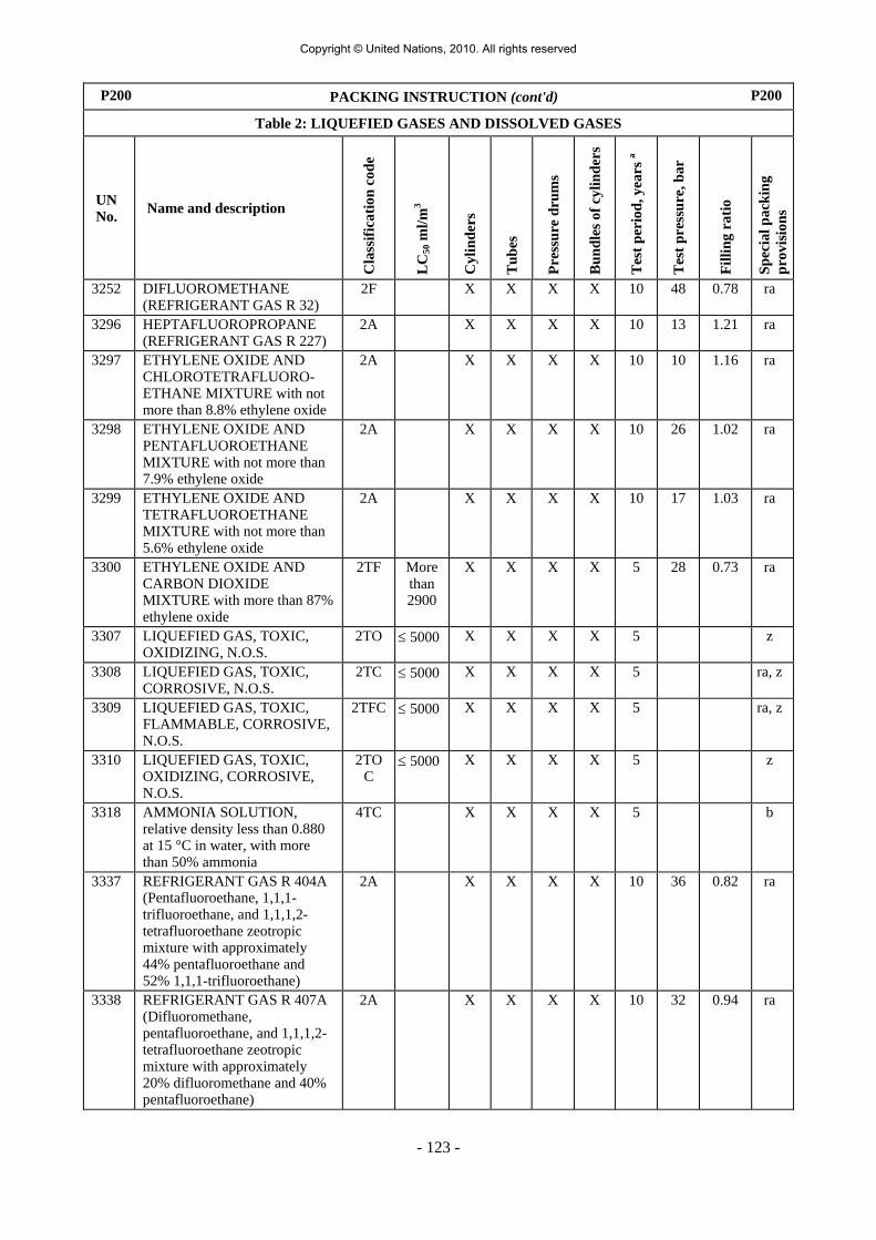
- 123 -
P200 PACKING INSTRUCTION (cont'd) P200
Table 2: LIQUEFIED GASES AND DISSOLVED GASES
UN No. Name and description
Cla
ssifi
catio
n co
de
LC
50 m
l/m3
Cyl
inde
rs
Tub
es
Pres
sure
dru
ms
Bun
dles
of c
ylin
ders
Tes
t per
iod,
yea
rs a
Tes
t pre
ssur
e, b
ar
Filli
ng r
atio
Spec
ial p
acki
ng
prov
isio
ns
3252 DIFLUOROMETHANE (REFRIGERANT GAS R 32)
2F X X X X 10 48 0.78 ra
3296 HEPTAFLUOROPROPANE (REFRIGERANT GAS R 227)
2A X X X X 10 13 1.21 ra
3297 ETHYLENE OXIDE AND CHLOROTETRAFLUORO-ETHANE MIXTURE with not more than 8.8% ethylene oxide
2A X X X X 10 10 1.16 ra
3298 ETHYLENE OXIDE AND PENTAFLUOROETHANE MIXTURE with not more than 7.9% ethylene oxide
2A X X X X 10 26 1.02 ra
3299 ETHYLENE OXIDE AND TETRAFLUOROETHANE MIXTURE with not more than 5.6% ethylene oxide
2A X X X X 10 17 1.03 ra
3300 ETHYLENE OXIDE AND CARBON DIOXIDE MIXTURE with more than 87% ethylene oxide
2TF More than 2900
X X X X 5 28 0.73 ra
3307 LIQUEFIED GAS, TOXIC, OXIDIZING, N.O.S.
2TO ≤ 5000 X X X X 5 z
3308 LIQUEFIED GAS, TOXIC, CORROSIVE, N.O.S.
2TC ≤ 5000 X X X X 5 ra, z
3309 LIQUEFIED GAS, TOXIC, FLAMMABLE, CORROSIVE, N.O.S.
2TFC ≤ 5000 X X X X 5 ra, z
3310 LIQUEFIED GAS, TOXIC, OXIDIZING, CORROSIVE, N.O.S.
2TOC
≤ 5000 X X X X 5 z
3318 AMMONIA SOLUTION, relative density less than 0.880 at 15 °C in water, with more than 50% ammonia
4TC X X X X 5 b
3337 REFRIGERANT GAS R 404A (Pentafluoroethane, 1,1,1-trifluoroethane, and 1,1,1,2-tetrafluoroethane zeotropic mixture with approximately 44% pentafluoroethane and 52% 1,1,1-trifluoroethane)
2A X X X X 10 36 0.82 ra
3338 REFRIGERANT GAS R 407A (Difluoromethane, pentafluoroethane, and 1,1,1,2-tetrafluoroethane zeotropic mixture with approximately 20% difluoromethane and 40% pentafluoroethane)
2A X X X X 10 32 0.94 ra
Copyright © United Nations, 2010. All rights reserved

- 124 -
P200 PACKING INSTRUCTION (cont'd) P200
Table 2: LIQUEFIED GASES AND DISSOLVED GASES
UN No. Name and description
Cla
ssifi
catio
n co
de
LC
50 m
l/m3
Cyl
inde
rs
Tub
es
Pres
sure
dru
ms
Bun
dles
of c
ylin
ders
Tes
t per
iod,
yea
rs a
Tes
t pre
ssur
e, b
ar
Filli
ng r
atio
Spec
ial p
acki
ng
prov
isio
ns
3339 REFRIGERANT GAS R 407B (Difluoromethane, pentafluoroethane, and 1,1,1,2-tetrafluoroethane zeotropic mixture with approximately 10% difluoromethane and 70% pentafluoroethane
2A X X X X 10 33 0.93 ra
3340 REFRIGERANT GAS R 407C (Difluoromethane, pentafluoroethane, and 1,1,1,2-tetrafluoroethane zeotropic mixture with approximately 23% difluoromethane and 25% pentafluoroethane)
2A X X X X 10 30 0.95 ra
3354 INSECTICIDE GAS, FLAMMABLE, N.O.S
2F X X X X 10 ra, z
3355 INSECTICIDE GAS, TOXIC, FLAMMABLE, N.O.S.
2TF X X X X 5 ra, z
3374 ACETYLENE, SOLVENT FREE
2F X X 5 60 c, p
a Not applicable for pressure receptacles made of composite materials. b For mixtures of UN No. 1965, the maximum permissible filling mass per litre of capacity is as follows:
c Considered as pyrophoric. d Considered to be toxic. The LC50 value still to be determined.
C
B
B2
B1
A1
A0
A02
A01
A
0.42
0.43
0.44
0.45
0.46
0.47
0.48
0.49
0.50
0.440 0.450 0.463 0.474 0.485 0.495 0.505 0.516 0.525
Maximum permissible mass of contents per litre of capacity
Density at 50 °C in kg/l
Commercial butaneCommercial propane
Copyright © United Nations, 2010. All rights reserved

- 125 -
P200 PACKING INSTRUCTION (cont'd) P200
Table 3: SUBSTANCES NOT IN CLASS 2
UN No. Name and description
Cla
ss
Cla
ssifi
catio
n C
ode
LC
50 m
l/m3
Cyl
inde
rs
Tub
es
Pres
sure
dru
ms
Bun
dles
of c
ylin
ders
Tes
t per
iod,
yea
rs a
Tes
t pre
ssur
e, b
ar
Filli
ng r
atio
Spec
ial p
acki
ng
prov
isio
ns
1051 HYDROGEN CYANIDE, STABILIZED containing less than 3% water
6.1 TF1 40 X X 5 100 0.55 k
1052 HYDROGEN FLUORIDE, ANHYDROUS
8 CT1 966 X X X 5 10 0.84 ab, ac
1745 BROMINE PENTAFLUORIDE
5.1 OTC 25 X X X 5 10 b k, ab, ad
1746 BROMINE TRIFLUORIDE 5.1 OTC 50 X X X 5 10 b k, ab, ad
1790 HYDROFLUORIC ACID, solution, with more than 85% hydrofluoric acid
8 CT1 966 X X X 5 10 0.84 ab, ac
2495 IODINE PENTAFLUORIDE 5.1 OTC 120 X X X 5 10 b k, ab, ad
a Not applicable for pressure receptacles made of composite materials. b A minimum ullage of 8% by volume is required.
Copyright © United Nations, 2010. All rights reserved

- 126 -
P201 PACKING INSTRUCTION P201This instruction applies to UN Nos. 3167, 3168 and 3169. The following packagings are authorized: (1) Cylinders tubes and pressure drums conforming to the construction, testing and filling requirements approved
by the competent authority; (2) In addition, the following packagings are authorized provided that the general provisions of 4.1.1 and 4.1.3
are met.
(a) For non-toxic gases, combination packagings with hermetically sealed inner packagings of glass or metal with a maximum capacity of 5 litres per package which meet the packing group III performance level;
(b) For toxic gases, combination packagings with hermetically sealed inner packagings of glass or metal
with a maximum capacity of 1 litre per package which meet the packing group III performance level.
P202 PACKING INSTRUCTION P202
(Reserved) P203 PACKING INSTRUCTION P203This instruction applies to Class 2 refrigerated liquefied gases. Requirements for closed cryogenic receptacles: (1) The special packing provisions of 4.1.6 shall be met. (2) The requirements of Chapter 6.2 shall be met. (3) The closed cryogenic receptacles shall be so insulated that they do not become coated with frost. (4) Test pressure Refrigerated liquids shall be filled in closed cryogenic receptacles with the following minimum test pressures:
(a) For closed cryogenic receptacles with vacuum insulation, the test pressure shall not be less than 1.3 times the sum of the maximum internal pressure of the filled receptacle, including during filling and discharge, plus 100 kPa (1 bar);
(b) For other closed cryogenic receptacles, the test pressure shall be not less than 1.3 times the maximum internal pressure of the filled receptacle, taking into account the pressure developed during filling and discharge.
(5) Degree of filling For non-flammable, non-toxic refrigerated liquefied gases (classification codes 3A and 3O) the volume of liquid phase at the filling temperature and at a pressure of 100 kPa (1 bar) shall not exceed 98% of the water capacity of the pressure receptacle. For flammable refrigerated liquefied gases (classification code 3F) the degree of filling shall remain below the level at which, if the contents were raised to the temperature at which the vapour pressure equalled the opening pressure of the relief valve, the volume of the liquid phase would reach 98% of the water capacity at that temperature.
(6) Pressure-relief devices Closed cryogenic receptacles shall be fitted with at least one pressure-relief device.
(7) Compatibility Materials used to ensure the leakproofness of the joints or for the maintenance of the closures shall be compatible with the contents. In the case of receptacles intended for the carriage of oxidizing gases (classification code 3O), these materials shall not react with these gases in a dangerous manner.
(Cont'd on next page)
Copyright © United Nations, 2010. All rights reserved

- 127 -
P203 PACKING INSTRUCTION (cont'd) P203Requirements for open cryogenic receptacles: Only the following non oxidizing refrigerated liquefied gases of classification code 3A may be carried in open cryogenic receptacles: UN Nos. 1913, 1951, 1963, 1970, 1977, 2591, 3136 and 3158. Open cryogenic receptacles shall be constructed to meet the following requirements: (1) The receptacles shall be designed, manufactured, tested and equipped in such a way as to withstand all
conditions, including fatigue, to which they will be subjected during their normal use and during normal conditions of carriage.
(2) The capacity shall be not more than 450 litres. (3) The receptacle shall have a double wall construction with the space between the inner and outer wall being
evacuated (vacuum insulation). The insulation shall prevent the formation of hoar frost on the exterior of the receptacle.
(4) The materials of construction shall have suitable mechanical properties at the service temperature. (5) Materials which are in direct contact with the dangerous goods shall not be affected or weakened by the
dangerous goods intended to be carried and shall not cause a dangerous effect, e.g. catalysing a reaction or reacting with the dangerous goods.
(6) Receptacles of glass double wall construction shall have an outer packaging with suitable cushioning or absorbent materials which withstand the pressures and impacts liable to occur under normal conditions of carriage.
(7) The receptacle shall be designed to remain in an upright position during carriage, e.g. have a base whose smaller horizontal dimension is greater than the height of the centre of gravity when filled to capacity or be mounted on gimbals.
(8) The openings of the receptacles shall be fitted with devices allowing gases to escape, preventing any splashing out of liquid, and so configured that they remain in place during carriage.
(9) Open cryogenic receptacles shall bear the following marks permanently affixed e.g. by stamping, engraving or etching: - The manufacturer’s name and address; - The model number or name; - The serial or batch number; - The UN number and proper shipping name of gases for which the receptacle is intended; - The capacity of the receptacle in litres.
P204 PACKING INSTRUCTION P204
(Deleted) P205 PACKING INSTRUCTION P205 This instruction applies to UN No. 3468. (1) For metal hydride storage systems, the special packing provisions of 4.1.6 shall be met. (2) Only pressure receptacles not exceeding 150 litres in water capacity and having a maximum developed
pressure not exceeding 25 MPa are covered by this packing instruction. (3) Metal hydride storage systems meeting the applicable requirements for the construction and testing of
pressure receptacles containing gas of Chapter 6.2 are authorised for the carriage of hydrogen only. (4) When steel pressure receptacles or composite pressure receptacles with steel liners are used, only those
bearing the "H" mark, in accordance with 6.2.2.9.2 (j) shall be used. (5) Metal hydride storage systems shall meet the service conditions, design criteria, rated capacity, type tests,
batch tests, routine tests, test pressure, rated charging pressure and provisions for pressure relief devices for transportable metal hydride storage systems specified in ISO 16111:2008 (Transportable gas storage devices – Hydrogen absorbed in reversible metal hydride) and their conformity and approval shall be assessed in accordance with 6.2.2.5.
(6) Metal hydride storage systems shall be filled with hydrogen at a pressure not exceeding the rated charging pressure shown in the permanent markings on the system as specified by ISO 16111:2008.
(7) The periodic test requirements for a metal hydride storage system shall be in accordance with ISO 16111:2008 and carried out in accordance with 6.2.2.6, and the interval between periodic inspections shall not exceed five years.
Copyright © United Nations, 2010. All rights reserved

- 128 -
P206 PACKING INSTRUCTION P206This packing instruction applies to UN No. 3150 devices, small, hydrocarbon gas powered or hydrocarbon gas refills for small devices (1) The special packing provisions of 4.1.6 when applicable shall be met. (2) The articles shall comply with the provisions of the country in which they were filled. (3) The devices and refills shall be packed in outer packagings conforming to 6.1.4 tested and approved in
accordance with Chapter 6.1 for packing group II. P300 PACKING INSTRUCTION P300This instruction applies to UN No. 3064. The following packagings are authorized, provided that the general provisions of 4.1.1 and 4.1.3 are met: Combination packagings consisting of inner metal cans of not more than 1 litre capacity each and outer wooden boxes (4C1, 4C2, 4D or 4F) containing not more than 5 litres of solution. Additional requirements:
1. Metal cans shall be completely surrounded with absorbent cushioning material.
2. Wooden boxes shall be completely lined with suitable material impervious to water and nitroglycerin.
P301 PACKING INSTRUCTION P301This instruction applies to UN No. 3165. The following packagings are authorized, provided that the general provisions of 4.1.1 and 4.1.3 are met: (1) Aluminium pressure vessel made from tubing and having welded heads. Primary containment of the fuel within this vessel shall consist of a welded aluminium bladder having a
maximum internal volume of 46 litres. The outer vessel shall have a minimum design gauge pressure of 1 275 kPa and a minimum burst gauge
pressure of 2 755 kPa. Each vessel shall be leak checked during manufacture and before dispatch and shall be found leakproof. The complete inner unit shall be securely packed in non-combustible cushioning material, such as
vermiculite, in a strong outer tightly closed metal packaging which will adequately protect all fittings. Maximum quantity of fuel per unit and package is 42 litres. (2) Aluminium pressure vessel.
Primary containment of the fuel within this vessel shall consist of a welded vapour tight fuel compartment with an elastomeric bladder having a maximum internal volume of 46 litres. The pressure vessel shall have a minimum design gauge pressure of 2 860 kPa and a minimum burst gauge pressure of 5 170 kPa. Each vessel shall be leak-checked during manufacture and before dispatch and shall be securely packed in non-combustible cushioning material such as vermiculite, in a strong outer tightly closed metal packaging which will adequately protect all fittings. Maximum quantity of fuel per unit and package is 42 litres.
Copyright © United Nations, 2010. All rights reserved

- 129 -
P302 PACKING INSTRUCTION P302
This instruction applies to UN No. 3269.
The following packagings are authorized, provided the general provisions of 4.1.1 and 4.1.3 are met:
Combination packagings which meet the packing group II or III performance level according to the criteria for Class 3, applied to the base material. The base material and the activator (organic peroxide) shall be each separately packed in inner packagings. The components may be placed in the same outer packaging provided they will not interact dangerously in the event of a leakage. The activator shall have a maximum quantity of 125 ml per inner packaging if liquid, and 500 g per inner packaging if solid.
P400 PACKING INSTRUCTION P400
The following packagings are authorized, provided that the general provisions of 4.1.1 and 4.1.3 are met: (1) Pressure receptacles, provided that the general provisions of 4.1.3.6 are met. They shall be made of steel and
shall be subjected to an initial test and periodic tests every 10 years at a pressure of not less than 1 MPa (10 bar, gauge pressure). During carriage, the liquid shall be under a layer of inert gas with a gauge pressure of not less than 20 kPa (0.2 bar);
(2) Boxes (4A, 4B, 4C1, 4C2, 4D, 4F or 4G), drums (1A2, 1B2, 1N2, 1D or 1G) or jerricans (3A2 or 3B2)
enclosing hermetically sealed metal cans with inner packagings of glass or metal, with a capacity of not more than 1 litre each, having threaded closures with gaskets. Inner packagings shall be cushioned on all sides with dry, absorbent, non-combustible material in a quantity sufficient to absorb the entire contents. Inner packagings shall not be filled to more than 90% of their capacity. Outer packagings shall have a maximum net mass of 125 kg;
(3) Steel, aluminium or metal drums (1A2, 1B2 or 1N2), jerricans (3A2 or 3B2) or boxes (4A or 4B) with a
maximum net mass of 150 kg each with hermetically sealed inner metal cans not more than 4 litre capacity each, with threaded closures fitted with gaskets. Inner packagings shall be cushioned on all sides with dry, absorbent, non-combustible material in a quantity sufficient to absorb the entire contents. Each layer of inner packagings shall be separated by a dividing partition in addition to cushioning material. Inner packagings shall not be filled to more than 90% of their capacity.
Special packing provision:
PP86 For UN Nos. 3392 and 3394, air shall be eliminated from the vapour space by nitrogen or other means.
P401 PACKING INSTRUCTION P401
The following packagings are authorized, provided that the general provisions of 4.1.1 and 4.1.3 are met: (1) Pressure receptacles, provided that the general provisions of 4.1.3.6 are met. They shall be made of steel and
subjected to an initial test and periodic tests every 10 years at a pressure of not less than 0.6 MPa (6 bar, gauge pressure). During carriage, the liquid shall be under a layer of inert gas with a gauge pressure of not less than 20 kPa (0.2 bar);
Inner packaging
Outer packaging
(2) Combination packagings with inner packagings of glass metal or plastics which have threaded closures surrounded in inert cushioning and absorbent material in a quantity sufficient to absorb the entire contents.
1 l 30 kg
(maximum net mass)
Special packing provision specific to RID and ADR:
RR7 For UN Nos. 1183, 1242, 1295 and 2988, the pressure receptacles shall however be subjected to the tests every five years.
Copyright © United Nations, 2010. All rights reserved

- 130 -
P402 PACKING INSTRUCTION P402
The following packagings are authorized, provided that the general provisions of 4.1.1 and 4.1.3 are met: (1) Pressure receptacles, provided that the general provisions of 4.1.3.6 are met. They shall be made of steel and
subjected to an initial test and periodic tests every 10 years at a pressure of not less than 0.6 MPa (6 bar, gauge pressure). During carriage, the liquid shall be under a layer of inert gas with a gauge pressure of not less than 20 kPa (0.2 bar);
Maximum net mass Inner packaging Outer
packaging (2) Combination packagings with inner packagings of glass, metal or plastics
which have threaded closures surrounded in inert cushioning and absorbent material in a quantity sufficient to absorb the entire contents;
10 kg (glass) 15 kg (metal or
plastics)
125 kg 125 kg
(3) Steel drums (1A1) with a maximum capacity of 250 litres; (4) Composite packagings consisting of a plastics receptacle with outer steel drum or aluminium (6HA1 or 6HB1)
with a maximum capacity of 250 litres. Special packing provisions specific to RID and ADR:
RR4 For UN No. 3130, the openings of receptacles shall be tightly closed by means of two devices in series, one of which shall be screwed or secured in an equivalent manner.
RR7 For UN No. 3129, the pressure receptacles shall however be subjected to the tests every five years.
RR8 For UN Nos. 1389, 1391, 1411, 1421, 1928, 3129, 3130, 3148 and 3482, the pressure receptacles shall however be subjected to an initial test and to periodic tests at a pressure of not less than 1 MPa (10 bar).
Copyright © United Nations, 2010. All rights reserved

- 131 -
P403 PACKING INSTRUCTION P403The following packagings are authorized, provided that the general provisions of 4.1.1 and 4.1.3 are met: Combination packagings: Inner packagings Outer packagings
Maximum net mass
Glass 2 kg Drums Plastics 15 kg steel (1A2) 400 kg Metal 20 kg aluminium (1B2) 400 kg metal, other than steel or aluminium (1N2) 400 kg
plastics (1H2) 400 kg plywood (1D) 400 kg fibre (1G) 400 kg Boxes steel (4A) 400 kg aluminium (4B) 400 kg natural wood (4C1) 250 kg natural wood with sift proof walls (4C2) 250 kg
Inner packagings shall be hermetically sealed (e.g. by taping or by threaded closures).
plywood (4D) 250 kg reconstituted wood (4F) 125 kg fibreboard (4G) 125 kg expanded plastics (4H1) 60 kg solid plastics (4H2) 250 kg Jerricans steel (3A2) 120 kg aluminium (3B2) 120 kg plastics (3H2) 120 kg Single packagings: Drums steel (1A1, 1A2) 250 kg aluminium (1B1, 1B2) 250 kg metal other than steel or aluminium (1N1, 1N2) 250 kg plastics (1H1, 1H2) 250 kg Jerricans steel (3A1, 3A2) 120 kg aluminium (3B1, 3B2) 120 kg plastics (3H1, 3H2) 120 kg Composite packagings plastics receptacle with outer steel or aluminium drums (6HA1 or 6HB1) 250 kg plastics receptacle with outer fibre, plastics or plywood drums (6HG1, 6HH1 or 6HD1) 75 kg plastics receptacle with outer steel or aluminium crate or box or with outer wooden, plywood, fibreboard or solid plastics boxes (6HA2, 6HB2, 6HC, 6HD2, 6HG2 or 6HH2)
75 kg
Pressure receptacles, provided that the general provisions of 4.1.3.6 are met. Additional requirement: Packagings shall be hermetically sealed. Special packing provision: PP83 For UN No. 2813, waterproof bags containing not more than 20 g of substance for the purposes of heat
formation may be packaged for carriage. Each waterproof bag shall be sealed in a plastics bag and placed within an intermediate packaging. No outer packaging shall contain more than 400 g of substance. Water or liquid which may react with the water reactive substance shall not be included in the packaging.
Copyright © United Nations, 2010. All rights reserved

- 132 -
P404 PACKING INSTRUCTION P404This instruction applies to pyrophoric solids: UN Nos.: 1383, 1854, 1855, 2008, 2441, 2545, 2546, 2846, 2881, 3200, 3391 and 3393. The following packagings are authorized, provided that the general provisions of 4.1.1 and 4.1.3 are met:
(1) Combination packagings
Outer packagings: (1A2, 1B2, 1N2, 1H2, 1D, 4A, 4B, 4C1, 4C2, 4D, 4F or 4H2)
Inner packagings: Metal packagings with a capacity of not more than 15 kg each. Inner packagings shall be hermetically sealed and have threaded closures;
(2) Metal packagings: (1A1, 1A2, 1B1, 1N1, 1N2, 3A1, 3A2, 3B1 and 3B2) Maximum gross mass: 150 kg;
(3) Composite packagings: Plastics receptacle with outer steel or aluminium drum (6HA1 or 6HB1) Maximum gross mass: 150 kg.
Pressure receptacles, provided that the general provisions of 4.1.3.6 are met.
Special packing provision:
PP86 For UN Nos. 3391 and 3393, air shall be eliminated from the vapour space by nitrogen or other means.
P405 PACKING INSTRUCTION P405This instruction applies to UN No. 1381. The following packagings are authorized, provided that the general provisions of 4.1.1 and 4.1.3 are met:
(1) For UN No. 1381, phosphorus, wet:
(a) Combination packagings
Outer packagings: (4A, 4B, 4C1, 4C2, 4D or 4F) Maximum net mass: 75 kg
Inner packagings:
(i) hermetically sealed metal cans, with a maximum net mass of 15 kg; or
(ii) glass inner packagings cushioned on all sides with dry, absorbent, non-combustible material in a quantity sufficient to absorb the entire contents with a maximum net mass of 2 kg; or
(b) Drums (1A1, 1A2, 1B1, 1B2, 1N1 or 1N2); maximum net mass: 400 kg
Jerricans (3A1 or 3B1); maximum net mass: 120 kg.
These packagings shall be capable of passing the leakproofness test specified in 6.1.5.4 at the packing group II performance level;
(2) For UN No. 1381, dry phosphorus:
(a) When fused, drums (1A2, 1B2 or 1N2) with a maximum net mass of 400 kg; or
(b) In projectiles or hard cased articles when carried without Class 1 components: as specified by the competent authority.
Copyright © United Nations, 2010. All rights reserved

- 133 -
P406 PACKING INSTRUCTION P406The following packagings are authorized, provided that the general provisions of 4.1.1 and 4.1.3 are met: (1) Combination packagings
outer packagings: (4C1, 4C2, 4D, 4F, 4G, 4H1, 4H2, 1G, 1D, 1H2 or 3H2)
inner packagings: water-resistant packagings; (2) Plastics, plywood or fibreboard drums (1H2, 1D or 1G) or boxes (4A, 4B, 4C1, 4D, 4F, 4C2, 4G and 4H2)
with a water resistant inner bag, plastics film lining or water resistant coating; (3) Metal drums (1A1, 1A2, 1B1, 1B2, 1N1 or 1N2), plastics drums (1H1 or 1H2), metal jerricans (3A1, 3A2,
3B1 or 3B2), plastics jerricans (3H1 or 3H2), plastics receptacle with outer steel or aluminium drums (6HA1 or 6HB1), plastics receptacle with outer fibre, plastics or plywood drums (6HG1, 6HH1 or 6HD1), plastics receptacle with outer steel or aluminium crate or box or with outer wooden, plywood, fibreboard or solid plastics boxes (6HA2, 6HB2, 6HC, 6HD2, 6HG2 or 6HH2).
Additional requirements:
1. Packagings shall be designed and constructed to prevent the loss of water or alcohol content or the content of the phlegmatizer.
2. Packagings shall be so constructed and closed so as to avoid an explosive overpressure or pressure build-up of more than 300 kPa (3 bar).
Special packing provisions:
PP24 UN Nos. 2852, 3364, 3365, 3366, 3367, 3368 and 3369 shall not be carried in quantities of more than 500 g per package.
PP25 For UN No. 1347, the quantity carried shall not exceed 15 kg per package.
PP26 For UN Nos. 1310, 1320, 1321, 1322, 1344, 1347, 1348, 1349, 1517, 2907, 3317 and 3376 packagings shall be lead free.
PP48 For UN No. 3474, metal packagings shall not be used.
PP78 UN No. 3370 shall not be carried in quantities of more than 11.5 kg per package.
PP80 For UN No. 2907, packagings shall meet the packing group II performance level. Packagings meeting the test criteria of packing group I shall not be used.
P407 PACKING INSTRUCTION P407This instruction applies to UN Nos. 1331, 1944, 1945 and 2254.
The following packagings are authorized, provided that the general provisions of 4.1.1 and 4.1.3 are met:
Combination packagings comprising securely closed inner packagings to prevent accidental ignition under normal conditions of transport. The maximum gross mass of the package shall not exceed 45 kg except for fibreboard boxes which shall not exceed 30 kg.
Additional requirement: Matches shall be tightly packed.
Special packing provision: PP27 UN No. 1331, Strike-anywhere matches shall not be packed in the same outer packaging with any other
dangerous goods other than safety matches or wax Vesta matches, which shall be packed in separate inner packagings. Inner packagings shall not contain more than 700 strike-anywhere matches.
Copyright © United Nations, 2010. All rights reserved

- 134 -
P408 PACKING INSTRUCTION P408This instruction applies to UN No. 3292. The following packagings are authorized, provided that the general provisions of 4.1.1 and 4.1.3 are met:
(1) For cells:
Outer packagings with sufficient cushioning material to prevent contact between cells and between cells and the internal surfaces of the outer packaging and to ensure that no dangerous movement of the cells within the outer packaging occurs during carriage. Packagings shall conform to the packing group II performance level;
(2) For batteries:
Batteries may be carried unpacked or in protective enclosures (e.g. in fully enclosed or wooden slatted crates). The terminals shall not support the weight of other batteries or materials packed with the batteries.
Additional requirement:
Batteries shall be protected against short circuit and shall be isolated in such a manner as to prevent short circuits.
P409 PACKING INSTRUCTION P409This instruction applies to UN Nos. 2956, 3242 and 3251. The following packagings are authorized, provided that the general provisions of 4.1.1 and 4.1.3 are met:
(1) Fibre drum (1G) which may be fitted with a liner or coating; maximum net mass: 50 kg;
(2) Combination packagings: Fibreboard box (4G) with a single inner plastic bag;
maximum net mass: 50 kg;
(3) Combination packagings: Fibreboard box (4G) or fibre drum (1G) with plastics inner packagings each containing a maximum of 5 kg; maximum net mass: 25 kg.
Copyright © United Nations, 2010. All rights reserved

- 135 -
P410 PACKING INSTRUCTION P410 The following packagings are authorized, provided that the general provisions of 4.1.1 and 4.1.3 are met: Combination packagings: Maximum net mass Inner packagings Outer packagings Packing group
II Packing group III
Glass 10 kg Drums Plastics a 30 kg steel (1A2) 400 kg 400 kg Metal 40 kg aluminium (1B2) 400 kg 400 kg Paper a, b 10 kg Fibre a, b 10 kg
metal other than steel or aluminium (1N2)
400 kg 400 kg
plastics (1H2) 400 kg 400 kg plywood (1D) 400 kg 400 kg a These packagings shall be sift-
proof. fibre (1G) a 400 kg 400 kg Boxes steel (4A) 400 kg 400 kg aluminium (4B) 400 kg 400 kg natural wood (4C1) 400 kg 400 kg
b These inner packagings shall not be used when the substances being carried may become liquid during carriage.
natural wood with sift-proof walls (4C2)
400 kg 400 kg
plywood (4D) 400 kg 400 kg reconstituted wood (4F) 400 kg 400 kg fibreboard (4G) a 400 kg 400 kg expanded plastics (4H1) 60 kg 60 kg solid plastics (4H2) 400 kg 400 kg Jerricans steel (3A2) 120 kg 120 kg aluminium (3B2) 120 kg 120 kg plastics (3H2) 120 kg 120 kg Single packagings: Drums steel (1A1 or 1A2) 400 kg 400 kg aluminium (1B1 or 1B2) 400 kg 400 kg metal other than steel or aluminium (1N1 or 1N2) 400 kg 400 kg plastics (1H1 or 1H2) 400 kg 400 kg Jerricans steel (3A1 or 3A2) 120 kg 120 kg aluminium (3B1 or 3B2) 120 kg 120 kg plastics (3H1 or 3H2) 120 kg 120 kg Boxes steel (4A) c 400 kg 400 kg aluminium (4B) c 400 kg 400 kg natural wood (4C1) c 400 kg 400 kg plywood (4D) c 400 kg 400 kg reconstituted wood (4F) c 400 kg 400 kg natural wood with sift-proof walls (4C2) c 400 kg 400 kg fibreboard (4G) c 400 kg 400 kg solid plastics (4H2) c 400 kg 400 kg Bags Bags (5H3, 5H4, 5L3, 5M2) c, d 50 kg 50 kg c These packagings shall not be used when the substances being carried may become liquid during carriage. d These packagings shall only be used for packing group II substances when carried in a closed vehicle or container.
(Cont'd on next page)
Copyright © United Nations, 2010. All rights reserved
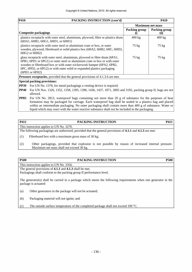
- 136 -
P410 PACKING INSTRUCTION (cont’d) P410 Maximum net mass
Composite packagings Packing group
II Packing group
III plastics receptacle with outer steel, aluminium, plywood, fibre or plastics drum (6HA1, 6HB1, 6HG1, 6HD1, or 6HH1)
400 kg 400 kg
plastics receptacle with outer steel or aluminium crate or box, or outer wooden, plywood, fibreboard or solid plastics box (6HA2, 6HB2, 6HC, 6HD2, 6HG2 or 6HH2)
75 kg 75 kg
glass receptacle with outer steel, aluminium, plywood or fibre drum (6PA1, 6PB1, 6PD1 or 6PG1) or outer steel or aluminium crate or box or with outer wooden or fibreboard box or with outer wickerwork hamper (6PA2, 6PB2, 6PC, 6PD2, or 6PG2) or with outer solid or expanded plastics packaging (6PH1 or 6PH2)
75 kg 75 kg
Pressure receptacles, provided that the general provisions of 4.1.3.6 are met. Special packing provisions: PP39 For UN No. 1378, for metal packagings a venting device is required. PP40 For UN Nos. 1326, 1352, 1358, 1395, 1396, 1436, 1437, 1871, 2805 and 3182, packing group II, bags are not
allowed. PP83 For UN No. 2813, waterproof bags containing not more than 20 g of substance for the purposes of heat
formation may be packaged for carriage. Each waterproof bag shall be sealed in a plastics bag and placed within an intermediate packaging. No outer packaging shall contain more than 400 g of substance. Water or liquid which may react with the water reactive substance shall not be included in the packaging.
P411 PACKING INSTRUCTION P411This instruction applies to UN No. 3270. The following packagings are authorized, provided that the general provisions of 4.1.1 and 4.1.3 are met:
(1) Fibreboard box with a maximum gross mass of 30 kg; (2) Other packagings, provided that explosion is not possible by reason of increased internal pressure.
Maximum net mass shall not exceed 30 kg. P500 PACKING INSTRUCTION P500This instruction applies to UN No. 3356. The general provisions of 4.1.1 and 4.1.3 shall be met. Packagings shall conform to the packing group II performance level. The generator(s) shall be carried in a package which meets the following requirements when one generator in the package is actuated: (a) Other generators in the package will not be actuated; (b) Packaging material will not ignite; and (c) The outside surface temperature of the completed package shall not exceed 100 °C.
Copyright © United Nations, 2010. All rights reserved

- 137 -
P501 PACKING INSTRUCTION P501This instruction applies to UN No. 2015. The following packagings are authorized, provided that the general provisions of 4.1.1 and 4.1.3 are met:
Combination packagings: Inner packaging maximum capacity
Outer packaging maximum net mass
(1) Boxes (4A, 4B, 4C1, 4C2, 4D, 4H2) or drums (1A2, 1B2, 1N2, 1H2, 1D) or jerricans (3A2, 3B2, 3H2) with glass, plastics or metal inner packagings
5 l 125 kg
(2) Fibreboard box (4G) or fibre drum (1G), with plastics or metal inner packagings each in a plastics bag
2 l 50 kg
Single packagings: Maximum capacity Drums steel (1A1) aluminium (1B1) metal other than steel or aluminium (1N1) plastics (1H1)
250 l
Jerricans steel (3A1) aluminium (3B1) plastics (3H1)
60 l
Composite packagings plastics receptacle with outer steel or aluminium drum (6HA1, 6HB1) 250 l plastics receptacle with outer fibre, plastics or plywood drum (6HG1, 6HH1, 6HD1)
250 l
plastics receptacle with outer steel or aluminium crate or box or plastics receptacle with outer wooden, plywood, fibreboard or solid plastics box (6HA2, 6HB2, 6HC, 6HD2, 6HG2 or 6HH2)
60 l
glass receptacle with outer steel, aluminium, fibre, plywood, solid plastics or expanded plastics drum (6PA1, 6PB1, 6PG1, 6PD1, 6PH1 or 6PH2) or with outer steel or aluminium crate or box or with outer wooden or fibreboard box or with outer wickerwork hamper (6PA2, 6PB2, 6PC, 6PG2 or 6PD2)
60 l
Additional requirements: 1. Packagings shall have a maximum filling degree of 90%. 2. Packagings shall be vented.
Copyright © United Nations, 2010. All rights reserved

- 138 -
P502 PACKING INSTRUCTION P502The following packagings are authorized, provided that the general provisions of 4.1.1 and 4.1.3 are met: Combination packagings: Inner packagings Outer packagings
Maximum net mass
Glass 5 l Drums Metal 5 l steel (1A2) 125 kg Plastics 5 l aluminium (1B2) 125 kg metal other than steel or aluminium (1N2) 125 kg plastics (1H2) 125 kg plywood (1D) 125 kg fibre (1G) 125 kg Boxes steel (4A) 125 kg aluminium (4B) 125 kg natural wood (4C1) 125 kg natural wood with sift-proof walls (4C2) 125 kg plywood (4D) 125 kg reconstituted wood (4F) 125 kg fibreboard (4G) 125 kg expanded plastics (4H1) 60 kg solid plastics (4H2) 125 kg Single packagings: Maximum capacityDrums steel (1A1) aluminium (1B1) plastics (1H1)
250 l
Jerricans steel (3A1) aluminium (3B1) plastics (3H1)
60 l
Composite packagings: plastics receptacle with outer steel or aluminium drum (6HA1, 6HB1) 250 l plastics receptacle with outer fibre, plastics or plywood drum (6HG1, 6HH1, 6HD1) 250 l plastics receptacle with outer steel or aluminium crate or box or plastics receptacle with outer wooden, plywood, fibreboard or solid plastics box (6HA2, 6HB2, 6HC, 6HD2, 6HG2 or 6HH2)
60 l
glass receptacle with outer steel, aluminium, fibre, plywood, solid plastics or expanded plastics drum (6PA1, 6PB1, 6PG1, 6PD1, 6PH1 or 6PH2) or with outer steel or aluminium crate or box or with outer wooden or fibreboard box or with outer wickerwork hamper (6PA2, 6PB2, 6PC, 6PG2 or 6PD2)
60 l
Special packing provision: PP28 For UN No. 1873, only glass inner packagings and glass inner receptacles are authorized respectively for
combination packagings and composite packagings.
Copyright © United Nations, 2010. All rights reserved

- 139 -
P503 PACKING INSTRUCTION P503The following packagings are authorized, provided that the general provisions of 4.1.1 and 4.1.3 are met: Combination packagings: Inner packagings Outer packagings Maximum net mass Glass 5 kg Drums Metal 5 kg steel (1A2) 125 kg Plastics 5 kg aluminium (1B2) 125 kg metal other than steel or aluminium (1N2) 125 kg plastics (1H2) 125 kg plywood (1D) 125 kg fibre (1G) 125 kg Boxes steel (4A) 125 kg aluminium (4B) 125 kg natural wood (4C1) 125 kg natural wood with sift-proof walls (4C2) 125 kg plywood (4D) 125 kg reconstituted wood (4F) 125 kg fibreboard (4G) 40 kg expanded plastics (4H1) 60 kg solid plastics (4H2) 125 kg Single packagings: Metal drums (1A1, 1A2, 1B1, 1B2, 1N1 or 1N2) with a maximum net mass of 250 kg. Fibreboard (1G) or plywood drums (1D) fitted with inner liners with a maximum net mass of 200 kg.
Copyright © United Nations, 2010. All rights reserved

- 140 -
P504 PACKING INSTRUCTION P504The following packagings are authorized, provided that the general provisions of 4.1.1 and 4.1.3 are met: Combination packagings: Maximum net mass (1) Glass receptacles with a maximum capacity of 5 litres in 1A2, 1B2, 1N2, 1H2, 1D,
1G, 4A, 4B, 4C1, 4C2, 4D, 4F, 4G, 4H2 outer packagings 75 kg
(2) Plastics receptacles with a maximum capacity of 30 litres in 1A2, 1B2, 1N2, 1H2, 1D, 1G, 4A, 4B, 4C1, 4C2, 4D, 4F, 4G, 4H2 outer packagings
75 kg
(3) Metal receptacles with a maximum capacity of 40 litres in 1G, 4F or 4G outer packagings
125 kg
(4) Metal receptacles with a maximum capacity of 40 litres in 1A2, 1B2, 1N2, 1H2, 1D, 4A, 4B, 4C1, 4C2, 4D, 4H2 outer packagings
225 kg
Single packagings: Maximum capacity Drums
steel, non-removable head (1A1) 250 l steel, removable head (1A2) 250 l aluminium, non-removable head (1B1) 250 l aluminium, removable head (1B2) 250 l metal other than steel or aluminium, non-removable head (1N1) 250 l metal other than steel or aluminium, removable head (1N2) 250 l plastics, non-removable head (1H1) 250 l plastics, removable head (1H2) 250 l
Jerricans steel, non-removable head (3A1) 60 l steel, removable head (3A2) 60 l aluminium, non-removable head (3B1) 60 l aluminium, removable head (3B2) 60 l plastics, non-removable head (3H1) 60 l plastics, removable head (3H2) 60 l
Composite packagings plastics receptacle with outer steel or aluminium drum (6HA1, 6HB1) 250 l plastics receptacle with outer fibre, plastics or plywood drum (6HG1, 6HH1, 6HD1) 120 l plastics receptacle with outer steel or aluminium crate or box or plastics receptacle with outer wooden, plywood, fibreboard or solid plastics box (6HA2, 6HB2, 6HC, 6HD2, 6HG2 or 6HH2)
60 l
glass receptacle with outer steel, aluminium, fibre, plywood, solid plastics or expanded plastics drum (6PA1, 6PB1, 6PG1, 6PD1, 6PH1 or 6PH2) or with outer steel or aluminium crate or box or with outer wooden fibreboard box or with outer wickerwork hamper (6PA2, 6PB2, 6PC, 6PG2 or 6PD2)
60 l
Special packing provisions: PP10 For UN No. 2014, 2984 and 3149, the packaging shall be vented.
Copyright © United Nations, 2010. All rights reserved

- 141 -
P520 PACKING INSTRUCTION P520This instruction applies to organic peroxides of Class 5.2 and self-reactive substances of Class 4.1
The packagings listed below are authorized provided the general provisions of 4.1.1 and 4.1.3 and special provisions of 4.1.7.1 are met. The packing methods are designated OP1 to OP8. The packing methods appropriate for the individual currently assigned organic peroxides and self-reactive substances are listed in 2.2.41.4 and 2.2.52.4. The quantities specified for each packing method are the maximum quantities authorized per package. The following packagings are authorized: (1) Combination packagings with outer packagings comprising boxes (4A, 4B, 4C1, 4C2, 4D, 4F, 4G, 4H1 and
4H2), drums (1A2, 1B2, 1G, 1H2 and 1D), jerricans (3A2, 3B2 and 3H2); (2) Single packagings consisting of drums (1A1, 1A2, 1B1, 1B2, 1G, 1H1, 1H2 and 1D) and jerricans (3A1, 3A2,
3B1, 3B2, 3H1 and 3H2); (3) Composite packagings with plastics inner receptacles (6HA1, 6HA2, 6HB1, 6HB2, 6HC, 6HD1, 6HD2, 6HG1,
6HG2, 6HH1 and 6HH2). Maximum quantity per packaging/package a for packing methods OP1 to OP8
OP1 OP2 a OP3 OP4 a OP5 OP6 OP7 OP8 Packing Method
Maximum Quantity
Maximum mass (kg) for solids and for combination packagings (liquid and solid)
0.5 0.5/10 5 5/25 25 50 50 400 b
Maximum contents in litres for liquids c
0.5 - 5 - 30 60 60 225 d
a If two values are given, the first applies to the maximum net mass per inner packaging and the second to the maximum net mass of the complete package.
b 60 kg for jerricans / 200 kg for boxes and, for solids, 400 kg in combination packagings with outer packagings
comprising boxes (4C1, 4C2, 4D, 4F, 4G, 4H1 and 4H2) and with inner packagings of plastics or fibre with a maximum net mass of 25 kg.
c Viscous substances shall be treated as solids when they do not meet the criteria provided in the definition for
"liquids" presented in 1.2.1. d 60 litres for jerricans. Additional requirements: 1. Metal packagings, including inner packagings of combination packagings and outer packagings of
combination or composite packagings may only be used for packing methods OP7 and OP8. 2. In combination packagings, glass receptacles may only be used as inner packagings with maximum contents
of 0.5 kg for solids or 0.5 litre for liquids. 3. In combination packagings, cushioning materials shall not be readily combustible. 4. The packaging of an organic peroxide or self-reactive substance required to bear an "EXPLOSIVE" subsidiary
risk label (model No.1, see 5.2.2.2.2) shall also comply with the provisions given in 4.1.5.10 and 4.1.5.11. Special packing provisions: PP21 For certain self-reactive substances of types B or C, UN Nos. 3221, 3222, 3223, 3224, 3231, 3232, 3233 and
3234, a smaller packaging than that allowed by packing methods OP5 or OP6 respectively shall be used (see 4.1.7 and 2.2.41.4).
PP22 UN No. 3241, 2-Bromo-2-nitropropane-1, 3-diol, shall be packed in accordance with packing method OP6.
Copyright © United Nations, 2010. All rights reserved

- 142 -
P600 PACKING INSTRUCTION P600This instruction applies to UN Nos. 1700, 2016 and 2017. The following packagings are authorized, provided the general provisions of 4.1.1 and 4.1.3 are met: Outer packagings (1A2, 1B2, 1N2, 1H2, 1D, 1G, 4A, 4B, 4C1, 4C2, 4D, 4F, 4G, 4H2) meeting the packing group II performance level. The articles shall be individually packaged and separated from each other using partitions, dividers, inner packagings or cushioning material to prevent inadvertent discharge during normal conditions of carriage. Maximum net mass: 75 kg
P601 PACKING INSTRUCTION P601The following packagings are authorized provided the general provisions of 4.1.1 and 4.1.3 are met and the packagings are hermetically sealed: (1) Combination packagings with a maximum gross mass of 15 kg, consisting of
− one or more glass inner packaging(s) with a maximum quantity of 1 litre each and filled to not more than 90% of their capacity; the closure(s) of which shall be physically held in place by any means capable of preventing back-off or loosening by impact or vibration during carriage, individually placed in
− metal receptacles together with cushioning and absorbent material sufficient to absorb the entire contents of the glass inner packaging(s), further packed in
− 1A2, 1B2, 1N2, 1H2, 1D, 1G, 4A, 4B, 4C1, 4C2, 4D, 4F, 4G or 4H2 outer packagings; (2) Combination packagings consisting of metal inner packagings not exceeding 5 litres in capacity individually
packed with absorbent material sufficient to absorb the contents and inert cushioning material in 1A2, 1B2, 1N2, 1H2, 1D, 1G, 4A, 4B, 4C1, 4C2, 4D, 4F, 4G or 4H2 outer packagings with a maximum gross mass of 75 kg. Inner packagings shall not be filled to more than 90% of their capacity. The closure of each inner packaging shall be physically held in place by any means capable of preventing back-off or loosening of the closure by impact or vibration during carriage;
(3) Packagings consisting of: Outer packagings: Steel or plastic drums, removable head (1A2 or 1H2) tested in accordance with the test
requirements in 6.1.5 at a mass corresponding to the mass of the assembled package either as a packaging intended to contain inner packagings, or as a single packaging intended to contain solids or liquids, and marked accordingly;
Inner packagings: Drums and composite packagings (1A1, 1B1, 1N1, 1H1 or 6HA1) meeting the requirements of Chapter 6.1
for single packagings, subject to the following conditions:
(a) The hydraulic pressure test shall be conducted at a pressure of at least 0.3 MPa (gauge pressure);
(b) The design and production leakproofness tests shall be conducted at a test pressure of 30 kPa;
(c) They shall be isolated from the outer drum by the use of inert shock-mitigating cushioning material which surrounds the inner packaging on all sides;
(d) Their capacity shall not exceed 125 litres; (Cont'd on next page)
Copyright © United Nations, 2010. All rights reserved

- 143 -
P601 PACKING INSTRUCTION (cont'd) P601(3) Packagings consisting of: (cont'd) (e) Closures shall be of a screw cap type that are:
(i) physically held in place by any means capable of preventing back-off or loosening of the closure by impact or vibration during carriage; and
(ii) provided with a cap seal;
(f) The outer and inner packagings shall be subjected periodically to a leakproofness test according to (b) at intervals of not more than two and a half years;
(g) The complete packaging shall be visually inspected to the satisfaction of the competent authority at least every 3 years; and
(h) The outer and inner packaging shall bear in clearly legible and durable characters:
(i) the date (month, year) of the initial test and the latest periodic test and inspection;
(ii) the stamp of the expert who carried out the test and inspection;
(4) Pressure receptacles, provided that the general provisions of 4.1.3.6 are met. They shall be subjected to an initial test and periodic tests every 10 years at a pressure of not less than 1 MPa (10 bar) (gauge pressure). Pressure receptacles may not be equipped with any pressure relief device. Each pressure receptacle containing a toxic by inhalation liquid with an LC50 less than or equal to 200 ml/m3 (ppm) shall be closed with a plug or valve conforming to the following:
(a) Each plug or valve shall have a taper-threaded connection directly to the pressure receptacle and be
capable of withstanding the test pressure of the pressure receptacle without damage or leakage;
(b) Each valve shall be of the packless type with non-perforated diaphragm, except that, for corrosive substances, a valve may be of the packed type with an assembly made gas-tight by means of a seal cap with gasket joint attached to the valve body or the pressure receptacle to prevent loss of substance through or past the packing;
(c) Each valve outlet shall be sealed by a threaded cap or threaded solid plug and inert gasket material;
(d) The materials of construction for the pressure receptacle, valves, plugs, outlet caps, luting and gaskets shall be compatible with each other and with the contents.
Each pressure receptacle with a wall thickness at any point of less than 2.0 mm and each pressure receptacle which does not have fitted valve protection shall be carried in an outer packaging. Pressure receptacles shall not be manifolded or interconnected.
Special packing provision: PP82 (Deleted) Special packing provisions specific to RID and ADR:
RR3 (Deleted)
RR7 For UN No. 1251, the pressure receptacles shall however be subjected to the tests every five years.
RR10 UN No. 1614, when completely absorbed by an inert porous material, shall be packed in metal receptacles of a capacity of not more than 7.5 litres, placed in wooden cases in such a manner that they cannot come into contact with one another. The receptacles shall be entirely filled with the porous material which shall not shake down or form dangerous spaces even after prolonged use or under impact, even at temperatures of up to 50 °C.
Copyright © United Nations, 2010. All rights reserved

- 144 -
P602 PACKING INSTRUCTION P602The following packagings are authorised provided the general provisions of 4.1.1 and 4.1.3 are met and the packagings are hermetically sealed:
(1) Combination packagings with a maximum gross mass of 15 kg, consisting of
− one or more glass inner packaging(s) with a maximum quantity of 1 litre each and filled to not more than 90% of their capacity; the closure(s) of which shall be physically held in place by any means capable of preventing back-off or loosening by impact or vibration during carriage, individually placed in
− metal receptacles together with cushioning and absorbent material sufficient to absorb the entire contents of the glass inner packaging(s), further packed in
− 1A2, 1B2, 1N2, 1H2, 1D, 1G, 4A, 4B, 4C1, 4C2, 4D, 4F, 4G or 4H2 outer packagings;
(2) Combination packagings consisting of metal inner packagings individually packed with absorbent material sufficient to absorb the entire contents and inert cushioning material in 1A2, 1B2, 1N2, 1H2, 1D, 1G, 4A, 4B, 4C1, 4C2, 4D, 4F, 4G or 4H2 outer packagings with a maximum gross mass of 75 kg. Inner packagings shall not be filled to more than 90% of their capacity. The closure of each inner packaging shall be physically held in place by any means capable of preventing back-off or loosening of the closure by impact or vibration during carriage. Inner packagings shall not exceed 5 litres in capacity;
(3) Drums and composite packagings (1A1, 1B1, 1N1, 1H1, 6HA1 or 6HH1), subject to the following conditions: (a) The hydraulic pressure test shall be conducted at a pressure of at least 0.3 MPa (gauge pressure); (b) The design and production leakproofness tests shall be conducted at a test pressure of 30 kPa; and (c) Closures shall be of a screw cap type that are: (i) physically held in place by any means capable of preventing back-off or loosening of the
closure by impact or vibration during carriage; and (ii) provided with a cap seal;
(4) Pressure receptacles, provided that the general provisions of 4.1.3.6 are met. They shall be subjected to an initial test and periodic tests every 10 years at a pressure of not less than 1 MPa (10 bar) (gauge pressure). Pressure receptacles may not be equipped with any pressure relief device. Each pressure receptacle containing a toxic by inhalation liquid with an LC50 less than or equal to 200 ml/m3 (ppm) shall be closed with a plug or valve conforming to the following: (a) Each plug or valve shall have a taper-threaded connection directly to the pressure receptacle and be
capable of withstanding the test pressure of the pressure receptacle without damage or leakage; (b) Each valve shall be of the packless type with non-perforated diaphragm, except that, for corrosive
substances, a valve may be of the packed type with an assembly made gas-tight by means of a seal cap with gasket joint attached to the valve body or the pressure receptacle to prevent loss of substance through or past the packing;
(c) Each valve outlet shall be sealed by a threaded cap or threaded solid plug and inert gasket material; (d) The materials of construction for the pressure receptacle, valves, plugs, outlet caps, luting and gaskets
shall be compatible with each other and with the contents.
Each pressure receptacle with a wall thickness at any point of less than 2.0 mm and each pressure receptacle which does not have fitted valve protection shall be carried in an outer packaging. Pressure receptacles shall not be manifolded or interconnected.
Copyright © United Nations, 2010. All rights reserved

- 145 -
P620 PACKING INSTRUCTION P620This instruction applies to UN Nos. 2814 and 2900. The following packagings are authorized provided the special packing provisions of 4.1.8 are met: Packagings meeting the requirements of Chapter 6.3 and approved accordingly consisting of:
(a) Inner packagings comprising:
(i) leakproof primary receptacle(s);
(ii) a leakproof secondary packaging;
(iii) other than for solid infectious substances, an absorbent material in sufficient quantity to absorb the entire contents placed between the primary receptacle(s) and the secondary packaging; if multiple primary receptacles are placed in a single secondary packaging, they shall be either individually wrapped or separated so as to prevent contact between them;
(b) A rigid outer packaging. The smallest external dimension shall be not less than 100 mm.
Additional requirements:
1. Inner packagings containing infectious substances shall not be consolidated with inner packagings containing unrelated types of goods. Complete packages may be overpacked in accordance with the provisions of 1.2.1 and 5.1.2; such an overpack may contain dry ice.
2. Other than for exceptional consignments, e.g. whole organs which require special packaging, the following additional requirements shall apply: (a) Substances consigned at ambient temperatures or at a higher temperature: Primary receptacles shall
be of glass, metal or plastics. Positive means of ensuring a leakproof seal shall be provided, e.g. a heat seal, a skirted stopper or a metal crimp seal. If screw caps are used, they shall be secured by positive means, e.g., tape, paraffin sealing tape or manufactured locking closure;
(b) Substances consigned refrigerated or frozen: Ice, dry ice or other refrigerant shall be placed around the secondary packaging(s) or alternatively in an overpack with one or more complete packages marked in accordance with 6.3.3. Interior supports shall be provided to secure secondary packaging(s) or packages in position after the ice or dry ice has dissipated. If ice is used, the outer packaging or overpack shall be leakproof. If dry ice is used, the outer packaging or overpack shall permit the release of carbon dioxide gas. The primary receptacle and the secondary packaging shall maintain their integrity at the temperature of the refrigerant used;
(c) Substances consigned in liquid nitrogen: Plastics primary receptacles capable of withstanding very low temperature shall be used. The secondary packaging shall also be capable of withstanding very low temperatures, and in most cases will need to be fitted over the primary receptacle individually. Provisions for the consignment of liquid nitrogen shall also be fulfilled. The primary receptacle and the secondary packaging shall maintain their integrity at the temperature of the liquid nitrogen;
(d) Lyophilised substances may also be carried in primary receptacles that are flame-sealed glass ampoules or rubber-stoppered glass vials fitted with metal seals.
3. Whatever the intended temperature of the consignment, the primary receptacle or the secondary packaging shall be capable of withstanding without leakage an internal pressure producing a pressure differential of not less than 95 kPa and temperatures in the range -40 °C to +55 °C.
4. Other dangerous goods shall not be packed in the same packaging as Class 6.2 infectious substances unless they are necessary for maintaining the viability, stabilizing or preventing degradation or neutralizing the hazards of the infectious substances. A quantity of 30 ml or less of dangerous goods included in Classes 3, 8 or 9 may be packed in each primary receptacle containing infectious substances. These small quantities of dangerous goods of Classes 3, 8 or 9 are not subject to any additional requirements of ADR when packed in accordance with this packing instruction.
5. Alternative packagings for the carriage of animal material may be authorized by the competent authority of the country of origin a in accordance with the provisions of 4.1.8.7.
a If the country of origin is not a Contracting Party to ADR, the competent authority of the first Contracting Party to the ADR reached by the consignment.
Copyright © United Nations, 2010. All rights reserved

- 146 -
P621 PACKING INSTRUCTION P621
This instruction applies to UN No. 3291. The following packagings are authorized provided the general provisions of 4.1.1, except 4.1.1.15, and 4.1.3 are met:
(1) Rigid, leakproof packagings meeting the requirements of Chapter 6.1 for solids, at the packing group II performance level, provided there is sufficient absorbent material to absorb the entire amount of liquid present and the packaging is capable of retaining liquids;
(2) For packages containing larger quantities of liquid, rigid packagings meeting the requirements of Chapter 6.1 at the packing group II performance level for liquids.
Additional requirement:
Packagings intended to contain sharp objects such as broken glass and needles shall be resistant to puncture and retain liquids under the performance test conditions in Chapter 6.1.
P650 PACKING INSTRUCTION P650 This packing instruction applies to UN No. 3373.
(1) The packaging shall be of good quality, strong enough to withstand the shocks and loadings normally encountered during carriage, including transhipment between vehicles or containers and between vehicles or containers and warehouses as well as any removal from a pallet or overpack for subsequent manual or mechanical handling. Packagings shall be constructed and closed to prevent any loss of contents that might be caused under normal conditions of carriage by vibration or by changes in temperature, humidity or pressure.
(2) The packaging shall consist of at least three components: (a) a primary receptacle;
(b) a secondary packaging; and
(c) an outer packaging
of which either the secondary or the outer packaging shall be rigid. (3) Primary receptacles shall be packed in secondary packagings in such a way that, under normal conditions of
carriage, they cannot break, be punctured or leak their contents into the secondary packaging. Secondary packagings shall be secured in outer packagings with suitable cushioning material. Any leakage of the contents shall not compromise the integrity of the cushioning material or of the outer packaging.
(4) For carriage, the mark illustrated below shall be displayed on the external surface of the outer packaging on a background of a contrasting colour and shall be clearly visible and legible. The mark shall be in the form of a square set at an angle of 45° (diamond-shaped) with minimum dimensions of 50 mm by 50 mm; the width of the line shall be at least 2 mm and the letters and numbers shall be at least 6 mm high. The proper shipping name "BIOLOGICAL SUBSTANCE, CATEGORY B" in letters at least 6 mm high shall be marked on the outer packaging adjacent to the diamond-shaped mark.
(5) At least one surface of the outer packaging shall have a minimum dimension of 100 mm × 100 mm. (6) The completed package shall be capable of successfully passing the drop test in 6.3.5.3 as specified in 6.3.5.2
at a height of 1.2 m. Following the appropriate drop sequence, there shall be no leakage from the primary receptacle(s) which shall remain protected by absorbent material, when required, in the secondary packaging.
(Cont'd on next page)
UN3373
Copyright © United Nations, 2010. All rights reserved

- 147 -
P650 PACKING INSTRUCTION (cont'd) P650
(7) For liquid substances: (a) The primary receptacle(s) shall be leakproof; (b) The secondary packaging shall be leakproof; (c) If multiple fragile primary receptacles are placed in a single secondary packaging, they shall be either
individually wrapped or separated to prevent contact between them; (d) Absorbent material shall be placed between the primary receptacle(s) and the secondary packaging. The
absorbent material shall be in quantity sufficient to absorb the entire contents of the primary receptacle(s) so that any release of the liquid substance will not compromise the integrity of the cushioning material or of the outer packaging;
(e) The primary receptacle or the secondary packaging shall be capable of withstanding, without leakage, an internal pressure of 95 kPa (0.95 bar).
(8) For solid substances: (a) The primary receptacle(s) shall be siftproof; (b) The secondary packaging shall be siftproof; (c) If multiple fragile primary receptacles are placed in a single secondary packaging, they shall be either
individually wrapped or separated to prevent contact between them; (d) If there is any doubt as to whether or not residual liquid may be present in the primary receptacle during
carriage then a packaging suitable for liquids, including absorbent materials, shall be used. (9) Refrigerated or frozen specimens: Ice, dry ice and liquid nitrogen:
(a) When dry ice or liquid nitrogen is used to keep specimens cold, all applicable requirements of ADR shall be met. When used, ice or dry ice shall be placed outside the secondary packagings or in the outer packaging or an overpack. Interior supports shall be provided to secure the secondary packagings in the original position after the ice or dry ice has dissipated. If ice is used, the outside packaging or overpack shall be leakproof. If carbon dioxide, solid (dry ice) is used, the packaging shall be designed and constructed to permit the release of carbon dioxide gas to prevent a build-up of pressure that could rupture the packagings and the package (the outer packaging or the overpack) shall be marked "Carbon dioxide, solid" or "Dry ice"'.
NOTE: If dry ice is used, there are no other requirements to be met (see 2.2.9.1.14). If liquid nitrogen is used, it is sufficient to comply with Chapter 3.3, special provision 593.
(b) The primary receptacle and the secondary packaging shall maintain their integrity at the temperature of the refrigerant used as well as the temperatures and the pressures which could result if refrigeration were lost.
(10) When packages are placed in an overpack, the package markings required by this packing instruction shall either be clearly visible or be reproduced on the outside of the overpack.
(11) Infectious substances assigned to UN No. 3373 which are packed and packages which are marked in accordance with this packing instruction are not subject to any other requirement in ADR.
(12) Clear instructions on filling and closing such packages shall be provided by packaging manufacturers and subsequent distributors to the consignor or to the person who prepares the package (e.g. patient) to enable the package to be correctly prepared for carriage.
(13) Other dangerous goods shall not be packed in the same packaging as Class 6.2 infectious substances unless they are necessary for maintaining the viability, stabilizing or preventing degradation or neutralizing the hazards of the infectious substances. A quantity of 30 ml or less of dangerous goods included in Classes 3, 8 or 9 may be packed in each primary receptacle containing infectious substances. When these small quantities of dangerous goods are packed with infectious substances in accordance with this packing instruction no other requirements of ADR need be met.
(14) If any substance has leaked and has been spilled in a vehicle or container, it may not be reused until after it has been thoroughly cleaned and, if necessary, disinfected or decontaminated. Any other goods and articles carried in the same vehicle or container shall be examined for possible contamination.
Additional requirement: Alternative packagings for the carriage of animal material may be authorized by the competent authority of the country of origin a in accordance with the provisions of 4.1.8.7. a If the country of origin is not a Contracting Party to ADR, the competent authority of the first Contracting
Party to the ADR reached by the consignment.
Copyright © United Nations, 2010. All rights reserved

- 148 -
P800 PACKING INSTRUCTION P800This instruction applies to UN Nos. 2803 and 2809. The following packagings are authorized, provided the general provisions of 4.1.1 and 4.1.3 are met: (1) Pressure receptacles, provided that the general provisions of 4.1.3.6 are met. (2) Steel flasks or bottles with threaded closures with a capacity not exceeding 3 l; or (3) Combination packagings which conform to the following requirements: (a) Inner packagings shall comprise glass, metal or rigid plastics intended to contain liquids with a
maximum net mass of 15 kg each; (b) The inner packagings shall be packed with sufficient cushioning material to prevent breakage; (c) Either the inner packagings or the outer packagings shall have inner liners or bags of strong leakproof
and puncture-resistant material impervious to the contents and completely surrounding the contents to prevent it from escaping from the package irrespective of its position or orientation;
(d) The following outer packagings and maximum net masses are authorized: Outer packaging: Maximum net mass Drums
steel (1A2) 400 kg metal other than steel or aluminium (1N2) 400 kg plastics (1H2) 400 kg plywood (1D) 400 kg fibre (1G) 400 kg
Boxes steel (4A) 400 kg natural wood (4C1) 250 kg natural wood with sift-proof walls (4C2) 250 kg plywood (4D) 250 kg reconstituted wood (4F) 125 kg fibreboard (4G) 125 kg expanded plastics (4H1) 60 kg solid plastics (4H2) 125 kg
Special packing provision: PP41 For UN No. 2803, when it is necessary to carry gallium at low temperatures in order to maintain it in a
completely solid state, the above packagings may be overpack ed in a strong, water-resistant outer packaging which contains dry ice or other means of refrigeration. If a refrigerant is used, all of the above materials used in the packaging of gallium shall be chemically and physically resistant to the refrigerant and shall have impact resistance at the low temperatures of the refrigerant employed. If dry ice is used, the outer packaging shall permit the release of carbon dioxide gas.
Copyright © United Nations, 2010. All rights reserved

- 149 -
P801 PACKING INSTRUCTION P801This instruction applies to new and used batteries assigned to UN Nos. 2794, 2795 or 3028. The following packagings are authorized, provided the general provisions of 4.1.1, except 4.1.1.3, and 4.1.3 are met: (1) Rigid outer packagings; (2) Wooden slatted crates; (3) Pallets. Additional requirements: 1. Batteries shall be protected against short circuits. 2. Batteries stacked shall be adequately secured in tiers separated by a layer of non conductive material. 3. Battery terminals shall not support the weight of other superimposed elements. 4. Batteries shall be packaged or secured to prevent inadvertent movement. Any cushioning material used shall
be inert. P801a PACKING INSTRUCTION P801aThis instruction applies to used batteries of UN Nos. 2794, 2795, 2800 and 3028. Stainless steel or solid plastics battery boxes of a capacity of up to 1 m3 are authorized provided the following provisions are met: (1) The battery boxes shall be resistant to the corrosive substances contained in the storage batteries; (2) Under normal conditions of carriage, no corrosive substance shall leak from the battery boxes and no other
substance (e.g. water) shall enter the battery boxes. No dangerous residues of corrosive substances contained in the storage batteries shall adhere to the outside of the battery boxes;
(3) The battery boxes shall not be loaded with storage batteries to a height greater than the height of their sides; (4) No storage battery containing substances or other dangerous goods which may react dangerously with one
another shall be placed in a battery box; (5) The battery boxes shall be either: (a) covered; or (b) carried in closed or sheeted vehicles or containers.
Copyright © United Nations, 2010. All rights reserved

- 150 -
P802 PACKING INSTRUCTION P802The following packagings are authorized, provided the general provisions of 4.1.1 and 4.1.3 are met: (1) Combination packagings: Outer packagings: 1A2, 1B2, 1N2, 1H2, 1D, 4A, 4B, 4C1, 4C2, 4D, 4F, or 4H2; maximum net mass: 75 kg. Inner packagings: glass or plastics; maximum capacity: 10 litres; (2) Combination packagings: Outer packagings: 1A2, 1B2, 1N2, 1H2, 1D, 1G, 4A, 4B, 4C1, 4C2, 4D, 4F, 4G or 4H2; maximum net mass: 125 kg. Inner packagings: metal; maximum capacity: 40 litres; (3) Composite packagings: Glass receptacle with outer steel, aluminium, plywood or solid plastics drum (6PA1,
6PB1, 6PD1, or 6PH2) or with outer steel or aluminium crate or box or with outer wooden box or with outer wickerwork hamper (6PA2, 6PB2, 6PC or 6PD2); maximum capacity: 60 litres;
(4) Steel drums (1A1) with a maximum capacity of 250 litres; (5) Pressure receptacles, provided that the general provisions of 4.1.3.6 are met.
P803 PACKING INSTRUCTION P803This instruction applies to UN No. 2028. The following packagings are authorized, provided the general provisions of 4.1.1 and 4.1.3 are met: (1) Drums (1A2, 1B2, 1N2, 1H2, 1D, 1G); (2) Boxes ( 4A, 4B, 4C1, 4C2, 4D, 4F, 4G, 4H2). Maximum net mass: 75 kg. The articles shall be individually packaged and separated from each other using partitions, dividers, inner packagings or cushioning material to prevent inadvertent discharge during normal conditions of carriage.
Copyright © United Nations, 2010. All rights reserved

- 151 -
P804 PACKING INSTRUCTION P804
This instruction applies to UN No. 1744.
The following packagings are authorized provided the general provisions of 4.1.1 and 4.1.3 are met and the packagings are hermetically sealed: (1) Combination packagings with a maximum gross mass of 25 kg, consisting of
- one or more glass inner packaging(s) with a maximum capacity of 1.3 litres each and filled to not more than 90% of their capacity; the closure(s) of which shall be physically held in place by any means capable of preventing back-off or loosening by impact or vibration during carriage, individually placed in
- metal or rigid plastics receptacles together with cushioning and absorbent material sufficient to absorb the entire contents of the glass inner packaging(s), further packed in
- 1A2, 1B2, 1N2, 1H2, 1D, 1G, 4A, 4B, 4C1, 4C2, 4D, 4F, 4G or 4H2 outer packagings. (2) Combination packagings consisting of metal or polyvinylidene fluoride (PVDF) inner packagings, not
exceeding 5 litres in capacity individually packed with absorbent material sufficient to absorb the contents and inert cushioning material in 1A2, 1B2, 1N2, 1H2, 1D, 1G, 4A, 4B, 4C1, 4C2, 4D, 4F, 4G or 4H2 outer packagings with a maximum gross mass of 75 kg. Inner packagings shall not be filled to more than 90% of their capacity. The closure of each inner packaging shall be physically held in place by any means capable of preventing back-off or loosening of the closure by impact or vibration during carriage;
(3) Packagings consisting of: Outer packagings: Steel or plastic drums, removable head (1A2 or 1H2) tested in accordance with the test requirements in 6.1.5 at a mass corresponding to the mass of the assembled package either as a packaging intended to contain inner packagings, or as a single packaging intended to contain solids or liquids, and marked accordingly; Inner packagings: Drums and composite packagings (1A1, 1B1, 1N1, 1H1 or 6HA1) meeting the requirements of Chapter 6.1 for single packagings, subject to the following conditions: (a) The hydraulic pressure test shall be conducted at a pressure of at least 300 kPa (3 bar) (gauge pressure); (b) The design and production leakproofness tests shall be conducted at a test pressure of 30 kPa (0.3 bar); (c) They shall be isolated from the outer drum by the use of inert shock-mitigating cushioning material
which surrounds the inner packaging on all sides; (d) Their capacity shall not exceed 125 litres; (e) Closures shall be of a screw type that are:
(i) Physically held in place by any means capable of preventing back-off or loosening of the closure by impact or vibration during carriage;
(ii) Provided with a cap seal; (f) The outer and inner packagings shall be subjected periodically to an internal inspection and
leakproofness test according to (b) at intervals of not more than two and a half years; and (g) The outer and inner packagings shall bear in clearly legible and durable characters:
(i) the date (month, year) of the initial test and the latest periodic test and inspection of the inner packaging; and
(ii) the name or authorized symbol of the expert who carried out the tests and inspections; (4) Pressure receptacles, provided that the general provisions of 4.1.3.6 are met.
(a) They shall be subjected to an initial test and periodic tests every 10 years at a pressure of not less than 1 MPa (10 bar) (gauge pressure);
(b) They shall be subjected periodically to an internal inspection and leakproofness test at intervals of not more than two and a half years;
(c) They may not be equipped with any pressure relief device; (d) Each pressure receptacle shall be closed with a plug or valve(s) fitted with a secondary closure device;
and (e) The materials of construction for the pressure receptacle, valves, plugs, outlet caps, luting and gaskets
shall be compatible with each other and with the contents.
Copyright © United Nations, 2010. All rights reserved

- 152 -
P900 PACKING INSTRUCTION P900
(Reserved)
P901 PACKING INSTRUCTION P901This instruction applies to UN No. 3316. The following packagings are authorized, provided the general provisions of 4.1.1 and 4.1.3 are met: Packagings conforming to the performance level consistent with the packing group assigned to the kit as a whole (see 3.3.1, special provision 251). The quantity of dangerous goods per outer packaging shall not exceed 10 kg, excluding the mass of any carbon dioxide, solid, (dry ice) used as a refrigerant. Additional requirements: Dangerous goods in kits shall be packed in inner packagings which shall not exceed either 250 ml or 250 g and shall be protected from other materials in the kit. Dry ice When carbon dioxide, solid, (dry ice) is used as a refrigerant, the packaging shall be designed and constructed to permit the release of the gaseous carbon dioxide to prevent the build up of pressure that could rupture the packaging.
P902 PACKING INSTRUCTION P902This instruction applies to UN No. 3268. The following packagings are authorized, provided the general provisions of 4.1.1 and 4.1.3 are met: Packagings conforming to the packing group III performance level. The packagings shall be designed and constructed to prevent movement of the articles and inadvertent operation during normal conditions of carriage. The articles may also be carried unpackaged in dedicated handling devices, vehicles or containers when moved from where they are manufactured to an assembly plant. Additional requirement: Any pressure vessel shall be in accordance with the requirements of the competent authority for the substance(s) contained in the pressure vessel(s).
P903 PACKING INSTRUCTION P903This instruction applies to UN Nos. 3090 , 3091, 3480 and 3481. The following packagings are authorized, provided the general provisions of 4.1.1 and 4.1.3 are met: Packagings conforming to the packing group II performance level. When cells and batteries are packed with equipment, they shall be packed in inner fibreboard packagings that meet the requirements for packing group II. When cells and batteries included in Class 9 are contained in equipment, the equipment shall be packed in strong outer packagings in such a manner as to prevent accidental operation during carriage. In addition, batteries with a strong, impact resistant outer casing of a gross mass of 12 kg or more, and assemblies of such batteries, may be packed in strong outer packagings, in protective enclosures (e.g., in fully enclosed or wooden slatted crates) unpackaged or on pallets. Batteries shall be secured to prevent inadvertent movement, and the terminals shall not support the weight of other superimposed elements. Additional requirement: Batteries shall be protected against short circuit.
Copyright © United Nations, 2010. All rights reserved

- 153 -
P903a PACKING INSTRUCTION P903aThis instruction applies to used cells and batteries of UN Nos. 3090 , 3091, 3480 and 3481. The following packagings are authorized, provided the general provisions of 4.1.1 and 4.1.3 are met: Packagings conforming to the packing group II performance level.
Non-approved packagings shall, however, be permitted provided that:
- they meet the general provisions of 4.1.1, except 4.1.1.3, and 4.1.3; - the cells and batteries are packed and stowed so as to prevent any risk of short circuits; - the packages weigh not more than 30 kg.
Additional requirement: Batteries shall be protected against short circuit.
P903b PACKING INSTRUCTION P903b
This instruction applies to used cells and batteries of UN Nos. 3090, 3091, 3480 and 3481.
Used lithium cells and batteries with a gross mass of not more than 500 g each, collected for disposal, may be carried together with other used non-lithium batteries or alone without being individually protected, under the following conditions:
(1) In 1H2 drums or 4H2 boxes conforming to the packing group II performance level for solids;
(2) In 1A2 drums or 4A boxes fitted with a polyethylene bag and conforming to the packing group II performance level for solids. The polyethylene bag
- shall have an impact resistance of at least 480 grams in both parallel and perpendicular planes with respect to the length of the bag;
- shall have a minimum of 500 microns of thickness with an electrical resistivity of more than 10 Mohms and a water absorption rate over 24 hours at 25 °C lower than 0.01%;
- shall be closed; and
- may only be used once;
(3) In collecting trays with a gross mass of less than 30 kg made from non-conducting material meeting the general conditions of 4.1.1.1, 4.1.1.2 and 4.1.1.5 to 4.1.1.8.
Additional requirements:
The empty space in the packaging shall be filled with cushioning material. The cushioning material may be dispensed with when the packaging is entirely fitted with a polyethylene bag and the bag is closed.
Hermetically sealed packagings shall be fitted with a venting device according to 4.1.1.8. The venting device shall be so designed that an overpressure caused by gases does not exceed 10 kPa.
Copyright © United Nations, 2010. All rights reserved
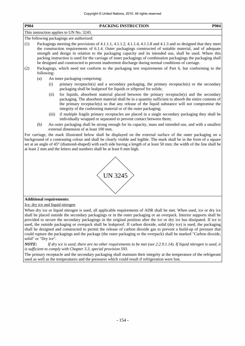
- 154 -
P904 PACKING INSTRUCTION P904This instruction applies to UN No. 3245. The following packagings are authorized: (1) Packagings meeting the provisions of 4.1.1.1, 4.1.1.2, 4.1.1.4, 4.1.1.8 and 4.1.3 and so designed that they meet
the construction requirements of 6.1.4. Outer packagings constructed of suitable material, and of adequate strength and design in relation to the packaging capacity and its intended use, shall be used. Where this packing instruction is used for the carriage of inner packagings of combination packagings the packaging shall be designed and constructed to prevent inadvertent discharge during normal conditions of carriage.
(2) Packagings, which need not conform to the packaging test requirements of Part 6, but conforming to the following:
(a) An inner packaging comprising: (i) primary receptacle(s) and a secondary packaging, the primary receptacle(s) or the secondary
packaging shall be leakproof for liquids or siftproof for solids; (ii) for liquids, absorbent material placed between the primary receptacle(s) and the secondary
packaging. The absorbent material shall be in a quantity sufficient to absorb the entire contents of the primary receptacle(s) so that any release of the liquid substance will not compromise the integrity of the cushioning material or of the outer packaging;
(iii) if multiple fragile primary receptacles are placed in a single secondary packaging they shall be individually wrapped or separated to prevent contact between them;
(b) An outer packaging shall be strong enough for its capacity, mass and intended use, and with a smallest external dimension of at least 100 mm.
For carriage, the mark illustrated below shall be displayed on the external surface of the outer packaging on a background of a contrasting colour and shall be clearly visible and legible. The mark shall be in the form of a square set at an angle of 45° (diamond-shaped) with each side having a length of at least 50 mm; the width of the line shall be at least 2 mm and the letters and numbers shall be at least 6 mm high. Additional requirements: Ice, dry ice and liquid nitrogen When dry ice or liquid nitrogen is used, all applicable requirements of ADR shall be met. When used, ice or dry ice shall be placed outside the secondary packagings or in the outer packaging or an overpack. Interior supports shall be provided to secure the secondary packagings in the original position after the ice or dry ice has dissipated. If ice is used, the outside packaging or overpack shall be leakproof. If carbon dioxide, solid (dry ice) is used, the packaging shall be designed and constructed to permit the release of carbon dioxide gas to prevent a build-up of pressure that could rupture the packagings and the package (the outer packaging or the overpack) shall be marked "Carbon dioxide, solid" or "Dry ice". NOTE: If dry ice is used, there are no other requirements to be met (see 2.2.9.1.14). If liquid nitrogen is used, it is sufficient to comply with Chapter 3.3, special provision 593. The primary receptacle and the secondary packaging shall maintain their integrity at the temperature of the refrigerant used as well as the temperatures and the pressures which could result if refrigeration were lost.
UN 3245
Copyright © United Nations, 2010. All rights reserved

- 155 -
P905 PACKING INSTRUCTION P905This instruction applies to UN Nos. 2990 and 3072. Any suitable packaging is authorized, provided the general provisions of 4.1.1 and 4.1.3 are met, except that packagings need not conform to the requirements of Part 6. When the life saving appliances are constructed to incorporate or are contained in rigid outer weatherproof casings (such as for lifeboats), they may be carried unpackaged. Additional requirements: 1. All dangerous substances and articles contained as equipment within the appliances shall be secured to
prevent inadvertent movement and in addition: (a) Signal devices of Class 1 shall be packed in plastics or fibreboard inner packagings; (b) Non-flammable, non-toxic gases shall be contained in cylinders as specified by the competent
authority, which may be connected to the appliance; (c) Electric storage batteries (Class 8) and lithium batteries (Class 9) shall be disconnected or electrically
isolated and secured to prevent any spillage of liquid; and (d) Small quantities of other dangerous substances (for example in Classes 3, 4.1 and 5.2) shall be packed
in strong inner packagings. 2. Preparation for transport and packaging shall include provisions to prevent any accidental inflation of the
appliance. P906 PACKING INSTRUCTION P906This instruction applies to UN Nos. 2315, 3151, 3152 and 3432. The following packagings are authorized, provided the general provisions of 4.1.1 and 4.1.3 are met: (1) For liquids and solids containing or contaminated with PCBs or polyhalogenated biphenyls or terphenyls:
Packagings in accordance with P001 or P002, as appropriate; (2) For transformers and condensers and other devices: Leakproof packagings which are capable of containing, in
addition to the devices, at least 1.25 times the volume of the liquid PCBs or polyhalogenated biphenyls or terphenyls present in them. There shall be sufficient absorbent material in the packagings to absorb at least 1.1 times the volume of liquid which is contained in the devices. In general, transformers and condensers shall be carried in leakproof metal packagings which are capable of holding, in addition to the transformers and condensers, at least 1.25 times the volume of the liquid present in them.
Notwithstanding the above, liquids and solids not packaged in accordance with P001 and P002 and unpackaged transformers and condensers may be carried in cargo transport units fitted with a leakproof metal tray to a height of at least 800 mm, containing sufficient inert absorbent material to absorb at least 1.1 times the volume of any free liquid. Additional requirement: Adequate provisions shall be taken to seal the transformers and condensers to prevent leakage during normal conditions of carriage.
Copyright © United Nations, 2010. All rights reserved

- 156 -
R001 PACKING INSTRUCTION R001The following packagings are authorized provided the general provisions of 4.1.1 and 4.1.3 are met:
Maximum capacity/maximum net mass Light gauge metal packagings
Packing group I Packing group II Packing group III
steel, non-removable head (0A1) Not allowed 40 l / 50 kg 40 l / 50 kg
steel, removable head (0A2) a Not allowed 40 l / 50 kg 40 l / 50 kg
a Not allowed for UN No. 1261 NITROMETHANE. NOTE 1: This instruction applies to solids and liquids (provided the design type is tested and marked appropriately). NOTE 2: For Class 3, packing group II, these packagings may be used only for substances with no subsidiary risk and a vapour pressure of not more than 110 kPa at 50 °C and for slightly toxic pesticides.
Copyright © United Nations, 2010. All rights reserved

- 157 -
4.1.4.2 Packing instructions concerning the use of IBCs IBC01 PACKING INSTRUCTION IBC01
The following IBCs are authorized, provided the general provisions of 4.1.1, 4.1.2 and 4.1.3 are met: Metal (31A, 31B and 31N). Special packing provision specific to RID and ADR: BB1 For UN No. 3130, the openings of receptacles for this substance shall be tightly closed by means of two
devices in series, one of which shall be screwed or secured in an equivalent manner. IBC02 PACKING INSTRUCTION IBC02
The following IBCs are authorized, provided the general provisions of 4.1.1, 4.1.2 and 4.1.3 are met: (1) Metal (31A, 31B and 31N); (2) Rigid plastics (31H1 and 31H2); (3) Composite (31HZ1). Special packing provisions: B5 For UN Nos. 1791, 2014, 2984 and 3149, IBCs shall be provided with a device to allow venting during
carriage. The inlet to the venting device shall be sited in the vapour space of the IBC under maximum filling conditions during carriage.
B7 For UN Nos. 1222 and 1865, IBCs with a capacity greater than 450 litres are not permitted due to the
substance’s potential for explosion when carried in large volumes. B8 The pure form of this substance shall not be transported in IBCs since it is known to have a vapour pressure
of more than 110 kPa at 50 °C or 130 kPa at 55 °C. B15 For UN No. 2031 with more than 55% nitric acid, the permitted use of rigid plastics IBCs and of composite
IBCs with a rigid plastics inner receptacle shall be two years from their date of manufacture. Special packing provision specific to RID and ADR: BB2 For UN No.1203, notwithstanding special provision 534 (see 3.3.1), IBCs shall only be used when the actual
vapour pressure is not more than 110 kPa at 50 ºC, or 130 kPa at 55 ºC. IBC03 PACKING INSTRUCTION IBC03
The following IBCs are authorized, provided the general provisions of 4.1.1, 4.1.2 and 4.1.3 are met: (1) Metal (31A, 31B and 31N); (2) Rigid plastics (31H1 and 31H2); (3) Composite (31HZ1, 31HA2, 31HB2, 31HN2, 31HD2 and 31HH2). Special packing provision: B8 The pure form of this substance shall not be carried in IBCs since it is known to have a vapour pressure of
more than 110 kPa at 50 °C or 130 kPa at 55 °C. IBC04 PACKING INSTRUCTION IBC04
The following IBCs are authorized, provided the general provisions of 4.1.1, 4.1.2 and 4.1.3 are met: Metal (11A, 11B, 11N, 21A, 21B and 21N).
Copyright © United Nations, 2010. All rights reserved

- 158 -
IBC05 PACKING INSTRUCTION IBC05
The following IBCs are authorized, provided the general provisions of 4.1.1, 4.1.2 and 4.1.3 are met: (1) Metal (11A, 11B, 11N, 21A, 21B and 21N); (2) Rigid plastics (11H1, 11H2, 21H1 and 21H2); (3) Composite (11HZ1 and 21HZ1).
IBC06 PACKING INSTRUCTION IBC06
The following IBCs are authorized, provided the general provisions of 4.1.1, 4.1.2 and 4.1.3 are met: (1) Metal (11A, 11B, 11N, 21A, 21B and 21N); (2) Rigid plastics (11H1, 11H2, 21H1 and 21H2); (3) Composite (11HZ1, 11HZ2, 21HZ1 and 21HZ2). Additional requirement: Where the solid may become liquid during carriage see 4.1.3.4. Special packing provisions: B12 For UN No. 2907, IBCs shall meet the packing group II performance level. IBCs meeting the test criteria of
packing group I shall not be used. IBC07 PACKING INSTRUCTION IBC07
The following IBCs are authorized, provided the general provisions of 4.1.1, 4.1.2 and 4.1.3 are met: (1) Metal (11A, 11B, 11N, 21A, 21B and 21N); (2) Rigid plastics (11H1, 11H2, 21H1 and 21H2); (3) Composite (11HZ1, 11HZ2, 21HZ1 and 21HZ2); (4) Wooden (11C, 11D and 11F). Additional requirements: 1. Where the solid may become liquid during carriage see 4.1.3.4. 2. Liners of wooden IBCs shall be siftproof.
Copyright © United Nations, 2010. All rights reserved

- 159 -
IBC08 PACKING INSTRUCTION IBC08
The following IBCs are authorized, provided the general provisions of 4.1.1, 4.1.2 and 4.1.3 are met: (1) Metal (11A, 11B, 11N, 21A, 21B and 21N); (2) Rigid plastics (11H1, 11H2, 21H1 and 21H2); (3) Composite (11HZ1, 11HZ2, 21HZ1 and 21HZ2); (4) Fibreboard (11G); (5) Wooden (11C, 11D and 11F); (6) Flexible (13H1, 13H2, 13H3, 13H4, 13H5, 13L1, 13L2, 13L3, 13L4, 13M1 and 13M2). Additional requirement: Where the solid may become liquid during carriage see 4.1.3.4. Special packing provisions: B3 Flexible IBCs shall be sift-proof and water-resistant or shall be fitted with a sift-proof and water-restistant
liner. B4 Flexible, fibreboard or wooden IBCs shall be sift-proof and water-resistant or shall be fitted with a sift-proof
and water-resistant liner. B6 For UN Nos. 1363, 1364, 1365, 1386, 1408, 1841, 2211, 2217, 2793 and 3314, IBCs are not required to meet
the IBC testing requirements of Chapter 6.5. B13 Note: For UN Nos. 1748, 2208, 2880, 3485, 3486 and 3487, carriage by sea in IBCs is prohibited according
to the IMDG Code. IBC99 PACKING INSTRUCTION IBC99
Only IBCs which are approved for these goods by the competent authority may be used. A copy of the competent authority approval shall accompany each consignment or the transport document shall include an indication that the packaging was approved by the competent authority.
Copyright © United Nations, 2010. All rights reserved

- 160 -
IBC100 PACKING INSTRUCTION IBC100
This instruction applies to UN Nos. 0082, 0241, 0331 and 0332. The following IBCs are authorized, provided the general provisions of 4.1.1, 4.1.2 and 4.1.3 and special provisions of 4.1.5 are met: (1) Metal (11A, 11B, 11N, 21A, 21B, 21N, 31A, 31B and 31N); (2) Flexible (13H2, 13H3, 13H4, 13L2, 13L3, 13L4 and 13M2); (3) Rigid plastics (11H1, 11H2, 21H1, 21H2, 31H1 and 31H2); (4) Composite (11HZ1, 11HZ2, 21HZ1, 21HZ2, 31HZ1 and 31HZ2). Additional requirements: 1. IBCs shall only be used for free flowing substances. 2. Flexible IBCs shall only be used for solids. Special packing provisions: B9 For UN No. 0082, this packing instruction may only be used when the substances are mixtures of ammonium
nitrate or other inorganic nitrates with other combustible substances which are not explosive ingredients. Such explosives shall not contain nitroglycerin, similar liquid organic nitrates, or chlorates. Metal IBCs are not authorized.
B10 For UN No. 0241, this packing instruction may only be used for substances which consist of water as an
essential ingredient and high proportions of ammonium nitrate or other oxidizing substances some or all of which are in solution. The other constituents may include hydrocarbons or aluminium powder, but shall not include nitro-derivatives such as trinitrotoluene. Metal IBCs are not authorized.
Copyright © United Nations, 2010. All rights reserved

- 161 -
IBC520 PACKING INSTRUCTION IBC520
This instruction applies to organic peroxides and self-reactive substances of type F. The IBCs listed below are authorized for the formulations listed, provided the general provisions of 4.1.1, 4.1.2 and 4.1.3 and special provisions of 4.1.7.2 are met. For formulations not listed below, only IBCs which are approved by the competent authority may be used (see 4.1.7.2.2). UN No. Organic peroxide Type of
IBC Maximum quantity
(litres/kg)
Control Tempe-rature
Emer-gencyTempera-
ture
3109 ORGANIC PEROXIDE, TYPE F, LIQUID tert-Butyl hydroperoxide, not more than 72% with water 31A 1 250 tert-Butyl peroxyacetate, not more than 32% in diluent
type A 31A
31HA1 1 250 1 000
tert-Butyl peroxybenzoate, not more than 32% in diluent type A
31A 1 250
tert-Butyl peroxy-3,5,5-trimethylhexanoate, not more than 37% in diluent type A
31A 31HA1
1 250 1 000
Cumyl hydroperoxide, not more than 90% in diluent type A
31HA1 1 250
Dibenzoyl peroxide, not more than 42% as a stable dispersion in water
31H1 1 000
Di-tert-butyl peroxide, not more than 52% in diluent type A
31A 31HA1
1 250 1 000
1,1-Di-(tert-butylperoxy) cyclohexane, not more than 42% in diluent type A
31H1 1 000
1,1-Di-(tert-butylperoxy) cyclohexane, not more than 37% in diluent type A
31A 1 250
Dilauroyl peroxide, not more than 42%, stable dispersion, in water
31HA1 1 000
Isopropyl cumyl hydroperoxide, not more than 72% in diluent type A
31HA1 1 250
p-Menthyl hydroperoxide, not more than 72% in diluent type A
31HA1 1 250
Peroxyacetic acid, stabilized, not more than 17% 31A 31H1 31H2
31HA1
1 500 1 500 1 500 1 500
3110 ORGANIC PEROXIDE, TYPE F, SOLID Dicumyl peroxide 31A
31H1 31HA1
2 000
3119 ORGANIC PEROXIDE, TYPE F, LIQUID, TEMPERATURE CONTROLLED
tert-Amyl peroxypivalate, not more than 32% in diluent type A
31A 1 250 +10 °C +15 °C
tert-Butyl peroxy-2-ethylhexanoate, not more than 32% in diluent type B
31HA1 31A
1 000 1 250
+30 °C +30 °C
+35 °C +35 °C
tert-Butyl peroxyneodecanoate, not more than 32% in diluent type A
31A 1 250 0 °C +10 °C
tert-Butyl peroxyneodecanoate, not more than 52%, stable dispersion, in water
31A 1 250 -5 °C +5 °C
tert-Butyl peroxypivalate, not more than 27% in diluent type B
31HA1 31A
1 000 1 250
+10 °C +10 °C
+15 °C +15 °C
Cumyl peroxyneodecanoate, not more than 52%, stable dispersion, in water
31A 1 250 -15 °C - 5 °C
(Cont'd on next page)
Copyright © United Nations, 2010. All rights reserved

- 162 -
IBC520 PACKING INSTRUCTION (cont’d) IBC520
UN No. Organic peroxide Type of IBC
Maximum quantity (litres)
Control Tempe-rature
Emer-gencyTempera-
ture
3119 (cont'd)
tert-Butyl peroxyneodecanoate, not more than 42% stable dispersion, in water
31A 1 250 - 5 °C + 5 °C
Di-(4-tert-butylcyclohexyl) peroxydicarbonate, not more than 42%, stable dispersion, in water
31HA1 1 000 +30 °C +35 °C
Dicetyl peroxydicarbonate, not more than 42%, stable dispersion, in water
31HA1 1 000 +30 °C +35 °C
Di-(2-neodecanoylperoxyisopropyl)benzene, not more than 42%, stable dispersion, in water
31A 1 250 -15 °C -5 °C
3-Hydroxy-1,1-dimethylbutyl peroxyneodecanoate, not more than 52%, stable dispersion, in water
31A 1 250 -15 °C -5 °C
Di-(2-ethylhexyl) peroxydicarbonate, not more than 62%, stable dispersion, in water
31A 1 250 -20 °C -10 °C
Dimyristyl peroxydicarbonate, not more than 42%, stable dispersion, in water
31HA1 1 000 +15 °C +20 °C
Di-(3,5,5-trimethylhexanoyl) peroxide, not more than 38% in diluent type A
31HA1 31A
1 000 1 250
+10 °C +10 °C
+15 °C +15 °C
Di-(3,5,5-trimethylhexanoyl) peroxide, not more than 52%, stable dispersion, in water
31A 1 250 +10 °C +15 °C
1,1,3,3-Tetramethylbutyl peroxyneodecanoate, not more than 52%, stable dispersion, in water
31A 1 250 - 5 °C + 5 °C
Dicyclohexylperoxydicarbonate, not more than 42% as a stable dispersion, in water
31A 1 250 +10 °C +15 °C
3120 ORGANIC PEROXIDE, TYPE F, SOLID, TEMPERATURE CONTROLLED No formulation listed
Additional requirements: 1. IBCs shall be provided with a device to allow venting during carriage. The inlet to the pressure-relief device
shall be sited in the vapour space of the IBC under maximum filling conditions during carriage. 2. To prevent explosive rupture of metal IBCs or composite IBCs with complete metal casing, the
emergency-relief devices shall be designed to vent all the decomposition products and vapours evolved during self-accelerating decomposition or during a period of not less than one hour of fire-engulfment as calculated by the formula in 4.2.1.13.8. The control and emergency temperatures specified in this packing instruction are based on a non-insulated IBC. When consigning an organic peroxide in an IBC in accordance with this instruction, it is the responsibility of the consignor to ensure that:
(a) the pressure and emergency relief devices installed on the IBC are designed to take appropriate account
of the self-accelerating decomposition of the organic peroxide and of fire-engulfment; and (b) when applicable, the control and emergency temperatures indicated are appropriate, taking into account
the design (e.g. insulation) of the IBC to be used. IBC620 PACKING INSTRUCTION IBC620
This instruction applies to UN No. 3291. The following IBCs are authorized, provided the general provisions of 4.1.1, except 4.1.1.15, 4.1.2 and 4.1.3 are met: Rigid, leakproof IBCs conforming to the packing group II performance level. Additional requirements: 1. There shall be sufficient absorbent material to absorb the entire amount of liquid present in the IBC. 2. IBCs shall be capable of retaining liquids. 3. IBCs intended to contain sharp objects such as broken glass and needles shall be resistant to puncture.
Copyright © United Nations, 2010. All rights reserved

- 163 -
4.1.4.3 Packing instructions concerning the use of large packagings LP01 PACKING INSTRUCTION (LIQUIDS) LP01The following large packagings are authorized provided the general provision of 4.1.1 and 4.1.3 are met:
Inner packagings Large outer packagings Packing group I Packing group II Packing group IIIGlass 10 litres Steel (50A) Plastics 30 litres Aluminium (50B) Metal 40 litres Metal other than steel or
aluminium (50N) Rigid plastics (50H) Natural wood (50C) Plywood (50D) Reconstituted wood (50F) Fibreboard (50G)
Not allowed Not allowed Maximum capacity: 3 m3
LP02 PACKING INSTRUCTION (SOLIDS) LP02The following large packagings are authorized provided the general provisions of 4.1.1 and 4.1.3 are met:
Inner packagings Large outer packagings Packing group I Packing group II Packing group IIIGlass 10 kg Steel (50A) Plastics b 50 kg Aluminium (50B) Metal 50 kg Paper a, b 50 kg
Metal other than steel or aluminium (50N)
Fibre a, b 50 kg Rigid plastics (50H) Natural wood (50C) Plywood (50D) Reconstituted wood (50F) Fibreboard (50G) Flexible plastics (51H) c
Not allowed Not allowed Maximum capacity: 3 m3
a These inner packagings shall not be used when the substances being carried may become liquid during carriage. b These inner packagings shall be sift-proof. c To be used with flexible inner packagings only. Special packing provision: L2 For UN 1950 aerosols, the large packaging shall meet the packing group III performance level. Large
packagings for waste aerosols carried in accordance with special provision 327 shall have in addition a means of retaining any free liquid that might escape during carriage e.g. absorbent material.
LP99 PACKING INSTRUCTION LP99
Only large packagings which are approved for these goods by the competent authority may be used. A copy of the competent authority approval shall accompany each consignment or the transport document shall include an indication that the packaging was approved by the competent authority.
Copyright © United Nations, 2010. All rights reserved

- 164 -
LP101 PACKING INSTRUCTION LP101
The following packagings are authorized, provided the general provisions of 4.1.1 and 4.1.3 and special provisions of 4.1.5 are met: Inner packagings Intermediate packagings Large packagings
Not necessary
Not necessary
Steel (50A) Aluminium (50B) Metal other than steel or aluminium (50N) Rigid plastics (50H) Natural wood (50C) Plywood (50D) Reconstituted wood (50F) Fibreboard (50G)
Special packing provision: L1 For UN Nos. 0006, 0009, 0010, 0015, 0016, 0018, 0019, 0034, 0035, 0038, 0039, 0048, 0056, 0137, 0138,
0168, 0169, 0171, 0181, 0182, 0183, 0186, 0221, 0243, 0244, 0245, 0246, 0254, 0280, 0281, 0286, 0287, 0297, 0299, 0300, 0301, 0303, 0321, 0328, 0329, 0344, 0345, 0346, 0347, 0362, 0363, 0370, 0412, 0424, 0425, 0434, 0435, 0436, 0437, 0438, 0451, 0488 and 0502:
Large and robust explosives articles, normally intended for military use, without their means of initiation or with their means of initiation containing at least two effective protective features, may be carried unpackaged. When such articles have propelling charges or are self-propelled, their ignition systems shall be protected against stimuli encountered during normal conditions of carriage. A negative result in Test Series 4 on an unpackaged article indicates that the article can be considered for carriage unpackaged. Such unpackaged articles may be fixed to cradles or contained in crates or other suitable handling devices.
LP102 PACKING INSTRUCTION LP102
The following packagings are authorized, provided the general provisions of 4.1.1 and 4.1.3 and special provisions of 4.1.5 are met: Inner packagings Intermediate packagings Outer packagings
Bags water resistant Receptacles fibreboard metal plastics wood Sheets fibreboard, corrugated Tubes fibreboard
Not necessary
Steel (50A) Aluminium (50B) Metal other than steel or aluminium (50N) Rigid plastics (50H) Natural wood (50C) Plywood (50D) Reconstituted wood (50F) Fibreboard (50G)
Copyright © United Nations, 2010. All rights reserved

- 165 -
LP621 PACKING INSTRUCTION LP621
This instruction applies to UN No. 3291. The following large packagings are authorized, provided the general provisions of 4.1.1 and 4.1.3 are met: (1) For clinical waste placed in inner packagings: Rigid, leakproof large packagings conforming to the
requirements of Chapter 6.6 for solids, at the packing group II performance level, provided there is sufficient absorbent material to absorb the entire amount of liquid present and the large packaging is capable of retaining liquids;
(2) For packages containing larger quantities of liquid: Large rigid packagings conforming to the requirements of
Chapter 6.6, at the packing group II performance level, for liquids. Additional requirement: Large packagings intended to contain sharp objects such as broken glass and needles shall be resistant to puncture and retain liquids under the performance test conditions in Chapter 6.6.
LP902 PACKING INSTRUCTION LP902
This instruction applies to UN No. 3268. The following packagings are authorized, provided the general provisions of 4.1.1 and 4.1.3 are met:
Packagings conforming to the packing group III performance level. The packagings shall be designed and constructed to prevent movement of the articles and inadvertent operation during normal conditions of carriage.
The articles may also be carried unpackaged in dedicated handling devices, vehicles, or containers when moved from where they are manufactured to an assembly plant.
Additional requirement:
Any pressure vessel shall be in accordance with the requirements of the competent authority for the substance(s) contained in the pressure vessel(s).
4.1.4.4 (Deleted)
Copyright © United Nations, 2010. All rights reserved

- 166 -
4.1.5 Special packing provisions for goods of Class 1 4.1.5.1 The general provisions of Section 4.1.1 shall be met. 4.1.5.2 All packagings for Class 1 goods shall be so designed and constructed that:
(a) They will protect the explosives, prevent them escaping and cause no increase in the risk of unintended ignition or initiation when subjected to normal conditions of carriage including foreseeable changes in temperature, humidity and pressure;
(b) The complete package can be handled safely in normal conditions of carriage; and
(c) The packages will withstand any loading imposed on them by foreseeable stacking to which they will be subject during carriage so that they do not add to the risk presented by the explosives, the containment function of the packagings is not harmed, and they are not distorted in a way or to an extent which will reduce their strength or cause instability of a stack.
4.1.5.3 All explosive substances and articles, as prepared for carriage, shall have been classified in
accordance with the procedures detailed in 2.2.1. 4.1.5.4 Class 1 goods shall be packed in accordance with the appropriate packing instruction shown
in Column (8) of Table A of Chapter 3.2, as detailed in 4.1.4. 4.1.5.5 Unless otherwise specified in ADR, packagings, including IBCs and large packagings, shall
conform to the requirements of chapters 6.1, 6.5 or 6.6, as appropriate, and shall meet their test requirements for packing group II.
4.1.5.6 The closure device of packagings containing liquid explosives shall ensure a double
protection against leakage. 4.1.5.7 The closure device of metal drums shall include a suitable gasket; if a closure device
includes a screw-thread, the ingress of explosive substances into the screw-thread shall be prevented.
4.1.5.8 Packagings for water soluble substances shall be water resistant. Packagings for desensitized
or phlegmatized substances shall be closed to prevent changes in concentration during carriage.
4.1.5.9 When the packaging includes a double envelope filled with water which may freeze during
transport, a sufficient quantity of an anti-freeze agent shall be added to the water to prevent freezing. Anti-freeze that could create a fire hazard because of its inherent flammability shall not be used.
4.1.5.10 Nails, staples and other closure devices made of metal without protective covering shall not
penetrate to the inside of the outer packaging unless the inner packaging adequately protects the explosives against contact with the metal.
4.1.5.11 Inner packagings, fittings and cushioning materials and the placing of explosive substances
or articles in packages shall be accomplished in a manner which prevents the explosive substances or articles from becoming loose in the outer packaging under normal conditions of carriage. Metallic components of articles shall be prevented from making contact with metal packagings. Articles containing explosive substances not enclosed in an outer casing shall be separated from each other in order to prevent friction and impact. Padding, trays, partitioning in the inner or outer packaging, mouldings or receptacles may be used for this purpose.
Copyright © United Nations, 2010. All rights reserved

- 167 -
4.1.5.12 Packagings shall be made of materials compatible with, and impermeable to, the explosives contained in the package, so that neither interaction between the explosives and the packaging materials, nor leakage, causes the explosive to become unsafe to carriage, or the hazard division or compatibility group to change.
4.1.5.13 The ingress of explosive substances into the recesses of seamed metal packagings shall be
prevented. 4.1.5.14 Plastics packagings shall not be liable to generate or accumulate sufficient static electricity
so that a discharge could cause the packaged explosive substances or articles to initiate, ignite or function.
4.1.5.15 Large and robust explosives articles, normally intended for military use, without their means
of initiation or with their means of initiation containing at least two effective protective features, may be carried unpackaged. When such articles have propelling charges or are self-propelled, their ignition systems shall be protected against stimuli encountered during normal conditions of carriage. A negative result in Test Series 4 on an unpackaged article indicates that the article can be considered for carriage unpackaged. Such unpackaged articles may be fixed to cradles or contained in crates or other suitable handling, storage or launching devices in such a way that they will not become loose during normal conditions of carriage.
Where such large explosive articles are as part of their operational safety and suitability tests
subjected to test regimes that meet the intentions of ADR and such tests have been successfully undertaken, the competent authority may approve such articles to be carried in accordance with ADR.
4.1.5.16 Explosive substances shall not be packed in inner or outer packagings where the differences
in internal and external pressures, due to thermal or other effects, could cause an explosion or rupture of the package.
4.1.5.17 Whenever loose explosive substances or the explosive substance of an uncased or partly
cased article may come into contact with the inner surface of metal packagings (1A2, 1B2, 4A, 4B and metal receptacles), the metal packaging shall be provided with an inner liner or coating (see 4.1.1.2).
4.1.5.18 Packing instruction P101 may be used for any explosive provided the packaging has been
approved by a competent authority regardless of whether the packaging complies with the packing instruction assignment in Column (8) of Table A of Chapter 3.2.
4.1.6 Special packing provisions for goods of Class 2 and goods of other classes assigned to
packing instruction P200 4.1.6.1 This section provides general requirements applicable to the use of pressure receptacles and
open cryogenic receptacles for the carriage of Class 2 substances and goods of other classes assigned to packing instruction P200 (e.g. UN 1051 hydrogen cyanide, stabilized). Pressure receptacles shall be constructed and closed so as to prevent any loss of contents which might be caused under normal conditions of carriage, including by vibration, or by changes in temperature, humidity or pressure (resulting from change in altitude, for example).
4.1.6.2 Parts of pressure receptacles and open cryogenic receptacles which are in direct contact with
dangerous goods shall not be affected or weakened by those dangerous goods and shall not cause a dangerous effect (e.g. catalysing a reaction or reacting with the dangerous goods) (see also table of standards at the end of this section).
Copyright © United Nations, 2010. All rights reserved

- 168 -
4.1.6.3 Pressure receptacles, including their closures and open cryogenic receptacles, shall be selected to contain a gas or a mixture of gases according to the requirements of 6.2.1.2 and the requirements of the relevant packing instructions of 4.1.4.1. This sub-section also applies to pressure receptacles which are elements of MEGCs and battery-vehicles.
4.1.6.4 A change of use of a refillable pressure receptacle shall include emptying, purging and
evacuation operations to the extent necessary for safe operation (see also table of standards at the end of this section). In addition, a pressure receptacle that previously contained a Class 8 corrosive substance or a substance of another class with a corrosive subsidiary risk shall not be authorized for the carriage of a Class 2 substance unless the necessary inspection and testing as specified in 6.2.1.6 and 6.2.3.5 respectively have been performed.
4.1.6.5 Prior to filling, the packer shall perform an inspection of the pressure receptacle or open
cryogenic receptacle and ensure that the pressure receptacle or open cryogenic receptacle is authorized for the substance to be carried and that the requirements have been met. Shut-off valves shall be closed after filling and remain closed during carriage. The consignor shall verify that the closures and equipment are not leaking.
NOTE: Shut-off valves fitted to individual cylinders in bundles may be open during carriage, unless the substance carried is subject to special packing provision ‘k’ or ‘q’ in packing provision P200.
4.1.6.6 Pressure receptacles and open cryogenic receptacles shall be filled according to the working pressures, filling ratios and provisions specified in the appropriate packing instruction for the specific substance being filled. Reactive gases and gas mixtures shall be filled to a pressure such that if complete decomposition of the gas occurs, the working pressure of the pressure receptacle shall not be exceeded. Bundles of cylinders shall not be filled in excess of the lowest working pressure of any given cylinder in the bundle.
4.1.6.7 Pressure receptacles, including their closures, shall conform to the design, construction,
inspection and testing requirements detailed in Chapter 6.2. When outer packagings are prescribed, the pressure receptacles and open cryogenic receptacles shall be firmly secured therein. Unless otherwise specified in the detailed packing instructions, one or more inner packagings may be enclosed in one outer packaging.
4.1.6.8 Valves shall be designed and constructed in such a way that they are inherently able to
withstand damage without release of the contents or shall be protected from damage which could cause inadvertent release of the contents of the pressure receptacle, by one of the following methods (see also table of standards at the end of this section):
(a) Valves are placed inside the neck of the pressure receptacle and protected by a
threaded plug or cap;
(b) Valves are protected by caps. Caps shall possess vent-holes of sufficient cross-sectional area to evacuate the gas if leakage occurs at the valves;
(c) Valves are protected by shrouds or guards;
(d) Pressure receptacles are carried in frames, (e.g. cylinders in bundles); or
(e) Pressure receptacles are carried in protective boxes. For UN pressure receptacles the packaging as prepared for carriage shall be capable of meeting the drop test specified in 6.1.5.3 at the packing group I performance level.
Copyright © United Nations, 2010. All rights reserved

- 169 -
4.1.6.9 Non-refillable pressure receptacles shall:
(a) be carried in an outer packaging, such as a box or crate, or in shrink-wrapped or stretch-wrapped trays;
(b) be of a water capacity less than or equal to 1.25 litres when filled with flammable or toxic gas;
(c) not be used for toxic gases with an LC50 less than or equal to 200 ml/m3; and
(d) not be repaired after being put into service.
4.1.6.10 Refillable pressure receptacles, other than cryogenic receptacles, shall be periodically inspected according to the provisions of 6.2.1.6, or 6.2.3.5.1 for non UN receptacles, and packing instruction P200 or P205 as applicable. Pressure receptacles shall not be filled after they become due for periodic inspection but may be carried after the expiry of the time-limit for purposes of performing inspection or disposal, including the intermediate carriage operations.
4.1.6.11 Repairs shall be consistent with the fabrication and testing requirements of the applicable
design and construction standards and are only permitted as indicated in the relevant periodic inspection standards specified in chapter 6.2. Pressure receptacles, other than the jacket of closed cryogenic receptacles, shall not be subjected to repairs of any of the following:
(a) weld cracks or other weld defects;
(b) cracks in walls;
(c) leaks or defects in the material of the wall, head or bottom. 4.1.6.12 Receptacles shall not be offered for filling:
(a) when damaged to such an extent that the integrity of the receptacle or its service equipment may be affected;
(b) unless the receptacle and its service equipment has been examined and found to be in good working order; and
(c) unless the required certification, retest, and filling markings are legible.
4.1.6.13 Filled receptacles shall not be offered for carriage:
(a) when leaking;
(b) when damaged to such an extent that the integrity of the receptacle or its service equipment may be affected;
(c) unless the receptacle and its service equipment has been examined and found to be in good working order; and
(d) unless the required certification, retest, and filling markings are legible.
4.1.6.14 Owners shall, on the basis of a reasoned request from the competent authority, provide it with all the information necessary to demonstrate the conformity of the pressure receptacle in a language easily understood by the competent authority. They shall cooperate with that authority, at its request, on any action taken to eliminate non-conformity of the pressure receptacles which they own.
Copyright © United Nations, 2010. All rights reserved

- 170 -
4.1.6.15 For UN pressure receptacles, the ISO standards listed below shall be applied. For other pressure receptacles, the requirements of section 4.1.6 are considered to have been complied with if the following standards, as relevant, are applied:
Applicable paragraphs
Reference Title of document
ISO 11114-1:1997 Transportable gas cylinders – Compatibility of cylinder and valve materials with gas contents – Part 1: Metallic Materials
4.1.6.2
ISO 11114-2:2000 Transportable gas cylinders – Compatibility of cylinder and valve materials with gas contents – Part 2: Non-metallic Materials
4.1.6.4 ISO 11621:2005 Gas cylinders – Procedures for change of gas service Annex A of EN ISO 10297:2006
Gas cylinder – Refillable gas cylinder valves – Specification and type testing
EN 13152:2001 + A1:2003
Testing and specifications of LPG cylinder valves – self closing
4.1.6.8 Valves with inherent protection
EN 13153:2001 + A1:2003
Testing and specifications of LPG cylinder valves – manually operated
ISO 11117:1998 Gas Cylinders – Valve Protection caps and valve guards for industrial and medical gas cylinders – Design construction and tests
EN 962:1996 + A2:2000
Valve protection caps and valve guards for industrial and medical gas cylinders – Design, construction and tests
4.1.6.8 (b) and (c)
ISO 16111:2008 Transportable gas storage devices – Hydrogen absorbed in reversible metal hydride
4.1.7 Special packing provisions for organic peroxides (Class 5.2) and self-reactive
substances of Class 4.1 4.1.7.0.1 For organic peroxides, all receptacles shall be "effectively closed". Where significant
internal pressure may develop in a package by the evolution of a gas, a vent may be fitted, provided the gas emitted will not cause danger, otherwise the degree of filling shall be limited. Any venting device shall be so constructed that liquid will not escape when the package is in an upright position and it shall be able to prevent ingress of impurities. The outer packaging, if any, shall be so designed as not to interfere with the operation of the venting device.
4.1.7.1 Use of packagings (except IBCs) 4.1.7.1.1 Packagings for organic peroxides and self-reactive substances shall conform to the
requirements of Chapter 6.1 and shall meet its test requirements for packing group II. 4.1.7.1.2 The packing methods for organic peroxides and self-reactive substances are listed in packing
instruction 520 and are designated OP1 to OP8. The quantities specified for each packing method are the maximum quantities authorized per package.
4.1.7.1.3 The packing methods appropriate for the individual currently assigned organic peroxides and
self-reactive substances are listed in 2.2.41.4 and 2.2.52.4. 4.1.7.1.4 For new organic peroxides, new self-reactive substances or new formulations of currently
assigned organic peroxides or self-reactive substances, the following procedure shall be used to assign the appropriate packing method:
Copyright © United Nations, 2010. All rights reserved

- 171 -
(a) ORGANIC PEROXIDE, TYPE B or SELF-REACTIVE SUBSTANCE, TYPE B: Packing method OP5 shall be assigned, provided that the organic peroxide (or self-
reactive substance) satisfies the criteria of 20.4.3 (b) (resp. 20.4.2 (b)) of the Manual of Tests and Criteria in a packaging authorized by the packing method. If the organic peroxide (or self-reactive substance) can only satisfy these criteria in a smaller packaging than those authorized by packing method OP5 (viz. one of the packagings listed for OP1 to OP4), then the corresponding packing method with the lower OP number is assigned;
(b) ORGANIC PEROXIDE, TYPE C or SELF-REACTIVE SUBSTANCE, TYPE C: Packing method OP6 shall be assigned, provided that the organic peroxide (or self-
reactive substance) satisfies the criteria of 20.4.3 (c) (resp. 20.4.2 (c)) of the Manual of Tests and Criteria in a packaging authorized by the packing method. If the organic peroxide (or self-reactive substance) can only satisfy these criteria in a smaller packaging than those authorized by packing method OP6 then the corresponding packing method with the lower OP number is assigned;
(c) ORGANIC PEROXIDE, TYPE D or SELF-REACTIVE SUBSTANCE, TYPE D: Packing method OP7 shall be assigned to this type of organic peroxide or self-reactive
substance; (d) ORGANIC PEROXIDE, TYPE E or SELF-REACTIVE SUBSTANCE, TYPE E: Packing method OP8 shall be assigned to this type of organic peroxide or self-reactive
substance; (e) ORGANIC PEROXIDE, TYPE F or SELF-REACTIVE SUBSTANCE, TYPE F: Packing method OP8 shall be assigned to this type of organic peroxide or self-reactive
substance. 4.1.7.2 Use of intermediate bulk containers 4.1.7.2.1 The currently assigned organic peroxides specifically listed in packing instruction IBC520
may be carried in IBCs in accordance with this packing instruction. IBCs shall conform to the requirements of Chapter 6.5 and shall meet its test requirements for packing group II.
4.1.7.2.2 Other organic peroxides and self-reactive substances of type F may be carried in IBCs under
conditions established by the competent authority of the country of origin when, on the basis of the appropriate tests, that competent authority is satisfied that such carriage may be safely conducted. The tests undertaken shall include those necessary:
(a) To prove that the organic peroxide (or self-reactive substance) complies with the
principles for classification given in 20.4.3 (f) [resp. 20.4.2 (f)] of the Manual of Tests and Criteria, exit box F of Figure 20.1 (b) of the Manual;
(b) To prove the compatibility of all materials normally in contact with the substance
during carriage; (c) To determine, when applicable, the control and emergency temperatures associated
with the carriage of the product in the IBC concerned as derived from the SADT; (d) To design, when applicable, pressure and emergency relief devices; and (e) To determine if any special provisions are necessary for safe carriage of the substance.
Copyright © United Nations, 2010. All rights reserved

- 172 -
If the country of origin is not a Contracting Party to ADR, the classification and transport conditions shall be recognized by the competent authority of the first country Contracting Party to ADR reached by the consignment.
4.1.7.2.3 Emergencies to be taken into account are self-accelerating decomposition and fire
engulfment. To prevent explosive rupture of metal or composite IBCs with a complete metal casing, the emergency-relief devices shall be designed to vent all the decomposition products and vapours evolved during self-accelerating decomposition or during a period of not less than one hour of complete fire engulfment calculated by the equations given in 4.2.1.13.8.
4.1.8 Special packing provisions for infectious substances (Class 6.2) 4.1.8.1 Consignors of infectious substances shall ensure that packages are prepared in such a manner
that they arrive at their destination in good condition and present no hazard to persons or animals during carriage.
4.1.8.2 The definitions in 1.2.1 and the general packing provisions of 4.1.1.1 to 4.1.1.16, except
4.1.1.3, 4.1.1.9 to 4.1.1.12 and 4.1.1.15 apply to infectious substances packages. However, liquids shall only be filled into packagings which have an appropriate resistance to the internal pressure that may develop under normal conditions of carriage.
4.1.8.3 An itemized list of contents shall be enclosed between the secondary packaging and the outer
packaging. When the infectious substances to be carried are unknown, but suspected of meeting the criteria for inclusion in Category A, the words "suspected Category A infectious substance" shall be shown, in parenthesis, following the proper shipping name on the document inside the outer packaging.
4.1.8.4 Before an empty packaging is returned to the consignor, or sent elsewhere, it shall be
disinfected or sterilized to nullify any hazard and any label or marking indicating that it had contained an infectious substance shall be removed or obliterated.
4.1.8.5 Provided an equivalent level of performance is maintained, the following variations in the
primary receptacles placed within a secondary packaging are allowed without the need for further testing of the completed packaging:
(a) Primary receptacles of equivalent or smaller size as compared to the tested primary
receptacles may be used provided:
(i) the primary receptacles are of similar design to the primary receptacle tested (e.g. shape: round, rectangular, etc.);
(ii) the material of construction of the primary receptacles (e.g. glass, plastics,
metal) offers resistance to impact and stacking forces equivalent to or better than that of the primary receptacles originally tested;
(iii) the primary receptacles have the same or smaller openings and the closure is of
equivalent design (e.g. screw cap, friction lid, etc.); (iv) sufficient additional cushioning material is used to take up empty spaces and to
prevent significant movement of the primary receptacles; and (v) primary receptacles are oriented within the secondary packagings in the same
manner as in the tested package;
Copyright © United Nations, 2010. All rights reserved

- 173 -
(b) A lesser number of the tested primary receptacles, or of the alternative types of primary receptacles identified in (a) above, may be used provided sufficient cushioning is added to fill the void space(s) and to prevent significant movement of the primary receptacles.
4.1.8.6 Paragraphs 4.1.8.1 to 4.1.8.5 only apply to infectious substances of Category A
(UN Nos. 2814 and 2900). They do not apply to UN No. 3373 BIOLOGICAL SUBSTANCE, CATEGORY B (see packing instruction P650 of 4.1.4.1), nor to UN No. 3291 CLINICAL WASTE, UNSPECIFIED, N.O.S. or (BIO) MEDICAL WASTE, N.O.S. or REGULATED MEDICAL WASTE, N.O.S.
4.1.8.7 For the carriage of animal material, packagings or IBCs not specifically authorized in the
applicable packing instruction shall not be used for the carriage of a substance or article unless specifically approved by the competent authority of the country of origin 2 and provided:
(a) The alternative packaging complies with the general requirements of this Part; (b) When the packing instruction indicated in Column (8) of Table A of Chapter 3.2 so
specifies, the alternative packaging meets the requirements of Part 6; (c) The competent authority of the country of origin 2 determines that the alternative
packaging provides at least the same level of safety as if the substance were packed in accordance with a method specified in the particular packing instruction indicated in Column (8) of Table A of Chapter 3.2; and
(d) A copy of the competent authority approval accompanies each consignment or the
transport document includes an indication that alternative packaging was approved by the competent authority.
4.1.9 Special packing provisions for Class 7 4.1.9.1 General 4.1.9.1.1 Radioactive material, packagings and packages shall meet the requirements of Chapter 6.4.
The quantity of radioactive material in a package shall not exceed the limits specified in 2.2.7.2.2, 2.2.7.2.4.1, 2.2.7.2.4.4, 2.2.7.2.4.5, 2.2.7.2.4.6, special provision 336 of Chapter 3.3 and 4.1.9.3.
The types of packages for radioactive materials covered by ADR, are: (a) Excepted package (see 1.7.1.5); (b) Industrial package Type 1 (Type IP-1 package); (c) Industrial package Type 2 (Type IP-2 package); (d) Industrial package Type 3 (Type IP-3 package); (e) Type A package; (f) Type B(U) package; (g) Type B(M) package; (h) Type C package. Packages containing fissile material or uranium hexafluoride are subject to additional requirements.
2 If the country of origin is not a Contracting Party to ADR, the competent authority of the first Contracting Party to the ADR reached by the consignment.
Copyright © United Nations, 2010. All rights reserved

- 174 -
4.1.9.1.2 The non-fixed contamination on the external surfaces of any package shall be kept as low as
practicable and, under routine conditions of transport, shall not exceed the following limits: (a) 4 Bq/cm2 for beta and gamma emitters and low toxicity alpha emitters; and (b) 0.4 Bq/cm2 for all other alpha emitters. These limits are applicable when averaged over any area of 300 cm2 of any part of the
surface. 4.1.9.1.3 A package, other than an excepted package, shall not contain any items other than those that
are necessary for the use of the radioactive material. The interaction between these items and the package under the conditions of carriage applicable to the design, shall not reduce the safety of the package.
4.1.9.1.4 Except as provided in 7.5.11, CV33, the level of non-fixed contamination on the external and
internal surfaces of overpacks, containers, tanks, IBCs and vehicles shall not exceed the limits specified in 4.1.9.1.2.
4.1.9.1.5 For radioactive material having other dangerous properties the package design shall take into
account those properties. Radioactive material with a subsidiary risk, packaged in packages that do not require competent authority approval, shall be carried in packagings, IBCs, tanks or bulk containers fully complying with the requirements of the relevant chapters of Part 6 as appropriate, as well as applicable requirements of chapters 4.1, 4.2 or 4.3 for that subsidiary risk.
4.1.9.1.6 Before the first shipment of any package, the following requirements shall be fulfilled:
(a) If the design pressure of the containment system exceeds 35 kPa (gauge), it shall be ensured that the containment system of each package conforms to the approved design requirements relating to the capability of that system to maintain its integrity under that pressure;
(b) For each Type B(U), Type B(M) and Type C package and for each package containing
fissile material, it shall be ensured that the effectiveness of its shielding and containment and, where necessary, the heat transfer characteristics and the effectiveness of the confinement system, are within the limits applicable to or specified for the approved design;
(c) For packages containing fissile material, where, in order to comply with the
requirements of 6.4.11.1, neutron poisons are specifically included as components of the package, checks shall be performed to confirm the presence and distribution of those neutron poisons.
4.1.9.1.7 Before each shipment of any package, the following requirements shall be fulfilled:
(a) For any package it shall be ensured that all the requirements specified in the relevant provisions of ADR have been satisfied;
(b) It shall be ensured that lifting attachments which do not meet the requirements of
6.4.2.2 have been removed or otherwise rendered incapable of being used for lifting the package, in accordance with 6.4.2.3;
(c) For each package requiring competent authority approval, it shall be ensured that all
the requirements specified in the approval certificates have been satisfied;
Copyright © United Nations, 2010. All rights reserved

- 175 -
(d) Each Type B(U), Type B(M) and Type C package shall be held until equilibrium conditions have been approached closely enough to demonstrate compliance with the requirements for temperature and pressure unless an exemption from these requirements has received unilateral approval;
(e) For each Type B(U), Type B(M) and Type C package, it shall be ensured by
inspection and/or appropriate tests that all closures, valves, and other openings of the containment system through which the radioactive contents might escape are properly closed and, where appropriate, sealed in the manner for which the demonstrations of compliance with the requirements of 6.4.8.8 and 6.4.10.3 were made;
(f) For each special form radioactive material, it shall be ensured that all the requirements
specified in the approval certificate and the relevant provisions of ADR have been satisfied;
(g) For packages containing fissile material the measurement specified in 6.4.11.4 (b) and
the tests to demonstrate closure of each package as specified in 6.4.11.7 shall be performed where applicable;
(h) For each low dispersible radioactive material, it shall be ensured that all the
requirements specified in the approval certificate and the relevant provisions of ADR have been satisfied.
4.1.9.1.8 The consignor shall also have a copy of any instructions with regard to the proper closing of
the package and any preparation for shipment before making any shipment under the terms of the certificates.
4.1.9.1.9 Except for consignments under exclusive use, the transport index of any package or
overpack shall not exceed 10, nor shall the criticality safety index of any package or overpack exceed 50.
4.1.9.1.10 Except for packages or overpacks carried under exclusive use under the conditions specified
in 7.5.11, CV33 (3.5)(a), the maximum radiation level at any point on any external surface of a package or overpack shall not exceed 2 mSv/h.
4.1.9.1.11 The maximum radiation level at any point on any external surface of a package or overpack
under exclusive use shall not exceed 10 mSv/h. 4.1.9.2 Requirements and controls for carriage of LSA material and SCO 4.1.9.2.1 The quantity of LSA material or SCO in a single Type IP-1 package , Type IP-2 package,
Type IP-3 package , or object or collection of objects, whichever is appropriate, shall be so restricted that the external radiation level at 3 m from the unshielded material or object or collection of objects does not exceed 10 mSv/h.
4.1.9.2.2 For LSA material and SCO which is or contains fissile material the applicable requirements
of 6.4.11.1 and 7.5.11 CV33 (4.1) and (4.2) shall be met. 4.1.9.2.3 LSA material and SCO in groups LSA-I and SCO-I may be carried unpackaged under the
following conditions: (a) All unpackaged material other than ores containing only naturally occurring
radionuclides shall be carried in such a manner that under routine conditions of carriage there will be no escape of the radioactive contents from the vehicle nor will there be any loss of shielding;
Copyright © United Nations, 2010. All rights reserved

- 176 -
(b) Each vehicle shall be under exclusive use, except when only carrying SCO-I on which the contamination on the accessible and the inaccessible surfaces is not greater than ten times the corresponding level according to the definition of "contamination" in 2.2.7.1.2; and
(c) For SCO-I where it is suspected that non-fixed contamination exists on inaccessible
surfaces in excess of the values specified in 2.2.7.2.3.2 (a)(i), measures shall be taken to ensure that the radioactive material is not released into the vehicle.
4.1.9.2.4 LSA material and SCO, except as otherwise specified in 4.1.9.2.3, shall be packaged in
accordance with the table below:
Industrial package requirements for LSA material and SCO
Industrial package type Radioactive contents
Exclusive use Not under exclusive use LSA-I
Solid a Liquid
Type IP-1 Type IP-1
Type IP-1 Type IP-2
LSA-II Solid Liquid and gas
Type IP-2 Type IP-2
Type IP-2 Type IP-3
LSA-III Type IP-2 Type IP-3 SCO-I a Type IP-1 Type IP-1 SCO-II Type IP-2 Type IP-2
a Under the conditions specified in 4.1.9.2.3, LSA-I material and SCO-I may be carried unpackaged.
4.1.9.3 Packages containing fissile material
Unless not classified as fissile in accordance with 2.2.7.2.3.5, packages containing fissile material shall not contain: (a) A mass of fissile material (or mass of each fissile nuclide for mixtures when
appropriate) different from that authorized for the package design; (b) Any radionuclide or fissile material different from those authorized for the package
design; or (c) Contents in a form or physical or chemical state, or in a spatial arrangement, different
from those authorized for the package design; as specified in their certificates of approval where appropriate.
Copyright © United Nations, 2010. All rights reserved

- 177 -
4.1.10 Special provisions for mixed packing 4.1.10.1 When mixed packing is permitted in accordance with the provisions of this section, different
dangerous goods or dangerous goods and other goods may be packed together in combination packagings conforming to 6.1.4.21, provided that they do not react dangerously with one another and that all other relevant provisions of this Chapter are complied with.
NOTE 1: See also 4.1.1.5 and 4.1.1.6. NOTE 2: For goods of Class 7, see 4.1.9. 4.1.10.2 Except for packages containing Class 1 goods only or Class 7 goods only, if wooden or
fibreboard boxes are used as outer packagings, a package containing different goods packed together shall not weigh more than 100 kg.
4.1.10.3 Unless otherwise prescribed by a special provision applicable according to 4.1.10.4,
dangerous goods of the same class and the same classification code may be packed together. 4.1.10.4 When indicated for a given entry in Column (9b) of Table A of Chapter 3.2, the following
special provisions shall apply to the mixed packing of the goods assigned to that entry with other goods in the same package.
MP 1 May only be packed together with goods of the same type within the same
compatibility group. MP 2 Shall not be packed together with other goods. MP 3 Mixed packing of UN No. 1873 with UN No. 1802 is permitted.
MP 4 Shall not be packed together with goods of other classes or with goods which are not subject to the requirements of ADR. However, if this organic peroxide is a hardener or compound system for Class 3 substances, mixed packing is permitted with these substances of Class 3.
MP 5 UN No. 2814 and UN No. 2900 may be packed together in a combination
packaging in conformity with P620. They shall not be packed together with other goods; this does not apply to UN No. 3373 Biological substance, Category B packed in accordance with P650 or to substances added as coolants, e.g. ice, dry ice or refrigerated liquid nitrogen.
MP 6 Shall not be packed together with other goods. This does not apply to
substances added as coolants, e.g. ice, dry ice or refrigerated liquid nitrogen. MP 7 May - in quantities not exceeding 5 litres per inner packaging - be packed
together in a combination packaging conforming to 6.1.4.21: - with goods of the same class covered by other classification codes when
mixed packing is also permitted for these; or - with goods which are not subject to the requirements of ADR, provided they do not react dangerously with one another. MP 8 May - in quantities not exceeding 3 litres per inner packaging - be packed
together in a combination packaging conforming to 6.1.4.21:
Copyright © United Nations, 2010. All rights reserved

- 178 -
- with goods of the same class covered by other classification codes when mixed packing is also permitted for these; or
- with goods which are not subject to the requirements of ADR, provided they do not react dangerously with one another. MP 9 May be packed together in an outer packaging for combination packagings in
accordance with 6.1.4.21: - with other goods of Class 2; - with goods of other classes, when the mixed packing is also permitted for
these; or - with goods which are not subject to the requirements of ADR, provided they do not react dangerously with one another. MP 10 May - in quantities not exceeding 5 kg per inner packaging - be packed together
in a combination packaging conforming to 6.1.4.21: - with goods of the same class covered by other classification codes or with
goods of other classes, when mixed packing is also permitted for these; or - with goods which are not subject to the requirements of ADR, provided they do not react dangerously with one another. MP 11 May - in quantities not exceeding 5 kg per inner packaging - be packed together
in a combination packaging conforming to 6.1.4.21: - with goods of the same class covered by other classification codes or with
goods of other classes (except substances of packing group I or II of Class 5.1) when mixed packing is also permitted for these; or
- with goods which are not subject to the requirements of ADR, provided they do not react dangerously with one another. MP 12 May - in quantities not exceeding 5 kg per inner packaging - be packed together
in a combination packaging conforming to 6.1.4.21: - with goods of the same class covered by other classification codes or with
goods of other classes (except substances of packing group I or II of Class 5.1) when mixed packing is also permitted for these; or
- with goods which are not subject to the requirements of ADR, provided they do not react dangerously with one another. Packagings shall not weigh more than 45 kg. If fibreboard boxes are used as
outer packagings however, a package shall not weigh more than 27 kg.
Copyright © United Nations, 2010. All rights reserved

- 179 -
MP 13 May - in quantities not exceeding 3 kg per inner packaging and per package - be packed together in a combination packaging conforming to 6.1.4.21:
- with goods of the same class covered by other classification codes or with
goods of other classes, when mixed packing is also permitted for these; or - with goods which are not subject to the requirements of ADR, provided they do not react dangerously with one another.
MP 14 May - in quantities not exceeding 6 kg per inner packaging - be packed together in a combination packaging conforming to 6.1.4.21:
- with goods of the same class covered by other classification codes or with
goods of other classes, when mixed packing is also permitted for these; or - with goods which are not subject to the requirements of ADR, provided they do not react dangerously with one another. MP 15 May - in quantities not exceeding 3 litres per inner packaging - be packed
together in a combination packaging conforming to 6.1.4.21: - with goods of the same class covered by other classification codes or with
goods of other classes, when mixed packing is also permitted for these; or - with goods which are not subject to the requirements of ADR, provided they do not react dangerously with one another. MP 16 May - in quantities not exceeding 3 litres per inner packaging and per package -
be packed together in a combination packaging conforming to 6.1.4.21: - with goods of the same class covered by other classification codes or with
goods of other classes, when mixed packing is also permitted for these; or - with goods which are not subject to the requirements of ADR, provided they do not react dangerously with one another. MP 17 May - in quantities not exceeding 0.5 litre per inner packaging and 1 litre per
package - be packed together in a combination packaging conforming to 6.1.4.21:
- with goods of other classes, except Class 7, when mixed packing is also
permitted for these; or - with goods which are not subject to the requirements of ADR, provided they do not react dangerously with one another. MP 18 May - in quantities not exceeding 0.5 kg per inner packaging and 1 kg per
package - be packed together in a combination packaging conforming to 6.1.4.21:
Copyright © United Nations, 2010. All rights reserved

- 180 -
- with goods or articles of other classes, except Class 7, when mixed packing is also permitted for these; or
- with goods which are not subject to the requirements of ADR, provided they do not react dangerously with one another. MP 19 May - in quantities not exceeding 5 litres per inner packaging - be packed
together in a combination packaging conforming to 6.1.4.21: - with goods of the same class covered by other classification codes or with
goods of other classes, when mixed packing is also permitted for these; or - with goods which are not subject to the requirements of ADR, provided
they do not react dangerously with one another. MP 20 May be packed together with substances covered by the same UN number. Shall not be packed together with goods and articles of Class 1 having different
UN numbers, except if provided for by special provision MP 24. Shall not be packed together with goods of other classes or with goods which
are not subject to the requirements of ADR. MP 21 May be packed together with articles covered by the same UN number. Shall not be packed together with goods of Class 1 having different
UN numbers, except for: (a) their own means of initiation, provided that (i) the means of initiation will not function under normal conditions of
carriage; or (ii) such means have at least two effective protective features which
prevent explosion of an article in the event of accidental functioning of the means of initiation; or
(iii) when such means do not have two effective protective features (i.e.
means of initiation assigned to compatibility group B), in the opinion of the competent authority of the country of origin3, the accidental functioning of the means of initiation does not cause the explosion of an article under normal conditions of carriage;
(b) articles of compatibility groups C, D and E. Shall not be packed together with goods of other classes or with goods which
are not subject to the requirements of ADR. When goods are packed together in accordance with this special provision,
account shall be taken of a possible amendment of the classification of packages in accordance with 2.2.1.1. For the description of the goods in the transport document, see 5.4.1.2.1 (b).
3 If the country of origin is not a Contracting Party to ADR, the approval shall require validation by the competent authority of the first country Contracting Party to ADR reached by the consignment.
Copyright © United Nations, 2010. All rights reserved

- 181 -
MP 22 May be packed together with articles covered by the same UN number. Shall not be packed together with goods of Class 1 having different
UN numbers, except (a) With their own means of initiation, provided that the means of initiation
will not function under normal conditions of carriage; or (b) With articles of compatibility groups C, D and E; or
(c) If provided for by special provision MP 24.
Shall not be packed together with goods of other classes or with goods which
are not subject to the requirements of ADR. When goods are packed together in accordance with this special provision,
account shall be taken of a possible amendment of the classification of packages in accordance with 2.2.1.1. For the description of the goods in the transport document, see 5.4.1.2.1 (b).
MP 23 May be packed together with articles covered by the same UN number. Shall not be packed together with goods and articles of Class 1 having different
UN numbers, except
(a) With their own means of initiation, provided that the means of initiation will not function under normal conditions of carriage; or
(b) If provided for by special provision MP 24.
Shall not be packed together with goods of other classes or with goods which are not subject to the requirements of ADR.
When goods are packed together in accordance with this special provision,
account shall be taken of a possible amendment of the classification of packages in accordance with 2.2.1.1. For the description of the goods in the transport document, see 5.4.1.2.1 (b).
MP 24 May be packed together with goods with the UN numbers shown in the table
below, under the following conditions:
- if a letter A is indicated in the table, the goods with those UN numbers
may be included in the same package without any special limitation of mass;
- if a letter B is indicated in the table, the goods with those UN numbers
may be included in the same package up to a total mass of 50 kg of explosive substances.
When goods are packed together in accordance with this special provision,
account shall be taken of a possible amendment of the classification of packages in accordance with 2.2.1.1. For the description of the goods in the transport document, see 5.4.1.2.1 (b).
Copyright © United Nations, 2010. All rights reserved

-182-
UN No. 0012 0014 0027 0028 0044 0054 0160 0161 0186 0191 0194 0195 0197 0238 0240 0312 0333 0334 0335 0336 0337 0373 0405 0428 0429 0430 0431 0432 0505 0506 0507
0012 A 0014 A 0027 B B B B 0028 B B B B 0044 B B B B 0054 B B B B B B B B B B B B B B B B B B 0160 B B B B 0161 B B B B 0186 B B B B B B B B B B B B B B B B B B 0191 B B B B B B B B B B B B B B B B B B 0194 B B B B B B B B B B B B B B B B B B 0195 B B B B B B B B B B B B B B B B B B 0197 B B B B B B B B B B B B B B B B B B 0238 B B B B B B B B B B B B B B B B B B 0240 B B B B B B B B B B B B B B B B B B 0312 B B B B B B B B B B B B B B B B B B 0333 A A A A 0334 A A A A 0335 A A A A 0336 A A A A 0337 A A A A 0373 B B B B B B B B B B B B B B B B B B 0405 B B B B B B B B B B B B B B B B B B 0428 B B B B B B B B B B B B B B B B B B 0429 B B B B B B B B B B B B B B B B B B 0430 B B B B B B B B B B B B B B B B B B 0431 B B B B B B B B B B B B B B B B B B 0432 B B B B B B B B B B B B B B B B B B 0505 B B B B B B B B B B B B B B B B B B 0506 B B B B B B B B B B B B B B B B B B 0507 B B B B B B B B B B B B B B B B B B
Copyright © United Nations, 2010. All rights reserved

- 183 -
CHAPTER 4.2
USE OF PORTABLE TANKS AND UN MULTIPLE-ELEMENT GAS CONTAINERS (MEGCs)
NOTE 1: For fixed tanks (tank-vehicles), demountable tanks and tank-containers and tank swap
bodies, with shells made of metallic materials, and battery-vehicles and multiple element gas containers (MEGCs), see Chapter 4.3; for fibre-reinforced plastics tanks, see Chapter 4.4; for vacuum operated waste tanks, see Chapter 4.5.
NOTE 2: Portable tanks and UN MEGCs marked in accordance with the applicable provisions of
Chapter 6.7 but which were approved in a State which is not a Contracting Party to ADR may nevertheless be used for carriage under ADR..
4.2.1 General provisions for the use of portable tanks for the carriage of substances of
Class 1 and Classes 3 to 9 4.2.1.1 This section provides general provisions applicable to the use of portable tanks for the
carriage of substances of Classes 1, 3, 4.1, 4.2, 4.3, 5.1, 5.2, 6.1, 6.2, 7, 8 and 9. In addition to these general provisions, portable tanks shall conform to the design, construction, inspection and testing requirements detailed in 6.7.2. Substances shall be carried in portable tanks conforming to the applicable portable tank instruction identified in Column (10) of the Table A of Chapter 3.2 and described in 4.2.5.2.6 (T1 to T23) and the portable tank special provisions assigned to each substance in Column (11) of Table A of Chapter 3.2 and described in 4.2.5.3.
4.2.1.2 During carriage, portable tanks shall be adequately protected against damage to the shell and
service equipment resulting from lateral and longitudinal impact and overturning. If the shell and service equipment are so constructed as to withstand impact or overturning it need not be protected in this way. Examples of such protection are given in 6.7.2.17.5.
4.2.1.3 Certain substances are chemically unstable. They are accepted for carriage only when the
necessary steps have been taken to prevent their dangerous decomposition, transformation or polymerization during carriage. To this end, care shall in particular be taken to ensure that shells do not contain any substances liable to promote these reactions.
4.2.1.4 The temperature of the outer surface of the shell excluding openings and their closures or of
the thermal insulation shall not exceed 70 °C during carriage. When necessary, the shell shall be thermally insulated.
4.2.1.5 Empty portable tanks not cleaned and not gas-free shall comply with the same provisions as
portable tanks filled with the previous substance. 4.2.1.6 Substances shall not be carried in the same or in adjoining compartments of shells when they
may react dangerously with each other (see definition for "dangerous reaction" in 1.2.1). 4.2.1.7 The design approval certificate, the test report and the certificate showing the results of the
initial inspection and test for each portable tank issued by the competent authority or its authorized body shall be retained by the authority or body and the owner. Owners shall be able to provide this documentation upon the request of any competent authority.
Copyright © United Nations, 2010. All rights reserved

- 184 -
4.2.1.8 Unless the name of the substance(s) being carried appears on the metal plate described in 6.7.2.20.2 a copy of the certificate specified in 6.7.2.18.1 shall be made available upon the request of a competent authority or its authorized body and readily provided by the consignor, consignee or agent, as appropriate.
4.2.1.9 Degree of filling 4.2.1.9.1 Prior to filling, the consignor shall ensure that the appropriate portable tank is used and that
the portable tank is not filled with substances which in contact with the materials of the shell, gaskets, service equipment and any protective linings, are likely to react dangerously with them to form dangerous products or appreciably weaken these materials. The consignor may need to consult the manufacturer of the substance in conjunction with the competent authority for guidance on the compatibility of the substance with the portable tank materials.
4.2.1.9.1.1 Portable tanks shall not be filled above the extent provided in 4.2.1.9.2 to 4.2.1.9.6. The
applicability of 4.2.1.9.2, 4.2.1.9.3 or 4.2.1.9.5.1 to individual substances is specified in the applicable portable tank instruction or special provisions in 4.2.5.2.6 or 4.2.5.3 and Column (10) or (11) of Table A of Chapter 3.2.
4.2.1.9.2 The maximum degree of filling (in %) for general use is determined by the formula:
) t- (t 197 filling of Degree
frα+=
4.2.1.9.3 The maximum degree of filling (in %) for liquids of Class 6.1 and Class 8, in packing
groups I and II, and liquids with an absolute vapour pressure of more than 175 kPa (1.75 bar) at 65 °C, is determined by the formula:
) t- (t 195 filling of Degree
frα+=
4.2.1.9.4 In these formulae, α is the mean coefficient of cubical expansion of the liquid between the
mean temperature of the liquid during filling (tf) and the maximum mean bulk temperature during carriage (tr) (both in °C). For liquids carried under ambient conditions α could be calculated by the formula:
50
5015
35dd -d
=α
in which d15 and d50 are the densities of the liquid at 15 °C and 50 °C, respectively. 4.2.1.9.4.1 The maximum mean bulk temperature (tr) shall be taken as 50 °C except that, for journeys
under temperate or extreme climatic conditions, the competent authorities concerned may agree to a lower or require a higher temperature, as appropriate.
4.2.1.9.5 The provisions of 4.2.1.9.2 to 4.2.1.9.4.1 do not apply to portable tanks which contain
substances maintained at a temperature above 50 °C during carriage (e.g. by means of a heating device). For portable tanks equipped with a heating device, a temperature regulator shall be used to ensure the maximum degree of filling is not more than 95% full at any time during carriage.
Copyright © United Nations, 2010. All rights reserved

- 185 -
4.2.1.9.5.1 The maximum degree of filling (in %) for solids carried above their melting point and for elevated temperature liquids shall be determined by the following formula:
f
r
dd
95 filling of Degree =
in which df and dr are the densities of the liquid at the mean temperature of the liquid during filling and the maximum mean bulk temperature during carriage respectively.
4.2.1.9.6 Portable tanks shall not be offered for carriage:
(a) With a degree of filling, for liquids having a viscosity less than 2 680 mm2/s at 20 °C or maximum temperature of the substance during carriage in the case of the heated substance, of more than 20% but less than 80% unless the shells of portable tanks are divided, by partitions or surge plates, into sections of not more than 7 500 litres capacity;
(b) With residue of substances previously carried adhering to the outside of the shell or service equipment;
(c) When leaking or damaged to such an extent that the integrity of the portable tank or its lifting or securing arrangements may be affected; and
(d) Unless the service equipment has been examined and found to be in good working order.
4.2.1.9.7 Forklift pockets of portable tanks shall be closed off when the tank is filled. This provision
does not apply to portable tanks which according to 6.7.2.17.4 need not be provided with a means of closing off the forklift pockets.
4.2.1.10 Additional provisions applicable to the carriage of Class 3 substances in portable tanks 4.2.1.10.1 All portable tanks intended for the carriage of flammable liquids shall be closed and be fitted
with relief devices in accordance with 6.7.2.8 to 6.7.2.15. 4.2.1.10.1.1 For portable tanks intended for use only on land, open venting systems may be used if
allowed according to Chapter 4.3. 4.2.1.11 Additional provisions applicable to the carriage of Classes 4.1, 4.2 or 4.3 substances (other
than Class 4.1 self-reactive substances) in portable tanks (Reserved) NOTE: For Class 4.1 self-reactive substances, see 4.2.1.13.1. 4.2.1.12 Additional provisions applicable to the carriage of Class 5.1 substances in portable tanks (Reserved) 4.2.1.13 Additional provisions applicable to the carriage of Class 5.2 substances and Class 4.1
self-reactive substances in portable tanks 4.2.1.13.1 Each substance shall have been tested and a report submitted to the competent authority of
the country of origin for approval. Notification thereof shall be sent to the competent authority of the country of destination. The notification shall contain relevant transport information and the report with test results. The tests undertaken shall include those necessary:
Copyright © United Nations, 2010. All rights reserved

- 186 -
(a) To prove the compatibility of all materials normally in contact with the substance during carriage;
(b) To provide data for the design of the pressure and emergency relief devices taking into account the design characteristics of the portable tank.
Any additional provision necessary for safe carriage of the substance shall be clearly
described in the report. 4.2.1.13.2 The following provisions apply to portable tanks intended for the carriage of Type F organic
peroxides or Type F self-reactive substances with a Self-Accelerating Decomposition Temperature (SADT) of 55 °C or more. In case of conflict these provisions prevail over those specified in Section 6.7.2. Emergencies to be taken into account are self-accelerating decomposition of the substance and fire-engulfment as described in 4.2.1.13.8.
4.2.1.13.3 The additional provisions for carriage of organic peroxides or self-reactive substances with a
SADT less than 55 °C in portable tanks shall be specified by the competent authority of the country of origin. Notification thereof shall be sent to the competent authority of the country of destination.
4.2.1.13.4 The portable tank shall be designed for a test pressure of at least 0.4 MPa (4 bar). 4.2.1.13.5 Portable tanks shall be fitted with temperature sensing devices. 4.2.1.13.6 Portable tanks shall be fitted with pressure-relief devices and emergency-relief devices.
Vacuum-relief devices may also be used. Pressure-relief devices shall operate at pressures determined according to both the properties of the substance and the construction characteristics of the portable tank. Fusible elements are not allowed in the shell.
4.2.1.13.7 The pressure-relief devices shall consist of spring-loaded valves fitted to prevent significant
build-up within the portable tank of the decomposition products and vapours released at a temperature of 50 °C. The capacity and start-to-discharge pressure of the relief valves shall be based on the results of the tests specified in 4.2.1.13.1. The start-to-discharge pressure shall, however, in no case be such that liquid would escape from the valve(s) if the portable tank were overturned.
4.2.1.13.8 The emergency-relief devices may be of the spring-loaded or frangible types, or a
combination of the two, designed to vent all the decomposition products and vapours evolved during a period of not less than one hour of complete fire-engulfment as calculated by the following formula:
0.82A F 70961 q ××=
where:
q = heat absorption [W]
A = wetted area [m2 ]
F = insulation factor = 1 for non-insulated shells, or
shells insulated for47032
T) - (923 U F =
Copyright © United Nations, 2010. All rights reserved

- 187 -
where:
K = heat conductivity of insulation layer [W. m-1. K-1]
L = thickness of insulation layer [m]
U = K/L = heat transfer coefficient of the insulation [W. m-2. K-1]
T = temperature of the substance at relieving conditions [K] The start-to-discharge pressure of the emergency-relief device(s) shall be higher than that
specified in 4.2.1.13.7 and based on the results of the tests referred to in 4.2.1.13.1. The emergency-relief devices shall be dimensioned in such a way that the maximum pressure in the portable tank never exceeds the test pressure of the tank.
NOTE: An example of a method to determine the size of emergency-relief devices is given in
Appendix 5 of the "Manual of Tests and Criteria". 4.2.1.13.9 For insulated portable tanks the capacity and setting of emergency-relief device(s) shall be
determined assuming a loss of insulation from 1% of the surface area. 4.2.1.13.10 Vacuum-relief devices and spring-loaded valves shall be provided with flame arresters. Due
attention shall be paid to the reduction of the relief capacity caused by the flame arrester. 4.2.1.13.11 Service equipment such as valves and external piping shall be so arranged that no substance
remains in them after filling the portable tank. 4.2.1.13.12 Portable tanks may be either insulated or protected by a sun-shield. If the SADT of the
substance in the portable tank is 55 °C or less, or the portable tank is constructed of aluminium, the portable tank shall be completely insulated. The outer surface shall be finished in white or bright metal.
4.2.1.13.13 The degree of filling shall not exceed 90% at 15 °C. 4.2.1.13.14 The marking as required in 6.7.2.20.2 shall include the UN number and the technical name
with the approved concentration of the substance concerned.
4.2.1.13.15 Organic peroxides and self-reactive substances specifically listed in portable tank instruction T23 in 4.2.5.2.6 may be carried in portable tanks.
4.2.1.14 Additional provisions applicable to the carriage of Class 6.1 substances in portable tanks (Reserved) 4.2.1.15 Additional provisions applicable to the carriage of Class 6.2 substances in portable tanks
(Reserved)
4.2.1.16 Additional provisions applicable to the carriage of Class 7 substances in portable tanks 4.2.1.16.1 Portable tanks used for the carriage of radioactive material shall not be used for the carriage
of other goods. 4.2.1.16.2 The degree of filling for portable tanks shall not exceed 90% or, alternatively, any other
value approved by the competent authority.
Copyright © United Nations, 2010. All rights reserved

- 188 -
4.2.1.17 Additional provisions applicable to the carriage of Class 8 substances in portable tanks 4.2.1.17.1 Pressure-relief devices of portable tanks used for the carriage of Class 8 substances shall be
inspected at intervals not exceeding one year. 4.2.1.18 Additional provisions applicable to the carriage of Class 9 substances in portable tanks (Reserved) 4.2.1.19 Additional provisions applicable to the carriage of solid substances carried above their
melting point
4.2.1.19.1 Solid substances carried or offered for carriage above their melting point which are not assigned a portable tank instruction in column (10) of the Table A of Chapter 3.2 or when the assigned portable tank instruction does not apply to carriage at temperatures above their melting point may be carried in portable tanks provided that the solid substances are classified in Classes 4.1, 4.2, 4.3, 5.1, 6.1, 8 or 9 and have no subsidiary risk other than that of Class 6.1 or Class 8 and are in packing group II or III.
4.2.1.19.2 Unless otherwise indicated in the Table A of Chapter 3.2, portable tanks used for the carriage
of these solid substances above their melting point shall conform to the provisions of portable tank instruction T4 for solid substances of packing group III or T7 for solid substances of packing group II. A portable tank which affords an equivalent or greater level of safety may be selected according to 4.2.5.2.5. The maximum degree of filling (in %) shall be determined according to 4.2.1.9.5 (TP3).
4.2.2 General provisions for the use of portable tanks for the carriage of non-refrigerated
liquefied gases 4.2.2.1 This section provides general provisions applicable to the use of portable tanks for the
carriage of non-refrigerated liquefied gases. 4.2.2.2 Portable tanks shall conform to the design, construction, inspection and testing requirements
detailed in 6.7.3. Non-refrigerated liquefied gases shall be carried in portable tanks conforming to portable tank instruction T50 as described in 4.2.5.2.6 and any portable tank special provisions assigned to specific non-refrigerated liquefied gases in Column (11) of Table A of Chapter 3.2 and described in 4.2.5.3.
4.2.2.3 During carriage, portable tanks shall be adequately protected against damage to the shell and
service equipment resulting from lateral and longitudinal impact and overturning. If the shell and service equipment are so constructed as to withstand impact or overturning it need not be protected in this way. Examples of such protection are given in 6.7.3.13.5.
4.2.2.4 Certain non-refrigerated liquefied gases are chemically unstable. They are accepted for
carriage only when the necessary steps have been taken to prevent their dangerous decomposition, transformation or polymerization during carriage. To this end, care shall in particular be taken to ensure that portable tanks do not contain any non-refrigerated liquefied gases liable to promote these reactions.
4.2.2.5 Unless the name of the gas(es) being carried appears on the metal plate described
in 6.7.3.16.2, a copy of the certificate specified in 6.7.3.14.1 shall be made available upon a competent authority request and readily provided by the consignor, consignee or agent, as appropriate.
Copyright © United Nations, 2010. All rights reserved

- 189 -
4.2.2.6 Empty portable tanks not cleaned and not gas-free shall comply with the same provisions as portable tanks filled with the previous non-refrigerated liquefied gas.
4.2.2.7 Filling 4.2.2.7.1 Prior to filling the portable tank shall be inspected to ensure that it is authorized for the non-
refrigerated liquefied gas to be carried and that the portable tank is not loaded with non-refrigerated liquefied gases which in contact with the materials of the shell, gaskets, service equipment and any protective linings, are likely to react dangerously with them to form dangerous products or appreciably weaken these materials. During filling, the temperature of the non-refrigerated liquefied gas shall fall within the limits of the design temperature range.
4.2.2.7.2 The maximum mass of non-refrigerated liquefied gas per litre of shell capacity (kg/l) shall
not exceed the density of the non-refrigerated liquefied gas at 50 °C multiplied by 0.95. Furthermore, the shell shall not be liquid-full at 60 °C.
4.2.2.7.3 Portable tanks shall not be filled above their maximum permissible gross mass and the
maximum permissible load mass specified for each gas to be carried. 4.2.2.8 Portable tanks shall not be offered for carriage:
(a) In an ullage condition liable to produce an unacceptable hydraulic force due to surge within the shell;
(b) When leaking; (c) When damaged to such an extent that the integrity of the tank or its lifting or securing
arrangements may be affected; and (d) Unless the service equipment has been examined and found to be in good working
order. 4.2.2.9 Forklift pockets of portable tanks shall be closed off when the tank is filled. This provision
does not apply to portable tanks which according to 6.7.3.13.4 need not be provided with a means of closing off the forklift pockets.
4.2.3 General provisions for the use of portable tanks for the carriage of refrigerated
liquefied gases 4.2.3.1 This section provides general provisions applicable to the use of portable tanks for the
carriage of refrigerated liquefied gases. 4.2.3.2 Portable tanks shall conform to the design, construction, inspection and testing requirements
detailed in 6.7.4. Refrigerated liquefied gases shall be carried in portable tanks conforming to portable tank instruction T75 as described in 4.2.5.2.6 and the portable tank special provisions assigned to each substance in Column (11) of Table A of Chapter 3.2 and described in 4.2.5.3.
4.2.3.3 During carriage, portable tanks shall be adequately protected against damage to the shell and
service equipment resulting from lateral and longitudinal impact and overturning. If the shell and service equipment are so constructed as to withstand impact or overturning it need not be protected in this way. Examples of such protection are provided in 6.7.4.12.5.
4.2.3.4 Unless the name of the gas(es) being carried appears on the metal plate described
in 6.7.4.15.2, a copy of the certificate specified in 6.7.4.13.1 shall be made available upon a
Copyright © United Nations, 2010. All rights reserved

- 190 -
competent authority request and readily provided by the consignor, consignee or agent, as appropriate.
4.2.3.5 Empty portable tanks not cleaned and not gas-free shall comply with the same provisions as
portable tanks filled with the previous substance. 4.2.3.6 Filling 4.2.3.6.1 Prior to filling the portable tank shall be inspected to ensure that it is authorized for the
refrigerated liquefied gas to be carried and that the portable tank is not loaded with refrigerated liquefied gases which in contact with the materials of the shell, gaskets, service equipment and any protective linings, are likely to react dangerously with them to form dangerous products or appreciably weaken these materials. During filling, the temperature of the refrigerated liquefied gas shall be within the limits of the design temperature range.
4.2.3.6.2 In estimating the initial degree of filling the necessary holding time for the intended journey
including any delays which might be encountered shall be taken into consideration. The initial degree of filling of the shell, except as provided for in 4.2.3.6.3 and 4.2.3.6.4, shall be such that if the contents, except helium, were to be raised to a temperature at which the vapour pressure is equal to the maximum allowable working pressure (MAWP) the volume occupied by liquid would not exceed 98%.
4.2.3.6.3 Shells intended for the carriage of helium can be filled up to but not above the inlet of the
pressure-relief device. 4.2.3.6.4 A higher initial degree of filling may be allowed, subject to approval by the competent
authority, when the intended duration of carriage is considerably shorter than the holding time.
4.2.3.7 Actual holding time 4.2.3.7.1 The actual holding time shall be calculated for each journey in accordance with a procedure
recognized by the competent authority, on the basis of the following: (a) The reference holding time for the refrigerated liquefied gas to be carried
(see 6.7.4.2.8.1) (as indicated on the plate referred to in 6.7.4.15.1); (b) The actual filling density; (c) The actual filling pressure; (d) The lowest set pressure of the pressure limiting device(s). 4.2.3.7.2 The actual holding time shall be marked either on the portable tank itself or on a metal plate
firmly secured to the portable tank, in accordance with 6.7.4.15.2. 4.2.3.8 Portable tanks shall not be offered for carriage: (a) In an ullage condition liable to produce an unacceptable hydraulic force due to surge
within the shell; (b) When leaking; (c) When damaged to such an extent that the integrity of the portable tank or its lifting or
securing arrangements may be affected;
Copyright © United Nations, 2010. All rights reserved

- 191 -
(d) Unless the service equipment has been examined and found to be in good working order;
(e) Unless the actual holding time for the refrigerated liquefied gas being carried has been
determined in accordance with 4.2.3.7 and the portable tank is marked in accordance with 6.7.4.15.2; and
(f) Unless the duration of carriage, after taking into consideration any delays which might be encountered, does not exceed the actual holding time.
4.2.3.9 Forklift pockets of portable tanks shall be closed off when the tank is filled. This provision
does not apply to portable tanks which according to 6.7.4.12.4, need not be provided with a means of closing off the forklift pockets.
4.2.4 General provisions for the use of UN multiple-element gas containers (MEGCs) 4.2.4.1 This section provides general requirements applicable to the use of multiple-element gas
containers (MEGCs) for the carriage of non-refrigerated gases referred to in 6.7.5. 4.2.4.2 MEGCs shall conform to the design, construction, inspection and testing requirements
detailed in 6.7.5. The elements of MEGCs shall be periodically inspected according to the provisions set out in packing instruction P200 of 4.1.4.1 and in 6.2.1.6.
4.2.4.3 During carriage, MEGCs shall be protected against damage to the elements and service
equipment resulting from lateral and longitudinal impact and overturning. If the elements and service equipment are so constructed as to withstand impact or overturning, they need not be protected in this way. Examples of such protection are given in 6.7.5.10.4.
4.2.4.4 The periodic testing and inspection requirements for MEGCs are specified in 6.7.5.12.
MEGCs or their elements shall not be charged or filled after they become due for periodic inspection but may be carried after the expiry of the time limit.
4.2.4.5 Filling
4.2.4.5.1 Prior to filling, the MEGC shall be inspected to ensure that it is authorized for the gas to be
carried and that the applicable provisions of ADR have been met. 4.2.4.5.2 Elements of MEGCs shall be filled according to the working pressures, filling ratios and
filling provisions specified in packing instruction P200 of 4.1.4.1 for the specific gas being filled into each element. In no case shall an MEGC or group of elements be filled as a unit in excess of the lowest working pressure of any given element.
4.2.4.5.3 MEGCs shall not be filled above their maximum permissible gross mass. 4.2.4.5.4 Isolation valves shall be closed after filling and remain closed during carriage. Toxic gases
(gases of groups T, TF, TC, TO, TFC and TOC) shall only be carried in MEGCs where each element is equipped with an isolation valve.
4.2.4.5.5 The opening(s) for filling shall be closed by caps or plugs. The leakproofness of the closures
and equipment shall be verified by the filler after filling. 4.2.4.5.6 MEGCs shall not be offered for filling:
(a) when damaged to such an extent that the integrity of the pressure receptacles or its
structural or service equipment may be affected;
Copyright © United Nations, 2010. All rights reserved

- 192 -
(b) unless the pressure receptacles and its structural and service equipment has been
examined and found to be in good working order; and (c) unless the required certification, retest, and filling markings are legible.
4.2.4.6 Charged MEGCs shall not be offered for carriage; (a) when leaking; (b) when damaged to such an extent that the integrity of the pressure receptacles or its
structural or service equipment may be affected; (c) unless the pressure receptacles and its structural and service equipment have been
examined and found to be in good working order; and (d) unless the required certification, retest, and filling markings are legible.
4.2.4.7 Empty MEGCs that have not been cleaned and purged shall comply with the same requirements as MEGCs filled with the previous substance.
4.2.5 Portable tank instructions and special provisions 4.2.5.1 General 4.2.5.1.1 This section includes the portable tank instructions and special provisions applicable to
dangerous goods authorized to be carried in portable tanks. Each portable tank instruction is identified by an alpha-numeric code (e.g. T1). Column (10) of Table A of Chapter 3.2 indicates the portable tank instruction that shall be used for each substance permitted for carriage in a portable tank. When no portable tank instruction appears in Column (10) for a specific dangerous goods entry then carriage of the substance in portable tanks is not permitted unless a competent authority approval is granted as detailed in 6.7.1.3. Portable tank special provisions are assigned to specific dangerous goods in Column (11) of Table A of Chapter 3.2. Each portable tank special provision is identified by an alpha-numeric code (e.g. TP1). A listing of the portable tank special provisions is provided in 4.2.5.3. NOTE: The gases authorized for carriage in MEGCs are indicated with the letter "(M)" in Column (10) of Table A of Chapter 3.2.
4.2.5.2 Portable tank instructions 4.2.5.2.1 Portable tank instructions apply to dangerous goods of Classes 1 to 9. Portable
tank instructions provide specific information relevant to portable tanks provisions applicable to specific substances. These provisions shall be met in addition to the general provisions in this Chapter and the general requirements in Chapter 6.7.
4.2.5.2.2 For substances of Class 1 and Classes 3 to 9, the portable tank instructions indicate the
applicable minimum test pressure, the minimum shell thickness (in reference steel), bottom opening requirements and pressure relief requirements. In portable tank instruction T23, self-reactive substances of Class 4.1 and Class 5.2 organic peroxides permitted to be carried in portable tanks are listed along with the applicable control and emergency temperatures.
4.2.5.2.3 Non-refrigerated liquefied gases are assigned to portable tank instruction T50. T50 provides
the maximum allowable working pressures, the requirements for the openings below liquid
Copyright © United Nations, 2010. All rights reserved

- 193 -
level, pressure-relief requirements and maximum filling density requirements for non-refrigerated liquefied gases permitted for carriage in portable tanks.
4.2.5.2.4 Refrigerated liquefied gases are assigned to portable tank instruction T75. 4.2.5.2.5 Determination of the appropriate portable tank instructions When a specific portable tank instruction is specified in Column (10) of Table A of
Chapter 3.2 for a specific dangerous goods entry additional portable tanks which possess higher minimum test pressures, greater shell thicknesses, more stringent bottom opening and pressure-relief device arrangements may be used. The following guidelines apply to determining the appropriate portable tanks which may be used for carriage of particular substances:
Portable tank
instruction specified
Portable tank instructions also permitted
T1 T2, T3, T4, T5, T6, T7, T8, T9, T10, T11, T12, T13, T14, T15, T16, T17, T18, T19, T20, T21, T22
T2 T4, T5, T7, T8, T9, T10, T11, T12, T13, T14, T15, T16, T17, T18, T19, T20, T21, T22
T3 T4, T5, T6, T7, T8, T9, T10, T11, T12, T13, T14, T15, T16, T17, T18, T19, T20, T21, T22
T4 T5, T7, T8, T9, T10, T11, T12, T13, T14, T15, T16, T17, T18, T19, T20, T21, T22 T5 T10, T14, T19, T20, T22 T6 T7, T8, T9, T10, T11, T12, T13, T14, T15, T16, T17, T18, T19, T20, T21, T22 T7 T8, T9, T10, T11, T12, T13, T14, T15, T16, T17, T18, T19, T20, T21, T22 T8 T9, T10, T13, T14, T19, T20, T21, T22 T9 T10, T13, T14, T19, T20, T21, T22
T10 T14, T19, T20, T22 T11 T12, T13, T14, T15, T16, T17, T18, T19, T20, T21, T22 T12 T14, T16, T18, T19, T20, T22 T13 T14, T19, T20, T21, T22 T14 T19, T20, T22 T15 T16, T17, T18, T19, T20, T21, T22 T16 T18, T19, T20, T22 T17 T18, T19, T20, T21, T22 T18 T19, T20, T22 T19 T20, T22 T20 T22 T21 T22 T22 None T23 None
Copyright © United Nations, 2010. All rights reserved

- 194 -
4.2.5.2.6 Portable tank instructions
Portable tank instructions specify the requirements applicable to a portable tank when used for the carriage of specific substances. Portable tank instructions T1 to T22 specify the applicable minimum test pressure, the minimum shell thickness (in mm reference steel), and the pressure-relief and bottom-opening requirements.
T1 - T22 PORTABLE TANK INSTRUCTIONS T1 - T22These portable tank instructions apply to liquid and solid substances of Classes 3 to 9. The general provisions of Section 4.2.1 and the requirements of Section 6.7.2 shall be met.
Portable tank instruction
Minimum test pressure (bar)
Minimum shell thickness (in mm-
reference steel) (see 6.7.2.4)
Pressure-relief requirementsa
(see 6.7.2.8)
Bottom opening requirementsb
(see 6.7.2.6)
T1 1.5 See 6.7.2.4.2 Normal See 6.7.2.6.2
T2 1.5 See 6.7.2.4.2 Normal See 6.7.2.6.3
T3 2.65 See 6.7.2.4.2 Normal See 6.7.2.6.2
T4 2.65 See 6.7.2.4.2 Normal See 6.7.2.6.3
T5 2.65 See 6.7.2.4.2 See 6.7.2.8.3 Not allowed
T6 4 See 6.7.2.4.2 Normal See 6.7.2.6.2
T7 4 See 6.7.2.4.2 Normal See 6.7.2.6.3
T8 4 See 6.7.2.4.2 Normal Not allowed
T9 4 6mm Normal Not allowed
T10 4 6mm See 6.7.2.8.3 Not allowed
T11 6 See 6.7.2.4.2 Normal See 6.7.2.6.3
T12 6 See 6.7.2.4.2 See 6.7.2.8.3 See 6.7.2.6.3
T13 6 6mm Normal Not allowed
T14 6 6mm See 6.7.2.8.3 Not allowed
T15 10 See 6.7.2.4.2 Normal See 6.7.2.6.3
T16 10 See 6.7.2.4.2 See 6.7.2.8.3 See 6.7.2.6.3
T17 10 6mm Normal See 6.7.2.6.3
T18 10 6mm See 6.7.2.8.3 See 6.7.2.6.3
T19 10 6mm See 6.7.2.8.3 Not allowed
T20 10 8mm See 6.7.2.8.3 Not allowed
T21 10 10mm Normal Not allowed
T22 10 10mm See 6.7.2.8.3 Not allowed
a When the word "Normal" is indicated, all the requirements of 6.7.2.8 apply except for 6.7.2.8.3. b When this column indicates "Not allowed", bottom openings are not permitted when the substance to be carried is a liquid (see 6.7.2.6.1). When the substance to be carried is a solid at all temperatures encountered under normal conditions of carriage, bottom openings conforming to the requirements of 6.7.2.6.2 are authorized.
Copyright © United Nations, 2010. All rights reserved

- 195 -
T23 PORTABLE TANK INSTRUCTION T23 This portable tank instruction applies to self-reactive substances of Class 4.1 and organic peroxides of Class 5.2. The general provisions of Section 4.2.1 and the requirements of Section 6.7.2 shall be met. The additional provisions specific to self-reactive substances of Class 4.1 and organic peroxides of Class 5.2 in 4.2.1.13 shall also be met. UN No.
Substance Minimum test
pressure (bar)
Minimum shell
thickness (mm-
reference steel)
Bottom opening requi-
rements
Pressure- relief requi-
rements
Degree of filling
Control tempe-rature
Emergency temperature
3109 ORGANIC PEROXIDE, TYPE F, LIQUID tert-Butyl hydro-peroxidea, not more than 72% with water Cumyl hydro-peroxide, not more than 90% in diluent type A Di-tert-butyl peroxide, not more than 32% in diluent type A Isopropyl cumyl hydro-peroxide, not more than 72% in diluent type A p-Menthyl hydro-peroxide, not more than 72% in diluent type A Pinanyl hydro- peroxide, not more than 56% in diluent type A
4 See 6.7.2.4.2
See 6.7.2.6.3
See 6.7.2.8.24.2.1.13.6 4.2.1.13.7 4.2.1.13.8
See 4.2.1.13.13
3110 ORGANIC PEROXIDE TYPE F, SOLID Dicumyl peroxide b
4 See 6.7.2.4.2
See 6.7.2.6.3
See 6.7.2.8.24.2.1.13.6 4.2.1.13.7 4.2.1.13.8
See 4.2.1.13.13
3119 ORGANIC PEROXIDE, TYPE F, LIQUID, TEMPERATURE CONTROLLED
4 See 6.7.2.4.2
See 6.7.2.6.3
See 6.7.2.8.24.2.1.13.6 4.2.1.13.7 4.2.1.13.8
See 4.2.1.13.13
c c
tert-Amyl peroxyneodecanoate, not more than 47% in diluent type A
-10 °C -5 °C
tert-Butyl peroxyacetate, not more than 32% in diluent type B
+30 °C
+35 °C
tert-Butyl peroxy-2-ethylhexanoate, not more than 32% in diluent type B
+15 °C
+20 °C
a Provided that steps have been taken to achieve the safety equivalence of 65% tert-Butyl hydroperoxide and 35% water. b Maximum quantity per portable tank: 2000 kg. c As approved by the competent authority.
Copyright © United Nations, 2010. All rights reserved

- 196 -
T23 PORTABLE TANK INSTRUCTION (cont'd) T23 This portable tank instruction applies to self-reactive substances of Class 4.1 and organic peroxides of Class 5.2. The general provisions of Section 4.2.1 and the requirements of Section 6.7.2 shall be met. The additional provisions specific to self-reactive substances of Class 4.1 and organic peroxides of Class 5.2 in 4.2.1.13 shall also be met. UN No.
Substance Minimum test
pressure (bar)
Minimum shell
thickness (mm-
reference steel)
Bottom opening requi-
rements
Pressure- relief requi-
rements
Degree of filling
Control tempe-rature
Emergency temperature
3119 (Cont'd)
tert-Butyl peroxypivalate, not more than 27% in diluent type B
c +5 °C
+10 °C
tert-Butyl peroxy-3,5,5-trimethyl-hexanoate, not more than 32% in diluent type B
+35 °C
+40 °C
Di-(3,5,5-trimethyl-hexanoyl) peroxide, not more than 38% in diluent type A or type B
0 °C
+5 °C
Peroxyacetic acid, distilled, type F, stabilized d
+30 °C
+35 °C
3120 ORGANIC PEROXIDE, TYPE F, SOLID, TEMPERATURE CONTROLLED
4 See 6.7.2.4.2
See 6.7.2.6.3
See 6.7.2.8.24.2.1.13.6 4.2.1.13.7 4.2.1.13.8
See 4.2.1.13.13
c c
3229
SELF-REACTIVE LIQUID TYPE F
4 See 6.7.2.4.2
See 6.7.2.6.3
See 6.7.2.8.2
4.2.1.13.6 4.2.1.13.7 4.2.1.13.8
See 4.2.1.13.13
3230 SELF-REACTIVE SOLID TYPE F
4 See 6.7.2.4.2
See 6.7.2.6.3
See 6.7.2.8.2
4.2.1.13.6 4.2.1.13.7 4.2.1.13.8
See 4.2.1.13.13
3239 SELF-REACTIVE LIQUID TYPE F, TEMPERATURE CONTROLLED
4 See 6.7.2.4.2
See 6.7.2.6.3
See 6.7.2.8.2
4.2.1.13.6 4.2.1.13.7 4.2.1.13.8
See 4.2.1.13.13
c c
3240 SELF-REACTIVE SOLID TYPE F, TEMPERATURE CONTROLLED
4 See 6.7.2.4.2
See 6.7.2.6.3
See 6.7.2.8.2
4.2.1.13.6 4.2.1.13.7 4.2.1.13.8
See 4.2.1.13.13
c c
c As approved by the competent authority. d Formulation derived from distillation of peroxyacetic acid originating from peroxyacetic acid in
concentration of not more than 41% with water, total active oxygen (Peroxyacetic acid+H2O2) ≤ 9.5%, which fulfils the criteria of the Manual of Tests and Criteria, paragraph 20.4.3 (f).
Copyright © United Nations, 2010. All rights reserved

- 197 -
T50 PORTABLE TANK INSTRUCTION T50 This portable tank instruction applies to non-refrigerated liquefied gases. The general provisions of Section 4.2.2 and the requirements of Section 6.7.3 shall be met.
UN No.
Non-refrigerated liquefied gases
Max. allowable working pressure (bar): Small;
Bare; Sunshield; Insulated; respectivelya
Openings below liquid
level
Pressure- relief requirementsb
(see 6.7.3.7)
Maximum filling density (kg/l)
1005 Ammonia, anhydrous 29.0 25.7 22.0 19.7
Allowed See 6.7.3.7.3 0.53
1009 Bromotrifluoromethane (Refrigerant gas R 13B1)
38.0 34.0 30.0 27.5
Allowed Normal 1.13
1010 Butadienes, stabilized 7.5 7.0 7.0 7.0
Allowed Normal 0.55
1010 Butadienes and hydrocarbon mixture, stabilized
See MAWP definition in 6.7.3.1
Allowed Normal See 4.2.2.7
1011 Butane 7.0 7.0 7.0 7.0
Allowed Normal 0.51
1012 Butylene 8.0 7.0 7.0 7.0
Allowed Normal 0.53
1017 Chlorine 19.0 17.0 15.0 13.5
Not Allowed See 6.7.3.7.3 1.25
1018 Chlorodifluoromethane (Refrigerant gas R 22)
26.0 24.0 21.0 19.0
Allowed Normal 1.03
1020 Chloropentafluoroethane (Refrigerant gas R 115)
23.0 20.0 18.0 16.0
Allowed Normal 1.06
1021 1-Chloro- 1,2,2,2-tetrafluoroethane (Refrigerant gas R 124)
10.3 9.8 7.9 7.0
Allowed Normal 1.20
1027 Cyclopropane 18.0 16.0 14.5 13.0
Allowed Normal 0.53
a "Small" means tanks having a shell with a diameter of 1.5 m or less; "Bare" means tanks having a shell with a diameter of more than 1.5 m without insulation or sun shield (see 6.7.3.2.12); "Sunshield" means tanks having a shell with a diameter of more than 1.5 m with sun shield (see 6.7.3.2.12); "Insulated" means tanks having a shell with a diameter of more than 1.5 m with insulation (see 6.7.3.2.12); (See definition of "Design reference temperature" in 6.7.3.1). b The word "Normal" in the pressure relief requirements column indicates that a frangible disc as specified in 6.7.3.7.3 is not required.
Copyright © United Nations, 2010. All rights reserved

- 198 -
T50 PORTABLE TANK INSTRUCTION (cont'd) T50 This portable tank instruction applies to non-refrigerated liquefied gases. The general provisions of Section 4.2.2 and the requirements of Section 6.7.3 shall be met.
UN No.
Non-refrigerated liquefied gases
Max. allowable working pressure (bar): Small;
Bare; Sunshield; Insulated; respectivelya
Openings below liquid
level
Pressure- relief requirementsb
(see 6.7.3.7)
Maximum filling density (kg/l)
1028 Dichlorodifluoromethane (Refrigerant gas R 12)
16.0 15.0 13.0 11.5
Allowed
Normal 1.15
1029 Dichlorofluoromethane (Refrigerant gas R 21)
7.0 7.0 7.0 7.0
Allowed Normal 1.23
1030 1,1-Difluoroethane (Refrigerant gas R 152a)
16.0 14.0 12.4 11.0
Allowed Normal 0.79
1032 Dimethylamine, anhydrous 7.0 7.0 7.0 7.0
Allowed Normal 0.59
1033 Dimethyl ether 15.5 13.8 12.0 10.6
Allowed Normal 0.58
1036 Ethylamine 7.0 7.0 7.0 7.0
Allowed Normal 0.61
1037 Ethyl chloride 7.0 7.0 7.0 7.0
Allowed Normal 0.80
1040 Ethylene oxide with nitrogen up to a total pressure of 1MPa (10 bar) at 50 °C
- - -
10.0
Not Allowed See 6.7.3.7.3 0.78
1041 Ethylene oxide and carbon dioxide mixture with more than 9% but not more than 87% ethylene oxide
See MAWP definition in 6.7.3.1
Allowed Normal See 4.2.2.7
1055 Isobutylene 8.1 7.0 7.0 7.0
Allowed Normal 0.52
a "Small" means tanks having a shell with a diameter of 1.5 m or less; "Bare" means tanks having a shell with a diameter of more than 1.5 m without insulation or sun shield (see 6.7.3.2.12); "Sunshield" means tanks having a shell with a diameter of more than 1.5 m with sun shield (see 6.7.3.2.12); "Insulated" means tanks having a shell with a diameter of more than 1.5 m with insulation (see 6.7.3.2.12); (See definition of "Design reference temperature" in 6.7.3.1). b The word "Normal" in the pressure relief requirements column indicates that a frangible disc as specified in 6.7.3.7.3 is not required.
Copyright © United Nations, 2010. All rights reserved

- 199 -
T50 PORTABLE TANK INSTRUCTION (cont'd) T50 This portable tank instruction applies to non-refrigerated liquefied gases. The general provisions of Section 4.2.2 and the requirements of Section 6.7.3 shall be met.
UN No.
Non-refrigerated liquefied gases
Max. allowable working pressure (bar): Small;
Bare; Sunshield; Insulated respectivelya
Openings below liquid
level
Pressure- relief requirementsb
(see 6.7.3.7)
Maximum filling density (kg/l)
1060 Methyllacetylene and propadiene mixture, stabilized
28.0 24.5 22.0 20.0
Allowed Normal 0.43
1061 Methylamine, anhydrous 10.8 9.6 7.8 7.0
Allowed Normal 0.58
1062 Methyl bromide with not more than 2% chloropicrin
7.0 7.0 7.0 7.0
Not Allowed See 6.7.3.7.3 1.51
1063 Methyl chloride (Refrigerant gas R 40)
14.5 12.7 11.3 10.0
Allowed Normal 0.81
1064 Methyl mercaptan 7.0 7.0 7.0 7.0
Not Allowed See 6.7.3.7.3 0.78
1067 Dinitrogen tetroxide 7.0 7.0 7.0 7.0
Not Allowed See 6.7.3.7.3 1.30
1075 Petroleum gases, liquefied See MAWP definition in 6.7.3.1
Allowed Normal See 4.2.2.7
1077 Propylene 28.0 24.5 22.0 20.0
Allowed Normal 0.43
1078 Refrigerant gas, n.o.s. See MAWP definition in 6.7.3.1
Allowed Normal See 4.2.2.7
1079 Sulphur dioxide 11.6 10.3 8.5 7.6
Not Allowed See 6.7.3.7.3 1.23
1082 Trifluorochloroethylene, stabilized (Refrigerant gas R 1113)
17.0 15.0 13.1 11.6
Not Allowed See 6.7.3.7.3 1.13
a "Small" means tanks having a shell with a diameter of 1.5 m or less; "Bare" means tanks having a shell with a diameter of more than 1.5 m without insulation or sun shield (see 6.7.3.2.12); "Sunshield" means tanks having a shell with a diameter of more than 1.5 m with sun shield (see 6.7.3.2.12); "Insulated" means tanks having a shell with a diameter of more than 1.5 m with insulation (see 6.7.3.2.12); (See definition of "Design reference temperature" in 6.7.3.1). b The word "Normal" in the pressure relief requirements column indicates that a frangible disc as specified in 6.7.3.7.3 is not required.
Copyright © United Nations, 2010. All rights reserved

- 200 -
T50 PORTABLE TANK INSTRUCTION (cont'd) T50 This portable tank instruction applies to non-refrigerated liquefied gases. The general provisions of Section 4.2.2 and the requirements of Section 6.7.3 shall be met.
UN No.
Non-refrigerated liquefied gases
Max. allowable working pressure (bar): Small;
Bare; Sunshield; Insulated respectivelya
Openings below liquid
level
Pressure- relief requirementsb
(see 6.7.3.7)
Maximum filling density (kg/l)
1083 Trimethylamine, anhydrous 7.0 7.0 7.0 7.0
Allowed Normal 0.56
1085 Vinyl bromide, stabilized 7.0 7.0 7.0 7.0
Allowed Normal 1.37
1086 Vinyl chloride, stabilized 10.6 9.3 8.0 7.0
Allowed Normal 0.81
1087 Vinyl methyl ether, stabilized 7.0 7.0 7.0 7.0
Allowed Normal 0.67
1581 Chloropicrin and methyl bromide mixture with more than 2% chloropicrin
7.0 7.0 7.0 7.0
Not Allowed See 6.7.3.7.3 1.51
1582 Chloropicrin and methyl chloride mixture
19.2 16.9 15.1 13.1
Not Allowed See 6.7.3.7.3 0.81
1858 Hexafluoropropylene (Refrigerant gas R 1216)
19.2 16.9 15.1 13.1
Allowed Normal 1.11
1912 Methyl chloride and methylene chloride mixture
15.2 13.0 11.6 10.1
Allowed Normal 0.81
1958 1,2-Dichloro-1,1,2,2-tetrafluoroethane (Refrigerant gas R 114)
7.0 7.0 7.0 7.0
Allowed Normal 1.30
1965 Hydrocarbon gas, mixture liquefied, n.o.s.
See MAWP definition in 6.7.3.1
Allowed Normal See 4.2.2.7
1969 Isobutane 8.5 7.5 7.0 7.0
Allowed Normal 0.49
a "Small" means tanks having a shell with a diameter of 1.5 m or less; "Bare" means tanks having a shell with a diameter of more than 1.5 m without insulation or sun shield (see 6.7.3.2.12); "Sunshield" means tanks having a shell with a diameter of more than 1.5 m with sun shield (see 6.7.3.2.12); "Insulated" means tanks having a shell with a diameter of more than 1.5 m with insulation (see 6.7.3.2.12); (See definition of "Design reference temperature" in 6.7.3.1). b The word "Normal" in the pressure relief requirements column indicates that a frangible disc as specified in 6.7.3.7.3 is not required.
Copyright © United Nations, 2010. All rights reserved

- 201 -
T50 PORTABLE TANK INSTRUCTION (cont'd) T50 This portable tank instruction applies to non-refrigerated liquefied gases. The general provisions of Section 4.2.2 and the requirements of Section 6.7.3 shall be met.
UN No.
Non-refrigerated liquefied gases
Max. allowable working pressure (bar): Small;
Bare; Sunshield; Insulated respectivelya
Openings below liquid
level
Pressure- relief requirementsb
(see 6.7.3.7)
Maximum filling density (kg/l)
1973 Chlorodifluoromethane and chloropentafluoroethane mixture with fixed boiling point, with approximately 49% chlorodifluoromethane (Refrigerant gas R 502)
28.3 25.3 22.8 20.3
Allowed Normal 1.05
1974 Chlorodifluorobromomethane (Refrigerant gas R 12B1)
7.4 7.0 7.0 7.0
Allowed Normal 1.61
1976 Octafluorocyclobutane (Refrigerant gas RC 318)
8.8 7.8 7.0 7.0
Allowed Normal 1.34
1978 Propane 22.5 20.4 18.0 16.5
Allowed Normal 0.42
1983 1-Chloro-2,2,2-trifluoroethane (Refrigerant gas R 133a)
7.0 7.0 7.0 7.0
Allowed Normal 1.18
2035 1,1,1-Trifluoroethane (Refrigerant gas R 143a)
31.0 27.5 24.2 21.8
Allowed Normal 0.76
2424 Octafluoropropane (Refrigerant gas R 218)
23.1 20.8 18.6 16.6
Allowed Normal 1.07
2517 1-Chloro-1,1-difluoroethane (Refrigerant gas R 142b)
8.9 7.8 7.0 7.0
Allowed Normal 0.99
2602 Dichlorodifluoromethane and 1,1-difluoroethane azeotropic mixture with approximately 74% dichlorodifluoromethane (Refrigerant gas R 500)
20.0 18.0 16.0 14.5
Allowed Normal 1.01
a "Small" means tanks having a shell with a diameter of 1.5 m or less; "Bare" means tanks having a shell with a diameter of more than 1.5 m without insulation or sun shield (see 6.7.3.2.12); "Sunshield" means tanks having a shell with a diameter of more than 1.5 m with sun shield (see 6.7.3.2.12); "Insulated" means tanks having a shell with a diameter of more than 1.5 m with insulation (see 6.7.3.2.12); (See definition of "Design reference temperature" in 6.7.3.1). b The word "Normal" in the pressure relief requirements column indicates that a frangible disc as specified in 6.7.3.7.3 is not required.
Copyright © United Nations, 2010. All rights reserved

- 202 -
T50 PORTABLE TANK INSTRUCTION (cont'd) T50 This portable tank instruction applies to non-refrigerated liquefied gases. The general provisions of Section 4.2.2 and the requirements of Section 6.7.3 shall be met.
UN No.
Non-refrigerated liquefied gases
Max. allowable working pressure (bar): Small;
Bare; Sunshield; Insulated; respectivelya
Openings below liquid
level
Pressure- relief requirementsb
(see 6.7.3.7)
Maximum filling density (kg/l)
3057 Trifluoroacetyl chloride 14.6 12.9 11.3 9.9
Not allowed 6.7.3.7.3 1.17
3070 Ethylene oxide and dichlorodifluoromethane mixture with not more than 12.5% ethylene oxide
14.0 12.0 11.0 9.0
Allowed 6.7.3.7.3 1.09
3153 Perfluoro (methyl vinyl ether) 14.3 13.4 11.2 10.2
Allowed Normal 1.14
3159 1,1,1,2-Tetrafluoroethane (Refrigerant gas R 134a)
17.7 15.7 13.8 12.1
Allowed Normal 1.04
3161 Liquefied gas, flammable, n.o.s. See MAWP definition
in 6.7.3.1
Allowed Normal See 4.2.2.7
3163 Liquefied gas, n.o.s. See MAWP definition
in 6.7.3.1
Allowed Normal See 4.2.2.7
3220 Pentafluoroethane (Refrigerant gas R 125)
34.4 30.8 27.5 24.5
Allowed Normal 0.95
3252 Difluoromethane (Refrigerant gas R 32)
43.0 39.0 34.4 30.5
Allowed Normal 0.78
3296 Heptafluoropropane (Refrigerant gas R 227)
16.0 14.0 12.5 11.0
Allowed Normal 1.20
3297 Ethylene oxide and chlorotetrafluoroethane mixture, with not more than 8.8% ethylene oxide
8.1 7.0 7.0 7.0
Allowed Normal 1.16
a "Small" means tanks having a shell with a diameter of 1.5 m or less; "Bare" means tanks having a shell with a diameter of more than 1.5 m without insulation or sun shield (see 6.7.3.2.12); "Sunshield" means tanks having a shell with a diameter of more than 1.5 m with sun shield (see 6.7.3.2.12); "Insulated" means tanks having a shell with a diameter of more than 1.5 m with insulation (see 6.7.3.2.12); (See definition of "Design reference temperature" in 6.7.3.1). b The word "Normal" in the pressure relief requirements column indicates that a frangible disc as specified in 6.7.3.7.3 is not required.
Copyright © United Nations, 2010. All rights reserved

- 203 -
T50 PORTABLE TANK INSTRUCTION (cont'd) T50 This portable tank instruction applies to non-refrigerated liquefied gases. The general provisions of Section 4.2.2 and the requirements of Section 6.7.3 shall be met.
UN No.
Non-refrigerated liquefied gases
Max. allowable working pressure (bar): Small;
Bare; Sunshield; Insulated; respectivelya
Openings below liquid
level
Pressure- relief requirementsb
(see 6.7.3.7)
Maximum filling density (kg/l)
3298 Ethylene oxide and pentafluoroethane mixture, with not more than 7.9% ethylene oxide
25.9 23.4 20.9 18.6
Allowed Normal 1.02
3299 Ethylene oxide and tetrafluoroethane mixture, with not more than 5.6% ethylene oxide
16.7 14.7 12.9 11.2
Allowed Normal 1.03
3318 Ammonia solution, relative density less than 0.880 at 15 °C in water, with more than 50% ammonia
See MAWP definition in 6.7.3.1
Allowed See 6.7.3.7.3 See 4.2.2.7
3337 Refrigerant gas R 404A 31.6 28.3 25.3 22.5
Allowed Normal 0.84
3338 Refrigerant gas R 407A 31.3 28.1 25.1 22.4
Allowed Normal 0.95
3339 Refrigerant gas R 407B 33.0 29.6 26.5 23.6
Allowed Normal 0.95
3340 Refrigerant gas R 407C 29.9 26.8 23.9 21.3
Allowed Normal 0.95
T75 PORTABLE TANK INSTRUCTION T75 This portable tank instruction applies to refrigerated liquefied gases. The general provisions of Section 4.2.3 and the requirements of Section 6.7.4 shall be met.
a "Small" means tanks having a shell with a diameter of 1.5 m or less; "Bare" means tanks having a shell with a diameter of more than 1.5 m without insulation or sun shield (see 6.7.3.2.12); "Sunshield" means tanks having a shell with a diameter of more than 1.5 m with sun shield (see 6.7.3.2.12); "Insulated" means tanks having a shell with a diameter of more than 1.5 m with insulation (see 6.7.3.2.12); (See definition of "Design reference temperature" in 6.7.3.1). b The word "Normal" in the pressure relief requirements column indicates that a frangible disc as specified in 6.7.3.7.3 is not required.
Copyright © United Nations, 2010. All rights reserved

- 204 -
4.2.5.3 Portable tank special provisions
Portable tank special provisions are assigned to certain substances to indicate provisions which are in addition to or in lieu of those provided by the portable tank instructions or the requirements in Chapter 6.7. Portable tank special provisions are identified by an alpha numeric code beginning with the letters "TP" (tank provision) and are assigned to specific substances in Column (11) of Table A of Chapter 3.2. The following is a list of the portable tank special provisions:
TP1 The degree of filling prescribed in 4.2.1.9.2 shall not be exceeded.
))t (t 1
97 filling of Degree(fr −α+
=
TP2 The degree of filling prescribed in 4.2.1.9.3 shall not be exceeded.
))t (t 1
95 filling of Degree(fr −α+
=
TP3 The maximum degree of filling (in %) for solids carried above their melting
point and for elevated temperature liquids shall be determined in accordance with 4.2.1.9.5.
)dd
95 filling of Degree(f
r=
TP4 The degree of filling shall not exceed 90% or, alternatively, any other value
approved by the competent authority (see 4.2.1.16.2). TP5 The degree of filling prescribed in 4.2.3.6 shall be met. TP6 To prevent the tank bursting in any event, including fire engulfment, it shall be
provided with pressure-relief devices which are adequate in relation to the capacity of the tank and to the nature of the substance carried. The device shall also be compatible with the substance.
TP7 Air shall be eliminated from the vapour space by nitrogen or other means. TP8 The test pressure may be reduced to 1.5 bar when the flash point of the
substances carried is greater than 0 °C. TP9 A substance under this description shall only be carried in a portable tank under
an approval granted by the competent authority. TP10 A lead lining, not less than 5 mm thick, which shall be tested annually, or
another suitable lining material approved by the competent authority is required. TP12 (Deleted) TP13 (Reserved)
Copyright © United Nations, 2010. All rights reserved

- 205 -
TP16 The tank shall be fitted with a special device to prevent under-pressure and excess pressure during normal carriage conditions. This device shall be approved by the competent authority.
Pressure-relief requirements are as indicated in 6.7.2.8.3 to prevent
crystallization of the product in the pressure-relief valve. TP17 Only inorganic non-combustible materials shall be used for thermal insulation of
the tank. TP18 Temperature shall be maintained between 18 °C and 40 °C. Portable tanks
containing solidified methacrylic acid shall not be reheated during carriage. TP19 The calculated shell thickness shall be increased by 3 mm. Shell thickness shall
be verified ultrasonically at intervals midway between periodic hydraulic tests. TP20 This substance shall only be carried in insulated tanks under a nitrogen blanket. TP21 The shell thickness shall be not less than 8 mm. Tanks shall be hydraulically
tested and internally inspected at intervals not exceeding 2.5 years. TP22 Lubricant for joints or other devices shall be oxygen compatible. TP23 Carriage permitted under special conditions prescribed by the competent
authorities. TP24 The portable tank may be fitted with a device located under maximum filling
conditions in the vapour space of the shell to prevent the build up of excess pressure due to the slow decomposition of the substance carried. This device shall also prevent an unacceptable amount of leakage of liquid in the case of overturning or entry of foreign matter into the tank. This device shall be approved by the competent authority or its authorized body.
TP25 Sulphur trioxide 99.95% pure and above may be carried in tanks without an
inhibitor provided that it is maintained at a temperature equal to or above 32.5 °C.
TP26 When carried under heated conditions, the heating device shall be fitted outside
the shell. For UN 3176 this requirement only applies when the substance reacts dangerously with water.
TP27 A portable tank having a minimum test pressure of 4 bar may be used if it is
shown that a test pressure of 4 bar or less is acceptable according to the test pressure definition in 6.7.2.1.
TP28 A portable tank having a minimum test pressure of 2.65 bar may be used if it is
shown that a test pressure of 2.65 bar or less is acceptable according to the test pressure definition in 6.7.2.1.
TP29 A portable tank having a minimum test pressure of 1.5 bar may be used if it is
shown that a test pressure of 1.5 bar or less is acceptable according to the test pressure definition in 6.7.2.1.
TP30 This substance shall be carried in insulated tanks. TP31 This substance may only be carried in tanks in the solid state.
Copyright © United Nations, 2010. All rights reserved

- 206 -
TP32 For UN Nos. 0331, 0332 and 3375, portable tanks may be used subject to the following conditions:
(a) To avoid unnecessary confinement, each portable tank constructed of
metal shall be fitted with a pressure-relief device that may be of the reclosing spring-loaded type, a frangible disc or a fusible element. The set to discharge or burst pressure, as applicable, shall not be greater than 2.65 bar for portable tanks with minimum test pressures greater than 4 bar.
(b) The suitability for carriage in tanks shall be demonstrated. One method to evaluate this suitability is test 8 (d) in Test Series 8 (see Manual of Tests and Criteria, Part 1, Sub-section 18.7).
(c) Substances shall not be allowed to remain in the portable tank for any
period that could result in caking. Appropriate measures shall be taken to avoid accumulation and packing of substances in the tank (e.g. cleaning, etc).
TP33 The portable tank instruction assigned for this substance applies to granular and
powdered solids and to solids which are filled and discharged at temperatures above their melting point which are cooled and carried as a solid mass. For solids which are carried above their melting point, see 4.2.1.19.
TP34 Portable tanks need not be subjected to the impact test in 6.7.4.14.1 if the
portable tank is marked "NOT FOR RAIL TRANSPORT" on the plate specified in 6.7.4.15.1 and also in letters of at least 10 cm high on both sides of the outer jacket.
TP35 Portable tank instruction T14 prescribed in ADR applicable up
to 31 December 2008 may continue to be applied until 31 December 2014. TP36 Fusible elements in the vapour space may be used on portable tanks. TP37 Portable tank instruction T14 may continue to be applied until 31 December
2016 except that until that date: (a) For UN Nos. 1810, 2474 and 2668, T7 may be applied; (b) For UN No. 2486, T8 may be applied; and (c) For UN No. 1838, T10 may be applied.
Copyright © United Nations, 2010. All rights reserved

- 207 -
CHAPTER 4.3
USE OF FIXED TANKS (TANK-VEHICLES), DEMOUNTABLE TANKS, TANK-CONTAINERS AND TANK SWAP BODIES WITH SHELLS MADE
OF METALLIC MATERIALS, AND BATTERY-VEHICLES AND MULTIPLE-ELEMENT GAS CONTAINERS (MEGCs)
NOTE: For portable tanks and UN multiple-element gas containers (MEGCs) see Chapter 4.2; for
fibre-reinforced plastics tanks, see Chapter 4.4; for vacuum operated waste tanks, see Chapter 4.5.
4.3.1 Scope 4.3.1.1 Provisions which take up the whole width of the page apply both to fixed tanks (tank-
vehicles), demountable tanks and battery-vehicles, and to tank-containers, tank swap bodies and MEGCs. Provisions contained in a single column apply only to:
- fixed tanks (tank-vehicles), demountable tanks and battery-vehicles (left-hand
column); - tank-containers, tank swap bodies and MEGCs (right-hand column).
4.3.1.2 These provisions apply to:
fixed tanks (tank-vehicles), demountable tanks and battery-vehicles
tank-containers, tank swap bodies and MEGCs
used for the carriage of gaseous, liquid, powdery or granular substances. 4.3.1.3 Section 4.3.2 lists the provisions applicable to fixed tanks (tank-vehicles), demountable
tanks, tank-containers and tank swap bodies, intended for the carriage of substances of all classes, and to battery-vehicles and MEGCs intended for the carriage of gases of Class 2. Sections 4.3.3 and 4.3.4 contain special provisions adding to or amending the provisions of Section 4.3.2.
4.3.1.4 For requirements concerning the construction, equipment, type approval, tests and marking,
see Chapter 6.8. 4.3.1.5 For transitional measures concerning the application of this Chapter, see:
1.6.3. 1.6.4. 4.3.2 Provisions applicable to all classes 4.3.2.1 Use 4.3.2.1.1 A substance subject to ADR may be carried in fixed tanks (tank-vehicles), demountable
tanks, battery-vehicles, tank-containers, tank swap bodies and MEGCs only when provision is made for a tank code according to 4.3.3.1.1 and 4.3.4.1.1 in Column (12) of Table A in Chapter 3.2.
Copyright © United Nations, 2010. All rights reserved

- 208 -
4.3.2.1.2 The required type of tank, battery-vehicle and MEGC is given in code form in Column (12) of Table A in Chapter 3.2. The identification codes appearing there are made up of letters or numbers in a given order. The explanations for reading the four parts of the code are given in 4.3.3.1.1 (when the substance to be carried belongs to Class 2) and in 4.3.4.1.1 (when the substance to be carried belongs to Classes 3 to 9) 1.
4.3.2.1.3 The required type according to 4.3.2.1.2 corresponds to the least stringent construction
requirements which are acceptable for the dangerous substance in question unless otherwise prescribed in this Chapter or in Chapter 6.8. It is possible to use tanks corresponding to codes prescribing a higher minimum calculation pressure, or more stringent requirements for filling or discharge openings or for safety valves/devices (see 4.3.3.1.1 for Class 2 and 4.3.4.1.1 for Classes 3 to 9).
4.3.2.1.4 For certain substances, tanks, battery-vehicles or MEGCs are subject to additional provisions
which are included as special provisions in Column (13) of Table A in Chapter 3.2. 4.3.2.1.5 Tanks, battery-vehicles and MEGCs shall not be loaded with any dangerous substances other
than those for the carriage of which they have been approved according to 6.8.2.3.1 and which, in contact with the materials of the shell, gaskets, equipment and protective linings, are not liable to react dangerously with them (see "dangerous reaction" in 1.2.1), to form dangerous products or appreciably to weaken these materials 2.
4.3.2.1.6 Foodstuffs shall not be carried in tanks used for dangerous substances unless the necessary
steps have been taken to prevent any harm to public health. 4.3.2.1.7 The tank record shall be retained by the owner or the operator who shall be able to provide
this documentation at the request of the competent authority. The tank record shall be maintained throughout the life of the tank and retained for 15 months after the tank is taken out of service. Should a change of owner or operator occur during the life of the tank the tank record shall be transferred to the new owner or operator. Copies of the tank record or all necessary documents shall be made available to the expert for tests, inspections and checks on tanks in accordance with 6.8.2.4.5 or 6.8.3.4.16, on the occasion of periodic inspections or exceptional checks.
4.3.2.2 Degree of filling 4.3.2.2.1 The following degrees of filling shall not be exceeded in tanks intended for the carriage of
liquids at ambient temperatures:
(a) for flammable substances without additional risks (e.g. toxicity or corrosivity), in tanks with a venting system or with safety valves (even where preceded by a bursting disc):
capacity of %) t- (50 1
100 filling of DegreeFα+
=
1 An exception is made for tanks intended for the carriage of substances of classes 5.2 or 7 (see 4.3.4.1.3). 2 It may be necessary to consult the manufacturer of the substance and the competent authority for guidance on the compatibility of the substance with the materials of the tank, battery-vehicle or MEGC.
Copyright © United Nations, 2010. All rights reserved

- 209 -
(b) for toxic or corrosive substances (whether flammable or not) in tanks with a venting system or with safety valves (even where preceded by a bursting disc):
capacity of %) t- (50 1
98 filling of DegreeFα+
=
(c) for flammable substances and for slightly toxic or corrosive substances (whether
flammable or not) in hermetically closed tanks without a safety device:
capacity of %) t- (50 1
97 filling of DegreeFα+
=
(d) for highly toxic, toxic, highly corrosive or corrosive substances (whether flammable or
not) in hermetically closed tanks without a safety device:
capacity of %) t- (50 1
95 filling of DegreeFα+
=
4.3.2.2.2 In these formulae, α is the mean coefficient of cubical expansion of the liquid between 15 °C
and 50 °C, i.e. for a maximum variation in temperature of 35 °C. α is calculated by the formula:
50
5015
d35dd −
=α
where d15 and d50 are the relative densities of the liquid at 15 °C and 50 °C respectively. tF is the mean temperature of the liquid during filling. 4.3.2.2.3 The provisions of 4.3.2.2.1 (a) to (d) above shall not apply to tanks whose contents are, by
means of a heating device, maintained at a temperature above 50 °C during carriage. In this case the degree of filling at the outset shall be such, and the temperature so regulated, that the tank is not full to more than 95% of its capacity and that the filling temperature is not exceeded, at any time during carriage.
4.3.2.2.4 Shells intended for the carriage of substances in the liquid state or liquefied gases or
refrigerated liquefied gases, which are not divided by partitions or surge plates into sections of not more than 7 500 litres capacity, shall be filled to not less than 80% or not more than 20% of their capacity.
This provision is not applicable to:
- liquids with a kinematic viscosity at 20 °C of at least 2 680 mm2/s; - molten substances with a kinematic viscosity at the temperature of filling of at least
2 680 mm2/s; - UN 1963 HELIUM, REFRIGERATED, LIQUID and UN 1966 HYDROGEN,
REFRIGERATED, LIQUID. 4.3.2.3 Operation 4.3.2.3.1 The thickness of the walls of the shell shall not, throughout its use, fall below the minimum
figure prescribed in:
6.8.2.1.17 to 6.8.2.1.21. 6.8.2.1.17 to 6.8.1.20.
Copyright © United Nations, 2010. All rights reserved

- 210 -
4.3.2.3.2 During carriage tank-containers/MEGCs shall
be loaded on the carrying vehicle in such a way as to be adequately protected by the fittings of the carrying vehicle or of the tank-container/MEGC itself against lateral and longitudinal impact and against overturning 3. If the tank-containers/MEGCs, including the service equipment, are so constructed as to withstand impact or overturning they need not be protected in this way.
4.3.2.3.3 During filling and discharge of tanks, battery-vehicles and MEGCs, appropriate measures
shall be taken to prevent the release of dangerous quantities of gases and vapours. Tanks, battery-vehicles and MEGCs shall be closed so that the contents cannot spill out uncontrolled. The openings of bottom-discharge tanks shall be closed by means of screw-threaded plugs, blank flanges or other equally effective devices. The leakproofness of the closures of the tanks, and of the battery-vehicles and MEGCs shall be checked by the filler after the tank is filled. This applies in particular to the upper part of the dip tube.
4.3.2.3.4 Where several closure systems are fitted in series, that nearest to the substance being carried
shall be closed first. 4.3.2.3.5 No dangerous residue of the filling substance shall adhere to the outside of the tank during
carriage. 4.3.2.3.6 Substances which may react dangerously with each other shall not be carried in adjoining
compartments of tanks. Substances which may react dangerously with each other may be carried in adjoining
compartments of tanks, when these compartments are separated by a partition with a wall thickness equal to or greater than that of the tank itself. They may also be carried separated by an empty space or an empty compartment between loaded compartments.
4.3.2.4 Empty tanks, battery-vehicles and MEGCs, uncleaned NOTE: For empty tanks, battery-vehicles and MEGCs, uncleaned, special provisions TU1,
TU2, TU4, TU16 and TU35 of 4.3.5 may apply. 4.3.2.4.1 No dangerous residue of the filling substance shall adhere to the outside of the tank during
carriage. 4.3.2.4.2 To be accepted for carriage, empty tanks, battery-vehicles and MEGCs, uncleaned, shall be
closed in the same manner and be leakproof to the same degree as if they were full.
3 Examples of protection of shells:
- protection against lateral impact may, for example, consist of longitudinal bars protecting the shell on both sides at the level of the median line;
- protection against overturning may, for example, consist of reinforcing rings or bars fixed transversally in relation to the frame;
- protection against rear impact, may, for example, consist of a bumper or frame.
Copyright © United Nations, 2010. All rights reserved

- 211 -
4.3.2.4.3 Where empty tanks, battery-vehicles and MEGCs, uncleaned, are not closed in the same manner and are not leakproof to the same degree as if they were full and where the provisions of ADR cannot be complied with, they shall be carried, with due regard to adequate safety, to the nearest suitable place where cleaning or repair can be carried out. Carriage is adequately safe if suitable measures have been taken to ensure equivalent safety commensurate with the provisions of ADR and to prevent the uncontrolled release of the dangerous goods.
4.3.2.4.4 Empty fixed tanks (tank-vehicles), demountable tanks, battery-vehicles, tank-containers,
tank swap bodies and MEGCs, uncleaned, may also be carried after the expiry of the periods established in 6.8.2.4.2 and 6.8.2.4.3 for undergoing the inspection.
4.3.3 Special provisions applicable to Class 2 4.3.3.1 Coding and hierarchy of tanks 4.3.3.1.1 Coding of tanks, battery-vehicles and MEGCs The four parts of the codes (tank codes) given in Column (12) of Table A in Chapter 3.2
have the following meanings:
Part Description Tank Code 1 Types of tank,
battery-vehicle or MEGC
C = tank, battery-vehicle or MEGC for compressed gases;
P = tank, battery-vehicle or MEGC for liquefied gases or dissolved gases;
R = tank for refrigerated liquefied gases. 2 Calculation
pressure X = value of the minimum relevant test pressure
according to the table in 4.3.3.2.5; or 22 = minimum calculation pressure in bar.
3 Openings (see 6.8.2.2 and 6.8.3.2)
B = tank with bottom filling or discharge openings with 3 closures; or
battery-vehicle or MEGC with openings below the surface of the liquid or for compressed gases;
C = tank with top filling or discharge openings with 3 closures with only cleaning openings below the surface of the liquid;
D = tank with top filling or discharge openings with 3 closures; or
battery-vehicle or MEGC with no openings below the surface of the liquid.
4 Safety valves/devices
N = tank, battery-vehicle or MEGC with safety valve according to 6.8.3.2.9 or 6.8.3.2.10 which is not hermetically closed;
H = hermetically closed tank, battery-vehicle or MEGC (see 1.2.1);
NOTE 1: The special provision TU17 indicated in Column (13) of Table A in Chapter 3.2 for certain gases means that the gas may only be carried in a battery-vehicle or MEGC the elements of which are composed of receptacles. NOTE 2: The pressures indicated on the tank itself or on the panel shall be not less than the value of "X" or the minimum calculation pressure.
Copyright © United Nations, 2010. All rights reserved

- 212 -
4.3.3.1.2 Hierarchy of tanks
Tank code
Other tank code(s) permitted for the substances under this code
C*BN C*BH C*CN C*CH C*DN C*DH P*BN P*BH P*CN P*CH P*DN P*DH R*BN R*CN R*DN
C#BN, C#CN, C#DN, C#BH, C#CH, C#DH C#BH, C#CH, C#DH C#CN, C#DN, C#CH, C#DH C#CH, C#DH C#DN, C#DH C#DH P#BN, P#CN, P#DN, P#BH, P#CH, P#DH P#BH, P#CH, P#DH P#CN, P#DN, P#CH, P#DH P#CH, P#DH P#DN, P#DH P#DH R#BN, R#CN, R#DN R#CN, R#DN R#DN
The figure represented by "#" shall be equal to or greater than the figure represented by "*". NOTE: This hierarchy does not take any special provisions into account (see 4.3.5
and 6.8.4) for each entry. 4.3.3.2 Filling conditions and test pressures 4.3.3.2.1 The test pressure for tanks intended for the carriage of compressed gases shall be at
least 1.5 times the working pressure as defined in 1.2.1 for pressure receptacles. 4.3.3.2.2 The test pressure for tanks intended for the carriage of:
- high pressure liquefied gases; and
- dissolved gases shall be such that, when the shell is filled to the maximum filling ratio, the pressure reached
in the shell by the substance at 55 °C for tanks with thermal insulation or 65 °C for tanks without thermal insulation does not exceed the test pressure.
4.3.3.2.3 The test pressure for tanks intended for the carriage of low pressure liquefied gases will be: (a) If the tank is equipped with thermal insulation, at least equal to the vapour pressure,
reduced by 0.1 MPa (1 bar) of the liquid at 60 °C, but not less than 1 MPa (10 bar); (b) If the tank is not equipped with thermal insulation, at least equal to the vapour
pressure, reduced by 0.1 MPa (1 bar), of the liquid at 65 °C, but not less than 1 MPa (10 bar).
The maximum permissible mass of contents per litre of capacity is calculated as follows: Maximum permissible mass of contents per litre of capacity = 0.95 × density of the liquid phase at 50 °C (in kg/l)
Copyright © United Nations, 2010. All rights reserved

- 213 -
Moreover the vapour phase shall not disappear below 60 °C. If the shells are not more than 1.5 m in diameter, the values of the test pressure and maximum filling ratio conforming to packing instruction P200 in 4.1.4.1 shall be applicable.
4.3.3.2.4 The test pressure for tanks intended for the carriage of refrigerated liquefied gases shall be not less than 1.3 times the maximum allowable working pressure and indicated on the tank but not less than 300 kPa (3 bar) (gauge pressure); for tanks with vacuum insulation the test pressure shall be not less than 1.3 times the maximum allowable working pressure increased by 100 kPa (1 bar).
4.3.3.2.5 Table of gases and gas mixtures which may be carried in fixed tanks (tank-vehicles), battery-
vehicles, demountable tanks, tank-containers or MEGCs indicating the minimum test pressure for tanks and as far as applicable the filling ratio
In the case of gases and gas mixtures classified under n.o.s. entries, the values of the test
pressure and the filling ratio shall be prescribed by the expert approved by the competent authority. When tanks for compressed or high pressure liquefied gases have been subjected to a test pressure lower than shown in the table, and the tanks are fitted with thermal insulation, a lower maximum load may be prescribed by the expert approved by the competent authority, provided that the pressure reached in the tank by the substance at 55 °C does not exceed the test pressure stamped on the tank.
Minimum test pressure for tanks With thermal
insulation Without thermal
insulation
Maximum permissible mass of contents per litre of capacity
UN No.
Name
Classification code
MPa bar MPa bar kg 1001 Acetylene, dissolved 4 F only in battery-vehicles and MEGCs composed of
receptacles 1002 Air, compressed 1 A see 4.3.3.2.1 1003 Air, refrigerated liquid 3 O see 4.3.3.2.4 1005 Ammonia, anhydrous 2 TC 2.6 26 2.9 29 0.53 1006 Argon, compressed 1 A see 4.3.3.2.1
22.5 225 22.5 225 0.715 1008 Boron trifluoride 2 TC 30 300 30 300 0.86 12 120 1.50 4.2 42 1.13 12 120 1.44
1009 Bromotrifluoromethane (Refrigerant gas R13B1)
2 A
25 250 1.60 1010 BUTADIENES, STABILIZED (1,2-
butadiene) or 2 F 1 10 1 10 0.59
1010 BUTADIENES, STABILIZED (1,3-butadiene) or 2 F 1 10 1 10 0.55
1010 BUTADIENES AND HYDROCARBON, MIXTURE, STABILIZED
2 F 1 10 1 10 0.50
1011 Butane 2 F 1 10 1 10 0.51 1012 1-butylene or 2 F 1 10 1 10 0.53 1012 trans-2-butylene or 2 F 1 10 1 10 0.54 1012 cis-2-butylene or 2 F 1 10 1 10 0.55 1012 butylenes mixture 2 F 1 10 1 10 0.50
19 190 0.73 22.5 225 0.78
19 190 0.66
1013 Carbon dioxide 2 A
25 250 0.75 1016 Carbon monoxide, compressed 1 TF see 4.3.3.2.1
Copyright © United Nations, 2010. All rights reserved

- 214 -
Minimum test pressure for tanks With thermal
insulation Without thermal
insulation
Maximum permissible mass of contents per litre of capacity
UN No.
Name
Classification code
MPa bar MPa bar kg 1017 Chlorine 2 TOC 1.7 17 1.9 19 1.25 1018 Chlorodifluoromethane (Refrigerant gas
R22) 2 A 2.4 24 2.6 26 1.03
1020 Chloropentafluoroethane (Refrigerant gas R115)
2 A 2 20 2.3 23 1.08
1021 1-chloro-1,2,2,2- tetrafluoroethane (Refrigerant gas R124)
2 A 1 10 1.1 11 1.2
12 120 0.96 22.5 225 1.12
10 100 0.83 12 120 0.90 19 190 1.04
1022 Chlorotrifluoromethane (Refrigerant gas R13)
2 A
25 250 1.10 1023 Coal gas, compressed TF see 4.3.3.2.1 1026 Cyanogen 2 TF 10 100 10 100 0.70 1027 Cyclopropane 2 F 1.6 16 1.8 18 0.53 1028 Dichlorodifluoromethane (Refrigerant
gas R12) 2 A 1.5 15 1.6 16 1.15
1029 Dichlorofluoromethane (Refrigerant gas R21)
2 A 1 10 1 10 1.23
1030 1,1-difluoroethane (Refrigerant gas R152a)
2 F 1.4 14 1.6 16 0.79
1032 Dimethylamine, anhydrous 2 F 1 10 1 10 0.59 1033 Dimethyl ether 2 F 1.4 14 1.6 16 0.58
12 120 0.32 9.5 95 0.25 12 120 0.29
1035 Ethane 2 F
30 300 0.39 1036 Ethylamine 2 F 1 10 1 10 0.61 1037 Ethyl chloride 2 F 1 10 1 10 0.8 1038 Ethylene, refrigerated liquid 3 F see 4.3.3.2.4 1039 Ethyl methyl ether 2 F 1 10 1 10 0.64 1040 Ethylene oxide with nitrogen up to a
total pressure of 1MPa (10 bar) at 50 °C 2 TF 1.5 15 1.5 15 0.78
1041 Ethylene oxide and carbon dioxide mixture, with more than 9% but not more than 87% ethylene oxide
2 F 2.4 24 2.6 26 0.73
1046 Helium, compressed 1 A see 4.3.3.2.1 1048 Hydrogen bromide, anhydrous 2 TC 5 50 5.5 55 1.54 1049 Hydrogen, compressed 1 F see 4.3.3.2.1
12 120 0.69 10 100 0.30 12 120 0.56 15 150 0.67
1050 Hydrogen chloride, anhydrous 2 TC
20 200 0.74 1053 Hydrogen sulphide 2 TF 4.5 45 5 50 0.67 1055 Isobutylene 2 F 1 10 1 10 0.52 1056 Krypton, compressed 1 A see 4.3.3.2.1 1058 Liquefied gases, non flammable,
charged with nitrogen, carbon dioxide or air
2 A 1.5 × filling pressure see 4.3.3.2.2 or 4.3.3.2.3
Copyright © United Nations, 2010. All rights reserved

- 215 -
Minimum test pressure for tanks With thermal
insulation Without thermal
insulation
Maximum permissible mass of contents per litre of capacity
UN No.
Name
Classification code
MPa bar MPa bar kg Methylacetylene and propadiene mixture, stabilized:
2 F see 4.3.3.2.2 or 4.3.3.2.3
mixture P1 2 F 2.5 25 2.8 28 0.49 mixture P2 2 F 2.2 22 2.3 23 0.47
1060
propadiene with 1% to 4% methylacetylene
2 F 2.2 22 2.2 22 0.50
1061 Methylamine, anhydrous 2 F 1 10 1.1 11 0.58 1062 Methyl bromide with not more than 2%
chloropicrin 2 T 1 10 1 10 1.51
1063 Methyl chloride (Refrigerant gas R40)
2 F 1.3 13 1.5 15 0.81
1064 Methyl mercaptan 2 TF 1 10 1 10 0.78 1065 Neon, compressed 1 A see 4.3.3.2.1 1066 Nitrogen, compressed 1 A see 4.3.3.2.1 1067 Dinitrogen tetroxide (nitrogen dioxide) 2 TOC only in battery-vehicles and MEGCs composed of
receptacles 22.5 225 0.78
18 180 0.68 22.5 225 0.74
1070 Nitrous oxide 2 O
25 250 0.75 1071 Oil gas, compressed 1 TF see 4.3.3.2.1 1072 Oxygen, compressed 1 O see 4.3.3.2.1 1073 Oxygen, refrigerated liquid 3 O see 4.3.3.2.4 1076 Phosgene 2 TC only in battery-vehicles and MEGCs composed of
receptacles 1077 Propylene 2 F 2.5 25 2.7 27 0.43
Refrigerant gases, n.o.s. such as: 2 A mixture F1 2 A 1 10 1.1 11 1.23 mixture F2 2 A 1.5 15 1.6 16 1.15 mixture F3 2 A 2.4 24 2.7 27 1.03
1078
other mixtures 2 A see 4.3.3.2.2 or 4.3.3.2.3 1079 Sulphur dioxide 2 TC 1 10 1.2 12 1.23
12 120 1.34 7 70 1.04 14 140 1.33
1080 Sulphur hexafluoride 2 A
16 160 1.37 1082 Trifluorochloroethylene, stabilized 2 TF 1.5 15 1.7 17 1.13 1083 Trimethylamine, anhydrous 2 F 1 10 1 10 0.56 1085 Vinyl bromide, stabilized 2 F 1 10 1 10 1.37 1086 Vinyl chloride, stabilized 2 F 1 10 1.1 11 0.81 1087 inyl methyl ether, stabilized 2 F 1 10 1 10 0.67 1581
Chloropicrin and methyl bromide mixture with more than 2% chloropicrin
2 T 1 10 1 10 1.51
1582
Chloropicrin and methyl chloride mixture
2 T 1.3 13 1.5 15 0.81
1612 Hexaethyl tetraphosphate and compressed gas mixture
1 T see 4.3.3.2.1
1749 Chlorine trifluoride 2 TOC 3 30 3 30 1.40 1858 Hexafluoropropylene
(Refrigerant gas R 1216) 2A 1.7 17 1.9 19 1.11
1859 Silicon tetrafluoride 2 TC 20 30
200 300
20 30
200 300
0.74 1.10
12 120 0.58 22.5 225 0.65
1860 Vinyl fluoride, stabilized 2 F
25 250 0.64
Copyright © United Nations, 2010. All rights reserved

- 216 -
Minimum test pressure for tanks With thermal
insulation Without thermal
insulation
Maximum permissible mass of contents per litre of capacity
UN No.
Name
Classification code
MPa bar MPa bar kg 1912 Methyl chloride and methylene chloride
mixture 2 F 1.3 13 1.5 15 0.81
1913 Neon, refrigerated liquid 3 A see 4.3.3.2.4 1951 Argon, refrigerated liquid 3 A see 4.3.3.2.4
19 190 19 190 0.66 1952 Ethylene oxide and carbon dioxide mixture, with not more than 9% ethylene oxide
2 A 25 250 25 250 0.75
1953 Compressed gas, toxic, flammable, n.o.s.a
1 TF see 4.3.3.2.1 or 4.3.3.2.2
1954 Compressed gas, flammable n.o.s. 1 F see 4.3.3.2.1 or 4.3.3.2.2 1955 Compressed gas, toxic, n.o.s.a 1 T see 4.3.3.2.1 or 4.3.3.2.2 1956 Compressed gas, n.o.s. 1 A see 4.3.3.2.1 or 4.3.3.2.2 1957 Deuterium, compressed 1 F see 4.3.3.2.1 1958 1,2-dichloro-1,1,2,2-tetrafluoroethane
(Refrigerant gas R114) 2 A 1 10 1 10 1.3
12 120 0.66 22.5 225 0.78
1959 1,1-difluoroethylene (Refrigerant gas R1132a)
2 F
25 250 0.77 1961 Ethane, refrigerated liquid 3 F see 4.3.3.2.4
12 120 0.25 22.5 225 0.36
22.5 225 0.34
1962 Ethylene 2 F
30 300 0.37 1963 Helium, refrigerated liquid 3 A see 4.3.3.2.4 1964 Hydrocarbon gas mixture, compressed,
n.o.s. 1 F see 4.3.3.2.1 or 4.3.3.2.2
1965 Hydrocarbon gas mixture, liquefied, n.o.s.:
2 F
Mixture A 2 F 1 10 1 10 0.50 Mixture A01 2 F 1.2 12 1.4 14 0.49 Mixture A02 2 F 1.2 12 1.4 14 0.48 Mixture A0 2 F 1.2 12 1.4 14 0.47 Mixture A1 2 F 1.6 16 1.8 18 0.46 Mixture B1 2 F 2 20 2.3 23 0.45 Mixture B2 2 F 2 20 2.3 23 0.44 Mixture B 2 F 2 20 2.3 23 0.43 Mixture C 2 F 2.5 25 2.7 27 0.42 Other mixtures 2 F see 4.3.3.2.2 or 4.3.3.2.3 1966 Hydrogen, refrigerated liquid 3 F see 4.3.3.2.4 1967 Insecticide gas, toxic, n.o.s.a 2 T see 4.3.3.2.2 or 4.3.3.2.3 1968 Insecticide gas, n.o.s. 2 A see 4.3.3.2.2 or 4.3.3.2.3 1969 Isobutane 2 F 1 10 1 10 0.49 1970 Krypton, refrigerated liquid 3 A see 4.3.3.2.4 1971 Methane, compressed or natural gas,
compressed with high methane content 1 F see 4.3.3.2.1
1972 Methane, refrigerated liquid or natural gas, refrigerated liquid with high methane content
3 F see 4.3.3.2.4
1973 Chlorodifluoromethane and chloropentafluoroethane mixture with fixed boiling point, with approximately 49% chlorodifluoromethane (Refrigerant gas R502)
2 A 2.5 25 2.8 28 1.05
a Allowed if LC50 equal to or greater than 200 ppm.
Copyright © United Nations, 2010. All rights reserved

- 217 -
Minimum test pressure for tanks With thermal
insulation Without thermal
insulation
Maximum permissible mass of contents per litre of capacity
UN No.
Name
Classification code
MPa bar MPa bar kg 1974 Chlorodifluorobromomethane
(Refrigerant gas R12B1) 2 A 1 10 1 10 1.61
1976 Octafluorocyclobutane (Refrigerant gas RC318)
2 A 1 10 1 10 1.34
1977 Nitrogen, refrigerated liquid 3 A see 4.3.3.2.4 1978 Propane 2 F 2.1 21 2.3 23 0.42
20 200 20 200 0.62 1982 Tetrafluoromethane (Refrigerant gas R14)
2 A 30 300 30 300 0.94
1983 1-chloro-2,2,2-trifluoroethane (Refrigerant gas R133a)
2 A 1 10 1 10 1.18
19 190 0.92 25 250 0.99 19 190 0.87
1984 Trifluoromethane (Refrigerant gas R23) 2 A
25 250 0.95 2034 Hydrogen and methane mixture,
compressed 1 F see 4.3.3.2.1
2035 1,1,1-trifluoroethane (Refrigerant gas R143a)
2 F 2.8 28 3.2 32 0.79
12 120 1.30 2036 Xenon 2 A 13 130 1.24
2044 2,2-dimethylpropane 2 F 1 10 1 10 0.53 2073 Ammonia solutions, relative density less
than 0.880 at 15 °C in water: 4 A
with more than 35% and not more than 40% ammonia
4 A 1 10 1 10 0.80
with more than 40% and not more than 50% ammonia
4 A 1.2 12 1.2 12 0.77
2187 Carbon dioxide, refrigerated liquid 3 A see 4.3.3.2.4 2189 Dichlorosilane 2 TFC 1 10 1 10 0.90 2191 Sulfuryl fluoride 2 T 5 50 5 50 1.1
16 160 1.28 20 200 1.34
2193 Hexafluoroethane (Refrigerant gas R116)
2 A
20 200 1.10 2197 Hydrogen iodide, anhydrous 2 TC 1.9 19 2.1 21 2.25 2200 Propadiene, stabilized 2 F 1.8 18 2.0 20 0.50 2201 Nitrous oxide, refrigerated liquid 3 O see 4.3.3.2.4
22.5 225 22.5 225 0.32 2203 Silane b 2 F 25 250 25 250 0.36
2204 Carbonyl sulphide 2 TF 2.7 27 3.0 30 0.84 2417 Carbonyl fluoride 2 TC 20 200 20 200 0.47 30 300 30 300 0.70 2419 Bromotrifluoroethylene 2 F 1 10 1 10 1.19 2420 Hexafluoroacetone 2 TC 1.6 16 1.8 18 1.08 2422 Octafluorobut-2-ene
(Refrigerant gas R1318) 2 A 1 10 1 10 1.34
2424 Octafluoropropane (Refrigerant gas R218)
2 A 2.1 21 2.3 23 1.07
20 200 20 200 0.50 2451 Nitrogen trifluoride 2 O 30 300 30 300 0.75
2452 Ethylacetylene, stabilized 2 F 1 10 1 10 0.57 2453 Ethyl fluoride
(Refrigerant gas R161) 2 F 2.1 21 2.5 25 0.57
b Considered as pyrophoric.
Copyright © United Nations, 2010. All rights reserved

- 218 -
Minimum test pressure for tanks With thermal
insulation Without thermal
insulation
Maximum permissible mass of contents per litre of capacity
UN No.
Name
Classification code
MPa bar MPa bar kg 2454 Methyl fluoride
(Refrigerant gas R41) 2 F 30 300 30 300 0.36
2517 1-chloro-1,1-difluoroethane (Refrigerant gas R142b)
2 F 1 10 1 10 0.99
2591 Xenon, refrigerated liquid 3 A see 4.3.3.2.4 3.1 31 3.1 31 0.11 4.2 42 0.21 10 100 0.76 4.2 42 0.20
2599 Chlorotrifluoromethane and trifluoromethane, azeotropic mixture with approximately 60% chlorotrifluoromethane (Refrigerant gas R503)
2 A
10 100 0.66 2601 Cyclobutane 2 F 1 10 1 10 0.63 2602 Dichlorodifluoromethane and
difluoro-1,1 ethane, azeotropic mixture with approximately 74% dichlorodifluoromethane (Refrigerant gas R500)
2 A 1.8 18 2 20 1.01
2901 Bromine chloride 2 TOC 1 10 1 10 1.50 3057 Trifluoroacetyl chloride 2 TC 1.3 13 1.5 15 1.17 3070 Ethylene oxide and
dichlorodifluoromethane mixture with not more than 12.5% ethylene oxide
2 A 1.5 15 1.6 16 1.09
3083 Perchloryl fluoride 2 TO 2.7 27 3.0 30 1.21 3136 Trifluoromethane, refigerated liquid 3 A See 4.3.3.2.4 3138 Ethylene, acetylene propylene in
mixture, refrigerated liquid, containing at least 71.5% ethylene with not more than 22.5% acetylene and not more than 6% propylene
3 F see 4.3.3.2.4
3153 Perfluoro(methyl vinyl ether) 2 F 1.4 14 1.5 15 1.14 3154 Perfluoro(ethyl vinyl ether) 2 F 1 10 1 10 0.98 3156 Compressed gas, oxidizing, n.o.s. 1 O see 4.3.3.2.1 or 4.3.3.2.2 3157 Liquefied gas, oxidizing, n.o.s. 2 O see 4.3.3.2.2 or 4.3.3.2.3 3158 Gas, refrigerated liquid, n.o.s. 3 A see 4.3.3.2.4 3159 1,1,1,2-tetrafluoroethane (Refrigerant
gas R134a) 2 A 1.6 16 1.8 18 1.04
3160 Liquefied gas, toxic, flammable, n.o.s. a 2 TF see 4.3.3.2.2 or 4.3.3.2.3
3161 Liquefied gas, flammable, n.o.s. 2 F see 4.3.3.2.2 or 4.3.3.2.3 3162 Liquefied gas, toxic, n.o.s. a 2 T see 4.3.3.2.2 or 4.3.3.2.3 3163 Liquefied gas, n.o.s. 2 A see 4.3.3.2.2 or 4.3.3.2.3 3220 Pentafluoroethane
(Refrigerant gas R125) 2 A 4.1 41 4.9 49 0.95
3252 Difluoromethane (Refrigerant gas R32)
2 F 3.9 39 4.3 43 0.78
3296 Heptafluoropropane (Refrigerant gas R227)
2 A 1.4 14 1.6 16 1.20
3297 Ethylene oxide and chlorotetrafluoroethane mixture, with not more than 8.8% ethylene oxide
2 A 1 10 1 10 1.16
3298 Ethylene oxide and pentafluoroethane mixture, with not more than 7.9% ethylene oxide
2 A 2.4 24 2.6 26 1.02
a Allowed if LC50 equal to or greater than 200 ppm.
Copyright © United Nations, 2010. All rights reserved

- 219 -
Minimum test pressure for tanks With thermal
insulation Without thermal
insulation
Maximum permissible mass of contents per litre of capacity
UN No.
Name
Classification code
MPa bar MPa bar kg 3299 Ethylene oxide and tetrafluoroethane
mixture, with not more than 5.6% ethylene oxide
2 A 1.5 15 1.7 17 1.03
3300 Ethylene oxide and carbon dioxide mixture, with more than 87% ethylene oxide
2 TF 2.8 28 2.8 28 0.73
3303 Compressed gas, toxic, oxidizing, n.o.s.a 1 TO see 4.3.3.2.1 or 4.3.3.2.2 3304 Compressed gas, toxic, corrosive, n.o.s.a 1 TC see 4.3.3.2.1 or 4.3.3.2.2 3305 Compressed gas, toxic, flammable,
corrosive, n.o.s. a 1 TFC see 4.3.3.2.1 or 4.3.3.2.2
3306 Compressed gas, toxic, oxidizing, corrosive, n.o.s. a
1 TOC see 4.3.3.2.1 or 4.3.3.2.2
3307 Liquefied gas, toxic, oxidizing, n.o.s. a 2 TO see 4.3.3.2.2 or 4.3.3.2.3 3308 Liquefied gas, toxic, corrosive, n.o.s. a 2 TC see 4.3.3.2.2 or 4.3.3.2.3 3309 Liquefied gas, toxic, flammable,
corrosive, n.o.s. a 2 TFC see 4.3.3.2.2 or 4.3.3.2.3
3310 Liquefied gas, toxic, oxidizing, corrosive, n.o.s. a
2 TOC see 4.3.3.2.2 or 4.3.3.2.3
3311 Gas, refrigerated liquid, oxidizing, n.o.s. 3 O see 4.3.3.2.4 3312 Gas, refrigerated liquid, flammable,
n.o.s. 3 F see 4.3.3.2.4
3318 Ammonia solutions, relative density less than 0.880 at 15 °C in water, with more than 50% ammonia
4 TC see 4.3.3.2.2
3337 Refrigerant gas R404A 2 A 2.9 29 3.2 32 0.84 3338 Refrigerant gas R407A 2 A 2.8 28 3.2 32 0.95 3339 Refrigerant gas R407B 2 A 3.0 30 3.3 33 0.95 3340 Refrigerant gas R407C 2 A 2.7 27 3.0 30 0.95 3354 Insecticide gas, flammable, n.o.s. 2 F see 4.3.3.2.2 or 4.3.3.2.3 3355 Insecticide gas, toxic, flammable, n.o.s.a 2 TF see 4.3.3.2.2 or 4.3.3.2.3
4.3.3.3 Operation 4.3.3.3.1 When tanks, battery-vehicles or MEGCs are approved for different gases, the change of use
shall include emptying, purging and evacuation operations to the extent necessary for safe operation.
4.3.3.3.2 When tanks, battery-vehicles or MEGCs are handed over for carriage, only the particulars
specified in 6.8.3.5.6 applicable to the gas loaded or just discharged shall be visible; all particulars concerning other gases shall be covered up.
4.3.3.3.3 All the elements of a battery-vehicle or MEGC shall contain only one and the same gas. 4.3.3.4 (Reserved)
a Allowed if LC50 equal to or greater than 200 ppm.
Copyright © United Nations, 2010. All rights reserved

- 220 -
4.3.4 Special provisions applicable to Classes 3 to 9 4.3.4.1 Coding, rationalized approach and hierarchy of tanks 4.3.4.1.1 Coding of tanks The four parts of the codes (tank codes) given in Column (12) of Table A in Chapter 3.2
have the following meanings:
Part Description Tank code 1 Types of tank L = tank for substances in the liquid state (liquids or solids
handed over for carriage in the molten state); S = tank for substances in the solid state (powdery or
granular). 2 Calculation
pressure G = minimum calculation pressure according to the
general requirements of 6.8.2.1.14; or 1.5; 2.65; 4; 10; 15 or 21= minimum calculation pressure in bar (see 6.8.2.1.14).
3 Openings (see 6.8.2.2.2)
A = tank with bottom-filling or bottom-discharge openings with 2 closures;
B = tank with bottom-filling or bottom-discharge openings
with 3 closures; C = tank with top-filling and discharge openings with only
cleaning openings below the surface of the liquid; D = tank with top-filling and discharge openings with no
openings below the surface of the liquid. 4 Safety
valves/devices V = tank with a venting system, according to 6.8.2.2.6, but
no flame trap; or non-explosion-pressure proof tank; F = tank with a venting system, according to 6.8.2.2.6,
fitted with a flame trap; or explosion-pressure proof tank; N = tank without a venting system according to 6.8.2.2.6
and not hermetically closed; H = hermetically closed tank (see 1.2.1).
Copyright © United Nations, 2010. All rights reserved

- 221 -
4.3.4.1.2 Rationalized approach for assignment of ADR tank codes to groups of substances and hierarchy of tanks
NOTE: Certain substances and groups of substances are not included in the rationalized approach, see 4.3.4.1.3.
Rationalized approach
Group of permitted substances Tank code Class Classification code Packing group
3 F2 III LIQUIDS LGAV 9 M9 III LGBV 4.1 F2 II, III 5.1 O1 III 9 M6 III M11 III and groups of permitted substances for tank code LGAV LGBF 3 F1 II
vapour pressure at 50 °C ≤ 1.1 bar F1 III D II
vapour pressure at 50 °C ≤ 1.1 bar D III and groups of permitted substances for tank codes LGAV and LGBV L1.5BN 3 F1 II
vapour pressure at 50 °C > 1.1 bar F1 III
flash-point < 23 °C, viscous, vapour pressure at 50 °C > 1.1 bar boiling point > 35 °C
D II vapour pressure at 50 °C > 1.1 bar
and groups of permitted substances for tank codes LGAV, LGBV and LGBF L4BN 3 F1 I,
III boiling point ≤ 35 °C FC III D I 5.1 O1 I, II OT1 I 8 C1 II, III C3 II, III C4 II, III C5 II, III C7 II, III C8 II, III C9 II, III C10 II, III CF1 II CF2 II CS1 II CW1 II CW2 II CO1 II CO2 II CT1 II, III CT2 II, III CFT II 9 M11 III and groups of permitted substances for tank codes LGAV, LGBV, LGBF and L1.5BN
Copyright © United Nations, 2010. All rights reserved

- 222 -
Rationalized approach Group of permitted substances Tank code
Class Classification code Packing group L4BH 3 FT1 II, III FT2 II FC II FTC II 6.1 T1 II, III T2 II, III T3 II, III T4 II, III T5 II, III T6 II, III T7 II, III TF1 II TF2 II, III TF3 II TS II TW1 II TW2 II TO1 II TO2 II TC1 II
TC2 II TC3 II
TC4 II TFC II 6.2 I3 II I4 9 M2 II and groups of permitted substances for tank codes LGAV, LGBV, LGBF, L1.5BN and L4BN L4DH 4.2 S1 II, III S3 II, III ST1 II, III ST3 II, III SC1 II, III SC3 II, III 4.3 W1 II, III WF1 II, III WT1 II, III WC1 II, III 8 CT1 II, III and groups of permitted substances for tank codes LGAV, LGBV, LGBF, L1.5BN, L4BN and L4BH L10BH 8 C1 I C3 I C4 I C5 I C7 I C8 I C9 I C10 I CF1 I СF2 I CS1 I СW1 I СW2 I CO1 I CO2 I CT1 I CT2 I COT I and groups of permitted substances for tank codes LGAV, LGBV, LGBF, L1.5BN, L4BN, and L4BH
Copyright © United Nations, 2010. All rights reserved

- 223 -
Rationalized approach Group of permitted substances Tank code
Class Classification code Packing group L10CH 3 FT1 I FT2 I FC I FTC I 6.1* T1 I T2 I T3 I T4 I T5 I T6 I T7 I TF1 I TF2 I TF3 I TS I TW1 I TO1 I TC1 I TC2 I TC3 I TC4 I TFC I TFW I and groups of permitted substances for tank codes LGAV, LGBV, LGBF, L1.5BN, L4BN, L4BH, and
L10BH * Substances with an LC50 lower than or equal to 200 ml/m3 and saturated vapour concentration greater
than or equal to 500 LC50 shall be assigned to tank code L15CH. L10DH 4.3 W1 I WF1 I WT1 I WC1 I WFC I 5.1 OTC I 8 CT1 I and groups of permitted substances for tank codes LGAV, LGBV, LGBF, L1.5BN, L4BN, L4BH,
L4DH, L10BH and L10CH L15CH 3 FT1 I 6.1** T1 I T4 I TF1 I TW1 I TO1 I TC1 I TC3 I TFC I TFW I and groups of permitted substances for tank codes LGAV, LGBV, LGBF, L1.5BN, L4BN, L4BH,
L10BH and L10CH ** Substances with an LC50 lower than or equal to 200 ml/m3 and saturated vapour concentration greater
than or equal to 500 LC50 shall be assigned to this tank code. L21DH 4.2 S1 I S3 I SW I ST3 I and groups of permitted substances for tank codes LGAV, LGBV, LGBF, L1.5BN, L4BN, L4BH,
L4DH, L10BH, L10CH, L10DH and L15CH
Copyright © United Nations, 2010. All rights reserved

- 224 -
Rationalized approach Group of permitted substances Tank code
Class Classification code Packing group 4.1 F1 III SOLIDS
SGAV F3 III 4.2 S2 II, III S4 III 5.1 O2 II, III 8 C2 II, III C4 III C6 III C8 III C10 II, III СT2 III 9 M7 III M11 II, III SGAN 4.1 F1 II F3 II FT1 II, III FT2 II, III FC1 II, III FC2 II, III 4.2 S2 II S4 II, III ST2 II, III ST4 II, III SC2 II, III SC4 II, III 4.3 W2 II, III WF2 II WS II, III WT2 II, III WC2 II, III 5.1 O2 II, III OT2 II, III OC2 II, III 8 C2 II С4 II С6 II С8 II С10 II CF2 II CS2 II CW2 II CO2 II CT2 II 9 M3 III and groups of permitted substances for tank codes SGAV SGAH 6.1 T2 II, III T3 II, III T5 II, III T7 II, III T9 II TF3 II TS II TW2 II TO2 II TC2 II TC4 II 9 M1 II, III and groups of permitted substances for tanks codes SGAV and SGAN
Copyright © United Nations, 2010. All rights reserved

- 225 -
Rationalized approach Group of permitted substances Tank code
Class Classification code Packing group S4AH 6.2 I3 II 9 M2 II and groups of permitted substances for tanks codes SGAV, SGAN and SGAH S10AN 8 C2 I C4 I C6 I C8 I C10 I CF2 I CS2 I CW2 I CO2 I CT2 I and groups of permitted substances for tank codes SGAV and SGAN S10AH 6.1 T2 I T3 I T5 I T7 I TS I TW2 I TO2 I TC2 I TC4 I and groups of permitted substances for tank codes SGAV, SGAN, SGAH and S10AN
Hierarchy of tanks Tanks with tank codes different from those indicated in this table or in Table A of Chapter 3.2 may also be used provided that any element (number or letter) of parts 1 to 4 of these tank codes correspond to a level of safety at least equivalent to the corresponding element of the tank code indicated in Table A of Chapter 3.2, according to the following increasing order: Part 1: Types of tanks S → L Part 2: Calculation pressure G → 1.5 → 2.65 → 4 → 10 → 15 → 21 bar Part 3: Openings A → B → C → D Part 4: Safety valves/devices V → F → N → H For example: - A tank with the tank code L10CN is authorized for the carriage of a substance to
which the tank code L4BN has been assigned; - A tank with the tank code L4BN is authorized for the carriage of a substance to which
the tank code SGAN has been assigned. NOTE: The hierarchy does not take account of any special provisions for each entry (see 4.3.5 and 6.8.4).
Copyright © United Nations, 2010. All rights reserved

- 226 -
4.3.4.1.3 The following substances and groups of substances in respect of which a "(+)" is given after the tank code in Column (12) of Table A in Chapter 3.2 are subject to special provisions. In that case the alternate use of the tanks for other substances and groups of substances is permitted only where this is specified in the certificate of type approval. Higher value tanks according to the provisions at the end of the table in 4.3.4.1.2 may be used with due regard to the special provisions indicated in Column (13) of Table A in Chapter 3.2.
(a) Class 4.1:
UN No. 2448 sulphur, molten: code LGBV; (b) Class 4.2:
UN No. 1381 phosphorus, white or yellow, dry, or under water or in solution and UN No. 2447 phosphorus, white molten: code L10DH;
(c) Class 4.3:
UN No. 1389 alkali metal amalgam, liquid, UN No. 1391 alkali metal dispersion or alkaline earth metal dispersion, UN No. 1392 alkaline earth metal amalgam, liquid, UN No. 1415 lithium, UN No. 1420 potassium metal alloys, liquid, UN No. 1421 alkali metal alloy, liquid, n.o.s, UN No. 1422 potassium sodium alloys, liquid, UN No. 1428 sodium, UN No. 2257 potassium, UN No. 3401 alkali metal amalgam, solid, UN No. 3402 alkaline earth metal amalgam, solid, 3403 potassium metal alloys, solid, UN No. 3404 potassium sodium alloys, solid and UN No. 3482 alkali metal dispersion, flammable or UN No. 3482 alkaline earth metal dispersion, flammable: code L10BN;
UN No. 1407 caesium and UN No. 1423 rubidium: code L10CH;
(d) Class 5.1:
UN No. 1873 perchloric acid 50-72%: code L4DN;
UN No. 2015 hydrogen peroxide, aqueous solution, stabilized with more than 70% hydrogen peroxide: code L4DV;
UN No. 2014 hydrogen peroxide, aqueous solution with 20-60% hydrogen peroxide, UN No. 2015 hydrogen peroxide, aqueous solution, stabilized with 60-70% hydrogen peroxide, UN No. 2426 ammonium nitrate, liquid, hot concentrated solution with more than 80% but not more than 93% and UN No. 3149 hydrogen peroxide and peroxyacetic acid mixture, stabilized: code L4BV;
UN No. 3375 ammonium nitrate emulsion, suspension or gel, liquid: code LGAV;
UN No. 3375 ammonium nitrate emulsion, suspension or gel, solid: code SGAV; (e) Class 5.2:
UN No. 3109 organic peroxide type F, liquid and UN No. 3119 organic peroxide, type F, liquid temperature controlled: code L4BN;
UN No. 3110 organic peroxide, type F, solid and UN No. 3120 organic peroxide, type F, solid, temperature controlled: code S4AN;
(f) Class 6.1:
UN No. 1613 hydrogen cyanide, aqueous solution and UN No. 3294 hydrogen cyanide solution in alcohol: code L15DH;
Copyright © United Nations, 2010. All rights reserved

- 227 -
(g) Class 7:
All substances: special tanks;
Minimum requirements for liquids: code L2.65CN; for solids: code S2.65AN
Notwithstanding the general requirements of this paragraph, tanks used for radioactive material may also be used for the carriage of other goods provided the requirements of 5.1.3.2 are complied with.
(h) Class 8:
UN No. 1052 hydrogen fluoride, anhydrous, UN No. 1744 bromine or bromine solution and UN No. 1790 hydrofluoric acid, solution, with more than 85% hydrofluoric acid: code L21DH;
UN No. 1791 hypochlorite solution and UN No. 1908 chlorite solution: code L4BV.
4.3.4.1.4 Tanks intended for the carriage of liquid wastes complying with the requirements of Chapter 6.10 and equipped with two closures in accordance with 6.10.3.2, shall be assigned to tank code L4AH. If the tanks concerned are equipped for the alternate carriage of liquid and solid substances, they shall be assigned to the combined codes L4AH+S4AH.
4.3.4.2 General provisions 4.3.4.2.1 Where hot substances are loaded, the temperature of the outer surface of the tank or of the
thermal insulation shall not exceed 70 °C during carriage. 4.3.4.2.2 The connecting pipes between independent but
interconnected tanks of a transport unit shall be empty during carriage. Flexible filling and discharge pipes which are not permanently connected to the shells shall be empty during carriage.
4.3.4.2.3 (Reserved) 4.3.5 Special provisions
When they are shown under an entry in Column (13) of Table of A in Chapter 3.2, the following special provisions apply:
TU1 The tanks shall not be handed over for carriage until the substance has solidified
completely and been covered by an inert gas. Uncleaned empty tanks which have contained these substances shall be filled with an inert gas.
TU2 The substance shall be covered by an inert gas. Uncleaned empty tanks which have
contained these substances shall be filled with an inert gas. TU3 The inside of the shell and all parts liable to come into contact with the substance
shall be kept clean. No lubricant capable of combining dangerously with the substance shall be used for pumps, valves or other devices.
TU4 During carriage, these substances shall be under a layer of inert gas, the gauge
pressure of which shall not be less than 50 kPa (0.5 bar). Uncleaned empty tanks which have contained these substances shall when handed
over for carriage be filled with an inert gas at a gauge pressure of at least 50 kPa (0.5 bar).
Copyright © United Nations, 2010. All rights reserved

- 228 -
TU5 (Reserved) TU6 Not authorized for carriage in tanks, battery-vehicles and MEGCs when having a
LC50 lower than 200 ppm. TU7 The materials used to ensure leakproofness of the joints or for the maintenance of
the closures shall be compatible with the contents. TU8 An aluminium-alloy tank shall not be used for carriage unless the tank is reserved
solely for such carriage and the acetaldehyde is free from acid. TU9 UN No.1203 petrol (gasoline) with a vapour pressure at 50 °C of more than
110 kPa (1.1 bar) but not above 150 kPa (1.5 bar) may also be carried in tanks designed according to 6.8.2.1.14 (a) and having equipment conforming to 6.8.2.2.6.
TU10 (Reserved) TU11 During filling, the temperature of this substance shall not exceed 60 °C. A
maximum filling temperature of 80 °C is allowed provided that smoulder spots are prevented and that the following conditions are met. After filling, the tanks shall be pressurized (e.g. with compressed air) to check tightness. It shall be ensured that no depressurization takes place during carriage. Before discharge, it shall be checked if pressure in the tanks is still above atmospheric. If this is not the case, an inert gas shall be introduced into the tanks prior to discharge.
TU12 In the event of a change of use, shells and equipment shall be thoroughly cleansed
of all residues before and after the carriage of this substance. TU13 Tanks shall be free from impurities at the time of filling. Service equipment such as
valves and external piping shall be emptied after filling or discharging. TU14 The protective caps of closures shall be locked during carriage. TU15 Tanks shall not be used for the carriage of foodstuffs, articles of consumption or
animal feeds. TU16 Uncleaned empty tanks, shall, when handed over for carriage, either: - be filled with nitrogen; or - be filled with water to not less than 96% and not more than 98% of their
capacity; between 1 October and 31 March, this water shall contain sufficient anti-freeze agent to make it impossible for the water to freeze during carriage; the anti-freeze agent shall be free from corrosive action and not liable to react with phosphorus.
TU17 Only to be carried in battery-vehicles or MEGCs the elements of which are
composed of receptacles. TU18 The degree of filling shall remain below the level at which, if the contents were
raised to a temperature at which the vapour pressure equalled the opening pressure of the safety valve, the volume of the liquid would reach 95% of the tank’s capacity at that temperature. The provision in 4.3.2.3.4 shall not apply.
TU19 Tanks may be filled to 98% at the filling temperature and pressure. The provision
in 4.3.2.3.4 shall not apply.
Copyright © United Nations, 2010. All rights reserved

- 229 -
TU20 (Reserved) TU21 The substance shall, if water is used as a protective agent, be covered with a depth
of not less than 12 cm of water at the time of filling; the degree of filling at a temperature of 60 °C shall not exceed 98%. If nitrogen is used as a protective agent, the degree of filling at a temperature of 60 °C shall not exceed 96%. The remaining space shall be filled with nitrogen in such a way that, even after cooling, the pressure at no time falls below atmospheric pressure. The tank shall be closed in such a way that no leakage of gas occurs.
TU22 Tanks shall be filled to not more than 90% of their capacity; a space of 5% shall
remain empty when the liquid is at an average temperature of 50 °C. TU23 The degree of filling shall not exceed 0.93 kg per litre of capacity, if filling is by
mass. If filling is by volume, the degree of filling shall not exceed 85%. TU24 The degree of filling shall not exceed 0.95 kg per litre of capacity, if filling is by
mass. If filling is by volume, the degree of filling shall not exceed 85%. TU25 The degree of filling shall not exceed 1.14 kg per litre of capacity, if filling is by
mass. If filling is by volume, the degree of filling shall not exceed 85%. TU26 The degree of filling shall not exceed 85%. TU27 Tanks shall not be filled to more than 98% of their capacity. TU28 Tanks shall be filled to not more than 95% of their capacity at a reference
temperature of 15 °C. TU29 Tanks shall be filled to not more than 97% of their capacity and the maximum
temperature after filling shall not exceed 140 °C. TU30 Tanks shall be filled as set out in the test report for the type approval of the tank
but shall be filled to not more than 90% of their capacity. TU31 Tanks shall not be filled to more than 1 kg per litre of capacity. TU32 Tanks shall not be filled to more than 88% of their capacity. TU33 Tanks shall be filled to not less than 88% and not more than 92% of their capacity
or to 2.86 kg per litre of capacity. TU34 Tanks shall not be filled to more than 0.84 kg per litre of capacity. TU35 Empty fixed tanks (tank-vehicles), empty demountable tanks and empty tank-
containers, uncleaned, which have contained these substances are not subject to the requirements of ADR if adequate measures have been taken to nullify any hazard.
TU36 The degree of filling according to 4.3.2.2, at the reference temperature of 15 °C,
shall not exceed 93% of the capacity. TU37 Carriage in tanks is limited to substances containing pathogens which are unlikely
to be a serious hazard, and for which, while capable of causing serious infection on exposure, effective treatment and preventive measures are available and the risk of spread of infection is limited (i.e. moderate individual risk and low community risk).
Copyright © United Nations, 2010. All rights reserved

- 230 -
TU38 (Reserved) TU39 The suitability of the substance for carriage in tanks shall be demonstrated. The
method to evaluate this suitability shall be approved by the competent authority. One method is test 8(d) in Test Series 8 (see Manual of Tests and Criteria, Part 1, sub-section 18.7).
Substances shall not be allowed to remain in the tank for any period that could
result in caking. Appropriate measures shall be taken to avoid accumulation and packing of substances in the tank (e.g. cleaning etc.).
Copyright © United Nations, 2010. All rights reserved

- 231 -
CHAPTER 4.4
USE OF FIBRE-REINFORCED PLASTICS (FRP) TANKS, FIXED TANKS (TANK-VEHICLES), DEMOUNTABLE TANKS, TANK-CONTAINERS
AND TANK SWAP BODIES NOTE: For portable tanks and UN multiple-element gas containers (MEGCs), see Chapter 4.2; for
fixed tanks (tank-vehicles), demountable tanks, tank-containers and tank swap bodies, with shells made of metallic materials, and battery-vehicles and multiple elements gas containers (MEGCs) other than UN MEGCs, see Chapter 4.3; for vacuum operated waste containers, see Chapter 4.5.
4.4.1 General
The carriage of dangerous substances in fibre-reinforced plastics (FRP) tanks is permitted only when the following conditions are met:
(a) The substance is classified in Class 3, 5.1, 6.1, 6.2, 8 or 9; (b) The maximum vapour pressure (absolute pressure) at 50 °C of the substance does not
exceed 110 kPa (1.1 bar); (c) The carriage of the substance in metallic tanks is authorized according to 4.3.2.1.1; (d) The calculation pressure specified for that substance in part 2 of the tank code given in
Column (12) of Table A in Chapter 3.2 does not exceed 4 bar (see also 4.3.4.1.1); and (e) The tank complies with the provisions of Chapter 6.9 applicable for the carriage of the
substance.
4.4.2 Operation 4.4.2.1 The provisions of 4.3.2.1.5 to 4.3.2.2.4, 4.3.2.3.3 to 4.3.2.3.6, 4.3.2.4.1, 4.3.2.4.2, 4.3.4.1 and
4.3.4.2 shall apply. 4.4.2.2 The temperature of the substance carried shall not exceed, at the time of filling, the
maximum service temperature indicated on the tank plate referred to in 6.9.6. 4.4.2.3 When applicable to carriage in metallic tanks, the special provisions (TU) of 4.3.5 shall also
apply, as indicated in Column (13) of Table A in Chapter 3.2.
Copyright © United Nations, 2010. All rights reserved

Copyright © United Nations, 2010. All rights reserved

- 233 -
CHAPTER 4.5
USE OF VACUUM OPERATED WASTE TANKS
NOTE: For portable tanks and UN multiple-element gas containers (MEGCs), see Chapter 4.2; for fixed tanks (tank-vehicles), demountable tanks, tank-containers and tank swap bodies, with shells made of metallic materials, and battery-vehicles and multiple elements gas containers (MEGCs) other than UN MEGCs, see Chapter 4.3; for fibre reinforced plastics tanks, see Chapter 4.4.
4.5.1 Use 4.5.1.1 Wastes consisting of substances in Classes 3, 4.1, 5.1, 6.1, 6.2, 8 and 9 may be carried in
vacuum-operated waste tanks conforming to Chapter 6.10 if their carriage in fixed tanks, demountable tanks, tank-containers or tank swap bodies is permitted according to Chapter 4.3. Substances assigned to tank code L4BH in Column (12) of Table A of Chapter 3.2 or to another tank code permitted under the hierarchy in 4.3.4.1.2 may be carried in vacuum operated waste tanks with the letter "A" or "B" in part 3 of the tank code, as indicated in No. 9.5 of the vehicle approval certificate conforming to 9.1.3.5.
4.5.2 Operation 4.5.2.1 The provisions of Chapter 4.3 except those of 4.3.2.2.4 and 4.3.2.3.3 apply to the carriage in
vacuum operated waste tanks and are supplemented by the provisions of 4.5.2.2 to 4.5.2.4 below.
4.5.2.2 For carriage of liquids classified as flammable, vacuum-operated waste tanks shall be filled
through fillings which discharge into the tank at a low level. Provisions shall be made to minimize the production of spray.
4.5.2.3 When discharging flammable liquids with a flash-point below 23 °C by using air pressure,
the maximum allowed pressure is 100 kPa (1 bar). 4.5.2.4 The use of tanks fitted with an internal piston operating as a compartment wall is allowed
only when the substances on either side of the wall (piston) do not react dangerously with each other (see 4.3.2.3.6).
Copyright © United Nations, 2010. All rights reserved

Copyright © United Nations, 2010. All rights reserved

- 235 -
CHAPTER 4.6
(Reserved)
Copyright © United Nations, 2010. All rights reserved

Copyright © United Nations, 2010. All rights reserved

- 237 -
CHAPTER 4.7
USE OF MOBILE EXPLOSIVES MANUFACTURING UNITS (MEMUs) NOTE 1: For packagings, see Chapter 4.1; for portable tanks, see Chapter 4.2; for fixed tanks (tank
vehicles), demountable tanks, tank-containers and tank swap bodies with shells made of metallic materials, see Chapter 4.3; for fibre-reinforced plastics (FRP) tanks, see Chapter 4.4; for vacuum operated waste tanks, see Chapter 4.5.
NOTE 2: For requirements concerning construction, equipment, type approval, tests and marking, see
Chapters 6.7, 6.8, 6.9, 6.11 and 6.12. 4.7.1 Use 4.7.1.1 Substances of Classes 3, 5.1, 6.1 and 8 may be carried on MEMUs conforming to Chapter
6.12, in portable tanks if their carriage is permitted according to Chapter 4.2; or in fixed tanks, demountable tanks, tank containers or tank swap bodies if their carriage is permitted according to Chapter 4.3; or in fibre-reinforced plastics (FRP) tanks if their carriage is permitted according to Chapter 4.4; or in bulk containers, if their carriage is permitted according to Chapter 7.3.
4.7.1.2 Subject to the approval of the competent authority (see 7.5.5.2.3) explosive substances or
articles of Class 1 may be carried in packages, in special compartments conforming to section 6.12.5, if their packaging is permitted according to Chapter 4.1 and their carriage is permitted according to Chapter 7.2 and 7.5.
4.7.2 Operation 4.7.2.1 The following provisions apply for operation of tanks according to Chapter 6.12:
(a) For tanks with a capacity of 1 000 litres or more, the provisions of Chapter 4.2, Chapter 4.3, except 4.3.1.4, 4.3.2.3.1, 4.3.3 and 4.3.4, or Chapter 4.4 apply to the carriage on MEMUs, and are supplemented by the provisions of 4.7.2.2 , 4.7.2.3 and 4.7.2.4 below.
(b) For tanks with a capacity of less than 1 000 litres, the provisions of Chapter 4.2,
Chapter 4.3, except 4.3.1.4, 4.3.2.1, 4.3.2.3.1, 4.3.3 and 4.3.4, or Chapter 4.4 apply to the carriage on MEMUs, and are supplemented by the provisions of 4.7.2.2, 4.7.2.3 and 4.7.2.4 below.
4.7.2.2 The thickness of the walls of the shell shall not, throughout its use, fall below the minimum
figure prescribed in the appropriate construction requirements. 4.7.2.3 Flexible discharge pipes, whether permanently connected or not, and hoppers shall be empty
of mixed or sensitised explosive substances during carriage. 4.7.2.4 When applicable to carriage in tanks, the special provisions (TU) of 4.3.5 shall also apply as
indicated in Column (13) of Table A in Chapter 3.2. 4.7.2.5 Operators shall ensure that the locks specified in 9.8.8 are used during carriage.
Copyright © United Nations, 2010. All rights reserved

Copyright © United Nations, 2010. All rights reserved

- 239 -
PART 5
Consignment procedures
Copyright © United Nations, 2010. All rights reserved

Copyright © United Nations, 2010. All rights reserved

- 241 -
CHAPTER 5.1
GENERAL PROVISIONS 5.1.1 Application and general provisions This Part sets forth the provisions for dangerous goods consignments relative to marking,
labelling, and documentation, and, where appropriate, authorization of consignments and advance notifications.
5.1.2 Use of overpacks 5.1.2.1 (a) An overpack shall be:
(i) marked with the word "OVERPACK"; and (ii) marked with the UN number preceded by the letters "UN", and labelled as
required for packages in 5.2.2, for each item of dangerous goods contained in the overpack;
unless the UN numbers and the labels representative of all dangerous goods contained in the overpack are visible, except as required in 5.2.2.1.11. If the same UN number or the same label is required for different packages, it only needs to be applied once. The marking of the word "OVERPACK", which shall be readily visible and legible, shall be in an official language of the country of origin and also, if that language is not English, French or German, in English, French or German, unless agreements, if any, concluded between the countries concerned in the transport operation provide otherwise.
(b) Orientation arrows illustrated in 5.2.1.9 shall be displayed on two opposite sides of the
following overpacks:
(i) overpacks containing packages which shall be marked in accordance with 5.2.1.9.1, unless the marking remains visible, and
(ii) overpacks containing liquids in packages which need not be marked in
accordance with 5.2.1.9.2, unless the closures remain visible. 5.1.2.2 Each package of dangerous goods contained in an overpack shall comply with all applicable
provisions of ADR. The intended function of each package shall not be impaired by the overpack.
5.1.2.3 Each package bearing package orientation markings as prescribed in 5.2.1.9 and which is
overpacked or placed in a large packaging shall be oriented in accordance with such markings.
5.1.2.4 The prohibitions on mixed loading also apply to these overpacks.
Copyright © United Nations, 2010. All rights reserved

- 242 -
5.1.3 Empty uncleaned packagings (including IBCs and large packagings), tanks, MEMUs, vehicles and containers for carriage in bulk
5.1.3.1 Empty uncleaned packagings (including IBCs and large packagings), tanks (including tank-
vehicles, battery-vehicles, demountable tanks, portable tanks, tank-containers, MEGCs), MEMUs, vehicles and containers for carriage in bulk having contained dangerous goods of the different classes other than Class 7, shall be marked and labelled as if they were full.
NOTE: For documentation, see Chapter 5.4. 5.1.3.2 Packagings, including IBCs, and tanks used for the carriage of radioactive material shall not
be used for the storage or carriage of other goods unless decontaminated below the level of 0.4 Bq/cm2 for beta and gamma emitters and low toxicity alpha emitters and 0.04 Bq/cm2 for all other alpha emitters.
5.1.4 Mixed packing When two or more dangerous goods are packed within the same outer packaging, the
package shall be labelled and marked as required for each substance or article. If the same label is required for different goods, it only needs to be applied once.
5.1.5 General provisions for Class 7 5.1.5.1 Approval of shipments and notification 5.1.5.1.1 General In addition to the approval for package designs described in Chapter 6.4, multilateral
shipment approval is also required in certain circumstances (5.1.5.1.2 and 5.1.5.1.3). In some circumstances it is also necessary to notify competent authorities of a shipment (5.1.5.1.4).
5.1.5.1.2 Shipment approvals Multilateral approval shall be required for:
(a) the shipment of Type B(M) packages not conforming with the requirements of 6.4.7.5 or designed to allow controlled intermittent venting;
(b) the shipment of Type B(M) packages containing radioactive material with an activity
greater than 3 000 A1 or 3 000 A2, as appropriate, or 1 000 TBq, whichever is the lower; and
(c) The shipment of packages containing fissile materials if the sum of the criticality
safety indexes of the packages in a single vehicle or container exceeds 50;
except that a competent authority may authorize carriage into or through its country without shipment approval, by a specific provision in its design approval (see 5.1.5.2.1).
5.1.5.1.3 Shipment approval by special arrangement Provisions may be approved by a competent authority under which a consignment, which
does not satisfy all of the applicable requirements of ADR may be carried under special arrangement (see 1.7.4).
Copyright © United Nations, 2010. All rights reserved

- 243 -
5.1.5.1.4 Notifications Notification to competent authorities is required as follows:
(a) Before the first shipment of any package requiring competent authority approval, the consignor shall ensure that copies of each applicable competent authority certificate applying to that package design have been submitted to the competent authority of the country of origin of the shipment and to the competent authority of each country through or into which the consignment is to be carried. The consignor is not required to await an acknowledgement from the competent authority, nor is the competent authority required to make such acknowledgement of receipt of the certificate;
(b) For each of the following types of shipments:
(i) Type C packages containing radioactive material with an activity greater than
3 000 A1 or 3 000 A2, as appropriate, or 1 000 TBq, whichever is the lower; (ii) Type B(U) packages containing radioactive material with an activity greater
than 3 000 A1 or 3 000 A2, as appropriate, or 1 000 TBq, whichever is the lower;
(iii) Type B(M) packages; (iv) Shipment under special arrangement;
The consignor shall notify the competent authority of the country of origin of the
shipment and the competent authority of each country through or into which the consignment is to be carried. This notification shall be in the hands of each competent authority prior to the commencement of the shipment, and preferably at least 7 days in advance;
(c) The consignor is not required to send a separate notification if the required
information has been included in the application for shipment approval; (d) The consignment notification shall include:
(i) sufficient information to enable the identification of the package or packages
including all applicable certificate numbers and identification marks; (ii) information on the date of shipment, the expected date of arrival and proposed
routeing; (iii) the name(s) of the radioactive material(s) or nuclide(s); (iv) descriptions of the physical and chemical forms of the radioactive material, or
whether it is special form radioactive material or low dispersible radioactive material; and
(v) the maximum activity of the radioactive contents during carriage expressed in
becquerels (Bq) with an appropriate SI prefix symbol (see 1.2.2.1). For fissile material, the mass of fissile material (or of each fissile nuclide for mixtures when appropriate) in grams (g), or multiples thereof, may be used in place of activity.
Copyright © United Nations, 2010. All rights reserved

- 244 -
5.1.5.2 Certificates issued by the competent authority
5.1.5.2.1 Certificates issued by the competent authority are required for the following:
(a) Designs for:
(i) special form radioactive material; (ii) low dispersible radioactive material; (iii) packages containing 0.1 kg or more of uranium hexafluoride; (iv) all packages containing fissile material unless excepted by 6.4.11.2; (v) Type B(U) packages and Type B(M) packages; (vi) Type C packages;
(b) Special arrangements; (c) Certain shipments (see 5.1.5.1.2).
The certificates shall confirm that the applicable requirements are met, and for design approvals shall attribute to the design an identification mark.
The package design and shipment approval certificates may be combined into a single
certificate. Certificates and applications for these certificates shall be in accordance with the
requirements in 6.4.23. 5.1.5.2.2 The consignor shall be in possession of a copy of each applicable certificate. 5.1.5.2.3 For package designs where a competent authority issued certificate is not required, the
consignor shall, on request, make available for inspection by the competent authority, documentary evidence of the compliance of the package design with all the applicable requirements.
5.1.5.3 Determination of transport index (TI) and criticality safety index (CSI) 5.1.5.3.1 The transport index (TI) for a package, overpack or container, or for unpackaged LSA-I or
SCO-I, shall be the number derived in accordance with the following procedure:
(a) Determine the maximum radiation level in units of millisieverts per hour (mSv/h) at a
distance of 1 m from the external surfaces of the package, overpack, container, or unpackaged LSA-I and SCO-I. The value determined shall be multiplied by 100 and the resulting number is the transport index. For uranium and thorium ores and their concentrates, the maximum radiation level at any point 1 m from the external surface of the load may be taken as:
0.4 mSv/h for ores and physical concentrates of uranium and thorium; 0.3 mSv/h for chemical concentrates of thorium; 0.02 mSv/h for chemical concentrates of uranium, other than uranium hexafluoride;
Copyright © United Nations, 2010. All rights reserved

- 245 -
(b) For tanks, containers and unpackaged LSA-I and SCO-I, the value determined in step (a) above shall be multiplied by the appropriate factor from Table 5.1.5.3.1;
(c) The value obtained in steps (a) and (b) above shall be rounded up to the first decimal
place (e.g. 1.13 becomes 1.2), except that a value of 0.05 or less may be considered as zero.
Table 5.1.5.3.1: Multiplication factors for tanks, containers
and unpackaged LSA-I and SCO-I
Size of load a Multiplication factor size of load ≤ 1 m2 1 1 m2 < size of load ≤ 5 m2 2 5 m2 < size of load ≤ 20 m2 3 20 m2 < size of load 10
a Largest cross-sectional area of the load being measured.
5.1.5.3.2 The transport index for each overpack, container or vehicle shall be determined as either the sum of the TIs of all the packages contained, or by direct measurement of radiation level, except in the case of non-rigid overpacks for which the transport index shall be determined only as the sum of the TIs of all the packages.
5.1.5.3.3 The criticality safety index for each overpack or container shall be determined as the sum of
the CSIs of all the packages contained. The same procedure shall be followed for determining the total sum of the CSIs in a consignment or aboard a vehicle.
5.1.5.3.4 Packages and overpacks shall be assigned to either category I-WHITE, II-YELLOW or III-YELLOW in accordance with the conditions specified in Table 5.1.5.3.4 and with the following requirements: (a) For a package or overpack, both the transport index and the surface radiation level
conditions shall be taken into account in determining which is the appropriate category. Where the transport index satisfies the condition for one category but the surface radiation level satisfies the condition for a different category, the package or overpack shall be assigned to the higher category. For this purpose, category I-WHITE shall be regarded as the lowest category;
(b) The transport index shall be determined following the procedures specified in
5.1.5.3.1 and 5.1.5.3.2; (c) If the surface radiation level is greater than 2 mSv/h, the package or overpack shall be
carried under exclusive use and under the provisions of 7.5.11, CV33 (1.3) and (3.5) (a);
(d) A package carried under a special arrangement shall be assigned to category III-YELLOW except under the provisions of 5.1.5.3.5;
(e) An overpack which contains packages carried under special arrangement shall be
assigned to category III-YELLOW except under the provisions of 5.1.5.3.5.
Copyright © United Nations, 2010. All rights reserved

- 246 -
Table 5.1.5.3.4: Categories of packages and overpacks Conditions
Transport index Maximum radiation level at any point on external surface Category
0a Not more than 0.005 mSv/h I-WHITE More than 0 but not more than 1a
More than 0.005 mSv/h but not more than 0.5 mSv/h II-YELLOW
More than 1 but not more than 10 More than 0.5 mSv/h but not more than 2 mSv/h III-YELLOW
More than 10 More than 2 mSv/h but not more than 10 mSv/h III-YELLOW b a If the measured TI is not greater than 0.05, the value quoted may be zero in accordance with 5.1.5.3.1 (c). b Shall also be carried under exclusive use.
5.1.5.3.5 In all cases of international carriage of packages requiring competent authority design or
shipment approval, for which different approval types apply in the different countries concerned by the shipment, the categorization shall be in accordance with the certificate of the country of origin of design.
5.1.5.4 Specific provisions for excepted packages 5.1.5.4.1 Excepted packages shall be legibly and durably marked on the outside of the packaging with:
(a) The UN number preceded by the letters "UN"; (b) An identification of either the consignor or consignee, or both; and (c) The permissible gross mass if this exceeds 50 kg.
5.1.5.4.2 The documentation requirements of Chapter 5.4 do not apply to excepted packages of
radioactive material, except that the UN number preceded by the letters "UN" and the name and address of the consignor and the consignee shall be shown on a transport document such as a bill of lading, air waybill or CMR or CIM consignment note.
5.1.5.5 Summary of approval and prior notification requirements NOTE 1: Before first shipment of any package requiring competent authority approval of
the design, the consignor shall ensure that a copy of the approval certificate for that design has been submitted to the competent authority of each country en route (see 5.1.5.1.4 (a)).
NOTE 2: Notification required if contents exceed 3 × 10³ A1, or 3 × 10³ A2, or 1 000 TBq;
(see 5.1.5.1.4 (b)). NOTE 3: Multilateral approval of shipment required if contents exceed 3 × 10³ A1,
or 3 × 10³ A2, or 1 000 TBq, or if controlled intermittent venting is allowed (see 5.1.5.1). NOTE 4: See approval and prior notification provisions for the applicable package for
carrying this material.
Copyright © United Nations, 2010. All rights reserved
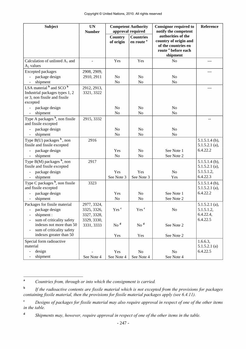
- 247 -
Competent Authority approval required
Subject UN Number
Country of origin
Countries en route a
Consignor required to notify the competent
authorities of the country of origin and
of the countries en route a before each
shipment
Reference
Calculation of unlisted A1 and A2 values
- Yes Yes No ---
Excepted packages - package design - shipment
2908, 2909, 2910, 2911
No No
No No
No No
---
LSA material b and SCO b Industrial packages types 1, 2 or 3, non fissile and fissile excepted
2912, 2913, 3321, 3322
---
- package design - shipment
No No
No No
No No
Type A packages b, non fissile and fissile excepted
2915, 3332 --
- package design - shipment
No No
No No
No No
Type B(U) packages b , non fissile and fissile excepted
2916
- package design - shipment
Yes No
No No
See Note 1 See Note 2
5.1.5.1.4 (b), 5.1.5.2.1 (a), 6.4.22.2
Type B(M) packages b, non fissile and fissile excepted
2917
- package design - shipment
Yes See Note 3
Yes See Note 3
No Yes
5.1.5.1.4 (b), 5.1.5.2.1 (a), 5.1.5.1.2, 6.4.22.3
Type C packages b, non fissile and fissile excepted
3323
- package design - shipment
Yes No
No No
See Note 1 See Note 2
5.1.5.1.4 (b), 5.1.5.2.1 (a), 6.4.22.2
Packages for fissile material - package design - shipment : - sum of criticality safety
indexes not more than 50 - sum of criticality safety
indexes greater than 50
2977, 3324, 3325, 3326, 3327, 3328, 3329, 3330, 3331, 3333
Yes c
No d
Yes
Yes c
No d
Yes
No
See Note 2
See Note 2
5.1.5.2.1 (a), 5.1.5.1.2, 6.4.22.4, 6.4.22.5
Special form radioactive material - design - shipment
-
See Note 4
Yes See Note 4
No See Note 4
No See Note 4
1.6.6.3, 5.1.5.2.1 (a) 6.4.22.5
a Countries from, through or into which the consignment is carried. b If the radioactive contents are fissile material which is not excepted from the provisions for packages containing fissile material, then the provisions for fissile material packages apply (see 6.4.11). c Designs of packages for fissile material may also require approval in respect of one of the other items in the table. d Shipments may, however, require approval in respect of one of the other items in the table.
Copyright © United Nations, 2010. All rights reserved

- 248 -
Competent Authority approval required
Subject UN Number
Country of origin
Countries en route a
Consignor required to notify the competent
authorities of the country of origin and
of the countries en route a before each
shipment
Reference
Low dispersable radioactive material
5.1.5.2.1 (a), 6.4.22.3
- design - shipment
- See Note 4
Yes See Note 4
No See Note 4
No See Note 4
Packages containing 0.1 kg or more of uranium hexafluoride
5.1.5.2.1 (a), 6.4.22.1
- design - shipment
- See Note 4
Yes See Note 4
No See Note 4
No See Note 4
Special Arrangement - shipment
2919, 3331 Yes
Yes
Yes
1.7.4.2, 5.1.5.2.1 (b), 5.1.5.1.4 (b)
Approved packages designs subjected to transitional measures
- See 1.6.6 See 1.6.6 See Note 1 1.6.6.1, 1.6.6.2, 5.1.5.1.4 (b), 5.1.5.2.1 (a), 5.1.5.1.2.
a Countries from, through or into which the consignment is carried.
Copyright © United Nations, 2010. All rights reserved

- 249 -
CHAPTER 5.2
MARKING AND LABELLING
5.2.1 Marking of packages NOTE: For markings related to the construction, testing and approval of packagings, large
packagings, gas receptacles and IBCs, see Part 6. 5.2.1.1 Unless provided otherwise in ADR, the UN number corresponding to the dangerous goods
contained, preceded by the letters "UN" shall be clearly and durably marked on each package. In the case of unpackaged articles the marking shall be displayed on the article, on its cradle or on its handling, storage or launching device.
5.2.1.2 All package markings required by this Chapter: (a) shall be readily visible and legible; (b) shall be able to withstand open weather exposure without a substantial reduction in
effectiveness. 5.2.1.3 Salvage packagings shall additionally be marked with the word "SALVAGE". 5.2.1.4 Intermediate bulk containers of more than 450 litres capacity and large packagings shall be
marked on two opposite sides. 5.2.1.5 Additional provisions for goods of Class 1 For goods of Class 1, packages shall, in addition, bear the proper shipping name as
determined in accordance with 3.1.2. The marking, which shall be clearly legible and indelible, shall be in an official language of the country of origin and also, if that language is not English, French or German, in English, French or German unless any agreements concluded between the countries concerned in the transport operation provide otherwise.
5.2.1.6 Additional provisions for goods of Class 2 Refillable receptacles shall bear the following particulars in clearly legible and durable
characters:
(a) the UN number and the proper shipping name of the gas or mixture of gases, as determined in accordance with 3.1.2. In the case of gases classified under an N.O.S. entry, only the technical name 1 of the gas has to be indicated in addition to the UN number. In the case of mixtures, not more than the two constituents which most predominantly contribute to the hazards have to be indicated;
1 Instead of the technical name the use of one of the following names is permitted:
- for UN No. 1078 refrigerant gas, n.o.s: mixture F1, mixture F2, mixture F3; - for UN No. 1060 methylacetylene and propadiene mixtures, stabilized: mixture P1, mixture P2; - for UN No. 1965 hydrocarbon gas mixture, liquefied, n.o.s.: mixture A or butane, mixture A01 or
butane, mixture A02 or butane, mixture A0 or butane, mixture A1, mixture B1, mixture B2, mixture B, mixture C or propane;
- for UN No. 1010 Butadienes, stabilized: 1,2-Butadiene, stabilized, 1,3-Butadiene, stabilized.
Copyright © United Nations, 2010. All rights reserved

- 250 -
(b) for compressed gases filled by mass and for liquefied gases, either the maximum filling mass and the tare of the receptacle with fittings and accessories as fitted at the time of filling, or the gross mass;
(c) the date (year) of the next periodic inspection.
These marks can either be engraved or indicated on a durable information disk or label attached on the receptacle or indicated by an adherent and clearly visible marking such as by printing or by any equivalent process.
NOTE 1: See also 6.2.2.7. NOTE 2: For non refillable receptacles, see 6.2.2.8.
5.2.1.7 Special marking provisions for goods of Class 7 5.2.1.7.1 Each package shall be legibly and durably marked on the outside of the packaging with an
identification of either the consignor or consignee, or both. 5.2.1.7.2 For each package, other than excepted packages, the UN number preceded by the letters
"UN" and the proper shipping name shall be legibly and durably marked on the outside of the packaging. The marking of excepted packages shall be as required by 5.1.5.4.1.
5.2.1.7.3 Each package of gross mass exceeding 50 kg shall have its permissible gross mass legibly
and durably marked on the outside of the packaging.
5.2.1.7.4 Each package which conforms to:
(a) a Type IP-1 package, a Type IP-2 package or a Type IP-3 package design shall be legibly and durably marked on the outside of the packaging with "TYPE IP-1", "TYPE IP-2" or "TYPE IP-3" as appropriate;
(b) a Type A package design shall be legibly and durably marked on the outside of the
packaging with "TYPE A"; (c) a Type IP-2 package, a Type IP-3 package or a Type A package design shall be
legibly and durably marked on the outside of the packaging with the international vehicle registration code (VRI Code) 2 of the country of origin of design and either the name of the manufacturer or other identification of the packaging specified by the competent authority of the country of origin of design.
5.2.1.7.5 Each package which conforms to a design approved by the competent authority shall be
legibly and durably marked on the outside of the packaging with:
(a) the identification mark allocated to that design by the competent authority; (b) a serial number to uniquely identify each packaging which conforms to that design; (c) in the case of a Type B(U) or Type B(M) package design, with "TYPE B(U)" or
"TYPE B(M)"; and (d) in the case of a Type C package design, with "TYPE C".
2 Distinguishing sign for motor vehicles in international traffic prescribed in the Vienna Convention on Road Traffic (1968).
Copyright © United Nations, 2010. All rights reserved

- 251 -
5.2.1.7.6 Each package which conforms to a Type B(U), Type B(M) or Type C package design shall have the outside of the outermost receptacle which is resistant to the effects of fire and water plainly marked by embossing, stamping or other means resistant to the effects of fire and water with the trefoil symbol shown in the figure below.
Basic trefoil symbol with proportions based on a central circle of radius X.
The minimum allowable size of X shall be 4 mm.
5.2.1.7.7 Where LSA-I or SCO-I material is contained in receptacles or wrapping materials and is
carried under exclusive use as permitted by 4.1.9.2.3, the outer surface of these receptacles or wrapping materials may bear the marking "RADIOACTIVE LSA-I" or "RADIOACTIVE SCO-I", as appropriate.
5.2.1.7.8 In all cases of international carriage of packages requiring competent authority design or
shipment approval, for which different approval types apply in the different countries concerned by the shipment, marking shall be in accordance with the certificate of the country of origin of the design.
5.2.1.8 Special marking provisions for environmentally hazardous substances 5.2.1.8.1 Packages containing environmentally hazardous substances meeting the criteria of 2.2.9.1.10
shall be durably marked with the environmentally hazardous substance mark shown in 5.2.1.8.3 with the exception of single packagings and combination packagings where such single packagings or inner packagings of such combination packagings have:
- a quantity of 5 l or less for liquids; or - a net mass of 5 kg or less for solids. 5.2.1.8.2 The environmentally hazardous substance mark shall be located adjacent to the markings
required by 5.2.1.1. The requirements of 5.2.1.2 and 5.2.1.4 shall be met.
Copyright © United Nations, 2010. All rights reserved

- 252 -
5.2.1.8.3 The environmentally hazardous substance mark shall be as shown below. The dimensions shall be 100 mm × 100 mm, except in the case of packages of such dimensions that they can only bear smaller marks.
Symbol (fish and tree): black on white or suitable contrasting background 5.2.1.9 Orientation arrows 5.2.1.9.1 Except as provided in 5.2.1.9.2:
- Combination packagings having inner packagings containing liquids; - Single packagings fitted with vents; and - Cryogenic receptacles intended for the carriage of refrigerated liquefied gases, shall be legibly marked with package orientation arrows which are similar to the illustration shown below or with those meeting the specifications of ISO 780:1997. The orientation arrows shall appear on two opposite vertical sides of the package with the arrows pointing in the correct upright direction. They shall be rectangular and of a size that is clearly visible commensurate with the size of the package. Depicting a rectangular border around the arrows is optional.
5.2.1.9.2 Orientation arrows are not required on packages containing: (a) Pressure receptacles except for cryogenic receptacles; (b) Dangerous goods in inner packagings of not more than 120 ml which are prepared
with sufficient absorbent material between the inner and outer packagings to completely absorb the liquid contents;
(c) Class 6.2 infectious substances in primary receptacles of not more than 50 ml;
(d) Class 7 radioactive material in Type IP-2, IP-3, A, B(U), B(M) or C packages;
Two black or red arrows on white or suitable contrasting background. The rectangular border is optional.
or
Copyright © United Nations, 2010. All rights reserved

- 253 -
(e) Articles which are leak-tight in all orientations (e.g. alcohol or mercury in thermometers, aerosols, etc.); or
(f) Combination packagings containing hermetically sealed inner packagings each
containing not more than 500 ml.
5.2.1.9.3 Arrows for purposes other than indicating proper package orientation shall not be displayed on a package marked in accordance with this sub-section.
5.2.2 Labelling of packages 5.2.2.1 Labelling provisions 5.2.2.1.1 For each article or substance listed in Table A of Chapter 3.2, the labels shown in
Column (5) shall be affixed unless otherwise provided for by a special provision in Column (6).
5.2.2.1.2 Indelible danger markings corresponding exactly to the prescribed models may be used
instead of labels. 5.2.2.1.3 to 5.2.2.1.5 (Reserved) 5.2.2.1.6 Except as provided in 5.2.2.2.1.2, each label shall:
(a) be affixed to the same surface of the package, if the dimensions of the package allow; for packages of Class1 and 7, near the mark indicating the proper shipping name;
(b) be so placed on the package that it is not covered or obscured by any part or
attachment to the packaging or any other label or marking; and (c) be displayed next to each other when more than one label is required.
Where a package is of such an irregular shape or small size that a label cannot be satisfactorily affixed, the label may be attached to the package by a securely affixed tag or other suitable means.
5.2.2.1.7 Intermediate bulk containers of more than 450 litres capacity and large packagings shall be
labelled on two opposite sides. 5.2.2.1.8 (Reserved) 5.2.2.1.9 Special provisions for the labelling of self-reactive substances and organic peroxides (a) The label conforming to model No. 4.1 also implies that the product may be
flammable and hence no label conforming to model No. 3 is required. In addition, a label conforming to model No. 1 shall be applied for self-reactive substances Type B, unless the competent authority has permitted this label to be dispensed with for a specific packaging because test data have proven that the self-reactive substance in such a packaging does not exhibit explosive behaviour.
(b) The label conforming to model No. 5.2 also implies that the product may be
flammable and hence no label conforming to model No. 3 is required. In addition, the following labels shall be applied:
Copyright © United Nations, 2010. All rights reserved

- 254 -
(i) A label conforming to model No. 1 for organic peroxides type B, unless the competent authority has permitted this label to be dispensed with for a specific packaging because test data have proven that the organic peroxide in such a packaging does not exhibit explosive behaviour;
(ii) A label conforming to model No. 8 is required when Packing Group I or II
criteria of Class 8 are met.
For self-reactive substances and organic peroxides mentioned by name, the labels to be affixed are indicated in the list found in 2.2.41.4 and 2.2.52.4 respectively.
5.2.2.1.10 Special provisions for the labelling of infectious substances packages In addition to the label conforming to model No. 6.2, infectious substances packages shall
bear any other label required by the nature of the contents. 5.2.2.1.11 Special provisions for the labelling of radioactive material
5.2.2.1.11.1 Except when enlarged labels are used in accordance with 5.3.1.1.3, each package, overpack
and container containing radioactive material shall bear at least two labels which conform to the models Nos.7A, 7B, and 7C as appropriate according to the category (see 5.1.5.3.4) of that package, overpack or container. Labels shall be affixed to two opposite sides on the outside of the package or on the outside of all four sides of the container. Each overpack containing radioactive material shall bear at least two labels on opposite sides of the outside of the overpack. In addition, each package, overpack and container containing fissile material, other than fissile material excepted under 6.4.11.2 shall bear labels which conform to model No.7E; such labels, where applicable shall be affixed adjacent to the labels for radioactive material. Labels shall not cover the markings specified in 5.2.1. Any labels which do not relate to the contents shall be removed or covered.
5.2.2.1.11.2 Each label conforming to models Nos.7A, 7B, and 7C shall be completed with the following
information.
(a) Contents:
(i) except for LSA-I material, the name(s) of the radionuclide(s) as taken from Table 2.2.7.2.2.1, using the symbols prescribed therein. For mixtures of radionuclides, the most restrictive nuclides shall be listed to the extent the space on the line permits. The group of LSA or SCO shall be shown following the name(s) of the radionuclide(s). The terms "LSA-II","LSA-III", "SCO-I" and "SCO-II" shall be used for this purpose;
(ii) for LSA-I material, only the term "LSA-I" is necessary; the name of the radionuclide is not necessary;
(b) Activity: The maximum activity of the radioactive contents during carriage expressed in becquerels (Bq) with the appropriate SI prefix symbol (see 1.2.2.1). For fissile material, the mass of fissile material (or mass of each fissile nuclide for mixtures when appropriate) in grams (g), or multiples thereof, may be used in place of activity;
(c) For overpacks and containers the "contents" and "activity" entries on the label shall bear the information required in (a) and (b) above, respectively, totalled together for the entire contents of the overpack or container except that on labels for overpacks or containers containing mixed loads of packages containing different radionuclides, such entries may read "See Transport Documents";
(d) Transport index: The number determined in accordance with 5.1.5.3.1 and 5.1.5.3.2 (no transport index entry is required for category I-WHITE).
Copyright © United Nations, 2010. All rights reserved

- 255 -
5.2.2.1.11.3 Each label conforming to the model No. 7E shall be completed with the criticality safety index (CSI) as stated in the certificate of approval for special arrangement or the certificate of approval for the package design issued by the competent authority.
5.2.2.1.11.4 For overpacks and containers, the criticality safety index (CSI) on the label shall bear the
information required in 5.2.2.1.11.3 totalled together for the fissile contents of the overpack or container.
5.2.2.1.11.5 In all cases of international carriage of packages requiring competent authority design or
shipment approval, for which different approval types apply in the different countries concerned by the shipment, labelling shall be in accordance with the certificate of the country of origin of design.
5.2.2.2 Provisions for labels 5.2.2.2.1 Labels shall satisfy the provisions below and conform, in terms of colour, symbols and
general format, to the models shown in 5.2.2.2.2. Corresponding models required for other modes of transport, with minor variations which do not affect the obvious meaning of the label, are also acceptable. NOTE: Where appropriate, labels in 5.2.2.2.2 are shown with a dotted outer boundary as provided for in 5.2.2.2.1.1. This is not required when the label is applied on a background of contrasting colour.
5.2.2.2.1.1 Labels shall be in the form of a square set at an angle of 45° (diamond-shaped) with
minimum dimensions of 100 mm by 100 mm. They shall have a line 5 mm inside the edge and running parallel with it. In the upper half of a label the line shall have the same colour as the symbol and in the lower half it shall have the same colour as the figure in the bottom corner. Labels shall be displayed on a background of contrasting colour, or shall have either a dotted or solid outer boundary line. If the size of the package so requires, the dimensions of the labels may be reduced, provided that they remain clearly visible.
5.2.2.2.1.2 Cylinders for Class 2 may, on account of their shape, orientation and securing mechanisms
for carriage, bear labels representative of those specified in this section, which have been reduced in size, according to the dimensions outlined in ISO 7225:2005, "Gas cylinders - Precautionary labels", for display on the non-cylindrical part (shoulder) of such cylinders. Notwithstanding the provisions of 5.2.2.1.6, labels may overlap to the extent provided for by ISO 7225:2005. However, in all cases, the primary risk label and the figures appearing on any label shall remain fully visible and the symbols recognizable. Empty uncleaned pressure receptacles for gases of Class 2 may be carried with obsolete or damaged labels for the purposes of refilling or inspection as appropriate and the application of a new label in conformity with current regulations or for the disposal of the pressure receptacle.
5.2.2.2.1.3 With the exception of labels for Divisions 1.4, 1.5 and 1.6 of Class 1, the upper half of the
label shall contain the pictorial symbol and the lower half shall contain:
(a) For Classes 1, 2, 3, 5.1, 5.2, 7, 8 and 9, the class number; (b) For Classes 4.1, 4.2 and 4.3, the figure "4"; (c) For Classes 6.1 and 6.2, the figure "6".
Copyright © United Nations, 2010. All rights reserved

- 256 -
The labels may include text such as the UN number or words describing the hazard (e.g. "flammable") in accordance with 5.2.2.2.1.5 provided the text does not obscure or detract from the other required label elements.
5.2.2.2.1.4 In addition, except for Divisions 1.4, 1.5 and 1.6, labels for Class 1 shall show in the lower
half, above the class number, the division number and the compatibility group letter for the substance or article. Labels for Divisions 1.4, 1.5 and 1.6 shall show in the upper half the division number, and in the lower half the class number and the compatibility group letter.
5.2.2.2.1.5 On labels other than those for material of Class 7, the optional insertion of any text (other
than the class number) in the space below the symbol shall be confined to particulars indicating the nature of the risk and precautions to be taken in handling.
5.2.2.2.1.6 The symbols, text and numbers shall be clearly legible and indelible and shall be shown in
black on all labels except for:
(a) the Class 8 label, where the text (if any) and class number shall appear in white; (b) labels with entirely green, red or blue backgrounds where they may be shown in
white; (c) the Class 5.2 label, where the symbol may be shown in white; and (d) labels conforming to model No. 2.1 displayed on cylinders and gas cartridges for
gases of UN Nos. 1011, 1075, 1965 and 1978, where they may be shown in the background colour of the receptacle if adequate contrast is provided.
5.2.2.2.1.7 All labels shall be able to withstand open weather exposure without a substantial reduction in
effectiveness.
Copyright © United Nations, 2010. All rights reserved

- 257 -
5.2.2.2.2 Specimen labels
CLASS 1 HAZARDExplosive substances or articles
(No. 1)Divisions 1.1, 1.2 and 1.3
Symbol (exploding bomb): black; Background: orange; Figure '1' in bottom corner
(No. 1.5)Division 1.5
(No. 1.4)Division 1.4
(No. 1.6)Division 1.6
Background: orange; Figures: black; Numerals shall be about 30 mm in heightand be about 5 mm thick (for a label measuring 100 mm x 100 mm); Figure '1' in bottom corner
Place for division - to be left blank if explosive is the subsidiary riskPlace for compatibility group - to be left blank if explosive is the subsidiary risk
CLASS 2 HAZARDGases
(No. 3)Symbol (flame): black or white;
Background: red; Figure '3' in bottom corner
(No. 2.1)Flammable gases
Symbol (flame): black or white;(except as provided for in 5.2.2.2.1.6 (d))
Background: red; Figure '2' in bottom corner
(No. 2.2)Non flammable, non-toxic gases
Symbol (gas cylinder): black or white;Background: green; Figure '2' in bottom corner
CLASS 3 HAZARDFlammable liquids
(No 2.3)
Symbol (skull and crossbones): black;Background: white; Figure '2' in bottom corner
Toxic gases.
33
- 257 -
Copyright © United Nations, 2010. All rights reserved

CLASS 4.1 HAZARDFlammable solids, self-reactivesubstances and
desensitized explosives
(No. 4.1)Symbol (flame): black;Background: white with
seven vertical red stripes;Figure '4' in bottom corner
(No. 4.2)Symbol (flame): black;
Background: upper half white,lower half red;
Figure '4' in bottom corner
(No. 4.3)Symbol (flame): black or white;
Background: blue;Figure '4' in bottom corner
CLASS 6.1 HAZARDToxic substances
CLASS 6.2 HAZARDInfectious substances
CLASS 5.1 HAZARDOxidizing substances
CLASS 5.2 HAZARDOrganic peroxides
(No. 6.1)Symbol (skull and crossbones): black;
Background: white; Figure '6' in bottom corner
(No. 6.2)The lower half of the label may bear the inscriptions: 'INFECTIOUS SUBSTANCE'and 'In the case of damage or leakage immediately notify Public Health Authority';
Symbol (three crescents superimposed on a circle) and inscriptions: black;Background: white; Figure '6' in bottom corner
CLASS 4.2 HAZARDSubstances liable tospontaneous combustion
CLASS 4.3 HAZARDSubstances which, in contact with water,emit flammable gases
(No. 5.1)
Figure '5.1' in bottom corner
Symbol (flame over circle): black;Background: yellow;
(No. 5.2)
Figure '5.2' in bottom corner
Symbol (flame): black or white;Background: upper half red; lower half yellow;
4
- 258 -
solid
Copyright © United Nations, 2010. All rights reserved

- 259 -
CLASS 7 HAZARDRadioactive material
(No. 7A)Category I - White
Symbol (trefoil): black; Background: white;
Text (mandatory): black in lower half of label:'RADIOACTIVE''
......'One red bar shall
follow the word ' ';Figure '7' in bottom corner.
CONTENTS .......''ACTIVITY
RADIOACTIVE
(No. 7B)Category II - Yellow
(No. 7C)Category III - Yellow
Symbol (trefoil): black; Background: upper half yellow with white border, lower half white;
Text (mandatory): black in lower half of label:'RADIOACTIVE''
......'In a black outlined box: ' ';
Figure '7' in bottom corner.
CONTENTS .......''ACTIVITY
TRANSPORT INDEXTwo red vertical bars shall
follow the word ;' 'RADIOACTIVEThree red vertical bars shall
follow the word ;' 'RADIOACTIVE
(No. 7E)Class 7 fissile material
Background: white;Text (mandatory): black in upper half of label: 'FISSILE';
In a black outlined box in the lower half of the label:'CRITICALITY SAFETY INDEX'
Figure '7' in bottom corner.
CLASS 8 HAZARDCorrosive substances
CLASS 9 HAZARDMiscellaneous dangerous substances and articles
(No. 8)Symbol (liquids, spilling from two glass vessels
and attacking a hand and a metal): black;Background: upper half white;
lower half black with white border;Figure '8' in bottom corner
(No. 9)Symbol (seven vertical stripes in upper half): black;
Background: white;Figure '9' underlined in bottom corner
- 259 -
Copyright © United Nations, 2010. All rights reserved

Copyright © United Nations, 2010. All rights reserved

- 261 -
CHAPTER 5.3
PLACARDING AND MARKING OF CONTAINERS, MEGCs, MEMUs, TANK-CONTAINERS, PORTABLE TANKS AND VEHICLES
NOTE: For marking and placarding of containers, MEGCs, tank-containers and portable tanks for
carriage in a transport chain including a maritime journey, see also 1.1.4.2.1. If the provisions of 1.1.4.2.1 (c) are applied, only 5.3.1.3 and 5.3.2.1.1 of this Chapter are applicable.
5.3.1 Placarding 5.3.1.1 General provisions 5.3.1.1.1 As and when required in this section, placards shall be affixed to the exterior surface of
containers, MEGCs, MEMUs, tank-containers, portable tanks and vehicles. Placards shall correspond to the labels required in Column (5) and, where appropriate, Column (6) of Table A of Chapter 3.2 for the dangerous goods contained in the container, MEGC, MEMU, tank-container, portable tank or vehicle and shall conform to the specifications given in 5.3.1.7. Placards shall be displayed on a background of contrasting colour, or shall have either a dotted or solid outer boundary line.
5.3.1.1.2 For Class 1, compatibility groups shall not be indicated on placards if the vehicle, container
or special compartments of MEMUs are carrying substances or articles belonging to two or more compatibility groups. Vehicles, containers or special compartments of MEMUs carrying substances or articles of different divisions shall bear only placards conforming to the model of the most dangerous division in the order:
1.1 (most dangerous), 1.5, 1.2, 1.3, 1.6, 1.4 (least dangerous). When 1.5 D substances are carried with substances or articles of Division 1.2, the vehicle or
container shall be placarded as Division 1.1. Placards are not required for the carriage of explosives of Division 1.4, compatibility group S.
5.3.1.1.3 For Class 7, the primary risk placard shall conform to model No. 7D as specified in
5.3.1.7.2. This placard is not required for vehicles or containers carrying excepted packages and for small containers.
Where both Class 7 labels and placards would be required to be affixed to vehicles,
containers, MEGCs, tank-containers or portable tanks, an enlarged label corresponding to the label required may be displayed instead of placard No.7D to serve both purposes.
5.3.1.1.4 Containers, MEGCs, MEMUs, tank-containers, portable tanks or vehicles containing goods
of more than one class need not bear a subsidiary risk placard if the hazard represented by that placard is already indicated by a primary or subsidiary risk placard.
5.3.1.1.5 Placards which do not relate to the dangerous goods being carried, or residues thereof, shall
be removed or covered. 5.3.1.1.6 When the placarding is affixed to folding panels, they shall be designed and secured so that
they cannot unfold or come loose from the holder during carriage (especially as a result of impacts or unintentional actions).
Copyright © United Nations, 2010. All rights reserved

- 262 -
5.3.1.2 Placarding of containers, MEGCs, tank-containers and portable tanks NOTE: This sub-section does not apply to swap bodies, except tank swap bodies or swap
bodies carried in combined road/rail transport. The placards shall be affixed to both sides and at each end of the container, MEGC, tank-
container or portable tank. When the tank-container or portable tank has multiple compartments and carries two or more
dangerous goods, the appropriate placards shall be displayed along each side at the position of the relevant compartments and one placard of each model shown on each side at both ends.
5.3.1.3 Placarding of vehicles carrying containers, MEGCs, tank-containers or portable tanks NOTE: This sub-section does not apply to the placarding of vehicles carrying swap bodies
other than tank swap bodies or than swap bodies carried in combined road/rail transport; for such vehicles, see 5.3.1.5.
If the placards affixed to the containers, MEGCs, tank-containers or portable tanks are not
visible from outside the carrying vehicles, the same placards shall also be affixed to both sides and at the rear of the vehicle. Otherwise, no placard need be affixed on the carrying vehicle.
5.3.1.4 Placarding of vehicles for carriage in bulk, tank-vehicles, battery-vehicles, MEMUs and
vehicles with demountable tanks 5.3.1.4.1 Placards shall be affixed to both sides and at the rear of the vehicle. When the tank-vehicle or the demountable tank carried on the vehicle has multiple
compartments and carries two or more dangerous goods, the appropriate placards shall be displayed along each side at the position of the relevant compartments and one placard of each model shown on each side at the rear of the vehicle. However, in such case, if all compartments have to bear the same placards, these placards need be displayed only once along each side and at the rear of the vehicle.
Where more than one placard is required for the same compartment, these placards shall be
displayed adjacent to each other. NOTE: When, in the course of an ADR journey or at the end of an ADR journey, a tank
semi-trailer is separated from its tractor to be loaded on board a ship or an inland navigation vessel, placards shall also be displayed at the front of the semi-trailer.
5.3.1.4.2 MEMUs with tanks and bulk containers shall be placarded in accordance with 5.3.1.4.1 for
the substances contained therein. For tanks with a capacity of less than 1 000 litres placards may be replaced by labels conforming to 5.2.2.2.
5.3.1.4.3 For MEMUs carrying packages containing substances or articles of Class 1 (other than of
Division 1.4, Compatibility group S), placards shall be affixed to both sides and at the rear of the MEMU.
Special compartments for explosives shall be placarded in accordance with the provisions of
5.3.1.1.2. The last sentence of 5.3.1.1.2 does not apply.
Copyright © United Nations, 2010. All rights reserved

- 263 -
5.3.1.5 Placarding of vehicles carrying packages only NOTE: This sub-section applies also to vehicles carrying swap bodies loaded with
packages, except for combined road/rail transport; for combined road/rail transport, see 5.3.1.2 and 5.3.1.3.
5.3.1.5.1 For vehicles carrying packages containing substances or articles of Class 1 (other than of
Division 1.4, compatibility group S), placards shall be affixed to both sides and at the rear of the vehicle.
5.3.1.5.2 For vehicles carrying radioactive material of Class 7 in packagings or IBCs (other than
excepted packages), placards shall be affixed to both sides and at the rear of the vehicle. 5.3.1.6 Placarding of empty tank-vehicles, battery-vehicles, MEGCs, MEMUs, tank-containers,
portable tanks and empty vehicles and containers for carriage in bulk 5.3.1.6.1 Empty tank-vehicles, vehicles with demountable tanks, battery-vehicles, MEGCs,
MEMUs, tank-containers and portable tanks uncleaned and not degassed, and empty vehicles and containers for carriage in bulk, uncleaned, shall continue to display the placards required for the previous load.
5.3.1.7 Specifications for placards 5.3.1.7.1 Except as provided in 5.3.1.7.2 for the Class 7 placard, a placard shall: (a) Be not less than 250 mm by 250 mm and have a line 12.5 mm inside the edge and
running parallel with it. In the upper half the line shall have the same colour as the symbol and in the lower half it shall have the same colour as the figure in the bottom corner;
(b) Correspond to the label required for the dangerous goods in question with respect to
colour and symbol (see 5.2.2.2); and (c) Display the numbers (and for goods of Class 1, the compatibility group letter)
prescribed for the dangerous goods in question in 5.2.2.2 for the corresponding label, in digits not less than 25 mm high.
5.3.1.7.2 The Class 7 placard shall be not less than 250 mm by 250 mm with a black line running
5 mm inside the edge and parallel with it and is otherwise as shown below (Model No. 7D). The number "7" shall not be less than 25 mm high. The background colour of the upper half of the placard shall be yellow and of the lower half white, the colour of the trefoil and the printing shall be black. The use of the word "RADIOACTIVE" in the bottom half is optional to allow the use of this placard to display the appropriate UN number for the consignment.
Copyright © United Nations, 2010. All rights reserved

- 264 -
Placard for radioactive material of Class 7
(No.7D)
Symbol (trefoil): black; Background: upper half yellow with white border, lower half white;
The lower half shall show the word "RADIOACTIVE" or alternatively, when required, the appropriate UN Number (see 5.3.2.1.2)
and the figure "7" in the bottom corner. 5.3.1.7.3 For tanks with a capacity of not more than 3 m3 and for small containers, placards may be
replaced by labels conforming to 5.2.2.2. 5.3.1.7.4 For Classes 1 and 7, if the size and construction of the vehicle are such that the available
surface area is insufficient to affix the prescribed placards, their dimensions may be reduced to 100 mm on each side.
5.3.2 Orange-coloured plate marking 5.3.2.1 General orange-coloured plate marking provisions 5.3.2.1.1 Transport units carrying dangerous goods shall display two rectangular orange-coloured
plates conforming to 5.3.2.2.1, set in a vertical plane. They shall be affixed one at the front and the other at the rear of the transport unit, both perpendicular to the longitudinal axis of the transport unit. They shall be clearly visible.
5.3.2.1.2 When a hazard identification number is indicated in Column (20) of table A of Chapter 3.2,
tank-vehicles, battery vehicles or transport units having one or more tanks carrying dangerous goods shall in addition display on the sides of each tank, each tank compartment or each element of battery vehicles, clearly visible and parallel to the longitudinal axis of the vehicle, orange-coloured plates identical with those prescribed in 5.3.2.1.1. These orange-coloured plates shall bear the hazard identification number and the UN number prescribed respectively in Columns (20) and (1) of table A of Chapter 3.2 for each of the substances carried in the tank, in a compartment of the tank or in an element of a battery vehicle. For MEMUs these requirements shall only apply to tanks with a capacity of 1 000 litres or more and bulk containers.
7
10 mmMINIMUM
5 mm
RADIOACTIVEMINIMUM DIMENSION
250 mm
MINIM
UM DIM
ENSION
250 m
m
Copyright © United Nations, 2010. All rights reserved

- 265 -
5.3.2.1.3 For tank-vehicles or transport units having one or more tanks carrying substances with UN Nos. 1202, 1203 or 1223, or aviation fuel classed under UN Nos. 1268 or 1863, but no other dangerous substance, the orange-coloured plates prescribed in 5.3.2.1.2 need not be affixed if the plates affixed to the front and rear in accordance with 5.3.2.1.1 bear the hazard identification number and the UN number prescribed for the most hazardous substance carried, i.e. the substance with the lowest flash-point.
5.3.2.1.4 When a hazard identification number is indicated in Column (20) of Table A of Chapter 3.2,
transport units and containers carrying unpackaged solids or articles or packaged radioactive material with a single UN number required to be carried under exclusive use and no other dangerous goods shall in addition display on the sides of each transport unit or container, clearly visible and parallel to the longitudinal axis of the vehicle, orange-coloured plates identical with those prescribed in 5.3.2.1.1. These orange-coloured plates shall bear the hazard identification number and the UN number prescribed respectively in Columns (20) and (1) of table A of Chapter 3.2 for each of the substances carried in bulk in the transport unit or in the container or for the packaged radioactive material when required to be carried under exclusive use in the transport unit or in the container.
5.3.2.1.5 If the orange-coloured plates prescribed in 5.3.2.1.2 and 5.3.2.1.4 affixed to the containers,
tank-containers, MEGCs or portable tanks are not clearly visible from outside the carrying vehicle, the same plates shall also be affixed to both sides of the vehicle.
NOTE: This paragraph need not be applied to the marking with orange coloured plates of closed and sheeted vehicles, carrying tanks with a maximum capacity of 3 000 litres.
5.3.2.1.6 For transport units carrying only one dangerous substance and no non-dangerous substance,
the orange-coloured plates prescribed in 5.3.2.1.2, 5.3.2.1.4 and 5.3.2.1.5 shall not be necessary provided that those displayed at the front and rear in accordance with 5.3.2.1.1 bear the hazard identification number and the UN number for that substance prescribed respectively in Columns (20) and (1) of Table A of Chapter 3.2.
5.3.2.1.7 The requirements of 5.3.2.1.1 to 5.3.2.1.5 are also applicable to empty fixed or demountable
tanks, battery-vehicles, tank-containers, portable tanks and MEGCs, uncleaned, not degassed or not decontaminated, MEMUs, uncleaned as well as to empty vehicles and containers for carriage in bulk, uncleaned or not decontaminated.
5.3.2.1.8 Orange-coloured marking which does not relate to dangerous goods carried, or residues
thereof, shall be removed or covered. If plates are covered, the covering shall be total and remain effective after 15 minute’ engulfment in fire.
5.3.2.2 Specifications for the orange-coloured plates 5.3.2.2.1 The orange-coloured plates shall be reflectorized and shall be of 40 cm base and of 30 cm
high; they shall have a black border of 15 mm wide. The material used shall be weather-resistant and ensure durable marking. The plate shall not become detached from its mount in the event of 15 minutes’ engulfment in fire. It shall remain affixed irrespective of the orientation of the vehicle. The orange-coloured plates may be separated in their middle with a black horizontal line of 15 mm thickness.
If the size and construction of the vehicle are such that the available surface area is insufficient to affix these orange-coloured plates, their dimensions may be reduced to 300 mm for the base, 120 mm for the height and 10 mm for the black border. In that case, for a packaged radioactive material carried under exclusive use, only the UN number is required, and the size of the digits stipulated in 5.3.2.2.2 may be reduced to 65 mm in height and 10 mm in stroke thickness.
Copyright © United Nations, 2010. All rights reserved

- 266 -
For containers carrying dangerous solid substances in bulk and for tank-containers, MEGCs and portable tanks, the plates prescribed in 5.3.2.1.2, 5.3.2.1.4 and 5.3.2.1.5 may be replaced by a self-adhesive sheet, by paint or by any other equivalent process. This alternative marking shall conform to the specifications set in this sub-section except for the provisions concerning resistance to fire mentioned in 5.3.2.2.1 and 5.3.2.2.2.
NOTE: The colour of the orange plates in conditions of normal use should have
chromaticity co-ordinates lying within the area on the chromaticity diagram formed by joining the following co-ordinates:
Chromaticity co-ordinates of points at the corners of the area on the chromaticity diagram x y
0.52 0.38
0.52 0.40
0.578 0.422
0.618 0.38
Luminance factor of reflectorized colour: β > 0.12. Reference centre E, standard illuminant C, normal incidence 45°, viewed at 0°. Co-efficient of reflex luminous intensity at an angle of illumination of 5°, viewed at 0.2°: not
less than 20 candelas per lux per m2.
5.3.2.2.2 The hazard identification number and the UN number shall consist of black digits 100 mm high and of 15 mm stroke thickness. The hazard-identification number shall be inscribed in the upper part of the plate and the UN number in the lower part; they shall be separated by a horizontal black line, 15 mm in stroke width, extending from side to side of the plate at mid-height (see 5.3.2.2.3).The hazard identification number and the UN number shall be indelible and shall remain legible after 15 minute’ engulfment in fire. Interchangeable numbers and letters on plates presenting the hazard identification number and the UN number shall remain in place during carriage and irrespective of the orientation of the vehicle.
5.3.2.2.3 Example of orange-coloured plate with hazard identification number and UN number
Background orange. Border, horizontal line and figures black, 15 mm thickness.
5.3.2.2.4 The permitted tolerances for dimensions specified in this sub-section are ± 10%.
10 c
m
331088
40 cm
30 c
m
10 c
m
Hazard Identification number (2 or 3 figures preceded where appropriate by the letter X, see 5.3.2.3)
UN number (4 figures)
Copyright © United Nations, 2010. All rights reserved

- 267 -
5.3.2.2.5 When the orange-coloured plate is affixed to folding panels, they shall be designed and secured so that they cannot unfold or come loose from the holder during carriage (especially as a result of impacts or unintentional actions).
5.3.2.3 Meaning of hazard identification numbers 5.3.2.3.1 The hazard identification number consists of two or three figures. In general, the figures
indicate the following hazards:
2 Emission of gas due to pressure or to chemical reaction 3 Flammability of liquids (vapours) and gases or self-heating liquid 4 Flammability of solids or self-heating solid 5 Oxidizing (fire-intensifying) effect 6 Toxicity or risk of infection 7 Radioactivity 8 Corrosivity 9 Risk of spontaneous violent reaction
NOTE: The risk of spontaneous violent reaction within the meaning of figure 9 include the possibility following from the nature of a substance of a risk of explosion, disintegration and polymerization reaction following the release of considerable heat or flammable and/or toxic gases.
Doubling of a figure indicates an intensification of that particular hazard. Where the hazard associated with a substance can be adequately indicated by a single figure,
this is followed by zero. The following combinations of figures, however, have a special meaning: 22, 323, 333, 362,
382, 423, 44, 446, 462, 482, 539, 606, 623, 642, 823, 842, 90 and 99, see 5.3.2.3.2 below.
If a hazard identification number is prefixed by the letter "X", this indicates that the substance will react dangerously with water. For such substances, water may only be used by approval of experts.
For substances of Class 1, the classification code in accordance with Column (3 b) of Table A of Chapter 3.2, shall be used as the hazard identification number. The classification code consists of: − the division number in accordance with 2.2.1.1.5; and − the compatibility group letter in accordance with 2.2.1.1.6.
5.3.2.3.2 The hazard identification numbers listed in Column (20) of table A of Chapter3.2 have the
following meanings: 20 asphyxiant gas or gas with no subsidiary risk 22 refrigerated liquefied gas, asphyxiant 223 refrigerated liquefied gas, flammable 225 refrigerated liquefied gas, oxidizing (fire-intensifying) 23 flammable gas 239 flammable gas, which can spontaneously lead to violent reaction 25 oxidizing (fire-intensifying) gas 26 toxic gas 263 toxic gas, flammable 265 toxic gas, oxidizing (fire-intensifying) 268 toxic gas, corrosive
Copyright © United Nations, 2010. All rights reserved

- 268 -
30 flammable liquid (flash-point between 23 °C and 60 °C, inclusive) or flammable liquid or solid in the molten state with a flash-point above 60 °C,
heated to a temperature equal to or above its flash-point, or self-heating liquid 323 flammable liquid which reacts with water, emitting flammable gases X323 flammable liquid which reacts dangerously with water, emitting flammable
gases 1 33 highly flammable liquid (flash-point below 23 °C) 333 pyrophoric liquid X333 pyrophoric liquid which reacts dangerously with water 1 336 highly flammable liquid, toxic 338 highly flammable liquid, corrosive X338 highly flammable liquid, corrosive, which reacts dangerously with water 1
339 highly flammable liquid which can spontaneously lead to violent reaction 36 flammable liquid (flash-point between 23 °C and 60 °C, inclusive), slightly
toxic, or self-heating liquid, toxic 362 flammable liquid, toxic, which reacts with water, emitting flammable gases X362 flammable liquid toxic, which reacts dangerously with water, emitting
flammable gases 1 368 flammable liquid, toxic, corrosive 38 flammable liquid (flash-point between 23 °C and 60 °C, inclusive), slightly
corrosive or self-heating liquid, corrosive 382 flammable liquid, corrosive, which reacts with water, emitting flammable gases X382 flammable liquid, corrosive, which reacts dangerously with water, emitting
flammable gases 1 39 flammable liquid, which can spontaneously lead to violent reaction 40 flammable solid, or self-reactive substance, or self-heating substance 423 solid which reacts with water, emitting flammable gases, or flammable solid
which reacts with water, emitting flammable gases or self-heating solid which reacts with water, emitting flammable gases
X423 solid which reacts dangerously with water, emitting flammable gases, or flammable solid which reacts dangerously with water, emitting flammable gases, or self-heating solid which reacts dangerously with water, emitting flammable gases 1
43 spontaneously flammable (pyrophoric) solid X432 spontaneously flammable (pyrophoric) solid which reacts dangerously with
water, emitting flammable gases1 44 flammable solid, in the molten state at an elevated temperature 446 flammable solid, toxic, in the molten state, at an elevated temperature 46 flammable or self-heating solid, toxic 462 toxic solid which reacts with water, emitting flammable gases X462 solid which reacts dangerously with water, emitting toxic gases 1 48 flammable or self-heating solid, corrosive 482 corrosive solid which reacts with water, emitting flammable gases X482 solid which reacts dangerously with water, emitting corrosive gases 1 50 oxidizing (fire-intensifying) substance 539 flammable organic peroxide 55 strongly oxidizing (fire-intensifying) substance 556 strongly oxidizing (fire-intensifying) substance, toxic 558 strongly oxidizing (fire-intensifying) substance, corrosive
1 Water not to be used except by approval of experts.
Copyright © United Nations, 2010. All rights reserved

- 269 -
559 strongly oxidizing (fire-intensifying) substance, which can spontaneously lead to violent reaction
56 oxidizing substance (fire-intensifying), toxic 568 oxidizing substance (fire-intensifying), toxic, corrosive 58 oxidizing substance (fire-intensifying), corrosive 59 oxidizing substance (fire-intensifying) which can spontaneously lead to violent
reaction 60 toxic or slightly toxic substance 606 infectious substance 623 toxic liquid, which reacts with water, emitting flammable gases 63 toxic substance, flammable (flash-point between 23 °C and 60 °C, inclusive) 638 toxic substance, flammable (flash-point between 23 °C and 60 °C, inclusive),
corrosive 639 toxic substance, flammable (flash-point not above 60 °C) which can
spontaneously lead to violent reaction 64 toxic solid, flammable or self-heating 642 toxic solid, which reacts with water, emitting flammable gases 65 toxic substance, oxidizing (fire-intensifying) 66 highly toxic substance 663 highly toxic substance, flammable (flash-point not above 60 °C) 664 highly toxic solid, flammable or self-heating 665 highly toxic substance, oxidizing (fire-intensifying) 668 highly toxic substance, corrosive X668 highly toxic substance, corrosive, which reacts dangerously with water1 669 highly toxic substance which can spontaneously lead to violent reaction 68 toxic substance, corrosive 69 toxic or slightly toxic substance, which can spontaneously lead to violent
reaction
70 radioactive material 78 radioactive material, corrosive 80 corrosive or slightly corrosive substance X80 corrosive or slightly corrosive substance, which reacts dangerously with water 1 823 corrosive liquid which reacts with water, emitting flammable gases 83 corrosive or slightly corrosive substance, flammable (flash-point between 23 °C
and 60 °C, inclusive) X83 corrosive or slightly corrosive substance, flammable, (flash-point between
23 °C and 60 °C, inclusive), which reacts dangerously with water 1
839 corrosive or slightly corrosive substance, flammable (flash-point between 23 °C and 60 °C inclusive) which can spontaneously lead to violent reaction
X839 corrosive or slightly corrosive substance, flammable (flash-point between 23 °C and 60 °C inclusive), which can spontaneously lead to violent reaction and which reacts dangerously with water 1
84 corrosive solid, flammable or self-heating 842 corrosive solid which reacts with water, emitting flammable gases 85 corrosive or slightly corrosive substance, oxidizing (fire-intensifying) 856 corrosive or slightly corrosive substance, oxidizing (fire-intensifying) and toxic 86 corrosive or slightly corrosive substance, toxic 88 highly corrosive substance X88 highly corrosive substance, which reacts dangerously with water 1
883 highly corrosive substance, flammable (flash-point between 23 °C and 60 °C inclusive)
1 Water not to be used except by approval of experts.
Copyright © United Nations, 2010. All rights reserved

- 270 -
884 highly corrosive solid, flammable or self-heating 885 highly corrosive substance, oxidizing (fire-intensifying) 886 highly corrosive substance, toxic X886 highly corrosive substance, toxic, which reacts dangerously with water 1
89 corrosive or slightly corrosive substance, which can spontaneously lead to violent reaction
90 environmentally hazardous substance; miscellaneous dangerous substances 99 miscellaneous dangerous substance carried at an elevated temperature. 5.3.3 Mark for elevated temperature substances Tank-vehicles, tank-containers, portable tanks, special vehicles or containers or especially
equipped vehicles or containers for which a mark for elevated temperature substances is required according to special provision 580 in Column (6) of Table A of Chapter 3.2 shall bear on both sides and at the rear for vehicles, and on both sides and at each end for containers, tank-containers and portable tanks, a triangular shaped mark with sides of at least 250 mm, to be shown in red, as reproduced below.
5.3.4 (Reserved) 5.3.5 (Reserved) 5.3.6 Environmentally hazardous substance mark
When a placard is required to be displayed in accordance with the provisions of section 5.3.1, containers, MEGCs, tank-containers, portable tanks and vehicles containing environmentally hazardous substances meeting the criteria of 2.2.9.1.10 shall be marked with the environmentally hazardous substance mark shown in 5.2.1.8.3. The provisions of section 5.3.1 concerning placards shall apply mutatis mutandis to the mark.
Copyright © United Nations, 2010. All rights reserved

- 271 -
CHAPTER 5.4
DOCUMENTATION 5.4.0 General 5.4.0.1 Unless otherwise specified, any carriage of goods governed by ADR shall be accompanied
by the documentation prescribed in this Chapter, as appropriate. NOTE: For the list of documentation to be carried on board transport units, see 8.1.2. 5.4.0.2 The use of electronic data processing (EDP) or electronic data interchange (EDI) techniques
as an aid to or instead of paper documentation is permitted, provided that the procedures used for the capture, storage and processing of electronics data meet the legal requirements as regards the evidential value and availability of data during transport in a manner at least equivalent to that of paper documentation.
5.4.0.3 When the dangerous goods transport information is given to the carrier by EDP or EDI
techniques, the consignor shall be able to give the information to the carrier as a paper document, with the information in the sequence required by this Chapter.
5.4.1 Dangerous goods transport document and related information 5.4.1.1 General information required in the transport document 5.4.1.1.1 The transport document(s) shall contain the following information for each dangerous
substance, material or article offered for carriage: (a) the UN number preceded by the letters "UN";
(b) the proper shipping name supplemented, when applicable (see 3.1.2.8.1) with the technical name in brackets (see 3.1.2.8.1.1), as determined in accordance with 3.1.2;
(c) - for substances and articles of Class 1: the classification code given in
Column (3b) of Table A in Chapter 3.2. When, in Column (5) of Table A in Chapter 3.2, label model numbers other
than 1, 1.4, 1.5 and 1.6 are given, these label model numbers, in brackets, shall follow the classification code;
- for radioactive material of Class 7: the Class number: "7";
NOTE: For radioactive material with a subsidiary risk, see also special provision 172 in Chapter 3.3.
- for substances and articles of other classes: the label model numbers given in
Column (5) of Table A in Chapter 3.2 or applicable according to a special provision referred to in Column (6). When more than one label model numbers are given, the numbers following the first one shall be given in brackets. For substances and articles for which no label model is given in Column (5) of Table A in Chapter 3.2, their class according to Column (3a) shall be given instead;
Copyright © United Nations, 2010. All rights reserved

- 272 -
(d) where assigned, the packing group for the substance which may be preceded by the letters "PG" (e.g. "PG II"), or the initials corresponding to the words "Packing Group" in the languages used according to 5.4.1.4.1;
NOTE: For radioactive material of Class 7 with subsidiary risks, see special
provision 172 (b) in Chapter 3.3. (e) the number and a description of the packages when applicable. UN packaging codes
may only be used to supplement the description of the kind of package (e.g. one box (4G));
NOTE: The number, type and capacity of each inner packaging within the outer
packaging of a combination packaging is not required to be indicated. (f) the total quantity of each item of dangerous goods bearing a different UN number,
proper shipping name or, when applicable, packing group (as a volume or as a gross mass, or as a net mass as appropriate);
NOTE 1: In the case of intended application of 1.1.3.6, the total quantity of dangerous goods for each transport category shall be indicated in the transport document in accordance with 1.1.3.6.3. NOTE 2: For dangerous goods in machinery or equipment specified in this Annex, the quantity indicated shall be the total quantity of dangerous goods contained therein in kilograms or litres as appropriate.
(g) the name and address of the consignor;
(h) the name and address of the consignee(s). With the agreement of the competent
authorities of the countries concerned by the carriage, when dangerous goods are carried to be delivered to multiple consignees who cannot be identified at the start of the carriage, the words "Delivery Sale" may be given instead;
(i) a declaration as required by the terms of any special agreement; (j) (Reserved) (k) where assigned, the tunnel restriction code given in Column (15) of Table A of
Chapter 3.2, in capitals within parenthesis. The tunnel restriction code need not be added in the transport document where the carriage is known beforehand not to pass through a tunnel with restrictions for carriage of dangerous goods.
The location and order in which the elements of information required appear in the transport
document is left optional, except that (a), (b), (c), (d) and (k) shall be shown in the order listed above (i.e. (a), (b), (c), (d), (k)) with no information interspersed, except as provided in ADR.
Examples of such permitted dangerous goods descriptions are:
"UN 1098 ALLYL ALCOHOL, 6.1 (3), I, (C/D)" or
"UN 1098, ALLYL ALCOHOL, 6.1 (3), PG I, (C/D)"
Copyright © United Nations, 2010. All rights reserved

- 273 -
5.4.1.1.2 The information required on a transport document shall be legible. Although upper case is used in Chapter 3.1 and in Table A in Chapter 3.2 to indicate the
elements which shall be part of the proper shipping name, and although upper and lower case are used in this Chapter to indicate the information required in the transport document, except for the provisions in 5.4.1.1.1 (k), the use of upper or of lower case for entering the information in the transport document is left optional.
5.4.1.1.3 Special provisions for wastes If waste containing dangerous goods (other than radioactive wastes) is being carried, the
proper shipping name shall be preceded by the word "WASTE", unless this term is part of the proper shipping name, e.g.:
"UN 1230 WASTE METHANOL, 3 (6.1), II, (D/E)", or "UN 1230 WASTE METHANOL, 3 (6.1), PG II, (D/E)", or "UN 1993 WASTE FLAMMABLE LIQUID, N.O.S. (toluene and ethyl alcohol), 3, II, (D/E)", or "UN 1993 WASTE FLAMMABLE LIQUID, N.O.S. (toluene and ethyl alcohol), 3, PG II, (D/E)". If the provision for waste as set out in 2.1.3.5.5 is applied, the following shall be added to the proper shipping name: "WASTE IN ACCORDANCE WITH 2.1.3.5.5" (e.g. "UN 3264, CORROSIVE LIQUID, ACIDIC, INORGANIC, N.O.S., 8, II, (E), WASTE IN ACCORDANCE WITH 2.1.3.5.5"). The technical name, as prescribed in Chapter 3.3, special provision 274, need not be added.
5.4.1.1.4 (Deleted) 5.4.1.1.5 Special provisions for salvage packagings When dangerous goods are carried in a salvage packaging, the words "SALVAGE
PACKAGE" shall be added after the description of the goods in the transport document. 5.4.1.1.6 Special provision for empty means of containment, uncleaned
5.4.1.1.6.1 For empty means of containment, uncleaned, which contain the residue of dangerous goods
of classes other than Class 7, the words "EMPTY, UNCLEANED" or "RESIDUE, LAST CONTAINED" shall be indicated before or after the dangerous goods description specified in 5.4.1.1.1 (a) to (d) and (k). Moreover, 5.4.1.1.1 (f) does not apply.
5.4.1.1.6.2 The special provision of 5.4.1.1.6.1 may be replaced with the provisions of 5.4.1.1.6.2.1,
5.4.1.1.6.2.2 or 5.4.1.1.6.2.3, as appropriate. 5.4.1.1.6.2.1 For empty packagings, uncleaned, which contain the residue of dangerous goods of classes
other than Class 7, including empty uncleaned receptacles for gases with a capacity of not more than 1 000 litres, the particulars according to 5.4.1.1.1 (a), (b), (c), (d), (e) and (f) are replaced with "EMPTY PACKAGING", "EMPTY RECEPTACLE", "EMPTY IBC" or "EMPTY LARGE PACKAGING", as appropriate, followed by the information of the goods last loaded, as described in 5.4.1.1.1 (c). See example as follows: "EMPTY PACKAGING, 6.1 (3)".
Copyright © United Nations, 2010. All rights reserved

- 274 -
In addition, in such a case, if the dangerous goods last loaded are goods of Class 2, the information prescribed in 5.4.1.1.1 (c) may be replaced by the number of the class "2".
5.4.1.1.6.2.2 For empty means of containment other than packagings, uncleaned, which contain the
residue of dangerous goods of classes other than Class 7 and for empty uncleaned receptacles for gases with a capacity of more than 1 000 litres, the particulars according to 5.4.1.1.1 (a) to (d) and (k) are preceded by "EMPTY TANK-VEHICLE", "EMPTY DEMOUNTABLE TANK", "EMPTY TANK-CONTAINER", "EMPTY PORTABLE TANK", "EMPTY BATTERY-VEHICLE", "EMPTY MEGC", "EMPTY MEMU", "EMPTY VEHICLE", "EMPTY CONTAINER" or "EMPTY RECEPTACLE", as appropriate, followed by the words "LAST LOAD:". Moreover, paragraph 5.4.1.1.1 (f) does not apply.
See examples as follows:
"EMPTY TANK-VEHICLE, LAST LOAD: UN 1098 ALLYL ALCOHOL, 6.1 (3), I, (C/D)" or "EMPTY TANK-VEHICLE, LAST LOAD: UN 1098 ALLYL ALCOHOL, 6.1 (3), PG I, (C/D)".
5.4.1.1.6.2.3 When empty means of containment, uncleaned, which contain the residue of dangerous goods of classes other than Class 7, are returned to the consignor, the transport documents prepared for the full-capacity carriage of these goods may also be used. In such cases, the indication of the quantity is to be eliminated (by effacing it, striking it out or any other means) and replaced by the words "EMPTY, UNCLEANED RETURN".
5.4.1.1.6.3 (a) If empty tanks, battery- vehicles and MEGCs, uncleaned, are carried to the nearest
place where cleaning or repair can be carried out in accordance with the provisions of 4.3.2.4.3, the following additional entry shall be made in the transport document: "Carriage in accordance with 4.3.2.4.3".
(b) If empty vehicles and containers, uncleaned, are carried to the nearest place where
cleaning or repair can be carried out in accordance with the provisions of 7.5.8.1, the following additional entry shall be made in the transport document: "Carriage in accordance with 7.5.8.1".
5.4.1.1.6.4 For the carriage of fixed tanks (tank vehicles), demountable tanks, battery-vehicles,
tank-containers and MEGCs under the conditions of 4.3.2.4.4, the following entry shall be included in the transport document: "Carriage in accordance with 4.3.2.4.4".
5.4.1.1.7 Special provisions for carriage in a transport chain including maritime or air carriage For carriage in accordance with 1.1.4.2.1, a statement shall be included in the transport
document, as follows: "Carriage in accordance with 1.1.4.2.1". 5.4.1.1.8 (Reserved) 5.4.1.1.9 (Reserved) 5.4.1.1.10 (Deleted)
Copyright © United Nations, 2010. All rights reserved

- 275 -
5.4.1.1.11 Special provisions for the carriage of IBCs or portable tanks after the date of expiry of the last periodic test or inspection
For carriage in accordance with 4.1.2.2 (b), 6.7.2.19.6 (b), 6.7.3.15.6 (b) or 6.7.4.14.6 (b), a statement to this effect shall be included in the transport document, as follows: "Carriage in accordance with 4.1.2.2 (b)", "Carriage in accordance with 6.7.2.19.6 (b)", "Carriage in accordance with 6.7.3.15.6 (b)" or "Carriage in accordance with 6.7.4.14.6 (b)" as appropriate.
5.4.1.1.12 (Reserved) 5.4.1.1.13 Special provisions for carriage in multi-compartment tank-vehicles or transport units with
more than one tank When by derogation from 5.3.2.1.2 a multi-compartment tank-vehicle or a transport unit with
more than one tank is marked in accordance with 5.3.2.1.3, the substances contained in each tank or in each compartment of a tank shall be specified in the transport document.
5.4.1.1.14 Special provisions for the carriage of substances carried under elevated temperature If the proper shipping name of a substance which is carried or offered for carriage in a liquid
state at a temperature equal to or exceeding 100 °C, or in a solid state at a temperature equal to or exceeding 240 °C, does not convey the elevated temperature condition (for example, by using the term "MOLTEN" or "ELEVATED TEMPERATURE" as part of the proper shipping name), the word "HOT" shall immediately precede the proper shipping name.
5.4.1.1.15 Special provisions for the carriage of substances stabilized by temperature control
If the word "STABILIZED" is part of the proper shipping name (see also 3.1.2.6), when stabilization is by means of temperature control, the control and emergency temperatures (see 2.2.41.1.17) shall be indicated in the transport document, as follows:
"Control temperature: ....°C Emergency temperature: .... °C" 5.4.1.1.16 Information required in accordance with special provision 640 in Chapter 3.3 Where it is required by special provision 640 of Chapter 3.3, the transport document shall
bear the inscription "Special provision 640X" where "X" is the capital letter appearing after the pertinent reference to special provision 640 in column (6) of Table A of Chapter 3.2.
5.4.1.1.17 Special provisions for the carriage of solids in bulk containers conforming to 6.11.4 When solid substances are carried in bulk containers conforming to 6.11.4, the following
statement shall be shown on the transport document (see NOTE at the beginning of 6.11.4):
"Bulk container BK(x) approved by the competent authority of…" 5.4.1.1.18 Special provisions for carriage of environmentally hazardous substances (aquatic
environment) When a substance belonging to one of classes 1 to 9 meets the classification criteria of
2.2.9.1.10, the transport document shall bear the additional inscription "ENVIRONMENTALLY HAZARDOUS". This additional requirement does not apply to UN Nos. 3077 and 3082 or for the exceptions listed in 5.2.1.8.1.
Copyright © United Nations, 2010. All rights reserved

- 276 -
The inscription "MARINE POLLUTANT" (according to 5.4.1.4.3 of the IMDG Code) instead of "ENVIRONMENTALLY HAZARDOUS" is acceptable for carriage in a transport chain including maritime carriage.
5.4.1.2 Additional or special information required for certain classes 5.4.1.2.1 Special provisions for Class 1 (a) The transport document shall indicate, in addition to the requirements in 5.4.1.1.1 (f): - the total net mass, in kg, of explosive contents 1 for each substance or article
bearing a different UN number; - the total net mass, in kg, of explosive contents 1 for all substances and articles
covered by the transport document;
(b) For mixed packing of two different goods, the description of the goods in the transport document shall include the UN numbers and names printed in capitals in Columns (1) and (2) of Table A of Chapter 3.2 of both substances or articles. If more than two different goods are contained in the same package in conformity with the mixed packing provisions given in 4.1.10 special provisions MP1, MP2 and MP20 to MP24, the transport document shall indicate under the description of the goods the UN numbers of all the substances and articles contained in the package, in the form, "Goods of UN Nos...";
(c) For the carriage of substances and articles assigned to an n.o.s. entry or the entry "0190 SAMPLES, EXPLOSIVE" or packed conforming to packing instruction P101 of 4.1.4.1, a copy of the competent authority approval with the conditions of carriage shall be attached to the transport document. It shall be drafted in an official language of the forwarding country and also, if that language is not English, French or German, in English, French or German unless agreements, if any, concluded between the countries concerned in the transport operation provide otherwise;
(d) If packages containing substances and articles of compatibility groups B and D are
loaded together in the same vehicle in accordance with the requirements of 7.5.2.2, a copy of the competent authority approval of the protective compartment or containment system in accordance with 7.5.2.2, note a under the table, shall be attached to the transport document. It shall be drafted in an official language of the forwarding country and also, if that language is not English, French or German, in English, French or German unless agreements, if any, concluded between the countries concerned in the transport operation provide otherwise;
(e) When explosive substances or articles are carried in packagings conforming to packing instruction P101, the transport document shall bear the inscription "Packaging approved by the competent authority of ..." (see 4.1.4.1, packing instruction P101);
(f) (Reserved)
(g) When fireworks of UN Nos. 0333, 0334, 0335, 0336 and 0337 are carried, the
transport document shall bear the inscription: "Classification of fireworks by the competent authority of XX with the firework
reference XX/YYZZZZ".
1 For articles, "explosive contents" means the explosive substance contained in the article.
Copyright © United Nations, 2010. All rights reserved

- 277 -
The classification approval certificate need not be carried with the consignment, but shall be made available by the consignor to the carrier or the competent authorities for control purposes. The classification approval certificate or a copy of it shall be in an official language of the forwarding country, and also, if that language is not German, English or French, in German, English or French.
NOTE 1: The commercial or technical name of the goods may be entered additionally to the proper shipping name in the transport document. NOTE 2: The classification reference(s) shall consist of the ADR Contracting Party in which the classification code according to special provision 645 of 3.3.1 was approved, indicated by the distinguishing sign for motor vehicles in international traffic (XX)2, the competent authority identification (YY) and a unique serial reference (ZZZZ). Examples of such classification references are: GB/HSE123456 D/BAM1234.
5.4.1.2.2 Additional provisions for Class 2
(a) For the carriage of mixtures (see 2.2.2.1.1) in tanks (demountable tanks, fixed tanks, portable tanks, tank-containers or elements of battery-vehicles or of MEGCs), the composition of the mixture as a percentage of the volume or as a percentage of the mass shall be given. Constituents below 1% need not be indicated (see also 3.1.2.8.1.2). The composition of the mixture need not be given when the technical names authorized by special provisions 581, 582 or 583 are used to supplement the proper shipping name;
(b) For the carriage of cylinders, tubes, pressure drums, cryogenic receptacles and bundles
of cylinders under the conditions of 4.1.6.10, the following entry shall be included in the transport document: "Carriage in accordance with 4.1.6.10".
5.4.1.2.3 Additional provisions for self-reactive substances of Class 4.1 and organic peroxides of
Class 5.2 5.4.1.2.3.1 For self-reactive substances of Class 4.1 and for organic peroxides of Class 5.2 that require
temperature control during carriage (for self-reactive substances see 2.2.41.1.17; for organic peroxides, see 2.2.52.1.15 to 2.2.52.1.17), the control and emergency temperatures shall be indicated in the transport document, as follows: "Control temperature: ... °C Emergency temperature: ... °C".
5.4.1.2.3.2 When for certain self-reactive substances of Class 4.1 and certain organic peroxides of
Class 5.2 the competent authority has permitted the label conforming to model No.1 to be dispensed with for a specific packaging (see 5.2.2.1.9), a statement to this effect shall be included in the transport document, as follows: "The label conforming to model No. 1 is not required".
5.4.1.2.3.3 When organic peroxides and self-reactive substances are carried under conditions where
approval is required (for organic peroxides see 2.2.52.1.8, 4.1.7.2.2 and special provision TA2 of 6.8.4; for self-reactive substances see 2.2.41.1.13 and 4.1.7.2.2, a statement to his effect shall be included in the transport document, e.g. "Carriage in accordance with 2.2.52.1.8".
2 Distinguishing sign for motor vehicles in international traffic prescribed in the Vienna Convention on Road Traffic (1968).
Copyright © United Nations, 2010. All rights reserved

- 278 -
A copy of the competent authority approval with the conditions of carriage shall be attached to the transport document. It shall be drafted in an official language of the forwarding country and also, if that language is not English, French or German, in English, French or German unless agreements, if any, concluded between the countries concerned in the transport operation provide otherwise.
5.4.1.2.3.4 When a sample of an organic peroxide (see 2.2.52.1.9) or a self-reactive substance
(see 2.2.41.1.15) is carried, a statement to this effect shall be included in the transport document, e.g. "Carriage in accordance with 2.2.52.1.9".
5.4.1.2.3.5 When self-reactive substances type G (see Manual of Tests and Criteria, Part II, paragraph
20.4.2 (g)) are carried, the following statement may be given in the transport document: "Not a self-reactive substance of Class 4.1".
When organic peroxides type G (see Manual of Tests and Criteria, Part II, paragraph 20.4.3
(g)) are carried, the following statement may be given in the transport document: "Not a substance of Class 5.2".
5.4.1.2.4 Additional provisions for Class 6.2
In addition to the information concerning the consignee (see 5.4.1.1.1 (h)), the name and telephone number of a responsible person shall be indicated.
5.4.1.2.5 Additional provisions for Class 7 5.4.1.2.5.1 The following information shall be inserted in the transport document for each consignment
of Class 7 material, as applicable, in the order given and immediately after the information required under 5.4.1.1.1 (a) to (c) and (k):
(a) The name or symbol of each radionuclide or, for mixtures of radionuclides, an appropriate general description or a list of the most restrictive nuclides;
(b) A description of the physical and chemical form of the material, or a notation that the
material is special form radioactive material or low dispersible radioactive material. A generic chemical description is acceptable for chemical form. For radioactive material with a subsidiary risk, see last sentence of special provision 172 of Chapter 3.3;
(c) The maximum activity of the radioactive contents during carriage expressed in
becquerels (Bq) with an appropriate SI prefix symbol (see 1.2.2.1). For fissile material, the mass of fissile material (or mass of each fissile nuclide for mixtures when appropriate) in grams (g), or appropriate multiples thereof, may be used in place of activity;
(d) The category of the package, i.e. I-WHITE, II-YELLOW, III-YELLOW; (e) The transport index (categories II-YELLOW and III-YELLOW only);
(f) For consignments including fissile material other than consignments excepted under 6.4.11.2, the criticality safety index;
(g) The identification mark for each competent authority approval certificate (special form
radioactive material, low dispersible radioactive material, special arrangement, package design, or shipment) applicable to the consignment;
(h) For consignments of more than one package, the information required in 5.4.1.1.1 and
in (a) to (g) above shall be given for each package. For packages in an overpack, container, or vehicle, a detailed statement of the contents of each package within the
Copyright © United Nations, 2010. All rights reserved

- 279 -
overpack, container, or vehicle and, where appropriate, of each overpack, container, or vehicle shall be included. If packages are to be removed from the overpack, container, or vehicle at a point of intermediate unloading, appropriate transport documents shall be made available;
(i) Where a consignment is required to be shipped under exclusive use, the statement
"EXCLUSIVE USE SHIPMENT"; and (j) For LSA-II and LSA-III substances, SCO-I and SCO-II, the total activity of the
consignment as a multiple of A2. For radioactive material for which the A2 value is unlimited, the multiple of A2 shall be zero.
5.4.1.2.5.2 The consignor shall provide in the transport documents a statement regarding actions, if any,
that are required to be taken by the carrier. The statement shall be in the languages deemed necessary by the carrier or the authorities concerned, and shall include at least the following information:
(a) Supplementary requirements for loading, stowage, carriage, handling and unloading of the package, overpack or container including any special stowage provisions for the safe dissipation of heat (see special provision CV33 (3.2) of 7.5.11), or a statement that no such requirements are necessary;
(b) Restrictions on the mode of carriage or vehicle and any necessary routeing instructions;
(c) Emergency arrangements appropriate to the consignment. 5.4.1.2.5.3 In all cases of international carriage of packages requiring competent authority design or
shipment approval, for which different approval types apply in the different countries concerned by the shipment, the UN number and proper shipping name required in 5.4.1.1.1 shall be in accordance with the certificate of the country of origin of design.
5.4.1.2.5.4 The applicable competent authority certificates need not necessarily accompany the
consignment. The consignor shall make them available to the carrier(s) before loading and unloading.
5.4.1.3 (Reserved) 5.4.1.4 Format and language 5.4.1.4.1 The document containing the information in 5.4.1.1 and 5.4.1.2 may be that already required
by other regulations in force for carriage by another mode of carriage. In case of multiple consignees, the name and address of the consignees and the quantities delivered enabling the nature and quantities carried to be evaluated at any time, may be entered in other documents which are to be used or in any other documents made mandatory according to other specific regulations and which shall be on board the vehicle.
The particulars to be entered in the document shall be drafted in an official language of the
forwarding country, and also, if that language is not English, French, or German, in English, French or German, unless international road carriage tariffs, if any, or agreements concluded between the countries concerned in the transport operation, provide otherwise.
5.4.1.4.2 If by reason of the size of the load, a consignment cannot be loaded in its entirety on a single
transport unit, at least as many separate documents, or copies of the single document, shall be made out as transport units loaded. Furthermore, in all cases, separate transport documents shall be made out for consignments or parts of consignments which may not be loaded together on the same vehicle by reason of the prohibitions set forth in 7.5.2.
Copyright © United Nations, 2010. All rights reserved

- 280 -
The information relative to the hazards of the goods to be carried (as indicated in 5.4.1.1) may be incorporated in, or combined with, an existing transport or cargo handling document. The layout of the information in the document (or the order of transmission of the corresponding data by electronic data processing (EDP) or electronic data interchange (EDI) techniques) shall be as provided in 5.4.1.1.1.
When an existing transport document or cargo handling document cannot be used for the
purposes of dangerous goods documentation for multimodal transport, the use of documents corresponding to the example shown in 5.4.5 is considered advisable 3.
5.4.1.5 Non-dangerous goods When goods mentioned by name in Table A of Chapter 3.2, are not subject to ADR because
they are considered as non-dangerous according to Part 2, the consignor may enter in the transport document a statement to that effect, e.g.: "Not goods of Class ..."
NOTE: This provision may be used in particular when the consignor considers that, due to the chemical nature of the goods (e.g. solutions and mixtures) carried or to the fact that such goods are deemed dangerous for other regulatory purposes the consignment might be subject to control during the journey.
3 If used, the relevant recommendations of the UNECE United Nations Centre for Trade Facilitation and Electronic Business (UN/CEFACT) may be consulted, in particular Recommendation No. 1 (United Nations Layout Key for Trade Documents) (ECE/TRADE/137, edition 81.3), UN Layout Key for Trade Documents - Guidelines for Applications (ECE/TRADE/270, edition 2002), Recommendation No. 11 (Documentary Aspects of the International Transport of Dangerous Goods) (ECE/TRADE/204, edition 96.1 – currently under revision) and Recommendation No. 22 (Layout Key for Standard Consignment Instructions) (ECE/TRADE/168, edition 1989). Refer also to the UN/CEFACT Summary of Trade Facilitation Recommendations (ECE/TRADE/346, edition 2006) and the United Nations Trade Data Elements Directory (UNTDED) (ECE/TRADE/362, edition 2005).
Copyright © United Nations, 2010. All rights reserved

- 281 -
5.4.2 Large container or vehicle packing certificate If the carriage of dangerous goods in a large container precedes a voyage by sea, a container
packing certificate conforming to section 5.4.2 of the IMDG Code 4 shall be provided with the transport document 5.
The functions of the transport document required under 5.4.1 and of the container packing certificate as provided above may be incorporated into a single document; if not, these documents shall be attached one to the other. If these functions are incorporated into a single document, the inclusion in the transport document of a statement that the loading of the container has been carried out in accordance with the applicable modal regulations together with the identification of the person responsible for the container packing certificate shall be sufficient.
NOTE: The container packing certificate is not required for portable tanks, tank-containers and MEGCs.
4 Guidelines for use in practice and in training for loading goods in transport units have also been drawn up by the International Maritime Organization (IMO), the International Labour Organization (ILO) and the United Nations Economic Commission for Europe (UNECE) and have been published by IMO ("IMO/ILO/UNECE Guidelines for Packing of Cargo Transport Units (CTUs)"). 5 Section 5.4.2 of the IMDG Code requires the following:
"5.4.2 Container/vehicle packing certificate 5.4.2.1 When dangerous goods are packed or loaded into any container or vehicle, those responsible for packing the container or vehicle shall provide a “container/vehicle packing certificate” specifying the container/vehicle identification number(s) and certifying that the operation has been carried out in accordance with the following conditions: .1 The container/vehicle was clean, dry and apparently fit to receive the goods; .2 Packages, which need to be segregated in accordance with applicable segregation requirements, have not
been packed together onto or in the container/vehicle [unless approved by the competent authority concerned in accordance with 7.2.2.3 (of the IMDG Code)];
.3 All packages have been externally inspected for damage, and only sound packages have been loaded;
.4 Drums have been stowed in an upright position, unless otherwise authorized by the competent authority, and all goods have been properly loaded, and, where necessary, adequately braced with securing material to suit the mode(s) of transport for the intended journey;
.5 Goods loaded in bulk have been evenly distributed within the container/vehicle;
.6 For consignments including goods of class 1, other than division 1.4, the container/vehicle is structurally serviceable in conformity with 7.4.6 (of the IMDG Code);
.7 The container/vehicle and packages are properly marked, labelled, and placarded, as appropriate;
.8 When solid carbon dioxide (CO2-dry ice) is used for cooling purposes, the container/vehicle is externally marked or labelled in a conspicuous place, such as, at the door end, with the words: "DANGEROUS CO2 GAS (DRY ICE) INSIDE. VENTILATE THOROUGHLY BEFORE ENTERING”; and
.9 A dangerous goods transport document, as indicated in 5.4.1 (of the IMDG Code) has been received for each dangerous goods consignment loaded in the container/vehicle.
NOTE: The container/vehicle packing certificate is not required for tanks 5.4.2.2 The information required in the dangerous goods transport document and the container/vehicle packing certificate may be incorporated into a single document; if not, these documents shall be attached one to the other. If the information is incorporated into a single document, the document shall include a signed declaration such as “It is declared that the packing of the goods into the container/vehicle has been carried out in accordance with the applicable provisions”. This declaration shall be dated and the person signing this declaration shall be identified on the document. Facsimile signatures are acceptable where applicable laws and regulations recognize the legal validity of facsimile signatures. 5.4.2.3 If the dangerous goods documentation is presented to the carrier by means of EDP or EDI transmission techniques, the signature(s) may be electronic signature(s) or may be replaced by the name(s) (in capitals) of the person authorized to sign. 5.4.2.4 When the dangerous goods transport information is given to a carrier by EDP or EDI techniques and subsequently the dangerous goods are transferred to a carrier that requires a paper dangerous goods transport document, the carrier shall ensure that the paper document indicates "Original received electronically" and the name of the signatory shall be shown in capital letters.".
Copyright © United Nations, 2010. All rights reserved

- 282 -
5.4.3 Instructions in writing 5.4.3.1 As an aid during an accident emergency situation that may occur or arise during carriage,
instructions in writing in the form specified in 5.4.3.4 shall be carried in the vehicle crew’s cab and shall be readily available.
5.4.3.2 These instructions shall be provided by the carrier to the vehicle crew in language(s) that
each member can read and understand before the commencement of the journey. The carrier shall ensure that each member of the vehicle crew concerned understands and is capable of carrying out the instructions properly.
5.4.3.3 Before the start of the journey, the members of the vehicle crew shall inform themselves of
the dangerous goods loaded and consult the instructions in writing for details on actions to be taken in the event of an accident or emergency.
5.4.3.4 The instructions in writing shall correspond to the following four page model as regards its
form and contents.
Copyright © United Nations, 2010. All rights reserved

- 283 -
INSTRUCTIONS IN WRITING ACCORDING TO ADR
Actions in the event of an accident or emergency In the event of an accident or emergency that may occur or arise during carriage, the members of the vehicle crew shall take the following actions where safe and practicable to do so:
- Apply the braking system, stop the engine and isolate the battery by activating the master switch where available;
- Avoid sources of ignition, in particular, do not smoke or switch on any electrical equipment; - Inform the appropriate emergency services, giving as much information about the incident or
accident and substances involved as possible; - Put on the warning vest and place the self-standing warning signs as appropriate; - Keep the transport documents readily available for responders on arrival; - Do not walk into or touch spilled substances and avoid inhalation of fumes, smoke, dusts and
vapours by staying up wind; - Where appropriate and safe to do so, use the fire extinguishers to put out small/initial fires in
tyres, brakes and engine compartments; - Fires in load compartments shall not be tackled by members of the vehicle crew; - Where appropriate and safe to do so, use on-board equipment to prevent leakages into the aquatic
environment or the sewage system and to contain spillages; - Move away from the vicinity of the accident or emergency, advise other persons to move away
and follow the advice of the emergency services; - Remove any contaminated clothing and used contaminated protective equipment and dispose of it
safely.
Copyright © United Nations, 2010. All rights reserved

- 284 -
Additional guidance to members of the vehicle crew on the hazard characteristics of dangerous goods by class and on actions subject to prevailing circumstances
Danger labels and placards Hazard characteristics Additional guidance (1) (2) (3)
Explosive substances and articles
1 1.5 1.6
May have a range of properties and effects such as mass detonation; projection of fragments; intense fire/heat flux; formation of bright light, loud noise or smoke. Sensitive to shocks and/or impacts and/or heat.
Take cover but stay away from windows.
Explosive substances and articles
1.4
Slight risk of explosion and fire. Take cover.
Flammable gases
2.1
Risk of fire. Risk of explosion. May be under pressure. Risk of asphyxiation. May cause burns and/or frostbite. Containments may explode when heated.
Take cover. Keep out of low areas.
Non-flammable, non-toxic gases
2.2
Risk of asphyxiation. May be under pressure. May cause frostbite. Containments may explode when heated.
Take cover. Keep out of low areas.
Toxic gases
2.3
Risk of intoxication. May be under pressure. May cause burns and/or frostbite. Containments may explode when heated.
Use emergency escape mask. Take cover. Keep out of low areas.
Flammable liquids
3
Risk of fire. Risk of explosion. Containments may explode when heated.
Take cover. Keep out of low areas.
Flammable solids, self-reactive substances and solid desensitized
explosives
4.1
Risk of fire. Flammable or combustible, may be ignited by heat, sparks or flames. May contain self-reactive substances that are liable to exothermic decomposition in the case of heat supply, contact with other substances (such as acids, heavy-metal compounds or amines), friction or shock. This may result in the evolution of harmful and flammable gases or vapours or self-ignition. Containments may explode when heated. Risk of explosion of desensitized explosives after loss of desensitizer.
Substances liable to spontaneous combustion
4.2
Risk of fire by spontaneous combustion if packages are damaged or contents are spilled. May react vigorously with water
Substances which, in contact with water, emit flammable gases
4.3
Risk of fire and explosion in contact with water. Spilled substances should be kept dry by covering the spillages.
3 3
4
4
4 4
Copyright © United Nations, 2010. All rights reserved

- 285 -
Danger labels and placards Hazard characteristics Additional guidance (1) (2) (3)
Oxidizing substances
5.1
Risk of vigorous reaction, ignition and explosion in contact with combustible or flammable substances.
Avoid mixing with flammable or combustible substances (e.g. sawdust).
Organic peroxides
5.2
Risk of exothermic decomposition at elevated temperatures, contact with other substances (such as acids, heavy-metal compounds or amines), friction or shock. This may result in the evolution of harmful and flammable gases or vapours or self-ignition.
Avoid mixing with flammable or combustible substances (e.g. sawdust).
Toxic substances
6.1
Risk of intoxication by inhalation, skin contact or ingestion. Risk to the aquatic environment or the sewerage system.
Use emergency escape mask.
Infectious substances
6.2
Risk of infection. May cause serious disease in humans or animals. Risk to the aquatic environment or the sewerage system.
Radioactive material
7A 7B
7C 7D
Risk of intake and external radiation. Limit time of exposure.
Fissile material
7E
Risk of nuclear chain reaction.
Corrosive substances
8
Risk of burns by corrosion. May react vigorously with each other, with water and with other substances. Spilled substance may evolve corrosive vapours. Risk to the aquatic environment or the sewerage system.
Miscellaneous dangerous substances and articles
9
Risk of burns. Risk of fire. Risk of explosion. Risk to the aquatic environment or the sewerage system.
NOTE 1: For dangerous goods with multiple risks and for mixed loads, each applicable entry shall be observed. NOTE 2: Additional guidance shown above may be adapted to reflect the classes of dangerous goods to be carried and their means of transport.
5.1
5.2 5.2
RADIOACTIVE
7
Copyright © United Nations, 2010. All rights reserved

- 286 -
Additional guidance to members of the vehicle crew on the hazard characteristics of dangerous goods, indicated by marks, and on actions subject to prevailing circumstances
Mark Hazard characteristics Additional guidance (1) (2) (3)
Environmentally hazardous substances
Risk to the aquatic environment or the sewerage system
Elevated temperature substances
Risk of burns by heat. Avoid contact with hot parts of the transport unit and the spilled substance.
Equipment for personal and general protection to carry out general actions and hazard specific emergency actions
to be carried on board the vehicle in accordance with section 8.1.5 of ADR The following equipment shall be carried on board the transport unit:
- for each vehicle, a wheel chock of a size suited to the maximum mass of the vehicle and to the diameter of the wheel;
- two self-standing warning signs; - eye rinsing liquida; and for each member of the vehicle crew - a warning vest (e.g. as described in the EN 471 standard); - portable lighting apparatus; - a pair of protective gloves; and - eye protection (e.g. protective goggles).
Additional equipment required for certain classes:
- an emergency escape maskb for each member of the vehicle crew shall be carried
on board the vehicle for danger label numbers 2.3 or 6.1; - a shovelc; - a drain sealc; - a collecting containerc.
a Not required for danger label numbers 1, 1.4, 1.5, 1.6, 2.1, 2.2 and 2.3. b For example an emergency escape mask with a combined gas/dust filter of the A1B1E1K1-P1 or
A2B2E2K2-P2 type which is similar to that described in the EN 141 standard. c Only required for solids and liquids with danger label numbers 3, 4.1, 4.3, 8 or 9.
Copyright © United Nations, 2010. All rights reserved

- 287 -
5.4.4 Retention of dangerous goods transport information 5.4.4.1 The consignor and the carrier shall retain a copy of the dangerous goods transport document
and additional information and documentation as specified in ADR, for a minimum period of three months.
5.4.4.2 When the documents are kept electronically or in a computer system, the consignor and the
carrier shall be able to reproduce them in a printed form. 5.4.5 Example of a multimodal dangerous goods form
Example of a form which may be used as a combined dangerous goods declaration and container packing certificate for multimodal carriage of dangerous goods.
Copyright © United Nations, 2010. All rights reserved

Copyright © United Nations, 2010. All rights reserved

-
1. Shipper / Consignor /Sender 2. Transport document number
3. 4. Shipper's reference Page 1 of Pages
5. Freight Forwarder's reference
6. Consignee 7. Carrier (to be completed by the carrier)
SHIPPER'S DECLARATION I hereby declare that the contents of this consignment are fully and accurately described below by the proper shipping name, and are classified, packaged, marked and labeled /placarded and are in all respects in proper condition for transport according to the applicable international and national governmental regulations.
8. This shipment is within the limitations prescribed for: (Delete non-applicable) 9. Additional handling information
PASSENGER AND CARGO AIRCRAFT ONLY
CARGO AIRCRAFT
10. Vessel / flight no. and date 11. Port / place of loading
12. Port / place of discharge 13. Destination
14. Shipping marks * Number and kind of packages; description of goods Gross mass (kg) Net mass Cube (m3)
15. Container identification No./ 16. Seal number (s) 17. Container/vehicle size & type 18. Tare (kg) 19. Total gross mass vehicle registration No. (including tare) (kg)
CONTAINER/VEHICLE PACKING CERTIFICATE 21.RECEIVING ORGANISATION RECEIPTI hereby declare that the goods described above have been Received the above number of packages/containers/trailers in apparent good order and conditionpacked/loaded into the container/vehicle identified above in unless stated hereon: RECEIVING ORGANISATION REMARKS: accordance with the applicable provisions **
MUST BE COMPLETED AND SIGNED FOR ALL
CONTAINER/VEHICLE LOADS BY PERSON
RESPONSIBLE FOR PACKING/LOADING
20. Name of company Haulier's name 22. Name of company (OF SHIPPER PREPARING THIS NOTE)
Name / Status of declarant Vehicle reg. no. Name / Status of declarant
Place and date Signature and date Place and date
Signature of declarant DRIVER'S SIGNATURE Signature of declarant
** See 5.4.2.
* FO
R D
ANG
ER
OU
S G
OO
DS:
you
mus
t spe
cify
: UN
no.
, pro
per s
hipp
ing
nam
e, h
azar
d cl
ass,
pac
king
gro
up (w
here
ass
igne
d)
an
d an
y ot
her e
lem
ent o
f inf
orm
atio
n re
quire
d un
der a
pplic
able
nat
iona
l and
inte
rnat
iona
l reg
ulat
ions
MULTIMODAL DANGEROUS GOODS FORM B
LAC
K H
ATC
HIN
GS
BLA
CK
HA
TCH
ING
S B
LAC
K H
ATC
HIN
GS
BLA
CK
HA
TCH
ING
S B
LAC
K H
ATC
HIN
GS
BLA
CK
HA
TCH
ING
S B
LAC
K H
ATC
HIN
GS
BLA
CK
HATC
HIN
GS
BLA
CK
HA
TCH
ING
S B
LAC
K H
ATC
HIN
GS
BLA
CK
HA
TCH
ING
S B
LAC
K H
ATC
HIN
GS
BLA
CK

-
MULTIMODAL DANGEROUS GOODS FORM Continuation Sheet 1. Shipper / Consignor /Sender 2. Transport document number
3. 4. Shipper's reference Page 1 of Pages
5. Freight Forwarder's reference
14. Shipping marks * Number and kind of packages; description of goods Gross mass (kg) Net mass Cube (m3)
* FO
R D
ANG
ER
OU
S G
OO
DS:
you
mus
t spe
cify
: UN
no.
, pro
per s
hipp
ing
nam
e, h
azar
d cl
ass,
pac
king
gro
up (w
here
ass
igne
d)
an
d an
y ot
her e
lem
ent o
f inf
orm
atio
n re
quire
d un
der a
pplic
able
nat
iona
l and
inte
rnat
iona
l reg
ulat
ions
B
LAC
K H
ATC
HIN
GS
BLA
CK
HA
TCH
ING
S B
LAC
K H
ATC
HIN
GS
BLA
CK
HA
TCH
ING
S B
LAC
K H
ATC
HIN
GS
BLA
CK
HA
TCH
ING
S B
LAC
K H
ATC
HIN
GS
BLA
CK
HATC
HIN
GS
BLA
CK
HA
TCH
ING
S B
LAC
K H
ATC
HIN
GS
BLA
CK
HA
TCH
ING
S B
LAC
K

- 291 -
CHAPTER 5.5
SPECIAL PROVISIONS 5.5.1 (Deleted) 5.5.2 Special provisions applicable to fumigated cargo transport units (UN 3359) 5.5.2.1 General 5.5.2.1.1 Fumigated cargo transport units (UN 3359) containing no other dangerous goods are not
subject to any provisions of ADR other than those of this section. NOTE: For the purposes of this Chapter, cargo transport unit means a vehicle, a container,
a tank-container, a portable tank or a MEGC. 5.5.2.1.2 When the fumigated cargo transport unit is loaded with dangerous goods in addition to the
fumigant, any provision of ADR relevant to these goods (including placarding, marking and documentation) applies in addition to the provisions of this section.
5.5.2.1.3 Only cargo transport units that can be closed in such a way that the escape of gas is reduced
to a minimum shall be used for the carriage of cargo under fumigation. 5.5.2.2 Training Persons engaged in the handling of fumigated cargo transport units shall be trained
commensurate with their responsibilities. 5.5.2.3 Marking and placarding 5.5.2.3.1 A fumigated cargo transport unit shall be marked with a warning mark, as specified in
5.5.2.3.2, affixed at each access point in a location where it will be easily seen by persons opening or entering the cargo transport unit. This mark shall remain on the cargo transport unit until the following provisions are met: (a) The fumigated cargo transport unit has been ventilated to remove harmful
concentrations of fumigant gas; and (b) The fumigated goods or materials have been unloaded.
5.5.2.3.2 The fumigation warning mark shall be rectangular and shall not be less than 300 mm wide
and 250 mm high. The markings shall be in black print on a white background with lettering not less than 25 mm high. An illustration of this mark is given in the figure below.
Copyright © United Nations, 2010. All rights reserved

- 292 -
Fumigation warning mark
5.5.2.3.3 If the fumigated cargo transport unit has been completely ventilated either by opening the doors of the unit or by mechanical ventilation after fumigation, the date of ventilation shall be marked on the fumigation warning mark.
5.5.2.3.4 When the fumigated cargo transport unit has been ventilated and unloaded, the fumigation
warning mark shall be removed. 5.5.2.3.5 Placards conforming to model No. 9 (see 5.2.2.2.2) shall not be affixed to a fumigated cargo
transport unit except as required for other Class 9 substances or articles packed therein. 5.5.2.4 Documentation 5.5.2.4.1 Documents associated with the carriage of cargo transport units that have been fumigated
and have not been completely ventilated before carriage shall include the following information:
- "UN 3359, fumigated cargo transport unit, 9", or "UN 3359, fumigated cargo transport unit,
Class 9";
- The date and time of fumigation; and
- The type and amount of the fumigant used.
These particulars shall be drafted in an official language of the forwarding country and also, if the language is not English, French or German, in English, French or German, unless agreements, if any, concluded between the countries concerned in the transport operation provide otherwise.
5.5.2.4.2 The documents may be in any form, provided they contain the information required in
5.5.2.4.1. This information shall be easy to identify, legible and durable. 5.5.2.4.3 Instructions for disposal of any residual fumigant including fumigation devices (if used)
shall be provided. 5.5.2.4.4 A document is not required when the fumigated cargo transport unit has been completely
ventilated and the date of ventilation has been marked on the warning mark (see 5.5.2.3.3 and 5.5.2.3.4).
DANGER
THIS UNIT IS UNDER FUMIGATION WITH ( fumigant name* ) APPLIED ON ( date* ) ( time* ) VENTILATED ON ( date* )
DO NOT ENTER
Not
less
than
250
mm
* Insert details as appropriate
Not less than 300 mm
Copyright © United Nations, 2010. All rights reserved

- 293 -
PART 6
Requirements for the construction and testing of packagings,
intermediate bulk containers (IBCs), large packagings, tanks and bulk containers
Copyright © United Nations, 2010. All rights reserved

-
Copyright © United Nations, 2010. All rights reserved

- 295 -
CHAPTER 6.1
REQUIREMENTS FOR THE CONSTRUCTION AND TESTING OF PACKAGINGS
6.1.1 General 6.1.1.1 The requirements of this Chapter do not apply to:
(a) Packages containing radioactive material of Class 7, unless otherwise provided (see 4.1.9);
(b) Packages containing infectious substances of Class 6.2, unless otherwise provided
(see Chapter 6.3, Note and packing instruction P621 of 4.1.4.1); (c) Pressure receptacles containing gases of Class 2; (d) Packages whose net mass exceeds 400 kg; (e) Packagings with a capacity exceeding 450 litres.
6.1.1.2 The requirements for packagings in 6.1.4 are based on packagings currently used. In order to
take into account progress in science and technology, there is no objection to the use of packagings having specifications different from those in 6.1.4, provided that they are equally effective, acceptable to the competent authority and able successfully to withstand the tests described in 6.1.1.3 and 6.1.5. Methods of testing other than those described in this Chapter are acceptable, provided they are equivalent, and are recognized by the competent authority.
6.1.1.3 Every packaging intended to contain liquids shall successfully undergo a suitable
leakproofness test, and be capable of meeting the appropriate test level indicated in 6.1.5.4.3:
(a) Before it is first used for carriage; (b) After remanufacturing or reconditioning, before it is re-used for carriage;
For this test, packagings need not have their own closures fitted. The inner receptacle of composite packagings may be tested without the outer packaging
provided the test results are not affected. This test is not necessary for:
- Inner packagings of combination packagings; - Inner receptacles of composite packagings (glass, porcelain or stoneware), marked
with the symbol "RID/ADR" according to 6.1.3.1 (a) (ii); - Light gauge metal packagings, marked with the symbol "RID/ADR" according to
6.1.3.1 (a) (ii). 6.1.1.4 Packagings shall be manufactured, reconditioned and tested under a quality assurance
programme which satisfies the competent authority in order to ensure that each packaging meets the requirements of this Chapter.
NOTE: ISO 16106:2006 "Packaging – Transport packages for dangerous goods –
Dangerous goods packagings, intermediate bulk containers (IBCs) and large packagings –
Copyright © United Nations, 2010. All rights reserved
- 296 -
Guidelines for the application of ISO 9001" provides acceptable guidance on procedures which may be followed.
6.1.1.5 Manufacturers and subsequent distributors of packagings shall provide information regarding procedures to be followed and a description of the types and dimensions of closures (including required gaskets) and any other components needed to ensure that packages as presented for carriage are capable of passing the applicable performance tests of this Chapter.
6.1.2 Code for designating types of packagings 6.1.2.1 The code consists of:
(a) An Arabic numeral indicating the kind of packaging, e.g. drum, jerrican, etc., followed by;
(b) A capital letter(s) in Latin characters indicating the nature of the material, e.g. steel, wood, etc., followed where necessary by;
(c) An Arabic numeral indicating the category of packaging within the kind to which the packaging belongs.
6.1.2.2 In the case of composite packagings, two capital letters in Latin characters are used in
sequence in the second position of the code. The first indicates the material of the inner receptacle and the second that of the outer packaging.
6.1.2.3 In the case of combination packagings only the code number for the outer packaging is used. 6.1.2.4 The letters "T", "V" or "W" may follow the packaging code. The letter "T" signifies a
salvage packaging conforming to the requirements of 6.1.5.1.11. The letter "V" signifies a special packaging conforming to the requirements of 6.1.5.1.7. The letter "W" signifies that the packaging, although of the same type indicated by the code, is manufactured to a specification different to that in 6.1.4 and is considered equivalent under the requirements of 6.1.1.2.
6.1.2.5 The following numerals shall be used for the kinds of packaging: l. Drum 2. (Reserved) 3. Jerrican 4. Box 5. Bag 6. Composite packaging 7. (Reserved) 0. Light gauge metal packagings 6.1.2.6 The following capital letters shall be used for the types of material: A. Steel (all types and surface treatments) B. Aluminium C. Natural wood D. Plywood F. Reconstituted wood G. Fibreboard H. Plastics material L. Textile M. Paper, multiwall N. Metal (other than steel or aluminium)
Copyright © United Nations, 2010. All rights reserved

- 297 -
P. Glass, porcelain or stoneware
NOTE: Plastics material is taken to include other polymeric materials such as rubber.
6.1.2.7 The following table indicates the codes to be used for designating types of packagings depending on the kind of packagings, the material used for their construction and their category; it also refers to the sub-sections to be consulted for the appropriate requirements:
Kind Material Category Code Sub-section
non-removable head 1A1 A. Steel removable head 1A2
6.1.4.1
non-removable head 1B1 B. Aluminium removable head 1B2
6.1.4.2
D. Plywood 1D 6.1.4.5 G. Fibre 1G 6.1.4.7
non-removable head 1H1 H. Plastics removable head 1H2
6.1.4.8
non-removable head 1N1
1. Drums
N. Metal, other than steel or aluminium removable head 1N2
6.1.4.3
2. (Reserved) non-removable head 3A1 A. Steel removable head 3A2
6.1.4.4
non-removable head 3B1 B. Aluminium removable head 3B2
6.1.4.4
non-removable head 3H1
3. Jerricans
H. Plastics removable head 3H2
6.1.4.8
A. Steel 4A 6.1.4.14 B. Aluminium 4B 6.1.4.14
ordinary 4C1 C. Natural wood with sift-proof walls 4C2
6.1.4.9
D. Plywood 4D 6.1.4.10 F. Reconstituted wood 4F 6.1.4.11 G. Fibreboard 4G 6.1.4.12
expanded 4H1
4. Boxes
H. Plastics solid 4H2
6.1.4.13
5. Bags H. Woven plastics without inner liner or coating
5H1
sift-proof 5H2 water resistant 5H3
6.1.4.16
H. Plastics film 5H4 6.1.4.17 L. Textile without inner liner or
coating 5L1
sift-proof 5L2 water resistant 5L3
6.1.4.15
M. Paper multiwall 5M1 multiwall, water resistant 5M2
6.1.4.18
Copyright © United Nations, 2010. All rights reserved

- 298 -
Kind Material Category Code Sub-section with outer steel drum 6HA1 with outer steel crate or box 6HA2 with outer aluminium drum 6HB1 with outer aluminium crate or box
6HB2
with outer wooden box 6HC with outer plywood drum 6HD1 with outer plywood box 6HD2 with outer fibre drum 6HG1 with outer fibreboard box 6HG2 with outer plastics drum 6HH1
H. Plastics receptacle
with outer solid plastics box
6HH2
6.1.4.19
with outer steel drum 6PA1 with outer steel crate or box 6PA2 with outer aluminium drum 6PB1 with outer aluminium crate or box
6PB2
with outer wooden box 6PC with outer plywood drum 6PD1 with outer wickerwork hamper
6PD2
with outer fibre drum 6PG1 with outer fibreboard box 6PG2 with outer expanded plastics packaging
6PH1
6. Composite packagings
P. Glass, porcelain or stoneware receptacle
with outer solid plastics packaging
6PH2
6.1.4.20
7. (Reserved) non-removable head 0A1 0. Light gauge metal
packagings A. Steel
removable head 0A2 6.1.4.22
6.1.3 Marking NOTE 1: The marking indicates that the packaging which bears it corresponds to a
successfully tested design type and that it complies with the requirements of this Chapter which are related to the manufacture, but not to the use, of the packaging. In itself, therefore, the mark does not necessarily confirm that the packaging may be used for any substance: generally the type of packaging (e.g. steel drum), its maximum capacity and/or mass, and any special requirements are specified for each substance in Table A of Chapter 3.2.
NOTE 2: The marking is intended to be of assistance to packaging manufacturers,
reconditioners, packaging users, carriers and regulatory authorities. In relation to the use of a new packaging, the original marking is a means for its manufacturer(s) to identify the type and to indicate those performance test regulations that have been met.
NOTE 3: The marking does not always provide full details of the test levels, etc., and these
may need to be taken further into account, e.g. by reference to a test certificate, to test
Copyright © United Nations, 2010. All rights reserved

- 299 -
reports or to a register of successfully tested packagings. For example, a packaging having an X or Y marking may be used for substances to which a packing group having a lesser degree of danger has been assigned with the relevant maximum permissible value of the relative density 1 determined by taking into account the factor 1.5 or 2.25 indicated in the packaging test requirements in 6.1.5 as appropriate, i.e. packing group I packaging tested for products of relative density 1.2 could be used as a packing group II packaging for products of relative density 1.8 or a packing group III packaging for products of relative density 2.7, provided of course that all the performance criteria can still be met with the higher relative density product.
6.1.3.1 Each packaging intended for use according to the ADR shall bear markings which are
durable, legible and placed in a location and of such a size relative to the packaging as to be readily visible. For packages with a gross mass of more than 30 kg, the markings or a duplicate thereof shall appear on the top or on a side of the packaging. Letters, numerals and symbols shall be at least 12 mm high, except for packagings of 30 litres or 30 kg capacity or less, when they shall be at least 6 mm in height and for packagings of 5 litres or 5 kg or less when they shall be of an appropriate size.
The marking shall show:
(a) (i) The United Nations packaging symbol
;
This symbol shall not be used for any purpose other than certifying that a packaging, a portable tank or a MEGC complies with the relevant requirements in Chapter 6.1, 6.2, 6.3, 6.5, 6.6 or 6.7. This symbol shall not be used for packagings which comply with the simplified conditions of 6.1.1.3, 6.1.5.3.1 (e), 6.1.5.3.5 (c), 6.1.5.4, 6.1.5.5.1 and 6.1.5.6 (see also (ii) below). For embossed metal packagings, the capital letters "UN" may be applied instead of the symbol; or
(ii) The symbol "RID/ADR" for composite packagings (glass, porcelain or
stoneware) and light gauge metal packagings conforming to simplified conditions (see 6.1.1.3, 6.1.5.3.1 (e), 6.1.5.3.5 (c), 6.1.5.4, 6.1.5.5.1 and 6.1.5.6);
NOTE: Packagings bearing this symbol are approved for rail, road and inland waterways transport operations which are subject to the provisions of RID, ADR and ADN respectively. They are not necessarily accepted for carriage by other modes of transport or for transport operations by road, rail or inland waterways which are governed by other regulations.
(b) The code designating the type of packaging according to 6.1.2; (c) A code in two parts:
(i) a letter designating the packing group(s) for which the design type has been successfully tested:
X for packing groups I, II and III; Y for packing groups II and III; Z for packing group III only;
1 Relative density (d) is considered to be synonymous with Specific Gravity (SG) and is used throughout this text.
Copyright © United Nations, 2010. All rights reserved
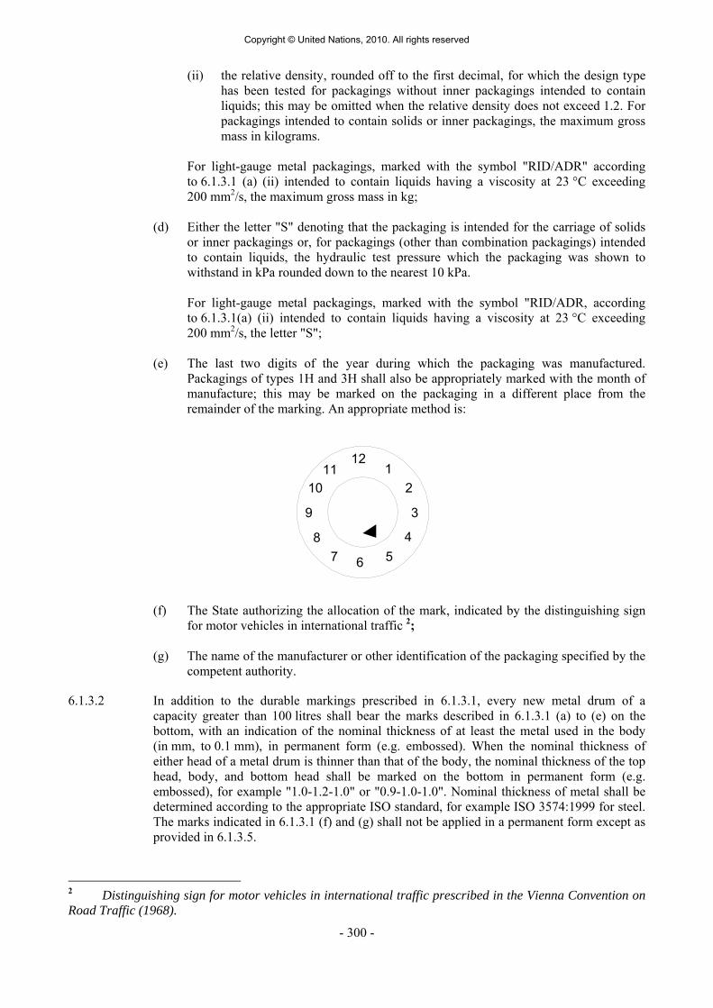
- 300 -
(ii) the relative density, rounded off to the first decimal, for which the design type has been tested for packagings without inner packagings intended to contain liquids; this may be omitted when the relative density does not exceed 1.2. For packagings intended to contain solids or inner packagings, the maximum gross mass in kilograms.
For light-gauge metal packagings, marked with the symbol "RID/ADR" according to 6.1.3.1 (a) (ii) intended to contain liquids having a viscosity at 23 °C exceeding 200 mm2/s, the maximum gross mass in kg;
(d) Either the letter "S" denoting that the packaging is intended for the carriage of solids or inner packagings or, for packagings (other than combination packagings) intended to contain liquids, the hydraulic test pressure which the packaging was shown to withstand in kPa rounded down to the nearest 10 kPa.
For light-gauge metal packagings, marked with the symbol "RID/ADR, according to 6.1.3.1(a) (ii) intended to contain liquids having a viscosity at 23 °C exceeding 200 mm2/s, the letter "S";
(e) The last two digits of the year during which the packaging was manufactured. Packagings of types 1H and 3H shall also be appropriately marked with the month of manufacture; this may be marked on the packaging in a different place from the remainder of the marking. An appropriate method is:
(f) The State authorizing the allocation of the mark, indicated by the distinguishing sign
for motor vehicles in international traffic 2; (g) The name of the manufacturer or other identification of the packaging specified by the
competent authority.
6.1.3.2 In addition to the durable markings prescribed in 6.1.3.1, every new metal drum of a capacity greater than 100 litres shall bear the marks described in 6.1.3.1 (a) to (e) on the bottom, with an indication of the nominal thickness of at least the metal used in the body (in mm, to 0.1 mm), in permanent form (e.g. embossed). When the nominal thickness of either head of a metal drum is thinner than that of the body, the nominal thickness of the top head, body, and bottom head shall be marked on the bottom in permanent form (e.g. embossed), for example "1.0-1.2-1.0" or "0.9-1.0-1.0". Nominal thickness of metal shall be determined according to the appropriate ISO standard, for example ISO 3574:1999 for steel. The marks indicated in 6.1.3.1 (f) and (g) shall not be applied in a permanent form except as provided in 6.1.3.5.
2 Distinguishing sign for motor vehicles in international traffic prescribed in the Vienna Convention on Road Traffic (1968).
12
6
39
12
45
8
1011
7
Copyright © United Nations, 2010. All rights reserved

- 301 -
6.1.3.3 Every packaging other than those referred to in 6.1.3.2 liable to undergo a reconditioning process shall bear the marks indicated in 6.1.3.1 (a) to (e) in a permanent form. Marks are permanent if they are able to withstand the reconditioning process (e.g. embossed). For packagings other than metal drums of a capacity greater than 100 litres, these permanent marks may replace the corresponding durable markings prescribed in 6.1.3.1.
6.1.3.4 For remanufactured metal drums, if there is no change to the packaging type and no
replacement or removal of integral structural components, the required markings need not be permanent. Every other remanufactured metal drum shall bear the markings in 6.1.3.1 (a) to (e) in a permanent form (e.g. embossed) on the top head or side.
6.1.3.5 Metal drums made from materials (e.g. stainless steel) designed to be reused repeatedly may
bear the markings indicated in 6.1.3.1 (f) and (g) in a permanent form (e.g. embossed). 6.1.3.6 The marking in accordance with 6.1.3.1 is valid for only one design type or series of design
types. Different surface treatments may fall within the same design type. A "series of design types" means packagings of the same structural design, wall thickness,
material and cross-section, which differ only in their lesser design heights from the design type approved.
The closures of receptacles shall be identifiable as those referred to in the test report. 6.1.3.7 Marking shall be applied in the sequence of the sub-paragraphs in 6.1.3.1; each element of
the marking required in these sub-paragraphs and when appropriate sub-paragraphs (h) to (j) of 6.1.3.8 shall be clearly separated, e.g. by a slash or space, so as to be easily identifiable. For examples, see 6.1.3.11.
Any additional markings authorized by a competent authority shall still enable the parts of
the mark to be correctly identified with reference to 6.1.3.1. 6.1.3.8 After reconditioning a packaging, the reconditioner shall apply to it a durable marking
showing, in the following sequence:
(h) The State in which the reconditioning was carried out, indicated by the distinguishing sign for motor vehicles in international traffic 2;
(i) The name of the reconditioner or other identification of the packaging specified by the
competent authority; (j) The year of reconditioning; the letter "R"; and, for every packaging successfully
passing the leakproofness test in 6.1.1.3, the additional letter "L".
6.1.3.9 When, after reconditioning, the markings required by 6.1.3.1 (a) to (d) no longer appear on the top head or the side of a metal drum, the reconditioner also shall apply them in a durable form followed by 6.1.3.8 (h), (i) and (j). These markings shall not identify a greater performance capability than that for which the original design type had been tested and marked.
6.1.3.10 Packagings manufactured with recycled plastics material as defined in 1.2.1 shall be marked
"REC". This mark shall be placed near the mark prescribed in 6.1.3.1.
2 Distinguishing sign for motor vehicles in international traffic prescribed in the Vienna Convention on Road Traffic (1968).
Copyright © United Nations, 2010. All rights reserved

- 302 -
6.1.3.11 Examples of markings for NEW packagings
4G/Y145/S/02 NL/VL823
as in 6.1.3.1 (a) (i), (b), (c), (d) and (e) as in 6.1.3.1 (f) and (g) For a new fibreboard box
1A1/Y1.4/150/98 NL/VL824
as in 6.1.3.1 (a) (i), (b), (c), (d) and (e) as in 6.1.3.1 (f) and (g)
For a new steel drum to contain liquids
1A2/Y150/S/01 NL/VL825
as in 6.1.3.1 (a) (i), (b), (c), (d) and (e) as in 6.1.3.1 (f) and (g)
For a new steel drum to contain solids, or inner packagings
4HW/Y136/S/98 NL/VL826
as in 6.1.3.1 (a) (i), (b), (c), (d) and (e) as in 6.1.3.1 (f) and (g)
For a new plastics box of equivalent specification
1A2/Y/100/01 USA/MM5
as in 6.1.3.1 (a) (i), (b), (c), (d) and (e) as in 6.1.3.1 (f) and (g)
For a remanufactured steel drum to contain liquids
RID/ADR/0A1/Y100/89 NL/VL123
as in 6.1.3.1 (a) (ii), (b), (c), (d) and (e) as in 6.1.3.1 (f) and (g)
For a new light gauge metal packaging, non-removable head
RID/ADR/0A2/Y20/S/04 NL/VL124
as in 6.1.3.1 (a) (ii), (b), (c), (d) and (e) as in 6.1.3.1 (f) and (g)
For a new light gauge metal packaging, removable head, intended to contain solids, or liquids with a viscosity at 23 °C exceeding 200 mm2/s.
6.1.3.12 Examples of markings for RECONDITIONED packagings
1A1/Y1.4/150/97 NL/RB/01 RL
as in 6.1.3.1 (a) (i), (b), (c), (d) and (e) as in 6.1.3.8 (h), (i) and (j)
1A2/Y150/S/99 USA/RB/00 R
as in 6.1.3.1 (a) (i), (b), (c), (d) and (e) as in 6.1.3.8 (h), (i) and (j)
6.1.3.13 Example of marking for SALVAGE packagings
1A2T/Y300/S/01 USA/abc
as in 6.1.3.1 (a) (i), (b), (c), (d) and (e) as in 6.1.3.1 (f) and (g)
NOTE: The markings, for which examples are given in 6.1.3.11, 6.1.3.12 and 6.1.3.13 may be applied in a single line or in multiple lines provided the correct sequence is respected.
6.1.3.14 Certification By affixing marking in accordance with 6.1.3.1, it is certified that mass-produced packagings
correspond to the approved design type and that the requirements referred to in the approval have been met.
6.1.4 Requirements for packagings 6.1.4.0 General requirements Any permeation of the substance contained in the packaging shall not constitute a danger
under normal conditions of carriage.
Copyright © United Nations, 2010. All rights reserved

- 303 -
6.1.4.1 Steel drums 1A1 non-removable head 1A2 removable head 6.1.4.1.1 Body and heads shall be constructed of steel sheet of a suitable type and of adequate
thickness in relation to the capacity of the drum and to its intended use.
NOTE: In the case of carbon steel drums, "suitable" steels are identified in ISO 3573:1999 "Hot rolled carbon steel sheet of commercial and drawing qualities" and ISO 3574:1999 "Cold-reduced carbon steel sheet of commercial and drawing qualities". For carbon steel drums below 100 litres "suitable" steels in addition to the above standards are also identified in ISO 11949:1995 "Cold-reduced electrolytic tinplate", ISO 11950:1995 "Cold-reduced electrolytic chromium/chromium oxide-coated steel" and ISO 11951:1995 "Cold-reduced blackplate in coil form for the production of tinplate or electrolytic chromium/chromium-oxide coated steel".
6.1.4.1.2 Body seams shall be welded on drums intended to contain more than 40 litres of liquid.
Body seams shall be mechanically seamed or welded on drums intended to contain solids or 40 litres or less of liquids.
6.1.4.1.3 Chimes shall be mechanically seamed or welded. Separate reinforcing rings may be applied. 6.1.4.1.4 The body of a drum of a capacity greater than 60 litres shall, in general, have at least two
expanded rolling hoops or, alternatively, at least two separate rolling hoops. If there are separate rolling hoops they shall be fitted tightly on the body and so secured that they cannot shift. Rolling hoops shall not be spot welded.
6.1.4.1.5 Openings for filling, emptying and venting in the bodies or heads of non-removable head
(1A1) drums shall not exceed 7 cm in diameter. Drums with larger openings are considered to be of the removable head type (1A2). Closures for openings in the bodies and heads of drums shall be so designed and applied that they will remain secure and leakproof under normal conditions of carriage. Closure flanges may be mechanically seamed or welded in place. Gaskets or other sealing elements shall be used with closures, unless the closure is inherently leakproof.
6.1.4.1.6 Closure devices for removable head (1A2) drums shall be so designed and applied that they
will remain secure and drums will remain leakproof under normal conditions of carriage. Gaskets or other sealing elements shall be used with all removable heads.
6.1.4.1.7 If materials used for body, heads, closures and fittings are not in themselves compatible with
the contents to be carried, suitable internal protective coatings or treatments shall be applied. These coatings or treatments shall retain their protective properties under normal conditions of carriage.
6.1.4.1.8 Maximum capacity of drum: 450 litres. 6.1.4.1.9 Maximum net mass: 400 kg.
6.1.4.2 Aluminium drums 1B1 non-removable head 1B2 removable head 6.1.4.2.1 Body and heads shall be constructed of aluminium at least 99% pure or of an aluminium
base alloy. Material shall be of a suitable type and of adequate thickness in relation to the capacity of the drum and to its intended use.
Copyright © United Nations, 2010. All rights reserved

- 304 -
6.1.4.2.2 All seams shall be welded. Chime seams, if any, shall be reinforced by the application of separate reinforcing rings.
6.1.4.2.3 The body of a drum of a capacity greater than 60 litres shall, in general, have at least two
expanded rolling hoops or, alternatively, at least two separate rolling hoops. If there are separate rolling hoops they shall be fitted tightly on the body and so secured that they cannot shift. Rolling hoops shall not be spot welded.
6.1.4.2.4 Openings for filling, emptying and venting in the bodies or heads of non-removable head
(1B1) drums shall not exceed 7 cm in diameter. Drums with larger openings are considered to be of the removable head type (1B2). Closures for openings in the bodies and heads of drums shall be so designed and applied that they will remain secure and leakproof under normal conditions of carriage. Closure flanges shall be welded in place so that the weld provides a leakproof seam. Gaskets or other sealing elements shall be used with closures, unless the closure is inherently leakproof.
6.1.4.2.5 Closure devices for removable head (1B2) drums shall be so designed and applied that they
will remain secure and drums will remain leakproof under normal conditions of carriage. Gaskets or other sealing elements shall be used with all removable heads.
6.1.4.2.6 Maximum capacity of drum: 450 litres. 6.1.4.2.7 Maximum net mass: 400 kg. 6.1.4.3 Drums of metal other than aluminium or steel 1N1 non-removable head
1N2 removable head 6.1.4.3.1 The body and heads shall be constructed of a metal or of a metal alloy other than steel or
aluminium. Material shall be of a suitable type and of adequate thickness in relation to the capacity of the drum and to its intended use.
6.1.4.3.2 Chime seams, if any, shall be reinforced by the application of separate reinforcing rings. All
seams, if any, shall be joined (welded, solded, etc.) in accordance with the technical state of the art for the used metal or metal alloy.
6.1.4.3.3 The body of a drum of a capacity greater than 60 litres shall, in general, have at least two
expanded rolling hoops or, alternatively, at least two separate rolling hoops. If there are separate rolling hoops they shall be fitted tightly on the body and so secured that they cannot shift. Rolling hoops shall not be spot welded.
6.1.4.3.4 Openings for filling, emptying and venting in the bodies or heads of non-removable head
(1N1) drums shall not exceed 7 cm in diameter. Drums with larger openings are considered to be of the removable head type (1N2). Closures for openings in the bodies and heads of drums shall be so designed and applied that they will remain secure and leakproof under normal conditions of carriage. Closure flanges shall be joined in place (welded, solded, etc.) in accordance with the technical state of the art for the used metal or metal alloy so that the seam join is leakproof. Gaskets or other sealing elements shall be used with closures, unless the closure is inherently leakproof.
6.1.4.3.5 Closure devices for removable head (1N2) drums shall be so designed and applied that they
will remain secure and drums will remain leakproof under normal conditions of carriage. Gaskets or other sealing elements shall be used with all removable heads.
Copyright © United Nations, 2010. All rights reserved

- 305 -
6.1.4.3.6 Maximum capacity of drum: 450 litres. 6.1.4.3.7 Maximum net mass: 400 kg. 6.1.4.4 Steel or aluminium jerricans 3A1 steel, non-removable head 3A2 steel, removable head 3B1 aluminium, non-removable head 3B2 aluminium, removable head 6.1.4.4.1 Body and heads shall be constructed of steel sheet, of aluminium at least 99% pure or of an
aluminium base alloy. Material shall be of a suitable type and of adequate thickness in relation to the capacity of the jerrican and to its intended use.
6.1.4.4.2 Chimes of steel jerricans shall be mechanically seamed or welded. Body seams of steel
jerricans intended to contain more than 40 litres of liquid shall be welded. Body seams of steel jerricans intended to contain 40 litres or less shall be mechanically seamed or welded. For aluminium jerricans, all seams shall be welded. Chime seams, if any, shall be reinforced by the application of a separate reinforcing ring.
6.1.4.4.3 Openings in non-removable head jerricans (3A1 and 3B1) shall not exceed 7 cm in diameter.
Jerricans with larger openings are considered to be of the removable head type (3A2 and 3B2). Closures shall be so designed that they will remain secure and leakproof under normal conditions of carriage. Gaskets or other sealing elements shall be used with closures, unless the closure is inherently leakproof.
6.1.4.4.4 If materials used for body, heads, closures and fittings are not in themselves compatible with
the contents to be carried, suitable internal protective coatings or treatments shall be applied. These coatings or treatments shall retain their protective properties under normal conditions of carriage.
6.1.4.4.5 Maximum capacity of jerrican: 60 litres. 6.1.4.4.6 Maximum net mass: 120 kg. 6.1.4.5 Plywood drums 1D 6.1.4.5.1 The wood used shall be well seasoned, commercially dry and free from any defect likely to
lessen the effectiveness of the drum for the purpose intended. If a material other than plywood is used for the manufacture of the heads, it shall be of a quality equivalent to the plywood.
6.1.4.5.2 At least two-ply plywood shall be used for the body and at least three-ply plywood for the
heads; the plies shall be firmly glued together by a water resistant adhesive with their grain crosswise.
6.1.4.5.3 The body and heads of the drum and their joins shall be of a design appropriate to the capacity of the drum and to its intended use.
6.1.4.5.4 In order to prevent sifting of the contents, lids shall be lined with kraft paper or some other
equivalent material which shall be securely fastened to the lid and extend to the outside along its full circumference.
Copyright © United Nations, 2010. All rights reserved

- 306 -
6.1.4.5.5 Maximum capacity of drum: 250 litres. 6.1.4.5.6 Maximum net mass: 400 kg. 6.1.4.6 (Deleted) 6.1.4.7 Fibre drums 1G 6.1.4.7.1 The body of the drum shall consist of multiple plies of heavy paper or fibreboard (without
corrugations) firmly glued or laminated together and may include one or more protective layers of bitumen, waxed kraft paper, metal foil, plastics material, etc.
6.1.4.7.2 Heads shall be of natural wood, fibreboard, metal, plywood, plastics or other suitable
material and may include one or more protective layers of bitumen, waxed kraft paper, metal foil, plastics material, etc.
6.1.4.7.3 The body and heads of the drum and their joins shall be of a design appropriate to the
capacity of the drum and to its intended use. 6.1.4.7.4 The assembled packaging shall be sufficiently water resistant so as not to delaminate under
normal conditions of carriage. 6.1.4.7.5 Maximum capacity of drum: 450 litres. 6.1.4.7.6 Maximum net mass: 400 kg. 6.1.4.8 Plastics drums and jerricans 1H1 drums, non-removable head 1H2 drums, removable head 3H1 jerricans, non-removable head 3H2 jerricans, removable head 6.1.4.8.1 The packaging shall be manufactured from suitable plastics material and be of adequate
strength in relation to its capacity and intended use. Except for recycled plastics material as defined in 1.2.1, no used material other than production residues or regrind from the same manufacturing process may be used. The packaging shall be adequately resistant to ageing and to degradation caused either by the substance contained or by ultra-violet radiation. Any permeation of the substance contained in the package, or recycled plastics material used to produce new packaging, shall not constitute a danger under normal conditions of carriage.
6.1.4.8.2 If protection against ultra-violet radiation is required, it shall be provided by the addition of
carbon black or other suitable pigments or inhibitors. These additives shall be compatible with the contents and remain effective throughout the life of the packaging. Where use is made of carbon black, pigments or inhibitors other than those used in the manufacture of the tested design type, retesting may be waived if the carbon black content does not exceed 2% by mass or if the pigment content does not exceed 3% by mass; the content of inhibitors of ultra-violet radiation is not limited.
6.1.4.8.3 Additives serving purposes other than protection against ultra-violet radiation may be
included in the composition of the plastics material provided that they do not adversely affect the chemical and physical properties of the material of the packaging. In such circumstances, retesting may be waived.
Copyright © United Nations, 2010. All rights reserved

- 307 -
6.1.4.8.4 The wall thickness at every point of the packaging shall be appropriate to its capacity and intended use, taking into account the stresses to which each point is liable to be exposed.
6.1.4.8.5 Openings for filling, emptying and venting in the bodies or heads of non-removable head
drums (1H1) and jerricans (3H1) shall not exceed 7 cm in diameter. Drums and jerricans with larger openings are considered to be of the removable head type (1H2 and 3H2). Closures for openings in the bodies or heads of drums and jerricans shall be so designed and applied that they will remain secure and leakproof under normal conditions of carriage. Gaskets or other sealing elements shall be used with closures unless the closure is inherently leakproof.
6.1.4.8.6 Closure devices for removable head drums and jerricans (1H2 and 3H2) shall be so designed
and applied that they will remain secure and leakproof under normal conditions of carriage. Gaskets shall be used with all removable heads unless the drum or jerrican design is such that, where the removable head is properly secured, the drum or jerrican is inherently leakproof.
6.1.4.8.7 The maximum permissible permeability for flammable liquids shall be 0.008 g/l.h at 23 °C
(see 6.1.5.7). 6.1.4.8.8 Where recycled plastics material is used for production of new packaging, the specific
properties of the recycled material shall be assured and documented regularly as part of a quality assurance programme recognised by the competent authority. The quality assurance programme shall include a record of proper pre-sorting and verification that each batch of recycled plastics material has the proper melt flow rate, density, and tensile yield strength, consistent with that of the design type manufactured from such recycled material. This necessarily includes knowledge about the packaging material from which the recycled plastics have been derived, as well as the awareness of the prior contents of those packagings if those prior contents might reduce the capability of new packaging produced using that material. In addition, the packaging manufacturer's quality assurance programme under 6.1.1.4 shall include performance of the mechanical design type test in 6.1.5 on packagings manufactured from each batch of recycled plastics material. In this testing, stacking performance may be verified by appropriate dynamic compression testing rather than static load testing. NOTE: ISO 16103:2005 – "Packaging – Transport packaging for dangerous goods - Recycled plastics material" provides additional guidance on procedures to be followed in approving the use of recycled plastics material.
6.1.4.8.9 Maximum capacity of drums and jerricans: 1H1, 1H2: 450 litres 3H1, 3H2: 60 litres. 6.1.4.8.10 Maximum net mass: 1H1, 1H2: 400 kg 3H1, 3H2: 120 kg.
6.1.4.9 Boxes of natural wood 4C1 ordinary 4C2 with sift-proof walls 6.1.4.9.1 The wood used shall be well seasoned, commercially dry and free from defects that would
materially lessen the strength of any part of the box. The strength of the material used and the method of construction shall be appropriate to the capacity and intended use of the box. The tops and bottoms may be made of water resistant reconstituted wood such as hardboard, particle board or other suitable type.
Copyright © United Nations, 2010. All rights reserved

- 308 -
6.1.4.9.2 Fastenings shall be resistant to vibration experienced under normal conditions of carriage. End grain nailing shall be avoided whenever practicable. Joins which are likely to be highly stressed shall be made using clenched or annular ring nails or equivalent fastenings.
6.1.4.9.3 Box 4C2: each part shall consist of one piece or be equivalent thereto. Parts are considered
equivalent to one piece when one of the following methods of glued assembly is used: Lindermann joint, tongue and groove joint, ship lap or rabbet joint or butt joint with at least two corrugated metal fasteners at each joint.
6.1.4.9.4 Maximum net mass: 400 kg. 6.1.4.10 Plywood boxes 4D 6.1.4.10.1 Plywood used shall be at least 3-ply. It shall be made from well seasoned rotary cut, sliced or
sawn veneer, commercially dry and free from defects that would materially lessen the strength of the box. The strength of the material used and the method of construction shall be appropriate to the capacity and intended use of the box. All adjacent plies shall be glued with water resistant adhesive. Other suitable materials may be used together with plywood in the construction of boxes. Boxes shall be firmly nailed or secured to corner posts or ends or be assembled by equally suitable devices.
6.1.4.10.2 Maximum net mass: 400 kg. 6.1.4.11 Reconstituted wood boxes 4F 6.1.4.11.1 The walls of boxes shall be made of water resistant reconstituted wood such as hardboard,
particle board or other suitable type. The strength of the material used and the method of construction shall be appropriate to the capacity of the boxes and to their intended use.
6.1.4.11.2 Other parts of the boxes may be made of other suitable material. 6.1.4.11.3 Boxes shall be securely assembled by means of suitable devices. 6.1.4.11.4 Maximum net mass: 400 kg. 6.1.4.12 Fibreboard boxes 4G 6.1.4.12.1 Strong and good quality solid or double-faced corrugated fibreboard (single or multiwall)
shall be used, appropriate to the capacity of the box and to its intended use. The water resistance of the outer surface shall be such that the increase in mass, as determined in a test carried out over a period of 30 minutes by the Cobb method of determining water absorption, is not greater than 155 g/m2 - see ISO 535:l991. It shall have proper bending qualities. Fibreboard shall be cut, creased without scoring, and slotted so as to permit assembly without cracking, surface breaks or undue bending. The fluting of corrugated fibreboard shall be firmly glued to the facings.
6.1.4.12.2 The ends of boxes may have a wooden frame or be entirely of wood or other suitable
material. Reinforcements of wooden battens or other suitable material may be used.
Copyright © United Nations, 2010. All rights reserved

- 309 -
6.1.4.12.3 Manufacturing joins in the body of boxes shall be taped, lapped and glued, or lapped and stitched with metal staples. Lapped joins shall have an appropriate overlap.
6.1.4.12.4 Where closing is effected by gluing or taping, a water resistant adhesive shall be used. 6.1.4.12.5 Boxes shall be designed so as to provide a good fit to the contents. 6.1.4.12.6 Maximum net mass: 400 kg. 6.1.4.13 Plastics boxes 4H1 expanded plastics boxes 4H2 solid plastics boxes 6.1.4.13.1 The box shall be manufactured from suitable plastics material and be of adequate strength in
relation to its capacity and intended use. The box shall be adequately resistant to ageing and to degradation caused either by the substance contained or by ultra-violet radiation.
6.1.4.13.2 An expanded plastics box shall comprise two parts made of a moulded expanded plastics
material, a bottom section containing cavities for the inner packagings and a top section covering and interlocking with the bottom section. The top and bottom sections shall be designed so that the inner packagings fit snugly. The closure cap for any inner packaging shall not be in contact with the inside of the top section of this box.
6.1.4.13.3 For dispatch, an expanded plastics box shall be closed with a self-adhesive tape having
sufficient tensile strength to prevent the box from opening. The adhesive tape shall be weather resistant and its adhesive compatible with the expanded plastics material of the box. Other closing devices at least equally effective may be used.
6.1.4.13.4 For solid plastics boxes, protection against ultra-violet radiation, if required, shall be
provided by the addition of carbon black or other suitable pigments or inhibitors. These additives shall be compatible with the contents and remain effective throughout the life of the box. Where use is made of carbon black, pigments or inhibitors other than those used in the manufacture of the tested design type, retesting may be waived if the carbon black content does not exceed 2% by mass or if the pigment content does not exceed 3% by mass; the content of inhibitors of ultra-violet radiation is not limited.
6.1.4.13.5 Additives serving purposes other than protection against ultra-violet radiation may be
included in the composition of the plastics material provided that they do not adversely affect the chemical or physical properties of the material of the box. In such circumstances, retesting may be waived.
6.1.4.13.6 Solid plastics boxes shall have closure devices made of a suitable material of adequate
strength and so designed as to prevent the box from unintentional opening. 6.1.4.13.7 Where recycled plastics material is used for production of new packaging, the specific
properties of the recycled material shall be assured and documented regularly as part of a quality assurance programme recognised by the competent authority. The quality assurance programme shall include a record of proper pre-sorting and verification that each batch of recycled plastics material has the proper melt flow rate, density, and tensile yield strength, consistent with that of the design type manufactured from such recycled material. This necessarily includes knowledge about the packaging material from which the recycled plastics have been derived, as well as the awareness of the prior contents of those packagings if those prior contents might reduce the capability of new packaging produced using that material. In addition, the packaging manufacturer's quality assurance programme under 6.1.1.4 shall include performance of the mechanical design type test in 6.1.5 on packagings
Copyright © United Nations, 2010. All rights reserved

- 310 -
manufactured from each batch of recycled plastics material. In this testing, stacking performance may be verified by appropriate dynamic compression testing rather than static load testing.
6.1.4.13.8 Maximum net mass 4H1: 60 kg 4H2: 400 kg. 6.1.4.14 Steel or aluminium boxes 4A steel 4B aluminium 6.1.4.14.l The strength of the metal and the construction of the box shall be appropriate to the capacity
of the box and to its intended use. 6.1.4.14.2 Boxes shall be lined with fibreboard or felt packing pieces or shall have an inner liner or
coating of suitable material, as required. If a double seamed metal liner is used, steps shall be taken to prevent the ingress of substances, particularly explosives, into the recesses of the seams.
6.1.4.14.3 Closures may be of any suitable type; they shall remain secured under normal conditions of
carriage. 6.1.4.14.4 Maximum net mass: 400 kg.
6.1.4.15 Textile bags 5L1 without inner liner or coating 5L2 sift-proof 5L3 water resistant 6.1.4.15.1 The textiles used shall be of good quality. The strength of the fabric and the construction of
the bag shall be appropriate to the capacity of the bag and to its intended use. 6.1.4.15.2 Bags, sift-proof, 5L2: the bag shall be made sift-proof, for example by the use of:
(a) paper bonded to the inner surface of the bag by a water resistant adhesive such as bitumen; or
(b) plastics film bonded to the inner surface of the bag; or (c) one or more inner liners made of paper or plastics material.
6.1.4.15.3 Bags, water resistant, 5L3: to prevent the entry of moisture the bag shall be made
waterproof, for example by the use of: (a) separate inner liners of water resistant paper (e.g. waxed kraft paper, tarred paper or
plastics-coated kraft paper); or (b) plastics film bonded to the inner surface of the bag; or (c) one or more inner liners made of plastics material.
6.1.4.15.4 Maximum net mass: 50 kg.
Copyright © United Nations, 2010. All rights reserved

- 311 -
6.1.4.16 Woven plastics bags 5H1 without inner liner or coating 5H2 sift-proof 5H3 water resistant 6.1.4.16.1 Bags shall be made from stretched tapes or monofilaments of a suitable plastics material.
The strength of the material used and the construction of the bag shall be appropriate to the capacity of the bag and to its intended use.
6.1.4.16.2 If the fabric is woven flat, the bags shall be made by sewing or some other method ensuring
closure of the bottom and one side. If the fabric is tubular, the bag shall be closed by sewing, weaving or some other equally strong method of closure.
6.1.4.16.3 Bags, sift-proof, 5H2: the bag shall be made sift-proof, for example by means of:
(a) paper or a plastics film bonded to the inner surface of the bag; or (b) one or more separate inner liners made of paper or plastics material.
6.1.4.16.4 Bags, water resistant, 5H3: to prevent the entry of moisture, the bag shall be made waterproof, for example by means of:
(a) separate inner liners of water resistant paper (e.g. waxed kraft paper, double-tarred
kraft paper or plastics-coated kraft paper); or (b) plastics film bonded to the inner or outer surface of the bag; or (c) one or more inner plastics liners.
6.1.4.16.5 Maximum net mass: 50 kg. 6.1.4.17 Plastics film bags 5H4 6.1.4.17.1 Bags shall be made of a suitable plastics material. The strength of the material used and the
construction of the bag shall be appropriate to the capacity of the bag and to its intended use. Joins and closures shall withstand pressures and impacts liable to occur under normal conditions of carriage.
6.1.4.17.2 Maximum net mass: 50 kg. 6.1.4.18 Paper bags 5M1 multiwall 5M2 multiwall, water resistant 6.1.4.18.1 Bags shall be made of a suitable kraft paper or of an equivalent paper with at least three
plies, the middle ply of which may be net-cloth and adhesive bonding to the outer paper plies. The strength of the paper and the construction of the bags shall be appropriate to the capacity of the bag and to its intended use. Joins and closures shall be sift-proof.
6.1.4.18.2 Bags 5M2: to prevent the entry of moisture, a bag of four plies or more shall be made
waterproof by the use of either a water resistant ply as one of the two outermost plies or a water resistant barrier made of a suitable protective material between the two outermost
Copyright © United Nations, 2010. All rights reserved
- 312 -
plies; a bag of three plies shall be made waterproof by the use of a water resistant ply as the outermost ply. Where there is a danger of the substance contained reacting with moisture or where it is packed damp, a waterproof ply or barrier, such as double-tarred kraft paper, plastics-coated kraft paper, plastics film bonded to the inner surface of the bag, or one or more inner plastics liners, shall also be placed next to the substance. Joins and closures shall be waterproof.
6.1.4.18.3 Maximum net mass: 50 kg. 6.1.4.19 Composite packagings (plastics material) 6HA1 plastics receptacle with outer steel drum 6HA2 plastics receptacle with outer steel crate or box 6HB1 plastics receptacle with outer aluminium drum 6HB2 plastics receptacle with outer aluminium crate or box 6HC plastics receptacle with outer wooden box 6HD1 plastics receptacle with outer plywood drum 6HD2 plastics receptacle with outer plywood box 6HG1 plastics receptacle with outer fibre drum 6HG2 plastics receptacle with outer fibreboard box 6HH1 plastics receptacle with outer plastics drum 6HH2 plastics receptacle with outer solid plastics box 6.1.4.19.1 Inner receptacle 6.1.4.19.1.1 The requirements of 6.1.4.8.1 and 6.1.4.8.4 to 6.1.4.8.7 apply to plastics inner receptacles. 6.1.4.19.1.2 The plastics inner receptacle shall fit snugly inside the outer packaging, which shall be free
of any projection that might abrade the plastics material. 6.1.4.19.1.3 Maximum capacity of inner receptacle: 6HA1, 6HB1, 6HD1, 6HG1, 6HH1: 250 litres 6HA2, 6HB2, 6HC, 6HD2, 6HG2, 6HH2: 60 litres. 6.1.4.19.1.4 Maximum net mass: 6HA1, 6HB1, 6HD1, 6HG1, 6HH1: 400 kg 6HA2, 6HB2, 6HC, 6HD2, 6HG2, 6HH2: 75 kg. 6.1.4.19.2 Outer packaging 6.1.4.19.2.1 Plastics receptacle with outer steel or aluminium drum 6HA1 or 6HB1; the relevant
requirements of 6.1.4.1 or 6.1.4.2, as appropriate, apply to the construction of the outer packaging.
6.1.4.19.2.2 Plastics receptacle with outer steel or aluminium crate or box 6HA2 or 6HB2; the relevant
requirements of 6.1.4.14 apply to the construction of the outer packaging. 6.1.4.19.2.3 Plastics receptacle with outer wooden box 6HC; the relevant requirements of 6.1.4.9 apply to
the construction of the outer packaging. 6.1.4.19.2.4 Plastics receptacle with outer plywood drum 6HD1; the relevant requirements of 6.1.4.5
apply to the construction of the outer packaging.
Copyright © United Nations, 2010. All rights reserved

- 313 -
6.1.4.19.2.5 Plastics receptacle with outer plywood box 6HD2; the relevant requirements of 6.1.4.10 apply to the construction of the outer packaging.
6.1.4.19.2.6 Plastics receptacle with outer fibre drum 6HG1; the requirements of 6.1.4.7.1 to 6.1.4.7.4
apply to the construction of the outer packaging. 6.1.4.19.2.7 Plastics receptacle with outer fibreboard box 6HG2; the relevant requirements of 6.1.4.12
apply to the construction of the outer packaging. 6.1.4.19.2.8 Plastics receptacle with outer plastics drum 6HH1; the requirements of 6.1.4.8.1 to 6.1.4.8.6
apply to the construction of the outer packaging. 6.1.4.19.2.9 Plastics receptacles with outer solid plastics box (including corrugated plastics material)
6HH2; the requirements of 6.1.4.13.1 and 6.1.4.13.4 to 6.1.4.13.6 apply to the construction of the outer packaging.
6.1.4.20 Composite packagings (glass, porcelain or stoneware) 6PA1 receptacle with outer steel drum 6PA2 receptacle with outer steel crate or box 6PB1 receptacle with outer aluminium drum 6PB2 receptacle with outer aluminium crate or box 6PC receptacle with outer wooden box 6PD1 receptacle with outer plywood drum 6PD2 receptacle with outer wickerwork hamper 6PG1 receptacle with outer fibre drum 6PG2 receptacle with outer fibreboard box 6PH1 receptacle with outer expanded plastics packaging 6PH2 receptacle with outer solid plastics packaging 6.1.4.20.1 Inner receptacle 6.1.4.20.1.1 Receptacles shall be of a suitable form (cylindrical or pear-shaped) and be made of good
quality material free from any defect that could impair their strength. The walls shall be sufficiently thick at every point and free from internal stresses.
6.1.4.20.1.2 Screw-threaded plastics closures, ground glass stoppers or closures at least equally effective
shall be used as closures for receptacles. Any part of the closure likely to come into contact with the contents of the receptacle shall be resistant to those contents. Care shall be taken to ensure that the closures are so fitted as to be leakproof and are suitably secured to prevent any loosening during carriage. If vented closures are necessary, they shall comply with 4.1.1.8.
6.1.4.20.1.3 The receptacle shall be firmly secured in the outer packaging by means of cushioning and/or
absorbent materials. 6.1.4.20.1.4 Maximum capacity of receptacle: 60 litres. 6.1.4.20.1.5 Maximum net mass: 75 kg. 6.1.4.20.2 Outer packaging 6.1.4.20.2.1 Receptacle with outer steel drum 6PA1; the relevant requirements of 6.1.4.1 apply to the
construction of the outer packaging. The removable lid required for this type of packaging may nevertheless be in the form of a cap.
Copyright © United Nations, 2010. All rights reserved

- 314 -
6.1.4.20.2.2 Receptacle with outer steel crate or box 6PA2; the relevant requirements of 6.1.4.14 apply to the construction of the outer packaging. For cylindrical receptacles the outer packaging shall, when upright, rise above the receptacle and its closure. If the crate surrounds a pear-shaped receptacle and is of matching shape, the outer packaging shall be fitted with a protective cover (cap).
6.1.4.20.2.3 Receptacle with outer aluminium drum 6PB1; the relevant requirements of 6.1.4.2 apply to
the construction of the outer packaging. 6.1.4.20.2.4 Receptacle with outer aluminium crate or box 6PB2; the relevant requirements of 6.1.4.14
apply to the construction of the outer packaging. 6.1.4.20.2.5 Receptacle with outer wooden box 6PC; the relevant requirements of 6.1.4.9 apply to the
construction of the outer packaging. 6.1.4.20.2.6 Receptacle with outer plywood drum 6PD1; the relevant requirements of 6.1.4.5 apply to the
construction of the outer packaging. 6.1.4.20.2.7 Receptacle with outer wickerwork hamper 6PD2. The wickerwork hamper shall be properly
made with material of good quality. It shall be fitted with a protective cover (cap) so as to prevent damage to the receptacle.
6.1.4.20.2.8 Receptacle with outer fibre drum 6PG1; the relevant requirements of 6.1.4.7.1 to 6.1.4.7.4
apply to the construction of the outer packaging.
6.1.4.20.2.9 Receptacle with outer fibreboard box 6PG2; the relevant requirements of 6.1.4.12 apply to the construction of the outer packaging.
6.1.4.20.2.10 Receptacle with outer expanded plastics or solid plastics packaging (6PH1 or 6PH2); the
materials of both outer packagings shall meet the relevant requirements of 6.1.4.13. Outer solid plastics packaging shall be manufactured from high density polyethylene or some other comparable plastics material. The removable lid for this type of packaging may nevertheless be in the form of a cap.
6.1.4.21 Combination packagings The relevant requirements of section 6.1.4 for the outer packagings to be used, are
applicable. NOTE: For the inner and outer packagings to be used, see the relevant packing instructions
in Chapter 4.1.
6.1.4.22 Light gauge metal packagings 0A1 non-removable-head 0A2 removable-head 6.1.4.22.1 The sheet metal for the body and ends shall be of suitable steel, and of a gauge appropriate to
the capacity and intended use of the packaging.
6.1.4.22.2 The joints shall be welded, at least double-seamed by welting or produced by a method ensuring a similar degree of strength and leakproofness.
6.1.4.22.3 Inner coatings of zinc, tin, lacquer, etc. shall be tough and shall adhere to the steel at every point, including the closures.
Copyright © United Nations, 2010. All rights reserved

- 315 -
6.1.4.22.4 Openings for filling, emptying and venting in the bodies or heads of non-removable head (0A1) packagings shall not exceed 7 cm in diameter. Packagings with larger openings shall be considered to be of the removable-head type (0A2).
6.1.4.22.5 The closures of non-removable-head packagings (0A1) shall either be of the screw-threaded type or be capable of being secured by a screwable device or a device at least equally effective. The closures of removable-head packagings (0A2) shall be so designed and fitted that they stay firmly closed and the packagings remain leakproof in normal conditions of carriage.
6.1.4.22.6 Maximum capacity of packagings: 40 litres. 6.1.4.22.7 Maximum net mass: 50 kg. 6.1.5 Test requirements for packagings 6.1.5.1 Performance and frequency of tests 6.1.5.1.1 The design type of each packaging shall be tested as provided in 6.1.5 in accordance with
procedures established by the competent authority allowing the allocation of the mark and shall be approved by this competent authority.
6.1.5.1.2 Each packaging design type shall successfully pass the tests prescribed in this Chapter before
being used. A packaging design type is defined by the design, size, material and thickness, manner of construction and packing, but may include various surface treatments. It also includes packagings which differ from the design type only in their lesser design height.
6.1.5.1.3 Tests shall be repeated on production samples at intervals established by the competent
authority. For such tests on paper or fibreboard packagings, preparation at ambient conditions is considered equivalent to the requirements of 6.1.5.2.3.
6.1.5.1.4 Tests shall also be repeated after each modification which alters the design, material or
manner of construction of a packaging.
6.1.5.1.5 The competent authority may permit the selective testing of packagings that differ only in minor respects from a tested type, e.g. smaller sizes of inner packagings or inner packagings of lower net mass; and packagings such as drums, bags and boxes which are produced with small reductions in external dimension(s).
6.1.5.1.6 (Reserved)
NOTE: For the conditions for assembling different inner packagings in an outer packaging and permissible variations in inner packagings, see 4.1.1.5.1.
6.1.5.1.7 Articles or inner packagings of any type for solids or liquids may be assembled and carried
without testing in an outer packaging under the following conditions:
(a) The outer packaging shall have been successfully tested in accordance with 6.1.5.3 with fragile (e.g. glass) inner packagings containing liquids using the packing group I drop height;
(b) The total combined gross mass of inner packagings shall not exceed one half the gross
mass of inner packagings used for the drop test in (a) above;
Copyright © United Nations, 2010. All rights reserved

- 316 -
(c) The thickness of cushioning material between inner packagings and between inner packagings and the outside of the packaging shall not be reduced below the corresponding thicknesses in the originally tested packaging; and if a single inner packaging was used in the original test, the thicknesses of cushioning between inner packagings shall not be less than the thickness of cushioning between the outside of the packaging and the inner packaging in the original test. If either fewer or smaller inner packagings are used (as compared to the inner packagings used in the drop test), sufficient additional cushioning material shall be used to take up void spaces;
(d) The outer packaging shall have passed successfully the stacking test in 6.1.5.6 while
empty. The total mass of identical packages shall be based on the combined mass of inner packagings used for the drop test in (a) above;
(e) Inner packagings containing liquids shall be completely surrounded with a sufficient
quantity of absorbent material to absorb the entire liquid contents of the inner packagings;
(f) If the outer packaging is intended to contain inner packagings for liquids and is not
leakproof, or is intended to contain inner packagings for solids and is not siftproof, a means of containing any liquid or solid contents in the event of leakage shall be provided in the form of a leakproof liner, plastics bag or other equally efficient means of containment. For packagings containing liquids, the absorbent material required in (e) above shall be placed inside the means of containing the liquid contents;
(g) Packagings shall be marked in accordance with 6.1.3 as having been tested to packing
group I performance for combination packagings. The marked gross mass in kilograms shall be the sum of the mass of the outer packaging plus one half of the mass of the inner packaging(s) as used for the drop test referred to in (a) above. Such a package mark shall also contain a letter "V" as described in 6.1.2.4.
6.1.5.1.8 The competent authority may at any time require proof, by tests in accordance with this
section, that serially-produced packagings meet the requirements of the design type tests. For verification purposes records of such tests shall be maintained.
6.1.5.1.9 If an inner treatment or coating is required for safety reasons, it shall retain its protective
properties even after the tests. 6.1.5.1.10 Provided the validity of the test results is not affected and with the approval of the competent
authority, several tests may be made on one sample. 6.1.5.1.11 Salvage packagings Salvage packagings (see 1.2.1) shall be tested and marked in accordance with the
requirements applicable to packing group II packagings intended for the carriage of solids or inner packagings, except as follows:
(a) The test substance used in performing the tests shall be water, and the packagings
shall be filled to not less than 98% of their maximum capacity. It is permissible to use additives, such as bags of lead shot, to achieve the requisite total package mass so long as they are placed so that the test results are not affected. Alternatively, in performing the drop test, the drop height may be varied in accordance with 6.1.5.3.5 (b);
(b) Packagings shall, in addition, have been successfully subjected to the leakproofness
test at 30 kPa, with the results of this test reflected in the test report required by 6.1.5.8; and
(c) Packagings shall be marked with the letter "T" as described in 6.1.2.4.
Copyright © United Nations, 2010. All rights reserved

- 317 -
6.1.5.2 Preparation of packagings for testing 6.1.5.2.1 Tests shall be carried out on packagings prepared as for carriage including, with respect to
combination packagings, the inner packagings used. Inner or single receptacles or packagings other than bags shall be filled to not less than 98% of their maximum capacity for liquids or 95% for solids. Bags shall be filled to the maximum mass at which they may be used. For combination packagings where the inner packaging is designed to carry liquids and solids, separate testing is required for both liquid and solid contents. The substances or articles to be carried in the packagings may be replaced by other substances or articles except where this would invalidate the results of the tests. For solids, when another substance is used it shall have the same physical characteristics (mass, grain size, etc.) as the substance to be carried. It is permissible to use additives, such as bags of lead shot, to achieve the requisite total package mass, so long as they are placed so that the test results are not affected.
6.1.5.2.2 In the drop tests for liquids, when another substance is used, it shall be of similar relative
density and viscosity to those of the substance being carried. Water may also be used for the liquid drop test under the conditions in 6.1.5.3.5.
6.1.5.2.3 Paper or fibreboard packagings shall be conditioned for at least 24 hours in an atmosphere
having a controlled temperature and relative humidity (r.h.). There are three options, one of which shall be chosen. The preferred atmosphere is 23 ± 2 °C and 50% ± 2% r.h. The two other options are 20 ± 2 °C and 65% ± 2% r.h. or 27 ± 2 °C and 65% ± 2% r.h.
NOTE: Average values shall fall within these limits. Short-term fluctuations and
measurement limitations may cause individual measurements to vary by up to ± 5% relative humidity without significant impairment of test reproducibility.
6.1.5.2.4 (Reserved) 6.1.5.2.5 To check that their chemical compatibility with the liquids is sufficient, plastics drums and
jerricans in accordance with 6.1.4.8 and if necessary composite packagings (plastics material) in accordance with 6.1.4.19 shall be subjected to storage at ambient temperature for six months, during which time the test samples shall be kept filled with the goods they are intended to carry.
For the first and last 24 hours of storage, the test samples shall be placed with the closure
downwards. However, packagings fitted with a vent shall be so placed on each occasion for five minutes only. After this storage the test samples shall undergo the tests prescribed in 6.1.5.3 to 6.1.5.6.
When it is known that the strength properties of the plastics material of the inner receptacles
of composite packagings (plastics material) are not significantly altered by the action of the filling substance, it shall not be necessary to check that the chemical compatibility is sufficient.
A significant alteration in strength properties means:
(a) distinct embrittlement; or (b) a considerable decrease in elasticity, unless related to a not less than proportionate
increase in the elongation under load.
Where the behaviour of the plastics material has been established by other means, the above compatibility test may be dispensed with. Such procedures shall be at least equivalent to the above compatibility test and be recognized by the competent authority.
Copyright © United Nations, 2010. All rights reserved

- 318 -
NOTE: For plastics drums and jerricans and composite packagings (plastics material) made of polyethylene, see also 6.1.5.2.6 below.
6.1.5.2.6 For polyethylene drums and jerricans in accordance with 6.1.4.8 and if necessary,
polyethylene composite packagings in accordance with 6.1.4.19, chemical compatibility with filling liquids assimilated in accordance with 4.1.1.19 may be verified as follows with standard liquids (see 6.1.6).
The standard liquids are representative for the processes of deterioration on polyethylene, as there are softening through swelling, cracking under stress, molecular degradation and combinations thereof. The sufficient chemical compatibility of the packagings may be verified by storage of the required test samples for three weeks at 40 °C with the appropriate standard liquid(s); where this standard liquid is water, storage in accordance with this procedure is not required. Storage is not required either for test samples which are used for the stacking test in case of the standard liquids "wetting solution" and "acetic acid".
For the first and last 24 hours of storage, the test samples shall be placed with the closure
downwards. However, packagings fitted with a vent shall be so placed on each occasion for five minutes only. After this storage, the test samples shall undergo the tests prescribed in 6.1.5.3 to 6.1.5.6.
The compatibility test for tert-Butyl hydroperoxide with more than 40% peroxide content
and peroxyacetic acids of Class 5.2 shall not be carried out using standard liquids. For these substances, sufficient chemical compatibility of the test samples shall be verified during a storage period of six months at ambient temperature with the substances they are intended to carry.
Results of the procedure in accordance with this paragraph from polyethylene packagings
can be approved for an equal design type, the internal surface of which is fluorinated. 6.1.5.2.7 For packagings made of polyethylene, as specified in 6.1.5.2.6, which have passed the test in
6.1.5.2.6, filling substances other than those assimilated in accordance with 4.1.1.19 may also be approved. Such approval shall be based on laboratory tests verifying that the effect of such filling substances on the test specimens is less than that of the appropriate standard liquid(s) taking into account the relevant processes of deterioration. The same conditions as those set out in 4.1.1.19.2 shall apply with respect to relative density and vapour pressure.
6.1.5.2.8 Provided that the strength properties of the plastics inner packagings of a combination
packaging are not significantly altered by the action of the filling substance, proof of chemical compatibility is not necessary. A significant alteration in strength properties means:
(a) distinct embrittlement; (b) a considerable decrease in elasticity, unless related to a not less than proportionate
increase in elastic elongation. 6.1.5.3 Drop test 3 6.1.5.3.1 Number of test samples (per design type and manufacturer) and drop orientation For other than flat drops the centre of gravity shall be vertically over the point of impact. Where more than one orientation is possible for a given drop test, the orientation most likely
to result in failure of the packaging shall be used. 3 See ISO Standard 2248.
Copyright © United Nations, 2010. All rights reserved

- 319 -
Packaging No. of test samples Drop orientation
(a) Steel drums Aluminium drums Drums of metal other than steel or
aluminium Steel jerricans Aluminium jerricans Plywood drums Fibre drums Plastics drums and jerricans Composite packagings which are in the shape of a drum Light gauge metal packagings
Six (three for each drop)
First drop (using three samples): the packaging shall strike the target diagonally on the chime or, if the packaging has no chime, on a circumferential seam or an edge. Second drop (using the other three samples): the packaging shall strike the target on the weakest part not tested by the first drop, for example a closure or, for some cylindrical drums, the welded longitudinal seam of the drum body
(b) Boxes of natural wood Plywood boxes Reconstituted wood boxes Fibreboard boxes Plastics boxes Steel or aluminium boxes Composite packagings which are in the
shape of a box
Five (one for each drop)
First drop: flat on the bottom Second drop: flat on the top Third drop: flat on the long side Fourth drop: flat on the short side Fifth drop: on a corner
(c) Bags - single-ply with a side seam Three (three drops per bag)
First drop: flat on a wide face Second drop: flat on a narrow face Third drop: on an end of the bag
(d) Bags - single-ply without a side seam, or multi-ply
Three (two drops per bag)
First drop: flat on a wide face Second drop: on an end of the bag
(e) Composite packagings (glass, stoneware or porcelain), marked with the symbol "RID/ADR" according to 6.1.3.1 (a) (ii) and which are in the shape of a drum or box
Three (one for each drop)
Diagonally on the bottom chime, or, if there is no chime, on a circumferential seam or the bottom edge
Copyright © United Nations, 2010. All rights reserved

- 320 -
6.1.5.3.2 Special preparation of test samples for the drop test The temperature of the test sample and its contents shall be reduced to –18 °C or lower for
the following packagings: (a) Plastics drums (see 6.1.4.8); (b) Plastics jerricans (see 6.1.4.8); (c) Plastics boxes other than expanded plastics boxes (see 6.1.4.13); (d) Composite packagings (plastics material) (see 6.1.4.19); and (e) Combination packagings with plastics inner packagings, other than plastics bags
intended to contain solids or articles. Where test samples are prepared in this way, the conditioning in 6.1.5.2.3 may be waived.
Test liquids shall be kept in the liquid state by the addition of anti-freeze if necessary. 6.1.5.3.3 Removable head packagings for liquids shall not be dropped until at least 24 hours after
filling and closing to allow for any possible gasket relaxation. 6.1.5.3.4 Target The target shall be a non-resilient and horizontal surface and shall be:
- Integral and massive enough to be immovable; - Flat with a surface kept free from local defects capable of influencing the test results; - Rigid enough to be non-deformable under test conditions and not liable to become
damaged by the tests; and - Sufficiently large to ensure that the test package falls entirely upon the surface.
6.1.5.3.5 Drop height For solids and liquids, if the test is performed with the solid or liquid to be carried or with
another substance having essentially the same physical characteristics:
Packing Group I Packing Group II Packing Group III 1.8 m 1.2 m 0.8 m
For liquids in single packagings and for inner packagings of combination packagings, if the test is performed with water: NOTE: The term water includes water/antifreeze solutions with a minimum specific gravity of 0.95 for testing at - 18 °C.
(a) where the substances to be carried have a relative density not exceeding 1.2:
Packing Group I Packing Group II Packing Group III 1.8 m 1.2 m 0.8 m
Copyright © United Nations, 2010. All rights reserved

- 321 -
(b) where the substances to be carried have a relative density exceeding 1.2, the drop height shall be calculated on the basis of the relative density (d) of the substance to be carried, rounded up to the first decimal, as follows:
Packing Group I Packing Group II Packing Group III
d × 1.5 (m) d × 1.0 (m) d × 0.67 (m) (c) for light-gauge metal packagings, marked with symbol "RID/ADR" according to
6.1.3.1(a) (ii) intended for the carriage of substances having a viscosity at 23 °C greater than 200 mm2/s (corresponding to a flow time of 30 seconds with an ISO flow cup having a jet orifice of 6 mm diameter in accordance with ISO Standard 2431:1993)
(i) if the relative density does not exceed 1.2:
Packing group II Packing group III
0.6 m 0.4 m
(ii) where the substances to be carried have a relative density (d) exceeding 1.2 the drop height shall be calculated on the basis of the relative density (d) of the substance to be carried, rounded up to the first decimal place, as follows:
Packing group II Packing group III
d × 0.5 m d × 0.33 m 6.1.5.3.6 Criteria for passing the test 6.1.5.3.6.1 Each packaging containing liquid shall be leakproof when equilibrium has been reached
between the internal and external pressures, however for inner packagings of combination packagings and except for inner receptacles of composite packagings (glass, porcelain or stoneware), marked with the symbol "RID/ADR" according to 6.1.3.1 (a) (ii) it is not necessary that the pressures be equalized.
6.1.5.3.6.2 Where a packaging for solids undergoes a drop test and its upper face strikes the target, the
test sample passes the test if the entire contents are retained by an inner packaging or inner receptacle (e.g. a plastics bag), even if the closure while retaining its containment function, is no longer sift-proof.
6.1.5.3.6.3 The packaging or outer packaging of a composite or combination packaging shall not exhibit
any damage liable to affect safety during carriage. Inner receptacles, inner packagings, or articles shall remain completely within the outer packaging and there shall be no leakage of the filling substance from the inner receptacle(s) or inner packaging(s).
6.1.5.3.6.4 Neither the outermost ply of a bag nor an outer packaging may exhibit any damage liable to
affect safety during carriage. 6.1.5.3.6.5 A slight discharge from the closure(s) upon impact is not considered to be a failure of the
packaging provided that no further leakage occurs. 6.1.5.3.6.6 No rupture is permitted in packagings for goods of Class 1 which would permit the spillage
of loose explosive substances or articles from the outer packaging.
Copyright © United Nations, 2010. All rights reserved

- 322 -
6.1.5.4 Leakproofness test The leakproofness test shall be performed on all design types of packagings intended to
contain liquids; however, this test is not required for
- inner packagings of combination packagings; - inner receptacles of composite packagings (glass, porcelain or stoneware), marked
with the symbol "RID/ADR" according to 6.1.3.1 (a) (ii); - light gauge metal packagings, marked with the symbol "RID/ADR" according
to 6.1.3.1 (a) (ii) intended for substances with a viscosity at 23 °C exceeding 200 mm2/s.
6.1.5.4.1 Number of test samples: three test samples per design type and manufacturer. 6.1.5.4.2 Special preparation of test samples for the test: either vented closures shall be replaced by
similar non-vented closures or the vent shall be sealed. 6.1.5.4.3 Test method and pressure to be applied: the packagings including their closures shall be
restrained under water for 5 minutes while an internal air pressure is applied, the method of restraint shall not affect the results of the test.
The air pressure (gauge) to be applied shall be:
Packing Group I Packing Group II Packing Group III
Not less than 30 kPa (0.3 bar)
Not less than 20 kPa (0.2 bar)
Not less than 20 kPa (0.2 bar)
Other methods at least equally effective may be used.
6.1.5.4.4 Criterion for passing the test: there shall be no leakage. 6.1.5.5 Internal pressure (hydraulic) test 6.1.5.5.1 Packagings to be tested The internal pressure (hydraulic) test shall be carried out on all design types of metal,
plastics and composite packagings intended to contain liquids. This test is not required for:
- Inner packagings of combination packagings; - Inner receptacles of composite packagings (glass, porcelain or stoneware), marked
with the symbol "RID/ADR" according to 6.1.3.1 (a) (ii); - Light gauge metal packagings, marked with the symbol "RID/ADR" according
to 6.1.3.1 (a) (ii) intended for substances with a viscosity at 23 °C exceeding 200 mm2/s.
6.1.5.5.2 Number of test samples: three test samples per design type and manufacturer. 6.1.5.5.3 Special preparation of packagings for testing: either vented closures shall be replaced by
similar non-vented closures or the vent shall be sealed.
Copyright © United Nations, 2010. All rights reserved

- 323 -
6.1.5.5.4 Test method and pressure to be applied: metal packagings and composite packagings (glass, porcelain or stoneware), including their closures, shall be subjected to the test pressure for 5 minutes. Plastics packagings and composite packagings (plastics material) including their closures shall be subjected to the test pressure for 30 minutes. This pressure is the one to be included in the marking required by 6.1.3.1 (d). The manner in which the packagings are supported shall not invalidate the test. The test pressure shall be applied continuously and evenly; it shall be kept constant throughout the test period. The hydraulic pressure (gauge) applied, as determined by any one of the following methods, shall be:
(a) not less than the total gauge pressure measured in the packaging (i.e. the vapour
pressure of the filling liquid and the partial pressure of the air or other inert gases, minus 100 kPa) at 55 °C, multiplied by a safety factor of 1.5; this total gauge pressure shall be determined on the basis of a maximum degree of filling in accordance with 4.1.1.4 and a filling temperature of l5 °C; or
(b) not less than 1.75 times the vapour pressure at 50 °C of the liquid to be carried,
minus 100 kPa but with a minimum test pressure of 100 kPa; or (c) not less than 1.5 times the vapour pressure at 55 °C of the liquid to be carried,
minus 100 kPa but with a minimum test pressure of 100 kPa.
6.1.5.5.5 In addition, packagings intended to contain liquids of packing group I shall be tested to a minimum test pressure of 250 kPa (gauge) for a test period of 5 or 30 minutes depending upon the material of construction of the packaging.
6.1.5.5.6 Criterion for passing the test: no packaging may leak. 6.1.5.6 Stacking test All design types of packagings other than bags, and other than non-stackable composite
packagings (glass, porcelain, or stoneware) marked with the symbol "RID/ADR" according to 6.1.3.1 (a) (ii), shall be subjected to a stacking test.
6.1.5.6.1 Number of test samples: three test samples per design type and manufacturer. 6.1.5.6.2 Test method: the test sample shall be subjected to a force applied to the top surface of the test
sample equivalent to the total weight of identical packages which might be stacked on it during carriage; where the contents of the test sample are liquids with relative density different from that of the liquid to be carried, the force shall be calculated in relation to the latter. The minimum height of the stack including the test sample shall be 3 metres. The duration of the test shall be 24 hours except that plastics drums, jerricans, and composite packagings 6HH1 and 6HH2 intended for liquids shall be subjected to the stacking test for a period of 28 days at a temperature of not less than 40 °C.
For the test in accordance with 6.1.5.2.5, the original filling substance shall be used. For the
test in accordance with 6.1.5.2.6, a stacking test shall be carried out with a standard liquid. 6.1.5.6.3 Criteria for passing the test: no test sample shall leak. In composite packagings or
combination packagings, there shall be no leakage of the filling substance from the inner receptacle or inner packaging. No test sample shall show any deterioration which could adversely affect transport safety or any distortion liable to reduce its strength or cause instability in stacks of packages. Plastics packagings shall be cooled to ambient temperature before the assessment.
Copyright © United Nations, 2010. All rights reserved

- 324 -
6.1.5.7 Supplementary permeability test for plastics drums and jerricans in accordance with 6.1.4.8 and for composite packagings (plastics material) in accordance with 6.1.4.19 intended for the carriage of liquids having a flash-point ≤ 60 °C, other than 6HA1 packagings
Polyethylene packagings need be subjected to this test only if they are to be approved for the
carriage of benzene, toluene, xylene or mixtures and preparations containing those substances.
6.1.5.7.1 Number of test samples: three packagings per design type and manufacturer. 6.1.5.7.2 Special preparation of the test sample for the test: the test samples are to be pre-stored with
the original filling substance in accordance with 6.1.5.2.5, or, for polyethylene packagings, with the standard liquid mixture of hydrocarbons (white spirit) in accordance with 6.1.5.2.6.
6.1.5.7.3 Test method: the test samples filled with the substance for which the packaging is to be
approved shall be weighed before and after storage for 28 days at 23 °C and 50% relative atmospheric humidity. For polyethylene packagings, the test may be carried out with the standard liquid mixture of hydrocarbons (white spirit) in place of benzene, toluene or xylene.
6.1.5.7.4 Criterion for passing the test: permeability shall not exceed 0.008 g/l.h. 6.1.5.8 Test Report 6.1.5.8.1 A test report containing at least the following particulars shall be drawn up and shall be
available to the users of the packaging:
1. Name and address of the test facility;
2. Name and address of applicant (where appropriate);
3. A unique test report identification;
4. Date of the test report;
5. Manufacturer of the packaging;
6. Description of the packaging design type (e.g. dimensions, materials, closures, thickness, etc.), including method of manufacture (e.g. blow moulding) and which may include drawing(s) and/or photograph(s);
7. Maximum capacity;
8. Characteristics of test contents, e.g. viscosity and relative density for liquids and particle size for solids;
9. Test descriptions and results;
10. The test report shall be signed with the name and status of the signatory.
6.1.5.8.2 The test report shall contain statements that the packaging prepared as for carriage was tested in accordance with the appropriate requirements of this section and that the use of other packaging methods or components may render it invalid. A copy of the test report shall be available to the competent authority.
Copyright © United Nations, 2010. All rights reserved

- 325 -
6.1.6 Standard liquids for verifying the chemical compatibility testing of polyethylene packagings, including IBCs, in accordance with 6.1.5.2.6 and 6.5.6.3.5, respectively
6.1.6.1 The following standard liquids shall be used for this plastics material.
(a) Wetting Solution for substances causing severe cracking in polyethylene under stress, in particular for all solutions and preparations containing wetting agents.
An aqueous solution of 1% of alkyl benzene sulphonate, or an aqueous solution of 5%
nonylphenol ethoxylate which has been preliminary stored for at least 14 days at a temperature of 40 °C before being used for the first time for the tests, shall be used. The surface tension of this solution shall be 31 to 35 mN/m at 23 °C.
The stacking test shall be carried out on the basis of a relative density of not less
than 1.20. A compatibility test with acetic acid is not required if adequate chemical compatibility
is proved with a wetting solution. For filling substances causing cracking in polyethylene under stress which is resistant
to the wetting solution, adequate chemical compatibility may be proved after preliminary storing for three weeks at 40 °C in accordance with 6.1.5.2.6, but with the original filling matter;
(b) Acetic acid for substances and preparations causing cracking in polyethylene under
stress, in particular for monocarboxylic acids and monovalent alcohols. Acetic acid in 98 to 100% concentration shall be used. Relative density = 1.05. The stacking test shall be carried out on the basis of a relative density not less
than 1.1. In the case of filling substances causing polyethylene to swell more than acetic acid
and to such an extent that the polyethylene mass is increased by up to 4%, adequate chemical compatibility may be proved after preliminary storing for three weeks at 40 °C, in accordance with 6.1.5.2.6 but with the original filling matter;
(c) Normal butyl acetate/normal butyl acetate-saturated wetting solution for substances
and preparations causing polyethylene to swell to such an extent that the polyethylene mass is increased by about 4% and at the same time causing cracking under stress, in particular for phyto-sanitary products, liquid paints and esters. Normal butyl acetate in 98 to 100% concentration shall be used for preliminary storage in accordance with 6.1.5.2.6.
For the stacking test in accordance with 6.1.5.6, a test liquid consisting of a 1 to 10%
aqueous wetting solution mixed with 2% normal butyl acetate conforming to (a) above shall be used.
The stacking test shall be carried out on the basis of a relative density not less
than 1.0. In the case of filling substances causing polyethylene to swell more than normal butyl
acetate and to such an extent that the polyethylene mass is increased by up to 7.5%, adequate chemical compatibility may be proved after preliminary storing for three weeks at 40 °C, in accordance with 6.1.5.2.6 but with the original filling matter;
Copyright © United Nations, 2010. All rights reserved

- 326 -
(d) Mixture of hydrocarbons (white spirit) for substances and preparations causing polyethylene to swell, in particular for hydrocarbons, esters and ketones.
A mixture of hydrocarbons having a boiling range 160 °C to 220 °C, relative density
0.78-0.80, flash-point > 50 °C and an aromatic content 16% to 21% shall be used. The stacking test shall be carried out on the basis of a relative density not less
than 1.0. In the case of filling substances causing polyethylene to swell to such an extent that
the polyethylene mass is increased by more than 7.5%, adequate chemical compatibility may be proved after preliminary storing for three weeks at 40 °C, in accordance with 6.1.5.2.6 but with the original filling matter;
(e) Nitric acid for all substances and preparations having an oxidizing effect on
polyethylene and causing molecular degradation identical to or less than 55% nitric acid.
Nitric acid in a concentration of not less than 55% shall be used. The stacking test shall be carried out on the basis of a relative density of not less
than 1.4. In the case of filling substances more strongly oxidizing than 55% nitric acid
or causing degradation of the molecular mass proceed in accordance with 6.1.5.2.5. The period of use shall be determined in such cases by observing the degree of
damage (e.g. two years for nitric acid in not less than 55% concentration); (f) Water for substances which do not attack polyethylene in any of the cases referred to
under (a) to (e), in particular for inorganic acids and lyes, aqueous saline solutions, polyvalent alcohols and organic substances in aqueous solution.
The stacking test shall be carried out on the basis of a relative density of not less
than 1.2. A design type test with water is not required if adequate chemical compatibility is proved with wetting solution or nitric acid.
Copyright © United Nations, 2010. All rights reserved

- 327 -
CHAPTER 6.2
REQUIREMENTS FOR THE CONSTRUCTION AND TESTING OF PRESSURE RECEPTACLES, AEROSOL DISPENSERS, SMALL RECEPTACLES
CONTAINING GAS (GAS CARTRIDGES) AND FUEL CELL CARTRIDGES CONTAINING LIQUEFIED FLAMMABLE GAS
NOTE: Aerosol dispensers, small receptacles containing gas (gas cartridges) and fuel cell
cartridges containing liquefied flammable gas are not subject to the requirements of 6.2.1 to 6.2.5.
6.2.1 General requirements 6.2.1.1 Design and construction 6.2.1.1.1 Pressure receptacles and their closures shall be designed, manufactured, tested and equipped
in such a way as to withstand all conditions, including fatigue, to which they will be subjected during normal conditions of carriage and use.
6.2.1.1.2 (Reserved) 6.2.1.1.3 In no case shall the minimum wall thickness be less than that specified in the design and
construction technical standards. 6.2.1.1.4 For welded pressure receptacles, only metals of weldable quality shall be used. 6.2.1.1.5 The test pressure of cylinders, tubes, pressure drums and bundles of cylinders shall be in
accordance with packing instruction P200 of 4.1.4.1. The test pressure for closed cryogenic receptacles shall be in accordance with packing instruction P203 of 4.1.4.1. The test pressure of a metal hydride storage system shall be in accordance with packing instruction P205 of 4.1.4.1.
6.2.1.1.6 Pressure receptacles assembled in bundles shall be structurally supported and held together
as a unit. Pressure receptacles shall be secured in a manner that prevents movement in relation to the structural assembly and movement that would result in the concentration of harmful local stresses. Manifold assemblies (e.g. manifold, valves, and pressure gauges) shall be designed and constructed such that they are protected from impact damage and forces normally encountered in carriage. Manifolds shall have at least the same test pressure as the cylinders. For toxic liquefied gases, each pressure receptacle shall have an isolation valve to ensure that each pressure receptacle can be filled separately and that no interchange of pressure receptacle contents can occur during carriage.
NOTE: Toxic liquefied gases have the classification codes 2T, 2TF, 2TC, 2TO, 2TFC or 2TOC.
6.2.1.1.7 Contact between dissimilar metals which could result in damage by galvanic action shall be
avoided. 6.2.1.1.8 Additional requirements for the construction of closed cryogenic receptacles for refrigerated
liquefied gases 6.2.1.1.8.1 The mechanical properties of the metal used shall be established for each pressure
receptacle, including the impact strength and the bending coefficient.
Copyright © United Nations, 2010. All rights reserved

- 328 -
NOTE: With regard to the impact strength, sub-section 6.8.5.3 gives details of test requirements which may be used.
6.2.1.1.8.2 The pressure receptacles shall be thermally insulated. The thermal insulation shall be
protected against impact by means of a jacket. If the space between the pressure receptacle and the jacket is evacuated of air (vacuum-insulation), the jacket shall be designed to withstand without permanent deformation an external pressure of at least 100 kPa (1 bar) calculated in accordance with a recognised technical code or a calculated critical collapsing pressure of not less than 200 kPa (2 bar) gauge pressure. If the jacket is so closed as to be gas-tight (e.g. in the case of vacuum-insulation), a device shall be provided to prevent any dangerous pressure from developing in the insulating layer in the event of inadequate gas-tightness of the pressure receptacle or its fittings. The device shall prevent moisture from penetrating into the insulation.
6.2.1.1.8.3 Closed cryogenic receptacles intended for the carriage of refrigerated liquefied gases having
a boiling point below –182 °C at atmospheric pressure shall not include materials which may react with oxygen or oxygen enriched atmospheres in a dangerous manner, when located in parts of the thermal insulation where there is a risk of contact with oxygen or with oxygen enriched liquid.
6.2.1.1.8.4 Closed cryogenic receptacles shall be designed and constructed with suitable lifting and
securing arrangements. 6.2.1.1.9 Additional requirements for the construction of pressure receptacles for acetylene Pressure receptacles for UN 1001 acetylene, dissolved, and UN 3374 acetylene, solvent free,
shall be filled with a porous material, uniformly distributed, of a type that conforms to the requirements and testing specified by the competent authority and which:
(a) Is compatible with the pressure receptacle and does not form harmful or dangerous
compounds either with the acetylene or with the solvent in the case of UN 1001; and (b) Is capable of preventing the spread of decomposition of the acetylene in the porous
material. In the case of UN 1001, the solvent shall be compatible with the pressure receptacle. 6.2.1.2 Materials 6.2.1.2.1 Construction materials of pressure receptacles and their closures which are in direct contact
with dangerous goods shall not be affected or weakened by the dangerous goods intended to be carried and shall not cause a dangerous effect e.g. catalysing a reaction or reacting with the dangerous goods.
6.2.1.2.2 Pressure receptacles and their closures shall be made of the materials specified in the design
and construction technical standards and the applicable packing instruction for the substances intended for carriage in the pressure receptacle. The materials shall be resistant to brittle fracture and to stress corrosion cracking as indicated in the design and construction technical standards.
6.2.1.3 Service equipment 6.2.1.3.1 Valves, piping and other fittings subjected to pressure, excluding pressure relief devices,
shall be designed and constructed so that the burst pressure is at least 1.5 times the test pressure of the pressure receptacle.
Copyright © United Nations, 2010. All rights reserved

- 329 -
6.2.1.3.2 Service equipment shall be configured or designed to prevent damage that could result in the release of the pressure receptacle contents during normal conditions of handling and carriage. Manifold piping leading to shut-off valves shall be sufficiently flexible to protect the valves and the piping from shearing or releasing the pressure receptacle contents. The filling and discharge valves and any protective caps shall be capable of being secured against unintended opening. Valves shall be protected as specified in 4.1.6.8.
6.2.1.3.3 Pressure receptacles which are not capable of being handled manually or rolled, shall be
fitted with devices (skids, rings, straps) ensuring that they can be safely handled by mechanical means and so arranged as not to impair the strength of, nor cause undue stresses in, the pressure receptacle.
6.2.1.3.4 Individual pressure receptacles shall be equipped with pressure relief devices as specified
in packing provision P200 (2) or P205 of 4.1.4.1 or in 6.2.1.3.6.4 and 6.2.1.3.6.5. Pressure-relief devices shall be designed to prevent the entry of foreign matter, the leakage of gas and the development of any dangerous excess pressure. When fitted, pressure relief devices on manifolded horizontal pressure receptacles filled with flammable gas shall be arranged to discharge freely to the open air in such a manner as to prevent any impingement of escaping gas upon the pressure receptacle itself under normal conditions of carriage.
6.2.1.3.5 Pressure receptacles whose filling is measured by volume shall be provided with a level
indicator. 6.2.1.3.6 Additional requirements for closed cryogenic receptacles 6.2.1.3.6.1 Each filling and discharge opening in a closed cryogenic receptacle used for the carriage of
flammable refrigerated liquefied gases shall be fitted with at least two mutually independent shut-off devices in series, the first being a stop-valve, the second being a cap or equivalent device.
6.2.1.3.6.2 For sections of piping which can be closed at both ends and where liquid product can be
trapped, a method of automatic pressure-relief shall be provided to prevent excess pressure build-up within the piping.
6.2.1.3.6.3 Each connection on a closed cryogenic receptacle shall be clearly marked to indicate its
function (e.g. vapour or liquid phase). 6.2.1.3.6.4 Pressure-relief devices 6.2.1.3.6.4.1 Every closed cryogenic receptacle shall be provided with at least one pressure-relief device.
The pressure-relief device shall be of the type that will resist dynamic forces including surge. 6.2.1.3.6.4.2 Closed cryogenic receptacles may, in addition, have a frangible disc in parallel with the
spring loaded device(s) in order to meet the requirements of 6.2.1.3.6.5. 6.2.1.3.6.4.3 Connections to pressure-relief devices shall be of sufficient size to enable the required
discharge to pass unrestricted to the pressure-relief device. 6.2.1.3.6.4.4 All pressure-relief device inlets shall under maximum filling conditions be situated in the
vapour space of the closed cryogenic receptacle and the devices shall be so arranged as to ensure that the escaping vapour is discharged unrestrictedly.
6.2.1.3.6.5 Capacity and setting of pressure-relief devices
NOTE: In relation to pressure-relief devices of closed cryogenic receptacles, maximum allowable working pressure (MAWP) means the maximum effective gauge pressure
Copyright © United Nations, 2010. All rights reserved

- 330 -
permissible at the top of a loaded closed cryogenic receptacle in its operating position including the highest effective pressure during filling and discharge.
6.2.1.3.6.5.1 The pressure-relief device shall open automatically at a pressure not less than the MAWP
and be fully open at a pressure equal to 110% of the MAWP. It shall, after discharge, close at a pressure not lower than 10% below the pressure at which discharge starts and shall remain closed at all lower pressures.
6.2.1.3.6.5.2 Frangible discs shall be set to rupture at a nominal pressure which is the lower of either the
test pressure or 150% of the MAWP. 6.2.1.3.6.5.3 In the case of the loss of vacuum in a vacuum-insulated closed cryogenic receptacle the
combined capacity of all pressure-relief devices installed shall be sufficient so that the pressure (including accumulation) inside the closed cryogenic receptacle does not exceed 120% of the MAWP.
6.2.1.3.6.5.4 The required capacity of the pressure-relief devices shall be calculated in accordance with an
established technical code recognized by the competent authority 1. 6.2.1.4 Approval of pressure receptacles 6.2.1.4.1 The conformity of pressure receptacles shall be assessed at time of manufacture as required
by the competent authority. Pressure receptacles shall be inspected, tested and approved by an inspection body. The technical documentation shall include full specifications on design and construction, and full documentation on the manufacturing and testing.
6.2.1.4.2 Quality assurance systems shall conform to the requirements of the competent authority. 6.2.1.5 Initial inspection and test 6.2.1.5.1 New pressure receptacles, other than closed cryogenic receptacles and metal hydride storage
systems, shall be subjected to testing and inspection during and after manufacture in accordance with the applicable design standards including the following:
On an adequate sample of pressure receptacles:
(a) Testing of the mechanical characteristics of the material of construction; (b) Verification of the minimum wall thickness; (c) Verification of the homogeneity of the material for each manufacturing batch; (d) Inspection of the external and internal conditions of the pressure receptacles; (e) Inspection of the neck threads; (f) Verification of the conformance with the design standard;
For all pressure receptacles: (g) A hydraulic pressure test. Pressure receptacles shall withstand the test pressure
without expansion greater than that allowed in the design specification;
1 See for example CGA Publications S-1.2-2003 "Pressure Relief Device Standards-Part 2-Cargo and Portable Tanks for Compressed Gases" and S-1.1-2003 "Pressure Relief Device Standards-Part 1-Cylinders for Compressed Gases".
Copyright © United Nations, 2010. All rights reserved

- 331 -
NOTE: With the agreement of the competent authority, the hydraulic pressure test may be replaced by a test using a gas, where such an operation does not entail any danger.
(h) Inspection and assessment of manufacturing defects and either repairing them or rendering the pressure receptacles unserviceable. In the case of welded pressure receptacles, particular attention shall be paid to the quality of the welds;
(i) An inspection of the markings on the pressure receptacles; (j) In addition, pressure receptacles intended for the carriage of UN No. 1001 acetylene,
dissolved, and UN No. 3374 acetylene, solvent free, shall be inspected to ensure proper installation and condition of the porous material and, if applicable, the quantity of solvent.
6.2.1.5.2 On an adequate sample of closed cryogenic receptacles, the inspections and tests specified in
6.2.1.5.1 (a), (b), (d) and (f) shall be performed. In addition, welds shall be inspected by radiographic, ultrasonic or another suitable non-destructive test method on a sample of closed cryogenic receptacles according to the applicable design and construction standard. This weld inspection does not apply to the jacket.
Additionally, all closed cryogenic receptacles shall undergo the initial inspections and tests specified in 6.2.1.5.1 (g), (h) and (i), as well as a leakproofness test and a test of the satisfactory operation of the service equipment after assembly.
6.2.1.5.3 For metal hydride storage systems, it shall be verified that the inspections and tests specified in 6.2.1.5.1 (a), (b), (c), (d), (e) if applicable, (f), (g), (h) and (i) have been performed on an adequate sample of the receptacles used in the metal hydride storage system. In addition, on an adequate sample of metal hydride storage systems, the inspections and tests specified in 6.2.1.5.1 (c) and (f) shall be performed, as well as 6.2.1.5.1 (e), if applicable, and inspection of the external conditions of the metal hydride storage system.
Additionally, all metal hydride storage systems shall undergo the initial inspections and tests
specified in 6.2.1.5.1 (h) and (i), as well as a leakproofness test and a test of the satisfactory operation of the service equipment.
6.2.1.6 Periodic inspection and test 6.2.1.6.1 Refillable pressure receptacles, other than cryogenic receptacles, shall be subjected to
periodic inspections and tests by a body authorised by the competent authority, in accordance with the following:
(a) Check of the external conditions of the pressure receptacle and verification of the
equipment and the external markings; (b) Check of the internal conditions of the pressure receptacle (e.g. internal inspection,
verification of minimum wall thickness); (c) Checking of the threads if there is evidence of corrosion or if the fittings are
removed; (d) A hydraulic pressure test and, if necessary, verification of the characteristics of the
material by suitable tests; (e) Check of service equipment, other accessories and pressure-relief devices, if to be
reintroduced into service.
Copyright © United Nations, 2010. All rights reserved

- 332 -
NOTE 1: With the agreement of the competent authority, the hydraulic pressure test may be replaced by a test using a gas, where such an operation does not entail any danger.
NOTE 2: With the agreement of the competent authority, the hydraulic pressure test of cylinders or tubes may be replaced by an equivalent method based on acoustic emission testing or a combination of acoustic emission testing and ultrasonic examination. ISO 16148:2006 may be used as a guide for acoustic emission testing procedures.
NOTE 3: The hydraulic pressure test may be replaced by ultrasonic examination carried out in accordance with ISO 10461:2005+A1:2006 for seamless aluminium alloy gas cylinders and in accordance with ISO 6406:2005 for seamless steel gas cylinders. NOTE 4: For the periodic inspection and test frequencies, see packing instruction P200 in 4.1.4.1.
6.2.1.6.2 Pressure receptacles intended for the carriage of UN No. 1001 acetylene, dissolved and UN No. 3374 acetylene, solvent free, shall be examined only as specified in 6.2.1.6.1 (a), (c) and (e). In addition the condition of the porous material (e.g. cracks, top clearance, loosening, settlement) shall be examined.
6.2.1.7 Requirements for manufacturers 6.2.1.7.1 The manufacturer shall be technically able and shall possess all resources required for the
satisfactory manufacture of pressure receptacles; this relates in particular to qualified personnel:
(a) To supervise the entire manufacturing process; (b) To carry out joining of materials; and (c) To carry out the relevant tests.
6.2.1.7.2 The proficiency test of a manufacturer shall in all instances be carried out by an inspection
body approved by the competent authority of the country of approval. 6.2.1.8 Requirements for inspection bodies 6.2.1.8.1 Inspection bodies shall be independent from manufacturing enterprises and competent to
perform the tests, inspections and approvals required. 6.2.2 Requirements for UN pressure receptacles
In addition to the general requirements of section 6.2.1, UN pressure receptacles shall comply with the requirements of this section, including the standards, as applicable.
6.2.2.1 Design, construction and initial inspection and test 6.2.2.1.1 The following standards apply for the design, construction, and initial inspection and test of
UN cylinders, except that inspection requirements related to the conformity assessment system and approval shall be in accordance with 6.2.2.5:
Copyright © United Nations, 2010. All rights reserved

- 333 -
ISO 9809-1:1999 Gas cylinders – Refillable seamless steel gas cylinders – Design, construction and testing – Part 1: Quenched and tempered steel cylinders with tensile strength less than 1 100 MPa NOTE: The note concerning the F factor in section 7.3 of this standard shall not be applied for UN cylinders.
ISO 9809-2:2000 Gas cylinders – Refillable seamless steel gas cylinders – Design, construction and testing – Part 2: Quenched and tempered steel cylinders with tensile strength greater than or equal to 1 100 MPa
ISO 9809-3:2000 Gas cylinders – Refillable seamless steel gas cylinders – Design, construction and testing – Part 3: Normalized steel cylinders
ISO 7866:1999 Gas cylinders – Refillable seamless aluminium alloy gas cylinders – Design, construction and testing NOTE: The note concerning the F factor in section 7.2 of this standard shall not be applied for UN cylinders. Aluminium alloy 6351A – T6 or equivalent shall not be authorised.
ISO 4706:2008 Gas cylinders – Refillable welded steel cylinders – Test pressure 60 bar and below
ISO 18172-1:2007 Gas cylinders – Refillable welded stainless steel cylinders – Part 1: Test pressure 6 MPa and below
ISO 20703:2006 Gas cylinders – Refillable welded aluminium-alloy cylinders – Design, construction and testing
ISO 11118:1999 Gas cylinders – Non-refillable metallic gas cylinders – Specification and test methods
ISO 11119-1:2002 Gas cylinders of composite construction – Specification and test methods – Part 1: Hoop wrapped composite gas cylinders
ISO 11119-2:2002 Gas cylinders of composite construction – Specification and test methods – Part 2: Fully wrapped fibre reinforced composite gas cylinders with load-sharing metal liners
ISO 11119-3:2002 Gas cylinders of composite construction – Specification and test methods – Part 3: Fully wrapped fibre reinforced composite gas cylinders with non-load-sharing metallic or non-metallic liners
NOTE 1: In the above referenced standards composite cylinders shall be designed for unlimited service life.
NOTE 2: After the first 15 years of service, composite cylinders manufactured according to these standards, may be approved for extended service by the competent authority which was responsible for the original approval of the cylinders and which will base its decision on the test information supplied by the manufacturer or owner or user.
6.2.2.1.2 The following standard apply for the design, construction, and initial inspection and test of
UN tubes, except that inspection requirements related to the conformity assessment system and approval shall be in accordance with 6.2.2.5:
ISO 11120:1999 Gas cylinders – Refillable seamless steel tubes for compressed gas
transport, of water capacity between 150 l and 3 000 l – Design, construction and testing NOTE: The note concerning the F factor in section 7.1 of this standard shall not be applied for UN tubes.
6.2.2.1.3 The following standards apply for the design, construction and initial inspection and test of
UN acetylene cylinders, except that inspection requirements related to the conformity assessment system and approval shall be in accordance with 6.2.2.5:
Copyright © United Nations, 2010. All rights reserved

- 334 -
For the cylinder shell:
ISO 9809-1:1999 Gas cylinders – Refillable seamless steel gas cylinders – Design, construction and testing – Part 1: Quenched and tempered steel cylinders with tensile strength less than 1 100 MPa NOTE: The note concerning the F factor in section 7.3 of this standard shall not be applied for UN cylinders.
ISO 9809-3:2000 Gas cylinders – Refillable seamless steel gas cylinders – Design, construction and testing – Part 3: Normalized steel cylinders
For the porous material in the cylinder:
ISO 3807-1:2000 Cylinders for acetylene – Basic requirements – Part 1: Cylinders
without fusible plugs ISO 3807-2:2000 Cylinders for acetylene – Basic requirements – Part 2: Cylinders
with fusible plugs 6.2.2.1.4 The following standard apply for the design, construction, and initial inspection and test of
UN cryogenic receptacles, except that inspection requirements related to the conformity assessment system and approval shall be in accordance with 6.2.2.5:
ISO 21029-1:2004 Cryogenic vessels – Transportable vacuum insulated vessels of not
more than 1 000 l volume – Part 1: Design, fabrication, inspection and tests
6.2.2.1.5 The following standard applies for the design, construction, and initial inspection and test of
UN metal hydride storage systems, except that inspection requirements related to the conformity assessment system and approval shall be in accordance with 6.2.2.5:
ISO 16111:2008 Transportable gas storage devices – Hydrogen absorbed in reversible metal hydride
6.2.2.2 Materials
In addition to the material requirements specified in the pressure receptacle design and construction standards, and any restrictions specified in the applicable packing instruction for the gas(es) to be carried (e.g. packing instruction P200 or P205 of 4.1.4.1), the following standards apply to material compatibility:
ISO 11114-1:1997 Transportable gas cylinders – Compatibility of cylinder and valve
materials with gas contents – Part 1: Metallic materials ISO 11114-2:2000 Transportable gas cylinders – Compatibility of cylinder and valve
materials with gas contents – Part 2: Non-metallic materials NOTE: The limitations imposed in ISO 11114-1 on high strength steel alloys at ultimate
tensile strength levels up to 1 100 MPa do not apply to UN No. 2203 silane. 6.2.2.3 Service equipment
The following standards apply to closures and their protection:
ISO 11117:1998 Gas cylinders – Valve protection caps and valve guards for industrial and medical gas cylinders – Design, construction and tests
ISO 10297:2006 Transportable gas cylinders – Cylinder valves – Specification and type testing NOTE: The EN version of this ISO standard fulfils the requirements and may also be used.
Copyright © United Nations, 2010. All rights reserved

- 335 -
For UN metal hydride storage systems, the requirements specified in the following standard apply to closures and their protection: ISO 16111:2008 Transportable gas storage devices – Hydrogen absorbed in reversible
metal hydride 6.2.2.4 Periodic inspection and test
The following standards apply to the periodic inspection and testing of UN cylinders and UN metal hydride storage systems:
ISO 6406:2005 Periodic inspection and testing of seamless steel gas cylinders ISO 10461:2005 + A1:2006
Seamless aluminium-alloy gas cylinders – Periodic inspection and testing
ISO 10462:2005 Gas cylinders – Transportable cylinders for dissolved acetylene – Periodic inspection and maintenance
ISO 11623:2002 Transportable gas cylinders – Periodic inspection and testing of composite gas cylinders
ISO 16111:2008 Transportable gas storage devices – Hydrogen absorbed in reversible metal hydride
6.2.2.5 Conformity assessment system and approval for manufacture of pressure receptacles 6.2.2.5.1 Definitions
For the purposes of this sub-section:
Conformity assessment system means a system for competent authority approval of a manufacturer, by pressure receptacle design type approval, approval of manufacturer's quality system and approval of inspection bodies;
Design type means a pressure receptacle design as specified by a particular pressure receptacle standard;
Verify means confirm by examination or provision of objective evidence that specified requirements have been fulfilled.
6.2.2.5.2 General requirements
Competent authority
6.2.2.5.2.1 The competent authority that approves the pressure receptacle shall approve the conformity assessment system for the purpose of ensuring that pressure receptacles conform to the requirements of ADR. In instances where the competent authority that approves a pressure receptacle is not the competent authority in the country of manufacture, the marks of the approval country and the country of manufacture shall be indicated in the pressure receptacle marking (see 6.2.2.7 and 6.2.2.8).
The competent authority of the country of approval shall supply, upon request, evidence demonstrating compliance to this conformity assessment system to its counterpart in a country of use.
6.2.2.5.2.2 The competent authority may delegate its functions in this conformity assessment system in
whole or in part.
Copyright © United Nations, 2010. All rights reserved

- 336 -
6.2.2.5.2.3 The competent authority shall ensure that a current list of approved inspection bodies and their identity marks and approved manufacturers and their identity marks is available.
Inspection body
6.2.2.5.2.4 The inspection body shall be approved by the competent authority for the inspection of
pressure receptacles and shall:
(a) Have a staff with an organisational structure, capable, trained, competent, and skilled, to satisfactorily perform its technical functions;
(b) Have access to suitable and adequate facilities and equipment;
(c) Operate in an impartial manner and be free from any influence which could prevent
it from doing so;
(d) Ensure commercial confidentiality of the commercial and proprietary activities of the manufacturer and other bodies;
(e) Maintain clear demarcation between actual inspection body functions and unrelated
functions;
(f) Operate a documented quality system;
(g) Ensure that the tests and inspections specified in the relevant pressure receptacle standard and ADR are performed; and
(h) Maintain an effective and appropriate report and record system in accordance with
6.2.2.5.6. 6.2.2.5.2.5 The inspection body shall perform design type approval, pressure receptacle production
testing and inspection, and certification to verify conformity with the relevant pressure receptacle standard (see 6.2.2.5.4 and 6.2.2.5.5).
Manufacturer
6.2.2.5.2.6 The manufacturer shall:
(a) Operate a documented quality system in accordance with 6.2.2.5.3; (b) Apply for design type approvals in accordance with 6.2.2.5.4; (c) Select an inspection body from the list of approved inspection bodies maintained by
the competent authority in the country of approval; and (d) Maintain records in accordance with 6.2.2.5.6. Testing laboratory
6.2.2.5.2.7 The testing laboratory shall have:
(a) Staff with an organisational structure, sufficient in number, competence, and skill; and
(b) Suitable and adequate facilities and equipment to perform the tests required by the
manufacturing standard to the satisfaction of the inspection body.
Copyright © United Nations, 2010. All rights reserved

- 337 -
6.2.2.5.3 Manufacturer's quality system 6.2.2.5.3.1 The quality system shall contain all the elements, requirements, and provisions adopted by
the manufacturer. It shall be documented in a systematic and orderly manner in the form of written policies, procedures and instructions.
The contents shall in particular include adequate descriptions of:
(a) The organisational structure and responsibilities of personnel with regard to design and product quality;
(b) The design control and design verification techniques, processes, and procedures
that will be used when designing the pressure receptacles;
(c) The relevant pressure receptacle manufacturing, quality control, quality assurance and process operation instructions that will be used;
(d) Quality records, such as inspection reports, test data and calibration data;
(e) Management reviews to ensure the effective operation of the quality system arising from the audits in accordance with 6.2.2.5.3.2;
(f) The process describing how customer requirements are met;
(g) The process for control of documents and their revision; (h) The means for control of non-conforming pressure receptacles, purchased
components, in-process and final materials; and
(i) Training programmes and qualification procedures for relevant personnel. 6.2.2.5.3.2 Audit of the quality system
The quality system shall be initially assessed to determine whether it meets the requirements in 6.2.2.5.3.1 to the satisfaction of the competent authority.
The manufacturer shall be notified of the results of the audit. The notification shall contain the conclusions of the audit and any corrective actions required.
Periodic audits shall be carried out, to the satisfaction of the competent authority, to ensure that the manufacturer maintains and applies the quality system. Reports of the periodic audits shall be provided to the manufacturer.
6.2.2.5.3.3 Maintenance of the quality system
The manufacturer shall maintain the quality system as approved in order that it remains adequate and efficient. The manufacturer shall notify the competent authority that approved the quality system, of any intended changes. The proposed changes shall be evaluated in order to determine whether the amended quality system will still satisfy the requirements in 6.2.2.5.3.1.
Copyright © United Nations, 2010. All rights reserved

- 338 -
6.2.2.5.4 Approval process
Initial design type approval 6.2.2.5.4.1 The initial design type approval shall consist of approval of the manufacturer's quality
system and approval of the pressure receptacle design to be produced. An application for an initial design type approval shall meet the requirements of 6.2.2.5.4.2 to 6.2.2.5.4.6 and 6.2.2.5.4.9.
6.2.2.5.4.2 A manufacturer desiring to produce pressure receptacles in accordance with a pressure
receptacle standard and ADR shall apply for, obtain, and retain a design type approval certificate issued by the competent authority in the country of approval for at least one pressure receptacle design type in accordance with the procedure given in 6.2.2.5.4.9. This certificate shall, on request, be submitted to the competent authority of the country of use.
6.2.2.5.4.3 An application shall be made for each manufacturing facility and shall include:
(a) The name and registered address of the manufacturer and in addition, if the application is submitted by an authorised representative, its name and address;
(b) The address of the manufacturing facility (if different from the above); (c) The name and title of the person(s) responsible for the quality system; (d) The designation of the pressure receptacle and the relevant pressure receptacle
standard;
(e) Details of any refusal of approval of a similar application by any other competent authority;
(f) The identity of the inspection body for design type approval; (g) Documentation on the manufacturing facility as specified under 6.2.2.5.3.1; and
(h) The technical documentation required for design type approval, which shall enable
verification of the conformity of the pressure receptacles with the requirements of the relevant pressure receptacle design standard. The technical documentation shall cover the design and method of manufacture and shall contain, as far as is relevant for assessment, at least the following:
(i) pressure receptacle design standard, design and manufacturing drawings,
showing components and subassemblies, if any;
(ii) descriptions and explanations necessary for the understanding of the drawings and intended use of the pressure receptacles;
(iii) a list of the standards necessary to fully define the manufacturing process;
(iv) design calculations and material specifications; and
(v) design type approval test reports, describing the results of examinations and
tests carried out in accordance with 6.2.2.5.4.9. 6.2.2.5.4.4 An initial audit in accordance with 6.2.2.5.3.2 shall be performed to the satisfaction of the
competent authority.
Copyright © United Nations, 2010. All rights reserved

- 339 -
6.2.2.5.4.5 If the manufacturer is denied approval, the competent authority shall provide written detailed reasons for such denial.
6.2.2.5.4.6 Following approval, changes to the information submitted under 6.2.2.5.4.3 relating to the
initial approval shall be provided to the competent authority.
Subsequent design type approvals 6.2.2.5.4.7 An application for a subsequent design type approval shall meet the requirements of
6.2.2.5.4.8 and 6.2.2.5.4.9, provided a manufacturer is in the possession of an initial design type approval. In such a case, the manufacturer's quality system according to 6.2.2.5.3 shall have been approved during the initial design type approval and shall be applicable for the new design.
6.2.2.5.4.8 The application shall include:
(a) The name and address of the manufacturer and in addition, if the application is submitted by an authorised representative, its name and address;
(b) Details of any refusal of approval of a similar application by any other competent
authority;
(c) Evidence that initial design type approval has been granted; and (d) The technical documentation, as described in 6.2.2.5.4.3 (h).
Procedure for design type approval
6.2.2.5.4.9 The inspection body shall:
(a) Examine the technical documentation to verify that:
(i) the design is in accordance with the relevant provisions of the standard, and
(ii) the prototype lot has been manufactured in conformity with the technical documentation and is representative of the design;
(b) Verify that the production inspections have been carried out as required in accordance with 6.2.2.5.5;
(c) Select pressure receptacles from a prototype production lot and supervise the tests of these pressure receptacles as required for design type approval;
(d) Perform or have performed the examinations and tests specified in the pressure receptacle standard to determine that:
(i) the standard has been applied and fulfilled, and
(ii) the procedures adopted by the manufacturer meet the requirements of the standard; and
(e) Ensure that the various type approval examinations and tests are correctly and competently carried out.
After prototype testing has been carried out with satisfactory results and all applicable requirements of 6.2.2.5.4 have been satisfied, a design type approval certificate shall be issued, which shall include the name and address of the manufacturer, results and conclusions of the examination, and the necessary data for identification of the design type.
Copyright © United Nations, 2010. All rights reserved

- 340 -
If the manufacturer is denied a design type approval, the competent authority shall provide written detailed reasons for such denial.
6.2.2.5.4.10 Modifications to approved design types
The manufacturer shall either:
(a) Inform the issuing competent authority of modifications to the approved design type, where such modifications do not constitute a new design, as specified in the pressure receptacle standard; or
(b) Request a subsequent design type approval where such modifications constitute a
new design according to the relevant pressure receptacle standard. This additional approval shall be given in the form of an amendment to the original design type approval certificate.
6.2.2.5.4.11 Upon request, the competent authority shall communicate to any other competent authority,
information concerning design type approval, modifications of approvals and withdrawn approvals.
6.2.2.5.5 Production inspection and certification
General requirements
An inspection body, or its delegate, shall carry out the inspection and certification of each pressure receptacle. The inspection body selected by the manufacturer for inspection and testing during production may be different from the inspection body used for the design type approval testing.
Where it can be demonstrated to the satisfaction of the inspection body that the manufacturer has trained competent inspectors, independent of the manufacturing operations, inspection may be performed by those inspectors. In such a case, the manufacturer shall maintain training records of the inspectors.
The inspection body shall verify that the inspections by the manufacturer, and tests performed on those pressure receptacles, fully conform to the standard and the requirements of ADR. Should non-conformance in conjunction with this inspection and testing be determined, the permission to have inspection performed by the manufacturer's inspectors may be withdrawn.
The manufacturer shall, after approval by the inspection body, make a declaration of conformity with the certified design type. The application of the pressure receptacle certification marking shall be considered a declaration that the pressure receptacle complies with the applicable pressure receptacle standards and the requirements of this conformity assessment system and ADR. The inspection body shall affix or delegate the manufacturer to affix the pressure receptacle certification marking and the registered mark of the inspection body to each approved pressure receptacle.
A certificate of compliance, signed by the inspection body and the manufacturer, shall be issued before the pressure receptacles are filled.
6.2.2.5.6 Records
Design type approval and certificate of compliance records shall be retained by the manufacturer and the inspection body for not less than 20 years.
Copyright © United Nations, 2010. All rights reserved
- 341 -
6.2.2.6 Approval system for periodic inspection and test of pressure receptacles 6.2.2.6.1 Definition For the purposes of this section:
Approval system means a system for competent authority approval of a body performing periodic inspection and test of pressure receptacles (hereinafter referred to as "periodic inspection and test body"), including approval of that body’s quality system.
6.2.2.6.2 General requirements
Competent authority 6.2.2.6.2.1 The competent authority shall establish an approval system for the purpose of ensuring that
the periodic inspection and test of pressure receptacles conform to the requirements of ADR. In instances where the competent authority that approves a body performing periodic inspection and test of a pressure receptacle is not the competent authority of the country approving the manufacture of the pressure receptacle, the marks of the approval country of periodic inspection and test shall be indicated in the pressure receptacle marking (see 6.2.2.7).
The competent authority of the country of approval for the periodic inspection and test shall supply, upon request, evidence demonstrating compliance to this approval system including the records of the periodic inspection and test to its counterpart in a country of use. The competent authority of the country of approval may terminate the approval certificate referred to in 6.2.2.6.4.1, upon evidence demonstrating non-compliance with the approval system.
6.2.2.6.2.2 The competent authority may delegate its functions in this approval system, in whole or in
part. 6.2.2.6.2.3 The competent authority shall ensure that a current list of approved periodic inspection and
test bodies and their identity marks is available.
Periodic inspection and test body 6.2.2.6.2.4 The periodic inspection and test body shall be approved by the competent authority and
shall:
(a) Have a staff with an organisational structure, capable, trained, competent, and skilled, to satisfactorily perform its technical functions;
(b) Have access to suitable and adequate facilities and equipment; (c) Operate in an impartial manner and be free from any influence which could prevent
it from doing so; (d) Ensure commercial confidentiality; (e) Maintain clear demarcation between actual periodic inspection and test body
functions and unrelated functions; (f) Operate a documented quality system accordance with 6.2.2.6.3; (g) Apply for approval in accordance with 6.2.2.6.4;
Copyright © United Nations, 2010. All rights reserved

- 342 -
(h) Ensure that the periodic inspections and tests are performed in accordance with 6.2.2.6.5; and
(i) Maintain an effective and appropriate report and record system in accordance
with 6.2.2.6.6. 6.2.2.6.3 Quality system and audit of the periodic inspection and test body 6.2.2.6.3.1 Quality system
The quality system shall contain all the elements, requirements, and provisions adopted by the periodic inspection and test body. It shall be documented in a systematic and orderly manner in the form of written policies, procedures, and instructions. The quality system shall include:
(a) A description of the organisational structure and responsibilities; (b) The relevant inspection and test, quality control, quality assurance, and process
operation instructions that will be used; (c) Quality records, such as inspection reports, test data, calibration data and certificates; (d) Management reviews to ensure the effective operation of the quality system arising
from the audits performed in accordance with 6.2.2.6.3.2; (e) A process for control of documents and their revision; (f) A means for control of non-conforming pressure receptacles; and (g) Training programmes and qualification procedures for relevant personnel.
6.2.2.6.3.2 Audit The periodic inspection and test body and its quality system shall be audited in order to
determine whether it meets the requirements of ADR to the satisfaction of the competent authority.
An audit shall be conducted as part of the initial approval process (see 6.2.2.6.4.3). An audit
may be required as part of the process to modify an approval (see 6.2.2.6.4.6). Periodic audits shall be conducted, to the satisfaction of the competent authority, to ensure
that the periodic inspection and test body continues to meet the requirements of ADR. The periodic inspection and test body shall be notified of the results of any audit. The
notification shall contain the conclusions of the audit and any corrective actions required. 6.2.2.6.3.3 Maintenance of the quality system The periodic inspection and test body shall maintain the quality system as approved in order
that it remains adequate and efficient. The periodic inspection and test body shall notify the competent authority that approved the
quality system, of any intended changes, in accordance with the process for modification of an approval in 6.2.2.6.4.6.
Copyright © United Nations, 2010. All rights reserved

- 343 -
6.2.2.6.4 Approval process for periodic inspection and test bodies
Initial approval 6.2.2.6.4.1 A body desiring to perform periodic inspection and test of pressure receptacles in accordance
with a pressure receptacle standard and ADR shall apply for, obtain, and retain an approval certificate issued by the competent authority.
This written approval shall, on request, be submitted to the competent authority of a
country of use. 6.2.2.6.4.2 An application shall be made for each periodic inspection and test body and shall include:
(a) The name and address of the periodic inspection and test body and, if the application is submitted by an authorised representative, its name and address;
(b) The address of each facility performing periodic inspection and test; (c) The name and title of the person(s) responsible for the quality system; (d) The designation of the pressure receptacles, the periodic inspection and test methods,
and the relevant pressure receptacle standards met by the quality system; (e) Documentation on each facility, the equipment, and the quality system as specified
under 6.2.2.6.3.1; (f) The qualifications and training records of the periodic inspection and test personnel;
and (g) Details of any refusal of approval of a similar application by any other competent
authority. 6.2.2.6.4.3 The competent authority shall:
(a) Examine the documentation to verify that the procedures are in accordance with the requirements of the relevant pressure receptacle standards and ADR; and
(b) Conduct an audit in accordance with 6.2.2.6.3.2 to verify that the inspections and tests
are carried out as required by the relevant pressure receptacle standards and ADR, to the satisfaction of the competent authority.
6.2.2.6.4.4 After the audit has been carried out with satisfactory results and all applicable requirements
of 6.2.2.6.4 have been satisfied, an approval certificate shall be issued. It shall include the name of the periodic inspection and test body, the registered mark, the address of each facility, and the necessary data for identification of its approved activities (e.g. designation of pressure receptacles, periodic inspection and test method and pressure receptacle standards).
6.2.2.6.4.5 If the periodic inspection and test body is denied approval, the competent authority shall
provide written detailed reasons for such denial.
Modifications to periodic inspection and test body approvals 6.2.2.6.4.6 Following approval, the periodic inspection and test body shall notify the issuing competent
authority of any modifications to the information submitted under 6.2.2.6.4.2 relating to the initial approval.
Copyright © United Nations, 2010. All rights reserved

- 344 -
The modifications shall be evaluated in order to determine whether the requirements of the relevant pressure receptacle standards and ADR will be satisfied. An audit in accordance with 6.2.2.6.3.2 may be required. The competent authority shall accept or reject these modifications in writing, and an amended approval certificate shall be issued as necessary.
6.2.2.6.4.7 Upon request, the competent authority shall communicate to any other competent authority,
information concerning initial approvals, modifications of approvals, and withdrawn approvals.
6.2.2.6.5 Periodic inspection and test and certification The application of the periodic inspection and test marking to a pressure receptacle shall be
considered a declaration that the pressure receptacle complies with the applicable pressure receptacle standards and the requirements of ADR. The periodic inspection and test body shall affix the periodic inspection and test marking, including its registered mark, to each approved pressure receptacle (see 6.2.2.7.7).
A record certifying that a pressure receptacle has passed the periodic inspection and test
shall be issued by the periodic inspection and test body, before the pressure receptacle is filled.
6.2.2.6.6 Records The periodic inspection and test body shall retain records of pressure receptacle periodic
inspection and tests (both passed and failed) including the location of the test facility, for not less than 15 years.
The owner of the pressure receptacle shall retain an identical record until the next periodic
inspection and test unless the pressure receptacle is permanently removed from service. 6.2.2.7 Marking of refillable UN pressure receptacles
NOTE: Marking requirements for UN metal hydride storage systems are given in 6.2.2.9. 6.2.2.7.1 Refillable UN pressure receptacles shall be marked clearly and legibly with certification,
operational and manufacturing marks. These marks shall be permanently affixed (e.g. stamped, engraved, or etched) on the pressure receptacle. The marks shall be on the shoulder, top end or neck of the pressure receptacle or on a permanently affixed component of the pressure receptacle (e.g. welded collar or corrosion resistant plate welded on the outer jacket of a closed cryogenic receptacle). Except for the UN packaging symbol, the minimum size of the marks shall be 5 mm for pressure receptacles with a diameter greater than or equal to 140 mm and 2.5 mm for pressure receptacles with a diameter less than 140 mm. The minimum size of the UN packaging symbol shall be 10 mm for pressure receptacles with a diameter greater than or equal to 140 mm and 5 mm for pressure receptacles with a diameter less than 140 mm.
6.2.2.7.2 The following certification marks shall be applied:
(a) The United Nations packaging symbol
;
This symbol shall not be used for any purpose other than certifying that a packaging, a portable tank or a MEGC complies with the relevant requirements in Chapter 6.1, 6.2, 6.3, 6.5, 6.6 or 6.7. This symbol shall not be used for pressure receptacles which only conform to the requirements of 6.2.3 to 6.2.5 (see 6.2.3.9).
Copyright © United Nations, 2010. All rights reserved
- 345 -
(b) The technical standard (e.g. ISO 9809-1) used for design, manufacture and testing; (c) The character(s) identifying the country of approval as indicated by the distinguishing
signs for motor vehicles in international traffic 2;
NOTE: The country of approval shall be understood to be the country that approved the body which inspected the individual receptacle at time of manufacture.
(d) The identity mark or stamp of the inspection body that is registered with the competent authority of the country authorizing the marking;
(e) The date of the initial inspection, the year (four digits) followed by the month (two
digits) separated by a slash (i.e. "/"); 6.2.2.7.3 The following operational marks shall be applied:
(f) The test pressure in bar, preceded by the letters "PH" and followed by the letters "BAR";
(g) The mass of the empty pressure receptacle including all permanently attached integral
parts (e.g. neck ring, foot ring, etc.) in kilograms, followed by the letters "KG". This mass shall not include the mass of valve, valve cap or valve guard, any coating or porous material for acetylene. The mass shall be expressed to three significant figures rounded up to the last digit. For cylinders of less than 1 kg, the mass shall be expressed to two significant figures rounded up to the last digit. In the case of pressure receptacles for UN No. 1001 acetylene, dissolved and UN No. 3374 acetylene, solvent free, at least one decimal shall be shown after the decimal point and two digits for pressure receptacles of less than 1 kg;
(h) The minimum guaranteed wall thickness of the pressure receptacle in millimetres followed by the letters "MM". This mark is not required for pressure receptacles with a water capacity less than or equal to 1 litre or for composite cylinders or for closed cryogenic receptacles;
(i) In the case of pressure receptacles for compressed gases, UN No. 1001 acetylene,
dissolved, and UN No. 3374 acetylene, solvent free, the working pressure in bar, preceded by the letters "PW". In the case of closed cryogenic receptacles, the maximum allowable working pressure preceded by the letters "MAWP";
(j) In the case of pressure receptacles for liquefied gases and refrigerated liquefied gases,
the water capacity in litres expressed to three significant figures rounded down to the last digit, followed by the letter "L". If the value of the minimum or nominal water capacity is an integer, the figures after the decimal point may be neglected;
(k) In the case of pressure receptacles for UN No. 1001 acetylene, dissolved, the total of
the mass of the empty receptacle, the fittings and accessories not removed during filling, any coating, the porous material, the solvent and the saturation gas expressed to three significant figures rounded down to the last digit followed by the letters "KG". At least one decimal shall be shown after the decimal point. For pressure receptacles of less than 1 kg, the mass shall be expressed to two significant figures rounded down to the last digit;
2 Distinguishing signs for motor vehicles in international traffic prescribed in the Vienna Convention on Road Traffic (1968).
Copyright © United Nations, 2010. All rights reserved

- 346 -
(l) In the case of pressure receptacles for UN No. 3374 acetylene, solvent free, the total of the mass of the empty receptacle, the fittings and accessories not removed during filling, any coating and the porous material expressed to three significant figures rounded down to the last digit followed by the letters "KG". At least one decimal shall be shown after the decimal point. For pressure receptacles of less than 1 kg, the mass shall be expressed to two significant figures rounded down to the last digit;
6.2.2.7.4 The following manufacturing marks shall be applied:
(m) Identification of the cylinder thread (e.g. 25E). This mark is not required for closed cryogenic receptacles;
(n) The manufacturer's mark registered by the competent authority. When the country of
manufacture is not the same as the country of approval, then the manufacturer's mark shall be preceded by the character(s) identifying the country of manufacture as indicated by the distinguishing signs for motor vehicles in international traffic 2. The country mark and the manufacturer’s mark shall be separated by a space or slash;
(o) The serial number assigned by the manufacturer; (p) In the case of steel pressure receptacles and composite pressure receptacles with steel
liner intended for the carriage of gases with a risk of hydrogen embrittlement, the letter "H" showing compatibility of the steel (see ISO 11114-1:1997).
6.2.2.7.5 The above marks shall be placed in three groups:
- Manufacturing marks shall be the top grouping and shall appear consecutively in the sequence given in 6.2.2.7.4.
- The operational marks in 6.2.2.7.3 shall be the middle grouping and the test pressure
(f) shall be immediately preceded by the working pressure (i) when the latter is required.
- Certification marks shall be the bottom grouping and shall appear in the sequence
given in 6.2.2.7.2.
The following is an example of the markings applied to a cylinder.
2 Distinguishing signs for motor vehicles in international traffic prescribed in the Vienna Convention on Road Traffic (1968).
(m) (n) (o) (p) 25E D MF 765432 H
(i) (f) (g) (j) (h)
PW200 PH300BAR 62.1KG 50L 5.8MM
(a) (b) (c) (d) (e)
ISO 9809-1 F IB 2000/12
Copyright © United Nations, 2010. All rights reserved

- 347 -
6.2.2.7.6 Other marks are allowed in areas other than the side wall, provided they are made in low stress areas and are not of a size and depth that will create harmful stress concentrations. In the case of closed cryogenic receptacles, such marks may be on a separate plate attached to the outer jacket. Such marks shall not conflict with required marks.
6.2.2.7.7 In addition to the preceding marks, each refillable pressure receptacle that meets the periodic
inspection and test requirements of 6.2.2.4 shall be marked indicating:
(a) The character(s) identifying the country authorizing the body performing the periodic inspection and test. This marking is not required if this body is approved by the competent authority of the country approving manufacture;
(b) The registered mark of the body authorised by the competent authority for
performing periodic inspection and test;
(c) The date of the periodic inspection and test, the year (two digits) followed by the month (two digits) separated by a slash (i.e. "/" ). Four digits may be used to indicate the year.
The above marks shall appear consecutively in the sequence given. 6.2.2.7.8 For acetylene cylinders, with the agreement of the competent authority, the date of the most
recent periodic inspection and the stamp of the body performing the periodic inspection and test may be engraved on a ring held on the cylinder by the valve. The ring shall be configured so that it can only be removed by disconnecting the valve from the cylinder.
6.2.2.7.9 For bundles of cylinders, pressure receptacle marking requirements shall only apply to the
individual cylinders of a bundle and not to any assembly structure. 6.2.2.8 Marking of non-refillable UN pressure receptacles 6.2.2.8.1 Non-refillable UN pressure receptacles shall be marked clearly and legibly with certification
and gas or pressure receptacle specific marks. These marks shall be permanently affixed (e.g. stencilled, stamped, engraved, or etched) on the pressure receptacle. Except when stencilled, the marks shall be on the shoulder, top end or neck of the pressure receptacle or on a permanently affixed component of the pressure receptacle (e.g. welded collar). Except for the UN packaging symbol and the "DO NOT REFILL" mark, the minimum size of the marks shall be 5 mm for pressure receptacles with a diameter greater than or equal to 140 mm and 2.5 mm for pressure receptacles with a diameter less than 140 mm. The minimum size of the UN packaging symbol shall be 10 mm for pressure receptacles with a diameter greater than or equal to 140 mm and 5 mm for pressure receptacles with a diameter less than 140 mm. The minimum size of the "DO NOT REFILL" mark shall be 5 mm.
6.2.2.8.2 The marks listed in 6.2.2.7.2 to 6.2.2.7.4 shall be applied with the exception of (g), (h) and
(m). The serial number (o) may be replaced by the batch number. In addition, the words "DO NOT REFILL" in letters of at least 5 mm in height are required.
6.2.2.8.3 The requirements of 6.2.2.7.5 shall apply.
NOTE: Non-refillable pressure receptacles may, on account of their size, substitute this marking by a label.
6.2.2.8.4 Other marks are allowed provided they are made in low stress areas other than the side wall
and are not of a size and depth that will create harmful stress concentrations. Such marks shall not conflict with required marks.
Copyright © United Nations, 2010. All rights reserved
- 348 -
6.2.2.9 Marking of UN metal hydride storage systems
6.2.2.9.1 UN metal hydride storage systems shall be marked clearly and legibly with the marks listed below. These marks shall be permanently affixed (e.g. stamped, engraved, or etched) on the metal hydride storage system. The marks shall be on the shoulder, top end or neck of the metal hydride storage system or on a permanently affixed component of the metal hydride storage system. Except for the United Nations packaging symbol, the minimum size of the marks shall be 5 mm for metal hydride storage systems with a smallest overall dimension greater than or equal to 140 mm and 2.5 mm for metal hydride storage systems with a smallest overall dimension less than 140 mm. The minimum size of the United Nations packaging symbol shall be 10 mm for metal hydride storage systems with a smallest overall dimension greater than or equal to 140 mm and 5 mm for metal hydride storage systems with a smallest overall dimension less than 140 mm.
6.2.2.9.2 The following marks shall be applied:
(a) The United Nations packaging symbol
;
This symbol shall not be used for any purpose other than certifying that a packaging, a portable tank or a MEGC complies with the relevant requirements in Chapter 6.1, 6.2, 6.3, 6.5, 6.6 or 6.7;
(b) "ISO 16111" (the technical standard used for design, manufacture and testing);
(c) The character(s) identifying the country of approval as indicated by the distinguishing signs of motor vehicles in international traffic2;
NOTE: The country of approval shall be understood to be the country that approved the body which inspected the individual receptacle at the time of manufacture.
(d) The identity mark or stamp of the inspection body that is registered with the competent authority of the country authorizing the marking;
(e) The date of the initial inspection, the year (four digits) followed by the month (two digits) separated by a slash (i.e. "/");
(f) The test pressure of the receptacle in bar, preceded by the letters "PH" and followed by the letters "BAR";
(g) The rated charging pressure of the metal hydride storage system in bar, preceded by the letters "RCP" and followed by the letters "BAR";
(h) The manufacturer's mark registered by the competent authority. When the country of manufacture is not the same as the country of approval, then the manufacturer's mark shall be preceded by the character(s) identifying the country of manufacture as indicated by the distinguishing signs of motor vehicles in international traffic2. The country mark and the manufacturer’s mark shall be separated by a space or slash;
(i) The serial number assigned by the manufacturer;
(j) In the case of steel receptacles and composite receptacles with steel liner, the letter "H" showing compatibility of the steel (see ISO 11114-1:1997); and,
2 Distinguishing signs for motor vehicles in international traffic prescribed in the Vienna Convention on Road Traffic (1968).
Copyright © United Nations, 2010. All rights reserved

- 349 -
(k) In the case of metal hydride storage systems having limited life, the date of expiry, denoted by the letters "FINAL" followed by the year (four digits) followed by the month (two digits) separated by a slash (i.e. "/").
The certification marks specified in (a) to (e) above shall appear consecutively in the sequence given. The test pressure (f) shall be immediately preceded by the rated charging pressure (g). The manufacturing marks specified in (h) to (k) above shall appear consecutively in the sequence given.
6.2.2.9.3 Other marks are allowed in areas other than the side wall, provided they are made in low
stress areas and are not of a size and depth that will create harmful stress concentrations. Such marks shall not conflict with required marks.
6.2.2.9.4 In addition to the preceding marks, each metal hydride storage system that meets the
periodic inspection and test requirements of 6.2.2.4 shall be marked indicating: (a) The character(s) identifying the country authorizing the body performing the periodic
inspection and test, as indicated by the distinguishing sign of motor vehicles in international traffic2. This marking is not required if this body is approved by the competent authority of the country approving manufacture;
(b) The registered mark of the body authorised by the competent authority for performing periodic inspection and test;
(c) The date of the periodic inspection and test, the year (two digits) followed by the month (two digits) separated by a slash (i.e. "/" ). Four digits may be used to indicate the year.
The above marks shall appear consecutively in the sequence given. 6.2.2.10 Equivalent procedures for conformity assessment and periodic inspection and test
For UN pressure receptacles the requirements of 6.2.2.5 and 6.2.2.6 are considered to have been complied with when the following procedures are applied:
Procedure Relevant body
Type approval (1.8.7.2) Xa
Supervision of manufacture (1.8.7.3) Xa or IS
Initial inspection and tests (1.8.7.4) Xa or IS
Periodic inspection (1.8.7.5) Xa or Xb or IS Xa means the competent authority, its delegate or inspection body conforming to 1.8.6.2, 1.8.6.4, 1.8.6.5 and 1.8.6.8 and accredited according to EN ISO/IEC 17020:2004 type A.
Xb means inspection body conforming to 1.8.6.2, 1.8.6.4, 1.8.6.5 and 1.8.6.8 and accredited according to EN ISO/IEC 17020:2004 type B.
IS means an in-house inspection service of the applicant under the surveillance of an inspection body conforming to 1.8.6.2, 1.8.6.4, 1.8.6.5 and 1.8.6.8 and accredited according to EN ISO/IEC 17020:2004 type A. The in-house inspection service shall be independent from design process, manufacturing operations, repair and maintenance.
2 Distinguishing signs for motor vehicles in international traffic prescribed in the Vienna Convention on Road Traffic (1968).
Copyright © United Nations, 2010. All rights reserved

- 350 -
6.2.3 General requirements for non-UN pressure receptacles 6.2.3.1 Design and construction 6.2.3.1.1 Pressure receptacles and their closures not designed, constructed, inspected, tested and
approved according to the requirements of 6.2.2 shall be designed, constructed, inspected, tested and approved in accordance with the general requirements of 6.2.1 as supplemented or modified by the requirements of this section and those of 6.2.4 or 6.2.5.
6.2.3.1.2 Whenever possible the wall thickness shall be determined by calculation, accompanied, if
needed, by experimental stress analysis. Otherwise the wall thickness may be determined by experimental means.
Appropriate design calculations for the pressure envelope and supporting components shall be used to ensure the safety of the pressure receptacles concerned.
The minimum wall thickness to withstand pressure shall be calculated in particular with regard to:
- The calculation pressures, which shall not be less than the test pressure; - The calculation temperatures allowing for appropriate safety margins; - The maximum stresses and peak stress concentrations where necessary; - Factors inherent to the properties of the material.
6.2.3.1.3 For welded pressure receptacles, only metals of weldable quality whose adequate impact strength at an ambient temperature of –20 °C can be guaranteed shall be used.
6.2.3.1.4 For closed cryogenic receptacles, the impact strength to be established as required by
6.2.1.1.8.1 shall be tested as laid down in 6.8.5.3. 6.2.3.2 (Reserved) 6.2.3.3 Service equipment 6.2.3.3.1 Service equipment shall comply with 6.2.1.3. 6.2.3.3.2 Openings
Pressure drums may be provided with openings for filling and discharge and with other openings intended for level gauges, pressure gauges or relief devices. The number of openings shall be kept to a minimum consistent with safe operations. Pressure drums may also be provided with an inspection opening, which shall be closed by an effective closure.
6.2.3.3.3 Fittings
(a) If cylinders are fitted with a device to prevent rolling, this device shall not be integral
with the valve cap; (b) Pressure drums which are capable of being rolled shall be equipped with rolling hoops
or be otherwise protected against damage due to rolling (e.g. by corrosion resistant metal sprayed on to the pressure receptacle surface);
Copyright © United Nations, 2010. All rights reserved

- 351 -
(c) Bundles of cylinders shall be fitted with appropriate devices ensuring that they can be handled and carried safely;
(d) If level gauges, pressure gauges or relief devices are installed, they shall be protected in
the same way as is required for valves in 4.1.6.8.
6.2.3.4 Initial inspection and test 6.2.3.4.1 New pressure receptacles shall be subjected to testing and inspection during and after
manufacture in accordance with the requirements of 6.2.1.5 except that 6.2.1.5.1 (g) shall be replaced by the following:
(g) A hydraulic pressure test. Pressure receptacles shall withstand the test pressure
without undergoing permanent deformation or exhibiting cracks.
6.2.3.4.2 Specific provisions applying to aluminium alloy pressure receptacles
(a) In addition to the initial inspection required by 6.2.1.5.1, it is necessary to test for possible intercrystalline corrosion of the inside wall of the pressure receptacles where use is made of an aluminium alloy containing copper, or where use is made of an aluminium alloy containing magnesium and manganese and the magnesium content is greater than 3.5% or the manganese content lower than 0.5%;
(b) In the case of an aluminium/copper alloy the test shall be carried out by the
manufacturer at the time of approval of a new alloy by the competent authority; it shall thereafter be repeated in the course of production, for each pour of the alloy;
(c) In the case of an aluminium/magnesium alloy the test shall be carried out by the
manufacturer at the time of approval of a new alloy and of the manufacturing process by the competent authority. The test shall be repeated whenever a change is made in the composition of the alloy or in the manufacturing process.
6.2.3.5 Periodic inspection and test 6.2.3.5.1 Periodic inspection and test shall be in accordance with 6.2.1.6.1.
NOTE: With the agreement of the competent authority of the country that issued the type approval, the hydraulic pressure test of each welded steel cylinder intended for the carriage of gases of UN No. 1965, hydrocarbon gas mixture liquefied, n.o.s., with a capacity below 6.5 l may be replaced by another test ensuring an equivalent level of safety.
6.2.3.5.2 (Deleted) 6.2.3.6 Approval of pressure receptacles 6.2.3.6.1 The procedures for conformity assessment and periodic inspection of section 1.8.7 shall be
performed by the relevant body according to the following table.
Procedure Relevant body
Type approval (1.8.7.2) Xa
Supervision of manufacture (1.8.7.3) Xa or IS
Initial inspection and tests (1.8.7.4) Xa or IS
Periodic inspection (1.8.7.5) Xa or Xb or IS
Copyright © United Nations, 2010. All rights reserved

- 352 -
The conformity assessment of valves and other accessories having a direct safety function may be carried out separately from the receptacles and the conformity assessment procedure shall be at least as stringent as that undergone by the pressure receptacle to which they are fitted.
Xa means the competent authority, its delegate or inspection body conforming to 1.8.6.2, 1.8.6.4, 1.8.6.5 and 1.8.6.8 and accredited according to EN ISO/IEC 17020:2004 type A.
Xb means inspection body conforming to 1.8.6.2, 1.8.6.4, 1.8.6.5 and 1.8.6.8 and accredited according to EN ISO/IEC 17020:2004 type B.
IS means an in-house inspection service of the applicant under the surveillance of an inspection body conforming to 1.8.6.2, 1.8.6.4, 1.8.6.5 and 1.8.6.8 and accredited according to EN ISO/IEC 17020:2004 type A. The in-house inspection service shall be independent from design process, manufacturing operations, repair and maintenance.
6.2.3.6.2 If the country of approval is not a Contracting Party to ADR, the competent authority mentioned in 6.2.1.7.2 shall be the competent authority of a Contracting Party to ADR.
6.2.3.7 Requirements for manufacturers 6.2.3.7.1 The relevant requirements of 1.8.7 shall be met. 6.2.3.8 Requirements for inspection bodies
The requirements of 1.8.6 shall be met. 6.2.3.9 Marking of refillable pressure receptacles 6.2.3.9.1 Markings shall be in accordance with sub-section 6.2.2.7 with the following variations. 6.2.3.9.2 The United Nations packaging symbol specified in 6.2.2.7.2 (a) shall not be applied. 6.2.3.9.3 The requirements of 6.2.2.7.3 (j) shall be replaced by the following:
(j) The water capacity of the pressure receptacle in litres followed by the letter "L". In the case of pressure receptacles for liquefied gases the water capacity in litres shall be expressed to three significant figures rounded down to the last digit. If the value of the minimum or nominal water capacity is an integer, the figures after the decimal point may be neglected.
6.2.3.9.4 The marks specified in 6.2.2.7.3 (g) and (h) and 6.2.2.7.4 (m) are not required for pressure receptacles for UN No. 1965 hydrocarbon gas mixture, liquefied, n.o.s.
6.2.3.9.5 When marking the date required by 6.2.2.7.7 (c), the month need not be indicated for gases
for which the interval between periodic inspections is 10 years or more (see packing instructions P200 and P203 of 4.1.4.1).
6.2.3.9.6 The marks in accordance with 6.2.2.7.7 may be engraved on a ring of an appropriate material
affixed to the cylinder when the valve is installed and which is removable only by disconnecting the valve from the cylinder.
6.2.3.10 Marking of non-refillable pressure receptacles 6.2.3.10.1 Markings shall be in accordance with 6.2.2.8, except that the United Nations packaging
symbol specified in 6.2.2.7.2 (a) shall not be applied.
Copyright © United Nations, 2010. All rights reserved

- 353 -
6.2.4 Requirements for non-UN pressure receptacles designed, constructed and tested according to referenced standards
NOTE: Persons or bodies identified in standards as having responsibilities in accordance with ADR shall meet the requirements of ADR.
6.2.4.1 Design, construction and initial inspection and test The standards referenced in the table below shall be applied for the issue of type approvals as indicated in column (4) to meet the requirements of Chapter 6.2 referred to in column (3). The requirements of Chapter 6.2 referred to in column (3) shall prevail in all cases. Column (5) gives the latest date when existing type approvals shall be withdrawn according to 1.8.7.2.4; if no date is shown the type approval remains valid until it expires. Since 1 January 2009 the use of the referenced standards has been mandatory. Exceptions are dealt with in 6.2.5. If more than one standard is referenced for the application of the same requirements, only one of them shall be applied, but in full unless otherwise specified in the table below.
Reference Title of document Applicable sub-
sections and paragraphs
Applicable for new type
approvals or for renewals
Latest date for withdrawal of existing type
approvals (1) (2) (3) (4) (5)
for design and construction Annex I, Parts 1 to 3 to 84/525/EEC
Council directive on the approximation of the laws of the Member States relating to seamless steel gas cylinders, published in the Official Journal of the European Communities No. L300 of 19.11.1984
6.2.3.1 and 6.2.3.4 Until further notice
Annex I, Parts 1 to 3 to 84/526/EEC
Council directive on the approximation of the laws of the Member States relating to seamless, unalloyed aluminium and aluminium alloy gas cylinders, published in the Official Journal of the European Communities No. L300 of 19.11.1984
6.2.3.1 and 6.2.3.4 Until further notice
Annex I, Parts 1 to 3 to 84/527/EEC
Council directive on the approximation of the laws of the Member States relating to welded unalloyed steel gas cylinders, published in the Official Journal of the European Communities No. L300 of 19.11.1984
6.2.3.1 and 6.2.3.4 Until further notice
EN 1442:1998 + AC:1999 Transportable refillable welded steel cylinders for liquefied petroleum gas (LPG) - Design and construction
6.2.3.1 and 6.2.3.4Between 1 July
2001 and 30 June 2007
31 December 2012
EN 1442:1998 + A2:2005 Transportable refillable welded steel cylinders for liquefied petroleum gas (LPG) - Design and construction 6.2.3.1 and 6.2.3.4
Between 1 January 2007 and
31 December 2010
EN 1442:2006 + A1:2008 Transportable refillable welded steel cylinders for liquefied petroleum gas (LPG) - Design and construction
6.2.3.1 and 6.2.3.4 Until further notice
EN 1800:1998 + AC:1999 Transportable gas cylinders - Acetylene cylinders - Basic requirements and definitions 6.2.1.1.9
Between 1 July 2001 and
31 December 2010
Copyright © United Nations, 2010. All rights reserved

- 354 -
Reference Title of document Applicable sub-
sections and paragraphs
Applicable for new type
approvals or for renewals
Latest date for withdrawal of existing type
approvals (1) (2) (3) (4) (5)
EN 1800:2006 Transportable gas cylinders - Acetylene cylinders - Basic requirements, definitions and type testing
6.2.1.1.9 Until further notice
EN 1964-1:1999 Transportable gas cylinders – Specifications for the design and construction of refillable transportable seamless steel gas cylinders of capacity from 0.5 litres up to 150 litres – Part 1: Cylinders made of seamless steel with a Rm value of less than 1 100 MPa
6.2.3.1 and 6.2.3.4 Until further notice
EN 1975:1999 (except Annex G)
Transportable gas cylinders – Specifications for the design and construction of refillable transportable seamless aluminium and aluminium alloy gas cylinders of capacity from 0.5 litres up to 150 litres
6.2.3.1 and 6.2.3.4 Before 1 July 2005
EN 1975:1999 + A1:2003 Transportable gas cylinders – Specifications for the design and construction of refillable transportable seamless aluminium and aluminium alloy gas cylinders of capacity from 0.5 litres up to 150 litres
6.2.3.1 and 6.2.3.4 Until further notice
EN ISO 11120:1999 Gas cylinders – Refillable seamless steel tubes for compressed gas transport of water capacity between 150 litres and 3 000 litres – Design, construction and testing
6.2.3.1 and 6.2.3.4 Until further notice
EN 1964-3:2000 Transportable gas cylinders – Specifications for the design and construction of refillable transportable seamless steel gas cylinders of capacity from 0.5 litre up to 150 litres – Part 3: Cylinders made of seamless stainless steel with an Rm value of less than 1 100 MPa
6.2.3.1 and 6.2.3.4 Until further notice
EN 12862:2000 Transportable gas cylinders- Specifications for the design and construction of refillable transportable welded aluminium alloy gas cylinders
6.2.3.1 and 6.2.3.4 Until further notice
EN 1251-2:2000 Cryogenic vessels – Transportable, vacuum insulated, of not more than 1 000 litres volume – Part 2: Design, fabrication, inspection and testing
6.2.3.1 and 6.2.3.4 Until further notice
EN 12257:2002 Transportable gas cylinders – Seamless, hoop wrapped composite cylinders 6.2.3.1 and 6.2.3.4 Until further
notice
EN 12807:2001 (except Annex A)
Transportable refillable brazed steel cylinders for liquefied petroleum gas (LPG) – Design and construction
6.2.3.1 and 6.2.3.4Between 1 January
2005 and 31 December 2010
31 December 2012
EN 12807:2008 Transportable refillable brazed steel cylinders for liquefied petroleum gas (LPG) – Design and construction
6.2.3.1 and 6.2.3.4 Until further notice
EN 1964-2:2001 Transportable gas cylinders – Specification for the design and construction of refillable transportable seamless steel gas cylinders of water capacities from 0.5 litre up to and including 150 litre – Part 2: Cylinders made of seamless steel with an Rm value of 1 100 MPa and above
6.2.3.1 and 6.2.3.4 Until further notice
Copyright © United Nations, 2010. All rights reserved

- 355 -
Reference Title of document Applicable sub-
sections and paragraphs
Applicable for new type
approvals or for renewals
Latest date for withdrawal of existing type
approvals (1) (2) (3) (4) (5)
EN 13293:2002 Transportable gas cylinders – Specification for the design and construction of refillable transportable seamless normalised carbon manganese steel gas cylinders of water capacity up to 0.5 litre for compressed, liquefied and dissolved gases and up to 1 litre for carbon dioxide
6.2.3.1 and 6.2.3.4 Until further notice
EN 13322-1:2003 Transportable gas cylinders – Refillable welded steel gas cylinders – Design and construction – Part 1: Welded steel
6.2.3.1 and 6.2.3.4 Before 1 July 2007
EN 13322-1:2003 + A1:2006
Transportable gas cylinders – Refillable welded steel gas cylinders – Design and construction – Part 1: Welded steel
6.2.3.1 and 6.2.3.4 Until further notice
EN 13322-2:2003 Transportable gas cylinders – Refillable welded stainless steel gas cylinders – Design and construction – Part 2: Welded stainless steel
6.2.3.1 and 6.2.3.4 Before 1 July 2007
EN 13322-2:2003 + A1:2006
Transportable gas cylinders – Refillable welded stainless steel gas cylinders – Design and construction – Part 2: Welded stainless steel
6.2.3.1 and 6.2.3.4 Until further notice
EN 12245:2002 Transportable gas cylinders – Fully wrapped composite cylinders 6.2.3.1 and 6.2.3.4 Until further
notice
EN 12205:2001 Transportable gas cylinders – Non refillable metallic gas cylinders 6.2.3.1 and 6.2.3.4 Until further
notice
EN 13110:2002 Transportable refillable welded aluminium cylinders for liquefied petroleum gas (LPG) – Design and construction
6.2.3.1 and 6.2.3.4 Until further notice
EN 14427:2004 Transportable refillable fully wrapped composite cylinders for liquefied petroleum gases - Design and construction NOTE: This standard applies only to cylinders equipped with pressure relief valves.
6.2.3.1 and 6.2.3.4 Before 1 July 2007
EN 14427:2004 + A1:2005
Transportable refillable fully wrapped composite cylinders for liquefied petroleum gases - Design and construction NOTE 1: This standard applies only to cylinders equipped with pressure relief valves. NOTE 2: In 5.2.9.2.1 and 5.2.9.3.1, both cylinders shall be subject to a burst test when they show damage equal to or worse than the rejection criteria.
6.2.3.1 and 6.2.3.4 Until further notice
EN 14208:2004 Transportable gas cylinders – Specification for welded pressure drums up to 1000 litres capacity for the transport of gases – Design and construction
6.2.3.1 and 6.2.3.4 Until further notice
EN 14140:2003 Transportable refillable welded steel cylinders for Liquefied Petroleum Gas (LPG) – Alternative design and construction
6.2.3.1 and 6.2.3.4
Between 1 January 2005 and
31 December 2010
Copyright © United Nations, 2010. All rights reserved

- 356 -
Reference Title of document Applicable sub-
sections and paragraphs
Applicable for new type
approvals or for renewals
Latest date for withdrawal of existing type
approvals (1) (2) (3) (4) (5)
EN 14140:2003 + A1:2006
LPG equipment and accessories – Transportable refillable welded steel cylinders for LPG – Alternative design and construction
6.2.3.1 and 6.2.3.4 Until further notice
EN 13769:2003 Transportable gas cylinders – Cylinder bundles – Design, manufacture, identification and testing
6.2.3.1 and 6.2.3.4 Before 1 July 2007
EN 13769:2003 + A1:2005
Transportable gas cylinders – Cylinder bundles – Design, manufacture, identification and testing
6.2.3.1 and 6.2.3.4 Until further notice
EN 14638-1:2006 Transportable gas cylinders – Refillable welded receptacles of a capacity not exceeding 150 litres – Part 1 Welded austenitic stainless steel cylinders made to a design justified by experimental methods
6.2.3.1 and 6.2.3.4 Until further notice
EN 14893:2006 + AC:2007
LPG equipment and accessories – Transportable LPG welded steel pressure drums with a capacity between 150 and 1 000 litres
6.2.3.1 and 6.2.3.4 Until further notice
for closures EN 849:1996 (except Annex A)
Transportable gas cylinders – Cylinder valves – Specification and type testing 6.2.3.1 Before 1 July
2003
EN 849:1996/A2:2001
Transportable gas cylinders – Cylinder valves – Specification and type testing 6.2.3.1 Before 1 July
2007
EN ISO 10297:2006 Transportable gas cylinders – Cylinder valves – Specification and type testing 6.2.3.1 Until further
notice
EN 13152:2001 Specifications and testing of LPG – Cylinder valves – Self closing 6.2.3.3
Between 1 January 2005 and
31 December 2010
EN 13152:2001 + A1:2003
Specifications and testing of LPG – Cylinder valves – Self closing 6.2.3.3 Until further
notice
EN 13153:2001 Specifications and testing of LPG – Cylinder valves – Manually operated 6.2.3.3
Between 1 January 2005 and
31 December 2010
EN 13153:2001 + A1:2003
Specifications and testing of LPG – Cylinder valves – Manually operated 6.2.3.3 Until further
notice
6.2.4.2 Periodic inspection and test
The standards referenced in the table below shall be applied for the periodic inspection and test of pressure receptacles as indicated in column (3) to meet the requirements of 6.2.3.5 which shall prevail in all cases. The use of a referenced standard is mandatory. When a pressure receptacle is constructed in accordance with the provisions of 6.2.5 the procedure for periodic inspection if specified in the type approval shall be followed. If more than one standard is referenced for the application of the same requirements, only one of them shall be applied, but in full unless otherwise specified in the table below.
Copyright © United Nations, 2010. All rights reserved

- 357 -
Reference Title of document Application authorized (1) (2) (3)
for periodic inspection and test EN 1251-3:2000 Cryogenic vessels – Transportable, vacuum insulated, of not more than
1 000 litres volume – Part 3: Operational requirements Until further notice
EN 1968:2002 + A1:2005 (except Annex B)
Transportable gas cylinders – Periodic inspection and testing of seamless steel gas cylinders Until further notice
EN 1802:2002 (except Annex B)
Transportable gas cylinders – Periodic inspection and testing of seamless aluminium alloy gas cylinders Until further notice
EN 12863:2002 + A1:2005 Transportable gas cylinders – Periodic inspection and maintenance of dissolved acetylene cylinders NOTE: In this standard "initial inspection" is to be understood as the "first periodic inspection" after final approval of a new acetylene cylinder.
Until further notice
EN 1803:2002 (except Annex B)
Transportable gas cylinders – Periodic inspection and testing of welded steel gas cylinders Until further notice
EN ISO 11623:2002 (except clause 4)
Transportable gas cylinders – Periodic inspection and testing of composite gas cylinders Until further notice
EN 14189:2003 Transportable gas cylinders – Inspection and maintenance of cylinder valves at time of periodic inspection of gas cylinders Until further notice
EN 14876:2007 Transportable gas cylinders – Periodic inspection and testing of welded steel pressure drums Until further notice
EN 14912:2005 LPG equipment and accessories – Inspection and maintenance of LPG cylinder valves at time of periodic inspection of cylinders Until further notice
6.2.5 Requirements for non-UN pressure receptacles not designed, constructed and tested
according to referenced standards
To reflect scientific and technical progress or where no standard is referenced in 6.2.2 or 6.2.4, or to deal with specific aspects not addressed in a standard referenced in 6.2.2 or 6.2.4, the competent authority may recognize the use of a technical code providing the same level of safety. In the type approval the issuing body shall specify the procedure for periodic inspections if the standards referenced in 6.2.2 or 6.2.4 are not applicable or shall not be applied. The competent authority shall transmit to the secretariat of UNECE a list of the technical codes that it recognises. The list should include the following details: name and date of the code, purpose of the code and details of where it may be obtained. The secretariat shall make this information publicly available on its website. A standard which has been adopted for reference in a future edition of the ADR may be approved by the competent authority for use without notifying the secretariat of UNECE. The requirements of 6.2.1, 6.2.3 and the following requirements however shall be met. NOTE: For this section, the references to technical standards in 6.2.1 shall be considered as references to technical codes.
6.2.5.1 Materials
The following provisions contain examples of materials that may be used to comply with the requirements for materials in 6.2.1.2:
(a) Carbon steel for compressed, liquefied, refrigerated liquefied gases and dissolved
gases as well as for substances not in Class 2 listed in Table 3 of packing instruction P200 of 4.1.4.1;
Copyright © United Nations, 2010. All rights reserved

- 358 -
(b) Alloy steel (special steels), nickel, nickel alloy (such as monel) for compressed, liquefied, refrigerated liquefied gases and dissolved gases as well as for substances not in Class 2 listed in Table 3 of packing instruction P200 of 4.1.4.1;
(c) Copper for:
(i) gases of classification codes 1A, 1O, 1F and 1TF, whose filling pressure referred to a temperature of 15 °C does not exceed 2 MPa (20 bar);
(ii) gases of classification code 2A and also UN No. 1033 dimethyl ether;
UN No. 1037 ethyl chloride; UN No. 1063 methyl chloride; UN No. 1079 sulphur dioxide; UN No. 1085 vinyl bromide; UN No. 1086 vinyl chloride; and UN No. 3300 ethylene oxide and carbon dioxide mixture with more than 87% ethylene oxide;
(iii) gases of classification codes 3A, 3O and 3F;
(d) Aluminium alloy: see special requirement "a" of packing instruction P200 (10) of
4.1.4.1;
(e) Composite material for compressed, liquefied, refrigerated liquefied gases and dissolved gases;
(f) Synthetic materials for refrigerated liquefied gases; and
(g) Glass for the refrigerated liquefied gases of classification code 3A other than
UN No. 2187 carbon dioxide, refrigerated, liquid or mixtures thereof, and gases of classification code 3O.
6.2.5.2 Service equipment
(Reserved) 6.2.5.3 Metal cylinders, tubes, pressure drums and bundles of cylinders
At the test pressure, the stress in the metal at the most severely stressed point of the pressure receptacle shall not exceed 77% of the guaranteed minimum yield stress (Re).
"Yield stress" means the stress at which a permanent elongation of 2 per thousand (i.e. 0.2%) or, for austenitic steels, 1% of the gauge length on the test-piece, has been produced.
NOTE: In the case of sheet-metal the axis of the tensile test-piece shall be at right angles to the direction of rolling. The permanent elongation at fracture, shall be measured on a test-piece of circular cross-section in which the gauge length "l" is equal to five times the diameter "d" (l = 5d); if test pieces of rectangular cross-section are used, the gauge length "l" shall be calculated by the formula:
F 65.5l o=
where F0 indicates the initial cross-sectional area of the test-piece.
Pressure receptacles and their closures shall be made of suitable materials which shall be resistant to brittle fracture and to stress corrosion cracking between –20 °C and +50 °C.
Welds shall be skilfully made and shall afford the fullest safety.
Copyright © United Nations, 2010. All rights reserved
- 359 -
6.2.5.4 Additional provisions relating to aluminium-alloy pressure receptacles for compressed gases, liquefied gases, dissolved gases and non pressurized gases subject to special requirements (gas samples) as well as articles containing gas under pressure other than aerosol dispensers and small receptacles containing gas (gas cartridges)
6.2.5.4.1 The materials of aluminium-alloy pressure receptacles which are to be accepted shall satisfy
the following requirements:
a See "Aluminium Standards and Data", Fifth edition, January 1976, published by the Aluminium Association, 750 Third Avenue, New York.
The actual properties will depend on the composition of the alloy concerned and on the final treatment of the pressure receptacle, but whatever alloy is used the thickness of the pressure receptacle shall be calculated by one of the following formulae:
bar
bar
MPa
MPa
P1.3
20ReD P
eor P
1.32Re
D Pe
+=
+=
where e = minimum thickness of pressure receptacle wall, in mm PMPa = test pressure, in MPa Pbar = test pressure, in bar D = nominal external diameter of the pressure receptacle, in mm and Re = guaranteed minimum proof stress with 0.2% proof stress, in MPa
(= N/mm2)
In addition, the value of the minimum guaranteed proof stress (Re) introduced into the formula is in no case to be greater than 0.85 times the guaranteed minimum tensile strength (Rm), whatever the type of alloy used.
NOTE 1: The above characteristics are based on previous experience with the following materials used for pressure receptacles: Column A: Aluminium, unalloyed, 99.5% pure; Column B: Alloys of aluminium and magnesium; Column C: Alloys of aluminium, silicon and magnesium, such as ISO/R209-Al-Si-Mg
(Aluminium Association 6351); Column D: Alloys of aluminium, copper and magnesium.
A B C D Tensile strength, Rm, in MPa (= N/mm2)
49 to 186
196 to 372
196 to 372
343 to 490
Yield stress, Re, in MPa (= N/mm2) (permanent set λ = 0.2%)
10 to 167
59 to 314
137 to 334
206 to 412
Permanent elongation at fracture (l = 5d) in per cent
12 to 40
12 to 30
12 to 30
11 to 16
Bend test (diameter of former d = n × e, where e is the thickness of the test piece)
n=5(Rm ≤ 98) n=6(Rm > 98)
n=6(Rm ≤ 325) n=7(Rm > 325)
n=6(Rm ≤ 325) n=7(Rm > 325)
n=7(Rm ≤ 392) n=8(Rm > 392)
Aluminium Association Series Number a
1 000
5 000
6 000 2 000
Copyright © United Nations, 2010. All rights reserved

- 360 -
NOTE 2: The permanent elongation at fracture is measured by means of test-pieces of circular cross-section in which the gauge length "l" is equal to five times the diameter "d" (l = 5d); if test-pieces of rectangular section are used the gauge length shall be calculated by the formula:
oF 65.5 l =
where Fo is the initial cross-section area of the test-piece.
NOTE 3: (a) The bend test (see diagram) shall be carried out on specimens obtained by cutting into two equal parts of width 3e, but in no case less than 25 mm, an annular section of a cylinder. The specimens shall not be machined elsewhere than on the edges;
(b) The bend test shall be carried out between a mandrel of diameter (d) and
two circular supports separated by a distance of (d + 3e). During the test the inner faces shall be separated by a distance not greater than the diameter of the mandrel;
(c) The specimen shall not exhibit cracks when it has been bent inwards
around the mandrel until the inner faces are separated by a distance not greater than the diameter of the mandrel;
(d) The ratio (n) between the diameter of the mandrel and the thickness of the
specimen shall conform to the values given in the table.
Diagram of bend test
6.2.5.4.2 A lower minimum elongation value is acceptable on condition that an additional test
approved by the competent authority of the country in which the pressure receptacles are made proves that safety of carriage is ensured to the same extent as in the case of pressure receptacles constructed to comply with the characteristics given in the table in 6.2.5.4.1 (see also EN 1975:1999 + A1:2003).
6.2.5.4.3 The wall thickness of the pressure receptacles at the thinnest point shall be the following:
- where the diameter of the pressure receptacle is less than 50 mm: not less than 1.5 mm;
- where the diameter of the pressure receptacle is from 50 to 150 mm: not less
than 2 mm; and
d
e
d+ 3 e approx.
Copyright © United Nations, 2010. All rights reserved
- 361 -
- where the diameter of the pressure receptacle is more than 150 mm: not less than 3 mm.
6.2.5.4.4 The ends of the pressure receptacles shall have a semicircular, elliptical or "basket-handle"
section; they shall afford the same degree of safety as the body of the pressure receptacle. 6.2.5.5 Pressure receptacles in composite materials
For composite cylinders, tubes, pressure drums and bundles of cylinders which make use of composite materials, the construction shall be such that a minimum burst ratio (burst pressure divided by test pressure) is:
- 1.67 for hoop wrapped pressure receptacles;
- 2.00 for fully wrapped pressure receptacles.
6.2.5.6 Closed cryogenic receptacles
The following requirements apply to the construction of closed cryogenic receptacles for refrigerated liquefied gases:
6.2.5.6.1 If non-metallic materials are used, they shall resist brittle fracture at the lowest working
temperature of the pressure receptacle and its fittings. 6.2.5.6.2 The pressure relief devices shall be so constructed as to work perfectly even at their lowest
working temperature. Their reliability of functioning at that temperature shall be established and checked by testing each device or a sample of devices of the same type of construction.
6.2.5.6.3 The vents and pressure relief devices of pressure receptacles shall be so designed as to
prevent the liquid from splashing out. 6.2.6 General requirements for aerosol dispensers, small receptacles containing gas (gas
cartridges) and fuel cell cartridges containing liquefied flammable gas 6.2.6.1 Design and construction 6.2.6.1.1 Aerosol dispensers (UN No.1950 aerosols) containing only a gas or a mixture of gases, and
small receptacles containing gas (gas cartridges) (UN No. 2037), shall be made of metal. This requirement shall not apply to aerosols and small receptacles containing gas (gas cartridges) with a maximum capacity of 100 ml for UN No. 1011 butane. Other aerosol dispensers (UN No.1950 aerosols) shall be made of metal, synthetic material or glass. Receptacles made of metal and having an outside diameter of not less than 40 mm shall have a concave bottom.
6.2.6.1.2 The capacity of receptacles made of metal shall not exceed 1 000 ml; that of receptacles
made of synthetic material or of glass shall not exceed 500 ml. 6.2.6.1.3 Each model of receptacles (aerosol dispensers or cartridges) shall, before being put into
service, satisfy a hydraulic pressure test carried out in conformity with 6.2.6.2. 6.2.6.1.4 The release valves and dispersal devices of aerosol dispensers (UN No.1950 aerosols) and
the valves of UN No. 2037 small receptacles containing gas (gas cartridges) shall ensure that the receptacles are so closed as to be leakproof and shall be protected against accidental opening. Valves and dispersal devices which close only by the action of the internal pressure are not to be accepted.
Copyright © United Nations, 2010. All rights reserved

- 362 -
6.2.6.1.5 The internal pressure at 50 °C shall exceed neither two-thirds of the test pressure nor 1.32 MPa (13.2 bar). Aerosol dispensers and small receptacles containing gas (gas cartridges) shall be so filled that at 50°C the liquid phase does not exceed 95% of their capacity.
6.2.6.2 Hydraulic pressure test 6.2.6.2.1 The internal pressure to be applied (test pressure) shall be 1.5 times the internal pressure
at 50 °C, with a minimum pressure of 1 MPa (10 bar). 6.2.6.2.2 The hydraulic pressure tests shall be carried out on at least five empty receptacles of each
model:
(a) until the prescribed test pressure is reached, by which time no leakage or visible permanent deformation shall have occurred; and
(b) until leakage or bursting occurs; the dished end, if any, shall yield first and the
receptacle shall not leak or burst until a pressure 1.2 times the test pressure has been reached or passed.
6.2.6.3 Tightness (leakproofness) test 6.2.6.3.1 Small receptacles containing gas (gas cartridges) and fuel cell cartridges containing
liquefied flammable gas 6.2.6.3.1.1 Each receptacle or fuel cell cartridge shall satisfy a tightness (leakproofness) test in a hot-
water bath. 6.2.6.3.1.2 The temperature of the bath and the duration of the test shall be such that the internal
pressure of each receptacle or fuel cell cartridge reaches at least 90% of the internal pressure that would be reached at 55 °C. However, if the contents are sensitive to heat or if the receptacles or fuel cell cartridges are made of a plastics material which softens at this temperature, the temperature of the bath shall be from 20 °C to 30 °C. In addition, one receptacle or fuel cell cartridge out of every 2000 shall be tested at 55 °C.
6.2.6.3.1.3 No leakage or permanent deformation of a receptacle or fuel cell cartridge shall occur,
except that a plastics receptacle or fuel cell cartridge may be deformed through softening provided that it does not leak.
6.2.6.3.2 Aerosol dispensers
Each filled aerosol dispenser shall be subjected to a test performed in a hot water bath or an approved water bath alternative.
6.2.6.3.2.1 Hot water bath test 6.2.6.3.2.1.1 The temperature of the water bath and the duration of the test shall be such that the internal
pressure reaches that which would be reached at 55 °C (50 °C if the liquid phase does not exceed 95% of the capacity of the aerosol dispenser at 50 °C). If the contents are sensitive to heat or if the aerosol dispensers are made of plastics material which softens at this test temperature, the temperature of the bath shall be set at between 20 °C and 30 °C but, in addition, one aerosol dispenser in 2 000 shall be tested at the higher temperature.
6.2.6.3.2.1.2 No leakage or permanent deformation of an aerosol dispenser may occur, except that a
plastics aerosol dispenser may be deformed through softening provided that it does not leak.
Copyright © United Nations, 2010. All rights reserved

- 363 -
6.2.6.3.2.2 Alternative methods
With the approval of the competent authority alternative methods which provide an equivalent level of safety may be used provided that the requirements of6.2.6.3.2.2.1, 6.2.6.3.2.2.2 and 6.2.6.3.2.2.3 are met.
6.2.6.3.2.2.1 Quality system
Aerosol dispenser fillers and component manufacturers shall have a quality system. The quality system shall implement procedures to ensure that all aerosol dispensers that leak or that are deformed are rejected and not offered for carriage. The quality system shall include:
(a) A description of the organizational structure and responsibilities; (b) The relevant inspection and test, quality control, quality assurance, and process
operation instructions that will be used; (c) Quality records, such as inspection reports, test data, calibration data and certificates; (d) Management reviews to ensure the effective operation of the quality system; (e) A process for control of documents and their revision; (f) A means for control of non-conforming aerosol dispensers; (g) Training programmes and qualification procedures for relevant personnel; and (h) Procedures to ensure that there is no damage to the final product. An initial audit and periodic audits shall be conducted to the satisfaction of the competent authority. These audits shall ensure the approved system is and remains adequate and efficient. Any proposed changes to the approved system shall be notified to the competent authority in advance.
6.2.6.3.2.2.2 Pressure and leak testing of aerosol dispensers before filling
Every empty aerosol dispenser shall be subjected to a pressure equal to or in excess of the maximum expected in the filled aerosol dispensers at 55 °C (50 °C if the liquid phase does not exceed 95% of the capacity of the receptacle at 50 °C). This shall be at least two-thirds of the design pressure of the aerosol dispenser. If any aerosol dispenser shows evidence of leakage at a rate equal to or greater than 3.3 × 10⁻² mbar.l.s-1 at the test pressure, distortion or other defect, it shall be rejected.
6.2.6.3.2.2.3 Testing of the aerosol dispensers after filling
Prior to filling the filler shall ensure that the crimping equipment is set appropriately and the specified propellant is used.
Each filled aerosol dispenser shall be weighed and leak tested. The leak detection equipment shall be sufficiently sensitive to detect at least a leak rate of 2.0 × 10⁻³ mbar.l.s-1 at 20 °C.
Any filled aerosol dispenser which shows evidence of leakage, deformation or excessive weight shall be rejected.
Copyright © United Nations, 2010. All rights reserved

- 364 -
6.2.6.3.3 With the approval of the competent authority, aerosols and receptacles, small, are not subject to 6.2.6.3.1 and 6.2.6.3.2, if they are required to be sterile but may be adversely affected by water bath testing, provided:
(a) They contain a non-flammable gas and either (i) contain other substances that are constituent parts of pharmaceutical products
for medical, veterinary or similar purposes; (ii) contain other substances used in the production process for pharmaceutical
products; or (iii) are used in medical, veterinary or similar applications; (b) An equivalent level of safety is achieved by the manufacturer's use of alternative
methods for leak detection and pressure resistance, such as helium detection and water bathing a statistical sample of at least 1 in 2000 from each production batch; and
(c) For pharmaceutical products according to (a) (i) and (iii) above, they are manufactured
under the authority of a national health administration. If required by the competent authority, the principles of Good Manufacturing Practice (GMP) established by the World Health Organization (WHO)3 shall be followed.
6.2.6.4 Reference to standards The requirements of this section are deemed to be met if the following standards are
complied with: - for aerosol dispensers (UN No. 1950 aerosols): Annex to Council
Directive 75/324/EEC 4 as amended and applicable at the date of manufacture; - for UN No. 2037, small receptacles containing gas (gas cartridges) containing
UN No. 1965, hydrocarbon gas mixture n.o.s, liquefied: EN 417:2003 Non-refillable metallic gas cartridges for liquefied petroleum gases, with or without a valve, for use with portable appliances - Construction, inspection, testing and marking.
3 WHO Publication: "Quality assurance of pharmaceuticals. A compendium of guidelines and related materials. Volume 2: Good manufacturing practices and inspection". 4 Council Directive 75/324/EEC of 20 May 1975 on the approximation of the laws of the Member States relating to aerosol dispensers, published in the Official Journal of the European Communities No. L 147 of 9.06.1975.
Copyright © United Nations, 2010. All rights reserved

- 365 -
CHAPTER 6.3
REQUIREMENTS FOR THE CONSTRUCTION AND TESTING OF PACKAGINGS FOR CLASS 6.2 INFECTIOUS SUBSTANCES OF CATEGORY A
NOTE: The requirements of this Chapter don't apply to packagings used for the carriage of
Class 6.2 substances according to packing instruction P621 of 4.1.4.1. 6.3.1 General 6.3.1.1 The requirements of this Chapter apply to packagings intended for the carriage of infectious
substances of Category A. 6.3.2 Requirements for packagings 6.3.2.1 The requirements for packagings in this section are based on packagings, as specified in
6.1.4, currently used. In order to take into account progress in science and technology, there is no objection to the use of packagings having specifications different from those in this Chapter provided that they are equally effective, acceptable to the competent authority and able successfully to withstand the tests described in 6.3.5. Methods of testing other than those described in ADR are acceptable provided they are equivalent, and are recognized by the competent authority.
6.3.2.2 Packagings shall be manufactured and tested under a quality assurance programme which
satisfies the competent authority in order to ensure that each packaging meets the requirements of this Chapter.
NOTE: ISO 16106:2006 "Packaging – Transport packages for dangerous goods –
Dangerous goods packagings, intermediate bulk containers (IBCs) and large packagings – Guidelines for the application of ISO 9001" provides acceptable guidance on procedures which may be followed.
6.3.2.3 Manufacturers and subsequent distributors of packagings shall provide information
regarding procedures to be followed and a description of the types and dimensions of closures (including required gaskets) and any other components needed to ensure that packages as presented for carriage are capable of passing the applicable performance tests of this Chapter.
6.3.3 Code for designating types of packagings 6.3.3.1 The codes for designating types of packagings are set out in 6.1.2.7. 6.3.3.2 The letters "U" or "W" may follow the packaging code. The letter "U" signifies a special
packaging conforming to the requirements of 6.3.5.1.6. The letter "W" signifies that the packaging, although, of the same type indicated by the code is manufactured to a specification different from that in 6.1.4 and is considered equivalent under the requirements of 6.3.2.1.
Copyright © United Nations, 2010. All rights reserved

- 366 -
6.3.4 Marking
NOTE 1: The marking indicates that the packaging which bears it corresponds to a successfully tested design type and that it complies with the requirements of this Chapter which are related to the manufacture, but not to the use, of the packaging. NOTE 2: The marking is intended to be of assistance to packaging manufacturers, reconditioners, packaging users, carriers and regulatory authorities. NOTE 3: The marking does not always provide full details of the test levels, etc., and these may need to be taken further into account, e.g. by reference to a test certificate, to test reports or to a register of successfully tested packagings.
6.3.4.1 Each packaging intended for use according to ADR shall bear markings which are durable, legible and placed in a location and of such a size relative to the packaging as to be readily visible. For packages with a gross mass of more than 30 kg, the markings or a duplicate thereof shall appear on the top or on a side of the packaging. Letters, numerals and symbols shall be at least 12 mm high, except for packagings of 30 litres or 30 kg capacity or less, when they shall be at least 6 mm in height and for packagings of 5 litres or 5 kg or less when they shall be of an appropriate size.
6.3.4.2 A packaging that meets the requirements of this section and of 6.3.5 shall be marked with:
(a) The United Nations packaging symbol
;
This symbol shall not be used for any purpose other than certifying that a packaging, a
portable tank or a MEGC complies with the relevant requirements in Chapter 6.1, 6.2, 6.3, 6.5, 6.6 or 6.7;
(b) The code designating the type of packaging according to the requirements of 6.1.2;
(c) The text "CLASS 6.2";
(d) The last two digits of the year of manufacture of the packaging; (e) The state authorizing the allocation of the mark, indicated by the distinguishing sign
for motor vehicles in international traffic 1; (f) The name of the manufacturer or other identification of the packaging specified by the
competent authority; (g) For packagings meeting the requirements of 6.3.5.1.6, the letter "U", inserted
immediately following the marking required in (b) above.
6.3.4.3 Marking shall be applied in the sequence shown in 6.3.4.2 (a) to (g); each element of the marking required in these sub-paragraphs shall be clearly separated, e.g. by a slash or space, so as to be easily identifiable. For examples, see 6.3.4.4.
Any additional markings authorized by a competent authority shall still enable the parts of
the mark to be correctly identified with reference to 6.3.4.1.
1 Distinguishing sign for motor vehicles in international traffic prescribed in the Vienna Convention on Road Traffic (1968).
Copyright © United Nations, 2010. All rights reserved

- 367 -
6.3.4.4 Example of marking
4G/CLASS 6.2/06 as in 6.3.4.2 (a), (b), (c) and (d) S/SP-9989-ERIKSSON as in 6.3.4.2 (e) and (f)
6.3.5 Test requirements for packagings 6.3.5.1 Performance and frequency of tests 6.3.5.1.1 The design type of each packaging shall be tested as provided in this section in accordance
with procedures established by the competent authority allowing the allocation of the mark and shall be approved by this competent authority.
6.3.5.1.2 Each packaging design type shall successfully pass the tests prescribed in this Chapter before
being used. A packaging design type is defined by the design, size, material and thickness, manner of construction and packing, but may include various surface treatments. It also includes packagings which differ from the design type only in their lesser design height.
6.3.5.1.3 Tests shall be repeated on production samples at intervals established by the competent
authority. 6.3.5.1.4 Tests shall also be repeated after each modification which alters the design, material or
manner of construction of a packaging. 6.3.5.1.5 The competent authority may permit the selective testing of packagings that differ only in
minor respects from a tested type, e.g. smaller sizes or lower net mass of primary receptacles; and packagings such as drums and boxes which are produced with small reductions in external dimension(s).
6.3.5.1.6 Primary receptacles of any type may be assembled within a secondary packaging and carried
without testing in the rigid outer packaging under the following conditions:
(a) The rigid outer packaging shall have been successfully tested in accordance with 6.3.5.2.2 with fragile (e.g. glass) primary receptacles;
(b) The total combined gross mass of primary receptacles shall not exceed one half the
gross mass of primary receptacles used for the drop test in (a) above; (c) The thickness of cushioning between primary receptacles and between primary
receptacles and the outside of the secondary packaging shall not be reduced below the corresponding thicknesses in the originally tested packaging; and if a single primary receptacle was used in the original test, the thickness of cushioning between primary receptacles shall not be less than the thickness of cushioning between the outside of the secondary packaging and the primary receptacle in the original test. When either fewer or smaller primary receptacles are used (as compared to the primary receptacles used in the drop test), sufficient additional cushioning material shall be used to take up the void spaces;
(d) The rigid outer packaging shall have successfully passed the stacking test in 6.1.5.6
while empty. The total mass of identical packages shall be based on the combined mass of packagings used in the drop test in (a) above;
(e) For primary receptacles containing liquids, an adequate quantity of absorbent material
to absorb the entire liquid content of the primary receptacles shall be present;
Copyright © United Nations, 2010. All rights reserved

- 368 -
(f) If the rigid outer packaging is intended to contain primary receptacles for liquids and is not leakproof, or is intended to contain primary receptacles for solids and is not siftproof, a means of containing any liquid or solid contents in the event of leakage shall be provided in the form of a leakproof liner, plastics bag or other equally effective means of containment;
(g) In addition to the markings prescribed in 6.3.4.2 (a) to (f), packagings shall be marked
in accordance with 6.3.4.2 (g). 6.3.5.1.7 The competent authority may at any time require proof, by tests in accordance with this
section, that serially-produced packagings meet the requirements of the design type tests. 6.3.5.1.8 Provided the validity of the test results is not affected and with the approval of the competent
authority, several tests may be made on one sample. 6.3.5.2 Preparation of packagings for testing
6.3.5.2.1 Samples of each packaging shall be prepared as for carriage, except that a liquid or solid infectious substance shall be replaced by water or, where conditioning at –18 °C is specified, by water/antifreeze. Each primary receptacle shall be filled to not less than 98% of its capacity.
NOTE: The term water includes water/antifreeze solution with a minimum specific gravity of 0.95 for testing at – 18 °C.
6.3.5.2.2 Tests and number of samples required
Tests required for packaging types
Type of packaging a Tests required Primary
receptacle Water spray
6.3.5.3.6.1
Cold conditioning
6.3.5.3.6.2
Drop 6.3.5.3
Additional drop
6.3.5.3.6.3
Puncture 6.3.5.4
Stack 6.1.5.6 Rigid outerpackaging
Plastics Other
No. of samples
No. of samples
No. of samples
No. of samples
No. of samples
No. of samples
x 5 5 10 2 Fibreboard box x 5 0 5 2
x 3 3 6 2 Fibreboard drum x 3 0 3 2
x 0 5 5 2 Plastics box
x 0 5 5 2 x 0 3 3 2 Plastics
drum/ jerrican x 0 3 3 2
x 0 5 5 2 Boxes of other material x 0 0 5 2
x 0 3 3 2 Drums/ jerricans of other material x 0 0 3
Required on one sample when the packaging is intended to contain dry ice.
2
Required on three samples when testing a "U"-marked packaging as defined in 6.3.5.1.6 for specific provisions.
a "Type of packaging" categorizes packagings for test purposes according to the kind of packaging and its material characteristics.
NOTE 1: In instances where a primary receptacle is made of two or more materials, the material most liable to damage determines the appropriate test.
Copyright © United Nations, 2010. All rights reserved

- 369 -
NOTE 2: The material of the secondary packagings are not taken into consideration when selecting the test or conditioning for the test.
Explanation for use of the table: If the packaging to be tested consists of a fibreboard outer box with a plastics primary
receptacle, five samples must undergo the water spray test (see 6.3.5.3.6.1) prior to dropping and another five must be conditioned to – 18 °C (see 6.3.5.3.6.2) prior to dropping. If the packaging is to contain dry ice then one further single sample shall be dropped five times after conditioning in accordance with 6.3.5.3.6.3.
Packagings prepared as for carriage shall be subjected to the tests in 6.3.5.3 and 6.3.5.4. For
outer packagings, the headings in the table relate to fibreboard or similar materials whose performance may be rapidly affected by moisture; plastics which may embrittle at low temperature; and other materials such as metal whose performance is not affected by moisture or temperature.
6.3.5.3 Drop test 6.3.5.3.1 Samples shall be subjected to free-fall drops from a height of 9 m onto a non-resilient,
horizontal, flat, massive and rigid surface in conformity with 6.1.5.3.4. 6.3.5.3.2 Where the samples are in the shape of a box, five shall be dropped one in each of the
following orientations: (a) flat on the base; (b) flat on the top; (c) flat on the longest side; (d) flat on the shortest side; (e) on a corner. 6.3.5.3.3 Where the samples are in the shape of a drum, three shall be dropped one in each of the
following orientations: (a) diagonally on the top chime, with the centre of gravity directly above the point of
impact; (b) diagonally on the base chime; (c) flat on the side. 6.3.5.3.4 While the sample shall be released in the required orientation, it is accepted that for
aerodynamic reasons the impact may not take place in that orientation. 6.3.5.3.5 Following the appropriate drop sequence, there shall be no leakage from the primary
receptacle(s) which shall remain protected by cushioning/absorbent material in the secondary packaging.
Copyright © United Nations, 2010. All rights reserved

- 370 -
6.3.5.3.6 Special preparation of test sample for the drop test 6.3.5.3.6.1 Fibreboard - Water spray test Fibreboard outer packagings: The sample shall be subjected to a water spray that simulates
exposure to rainfall of approximately 5 cm per hour for at least one hour. It shall then be subjected to the test described in 6.3.5.3.1.
6.3.5.3.6.2 Plastics material – Cold conditioning Plastics primary receptacles or outer packagings: The temperature of the test sample and its
contents shall be reduced to – 18 °C or lower for a period of at least 24 hours and within 15 minutes of removal from that atmosphere the test sample shall be subjected to the test described in 6.3.5.3.1. Where the sample contains dry ice, the conditioning period shall be reduced to 4 hours.
6.3.5.3.6.3 Packagings intended to contain dry ice – Additional drop test Where the packaging is intended to contain dry ice, a test additional to that specified
in 6.3.5.3.1 and, when appropriate, in 6.3.5.3.6.1 or 6.3.5.3.6.2 shall be carried out. One sample shall be stored so that all the dry ice dissipates and then that sample shall be dropped in one of the orientations described in 6.3.5.3.2 which shall be that most likely to result in failure of the packaging.
6.3.5.4 Puncture test 6.3.5.4.1 Packagings with a gross mass of 7 kg or less Samples shall be placed on a level hard surface. A cylindrical steel rod with a mass of at
least 7 kg, a diameter of 38 mm and whose impact end edges have a radius not exceeding 6 mm (see Figure 6.3.5.4.2), shall be dropped in a vertical free fall from a height of 1 m, measured from the impact end to the impact surface of the sample. One sample shall be placed on its base. A second sample shall be placed in an orientation perpendicular to that used for the first. In each instance the steel rod shall be aimed to impact the primary receptacle. Following each impact, penetration of the secondary packaging is acceptable, provided that there is no leakage from the primary receptacle(s).
6.3.5.4.2 Packagings with a gross mass exceeding 7 kg Samples shall be dropped on to the end of a cylindrical steel rod. The rod shall be set
vertically in a level hard surface. It shall have a diameter of 38 mm and the edges of the upper end a radius not exceeding 6 mm (see Figure 6.3.5.4.2). The rod shall protrude from the surface a distance at least equal to that between the centre of the primary receptacle(s) and the outer surface of the outer packaging with a minimum of 200 mm. One sample shall be dropped with its top face lowermost in a vertical free fall from a height of 1 m, measured from the top of the steel rod. A second sample shall be dropped from the same height in an orientation perpendicular to that used for the first. In each instance, the packaging shall be so orientated that the steel rod would be capable of penetrating the primary receptacle(s). Following each impact, penetration of the secondary packaging is acceptable provided that there is no leakage from the primary receptacle(s).
Copyright © United Nations, 2010. All rights reserved

- 371 -
Figure 6.3.5.4.2
Radius ≤ 6mm
Dimensions In millimetres
6.3.5.5 Test report 6.3.5.5.1 A written test report containing at least the following particulars shall be drawn up and shall
be available to the users of the packaging: 1. Name and address of the test facility;
2. Name and address of applicant (where appropriate);
3. A unique test report identification;
4. Date of the test and of the report;
5. Manufacturer of the packaging;
6. Description of the packaging design type (e.g. dimensions, materials, closures, thickness, etc.), including method of manufacture (e.g. blow moulding) and which may include drawing(s) and/or photograph(s);
7. Maximum capacity;
8. Test contents;
9. Test descriptions and results;
10. The test report shall be signed with the name and status of the signatory.
6.3.5.5.2 The test report shall contain statements that the packaging prepared as for carriage was tested in accordance with the appropriate requirements of this Chapter and that the use of other packaging methods or components may render it invalid. A copy of the test report shall be available to the competent authority.
Copyright © United Nations, 2010. All rights reserved

Copyright © United Nations, 2010. All rights reserved

- 373 -
CHAPTER 6.4
REQUIREMENTS FOR THE CONSTRUCTION, TESTING AND APPROVAL OF PACKAGES AND MATERIAL OF CLASS 7
6.4.1 (Reserved) 6.4.2 General requirements 6.4.2.1 The package shall be so designed in relation to its mass, volume and shape that it can be
easily and safely carried. In addition, the package shall be so designed that it can be properly secured in or on the vehicle during carriage.
6.4.2.2 The design shall be such that any lifting attachments on the package will not fail when used
in the intended manner and that, if failure of the attachments should occur, the ability of the package to meet other requirements of this Annex would not be impaired. The design shall take account of appropriate safety factors to cover snatch lifting.
6.4.2.3 Attachments and any other features on the outer surface of the package which could be used
to lift it shall be designed either to support its mass in accordance with the requirements of 6.4.2.2 or shall be removable or otherwise rendered incapable of being used during carriage.
6.4.2.4 As far as practicable, the packaging shall be so designed and finished that the external
surfaces are free from protruding features and can be easily decontaminated. 6.4.2.5 As far as practicable, the outer layer of the package shall be so designed as to prevent the
collection and the retention of water. 6.4.2.6 Any features added to the package at the time of carriage which are not part of the package
shall not reduce its safety. 6.4.2.7 The package shall be capable of withstanding the effects of any acceleration, vibration or
vibration resonance which may arise under routine conditions of carriage without any deterioration in the effectiveness of the closing devices on the various receptacles or in the integrity of the package as a whole. In particular, nuts, bolts and other securing devices shall be so designed as to prevent them from becoming loose or being released unintentionally, even after repeated use.
6.4.2.8 The materials of the packaging and any components or structures shall be physically and
chemically compatible with each other and with the radioactive contents. Account shall be taken of their behaviour under irradiation.
6.4.2.9 All valves through which the radioactive contents could escape shall be protected against
unauthorized operation. 6.4.2.10 The design of the package shall take into account ambient temperatures and pressures that
are likely to be encountered in routine conditions of carriage. 6.4.2.11 For radioactive material having other dangerous properties the package design shall take into
account those properties; see 2.1.3.5.3 and 4.1.9.1.5.
Copyright © United Nations, 2010. All rights reserved

- 374 -
6.4.2.12 Manufacturers and subsequent distributors of packagings shall provide information regarding procedures to be followed and a description of the types and dimensions of closures (including required gaskets) and any other components needed to ensure that packages as presented for carriage are capable of passing the applicable performance tests of this Chapter.
6.4.3 (Reserved) 6.4.4 Requirements for excepted packages An excepted package shall be designed to meet the requirements specified in 6.4.2. 6.4.5 Requirements for Industrial packages 6.4.5.1 Types IP-1, IP-2, and IP-3 packages shall meet the requirements specified in 6.4.2 and
6.4.7.2. 6.4.5.2 A Type IP-2 package shall, if it were subjected to the tests specified in 6.4.15.4 and 6.4.15.5,
prevent: (a) Loss or dispersal of the radioactive contents; and (b) More than a 20% increase in the maximum radiation level at any external surface of
the package. 6.4.5.3 A Type IP-3 package shall meet all the requirements specified in 6.4.7.2 to 6.4.7.15. 6.4.5.4 Alternative requirements for Types IP-2 and IP-3 packages 6.4.5.4.1 Packages may be used as Type IP-2 package provided that: (a) They satisfy the requirements of 6.4.5.1; (b) They are designed to satisfy the requirements prescribed for packing group I or II in
Chapter 6.1; and (c) When subjected to the tests required for packing groups I or II in Chapter 6.1, they
would prevent:
(i) Loss or dispersal of the radioactive contents; and
(ii) More than a 20% increase in the maximum radiation level at any external surface of the package.
6.4.5.4.2 Portable tanks may also be used as Types IP-2 or IP-3 packages, provided that: (a) They satisfy the requirements of 6.4.5.1; (b) They are designed to satisfy the requirements prescribed in Chapter 6.7 and are
capable of withstanding a test pressure of 265 kPa; and (c) They are designed so that any additional shielding which is provided shall be capable
of withstanding the static and dynamic stresses resulting from handling and routine conditions of carriage and of preventing more than a 20% increase in the maximum radiation level at any external surface of the portable tanks.
Copyright © United Nations, 2010. All rights reserved

- 375 -
6.4.5.4.3 Tanks, other than portable tanks, may also be used as Types IP-2 or IP-3 packages for carrying LSA-I and LSA-II liquids and gases as prescribed in Table 4.1.9.2.4, provided that:
(a) They satisfy the requirements of 6.4.5.1; (b) They are designed to satisfy the requirements prescribed in Chapter 6.8; and (c) They are designed so that any additional shielding which is provided shall be capable
of withstanding the static and dynamic stresses resulting from handling and routine conditions of carriage and of preventing more than a 20% increase in the maximum radiation level at any external surface of the tanks.
6.4.5.4.4 Containers with the characteristics of a permanent enclosure may also be used as Types IP-2
or IP-3 packages, provided that:
(a) The radioactive contents are restricted to solid materials; (b) They satisfy the requirements of 6.4.5.1; and (c) They are designed to conform to ISO 1496-1:1990: "Series 1 Containers -
Specifications and Testing - Part 1: General Cargo Containers" and subsequent amendments 1:1993, 2:1998, 3:2005, 4:2006 and 5:2006, excluding dimensions and ratings. They shall be designed such that if subjected to the tests prescribed in that document and the accelerations occurring during routine conditions of carriage they would prevent:
(i) loss or dispersal of the radioactive contents; and
(ii) more than a 20% increase in the maximum radiation level at any external surface of the containers.
6.4.5.4.5 Metal intermediate bulk containers may also be used as Types IP-2 or IP-3 packages
provided that:
(a) They satisfy the requirements of 6.4.5.1; and (b) They are designed to satisfy the requirements prescribed in Chapter 6.5 for packing
group I or II, and if they were subjected to the tests prescribed in that Chapter, but with the drop test conducted in the most damaging orientation, they would prevent:
(i) loss or dispersal of the radioactive contents; and
(ii) more than a 20% increase in the maximum radiation level at any external surface of the intermediate bulk container.
6.4.6 Requirements for packages containing uranium hexafluoride 6.4.6.1 Packages designed to contain uranium hexafluoride shall meet the requirements prescribed
elsewhere in ADR which pertain to the radioactive and fissile properties of the material. Except as allowed in 6.4.6.4, uranium hexafluoride in quantities of 0.1 kg or more shall also be packaged and carried in accordance with the provisions of ISO 7195:2005 "Nuclear Energy – Packaging of uranium hexafluoride (UF6) for transport", and the requirements of 6.4.6.2 and 6.4.6.3.
6.4.6.2 Each package designed to contain 0.1 kg or more of uranium hexafluoride shall be designed
so that it would meet the following requirements:
Copyright © United Nations, 2010. All rights reserved

- 376 -
(a) Withstand without leakage and without unacceptable stress, as specified in ISO 7195:2005, the structural test as specified in 6.4.21.5;
(b) Withstand without loss or dispersal of the uranium hexafluoride the free drop test specified in 6.4.15.4; and
(c) Withstand without rupture of the containment system the thermal test specified in 6.4.17.3.
6.4.6.3 Packages designed to contain 0.1 kg or more of uranium hexafluoride shall not be provided
with pressure relief devices. 6.4.6.4 Subject to the approval of the competent authority, packages designed to contain 0.1 kg or
more of uranium hexafluoride may be carried if:
(a) The packages are designed to international or national standards other than ISO 7195:2005 provided an equivalent level of safety is maintained;
(b) The packages are designed to withstand without leakage and without unacceptable
stress a test pressure of less than 2.76 MPa as specified in 6.4.21.5; or (c) For packages designed to contain 9 000 kg or more of uranium hexafluoride, the
packages do not meet the requirement of 6.4.6.2 (c). In all other respects the requirements specified in 6.4.6.1 to 6.4.6.3 shall be satisfied.
6.4.7 Requirements for Type A packages 6.4.7.1 Type A packages shall be designed to meet the general requirements of 6.4.2 and of 6.4.7.2
to 6.4.7.17. 6.4.7.2 The smallest overall external dimension of the package shall not be less than 10 cm. 6.4.7.3 The outside of the package shall incorporate a feature such as a seal, which is not readily
breakable and which, while intact, will be evidence that it has not been opened. 6.4.7.4 Any tie-down attachments on the package shall be so designed that, under normal and
accident conditions of carriage, the forces in those attachments shall not impair the ability of the package to meet the requirements of ADR.
6.4.7.5 The design of the package shall take into account temperatures ranging from -40°C to +70°C
for the components of the packaging. Attention shall be given to freezing temperatures for liquids and to the potential degradation of packaging materials within the given temperature range.
6.4.7.6 The design and manufacturing techniques shall be in accordance with national or
international standards, or other requirements, acceptable to the competent authority. 6.4.7.7 The design shall include a containment system securely closed by a positive fastening device
which cannot be opened unintentionally or by a pressure which may arise within the package.
6.4.7.8 Special form radioactive material may be considered as a component of the containment
system.
Copyright © United Nations, 2010. All rights reserved

- 377 -
6.4.7.9 If the containment system forms a separate unit of the package, it shall be capable of being securely closed by a positive fastening device which is independent of any other part of the packaging.
6.4.7.10 The design of any component of the containment system shall take into account, where applicable, the radiolytic decomposition of liquids and other vulnerable materials and the generation of gas by chemical reaction and radiolysis.
6.4.7.11 The containment system shall retain its radioactive contents under a reduction of ambient
pressure to 60 kPa. 6.4.7.12 All valves, other than pressure relief valves, shall be provided with an enclosure to retain any
leakage from the valve. 6.4.7.13 A radiation shield which encloses a component of the package specified as a part of the
containment system shall be so designed as to prevent the unintentional release of that component from the shield. Where the radiation shield and such component within it form a separate unit, the radiation shield shall be capable of being securely closed by a positive fastening device which is independent of any other packaging structure.
6.4.7.14 A package shall be so designed that if it were subjected to the tests specified in 6.4.15, it
would prevent:
(a) Loss or dispersal of the radioactive contents; and (b) More than a 20% increase in the maximum radiation level at any external surface of
the package. 6.4.7.15 The design of a package intended for liquid radioactive material shall make provision for
ullage to accommodate variations in the temperature of the contents, dynamic effects and filling dynamics.
Type A packages to contain liquids 6.4.7.16 A Type A package designed to contain liquid radioactive material shall, in addition:
(a) Be adequate to meet the conditions specified in 6.4.7.14 (a) above if the package is subjected to the tests specified in 6.4.16; and
(b) Either
(i) be provided with sufficient absorbent material to absorb twice the volume of the liquid contents. Such absorbent material shall be suitably positioned so as to contact the liquid in the event of leakage; or
(ii) be provided with a containment system composed of primary inner and
secondary outer containment components designed to enclose the liquid contents completely and ensure their retention, within the secondary outer containment components, even if the primary inner components leak.
Type A packages to contain gas 6.4.7.17 A package designed for gases shall prevent loss or dispersal of the radioactive contents if the
package were subjected to the tests specified in 6.4.16. A Type A package designed for tritium gas or for noble gases shall be excepted from this requirement.
Copyright © United Nations, 2010. All rights reserved

- 378 -
6.4.8 Requirements for Type B(U) packages 6.4.8.1 Type B(U) packages shall be designed to meet the requirements specified in 6.4.2, and of
6.4.7.2 to 6.4.7.15, except as specified in 6.4.7.14 (a), and, in addition, the requirements specified in 6.4.8.2 to 6.4.8.15.
6.4.8.2 A package shall be so designed that, under the ambient conditions specified in 6.4.8.5
and 6.4.8.6 heat generated within the package by the radioactive contents shall not, under normal conditions of carriage, as demonstrated by the tests in 6.4.15, adversely affect the package in such a way that it would fail to meet the applicable requirements for containment and shielding if left unattended for a period of one week. Particular attention shall be paid to the effects of heat, which may:
(a) Alter the arrangement, the geometrical form or the physical state of the radioactive
contents or, if the radioactive material is enclosed in a can or receptacle (for example, clad fuel elements), cause the can, receptacle or radioactive material to deform or melt; or
(b) Lessen the efficiency of the packaging through differential thermal expansion or
cracking or melting of the radiation shielding material; or (c) In combination with moisture, accelerate corrosion.
6.4.8.3 A package shall be so designed that, under the ambient condition specified in 6.4.8.5 and in
the absence of insolation, the temperature of the accessible surfaces of a package shall not exceed 50 °C, unless the package is carried under exclusive use.
6.4.8.4 The maximum temperature of any surface readily accessible during carriage of a package
under exclusive use shall not exceed 85 °C in the absence of insolation under the ambient conditions specified in 6.4.8.5. Account may be taken of barriers or screens intended to give protection to persons without the need for the barriers or screens being subject to any test.
6.4.8.5 The ambient temperature shall be assumed to be 38 °C. 6.4.8.6 The solar insolation conditions shall be assumed to be as specified in Table 6.4.8.6.
Table 6.4.8.6: Insolation data
Case Form and location of surface Insolation for 12 hours per day (W/m2)
1 Flat surfaces carried horizontally-downward facing 0
2 Flat surfaces carried horizontally-upward facing 800 3 Surfaces carried vertically 200a 4 Other downward facing (not horizontal) surfaces 200a 5 All other surfaces 400a
a Alternatively, a sine function may be used, with an absorption coefficient adopted and the effects of possible reflection from neighbouring objects neglected.
6.4.8.7 A package which includes thermal protection for the purpose of satisfying the requirements
of the thermal test specified in 6.4.17.3 shall be so designed that such protection will remain effective if the package is subjected to the tests specified in 6.4.15 and 6.4.17.2 (a) and (b) or 6.4.17.2 (b) and (c), as appropriate. Any such protection on the exterior of the package shall not be rendered ineffective by ripping, cutting, skidding, abrasion or rough handling.
Copyright © United Nations, 2010. All rights reserved

- 379 -
6.4.8.8 A package shall be so designed that, if it were subjected to:
(a) The tests specified in 6.4.15, it would restrict the loss of radioactive contents to not more than 10-6 A2 per hour; and
(b) The tests specified in 6.4.17.1, 6.4.17.2 (b), 6.4.17.3, and 6.4.17.4 and the tests in
(i) 6.4.17.2 (c), when the package has a mass not greater than 500 kg, an overall
density not greater than 1 000 kg/m3 based on the external dimensions, and radioactive contents greater than 1 000 A2 not as special form radioactive material, or
(ii) 6.4.17.2 (a), for all other packages,
it would meet the following requirements:
- retain sufficient shielding to ensure that the radiation level at 1 m from the surface of the package would not exceed 10 mSv/h with the maximum radioactive contents which the package is designed to contain; and
- restrict the accumulated loss of radioactive contents in a period of one week to not
more than 10 A2 for krypton-85 and not more than A2 for all other radionuclides. Where mixtures of different radionuclides are present, the provisions of 2.2.7.2.2.4 to
2.2.7.2.2.6 shall apply except that for krypton-85 an effective A2(i) value equal to 10 A2 may be used. For case (a) above, the assessment shall take into account the external contamination limits of 4.1.9.1.2.
6.4.8.9 A package for radioactive contents with activity greater than 105 A2 shall be so designed that
if it were subjected to the enhanced water immersion test specified in 6.4.18, there would be no rupture of the containment system.
6.4.8.10 Compliance with the permitted activity release limits shall depend neither upon filters nor
upon a mechanical cooling system. 6.4.8.11 A package shall not include a pressure relief system from the containment system which
would allow the release of radioactive material to the environment under the conditions of the tests specified in 6.4.15 and 6.4.17.
6.4.8.12 A package shall be so designed that if it were at the maximum normal operating pressure and
it were subjected to the tests specified in 6.4.15 and 6.4.17, the level of strains in the containment system would not attain values which would adversely affect the package in such a way that it would fail to meet the applicable requirements.
6.4.8.13 A package shall not have a maximum normal operating pressure in excess of a gauge
pressure of 700 kPa. 6.4.8.14 A package containing low dispersible radioactive material shall be so designed that any
features added to the low dispersible radioactive material that are not part of it, or any internal components of the packaging shall not adversely affect the performance of the low dispersible radioactive material.
6.4.8.15 A package shall be designed for an ambient temperature range from -40 °C to +38 °C.
Copyright © United Nations, 2010. All rights reserved

- 380 -
6.4.9 Requirements for Type B(M) packages 6.4.9.1 Type B(M) packages shall meet the requirements for Type B(U) packages specified
in 6.4.8.1, except that for packages to be carried solely within a specified country or solely between specified countries, conditions other than those given in 6.4.7.5, 6.4.8.5, 6.4.8.6, and 6.4.8.9 to 6.4.8.15 above may be assumed with the approval of the competent authorities of these countries. Notwithstanding, the requirements for Type B(U) packages specified in 6.4.8.9 to 6.4.8.15 shall be met as far as practicable.
6.4.9.2 Intermittent venting of Type B(M) packages may be permitted during carriage, provided that
the operational controls for venting are acceptable to the relevant competent authorities. 6.4.10 Requirements for Type C packages
6.4.10.1 Type C packages shall be designed to meet the requirements specified in 6.4.2 and of 6.4.7.2
to 6.4.7.15, except as specified in 6.4.7.14 (a), and of the requirements specified in 6.4.8.2 to 6.4.8.6, 6.4.8.10 to 6.4.8.15, and, in addition, of 6.4.10.2 to 6.4.10.4.
6.4.10.2 A package shall be capable of meeting the assessment criteria prescribed for tests in
6.4.8.8 (b) and 6.4.8.12 after burial in an environment defined by a thermal conductivity of 0.33 W.m-1.K-1 and a temperature of 38 °C in the steady state. Initial conditions for the assessment shall assume that any thermal insulation of the package remains intact, the package is at the maximum normal operating pressure and the ambient temperature is 38 °C.
6.4.10.3 A package shall be so designed that, if it were at the maximum normal operating pressure
and subjected to:
(a) The tests specified in 6.4.15, it would restrict the loss of radioactive contents to not more than 10-6 A2 per hour; and
(b) The test sequences in 6.4.20.1, it would meet the following requirements:
(i) retain sufficient shielding to ensure that the radiation level at 1 m from the surface of the package would not exceed 10 mSv/h with the maximum radioactive contents which the package is designed to contain; and
(ii) restrict the accumulated loss of radioactive contents in a period of 1 week to not
more than 10 A2 for krypton-85 and not more than A2 for all other radionuclides.
Where mixtures of different radionuclides are present, the provisions of 2.2.7.2.2.4 to 2.2.7.2.2.6 shall apply except that for krypton-85 an effective A2(i) value equal to 10 A2 may be used. For case (a) above, the assessment shall take into account the external contamination limits of 4.1.9.1.2.
6.4.10.4 A package shall be so designed that there will be no rupture of the containment system
following performance of the enhanced water immersion test specified in 6.4.18.
Copyright © United Nations, 2010. All rights reserved

- 381 -
6.4.11 Requirements for packages containing fissile material 6.4.11.1 Fissile material shall be carried so as to:
(a) Maintain sub-criticality during normal and accident conditions of carriage; in particular, the following contingencies shall be considered:
(i) water leaking into or out of packages; (ii) the loss of efficiency of built-in neutron absorbers or moderators; (iii) rearrangement of the contents either within the package or as a result of loss
from the package; (iv) reduction of spaces within or between packages; (v) packages becoming immersed in water or buried in snow; and
(vi) temperature changes; and
(b) Meet the requirements:
(i) of 6.4.7.2 for packages containing fissile material; (ii) prescribed elsewhere in ADR which pertain to the radioactive properties of the
material; and (iii) specified in 6.4.11.3 to 6.4.11.12, unless excepted by 6.4.11.2.
6.4.11.2 Fissile material meeting one of the provisions (a) to (d) of 2.2.7.2.3.5 is excepted from the
requirement to be carried in packages that comply with 6.4.11.3 to 6.4.11.12 as well as the other requirements of ADR that apply to fissile material. Only one type of exception is allowed per consignment.
6.4.11.3 Where the chemical or physical form, isotopic composition, mass or concentration, moderation ratio or density, or geometric configuration is not known, the assessments of 6.4.11.7 to 6.4.11.12 shall be performed assuming that each parameter that is not known has the value which gives the maximum neutron multiplication consistent with the known conditions and parameters in these assessments.
6.4.11.4 For irradiated nuclear fuel the assessments of 6.4.11.7 to 6.4.11.12 shall be based on an
isotopic composition demonstrated to provide:
(a) The maximum neutron multiplication during the irradiation history; or (b) A conservative estimate of the neutron multiplication for the package assessments.
After irradiation but prior to shipment, a measurement shall be performed to confirm the conservatism of the isotopic composition.
6.4.11.5 The package, after being subjected to the tests specified in 6.4.15, shall:
(a) Preserve the minimum overall outside dimensions of the package to at least 10 cm;
and (b) Prevent the entry of a 10 cm cube.
Copyright © United Nations, 2010. All rights reserved

- 382 -
6.4.11.6 The package shall be designed for an ambient temperature range of -40°C to + 38°C unless the competent authority specifies otherwise in the certificate of approval for the package design.
6.4.11.7 For a package in isolation, it shall be assumed that water can leak into or out of all void
spaces of the package, including those within the containment system. However, if the design incorporates special features to prevent such leakage of water into or out of certain void spaces, even as a result of error, absence of leakage may be assumed in respect of those void spaces. Special features shall include the following:
(a) Multiple high standard water barriers, not less than two of which would remain
watertight if the package were subject to the tests prescribed in 6.4.11.12 (b), a high degree of quality control in the manufacture, maintenance and repair of packagings and tests to demonstrate the closure of each package before each shipment; or
(b) For packages containing uranium hexafluoride only, with maximum enrichment of
5 mass percent uranium-235:
(i) packages where, following the tests prescribed in 6.4.11.12 (b), there is no physical contact between the valve and any other component of the packaging other than at its original point of attachment and where, in addition, following the test prescribed in 6.4.17.3 the valves remain leaktight; and
(ii) a high degree of quality control in the manufacture, maintenance and repair of
packagings coupled with tests to demonstrate closure of each package before each shipment.
6.4.11.8 It shall be assumed that the confinement system shall be closely reflected by at least 20 cm
of water or such greater reflection as may additionally be provided by the surrounding material of the packaging. However, when it can be demonstrated that the confinement system remains within the packaging following the tests prescribed in 6.4.11.12 (b), close reflection of the package by at least 20 cm of water may be assumed in 6.4.11.9 (c).
6.4.11.9 The package shall be subcritical under the conditions of 6.4.11.7 and 6.4.11.8 with the
package conditions that result in the maximum neutron multiplication consistent with:
(a) Routine conditions of carriage (incident free); (b) The tests specified in 6.4.11.11 (b); (c) The tests specified in 6.4.11.12 (b).
6.4.11.10 (Reserved) 6.4.11.11 For normal conditions of carriage a number "N" shall be derived, such that five times "N"
packages shall be subcritical for the arrangement and package conditions that provide the maximum neutron multiplication consistent with the following:
(a) There shall not be anything between the packages, and the package arrangement shall
be reflected on all sides by at least 20 cm of water; and (b) The state of the packages shall be their assessed or demonstrated condition if they had
been subjected to the tests specified in 6.4.15.
Copyright © United Nations, 2010. All rights reserved

- 383 -
6.4.11.12 For accident conditions of carriage a number "N" shall be derived, such that two times "N" packages shall be subcritical for the arrangement and package conditions that provide the maximum neutron multiplication consistent with the following:
(a) Hydrogenous moderation between packages, and the package arrangement reflected
on all sides by at least 20 cm of water; and
(b) The tests specified in 6.4.15 followed by whichever of the following is the more limiting:
(i) the tests specified in 6.4.17.2 (b) and, either 6.4.17.2 (c) for packages having a
mass not greater than 500 kg and an overall density not greater than 1 000 kg/m3 based on the external dimensions, or 6.4.17.2 (a) for all other packages; followed by the test specified in 6.4.17.3 and completed by the tests specified in 6.4.19.1 to 6.4.19.3; or
(ii) the test specified in 6.4.17.4; and
(c) Where any part of the fissile material escapes from the containment system following
the tests specified in 6.4.11.12 (b), it shall be assumed that fissile material escapes from each package in the array and all of the fissile material shall be arranged in the configuration and moderation that results in the maximum neutron multiplication with close reflection by at least 20 cm of water.
6.4.11.13 The criticality safety index (CSI) for packages containing fissile material shall be obtained
by dividing the number 50 by the smaller of the two values of N derived in 6.4.11.11 and 6.4.11.12 (i.e. CSI = 50/N). The value of the criticality safety index may be zero, provided that an unlimited number of packages is subcritical (i.e. N is effectively equal to infinity in both cases).
6.4.12 Test procedures and demonstration of compliance 6.4.12.1 Demonstration of compliance with the performance standards required in 2.2.7.2.3.1.3,
2.2.7.2.3.1.4, 2.2.7.2.3.3.1, 2.2.7.2.3.3.2, 2.2.7.2.3.4.1, 2.2.7.2.3.4.2, and 6.4.2 to 6.4.11 must be accomplished by any of the methods listed below or by a combination thereof:
(a) Performance of tests with specimens representing LSA-III material, or special form
radioactive material, or low dispersible radioactive material or with prototypes or samples of the packaging, where the contents of the specimen or the packaging for the tests shall simulate as closely as practicable the expected range of radioactive contents and the specimen or packaging to be tested shall be prepared as presented for carriage;
(b) Reference to previous satisfactory demonstrations of a sufficiently similar nature; (c) Performance of tests with models of appropriate scale incorporating those features
which are significant with respect to the item under investigation when engineering experience has shown results of such tests to be suitable for design purposes. When a scale model is used, the need for adjusting certain test parameters, such as penetrator diameter or compressive load, shall be taken into account;
(d) Calculation, or reasoned argument, when the calculation procedures and parameters
are generally agreed to be reliable or conservative.
Copyright © United Nations, 2010. All rights reserved

- 384 -
6.4.12.2 After the specimen, prototype or sample has been subjected to the tests, appropriate methods of assessment shall be used to assure that the requirements for the test procedures have been fulfilled in compliance with the performance and acceptance standards prescribed in 2.2.7.2.3.1.3, 2.2.7.2.3.1.4, 2.2.7.2.3.3.1, 2.2.7.2.3.3.2, 2.2.7.2.3.4.1, 2.2.7.2.3.4.2, and 6.4.2 to 6.4.11.
6.4.12.3 All specimens shall be inspected before testing in order to identify and record faults or
damage including the following:
(a) Divergence from the design; (b) Defects in manufacture; (c) Corrosion or other deterioration; and (d) Distortion of features.
The containment system of the package shall be clearly specified. The external features of the specimen shall be clearly identified so that reference may be made simply and clearly to any part of such specimen.
6.4.13 Testing the integrity of the containment system and shielding and evaluating criticality
safety After each of the applicable tests specified in 6.4.15 to 6.4.21:
(a) Faults and damage shall be identified and recorded; (b) It shall be determined whether the integrity of the containment system and shielding
has been retained to the extent required in 6.4.2 to 6.4.11 for the package under test; and
(c) For packages containing fissile material, it shall be determined whether the
assumptions and conditions used in the assessments required by 6.4.11.1 to 6.4.11.13 for one or more packages are valid.
6.4.14 Target for drop tests The target for the drop tests specified in 2.2.7.2.3.3.5 (a), 6.4.15.4, 6.4.16 (a), 6.4.17.2 and
6.4.20.2 shall be a flat, horizontal surface of such a character that any increase in its resistance to displacement or deformation upon impact by the specimen would not significantly increase the damage to the specimen.
6.4.15 Tests for demonstrating ability to withstand normal conditions of carriage 6.4.15.1 The tests are: the water spray test, the free drop test, the stacking test and the penetration test.
Specimens of the package shall be subjected to the free drop test, the stacking test and the penetration test, preceded in each case by the water spray test. One specimen may be used for all the tests, provided that the requirements of 6.4.15.2 are fulfilled.
6.4.15.2 The time interval between the conclusion of the water spray test and the succeeding test shall
be such that the water has soaked in to the maximum extent, without appreciable drying of the exterior of the specimen. In the absence of any evidence to the contrary, this interval
Copyright © United Nations, 2010. All rights reserved

- 385 -
shall be taken to be two hours if the water spray is applied from four directions simultaneously. No time interval shall elapse, however, if the water spray is applied from each of the four directions consecutively.
6.4.15.3 Water spray test: The specimen shall be subjected to a water spray test that simulates
exposure to rainfall of approximately 5 cm per hour for at least one hour.
6.4.15.4 Free drop test: The specimen shall drop onto the target so as to suffer maximum damage in respect of the safety features to be tested.
(a) The height of drop measured from the lowest point of the specimen to the upper
surface of the target shall be not less than the distance specified in Table 6.4.15.4 for the applicable mass. The target shall be as defined in 6.4.14;
(b) For rectangular fibreboard or wood packages not exceeding a mass of 50 kg, a
separate specimen shall be subjected to a free drop onto each corner from a height of 0.3 m;
(c) For cylindrical fibreboard packages not exceeding a mass of 100 kg, a separate
specimen shall be subjected to a free drop onto each of the quarters of each rim from a height of 0.3 m.
Table 6.4.15.4: Free drop distance for testing packages to normal conditions of
carriage
Package mass (kg) Free drop distance (m) Package mass < 5 000 1.2
5 000 ≤ Package mass < 10 000 0.9
10 000 ≤ Package mass < 15 000 0.6
15 000 ≤ Package mass 0.3
6.4.15.5 Stacking test: Unless the shape of the packaging effectively prevents stacking, the specimen shall be subjected, for a period of 24 h, to a compressive load equal to the greater of the following:
(a) A total weight equal to 5 times the maximum weight of the package; and (b) The equivalent of 13 kPa multiplied by the vertically projected area of the package.
The load shall be applied uniformly to two opposite sides of the specimen, one of which
shall be the base on which the package would typically rest. 6.4.15.6 Penetration test: The specimen shall be placed on a rigid, flat, horizontal surface which will
not move significantly while the test is being carried out.
(a) A bar of 3.2 cm in diameter with a hemispherical end and a mass of 6 kg shall be dropped and directed to fall, with its longitudinal axis vertical, onto the centre of the weakest part of the specimen, so that, if it penetrates sufficiently far, it will hit the containment system. The bar shall not be significantly deformed by the test performance;
(b) The height of drop of the bar measured from its lower end to the intended point of
impact on the upper surface of the specimen shall be 1 m.
Copyright © United Nations, 2010. All rights reserved

- 386 -
6.4.16 Additional tests for Type A packages designed for liquids and gases A specimen or separate specimens shall be subjected to each of the following tests unless it
can be demonstrated that one test is more severe for the specimen in question than the other, in which case one specimen shall be subjected to the more severe test.
(a) Free drop test: The specimen shall drop onto the target so as to suffer the maximum
damage in respect of containment. The height of the drop measured from the lowest part of the specimen to the upper surface of the target shall be 9 m. The target shall be as defined in 6.4.14;
(b) Penetration test: The specimen shall be subjected to the test specified in 6.4.15.6
except that the height of drop shall be increased to 1.7 m from the 1 m specified in 6.4.15.6 (b).
6.4.17 Tests for demonstrating ability to withstand accident conditions in carriage 6.4.17.1 The specimen shall be subjected to the cumulative effects of the tests specified in 6.4.17.2
and 6.4.17.3, in that order. Following these tests, either this specimen or a separate specimen shall be subjected to the effect(s) of the water immersion test(s) as specified in 6.4.17.4 and, if applicable, 6.4.18.
6.4.17.2 Mechanical test: The mechanical test consists of three different drop tests. Each specimen
shall be subjected to the applicable drops as specified in 6.4.8.8 or 6.4.11.12. The order in which the specimen is subjected to the drops shall be such that, on completion of the mechanical test, the specimen shall have suffered such damage as will lead to the maximum damage in the thermal test which follows.
(a) For drop I, the specimen shall drop onto the target so as to suffer the maximum damage, and the height of the drop measured from the lowest point of the specimen to the upper surface of the target shall be 9 m. The target shall be as defined in 6.4.14;
(b) For drop II, the specimen shall drop so as to suffer the maximum damage onto a bar rigidly mounted perpendicularly on the target. The height of the drop measured from the intended point of impact of the specimen to the upper surface of the bar shall be 1 m. The bar shall be of solid mild steel of circular section, (15.0 cm ± 0.5 cm) in diameter and 20 cm long unless a longer bar would cause greater damage, in which case a bar of sufficient length to cause maximum damage shall be used. The upper end of the bar shall be flat and horizontal with its edge rounded off to a radius of not more than 6 mm. The target on which the bar is mounted shall be as described in 6.4.14;
(c) For drop III, the specimen shall be subjected to a dynamic crush test by positioning the specimen on the target so as to suffer maximum damage by the drop of a 500 kg mass from 9 m onto the specimen. The mass shall consist of a solid mild steel plate 1 m by 1 m and shall fall in a horizontal attitude. The height of the drop shall be measured from the underside of the plate to the highest point of the specimen. The target on which the specimen rests shall be as defined in 6.4.14.
6.4.17.3 Thermal test: The specimen shall be in thermal equilibrium under conditions of an ambient
temperature of 38 °C, subject to the solar insolation conditions specified in Table 6.4.8.6 and subject to the design maximum rate of internal heat generation within the package from the radioactive contents. Alternatively, any of these parameters are allowed to have different values prior to and during the test, providing due account is taken of them in the subsequent assessment of package response.
The thermal test shall then consist of:
Copyright © United Nations, 2010. All rights reserved

- 387 -
(a) Exposure of a specimen for a period of 30 minutes to a thermal environment which provides a heat flux at least equivalent to that of a hydrocarbon fuel/air fire in sufficiently quiescent ambient conditions to give a minimum average flame emissivity coefficient of 0.9 and an average temperature of at least 800 °C, fully engulfing the specimen, with a surface absorptivity coefficient of 0.8 or that value which the package may be demonstrated to possess if exposed to the fire specified, followed by;
(b) Exposure of the specimen to an ambient temperature of 38 °C, subject to the solar insolation conditions specified in Table 6.4.8.6 and subject to the design maximum rate of internal heat generation within the package by the radioactive contents for a sufficient period to ensure that temperatures in the specimen are everywhere decreasing and/or are approaching initial steady state conditions. Alternatively, any of these parameters are allowed to have different values following cessation of heating, providing due account is taken of them in the subsequent assessment of package response.
During and following the test the specimen shall not be artificially cooled and any combustion of materials of the specimen shall be permitted to proceed naturally.
6.4.17.4 Water immersion test: The specimen shall be immersed under a head of water of at least
15 m for a period of not less than eight hours in the attitude which will lead to maximum damage. For demonstration purposes, an external gauge pressure of at least 150 kPa shall be considered to meet these conditions.
6.4.18 Enhanced water immersion test for Type B(U) and Type B(M) packages containing
more than 105 A2 and Type C packages Enhanced water immersion test: The specimen shall be immersed under a head of water of at
least 200 m for a period of not less than one hour. For demonstration purposes, an external gauge pressure of at least 2 MPa shall be considered to meet these conditions.
6.4.19 Water leakage test for packages containing fissile material 6.4.19.1 Packages for which water in-leakage or out-leakage to the extent which results in greatest
reactivity has been assumed for purposes of assessment under 6.4.11.7 to 6.4.11.12 shall be excepted from the test.
6.4.19.2 Before the specimen is subjected to the water leakage test specified below, it shall be
subjected to the tests in 6.4.17.2 (b), and either 6.4.17.2 (a) or (c) as required by 6.4.11.12, and the test specified in 6.4.17.3.
6.4.19.3 The specimen shall be immersed under a head of water of at least 0.9 m for a period of not
less than 8 hours and in the attitude for which maximum leakage is expected. 6.4.20 Tests for Type C packages 6.4.20.1 Specimens shall be subjected to the effects of each of the following test sequences in the
orders specified: (a) The tests specified in 6.4.17.2 (a), 6.4.17.2 (c), 6.4.20.2 and 6.4.20.3; and (b) The test specified in 6.4.20.4.
Copyright © United Nations, 2010. All rights reserved

- 388 -
Separate specimens are allowed to be used for each of the sequences (a) and (b). 6.4.20.2 Puncture/tearing test: The specimen shall be subjected to the damaging effects of a solid
probe made of mild steel. The orientation of the probe to the surface of the specimen shall be as to cause maximum damage at the conclusion of the test sequence specified in 6.4.20.1 (a). (a) The specimen, representing a package having a mass less than 250 kg, shall be placed
on a target and subjected to a probe having a mass of 250 kg falling from a height of 3 m above the intended impact point. For this test the probe shall be a 20 cm diameter cylindrical bar with the striking end forming a frustum of a right circular cone with the following dimensions: 30 cm height and 2.5 cm in diameter at the top with its edge rounded off to a radius of not more than 6 mm. The target on which the specimen is placed shall be as specified in 6.4.14;
(b) For packages having a mass of 250 kg or more, the base of the probe shall be placed
on a target and the specimen dropped onto the probe. The height of the drop, measured from the point of impact with the specimen to the upper surface of the probe shall be 3 m. For this test the probe shall have the same properties and dimensions as specified in (a) above, except that the length and mass of the probe shall be such as to incur maximum damage to the specimen. The target on which the base of the probe is placed shall be as specified in 6.4.14.
6.4.20.3 Enhanced thermal test: The conditions for this test shall be as specified in 6.4.17.3, except
that the exposure to the thermal environment shall be for a period of 60 minutes. 6.4.20.4 Impact test: The specimen shall be subject to an impact on a target at a velocity of not less
than 90 m/s, at such an orientation as to suffer maximum damage. The target shall be as defined in 6.4.14, except that the target surface may be at any orientation as long as the surface is normal to the specimen path.
6.4.21 Inspections for packagings designed to contain 0.1 kg or more of uranium hexafluoride 6.4.21.1 Every manufactured packaging and its service and structural equipment shall, either jointly
or separately, undergo an inspection initially before being put into service and periodically thereafter. These inspections shall be performed and certified by agreement with the competent authority.
6.4.21.2 The initial inspection shall consist of a check of the design characteristics, a structural test, a
leakproofness test, a water capacity test and a check of satisfactory operation of the service equipment.
6.4.21.3 The periodic inspections shall consist of a visual examination, a structural test, a
leakproofness test and a check of satisfactory operation of the service equipment. The maximum intervals for periodic inspections shall be five years. Packagings which have not been inspected within this five-year period shall be examined before carriage in accordance with a programme approved by the competent authority. They shall not be refilled before completion of the full programme for periodic inspections.
6.4.21.4 The check of design characteristics shall demonstrate compliance with the design type
specifications and the manufacturing programme. 6.4.21.5 For the initial structural test, packagings designed to contain 0.1 kg or more of uranium
hexafluoride shall be tested hydraulically at an internal pressure of at least 1.38 MPa but, when the test pressure is less than 2.76 MPa, the design shall require multilateral approval.
Copyright © United Nations, 2010. All rights reserved

- 389 -
For retesting packagings, any other equivalent non-destructive testing may be applied subject to multilateral approval.
6.4.21.6 The leakproofness test shall be performed in accordance with a procedure which is capable
of indicating leakages in the containment system with a sensitivity of 0.1 Pa.l/s (10-6 bar.l/s). 6.4.21.7 The water capacity of the packagings shall be established with an accuracy of ± 0.25% at a
reference temperature of 15 °C. The volume shall be stated on the plate described in 6.4.21.8.
6.4.21.8 A plate made of non-corroding metal shall be durably attached to every packaging in a
readily accessible place. The method of attaching the plate must not impair the strength of the packaging. The following particulars, at least, shall be marked on the plate by stamping or by any other equivalent method:
- Approval number;
- Manufacturer's serial number;
- Maximum working pressure (gauge pressure);
- Test pressure (gauge pressure);
- Contents: uranium hexafluoride;
- Capacity in litres;
- Maximum permissible filling mass of uranium hexafluoride;
- Tare mass;
- Date (month, year) of the initial test and the most recent periodic test;
- Stamp of the expert who performed the tests. 6.4.22 Approvals of package designs and materials 6.4.22.1 The approval of designs for packages containing 0.1 kg or more of uranium hexafluoride
requires that:
(a) Each design that meets the requirements of 6.4.6.4 shall require multilateral approval; (b) Each design that meets the requirements of 6.4.6.1 to 6.4.6.3 shall require unilateral
approval by the competent authority of the country of origin of the design, unless multilateral approval is otherwise required by ADR.
6.4.22.2 Each Type B(U) and Type C package design shall require unilateral approval, except that:
(a) A package design for fissile material, which is also subject to 6.4.22.4, 6.4.23.7, and 5.1.5.2.1 shall require multilateral approval; and
(b) A Type B(U) package design for low dispersible radioactive material shall require
multilateral approval.
Copyright © United Nations, 2010. All rights reserved

- 390 -
6.4.22.3 Each Type B(M) package design, including those for fissile material which are also subject to the requirements of 6.4.22.4, 6.4.23.7, and 5.1.5.2.1 and those for low dispersible radioactive material, shall require multilateral approval.
6.4.22.4 Each package design for fissile material which is not excepted according to 6.4.11.2 from the
requirements that apply specifically to packages containing fissile material shall require multilateral approval.
6.4.22.5 The design for special form radioactive material shall require unilateral approval. The design
for low dispersible radioactive material shall require multilateral approval (see also 6.4.23.8). 6.4.22.6 Any design that requires unilateral approval originating in a country Contracting Party
to ADR shall be approved by the competent authority of this country; if the country where the package has been designed is not a Contracting Party to ADR, carriage is possible on condition that:
(a) A certificate has been supplied by this country, proving that the package design
satisfies the technical requirements of ADR, and that this certificate is countersigned by the competent authority of the first country Contracting Party to ADR reached by the consignment;
(b) If no certificate and no existing package design approval by a country Contracting
Party to ADR has been supplied, the package design is approved by the competent authority of the first country Contracting Party to ADR reached by the consignment.
6.4.22.7 For designs approved under the transitional measures see 1.6.6. 6.4.23 Applications and approvals for radioactive material carriage 6.4.23.1 (Reserved) 6.4.23.2 An application for shipment approval shall include:
(a) The period of time, related to the shipment, for which the approval is sought; (b) The actual radioactive contents, the expected modes of carriage, the type of vehicle,
and the probable or proposed route; and
(c) The details of how the precautions and administrative or operational controls, referred to in the package design approval certificates issued under 5.1.5.2.1, are to be put into effect.
6.4.23.3 An application for approval of shipments under special arrangement shall include all the
information necessary to satisfy the competent authority that the overall level of safety in carriage is at least equivalent to that which would be provided if all the applicable requirements of ADR had been met.
The application shall also include:
(a) A statement of the respects in which, and of the reasons why, the shipment cannot be made in full accordance with the applicable requirements of ADR; and
(b) A statement of any special precautions or special administrative or operational
controls which are to be employed during carriage to compensate for the failure to meet the applicable requirements of ADR.
Copyright © United Nations, 2010. All rights reserved

- 391 -
6.4.23.4 An application for approval of Type B(U) or Type C package design shall include:
(a) A detailed description of the proposed radioactive contents with reference to their physical and chemical states and the nature of the radiation emitted;
(b) A detailed statement of the design, including complete engineering drawings and
schedules of materials and methods of manufacture; (c) A statement of the tests which have been done and their results, or evidence based on
calculative methods or other evidence that the design is adequate to meet the applicable requirements;
(d) The proposed operating and maintenance instructions for the use of the packaging; (e) If the package is designed to have a maximum normal operating pressure in excess of
100 kPa gauge, a specification of the materials of manufacture of the containment system, the samples to be taken, and the tests to be made;
(f) Where the proposed radioactive contents are irradiated fuel, a statement and a
justification of any assumption in the safety analysis relating to the characteristics of the fuel and a description of any pre-shipment measurement as required by 6.4.11.4 (b);
(g) Any special stowage provisions necessary to ensure the safe dissipation of heat from
the package considering the various modes of carriage to be used and type of vehicle or container;
(h) A reproducible illustration, not larger than 21 cm by 30 cm, showing the make-up of
the package; and (i) A specification of the applicable quality assurance programme as required in 1.7.3.
6.4.23.5 An application for approval of a Type B(M) package design shall include, in addition to the
general information required for package approval in 6.4.23.4 for Type B(U) packages:
(a) A list of the requirements specified in 6.4.7.5, 6.4.8.5, 6.4.8.6 and 6.4.8.9 to 6.4.8.15 with which the package does not conform;
(b) Any proposed supplementary operational controls to be applied during carriage not
regularly provided for in this Annex, but which are necessary to ensure the safety of the package or to compensate for the deficiencies listed in (a) above;
(c) A statement relative to any restrictions on the mode of carriage and to any special
loading, carriage, unloading or handling procedures; and (d) The range of ambient conditions (temperature, solar radiation) which are expected to
be encountered during carriage and which have been taken into account in the design. 6.4.23.6 The application for approval of designs for packages containing 0.1 kg or more of uranium
hexafluoride shall include all information necessary to satisfy the competent authority that the design meets the applicable requirements of 6.4.6.1, and a description of the applicable quality assurance programme as required in 1.7.3.
Copyright © United Nations, 2010. All rights reserved

- 392 -
6.4.23.7 An application for a fissile package approval shall include all information necessary to satisfy the competent authority that the design meets the applicable requirements of 6.4.11.1, and a specification of the applicable quality assurance programme as required by 1.7.3.
6.4.23.8 An application for approval of design for special form radioactive material and design for
low dispersible radioactive material shall include:
(a) A detailed description of the radioactive material or, if a capsule, the contents; particular reference shall be made to both physical and chemical states;
(b) A detailed statement of the design of any capsule to be used; (c) A statement of the tests which have been done and their results, or evidence based on
calculative methods to show that the radioactive material is capable of meeting the performance standards, or other evidence that the special form radioactive material or low dispersible radioactive material meets the applicable requirements of ADR;
(d) A specification of the applicable quality assurance programme as required in 1.7.3;
and (e) Any proposed pre-shipment actions for use in the consignment of special form
radioactive material or low dispersible radioactive material.
6.4.23.9 Each approval certificate issued by a competent authority shall be assigned an identification mark. The identification mark shall be of the following generalized type:
VRI/Number/Type Code
(a) Except as provided in 6.4.23.10 (b), VRI represents the international vehicle registration identification code of the country issuing the certificate 1;
(b) The number shall be assigned by the competent authority, and shall be unique and
specific with regard to the particular design or shipment. The shipment approval identification mark shall be clearly related to the design approval identification mark;
(c) The following type codes shall be used in the order listed to indicate the types of
approval certificates issued:
AF Type A package design for fissile material B(U) Type B(U) package design [B(U) F if for fissile material] B(M) Type B(M) package design [B(M) F if for fissile material] C Type C package design (CF if for fissile material) IF Industrial package design for fissile material S Special form radioactive material LD Low dispersible radioactive material T Shipment X Special arrangement In the case of package designs for non-fissile or fissile excepted uranium hexafluoride, where none of the above codes apply, then the following type codes shall be used:
H(U) Unilateral approval H(M) Multilateral approval;
1 See the Vienna Convention on Road Traffic (1968).
Copyright © United Nations, 2010. All rights reserved

- 393 -
(d) For package design and special form radioactive material approval certificates, other than those issued under the transitional provisions of 1.6.6.2 and 1.6.6.3, and for low dispersible radioactive material approval certificates, the symbols "-96" shall be added to the type code.
6.4.23.10 These type codes shall be applied as follows:
(a) Each certificate and each package shall bear the appropriate identification mark, comprising the symbols prescribed in 6.4.23.9 (a), (b), (c) and (d) above, except that, for packages, only the applicable design type codes including, if applicable, the symbols "-96", shall appear following the second stroke, that is, the "T" or "X" shall not appear in the identification marking on the package. Where the design approval and shipment approval are combined, the applicable type codes do not need to be repeated. For example:
A/132/B(M)F-96: A Type B(M) package design approved for fissile material,
requiring multilateral approval, for which the competent authority of Austria has assigned the design number 132 (to be marked on both the package and on the package design approval certificate);
A/132/B(M)F-96T: The shipment approval issued for a package bearing the identification mark elaborated above (to be marked on the certificate only);
A/137/X: A special arrangement approval issued by the competent
authority of Austria, to which the number 137 has been assigned (to be marked on the certificate only);
A/139/IF-96: An industrial package design for fissile material approved by
the competent authority of Austria, to which package design number 139 has been assigned (to be marked on both the package and on the package design approval certificate); and
A/145/H(U)-96: A package design for fissile excepted uranium hexafluoride
approved by the competent authority of Austria, to which package design number 145 has been assigned (to be marked on both the package and on the package design approval certificate);
(b) Where multilateral approval is effected by validation according to 6.4.23.16, only the
identification mark issued by the country of origin of the design or shipment shall be used. Where multilateral approval is effected by issue of certificates by successive countries, each certificate shall bear the appropriate identification mark and the package whose design was so approved shall bear all appropriate identification marks. For example:
A/132/B(M)F-96 CH/28/B(M)F-96 would be the identification mark of a package which was originally approved by
Austria and was subsequently approved, by separate certificate, by Switzerland. Additional identification marks would be tabulated in a similar manner on the package;
(c) The revision of a certificate shall be indicated by a parenthetical expression following
the identification mark on the certificate. For example, A/132/B(M)F-96 (Rev.2) would indicate revision 2 of the Austrian package design approval certificate; or
Copyright © United Nations, 2010. All rights reserved

- 394 -
A/132/B(M)F-96 (Rev.0) would indicate the original issuance of the Austrian package design approval certificate. For original issuances, the parenthetical entry is optional and other words such as "original issuance" may also be used in place of "Rev.0". Certificate revision numbers may only be issued by the country issuing the original approval certificate;
(d) Additional symbols (as may be necessitated by national regulations) may be added in brackets to the end of the identification mark; for example, A/132/B(M)F-96(SP503);
(e) It is not necessary to alter the identification mark on the packaging each time that a
revision to the design certificate is made. Such re-marking shall be required only in those cases where the revision to the package design certificate involves a change in the letter type codes for the package design following the second stroke.
6.4.23.11 Each approval certificate issued by a competent authority for special form radioactive
material or low dispersible radioactive material shall include the following information:
(a) Type of certificate; (b) The competent authority identification mark; (c) The issue date and an expiry date; (d) List of applicable national and international regulations, including the edition of the
IAEA Regulations for the Safe Transport of Radioactive Material under which the special form radioactive material or low dispersible radioactive material is approved;
(e) The identification of the special form radioactive material or low dispersible
radioactive material; (f) A description of the special form radioactive material or low dispersible radioactive
material; (g) Design specifications for the special form radioactive material or low dispersible
radioactive material which may include references to drawings; (h) A specification of the radioactive contents which includes the activities involved and
which may include the physical and chemical form; (i) A specification of the applicable quality assurance programme as required in 1.7.3; (j) Reference to information provided by the applicant relating to specific actions to be
taken prior to shipment; (k) If deemed appropriate by the competent authority, reference to the identity of the
applicant; (l) Signature and identification of the certifying official.
6.4.23.12 Each approval certificate issued by a competent authority for a special arrangement shall
include the following information: (a) Type of certificate; (b) The competent authority identification mark; (c) The issue date and an expiry date;
Copyright © United Nations, 2010. All rights reserved

- 395 -
(d) Mode(s) of carriage; (e) Any restrictions on the modes of carriage, type of vehicle, container, and any
necessary routeing instructions;
(f) List of applicable national and international regulations, including the edition of the IAEA Regulations for the Safe Transport of Radioactive Material under which the special arrangement is approved;
(g) The following statement:
"This certificate does not relieve the consignor from compliance with any requirement of the government of any country through or into which the package will be carried.";
(h) References to certificates for alternative radioactive contents, other competent authority validation, or additional technical data or information, as deemed appropriate by the competent authority;
(i) Description of the packaging by a reference to the drawings or a specification of the
design. If deemed appropriate by the competent authority, a reproducible illustration, not larger than 21 cm by 30 cm, showing the make-up of the package shall also be provided, accompanied by a brief description of the packaging, including materials of manufacture, gross mass, general outside dimensions and appearance;
(j) A specification of the authorized radioactive contents, including any restrictions on the
radioactive contents which might not be obvious from the nature of the packaging. This shall include the physical and chemical forms, the activities involved (including those of the various isotopes, if appropriate), amounts in grams (for fissile material or for each fissile nuclide when appropriate), and whether special form radioactive material or low dispersible radioactive material, if applicable;
(k) Additionally, for packages containing fissile material:
(i) a detailed description of the authorized radioactive contents;
(ii) the value of the criticality safety index;
(iii) reference to the documentation that demonstrates the criticality safety of the contents;
(iv) any special features, on the basis of which the absence of water from certain
void spaces has been assumed in the criticality assessment;
(v) any allowance (based on 6.4.11.4 (b)) for a change in neutron multiplication assumed in the criticality assessment as a result of actual irradiation experience; and
(vi) the ambient temperature range for which the special arrangement has been
approved; (l) A detailed listing of any supplementary operational controls required for preparation,
loading, carriage, unloading and handling of the consignment, including any special stowage provisions for the safe dissipation of heat;
(m) If deemed appropriate by the competent authority, reasons for the special arrangement;
Copyright © United Nations, 2010. All rights reserved

- 396 -
(n) Description of the compensatory measures to be applied as a result of the shipment being under special arrangement;
(o) Reference to information provided by the applicant relating to the use of the
packaging or specific actions to be taken prior to the shipment; (p) A statement regarding the ambient conditions assumed for purposes of design if these
are not in accordance with those specified in 6.4.8.5, 6.4.8.6, and 6.4.8.15, as applicable;
(q) Any emergency arrangements deemed necessary by the competent authority; (r) A specification of the applicable quality assurance programme as required in 1.7.3;
(s) If deemed appropriate by the competent authority, reference to the identity of the applicant and to the identity of the carrier;
(t) Signature and identification of the certifying official.
6.4.23.13 Each approval certificate for a shipment issued by a competent authority shall include the following information:
(a) Type of certificate; (b) The competent authority identification mark(s); (c) The issue date and an expiry date; (d) List of applicable national and international regulations, including the edition of the
IAEA Regulations for the Safe Transport of Radioactive Material under which the shipment is approved;
(e) Any restrictions on the modes of carriage, type of vehicle, container, and any necessary routeing instructions;
(f) The following statement:
"This certificate does not relieve the consignor from compliance with any requirement of the government of any country through or into which the package will be carried.";
(g) A detailed listing of any supplementary operational controls required for preparation,
loading, carriage, unloading and handling of the consignment, including any special stowage provisions for the safe dissipation of heat or maintenance of criticality safety;
(h) Reference to information provided by the applicant relating to specific actions to be
taken prior to shipment; (i) Reference to the applicable design approval certificate(s); (j) A specification of the actual radioactive contents, including any restrictions on the
radioactive contents which might not be obvious from the nature of the packaging. This shall include the physical and chemical forms, the total activities involved (including those of the various isotopes, if appropriate), amounts in grams (for fissile material or for each fissile nuclide when appropriate), and whether special form radioactive material or low dispersible radioactive material, if applicable;
(k) Any emergency arrangements deemed necessary by the competent authority;
Copyright © United Nations, 2010. All rights reserved

- 397 -
(l) A specification of the applicable quality assurance programme as required in 1.7.3; (m) If deemed appropriate by the competent authority, reference to the identity of the
applicant; (n) Signature and identification of the certifying official.
6.4.23.14 Each approval certificate of the design of a package issued by a competent authority shall include the following information:
(a) Type of certificate; (b) The competent authority identification mark;
(c) The issue date and an expiry date; (d) Any restriction on the modes of carriage, if appropriate; (e) List of applicable national and international regulations, including the edition of the
IAEA Regulations for the Safe Transport of Radioactive Material under which the design is approved;
(f) The following statement; "This certificate does not relieve the consignor from compliance with any requirement
of the government of any country through or into which the package will be carried."; (g) References to certificates for alternative radioactive contents, other competent
authority validation, or additional technical data or information, as deemed appropriate by the competent authority;
(h) A statement authorizing shipment where shipment approval is required under 5.1.5.1.2, if deemed appropriate;
(i) Identification of the packaging; (j) Description of the packaging by a reference to the drawings or specification of the
design. If deemed appropriate by the competent authority, a reproducible illustration, not larger than 21 cm by 30 cm, showing the make-up of the package shall also be provided, accompanied by a brief description of the packaging, including materials of manufacture, gross mass, general outside dimensions and appearance;
(k) Specification of the design by reference to the drawings; (l) A specification of the authorized radioactive content, including any restrictions on the
radioactive contents which might not be obvious from the nature of the packaging. This shall include the physical and chemical forms, the activities involved (including those of the various isotopes, if appropriate), amounts in grams (for fissile material or for each fissile nuclide when appropriate), and whether special form radioactive material or low dispersible radioactive material, if applicable;
(m) A description of the containment system; (n) Additionally, for packages containing fissile material:
Copyright © United Nations, 2010. All rights reserved

- 398 -
(i) a detailed description of the authorized radioactive contents; (ii) a description of the confinement system;
(iii) the value of the criticality safety index; (iv) reference to the documentation that demonstrates the criticality safety of the
contents; (v) any special features, on the basis of which the absence of water from certain
void spaces has been assumed in the criticality assessment; (vi) any allowance (based on 6.4.11.4 (b)) for a change in neutron multiplication
assumed in the criticality assessment as a result of actual irradiation experience; and
(vii) the ambient temperature range for which the package design has been approved;
(o) For Type B(M) packages, a statement specifying those requirements of 6.4.7.5, 6.4.8.4, 6.4.8.5, 6.4.8.6 and 6.4.8.9 to 6.4.8.15 with which the package does not conform and any amplifying information which may be useful to other competent authorities;
(p) For packages containing more than 0.1 kg of uranium hexafluoride, a statement
specifying those prescriptions of 6.4.6.4 which apply if any and any amplifying information which may be useful to other competent authorities;
(q) A detailed listing of any supplementary operational controls required for preparation,
loading, carriage, unloading and handling of the consignment, including any special stowage provisions for the safe dissipation of heat;
(r) Reference to information provided by the applicant relating to the use of the
packaging or specific actions to be taken prior to shipment; (s) A statement regarding the ambient conditions assumed for purposes of design if these
are not in accordance with those specified in 6.4.8.5, 6.4.8.6 and 6.4.8.15, as applicable;
(t) A specification of the applicable quality assurance programme as required in 1.7.3; (u) Any emergency arrangements deemed necessary by the competent authority; (v) If deemed appropriate by the competent authority, reference to the identity of the
applicant; (w) Signature and identification of the certifying official.
6.4.23.15 The competent authority shall be informed of the serial number of each packaging
manufactured to a design approved by them under 1.6.6.2.1, 1.6.6.2.2, 6.4.22.2, 6.4.22.3 and 6.4.22.4.
6.4.23.16 Multilateral approval may be by validation of the original certificate issued by the competent
authority of the country of origin of the design or shipment. Such validation may take the form of an endorsement on the original certificate or the issuance of a separate endorsement, annex, supplement, etc., by the competent authority of the country through or into which the shipment is made.
Copyright © United Nations, 2010. All rights reserved

- 399 -
CHAPTER 6.5
REQUIREMENTS FOR THE CONSTRUCTION AND TESTING OF INTERMEDIATE BULK CONTAINERS (IBCs)
6.5.1 General requirements 6.5.1.1 Scope 6.5.1.1.1 The requirements of this Chapter apply to intermediate bulk containers (IBCs) the use of
which is expressly authorized for the carriage of certain dangerous goods according to the packing instructions indicated in Column (8) of Table A in Chapter 3.2. Portable tanks and tank-containers which meet the requirements of Chapter 6.7 or 6.8 respectively are not considered to be IBCs. IBCs which meet the requirements of this Chapter are not considered to be containers for the purposes of ADR. The letters IBC only will be used in the rest of the text to refer to intermediate bulk containers.
6.5.1.1.2 Exceptionally, IBCs and their service equipment not conforming strictly to the requirements
herein, but having acceptable alternatives, may be considered by the competent authority for approval. In addition, in order to take into account progress in science and technology, the use of alternative arrangements which offer at least equivalent safety in use in respect of compatibility with the properties of the substances carried and equivalent or superior resistance to impact, loading and fire, may be considered by the competent authority.
6.5.1.1.3 The construction, equipment, testing, marking and operation of IBCs shall be subject to
acceptance by the competent authority of the country in which the IBCs are approved. 6.5.1.1.4 Manufacturers and subsequent distributors of IBCs shall provide information regarding
procedures to be followed and a description of the types and dimensions of closures (including required gaskets) and any other components needed to ensure that IBCs as presented for carriage are capable of passing the applicable performance tests of this Chapter.
6.5.1.2 (Reserved)
6.5.1.3 (Reserved) 6.5.1.4 Designatory code system for IBCs 6.5.1.4.1 The code shall consist of two Arabic numerals as specified in (a), followed by a capital
letter(s) specified in (b), followed, when specified in an individual section, by an Arabic numeral indicating the category of IBC.
For solids, filled or discharged Type by gravity
under pressure of more than 10 kPa (0.1 bar)
For liquids
Rigid 11 21 31
(a)
Flexible 13 - -
Copyright © United Nations, 2010. All rights reserved

- 400 -
(b) Materials
A. Steel (all types and surface treatments) B. Aluminium C. Natural wood D. Plywood F. Reconstituted wood G. Fibreboard H. Plastics material L. Textile M. Paper, multiwall N. Metal (other than steel or aluminium).
6.5.1.4.2 For composite IBCs, two capital letters in Latin characters shall be used in sequence in the
second position of the code. The first shall indicate the material of the inner receptacle of the IBC and the second that of the outer packaging of the IBC.
6.5.1.4.3 The following types and codes of IBC are assigned:
Material Category Code Sub-
section Metal
for solids, filled or discharged by gravity 11A for solids, filled or discharged under pressure 21A
A. Steel
for liquids 31A for solids, filled or discharged by gravity 11B for solids, filled or discharged under pressure 21B
B. Aluminium
for liquids 31B for solids, filled or discharged by gravity 11N for solids, filled or discharged under pressure 21N
N. Other than steel or aluminium
for liquids 31N
6.5.5.1
Flexible woven plastics without coating or liner 13H1 woven plastics, coated 13H2 woven plastics with liner 13H3 woven plastics, coated and with liner 13H4
H. Plastics
plastics film 13H5 without coating or liner 13L1 coated 13L2 with liner 13L3
L. Textile
coated and with liner 13L4 multiwall 13M1 M. Paper multiwall, water resistant 13M2
6.5.5.2
for solids, filled or discharged by gravity, fitted with structural equipment
11H1
for solids, filled or discharged by gravity, freestanding
11H2
for solids, filled or discharged under pressure, fitted with structural equipment
21H1
for solids, filled or discharged under pressure, freestanding
21H2
for liquids, fitted with structural equipment 31H1
H. Rigid plastics
for liquids, freestanding 31H2
6.5.5.3
Copyright © United Nations, 2010. All rights reserved

- 401 -
Material Category Code Sub-section
for solids, filled or discharged by gravity, with rigid plastics inner receptacle
11HZ1
for solids, filled or discharged by gravity, with flexible plastics inner receptacle
11HZ2
for solids, filled or discharged under pressure, with rigid plastics inner receptacle
21HZ1
for solids, filled or discharged under pressure, with flexible plastics inner receptacle
21HZ2
for liquids, with rigid plastics inner receptacle 31HZ1
HZ. Composite with plastics inner receptacle a
for liquids, with flexible plastics inner receptacle 31HZ2
6.5.5.4
G. Fibreboard for solids, filled or discharged by gravity 11G 6.5.5.5 Wooden C. Natural wood for solids, filled or discharged by gravity with
inner liner 11C
D. Plywood for solids, filled or discharged by gravity, with inner liner
11D
F. Reconstituted wood
for solids, filled or discharged by gravity, with inner liner
11F
6.5.5.6
a The code shall be completed by replacing the letter Z by a capital letter in accordance with 6.5.1.4.1 (b) to indicate the nature of the material used for the outer casing.
6.5.1.4.4 The letter "W" may follow the IBC code. The letter "W" signifies that the IBC, although of
the same type indicated by the code, is manufactured to a specification different from those in 6.5.5 and is considered equivalent in accordance with the requirements in 6.5.1.1.2.
6.5.2 Marking 6.5.2.1 Primary marking 6.5.2.1.1 Each IBC manufactured and intended for use according to ADR shall bear markings which
are durable, legible and placed in a location so as to be readily visible. Letters, numerals and symbols shall be at least 12 mm high and shall show:
(a) The United Nations packaging symbol
;
This symbol shall not be used for any purpose other than certifying that a packaging, a portable tank or a MEGC complies with the relevant requirements in Chapter 6.1, 6.2, 6.3, 6.5, 6.6 or 6.7. For metal IBCs on which the marking is stamped or embossed, the capital letters "UN" may be applied instead of the symbol;
(b) The code designating the type of IBC according to 6.5.1.4; (c) A capital letter designating the packing group(s) for which the design type has been
approved:
(i) X for packing groups I, II and III (IBCs for solids only);
(ii) Y for packing groups II and III;
(iii) Z for packing group III only;
Copyright © United Nations, 2010. All rights reserved

- 402 -
(d) The month and year (last two digits) of manufacture; (e) The State authorizing the allocation of the mark; indicated by the distinguishing sign
for motor vehicles in international traffic 1; (f) The name or symbol of the manufacturer and other identification of the IBC as
specified by the competent authority; (g) The stacking test load in kg. For IBCs not designed for stacking, the figure "0" shall
be shown; (h) The maximum permissible gross mass in kg. The primary marking required above shall be applied in the sequence of the subparagraphs
below. The marking required by 6.5.2.2 and any further marking authorized by a competent authority shall still enable the parts of the mark to be correctly identified.
Each element of the marking applied in accordance with (a) to (h) and with 6.5.2.2 shall be
clearly separated, e.g. by a slash or space, so as to be easily identifiable. 6.5.2.1.2 Examples of markings for various types of IBC in accordance with 6.5.2.1.1 (a) to (h) above:
11A/Y/02 99 NL/Mulder 007 5500/1500
For a metal IBC for solids discharged by gravity and made from steel/for packing groups II and III/ manufactured in February 1999/authorized by the Netherlands/manufactured by Mulder and of a design type to which the competent authority has allocated serial number 007/the stacking test load in kg/the maximum permissible gross mass in kg.
13H3/Z/03 01 F/Meunier 1713 0/1500
For a flexible IBC for solids discharged for instance by gravity and made from woven plastics with a liner/not designed to be stacked.
31H1/Y/04 99 GB/9099 10800/1200
For a rigid plastics IBC for liquids made from plastics with structural equipment withstanding the stack load.
31HA1/Y/05 01 D/Muller 1683 10800/1200
For a composite IBC for liquids with a rigid plastics inner receptacle and a steel outer casing.
11C/X/01 02 S/Aurigny 9876 3000/910
For a wooden IBC for solids with an inner liner authorized for packing groups I, II and III solids.
1 Distinguishing sign for motor vehicles in international traffic prescribed in the Vienna Convention on Road Traffic (1968).
Copyright © United Nations, 2010. All rights reserved

- 403 -
6.5.2.2 Additional marking 6.5.2.2.1 Each IBC shall bear the markings required in 6.5.2.1 and, in addition, the following
information which may appear on a corrosion-resistant plate permanently attached in a place readily accessible for inspection:
Category of IBC Additional marking
Metal Rigid plastics
Composite
Fibreboard Wooden
Capacity in litres a at 20 °C X X X Tare mass in kg a X X X X X Test (gauge) pressure, in kPa or bar a, if applicable
X X
Maximum filling / discharge pressure in kPa or bar a , if applicable
X X X
Body material and its minimum thickness in mm
X
Date of last leakproofness test, if applicable (month and year)
X X X
Date of last inspection (month and year)
X X X
Serial number of the manufacturer
X
Maximum permitted stacking load b
X X X X X
a The unit used shall be indicated. b See 6.5.2.2.2. This additional marking shall apply to all IBCs manufactured, repaired
or remanufactured as from 1 January 2011 (see also 1.6.1.15). 6.5.2.2.2 The maximum permitted stacking load applicable when the IBC is in use shall be displayed
on a symbol as follows:
- IBCs capable of being stacked - IBCs NOT capable
of being stacked
The symbol shall be not less than 100 mm × 100 mm, be durable and clearly visible. The letters and numbers indicating the mass shall be at least 12 mm high.
The mass marked above the symbol shall not exceed the load imposed during the design type
test (see 6.5.6.6.4) divided by 1.8.
NOTE: The provisions of 6.5.2.2.2 shall apply to all IBCs manufactured, repaired or remanufactured as from 1 January 2011 (see also 1.6.1.15).
... kg max
Copyright © United Nations, 2010. All rights reserved

- 404 -
6.5.2.2.3 In addition to the markings required in 6.5.2.1, flexible IBCs may bear a pictogram indicating recommended lifting methods.
6.5.2.2.4 The inner receptacle of composite IBCs manufactured after 1 January 2011 shall bear the
markings indicated in 6.5.2.1.1 (b), (c), (d) where this date is that of the manufacture of the plastics inner receptacle, (e) and (f). The UN packaging symbol shall not be applied. The marking shall be applied in the sequence shown in 6.5.2.1.1. It shall be durable, legible and placed in a location so as to be readily visible when the inner receptacle is placed in the outer casing.
The date of the manufacture of the plastics inner receptacle may alternatively be marked on
the inner receptacle adjacent to the remainder of the marking. An example of an appropriate marking method is:
6.5.2.2.5 Where a composite IBCs is designed in such a manner that the outer casing is intended to be
dismantled for carriage when empty (such as for return of the IBC for reuse to the original consignor), each of the parts intended to be detached when so dismantled shall be marked with the month and year of manufacture and the name or symbol of the manufacturer and other identification of the IBC as specified by the competent authority (see 6.5.2.1.1 (f)).
6.5.2.3 Conformity to design type The marking indicates that IBCs correspond to a successfully tested design type and that the
requirements referred to in the certificate have been met. 6.5.2.4 Marking of remanufactured composite IBCs (31HZ1) The marking specified in 6.5.2.1.1 and 6.5.2.2 shall be removed from the original IBC or
made permanently illegible and new markings shall be applied to an IBC remanufactured in accordance with ADR.
6.5.3 Construction requirements 6.5.3.1 General requirements 6.5.3.1.1 IBCs shall be resistant to or adequately protected from deterioration due to the external
environment. 6.5.3.1.2 IBCs shall be so constructed and closed that none of the contents can escape under normal
conditions of carriage including the effect of vibration, or by changes in temperature, humidity or pressure.
6.5.3.1.3 IBCs and their closures shall be constructed of materials compatible with their contents, or
be protected internally, so that they are not liable:
(a) To be attacked by the contents so as to make their use dangerous;
Copyright © United Nations, 2010. All rights reserved

- 405 -
(b) To cause the contents to react or decompose, or form harmful or dangerous compounds with the IBCs.
6.5.3.1.4 Gaskets, where used, shall be made of materials not subject to attack by the contents of
the IBCs. 6.5.3.1.5 All service equipment shall be so positioned or protected as to minimize the risk of escape of
the contents owing to damage during handling and carriage. 6.5.3.1.6 IBCs, their attachments and their service and structural equipment shall be designed to
withstand, without loss of contents, the internal pressure of the contents and the stresses of normal handling and carriage. IBCs intended for stacking shall be designed for stacking. Any lifting or securing features of IBCs shall be of sufficient strength to withstand the normal conditions of handling and carriage without gross distortion or failure and shall be so positioned that no undue stress is caused in any part of the IBC.
6.5.3.1.7 Where an IBC consists of a body within a framework it shall be so constructed that:
(a) The body does not chafe or rub against the framework so as to cause material damage to the body;
(b) The body is retained within the framework at all times; (c) The items of equipment are fixed in such a way that they cannot be damaged if the
connections between body and frame allow relative expansion or movement. 6.5.3.1.8 Where a bottom discharge valve is fitted, it shall be capable of being made secure in the
closed position and the whole discharge system shall be suitably protected from damage. Valves having lever closures shall be able to be secured against accidental opening and the open or closed position shall be readily apparent. For IBCs containing liquids, a secondary means of sealing the discharge aperture shall also be provided, e.g. a blank flange or equivalent device.
6.5.4 Testing, certification and inspection 6.5.4.1 Quality assurance: the IBCs shall be manufactured, remanufactured, repaired and tested
under a quality assurance programme which satisfies the competent authority, in order to ensure that each manufactured, remanufactured or repaired IBC meets the requirements of this Chapter.
NOTE: ISO 16106:2006 "Packaging – Transport packages for dangerous goods –
Dangerous goods packagings, intermediate bulk containers (IBCs) and large packagings – Guidelines for the application of ISO 9001" provides acceptable guidance on procedures which may be followed.
6.5.4.2 Test requirements: IBCs shall be subject to design type tests and, if applicable, to initial and
periodic inspections and tests in accordance with 6.5.4.4. 6.5.4.3 Certification: in respect of each design type of IBC a certificate and mark (as in 6.5.2) shall
be issued attesting that the design type, including its equipment, meets the test requirements. 6.5.4.4 Inspection and testing
NOTE: See also 6.5.4.5 for tests and inspections on repaired IBCs.
Copyright © United Nations, 2010. All rights reserved

- 406 -
6.5.4.4.1 Every metal, rigid plastics and composite IBC shall be inspected to the satisfaction of the competent authority:
(a) Before it is put into service (including after remanufactured), and thereafter at
intervals not exceeding five years, with regard to:
(i) conformity to design type including marking; (ii) internal and external condition; (iii) proper functioning of service equipment.
Thermal insulation, if any, need be removed only to the extent necessary for a proper
examination of the body of the IBC.
(b) At intervals of not more than two and a half years, with regard to:
(i) external condition; (ii) proper functioning of service equipment.
Thermal insulation, if any, need be removed only to the extent necessary for a proper examination of the body of the IBC.
Each IBC shall correspond in all respects to its design type. 6.5.4.4.2 Every metal, rigid plastics and composite IBC for liquids, or for solids which are filled or
discharged under pressure, shall undergo a suitable leakproofness test at least equally effective as the test prescribed in 6.5.6.7.3 and be capable of meeting the test level indicated in 6.5.6.7.3: (a) Before it is first used for carriage; (b) At intervals of not more than two and a half years. For this test the IBC shall be fitted with the primary bottom closure. The inner receptacle of a composite IBC may be tested without the outer casing, provided that the test results are not affected.
6.5.4.4.3 A report of each inspection and test shall be kept by the owner of the IBC at least until the next inspection or test. The report shall include the results of the inspection and test and shall identify the party performing the inspection and test (see also the marking requirements in 6.5.2.2.1).
6.5.4.4.4 The competent authority may at any time require proof, by tests in accordance with this
Chapter, that IBCs meet the requirements of the design type tests. 6.5.4.5 Repaired IBCs 6.5.4.5.1 When an IBC is impaired as a result of impact (e.g. accident) or any other cause, it shall be
repaired or otherwise maintained (see definition of "Routine maintenance of IBCs" in 1.2.1), so as to conform to the design type. The bodies of rigid plastics IBCs and the inner receptacles of composite IBCs that are impaired shall be replaced.
Copyright © United Nations, 2010. All rights reserved

- 407 -
6.5.4.5.2 In addition to any other testing and inspection requirements in ADR, an IBC shall be subjected to the full testing and inspection requirements set out in 6.5.4.4, and the required reports shall be prepared, whenever it is repaired.
6.5.4.5.3 The Party performing the tests and inspections after the repair shall durably mark the IBC
near the manufacturer's UN design type marking to show:
(a) The State in which the tests and inspections were carried out; (b) The name or authorized symbol of the party performing the tests and inspections; and (c) The date (month, year) of the tests and inspections.
6.5.4.5.4 Test and inspections performed in accordance with 6.5.4.5.2 may be considered to satisfy the
requirements for the two and a half and five year periodic tests and inspections. 6.5.5 Specific requirements for IBCs 6.5.5.1 Specific requirements for metal IBCs 6.5.5.1.1 These requirements apply to metal IBCs intended for the carriage of solids and liquids. There
are three categories of metal IBCs:
(a) Those for solids which are filled or discharged by gravity (11A, 11B, 11N); (b) Those for solids which are filled or discharged at a gauge pressure greater than 10 kPa
(0.1 bar) (21A, 21B, 21N); and (c) Those for liquids (31A, 31B, 31N).
6.5.5.1.2 Bodies shall be made of suitable ductile metal in which the weldability has been fully
demonstrated. Welds shall be skilfully made and afford complete safety. Low-temperature performance of the material shall be taken into account when appropriate.
6.5.5.1.3 Care shall be taken to avoid damage by galvanic action due to the juxtaposition of dissimilar
metals. 6.5.5.1.4 Aluminium IBCs intended for the carriage of flammable liquids shall have no movable parts,
such as covers, closures, etc., made of unprotected steel liable to rust, which might cause a dangerous reaction by coming into frictional or percussive contact with the aluminium.
6.5.5.1.5 Metal IBCs shall be made of metals which meet the following requirements:
(a) for steel the elongation at fracture, in %, shall not be less than Rm
10000 with an absolute
minimum of 20%; where Rm = guaranteed minimum tensile strength of the steel to be used, in N/mm2; (b) for aluminium and its alloy the elongation at fracture, in %, shall not be less than
Rm610000 with an absolute minimum of 8%.
Copyright © United Nations, 2010. All rights reserved

- 408 -
Specimens used to determine the elongation at fracture shall be taken transversely to the direction of rolling and be so secured that:
Lo = 5d or
Lo = A65.5
where: Lo = gauge length of the specimen before the test d = diameter A = cross-sectional area of test specimen.
6.5.5.1.6 Minimum wall thickness:
(a) for a reference steel having a product of Rm × Ao = 10 000, the wall thickness shall not be less than:
Wall thickness (T) in mm
Types 11A, 11B, 11N Types 21A, 21B, 21N, 31A, 31B, 31N Capacity (C)
in litres Unprotected Protected Unprotected Protected
C ≤ 1000 2.0 1.5 2.5 2.0
1000 < C ≤ 2000 T = C/2000 + 1.5 T = C/2000 + 1.0 T = C/2000 + 2.0 T = C/2000 + 1.5
2000 < C ≤ 3000 T = C/2000 + 1.5 T = C/2000 + 1.0 T = C/1000 + 1.0 T = C/2000 + 1.5
where: Ao = minimum elongation (as a percentage) of the reference steel to be used on fracture under tensile stress (see 6.5.5.1.5);
(b) for metals other than the reference steel described in (a), the minimum wall thickness
is given by the following equivalence formula:
311
01
ARme 21.4
e×
×=
where: e1 = required equivalent wall thickness of the metal to be used (in mm); e0 = required minimum wall thickness for the reference steel (in mm); Rm1 = guaranteed minimum tensile strength of the metal to be used
(in N/mm2) (see (c)); A1 = minimum elongation (as a percentage) of the metal to be used on
fracture under tensile stress (see 6.5.5.1.5). However, in no case shall the wall thickness be less than 1.5 mm.
(c) For purposes of the calculation described in (b), the guaranteed minimum tensile strength of the metal to be used (Rm1) shall be the minimum value according to national or international material standards. However, for austenitic steels, the specified value for Rm according to the material standards may be increased by up to 15% when a greater value is attested in the material inspection certificate. When no material standard exists for the material in question, the value of Rm shall be the minimum value attested in the material inspection certificate.
Copyright © United Nations, 2010. All rights reserved

- 409 -
6.5.5.1.7 Pressure-relief requirements: IBCs for liquids shall be capable of releasing a sufficient amount of vapour in the event of fire engulfment to ensure that no rupture of the body will occur. This can be achieved by conventional pressure relief devices or by other constructional means. The start-to-discharge pressure shall not be higher than 65 kPa (0.65 bar) and no lower than the total gauge pressure experienced in the IBC (i.e. the vapour pressure of the filling substance plus the partial pressure of the air or other inert gases, minus 100 kPa (1 bar)) at 55 °C, determined on the basis of a maximum degree of filling as defined in 4.1.1.4. The required relief devices shall be fitted in the vapour space.
6.5.5.2 Specific requirements for flexible IBCs 6.5.5.2.1 These requirements apply to flexible IBCs of the following types: 13H1 woven plastics without coating or liner 13H2 woven plastics, coated 13H3 woven plastics with liner 13H4 woven plastics, coated and with liner 13H5 plastics film 13L1 textile without coating or liner 13L2 textile, coated 13L3 textile with liner 13L4 textile, coated and with liner 13M1 paper, multiwall 13M2 paper, multiwall, water resistant Flexible IBCs are intended for the carriage of solids only. 6.5.5.2.2 Bodies shall be manufactured from suitable materials. The strength of the material and the
construction of the flexible IBC shall be appropriate to its capacity and its intended use. 6.5.5.2.3 All materials used in the construction of flexible IBCs of types 13M1 and 13M2 shall, after
complete immersion in water for not less than 24 hours, retain at least 85% of the tensile strength as measured originally on the material conditioned to equilibrium at 67% relative humidity or less.
6.5.5.2.4 Seams shall be formed by stitching, heat sealing, gluing or any equivalent method. All
stitched seam-ends shall be secured. 6.5.5.2.5 Flexible IBCs shall provide adequate resistance to ageing and to degradation caused by
ultraviolet radiation or the climatic conditions, or by the substance contained, thereby rendering them appropriate to their intended use.
6.5.5.2.6 For flexible plastics IBCs where protection against ultraviolet radiation is required, it shall
be provided by the addition of carbon black or other suitable pigments or inhibitors. These additives shall be compatible with the contents and remain effective throughout the life of the body. Where use is made of carbon black, pigments or inhibitors other than those used in the manufacture of the tested design type, re-testing may be waived if changes in the carbon black content, the pigment content or the inhibitor content do not adversely affect the physical properties of the material of construction.
6.5.5.2.7 Additives may be incorporated into the material of the body to improve the resistance to
ageing or to serve other purposes, provided that these do not adversely affect the physical or chemical properties of the material.
6.5.5.2.8 No material recovered from used receptacles shall be used in the manufacture of IBC bodies.
Production residues or scrap from the same manufacturing process may, however, be used.
Copyright © United Nations, 2010. All rights reserved

- 410 -
Component parts such as fittings and pallet bases may also be used provided such components have not in any way been damaged in previous use.
6.5.5.2.9 When filled, the ratio of height to width shall be not more than 2:1. 6.5.5.2.10 The liner shall be made of a suitable material. The strength of the material used and the
construction of the liner shall be appropriate to the capacity of the IBC and the intended use. Joins and closures shall be siftproof and capable of withstanding pressures and impacts liable to occur under normal conditions of handling and carriage.
6.5.5.3 Specific requirements for rigid plastics IBCs 6.5.5.3.1 These requirements apply to rigid plastics IBCs for the carriage of solids or liquids. Rigid
plastics IBCs are of the following types: 11H1 fitted with structural equipment designed to withstand the whole load when IBCs
are stacked, for solids which are filled or discharged by gravity 11H2 freestanding, for solids which are filled or discharged by gravity 21H1 fitted with structural equipment designed to withstand the whole load when IBCs
are stacked, for solids which are filled or discharged under pressure 21H2 freestanding, for solids which are filled or discharged under pressure 31H1 fitted with structural equipment designed to withstand the whole load when IBCs
are stacked, for liquids 31H2 freestanding, for liquids. 6.5.5.3.2 The body shall be manufactured from suitable plastics material of known specifications and
be of adequate strength in relation to its capacity and its intended use. The material shall be adequately resistant to ageing and to degradation caused by the substance contained or, where relevant, by ultraviolet radiation. Low temperature performance shall be taken into account when appropriate. Any permeation of the substance contained shall not constitute a danger under normal conditions of carriage.
6.5.5.3.3 Where protection against ultraviolet radiation is required, it shall be provided by the addition
of carbon black or other suitable pigments or inhibitors. These additives shall be compatible with the contents and remain effective throughout the life of the body. Where use is made of carbon black, pigments or inhibitors other than those used in the manufacture of the tested design type, re-testing may be waived if changes in the carbon black content, the pigment content or the inhibitor content do not adversely affect the physical properties of the material of construction.
6.5.5.3.4 Additives may be incorporated in the material of the body to improve the resistance to
ageing or to serve other purposes, provided that these do not adversely affect the physical or chemical properties of the material.
6.5.5.3.5 No used material other than production residues or regrind from the same manufacturing
process may be used in the manufacture of rigid plastics IBCs. 6.5.5.4 Specific requirements for composite IBCs with plastics inner receptacles 6.5.5.4.1 These requirements apply to composite IBCs for the carriage of solids and liquids of the
following types: 11HZ1 Composite IBCs with a rigid plastics inner receptacle, for solids filled or
discharged by gravity 11HZ2 Composite IBCs with a flexible plastics inner receptacle, for solids filled or
discharged by gravity
Copyright © United Nations, 2010. All rights reserved

- 411 -
21HZ1 Composite IBCs with a rigid plastics inner receptacle, for solids filled or discharged under pressure
21HZ2 Composite IBCs with a flexible plastics inner receptacle, for solids filled or discharged under pressure
31HZ1 Composite IBCs with a rigid plastics inner receptacle, for liquids 31HZ2 Composite IBCs with a flexible plastics inner receptacle, for liquids. This code shall be completed by replacing the letter Z by a capital letter in accordance
with 6.5.1.4.1 (b) to indicate the nature of the material used for the outer casing. 6.5.5.4.2 The inner receptacle is not intended to perform a containment function without its outer
casing. A "rigid" inner receptacle is a receptacle which retains its general shape when empty without closures in place and without benefit of the outer casing. Any inner receptacle that is not "rigid" is considered to be "flexible".
6.5.5.4.3 The outer casing normally consists of rigid material formed so as to protect the inner
receptacle from physical damage during handling and carriage but is not intended to perform the containment function. It includes the base pallet where appropriate.
6.5.5.4.4 A composite IBC with a fully enclosing outer casing shall be so designed that the integrity of
the inner receptacle may be readily assessed following the leakproofness and hydraulic pressure tests.
6.5.5.4.5 IBCs of type 31HZ2 shall be limited to a capacity of not more than 1 250 litres. 6.5.5.4.6 The inner receptacle shall be manufactured from suitable plastics material of known
specifications and be of adequate strength in relation to its capacity and its intended use. The material shall be adequately resistant to ageing and to degradation caused by the substance contained or, where relevant, by ultraviolet radiation. Low temperature performance shall be taken into account when appropriate. Any permeation of the substance contained shall not constitute a danger under normal conditions of carriage.
6.5.5.4.7 Where protection against ultraviolet radiation is required, it shall be provided by the addition
of carbon black or other suitable pigments or inhibitors. These additives shall be compatible with the contents and remain effective throughout the life of the inner receptacle. Where use is made of carbon black, pigments or inhibitors, other than those used in the manufacture of the tested design type, retesting may be waived if changes in carbon black content, the pigment content or the inhibitor content do not adversely affect the physical properties of the material of construction.
6.5.5.4.8 Additives may be incorporated in the material of the inner receptacle to improve the
resistance to ageing or to serve other purposes, provided that these do not adversely affect the physical or chemical properties of the material.
6.5.5.4.9 No used material other than production residues or regrind from the same manufacturing
process may be used in the manufacture of inner receptacles. 6.5.5.4.10 The inner receptacle of IBCs type 31HZ2 shall consist of at least three plies of film. 6.5.5.4.11 The strength of the material and the construction of the outer casing shall be appropriate to
the capacity of the composite IBC and its intended use. 6.5.5.4.12 The outer casing shall be free of any projection that might damage the inner receptacle. 6.5.5.4.13 Metal outer casings shall be constructed of a suitable metal of adequate thickness.
Copyright © United Nations, 2010. All rights reserved

- 412 -
6.5.5.4.14 Outer casings of natural wood shall be of well seasoned wood, commercially dry and free from defects that would materially lessen the strength of any part of the casing. The tops and bottoms may be made of water resistant reconstituted wood such as hardboard, particle board or other suitable type.
6.5.5.4.15 Outer casings of plywood shall be made of well seasoned rotary cut, sliced or sawn veneer,
commercially dry and free from defects that would materially lessen the strength of the casing. All adjacent plies shall be glued with water resistant adhesive. Other suitable materials may be used with plywood for the construction of casings. Casings shall be firmly nailed or secured to corner posts or ends or be assembled by equally suitable devices.
6.5.5.4.16 The walls of outer casings of reconstituted wood shall be made of water resistant reconstituted wood such as hardboard, particle board or other suitable type. Other parts of the casings may be made of other suitable material.
6.5.5.4.17 For fibreboard outer casings, strong and good quality solid or double-faced corrugated
fibreboard (single or multiwall) shall be used appropriate to the capacity of the casing and to its intended use. The water resistance of the outer surface shall be such that the increase in mass, as determined in a test carried out over 30 minutes by the Cobb method of determining water absorption, is not greater than 155 g/m2 (see ISO 535:1991). It shall have proper bending qualities. Fibreboard shall be cut, creased without scoring, and slotted so as to permit assembly without cracking, surface breaks or undue bending. The fluting of corrugated fibreboard shall be firmly glued to the facings.
6.5.5.4.18 The ends of fibreboard outer casings may have a wooden frame or be entirely of wood.
Reinforcements of wooden battens may be used. 6.5.5.4.19 Manufacturing joins in the fibreboard outer casing shall be taped, lapped and glued, or
lapped and stitched with metal staples. Lapped joins shall have an appropriate overlap. Where closing is effected by gluing or taping, a water resistant adhesive shall be used.
6.5.5.4.20 Where the outer casing is of plastics material, the relevant requirements of 6.5.5.4.6
to 6.5.5.4.9 apply, on the understanding that, in this case, the requirements applicable to the inner receptacle are applicable to the outer casing of composite IBCs.
6.5.5.4.21 The outer casing of an IBC type 31HZ2 shall enclose the inner receptacle on all sides. 6.5.5.4.22 Any integral pallet base forming part of an IBC or any detachable pallet shall be suitable for
mechanical handling with the IBC filled to its maximum permissible gross mass. 6.5.5.4.23 The pallet or integral base shall be designed so as to avoid any protrusion of the base of the
IBC that might be liable to damage in handling. 6.5.5.4.24 The outer casing shall be secured to any detachable pallet to ensure stability in handling and
carriage. Where a detachable pallet is used, its top surface shall be free from sharp protrusions that might damage the IBC.
6.5.5.4.25 Strengthening devices such as timber supports to increase stacking performance may be used
but shall be external to the inner receptacle. 6.5.5.4.26 Where IBCs are intended for stacking, the bearing surface shall be such as to distribute the
load in a safe manner. Such IBCs shall be designed so that the load is not supported by the inner receptacle.
Copyright © United Nations, 2010. All rights reserved

- 413 -
6.5.5.5 Specific requirements for fibreboard IBCs 6.5.5.5.1 These requirements apply to fibreboard IBCs for the carriage of solids which are filled or
discharged by gravity. Fibreboard IBCs are of the following type: 11G. 6.5.5.5.2 Fibreboard IBCs shall not incorporate top lifting devices. 6.5.5.5.3 The body shall be made of strong and good quality solid or double-faced corrugated
fibreboard (single or multiwall), appropriate to the capacity of the IBC and to its intended use. The water resistance of the outer surface shall be such that the increase in mass, as determined in a test carried out over a period of 30 minutes by the Cobb method of determining water absorption, is not greater than 155 g/m2 (see ISO 535:1991). It shall have proper bending qualities. Fibreboard shall be cut, creased without scoring, and slotted so as to permit assembly without cracking, surface breaks or undue bending. The fluting or corrugated fibreboard shall be firmly glued to the facings.
6.5.5.5.4 The walls, including top and bottom, shall have a minimum puncture resistance of 15 J
measured according to ISO 3036:1975. 6.5.5.5.5 Manufacturing joins in the body of IBCs shall be made with an appropriate overlap and shall
be taped, glued, stitched with metal staples or fastened by other means at least equally effective. Where joins are effected by gluing or taping, a water resistant adhesive shall be used. Metal staples shall pass completely through all pieces to be fastened and be formed or protected so that any inner liner cannot be abraded or punctured by them.
6.5.5.5.6 The liner shall be made of a suitable material. The strength of the material used and the
construction of the liner shall be appropriate to the capacity of the IBC and the intended use. Joins and closures shall be siftproof and capable of withstanding pressures and impacts liable to occur under normal conditions of handling and carriage.
6.5.5.5.7 Any integral pallet base forming part of an IBC or any detachable pallet shall be suitable for
mechanical handling with the IBC filled to its maximum permissible gross mass. 6.5.5.5.8 The pallet or integral base shall be designed so as to avoid any protrusion of the base of the
IBC that might be liable to damage in handling. 6.5.5.5.9 The body shall be secured to any detachable pallet to ensure stability in handling and
carriage. Where a detachable pallet is used, its top surface shall be free from sharp protrusions that might damage the IBC.
6.5.5.5.10 Strengthening devices such as timber supports to increase stacking performance may be used
but shall be external to the liner. 6.5.5.5.11 Where IBCs are intended for stacking, the bearing surface shall be such as to distribute the
load in a safe manner. 6.5.5.6 Specific requirements for wooden IBCs 6.5.5.6.1 These requirements apply to wooden IBCs for the carriage of solids which are filled or
discharged by gravity. Wooden IBCs are of the following types: 11C Natural wood with inner liner 11D Plywood with inner liner 11F Reconstituted wood with inner liner. 6.5.5.6.2 Wooden IBCs shall not incorporate top lifting devices.
Copyright © United Nations, 2010. All rights reserved

- 414 -
6.5.5.6.3 The strength of the materials used and the method of construction of the body shall be appropriate to the capacity and intended use of the IBC.
6.5.5.6.4 Natural wood shall be well seasoned, commercially dry and free from defects that would
materially lessen the strength of any part of the IBC. Each part of the IBC shall consist of one piece or be equivalent thereto. Parts are considered equivalent to one piece when a suitable method of glued assembly is used (as for instance Lindermann joint, tongue and groove joint, ship lap or rabbet joint); or butt joint with at least two corrugated metal fasteners at each joint, or when other methods at least equally effective are used.
6.5.5.6.5 Bodies of plywood shall be at least 3-ply. They shall be made of well seasoned rotary cut,
sliced or sawn veneer, commercially dry and free from defects that would materially lessen the strength of the body. All adjacent plies shall be glued with water resistant adhesive. Other suitable materials may be used with plywood for the construction of the body.
6.5.5.6.6 Bodies of reconstituted wood shall be made of water resistant reconstituted wood such as
hardboard, particle board or other suitable type. 6.5.5.6.7 IBCs shall be firmly nailed or secured to corner posts or ends or be assembled by equally
suitable devices. 6.5.5.6.8 The liner shall be made of a suitable material. The strength of the material used and the
construction of the liner shall be appropriate to the capacity of the IBC and the intended use. Joins and closures shall be siftproof and capable of withstanding pressures and impacts liable to occur under normal conditions of handling and carriage.
6.5.5.6.9 Any integral pallet base forming part of an IBC or any detachable pallet shall be suitable for
mechanical handling with the IBC filled to its maximum permissible gross mass. 6.5.5.6.10 The pallet or integral base shall be designed so as to avoid any protrusion of the base of the
IBC that might be liable to damage in handling. 6.5.5.6.11 The body shall be secured to any detachable pallet to ensure stability in handling and
carriage. Where a detachable pallet is used, its top surface shall be free from sharp protrusions that might damage the IBC.
6.5.5.6.12 Strengthening devices such as timber supports to increase stacking performance may be used
but shall be external to the liner. 6.5.5.6.13 Where IBCs are intended for stacking, the bearing surface shall be such as to distribute the
load in a safe manner. 6.5.6 Test requirements for IBCs 6.5.6.1 Performance and frequency of tests 6.5.6.1.1 Each IBC design type shall successfully pass the tests prescribed in this Chapter before being
used and being approved by the competent authority allowing the allocation of the mark. An IBC design type is defined by the design, size, material and thickness, manner of construction and means of filling and discharging but may include various surface treatments. It also includes IBCs which differ from the design type only in their lesser external dimensions.
6.5.6.1.2 Tests shall be carried out on IBCs prepared for carriage. IBCs shall be filled as indicated in
the relevant sections. The substances to be carried in the IBCs may be replaced by other substances except where this would invalidate the results of the tests. For solids, when
Copyright © United Nations, 2010. All rights reserved

- 415 -
another substance is used it shall have the same physical characteristics (mass, grain size, etc.) as the substance to be carried. It is permissible to use additives, such as bags of lead shot, to achieve the requisite total package mass, so long as they are placed so that the test results are not affected.
6.5.6.2 Design type tests 6.5.6.2.1 One IBC of each design type, size, wall thickness and manner of construction shall be
submitted to the tests listed in the order shown in 6.5.6.3.7 and as set out in 6.5.6.5 to 6.5.6.13. These design type tests shall be carried out as required by the competent authority.
6.5.6.2.2 To prove sufficient chemical compatibility with the contained goods or standard liquids in
accordance with 6.5.6.3.3 or 6.5.6.3.5 for rigid plastics IBCs of type 31H2 and for composite IBCs of types 31HH1 and 31HH2, a second IBC can be used when the IBCs are designed to be stacked. In such case both IBCs shall be subjected to a preliminary storage.
6.5.6.2.3 The competent authority may permit the selective testing of IBCs which differ only in minor
respects from a tested type, e.g. with small reductions in external dimensions. 6.5.6.2.4 If detachable pallets are used in the tests, the test report issued in accordance with 6.5.6.14
shall include a technical description of the pallets used. 6.5.6.3 Preparation of IBCs for testing 6.5.6.3.1 Paper and fibreboard IBCs and composite IBCs with fibreboard outer casings shall be
conditioned for at least 24 hours in an atmosphere having a controlled temperature and relative humidity (r.h.). There are three options, one of which shall be chosen. The preferred atmosphere is 23 ± 2 °C and 50% ± 2% r.h. The two other options are 20 ± 2 °C and 65% ± 2% r.h.; or 27 ± 2 °C and 65% ± 2% r.h. NOTE: Average values shall fall within these limits. Short-term fluctuations and measurement limitations may cause individual measurements to vary by up to ± 5% relative humidity without significant impairment of test reproducibility.
6.5.6.3.2 Additional steps shall be taken to ascertain that the plastics material used in the manufacture
of rigid plastics IBCs (types 31H1 and 31H2) and composite IBCs (types 31HZ1 and 31HZ2) complies respectively with the requirements in 6.5.5.3.2 to 6.5.5.3.4 and 6.5.5.4.6 to 6.5.5.4.9.
6.5.6.3.3 To prove there is sufficient chemical compatibility with the contained goods, the sample IBC
shall be subjected to a preliminary storage for six months, during which the samples shall remain filled with the substances they are intended to contain or with substances which are known to have at least as severe a stress-cracking, weakening or molecular degradation influence on the plastics materials in question, and after which the samples shall be submitted to the applicable tests listed in the table in 6.5.6.3.7.
6.5.6.3.4 Where the satisfactory behaviour of the plastics material has been established by other
means, the above compatibility test may be dispensed with. Such procedures shall be at least equivalent to the above compatibility test and recognized by the competent authority.
6.5.6.3.5 For polyethylene rigid plastics IBCs (types 31H1 and 31H2) in accordance with 6.5.5.3 and
composite IBCs with polyethylene inner receptacle (types 31HZ1 and 31HZ2) in accordance with 6.5.5.4, chemical compatibility with filling liquids assimilated in accordance with 4.1.1.19 may be verified as follows with standard liquids (see 6.1.6).
Copyright © United Nations, 2010. All rights reserved

- 416 -
The standard liquids are representative for the processes of deterioration on polyethylene, as there are softening through swelling, cracking under stress, molecular degradation and combinations thereof. The sufficient chemical compatibility of the IBCs may be verified by storage of the required test samples for three weeks at 40 °C with the appropriate standard liquid(s); where this standard liquid is water, storage in accordance with this procedure is not required. Storage is not required either for test samples which are used for the stacking test in case of the standard liquids wetting solution and acetic acid. After this storage, the test samples shall undergo the tests prescribed in 6.5.6.4 to 6.5.6.9. The compatibility test for tert-Butyl hydroperoxide with more than 40% peroxide content and peroxyacetic acids of Class 5.2 shall not be carried out using standard liquids. For these substances, sufficient chemical compatibility of the test samples shall be verified during a storage period of six months at ambient temperature with the substances they are intended to carry. Results of the procedure in accordance with this paragraph from polyethylene IBCs can be approved for an equal design type, the internal surface of which is fluorinated.
6.5.6.3.6 For IBC design types, made of polyethylene, as specified in 6.5.6.3.5, which have passed the test in 6.5.6.3.5, the chemical compatibility with filling substances may also be verified by laboratory tests proving that the effect of such filling substances on the test specimens is less than that of the appropriate standard liquid(s) taking into account the relevant processes of deterioration. The same conditions as those set out in 4.1.1.19.2 shall apply with respect to relative density and vapour pressure.
6.5.6.3.7 Design type tests required and sequential order
Type of IBC Vibration f Bottom lift
Top lift a
Stacking b
Leak-proofness
Hydraulic pressure
Drop Tear Topple
Righting c
Metal: 11A, 11B, 11N - 1st a 2nd 3rd - - 4th e - - - 21A, 21B, 21N - 1st a 2nd 3rd 4th 5th 6th e - - - 31A, 31B, 31N 1st 2nd a 3rd 4th 5th 6th 7th e - - - Flexible d - - x c x - - x x x x Rigid plastics: 11H1, 11H2 - 1st a 2nd 3rd - - 4th - - - 21H1, 21H2 - 1st a 2nd 3rd 4th 5th 6th - - - 31H1, 31H2 1st 2nd a 3rd 4th g 5th 6th 7th - - - Composite: 11HZ1, 11HZ2 - 1st a 2nd 3rd - - 4th e - - - 21HZ1, 21HZ2 - 1st a 2nd 3rd 4th 5th 6th e - - - 31HZ1, 31HZ2 1st 2nd a 3rd 4th g 5th 6th 7th e - - - Fibreboard - 1st - 2nd - - 3rd - - - Wooden - 1st - 2nd - - 3rd - - -
a When IBCs are designed for this method of handling. b When IBCs are designed to be stacked. c When IBCs are designed to be lifted from the top or the side. d Required test indicated by x; an IBC which has passed one test may be used for other tests, in any
order. e Another IBC of the same design may be used for the drop test. f Another IBC of the same design may be used for the vibration test. g The second IBC in accordance with 6.5.6.2.2 can be used out of the sequential order direct after the
preliminary storage.
Copyright © United Nations, 2010. All rights reserved

- 417 -
6.5.6.4 Bottom lift test 6.5.6.4.1 Applicability For all fibreboard and wooden IBCs, and for all types of IBC which are fitted with means of
lifting from the base, as a design type test. 6.5.6.4.2 Preparation of the IBC for test The IBC shall be filled. A load shall be added and evenly distributed. The mass of the filled
IBC and the load shall be 1.25 times the maximum permissible gross mass. 6.5.6.4.3 Method of testing The IBC shall be raised and lowered twice by a lift truck with the forks centrally positioned
and spaced at three quarters of the dimension of the side of entry (unless the points of entry are fixed). The forks shall penetrate to three quarters of the direction of entry. The test shall be repeated from each possible direction of entry.
6.5.6.4.4 Criteria for passing the test No permanent deformation which renders the IBC, including the base pallet, if any, unsafe
for carriage and no loss of contents. 6.5.6.5 Top lift test 6.5.6.5.1 Applicability For all types of IBC which are designed to be lifted from the top and for flexible IBCs
designed to be lifted from the top or the side, as a design type test. 6.5.6.5.2 Preparation of the IBC for test Metal, rigid plastics and composite IBCs shall be filled. A load shall be added and evenly
distributed. The mass of the filled IBC and the load shall be twice the maximum permissible gross mass. Flexible IBCs shall be filled with a representative material and then shall be loaded to six times their maximum permissible gross mass, the load being evenly distributed.
6.5.6.5.3 Methods of testing Metal and flexible IBCs shall be lifted in the manner for which they are designed until clear
of the floor and maintained in that position for a period of five minutes.
Rigid plastics and composite IBCs shall be lifted: (a) by each pair of diagonally opposite lifting devices, so that the hoisting forces are
applied vertically, for a period of five minutes; and (b) by each pair of diagonally opposite lifting devices, so that the hoisting forces are
applied toward the centre at 45º to the vertical, for a period of five minutes. 6.5.6.5.4 Other methods of top lift testing and preparation at least equally effective may be used for
flexible IBCs.
Copyright © United Nations, 2010. All rights reserved

- 418 -
6.5.6.5.5 Criteria for passing the test (a) Metal, rigid plastics and composite IBCs: the IBC remains safe for normal conditions
of carriage, there is no observable permanent deformation of the IBC, including the base pallet, if any, and no loss of contents;
(b) Flexible IBCs: no damage to the IBC or its lifting devices which renders the IBC
unsafe for carriage or handling and no loss of contents. 6.5.6.6 Stacking test 6.5.6.6.1 Applicability For all types of IBC which are designed to be stacked on each other, as a design type test. 6.5.6.6.2 Preparation of the IBC for test The IBC shall be filled to its maximum permissible gross mass. If the specific gravity of the
product being used for testing makes this impracticable, the IBC shall additionally be loaded so that it is tested at its maximum permissible gross mass the load being evenly distributed.
6.5.6.6.3 Method of testing (a) The IBC shall be placed on its base on level hard ground and subjected to a uniformly
distributed superimposed test load (see 6.5.6.6.4). For rigid plastics IBCs of type 31H2 and composite IBCs of types 31HH1 and 31HH2, a stacking test shall be carried out with the original filling substance or a standard liquid (see 6.1.6) in accordance with 6.5.6.3.3 or 6.5.6.3.5 using the second IBC in accordance with 6.5.6.2.2 after the preliminary storage. IBCs shall be subjected to the test load for a period of at least:
(i) 5 minutes, for metal IBCs; (ii) 28 days at 40 ºC, for rigid plastics IBCs of types 11H2, 21H2 and 31H2 and for
composite IBCs with outer casings of plastics material which bear the stacking load (i.e., types 11HH1, 11HH2, 21HH1, 21HH2, 31HH1 and 31HH2);
(iii) 24 hours, for all other types of IBCs;
(b) The load shall be applied by one of the following methods: (i) one or more IBCs of the same type filled to the maximum permissible gross
mass stacked on the test IBC; (ii) appropriate weights loaded on to either a flat plate or a reproduction of the base
of the IBC, which is stacked on the test IBC. 6.5.6.6.4 Calculation of superimposed test load The load to be placed on the IBC shall be 1.8 times the combined maximum permissible
gross mass of the number of similar IBCs that may be stacked on top of the IBC during carriage.
Copyright © United Nations, 2010. All rights reserved

- 419 -
6.5.6.6.5 Criteria for passing the test (a) All types of IBCs other than flexible IBCs: no permanent deformation which renders
the IBC including the base pallet, if any, unsafe for carriage and no loss of contents; (b) Flexible IBCs: no deterioration of the body which renders the IBC unsafe for carriage
and no loss of contents. 6.5.6.7 Leakproofness test 6.5.6.7.1 Applicability For those types of IBC used for liquids or for solids filled or discharged under pressure, as a
design type test and periodic test. 6.5.6.7.2 Preparation of the IBC for test The test shall be carried out before the fitting of any thermal insulation equipment. Vented
closures shall either be replaced by similar non-vented closures or the vent shall be sealed. 6.5.6.7.3 Method of testing and pressure to be applied The test shall be carried out for a period of at least 10 minutes using air at a gauge pressure
of not less than 20 kPa (0.2 bar). The air tightness of the IBC shall be determined by a suitable method such as by air-pressure differential test or by immersing the IBC in water or, for metal IBCs, by coating the seams and joints with a soap solution. In the case of immersing a correction factor shall be applied for the hydrostatic pressure.
6.5.6.7.4 Criterion for passing the test No leakage of air. 6.5.6.8 Internal pressure (hydraulic) test 6.5.6.8.1 Applicability For those types of IBCs used for liquids or for solids filled or discharged under pressure, as a
design type test. 6.5.6.8.2 Preparation of the IBC for test The test shall be carried out before the fitting of any thermal insulation equipment. Pressure-
relief devices shall be removed and their apertures plugged, or shall be rendered inoperative. 6.5.6.8.3 Method of testing The test shall be carried out for a period of at least 10 minutes applying a hydraulic pressure
not less than that indicated in 6.5.6.8.4. The IBCs shall not be mechanically restrained during the test.
Copyright © United Nations, 2010. All rights reserved

- 420 -
6.5.6.8.4 Pressures to be applied 6.5.6.8.4.1 Metal IBCs: (a) For IBCs of types 21A, 21B and 21N, for packing group I solids, a 250 kPa (2.5 bar)
gauge pressure; (b) For IBCs of types 21A, 21B, 21N, 31A, 31B and 31N, for packing groups II or III
substances, a 200 kPa (2 bar) gauge pressure; (c) In addition, for IBCs of types 31A, 31B and 31N, a 65kPa (0.65 bar) gauge pressure.
This test shall be performed before the 200 kPa (2 bar) test. 6.5.6.8.4.2 Rigid plastics and composite IBCs: (a) For IBCs of types 21H1, 2lH2, 21HZ1 and 21HZ2: 75 kPa (0.75 bar) (gauge); (b) For IBCs of types 31H1, 31H2, 31HZ1 and 31HZ2: whichever is the greater of two
values, the first as determined by one of the following methods: (i) the total gauge pressure measured in the IBC (i.e. the vapour pressure of the
filling substance and the partial pressure of the air or other inert gases, minus 100 kPa) at 55 °C multiplied by a safety factor of 1.5; this total gauge pressure shall be determined on the basis of a maximum degree of filling in accordance with 4.1.1.4 and a filling temperature of 15 °C;
(ii) 1.75 times the vapour pressure at 50 °C of the substance to be carried minus
100 kPa, but with a minimum test pressure of 100 kPa; (iii) 1.5 times the vapour pressure at 55 °C of the substance to be carried minus
100 kPa, but with a minimum test pressure of 100 kPa; and the second as determined by the following method: (iv) twice the static pressure of the substance to be carried, with a minimum of twice
the static pressure of water; 6.5.6.8.5 Criteria for passing the test(s): (a) For IBCs of types 21A, 21B, 21N, 31A, 31B and 31N, when subjected to the test
pressure specified in 6.5.6.8.4.1 (a) or (b): no leakage; (b) For IBCs of types 31A, 31B and 31N, when subjected to the test pressure specified
in 6.5.6.8.4.1 (c): no permanent deformation which renders the IBC unsafe for carriage and no leakage;
(c) For rigid plastics and composite IBCs: no permanent deformation which would render the IBC unsafe for carriage and no leakage.
6.5.6.9 Drop test 6.5.6.9.1 Applicability For all types of IBCs, as a design type test.
Copyright © United Nations, 2010. All rights reserved

- 421 -
6.5.6.9.2 Preparation of the IBC for test (a) Metal IBCs: the IBC shall be filled to not less than 95% of its maximum capacity for
solids or 98% of its maximum capacity for liquids. Pressure-relief devices shall be removed and their apertures plugged, or shall be rendered inoperative;
(b) Flexible IBCs: the IBC shall be filled to the maximum permissible gross mass, the
contents being evenly distributed; (c) Rigid plastics and composite IBCs: the IBC shall be filled to not less than 95% of its
maximum capacity for solids or 98% of its maximum capacity for liquids. Arrangements provided for pressure relief may be removed and plugged or rendered inoperative. Testing of IBCs shall be carried out when the temperature of the test sample and its contents has been reduced to minus 18 °C or lower. Where test samples of composite IBCs are prepared in this way the conditioning specified in 6.5.6.3.1 may be waived. Test liquids shall be kept in the liquid state, if necessary by the addition of anti-freeze. This conditioning may be disregarded if the materials in question are of sufficient ductility and tensile strength at low temperatures;
(d) Fibreboard and wooden IBCs: The IBC shall be filled to not less than 95% of its
maximum capacity. 6.5.6.9.3 Method of testing
The IBC shall be dropped on its base onto a non-resilient, horizontal, flat, massive and rigid surface in conformity with the requirements of 6.1.5.3.4, in such a manner as to ensure that the point of impact is that part of the base of the IBC considered to be the most vulnerable. IBCs of 0.45 m3 or less capacity shall also be dropped:
(a) Metal IBCs: on the most vulnerable part other than the part of the base tested in the
first drop; (b) Flexible IBCs: on the most vulnerable side; (c) Rigid plastics, composite, fibreboard and wooden IBCs: flat on a side, flat on the top
and on a corner. The same or different IBCs may be used for each drop.
6.5.6.9.4 Drop height For solids and liquids, if the test is performed with the solid or liquid to be carried or with another substance having essentially the same physical characteristics:
Packing group I Packing group II Packing group III
1.8 m 1.2 m 0.8 m
For liquids if the test is performed with water: (a) Where the substances to be carried have a relative density not exceeding 1.2:
Packing group II Packing group III
1.2 m 0.8 m
Copyright © United Nations, 2010. All rights reserved

- 422 -
(b) Where the substances to be carried have a relative density exceeding 1.2, the drop heights shall be calculated on the basis of the relative density (d) of the substance to be carried rounded up to the first decimal as follows:
Packing group II Packing group III
d × 1.0 m d × 0.67 m 6.5.6.9.5 Criteria for passing the test(s): (a) Metal IBCs: no loss of contents; (b) Flexible IBCs: no loss of contents. A slight discharge, e.g. from closures or stitch
holes, upon impact shall not be considered to be a failure of the IBC provided that no further leakage occurs after the IBC has been raised clear of the ground;
(c) Rigid plastics, composite, fibreboard and wooden IBCs: no loss of contents. A slight
discharge from a closure upon impact shall not be considered to be a failure of the IBC provided that no further leakage occurs;
(d) All IBCs: no damage which renders the IBC unsafe to be carried for salvage or for
disposal, and no loss of contents. In addition, the IBC shall be capable of being lifted by an appropriate means until clear of the floor for five minutes.
NOTE: The criteria in (d) apply to design types for IBCs manufactured as from
1 January 2011. 6.5.6.10 Tear test 6.5.6.10.1 Applicability For all types of flexible IBCs, as a design type test. 6.5.6.10.2 Preparation of the IBC for test The IBC shall be filled to not less than 95% of its capacity and to its maximum permissible
gross mass, the contents being evenly distributed. 6.5.6.10.3 Method of testing Once the IBC is placed on the ground, a 100 mm knife score, completely penetrating the
wall of a wide face, is made at a 45° angle to the principal axis of the IBC, halfway between the bottom surface and the top level of the contents. The IBC shall then be subjected to a uniformly distributed superimposed load equivalent to twice the maximum permissible gross mass. The load shall be applied for at least five minutes. An IBC which is designed to be lifted from the top or the side shall then, after removal of the superimposed load, be lifted clear of the floor and maintained in that position for a period of five minutes.
6.5.6.10.4 Criteria for passing the test The cut shall not propagate more than 25% of its original length. 6.5.6.11 Topple test 6.5.6.11.1 Applicability For all types of flexible IBC, as a design type test.
Copyright © United Nations, 2010. All rights reserved

- 423 -
6.5.6.11.2 Preparation of the IBC for test The IBC shall be filled to not less than 95% of its capacity and to its maximum permissible
gross mass, the contents being evenly distributed. 6.5.6.11.3 Method of testing The IBC shall be caused to topple on to any part of its top on to a rigid, non-resilient,
smooth, flat and horizontal surface. 6.5.6.11.4 Topple height
Packing group I Packing group II Packing group III 1.8 m 1.2 m 0.8 m
6.5.6.11.5 Criteria for passing the test No loss of contents. A slight discharge, e.g. from closures or stitch holes, upon impact shall
not be considered to be a failure of the IBC provided that no further leakage occurs. 6.5.6.12 Righting test 6.5.6.12.1 Applicability For all flexible IBCs designed to be lifted from the top or side, as a design type test. 6.5.6.12.2 Preparation of the IBC for test The IBC shall be filled to not less than 95% of its capacity and to its maximum permissible
gross mass, the contents being evenly distributed. 6.5.6.12.3 Method of testing The IBC, lying on its side, shall be lifted at a speed of at least 0.1 m/s to upright position,
clear of the floor, by one lifting device or by two lifting devices when four are provided. 6.5.6.12.4 Criteria for passing the test No damage to the IBC or its lifting devices which renders the IBC unsafe for carriage or
handling. 6.5.6.13 Vibration test 6.5.6.13.1 Applicability
For all IBCs used for liquids, as a design type test. NOTE: This test applies to design types for IBCs manufactured after 31 December 2010
(see also 1.6.1.14). 6.5.6.13.2 Preparation of the IBC for test A sample IBC shall be selected at random and shall be fitted and closed as for carriage. The
IBC shall be filled with water to not less than 98% of its maximum capacity.
Copyright © United Nations, 2010. All rights reserved
- 424 -
6.5.6.13.3 Test method and duration 6.5.6.13.3.1 The IBC shall be placed in the center of the test machine platform with a vertical sinusoidal,
double amplitude (peak-to peak displacement) of 25 mm ± 5%. If necessary, restraining devices shall be attached to the platform to prevent the specimen from moving horizontally off the platform without restricting vertical movement.
6.5.6.13.3.2 The test shall be conducted for one hour at a frequency that causes part of the base of the
IBC to be momentarily raised from the vibrating platform for part of each cycle to such a degree that a metal shim can be completely inserted intermittently at, at least, one point between the base of the IBC and the test platform. The frequency may need to be adjusted after the initial set point to prevent the packaging from going into resonance. Nevertheless, the test frequency shall continue to allow placement of the metal shim under the IBC as described in this paragraph. The continuing ability to insert the metal shim is essential to passing the test. The metal shim used for this test shall be at least 1.6 mm thick, 50 mm wide, and be of sufficient length to be inserted between the IBC and the test platform a minimum of 100 mm to perform the test.
6.5.6.13.4 Criteria for passing the test No leakage or rupture shall be observed. In addition, no breakage or failure of structural
components, such as broken welds or failed fastenings, shall be observed. 6.5.6.14 Test report 6.5.6.14.1 A test report containing at least the following particulars shall be drawn up and shall be
made available to the users of the IBC: 1. Name and address of the test facility; 2. Name and address of applicant (where appropriate); 3. A unique test report identification; 4. Date of the test report; 5. Manufacturer of the IBC; 6. Description of the IBC design type (e.g. dimensions, materials, closures, thickness,
etc.) including method of manufacture (e.g. blow moulding) and which may include drawing(s) and/or photograph(s);
7. Maximum capacity; 8. Characteristics of test contents, e.g. viscosity and relative density for liquids and
particle size for solids; 9. Test descriptions and results; 10. The test report shall be signed with the name and status of the signatory. 6.5.6.14.2 The test report shall contain statements that the IBC prepared as for carriage was tested in
accordance with the appropriate requirements of this Chapter and that the use of other packaging methods or components may render it invalid. A copy of the test report shall be available to the competent authority.
Copyright © United Nations, 2010. All rights reserved

- 425 -
CHAPTER 6.6
REQUIREMENTS FOR THE CONSTRUCTION AND TESTING OF LARGE PACKAGINGS
6.6.1 General 6.6.1.1 The requirements of this Chapter do not apply to: - packagings for Class 2, except large packagings for articles, including aerosols; - packagings for Class 6.2, except large packagings for clinical waste of UN No. 3291; - Class 7 packages containing radioactive material. 6.6.1.2 Large packagings shall be manufactured, tested and remanufactured under a quality
assurance programme which satisfies the competent authority in order to ensure that each manufactured or remanufactured large packaging meets the requirements of this Chapter.
NOTE: ISO 16106:2006 "Packaging – Transport packages for dangerous goods –
Dangerous goods packagings, intermediate bulk containers (IBCs) and large packagings – Guidelines for the application of ISO 9001" provides acceptable guidance on procedures which may be followed.
6.6.1.3 The specific requirements for large packagings in 6.6.4 are based on large packagings
currently used. In order to take into account progress in science and technology, there is no objection to the use of large packagings having specifications different from those in 6.6.4 provided they are equally effective, acceptable to the competent authority and able successfully to withstand the tests described in 6.6.5. Methods of testing other than those described in ADR are acceptable provided they are equivalent and are recognized by the competent authority.
6.6.1.4 Manufacturers and subsequent distributors of packagings shall provide information regarding
procedures to be followed and a description of the types and dimensions of closures (including required gaskets) and any other components needed to ensure that packages as presented for carriage are capable of passing the applicable performance tests of this Chapter.
6.6.2 Code for designating types of large packagings 6.6.2.1 The code used for large packagings consist of: (a) Two Arabic numerals: 50 for rigid large packagings; or 51 for flexible large packagings; and (b) A capital letter in Latin character indicating the nature of the material, e.g. wood,
steel etc. The capital letters used shall be those shown in 6.1.2.6. 6.6.2.2 The letter "W" may follow the Large Packaging code. The letter "W" signifies that the large
packaging, although of the same type indicated by the code, is manufactured to a specification different from those in 6.6.4 and is considered equivalent in accordance with the requirements in 6.6.1.3.
Copyright © United Nations, 2010. All rights reserved

- 426 -
6.6.3 Marking 6.6.3.1 Primary marking Each large packaging manufactured and intended for use in accordance with the provisions
of ADR shall bear durable and legible markings showing:
(a) The United Nations packaging symbol
;
This symbol shall not be used for any purpose other than certifying that a packaging, a
portable tank or a MEGC complies with the relevant requirements in Chapter 6.1, 6.2, 6.3, 6.5, 6.6 or 6.7. For metal large packagings on which the marking is stamped or embossed, the capital letters "UN" may be applied instead of the symbol;
(b) The number "50" designating a large rigid packaging or "51" for flexible large
packagings, followed by the material type in accordance with 6.5.1.4.1 (b); (c) A capital letter designating the packing group(s) for which the design type has been
approved: X for packing groups I, II and III Y for packing groups II and III Z for packing group III only; (d) The month and year (last two digits) of manufacture; (e) The State authorizing the allocation of the mark; indicated by the distinguishing sign
for motor vehicles in international traffic 1; (f) The name or symbol of the manufacturer and other identification of the large
packagings as specified by the competent authority; (g) The stacking test load in kg. For large packagings not designed for stacking the figure
"0" shall be shown; (h) The maximum permissible gross mass in kilograms. The primary marking required above shall be applied in the sequence of the sub-paragraphs. Each element of the marking applied in accordance with (a) to (h) shall be clearly separated,
e.g. by a slash or space, so as to be easily identifiable. 6.6.3.2 Examples of the marking:
50A/X/05 01/N/PQRS 2500/1000
For a large steel packaging suitable for stacking; stacking load: 2 500 kg; maximum gross mass: 1 000 kg.
50H/Y/04 02/D/ABCD 987 0/800
For a large plastics packaging not suitable for stacking; maximum gross mass: 800 kg.
51H/Z/06 01/S/1999 0/500
For a large flexible packaging not suitable for stacking; maximum gross mass: 500 kg.
1 Distinguishing sign for motor vehicles in international traffic prescribed in the Vienna Convention on Road Traffic (1968).
Copyright © United Nations, 2010. All rights reserved

- 427 -
6.6.4 Specific requirements for large packagings 6.6.4.1 Specific requirements for metal large packagings 50A steel 50B aluminium 50N metal (other than steel or aluminium) 6.6.4.1.1 The large packaging shall be made of suitable ductile metal in which the weldability has
been fully demonstrated. Welds shall be skilfully made and afford complete safety. Low-temperature performance shall be taken into account when appropriate.
6.6.4.1.2 Care shall be taken to avoid damage by galvanic action due to the juxtaposition of dissimilar
metals. 6.6.4.2 Specific requirements for flexible material large packagings 51H flexible plastics 51M flexible paper 6.6.4.2.1 The large packaging shall be manufactured from suitable materials. The strength of the
material and the construction of the flexible large packagings shall be appropriate to its capacity and its intended use.
6.6.4.2.2 All materials used in the construction of flexible large packagings of types 51M shall, after
complete immersion in water for not less than 24 hours, retain at least 85% of the tensile strength as measured originally on the material conditioned to equilibrium at 67% relative humidity or less.
6.6.4.2.3 Seams shall be formed by stitching, heat sealing, glueing or any equivalent method. All
stitched seam-ends shall be secured. 6.6.4.2.4 Flexible large packagings shall provide adequate resistance to ageing and to degradation
caused by ultraviolet radiation or the climatic conditions, or by the substance contained, thereby rendering them appropriate to their intended use.
6.6.4.2.5 For plastics flexible large packagings where protection against ultraviolet radiation is
required, it shall be provided by the addition of carbon black or other suitable pigments or inhibitors. These additives shall be compatible with the contents and remain effective throughout the life of the large packaging. Where use is made of carbon black, pigments or inhibitors other than those used in the manufacture of the tested design type, re-testing may be waived if changes in the carbon black content, the pigment content or the inhibitor content do not adversely affect the physical properties of the material of construction.
6.6.4.2.6 Additives may be incorporated into the material of the large packaging to improve the resistance to ageing or to serve other purposes, provided that these do not adversely affect the physical or chemical properties of the material.
6.6.4.2.7 When filled, the ratio of height to width shall be not more than 2:1.
Copyright © United Nations, 2010. All rights reserved

- 428 -
6.6.4.3 Specific requirements for plastics large packagings 50H rigid plastics 6.6.4.3.1 The large packaging shall be manufactured from suitable plastics material of known
specifications and be of adequate strength in relation to its capacity and its intended use. The material shall be adequately resistant to ageing and to degradation caused by the substance contained or, where relevant, by ultraviolet radiation. Low temperature performance shall be taken into account when appropriate. Any permeation of the substance contained shall not constitute a danger under normal conditions of carriage.
6.6.4.3.2 Where protection against ultraviolet radiation is required, it shall be provided by the addition
of carbon black or other suitable pigments or inhibitors. These additives shall be compatible with the contents and remain effective throughout the life of the outer packaging. Where use is made of carbon black, pigments or inhibitors other than those used in the manufacture of the tested design type, re-testing may be waived if changes in the carbon black content, the pigment content or the inhibitor content do not adversely affect the physical properties of the material of construction.
6.6.4.3.3 Additives may be incorporated in the material of the large packaging to improve the
resistance to ageing or to serve other purposes, provided that these do not adversely affect the physical or chemical properties of the material.
6.6.4.4 Specific requirements for fibreboard large packagings 50G rigid fibreboard 6.6.4 4.1 Strong and good quality solid or double-faced corrugated fibreboard (single or multiwall)
shall be used, appropriate to the capacity of the large packagings and to their intended use. The water resistance of the outer surface shall be such that the increase in mass, as determined in a test carried out over a period of 30 minutes by the Cobb method of determining water absorption, is not greater than 155 g/m2 - see ISO 535:1991. It shall have proper bending qualities. Fibreboard shall be cut, creased without scoring, and slotted so as to permit assembly without cracking, surface breaks or undue bending. The fluting or corrugated fibreboard shall be firmly glued to the facings.
6.6.4.4.2 The walls, including top and bottom, shall have a minimum puncture resistance of 15 J
measured according to ISO 3036:1975. 6.6.4.4.3 Manufacturing joins in the outer packaging of large packagings shall be made with an
appropriate overlap and shall be taped, glued, stitched with metal staples or fastened by other means at least equally effective. Where joins are effected by gluing or taping, a water resistant adhesive shall be used. Metal staples shall pass completely through all pieces to be fastened and be formed or protected so that any inner liner cannot be abraded or punctured by them.
6.6.4.4.4 Any integral pallet base forming part of a large packaging or any detachable pallet shall be
suitable for mechanical handling with the large packaging filled to its maximum permissible gross mass.
6.6.4.4.5 The pallet or integral base shall be designed so as to avoid any protrusion of the base of the
large packaging that might be liable to damage in handling. 6.6.4.4.6 The body shall be secured to any detachable pallet to ensure stability in handling and
carriage. Where a detachable pallet is used, its top surface shall be free from sharp protrusions that might damage the large packaging.
Copyright © United Nations, 2010. All rights reserved

- 429 -
6.6.4.4.7 Strengthening devices such as timber supports to increase stacking performance may be used but shall be external to the liner.
6.6.4.4.8 Where large packagings are intended for stacking, the bearing surface shall be such as to
distribute the load in a safe manner.
6.6.4.5 Specific requirements for wooden large packagings 50C natural wood 50D plywood 50F reconstituted wood 6.6.4.5.1 The strength of the materials used and the method of construction shall be appropriate to the
capacity and intended use of the large packagings. 6.6.4.5.2 Natural wood shall be well seasoned, commercially dry and free from defects that would
materially lessen the strength of any part of the large packagings. Each part of the large packagings shall consist of one piece or be equivalent thereto. Parts are considered equivalent to one piece when a suitable method of glued assembly is used as for instance Lindermann joint, tongue and groove joint, ship lap or rabbet joint; or butt joint with at least two corrugated metal fasteners at each joint, or when other methods at least equally effective are used.
6.6.4.5.3 Large packagings of plywood shall be at least 3-ply. They shall be made of well seasoned
rotary cut, sliced or sawn veneer, commercially dry and free from defects that would materially lessen the strength of the large packaging. All adjacent plies shall be glued with water resistant adhesive. Other suitable materials may be used with plywood for the construction of the large packaging.
6.6.4.5.4 Large packagings of reconstituted wood shall be made of water resistant reconstituted wood
such as hardboard, particle board or other suitable type. 6.6.4.5.5 Large packagings shall be firmly nailed or secured to corner posts or ends or be assembled
by equally suitable devices. 6.6.4.5.6 Any integral pallet base forming part of a large packaging or any detachable pallet shall be
suitable for mechanical handling with the large packaging filled to its maximum permissible gross mass.
6.6.4.5.7 The pallet or integral base shall be designed so as to avoid any protrusion of the base of the
large packaging that might be liable to damage in handling. 6.6.4.5.8 The body shall be secured to any detachable pallet to ensure stability in handling and
carriage. Where a detachable pallet is used, its top surface shall be free from sharp protrusions that might damage the large packaging.
6.6.4.5.9 Strengthening devices such as timber supports to increase stacking performance may be used
but shall be external to the liner. 6.6.4.5.10 Where large packagings are intended for stacking, the bearing surface shall be such as to
distribute the load in a safe manner.
Copyright © United Nations, 2010. All rights reserved

- 430 -
6.6.5 Test requirements for large packagings 6.6.5.1 Performance and frequency of test 6.6.5.1.1 The design type of each large packaging shall be tested as provided in 6.6.5.3 in accordance
with procedures established by the competent authority allowing the allocation of the mark and shall be approved by this competent authority.
6.6.5.1.2 Each large packaging design type shall successfully pass the tests prescribed in this Chapter
before being used. A large packaging design type is defined by the design, size, material and thickness, manner of construction and packing, but may include various surface treatments. It also includes large packagings which differ from the design type only in their lesser design height.
6.6.5.1.3 Tests shall be repeated on production samples at intervals established by the competent
authority. For such tests on fibreboard large packagings, preparation at ambient conditions is considered equivalent to the provisions of 6.6.5.2.4.
6.6.5.1.4 Tests shall also be repeated after each modification which alters the design, material or
manner of construction of large packagings. 6.6.5.1.5 The competent authority may permit the selective testing of large packagings that differ only
in minor respects from a tested type, e.g. smaller sizes of inner packagings or inner packagings of lower net mass; and large packagings which are produced with small reductions in external dimension(s).
6.6.5.1.6 (Reserved)
NOTE: For the conditions for assembling different inner packagings in a large packaging and permissible variations in inner packagings, see 4.1.1.5.1.
6.6.5.1.7 The competent authority may at any time require proof, by tests in accordance with this
section, that serially-produced large packagings meet the requirements of the design type tests.
6.6.5.1.8 Provided the validity of the test results is not affected and with the approval of the competent authority, several tests may be made on one sample.
6.6.5.2 Preparation for testing 6.6.5.2.1 Tests shall be carried out on large packagings prepared as for carriage including the inner
packagings or articles used. Inner packagings shall be filled to not less than 98% of their maximum capacity for liquids or 95% for solids. For large packagings where the inner packagings are designed to carry liquids and solids, separate testing is required for both liquid and solid contents. The substances in the inner packagings or the articles to be carried in the large packagings may be replaced by other material or articles except where this would invalidate the results of the tests. When other inner packagings or articles are used they shall have the same physical characteristics (mass, etc) as the inner packagings or articles to be carried. It is permissible to use additives, such as bags of lead shot, to achieve the requisite total package mass, so long as they are placed so that the test results are not affected.
6.6.5.2.2 In the drop tests for liquids, when another substance is used, it shall be of similar relative
density and viscosity to those of the substance being carried. Water may also be used for the liquid drop test under the conditions in 6.6.5.3.4.4.
Copyright © United Nations, 2010. All rights reserved

- 431 -
6.6.5.2.3 Large packagings made of plastics materials and large packagings containing inner packagings of plastic materials - other than bags intended to contain solids or articles - shall be drop tested when the temperature of the test sample and its contents has been reduced to -18 °C or lower. This conditioning may be disregarded if the materials in question are of sufficient ductility and tensile strength at low temperatures. Where test sample are prepared in this way, the conditioning in 6.6.5.2.4 may be waived. Test liquids shall be kept in the liquid state by the addition of anti-freeze if necessary.
6.6.5.2.4 Large packagings of fibreboard shall be conditioned for at least 24 hours in an atmosphere
having a controlled temperature and relative humidity (r.h.). There are three options, one of which shall be chosen.
The preferred atmosphere is 23 °C ± 2 °C and 50% ± 2% r.h. The two other options are:
20 °C ± 2 °C and 65% ± 2% r.h.; or 27 °C ± 2 °C and 65% ± 2% r.h. NOTE: Average values shall fall within these limits. Short term fluctuations and
measurement limitations may cause individual measurements to vary by up to ± 5% relative humidity without significant impairment of test reproducibility.
6.6.5.3 Test requirements 6.6.5.3.1 Bottom lift test 6.6.5.3.1.1 Applicability For all types of large packagings which are fitted with means of lifting from the base, as a
design type test. 6.6.5.3.1.2 Preparation of large packaging for test The large packaging shall be loaded to 1.25 times its maximum permissible gross mass, the
load being evenly distributed. 6.6.5.3.1.3 Method of testing The large packaging shall be raised and lowered twice by a lift truck with the forks centrally
positioned and spaced at three quarters of the dimension of the side of entry (unless the points of entry are fixed). The forks shall penetrate to three quarters of the direction of entry. The test shall be repeated from each possible direction of entry.
6.6.5.3.1.4 Criteria for passing the test No permanent deformation which renders the large packaging unsafe for carriage and no loss
of contents. 6.6.5.3.2 Top lift test 6.6.5.3.2.1 Applicability For types of large packagings which are intended to be lifted from the top and fitted with
means of lifting, as a design type test.
Copyright © United Nations, 2010. All rights reserved

- 432 -
6.6.5.3.2.2 Preparation of large packaging for test The large packaging shall be loaded to twice its maximum permissible gross mass. A flexible
large packaging shall be loaded to six times its maximum permissible gross mass, the load being evenly distributed.
6.6.5.3.2.3 Method of testing The large packaging shall be lifted in the manner for which it is designed until clear of the
floor and maintained in that position for a period of five minutes. 6.6.5.3.2.4 Criteria for passing the test
(a) Metal and rigid plastics large packagings: no permanent deformation which renders the large packaging, including the base pallet, if any, unsafe for carriage and no loss of contents;
(b) Flexible large packagings: no damage to the large packaging or its lifting devices
which renders the large packaging unsafe for carriage or handling and no loss of contents.
6.6.5.3.3 Stacking test 6.6.5.3.3.1 Applicability For all types of large packagings which are designed to be stacked on each other, as a design
type test. 6.6.5.3.3.2 Preparation of large packaging for test The large packaging shall be filled to its maximum permissible gross mass. 6.6.5.3.3.3 Method of testing The large packaging shall be placed on its base on level hard ground and subjected to a
uniformly distributed superimposed test load (see 6.6.5.3.3.4) for a period of at least five minutes, large packagings of wood, fibreboard and plastics materials for a period of 24 h.
6.6.5.3.3.4 Calculation of superimposed test load The load to be placed on the large packagings shall be 1.8 times the combined maximum
permissible gross mass of the number of similar large packagings that may be stacked on top of the large packagings during carriage.
6.6.5.3.3.5 Criteria for passing the test
(a) All types of large packagings other than flexible large packagings: no permanent deformation which renders the large packaging including the base pallet, if any, unsafe for carriage and no loss of contents;
(b) Flexible large packagings: no deterioration of the body which renders the large packaging unsafe for carriage and no loss of contents.
Copyright © United Nations, 2010. All rights reserved

- 433 -
6.6.5.3.4 Drop test 6.6.5.3.4.1 Applicability For all types of large packagings as a design type test. 6.6.5.3.4.2 Preparation of large packaging for testing The large packaging shall be filled in accordance with 6.6.5.2.1 6.6.5.3.4.3 Method of testing The large packaging shall be dropped onto a non resilient, horizontal, flat, massive and rigid
surface in conformity with the requirements of 6.1.5.3.4, in such a manner as to ensure that the point of impact is that part of the base of the large packaging considered to be the most vulnerable.
6.6.5.3.4.4 Drop height NOTE: Large packagings for substances and articles of Class 1 shall be tested at the
packing group II performance level. 6.6.5.3.4.4.1 For inner packagings containing solid or liquid substances or articles, if the test is performed
with the solid, liquid or articles to be carried, or with another substance or article having essentially the same characteristics:
Packing group I Packing group II Packing group III
1.8 m 1.2 m 0.8 m 6.6.5.3.4.4.2 For inner packagings containing liquids if the test is performed with water:
(a) Where the substances to be carried have a relative density not exceeding 1.2:
Packing group I Packing group II Packing group III 1.8 m 1.2 m 0.8 m
(b) Where the substances to be carried have a relative density exceeding 1.2, the drop
height shall be calculated on the basis of the relative density (d) of the substance to be carried, rounded up to the first decimal, as follows:
Packing group I Packing group II Packing group III d ×1.5 (m) d × 1.0 (m) d × 0.67 (m)
6.6.5.3.4.5 Criteria for passing the test 6.6.5.3.4.5.1 The large packaging shall not exhibit any damage liable to affect safety during carriage.
There shall be no leakage of the filling substance from inner packaging(s) or article(s). 6.6.5.3.4.5.2 No rupture is permitted in large packagings for articles of Class 1 which would permit the
spillage of loose explosive substances or articles from the large packaging. 6.6.5.3.4.5.3 Where a large packaging undergoes a drop test, the sample passes the test if the entire
contents are retained even if the closure is no longer sift-proof.
Copyright © United Nations, 2010. All rights reserved

- 434 -
6.6.5.4 Certification and test report 6.6.5.4.1 In respect of each design type of large packaging a certificate and mark (as in 6.6.3) shall be
issued attesting that the design type including its equipment meets the test requirements. 6.6.5.4.2 A test report containing at least the following particulars shall be drawn up and shall be
made available to the users of the large packaging: 1. Name and address of the test facility;
2. Name and address of applicant (where appropriate);
3. A unique test report identification;
4. Date of the test report;
5. Manufacturer of the large packaging;
6. Description of the large packaging design type (e.g. dimensions, materials, closures, thickness, etc) and/or photograph(s);
7. Maximum capacity/maximum permissible gross mass;
8. Characteristics of test contents, e.g. types and descriptions of inner packagings or articles used;
9. Test descriptions and results;
10. The test report shall be signed with the name and status of the signatory.
6.6.5.4.3 The test report shall contain statements that the large packaging prepared as for carriage was
tested in accordance with the appropriate provisions of this Chapter and that the use of other packaging methods or components may render it invalid. A copy of the test report shall be available to the competent authority.
Copyright © United Nations, 2010. All rights reserved

- 435 -
CHAPTER 6.7
REQUIREMENTS FOR THE DESIGN, CONSTRUCTION, INSPECTION AND TESTING OF PORTABLE TANKS AND UN MULTIPLE-ELEMENT GAS CONTAINERS (MEGCs)
NOTE: For fixed tanks (tank-vehicles), demountable tanks and tank-containers and tank swap
bodies, with shells made of metallic materials, and battery-vehicles and multiple element gas containers (MEGCs) other than UN MEGCs, see Chapter 6.8; for fibre-reinforced plastics tanks, see Chapter 6.9; for vacuum operated waste tanks, see Chapter 6.10.
6.7.1 Application and general requirements 6.7.1.1 The requirements of this Chapter apply to portable tanks intended for the carriage of
dangerous goods, and to MEGCs intended for the carriage of non-refrigerated gases of Class 2, by all modes of carriage. In addition to the requirements of this Chapter, unless otherwise specified, the applicable requirements of the International Convention for Safe Containers (CSC) 1972, as amended, shall be fulfilled by any multimodal portable tank or MEGC which meets the definition of a "container" within the terms of that Convention. Additional requirements may apply to offshore portable tanks or MEGCs that are handled in open seas.
6.7.1.2 In recognition of scientific and technological advances, the technical requirements of this
Chapter may be varied by alternative arrangements. These alternative arrangements shall offer a level of safety not less than that given by the requirements of this Chapter with respect to the compatibility with substances carried and the ability of the portable tank or MEGC to withstand impact, loading and fire conditions. For international carriage, alternative arrangement portable tanks or MEGCs shall be approved by the applicable competent authorities.
6.7.1.3 When a substance is not assigned a portable tank instruction (T1 to T23, T50 or T75) in
Column (10) of Table A of in Chapter 3.2, interim approval for carriage may be issued by the competent authority of the country of origin. The approval shall be included in the documentation of the consignment and contain as a minimum the information normally provided in the portable tank instructions and the conditions under which the substance shall be carried.
6.7.2 Requirements for the design, construction, inspection and testing of portable tanks
intended for the carriage of substances of Class 1 and Classes 3 to 9 6.7.2.1 Definitions For the purposes of this section: Alternative arrangement means an approval granted by the competent authority for a
portable tank or MEGC that has been designed, constructed or tested to technical requirements or testing methods other than those specified in this Chapter:
Portable tank means a multimodal tank used for the carriage of substances of Class 1 and
Classes 3 to 9. The portable tank includes a shell fitted with service equipment and structural equipment necessary for the carriage of dangerous substances. The portable tank shall be capable of being filled and discharged without the removal of its structural equipment. It shall possess stabilizing members external to the shell, and shall be capable of being lifted when full. It shall be designed primarily to be loaded onto a vehicle, wagon or sea-going or
Copyright © United Nations, 2010. All rights reserved

- 436 -
inland navigation vessel and shall be equipped with skids, mountings or accessories to facilitate mechanical handling. Tank-vehicles, tank-wagons, non-metallic tanks and intermediate bulk containers (IBCs) are not considered to fall within the definition for portable tanks;
Shell means the part of the portable tank which retains the substance intended for carriage
(tank proper), including openings and their closures, but does not include service equipment or external structural equipment;
Service equipment means measuring instruments and filling, discharge, venting, safety,
heating, cooling and insulating devices; Structural equipment means the reinforcing, fastening, protective and stabilizing members
external to the shell; Maximum allowable working pressure (MAWP) means a pressure that shall be not less than
the highest of the following pressures measured at the top of the shell while in operating position:
(a) The maximum effective gauge pressure allowed in the shell during filling or
discharge; or (b) The maximum effective gauge pressure to which the shell is designed which shall be
not less than the sum of:
(i) the absolute vapour pressure (in bar) of the substance at 65 °C, minus 1 bar; and (ii) the partial pressure (in bar) of air or other gases in the ullage space being
determined by a maximum ullage temperature of 65 °C and a liquid expansion due to an increase in mean bulk temperature of tr - tf (tf = filling temperature, usually 15 °C; tr = maximum mean bulk temperature, 50 °C);
Design pressure means the pressure to be used in calculations required by a recognized
pressure vessel code. The design pressure shall be not less than the highest of the following pressures:
(a) The maximum effective gauge pressure allowed in the shell during filling or
discharge; or (b) The sum of:
(i) the absolute vapour pressure (in bar) of the substance at 65 °C, minus 1 bar; (ii) the partial pressure (in bar) of air or other gases in the ullage space being
determined by a maximum ullage temperature of 65 °C and a liquid expansion due to an increase in mean bulk temperature of tr - tf (tf = filling temperature usually 15 °C; tr = maximum mean bulk temperature, 50 °C); and
(iii) a head pressure determined on the basis of the static forces specified
in 6.7.2.2.12, but not less than 0.35 bar; or
(c) Two thirds of the minimum test pressure specified in the applicable portable tank instruction in 4.2.5.2.6;
Copyright © United Nations, 2010. All rights reserved

- 437 -
Test pressure means the maximum gauge pressure at the top of the shell during the hydraulic pressure test equal to not less than 1.5 times the design pressure. The minimum test pressure for portable tanks intended for specific substances is specified in the applicable portable tank instruction in 4.2.5.2.6;
Leakproofness test means a test using gas subjecting the shell and its service equipment to an
effective internal pressure of not less than 25% of the MAWP; Maximum permissible gross mass (MPGM) means the sum of the tare mass of the portable
tank and the heaviest load authorized for carriage; Reference steel means a steel with a tensile strength of 370 N/mm2 and an elongation at
fracture of 27%; Mild steel means a steel with a guaranteed minimum tensile strength of 360 N/mm2
to 440 N/mm2 and a guaranteed minimum elongation at fracture conforming to 6.7.2.3.3.3; Design temperature range for the shell shall be -40 °C to 50 °C for substances carried under
ambient conditions. For the other substances handled under elevated temperature conditions the design temperature shall be not less than the maximum temperature of the substance during filling, discharge or carriage. More severe design temperatures shall be considered for portable tanks subjected to severe climatic conditions;
Fine grain steel means steel which has a ferritic grain size of 6 or finer when determined in accordance with ASTM E 112-96 or as defined in EN 10028-3, Part 3; Fusible element means a non-reclosable pressure relief device that is thermally actuated;
Offshore portable tank means a portable tank specially designed for repeated use for carriage to, from and between offshore facilities. An offshore portable tank is designed and constructed in accordance with the guidelines for the approval of containers handled in open seas specified by the International Maritime Organization in document MSC/Circ.860.
6.7.2.2 General design and construction requirements 6.7.2.2.1 Shells shall be designed and constructed in accordance with the requirements of a pressure
vessel code recognized by the competent authority. Shells shall be made of metallic materials suitable for forming. The materials shall in principle conform to national or international material standards. For welded shells only a material whose weldability has been fully demonstrated shall be used. Welds shall be skilfully made and afford complete safety. When the manufacturing process or the materials make it necessary, the shells shall be suitably heat-treated to guarantee adequate toughness in the weld and in the heat affected zones. In choosing the material, the design temperature range shall be taken into account with respect to risk of brittle fracture, to stress corrosion cracking and to resistance to impact. When fine grain steel is used, the guaranteed value of the yield strength shall be not more than 460 N/mm2 and the guaranteed value of the upper limit of the tensile strength shall be not more than 725 N/mm2 according to the material specification. Aluminium may only be used as a construction material when indicated in a portable tank special provision assigned to a specific substance in Column (11) of Table A of Chapter 3.2 or when approved by the competent authority. When aluminium is authorized, it shall be insulated to prevent significant loss of physical properties when subjected to a heat load of 110 kW/m2 for a period of not less than 30 minutes. The insulation shall remain effective at all temperatures less than 649 °C and shall be jacketed with a material with a melting point of not less than 700 °C. Portable tank materials shall be suitable for the external environment in which they may be carried.
Copyright © United Nations, 2010. All rights reserved

- 438 -
6.7.2.2.2 Portable tank shells, fittings, and pipework shall be constructed from materials which are:
(a) Substantially immune to attack by the substance(s) intended to be carried; or (b) Properly passivated or neutralized by chemical reaction; or (c) Lined with corrosion-resistant material directly bonded to the shell or attached by
equivalent means. 6.7.2.2.3 Gaskets shall be made of materials not subject to attack by the substance(s) intended to be
carried. 6.7.2.2.4 When shells are lined, the lining shall be substantially immune to attack by the substance(s)
intended to be carried, homogeneous, non porous, free from perforations, sufficiently elastic and compatible with the thermal expansion characteristics of the shell. The lining of every shell, shell fittings and piping shall be continuous, and shall extend around the face of any flange. Where external fittings are welded to the tank, the lining shall be continuous through the fitting and around the face of external flanges.
6.7.2.2.5 Joints and seams in the lining shall be made by fusing the material together or by other
equally effective means. 6.7.2.2.6 Contact between dissimilar metals which could result in damage by galvanic action shall be
avoided. 6.7.2.2.7 The materials of the portable tank, including any devices, gaskets, linings and accessories,
shall not adversely affect the substance(s) intended to be carried in the portable tank. 6.7.2.2.8 Portable tanks shall be designed and constructed with supports to provide a secure base
during carriage and with suitable lifting and tie-down attachments. 6.7.2.2.9 Portable tanks shall be designed to withstand, without loss of contents, at least the internal
pressure due to the contents, and the static, dynamic and thermal loads during normal conditions of handling and carriage. The design shall demonstrate that the effects of fatigue, caused by repeated application of these loads through the expected life of the portable tank, have been taken into account.
6.7.2.2.10 A shell which is to be equipped with a vacuum-relief device shall be designed to withstand,
without permanent deformation, an external pressure of not less than 0.21 bar above the internal pressure. The vacuum-relief device shall be set to relieve at a vacuum setting not greater than minus (-) 0.21 bar unless the shell is designed for a higher external over pressure, in which case the vacuum-relief pressure of the device to be fitted shall be not greater than the tank design vacuum pressure. A shell used for the carriage of solid substances (powdery or granular) of packing groups II or III only, which do not liquefy during carriage, may be designed for a lower external pressure, subject to the approval of the competent authority. In this case, the vacuum valve shall be set to relieve at this lower pressure. A shell that is not to be fitted with a vacuum-relief device shall be designed to withstand, without permanent deformation an external pressure of not less than 0.4 bar above the internal pressure.
6.7.2.2.11 Vacuum-relief devices used on portable tanks intended for the carriage of substances
meeting the flash-point criteria of Class 3, including elevated temperature substances carried at or above their flash-point, shall prevent the immediate passage of flame into the shell, or the portable tank shall have a shell capable of withstanding, without leakage an internal explosion resulting from the passage of flame into the shell.
Copyright © United Nations, 2010. All rights reserved

- 439 -
6.7.2.2.12 Portable tanks and their fastenings shall, under the maximum permissible load, be capable of absorbing the following separately applied static forces:
(a) In the direction of travel: twice the MPGM multiplied by the acceleration due to
gravity (g) 1; (b) Horizontally at right angles to the direction of travel: the MPGM (when the direction
of travel is not clearly determined, the forces shall be equal to twice the MPGM) multiplied by the acceleration due to gravity (g) 1;
(c) Vertically upwards: the MPGM multiplied by the acceleration due to gravity (g) 1; and (d) Vertically downwards: twice the MPGM (total loading including the effect of gravity)
multiplied by the acceleration due to gravity (g) 1.
6.7.2.2.13 Under each of the forces in 6.7.2.2.12, the safety factor to be observed shall be as follows:
(a) For metals having a clearly defined yield point, a safety factor of 1.5 in relation to the guaranteed yield strength; or
(b) For metals with no clearly defined yield point, a safety factor of 1.5 in relation to the
guaranteed 0.2% proof strength and, for austenitic steels, the 1% proof strength. 6.7.2.2.14 The values of yield strength or proof strength shall be the values according to national or
international material standards. When austenitic steels are used, the specified minimum values of yield strength or proof strength according to the material standards may be increased by up to 15% when these greater values are attested in the material inspection certificate. When no material standard exists for the metal in question, the value of yield strength or proof strength used shall be approved by the competent authority.
6.7.2.2.15 Portable tanks shall be capable of being electrically earthed when intended for the carriage of
substances meeting the flash-point criteria of Class 3 including elevated temperature substances carried at or above their flash-point. Measures shall be taken to prevent dangerous electrostatic discharge.
6.7.2.2.16 When required for certain substances by the applicable portable tank instruction indicated in
Column (10) of Table A of Chapter 3.2 and described in 4.2.5.2.6 or by a portable tank special provision indicated in Column (11) of Table A of Chapter 3.2 and described in 4.2.5.3, portable tanks shall be provided with additional protection, which may take the form of additional shell thickness or a higher test pressure, the additional shell thickness or higher test pressure being determined in the light of the inherent risks associated with the carriage of the substances concerned.
6.7.2.3 Design criteria 6.7.2.3.1 Shells shall be of a design capable of being stress-analysed mathematically or experimentally
by resistance strain gauges, or by other methods approved by the competent authority. 6.7.2.3.2 Shells shall be designed and constructed to withstand a hydraulic test pressure not less
than 1.5 times the design pressure. Specific requirements are laid down for certain substances in the applicable portable tank instruction indicated in Column (10) of Table A of Chapter 3.2 and described in 4.2.5.2.6 or by a portable tank special provision indicated in Column (11) of Table A of Chapter 3.2 and described in 4.2.5.3. Attention is drawn to the minimum shell thickness requirements specified in 6.7.2.4.1 to 6.7.2.4.10.
1 For calculation purposes g = 9.81 m/s2.
Copyright © United Nations, 2010. All rights reserved

- 440 -
6.7.2.3.3 For metals exhibiting a clearly defined yield point or characterized by a guaranteed proof strength (0.2% proof strength, generally, or 1% proof strength for austenitic steels) the primary membrane stress σ (sigma) in the shell shall not exceed 0.75 Re or 0.50 Rm, whichever is lower, at the test pressure, where:
Re = yield strength in N/mm2, or 0.2% proof strength or, for austenitic steels, 1%
proof strength; Rm = minimum tensile strength in N/mm2.
6.7.2.3.3.1 The values of Re and Rm to be used shall be the specified minimum values according to national or international material standards. When austenitic steels are used, the specified minimum values for Re and Rm according to the material standards may be increased by up to 15% when greater values are attested in the material inspection certificate. When no material standard exists for the metal in question, the values of Re and Rm used shall be approved by the competent authority or its authorized body.
6.7.2.3.3.2 Steels which have a Re/Rm ratio of more than 0.85 are not allowed for the construction of
welded shells. The values of Re and Rm to be used in determining this ratio shall be the values specified in the material inspection certificate.
6.7.2.3.3.3 Steels used in the construction of shells shall have an elongation at fracture, in %, of not less
than 10 000/Rm with an absolute minimum of 16% for fine grain steels and 20% for other steels. Aluminium and aluminium alloys used in the construction of shells shall have an elongation at fracture, in %, of not less than 10 000/6Rm with an absolute minimum of 12%.
6.7.2.3.3.4 For the purpose of determining actual values for materials, it shall be noted that for sheet
metal, the axis of the tensile test specimen shall be at right angles (transversely) to the direction of rolling. The permanent elongation at fracture shall be measured on test specimens of rectangular cross sections in accordance with ISO 6892:1998 using a 50 mm gauge length.
6.7.2.4 Minimum shell thickness 6.7.2.4.1 The minimum shell thickness shall be the greater thickness based on:
(a) The minimum thickness determined in accordance with the requirements of 6.7.2.4.2 to 6.7.2.4.10;
(b) The minimum thickness determined in accordance with the recognized pressure vessel
code including the requirements in 6.7.2.3; and (c) The minimum thickness specified in the applicable portable tank instruction indicated
in Column (10) of Table A of Chapter 3.2 and described in 4.2.5.2.6 or by a portable tank special provision indicated in Column (11) of Table A of Chapter 3.2 and described in 4.2.5.3.
6.7.2.4.2 The cylindrical portions, ends (heads) and manhole covers of shells not more than 1.80 m in
diameter shall be not less than 5 mm thick in the reference steel or of equivalent thickness in the metal to be used. Shells more than 1.80 m in diameter shall be not less than 6 mm thick in the reference steel or of equivalent thickness in the metal to be used, except that for powdered or granular solid substances of packing group II or III the minimum thickness requirement may be reduced to not less than 5 mm thick in the reference steel or of equivalent thickness in the metal to be used.
Copyright © United Nations, 2010. All rights reserved
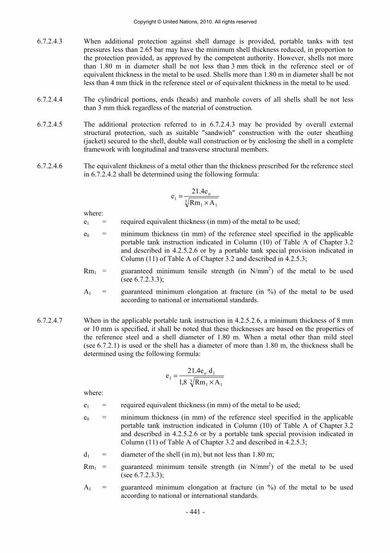
- 441 -
6.7.2.4.3 When additional protection against shell damage is provided, portable tanks with test pressures less than 2.65 bar may have the minimum shell thickness reduced, in proportion to the protection provided, as approved by the competent authority. However, shells not more than 1.80 m in diameter shall be not less than 3 mm thick in the reference steel or of equivalent thickness in the metal to be used. Shells more than 1.80 m in diameter shall be not less than 4 mm thick in the reference steel or of equivalent thickness in the metal to be used.
6.7.2.4.4 The cylindrical portions, ends (heads) and manhole covers of all shells shall be not less
than 3 mm thick regardless of the material of construction. 6.7.2.4.5 The additional protection referred to in 6.7.2.4.3 may be provided by overall external
structural protection, such as suitable "sandwich" construction with the outer sheathing (jacket) secured to the shell, double wall construction or by enclosing the shell in a complete framework with longitudinal and transverse structural members.
6.7.2.4.6 The equivalent thickness of a metal other than the thickness prescribed for the reference steel
in 6.7.2.4.2 shall be determined using the following formula:
311
o1
A Rm21.4e
e×
=
where: e1 = required equivalent thickness (in mm) of the metal to be used;
e0 = minimum thickness (in mm) of the reference steel specified in the applicable portable tank instruction indicated in Column (10) of Table A of Chapter 3.2 and described in 4.2.5.2.6 or by a portable tank special provision indicated in Column (11) of Table A of Chapter 3.2 and described in 4.2.5.3;
Rm1 = guaranteed minimum tensile strength (in N/mm2) of the metal to be used (see 6.7.2.3.3);
A1 = guaranteed minimum elongation at fracture (in %) of the metal to be used according to national or international standards.
6.7.2.4.7 When in the applicable portable tank instruction in 4.2.5.2.6, a minimum thickness of 8 mm
or 10 mm is specified, it shall be noted that these thicknesses are based on the properties of the reference steel and a shell diameter of 1.80 m. When a metal other than mild steel (see 6.7.2.1) is used or the shell has a diameter of more than 1.80 m, the thickness shall be determined using the following formula:
311
1o1
A Rm 8,1d 21.4e
e×
=
where:
e1 = required equivalent thickness (in mm) of the metal to be used;
e0 = minimum thickness (in mm) of the reference steel specified in the applicable portable tank instruction indicated in Column (10) of Table A of Chapter 3.2 and described in 4.2.5.2.6 or by a portable tank special provision indicated in Column (11) of Table A of Chapter 3.2 and described in 4.2.5.3;
d1 = diameter of the shell (in m), but not less than 1.80 m;
Rm1 = guaranteed minimum tensile strength (in N/mm2) of the metal to be used (see 6.7.2.3.3);
A1 = guaranteed minimum elongation at fracture (in %) of the metal to be used according to national or international standards.
Copyright © United Nations, 2010. All rights reserved

- 442 -
6.7.2.4.8 In no case shall the wall thickness be less than that prescribed in 6.7.2.4.2, 6.7.2.4.3 and 6.7.2.4.4. All parts of the shell shall have a minimum thickness as determined by 6.7.2.4.2 to 6.7.2.4.4. This thickness shall be exclusive of any corrosion allowance.
6.7.2.4.9 When mild steel is used (see 6.7.2.1), calculation using the formula in 6.7.2.4.6 is not
required. 6.7.2.4.10 There shall be no sudden change of plate thickness at the attachment of the ends (heads) to
the cylindrical portion of the shell. 6.7.2.5 Service equipment 6.7.2.5.1 Service equipment shall be so arranged as to be protected against the risk of being wrenched
off or damaged during handling and carriage. When the connection between the frame and the shell allows relative movement between the sub-assemblies, the equipment shall be so fastened as to permit such movement without risk of damage to working parts. The external discharge fittings (pipe sockets, shut-off devices), the internal stop-valve and its seating shall be protected against the danger of being wrenched off by external forces (for example using shear sections). The filling and discharge devices (including flanges or threaded plugs) and any protective caps shall be capable of being secured against unintended opening.
6.7.2.5.2 All openings in the shell, intended for filling or discharging the portable tank shall be fitted
with a manually operated stop-valve located as close to the shell as reasonably practicable. Other openings, except for openings leading to venting or pressure-relief devices, shall be equipped with either a stop-valve or another suitable means of closure located as close to the shell as reasonably practicable.
6.7.2.5.3 All portable tanks shall be fitted with a manhole or other inspection openings of a suitable
size to allow for internal inspection and adequate access for maintenance and repair of the interior. Compartmented portable tanks shall have a manhole or other inspection openings for each compartment.
6.7.2.5.4 As far as reasonably practicable, external fittings shall be grouped together. For insulated
portable tanks, top fittings shall be surrounded by a spill collection reservoir with suitable drains.
6.7.2.5.5 Each connection to a portable tank shall be clearly marked to indicate its function. 6.7.2.5.6 Each stop-valve or other means of closure shall be designed and constructed to a rated
pressure not less than the MAWP of the shell taking into account the temperatures expected during carriage. All stop-valves with screwed spindles shall close by a clockwise motion of the handwheel. For other stop-valves the position (open and closed) and direction of closure shall be clearly indicated. All stop-valves shall be designed to prevent unintentional opening.
6.7.2.5.7 No moving parts, such as covers, components of closures, etc., shall be made of unprotected
corrodible steel when they are liable to come into frictional or percussive contact with aluminium portable tanks intended for the carriage of substances meeting the flash-point criteria of Class 3 including elevated temperature substances carried at or above their flash-point.
6.7.2.5.8 Piping shall be designed, constructed and installed so as to avoid the risk of damage due to
thermal expansion and contraction, mechanical shock and vibration. All piping shall be of a suitable metallic material. Welded pipe joints shall be used wherever possible.
Copyright © United Nations, 2010. All rights reserved

- 443 -
6.7.2.5.9 Joints in copper tubing shall be brazed or have an equally strong metal union. The melting point of brazing materials shall be no lower than 525 °C. The joints shall not decrease the strength of the tubing as may happen when cutting threads.
6.7.2.5.10 The burst pressure of all piping and pipe fittings shall be not less than the highest of four
times the MAWP of the shell or four times the pressure to which it may be subjected in service by the action of a pump or other device (except pressure-relief devices).
6.7.2.5.11 Ductile metals shall be used in the construction of valves and accessories. 6.7.2.6 Bottom openings 6.7.2.6.1 Certain substances shall not be carried in portable tanks with bottom openings. When the
applicable portable tank instruction identified in Column (10) of Table A of Chapter 3.2 and described in 4.2.5.2.6 indicates that bottom openings are prohibited there shall be no openings below the liquid level of the shell when it is filled to its maximum permissible filling limit. When an existing opening is closed it shall be accomplished by internally and externally welding one plate to the shell.
6.7.2.6.2 Bottom discharge outlets for portable tanks carrying certain solid, crystallizable or highly
viscous substances shall be equipped with not less than two serially fitted and mutually independent shut-off devices. The design of the equipment shall be to the satisfaction of the competent authority or its authorized body and shall include:
(a) An external stop-valve, fitted as close to the shell as reasonably practicable, and so
designed as to prevent any unintended opening through impact or other inadvertent act; and
(b) A liquid tight closure at the end of the discharge pipe, which may be a bolted blank
flange or a screw cap. 6.7.2.6.3 Every bottom discharge outlet, except as provided in 6.7.2.6.2, shall be equipped with three
serially fitted and mutually independent shut-off devices. The design of the equipment shall be to the satisfaction of the competent authority or its authorized body and include:
(a) A self-closing internal stop-valve, that is a stop-valve within the shell or within a
welded flange or its companion flange, such that:
(i) The control devices for the operation of the valve are designed so as to prevent any unintended opening through impact or other inadvertent act;
(ii) The valve may be operable from above or below;
(iii) If possible, the setting of the valve (open or closed) shall be capable of being verified from the ground;
(iv) Except for portable tanks having a capacity of not more than 1 000 litres, it shall be possible to close the valve from an accessible position of the portable tank that is remote from the valve itself; and
(v) The valve shall continue to be effective in the event of damage to the external device for controlling the operation of the valve;
(b) An external stop-valve fitted as close to the shell as reasonably practicable; and (c) A liquid tight closure at the end of the discharge pipe, which may be a bolted blank
flange or a screw cap.
Copyright © United Nations, 2010. All rights reserved

- 444 -
6.7.2.6.4 For a lined shell, the internal stop-valve required by 6.7.2.6.3 (a) may be replaced by an additional external stop-valve. The manufacturer shall satisfy the requirements of the competent authority or its authorized body.
6.7.2.7 Safety-relief devices 6.7.2.7.1 All portable tanks shall be fitted with at least one pressure-relief device. All relief devices
shall be designed, constructed and marked to the satisfaction of the competent authority or its authorized body.
6.7.2.8 Pressure-relief devices 6.7.2.8.1 Every portable tank with a capacity not less than 1 900 litres and every independent
compartment of a portable tank with a similar capacity, shall be provided with one or more pressure-relief devices of the spring-loaded type and may in addition have a frangible disc or fusible element in parallel with the spring-loaded devices except when prohibited by reference to 6.7.2.8.3 in the applicable portable tank instruction in 4.2.5.2.6. The pressure-relief devices shall have sufficient capacity to prevent rupture of the shell due to over pressurization or vacuum resulting from filling, discharging, or from heating of the contents.
6.7.2.8.2 Pressure-relief devices shall be designed to prevent the entry of foreign matter, the leakage
of liquid and the development of any dangerous excess pressure. 6.7.2.8.3 When required for certain substances by the applicable portable tank instruction indicated in
Column (10) of Table A of Chapter 3.2 and described in 4.2.5.2.6, portable tanks shall have a pressure-relief device approved by the competent authority. Unless a portable tank in dedicated service is fitted with an approved relief device constructed of materials compatible with the substance carried, the relief device shall comprise a frangible disc preceding a spring-loaded pressure-relief device. When a frangible disc is inserted in series with the required pressure-relief device, the space between the frangible disc and the pressure-relief device shall be provided with a pressure gauge or suitable tell-tale indicator for the detection of disc rupture, pinholing, or leakage which could cause a malfunction of the pressure-relief system. The frangible disc shall rupture at a nominal pressure 10% above the start to discharge pressure of the relief device.
6.7.2.8.4 Every portable tank with a capacity less than 1 900 litres shall be fitted with a pressure-relief
device which may be a frangible disc when this disc complies with the requirements of 6.7.2.11.1. When no spring-loaded pressure-relief device is used, the frangible disc shall be set to rupture at a nominal pressure equal to the test pressure. In addition, fusible elements conforming to 6.7.2.10.1 may also be used.
6.7.2.8.5 When the shell is fitted for pressure discharge, the inlet line shall be provided with a suitable
pressure-relief device set to operate at a pressure not higher than the MAWP of the shell, and a stop-valve shall be fitted as close to the shell as reasonably practicable.
6.7.2.9 Setting of pressure-relief devices 6.7.2.9.1 It shall be noted that the pressure-relief devices shall operate only in conditions of excessive
rise in temperature, since the shell shall not be subject to undue fluctuations of pressure during normal conditions of carriage (see 6.7.2.12.2).
6.7.2.9.2 The required pressure-relief device shall be set to start-to-discharge at a nominal pressure of
five-sixths of the test pressure for shells having a test pressure of not more than 4.5 bar and 110% of two-thirds of the test pressure for shells having a test pressure of more than 4.5 bar. After discharge the device shall close at a pressure not more than 10% below the pressure at
Copyright © United Nations, 2010. All rights reserved

- 445 -
which the discharge starts. The device shall remain closed at all lower pressures. This requirement does not prevent the use of vacuum-relief or combination pressure-relief and vacuum-relief devices.
6.7.2.10 Fusible elements 6.7.2.10.1 Fusible elements shall operate at a temperature between 100 °C and 149 °C on condition that
the pressure in the shell at the fusing temperature will be not more than the test pressure. They shall be placed at the top of the shell with their inlets in the vapour space and when used for transport safety purposes, they shall not be shielded from external heat. Fusible elements shall not be used on portable tanks with a test pressure which exceeds 2.65 bar unless specified by special provision TP36 in Column (11) of Table A of Chapter 3.2. Fusible elements used on portable tanks intended for the carriage of elevated temperature substances shall be designed to operate at a temperature higher than the maximum temperature that will be experienced during carriage and shall be to the satisfaction of the competent authority or its authorized body.
6.7.2.11 Frangible discs 6.7.2.11.1 Except as specified in 6.7.2.8.3, frangible discs shall be set to rupture at a nominal pressure
equal to the test pressure throughout the design temperature range. Particular attention shall be given to the requirements of 6.7.2.5.1 and 6.7.2.8.3 if frangible discs are used.
6.7.2.11.2 Frangible discs shall be appropriate for the vacuum pressures which may be produced in the
portable tank. 6.7.2.12 Capacity of pressure-relief devices 6.7.2.12.1 The spring-loaded pressure-relief device required by 6.7.2.8.1 shall have a minimum cross
sectional flow area equivalent to an orifice of 31.75 mm diameter. Vacuum-relief devices, when used, shall have a cross sectional flow area not less than 284 mm2.
6.7.2.12.2 The combined delivery capacity of the pressure relief system (taking into account the
reduction of the flow when the portable tank is fitted with frangible-discs preceding spring-loaded pressure-relief devices or when the spring-loaded pressure-relief devices are provided with a device to prevent the passage of the flame), in condition of complete fire engulfment of the portable tank shall be sufficient to limit the pressure in the shell to 20% above the start-to-discharge pressure of the pressure limiting device. Emergency pressure-relief devices may be used to achieve the full relief capacity prescribed. These devices may be fusible, spring loaded or frangible disc components, or a combination of spring-loaded and frangible disc devices. The total required capacity of the relief devices may be determined using the formula in 6.7.2.12.2.1 or the table in 6.7.2.12.2.3.
6.7.2.12.2.1 To determine the total required capacity of the relief devices, which shall be regarded as
being the sum of the individual capacities of all the contributing devices, the following formula shall be used:
MZT
LCFA 12.4 Q
0.82=
Copyright © United Nations, 2010. All rights reserved

- 446 -
where: Q = minimum required rate of discharge in cubic metres of air per second (m3/s) at
standard conditions: 1 bar and 0 °C (273 K); F = is a coefficient with the following value:
for uninsulated shells: F = 1; for insulated shells: F = U(649 - t)/13.6 but in no case is less than 0.25 where: U = thermal conductance of the insulation, in kW.m-2. K-1, at 38 °C; t = actual temperature of the substance during filling (in °C); when
this temperature is unknown, let t = 15 °C;
The value of F given above for insulated shells may be taken provided that the insulation is in accordance with 6.7.2.12.2.4; A = total external surface area of shell in m2;
Z = the gas compressibility factor in the accumulating condition (when this factor is unknown, let Z =1.0);
T = absolute temperature in Kelvin (°C + 273) above the pressure-relief devices in the accumulating condition;
L = the latent heat of vaporization of the liquid, in kJ/kg, in the accumulating condition;
M = molecular mass of the discharged gas;
C = a constant which is derived from one of the following formulae as a function of the ratio k of specific heats:
v
p
cc
k =
where:
cp is the specific heat at constant pressure; and cv is the specific heat at constant volume. When k>1:
1k1k
1 k2k C
−+
⎟⎠⎞
⎜⎝⎛
+=
When k = 1 or k is unknown:
607.0e
1C ==
where e is the mathematical constant 2.7183 C may also be taken from the following table:
Copyright © United Nations, 2010. All rights reserved

- 447 -
k C k C k C 1.00 0.607 1.26 0.660 1.52 0.704 1.02 0.611 1.28 0.664 1.54 0.707 1.04 0.615 1.30 0.667 1.56 0.710 1.06 0.620 1.32 0.671 1.58 0.713 1.08 0.624 1.34 0.674 1.60 0.716 1.10 0.628 1.36 0.678 1.62 0.719 1.12 0.633 1.38 0.681 1.64 0.722 1.14 0.637 1.40 0.685 1.66 0.725 1.16 0.641 1.42 0.688 1.68 0.728 1.18 0.645 1.44 0.691 1.70 0.731 1.20 0.649 1.46 0.695 2.00 0.770 1.22 0.652 1.48 0.698 2.20 0.793 1.24 0.656 1.50 0.701
6.7.2.12.2.2 As an alternative to the formula above, shells designed for the carriage of liquids may have
their relief devices sized in accordance with the table in 6.7.2.12.2.3. This table assumes an insulation value of F = 1 and shall be adjusted accordingly when the shell is insulated. Other values used in determining this table are:
M = 86.7 T = 394 K L = 334.94 kJ/kg C = 0.607 Z = 1 6.7.2.12.2.3 Minimum required rate of discharge, Q, in cubic metres per air per second at 1 bar
and 0 °C (273 K)
A Exposed area
(square metres)
Q (cubic metres of air per second)
A Exposed area
(square metres)
Q (cubic metres of air per second)
2 0.230 37.5 2.539 3 0.320 40 2.677 4 0.405 42.5 2.814 5 0.487 45 2.949 6 0.565 47.5 3.082 7 0.641 50 3.215 8 0.715 52.5 3.346 9 0.788 55 3.476
10 0.859 57.5 3.605 12 0.998 60 3.733 14 1.132 62.5 3.860 16 1.263 65 3.987 18 1.391 67.5 4.112 20 1.517 70 4.236
22.5 1.670 75 4.483 25 1.821 80 4.726
27.5 1.969 85 4.967 30 2.115 90 5.206
32.5 2.258 95 5.442 35 2.400 100 5.676
Copyright © United Nations, 2010. All rights reserved

- 448 -
6.7.2.12.2.4 Insulation systems, used for the purpose of reducing venting capacity, shall be approved by the competent authority or its authorized body. In all cases, insulation systems approved for this purpose shall:
(a) Remain effective at all temperatures up to 649 °C; and (b) Be jacketed with a material having a melting point of 700 °C or greater. 6.7.2.13 Marking of pressure-relief devices 6.7.2.13.1 Every pressure-relief device shall be clearly and permanently marked with the following
particulars:
(a) The pressure (in bar or kPa) or temperature (in °C) at which it is set to discharge; (b) The allowable tolerance at the discharge pressure for spring-loaded devices; (c) The reference temperature corresponding to the rated pressure for frangible discs; (d) The allowable temperature tolerance for fusible elements; and (e) The rated flow capacity of the spring-loaded pressure relief devices, frangible discs or
fusible elements in standard cubic metres of air per second (m3/s); When practicable, the following information shall also be shown: (f) The manufacturer’s name and relevant catalogue number of the device.
6.7.2.13.2 The rated flow capacity marked on the spring-loaded pressure-relief devices shall be determined according to ISO 4126-1:1991.
6.7.2.14 Connections to pressure-relief devices 6.7.2.14.1 Connections to pressure-relief devices shall be of sufficient size to enable the required
discharge to pass unrestricted to the safety device. No stop-valve shall be installed between the shell and the pressure-relief devices except where duplicate devices are provided for maintenance or other reasons and the stop-valves serving the devices actually in use are locked open or the stop-valves are interlocked so that at least one of the duplicate devices is always in use. There shall be no obstruction in an opening leading to a vent or pressure-relief device which might restrict or cut-off the flow from the shell to that device. Vents or pipes from the pressure-relief device outlets, when used, shall deliver the relieved vapour or liquid to the atmosphere in conditions of minimum back-pressure on the relieving devices.
6.7.2.15 Siting of pressure-relief devices 6.7.2.15.1 Each pressure-relief device inlet shall be situated on top of the shell in a position as near the
longitudinal and transverse centre of the shell as reasonably practicable. All pressure-relief device inlets shall under maximum filling conditions be situated in the vapour space of the shell and the devices shall be so arranged as to ensure the escaping vapour is discharged unrestrictedly. For flammable substances, the escaping vapour shall be directed away from the shell in such a manner that it cannot impinge upon the shell. Protective devices which deflect the flow of vapour are permissible provided the required relief-device capacity is not reduced.
6.7.2.15.2 Arrangements shall be made to prevent access to the pressure-relief devices by unauthorized
persons and to protect the devices from damage caused by the portable tank overturning.
Copyright © United Nations, 2010. All rights reserved

- 449 -
6.7.2.16 Gauging devices 6.7.2.16.1 Glass level-gauges and gauges made of other fragile material, which are in direct
communication with the contents of the tank shall not be used. 6.7.2.17 Portable tank supports, frameworks, lifting and tie-down attachments 6.7.2.17.1 Portable tanks shall be designed and constructed with a support structure to provide a secure
base during carriage. The forces specified in 6.7.2.2.12 and the safety factor specified in 6.7.2.2.13 shall be considered in this aspect of the design. Skids, frameworks, cradles or other similar structures are acceptable.
6.7.2.17.2 The combined stresses caused by portable tank mountings (e.g. cradles, framework, etc.) and
portable tank lifting and tie-down attachments shall not cause excessive stress in any portion of the shell. Permanent lifting and tie-down attachments shall be fitted to all portable tanks. Preferably they shall be fitted to the portable tank supports but may be secured to reinforcing plates located on the shell at the points of support.
6.7.2.17.3 In the design of supports and frameworks the effects of environmental corrosion shall be
taken into account. 6.7.2.17.4 Forklift pockets shall be capable of being closed off. The means of closing forklift pockets
shall be a permanent part of the framework or permanently attached to the framework. Single compartment portable tanks with a length less than 3.65 m need not have closed off forklift pockets provided that:
(a) The shell including all the fittings are well protected from being hit by the forklift
blades; and (b) The distance between the centres of the forklift pockets is at least half of the
maximum length of the portable tank.
6.7.2.17.5 When portable tanks are not protected during carriage, according to 4.2.1.2, the shells and service equipment shall be protected against damage to the shell and service equipment resulting from lateral or longitudinal impact or overturning. External fittings shall be protected so as to preclude the release of the shell contents upon impact or overturning of the portable tank on its fittings. Examples of protection include:
(a) Protection against lateral impact which may consist of longitudinal bars protecting the
shell on both sides at the level of the median line;
(b) Protection of the portable tank against overturning which may consist of reinforcement rings or bars fixed across the frame;
(c) Protection against rear impact which may consist of a bumper or frame; (d) Protection of the shell against damage from impact or overturning by use of an
ISO frame in accordance with ISO 1496-3:1995.
6.7.2.18 Design approval 6.7.2.18.1 The competent authority or its authorized body shall issue a design approval certificate for
any new design of a portable tank. This certificate shall attest that a portable tank has been surveyed by that authority, is suitable for its intended purpose and meets the requirements of this Chapter and where appropriate, the provisions for substances provided in Chapter 4.2 and in Table A of Chapter 3.2. When a series of portable tanks are manufactured without
Copyright © United Nations, 2010. All rights reserved

- 450 -
change in the design, the certificate shall be valid for the entire series. The certificate shall refer to the prototype test report, the substances or group of substances allowed to be carried, the materials of construction of the shell and lining (when applicable) and an approval number. The approval number shall consist of the distinguishing sign or mark of the State in whose territory the approval was granted, i.e. the distinguishing sign for use in international traffic as prescribed by the Convention on Road Traffic, Vienna 1968, and a registration number. Any alternative arrangements according to 6.7.1.2 shall be indicated on the certificate. A design approval may serve for the approval of smaller portable tanks made of materials of the same kind and thickness, by the same fabrication techniques and with identical supports, equivalent closures and other appurtenances.
6.7.2.18.2 The prototype test report for the design approval shall include at least the following:
(a) The results of the applicable framework test specified in ISO 1496-3:1995; (b) The results of the initial inspection and test according to 6.7.2.19.3; and (c) The results of the impact test in 6.7.2.19.1, when applicable.
6.7.2.19 Inspection and testing 6.7.2.19.1 Portable tanks meeting the definition of container in the International Convention for Safe
Containers (CSC), 1972, as amended, shall not be used unless they are successfully qualified by subjecting a representative prototype of each design to the Dynamic, Longitudinal Impact Test prescribed in the Manual of Tests and Criteria, Part IV, Section 41.
6.7.2.19.2 The shell and items of equipment of each portable tank shall be inspected and tested before
being put into service for the first time (initial inspection and test) and thereafter at not more than five-year intervals (5 year periodic inspection and test) with an intermediate periodic inspection and test (2.5 year periodic inspection and test) midway between the 5 year periodic inspections and tests. The 2.5 year inspection and test may be performed within 3 months of the specified date. An exceptional inspection and test shall be performed regardless of the date of the last periodic inspection and test when necessary according to 6.7.2.19.7.
6.7.2.19.3 The initial inspection and test of a portable tank shall include a check of the design
characteristics, an internal and external examination of the portable tank and its fittings with due regard to the substances to be carried, and a pressure test. Before the portable tank is placed into service, a leakproofness test and a check of the satisfactory operation of all service equipment shall also be performed. When the shell and its fittings have been pressure-tested separately, they shall be subjected together after assembly to a leakproofness test.
6.7.2.19.4 The 5-year periodic inspection and test shall include an internal and external examination
and, as a general rule, a hydraulic pressure test. Sheathing, thermal insulation and the like shall be removed only to the extent required for reliable appraisal of the condition of the portable tank. When the shell and equipment have been pressure-tested separately, they shall be subjected together after assembly to a leakproofness test.
6.7.2.19.5 The intermediate 2.5 year periodic inspection and test shall at least include an internal and
external examination of the portable tank and its fittings with due regard to the substances intended to be carried, a leakproofness test and a check of the satisfactory operation of all service equipment. Sheathing, thermal insulation and the like shall be removed only to the extent required for reliable appraisal of the condition of the portable tank. For portable tanks intended for the carriage of a single substance, the 2.5 year internal examination may be waived or substituted by other test methods or inspection procedures specified by the competent authority or its authorized body.
Copyright © United Nations, 2010. All rights reserved

- 451 -
6.7.2.19.6 A portable tank may not be filled and offered for carriage after the date of expiry of the last 5 year or 2.5 year periodic inspection and test as required by 6.7.2.19.2. However, a portable tank filled prior to the date of expiry of the last periodic inspection and test may be carried for a period not to exceed three months beyond the date of expiry of the last periodic test or inspection. In addition, a portable tank may be carried after the date of expiry of the last periodic test and inspection:
(a) After emptying but before cleaning, for purposes of performing the next required test
or inspection prior to refilling; and (b) Unless otherwise approved by the competent authority, for a period not to exceed six
months beyond the date of expiry of the last periodic test or inspection, in order to allow the return of dangerous goods for proper disposal or recycling. Reference to this exemption shall be mentioned in the transport document.
6.7.2.19.7 The exceptional inspection and test is necessary when the portable tank shows evidence of
damaged or corroded areas, or leakage, or other conditions that indicate a deficiency that could affect the integrity of the portable tank. The extent of the exceptional inspection and test shall depend on the amount of damage or deterioration of the portable tank. It shall include at least the 2.5 year inspection and test according to 6.7.2.19.5.
6.7.2.19.8 The internal and external examinations shall ensure that:
(a) The shell is inspected for pitting, corrosion, or abrasions, dents, distortions, defects in
welds or any other conditions, including leakage, that might render the portable tank unsafe for carriage;
(b) The piping, valves, heating/cooling system, and gaskets are inspected for corroded
areas, defects, or any other conditions, including leakage, that might render the portable tank unsafe for filling, discharge or carriage;
(c) Devices for tightening manhole covers are operative and there is no leakage at
manhole covers or gaskets;
(d) Missing or loose bolts or nuts on any flanged connection or blank flange are replaced or tightened;
(e) All emergency devices and valves are free from corrosion, distortion and any damage
or defect that could prevent their normal operation. Remote closure devices and self-closing stop-valves shall be operated to demonstrate proper operation;
(f) Linings, if any, are inspected in accordance with criteria outlined by the lining
manufacturer; (g) Required markings on the portable tank are legible and in accordance with the
applicable requirements; and (h) The framework, supports and arrangements for lifting the portable tank are in a
satisfactory condition.
6.7.2.19.9 The inspections and tests in 6.7.2.19.1, 6.7.2.19.3, 6.7.2.19.4, 6.7.2.19.5 and 6.7.2.19.7 shall be performed or witnessed by an expert approved by the competent authority or its authorized body. When the pressure test is a part of the inspection and test, the test pressure shall be the one indicated on the data plate of the portable tank. While under pressure, the portable tank shall be inspected for any leaks in the shell, piping or equipment.
Copyright © United Nations, 2010. All rights reserved

- 452 -
6.7.2.19.10 In all cases when cutting, burning or welding operations on the shell have been effected, that work shall be to the approval of the competent authority or its authorized body taking into account the pressure vessel code used for the construction of the shell. A pressure test to the original test pressure shall be performed after the work is completed.
6.7.2.19.11 When evidence of any unsafe condition is discovered, the portable tank shall not be returned
to service until it has been corrected and the test is repeated and passed. 6.7.2.20 Marking 6.7.2.20.1 Every portable tank shall be fitted with a corrosion resistant metal plate permanently
attached to the portable tank in a conspicuous place readily accessible for inspection. When for reasons of portable tank arrangements the plate cannot be permanently attached to the shell, the shell shall be marked with at least the information required by the pressure vessel code. As a minimum, at least the following information shall be marked on the plate by stamping or by any other similar method:
(a) Owner information
(i) Owner’s registration number;
(b) Manufacturing information
(i) Country of manufacture;
(ii) Year of manufacture;
(iii) Manufacturer’s name or mark;
(iv) Manufacturer’s serial number;
(c) Approval information
(i) The United Nations packaging symbol
;
This symbol shall not be used for any purpose other than certifying that a
packaging, a portable tank or a MEGC complies with the relevant requirements in Chapter 6.1, 6.2, 6.3, 6.5, 6.6 or 6.7;
(ii) Approval country;
(iii) Authorized body for the design approval;
(iv) Design approval number;
(v) Letters ‘AA’, if the design was approved under alternative arrangements (see 6.7.1.2);
(vi) Pressure vessel code to which the shell is designed;
(d) Pressures
(i) MAWP (in bar gauge or kPa gauge)2;
(ii) Test pressure (in bar gauge or kPa gauge)2;
(iii) Initial pressure test date (month and year);
(iv) Identification mark of the initial pressure test witness;
(v) External design pressure3 (in bar gauge or kPa gauge)2;
2 The unit used shall be indicated. 3 See 6.7.2.2.10.
Copyright © United Nations, 2010. All rights reserved

- 453 -
(vi) MAWP for heating/cooling system (in bar gauge or kPa gauge)2 (when applicable);
(e) Temperatures
(i) Design temperature range (in °C)2;
(f) Materials
(i) Shell material(s) and material standard reference(s);
(ii) Equivalent thickness in reference steel (in mm)2;
(iii) Lining material (when applicable);
(g) Capacity
(i) Tank water capacity at 20 °C (in litres)2;
This indication is to be followed by the symbol "S" when the shell is divided by surge plates into sections of not more than 7 500 litres capacity;
(ii) Water capacity of each compartment at 20 °C (in litres)2 (when applicable, for multi-compartment tanks).
This indication is to be followed by the symbol "S" when the compartment is divided by surge plates into sections of not more than 7 500 litres capacity;
(h) Periodic inspections and tests
(i) Type of the most recent periodic test (2.5-year, 5-year or exceptional);
(ii) Date of the most recent periodic test (month and year);
(iii) Test pressure (in bar gauge or kPa gauge)2 of the most recent periodic test (if applicable);
(iv) Identification mark of the authorized body who performed or witnessed the most recent test.
2 The unit used shall be indicated.
Copyright © United Nations, 2010. All rights reserved

- 454 -
Figure 6.7.2.20.1: Example of identification plate marking
Owner’s registration number MANUFACTURING INFORMATION Country of manufacture Year of manufacture Manufacturer Manufacturer’s serial number APPROVAL INFORMATION
Approval country Authorized body for design approval
Design approval number ‘AA’ (if applicable) Shell design code (pressure vessel code) PRESSURES MAWP bar or kPaTest pressure bar or kPaInitial pressure test date: (mm/yyyy) Witness stamp: External design pressure bar or kPaMAWP for heating/cooling system (when applicable) bar or kPa
TEMPERATURES Design temperature range °C to °CMATERIALS Shell material(s) and material standard reference(s) Equivalent thickness in reference steel mmLining material (when applicable) CAPACITY Tank water capacity at 20 °C litres ‘S’ (if applicable) Water capacity of compartment at 20 °C (when applicable, for multi-compartment tanks) litres ‘S’ (if applicable)
PERIODIC INSPECTIONS / TESTS
Test type Test date Witness stamp and test pressurea Test type Test date Witness stamp and
test pressurea
(mm/yyyy) bar or kPa (mm/yyyy) bar or kPa a Test pressure if applicable. 6.7.2.20.2 The following particulars shall be marked either on the portable tank itself or on a metal
plate firmly secured to the portable tank:
Name of the operator Maximum permissible gross mass (MPGM) ___________ kg Unladen (tare) mass ___________ kg Portable tank instruction in accordance with 4.2.5.2.6 NOTE: For the identification of the substances being carried, see also Part 5.
6.7.2.20.3 If a portable tank is designed and approved for handling in open seas, the words "OFFSHORE PORTABLE TANK" shall be marked on the identification plate.
Copyright © United Nations, 2010. All rights reserved

- 455 -
6.7.3 Requirements for the design, construction, inspection and testing of portable tanks intended for the carriage of non-refrigerated liquefied gases
6.7.3.1 Definitions For the purposes of this section: Alternative arrangement means an approval granted by the competent authority for a
portable tank or MEGC that has been designed, constructed or tested to technical requirements or testing methods other than those specified in this Chapter;
Portable tank means a multimodal tank having a capacity of more than 450 litres used for
the carriage of non-refrigerated liquefied gases of Class 2. The portable tank includes a shell fitted with service equipment and structural equipment necessary for the carriage of gases. The portable tank shall be capable of being filled and discharged without the removal of its structural equipment. It shall possess stabilizing members external to the shell, and shall be capable of being lifted when full. It shall be designed primarily to be loaded onto a vehicle, wagon or sea-going or inland navigation vessel and shall be equipped with skids, mountings or accessories to facilitate mechanical handling. Tank-vehicles, tank-wagons, non-metallic tanks, intermediate bulk containers (IBCs), gas cylinders and large receptacles are not considered to fall within the definition for portable tanks;
Shell means the part of the portable tank which retains the non-refrigerated liquefied gas
intended for carriage (tank proper), including openings and their closures, but does not include service equipment or external structural equipment;
Service equipment means measuring instruments and filling, discharge, venting, safety and
insulating devices;
Structural equipment means the reinforcing, fastening, protective and stabilizing members external to the shell;
Maximum allowable working pressure (MAWP) means a pressure that shall be not less than
the highest of the following pressures measured at the top of the shell while in operating position, but in no case less than 7 bar:
(a) The maximum effective gauge pressure allowed in the shell during filling or
discharge; or (b) The maximum effective gauge pressure to which the shell is designed, which shall be:
(i) for a non-refrigerated liquefied gas listed in the portable tank instruction T50 in 4.2.5.2.6, the MAWP (in bar) given in T50 portable tank instruction for that gas;
(ii) for other non-refrigerated liquefied gases, not less than the sum of:
- the absolute vapour pressure (in bar) of the non-refrigerated liquefied gas
at the design reference temperature minus 1 bar; and - the partial pressure (in bar) of air or other gases in the ullage space
being determined by the design reference temperature and the liquid phase expansion due to an increase of the mean bulk temperature of tr -tf (tf = filling temperature, usually 15 °C, tr = maximum mean bulk temperature, 50 °C);
Copyright © United Nations, 2010. All rights reserved

- 456 -
Design pressure means the pressure to be used in calculations required by a recognized pressure vessel code. The design pressure shall be not less than the highest of the following pressures:
(a) The maximum effective gauge pressure allowed in the shell during filling or
discharge; or (b) The sum of:
(i) the maximum effective gauge pressure to which the shell is designed as defined
in (b) of the MAWP definition (see above); and (ii) a head pressure determined on the basis of the static forces specified
in 6.7.3.2.9, but not less than 0.35 bar; Test pressure means the maximum gauge pressure at the top of the shell during the pressure
test; Leakproofness test means a test using gas subjecting the shell and its service equipment to an
effective internal pressure of not less than 25% of the MAWP; Maximum permissible gross mass (MPGM) means the sum of the tare mass of the portable
tank and the heaviest load authorized for carriage; Reference steel means a steel with a tensile strength of 370 N/mm2 and an elongation at
fracture of 27%; Mild steel means a steel with a guaranteed minimum tensile strength of 360 N/mm2
to 440 N/mm2 and a guaranteed minimum elongation at fracture conforming to 6.7.3.3.3.3;
Design temperature range for the shell shall be -40 °C to 50 °C for non-refrigerated liquefied gases carried under ambient conditions. More severe design temperatures shall be considered for portable tanks subjected to severe climatic conditions;
Design reference temperature means the temperature at which the vapour pressure of the
contents is determined for the purpose of calculating the MAWP. The design reference temperature shall be less than the critical temperature of the non-refrigerated liquefied gas intended to be carried to ensure that the gas at all times is liquefied. This value for each portable tank type is as follows:
(a) Shell with a diameter of 1.5 metres or less: 65 °C; (b) Shell with a diameter of more than 1.5 metres:
(i) without insulation or sun shield: 60 °C; (ii) with sun shield (see 6.7.3.2.12): 55 °C; and (iii) with insulation (see 6.7.3.2.12) : 50 °C;
Filling density means the average mass of non-refrigerated liquefied gas per litre of shell capacity (kg/l). The filling density is given in portable tank instruction T50 in 4.2.5.2.6.
6.7.3.2 General design and construction requirements 6.7.3.2.1 Shells shall be designed and constructed in accordance with the requirements of a pressure
vessel code recognized by the competent authority. Shells shall be made of steel suitable for forming. The materials shall in principle conform to national or international material standards. For welded shells, only a material whose weldability has been fully demonstrated
Copyright © United Nations, 2010. All rights reserved

- 457 -
shall be used. Welds shall be skilfully made and afford complete safety. When the manufacturing process or the materials make it necessary, the shells shall be suitability heat-treated to guarantee adequate toughness in the weld and in the heat affected zones. In choosing the material the design temperature range shall be taken into account with respect to risk of brittle fracture, to stress corrosion cracking and to resistance to impact. When fine grain steel is used, the guaranteed value of the yield strength shall be not more than 460 N/mm2 and the guaranteed value of the upper limit of the tensile strength shall be not more than 725 N/mm2 according to the material specification. Portable tank materials shall be suitable for the external environment in which they may be carried.
6.7.3.2.2 Portable tank shells, fittings and pipework shall be constructed of materials which are:
(a) Substantially immune to attack by the non-refrigerated liquefied gas(es) intended to be carried; or
(b) Properly passivated or neutralized by chemical reaction.
6.7.3.2.3 Gaskets shall be made of materials compatible with the non-refrigerated liquefied gas(es) intended to be carried.
6.7.3.2.4 Contact between dissimilar metals which could result in damage by galvanic action shall be
avoided. 6.7.3.2.5 The materials of the portable tank, including any devices, gaskets, and accessories, shall not
adversely affect the non-refrigerated liquefied gas(es) intended for carriage in the portable tank.
6.7.3.2.6 Portable tanks shall be designed and constructed with supports to provide a secure base
during carriage and with suitable lifting and tie-down attachments.
6.7.3.2.7 Portable tanks shall be designed to withstand, without loss of contents, at least the internal pressure due to the contents, and the static, dynamic and thermal loads during normal conditions of handling and carriage. The design shall demonstrate that the effects of fatigue, caused by repeated application of these loads through the expected life of the portable tank, have been taken into account.
6.7.3.2.8 Shells shall be designed to withstand an external pressure of at least 0.4 bar (gauge pressure)
above the internal pressure without permanent deformation. When the shell is to be subjected to a significant vacuum before filling or during discharge it shall be designed to withstand an external pressure of at least 0.9 bar (gauge pressure) above the internal pressure and shall be proven at that pressure.
6.7.3.2.9 Portable tanks and their fastenings shall, under the maximum permissible load, be capable of
absorbing the following separately applied static forces:
(a) In the direction of travel: twice the MPGM multiplied by the acceleration due to gravity (g) 1;
(b) Horizontally at right angles to the direction of travel: the MPGM (when the direction
of travel is not clearly determined, the forces shall be equal to twice the MPGM) multiplied by the acceleration due to gravity (g) 1;
(c) Vertically upwards: the MPGM multiplied by the acceleration due to gravity (g) 1; and (d) Vertically downwards: twice the MPGM (total loading including the effect of gravity)
multiplied by the acceleration due to gravity (g) 1.
1 For calculation purposes g = 9.81 m/s2.
Copyright © United Nations, 2010. All rights reserved

- 458 -
6.7.3.2.10 Under each of the forces in 6.7.3.2.9, the safety factor to be observed shall be as follows:
(a) For steels having a clearly defined yield point, a safety factor of 1.5 in relation to the guaranteed yield strength; or
(b) For steels with no clearly defined yield point, a safety factor of 1.5 in relation to the
guaranteed 0.2% proof strength and, for austenitic steels, the 1% proof strength.
6.7.3.2.11 The values of yield strength or proof strength shall be the values according to national or international material standards. When austenitic steels are used, the specified minimum values of yield strength and proof strength according to the material standards may be increased by up to 15% when these greater values are attested in the material inspection certificate. When no material standard exists for the steel in question, the value of yield strength or proof strength used shall be approved by the competent authority.
6.7.3.2.12 When the shells intended for the carriage of non-refrigerated liquefied gases are equipped
with thermal insulation, the thermal insulation systems shall satisfy the following requirements:
(a) It shall consist of a shield covering not less than the upper third but not more than the
upper half of the surface of the shell and separated from the shell by an air space about 40 mm across;
(b) It shall consist of a complete cladding of adequate thickness of insulating materials
protected so as to prevent the ingress of moisture and damage under normal conditions of carriage and so as to provide a thermal conductance of not more than 0.67 (W.m-2.K-1);
(c) When the protective covering is so closed as to be gas-tight, a device shall be provided to prevent any dangerous pressure from developing in the insulating layer in the event of inadequate gas tightness of the shell or of its items of equipment; and
(d) The thermal insulation shall not inhibit access to the fittings and discharge devices.
6.7.3.2.13 Portable tanks intended for the carriage of flammable non-refrigerated liquefied gases shall be capable of being electrically earthed.
6.7.3.3 Design criteria
6.7.3.3.1 Shells shall be of a circular cross-section.
6.7.3.3.2 Shells shall be designed and constructed to withstand a test pressure not less than 1.3 times the design pressure. The shell design shall take into account the minimum MAWP values provided in portable tank instruction T50 in 4.2.5.2.6 for each non-refrigerated liquefied gas intended for carriage. Attention is drawn to the minimum shell thickness requirements for these shells specified in 6.7.3.4.
6.7.3.3.3 For steels exhibiting a clearly defined yield point or characterized by a guaranteed proof strength (0.2% proof strength, generally, or 1% proof strength for austenitic steels) the primary membrane stress σ (sigma) in the shell shall not exceed 0.75 Re or 0.50 Rm, whichever is lower, at the test pressure, where:
Re = yield strength in N/mm2, or 0.2% proof strength or, for austenitic steels, 1% proof stress;
Rm = minimum tensile strength in N/mm2.
Copyright © United Nations, 2010. All rights reserved

- 459 -
6.7.3.3.3.1 The values of Re and Rm to be used shall be the specified minimum values according to national or international material standards. When austenitic steels are used, the specified minimum values for Re and Rm according to the material standards may be increased by up to 15% when these greater values are attested in the material inspection certificate. When no material standard exists for the steel in question, the values of Re and Rm used shall be approved by the competent authority or its authorized body.
6.7.3.3.3.2 Steels which have a Re/Rm ratio of more than 0.85 are not allowed for the construction of welded shells. The values of Re and Rm to be used in determining this ratio shall be the values specified in the material inspection certificate.
6.7.3.3.3.3 Steels used in the construction of shells shall have an elongation at fracture, in %, of not less than 10 000/Rm with an absolute minimum of 16% for fine grain steels and 20% for other steels.
6.7.3.3.3.4 For the purpose of determining actual values for materials, it shall be noted that for sheet metal, the axis of the tensile test specimen shall be at right angles (transversely) to the direction of rolling. The permanent elongation at fracture shall be measured on test specimens of rectangular cross sections in accordance with ISO 6892:1998 using a 50 mm gauge length.
6.7.3.4 Minimum shell thickness 6.7.3.4.1 The minimum shell thickness shall be the greater thickness based on:
(a) The minimum thickness determined in accordance with the requirements in 6.7.3.4; and
(b) The minimum thickness determined in accordance with the recognized pressure vessel
code including the requirements in 6.7.3.3.
6.7.3.4.2 The cylindrical portions, ends (heads) and manhole covers of shells of not more than 1.80 m in diameter shall be not less than 5 mm thick in the reference steel or of equivalent thickness in the steel to be used. Shells of more than 1.80 m in diameter shall be not less than 6 mm thick in the reference steel or of equivalent thickness in the steel to be used.
6.7.3.4.3 The cylindrical portions, ends (heads) and manhole covers of all shells shall be not less
than 4 mm thick regardless of the material of construction. 6.7.3.4.4 The equivalent thickness of a steel other than the thickness prescribed for the reference steel
in 6.7.3.4.2 shall be determined using the following formula:
13
1
o1
A Rme4,21
e×
=
where:
e1 = required equivalent thickness (in mm) of the steel to be used;
e0 = minimum thickness (in mm) for the reference steel specified in 6.7.3.4.2;
Rm1 = guaranteed minimum tensile strength (in N/mm2) of the steel to be used (see 6.7.3.3.3);
A1 = guaranteed minimum elongation at fracture (in %) of the steel to be used according to national or international standards.
Copyright © United Nations, 2010. All rights reserved

- 460 -
6.7.3.4.5 In no case shall the wall thickness be less than that prescribed in 6.7.3.4.1 to 6.7.3.4.3. All parts of the shell shall have a minimum thickness as determined by 6.7.3.4.1 to 6.7.3.4.3. This thickness shall be exclusive of any corrosion allowance.
6.7.3.4.6 When mild steel is used (see 6.7.3.1), calculation using the formula in 6.7.3.4.4 is not
required. 6.7.3.4.7 There shall be no sudden change of plate thickness at the attachment of the ends (heads) to
the cylindrical portion of the shell. 6.7.3.5 Service equipment 6.7.3.5.1 Service equipment shall be so arranged as to be protected against the risk of being wrenched
off or damaged during handling and carriage. When the connection between the frame and the shell allows relative movement between the sub-assemblies, the equipment shall be so fastened as to permit such movement without risk of damage to working parts. The external discharge fittings (pipe sockets, shut-off devices), the internal stop-valve and its seating shall be protected against the danger of being wrenched off by external forces (for example using shear sections). The filling and discharge devices (including flanges or threaded plugs) and any protective caps shall be capable of being secured against unintended opening.
6.7.3.5.2 All openings with a diameter of more than 1.5 mm in shells of portable tanks, except
openings for pressure-relief devices, inspection openings and closed bleed holes, shall be fitted with at least three mutually independent shut-off devices in series, the first being an internal stop-valve, excess flow valve or equivalent device, the second being an external stop-valve and the third being a blank flange or equivalent device.
6.7.3.5.2.1 When a portable tank is fitted with an excess flow valve, the excess flow valve shall be so
fitted that its seating is inside the shell or inside a welded flange or, when fitted externally, its mountings shall be designed so that in the event of impact its effectiveness shall be maintained. The excess flow valves shall be selected and fitted so as to close automatically when the rated flow specified by the manufacturer is reached. Connections and accessories leading to or from such a valve shall have a capacity for a flow more than the rated flow of the excess flow valve.
6.7.3.5.3 For filling and discharge openings, the first shut-off device shall be an internal stop-valve
and the second shall be a stop-valve placed in an accessible position on each discharge and filling pipe.
6.7.3.5.4 For filling and discharge bottom openings of portable tanks intended for the carriage of
flammable and/or toxic non-refrigerated liquefied gases the internal stop-valve shall be a quick closing safety device which closes automatically in the event of unintended movement of the portable tank during filling or discharge or fire engulfment. Except for portable tanks having a capacity of not more than 1 000 litres, it shall be possible to operate this device by remote control.
6.7.3.5.5 In addition to filling, discharge and gas pressure equalizing orifices, shells may have
openings in which gauges, thermometers and manometers can be fitted. Connections for such instruments shall be made by suitable welded nozzles or pockets and not be screwed connections through the shell.
6.7.3.5.6 All portable tanks shall be fitted with manholes or other inspection openings of suitable size
to allow for internal inspection and adequate access for maintenance and repair of the interior.
Copyright © United Nations, 2010. All rights reserved

- 461 -
6.7.3.5.7 External fittings shall be grouped together so far as reasonably practicable. 6.7.3.5.8 Each connection on a portable tank shall be clearly marked to indicate its function. 6.7.3.5.9 Each stop-valve or other means of closure shall be designed and constructed to a rated
pressure not less than the MAWP of the shell taking into account the temperatures expected during carriage. All stop-valves with a screwed spindle shall close by a clockwise motion of the handwheel. For other stop-valves the position (open and closed) and direction of closure shall be clearly indicated. All stop-valves shall be designed to prevent unintentional opening.
6.7.3.5.10 Piping shall be designed, constructed and installed so as to avoid the risk of damage due to
thermal expansion and contraction, mechanical shock and vibration. All piping shall be of suitable metallic material. Welded pipe joints shall be used wherever possible.
6.7.3.5.11 Joints in copper tubing shall be brazed or have an equally strong metal union. The melting
point of brazing materials shall be no lower than 525 °C. The joints shall not decrease the strength of tubing as may happen when cutting threads.
6.7.3.5.12 The burst pressure of all piping and pipe fittings shall be not less than the highest of four
times the MAWP of the shell or four times the pressure to which it may be subjected in service by the action of a pump or other device (except pressure-relief devices).
6.7.3.5.13 Ductile metals shall be used in the construction of valves and accessories. 6.7.3.6 Bottom openings 6.7.3.6.1 Certain non-refrigerated liquefied gases shall not be carried in portable tanks with bottom
openings when portable tank instruction T50 in 4.2.5.2.6 indicates that bottom openings are not allowed. There shall be no openings below the liquid level of the shell when it is filled to its maximum permissible filling limit.
6.7.3.7 Pressure-relief devices 6.7.3.7.1 Portable tanks shall be provided with one or more spring-loaded pressure-relief devices. The
pressure-relief devices shall open automatically at a pressure not less than the MAWP and be fully open at a pressure equal to 110% of the MAWP. These devices shall, after discharge, close at a pressure not lower than 10% below the pressure at which discharge starts and shall remain closed at all lower pressures. The pressure-relief devices shall be of a type that will resist dynamic forces including liquid surge. Frangible discs not in series with a spring-loaded pressure-relief device are not permitted.
6.7.3.7.2 Pressure-relief devices shall be designed to prevent the entry of foreign matter, the leakage
of gas and the development of any dangerous excess pressure. 6.7.3.7.3 Portable tanks intended for the carriage of certain non-refrigerated liquefied gases identified
in portable tank instruction T50 in 4.2.5.2.6 shall have a pressure-relief device approved by the competent authority. Unless a portable tank in dedicated service is fitted with an approved relief device constructed of materials compatible with the load, such device shall comprise a frangible disc preceding a spring-loaded device. The space between the frangible disc and the device shall be provided with a pressure gauge or a suitable tell-tale indicator. This arrangement permits the detection of disc rupture, pinholing or leakage which could cause a malfunction of the pressure-relief device. The frangible discs shall rupture at a nominal pressure 10% above the start-to-discharge pressure of the relief device.
Copyright © United Nations, 2010. All rights reserved

- 462 -
6.7.3.7.4 In the case of multi-purpose portable tanks, the pressure-relief devices shall open at a pressure indicated in 6.7.3.7.1 for the gas having the highest maximum allowable pressure of the gases allowed to be carried in the portable tank.
6.7.3.8 Capacity of relief devices 6.7.3.8.1 The combined delivery capacity of the relief devices shall be sufficient that, in the event of
total fire engulfment, the pressure (including accumulation) inside the shell does not exceed 120% of the MAWP. Spring-loaded relief devices shall be used to achieve the full relief capacity prescribed. In the case of multi-purpose tanks, the combined delivery capacity of the pressure-relief devices shall be taken for the gas which requires the highest delivery capacity of the gases allowed to be carried in portable tanks.
6.7.3.8.1.1 To determine the total required capacity of the relief devices, which shall be regarded as
being the sum of the individual capacities of the several devices, the following formulae 4 shall be used:
MZT
LCFA 12.4 Q
0.82
=
where:
Q = minimum required rate of discharge in cubic metres of air per second (m3/s) at standard conditions: 1 bar and 0 °C (273 K);
F = is a coefficient with the following value:
for uninsulated shells: F = 1;
for insulated shells: F = U(649-t)/13.6 but in no case is less than 0.25
where: U = thermal conductance of the insulation, in Kw.m-2.K-1, at 38 °C; t = actual temperature of the non-refrigerated liquefied gas during
filling (°C); when this temperature is unknown, let t=15 °C;
The value of F given above for insulated shells may be taken provided that the insulation is in accordance with 6.7.3.8.1.2; where: A = total external surface area of shell in square metres; Z = the gas compressibility factor in the accumulating condition (when
this factor is unknown, let Z =1.0); T = absolute temperature in Kelvin (°C + 273) above the pressure relief
devices in the accumulating condition;
4 This formula applies only to non-refrigerated liquefied gases which have critical temperatures well above the temperature at the accumulating condition. For gases which have critical temperatures near or below the temperature at the accumulating condition, the calculation of the pressure-relief device delivery capacity shall consider further thermodynamic properties of the gas (see for example CGA S-1.2-2003 "Pressure Relief Device Standards - Part 2 - Cargo and Portable Tanks for Compressed Gases").
Copyright © United Nations, 2010. All rights reserved

- 463 -
L = the latent heat of vaporization of the liquid, in kJ/kg, in the accumulating condition;
M = molecular mass of the discharged gas; C = a constant which is derived from one of the following formulae as
a function of the ratio k of specific heats
v
p
cc
k =
where
cp is the specific heat at constant pressure; and cv is the specific heat at constant volume.
when k>1:
1k1k
1 k2k C
−+
⎟⎠⎞
⎜⎝⎛
+=
when k = 1 or k is unknown:
607.0e
1C ==
where e is the mathematical constant 2.7183
C may also be taken from the following table:
k C k C k C
1.00 0.607 1.26 0.660 1.52 0.704 1.02 0.611 1.28 0.664 1.54 0.707 1.04 0.615 1.30 0.667 1.56 0.710 1.06 0.620 1.32 0.671 1.58 0.713 1.08 0.624 1.34 0.674 1.60 0.716 1.10 0.628 1.36 0.678 1.62 0.719 1.12 0.633 1.38 0.681 1.64 0.722 1.14 0.637 1.40 0.685 1.66 0.725 1.16 0.641 1.42 0.688 1.68 0.728 1.18 0.645 1.44 0.691 1.70 0.731 1.20 0.649 1.46 0.695 2.00 0.770 1.22 0.652 1.48 0.698 2.20 0.793 1.24 0.656 1.50 0.701
6.7.3.8.1.2 Insulation systems, used for the purpose of reducing the venting capacity, shall be approved
by the competent authority or its authorized body. In all cases, insulation systems approved for this purpose shall:
(a) Remain effective at all temperatures up to 649 °C; and (b) Be jacketed with a material having a melting point of 700 °C or greater.
Copyright © United Nations, 2010. All rights reserved

- 464 -
6.7.3.9 Marking of pressure-relief devices 6.7.3.9.1 Every pressure-relief device shall be plainly and permanently marked with the following
particulars:
(a) The pressure (in bar or kPa) at which it is set to discharge; (b) The allowable tolerance at the discharge pressure for spring-loaded devices; (c) The reference temperature corresponding to the rated pressure for frangible discs; and (d) The rated flow capacity of the device in standard cubic metres of air per second (m3/s).
When practicable, the following information shall also be shown: (e) The manufacturer's name and relevant catalogue number of the device.
6.7.3.9.2 The rated flow capacity marked on the pressure-relief devices shall be determined according
to ISO 4126-1:1991.
6.7.3.10 Connections to pressure-relief devices 6.7.3.10.1 Connections to pressure-relief devices shall be of sufficient size to enable the required
discharge to pass unrestricted to the safety device. No stop-valve shall be installed between the shell and the pressure-relief devices except when duplicate devices are provided for maintenance or other reasons and the stop-valves serving the devices actually in use are locked open or the stop-valves are interlocked so that at least one of the duplicate devices is always operable and capable of meeting the requirements of 6.7.3.8. There shall be no obstruction in an opening leading to a vent or pressure-relief device which might restrict or cut-off the flow from the shell to that device. Vents from the pressure-relief devices, when used, shall deliver the relieved vapour or liquid to the atmosphere in conditions of minimum back-pressure on the relieving device.
6.7.3.11 Siting of pressure-relief devices 6.7.3.11.1 Each pressure-relief device inlet shall be situated on top of the shell in a position as near the
longitudinal and transverse centre of the shell as reasonably practicable. All pressure relief device inlets shall under maximum filling conditions be situated in the vapour space of the shell and the devices shall be so arranged as to ensure that the escaping vapour is discharged unrestrictedly. For flammable non-refrigerated liquefied gases, the escaping vapour shall be directed away from the shell in such a manner that it cannot impinge upon the shell. Protective devices which deflect the flow of vapour are permissible provided the required relief-device capacity is not reduced.
6.7.3.11.2 Arrangements shall be made to prevent access to the pressure-relief devices by unauthorized
persons and to protect the devices from damage caused by the portable tank overturning. 6.7.3.12 Gauging devices 6.7.3.12.1 Unless a portable tank is intended to be filled by weight it shall be equipped with one or
more gauging devices. Glass level-gauges and gauges made of other fragile material, which are in direct communication with the contents of the shell shall not be used.
Copyright © United Nations, 2010. All rights reserved

- 465 -
6.7.3.13 Portable tank supports, frameworks, lifting and tie-down attachments 6.7.3.13.1 Portable tanks shall be designed and constructed with a support structure to provide a secure
base during carriage. The forces specified in 6.7.3.2.9 and the safety factor specified in 6.7.3.2.10 shall be considered in this aspect of the design. Skids, frameworks, cradles or other similar structures are acceptable.
6.7.3.13.2 The combined stresses caused by portable tank mountings (e.g. cradles, frameworks, etc.)
and portable tank lifting and tie-down attachments shall not cause excessive stress in any portion of the shell. Permanent lifting and tie-down attachments shall be fitted to all portable tanks. Preferably they shall be fitted to the portable tank supports but may be secured to reinforcing plates located on the shell at the points of support.
6.7.3.13.3 In the design of supports and frameworks the effects of environmental corrosion shall be
taken into account. 6.7.3.13.4 Forklift pockets shall be capable of being closed off. The means of closing forklift pockets
shall be a permanent part of the framework or permanently attached to the framework. Single compartment portable tanks with a length less than 3.65 m need not have closed off forklift pockets provided that:
(a) The shell and all the fittings are well protected from being hit by the forklift blades;
and
(b) The distance between the centres of the forklift pockets is at least half of the maximum length of the portable tank.
6.7.3.13.5 When portable tanks are not protected during carriage, according to 4.2.2.3, the shells and
service equipment shall be protected against damage to the shell and service equipment resulting from lateral or longitudinal impact or overturning. External fittings shall be protected so as to preclude the release of the shell contents upon impact or overturning of the portable tank on its fittings. Examples of protection include:
(a) Protection against lateral impact which may consist of longitudinal bars protecting the
shell on both sides at the level of the median line; (b) Protection of the portable tank against overturning which may consist of
reinforcement rings or bars fixed across the frame; (c) Protection against rear impact which may consist of a bumper or frame; (d) Protection of the shell against damage from impact or overturning by use of an
ISO frame in accordance with ISO 1496-3:1995. 6.7.3.14 Design approval 6.7.3.14.1 The competent authority or its authorized body shall issue a design approval certificate for
any new design of a portable tank. This certificate shall attest that a portable tank has been surveyed by that authority, is suitable for its intended purpose and meets the requirements of this Chapter and where appropriate the provisions for gases provided in portable tank instruction T50 in 4.2.5.2.6. When a series of portable tanks are manufactured without change in the design, the certificate shall be valid for the entire series. The certificate shall refer to the prototype test report, the gases allowed to be carried, the materials of construction of the shell and an approval number. The approval number shall consist of the distinguishing sign or mark of the State in whose territory the approval was granted, i.e. the distinguishing sign for use in international traffic, as prescribed by the Convention on Road Traffic, Vienna 1968, and a registration number. Any alternative arrangements according
Copyright © United Nations, 2010. All rights reserved

- 466 -
to 6.7.1.2 shall be indicated on the certificate. A design approval may serve for the approval of smaller portable tanks made of materials of the same kind and thickness, by the same fabrication techniques and with identical supports, equivalent closures and other appurtenances.
6.7.3.14.2 The prototype test report for the design approval shall include at least the following:
(a) The results of the applicable framework test specified in ISO 1496-3:1995; (b) The results of the initial inspection and test in 6.7.3.15.3; and (c) The results of the impact test in 6.7.3.15.1, when applicable.
6.7.3.15 Inspection and testing 6.7.3.15.1 Portable tanks meeting the definition of container in the International Convention for Safe
Containers (CSC), 1972, as amended, shall not be used unless they are successfully qualified by subjecting a representative prototype of each design to the Dynamic, Longitudinal Impact Test prescribed in the Manual of Tests and Criteria, Part IV, Section 41.
6.7.3.15.2 The shell and items of equipment of each portable tank shall be inspected and tested before
being put into service for the first time (initial inspection and test) and thereafter at not more than five-year intervals (5 year periodic inspection and test) with an intermediate periodic inspection and test (2.5 year periodic inspection and test) midway between the 5 year periodic inspections and tests. The 2.5 year inspection and test may be performed within 3 months of the specified date. An exceptional inspection and test shall be performed regardless of the last periodic inspection and test when necessary according to 6.7.3.15.7.
6.7.3.15.3 The initial inspection and test of a portable tank shall include a check of the design
characteristics, an internal and external examination of the portable tank and its fittings with due regard to the non-refrigerated liquefied gases to be carried, and a pressure test referring to the test pressures according to 6.7.3.3.2. The pressure test may be performed as a hydraulic test or by using another liquid or gas with the agreement of the competent authority or its authorized body. Before the portable tank is placed into service, a leakproofness test and a test of the satisfactory operation of all service equipment shall also be performed. When the shell and its fittings have been pressure-tested separately, they shall be subjected together after assembly to a leakproofness test. All welds subject to full stress level in the shell shall be inspected during the initial test by radiographic, ultrasonic, or another suitable non-destructive test method. This does not apply to the jacket.
6.7.3.15.4 The 5 year periodic inspection and test shall include an internal and external examination
and, as a general rule, a hydraulic pressure test. Sheathing, thermal insulation and the like shall be removed only to the extent required for reliable appraisal of the condition of the portable tank. When the shell and equipment have been pressure-tested separately, they shall be subjected together after assembly to a leakproofness test.
6.7.3.15.5 The intermediate 2.5 year periodic inspection and test shall at least include an internal and
external examination of the portable tank and its fittings with due regard to the non-refrigerated liquefied gases intended to be carried, a leakproofness test and a check of the satisfactory operation of all service equipment. Sheathing thermal insulation and the like shall be removed only to the extent required for reliable appraisal of the condition of the portable tank. For portable tanks intended for the carriage of a single non-refrigerated liquefied gas, the 2.5 year internal examination may be waived or substituted by other test methods or inspection procedures specified by the competent authority or its authorized body.
Copyright © United Nations, 2010. All rights reserved

- 467 -
6.7.3.15.6 A portable tank may not be filled and offered for carriage after the date of expiry of the last 5 year or 2.5 year periodic inspection and test as required by 6.7.3.15.2. However a portable tank filled prior to the date of expiry of the last periodic inspection and test may be carried for a period not to exceed three months beyond the date of expiry of the last periodic test or inspection. In addition, a portable tank may be carried after the date of expiry of the last periodic test and inspection:
(a) After emptying but before cleaning, for purposes of performing the next required test
or inspection prior to refilling; and (b) Unless otherwise approved by the competent authority, for a period not to exceed
six months beyond the date of expiry of the last periodic test or inspection, in order to allow the return of dangerous goods for proper disposal or recycling. Reference to this exemption shall be mentioned in the transport document.
6.7.3.15.7 The exceptional inspection and test is necessary when the portable tank shows evidence of
damaged or corroded areas, or leakage, or other conditions that indicate a deficiency that could affect the integrity of the portable tank. The extent of the exceptional inspection and test shall depend on the amount of damage or deterioration of the portable tank. It shall include at least the 2.5 year inspection and test according to 6.7.3.15.5.
6.7.3.15.8 The internal and external examinations shall ensure that:
(a) The shell is inspected for pitting, corrosion, or abrasions, dents, distortions, defects in welds or any other conditions, including leakage, that might render the portable tank unsafe for carriage;
(b) The piping, valves, and gaskets are inspected for corroded areas, defects, or any other
conditions, including leakage, that might render the portable tank unsafe for filling, discharge or carriage;
(c) Devices for tightening manhole covers are operative and there is no leakage at
manhole covers or gaskets; (d) Missing or loose bolts or nuts on any flanged connection or blank flange are replaced
or tightened; (e) All emergency devices and valves are free from corrosion, distortion and any damage
or defect that could prevent their normal operation. Remote closure devices and self-closing stop-valves shall be operated to demonstrate proper operation;
(f) Required markings on the portable tank are legible and in accordance with the
applicable requirements; and (g) The framework, the supports and the arrangements for lifting the portable tank are in
satisfactory condition. 6.7.3.15.9 The inspections and tests in 6.7.3.15.1, 6.7.3.15.3, 6.7.3.15.4, 6.7.3.15.5 and 6.7.3.15.7 shall
be performed or witnessed by an expert approved by the competent authority or its authorized body. When the pressure test is a part of the inspection and test, the test pressure shall be the one indicated on the data plate of the portable tank. While under pressure, the portable tank shall be inspected for any leaks in the shell, piping or equipment.
Copyright © United Nations, 2010. All rights reserved

- 468 -
6.7.3.15.10 In all cases when cutting, burning or welding operations on the shell have been effected, that work shall be to the approval of the competent authority or its authorized body taking into account the pressure vessel code used for the construction of the shell. A pressure test to the original test pressure shall be performed after the work is completed.
6.7.3.15.11 When evidence of any unsafe condition is discovered, the portable tank shall not be returned
to service until it has been corrected and the pressure test is repeated and passed. 6.7.3.16 Marking 6.7.3.16.1 Every portable tank shall be fitted with a corrosion resistant metal plate permanently
attached to the portable tank in a conspicuous place readily accessible for inspection. When for reasons of portable tank arrangements the plate cannot be permanently attached to the shell, the shell shall be marked with at least the information required by the pressure vessel code. As a minimum, at least the following information shall be marked on the plate by stamping or by any other similar method: (a) Owner information
(i) Owner’s registration number;
(b) Manufacturing information
(i) Country of manufacture;
(ii) Year of manufacture;
(iii) Manufacturer’s name or mark;
(iv) Manufacturer’s serial number;
(c) Approval information
(i) The United Nations packaging symbol
;
This symbol shall not be used for any purpose other than certifying that a
packaging, a portable tank or a MEGC complies with the relevant requirements in Chapter 6.1, 6.2, 6.3, 6.5, 6.6 or 6.7;
(ii) Approval country;
(iii) Authorized body for the design approval;
(iv) Design approval number;
(v) Letters ‘AA’, if the design was approved under alternative arrangements (see 6.7.1.2);
(vi) Pressure vessel code to which the shell is designed;
(d) Pressures
(i) MAWP (in bar gauge or kPa gauge)2;
(ii) Test pressure (in bar gauge or kPa gauge)2;
(iii) Initial pressure test date (month and year);
(iv) Identification mark of the initial pressure test witness;
(v) External design pressure5 (in bar gauge or kPa gauge)2;
2 The unit used shall be indicated. 5 See 6.7.3.2.8.
Copyright © United Nations, 2010. All rights reserved

- 469 -
(e) Temperatures (i) Design temperature range (in °C)2; (ii) Design reference temperature (in °C)2; (f) Materials (i) Shell material(s) and material standard reference(s); (ii) Equivalent thickness in reference steel (in mm)2; (g) Capacity (i) Tank water capacity at 20 °C (in litres)2; (h) Periodic inspections and tests (i) Type of the most recent periodic test (2.5-year, 5-year or exceptional); (ii) Date of the most recent periodic test (month and year); (iii) Test pressure (in bar gauge or kPa gauge)2 of the most recent periodic test (if
applicable); (iv) Identification mark of the authorized body who performed or witnessed the most
recent test.
Figure 6.7.3.16.1: Example of identification plate marking
Owner’s registration number MANUFACTURING INFORMATION Country of manufacture Year of manufacture Manufacturer Manufacturer’s serial number APPROVAL INFORMATION
Approval country Authorized body for design approval
Design approval number ‘AA’ (if applicable) Shell design code (pressure vessel code) PRESSURES MAWP bar or kPaTest pressure bar or kPaInitial pressure test date: (mm/yyyy) Witness stamp: External design pressure bar or kPaTEMPERATURES Design temperature range °C to °CDesign reference temperature °CMATERIALS Shell material(s) and material standard reference(s) Equivalent thickness in reference steel mmCAPACITY Tank water capacity at 20 °C litresPERIODIC INSPECTIONS / TESTS
Test type Test date Witness stamp and test pressurea Test type Test date Witness stamp and
test pressurea
(mm/yyyy) bar or kPa (mm/yyyy) bar or kPa a Test pressure if applicable.
2 The unit used shall be indicated.
Copyright © United Nations, 2010. All rights reserved

- 470 -
6.7.3.16.2 The following information shall be marked either on the portable tank itself or on a metal plate firmly secured to the portable tank:
Name of the operator Name of non-refrigerated liquefied gas(es) permitted for carriage Maximum permissible load mass for each non-refrigerated liquefied gas permitted ________kg Maximum permissible gross mass (MPGM)__________kg Unladen (tare) mass_________kg Portable tank instruction in accordance with 4.2.5.2.6
NOTE: For the identification of the non-refrigerated liquefied gases being carried, see also Part 5.
6.7.3.16.3 If a portable tank is designed and approved for handling in open seas, the words
"OFFSHORE PORTABLE TANK" shall be marked on the identification plate. 6.7.4 Requirements for the design, construction, inspection and testing of portable tanks
intended for the carriage of refrigerated liquefied gases 6.7.4.1 Definitions For the purposes of this section: Alternative arrangement means an approval granted by the competent authority for a
portable tank or MEGC that has been designed, constructed or tested to technical requirements or testing methods other than those specified in this Chapter;
Portable tank means a thermally insulated multimodal tank having a capacity of more
than 450 litres fitted with service equipment and structural equipment necessary for the carriage of refrigerated liquefied gases. The portable tank shall be capable of being filled and discharged without the removal of its structural equipment. It shall possess stabilizing members external to the tank, and shall be capable of being lifted when full. It shall be designed primarily to be loaded onto a vehicle, wagon or sea-going or inland navigation vessel and shall be equipped with skids, mountings or accessories to facilitate mechanical handling. Tank-vehicles, tank-wagons, non-metallic tanks, intermediate bulk containers (IBCs), gas cylinders and large receptacles are not considered to fall within the definition for portable tanks;
Tank means a construction which normally consists of either :
(a) A jacket and one or more inner shells where the space between the shell(s) and the jacket is exhausted of air (vacuum insulation) and may incorporate a thermal insulation system; or
(b) A jacket and an inner shell with an intermediate layer of solid thermally insulating
material (e.g. solid foam);
Shell means the part of the portable tank which retains the refrigerated liquefied gas intended for carriage, including openings and their closures, but does not include service equipment or external structural equipment;
Jacket means the outer insulation cover or cladding which may be part of the insulation
system;
Copyright © United Nations, 2010. All rights reserved

- 471 -
Service equipment means measuring instruments and filling, discharge, venting, safety, pressurizing, cooling and thermal insulation devices;
Structural equipment means the reinforcing, fastening, protective and stabilizing members
external to the shell; Maximum allowable working pressure (MAWP) means the maximum effective gauge
pressure permissible at the top of the shell of a loaded portable tank in its operating position including the highest effective pressure during filling and discharge;
Test pressure means the maximum gauge pressure at the top of the shell during the pressure
test; Leakproofness test means a test using gas subjecting the shell and its service equipment, to
an effective internal pressure not less than 90% of the MAWP;
Maximum permissible gross mass (MPGM) means the sum of the tare mass of the portable tank and the heaviest load authorized for carriage;
Holding time means the time that will elapse from the establishment of the initial filling
condition until the pressure has risen due to heat influx to the lowest set pressure of the pressure limiting device(s);
Reference steel means a steel with a tensile strength of 370 N/mm2 and an elongation at
fracture of 27%; Minimum design temperature means the temperature which is used for the design and
construction of the shell not higher than the lowest (coldest) temperature (service temperature) of the contents during normal conditions of filling, discharge and carriage.
6.7.4.2 General design and construction requirements 6.7.4.2.1 Shells shall be designed and constructed in accordance with the requirements of a pressure
vessel code recognized by the competent authority. Shells and jackets shall be made of metallic materials suitable for forming. Jackets shall be made of steel. Non-metallic materials may be used for the attachments and supports between the shell and jacket, provided their material properties at the minimum design temperature are proven to be sufficient. The materials shall in principle conform to national or international material standards. For welded shells and jackets only materials whose weldability has been fully demonstrated shall be used. Welds shall be skilfully made and afford complete safety. When the manufacturing process or the materials make it necessary, the shell shall be suitably heat treated to guarantee adequate toughness in the weld and in the heat affected zones. In choosing the material, the minimum design temperature shall be taken into account with respect to risk of brittle fracture, to hydrogen embrittlement, to stress corrosion cracking and to resistance to impact. When fine grain steel is used, the guaranteed value of the yield strength shall be not more than 460 N/mm2 and the guaranteed value of the upper limit of the tensile strength shall be not more than 725 N/mm2 in accordance with the material specifications. Portable tank materials shall be suitable for the external environment in which they may be carried.
6.7.4.2.2 Any part of a portable tank, including fittings, gaskets and pipe-work, which can be expected
normally to come into contact with the refrigerated liquefied gas carried shall be compatible with that refrigerated liquefied gas.
6.7.4.2.3 Contact between dissimilar metals which could result in damage by galvanic action shall be
avoided.
Copyright © United Nations, 2010. All rights reserved

- 472 -
6.7.4.2.4 The thermal insulation system shall include a complete covering of the shell(s) with effective
insulating materials. External insulation shall be protected by a jacket so as to prevent the ingress of moisture and other damage under normal carriage conditions.
6.7.4.2.5 When a jacket is so closed as to be gas-tight, a device shall be provided to prevent any
dangerous pressure from developing in the insulation space. 6.7.4.2.6 Portable tanks intended for the carriage of refrigerated liquefied gases having a boiling point
below minus (-) 182 °C at atmospheric pressure shall not include materials which may react with oxygen or oxygen enriched atmospheres in a dangerous manner, when located in parts of the thermal insulation when there is a risk of contact with oxygen or with oxygen enriched fluid.
6.7.4.2.7 Insulating materials shall not deteriorate unduly in service. 6.7.4.2.8 A reference holding time shall be determined for each refrigerated liquefied gas intended for
carriage in a portable tank. 6.7.4.2.8.1 The reference holding time shall be determined by a method recognized by the competent
authority on the basis of the following:
(a) The effectiveness of the insulation system, determined in accordance with 6.7.4.2.8.2; (b) The lowest set pressure of the pressure limiting device(s); (c) The initial filling conditions; (d) An assumed ambient temperature of 30 °C; (e) The physical properties of the individual refrigerated liquefied gas intended to be
carried. 6.7.4.2.8.2 The effectiveness of the insulation system (heat influx in watts) shall be determined by type
testing the portable tank in accordance with a procedure recognized by the competent authority. This test shall consist of either:
(a) A constant pressure test (for example at atmospheric pressure) when the loss of
refrigerated liquefied gas is measured over a period of time; or (b) A closed system test when the rise in pressure in the shell is measured over a period of
time. When performing the constant pressure test, variations in atmospheric pressure shall be taken
into account. When performing either tests corrections shall be made for any variation of the ambient temperature from the assumed ambient temperature reference value of 30 °C.
NOTE: For the determination of the actual holding time before each journey, refer to 4.2.3.7.
6.7.4.2.9 The jacket of a vacuum-insulated double-wall tank shall have either an external design
pressure not less than 100 kPa (1 bar) (gauge pressure) calculated in accordance with a recognized technical code or a calculated critical collapsing pressure of not less than 200 kPa (2 bar) (gauge pressure). Internal and external reinforcements may be included in calculating the ability of the jacket to resist the external pressure.
Copyright © United Nations, 2010. All rights reserved

- 473 -
6.7.4.2.10 Portable tanks shall be designed and constructed with supports to provide a secure base during carriage and with suitable lifting and tie-down attachments.
6.7.4.2.11 Portable tanks shall be designed to withstand, without loss of contents, at least the internal
pressure due to the contents, and the static, dynamic and thermal loads during normal conditions of handling and carriage. The design shall demonstrate that the effects of fatigue, caused by repeated application of these loads through the expected life of the portable tank, have been taken into account.
6.7.4.2.12 Portable tanks and their fastenings under the maximum permissible load shall be capable of
absorbing the following separately applied static forces:
(a) In the direction of travel: twice the MPGM multiplied by the acceleration due to gravity (g) 1;
(b) Horizontally at right angles to the direction of travel: the MPGM (when the direction of travel is not clearly determined, the forces shall be equal to twice the MPGM) multiplied by the acceleration due to gravity (g) 1;
(c) Vertically upwards: the MPGM multiplied by the acceleration due to gravity (g) 1; and (d) Vertically downwards: twice the MPGM (total loading including the effect of gravity)
multiplied by the acceleration due to gravity (g) 1. 6.7.4.2.13 Under each of the forces in 6.7.4.2.12, the safety factor to be observed shall be as follows:
(a) For materials having a clearly defined yield point, a safety factor of 1.5 in relation to the guaranteed yield strength; and
(b) For materials with no clearly defined yield point, a safety factor of 1.5 in relation to
the guaranteed 0.2% proof strength or, in case of austenitic steels, the 1% proof strength.
6.7.4.2.14 The values of yield strength or proof strength shall be the values according to national or
international material standards. When austenitic steels are used, the specified minimum values according to the material standards may be increased by up to 15% when greater values are attested in the material inspection certificate. When no material standard exists for the metal in question, or when non-metallic materials are used the values of yield strength or proof strength shall be approved by the competent authority.
6.7.4.2.15 Portable tanks intended for the carriage of flammable refrigerated liquefied gases shall be
capable of being electrically earthed. 6.7.4.3 Design criteria 6.7.4.3.1 Shells shall be of a circular cross section. 6.7.4.3.2 Shells shall be designed and constructed to withstand a test pressure not less than 1.3 times
the MAWP. For shells with vacuum insulation the test pressure shall not be less than 1.3 times the sum of the MAWP and 100 kPa (1 bar). In no case shall the test pressure be less than 300 kPa (3 bar) (gauge pressure). Attention is drawn to the minimum shell thickness requirements, specified in 6.7.4.4.2 to 6.7.4.4.7.
1 For calculation purposes g = 9.81 m/s2.
Copyright © United Nations, 2010. All rights reserved

- 474 -
6.7.4.3.3 For metals exhibiting a clearly defined yield point or characterized by a guaranteed proof strength (0.2% proof strength, generally, or 1% proof strength for austenitic steels) the primary membrane stress σ (sigma) in the shell shall not exceed 0.75 Re or 0.50 Rm, whichever is lower, at the test pressure, where:
Re = yield strength in N/mm2, or 0.2% proof strength or, for austenitic steels, 1%
proof strength; Rm = minimum tensile strength in N/mm2. 6.7.4.3.3.1 The values of Re and Rm to be used shall be the specified minimum values according to
national or international material standards. When austenitic steels are used, the specified minimum values for Re and Rm according to the material standards may be increased by up to 15% when greater values are attested in the material inspection certificate. When no material standard exists for the metal in question, the values of Re and Rm used shall be approved by the competent authority or its authorized body.
6.7.4.3.3.2 Steels which have a Re/Rm ratio of more than 0.85 are not allowed for the construction of welded shells. The values of Re and Rm to be used in determining this ratio shall be the values specified in the material inspection certificate.
6.7.4.3.3.3 Steels used in the construction of shells shall have an elongation at fracture, in %, of not less
than 10 000/Rm with an absolute minimum of 16% for fine grain steels and 20% for other steels. Aluminium and aluminium alloys used in the construction of shells shall have an elongation at fracture, in %, of not less than 10 000/6Rm with an absolute minimum of 12%.
6.7.4.3.3.4 For the purpose of determining actual values for materials, it shall be noted that for sheet
metal, the axis of the tensile test specimen shall be at right angles (transversely) to the direction of rolling. The permanent elongation at fracture shall be measured on test specimens of rectangular cross sections in accordance with ISO 6892:1988 using a 50 mm gauge length.
6.7.4.4 Minimum shell thickness 6.7.4.4.1 The minimum shell thickness shall be the greater thickness based on:
(a) The minimum thickness determined in accordance with the requirements in 6.7.4.4.2 to 6.7.4.4.7; or
(b) The minimum thickness determined in accordance with the recognized pressure vessel
code including the requirements in 6.7.4.3. 6.7.4.4.2 Shells of not more than 1.80 m in diameter shall be not less than 5 mm thick in the reference
steel or of equivalent thickness in the metal to be used. Shells of more than 1.80 m in diameter shall be not less than 6 mm thick in the reference steel or of equivalent thickness in the metal to be used.
6.7.4.4.3 Shells of vacuum-insulated tanks of not more than 1.80 m in diameter shall be not less
than 3 mm thick in the reference steel or of equivalent thickness in the metal to be used. Such shells of more than 1.80 m in diameter shall be not less than 4 mm thick in the reference steel or of equivalent thickness in the metal to be used.
6.7.4.4.4 For vacuum-insulated tanks, the aggregate thickness of the jacket and the shell shall
correspond to the minimum thickness prescribed in 6.7.4.4.2, the thickness of the shell itself being not less than the minimum thickness prescribed in 6.7.4.4.3.
Copyright © United Nations, 2010. All rights reserved

- 475 -
6.7.4.4.5 Shells shall be not less than 3 mm thick regardless of the material of construction. 6.7.4.4.6 The equivalent thickness of a metal other than the thickness prescribed for the reference steel
in 6.7.4.4.2 and 6.7.4.4.3 shall be determined using the following formula:
311
o1
A Rme4.21
e×
=
where:
e1 = required equivalent thickness (in mm) of the metal to be used; e0 = minimum thickness (in mm) of the reference steel specified in 6.7.4.4.2
and 6.7.4.4.3; Rm1 = guaranteed minimum tensile strength (in N/mm2) of the metal to be used
(see 6.7.4.3.3); A1 = guaranteed minimum elongation at fracture (in %) of the metal to be used
according to national or international standards.
6.7.4.4.7 In no case shall the wall thickness be less than that prescribed in 6.7.4.4.1 to 6.7.4.4.5. All parts of the shell shall have a minimum thickness as determined by 6.7.4.4.1 to 6.7.4.4.6. This thickness shall be exclusive of any corrosion allowance.
6.7.4.4.8 There shall be no sudden change of plate thickness at the attachment of the ends (heads) to
the cylindrical portion of the shell. 6.7.4.5 Service equipment 6.7.4.5.1 Service equipment shall be so arranged as to be protected against the risk of being wrenched
off or damaged during handling and carriage. When the connection between the frame and the tank or the jacket and the shell allows relative movement, the equipment shall be so fastened as to permit such movement without risk of damage to working parts. The external discharge fittings (pipe sockets, shut-off devices), the stop-valve and its seating shall be protected against the danger of being wrenched off by external forces (for example using shear sections). The filling and discharge devices (including flanges or threaded plugs) and any protective caps shall be capable of being secured against unintended opening.
6.7.4.5.2 Each filling and discharge opening in portable tanks used for the carriage of flammable
refrigerated liquefied gases shall be fitted with at least three mutually independent shut-off devices in series, the first being a stop-valve situated as close as reasonably practicable to the jacket, the second being a stop-valve and the third being a blank flange or equivalent device. The shut-off device closest to the jacket shall be a quick closing device, which closes automatically in the event of unintended movement of the portable tank during filling or discharge or fire engulfment. This device shall also be possible to operate by remote control.
6.7.4.5.3 Each filling and discharge opening in portable tanks used for the carriage of non-flammable
refrigerated liquefied gases shall be fitted with at least two mutually independent shut-off devices in series, the first being a stop-valve situated as close as reasonably practicable to the jacket, the second a blank flange or equivalent device.
6.7.4.5.4 For sections of piping which can be closed at both ends and where liquid product can be
trapped, a method of automatic pressure relief shall be provided to prevent excess pressure build-up within the piping.
Copyright © United Nations, 2010. All rights reserved

- 476 -
6.7.4.5.5 Vacuum insulated tanks need not have an opening for inspection. 6.7.4.5.6 External fittings shall be grouped together so far as reasonably practicable. 6.7.4.5.7 Each connection on a portable tank shall be clearly marked to indicate its function. 6.7.4.5.8 Each stop-valve or other means of closure shall be designed and constructed to a rated
pressure not less than the MAWP of the shell taking into account the temperature expected during carriage. All stop-valves with a screwed spindle shall be closed by a clockwise motion of the handwheel. In the case of other stop-valves the position (open and closed) and direction of closure shall be clearly indicated. All stop-valves shall be designed to prevent unintentional opening.
6.7.4.5.9 When pressure-building units are used, the liquid and vapour connections to that unit shall be
provided with a valve as close to the jacket as reasonably practicable to prevent the loss of contents in case of damage to the pressure-building unit.
6.7.4.5.10 Piping shall be designed, constructed and installed so as to avoid the risk of damage due to
thermal expansion and contraction, mechanical shock and vibration. All piping shall be of a suitable material. To prevent leakage due to fire, only steel piping and welded joints shall be used between the jacket and the connection to the first closure of any outlet. The method of attaching the closure to this connection shall be to the satisfaction of the competent authority or its authorized body. Elsewhere pipe joints shall be welded when necessary.
6.7.4.5.11 Joints in copper tubing shall be brazed or have an equally strong metal union. The melting
point of brazing materials shall be no lower than 525 °C. The joints shall not decrease the strength of the tubing as may happen when cutting threads.
6.7.4.5.12 The materials of construction of valves and accessories shall have satisfactory properties at
the lowest operating temperature of the portable tank. 6.7.4.5.13 The burst pressure of all piping and pipe fittings shall be not less than the highest of four
times the MAWP of the shell or four times the pressure to which it may be subjected in service by the action of a pump or other device (except pressure-relief devices).
6.7.4.6 Pressure-relief devices 6.7.4.6.1 Every shell shall be provided with not less than two independent spring-loaded pressure-
relief devices. The pressure-relief devices shall open automatically at a pressure not less than the MAWP and be fully open a pressure equal to 110% of the MAWP. These devices shall, after discharge, close at a pressure not lower than 10% below the pressure at which discharge starts and shall remain closed at all lower pressures. The pressure-relief devices shall be of the type that will resist dynamic forces including surge.
6.7.4.6.2 Shells for non-flammable refrigerated liquefied gases and hydrogen may in addition have
frangible discs in parallel with the spring-loaded devices as specified in 6.7.4.7.2 and 6.7.4.7.3.
6.7.4.6.3 Pressure-relief devices shall be designed to prevent the entry of foreign matter, the leakage
of gas and the development of any dangerous excess pressure. 6.7.4.6.4 Pressure-relief devices shall be approved by the competent authority or its authorized body.
Copyright © United Nations, 2010. All rights reserved

- 477 -
6.7.4.7 Capacity and setting of pressure-relief devices 6.7.4.7.1 In the case of the loss of vacuum in a vacuum-insulated tank or of loss of 20% of the
insulation of a tank insulated with solid materials, the combined capacity of all pressure-relief devices installed shall be sufficient so that the pressure (including accumulation) inside the shell does not exceed 120% of the MAWP.
6.7.4.7.2 For non-flammable refrigerated liquefied gases (except oxygen) and hydrogen, this capacity
may be achieved by the use of frangible discs in parallel with the required safety-relief devices. Frangible discs shall rupture at nominal pressure equal to the test pressure of the shell.
6.7.4.7.3 Under the circumstances described in 6.7.4.7.1 and 6.7.4.7.2 together with complete fire engulfment the combined capacity of all pressure-relief devices installed shall be sufficient to limit the pressure in the shell to the test pressure.
6.7.4.7.4 The required capacity of the relief devices shall be calculated in accordance with a well-
established technical code recognized by the competent authority 6. 6.7.4.8 Marking of pressure-relief devices 6.7.4.8.1 Every pressure-relief device shall be plainly and permanently marked with the following
particulars:
(a) The pressure (in bar or kPa) at which it is set to discharge; (b) The allowable tolerance at the discharge pressure for spring-loaded devices; (c) The reference temperature corresponding to the rated pressure for frangible discs; and (d) The rated flow capacity of the device in standard cubic meters of air per second (m3/s). When practicable, the following information shall also be shown: (e) The manufacturer’s name and relevant catalogue number of the device.
6.7.4.8.2 The rated flow capacity marked on the pressure-relief devices shall be determined according to ISO 4126-1:1991.
6.7.4.9 Connections to pressure-relief devices 6.7.4.9.1 Connections to pressure-relief devices shall be of sufficient size to enable the required
discharge to pass unrestricted to the safety device. No stop-valve shall be installed between the shell and the pressure-relief devices except when duplicate devices are provided for maintenance or other reasons and the stop-valves serving the devices actually in use are locked open or the stop-valves are interlocked so that the requirements of 6.7.4.7 are always fulfilled. There shall be no obstruction in an opening leading to a vent or pressure-relief device which might restrict or cut-off the flow from the shell to that device. Pipework to vent the vapour or liquid from the outlet of the pressure-relief devices, when used, shall deliver the relieved vapour or liquid to the atmosphere in conditions of minimum back-pressure on the relieving device.
6 See for example CGA S-1.2-2003 "Pressure Relief Device Standards - Part 2 - Cargo and Portable Tanks for Compressed Gases".
Copyright © United Nations, 2010. All rights reserved

- 478 -
6.7.4.10 Siting of pressure-relief devices 6.7.4.10.1 Each pressure-relief device inlet shall be situated on top of the shell in a position as near the
longitudinal and transverse centre of the shell as reasonably practicable. All pressure-relief device inlets shall under maximum filling conditions be situated in the vapour space of the shell and the devices shall be so arranged as to ensure that the escaping vapour is discharged unrestrictedly. For refrigerated liquefied gases, the escaping vapour shall be directed away from the tank and in such a manner that it cannot impinge upon the tank. Protective devices which deflect the flow of vapour are permissible provided the required relief-device capacity is not reduced.
6.7.4.10.2 Arrangements shall be made to prevent access to the devices by unauthorized persons and to
protect the devices from damage caused by the portable tank overturning. 6.7.4.11 Gauging devices 6.7.4.11.1 Unless a portable tank is intended to be filled by weight, it shall be equipped with one or
more gauging devices. Glass level-gauges and gauges made of other fragile material, which are in direct communication with the contents of the shell shall not be used.
6.7.4.11.2 A connection for a vacuum gauge shall be provided in the jacket of a vacuum-insulated
portable tank. 6.7.4.12 Portable tank supports, frameworks, lifting and tie-down attachments 6.7.4.12.1 Portable tanks shall be designed and constructed with a support structure to provide a secure
base during carriage. The forces specified in 6.7.4.2.12 and the safety factor specified in 6.7.4.2.13 shall be considered in this aspect of the design. Skids, frameworks, cradles or other similar structures are acceptable.
6.7.4.12.2 The combined stresses caused by portable tank mountings (e.g. cradles, frameworks, etc.)
and portable tank lifting and tie-down attachments shall not cause excessive stress in any portion of the tank. Permanent lifting and tie-down attachments shall be fitted to all portable tanks. Preferably they shall be fitted to the portable tank supports but may be secured to reinforcing plates located on the tank at the points of support.
6.7.4.12.3 In the design of supports and frameworks the effects of environmental corrosion shall be
taken into account. 6.7.4.12.4 Forklift pockets shall be capable of being closed off. The means of closing forklift pockets
shall be a permanent part of the framework or permanently attached to the framework. Single compartment portable tanks with a length less than 3.65 m need not have closed off forklift pockets provided that:
(a) The tank and all the fittings are well protected from being hit by the forklift blades;
and
(b) The distance between the centres of the forklift pockets is at least half of the maximum length of the portable tank.
6.7.4.12.5 When portable tanks are not protected during carriage, according to 4.2.3.3, the shells and
service equipment shall be protected against damage to the shell and service equipment resulting from lateral or longitudinal impact or overturning. External fittings shall be protected so as to preclude the release of the shell contents upon impact or overturning of the portable tank on its fittings. Examples of protection include:
Copyright © United Nations, 2010. All rights reserved

- 479 -
(a) Protection against lateral impact which may consist of longitudinal bars protecting the shell on both sides at the level of the median line;
(b) Protection of the portable tank against overturning which may consist of
reinforcement rings or bars fixed across the frame;
(c) Protection against rear impact which may consist of a bumper or frame;
(d) Protection of the shell against damage from impact or overturning by use of an ISO frame in accordance with ISO 1496-3:1995;
(e) Protection of the portable tank from impact or overturning by a vacuum insulation
jacket.
6.7.4.13 Design approval 6.7.4.13.1 The competent authority or its authorized body shall issue a design approval certificate
for any new design of a portable tank. This certificate shall attest that a portable tank has been surveyed by that authority, is suitable for its intended purpose and meets the requirements of this Chapter. When a series of portable tanks are manufactured without change in the design, the certificate shall be valid for the entire series. The certificate shall refer to the prototype test report, the refrigerated liquefied gases allowed to be carried, the materials of construction of the shell and jacket and an approval number. The approval number shall consist of the distinguishing sign or mark of the State in whose territory the approval was granted, i.e. the distinguishing sign for use in international traffic, as prescribed by the Convention on Road Traffic, Vienna 1968, and a registration number. Any alternative arrangements according to 6.7.1.2 shall be indicated on the certificate. A design approval may serve for the approval of smaller portable tanks made of materials of the same kind and thickness, by the same fabrication techniques and with identical supports, equivalent closures and other appurtenances.
6.7.4.13.2 The prototype test report for the design approval shall include at least the following:
(a) The results of the applicable frame-work test specified in ISO 1496-3:1995; (b) The results of the initial inspection and test in 6.7.4.14.3; and (c) The results of the impact test in 6.7.4.14.1, when applicable.
6.7.4.14 Inspection and testing 6.7.4.14.1 Portable tanks meeting the definition of container in the International Convention for Safe
Containers (CSC), 1972, as amended, shall not be used unless they are successfully qualified by subjecting a representative prototype of each design to the Dynamic, Longitudinal Impact Test prescribed in the Manual of Tests and Criteria, Part IV, Section 41.
6.7.4.14.2 The tank and items of equipment of each portable tank shall be inspected and tested before
being put into service for the first time (initial inspection and test) and thereafter at not more than five-year intervals (5 year periodic inspection and test) with an intermediate periodic inspection and test (2.5 year periodic inspection and test) midway between the 5 year periodic inspections and tests. The 2.5 year inspection and test may be performed within 3 months of the specified date. An exceptional inspection and test shall be performed regardless of the last periodic inspection and test when necessary according to 6.7.4.14.7.
6.7.4.14.3 The initial inspection and test of a portable tank shall include a check of the design
characteristics, an internal and external examination of the portable tank shell and its fittings with due regard to the refrigerated liquefied gases to be carried, and a pressure test referring
Copyright © United Nations, 2010. All rights reserved

- 480 -
to the test pressures according to 6.7.4.3.2. The pressure test may be performed as a hydraulic test or by using another liquid or gas with the agreement of the competent authority or its authorized body. Before the portable tank is placed into service, a leakproofness test and a check of the satisfactory operation of all service equipment shall also be performed. When the shell and its fittings have been pressure-tested separately, they shall be subjected together after assembly to a leakproofness test. All welds subject to full stress level shall be inspected during the initial test by radiographic, ultrasonic, or another suitable non-destructive test method. This does not apply to the jacket.
6.7.4.14.4 The 5 and 2.5 year periodic inspections and tests shall include an external examination of the
portable tank and its fittings with due regard to the refrigerated liquefied gases carried, a leakproofness test, a check of the satisfactory operation of all service equipment and a vacuum reading, when applicable. In the case of non-vacuum insulated tanks, the jacket and insulation shall be removed during the 2.5 year and the 5 year periodic inspections and tests but only to the extent necessary for a reliable appraisal.
6.7.4.14.5 (Deleted) 6.7.4.14.6 A portable tank may not be filled and offered for carriage after the date of expiry of the
last 5 year or 2.5 year periodic inspection and test as required by 6.7.4.14.2. However a portable tank filled prior to the date of expiry of the last periodic inspection and test may be carried for a period not to exceed three months beyond the date of expiry of the last periodic test or inspection. In addition, a portable tank may be carried after the date of expiry of the last periodic test and inspection:
(a) After emptying but before cleaning, for purposes of performing the next required test
or inspection prior to refilling; and (b) Unless otherwise approved by the competent authority, for a period not to exceed
six months beyond the date of expiry of the last periodic test or inspection, in order to allow the return of dangerous goods for proper disposal or recycling. Reference to this exemption shall be mentioned in the transport document.
6.7.4.14.7 The exceptional inspection and test is necessary when the portable tank shows evidence of
damaged or corroded areas, leakage, or any other conditions that indicate a deficiency that could affect the integrity of the portable tank. The extent of the exceptional inspection and test shall depend on the amount of damage or deterioration of the portable tank. It shall include at least the 2.5 year inspection and test according to 6.7.4.14.4.
6.7.4.14.8 The internal examination during the initial inspection and test shall ensure that the shell is
inspected for pitting, corrosion, or abrasions, dents, distortions, defects in welds or any other conditions, that might render the portable tank unsafe for carriage.
6.7.4.14.9 The external examination shall ensure that:
(a) The external piping, valves, pressurizing/cooling systems when applicable and gaskets are inspected for corroded areas, defects, or any other conditions, including leakage, that might render the portable tank unsafe for filling, discharge or carriage;
(b) There is no leakage at any manhole covers or gaskets; (c) Missing or loose bolts or nuts on any flanged connection or blank flange are replaced
or tightened;
Copyright © United Nations, 2010. All rights reserved

- 481 -
(d) All emergency devices and valves are free from corrosion, distortion and any damage or defect that could prevent their normal operation. Remote closure devices and self-closing stop-valves shall be operated to demonstrate proper operation;
(e) Required markings on the portable tank are legible and in accordance with the
applicable requirements; and (f) The framework, the supports and the arrangements for lifting the portable tank are in
satisfactory condition.
6.7.4.14.10 The inspections and tests in 6.7.4.14.1, 6.7.4.14.3, 6.7.4.14.4, 6.7.4.14.5 and 6.7.4.14.7 shall be performed or witnessed by an expert approved by the competent authority or its authorized body. When the pressure test is a part of the inspection and test, the test pressure shall be the one indicated on the data plate of the portable tank. While under pressure, the portable tank shall be inspected for any leaks in the shell, piping or equipment.
6.7.4.14.11 In all cases when cutting, burning or welding operations on the shell of a portable tank have been effected, that work shall be to the approval of the competent authority or its authorized body taking into account the pressure vessel code used for the construction of the shell. A pressure test to the original test pressure shall be performed after the work is completed.
6.7.4.14.12 When evidence of any unsafe condition is discovered, the portable tank shall not be returned
to service until it has been corrected and the test is repeated and passed. 6.7.4.15 Marking 6.7.4.15.1 Every portable tank shall be fitted with a corrosion resistant metal plate permanently
attached to the portable tank in a conspicuous place readily accessible for inspection. When for reasons of portable tank arrangements the plate cannot be permanently attached to the shell, the shell shall be marked with at least the information required by the pressure vessel code. As a minimum, at least the following information shall be marked on the plate by stamping or by any other similar method: (a) Owner information
(i) Owner’s registration number;
(b) Manufacturing information
(i) Country of manufacture;
(ii) Year of manufacture;
(iii) Manufacturer’s name or mark;
(iv) Manufacturer’s serial number;
(c) Approval information
(i) The United Nations packaging symbol
;
This symbol shall not be used for any purpose other than certifying that a packaging, a portable tank or a MEGC complies with the relevant requirements in Chapter 6.1, 6.2, 6.3, 6.5, 6.6 or 6.7;
(ii) Approval country;
(iii) Authorized body for the design approval;
Copyright © United Nations, 2010. All rights reserved

- 482 -
(iv) Design approval number;
(v) Letters ‘AA’, if the design was approved under alternative arrangements (see 6.7.1.2);
(vi) Pressure vessel code to which the shell is designed;
(d) Pressures
(i) MAWP (in bar gauge or kPa gauge)2;
(ii) Test pressure (in bar gauge or kPa gauge)2;
(iii) Initial pressure test date (month and year);
(iv) Identification mark of the initial pressure test witness;
(e) Temperatures
(i) Minimum design temperature (in °C)2;
(f) Materials
(i) Shell material(s) and material standard reference(s);
(ii) Equivalent thickness in reference steel (in mm)2;
(g) Capacity
(i) Tank water capacity at 20 °C (in litres)2;
(h) Insulation
(i) Either "Thermally insulated" or "Vacuum insulated" (as applicable);
(ii) Effectiveness of the insulation system (heat influx) (in Watts)2;
(i) Holding times – for each refrigerated liquefied gas permitted to be carried in the portable tank
(i) Name, in full, of the refrigerated liquefied gas;
(ii) Reference holding time (in days or hours)2;
(iii) Initial pressure (in bar gauge or kPa gauge)2;
(iv) Degree of filling (in kg)2;
(j) Periodic inspections and tests
(i) Type of the most recent periodic test (2.5-year, 5-year or exceptional);
(ii) Date of the most recent periodic test (month and year);
(iii) Identification mark of the authorized body who performed or witnessed the most recent test.
2 The unit used shall be indicated.
Copyright © United Nations, 2010. All rights reserved

- 483 -
Figure 6.7.4.15.1: Example of identification plate marking Owner’s registration number MANUFACTURING INFORMATION Country of manufacture Year of manufacture Manufacturer Manufacturer’s serial number APPROVAL INFORMATION
Approval country Authorized body for design approval
Design approval number ‘AA’ (if applicable) Shell design code (pressure vessel code) PRESSURES MAWP bar or kPaTest pressure bar or kPaInitial pressure test date: (mm/yyyy) Witness stamp: TEMPERATURES Minimum design temperature °CMATERIALS Shell material(s) and material standard reference(s) Equivalent thickness in reference steel mmCAPACITY Tank water capacity at 20 °C litresINSULATION ‘Thermally insulated’ or ‘Vacuum insulated’ (as applicable) Heat influx WattsHOLDING TIMES Refrigerated liquefied gas(es) permitted Reference holding time Initial pressure Degree of
filling days or hours bar or kPa kg PERIODIC INSPECTIONS / TESTS
Test type Test date Witness stamp Test type Test date Witness stamp (mm/yyyy) (mm/yyyy) 6.7.4.15.2 The following particulars shall be durably marked either on the portable tank itself or on a
metal plate firmly secured to the portable tank.
Name of the owner and the operator Name of the refrigerated liquefied gas being carried (and minimum mean bulk temperature) Maximum permissible gross mass (MPGM)________kg Unladen (tare) mass________kg Actual holding time for gas being carried ______days (or hours) Portable tank instruction in accordance with 4.2.5.2.6 NOTE: For the identification of the refrigerated liquefied gas(es) being carried, see also Part 5.
Copyright © United Nations, 2010. All rights reserved

- 484 -
6.7.4.15.3 If a portable tank is designed and approved for handling in open seas, the words "OFFSHORE PORTABLE TANK" shall be marked on the identification plate.
6.7.5 Requirements for the design, construction, inspection and testing of UN multiple-
element gas containers (MEGCs) intended for the carriage of non-refrigerated gases 6.7.5.1 Definitions
For the purposes of this section: Alternative arrangement means an approval granted by the competent authority for a portable tank or MEGC that has been designed, constructed or tested to technical requirements or testing methods other than those specified in this Chapter; Elements are cylinders, tubes or bundles of cylinders; Leakproofness test means a test using gas subjecting the elements and the service equipment of the MEGC to an effective internal pressure of not less than 20% of the test pressure; Manifold means an assembly of piping and valves connecting the filling and/or discharge openings of the elements; Maximum permissible gross mass (MPGM) means the sum of the tare mass of the MEGC and the heaviest load authorized for carriage; UN Multiple-element gas containers (MEGCs) are multimodal assemblies of cylinders, tubes and bundles of cylinders which are interconnected by a manifold and which are assembled within a framework. The MEGC includes service equipment and structural equipment necessary for the carriage of gases; Service equipment means measuring instruments and filling, discharge, venting and safety devices; Structural equipment means the reinforcing, fastening, protective and stabilizing members external to the elements.
6.7.5.2 General design and construction requirements
6.7.5.2.1 The MEGC shall be capable of being filled and discharged without the removal of its
structural equipment. It shall possess stabilizing members external to the elements to provide structural integrity for handling and carriage. MEGCs shall be designed and constructed with supports to provide a secure base during carriage and with lifting and tie-down attachments which are adequate for lifting the MEGC including when filled to its maximum permissible gross mass. The MEGC shall be designed to be loaded onto a vehicle, wagon or sea-going or inland navigation vessel and shall be equipped with skids, mountings or accessories to facilitate mechanical handling.
6.7.5.2.2 MEGCs shall be designed, manufactured and equipped in such a way as to withstand all
conditions to which they will be subjected during normal conditions of handling and carriage. The design shall take into account the effects of dynamic loading and fatigue.
6.7.5.2.3 Elements of an MEGC shall be made of seamless steel and be constructed and tested
according to 6.2.1 and 6.2.2. All of the elements in an MEGC shall be of the same design type.
Copyright © United Nations, 2010. All rights reserved

- 485 -
6.7.5.2.4 Elements of MEGCs, fittings and pipework shall be: (a) Compatible with the substances intended to be carried (see ISO 11114-1:1997 and
ISO 11114-2:2000); or (b) Properly passivated or neutralized by chemical reaction.
6.7.5.2.5 Contact between dissimilar metals which could result in damage by galvanic action shall be
avoided. 6.7.5.2.6 The materials of the MEGC, including any devices, gaskets, and accessories, shall not
adversely affect the gas(es) intended for carriage in the MEGC. 6.7.5.2.7 MEGCs shall be designed to withstand, without loss of contents, at least the internal pressure
due to the contents, and the static, dynamic and thermal loads during normal conditions of handling and carriage. The design shall demonstrate that the effects of fatigue, caused by repeated application of these loads through the expected life of the multiple-element gas container, have been taken into account.
6.7.5.2.8 MEGCs and their fastenings shall, under the maximum permissible load, be capable of
withstanding the following separately applied static forces:
(a) In the direction of travel: twice the MPGM multiplied by the acceleration due to gravity (g) 1;
(b) Horizontally at right angles to the direction of travel: the MPGM (when the direction
of travel is not clearly determined, the forces shall be equal to twice the MPGM) multiplied by the acceleration due to gravity (g) 1;
(c) Vertically upwards: the MPGM multiplied by the acceleration due to gravity (g) 1; and (d) Vertically downwards: twice the MPGM (total loading including the effect of gravity)
multiplied by the acceleration due to gravity (g) 1.
6.7.5.2.9 Under the forces defined in 6.7.5.2.8, the stress at the most severely stressed point of the elements shall not exceed the values given in either the relevant standards of 6.2.2.1 or, if the elements are not designed, constructed and tested according to those standards, in the technical code or standard recognised or approved by the competent authority of the country of use (see 6.2.5).
6.7.5.2.10 Under each of the forces in 6.7.5.2.8, the safety factor for the framework and fastenings to be
observed shall be as follows: (a) for steels having a clearly defined yield point, a safety factor of 1.5 in relation to the
guaranteed yield strength; or (b) for steels with no clearly defined yield point, a safety factor of 1.5 in relation to the
guaranteed 0.2% proof strength and, for austenitic steels, the 1% proof strength. 6.7.5.2.11 MEGCs intended for the carriage of flammable gases shall be capable of being electrically
earthed. 6.7.5.2.12 The elements shall be secured in a manner that prevents undesired movement in relation to
the structure and the concentration of harmful localized stresses.
1 For calculation purposes g = 9.81 m/s2.
Copyright © United Nations, 2010. All rights reserved

- 486 -
6.7.5.3 Service equipment
6.7.5.3.1 Service equipment shall be configured or designed to prevent damage that could result in the release of the pressure receptacle contents during normal conditions of handling and carriage. When the connection between the frame and the elements allows relative movement between the sub-assemblies, the equipment shall be so fastened as to permit such movement without damage to working parts. The manifolds, the discharge fittings (pipe sockets, shut-off devices), and the stop-valves shall be protected from being wrenched off by external forces. Manifold piping leading to shut-off valves shall be sufficiently flexible to protect the valves and the piping from shearing, or releasing the pressure receptacle contents. The filling and discharge devices (including flanges or threaded plugs) and any protective caps shall be capable of being secured against unintended opening.
6.7.5.3.2 Each element intended for the carriage of toxic gases (gases of groups T, TF, TC, TO, TFC
and TOC) shall be fitted with a valve. The manifold for liquefied toxic gases (gases of classification codes 2T, 2TF, 2TC, 2TO, 2TFC and 2TOC) shall be so designed that the elements can be filled separately and be kept isolated by a valve capable of being sealed. For the carriage of flammable gases (gases of group F), the elements shall be divided into groups of not more than 3 000 litres each isolated by a valve.
6.7.5.3.3 For filling and discharge openings of the MEGC, two valves in series shall be placed in an
accessible position on each discharge and filling pipe. One of the valves may be a non-return valve. The filling and discharge devices may be fitted to a manifold. For sections of piping which can be closed at both ends and where a liquid product can be trapped, a pressure-relief valve shall be provided to prevent excessive pressure build-up. The main isolation valves on an MEGC shall be clearly marked to indicate their directions of closure. Each stop-valve or other means of closure shall be designed and constructed to withstand a pressure equal to or greater than 1.5 times the test pressure of the MEGC. All stop-valves with screwed spindles shall close by a clockwise motion of the handwheel. For other stop-valves, the position (open and closed) and direction of closure shall be clearly indicated. All stop-valves shall be designed and positioned to prevent unintentional opening. Ductile metals shall be used in the construction of valves or accessories.
6.7.5.3.4 Piping shall be designed, constructed and installed so as to avoid damage due to expansion
and contraction, mechanical shock and vibration. Joints in tubing shall be brazed or have an equally strong metal union. The melting point of brazing materials shall be no lower than 525 °C. The rated pressure of the service equipment and of the manifold shall be not less than two thirds of the test pressure of the elements.
6.7.5.4 Pressure-relief devices 6.7.5.4.1 The elements of MEGCs used for the carriage of UN No. 1013 carbon dioxide and UN No.
1070 nitrous oxide shall be divided into groups of not more than 3 000 litres each isolated by a valve. Each group shall be fitted with one or more pressure relief devices. If so required by the competent authority of the country of use, MEGCs for other gases shall be fitted with pressure relief devices as specified by that competent authority.
6.7.5.4.2 When pressure relief devices are fitted, every element or group of elements of an MEGC that
can be isolated shall then be fitted with one or more pressure relief devices. Pressure relief devices shall be of a type that will resist dynamic forces including liquid surge and shall be designed to prevent the entry of foreign matter, the leakage of gas and the development of any dangerous excess pressure.
Copyright © United Nations, 2010. All rights reserved

- 487 -
6.7.5.4.3 MEGCs used for the carriage of certain non-refrigerated gases identified in portable tank instruction T50 in 4.2.5.2.6 may have a pressure-relief device as required by the competent authority of the country of use. Unless an MEGC in dedicated service is fitted with an approved pressure relief device constructed of materials compatible with the gas carried, such a device shall comprise a frangible disc preceding a spring-loaded device. The space between the frangible disc and the spring-loaded device may be equipped with a pressure gauge or a suitable telltale indicator. This arrangement permits the detection of disc rupture, pinholing or leakage which could cause a malfunction of the pressure relief device. The frangible disc shall rupture at a nominal pressure 10% above the start-to-discharge pressure of the spring-loaded device.
6.7.5.4.4 In the case of multi-purpose MEGCs used for the carriage of low-pressure liquefied gases,
the pressure-relief devices shall open at a pressure as specified in 6.7.3.7.1 for the gas having the highest maximum allowable working pressure of the gases allowed to be carried in the MEGC.
6.7.5.5 Capacity of pressure relief devices 6.7.5.5.1 The combined delivery capacity of the pressure relief devices when fitted shall be sufficient
that, in the event of total fire engulfment of the MEGC, the pressure (including accumulation) inside the elements does not exceed 120% of the set pressure of the pressure relief device. The formula provided in CGA S-1.2-2003 "Pressure Relief Device Standards - Part 2 - Cargo and Portable Tanks for Compressed Gases" shall be used to determine the minimum total flow capacity for the system of pressure relief devices. CGA S-1.1-2003 "Pressure Relief Device Standards - Part 1 - Cylinders for Compressed Gases" may be used to determine the relief capacity of individual elements. Spring-loaded pressure relief devices may be used to achieve the full relief capacity prescribed in the case of low pressure liquefied gases. In the case of multi-purpose MEGCs, the combined delivery capacity of the pressure-relief devices shall be taken for the gas which requires the highest delivery capacity of the gases allowed to be carried in the MEGC.
6.7.5.5.2 To determine the total required capacity of the pressure relief devices installed on the elements for the carriage of liquefied gases, the thermodynamic properties of the gas shall be considered (see, for example, CGA S-1.2-2003 "Pressure Relief Device Standards - Part 2 - Cargo and Portable Tanks for Compressed Gases" for low pressure liquefied gases and CGA S-1.1-2003 "Pressure Relief Device Standards - Part 1 - Cylinders for Compressed Gases" for high pressure liquefied gases).
6.7.5.6 Marking of pressure-relief devices 6.7.5.6.1 Pressure relief devices shall be clearly and permanently marked with the following:
(a) The manufacturer's name and relevant catalogue number; (b) The set pressure and/or the set temperature; (c) The date of the last test.
6.7.5.6.2 The rated flow capacity marked on spring loaded pressure relief devices for low pressure
liquefied gases shall be determined according to ISO 4126-1:1991. 6.7.5.7 Connections to pressure-relief devices 6.7.5.7.1 Connections to pressure-relief devices shall be of sufficient size to enable the required
discharge to pass unrestricted to the pressure relief device. No stop-valve shall be installed between the element and the pressure-relief devices, except when duplicate devices are
Copyright © United Nations, 2010. All rights reserved

- 488 -
provided for maintenance or other reasons, and the stop-valves serving the devices actually in use are locked open, or the stop-valves are interlocked so that at least one of the duplicate devices is always operable and capable of meeting the requirements of 6.7.5.5. There shall be no obstruction in an opening leading to or leaving from a vent or pressure-relief device which might restrict or cut-off the flow from the element to that device. The opening through all piping and fittings shall have at least the same flow area as the inlet of the pressure relief device to which it is connected. The nominal size of the discharge piping shall be at least as large as that of the pressure relief device outlet. Vents from the pressure-relief devices, when used, shall deliver the relieved vapour or liquid to the atmosphere in conditions of minimum back-pressure on the relieving device.
6.7.5.8 Siting of pressure-relief devices 6.7.5.8.1 Each pressure relief device shall, under maximum filling conditions, be in communication
with the vapour space of the elements for the carriage of liquefied gases. The devices, when fitted, shall be so arranged as to ensure that the escaping vapour is discharged upwards and unrestrictedly as to prevent any impingement of escaping gas or liquid upon the MEGC, its elements or personnel. For flammable, pyrophoric and oxidizing gases, the escaping gas shall be directed away from the element in such a manner that it cannot impinge upon the other elements. Heat resistant protective devices which deflect the flow of gas are permissible provided the required pressure relief device capacity is not reduced.
6.7.5.8.2 Arrangements shall be made to prevent access to the pressure-relief devices by unauthorized
persons and to protect the devices from damage caused by the MEGC overturning. 6.7.5.9 Gauging devices 6.7.5.9.1 When an MEGC is intended to be filled by mass, it shall be equipped with one or more
gauging devices. Level-gauges made of glass or other fragile material shall not be used. 6.7.5.10 MEGC supports, frameworks, lifting and tie-down attachments 6.7.5.10.1 MEGCs shall be designed and constructed with a support structure to provide a secure base
during carriage. The forces specified in 6.7.5.2.8 and the safety factor specified in 6.7.5.2.10 shall be considered in this aspect of the design. Skids, frameworks, cradles or other similar structures are acceptable.
6.7.5.10.2 The combined stresses caused by element mountings (e.g. cradles, frameworks, etc.) and
MEGC lifting and tie-down attachments shall not cause excessive stress in any element. Permanent lifting and tie-down attachments shall be fitted to all MEGCs. In no case shall mountings or attachments be welded onto the elements.
6.7.5.10.3 In the design of supports and frameworks, the effects of environmental corrosion shall be
taken into account. 6.7.5.10.4 When MEGCs are not protected during carriage, according to 4.2.4.3, the elements and
service equipment shall be protected against damage resulting from lateral or longitudinal impact or overturning. External fittings shall be protected so as to preclude the release of the elements' contents upon impact or overturning of the MEGC on its fittings. Particular attention shall be paid to the protection of the manifold. Examples of protection include: (a) Protection against lateral impact which may consist of longitudinal bars;
(b) Protection against overturning which may consist of reinforcement rings or bars fixed across the frame;
(c) Protection against rear impact which may consist of a bumper or frame;
Copyright © United Nations, 2010. All rights reserved

- 489 -
(d) Protection of the elements and service equipment against damage from impact or overturning by use of an ISO frame in accordance with the relevant provisions of ISO 1496-3:1995.
6.7.5.11 Design approval
6.7.5.11.1 The competent authority or its authorized body shall issue a design approval certificate for
any new design of an MEGC. This certificate shall attest that the MEGC has been surveyed by that authority, is suitable for its intended purpose and meets the requirements of this Chapter, the applicable provisions for gases of Chapter 4.1 and of packing instruction P200. When a series of MEGCs are manufactured without change in the design, the certificate shall be valid for the entire series. The certificate shall refer to the prototype test report, the materials of construction of the manifold, the standards to which the elements are made and an approval number. The approval number shall consist of the distinguishing sign or mark of the country granting the approval, i.e. the distinguishing sign for use in international traffic, as prescribed by the Convention on Road Traffic, Vienna 1968, and a registration number. Any alternative arrangements according to 6.7.1.2 shall be indicated on the certificate. A design approval may serve for the approval of smaller MEGCs made of materials of the same type and thickness, by the same fabrication techniques and with identical supports, equivalent closures and other appurtenances.
6.7.5.11.2 The prototype test report for the design approval shall include at least the following:
(a) The results of the applicable framework test specified in ISO1496-3:1995;
(b) The results of the initial inspection and test specified in 6.7.5.12.3;
(c) The results of the impact test specified in 6.7.5.12.1; and
(d) Certification documents verifying that the cylinders and tubes comply with the applicable standards.
6.7.5.12 Inspection and testing 6.7.5.12.1 MEGCs meeting the definition of container in the International Convention for Safe
Containers (CSC), 1972, as amended, shall not be used unless they are successfully qualified by subjecting a representative prototype of each design to the Dynamic, Longitudinal Impact Test prescribed in the Manual of Tests and Criteria, Part IV, Section 41.
6.7.5.12.2 The elements and items of equipment of each MEGC shall be inspected and tested before
being put into service for the first time (initial inspection and test). Thereafter, MEGCs shall be inspected at no more than five-year intervals (5 year periodic inspection). An exceptional inspection and test shall be performed, regardless of the last periodic inspection and test, when necessary according to 6.7.5.12.5.
6.7.5.12.3 The initial inspection and test of an MEGC shall include a check of the design
characteristics, an external examination of the MEGC and its fittings with due regard to the gases to be carried, and a pressure test performed at the test pressures according to packing instruction P200 of 4.1.4.1. The pressure test of the manifold may be performed as a hydraulic test or by using another liquid or gas with the agreement of the competent authority or its authorized body. Before the MEGC is placed into service, a leakproofness test and a test of the satisfactory operation of all service equipment shall also be performed. When the elements and their fittings have been pressure-tested separately, they shall be subjected together after assembly to a leakproofness test.
Copyright © United Nations, 2010. All rights reserved

- 490 -
6.7.5.12.4 The 5-year periodic inspection and test shall include an external examination of the structure, the elements and the service equipment in accordance with 6.7.5.12.6. The elements and the piping shall be tested at the periodicity specified in packing instruction P200 and in accordance with the provisions described in 6.2.1.6. When the elements and equipment have been pressure-tested separately, they shall be subjected together after assembly to a leakproofness test.
6.7.5.12.5 An exceptional inspection and test is necessary when the MEGC shows evidence of damaged
or corroded areas, leakage, or other conditions that indicate a deficiency that could affect the integrity of the MEGC. The extent of the exceptional inspection and test shall depend on the amount of damage or deterioration of the MEGC. It shall include at least the examinations required under 6.7.5.12.6.
6.7.5.12.6 The examinations shall ensure that:
(a) The elements are inspected externally for pitting, corrosion, abrasions, dents, distortions, defects in welds or any other conditions, including leakage, that might render the MEGC unsafe for carriage;
(b) The piping, valves, and gaskets are inspected for corroded areas, defects, and other conditions, including leakage, that might render the MEGC unsafe for filling, discharge or carriage;
(c) Missing or loose bolts or nuts on any flanged connection or blank flange are replaced or tightened;
(d) All emergency devices and valves are free from corrosion, distortion and any damage or defect that could prevent their normal operation. Remote closure devices and self-closing stop-valves shall be operated to demonstrate proper operation;
(e) Required markings on the MEGC are legible and in accordance with the applicable requirements; and
(f) The framework, the supports and the arrangements for lifting the MEGC are in satisfactory condition.
6.7.5.12.7 The inspections and tests in 6.7.5.12.1, 6.7.5.12.3, 6.7.5.12.4 and 6.7.5.12.5 shall be
performed or witnessed by a body authorized by the competent authority. When the pressure test is a part of the inspection and test, the test pressure shall be the one indicated on the data plate of the MEGC. While under pressure, the MEGC shall be inspected for any leaks in the elements, piping or equipment.
6.7.5.12.8 When evidence of any unsafe condition is discovered, the MEGC shall not be returned to
service until it has been corrected and the applicable tests and verifications are passed. 6.7.5.13 Marking 6.7.5.13.1 Every MEGC shall be fitted with a corrosion resistant metal plate permanently attached to
the MEGC in a conspicuous place readily accessible for inspection. The metal plate shall not be affixed to the elements. The elements shall be marked in accordance with Chapter 6.2. As a minimum, at least the following information shall be marked on the plate by stamping or by any other similar method: (a) Owner information
(i) Owner’s registration number;
Copyright © United Nations, 2010. All rights reserved

- 491 -
(b) Manufacturing information
(i) Country of manufacture;
(ii) Year of manufacture;
(iii) Manufacturer’s name or mark;
(iv) Manufacturer’s serial number;
(c) Approval information
(i) The United Nations packaging symbol
;
This symbol shall not be used for any purpose other than certifying that a
packaging, a portable tank or a MEGC complies with the relevant requirements in Chapter 6.1, 6.2, 6.3, 6.5, 6.6 or 6.7;
(ii) Approval country;
(iii) Authorized body for the design approval;
(iv) Design approval number;
(v) Letters ‘AA’, if the design was approved under alternative arrangements (see 6.7.1.2);
(d) Pressures
(i) Test pressure (in bar gauge)2;
(ii) Initial pressure test date (month and year);
(iii) Identification mark of the initial pressure test witness;
(e) Temperatures
(i) Design temperature range (in °C)2;
(f) Elements / Capacity
(i) Number of elements;
(ii) Total water capacity (in litres)2;
(g) Periodic inspections and tests
(i) Type of the most recent periodic test (5-year or exceptional);
(ii) Date of the most recent periodic test (month and year);
(iii) Identification mark of the authorized body who performed or witnessed the most recent test.
2 The unit used shall be indicated.
Copyright © United Nations, 2010. All rights reserved

- 492 -
Figure 6.7.5.13.1: Example of identification plate marking Owner’s registration number MANUFACTURING INFORMATION Country of manufacture Year of manufacture Manufacturer Manufacturer’s serial number APPROVAL INFORMATION
Approval country Authorized body for design approval
Design approval number ‘AA’ (if applicable) PRESSURES Test pressure barInitial pressure test date: (mm/yyyy) Witness stamp: TEMPERATURES Design temperature range °C to °CELEMENTS / CAPACITY Number of elements Total water capacity litresPERIODIC INSPECTIONS / TESTS
Test type Test date Witness stamp Test type Test date Witness stamp (mm/yyyy) (mm/yyyy) 6.7.5.13.2 The following information shall be marked on a metal plate firmly secured to the MEGC:
Name of the operator Maximum permissible load mass ________ kg Working pressure at 15°C: ________ bar gauge Maximum permissible gross mass (MPGM) __________ kg Unladen (tare) mass _________ kg
Copyright © United Nations, 2010. All rights reserved

- 493 -
CHAPTER 6.8
REQUIREMENTS FOR THE CONSTRUCTION, EQUIPMENT, TYPE APPROVAL, INSPECTIONS AND TESTS, AND MARKING
OF FIXED TANKS (TANK-VEHICLES), DEMOUNTABLE TANKS AND TANK-CONTAINERS AND TANK SWAP BODIES, WITH SHELLS MADE OF
METALLIC MATERIALS, AND BATTERY-VEHICLES AND MULTIPLE ELEMENT GAS CONTAINERS (MEGCs)
NOTE: For portable tanks and UN multiple-element gas containers (MEGCs) see Chapter 6.7, for
fibre-reinforced plastics tanks see Chapter 6.9, for vacuum operated waste tanks see Chapter 6.10.
6.8.1 Scope 6.8.1.1 The requirements across the whole width of the page apply both to fixed tanks
(tank-vehicles), to demountable tanks and battery-vehicles, and to tank-containers, tank swap bodies and MEGCs. Those contained in a single column apply only: - to fixed tanks (tank-vehicles), to demountable tanks and battery-vehicles (left hand
column); - to tank-containers, tank swap bodies and MEGCs (right hand column).
6.8.1.2 These requirements shall apply to
fixed tanks (tank-vehicles), demountable tanks and battery-vehicles
tank-containers, tank swap bodies and MEGCs
used for the carriage of gaseous, liquid, powdery or granular substances.
6.8.1.3 Section 6.8.2 sets out the requirements applicable to fixed tanks (tank-vehicles), to
demountable tanks, tank-containers, tank swap bodies intended for the carriage of substances of all classes and battery-vehicles and MEGCs for gases of Class 2. Sections 6.8.3 to 6.8.5 contain special requirements supplementing or modifying the requirements of section 6.8.2.
6.8.1.4 For provisions concerning use of these tanks, see Chapter 4.3. 6.8.2 Requirements applicable to all classes 6.8.2.1 Construction Basic principles 6.8.2.1.1 Shells, their attachments and their service and structural equipment shall be designed to
withstand without loss of contents (other than quantities of gas escaping through any degassing vents): - static and dynamic stresses in normal conditions of carriage as defined in 6.8.2.1.2
and 6.8.2.1.13; - prescribed minimum stresses as defined in 6.8.2.1.15.
Copyright © United Nations, 2010. All rights reserved

- 494 -
6.8.2.1.2 The tanks and their fastenings shall be capable of absorbing, under the maximum permissible load, the forces exerted by: - in the direction of travel: twice the total
mass;
- at right angles to the direction of travel: the total mass;
- vertically upwards: the total mass;
- vertically downwards: twice the total mass.
Tank-containers and their fastenings shall, under the maximum permissible load be capable of absorbing the forces equal to those exerted by: - in the direction of travel: twice the
total mass;
- horizontally at right angles to the direction of travel: the total mass; (where the direction of travel is not clearly determined, twice the total mass in each direction);
- vertically upwards: the total mass;
- vertically downwards: twice the total mass.
6.8.2.1.3 The walls of the shells shall have at least the thickness specified in 6.8.2.1.17 to 6.8.2.1.21 6.8.2.1.17 to 6.8.2.1.20.
6.8.2.1.4 Shells shall be designed and constructed in accordance with the requirements of standards
listed in 6.8.2.6 or of a technical code recognized by the competent authority, in accordance with 6.8.2.7, in which the material is chosen and the shell thickness determined taking into account maximum and minimum filling and working temperatures, but the following minimum requirements of 6.8.2.1.6 to 6.8.2.1.26 shall be met.
6.8.2.1.5 Tanks intended to contain certain dangerous substances shall be provided with additional
protection. This may take the form of additional thickness of the shell (increased calculation pressure) determined in the light of the dangers inherent in the substances concerned or of a protective device (see the special provisions of 6.8.4).
6.8.2.1.6 Welds shall be skilfully made and shall afford the fullest safety. The execution and checking
of welds shall comply with the requirements of 6.8.2.1.23. 6.8.2.1.7 Measures shall be taken to protect shells against the risk of deformation as a result of a
negative internal pressure. Shells, other than shells according to 6.8.2.2.6, designed to be equipped with vacuum valves shall be able to withstand, without permanent deformation, an external pressure of not less than 21 kPa (0.21 bar) above the internal pressure. Shells used for the carriage of solid substances (powdery or granular) of packing groups II or III only, which do not liquefy during carriage, may be designed for a lower external pressure but not less than 5 kPa (0.05 bar). The vacuum valves shall be set to relieve at a vacuum setting not greater than the tank's design vacuum pressure. Shells, which are not designed to be equipped with a vacuum valve shall be able to withstand, without permanent deformation an external pressure of not less than 40 kPa (0.4 bar) above the internal pressure.
Materials for shells 6.8.2.1.8 Shells shall be made of suitable metallic materials which, unless other temperature ranges
are prescribed in the various classes, shall be resistant to brittle fracture and to stress corrosion cracking between -20 °C and +50 °C.
6.8.2.1.9 The materials of shells or of their protective linings which are in contact with the contents
shall not contain substances liable to react dangerously (see "Dangerous reaction" in 1.2.1) with the contents, to form dangerous compounds, or substantially to weaken the material.
Copyright © United Nations, 2010. All rights reserved

- 495 -
If contact between the substance carried and the material used for the construction of the shell entails a progressive decrease in the shell thickness, this thickness shall be increased at manufacture by an appropriate amount. This additional thickness to allow for corrosion shall not be taken into consideration in calculating the shell thickness.
6.8.2.1.10 For welded shells only materials of faultless weldability whose adequate impact strength at an ambient temperature of –20 ºC can be guaranteed, particularly in the weld seams and the zones adjacent thereto, shall be used.
If fine-grained steel is used, the guaranteed value of the yield strength Re shall not
exceed 460 N/mm2 and the guaranteed value of the upper limit of tensile strength Rm shall not exceed 725 N/mm2, in accordance with the specifications of the material.
6.8.2.1.11 Ratios of Re/Rm exceeding 0.85 are not allowed for steels used in the construction of welded
tanks.
Re = apparent yield strength for steels having a clearly-defined yield point or guaranteed 0.2% proof strength for steels with no clearly-defined yield point
(1% for austenitic steels) Rm = tensile strength.
The values specified in the inspection certificate for the material shall be taken as a basis in
determining this ratio in each case. 6.8.2.1.12 For steel, the elongation at fracture, in % shall be not less than
2N/mmin stenght tensiledetermined000 10
but in any case for fine-grained steels it shall be not less than 16% and not less than 20% for
other steels. For aluminium alloys the elongation at fracture shall be not less than 12% 1. Calculation of the shell thickness 6.8.2.1.13 The pressure on which the shell thickness is based shall not be less than the calculation
pressure, but the stresses referred to in 6.8.2.1.1 shall also be taken into account, and, if necessary, the following stresses:
In the case of vehicles in which the tank
constitutes a stressed self-supporting member, the shell shall be designed to withstand the stresses thus imposed in addition to stresses from other sources.
1 In the case of sheet metal the axis of the tensile test-piece shall be at right angles to the direction of rolling. The permanent elongation at fracture shall be measured on test-pieces of circular cross-section in which the gauge length l is equal to five times the diameter d (l = 5d); if test-pieces of rectangular section are used, the gauge length shall be calculated by the formula
oF 65,5 l = , where Fo indicates the initial cross-section area of the test-piece.
Copyright © United Nations, 2010. All rights reserved

- 496 -
Under these stresses, the stress at the most severely stressed point of the shell and its fastenings shall not exceed the value σ defined in 6.8.2.1.16.
Under each of these stresses the safety factors to be observed shall be the following:
- for metals having a clearly-defined yield point: a safety factor of 1.5 in relation to the apparent yield strength; or
- for metals with no clearly-defined yield point: a safety factor of 1.5 in relation to the guaranteed 0.2% proof strength (1% maximum elongation for austenitic steels).
6.8.2.1.14 The calculation pressure is in the second part of the code (see 4.3.4.1) according to
Column (12) of Table A of Chapter 3.2. When "G" appears, the following requirements shall apply:
(a) Gravity-discharge shells intended for the carriage of substances having a vapour pressure not exceeding 110 kPa (1.1 bar) (absolute pressure) at 50 ºC shall be designed for a calculation pressure of twice the static pressure of the substance to be carried but not less than twice the static pressure of water;
(b) Pressure-filled or pressure-discharge shells intended for the carriage of substances
having a vapour pressure not exceeding 110 kPa (1.1 bar) (absolute pressure) at 50 ºC shall be designed for a calculation pressure equal to 1.3 times the filling or discharge pressure;
When the numerical value of the minimum calculation pressure is given (gauge pressure) the
shell shall be designed for this pressure which shall not be less than 1.3 times the filling or discharge pressure. The following minimum requirements shall apply in these cases:
(c) Shells intended for the carriage of substances having a vapour pressure of more
than 110 kPa (1.1 bar) at 50 °C and a boiling point of more than 35 °C shall, whatever their filling or discharge system, be designed for a calculation pressure of not less than 150 kPa (1.5 bar) gauge pressure or 1.3 times the filling or discharge pressure, whichever is the higher;
(d) Shells intended for the carriage of substances having a boiling point of not more than
35 °C shall, whatever their filling or discharge system, be designed for a calculation pressure equal to 1.3 times the filling or discharge pressure but not less than 0.4 MPa (4 bar) (gauge pressure).
6.8.2.1.15 At the test pressure, the stress σ at the most severely stressed point of the shell shall not
exceed the material-dependent limits prescribed below. Allowance shall be made for any weakening due to the welds.
6.8.2.1.16 For all metals and alloys, the stress σ at the test pressure shall be lower than the smaller of
the values given by the following formulae:
σ ≤ 0.75 Re or σ ≤ 0.5 Rm
where
Re = apparent yield strength for steels having a clearly-defined yield point; or
guaranteed 0.2% proof strength for steels with no clearly-defined yield point (1% for austenitic steels)
Rm = tensile strength.
Copyright © United Nations, 2010. All rights reserved

- 497 -
The values of Re and Rm to be used shall be specified minimum values according to material standards. If no material standard exists for the metal or alloy in question, the values of Re and Rm used shall be approved by the competent authority or by a body designated by that authority.
When austenitic steels are used, the specified minimum values according to the material
standards may be exceeded by up to 15% if these higher values are attested in the inspection certificate. The minimum values shall, however, not be exceeded when the formula given in 6.8.2.1.18 is applied.
Minimum shell thickness
6.8.2.1.17 The shell thickness shall not be less than the greater of the values determined by the
following formulae:
λσ=
2DP
e T σ
= 2DP
e C
where:
e = minimum shell thickness in mm PT = test pressure in MPa PC = calculation pressure in MPa as specified in 6.8.2.1.14 D = internal diameter of shell in mm σ = permissible stress, as defined in 6.8.2.1.16, in N/mm2 λ = a coefficient not exceeding 1, allowing for any weakening due to welds, and
linked to the inspection methods defined in 6.8.2.1.23.
The thickness shall in no case be less than that defined in
6.8.2.1.18 to 6.8.2.1.21. 6.8.2.1.18 to 6.8.2.1.20. 6.8.2.1.18 Shells of circular cross-section 2 not more
than 1.80 m in diameter other than those referred to in 6.8.2.1.21, shall not be less than 5 mm thick if of mild steel 3, or of equivalent thickness if of another metal.
Shells shall be not less than 5 mm thick if of mild steel 3 (in conformity with the requirements of 6.8.2.1.11 and 6.8.2.1.12) or of equivalent thickness if of another metal.
Where the diameter is more than 1.80 m, this thickness shall be increased to 6 mm except in the case of shells intended for the carriage of powdery or granular substances, if the shell is of mild steel 3, or to an equivalent thickness if of another metal.
Where the diameter is more than 1.80 m, this thickness shall be increased to 6 mm except in the case of tanks intended for the carriage of powdery or granular substances, if the shell is of mild steel 3 or to an equivalent thickness if of another metal.
Whatever the metal used, the shell thickness shall in no case be less than 3 mm.
2 For shells not of a circular cross-section, for example box-shaped or elliptical shells, the indicated diameters shall correspond to those calculated on the basis of a circular cross-section of the same area. For such shapes of cross-section the radius of convexity of the shell wall shall not exceed 2 000 mm at the sides or 3 000 mm at the top and bottom. 3 For the definitions of "mild steel" and "reference steel" see 1.2.1. "Mild steel" in this case also covers a steel referred to in EN material standards as "mild steel", with a minimum tensile strength between 360 N/mm² and 490 N/mm² and a minimum elongation at fracture conforming to 6.8.2.1.12.
Copyright © United Nations, 2010. All rights reserved

- 498 -
"Equivalent thickness" means the thickness obtained by the following formula3
4:
( )3 211m
01
AR
e464e =
6.8.2.1.19
Where protection of the tank against damage through lateral impact or overturning is provided according to 6.8.2.1.20, the competent authority may allow the aforesaid minimum thicknesses to be reduced in proportion to the protection provided; however, the said thicknesses shall not be less than 3 mm in the case of mild steel 3, or than an equivalent thickness in the case of other materials, for shells not more than 1.80 m in diameter. For shells with a diameter exceeding 1.80 m the aforesaid minimum thickness shall be increased to 4 mm in the case of mild steel 3 and to an equivalent thickness in the case of other metals.
Where protection of the tank against damage is provided according to 6.8.2.1.20, the competent authority may allow the aforesaid minimum thicknesses to be reduced in proportion to the protection provided; however, the said thicknesses shall be not less than 3 mm in the case of mild steel 3, or than an equivalent thickness in the case of other materials, for shells not more than 1.80 m in diameter. For shells of a diameter exceeding 1.80 m this minimum thickness shall be increased to 4 mm in the case of mild steel 3, and to an equivalent thickness in the case of other metals.
Equivalent thickness means the thickness given by the formula in 6.8.2.1.18. Except in cases for which 6.8.2.1.21 provide, the thickness of shells with protection against damage in accordance with 6.8.2.1.20 (a) or (b) shall not be less than the values given in the table below.
Equivalent thickness means the thickness given by the formula in 6.8.2.1.18. The thickness of shells with protection against damage in accordance with 6.8.2.1.20 shall not be less than the values given in the table below.
Diameter of shell ≤ 1.80 m > 1.80 m
Stainless austenitic steels 2.5 mm 3 mm Other steels 3 mm 4 mm Aluminium alloys 4 mm 5 mm
Min
imum
th
ickn
ess
of sh
ells
Pure aluminium of 99.80% 6 mm 8 mm
3 For the definitions of "mild steel" and "reference steel" see 1.2.1. "Mild steel" in this case also covers a steel referred to in EN material standards as "mild steel", with a minimum tensile strength between 360 N/mm² and 490 N/mm² and a minimum elongation at fracture conforming to 6.8.2.1.12. 4 This formula is derived from the general formula:
3
2
m1
0m001 A1R
AR ee ⎟⎟
⎠
⎞⎜⎜⎝
⎛=
where e1 = minimum shell thickness for the metal chosen, in mm; eo = minimum shell thickness for mild steel, in mm, according to 6.8.2.1.18 and
6.8.2.1.19;
Rmo = 370 (tensile strength for reference steel, see definition 1.2.1, in N/mm2); Ao = 27 (elongation at fracture for reference steel, in %); Rm1 = minimum tensile strength of the metal chosen, in N/mm2; and A1 = minimum elongation at fracture of the metal chosen under tensile stress, in %.
Copyright © United Nations, 2010. All rights reserved

- 499 -
6.8.2.1.20 For tanks built after 1 January 1990, there is protection against damage as referred to in 6.8.2.1.19 when the following measures or equivalent measures are adopted:
(a) For tanks intended for the carriage of powdery or granular substances, the protection against damage shall satisfy the competent authority.
(b) For tanks intended for the carriage of other substances, there is protection against damage when:
The protection referred to in 6.8.2.1.19 may consist of: - overall external structural protection as in
"sandwich" construction where the sheathing is secured to the shell; or
- a structure in which the shell is supported by a complete skeleton including longitudinal and transverse structural members; or
- double-wall construction.
1. For shells with a circular or elliptical cross-section having a maximum radius of curvature of 2 m, the shell is equipped with strengthening members comprising partitions, surge-plates or external or internal rings, so placed that at least one of the following conditions is met:
- Distance between two adjacent
strengthening elements of not more than 1.75 m.
- Volume contained between two
partitions or surge-plates of not more than 7 500 l.
The vertical cross-section of a ring,
with the associated coupling, shall have a section modulus of at least 10 cm3.
Where the tanks are made with double walls, the space between being evacuated of air, the aggregate thickness of the outer metal wall and the shell wall shall correspond to the minimum wall thickness prescribed in 6.8.2.1.18, the thickness of the wall of the shell itself being not less than the minimum thickness prescribed in 6.8.2.1.19. Where tanks are made with double walls with an intermediate layer of solid materials at least 50 mm thick, the outer wall shall have a thickness of not less than 0.5 mm if it is made of mild steel 3 or at least 2 mm if it is made of a plastics material reinforced with glass fibre. Solid foam with an impact absorption capacity such as that, for example, of polyurethane foam, may be used as the intermediate layer of solid material.
External rings shall not have
projecting edges with a radius of less than 2.5 mm.
Partitions and surge-plates shall
conform to the requirements of 6.8.2.1.22.
The thickness of the partitions and
surge-plates shall in no case be less than that of the shell.
2. For tanks made with double walls,
the space between being evacuated of air, the aggregate thickness of the outer metal wall and the shell wall corresponds to the wall thickness prescribed in 6.8.2.1.18, and the thickness of the wall of the shell itself is not less than the minimum thickness prescribed in 6.8.2.1.19.
3 For the definitions of "mild steel" and "reference steel" see 1.2.1. "Mild steel" in this case also covers
a steel referred to in EN material standards as "mild steel", with a minimum tensile strength between 360 N/mm² and 490 N/mm² and a minimum elongation at fracture conforming to 6.8.2.1.12.
Copyright © United Nations, 2010. All rights reserved

- 500 -
3. For tanks made with double walls having an intermediate layer of solid materials at least 50 mm thick, the outer wall has a thickness of at least 0.5 mm of mild steel 3 or at least 2 mm of a plastics material reinforced with glass fibre. Solid foam (with an impact absorption capacity like that, for example, of polyurethane foam) may be used as the intermediate layer of solid material.
4. Shells of forms other than in 1, especially box-shaped shells, are provided, all round the mid-point of their vertical height and over at least 30% of their height with a protection designed in such a way as to offer specific resilience at least equal to that of a shell constructed in mild steel 3 of a thickness of 5 mm (for a shell diameter not exceeding 1.80 m) or 6 mm (for a shell diameter exceeding 1.80 m). The protection shall be applied in a durable manner to the shell.
This requirement shall be considered to have been met without further proof of the specific resilience when the protection involves the welding of a plate of the same material as the shell to the area to be strengthened, so that the minimum wall thickness is in accordance with 6.8.2.1.18.
This protection is dependent upon the possible stresses exerted on mild steel 3 shells in the event of an accident, where the ends and walls have a thickness of at least 5 mm for a diameter not exceeding 1.80 m or at least 6 mm for a diameter exceeding 1.80 m. If another metal is used, the equivalent thickness shall be obtained in accordance with the formula in 6.8.2.1.18.
For demountable tanks this protection is not required when they are protected on all sides by the drop sides of the carrying vehicle.
3 For the definitions of "mild steel" and "reference steel" see 1.2.1. "Mild steel" in this case also covers
a steel referred to in EN material standards as "mild steel", with a minimum tensile strength between 360 N/mm² and 490 N/mm² and a minimum elongation at fracture conforming to 6.8.2.1.12.
Copyright © United Nations, 2010. All rights reserved

- 501 -
6.8.2.1.21 The thickness of shells designed in accordance with 6.8.2.1.14 (a) which either are of not more than 5 000 litres capacity or are divided into leakproof compartments of not more than 5 000 litres unit capacity may be adjusted to a level which, unless prescribed otherwise in 6.8.3 or 6.8.4, shall however not be less than the appropriate value shown in the following table:
Minimum
thickness (mm)
Maximum radius of curvature of shell
(m)
Capacity of shell or shell compartment
(m3) Mild steel
≤ 2 ≤ 5.0 3 2 - 3 ≤ 3.5 3 > 3.5 but ≤ 5.0 4
Where a metal other than mild steel 3 is
used, the thickness shall be determined by the equivalence formula given in 6.8.2.1.18 and shall not be less than the values given in the following table:
Maximum radius of
curvature of shell (m)
≤ 2 2-3 2-3
Capacity of shell or shell compartment
(m3)
≤ 5.0 ≤ 3.5 > 3.5 but
≤ 5.0
Austenitic stainless steels
2.5 mm 2.5 mm 3 mm
Other steels 3 mm 3 mm 4 mm Aluminium alloys 4 mm 4 mm 5 mm
Minimum thickness of shell
Pure aluminium at 99.80%
6 mm 6 mm 8 mm
The thickness of the partitions and surge-
plates shall in no case be less than that of the shell.
3 For the definitions of "mild steel" and "reference steel" see 1.2.1. "Mild steel" in this case also covers
a steel referred to in EN material standards as "mild steel", with a minimum tensile strength between 360 N/mm² and 490 N/mm² and a minimum elongation at fracture conforming to 6.8.2.1.12.
Copyright © United Nations, 2010. All rights reserved

- 502 -
6.8.2.1.22 Surge-plates and partitions shall be dished, with a depth of dish of not less than 10 cm, or shall be corrugated, profiled or otherwise reinforced to give equivalent strength. The area of the surge plate shall be at least 70% of the cross-sectional area of the tank in which the surge-plate is fitted.
Welding and inspection of welds
6.8.2.1.23 The manufacturer's qualification for performing welding operations shall be one recognized by the competent authority. Welding shall be performed by skilled welders using a welding process whose effectiveness (including any heat treatments required) has been demonstrated by test. Non-destructive tests shall be carried out by radiography or by ultrasound and must confirm that the quality of the welding is appropriate to the stresses.
The following checks shall be carried out in accordance with the value of the coefficient λ
used in determining the thickness of the shell in 6.8.2.1.17: λ = 0.8: the weld beads shall so far as possible be inspected visually on both faces
and shall be subjected to a non-destructive spot check. All weld "Tee" junctions with the total length of weld examined to be not less than 10% of the sum of the length of all longitudinal, circumferential and radial (in the tank ends) welds shall be tested;
λ = 0.9: all longitudinal beads throughout their length, all connections, 25% of circular beads, and welds for the assembly of large-diameter items of equipment shall be subjected to non-destructive checks. Beads shall be checked visually on both sides as far as possible;
λ = 1: all beads shall be subjected to non-destructive checks and shall so far as possible be inspected visually on both sides. A weld test-piece shall be taken.
Where the competent authority has doubts regarding the quality of weld beads, it may require additional checks.
Other construction requirements 6.8.2.1.24 The protective lining shall be so designed that its leakproofness remains intact, whatever the
deformation liable to occur in normal conditions of carriage (see 6.8.2.1.2). 6.8.2.1.25 The thermal insulation shall be so designed as not to hinder access to, or the operation of,
filling and discharge devices and safety valves. 6.8.2.1.26 If shells intended for the carriage of flammable liquids having a flash-point of not more
than 60 ºC are fitted with non-metallic protective linings (inner layers), the shells and the protective linings shall be so designed that no danger of ignition from electrostatic charges can occur.
Copyright © United Nations, 2010. All rights reserved

- 503 -
6.8.2.1.27 Shells intended for the carriage of liquids having a flash-point of not more than 60 ºC or for the carriage of flammable gases, or of UN No.1361 carbon or UN No.1361 carbon black, packing group II, shall be linked to the chassis by means of at least one good electrical connection. Any metal contact capable of causing electrochemical corrosion shall be avoided. Shells shall be provided with at least one earth fitting
clearly marked with the symbol " ", capable of being electrically connected.
All parts of a tank-container intended for the carriage of liquids having a flash-point of not more than 60 ºC, flammable gases, or UN No.1361 carbon or UN No.1361 carbon black, packing group II, shall be capable of being electrically earthed. Any metal contact capable of causing electrochemical corrosion shall be avoided.
6.8.2.1.28 Protection of fittings mounted on the upper part of the tank The fittings and accessories mounted on the upper part of the tank shall be protected against damage caused by overturning. This protection may take the form of strengthening rings, protective canopies or transverse or longitudinal members so shaped that effective protection is given.
6.8.2.2 Items of equipment
6.8.2.2.1 Suitable non-metallic materials may be used to manufacture service and structural equipment.
The items of equipment shall be so arranged as to be protected against the risk of being wrenched off or damaged during carriage or handling. They shall exhibit a suitable degree of safety comparable to that of the shells themselves, and shall in particular: - be compatible with the substances carried; and - meet the requirements of 6.8.2.1.1. Piping shall be designed, constructed and installed so as to avoid the risk of damage due to thermal expansion and contraction, mechanical shock and vibration.
As many operating parts as possible shall be served by the smallest possible number of openings in the shell. The leakproofness of the service equipment including the closure (cover) of the inspection openings shall be ensured even in the event of overturning of the tank, taking into account the forces generated by an impact (such as acceleration and dynamic pressure). Limited release of the tank contents due to a pressure peak during the impact is however allowed.
The leakproofness of the service equipment shall be ensured even in the event of the overturning of the tank-container.
The gaskets shall be made of a material compatible with the substance carried and shall be replaced as soon as their effectiveness is impaired, for example as a result of ageing.
Gaskets ensuring the leakproofness of fittings requiring manipulation during normal use of tanks shall be so designed and arranged that manipulation of the fittings incorporating them does not damage them.
Copyright © United Nations, 2010. All rights reserved

- 504 -
6.8.2.2.2
Each bottom-filling or bottom-discharge opening in tanks which are referred to, in Column (12) of Table A of Chapter 3.2, with a tank code including the letter "A" in its third part (see 4.3.4.1.1) shall be equipped with at least two mutually independent closures, mounted in series, comprising - an external stop-valve with piping made of a malleable metal material and - a closing device at the end of each pipe which may be a screw-threaded plug, a blank
flange or an equivalent device. This closing device shall be sufficiently tight so that the substance is contained without loss. Measures shall be taken to enable the safe release of pressure in the discharge pipe before the closing device is completely removed.
Each bottom-filling or bottom-discharge opening in tanks which are referred to, in Column (12) of Table A of Chapter 3.2, with a tank code including the letter "B" in its third part (see 4.3.3.1.1 or 4.3.4.1.1) shall be equipped with at least three mutually independent closures, mounted in series, comprising - an internal stop-valve, i.e. a stop-valve mounted inside the shell or in a welded flange
or companion flange; - an external stop-valve or an equivalent device 5
one at the end of each pipe as near as possible to the shell
and
- a closing device at the end of each pipe which may be a screw-threaded plug, a blankflange or an equivalent device. This closing device shall be sufficiently tight so thatthe substance is contained without loss. Measures shall be taken to enable the saferelease of pressure in the discharge pipe before the closing device is completelyremoved.
However, in the case of tanks intended for the carriage of certain crystallizable or highly
viscous substances and shells fitted with an ebonite or thermoplastic coating, the internalstop-valve may be replaced by an external stop-valve provided with additional protection.
The internal stop-valve shall be operable either from above or from below. Its setting - openor closed - shall so far as possible in each case be capable of being verified from the ground.Internal stop-valve control devices shall be so designed as to prevent any unintendedopening through impact or an inadvertent act.
The internal shut-off device shall continue to be effective in the event of damage to theexternal control device.
In order to avoid any loss of contents in the event of damage to the external fittings (pipes,lateral shut-off devices), the internal stop-valve and its seating shall be protected against thedanger of being wrenched off by external stresses or shall be so designed as to resist them.The filling and discharge devices (including flanges or threaded plugs) and protective caps(if any) shall be capable of being secured against any unintended opening.
The position and/or direction of closure of shut-off devices shall be clearly apparent.
All openings of tanks which are referred to in Column (12) of Table A of Chapter 3.2, by atank code including letter "C" or "D" in its third part (see 4.3.3.1.1 and 4.3.4.1.1) shall be
5 In the case of tank-containers of less than 1 m3 capacity, the external stop-valve or other equivalent device may be replaced by a blank flange.
Copyright © United Nations, 2010. All rights reserved

- 505 -
situated above the surface level of the liquid. These tanks shall have no pipes or pipeconnections below the surface level of the liquid. The cleaning openings (fist-holes) are,however, permitted in the lower part of the shell for tanks referred to by a tank codeincluding letter "C" in its third part. This opening shall be capable of being sealed by aflange so closed as to be leakproof and whose design shall be approved by the competentauthority or by a body designated by that authority.
6.8.2.2.3 Tanks that are not hermetically closed may be fitted with vacuum valves to avoid an
unacceptable negative internal pressure; these vacuum-relief valves shall be set to relieve at avacuum setting not greater than the vacuum pressure for which the tank has been designed(see 6.8.2.1.7). Hermetically closed tanks shall not be fitted with vacuum valves. However,tanks of the tank code SGAH, S4AH or L4BH, fitted with vacuum valves which open at anegative pressure of not less than 21 kPa (0.21 bar) shall be considered as being hermeticallyclosed. For tanks intended for the carriage of solid substances (powdery or granular) ofpacking groups II or III only, which do not liquefy during transport, the negative pressuremay be reduced to not less than 5 kPa (0.05 bar). Vacuum valves and venting systems (see 6.8.2.2.6) used on tanks intended for the carriage ofsubstances meeting the flash-point criteria of Class 3, shall prevent the immediate passage offlame into the tank by means of a suitable device to prevent the propagation of a flame, orthe shell of the tank shall be capable of withstanding, without leakage, an explosion resultingfrom the passage of the flame. If the protection consists of a suitable flame trap or flame arrester, it shall be positioned asclose as possible to the shell or the shell compartment. For multi-compartment tanks, eachcompartment shall be protected separately.
6.8.2.2.4 The shell or each of its compartments shall be provided with an opening large enough to
permit inspection. 6.8.2.2.5 (Reserved)
6.8.2.2.6 Tanks intended for the carriage of liquids having a vapour pressure of not more than 110 kPa
(1.1 bar) (absolute) at 50 oC shall have a venting system and a safety device to prevent thecontents from spilling out if the tank overturns; otherwise they shall conform to 6.8.2.2.7or 6.8.2.2.8.
6.8.2.2.7 Tanks intended for the carriage of liquids having a vapour pressure of more than 110 kPa
(1.1 bar) at 50 °C and a boiling point of more than 35 °C shall have a safety valve set at notless than 150 kPa (1.5 bar) (gauge pressure) and which shall be fully open at a pressure notexceeding the test pressure; otherwise they shall conform to 6.8.2.2.8.
6.8.2.2.8 Tanks intended for the carriage of liquids having a boiling point of not more than 35 °C shall
have a safety valve set at not less than 300 kPa (3 bar) gauge pressure and which shall befully open at a pressure not exceeding the test pressure; otherwise they shall be hermeticallyclosed 6.
6.8.2.2.9 Movable parts such as covers, closures, etc., which are liable to come into frictional or
percussive contact with aluminium shells intended for the carriage of flammable liquidshaving a flash-point of not more than 60 ºC or for the carriage of flammable gases shall notbe made of unprotected corrodible steel.
6 For the definition of "hermetically closed tank" see 1.2.1.
Copyright © United Nations, 2010. All rights reserved

- 506 -
6.8.2.2.10 If tanks required to be hermetically closed are equipped with safety valves, these shall be preceded by a bursting disc and the following conditions shall be observed:
The arrangement of the bursting disc and safety valve shall be such as to satisfy the
competent authority. A pressure gauge or another suitable indicator shall be provided in thespace between the bursting disc and the safety valve, to enable detection of any rupture,perforation or leakage of the disc which may disrupt the action of the safety valve.
6.8.2.3
Type approval
6.8.2.3.1 The competent authority or a body designated by that authority shall issue in respect of eachnew type of tank-vehicle, demountable tank, tank-container, tank swap body, battery-vehicle or MEGC a certificate attesting that the type, including fastenings, which it hasinspected is suitable for the purpose for which it is intended and meets the constructionrequirements of 6.8.2.1, the equipment requirements of 6.8.2.2 and the special conditionsfor the classes of substances carried. The certificate shall show:
- the results of the test;
- an approval number for the type;
The approval number shall consist of the distinguishing sign 7 of the State in whose territory the approval was granted and a registration number.
- the tank code in accordance with 4.3.3.1.1 or 4.3.4.1.1; - the alphanumerical codes of special provisions of construction (TC), equipment (TE)
and type approval (TA) of 6.8.4 which are shown in column (13) of Table A of Chapter 3.2 for those substances for the carriage of which the tank has been approved;
- if required, the substances and/or group of substances for the carriage of which the
tank has been approved. These shall be shown with their chemical name or the corresponding collective entry (see 2.1.1.2), together with their classification (class, classification code and packing group). With the exception of substances of Class 2 and those listed in 4.3.4.1.3, the listing of approved substances may be dispensed with. In such cases, groups of substances permitted on the basis of the tank code shown in the rationalised approach in 4.3.4.1.2 shall be accepted for carriage taking into account any relevant special provision.
The substances referred to in the certificate or the groups of substances approved according to the rationalised approach shall, in general, be compatible with the characteristics of the tank. A reservation shall be included in the certificate if it was not possible to investigate this compatibility exhaustively when the type approval was issued. A copy of the certificate shall be attached to the tank record of each tank, battery-vehicle or MEGC constructed (see 4.3.2.1.7).
7 Distinguishing sign for use in international traffic prescribed by the Convention on Road Traffic (Vienna, 1968).
Copyright © United Nations, 2010. All rights reserved

- 507 -
6.8.2.3.2 If the tanks, battery-vehicles or MECGs are manufactured in series without modification this approval shall be valid for the tanks, battery-vehicles or MECGs manufactured in series or according to the prototype.
A type approval may however serve for the approval of tanks with limited variations of the
design that either reduce the loads and stresses on the tanks (e.g. reduced pressure, reduced mass, reduced volume) or increase the safety of the structure (e.g. increased shell thickness, more surge-plates, decreased diameter of openings). The limited variations shall be clearly described in the type approval certificate.
6.8.2.3.3 The following requirements apply to tanks for which special provision TA4 of 6.8.4 (and therefore 1.8.7.2.4) does not apply.
The type approval shall be valid for a maximum of ten years. If within that period the relevant technical requirements of ADR (including referenced standards) have changed so that the approved type is no longer in conformity with them, the competent authority or the body designated by that authority which issued the type approval shall withdraw it and inform the holder of the type approval.
NOTE: For the ultimate dates for withdrawal of existing type approvals, see column (5) of the tables in 6.8.2.6 or 6.8.3.6 as appropriate.
If a type approval has expired or has been withdrawn, the manufacture of the tanks, battery-vehicles or MEGCs according to that type approval is no longer authorised.
In such a case, the relevant provisions concerning the use, periodic inspection and intermediate inspection of tanks, battery-vehicles or MEGCs contained in the type approval which has expired or has been withdrawn shall continue to apply to these tanks, battery-vehicles or MEGCs constructed before the expiry or the withdrawal if they may continue to be used.
They may continue to be used as long as they remain in conformity with the requirements of ADR. If they are no longer in conformity with the requirements of ADR they may continue to be used only if such use is permitted by relevant transitional measures in Chapter 1.6.
Type approvals may be renewed by a complete review and assessment for conformity with the provisions of ADR applicable at the date of renewal. Renewal is not permitted after a type approval has been withdrawn. Interim amendments of an existing type approval not affecting conformity (see 6.8.2.3.2) do not extend or modify the original validity of the certificate.
NOTE: The review and assessment of conformity can be done by a body other than the one which issued the original type approval.
The issuing body shall keep all documents for the type approval for the whole period of validity including its renewals if granted.
If the designation of the issuing body is revoked or restricted, or when the body has ceased activity, the competent authority shall take appropriate steps to ensure that the files are either processed by another body or kept available.
Copyright © United Nations, 2010. All rights reserved

- 508 -
6.8.2.4 Inspections and tests
6.8.2.4.1 Shells and their equipment shall either together or separately undergo an initial inspection before being put into service. This inspection shall include:
- a check of conformity to the approved type;
- a check of the design characteristics 8
- an examination of the internal and external conditions;
- a hydraulic pressure test 9 at the test pressure indicated on the plate prescribed in 6.8.2.5.1; and
- a leakproofness test and a check of satisfactory operation of the equipment.
Except in the case of Class 2, the test pressure for the hydraulic pressure test depends on the calculation pressure and shall be at least equal to the pressure indicated below:
Calculation pressure (bar) Test pressure (bar) G 10 G 10 1.5 1.5
2.65 2.65 4 4
10 4 15 4 21 10 (4 11)
The minimum test pressures for Class 2 are given in the table of gases and gas mixtures in 4.3.3.2.5. The hydraulic pressure test shall be carried out on the shell as a whole and separately on each compartment of compartmented shells.
The test shall be carried out on each compartment at a pressure at least equal to 1.3 times the maximum working pressure.
The hydraulic pressure test shall be carried out before the installation of a thermal insulation as may be necessary. If the shells and their equipment are tested separately, they shall be jointly subjected to a leakproofness test after assembly in accordance with 6.8.2.4.3.
The leakproofness test shall be carried out separately on each compartment of compartmented shells.
8 The check of the design characteristics shall also include, for shells requiring a test pressure of 1 MPa (10 bar) or higher, the taking of weld test-pieces (work samples) in accordance with 6.8.2.1.23 and the tests prescribed in 6.8.5. 9 In special cases and with the agreement of the expert approved by the competent authority, the hydraulic pressure test may be replaced by a pressure test using another liquid or gas, where such an operation does not present any danger. 10 G = minimum calculation pressure according to the general requirements of 6.8.2.1.14 (see 4.3.4.1). 11 Minimum test pressure for UN No. 1744 bromine or UN No. 1744 bromine solution.
Copyright © United Nations, 2010. All rights reserved

- 509 -
6.8.2.4.2 Shells and their equipment shall undergo periodic inspections no later than every
six years. five years. These periodic inspections shall include: - An external and internal examination; - A leakproofness test in accordance with 6.8.2.4.3 of the shell with its equipment and
check of the satisfactory operation of all the equipment; - As a general rule, a hydraulic pressure test 9 (for the test pressure for the shells and
compartments if applicable, see 6.8.2.4.1). Sheathing for thermal or other insulation shall be removed only to the extent required for
reliable appraisal of the characteristics of the shell. In the case of tanks intended for the carriage of powdery or granular substances, and with the
agreement of the expert approved by the competent authority, the periodic hydraulic pressure tests may be omitted and replaced by leakproofness tests in accordance with 6.8.2.4.3, at an effective internal pressure at least equal to the maximum working pressure.
6.8.2.4.3 Shells and their equipment shall undergo intermediate inspections at least every
three years two and a half years after the initial inspection and each periodic inspection. These intermediate inspections may
be performed within three months before or after the specified date. However, the intermediate inspection may be performed at any time before the specified
date. If an intermediate inspection is performed more than three months before the due date,
another intermediate inspection shall be performed at the latest
three years two and a half years after this date. These intermediate inspections shall include a leakproofness test of the shell with its
equipment and check of the satisfactory operation of all the equipment. For this purpose the tank shall be subjected to an effective internal pressure at least equal to the maximum working pressure. For tanks intended for the carriage of liquids or solids in the granular or powdery state, when a gas is used for the leakproofness test it shall be carried out at a pressure at least equal to 25% of the maximum working pressure. In all cases, it shall not be less than 20 kPa (0.2 bar) (gauge pressure).
For tanks equipped with venting systems and a safety device to prevent the contents spilling
out if the tank overturns, the pressure test shall be equal to the static pressure of the filling substance.
The leakproofness test shall be carried out separately on each compartment of
compartmented shells. 9 In special cases and with the agreement of the expert approved by the competent authority, the hydraulic pressure test may be replaced by a pressure test using another liquid or gas, where such an operation does not present any danger.
Copyright © United Nations, 2010. All rights reserved

- 510 -
6.8.2.4.4 When the safety of the tank or of its equipment may have been impaired as a result of repairs, alterations or accident, an exceptional check shall be carried out. If an exceptional check fulfilling the requirements of 6.8.2.4.2 has been performed, then the exceptional check may be considered to be a periodic inspection. If an exceptional check fulfilling the requirements of 6.8.2.4.3 has been performed then the exceptional check may be considered to be an intermediate inspection.
6.8.2.4.5 The tests, inspections and checks in accordance with 6.8.2.4.1 to 6.8.2.4.4 shall be carried
out by the expert approved by the competent authority. Certificates shall be issued showing the results of these operations, even in the case of negative results. These certificates shall refer to the list of the substances permitted for carriage in this tank or to the tank code and the alphanumeric codes of special provisions in accordance with 6.8.2.3. A copy of these certificates shall be attached to the tank record of each tank, battery-vehicle or MEGC tested (see 4.3.2.1.7).
6.8.2.5 Marking 6.8.2.5.1 Every tank shall be fitted with a corrosion-resistant metal plate permanently attached to the
tank in a place readily accessible for inspection. The following particulars at least shall be marked on the plate by stamping or by any other similar method. These particulars may be engraved directly on the walls of the shell itself, if the walls are so reinforced that the strength of the shell is not impaired 12:
- approval number;
- manufacturer’s name or mark;
- manufacturer’s serial number;
- year of manufacture;
- test pressure (gauge pressure);
- external design pressure (see 6.8.2.1.7);
- capacity of the shell – in the case of multiple-compartment shells, the capacity of each compartment –, followed by the symbol "S" when the shells or the compartments of more than 7 500 litres are divided by surge plates into sections of not more than 7 500 litres capacity;
- design temperature (only if above +50 ºC or below -20 ºC);
- date and type of the most recent test: "month, year" followed by a "P" when the test is the initial test or a periodic test in accordance with 6.8.2.4.1 and 6.8.2.4.2, or "month, year" followed by an "L" when the test is an intermediate leakproofness test in accordance with 6.8.2.4.3;
- stamp of the expert who carried out the tests;
- material of the shell and reference to materials standards, if available and, where appropriate, the protective lining;
- test pressure on the shell as a whole and test pressure by compartment in MPa or bar (gauge pressure) where the pressure by compartment is less than the pressure on the shell.
12 Add the units of measurement after the numerical values.
Copyright © United Nations, 2010. All rights reserved

- 511 -
In addition, the maximum working pressure allowed shall be inscribed on pressure-filled or pressure-discharge tanks.
6.8.2.5.2 The following particulars shall be inscribed
on the tank-vehicle itself or on a plate 12:
- name of owner or operator;
- unladen mass; and
- maximum permissible mass.
These particulars shall not be required in the case of a vehicle carrying demountable tanks. The tank code according to 4.3.4.1.1 shall be inscribed on the demountable tank itself or on a plate.
The following particulars shall be inscribed either on the tank-container itself or on a plate 12:
- names of owner and of operator;
- capacity of the shell;
- tare;
- maximum permissible laden mass;
- for the substances according to 4.3.4.1.3, the proper shipping name of the substance(s) accepted for carriage;
- tank code according to 4.3.4.1.1;
- for substances other than those according to 4.3.4.1.3, the alphanumeric codes of all special provisions TC and TE which are shown in column (13) of Table A of Chapter 3.2 for the substances to be carried in the tank.
6.8.2.6 Requirements for tanks which are designed, constructed and tested according to
referenced standards NOTE: Persons or bodies identified in standards as having responsibilities in accordance
with ADR shall meet the requirements of ADR. 6.8.2.6.1 Design and construction The standards referenced in the table below shall be applied for the issue of type approvals
as indicated in column (4) to meet the requirements of Chapter 6.8 referred to in column (3). The requirements of Chapter 6.8 referred to in column (3) shall prevail in all cases. Column (5) gives the latest date when existing type approvals shall be withdrawn according to 1.8.7.2.4 or 6.8.2.3.3; if no date is shown the type approval remains valid until it expires.
Since 1 January 2009 the use of the referenced standards has been mandatory. Exceptions are
dealt with in 6.8.2.7 and 6.8.3.7. If more than one standard is referenced for the application of the same requirements, only
one of them shall be applied, but in full unless otherwise specified in the table below.
12 Add the units of measurement after the numerical values.
Copyright © United Nations, 2010. All rights reserved
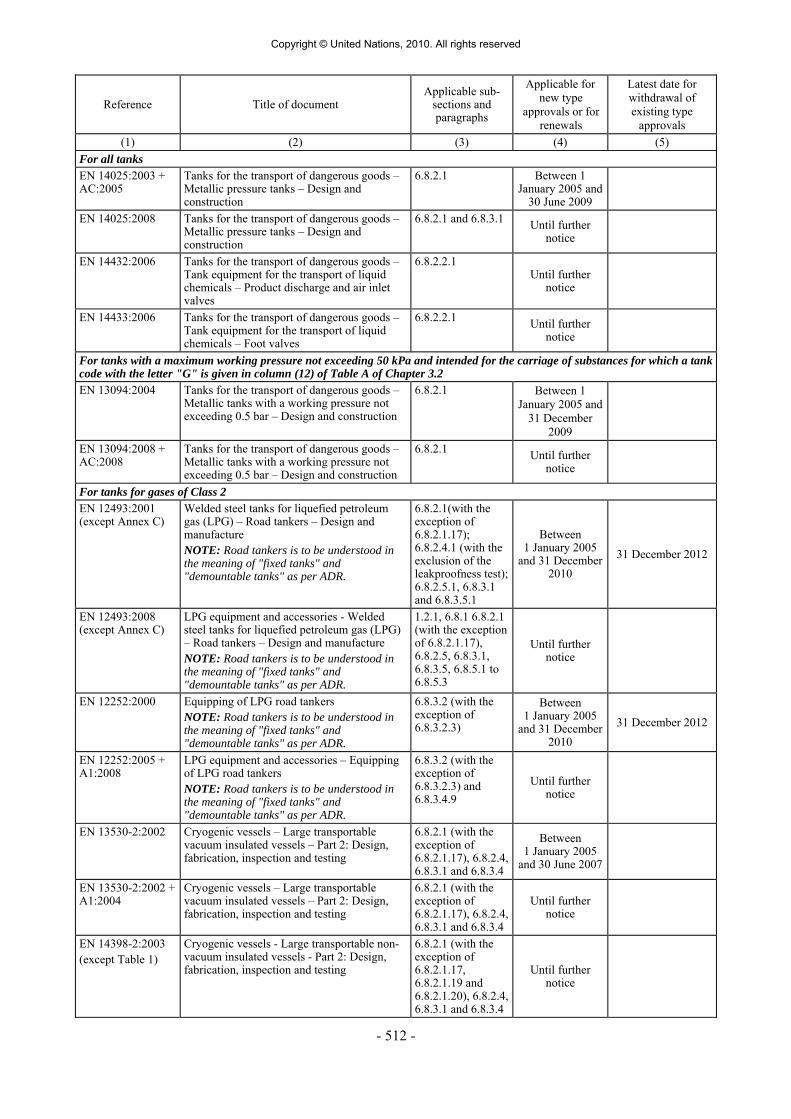
- 512 -
Reference Title of document Applicable sub-
sections and paragraphs
Applicable for new type
approvals or for renewals
Latest date for withdrawal of existing type
approvals (1) (2) (3) (4) (5)
For all tanks EN 14025:2003 + AC:2005
Tanks for the transport of dangerous goods – Metallic pressure tanks – Design and construction
6.8.2.1 Between 1 January 2005 and
30 June 2009
EN 14025:2008 Tanks for the transport of dangerous goods – Metallic pressure tanks – Design and construction
6.8.2.1 and 6.8.3.1 Until further notice
EN 14432:2006 Tanks for the transport of dangerous goods – Tank equipment for the transport of liquid chemicals – Product discharge and air inlet valves
6.8.2.2.1 Until further
notice
EN 14433:2006 Tanks for the transport of dangerous goods – Tank equipment for the transport of liquid chemicals – Foot valves
6.8.2.2.1 Until further notice
For tanks with a maximum working pressure not exceeding 50 kPa and intended for the carriage of substances for which a tank code with the letter "G" is given in column (12) of Table A of Chapter 3.2 EN 13094:2004 Tanks for the transport of dangerous goods –
Metallic tanks with a working pressure not exceeding 0.5 bar – Design and construction
6.8.2.1 Between 1 January 2005 and
31 December 2009
EN 13094:2008 + AC:2008
Tanks for the transport of dangerous goods – Metallic tanks with a working pressure not exceeding 0.5 bar – Design and construction
6.8.2.1 Until further notice
For tanks for gases of Class 2 EN 12493:2001 (except Annex C)
Welded steel tanks for liquefied petroleum gas (LPG) – Road tankers – Design and manufacture NOTE: Road tankers is to be understood in the meaning of "fixed tanks" and "demountable tanks" as per ADR.
6.8.2.1(with the exception of 6.8.2.1.17); 6.8.2.4.1 (with the exclusion of the leakproofness test); 6.8.2.5.1, 6.8.3.1 and 6.8.3.5.1
Between 1 January 2005
and 31 December 2010
31 December 2012
EN 12493:2008 (except Annex C)
LPG equipment and accessories - Welded steel tanks for liquefied petroleum gas (LPG) – Road tankers – Design and manufacture NOTE: Road tankers is to be understood in the meaning of "fixed tanks" and "demountable tanks" as per ADR.
1.2.1, 6.8.1 6.8.2.1 (with the exception of 6.8.2.1.17), 6.8.2.5, 6.8.3.1, 6.8.3.5, 6.8.5.1 to 6.8.5.3
Until further notice
EN 12252:2000 Equipping of LPG road tankers NOTE: Road tankers is to be understood in the meaning of "fixed tanks" and "demountable tanks" as per ADR.
6.8.3.2 (with the exception of 6.8.3.2.3)
Between 1 January 2005
and 31 December 2010
31 December 2012
EN 12252:2005 + A1:2008
LPG equipment and accessories – Equipping of LPG road tankers NOTE: Road tankers is to be understood in the meaning of "fixed tanks" and "demountable tanks" as per ADR.
6.8.3.2 (with the exception of 6.8.3.2.3) and 6.8.3.4.9
Until further notice
EN 13530-2:2002 Cryogenic vessels – Large transportable vacuum insulated vessels – Part 2: Design, fabrication, inspection and testing
6.8.2.1 (with the exception of 6.8.2.1.17), 6.8.2.4, 6.8.3.1 and 6.8.3.4
Between 1 January 2005
and 30 June 2007
EN 13530-2:2002 + A1:2004
Cryogenic vessels – Large transportable vacuum insulated vessels – Part 2: Design, fabrication, inspection and testing
6.8.2.1 (with the exception of 6.8.2.1.17), 6.8.2.4, 6.8.3.1 and 6.8.3.4
Until further notice
EN 14398-2:2003 (except Table 1)
Cryogenic vessels - Large transportable non-vacuum insulated vessels - Part 2: Design, fabrication, inspection and testing
6.8.2.1 (with the exception of 6.8.2.1.17, 6.8.2.1.19 and 6.8.2.1.20), 6.8.2.4, 6.8.3.1 and 6.8.3.4
Until further notice
Copyright © United Nations, 2010. All rights reserved

- 513 -
Reference Title of document Applicable sub-
sections and paragraphs
Applicable for new type
approvals or for renewals
Latest date for withdrawal of existing type
approvals (1) (2) (3) (4) (5)
For tanks intended for the carriage of liquid petroleum products and other dangerous substances of Class 3 which have a vapour pressure not exceeding 110 kPa at 50 °C and petrol, and which have no toxic or corrosive subsidiary hazard EN 13094:2004 Tanks for the transport of dangerous goods –
Metallic tanks with a working pressure not exceeding 0.5 bar – Design and construction
6.8.2.1 Between 1 January 2005
and 31 December 2009
EN 13094:2008 + AC:2008
Tanks for the transport of dangerous goods – Metallic tanks with a working pressure not exceeding 0.5 bar – Design and construction
6.8.2.1 Until further notice
EN 13082:2001 Tanks for transport of dangerous goods – Service equipment for tanks – Vapour transfer valve
6.8.2.2 and 6.8.2.4.1 Until further
notice
EN 13308:2002 Tanks for transport of dangerous goods – Service equipment for tanks – Non pressure balanced footvalve
6.8.2.2 and 6.8.2.4.1 Until further
notice
EN 13314:2002 Tanks for transport of dangerous goods – Service equipment for tanks – Fill hole cover
6.8.2.2 and 6.8.2.4.1
Until further notice
EN 13316:2002 Tanks for transport of dangerous goods – Service equipment for tanks –Pressure balanced footvalve
6.8.2.2 and 6.8.2.4.1 Until further
notice
EN 13317:2002 (except for the figure and table B.2 in Annex B) (The material shall meet the requirements of standard EN 13094:2004, Clause 5.2)
Tanks for transport of dangerous goods – Service equipment for tanks – Manhole cover assembly
6.8.2.2 and 6.8.2.4.1
Between 1 January 2005
and 31 December 2010
31 December 2012
EN 13317:2002 + A1:2006
Tanks for transport of dangerous goods – Service equipment for tanks – Manhole cover assembly
6.8.2.2 and 6.8.2.4.1 Until further
notice
EN 14595:2005 Tanks for transport of dangerous goods - Service equipment for tanks - Pressure and vacuum breather vent
6.8.2.2 and 6.8.2.4.1 Until further
notice
6.8.2.6.2 Inspection and test The standard referenced in the table below shall be applied for the inspection and test of
tanks as indicated in column (4) to meet the requirements of Chapter 6.8 referred to in column (3) which shall prevail in all cases.
The use of a referenced standard is mandatory.
Reference Title of document Applicable sub-
sections and paragraphs
Application authorized
(1) (2) (3) (4) EN 12972:2007 Tanks for transport of dangerous goods – Testing,
inspection and marking of metallic tanks 6.8.2.4 6.8.3.4 Until further notice
Copyright © United Nations, 2010. All rights reserved

- 514 -
6.8.2.7 Requirements for tanks which are not designed, constructed and tested according to referenced standards
To reflect scientific and technical progress or where no standard is referenced in 6.8.2.6 or to
deal with specific aspects not addressed in a standard referenced in 6.8.2.6, the competent authority may recognize the use of a technical code providing the same level of safety. Tanks shall, however, comply with the minimum requirements of 6.8.2.
The competent authority shall transmit to the secretariat of UNECE a list of the technical
codes that it recognises. The list should include the following details: name and date of the code, purpose of the code and details of where it may be obtained. The secretariat shall make this information publicly available on its website.
A standard which has been adopted for reference in a future edition of the ADR may be
approved by the competent authority for use without notifying the UNECE secretariat. For testing, inspection and marking, the applicable standard referenced in 6.8.2.6 may also
be used.
6.8.3 Special requirements applicable to Class 2 6.8.3.1 Construction of shells 6.8.3.1.1 Shells intended for the carriage of compressed or liquefied gases or dissolved gases shall be
made of steel. In the case of weldless shells, by derogation from 6.8.2.1.12 a minimum elongation at fracture of 14% and also a stress σ lower than or equal to limits hereafter given according to the material may be accepted:
(a) When the ratio Re/Rm (of the minimum guaranteed characteristics after heat
treatment) is higher than 0.66 without exceeding 0.85:
σ ≤ 0.75 Re;
(b) When the ratio Re/Rm (of the minimum guaranteed characteristics after heat treatment) is higher than 0.85:
σ ≤ 0.5 Rm.
6.8.3.1.2 The requirements of 6.8.5 apply to the materials and construction of welded shells. 6.8.3.1.3 (Reserved)
Construction of battery-vehicles and MEGCs 6.8.3.1.4 Cylinders, tubes, pressure drums and bundles of cylinders, as elements of a battery-vehicle
or MEGC, shall be constructed in accordance with Chapter 6.2.
NOTE 1: Bundles of cylinders which are not elements of a battery-vehicle or of a MEGC shall be subject to the requirements of Chapter 6.2.
NOTE 2: Tanks as elements of battery-vehicles and MEGCs shall be constructed in accordance with 6.8.2.1 and 6.8.3.1.
Copyright © United Nations, 2010. All rights reserved

- 515 -
NOTE 3: Demountable tanks 13 are not to be considered elements of battery-vehicles or MEGCs.
6.8.3.1.5 Elements and their fastenings shall be capable of absorbing under the maximum permissible load the forces defined in 6.8.2.1.2. Under each force the stress at the most severely stressed point of the element and its fastenings shall not exceed the value defined in 6.2.5.3 for cylinders, tubes, pressure drums and bundles of cylinders and for tanks the value of σ defined in 6.8.2.1.16.
6.8.3.2 Items of equipment 6.8.3.2.1 The discharge pipes of tanks shall be capable of being closed by blank flanges or some other
equally reliable device. For tanks intended for the carriage of refrigerated liquefied gases, these blank flanges or other equally reliable devices may be fitted with pressure-release openings of a maximum diameter of 1.5 mm.
6.8.3.2.2 Shells intended for the carriage of liquefied gases may be provided with, in addition to the
openings prescribed in 6.8.2.2.2 and 6.8.2.2.4, openings for the fitting of gauges, thermometers, manometers and with bleed holes, as required for their operation and safety.
6.8.3.2.3 The internal stop-valve of all filling and all discharge openings of tanks
with a capacity greater than 1 m3 intended for the carriage of liquefied flammable or toxic gases shall be instant-closing and
shall close automatically in the event of an unintended movement of the tank or in the event of fire. It shall also be possible to operate the internal stop-valve by remote control.
However on tanks intended for the carriage of liquefied non-toxic flammable gases, the internal stop-valve with remote control may be replaced by a non-return valve for filling openings into the vapour phase of the tank only. The non-return valve shall be positioned internally in the tank, be spring loaded so that the valve is closed if the pressure in the filling line is equal to or lower than the pressure in the tank and be equipped with appropriate sealing14.
6.8.3.2.4 All openings, other than those accommodating safety valves and closed bleed holes, of tanks
intended for the carriage of liquefied flammable and/or toxic gases shall, if their nominal diameter is more than 1.5 mm, shall be equipped with an internal shut-off device.
6.8.3.2.5 Notwithstanding the requirements of 6.8.2.2.2, 6.8.3.2.3 and 6.8.3.2.4, tanks intended for the
carriage of refrigerated liquefied gases may be equipped with external devices in place of internal devices if the external devices afford protection against external damage at least equivalent to that afforded by the wall of the shell.
6.8.3.2.6 If the tanks are equipped with gauges in direct contact with the substance carried, the gauges
shall not be made of a transparent material. If there are thermometers, they shall not project directly into the gas or liquid through the shell.
13 For the definition of "demountable tank" see 1.2.1. 14 The use of metal to metal sealing is not permitted.
Copyright © United Nations, 2010. All rights reserved

- 516 -
6.8.3.2.7 Filling and discharge openings situated in the upper part of tanks shall be equipped with, in addition to what is prescribed in 6.8.3.2.3, a second, external, closing device. This device shall be capable of being closed by a blank flange or some other equally reliable device.
6.8.3.2.8 Safety valves shall meet the requirements of 6.8.3.2.9 to 6.8.3.2.12 below: 6.8.3.2.9 Tanks intended for the carriage of compressed or liquefied gases or dissolved gases, may be
fitted with spring-loaded safety valves. These valves shall be capable of opening automatically under a pressure between 0.9 and 1.0 times the test pressure of the tank to which they are fitted. They shall be of such a type as to resist dynamic stresses, including liquid surge. The use of dead weight or counter weight valves is prohibited. The required capacity of the safety valves shall be calculated in accordance with the formula contained in 6.7.3.8.1.1.
6.8.3.2.10 Where tanks are intended for carriage by sea, the requirements of 6.8.3.2.9 shall not prohibit
the fitting of safety valves conforming to the IMDG Code. 6.8.3.2.11 Tanks intended for the carriage of refrigerated liquefied gases shall be equipped with two or
more independent safety valves capable of opening at the maximum working pressure indicated on the tank. Two of these safety valves shall be individually sized to allow the gases formed by evaporation during normal operation to escape from the tank in such a way that the pressure does not at any time exceed by more than 10% the working pressure indicated on the tank.
One of the safety valves may be replaced by a bursting disc which shall be such as to burst at
the test pressure. In the event of loss of the vacuum in a double-walled tank, or of destruction of 20% of the
insulation of a single-walled tank, the combination of the pressure relief devices shall permit an outflow such that the pressure in the shell cannot exceed the test pressure. The provisions of 6.8.2.1.7 shall not apply to vacuum-insulated tanks.
6.8.3.2.12 These pressure relief devices of tanks intended for the carriage of refrigerated liquefied gases
shall be so designed as to function faultlessly even at their lowest working temperature. The reliability of their operation at that temperature shall be established and checked either by testing each device or by testing a specimen device of each design-type.
6.8.3.2.13 The valves of demountable tanks that can be rolled shall be provided with protective caps.
Thermal insulation 6.8.3.2.14 If tanks intended for the carriage of liquefied gases are equipped with thermal insulation,
such insulation shall consist of either:
- a sun shield covering not less than the upper third but not more than the upper half of the tank surface and separated from the shell by an air space at least 4 cm across; or
- a complete cladding, of adequate thickness, of insulating materials.
6.8.3.2.15 Tanks intended for the carriage of refrigerated liquefied gases shall be thermally insulated.
Thermal insulation shall be ensured by means of a continuous sheathing. If the space between the shell and the sheathing is under vacuum (vacuum insulation), the protective sheathing shall be so designed as to withstand without deformation an external pressure of at least 100 kPa (1 bar) (gauge pressure). By derogation from the definition of "calculation pressure" in 1.2.1, external and internal reinforcing devices may be taken into account in the
Copyright © United Nations, 2010. All rights reserved

- 517 -
calculations. If the sheathing is so closed as to be gas-tight, a device shall be provided to prevent any dangerous pressure from developing in the insulating layer in the event of inadequate gas-tightness of the shell or of its items of equipment. The device shall prevent the infiltration of moisture into the heat-insulating sheath.
6.8.3.2.16 Tanks intended for the carriage of liquefied gases having a boiling point below -182° C at
atmospheric pressure shall not include any combustible material either in the thermal insulation or in the means of attachment.
The means of attachment for vacuum insulated tanks may, with the approval of the
competent authority, contain plastics substances between the shell and the sheathing. 6.8.3.2.17 By derogation from the requirements of 6.8.2.2.4 shells intended for the carriage of
refrigerated liquefied gases need not have an inspection opening. Items of equipment for battery-vehicles and MEGCs 6.8.3.2.18 Service and structural equipment shall be configured or designed to prevent damage that
could result in the release of the pressure receptacle contents during normal conditions of handling and carriage. When the connection between the frame of the battery-vehicle or MEGC and the elements allows relative movement between the sub-assemblies, the equipment shall be so fastened as to permit such movement without damage to working parts. Manifold piping leading to shut-off valves shall be sufficiently flexible to protect the valves and the piping from shearing, or releasing the pressure receptacle contents. The filling and discharge devices (including flanges or threaded plugs) and any protective caps shall be capable of being secured against unintended opening.
6.8.3.2.19 In order to avoid any loss of content in the event of damage, the manifolds, the discharge
fittings (pipe sockets, shut-off devices), and the stop-valves shall be protected or arranged from being wrenched off by external forces or designed to withstand them.
6.8.3.2.20 The manifold shall be designed for service in a temperature range of -20° C to +50° C. The manifold shall be designed, constructed and installed so as to avoid the risk of damage
due to thermal expansion and contraction, mechanical shock and vibration. All piping shall be of suitable metallic material. Welded pipe joints shall be used wherever possible.
Joints in copper tubing shall be brazed or have an equally strong metal union. The melting
point of brazing materials shall be no lower than 525ºC. The joints shall not decrease the strength of tubing as may happen when cutting threads.
6.8.3.2.21 Except for UN No.1001 acetylene, dissolved, the permissible maximum stress σ of the manifolding arrangement at the test pressure of the receptacles shall not exceed 75% of the guaranteed yield strength of the material.
The necessary wall thickness of the manifolding arrangement for the carriage of
UN No.1001 acetylene, dissolved shall be calculated according to an approved code of practice.
NOTE: For the yield strength, see 6.8.2.1.11. The basic requirements of this paragraph shall be deemed to have been complied with if the
following standards are applied: (Reserved).
Copyright © United Nations, 2010. All rights reserved

- 518 -
6.8.3.2.22 By derogation from the requirements of 6.8.3.2.3, 6.8.3.2.4 and 6.8.3.2.7, for cylinders, tubes, pressure drums and bundles of cylinders (frames) forming a battery-vehicle or MEGC, the required closing devices may be provided for within the manifolding arrangement.
6.8.3.2.23 If one of the elements is equipped with a safety valve and shut-off devices are provided
between the elements, every element shall be so equipped. 6.8.3.2.24 The filling and discharge devices may be affixed to a manifold. 6.8.3.2.25 Each element, including each individual cylinder of a bundle, intended for the carriage of
toxic gases, shall be capable of being isolated by a shut-off valve. 6.8.3.2.26 Battery-vehicles or MEGCs intended for the carriage of toxic gases shall not have safety
valves, unless the safety valves are preceded by a bursting disc. In the latter case, the arrangement of the bursting disc and safety valve shall be satisfactory to the competent authority.
6.8.3.2.27 When battery-vehicles or MEGCs are intended for carriage by sea, the requirements of
6.8.3.2.26 shall not prohibit the fitting of safety valves conforming to the IMDG Code. 6.8.3.2.28 Receptacles which are elements of a battery-vehicle or MEGC intended for the carriage of
flammable gases shall be combined in groups of not more than 5 000 litres which are capable of being isolated by a shut-off valve.
Each element of a battery-vehicle or MEGC intended for the carriage of flammable gases,
when consisting of tanks conforming to this Chapter, shall be capable of being isolated by a shut-off valve.
6.8.3.3 Type approval No special requirements. 6.8.3.4 Inspections and tests 6.8.3.4.1 The materials of every welded shell with the exception of cylinders, tubes, pressure drums
and cylinders as part of bundles of cylinders which are elements of a battery-vehicle or of a MEGC shall be tested according to the method described in 6.8.5.
6.8.3.4.2 The basic requirements for the test pressure are given in 4.3.3.2.1 to 4.3.3.2.4 and the
minimum test pressures are given in the table of gases and gas mixtures in 4.3.3.2.5. 6.8.3.4.3 The first hydraulic pressure test shall be carried out before thermal insulation is placed in
position. When the shell, its fittings, piping and items of equipment have been tested separately, the tank shall be subjected to a leakproofness test after assembly.
6.8.3.4.4 The capacity of each shell intended for the carriage of compressed gases filled by mass,
liquefied gases or dissolved gases shall be determined, under the supervision of an expert approved by the competent authority, by weighing or volumetric measurement of the quantity of water which fills the shell; the measurement of shell capacity shall be accurate to within 1%. Determination by a calculation based on the dimensions of the shell is not permitted. The maximum filling masses allowed in accordance with packing instruction P200 or P203 in 4.1.4.1 as well as 4.3.3.2.2 and 4.3.3.2.3 shall be prescribed by an approved expert.
6.8.3.4.5 Checking of the welds shall be carried out in accordance with the λ=1 requirements
of 6.8.2.1.23.
Copyright © United Nations, 2010. All rights reserved

- 519 -
6.8.3.4.6 By derogation from the requirements of 6.8.2.4, the periodic inspections according to 6.8.2.4.2, shall take place:
(a) at least every three years at least every two and a half years
in the case of tanks intended for the carriage of UN No. 1008 boron trifluoride, UN No. 1017
chlorine, UN No. 1048 hydrogen bromide, anhydrous, UN No. 1050 hydrogen chloride, anhydrous, UN No. 1053 hydrogen sulphide or UN No. 1079 sulphur dioxide; (b) at least after six years
at least after 8 years
of service and thereafter at least every 12 years in the case of tanks intended for the carriage
of refrigerated liquefied gases.
The intermediate inspections according to 6.8.2.4.3 shall be carried out at least six years after each periodic inspection.
A leakproofness test or an intermediate inspection according to 6.8.2.4.3 may be performed, at the request of the competent authority, between any two successive periodic inspections.
When the shell, its fittings, piping and items of equipment have been tested separately, the
tank shall be subjected to a leakproofness test after assembly. 6.8.3.4.7 In the case of vacuum-insulated tanks, the hydraulic-pressure test and the check of the
internal condition may, with the consent of the approved expert, be replaced by a leakproofness test and measurement of the vacuum.
6.8.3.4.8 If, at the time of periodic inspections, openings have been made in shells intended for the
carriage of refrigerated liquefied gases, the method by which they are hermetically closed before the shells are returned to service shall be approved by the approved expert and shall ensure the integrity of the shell.
6.8.3.4.9 Leakproofness tests of tanks intended for the carriage of gases shall be performed at a
pressure of not less than:
- For compressed gases, liquefied gases and dissolved gases: 20% of the test pressure;
- For refrigerated liquefied gases: 90% of the maximum working pressure.
Inspections and tests for battery-vehicles and MEGCs 6.8.3.4.10 The elements and items of equipment of each battery-vehicle or MEGC shall be inspected
and tested either together or separately before being put into service for the first time (initial inspection and test). Thereafter battery-vehicles or MEGCs the elements of which are receptacles shall be inspected at not more than five-year intervals. Battery-vehicles and MEGCs the elements of which are tanks shall be inspected according to 6.8.3.4.6. An exceptional inspection and test shall be performed regardless of the last periodic inspection and test when necessary according to 6.8.3.4.14.
6.8.3.4.11 The initial inspection shall include:
- a check of conformity to the approved type;
- a check of the design characteristics;
- an examination of the internal and external conditions;
Copyright © United Nations, 2010. All rights reserved
- 520 -
- a hydraulic pressure test 9 at the test pressure indicated on the plate prescribed in 6.8.3.5.10;
- a leakproofness test at the maximum working pressure; and
- a check of satisfactory operation of the equipment.
When the elements and their fittings have been pressure-tested separately, they shall be subjected together after assembly to a leakproofness test.
6.8.3.4.12 Cylinders, tubes and pressure drums and cylinders as part of bundles of cylinders shall be
tested according to packing instruction P200 or P203 in 4.1.4.1. The test pressure of the manifold of the battery-vehicle or MEGC shall be the same as that of
the elements of the battery-vehicle or MEGC. The pressure test of the manifold may be performed as a hydraulic test or by using another liquid or gas with the agreement of the competent authority or its authorised body. By derogation from this requirement, the test pressure for the manifold of battery-vehicle or MEGC shall not be less than 300 bar for UN No. 1001 acetylene, dissolved.
6.8.3.4.13 The periodic inspection shall include a leakproofness test at the maximum working pressure
and an external examination of the structure, the elements and the service equipment without disassembling. The elements and the piping shall be tested at the periodicity defined in packing instruction P200 of 4.1.4.1 and in accordance with the requirements of 6.2.1.6 and 6.2.3.5 respectively. When the elements and equipment have been pressure-tested separately, they shall be subjected together after assembly to a leakproofness test.
6.8.3.4.14 An exceptional inspection and test is necessary when the battery-vehicle or MEGC shows
evidence of damaged or corroded areas, or leakage, or any other conditions, that indicate a deficiency that could affect the integrity of the battery-vehicle or MEGC. The extent of the exceptional inspection and test and, if deemed necessary, the disassembling of elements shall depend on the amount of damage or deterioration of the battery-vehicle or MEGC. It shall include at least the examinations required under 6.8.3.4.15.
6.8.3.4.15 The examinations shall ensure that:
(a) The elements are inspected externally for pitting, corrosion, or abrasions, dents,
distortions, defects in welds or any other conditions, including leakage, that might render the battery-vehicles or MEGCs unsafe for transport;
(b) The piping, valves, and gaskets are inspected for corroded areas, defects, and other
conditions, including leakage, that might render battery-vehicles or MEGCs unsafe for filling, discharge or transport;
(c) Missing or loose bolts or nuts on any flanged connection or blank flange are replaced
or tightened; (d) All emergency devices and valves are free from corrosion, distortion and any damage
or defect that could prevent their normal operation. Remote closure devices and self-closing stop-valves shall be operated to demonstrate proper operation;
(e) Required markings on the battery-vehicles or MEGCs are legible and in accordance
with the applicable requirements; and 9 In special cases and with the agreement of the expert approved by the competent authority, the hydraulic pressure test may be replaced by a pressure test using another liquid or gas, where such an operation does not present any danger.
Copyright © United Nations, 2010. All rights reserved

- 521 -
(f) Any framework, supports and arrangements for lifting the battery-vehicles or MEGCs are in satisfactory condition.
6.8.3.4.16 The tests, inspections and checks in accordance with 6.8.3.4.10 to 6.8.3.4.15 shall be carried
out by the expert approved by the competent authority. Certificates shall be issued showing the results of these operations, even in the case of negative results.
These certificates shall refer to the list of the substances permitted for carriage in this battery-vehicle or MEGC in accordance with 6.8.2.3.1. A copy of these certificates shall be attached to the tank record of each tank, battery-vehicle or MEGC tested (see 4.3.2.1.7).
6.8.3.5 Marking 6.8.3.5.1 The following additional particulars shall be marked by stamping or by any other similar
method on the plate prescribed in 6.8.2.5.1, or directly on the walls of the shell itself if the walls are so reinforced that the strength of the tank is not impaired.
6.8.3.5.2 On tanks intended for the carriage of only one substance:
- the proper shipping name of the gas and, in addition for gases classified under an n.o.s. entry, the technical name 15;
This indication shall be supplemented:
- in the case of tanks intended for the carriage of compressed gases filled by volume (pressure), by an indication of the maximum filling pressure at 15 °C permitted for the tank; and
- in the case of tanks intended for the carriage of compressed gases filled by mass, and of liquefied gases, refrigerated liquefied gases or dissolved gases by an indication of the maximum permissible load mass in kg and of the filling temperature if below –20 °C.
6.8.3.5.3 On multipurpose tanks:
- the proper shipping names of the gases and, in addition for gases classified under an n.o.s. entry, the technical name of the gases 15 for whose carriage the tank is approved.
These particulars shall be supplemented by an indication of the maximum permissible load
mass in kg for each gas. 6.8.3.5.4 On tanks intended for the carriage of refrigerated liquefied gases:
- the maximum working pressure allowed. 15 Instead of the proper shipping name or, if applicable, of the proper shipping name of the n.o.s. entry followed by the technical name, the use of the following names is permitted:
- for UN No. 1078 refrigerant gas, n.o.s: mixture F1, mixture F2, mixture F3; - for UN No. 1060 methylacetylene and propadiene mixtures, stabilized: mixture P1, mixture P2; - for UN No. 1965 hydrocarbon gas mixture, liquefied, n.o.s: mixture A, mixture A01,
mixture A02, mixture A0, mixture A1, mixture B1, mixture B2, mixture B, mixture C. The names customary in the trade and mentioned in 2.2.2.3, Classification code 2F, UN No. 1965, Note 1 may be used only as a complement;
- for UN No. 1010 Butadienes, stabilized: 1,2-Butadiene, stabilized, 1,3-Butadiene, stabilized.
Copyright © United Nations, 2010. All rights reserved

- 522 -
6.8.3.5.5 On tanks equipped with thermal insulation:
- the inscription "thermally insulated" or "thermally insulated by vacuum".
6.8.3.5.6 In addition to the particulars prescribed in 6.8.2.5.2, the following shall be inscribed on
the tank itself or on a plate: the tank-container itself or on a plate:
(a) - the tank code according to the certificate (see 6.8.2.3.1) with the actual test pressure of the tank;
- the inscription: "minimum filling temperature allowed: …";
(b) where the tank is intended for the carriage of one substance only:
-2 the proper shipping name of the gas and, in addition for gases classified under
an n.o.s. entry, the technical name 15; - for compressed gases which are filled by mass, and for liquefied gases,
refrigerated liquefied gases or dissolved gases, the maximum permissible load mass in kg;
(c) where the tank is a multipurpose tank:
- the proper shipping name of the gas and, for gases classified under an n.o.s. entry, the technical name 15 of all gases to whose carriage the tank is assigned with an indication of the maximum permissible load mass in kg for each of them;
(d) where the shell is equipped with thermal insulation:
- the inscription "thermally insulated" (or "thermally insulated by vacuum"), in an
official language of the country of registration and also, if that language is not English, French or German, in English, French or German, unless any agreements concluded between the countries concerned in the transport operation provide otherwise.
6.8.3.5.7 (Reserved) 6.8.3.5.8 These particulars shall not be required in the
case of a vehicle carrying demountable tanks.
6.8.3.5.9 (Reserved)
15 Instead of the proper shipping name or, if applicable, of the proper shipping name of the n.o.s. entry followed by the technical name, the use of the following names is permitted:
- for UN No. 1078 refrigerant gas, n.o.s: mixture F1, mixture F2, mixture F3; - for UN No. 1060 methylacetylene and propadiene mixtures, stabilized: mixture P1, mixture P2; - for UN No. 1965 hydrocarbon gas mixture, liquefied, n.o.s: mixture A, mixture A01,
mixture A02, mixture A0, mixture A1, mixture B1, mixture B2, mixture B, mixture C. The names customary in the trade and mentioned in 2.2.2.3, Classification code 2F, UN No. 1965, Note 1 may be used only as a complement;
- for UN No. 1010 Butadienes, stabilized: 1,2-Butadiene, stabilized, 1,3-Butadiene, stabilized.
Copyright © United Nations, 2010. All rights reserved

- 523 -
Marking of battery-vehicles and MEGCs 6.8.3.5.10 Every battery-vehicle and every MEGC shall be fitted with a corrosion-resistant metal plate
permanently attached in a place readily accessible for inspection. The following particulars at least shall be marked on the plate by stamping or by any other similar method 12
- approval number;
- manufacturer’s name or mark;
- manufacturer’s serial number;
- year of manufacture;
- test pressure (gauge pressure)
- design temperature (only if above +50 °C or below -20 °C);
- date (month and year) of initial test and most recent periodic test in accordance with 6.8.3.4.10 to 6.8.3.4.13;
- stamp of the expert who carried out the tests. 6.8.3.5.11 The following particulars shall be inscribed
on the battery-vehicle itself or on a plate 12:
- names of owner or of operator;
- number of elements;
- total capacity of the elements;
and for battery-vehicles filled by mass:
- unladen mass;
- maximum permissible mass.
The following particulars shall be inscribed either on the MEGC itself or on a plate 12:
- names of owner and of operator;
- number of elements;
- total capacity of the elements;
- maximum permissible laden mass;
- the tank code according to the certificate of approval (see 6.8.2.3.1) with the actual test pressure of the MEGC;
- the proper shipping name of the gases, and in addition, for gases classified under an n.o.s. entry, the technical name 15 of the gases for whose carriage the MEGC is used;
and for MEGCs filled by mass:
- tare.
12 Add the units of measurements after the numerical values. 15 Instead of the proper shipping name or, if applicable, of the proper shipping name of the n.o.s. entry followed by the technical name, the use of the following names is permitted:
- for UN No. 1078 refrigerant gas, n.o.s: mixture F1, mixture F2, mixture F3; - for UN No. 1060 methylacetylene and propadiene mixtures, stabilized: mixture P1, mixture P2; - for UN No. 1965 hydrocarbon gas mixture, liquefied, n.o.s: mixture A, mixture A01,
mixture A02, mixture A0, mixture A1, mixture B1, mixture B2, mixture B, mixture C. The names customary in the trade and mentioned in 2.2.2.3, Classification code 2F, UN No. 1965, Note 1 may be used only as a complement;
- for UN No. 1010 Butadienes, stabilized: 1,2-Butadiene, stabilized, 1,3-Butadiene, stabilized.
Copyright © United Nations, 2010. All rights reserved

- 524 -
6.8.3.5.12 The frame of a battery-vehicle or MEGC shall bear near the filling point a plate specifying:
- the maximum filling pressure 12 at 15 °C allowed for elements intended for compressed gases;
- the proper shipping name of the gas in accordance with Chapter 3.2 and, in addition
for gases classified under an n.o.s. entry, the technical name 15;
and, in addition, in the case of liquefied gases: - the permissible maximum load per element 12.
6.8.3.5.13 Cylinders, tubes and pressure drums, and cylinders as part of bundles of cylinders, shall be
marked according to 6.2.2.7. These receptacles need not be labelled individually with the danger labels as required in Chapter 5.2.
Battery-vehicles and MEGCs shall be placarded and marked according to Chapter 5.3. 6.8.3.6 Requirements for battery-vehicles and MEGCs which are designed, constructed and tested
according to referenced standards
NOTE: Persons or bodies identified in standards as having responsibilities in accordance with ADR shall meet the requirements of ADR.
The standard referenced in the table below shall be applied for the issue of type approvals as
indicated in column (4) to meet the requirements of Chapter 6.8 referred to in column (3). The requirements of Chapter 6.8 referred to in column (3) shall prevail in all cases. Column (5) gives the latest date when existing type approvals shall be withdrawn according to 1.8.7.2.4; if no date is shown the type approval remains valid until it expires.
Since 1 January 2009 the use of the referenced standards has been mandatory. Exceptions
are dealt with in 6.8.3.7 If more than one standard is referenced for the application of the same requirements, only
one of them shall be applied, but in full unless otherwise specified in the table below.
12 Add the units of measurements after the numerical values. 15 Instead of the proper shipping name or, if applicable, of the proper shipping name of the n.o.s. entry followed by the technical name, the use of the following names is permitted:
- for UN No. 1078 refrigerant gas, n.o.s: mixture F1, mixture F2, mixture F3; - for UN No. 1060 methylacetylene and propadiene mixtures, stabilized: mixture P1, mixture P2; - for UN No. 1965 hydrocarbon gas mixture, liquefied, n.o.s: mixture A, mixture A01,
mixture A02, mixture A0, mixture A1, mixture B1, mixture B2, mixture B, mixture C. The names customary in the trade and mentioned in 2.2.2.3, Classification code 2F, UN No. 1965, Note 1 may be used only as a complement;
- for UN No. 1010 Butadienes, stabilized: 1,2-Butadiene, stabilized, 1,3-Butadiene, stabilized.
Copyright © United Nations, 2010. All rights reserved

- 525 -
Reference Title of document Applicable sub-
sections and paragraphs
Applicable for new type
approvals or for renewals
Latest date for withdrawal of existing type
approvals (1) (2) (3) (4) (5)
EN 13807:2003 Transportable gas cylinders – Battery vehicles – Design, manufacture, identification and testing
6.8.3.1.4 and 6.8.3.1.5, 6.8.3.2.18 to 6.8.3.2.26, 6.8.3.4.10 to 6.8.3.4.12 and 6.8.3.5.10 to 6.8.3.5.13
Until further notice
6.8.3.7 Requirements for battery-vehicles and MEGCs which are not designed, constructed and
tested according to referenced standards To reflect scientific and technical progress or where no standard is referenced in 6.8.3.6 or to
deal with specific aspects not addressed in a standard referenced in 6.8.3.6, the competent authority may recognize the use of a technical code providing the same level of safety. Battery-vehicles and MEGCs shall, however, comply with the minimum requirements of 6.8.3.
In the type approval the issuing body shall specify the procedure for periodic inspections if
the standards referenced in 6.2.2, 6.2.4 or 6.8.2.6 are not applicable or shall not be applied. The competent authority shall transmit to the secretariat of UNECE a list of the technical
codes that it recognises. The list should include the following details: name and date of the code, purpose of the code and details of where it may be obtained. The secretariat shall make this information publicly available on its website.
A standard which has been adopted for reference in a future edition of the ADR may be
approved by the competent authority for use without notifying the UNECE secretariat. 6.8.4 Special provisions
NOTE 1: For liquids having a flash-point of not more than 60 °C and for flammable gases, see also 6.8.2.1.26, 6.8.2.1.27 and 6.8.2.2.9. NOTE 2: For requirements for tanks subjected to a pressure test of not less than 1 MPa (10 bar) or for tanks intended for the carriage of refrigerated liquefied gases, see 6.8.5.
When they are shown under an entry in Column (13) of Table A of Chapter 3.2, the
following special provisions apply:
(a) Construction (TC)
TC1 The requirements of 6.8.5 are applicable to the materials and construction of these shells.
TC2 Shells, and their items of equipment, shall be made of aluminium not less than
99.5% pure or of suitable steel not liable to cause hydrogen peroxide to decompose. Where shells are made of aluminium not less than 99.5% pure, the wall thickness need not exceed 15 mm, even where calculation in accordance with 6.8.2.1.17 gives a higher value.
TC3 The shells shall be made of austenitic steel.
Copyright © United Nations, 2010. All rights reserved

- 526 -
TC4 Shells shall be provided with an enamel or equivalent protective lining if the material of the shell is attacked by UN No. 3250 chloroacetic acid.
TC5 Shells shall be provided with a lead lining not less than 5 mm thick or an equivalent
lining. TC6 Where the use of aluminium is necessary for tanks, such tanks shall be made of
aluminium not less than 99.5% pure; the wall thickness need not exceed 15 mm even where calculation in accordance with 6.8.2.1.17 gives a higher value.
TC7 The effective minimum thickness of the shell shall not be less than 3 mm. (b) Items of equipment (TE) TE1 (Deleted) TE2 (Deleted)
TE3 Tanks shall in addition meet the following requirements. The heating device shall not penetrate into, but shall be exterior to the shell. However, a pipe used for extracting the phosphorus may be equipped with a heating jacket. The device heating the jacket shall be so regulated as to prevent the temperature of the phosphorus from exceeding the filling temperature of the shell. Other piping shall enter the shell in its upper part; openings shall be situated above the highest permissible level of the phosphorus and be capable of being completely enclosed under lockable caps. The tank shall be equipped with a gauging system for verifying the level of the phosphorus and, if water is used as a protective agent, with a fixed gauge mark showing the highest permissible level of the water.
TE4 Shells shall be equipped with thermal insulation made of materials which are not
readily flammable. TE5 If shells are equipped with thermal insulation, such insulation shall be made of
materials which are not readily flammable. TE6 Tanks may be equipped with a device of a design which precludes its obstruction by
the substance carried and which prevents leakage and the build-up of excess overpressure or underpressure inside the shell.
TE7 The shell-discharge system shall be equipped with two mutually independent shut-
off devices mounted in series, the first taking the form of a quick-closing internal stop-valve of an approved type and the second that of an external stop-valve, one at each end of the discharge pipe. A blank flange, or another device providing the same measure of security, shall also be fitted at the outlet of each external stop-valve. The internal stop-valve shall be such that if the pipe is wrenched off the stop-valve will remain integral with the shell and in the closed position.
TE8 The connections to the external pipe-sockets of tanks shall be made of materials not
liable to cause decomposition of hydrogen peroxide. TE9 Tanks shall be fitted in their upper part with a shut-off device preventing any build-
up of excess pressure inside the shell due to the decomposition of the substances carried, any leakage of liquid, and any entry of foreign matter into the shell.
Copyright © United Nations, 2010. All rights reserved

- 527 -
TE10 The shut-off devices of tanks shall be so designed as to preclude obstruction of the devices by the solidified substance during carriage. Where tanks are sheathed in thermally-insulating material, the material shall be of an inorganic nature and entirely free from combustible matter.
TE11 Shells and their service equipment shall be so designed as to prevent the entry of
foreign matter, leakage of liquid or any building up of dangerous excess pressure inside the shell due to the decomposition of the substances carried. A safety valve preventing the entry of foreign matter also fulfils this provision.
TE12 Tanks shall be equipped with thermal insulation complying with the requirements of 6.8.3.2.14. If the SADT of the organic peroxide in the tank is 55 °C or less, or the tank is constructed of aluminium, the shell shall be completely insulated. The sun shield and any part of the tank not covered by it, or the outer sheathing of a complete lagging, shall be painted white or finished in bright metal. The paint shall be cleaned before each transport journey and renewed in case of yellowing or deterioration. The thermal insulation shall be free from combustible matter. Tanks shall be fitted with temperature sensing devices.
Tanks shall be fitted with safety valves and emergency pressure-relief devices.
Vacuum-relief devices may also be used. Emergency pressure-relief devices shall operate at pressures determined according to both the properties of the organic peroxide and the construction characteristics of the tank. Fusible elements shall not be permitted in the body of the shell.
Tanks shall be fitted with spring-loaded safety valves to prevent significant pressure
build-up within the shell of the decomposition products and vapours released at a temperature of 50 °C. The capacity and start-to-discharge pressure of the safety-valve(s) shall be based on the results of the tests specified in special provision TA2. The start-to-discharge pressure shall however in no case be such that liquid could escape from the valve(s) if the tank were overturned.
The emergency-relief devices may be of the spring-loaded or frangible types
designed to vent all the decomposition products and vapours evolved during a period of not less than one hour of complete fire-engulfment as calculated by the following formula:
0.82AF 70961 q ××=
where: q = heat absorption [W] A = wetted area [m2] F = insulation factor
F = l for non-insulated tanks, or
s tankinsulatedfor 47032
)T - (923 U F P0=
where: K = heat conductivity of insulation layer [W·m-1·K-1] L = thickness of insulation layer [m] U = K/L = heat transfer coefficient of the insulation [W·m-2·K-1] TPO = temperature of peroxide at relieving conditions [K]
Copyright © United Nations, 2010. All rights reserved
- 528 -
The start-to-discharge pressure of the emergency-relief device(s) shall be higher than that above specified and based on the results of the tests referred to in special provision TA2. The emergency-relief devices shall be dimensioned in such a way that the maximum pressure in the tank never exceeds the test pressure of the tank. NOTE: An example of a method to determine the size of emergency-relief devices is given in Appendix 5 of the Manual of Tests and Criteria. For tanks equipped with thermal insulation consisting of a complete cladding, the capacity and setting of the emergency-relief device(s) shall be determined assuming a loss of insulation from 1% of the surface area. Vacuum-relief devices and spring-loaded safety valves of tanks shall be provided with flame arresters unless the substances to be carried and their decomposition products are non-combustible. Due attention shall be paid to the reduction of the relief capacity caused by the flame arrester.
TE13 Tanks shall be thermally insulated and fitted with a heating device on the outside. TE14 Tanks shall be equipped with thermal insulation. The thermal insulation directly in
contact with the shell shall have an ignition temperature at least 50 °C higher than the maximum temperature for which the tank was designed.
TE15 (Deleted) TE16 (Reserved) TE17 (Reserved) TE18 Tanks intended for the carriage of substances filled at a temperature higher
than 190 ºC shall be equipped with deflectors placed at right angles to the upper filling openings, so as to avoid a sudden localized increase in wall temperature during filling.
TE19 Fittings and accessories mounted in
the upper part of the tank shall be either:
- inserted in a recessed housing; or
- equipped with an internal safety valve; or
- shielded by a cap, or by transverse and/or longitudinal members, or by other equally effective devices, so profiled that in the event of overturning the fittings and accessories will not be damaged.
Fittings and accessories mounted in the lower part of the tank:
Copyright © United Nations, 2010. All rights reserved

- 529 -
Pipe-sockets, lateral shut-off devices, and all discharge devices shall either be recessed by at least 200 mm from the extreme outer edge of the tank or be protected by a rail having a coefficient of inertia of not less than 20 cm3 transversally to the direction of travel; their ground clearance shall be not less than 300 mm with the tank full.
Fittings and accessories mounted on the rear face of the tank shall be protected by the bumper prescribed in 9.7.6. Their height above the ground shall be such that they are adequately protected by the bumper
TE20 Notwithstanding the other tank-codes which are permitted in the hierarchy of tanks
of the rationalized approach in 4.3.4.1.2, tanks shall be equipped with a safety valve. TE21 The closures shall be protected with lockable caps. TE22 (Reserved) TE23 Tanks shall be equipped with a device of a design which precludes its obstruction by
the substance carried and which prevents leakage and the build-up of excess overpressure or underpressure inside the shell.
TE24 If tanks, intended for the carriage and
handling of bitumen, are equipped with a spray bar at the end of the discharge pipe, the closing device, as required by 6.8.2.2.2, may be replaced by a shut-off valve, situated on the discharge pipe and preceding the spray bar.
TE25 (Reserved) (c) Type approval (TA) TA1 Tanks shall not be approved for the carriage of organic substances. TA2 This substance may be carried in fixed or demountable tanks or tank-containers
under the conditions laid down by the competent authority of the country of origin, if, on the basis of the tests mentioned below, the competent authority is satisfied that such a transport operation can be carried out safely. If the country of origin is not party to ADR, these conditions shall be recognized by the competent authority of the first ADR country reached by the consignment.
For the type approval tests shall be undertaken:
- to prove the compatibility of all materials normally in contact with the substance during carriage;
- to provide data to facilitate the design of the emergency pressure-relief devices and safety valves taking into account the design characteristics of the tank; and
Copyright © United Nations, 2010. All rights reserved

- 530 -
- to establish any special requirements necessary for the safe carriage of the substance.
The test results shall be included in the report for the type approval.
TA3 This substance may be carried only in tanks with the tank code LGAV or SGAV; the
hierarchy in 4.3.4.1.2 is not applicable. TA4 The conformity assessment procedures of section 1.8.7 shall be applied by the
competent authority, its delegate or inspection body conforming to 1.8.6.2, 1.8.6.4, 1.8.6.5 and 1.8.6.8 and accredited to EN ISO/IEC 17020:2004 type A.
(d) Tests (TT) TT1 Tanks of pure aluminium need to be subjected to the initial and periodic hydraulic
pressure tests at a pressure of only 250 kPa (2.5 bar) (gauge pressure). TT2 The condition of the lining of shells shall be inspected every year by an expert
approved by the competent authority, who shall inspect the inside of the shell.
TT3 By derogation from the requirements of 6.8.2.4.2,, periodic inspections shall take place at least every eight years and shall include a thickness check using suitable instruments. For such tanks, the leakproofness test and check for which provision is made in 6.8.2.4.3 shall be carried out at least every four years.
TT4 (Reserved) TT5 The hydraulic pressure tests shall take place at least every
3 years. 2½ years.
TT6 The periodic tests, including the hydraulic pressure test, shall be carried out at least every 3 years.
TT7 Notwithstanding the requirements of 6.8.2.4.2, the periodic internal inspection may
be replaced by a programme approved by the competent authority. TT8 Tanks on which the proper shipping name required for the entry UN 1005
AMMONIA, ANHYDROUS is marked in accordance with 6.8.3.5.1 to 6.8.3.5.3 and constructed of fine-grained steel with a yield strength of more than 400 N/mm2 in accordance with the material standard, shall be subjected at each periodic test according to 6.8.2.4.2, to magnetic particle inspections to detect surface cracking.
For the lower part of each shell at least 20% of the length of each circumferential
and longitudinal weld shall, together with all nozzle welds and any repair or ground areas, be inspected.
If the marking of the substance on the tank or tank plate is removed, a magnetic
particle inspection shall be carried out and these actions recorded in the inspection certificate attached to the tank record.
TT9 For inspections and tests (including supervision of the manufacture) the procedures
of section 1.8.7 shall be applied by the competent authority, its delegate or inspection body conforming to 1.8.6.2, 1.8.6.4, 1.8.6.5 and 1.8.6.8 and accredited according to EN ISO/IEC 17020:2004 type A.
Copyright © United Nations, 2010. All rights reserved

- 531 -
(e) Marking (TM) NOTE: These particulars shall be in an official language of the country of approval, and also, if that language is not English, French or German, in English, French or German, unless any agreements concluded between the countries concerned in the transport operation provide otherwise. TM1 Tanks shall bear in addition to the particulars prescribed in 6.8.2.5.2, the words:
"Do not open during carriage. Liable to spontaneous combustion" (see also the Note above).
TM2 Tanks shall bear in addition to the particulars prescribed in 6.8.2.5.2, the words:
"Do not open during carriage. Gives off flammable gases on contact with water" (see also the Note above).
TM3 Tanks shall also bear, on the plate prescribed in 6.8.2.5.1, the proper shipping names
of the approved substances and the maximum permissible load of the tank in kg. TM4 For tanks the following additional particulars shall be marked by stamping or by any
other similar method on the plate prescribed in 6.8.2.5.2 or directly on the shell itself, if the walls are so reinforced that the strength of the tank is not impaired: the chemical name with the approved concentration of the substance concerned.
TM5 Tanks shall bear, in addition to the particulars referred to in 6.8.2.5.1 the date
(month, year) of the most recent inspection of the internal condition of the shell. TM6 (Reserved) TM7 The trefoil symbol, as described in 5.2.1.7.6, shall be marked by stamping or any
other equivalent method on the plate described in 6.8.2.5.1. This trefoil may be engraved directly on the walls of the shell itself, if the walls are so reinforced that the strength of the shell is not impaired.
Copyright © United Nations, 2010. All rights reserved
- 532 -
6.8.5 Requirements concerning the materials and construction of fixed welded tanks, demountable welded tanks, and welded shells of tank-containers for which a test pressure of not less than 1 MPa (10 bar) is required, and of fixed welded tanks, demountable welded tanks and welded shells of tank-containers intended for the carriage of refrigerated liquefied gases of Class 2
6.8.5.1 Materials and shells
6.8.5.1.1 (a) Shells intended for the carriage of :
- compressed, liquefied gases or dissolved gases of Class 2;
- UN Nos. 1380, 2845, 2870, 3194 and 3391 to 3394 of Class 4.2; and
- UN No. 1052 hydrogen fluoride, anhydrous and UN No.1790 hydrofluoric acid with more than 85% hydrogen fluoride of Class 8
shall be made of steel;
(b) Shells constructed of fine-grained steels for the carriage of:
- corrosive gases of Class 2 and UN No. 2073 ammonia solution; and
- UN No. 1052 hydrogen fluoride, anhydrous and UN No.1790 hydrofluoric acid with more than 85% hydrogen fluoride of Class 8
shall be heat-treated for thermal stress relief;
(c) Shells intended for the carriage of refrigerated liquefied gases of Class 2, shall be
made of steel, aluminium, aluminium alloy, copper or copper alloy (e.g. brass). However, shells made of copper or copper alloy shall be allowed only for gases containing no acetylene; ethylene, however, may contain not more than 0.005% acetylene;
(d) Only materials appropriate to the lowest and highest working temperatures of the
shells and of their fittings and accessories may be used. 6.8.5.1.2 The following materials shall be allowed for the manufacture of shells:
(a) Steels not subject to brittle fracture at the lowest working temperature (see 6.8.5.2.1):
- mild steels (except for refrigerated liquefied gases of Class 2);
- fine-grained steels, down to a temperature of -60 ºC;
- nickel steels (with a nickel content of 0.5 to 9%), down to a temperature of –196 ºC, depending on the nickel content;
- austenitic chrome-nickel steels, down to a temperature of -270 ºC;
(b) Aluminium not less than 99.5% pure or aluminium alloys (see 6.8.5.2.2); (c) Deoxidized copper not less than 99.9% pure, or copper alloys having a copper content
of over 56% (see 6.8.5.2.3).
6.8.5.1.3 (a) Shells made of steel, aluminium or aluminium alloys shall be either seamless or welded;
(b) Shells made of austenitic steel, copper or copper alloy may be hard-soldered.
Copyright © United Nations, 2010. All rights reserved

- 533 -
6.8.5.1.4 The fittings and accessories may either be screwed to the shells or be secured thereto as follows:
(a) Shells made of steel, aluminium or aluminium alloy: by welding; (b) Shells made of austenitic steel, of copper or of copper alloy: by welding or hard-
soldering. 6.8.5.1.5 The construction of shells and their attachment to the vehicle, to the underframe or in the
container frame shall be such as to preclude with certainty any such reduction in the temperature of the load-bearing components as would be likely to render them brittle. The means of attachment of shells shall themselves be so designed that even when the shell is at its lowest working temperature they still possess the necessary mechanical properties.
6.8.5.2 Test requirements 6.8.5.2.1 Steel shells The materials used for the manufacture of shells and the weld beads shall, at their lowest
working temperature, but at least at -20 ºC, meet at least the following requirements as to impact strength:
- The tests shall be carried out with test-pieces having a V-shaped notch; - The minimum impact strength (see 6.8.5.3.1 to 6.8.5.3.3) for test-pieces with the
longitudinal axis at right angles to the direction of rolling and a V-shaped notch (conforming to ISO R 148) perpendicular to the plate surface, shall be 34 J/cm2 for mild steel (which, because of existing ISO standards, may be tested with test-pieces having the longitudinal axis in the direction of rolling); fine-grained steel; ferritic alloy steel Ni < 5%, ferritic alloy steel 5% ≤ Ni ≤ 9%; or austenitic Cr - Ni steel;
- In the case of austenitic steels, only the weld bead need be subjected to an impact-
strength test; - For working temperatures below -196ºC the impact-strength test is not performed at
the lowest working temperature, but at -196 ºC.
6.8.5.2.2 Shells made of aluminium or aluminium alloy The seams of shells shall meet the requirements laid down by the competent authority. 6.8.5.2.3 Shells made of copper or copper alloy It is not necessary to carry out tests to determine whether the impact strength is adequate. 6.8.5.3 Impact-strength tests 6.8.5.3.1 For sheets less than 10 mm but not less than 5 mm thick, test-pieces having a cross-section
of 10 mm × e mm, where "e" represents the thickness of the sheet, shall be used. Machining to 7.5 mm or 5 mm is permitted if it is necessary. The minimum value of 34 J/cm2 shall be required in every case.
NOTE: No impact-strength test shall be carried out on sheets less than 5 mm thick, or on
their weld seams.
Copyright © United Nations, 2010. All rights reserved

- 534 -
6.8.5.3.2 (a) For the purpose of testing sheets, the impact strength shall be determined on three test-pieces. Test-pieces shall be taken at right angles to the direction of rolling; however, for mild steel they may be taken in the direction of rolling.
(b) For testing weld seams the test-pieces shall be taken as follows:
when e ≤ 10 mm: three test-pieces with the notch at the centre of the weld; three test-pieces with the notch in the centre of the heat affected zone (the V-notch to cross the fusion boundary at the centre of the specimen);
when 10 mm < e ≤ 20 mm: three test-pieces from the centre of the weld; three test-pieces from the heat affected zone (the V-notch to cross the fusion boundary at the centre of the specimen);
Center of the weld Heat affected zone
Heat affected zone
e 2
ee 2
Center of the weld
Copyright © United Nations, 2010. All rights reserved

- 535 -
when e > 20 mm two sets of three test-pieces, one set on the upper face, one set on the lower face at each of the points indicated below (the V-notch to cross the fusion boundary at the centre of the specimen for those taken from the heat affected zone)
6.8.5.3.3 (a) For sheets, the average of the three tests shall meet the minimum value of 34 J/cm2
indicated in 6.8.5.2.1; not more than one of the individual values may be below the minimum value and then not below 24 J/cm2;
(b) For welds, the average value obtained from the three test-pieces taken at the centre of
the weld shall not be below the minimum value of 34 J/cm2; not more than one of the individual values may be below the minimum value and then not below 24 J/cm2;
(c) For the heat affected zone (the V-notch to cross the fusion boundary at the centre of the specimen) the value obtained from not more than one of the three test-pieces may be below the minimum value of 34 J/cm2, though not below 24 J/cm2.
6.8.5.3.4 If the requirements prescribed in 6.8.5.3.3 are not met, one retest only may be done if:
(a) the average value of the first three tests is below the minimum value of 34 J/cm2; or (b) more than one of the individual values is less than the minimum value of 34 J/cm2 but
not below 24 J/cm2.
6.8.5.3.5 In a repeated impact test on sheets or welds, none of the individual values may be below 34 J/cm2. The average value of all the results of the original test and of the retest should be equal to or more than the minimum of 34 J/cm2.
On a repeated impact strength test on the heat-affected zone, none of the individual values
may be below 34 J/cm2.
e
Center of the weld
Heat affected zone
Copyright © United Nations, 2010. All rights reserved

- 536 -
6.8.5.4 Reference to standards
The requirements of 6.8.5.2 and 6.8.5.3 shall be deemed to have been complied with if the following relevant standards have been applied: EN 1252-1:1998 Cryogenic vessels - Materials - Part 1: Toughness requirements for temperature below - 80 °C. EN 1252-2: 2001 Cryogenic vessels - Materials - Part 2: Toughness requirements for temperature between - 80 °C and - 20 °C.
Copyright © United Nations, 2010. All rights reserved

- 537 -
CHAPTER 6.9
REQUIREMENTS FOR THE DESIGN, CONSTRUCTION, EQUIPMENT, TYPE APPROVAL, TESTING AND MARKING OF FIBRE-REINFORCED PLASTICS (FRP) FIXED TANKS (TANK-VEHICLES), DEMOUNTABLE
TANKS, TANK-CONTAINERS AND TANK SWAP BODIES NOTE: For portable tanks and UN multiple-element gas containers (MEGCs) see Chapter 6.7; for
fixed tanks (tank-vehicles), demountable tanks and tank-containers and tank swap bodies, with shells made of metallic materials, and battery-vehicles and multiple element gas containers (MEGCs) other than UN MEGCs see Chapter 6.8; for vacuum operated waste tanks see Chapter 6.10.
6.9.1 General 6.9.1.1 FRP tanks shall be designed, manufactured and tested in accordance with a quality assurance
programme recognized by the competent authority; in particular, lamination work and welding of thermoplastic liners shall only be carried out by qualified personnel in accordance with a procedure recognized by the competent authority.
6.9.1.2 For the design and testing of FRP tanks, the provisions of 6.8.2.1.1, 6.8.2.1.7, 6.8.2.1.13,
6.8.2.1.14 (a) and (b), 6.8.2.1.25, 6.8.2.1.27, 6.8.2.1.28 and 6.8.2.2.3 shall also apply. 6.9.1.3 Heating elements shall not be used for FRP tanks. 6.9.1.4 For the stability of tank-vehicles, the requirements of 9.7.5.1 shall apply. 6.9.2 Construction 6.9.2.1 Shells shall be made of suitable materials, which shall be compatible with the substances to
be carried in a service temperature range of between -40°C and +50°C, unless temperature ranges are specified for specific climatic conditions by the competent authority of the country where the transport operation is performed.
6.9.2.2 Shells shall consist of the following three elements : - internal liner, - structural layer, - external layer. 6.9.2.2.1 The internal liner is the inner shell wall zone designed as the primary barrier to provide for
the long-term chemical resistance in relation to the substances to be carried, to prevent any dangerous reaction with the contents or the formation of dangerous compounds and any substantial weakening of the structural layer owing to the diffusion of products through the internal liner.
The internal liner may either be a FRP liner or a thermoplastic liner.
Copyright © United Nations, 2010. All rights reserved

- 538 -
6.9.2.2.2 FRP liners shall consist of:
(a) surface layer ("gel-coat"): adequate resin rich surface layer, reinforced with a veil, compatible with the resin and contents. This layer shall have a fibre mass content of not more than 30% and have a thickness between 0.25 and 0.60 mm;
(b) strengthening layer(s): layer or several layers with a minimum thickness of 2 mm,
containing a minimum of 900 g/m² of glass mat or chopped fibres with a mass content in glass of not less than 30% unless equivalent safety is demonstrated for a lower glass content.
6.9.2.2.3 Thermoplastic liners shall consist of thermoplastic sheet material as referred to in 6.9.2.3.4,
welded together in the required shape, to which the structural layers are bonded. Durable bonding between liners and the structural layer shall be achieved by the use of an appropriate adhesive.
NOTE: For the carriage of flammable liquids the internal layer may require additional
measures in accordance with 6.9.2.14, in order to prevent the accumulation of electrical charges.
6.9.2.2.4 The structural layer of the shell is the zone specially designed according to 6.9.2.4 to 6.9.2.6
to withstand the mechanical stresses. This part normally consists of several fibre reinforced layers in determined orientations.
6.9.2.2.5 The external layer is the part of the shell which is directly exposed to the atmosphere. It shall
consist of a resin rich layer with a thickness of at least 0.2 mm. For a thickness larger than 0.5 mm, a mat shall be used. This layer shall have a mass content in glass of less than 30% and shall be capable of withstanding exterior conditions, in particular the occasional contact with the substance to be carried. The resin shall contain fillers or additives to provide protection against deterioration of the structural layer of the shell by ultra-violet radiation.
6.9.2.3 Raw materials 6.9.2.3.1 All materials used for the manufacture of FRP tanks shall be of known origin and
specifications. 6.9.2.3.2 Resins The processing of the resin mixture shall be carried out in strict compliance with the
recommendations of the supplier. This concerns mainly the use of hardeners, initiators and accelerators. These resins can be:
- unsaturated polyester resins; - vinyl ester resins; - epoxy resins; - phenolic resins.
The heat distortion temperature (HDT) of the resin, determined in accordance with
ISO 75-1:1993 shall be at least 20°C higher than the maximum service temperature of the tank, but shall in any case not be lower than 70 °C.
Copyright © United Nations, 2010. All rights reserved

- 539 -
6.9.2.3.3 Reinforcement fibres The reinforcement material of the structural layers shall be a suitable grade of fibres such as
glass fibres of type E or ECR according to ISO 2078:1993. For the internal surface liner, glass fibres of type C according to ISO 2078:1993 may be used. Thermoplastic veils may only be used for the internal liner when their compatibility with the intended contents has been demonstrated.
6.9.2.3.4 Thermoplastic liner material Thermoplastic liners, such as unplastified polyvinyl chloride (PVC-U), polypropylene (PP),
polyvinylidene fluoride (PVDF), polytetrafluoroethylene (PTFE), etc. may be used as lining materials.
6.9.2.3.5 Additives Additives necessary for the treatment of the resin, such as catalysts, accelerators, hardeners
and thixotropic substances as well as materials used to improve the tank, such as fillers, colours, pigments etc. shall not cause weakening of the material, taking into account lifetime and temperature expectancy of the design.
6.9.2.4 Shells, their attachments and their service and structural equipment shall be designed to
withstand without loss of contents (other than quantities of gas escaping through any degassing vents) during the design lifetime:
- the static and dynamic loads in normal conditions of carriage; - the prescribed minimum loads as defined in 6.9.2.5 to 6.9.2.10.
6.9.2.5 At the pressures as indicated in 6.8.2.1.14 (a) and (b), and under the static gravity forces caused by the contents with maximum density specified for the design and at maximum filling degree, the design stress σ in longitudinal and circumferential direction of any layer of the shell shall not exceed the following value:
KR
m≤σ
where:
Rm = the value of tensile strength given by taking the mean value of the test results minus twice the standard deviation of the test results. The tests shall be carried out, in accordance with the requirements of EN 61:1977, on not less than six samples representative of the design type and construction method;
K = S × K0 × K1 × K2 × K3
where K shall have a minimum value of 4, and
S = the safety coefficient. For the general design, if the tanks are referred to in Column (12) of Table A of Chapter 3.2 by a tank code including the letter "G" in its second part (see 4.3.4.1.1), the value for S shall be equal to or more than 1.5. For tanks intended for the carriage of substances which require an increased safety level, i.e. if the tanks are referred to in Column (12) of Table A of Chapter 3.2 by a tank code including the number "4" in its second part (see 4.3.4.1.1), the value
Copyright © United Nations, 2010. All rights reserved

- 540 -
of S shall be multiplied by a factor of two, unless the shell is provided with protection against damage consisting of a complete metal skeleton including longitudinal and transverse structural members;
K0 = a factor related to the deterioration in the material properties due to
creep and ageing and as a result of the chemical action of the substances to be carried. It shall be determined by the formula:
αβ= 1Ko
where "α" is the creep factor and "β" is the ageing factor determined in accordance with EN 978:1997 after performance of the test according to EN 977:1997. Alternatively, a conservative value of K0 = 2 may be applied. In order to determine α and β the initial deflection shall correspond to 2σ;
K1 = a factor related to the service temperature and the thermal properties
of the resin, determined by the following equation, with a minimum value of 1:
K1 = 1.25 - 0.0125 (HDT - 70)
where HDT is the heat distortion temperature of the resin, in ºC;
K2 = a factor related to the fatigue of the material; the value of K2 = 1.75
shall be used unless otherwise agreed with the competent authority. For the dynamic design as outlined in 6.9.2.6 the value of K2 = 1.1 shall be used;
K3 = a factor related to curing and has the following values:
- 1.1 where curing is carried out in accordance with an approved and
documented process; - 1.5 in other cases.
6.9.2.6 At the dynamic stresses, as indicated in 6.8.2.1.2 the design stress shall not exceed the value
specified in 6.9.2.5, divided by the factor α. 6.9.2.7 At any of the stresses as defined in 6.9.2.5 and 6.9.2.6, the resulting elongation in any
direction shall not exceed 0.2% or one tenth of the elongation at fracture of the resin, whichever is lower.
6.9.2.8 At the specified test pressure, which shall not be less than the relevant calculation pressure as
specified in 6.8.2.1.14 (a) and (b) the maximum strain in the shell shall not be greater than the elongation at fracture of the resin.
6.9.2.9 The shell shall be capable of withstanding the ball drop test according to 6.9.4.3.3 without
any visible internal or external defects. 6.9.2.10 The overlay laminates used in the joints, including the end joints, the joints of the surge
plates and the partitions with the shell shall be capable of withstanding the static and dynamic stresses mentioned above. In order to avoid concentrations of stresses in the overlay lamination, the applied tapper shall not be steeper than 1:6.
Copyright © United Nations, 2010. All rights reserved

- 541 -
The shear strength between the overlay laminate and the tank components to which it is bonded shall not be less than:
K
lQ Rττ ≤=
where: τR is the bending shear strength according to EN ISO 14125:1998 (three points method)
with a minimum of τR = 10 N/mm2, if no measured values are available; Q is the load per unit width that the joint shall carry under the static and dynamic loads; K is the factor calculated in accordance with 6.9.2.5 for the static and dynamic stresses; l is the length of the overlay laminate.
6.9.2.11 Openings in the shell shall be reinforced to provide at least the same safety factors against
the static and dynamic stresses as specified in 6.9.2.5 and 6.9.2.6 as that for the shell itself. The number of openings shall be minimized. The axis ratio of oval-shaped openings shall be not more than 2.
6.9.2.12 For the design of flanges and pipework attached to the shell, handling forces and the
fastening of bolts shall also be taken into account. 6.9.2.13 The tank shall be designed to withstand, without significant leakage, the effects of a full
engulfment in fire for 30 minutes as specified by the test requirements in 6.9.4.3.4. Testing may be waived with the agreement of the competent authority, where sufficient proof can be provided by tests with comparable tank designs.
6.9.2.14 Special requirements for the carriage of substances with a flash-point of not more
than 60 °C FRP tanks used for the carriage of substances with a flash-point of not more than 60°C shall
be constructed so as to ensure the elimination of static electricity from the various component parts so as to avoid the accumulation of dangerous charges.
6.9.2.14.1 The electrical surface resistance of the inside and outside of the shell as established by
measurements shall not be higher than 109 ohms. This may be achieved by the use of additives in the resin or interlaminate conducting sheets, such as metal or carbon network.
6.9.2.14.2 The discharge resistance to earth as established by measurements shall not be higher
than 107 ohms. 6.9.2.14.3 All components of the shell shall be electrically connected to each other and to the metal
parts of the service and structural equipment of the tank and to the vehicle. The electrical resistance between components and equipment in contact with each other shall not exceed 10 ohms.
6.9.2.14.4 The electrical surface-resistance and discharge resistance shall be measured initially on each
manufactured tank or a specimen of the shell in accordance with a procedure recognized by the competent authority.
6.9.2.14.5 The discharge resistance to earth of each tank shall be measured as part of the periodic
inspection in accordance with a procedure recognized by the competent authority.
Copyright © United Nations, 2010. All rights reserved

- 542 -
6.9.3 Items of equipment 6.9.3.1 The requirements of 6.8.2.2.1, 6.8.2.2.2 and 6.8.2.2.4 to 6.8.2.2.8 shall apply. 6.9.3.2 In addition, when they are shown under an entry in Column (13) of Table A of Chapter 3.2,
the special provisions of 6.8.4 (b) (TE) shall also apply. 6.9.4 Type testing and approval 6.9.4.1 For any design of a FRP tank type, its materials and a representative prototype shall be
subjected to the design type testing as outlined below. 6.9.4.2 Material testing 6.9.4.2.1 The elongation at fracture according to EN ISO 527-5:1997 and the heat distortion
temperature according to ISO 75-1:1993 shall be determined for the resins to be used. 6.9.4.2.2 The following characteristics shall be determined for samples cut out of the shell. Samples
manufactured in parallel may only be used, if it is not possible to use cutouts from the shell. Prior to testing, any liner shall be removed.
The tests shall cover:
- Thickness of the laminates of the central shell wall and the ends; - Mass content and composition of glass, orientation and arrangement of reinforcement
layers; - Tensile strength, elongation at fracture and modulus of elasticity according to
EN ISO 527-5:1997 in the direction of stresses. In addition, the elongation at fracture of the resin shall be established by means of ultrasound;
- Bending strength and deflection established by the bending creep test according to
ISO 14125:1998 for a period of 1000 hours using a sample with a minimum width of 50 mm and a support distance of at least 20 times the wall thickness. In addition, the creep factor α and the ageing factor β shall be determined by this test and according to EN 978:1997.
6.9.4.2.3 The interlaminate shear strength of the joints shall be measured by testing representative
samples in the tensile test according to EN ISO 14130:1997. 6.9.4.2.4 The chemical compatibility of the shell with the substances to be carried shall be
demonstrated by one of the following methods with the agreement of the competent authority. This demonstration shall account for all aspects of the compatibility of the materials of the shell and its equipment with the substances to be carried, including chemical deterioration of the shell, initiation of critical reactions of the contents and dangerous reactions between both.
- In order to establish any deterioration of the shell, representative samples taken from
the shell, including any internal liners with welds, shall be subjected to the chemical compatibility test according to EN 977:1997 for a period of 1 000 hours at 50°C. Compared with a virgin sample, the loss of strength and elasticity modulus measured by the bending test according to EN 978:1997 shall not exceed 25%. Cracks, bubbles, pitting effects as well as separation of layers and liners and roughness shall not be acceptable.
Copyright © United Nations, 2010. All rights reserved

- 543 -
- Certified and documented data of positive experiences on the compatibility of the filling substances in question with the materials of the shell with which they come into contact at given temperatures, times and any other relevant service conditions.
- Technical data published in relevant literature, standards or other sources, acceptable
to the competent authority. 6.9.4.3 Type testing A representative prototype tank shall be subjected to tests as specified below. For this
purpose service equipment may be replaced by other items if necessary. 6.9.4.3.1 The prototype shall be inspected for compliance with the design type specification. This
shall include an internal and external visual inspection and measurement of the main dimensions.
6.9.4.3.2 The prototype, equipped with strain gauges at all locations where a comparison with the
design calculation is required, shall be subjected to the following loads and the strains shall be recorded:
- Filled with water to the maximum filling degree. The measuring results shall be used
to calibrate the design calculation according to 6.9.2.5; - Filled with water to the maximum filling degree and subjected to accelerations in all
three directions by means of driving and braking exercises with the prototype attached to a vehicle. For comparison with the design calculation according to 6.9.2.6 the strains recorded shall be extrapolated in relation to the quotient of the accelerations required in 6.8.2.1.2 and measured;
- Filled with water and subjected to the specified test pressure. Under this load, the shell
shall exhibit no visual damage or leakage.
6.9.4.3.3 The prototype shall be subjected to the ball drop test according to EN 976-1:1997, No. 6.6. No visible damage inside or outside the tank shall occur.
6.9.4.3.4 The prototype with its service and structural equipment in place and filled to 80% of its
maximum capacity with water, shall be exposed to a full engulfment in fire for 30 minutes, caused by an open heating oil pool fire or any other type of fire with the same effect. The dimensions of the pool shall exceed those of the tank by at least 50 cm to each side and the distance between fuel level and tank shall be between 50 cm and 80 cm. The rest of the tank below liquid level, including openings and closures, shall remain leakproof except for drips.
6.9.4.4 Type approval 6.9.4.4.1 The competent authority or a body designated by that authority shall issue in respect of each
new type of tank an approval attesting that the design is suitable for the purpose for which it is intended and meets the construction and equipment requirements of this chapter as well as the special provisions applicable to the substances to be carried.
6.9.4.4.2 The approval shall be based on the calculation and the test report, including all material and
prototype test results and its comparison with the design calculation, and shall refer to the design type specification and the quality assurance programme.
6.9.4.4.3 The approval shall include the substances or group of substances for which compatibility
with the shell is provided. Their chemical names or the corresponding collective entry (see 2.1.1.2), and their class and classification code shall be indicated.
Copyright © United Nations, 2010. All rights reserved

- 544 -
6.9.4.4.4 In addition, it shall include design and threshold values (such as life-time, service temperature range, working and test pressures, material data) specified and all precautions to be taken for the manufacture, testing, type approval, marking and use of any tank, manufactured in accordance with the approved design type.
6.9.5 Inspections 6.9.5.1 For every tank, manufactured in conformity with the approved design, material tests and
inspections shall be performed as specified below. 6.9.5.1.1 The material tests according to 6.9.4.2.2, except for the tensile test and for a reduction of the
testing time for the bending creep test to 100 hours shall be performed with samples taken from the shell. Samples manufactured in parallel may only be used, if no cutouts from the shell are possible. The approved design values shall be met.
6.9.5.1.2 Shells and their equipment shall either together or separately undergo an initial inspection
before being put into service. This inspection shall include:
- a check of conformity to the approved design;
- a check of the design characteristics;
- an internal and external examination;
- a hydraulic pressure test at the test pressure indicated on the plate prescribed in 6.8.2.5.1;
- a check of operation of the equipment;
- a leakproofness test, if the shell and its equipment have been pressure tested separately.
6.9.5.2 For the periodic inspection of tanks the requirements of 6.8.2.4.2 to 6.8.2.4.4 shall apply. In
addition, the inspection in accordance with 6.8.2.4.3 shall include an examination of the internal condition of the shell.
6.9.5.3 The inspections and tests in accordance with 6.9.5.1 and 6.9.5.2 shall be carried out by the
expert approved by the competent authority. Certificates shall be issued showing the results of these operations. These certificates shall refer to the list of the substances permitted for carriage in this shell in accordance with 6.9.4.4.
6.9.6 Marking 6.9.6.1 The requirements of 6.8.2.5 shall apply to the marking of FRP tanks, with the following
amendments:
- the tank plate may also be laminated to the shell or be made of suitable plastics materials;
- the design temperature range shall always be marked. 6.9.6.2 In addition, when they are shown under an entry in Column (13) of Table A of Chapter 3.2,
the special provisions of 6.8.4 (e) (TM) shall also apply.
Copyright © United Nations, 2010. All rights reserved

- 545 -
CHAPTER 6.10
REQUIREMENTS FOR THE CONSTRUCTION, EQUIPMENT, TYPE APPROVAL, INSPECTION AND MARKING OF
VACUUM-OPERATED WASTE TANKS NOTE 1: For portable tanks and UN multiple-element gas containers (MEGCs) see Chapter 6.7; for
fixed tanks (tank-vehicles), demountable tanks and tank containers and tank swap bodies, with shells made of metallic materials, and battery-vehicles and multiple element gas containers (MEGCs) other than UN MEGCs see Chapter 6.8; for fibre-reinforced plastic tanks see Chapter 6.9.
NOTE 2: This Chapter applies to fixed tanks, demountable tanks, tank-containers and tank swap
bodies. 6.10.1 General 6.10.1.1 Definition
NOTE: A tank which fully complies with the requirements of Chapter 6.8 is not considered to be a "vacuum-operated waste tank".
6.10.1.1.1 The term "protected area" means the areas located as follows:
(a) The lower part of the tank in a zone which extends over a 60o angle on either side of the lower generating line;
(b) The top part of the tank in a zone which extends over a 30° angle on either side of the top generating line;
(c) On the end front of the tank on motor vehicles;
(d) On the rear end of the tank inside the protection volume formed by the device stipulated in 9.7.6.
6.10.1.2 Scope 6.10.1.2.1 The special requirements of 6.10.2 to 6.10.4 complete or modify Chapter 6.8 and are applied
to vacuum-operated waste tanks.
Vacuum-operated waste tanks may be equipped with openable ends, if the requirements of Chapter 4.3 allow bottom discharge of the substances to be carried (indicated by letters "A" or "B" in Part 3 of the tank code given in Column (12) of Table A of Chapter 3.2, in accordance with 4.3.4.1.1).
Vacuum-operated waste tanks shall comply with all requirements of Chapter 6.8, with the exception of requirements overtaken by a special provision in this Chapter. However the requirements of 6.8.2.1.19, 6.8.2.1.20, and 6.8.2.1.21 shall not apply.
6.10.2 Construction 6.10.2.1 Tanks shall be designed for a calculation pressure equal to 1.3 times the filling or discharge
pressure but not less than 400 kPa (4 bar) (gauge pressure). For the carriage of substances for which a higher calculation pressure of the tank is specified in Chapter 6.8, this higher pressure shall apply.
6.10.2.2 Tanks shall be designed to withstand a negative internal pressure of 100 kPa (1 bar).
Copyright © United Nations, 2010. All rights reserved

- 546 -
6.10.3 Items of equipment 6.10.3.1 The items of equipment shall be so arranged as to be protected against the risk of being
wrenched off or damaged during carriage or handling. This requirement can be fulfilled by placing the items of equipment in a so called "protected area" (see 6.10.1.1.1).
6.10.3.2 The bottom discharge of shells may be constituted by external piping with a stop-valve fitted
as close to the shell as practicable and a second closure which may be a blank flange or other equivalent device.
6.10.3.3 The position and closing direction of the stop-valve(s) connected to the shell, or to any
compartment in the case of compartmented shells, shall be unambiguous, and be able to be checked from the ground.
6.10.3.4 In order to avoid any loss of contents in the event of damage to the external filling and
discharge fittings (pipes, lateral shut-off devices), the internal stop-valve, or the first external stop-valve (where applicable), and its seatings shall be protected against the danger of being wrenched off by external stresses or shall be so designed as to withstand them. The filling and discharge devices (including flanges or threaded plugs) and protective caps (if any) shall be capable of being secured against any unintended opening.
6.10.3.5 The tanks may be equipped with openable ends. Openable ends shall comply with the
following conditions:
(a) The ends shall be designed to be secured leaktight when closed;
(b) Unintentional opening shall not be possible;
(c) Where the opening mechanism is power operated the end shall remain securely closed in the event of a power failure;
(d) A safety or breakseal device shall be incorporated to ensure that the openable end
cannot be opened when there is still a residual over pressure in the tank. This requirement does not apply to openable ends which are power-operated, where the movement is positively controlled. In this case the controls shall be of the dead-man type and be so positioned that the operator can observe the movement of the openable end at all times and is not endangered during opening and closing of the openable end; and
(e) Provisions shall be made to protect the openable end and prevent it from being forced
open during a roll-over of the vehicle, tank-container or tank swap body.
6.10.3.6 Vacuum-operated waste tanks which are fitted with an internal piston to assist in the cleaning of the tank or discharging shall be provided with stop-devices to prevent the piston in every operational position being ejected from the tank when a force equivalent to the maximum working pressure of the tank is applied to the piston. The maximum working pressure for tanks or compartments with pneumatic operated piston shall not exceed 100 kPa (1.0 bar). The internal piston shall be constructed in a manner and of materials which will not cause an ignition source when the piston is moved. The internal piston may be used as a compartment provided it is secured in position. Where any of the means by which the internal piston is secured is external to the tank, it shall be placed in a position not liable to accidental damage.
Copyright © United Nations, 2010. All rights reserved

- 547 -
6.10.3.7 The tanks may be equipped with suction booms if:
(a) The boom is fitted with an internal or external stop-valve fixed directly to the shell, or directly to a bend that is welded to the shell; a rotation crown wheel can be fitted between the shell or the bend and the external stop valve, if this rotation crown wheel is located in the protected area and the stop-valve control device is protected with a housing or cover against the danger of being wrenched off by external loads;
(b) The stop-valve mentioned in (a) is so arranged that carriage with the valve in an open
position is prevented; and (c) The boom is constructed in such a way that the tank will not leak as a result of
accidental impact on the boom.
6.10.3.8 The tanks shall be fitted with the following additional service equipment:
(a) The outlet of a pump/exhauster unit shall be so arranged as to ensure that any flammable or toxic vapours are diverted to a place where they will not cause a danger;
(b) A device to prevent immediate passage of flame shall be fitted to both the inlet and
outlet of a vacuum pump/exhauster unit which may create sparks and which is fitted on a tank used for the carriage of flammable wastes;
(c) Pumps which can deliver a positive pressure shall have a safety device fitted in the
pipework which can be pressurised. The safety device shall be set to discharge at a pressure not exceeding the maximum working pressure of the tank;
(d) A stop-valve shall be fitted between the shell, or the outlet of the overfill prevention
device fitted to the shell, and the pipework connecting the shell to the pump/exhauster unit;
(e) The tank shall be fitted with a suitable pressure/vacuum manometer which shall be
mounted in a position where it can be easily read by the person operating the pump/exhauster unit. A distinguishing line shall be marked on the scale to indicate the maximum working pressure of the tank;
(f) The tank, or in case of compartmented tanks, every compartment, shall be equipped
with a level indicating device. Sight glasses may be used as level indicating devices provided:
(i) they form a part of the tank wall and have a resistance to the pressure
comparable to that of the tank; or they are fitted external to the tank;
(ii) the top and bottom connections to the tank are equipped with shut-off valves fixed directly to the shell and so arranged that carriage with the valves in an open position is prevented;
(iii) are suitable for operation at the maximum working pressure of the tank; and
(iv) are placed in a position where they will not be liable to accidental damage.
6.10.3.9 The shells of vacuum-operated waste tanks shall be fitted with a safety valve preceded by a bursting disc.
Copyright © United Nations, 2010. All rights reserved

- 548 -
The valve shall be capable of opening automatically at a pressure between 0.9 and 1.0 times the test pressure of the tank to which it is fitted. The use of dead weight or counterweight valves is prohibited.
The bursting disc shall burst at the earliest when the initial opening pressure of the valve is
reached and at the latest when this pressure reaches the test pressure of the tank to which it is fitted.
Safety devices shall be of such a type as to resist dynamic stresses, including liquid surge. The space between the bursting disc and the safety valve shall be provided with a pressure
gauge or suitable tell-tale indicator for the detection of disc rupture, pinholing or leakage wich could cause a malfunction of the safety valve.
6.10.4 Inspection Vacuum-operated waste tanks shall be subject every three years for fixed tanks or
demountable tanks and at least every two and a half years for tank-containers and tank swap bodies to an examination of the internal condition, in addition to the tests according to 6.8.2.4.3.
Copyright © United Nations, 2010. All rights reserved

- 549 -
CHAPTER 6.11
REQUIREMENTS FOR THE DESIGN, CONSTRUCTION, INSPECTION AND TESTING OF BULK CONTAINERS
6.11.1 Definitions
For the purposes of this section: Closed bulk container means a totally closed bulk container having a rigid roof, sidewalls, end walls and floor (including hopper-type bottoms). The term includes bulk containers with an opening roof, side or end wall that can be closed during carriage. Closed bulk containers may be equipped with openings to allow for the exchange of vapours and gases with air and which prevent under normal conditions of carriage the release of solid contents as well as the penetration of rain and splash water;
Sheeted bulk container means an open top bulk container with rigid bottom (including hopper-type bottom), side and end walls and a non-rigid covering;
6.11.2 Application and general requirements 6.11.2.1 Bulk containers and their service and structural equipment shall be designed and constructed
to withstand, without loss of contents, the internal pressure of the contents and the stresses of normal handling and carriage.
6.11.2.2 Where a discharge valve is fitted, it shall be capable of being made secure in the closed
position and the whole discharge system shall be suitably protected from damage. Valves having lever closures shall be able to be secured against unintended opening and the open or closed position shall be readily apparent.
6.11.2.3 Code for designating types of bulk container The following table indicates the codes to be used for designating types of bulk containers:
Types of bulk containers Code Sheeted bulk container BK1 Closed bulk container BK2
6.11.2.4 In order to take account of progress in science and technology, the use of alternative
arrangements which offer at least equivalent safety as provided by the requirements of this chapter may be considered by the competent authority.
6.11.3 Requirements for the design, construction, inspection and testing of containers
conforming to the CSC used as bulk containers 6.11.3.1 Design and construction requirements 6.11.3.1.1 The general design and construction requirements of this sub-section are deemed to be met if
the bulk container complies with the requirements of ISO 1496-4:1991 "Series 1 Freight containers- Specification and testing – Part 4: Non pressurized containers for dry bulk" and the container is siftproof.
Copyright © United Nations, 2010. All rights reserved

- 550 -
6.11.3.1.2 Containers designed and tested in accordance with ISO 1496-1:1990 "Series 1 Freight containers- Specification and testing - Part 1: General cargo containers for general purposes" shall be equipped with operational equipment which is, including its connection to the container, designed to strengthen the end walls and to improve the longitudinal restraint as necessary to comply with the test requirements of ISO 1496-4:1991 as relevant.
6.11.3.1.3 Bulk containers shall be siftproof. Where a liner is used to make the container siftproof it
shall be made of a suitable material. The strength of material used for, and the construction of, the liner shall be appropriate to the capacity of the container and its intended use. Joins and closures of the liner shall withstand pressures and impacts liable to occur under normal conditions of handling and carriage. For ventilated bulk containers any liner shall not impair the operation of ventilating devices.
6.11.3.1.4 The operational equipment of bulk containers designed to be emptied by tilting shall be
capable of withstanding the total filling mass in the tilted orientation. 6.11.3.1.5 Any movable roof or side or end wall or roof section shall be fitted with locking devices
with securing devices designed to show the locked state to an observer at ground level. 6.11.3.2 Service equipment 6.11.3.2.1 Filling and discharge devices shall be so constructed and arranged as to be protected against
the risk of being wrenched off or damaged during carriage and handling. The filling and discharge devices shall be capable of being secured against unintended opening. The open and closed position and direction of closure shall be clearly indicated.
6.11.3.2.2 Seals of openings shall be so arranged as to avoid any damage by the operation, filling and
emptying of the bulk container. 6.11.3.2.3 Where ventilation is required bulk containers shall be equipped with means of air exchange,
either by natural convection, e.g. by openings, or active elements, e.g. fans. The ventilation shall be designed to prevent negative pressures in the container at all times. Ventilating elements of bulk containers for the carriage of flammable substances or substances emitting flammable gases or vapours shall be designed so as not to be a source of ignition.
6.11.3.3 Inspection and testing 6.11.3.3.1 Containers used, maintained and qualified as bulk containers in accordance with the
requirements of this section shall be tested and approved in accordance with the CSC. 6.11.3.3.2 Containers used and qualified as bulk containers shall be inspected periodically according to
the CSC. 6.11.3.4 Marking 6.11.3.4.1 Containers used as bulk containers shall be marked with a Safety Approval Plate in
accordance with the CSC.
Copyright © United Nations, 2010. All rights reserved
- 551 -
6.11.4 Requirements for the design, construction and approval of bulk containers other than containers conforming to the CSC
NOTE: When containers conforming to the provisions of this section are used for the
carriage of solids in bulk, the following statement shall be shown on the transport document: "Bulk container BK(x) approved by the competent authority of ……". (see 5.4.1.1.17)". 6.11.4.1 Bulk containers covered in this section include skips, offshore bulk containers, bulk bins,
swap bodies, trough shaped containers, roller containers, and load compartments of vehicles.
NOTE: These bulk containers also include containers conforming to the UIC leaflets 591 and 592-2 to 592-4 as mentioned in 7.1.3 which do not conform to the CSC.
6.11.4.2 These bulk containers shall be designed and constructed so as to be strong enough to
withstand the shocks and loadings normally encountered during carriage including, as applicable, transhipment between modes of transport.
6.11.4.3 (Reserved) 6.11.4.4 These bulk containers shall be approved by the competent authority and the approval shall
include the code for designating types of bulk containers in accordance with 6.11.2.3 and the requirements for inspection and testing as appropriate.
6.11.4.5 Where it is necessary to use a liner in order to retain the dangerous goods it shall meet the
provisions of 6.11.3.1.3.
Copyright © United Nations, 2010. All rights reserved

Copyright © United Nations, 2010. All rights reserved

- 553 -
CHAPTER 6.12
REQUIREMENTS FOR THE CONSTRUCTION, EQUIPMENT, TYPE APPROVAL, INSPECTIONS AND TESTS, AND MARKING OF TANKS, BULK
CONTAINERS AND SPECIAL COMPARTMENTS FOR EXPLOSIVES OF MOBILE EXPLOSIVES MANUFACTURING UNITS (MEMUs)
NOTE 1: For portable tanks, see Chapter 6.7; for fixed tanks (tank-vehicles), demountable tanks,
tank-containers and tank swap bodies, with shells made of metallic materials, see Chapter 6.8; for fibre-reinforced plastics tanks see Chapter 6.9; for vacuum operated waste tanks see Chapter 6.10; for bulk containers see Chapter 6.11.
NOTE 2: This Chapter applies to fixed tanks, demountable tanks, tank-containers, tank swap bodies,
which do not comply with all requirements of the Chapters mentioned in Note 1 as well as bulk containers and special compartments for explosives.
6.12.1 Scope The requirements of this Chapter are applicable to tanks, bulk containers and special
compartments intended for the carriage of dangerous goods on MEMUs. 6.12.2 General provisions 6.12.2.1 Tanks shall meet the requirements of Chapter 6.8, notwithstanding the minimum capacity
defined in section 1.2.1 for fixed tanks, as modified by the special provisions of this Chapter. 6.12.2.2 Bulk containers intended for the carriage of dangerous goods on MEMUs shall comply with
the requirements for bulk containers of type BK2. 6.12.2.3 Where a single tank or bulk container contains more than one substance each substance shall
be separated by at least two walls with drained air space between. 6.12.3 Tanks 6.12.3.1 Tanks with a capacity of 1 000 litres or more 6.12.3.1.1 These tanks shall meet the requirements of section 6.8.2. 6.12.3.1.2 Where a safety valve is required by the provisions of section 6.8.2, a tank shall also have a
bursting disc, or other suitable means of pressure relief, approved by the competent authority.
6.12.3.1.3 For shells not of a circular cross-section, for example box-shaped or elliptical shells, which
cannot be calculated according to 6.8.2.1.4 and standards or technical code mentioned therein, the ability to withstand the permissible stress may be demonstrated by a pressure test specified by the competent authority.
These tanks shall meet the requirements of sub-section 6.8.2.1 other than 6.8.2.1.3, 6.8.2.1.4
and 6.8.2.1.13 to 6.8.2.1.22.
Copyright © United Nations, 2010. All rights reserved

- 554 -
The thickness of these shells shall not be less than the values given in the table below:
Material Minimum thickness Stainless austenitic steels 2.5 mm Other steels 3 mm Aluminium alloys 4 mm Pure aluminium of 99.80% 6 mm
Protection of the tank against damage through lateral impact or overturning shall be
provided. Protection shall be provided according to 6.8.2.1.20 or the competent authority shall approve alternative protection measures.
6.12.3.1.4 By derogation from the requirements of 6.8.2.5.2 tanks do not need to be marked with the
tank code and the special provisions, as applicable. 6.12.3.2 Tanks with a capacity of less than 1 000 litres 6.12.3.2.1 The construction of these tanks shall meet the requirements of sub-section 6.8.2.1 other than
6.8.2.1.3, 6.8.2.1.4, 6.8.2.1.6, 6.8.2.1.10 to 6.8.2.1.23 and 6.8.2.1.28. 6.12.3.2.2 The equipment of these tanks shall meet the requirements of 6.8.2.2.1. Where a safety valve
is required by the provisions of 6.8.2, a tank shall also have a bursting disc, or other suitable means of pressure relief, approved by the competent authority.
6.12.3.2.3 The thickness of these shells shall not be less than the values given in the table below:
Material Minimum thickness Stainless austenitic steels 2.5 mm Other steels 3 mm Aluminium alloys 4 mm Pure aluminium of 99.80% 6 mm
6.12.3.2.4 Tanks may have constructional parts that are without a radius of convexity. Alternative
supportive measures may be curved walls, corrugated walls or ribs. In at least one direction the distance between parallel supports on each side of the tank shall not be greater than 100 times the wall thickness.
6.12.3.2.5 Welds shall be skilfully made and shall afford the fullest safety. Welding shall be performed
by skilled welders using a welding process whose effectiveness (including any heat treatments required) has been demonstrated by test.
6.12.3.2.6 The requirements of 6.8.2.4 do not apply. However, the initial and periodic inspections of
these tanks shall be carried out under the responsibility of the user or owner of the MEMU. Shells and their equipment shall be subject to visual examination of their external and internal condition and a leakproofness test to the satisfaction of the competent authority at least every three years.
6.12.3.2.7 The requirements for type approval of 6.8.2.3 and for marking of 6.8.2.5 do not apply. 6.12.4 Items of equipment 6.12.4.1 Tanks with bottom discharge for UN 1942 and UN 3375 shall have at least two closures.
One of these closures may be the product mixing or discharge pump or auger.
Copyright © United Nations, 2010. All rights reserved

- 555 -
6.12.4.2 Any piping after the first closure shall be of a fusible material (i.e. rubber hose) or have fusible elements.
6.12.4.3 In order to avoid any loss of contents in the event of damage to the external pumps and
discharge fittings (pipes), the first closure and its seatings shall be protected against the danger of being wrenched off by external stresses or shall be so designed as to withstand them. The filling and discharge devices (including flanges or threaded plugs) and protective caps (if any) shall be capable of being secured against any unintended opening.
6.12.4.4 Venting systems in accordance with 6.8.2.2.6 on tanks for UN 3375 may be substituted by
"goose necks". Such equipment shall be protected against the danger of being wrenched off by external stresses or shall be so designed as to withstand them.
6.12.5 Special compartments for explosives Compartments for packages of explosives containing detonators and/or detonator assemblies
and those containing substances or articles of compatibility group D shall be designed to provide effective segregation such that there is no danger of transmission of detonation from the detonators and/or detonator assemblies to the substances or articles of compatibility group D. Segregation shall be achieved by the use of separate compartments or by placing one of the two types of explosive in a special containment system. Either method of segregation shall be approved by the competent authority. If the material used for the compartment is metal, the complete inside of the compartment shall be covered with materials providing suitable fire resistance. The explosives compartments shall be located where they are protected from impact and from damage on rough terrain and dangerous interaction with other dangerous goods on board and from ignition sources on the vehicle e.g. exhausts etc.
NOTE: Materials classified as class B-s3-d2 according to standard EN 13501-1:2002 are
deemed to fulfil the fire resistance requirement.
Copyright © United Nations, 2010. All rights reserved

Copyright © United Nations, 2010. All rights reserved

- 557 -
PART 7
Provisions concerning the conditions of carriage, loading, unloading
and handling
Copyright © United Nations, 2010. All rights reserved

Copyright © United Nations, 2010. All rights reserved

- 559 -
CHAPTER 7.1
GENERAL PROVISIONS
7.1.1 The carriage of dangerous goods is subject to the mandatory use of a particular type of transport equipment in accordance with the provisions of this Chapter and Chapter 7.2 for carriage in packages, Chapter 7.3 for carriage in bulk and Chapter 7.4 for carriage in tanks. In addition, the provisions of Chapter 7.5 concerning loading, unloading and handling shall be observed.
Columns (16), (17) and (18) of Table A of Chapter 3.2 show the particular provisions of this Part that apply to specific dangerous goods.
7.1.2 In addition to the provisions of this Part, vehicles used for the carriage of dangerous goods
shall, as regards their design, construction and, if appropriate, their approval, conform to the relevant requirements of Part 9.
7.1.3 Large containers, portable tanks and tank-containers which meet the definition of "container"
given in the CSC (1972), as amended, or in UIC leaflets 591 (status at 01.10.2007, 3rd edition), 592-2 (status at 01.10.2004, 6th edition), 592-3 (status at 01.01.1998, 2nd edition) and 592-4 (status at 01.05.2007, 3rd edition) may not be used to carry dangerous goods unless the large container or the frame of the portable tank or tank-container satisfies the provisions of the CSC or of UIC leaflets 591 and 592-2 to 592-4.
7.1.4 A large container may be presented for carriage only if it is structurally serviceable.
"Structurally serviceable" means that the container is free from major defects in its structural components, e.g. top and bottom side rails, doorsill and header, floor cross members, corner posts, and corner fittings. "Major defects" are dents or bends in structural members greater than 19 mm in depth, regardless of length; cracks or breaks in structural members; more than one splice or an improper splice (e.g. a lapped splice) in top or bottom end rails or door headers or more than two splices in any one top or bottom side rail or any splice in a door sill or corner post; door hinges and hardware that are seized, twisted, broken, missing or otherwise inoperative; non-closing gaskets and seals; any distortion of the overall configuration sufficient to prevent proper alignment of handling equipment, mounting and securing on a chassis or vehicle.
In addition, deterioration in any component of the container, such as rusted metal in side walls or disintegrated fibreglass is unacceptable, regardless of the material of construction. Normal wear, including oxidization (rust), slight dents and scratches and other damage that do not affect serviceability or weather-tightness are, however, acceptable.
Prior to loading the container shall also be checked to ensure that it is free from any residue of a previous load and that the interior floor and walls are free from protrusions.
7.1.5 Large containers shall meet the requirements concerning the body of the vehicle laid down in
this Part and, if appropriate, those laid down in Part 9 for the load in question; the body of the vehicle need not then satisfy those provisions.
However, large containers carried on vehicles whose platforms have insulation and heat-resistant qualities which satisfy those requirements need not then satisfy the said requirements.
This provision also applies to small containers for the carriage of explosive substances and articles of Class 1.
7.1.6 Subject to the provisions of the last part of the first sentence of 7.1.5, the fact that dangerous
goods are contained in one or more containers shall not affect the conditions to be met by the vehicle by reason of the nature and quantities of the dangerous goods carried.
Copyright © United Nations, 2010. All rights reserved

Copyright © United Nations, 2010. All rights reserved

- 561 -
CHAPTER 7.2
PROVISIONS CONCERNING CARRIAGE IN PACKAGES
7.2.1 Unless otherwise provided in 7.2.2 to 7.2.4, packages may be loaded: (a) in closed vehicles or in closed containers; or (b) in sheeted vehicles or in sheeted containers; or (c) in open vehicles or in open containers. 7.2.2 Packages comprising packagings made of materials sensitive to moisture shall be loaded on
to closed or on to sheeted vehicles or into closed or sheeted containers. 7.2.3 (Reserved) 7.2.4 When they are shown under an entry in Column (16) of Table A of Chapter 3.2, the
following special provisions apply: V1 Packages shall be loaded on to closed or sheeted vehicles or into closed or sheeted
containers.
V2 (1) Packages shall only be loaded on to EX/II or EX/III vehicles which satisfy the relevant requirements of Part 9. The choice of vehicle depends on the quantity to be carried, which is limited per transport unit in accordance with the provisions concerning loading (see 7.5.5.2).
(2) Trailers, except semi-trailers, which satisfy the requirements for EX/II or EX/III
vehicles may be drawn by motor vehicles which do not satisfy those requirements.
For carriage in containers, see also 7.1.3 to 7.1.6. Where substances or articles of Class 1 in quantities requiring a transport unit
made up of EX/III vehicle(s) are being carried in containers to or from harbour areas, rail terminals or airports of arrival or departure as part of a multimodal journey, a transport unit made up of EX/II vehicle(s) may be used instead, provided that the containers being carried comply with the appropriate requirements of the IMDG Code, the RID or the ICAO Technical Instructions.
V3 For free-flowing powdery substances and for fireworks the floor of a container shall
have a non-metallic surface or covering. V4 (Reserved) V5 Packages may not be carried in small containers. V6 Flexible IBCs shall be carried in closed vehicles or in closed containers, in sheeted
vehicles or in sheeted containers. The sheet shall be of an impermeable and non-combustible material.
V7 (Reserved)
Copyright © United Nations, 2010. All rights reserved

- 562 -
V8 (1) Substances stabilized by temperature control shall be forwarded in such manner that the control temperatures indicated in 2.2.41.1.17 and 2.2.41.4 or in 2.2.52.1.16 and 2.2.52.4, as appropriate, are never exceeded.
(2) The means of temperature control chosen for the transport operation depends on
a number of factors such as:
- the control temperature(s) of the substance(s) to be carried; - the difference between the control temperature and the expected ambient
temperature; - the effectiveness of the thermal insulation; - the duration of the transport operation; and - the safety margin to be allowed for delays en route.
(3) Suitable methods to prevent the control temperature from being exceeded are listed below, in ascending order of effectiveness:
R1 Thermal insulation, provided that the initial temperature of the substance(s) is sufficiently below the control temperature;
R2 Thermal insulation and coolant system, provided that:
- an adequate quantity of non-flammable coolant (e.g. liquid nitrogen or solid carbon dioxide), allowing a reasonable margin for possible delay, is carried or a means of replenishment is assured;
- liquid oxygen or air is not used as coolant; - there is a uniform cooling effect even when most of the coolant has
been consumed; and - the need to ventilate the transport unit before entering is clearly
indicated by a warning on the door(s); R3 Thermal insulation and single mechanical refrigeration, provided that for
substances with a flash-point lower than the sum of the emergency temperature plus 5 °C explosion-proof electrical fittings, EEx IIB T3, are used within the cooling compartment to prevent ignition of flammable vapours from the substances;
R4 Thermal insulation and combined mechanical refrigeration system and
coolant system, provided that: - the two systems are independent of one another; and - the requirements of methods R2 and R3 above are met; R5 Thermal insulation and dual mechanical refrigeration system, provided
that: - apart from the integral power supply unit, the two systems are
independent of one another;
Copyright © United Nations, 2010. All rights reserved

- 563 -
- each system alone is capable of maintaining adequate temperature control; and
- for substances with a flash-point lower than the sum of the
emergency temperature plus 5 °C explosion-proof electrical fittings, EEx IIB T3, are used within the cooling compartment to prevent ignition of flammable vapours from the substances.
(4) Methods R4 and R5 may be used for all organic peroxides and self-reactive substances.
Method R3 may be used for organic peroxides and self-reactive substances of Types C, D, E and F and, when the maximum ambient temperature to be expected during carriage does not exceed the control temperature by more than 10 °C, for organic peroxides and self-reactive substances of Type B.
Method R2 may be used for organic peroxides and self-reactive substances of
Types C, D, E and F when the maximum ambient temperature to be expected during carriage does not exceed the control temperature by more than 30 °C.
Method R1 may be used for organic peroxides and self-reactive substances of
Types C, D, E and F when the maximum ambient temperature to be expected during carriage is at least 10 °C below the control temperature.
(5) Where substances are required to be carried in insulated, refrigerated or
mechanically-refrigerated vehicles or containers, these vehicles or containers shall satisfy the requirements of Chapter 9.6.
(6) If substances are contained in protective packagings filled with a coolant, they
shall be loaded in closed or sheeted vehicles or closed or sheeted containers. If the vehicles or containers used are closed they shall be adequately ventilated. Sheeted vehicles and containers shall be fitted with sideboards and a tailboard. The sheets of these vehicles and containers shall be of an impermeable and non-combustible material.
(7) Any control and temperature sensing devices in the refrigeration system shall be
readily accessible and all electrical connections shall be weatherproof. The temperature of the air inside the transport unit shall be measured by two independent sensors and the output shall be recorded so that any change in temperature is readily detectable. When substances having a control temperature of less than +25 °C are carried, the transport unit shall be equipped with visible and audible alarms, powered independently of the refrigeration system and set to operate at or below the control temperature.
(8) A back-up refrigeration system or spare parts shall be available. NOTE: This provision V8 does not apply to substances referred to in 3.1.2.6 when
substances are stabilized by the addition of chemical inhibitors such that the SADT is greater than 50 °C. In this latter case, temperature control may be required under conditions of carriage where the temperature may exceed 55 °C.
V9 (Reserved) V10 IBCs shall be carried in closed or sheeted vehicles or closed or sheeted containers.
Copyright © United Nations, 2010. All rights reserved

- 564 -
V11 IBCs other than metal or rigid plastics IBCs shall be carried in closed or sheeted vehicles or closed or sheeted containers.
V12 IBCs of type 31HZ2 (31HA2, 31HB2, 31HN2, 31HD2 and 31HH2) shall be carried in
closed vehicles or containers. V13 When packed in 5H1, 5L1 or 5 M1 bags, shall be carried in closed vehicles or
containers. V14 Aerosols carried for the purposes of reprocessing or disposal under special provision
327 in Chapter 3.3 shall only be carried in ventilated or open vehicles or containers.
Copyright © United Nations, 2010. All rights reserved

- 565 -
CHAPTER 7.3
PROVISIONS CONCERNING CARRIAGE IN BULK 7.3.1 General provisions 7.3.1.1 Goods may not be carried in bulk in bulk containers, containers or vehicles unless:
(a) either a special provision, identified by the code BK, explicitly authorizing this mode of carriage is indicated in column (10) of Table A of Chapter 3.2 and the relevant conditions of 7.3.2 are satisfied in addition to those of this section; or
(b) a special provision, identified by the code VV, explicitly authorizing this mode of
carriage is indicated in column (17) of Table A of Chapter 3.2 and the conditions of this special provision, as laid down in 7.3.3 are satisfied in addition to those of this section.
Nevertheless, empty packagings, uncleaned, may be carried in bulk if this mode of carriage
is not explicitly prohibited by other provisions of ADR. NOTE: For carriage in tanks, see Chapters 4.2 and 4.3.
7.3.1.2 Substances which may become liquid at temperatures likely to be encountered during
carriage, are not permitted for carriage in bulk. 7.3.1.3 Bulk containers, containers or bodies of vehicles shall be siftproof and shall be so closed that
none of the contents can escape under normal conditions of carriage including the effect of vibration, or by changes of temperature, humidity or pressure.
7.3.1.4 Bulk solids shall be loaded and evenly distributed in a manner that minimises movement that
could result in damage to the bulk container, container or vehicle or leakage of the dangerous goods.
7.3.1.5 Where venting devices are fitted they shall be kept clear and operable. 7.3.1.6 Bulk solids shall not react dangerously with the material of the bulk container, container,
vehicle, gaskets, equipment including lids and tarpaulins and with protective coatings which are in contact with the contents or significantly weaken them. Bulk containers, containers or vehicles shall be so constructed or adapted that the goods cannot penetrate between wooden floor coverings or come into contact with those parts of the bulk container, container or vehicle that may be affected by the materials or residues thereof.
7.3.1.7 Before being filled and handed over for carriage, each bulk container, container or vehicle
shall be inspected and cleaned to ensure that it does not contain any residue on the interior or exterior of the bulk container, container or vehicle that could:
- cause a dangerous reaction with the substance intended for carriage; - detrimentally affect the structural integrity of the bulk container, container or vehicle; or - affect the dangerous goods retention capabilities of the bulk container, container or
vehicle. 7.3.1.8 During carriage, no dangerous residues shall adhere to the outer surfaces of bulk containers,
containers or of the bodies of vehicles.
Copyright © United Nations, 2010. All rights reserved

- 566 -
7.3.1.9 If several closure systems are fitted in series, the system which is located nearest to the substance to be carried shall be closed first before filling.
7.3.1.10 Empty bulk containers, containers or vehicles which have carried a dangerous solid substance in bulk shall be treated in the same manner as is required by ADR for a filled bulk container, container or vehicle, unless adequate measures have been taken to nullify any hazard.
7.3.1.11 If bulk containers, containers or vehicles are used for the carriage in bulk of goods liable to
cause a dust explosion, or evolve flammable vapours (e. g. for certain wastes) measures shall be taken to exclude sources of ignition and prevent dangerous electrostatic discharge during carriage, filling or discharge of the substance.
7.3.1.12 Substances, for example wastes, which may react dangerously with one another and
substances of different classes and goods not subject to ADR, which are liable to react dangerously with one another shall not be mixed together in the same bulk container, container or vehicle. Dangerous reactions are:
(a) Combustion and/or evolution of considerable heat; (b) Emission of flammable and/or toxic gases; (c) Formation of corrosive liquids; or (d) Formation of unstable substances. 7.3.1.13 Before a bulk container, container or vehicle is filled it shall be visually examined to ensure
it is structurally serviceable, its interior walls, ceiling and floors are free from protrusions or damage and that any inner liners or substance retaining equipment are free from rips, tears or any damage that would compromise its cargo retention capabilities. Structurally serviceable means the bulk container, container or vehicle does not have major defects in its structural components, such as top and bottom side rails, top and bottom end rails, door sill and header, floor cross members, corner posts, and corner fittings in a bulk container or container. Major defects include:
(a) Bends, cracks or breaks in the structural or supporting members that affect the
integrity of the bulk container, container or of the body of the vehicle; (b) More than one splice or an improper splice (such as a lapped splice) in top or bottom
end rails or door headers; (c) More than two splices in any one top or bottom side rail; (d) Any splice in a door sill or corner post; (e) Door hinges and hardware that are seized, twisted, broken, missing, or otherwise
inoperative; (f) Gaskets and seals that do not seal; (g) Any distortion of the overall configuration of a bulk container or container great
enough to prevent proper alignment of handling equipment, mounting and securing on a chassis or vehicle;
(h) Any damage to lifting attachments or handling equipment interface features; or (i) Any damage to service or operational equipment.
Copyright © United Nations, 2010. All rights reserved

- 567 -
7.3.2 Additional provisions for the carriage in bulk when the provisions of 7.3.1.1 (a) are applied
7.3.2.1 The codes BK1 and BK2 in column (10) of Table A of Chapter 3.2 have the following
meanings: BK1: Carriage in bulk in sheeted bulk containers is permitted; BK2: Carriage in bulk in closed bulk containers is permitted. 7.3.2.2 The bulk container used shall conform to the requirements of Chapter 6.11. 7.3.2.3 Goods of Class 4.2 The total mass carried in a bulk container shall be such that its spontaneous ignition
temperature is greater than 55 °C. 7.3.2.4 Goods of Class 4.3 These goods shall be carried in bulk containers which are watertight. 7.3.2.5 Goods of Class 5.1 Bulk containers shall be so constructed or adapted that the goods cannot come into contact
with wood or any other incompatible material. 7.3.2.6 Goods of Class 6.2 7.3.2.6.1 Animal material containing infectious substances (UN Nos. 2814, 2900 and 3373) is
authorized for carriage in bulk containers provided the following conditions are met: (a) Sheeted bulk containers BK1 are permitted provided that they are not filled to
maximum capacity to avoid substances coming into contact with the sheeting. Closed bulk containers BK2 are also permitted;
(b) Closed and sheeted bulk containers, and their openings, shall be leak-proof by design
or by the fitting of a suitable liner; (c) The animal material shall be thoroughly treated with an appropriate
disinfectant before loading prior to carriage; (d) Sheeted bulk containers shall be covered by an additional top liner weighted down
by absorbent material treated with an appropriate disinfectant; (e) Closed or sheeted bulk containers shall not be re-used until after they have been
thoroughly cleaned and disinfected. NOTE: Additional provisions may be required by appropriate national health authorities. 7.3.2.6.2 Wastes of Class 6.2 (UN 3291)
(a) (Reserved); (b) Closed bulk containers and their openings shall be leakproof by design. These bulk
containers shall have non porous interior surfaces and shall be free from cracks or other features which could damage packagings inside, impede disinfection or permit inadvertent release;
Copyright © United Nations, 2010. All rights reserved

- 568 -
(c) Wastes of UN No. 3291 shall be contained within the closed bulk container in UN type tested and approved sealed leakproof plastics bags tested for solids of packing group II and marked in accordance with 6.1.3.1. Such plastics bags shall be capable of passing the tests for tear and impact resistance according to ISO 7765-1:1988 "Plastics film and sheeting - Determination of impact resistance by the free-falling dart method - Part 1: Staircase methods" and ISO 6383-2:1983 "Plastics - Film and sheeting - Determination of tear resistance. Part 2: Elmendorf method". Each bag shall have an impact resistance of at least 165 g and a tear resistance of at least 480 g in both parallel and perpendicular planes with respect to the length of the bag. The maximum net mass of each plastics bag shall be 30 kg;
(d) Single articles exceeding 30 kg such as soiled mattresses may be carried without the
need for a plastics bag when authorized by the competent authority; (e) Wastes of UN No. 3291 which contain liquids shall only be carried in plastics bags
containing sufficient absorbent material to absorb the entire amount of liquid without it spilling in the bulk container;
(f) Wastes of UN No. 3291 containing sharp objects shall only be carried in UN type
tested and approved rigid packagings meeting the provisions of packing instructions P621, IBC620 or LP621;
(g) Rigid packagings specified in packing instructions P621, IBC620 or LP621 may also
be used. They shall be properly secured to prevent damage during normal conditions of carriage. Wastes carried in rigid packagings and plastics bags together in the same closed bulk container shall be adequately segregated from each other, e.g. by suitable rigid barriers or dividers, mesh nets or otherwise securing, such that they prevent damage to the packagings during normal conditions of carriage;
(h) Wastes of UN No. 3291 in plastics bags shall not be compressed in a closed bulk
container in such a way that bags may be rendered no longer leakproof; (i) The closed bulk container shall be inspected for leakage or spillage after each journey.
If any wastes of UN No. 3291 have leaked or been spilled in the closed bulk container, it shall not be re-used until after it has been thoroughly cleaned and, if necessary, disinfected or decontaminated with an appropriate agent. No other goods shall be carried together with UN No. 3291 other than medical or veterinary wastes. Any such other wastes carried in the same closed bulk container shall be inspected for possible contamination.
7.3.2.7 Material of Class 7 For the carriage of unpackaged radioactive material, see 4.1.9.2.3. 7.3.2.8 Goods of Class 8 These goods shall be carried in bulk containers which are watertight. 7.3.3 Special provisions for the carriage in bulk when the provisions of 7.3.1.1 (b) are applied When they are shown under an entry in Column (17) of Table A of Chapter 3.2, the
following special provisions apply:
VV1 Carriage in bulk in closed or sheeted vehicles, in closed containers or in large sheeted containers is permitted.
Copyright © United Nations, 2010. All rights reserved

- 569 -
VV2 Carriage in bulk is permitted in closed vehicles with a metal body, closed metal containers and in sheeted vehicles and sheeted large containers covered with a non-combustible sheet and having a metal body or having floor and walls protected from the load.
VV3 Carriage in bulk is permitted in sheeted vehicles and sheeted large containers with
adequate ventilation. VV4 Carriage in bulk is permitted in closed or sheeted vehicles with a metal body, and
in closed metal containers or in sheeted large metal containers.
For UN Nos. 2008, 2009, 2210, 2545, 2546, 2881, 3189 and 3190, only carriage in bulk of solid waste is permitted.
VV5 Carriage in bulk is permitted in specially equipped vehicles and containers.
The openings used for loading and unloading shall be capable of being closed hermetically.
VV6 (Reserved) VV7 Carriage in bulk in closed or sheeted vehicles, in closed containers or in large
sheeted containers is permitted only if the substance is in pieces. VV8 Carriage in bulk is permitted, as a full load, in closed vehicles, closed containers or
sheeted vehicles or large containers covered with an impermeable, non-combustible sheet.
Vehicles and containers shall be so constructed either that the substances contained cannot come into contact with wood or any other combustible material, or that the entire surface of the floor and walls, if made of wood or another combustible material has been provided with an impermeable surfacing resistant to combustion or has been coated with sodium silicate or a similar substance.
VV9 Carriage in bulk is permitted, as a full load, in sheeted vehicles, closed containers
or in sheeted large containers with complete walls.
For substances of Class 8, the body of the vehicle or container shall be equipped with a suitable and sufficiently stout inner lining.
VV10 Carriage in bulk is permitted, as a full load, in sheeted vehicles, closed containers
or sheeted large containers with complete walls.
The body of vehicles or containers shall be leakproof or rendered leakproof, for example by means of a suitable and sufficiently stout inner lining.
VV11 Carriage in bulk is permitted in specially equipped vehicles and containers in a
manner which avoids risks to humans, animals and the environment, e.g. by loading the wastes in bags or by airtight connections.
VV12 Substances for which carriage in tank-vehicles, in portable tanks or in tank-
containers is unsuitable because of the high temperature and density of the substance may be carried in special vehicles or containers in accordance with standards specified by the competent authority of the country of origin. If the country of origin is not a contracting party to ADR, the conditions laid down shall be recognized by the competent authority of the first country contracting party to ADR reached by the consignment.
Copyright © United Nations, 2010. All rights reserved

- 570 -
VV13 Carriage in bulk is permitted in specially equipped vehicles or containers in accordance with standards specified by the competent authority of the country of origin. If the country of origin is not a contracting party to ADR, the conditions laid down shall be recognized by the competent authority of the first country contracting party to ADR reached by the consignment.
VV14 (1) Used batteries may be carried in bulk in specially equipped vehicles or
containers. Large plastics containers shall not be permitted. Small plastics containers shall be capable of withstanding, when fully loaded, a drop from a height of 0.8 m onto a hard surface at -18 °C, without breakage.
(2) The load compartments of vehicles or containers shall be of steel resistant to
the corrosive substances contained in the batteries. Less resistant steels may be used when there is a sufficiently great wall thickness or a plastics lining/layer resistant to the corrosive substances.
The design of the load compartments of vehicles or containers shall take
account of any residual currents and impact from the batteries. NOTE: Steel exhibiting a maximum rate of progressive reduction of 0.1 mm
per year under the effects of the corrosive substances may be considered as resistant.
(3) It shall be ensured by means of constructional measures that there will be no
leakage of corrosive substances from the load compartments of vehicles or containers during carriage. Open load compartments shall be covered. The cover shall be resistant to the corrosive substances.
(4) Before loading, the load compartments of vehicles or containers, including
their equipment, shall be inspected for damage. Vehicles or containers with damaged load compartments shall not be loaded.
The load compartments of vehicles or containers shall not be loaded above
the top of their walls. (5) No batteries containing different substances and no other goods liable to
react dangerously with each other shall be present in the load compartments of vehicles or containers (see "Dangerous reaction" in 1.2.1).
During carriage no dangerous residue of the corrosive substances contained
in the batteries shall adhere to the outer surface of the load compartments of vehicles or containers.
VV15 Carriage in bulk is permitted in closed or sheeted vehicles, closed containers or sheeted large containers with complete walls for substances or mixtures (such as preparations or wastes) containing not more than 1000 mg/kg of substance to which this UN No is assigned.
The bodies of vehicles or containers shall be leakproof or rendered leakproof, for
example by means of a suitable and sufficiently stout inner lining.
VV16 Carriage in bulk is permitted in accordance with the provisions of 4.1.9.2.3.
VV17 Carriage in bulk of SCO-I is permitted in accordance with the provisions of 4.1.9.2.3.
Copyright © United Nations, 2010. All rights reserved

- 571 -
CHAPTER 7.4
PROVISIONS CONCERNING CARRIAGE IN TANKS
7.4.1 Dangerous goods may not be carried in tanks unless a code is indicated in Columns (10) or
(12) of Table A of Chapter 3.2 or unless a competent authority approval is granted as detailed in 6.7.1.3. The carriage shall be in accordance with the provisions of Chapters 4.2 or 4.3. The vehicles, whether they be rigid vehicles, drawing vehicles, trailers or semi-trailers, shall satisfy the relevant requirements of Chapters 9.1, 9.2 and 9.7.2 concerning the vehicle to be used, as indicated in Column (14) of Table A in Chapter 3.2.
7.4.2 The vehicles designated by the codes EX/III, FL, OX or AT in 9.1.1.2 shall be used as
follows: - Where an EX/III vehicle is prescribed, only an EX/III vehicle may be used; - Where a FL vehicle is prescribed, only an FL vehicle may be used; - Where a OX vehicle is prescribed, only an OX vehicle may be used; - Where a AT vehicle is prescribed, AT, FL and OX vehicles may be used.
Copyright © United Nations, 2010. All rights reserved

Copyright © United Nations, 2010. All rights reserved

- 573 -
CHAPTER 7.5
PROVISIONS CONCERNING LOADING, UNLOADING AND HANDLING
7.5.1 General provisions concerning loading, unloading and handling
NOTE: Within the meaning of this section, placing a container, bulk-container, tank-container or portable tank onto a vehicle is considered as loading, and removing it is considered as unloading.
7.5.1.1 The vehicle and its driver, as well as the large container(s), bulk-container(s), tank-
container(s) or portable tank(s) if any, shall comply with the regulatory provisions (especially those concerning safety, security, cleanliness and satisfactory operation of the equipment used in loading and unloading) upon arrival at the loading and unloading sites, which include container terminals.
7.5.1.2 The loading shall not be carried out if:
(a) an examination of the documents; or (b) a visual inspection of the vehicle or of the large container(s), bulk-container(s), tank-
container(s) or portable tank(s) if any, as well as of their equipment used in loading and unloading,
shows that the vehicle, the driver, a large container, a bulk-container, a tank-container, a portable tank or their equipment do not comply with the regulatory provisions.
7.5.1.3 The unloading shall not be carried out, if the above-mentioned inspections reveal
deficiencies that might affect the safety or the security of the unloading. The interior and exterior of a vehicle or container shall be inspected prior to loading to ensure that there is no damage that could affect its integrity or that of the packages to be loaded in it.
7.5.1.4 In accordance with the special provisions of 7.3.3 or 7.5.11, in conformity with
Columns (17) and (18) of Table A of Chapter 3.2, certain dangerous goods shall only be forwarded as a "full load" (see definition in 1.2.1). In such a case, the competent authorities may require the vehicle or large container used for such carriage to be loaded at only one point and unloaded at only one point.
7.5.1.5 When orientation arrows are required packages shall be oriented in accordance with such
markings.
NOTE: Liquid dangerous goods shall be loaded below dry dangerous goods whenever practicable.
7.5.2 Mixed loading prohibition 7.5.2.1 Packages bearing different danger labels shall not be loaded together in the same vehicle or
container unless mixed loading is permitted according to the following Table based on the danger labels they bear.
NOTE: In accordance with 5.4.1.4.2, separate transport documents shall be drawn up for
consignments that cannot be loaded together in the same vehicle or container.
Copyright © United Nations, 2010. All rights reserved

- 574 -
Labels Nos. 1 1.4 1.5 1.6 2.1, 2.2, 2.3
3 4.1 4.1+ l
4.2 4.3 5.1 5.2 5.2+ 1
6.1 6.2 7 A, B, C
8 9
1 d b 1.4 a a a a a a a a a a a a
b
c 1.5 b 1.6
See 7.5.2.2
b 2.1, 2.2, 2.3 a X X X X X X X X X X X X 3 a X X X X X X X X X X X X 4.1 a X X X X X X X X X X X X 4.1 + 1 X 4.2 a X X X X X X X X X X X X 4.3 a X X X X X X X X X X X X 5.1 d a X X X X X X X X X X X X 5.2 a X X X X X X X X X X X X X 5.2 + 1 X X 6.1 a X X X X X X X X X X X X 6.2 a X X X X X X X X X X X X 7A, B, C a X X X X X X X X X X X X 8 a X X X X X X X X X X X X 9 b a
b
c
b b X X X X X X X X X X X X
X Mixed loading permitted. a Mixed loading permitted with 1.4S substances and articles. b Mixed loading permitted between goods of Class 1 and life-saving appliances of Class 9
(UN Nos. 2990, 3072 and 3268). c Mixed loading permitted between air bag inflators, or air bag modules, or seat-belt pretensioners of
Division 1.4, compatibility group G, (UN No. 0503) and air bag inflators or air bag modules or seat-belt pretensioners of Class 9 (UN No. 3268).
d Mixed loading permitted between blasting explosives (except UN No. 0083 explosive, blasting, type C)
and ammonium nitrate (UN Nos. 1942 and 2067) and alkali metal nitrates and alkaline earth metal nitrates provided the aggregate is treated as blasting explosives under Class 1 for the purposes of placarding, segregation, stowage and maximum permissible load. Alkali metal nitrates include caesium nitrate (UN 1451), lithium nitrate (UN 2722), potassium nitrate (UN 1486), rubidium nitrate (UN 1477) and sodium nitrate (UN 1498). Alkaline earth metal nitrates include barium nitrate (UN 1446), beryllium nitrate (UN 2464), calcium nitrate (UN 1454), magnesium nitrate (UN 1474) and strontium nitrate (UN 1507).
Copyright © United Nations, 2010. All rights reserved

- 575 -
7.5.2.2 Packages containing substances or articles of Class 1, bearing a label conforming to models Nos. 1, 1.4, 1.5 or 1.6 which are assigned to different compatibility groups shall not be loaded together in the same vehicle or container, unless mixed loading is permitted in accordance with the following Table for the corresponding compatibility groups.
Compatibility
Group A B C D E F G H J L N S
A X
B X a X
C X X X X b c X
D a X X X X b c X
E X X X X b c X
F X X
G X X X X X
H X X
J X X
L d
N b c b c b c b X
S X X X X X X X X X X
X Mixed loading permitted. a Packages containing articles of compatibility group B and those containing
substances or articles of compatibility group D may be loaded together on one vehicle or in one container provided they are effectively segregated such that there is no danger of transmission of detonation from the articles of compatibility group B to the substances or articles of compatibility group D. Segregation shall be achieved by the use of separate compartments or by placing one of the two types of explosive in a special containment system. Either method of segregation shall be approved by the competent authority.
b Different types of articles of division 1.6, compatibility group N, may be carried
together as articles of division 1.6, compatibility group N, only when it is proven by testing or analogy that there is no additional risk of sympathetic detonation between the articles. Otherwise they should be treated as hazard division 1.1.
c When articles of compatibility group N are carried with substances or articles of
compatibility groups C, D or E, the articles of compatibility group N should be considered as having the characteristics of compatibility group D.
d Packages containing substances and articles of Compatibility Group L may be loaded
together on one vehicle or in one container with packages containing the same type of substances and articles of that compatibility group.
Copyright © United Nations, 2010. All rights reserved

- 576 -
7.5.2.3 For the purpose of the application of the prohibitions of mixed loading on one vehicle, no account shall be taken of substances contained in closed containers with complete sides. Nevertheless, the mixed loading prohibitions laid down in 7.5.2.1 concerning mixed loading of packages bearing labels conforming to models Nos. 1, 1.4, 1.5 or 1.6 with other packages, and in 7.5.2.2 concerning mixed loading of explosives of different compatibility groups shall also apply between dangerous goods contained in a container and the other dangerous goods loaded on the same vehicle, whether or not the latter goods are enclosed in one or more other containers.
7.5.3 (Reserved) 7.5.4 Precautions with respect to foodstuffs, other articles of consumption and animal feeds If special provision CV28 is indicated for a substance or article in Column (18) of Table A of
Chapter 3.2, precautions with respect to foodstuffs, other articles of consumption and animal feeds shall be taken as follows.
Packages as well as uncleaned empty packagings, including large packagings and
intermediate bulk containers (IBCs), bearing labels conforming to models Nos. 6.1 or 6.2 and those bearing labels conforming to model No. 9 containing goods of UN Nos. 2212, 2315, 2590, 3151, 3152 or 3245, shall not be stacked on or loaded in immediate proximity to packages known to contain foodstuffs, other articles of consumption or animal feeds in vehicles, in containers and at places of loading, unloading or transhipment.
When these packages, bearing the said labels, are loaded in immediate proximity of packages
known to contain foodstuffs, other articles of consumption or animal feeds, they shall be kept apart from the latter:
(a) By complete partitions which should be as high as the packages bearing the said
labels;
(b) By packages not bearing labels conforming to models Nos. 6.1, 6.2 or 9 or packages bearing labels conforming to model No.9 but not containing goods of UN Nos. 2212, 2315, 2590, 3151, 3152 or 3245; or
(c) By a space of at least 0.8 m;
unless the packages bearing the said labels are provided with an additional packaging or are
completely covered (e.g. by a sheeting, a fibreboard cover or other measures). 7.5.5 Limitation of the quantities carried 7.5.5.1 If the provisions below, or the additional provisions of 7.5.11 to be applied according to
Column (18) of Table A of Chapter 3.2 require a limitation of the quantity of specific goods that can be carried, the fact that dangerous goods are contained in one or more containers shall not affect the mass limitations per transport unit laid down by these provisions.
7.5.5.2 Limitations with respect to explosive substances and articles 7.5.5.2.1 Substances and quantities carried The total net mass in kg of explosive substance (or in the case of explosive articles, the total
net mass of explosive substance contained in all the articles combined) which may be carried
Copyright © United Nations, 2010. All rights reserved

- 577 -
on one transport unit shall be limited as indicated in the table below (see also 7.5.2.2 as regards the prohibition of mixed loading):
Maximum permissible net mass in kg of explosive in Class 1 goods per transport unit
Division
1.1 1.2 1.3 1.4 1.5
and 1.6 Transport
Unit Compatibility
group 1.1A Other
than 1.1A Other
than 1.4S1.4S
Empty uncleaned packagings
EX/II a 6.25 1 000 3 000 5 000 15 000 Unlimited 5 000 Unlimited
EX/III a 18.75 16 000 16 000 16 000 16 000 Unlimited 16 000 Unlimited
a For the description of EX/II and EX/III vehicles see Part 9. 7.5.5.2.2 Where substances and articles of different divisions of Class 1 are loaded on one transport
unit in conformity with the prohibitions of mixed loading contained in 7.5.2.2, the load as a whole shall be treated as if it belonged to the most dangerous division (in the order 1.1, 1.5, 1.2, 1.3, 1.6, 1.4). However, the net mass of explosives of compatibility group S shall not count towards the limitation of quantities carried.
Where substances classified as 1.5D are carried on one transport unit together with
substances or articles of division 1.2, the entire load shall be treated for carriage as if it belonged to division 1.1.
7.5.5.2.3 Carriage of explosives on MEMUs
Carriage of explosives on MEMUs is only permitted subject to the following conditions: (a) The competent authority shall authorize the transport operation within its territory; (b) The type and quantity of packaged explosives carried shall be limited to those
necessary for the quantity of material to be manufactured on the MEMU, and in any case shall not exceed:
- 200 kg of explosives of compatibility group D; and - a total of 400 units of detonators or detonator assemblies, or a mixture of both,
unless otherwise approved by the competent authority;
(c) Packaged explosives shall only be carried in compartments that meet the requirements
of 6.12.5; (d) No other dangerous goods may be carried in the same compartment as the packaged
explosives; (e) Packaged explosives shall only be loaded onto the MEMU once the loading of other
dangerous goods has been completed and immediately prior to carriage; (f) When mixed loading is permitted between explosives and substances of Class 5.1 (UN
1942 and UN 3375) the aggregate is treated as blasting explosives under Class 1 for the purposes of segregation, stowage and maximum permissible load.
7.5.5.3 The maximum quantity of organic peroxides of Class 5.2 and self-reactive substances of
Class 4.1 of Types B, C, D, E or F is limited to 20 000 kg per transport unit.
Copyright © United Nations, 2010. All rights reserved

- 578 -
7.5.6 (Reserved) 7.5.7 Handling and stowage 7.5.7.1 Where appropriate the vehicle or container shall be fitted with devices to facilitate securing
and handling of the dangerous goods. Packages containing dangerous substances and unpackaged dangerous articles shall be secured by suitable means capable of restraining the goods (such as fastening straps, sliding slatboards, adjustable brackets) in the vehicle or container in a manner that will prevent any movement during carriage which would change the orientation of the packages or cause them to be damaged. When dangerous goods are carried with other goods (e.g. heavy machinery or crates), all goods shall be securely fixed or packed in the vehicles or containers so as to prevent the release of dangerous goods. Movement of packages may also be prevented by filling any voids by the use of dunnage or by blocking and bracing. Where restraints such as banding or straps are used, these shall not be over-tightened to cause damage or deformation of the package 1.
7.5.7.2 Packages shall not be stacked unless designed for that purpose. Where different design types
of packages that have been designed for stacking are to be loaded together, consideration shall be given to their compatibility for stacking with each other. Where necessary, stacked packages shall be prevented from damaging the package below by the use of load-bearing devices.
7.5.7.3 During loading and unloading, packages containing dangerous goods shall be protected from
being damaged.
NOTE: Particular attention shall be paid to the handling of packages during their preparation for carriage, the type of vehicle or container on which they are to be carried and to the method of loading or unloading, so that accidental damage is not caused through dragging or mishandling the packages.
7.5.7.4 The provisions of 7.5.7.1 also apply to the loading, stowage and unloading of containers on
to and from vehicles. 7.5.7.5 Members of the vehicle crew may not open a package containing dangerous goods. 7.5.8 Cleaning after unloading 7.5.8.1 If, when a vehicle or container which has contained packaged dangerous goods is unloaded,
some of the contents are found to have escaped, the vehicle or container shall be cleaned as soon as possible and in any case before reloading.
If it is not possible to do the cleaning locally, the vehicle or container shall be carried, with
due regard to adequate safety, to the nearest suitable place where cleaning can be carried out. Carriage is adequately safe if suitable measures have been taken to prevent the uncontrolled
release of the dangerous goods that have escaped. 7.5.8.2 Vehicles or containers which have been loaded with dangerous goods in bulk shall be
properly cleaned before reloading unless the new load consists of the same dangerous goods as the preceding load.
1 Guidance on the stowage of dangerous goods can be found in the European Best Practice Guidelines on Cargo Securing for Road Transport published by the European Commission. Other guidance is also available from competent authorities and industry bodies.
Copyright © United Nations, 2010. All rights reserved

- 579 -
7.5.9 Prohibition of smoking Smoking shall be prohibited during handling operations in the vicinity of vehicles or
containers and inside the vehicles or containers. 7.5.10 Precautions against electrostatic charges In the case of flammable gases, or liquids with a flash-point of 60 °C or below, or UN
No. 1361, carbon or carbon black, packing group II, a good electrical connection from the chassis of the vehicle, the portable tank or the tank-container to earth shall be established before tanks are filled or emptied. In addition, the rate of filling shall be limited.
7.5.11 Additional provisions applicable to certain classes or specific goods In addition to the provisions of sections 7.5.1 to 7.5.10, the following provisions shall apply
when they are shown under an entry indicated in Column (18) of Table A of Chapter 3.2.
CV1 (1) The following operations are prohibited:
(a) Loading or unloading goods in a public place in a built-up area without special permission from the competent authorities;
(b) Loading or unloading goods in a public place elsewhere than in a built-
up area without prior notice thereof having been given to the competent authorities, unless these operations are urgently necessary for reasons of safety.
(2) If, for any reason, handling operations have to be carried out in a public
place, then substances and articles of different kinds shall be separated according to the labels.
CV2 (1) Before loading, the loading surface of the vehicle or container shall be
thoroughly cleaned.
(2) The use of fire or naked flame shall be prohibited on vehicles and containers carrying goods, in their vicinity and during the loading and unloading of these goods.
CV3 See 7.5.5.2.
CV4 Substances and articles of compatibility group L shall only be carried as a full load.
CV5 to CV8 (Reserved)
CV9 Packages shall not be thrown or subjected to impact. Receptacles shall be so stowed in the vehicle or container that they cannot overturn
or fall.
CV10 Cylinders as defined in 1.2.1, shall be laid parallel to or at right angles to the longitudinal axis of the vehicle or container; however, those situated near the forward transverse wall shall be laid at right angles to the said axis.
Copyright © United Nations, 2010. All rights reserved

- 580 -
Short cylinders of large diameter (about 30 cm and over) may be stowed longitudinally with their valve-protecting devices directed towards the middle of the vehicle or container.
Cylinders which are sufficiently stable or are carried in suitable devices effectively
preventing them from overturning may be placed upright. Cylinders which are laid flat shall be securely and appropriately wedged, attached
or secured so that they cannot shift. CV11 Receptacles shall always be placed in the position for which they were designed
and be protected against any possibility of being damaged by other packages. CV12 When pallets loaded with articles are stacked, each tier of pallets shall be evenly
distributed over the lower tier, if necessary by the interposition of a material of adequate strength.
CV13 If any substances have leaked and been spilled in a vehicle or container, it may not
be re-used until after it has been thoroughly cleaned and, if necessary, disinfected or decontaminated. Any other goods and articles carried in the same vehicle or container shall be examined for possible contamination.
CV14 Goods shall be shielded from direct sunlight and heat during carriage. Packages shall be stored only in cool, well-ventilated places away from heat
sources. CV15 See 7.5.5.3. CV16 to CV19 (Reserved)
CV20 The provisions of Chapter 5.3 and special provisions V1 and V8(5) and (6) of
Chapter 7.2 shall not apply provided that the substance is packaged in accordance with packing method OP1 or OP2 of packing instruction P520 in 4.1.4.1, as required, and the total quantity of substances to which this derogation applies per transport unit is limited to 10 kg.
Copyright © United Nations, 2010. All rights reserved

- 581 -
CV21 The transport unit shall be thoroughly inspected prior to loading. Before carriage, the carrier shall be informed:
- about the operation of the refrigeration system, including a list of the suppliers of coolant available en route;
- procedures to be followed in the event of loss of temperature control.
In the case of temperature control in accordance with methods R2 or R4 of special provision V8(3) of Chapter 7.2, a sufficient quantity of non-flammable refrigerant (e.g. liquid nitrogen or dry ice), including a reasonable margin for possible delays, shall be carried unless a means of replenishment is assured. Packages shall be so stowed as to be readily accessible. The specified control temperature shall be maintained during the whole transport operation, including loading and unloading, as well as any intermediate stops.
CV22 Packages shall be loaded so that a free circulation of air within the loading space
provides a uniform temperature of the load. If the contents of one vehicle or large container exceed 5 000 kg of flammable solids and/or organic peroxides, the load shall be divided into stacks of not more than 5 000 kg separated by air spaces of at least 0.05 m.
CV23 When handling packages, special measures shall be taken to ensure that they do not
come into contact with water. CV24 Before loading, vehicles and containers shall be thoroughly cleaned and in
particular be free of any combustible debris (straw, hay, paper, etc.). The use of readily flammable materials for stowing packages is prohibited.
CV25 (1) Packages shall be so stowed that they are readily accessible.
(2) When packages are to be carried at an ambient temperature of not more than 15 °C or refrigerated, the temperature shall be maintained when unloading or during storage.
(3) Packages shall be stored only in cool places away from sources of heat. CV26 The wooden parts of a vehicle or container which have come into contact with
these substances shall be removed and burnt. CV27 (1) Packages shall be so stowed that they are readily accessible.
(2) When packages are to be carried refrigerated, the functioning of the cooling chain shall be ensured when unloading or during storage.
(3) Packages shall only be stored in cool places away from sources of heat.
CV28 See 7.5.4. CV29 to CV32 (Reserved)
Copyright © United Nations, 2010. All rights reserved

- 582 -
CV33 NOTE 1: "Critical group" means a group of members of the public which is reasonably homogeneous with respect to its exposure for a given radiation source and given exposure pathway and is typical of individual receiving the highest effective dose by the given exposure pathway from the given source.
NOTE 2: "Members of the public" means in a general sense, any individuals in the population except when subject to occupational or medical exposure.
NOTE 3: "Workers" are any persons who work, whether full time, part-time or temporarily, for an employer and who have recognised rights and duties in relation to occupational radiation protection.
(1) Segregation
(1.1) Packages, overpacks, containers and tanks containing radioactive
material and unpacked radioactive material shall be segregated during carriage:
(a) from workers in regularly occupied working areas:
(i) in accordance with Table A below; or
(ii) by distances calculated using a dose criterion of 5 mSv in
a year and conservative model parameters;
NOTE: Workers subject to individual monitoring for the purposes of radiation protection shall not be considered for the purposes of segregation.
(b) from members of the critical group of the public, in areas where
the public has regular access:
(i) in accordance with Table A below; or (ii) by distances calculated using a dose criterion of 1 mSv in
a year and conservative model parameters;
(c) from undeveloped photographic film and mailbags:
(i) in accordance with Table B below; or (ii) by distances calculated using a radiation exposure
criterion for undeveloped photographic film due to the transport of radioactive material for 0.1 mSv per consignment of such film; and
NOTE: Mailbags shall be assumed to contain undeveloped film and plates and therefore be separated from radioactive material in the same way.
(d) from other dangerous goods in accordance with 7.5.2.
Copyright © United Nations, 2010. All rights reserved

- 583 -
Table A: Minimum distances between packages of category II-YELLOW or of category III-YELLOW and persons
Exposure time per year (hours)
Areas where members of the public have regular access
Regularly occupied working areas
50 250 50 250
Sum of transport indexes not more
than Segregation distance in metres, no shielding material
intervening, from: 2 1 3 0.5 1 4 1.5 4 0.5 1.5 8 2.5 6 1.0 2.5
12 3 7.5 1.0 3 20 4 9.5 1.5 4 30 5 12 2 5 40 5.5 13.5 2.5 5.5 50 6.5 15.5 3 6.5
Table B: Minimum distances between packages of category
II-YELLOW or of category III-YELLOW and packages bearing the word "FOTO", or mailbags
Total number of
packages not more than
Journey or storage duration, in hours
Category 1 2 4 10 24 48 120 240 III-
yellow II-
yellow
Sum of transport
indexes not more than
Minimum distances in metres
0.2 0.5 0.5 0.5 0.5 1 1 2 3 0.5 0.5 0.5 0.5 1 1 2 3 5 1 1 0.5 0.5 1 1 2 3 5 7 2 2 0.5 1 1 1.5 3 4 7 9 4 4 1 1 1.5 3 4 6 9 13 8 8 1 1.5 2 4 6 8 13 18
1 10 10 1 2 3 4 7 9 14 20 2 20 20 1.5 3 4 6 9 13 20 30 3 30 30 2 3 5 7 11 16 25 35 4 40 40 3 4 5 8 13 18 30 40 5 50 50 3 4 6 9 14 20 32 45
(1.2) Category II-YELLOW or III-YELLOW packages or overpacks shall
not be carried in compartments occupied by passengers, except those exclusively reserved for couriers specially authorized to accompany such packages or overpacks.
(1.3) No persons other than members of the vehicle crew shall be permitted
in vehicles carrying packages, overpacks or containers bearing category II-YELLOW or III-YELLOW labels.
(2) Activity limits
The total activity in a vehicle, for carriage of LSA material or SCO in
Industrial Packages Type 1 (Type IP-1), Type 2 (Type IP-2), Type 3 (Type IP-3) or unpackaged, shall not exceed the limits shown in Table C below.
Copyright © United Nations, 2010. All rights reserved

- 584 -
Table C: Vehicle activity limits for LSA material and SCO in industrial packages or unpackaged
Nature of material or object Activity limit for vehicle
LSA-I No limit LSA-II and LSA-III
non-combustible solids No limit
LSA-II and LSA-III combustible solids,
and all liquids and gases 100 A2
SCO 100 A2 (3) Stowage during carriage and storage in transit
(3.1) Consignments shall be securely stowed.
(3.2) Provided that its average surface heat flux does not exceed 15 W/m2
and that the immediately surrounding cargo is not in bags, a package or overpack may be carried or stored among packaged general cargo without any special stowage provisions except as may be specifically required by the competent authority in an applicable approval certificate.
(3.3) Loading of containers and accumulation of packages, overpacks and
containers shall be controlled as follows:
(a) Except under the condition of exclusive use, and for consignments of LSA-I material, the total number of packages, overpacks and containers aboard a single vehicle shall be so limited that the total sum of the transport indexes aboard the vehicle does not exceed the values shown in Table D below;
(b) The radiation level under routine conditions of carriage shall
not exceed 2 mSv/h at any point on, and 0.1 mSv/h at 2 m from, the external surface of the vehicle, except for consignments carried under exclusive use, for which the radiation limits around the vehicle are set forth in (3.5) (b) and (c);
(c) The total sum of the criticality safety indexes in a container and
aboard a vehicle shall not exceed the values shown in Table E below.
Table D: Transport Index limits for containers and vehicles not under
exclusive use
Type of container or vehicle
Limit on total sum of transport indexes in a container or aboard a vehicle
Small container 50 Large container 50
Vehicle 50
Copyright © United Nations, 2010. All rights reserved

- 585 -
Table E: Criticality Safety Index for containers and vehicles containing fissile material
Limit on total sum of criticality safety indexes Type of container
or vehicle Not under exclusive use Under exclusive use Small container 50 n.a. Large container 50 100
Vehicle 50 100
(3.4) Any package or overpack having either a transport index greater than 10, or any consignment having a criticality safety index greater than 50, shall be carried only under exclusive use.
(3.5) For consignments under exclusive use, the radiation level shall not
exceed:
(a) 10 mSv/h at any point on the external surface of any package or overpack, and may only exceed 2 mSv/h provided that:
(i) the vehicle is equipped with an enclosure which, during
routine conditions of carriage, prevents the access of unauthorized persons to the interior of the enclosure;
(ii) provisions are made to secure the package or overpack so
that its position within the vehicle enclosure remains fixed during routine conditions of carriage, and
(iii) there is no loading or unloading during the shipment;
(b) 2 mSv/h at any point on the outer surfaces of the vehicle,
including the upper and lower surfaces, or, in the case of an open vehicle, at any point on the vertical planes projected from the outer edges of the vehicle, on the upper surface of the load, and on the lower external surface of the vehicle; and
(c) 0.1 mSv/h at any point 2 m from the vertical planes represented
by the outer lateral surfaces of the vehicle, or, if the load is carried in an open vehicle, at any point 2 m from the vertical planes projected from the outer edges of the vehicle.
(4) Segregation of packages containing fissile material during carriage and
storage in transit
(4.1) Any group of packages, overpacks, and containers containing fissile material stored in transit in any one storage area shall be so limited that the total sum of the CSIs in the group does not exceed 50. Each group shall be stored so as to maintain a spacing of at least 6 m from other such groups.
(4.2) Where the total sum of the criticality safety indexes on board a vehicle
or in a container exceeds 50, as permitted in Table E above, storage shall be such as to maintain a spacing of at least 6 m from other groups of packages, overpacks or containers containing fissile material or other vehicles carrying radioactive material.
Copyright © United Nations, 2010. All rights reserved

- 586 -
(5) Damaged or leaking packages, contaminated packagings
(5.1) If it is evident that a package is damaged or leaking, or if it is suspected that the package may have leaked or been damaged, access to the package shall be restricted and a qualified person shall, as soon as possible, assess the extent of contamination and the resultant radiation level of the package. The scope of the assessment shall include the package, the vehicle, the adjacent loading and unloading areas, and, if necessary, all other material which has been carried in the vehicle. When necessary, additional steps for the protection of persons property and the environment, in accordance with provisions established by the competent authority, shall be taken to overcome and minimize the consequences of such leakage or damage.
(5.2) Packages damaged or leaking radioactive contents in excess of
allowable limits for normal conditions of carriage may be removed to an acceptable interim location under supervision, but shall not be forwarded until repaired or reconditioned and decontaminated.
(5.3) A vehicle and equipment used regularly for the carriage of radioactive
material shall be periodically checked to determine the level of contamination. The frequency of such checks shall be related to the likelihood of contamination and the extent to which radioactive material is carried.
(5.4) Except as provided in paragraph (5.5), any vehicle, or equipment or
part thereof which has become contaminated above the limits specified in 4.1.9.1.2 in the course of carriage of radioactive material, or which shows a radiation level in excess of 5 µSv/h at the surface, shall be decontaminated as soon as possible by a qualified person and shall not be re-used unless the non-fixed contamination does not exceed the limits specified in 4.1.9.1.2, and the radiation level resulting from the fixed contamination on surfaces after decontamination is less than 5 µSv/h at the surface.
(5.5) A container, tank, intermediate bulk container or vehicle dedicated to
the carriage of unpackaged radioactive material under exclusive use shall be excepted from the requirements of the previous paragraph (5.4) and in 4.1.9.1.4 solely with regard to its internal surfaces and only for as long as it remains under that specific exclusive use.
(6) Other provisions
Where a consignment is undeliverable, the consignment shall be placed in a safe location and the competent authority shall be informed as soon as possible and a request made for instructions on further action.
Copyright © United Nations, 2010. All rights reserved

- 587 -
CV34 Prior to carriage of pressure receptacles it shall be ensured that the pressure has not risen due to potential hydrogen generation.
CV35 If bags are used as single packagings, they shall be adequately separated to allow
for the dissipation of heat. CV36 Packages shall preferably be loaded in open or ventilated vehicles or open or
ventilated containers. If this is not feasible and packages are carried in other closed vehicles or containers, the cargo doors of the vehicles or containers shall be marked with the following in letters not less than 25 mm high:
"WARNING
NO VENTILATION OPEN WITH CAUTION"
This shall be in a language considered appropriate by the consignor.
Copyright © United Nations, 2010. All rights reserved

Copyright © United Nations, 2010. All rights reserved
- 589 -
ANNEX B
PROVISIONS CONCERNING TRANSPORT EQUIPMENT
AND TRANSPORT OPERATIONS
Copyright © United Nations, 2010. All rights reserved

Copyright © United Nations, 2010. All rights reserved
- 591 -
PART 8
Requirements for vehicle crews, equipment, operation and documentation
Copyright © United Nations, 2010. All rights reserved

Copyright © United Nations, 2010. All rights reserved

- 593 -
CHAPTER 8.1
GENERAL REQUIREMENTS CONCERNING TRANSPORT UNITS AND EQUIPMENT ON BOARD
8.1.1 Transport units A transport unit loaded with dangerous goods may in no case include more than one trailer
(or semi-trailer). 8.1.2 Documents to be carried on the transport unit 8.1.2.1 In addition to the documents required under other regulations, the following documents shall
be carried on the transport unit:
(a) The transport documents prescribed in 5.4.1, covering all the dangerous goods carried and, when appropriate, the large container or vehicle packing certificate prescribed in 5.4.2;
(b) The instructions in writing prescribed in 5.4.3; (c) (Reserved); (d) Means of identification, which include a photograph, for each member of the vehicle
crew, in accordance with 1.10.1.4.
8.1.2.2 Where the provisions of ADR require the following documents to be drawn up, they shall likewise be carried on the transport unit: (a) The certificate of approval referred to in 9.1.3 for each transport unit or element
thereof; (b) The driver's training certificate prescribed in 8.2.1; (c) A copy of the competent authority approval, when required in 5.4.1.2.1 (c) or (d) or
5.4.1.2.3.3. 8.1.2.3 The instructions in writing prescribed in 5.4.3 shall be kept readily available. 8.1.2.4 (Deleted) 8.1.3 Placarding and marking Transport units carrying dangerous goods shall be placarded and marked in conformity with
Chapter 5.3.
Copyright © United Nations, 2010. All rights reserved

- 594 -
8.1.4 Fire-fighting equipment
8.1.4.1 The following provisions apply to transport units carrying dangerous goods other than those referred to in 8.1.4.2:
(a) Every transport unit shall be equipped with at least one portable fire extinguisher for
the inflammability classes 1 A, B and C, with a minimum capacity of 2 kg dry powder (or an equivalent capacity for any other suitable extinguishant agent) suitable for fighting a fire in the engine or cab of the transport unit;
(b) Additional equipment is required as follows:
(i) for transport units with a maximum permissible mass of more than 7.5 tonnes,
one or more portable fire extinguishers for the inflammability classes 1 A, B and C, with a minimum total capacity of 12 kg dry powder (or an equivalent capacity for any other suitable extinguishing agent), of which at least one shall have a minimum capacity of 6 kg;
(ii) for transport units with a maximum permissible mass of more than 3.5 tonnes
up to and including 7.5 tonnes, one or more portable fire extinguishers for the inflammability classes 1 A, B and C, with a minimum total capacity of 8 kg dry powder (or an equivalent capacity for any other suitable extinguishing agent), of which at least one shall have a minimum capacity of 6 kg;
(iii) for transport units with a maximum permissible mass of up to and including
3.5 tonnes, one or more portable fire extinguishers for the inflammability classes 1 A, B and C with a minimum total capacity of 4 kg dry powder (or an equivalent capacity for any other suitable extinguishing agent);
(c) The capacity of the fire extinguisher(s) required under (a) may be deducted from the
minimum total capacity of the extinguishers required under (b). 8.1.4.2 Transport units carrying dangerous goods in accordance with 1.1.3.6 shall be equipped with
one portable fire extinguisher for the inflammability classes 1 A, B and C, with a minimum capacity of 2 kg dry powder (or an equivalent capacity for any other suitable extinguishing agent).
8.1.4.3 The portable fire extinguishers shall be suitable for use on a vehicle and shall comply with
the relevant requirements of EN 3 Portable fire extinguishers, Part 7 (EN 3-7:2004 + A1:2007).
If the vehicle is equipped with a fixed fire extinguisher, automatic or easily brought into action for fighting a fire in the engine, the portable extinguisher need not be suitable for fighting a fire in the engine. The extinguishing agents shall be such that they are not liable to release toxic gases into the driver’s cab or under the influence of the heat of the fire.
8.1.4.4 The portable fire extinguishers conforming to the provisions of 8.1.4.1 or 8.1.4.2 shall be
fitted with a seal verifying that they have not been used. In addition, they shall bear a mark of compliance with a standard recognized by a competent
authority and an inscription at least indicating the date (month, year) of the next recurrent inspection or of the maximum permissible period of use, as applicable.
The fire extinguishers shall be subjected to periodic inspections in accordance with authorized national standards in order to guarantee their functional safety.
1 For the definition of the inflammability classes, see Standard EN 2:1992 Classification of fires.
Copyright © United Nations, 2010. All rights reserved

- 595 -
8.1.4.5 The fire extinguishers shall be installed on the transport units in a way that they are easily accessible to the vehicle crew. The installation shall be carried out in such a way that the fire extinguishers shall be protected against effects of the weather so that their operational safety is not affected.
8.1.5 Miscellaneous equipment and equipment for personal protection 8.1.5.1 Each transport unit carrying dangerous goods shall be provided with items of equipment for
general and personal protection in accordance with 8.1.5.2. The items of equipment shall be selected in accordance with the danger label number of the goods loaded. The label numbers can be identified through the transport document.
8.1.5.2 The following equipment shall be carried on board the transport unit:
- For each vehicle, a wheel chock of a size suited to the maximum mass of the vehicle and to the diameter of the wheel;
- Two self-standing warning signs;
- Eye rinsing liquid2; and
for each member of the vehicle crew
- A warning vest (e.g. as described in the EN 471 standard); - Portable lighting apparatus conforming to the provisions of 8.3.4; - A pair of protective gloves; and
- Eye protection (e.g. protective goggles).
8.1.5.3 Additional equipment required for certain classes:
- An emergency escape mask3 for each member of the vehicle crew shall be carried on
board the vehicle for danger label numbers 2.3 or 6.1; - A shovel4; - A drain seal4; - A collecting container4.
2 Not required for danger label numbers 1, 1.4, 1.5, 1.6, 2.1, 2.2 and 2.3. 3 For example an emergency escape mask with a combined gas/dust filter of the A1B1E1K1-P1 or
A2B2E2K2-P2 type which is similar to that described in the EN 141 standard. 4 Only required for solids and liquids with danger label numbers 3, 4.1, 4.3, 8 or 9.
Copyright © United Nations, 2010. All rights reserved

Copyright © United Nations, 2010. All rights reserved

- 597 -
CHAPTER 8.2
REQUIREMENTS CONCERNING THE TRAINING OF THE VEHICLE CREW 8.2.1 Scope and general requirements concerning the training of drivers 8.2.1.1 Drivers of vehicles carrying dangerous goods shall hold a certificate issued by the competent
authority stating that they have participated in a training course and passed an examination on the particular requirements that have to be met during carriage of dangerous goods.
8.2.1.2 Drivers of vehicles carrying dangerous goods shall attend a basic training course. Training
shall be given in the form of a course approved by the competent authority. Its main objectives are to make drivers aware of hazards arising in the carriage of dangerous goods and to give them basic information indispensable for minimizing the likelihood of an incident taking place and, if it does, to enable them to take measures which may prove necessary for their own safety and that of the public and the environment, for limiting the effects of an incident. This training, which shall include individual practical exercises, shall act as the basis of training for all categories of drivers covering at least the subjects defined in 8.2.2.3.2. The competent authority may approve basic training courses limited to specific dangerous goods or to a specific class or classes. These restricted basic training courses shall not be provided for drivers of vehicles referred to in 8.2.1.4.
8.2.1.3 Drivers of vehicles or MEMUs carrying dangerous goods in fixed tanks or demountable
tanks with a capacity exceeding 1 m3, drivers of battery-vehicles with a total capacity exceeding 1 m3 and drivers of vehicles or MEMUs carrying dangerous goods in tank-containers, portable tanks or MEGCs with an individual capacity exceeding 3 m3 on a transport unit, shall attend a specialization training course for carriage in tanks covering at least the subjects defined in 8.2.2.3.3. The competent authority may approve tank specialization training courses limited to specific dangerous goods or to a specific class or classes. These restricted tank specialization training courses shall not be provided for drivers of vehicles referred to in 8.2.1.4.
8.2.1.4 Drivers of vehicles carrying substances or articles of Class 1, other than substances and
articles of Division 1.4, compatibility group S (see additional requirement S1 in Chapter 8.5), drivers of MEMU carrying mixed loads of substances or articles of Class 1 and substances of Class 5.1 (see 7.5.5.2.3) and drivers of vehicles carrying certain radioactive material (see special provisions S11 and S12 in Chapter 8.5) shall attend specialization training courses covering at least the subjects defined in 8.2.2.3.4 or 8.2.2.3.5.
8.2.1.5 All training courses, practical exercises, examinations and the role of competent authorities
shall comply with the provisions of 8.2.2. 8.2.1.6 All training certificates conforming to the requirements of this section and issued in
accordance with 8.2.2.8 by the competent authority of a Contracting Party shall be accepted during their period of validity by the competent authorities of other Contracting Parties.
8.2.2 Special requirements concerning the training of drivers 8.2.2.1 The necessary knowledge and skills shall be imparted by training covering theoretical
courses and practical exercises. The knowledge shall be tested in an examination. 8.2.2.2 The training body shall ensure that the training instructors have a good knowledge of, and
take into consideration, recent developments in regulations and training requirements relating to the carriage of dangerous goods. The training shall be practice-related. The
Copyright © United Nations, 2010. All rights reserved

- 598 -
training programme shall conform with the approval referred to in 8.2.2.6, on the subjects set out in 8.2.2.3.2 to 8.2.2.3.5. The training shall also include individual practical exercises (see 8.2.2.3.8).
8.2.2.3 Structure of training 8.2.2.3.1 Training shall be given in the form of a basic training course and, when applicable,
specialization training courses. Basic training courses and specialization training courses may be given in the form of comprehensive training courses, conducted integrally, on the same occasion and by the same training body.
8.2.2.3.2 Subjects to be covered by the basic training course shall be, at least:
(a) General requirements governing the carriage of dangerous goods; (b) Main types of hazard; (c) Information on environmental protection in the control of the transfer of wastes; (d) Preventive and safety measures appropriate to the various types of hazard; (e) What to do after an accident (first aid, road safety, basic knowledge about the use of
protective equipment, instructions in writing, etc.); (f) Marking, labelling, placarding and orange-coloured plate marking; (g) What a driver should and should not do during the carriage of dangerous goods; (h) Purpose and the method of operation of technical equipment on vehicles; (i) Prohibitions on mixed loading in the same vehicle or container; (j) Precautions to be taken during loading and unloading of dangerous goods; (k) General information concerning civil liability; (l) Information on multimodal transport operations; (m) Handling and stowage of packages; (n) Traffic restrictions in tunnels and instructions on behaviour in tunnels (prevention of
incidents, safety, action in the event of fire or other emergencies, etc.); (o) Security awareness.
8.2.2.3.3 Subjects to be covered by the specialization training course for carriage in tanks shall be, at least:
(a) Behaviour of vehicles on the road, including movements of the load; (b) Specific requirements of the vehicles; (c) General theoretical knowledge of the various and different filling and discharge
systems;
Copyright © United Nations, 2010. All rights reserved

- 599 -
(d) Specific additional provisions applicable to the use of those vehicles (certificates of approval, approval marking, placarding and orange-coloured plate marking, etc.).
8.2.2.3.4 Subjects to be covered by the specialization training course for the carriage of substances
and articles of Class 1 shall be, at least:
(a) Specific hazards related to explosive and pyrotechnical substances and articles; (b) Specific requirements concerning mixed loading of substances and articles of Class 1.
8.2.2.3.5 Subjects to be covered by the specialization training course for the carriage of radioactive material of Class 7 shall be, at least:
(a) Specific hazards related to ionizing radiation; (b) Specific requirements concerning packing, handling, mixed loading and stowage of
radioactive material; (c) Special measures to be taken in the event of an accident involving radioactive
material.
8.2.2.3.6 Teaching units are intended to last 45 minutes. 8.2.2.3.7 Normally, not more than eight teaching units are permitted on each training day. 8.2.2.3.8 The individual practical exercises shall take place in connection with the theoretical training,
and shall at least cover first aid, fire-fighting and what to do in case of an incident or accident.
8.2.2.4 Initial training programme 8.2.2.4.1 The minimum duration of the theoretical element of each initial training course or part of the
comprehensive training course shall be as follows:
Basic training course 18 teaching units
Specialization training course for carriage in tanks 12 teaching units
Specialization training course for carriage of substances and articles of Class 1
8 teaching units
Specialization training course for carriage of radioactive material of Class 7
8 teaching units
For the basic training course and the specialization training course for carriage in tanks,
additional teaching units are required for practical exercises referred to in 8.2.2.3.8 which will vary depending on the number of drivers under instruction.
8.2.2.4.2 The total duration of the comprehensive training course may be determined by the competent
authority, who shall maintain the duration of the basic training course and the specialization training course for tanks, but may supplement it with shortened specialization training courses for Classes 1 and 7.
Copyright © United Nations, 2010. All rights reserved

- 600 -
8.2.2.5 Refresher training programme 8.2.2.5.1 Refresher training undertaken at regular intervals serves the purpose of bringing the drivers'
knowledge up to date; it shall cover new technical, legal and substance-related developments.
8.2.2.5.2 The duration of the refresher training including individual practical exercises shall be of at
least two days for comprehensive training courses, or at least one half the duration allocated to the corresponding initial basic or initial specialization training courses as specified in 8.2.2.4.1 for individual training courses.
8.2.2.5.3 A driver may replace a refresher training course and examination with the corresponding
initial training course and examination. 8.2.2.6 Approval of training 8.2.2.6.1 The training courses shall be subject to approval by the competent authority. 8.2.2.6.2 Approval shall only be given with regard to applications submitted in writing. 8.2.2.6.3 The following documents shall be attached to the application for approval:
(a) A detailed training programme specifying the subjects taught and indicating the time schedule and planned teaching methods;
(b) Qualifications and fields of activities of the teaching personnel; (c) Information on the premises where the courses take place and on the teaching
materials as well as on the facilities for the practical exercises; (d) Conditions of participation in the courses, such as number of participants.
8.2.2.6.4 The competent authority shall organize the supervision of training and examinations. 8.2.2.6.5 Approval shall be granted in writing by the competent authority subject to the following
conditions:
(a) The training shall be given in conformity with the application documents; (b) The competent authority shall be granted the right to send authorized persons to be
present at the training courses and examinations; (c) The competent authority shall be advised in time of the dates and the places of the
individual training courses; (d) The approval may be withdrawn if the conditions of approval are not complied with.
8.2.2.6.6 The approval document shall indicate whether the courses concerned are basic or specialization training courses, initial or refresher training courses, and whether they are limited to specific dangerous goods or a specific class or classes.
8.2.2.6.7 If the training body, after a training course has been given approval, intends to make any
alterations with respect to such details as were relevant to the approval, it shall seek permission in advance from the competent authority. This applies in particular to changes concerning the training programme.
Copyright © United Nations, 2010. All rights reserved

- 601 -
8.2.2.7 Examinations 8.2.2.7.1 Examinations for the basic training course 8.2.2.7.1.1 After completion of the basic training, including the practical exercises, an examination shall
be held on the corresponding basic training course. 8.2.2.7.1.2 In the examination, the candidate has to prove that he has the knowledge, insight and skill
for the practice of professional driver of vehicles carrying dangerous goods as provided in the basic training course.
8.2.2.7.1.3 For this purpose the competent authority shall prepare a catalogue of questions which refer
to the items summarized in 8.2.2.3.2. Questions in the examination shall be drawn from this catalogue. The candidates shall not have any knowledge of the questions selected from the catalogue prior to the examination.
8.2.2.7.1.4 A single examination for comprehensive training courses may be held. 8.2.2.7.1.5 Each competent authority shall supervise the modalities of the examination. 8.2.2.7.1.6 The examination shall take the form of a written examination or a combination of a written
and oral examination. Each candidate shall be asked at least 25 written questions for the basic training course. If the examination follows a refresher training course, at least 15 written questions shall be asked. The duration of these examinations shall be at least 45 and 30 minutes respectively. The questions may be of a varying degree of difficulty and be allocated a different weighting.
8.2.2.7.2 Examinations for specialization training courses for carriage in tanks or carriage of
substances and articles of Class 1 or radioactive material of Class 7 8.2.2.7.2.1 After having sat the examination on the basic training course and after having attended the
specialization training course for carriage in tanks or carriage of substances and articles of Class 1 or radioactive material of Class 7, the candidate shall be allowed to take part in the examination corresponding to the training.
8.2.2.7.2.2 This examination shall be held and supervised on the same basis as in 8.2.2.7.1. The
catalogue of questions shall refer to the items summarized in 8.2.2.3.3, 8.2.2.3.4 or 8.2.2.3.5, as appropriate.
8.2.2.7.2.3 With respect to each specialization training examination, at least 15 written questions shall
be asked. If the examination follows a refresher training course, at least 10 written questions shall be asked. The duration of these examinations shall be at least 30 and 20 minutes respectively.
8.2.2.7.2.4 If an examination is based on a restricted basic training course, this limits the examination of
the specialization training course to the same scope. 8.2.2.8 Certificate of driver's training 8.2.2.8.1 The certificate referred to in 8.2.1.1 shall be issued:
(a) After completion of a basic training course, provided the candidate has successfully passed the examination in accordance with 8.2.2.7.1;
Copyright © United Nations, 2010. All rights reserved
- 602 -
(b) If applicable, after completion of a specialization training course for carriage in tanks or carriage of substances and articles of Class 1 or radioactive material of Class 7, or after having acquired the knowledge referred to in special provisions S1 and S11 in Chapter 8.5, provided the candidate has successfully passed an examination in accordance with 8.2.2.7.2;
(c) If applicable, after completion of a restricted basic or restricted tank specialization
training course, provided the candidate has successfully passed the examination in accordance with 8.2.2.7.1 or 8.2.2.7.2. The certificate issued shall clearly indicate its limited scope of validity to the relevant dangerous goods or class(es).
8.2.2.8.2 The date of validity of a driver training certificate shall be five years from the date the driver
passes an initial basic or initial comprehensive training examination. The certificate shall be renewed if the driver furnishes proof of participation in refresher
training in accordance with 8.2.2.5 and has passed an examination in accordance with 8.2.2.7 in the following cases:
(a) In the twelve months before the date of expiry of the certificate. The competent
authority shall issue a new certificate, valid for five years, the period of validity of which shall begin with the date of expiry of the previous certificate;
(b) Prior to the twelve months before the date of expiry of the certificate. The competent
authority shall issue a new certificate, valid for five years, the period of validity of which shall begin from the date on which the refresher examination was passed.
Where a driver extends the scope of his certificate during its period of validity, by meeting
the requirements of 8.2.2.8.1 (b) and (c), the period of validity of a new certificate shall remain that of the previous certificate. When a driver has passed a specialization training examination, the specialization shall be valid until the date of expiry of the certificate.
8.2.2.8.3 The certificate shall have the layout of the model shown in 8.2.2.8.5. Its dimensions shall be
in accordance with ISO 7810:2003 ID-1 and it shall be made of plastic. The colour shall be white with black lettering. It shall include an additional security feature such as a hologram, UV printing or guilloche patterns.
8.2.2.8.4 The certificate shall be prepared in the language(s) or one of the languages of the country of
the competent authority which issued the certificate. If none of these languages is English, French or German, the title of the certificate, the title of item 8 and the titles on the back shall also be drawn up in English, French or German.
Copyright © United Nations, 2010. All rights reserved

- 603 -
8.2.2.8.5 Model for the training certificate for drivers of vehicles carrying dangerous goods
Front
Back
* Replace the text with appropriate data.
** Distinguishing sign used on vehicles in international traffic (for Parties to the 1968 Convention on Road Traffic or the 1949 Convention on Road Traffic, as notified to the Secretary General of the United Nations in accordance with respectively article 45(4) or annex 4 of these conventions).
8.2.3 Training of persons other than the drivers holding a certificate in accordance with
8.2.1, involved in the carriage of dangerous goods by road Persons whose duties concern the carriage of dangerous goods by road shall have received
training in the requirements governing the carriage of such goods appropriate to their responsibilities and duties according to Chapter 1.3. This requirement shall apply to individuals such as personnel who are employed by the road vehicle operator or the consignor, personnel who load or unload dangerous goods, personnel in freight forwarding or shipping agencies and drivers of vehicles other than drivers holding a certificate in accordance with 8.2.1, involved in the carriage of dangerous goods by road.
.
ADR DRIVER TRAINING CERTIFICATE
1. (CERTIFICATE No.)* 2. (SURNAME)* 3. (OTHER NAME(S))* 4. (DATE OF BIRTH dd/mm/yyyy)* 5. (NATIONALITY)* 6. (DRIVER SIGNATURE)* 7. (ISSUING BODY)* 8. VALID TO: (dd/mm/yyyy)*
**
(Insert driver photograph)
*
VALID FOR CLASS(ES) OR UN Nos.: TANKS OTHER THAN TANKS
9. (Enter Class 10. (Enter Class or UN Number(s))* or UN Number(s))*
Copyright © United Nations, 2010. All rights reserved

Copyright © United Nations, 2010. All rights reserved

- 605 -
CHAPTER 8.3
MISCELLANEOUS REQUIREMENTS TO BE COMPLIED WITH BY THE VEHICLE CREW
8.3.1 Passengers Apart from members of the vehicle crew, no passengers may be carried in transport units
carrying dangerous goods. 8.3.2 Use of fire-fighting appliances Members of the vehicle crew shall know how to use the fire-fighting appliances. 8.3.3 Prohibition on opening packages A driver or a driver's assistant may not open a package containing dangerous goods. 8.3.4 Portable lighting apparatus The portable lighting apparatus used shall not exhibit any metal surface liable to produce
sparks. 8.3.5 Prohibition on smoking Smoking shall be prohibited during handling operations in the vicinity of vehicles and inside
the vehicles. 8.3.6 Running the engine during loading or unloading Except where the engine has to be used to drive the pumps or other appliances for loading or
unloading the vehicle and the laws of the country in which the vehicle is operating permit such use, the engine shall be shut off during loading and unloading operations.
8.3.7 Use of the parking brakes and wheel chocks No vehicles carrying dangerous goods may be parked without the parking brakes being
applied. Trailers without braking devices shall be restrained from moving by applying at least one wheel chock as described in 8.1.5.2.
8.3.8 Use of cables In the case of a transport unit equipped with an anti-lock braking system, consisting of a
motor vehicle and an O3 or O4 trailer, the connections referred to in paragraph 9.2.2.6.3 shall be connecting the towing vehicle and the trailer at all times during carriage.
Copyright © United Nations, 2010. All rights reserved

Copyright © United Nations, 2010. All rights reserved

- 607 -
CHAPTER 8.4
REQUIREMENTS CONCERNING THE SUPERVISION OF VEHICLES
8.4.1 Vehicles carrying dangerous goods in the quantities shown in special provisions S1 (6) and S14 to S24 of Chapter 8.5 for a given substance according to Column (19) of Table A of Chapter 3.2 shall be supervised or alternatively may be parked, unsupervised, in a secure depot or secure factory premises. If such facilities are not available, the vehicle, after having been properly secured, may be parked in an isolated position meeting the requirements of (a), (b) or (c) below:
(a) A vehicle park supervised by an attendant who has been notified of the nature of the
load and the whereabouts of the driver;
(b) A public or private vehicle park where the vehicle is not likely to suffer damage from other vehicles; or
(c) A suitable open space separated from the public highway and from dwellings, where
the public does not normally pass or assemble.
The parking facilities permitted in (b) shall be used only if those described in (a) are not available, and those described in (c) may be used only if facilities described in (a) and (b) are not available.
8.4.2 Loaded MEMUs shall be supervised or alternatively may be parked, unsupervised, in a
secure depot or secure factory premises. Empty uncleaned MEMUs are exempted from this requirement.
Copyright © United Nations, 2010. All rights reserved

Copyright © United Nations, 2010. All rights reserved

- 609 -
CHAPTER 8.5
ADDITIONAL REQUIREMENTS RELATING TO PARTICULAR CLASSES OR SUBSTANCES
In addition to the requirements of Chapters 8.1 to 8.4, when reference is made to them in Column (19) of Table A of Chapter 3.2, the following requirements shall apply to the carriage of the substances or articles concerned. In the event of conflict with the requirements of Chapters 8.1 to 8.4, the requirements of this Chapter shall take precedence.
S1: Additional requirements concerning the carriage of explosive substances and articles
(Class 1) (1) Special training of drivers
(a) The requirements of 8.2.1 shall apply to drivers of vehicles carrying substances or articles of Class 1, other than substances and articles of Division 1.4, compatibility group S;
(b) Drivers of vehicles carrying substances or articles of Class 1, other than
substances and articles of Division 1.4, compatibility group S, shall attend a specialization training course covering at least the subjects defined in 8.2.2.3.4;
(c) If, according to other regulations applicable in the country of a Contracting
Party, a driver has followed equivalent training under a different regime or for a different purpose, covering the subjects referred to in (b), the specialization course may be totally or partially dispensed with.
(2) Approved official If the national regulations so provide, the competent authority of a country contracting
party to ADR may require an approved official to be carried in the vehicle at the carrier's expense.
(3) Prohibition of smoking, fire and naked flame Smoking, the use of fire or of naked flames shall be prohibited on vehicles carrying
substances and articles of Class 1, in their vicinity and during the loading and unloading of these substances and articles.
(4) Places of loading and unloading
(a) Loading or unloading of substances and articles of Class 1 shall not take place
in a public place in a built-up area without special permission from the competent authorities;
(b) Loading or unloading of substances and articles of Class 1 in a public space
elsewhere than in a built-up area without prior notice thereof having been given to the competent authorities shall be prohibited, unless operations are urgently necessary for reasons of safety;
(c) If, for any reason, handling operations have to be carried out in a public place,
then substances and articles of different kinds shall be separated according to the labels;
Copyright © United Nations, 2010. All rights reserved

- 610 -
(d) When vehicles carrying substances and articles of Class 1 are obliged to stop for loading or unloading operations in a public place, a distance of at least 50 m shall be maintained between the stationary vehicles.
(5) Convoys
(a) When vehicles carrying substances and articles of Class 1 travel in convoy, a distance of not less than 50 m shall be maintained between each transport unit and the next;
(b) The competent authority may lay down rules for the order or composition of
convoys. (6) Supervision of vehicles The requirements of Chapter 8.4 shall be applicable only when substances and articles
of Class 1 having a total net mass of explosive substance above the limits set below are carried in a vehicle:
Division 1.1: 0 kg Division 1.2: 0 kg Division 1.3, compatibility group C: 0 kg Division 1.3, other than compatibility group C: 50 kg Division 1.4, other than those listed below: 50 kg Division 1.5: 0 kg Division 1.6: 50 kg Substances and articles of Division 1.4 belonging to UN numbers 0104, 0237,0255, 0267, 0289, 0361, 0365, 0366, 0440, 0441, 0455, 0456 and 0500: 0 kg
For mixed loads the lowest limit applicable to any of the substances or articles carried
shall be used for the load as a whole. In addition, these substances and articles shall be supervised at all times in order to
prevent any malicious act and to alert the driver and the competent authorities in the event of loss or fire.
Empty uncleaned packagings are exempted. (7) Locking of vehicles
Doors and rigid covers in the load compartments of EX/II vehicles and all openings in
the load compartments of EX/III vehicles carrying substances and articles of Class 1 shall be locked during transport, except for the periods of loading and unloading.
S2: Additional requirements concerning the carriage of flammable liquids or gases (1) Portable lighting apparatus The load compartment of closed vehicles carrying liquids having a flash-point of not
more than 60 °C or flammable substances or articles of Class 2, shall not be entered by persons carrying portable lighting apparatus other than those so designed and constructed that they cannot ignite any flammable vapours or gases which may have penetrated into the interior of the vehicle.
Copyright © United Nations, 2010. All rights reserved

- 611 -
(2) Operation of combustion heaters during loading or unloading The operation of combustion heaters of vehicles of type FL (see Part 9) is forbidden
during loading and unloading and at loading sites. (3) Precautions against electrostatic charges In the case of vehicles of type FL (see Part 9), a good electrical connection from the
vehicle chassis to earth shall be established before tanks are filled or emptied. In addition, the rate of filling shall be limited.
S3: Special provisions concerning the carriage of infectious substances For transport units carrying dangerous substances of Class 6.2, the requirements of
8.1.4.1 (b) and 8.3.4 shall not apply. S4: Additional requirements concerning carriage under controlled temperatures Maintenance of the prescribed temperature is essential for safe carriage. In general, there
shall be: - thorough inspection of the transport unit prior to loading;
- instructions to the carrier about the operation of the refrigeration system, including a
list of the suppliers of coolant available en route;
- procedures to be followed in the event of loss of control;
- regular monitoring of operating temperatures; and
- availability of a back-up refrigeration system or spare parts. The temperature of the air space within the transport unit shall be measured by two
independent sensors and the output shall be so recorded that temperature changes are readily detectable.
The temperature shall be checked every four to six hours and logged. If the control temperature is exceeded during carriage, an alert procedure shall be initiated
involving any necessary repairs to the refrigeration equipment or an increase in the cooling capacity (e.g. by adding liquid or solid coolant). There shall also be frequent checking of the temperature and preparations for implementation of the emergency procedures. If the emergency temperature (see also 2.2.41.1.17 and 2.2.52.1.15 to 2.2.52.1.18) is reached, the emergency procedures shall be set in operation.
NOTE: This provision S4 does not apply to substances referred to in 3.1.2.6 when
substances are stabilized by the addition of chemical inhibitors such that the SADT is greater than 50 °C. In this latter case, temperature control may be required under conditions of carriage where the temperature may exceed 55 °C.
S5: Special provisions common to the carriage of radioactive material of Class 7 in
excepted packages (UN Nos. 2908, 2909, 2910 and 2911) only The requirements of the instructions in writing of 8.1.2.1 (b) and of 8.2.1, 8.3.1 and 8.3.4
shall not apply.
Copyright © United Nations, 2010. All rights reserved

- 612 -
S6: Special provisions common to the carriage of radioactive material of Class 7 other than in excepted packages
The provisions of 8.3.1 shall not apply to vehicles carrying only packages, overpacks or
containers bearing category I-WHITE labels. The provisions of 8.3.4 shall not apply provided there is no subsidiary risk. Other additional requirements or special provisions S7: (Deleted) S8: When a transport unit is loaded with more than 2 000 kg of these substances, stops for
service requirements shall as far as possible not be made near inhabited places or frequented places. A longer stop near such places is permissible only with the consent of the competent authorities.
S9: During the carriage of these substances, stops for service requirements shall as far as
possible not be made near inhabited places or frequented places. A longer stop near such places is permissible only with the consent of the competent authorities.
S10: During the period April to October, when a vehicle is stationary, the packages shall, if the
legislation of the country in which the vehicle is halted so requires, be effectively protected against the action of the sun, e.g. by means of sheets placed not less than 20 cm above the load.
S11: (1) The requirements of 8.2.1 shall apply.
(2) Drivers shall attend a specialization training course covering at least the subjects defined in 8.2.2.3.5.
(3) If, according to other regulations applicable in the country of a Contracting Party, a
driver has followed equivalent training under a different regime or for a different purpose covering the subjects referred to in (2), the specialization course may be totally or partially dispensed with.
S12: If the total number of packages containing radioactive material carried does not exceed 10,
and the sum of the transport indices does not exceed 3, special provision S11 need not be applied. However, drivers shall then receive appropriate training, commensurate with and appropriate to their duties, which provides them with an awareness of the radiation hazards involved in the carriage of radioactive material. Such awareness training shall be confirmed by a certificate provided by their employer.
S13: When a consignment cannot be delivered, it shall be placed in a safe place; the competent
authority should be informed as soon as possible and requested for instructions on how to proceed.
S14: The provisions of Chapter 8.4 concerning the supervision of vehicles shall apply for vehicles
carrying any amount of these substances. S15: The provisions of Chapter 8.4 concerning the supervision of vehicles shall apply for vehicles
carrying any amount of these substances. However, the provisions of Chapter 8.4 need not be applied when the loaded compartment is locked or the packages carried are otherwise protected against any illicit unloading.
Copyright © United Nations, 2010. All rights reserved

- 613 -
S16: The provisions of Chapter 8.4 concerning the supervision of vehicles shall apply when the total mass of these substances in the vehicle exceeds 500 kg.
In addition, vehicles carrying more than 500 kg of these substances shall be subject at all
times to supervision to prevent any malicious act and to alert the driver and competent authorities in the event of loss or fire.
S17: The provisions of Chapter 8.4 concerning the supervision of vehicles shall apply when the
total mass of these substances in the vehicle exceeds 1 000 kg. S18: The provisions of Chapter 8.4 concerning the supervision of vehicles shall apply when the
total mass of such substances in the vehicle exceeds 2 000 kg.
S19: The provisions of Chapter 8.4 concerning the supervision of vehicles shall apply when the total mass of such substances in the vehicle exceeds 5 000 kg.
S20: The provisions of Chapter 8.4 concerning the supervision of vehicles shall apply when the
total mass or volume of these substances in the vehicle exceeds 10 000 kg as packaged goods or 3 000 litres in tanks.
S21: The provisions of Chapter 8.4 concerning the supervision of vehicles shall apply to all
material, in whatever mass. In addition, these goods shall be subject at all times to supervision to prevent any malicious act and to alert the driver and the competent authorities in the event of loss or fire. However, the provisions of Chapter 8.4 need not be applied where:
(a) The loaded compartment is locked or the packages carried are otherwise protected
against illicit unloading; and (b) The dose rate does not exceed 5μSv/h at any accessible point on the outer surface of
the vehicle.
S22: The provisions of Chapter 8.4 concerning the supervision of vehicles shall apply when the total mass or volume of these substances in the vehicle exceeds 5 000 kg as packaged goods or 3 000 litres in tanks.
S23: The provisions of Chapter 8.4 concerning the supervision of vehicles shall apply when this
substance is carried in bulk or in tanks and when the total mass or volume in the vehicle exceeds 3 000 kg or 3 000 litres, as applicable.
S24: The provisions of Chapter 8.4 concerning the supervision of vehicles shall apply when the
total mass of these substances in the vehicle exceeds 100 kg.
Copyright © United Nations, 2010. All rights reserved

Copyright © United Nations, 2010. All rights reserved

- 615 -
CHAPTER 8.6
ROAD TUNNEL RESTRICTIONS FOR THE PASSAGE OF VEHICLES CARRYING DANGEROUS GOODS
8.6.1 General provisions
The provisions of this Chapter apply when the passage of vehicles through road tunnels is restricted in accordance with 1.9.5.
8.6.2 Road signs or signals governing the passage of vehicles carrying dangerous goods
The tunnel category, assigned in accordance with 1.9.5.1 by the competent authority to a given road tunnel for the purpose of restricting the passage of transport units carrying dangerous goods, shall be indicated as follows by means of road signs and signals:
Sign and signal Tunnel category
No sign Tunnel category A Sign with an additional panel bearing a letter B Tunnel category B Sign with an additional panel bearing a letter C Tunnel category C Sign with an additional panel bearing a letter D Tunnel category D Sign with an additional panel bearing a letter E Tunnel category E
8.6.3 Tunnel restriction codes 8.6.3.1 The restrictions for the transport of specific dangerous goods through tunnels are based on
the tunnel restriction code of these goods, indicated in Column (15) of Table A of Chapter 3.2. The tunnel restriction codes are put between brackets at the bottom of the cell. When ‘(─)’ is indicated instead of one of the tunnel restriction codes, the dangerous goods are not subject to any tunnel restriction; for the dangerous goods assigned to UN Nos. 2919 and 3331, restrictions to the passage through tunnels may, however, be part of the special arrangement approved by the competent authority(ies) on the basis of 1.7.4.2.
8.6.3.2 When a transport unit contains dangerous goods to which different tunnel restriction codes
have been assigned, the most restrictive of these tunnel restriction codes shall be assigned to the whole load.
8.6.3.3 Dangerous goods carried in accordance with 1.1.3 are not subject to the tunnel restrictions
and shall not be taken into account when determining the tunnel restriction code to be assigned to the whole load of a transport unit.
Copyright © United Nations, 2010. All rights reserved

- 616 -
8.6.4 Restrictions for the passage of transport units carrying dangerous goods through tunnels Once the tunnel restriction code to be assigned to the whole load of the transport unit has been determined, the restrictions for the passage of this transport unit through tunnels are the following:
Tunnel restriction code of the whole load
Restriction
B Passage forbidden through tunnels of category B, C, D and E B1000C Carriage where the total net explosive mass per transport unit
- exceeds 1000 kg: Passage forbidden through tunnels of category B, C, D and E;
- does not exceed 1000 kg: Passage forbidden through tunnels of category C, D and E
B/D Tank carriage: Passage forbidden through tunnels of category B, C, D and E; Other carriage: Passage forbidden through tunnels of category D and E
B/E Tank carriage: Passage forbidden through tunnels of category B, C, D and E; Other carriage: Passage forbidden through tunnels of category E
C Passage forbidden through tunnels of category C, D and E C5000D Carriage where the total net explosive mass per transport unit
- exceeds 5000 kg: Passage forbidden through tunnels of category C, D and E;
- does not exceed 5000 kg: Passage forbidden through tunnels of category D and E
C/D Tank carriage: Passage forbidden through tunnels of category C, D and E; Other carriage: Passage forbidden through tunnels of category D and E
C/E Tank carriage: Passage forbidden through tunnels of category C, D and E; Other carriage: Passage forbidden through tunnels of category E
D Passage forbidden through tunnels of category D and E D/E Bulk or tank carriage: Passage forbidden through tunnels of
category D and E; Other carriage: Passage forbidden through tunnels of category E
E Passage forbidden through tunnels of category E - Passage allowed through all tunnels (For UN Nos. 2919 and
3331, see also 8.6.3.1). NOTE: For example, the passage of a transport unit carrying UN 0161, powder, smokeless, classification code 1.3C, tunnel restriction code C5000D, in a quantity representing a total net explosive mass of 3000 kg is forbidden in tunnels of categories D and E.
Copyright © United Nations, 2010. All rights reserved

- 617 -
PART 9
Requirements concerning the construction and approval of vehicles
Copyright © United Nations, 2010. All rights reserved

Copyright © United Nations, 2010. All rights reserved

- 619 -
CHAPTER 9.1
SCOPE, DEFINITIONS AND REQUIREMENTS FOR THE APPROVAL OF VEHICLES
9.1.1 Scope and definitions 9.1.1.1 Scope The requirements of Part 9 shall apply to vehicles of categories N and O, as defined in
Annex 7 of the Consolidated Resolution on the Construction of Vehicles (R.E.3)1, intended for the carriage of dangerous goods.
These requirements refer to vehicles, as regards their construction, type approval, ADR
approval and annual technical inspection. 9.1.1.2 Definitions For the purposes of Part 9:
"Vehicle" means any vehicle, whether complete, incomplete or completed, intended for the carriage of dangerous goods by road;
"EX/II vehicle" or "EX/III vehicle" means a vehicle intended for the carriage of explosive substances and articles (Class 1);
"FL vehicle" means:
(a) A vehicle intended for the carriage of liquids having a flash-point of not more than
60°C (with the exception of diesel fuel complying with standard EN 590:2004, gas oil, and heating oil (light) - UN No. 1202 - with a flash-point as specified in standard EN 590:2004) in fixed tanks or demountable tanks with a capacity exceeding 1 m3 or in tank-containers or portable tanks with an individual capacity exceeding 3 m3; or
(b) A vehicle intended for the carriage of flammable gases in fixed tanks or
demountable tanks with a capacity exceeding 1 m3 or in tank-containers, portable tanks or MEGCs with an individual capacity exceeding 3 m3; or,
(c) A battery-vehicle with a total capacity exceeding 1 m3 intended for the carriage of
flammable gases;
"OX vehicle" means a vehicle intended for the carriage of hydrogen peroxide, stabilized or hydrogen peroxide, aqueous solution stabilized with more than 60% hydrogen peroxide (Class 5.1, UN No. 2015) in fixed tanks or demountable tanks with a capacity exceeding 1 m3 or in tank-containers or portable tanks with an individual capacity exceeding 3 m3;
1 Document of the UNECE, TRANS/WP.29/78/Rev.1, as amended.
Copyright © United Nations, 2010. All rights reserved

- 620 -
"AT vehicle" means:
(a) A vehicle, other than EX/III, FL or OX vehicle, intended for the carriage of dangerous goods in fixed tanks or demountable tanks with a capacity exceeding 1 m3 or in tank-containers, portable tanks or MEGCs with an individual capacity exceeding 3 m3; or
(b) A battery-vehicle with a total capacity exceeding 1 m3 other than a FL vehicle; "MEMU" means a vehicle meeting the definition of mobile explosives manufacturing unit in 1.2.1. "Complete vehicle" means any vehicle which does not need any further completion (e.g. one stage built vans, lorries, tractors, trailers); "Incomplete vehicle" means any vehicle which still needs completion in at least one further stage (e.g. chassis-cab, trailer chassis); "Completed vehicle" means any vehicle which is the result of a multi-stage process (e.g. chassis or chassis-cab fitted with a bodywork); "Type-approved vehicle" means any vehicle which has been approved in accordance with ECE Regulation No. 105 2 or Directive 98/91/EC 3;
"ADR approval" means certification by a competent authority of a Contracting Party that a single vehicle intended for the carriage of dangerous goods satisfies the relevant technical requirements of this Part as an EX/II, EX/III, FL, OX, or AT vehicle.
9.1.2 Approval of EX/II, EX/III, FL, OX and AT vehicles and MEMUs
NOTE: No special certificates of approval shall be required for vehicles other than EX/II, EX/III, FL, OX and AT vehicles and MEMUs, apart from those required by the general safety regulations normally applicable to vehicles in the country of origin.
9.1.2.1 General EX/II, EX/III, FL, OX and AT vehicles and MEMUs shall comply with the relevant
requirements of this Part. Every complete or completed vehicle shall be subjected to a first inspection by the
competent authority in accordance with the administrative requirements of this Chapter to verify conformity with the relevant technical requirements of Chapters 9.2 to 9.8.
The competent authority may waive the first inspection for a tractor for a semi trailer type-approved in accordance with 9.1.2.2 for which the manufacturer, his duly accredited representative or a body recognised by the competent authority has issued a declaration of conformity with the requirements of Chapter 9.2.
2 ECE Regulation No. 105 (Uniform provisions concerning the approval of vehicles intended for the carriage of dangerous goods with regard to their specific constructional features). 3 Directive 98/91/EC of the European Parliament and of the Council of 14 December 1998 relating to motor vehicles and their trailers intended for the transport of dangerous goods by road and amending Directive 70/156/EEC relating to the type approval of motor vehicles and their trailers (Official Journal of the European Communities No. L 011 of 16.01.1999, p. 0025 – 0036).
Copyright © United Nations, 2010. All rights reserved

- 621 -
The conformity of the vehicle shall be certified by the issue of a certificate of approval in accordance with 9.1.3.
When vehicles are required to be fitted with an endurance braking system, the manufacturer
of the vehicle or his duly accredited representative shall issue a declaration of conformity with the relevant prescriptions of Annex 5 of ECE Regulation No. 134. This declaration shall be presented at the first technical inspection.
9.1.2.2 Requirements for type-approved vehicles
At the request of the vehicle manufacturer or his duly accredited representative, vehicles subject to ADR approval according to 9.1.2.1 may be type-approved by a competent authority. The relevant technical requirements of Chapter 9.2 shall be considered to be fulfilled if a type approval certificate has been issued by a competent authority in accordance with ECE Regulation No. 1052 or Directive 98/91/EC3 provided that the technical requirements of the said Regulation or the said Directive correspond to those of Chapter 9.2 of this Part and provided that no modification of the vehicle alters its validity. In the case of MEMUs, the type approval mark affixed in accordance with ECE Regulation No. 105 may identify the vehicle as either MEMU or EX/III. MEMUs need only be identified as such on the certificate of approval issued in accordance with 9.1.3.
This type approval, granted by one Contracting Party, shall be accepted by the other
Contracting Parties as ensuring the conformity of the vehicle when the single vehicle is submitted for inspection for ADR approval.
At the inspection for ADR approval, only those parts of the type-approved incomplete
vehicle which have been added or modified in the process of completion shall be inspected for compliance with the applicable requirements of Chapter 9.2.
9.1.2.3 Annual technical inspection EX/II, EX/III, FL, OX and AT vehicles and MEMUs shall be subject to an annual technical
inspection in their country of registration to make sure that they conform to the relevant requirements of this Part, and to the general safety regulations (concerning brakes, lighting, etc.) in force in their country of registration.
The conformity of the vehicle shall be certified either by the extension of validity of the
certificate of approval or by the issue of a new certificate of approval in accordance with 9.1.3.
4 9.1.3 Certificate of approval 9.1.3.1 Conformity of EX/II, EX/III, FL, OX and AT vehicles and MEMUs with the requirements of
this Part is subject to a certificate of approval (certificate of ADR approval) issued by the competent authority of the country of registration for each vehicle whose inspection yields
2 ECE Regulation No 105 (Uniform provisions concerning the approval of vehicles intended for the carriage of dangerous goods with regard to their specific construction features). 3 Directive 98/91/EC of the European Parliament and of the Council of 14 December 1998 relating to motor vehicles and their trailers intended for the transport of dangerous goods by road and amending Directive 70/156/EEC relating to the type approval of motor vehicles and their trailers (Official Journal of the European Communities No L011 of 16.01.1999, p. 0025-0036). 4 ECE Regulation No. 13 (Uniform provisions concerning the approval of vehicles of categories M, N and O with regards to braking).
Copyright © United Nations, 2010. All rights reserved

- 622 -
satisfactory results or has resulted in the issue of a declaration of conformity with the requirements of Chapter 9.2 in accordance with 9.1.2.1.
9.1.3.2 A certificate of approval issued by the competent authority of one Contracting Party for a
vehicle registered in the territory of that Contracting Party shall be accepted, so long as its validity continues, by the competent authorities of the other Contracting Parties.
9.1.3.3 The certificate of approval shall have the same layout as the model shown in 9.1.3.5. Its
dimensions shall be 210 mm × 297 mm (format A4). Both front and back may be used. The colour shall be white, with a pink diagonal stripe.
It shall be drawn up in the language or one of the languages of the country issuing it. If that language is not English, French or German, the title of the certificate of approval and any remarks under No. 11 shall also be drawn up in English, French or German.
The certificate of approval for a vacuum-operated waste tank-vehicle shall bear the
following remark: "vacuum-operated waste tank-vehicle". 9.1.3.4 The validity of a certificate of approval shall expire not later than one year after the date of
the technical inspection of the vehicle preceding the issue of the certificate. The next approval term shall, however, be related to the last nominal expiry date, if the technical inspection is performed within one month before or after that date.
However, in the case of tanks subject to compulsory periodic inspection this provision shall
not mean that tightness (leakproofness) tests, hydraulic pressure tests or internal inspections of tanks have to be carried out at intervals shorter than those laid down in Chapters 6.8 and 6.9.
Copyright © United Nations, 2010. All rights reserved

- 623 -
9.1.3.5 Model for certificate of approval for vehicles carrying certain dangerous goods
CERTIFICATE OF APPROVAL FOR VEHICLES CARRYING CERTAIN DANGEROUS GOODS
This certificate testifies that the vehicle specified below fulfils the conditions prescribed by the European Agreement
concerning the International Carriage of Dangerous Goods by Road (ADR).
1. Certificate No.: 2. Vehicle manufacturer: 3. Vehicle Identification No.: 4. Registration number (if any):
5. Name and business address of carrier, operator or owner:
6. Description of vehicle: 1
7. Vehicle designation(s) according to 9.1.1.2 of ADR: 2 EX/II EX/III FL OX AT MEMU
8. Endurance braking system: 3
□ Not applicable □ The effectiveness according to 9.2.3.1.2 of ADR is sufficient for a total mass of the transport unit of ____t 4
9. Description of the fixed tank(s)/battery-vehicle (if any): 9.1 Manufacturer of the tank: 9.2 Approval number of the tank/battery-vehicle: 9.3 Tank manufacturer's serial number/Identification of elements of battery-vehicle: 9.4 Year of manufacture: 9.5 Tank code according to 4.3.3.1 or 4.3.4.1 of ADR: 9.6 Special provisions TC and TE according to 6.8.4 of ADR (if applicable) 6: 10. Dangerous goods authorised for carriage: The vehicle fulfils the conditions required for the carriage of dangerous goods assigned to the vehicle
designation(s) in No. 7.
10.1 In the case of an EX/II or EX/III vehicle 3
□ goods of Class 1 including compatibility group J □ goods of Class 1 excluding compatibility group J
10.2 In the case of a tank-vehicle/battery-vehicle 3 □ only the substances permitted under the tank code and any special provisions specified in No. 9 may be
carried 5 or □ only the following substances (Class, UN number, and if necessary packing group and proper shipping
name) may be carried:
Only substances which are not liable to react dangerously with the materials of the shell, gaskets, equipment and protective linings (if applicable) may be carried.
11. Remarks:
12. Valid until: Stamp of issuing service Place, Date, Signature
1 According to the definitions for power-driven vehicles and for trailers of categories N and O as defined in Annex 7 of the Consolidated Resolution on the Construction of Vehicles (R.E.3) or in Directive 97/27/EC.
2 Strike out what is not appropriate. 3 Mark the appropriate. 4 Enter appropriate value. A value of 44t will not limit the "registration / in-service maximum permissible mass"
indicated in the registration document(s). 5 Substances assigned to the tank code specified in No. 9 or to another tank code permitted under the hierarchy
in 4.3.3.1.2 or 4.3.4.1.2, taking account of the special provision(s), if any. 6 Not required when the authorized substances are listed in No. 10.2.
Copyright © United Nations, 2010. All rights reserved

- 624 -
13. Extensions of validity Validity extended until Stamp of issuing service, place, date, signature:
NOTE: This certificate shall be returned to the issuing service when the vehicle is taken out of service; if the vehicle is transferred to another carrier, operator or owner, as specified in No. 5; on expiry of the validity of the certificate; and if there is a material change in one or more essential characteristics of the vehicle.
Copyright © United Nations, 2010. All rights reserved

- 625 -
CHAPTER 9.2
REQUIREMENTS CONCERNING THE CONSTRUCTION OF VEHICLES
9.2.1 Compliance with the requirements of this Chapter 9.2.1.1 EX/II, EX/III, FL, OX and AT vehicles shall comply with the requirements of this Chapter,
according to the table below. For vehicles other than of EX/II, EX/III, FL, OX and AT: - the requirements of 9.2.3.1.1 (Braking equipment in accordance with ECE Regulation
No. 13 or Directive 71/320/EEC) are applicable to all vehicles first registered (or which entered into service if the registration is not mandatory) after 30 June 1997;
- the requirements of 9.2.5 (Speed limitation device in accordance with ECE Regulation
No. 89 or Directive 92/24/EEC) are applicable to all motor vehicles with a maximum mass exceeding 12 tonnes first registered after 31 December 1987 and all motor vehicles with a maximum mass exceeding 3.5 tonnes but not more than 12 tonnes first registered after 31 December 2007.
Copyright © United Nations, 2010. All rights reserved

- 626 -
VEHICLES COMMENTS
TECHNICAL SPECIFICATIONS EX/II EX/III AT FL OX
9.2.2 ELECTRICAL EQUIPMENT
9.2.2.2 Wiring X X X X 9.2.2.3 Battery master switch
9.2.2.3.1 X a X a a The last sentence of 9.2.2.3.1 is applicable to vehicles first registered (or which entered into service if registration is not mandatory) as from 1 July 2005.
9.2.2.3.2 X X
9.2.2.3.3 X
9.2.2.3.4 X X
9.2.2.4 Batteries X X X
9.2.2.5 Permanently energized circuits
9.2.2.5.1 X
9.2.2.5.2 X
9.2.2.6 Electrical installation at rear of cab
X X
9.2.3 BRAKING EQUIPMENT
9.2.3.1 General provisions X X X X X
Anti-lock braking system Xb Xb Xb Xb b Applicable to motor vehicles (tractors and rigid vehicles) with a maximum mass exceeding 16 tonnes and motor vehicles authorized to tow trailers (i.e. full-trailers, semi-trailers and centre axle-trailers) with a maximum mass exceeding 10 tonnes. Motor vehicles shall be equipped with a category 1 anti-lock braking system. Applicable to trailers (i.e. full-trailers, semi-trailers and centre axle-trailers) with a maximum mass exceeding 10 tonnes. Trailers shall be equipped with a category A anti-lock braking system.
Endurance braking system
Xc Xc Xc Xc c Applicable to motor vehicles with a maximum mass exceeding 16 tonnes or authorized to tow a trailer with a maximum mass exceeding 10 tonnes. The endurance braking system shall be of type IIA.
Copyright © United Nations, 2010. All rights reserved

- 627 -
VEHICLES COMMENTS
TECHNICAL SPECIFICATIONS EX/II EX/III AT FL OX 9.2.4 PREVENTION OF
FIRE RISKS
9.2.4.2 Vehicle cab X
9.2.4.3 Fuel tanks X X X X
9.2.4.4 Engine X X X X
9.2.4.5 Exhaust system X X X
9.2.4.6 Vehicle endurance braking
X X X X
9.2.4.7 Combustion heaters
9.2.4.7.1 9.2.4.7.2 9.2.4.7.5
X d X d X d X d X d d Applicable to motor vehicles equipped after 30 June 1999. Mandatory compliance by 1 January 2010 for vehicles equipped before 1 July 1999. If the date of equipping is not available the date of first registration of the vehicle shall be used instead.
9.2.4.7.3 9.2.4.7.4
X d d Applicable to motor vehicles equipped after 30 June 1999. Mandatory compliance by 1 January 2010 for vehicles equipped before 1 July 1999. If the date of equipping is not available the date of first registration of the vehicle shall be used instead.
9.2.4.7.6 X X
9.2.5 SPEED LIMITATION DEVICE
X e X e X e X e X e e Applicable to motor vehicles with a maximum mass exceeding 12 tonnes first registered after 31 December 1987, and all motor vehicles with a maximum mass exceeding 3.5 tonnes but not more than 12 tonnes registered after 31 December 2007.
9.2.6 COUPLING DEVICE OF TRAILERS
X X
Copyright © United Nations, 2010. All rights reserved
- 628 -
9.2.1.2 MEMUs shall comply with the requirements of this Chapter applicable to EX/III-vehicles. 9.2.2 Electrical equipment 9.2.2.1 General provisions The electrical installation as a whole shall meet the provisions of 9.2.2.2 to 9.2.2.6 in
accordance with the table of 9.2.1. 9.2.2.2 Wiring 9.2.2.2.1 The size of conductors shall be large enough to avoid overheating. Conductors shall be
adequately insulated. All circuits shall be protected by fuses or automatic circuit breakers, except for the following:
- from the battery to the cold start and stopping systems of the engine; - from the battery to the alternator; - from the alternator to the fuse or circuit breaker box; - from the battery to the starter motor; - from the battery to the power control housing of the endurance braking system
(see 9.2.3.1.2), if this system is electrical or electromagnetic; - from the battery to the electrical lifting mechanism for lifting the bogie axle. The above unprotected circuits shall be as short as possible. 9.2.2.2.2 Cables shall be securely fastened and positioned in such a way that the conductors are
adequately protected against mechanical and thermal stresses. 9.2.2.3 Battery master switch 9.2.2.3.1 A switch for breaking the electrical circuits shall be placed as close to the battery
as practicable. If a single pole switch is used it shall be placed in the supply lead and not in the earth lead.
9.2.2.3.2 A control device to facilitate the disconnecting and reconnecting functions of the switch shall
be installed in the driver's cab. It shall be readily accessible to the driver and be distinctively marked. It shall be protected against inadvertent operation by either adding a protective cover, by using a dual movement control device or by other suitable means. Additional control devices may be installed provided they are distinctively marked and protected against inadvertent operation. If the control device(s) are electrically operated, the circuits of the control device(s) are subject to the requirements of 9.2.2.5.
9.2.2.3.3 The switch shall have a casing with protection degree IP 65 in accordance with
IEC Standard 529. 9.2.2.3.4 The cable connections on the switch shall have protection degree IP 54. However, this does
not apply if these connections are contained in a housing which may be the battery box. In this case it is sufficient to insulate the connections against short circuits, for example with a rubber cap.
Copyright © United Nations, 2010. All rights reserved

- 629 -
9.2.2.4 Batteries The battery terminals shall be electrically insulated or covered by an insulating battery box
cover. If the batteries are not located under the engine bonnet, they shall be fitted in a vented box.
9.2.2.5 Permanently energized circuits 9.2.2.5.1 (a) Those parts of the electrical installation including the leads which shall remain
energized when the battery master switch is open, shall be suitable for use in hazardous areas. Such equipment shall meet the general requirements of IEC 60079, parts 0 and 141 and the additional requirements applicable from IEC 60079, parts 1, 2, 5, 6, 7, 11, 15 or 182;
(b) For the application of IEC 60079 part 141, the following classification shall be used:
Permanently energized electrical equipment including the leads which is not subject to 9.2.2.3 and 9.2.2.4 shall meet the requirements for Zone 1 for electrical equipment in general or meet the requirements for Zone 2 for electrical equipment situated in the driver's cab. The requirements for explosion group IIC, temperature class T6 shall be met. However, for permanently energized electrical equipment installed in an environment where the temperature caused by non-electrical equipment situated in that environment exceeds the T6 temperature limit, the temperature classification of the permanently energized electrical equipment shall be at least that of the T4 temperature class.
(c) The supply leads for permanently energised equipment shall either comply with the provisions of IEC 60079, part 7 ("Increased safety") and be protected by a fuse or automatic circuit breaker placed as close to the source of power as practicable or, in the case of "intrinsically safe equipment", they shall be protected by a safety barrier placed as close to the source of power as practicable.
9.2.2.5.2 Bypass connections to the battery master switch for electrical equipment which must remain energized when the battery master switch is open shall be protected against overheating by suitable means, such as a fuse, a circuit breaker or a safety barrier (current limiter).
9.2.2.6 Provisions concerning that part of the electrical installation situated to the rear of the
driver's cab The whole installation shall be so designed, constructed and protected such that it cannot
provoke any ignition or short-circuit under normal conditions of use of vehicles and that these risks can be minimized in the event of an impact or deformation. In particular:
9.2.2.6.1 Wiring The wiring located to the rear of the driver's cab shall be protected against impact, abrasion
and chafing during normal vehicle operation. Examples of appropriate protection are given in figures 1, 2, 3 and 4 below. However, the sensor cables of anti-lock braking devices do not need additional protection.
1 The requirements of IEC 60079 part 14 do not take precedence over the requirement of this Part. 2 As an alternative, the general requirements of EN 50014 and the additional requirements of EN 50015, 50016, 50017, 50018, 50019, 50020, 50021 or 50028 may be used
Copyright © United Nations, 2010. All rights reserved

- 630 -
Figure N°1
Corrugated polyamide conduit
Separate insulated wires
Insulating sheath
Figure N°2
Polyurethane sheath With inner sheath
Figure N°3
Outer layer
Metal-threaded protection
Inner layer
Figure N°4
Corrugated polyamide conduit
Separate insulated wires
Separate insulated wires
Separate insulated wires
Copyright © United Nations, 2010. All rights reserved

- 631 -
9.2.2.6.2 Lighting Lamp bulbs with a screw cap shall not be used. 9.2.2.6.3 Electrical connections Electrical connections between motor vehicles and trailers shall have a protection
degree IP54 in accordance with IEC standard 529 and be designed to prevent accidental disconnection. Connections shall be in conformity with ISO 12098:2004 and ISO 7638:2003, as appropriate.
9.2.3 Braking equipment 9.2.3.1 General provisions 9.2.3.1.1 Motor vehicles and trailers intended for use as transport units for dangerous goods shall fulfil
all relevant technical requirements of ECE Regulation No.133 or Directive 71/320/EEC4, as amended, in accordance with the dates of application specified therein.
9.2.3.1.2 EX/III, FL, OX and AT vehicles shall fulfil the requirements of ECE Regulation No.133,
Annex 5. 9.2.3.2 (Deleted) 9.2.4 Prevention of fire risks 9.2.4.1 General provisions The following technical provisions shall apply in accordance with the table of 9.2.1. 9.2.4.2 Vehicle cab Unless the driver's cab is made of materials which are not readily flammable, a shield made
of metal or other suitable material of the same width as the tank shall be fitted at the rear of the cab. Any windows in the rear of the cab or in the shield shall be hermetically closed and made of fire-resistant safety glass with fire-resistant frames. Furthermore, there shall be a clear space of not less than 15 cm between the tank and the cab or the shield.
9.2.4.3 Fuel tanks The fuel tanks for supplying the engine of the vehicle shall meet the following requirements:
(a) In the event of any leakage, the fuel shall drain to the ground without coming into contact with hot parts of the vehicle or the load;
(b) Fuel tanks containing petrol shall be equipped with an effective flame trap at the filler
opening or with a closure enabling the opening to be kept hermetically sealed.
3 ECE Regulation No. 13 (Uniform provisions concerning the approval of vehicles of categories M, N and O with regard to braking). 4 Directive 71/320/EEC (originally published in the Official Journal of the European Communities No. L202 of 6.9.1971).
Copyright © United Nations, 2010. All rights reserved

- 632 -
9.2.4.4 Engine The engine propelling the vehicle shall be so equipped and situated to avoid any danger to
the load through heating or ignition. In the case of EX/II and EX/III vehicles the engine shall be of compression-ignition construction.
9.2.4.5 Exhaust system The exhaust system (including the exhaust pipes) shall be so directed or protected to avoid
any danger to the load through heating or ignition. Parts of the exhaust system situated directly below the fuel tank (diesel) shall have a clearance of at least 100 mm or be protected by a thermal shield.
9.2.4.6 Vehicle endurance braking Vehicles equipped with endurance braking systems emitting high temperatures placed
behind the rear wall of the driver's cab shall be equipped with a thermal shield securely fixed and located between this system and the tank or load so as to avoid any heating, even local, of the tank wall or the load.
In addition, the thermal shield shall protect the braking system against any outflow or
leakage, even accidental, of the load. For instance, a protection including a twin-shell shield shall be considered satisfactory.
9.2.4.7 Combustion heaters 9.2.4.7.1 Combustion heaters shall comply with the relevant technical requirements of ECE
Regulation No. 122 5, as amended, or of Directive 2001/56/EC 6, as amended, in accordance with the dates of application specified therein and the provisions of 9.2.4.7.2 to 9.2.4.7.6 applicable according to the table in 9.2.1.
9.2.4.7.2 The combustion heaters and their exhaust gas routing shall be designed, located, protected or
covered so as to prevent any unacceptable risk of heating or ignition of the load. This requirement shall be considered as fulfilled if the fuel tank and the exhaust system of the appliance conform to provisions similar to those prescribed for fuel tanks and exhaust systems of vehicles in 9.2.4.3 and 9.2.4.5 respectively.
9.2.4.7.3 The combustion heaters shall be put out of operation by at least the following methods: (a) Intentional manual switching off from the driver's cab; (b) Stopping of the vehicle engine; in this case the heating device may be restarted
manually by the driver; (c) Start up of a feed pump on the motor vehicle for the dangerous goods carried. 9.2.4.7.4 Afterrunning is permitted after the combustion heaters have been put out of operation. For
the methods of 9.2.4.7.3 (b) and (c) the supply of combustion air shall be interrupted by suitable measures after an afterrunning cycle of not more than 40 seconds. Only heaters shall
5 ECE Regulation No. 122 (Regulation with regard the type approval of a heating system and of a vehicle with regard to its heating system). 6 Directive 2001/56/EC of the European Parliament and of the Council of 27 September 2001 relating to heating systems for motor vehicles and their trailers (initially published in the Official Journal of the European Communities No. L292 of 9 November 2001).
Copyright © United Nations, 2010. All rights reserved

- 633 -
be used for which proof has been furnished that the heat exchanger is resistant to the reduced afterrunning cycle of 40 seconds for the time of their normal use.
9.2.4.7.5 The combustion heater shall be switched on manually. Programming devices shall be
prohibited. 9.2.4.7.6 Combustion heaters with gaseous fuels are not permitted. 9.2.5 Speed limitation device Motor vehicles (rigid vehicles and tractors for semi-trailers) with a maximum mass
exceeding 3.5 tonnes, shall be equipped with a speed limitation device according to the technical requirements of ECE Regulation No. 89 7, as amended. The device shall be set in such a way that the speed cannot exceed 90 km/h, bearing in mind the technological tolerance of the device.
9.2.6 Coupling devices of trailers Coupling devices of trailers shall comply with the technical requirements of ECE Regulation
No. 55 8 or Directive 94/20/EC 9, as amended, in accordance with the dates of application specified therein.
7 ECE Regulation No. 89: uniform provisions concerning the approval of: I. Vehicles with regard to limitation of their maximum speed; II. Vehicles with regard to the installation of a speed limitation device (SLD) of an approved type; III. Speed limitation devices (SLD). As an alternative, the corresponding provisions of directive 92/24/EEC of the Council of 31 March 1992 (originally published in the Official Journal of the European Communities No. L 129 of 14.05.1992), as amended, may apply provided that they have been amended in accordance with the latest amended form of ECE Regulation No. 89 applicable at the time of the vehicle approval. 8 ECE Regulation No. 55 (Uniform provisions concerning the approval of mechanical coupling components of combinations of vehicles). 9 Directive 94/20/EC of the European parliament and of the Council of 30 of May 1994 (originally published in the Official Journal of the European Communities No. L 195 of 29.07.1994).
Copyright © United Nations, 2010. All rights reserved

Copyright © United Nations, 2010. All rights reserved

- 635 -
CHAPTER 9.3
ADDITIONAL REQUIREMENTS CONCERNING COMPLETE OR COMPLETED EX/II OR EX/III VEHICLES INTENDED FOR THE CARRIAGE OF
EXPLOSIVE SUBSTANCES AND ARTICLES (CLASS 1) IN PACKAGES
9.3.1 Materials to be used in the construction of vehicle bodies No materials likely to form dangerous compounds with the explosive substances carried
shall be used in the construction of the body. 9.3.2 Combustion heaters 9.3.2.1 Combustion heaters may only be installed on EX/II and EX/III vehicles for heating of the
driver’s cab or the engine. 9.3.2.2 Combustion heaters shall meet the requirements of 9.2.4.7.1, 9.2.4.7.2, 9.2.4.7.5 and
9.2.4.7.6. 9.3.2.3 The switch of the combustion heater may be installed outside the driver's cab.
It is not necessary to prove that the heat exchanger is resistant to the reduced afterrunning cycle.
9.3.2.4 No combustion heaters or fuel tanks, power sources, combustion air or heating air intakes as
well as exhaust tube outlets required for the operation of the combustion heater shall be installed in the load compartment.
9.3.3 EX/II vehicles The vehicles shall be designed, constructed and equipped so that the explosives are protected
from external hazards and the weather. They shall be either closed or sheeted. Sheeting shall be resistant to tearing and be of impermeable material, not readily flammable1. It shall be tautened so as to cover the loading area on all sides.
All openings in the load compartment of closed vehicles shall have lockable, close-fitting
doors or rigid covers. The driver’s compartment shall be separated from the load compartment by a continuous wall.
9.3.4 EX/III vehicles 9.3.4.1 The vehicles shall be designed, constructed and equipped so that the explosives are protected
from external hazards and the weather. These vehicles shall be closed. The driver’s compartment shall be separated from the load compartment by a continuous wall. The loading surface shall be continuous. Load restraint anchorage points may be installed. All
1 In the case of flammability, this requirement will be deemed to be met if, in accordance with the procedure specified in ISO standard 3795:1989 ‘Road vehicles, and tractors and machinery for agriculture and forestry - Determination of burning behaviour of interior materials’, samples of the sheeting have a burn rate not exceeding 100 mm/min.
Copyright © United Nations, 2010. All rights reserved

- 636 -
joints shall be sealed. All openings shall be capable of being locked. They shall be so constructed and placed as to overlap at the joints.
9.3.4.2 The body shall be made from heat and flame resistant materials with a minimum thickness of
10 mm. Materials classified as Class B-s3-d2 according to standard EN 13501-1: 2002 are deemed to fulfil this requirement.
If the material used for the body is metal, the complete inside of the body shall be covered
with materials fulfilling the same requirement. 9.3.5 Engine and load compartment The engine propelling an EX/II or EX/III vehicle shall be placed forward of the front wall of
the load compartment; it may nevertheless be placed under the load compartment, provided this is done in such a way that any excess heat does not constitute a hazard to the load by raising the temperature on the inner surface of the load compartment above 80 ºC.
9.3.6 External heat sources and load compartment The exhaust system of EX/II and EX/III vehicles or others parts of these complete or
completed vehicles shall be so constructed and situated that any excess heat shall not constitute a hazard to the load by raising the temperature on the inner surface of the load compartment above 80 ºC.
9.3.7 Electrical equipment
9.3.7.1 The rated voltage of the electrical system shall not exceed 24V. 9.3.7.2 Any lighting in the load compartment of EX/II vehicles shall be on the ceiling and covered,
i.e. with no exposed wiring or bulb. In the case of Compatibility Group J, the electrical installation shall be at least IP65 (e.g.
flame-proof Eex d). Any electrical equipment accessible from the inside of the load compartment shall be sufficiently protected from mechanical impact from the inside.
9.3.7.3 The electrical installation on EX/III vehicles shall meet the relevant requirements of 9.2.2.2,
9.2.2.3, 9.2.2.4, 9.2.2.5.2 and 9.2.2.6. The electrical installation in the load compartment shall be dust-protected (at least IP54 or
equivalent) or, in the case of Compatibility Group J, at least IP65 (e.g. flame-proof Eex d).
Copyright © United Nations, 2010. All rights reserved

- 637 -
CHAPTER 9.4
ADDITIONAL REQUIREMENTS CONCERNING THE CONSTRUCTION OF THE BODIES OF COMPLETE OR COMPLETED VEHICLES INTENDED FOR THE CARRIAGE OF DANGEROUS GOODS IN PACKAGES (OTHER THAN EX/II
AND EX/III VEHICLES)
9.4.1 Combustion heaters shall meet the following requirements: (a) The switch may be installed outside the driver's cab; (b) The device may be switched off from outside the load compartment; and (c) It is not necessary to prove that the heat exchanger is resistant to the reduced
afterrunning cycle. 9.4.2 If the vehicle is intended for the carriage of dangerous goods for which a label conforming to
models Nos. 1, 1.4, 1.5, 1.6, 3, 4.1, 4.3, 5.1 or 5.2 is prescribed, no fuel tanks, power sources, combustion air or heating air intakes as well as exhaust tube outlets required for the operation of the combustion heater shall be installed in the load compartment. It shall be ensured that the heating air outlet cannot be blocked by cargo. The temperature to which packages are heated shall not exceed 50º C. Heating devices installed inside the load compartments shall be designed so as to prevent the ignition of an explosive atmosphere under operating conditions.
9.4.3 Additional requirements concerning the construction of the bodies of vehicles intended for
the carriage of given dangerous goods or specific packagings may be included in Part 7, Chapter 7.2 in accordance with the indications in Column (16) of Table A of Chapter 3.2, for a given substance.
Copyright © United Nations, 2010. All rights reserved

Copyright © United Nations, 2010. All rights reserved

- 639 -
CHAPTER 9.5
ADDITIONAL REQUIREMENTS CONCERNING THE CONSTRUCTION OF THE BODIES OF COMPLETE OR COMPLETED VEHICLES INTENDED
FOR THE CARRIAGE OF DANGEROUS SOLIDS IN BULK
9.5.1 Combustion heaters shall meet the following requirements: (a) The switch may be installed outside the driver's cab; (b) The device may be switched off from outside the load compartment; and (c) It is not necessary to prove that the heat exchanger is resistant to the reduced
afterrunning cycle. 9.5.2 If the vehicle is intended for the carriage of dangerous goods for which a label conforming to
models Nos. 4.1, 4.3 or 5.1 is prescribed, no fuel tanks, power sources, combustion air or heating air intakes as well as exhaust tube outlets required for the operation of the combustion heater shall be installed in the load compartment. It shall be ensured that the heating air outlet cannot be blocked by cargo. The temperature to which the load is heated shall not exceed 50 ºC. Heating devices installed inside the load compartments shall be designed so as to prevent the ignition of an explosive atmosphere under operating conditions.
9.5.3 The bodies of vehicles intended for the carriage of dangerous solids in bulk shall meet the
requirements of Chapter 6.11 and 7.3, as appropriate, including those of 7.3.2 or 7.3.3 which may be applicable in accordance with the indications in columns (10) or (17) respectively of Table A of Chapter 3.2 for a given substance.
Copyright © United Nations, 2010. All rights reserved

Copyright © United Nations, 2010. All rights reserved

- 641 -
CHAPTER 9.6
ADDITIONAL REQUIREMENTS CONCERNING COMPLETE OR COMPLETED VEHICLES INTENDED FOR THE CARRIAGE OF
TEMPERATURE CONTROLLED SUBSTANCES
9.6.1 Insulated, refrigerated and mechanically-refrigerated vehicles intended for the carriage of
temperature controlled substances shall conform to the following conditions: (a) the vehicle shall be such and so equipped as regards its insulation and means of
refrigeration, that the control temperature prescribed in 2.2.41.1.17 and 2.2.52.1.16 and in 2.2.41.4 and 2.2.52.4 for the substance to be carried is not exceeded. The overall heat transfer coefficient shall be not more than 0.4 W/m2K;
(b) the vehicle shall be so equipped that vapours from the substances or the coolant
carried cannot penetrate into the driver's cab; (c) a suitable device shall be provided enabling the temperature prevailing in the loading
space to be determined at any time from the cab; (d) the loading space shall be provided with vents or ventilating valves if there is any risk
of a dangerous excess pressure arising therein. Care shall be taken where necessary to ensure that refrigeration is not impaired by the vents or ventilating valves;
(e) the refrigerant shall not be flammable; and (f) the refrigerating appliance of a mechanically refrigerated vehicle shall be capable of
operating independently of the engine used to propel the vehicle. 9.6.2 Suitable methods (see V8(3)) to prevent the control temperature from being exceeded are
listed in Chapter 7.2 (R1 to R5). Depending on the method used, additional provisions concerning the construction of vehicle bodies may be included in Chapter 7.2.
Copyright © United Nations, 2010. All rights reserved

Copyright © United Nations, 2010. All rights reserved

- 643 -
CHAPTER 9.7
ADDITIONAL REQUIREMENTS CONCERNING FIXED TANKS (TANK-VEHICLES), BATTERY-VEHICLES AND COMPLETE OR
COMPLETED VEHICLES USED FOR THE CARRIAGE OF DANGEROUS GOODS IN DEMOUNTABLE TANKS WITH A CAPACITY GREATER THAN
1 M3 OR IN TANK-CONTAINERS, PORTABLE TANKS OR MEGCs OF A CAPACITY GREATER THAN 3 M3 (EX/III, FL, OX AND AT VEHICLES)
9.7.1 General provisions 9.7.1.1 In addition to the vehicle proper, or the units of running gear used in its stead, a tank-vehicle
comprises one or more shells, their items of equipment and the fittings for attaching them to the vehicle or to the running-gear units.
9.7.1.2 Once the demountable tank has been attached to the carrier vehicle, the entire unit shall meet
the requirements prescribed for tank-vehicles. 9.7.2 Requirements concerning tanks 9.7.2.1 Fixed tanks or demountable tanks made of metal shall meet the relevant requirements of
Chapter 6.8. 9.7.2.2 Elements of battery-vehicles and of MEGCs shall meet the relevant requirements of
Chapter 6.2 in the case of cylinders, tubes, pressure drums and bundles of cylinders and the requirements of Chapter 6.8 in the case of tanks.
9.7.2.3 Tank-containers made of metal shall meet the requirements of Chapter 6.8, portable tanks
shall meet the requirements of Chapter 6.7 or, if applicable, those of the IMDG Code (see 1.1.4.2).
9.7.2.4 Tanks made of fibre-reinforced plastics material shall meet the requirements of Chapter 6.9. 9.7.2.5 Vacuum-operated waste tanks shall meet the requirements of Chapter 6.10. 9.7.3 Fastenings Fastenings shall be designed to withstand static and dynamic stresses in normal conditions of
carriage, and minimum stresses as defined in 6.8.2.1.2, 6.8.2.1.11 to 6.8.2.1.15 and 6.8.2.1.16 in the case of tank-vehicles, battery-vehicles, and vehicles carrying demountable tanks.
9.7.4 Earthing of FL vehicles Tanks made of metal or of fibre-reinforced plastics material of FL tank-vehicles and battery
elements of FL battery-vehicles shall be linked to the chassis by means of at least one good electrical connection. Any metal contact capable of causing electrochemical corrosion shall be avoided.
NOTE: See also 6.9.1.2 and 6.9.2.14.3.
Copyright © United Nations, 2010. All rights reserved

- 644 -
9.7.5 Stability of tank-vehicles 9.7.5.1 The overall width of the ground-level bearing surface (distance between the outer points of
contact with the ground of the right-hand tyre and the left-hand tyre of the same axle) shall be at least equal to 90% of the height of the centre of gravity of the laden tank-vehicle. In an articulated vehicle the mass on the axles of the load-carrying unit of the laden semi-trailer shall not exceed 60% of the nominal total laden mass of the complete articulated vehicle.
9.7.5.2 In addition, tank-vehicles with fixed tanks with a capacity of more than 3 m3 intended for the
carriage of dangerous goods in the liquid or molten state tested with a pressure of less than 4 bar, shall comply with the technical requirements of ECE Regulation No. 111 1 for lateral stability, as amended, in accordance with the dates of application specified therein. The requirements are applicable to tank-vehicles which are first registered as from 1 July 2003.
9.7.6 Rear protection of vehicles A bumper sufficiently resistant to rear impact shall be fitted over the full width of the tank at
the rear of the vehicle. There shall be a clearance of at least 100 mm between the rear wall of the tank and the rear of the bumper (this clearance being measured from the rearmost point of the tank wall or from projecting fittings or accessories in contact with the substance being carried). Vehicles with a tilting shell for the carriage of powdery or granular substances and a vacuum-operated waste tank with a tilting shell with rear discharge do not require a bumper if the rear fittings of the shell are provided with a means of protection which protects the shell in the same way as a bumper.
NOTE 1: This provision does not apply to vehicles used for the carriage of dangerous goods in tank-containers, MEGCs or portable tanks.
NOTE 2: For the protection of tanks against damage by lateral impact or overturning, see 6.8.2.1.20 and 6.8.2.1.21 or, for portable tanks, 6.7.2.4.3 and 6.7.2.4.5.
9.7.7 Combustion heaters 9.7.7.1 Combustion heaters shall meet the requirements of 9.2.4.7.1, 9.2.4.7.2, 9.2.4.7.5 and the
following:
(a) The switch may be installed outside the driver's cab;
(b) The device may be switched off from outside the load compartment; and
(c) It is not necessary to prove that the heat exchanger is resistant to the reduced afterrunning cycle.
In addition for FL vehicles, they shall meet the requirements of 9.2.4.7.3 and 9.2.4.7.4. 9.7.7.2 If the vehicle is intended for the carriage of dangerous goods for which a label conforming to
models Nos. 1.5, 3, 4.1, 4.3, 5.1 or 5.2 is prescribed, no fuel tanks, power sources, combustion air or heating air intakes as well as exhaust tube outlets required for the operation of the combustion heater shall be installed in the load compartment. It shall be ensured that the heating air outlet cannot be blocked by cargo. The temperature to which the load is heated shall not exceed 50 ºC. Heating devices installed inside the load compartments shall be designed so as to prevent the ignition of an explosive atmosphere under operating conditions.
1 ECE Regulation No. 111: Uniform provisions concerning the approval of tank-vehicles of categories N and O with regard to rollover stability.
Copyright © United Nations, 2010. All rights reserved

- 645 -
9.7.8 Electrical equipment 9.7.8.1 The electrical installation on FL vehicles for which an approval according to 9.1.2 is
required shall meet the requirements of 9.2.2.2, 9.2.2.3, 9.2.2.4, 9.2.2.5.1 and 9.2.2.6. However additions to or modifications of the electrical installations of the vehicle shall meet
the requirements for the electrical apparatus of the relevant group and temperature class according to the substances to be carried.
NOTE: For transitional provisions, see also 1.6.5. 9.7.8.2 Electrical equipment on FL vehicles, situated in areas where an explosive atmosphere is, or
may be expected to be, present in such quantities as to require special precautions, shall be suitable for use in a hazardous area. Such equipment shall meet the general requirements of IEC 60079 parts 0 and 14 and the additional requirements applicable from IEC 60079 parts 1, 2, 5, 6, 7, 11 or 18 2. The requirements for the electrical apparatus of the relevant group and temperature class according to the substances to be carried shall be met.
For the application of IEC 60079 part 14 2, the following classification shall be used: ZONE 0 Inside tank compartments, fittings for filling and discharge and vapour recovery lines. ZONE 1
Inside cabinets for equipment used for filling and discharge and within 0.5 m of venting devices and pressure relief safety valves.
9.7.8.3 Permanently energized electrical equipment, including the leads, which is situated outside
Zones 0 and 1 shall meet the requirements for Zone 1 for electrical equipment in general or meet the requirements for Zone 2 according to IEC 60079 part 14 2 for electrical equipment situated in the driver's cab. The requirements for the relevant group of electrical apparatus according to the substances to be carried shall be met.
2 As an alternative, the general requirements of EN 50014 and the additional requirements of EN 50015, 50016, 50017, 50018, 50019, 50020 or 50028 may be used.
Copyright © United Nations, 2010. All rights reserved

Copyright © United Nations, 2010. All rights reserved

- 647 -
CHAPTER 9.8
ADDITIONAL REQUIREMENTS CONCERNING COMPLETE AND COMPLETED MEMUs
9.8.1 General provisions
In addition to the vehicle proper, or the units of running gear used in its stead, a MEMU comprises one or more tanks and bulk containers, their items of equipment and the fittings for attaching them to the vehicle or to the running-gear units.
9.8.2 Requirements concerning tanks and bulk containers
Tanks, bulk containers and special compartments for packages of explosives of MEMUs shall meet the requirements of Chapter 6.12.
9.8.3 Earthing of MEMUs
Tanks, bulk containers and special compartments for packages of explosives made of metal or of fibre-reinforced plastics material shall be linked to the chassis by means of at least one good electrical connection. Any metal contact capable of causing electro-chemical corrosion or reacting with the dangerous goods carried in the tanks and bulk containers shall be avoided.
9.8.4 Stability of MEMUs
The overall width of the ground-level bearing surface (distance between the outer points of contact with the ground of the right-hand tyre and the left-hand tyre of the same axle) shall be at least equal to 90% of the height of the centre of gravity of the laden vehicle. In an articulated vehicle the mass on the axles of the load-carrying unit of the laden semi-trailer shall not exceed 60% of the nominal total laden mass of the complete articulated vehicle.
9.8.5 Rear protection of MEMUs
A bumper sufficiently resistant to rear impact shall be fitted over the full width of the tank at the rear of the vehicle. There shall be a clearance of at least 100 mm between the rear wall of the tank and the rear of the bumper (this clearance being measured from the rearmost point of the tank wall or from protecting fittings or accessories in contact with the substance being carried). Vehicles with a tilting shell with rear discharge do not require a bumper if the rear fittings of the shell are provided with a means of protection which protects the shell in the same way as a bumper.
NOTE: This provision does not apply to MEMUs where the tanks are protected adequately against rear impact by other means, e.g. machinery or piping not containing dangerous goods.
Copyright © United Nations, 2010. All rights reserved
- 648 -
9.8.6 Combustion heaters 9.8.6.1 Combustion heaters shall meet the requirements of 9.2.4.7.1, 9.2.4.7.2, 9.2.4.7.5, 9.2.4.7.6
and the following:
(a) the switch may be installed outside the driver's cab; (b) the device shall be switched off from outside the MEMU compartment; and (c) it is not necessary to prove that the heat exchanger is resistant to the reduced
afterrunning cycle.
9.8.6.2 No fuel tanks, power sources, combustion air or heating air intakes as well as exhaust tube outlets required for the operation of the combustion heater shall be installed in the load compartments containing tanks. It shall be ensured that the heating air outlet cannot be blocked. The temperature to which any equipment is heated shall not exceed 50 ºC. Heating devices installed inside the compartments shall be designed so as to prevent the ignition of any explosive atmosphere under operating conditions.
9.8.7 Additional safety requirements 9.8.7.1 MEMUs shall be equipped with automatic fire extinguisher systems for the engine
compartment. 9.8.7.2 Protection of the load by metal thermal shields against tyre fire shall be provided. 9.8.8 Additional security requirements Process equipment and special compartments in MEMUs shall be fitted with locks.
Copyright © United Nations, 2010. All rights reserved