Cyber Selection Test Research Effort for U.S. Army ... - DTIC
Upload
khangminh22Category
view
1download
0
Blue Grass Chemical Agent-Destruction Pilot Plant
Resource Conservation and Recovery Act
Research, Development and Demonstration Permit Application
Submitted To:The Kentucky Department for Environmental Protection,
Division of Waste Management 14 Reilly Road
Frankfort, Kentucky 40601
Submitted By:Blue Grass Army Depot 2091 Kingston Highway
Richmond, Kentucky 40475-5001 and
Bechtel Parsons Blue Grass 301 Highland Park Drive
Richmond, Kentucky 40475
Prepared By:Bechtel Parsons Blue Grass 301 Highland Park Drive
Richmond, Kentucky 40475
June 2007 Revision 4
Volume I
This document has been reviewed for OPSEC,and no OPSEC sensitive information was found.

BGCAPP RD&D Permit Application Rev. 4 Table of Contents
June 2007 a RD&D/Table of Contents – Rev 4.doc
VOLUME I ContentsSubmittal Letter Part A Acronyms ..................................................................................................................................... i
ApplicationA General Information ......................................................................................................... 2B Ownership Information .................................................................................................... 3 C Waste Source Information ............................................................................................... 4 D Description of Research, Development, or Demonstration Process........................... 5 E Description of Construction and Operation of Facility ................................................. 5 F Performance Criteria ........................................................................................................ 5G Permit Preparation Information....................................................................................... 6 H Other Information ............................................................................................................. 6 I Public Notices................................................................................................................... 7 J Certification....................................................................................................................... 7
Attachments1 Key Personnel Disclosure Forms 2 Laboratory Analyses of Waste to be Processed 3 Waste Description 4 Description of Proposed Research, Development, or Demonstration Process 5 Method Used to Meet Environmental Protection Standards in Accordance with
401 KAR 30:031 6 Facility Construction and Operation 7 Recordkeeping Procedures 8 Procedures for Water Monitoring, Groundwater Monitoring, Soil Testing, and Waste
Analysis 9 Closure Process for Blue Grass Chemical Agent Destruction Pilot Plant 10 Process Efficiency and Performance Criteria 11 Criteria to be Used to Determine Effects on Human Health and Environment 12 Additional Information Pertinent to Proposed Operation of Experimental Waste
Facility or Process 13 Public Notice 14 Public Notice

BGCAPP RD&D Permit Application Rev. 4 Table of Contents
June 2007 b RD&D/Table of Contents – Rev 4.doc
VOLUME II (See note below) AppendicesA Site Topographic Map B Wind Rose for BGAD C Process Flow Diagrams (PFDs) and Material Balances for BGCAPP D Material Safety Data Sheets (MSDSs) E (Deleted) F RD&D Permit Pre-Application Meeting Documentation
Note: There have been no changes to Volume II of the RD&D Permit Application, Revision 3 as a result of the responses to the KDEP Notice of Deficiency. The most current version of Volume II of the RD&D Permit Application is Revision 3 dated September 2006.

June 18, 2007
Environmental Office
Commonwealth of Kentucky Department for Environmental Protection Division of Waste Management ATTN: Mrs. April Webb, P.E. Frankfort Office Park 14 Reilly Road Frankfort, Kentucky 40601-1190
Subject: Response to Notice of Deficiency Blue Grass Chemical Agent-Destruction Pilot Plant (BGCAPP) Research, Development, and Demonstration Permit Application, Revision 3
Blue Grass Army Depot, Richmond, Kentucky EPA ID # KY8-213-820-105, AI 2805
Dear Mrs. Webb:
On March 27, 2007 Blue Grass Army Depot (BGAD) and Bechtel Parsons Blue Grass Joint Venture (BPBG) received the Notice of Deficiency (NOD) on the Research, Development, and Demonstration (RD&D) Permit Application, Revision 3 for the Blue Grass Chemical Agent-Destruction Pilot Plant (BGCAPP) facility. This NOD was provided by the Kentucky Department for Environmental Protection (KDEP), Division of Waste Management (DWM) upon review of the permit application. KDEP requested a response within 45 days for which BGAD / BPBG requested an additional 45 day extension in order to prepare the responses to NOD comments, revised application, and perform detailed reviews. BGAD / BPBG appreciates favorable consideration of the request by DWM and granting extension until June 25, 2007 to re-submit the application.
Enclosed is the response to the NOD and three copies of Revision 4 of the RD&D Permit Application, Volume I, as requested by KDEP, DWM. Based on recent discussions with KDEP, DWM, only Volume I of the revised RD&D Permit Application is being submitted as there have been no changes to Volume II. The most current version of Volume II of the RD&D Permit Application is Revision 3 dated September 2006.
REPLY TO ATTENTION OF:
DEPARTMENT OF THE ARMYBLUE GRASS ARMY DEPOT 2091 KINGSTON HIGHWAY
RICHMOND, KENTUCKY 40475-5060


BGCAPP RD&D Application, Rev. 3. BGCAPP Responses to Notice of Deficiency
Page 1 of 34
6/15/2007
1 Part A, page 3. Explain why the CHB capacity increased from 6,500 to 9,500 gallons and 13 EONC’s, in a facility with reduced capacity.
Response: The CHB was originally permitted to hold 36 EONC’s each holding a maximum of 30 rockets. The original storage capacity of the CHB assumed deliveries of munitions to the BGCAPP four days a week. This delivery schedule did not assume any delivery days would be lost due to holidays or severe weather. Based on this fact and as the design matured, Operations determined that storage capacity for 53 EONCs would be required to store enough munitions to permit 24 hour/7 day per week operation at full rate processing during the VX campaign.
2 Part A, page 3-5. Explain why it is necessary to have so many additional container storage areas and capacity holding “various secondary wastes”. The explanation should include a detailed description of each proposed waste, descriptions of the waste containers, storage time, explanation for increased capacity (if applicable), and waste tracking system.
Response: The majority of the additional container storage area capacity was added to address container storage requirements during closure of the facility. BPBG and the BGAD have removed the container storage area volumes that were added to support closure activities only. The required closure container storage area volumes will be included with the submittal of the Closure Plan in accordance with Compliance Schedule Item # 28. Based on removing the closure related container storage volumes from the Part A, the difference in the requested total container storage areas in the RD&D Permit Application Revision 3, as compared to the Part A in the approved RD&D Permit Application, Revision 2 has increased by 5,440 gallons, approximately a 7% increase.
Listed below under each description of the storage areas, is an explanation of the storage requirements (whether increased or decreased). Additionally, a general description of the waste to be stored is presented. Detailed descriptions of each proposed waste, waste storage containers, storage times and waste tracking system are not currently available and will be provided in accordance with the BGCAPP RD&D Permit. Detailed information regarding container management areas will be submitted to KDEP 36 months prior to receipt of hazardous waste in the facility in accordance with Compliance Schedule items 10 & 11. Containers and the management of those containers will be in accordance with Permit Condition T-63 through T-76. Additionally, BGCAPP will manage waste in accordance with the storage duration limits outlined in Permit Conditions T-138 through T-140. Detailed descriptions of the wastes to be managed will be submitted to KDEP in the Waste Analysis Plan no later than 18 months prior to the receipt of hazardous waste in accordance with Compliance Schedule item 18. Container waste tracking is discussed in general terms in Attachment 7 of the RD&D Permit Application. The waste tracking system that will be used will comply with the requirements of 401 KAR 34.290.
This document has been reviewed for OPSEC,and no OPSEC sensitive information was found.

BGCAPP RD&D Application, Rev. 3. BGCAPP Responses to Notice of Deficiency
Page 2 of 34
6/15/2007
a. Agent Neutralization System (ANS) Storage Area- 2,750 gallons. New
i) Describe the “contingency storage for the SDS” scenario.
Response: It is possible that during certain times such as changeover or other shutdowns that the SDS tanks will be unable to accept additional agent contaminated spent decon solution. In this event, spent decon solution that is generated during personnel decontamination and other essential operations will be stored in up to 20 55-gallon polyethylene drums until the SDS tank system is able to accept additional spent decon solution.
b. Tray/Container Transfer Room- 5,500 gallons. New.
Response: Storage is provided for up to10 drums (550 gallons) of various wastes generated during maintenance and operations entries. This waste may consist of items such as used equipment parts, pipes, valves, pumps and secondary wastes generated during maintenance operations. The additional storage volume is needed to allow a sufficient quantity of waste to be accumulated for sorting, decontamination and more efficient loading of trays going to the MPT while minimizing the number of personnel entries required.
The remainder of the requested volume was to be used during closure. BPBG has removed this 4,950 gallons from this revision and request additional storage capacity for use during closure with the Closure Plan (Compliance Schedule Item #28.)
c. Munitions Washout System (MWS) Storage Area- 5,500 gallons. New
Response: The additional requested volume will be used during closure. BPBG has removed this 5,500 gallons from this revision and request additional storage capacity for use during closure with the submittal of the Closure Plan (Compliance Schedule Item #28).
d. Explosive Containment Vestibule (ECV) Storage Areas (2) - 500 gallons ea. New
Response: The 500 gallons listed in the Part A is the total storage capacity for both ECV’s. Revision 2 of the RD&D Permit Application, which is incorporated into the RD&D Permit, only has one ECV with a container storage area capacity of 600 gallons. Based on discussions with Operations and the design maturation, this total storage volume has been decreased by 100 gallons in Revision 3. These areas will be used to store waste munitions, various secondary waste and equipment waiting for maintenance.
e. Unpack Area (UPA) - increased from 1,000 to 9,800 gallons.
Response: 4800 gallons of the storage capacity in the two UPAs, included in Revision 3 of the RD&D Permit Application, is required for operations. In the current MDB design,

BGCAPP RD&D Application, Rev. 3. BGCAPP Responses to Notice of Deficiency
Page 3 of 34
6/15/2007
one UPA is designed to store approximately 150 M55 rockets and the other UPA is designed to store approximately 144 GB 8” projectiles. The remainder of the storage capacity is for drummed secondary waste. The increased capacity covers storage required during operations and storage required during the closure process.
The remaining 5,000 gallons of UPA container storage is proposed for use during closure. This storage capacity has been removed from the Part A that will be submitted with this RD&D Permit revision. The additional storage capacity for use during closure will be submitted with the Closure Plan (Compliance Schedule Item #28.)
f. EBH Neutralization System (ENS) Storage Area — 550 gallons. New
Response: BPBG assumes this comment is referring to the EBH offgas treatment system (OTE) storage area. This additional storage area will be used only during closure. BPBG has removed this 550 gallons container storage area from the Part A that will be submitted in this RD&D Permit revision and will request the additional storage capacity for use during closure with the Closure Plan (Compliance Schedule Item #28.)
g. Energetics Neutralization System (ENS) Storage Area- 550 gallons. New
Response: The additional storage area will be used only during closure. BPBG has removed this 550 gallons container storage area from the Part A that will be submitted in the RD&D Permit revision and will request the additional storage capacity for use during closure with the Closure Plan (Compliance Schedule Item #28.)
h. Energetic Batch Hydrolyzer (EBH) Storage Area- 550 gallons. New
Response: The additional storage area will be used only during closure. BPBG has removed this 550 gallons container storage area from the Part A that will be submitted in the RD&D Permit revision and will request the additional storage capacity for use during closure with the Closure Plan (Compliance Schedule Item #28).
i. Explosive Containment Rooms (2) - increased from 30 gallons to 2, 1,200 gallons.
Response: The additional requested volume will be used only during closure. BPBG has removed the additional 1,170 gallons of container storage capacity from the Part A that will be submitted in the RD&D Permit revision. The additional storage capacity for closure will be requested with the Closure Plan (Compliance Schedule Item #28).
j. Metal Parts Treater Offgas Treatment System (OTM) Storage Area. 550 gallons.
New
Response: The additional storage area will be used only during closure. BPBG has removed this 550 gallons container storage area from the Part A that will be submitted in this RD&D Permit revision and will request the additional storage capacity for use during

BGCAPP RD&D Application, Rev. 3. BGCAPP Responses to Notice of Deficiency
Page 4 of 34
6/15/2007
closure with the Closure Plan (Compliance Schedule Item #28.)
k. SCWO Processing Building (SPB) Storage Area. 8,550 gallons. New
Response: This area is used to store aluminum filter cake and secondary waste prior to offsite shipment. The waste aluminum filter cake will be stored in two 20 cubic yard roll-off bins. Secondary waste will be stored in up to ten 55 gallon drums.
l. Waste Storage Area (WSA) — 5,000 gallons. New
Response: This container storage area will be used to store miscellaneous non-agent or cleared wastes in drums, roll-off bins and other containers prior to shipment offsite.
3 Part A, page 4. Describe the hazards associated with storage of rocket motors in
boxes and what procedures will be in place to prevent ignition and projected conflagration.
Response: The potential hazard associated with storage of non-contaminated rocket motors (NCRMs) in boxes, is the ignition of one of the motors; however, this is an extremely unlikely event and the storage of just the NCRMs substantially reduces the risk to human health and the environment. This statement is supported by the following facts:
1. The RCM reduces the risk to human health and the environment. Removing the rocket warhead from the NCRMs isolates the propellant from the agent. Separating the warhead from the NCRMs reduces the risk to human health and the environment in the unlikely event of an ignition.
2. The RCM does not remove the NCRM from its half of the SFT. Prior to storing the NCRMs in the MDB storage areas, the NCRM and the SFT will be placed in a box which is being designed for this specific application by the Defense Ammunition Center. The longer term storage of the NCRMs will occur elsewhere on the BGAD until the treatment of the NCRMs takes place. The NCRMs will be stored in a similar configuration to the M55 rockets currently being safely stored at the BGAD.
3. In the unlikely event that a rocket motor was to ignite, the fire protection system, which will be installed in the NCRM storage areas in the MDB, is designed to minimize the potential for other motors to ignite. Once the NCRM is placed in the storage box, ignition is an extremely unlikely event because of the type of propellant, the storage history and the lack of ignition sources in the storage areas.
The Procedures to Prevent Hazards that will be submitted as required by the RD&D Permit Compliance Schedule, Item #16, will describe the procedures and the precautions that will be used to prevent an NCRM ignition. In addition, the Contingency Plan that will be submitted as required by the RD&D Permit Compliance Schedule, Item #13, will

BGCAPP RD&D Application, Rev. 3. BGCAPP Responses to Notice of Deficiency
Page 5 of 34
6/15/2007
address the procedures to be used in the event of the ignition of a rocket motor.
4 Part A, page 5. SCWO Tank Area (STA). Will RCRA Air Emission Standards apply to any of the 7 tanks?
Response: The SCWO Tank Area (STA) tanks contains less than 100 ppm of organic compounds and are therefore not subject to any of the air emission standards found in 401 KAR 34:275, 34:280, and 34:281, which incorporate by reference 40 CFR §264.1030 through §264.1090, Subparts AA, BB, and CC. This conclusion is based on the following facts:
Subpart AA
The STA does not include any of the processes that are subject to Subpart AA (distillation, fractionation, thin-film evaporation, solvent extraction, or air or steam stripping operations) and therefore the STA is not subject to these regulations.
Subpart BB
Subpart BB would be applicable to the STA if the organic weight percent in the waste were greater than 10%. Since all of the waste liquids being stored in the STA are after treatment in the SCWO units, the water contains insignificant quantities of organic compounds (<100 ppm, which corresponds to <0.01%) and thus Subpart BB regulations do not apply.
Subpart CC
Subpart CC is not applicable to the tanks in the STA because 40 CFR §264.1082(c)(1) exempts tanks, surface impoundments or containers from the standards if the hazardous waste entering the unit has an average Volatile Organic (VO) concentration of less than 500 ppm. All of the waste liquids being stored in the STA contain less than 100 ppm of volatile organic compounds and therefore the standard does not apply.
This evaluation is based on the currently available information on the BGCAPP waste streams based on the material balances. BGAD and BPBG will provide additional information concerning these requirements as it becomes available.
What about during startup and “upset conditions?
Response: No agent or energetics hydrolysate is processed through the SCWO during startup. As discussed in Attachment 4, page 4-21, Lines 13 through 20, hydrolysate feed does not commence until the SCWO reactor has been brought up to its full operating temperature and flows using heat and isopropyl alcohol (IPA).
During upset conditions the SCWO effluent is diverted to the Off-Spec Effluent Tank

BGCAPP RD&D Application, Rev. 3. BGCAPP Responses to Notice of Deficiency
Page 6 of 34
6/15/2007
(MV-SCWO-0041), and not to the tanks in the STA. The Off-Spec Effluent tanks are located in the SPB and are vented to the SPB HVAC system. This is shown in PFD 24915-10-M5-SCWO-00001, Sheet 1.
5 Part A, page 5. Spent Decon System (SDS). a. Explain why the number of tanks increased from 2 to 3, with an increase in
capacity from 20,000 to 30,000 gallons per day in a facility with reduced capacity?
Response: PFD 24915-07-M5-SDS-00001, Sheet 1 in appendix C of revision 2 of the RD&D permit application shows 3 SDS tanks. One of the tanks was inadvertently left out of the Part A and this change is to correct that error. The three tanks have a capacity of 10,000 gallons each with a total capacity of 30,000 gallons.
b. Will RCRA Air Emission Standards apply?
Response: 401 KAR.275 which incorporates 40 CFR §264.1030, Subpart AA, does not apply to the SDS system. Subpart AA applies only to evaporators and distillation columns, which do not apply to the SDS system. 401 KAR 34:280 which incorporates 40 CFR §264.1050, Subpart BB (equipment leaks) and 401 KAR 34:281 which incorporates 40 CFR §264.1080, Subpart CC (Tanks, surface impoundments and containers) are also not expected to apply. As shown in the M&EB 24917-07-M5-SDS-00001, Stream #313, does not contain measurable volatile organic compounds (VOCs). §264.1050(b) exempts equipment containing less than 10% by weight organics concentration from Subpart BB. The SDS system is exempted from Subpart CC by §264.1080(b) (7). The SDS system is contained inside the MDB, which is completely vented through the MDB HVAC filters and qualifies as “an enclosure, as opposed to a cover. The SDS system, therefore, is in compliance with the enclosure and control device requirements of § 264.1084(i).” except as provided in § 264.1082(c)(5).
c. Justify the process code change from S02 to T01. Explain how adding decontamination solution constitutes treatment and not dilution, considering that the primary hydrolysis occurs in a reactor.
Response: Operational experience at the other chemical demilitarization facilities has proven that decontamination solution will react with the agent without the elevated temperature used in the agent neutralization reactors (ANRs). The decontamination solution is not added in a large enough quantity to be considered dilution; in this situation, the SDS tanks can also be used to treat residual agent in the SDS, if present above the target release level. Based on this, the SDS tanks may be used as treatment tanks in addition to being storage tanks.
The decontamination solution used during the GB and H campaign is sodium hydroxide solution, which is also the reagent used to neutralize the GB in the ANS. A 5.5% solution of sodium hypochlorite (bleach) in water may be used during the VX campaign

BGCAPP RD&D Application, Rev. 3. BGCAPP Responses to Notice of Deficiency
Page 7 of 34
6/15/2007
instead of sodium hydroxide. Hypochlorite is a strong oxidizing agent, which decontaminates the surfaces by chemically oxidizing the agents. A final decision on the VX decontamination solution will not be made until after additional operational experience is obtained at the chemical demilitarization facilities that are using sodium hydroxide in the VX campaign.
The SDS tanks are equipped with agitators and recirculation lines, which ensure that adequate mixing will occur to destroy the agent. PFD 24915-07—M5-SDS-00001 shows, the SDS tanks are configured to allow the direct addition of caustic. If the target release level is not achieved through the addition of sodium hydroxide solution, then the contents of the tank will be transferred to one of the ANRs for further treatment. This approach constitutes a redundant method for providing protection of health and of the environment.
6 Part A, page 6. Agent Neutralization System (ANS). a. Explain why the number of tanks increased from 4 to 5, with an increase in
capacity from 1,500 to 7,300 pounds per hour in a facility with reduced capacity?
Response: In the Revision 1 & Revision 2 of the RD&D Permit Application, there were four ANRs listed in the Part A. There were also four Hydrolysate Sampling Tanks listed in the Part A with a storage capacity of 160,000 gallons. Thus, in Revision 1 & Revision 2 of the RD&D Permit Application, there were a total of 4 ANRs and 4 Hydrolysate Sampling Tanks used in the agent neutralization process. The processing rate estimate for the ANS in Revision 1 was based on treating approximately 10,524 lbs of waste per batch with a 14 hour batch cycle. This equates to approximately 1,500 lbs per hour. However, as the design progressed and M&EBs became more mature, the process rates were revised based on additional data. In the Revision 2 of the RD&D Permit Application, M&EB 24915-07-M5-ANS-00001 was used to calculate the processing rate for GB, with the peak processing rate of 4,321 lbs per hour included in the Part A.
In Revision 3 of the application, the ANRs and the agent Hydrolysate Sampling Tanks were combined into one line item on the Part A with a total of 5 tanks (2 ANRs and 3 Hydrolysate Sampling Tanks). The tanks were combined on one line item based on the fact that in the event a batch fails to meet the target release level, additional reaction time can occur in the Hydrolysate Sampling Tanks. The processing rates for the ANS in Rev 3 of the application was based on information available on all three agents, not just GB. The processing rate included in the Part A in Revision 3 of the RD&D Permit Application represents the peak processing rate for the H campaign of 7,300 lbs/hr.
b. Justify the process code T01 in the non-reactor tanks.
Response: Chemical reactions can occur in the Hydrolysate Sampling Tanks if the agent concentration is found to be above the target release level. The hydrolysate, which has a high alkalinity, will be recirculated and mixed using the tank agitator in order to continue the reaction in the sampling tank. Based on this, the Hydrolysate Sampling Tanks may be used as treatment tanks in addition to being storage tanks.

BGCAPP RD&D Application, Rev. 3. BGCAPP Responses to Notice of Deficiency
Page 8 of 34
6/15/2007
c. Explain how adding decontamination solution constitutes treatment and not dilution, considering that the primary hydrolysis occurs in a reactor.
Response: No additional decontamination solution or sodium hydroxide is added to the Hydrolysate Sampling Tanks. Additional reaction time and mixing will be used to further destroy the agent. If this is not successful, the hydrolysate will be transferred back to one of the ANRs for further treatment.
7 Part A, page 6. Energetics Neutralization System (ENS). a. Justify the process code T01 in the non-reactor tanks.
Response: As shown on PFD 24915-07-M5-ENS-00001, sheet 1 in appendix C, the only treatment units in the ENS are MV-ENS-0101/0102/0103, which are the energetics neutralization reactors.
b. Explain how adding decontamination solution constitutes treatment and not dilution, considering that the primary hydrolysis occurs in a reactor.
Response: As discussed in the response to 7a, all of the tanks in the ENS are reactors.
8 Part A, page 6. Munitions Washout System (MWS). Explain the dramatic reduction in capacity from 24,000 to 871 pounds per hour.
Response: In Revision 1 of the RD&D Permit Application submitted in March 2004, the maximum throughput rate for the MWS was established at 40 GB 8” projectiles per hour per MWS. In calculating this rate, the weight of the munition body was included with the weight of the waste. This resulted in a maximum processing rate of 24,000 lbs per hour. In Revision 2 of the RD&D Permit Application which is incorporated by reference into the RD&D Permit, the weight of the munition body was removed from the calculation (only the weight of the waste was included in the calculation) and the throughput was reduced from 40 GB 8” projectiles per hour to 20 GB 8” projectiles per hour. This resulted in a maximum throughput of 871 lbs per hour. This rate did not change from Revision 2 to Revision 3 of the RD&D Permit Application.
9 Part A, page 6. Nose Closure Removal System (NCRS). Explain the dramatic reduction in capacity from 16,000 to 581 pounds per hour.
Response: Revision 1 of the RD&D Permit Application submitted in March 2004, the maximum through put rate for the NCRS was established at 40 GB 8” projectiles an hour per NCRS. In calculating this rate, the weight of the munition body was included with the weight of the waste. This resulted in a maximum processing rate of 16,000 lbs per hour. In Revision 2 of the RD&D Permit Application which is incorporated by reference into the RD&D Permit, the weight of the munition body was removed from the calculation (only the weight of the waste was included in the calculation) and the throughput was reduced

BGCAPP RD&D Application, Rev. 3. BGCAPP Responses to Notice of Deficiency
Page 9 of 34
6/15/2007
from 40 GB 8” projectiles per hour to 20 GB 8” projectiles per hour. This resulted in a maximum throughput of 581 lbs per hour. This rate did not change from Revision 2 to Revision 3 of the RD&D Permit Application.
10 Part A, page 6. Projectile Mortar Disassembly Machine (PMD). Explain the dramatic reduction in capacity from 8,000 to 410 pounds per hour.
Response: In Revision 1 of the RD&D Permit Application, the maximum through put rate for the PMD was established at 40 GB 8” projectiles an hour. In calculating this rate the weight of the munition body was included with the weight of the waste. This resulted in a peak processing rate of 8,000 lbs per hour. Revision 2 of the RD&D Permit Application which is incorporated by reference into the RD&D Permit, the weight of the munition body was removed from the calculation (only the waste is now included in the calculation). Since only H projectiles are processed in the PMD, the throughput was reduced from 40 GB 8” projectiles per hour to 26 H 155 mm projectiles per hour, resulting in peak processing rate of 410 lbs/hr in Revision 3 of the RD&D Permit Application.
11 Part A, page 6 Rocket Shear Machine (RSM). Explain the reduction in capacity from 7,300 to 3,900 pounds per hour.
Response: In Revision 1 of the RD&D Permit Application, the maximum throughput rate for the RSM was established at 50 rockets per hour per RSM. In calculating this rate the weight of only the energetics and agent was used (33.6 lbs). This resulted in a peak processing rate of 7,300 lbs per hour. In Revision 2 of the RD&D Permit Application which is incorporated by reference into the RD&D Permit, the maximum daily processing rate of 39,860 lb per day was converted to the hourly rate of 1,661 lb per hour. In Revision 3 of the RD&D Permit Application, this processing rate was calculated based on a peak throughput rate of 26 rockets per RSM counting the weight of a complete rocket and SFT (73.8 lbs). This resulted in a peak processing rate of 3,900 lb per hour for 2 RSMs.
12 Part A, page 7 Energetics Batch Hydrolyzer (EBH). a. Explain why the capacity changed from 7,300 pounds per hour to 10,100 pounds
per hour in a facility with reduced capacity, while the number of units decreased from 18 to 6.
Response: In Revision 1 of the RD&D Permit Application, the peak throughput rate for the EBH was established at 100 rockets per hour for all EBHs. In calculating this rate the total weight of the rocket and SFT less the drained agent was used (66.4 lbs). This resulted in a peak processing rate of 7,300 lbs per hour. In Revision 2 and Revision 3 of the RD&D Permit Applications, the Part A included both the waste volume and the caustic reagent volume. The Part A has been revised to include only the peak waste throughput rate for the EBHs based on 26 rockets per hour per EBH. In calculating this rate, the total weight of the rocket and SFT less the drained agent was used (66.4 lbs). This results in a peak processing rate of 5,180 lbs per hour for 3 EBHs.

BGCAPP RD&D Application, Rev. 3. BGCAPP Responses to Notice of Deficiency
Page 10 of 34
6/15/2007
b. Describe why the process code changed from T01 to X99.
Response: As the design matured and the exact configuration of the EBH became better defined, BPBG determined that the EBH was more appropriately described as an X99 unit as opposed to a T01 unit. This change was made with the submittal of the Revision 2 of the RD&D Permit Application which is incorporated by reference into the RD&D Permit.
13 Part A, page 7 Water Recovery System. a. Justify the use of D (short tons per hour) instead of E (gallons per hour) or U
(gallons per day), and restate using gallons if appropriate.
Response: BPBG has restated the WRS processing rate using U (gallons per day). The value will be shown as 146,063 gallons/day.
b. How much effluent is produced from each SCWO in gallons per hour?
Response: Each SCWO produces approximately 510 gallons per hour of effluent on average. This information is presented in Appendix C on PFD 24915-10-SCWO-00001 sheet 4, stream 670.
14 Part A, page 8 What density is used for waste stream 3, SCWO effluent?
Response: The density of the SCWO effluent is 60.45 lb/ft3. This information is presented in Appendix C, 24915-10-SCWO-00001 sheet 4, stream 670.
15 Part A, page 8 If waste stream 10 (HSA) — 9,000 tons) consists of waste streams: Waste Stream 9 (Agent Treatment) — 3,000 tons. Waste Stream 8 (Energetic Treatment) — 3,600 tons. Waste Stream 11 (SDS) — 2,500 tons. a. Waste streams 8, 9, and 11 equal 9,100 tons. Explain the unaccounted for 100
tons.
Response: These quantities are estimates and were not properly reconciled. Waste stream 10 has been adjusted to be 9,100 tons.
b. Adjust the figures so that they balance.
Response: BPBG will adjust the waste stream estimate for waste stream 10 to be 9,100 tons.
16 Part A, page 8 What density is used for waste stream 8, Energetics Treatment?
Response: The density of the energetics hydrolysate is 73.80 lb/ft3. This information is

BGCAPP RD&D Application, Rev. 3. BGCAPP Responses to Notice of Deficiency
Page 11 of 34
6/15/2007
presented in Appendix C, PFD 24915-11-HSS-00002 sheet 2, stream 546.
17 Part A, page 8 What density is used for waste stream 9, Agent Treatment?
Response: The density of the agent hydrolysate is 63.25 lb/ft3. This information is presented in Appendix C, PFD 24915-11-HSS-00001 sheet 2, stream 634.
18 Part A, page 8 What density is used for waste stream 10, HSA?
Response: Each of the densities of the waste streams that feed into the HSA varies. The estimate for Waste Stream 10 was generated by simply adding the estimates for Waste Streams 8(Energetics Treatment), 9 (Agent Treatment) & 11 (SDS).
19 Part A, page 9 What density is used for waste stream 11, SDS?
Response: The density of the SDS is approximately 62.53 lb/ft3 for the GB campaign. The SDS density is presented in Appendix C PFD 24915-07-SDS-00001 sheet 2, stream 313.
Please note that SDS is generated by non-process events such as the number of personnel entries requiring decontamination of PPE, equipment decontamination events, etc. The annual quantity of SDS was estimated from operations experience at other chemical demilitarization sites. The density of the Spent Decontamination Solution was not used to develop the SDS estimate.
20 Part A, page 9 Waste Stream 14. a. What is the average weight of a NCRM?
Response: The weight of a NCRM, including the SFT and the end cap is approximately 44.8 lbs.
b. 840 tons appears to be less than the maximum process rate for rockets. How was the estimated annual amount determined? Correct the estimate if appropriate.
Response: The estimate was arrived at by using 44.8 lb per NCRM based on a 20 months of operation for the BGCAPP. In the first year, BGCAPP expects to generate approximately 41,550 NCRMs. The unit of measure used was long tons (2200 lb/ton) instead of short tons (2000 lb/ton). The correct estimate is 931 tons. This has been corrected in the Part A.
21 Page 3-1, 3.1.1.3 Overpacked Leaker Projectiles. Says that they will be processed the same as non-leakers once removed from their overpacks. a. Will they be surface decontaminated first?
Response: The overpacked leaker projectiles will not be surface decontaminated prior to

BGCAPP RD&D Application, Rev. 3. BGCAPP Responses to Notice of Deficiency
Page 12 of 34
6/15/2007
processing.
b. Will they be processed the same if they have liquid leaks?
Response: After the projectile has been removed from its overpack, it will be processed through the same equipment as the non-leaker projectiles, specifically the MWS for GB and VX projectiles, the PMD and the MWS for H projectiles. The overpack containers will be either chemically decontaminated or thermally decontaminated in the MPT prior to offsite recycling or disposal.
The following paragraph has been added to the end of Section 4.3.1.1:
“The overpacked GB and VX projectiles will be removed from the EONC in the UPA and transferred to the TMA where they will be manually unpacked and placed on a tray on the conveyor system for processing through the MWS. The overpacked H projectiles will be removed from the EONC in the UPA and transferred to the ECV where they will be manually unpacked and the projectiles placed on the conveyor system for processing in the PMD. The overpack containers will be taken to the TMA. The empty overpack container will be chemically decontaminated or thermally decontaminated in the MPT prior to offsite recycling or disposal at a permitted TSDF.”
In addition, the following sentence has been added to Section 3.1.1 on line 22:
“The projectile processing sequence is discussed in more detail in Sections 4.3.1, 4.5 and 4.6.”
22 Page 3-2, 3.1.2.2 Overpacked Leaker M55 Rockets. Describe any special handling that they will get.
Response: This is discussed in Section 4.3.1.2.2. For clarification, the following text has been added to Page 3-2, at the end of line 30:
“as discussed in Section 4.3.1.2.2.”
23 Page 3-3, 3.1.5.4 Agent Contaminated Spent Activated Carbon. Spent Carbon from the HVAC filters should be in a category by itself and not mixed with other carbon streams, particularly PPE. Discuss these items separately.
Response: The reference to “gas mask carbon filters” has been removed from Section 3.1.5.4 and has been added to Section 3.1.5.2, Agent Contaminated Plastic and Personnel Protective Equipment.
The last sentence in Section 3.1.5.2 has been replaced with the following:
“Plastic and PPE (plastic, rubber and gas mask carbon filters) are assumed to be contaminated if they have been exposed to agent; they will be processed as
BGCAPP RD&D Application, Rev. 3. BGCAPP Responses to Notice of Deficiency
Page 13 of 34
6/15/2007
described in Attachment 4, Section 4.3.”
24 Page 3-3, 3.1.5.6 Reverse Osmosis (RO) Brine Solution. What are the anticipated % solids (by weight) in the reject water?
Response: The RO Brine (or reject) solution has a percent solids content of 3.9 percent for the GB scenario. See Appendix C PFDs & M&EBs 24915-11-RO-00001 and -00002 for the composition of all of the Reverse Osmosis streams under each operating scenario, stream #1060. The M&EB presents the lb/hr flow of each constituent. The percent solids can be computed by dividing the sum of the flow of the dissolved constituents by the “Total Peak Mass Flow” line of the stream.
25 Page 3-3, 3.1.5.7 Other Secondary Waste. There is an incomplete sentence. “Either” should be proceeded by an “or”. Clarify this sentence.
Response: The sentence has been changed to state the following:
“If they are contaminated with agent, either the wastes will be treated at BGCAPP through the appropriate waste handling system, or decontaminated and shipped off site for disposal at a permitted treatment, storage, and disposal facility (TSDF).
26 Page 3-3 Add non-contaminated rocket motors to the list of expected secondary waste.
Response: The non-contaminated rocket motors (NCRMs) are primary wastes and not secondary wastes and therefore are not listed here.
27 Page 3-3 Add removed aluminum to the list on expected secondary waste.
Response: Aluminum is not an expected secondary waste. Aluminum is a component of the M55 rockets and M56 warheads and it does not need to be called out individually. The aluminum compounds produced in the APS/AFS are included in the wastes that are produced by the BGCAPP and are identified in Section 3.3
28 Page 3-3 3.2 8” GB projectiles have the lowest daily process rate (Table 3-2). a. Explain why this is lower than burstered H- projectiles.
Response: GB projectiles processing rate is based on the MPT. The GB projectiles have a much greater metal mass than the 155mm projectiles, fewer projectiles can be treated per tray in the MPT and thus, the processing rate is lower.
b. Add this to the critical path if appropriate.
Response: Due the relative small number of GB projectiles, their treatment is not the critical path during the GB campaign.

BGCAPP RD&D Application, Rev. 3. BGCAPP Responses to Notice of Deficiency
Page 14 of 34
6/15/2007
29 Page 3-4, 3.3 3. a. If recovered RO water is recycled back into the MWS, ENS, and/or ANS, state that
instead of being recycled “back into the SCWO process”.
Response: The text as written is correct. The RO permeate water is only recycled back into the SCWO process and not used elsewhere. This is shown in Appendix C, PFD 24915-10-M5-RO-00002, stream 1409, the RO permeate only goes to SCW0-00001 (Shown on Sheet 2 of 24915-10-M5-SCWO-00001, Sheet 2) as stream 655, which enters the SCWO reactor.
b. Describe how the SCWO process uses “makeup water”.
Response: The following text has been added to Section 4.15 on page 4-21 after Line 20 to describe how the SCWO process uses “make-up water”:
“RO permeate is introduced into the SCWO reactor near the bottom to reduce the SCWO effluent’s temperature to below the critical point and results in the re-solution of the inorganic constituents facilitating their discharge from the reactor.”
30 Page 3.4, 3.3 Distinguish the difference between step 1 and 3.
Response: Page 3-4, Section 3.3 identifies wastes produced and does not identify any steps.
Item 1 refers to the solid residue from the EBH, which is further processed in the MPT; hence, the source of this waste stream is the EBH. Item 3 is the RO reject brine solution, which is an entirely different waste stream.
31 Page 3.4, Section 3.1.5 list six major secondary waste stream (add 2 see Comment 26 and 27). Section 3.3. lists 4 secondary waste streams. Table 3.2 lists 3 secondary waste streams. KDEP counts 8 major secondary waste streams. Clarify by addressing the inconsistencies.
Response: Section 3.1.5 describes the secondary wastes that are produced and are either recycled into the process, treated in the BGCAPP, or disposed of off-site. Section 3.3 identifies the wastes that are actually shipped out of the BGCAPP for disposal. For example, although Section 3.1.5.5 identifies SDS, this material is treated either by hydrolysis followed by SCWO or directly by SCWO (depending on its agent concentration). It is shipped offsite for disposal as part of the RO reject waste stream, which is identified in Section 3.3.
32 Page 3.9, Table 3-2 Daily Design Capacity. a. Explain why there are different rates for each projectile.

BGCAPP RD&D Application, Rev. 3. BGCAPP Responses to Notice of Deficiency
Page 15 of 34
6/15/2007
Response: Each type of projectile has a different processing rate based on the individual sizes and characteristics.
b. Describe the limiting factor for each projectile.
Response: The limiting factor for the 8” GB projectiles is the rate at which they can be processed through the MPT. The 8” GB projectiles have a much greater mass of metal to be thermally treated than either the 155 mm VX or H projectiles.
The limiting factor for the 155mm VX projectiles is the rate at which they can be processed through the MWS.
The limiting factor for the 155mm H projectiles is the rate at which they can be processed through the PMD to remove the bursters.
c. Explain why the ANS has increased from 150 to 6,626 gallons per hour in a reduced capacity facility.
Response: Please see response to 6a. In addition, the ANS capacities listed in Table 3.2 had incorrect units of measure and are the average rates rather than the peak rates. Table 3.2 will be changed to reflect the peak hourly rate of 7,300 lb/hr and a daily design rate of 175,200 lbs.
d. The capacity of the MPT changed from 40 projectiles per hour to 7,723 pounds per hour. Provide KDEP the equivalent rate in pounds per hour of 40 projectiles.
Response: The average rate in pounds per hour of forty GB 8” projectiles is 6,998 lbs/hr. As the design has matured, the MPT treatment rate increased with the elimination of the HDC. The capacity of the MPT was calculated as shown on M&EB 24915-07-M5-MPT-00001.
33 Page 3-10, Table 3-3 Estimated Quantity of Waste by year. a. Add NCRM and other waste as appropriate.
Response: The NCRMs are primary wastes and not secondary wastes and therefore are not listed in Table 3-3. Table 3-3 has been revised to include other wastes as appropriate.
b. Explain why the MPT Waste estimate increased so dramatically each year in a reduced capacity facility.
Response: The MPT Waste estimate now includes the HDC Waste estimate. The HDC has been eliminated and the MPT will be treating the solid residue from the EBHs (excluding the NCRM components) that were originally treated by the HDC.
c. Based on the RO data presented here, and the stated 30% reject rate, Waste

BGCAPP RD&D Application, Rev. 3. BGCAPP Responses to Notice of Deficiency
Page 16 of 34
6/15/2007
Stream 3 (SCWO Effluent) in Part A should be 133,257 tons and not 155,000 tons. Clarify and correct.
Response: Waste stream 3 in the Part A has been reduced to 133,257 tons.
34 Page 4.2, 4.1, 4 Consider adding “other secondary waste” to the list of items in the MPT, or explain why it should not be.
Response: “Solid residue” as stated in the current text includes other secondary wastes that may be generated in the BGCAPP.
35 Page 4-2, 4.1 Justification for Research. a. Consider adding the ARS to the justification, or explain why it should not be.
Response: Precipitation and filtration systems similar to the ARS are used in industry and thus, are not unique to the BGCAPP. The ARS requires no further research to be used in the BGCAPP.
b. Consider adding the WRS to the justification, or explain why it should not be.
Response: The WRS is an off-the-shelf reverse osmosis package and it requires no further research to be used in the BGCAPP.
36 Page 4-3, line 2-5 The Division reserves the right to determine if and when a permit modification is necessary. Remove the sentence.
Response: The sentence in question has not been changed since the Revision 1 of the RD&D Permit Application was submitted in March 2004. However, this sentence has been removed as requested.
37 Page 4-3, lines 16 through 20 While the Compliance Schedule has been designed to include components of a Part B application, the Division reserves the right to require additional information. Modify this paragraph so that it does not presume that the Compliance Schedule items necessarily complete a Part B application.
Response: The following sentence has been added at the end of line 20:
“It is recognized, however, that the Division of Waste Management has the right to require additional information as part of a complete Part B application.”
38 Page 4-3, line 21 The Division emphasizes that a schedule for performance tests, the objectives, protocol, and test plans have not yet been determined or approved. The Division concurs that initial performance shall be demonstrated as indicated in line 12.
Response: The BGAD and BPBG will work with KDEP to develop this information in the

BGCAPP RD&D Application, Rev. 3. BGCAPP Responses to Notice of Deficiency
Page 17 of 34
6/15/2007
future.
39 Page 4-4, Process Description, Item 7 There are many details yet to be worked out prior to shipping untreated spent activated carbon from the HVAC filter. This step will be considered for approval in the final Closure Plan.
Response: The BGAD and BPBG will work with KDEP to develop this information in the future.
40 Page 4-4, lines 35-37 Army Decontamination Standards. This reference is used throughout this application for managing secondary waste. An acronym should be developed and used throughout this application for clarity. It shall be understood that it refers to a specific set of standards and criteria for determining contamination. Include the Army decontamination standards, and criteria for determining contamination, along with a statement from an independent scientific review (CDC?) that concurs with the standards and criteria, in a separate attachment to this application.
Response: The United States Army has adopted the airborne exposure limits criteria for the general population and chemical workers as recommended by the Center for Disease Control and Prevention (CDC) guidance published in the Federal Register (FR) Volume 68, Number 196, October 9, 2003 for nerve agents GB, GA, and VX and FR Volume 69, Number 85, May 3, 2004 for blister agents H, HD and HT. Copies of these Federal Register are attached for your review.
BGAD and BPBG will replace the Army Decontamination Standard reference with Airborne Exposure Limits (AELs) in Attachment 4.
The decontamination standards will be addressed in the Waste Analysis Plan and the Monitoring Plan that are included in the RD&D Permit Compliance Schedule as Items # 18 and # 30, respectively.
The CDC has been mandated by Congress to provide oversight to the chemical demilitarization facilities and will also perform the same role with BGCAPP. It is our understanding that they will review the BGCAPP monitoring program prior to the start of pilot testing.
41 Page 4-5, line 4-5. Explain the appropriate means by which RO reject is managed to minimize waste.
Response: The RO Reject is a candidate for delisting which may allow it to be managed as a non-hazardous waste.
The following text has replaced the text on page 4-5, lines 4-5:
“The RO Reject stream is anticipated not to exhibit any characteristics of a hazardous
BGCAPP RD&D Application, Rev. 3. BGCAPP Responses to Notice of Deficiency
Page 18 of 34
6/15/2007
waste. Since this waste stream will only carry an N waste code based on the derived from rule, delisting will allow this waste to be managed as a non-hazardous waste. If it is not delisted, it will be shipped to a TSDF for disposal.”
42 Page 4-5, line 25. Include the missing verb.
Response: “transferred” has been inserted between “then” and “to” on line 25.
43 Page 4-5, line 14. Make “disposal facility” plural if appropriate.
Response: It is assumed that the comment refers to Page 4-6, line 14. Since any load of waste can only be shipped to one disposal facility, the singular case as written is appropriate in this context.
44 Page 4-7,linel. a. Will each batch of energetic hydrolysate be tested for the TRL before release?
Response: The initial batches of energetic hydrolysate will be tested prior to release. Once the BGAD and BPBG have been able demonstrate that statistical process controls can be used, the plan is to analyze on a statistical basis.
Page 4-7, line 1 has been revised to state the following:
“…the batches of agent and energetic hydrolysate are transferred to the HSA before they are transferred to the SPB for further treatment.”
In addition, the first sentence in Section 4.9.3 on pages 4-16 has been revised to state the following:
“The energetic hydrolysate may be sampled and analyzed to ensure that it is below the target release level or it may be released based on validated process controls and statistical testing. This alternative analytical approach will be submitted to KDEP as part of the Waste Analysis Plan that is included in the RD&D Permit Compliance Schedule, Appendix B, Item # 18.”
b. Provide a clear justification for not testing each batch of agent hydrolysate prior to release from the MDB.
Response: As stated on page 4-7 and in Section 4.11, a detailed justification will be provided as part of the Waste Analysis Plan when submitted as required by Compliance Schedule Item #18. This will include the statistical approach that will be used to demonstrate that process controls can be used for agent and energetic hydrolysate. This alternative approach will be reviewed and approved by the Cabinet as part of the Waste Analysis Plan.

BGCAPP RD&D Application, Rev. 3. BGCAPP Responses to Notice of Deficiency
Page 19 of 34
6/15/2007
45 Page 4-7, second paragraph. a. Provide test data demonstrating that relocating the ARS from the MDB does not
present a risk.
Response: The Energetic Hydrolysate will be transferred from the MDB to the Hydrolysate Storage Area (HSA) based on meeting the target release level. While Revision 1 of the RD&D Permit Application had the ARS (APS/AFS) inside the MDB, subsequent design indicated that this was not necessary. Revision 2 of the RD&D Permit Application, which is incorporated into the RD&D Permit by reference, shows the APS/AFS located in a separate building, the Aluminum Filtration Building, (AFB). With the reduction in the number of SCWO units as the result of the Design Consideration Studies, the APS and AFS were re-located into the SPB. As shown on PFD 24915-10-M5-APS-00001, The APS only receives energetics hydrolysate from the HSA (Stream #546). Since all hydrolysate in the HSA has been demonstrated to have an agent concentration below the target release level, there is no unusual risk associated with this transfer.
b. Explain how the fumes from the aluminum precipitate will be captured.
Response: As shown in the M&EBs associated with PFD 24915-10-M5-APS-00001, the vent from the APS (Stream # 548) is anticipated to contain only small quantities of volatile compounds, mainly ammonia. These are removed from the stream by the carbon filters MK-PS-0101A/B, which are designed to remove the volatile compounds in the APS vent gas.
c. What tests will be conducted on the filtrate to characterize it?
Response: Since the only reason for removing aluminum is to prevent clogging in the SCWO, the only test that is required is for turbidity. The test procedure will be submitted as part of the Waste Analysis Plan, Compliance Schedule Item #18.
46 Page 4-8, line 6, 7. Discuss bypassing the agent sampling tank for VX.
Response: VX hydrolysate is a mixture of organic and aqueous components. Operations experience from the Newport Chemical Agent Disposal Facility (NECDF) has shown that the two components can separate if not kept agitated. The in-line static mixer in the reactor piping system and the reactor agitator are specifically designed to keep the hydrolysate homogeneous while the reactor is being circulated for a sample.
47 Page 4-8, 4.3.1.2.1., Nonleaker Rocket Processing Sequence. Add a step between 9 and 10 where the agent is hydrolyzed and destroyed.
Response: Instead of adding a step here, BGAD and BPBG have deleted steps 10 and 11 which are already addressed in Section 4.11. With the deletion of steps 10 and 11, Steps 12 through 19 become steps 10 through 17. In addition, the reference to Section 4.10 in steps 7 and 9 has been corrected to reference Section 4.11.

BGCAPP RD&D Application, Rev. 3. BGCAPP Responses to Notice of Deficiency
Page 20 of 34
6/15/2007
To be consistent, the same changes have been made to Section 4.3.1.1.
48 Page 4-11, 4.3.1.4, GB Ton Containers. a. If the OTC’s are not processed during the GB campaign, when will they be
processed?
Response: The OTC’s will be processed during the GB campaign.
b. A Work Plan or additional process description must be submitted to KDEP for approval prior to treatment.
Response: A separate work plan will not be required because the treatment will be conducted under the RD&D permit or the Part B permit. If the OTCs are treated under the RD&D Permit, additional process description will be submitted in sufficient time to allow for KDEP review and approval prior to treatment.
49 Page 4-12, 4.3.4. Wood Pallets. a. Line 8, “appropriate means” as used here and throughout this application is not
considered an acceptable description of the intended managing procedures. Further elaboration is required.
Response: The term “appropriate means” refers to different methods of recycling or disposal that may be available in the future during the operations of the BGCAPP. The specific methods that will be used will be provided in the Waste Analysis Plan, Compliance Schedule Item # 18, which will be submitted 18 months prior to the start of hazardous waste operations. Information included in the Waste Analysis Plan will include methods for waste determination, waste characterization and management procedures for waste streams in accordance with 401 KAR 34:020 Section 4.
b. Line 10, “if chemical decontamination does not prove successful” as used here and though out this application is incomplete. The Division expects a complete description of the proposed test methods in Compliance Schedule Item 18, Waste Analysis Test Plan...
Response: The BGAD and BPBG will provide a complete description of the proposed test methods in the Waste Analysis Plan.
50 Page 4-12, 4.3.7. Spent Activated Carbon. See comments 23 and 39.
Response: Please see response to Comments 23 and 39.
51 Page 4-12, 4.3.8, 1. Spent Decontamination Solution. a. List the components what SDS will be tested for during characterization.

BGCAPP RD&D Application, Rev. 3. BGCAPP Responses to Notice of Deficiency
Page 21 of 34
6/15/2007
Response: Characterization will be performed in accordance with 401 KAR 31.
b. Describe the trigger that will invoke “other appropriate means”.
Response: If through generator knowledge or analyses, the Category C sump liquid is determined to be non-hazardous, it will not be processed through the BGCAPP, but disposed in accordance with applicable requirements.
c. Describe “other appropriate means”.
Response: Please see response to Comment 49 a.
52. Page 4-13, lines 1-5.a. Correct the formatting.
Response: The formatting has been corrected.
b. Explain how adding decontamination solution in the SDS constitutes treatment and not dilution, considering that the primary hydrolysis occurs in a reactor, or remove the statement “treat the SDS in the SDS tank with caustic and resample or”.
Response: Please see the response to item 5(c).
53 Page 4-13. footnote 11. Add any “missing” components in this list equipment to the RD&D justification if appropriate.
Response: Footnote 11 has been changed to include 4-15.
54 Page 4-17, line 5.a. Justify in detail (citing reports) why is appropriate and acceptable treatment to
send ENR gas to the OTE versus the OTM, or remove the sentence.
Response: The M&EBs for the EBH and the ENS (24915-07M5-EBH-00001 and -ENS-00001) show the vents from the ENR (Stream #552) contain far fewer contaminants than the vent from the EBH (Stream #17). Neither stream contains measurable quantities of chemical agent because the caustic environment in the EBH and in the ENR neutralizes any residual agent by hydrolysis. As a result, the OTE is fully capable of also handling the off-gases from the ENR in case of shutdown of the OTM. Furthermore, because the OTE vents to the MDB HVAC filter, diversion of the ENR gas to the OTE is fully protective of the environment.
b. Describe the conditions when the OTM may not be in operation.
Response: The OTM may not be in operation in the event of a malfunction on one of the OTMs while the other OTM is shutdown for scheduled maintenance.
BGCAPP RD&D Application, Rev. 3. BGCAPP Responses to Notice of Deficiency
Page 22 of 34
6/15/2007
55 Page 4-17, 4.10, Aluminum Precipitation System. See comment 45.
Response: Please see response to comment 45.
56 Page 4-17 line 39. SDS Treatment. See comment 52.
Response: Please see response to comment 5(c).
57 Page 4-18, line 1-2. VX Hydrolysate Sampling. See comment 46.
Response: Please see response to comment 46. 58 Page 4-18, lines 3-6. The Division emphasizes that a statistical approach to
hydrolysate release from the MDB has only been discussed, and has not been submitted in detail or approved at this time.
Response: The BGAD and BPBG understand that additional information must be provided to the Cabinet before statistical process controls can be approved. This information will be provided in conjunction with the submittal of the Waste Analysis Plan required by Compliance Schedule item # 18.
59 Page 4-18, Footnote 13. Change OTE to OTM.
Response: The reference in the footnote has been changed from OTE to OTM.
60 Page 4-19, 4.12.2, MCS, Is the Metal Cooling System enclosed?
Response: As shown on PFD 24915-07-M5-MCS-00001, the MPT cooling chamber (MJ-THS-0136) is enclosed and the air exiting the cooling chamber is filtered by particulate filter MK-MCS-0101.
61 Page 4-19, 4.12.3, OTM. a. What is the temperature of the OTM entering the MDB HVAC stream?
Response: The temperature of the OTM exhaust gas entering the MDB HVAC filter is 158°F for the GB case. This information is shown in the PFDs and M&EBs 24915-07-M5-OTM-00001, sheets 1 through 4, stream #807.
b. Describe the addition and removal of liquids from the OTM.
Response: As shown on PFD 24915-07-OTM-00001, process water is added to the OTM to control temperature in the BOX and to the Scrubber Tower. The only liquid discharge from the OTM is the MPT Condensate Stream #820, which goes to the Energetics Hydrolysate Storage Tank prior to further treatment in the SCWO. In the event of an upset condition in the MPT/OTM, piping has been included to allow return of

BGCAPP RD&D Application, Rev. 3. BGCAPP Responses to Notice of Deficiency
Page 23 of 34
6/15/2007
the MPT Condensate to the Spent Decon Storage Tank; this line is also shown on the above referenced PFD.
c. List the minimum residence time in the BOX.
Response: The following text has been added to Page 4-19, following line 34.
“The BOX consists of two sections, an oxidizing section, and a quench section. The oxidizing section has a minimum gas residence time of two seconds at a minimum temperature of 2,000°F.”
d. Describe the material used to construct the OTM filter/demister.
Response: The OTM filter is a cartridge-type filter made of polyester fiber.
e. Describe the replacement schedule for this media.
Response: The media used is self-cleaning in that as the mist accumulates on it, it runs down the filter elements, collects at the bottom of the filter housing and, as shown on the PFD, returned to the bottom of the packed tower section of the scrubber tower. If the cartridge shows signs of clogging, as determined by the pressure drop across it, it will be replaced.
62 Page 4-20, 4.13 Decontamination Solutions. Discuss the impact of possible combinations of ammonia and decontamination solutions anywhere in individual systems at the facility.
Response: The only place ammonia may be generated is in the EBH and the ENS rooms. This is shown on M&EBs 24915-07-M5-EBH-0001 & -ENS-00001. The vent gases from the EBHs are further treated in the OTE and the vent gases from the ENRs are treated in the OTM or the OTE, if the OTM is shutdown. The scrubbers in both the OTE and the OTM use sodium hydroxide which is compatible with ammonia. Sodium hypochlorite (NaOCl) and ammonia may react to produce chlorine gas, However, they do not come in contact with each other in the BGCAPP process.
63 Page 4-20, 4.14 SCWO Units. Line 2 1-24. The TRRP was conducted using the assumption the larger quantities of energetic hydrolysate would be available. Describe what design, operational, or maintenance changes will be implemented; and if additional studies will be conducted if NCRM’s are not treated in BGCAPP.
Response: In the BGCAPP response to the KDEP comments on the SCWO TRRP Report, dated July 24, 2006, the response to comment #3 addresses this question:
“Since completion of the SCWO TRRP test reports, the Blue Grass Program has
decided that non-contaminated rocket motors will be processed separately from the BGCAPP facility. Relative to SCWO processing, the effect of this decision is

BGCAPP RD&D Application, Rev. 3. BGCAPP Responses to Notice of Deficiency
Page 24 of 34
6/15/2007
a reduction in the amount of energetics hydrolysate available for combining with agent hydrolysate. Since the essentially non-corrosive energetics hydrolysate dilutes the more corrosive agent hydrolysate, less energetics hydrolysate results in slightly higher corrosion rates for the titanium liners of the reactor during SCWO processing. With removal of the non-contaminated rocket motors, the energetics hydrolysate-to-agent hydrolysate ratio for the GB campaign was reduced from 3.4:1 to 2.5:1, while the energetics hydrolysate-to-agent hydrolysate ratios for the VX and H campaigns were unchanged at 2.5:1 and 1:1, respectively. Although not actually tested during the SCWO TRRP program, the reduced energetics hydrolysate-to-agent hydrolysate ratio of 2.5:1 for BGCAPP GB blended feed operations was evaluated by BGCAPP risk assessment personnel and was determined to be a low-risk change not requiring further testing. The SCWO TRRP VX blended feed tests were performed at a blend ratio of 2.5:1, and VX hydrolysate is more corrosive than GB hydrolysate. Therefore, GB blended feed operations at a 2.5:1 ratio will be less corrosive than VX blended feed at the same ratio, where the corrosion rate was already determined to be acceptable”.
No additional TRRP testing will be conducted. 64 Page 4-21. Add a paragraph describing how SCWO effluents will be managed during
startup, shut down, and upset conditions.
Response: Please see response to Comment #4.
The following text has been added to Section 4.14, Page 4-21, after Line 28;
“During upset conditions, the SCWO effluent is diverted to the Off-Spec Effluent Tank (MV-SCWO-0041), and not to the tanks in the STA. The Off-Spec Effluent tanks are located in the SPB and are controlled by the SPB HVAC system. This is shown in PFD 24915-10-M5-SCWO-00001, Sheet 3.”
65 Page 4-22, Table 4-2, Hydrolysis Types to be Used at BGCAPP. References were made to NaOCL and other decontamination solutions. Include these here if appropriate.
Response: The hydrolysis process will use either sodium hydroxide (GB, VX and Energetics) or hot water (H). Sodium hypochlorite and the other decontamination solutions will be used only for personnel and equipment decontamination.
66 Page 5-5, 4. Hazardous Waste Container Storage Areas. See Comment 2 and adjust as appropriate. Closure waste can be dealt with in the final approved Closure Plan.
Response: Please see the responses to comment 2. The container storage areas that will be used only for closure wastes have been removed.

BGCAPP RD&D Application, Rev. 3. BGCAPP Responses to Notice of Deficiency
Page 25 of 34
6/15/2007
67 Page 5-6, Table 5.1 Container Management Regulatory Standards. See Comments 2 and 66.
Response: Please see responses to comment 2. The container storage areas that will be used only for closure wastes have been removed.
68 Page 5-7, 1. Unpack Areas (UPAs). If there are sumps, they should be mentioned here.
Response: There are sumps located in the Unpack Areas.
Lines 10-12 on page 5-7 have been revised as follows:
“The number of construction and expansion joints will be kept to a minimum in this area and the floor, sumps and curbs have been coated.”
69 Page 5-7, 5-8, 5-9. See Comments 2, 66 and 65.
Response: Please see responses to comment 2. The container storage areas included that will be used only for closure wastes have been removed.
70 Page 5-8, 10. ANS Room.
a. Describe the contingency basis when SDS may need to be stored in containers.
Response: Please see response to Comment 2(a).
b. Describe the container to be used during such a contingency.
Response: The containers that will be used are 55 gallon polyethylene drums.
71 Page 5-8, 13. and 14. NCRM Storage. See Comment 3
Response: Please see response to Comment 3.
72 Page 5-9, lines 10-18. Correct the formatting.
Response: The formatting has been corrected.
73 Page 5-10, Table 5-2, Tank Systems Regulatory Standards. This table is incomplete and presents an inaccurate impression of the scope of the hazardous waste tanks.
a. Include the Hydrolysate Storage Area Tanks.
Response: The table has been revised to include HSA

BGCAPP RD&D Application, Rev. 3. BGCAPP Responses to Notice of Deficiency
Page 26 of 34
6/15/2007
b. Include The Spent Decon Tanks.
Response: The table has been revised to include SDS tank
c. Include Lab Waste Tanks
Response: The lab waste tank was deleted from the Part A and Attachment 5 of Revision 3 of the RD&D Permit Application. Table 5-2 is correct as written.
d. Include Sampling Tanks.
Response: The sampling tanks are included as part of the ANS. No change to Table 5-2 is required.
e. Include other tanks not listed above.
Response: All regulated tank units are included
f. Include the regulations for Air Emission Standards where appropriate.
Response: 401 KAR 34:275, 34:280 and 34:281, which incorporate by reference 40CFR §264.1030 through §264.1090, Subparts AA, BB, and CC, do not apply to any of the tanks in either the MDB or the SPB. Subpart AA applies only to evaporators and distillation columns, which do not exist in the BGCAPP. Subparts BB (equipment leaks) and CC (Tanks, surface impoundments and containers) do not apply because to the tanks located inside the MDB because both the tanks and fittings are completely vented through the MDB HVAC filters. The MDB, therefore, qualifies as “an enclosure, as opposed to a cover, and meets the control device requirements of § 264.1084(i).” Finally, the RO Permeate Tank and the RO Reject tank are not subject to these regulations as discussed in the response to NOD comment #4.
g. Include other regulations where appropriate.
Response: All applicable regulations have been listed.
74 Page 5-11. Table 5.3 Treatment Unit Regulatory Standards. This table is incomplete and presents an inaccurate impression of the scope of the hazardous waste treatment units. a. The APS/AFS is shown in the MDB, which may be correct, but is inconsistent with
earlier description of the process.
Response: Table 5.3 has been corrected to indicate that the APS/AFS are located in the SPB.
b. Include the OTE.

BGCAPP RD&D Application, Rev. 3. BGCAPP Responses to Notice of Deficiency
Page 27 of 34
6/15/2007
Response: The OTE is an integral part of the EBH and included as part of the EBH Subpart X Unit.
c. Include the OTM
Response: The OTM is an integral part of the MPT and included as part of the MPT Subpart X Unit.
d. Include the MDB HVAC.
Response: The MDB HVAC Filter System is an Air Pollution Control System and is not a hazardous waste management unit.
e. Include other treatment units not list above if appropriate.
Response: All treatment units have been included.
f. Include the air emission Standards were appropriate.
Response: None of these treatment units is subject to 401 KAR 34:275, 34:280, and 34:281, which incorporate by reference 40CFR §264.1030 through §264.1090, Subparts AA, BB, and CC for the reasons presented in the response to NOD item 4.
g. Include other regulations where appropriate.
Response: All applicable regulations have been listed.
75 Page 5-12. Add additional regulations where appropriate. Include 38:230, 38:240, and 38:250.
Response: A discussion regarding 401 KAR 38:230 is already included on page 5-12. BPBG does not believe that 401 KAR 38:240 and 401 KAR 38:250 are appropriate to include here. These regulations govern permitting requirements for air emission standards for process vents and equipment leaks. See response to comment #4 for a discussion of the applicability of these requirements.
76 Attachment 6. The organization of this attachment is misleading and presumptuous. Do not separate buildings and equipment that are “potentially subject” or “not potentially subject to KHW regulations”. BGCAPP is being design, constructed and operated for the sole purpose of treating hazardous waste. Therefore the entire facility is subject to KHW regulations. The Division will determine which areas and equipment will receive over-site and specific permit conditions. Excluding systems that are critically important to the protection of human health and the environmental, such as standby electrical generators and fire protection systems, is illogical. Reformat and re-title the attachment.

BGCAPP RD&D Application, Rev. 3. BGCAPP Responses to Notice of Deficiency
Page 28 of 34
6/15/2007
Response: The format of Attachment 6 in Revision 3 of the RD&D Permit Application has not changed from Revision 1 and Revision 2 of the RD&D Permit Applications. Attachment 6 was formatted to provide the Cabinet with information on all of the buildings and facilities that are part of the BGCAPP and to identify those buildings and facilities that contain hazardous waste management units. The BGAD and BPBG concur that there are other critical systems, including the Standby Diesel Generators and the Fire Protection Systems, that will be an integral part of the emergency systems for the BGCAPP, but are not hazardous waste management units. The BGAD and BPBG will revise the title of Section 6.1.2 to “Building and Structures containing Hazardous Waste Management Units” and Section 6.1.4 to “Buildings and Structures not Containing Hazardous Waste Management Units”.
The BGAD and BPBG believe that with this change, no other changes to Attachment 6 are required.
77 Page 6-2. List the Aluminum Removal System somewhere.
Response: The Aluminum Removal System has been added to Page 6-2 after line 26
78 Page 6-3. Reinsert references to the maintaining positive pressure in the CSB or justify why it is no longer necessary.
Response: The control room, not the CSB, is referenced in Revisions 1 and 2 of the RD&D Permit Application as being positive pressure. The reference to maintaining positive pressure in the control room has been reinserted.
79 Page 6-4, line 34. Justify why the MDB, HVAC Air Handlers is considered a major component of the CSB.
Response: It is not a major component of the CSB and it has been deleted.
80 Page 6-7, 6.1.4.16 Toxic Maintenance Building (TMB). a. Describe the activities that will be performed in this building, and if they include
working with agent contaminated equipment.b. Describe the size of this building. c. What type of floor? d. Justify the use a fabric faced building in a facility treating energetics.
Response: The Toxic Maintenance Building (TMB) has been eliminated from the BGCAPP. The TMB was originally intended to house shops that repair decontaminated or uncontaminated equipment. This function will now be performed in the Vehicle Support Facility (VSF), which is inside of the Chemical Limited Area (CLA). No agent, or agent-contaminated material or equipment will be housed or handled in the VSF. In addition, the Toxic Chemical Maintenance Building (TCM), an existing building on the BGAD, has been incorporated into the BGCAPP. The TCM will be outside of the CLA

BGCAPP RD&D Application, Rev. 3. BGCAPP Responses to Notice of Deficiency
Page 29 of 34
6/15/2007
when the security fence is rerouted and will be used strictly for personnel support. No hazardous waste, including agent or agent-contaminated materials, will be allowed in the TCM
Section 6.1.4.16 has been replaced by the following text and a new section, Section 6.1.4.17 has been added as follows:
“6.1.4.16 Toxic Chemical Maintenance Building (TCM)
1. Description: The TCM is an existing BGCA building, which was originally intended as a repair facility for chemical weapons; however, it was never used for this purpose. It will be used only as a personnel service building. It contains a small medical area, lockers, showers, break rooms, and related facilities. It is located outside of the CLA. No hazardous waste, including energetics, agent or agent-contaminated materials, will be stored or processed in the TCM.
2. Method of Construction: Existing structure.
3. Major Equipment: None.
6.1.4.17 Vehicle Support Facility (VSF)
1. Description: The building will be used to service vehicles and contains an area for performing maintenance activities for uncontaminated equipment. On rare occasions, decontaminated equipment from the BGCAPP may be brought to the VSF for repair. The building is expected to house a shop area, tool crib, and a supply of operational material and spares. It includes a maintenance shop that has areas for welding, small metal fabrication, instrument calibration, tool storage, and storage space for maintenance consumables. The VSF is a metal framed structure on a concrete slab. It is located inside of the CLA. No hazardous waste, including energetics, agent or agent-contaminated materials, will be stored or processed in the VSF.
2. Method of Construction: Field fabricated.
3. Major Equipment: None.”
81 Page 6-11, 6.4, Systemization. The Division will need assurances that the facility is ready to begin treating hazardous waste. Therefore the BPBG and the Division must work together during Systemization to provide and review preliminary and intermediate testing and validation of equipment and processes.
Response: The BGAD and BPBG will work with the Cabinet to provide them the necessary information prior to the start of hazardous waste operations. This includes Compliance Schedule Items #22 and #23, the Subpart X Units, Performance Test Plans & Reports, respectively.
82 6.5.1 Several key components appear to be missing. a. OTE

BGCAPP RD&D Application, Rev. 3. BGCAPP Responses to Notice of Deficiency
Page 30 of 34
6/15/2007
Response: The OTE is an integral part of the EBH and is included as part of the EBH Subpart X Unit.
b. OTM
Response: The OTM is an integral part of the MPT and is included as part of the MPT Subpart X Unit.
c. MDB, HVAC
Response: The MDB HVAC Filter System is not part of the RD&D as it has operated at all of the other chemical demilitarization facilities. Testing of the MDB HVAC system will occur during the systemization phase.
d. ARS
Response: Precipitation and filtration systems similar to the ARS are used in industry and thus, are not unique to the BGCAPP. The ARS requires no further research to be used in the BGCAPP.
83 Page 6-15, line 23. Describe the difference between M61 and M55/M56 rockets. Response: The difference between the M61 rocket and M55 rocket is that the M61
rocket is a test munition that contains ethylene glycol instead of chemical agent. Allother components are the same. The M56 warhead is described in Attachment 3, Section 3.1.2.1 of the RD&D Permit Application.
84 Page 6-15, line 28. Change OTS to OTM.
Response: The reference to OTS has been replaced by OTM.
85 6.5.1.6. Demonstrate SCWO. If there will be multiple blended hydrolysate formulas, the justification and demonstration should reflect this.
Response: During the RD&D pilot testing, the intent is to process only blended energetics hydrolysate and GB agent hydrolysate in a ratio of 2.5:1 energetic hydrolysate to GB agent hydrolysate. However, during RD&D, if it is determined that a revised blend formula needs to be evaluated, other blended hydrolysate formulas may be used.
86 Page 6-18. lines 1-6.
a. Explain what criteria would prevent H from being processed through the SCWO.
Response: BGAD and BPBG assume the Cabinet is asking what would prevent

BGCAPP RD&D Application, Rev. 3. BGCAPP Responses to Notice of Deficiency
Page 31 of 34
6/15/2007
hydrolysate from being processed through the SCWO. The intent is to continue to process hydrolysate through the SCWO throughout the RD&D pilot testing period once SCWO processing has started.
b. List other non-preferred alternatives.
Response: During the RD&D Pilot testing, as stated on page 6-16, lines 2 & 3, the two alternatives are to accumulate hydrolysate in the HSA or process the hydrolysate through the SCWO units.
c. How would these alternatives affect the water supply and HSA capacities.
Response: See the response to comment 29a. If the SCWO units are not operating, the amount of hydrolysate accumulating in the HSA would increase and since the water from the Water Recovery System is only recycled to the SCWO units, there will be no impact to the plant water balance if the SCWO units are shutdown.
The following sentence on page 6-16, lines 4-6 has been deleted:
“The continued processing of hydrolysate through the SCWO is an important aspect of maintaining the plant water balance by recycling water to the ANRs and the EBHs; therefore, it is the preferred alternative.”
87 Page 6-16, 6.5.1.7, The RO is part of the WRS. Characterizing the reject and maximizing the reuse should be listed if appropriate.
Response: The WRS is not part of the RD&D program as it is an off the shelf commercial system. The characterization requirements of the RO reject will be included in the Waste Analysis Plan that will be submitted in accordance with Compliance Schedule Item # 18. Maximizing the amount of water that can be reused will be part of the optimization of the WRS.
88 6-15, 6.5.3, Testing schedule and Criteria for Processing Rates. The Division will need assurances that the facility is ready to increase treatment rates of treating hazardous waste. Therefore the BPBG and the Division must work together during RD&D to provide and review preliminary and intermediate testing and validation of equipment and processes. Performance testing is expected to occur very early on and not the last 2 weeks.
Response: BGAD and BPBG understand the need for collaboration on reviewing preliminary and intermediate testing. The performance testing described in this section is intended to be performed at the design rate for the facility
89 Page 7-2, 7.2. See comment 58.
Response: As stated in Section 7.2, lines 24-29, the BGAD and BPBG understand that

BGCAPP RD&D Application, Rev. 3. BGCAPP Responses to Notice of Deficiency
Page 32 of 34
6/15/2007
additional information must be provided to the Cabinet before statistical process controls can be approved. This information will be provided in conjunction with the submittal of the Waste Analysis Plan required by Compliance Schedule item # 18.
90 Page 7-2. Describe how the ARS will be tracked.
Response: Section 7.4 has been modified to include both the ARS (7.4.1) and the SCWO (7.4.2).
The following has been added as Section 7.4.1:
“7.4.1 Aluminum Removal System
Energetic hydrolysate from the HSA is transferred into the Aluminum Precipitation Reactor and recorded on a log sheet. As each batch of filtrate is transferred to the SCWO blend tank, it is recorded on a log sheet. As the aluminum precipitate from each batch is collected in a roll-off box, the batch will be recorded on the roll-ff box log sheet for use in manifesting the waste to a TSDF.”
91 Page 7-3, 7.8 Secondary Waste. Provide more information about secondary waste tracking. Include weight methods, and connection to analysis and decontamination verification.
Response: At this stage of the design, the analytical and waste tracking requirements have not been determined. The requirements for secondary waste analysis will be included in the Waste Analysis Plan, Compliance Schedule Item #18, which is included in Appendix B of the RD&D Permit. The waste tracking system that will be used has not been developed at this time but will comply with the requirements of 401 KAR 34.290.
92 Page 8-1. Add a statement near line 18 that the analytical methods will be included in the Waste Analysis Plan that will be submitted to KDEP according to Compliance Schedule Item 21 (Waste Analysis Plan).
Response: The last sentence on page 8-1 has been revised to state the following:
“The BGCAPP specific analytical procedures will be referenced in the Waste Analysis Plan required by Compliance Schedule item # 18 of the RD&D Permit.”
93 Page 9-1, lines 32 and 33. “Army Decontamination Standard”. See Comment 40.
Response: The references to the Army Decontamination Standards on page 9-1 lines 32 and 33 have been replaced with the following:
“… in accordance with the Closure Plan that will be submitted as required by the RD&D Permit Compliance Schedule Item # 28.”

BGCAPP RD&D Application, Rev. 3. BGCAPP Responses to Notice of Deficiency
Page 33 of 34
6/15/2007
In addition, there are three other references (pages 9-2, 9-3 and 9-4) to the “Army Decontamination Standards” in Attachment 9 of the RD&D Permit Application. These references have been addressed as follows:
On page 9-2, the last sentence in the first paragraph, lines 1-3 has been deleted as this is repetitive.
On page 9-3, line 1 “… to the Army Decontamination Standard” has been replaced with the following:
“… in accordance with the Closure Plan that will be submitted as required by the RD&D
Permit Compliance Schedule Item # 28.”
On page 9-4, lines 31-33, “… that cannot be decontaminated to the Army Decontamination Standard will be processed onsite in the MPT and disposed of at a permitted hazardous waste TSDF.” Has been replaced with the following:
“will be decontaminated in accordance with the Closure Plan that will be submitted as required by the RD&D Permit Compliance Schedule Item # 28.”
94 Page 10-1. Add MPT, SCWO, OTE and OTM to the first paragraph.
Response: The OTE and the OTM are part of the EBH and MPT Subpart X Miscellaneous Treatment Units. The MPT, the EBH and the SCWO have been added to the list of items on Page 10-1, after line 26 as follows:
“7. Verify that the MPT can treat the materials to a minimum of 1000°F for a minimum of 15 minutes and that the OTM performs as designed.
8. Verify that the EBH and the OTE perform as designed. 9. Verify proper operation of the SCWO system on actual hydrolysate”
95 Page 10-1 line 19. Consider removing footnote 1.
Response: Footnote 1 has been removed.
96 Page 10-1, line 27, Add aluminum precipitate, treated metal, and RO brine reject if appropriate.
Response: These are incorporated in item 4 on page 10-1. No change is required to the application.
97 Page 10-2, 10.2 1. The ENS vents to the OTM not OTR.
Response: Section 10.2, 1 and 2 have been revised as follows:

BGCAPP RD&D Application, Rev. 3. BGCAPP Responses to Notice of Deficiency
Page 34 of 34
6/15/2007
1. EBH, which vents to the EBH offgas treatment system (OTE) 2. Energetics Neutralization Reactor which normally vents to the MPT offgas treatment
system (OTM), but may vent to the OTE if the OTM is shutdown for maintenance. 3. The Agent Collection System (ACS) tanks, Agent Neutralization System (ANS)
reactors and sampling tanks and the Spent Decontamination Solution Tanks and Metal Parts Treaters (MPT), which vent to the MPT offgas treatment system (OTM).
98 Page 10-2, line 21. Add the footnote that is referenced in this line.
Response: The referenced footnote is listed on page 10-1 and is associated with the sentence on lines 30-31, which is the same as the sentence on page 10-2, lines 20-21. The sentence will be deleted on page 10-1 and the footnote moved to page 10-2.
99 Page 11-1, item 3. a. The SPB has multiple emission points that are not all controlled by redundant air
pollution control equipment.
Response: The redundant air pollution control equipment only applies to the MDB where all agent and agent-contaminated materials are stored and processed. All of the material that is in the HSA and the SPB has met the release criteria prior to transfer from the MDB. Therefore, redundant controls are not required.
The revised text for number 3 on lines 16-17 is as follows:
“3. The BGCAPP has three emissions points: a. The MDB which is controlled by redundant air pollution control equipment b. The SCWO system which vents to the SPB HVAC filters c. The HSA which has carbon filters on the tank vents”
b. Include diesel generators, boiler, RO effluent, Tanker load/unload stations, ARS if appropriate.
Response: The following items have been added on page 11-1 after line 24:
7. The Standby Diesel Generators which are used to provide emergency backup power to critical systems in the BGCAPP. 8. The process boilers, which provide process and space heat steam. 9. The tanker load and unload stations, which are used for receipt of raw materials and shipment of RO reject.

Please type or print clearly in ink (Do not use pencil) DEP-7058A (July 1997)
Kentucky Natural Resources and Environmental Protection Cabinet DO NOT WRITE IN THIS SPACEDepartment for Environmental Protection
Division of Waste Management14 Reilly Road - Frankfort, Kentucky 40601
Part A of the Kentucky Hazardous WastePermit Application
Facility’s EPA ID No.
FIRST SUBMITTAL (see INSTRUCTIONS) XX REVISION PAGE OF
RENEWAL1. Name of Facility: Blue Grass Chemical Agent-Destruction Pilot Plant
2. Location of Facility: 2091 Kingston Highway
City: Richmond State: KY Zip Code: 40475-5001
3. County: See INSTRUCTIONS: Latitude: Longitude:
4. Name of Land Owner: See INSTRUCTIONS: U.S. Department of the Army
Legal status of Land Owner: XX Federal (F) State (S) County ( C ) Indian (I)
Municipal (M) District (D) Private (P)
Other (O) specify:
Land Owner’s Mailing Address: 2091 Kingston Highway
City: Richmond State: KY Zip Code: 40475-5001
Facility Land Owner’s Telephone Number: (859) 779-6246
5. Existing Facilities, provide the date operation began or construction commenced: 1941(Month, Day, Year)
New Facilities, provide the date operation is expected to begin:(Month, Day, Year)
6. Facility Mailing Address: 2091 Kingston Highway
City: Richmond State: KY Zip Code: 40475-5001
7. Facility Contact Person: Todd G. Williams
Title: Environmental Coordinator Phone Number: (859) 779-6280
Facility Contact Person may be reached at Mailing Address XX Location Address Other Specify:
Street Address:
City: State: Zip Code:
11
37º 42' 00" NMadison
1
5010K 283128Y
84º 12' 30" W

PAGE OF
8. Name of Facility Operator: See INSTRUCTIONS: Bechtel Parsons Blue Grass
Type of Owner: XX Federal (F) State (S) County ( C ) Indian (I)
Municipal (M) District (D) XX Private (P)
Other (O) specify:
Operator’s Mailing Address: 301 Highland Park Drive
City: Richmond State: KY Zip Code: 40475
Facility Operator’s Telephone Number: (859) 625-1665
New Operator Assumed Responsibility for Facility on this Date: See Notes, Page 11(Month, Day, Year)
9. Name of Facility Owner: See INSTRUCTIONS: U.S. Department of the Army
Legal status of Land Owner: XX Federal (F) State (S) County ( C ) Indian (I)
Municipal (M) District (D) Private (P)
Other (O) specify:
Owner’s Mailing Address: 2091 Kingston Highway
City: Richmond State: KY Zip Code: 40475-5060
Facility Owner’s Telephone Number: (859) 779-6246
New Operator Assumed Responsibility for Facility on this Date: 1941(Month, Day, Year)
10. SIC Codes: (1) 9711 (1) (1) (1)
Briefly describe the type of business conducted at this site: National Security (U.S. Army)
K Y 8
2 11Facility’s EPA ID Number
52 1 3 8 2 0 1 0

PAG
E
3 O
F
11
11.
PRO
CES
S D
ESC
RIP
TIO
N.
See
Inst
ruct
ions
KY
82
13
82
01
05
Com
mer
cial
In
dica
tor
Uni
que
Uni
t
or
Gro
up N
ame
Lega
l St
atus
C
ode
Proc
ess
Cod
esPr
oces
s Des
ign
Cap
acity
Of A
ll U
nits
Lis
ted
Und
er
This
Nam
e
Uni
t of
Mea
sure
Num
ber o
f In
divi
dual
U
nits
In
This
Pr
oces
s
4
Con
tain
er H
andl
ing
Bui
ldin
g (C
HB
)R
DS0
19,
500
G1
4
Labo
rato
ry W
aste
Han
dlin
g A
rea
RD
S01
2,20
0G
1
4
MD
B R
esid
ue H
andl
ing
Are
a *
RD
S01
24,0
00G
1
4
Box
Sto
rage
*
RD
S01
3,00
0G
1
4
Age
nt N
eutra
lizat
ion
Syst
em
(AN
S) S
tora
ge A
rea
*R
DS0
12,
750
G1
4
Tray
/Con
tain
er T
rans
fer R
oom
*
RD
S01
550
G1
4
Met
al P
arts
Tre
ater
(MPT
) Coo
ling
Con
veyo
r Sto
rage
Are
a *
RD
S01
8,19
0G
1
4
Toxi
c M
aint
enan
ce A
rea
(TM
A)
Stor
age
Are
a *
RD
S01
5,50
0G
1
DEP
- 70
58 A
(Jul
y 19
97)
Faci
lity'
s EPA
ID N
umbe
r
Ope
ratin
g St
atus
Cod
e
Des
crip
tion
Of P
roce
ss
BC
Stor
e ha
zard
ous w
aste
gen
erat
ed d
urin
g op
erat
ion
of
the
faci
lity
labo
rato
ry
BC
Stor
es u
p to
53
EON
Cs,
30 ro
cket
s per
EO
NC
prio
r to
mov
emen
t to
MD
B
BC
Stor
e va
rious
haz
ardo
us w
aste
s prio
r to
final
tre
atm
ent o
r dis
posa
l
BC
Stor
e 36
DO
T bo
xes o
f 30
rock
et m
otor
s per
box
BC
Stor
e va
rious
seco
ndar
y w
aste
s as w
ell a
s co
ntin
genc
y st
orag
e fo
r the
SD
S
BC
Stor
e va
rious
seco
ndar
y w
aste
s
BC
Stor
e up
to o
ne 2
0 cu
bic
yard
s rol
l off
bin
and
va
rious
tray
s que
ued
on c
onve
yor
BC
Stor
e dr
ums o
f var
ious
was
te, c
onta
min
ated
eq
uipm
ent a
nd/o
r le
akin
g m
uniti
ons
* U
nit(s
) loc
ated
in M
uniti
ons D
emili
tariz
atio
n B
uild
ing

PAG
E
4 O
F
11
11.
PRO
CES
S D
ESC
RIP
TIO
N.
See
Inst
ruct
ions
KY
82
13
82
01
05
Com
mer
cial
In
dica
tor
Uni
que
Uni
t
or
Gro
up N
ame
Lega
l St
atus
C
ode
Proc
ess
Cod
esPr
oces
s Des
ign
Cap
acity
Of A
ll U
nits
Lis
ted
Und
er
This
Nam
e
Uni
t of
Mea
sure
Num
ber o
f In
divi
dual
U
nits
In
This
Pr
oces
s
4
Expl
osiv
e C
onta
inm
ent V
estib
ule
(EC
V) S
tora
ge A
rea
*R
DS0
150
0G
2
4
Unp
ack
Are
a (U
PA) *
RD
S01
4,80
0G
2
4
Mot
or S
hipp
ing
Roo
m
(MSR
)/Cov
ered
Loa
ding
Are
a (f
or
NC
RM
) *R
DS0
135
0G
1
4
Mot
or P
acki
ng R
oom
(MPR
) St
orag
e A
rea
(for
NC
RM
) *R
DS0
135
0G
1
4
Expl
osiv
e C
onta
inm
ent R
oom
(E
CR
) Sto
rage
Are
a *
RD
S01
30G
2
4
SCW
O P
roce
ssin
g B
uild
ing
(SPB
) St
orag
e A
rea
RD
S01
8,55
0G
1
4
Was
te S
tora
ge A
rea
(WSA
)
RD
S01
5,00
0G
1
4
Hyd
roly
sate
Sto
rage
Are
a (H
SA)
RD
S02
3,21
0,00
0G
9
DEP
- 70
58 A
(Jul
y 19
97)
BC
Stor
e up
to 2
DO
T bo
xes o
f 30
rock
et m
otor
s per
box
&
2 D
OT
boxe
s of e
mpt
y w
arhe
ad sh
ippi
ng a
nd
firin
g tu
bes
BC
Stag
e w
aste
prio
r to
offs
ite sh
ipm
ent
BC
Stor
e va
rious
seco
ndar
y w
aste
s
BC
Stor
e A
FS fi
lter c
ake
and
vario
us se
cond
ary
was
tes
BC
Stor
e m
uniti
ons a
nd v
ario
us se
cond
ary
was
tes
BC
Stor
e up
to 2
DO
T bo
xes o
f 30
rock
et m
otor
s per
box
&
2 D
OT
boxe
s of e
mpt
y w
arhe
ad sh
ippi
ng a
nd
firin
g tu
besFa
cilit
y's E
PA ID
Num
ber
Ope
ratin
g St
atus
Cod
e
Des
crip
tion
Of P
roce
ss
BC
Stor
e va
rious
seco
ndar
y w
aste
s
BC
Stor
e hy
drol
ysat
e pr
ior t
o tre
atm
ent i
n SC
WO
* U
nit(s
) loc
ated
in M
uniti
ons D
emili
tariz
atio
n B
uild
ing

PAG
E
5 O
F
11
11.
PRO
CES
S D
ESC
RIP
TIO
N.
See
Inst
ruct
ions
KY
82
13
82
01
05
Com
mer
cial
In
dica
tor
Uni
que
Uni
t
or
Gro
up N
ame
Lega
l St
atus
C
ode
Proc
ess
Cod
esPr
oces
s Des
ign
Cap
acity
Of A
ll U
nits
Lis
ted
Und
er
This
Nam
e
Uni
t of
Mea
sure
Num
ber o
f In
divi
dual
U
nits
In
This
Pr
oces
s
4
Age
nt C
olle
ctio
n/To
xic
Stor
age
Tank
s *R
DS0
23,
600
G2
4
SCW
O T
ank
Are
a (S
TA)
RD
S02
412,
500
G7
4
Spen
t Dec
on S
yste
m (S
DS)
*
RD
T01
30,0
00U
3
4
Age
nt N
eutra
lizat
ion
Syst
em
(AN
S) *
RD
T01
7,30
0J
5
4
Ener
getic
s Neu
traliz
atio
n Sy
stem
(E
NS)
*R
DT0
112
,100
J3
4
Mun
ition
s Was
hout
Sys
tem
(M
WS)
*R
DX
0287
1J
3
4
Nos
e C
losu
re R
emov
al S
yste
m
(NC
RS)
*R
DX
0258
1J
1
4
Proj
ectil
e M
orta
r Dis
asse
mbl
y M
achi
ne (P
MD
) *R
DX
0241
0J
1
DEP
- 70
58 A
(Jul
y 19
97)
BC
Stor
e ag
ent p
rior t
o tre
atm
ent
Neu
traliz
e ag
ent (
syst
em in
clud
es re
acto
rs a
nd
sam
plin
g ta
nks)
BC
Neu
traliz
e w
aste
ene
rget
ics i
n ta
nks
BC
BC
Mec
hani
cally
dis
asse
mbl
e pr
ojec
tiles
for t
reat
men
t
BC
Dra
in a
nd w
asho
ut c
hem
ical
war
fare
age
nt fr
om
proj
ectil
es
BC
Rem
ove
nose
clo
sure
s fro
m p
roje
ctile
s
Faci
lity'
s EPA
ID N
umbe
r
Ope
ratin
g St
atus
Cod
e
Des
crip
tion
Of P
roce
ss
Stor
e br
ine
gene
rate
d du
ring
hydr
olys
ate
treat
men
t
BC
Stor
e an
d or
trea
t spe
nt d
econ
col
lect
ed fr
om su
mps
an
d va
rious
dec
on a
ctiv
ities
.
BC
* U
nit(s
) loc
ated
in M
uniti
ons D
emili
tariz
atio
n B
uild
ing

PAG
E
6 O
F
11
11.
PRO
CES
S D
ESC
RIP
TIO
N.
See
Inst
ruct
ions
KY
82
13
82
01
05
Com
mer
cial
In
dica
tor
Uni
que
Uni
t
or
Gro
up N
ame
Lega
l St
atus
C
ode
Proc
ess
Cod
esPr
oces
s Des
ign
Cap
acity
Of A
ll U
nits
Lis
ted
Und
er
This
Nam
e
Uni
t of
Mea
sure
Num
ber o
f In
divi
dual
U
nits
In
This
Pr
oces
s
4
Roc
ket S
hear
Mac
hine
(RSM
) *
RD
X02
3,90
0J
2
4
Roc
ket C
uttin
g M
achi
ne (R
CM
) *
RD
X02
3,90
0J
2
4
Met
al P
arts
Tre
ater
(MPT
) *
RD
X03
8,50
0J
2
4
Ener
getic
s Bat
ch H
ydro
lyze
r (E
BH
) *R
DX
995,
180
J6
4
Wat
er R
ecov
ery
Syst
em
RD
X99
146,
063
U1
4
Alu
min
um R
emov
al S
yste
m
RD
X99
3,20
0J
2
4
Supe
rcrit
ical
Wat
er O
xida
tion
(SC
WO
) Rea
ctor
sR
DX
996,
600
J6
DEP
- 70
58 A
(Jul
y 19
97)
BC
Trea
t ble
nded
age
nt a
nd e
nerg
etic
hyd
roly
sate
by
oxid
atio
n
BC
Syst
em re
cove
rs w
ater
from
SC
WO
eff
luen
t
BC
Prec
ipita
te a
nd fi
lter a
lum
inum
com
poun
ds fr
om
hydr
olys
ate
BC
Trea
t con
tam
inat
ed m
etal
par
ts
BC
Trea
tmen
t of w
aste
ene
rget
ics
BC
Mec
hani
cally
dis
asse
mbl
e M
55 ro
cket
s and
M56
w
arhe
ads f
or tr
eatm
ent
BC
Mec
hani
cally
dis
asse
mbl
e M
55 ro
cket
s by
sepa
ratin
g th
e m
otor
from
the
war
head
Faci
lity'
s EPA
ID N
umbe
r
Ope
ratin
g St
atus
Cod
e
Des
crip
tion
Of P
roce
ss
* U
nit(s
) loc
ated
in M
uniti
ons D
emili
tariz
atio
n B
uild
ing

PAGE OF
12. WASTE STREAM DESCRIPTION. See Instructions.
DEP - 7058A (July 1997)
S02 HSA
10 9,100
TONS
N001, N002, N003, D001, D002, D004, D005, D006, D007, D008, D009, D010 and/or D011
S01, S02, T01, X02, X03, X99 Energetics Treatment (EBH & ENS)
9 3,000
TONS
N001, N002, N003, D001, D002, D004, D005, D006, D007, D008, D009, D010 and/or D011
S01, S02, T01, X02, X03, X99 Agent Treatment (ACS & ANS)
8 3,600
TONS
N001, N002, N003, D001, D002, D003, D004, D005, D006, D007, D008, D009, D010 and/or D011
3
S01, S02, T01, X02, X03, X99 MPT Residues
S01, S02, T01, X02, X03, X99 APS/AFS Preciptate
133,257
TONS
D004, D005, D006, D007, D008, D009, D010, D011, N001, N002 and/or N003
S01, S02, T01, X02, X03, X99 SCWO Effluent (70% of this waste stream is recycled back into the BGCAPP process)
2 1,417
TONS
8
D004, D005, D006, D007, D008, D009, D010, D011, N001, N002 and/or N003
1 2,400
TONS
D004, D005, D006, D007, D008, D009, D010, D011, N001, N002 and/or N003
8 2 1 3 5
WASTESTREAMNUMBER
ESTIMATE ANNUAL WASTE AMOUNT
UNIT OF MEASURE EPA WASTE NUMBERS PROCESS CODE ASSOCIATED
WITH THIS WASTE
2 0 1 0
S01 & S02 Metal Parts Washing Waste
4 0.5
TONS
F001, F002, F003, F004 & F005
Facility’s EPA ID Number7 11
K Y
N001, N002, D001, D003, D004, D005, D006, D007, D008, D009, D010 and/or D011
5
6
2,500
5,200
S01, S02, T01, X02, X03, X99 Closure Waste
S01, S02, T01, X02, X03, X99 Rocket Handling Systems (RCM & RSM)
7 400
TONS
N001, N002, N003, D001, D003, D004, D005, D006, D007, D008, D009, D010 and/or D011
S01, S02, T01, X02, X03, X99 Projectile Handling Systems (PMD, NCRS & MWS)
TONS
TONS
D004, D005, D006, D007, D008, D009, D010, D011, D022, D024, D029, D037, N001, N002 and/or N003

PAGE OF
12. WASTE STREAM DESCRIPTION. See Instructions.
DEP - 7058A (July 1997)
TONS
TONS
TONS
TONS
TONS
TONS
S01 & X03 Wood and Metal Dunnage
14 931
TONS
D001, D003 and/or D008 S01 NCRM
13 260
TONS
N001, N002, N003, D022, D024, D029 and/or D037
S02 & T01 SDS
12 10
TONS
D001, D002, D003, D004, D005, D006, D007, D008, D009, D010, D011, D022, D024, D029, D037, N001, N002 and/or N003
S01 Lab Waste
11 2,500
TONS
N001, N002, N003, D002, D004, D005, D006, D007, D008, D009, D010 and/or D011
5
WASTESTREAMNUMBER
ESTIMATE ANNUAL WASTE AMOUNT
UNIT OF MEASURE EPA WASTE NUMBERS PROCESS CODE ASSOCIATED
WITH THIS WASTE
2 0 1 0
Facility’s EPA ID Number8 11
K Y 8 2 1 3 8


Blue Grass Army Depot EPA #KY8-213-820-105 Part A Submittal March, 2004 Page 10 of 11 Revised November 2004
Revised September 2006
NOTES
I. Waste streams listed on pages 8 & 9 are further described below.
1. Waste stream number 1 is the residues coming out of the Metal Parts Treaters (MPTs). Annual waste amount represents the highest annual waste amount processed during the life of the facility.
2. Waste stream number 2 is the solid residues coming out of the Aluminum Precipitation System (APS)/Aluminum Filtration System (AFS). Annual waste amount represents the highest annual waste amount processed during the life of the facility.
3. Waste stream number 3 is the SCWO Effluent coming out of the SCWO system. 70% of this waste stream is recycled after treatment in the Water Recovery System. Annual waste amount represents the highest annual waste amount processed during the life of the facility.
4. Waste stream number 4 represents waste generated from onsite metal parts washers used during facility maintenance.
5. Waste stream number 5 is the estimated amount of waste generated during closure of the facility as well as secondary wastes. Annual waste amount represents the highest annual waste amount generated during the closure of the facility.
6. This waste stream represents the waste generated by the Rocket Handling System. Annual waste amount represents the highest annual waste amount processed during the life of the facility.
7. This waste stream represents the waste generated by the Projectile Handling System. Annual waste amount represents the highest annual waste amount processed during the life of the facility.
8. This waste stream represents the waste generated by the Energetics Treatment System. Annual waste amount represents the highest annual waste amount processed during the life of the facility.
9. This waste stream represents the waste generated by the Agent Treatment System. Annual waste amount represents the highest annual waste amount processed during the life of the facility.
10. This waste stream represents the waste managed through the HSA tank system. Annual waste amount represents the highest annual waste amount processed during the life of the facility.
11. This waste stream represents the waste managed by the SDS tank system. Annual waste amount represents the highest annual waste amount processed during the life of the facility.
12. This waste stream represents the waste generated by the BGCAPP laboratory.Annual waste amount represents the highest annual waste amount processed during the life of the facility.

Blue Grass Army Depot EPA #KY8-213-820-105 Part A Submittal March, 2004 Page 11 of 11 Revised November 2004
Revised September 2006
13. This waste stream represents the wood dunnage waste (wooden munition pallets and metal strapping) generated by the BGCAPP. Annual waste amount represents the highest annual waste amount processed during the life of the facility.
II. This Part A permit application is submitted as part of the Blue Grass Chemical Agent-Destruction Pilot Plant’s application for a Research, Development and Demonstration permit.

General Instructions forPart A of the Kentucky Hazardous Waste Permit Application
(DEP - 7058A, effective 7/97)
Instructions are provided only for categories on Part A of the Kentucky Hazardous Waste Permit Application form which are not selfexplanatory. If you have questions about any information category, please call the Division of Waste Management at (502) 564-6716and ask for the Hazardous Waste Branch. The form must be typed or printed legibly. Important Note: This Part A of theKentucky Hazardous Waste Permit Application form will supersede all Part A forms previously submitted for your company.Be sure to include all information for every activity at your installation.
Part A Filing Fee: For first time submittals $1,000, Part B Permit renewals $1,000; there is no filing fee for revising the Part A form.Checks must be made payable to the Kentucky State Treasurer and submitted with the form to the Division of Waste Management,Hazardous Waste Branch, 14 Reilly Road, Frankfort, Kentucky 40601.
First Submittal: Applications marked as “first submittal” must be accompanied by the completed form (DEP - 7037).
3. Latitude/Longitude: This can be obtained from a USGS topographic map. Latitude and longitude must be provided in degrees,minutes, and seconds. If you cannot determine this information for your company, leave this category blank and send a mapwhich clearly identified your company’s location with respect to named streets and landmarks.
4. Name of Land Owner: Enter the name of the property owner(s) of the land. Identify EVERY individual or stockholder owning25% or more interest in this property. Use a separate sheet if necessary. Identify the legal status of the land owner and provide amailing address and telephone number of the land owner’s contact person.
8. Name of Facility Operator: Enter the legal name of the company(ies) or individual(s) that serve as the operator at this facility.Identify EVERY individual or stockholder owning 25% or more interest in the operation of this facility. Use a separate sheet ifnecessary. Identify the legal status of the operator and provide a mailing address and telephone number of the operator.
9. Name of Facility Owner: Enter the legal name of the company(ies) or individual(s) that own this facility. Identify EVERYstockholder owning 25% or more interest in this facility. Use a separate sheet if necessary. Identify the legal status of the ownerand provide a mailing address and telephone number of the owner’s contact person.
10. SIC Codes: Identify the four-digit Standard Industrial Classification code that applies to your business. If several codes apply,use up to four separate SIC codes to describe your business. The first SIC code entered is the primary code for the facility. SICCodes can be obtained from the 1987 Standard Industrial Classification Manual available at libraries or from the Division ofWaste Management.
11. PROCESS DESCRIPTION
COMMERCIALINDICATOR:
1 = Accepts waste from off-site generators2 = Accepts waste only from related “captive” off-site generators (same corporation)3 = Accepts waste from a restricted group of off-site generators4 = Not commercial - accepts no off-site waste (Closed units should use this category)
UNIQUE UNIT OR GROUP NAME: Provide a brief and unique name (the computer will accept only 18 characters) foreach unit or group of units at the facility. Do NOT include units that have verified clean closure. Names must bedescriptive and must be identified on the attached maps. These names should be referenced on future submittal such asPart B applications and reports. Examples of descriptive names include: Tank Farm 1; Drum Area; West Pond; CoolPond; Acid Tank; Tank B52; etc.

LEGAL STATUS CODE: Use from the double character legal status codes identified below for the process codeselected for each unit/group name:
DL = DelistedEM = Emergency PermitIS = Interim StatusIT = Interim Status TerminatedLI = Lost of Interim StatusLP = Loss of Pre-Mod AuthorizationNN = Non-notifier/IllegalNR = Never Regulated as a TSDPC = Post-Closure Permitted
PI = PermittedPM = Pre-Mod AuthorizationPR = ProposedPT = Permit Terminated/Permit Expired, not ContinuedRD = Research, Development, and Demonstration PermitRQ = Requested but Not ApprovedRU = Permit-by-RuleSR = State RegulatedTA = Temporary Authorization
PROCESS CODES: Use any code from the tables below that applies. The “Unit of Measure” used to report “ProcessDesign Capacity: must be one of the codes identified in the table below. For example, a waste pile (S03) may only report“Process Design Capacity” in cubic meter (C) or cubic yards (Y).
TREATMENTPROCESS
CODESPROCESS DESCRIPTION UNIT OF MEASURE
CODET01 Tank Treatment D, E, H, J, N, R, S, U,
V, W
T02 Surface Impoundment Treatment D, E, H, J, N, R, S, U,V, W
T03 Incinerator D, E, H, I, J, N, R, S, U,V, W, X
T04 Other Treatment D, E, H, I, J, N, R, S, U,V, W, X
T80 Boiler E, G, H, I, L, X
T81 Cement Kiln D, E, H, I, J, N, R, S, U,V, X, X
T82 Lime Kiln D, E, H, I, J, N, R, S, U,V, X, X
T83 Aggregate Kiln D, E, H, I, J, N, R, S, U,V, W, X
T84 Phosphate Kiln D, E, H, I, J, N, R, S, U,V, W, X
T85 Coke Oven D, E, H, I, J, N, R, S, U,V, W, X
T86 Blast Furnace D, E, H, I, J, N, R, S, U,V, W, X
T87 Smelting, Melting, or Refining Furnace D, E, H, I, J, N, R, S, U,V, W, X
T88 Titanium Dioxide Chloride Process Oxidation Reactor D, E, H, I, J, N, R, S, U,V, W, X
T89 Methane Reforming Furnace D, E, H, I, J, N, R, S, U,V, W, X

PROCESS CODES CONTINUED . . . .
“Use any code from the tables below that applies”
TREATMENT CONTINUEDPROCESS
CODEPROCESS DESCRIPTION UNIT OF MEASURE
CODET90 Pulping Liquor Recovery Furnace D, E, H, I, J, N, R, S,
U, V, W, XT91 Combustion Device Used in the Recovery of Sulfur Values from Spent Sulfuric Acid D, E, H, I, J, N, R, S,
U, V, W, XT92 Halogen Acid Furnaces D, E, H, I, J, N, R, S,
U, V, W, XT93 Other Industrial Furnaces Listed in 401 KAR 30:010 D, E, H, I, J, N, R, S,
U, V, W, XT94 Containment Building for Treatment C, D, E, H, J, N, R, S,
U, V, W, Y
STORAGEPROCESS
CODEPROCESS DESCRIPTION UNIT OF MEASURE
CODES01 Container C, G, L, Y
S02 Tank Storage C, G, L, Y
S03 Waste Pile Storage C, Y
S04 Surface Impoundment Storage C, G, L, Y
S05 Drip Pad C, G, L, Q, Y
S06 Containment Building for Storage C, Y
S99 Other Storage A, B, C, D, E, F, G,H, I, J, L, N, Q, R, S,U, V, W, Y
DISPOSALPROCESS
CODEPROCESS DESCRIPTION UNIT OF MEASURE
CODED79 Underground Inject Well Disposal G, L, U, V
D80 Landfill A, B, C, F, Q, Y
D81 Land Application B, C, Q, Y
D82 Ocean Disposal U, V
D83 Surface Impoundment Disposal C, G, L, Y
D99 Other Disposal A, B, C, D, E, F, G,H, I, J, L, N, Q, R, S,U, V, W, Y

PROCESS CODES CONTINUED . . . .
“Use any code from the table below that applies”
MISCELLANEOUSPROCESSCODE
PROCESS DESCRIPTION UNIT OF MEASOURE CODE
X01 Open Burning/Open Detonation A, B, C, D, E, F, G, H, I, J, L,N, Q, R, S, U, V, W, X, Y
X02 Mechanical Processing D, E, H, J, N, R, S, U, V, W
X03 Thermal Unit C, D, I, J, N, R, S, U, V, W, X,Y
X04 Geologic Repository A, C, F, G, L, Y
X99 Other Subpart X (Other Miscellaneous Units) A, B, C, D, E, F, G, H, I, J, L,N, Q, R, S, U, V, W, Y
PROCESS DESIGN CAPACITY: If the unit/group of units is operating, provide the total capacity for the entire groupof units identified under the Unique Unit ID Name. For example, a storage tank farm with four 1,000 gallon tanks couldbe reported as 4,000 G (gallons). If the unit/group of units is closed with waste in place, provide the total amount of wasteor soil contamination disposed. For example, a landfill with an original design capacity of 1,000 cubic yards that closedwith only 500 cub yards of waste in place would be reported as 500 Y (cubic yards). A tank that closed as a landfill dueto contamination would be reported as a landfill (D80) with the estimated amount of soil contamination present in A(acre-feet) or F (hectare-meter). A certified clean closed unit which has been verified by the Division (i.e., a verified cleanclosed container storage unit) is NOT reported.
UNIT OF MEASURE: Use the single digit Unit of Measure Code identified below for the Process Code selected foreach unit. For example for a container storage area (S01), the only valid units of measure are gallons (G) or liters (L).
A = acre-feetB = acresC = cubic metersD = short tons per hourE = gallons per hourF = hectare-meterG = gallonsH = liters per hourI = BTUs per hourJ = pounds per hour
L = litersN = short tons per dayQ = hectaresR = kilograms per hourS = metric tons per dayU = gallons per dayV = liters per dayW = metric tons per hourX = million BTU’s per hourY = cubic yards
NUMBER OF INDIVIDUAL UNITS IN PROCESS: Identify the number of individual units within the area identifiedwith the Unique Unit or Group ID Name. For example, a tank farm may have five tanks within the containment area; acooling water system may have only one impoundment; a container storage area may be divided into three separatecontainments areas, etc. Do not count the number of containers within each containment area; list the number ofcontainment areas.
OPERATING STATUS CODE: Use from the double character operating status codes identified below for the processcode selected for each unit/group name:
AB = AbandonedBC = Before ConstructionCC = Cleaned ClosedCO = Completed Post-Closure CareCP = Closed with waste in placeDC = Delay of ClosureCV = Converted but Not RCRA Closed
CR = Conducting Activities not Requiring a PermitIN = Inactive/Closing but not yet RCRA ClosedOP = Operating, Actively Managing RCRA-Regulated WastePF = Protective FilerSF = Referred to CERCLAUC = Under ConstructionCN = Constructed, Not yet Managing Hazardous Waste

DESCRIPTION OF PROCESS: Provide a brief description of each process for every unique unit/group name (i.e.storage of waste antifreeze, storage/treatment of halogenated waste, etc.)
12. WASTE STREAM DESCRIPTION
WASTE STREAM NUMBER: Number each waste stream. A waste stream is thetotal output of waste at a single “point of generation” such as the waste generated by apiece of equipment or at the end of a pipeline, etc. Closed facilities/units should reportthe waste streams which remain on-site (i.e., landfill, disposal surface impoundments,soil contamination from tanks, etc.), but NOT generator accumulation wastes or cleanclosed units. (Waste stream examples: acetone waste (F003) which is generated fromtwo separate processes (such as degreasing and paint removal) would be reported ontwo separate lines with two different waste stream numbers. A waste which isgenerated as a mixture of several hazardous wastes (i.e., degreasing solvent containingboth acetone and 1,1,1-trichloroethane) would be reported as a single streamF003/F001, if it is mixed before the point of generation.
ESTIMATED ANNUAL WASTE AMOUNT: List the estimated annual amount ofwaste managed at this facility for each waste stream listed. For closed facilities, thiscategory should be completed with a zero since no new wastes will be receivedannually (i.e., closed landfills, D80 can only be reported with a zero).
UNIT OF MEASURE: The annual estimated amount of waste managed must bereported in TONS (2000 pounds per ton). When possible, use the actual weight of thewaste. Approximations can be made for liquids based upon the weight of water (8.34pounds per gallon).
EPA WASTE NUMBERS: List every EPA waste number that describes the wastestream. Facilities/units that closed with waste or soil contamination in place shouldreport the waste numbers for these wastes. The codes PALL, UALL, FALL, KALL, orDALL may be used to designate that a waste stream contains EVERY waste listedunder P(PALL), U(UALL), F(FALL), K(KALL), or D(DALL) waste codes. The listsof hazardous wastes are found in 401 KAR 31:040. The waste numbers forcharacteristically hazardous wastes are found in 401 KAR 31:030.
PROCESS CODES ASSOCIATED WITH THIS WASTE: Identify every processcode from the preceding page that is used in the management of each waste stream.Process codes on this page must match those reported in item 11 Process Description.
13. EXISTING ENVIRONMENTAL PERMITS:
Identify every existing environmental permit that your facility holds. Categories that are not applicable may be leftblank.
14. FACILITY STATUS:
Mark each category that is applicable. Identify whether your facility operates as a commercial waste managementfacility and whether waste is received from off-site. Commercial facilities typically are those that accept waste from off-site and whose primary business is waste management as opposed to manufacturing or other services. Non-commercialor private facilities typically handle only those wastes generated on-site or from related (same corporation) generators.
15. PHOTOGRAPHS, DRAWING AND MAPS:
Each Part A must be accompanied by the following:
(1) Topographic map of the area extending at least to one mile beyond the property boundaries of the facilitywhich clearly shows: (a) the legal boundaries of the facility (b) the location and serial number of each existing

or proposed intake and discharge structure ( c ) all hazardous waste management facilities (d) each well whereyou inject fluids underground and (e) all springs and surface water bodies in the area plus all drinking waterwells within ¼ mile of the facility which are identified in the public record or are otherwise known to you. Eachmap must contain the map scale, a meridian arrow showing north, and latitude/longitude at the nearest wholesecond. On all maps which depict rivers, show the direction of flow. You must use a 7 ½ minute mappublished by the US Geological Survey if one is available for your area. If a 7 ½ minute map is unavailable,you may use a 15 minute map from the US Geological Survey. If neither a 7 ½ minute map nor a 15 minutemap is available from the US Geological Survey, then use a plat map or other appropriate map which includesall the required information and briefly describe land uses in the map area (i.e., residential, commercial, etc.).You may trace a map from a geological survey chart or other map meeting the required specifications. If youdo, your map must bear the number or title of the map or chart from which it was traced. It must include thenames of towns, water bodies and other prominent points.
(2) All existing facilities must include a drawing showing the general layout of the facility. The drawing mustbe approximately to scale and must fit on an 8 ½ x 11 inch piece of paper. The drawing must show (a) theproperty boundaries of the facility; (b) the areas occupied by all storage, treatment or disposal operations; ( c )the name of each hazardous waste operation and this name MUST match the name provided for each unit incategory 11; (d) areas of past storage, treatment or disposal operations; (e) areas of future storage, treatment, ordisposal operations, and approximate dimensions for the property boundaries and all storage, treatment ordisposal areas. NEW FACILITIES are not required to submit this drawing.
(3) All existing facilities must include photographs that clearly delineate (a) all existing structures (b) allexisting areas for storage, treatment, or disposal and ( c ) all known sites for future storage, treatment or disposaloperations. Photographs may be in color or black and white. They may be taken at ground level or may beaerial photographs. The date, that each photograph was taken, must be included on the back of the photograph.
16. OWNER CERTIFICATION: Each entity must certify the accuracy of the Part A form. All Part A forms must17. OPERATOR CERTIFICATION: include this certification to be considered complete. Copies or stamped signatures are18. LAND OWNER CERTIFICATION: are not acceptable. If the company, which owns the facility is the same as the
company which operates the facility, only one signature is required in Item 17. If one company owns the facility, operates thefacility, and owns the land, then only one signature is required in Item 17. Each certification must be originally signed and datedby the owner, operator, land owner or an “authorized representative” of the owner, operator or land owner. “Authorizedrepresentative” is defined in 401 KAR 38:070, Section 7 and includes:
(1) For corporations: (a) a responsible corporate officer such as a president, vice president, secretary ortreasurer or any other person who performs a similar policy/decision making role for the corporation: (b)the manager of a manufacturing, production or operating facility employing more than 250 persons orhaving gross annual sales or expenditures exceeding $25 million (in second quarter 1980 dollars) ifauthority to sign documents has been delegated to this manager in accordance with corporate procedures.
(2) For partnerships: a genera partner
(3) For sole proprietorships: the proprietor
(4) For public agencies: a principal executive officer (i.e., the chief executive officer of the agency or asenior executive officer having responsibility for overall operations of a principal geographic unit of theagency) or a ranking elected official.
IMPORTANT NOTE: All information submitted on this form will be subject to public disclosure to the extent provided byKentucky law. Persons filing this form may make claims of confidentiality in accordance with 400 KAR 1:060.

BGCAPP RD&D Permit Application Rev. 4 Acronyms
June 2007 i RD&D/Acronyms Rev 4.doc
Acronym DefinitionA/G abovegroundAAE Army Acquisition ExecutiveABCDF Aberdeen Chemical Agent Disposal FacilityACAMS automatic, continuous air monitoring systemACANF Aberdeen Chemical Agent Neutralization FacilityACB access control buildingACO Administrative Contracting OfficerACWA Assembled Chemical Weapons AlternativesACWP actual cost of work performedADA Americans with Disabilities ActAEL airborne exposure limitAFB aluminum filtration buildingAFS aluminum filtration systemAHA activity hazards analysisAISC American Institute of Steel ConstructionAMC Army Materiel CommandAMS agent monitoring system AMSAA Army Materiel Systems Analysis ActivityANCDF Anniston Chemical Agent Disposal FacilityANR agent neutralization reactor ANS agent neutralization systemAPE area project engineerAPP accident prevention planAPS aluminum precipitation systemAQS agent quantification systemAR Army Regulation ARP access road and parking lot ASB access security buildingASF administrative support facilityASME American Society of Mechanical EngineersAWS American Welding SocietyBC brine concentratorBCC Bechtel Construction CompanyBCD bulk chemical distributionBCOI Bechtel Construction Operations Inc. BCS bulk chemical storageBCWP budgeted cost of work performedBCWS budgeted cost of work scheduledBEA bid, evaluate, and awardBETK Bechtel Estimating Tool KitBG Blue Grass BGAD Blue Grass Army DepotBGCA Blue Grass Chemical Activity

BGCAPP RD&D Permit Application Rev. 4 Acronyms
June 2007 ii RD&D/Acronyms Rev 4.doc
Acronym DefinitionBGCAPP Blue Grass Chemical Agent Destruction Pilot PlantBMPT batch metal parts treaterBNI Bechtel National Inc.BOD basis of designBOX bulk oxidizer BPBG Bechtel Parsons Blue GrassBPBGT Bechtel Parsons Blue Grass TeamBPS Bechtel Procurement System BRS brine recovery systemBRS burster removal stationBSII Bechtel Systems and Infrastructure, Inc.C&S civil and structural C3H8O isopropyl alcohol CA chemical agentCAA Clean Air Act CAC Citizens Advisory CommitteeCAD computer-aided designCADD computer-aided design and draftingCAE computer-aided engineeringCAM cavity access machineCAM cost account managerCAMDS chemical agent munitions disposal systemCAR corrective action reportCASARM chemical agent standard analytical reference materialCatOx catalytic oxidation CCB Change Control BoardCCTV closed-circuit televisionCD compact disk CDB chemical demilitarization buildingCDCAB Chemical Destruction Community Advisory BoardCDP construction data packageCDRL contract data requirements listCDTF Chemical Demilitarization Training FacilityCEMS continuous emissions monitoring systemCFR Code of Federal RegulationsCHB container handling buildingchem demil chemical demilitarizationCHP chemical hygiene planCI configuration item CIE computer-integrated engineeringCLA chemical limited areaCM configuration managementCMA Chemical Materials Agency

BGCAPP RD&D Permit Application Rev. 4 Acronyms
June 2007 iii RD&D/Acronyms Rev 4.doc
Acronym DefinitionCMP configuration management planCMU concrete masonry unitCN change notice CO carbon monoxide CO2 carbon dioxide COCO cost and commitmentCOPQ cost of poor qualityCOTS commercial off-the-shelfCPM critical path method CPR cost performance reportCPRP Chemical Personnel Reliability ProgramCPSR contract purchasing systems review CQCM construction quality control managerCRM contaminated rocket motor CRO control room operatorCRS controller reporting systemCSB control and support buildingCSDP Chemical Stockpile Disposal ProgramCSEPP Chemical Stockpile Emergency Preparedness ProgramCSMP Chemical Surety Management PlanCST continuous steam treaterCWA Clean Water Act CWBS contract work breakdown structureCWC Chemical Weapons Convention (treaty)CWP construction work packageCWWG Chemical Weapons Working GroupDA Department of the ArmyDA PAM Department of the Army PamphletDAT drill and transfer DBM Design-Build ManagerDBP Design-Build Plan DCAA Defense Contract Audit AgencyDCD Deseret Chemical DepotDCHCDI dicyclohexylcarbodiimideDCN design change noticeDCS distributed control systemDDESB Department of Defense Explosives Safety Boarddecon decontamination (solution)DEMP diethylmethylphosphonateDFARS Defense Federal Acquisition Regulation SupplementDH direct hire DIA design integration assessmentDICDI diisopropylcarbodiimide

BGCAPP RD&D Permit Application Rev. 4 Acronyms
June 2007 iv RD&D/Acronyms Rev 4.doc
Acronym DefinitionDIMP diisopropyl methyl phosphonateDIU diisopropyl urea DMCS document and material control system DoD Department of DefenseDOT Department of TransportationDPE demilitarization protective ensembleDR deficiency reportDrChecks Design Review and Checking SystemDRE destruction and removal efficiencyDRL data requirements listDRMO Defense Reutilization and Marketing Office DRN design review noticeDSA demilitarization protective ensemble (DPE) support areaDSCM dry standard cubic meter DSH dunnage shredding and handlingDVD digital video disk DWM Division of Waste Management EA environmental assessment EA 2192 S-(2-diisopropylaminoethyl) methyl phosphonothioic acidEAC estimate at completionEBH energetics batch hydrolyzerEC evaporator/crystallizerECD electron capture detectorECF entry control facilityECP engineering change proposalECR explosive containment roomECV explosive containment vestibuleEDE execution and delivery environmentEDI electronic data interchangeEDM electronic distance measuringEDMS electronic data management systemEDP [Bechtel] Engineering Department ProcedureEDPI [Bechtel] Engineering Department Project InstructionEDS engineering design studyEG&G Edgerton, Germeshausen & GrierEIS environmental impact statementEKU Eastern Kentucky UniversityENR energetics neutralization reactor ENS energetics neutralization systemENVIROP environmental/operabilityEO Executive OrderEONC enhanced onsite containerEPA Environmental Protection Agency

BGCAPP RD&D Permit Application Rev. 4 Acronyms
June 2007 v RD&D/Acronyms Rev 4.doc
Acronym DefinitionEPC engineering, procurement, and constructionEPPR engineering progress and performance reportERH energetic rotary hydrolyzerES&H environmental safety and healthESS electronic security system ETAP Electrical Transient and Analysis ProgramETC estimate to completeeTRACK timekeeping softwareEVMS earned value management systemFAR Federal Acquisition RegulationFCC facilities construction certificationFCN field change notice FCR field change requestFCS facility control systemFDM Facilities Design ManagerFDP final design packageFEM fire extinguishing medium FIL filter area FMEA failure mode and effects analysisFMECA failure mode, effect, and criticality analysisFMP forestry management planFOAK first-of-a-kindFOCIS FOCIS Associates, a Geo-Centers, Inc., CompanyFPDA fire protection design analysisFPS facility protection systemFTA fault tree analysisFWC fuze well cupFY fiscal yearGA general arrangementGATS General Atomics Total SolutionGB nerve agent sarin, isopropyl methyl phosphonofluoridate (C4H10FO2P)GC gas chromatographgCMIS Global Contract Management Information System GCS gimbal cam socket GFE government-furnished equipmentGLS gas/liquid separatorGP General PhysicsGPA Government Property Administrationgpd gallon per dayGSA Government Services AdministrationGSB gas mask storage buildingH blister agent mustard made by the Levinstein process,
bis(2-chloroethyl) sulfide or 2,2'-dichlorodiethyl sulfide (C4H8Cl2S)
BGCAPP RD&D Permit Application Rev. 4 Acronyms
June 2007 vi RD&D/Acronyms Rev 4.doc
Acronym DefinitionH2 hydrogen H2SO4 sulfuric acid H3PO4 phosphoric acid HAZMAT hazardous material HAZOP hazard and operability (analysis)HD mustard agent, bis(2-chloroethyl) sulfide or 2,2'-dichlorodiethyl sulfide HDC heated discharge conveyorHEPA high-efficiency particulate air (filter)HP high pressure HPGLSS high-pressure gas/liquid/solid separatorHPSLS high-pressure solid/liquid separatorHSA hydrolysate storage areaHTRR hazard tracking and risk resolutionHVAC heating, ventilating, and air conditioningI&C instrumentation and controlI/O input/output IBC intermediate bulk container IBR integrated baseline review ICD interface control documentICP inductively coupled plasmaICS integrated process and facilities control systemID identification IDLH immediately dangerous to life and healthIDS intrusion detection systemIFA issued for approvalIFC issued for constructionIFD issued for design IFF issued for fabricationIFR issued for (external) reviewIMP integrated management planIMS integrated master scheduleIPA isopropyl alcohol IPT integrated product teamIS information systemsIS&T information systems and technologyISO International Organization for Standardization IT information technologyJACADS Johnston Atoll Chemical Agent Disposal SystemJMC Joint Munitions CommandJTA job task analysisJV joint venture KAR Kentucky Administrative RegulationKDEP Kentucky Department for Environmental Protection

BGCAPP RD&D Permit Application Rev. 4 Acronyms
June 2007 vii RD&D/Acronyms Rev 4.doc
Acronym DefinitionKHW Kentucky Hazardous WasteKK bis(2-diisopropylaminoethyl)sulfideKM bis(2-diisopropylaminoethyl)disulfide (or EA 4196)KPDES Kentucky Pollutant Discharge Elimination SystemKRS Kentucky Revised Statute LAB laboratory buildingLBCDF Lexington Bluegrass Chemical Agent Destruction FacilityLCCE life cycle cost estimateLCHP laboratory chemical hygiene planLDT line designation tableLEL lower explosive limitLFA laboratory building (LAB) filter areaLFL lower flammability limit LOP laboratory operating procedureLPMD linear projectile/mortar disassemblyLWCR lost workday case rateM&EB material and energy balanceMAS material assignment schedule MB maintenance buildingMCA Military Construction AllowanceMCC motor control centerMCD Military Construction DefenseMCS metal parts treater (MPT) cooling system MDB munitions demilitarization buildingMDL method detection limitMEL master equipment listMFCR minimum functional control reportMILCON Military ConstructionMIL-HDBK Military Handbook MIL-STD Military Standard MIP Medical implementation planMLA modular laboratory areaMOP maintenance operating procedureMPR monthly progress report MPR motor processing room MPRS miscellaneous parts removal systemMPT metal parts treaterMR material requisitionMS mass spectrometerMS mass spectroscopyMSB munition storage buildingMSDS material safety data sheetMSR motor storage room

BGCAPP RD&D Permit Application Rev. 4 Acronyms
June 2007 viii RD&D/Acronyms Rev 4.doc
Acronym DefinitionMTBF mean time between failuresMTO material takeoffMTTR mean time to repairMWR material withdrawal requestMWS munitions washout systemN2 nitrogen N2O nitrous oxide Na2SO4 sodium sulfate NaCl sodium chloride NaF sodium fluoride NaH2PO4 sodium monophosphate NaOCl sodium hypochlorite NaOH sodium hydroxide NCA National Construction AgreementNCR nose closure removalNCRM noncontaminated rocket motor NCRS nose closure removal stationNDE nondestructive examinationNECDF Newport Chemical Agent Disposal FacilityNEPA National Environmental Policy Act NGO nongovernment organizationNIOSH National Institute for Occupational Safety and HealthNOD notice of deficiencyNOI notice of intent NOV notice of violation NPDES National Pollutant Discharge Elimination SystemNRC National Research CouncilNTP notice to proceed O&M operations and maintenanceO&SHA operating and support hazard analysisOBS organizational breakdown structureOHHP occupational health and hygiene planOPSEC operations securityORR operational readiness reviewOSHA Occupational Safety and Health AdministrationOTE energetics batch hydrolyzer (EBH) offgas treatment system OTM metal parts treater (MPT) offgas treatment system OTS offgas treatment systemP&A precision and accuracyP&ID piping and instrumentation diagramP.E. Professional EngineerP2 pollution prevention P3 Primavera Project Planner

BGCAPP RD&D Permit Application Rev. 4 Acronyms
June 2007 ix RD&D/Acronyms Rev 4.doc
Acronym DefinitionPA public address PAB process auxiliary buildingPBCDF Pine Bluff Chemical Agent Disposal FacilityPCA physical configuration unitPCAPP Pueblo Chemical Agent Destruction Pilot PlantPCB polychlorinated biphenylPCD Pueblo Chemical DepotPDCC Project Document Control Center PDM Process Design ManagerPDS plant design systemPE project engineerPEBH propellant energetics batch hydrolyzerPEDMS Parsons Engineering Data/Document Management System PESC project engineering systems coordinatorPFCI Parsons Fabricators and Constructors PFD process flow diagramPFE project field engineerPFS project field superintendentPHA preliminary hazard analysisPHL preliminary hazard listPHS projectile handling system PI&T Parsons Infrastructure & TechnologyPIL priority items list PIP process improvement projectPLC programmable logic controllerPM ACWA Program Manager, Assembled Chemical Weapons Alternatives PMATA Program Manager for Alternative Technologies and ApproachesPMB process and maintenance buildingPMCD Program Manager for Chemical DemilitarizationPMD projectile/mortar disassemblyPMECW Program Manager for the Elimination of Chemical WeaponsPMS plant monitoring systemPO purchase orderPPE personnel protective equipmentPPM Project Procurement ManagerPRP personnel reliability programPSA protective equipment support areaPSB personnel support buildingPSD prevention of significant deteriorationQA quality assurance QC quality control QD quantity-distance QMP quality management plan
BGCAPP RD&D Permit Application Rev. 4 Acronyms
June 2007 x RD&D/Acronyms Rev 4.doc
Acronym DefinitionQRA quantitative risk assessmentQRS quantity reporting systemQURR quantity unit rate reportQV quantity verification R&D research and developmentRAC risk assessment codeRAM reliability, availability, and maintainabilityRCM rocket cutting machine RCRA Resource Conservation and Recovery ActRD&D research, development, and demonstrationRDM rocket demilitarization machineRDT&E research, development, test, and evaluationRDX cyclonite RE resident engineeringRFA RCRA Facility AssessmentRFI request for informationRFP request for proposalRHA residue handling area RHS rocket handling system RIR recordable injury rateRO reverse osmosis ROM rough order of magnitudeRSM rocket shear machineRTS RTW Wright IndustriesRX reactorSC systems contractor SCA subcontracts administratorSCM site construction managerSCWO supercritical water oxidationSDD system design descriptionSDDR supplier document deviation requestSDG standby diesel generatorSDN standard document numberSDRM safety design requirements manualSDS spent decon systemSETH simulated equipment training hardware SFT shipping and firing tube SHA system hazard analysisSME subject matter expertSOP standard operating procedureSOW scope of work SP site preparation SP site plan
BGCAPP RD&D Permit Application Rev. 4 Acronyms
June 2007 xi RD&D/Acronyms Rev 4.doc
Acronym DefinitionSPB supercritical water oxidation (SCWO) processing buildingSPI schedule performance indexSR service requisitionSRC single round container SS substation SSHA subsystem hazard analysisSSLD system symbolic logic diagramSSPP system safety program planSTA supercritical water oxidation (SCWO) tank areaSTARRT safety task analysis risk reduction talkSTDP system technical data packageSTR subcontract technical representativeSUB substation SUPLECAM Surveillance Program, Lethal Chemical Agents and Munitions SVOC semivolatile organic compoundSWPP standard work process procedureTAA throughput and availability analysisTBA tertiary butyl alcoholTBD to be determined TC ton containerTCC temporary configuration changeTCM Toxic Chemical Maintenance BuildingTDP technical data packageTEAD Tooele Army Depot, UtahTF total float TM technical managerTMA toxic maintenance areaTMB toxic maintenance building TNT trinitrotoluene TOC total organic carbon TOCDF Tooele Chemical Agent Disposal FacilityTPIL technical risk reduction project (TRRP) priority items listTRA technical risk assessment TRIS test requirements and impact specificationTRRP technical risk reduction projectTSCA Toxic Substances Control Act TSDD technical risk reduction project (TRRP) system design descriptionTSDF treatment, storage, and disposal facilityTWA time-weighted averageU/G undergroundUB utility buildingUBK utility block building UMCDF Umatilla Chemical Agent Disposal Facility
BGCAPP RD&D Permit Application Rev. 4 Acronyms
June 2007 xii RD&D/Acronyms Rev 4.doc
Acronym DefinitionUPA unpack area UPS uninterruptible power supplyUSACE U.S. Army Corps of EngineersUSAESCH U.S. Army Engineering and Support Center, HuntsvilleUSATCES U.S. Army Technical Center for Explosives SafetyUV ultraviolet UXO unexploded ordnanceVE value engineeringVECP value engineering change proposalVOC volatile organic compoundVX nerve agent, O-ethyl S-(2-diisopropylaminoethyl) methylphosphonothiolate WBS work breakdown structureWDC Washington Demilitarization CompanyWEBH warhead energetics batch hydrolyzerWHEAT water hydrolysis of energetic and agent technologiesWIPT working integrated product teamWRS water recovery systemWSA waste storage area WSB waste storage buildingZFF zero free float

March 2004 1 RD&D/RDD Permit Application Form Rev 1.doc
Natural Resources and Environmental Protection Cabinet
DEPARTMENT FOR ENVIRONMENTAL PROTECTION DIVISION OF WASTE MANAGEMENT
14 REILLY ROAD FRANKFORT, KENTUCKY 40601
TELEPHONE NUMBER (502) 564-6716
RESEARCH DEVELOPMENT, AND DEMONSTRATION PERMIT APPLICATION
DEP 7094B (3/92)
GENERAL INSTRUCTIONS
1. APPLICABILITY - This permit form must be completed and submitted to the Cabinet by persons Who propose to utilize an innovative and experimental special waste for technology or process not Specifically regulated under 401 KAR Chapter 45.
2. ASSISTANCE - Questions regarding this registration form may be directed in writing to the Division of Waste Management, Solid Waste Branch, at the address listed above, or by calling (502) 564-6716.
3. SUBMISSION - Please type or print legibly. Submit the original and three (3) copies of the completed application form to the Division of Waste Management at the address listed above. If an item is not applicable to your facility write “N/A” for not applicable in the space provided.
4. FILING FEES – Applicants must submit appropriate filing fees a the time of application submittal in accordance with 401 KAR 45:250.
5. LAWS AND REGULATIONS – Permittees are expected to understand and comply with all laws and regulations applicable to special waste management, treatment and disposal. Reference 401 KAR Chapter 45 and 401 KAR 30:301.

March 2004 2 RD&D/RDD Permit Application Form Rev 1.doc
DEP 7094D (5/92)
______________________________________________________________________________________________________
A. GENERAL INFORMATION ______________________________________________________________________________________________________
Application No._________________________________________________________(To be assigned by Cabinet)
Fee Submitted $ __________________ County______________________Date_____________________
Method of Payment: ________Check _______Certified Check ________Money Order
No.___________________________________________
Type of application: X New ________Renewal
1. Applicant Blue Grass Army Depot
Address 2091 Kingston Highway
City Richmond State KY Zip Code 40475-5001
Telephone Number (859) 625-6280
Contact Person Mr. Todd Williams
2. Mailing Address (If different from above) See above
Address _________________________________________________________________________
City __________________________________State ________________Zip Code ______________
Telephone Number (______)_________________________________________________________
Contact Person at Facility See above
3. Corrections to application are to be made by:
Name Todd Williams 1
Address 2091 Kingston Highway
City Richmond State KY Zip Code 40475-5001
Telephone Number (859) 625-6280
4. Applicant legal status: X Government ________ Private
1 Please copy all correspondence regarding permit application to Thomas A Kurkjy, 301 Highland Park Drive, Richmond, KY 40475

March 2004 3 RD&D/RDD Permit Application Form Rev 1.doc
DEP 7094B (3/92)
5. Do you now hold, or have you held, any other permit or approval to dispose of waste from the Division, including a landfarming permit, registered permit-by-rule, sludge giveaway, or permit modification to landfill? If so, state type, permit number if applicable, and date permit or approval was granted.
Type Permit Number if Applicable
Date of Approval Landfill Name if Applicable
Landfill Permit Number if Applicable
None
______________________________________________________________________________________________________
B. OWNERSHIP INFORMATION ______________________________________________________________________________________________________
1. Indicate by checking the appropriate blank, the legal organizational structure of the applicant.
_______________ Proprietorship
_______________ Partnership _______________ General _______________ Limited
_______________ Corporation
_______________ Joint venture
X Governmental agency
_______________ Other. Describe ___________________________________________________
________________________________________________________________________________
2. If the owner is a corporation, is it registered with the Kentucky Secretary of State?
N/A Yes _______________ No
3. For the applicant and each person meeting the definition of key personnel, provide a Past Performance Information form as required by KRS 224.40-330 (1) and (3). The Cabinet has developed form DEP 7049J for submittal of this information. Complete this form and include it as part of this application as Attachment 1.
NOTE: DEP Form No. 7094J may be obtained by contacting the Division of Waste Management at the address specified on the “General Instructions” page of this application.

March 2004 4 RD&D/RDD Permit Application Form Rev 1.doc
DEP 7094B (3/92)
______________________________________________________________________________________________________
C. WASTE SOURCE INFORMATION ______________________________________________________________________________________________________
1. Waste Source (Generator): Blue Grass Army Depot
Address 2091 Kingston Highway
City Richmond State KY Zip Code 40475-5001
Telephone Number (859) 625-6280
Contact Person Mr. Todd Williams
2. Describe the waste that is proposed to be managed, treated and disposed of for which this application is being sought: The proposed RD&D facility will ultimately be used to treat (destroy) the chemical
weapon stockpile located at the facility. A more detailed waste description is included in this application
as Attachment 3.
3. Daily design capacity of special waste source generator plant:
Wastewater Treatment Plant Other Waste Plan See Table 3-2 Attachment 3 ___________ gallons per day OR ___________ tons per day
4. Describe the Process to Significantly Reduce Pathogens specified in 401 KAR 45:100 Section 11 that will be used under this permit:
Land farming and/or composting of special waste will not be performed at this facility. Thus, 401 KAR
45:100 Section 11 does not apply.
________________________________________________________________________________
________________________________________________________________________________
5. Total estimate quantity of waste to be disposed of per year:
See attachment 3
6. Provide the actual laboratory analysis of the waste to be processed under this permit. Label as Attachment 2.
Repeat items C1 through C6 for each waste source if necessary. Label as Attachment 3.
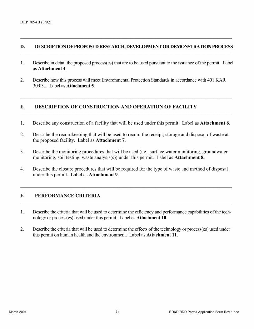
March 2004 5 RD&D/RDD Permit Application Form Rev 1.doc
DEP 7094B (3/92)
______________________________________________________________________________________________________
D. DESCRIPTION OF PROPOSED RESEARCH, DEVELOPMENT OR DEMONSTRATION PROCESS ______________________________________________________________________________________________________
1. Describe in detail the proposed process(es) that are to be used pursuant to the issuance of the permit. Label as Attachment 4.
2. Describe how this process will meet Environmental Protection Standards in accordance with 401 KAR 30:031. Label as Attachment 5.
______________________________________________________________________________________________________
E. DESCRIPTION OF CONSTRUCTION AND OPERATION OF FACILITY ______________________________________________________________________________________________________
1. Describe any construction of a facility that will be used under this permit. Label as Attachment 6.
2. Describe the recordkeeping that will be used to record the receipt, storage and disposal of waste at the proposed facility. Label as Attachment 7.
3. Describe the monitoring procedures that will be used (i.e., surface water monitoring, groundwater monitoring, soil testing, waste analysis(s)) under this permit. Label as Attachment 8.
4. Describe the closure procedures that will be required for the type of waste and method of disposal under this permit. Label as Attachment 9.
______________________________________________________________________________________________________
F. PERFORMANCE CRITERIA ______________________________________________________________________________________________________
1. Describe the criteria that will be used to determine the efficiency and performance capabilities of the tech-nology or process(es) used under this permit. Label as Attachment 10.
2. Describe the criteria that will be used to determine the effects of the technology or process(es) used under this permit on human health and the environment. Label as Attachment 11.

March 2004 6 RD&D/RDD Permit Application Form Rev 1.doc
DEP 7094B (3/92) ______________________________________________________________________________________________________
G. PERMIT PREPARATION INFORMATION ______________________________________________________________________________________________________
* Complete the appropriate information (1 or 2) for the individual(s) responsible for completing this application.
1. Engineer Kevin M. Regan, P.E.
Kentucky Registration No. 21992
Address 301 Highland Park Drive
City Richmond State KY Zip Code 40475
Company Name Bechtel Parsons Blue Grass
Telephone Number (859) 625-5417
2. Other Professional Thomas A. Kurkjy
Address 301 Highland Park Drive
City Richmond State KY Zip Code 40475
Company Name Bechtel Parsons Blue Grass
Telephone Number (859) 625-1285
3. Indicate the individuals(s) authorized to make any necessary corrections to this application and to receive related correspondence from the Division:
Name(s) Todd Williams2
Address 2091 Kingston Highway
City Richmond State KY Zip Code 40475-5001
Company Affiliation Blue Grass Army Depot
Telephone Number (859) 625-6280 ______________________________________________________________________________________________________
H. OTHER INFORMATION ______________________________________________________________________________________________________
1. Provide any additional information that is pertinent to the proposed operation of the experimental waste facility or process(es). Label as Attachment 12.
NOTE: The Cabinet may require additional information before a final determination to issue a permit or deny this application in accordance with 401 KAR 45:030 Section 8(7).
2 Please copy all correspondence regarding permit application to Thomas A. Kurkjy, 301 Highland Park Drive, Richmond, KY 40475
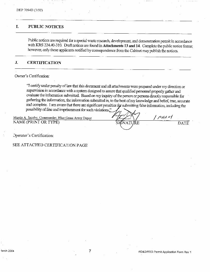


BGCAPP RD&D Permit Application Rev. 4 Attachment 1
June 2007 1-i Attachment_01_Cover_Page Rev 4.doc
Attachment 1 Contents 1
Attachment 1 Key Personnel Disclosure Forms 2
3
4
5
6
7
8
9
10
11
12
13
14
15
16
17
18
19
20
21
22
23
24
25
26
27
28
29
30
31
32
33
34
35
36
37
38
39
40
41
42


DEP 7094J(3/92)
ATTACHMENT NO.____________________
PERMIT/APPLICATION NO._____________
DATE__________________________________
PART B
PAST PERFORMANCE INFORMATION FOR KEY PERSONNEL
1. ________________________________________________________________________________________Complete Name
________________________________________________________________________________________Business Address (Do not use P.O. Box Number)
________________________________________________________________________________________Mailing Address
________________________________________________________________________________________Type of Person (KRS 224.01-010 (17))
2. Describe the relationship between the applicant and the person completing this Part B attachment thatestablishes the person as a key personnel of the applicant.
_________________________________________________________________________________________
_________________________________________________________________________________________
_________________________________________________________________________________________
3. Have any civil administrative complaints been brought or filed against you that alleges that an act or omissionthat constitutes a violation of a state or federal environmental protection law or regulation presented a sub-stantial endangerment to public health or to the environment?
YES ______________ NO _______________
9
Richard Reid Rife II
100 West Walnut Street
Pasadena, California 91124
Manager
Deputy General Manager, Bechtel Parsons Blue Grass Joint Venture
X
8

DEP 7094J(3/92)
If yes, describe each civil or administrative complaint containing the allegation of the act or omissionpresenting a substantial endangerment to public health or the environment. Each description shall include at aminimum the following: the style of the complaint; the case, file or other identifying number; the identities ofeach party to the complaint; the forum in which the complaint was brought; the identity of each state or federalagency involved with or named in the complaint; an explanation of the alleged act or omission; the identity anda description of the environmental protection law or regulation alleged to have been violated; an explanation ofall corrective action measures performed to correct or mitigated the alleged violation(s); a description of thealleged endangerment to public health or to the environment; and state whether the issues raised in thecomplaint have been resolved, and if so, whether the resolution was the result of a settlement or agreement, anadministrative order or a court order or judgement. If litigating on the allegation(s) is ongoing, describe anyorders or judgements entered and describe the present status of the litigation. Attach additional sheets ifnecessary and label as Attachment B-1.
___________________________________________________________________________________________
___________________________________________________________________________________________
___________________________________________________________________________________________
___________________________________________________________________________________________
___________________________________________________________________________________________
___________________________________________________________________________________________
___________________________________________________________________________________________
___________________________________________________________________________________________
___________________________________________________________________________________________
___________________________________________________________________________________________
___________________________________________________________________________________________
___________________________________________________________________________________________
___________________________________________________________________________________________
___________________________________________________________________________________________
___________________________________________________________________________________________
___________________________________________________________________________________________
9
N/A

DEP 7094J(3/92)
4. Describe all pending criminal complaints that allege that your violation of a state or federal environmentalprotection law or regulation. If none, write NONE. Each description must include at a minimum the styleof the case and the identifying case number, the date the complaint was filed, the forum in which the complaintis pending, the identity of the law or regulation allegedly violated and a narrative description of the law orregulation, whether the alleged violation(s) is a misdemeanor or a felony, and all actions and pleadings whichhave occurred or been filed in association with the complaint. Criminal complaints filed more than five (5)years prior to the date of submission of the Applicant’s permit application need not be listed. Attachadditional sheets if necessary and label as Attachment B-2.
___________________________________________________________________________________________
___________________________________________________________________________________________
__________________________________________________________________________________________
___________________________________________________________________________________________
___________________________________________________________________________________________
___________________________________________________________________________________________
___________________________________________________________________________________________
__________________________________________________________________________________________
___________________________________________________________________________________________
___________________________________________________________________________________________
___________________________________________________________________________________________
__________________________________________________________________________________________
___________________________________________________________________________________________
___________________________________________________________________________________________
__________________________________________________________________________________________
___________________________________________________________________________________________
10
None

DEP 7094J(3/92)
IN RESPONSE TO ITEMS 5 AND 6, EACH DESCRIPTION GIVEN MUST INCLUDE AT A MINIMUM THE FOLLOWING:STYLE, CASE NUMBER; FORUM IN WHICH CONVICTION ENTERED; DATE OF JUDGEMENT;SENTENCE IMPOSED;THE IDENTITY AND DESCRIPTION OF EACH LAW APPLICANT WAS CONVICTED OF VIOLATING; WHETHER THECONVICTION WAS THE RESULT OF A PLEA AGREEMENT OR A TRIAL; AND, IF CURRENTLY ON APPEAL, THESTATUS OF THE APPEAL. ATTACH ADDITIONAL SHHETS IF NECESSARY AND LABEL AS ATTACHMENT B-3AND B-4.
5. Describe all judgements of criminal conviction entered against you for the violation of any state or federalenvironmental protection law or regulation. Convictions entered more than five (5) yearsbefore the submission date of the Applicant’s permit application need not be listed.
___________________________________________________________________________________________
___________________________________________________________________________________________
___________________________________________________________________________________________
___________________________________________________________________________________________
___________________________________________________________________________________________
___________________________________________________________________________________________
6. Describe all judgements of criminal conviction of a felony under the laws of any state or of the United Statesthat have been entered against the you within the five (5) year period preceding the date of submission ofthe Applicant’s application.
___________________________________________________________________________________________
___________________________________________________________________________________________
___________________________________________________________________________________________
___________________________________________________________________________________________
___________________________________________________________________________________________
___________________________________________________________________________________________
___________________________________________________________________________________________
11
None
None


BGCAPP RD&D Permit Application Rev. 4 Attachment 2
June 2007 2-i RD&D/Attachment_02 Rev 4.doc
Attachment 2 Contents 1
Attachment 2 Laboratory Analysis of Waste to be Processed.......................................2-12
2.1 GB 115-mm Rockets ..........................................................................................2-132.2 GB 8-Inch Projectiles..........................................................................................2-142.3 VX 115-mm Rockets ..........................................................................................2-152.4 VX 155-mm Projectiles.......................................................................................2-162.5 H 155-mm Projectiles .........................................................................................2-172.6 Nonstockpile Items .............................................................................................2-18
2.6.1 GB Ton Container...................................................................................2-192.6.2 DOT Bottles ............................................................................................2-210
2.7 Energetics/Propellants .......................................................................................2-2112.7.1 Rocket Energetics ..................................................................................2-2122.7.2 Rocket Propellant ...................................................................................2-2132.7.3 Projectile Energetics...............................................................................2-214
15
Tables16
2-1 Laboratory Analytical Data for GB 115-mm Rockets......................................................2-3172-2 Laboratory Analytical Data for GB 8-Inch Projectiles .....................................................2-4182-3 Laboratory Analytical Data for VX 115-mm Rockets ......................................................2-5192-4 155-mm H Projectile Sample Summary Results ............................................................2-620
2122
23
BGCAPP RD&D Permit Application Rev. 4 Attachment 2
June 2007 2-1 RD&D/ Attachment_02 Rev 4.doc
Attachment 2 Laboratory Analysis of Waste to be Processed 1
Limited analytical data is available regarding the agent stored at the Blue Grass Army Depot 2(BGAD). Some of the GB 8-inch projectiles were sampled and analyzed during operations 3conducted in 1979. No other munition types have been sampled or analyzed. However, 4laboratory analytical data is available from other chemical agent disposal facilities. Material 5safety data sheets (MSDSs) for GB and VX nerve agent and for H blister agent are provided in 6Appendix D. The source of the available data for each munition type is provided below. 7
2.1 GB 115-mm Rockets 8
Table 2-11 provides the laboratory analytical data from sampling that was performed at the 9Tooele Chemical Agent Disposal Facility (TOCDF). Although the analytical data from the other 10chemical disposal facilities is not from the munitions stored by Blue Grass Chemical Activity 11(BGCA) at BGAD, it is representative of the nerve agent stored at BGAD. 12
2.2 GB 8-Inch Projectiles 13
Table 2-2 provides the data from sampling and laboratory analysis that was performed on the 14GB 8-inch projectiles in storage at BGAD in 1979. 15
2.3 VX 115-mm Rockets 16
Table 2-3 provides the laboratory analytical data from the sampling that was performed at the 17TOCDF. Although the analytical data from the other chemical disposal facilities is not from the 18munitions stored by BGCA at BGAD, it is representative of the nerve agent stored at BGAD. 19
2.4 VX 155-mm Projectiles 20
Laboratory analytical data is currently not available; however, data from TOCDF will be 21available in the future. Although the analytical data from the other chemical disposal facilities is 22not from the munitions stored by BGCA at BGAD, it is representative of the nerve agent stored 23at BGAD. 24
2.5 H 155-mm Projectiles 25
Samples were taken of the agent in the 155-mm projectiles during the testing of the munitions 26washout system (MWS) at Chemical Agent Munitions Disposal System (CAMDS) in 2003 for the 27Assembled Chemical Weapons Alternatives (ACWA). Analyses have been completed on these 28samples, and the results are shown in Table 2-4. 29
2.6 Nonstockpile Items 30
2.6.1 GB Ton Containers 31
During recent operations, the BGCA transferred the contents of the ton container (TC) stored at 32the BGCA to two additional TCs as part of a risk reduction program. BGAD previously submitted 33the sample results to the Kentucky Department of Environmental Protection (KDEP) in January 342005.35
1 Tables are presented at the end of this attachment.

BGCAPP RD&D Permit Application Rev. 4 Attachment 2
June 2007 2-2 RD&D/ Attachment_02 Rev 4.doc
2.6.2 DOT Bottles 1
No analytical data is available on the VX and H Department of Transportation (DOT) bottles. 2
2.7 Energetics/Propellants 3
Energetic and propellant materials that are part of the munitions in storage at BGAD consist of 4the explosive compounds described in the following sections. No waste analyses are provided 5for these compounds; however, the MSDSs for these compounds are provided in Appendix D. 6
2.7.1 Rocket Energetics 7
Rocket energetics consist of the following components: 8
1. Fuze composed of RDX 9
2. Detonator composed of lead azide and RDX 10
3. Burster composed of Comp B, which is a 60:40 mixture of RDX and trinitrotoluene 11(TNT)12
2.7.2 Rocket Propellant 13
The rocket propellant consists of M-28, which is a mixture of the following components: 14
1. 60% nitrocellulose 15
2. 23.8% nitroglycerin 16
3. 9.9% triacetin 17
4. 2.6% diethylphthlate 18
5. 2% lead stearate 19
6. 1.7% 2-nitrodiphenylamine 20
2.7.3 Projectile Energetics 21
The projectile energetics consist of tetrytol, which is a 70:30 mixture of tetryl and TNT. 22

BGCAPP RD&D Permit Application Rev. 4 Attachment 2
June 2007 2-3 RD&D/ Attachment_02 Rev 4.doc
1
Table 2-1—Laboratory Analytical Data for GB 115-mm Rockets 2
Compound (wt%) Average Maximum MinimumAgent GB 85.1 97.0 44.8
DIMP 4.5 10.8 2.7 TBA 5.6 5.9 5.5 DIU 0.9 2.4 0.4
DICDI 0.4 1.1 0.0 Metals (mg/kg)
Aluminum 628.3 3205.0 10.0 Antimony 26.3 154.0 0.2
Arsenic 7.0 34.0 3.5 Barium 4.7 40.0 0.1
Beryllium 0.1 0.6 .0.0 Boron 1135.8 4585.0 4.1
Cadmium 3.2 12.0 1.1 Chromium 3.2 12.0 1.1
Cobalt 2.5 8.9 0.1 Copper 13.4 120.0 1.7
Lead 9.8 46.0 0.6 Manganese 2.7 18.2 0.6
Mercury 0.1 0.2 0.0 Nickel 7.2 31.0 2.1
Selenium 16.3 92.0 0.4 Silver 1.2 6.2 0.1
Thallium 26.3 154.0 0.1 Tin 53.3 308.0 1.1
Vanadium 1.4 6.2 0.7 Zinc 28.8 172.0 5.4
Source: Tooele Chemical Agent Destruction Facility, 1996–1998 Key: DICDI = Diisopropylcarbodiimide (stabilizer) DIU = Diisopropyl urea
DIMP = Diisopropyl methyl phosphonate TBA = Tributylamine
Analytical Methods: Agent: TE-LOP-584 (agent and degradation products) Metals: Method 7470, SW-846 (mercury) Method 6020, SW-846 (all other metals)
3456

BGCAPP RD&D Permit Application Rev. 4 Attachment 2
June 2007 2-4 RD&D/ Attachment_02 Rev 4.doc
Table 2-2—Laboratory Analytical Data for GB 8-Inch Projectiles 1
Agent Lot No. 1034-54-1005 1034-62-1330 % GB 89.59 86.53
Metals, ppm Iron 102.34 521.27
Copper <0.010 <0.008 Nickel <0.019 <0.015
Aluminum 34.61 28.49 Source: Surveillance Program, Lethal Chemical Agents and Munitions (SUPLECAM) Report, 1979 Analytical Methods Mil-C-10758D (MU), 2 September 1969
234

BGCAPP RD&D Permit Application Rev. 4 Attachment 2
June 2007 2-5 RD&D/ Attachment_02 Rev 4.doc
Table 2-3—Laboratory Analytical Data for VX 115-mm Rockets 1
2
3
Compound (wt%) Average Maximum Minimum Agent VX 90.0 93.2 86.5
DICDI <0.6 <0.6 <0.6 DEMP 0.7 0.95 <0.6
DCHCDI 0.9 1.6 0.7 KK 0.5 <0.5 <0.3 KM 1.5 2.4 <0.6
EA 2192 0.3 0.55 0.21 Metals (mg/L)
Aluminum 1,273.5 7,391 <46 Antimony 3.3 <10 <1.8
Arsenic 3.3 <10 <1.8 Barium 1.7 <5.0 <0.91
Beryllium 1.7 <5.0 <0.91 Boron <83.7 <252 <46
Cadmium 1.7 <5.0 <0.9 Chromium 3.4 <10 <1.9
Cobalt 1.7 <5.0 <0.9 Copper <4.2 <10 <1.9
Lead 3.2 13.6 <1.0 Manganese <1.0 <1.1 <0.9
Mercury 0.3 1.31 <0.078 Nickel <3.3 <10 <1.8
Selenium 3.3 <10 <1.8 Silver <1.7 <5.0 <0.9
Thallium <1.7 <5.0 <0.9 Tin <16.7 <50 <9.1
Vanadium <16.7 <50 <9.1 Zinc 13.7 < 41.60 <4.9
Source: Tooele Chemical Agent Disposal Facility, 2003
Key: Agent VX = O-ethyl-S-(2-diisopropylaminoethyl) methyl phosphonothiolate DICDI = Diisopropylcarbodiimide (stabilizer) DEMP = Diethylmethylphosphonate DCHCDI = Dicyclohexylcarbodiimide KK = Bis(2-diisopropylaminoethyl)sulfide KM = Bis(2-diisopropylaminoethyl)disulfide or EA 4196 EA 2192 = S-(2-diisopropylaminoethyl) methyl phosphonothioic acid
Analytical Methods: Agent : TE-LOP-584 (agent and degradation products) Metals: Method 7470, SW-846 (Mercury) Method 6020, SW-846 (all other metals)

BGCAPP RD&D Permit Application Rev. 4 Attachment 2
June 2007 2-6 RD&D/ Attachment_02 Rev 4.doc
Table 2-4—155-mm H Projectile Sample Summary Results 1
Target Minimum Maximum Average
Organic Compounds, wt% Bis (2-chloroethyl) sulfide 70.5 83.6 77.0
Thiodiglycol < 0.025 < 0.026 < 0.026 1,2-Dichloroethane 1.22 2.88 1.93
Tetrachloroethylene < 0.049 < 0.052 < 0.050 1,1,2,2-Tetrachloroethane < 0.049 < 0.052 < 0.050
T < 0.24 < 0.27 < 0.26 Q 4.55 7.34 5.52
Hexachloroethane < 0.024 < 0.027 < 0.026 Organic Compounds, mg/kg
Lewisite < 4.9 < 5.3 < 5.1 Metals, mg/kg
Aluminum < 48 < 53 < 50 Antimony < 4.8 < 5.3 < 5.0
Arsenic < 4.8 < 5.3 < 5.0 Barium < 4.8 < 5.3 < 5.0
Beryllium < 4.8 < 5.3 < 5.0 Boron < 9.6 < 11 < 10
Cadmium < 4.8 < 5.3 < 5.0 Chromium < 4.8 6.58 < 5.3
Cobalt < 0.96 < 1.1 < 1.0 Copper 20.5 52.5 35.9
Lead < 4.8 < 5.3 < 5.0 Manganese < 0.96 2.83 < 1.3
Mercury < 0.48 < 0.53 < 0.50 Nickel < 4.8 < 5.3 < 5.0
Selenium < 9.6 < 11 < 10 Silver < 4.8 < 5.3 < 5.0
Thallium < 4.8 < 5.3 < 5.0 Tin < 9.6 < 11 < 10
Vanadium < 4.8 < 5.3 < 5.0 Zinc < 9.6 < 11 < 10
Source: Tooele Chemical Agent Disposal Facility, 2003.
Key: T = Bis[2(2-chloroethylthio)ethyl] ether Q = 1,2-bis(2-chloroethylthio) ethane
234
5

BGCAPP RD&D Permit Application Rev. 4 Attachment 3
June 2007 3-i RD&D/Attachment_03 Rev 4.doc
Attachment 3 Contents 1
Attachment 3 Waste Description.......................................................................................3-12
3.1 Waste Description ..............................................................................................3-133.1.1 Projectiles .........................................................................................3-1 43.1.2 M55 Rockets.....................................................................................3-2 53.1.3 Nonstockpile Items ...........................................................................3-2 63.1.4 Types and Quantities of Munitions ...................................................3-2 73.1.5 Secondary Wastes............................................................................3-2 8
3.2 Daily Design Capacity ........................................................................................3-493.3 Total Estimated Quantity of Waste to be Disposed of per Year .........................3-410
11
Figures12
3-1 155-mm Projectile ..........................................................................................................3-6133-2 115-mm Rocket..............................................................................................................3-714
15
Tables16
3-1 Stored Munitions Data....................................................................................................3-8173-2 Daily Design Capacity ....................................................................................................3-9183-3 Estimated Quantity of Waste by Munition Campaign...................................................3-1019
20

BGCAPP RD&D Permit Application Rev. 4 Attachment 3
June 2007 3-1 RD&D/Attachment_03 Rev 4.doc
Attachment 3 Waste Description 1
3.1 Waste Description 2
The wastes that the Blue Grass Chemical Agent Destruction Pilot Plant (BGCAPP) will 3eventually treat consist primarily of M55 rockets and M56 warheads and projectiles (8 inch and 4155 mm). Under the proposed research, development, and demonstration (RD&D) permit, the 5GB munitions and GB ton container (TC) will be used to demonstrate the effectiveness of the 6treatment process.7
Although not all of the munition types and nonstockpile items stored at Blue Grass Army Depot 8(BGAD) will be used during the RD&D process, the Bechtel Parsons Blue Grass Team (BPBGT) 9has included descriptions of all of these items to provide KDEP a complete list of munitions in 10storage at BGAD. The assembled munitions stored at BGAD contain both chemical agent (CA) 11and energetic materials (i.e., propellant and/or explosive charges). Two basic classes of 12assembled chemical weapons are stored at BGAD: projectiles and rockets. 13
Each waste class is described below in greater detail. The waste codes associated with each 14waste stream are provided in Part A of this permit application. 15
3.1.1 Projectiles 16
Projectiles are shells that are fired from guns or cannons. They have roughly cylindrical steel 17bodies with tapered noses and a hollow cylindrical tube (known as the burster well) running 18down the center of the shell. This tube holds the burster, an explosive charge that disperses the 19CA upon detonation. The liquid agent itself is contained in the annular region between the 20burster well and the shell wall. All projectiles stored at BGAD have nose closures installed in 21place of fuzes. The projectile processing sequence is discussed in more detail in 22Sections 4.3.1, 4.5 and 4.623
3.1.1.1 155-mm Projectiles 24
The BGAD stockpile contains both VX and H 155-mm projectiles. The VX 155-mm projectiles 25are designated as M121A1; the H 155-projectiles are designated as M110 (see Figure 3-11).26
Only the H 155-mm projectiles contain energetic material (composed of tetrytol) in the burster 27well.28
3.1.1.2 8-Inch Projectiles 29
The 8-inch (20.32-cm) projectile, designated as M426, has a mass of more than 90 kg and 30contains GB chemical agent. These projectiles are stored without a burster. 31
3.1.1.3 Overpacked Leaker Projectiles 32
Currently, 69 H 155-mm projectiles have been overpacked at BGAD. They will be processed in 33the same manner as regular (nonleaker) projectiles after they are removed from the overpack 34container.35
Additionally, 26 GB 8-in projectiles have been overpacked at BGAD. They will be processed in 36the same manner as regular (nonleaker) projectiles after they are removed from the overpack 37container.38
1 Figures and tables are presented at the end of this attachment.

BGCAPP RD&D Permit Application Rev. 4 Attachment 3
June 2007 3-2 RD&D/Attachment_03 Rev 4.doc
3.1.2 M55 Rockets 1
A rocket is an airborne weapon propelled by a mixture of a fuel and an oxidizer. The only rocket 2type in the chemical stockpile is the 115-mm-diameter M55 rocket. This rocket is 1.98 m long 3and has a mass of nearly 26 kg (see Figure 3-2). It consists of two sections: 4
1. An aluminum-alloy warhead section, which contains the CA, two bursters, and the fuze 5
2. A steel motor section, which contains the propellant grain, the igniter assembly, and 6the nozzle and fins 7
Both GB and VX M55 rockets are part of the BGAD chemical stockpile. The bursters are 8composed of Composition B (Comp B) explosive. The propellant is double base M28 9(nitroglycerin/nitrocellulose). The rocket is stored in a shipping and firing tube (SFT) made of 10fiberglass-reinforced resin that could contain polychlorinated biphenyls (PCBs). An indexing ring 11on the outside of the tube near the front (fuze) end of the rocket identifies the front of the rocket 12in the SFT. Aluminum caps seal the ends of the tube. 13
PCB concentrations could range from under 50 to more than 2,000 parts per million (ppm). 14These PCBs are integral to the structure of the rockets’ SFTs and are regulated under the Toxic 15Substances Control Act (TSCA) regulations subject disposal requirements of 40 CFR 761.62(c). 16This information is based on a study conducted by the U.S. Army Environmental Hygiene 17Agency, Hazardous Waste Study No. 37-26-1345-86 and -87 which sampled and analyzed 18SFTs in the Tooele Army Depot (now called the Deseret Chemical Depot) to determine the PCB 19concentration. This information has been used by the Environmental Protection Agency (EPA) 20as the basis for issuing the nationwide approval for incineration of PCBs at the four continental 21United States Chemical Demilitarization Incineration Facilities. The PCB aspects of the project 22are subject to regulation by the EPA Region 4. A separate permit request will be submitted to 23EPA Region 4 to address the processing of the PCB-contaminated SFTs. 24
3.1.2.1 M56 Warheads 25
M56 warheads are similar to the M55 rockets except that the motor section has been removed; 26thus, M56 warheads do not contain M28 propellant. 27
3.1.2.2 Overpacked Leaker M55 Rockets 28
Currently, 97 leaker GB 115-mm M55 rockets have been overpacked at the BGAD. They will be 29processed after they are removed from the overpack container as discussed in Section 304.3.1.2.2.31
3.1.3 Nonstockpile Items 32
Six nonstockpile items are stored at BGAD and will be processed at BGCAPP: three GB TCs, 33one VX Department of Transportation (DOT) bottle, and two H DOT bottles. These items are 34listed in Table 3-1. 35
3.1.4 Types and Quantities of Munitions 36
Table 3-1 lists the types and quantities of the munitions in the BGAD stockpile. 37
3.1.5 Secondary Wastes 38
Six major types of secondary waste will be generated at BGCAPP; these wastes are described 39below.40

BGCAPP RD&D Permit Application Rev. 4 Attachment 3
June 2007 3-3 RD&D/Attachment_03 Rev 4.doc
3.1.5.1 Wood Pallets 1
All munitions are stored on wood pallets in the igloos. As munitions are shipped to BGCAPP, 2wood pallets and metal straps that are not contaminated with agent as determined by enhanced 3onsite container (EONC) monitoring prior to opening, will be shipped off site for disposal by 4appropriate methods to promote waste minimization without any treatment at BGCAPP. All 5wood pallets and other dunnage associated with leaking munitions will be treated as agent-6contaminated dunnage and will be processed as described in Attachment 4, Section 4.3. 7
3.1.5.2 Agent-Contaminated Plastic and Personnel Protective Equipment (PPE) 8
Plastic materials and PPE that are not contaminated with agent will be shipped off site for 9disposal by appropriate methods to promote waste minimization without any treatment at 10BGCAPP. Plastic and PPE (plastic, rubber and gas mask carbon filters) are assumed to be 11contaminated if they have been exposed to agent; they will be processed as described in 12Attachment 4, Section 4.3. 13
3.1.5.3 Miscellaneous Agent-Contaminated Metal Parts 14
Miscellaneous agent-contaminated metal parts generated during the RD&D program are sent 15directly to the metal parts treater (MPT) for thermal treatment (a minimum of 1,000˚F for 1615 minutes) before they are shipped off site for disposal by appropriate methods to minimize 17waste.18
3.1.5.4 Agent-Contaminated Spent Activated Carbon 19
Agent-contaminated spent activated carbon from the heating, ventilating, and air conditioning 20(HVAC) filters that is generated during the RD&D program will be processed as described in 21Attachment 4, Section 4.3. 22
3.1.5.5 Spent Decontamination Solution (SDS) 23
SDS that is generated during the decontamination of personnel and equipment will be 24processed as described in Attachment 4, Section 4.3. 25
3.1.5.6 Reverse Osmosis (RO) Brine Solution 26
The supercritical water oxidation (SCWO) effluent is a brine solution comprised primarily of 27sodium sulfate (Na2SO4), sodium chloride (NaCl), sodium fluoride (NaF), and sodium 28monophosphate (NaH2PO4). The water recovery system (WRS) package is designed to produce 29a water stream that is of sufficient quality to be recycled to the SCWO process (approximately 3070%) and a wastewater stream (RO reject) that will be characterized and shipped to a permitted 31disposal facility. 32
3.1.5.7 Other Secondary Wastes 33
During the RD&D program, other secondary wastes may be generated at BGCAPP. As these 34waste streams are identified, they will be characterized prior to treatment. If they are 35contaminated with agent, either the wastes will be treated at BGCAPP through the appropriate 36waste handling system, or decontaminated, and shipped off site for disposal at a permitted 37treatment, storage, and disposal facility (TSDF). If the waste is not contaminated with agent, the 38secondary waste will be shipped off site for disposal at a permitted treatment, storage and 39disposal facility (TSDF).40

BGCAPP RD&D Permit Application Rev. 4 Attachment 3
June 2007 3-4 RD&D/Attachment_03 Rev 4.doc
3.2 Daily Design Capacity 1
The initial daily design capacity of the plant is based on data developed during Program 2Manager for Chemical Demilitarization (PMCD) and Program Manager, Assembled Chemical 3Weapons Alternatives (PM ACWA) testing programs and on the actual Johnston Atoll Chemical 4Agent Disposal System (JACADS) and Tooele Chemical Agent Disposal Facility (TOCDF) 5operating data. The BGCAPP process has two critical paths: 6
1. GB and VX M55 rockets/M56 warheads with a limiting step of the rocket cutting 7machine (RCM) and rocket shear machine (RSM) to the energetics batch 8hydrolyzer/energetics neutralization system (EBH/ENS). 9
2. Burstered H 155-mm projectiles with a limiting step of the projectile/mortar disassembly 10machine (PMD) to the EBH/ENS and munitions washout system/agent neutralization 11system (MWS/ANS). 12
Table 3-2 summarizes the peak hourly rates and the daily design capacity of the major 13equipment trains. 14
The throughput rate is based on the peak processing rates of the RSM, nose closure removal 15system (NCRS), projectile/mortar disassembly (PMD), and supercritical water oxidation 16(SCWO). The RSM rate is based on JACADS operations verification testing (OVT) and the PMD 17rate is based on operating experience at JACADS and TOCDF. The other equipment in the 18process train is sized based on the peak processing rate of the limiting step. A major portion of 19the RD&D program will involve verifying and determining the optimal throughput rates. The 20SCWO processing rate is based on the throughput requirements for BGCAPP based on the 21material balance. 22
All of these design throughput rates will be verified and may be modified during the RD&D 23program after a thorough evaluation of data collected.24
3.3 Total Estimated Quantity of Waste to be Disposed of per Year 25
Table 3-3 summarizes the estimated quantity of waste generated annually. The waste streams 26will come from four primary sources: 27
1. MPT Residues: This waste stream will consist of projectile bodies and rocket pieces28consisting of steel as well as Shipping and Firing Tubes (SFTs) from Contaminated 29Rocket Motors after processing through the MPT, as well as any miscellaneous 30metal parts and secondary wastes that are generated during the treatment 31processes.32
2. AFS Precipitate: This waste stream will consist of the aluminum compounds 33precipitated and filtered out of the energetics hydrolysate generated from the treatment 34of rockets. 35
3. RO Reject Brine Solution: The treated hydrolysate from the SCWO units will be 36processed through the RO system to recycle as much water as possible back into the 37process. Appendix C provides the process flow diagrams (PFDs) of this system. Waste 38brine solution will be shipped off site for disposal at a permitted TSDF. The recovered 39water will be recycled back into the SCWO process in lieu of makeup water or shipped 40off site to a permitted TSDF. 41

BGCAPP RD&D Permit Application Rev. 4 Attachment 3
June 2007 3-5 RD&D/Attachment_03 Rev 4.doc
4. NCRMs: This waste stream consists of the non-contaminated rocket motors that 1have been separated from the rocket warhead that will not be processed in the 2BGCAPP. This waste stream will be stored at the BGAD until final treatment 3process has been determined.4
Table 3-3 identifies the quantity of each waste stream listed above by munition campaign. It is 5important to note that the water recovery system greatly reduces the amount of waste that will 6be generated for off-site disposal from BGCAPP during the life of the project and will be an 7integral part of BGCAPP’s waste minimization program. 8
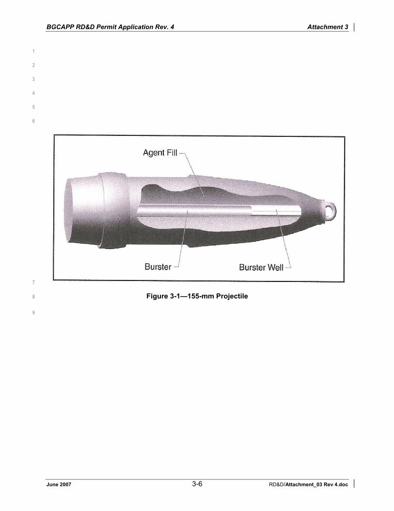
BGCAPP RD&D Permit Application Rev. 4 Attachment 3
June 2007 3-6 RD&D/Attachment_03 Rev 4.doc
1
2
3
4
5
6
7
Figure 3-1—155-mm Projectile 8
9

BGCAPP RD&D Permit Application Rev. 4 Attachment 3
June 2007 3-7 RD&D/Attachment_03 Rev 4.doc
1
2
3
4
5
6
Figure 3-2—155-mm Rocket 7

BGCAPP RD&D Permit Application Rev. 4 Attachment 3
June 2007 3-8 RD&D/Attachment_03 Rev 4.doc
Table 3-1—Stored Munitions Data 1
MunitionAgentType Type Caliber
M55 GB Rocket 115 mm M56 GB Warhead 115 mm M426 GB Projectile 8 inch Ton container GB Nonstockpile NA M55 VX Rocket 115 mm M56 VX Warhead 115 mm M121A1 VX Projectile 155 mm M110 H Projectile 155 mm DOT bottle H Nonstockpile NA DOT bottle VX Nonstockpile NA Notes:1. All GB will be processed during the RD&D Program. Attachment 6, Table 6-1 presents the
planned Processing rates during the RD&D Program. 2. The following overpacked munitions are included in the above numbers: a. 97 GB M55 rockets (leakers) b. 24 GB M56 warheads c. 26 GB 8-inch projectiles d. 69 H 155-mm projectiles (leakers)

BGCAPP RD&D Permit Application Rev. 4 Attachment 3
June 2007 3-9 RD&D/Attachment_03 Rev 4.doc
Table 3-2—Daily Design Capacity 1
Equipment/System Munition Type Peak Rate per hr Daily Design Rate
Rocket cutting machine (RCM) M55 Rockets 26 rockets 624 rockets Rocket shear machine (RSM) M55 rockets /
M56 warheads 26 rockets 624 rockets
Projectile handling system (PHS) 155-mm H projectiles 8-inch GB projectiles 155-mm VX projectiles
26 projectiles 15 projectiles 21 projectiles
624 projectiles 360 projectiles 504 projectiles
Energetics batch hydrolyzer (EBH) M55 rockets 26 rockets 624 rockets
Agent neutralization system (ANS) All 7300 lbs 175,200 lbs
Energetics neutralization system (ENS) All 26 rockets 624 rockets
Supercritical water oxidation (SCWO) All 3,364 lb 80,736 lb
Munitions washout system (MWS) 155-mm H projectiles 8-inch GB projectiles 155-mm VX projectiles
26 projectiles 15 projectiles 21 projectiles
624 projectiles 360 projectiles 504 projectiles
Metal parts treater (MPT) Projectiles 7,723 lb 185,352 lb 2

BGCAPP RD&D Permit Application Rev. 4 Attachment 3
June 2007 3-10 RD&D/Attachment_03 Rev 4.doc
Table 3-3—Estimated Quantity of Waste by Year 1
Year
1 2 3 Waste Type (tons) (tons) (tons)
Total(Tons)
MPT Residue 830 2,400 510 3,740 AFS Precipitate 1,417 1,001 290 2,708
RO Reject Brine Solution
39,980 38,022 14,689 92,691
NCRMs 931 565 0 1496Total Solid Wastes 43,158 41,988 15,489 100,635
Note: These numbers do not include secondary wastes that will be processed through the MPT and closure wastes.
2

BGCAPP RD&D Permit Application Rev. 4 Attachment 4
June 2007 4-i RD&D/Attachment_04 Rev 4.doc
Attachment 4 Contents Attachment 4 Description of Proposed Research, Development, and
Demonstration Process .......................................................................4-14.1 Justification for Research ...................................................................................4-24.2 Process Description ...........................................................................................4-34.3 Waste Processing Sequences............................................................................4-7
4.3.1 GB Nerve Agent Munitions .....................................................................4-74.3.2 VX Nerve Agent Munitions....................................................................4-104.3.3 H (Mustard) Blister Agent Munitions .....................................................4-114.3.4 Wood Pallets.........................................................................................4-114.3.5 Agent-Contaminated Plastic and PPE..................................................4-114.3.6 Miscellaneous Agent-Contaminated Metal Parts (e.g., banding,
pumps, and pipe) ..................................................................................4-114.3.7 Spent Activated Carbon........................................................................4-124.3.8 Spent Decontamination Solution (SDS)................................................4-12
4.4 Munitions Unpacking ........................................................................................4-124.4.1 Projectile Input Subsystem ...................................................................4-134.4.2 Rocket Input Subsystem.......................................................................4-134.4.3 Dunnage/Secondary Waste..................................................................4-13
4.5 Projectile Handling System (PHS) (Drawing 24915-07-M5-PHS-00001) .........4-134.5.1 Projectile/Mortar Disassembly (PMD) Machine ....................................4-13
4.6 Nose Closure Removal System/Munition Washout System (Draing 24915-07-M5-MWS-00001) .................................................................4-144.6.1 Nose Closure Removal Station.............................................................4-144.6.2 Munition Washout System....................................................................4-14
4.7 Rocket Handling System (RHS) (Drawing 24915-07-M5-RHS-00001) ............4-144.7.1 Rocket Cutting Machine (RCM) ............................................................4-144.7.2 Rocket Shear Machine (RSM) ..............................................................4-14
4.8 Dunnage Treatment .........................................................................................4-154.9 Energetics Treatment (Drawings 24915-07-M5-EBH-00001, -ENS-00001,
-OTE-00001, and 24915-11-M5-HSS-00002) ..................................................4-154.9.1 Energetics Batch Hydrolyzer ................................................................4-154.9.2 Heated Discharge Conveyors...............................................................4-164.9.3 Energetics Neutralization System.........................................................4-164.9.4 EBH Offgas Treatment System (OTE)..................................................4-16
4.10 Aluminum Precipitation System (APS)/Aluminum Filtration System (Drawings 24915-07-M5-APS-00001, -AFS-00001).........................................4-16
4.11 Agent Neutralization by Hydrolysis (Drawings 24915-07-M5-ACS-00001, -ANS-00001, and 24915-11-M5-HSS-00001) ..................................................4-17
4.12 Metal Parts Treater, MPT Cooling System (MCS), and Offgas Treatment System (Drawings 24915-07-M5-MPT-00001, -MCS-00001, and -OTM-00001).............................................................................................4-174.12.1 MPT (Drawing 24915-07-M5-MPT-00001) ...........................................4-174.12.2 MCS (Drawing 24915-07-M5-MCS-00001) ..........................................4-184.12.3 OTM (Drawing 24915-07-M5-OTM-00001) ..........................................4-18
4.13 Decon Solution Supply and Spent Decon Solution Capture/Storage System (Drawing 24915-07-M5-SDS-00001)................................................................4-19
4.14 SCWO Units (Drawing 24915-10-M5-SCWO-00001).......................................4-194.15 Reverse Osmosis (RO) (Drawing 24915-10-M5-RO-00001)............................4-21
BGCAPP RD&D Permit Application Rev. 4 Attachment 4
June 2007 4-ii RD&D/Attachment_04 Rev 4.doc
Figures4-1 Block Flow Diagram .....................................................................................................4-234-2 Enhanced Onsite Container (EONC) ...........................................................................4-244-3 Projectile with Crushed Burster Tube...........................................................................4-254-4 Schematic of a SCWO Reactor....................................................................................4-26
Tables4-1 Major NRC Reports Relevant to Destruction of Weapons at BGAD ............................4-224-2 Hydrolysis Types to be Used at BGCAPP ...................................................................4-22

BGCAPP RD&D Permit Application Rev. 4 Attachment 4
June 2007 4-1 RD&D/Attachment_04 Rev 4.doc
Attachment 4 Description of Proposed Research, 1
Development, and Demonstration Process 2
This attachment describes the overall process that will be used to perform the research, 3development and demonstration (RD&D) program that is covered under this permit application 4and presents the justification for this research. Attachment 5 explains how the process satisfies 5the requirements of Kentucky Revised Statute (KRS) 224.50-130 and how this process will meet 6environmental protection standards in accordance with 401 KAR 341. 7
The proposed facility is a full-scale pilot plant that will be used to validate the National Research 8Council’s (NRC’s) stated requirement for research on process integration that is discussed in 9Section 4.1. Although some integration research of the BGCAPP can and will be conducted 10using surrogates and simulants, testing with live agents and agent-containing munitions is 11necessary to verify that the design will perform properly for the Blue Grass Army Depot’s 12(BGAD’s) inventory of munitions. The overriding criterion that drives this design is that the 13facility be capable of performing the RD&D in a manner that is safe and protective of health and 14the environment. 15
To this end, the Blue Grass Chemical Agent Destruction Pilot Plant (BGCAPP) will be built to 16the same standards as a full-scale treatment facility. For example, the blast-resistant 17containments, the highly filtered heating, ventilating, and air conditioning (HVAC) exhausts, and 18the numerous other protective systems that are necessary for a fully functional system are also 19necessary to ensure safety and environmental protection during the RD&D program. Because of 20this requirement, and because it is very difficult to add equipment after the treatment areas are 21contaminated with agent, the full facility must be built to support the RD&D program and then 22tested as one unit. As a result, the description of the BGCAPP is that of the full-scale facility. In 23spite of this similarity, it is important to emphasize that this RD&D permit application is only 24intended for the RD&D program. 25
The technology that is intended to be used by the BGCAPP was chosen to meet the 26requirement of KRS 224.50-130 (3a) and (4): that it exists in an operational facility or it has been 27demonstrated in a disposal program at a comparable scale and that it creates less risk of 28release, acute or chronic health effect, or adverse environmental effect. This determination was 29made through an extensive testing, evaluation, and selection process that was documented and 30critiqued by internal Department of Defense (DoD) groups and independently reviewed by many 31NRC panels. Table 4-12 lists the major reports in which the NRC panels chronicled and critiqued 32the progress of the evaluation and selection process. 33
The evaluation process first examined numerous alternative technologies (NRC 1993) and in 34NRC 2002 and NRC 2002a identified two technologies that were subsequently demonstrated 35under the Assembled Chemical Weapons Alternatives (ACWA) program. It identified the 36General Atomics Total Solution (GATS) process, on which the BGCAPP design is based, as the 37one with lower hydrocarbon and carbon monoxide emissions. The Final Environmental Impact 38Statement (EIS) for BGCAPP (December 2002) also discusses alternate technologies and 39draws the same conclusion. 40
The ultimate ability of the facility to destroy the chemical weapons stockpile will be assessed 41during the RD&D program. A Kentucky Hazardous Waste (KHW) Part B Permit application will 42
1 The RD&D Guidance document references 401 KAR 30:031, which applies to landfarming of special wastes. This
is not an appropriate criterion for the subject process, which is a treatment process. We have, therefore, substituted the citation as shown.
2 All tables and figures are presented at the end of this attachment.

BGCAPP RD&D Permit Application Rev. 4 Attachment 4
June 2007 4-2 RD&D/Attachment_04 Rev 4.doc
be submitted prior to completion of the RD&D program to allow the Kentucky Department for 1Environmental Protection (KDEP) and other regulators to fully evaluate the process’ safety and 2environmental compliance. 3
The process flow diagrams (PFDs) referenced throughout this attachment are presented in 4Appendix C. PFDs not related to hazardous waste management units may be referenced on the 5PFDs included in Appendix C. The applicable PFDs are cited in the headings of Sections 4.4 6through 4.14. 7
4.1 Justification for Research 8
It is fully recognized that the BGCAPP will ultimately be used to destroy all chemical weapons at 9BGAD. Maximum safety and environmental protection will be achieved during the destruction of 10the chemical weapons at BGAD by incorporating the lessons learned from the RD&D program 11into the final design. To date, a large amount of work has been conducted to evaluate 12alternative technologies for destroying the BGAD’s chemical weapons stockpile. This work was 13carefully monitored and assessed by many groups, including a number of independent panels 14assembled for this purpose by the NRC. The NRC panels reviewed the results in a series of 15reports listed in Table 4-1 and, in its last report3, identified a process termed General Atomics 16Total Solution (GATS) as the most mature alternative process for use at BGAD. The report 17suggested improvements in the design, but most critically, it indicated that although all of the 18individual processes are acceptable for application at BGAD, RD&D must be performed to refine 19and demonstrate the integrated process before going to full operation. The BGCAPP design 20incorporates the design improvements identified by the NRC, and the BGCAPP RD&D program 21incorporates this integration research. Also, the treatment system units proposed for BGCAPP 22are roughly the same size as the units tested and proven during the ACWA engineering design 23studies. The final stage of development is the testing and evaluation of the integrated process 24under a carefully developed RD&D program that is the purpose of this application. The RD&D 25program that will be conducted at BGCAPP includes the following goals: 26
The RD&D program to be conducted at BGCAPP includes the following goals: 27
1. Conduct a thorough program of system integration including the conveyance of 28munitions and munition segments from one part of the treatment train to the next up to 29and including the release of the munition parts from the MDB. 30
2. Demonstrate that 99.9999% destruction efficiency of GB agent can be achieved in the 31agent neutralization reactors (ANRs) as required by KRS 224.50-130. 32
3. Demonstrate that the energetics can be treated in the energetics batch hydrolyzers 33(EBHs) and the energetics neutralization system (ENS). 34
4. Demonstrate that the metal parts treater (MPT) will destroy the residual chemical agent 35in the projectile bodies and solid residue in the energetics batch hydrolyzer (EBH) by 36thermally treating them at a minimum of 1,000°F for a minimum of 15 minutes. 37
5. Demonstrate the performance of the supercritical water oxidation (SCWO) reactor 38system. 39
The RD&D program described herein is being conducted interactively with the design of the 40facility. As data are obtained from both ongoing equipment design and testing programs, they 41
3 Analysis of Engineering Design Studies for Demilitarization of Assembled Chemical Weapons at Blue Grass
Army Depot, 2002. National Academy Press, Washington, D.C. Available for purchase or download at www.nap.edu.

BGCAPP RD&D Permit Application Rev. 4 Attachment 4
June 2007 4-3 RD&D/Attachment_04 Rev 4.doc
are fed back to the design team so that the information can be used to improve and validate the 1process. No changes will be made that could increase risk or environmental releases. In fact, 2the likely outcome of the RD&D program will be further reductions in risk. 3
The present permit application only requests that approval be granted for the BGCAPP to be 4built and operated as a pilot plant to conduct RD&D on the process. Much of the RD&D program 5will not involve hazardous wastes; the initial tests will be performed using simulants and 6surrogate materials. After the overall plant’s performance, safety, environmental acceptability, 7and reliability have been established, the RD&D program will progress to include small amounts 8of agent initially; after demonstrated performance, increasingly larger amounts of agent and 9chemical munitions will be processed. At the conclusion of the research, the facility will have 10demonstrated that it is capable of operating at full capacity and the remainder of the stockpile 11will be processed under the Part B permit. 12
The information that is included in the RD&D permit compliance schedule (Appendix B to the 13RD&D Permit issued on 30 September 2005) is equivalent to the information that would be 14required by a Part B permit application for a hazardous waste treatment facility. Therefore, the 15compliance schedule corresponds to the submission of the components that constitute the Part 16B permit application. It is recognized, however, that the Division of Waste Management has 17the right to require additional information as part of a complete Part B application. 18
Attachment 6, Section 6.5, presents a comprehensive draft schedule for the activities that will be 19performed under the RD&D permit. As shown in Attachment 6, Table 6-1, the performance test 20constitutes the transition from operation under the RD&D permit to operation under the full 21Resource Conservation and Recovery Act (RCRA) Kentucky Hazardous Waste (KHW) Part B 22permit. All activities prior to and including the performance test take place under the RD&D 23permit. 24
The RD&D program will include the processing of only the GB munitions in the BGAD stockpile. 25The VX and H munitions, as well as any GB munitions not required under the RD&D program, 26will be processed under the Part B permit. The material balances for the VX and H campaigns 27are included in Appendix C for completeness; however, they are not part of the RD&D program. 28
4.2 Process Description 29
This section presents the overall processing sequence of the BGCAPP. The subsequent 30sections describe the individual process units. 31
The BGCAPP design will safely destroy the BGAD’s chemical munitions stockpile by combining 32proven, low-risk, Army-approved, NRC-recommended neutralization and SCWO technologies 33that have been successfully demonstrated for the Program Manager, Assembled Chemical 34Weapons Alternatives (PM ACWA) into an integrated plant that will be tested during the RD&D 35program that is the subject of this permit. 36
Chemical demilitarization of the BGAD stockpile occurs in the munitions demilitarization building 37(MDB) and subsequent treatment of the residual compounds occurs in the SCWO processing 38building (SPB). Attachment 6 describes the buildings and the high level of added safety and 39environmental protection that it offers. The BGCAPP design is an integrated system that will be 40used to safely destroy the agent and energetics by the following environmentally acceptable 41procedure: 42
1. Agent and energetics access (mechanical). 43
2. Energetics removal and deactivation by hydrolysis. 44

BGCAPP RD&D Permit Application Rev. 4 Attachment 4
June 2007 4-4 RD&D/Attachment_04 Rev 4.doc
3. Metal and other solids decontamination by heating to a minimum of 1,000°F for 115 minutes in the inductively heated MPTs. 2
4. Agent neutralization by hydrolysis. 3
5. Post-treatment of agent/energetic hydrolysates using commercial-scale, solid-wall 4SCWO units. 5
6. Some secondary wastes (e.g., agent-contaminated pallets and personal protective 6equipment [PPE]) will be treated by chemical decontamination. The chemically 7decontaminated residue will be disposed of at an off-site treatment, storage, and 8disposal facility (TSDF). If chemical decontamination does not prove successful, the 9residue will be treated in the MPT and then managed by appropriate means to 10minimize waste. 11
7. Spent activated carbon will be shipped off site for further treatment at a permitted 12TSDF. 13
8. Agent-contaminated metal secondary wastes (e.g., miscellaneous metal parts, metal 14reinforced hoses, piping, valves, and tools) that have not been chemically 15decontaminated will be processed through the MPT and then managed by appropriate 16means to minimize waste. 17
9. Secondary wastes that are not agent-contaminated will not be processed through the 18BGCAPP; they will be managed by appropriate means to minimize waste. 19
The process achieves the required 99.9999%4 (as a minimum) destruction of agent stored at the 20BGAD by neutralization via hydrolysis, whereby the agent or agent-contaminated liquid is mixed 21in an enclosed vessel with hot water (H) and hot caustic solution (GB and VX) [i.e., sodium 22hydroxide (NaOH)]. The chemical reaction destroys the agent. Hydrolysis has been shown to 23achieve this required performance for agent destruction. Table 4-2 lists the types of hydrolysis 24to be used. 25
The munition bodies and other metallic components of the munitions are washed using high-26pressure water and thermally treated in the MPT at a minimum of 1,000°F for a minimum of 2715 minutes. At this point, they will be released from the containment system. 28
The facility has been designed to safely treat all chemical weapons, chemical warfare agent, 29and ancillary materials.5 However, certain ancillary (secondary) wastes may be decontaminated 30with sodium hydroxide (NaOH), sodium hypochlorite (NaOCl), or other appropriate 31decontamination (decon) solutions. These wastes, PPE, and other plastic/rubber items, will be 32decontaminated to the Airborne Exposure Limits (AELS) and then shipped off site to a 33permitted TSDF. If they cannot be decontaminated to the AELs, these wastes will be treated in 34the MPT before they are shipped off site for disposal in a permitted TSDF. 35
To the maximum extent possible, process liquid streams are recycled to conserve water and to 36prevent discharge to ground or surface water. Water is recycled via a water recovery system 37that produces water of a quality suitable to recycle back into the process during the pilot testing 38
4 KRS 224-50-130 (3) (b) states that “…(m)onitoring data from an operational facility or alternative disposal program
as described in paragraph (a) of this subsection reflects that the emissions from treatment and destruction facilities or fugitive sources, including, but not limited to, the emissions of the compounds identified in subsection (2) of this section and products of combustion, incomplete combustion, and other processes alone or in combination present no more than a minimal risk of acute or chronic human health effect, as demonstrated by sufficient and applicable toxicological data, or adverse environmental effect…”
5 For example, metal, agent contaminated wooden pallets, agent-contaminated PPE, and any other agent-contaminated secondary waste streams generated from these activities.

BGCAPP RD&D Permit Application Rev. 4 Attachment 4
June 2007 4-5 RD&D/Attachment_04 Rev 4.doc
and operations phases. The RO Reject stream is anticipated not to exhibit any 1characteristics of a hazardous waste. Since this waste stream will only carry an N waste 2code based on the derived from rule, delisting will allow this waste to be managed as a 3non-hazardous waste. If it is not delisted, it will be shipped to a TSDF for disposal. 4
Figure 4-16 is a process block flow diagram for the hazardous waste processing units. The 5figure shows the flow of munitions and other streams from the container handling building (CHB) 6through the various systems. 7
Palletized munitions are stored in “igloos” and are currently regulated under the BGAD 8hazardous waste storage permit. The location of each type of munition is fully documented so 9that the specific munition type required for a particular test can be transferred with minimum 10disturbance of the overall stockpile of munitions7. Any munitions selected for testing will be 11transported via enhanced onsite containers (EONCs) from the storage igloos to the CHB. 12
The EONCs are airtight vessels that are specifically designed to contain munitions during 13transport from the BGAD storage igloos to the CHB. Figure 4-2 is a photograph of an EONC. 14The EONC8 is a well-established design that is currently used safely at the Tooele Chemical 15Agent Disposal Facility (TOCDF), the Anniston Chemical Agent Disposal Facility (ANCDF), 16Umatilla Chemical Agent Disposal Facility (UMCDF), and the Pine Bluff Chemical Agent 17Disposal Facility (PBCDF). 18
The EONC is received in the CHB, where it is stored until its contents are to be treated. At that 19time it is transferred to the west unpack area (UPA), which is under “Engineering Controls”9, and 20the air in the sealed EONC is monitored for agent. If agent monitoring indicates that the EONC 21does not contain any leaking munitions, the EONC is opened, and the munitions are then 22transferred to the appropriate conveyor line that convey them through the treatment process for 23that particular munition. 24
If agent is detected in the EONC (indicating a leaking munition), the EONC is moved to an area 25under a higher level of Engineering Control, where it is opened and the munitions are processed 26by personnel wearing appropriate protective clothing. The munitions are removed from the 27EONC and placed on the appropriate processing conveyor line, passing through the explosive 28containment vestibule (ECV) or toxic maintenance area (TMA). The contaminated metal straps 29are transferred to the MPT for treatment. The contaminated wood pallets may either be treated 30on site by chemical decontamination or treated in the MPT and then shipped off site to a 31permitted TSDF. The EONC is then decontaminated and released for further use. 32
The treatment operations are performed by remote control systems on the following lines: 33
1. Rocket input subsystem 34
2. Projectiles input subsystem 35
6 Figures are presented at the end of this attachment. 7 SB 162 Amended KRS 224.50-130 requires that handling and movement of munitions for nonemergency situations
be subject to a plan that is submitted and approved by the cabinet. Such a plan will be submitted to the cabinet in sufficient time to allow full review, including time for public notice and opportunity to be heard before munitions are handled or moved.
8 An older version of the design, termed an “ONC,” is used at TOCDF. The difference between the ONC and EONC is the type of closure locks used on the main hatch. The ONC uses bolts that require manual tightening to fasten the main hatch; the EONC uses a hydraulic locking mechanism that ensures a more uniform seal around the perimeter.
9 The higher the level of engineering control, the lower the air pressure maintained in the area by the cascading ventilation system. See Attachment 6, Section 6.1.3, for a detailed description of the HVAC system.
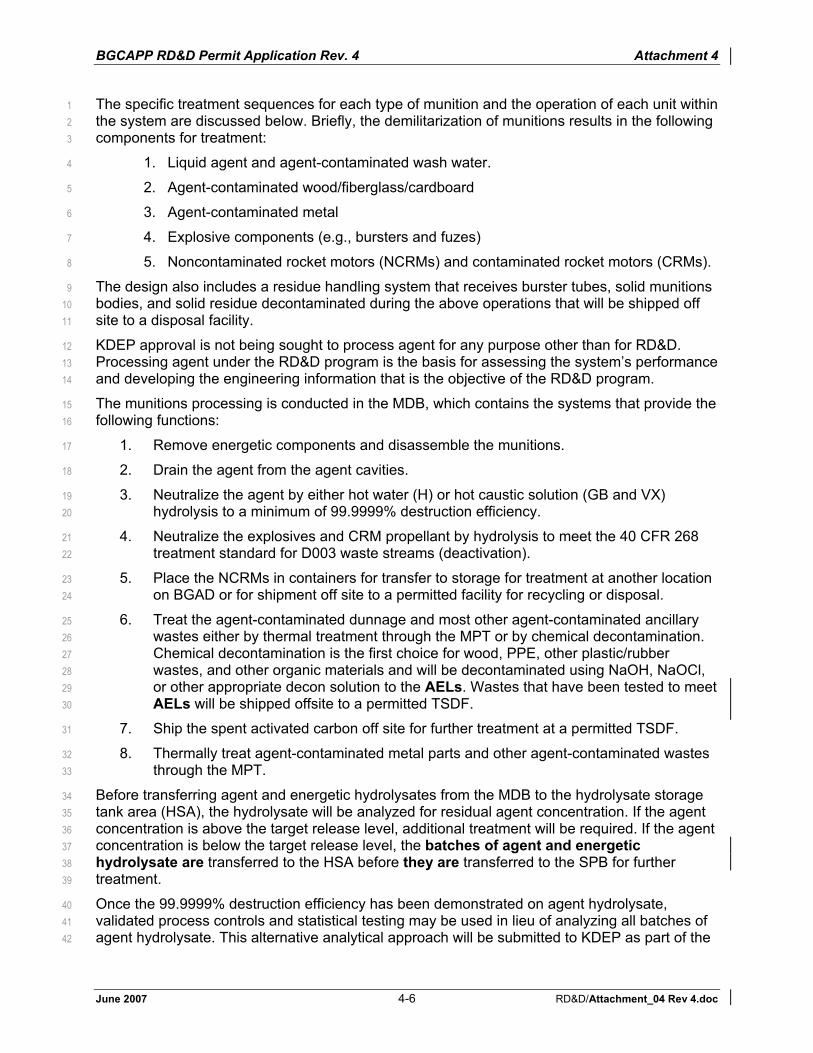
BGCAPP RD&D Permit Application Rev. 4 Attachment 4
June 2007 4-6 RD&D/Attachment_04 Rev 4.doc
The specific treatment sequences for each type of munition and the operation of each unit within 1the system are discussed below. Briefly, the demilitarization of munitions results in the following 2components for treatment: 3
1. Liquid agent and agent-contaminated wash water. 4
2. Agent-contaminated wood/fiberglass/cardboard 5
3. Agent-contaminated metal 6
4. Explosive components (e.g., bursters and fuzes) 7
5. Noncontaminated rocket motors (NCRMs) and contaminated rocket motors (CRMs). 8
The design also includes a residue handling system that receives burster tubes, solid munitions 9bodies, and solid residue decontaminated during the above operations that will be shipped off 10site to a disposal facility. 11
KDEP approval is not being sought to process agent for any purpose other than for RD&D. 12Processing agent under the RD&D program is the basis for assessing the system’s performance 13and developing the engineering information that is the objective of the RD&D program. 14
The munitions processing is conducted in the MDB, which contains the systems that provide the 15following functions: 16
1. Remove energetic components and disassemble the munitions. 17
2. Drain the agent from the agent cavities. 18
3. Neutralize the agent by either hot water (H) or hot caustic solution (GB and VX) 19hydrolysis to a minimum of 99.9999% destruction efficiency. 20
4. Neutralize the explosives and CRM propellant by hydrolysis to meet the 40 CFR 268 21treatment standard for D003 waste streams (deactivation). 22
5. Place the NCRMs in containers for transfer to storage for treatment at another location 23on BGAD or for shipment off site to a permitted facility for recycling or disposal. 24
6. Treat the agent-contaminated dunnage and most other agent-contaminated ancillary 25wastes either by thermal treatment through the MPT or by chemical decontamination. 26Chemical decontamination is the first choice for wood, PPE, other plastic/rubber 27wastes, and other organic materials and will be decontaminated using NaOH, NaOCl, 28or other appropriate decon solution to the AELs. Wastes that have been tested to meet 29AELs will be shipped offsite to a permitted TSDF. 30
7. Ship the spent activated carbon off site for further treatment at a permitted TSDF. 31
8. Thermally treat agent-contaminated metal parts and other agent-contaminated wastes 32through the MPT. 33
Before transferring agent and energetic hydrolysates from the MDB to the hydrolysate storage 34tank area (HSA), the hydrolysate will be analyzed for residual agent concentration. If the agent 35concentration is above the target release level, additional treatment will be required. If the agent 36concentration is below the target release level, the batches of agent and energetic 37hydrolysate are transferred to the HSA before they are transferred to the SPB for further 38treatment. 39
Once the 99.9999% destruction efficiency has been demonstrated on agent hydrolysate, 40validated process controls and statistical testing may be used in lieu of analyzing all batches of 41agent hydrolysate. This alternative analytical approach will be submitted to KDEP as part of the 42

BGCAPP RD&D Permit Application Rev. 4 Attachment 4
June 2007 4-7 RD&D/Attachment_04 Rev 4.doc
Waste Analysis Plan that is included in the RD&D Permit Compliance Schedule, Appendix B, 1Item # 18. 2
In the SPB, the pH of the energetics hydrolysate is adjusted in the aluminum precipitation 3system (APS). The dissolved aluminum compounds in the energetics hydrolysate are 4precipitated out of the hydrolysate in the APS and then physically separated from the 5hydrolysate in the aluminum filtration system (AFS). The AFS filtrate is blended with agent 6hydrolysate and fed to the SCWO system for treatment. The filter cake is shipped off site to a 7permitted TSDF. 8
Agent-contaminated waste streams will either be treated at a minimum of 1,000°F for a 9minimum of 15 minutes, which destroys residual agent and energetics, if present, or they will be 10shipped off site after being decontaminated to the AELs. All gas streams (including all 11ventilating air) are filtered through multiple banks of both particulate (HEPA) filters and activated 12carbon and are monitored for agent. The combination of liquid phase processing, batch 13operation with analysis of the contents prior to release and air stream filtering systems 14minimizes risk to human health and the environment. 15
4.3 Waste Processing Sequences 16
The following sections provide the processing sequence for each waste. Each unit operation is 17described in greater detail in subsequent subsections. 18
4.3.1 GB Nerve Agent Munitions 19
4.3.1.1 GB 8-Inch Projectile (no energetics are associated with this munition)20
1. Remove the pallet of projectiles from the EONC. 21
2. Load the projectiles into a tray. 22
3. Convey the tray to the nose closure removal and munitions washout system (NCR / 23MWS). 24
4. Via robot, transfer each individual projectile to the nose closure removal station 25(NCRS) and remove the lifting plug from the nose. 26
5. Via robot, transfer the individual projectiles from the NCRS and load them into the 27MWS module, nose-down. 28
6. Hydraulically collapse the burster well into the projectile’s agent cavity. 29
7. Gravity-drain the agent through the nose of the projectile. 30
8. Wash out the agent cavity using high-pressure water. 31
9. Send the drained agent and washout water to storage tanks in the agent neutralization 32room. (See Section 4.11 for a discussion of the ANS). 33
10. Replace each washed munitions body into its tray. 34
11. Convey the tray of washed projectiles to the MPT for thermal treatment. 35
The overpacked GB and VX projectiles will be removed from the EONC in the UPA and 36transferred to the TMA where they will be manually unpacked and placed on a tray on the 37conveyor system for processing through the MWS. The overpacked H projectiles will be 38removed from the EONC in the UPA and transferred to the ECV where they will be 39manually unpacked and the projectiles placed on the conveyor system for processing in 40the PMD. The overpack containers will be taken to the TMA. The empty overpack 41

BGCAPP RD&D Permit Application Rev. 4 Attachment 4
June 2007 4-8 RD&D/Attachment_04 Rev 4.doc
container will be chemically decontaminated or thermally decontaminated in the MPT 1prior to offsite recycling or disposal at a permitted TSDF. 2
4.3.1.2 GB M55 Rockets 3
The majority of the M55 rockets are stored in the BGCA igloos on pallets in their shipping and 4firing tubes (SFTs). These rockets are termed “nonleakers.” A small number of the M55 rockets 5have been overpacked because of leaks that were identified during routine agent monitoring in 6the igloos; these rockets are termed “leaker” rockets. Section 4.3.1.2.1 presents the processing 7sequence for the nonleaker rockets ; Section 4.3.1.2.2, the overpacked rockets (also termed 8leaker rockets). 9
4.3.1.2.1 Nonleaker Rocket Processing Sequence 10
The motors from the nonleaker M55 rockets are termed “noncontaminated rocket motors” 11(NCRMs). The processing sequence for the nonleaker rockets is as follows: 12
1. Remove the pallet of rockets from the EONC (UPA). 13
2. Place each rocket individually onto the rocket input assembly, which conveys it through 14the airlock to the ECV and to the rocket cutting machine (RCM). The RCM separates 15the rocket into three pieces: the warhead, the warhead’s SFT and the NCRM. 16
3. Transfer the NCRM (still contained in its section of the SFT) to a container for further 17treatment at another location on BGAD or an offsite TSDF. 18
4. Transfer the warhead’s SFT to a container for disposal at a permitted Toxic 19Substances Control Act (TSCA) landfill. 20
5. Convey the rocket warhead to the punch-and-drain station of the rocket shear machine 21(RSM) in the explosive containment room (ECR). 22
6. Punch holes in the top and bottom of the rocket warhead agent cavity with the punch-23and-drain station. 24
7. Drain the agent through the lower clamp. Send the drained agent into an agent storage 25tank in the agent neutralization room (See Section 4.11 for a discussion of the ANS). 26
8. Introduce high-pressure water. Flush the agent cavity (the optimum flush duration, 27pressure and flow rate will be the subjects of simulant, surrogate, and agent testing 28during the RD&D program), maintaining suction at a slightly higher flow rate than the 29inflow. 30
9. Send the washout water to a storage tank in the agent neutralization room (See 31Section 4.11 for a discussion of the ANS). 32
10. Move the rocket to the shear station for cutting. 33
11. Cut the warhead portion into segments. The warhead includes the fuze, the burster, 34and the washed agent cavity. 35
12. Send the warhead segments to the EBHs. 36
13. Send the energetics hydrolysate from the EBH to the energetics neutralization system 37(ENS) for further hydrolysis, as required. 38
14. Sample and analyze the energetics hydrolysate to verify that it no longer exhibits the 39characteristic of reactivity and that the agent concentration is below the target release 40level for agent before transfer to the HSA. 41

BGCAPP RD&D Permit Application Rev. 4 Attachment 4
June 2007 4-9 RD&D/Attachment_04 Rev 4.doc
15. Transfer the energetics hydrolysate from the HSA to the APS and the AFS in the SPB. 1
16. Chemically precipitate the aluminum and then remove the precipitate by filtration. The 2aluminum precipitate is characterized and sent offsite to a permitted disposal facility. 3Send the filtrate to the SCWO for further treatment. 4
17. Send solid material (rocket sections and pieces) from the EBHs through the MPT for 5thermal treatment at a minimum of 1,000°F for a minimum of 15 minutes. 6
4.3.1.2.2 Leaker Rocket Processing Sequence 7
The leaker rockets are classified into two categories: known and unknown. The known leaker 8rockets are those that were identified through monitoring in the BGCA igloos and are stored in 9the igloos in overpacks. The unknown leaker rockets are those that did not arrive in the UPA as 10known leakers but were later identified as such in the EONC or in the RCM. 11
The known leaker rockets will be processed at the end of each agent (GB and VX) campaign at 12BGCAPP. 13
The unknown leaker rockets will be accumulated in the ECVs and then processed in a leaker 14campaign, or they will be overpacked and sent back to the leaker storage igloo for processing 15during the known leaker rocket campaign. The leaker processing sequences for both known and 16unknown rockets are presented below: 17
1. For known overpacked rocket leakers (stored in the igloos in overpacks): 18
a. The EONCs of overpacked rockets are monitored for agent in the UPA. If agent 19monitoring indicates that the EONC does not contain any leaking overpacks, the 20EONC is opened and the overpacks are transferred to the ECV. 21
b. In the ECV, the rocket overpack is opened manually by operations personnel in 22PPE and the rocket is removed from the overpack. The rocket is placed on the 23RCM conveyor system in the ECV. 24
2. For unknown rocket leakers (nonoverpacked leaker rockets that are identified in 25EONCs and at the RCM): 26
a. Leaking rocket(s) could be detected when monitoring EONCs for agent in the 27UPA. The EONC that has been found to contain leaking rockets will be 28transported to the EONC leaker airlock so that the leaking rockets can be moved 29from the EONC to the ECV. Personnel in appropriate PPE will place each 30potentially contaminated rocket onto the RCM conveyor system. 31
b. A leaking rocket could be detected when monitoring for agent at the RCM or 32while observing the RCM. The leaking rocket that is found at the RCM may either 33be stored for a short duration, overpacked, and sent back to the igloo for later 34processing; or it can be processed immediately if the number of stored leaking 35rockets in the ECV is sufficient to justify stopping normal rocket processing to 36process the stored leakers. Personnel in appropriate PPE will place the rockets 37onto the RCM conveyor system. 38
3. The RCM separates the rocket into three pieces: warhead, warhead’s SFT, and CRM. 39
4. The warhead is processed in one of the two ECRs, following steps 4 through 18 in 40Section 4.3.1.2.1. 41

BGCAPP RD&D Permit Application Rev. 4 Attachment 4
June 2007 4-10 RD&D/Attachment_04 Rev 4.doc
5. The agent-contaminated SFT is removed from the conveyor in the ECV and transferred 1to the TMA for chemical decontamination to the AELs and disposed of at an off-site 2permitted TSCA TSDF. If chemical treatment proves unsuccessful, the SFT may be 3thermally treated in the MPT. 4
6. The CRM is conveyed to the ECR for processing at the RSM, which shears the rocket 5motor into four (approximately) 8-inch pieces and the tailfin using cuts 5, 6, 7, and 8 6following the original baseline design. Cut 8 is located at a point that isolates the tailfin 7section from the propellant. 8
7. The tailfin section and the segments of rocket propellant are transferred to and 9processed in separate EBHs. 10
8. The energetics hydrolysate is sent from the EBHs to the ENS for further hydrolysis, as 11required. 12
9. Before the energetics hydrolysate is transferred to the HSA, it is sampled and analyzed 13to verify that it no longer exhibits the characteristic of reactivity and that the agent 14concentration is below the target release level for agent. 15
10. The energetics hydrolysate is transferred from the HSA to the APS and AFS in the 16SPB. 17
11. The aluminum is chemically precipitated and the precipitate is removed by filtration. 18The aluminum precipitate is characterized and sent off site to a permitted disposal 19facility. The filtrate is sent to the SCWO for further treatment. 20
12. Solid material (rocket sections and pieces) from the EBHs is sent through the MPT for 21thermal treatment at a minimum of 1,000°F for a minimum of 15 minutes. 22
4.3.1.3 GB M56 Warheads 23
The GB M56 warheads will be processed and treated following the steps outlined in Section 244.3.1.2, except that (because they have no rocket motors) it will not be necessary to cut and 25remove the rocket motor in the RCM. 26
4.3.1.4 GB Ton Containers 27
The three GB TCs may be treated at the end of the RD&D program. The method for treating the 28GB TCs will be established on the basis of ongoing experience in handling and accessing TCs 29at other chemical demilitarization sites10 and experience gained on GB munitions during the 30earlier stages of the RD&D program. 31
4.3.2 VX Nerve Agent Munitions 32
4.3.2.1 VX 155-mm Projectiles (no energetics are associated with this munition)33
The VX 155-mm projectiles will not be treated under this RD&D permit. The treatment 34procedure for VX 155-mm projectiles will be similar to the procedure for GB 8-inch projectiles. 35
4.3.2.2 VX M55 Rockets 36
The VX M55 rockets will not be treated under this RD&D permit. The treatment procedure for 37VX M55 rockets will be similar to the procedure for GB M55 rockets. 38
10 ABCDF and NECDF.

BGCAPP RD&D Permit Application Rev. 4 Attachment 4
June 2007 4-11 RD&D/Attachment_04 Rev 4.doc
4.3.2.3 VX M56 Warheads 1
The VX M56 rocket warheads will not be treated under this RD&D permit. The treatment 2procedure for VX M56 rocket warheads will be similar to the procedure for GB M56 warheads. 3
4.3.2.4 VX Department of Transportation (DOT) Bottle 4
The VX DOT bottle will not be treated under this RD&D Permit. The method for treating the VX 5DOT bottle will be established on the basis of experience gained on other munitions during the 6earlier stages of the RD&D program. 7
4.3.3 H (Mustard) Blister Agent Munitions 8
4.3.3.1 H 155-mm Projectiles with Explosives 9
The H 155-mm projectiles will not be treated under this RD&D permit. The treatment procedure 10for H 155-mm projectiles is expected to be similar to the procedure for GB 8-inch projectiles with 11additional steps for treating tetrytol bursters that are part of the H projectiles. 12
4.3.3.2 H DOT Bottles 13
The H DOT bottles will not be treated under this RD&D permit. The method for treating the H 14DOT bottles will be established on the basis of experience gained on other munitions during the 15RD&D program. 16
4.3.4 Wood Pallets 17
Wood pallets that have not been exposed to a leaking munition will not be processed through 18the BGCAPP and will be managed by appropriate methods to promote waste minimization. The 19quantity of agent-contaminated wood pallets cannot be determined at this time. 20
All pallets and other dunnage associated with leaking munitions will be tested following Army-21approved methods. If they are contaminated, they will be treated by chemical decontamination 22to meet the AEL requirements. Wastes that have been confirmed to meet AEL requirements 23will be managed by appropriate means to minimize waste. 24
If chemical decontamination does not prove successful, the contaminated material will be 25treated in the MPT. The decontaminated residue will be managed by appropriate means to 26minimize waste. 27
4.3.5 Agent-Contaminated Plastic and PPE 28
Plastic materials that are not contaminated with agent will be managed by appropriate methods 29to promote waste minimization without any further treatment at BGCAPP. Plastic and PPE are 30assumed to be contaminated if they have been exposed to agent. Agent-contaminated plastic 31material (e.g., personnel protective ensembles, aprons, and gloves) that is generated during the 32RD&D program will be chemically decontaminated. If chemical decontamination does not prove 33successful, the material will be treated in the MPT. The decontaminated residue will be 34disposed of off site at a permitted TSDF. 35
4.3.6 Miscellaneous Agent-Contaminated Metal Parts (e.g., banding, pumps, 36and pipe)37
Metal material and parts that are not contaminated with agent will be managed by appropriate 38methods to minimize waste without any further treatment at BGCAPP. Agent-contaminated 39metal material and parts that are generated during the RD&D program will be chemically 40
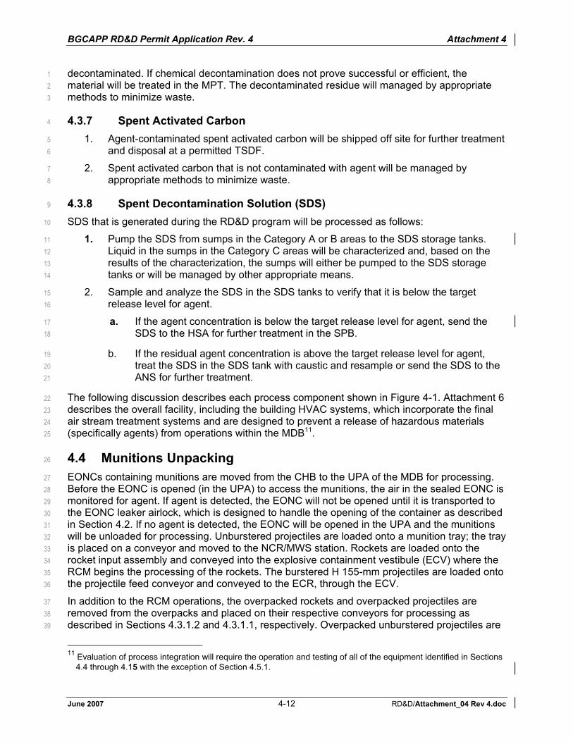
BGCAPP RD&D Permit Application Rev. 4 Attachment 4
June 2007 4-12 RD&D/Attachment_04 Rev 4.doc
decontaminated. If chemical decontamination does not prove successful or efficient, the 1material will be treated in the MPT. The decontaminated residue will managed by appropriate 2methods to minimize waste. 3
4.3.7 Spent Activated Carbon 4
1. Agent-contaminated spent activated carbon will be shipped off site for further treatment 5and disposal at a permitted TSDF. 6
2. Spent activated carbon that is not contaminated with agent will be managed by 7appropriate methods to minimize waste. 8
4.3.8 Spent Decontamination Solution (SDS) 9
SDS that is generated during the RD&D program will be processed as follows: 10
1. Pump the SDS from sumps in the Category A or B areas to the SDS storage tanks. 11Liquid in the sumps in the Category C areas will be characterized and, based on the 12results of the characterization, the sumps will either be pumped to the SDS storage 13tanks or will be managed by other appropriate means. 14
2. Sample and analyze the SDS in the SDS tanks to verify that it is below the target 15release level for agent. 16
a. If the agent concentration is below the target release level for agent, send the 17SDS to the HSA for further treatment in the SPB. 18
b. If the residual agent concentration is above the target release level for agent, 19treat the SDS in the SDS tank with caustic and resample or send the SDS to the 20ANS for further treatment. 21
The following discussion describes each process component shown in Figure 4-1. Attachment 6 22describes the overall facility, including the building HVAC systems, which incorporate the final 23air stream treatment systems and are designed to prevent a release of hazardous materials 24(specifically agents) from operations within the MDB11. 25
4.4 Munitions Unpacking 26
EONCs containing munitions are moved from the CHB to the UPA of the MDB for processing. 27Before the EONC is opened (in the UPA) to access the munitions, the air in the sealed EONC is 28monitored for agent. If agent is detected, the EONC will not be opened until it is transported to 29the EONC leaker airlock, which is designed to handle the opening of the container as described 30in Section 4.2. If no agent is detected, the EONC will be opened in the UPA and the munitions 31will be unloaded for processing. Unburstered projectiles are loaded onto a munition tray; the tray 32is placed on a conveyor and moved to the NCR/MWS station. Rockets are loaded onto the 33rocket input assembly and conveyed into the explosive containment vestibule (ECV) where the 34RCM begins the processing of the rockets. The burstered H 155-mm projectiles are loaded onto 35the projectile feed conveyor and conveyed to the ECR, through the ECV. 36
In addition to the RCM operations, the overpacked rockets and overpacked projectiles are 37removed from the overpacks and placed on their respective conveyors for processing as 38described in Sections 4.3.1.2 and 4.3.1.1, respectively. Overpacked unburstered projectiles are 39
11 Evaluation of process integration will require the operation and testing of all of the equipment identified in Sections
4.4 through 4.15 with the exception of Section 4.5.1.

BGCAPP RD&D Permit Application Rev. 4 Attachment 4
June 2007 4-13 RD&D/Attachment_04 Rev 4.doc
loaded onto a munition tray for processing through the nose closure removal station (NCRS) as 1described in Section 4.3.1.1. 2
The following subsections describe the munitions unpacking subsystems. 3
4.4.1 Projectile Input Subsystem 4
The burstered H 155-mm projectiles are unpacked in the UPA, placed onto the projectile feed 5conveyor, and transferred through the ECV and into the ECR for reverse assembly by the PMD. 6
The projectile feed conveyor is a combination of a roller-type conveyor and an airlock assembly 7with a series of doors. The doors provide for an airlock into the ECV and provide the negative 8pressure to prevent the air in the ECV from flowing into the UPA. 9
4.4.2 Rocket Input Subsystem 10
M55 rockets are unpacked on the receiving table in the UPA, placed onto the rocket input 11assembly, and conveyed to the ECV for processing on the RCM. Following RCM processing, 12the rocket warheads are conveyed into the ECR through a munition access blast gate for 13processing by the RSM. The plant has two RCMs and two RSMs: each has its own rocket input 14system, and one RCM is located in each ECV and one RSM is located in each ECR. 15
4.4.3 Dunnage/Secondary Waste 16
The main component of the dunnage is the wood pallets on which the munitions were stored 17and transported. The majority of the wood pallets are not agent-contaminated; they will be 18segregated in the UPA and managed by appropriate methods to minimize waste. 19
Pallets that are associated with leaker munitions will be processed as described in 20Section 4.3.4. 21
Other agent-contaminated (or potentially agent-contaminated) secondary waste, such as PPE 22and plastic, will be managed as described in Section 4.3.5. 23
Spent activated carbon will be managed as described in Section 4.3.7. 24
4.5 Projectile Handling System (PHS) (Drawing 24915-07-M5-PHS-00001)25
All 155-mm H projectiles are processed in the PMD to be installed in an ECR. 26
4.5.1 Projectile/Mortar Disassembly (PMD) Machine 27
The PMD machine will remove the nose closures and the bursters from the 155-mm H 28projectiles. After the nose closure and the burster are removed, the projectile will be conveyed 29out of the ECR, loaded onto a munition tray, and conveyed to the MWS. 30
The PMD processes the 155-mm H projectiles by first unscrewing the nose closure and 31removing the burster and miscellaneous components. The projectile is conveyed out of the ECR 32and placed on a munition tray for processing through the MWS. The nose closure, 33miscellaneous parts, and bursters are transferred to the energetics batch hydrolyzer (EBH) for 34deactivation by hydrolysis. 35
At any point in time, the number of projectiles in the ECR is limited by the total explosive limit of 36the aggregate number of projectiles present. The system is designed so that the total explosive 37limit is consistent with the design that has been submitted to the Department of Defense 38Explosives Safety Board (DDESB). 39

BGCAPP RD&D Permit Application Rev. 4 Attachment 4
June 2007 4-14 RD&D/Attachment_04 Rev 4.doc
4.6 Nose Closure Removal System/Munition Washout System (Drawing 124915-07-M5-MWS-00001) 2
4.6.1 Nose Closure Removal Station3
The NCRS removes the nose closures from the unburstered projectiles (GB and VX) by 4unscrewing them from the nose of the projectile and placing them in a storage bin or tray. After 5the nose closures have been removed from each projectile, a robot transfers the projectile from 6the NCR station to the MWS station. The removed nose closures are placed on munitions trays 7and processed through the MPT. 8
4.6.2 Munition Washout System 9
At the MWS, the projectile is inverted, placed into one of the MWS modules that contain a cavity 10access machine. A ram is hydraulically forced into the projectile, collapsing the burster well into 11the agent cavity as shown in Figure 4-3. The agent drains by gravity and is fed to the agent 12storage tank in the ANS. The washout nozzle array (consisting of high-pressure nozzles in a 13configuration that aims the water jets) is integral with the shaft of the burster well ram, and high-14pressure water is sprayed to flush the cavity. After flushing the cavity, the projectile is placed 15back on the munition tray and transferred to the MPT. 16
4.7 Rocket Handling System (RHS) (Drawing 24915-07-M5-RHS-00001)17
The RHS comprises the RCM and the RSM which, are discussed below. Section 4.3.1.2 18describes the processing steps of this system. 19
4.7.1 Rocket Cutting Machine (RCM) 20
The RCM’s design is based on a commercially available pipe cutter. The whole rocket, inside 21the SFT, is placed into the RCM, which clamps the motor end into a rotating chuck. As the 22chuck rotates, a cutting wheel cuts through the SFT and then through the rocket at the point 23between the warhead and the rocket motor. After the wheel cuts through the rocket, the 24warhead’s SFT is slid away from around the warhead and sent out of the MDB. The warhead is 25sent to the ECR and the rocket motor is sent out of the MDB as described in Section 4.3.1.2. 26
4.7.2 Rocket Shear Machine (RSM) 27
The RSM demilitarizes the M55 rocket warheads that have been separated from the rocket 28motor in the RCM as well as M56 warheads containing GB and VX agents. The RSM extracts 29agent from rockets in a punch, drain, and wash station, and then shears them into segments to 30access the energetics for neutralization in the EBH. Drained agent extracted at the RSM is 31pumped directly into the agent storage tanks; all agent washout water is pumped to the spent 32decontamination solution (SDS) storage tanks. From the storage tanks, the agent and flush 33material are pumped to the ANS where the agent is neutralized. The rocket warheads are 34processed at the RSM after being removed from their fiberglass SFTs. The RSM used at the 35BGCAPP is similar to the RSM used at baseline operations, but it has been modified to process 36warheads that have been removed from the SFT to include a high-pressure flushing step that 37washes residual agent from the agent cavity and removes any gelled agent. A fully automated, 38hydraulically powered RSM is installed in each ECR. 39
4.7.2.1 Punch/Drain and Wash Station 40
The punch/drain and wash station clamps the warhead while the warhead is punched, drained, 41and washed out. To reduce residual agent in the rocket warhead cavity, and therefore minimize 42

BGCAPP RD&D Permit Application Rev. 4 Attachment 4
June 2007 4-15 RD&D/Attachment_04 Rev 4.doc
the amount of agent processed in the EBH, the baseline RSM punch-and-drain station has been 1modified to include a pressurized water spray system. 2
The sprays remove the residual agent and dissolve solidified material that does not drain during 3the punch-and-drain cycle. The high-pressure water flush system improves cleaning of the 4rocket warhead while minimizing changes to the baseline RSM system. 5
The flush rate is maintained at less than the drain rate capacity, assisted by vacuum, to avoid 6pressurizing the warhead. The spray pattern and spray duration needed to achieve an effective 7flush will be validated during the Technical Risk Reduction Program (TRRP). 8
4.7.2.2 Rocket Shear Station 9
The warhead, with the agent cavity drained and washed, is conveyed from the punch/drain and 10wash station to the rocket shear station. Shearing is necessary to open the interior of the agent 11cavity for improved decontamination, to open the interior of the burster for improved explosive 12neutralization, and to cut the warhead into smaller sections that can be safely placed into the 13EBHs. When processing the CRMs, cutting the CRM propellant into smaller pieces also 14exposes more surface area to the hot caustic in the EBH, increasing the rate of hydrolysis. 15
The rocket shear station is equipped with an optical sensor that reads the position of a pusher 16arm that moves the rocket forward for shearing. The sensor output identifies the location of each 17cut that the blade will make on the rocket. The rocket is progressively positioned under the 18blade, which shears the warhead into smaller segments in a predefined pattern. 19
The solid material from the rocket shear station is transferred to the EBH for further processing. 20
4.8 Dunnage Treatment 21
Dunnage will be managed in accordance with the procedures described in Sections 4.3.4, 4.3.5, 224.3.6, and 4.4.3. 23
4.9 Energetics Treatment (Drawings 24915-07-M5-EBH-00001, -ENS-00001, 24
-OTE-00001, and 24915-11-M5-HSS-00002)25
4.9.1 Energetics Batch Hydrolyzer 26
Explosives and CRM propellant contained in the rockets and explosives contained in the 27155-mm H projectiles are treated in EBHs as shown in the PFD for the EBH system. 28
After the M55 rockets and M56 warheads are drained of agent and sheared in the RSM, the 29segments are placed in the EBHs for processing. Projectile bursters from 155-mm H projectiles 30are removed by the PMD and are also processed in the EBHs. An EBH is a large steam-heated 31inclined drum similar in shape to a traditional cement mixer. The drum is partially filled with hot 32NaOH solution. During rocket processing, sheared rocket segments are placed in the rotating 33drum where the energetics are dissolved and hydrolyzed. Rocket warhead segments 34(containing aluminum) are fed separately to EBH units. Aluminum in the rocket segments is also 35hydrolyzed. Steel-cased CRM segments are placed in an EBH and the propellant is hydrolyzed. 36
Hydrogen gas generated by the reaction of aluminum with sodium hydroxide is monitored, and 37an air or nitrogen purge is provided to ensure that hydrogen levels are maintained below the 3825% of the lower flammability limit (LFL). The EBH room is designed as an explosion 39containment room (ECR). 40
After the EBH charging step is completed, the second and third EBHs are used as required for 41receipt of energetics. The first EBH then completes the treatment of the energetics. The solid 42

BGCAPP RD&D Permit Application Rev. 4 Attachment 4
June 2007 4-16 RD&D/Attachment_04 Rev 4.doc
residues are then separated from the liquid hydrolysate and transferred to the MPT for thermal 1decontamination. The hydrolysate is transferred to the energetics neutralization reactors (ENRs) 2for final energetics destruction confirmation. Samples are taken to verify that the hydrolysate is 3below the target release level for agent and then transferred to the energetic hydrolysate 4storage tanks in the HSA. If the residual agent concentration is above the target release level, 5additional reaction time will be required in the ENRs before transfer to the HSA. 6
Gases from the EBHs and ENRs are sent to the dedicated EBH offgas treatment system (OTE). 7After treatment in the OTE, the gases are released to the MDB HVAC filter system. 8
4.9.2 Heated Discharge Conveyors 9
The heated discharge conveyors (HDCs) have been removed from the BGCAPP design; the 10NCRMs will be processed outside the BGCAPP facility. 11
4.9.3 Energetics Neutralization System 12
The energetics hydrolysate is not released from the MDB until it has been tested for agent and 13verified to have met all requirements for release from engineering controls. The hydrolysate is 14transferred to the energetic hydrolysate storage tanks in the HSA. If the residual agent 15concentration is above the target release level, additional reaction time will be required in the 16ENRs before transfer to the HSA. Gases from the ENS are sent to the MPT offgas treatment 17system (OTM). After treatment in the OTM, the gases are released to the MDB HVAC filter 18system. The ENS gases can also be sent to the EBH OTE if the OTM is not in operation. 19
4.9.4 EBH Offgas Treatment System (OTE) 20
The offgases from the EBHs are vented through the OTE. The offgases from the ENS can also 21be vented to the OTE if the OTM is not in operation. 22
The OTE consists of a scrubber tower system, offgas filters, an air reheater and exhaust 23blowers. 24
The OTE scrubber tower’s main function is to capture and neutralize ammonia and energetics 25constituents that may be present in the EBH offgas. It also captures liquid mist, particulates, and 26other organic materials in these offgases. The pH is controlled in the system by adding sulfuric 27acid to the EBH scrubber recirculation tank. 28
The offgas from the scrubber tower is ducted to a filter that is sized to remove particulates and 29droplets greater than 3 microns (�) in diameter at 99.9% efficiency. This filter normally acts as a 30demister, removing fine mist that may pass through the scrubber tower’s demister system. 31
The offgas from the filter is passed through an electric heater, which raises its temperature and 32reduces its relative humidity to below 55%. The gases from the OTE discharge to the MDB 33HVAC filter system. 34
4.10 Aluminum Precipitation System (APS)/Aluminum Filtration 35
System (Drawings 24915-07-M5-APS-00001, -AFS-00001) 36
The energetics hydrolysate is transferred from the HSA to the APS in the SPB, where pH of the 37hydrolysate is adjusted to precipitate the aluminum compounds before it is sent to the AFS to 38remove the precipitated aluminum compounds. 39
The AFS filtrate is transferred to the SCWO feed tanks for blending with the agent hydrolysate. 40The filter cake is removed and disposed of at a permitted TSDF. 41

BGCAPP RD&D Permit Application Rev. 4 Attachment 4
June 2007 4-17 RD&D/Attachment_04 Rev 4.doc
4.11 Agent Neutralization by Hydrolysis (Drawing 24915-07-M5-ACS-00001, 1
-ANS-00001, and 24915-11-M5-HSS-00001) 2
The agent drained from the munitions, as well as the wash liquid from the drain-and-wash 3operation, is hydrolyzed in the ANS reactors. Hot water will be used to neutralize H; hot NaOH 4solution will be used to neutralize VX and GB. 5
In the neutralization process, the agent will be destroyed to at least 99.9999% on a mass basis 6(i.e., the mass of agent entering the ANS versus mass of agent leaving the hydrolysis system). 7Attachment 10, Section 10.1, discusses how the destruction efficiency is determined. 8
SDS will be analyzed for agent; if agent concentration is below the target release level, the SDS 9will be transferred to the HSA. If the agent concentration is not below the target release level, 10the SDS either be treated in the SDS Tanks with caustic and resampled or will be sent to the 11agent hydrolysis reactors for further treatment. The agent hydrolysis reactors are kept under a 12nitrogen purge and the reactors’ vent gas is treated in the OTM (as described in Section 4.12) 13before it is released to the MDB HVAC filter system. 14
Before the hydrolysate is discharged from the agent reactors for VX or the sampling tanks for 15GB and H, it may be sampled and analyzed to ensure that it is below the target release level for 16agent or it may be released based on validated process controls and statistical testing. This 17alternative analytical approach will be submitted to KDEP as part of the Waste Analysis Plan 18that is included in the RD&D Permit Compliance Schedule, Appendix B, Item # 18. Only after 19one of these criteria have been met is the hydrolysate released from the reactor or the sampling 20tank and pumped to the HSA prior to further treatment by the SCWO treatment process. 21
4.12 Metal Parts Treater, MPT Cooling System (MCS), and Offgas 22
Treatment System 23
(Drawings 24915-07-M5-MPT-00001, -MCS-00001, and -OTM-00001)24
Washed munition bodies from MWS, EBH solid residues, and secondary wastes are thermally 25decontaminated in the MPT units. These items are placed on trays and are conveyed to the 26MPT; the chamber is sealed, purged with nitrogen gas, and inductively heated until all 27components have been thermally treated to a minimum of 1,000°F for a minimum of 15 minute. 28
The MCS cools the trays exiting the MPT to a temperature at which it is safe to handle. 29
The OTM treats the offgases from the MPT and the vent gases from the ACS, ANS, ENS, and 30SDS tank systems before the offgases are released to the MDB HVAC filter system. 31
The following subsections describe these three systems. 32
4.12.1 MPT (Drawing 24915-07-M5-MPT-00001) 33
The MPT thermally decontaminates the munitions bodies of 155-mm and 8-in. projectiles using 34inductive heating and superheated steam. Air is excluded from the system through the use of 35airlocks and nitrogen purges. 36
Trays of projectiles and other materials are processed by placing them on a conveyor, which 37carries them through the first door12 into the inlet airlock. The tray is staged in the inlet airlock, 38which is purged with nitrogen, until the trays in the MPT have completed processing and have 39
12 All doors in the inlet and outlet airlocks, both between the airlocks and the MPT and the surroundings, are normally
closed. They are opened only to transfer a tray of material. Both doors in each airlock cannot be opened at the same time to prevent air infiltration.

BGCAPP RD&D Permit Application Rev. 4 Attachment 4
June 2007 4-18 RD&D/Attachment_04 Rev 4.doc
been moved downstream. The tray is conveyed through the gate into MPT zone 1, where it is 1held until it reaches the desired initial temperature13. It is then moved into MPT zone 2 where it 2is further heated for a sufficient time to ensure that the complete mass of material has achieved 3a minimum of 1,000°F for a minimum of 15 minutes. After these conditions have been achieved, 4the tray from zone 2 is moved into the exit airlock where it is kept for a sufficient period to 5ensure that it has cooled in the nitrogen atmosphere which prevents the formation of dioxins 6and related compounds. This type of sequential operation allows for continuous treatment of 7trays of material while ensuring that the material in each tray has been heated to a minimum of 81,000°F for a minimum of 15 minutes. 9
4.12.2 MCS (Drawing 24915-07-M5-MCS-00001) 10
The MCS cools the material to a temperature at which it is safe to handle. 11
The MPT residue is transferred from the outlet airlock to the MCS, where the tray and its 12contents are placed onto the cooling conveyor. Ambient air is slowly blown across and through 13the mass of solids at a flow low enough not to create dust. The air cools the munition tray to a 14safe temperature for removing the munitions. The MCS incorporates a system that can use 15water to lightly mist the hot air in the MCS. The mist is designed only to keep the air cool; it does 16not contact the hot residue. 17
A particulate filter may be installed on the MCS to control any potential emissions. 18
The solid residue leaving the MCS will be shipped off site for disposal at a permitted TSDF. 19
4.12.3 OTM (Drawing 24915-07-M5-OTM-00001) 20
The OTM is designed to process the offgas from the MPT and the vent gases from the ACS, 21ANS, ENS, and SDS tank systems. The OTM consists of two bulk oxidizers (BOXs), two 22cyclones, a common wet venturi scrubber system, filters and blowers. Each MPT has its own 23BOX and cyclone. The offgas from the two MPTs then combines to be further treated through 24the scrubber system and filter before it is discharged to the MDB HVAC filter system. 25
The BOX unit is a flameless thermal oxidizer that oxidizes organics that may be present in the 26MPT, ANS room tanks, and ENS offgases. It is designed to handle a wide variety of materials 27such as halogenated organics, methane, hydrocarbons, ammonia, carbon monoxide, and 28hydrogen. The BOX unit handles the following input streams: 29
1. Air feed to the oxidizing section to ensure that the residual oxygen level in the unit 30effluent is at least 5%. 31
2. Fine mist of water to the oxidizing section to maintain the operating temperature at 322,000°F with capability to operate at 2,200°F if the gas feed has a higher heating value. 33A 2,200°F temperature is required when contaminated wood pallets and SFTs from the 34rocket handling system are processed in the MPT. 35
3. Natural gas to maintain the operating temperature at 2,000°F (or 2,200°F) if the heating 36value in the gas feed is not sufficient to maintain the operating temperature. 37
4. Fine mist of water to the cooling section to maintain the exit temperature at 1,200°F. 38
13 The two-zone heating allows for control of the rate of heat-up so as to properly manage the release of off-gases to
the OTM.

BGCAPP RD&D Permit Application Rev. 4 Attachment 4
June 2007 4-19 RD&D/Attachment_04 Rev 4.doc
The BOX consists of two sections, an oxidizing section, and a quench section. The 1oxidizing section has a minimum gas residence time of two seconds at a minimum 2temperature of 2,000°F. 3
The MPT cyclone removes ash and other large particulate matter from the BOX unit effluent 4gases and discharges the gases to the combined scrubber system. 5
The venturi/scrubber system is a combination of a venturi impaction scrubber that captures 6particulates and rapidly quenches the hot gases, followed by an absorption tower that captures 7acid gases. Caustic solution is added to the system to maintain pH and neutralize the captured 8acids. 9
The OTM offgas filter removes residual particulate matter greater than 3 � in diameter. This filter 10also is a demister, removing fine mist that may pass through the scrubber tower’s demister 11system. 12
The gas reheater reheats the OTM outlet gases to maintain the relative humidity of the blower 13effluent stream below 55% to avoid condensation in the HVAC ducts. The treated offgases from 14the OTM then go to the MDB HVAC filter system. 15
4.13 Decontamination Solution Supply and Spent Decontamination 16
Solution Capture/Storage System (Drawing 24915-07-M5-SDS-00001)17
Decontamination solution is used in the following activities: 18
1. Wash down any spills of agent that may have occurred. 19
2. Decontaminate equipment. 20
3. Decontaminate PPE that may have been contaminated during toxic area entries.14 21
Decontamination solution is used by applying it to an area of contamination, allowing sufficient 22contact time, and then rinsing the area with water. The wash water drains to sumps in the MDB. 23
The decontamination solution is based on NaOH, NaOCl, or other decon solutions. Other 24possible decon solutions will be evaluated and used if their overall performance and 25environmental health impacts prove to be equal to or better than current decon solutions. 26
The SDS is managed as described in Section 4.3.8. 27
4.14 SCWO Units (Drawing 24915-10-M5-SCWO-00001)28
The SCWO units are used to treat the agent and energetics hydrolysates and spent 29decontamination fluid. The various waste streams may be processed through the SCWO units 30either individually or as blends. All materials that are fed to the SCWO units have been 31previously verified to be below the target release level for agent; therefore, the SCWO and 32downstream operations do not require engineering controls. Tests conducted as part of the 33TRRP have provided data on the appropriate ratios of caustic and salt transport additives. The 34SCWO TRRP reports have been submitted to KDEP as required by the RD&D Permit, Appendix 35B, Compliance Schedule Item 1. 36
The SCWO process is based on the unique properties of water at conditions above its 37thermodynamic critical point of 374°C (705°F) and 3,206 psia. At these supercritical conditions, 38organic materials and oxidant gases are generally completely miscible in water and the elevated 39
14 To prevent agent from being carried out of the agent-contaminated areas of the MDB, PPE is washed down with
decon solution and water. Agent monitoring is performed prior to exiting the area through the airlocks.

BGCAPP RD&D Permit Application Rev. 4 Attachment 4
June 2007 4-20 RD&D/Attachment_04 Rev 4.doc
pressure increases the mixture density in the reactor, thus allowing rapid and complete 1oxidation reactions. 2
The SCWO reactor is a vertical down-flow high-pressure cylindrical vessel. Its general 3configuration is shown in Figure 4-4. A replaceable annular liner is fitted into the vessel as 4shown. A small flow of air or nitrogen is maintained in the annulus between the liner and the 5pressure vessel to inhibit the ingress of process fluid into the annulus. 6
The material to be reacted (hydrolysate or spent decontamination solution) along with air is 7pumped through the feed-nozzle at the top of the reactor. The feed material will be 8supplemented with additional organic feed (supplemental fuel) in order to increase its heating 9value, as required to maintain an autogenous15 reaction. Isopropyl alcohol (IPA), fuel oil, or 10kerosene may be used as supplemental fuels at the BGCAPP. 11
In the SCWO reactor, the organic constituents of the waste are converted to carbon dioxide 12(CO2), water (H2O), nitrogen (N2), or nitrous oxide (N2O), and sulfates and phosphates (if sulfur 13or phosphorus is present in the feed). Halogens are converted to their respective acids. The 14acids react with the caustic to form sodium salts such as sodium chloride (NaCl), sodium 15fluoride (NaF), monosodium phosphate (NaH2PO4), and sodium sulfate (Na2SO4), depending on 16the agent being processed. The salts are not soluble in the supercritical fluid and they are 17carried through the reaction zone (from the injector to the quench region) as solids or as 18slurries. At the bottom of the reactor, quench water is introduced, lowering the temperature 19below the critical point and converting the supercritical fluid to a liquid into which the salts 20dissolve. All of the reaction products flow out of the bottom of the SCWO reactor. 21
During system startup, an electric feed preheater is used to heat the SCWO reactor to the fuel 22initiation temperature at the nominal operating pressure of about 3,400 psi. At this point, flows of 23oxidant and fuel are begun, and reaction is initiated. Oxidation of the fuel brings the SCWO 24system to the full operating temperature before the hydrolysate is introduced. After the 25hydrolysate flow is initiated, fuel flow is reduced to accommodate the heat released by 26hydrolysate oxidation. As the hydrolysate feed rate is ramped up to the target throughput, the 27fuel, water, and air flow rates are adjusted as required to maintain the desired operating 28conditions. 29
The quenched reactor effluent is passed through a series of heat exchangers to cool it to near-30ambient temperature, passed through a high-pressure gas/liquid separator (GLS), and then 31passed through pressure reduction control valves. The gas stream and the liquid stream are 32depressurized separately. The liquid stream goes to a second GLS to further remove gases that 33were soluble at high pressure, principally residual CO2. The gas is combined with the main gas 34stream exiting the high-pressure GLS. The SCWO aqueous effluent exits the bottom of the low-35pressure gas/liquid separator and is pumped to the SCWO effluent tank for storage before it is 36transferred to the reverse osmosis (RO) system. 37
During upset conditions, the SCWO effluent is diverted to the Off-Spec Effluent Tank 38(MV-SCWO-0041), and not to the tanks in the STA. The Off-Spec Effluent tanks are 39located in the SPB and are controlled by the SPB HVAC system. This is shown in PFD 4024915-10-M5-SCWO-00001, Sheet 3. 41
15 Autogenous refers to the ability of a chemical reaction to maintain a sufficiently high temperature to sustain itself
without the need to add additional heat to the reactor vessel.

BGCAPP RD&D Permit Application Rev. 4 Attachment 4
June 2007 4-21 RD&D/Attachment_04 Rev 4.doc
4.15 Reverse Osmosis (RO) (Drawing 24915-10-M5-RO-00001)1
The RO unit processes the effluents from the SCWO units. SCWO effluents are first fed to the 2feed preparation subsystem, consisting of a clarifier for removing suspended solids, a 3multimedia filter, and a cartridge filter. This water stream from the preparation stage is then fed 4to an RO unit for brine concentration. The RO system creates a permeate stream, which is of 5suitable quality for reuse in the SCWO system. All residues from the clarifier and the filters are 6injected into the RO reject stream. Reject from the RO unit combines with blowdown from 7processing units, stored in the RO reject tanks, and then shipped off site to a permitted TSDF.8
RO permeate is introduced into the SCWO reactor near the bottom to reduce the SCWO 9effluent’s temperature to below the critical point and results in the re-solution of the 10inorganic constituents facilitating their discharge from the reactor. 11

BGCAPP RD&D Permit Application Rev. 4 Attachment 4
June 2007 4-22 RD&D/Attachment_04 Rev 4.doc
Table 4-1—Major NRC Reports Relevant to Destruction of Weapons at BGAD 1
NRC 1993 Alternative Technologies for the Destruction of Chemical Agents and Munitions
NRC 1995 Review of Alternative Chemical Disposal Technologies
NRC 1999 Review and Evaluation of Alternative Technologies for Demilitarization of Assembled Chemical Weapons
NRC 2000 Evaluation of Demonstration Test Results of Alternative Technologies for Demilitarization of Assembled Chemical Weapons, a Supplemental Review for Demonstration II
NRC 2000a Integrated Design of Alternative Technologies for Bulk-Only Chemical Agent Disposal Facilities
NRC 2001 Analysis of Engineering Design Studies for Demilitarization of Assembled Chemical Weapons at Pueblo Chemical Depot
NRC 2001a Disposal of Neutralent Wastes
NRC 2002 Analysis of Engineering Design Studies for Demilitarization of Assembled Chemical Weapons at Blue Grass Army Depot, 2002
NRC 2002a Update Engineering Design Studies for Demilitarization of Assembled Chemical Weapons at Blue Grass Army Depot
All NRC reports are available for purchase or download at www.nap.edu. 2
3
Table 4-2—Hydrolysis Types to be Used at BGCAPP 4
HydrolysisType Agent
Hot water H, blister agent mustarda: bis(2-chloroethyl) sulfide or ,2'-dichlorodiethyl sulfide (C4H8Cl2S)
GB [nerve agent sarin: isopropyl methyl phosphonofluoridate (C4H10FO2P)]
VX [nerve agent: O-ethyl S-(2-diisopropyl-aminoethyl) methylphosphonothiolate (C11H26NO2PS)]
Hot sodium hydroxide solution
Energetic materials (explosives and rocket propellants) aLevinstein mustard.
5

BG
CA
PP R
D&
D P
erm
it A
pplic
atio
n R
ev. 4
A
ttach
men
t 4
June
200
7 4-
23
RD
&D
/Atta
chm
ent_
04 R
ev 4
.doc
Figu
re 4
-1—
Blo
ck F
low
Dia
gram

BGCAPP RD&D Permit Application Rev. 4 Attachment 4
June 2007 4-24 RD&D/Attachment_04 Rev 4.doc
Figure 4-2—Enhanced Onsite Container (EONC)

BGCAPP RD&D Permit Application Rev. 4 Attachment 4
June 2007 4-25 RD&D/Attachment_04 Rev 4.doc
Figure 4-3—Projectile with Crushed Burster Tube

BGCAPP RD&D Permit Application Rev. 4 Attachment 4
June 2007 4-26 RD&D/Attachment_04 Rev 4.doc
Note: This figure is presented as general illustration of the functioning of a SCWO reactor. It is not necessarily an accurate representation of the interior details of the BGCAPP SCWO reactors.
Figure 4-4—Schematic of a SCWO Reactor
Cyclonic Quench Addition
Removable Liner Assembly
Pressure Vessel Wall
Effluent Discharge
Mix Zone
Feed Nozzle
Annular Air Purge

BGCAPP RD&D Permit Application Rev. 4 Attachment 5
June 2007 5-i RD&D/Attachment_05 Rev 4.doc
Attachment 5 Contents Attachment 5 Method Used to Meet Environmental Protection Standards In
Accordance with 401 KAR 30:031.............................................................5-1KAR 30:031 Section 2: Floodplains ...............................................................................5-1KAR 30:031 Section 3: Endangered Species ................................................................5-1KAR 30:031 Section 4: Surface Waters .........................................................................5-1KAR 30:031 Section 5: Groundwater .............................................................................5-1KAR 30:031 Section 6: Application to Land Use for the Production of Food Chain Crops ...............................................................................................5-1KAR 30:031 Section 7: Land Disposal of Polychlorinated Biphenyls (PCBs) ................5-1KAR 30:031 Section 8: Disease.....................................................................................5-2KAR 30:031 Section 9: Air .............................................................................................5-2KAR 30:031 Section 10: Safety......................................................................................5-2KAR 30:031 Section 11: Public Nuisance ......................................................................5-2KAR 30:031 Section 12: Wetlands.................................................................................5-2KAR 30:031 Section 13: Karst .......................................................................................5-2KAR 30:031 Section 14: Compliance.............................................................................5-2401 KAR 38:230 Section 1 (4): Effectiveness of Treatment.........................................5-12401 KAR 38:230 Section 1 (5): Air Emissions, Additional Information.........................5-12401 KAR 34:190 and 401 KAR 38:160: Tank Systems................................................5-12401 KAR 34:190 Section 3(1): Assessment of New Tank System's Integrity ..............5-12401 KAR 34:190 Section 3: Description of Tank System Installation and Testing Plans and Procedures .........................................................................5-12401 KAR 38:160 Section 2: Dimensions and Capacity of Each Tank..........................5-13401 KAR 34:190 Section 4: Containment and Detection of Releases .........................5-13401 KAR 34:190 Section 4(4)&(5): Requirements for External Liner, Vault, Double-Walled Tank or Equivalent Device .......................................................5-13401 KAR 34:190 Section 4(6): Secondary Containment and Leak Detection Requirements for Ancillary Equipment .............................................................5-14401 KAR 34:190 Sections 5 and 6: Controls and Practices to Prevent Spills and Overflows.........................................................................................5-14
Tables5-1 Container Management Regulatory Standards..............................................................5-65-2 Tank Systems Regulatory Standards...........................................................................5-105-3 Treatment Unit Regulatory Standards..........................................................................5-11

BGCAPP RD&D Permit Application Rev. 4 Attachment 5
June 2007 5-1 RD&D/Attachment_05 Rev 4.doc
Attachment 5 Method Used to Meet Environmental Protection 1
Standards In Accordance with 401 KAR 30:031 2
The requirements of KAR 30:031 regulate the three vectors for contaminant release from a 3treatment, storage, and disposal facility (TSDF): 4
1. Discharge to surface water 5
2. Contamination of soil and groundwater 6
3. Release to the atmosphere 7
The Blue Grass Chemical Agent Destruction Pilot Plant (BGCAPP) is a completely enclosed 8facility with no discharges to surface water, ground, or groundwater. It does have the potential to 9release contaminants to the air. The following discussion addresses those aspects of KAR 1030.031 that relate to the first two vectors for contaminant release. The discharges to the 11atmosphere and how these comply with and exceed all of the regulatory requirements are 12discussed in addressing the requirements of 401 KAR 30:031, Section 9. 13
KAR 30:031 Section 2: Floodplains 14
The BGCAPP is not located in a floodplain. 15
KAR 30:031 Section 3: Endangered Species 16
As discussed in the Destruction of Chemical Munitions at Blue Grass Army Depot (BGAD), 17Kentucky, Final Environmental Impact Statement (EIS) (December 2002), the area of 18construction has been surveyed and the BGCAPP will be sited so that it does not impact any 19endangered species. Final site determination will be analyzed in a National Environmental 20Protection Act (NEPA) document to be prepared in 2004. 21
KAR 30:031 Section 4: Surface Waters 22
The BGCAPP is a zero-discharge facility; it does not discharge to surface waters. 23
KAR 30:031 Section 5: Groundwater 24
The BGCAPP is totally enclosed. All hazardous waste storage tanks will be constructed to meet 25the requirements of 401 KAR 34:190 and are provided with secondary containment designed 26and operated to contain 100% of the capacity of the largest tank and the additional capacity to 27contain the precipitation from a 25-year, 24-hour storm (5.3 inches). 28
KAR 30:031 Section 6: Application to Land Use for the Production of 29
Food Chain Crops 30
The BGCAPP does not apply waste to the land or dispose of any waste on the land. 31
KAR 30:031 Section 7: Land Disposal of Polychlorinated Biphenyls 32
(PCBs)33
The BGCAPP will send all PCB waste only to approved Toxic Substance Control Act (TSCA) 34disposal sites. 35

BGCAPP RD&D Permit Application Rev. 4 Attachment 5
June 2007 5-2 RD&D/Attachment_05 Rev 4.doc
KAR 30:031 Section 8: Disease 1
The BGCAPP will not process pathogenic or other biological wastes. 2
KAR 30:031 Section 9: Air 3
1. Open burning of wastes. 4The BGCAPP will not perform open burning of any wastes. 5
2. KRS Chapter 224, Air Pollution Regulations. 6The BGCAPP will comply with all requirements of KRS [Kentucky Revised Statute] 7Chapter 224 or administrative regulations promulgated pursuant thereto. A modification 8to the existing Blue Grass Army Depot (BGAD) Air Permit (No. O-86-12) will be 9submitted in sufficient time to allow full statutory review prior to the start of construction of 10treatment facilities requiring the Air Permit approval. See Section 11.5, Attachment 11, 11for additional information on anticipated releases to the air. 12
KAR 30:031 Section 10: Safety 13
1. Explosive gases.14Waste processing that may generate explosive gases is described in Attachment 4, 15Section 4.9.1. Additional information will be provided to KDEP in sufficient time before 16the start of construction of the affected treatment units. 17
2. Fires.18No waste will be disposed of on land; therefore, the types of fires covered by this 19paragraph cannot occur. 20
3. Access.21Access to all of the BGAD chemical limited area (CLA) is controlled and monitored by 22security. The BGAD is surrounded by a heavy chain link fence topped by barbed wire. 23The BGCAPP will be surrounded by a double fence topped with barbed wire. The 24BGCAPP can be accessed through the manned entry control facility (ECF). 25
KAR 30:031 Section 11: Public Nuisance 26
The BGCAPP is within the confines of the BGAD and is well away from any public view or 27contact. It poses no public nuisance. 28
KAR 30:031 Section 12: Wetlands 29
The BGCAPP is not located in a wetland. 30
KAR 30:031 Section 13: Karst 31
All operations will be performed in enclosed buildings with no runon or runoff. 32
KAR 30:031 Section 14: Compliance 33
BGCAPP will comply with the applicable requirements of KRS 224, 401 KAR, and the BGCAPP 34Permit. Regulated units within BGCAPP will be managed in accordance with 401 KAR Chapter 3534 “Standards for Owners and Operators of Hazardous Waste Storage, Treatment and Disposal 36

BGCAPP RD&D Permit Application Rev. 4 Attachment 5
June 2007 5-3 RD&D/Attachment_05 Rev 4.doc
Facilities.” Each regulated area or unit is discussed below with the appropriate regulatory 1requirements from 401 KAR Chapter 34. 2
1. Container Storage 3This section describes the areas in which BGCAPP will manage containers of 4hazardous waste and some of the types of containers managed, and briefly describes 5the hazardous waste. Containers listed below and additional containers selected and 6used during systemization and the RD&D program at BGCAPP meet the definition and 7requirements of 401 KAR 38:005, 401 KAR 34:180, and 401 KAR 38:150. 8
2. Hazardous Waste Containers 9Several different containers will be used to manage, store, and transport hazardous 10waste within BGCAPP, in addition to the munitions themselves. Several of these 11containers are described below, but this listing is not all inclusive. As additional types of 12containers are identified, they will be incorporated into BGCAPP procedures in 13compliance with 401 KAR 34:180 and 401 KAR 38:150. Only compatible wastes will be 14containerized together. 15
a. Single Round Container (SRC)16M55 rockets that have been found to be leaking are containerized in a single 17round container (SRC). The SRC was specifically developed to contain the M-55 18in a substantial steel shell, which has been subjected to a helium leak test as part 19of the acceptance process. Leaking M-55 rockets, which were containerized 20before the development of the SRC, are stored in a modified M-1 container. The 21modified M-1 is a heavy steel cylinder bolted on with a gasket seal with eight 22bolts. All munitions are stored on specialized pallets designed to store the 23overpacked unit securely. 24
b. M16 Series Overpack Container 25The M16 series containers are cylindrical steel containers designed to be air 26tight, designated for the over-pack of projectiles. Overpacked 155-mm projectiles 27are stored in wooden “egg crates” specifically designed to store the M16 28overpack container. 29
c. M10 Series Overpack Container30The M10 series container is a cylindrical steel container that is designed to be 31airtight and is designated for use as an overpack container for leaking or 32deteriorated M16 containers and as an overpack container for 8-in. projectiles. 33
d. DOT Bottle34DOT bottles are cylindrical containers of steel. Each bottle contains 35approximately 3 gallons of chemical warfare agent. 36
e. One-Ton Containers37Three one-ton containers hold unserviceable mixtures of GB agent and liquid 38from drill and transfer (DAT) operations and Surveillance Program, Lethal 39Chemical Agents and Munitions [SUPLECAM] operation. The one-ton containers 40are cylindrical steel containers. All valves and pipes have been replaced with 41steel plugs. 42
f. ISO 55-Gallon Steel Drum43Some secondary waste generated during the RD&D process will be 44containerized in 55-gallon steel drums. The lids will be kept closed except during 45

BGCAPP RD&D Permit Application Rev. 4 Attachment 5
June 2007 5-4 RD&D/Attachment_05 Rev 4.doc
filling. Each drum is manufactured with 18-gauge cold rolled steel in accordance 1with 49 CFR 178.54. Maximum volume of each drum is 55 gallons and has an 2empty weight of approximately 38 pounds. All drums are approximately 35 inches 3tall with a diameter of 22½ in. 4
g. Intermediate Bulk Containers (IBCs)5IBCs may be used throughout the process to collect various liquid waste 6streams. Each IBC will have a capacity of 300 gallons with nominal dimensions 7of 42 by 48 by 41 in. (LxWxH). IBCs are manufactured from various materials 8including carbon steel, stainless steel and polymers in accordance with DOT 9regulations. 10
h. Enhanced Onsite Container (EONC)11The Department of the Army uses EONCs to store and transport the munitions 12and bulk containers for the time period immediately preceding demilitarization 13activities. The EONC is designed to provide vaportight containment of agent; all 14seals on the containers are impervious to agent and are able to withstand 15decontamination solutions. The EONC will provide secondary containment for the 16munitions or containers stored within. The EONCs and any components mounted 17on the surface will fit within an envelope that is 8.5 ft by 8.5 ft by 12 ft high. The 18combined weight of the EONC and munition holding trays will not exceed 1926,000 lb. 20
3. Container Management21Containers at BGCAPP will be managed in accordance with 401 KAR 38:005, 401 22KAR 34:180 and 401 KAR 38:1501. Munitions destined for demilitarization are 23described in Attachment 3. The munitions are transported to the container handling 24building (CHB) for storage prior to processing during the RD&D program. The Blue 25Grass Chemical Activity (BGCA) is responsible for the safe storage and delivery to 26BGCAPP of these munitions, including, but not limited to: 27
a. Loading specified chemical munition types into EONCs. 28
b. Transporting the EONCs from the CLA to the CHB of BGCAPP. 29
c. Completing required record keeping for transfer of custody of munitions to 30BGCAPP.31
d. Returning unloaded EONCs to the CLA. 32
This activity will be completed under a BGCA Work Plan approved by KDEP in 33accordance with the requirements of KRS 224.50.130 (Chemical Munitions). 34
Each truck used by BGCA can transport one EONC of munitions. The number of trucks 35per day and the loading configuration in the EONCs will differ with the specific goal of 36scheduled research. EONC movement from the CHB to the munitions demilitarization 37building (MDB) continues 24 hr/day, 7 days/week. 38
When the truck enters the BGCAPP perimeter, it will move to an off-loading area at the 39CHB. A bridge crane or similar device will be used to unload the EONC. All containers 40present in the CHB will contain the same agent because the facility will process only 41
1 Attachment 12 provides a list of specific regulatory waivers BGCAPP is requesting, along with
justification for each request.

BGCAPP RD&D Permit Application Rev. 4 Attachment 5
June 2007 5-5 RD&D/Attachment_05 Rev 4.doc
one lethal chemical agent at a time. In accordance with the Kentucky Hazardous 1Waste regulation 401 KAR 34:180 Section 5, the vapor space of the EONCs containing 2waste that remain in the CHB for more than 1 week will be monitored using an agent 3monitor port in the EONC on a weekly basis for agent vapor in lieu of visual inspections 4of the hazardous waste containers (munitions). 5
Wastes generated during the RD&D program and construction will be placed in 6containers whose materials of construction is compatible with the contents. The 7selection will be made on a case-by-case basis consistent with generator knowledge of 8the stream. In cases of uncertainty, the stream’s pH or other relevant parameters will 9be evaluated and the container material selected on the basis of this analysis. All 10waste containers will always be kept closed during storage except when adding or 11removing waste. 12
All containers will be handled in a manner to avoid rupturing or leaking. All handling will 13be performed with drum dollies, forklifts, overhead cranes, or other means, as 14appropriate. One of the goals of the process integration RD&D will be to evaluate the 15safety and suitability of the handling procedures. 16
Development of container management will continue throughout systemization and the 17RD&D program. 18
4. Hazardous Waste Container Storage Areas19Several areas within BGCAPP will have permitted container storage areas. These 20areas will be designed, constructed and managed in accordance with all applicable 21standards of 401 KAR 38:005, 401 KAR 34:180, and 401 KAR 38:150. Table 5-1 22summarizes the areas within BGCAPP to be permitted for container storage; more 23detailed descriptions follow. 24
a. CHB25The CHB is a steel-frame building with insulated metal roofing and insulated siding 26panels. A side loader truck will be used to move the EONCs into the CHB and also to 27transfer them to the unpack area (UPA). 28
The EONC storage area is sized to store 53 EONCs. 29
Permitted storage will be limited to the storage of containers inside of EONCs. The 30EONC meets secondary containment requirements of 401 KAR 34:180 Section 6 for 31the munitions contained within. 32
The floor of the CHB is constructed of reinforced concrete. The CHB-MDB transition 33structure is metal siding with a reinforced concrete floor. The number of construction 34and expansion joints will be kept to a minimum. All joints between floors and walls will 35be covered and sealed. 36
b. MDB37The MDB is the primary treatment facility in the chemical weapons destruction process 38and includes the following components: 39

BGCAPP RD&D Permit Application Rev. 4 Attachment 5
June 2007 5-6 RD&D/Attachment_05 Rev 4.doc
Table 5-1—Container Management Regulatory Standards 1
Container Storage Areas Container Management Regulatory
Standards Container Handling Building (CHB) 401 KAR 34:180
(Use and Management of Containers) Areas within Munitions Demilitarization Building (MDB)
Unpack Areas (UPAs) Explosive Containment Vestibules (ECVs) Explosive Containment Rooms (ECRs) Toxic Maintenance Area (TMA) Residue Handling Area Metal Parts Treater (MPT) Cooling Conveyor Area Tray/Container Transfer Room Agent Neutralization System (ANS) Room Motor Packing Room (MPR) Area Motor Shipping Room (MSR)/Covered Loading AreaBox Storage Area
SCWO Processing Building (SPB) Storage AreaWaste Storage Area (WSA) Laboratory Waste Handling Area
2

BGCAPP RD&D Permit Application Rev. 4 Attachment 5
June 2007 5-7 RD&D/Attachment_05 Rev 4.doc
1. Unpack Areas (UPAs) 1Containers and munitions will be brought from the CHB into the MDB via the 2UPAs. Each UPA is a transition area between the CHB and the hazardous 3waste processing in the MDB. Permitted storage will be limited to the storage 4of containers inside of EONCs or on secondary containment pallets. The 5EONC meets secondary containment requirements of 401 KAR 34:180 6Section 6 for the munitions contained within. This area will also provide a 7means to monitor the EONCs for leakers, provides an unpack station, and 8provides a means to return empty EONCs to the CHB for temporary storage. 9The floor of each UPA is constructed of reinforced concrete. The number of 10construction and expansion joints will be kept to a minimum in this area and 11the floor, sumps, and curbs have been coated. 12
2. Explosive Containment Vestibules (ECVs) 13Munitions will be stored on the conveyors in these rooms and the munitions 14will also be stored on the reject systems located in these rooms. In addition, 15leaking or reject projectiles that have been placed in overpacks may be 16stored on the floor in these rooms. Storage of projectiles or rockets, in or out 17of EONCs, will not exceed the maximum number allowable determined by 18the net explosive weight. Secondary containment will be provided by a 19coated, reinforced concrete floor, sumps, and perimeter curbs/walls. The 20number of construction and expansion joints has been kept to a minimum in 21this area and the floor, sumps, and curbs have been coated. 22
3. Explosive Containment Rooms (ECRs) 23Munitions containing explosives (projectiles with bursters and rockets) are 24processed in ECRs. The number of projectiles in an explosive contaminant 25room at any time is limited by the explosive force contained in the aggregate 26projectiles as determined by the net explosive weight. Munitions will be 27stored on the conveyors in this room and the munitions will also be stored on 28the reject systems located in this room. In addition, leaking projectiles that 29have been placed in overpacks may be stored on the floor in this room. 30Secondary containment will be provided by a coated and reinforced concrete 31floor, sumps, and perimeter curbs/walls. The number of construction and 32expansion joints will be kept to a minimum in this area and the floor, sumps, 33and curbs have been coated. 34
4. Toxic Maintenance Area (TMA) 35The TMA is located within the MDB and a portion of the Category A section 36of the TMA is designated as the TMA container storage area. This TMA 37container storage area is sized to store one hundred 55-gallon drums. The 38TMA airlock/decon area is sized to store one EONC. Secondary containment 39will be provided by a coated and reinforced concrete floor, sumps, and 40perimeter curbs/walls. The number of construction and expansion joints has 41been kept to a minimum in these areas and the floor, sumps, and curbs have 42been coated. 43
5. 5. Residue Handling Area (RHA) 44BGCAPP process residues consist of metal parts associated with the 45munitions from the metal parts treaters (MPTs), various solid dunnage. Also, 46dunnage scheduled to be processed through the BGCAPP will be stored in 47the RHA container storage area. Typical containers include 55-gallon drums, 48

BGCAPP RD&D Permit Application Rev. 4 Attachment 5
June 2007 5-8 RD&D/Attachment_05 Rev 4.doc
rolloff boxes, and plastic bags used to hold contaminated personnel 1protective equipment (PPE) prior to treatment. 2
6. Metal Parts Treater (MPT) Cooling Conveyor Area 3BGCAPP process residues stored in this area include metal parts associated 4with the treatment of the munitions and secondary waste from the MPTs. 5Typical containers include 55-gallon drums and rolloff boxes. 6
7. Tray/Container Transfer Room 7Miscellaneous secondary waste will be stored in this room until it is removed 8for disposal. Typical containers include 55-gallon drums, plastic bags, and 9boxes.10
8. Agent Neutralization System (ANS) Room 11Miscellaneous secondary waste will be stored in this room until it is removed 12for disposal. The room may also used to store spent decon solution (SDS) 13on a contingency basis. Typical containers include IBCs, 55-gallon drums, 14plastic bags, and boxes. 15
9. Motor Packing Room (MPR)16Separated rocket motors will be stored in this room prior to their ultimate 17disposal. In addition to the rocket motors, empty warhead shipping and firing 18tubes (SFTs) will also be stored here. Typical containers include Department 19of Transportation (DOT)-approved shipping boxes. 20
10. Motor Shipping Room (MSR)/Covered Loading Area 21Separated rocket motors will be stored in this room prior to their ultimate 22disposal. In addition to the rocket motors, empty warhead SFTs will also be 23stored here. Typical containers include DOT-approved shipping boxes. 24
11. Box Storage Area 25Separated rocket motors will be stored in this room prior to their ultimate 26disposal. In addition to the rocket motors, empty warhead SFTs will also be 27stored here. Typical containers include DOT-approved shipping boxes. 28
c. SPB Area29Miscellaneous secondary waste will be stored in this area until it is removed for 30disposal. Typical containers include rolloff bins, 55-gallon drums, plastic bags, and 31boxes.32
d. Waste Storage Area33Various liquid and solid hazardous wastes will be stored in this area until it is shipped 34off site for disposal. Typical containers include rolloff bins and 55-gallon drums. 35
e. Laboratory Waste Handling Area 36Various liquid and solid hazardous waste generated from lab operations. Typical 37containers include IBCs and 55-gallon drums. 38
5. Hazardous Waste Tank Storage Areas 39Several tank systems within BGCAPP will be permitted for storage of hazardous 40wastes. These areas are located outside, within the MDB, and within the SPB. These 41tank systems will be designed, constructed, and operated in accordance with all 42applicable standards of 401 KAR 38:005, 401 KAR 34:190 and 401 KAR 38:160. 43

BGCAPP RD&D Permit Application Rev. 4 Attachment 5
June 2007 5-9 RD&D/Attachment_05 Rev 4.doc
Table 5-2 shows areas within BGCAPP to be permitted for storage of hazardous 1wastes in tanks. 2
6. Hazardous Waste Treatment Units 3Numerous hazardous waste treatment units will be used to destroy the chemical 4weapons stockpile at BGCAPP. All the units will be installed during the RD&D program, 5although the PMD machine will only be used to process the mustard 155-mm 6projectiles which are not the subject of this RD&D Permit Application. Each hazardous 7waste treatment unit will be designed, constructed, and operated in accordance with 8the applicable standards from 401 KAR Chapter 34 (Standards for Owners and 9Operators of Hazardous Waste Storage, Treatment and Disposal Facilities). Table 5-3 10describes the hazardous waste treatment units as well as the applicable sections of 11Chapter 34. 12
See Attachment 4 for the process description of these treatment units. Materials of construction 13and dimensions of miscellaneous treatment units will be provided to KDEP in sufficient time 14before the start of construction of the miscellaneous treatment units to allow full evaluation of 15their adequacy. 16

BGCAPP RD&D Permit Application Rev. 4 Attachment 5
June 2007 5-10 RD&D/Attachment_05 Rev 4.doc
Table 5-2—Tank System Regulatory Standards 1
Hazardous Waste Tank Systems Tank System
Regulatory Standard
Tank Systems within MDB: Agent Collection/Toxic Storage (ACS) 401 KAR 34:190 (Tanks) Spent Decon System (SDS) 401 KAR 34:190 (Tanks) Agent Neutralization System (ANS) 401 KAR 34:190 (Tanks) Energetic Neutralization System (ENS) 401 KAR 34:190 (Tanks)
Hydrolysate Storage Area (HSA) 401 KAR 34:190 (Tanks)
SCWO Tank Area (STA) 401 KAR 34:190 (Tanks)
2

BGCAPP RD&D Permit Application Rev. 4 Attachment 5
June 2007 5-11 RD&D/Attachment_05 Rev 4.doc
Table 5-3—Miscellaneous Treatment Unit Regulatory Standards 1
Hazardous Waste Treatment Unit Applicable Standard
Munitions demilitarization building (MDB):Rocket cutting machine system (RCM) 401 KAR 34:250
(Miscellaneous Units - Mechanical Rocket shear machine (RSM) system 401 KAR 34:250
(Miscellaneous Units - Mechanical) Projectile/mortar disassembly (PMD) system 401 KAR 34:250
(Miscellaneous Units - Mechanical) Energetics batch hydrolyzer (EBH) 401 KAR 34:250
(Miscellaneous Units - Other) Munition washout system (MWS) 401 KAR 34:250
(Miscellaneous Units - Mechanical) Metal parts treaters (MPTs) 401 KAR 34:250
(Miscellaneous Units - Thermal) Nose closure removal system (NCRS) 401 KAR 34:250
(Miscellaneous Units - Mechanical)
SCWO processing building (SPB): SCWO units 401 KAR 34:250
(Miscellaneous Units - Other) RO system 401 KAR 34:250
(Miscellaneous Units - Other) Aluminum precipitation and filtration system
401 KAR 34:250(Miscellaneous Units - Other)
2

BGCAPP RD&D Permit Application Rev. 4 Attachment 5
June 2007 5-12 RD&D/Attachment_05 Rev 4.doc
401 KAR 38:230 Section 1 (4): Effectiveness of Treatment 1
See Attachment 4, Section 4.1, for a discussion of the National Research Council (NRC) 2Reports, which evaluated the various technologies and identified neutralization by hydrolysis to 3be an effective and safe method for treating the chemical agent and the energetics that are 4stored at BGAD. The NRC reports are prepared by committees selected for their experience 5and knowledge of the subject matter being evaluated. The reports are very heavily peer-6reviewed prior to publication. All reports identified in Attachment 4, Table 4-1 (as well as 7numerous other reports), have identified neutralization followed by supercritical water oxidation 8(SCWO) as the appropriate treatment technology for BGCAPP. 9
In addition: 10
1. Mustard agent was successfully treated by hot water hydrolysis (the process that will 11be used at BGCAPP) at the Aberdeen Chemical Agent Disposal Facility (ABCDF). 12ABCDF operation has been completed and the facility has completed closure 13activities.14
2. VX is being successfully treated at the Newport Chemical Agent Disposal Facility 15(NECDF), which is currently on line and will have completed operation before the start 16of the BGCAPP RD&D program. 17
401 KAR 38:230 Section 1 (5): Air Emissions, Additional Information 18
All sources of agent emissions are contained in the MDB and pass through the MDB HVAC filter 19system, which is described in Attachment 6, Section 6.1.3. As indicated, the MDB HVAC filter 20system is the same one that is used or planned at all of the chemical demilitarization facilities. It 21has performed satisfactorily at all active facilities. 22
401 KAR 34:190 and 401 KAR 38:160: Tank Systems 23
This section presents additional information on the tank systems. Part A of this application lists 24the tanks and their aggregate volumes. All tanks are maintained at essentially ambient pressure 25and temperature. All agent and agent-contaminated storage tanks are kept inside the MDB and 26are vented to the MDB HVAC filter system. 27
401 KAR 34:190 Section 3(1): Assessment of New Tank System's 28
Integrity 29
The assessment of adequacy of the design will be submitted to KDEP before the start of 30construction of the tanks for their review. No underground storage tanks will be used for 31hazardous wastes. All tanks storing hazardous waste at the BGCAPP are located above 32ground.33
401 KAR 34:190 Section 3: Description of Tank System Installation 34
and Testing Plans and Procedures 35
An independent, qualified installation inspector or an independent, qualified registered 36professional engineer will inspect each new tank system prior to placing a new tank system in 37service. Inspection will include evaluation of the following items: 38
1. Welds to ensure the absence of breaks 39

BGCAPP RD&D Permit Application Rev. 4 Attachment 5
June 2007 5-13 RD&D/Attachment_05 Rev 4.doc
2. Integrity to ensure the absence of punctures and cracks 1
3. Integrity of the protective coatings to ensure that it has not been scraped through or 2otherwise removed in locations 3
4. Lack of corrosion 4
5. Other structural damage or inadequate construction/installation. 5
All discrepancies will be repaired by appropriate methods. The tank will not be placed into 6service until it has passed all appropriate inspections. 7
All tanks and ancillary equipment will be tested for tightness to liquid and vapor as appropriate 8before being placed in use. All discrepancies will be repaired by appropriate methods. The tank 9will not be placed into service until it has passed all appropriate inspections. 10
Ancillary equipment will be supported and protected against physical damage and excessive 11stress due to settlement, vibration, expansion, or contraction. 12
401 KAR 38:160 Section 2: Dimensions and Capacity of Each Tank 13
The capacity and number of tanks is specified in the Part A permit application. The tank 14dimensions will be submitted to KDEP as part of the Tank Assessment Report prior to the start 15of tank construction. 16
1. Description of Feed Systems, Safety Cutoff, Bypass Systems, and Pressure Controls17This information will be submitted to KDEP 24 months prior to the receipt of hazardous 18waste as specified in the BGCAPP RD&D Permit KY8-213-820-105, Appendix B. 19
2. Diagram of Piping, Instrumentation, and Process Flow20The P&IDs will be submitted to KDEP 24 months prior to the receipt of hazardous 21waste as specified in the BGCAPP RD&D Permit KY8-213-820-105, Appendix B. 22
401 KAR 34:190 Section 4: Containment and Detection of Releases 23
1. Plans and Description of Design, Construction, and Operation of Secondary 24Containment System 25This information will be provided in sufficient time to KDEP before the start of 26construction to allow full evaluation of their adequacy. 27
401 KAR 34:190 Section 4(4)&(5): Requirements for External Liner, 28
Vault, Double-Walled Tank or 29
Equivalent Device 30
1. External liner system. 31The external liner (secondary containment) system will be sized to contain as a 32minimum 100 percent of the capacity of the largest tank within its boundary. The 33containment will also be sufficient size to contain precipitation from a 25-year, 24-hour 34rainfall (5.3 in). The containment will be 35
a. Free of cracks or gaps 36
b. System surrounds the tank completely and covers all surrounding soil likely to 37come in contact with the wastes if they were released from the tank(s) 38

BGCAPP RD&D Permit Application Rev. 4 Attachment 5
June 2007 5-14 RD&D/Attachment_05 Rev 4.doc
The calculations will be provided in the Tank Assessment Report to KDEP in sufficient 1time before the start of construction to allow full evaluation of the containment’s 2adequacy.3
2. Vault system.4Vaults are not used in the BGCAPP. 5
3. Double-walled tank. 6Double-walled tanks are not used in the BGCAPP.7
401 KAR 34:190 Section 4(6): Secondary Containment and Leak 8
Detection Requirements for Ancillary 9
Equipment 10
All piping and fittings are either above ground and will be visually inspected for leaks daily or will 11be equipped with leak detection. All piping and fittings containing agent or agent-contaminated 12liquids are located in the MDB, which is subject to engineering control of liquids and monitored 13for agent vapor. 14
401 KAR 34:190 Sections 5 and 6: Controls and Practices to Prevent 15
Spills and Overflows 16
This information will be provided to KDEP in sufficient time before the start of construction to 17allow full evaluation of the system’s adequacy. 18

BGCAPP RD&D Permit Application Rev. 4 Attachment 6
June 2007 6-i RD&D/Attachment_06 Rev 4.doc
Attachment 6 Contents 1
Attachment 6 Facility Construction and Operation...................................................6-12
6.1 Facility Description .............................................................................................6-136.1.1 Building and Structure Definitions...........................................................6-146.1.2 Buildings and Structures Potentially Subject to KHW Regulation...........6-156.1.3 MDB Cascade HVAC System Description..............................................6-366.1.4 Buildings and Structures not Potentially Subject to KHW Regulation.....6-476.1.5 Plant Systems and Subsystems not Potentially Subject to KHW 8
Regulation ..............................................................................................6-896.2 Construction Sequence ......................................................................................6-910
6.2.1 Site Preparation......................................................................................6-9116.2.2 Construction Sequence ..........................................................................6-9126.2.3 Environmental Compliance During Construction ..................................6-1013
6.3 Independent Facilities Construction Certification .............................................6-11146.4 Systemization (not subject to KHW regulation) ................................................6-11156.5 Performance of the RD&D Program – Pilot Testing .........................................6-1116
6.5.1 Purpose and Objectives of RD&D Program..........................................6-12176.5.2 Quantities of Waste to be Treated ........................................................6-16186.5.3 Testing Schedule and Criteria for Increasing Processing Rates ..........6-1819
6.6 Operation Subject to Regulation by KHW Part B Permit ..................................6-182021
Figures22
6-1 BGCAPP Building Layout (R12, 6/30/06)....................................................................6-19236-2 MDB HVAC Filter Unit ..................................................................................................6-2024
25
Tables26
6-1 BGCAPP Pilot Testing Nominal Feed Rate .................................................................6-21276-2 Cross Walk to Selected Items in Guidance Manual for RD&D Permit .........................6-2228
29

BGCAPP RD&D Permit Application Rev. 4 Attachment 6
June 2007 6-1 RD&D/Attachment_06 Rev 4.doc
Attachment 6 Facility Construction and Operation 1
This attachment describes the facility and how it is to be built. The equipment and its operation 2are described in Attachment 4. Section 6.1 describes the buildings and structures and the plant 3subsystems that constitute the complete facility. Section 6.2 describes the subsystems (e.g., the 4air pollution control systems) that capture contaminants that might be released from the 5processing equipment and from activities within the buildings. Comparatively few of the 6buildings, structures, and systems store or treat hazardous waste, and only those so identified 7are subject to regulation under this research, development, and demonstration (RD&D) permit. 8Sections 6.3 through 6.4 describe the construction required to build the facilities that will be 9used for the RD&D program. Section 6.5 describes the RD&D program itself. 10
6.1 Facility Description 11
Most of the buildings that constitute the Blue Grass Chemical Agent Destruction Pilot Plant 12(BGCAPP) are support structures that do not handle or contain hazardous wastes and are not 13subject to regulation by the Kentucky Department for Environmental Protection (KDEP). The 14buildings that do store and/or treat hazardous waste are designed to provide maximum 15protection to human health and the environment. Figure 6-11 shows the BGCAPP building 16layout.17
6.1.1 Building and Structure Definitions 18
6.1.1.1 Pre-engineered Metal Building 19
A metal building consisting of prefabricated steel columns and trusses will be erected at the site. 20This building is covered with composite sheet metal siding (insulation sandwiched between 21inner and outer sheet metal) and is prepainted to color and coating requirements. No 22architectural finishes, process, utility systems, or equipment are preinstalled. 23
6.1.1.2 Modular Buildings 24
These metal- and wood-framed buildings are of various lengths and widths that can be 25connected together on site. They are fabricated of sheet metal or aluminum siding for the 26exterior, and metal or wood studs with either gypsum board or paneling on the interior. To the 27maximum extent possible, all architectural finishes, process and utility systems, and some 28equipment will be preinstalled. 29
6.1.1.3 Field Fabrication 30
Various construction materials and pre-engineered bulk commodities are used to the maximum 31extent possible; however, some field fabrication is required. All architectural finishes, process, 32utility systems, and equipment are erected in place. 33
6.1.2 Buildings and Structures Containing Hazardous Waste Management 34Units35
6.1.2.1 Container Handling Building (CHB) 36
1. Description: Permitted CHB used to store munitions received from storage igloos. 37
2. Method of Construction: Pre-engineered metal building. 38
1 Figures and tables are presented at the end of this attachment.

BGCAPP RD&D Permit Application Rev. 4 Attachment 6
June 2007 6-2 RD&D/Attachment_06 Rev 4.doc
3. Major Equipment: Enhanced onsite containers (EONCs) 1
6.1.2.2 Munitions Demilitarization Building (MDB) 2
1. Description: Pre-engineered building shell with an inner, field-fabricated reinforced 3concrete building that contains explosive containment rooms (ECRs). 4
2. Method of Construction: Field Fabrication 5
3. Major Equipment:6
a. Rocket cutting machine (RCM) 7
b. Rocket shear machine (RSM) 8
c. Metal parts treater (MPT) 9
d. Energetics batch hydrolyzer (EBH) 10
e. Agent neutralization system (ANS) 11
f. Energetics neutralization system (ENS) 12
g. Projectile mortar disassembly machine (PMD) 13
h. Munition washout system (MWS) 14
i. Offgas treatment units (OTE and OTM) 15
j. Material handling systems and components 16
k. Blast gates and doors 17
l. Agent monitoring system 18
6.1.2.3 SCWO Processing Building (SPB) 19
1. Description: Pre-engineered building. SCWO chemical storage tanks. 20
2. Method of Construction: Pre-engineered metal building. 21
3. Major Equipment:22
a. SCWO units 23
b. Reverse osmosis (RO) system 24
c. Chemical storage tanks 25
d. Recycled water storage 26
e. Aluminum Removal System 27
6.1.2.4 Hydrolysate Storage Tanks Area 28
1. Description: Large carbon steel tanks and liquid transfer equipment for the agent and 29energetics hydrolysate from the MDB. Serves as buffer storage for processing 30hydrolysate feeds to the SPB. 31

BGCAPP RD&D Permit Application Rev. 4 Attachment 6
June 2007 6-3 RD&D/Attachment_06 Rev 4.doc
2. Method of Construction: Field fabrication. 1
3. Major Equipment: 2
a. Agent and energetic hydrolysate storage tanks 3
b. Transfer pumps and ancillary piping systems 4
6.1.3 MDB Cascade HVAC System Description 5
The heating, ventilation, and air conditioning (HVAC) system of the MDB is one of the most 6important systems at the BGCAPP. Proper operation of the HVAC system is required to 7maintain the negative pressure within the MDB while providing heating and air conditioning for 8toxic and nontoxic areas. 9
The cascade HVAC system serves a fourfold purpose: 10
1. Maintain a negative pressure environment in the MDB. 11
2. Maintain the flow of air from areas of low contamination probability to areas of higher 12contamination probability. 13
3. Remove agent from the air prior to discharge to the atmosphere. 14
4. Provide for human comfort. 15
The primary means of preventing the release or spread of contamination is through the use of 16cascaded pressure control. The control room is maintained at a positive atmospheric 17pressure. Toxic areas are maintained at a negative atmospheric pressure. This arrangement 18ensures a flow of air from the areas with the least agent contamination to the areas with the 19most contamination in the MDB and ensures containment within the MDB. 20
The amount of air changed in each room is higher for areas likely to be contaminated. This 21minimizes the spread of contamination and maintains the toxic boundaries. Air flow is controlled 22by modulating the supply air into the building, by modulating the exhaust flow of air out of the 23building, and by setting weighted dampers throughout the building. 24
Each room in the MDB has a designated category rating of A, B, C, D, or E based on the 25potential for agent contamination: 26
RoomCategory Description
A Routinely contaminated by either agent liquid or vapor B High probability of agent vapor contamination resulting from
routine operations C Low probability of agent vapor contamination D Very low probability of ever being contaminated by agent E Maintained at positive atmospheric pressure at all times to
prevent contamination by agent
Only rooms with Category A, B, or C ratings are maintained under a continuous negative 27pressure by the HVAC system. 28
All process components that involve agent or agent-contaminated materials are contained in the 29MDB, which is vented into HVAC filters that process all air drawn by the HVAC system. It is 30

BGCAPP RD&D Permit Application Rev. 4 Attachment 6
June 2007 6-4 RD&D/Attachment_06 Rev 4.doc
described here to support the assertion that the RD&D will be performed in a manner that is 1protective of human health and the environment. 2
The HVAC system controls any contaminants that might be released from the process whether 3as a point source or as a fugitive emission. Each filter unit consists of the following stages: 4
1. A row of prefilters, which remove the larger particulate matter 5
2. A row of high-efficiency particulate air (HEPA) filters, which remove very fine 6particulate matter 7
3. Six rows of carbon filters, which remove agent and other gaseous contaminants such 8as organic vapors 9
4. A final row of HEPA filters, which capture any particulate that may be released from the 10carbon filters 11
Figure 6-2 shows the typical configuration of a HVAC filter unit. Process Flow Diagrams (PFDs) 1224915-08-M5-HVAC-00001 and -00002 in Appendix C show the process flow of the HVAC filter. 13
6.1.4 Buildings and Structures not Containing Hazardous Waste Management 14Units15
6.1.4.1 Access Control Building (ACB) 16
The ACB is a freestanding building that will be located at the entrance of the Blue Grass Army 17Depot (BGAD) and will be used to control access to the BGAD. 18
1. Description: Facility size and shape will depend on outcome of security requirement 19talks with BGAD and recent code changes for installations. 20
2. Method of Construction: Modular or field fabricated (decision pending). 21
3. Major Equipment: Standby diesel generator (SDG). 22
6.1.4.2 Badging Facility 23
1. Description: Houses security personnel who issue badges for site access. 24
2. Method of Construction: Prefabricated modular building. 25
3. Major Equipment: None.26
6.1.4.3 Control and Support Building (CSB) and Integrated Control System 27(ICS)28
1. Description: Control room and ICS used to operate BGCAPP, some storage and 29change facility, and breathing air auxiliary systems and demilitarization protective 30ensemble (DPE) storage. The ICS includes all of the programming, graphics, wiring, 31and devices located throughout BGCAPP for the facility control system (FCS) and 32facility protection system (FPS). 33
2. Method of Construction: Pre-engineered metal building included as part of the MDB 34separated by an accessway. 35
3. Major Equipment: Control room, consoles, cabinets. 36

BGCAPP RD&D Permit Application Rev. 4 Attachment 6
June 2007 6-5 RD&D/Attachment_06 Rev 4.doc
6.1.4.4 Entry Control Facility (ECF) 1
1. Description: Provides access to the new BGCAPP chemical limited area (CLA).2
2. Method of Construction: Modular.3
3. Major Equipment: Standby diesel generator (SDG). 4
6.1.4.5 Gas Mask Storage Building (GSB) 5
1. Description: Modular building with no major systems or equipment. Its only 6requirement is to store gas masks within their storage requirements. Lighting and 7lockers are the only other known requirements. 8
2. Method of Construction: Modular building. 9
3. Major Equipment: None.10
6.1.4.6 Modular Laboratory (LAB) 11
1. Description: Modular building used to house shift lab personnel and to conduct 12procedures to support the neutralization operations and documentation requirements. 13
2. Method of Construction: Modular building. 14
3. Major Equipment: Laboratory instrumentation and hoods. 15
6.1.4.7 LAB Filter Area (LFA) 16
1. Description: Activated carbon filters to control emissions from laboratory hoods. 17
2. Method of Construction: Field fabricated. 18
3. Major Equipment: HVAC filter system. 19
6.1.4.8 Maintenance Building (MB) 20
1. Description: Pre-engineered building with utility system. It is expected to house a 21shop area, tool crib, and a supply of operational material and spares. The maintenance 22shop has areas for welding, small metal fabrication, conduit bending, tool storage, and 23maintenance consumables and flammable material storage. 24
2. Method of Construction: Pre-engineered metal building. 25
3. Major Equipment: None.26
6.1.4.9 Personnel Maintenance Building (PMB) 27
1. Description: Baseline facility expected to be a pre-engineered building with only utility 28systems being supplied. It will house the medical facilities, personnel lockers, showers, 29lunchroom, and equipment required to support operations. It will also house Treaty 30inspectors.31
2. Method of Construction: Pre-engineered metal building. 32
3. Major Equipment: None. 33

BGCAPP RD&D Permit Application Rev. 4 Attachment 6
June 2007 6-6 RD&D/Attachment_06 Rev 4.doc
6.1.4.10 Personnel Support Building (PSB) 1
1. Description: Modular building with utility systems being supplied. Its primary purpose 2is to house operation, maintenance, and engineering employees that support the daily 3activities of the plant. 4
2. Method of Construction: Modular building. 5
3. Major Equipment: None.6
6.1.4.11 Standby Diesel Generators (SDGs)27
1. Description: Diesel-fueled electrical power generators. 8
2. Method of Construction: Modular.9
3. Major Equipment: SDGs. 10
6.1.4.12 Substation (SUB) 11
1. Description: An outdoor electrical switchyard constructed on the installation will 12furnish power to the site. 13
2. Method of Construction: Modular.14
3. Major Equipment: Switchgear and transformers. 15
6.1.4.13 Utility Building (UB)16
1. Description: Pre-engineered steel framed structure with composite siding and a roof 17deck over slab on grade. Houses plant utility systems and local control panels. 18
2. Method of Construction: Pre-engineered metal building. 19
3. Major Equipment:20
a. Package boilers and related auxiliary systems2.21
b. Compressors. 22
c. Chillers. 23
d. Motor control centers (MCCs). 24
6.1.4.14 Bulk Chemical Storage (BCS) 25
The BCS will provide tank storage for the following chemicals: 26
1. Sulfuric acid (H2SO4)27
2. Sodium hypochlorite (NaOCl) 28
3. Sodium hydroxide (NaOH) 29
4. Phosphoric acid (H3PO4)30
2 The SDGs and the process boilers are permitted under the BGCAPP Title V Air Permit

BGCAPP RD&D Permit Application Rev. 4 Attachment 6
June 2007 6-7 RD&D/Attachment_06 Rev 4.doc
5. Isopropyl alcohol (C3H8O)1
6. Liquid nitrogen 2
6.1.4.15 Temporary Construction Facilities 3
During construction, systemization, and possibly during pilot testing, the following temporary 4facilities will be provided to effectively manage and perform the construction of BGCAPP: 5
1. Field offices (trailers) 6
2. Warehouses – storage handling 7
3. Change houses 8
4. Fabrication shops 9
5. Welder's test shop 10
6. First aid trailer 11
7. Temporary toilet facilities 12
6.1.4.16 Toxic Chemical Maintenance Building (TCM) 13
1. Description: The TCM is an existing BGCA building, which was originally 14intended as a repair facility for chemical weapons; however, it was never used 15for this purpose. It will be used only as a personnel service building. It contains 16a small medical area, lockers, showers, break rooms, and related facilities. It is 17located outside of the CLA. No hazardous waste, including energetics, agent or 18agent-contaminated materials, will be stored or processed in the TCM.19
2. Method of Construction: Existing structure.20
3. Major Equipment: None.21
6.1.4.17 Vehicle Support Facility (VSF) 22
1. Description: The building will be used to service vehicles and contains an area 23for performing maintenance activities for uncontaminated equipment. On rare 24occasions, decontaminated equipment from the BGCAPP may be brought to the 25VSF for repair. The building is expected to house a shop area, tool crib, and a 26supply of operational material and spares. It includes a maintenance shop that 27has areas for welding, small metal fabrication, instrument calibration, tool storage, 28and storage space for maintenance consumables. The VSF is a metal framed 29structure on a concrete slab. It is located inside of the CLA. No hazardous waste, 30including energetics, agent or agent-contaminated materials, will be stored or 31processed in the VSF. 32
332. Method of Construction: Field fabricated. 34
353. Major Equipment: None 36
373839

BGCAPP RD&D Permit Application Rev. 4 Attachment 6
June 2007 6-8 RD&D/Attachment_06 Rev 4.doc
6.1.5 Plant Systems and Subsystems not Containing Hazardous Waste 1Management Units 2
The following systems are an integral part of the plant, but they do not contain any 3hazardous waste management units. They are included here only to provide a complete 4description of the construction of the facility.5
1. Process water system 6
2. Cooling water system 7
3. Compressed air and nitrogen 8
a. Instrument air system 9
b. Plant air system 10
c. Life support air system 11
d. Nitrogen supply system 12
4. Fire protection systems: 13
a. Wet and/or dry pipe sprinkler system, through all permanent buildings 14
b. Dry chemical system 15
c. ECR deluge fire system 16
d. CSB fire extinguishing medium (FEM) (inert gas) fire protection system 17
5. Fire detection systems for the following buildings: 18
a. MDB 19
b. UB 20
c. SPB 21
d. CHB 22
e. LAB 23
f. PMB 24
g. CSB 25
h. PSB 26
i. ECF 27
6. Site communication systems (site communication meets all requirements of 401 KAR 2834:020)29
a. Site public address (PA) and paging system 30
b. Closed circuit television (CCTV) system 31

BGCAPP RD&D Permit Application Rev. 4 Attachment 6
June 2007 6-9 RD&D/Attachment_06 Rev 4.doc
c. Site radio system 1
d. Agent alarm lights 2
7. Process steam supply system 3
8. Site utilities (above- and underground) 4
9. Intrusion prevention system 5
a. CCTV system 6
b. Motion detectors 7
6.2 Construction Sequence 8
The construction sequence is described in the following two subsections. 9
6.2.1 Site Preparation 10
Prior to the start of construction of the BGCAPP, the site will be prepared by performing the 11following activities: 12
1. Install the outer perimeter security fence, which will include any silt control as specified 13by the Soil and Erosion Control Plan. 14
2. Clear and grub the site, and prepare the laydown areas surrounding the facility 15(including roads). 16
3. Bring the site to the proper grade and establish drainage. 17
4. Install the temporary construction roads, using the permanent plant road subgrade and 18base course, wherever possible. 19
5. Excavate and install the sediment retention basins. 20
6. Install the storm drain system. 21
Dust control procedures will be implemented immediately upon site occupancy. Water trucks 22with water monitors will be used as necessary to control dust during construction. These trucks 23or similar equipment will also be used during site preparation for soil compaction activities. 24
6.2.2 Construction Sequence 25
The precise construction sequence will depend on funding availability and on the conditions that 26may be encountered during construction. However, the following tentative construction 27sequence is presented for information: 28
1. Access road and parking lot (ARP) 29
2. Site Plan (SP) 30
3. Access control building (ACB) 31
3. Site utility systems underground (U/G) 32

BGCAPP RD&D Permit Application Rev. 4 Attachment 6
June 2007 6-10 RD&D/Attachment_06 Rev 4.doc
4. Badging facility 1
5. Munitions demilitarization building (MDB)32
6. Maintenance building (MB) 3
7. Control and support building (CSB) 4
8. Electrical substation (SS) 5
9. Utility block/building (UBK) 6
10. MDB filter area (FIL) 7
11. Site utility systems – above ground (A/G) 8
12. Lab filter area (LFA) 9
13. Integrated process and facility control system (ICS) 10
14. Modular laboratory (LAB) 11
15. Container handling building (CHB)312
16. SCWO processing building (SPB)313
17. Hydrolysate storage area (HSA)314
18. Entry control facility (ECF) 15
19. Personnel and maintenance building (PMB) 16
20. Standby diesel generators (SDGs) 17
21. Personnel support building (PSB) 18
22. Electronic security system (ESS) 19
23. Toxic maintenance building (TMB) 20
24. Gas mask storage building (GSB) 21
6.2.3 Environmental Compliance During Construction 22
The environmental safety and health (E&SH) construction safety plan includes specific details 23relating to compliance with federal, state, and BGAD environmental regulations. BGCAPP will 24comply with the requirements of the permits as applicable to the construction portion of the 25project. This portion of the E&SH plan addresses the following issues: 26
1. Uncontaminated construction waste, including: 27
a. Packing material 28
b. Machinery components 29
3 Hazardous waste management units. The RD&D Permit is required prior to the start of construction of the
Hazardous Waste Management Units. The remainder of the items are listed for completeness only.

BGCAPP RD&D Permit Application Rev. 4 Attachment 6
June 2007 6-11 RD&D/Attachment_06 Rev 4.doc
c. General household waste 1
d. Landscape waste 2
e. Construction or demolition debris 3
2. Hazardous waste, including: 4
a. Waste lubricating oil, motor fuel, hydraulic oils, and cutting oils 5
b. Cleaning solvents such as those used by pipefitters, millwrights, and electricians 6
c. Paint wastes (water- or oil-based) such as rags, slops, sludge, paint solvents, 7paint and varnish removers and strippers, and paint cans containing paint 8residue9
3. Use, storage, transportation, and disposal of hazardous materials and hazardous 10wastes will comply with BGAD, state, and federal requirements 11
4. Chemical handling requirements will comply with all federal, state, and BGAD 12requirements13
5. Stormwater runoff control will comply with the terms of the project’s Stormwater 14Management Plan 15
6.3 Independent Facilities Construction Certification 16
During construction, a Professional Engineer (P.E.) licensed in Kentucky will be present at the 17facility to verify that the hazardous waste management units are being built in accordance with 18the facility design. Before pilot testing with hazardous waste begins, a registered professional 19engineer (licensed in Kentucky) will perform facilities construction certification (FCC) of each 20KHW-regulated building, area, and system that is directly associated with the hazardous waste 21management unit. The P.E. will certify that each building and system has been constructed as 22designed and in accordance with the RD&D permit. The FCC process is required by 401 KAR 2338:030 Section 1 (12) (b). 24
6.4 Systemization 25
The construction sequence described in Section 6.2 results in the individual subsystems being 26completed in a staged manner. As a subsystem is completed, it will be turned over to the 27Systemization Group who will test its mechanical ability, liquid and gas containment integrity, 28and numerous other functions. No chemical agent or any agent-contaminated materials will be 29processed during systemization. The systemization will be conducted using simulant and 30surrogate materials in all cases. Although the systemization phase of the program does not 31involve the processing of hazardous waste, it is the first part of the overall on-site RD&D 32program. Its RD&D objective is to assess the system’s overall ability to function as an integrated 33unit and to identify problems in the interfaces between the subsystems. 34
6.5 Performance of the RD&D Program – Pilot Testing 35
After all of the subsystems have been subjected to rigorous testing under the Systemization 36program and the results of systemization have been deemed acceptable by Army, Assembled 37Chemical Weapons Alternatives (ACWA), and Bechtel Parsons Blue Grass (BPBG), the 38program will move into the second on-site phase of the RD&D program, termed “pilot testing.” 39

BGCAPP RD&D Permit Application Rev. 4 Attachment 6
June 2007 6-12 RD&D/Attachment_06 Rev 4.doc
Pilot testing starts by processing the munitions at very slow rates, and a large amount of testing 1and verification takes place during the processing. 2
Pilot testing will begin with the processing of GB rockets and projectiles at the rates shown in 3Table 6-1. Treatment of the GB ton containers (TCs) is not shown in Table 6-1 because they are 4one-of-a-kind items that may either be processed during RD&D or during subsequent 5operations under the Part B permit. It is anticipated that testing with the GB inventory will 6meet the system integration objectives of the RD&D program. The bases for this conclusion are 7as follows: 8
1. All of the components of the BGCAPP, except the projectile/mortar disassembly (PMD) 9machine, are tested during the RD&D program. The PMD to be used is a derivative of 10the PMD design that has been successfully used at the Johnston Atoll Chemical Agent 11Disposal System (JACADS) and the Tooele Chemical Agent Disposal Facility 12(TOCDF). The PMD machine may be installed during construction for ease of 13installation along with the other equipment, which will be needed for the RD&D 14program.15
2. The Aberdeen Chemical Agent Disposal Facility (ABCDF) and the Newport Chemical 16Agent Disposal Facility (NECDF) will have completed operations on mustard and VX, 17respectively, by the time the BGCAPP operations phase starts; therefore, an RD&D 18program should not be required for these agents. 19
Table 6-1 shows that, during the RD&D program, munitions processing will begin slowly. As the 20system is validated and issues are identified and resolved, the processing rates will increase 21over a period of approximately 5 months. The 5-month period is based on an assumption that 22no major problems arise. But the program schedule is designed to allow sufficient time to 23identify and overcome problems. If problems arise during the RD&D period, the RD&D program 24may require the full 1-year period allowed by the RD&D regulations that is being requested in 25this permit application. The RD&D program will end when the BGCAPP is operating at its full 26daily throughput rate and it has been determined that sufficient data is available to allow full-27scale treatment of the remainder of the BGAD inventory. 28
6.5.1 Purpose and Objectives of RD&D Program 29
The EPA RD&D Guidance (EPA Guidance Manual for Research, Development, and 30Demonstration Permit Units Under 40 CFR Section 270-65, EPA/530-SW-86-008, July 1986), 31Section 4-1, advises the applicant to consider eight questions, as applicable, as a basis for 32preparing the application. Table 6-2 lists the eight questions and cites the sections of the RD&D 33permit application where they are addressed. 34
The objectives of the RD&D program are listed in Attachment 4, Section 4.1. The following 35subsections present additional details, including the justification for conducting the RD&D with 36hazardous waste, the measurements and observations used to determine success, safety and 37environmental considerations, and the success criteria that will be used to evaluate the results 38at each ramp-up rate. 39
6.5.1.1 System Integration 40
Conduct a thorough program of system integration including the conveyance of munitions and 41munition segments from one part of the treatment train to the next up to and including the 42release of the munition parts from the MDB. 43
System integration has two components: 44

BGCAPP RD&D Permit Application Rev. 4 Attachment 6
June 2007 6-13 RD&D/Attachment_06 Rev 4.doc
1. Ability of the equipment to function as one unit with the actual wastes. 12. Maximizing the operators’ proficiency under safe operating conditions. 2
Optimizing the proficiency of the operators under carefully controlled and supervised conditions 3has traditionally not been considered as RD&D. However, such human factors research is 4essential to maximize safety and protect the environment; hence it has been made an important 5component of the RD&D process. 6
Before hazardous waste (agent) operations begin, the operators are thoroughly trained in their 7duties and responsibilities through coursework, simulations, and actual hands-on experience 8with simulated munitions. However, it must be recognized that handling and processing actual 9munitions can only be fully addressed by a slow and deliberate process in which the operators 10handle the munitions at initially very low rates and under the direct supervision of management 11and system engineers on the day shift. As the operators gain experience, the processing rates 12are increased in accordance with the ramp-up schedule in Table 6-1. Simulated equipment 13training hardware (SETH) munitions are constructed to have physical dimensions that are 14similar to the actual munitions, but they do not contain the chemical agent and energetics. Only 15operations conducted with actual munitions can provide the required operator experience and 16proficiency to verify that the process fully addresses human factors and, therefore, minimizes 17risk to human health and to the environment. 18
To take advantage of the increased management oversight available during the day shift, initial 19munition operations will occur on the day shift only. Night shift activities will concentrate on 20preventive and corrective maintenance activities, monitoring the EBH neutralization process and 21prestaging of munitions for the next day of operations. The step changes in processing rates are 22typically scheduled in 4-week intervals to ensure that each of the four rotating operations shifts 23have an opportunity to process munitions on day shift. The step change in rate also factors in a 24logical progression to allow operator proficiency. The RD&D with agent munitions is required 25because of the differences experienced when processing actual munitions as compared to the 26simulated munitions used in systemization. 27
1. Justification for Conducting with Hazardous Waste: To establish successful system 28integration, all BGCAPP subsystems must operate as an integrated facility. This 29requires that the processing include agent, agent hydrolysate, energetics, energetics 30hydrolysate, munition components, dunnage, and secondary waste. Appropriate 31development of this process integration requires the processing of real munitions that 32are unique to BGAD. 33
2. Measurements and Observations Required: Process integration is considered to be 34achieved when the process successfully operates at the peak munitions processing 35rate as described in Table 6-1. Process integration is the overarching objective: it 36describes the process’ ability to achieve the necessary results when operating as a unit 37and when treating the actual hazardous wastes at the peak processing rate. The 38criteria that are required to assess and demonstrate the integrated process are 39discussed in Sections 6.5.1.2 through 6.5.1.7. 40
3. Safety and Environmental: Maximum safety and environmental protection is 41achieved by performing this verification at an initially very slow rate during weeks 1 42through 4 and increasing the processing rate as information is gathered. This slow 43ramp-up ensures adequate time to properly evaluate the agent and energetic 44destruction results and to verify the operators’ knowledge and performance to ensure 45safe operation. Plant operating rates are progressively increased at the nominal rates 46shown in Table 6-1.47

BGCAPP RD&D Permit Application Rev. 4 Attachment 6
June 2007 6-14 RD&D/Attachment_06 Rev 4.doc
4. Success Criteria: Process integration is considered to be successful at each ramp-up 1rate when all operators are assessed to be proficient at their functions, and all exit 2streams meet the safety and environmental requirements as discussed in the following 3subsections. 4
6.5.1.2 Demonstrate 99.9999% Destruction Efficiency for GB 5
Demonstrate that 99.9999% destruction efficiency can be achieved for GB agent in the agent 6neutralization reactors (ANRs) as required by KRS 224.50-13 and 401 KAR 34:350. 7
1. Justification for Conducting Operations with Hazardous Waste: Agent hydrolysis 8has been demonstrated to achieve the requisite 99.9999% destruction efficiency for 9GB in the previous testing conducted by the Program Manager, Assembled Chemical 10Weapons Assessment (PM ACWA). Agent destruction at BGCAPP must be 11demonstrated using the BGCAPP equipment with the BGAD munitions as required by 12KRS 224.50-130(3)(a). This cannot be demonstrated without conducting tests with 13hazardous waste. 14
2. Measurements and Observations Required: Before GB is processed in the agent 15neutralization reactor (ANR), the GB drained from the munitions is stored in the ACS 16until a sufficient quantity of agent has been accumulated. The agent is transferred to an 17ANR, where it is hydrolyzed; the hydrolysate is analyzed for GB. The destruction 18efficiency is calculated using the equation presented in Attachment 10, Section 10.1. 19The number of ANS batches to be tested in this way is established as specified by the 20test plan, which will be submitted in accordance with the BGCAPP’s compliance 21schedule.22
3. Safety and Environmental: The ANRs are batch reactors that contain the agent. The 23ANR’s contents are not released from the MDB until the analytical results demonstrate 24that the target release level has been met. The ANR vents to the MPT offgas treatment 25system (OTM) and then to the MDB HVAC filter system before release to the 26atmosphere. These multiple layers of protection provide a high degree of safety and 27protection of the environment. A slow start of operation (as specified in the test plan) 28maximizes personnel safety and protection of the environment by minimizing the 29amount of agent in process while the initial batch of agent is neutralized. 30
4. Success Criteria: The process meets the 99.9999% destruction efficiency as 31specified in Attachment 10, Section 10.1. 32
6.5.1.3 Demonstrate EBH’s Ability to Treat Rocket Energetics 33
Demonstrate that the rocket energetics can be treated in the EBHs and the energetics 34neutralization system (ENS). 35
1. Justification for Conducting with Hazardous Waste: EBH performance has been 36demonstrated to achieve this objective using M61 rockets pieces with energetics during 37the technical risk reduction program (TRRP) for the EBH. The test also demonstrated 38that the hydrogen (H2) levels could be maintained below 25% of the lower flammability 39limit (LFL). Although energetics neutralization has been demonstrated, it is necessary 40to verify and demonstrate these results with the BGCAPP equipment and BGAD 41munitions. This involves system integration and includes the transfer of the rocket 42warhead segments from the RSM to the EBHs and the transfer of the treated EBH 43solid residue from the EBH to the MPT. This objective can only be validated by treating 44agent-contaminated energetic-components from the BGAD stockpile. This verification 45must be completed on all installed EBHs. 46

BGCAPP RD&D Permit Application Rev. 4 Attachment 6
June 2007 6-15 RD&D/Attachment_06 Rev 4.doc
2. Measurements and Observations Required: The hydrogen (H2) gas concentration 1must be monitored in the EBHs’ vent gases to ensure that H2 gas concentration is 2below 25% of the LFL. The EBH and vent gas system will demonstrate their ability to 3handle the increase in hydrogen generation at each processing rate in the ramp-up 4schedule.5
Hydrolysate leaving each EBH batch goes to the ENRs for further treatment. The 6solids leaving the EBHs go to the MPT. No specific measurements are made on the 7EBH solid residue except for observing that the mechanical equipment is operating 8properly under agent munition operations. The energetics hydrolysate is sampled in 9the ENR to verify successful treatment. 10
3. Safety and Environmental: Maximum safety and environmental protection is 11achieved by verifying the system performance at a slow rate during weeks 1 through 4 12and progressively increasing the processing rate as the performance objectives are 13met. This slow ramp-up ensures adequate time to verify that the energetics are 14hydrolyzed and the agent concentration meets the required target release level to 15transfer the hydrolysate to the HSA. The rocket feed rate is increased in accordance 16with the nominal feed rates as shown in Table 6-1. 17
4. Success Criteria: 18
a. Hydrogen monitoring system works as designed at all rocket ramp-up processing 19rates on each EBH. 20
b. EBH solids transfer system to the MPT works as the rocket feed rates increase. 21
c. Hydrolysate in the ENR meets the required energetics destruction and the agent 22target release level. 23
d. OTE can handle the vent gas from the EBH trains at each of the ramp-up rates. 24
6.5.1.4 Demonstrate MPT’s Ability to Treat Projectiles 25
Demonstrate that the MPT can thermally treat all projectile bodies in a batch to a minimum of 261,000°F for a minimum of 15 minutes. 27
1. Justification for Conducting with Hazardous Waste: TRRP testing with SETH 28munitions have demonstrated that the MPT can thermally treat a full tray of projectiles 29to a minimum of 1,000°F for a minimum of 15 minutes. Thermal treatment in the MPT 30must be demonstrated to verify the previous results with actual munitions from the 31BGAD stockpile. 32
2. Measurements and Observations Required: Temperature measurements are 33performed to confirm the temperature profile previously demonstrated during 34systemization. The first trays of material are monitored for agent in the discharge 35airlock to verify that the MPT time and temperature conditions meet or exceed the 36minimum requirements to process the GB 8-inch projectiles. 37
3. Safety and Environmental: Slow initial operating rates ensure that all material in the 38MPT achieves the appropriate temperature before it is removed from the MPT. The 39batch nature of the operation allows the time per batch or the power input to be 40increased to establish the operating conditions necessary to ensure proper 41decontamination of the metal. Environmental protection is maintained by discharging 42the MPT offgas through the OTM and then through the MDB HVAC filter system. 43

BGCAPP RD&D Permit Application Rev. 4 Attachment 6
June 2007 6-16 RD&D/Attachment_06 Rev 4.doc
4. Success Criteria: Verify by temperature measurements of the treated munition bodies 1that the projectile carcasses in the first trays of material have all been exposed to a 2minimum of 1,000°F for a minimum of 15 minutes. Further verify the absence of agent 3residue by testing the air in the discharge airlock for agent. 4
6.5.1.5 Demonstrate HDC’s Ability to Treat Rocket Segments 5
The heated discharge conveyors (HDCs) have been removed from the BGCAPP design. 6
6.5.1.6 Demonstrate Performance of SCWO Reactor System 7
1. Justification for Conducting with Hazardous Waste: Tests with the agent and 8energetic hydrolysates were performed under the PM ACWA engineering design study 9(EDS) test program. Testing under the RD&D program is required to demonstrate the 10SCWO treatment of the blended hydrolysate. 11
All materials fed to the SCWO have previously been tested for agent and verified to be 12below the target release level. Processing the hydrolysate ensures that the SCWO 13effluent meets the expected performance criteria before the water is further treated in 14the water recovery system (WRS). Because the SCWO performance can be assessed 15early in the RD&D program, the hydrolysate can either be stored in the HSA or it can 16continue to be processed through the SCWO units while RD&D continues on the other 17upstream treatment units. 18
2. Measurements and Observations Required: The operating parameters of the 19SCWO reactors are monitored to verify that the equipment is performing properly. The 20SCWO effluent is analyzed for total organic carbon (TOC). The vents from the pressure 21letdown systems are monitored for carbon monoxide (CO) and total hydrocarbons to 22establish the criteria that reflect the SCWO’s performance. 23
3. Safety and Environmental: SCWO has been demonstrated to have extremely low 24emissions. According to all available data, the air emissions from the SCWO do not 25require further treatment prior to release to the environment. 26
4. Success Criteria: These tests are intended to verify the operating parameters such as 27temperature and pressure that will provide maximum organic constituent destruction 28and maximize the SCWO’s reliability. 29
6.5.1.7 Characterize and Quantify Emissions from WRS 30
The brine recovery system has been deleted from the BGCAPP design and therefore there will 31not be any emissions from the WRS. 32
6.5.2 Quantities of Waste to be Treated 33
This section justifies the need for the proposed quantities of waste that are to be treated under 34this RD&D program. EPA Guidance Manual for Research, Development, and Demonstration 35Permit Units under 40 CFR Section 270-65 (EPA/530-SW-86-008, July 1986), page 8, 36recommends the following limits on the amount of waste that is to be treated under an RD&D 37permit:38
1. Treat a maximum of 15,000 kg of hazardous waste per month for experimental 39purposes.40
2. Store a maximum of 15,000 kg of hazardous waste intended for experimental purposes 41at any time. 42

BGCAPP RD&D Permit Application Rev. 4 Attachment 6
June 2007 6-17 RD&D/Attachment_06 Rev 4.doc
3. Treat a maximum of 400 kg of hazardous waste per hour in any experiment. 1
Table 6-1 presents the hourly, weekly, and monthly hazardous waste processing rates in the 2proposed RD&D program. These processing rates are nominal and will be increased only after 3the success criteria have been achieved as described in Section 6.5.1. The following discussion 4relates to these three recommendations. Table 6-1 also presents the nominal ramp-up rates (as 5a percentage of full operation, for the processing of projectiles and rockets. 6
6.5.2.1 Hourly Operating Rate 7
The hourly processing rates shown in Table 6-1 are based on the maximum design processing 8rate for the BGCAPP, which for GB is 20 rockets and 16 projectiles per hour. Each rocket 9contains a total of 14.3 kg of hazardous waste (chemical agent, propellant, and explosives); 10each projectile, 6.6 kg. This results in a maximum of (20 x 14.3) + (16 x 6.6) = 391.6 kg/hr. This 11peak is less than the 400 kg/hr that is allowed by the RD&D guidance. 12
This is the maximum processing rate for the design during any hour of operation. This value 13does not correlate to the weekly or monthly operating rates because munitions will not be fed at 14this rate until week 20, when the nominal throughput (Table 6-1, columns 2 and 3) is increased 15to 100% because of the feeding of GB projectiles in preparation for the performance test. 16
6.5.2.2 Quantity of Waste Stored17
The Guidance Manual recommends that no more than 15,000 kg of hazardous waste intended 18for experimental purposes be stored at any one time. The number of munitions to be stored in 19the BGCAPP at any one time for research will be less than this value. Therefore, the research 20program does not exceed the storage limitation suggested by the Guidance Manual. 21
6.5.2.3 Monthly Processing Rates 22
Table 6-1 also shows the monthly processing rates, which are calculated assuming 4 weeks of 23operation per month. These values exceed the 15,000 kg recommended by the EPA’s Guidance 24Manual for RD&D. The justification for exceeding the recommended monthly quantity is based 25on the need to increase the processing rate to the maximum design rate by ramping up in small 26increments. Section 6.5.1 discusses the rationale for this requirement. 27
As discussed in Section 6.5.1.1, to safely test the system’s integration (including the human 28factors) at rates approaching the BGCAPP’s full operating rate, the hazardous waste must be 29processed at rates exceeding the 15,000 kg per month. 30
The hazardous waste (i.e., munitions) processing rates on which Table 6-1 is based are maxima 31that are based on the assumption that the process integration RD&D will not identify any design 32issues that require correction. This is an improbable scenario: this RD&D program would not be 33necessary if it were otherwise. Hence, the most probable scenario will be a slower processing 34rate than requested. 35
Regardless of the actual waste processing rates, the RD&D program will not compromise health 36or the environment. This statement is based on the following design and operating 37characteristics of the BGCAPP: 38
1. All agent-related processing is performed in the MDB, which is fully contained by the 39MDB HVAC filter system. This is a proven system that maintains protection even if an 40upset or operating anomaly occurs. 41
2. The MDB HVAC filter system is monitored for agent on a near-real-time basis. 42

BGCAPP RD&D Permit Application Rev. 4 Attachment 6
June 2007 6-18 RD&D/Attachment_06 Rev 4.doc
3. Each batch of hydrolysate is tested and found to meet the target release levels for 1agent before it is transferred to the HSA. 2
4. The process’ ability to achieve 99.9999% destruction efficiency for agent is 3demonstrated on the first batches of agent processed in the ANR. This initial validation 4satisfies the requirements of Attachment 10. The testing is performed in accordance 5with the procedures described in the Test Plan. 6
In conclusion, the requested processing rates do not pose a risk to health or to the environment, 7and they are essential to meet the process integration needs of the RD&D program. 8
6.5.3 Testing Schedule and Criteria for Increasing Processing Rates 9
Section 6.5.2 explains the reasons for the processing rates proposed for the RD&D program. 10The explanation is based on the need to demonstrate process integration through research, 11which is discussed in Section 6.5.1. 12
The increase in projectile and rocket processing rates will be decided on the basis of all of the 13applicable success criteria identified in Sections 6.5.1. If all processes are working as designed, 14all batches of agent and energetics hydrolysate meet their respective target release levels, and 15all success criteria identified in Section 6.5.1 are satisfied at the given rate, then the munitions 16processing rate will be increased to the next higher rate. 17
This cautious approach, which recognizes human factors and provides safeguards at every 18step, maximizes safety and environmental protection and results in the safe and effective 19completion of the RD&D program on the chemical agent munitions. 20
6.6 Operation Subject to Regulation by KHW Part B Permit 21
During the design and construction phases of the BGCAPP program, the KHW Part B Permit 22Application will be prepared and submitted to KDEP. These submissions will be made in 23adequate time to allow KDEP/Division of Waste Management (DWM) to evaluate and approve 24the KHW Part B before the end of pilot testing. 25
As shown in Table 6-1, a performance test will be conducted at the conclusion of the RD&D 26program. This performance test will provide the final validation of the safety and environmental 27acceptability of the process. After completion of the performance test, operations will continue 28pending approval of the Part B Permit. 29

BG
CA
PP R
D&
D P
erm
it A
pplic
atio
n R
ev. 4
A
ttach
men
t 6
June
200
76-
19R
D&
D/A
ttach
men
t_06
Rev
4.d
oc
Figu
re 6
-1—
BG
CA
PP B
uild
ing
Layo
ut (
R12
, 6/3
0/06
)

BGCAPP RD&D Permit Application Rev. 4 Attachment 6
June 2007 6-20 RD&D/Attachment_06 Rev 4.doc
HIG
H –
Pre
filte
r
HE
PA
– H
EP
A F
ilter
CH
AR
– A
ctiv
ated
car
bon
filte
r
Figu
re 6
-2—
MD
B H
VAC
Filt
er U
nit

BGCAPP RD&D Permit Application Rev. 4 Attachment 6
June 2007 6-21 RD&D/Attachment_06 Rev 4.doc
Table 6-1—BGCAPP Pilot Testing Nominal Feed Rate
Nominal Throughput, %a Rounds/Hrb Rounds/Weeka Rounds/Month
Hazardous Waste
Processed, kgc
Wee
k of
RD
&D
Roc
kets
Proj
ectil
es
Roc
kets
Proj
ectil
es
Roc
kets
Proj
ectil
es
Roc
kets
Proj
ectil
es
Hou
rly
Mon
thly
1 1.0 0.0 18 0 18 0 257 2 2.0 0.0 20 0 36 0 285 3 4.0 0.0 20 0 72 0 285 4 4.0 0.0 20 0 72 0 198 285 2,823 5 7.9 0.0 20 0 144 0 285 6 11.9 0.0 20 0 216 0 285 7 18.9 0.0 20 0 342 0 285 8 37.5 0.0 20 0 680 0 1,382 285 19,706 9 37.5 0.0 20 0 680 0 285
10 37.5 0.0 20 0 680 0 285 11 37.5 0.0 20 0 680 0 285 12 50.0 0.0 20 0 907 0 2,947 285 42,022 13 50.0 0.0 20 0 907 0 285 14 50.0 0.0 20 0 907 0 285 15 50.0 0.0 20 0 907 0 285 16 75.0 0.0 20 0 1,360 0 4,081 285 58,192 17 75.0 0.0 20 0 1,360 0 285 18 75.0 0.0 20 0 1,360 0 285 19 75.0 0.0 20 0 1,360 0 285 20 100.0 56.4 20 16 1,814 352 5,894 352 390 86,359 21 100.0 56.4 20 16 1,814 352 390 22 100.0 56.4 20 16 1,814 352 390 23 100.0 56.4 20 16 1,814 352 390 24 100.0 56.4 20 16 1,814 352 7,256 1,408 390 112,726 25 28.6 105.8 20 16 518 660 390
26 d 0.0 0.0 0 0 0 0 0
27-Test e 100.0 100.0 20 16 1,814 624 390
28-Teste 100.0 100.2 20 16 1,814 625 4,146 1,909 390 71,675
TOTALS 25,904 3,669 25,904 3,669 393,503
a The feed rates shown for the RD&D program are nominal. Actual processing rates will be established on the basis of RD&D. b These are the peak hourly rates that rockets (20/hr) and projectiles (16/hr) can be fed to the system. They do not necessarily
correspond to the weekly peak operating rates because the plant can be operating processing agent and/or energetics even though no new munitions are being fed at the time.
c Based on 14.3 kg of hazardous waste per rocket and 6.6 kg agent per projectile. d 12-day outage in preparation for performance test. e Test refers to the performance test, which will fully demonstrate the process at full operating rate.

BGCAPP RD&D Permit Application Rev. 4 Attachment 6
June 2007 6-22 RD&D/Attachment_06 Rev 4.doc
Table 6-2—Cross Walk to Selected Items in Guidance Manual for RD&D Permit
Itema Item Cross Reference 1 Purpose of Project Attachment 4 2 Minimum Quantities of
Hazardous Waste required to meet the RD&D Objectives
See Section 6.5.2
3 Anticipated Environmental Releases
Attachment 5.
4 Sampling and Analytical Procedures
To be provided as part of the Waste Analysis Plan, and the Performance Test Plan, which are Compliance Schedule item identified in Attachment 12.3.
5 Research Personnel Experience
Attachment 1, Key Personnel
6 Emergency Response Procedures
To be provided under the “Procedures to Prevent Hazard”, which is a Compliance Schedule item identified in Attachment 12.3.
7 Facility Closure at Conclusion of the Research
Attachment 9.
8 Financial Responsibility for Closure
This requirement is not applicable to BGCAPP since it is a federal facility.
a The numbers correspond to the item numbers in the EPA’s Guidance Manual for Research, Development, and Demonstration Permit.

BGCAPP RD&D Permit Application Rev. 4 Attachment 7
June 2007 7-i RD&D/Attachment_07 Rev 4.doc
Attachment 7 Contents 1
Attachment 7 Recordkeeping Procedures .......................................................................7-12
7.1 Munition Waste Tracking....................................................................................7-137.1.1 Munition Receipt in Container Handling Building (CHB) ........................7-147.1.2 Munition Receipt in Unpack Area (UPA) ................................................7-15
7.2 Neutralization Process .......................................................................................7-267.3 Hydrolysate Storage Tanks ................................................................................7-277.4 SCWOs ..............................................................................................................7-287.5 SCWO Storage Tanks........................................................................................7-397.6 Water Recovery System.....................................................................................7-3107.7 Metal Parts Treater (MPT)..................................................................................7-3117.8 Secondary Waste ...............................................................................................7-312
13
14

BGCAPP RD&D Permit Application Rev. 4 Attachment 7
June 2007 7-1 RD&D/Attachment_07 Rev 4.doc
Attachment 7 Recordkeeping Procedures 1
In accordance with the requirements of 401 KAR 34:050 Section 4 and 401 KAR 34:290, 2BGCAPP will develop recordkeeping procedures to maintain the written operating record. An 3outline of some of these procedures is provided below for the various waste types. 4
7.1 Munition Waste Tracking 5
7.1.1 Munition Receipt in Container Handling Building (CHB) 6
Each pallet of munitions loaded into an enhanced onsite container (EONC) will be recorded onto 7an Army accountability form to document the required information to track the munitions from 8the storage igloo through the process. 9
When the EONC is received at the CHB, the paperwork will be checked by BGCAPP personnel 10for completeness before the EONC is accepted into CHB storage. The EONC will be stored in 11the CHB until it is transferred to the unpack area (UPA) for unloading. 12
7.1.2 Munition Receipt in Unpack Area (UPA) 13
After the EONC is received in the UPA, the UPA personnel will document the date the EONC is 14placed in storage in the UPA, and the EONC will be monitored with a near real-time monitor to 15determine whether the munitions are leaking. If agent is detected in the EONC, additional 16personnel protective equipment (PPE) will be required to unload the munitions in the UPA or the 17EONC will be transferred to the toxic maintenance area (TMA) to be unloaded in PPE. 18
The EONC will be opened in either the UPA or the TMA and the information on the 19accountability form will be verified before unloading. If there is a discrepancy in count, lot 20number or munition type, the EONC will be closed and the discrepancy will be resolved with the 21Blue Grass Chemical Activity (BGCA) before unloading. 22
After the count is verified, the munitions will be unloaded from the EONC. The following sections 23discuss the three processing trains. 24
7.1.2.1 Rocket Processing 25
The pallet of rockets will be placed on the table by the rocket input assembly, where they will be 26loaded manually onto the rocket input assembly by the UPA personnel. The control room 27operator (CRO) monitors the movement of the rockets into the explosive containment vestibule 28(ECV) and the rocket cutting machine (RCM). Here the rocket motors are separated from the 29rocket warheads. 30
The separated warheads are then loaded on the rocket input assembly and into the explosive 31containment room (ECR) and into the punch-and-drain station. The CRO will then record the 32processing of each rocket warhead through the rocket shear machine (RSM) on a log sheet. 33
The separated rocket motors are transferred to the motor processing room (MPR) where they 34are packed in specially designed boxes for shipment. Operators record the packing of motors on 35a log sheet. Packed motors are then staged before they are shipped to another location at the 36Blue Grass Army Depot (BGAD) for further treatment. 37
7.1.2.2 Energetic Projectile Processing 38
The energetic projectiles will be loaded one at a time onto the conveyor that will move the 39projectile into the ECR for processing through the projectile/mortar disassembly machine 40

BGCAPP RD&D Permit Application Rev. 4 Attachment 7
June 2007 7-2 RD&D/Attachment_07 Rev 4.doc
(PMD). As with the rocket processing line, the CRO monitors PMD operation as the projectile is 1processed through the machine. The burster is conveyed to the energetics batch hydrolyzer 2(EBH) for treatment. The projectile will then be loaded on to a munition tray for processing 3through the munition washout system (MWS) as outlined in Section 7.1.2.3. The nose closures 4are placed in the tray and are then conveyed to the metal parts treater (MPT) for thermal 5treatment. The CRO will record the munition tray number on a log sheet to track the projectile 6processing through the MWS and MPT. 7
7.1.2.3 Nonenergetic Projectile Processing 8
Nonenergetic projectiles are loaded onto a munition tray in the UPA, and the UPA personnel 9record the tray number on a log sheet. The tray is loaded onto the bypass conveyor where the 10CRO will move the tray to the nose closure removal station (NCRS). The nose closures are 11conveyed to the MPT for thermal treatment. The projectile tray is then conveyed to the MWS. 12The projectile burster tube is pressed into the projectile cavity to remove the agent and wash out 13any solids in the projectile. The tray of projectiles is then processed through the MPT for thermal 14treatment.15
7.2 Neutralization Process 16
Each batch of material that is processed through the energetics batch hydrolyzers (EBHs), 17energetics neutralization system (ENS), and agent neutralization system (ANS) will have a 18batch processing log sheet. The energetics hydrolysate will be sampled and analyzed before it 19is transferred into the energetic hydrolysate storage tanks. The analytical results will be 20attached to the batch processing log sheet. The agent hydrolysate will either be sampled and 21analyzed before it is transferred to the agent hydrolysate storage tanks or transferred to the 22agent hydrolysate storage tanks based on statistical process control approach that will be 23submitted to KDEP as part of the Waste Analysis Plan that is included in the RD&D Permit 24Compliance Schedule, Appendix B, Item 18. 25
7.3 Hydrolysate Storage Tanks 26
As each batch of neutralized agent, energetics, and propellant is transferred into the hydrolysate 27storage tanks, the source and the amount of material being transferred will be recorded on a 28transfer log. As each batch is transferred to a supercritical water oxidation (SCWO) unit, the 29SCWO unit number and the amount transferred will be recorded on a log sheet. 30
7.4 SCWO Processing Building (SPB) 31
7.4.1 Aluminum Removal System 32
Energetic hydrolysate from the HSA is transferred into the Aluminum Precipitation 33Reactor and recorded on a log sheet. As each batch of filtrate is transferred to the 34SCWO blend tank, it is recorded on a log sheet. As the aluminum precipitate from each 35batch is collected in a roll-off box, the batch will be recorded on the roll-off box log sheet 36for use in manifesting the waste to a TSDF. 37
7.4.2 SCWO 38
Each batch of hydrolysate, processed through the SCWOs, will be recorded on a log sheet. The 39treated waste stream from the SCWO units will be transferred into the SCWO storage tanks and 40recorded on a log sheet. 41

BGCAPP RD&D Permit Application Rev. 4 Attachment 7
June 2007 7-3 RD&D/Attachment_07 Rev 4.doc
7.5 SCWO Storage Tanks 1
As each batch of SCWO treated water is transferred into the SCWO storage tanks, the transfer 2will be recorded on the SCWO log sheet. As each batch is transferred to the water recovery 3system, the amount transferred will be recorded on a log sheet. 4
7.6 Water Recovery System 5
The water recovery system concentrates the salts that are present in the SCWO outlet water 6stream. The waste brine solution from the reverse osmosis (RO) unit will be disposed of at a 7permitted hazardous waste treatment, storage, and disposal facility (TSDF). The treated water 8stream will be recycled to the SCWO process or shipped off site to a permitted TSDF. 9
7.7 Metal Parts Treater (MPT) 10
A log sheet will be used to track all trays of projectiles that are processed through the MPT. 11Projectiles and nose closures will be loaded into a roll-off box for disposal at a permitted TSDF. 12
7.8 Secondary Waste 13
Agent-contaminated liquid waste streams generated in the BGCAPP (e.g., spent 14decontamination solution and spilled hydraulic fluid) will be processed through the neutralization 15system, SCWO, and the water recovery system before they are disposed of at a TSDF. 16
Agent-contaminated solid wastes will be treated by chemical decontamination. The 17decontaminated residue will be shipped off site for disposal at a permitted TSDF. If chemical 18decontamination does not prove successful, the contaminated material will be treated in the 19MPT and then shipped off site for disposal at a permitted TSDF. 20

BGCAPP RD&D Permit Application Rev. 4 Attachment 8
June 2007 8-i RD&D/Attachment_08 Rev 4.doc
Attachment 8 Contents 1
Attachment 8 Procedures for Water Monitoring, Groundwater Monitoring, Soil 2Testing, and Waste Analysis .....................................................................8-13
4
5

BGCAPP RD&D Permit Application Rev. 4 Attachment 8
June 2007 8-1 RD&D/Attachment_08 Rev 4.doc
Attachment 8 Procedures for Water Monitoring, Groundwater 1
Monitoring, Soil Testing, and Waste Analysis 2
Before the start of the construction of BGCAPP, a background soil and water investigation will 3be completed to establish baseline information to be used during the closure phase of the 4project. This investigation may include surface water and groundwater sampling and analysis as 5well as soil sampling and analysis. 6
The wastes treated at BGCAPP will be processed in engineered vessels and facilities designed 7to contain the wastes and to prevent contamination of the soil and the groundwater. All 8wastewater generated in the facility is either recycled back into the process or shipped to a 9permitted treatment, storage, and disposal facility (TSDF). As a result, surface water or 10groundwater monitoring or soil testing is not needed during the research, development, and 11demonstration (RD&D) program. 12
Several munitions types that will be treated at the BGCAPP have been characterized either at 13Blue Grass Army Depot (BGAD) or at other chemical demilitarization facilities. Attachment 2 14provides the available laboratory analyses of the agent contained in the munitions. 15
The solid wastes that will be produced during the RD&D program will be characterized in 16accordance with the current edition of SW-846 before they are shipped to a permitted TSDF. 17
The sampling and analytical methods used at BGCAPP will be based on the following methods: 18
1. U.S. Army or programmatic agent and agent-related methods 19
2. USEPA SW-846 methods and procedures 20
3. Methods for the Examination of Water or Wastewater (20th Ed.) 21
4. Protocols and techniques that are recognized and accepted by the scientific 22community. 23
These methods may require modification to effectively analyze BGCAPP sample matrices. The 24analytical methods will be validated and documented to show that data and results from BGCAPP are 25scientifically and technically defensible. The BGCAPP specific analytical procedures will be 26referenced in the Waste Analysis Plan required by Compliance Schedule item # 18 of 27the RD&D Permit. 28
29

BGCAPP RD&D Permit Application Rev. 4 Attachment 9
June 2007 9-i RD&D/Attachment_09 Rev 4.doc
Attachment 9 Contents 1
Attachment 9 Closure Process for BGCAPP....................................................................9-12
9.1 General Information............................................................................................9-139.2 Closure Plan.......................................................................................................9-14
9.2.1 Closure Performance Standard ..............................................................9-159.2.2 Closure Activities ....................................................................................9-269.2.3 General Decontamination Procedures and Techniques.........................9-27
9.3 Maximum Waste Inventory .................................................................................9-389.4 Schedule for Closure..........................................................................................9-399.5 Closure Timeline ................................................................................................9-310
9.5.1 Time Allowed for Closure .......................................................................9-3119.5.2 Extension for Closure Time ....................................................................9-312
9.6 Closure Procedures............................................................................................9-3139.6.1 Removal of Hazardous Waste Inventory ................................................9-3149.6.2 Inventory of Contaminated Buildings, Equipment, and Soils..................9-4159.6.3 Decontamination of Tank Systems and Container Storage Areas .........9-4169.6.4 Disposal of Contaminated Soil ...............................................................9-4179.6.5 Documentation of Closure ......................................................................9-418
9.7 Post-Closure Plans.............................................................................................9-41920
21

BGCAPP RD&D Permit Application Rev. 4 Attachment 9
June 2007 9-1 RD&D/Attachment_09 Rev 4.doc
Attachment 9 Closure Process for BGCAPP 1
9.1 General Information 2
The objective of closure for the Blue Grass Chemical Agent Destruction Pilot Plant (BGCAPP) is 3to render the facility “clean” in accordance with the Kentucky Department for Environmental 4Protection (KDEP) and Resource Conservation and Recovery Act (RCRA) criteria and to close 5the facility with no requirement for post-closure care. The lessons learned from the closure of 6previous demilitarization facilities will be reviewed and incorporated into the BGCAPP design to 7minimize the rework engineering required during the closure phase. The Closure Plan 8presented in this attachment is a broad outline; the detailed Closure Plan will address the 9requirements of 401 KAR 34:070 Section 3, including the treatment and disposal of all 10contaminated waste residues and components, soils, structures, and equipment. The Closure 11Plan will be submitted to KDEP DWM in accordance with the Compliance Schedule that is 12discussed in Attachment 12. The facility owner, Blue Grass Army Depot (BGAD) and the facility 13operator, Bechtel Parsons Blue Grass (BPBG), will not proceed with the final closure of 14BGCAPP until the Closure Plan is approved by KDEP. 15
Any closure activities not related to BGCAPP operations will not be addressed as part of the 16BGCAPP Closure Plan, but they will be addressed by BGAD as part of the Closure Plan for 17BGAD. 18
9.2 Closure Plan 19
9.2.1 Closure Performance Standard 20
In accordance with the requirements of 401 KAR 34:070 Section 2, BGCAPP will be closed in a 21manner that accomplishes the following goals: 22
1. Minimize the need for further maintenance. 23
2. Control, minimize, or eliminate, to the extent necessary to protect human health and 24the environment, post-closure escape of hazardous waste, hazardous constituents, 25leachate, contaminated runoff, or waste decomposition products to the ground or 26surface waters or to the atmosphere. 27
3. Comply with the KDEP closure requirements for containers, tanks, and miscellaneous 28units.29
Waste generated during the closure period will be processed as follows: 30
1. Solid (physical state) wastes that might be contaminated with chemical agent will be 31monitored to verify that the waste has been decontaminated in accordance with the 32Closure Plan that will be submitted as required by the RD&D Permit Compliance 33Schedule Item # 28. These wastes will be containerized and disposed of at a 34permitted hazardous waste treatment, storage, and disposal facility (TSDF). 35
2. Solid waste (e.g., metal parts) that can be processed through the metal parts treater 36(MPT) will be thermally treated to a minimum of 1,000˚F for a minimum of 15 minutes. 37
3. For buildings and structures (both metal and concrete), the clean closure target levels 38will be developed and included in the Closure Plan. 39

BGCAPP RD&D Permit Application Rev. 4 Attachment 9
June 2007 9-2 RD&D/Attachment_09 Rev 4.doc
4. Prior to shipment of any waste material offsite, wastes will be characterized in 1accordance with Kentucky Hazardous Waste Regulations. 2
The closure of the BGCAPP will be accomplished by demonstrating that the clean closure target 3levels have been achieved in the following locations: 4
1. On surfaces within the facility and waste storage areas. 5
2. On surfaces and subsurfaces where surface contamination has been discovered 6surrounding the facility and waste storage areas. 7
3. On subsurfaces directly beneath the facility and waste storage areas that have been 8removed, where necessary. 9
4. On or within any other area or structure deemed to be included in the BGCAPP closure 10through the RCRA Facility Assessment (RFA) or other means. 11
Sampling and analysis will be performed to demonstrate that the clean closure target levels 12have been met in accordance with EPA’s SW-846 (most recent edition) or equivalent methods 13approved by the KDEP, and as described in the sampling and analysis plan to be provided with 14the detailed Closure Plan. 15
9.2.2 Closure Activities 16
BGCAPP will be closed completely after the chemical agent stockpile has been destroyed and 17all munitions have been decontaminated. Closure activities will include: 18
1. Treatment and/or disposal of existing waste inventories [including secondary wastes 19such as spent carbon, used personnel protective equipment (PPE), etc.] 20
2. Decontamination of equipment, structures, and soils, as required 21
3. Dismantling and disposal of contaminated process and support equipment 22
4. Treatment and/or disposal of wastes generated during closure 23
5. Demolition of structures that will not be reused by BGAD after the completion of 24BGCAPP closure activities 25
9.2.3 General Decontamination Procedures and Techniques 26
Where liquid chemical agent contamination is suspected (based on operating history) or in27monitoring areas where sustained levels of agent vapors are routinely present, chemical agent 28decontamination procedures will be used. A list of these areas will be included in the Closure 29Plan.30
Agent-contaminated items will be decontaminated in accordance with the Closure Plan that 31will be submitted as required by the RD&D Permit Compliance Schedule Item # 28. In 32general, decontamination will be accomplished either by wash down with decontamination 33(decon) solution followed by flushing with water or by heating the item to a minimum of 1,000°F 34for a minimum of 15 minutes. Items that require additional decontamination will be further 35treated by one of the following means: 36
1. Additional chemical decontamination 37
2. Processed through the MPT 38

BGCAPP RD&D Permit Application Rev. 4 Attachment 9
June 2007 9-3 RD&D/Attachment_09 Rev 4.doc
Decontamination will be performed under the direction of the Closure Manager, who will consult 1regularly with the certifying Registered Engineer. 2
Items contaminated with hazardous wastes other than agent will be decontaminated onsite, if 3necessary, with waste-specific techniques or they will be containerized and shipped offsite to a4permitted hazardous waste TSDF. 5
9.3 Maximum Waste Inventory 6
Section 3 (2) of 401 KAR 34:070 requires that the Closure Plan identify steps necessary to 7perform partial and final closure of the facility at any point during the facility’s active life, 8including an estimate of the maximum waste inventory that was ever on site and a detailed 9description of the methods to be used for removal, treatment, storage, and disposal of all 10hazardous waste at a permitted TSDF. Because this information is used by privately owned 11facilities to develop closure cost estimates and closure financial requirements from which 12federal facilities are exempt, this requirement will not be addressed in the BGCAPP Closure 13Plan. However, the waste inventory will be maintained at the lowest level possible while 14efficiently operating the plant equipment. As such, the waste inventory at the end of the 15operations phase will be substantially less than the storage tank design capacity of the plant 16because the storage tank capacity was designed for the storage of waste generated during the 17initial campaign (GB). 18
9.4 Schedule for Closure 19
Based on the lessons learned from Johnston Atoll Chemical Agent Disposal System (JACADS), 20closure is expected to take approximately 2 years. The detailed schedule for closure will be 21provided as part of the Closure Plan. The Closure Plan will also provide a detailed description of 22the decontamination process that will be used in the BGCAPP. The start of closure is based on 23the completion of munition processing. Partial closure of some equipment can begin after the 24completion of the VX rocket and projectile campaigns, respectively. 25
9.5 Closure Timeline 26
9.5.1 Time Allowed for Closure 27
The Closure Plan will delineate the timeline for closure as discussed previously. 28
9.5.2 Extension for Closure Time 29
BGCAPP does not expect to request an extension of time for closure beyond what is proposed 30in the Closure Plan. However, if additional time is required, the proper request will be made in 31accordance with KDEP regulations. 32
9.6 Closure Procedures 33
9.6.1 Removal of Hazardous Waste Inventory 34
All waste will be removed from BGCAPP tanks and container storage areas and will either be 35processed through the treatment facilities at BGCAPP or characterized properly, packaged, and 36transported to a permitted hazardous waste TSDF. 37

BGCAPP RD&D Permit Application Rev. 4 Attachment 9
June 2007 9-4 RD&D/Attachment_09 Rev 4.doc
9.6.2 Inventory of Contaminated Buildings, Equipment, and Soils 1
The final Closure Plan will include a listing of BGCAPP buildings or rooms within buildings [e.g., 2the munitions demilitarization building (MDB)] and a designation (based on BGCAPP 3operations’ knowledge at the time of Closure Plan submittal) of whether each building has, has 4not, or may have been contaminated with chemical agent or other hazardous waste. The list will 5further indicate whether each building will be demolished, stripped of all equipment but left in 6place, left in place with equipment, or removed from site for salvage (e.g., portable trailers). This 7list may be updated until completion of operations and in the early stages of closure as 8additional data become available. 9
Criteria used to determine the necessity of soil sampling to evaluate contamination will include 10generator knowledge such as spill history and/or major breaches to any secondary containment 11(as applicable). Soil removal is not expected to be necessary during closure because any 12incidents that involve agent release (or other hazardous waste) during the operational life of the 13facility will be addressed immediately to minimize the potential of migration of hazardous 14constituents. Hazardous waste operations will occur in totally enclosed buildings with secondary 15containment to prevent contamination of the surrounding soil if there is an accidental spill. 16
9.6.3 Decontamination of Tank Systems and Container Storage Areas 17
Decontamination of equipment and material that was exposed to chemical agent will be 18performed in accordance with BGCAPP decontamination procedures. After waste, equipment, 19and materials are removed, walls, floors, and doors will be decontaminated, if necessary, using 20appropriate mechanical abrasion (e.g., scabbling), physical extraction or chemical extraction 21technologies (e.g., high-pressure steam and water sprays that include appropriate surfactant, 22acids, bases, or detergents). 23
Spent wash and rinse solutions generated as part of decontamination procedures will be treated 24onsite or will be characterized, containerized, and disposed of at a permitted hazardous waste 25TSDF. Any solid residues, building components, appurtenances, etc., will be decontaminated in26accordance with the Closure Plan that will be submitted as required by the RD&D Permit 27Compliance Schedule Item # 28.28
9.6.4 Disposal of Contaminated Soil 29
As discussed in Section 9.6.2, no contaminated soil is expected to be disposed of during 30closure. If soil removal is necessary, residues that exceed clean closure target levels of 31hazardous constituents will be containerized and shipped to a permitted hazardous waste 32TSDF.33
9.6.5 Documentation of Closure 34
After the facility closure is complete, a copy of the certification by the owner/operator and the 35registered professional engineer (stating that the facility was closed in accordance with the 36approved closure plan) will be submitted to KDEP. The certification will be accompanied by the 37appropriate documentation. 38
9.7 Post-Closure Plans 39
Post-closure maintenance or monitoring are not anticipated for the BGCAPP because no 40contaminated equipment, structures, or soils resulting from the BGCAPP operation are 41expected to remain above closure target levels following final closure. If predetermined closure 42

BGCAPP RD&D Permit Application Rev. 4 Attachment 9
June 2007 9-5 RD&D/Attachment_09 Rev 4.doc
target levels cannot be achieved, the Closure Plan will be revised accordingly. The facility site 1will remain under the control of BGAD after closure of BGCAPP. 2

BGCAPP RD&D Permit Application Rev. 4 Attachment 10
June 2007 10-i RD&D/Attachment_10 Rev 4.doc
Attachment 10 Contents 1
Attachment 10 Process Efficiency and Performance Criteria ........................................10-12
10.1 Calculation Method for 99.9999% Destruction Efficiency.................................10-2310.2 Munitions Demilitarization Building (MDB) .......................................................10-2410.3 Agent and Energetics Hydrolysate Storage......................................................10-2510.4 Supercritical Water Oxidation (SCWO) Processing Building (SPB) .................10-2610.5 Polychlorinated Biphenyls (PCBs)....................................................................10-37
8
9

BGCAPP RD&D Permit Application Rev. 4 Attachment 10
June 2007 10-1 RD&D/Attachment_10 Rev 4.doc
Attachment 10 Process Efficiency and Performance 1
Criteria2
As discussed in Attachment 4, Section 4.1, the main purpose of this research, development, 3and demonstration (RD&D) is to evaluate and demonstrate the integrated process as one 4operating unit. This will be done by operating the individual (proven) components [e.g., rocket 5shear machine (RSM) and energetics batch hydrolyzer (EBH) first with surrogates (during 6systemization) and then with agent-bearing wastes under this RD&D program. In this way, it will 7be possible to fully assess the process efficiency and performance. 8
During the RD&D program, the integrated process will be assessed for its ability to meet all 9efficiency and performance criteria that are discussed in Attachment 6, Section 6.5. The process 10will be tested to: 11
1. Demonstrate 99.9999% destruction efficiency for agent via hydrolysis on the first 12batches of agent processed. 13
2. Demonstrate sufficient destruction of energetics by hydrolysis to ensure that the solids 14exiting the energetics neutralization system (ENS) meet the 401 KAR 37:040 treatment 15standard for D003 waste streams (Deactivation). 16
3. Verify that all emission sources meet the environmental requirements as defined by the 17health and environmental risk assessments that will be performed as part of the RD&D 18program.19
4. Validate the plant’s anticipated overall hazardous waste generation rates and assess 20the wastes’ characteristics to allow evaluation and approval by offsite disposal facilities. 21
5. Identify the individual process parameters and their ranges to ensure successful 22simultaneous operation of systems and processes while meeting all applicable 23environmental standards. 24
6. Confirm and validate the procedures of support services such as environmental 25compliance and hazardous waste management. 26
7. Verify that the MPT can treat the materials to a minimum of 1000°F for a 27minimum of 15 minutes and that the OTM performs as designed. 28
8. Verify that the EBH and the OTE perform as designed. 29
9. Verify proper operation of the SCWO system on actual hydrolysate 30
The environmental impact of the BGCAPP is very small, consisting primarily of air 31emissions. All wastes that are generated in the MDB will be characterized during the RD&D 32program to assess the type of disposal facility that is appropriate for each. 33
The following sections discuss how these criteria will be met. Section 10.1 presents the method 34to be used to demonstrate 99.9999% destruction efficiency for agent. The remaining sections 35show how the RD&D objectives will be met for each of the air emission sources and the 36polychlorinated biphenyls (PCBs). Process-specific RD&D objectives and performance criteria 37are discussed throughout Attachments 4 and 6. Although the results demonstrate that the 38process can be made safe, they should not be construed as the maximum safe emissions from 39the BGCAPP. The maximum safe—and hence allowable—emissions under the RD&D program 40and other permits will be based on an environmental assessment of the BGCAPP, which will be 41

BGCAPP RD&D Permit Application Rev. 4 Attachment 10
June 2007 10-2 RD&D/Attachment_10 Rev 4.doc
performed in sufficient time prior to the start of testing with agent to allow a full evaluation of the 1results. 2
10.1 Calculation Method for 99.9999% Destruction Efficiency 3
Destruction efficiency will be calculated according to the equation described in BGCAPP permit 4KY8-213-820-105, condition T-9. 5
10.2 Munitions Demilitarization Building (MDB) 6
Except for the processes listed below, all processes within the MDB perform mechanical 7processes on the munitions (e.g., punching, draining, washing, and shearing of the munitions): 8
1. EBH, which vents to the EBH offgas treatment system (OTE) 92. Energetics Neutralization Reactor which normally vents to the MPT offgas 10
treatment system (OTM), but may vent to the OTE if the OTM is shutdown for 11maintenance.12
3. The Agent Collection System (ACS) tanks, Agent Neutralization System (ANS) 13reactors and sampling tanks and the Spent Decontamination Solution Tanks 14and Metal Parts Treaters (MPT), which vent to the MPT offgas treatment system 15(OTM).16
The emissions from these processes will be discharged into the MDB heating, ventilating, and 17air conditioning (HVAC) filter system. 18
All air emissions from the MDB are filtered through the HVAC filter system described in 19Attachment 6. The HVAC filter system is a proven system with over 20 years of combined 20operation at other chemical demilitarization sites1.21
10.3 Agent and Energetics Hydrolysate Storage 22
These storage tanks form a buffer between the treatment operations in the MDB and the SCWO 23process. The hydrolysates’ vapor pressures are very low. However, as a precaution and to 24control possible vapors, the hydrolysate tanks are vented to activated carbon adsorbers. The 25RD&D program will identify the frequency of replacement that these filters will require to ensure 26that vapor control can be achieved during normal operation. 27
10.4 Supercritical Water Oxidation (SCWO) Processing Building 28
(SPB)29
This building includes the SCWO reactors and the water recovery system. All materials that 30enter this building have been analyzed and shown to be below the target release level for agent 31and the emissions from these sources pose no agent hazard. The processing may produce 32small quantities of other emissions. Extensive tests have been conducted on SCWO systems 33treating agent and energetics hydrolysates and hydrolysate simulants as part of the Program 34Manager for Alternative Technologies and Approaches (PMATA) and Program Manager, 35Assembled Chemical Weapons Alternatives (PM ACWA) programs. These tests were reviewed 36and evaluated by a number of National Research Council (NRC) panels. The panels findings 37and conclusions and an extensive list of references containing the data on which their 38
1 At JACADS, TOCDF, ANCDF, and ABCDF, the same type of system is also installed or planned for the remaining
chemical demilitarization sites.

BGCAPP RD&D Permit Application Rev. 4 Attachment 10
June 2007 10-3 RD&D/Attachment_10 Rev 4.doc
conclusions are based are presented in the reports that are listed in Attachment 4, Table 4-1. 1The reports all concluded that the emissions from the General Atomics Design SCWO reactor 2were extremely low. The RD&D program will further characterize these emissions and verify 3their levels for the actual wastes found in the Blue Grass Army Depot (BGAD). 4
The SCWO system selected at BGAD has been successfully demonstrated at a scale 5comparable to that to be used at BGCAPP during the extensive demonstration under ACWA. 6The demonstrations were performed at increasingly longer time frames and culminated in a 7series of long-term tests, termed the 500-hour tests, on the materials that will be treated by 8SCWO at BGAD. These tests included GB, VX, and mustard hydrolysates and energetic 9hydrolysates. All tests demonstrated extremely and consistently high levels of organic chemical 10destruction. The tests were documented and critiqued by internal Department of Defense (DOD) 11groups and independently reviewed by many NRC panels. Table 4-1 lists the major reports in 12which the NRC panels chronicled and critiqued the progress of the evaluation and selection 13process. The NRC reports cite the numerous internal government reports that document all of 14the demonstration programs. 15
The evaluation process first examined numerous alternative technologies (NRC 1993) and in 16NRC 2002 and NRC 2002a identified two technologies that had been demonstrated. It identified 17the General Atomics Total Solution (GATS) process, on which the BGCAPP design is based, as 18the one with lower total hydrocarbon and carbon monoxide (CO) emissions. The Final 19Environmental Impact Statement (EIS) for BGCAPP (December 2002) also discusses alternate 20technologies and draws the same conclusion. 21
Based on the testing referenced above, the gas streams exiting the SCWO unit2 are typically 22very low in total hydrocarbons (less than 1 ppm). The CO concentration has been demonstrated 23to be consistently less than 2 ppm and particulates less than 4 mg/dry standard cubic meter 24(DSCM). Cadmium (Cd) + lead (Pb) are less than 0.015 mg/DSCM, and antimony (Sb) + 25Arsenic (As) + Beryllium (Be) + Chromium (Cr) are less than 0.045 mg/DSCM3. Most of these 26values are below the lower limit of detection of the measurement method4. These results 27support the conclusion that the SCWO technology has a negligible impact on the environment. 28
The concentrations identified above were measured during the system demonstration programs. 29Although they do demonstrate that the system is safe and protective of the environment, they 30should not be construed as the requested performance limits on the final system. The actual 31emission limits for the BGCAPP will be established on the basis of the environmental and health 32evaluations that will be performed during the RD&D program. 33
10.5 Polychlorinated Biphenyls (PCBs) 34
PCBs have been found in the rocket shipping and firing tubes. These materials are part of the 35matrix of the shipping and firing tubes. They exit the process as part of the rocket solids and this 36waste stream will be disposed of at a permitted Toxic Substances Control Act (TSCA) offsite 37disposal facility. 38
2 The only gas releases from the SCWO are through the gas-liquid separators and pressure reducers. 3 They are presented as uncorrected for dilution because the oxygen concentration in the SCWO gas streams is
below 7%. 4 Quantities at or below the method detection limit are typically reported as less than the method detection limit.

BGCAPP RD&D Permit Application Rev. 4 Attachment 11
June 2007 11-i RD&D/Attachment_11 Rev 4.doc
Attachment 11 Contents 1
Attachment 11 Criteria to be Used to Determine Effects on Human Health and 2Environment..............................................................................................11-13
11.1 Anticipated Composition of Exit Streams from BGCAPP .................................11-2411.2 Waste Solids ....................................................................................................11-2511.3 Process Liquid Effluents...................................................................................11-2611.4 Nonprocess Liquid Effluents.............................................................................11-2711.5 Gaseous Emissions..........................................................................................11-28
9
10

BGCAPP RD&D Permit Application Rev. 4 Attachment 11
June 2007 11-1 RD&D/Attachment_11 Rev 4.doc
Attachment 11 Criteria to be Used to Determine Effects on 1
Human Health and Environment 2
The research, development, and demonstration (RD&D) program that will be performed under 3the requested permit will not have an adverse effect on human health and the environment. 4
During malfunctions, upsets, or unplanned shutdowns, any agent compounds (including 5degradation products) will be contained, reprocessed, or controlled to prevent agent release as 6required by KRS 224.50-130(3)(a). 7
It is critical to keep the following in mind when assessing the BGCAPP’s impact on health and 8the environment: 9
1. Its projected period of operation is approximately 36 months. The permit for the RD&D 10program is requested for 1 year of agent testing as allowed by 401 KAR 38:060 11Section 6 (a). 12
2. Its total store of material is fixed so that its chronic impact is best assessed on the 13basis of total plant impact over the life of the plant rather than as an hourly or yearly 14impact.15
3. The BGCAPP has three emissions points: 16
a. The MDB which is controlled by redundant air pollution control 17equipment18
b. The SCWO System which vents to the SPB HVAC filters 19c. The HSA which has carbon filters on the tank vents 20
214. All emission points that can contain chemical agent are monitored by systems that 22
have been proven to detect levels of chemical agent below the established maximum 23safe ambient air concentration. 24
5. Groundwater and soil are not plausible pathways for contaminant release from the 25BGCAPP.26
6. The plant produces no process wastes discharged to sewer, groundwater or to surface 27water.28
7. The Standby Diesel Generators which are used to provide emergency backup 29power to critical systems in the BGCAPP. 30
318. The process boilers, which provide process and space heat steam. 32
339. The tanker load and unload stations, which are used for receipt of raw materials 34
and shipment of RO reject 35
Before the start of agent operations, a risk assessment will be performed for the facility, using a 36risk assessment protocol that will be established through discussions with the Kentucky 37Department for Environmental Protection (KDEP). 38

BGCAPP RD&D Permit Application Rev. 4 Attachment 11
June 2007 11-2 RD&D/Attachment_11 Rev 4.doc
11.1 Anticipated Composition of Exit Streams from BGCAPP 1
The BGCAPP process produces solid effluents, treated air, and recyclable water. The effluent 2type, its constituents, and each effluent’s final treatment and disposal method are described in 3the following sections. 4
The estimated anticipated releases from the BGCAPP are found in the material balances 5presented in Appendix C. It is noteworthy that the material balances are based on the proposed 6peak rates for the BGCAPP. 7
11.2 Waste Solids 8
Waste solids include thermally decontaminated metal parts, energetics batch hydrolyzer (EBH) 9residues and leaker rocket shipping and firing tubes (SFTs) from the EBHs, dewatered 10aluminum compound filter cake from the aluminum filtration system (AFS), and the brine 11solution (reverse osmosis [RO] reject water) from the water recovery system (WRS). The brine 12solution will include sodium chloride, sodium phosphate, sodium sulfate, sodium fluoride, metal 13oxides from the hydrolysate feeds, and bound water. The solids production rates and 14composition are given in the material balance calculations in Appendix C. All of these wastes 15will be characterized during the RD&D program and will be managed by appropriate methods to 16minimize waste. The SFTs from the rocket warheads and the overpacked leaker rockets are 17assumed to contain polychlorinated biphenyls (PCBs); they will be sent to a treatment, storage, 18and disposal facility TSDF that is approved for PCB disposal. 19
11.3 Process Liquid Effluents 20
The BGCAPP is a closed-loop, zero-discharge plant. It does not release any process effluent to 21surface or groundwater or to onsite wastewater treatment plants. Any liquid waste that might be 22shipped offsite will be shipped to an appropriate hazardous waste TSDF. 23
11.4 Nonprocess Liquid Effluents 24
Clean water from tanks used during systemization that never contained hazardous materials 25may be discharged into the sanitary sewer system. Except for sanitary sewage and stormwater, 26no liquid effluent is discharged to the surface- or ground waters of the Commonwealth or to the 27sanitary sewer system of the BGAD. 28
11.5 Gaseous Emissions 29
The emission points are listed below: 30
1. Munitions demilitarization building (MDB) HVAC filter 31
2. Hydrolysate storage tank vent filters 32
3. SCWO 33
4. Metal parts treater (MPT) offgas treatment system (OTM) 34
5. EBH offgas treatment system (OTE) 35
For the purposes of the RD&D program, all emissions from the MPT and the EBH offgas 36treatment systems will be ducted to the MDB HVAC filter system (FIL). This arrangement will 37ensure a redundant level of protection of health and of the environment, because the gaseous 38

BGCAPP RD&D Permit Application Rev. 4 Attachment 11
June 2007 11-3 RD&D/Attachment_11 Rev 4.doc
emissions from these sources will first be treated by their respective offgas treatment systems 1and then again by the extremely efficient multiple high-efficiency particulate air (HEPA) filters 2and activated carbon adsorption banks of the FIL. 3
As discussed in Attachment 10, Section 10.1, hydrolysate will have been sampled and analyzed 4for residual agent, before it is released from the MDB to the hydrolysate storage tanks. 5
Nevertheless, the vents on the hydrolysate storage tanks will be filtered through activated 6carbon adsorbers. 7
The SCWO system and the WRS treat only the hydrolysates and spent decontamination 8solution. As discussed in Attachment 10, these systems produce inherently low emissions and 9do not require additional air pollution control equipment. During startup, they will be vented to 10the SCWO process building (SPB) filtration system as a precautionary measure. After the 11process is validated, they will vent directly to the atmosphere. 12
The following criteria will be used to assess the impact of the air emissions on health and the 13environment: 14
1. Measure the actual emissions from all sources and apply them to the risk assessment 15methodology that will have been developed. 16
2. Demonstrate that the emissions do not exceed risk-based values for acceptable risk 17and environmental protection. 18
19

BGCAPP RD&D Permit Application Rev. 4 Attachment 12
June 2007 12-i RD&D/Attachment_12 Rev 4.doc
Attachment 12 Contents Attachment 12 Additional Information Pertinent to Proposed Operation of Experimental
Waste Facility or Process ........................................................................12-112.1 Previously Published Documents .....................................................................12-112.2 Appendixes.......................................................................................................12-112.3 Additional Information to Be Provided to KDEP ...............................................12-112.4 Regulatory Waiver Requests............................................................................12-1
BGCAPP RD&D Permit Application Rev. 4 Attachment 12
June 2007 12-1 RD&D/Attachment_12 Rev 4.doc
Attachment 12 Additional Information Pertinent to 1
Proposed Operation of Experimental Waste 2
Facility or Process3
In addition to the information contained in this RD&D Permit Application, additional information 4is referenced in previously published documents and attached appendixes. These information 5sources are listed below. 6
12.1 Previously Published Documents 7
1. Final Environmental Impact Statement, Destruction of Chemical Munitions at Blue 8Grass Army Depot (BGAD), Kentucky, December 2002. 9
2. Chemical Weapon Storage Permit Application, Blue Grass Army Depot, January 2002. 10BGAD previously submitted this document to the Kentucky Department for 11Environmental Protection (KDEP). This document contains more detailed weapon 12descriptions, the contingency plan, and the procedure to prevent hazards. 13
12.2 Appendixes 14
Appendix A Site Topographic Map 15
Appendix B Wind Rose for BGAD 16
Appendix C Process Flow Diagrams (PFDs) and Material Balances for BGCAPP 17
Appendix D Material Safety Data Sheets (MSDSs) 18
Appendix E (Deleted) 19
Appendix F RD&D Permit Pre-Application Meeting Documentation 20
12.3 Additional Information to Be Provided to KDEP 21
Currently, detailed design for the Blue Grass Chemical Agent Destruction Pilot Plant (BGCAPP) 22has not been completed. Additional information will be submitted to KDEP in accordance with 23the Compliance Schedule provided in RD&D Permit KY8-213-820-105, Appendix B. 24
12.4 Regulatory Waiver Requests 25
To maximize safety during the RD&D program and operation of the facility, BGCAPP requested 26a waiver from the permitting requirements listed below. These requests were made under 27401 KAR 38:060 Section 6 (2) and incorporated into BGCAPP permit KY8-218-820-105: 28
1. 401 KAR 34:180 Section 4 (3) – “A container holding hazardous waste shall be labeled 29"Hazardous Waste" upon the date that hazardous waste is first added to the container.” 30
The enhanced onsite container (EONC) will be labeled upon receipt at the container 31handling building (CHB). The labeling of the individual munitions will not be done as 32this would require additional handling of the munitions prior to destruction, increasing 33the risk to human health and the environment. 34

BGCAPP RD&D Permit Application Rev. 4 Attachment 12
June 2007 12-2 RD&D/Attachment_12 Rev 4.doc
The above request was incorporated into RD&D Permit KY8-213-820-105, 1Condition T-72. 2
2. 401 KAR 34:180 Section 5 – “Inspections. At least weekly, the owner or operator must 3inspect areas where containers are stored, looking for leaking containers and for 4deterioration of containers and the containment system caused by corrosion or other 5factors.”6
In lieu of visual inspections of chemical munitions and containers inside of EONCs, 7BGCAPP proposes that for any EONC containing hazardous wastes that are stored at 8the CHB more than 7 days, chemical agent monitoring of the air in the EONC will be 9performed. This request maximizes safety of workers at the facility while allowing 10BGCAPP personnel to detect leaking munitions. 11
The above request was incorporated into RD&D Permit KY8-213-820-105, 12Condition T-73. 13
3. 401 KAR 34:350 – Chemical Munitions 14401 KAR 34:350 requires permit applicants to demonstrate “…99.9999 percent 15destruction or neutralization of each substance proposed to be treated or destroyed.” 16The regulation further defines this destruction efficiency by the equation listed below. 17
18
Where:19
Win = Mass feed rate of waste to the incinerator. 20
Wout = Mass emission rate of the same waste present in exhaust emissions prior 21to release to the atmosphere. 22
Wres = Mass removal rate of waste via the incinerator residues. 23
Because this equation is more applicable to incinerators (hence the reference to 24removal rate of incinerator residues), this equation is not appropriate for the proposed 25neutralization process. The following equation is proposed as a more appropriate 26method of calculating the destruction efficiency for the BGCAPP: 27
% Destruction Efficiency = 100% x (M in – M out) / M in28
M in = Mass of agent per reactor batch into the agent neutralization system 29(ANS) reactor (also called the “agent hydrolyzer” in Figure 4-1) 30
M out = Mass of agent per reactor batch exiting the ANS in the hydrolysate 31
The above request was incorporated into RD&D Permit KY8-213-820-105, 32Condition T-9.33

BGCAPP RD&D Permit Application Rev. 4 Attachment 13
June 2007 13-1 RD&D/Attachment_13 Rev 4.doc
DEP 7094B (35/92) 1
Attachment 13 Public Notice 2
PURSUANT TO APPLICATION NUMBER: _____________________ 3
The Natural Resources and Environmental Protection Cabinet, Division of Waste 4Management, has received a special waste, research, development, and demonstration 5permit application from: 6
Name of Applicant __Blue Grass Army Depot_________________________________7
Name of Facility ____See Above___________________________________________8
Address __________2091 Kingston Highway_________________________________9
City ___Richmond______________State ______KY________Zip Code _40475-5001_10
This application, if approved, would allow the construction of the facility to accept the 11following types of waste and the following activities: 12
This facility would be used to conduct Research, Development and Demonstration on 13technology selected to be used to destroy the chemical weapon stockpile at the BGAD14
______________________________________________________________________ 15
The proposed facility may be accessed from _KY Route 52_______________________16
by traveling east from Richmond toward Waco_________________________________ 17
______________________________________________________________________ 18
Additional information regarding this application may be obtained from: 19
Contact Person ___Mr. Dave Easter1 ________________________________________ 20
Address _________2091 Kingston Hwy______________________________________21
City _____Richmond____________ State ______KY_________Zip Code _40475-500722
Phone No. (859)_779-6221________________________________________________23
The permit application is being processed at the following location: 24
Division of Waste Management 25Solid Waste Branch 2614 Reilly Road 27Frankfort, Kentucky 40601 28
1 All correspondence and questions regarding this notice may also be directed to Sandra Plant, 301
Highland Park Drive, Richmond, KY 40475 – (859) 625-1291.

BGCAPP RD&D Permit Application Rev. 4 Attachment 13
June 2007 13-2 RD&D/Attachment_13 Rev 4.doc
Within thirty (30) days of the publication of this notice, any person who wishes to 1comment on the application may submit written comments, and, if desired, request from 2the Cabinet a public meeting. 3
Please refer to Application No._______________________on all correspondence. 4
Publication pursuant to KRS 224.40-310. 5

BGCAPP RD&D Permit Application Rev. 4 Attachment 14
June 2007 14-1 RD&D/Attachment_14 Rev 4.doc
DEP 7094B(3/92) 1
Attachment 14 Public Notice 2
Pursuant to Application Number: _____________________3
The Natural Resources and Environmental Protection Cabinet, Division of Waste 4Management, has received a special waste, research, development, and demonstration 5permit application from, and has prepared a draft permit for: 6
Name of Applicant _____Blue Grass Army Depot_____________________________ 7
Name of Facility ________________________________________________________ 8
Address _____________2091 Kingston Highway_______________________________9
City ___Richmond____________State ____KY_____ Zip Code __40475-5001______ 10
This application, if approved, would allow the construction of the facility to accept the 11following types of waste and the following activities: _No offsite waste would be 12accepted; the facility would only be used to destroy chemical weapons stored onsite___13
The proposed facility may be accessed from _KY Route 52_______________________14
by traveling east from Richmond toward Waco_________________________________ 15
______________________________________________________________________ 16
Additional information regarding this application may be obtained from: 17
Contact Person _____Mr. Dave Easter1______________________________________18
Address ___________2091 Kingston Hwy ___________________________________19
City_____Richmond___________ State _____KY________ Zip Code _40475-5007___20
Phone No. (_859___)__779-6221_________________________________21
All data submitted by the applicant and other documents concerning this application are 22available for public inspection during normal business hours at the following location: 23
Office __Blue Grass Chemical Stockpile Outreach Office________________________24
Address _ 1000 Gibson Bay Dr., Suite 2 __________________________________25
City __Richmond____________ State _____KY_______ Zip Code _40475__________26
The permit application is being processed at the following location: 27
Division of Waste Management 28Solid Waste Branch 29
1 All correspondence and questions regarding this notice may also be directed to Sandra Plant, 301 Highland Park Drive, Richmond, KY 40475 – (859) 625-1291.

BGCAPP RD&D Permit Application Rev. 4 Attachment 14
June 2007 14-2 RD&D/Attachment_14 Rev 4.doc
14 Reilly Road 1Frankfort, Kentucky 40601 2103
DEP 7094B(3/92) 4
A public hearing has been scheduled to receive public comments and will be conducted 5at the following location and time: 6
Place_________________________________________________________________ 7
Address_______________________________________________________________8
City________________________ State ______________ Zip Code ___________ 9
From________________________________ to _______________________________ 10
Any person who wishes to comment on the draft permit decision for this special waste 11site or facility may file comments with the Cabinet and, if desired request a public 12hearing within thirty (30) days of the publication of this notice pursuant to Section 6 of 13401 KAR 45:050.application may submit written comments, and, if desired, request from 14the Cabinet a public meeting. 15
Please refer to Application No._______________________on all correspondence. 16
Publication pursuant to KRS 224.40-310.17
Copyright © 2022 FDOKUMEN