
Volume 23 Number 1, Spring 1993 - The COMSAT Legacy ...
107
COMSAT Technical Review Volume 23 Number 1, Spring 1993
-
Upload
khangminh22 -
Category
Documents
-
view
0 -
download
0
Transcript of Volume 23 Number 1, Spring 1993 - The COMSAT Legacy ...
COMSATTechnical Review
Volume 23 Number 1, Spring 1993
Ad i.sorv Board Joel R. AlperJoseph V. CharykJohn V. EvansJohn. S. Hannon
Editorial Board Richard A. Arndt. ChairmanOlaleye A. AinaS. Joseph CampanellaDattakumar M. ChitreCalvin B. CotnerAllen D. DaytonRussell J. FangRamesh K. GuptaMichael A. HulleyEdmund JurkicwiczLewis R. KarlIvor N. Knight
Amir 1. Zaghloul
Past Editors Pier L. Bargellini, 1971-1983
Geoffrey Hyde, 1984-1988
Editorial Staft MANAGING EDITOR
Margaret B. Jacocks
TECHNICAL EDITOR
Barbara J. Wassell
PRODUCTION
Barbara J. Wassell
N. Kay Flesher, Composition
Virginia M. Ingram, Graphics
CIRCULATION
Merilee J. Worsey
COMSAT TECIINICAL REVIEW is published by COMSAT Corporation. Subscriptions,
which include the two issues published for a calendar year, are: one year, $20 U.S.;two years, $35; three years. $50; single copies, $12: article reprints, $3. Overseasairmail delivery is available at an additional cost of $ 18 per year. Make checks payableto COMSAT and address to: Records Department. COMSAT Corporation. 22300 COMSAT
Drive, Clarksburg, MD 20871-9475, U.S.A.
ISSN 0095-9669
O COMSAT CORPORATION 1993
COMSAT IS A TRADE MARK AND SERVICE MARK
OF COMSAT CORPORATION
COMSAT TECHNICAL REVIEW
Volume 23 Number 1, Spring 1993
1 ARCHI IECI'U RES FOR INTELSAT COMMUNICATIONS SYSTEMS IN
THE ISDN ERA
D. M. Chitre AND W. S. Oei
35 DESIGN AND VALIDATION OF THE ITALSAT AOCS FLIGHT
SIMULATOR
A. Ramos, R. L. Minciotti, T. Hampsch , G. Allison,E. W. Hare AND J . W. Opiekun
61 THE. EUTELSAT IN-ORBIT TEST SYSTEM
K. D. Follett, B. J. Kasstan , W. D. Kelley, V. E. Riginos,P-H. Shen , S. L. Teller AND Y. Tharaud
101 MICROWAVE MEASUREMENT SYSTEM SOFTWARE
K. D. Fullett, W. D. Kelley, V. E. Riginos , P-H. ShenAND S. L. Teller
139 CTR NOTE: GEOSTATIONARY COMMUNICATIONS SATELLITE LOGFOR YEAR-END 1992L. W. Kemp AND D. C. May
207 TRANSLATIONS OF ABSTRACTS
FRENCH 207 SPANISH 210
213 AUTHOR INDEX. CTR 1992
215 INDEX OF 1992 PUBLICATIONS BY COMSAT AUTHORS
ii iii
Index: communication satellites, INTELSAT,networks, protocols
Architectures for INTELSATcommunications systems in the ISDNera
D. M. CHITRE AND W. S. OEI
(Monuscripl received November 15. 1991)
Abstract
A series of INTELSAT satellite system architectures that support narrowband andbroadband integrated services digital network (ISDN) services is presented. Thesearchitectures define an evolutionary path for the INTELSAT system, from its traditionalrole as a physical transmission medium, to more elaborate ISDN switching and signalingfunctions . By using the information available in ISDN signaling messages andperforming certain enhanced functions within the satellite system as a subnetwork,system-specific technologies and inherent strengths can be exploited for better networkfunctional support. In addition, possible deficiencies due to propagation delay can beremoved. For broadband ISDN (BISDN ). a separate migration path is described whichfully matches the synchronous optical network and synchronous digital hierarchytransmission technologies . This approach can potentially evolve toward onboard pro-cessing of BISDN asynchronous transfer mode functions.
Introduction
A worldwide revolution is under way in the telecommunicationsenvironment, stimulated by rapid advances in digital technology and explosivegrowth in the information marketplace. Progress in information technologyhas led to significant changes in the generation and communication ofinformation-both qualitative and quantitative, as well as verbal, pictorial,and numerical. The coupling of local area networks (LANs) with globalcommunications networks can make information. database, and processingpower available anywhere in the world. The essential infrastructure to realize
1
2 COMSATTECHNICAL. REVIEW VOLUME 23 NUMBER I. SPRING 1993
this vision of the "global village" is the integrated services digital network
(ISDN).The motivation behind the ISDN concept is the application of innovative
technologies that promote competition among equipment vendors, improveand enhance service quality and diversity for carriers , and improve service for
subscribers at lower total cost.Narrowband ISDN (NISDN) will provide additional network features
(supplementary services ) such as calling and called party identity presentation;service and bandwidth flexibility; improved quality and network responsiveness;higher information transfer speed ; network-based message handling (user-to-
user signaling); and greater control by end users over their calls, includingend-to-end terminal interworking . To evolve through transitional periods withcommunications over dissimilar networks, a number of interworking solutionshave been devised which support interfaces between the ISDN and networkssuch as the public switched telephone network, the packet -switched public
data network , the circuit-switched public data network, and other ISONS.The above ISDN service features and network functions rely on network
information contained in stored-program-controlled exchanges , combined withenhanced subscriber and interoffice common channel signaling. Within thenetwork, the SON will use Common Channel Signaling System No . 7 (Ss7),
with the ISDN user part ( ISUP), the signaling connection control part (SCCP), thetransaction capability application part for enhanced services such as 800 service,and the operations and maintenance application part for signaling networkmanagement . At the subscriber access level , the common channel signaling isDigital Subscriber Signaling System No. I (DSSI ) over either a 16-kbitls
(basic access ) or 64-kbit/s (primary access) D-channel. Apart from signaling,the D-channel can also be used for relatively low-speed data communications(e.g., credit card validation).
Another new network service is the software-defined virtual private networkfor use by multinational subscribers . This is an innovative network-basedalternative to private networks interconnected by permanent leased lines. Thetelecommunications deregulation that is spreading globally will stimulate theinterest in such value-added network service for inter-corporate private net-working on an international basis. Both non-ISON services and virtual privatenetworks employ remotely controllable network facilities (e.g., digital cross-connects and multiplexers), as well as stored program control capabilities inpublic network exchanges.
The prospect of fiber optic technologies replacing copper-wire subscriberloops will open up a considerable amount of end-to-end bandwidth , preparing
INTELSAT SYSTEMS ARC I IITECIURES FOR ISDN 3
the way for future broadband ISDN (BISON). In paral lel, advances in very large-scale integration technology are creating new possibilities for the design andimplementation of multigigabit-per-second switches for BISDN nodes. TheBISDN is expected to be based on a new form of fast packet switching knownas asynchronous transfer mode (ATM), which is an innovative network transportconcept that employs a single switching fabric common to all narrowband andbroadband telecommunications services. ATM is a cell-based transport systemin which each cell is of constant size (53 bytes) and has a 5-byte header thatincludes routing information.
Recently, alternative network technologies have emerged which, giventheir current level of maturity, are likely to be implemented to meet moreimmediate service needs prior to the time when BISON ATM becomes a com-monly accepted network solution. These pre-BISDN technologies are inter-LANcommunications that employ frame relay network services at TI and El bitrates, and switched multimegabit data service (SMDS) operating at 45 Mbit/s inthe U.S. The SMOS technology is based on switching and multiplexing short,53-byte cells, and can be seen as a predecessor to the ATM technique forBtSDN. These two candidate network technologies are geared toward intra-corporation, high-speed data communications over higher bit rate, high-quality leased digital connections. They are being advertised as the vehicle forhigher throughput and faster network transport of hursty data communicationstraffic. Metropolitan area networks operating at 100-Mbit/s rates represent athird network technology, which is expected to integrate data and voice com-munications over a common ATM-like transport network composed of high-speed internetwork nodes and leased digital connections. The faster cross-network times of these new technologies are a direct result of the high qualityof modern transmission media. Very low error occurrences permit considerablereduction of processing within the networks, especially the elimination ofnode-to-node error handling by acknowledgment and retransmissions protocols.This in turn leads to a need for effective congestion-control mechanisms tohandle traffic surges.
Effects on international satellite systems
Most of the new network services described above will present themselvesto the INTELSAT system as an increase in demand for digital satellite leasedconnections. Growth will also occur in existing and future connections thatare part of public switched networks (digital PSTN and public ISDN). Foralmost any new development in telecommunications networks, conventionalwisdom has assumed that the only role for satellites will be to provide higher
Q COMSA I TECHNICAL REVIEW VOLUMED NUMBER I, SPRING 1993
bit rates and better bit-transparent transmission facilities for both PSTN and
leased connections.It is frequently stated that the geographical advantage of satellites facili-
tates the provision of network services on a global basis. However, furtherinvestigation has shown that the provision of digital transmission (open systemsinterconnection host] layer 0) capability alone is insufficient. Offeringtraditional, static transmission pipes without additional features has several
drawbacks and consequences.Certain ISDN and non-ISDN (data) services will experience discernible quality-
of-service (Qos) degradation due to the inherently long satellite delay. Also,early and frequent congestion is experienced on satellite fixed-capacityconnections, especially on the more dispersed thin routes and high-bandwidthservices. Alternatively, satellite routes may be engineered to achieve accept-able Qos levels, although this would result in inefficient use of the system.The resource efficiencies that could be achieved with any form of call concen-tration, point-to-point switching, and (for selected communications types)point-to-niultipoint mode would remain unexploited. The multipoint/multidestination features of satellites could be offered as value-added networksupport for specific communications service connectivities and network capa-bility requirements not easily met with terrestrial connection.
This paper evaluates the design philosophies of satellite communicationssystems in view of current telecommunications network developments.Specifically, for INTELSAT, new alternatives are presented for retaining therole of the system as the international communications interconnection be-tween the national networks of signatories and users. This process does notpreclude system functional enhancements in terms of architectural makeup,functional integration or separation. level of intelligence, technology compo-sitions, and so forth. As an international network interconnection facility,INTELSAT's adaptations to these network trends should not be customized tospecific network services, but instead should be able to accommodate andsupport a large spectrum of telecommunications services with virtual service
transparency.Based on current and projected telecommunications and network service
needs, the overall impact of the latest technical developments on public andprivate telecommunications networks is assessed. Three key requirementsmust be satisfied by the satellite system: connectivity, adaptability to thevarious bandwidths of ISDN services, and QOS. These requirements translateinto functional determinants for the satellite system architectural design, andfor migration of the INTELSAT satellite communications systems. The fivefunctional determinants identified for future enhanced satellite systems aredescribed below.
INTELSAT SYSTEMS ARC In IECI URF:S NOR ISDN 5
Transmission quality and bandwidth
On heavy traffic routes, quality and bandwidth requirements for satelliteconnections will tend to be determined by the submarine fiber optic cablessharing these routes. These cables will he used for high transmission bit rateconnections (e.g., synchronous digital hierarchy ISDHI) supporting a range oflow- and high-bandwidth services, from voice to digital video. It is expectedthat such connections will have a bit error rate (BER) of I X 10-9 or better.High-bit-rate services will always demand high transmission quality.
It is also prudent to establish the quality requirements for lower bit ratesatellite transmission links on medium and thin routes at the same levels as forthick routes. From a service viewpoint, the accuracy and integrity of theresulting end-to-end, user-perceivable QOS parameter information should notbe route- or destination-dependent.
Resource time- and space-sharing
For satellite systems, the available absolute bandwidth, power, and orbitalslots are limited. The large service area typical of satellite systems amplifiesthese limitations on a per-link basis. Sharing time and space resources withinthe satellite system enables more efficient use of these valuable resources,while supporting new service applications with a higher bit rate per service.The efficiency is gained by exploiting the statistical independence of varioussources of calls, and through call concentration and call switching. Suchtechniques are especially effective on lower rate satellite connections.
Dispersed network eonneetivities
Satellite systems have an advantage over terrestrial systems in terms oftheir flexibility in interconnecting networks at any geographical location andnetwork hierarchical switching level within their coverage area. Themulticapability ISDN, as a network. may benefit from this satellite-dispersednetworking feature for optimum, nonhierarchical network structuring. Theconcept, based on small earth stations spread over a larger number of terres-trial network "landing points," is more acceptable in today's evolving deregu-lated telecommunications environment.
Delay effect compensation
Independence from the transmission medium is a criterion for the virtualtransparency of the network as a whole to telecommunications services. Thelong cross-network signal transfer time encountered over satellite connectionsoften manifests itself as end-user-perceived degradation of data communications
6 COMSAT TECHNICAL REVIEW VOLCME 23 NUMBER 1. SPRING 1993
protocol throughput. These protocols are used in certain telecommunicationsservices, such as those based on packet switching. and Qos degradation isincurred when the protocol operating parameters are selected improperly. Therelative throughput degradation is proportional to the connection bit rate under
an error-free environment.Techniques to compensate for the effect of satellite delay on data protocols
are currently in use in dedicated (private) data networks. Service transparencyof the ISDN requires selective application of protocol conversion or adap-tation techniques internal to the network, possibly as part of the satellite
subnetworks.
ultipoint network connection structureMI
The multipoint value of certain ISDN teleservices or bearer services, as wellas multiparty and conference call ISDN supplementary services, normallyrequires special arrangements (e.g., bridges, and the signaling procedures toactivate them) of the ISDN exchanges in the essentially point-to-point-orientedISDN. The satellite transmission system is well-suited to wide-area bridging.with considerably less network resources and facilities than would be necessarywith terrestrial systems. The per-call establishment of satellite-based multipointconnectivities would need to be controlled by appropriate network signaling
procedures.
NISIDN-compatible INTELSAT satellite communicationssubnetwork
In the architecture described below, the satellite system provides nonswitchedpoint-to-point transmission for international transit links between nationalNISDNS. In this role, the earth segment of the satellite system does not needISDN call-addressing information, as no call routing is performed. Thus, thesatellite network appears to be a point-to-point link between two switchingcenters carrying ISDN traffic. The satellite system essentially provides thetransmission function of either a national or international transit connectionelement. The switching center connected to the earth station contains thefunctions necessary to interpret call-addressing information according to theISDN international numbering plan. and any interworking functions needed toconnect dissimilar ISDNS. Dedicated trunks must be established between eachcommunicating pair of switching centers "logically extended" through thesatellite subnetwork. In addition, trunk groups must be provisioned to matchservice characteristics, because service-related information is not availabledirectly to the earth station due to the lack of ISDN signaling capability.
INLFLSAT SYSTEMS ARCHI I hC1URES FOR ISDN 7
Categories of fimclions
Two new categories of functions are incorporated into this architecture toenhance the support of ISDN services, and one support function categoryresults from the other two.
CATEGORY I: SINGLE AND MULTIRATE CIRCUIT-MODE BEARER SERVICE SUPPORTFUNCTIONS
To efficiently support unrestricted ISDN circuit-mode bearer services suchas 2 X 64 khit/s, 384 kbit/s, 1,544 kbit/s, and 1,920 kbit/s in this architecture,the satellite subnetwork performs call concentration on a wide -area-network(WAN) basis, whereby appropriate satellite capacity is assigned on demand,call by call. ISDN traffic pertaining to services such as 64-kbit/s unrestrictedtransfer, and services requiring N X 64 kbit/s capacity , are accommodatedefficiently using a pool of 64-kbit/s channels accessible to all earth stations inthe community.
('Al HGORY 2: PROTOCOL CONVERSION EUNCrION
Packet-mode bearer services, frame-mode bearer services, and teleservicesthat use packet protocols employing circuit-mode bearer services may experi-ence general performance degradation due to the long propagation delayintroduced by the satellite system. This degradation results mainly from theuse of suboptimum protocol parameters for operation within a satelliteenvironment. Protocol conversion techniques are used to overcome thesedrawbacks.
The protocol conversion function (PCF) is an ISDN facility logically associated
with routing decisions in ISDN exchanges. It is activated selectively, depending
on the ISDN call type and call routing. The process can he considered an
internal ISDN interworking function. The PCF ensures transparency to ISDN
services when calls are routed over satellite connections. The protocols in-
volved include ISDN communications protocols contained in-hand, with delay-
sensitive operating parameters at OSI layers 2 and 3 associated with some ISDN
hearer services and/or end terminals. Also included are delay-sensitive ISDN
protocols and network-provided interworking (or os1) lower layer interworking
procedures. The undesired effects of satellite delay are poor performance, or
even failure, of these protocols when operated over 64 kbit/s or N X 64-kbit/s
connections (HI l and 1112 connections). The PCF essentially converts such
protocols into one of a small number of satellite-optimized common protocols
used over the satellite connection segment.
S COMSAT THCI INICAL REVIEW VOLUME 23 NUMBER I. SPRING 1993
CATEGORY 3: SIGNALING SUPPORT ('UNCTIONS
Some signaling capabilities are necessary within the satellite subnetwork tosupport category I and 2 functions . The degree of access to ISDN Ss7 networksignaling and satellite system internal signaling capabilities depends to a greatextent on the satellite system's functional architecture and on the way the twosupported functionalities are implemented.
For concentrating or switching ISDN calls over the subnetwork . per-callhandling of connection within the satellite subnetwork requires connectioncontrol , either as part of, or derived from. ISDN signaling . Two basic approachesare conceivable . The first consists of full functional integration of satellitesubnetwork signaling into the Ss7 network , with the SS7 signaling point codesassigned to the satellite subnetwork acting as a transit exchange . In the secondapproach , connection control is derived from the ISDN signaling networkthrough the ISDN exchanges " suspended" by the satellite subnetwork . The firstmethod is appropriate when true switching is performed by the satellite sub-network, while the second is more suitable if the subnetwork under consider-ation is performing a wide area concentration function without call switchingand routing.
For PCF, a number of implementations are conceivable . Stand-alone PCFcan occur , either remotely ( e.g.. in the earth stations ) or collocated with ISDNexchanges . This approach would require call information exchange over adedicated signaling arrangement between the ISDN exchange and the stand-alone PCF, based on principles similar to those employed in the internationalswitching center (ISC) digital circuit multiplication equipment (DCME) signalingsystem defined in International Telegraphy and Telephony ConsultativeCommittee (CCITT) Recommendation Q.50. In a more integrated approach,tight functional interactions could occur with internal ISDN exchange functions.
Access to ISDN Ss7 messages is required in any case so that the networkinterworking function associated with satellite routing and PCF can detect,during call setup, known delay-sensitive ISDN in-band communications proto-cols (e.g., those currently encoded in the ISDN DSSI and those under discus-sion in international standards committees ), as well as delay-sensitive ISDNprotocols . Access is also necessary to invoke the PCF that terminates theprotocol locally , selects and inserts one of a small number of satellite-optimized common protocols , and requests that the other end of the linkperform the reverse processes.
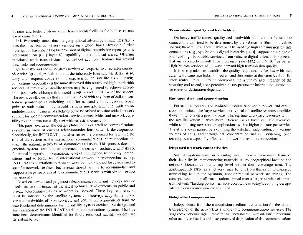
Subnetwork functional architecture
Figures I and 2 are composite functional block diagrams of the satellitesubnetwork and earth stations, respectively. All new functionalities for enhanced
1111111111111111
m
ad
o^
HE FIT
wz
TFMTFT77
IN[ El SA I SYSTEMS ARCH I rECTURES FOR ISDN 9
E
oax
y
Cw

10 COMSAT TECIINICAI. REVIEW VOLUME 23 NUMBER I. SPRING 1991
Figure 2. Satellite Access to Exchange Interfacing via Earth Station TIU
NISDN service support are collected in a functional grouping called the terrestrialinterface unit (TIU). The interfaces to a TIE are as follows:
• Terrestrial trunk interface from the switching center
• Tnternetwork signaling subsystem
• Time-division multiple access (TDMA) capacity manager
• Intranetwork signaling subsystem
• Satellite protocol conversion subsystem.
Operation of the wide-area circuit concentration in the TIE centers on thefact that the terrestrial switches do not make full use of trunk capacity whensupporting N X 64-kbids services. When dedicated satellite trunks arepreallocated to connect terrestrial trunks, valuable satellite capacity may remainunused. Therefore, sharing the satellite channels among the terrestrial trunkswill result in more efficient use of satellite resources. The amount of satellitecapacity saved will depend on the service mix and the service-provisioningtechniques used in the terrestrial network to support these services.
INTELSAT SYSTEMS ARCHITECTURES FOR ISDN 11
A stand-alone PCF is located remotely in the earth station TIIJ functionalgrouping in order to relieve the terrestrial network exchanges of additionalsatellite subnetwork functions.
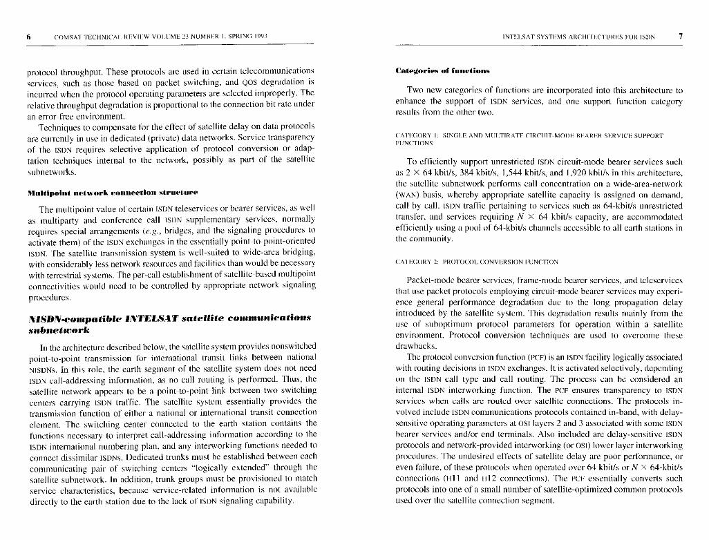
Subnetwork signaling support
The subnetwork architectural design and functional grouping determine thesignaling support functions and interfaces. Overall, subnetwork signaling isdivided into three segments:
Segment 1. External Signaling among terrestrial switching centers ex-ternal to the satellite network.
Segment 2. Internal Signaling among earth stations and the satellitenetwork controller.
Segment 3. Dedicated Internet work Signaling between a terrestrialswitching center and an earth station.
Figure 3 depicts the relationship among the three signaling groups.
SEGMENT l: EXTERNAL SIGNALING
External signaling here refers to ISDN signaling capability ( i.e., ss7). Theterrestrial switching centers use the message transfer part (MTF) protocol(refer to the Appendix , CCITT Rec. Q.701 -Q.704) to exchange ISUE signalingmessages over point-to-point signaling links. For international signaling, thelinks may be provided by the satellite network transparently , or by terrestrialor undersea cables. In either case , the Sup signaling messages and informa-tion are normally not accessible to the earth station.
The IsLP in the ss7 protocol provides the signaling functions required tosupport basic bearer services and supplementary services for voice and non-voice applications in an ISDN. The [sup uses the MTP (and in some cases thesccP) to transfer signaling and control information between network switch-ing and signaling nodes.
The Isup messages are carried in the signaling information field of the MTPsignaling units. A message may consist of the following parts:
• Routing label
• Circuit identification code (CIC)
• Message type code
• Mandatory fixed part
12 COMSATTFCI IN I CAL REVIEW VOLUME 23 NUMBER I. SPRING 1993
cn
z MO ZF Or
Z Uzz
LL0
0N
U ZZ U
Z < FU Z U0 Z Z
cflu-
rn ?
A
0 ZZ U
Z J _O Z U[/1 Z Z
r7'mLL
oZw_-o^
0 UZ
UQtan
INTELSAT SYSTEMS ARCHITECTURES FOR ISDN 13
• Mandatory variable part
• Optional part (which may contain fixed- and variable - length parameterfields).
A set of signaling procedures is defined for the setup and release of nationaland international ISDN connections . The basic call-control procedure is dividedinto three phases: call setup, data /conversation , and call clear-down. When anoriginating switching center has received complete selection information fromthe calling party and has determined that the call is to be routed to anotherswitching center, it selects a suitable, available . interswitching center circuitand sends an initial address message DAM) to the succeeding center. The Etcfield of this ISUP message carries the identifier of the available circuit. Therouting information either is stored locally or can be obtained from a remotedatabase . The setup message also contains bearer capability information, whichis analyzed by the originating switching center to determine the correctconnection type and network signaling capability . This information is thenmapped into the user service information parameter of the IAM.
Information received from the access interface is used to set the transmissionmedium requirement (rMR) parameter , while the bearer information receivedis used to set the initial (node of the connection . The connection types allowedare speech, 3.1-kHz audio , 64-kbitls unrestricted , alternate speech /64-kbit/sunrestricted , and alternate 64-khit/s unrestricted/speech. The IAM conveys thatthe indicated circuit has been seized.
When N X 64 kbit/s ( N> 2) connections are required , the basic proceduresfor single 64 -kbit/s connections are used to control contiguous 64-kbit /s chan-nels between exchanges.
SEGMEN r 2: INTERNAL SIGNALING
The internal (or network) signaling of the satellite network consists ofsignaling functions related to ISDN connection control and satellite networkmanagement. For network management, internal system signaling is used tocoordinate (infrequent) capacity reassignments to traffic terminals, undersupervision of the Network Control Center (NEC). The initiation of suchreassignments depends on the traffic load distribution across the various coln-municating traffic terminals, and can be done either automatically (based onlocal load measurements and some cooperative decision algorithms) or manuallyby the system operator at the NCC.
For ISDN per-call connection control, internal system signaling betweenISDN entities in correspondent traffic terminals is used to coordinate, on a call-by-call basis, the terrestrial-channel-to-satellite-channel assignments (including

14 COMSAT TECHNICAL REV IEW VOLUME 23 NUM HER I, SPRING 1993
time slot groupings) for N X 64-kbit/s connections between pairs of trafficterminals. It is also used for call-by-call coordination of the identification andinvocation of appropriate satellite protocol conversion functions for certaintypes of ISDN communications protocols.
The specifics of the per-call signaling mechanism will depend on theinternal satellite subnetwork system selected. A low-rate TDMA system isconsidered below to illustrate intranetwork signaling issues. This signalingcapability can be achieved by one of two methods. The first employs thesatellite common channel signaling system, in which signaling informationfrom a source TIU to a destination TIU passes through the NCC. The earthstations send this information using inbound (to NCC) orderwire channelsavailable in the signaling/status burst (SB) assigned to that earth station. Thesource earth station sends a (forward) channel assignment inbound orderwiremessage containing the value of N, time slot sequence integrity information,and destination trunk identification information. The NCC relays this messageto the destination earth station after validating and logging it locally forstatistical and monitoring purposes. The destination earth station acknowl-edges the assignment by sending an explicit acknowledgment messagecontaining reverse channel assignment messages (effectively lengthening the
call setup time).Call setup time may be reduced by eliminating the acknowledgment and
letting the source earth station select both the forward and reverse channelsbased on information accumulated in a local database. This introduces a finiteprobability that the destination earth station will assign overlapping forwardor reverse channels to an incoming call. With the use of well-protected bursts,a feed-forward signaling system may be employed which does not requireexplicit acknowledgment of assignment messages. The SBS could use forwarderror correction to introduce sufficient redundancy in signaling information.Use of a feedback signaling system increases call setup time.
A second method for conveying inter-TILT signaling is to use a direct signalingchannel that carries all channel assignment information. In this case, the SBchannel carries signaling information directly between the earth stations. Byproper selection of burst time plans (REPS), SBS can be made receivable by aset of earth stations. As a broadcast burst, the SR can be received by a group ofcorrespondent earth stations, in addition to the network controller, and can heused to carry call setup-related signaling among earth stations, with the NCC asa passive monitor (e.g., gathering call statistics) in the process. This schemeintroduces a single-hop delay in call setup time and offers better delay perfor-mance than the previous scheme, which used the satellite common channel
signaling system.
INTELSAT SYSTEMS ARCHITECTURES POR ISDN 15
SEGMENT 3. DEDICATED INTERNETWORK SIGNALING
To control satellite system functions on a call-by-call basis, the earthstation equipment must have access to a subset of ISDN signaling informationfrom the SS7 network. The switching centers can provide this information byextracting relevant signaling parameters from ISDN messages, as describedlater. The center then uses separate standard and/or proprietary signalingprotocols to communicate this information to the earth station equipment.
To support ISDN services such as speech, 3.1-kHz audio, and especially on-demand 64-kbiUs unrestricted digital information transfer via DCME, dedicatedsignaling is provided using an international standard given in CCITT Rec.Q.50. The switching center uses a Q.50 signaling link to the DCME to transmitcircuit seizure and release messages for on-demand connections, receive ack-nowledgments and circuit status from the DCME, and perform maintenancefunctions. At the earth station, this Q.50 link is terminated within the DCME.Therefore, the signaling procedures used to support these services are trans-parent to the rest of the earth station equipment. The DCME communicateswith remote DCMES at other earth stations via an inter-DCME assignmentsignaling channel.
In the NiSDN satellite subnetwork architecture, a small number of satellitechannels are allocated on demand to a large number of incoming terrestrialchannels, based on system engineering and traffic analysis. It is assumed thatthe service profile of the traffic on each route within the coverage area willprovide sufficient burstiness to make efficient use of satellite resources throughcall concentration. This also means that there may not always be sufficientsatellite capacity available to meet the incoming demand, leading to blockingin the satellite system.
Efficient support of ISDN multirate services (N X 64-kbit/s UDI transfer)can be provided by an arrangement similar to the DCME case described above,using signaling between a switching center and an earth station TILT to indicateservice requests. This signaling can be used to perform multirate call setupand release, perform satellite protocol conversion on links supporting otherdata transfer services, communicate resource availability for these services tothe switching center, and so forth. Since there is currently no CCITT standardfor the exchange of such information, an ad hoc signaling capability similar toQ.50 is identified and referred to here as Q.sat.
Messages
A number of messages are necessary for the Q.sat signaling capability toaccomplish the functions listed above. The first group of messages conveys
16 COMSAT TECHNICA[. RFVIIiW VOLUME 23 NUMBER I. SPRING 1993
channel availability information , and the corresponding acknowledgments,from the TIU to the switching center. This message group contains informationabout the number of 64-kbiUs channels available for unrestricted informationtransfer. An acknowledgment message from the switching center confirmscorrect receipt of the status information . A reliable communications protocolis necessary between the switching center and the TIU to ensure correct trans-mission and reception of this vital information.
The second set of messages consists of the N X 64-kbiUs call setup/
disconnect information flow and corresponding acknowledgments , which result
in the assignment of satellite capacity to a call. These messages are similar tothe call setup/disconnect messages and their acknowledgments specified in
Rec. Q.50.Since this architecture does not support switching capability in the satellite
network, these services are supported over dedicated trunks that arepreconfigured between the switching center and the earth station at networkconfiguration time. The trunks ' fixed correspondence between the switchingcenter and the earth station allows for the unambiguous eic used in the ISUP
message.The Q.sat seizure request message carries the following information:
• Incoming trunk/channel identification (corresponding to the did ofthe IAM).
• Number of incoming channels (corresponding to the TMR of the IAN).
• Lower-layer protocol information for satellite protocol conversion.
The earth station sends the following information to the switching centerover a Q.sat link:
• Accept/reject (blocked) message in response to a circuit seizure mes-sage received from the switching center.
• Acknowledgment of circuit release message status information con-sisting of duplex channel availability within the satellite system betweenthis earth station and its correspondent earth stations (updated
periodically).
• Maintenance-related messages for trunks.
The third set of messages consists of those required for maintenance. They
describe the status (out of service /in service) of individual terrestrial and
space channels , loopback test pass/ fail, link status , error performance on the
space segment, new capacity allocation within the space segment resultingfrom time plan changes, and so forth . These messages may also require
acknowledgment.
INI F SAI SYS1FMS ARCHII FCI ;RCS FOR IS PIN 17
A fourth set of messages is used to administer protocol conversion func-tions within the satellite system.
Q.sat message communicat ions protocols
A message-based protocol can be used to support Q.sat signaling informa-tion transfer. For a message-based protocol at the physical level, a 64-kbit/sdigital channel could control a sizable number of trunks. At the link level, apoint-to-point, error-correcting, high-level data link control (HDLC)-classprotocol will provide the expected performance.
For communication over short distances, better performance can be obtainedwithout error-correcting protocols. Since the signaling messages in questionare independent of each other, a datagram transport service may be appropriate,as opposed to a connection-oriented scheme. An architecture based on anMTP-like protocol provides the features required for such a transport link.
Call processing
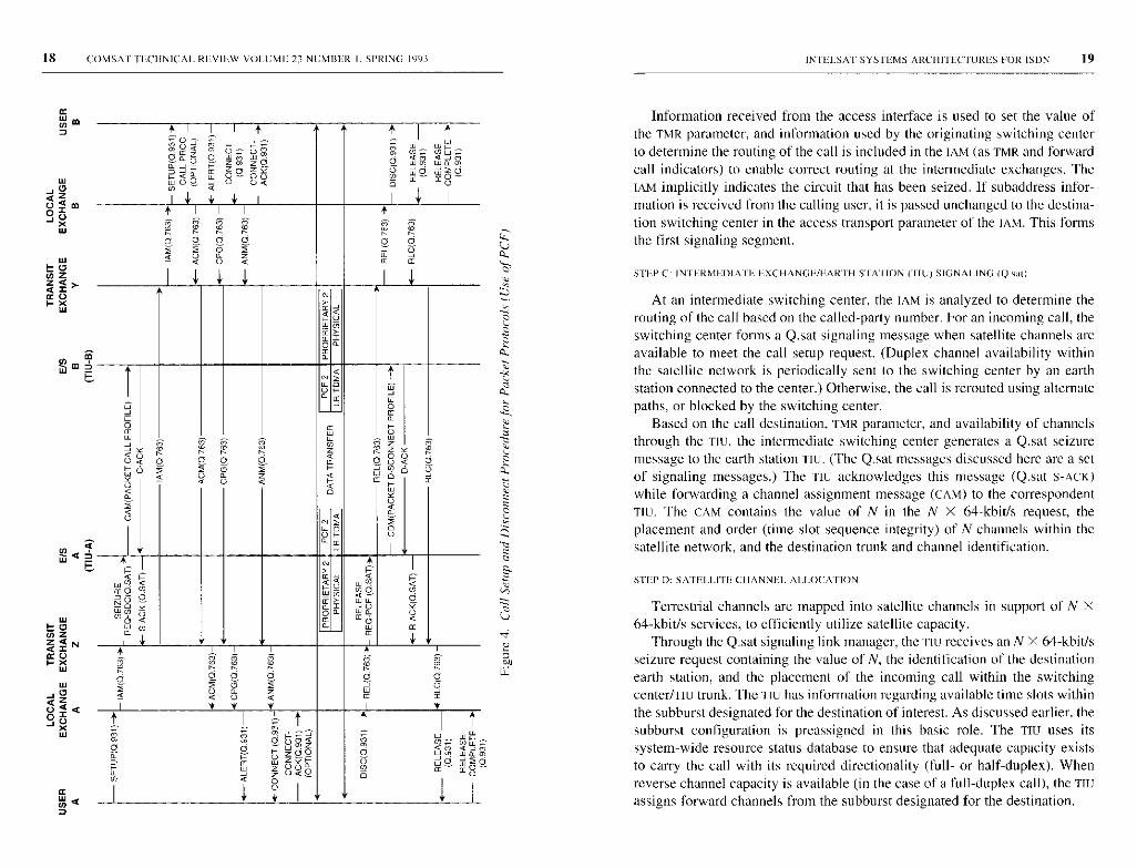
Figure 4 depicts a successful ISDN call setup and disconnect phase tosupport N X 64-kbit/s unrestricted bearer services that use a TIU in a satellitenetwork. The following sequence describes the end -to-end call setup signaling.
STEP A_ USER/LOCAL EXCHANGE SIGNALING IREC. Q.9311
When a user initiates a call, the terminal equipment sends a Q.931 SETUPmessage to the local switching center. This message contains such informationelements as bearer capability (and optionally transit network selection), low-layer capability, called party number. and called party subaddress.
STEP B: LOCAL EXCHANGE/INTERMEDIATE EXCHANGE SIGNALING (REC. Q.763)
When the originating (local) switching center receives complete selection
information from the calling party and determines that the call is to he routed
to another switching center, a suitable and available interexchange circuit is
selected. An IAM is then generated and sent to the succeeding switching
center. Appropriate routing information is available at the originating switching
center, or can be obtained by querying a remote database. Selection of the
route will depend upon the called party number, connection type required, and
signaling capability of the network. The bearer capability information in the
Q.931 SETUP message is analyzed by the originating switching center to
determine the correct connection type and network signaling capability. This
information is then mapped into the user service information parameter of the
IAM SUP message.
18 COMSA I TECHNIC AL REV IE.W VOLUME 23 NUMBER I, SPRING 1993
W'0az0 4 m
O OXW
tooN zz<Na2
XW
<dd a z z w
ww^p m o o m m
0o z u v Jo wpooU
i¢ ¢Q p U
T T
0 0 O 0 d ^O
C Q U Q ¢
aGOw Na >
oa
a
T N ^
a0¢
n W US N m z mU¢ O O O O O Q O
U Q ¢ U ¢ Q
O
¢ ¢
p
CY
aU N c
a0
O H U
R > ^
r U N¢O ^^O O ¢ i
^/+Owu, O
a dN O ¢ U6 ? d o Q
ka
1
a o 0 o a o7 O 7 U
W W W
T ^ T Tm
S3 mo gzoo o
am aw:w a1
OUaN O (w w Z UQO 0 ¢
¢U
INTELSAT SYSTEMS ARCHITECTURES FOR ISDN 19
Information received from the access interface is used to set the value ofthe TMR parameter, and information used by the originating switching centerto determine the routing of the call is included in the TAM (as TMR and forwardcall indicators) to enable correct routing at the intermediate exchanges. TheTAM implicitly indicates the circuit that has been seized. If subaddress infor-mation is received from the calling user, it is passed unchanged to the destina-tion switching center in the access transport parameter of the IAM. This formsthe first signaling segment.
STEP C: INI E:RMHOIA I E E:XCHANGH/HARIH STATION (r1U) SIGNALING ((2oa0
At an intermediate switching center, the IAM is analyzed to determine therouting of the call based on the called-party number. For an incoming call, theswitching center forms a Q.sat signaling message when satellite channels areavailable to meet the call setup request. (Duplex channel availability withinthe satellite network is periodically sent to the switching center by an earthstation connected to the center.) Otherwise, the call is rerouted using alternatepaths, or blocked by the switching center.
Based on the call destination, TMR parameter, and availability of channelsthrough the TIU, the intermediate switching center generates a Q.sat seizuremessage to the earth station TIU. (The Q .sat messages discussed here are a setof signaling messages.) The TIU acknowledges this message (Q.sat S-ACK)while forwarding a channel assignment message (CAM) to the correspondentTill. The CAM contains the value of N in the N X 64-kbids request, theplacement and order (time slot sequence integrity) of N channels within thesatellite network. and the destination trunk and channel identification.
STEP D: SATELLITE CHANNEL ALLOCATION
Terrestrial channels are mapped into satellite channels in support of N X64-kbit/s services, to efficiently utilize satellite capacity.
Through the Q.sat signaling link manager, the TIC receives an N X 64-kbiUsseizure request containing the value of N, the identification of the destinationearth station, and the placement of the incoming call within the switchingcenter/TIU trunk. The TIU has information regarding available time slots withinthe subburst designated for the destination of interest. As discussed earlier, thesubburst configuration is preassigned in this basic role. The Ttu uses itssystem-wide resource status database to ensure that adequate capacity existsto carry the call with its required directionality (full- or half-duplex). Whenreverse channel capacity is available (in the case of a full-duplex call), the TICassigns forward channels from the subburst designated for the destination.
20 COMSAT lHCI INICAI. RF:VIF:w VOLUME 23 NUMBER I, SPRING 1993
The TILE must inform the destination TIE of this (forward) channel assign-ment, using a signaling method explained below. Based on this signalinginformation, the destination TIU maps satellite channels back to the originalterrestrial channel format and thus completes the call through the satellitesystem. The call may be blocked at the destination TIU due to lack of satellitecapacity for the reverse channels, or due to glare conditions (simultaneousseizure of identical time slots). Further, the switching center may have toovercome its own glare conditions for the call. These issues will he discussedlater.
When the call is disconnected, the switching centers inform the respectiveTIUS of call-disconnect status, and the TIUS return the satellite channels relatedto the call back to the subbursts for reassignment to the next call. Periodically,the Tics report the number of 64-kbitls channels available to their respectiveswitching centers in the form of a status message. The switching centers usethis information during connection establishment. For example, the switchingcenters may not offer a call to the T[U if sufficient capacity is not available forthat call.
The Tlus may occasionally find that their need for channels does not matchthe actual call arrival rate. Based on cumulative averages and call statistics, aTIU may require more or less of the available capacity. As explained previ-ously, in this basic role a TIC has two means available to alter the inter-TIEcapacity: It may reassign subbursts in coordination with all affected earthstations, or it may request additional capacity from the network controller.The decision to change the capacity requirement is based on call-blockingstatistics and QOS requirements information collected at the earth station, andtherefore occurs infrequently. Reconfiguration of subbursts within a burst, orthe use of channels from a global pool in coordination with the NCC, requiresBTP changes that affect only a limited set of earth stations.
STEP E INTERMEDIATE EXCHANGE SIGNALING (Q.763)
When the source switching center receives an S-ACK Q.sat message fromthe connected earth station, it forwards an [AM to the next switching center towhich the destination earth station is connected. In order to carry [SUP messages,the switching centers use the ss7 network, which may bypass the satellitenetwork. The C IC used in this message informs the switching center connectedto the destination earth station of the trunk and channels selected for the call.Based on this information, the destination switching center performs outboundseizure to switch the channels and forwards an LAM to the next switchingcenter in the path. The signaling and communications paths are eventually set
INTELSAT SYST EMS ARCHITECTURES FOR ISDN 21
up to the remote local switching center, to which the destination user isconnected, and the call setup process is completed.
STEP F. LOCAL EXCHA NGIUDGSTINA IION USER SIGNALING (Q 931)
Upon receipt of the IAN, the destination switching center analyzes thecalled-party number to determine the destination user. It also checks the calledparty's line condition and performs a number of other checks to verify that theconnection is allowable. These checks include compatibility checks and checksassociated with supplementary services. The local exchange then generates aQ.93 I SETUP message to the destination user. The remainder of the messageflow associated with completing call setup is shown in Figure 4. When thecalling user receives a Q.931 CONNECT message, an end-to-end call is set upand a communications path is established for information transfer.
The call can be disconnected by either party sending a Q.931 DISCONNECT
message to the local switching center. The protocol for disconnecting a call is
symmetric, and the same procedures are used in the network irrespective of
whether they are initiated by the calling party, the called party, or the network.
Upon receipt of a DISCONNECT message from the calling party, the originating
switching center immediately initiates release of the switched path by sending
a RELEASE ISUP message.
When it receives a RELEASE message, the intermediate switching center
sends a QSAT RELEASE message to the earth station TIE and forwards a
RELEASE ISUP message to the next switching center to which the destination
earth station is connected. The TIU sends a channel disconnect message to the
correspondent TIU and waits for an acknowledgment. It then acknowledges
the release hack to the switching center by sending a D-ACK (Q.sat) message.
From the destination switching center, the [SUP RELEASE message reachesthe destination local exchange, where it is mapped into a Q.931 DISCONNECTmessage and forwarded to the destination user. The remainder of the messageflow, resulting in complete release, is shown in Figure 4.
HISDN-compatible INTELSAT satellite communicationssubnetworks
An evolutionary series of architectures can be considered for the integrationof HISDN into the INTELSAT system. A set of four architectures, of increasingcomplexity, is described briefly below, and the major elements of the first twoarchitectures are then discussed in more detail in the subsections that follow.
The first architecture supports BISON services through the transmission ofSDH carriers. SDH defines a worldwide digital hierarchy and network node
24 COMSAT TECIINICAI. REVIEW VOI11ME 23 NUMBER 1. SPRING 1993
TRANSMISSION HIT RATES IN RELATION TO SATELLITE Rot, IF, SIZES
The lowest SDH level is at 155.52 Mbit/s; however, CCITT has adopted asub-STM-I bit rate of 51.84 Mbit/s specifically for radio digital sections (Rec.G.707 and G.708 Annex A). The sub-STM-I rate is not a standardized SDHmultiplex level or an NNI. With the sub-STM-1 frame format derived from theG.708 srM-1 structure, a number of the original SDH overhead functions havebeen retained for shared/common use with radio systems in a mixed-media
SDH network environment.Because transmission system resources (power. bandwidth, and orbital
locations) are limited, efficient satellite network planning and dimensioningare crucial. That is, the transmission bandwidth and bit rate on each linkshould preferably be matched to the expected level of actual traffic beingcarried on the route. On major intercontinental thick routes, both 155.52- and51.84-MhiUs transmission is expected. On medium routes, 51.84 Mbit/s maysuffice. Initial studies are currently under way to define satellite SDH links ateven lower bit rates (e.g., 2.4 and 7.0 Mbit/s).
For transport within the INTELSAT SDII subnetwork at the sub-STM-1 rateof 51.84 Mbit/s, the STM- I signal delivered across the terrestrial NNI must firstbe converted. If the STM-l signal is suitably composed of three sub-STM-Isignals, it can easily be demultiplexed and its component sub-STM-I signalstransported separately. However, if the STM-1 signal delivered across the NNIcontains a high-bit-rate payload (e.g., 139-Mbit/s high-definition televisionIHDTVI), then demultiplexing the signal will be prohibitively expensive. Workon the 155-Mbit/s modem is actively under way and anticipates the need for
STM-I signal transmission.
ML I rI POI NT TOPOLOGY
To accommodate satellite traffic routes that are much thinner than the sub-srM-I bit rate, while retaining some of the standard SDH functionalities, furtherefficiencies could be attained by allowing multidestination/multipointnetworking at the sub-STM-1 level and virtual container 3 (vc-3) path layer(e.g., to support 34/45-Mbit/s digital video distribution). vc-3 multipointnetworking would also allow distribution of individual vc-2 (6,312-kbiUs)
point-to-point path connections.As presently defined by the CCITT, all SDH section and path overhead
functions, bit/byte allocation, and protocols are for point-to-point operationbetween pairs of functionally equivalent terminating points (i.e., multiplexer
section or path terminations). Three categories of backward-maintenance andalarm signals are defined in the SDH (Rec. G.708 and G.782):
INTELSAT SYSTEMS ARCHrrECT ORES FOR ISDN 25
• Multiplex section far-end receive failure (MS-FERE)
• VC-3 far-end block error (FEBE ) and path FERE
• vc- I /vc-2 FEBE and path SERE.
To extend standardized SDH-based maintenance and alarm signaling (part ofo&M) to operate in a multipoint mode, an addressing capability associatedwith the first two backward indications to multiple correspondents (origins ofthe failed signals ) is necessary.
SDH/PUH IN I ERWORKING AT THE INTERNATIONAL NETWORK ITVra.
The INTELSAT interconnect network may be required to provide inter-working functions between dissimilar national networks, as necessary, toaccommodate different implementation plans, technical upgrades, and en-hancements in those networks. This will be the case between some countriesrapidly converting to SDH technology, and others which continue to use PDH intheir digital networks. The flexibility of SOB multiplexing methods, and theuse of associated standard multiplexing equipment at the satellite earth sta-tion, provides an elegant means of achieving SDH/PDH interworking at theinternational network level.
CABLE RESTORAI [ON
Cable restoration by satellites could technically be offered with shorterservice interruptions if realized with an SDII-based multimedia automaticprotection arrangement. Such service must be justified economically,considering its use of satellite resources. The SDH concepts include automaticprotection switching facilities for network-level protection over entire SDHmultiplex sections, and the use of bit-oriented protocols over multiplex sec-tion overhead (MSOH) bytes KI and K2 (Rec. G. 783). Fixed Satellite Service(FSS)-SDII subnetworks which function only as an SDH regenerator section (ateither STM- I or sub-STM-I rate) provide transparency to MSOH, and thus to theKl/K2 bytes. Such FSS-SOU subnetworks can thus be part of multimedia(cable-over-satellite) and mixed-media, point-to-point multiplex section pro-tection arrangements, as described in Rec. G.783, Annex A.
NETWORK MANAGEMENT
SDH has an extensive set of features for network management. These in-clude operations, administration, maintenance, and provisioning for SDH mul-tiplex systems; message transport facilities for SDH management subnetworks;and network management communications in the broader telecommunications
26 COMSAT TECHNICAL REV I HW VOLUME 23 NUMBER I,SPRING 1993
management network (TMN) sense (CCITT Rec. M.30 ). With regard to mes-sage transport, SDH data communications channel DCCR (bytes Dl-D3 in theregenerator section overhead [RSOIQ ) is used to manage SDH network ele-ments within a management subnetwork , whereas SDH DCCM (bytes D4-D12in the MSOH ) is used for a wide-area , general - purpose communications chan-nel to support TMN, including non-SDH applications . All communications overthese DCCS use the embedded communications protocol stack defined in Rec.G.784. Common use of these standard management concepts , principles, andprotocols by all systems and subnetworks-including satellite systems such asFSS-SDH subnetworks , and satellite communications multiple-access systemssuch as TDMA-would facilitate the implementation of integrated networkmanagement systems. while providing cost savings through the use of com-mon equipment.
The following aspects of network management are important from a satellitesystems perspective:
Commonalty With Terrestrial SDH System. To realize a cost-effective design,the satellite SDH subnetwork should have maximum equipment and man-agement commonalty with the terrestrial SDH system . Nonstandard and/orsatellite-specific functions should he implemented in a manner which does notaffect system transparency to external SDH functions . Such functions shouldbe implemented in a separate satellite transmission frame complementaryoverhead (SFCOH).
VC Path Setup and Validation . SDH network management requires thecapability to automatically set up and validate VC paths across operatorboundaries . The INTELSAT system can be designed to support this capability,considering aspects such as bandwidth management schemes within the satellitesubnetwork , path setup protocols , and the allocation of access point identifiersin the subnetwork.
In-Service Path Monitoring . Continuous in-service monitoring of paths isrecommended to verify compliance with service commitments . Wheneverpossible, the satellite subnetwork should perform standard SDH path monitoringfunctions , supported by the path overhead , using bit-interleaved parity-N
techniques.
Automatic ProtectioniRestoration . CCITT Rec. (G.831 ) calls for automaticprotection /restoration of failed vc paths, to maintain them at a prescribedlevel of availability . Section-level protection switching in a In arrangementwithin the satellite system is not justified due to nondispersive satellite fadingphenomena across the satellite operational band, as well as limited satelliteresources.
INTEISAT SYSTEMS ARCI IITECTURFS FOR ISDN 27
Remote Maintenance and Supervision. SDH network management shouldbecome part of a central network management system based on TMN concepts.The philosophy of centralized network management resembles that of theexisting INTELSAT system, which is monitored, controlled, and coordinatedby the INTELSAT Operations Center.
ERROR PERFORMANCE MONITORING FACILITIES IN son OVERHEAD
The SDH concepts provide a variety of performance monitoring facilities(Rec. 708). From the lowest network layer up, performance monitoring usesthe bit interleave parity 8 (BIP-8) code in the SDH RSOH byte BI; HIP-24 codein the SDH MSOH bytes B2 (3x); path BIP-8 code in the VC-3/4 path overheadbyte B3; and mP-2 code in the VC-1/2 path overhead byte. The ability of thesatellite FSS-SDH subnetworks to access one or more of these SDH errorperformance monitoring features depends on the subnetwork architecture, andon the resulting accessibility of the various transport network layers.
Figure 5 gives an overview of the subnetwork to he used in an SDH transportnetwork environment. This subnetwork will be used to provide internationalinterconnections between standard SDH transmission equipment at a selectnumber of public international gateway exchanges (ISCS). Along with the SDHdigital transmission technology now being implemented in national networksas the first step toward broadband digital networks, this subnetwork is aprecursor to the introduction of BISDN. The terrestrial interfaces at thesubnetwork access are in accordance with the NNi standards for SDH definedby the CCITT in Rec. G.707, G.708, and G.709.
The interconnected national SDH transport networks (e.g., internationalgateways) will conceivably deliver three basic types of traffic payload to thesubnetwork: ATM (BISDN): multiplexed 64-kbiUs circuits used for NISDN64-knit/s-type circuit-mode-oriented traffic such as 64-kbiUs NISDN and low-and medium-speed data over private network leased circuit groups; and general"new" traffic, such as HDTV and high-speed data over private network leasedcircuit groups, all encapsulated within standard SDH vcs. All traffic will bereceived across the NNI within the standard SDII STM-N multiplex format.
The subnetwork provides standardized connectivities to SDH vc pathsbetween national SDH digital transport networks from/to the internationalgateways. These paths are established on a semipermanent basis by mutualagreement between administrations. SDH international paths can be added,deleted, reconfigured, rerouted, cross-connected, or through-connected at thesubnetwork earth station SDH multiplex equipment to meet service demandsand operational requirements. Remote configuration control is facilitated bythe enhanced network management features of the SDH. The traffic hand-ling capacity of the subnetwork is determined by its total SDH path capacity,

28 COMSAT TECHNICAL REVIEW VOLUME 13 NUMBER I, SPRING 1993
OQ O N
out
n wz iow zs -¢- ^w mJ wj OozF y o F oz
0a ^0 zm0,J O d mQ oO
zs<
z OO¢p 100 NH
m
Z ym az
Z mwozp H^ moU •
F
NJ
U
-Jzavo,
II
0m
X
JQzO
z °m
N 0m
z x ^x0 ^U JU
K
IN TEI.SAr SYSTEMS ARCHITE'CTURE'S POR ISIN 29
which is equal to the maximum incoming and outgoing traffic flow (with nocompression).
Digital transport of the SOH vcs within the subnetwork can be in standard5OH STM-I or sub-STM-I frame format, or can be based on other non-SOHformats (e.g., within Pon network connections), or a combination of both.Non-SOH transport within the subnetwork is envisaged for SDH/PDH networkinterconnection and interworking, as well as for thin routes for which the51.84-Mbit/s sub-STM-I rate is not justifiable. System-specific operationalfunctions within the subnetwork may require separate transmission over adedicated SFcoti.
Through standard access to SOH management subnetworks. the subnetworkis amenable to the TMN concepts leading to an integrated network managementsystem, which includes the satellite subnetwork comprising managed networkelements.
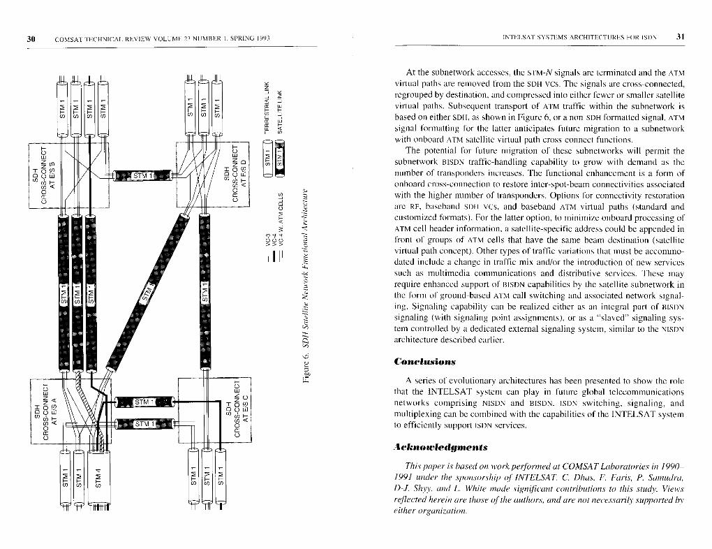
Earth station a irtual path cross-conned
Figure 6 illustrates the subnetwork support for an ATM within an SDHtransport network environment. This subnetwork has the added ability tohandle BISDN ATM traffic, providing international interconnections between aselect number of HISDN international ATM gateway exchanges and ATM trans-mission network elements (cross-connects). It can also be used to interconnectmetropolitan area networks.
The interconnected national HISONS deliver ATM-type traffic to the subnet-
work encapsulated within standard SoH vcs (vc-3 and VC-4). The subnetwork
provides standardized connectivities to ATM virtual paths between national
ATM networks from, to, or through their international ATM gateways. These
paths are established on a semipermanent basis by mutual agreement between
administrations. ATM international virtual paths can be added, deleted, recon-
figured, rerouted, cross-connected, or through-connected at the subnetwork to
meet AIM service demands and operational requirements. Resource efficiency
is achieved by taking advantage of the wide statistical variation in ATM traffic
flow to concentrate ATM traffic within the earth station ATM path. Capacity
gain is achieved by removing unassigned cells.
ATM congestion control indications are provided by the subnetwork as anelement of overall ATM network connection admission control. This isaccomplished by means of a real-time indication of ATM traffic load to theinterconnected exchanges. Under heavy load conditions, when the compressedATM virtual paths within the subnetwork cannot accommodate new calls attheir negotiated QOS, new connections are rerouted or blocked by the ATMgateways to maintain the QoS of existing connections.
INIEJ SAT SYSTEMS ARCHITECTURES FOR ISBN 3130 COMSAT I ECHNICAI. REVIEW VOLUME 23 NUMBER I. SPRING 1993
At the subnetwork accesses, the S'UM-N signals are terminated and the ATMvirtual paths are removed from the SOH yes. The signals are cross-connected,regrouped by destination, and compressed into either fewer or smaller satellitevirtual paths. Subsequent transport of ATM traffic within the subnetwork isbased on either SOH, as shown in Figure 6, or a non-SDH formatted signal. ATMsignal formatting for the latter anticipates future migration to a subnetworkwith onboard ATM satellite virtual path cross-connect functions.
The potential for future migration of these subnetworks will permit thesubnetwork BISDN traffic-handling capability to grow with demand as thenumber of transponders increases. The functional enhancement is a form ofonboard cross-connection to restore inter-spot-beam connectivities associatedwith the higher number of transponders. Options for connectivity restorationare RF, baseband Sole vcs, and baseband ATM virtual paths (standard andcustomized formats). For the latter option, to minimize onboard processing ofATM cell header information, a satellite-specific address could be appended infront of groups of ATM cells that have the same beam destination (satellitevirtual path concept). Other types of traffic variations that must be accommo-dated include a change in traffic mix and/or the introduction of new servicessuch as multimedia communications and distributive services. These mayrequire enhanced support of BISDN capabilities by the satellite subnetwork inthe form of ground-based ATM call switching and associated network signal-ing. Signaling capability can be realized either as an integral part of BISONsignaling (with signaling point assignments), or as a "slaved" signaling sys-tem controlled by a dedicated external signaling system, similar to the NISONarchitecture described earlier.
Conclusions
A series of evolutionary architectures has been presented to show the rolethat the INTELSAT system can play in future global telecommunicationsnetworks comprising NISDN and BISON. ISBN switching, signaling, andmultiplexing can he combined with the capabilities of the INTELSAT systemto efficiently support ISBN services.
Acknuowledginents
This paper is based on work performed at COMSAT Laboratories in 1990-1991 under the sponsorship of INTELSAT C. Dhas, F. Faris, P. Samudra,
D4. Shy,, and L. White made significant contributions to this study. Views
reflected herein are those of the authors, and are not necessarily supported by
either organization.
32 COMSAT1NCHNICAL REVIEW VOLUME 23 NUMBER I, SPRING 1991
Appendix
The ISDN Recommendations referred to in this paper can be found in the
following volumes of the CCITT Blue Books (ITU, Geneva, 1988), or as draft
recommendations from the CCITT Study Group XVIII meeting in Matsuyama,Japan, November 26-December 7, 1990.
Volume III
FASCICLE 111.5, "Digital Networks. Digital Sections, and Digital Line Systems," Rec.
G.801-G956 (Study Groups XV and XVIII).FASCICLE 111.7, "Integrated Services Digital Network (ISDN): General Structure and
Service Capabilities." Rec. I.110-1.257 (Study Group X V I II).FASCICLE 111.8, "Integrated Services Digital Network (ISDN): Overall Network
Aspects and Functions. ISDN User-Network Interfaces." Rec. 1.310-1.470 (Study
Group XVIII).FASCICLE 111.9. "Integrated Services Digital Network (ISDN): Internetwork Inter-
faces and Maintenance Principles." Rec. 1.500-1.600 (Study Group XVIII).
Volume VI
FASCICLE V1.7. "Specifications of Signaling System No . 7," Rec. Q.700-Q.716.
(Study Group XI).FASCICLE VI.8. "Specifications of Signaling System No . 7," Rec. Q.721-Q.766
(Study Group XI).FASCICLE V1.9, "Specifications of Signaling Systems No . 7," Rec. Q.771-Q.795
(Study Group XI).FASCICLE V I. 10, "Digital Access Signaling System , Data Link Layer ," Rec. Q920-
Q.921 (Study Group XI).FASCICLE V I I I , "Digital Access Signaling Systems , Network Layer, User-Network
Management" Rec. Q.930-Q.940 ( Study Group XI).
INTELSA'I' SYSTEMS ARCHITECTURES FOR ISDN 33
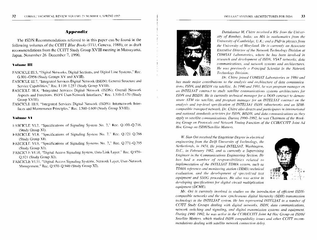
Dattakumar M. Chitre received a BSc from the Univer-
sity of Bornhav. India; an MA in mathematics from the
University of Cambridge, U. K.^ and a PhD in physics fiom
the University of Mannland. He is currently an Associate
Executive Director of the Network Technology Division at
COMSAT Laboratories, where he has been invoked in
research and development of ISDN, VSAT networks, data
communicaions, laid netnm'k systems and architectures.
lie was previously a Principal Scientist in the Network
Technology Division.
Dr. Chitre joined COMSAT Laboratories in 1980 andhas made major contribution,' to the anahsis and architecture of data connanica-
tion.s, ISDN, and BISON via satellite. In 1990 and 1991, lie was program manager on
an INTELSAT contract to stuck satellite coomumii'ations s.v.stems architectures for
ISDN and BISDN. He is currently technical manager for it DOD contract to demon-
strate ATM via satellite, and program manager for an INTELSAI' contract an the
analysis and top-level specification of INTELSAT ISDN subnetworks and an SDH-
compatible transport netvo k. Dr. Chitre also directs and participates in intenational
and national standards activities for ISDN, BISON, and data communications as they
apply to .satellite comnaucations. During 1990-1992, lie was Chairman of the Work-
ing Group on Protocols and Network Timing Traction of the CCIR/CCITT Joint Ad
Hoc Group on ISDN/Satellite Matters.
Mr. Oei is currently involved in studies oil the introduction of efficient ISDN-
compatible networks and the new .synchronous digital hierarchy (SDH) transmissiontechnology in the INTELSAT system. He has represented INTELSAT in a number ofCCITT Stuck Groups dealing with digital networks, ISDN, data communicadmns,network switching and signaling, and digital transmission systems and equipment.During 1990-1992, lie was active in the CCIR/CCITT Joint Ad Hoc Group on ISDN/
Satellite Matters, which studied ISDN compatibility issues and other CCITT recom-mendations dealing with satellite network connection delay.
W. Sian Oei received the Engenieur Degree in electrical
engineering from the Delft University of Technology, the
Netherlands, in 1974. He joined INTELSAT, Washington,
D.C., in Eehruary 1982, and is currently a Supervising
Engineer in the Communications Engineering Se(tion. He
has had a number of respa nsibit ities related to
implementation of the INTELSAT TDMA system, such as
TDMA reference and monitoring station (1'RMS) technical
evaluation, and the development of specialized test
equipment and SSOG procedures. He also was active in
developing specifications for digital circuit multiplicationequipment (DCME).
Index: attitude control, simulation,communication satellites, models
Design and validation of the ITALSATAOCS flight simulator
A. RAMOS, R. L. MINCIOTTI, T. HAMPSCH. G. ALLISON,
E. W. HARE, AND J. W. OPIEKIJN
(Mmwscript received April 16, 1992)
Abstract
A real-time, hardware-itl-the-loop simulator of the ITALSAT satellite attitude and
orbit control subsystem (AOCS) was developed for the Italian Space Agency. Thesimulator is called the ITALSAT AOCS Flight Simulator (IAFSIM). The applications,design, and validation of IAFSIM are described, and examples of validation tests aregiven which cover AOCS modes of operation during the various ITALSAT missionphases. Possible future applications of IAFSIM are also discussed.
Introduction
Spacecraft flight simulators provide a means for training personnel andinvestigating flight anomalies. Some features of these simulators areindependent of the spacecraft system, while others are unique to a particularsystem. The operation of a simulator can best be described by focusing on onespecific version and generalizing to others.
Recently, a real-time, hardware-in-the-loop simulator was developedfor the attitude and orbit control subsystem (AOCS) of the ITALSAT space-craft. This simulator (Figure I). called the ITALSAT AOCS Flight Simulator(IAFSIM), was developed as part of the ITALSAT program of the Italian SpaceAgency (ASI), and has been in operation at the IIALSAT Operations ControlCenter (loco) in Fucino, Italy, since April 1990. The ITALSAT program isbased on an advanced three-axis-stabilized spacecraft with two 20/30-GHztelecommunications payloads. These payloads include two multibeam
35
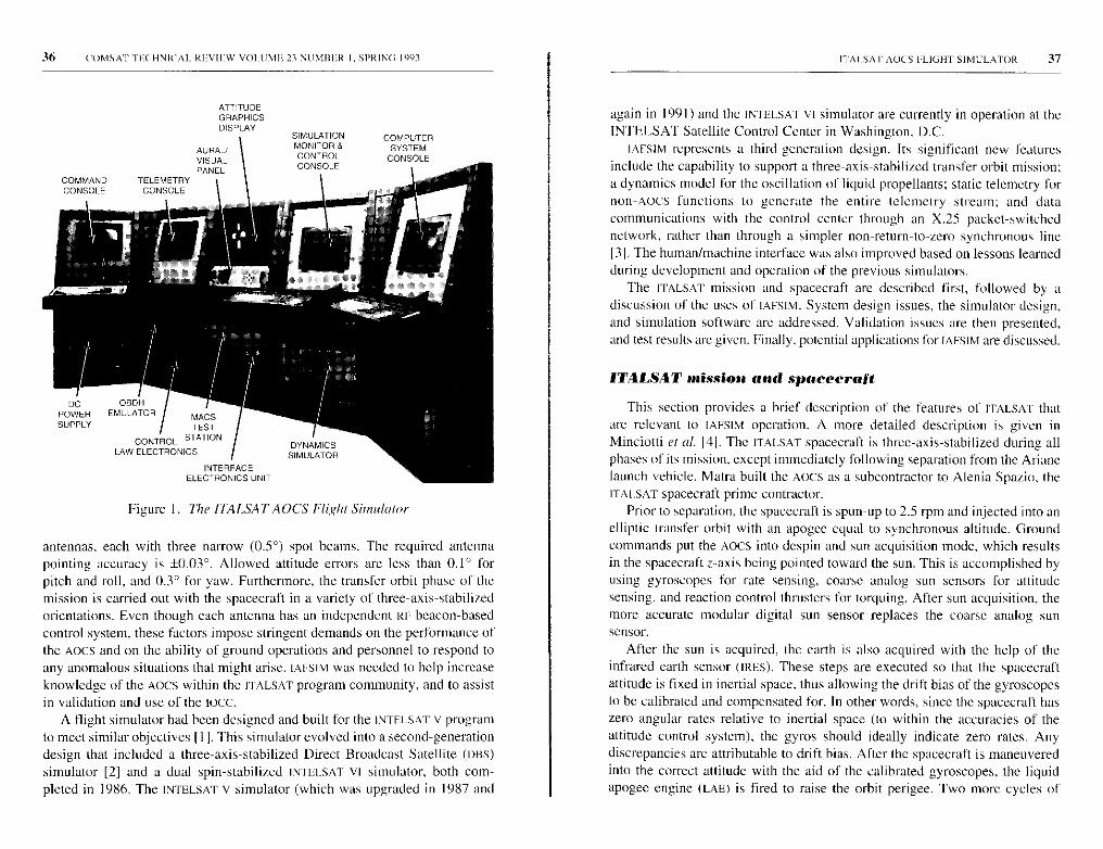
36 ('OMSA I''] F(HNICAL RFVIEW VOLUM1; 23 NtI MItLR I. SPRING 1993
ATTITUDEGRAPHICSDISPLAY
AURAL/VISUALPANEL
COMMAND TELEMETRYCONSOLE CONSOLE
MACS
TEST
STATIONCONTROLLAW ELECTRONICS
INTERFACEELECTRONICS UNIT
Figure 1. The l1ALSATAOCS Flight Simulator
antennas, each with three narrow (0.5°) spot beams. The required antennapointing accuracy is ±0.03°. Allowed attitude errors are less than 0.1° forpitch and roll, and 0.3° for yaw. Furthermore, the transfer orbit phase of themission is carried out with the spacecraft in a variety of three-axis-stabilizedorientations. Even though each antenna has an independent RF beacon-basedcontrol system, these factors impose stringent demands on the performance ofthe AOCS and on the ability of ground operations and personnel to respond toany anomalous situations that might arise. IAFSIM was needed to help increaseknowledge of the AOCS within the I IALSAT program community, and to assistin validation and use of the tocc.
A flight simulator had been designed and built for the INTELSAT V programto meet similar objectives [I ]. This simulator evolved into a second-generationdesign that included a three-axis-stabilized Direct Broadcast Satellite (DHS)simulator [2] and a dual spin-stabilized INTELSAT VI simulator, both com-pleted in 1986. The INTELSAT V simulator (which was upgraded in 1987 and
ITAISAT AOCS FLIGHT SIMULATOR 37
again in 1991) and the INTELSAT VI simulator are currently in operation at theINTELSAT Satellite Control Center in Washington, D.C.
IAFSIM represents a third -generation design. Its significant new featuresinclude the capability to support a three-axis-stabilized transfer orbit mission;a dynamics model for the oscillation of liquid propellants; static telemetry fornon-AOCS functions to generate the entire telemetry stream; and datacommunications with the control center through an X.25 packet- switchednetwork, rather than through a simpler non -return-to-zero synchronous line131. The human /machine interface was also improved based on lessons learnedduring development and operation of the previous simulators.
The ITALSAT mission and spacecraft are described first, followed by adiscussion of the uses of IAFSIM. System design issues , the simulator design,and simulation software are addressed . Validation issues are then presented,and test results are given. Finally, potential applications for IAFSIM are discussed.
ITALSAT mission and spacecraft
This section provides a brief description of the features of ITAESAT thatare relevant to IAFSIM Operation. A more detailed description is given inMinciotti et al. 141. The ITALSAT spacecraft is three-axis-stabilized during allphases of its mission, except immediately following separation from the Arianelaunch vehicle. Matra built the AOCS as a subcontractor to Alenia Spazio, theITAESAT spacecraft prime contractor.
Prior to separation, the spacecraft is spun-up to 2.5 rpm and injected into anelliptic transfer orbit with an apogee equal to synchronous altitude. Groundcommands put the AOCS into despin and sun acquisition mode, which resultsin the spacecraft z-axis being pointed toward the sun. This is accomplished byusing gyroscopes for rate sensing, coarse analog sun sensors for attitudesensing, and reaction control thrusters for torquing. After sun acquisition, themore accurate modular digital sun sensor replaces the coarse analog sunsensor.
After the sun is acquired, the earth is also acquired with the help of theinfrared earth sensor (IRES). These steps are executed so that the spacecraftattitude is fixed in inertial space, thus allowing the drift bias of the gyroscopesto be calibrated and compensated for. In other words, since the spacecraft haszero angular rates relative to inertial space (to within the accuracies of theattitude control system), the gyros should ideally indicate zero rates. Anydiscrepancies are attributable to drift bias. After the spacecraft is maneuveredinto the correct attitude with the aid of the calibrated gyroscopes. the liquidapogee engine (LAE) is fired to raise the orbit perigee. Two more cycles of
Sit' COM,SAIPECHNICAL REVIEW VOLUME 23 NU MER I, SPRING 1993
earth acquisition/gyro calibration/LAE maneuver/LAE firing (LAEF) are exe-
cuted to place the spacecraft into synchronous orbit.After another earth acquisition, the AOCS is commanded into the normal
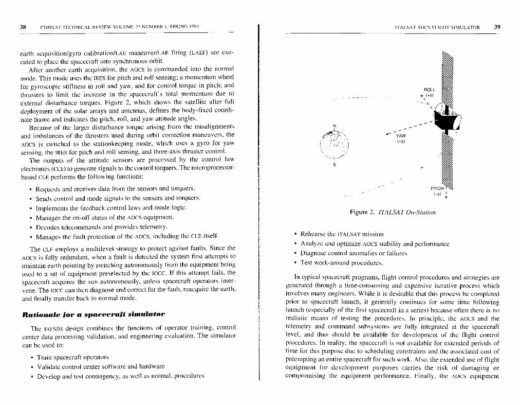
mode. This mode uses the WRES for pitch and roll sensing; a momentum wheelfor gyroscopic stiffness in roll and yaw, and for control torque in pitch; andthrusters to limit the increase in the spacecraft's total momentum due toexternal disturbance torques. Figure 2, which shows the satellite after fulldeployment of the solar arrays and antennas, defines the body-fixed coordi-nate frame and indicates the pitch, roll, and yaw attitude angles.
Because of the larger disturbance torque arising from the misalignmentsand imbalances of the thrusters used during orbit correction maneuvers, theAocs is switched to the stationkeeping mode, which uses a gyro for yawsensing, the IRES for pitch and roll sensing, and three-axis thruster control.
The outputs of the attitude sensors are processed by the control lawelectronics (CLE) to generate signals to the control torquers. The microprocessor-based CLE performs the following functions:
• Requests and receives data from the sensors and torquers.
• Sends control and mode signals to the sensors and torquers.
• Implements the feedback control laws and mode logic.
• Manages the on-off status of the AOCS equipment.
• Decodes telecommands and provides telemetry.
• Manages the fault protection of the Aocs, including the CLE itself.
The CLE. employs a multilevel strategy to protect against faults. Since theAOCS is fully redundant, when a fault is detected the system first attempts tomaintain earth pointing by switching autonomously from the equipment beingused to a set of equipment preselected by the Ioce. If this attempt fails, thespacecraft acquires the sun autonomously, unless spacecraft operators inter-vene. The 1000 can then diagnose and correct for the fault, reacquire the earth,
and finally transfer back to normal mode.
Rationale for a spacecraft simulator
The IAESIM design combines the functions of operator training, controlcenter data processing validation, and engineering evaluation. The simulator
can be used to:
• Train spacecraft operators
• Validate control center software and hardware
• Develop and test contingency, as well as normal, procedures
ITALSAT AOCS FI.IGHt SIMULATOR 39
Figure 2. IIALSAT On-Station
• Rehearse the ITALSAT mission
• Analyze and optimize AOCS stability and performance
• Diagnose control anomalies or failures
• Test work-around procedures.
In typical spacecraft programs, flight control procedures and strategies aregenerated through a time-consuming and expensive iterative process whichinvolves many engineers. While it is desirable that this process be completedprior to spacecraft launch, it generally continues for some time followinglaunch (especially of the first spacecraft in a series) because often there is norealistic means of testing the procedures. In principle, the AOCS and thetelemetry and command subsystems are fully integrated at the spacecraftlevel, and thus should be available for development of the flight controlprocedures. In reality, the spacecraft is not available for extended periods oftime for this purpose due to scheduling constraints and the associated cost ofpreempting an entire spacecraft for such work. Also, the extended use of flightequipment for development purposes carries the risk of damaging orcompromising the equipment performance. Finally, the Aocs equipment
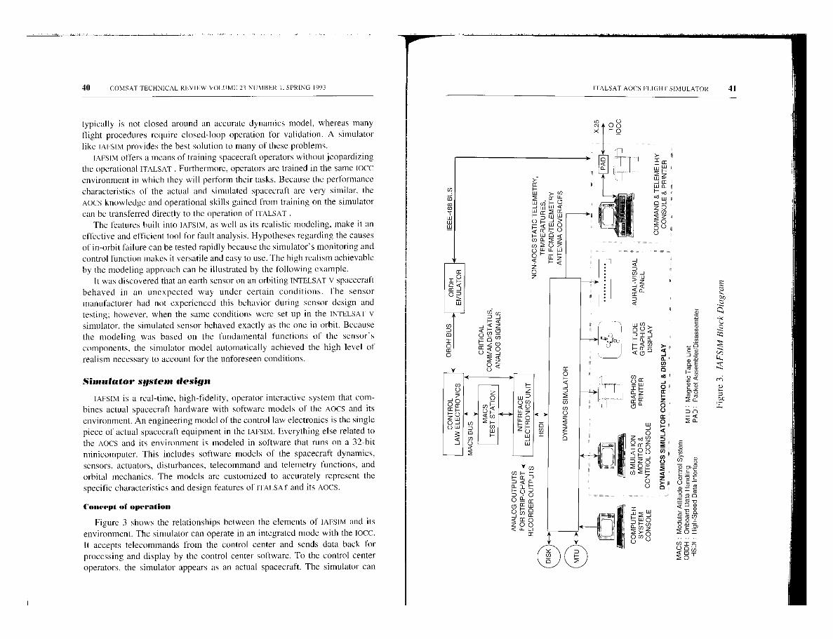
40 COMSAT TECHNICAL REVIEW VOLUME 23 NUMBER I, SPRING 1993
typically is not closed around an accurate dynamics model, whereas manyflight procedures require closed-loop operation for validation. A simulatorlike IAFSIM provides the best solution to many of these problems.
IAFSIM offers a means of training spacecraft operators without jeopardizingthe operational ITALSAT . Furthermore, operators are trained in the same Ioccenvironment in which they will perform their tasks. Because the performancecharacteristics of the actual and simulated spacecraft are very similar, theAocs knowledge and operational skills gained from training on the simulator
can he transferred directly to the operation of I I ALSAT ,The features built into IAFSIM, as well as its realistic modeling, make it an
effective and efficient tool for fault analysis. Hypotheses regarding the causesof in-orbit failure can be tested rapidly because the simulator's monitoring andcontrol function makes it versatile and easy to use. The high realism achievableby the modeling approach can be illustrated by the following example.
It was discovered that an earth sensor on an orbiting INTELSAT v spacecraftbehaved in an unexpected way under certain conditions. The sensormanufacturer had not experienced this behavior during sensor design andtesting; however, when the same conditions were set up in the INIELSAT Vsimulator, the simulated sensor behaved exactly as the one in orbit. Becausethe modeling was based on the fundamental functions of the sensor'scomponents, the simulator model automatically achieved the high level ofrealism necessary to account for the unforeseen conditions.
Simulator system design
IAFSIM is a real-time, high-fidelity, operator-interactive system that com-bines actual spacecraft hardware with software models of the Aocs and itsenvironment. An engineering model of the control law electronics is the singlepiece of actual spacecraft equipment in the IAFSIM. Everything else related tothe Aocs and its environment is modeled in software that runs on a 32-bitminicomputer. This includes software models of the spacecraft dynamics,sensors, actuators, disturbances, telecommand and telemetry functions, andorbital mechanics. The models are customized to accurately represent thespecific characteristics and design features of ITAISAr and its AOCS.
Concept of operation
Figure 3 shows the relationships between the elements of IAFSIM and itsenvironment. The simulator can operate in an integrated mode with the Iocc.It accepts telecommands from the control center and sends data back forprocessing and display by the control center software. To the control centeroperators, the simulator appears as an actual spacecraft. The simulator can
Mt00
IT ALSAT AOCS FLIGH I SIMULATOR 41
Z U u D q
I- _ < n., ^d
Z^ q aZ
w x ro z,°W OQ? 9
JFU rn
D Z^F 0^ P gi
z aU
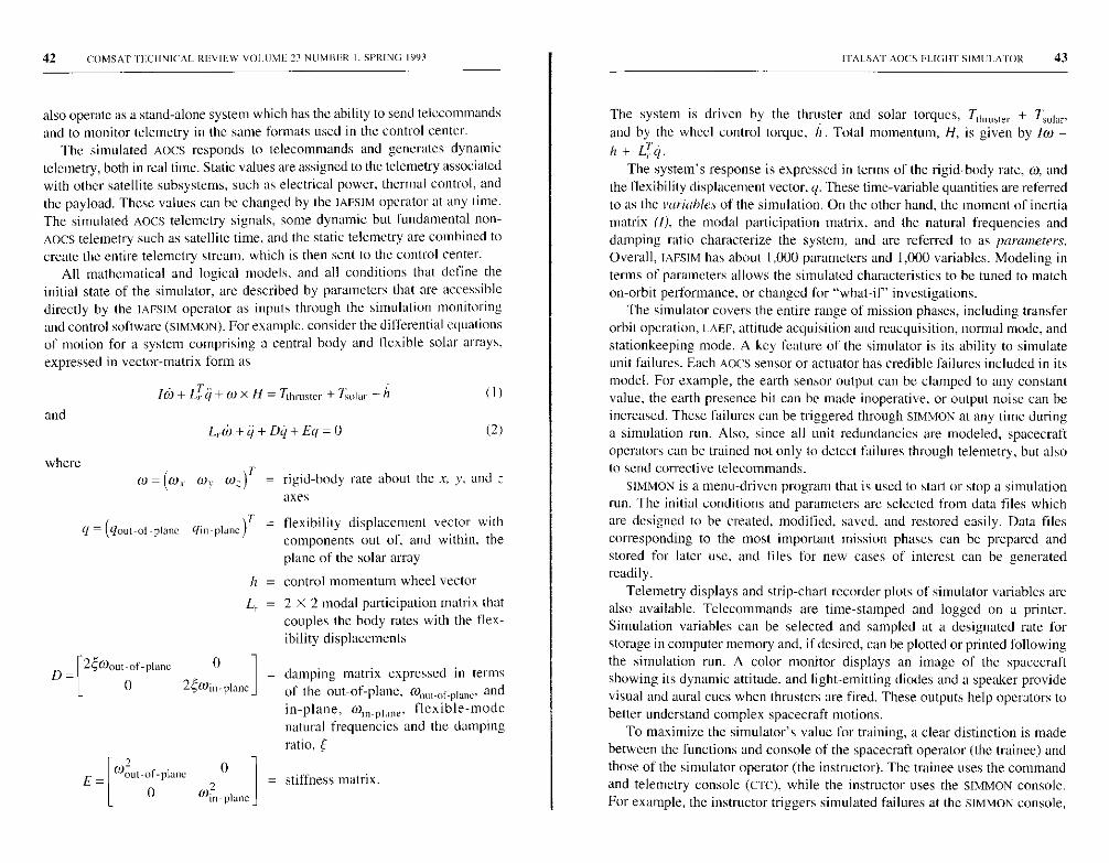
42 COMSAT rEC11NICAL REVIEW VOLUME 23 NUMBER I. SPRING 1993
also operate as a stand-alone system which has the ability to send telecommandsand to monitor telemetry in the same formats used in the control center.
The simulated AOCS responds to telecommands and generates dynamictelemetry, both in real time. Static values are assigned to the telemetry associatedwith other satellite subsystems, such as electrical power, thermal control, andthe payload. These values can be changed by the IAFSIM operator at any time.The simulated AOCS telemetry signals, some dynamic but fundamental non-AOCS telemetry such as satellite time, and the static telemetry are combined tocreate the entire telemetry stream, which is then sent to the control center.
All mathematical and logical models, and all conditions that define theinitial state of the simulator, are described by parameters that are accessibledirectly by the IAFSIM operator as inputs through the simulation monitoringand control software (SIMMON). For example, consider the differential equationsof motion for a system comprising a central body and flexible solar arrays,
expressed in vector-matrix form as
Iw + LTq + w x H = Tlhnlstcr + 7,0
and
where
L,w+q+Dq+Eq=0 (2)
to = (w, w„ w ;) T = rigid-body rate about the x, y, and ;.axes
q = (gout-ol-plane qin-planeflexibility displacement vector withcomponents out of, and within, theplane of the solar array
h = control momentum wheel vector
Lr = 2 X 2 modal participation matrix thatcouples the body rates with the flex-ibility displacements
n- 2ywout -of-plane 0
0 2 win
E_
-plane
r o
0).U- t-of -plane0
20 win-plane
damping matrix expressed in termsof the out-of-plane, r0out-of plane. andin-plane. Wi„-plane, flexible-modenatural frequencies and the damping
ratio. E
= stiffness matrix.
ITALSAT AOCS FLIGHT SIMULATOR 43
The system is driven by the thruster and solar torques, Tlhf111ef + Tolar'and by the wheel control torque, h. Total momentum, H, is given by lo) +h + LTq.
The system's response is expressed in terms of the rigid-body rate, W. andthe flexibility displacement vector, q. These time-variable quantities are referredto as the variables of the simulation. On the other hand, the moment of inertiamatrix (1), the modal participation matrix, and the natural frequencies anddamping ratio characterize the system, and are referred to as parameters.Overall, IAFSIM has about 1,000 parameters and 1,000 variables. Modeling interms of parameters allows the simulated characteristics to be tuned to matchon-orbit performance, or changed for "what-if' investigations.
The simulator covers the entire range of mission phases, including transferorbit operation, IAFF, attitude acquisition and reacquisition, normal mode, andstationkeeping mode. A key feature of the simulator is its ability to simulateunit failures. Each AOCS sensor or actuator has credible failures included in itsmodel. For example, the earth sensor output can be clamped to any constantvalue, the earth presence bit can be made inoperative, or output noise can beincreased. These failures can be triggered through SIMMON at any time duringa simulation run. Also, since all unit redundancies are modeled, spacecraftoperators can be trained not only to detect failures through telemetry, but alsoto send corrective telecommands.
SIMMON is a menu-driven program that is used to start or stop a simulationrun. The initial conditions and parameters are selected from data files whichare designed to be created, modified, saved, and restored easily. Data filescorresponding to the most important mission phases can be prepared andstored for later use, and files for new cases of interest can be generatedreadily.
Telemetry displays and strip-chart recorder plots of simulator variables arealso available. Telecommands are time-stamped and logged on a printer.Simulation variables can be selected and sampled at a designated rate forstorage in computer memory and, if desired, can be plotted or printed followingthe simulation run. A color monitor displays an image of the spacecraftshowing its dynamic attitude, and light-emitting diodes and a speaker providevisual and aural cues when thrusters are fired. These outputs help operators tobetter understand complex spacecraft motions.
To maximize the simulator's value for training, a clear distinction is made
between the functions and console of the spacecraft operator (the trainee) and
those of the simulator operator (the instructor). The trainee uses the command
and telemetry console (CTC), while the instructor uses the SIMMON console.
For example, the instructor triggers simulated failures at the SIMMON console,
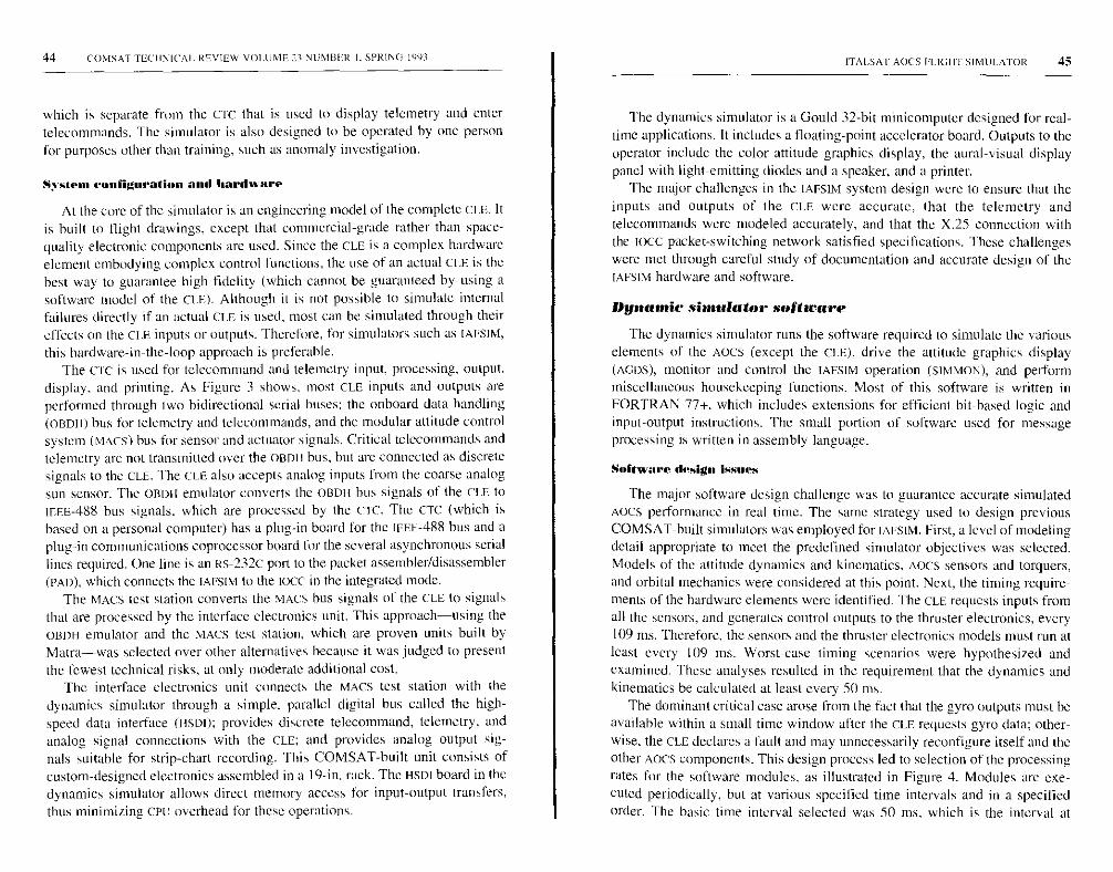
44 COMSAT TEC'IINICAI. REVIEW VOLUME 23 Nt:M13ER I, SPRING 1993
which is separate from the CTC that is used to display telemetry and entertelecommands. The simulator is also designed to be operated by one personfor purposes other than training, such as anomaly investigation.
System configuration and hardware
At the core of the simulator is an engineering model of the complete CLE. Itis built to flight drawings, except that commercial-grade rather than space-quality electronic components are used. Since the CLE is a complex hardwareelement embodying complex control functions, the use of an actual CLE is thebest way to guarantee high fidelity (which cannot be guaranteed by using asoftware model of the CLE). Although it is not possible to simulate internalfailures directly if an actual CLE is used, most can he simulated through theireffects on the CI.E inputs or outputs. Therefore, for simulators such as IAESIM,
this hardware-in-the-loop approach is preferable.The crc is used for teleconmiand and telemetry input, processing, output,
display, and printing. As Figure 3 shows, most CLE inputs and outputs areperformed through two bidirectional serial buses: the onboard data handling(OeDII) bus for telemetry and telecommands, and the modular attitude controlsystem (MACS) bus for sensor and actuator signals. Critical telecommands andtelemetry are not transmitted over the OBOI I bus, but are connected as discretesignals to the CLE. The CLE also accepts analog inputs from the coarse analogsun sensor. The OEDH emulator converts the OBDH bus signals of the CLE toreef-488 bus signals, which are processed by the c w. The CTC (which isbased on a personal computer) has a plug-in board for the Ieee-488 bus and aplug-in communications coprocessor board for the several asynchronous seriallines required. One line is an es-232c port to the packet assembler/disassembler(PAD), which connects the IAESIM to the 1oCC in the integrated mode.
The MACS test station converts the MACS bus signals of the CLE to signalsthat are processed by the interface electronics unit. This approach-using theOBDH emulator and the MACS test station, which are proven units built by
Matra-was selected over other alternatives because it was judged to presentthe fewest technical risks, at only moderate additional cost.
The interface electronics unit connects the MACS test station with thedynamics simulator through a simple. parallel digital bus called the high-speed data interface (HSDI); provides discrete telecommand, telemetry, andanalog signal connections with the CLE; and provides analog output sig-nals suitable for strip-chart recording. This COMSAT-built unit consists ofcustom-designed electronics assembled in a 19-in. rack. The HSOI board in thedynamics simulator allows direct memory access for input-output transfers.thus minimizing CPU overhead for these operations.
ITALSA I' AOCS PLIGI II SIMULATOR 45
The dynamics simulator is a Gould 32-bit minicomputer designed for real-tilne applications. It includes a floating-point accelerator board. Outputs to theoperator include the color attitude graphics display, the aural-visual displaypanel with light-emitting diodes and a speaker, and a printer.
The major challenges in the IAESIM system design were to ensure that theinputs and outputs of the CLE were accurate, that the telemetry andtelecommands were modeled accurately, and that the X.25 connection withthe IOCC packet-switching network satisfied specifications. These challengeswere met through careful study of documentation and accurate design of theIAESIM hardware and software.
Dynamic simulator software
The dynamics simulator runs the software required to simulate the various
elements of the AOCS (except the CLE), drive the attitude graphics display
(AGDS), monitor and control the IAFSIM operation (SIMMON), and perform
miscellaneous housekeeping functions. Most of this software is written in
FORTRAN 77+. which includes extensions for efficient bit-based logic and
input-output instructions. The small portion of software used for message
processing is written in assembly language.
Software design issues
The major software design challenge was to guarantee accurate simulatedAOCS performance in real time. The same strategy used to design previousCOMSAT-built simulators was employed for IAESIM. First, a level of modelingdetail appropriate to meet the predefined simulator objectives was selected.Models of the attitude dynamics and kinematics, AOCS sensors and torquers,and orbital mechanics were considered at this point. Next, the timing require-ments of the hardware elements were identified. The CLE requests inputs fromall the sensors, and generates control outputs to the thruster electronics, every109 ms. Therefore, the sensors and the thruster electronics models must run atleast every 109 ms. Worst-case timing scenarios were hypothesized andexamined. These analyses resulted in the requirement that the dynamics andkinematics be calculated at least every 50 ms.
The dominant critical case arose from the fact that the gyro outputs must heavailable within a small time window after the CLE requests gyro data; other-wise, the CLE declares a fault and may unnecessarily reconfigure itself and theother AOCS components. This design process led to selection of the processingrates for the software modules, as illustrated in Figure 4. Modules are exe-cuted periodically, but at various specified time intervals and in a specifiedorder. The basic time interval selected was 50 ms, which is the interval at

46 COMSAT TECHNICAL REVIEW VOLUME 23 NUMBER I, SPRING 1993
Wm0 H
0a
H<
Z Z Zo >0
WC U
S WHW 0<
qW LL Q Q a Z
¢ o
H N 0)0 ¢ U Ha O < 0H W
<
0Z Z
ZZo W >
0
CDH__
U
0q " ¢ 5 0 < a- z W Q W ZO >
0
0 U H
H w
Z¢Z
az0
NU
5wHw
ao Q 0UQ az^ z U- QI Z> v >O q
¢NU
0a
H
Z Z Z
0 m 0
WU H
i1Q
Z Z
z H¢ OzOW WjIUJ
4- 0w3w0
X -
N
0
00
0
0
ITALSAT AOCS FLIGHT SIMULATOR 47
which the differential equations for attitude dynamics and kinematics are
integrated, and at which the module for CLE commands and data requests
(SSIN) is processed. The modules corresponding to responses to CLE requests
(SSOUT), sensor models, and actuator models are generally processed at 100-ms
intervals. Some modules, such as orbital mechanics and sun interference
alerts, are executed at I-s intervals. Since the mass properties of the spacecraft
change very slowly (due to rotation of the solar array and consumption of
propellant during LAEF), they are recalculated only once every minute using
the DYNPARM module.
The numerical integration method was then selected. The integration stepsize was sufficiently small that a simple second-order method could yieldacceptable accuracy, even for simulation runs of several hours duration. Thesimplest approach was selected to minimize the demand on computer time.
Figure 5 is a top-level data flow diagram for the dynamics simulatorsoftware. The time-critical simulation and housekeeping tasks are executed atfixed intervals, whereas SIMMON and AGDS are processed in the time remaining.Data are stored in global common memory to be shared among modules. Forthe Gould real-time operating system used in IAFSIM, this technique (as com-pared to parameter-passing) was found during previous simulator projects tosave computer time, the most critical resource of this application. The fact thatthis technique has been workable, even though it leads to high intermodulecoupling, can be attributed to the predetermined, well-ordered execution ofthe tune-critical tasks. It should be noted that each variable is written by onlyone module of simulation software, although it may be read by any module inthe program. Similarly, parameters intended to be constant or to changeinfrequently are altered only through operator action via SIMMON.
Simulation software
Simulation software includes models for all the sensors and actuators; therigid body coupled with the flexibility dynamics of the solar array and theliquid propellant; the kinematics from which attitude angles are calculated;orbital mechanics; and disturbance torques (due to solar pressure, thrustermisalignments, and thruster plumes impinging on spacecraft surfaces).Simulation software also includes high-fidelity representations of the sensorand actuator input-output connections to the CLE.
Several of the models in the simulation software were used in previous
simulators, and several new models were developed that are unique to ITALSAT.
The INTELSAT v and DBS simulators-the predecessors of IAPSIM for three-
axis-stabilized spacecraft-covered only the synchronous orbit mission phase.
For IAFSIM, it is also necessary to cover the complex transfer and intermediate
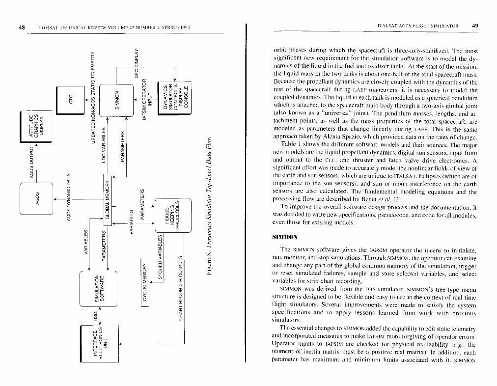
48 COMSAT l ECHNICAI. REVIEW VOLUME D NUMBER I, SPRING 1991
U
zOa
¢3
20Z-, N
02
00- w
UHOC^¢w JO
Z ZD
ZZ0p0
O ^/r U
w ^rpUQ
^aa
< CDc^
w
ma
2
4
a
CO
Ca
a
zU
ITALSAT AOCS PLIGHT SIMULATOR 49
orbit phases during which the spacecraft is three-axis-stabilized. The mostsignificant new requirement for the simulation software is to model the dy-namics of the liquid in the fuel and oxidizer tanks. At the start of the mission,the liquid mass in the two tanks is about one-half of the total spacecraft mass.Because the propellant dynamics are closely coupled with the dynamics of therest of the spacecraft during LAEF maneuvers, it is necessary to model thecoupled dynamics. The liquid in each tank is modeled as a spherical pendulumwhich is attached to the spacecraft main body through a two-axis gimbal joint(also known as a "universal" joint). The pendulum masses, lengths, and at-tachment points, as well as the mass properties of the total spacecraft, aremodeled as parameters that change linearly during I.AEE. This is the sameapproach taken by Alenia Spazio, which provided data on the rates of change.
Table 1 shows the different software models and their sources. The majornew models are the liquid propellant dynamics, digital sun sensors, input fromand output to the CLE, and thruster and latch valve drive electronics. Asignificant effort was made to accurately model the nonlinear fields of view ofthe earth and sun sensors, which are unique to tTALSA I. Eclipses (which are ofimportance to the sun sensors), and sun or moon interference on the earthsensors are also calculated. The fundamental modeling equations and theprocessing flow are described by Beret et al. [2].
To improve the overall software design process and the documentation, itwas decided to write new specifications, pseudocode, and code for all modules,even those for existing models.
snnloN
The SIMMON software gives the IANSIM operator the means to initialize,
run. monitor, and stop simulations. Through SIMMOIV, the operator can examineand change any part of the global common memory of the simulation, triggeror reset simulated failures, sample and store selected variables, and selectvariables for strip-chart recording.
SIMMON was derived from the DBS simulator. SIMMON'S tree-type menu
structure is designed to be flexible and easy to use in the context of real-time
flight simulators. Several improvements were made to satisfy the system
specifications and to apply lessons learned from work with previous
simulators.
The essential changes to SIMMON added the capability to edit static telemetryand incorporated measures to make IAFSIM more forgiving of operator errors.Operator inputs to IAESIM are checked for physical realizability (e.g., themoment of inertia matrix must be a positive real matrix). In addition, eachparameter has maximum and minimum limits associated with it. SIMMON
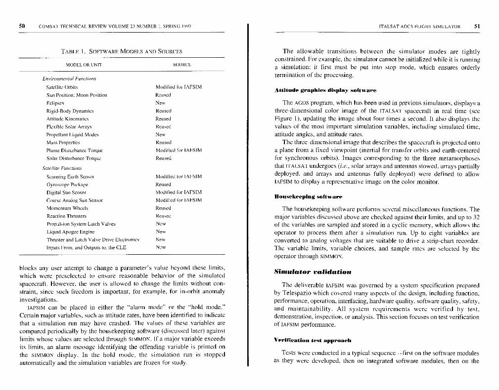
50 COMSAT TECHNICAL REVIEW VOLUME 23 NUMBER I. SPRING 1993 1 ITALSAT AOCS Fl..IGIrr SIMULATOR 51
TABLE 1. SOFTWARE MODELS AND SOURCES
MODEL OR UNIT
En ironmenial Functian.s
Satellite Orbits
Sun Position: Moon Position
Eclipses
Rigid-Body Dynamics
Attitude Kinematics
Flexible Solar Arrays
Propellant Liquid Modes
Mass Properties
Plume Disturbance Torque
Solar Disturbance Torque
Satellite Functions
Scanning Earth Sensor
Gyroscope Package
Digital Sun Sensor
Coarse Analog Sun Sensor
Momentum Wheels
Reaction Thrusters
Propulsion System Latch Valves
Liquid Apogee Engine
Thmster and Latch Valve Drive Electronics
Inputs From, and Outputs to, the CLE
SOURCE
Modified for IAFSIM
Reused
New
Reused
Reused
Reused
New
Reused
Modified for IAFSIM
Reused
Modified for IAFSIM
Reused
Modified for IAFSTM
Modified for IAFSIM
Reused
Reused
New
New
New
New
blocks any user attempt to change a parameter's value beyond these limits,which were preselected to ensure reasonable behavior of the simulatedspacecraft. However, the user is allowed to change the limits without con-straint, since such freedom is important, for example. for in-orbit anomalyinvestigations.
IAFSIM can he placed in either the "alarm mode" or the "hold mode."Certain major variables, such as attitude rates, have been identified to indicatethat a simulation run may have crashed. The values of these variables arecompared periodically by the housekeeping software (discussed later) againstlimits whose values are selected through SIMMON. If a major variable exceedsits limits, an alarm message identifying the offending variable is printed onthe SUMMON display. In the hold mode, the simulation run is stoppedautomatically and the simulation variables are frozen for study.
The allowable transitions between the simulator modes are tightlyconstrained. For example, the simulator cannot be initialized while it is runninga simulation: it first must be put into stop mode, which ensures orderlytermination of the processing.
Attitude graphics display software
The AGDS program, which has been used in previous simulators, displays athree-dimensional color image of the ITALSAT spacecraft in real time (seeFigure I), updating the image about four times a second. It also displays thevalues of the most important simulation variables, including simulated time,attitude angles, and attitude rates.
The three-dimensional image that describes the spacecraft is projected ontoa plane from a fixed viewpoint (inertial for transfer orbits and earth-centeredfor synchronous orbits). Images corresponding to the three metamorphosesthat ITALSAT undergoes (i.e., solar arrays and antennas stowed, arrays partiallydeployed, and arrays and antennas fully deployed) were defined to allowIAFSIM to display a representative image on the color monitor.
Housekeeping software.
The housekeeping software performs several miscellaneous functions. Themajor variables discussed above are checked against their limits, and up to 32of the variables are sampled and stored in a cyclic memory, which allows theoperator to process them after a simulation run. Up to eight variables areconverted to analog voltages that are suitable to drive a strip-chart recorder.The variable limits, variable choices, and sample rates are selected by theoperator through SIMMON.
Simulator validation
The deliverable IAFSIM was governed by a system specification prepared
by Telespazio which covered many aspects of the design, including function,
performance, operation, interfacing, hardware quality, software quality, safety,
and maintainability. All system requirements were verified by test,
demonstration, inspection, or analysis. This section focuses on test verification
of IAFSIM performance.
Verification test approach
Tests were conducted in a typical sequence-first on the software modulesas they were developed, then on integrated software modules, then on the
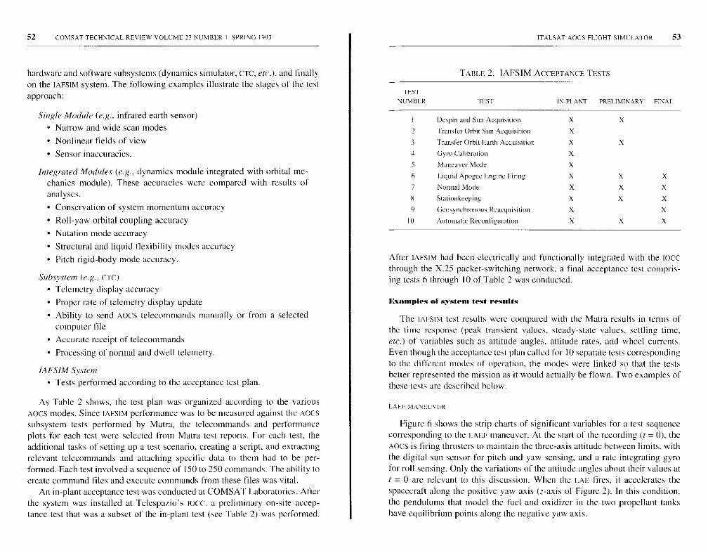
52 COMSAT TECHNICAL REVIEW VOLUME 23 NUMBER L SPRING 1993
hardware and software subsystems (dynamics simulator , CTC, et( .), and finallyon the IAFSIM system. The following examples illustrate the stages of the testapproach:
Single Module (e.g., infrared earth sensor)
• Narrow and wide scan modes
• Nonlinear fields of view
• Sensor inaccuracies.
Integrated Modules (e.g., dynamics module integrated with orbital me-chanics module ). These accuracies were compared with results ofanalyses.
• Conservation of system momentum accuracy
• Roll-yaw orbital coupling accuracy
• Nutation mode accuracy
• Structural and liquid flexibility modes accuracy
• Pitch rigid - body mode accuracy.
Suluvstem (e.g., CIC)
• Telemetry display accuracy
• Proper rate of telemetry display update
• Ability to send AOCS telecommands manually or from a selectedcomputer file
• Accurate receipt of telecommands
• Processing of normal and dwell telemetry.
IAFSIM System• Tests performed according to the acceptance test plan.
As Table 2 shows, the test plan was organized according to the variousAocs modes. Since IAFSIM performance was to be measured against the AOCSsubsystem tests performed by Matra, the telecommands and performanceplots for each test were selected from Matra test reports. For each test, theadditional tasks of setting up a test scenario, creating a script, and extractingrelevant telecommands and attaching specific data to them had to be per-formed. Each test involved a sequence of 150 to 250 commands. The ability tocreate command files and execute commands from these files was vital.
An in-plant acceptance test was conducted at COMSAT Laboratories. Afterthe system was installed at Telespazio's IoeC, a preliminary on-site accep-tance test that was a subset of the in-plant test (see Table 2) was performed.
ITALSAT AOCS FLIGHT SIMI : I. AIOR 53
TABLE 2. IAFSIM ACCEPTANCE TESTS
I1:S I
NUMBER nos r IN-PLANT PRELIMINARY FINAL
I Despin and Sun Acquisition X X
2 Transfer Orbit Sun Acquisition X
3 Transfer Orbit Earth Acquisition X X
4 Gyro Calibration X
5 Maneuver Mode X
6 Liquid Apogee Engine Firing X X X
7 Normal Mode X X X
8 Stationkeeping X X X
9 (cosynchmnuus Reacquisition X X
In Automatic Reconfiguration X X X
After IAFSIM had been electrically and functionally integrated with the 1000through the X.25 packet-switching network, a final acceptance test compris-ing tests 6 through 10 of Table 2 was conducted.
Examples of system test results
The IAFSIM test results were compared with the Matra results in terms ofthe time response (peak transient values, steady-state values. settling time,etc.) of variables such as attitude angles, attitude rates, and wheel currents.Even though the acceptance test plan called for 10 separate tests correspondingto the different modes of operation, the modes were linked so that the testsbetter represented the mission as it would actually be flown. Two examples ofthese tests are described below.
LAFF NIANIUUVER
Figure 6 shows the strip charts of significant variables for a test sequencecorresponding to the LAEF maneuver. At the start of the recording (t= 0), theAOCS is firing thrusters to maintain the three-axis attitude between limits, withthe digital sun sensor for pitch and yaw sensing, and a rate-integrating gyrofor roll sensing. Only the variations of the attitude angles about their values att = 0 are relevant to this discussion. When the LAE fires, it accelerates thespacecraft along the positive yaw axis (z-axis of Figure 2). In this condition,the pendulums that model the fuel and oxidizer in the two propellant tankshave equilibrium points along (he negative yaw axis.
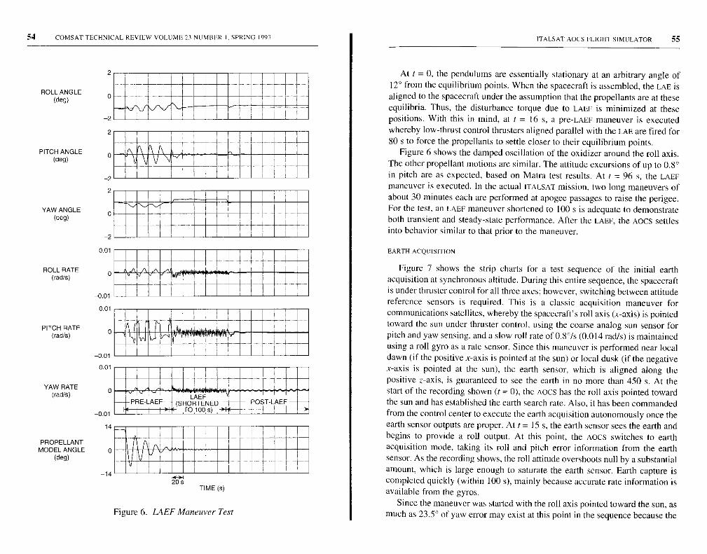
54 COMSAT TECHNICAL REVIEW VOLUME 23 NUMBER 1-SPRING 1993
ROLL ANGLE(deg)
2
0
2
- 1
PITCH ANGLE(deg) 0
-2
YAW ANGLE(deg)
2
0
20.01
ROLL RATE 0(rad/s)
-0.0 1
0.01
PITCH RATEgrad/s)
-0.010.01
YAW RATE 0(rad/s)
-0.0114
PROPELLANTMODEL ANGLE 0
(deg)
TENEPRELAEF--- (SR D
POST-LAE F_tTO T O s)
-14
-17- V J_ _Lj
20TIME (s)
Figure 6. LAEF Maneuver Test
ITALSAT AOCS FLIGHT SIMULATOR 55
At t = 0, the pendulums are essentially stationary at an arbitrary angle of12° from the equilibrium points. When the spacecraft is assembled, the LAE isaligned to the spacecraft under the assumption that the propellants are at theseequilibria. Thus, the disturbance torque due to LAEF is minimized at thesepositions. With this in mind, at I = 16 s, a pre-LAEF maneuver is executedwhereby low-thrust control thrusters aligned parallel with the LAE are fired for80 s to force the propellants to settle closer to their equilibrium points.
Figure 6 shows the damped oscillation of the oxidizer around the roll axis.The other propellant motions are similar. The attitude excursions of up to 0.8°in pitch are as expected, based on Matra test results. At t = 96 s, the LAEFmaneuver is executed. In the actual ITALSAT mission, two long maneuvers ofabout 30 minutes each are performed at apogee passages to raise the perigee.For the test, an LAEF maneuver shortened to 100 s is adequate to demonstrateboth transient and steady-state performance. After the LAEF, the AOCS settlesinto behavior similar to that prior to the maneuver.
EARTH ACQUISITION
Figure 7 shows the strip charts for a test sequence of the initial earthacquisition at synchronous altitude. During this entire sequence, the spacecraftis under thruster control for all three axes; however, switching between attitudereference sensors is required. This is a classic acquisition maneuver forcommunications satellites, whereby the spacecraft's roll axis (x-axis) is pointedtoward the sun under thruster control, using the coarse analog sun sensor forpitch and yaw sensing, and a slow roll rate of 0.8°/s (0.014 rad/s) is maintainedusing a roll gyro as a rate sensor. Since this maneuver is performed near localdawn (if the positive x-axis is pointed at the sun) or local dusk (if the negativex-axis is pointed at the sun), the earth sensor, which is aligned along thepositive z-axis, is guaranteed to see the earth in no more than 450 s. At thestart of the recording shown (t = 0), the Aocs has the roll axis pointed towardthe sun and has established the earth search rate. Also, it has been commandedfrom the control center to execute the earth acquisition autonomously once theearth sensor outputs are proper. At t = 15 s, the earth sensor sees the earth andbegins to provide a roll output. At this point, the Aocs switches to earthacquisition mode, taking its roll and pitch error information from the earthsensor. As the recording shows, the roll attitude overshoots null by a substantialamount, which is large enough to saturate the earth sensor. Earth capture iscompleted quickly (within 100 s), mainly because accurate rate information isavailable from the gyros.
Since the maneuver was started with the roll axis pointed toward the sun, asmuch as 23.5° of yaw error may exist at this point in the sequence because the
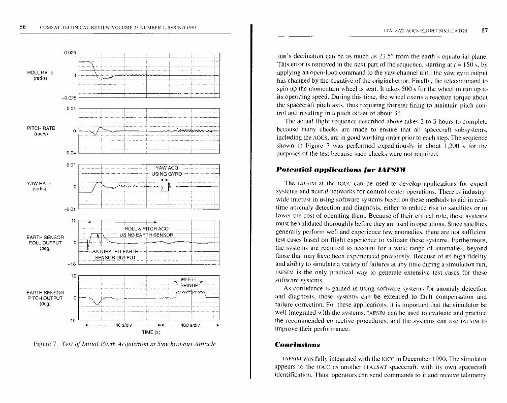
56 COMSAT IFUI INICAL REVIEW VOLUME 23 NUMBER I. SPRING 1993
ROLL RATE(rad/s)
PITCH RATE( rad/s)
YAW RATE(rad/s)
EARTH SENSORROLL OUTPUT
(deg)
1 0
-10
10
YAW ACO'--- USING GYRO------
' SATURATED EARTH-',.SENSOR OUTPUT
EARTH SENSOR^--^ /^-PITCH OUTPUT 0
(den) ff
-1 0f_ --- 40s/dlv ,c 400 s /div
TIME (s)
Figure 7. Test of Initial Earth Acquisition at Synchronous Altitude
I IAI.SAT ROCS PLIGHT SIMULATOR 57
sun's declination can be as much as 23.5° from the earth's equatorial plane.This error is removed in the next part of the sequence, starting at t = 150 s, byapplying an open-loop command to the yaw channel until the yaw gyro outputhas changed by the negative of the original error. Finally, the telecommand tospin up the momentum wheel is sent. It takes 500 s for the wheel to run up toits operating speed. During this time, the wheel exerts a reaction torque aboutthe spacecraft pitch axis, thus requiring thruster firing to maintain pitch con-trol and resulting in a pitch offset of about 3°.
The actual flight sequence described above takes 2 to 3 hours to completebecause many checks are made to ensure that all spacecraft subsystems,including the AOCS, are in good working order prior to each step. The sequenceshown in Figure 7 was performed expeditiously in about 1,200 s for thepurposes of the test because such checks were not required.
Potential applications for IAFSIt11
The IAPSIM at the Iocc can be used to develop applications for expertsystems and neural networks for control center operations. There is industry-wide interest in using software systems based on these methods to aid in real-time anomaly detection and diagnosis, either to reduce risk to satellites or tolower the cost of operating them. Because of their critical role, these systemsmust be validated thoroughly before they are used in operations. Since satellitesgenerally perform well and experience few anomalies. there are not sufficienttest cases based on flight experience to validate these systems. Furthermore,the systems are required to account for a wide range of anomalies, beyondthose that may have been experienced previously. Because of its high fidelityand ability to simulate a variety of failures at any time during a simulation run,IAFSIM is the only practical way to generate extensive test cases for thesesoftware systems.
As confidence is gained in using software systems for anomaly detectionand diagnosis, these systems can be extended to fault compensation andfailure correction. For these applications, it is important that the simulator bewell integrated with the systems. TAFSIM can be used to evaluate and practicethe recommended corrective procedures. and the systems can use IAFSIM toimprove their performance.
Conclusions
IAFSIM was fully integrated with the IOCC in December 1990. The simulatorappears to the IOCc as another ITALSAT spacecraft, with its own spacecraftidentification. Thus, operators can send commands to it and receive telemetry
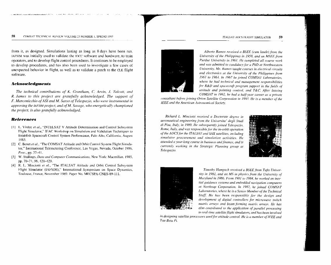
58 COMSAT TECHNICAL REVIEW VOLUME 23 NUMBER I. SPRING 1993
from it, as designed. Simulations lasting as long as 8 days have been run.IAFSIM was initially used to validate the ICICC software and hardware, to trainoperators, and to develop flight control procedures. It continues to be employedto develop procedures, and has also been used to investigate a few cases ofunexpected behavior in flight, as well as to validate a patch to the CLE flightsoftware.
Acknowledgments
The technical contributions of K. Grantham, C. Arvin, J. Talcott, and
R. James to this project are gratefully acknowledged. The support of
F. Marconicchio of AS! and M. Sasso of Telespazio, who were instrumental in
approving the IAFSIM project, and of M. Savage, who energetically championed
the project, is also gratefully acknowledged.
References
III L. Virdec et at., "INTELSAT V Attitude Determination and Control SubsystemFlight Simulator," IFAC Workshop on Simulation and Validation Techniques to
Establish Spacecraft Control System Performance, Palo Alto, California, August1983.
[2] C. Bonet et al., "The COMSAT Attitude and Orbit Control System Flight Simula-
[3]
tor," International Telemetering Conference, Las Vegas, Nevada, October 1986,Proc., pp. 37-41.W. Stallings, Data and Computer Communications, New York: Macmillan, 1985,pp. 70-71, 98, 420-429.
[4] R. L. Minciotti et al., "The ITALSAT Attitude and Orbit Control SubsystemFlight Simulator (IAFSIM)," International Symposium on Space Dynamics,Toulouse, France, November 1989. Paper No. MECSPA-CNES-89-111.
ITALSA'I' AOCS PLIGHT' SIMULATOR 59
Alberto Ramos received a BSEE (cum laude) from the
University of the Philippines in 1958, and an MSEE from
Purdue University in 1961. He completed all course work
and was admitted to candidacy for a PhD at Northwestern
University. Mr. Ramos taught courses in electrical circuits
and electronics at the University of the Philippines from
1961 to 1964. In 1967 he joined COMSAT Laboratories,
where he had technical and management responsibilities
for R&D and spacecraft program support in the fields of
attitude and pointing control, and T&C. After leaving
COMSAT in 1992, he had a half-year career as a private
consultant before joining Orion Satellite Corporation in 1993. He is a member of theIEEE and the American Astronomical Society.
Richard L. Minciotti received a Doctorate degree in
aeronautical engineering from the Universita' degli Studi
di Pisa, Italy, in 1989. He subsequently joined Telespazio,
Rome, Italy, and was responsible for the in-orbit operation
of the AOCS for the ITALSAT and SAX satellites, including
simulator procurement and simulation activities. He
attended a year-long course in business and finance, and is
currently working in the Strategic Planning group at
Telespazio.
Timothy Hampsch received a BSEE from Tufts Univer-sity in 1981, and an MS in physics from the University ofMaryland in 1986. From 7981 to 1984, he worked on inertial guidance systems and embedded navigation computersat Northrop Corporation. In 1987, he joined COMSATLaboratories, where he is a Senior Member of the TechnicalStaff He has been responsible for the design and
development of digital controllers for microwave switchmatrix arrays and beam forming matrix arrays. He hasalso contributed to the application of parallel processing
to real-time satellite flightsimulators, and has been involvedin designing satellite processors used for attitude control. He is a member of IEEE andTau Beta Pi-

60
George Allison received a BS in physics from Old
Dominion Universi v, and an M.S in applied physics from
The Johns Hopkins Uninersitn- As a nremrber of COMSAT's
Communications Products Software Engineering Deport-
ment, lie provides support for' the design, integration, and
deliver-i of bpnarsat earth ctatiun.t. In addition, he was
responsible for developing the satellite sunu/Wion software
for the 17ALSA'1' AOCS Flight Simulamr. Prior to joining
COMSAT. Mr. Allison worked at The Johns Hopkins Ap-
plied Physics Laborntorv, where lie developed conlpater
modeling of acoustic propagation in the ocean.
Ernai W- Hare has been incoft el] with electtonic.s shire
1970, when lie began a 4-year term with the U.S. Nava.
After completing the Nanl Aviation Election it's Coine at
Memphis Naval Air Station. he was responsible for the
elecn-onics systems of the A-6 eircroft. After leaning the
service in 1974, lie was employed by Fairchild Industries
in the F-14 program and performed acceptance testing on
the fire control panel. In 1979 he joined COMSAT
Teles}stems, working with the Echo Canceller ptogranr.
He is cinrenth all Assistant Staff Member in the Power
Si veins and Electronics Department of the Satellite and
Systems Technologic-s Division at COMSAT Laboratories. He has been invok=ed in the
design call] development of the INTELSAT V and VI. and ITALSAT flight simlators,and has gained experience in the areas o/ beans Jinnning networks, digital controllers
tor inicrotrave switch nmtrices, unit spacecraft hanhreme evaluation and testing.
Jeffrey W. Opiekun received a US in niallieniolicy Iran
Towson Universir, in 1978, cod an MS in computer science
finny The John.; Hopkins Uninersih' in 1982, fie is t'uriently
a Senior Member of the Technical Staff in the Sisteni
Development Division tit COMSAT Laboratories. He has
worked on nwnerats projects, including the ITALSAT AOC.S
Flight Simulator, the INTELSAT V Attitude Simulator
Upgrade. i/ie NASA Ad cancel] Conmiunication s Tedinningv
Satellite (ACTS) Master Control Station, and couimmrico-
tions anah'sis sof6vaic for the Universal Modem Si'steni
fa' the U.S. Government. From /980 to /983 he worked for
Computer Sciences Caporotion. inhere lie participated in
developing sofnrare that generated ore quisiiion dam for rnaruted and i munmed space-
craft at the Goddard Space Flight Center.
COMSAT 'I ECINICAL REVICw V OLUME. 23 NUMBER I , SPRING 1993
Index: communication satellites, earth stations,in-orbit testing , performance, transponders
The EUTELSAT in-orbit test system
K. D. FUI.LETT, B. J. KASSTAN, W. D. KELLEY, V. E. RIGINOS,
P-H. SHEN, S. L. TELLER, AND Y. THARAUD
(Manuscript received Noveoiher 3, 1992)
Abstract
An integrated suite of microwave measurement equipment, computer hardware.
and measurement software was designed, fabricated, and installed into a unified testfacility for measuring the communications subsystem performance of European Tele-communications Satellite Organization (EUTELSAT) communications satellites. The
EUTELSAT in-orbit test (IOT) system software supports UNIX-based multiuser, multi-tasking operation in a networked environment that permits remote access and controlof the IOT measurement hardware and includes a scheduler that permits unattendedstability measurements. The system's human-machine interface offers point-and-clickmenu selection and input via a mouse device.
The EUTELSAT IOT facility incorporates a dedicated earth station command andcontrol system computer for earth station status checking and configuration, automaticsatellite saturation control hardware, and a radiometer for reading atmospheric attenua-tion. New tests include a method for quickly measuring the frequency response of a
spacecraft channel, as well as procedures for measuring AM-to-PM conversion andAM-to-PM transfer coefficient. In addition, the satellite is used as a far-field calibratedsignal source for earth station verification and assistance, which enables EUTELSATto independently test new or existing earth stations for EIRP, gain-to-noise temperatureratio, transmit polarization isolation, and transmit antenna pattern.
Introduction
Following successful launch of a communications satellite, it is desirable totest the communications subsystem in orbit [1]-[3]. Data measured during in-orbit test HOT) are compared with prelaunch data to determine whether the
61
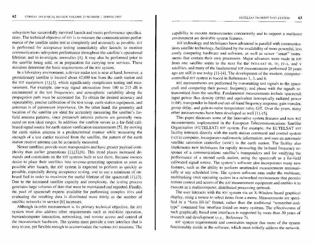
62 COMSAT IFCI IN ]CAL REVIEW VOLUME 23 NUMBER I. SPRING 1993
subsystem has successfully survived launch and meets performance specifica-tions. The technical objective of OF is to measure the communications perfor-mance of the satellite under test as completely and accurately as possible. IOTis performed for acceptance testing immediately after launch ; to monitorcommunications subsystem performance throughout the satellite's operationallifetime; and to investigate anomalies [4 ]. It may also be performed prior tothe satellite being sold, or in preparation for carrying new services. Thesemissions determine the basic requirements of the IoT system.
In a laboratory environment, a device under test is near at hand ; however, ageostationary satellite is located about 42,000 km from the earth station andthe IOT equipment [ I],[3], which significantly complicates testing and mea-surement . For example , one-way signal attenuation from 180 to 215 dB isencountered at the test frequencies , and atmospheric variability along thepropagation path must be accounted for. To obtain the desired accuracy andrepeatability , precise calibration of the test setup , earth station equipment, andantennas is of paramount importance . On the other hand, the geometry andlocation of the satellite are ideal for accurately measuring the satellite's far-field antenna patterns , since prelaunch antenna patterns are generally mea-sured on non-ideal ranges . In addition , the satellite serves as a far-field cali-brated signal source for earth station verification measurements [5]. By movingthe earth station antenna in a predetermined manner while measuring thestrength of a test carrier received from the satellite , the pattern of the earthstation receive antenna can be accurately measured.
Newer satellites provide more transponders and have greater payload com-plexity than earlier generations [ 1],[3],161. This trend places increased de-mands and constraints on the IOT systems built to test them. Because ownersdesire to place their satellites into revenue-generating operation as soon aspossible after launch, the IOT system is expected to perform as quickly aspossible. especially during acceptance testing, and to use a minimum of on-board fuel in order to maximize the useful lifetime of the spacecraft 111,13].Due to the increased satellite capacity and complexity , the testing processgenerates large volumes of data that must be maintained and reported. Finally,the pool of spacecraft experts available for performing complex WITS andevaluating the resulting data is distributed more thinly as the number ofsatellite networks in service [6 ] increases.
Although in -orbit measurement is its primary technical objective , the IoTsystem must also address other requirements such as real - time operation,human/computer interaction , networking , and remote access and control ofthe measurement hardware . The system must provide a user interface that iseasy to use , yet flexible enough to accommodate the various IoT missions. The
FUTELSA TIN-ORBITTEST SYSTEM 63
capability to execute measurements concurrently and to support a multiuserenvironment are desirable system features.
to]' technology and techniques have advanced in parallel with communica-
tions satellite technology, facilitated by the availability of more powerful, less
costly computing hardware and software, as well as newer "smart" instru-
ments that contain their own processors. Major advances were made in tar
from one satellite series to the next for the INTELSAT III, IV, IV-A, and v
satellites, and many of the fundamental IOT measurements performed 20 years
ago are still in use today [11-[4]. The development of the modern, computer-
controlled IOT system is traced in References 1, 3, and 6.
IOT measurements are performed by transmitting test signals to the space-craft and comparing their power, frequency, and phase with the signals re-transmitted from the satellite. Fundamental measurements include spacecraftinput power flux density (MILD) and equivalent isotropically radiated power(EIRP), transponder in-band and out-of-hand frequency response, gain transfer,group delay, and gain-to-noise temperature ratio, GIT. Over the years, manyother measurements have been developed as well [11-15].
This paper discusses some of the innovative system features and new 1OTmeasurements implemented in the European Telecommunications SatelliteOrganization (EUTELSAT) IOT system. For example, the EUTELSAT IOTfacility interacts directly with the earth station command and control system(ECCS) computer, incorporates radiometric information, and uses an automaticsatellite saturation controller (ASSC) in the earth station. The facility alsoimplements new techniques for rapidly measuring the in-band frequency re-sponse of a communications satellite's transponders and for verifying theperformance of a second earth station, using the spacecraft as a far-fieldcalibrated signal source. The system's software also incorporates many newfeatures, such as the ability to perform unattended measurements automati-cally at any scheduled time. The system software runs under the multiuser,multitasking UNIX operating system in a networked environment that permitsremote control and access of the IOT measurement equipment and enables it toexecute in a multicomputer, distributed processing network.
The user interacts with the 1OT system via an X-Window-based graphicaldisplay, using a mouse to select items from a menu. Measurements are speci-fied in a "form-fill-in" format, rather than the traditional "remember-and-type" command line interface found on many systems. The effectiveness ofsuch graphically based user interfaces is supported by more than 30 years ofresearch and development (e.g., Reference 7).
10T system requirements and constraints require that more of the systemfunctionality reside in the software, which must initially address the network,
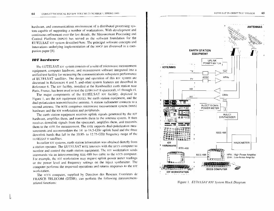
64 COMSAT TLC I INICAL REVIEW VOL[ ME 23 NUMBER I, SPRING 1993
hardware, and communications environment of a distributed processing sys-tem capable of supporting a number of workstations. With development andcontinuous refinement over the last decade, the Measurement Processing andControl Platform (MPCP) has served as the software foundation for theEUTELSAT LOT system described here. The principal software concepts andinnovations underlying implementation of the MPCP are discussed in a com-
panion paper [81.
►OT hardware
The EUTELSAT IOT system consists of a suite of microwave measurementequipment, computer hardware, and measurement software integrated into aunified test facility for measuring the communications subsystem performanceof EUTELSAT satellites. The design and operation of this or system arediscussed in References 4 and 5, and other system features are described inReference 6. The 1OT facility, installed at the Ramhouillet earth station nearParis. France. has been used to test the EUTELSAT n spacecraft. El through E4.
The major components of the EUTELSAT IOT facility, depicted in
Figure I. are the lOT equipment (TOTE), the earth station equipment, and the
dual-polarization transmit/receive antenna. A station radiometer connects to a
second antenna. The LOTS comprises microwave measurement system (MMS)
hardware and the OF workstation and peripherals.
The earth station equipment receives uplink signals generated by the LOT
hardware, amplifies them, and transmits them to the antenna system. It then
receives downlink signals from the spacecraft, amplifies them, and transmits
them to the IOTE for measurement. The IOTE supports dual-polarization mea-
surements and accommodates the 14- to 14.5-GHz uplink band and the three
downlink bands that fall in the 10.95- to 12.75-GHz frequency range of the
EUTELSAT II satellites.In earlier LOT systems. earth station information was obtained directly from
a station operator. The EUTELSAT LOTE interacts with the ECCS computer tomonitor and control the earth station equipment. The LOT workstation sendscommands via an interconnecting IEEE-488 bus cable to the ECCS computer.For example, the or workstation may request uplink power meter readingsor the power level and frequency settings on the inject synthesizer. Thecomputer performs the requested operations and returns responses to the LOT
workstation.The ECCS computer, supplied by Direction des Reseaux Exterieurs de
FRANCE TELECOM (DTRE), can perform the following measurement-
related functions:
IOTE/MMS
EIIrELSAT IN-ORBIT TEST SYSTEM 65
LNA : Low-Noise Amplifier
Figure 1. ELTELSAT LOT System Block Diagram
EARTH STATIONEQUIPMENT
UPLINKPOWER METER
INJECT SIGNALPOWER METER
IEEE-488 0...I r'lfI HPA: High- Power Amplifier

66 COMSAT rECHN ICA I, REVIEW VOLT ME 23 NUMBER I. SPRING 1993
• Control the injected signal power and frequency as commanded by
the IOT workstation.
• Control the uplink power level and perform power-leveling as the
frequency is varied.
• Control the ASSC equipment to determine the saturation power level.
• Provide a radiometer reading to the IOT workstation on command.
• Read the uplink power meter at the feed and provide the calibrated
readings to the TOT workstation.
• Provide the antenna gain and coupler calibration values for any opera-
tional uplink or downlink frequency.
• Provide the azimuth and elevation antenna position to the IOT
workstation.
• Configure the earth station on command from the TOT workstation.
• Zero and calibrate the uplink and inject signal power meters.
IOT systems must be capable of determining the saturation flux density ofthe spacecraft. One method that has been used successfully is the amplitude-modulated (AM) nulling technique, described in the IOT system literature (e.g.,References I and 2). In early or systems, AM nulling was applied manually;the EUTELSAT tOT uses the ASSC to perform this function automatically. TheASSC maintains the satellite at saturation, and was designed to meet EUTELSATspecifications 14]. It operates over a large dynamic range of satellite gain.
The ASSC automates the AM nulling technique to determine saturation fluxdensity, as follows. First, an AM carrier is transmitted to the spacecraft. On thedownlink, after envelope detection, the AM carrier is phase-locked to the AMsource. producing an error voltage proportional to the modulation amplitude,which decreases as saturation is approached. The error voltage is interpretedby the digital processor, which commands the uplink earth station EIRP. Assaturation approaches, the EIRP is controlled in 0.05-dB steps. When the errorvoltage reaches a minimum. saturation has been achieved. Since the ASSCoperates as a closed loop, any variation in uplink propagation conditions iscounteracted by the detected error voltage, the sign of which governs the
relative polarity of the uplink EIRP.The TOT setup must take into account not only instrumentation, earth station
equipment, and antenna uncertainties, but also the RE path between the stationand the spacecraft [11,131. In the EUTELSAT TOT system, the measurementprogram obtains atmospheric attenuation data from a radiometer. The radio-metric configuration consists of a Cassegrain antenna connected to a noise-injection-type radiometric receiver, and a computer to control operation, pro-
EUTELSAT IN-ORBIT TEST SYSTEM 67
cess the measurement data and perform housekeeping functions 14]. Attenua-tion calculated at 13 GHz is scaled to other frequencies by the radiometer'scomputer, using standard frequency-scaling equations. Over the short timeperiod typical of an IOT measurement (a few minutes). the change in atmo-spheric attenuation is assumed to he negligible.
Figure 2 is a simplified block diagram of the EUTELSAT IOTE MMShardware configuration. A high-stability, 10-MHz reference signal output byuplink synthesizer I (UL Syn I) is amplified and distributed to the IOT instru-ments as a common reference signal. The IOT workstation communicates withthe instruments via three IEEE-488 buses, and with the ECCS computer via afourth IEEE-488 bus.
Two test carriers are provided by two RE synthesizers. UL Syn I outputs anRE test carrier, as commanded by the IOT workstation. The synthesizer's RFoutput can be frequency-modulated by an externally supplied modulationsignal to disperse the uplink energy, in order to meet the downlink earthsurface spectral density specifications of the International Radio ConsultativeCommittee (CCIR) 358-2 during routine operation. Because the synthesizerdoes not operate over the required uplink frequency range, a 12-times fre-quency multiplier is employed.
Uplink synthesizer 2 (UL Syn 2) is capable of generating an RE output testsignal anywhere in the uplink frequency range. The synthesizer's RF output (inthe 14- to 14.5-GHz range) can be amplitude-modulated externally (via themodulator shown in Figure 2) when necessary-for example, when groupdelay is measured.
An uplink switching/coupling matrix provides flexible uplink configura-tions and is necessary to support all IOT measurements. The RE output fromeither synthesizer can be switched and routed to either transmit polarizationwaveguide, TX or TY. When required, the lo'rE can produce two carriers onone of the two polarizations, or a single carrier on each polarization, tosupport two-tone measurements such as third-order intermodulation, C/13.
As shown in Figure 2, the spectrum analyzer (SA) can be switched, via the8-pole switch, to input the uplink polarization (TX or TY), the received signal(RX or RY, selected by another switch), the IF synthesizer output, or theoutput from the phase measurement subsystem. Additionally, the spectrumanalyzer can be switched to input a sample of either high-power amplifier(HPA) output signal, as well as to receive an input signal from a front panelconnector. The video output of the spectrum analyzer can he switched toprovide an input to either the network analyzer or the digital voltmeter. Theanalyzer's IF output can be switched to provide an input to either the modula-tion analyzer or the frequency counter. The switch configurations for all

68 COMSAT TECHNICAL REVIEW VOLUME 23 NUMBER I. SPRING 1993
UPLINKSWITCHING/COUPLING MATRIX
UL SYN 1
RFOUT
UL SYN 2
REOUT
MODULATIONSWITCHMATRIX
NETWORKANALYZER
RE CHA
OUT CH B
12XMULTIPLIER
SW
sw
Sw
IFSYNTHESIZER
SPECTRUMANALYZER
VIDEO RFOUT IN
DIGITALVOLTMETER
IF OUT
1-MHzAM FEED
PROCESSOR
SA B-POLEINPUT SWITCH
(NOT ALL POLES SHOWN)
Sw
IOT WORKSTATION
FREQUENCYCOUNTER
MODULATIONANALYZER
UPLINK 1 TX
UPLINK 2
xTY
SW
sw
x
ANT TX
H- ANT TY
RX
CRY
PHASEMEASUREMENTSUBSYSTEM
Figure 2. IOTE Microwave Measurement System Block Diagram
EUTELSAT IN-ORBIT TEST SYSTEM 69
measurements are controlled by the IOT workstation via RF switch controllersand IEEE-488 buses.
The feed processor, which is used for measurements such as group delay,performs the following function. When the uplink carrier produced by ULSyn 1 or UL Syn 2 is amplitude-modulated. the modulation is detected bydiode detectors located near the antenna feed. Typically, the AM frequency isaround I MHz. The detected modulation is transmitted to the input of the feedprocessor, which can be switched to select either of the uplink polarizations(ANT TX or ANT TY in Figure 2). The feed processor amplifies and filtersthe detected modulation, and supplies it to the IF synthesizer as a reference.The synthesizer's t-MHz, frequency-adjusted output is fed into the networkanalyzer, which measures its phase relationship with respect to the Doppler-shifted I -MHz modulation on the carrier received by the spacecraft.
The phase measurement subsystem is used to perform phase noise mea-
surements on the received RF signal. such as AM-PM conversion, AM-PM
transfer coefficient, and spurious modulation. It consists of a down-converter,
a phase reference synthesizer, and a dedicated low-frequency spectrumanalyzer.
An important innovation of the EUTELSAT IOT system is its ability toperform unattended stability measurements. While measurements are nor-mally performed with operator interaction, some can be executed in a non-interactive mode if directed by the user via the X Window interface. TheEUTELSAT IOT system allows the user to specify measurements to execute atany scheduled time and at specified intervals throughout a specified duration.
The ability to schedule measurements and to have them execute periodi-cally provides the basis for performing stability measurements, which trackvarious quantities as a function of time. For example, the EIRP measurementcan be scheduled to run every hour over a 24-hr period to determine EIRPvariation. Stability measurements can be performed for spacecraft EIRE, space-craft IPEU, in-band and out-of-band transponder frequency response. space-craft G//-, beacon EIRP, and beacon frequency.
The JOT system scheduler launches measurements at the scheduled timeand allocates resources to a measurement that has requested them. It alsomanages scheduling conflicts between two or more measurements on a first-come, first-served basis. When a measurement completes execution, it returnsresources such as the spectrum analyzer and other measurement instrumentsto the scheduler, which makes them available to the next scheduled measure-ment. The operation of the IOT scheduler, and its interaction with the measure-ment user interface program and the actual measurement program (which are
70 COMSAT TECHNICAL REVIEW VOLUME 23 NUMBER I. SPRING 1993
separate programs that can execute on different workstations and at differenttimes), are described in the companion paper 181.
The TOTE is controlled by a 32-bit, reduced instruction set computing(Rise)-based engineering workstation with 16 Mbytes of memory and a600-Mbyte hard disk for program and data storage. The workstation executesIOT system and measurement software to perform IOT measurements and toprocess, store, and retrieve measurement data. The software runs under alicensed version of the UNIX System v operating system. The TOT workstationcontrols the microwave measurement hardware and communicates with theECCS computer across an IEEE: 488 bus. It also communicates with the user viaan X-Window-based, graphical user interface with keyboard and mouse input.The workstation supports connection to an IEEE 802.3 local area network(LAN). Its peripherals include a l9-in., high-resolution, color bit-mapped dis-play; a multipen plotter; a printer; a cathode-ray tube (CRT) terminal; and a9,600-bids modem for remote access and control. The TOT software is de-scribed in detail in Reference 8.
Standard /OT measurements
Most satellite communications payload parameters, such as antenna pat-terns, EIRP, and receive GTE, can be derived from fundamental measurementsof microwave power and frequency 13]. During the past 20 years, the evolu-tion of toT measurement techniques has been governed by the increasingcomplexity of communications payloads and the requirement to place thespacecraft into operational service as quickly as possible while minimizingconsumption of onboard fuel. Continuous refinement of measurement tech-niques has permitted more parameters to be measured with a higher level ofconfidence. This has resulted in an expanding amount of data from the in-creased number of transponders and connectivity configurations 11],[3].
For each IoT measurement, all uncertainties must be identified and ac-counted for in an error budget. The total root-sum-square (RSS) uncertaintyresulting from all error sources is computed for each measurement. As dis-cussed in Reference 9, uncertainties can arise from the spacecraft (antennapointing, platform stability, and repeatability of switching), atmospheric lossand variability, the earth station (antenna calibration and pointing, up anddownlink coupler calibration), and measurement instrumentation. Numericaluncertainties due to digital processing of raw measurement data within theworkstation must be considered for some measurements, such as the"Fastsweep" measurement described later.
The human operator is another potential source of measurement error (e.g.,improper use of instrumentation, lack of skill, and improper measurement
EUTELSAT IN-ORBIT TEST SYSTEM 71
technique). Human interface engineering can detect and prevent (or minimize)operator errors, as discussed in References 6 and S.
To enhance measurement accuracy, the measurements of absolute quanti-ties necessary for an or have been reduced to microwave power, frequency,and phase [11; all other measurements are relative to, or can be derived from,these values. For the uplink, transmit power is measured directly by a direc-tional coupler that provides power from the uplink waveguide to a powermeter.
The EUTELSAT LOT system performs a large number of measurementsthat can be grouped according to the basic quantity measured: power, fre-quency, or phase.
Power measurements
The fundamental power measurement performed by an IOT system is theaccurate measurement of spacecraft EIRE. Many other measurements are de-rived from the EIRP, including the point-to-point transponder frequency re-sponse and gain transfer measurements.
For measuring downlink signals, an injected carrier technique has provedto be the best approach and continues to be used in IOT systems [I]-131. Alocally generated carrier (the inject signal) is offset slightly in frequency fromthe carrier received from the satellite, and is injected via a directional couplerinto the waveguide between the receive antenna feed and the low-noise ampli-fier (LNA), as shown in Figure 1. After amplification by the LNA (and addi-tional amplifiers, if necessary), both the received and injected signals aredisplayed on the spectrum analyzer and measured. The difference is used bythe EIRP program to adaptively adjust the injected signal power to within aboutI dB of the received signal. The final difference is then measured by thespectrum analyzer, and the power level of the final injected carrier is Inea-sured precisely by a power meter. Based on this knowledge of the injectedsignal level and its difference from the received signal level, the level of thereceived signal (even if noisy) can be determined to within a few tenths of adecibel. This adaptive technique ensures a wider dynamic range, while reduc-ing logarithmic amplifier errors within the spectrum analyzer. The injectedcarrier technique permits accurate measurement of received continuous-wave(CW) carriers and is unaffected by any change in the gain of the receive chain.The calibration effort can thus be restricted to a few passive microwavecomponents, such as the inject coupler [11.
The spacecraft EIRP is computed from the measured injected signal powermeter reading, the level difference measured by the spectrum analyzer, theinject signal coupler value, the downlink antenna gain at the frequency of
72 COMSAT IF:CHNICAI. REVIEW VOLUME 23 NUMBER I. SPRING 1993
interest, the downlink path loss, and the downlink atmospheric loss. Space-craft EIRP measurement using the injected signal technique is well establishedand has been described in earlier TOT literature (e.g., References I and 2.)
The EUTELSAT lOT system performs the following power measurementsand monitoring functions:
• EIRP (downlink only. with no uplink test signal from the TOT station)
• Combined spacecraft IPFD and spacecraft EIRP
• Amplitude linearity (gain transfer) and intermodulation (("/13)
• G/T and GIT stability
• Point-to-point frequency response (in-band, in-band stability, out-of-band, and out-of-hand stability)
• Fastsweep frequency response
• Overall cross-polarization isolation
• Receive and transmit cross-polarization
• Antenna pattern
• Gain adjustment
• Spurious output
• Beacon measurements (FIRP, EIRP stability, cross-polarizationisolation)
• Communications system monitoring (cSM)
• Payload monitoring (IPSO/EIRP. linear gain, gain transfer, local oscil-lator frequency)
• Earth station verification and assistance (ESVA).
The Fastsweep and ESVA measurements are new with the EUTELSAT TOTsystem, and are described later in this paper.
Frequency measurements
Frequency measurements are the second category of fundamental measure-ments performed by an TOT system. The EUTELSAT 10'1 system can measurefrequency conversion error and stability, beacon frequency and beacon fre-quency stability, and routine spacecraft payload monitoring (RSPM) frequencyconversion error. Since the uplink frequency and nominal spacecraft localoscillator frequency are known, the spectrum analyzer (Figure 2) can be tunedto the nominal downlink frequency, where it performs peak and zero-spanmeasurements. The frequency of the analyzer's IF output is measured pre-cisely by the counter. The measured received signal frequency offset from the
ILUIFLSAT IN-ORBIT TEST SYSTEM 73
center frequency of the analyzer IF is used in conjunction with the analyzer'stuned microwave frequency to fine-tune the analyzer to the frequency of thereceived signal. This technique is employed in all TOTE measurements to
ensure that the spectrum analyzer is tuned precisely to the received signalfrequency, so that power measurements are performed accurately.
For some measurements in which the precise frequency is the objective,the IOTE can correct for the Doppler shift caused by non-zero radial velocitybetween the spacecraft and the earth station. For example, in measuring thespacecraft local oscillator frequency, the loT user interface permits the user tospecify that Doppler correction be performed. The measurement then com-putes the Doppler-effect frequency contribution, based on the velocity, andcorrects the received frequency.
Phase noise measurements
The EUTELSAT lOT phase measurement subsystem, shown in Figure 2,
measures the AM-PM conversion coefficient, KI,: AM-PM transfer coefficient,
KI; and spurious modulation. The AM-PM conversion and transfer coefficient
measurements are new, and are described in the next section.
New sneasnrentents
Among the system features mentioned above are several new measure-ments implemented in the EUTELSAT IoT system: Fastsweep frequencyresponse. AM-PM conversion coefficient, AM-PM transfer coefficient, and sev-eral ESVA measurements (EIRP, Gil', transmit polarization isolation, and trans-
mit antenna pattern).
Fastsweep Frequency response measurement
Measurement of a spacecraft channel's frequency response is a fundamen-tal TOT system requirement. The standard technique measures the responsepoint-to-point throughout the hand of interest. Because of the larger numberof channels on board the latest generation of communications satellites, suchas EUTELSAT n, measuring the frequency response of all channels requiressubstantial testing time. Since this activity deprives the satellite owner ofrevenue, there is continual pressure on lOT systems designers to shorten the
time required for TOT.A new technique called Fastsweep has been developed which measures
frequency response by continuously sweeping the desired spacecraft channel,while simultaneously measuring the received downlink signal on the spectrum
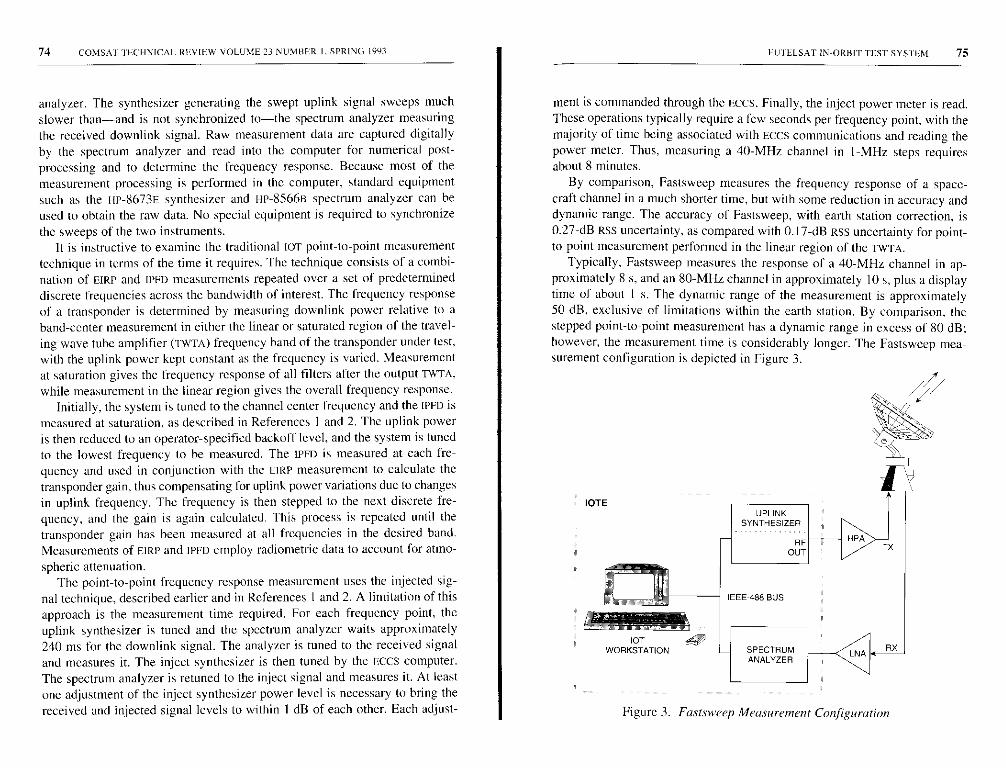
74 COMSAT TECHNICAL REVIEW VOLUME 23 NUMBER I , SPRING 1993
analyzer. The synthesizer generating the swept uplink signal sweeps muchslower than-and is not synchronized to-the spectrum analyzer measuringthe received downlink signal. Raw measurement data are captured digitallyby the spectrum analyzer and read into the computer for numerical post-processing and to determine the frequency response. Because most of themeasurement processing is performed in the computer, standard equipmentsuch as the HP-8673E synthesizer and HP-8566B spectrum analyzer can beused to obtain the raw data. No special equipment is required to synchronize
the sweeps of the two instruments.It is instructive to examine the traditional IOT point-to-point measurement
technique in terms of the time it requires. The technique consists of a combi-nation of EJRP and IPPD measurements repeated over a set of predetermineddiscrete frequencies across the bandwidth of interest. The frequency responseof a transponder is determined by measuring downlink power relative to aband-center measurement in either the linear or saturated region of the travel-ing wave tube amplifier (TwTA) frequency band of the transponder under test,with the uplink power kept constant as the frequency is varied. Measurementat saturation gives the frequency response of all filters after the output TWTA,while measurement in the linear region gives the overall frequency response.
Initially, the system is tuned to the channel center frequency and the IPFD ismeasured at saturation, as described in References I and 2. The uplink poweris then reduced to an operator-specified backoff level, and the system is tunedto the lowest frequency to be measured. The IPFD is measured at each fre-quency and used in conjunction with the EIRP measurement to calculate thetransponder gain, thus compensating for uplink power variations due to changesin uplink frequency. The frequency is then stepped to the next discrete fre-quency, and the gain is again calculated. This process is repeated until thetransponder gain has been measured at all frequencies in the desired band.Measurements of FIRP and IPFO employ radiometric data to account for atmo-
spheric attenuation.The point-to-point frequency response measurement uses the injected sig-
nal technique, described earlier and in References I and 2. A limitation of thisapproach is the measurement time required. For each frequency point, theuplink synthesizer is tuned and the spectrum analyzer waits approximately240 ms for the downlink signal. The analyzer is tuned to the received signaland measures it. The inject synthesizer is then tuned by the ECCS computer.The spectrum analyzer is retuned to the inject signal and measures it. At leastone adjustment of the inject synthesizer power level is necessary to bring thereceived and injected signal levels to within I dB of each other. Each adjust-
EUTELSAT IN-ORBIT TEST SYSTEM 75
ment is commanded through the Eccs. Finally, the inject power meter is read.These operations typically require a few seconds per frequency point, with themajority of time being associated with ECCS communications and reading thepower meter. Thus, measuring a 40-MHz channel in I-MHz steps requiresabout 8 minutes.
By comparison, Fastsweep measures the frequency response of a space-craft channel in a much shorter time, but with some reduction in accuracy anddynamic range. The accuracy of Fastsweep. with earth station correction, is0.27-dB RSS uncertainty, as compared with 0.17-dB RSS uncertainty for point-to-point measurement performed in the linear region of the TWTA.
Typically, Fastsweep measures the response of a 40-MHz channel in ap-proximately 8 s, and an 80-MHz channel in approximately 10 s, plus a displaytime of about I s. The dynamic range of the measurement is approximately50 dB, exclusive of limitations within the earth station. By comparison, thestepped point-to-point measurement has a dynamic range in excess of 80 dB;however, the measurement time is considerably longer. The Fastsweep mea-surement configuration is depicted in Figure 3.
UPLINKSYNTHESIZER
IEEE488 BUS
SPECTRUMANALYZER
Figure 3. Fastsweep Measurement Configuration
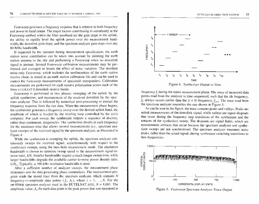
76 COMSAT TECHNICAL REVIEW VOLUME 23 NUMBER I. SPRING 1993
Fastsweep generates a frequency response that is relative in both frequencyand power to band center. The major factors contributing to uncertainty in theFastsweep method within the filter passband are the gain slope in the uplink.the ability to rapidly level the uplink power over the measurement band-width, the downlink gain slope, and the spectrum analyzer gain slope over any80-MHz bandwidth.
If requested by the operator during measurement specification, the earthstation noise contribution can be taken into account by pointing the earthstation antenna to the sky and performing a Fastsweep when no downlinksignal is present. Several Fastsweep calibration measurements may be per-formed and averaged to lessen the effect of noise variation. The resultantnoise-only Fastsweep, which includes the nonlinearities of the earth station
receive chain, is stored in an earth station calibration file and can be used tocorrect the Fastsweep measurements of spacecraft transponders. Calibrationmeasurements are performed for each receive polarization across each of thethree HUTELSAT [I downlink receive hands.
Fastsweep is performed in two phases: sweeping of the uplink by theuplink synthesizer, and measurement of the received downlink by the spec-trum analyzer. This is followed by numerical post-processing to extract thefrequency response from the raw data. When the measurement phase begins,the synthesizer generates a frequency sweep over the desired uplink band, theamplitude of which is leveled by the leveling loop controlled by the Ecescomputer. For each sweep, the synthesizer outputs a sequence of discrete,rather than continuous, frequencies. The synthesizer dwells at each frequencyfor the minimum time that allows several measurements (i.e., spectrum ana-lyzer sweeps) of the received signal by the spectrum analyzer, as illustrated inFigure 4.
While the synthesizer is sweeping the uplink, the spectrum analyzer con-tinuously sweeps the received signal, asynchronously with respect to thesynthesizer sweeps, using the max-hold measurement mode. The resolutionbandwidth is chosen to optimize sweep speed vs the measurement signal-to-noise ratio, S/N. Smaller bandwidths require a much longer sweep time, whilelarger bandwidths degrade the available carrier-to-noise power density ratio,C/N0. Typically, a 100-kHz-resolution bandwidth is used.
After a sufficient number of analyzer sweeps, the measurement phaseterminates and the data processing phase commences. The measurement pro-gram reads the stored trace from the spectrum analyzer, which contains Nfrequency-vs-amplitude data points (f„ A;), where i = 1, ..., N. For the
HP-8566B spectrum analyzer used in the EUTELSAT [OTE, N = 1,001. Theamplitude value, A,, for each data point is the peak power that was measured at
EUTEI SAT IN-ORBIT TEST SYSTEM 77
f5
I
1 SWEEP
11 12 t3 t4 15 t6 17 III t9 11o
TIME
Figure 4. Synthesizer Output vs Time
frequency f, during the entire measurement phase. The array of measured datapoints read from the analyzer is time-sequenced, such that the ith frequency,f1, always occurs earlier than the (i + I) frequency, f,, 1. The trace read fromthe spectrum analyzer resembles the one shown in Figure 5.
As can be seen in the figure, the trace contains peaks and valleys. Peaks areactual measurements of the downlink signal, while valleys are signal dropoutsthat occur during the frequency step transitions of the synthesizer and theretraces of the synthesizer sweep. The dropouts are signal fades, which aremeasurement artifacts that occur because the spectrum analyzer and synthe-sizer sweeps are not synchronized. The spectrum analyzer measures noisepeaks, rather than the actual signal, during synthesizer switching transitions tonew frequencies.
250 500 750
HORIZONTAL DISPLAY UNITS
Figure 5. Fastsweep Spectrum Analyzer Trace Output
1,000

78 COMSAT TECHNICAL REVIEW VOLUME 23 NUMBER I. SPRING 1993
The desired response can be obtained by extracting the envelope of thetrace data. This is accomplished by numerically post-processing the data, asfollows. The analyzer trace depicted in Figure 5 can be viewed as a time-sequenced "signal" with low-frequency components (i.e.. the envelope that isthe desired response) and high-frequency components (the signal dropouts).The envelope can then be extracted by applying a numerical low-pass filter tothe "signal." The filter consists of a fast Fourier transform (Eve) operation onthe data set, followed by removal of high-frequency points, followed by asecond PET. A peak detection is then performed on the filtered data to obtain
the envelope.Although the numerically implemented low-pass filter algorithm removes
the systematic high-frequency perturbations contained in the measured dataset, random noise in the correlated samples is not removed. To minimize thenoise, multiple Fastsweeps are performed and averaged. Figure 6 is a typical
plot output of a Fastsweep.
0
I-0.02
I
-2
-6
-8
-10-0.04 0 0.02
FREQUENCY (GHz)
0.04
Figure 6. Fastsweep Measurement Plot Oulput
EUTELSAT IN -ORBIT TEST SYSTEM 79
n"-PM conversion and phase shift
The AM-PM conversion measurement determines that the AM-PM conver-
sion coefficient, KI,, for each transponder is within the limits specified for
drive levels to the TWTA, from 20-dB input backoff to saturation. The total
phase shift is calculated by integrating the conversion coefficient phase for
comparison with the satellite specification.
In this measurement. the IOTE transmits an amplitude-modulated carrierwith a low modulation index at an uplink power level corresponding to 20-dBinput backoff of the TWTA. The power level is then stepped up to TWTAsaturation in 1-dB steps. For each uplink power level, the correspondingdownlink signal is phase-demodulated by the modulation analyzer and thephase measurement subsystem. Using a test translator, the above sequence canbe repeated for the earth station loop in order to measure the phase modulationof the earth station receive chain for inclusion in the AM-PM conversioncoefficient computation. The coefficient, K0. is then plotted against the TWTAinput backoff.
The measurement sequence proceeds as follows. First, a calibration pro-cedure (described below) is performed and the synthesizer is amplitude-modulated via the external PIN modulator (see Figures 2 and 7 for the hard-ware configuration). The power level of the modulated carrier is then adjustedto the user-specified backoff level. The demodulated tone, output by themodulation analyzer (HP-8901A), is measured using the low-frequency spec-trum analyzer (SA), and data are gathered to perform the K0 computations.
The AM-PM conversion measurement employs the phase measurement sub-system of Figure 2. which consists of an HP-I 1729c carrier noise test set, alow-frequency HP-3582A spectrum analyzer, and an HP-8662B RE synthesizer[101. The subsystem configuration is depicted in Figure 7.
The instrumentation used to perform the measurement depends on themodulation frequency of the carrier, as shown in the figure. If the modulationfrequency is less than or equal to 20 kHz, the modulation analyzer and low-frequency spectrum analyzer are used. If the modulation frequency is greaterthan 20 kHz, the HP-11729c carrier noise test set may he used.
The KP calibration procedure is performed as follows. A single CW testcarrier is transmitted to the spacecraft to verify test signal levels and thespacecraft local oscillator frequency. The IF synthesizer outputs a calibrationsignal into the FM port of the uplink synthesizer via the modulation inputmatrix switch. The modulation voltage is selected to generate a low-deviationFM signal having a nominal phase modulation of 5° peak-to-peak, which
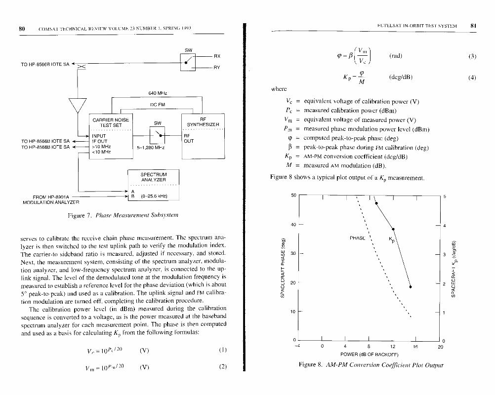
80 COMSAT TECHNICAL REVIEW VOLUME 23 NUMI3E: R I, SPRING 1993
SW
TO HP -8566B IOTE SA
640 MHz
TO HP 8566B TOTE SATO HP-8566B IOTE SA
FROM HP-8901A -MODULATION ANALYZER
CARRIER NOISETEST SET
INPUTIF OUT>10 MHz<10 MHz
DC FM
SW
5-1,280 MHz
SPECTRUMANALYZER
AB (0-25.6 kHz)
Figure 7. Phase Measurement Suhsystent
RX
RY
RFSYNTHESIZER
RFOUT
serves to calibrate the receive chain phase measurement. The spectrum ana-lyzer is then switched to the test uplink path to verify the modulation index.The carrier-to-sideband ratio is measured, adjusted if necessary, and stored.Next, the measurement system, consisting of the spectrum analyzer, modula-tion analyzer, and low-frequency spectrum analyzer, is connected to the up-link signal. The level of the demodulated tone at the modulation frequency ismeasured to establish a reference level for the phase deviation (which is about5° peak-to-peak) and used as a calibration. The uplink signal and FM calibra-tion modulation are turned off, completing the calibration procedure.
The calibration power level (in dBm) measured during the calibrationsequence is converted to a voltage, as is the power measured at the basehandspectrum analyzer for each measurement point. The phase is then computedand used as a basis for calculating KP from the following formulas:
V,.=IOP<t20 (V) (I)
Vm-lop m120 (V) (2)
where
PUTELSAT IN-ORBIT TEST.SYSTEM 81
rp = /3V n1-^ (rod) (3)V,.
Kp=M (deg/dB) (4)
Vc = equivalent voltage of calibration power (V)
Pr = measured calibration power (dBm)
Vm = equivalent voltage of measured power (V)
Pm = measured phase modulation power level (dBm)
tp = computed peak-to-peak phase (deg)
(3 = peak-to-peak phase during FM calibration (deg)
KP = AM-PM conversion coefficient (deg/dB)
M = measured AM modulation (dB).
Figure 8 shows a typical plot output of a KP measurement.
0 4 8 12
POWER (dB OF RACKOFF)
16
Figure 8. AM-PM Conversion Coefficient Plot Output
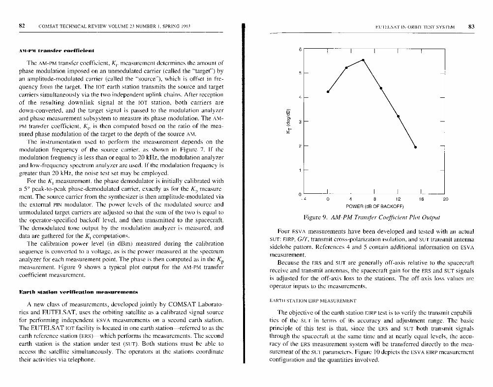
82 COMSAT TECHNICAL REVIEW VOLUME 23 NUMBER I. SPRING 1993
AM-rm transfer coefficient
The AM-PM transfer coefficient, KI. measurement determines the amount ofphase modulation imposed on an unmodulated carrier (called the "target") byan amplitude-modulated carrier (called the "source"), which is offset in fre-quency from the target. The IOT earth station transmits the source and targetcarriers simultaneously via the two independent uplink chains. After receptionof the resulting downlink signal at the 10T station, both carriers aredown-converted, and the target signal is passed to the modulation analyzerand phase measurement subsystem to measure its phase modulation. The AM-PM transfer coefficient. Kr, is then computed based on the ratio of the mea-sured phase modulation of the target to the depth of the source AM.
The instrumentation used to perform the measurement depends on themodulation frequency of the source carrier, as shown in Figure 7. If themodulation frequency is less than or equal to 20 kHz, the modulation analyzerand low-frequency Spectrum analyzer are used. If the modulation frequency isgreater than 20 kHz, the noise test set may be employed.
For the KI measurement, the phase demodulator is initially calibrated witha 5° peak-to-peak phase-demodulated carrier, exactly as for the KP measure-ment. The source carrier from the synthesizer is then amplitude-modulated viathe external PIN modulator. The power levels of the modulated source andunmodulated target carriers are adjusted so that the sum of the two is equal tothe operator-specified backoff level, and then transmitted to the spacecraft.The demodulated tone output by the modulation analyzer is measured, anddata are gathered for the KI computations.
The calibration power level (in dBm) measured during the calibrationsequence is converted to a voltage, as is the power measured at the spectrumanalyzer for each measurement point. The phase is then computed as in the KPmeasurement. Figure 9 shows a typical plot output for the AM-PM transfercoefficient measurement.
Earth station verification measurements
A new class of measurements, developed jointly by COMSAT Laborato-ries and EUTELSAT, uses the orbiting satellite as a calibrated signal sourcefor performing independent ESVA measurements on a second earth station.The EUTELSAT IOT facility is located in one earth station-referred to as theearth reference station (ERs)-which performs the measurements. The secondearth station is the station under test (SUT). Both stations must be able toaccess the satellite simultaneously. The operators at the stations coordinatetheir activities via telephone.
FUrELSAT IN-ORBIT TEST SYSTEM 83
4 8 12
POWER (dB OF BACKOFF)
16
Figure 9. AM-PM Transfer Coefficient Plot Output
20
Four ESVA measurements have been developed and tested with an actual
sur: EIRP, G/T, transmit cross-polarization isolation, and SUT transmit antenna
sidelobe pattern. References 4 and 5 contain additional information on ESVA
measurement.
Because the ERS and SUT are generally off axis relative to the spacecraftreceive and transmit antennas, the spacecraft gain for the ERs and SUT signalsis adjusted for the off-axis loss to the stations. The off-axis loss values areoperator inputs to the measurements.
FART 11 STATION EIRP MEASUREMENT
The objective of the earth station EIRP test is to verify the transmit capabili-ties of the sut, in terms of its accuracy and adjustment range. The basicprinciple of this test is that, since the ERS and SUT both transmit signalsthrough the spacecraft at the same time and at nearly equal levels, the accu-racy of the ERS measurement system will he transferred directly to the mea-surement of the stir parameters. Figure 10 depicts the ESVA EIRP measurementconfiguration and the quantities involved.
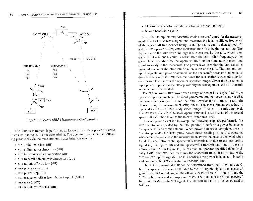
84 COMSAT TECHNICAL REVIEW VOLUME 23 NUMBER I, SPRING 1993
S/C RX ANT
SIC
GeSIC TX ANT
VEtaEts
D/L SLIT D/L ERS
SUT UPLINK ERS UPLINK
Lps
Las
Los
Ppm
Lee
Lae
Lee
Figure 10. ESVA EIRP Measurement Configuration
The EIRP measurement is performed as follows. First, the operator is askedto ensure that the SLIT is not transmitting. The operator then enters the follow-ing parameters via the measurement's user interface window:
• SLIT uplink path loss (dB)
• SUT uplink atmospheric loss (dB)
• SLIT transmit coupler calibration (dB)
• SET transmit antenna waveguide loss (dB)
• SLIT uplink off-axis loss (dB)
• ERS power range (dB)
• ERS power step (dB)
• ERS frequency offset from the SET uplink (MHz)
• ERS EIRP (dBW)
• ERS uplink off-axis loss (dB)
EIIIELSAT IN-ORBIT TEST SYSTEM 85
• Maximum power balance delta between stir and ERS (dB)
• Search bandwidth (MHz)
Next, the ERS uplink and downlink chains are configured for the measure-ment. The ERS transmits a signal and measures the local oscillator frequencyof the spacecraft transponder being used. The ERS signal is then turned off,and the ERS operator is requested to instruct the SLIT to begin transmitting. Thefrequency of the SUT downlink signal is measured by the ERs, which thentransmits at a frequency that is offset from the SLIT uplink frequency, at thepower level specified by the operator. Both stations are now transmittingsimultaneously to the spacecraft. The power level at which the ERS transmitstakes into account the atmospheric attenuation at the ERs. The ERS and SUTuplink signals are "power-balanced" at the spacecraft's transmit antenna, asdescribed below. The IOTE then measures the SLIT station's transmit EIRP foreach power level across the operator-specified range. Given the SLIT antennainput power supplied to the ERS operator by the SUT operator, the SLIT transmit
antenna gain is calculated.The ERS measures SUT power over a range of power levels specified by the
operator input parameters. The input parameters are the power range (in dB),the power step size (in dB), and the initial level of the ERS transmit EIRP (indBW) during the measurement setup phase. The measurement procedure isrepeated for a typical 15-dB adjustment range of the SLIT transmit EIRP level.The ERS EIRP power level (also an operator input) is used instead of the normalspacecraft saturation level as the backoff reference level.
For each power level in the sweep, the following steps are performed. TheSLIT operator is requested by the ERS operator to perform a power balance atthe spacecraft's transmit antenna. When power balance is complete, the SEToperator provides the SET uplink power meter reading to the ERS operator,who enters the value into the measurement. Power balance is achieved whenthe difference between the spacecraft's transmit EIRP due to the ERS uplinksignal (E1e in Figure 10) and the spacecraft's transmit EIRP due to the SETuplink signal (Er, in Figure 10) is less than an operator-specified delta (typi-cally I dB). The FRS then measures the spacecraft transmit EIRPS due to theSLIT and ERS uplink signals. The ERS confirms the power balance at this pointand computes the SuT earth station transmit EIRP.
The SUT'S transmitted EIRP can be determined from the following quanti-ties: the spacecraft transmit EIRE due to the Stir uplink signal, the spacecraftgain for the ERS uplink signal, the off-axis losses for the ERS and SLIT, and theSLITS uplink path and atmospheric losses. The IOTE measures the spacecrafttransmit EIRP due to the SET signal. The SET transmit EIRP is then calculated asfollows:
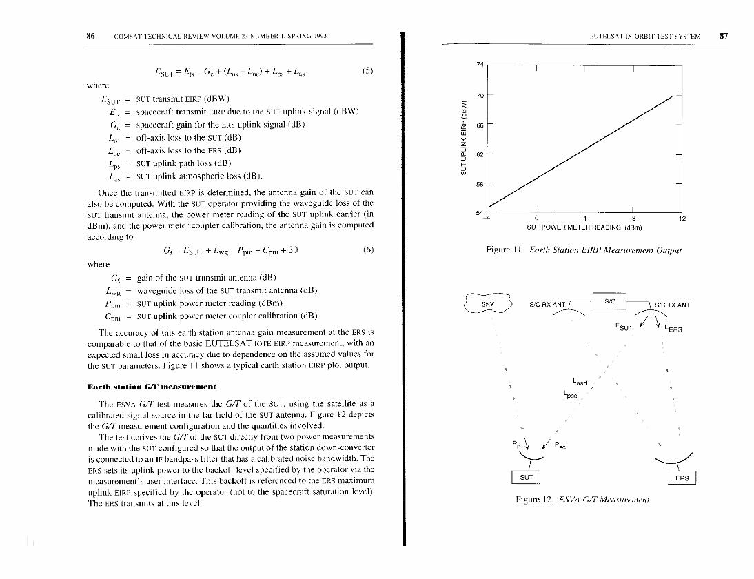
86 COMSAT TECHNICAL REVIEW VOLUME 23 NUMBER I. SPRING 1993
ESUT=Ell -G'e+(L0 -L0)+Lps+Las (5)
where
Esur = SUT transmit EIRP (dBW)
Ert = spacecraft transmit EIRP due to the SUT uplink signal (dBW)
Gr = spacecraft gain for the ERS uplink signal (dB)
L., = off-axis loss to the SUT (dB)
L„e = off-axis loss to the ERS (dB)
LpS = SUT uplink path loss (dB)
Las = SuW uplink atmospheric loss (dB).
Once the transmitted E[RP is determined, the antenna gain of the Sur canalso be computed. With the SET operator providing the waveguide loss of theSLIT transmit antenna, the power meter reading of the SUT uplink carrier (indBm), and the power meter coupler calibration, the antenna gain is computedaccording to
Gs = ESUT + Lwg - Ppm - Cpm + 30
where
(6)
Gs = gain of the stir transmit antenna (dB)
Lwg = waveguide loss of the SUT transmit antenna (dB)
Ppm = Sul uplink power meter reading (dBm)
Cpm = SET uplink power meter coupler calibration (dB).
The accuracy of this earth station antenna gain measurement at the ERS iscomparable to that of the basic EUTELSAT 101E EIRP measurement , with anexpected small loss in accuracy due to dependence on the assumed values forthe SET parameters . Figure I I shows a typical earth station EIRP plot output.
Forth station G/f measurement
The ESVA G/T test measures the GIT of the Sul, using the satellite as acalibrated signal source in the far field of the SUT antenna. Figure 12 depicts
the GIT measurement configuration and the quantities involved.The test derives the G/L of the SUT directly from two power measurements
made with the SUT configured so that the output of the station down-converteris connected to an IF bandpass filter that has a calibrated noise bandwidth. TheERS sets its uplink power to the backoff level specified by the operator via themeasurement's user interface. This backoff is referenced to the ERS maximumuplink EIRP specified by the operator (not to the spacecraft saturation level).
The ERS transmits at this level.
EETP.ESAI IN- ORBIT TEST SYSTEM 87
0 4 8SUT POWER METER READING (dBm)
12
Figure I I . Earth Station EIRP Measurement Output
S/C RX ANT S/C
ESU
SIC TX ANT
EERS
Figure 12. ESVA GIT Measurement

88 (BMS AT TECI INICAI. REVIEW VOLUME. 24 NUMBER I. SPRING 1993
The SUT antenna is pointed toward the satellite, and the power, Psi, at thefilter output is measured. The SUT antenna is then pointed toward the sky,away from the satellite, and the noise power, P,,, at the filter output is mea-sured. G/T is computed using P, and P,,.
The ERS uplink and downlink are configured for each channel being mea-
sured, and the local oscillator frequency of the spacecraft is measured, if it is
different from that of the last channel. The uplink at the ERS is then set to the
operator-specified hackoff level from the specified maximum uplink power,
and the mFD and EIRP are measured. Next, the ERS operator enters the off axis
losses, as well as the downlink atmospheric and path losses, as seen from the
SuT and provided by the SET operator. The suT operator is directed to measure
the received power at the SUr, and then to move the SUT antenna away from
the spacecraft and measure the noise received from the sky. The IOTE deter-
mines the spacecraft's transmit FIRE as seen at the SET by calculating the
spacecraft's transmit EIRP as seen at the ERs. The SET G/T is computed as
follows:
where
G/F,=-228.6+laws + Lpsd+Lasd-ESUT+10XIog P3-CF (7)
G/T, =
-228.6 =
Bw, _
Lpsd =
Lasd =
ESCr =P, _
where
measured Su'r G/T (dB/K)
dB equivalent of Boltzmann's constant
SUT filter bandwidth (dB-Hz)
Stir downlink path losses (dB)
SET downlink atmospheric loss (dB)
spacecraft EIRP seen by SUT (dBW)
(P2/PI - I)
P = 10(P°/IO)
P = l o (`5-/IO)
CF = operator-entered correction factor (dB).
ESV.% transmit polarization isolation measurement
This test measures the transmit polarization isolation of the sue. In theEUTELSAT TOT, the test can be performed in both the X and the Y polarizationsat various SUT antenna pointing angles. Figure 13 illustrates the ESVA trans-mit cross-polarization isolation measurement configuration and the quantitiesinvolved.
S/C RX ANT
EUTELSAT INORBIT TEST SYSTEM 89
S/C S/C TX ANT
EIRPSX >\>^\ EIRPsyEIRPe
EIRPex
SUT UIL LOSSES ERS U/L LOSSES
Lsup Leup
Lsua Leua
Los Lae
SUT CROSS-POL EIRP
DUE TO EtSX
SUIT TX ANT ERS TX ANT
ERS D/L LOSSES
Ledp
Leda
Figure 13. ESVA Transmit Cross-Polarization Isolation Measurement
When the SUT transmits a carrier in one polarization, a small amount of thecarrier's power spills over, or leaks, into the opposite polarization trans-mit path due to imperfect isolation between the two paths. This leakagepower is also transmitted in the opposite polarization. The SUT transmit cross-polarization isolation, I, between the two transmission paths measures the
degree of isolation.The measurement uses two spacecraft transponders: one designated as the
copolarization (copol) transponder, and the other as the cross-polarization(cross-pol) transponder. First, the ERS operator configures the measurement byentering various parameters into the measurement's user interface window,and establishes communication with the SUT operator, who supplies SUT pa-rameter values for entry via the user interface window. During the measure-ment, the ERS operator is prompted via dialog windows to provide input andperform various actions. The ERS operator is then requested to turn on thecopol transponder and turn off the cross-poI transponder. The ERS configures
90 COMSAT TEC1 INICAI. REVIEW VOLUME 13 NUMBER I. SPRING 1993
its uplink and downlink chains for the spacecraft channel being used andtransmits an uplink carrier in the copol transponder at the center frequency ofthe channel. The downlink signal is received at the ERS, and the spacecraft'slocal oscillator frequency is measured. The SLIT operator is then instructed totransmit at the same frequency and polarization as the ERS uplink carrier. TheERS stops transmitting. and the frequency of the SET transmission is measuredat the ERS. The ERS is retuned to a frequency that is offset from the SuT uplinkfrequency, and then transmits at a backoff level relative to the maximum earthstation uplink transmit EIRP allowed by the measurement program.
An interactive power balance procedure is now performed, as in the FSVAEIRP measurement. The balancing procedure ensures that the spacecraft trans-mit EIRP due to the ERS uplink carrier (EIRP0c in Figure 13) and the spacecrafttransmit EIRP due to the SET uplink carrier (EIRPtx) differ by less than anoperator-specified amount. The SUT copol transmit EIRP is designated as E,,x,where the subscripts indicate transmission (t) by the SLIT (s) in the arbitrarilychosen X polarization (x). Uplink and downlink parameters (path and atmo-spheric losses) are measured for both the ERS and SUT uplink and downlinkcarriers.
Next, the sul operator is requested to turn off the SET uplink carrier. Thecopol transponder is turned off, and the cross-pol transponder is turned on.The ERS then transmits a cross-pol carrier (i.e., a carrier on the oppositepolarization. E,cy) at the same frequency used in the copol measurementprocedure above, but 30 dB down from the level transmitted by the ERs duringthe copol measurement (E,cx) just performed.
At this time, a series of measurements are performed. The SUT operator isrequested to transmit again in the copolarization at the level of E„x, as before.Some of the power from the SET transmission of a copol uplink carrier leaksinto the transmission path of the opposite polarization and is also transmittedby the SUT as a small cross-pol carrier. This undesirable carrier causes acorresponding spacecraft EIRP (EIRP,,) to be transmitted. The ERS cross-poluplink carrier, Etey, causes a new level of spacecraft transmit EIRP, EIRP0,. Theuplink and downlink parameters for the ERS and SET signals are measured foruse in the cross-pol measurement.
The ERS operator is prompted for the SET power meter reading. the SuTantenna azimuth or elevation, and the contour value of the su I antenna gain.Based on the copol and cross-pol measurements just performed, the SETantenna transmit isolation is computed (in dB) as follows:
fs = Etsx - (Eresy - Ereey) - I=tcy - (Lsup - Lcup)
- (Lsua - Law) + (Los - !roc) (S)
Is =
Etsx =
EUTELSAP IN-ORB[ r TEST SYSTEM 91
SET transmit cross-pol isolation (dB)
SUT transmit copol EIRP (dBW)
Eresy = computed equivalent spacecraft EIRE at the ERS receive antennadue to the SET transmit cross-pol carrier (dBW)
Erccy = computed equivalent spacecraft EIRP at the ERS receive antennadue to the ERS transmit cross-pol carrier (dBW)
E,cy = earth station EIRP transmitted by the ERS in the cross-pot carrier(dBW)
Lsup = stir uplink path loss (dB)
Leup = ERS uplink path loss (dB)
Lsua = SUT uplink atmospheric loss (dB)
Lcua = ERS uplink atmospheric loss (dB)
Los = off-axis loss to the SET (dB)
Loc = off-axis loss to the ERs (dB).
Because the SUT and ERS downlink frequencies are very close (typically2 MHz apart at I 2-GHz carrier frequencies), the measurement assumes thatthe difference in downlink losses for the ERS and Su I signals is negligible forthe downlink path and atmospheric losses.
ESV,% transmit sidelobe pattern measurement
This test, which measures the transmit sidelobe levels of the Su'r transmitantenna, is performed to ensure that the SUT meets EUTELSAT specifications.Figure 14 depicts the ESVA transmit sidelohc measurement configuration andthe quantities involved.
First, the SET transmits in the linear region of the spacecraft TWTA gaintransfer characteristic. It then stews the su I antenna in azimuth or elevation,and the ERS measures the downlink power. Next, the SET antenna is offset by1° and the uplink power is increased by 15 dB. The SET antenna is thensteered away from beam center while the ERS measures the downlink power.This procedure is repeated for both sides of the SET antenna beam. The ERSEIRP power level (an operator input) is used, instead of the spacecraft satura-tion level, as the backoff reference level. The measurements for each side ofthe SUT antenna beam are then combined in an interactive data analysis andmanipulation software package and plotted to show the Sul antenna pattern.
A gain transfer measurement is performed, using the injected signal tech-nique, and ,saved for later use in computing spacecraft transmit EIRP. The SET

92 COMSAT TECHNICAL REVIEW VOLUME 23 -N UMBER I . SPRINO 1993
S/C RX ANT
Fe
S/c SIC TX ANT
EsV y Ee
Lsup
LsuaL0
t PSUT
Figure 14. ESVA Transmit Sidelobe Measuremen!
is directed to turn off its transmitter during this measurement. The Sur thenturns on its transmitter and transmits a carrier to the spacecraft, and thecarrier's downlink frequency is measured by the ERS. The ERS transmits anuplink carrier at a frequency that is offset from the SUT uplink. The SUIT andERS signals are power-balanced, as in the ESVA EIRP measurement, and the ERSturns off its uplink signal.
The SLIT is then directed to slew its antenna at a user-specified rate, and themeasurement is initiated by the ERS operator via a dialog window and contin-ues until stopped by the operator. For each Su'r transmit ETRP measurement,the measurement program computes the antenna slew angle in real time, basedon the initial angle, start time, and slew rate inputs supplied by the operator,and the time elapsed since the start.
The spacecraft EIRP due to the SUT uplink carrier is expressed in terms ofthe EIRP caused by the ERS uplink carrier and the levels measured on thespectrum analyzer for both downlink carriers, as follows:
E,=Ee+ (S,-Se) (dBW) (9)where
Es = spacecraft transmit EIRP due to SUT carrier (dBW)
HUrILLSAT IN-ORBIT TEST SYSTL'M 93
Ee = spacecraft transmit EIRP due to ERS carrier (dBW)
Ss = received SUT signal measured on spectrum analyzer (dBm)
Se = received FRS signal measured on spectrum analyzer (dBm).
The spacecraft transmit EIRE due to the stir carrier can be obtained bymeasuring only three quantities: Ee, Ss, and S. The value for Ee and theassociated signal level measured on the spectrum analyzer, S, are arbitrarilychosen as the first point in the gain transfer measurement performed earlier.The above relationship assumes the following:
• The ERS gain transfer measurement is performed using the injectedsignal technique.
• The ERS is not transmitting during measurement under slowingconditions.
• The SUT downlink carrier is at the same frequency and polarization asthe gain transfer measurement.
• The injected signal power level is the same in both measurements.
• There is negligible change in the ERS distance to the spacecraft be-tween the gain transfer measurement and the ERs Eu(P measurement afew minutes later.
• Because the gain transfer and EIRP measurements are performed a fewminutes apart, the downlink path loss, downlink atmospheric loss, ERSreceive antenna gain, and inject signal coupler value are assumed tobe constant during the measurement.
• The SUT antenna clews over the desired range in a few minutes. If theslew rate is a typical 0.02°/s, the Sul- requires 5 minutes to slew 6°.
Since E, and S, were measured and stored during the gain transfer test, thespacecraft EIRP due to the SET uplink carrier can be determined by measuringthe received signal level on the spectrum analyzer while the SET antenna isslewing in real time. The spectrum analyzer is set to a reference vertical scalelevel and left on that scale setting during the slew measurement. The measure-ment then makes successive and rapid readings of the voltage measured by thedigital voltmeter and converts them to equivalent power in dBm. The aboverelationship [equation (9)] is used to compute the spacecraft transmit EIRP dueto the SUT uplink carrier in real time and "on the fly." while the SET antenna isslewing. Thus, it is not necessary to perform actual injected-signal EIRP mea-surements for the SET signal. The relationship has been verified empiricallywith measurement data.
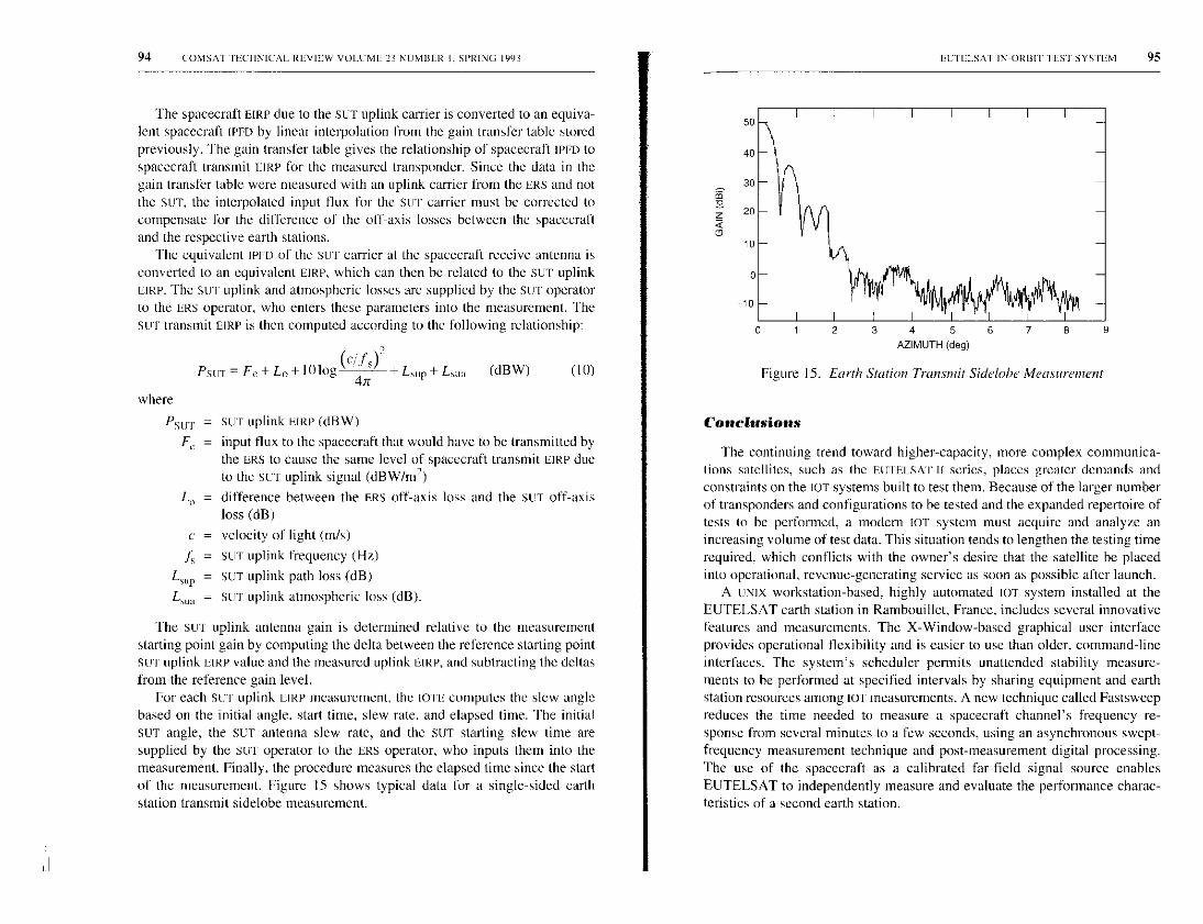
94 COMSAT TECHNICAL REVIEW VOLUME 23 NUMBER I. SPRING 1993
The spacecraft EIRE due to the SUT uplink carrier is converted to an equiva-lent spacecraft IPFD by linear interpolation from the gain transfer table storedpreviously. The gain transfer table gives the relationship of spacecraft IPFD tospacecraft transmit EIRE for the measured transponder. Since the data in thegain transfer table were measured with an uplink carrier from the ERS and notthe sur, the interpolated input flux for the SLIT carrier must be corrected tocompensate for the difference of the off-axis losses between the spacecraftand the respective earth stations.
The equivalent IPFD of the SUT carrier at the spacecraft receive antenna isconverted to an equivalent EIRP, which can then be related to the SUT uplinkLIRE. The SLIT, uplink and atmospheric losses are supplied by the Su I operatorto the ERS operator, who enters these parameters into the measurement. TheSu r transmit EIRP is then computed according to the following relationship:
PsoT=Fe+L0+IOlog(c47ry +LnuP+Lsua (dBW) (10)
where
PSUT = SLIT uplink LIRE (dBW)
F, = input flux to the spacecraft that would have to he transmitted bythe ERS to cause the same level of spacecraft transmit LIRE dueto the SET uplink signal (dBW/m2)
L„ = difference between the ERS off-axis loss and the SLIT off-axisloss (dB)
c = velocity of light (m/s)
J, = SUT uplink frequency (Hz)
Lion = SLIT uplink path loss (dB)
L,,,, = SET uplink atmospheric loss (dB).
The SUT uplink antenna gain is determined relative to the measurementstarting point gain by computing the delta between the reference starting pointSu'r uplink FIRE value and the measured uplink EIRE, and subtracting the deltasfrom the reference gain level.
For each SET uplink FIRE measurement, the IOTE computes the slew anglebased on the initial angle. start time, slew rate, and elapsed time. The initialSLIT angle, the SUT antenna slew rate, and the SUT starting slew time aresupplied by the SET operator to the ERS operator, who inputs them into themeasurement. Finally, the procedure measures the elapsed time since the startof the measurement. Figure 15 shows typical data for a single-sided earthstation transmit sidelobe measurement.
EUTELSAT IN-ORBIT TEST SYSTEM 95
Figure 15. Earth Station Transmit Sidelobe Measurement
Conclusions
The continuing trend toward higher-capacity, more complex communica-tions satellites, such as the FUTELSArIt series, places greater demands andconstraints on the IOT systems built to test them. Because of the larger numberof transponders and configurations to be tested and the expanded repertoire oftests to be performed, a modern TOT system must acquire and analyze anincreasing volume of test data. This situation tends to lengthen the testing timerequired, which conflicts with the owner's desire that the satellite be placedinto operational, revenue-generating service as soon as possible after launch.
A UNIX workstation-based, highly automated IOT system installed at theEUTELSAT earth station in Rambouillet, France, includes several innovativefeatures and measurements. The X-Window-hased graphical user interfaceprovides operational flexibility and is easier to use than older, command-lineinterfaces. The system's scheduler permits unattended stability measure-ments to be performed at specified intervals by sharing equipment and earthstation resources among LOT measurements. A new technique called Fastsweepreduces the time needed to measure a spacecraft channel's frequency re-sponse from several minutes to a few seconds, using an asynchronous swept-frequency measurement technique and post-measurement digital processing.The use of the spacecraft as a calibrated far-field signal source enablesEUTELSAT to independently measure and evaluate the performance charac-teristics of a second earth station.

96 COMSAT 'I HCIINICN. REVIEW VOLUME 13 NUMBER I. SPRING 1993
The EUTELSAT lOT system was developed to support EUTELSAT's test-ing of its second-generation satellites, and has been used for the lOT of theEUTII.SAT n F1, F2, F3, and F4 spacecraft.
Acknowledgments
The authors would like to acknowledge the following individuals. C. Mahleof COMSAT Laboratories has been it constant source of help and encourage-
intent. His past and current contributions to this work are major. S. Bangara.
currently with INTELSAT, played a key role in defining the .system require-
ments fir the EUTELSAT LOTE, and R. Aster of DTRE made significant
contributions to the TOTE-ECCS interface implementation and testing. The
DTRE slafj at the Rambouillet earth station are acknowledged for their a.s.sis-
tatce and support during the system installation, testing, and deployment of
the EUTELSAT IOTF_.
The earth station (ex(luding the IOTE/AIMS) was made available to
EUTELSAT by DTRE, the overseas arm of the French Post, Telephone, and
Telegraph Administration (PTT). The ECCS computer and its station control
and status software are supplied to EUTELSAT by DTRE.
References
[I] I. Dostis et al., "In-Orbit Testing of Communications Satellites;" COMSAT Tech-
nical Review. Vol. 7. No. I, Spring 1977, pp. 197-226.121 A. F. Standing, Measurement Techniques for In-Orbit Testing of Satellites. Coln-
[31puler Science Press. New York: W. H. Freeman, 1990.C. E. Mahle, "In-Orbit Testing of Commercial Communications Satellites." 23rdGeneral Assembly of the International Union of Radio Science (URSI). Prague,Czechoslovakia. August-September 1990.
[4] Y. Tharaud. B. Kasstan, and P. Barthmann . `101 System for the EUTELSAT II
[51
Satellites," IEEE Global Satellite Communications Symposium, Nanjing, China.May 1991, Proc., pp. 168-177.Y. Tharaud and V. Riginos, "EUTELSAT's Facilities for Measurement of
Earth Stations and In-Orbit Satellite Payloads." 23rd General Assembly of the
International Union of Radio Science (URSI), Prague, Czechoslovakia, August-
September 1990.
[61 V. Riginos, P. Shen, and S. Bangara , "In-Orbit Testing of Communications Satel-
[7]
liter: The State of the Art," IEEE Global Satellite Communications Symposium.
Nanjing, China. May 1991, Proc., pp. 150-159.
S. K. Card. T. P. Moran, and A. Newell, The Psychology of Human-Computer
Interaction, Hillsdale, NJ: Lawrence Erlhaum, 1983.
FtUTILLSAT IN-ORBIT TEST SYSTEM 97
IS!
191
K. D. Fullett et al., "Microwave Measurement Software System," COMSATTech-nical Review, Vol. 23, No. I. Spring 1993, pp. 101-137 (this issue).K. D. Fullett and V. E. Riginos. "Error Analysis of In-Orbit Measurements onCommunications Satellites," 23rd General Assembly of the International Union
of Radio Science (URSI). Prague, Czechoslovakia, August-September 1990.1 101 Hewlett-Packard. "Phase Noise Characterization of Microwave Oscillators," HP
Product Note No. 117296-I.
Kenneth D. Fullett received a BSEE and MSEE from
the University of Illinois, Urbana-Champaign, in 1979 and
1981, respectively. He joined COMSAT Laboratories in
1981 as a member of the Transponders Department of the
Microwave Technology Division and participated in all
aspects (in(luding both microwave hardware and computer
software .system design) of many LOT systems, including
those for INTELSAT MCI, and EUTELSAT. His work also
involved software development for COMPACT Software,
and he was a project manager for the RF Terminal Super-
visory System of the NASA/ACTS earth station. Mr. Fullett
is currently engaged in high-energy physics research in the Anti-Proton Source De-
partment of the Accelerator Division of Fermi National Accelerator Lahoratorv. Batavia,
Illinois.
Bernard J. Kasstan received an Honours degree in phys-
ics mud electronics from Newcastle- upon -Tyne Polviech-
nic, U. K., in 1981; and a Masters degree in te leeonununi-
cation .s from the University of Essex in 1982. He
subsequently conducted research on tropospheric propa-
gation on earth-to-satellite paths . He joined EUTEISAT in
1984, and was responsible for the verification of nets earth
stations in the EUTELSAT space segment. In 1987, he moved
to JOT activities, including payload subsystem performmnce
evaluation , investigations of payload anomalies in orbit,
and supervision of JOT installation at the host stations. In
conjunction with the System Verification Test Section, Mr. Kasstan has developed newJOT techniques that have been discussed in numerous published papers.
98 COMSAT TECHNICAL REVIEW VOLUME 23 NUMBER I. SPRING 1993 1 EUTELSAT IN-ORRIT TEST SYSTEM 99
Walter D. Kellev, Jr., earned a BS in electrical
engineering at the Catholic University of America,
Washington, D.C., in 1974; and an MBA at Marvmwm,t
University, Arlington, VA, in 1983. In 1991, he joined the
Transponders Department of the Satellite and Systems
Technologies Division at COMSAT Laboratories as a Mem-
ber of the Technical Staff. At COMSAT, lie has participated
in development of the IOT system .for Hughes Connumica-
tion.s' DirecTv an 10T system for EUTELSAT, and the
NASA/AC'T'S ground .station control and status subsystem.
Vasilis E. Riginos received a BE, MEng, and PhD in
electrophv--vies firm the Stevens Institute of Technology,
Hoboken, N.J. in 1964, 1970, and 1973, respectively. He is
currently Manager of the Transponders Department of the
Satellite and Systems Technologies Division at COMSAT
Laboratories, where he is responsible for-directing research
and development on contnnlnicatian5 system performance
as applied to satellite transponders. He also supervises
research and development in advanced microwave circuits
such as highpawer amplifiers, regenerative receivers,
filter's, and multiplexers. Dr. Riginos participated in the
evaluation of the Irnmarsat progran, and has been project manager fi r the GTE ATEF
lOT system, the INTELSAT Maritime Communications Subsistent LOT station, the
EUTELSAT lOT system, and the Hughes DirecTv' lOT system. He is a member of
Sigma Xi, AAAS, IEEE, and the American Physical Society.
Pei-Hong Shen received a BS and MS in genetics, and
an MS in computer science, from Washington State
University in 1983, 1984, and 1986, respectively. From
1978 to 1981, she studied biology and genetics while at-
tending butlan University in Shanghai, Peoples Republic of
China. Ms. Shen is currently it Senior Member of the
Technical Staff in the Transponders Department of the
Satellite and Systems Technologies Division at COMSAT
Laboratories, where she is primarily re.sponsiblefor design
and development of software fa- cotnmunicatio s satellite
application v, Since joining COMSAT in 1987, she has been
Steven L. Teller received an AS and AA from HarperCollege in 1979; and a BA in information and computersciences from Hood College in 1991. He is currently aMentber of the Technical Staff in the TranspondersDepartment of the Satellite and Systems Technologies
Division at COMSAT Laboratories. Since joining COMSAT,he has been involved in various aspects of the IOT of
eommmtication.s satellites, including the NASA/ACTS REterminal supervisor, and 107 for EUTELSAT, MCI,
INTELSA7; GTE, and the Hughes Dire( ll T"' system. Hehas been responsible for software us manual measurement
verification during system development, ill-plant testing, and on-site testing. He wasalso involved in prototrping and testing various new measurement schemes, and was amajor contributor to final system installation testing.
Yves Tharaud received at MSc in electron icy,
electrotec'hnology, and automatics flan, the University ofBordeaux, France, in 1974: and the title of Engineer fort
the Ecole Nationale Superieure d'Electrouyue et de
Radioelectricite de Bordeaux in 1975. He joined EUTELSAT
in 198/ cmd participated in the definition and implementa-
tion of new facilities dedicated to LOT, earth station verifi-
(ation and assistance (ESVA), and payload traffic monitor-
ing for the EUTELSA T LL satellites. He served as manager
of the System Verification Test Se, tion in the Operations
Department, where lie supervised activities related to sat-
ellite payload LOT and ESVA. Mr. Tharaud cooperated with the European SpaceAgency in similar activities oil the ECS satellites and participated in the payload 101and various other experiments on the OTS satellite as a member of the CNET inFRANCE TELECOM.
involved in the design and development of die following systems: NASA/ACTS,EUTELSAT LOT, and Hughes ' Direci'T"' 10T. She is a memtber of the IEEE ComputerSociety.
Index: cnnnnunieallon satellites, in-orhit testing,software , systems monitoring, transponders
Microwave measurement systemsoftware
K. D. FULl.Fn, W. D. KELLEY, V. E. RICINOS, P-H. SHEN,
AND S. L. TELLER
(Ylunmsdpt received Dccemher 9, 1992)
Abstract
To facilitate efficient, cost-effective development of in-orbit lest (LOT) measure-ments and turnkey systems, microwave measurement system (MMS) software built onan engineered platform of reusable software services and facilities has been developedover the past several years and deployed in operational systems. The Measurement
Processing and Control Platform (MPCP) provides modular software components thathave been developed and tested for measurement scheduling, interprocess communica-tions, and resource and system information sharing. Its code libraries support graphicallybased user interfaces, instrument control, instrument bus management, and error detectionand reporting; and its data processing subsystems support database management, reportgeneration, and interactive data analysis.
Operating in a network environment under a UNIX System V operating system,this multiuser, multitasking MMS software supports both local and wide-area network-
ing, including remote access and control of the IOT measurement equipment. It ex-
ecutes in a distributed processing system architecture spanning a number of dissimilarworkstations. With interprocess/intermachine communications provided by the MPCPmail system, the separate user interface and measurement programs can execute ondifferent machines at different times, for improved operational flexibility.
This paper describes the design and implementation of the MMS software. Theconcepts and methods presented are also applicable to other measurement-orientedsystems (such as those used for communications system monitoring), where escalatingsoftware costs must be controlled.
101

102 COMSAI I ECHNICAL REVIEW VOLUME, 23 NUMBER I, SPRING 1993
Introduction
Computer-controlled in-orbit test (IOT) systems integrate microwavemeasurement equipment, computer hardware, and measurement software intoa unified test facility for measuring the communications subsystem perfor-mance of an orbiting satellite. To assess performance, the IOT system conductsa variety of microwave frequency measurements. These include the measure-ment of spacecraft input power flux density ([PFD) and equivalent isotropicallyradiated power (FURP); transponder frequency response; gain transfer; groupdelay: gain-to-noise temperature ratio, G/C; and others [1],[2].
The development of modern JOT systems is traced by Shen el at. [31. Asnoted in that paper. IOT is performed for acceptance testing immediatelyfollowing launch; to monitor communications subsystem performance through-out the satellite's operational lifetime; and to investigate anomalies. The specificmissions determine the IOT system's basic requirements. The fact that newersatellites contain more transponders and have increased payload complexitycompared to earlier generations places greater demands and constraints on theIOT systems built to test them. Because the satellite owner desires to place thesatellite into revenue-generating operational service as soon as possible afterlaunch, the IoT system is constrained to accomplish its task as quickly aspossible, especially during acceptance testing. Increased satellite capacity andcomplexity have also resulted in greater volumes of test data, which must bemaintained and reported. Finally, the pool of spacecraft experts available forperforming complex IOTs and evaluating the data is distributed more thinly asthe number of satellite networks in service increases.
In addition to its primary mission of performing loT measurements, themodern computer-controlled IOT system must address such system requirementsas real-time and network operation, human-machine interaction, and remoteaccess and control of the measurement hardware. The system must provide auser interface that is easy to use, yet flexible enough to accommodate thevarious IOT missions. The capability to execute measurements concurrentlyand to support a multiuser environment are desirable system features.
These requirements and constraints place greater responsibility for loTsystem functionality on the software, which must address the network, hardware,and communications environment of a distributed processing system spanninga number of workstations. As a result, the TOT software, with its volume,sophistication, complexity, and difficulty of development and control, hascome to dominate both overall system cost and scheduling. The developmentof custom software is time-consuming and costly, and requires highly skilledpersonnel. Methods and techniques are continually being sought to make the
MICROWAVE MEASUREMENT SYSTEM SOFTWARE 103
tOT software production process more efficient. By contrast, the cost andscheduling aspects of hardware implementation for IOT and similar measurementsystems are generally well-understood and well-controlled.
This paper discusses the principal software concepts underlyingdevelopment of the Measurement Processing and Control Platform (MPCP),which served as the foundation for design and implementation of the microwavemeasurement system (MMS) software. Specific applications for computer-controlled TOT measurements and turnkey systems are addressed. A companionpaper 141 describes the implementation of the MPCP software in a specific lOT
system.The principles underlying a robust, software-engineered platform such as
MPCP are also applicable to the software implementation of similarmeasurement-oriented, computer-controlled systems, such as communicationsmonitoring systems. Like computer-controlled TOT systems, these systemsrequire escalating amounts of software for which costs, scheduling, and quality
must be controlled.
Software development methodology
IOT systems are uniquely designed to test specific satellite characteristicsand networks; however, many IOT measurement subtasks are the same fromone IOT system to the next. Such commonality of function underlies much of
the MMS design.Because 1oT systems are unique and custom-built, the software
implementation of computer-controlled IOT systems is not standardized, nor isthere a standard 1oT software architecture. Riginos et at. [51 contrasts twoapproaches to designing such software. In one approach, measurements areimplemented one at a time in a self-contained manner. Each measurementperforms all required functions, including instrument control, user interface,and data processing tasks such as database management, printing, and plotting.As new measurements are required, an existing measurement is copied andmodified to meet the specific requirements. While this self-contained approachhas certain attributes, such as moderate levels of developmental effort forsucceeding measurements, its use for large-scale systems software developmentalso contributes to problems in terms of life cycle maintenance, quality,
capability, flexibility, and extensibility.Early implementations of computer-controlled 1OT systems employed the
self-contained measurement methodology. After several such systems hadbeen implemented, it was realized that 80 to 90 percent of the measurementtasks-such as managing the user interface, controlling and managing the
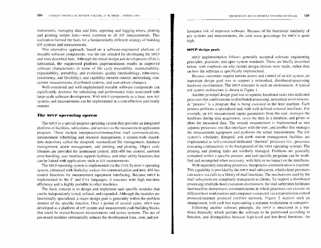
104 COMSAT IECI INICAL REVIEW VOLUME 2 3 NUMBER I . SPRING 1993
instruments, managing data and files, reporting and logging errors, plottingand printing output data-were common to all IOT measurements. Thisrealization formed the basis for a fundamentally different strategy of buildingIOT systems and measurements.
This alternative approach, based on a software-engineered platform ofreusable software components, was the one selected for developing the MPCPand MMS described here. Although the initial design and development effort issubstantial, the engineered platform implementation results in improvedsoftware characteristics in terms of life cycle (reusability, maintainability,expandability, portability, and evolution), quality (methodology, robustness,consistency, and flexibility), and capability (remote control, networking, con-current measurements, distributed systems, and user-driven changes).
Well-conceived and well-implemented reusable software components cansignificantly decrease the scheduling and performance risks associated withlarge-scale software development. With MPCP components as a base, new orsystems and measurements can be implemented in a cost-effective and timelymanner.
The firer operating system
The MPCP is a special-purpose operating system that provides an integrated
platform of facilities, subsystems, and services to the measurement application
program. These include interprocess/intermachine mail communications,
measurement scheduling and resource management, a system-wide shared-
data depository called the datapool. standardized file management, database
management, alarm management, and printing and plotting. Object code
libraries are provided for instrument control, IEEE-488 bus control, uniform
error handling, user interface support facilities, and other utility functions that
can be linked with applications such as IOT measurements.
The MPCP operating system is implemented via the UNIX System V operatingsystem. enhanced with Berkeley sockets for communication and IEEE-488 buscontrol functions for measurement equipment interfacing. Because MPCP isimplemented in the C and C++ languages, it executes with high run-timeefficiency and is highly portable to other machines.
The basic concept is to design and implement task-specific modules thatcan be independently tested, refined, and expanded. Although the modules arefunctionally specialized, a major design goal is generality within the problemdomain of the specific function. Over a period of several years, MPCP wasdeveloped as a platform of IOT system and measurement code building blocksthat could be reused between measurements and across systems. The use ofpre-tested modules substantially reduces the development time, cost, and per-
MICROWAVE MEASUREMENT SYSTEM SOFTWARE 105
formance risk of unproven software. Because of the functional similarity ofJOT systems and measurements, the code reuse percentage for MPCP is quite
high.
MPCP design goals
MPCP implementation follows generally accepted software engineeringprinciples, practices, and open system standards. These are briefly describedbelow, with emphasis on why certain design choices were made, rather thanon how the software is specifically implemented.
Because customers require remote access and control of an IOT system, animportant design goal was to support a networked, distributed-processinghardware environment. The Mpcp executes in such an environment. A typicallOT system architecture is shown in Figure 1.
Another principal design goal was to separate functional tasks into dedicatedprocesses that could execute in distributed-processing, networked environments.A "process" is a program that is being executed in the host machine. Eachprocess performs a specialized task with well-defined external interfaces. Forexample. an IOT measurement inputs parameters from the user, manages thehardware during data acquisition, saves the data in a database, and prints orplots the measured data. The overall measurement is implemented as twoseparate processes: one that interfaces with the user, and another that managesthe measurement equipment and performs the actual measurement. The 101system's scheduler, datapool. and earth station management facilities areimplemented as self-contained dedicated "daemon" processes (i.e., processesexecuting continuously in the background of the UNIX operating system). Theprinting and plotting tasks are similarly managed. Problems are generallycontained within a specific process, and task-specific programs can be modi-fied and recompiled when necessary, with little or no impact on the interfaces.
With separately executing processes. interprocess communication is required.This capability is provided by the MPCP mail subsystem, which client processescan access via calls to a library of mail functions. The mechanisms used by themail subsystem are completely transparent to clients. To support a distributedprocessing (multiple-host) execution environment, the mail subsystem facilitatesintermachine interprocess communications in which processes can execute ondifferent host workstations and computers connected via a transmission controlprotocol/internet protocol (rCP/IP) network. Figure 2 depicts such anarrangement, with each box representing a separate workstation or computer.
Following another software principle, the MPCP is structured in a top-down hierarchy which permits the software to be partitioned according tofunction, and distinguishes between high-level and low-level functions. An
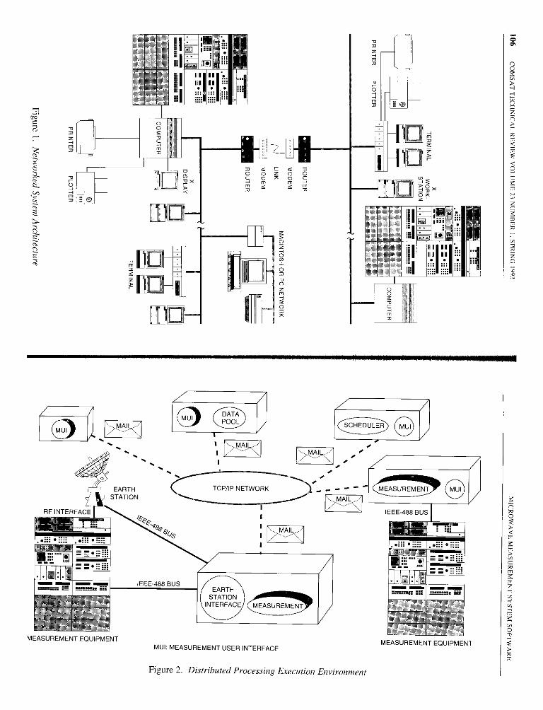
O0
110
EARTHSTATION
RF INTERFACE
MEASUREMENT EQUIPMENTMUI: MEASUREMENT USER INTERFACE
Figure 2. Distributed Processing Execution Environment
A1111I11
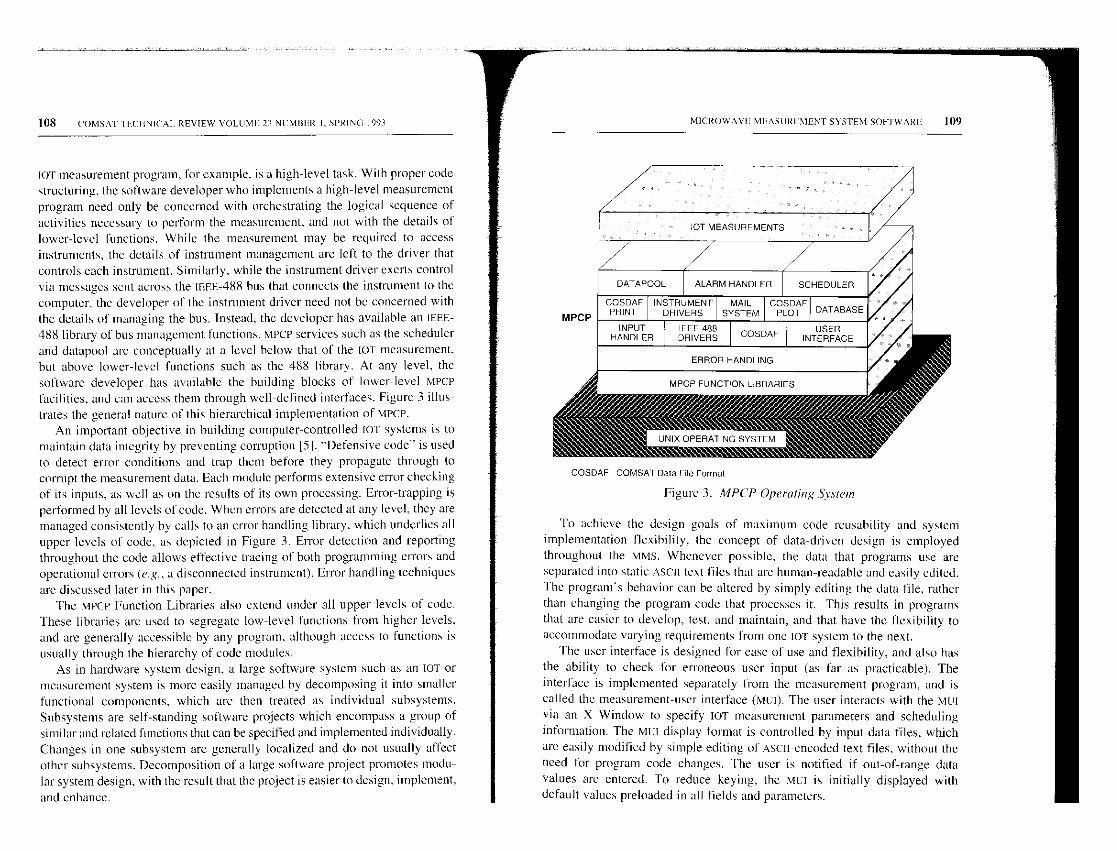
108 COMSAT II;CIINICAI. REVIEW VOLUME 23 NI MBL'R I. SPRING 1991
or measurement program, for example, is a high-level task. With proper codestructuring, the software developer who implements a high-level measurementprogram need only be concerned with orchestrating the logical sequence ofactivities necessary to perform the measurement, and not with the details oflower-level functions. While the measurement may be required to accessinstruments, the details of instrument management arc left to the driver thatcontrols each instrument. Similarly, while the instrument driver exerts controlvia messages sent across the IEHH-488 bus that connects the instrument to thecomputer, the developer of the instrument driver need not be concerned withthe details of managing the bus. Instead, the developer has available an IEEE-488 library of bus management functions. MPCI services such as the schedulerand datapool are conceptually at a level below that of the IoT measurement,but above lower-level functions such as the 488 library. At any level, thesoftware developer has available the building blocks of lower-level MPCPfacilities, and can access them through well-defined interfaces. Figure 3 illus-trates the general nature of this hierarchical implementation of MPCP.
An important objective in building computer-controlled IOT systems is tomaintain data integrity by preventing corruption [51. "Defensive code" is usedto detect en-or conditions and trap them before they propagate through tocorrupt the measurement data. Each module performs extensive error checkingof its inputs, as well as on the results of its own processing. Error-trapping isperformed by all levels of code. When errors are detected at any level, they aremanaged consistently by calls to an error handling library, which underlies allupper levels of code, as depicted in Figure 3. Error detection and reportingthroughout the code allows effective tracing of both programming errors andoperational errors (e.g., a disconnected instrument). Error handling techniques
are discussed later in this paper.The MPCP Function Libraries also extend under all upper levels of code.
These libraries are used to segregate low-level functions from higher levels.and are generally accessible by any program. although access to functions isusually through the hierarchy of code modules.
As in hardware system design, a large software system such as an TOT ormeasurement system is more easily managed by decomposing it into smallerfunctional components, which are then treated as individual subsystems.Subsystems are self-standing software projects which encompass a group ofsimilar and related functions that can be specified and implemented individually.Changes in one subsystem are generally localized and do not usually affectother subsystems. Decomposition of a large software project promotes modu-lar system design, with the result that the project is easier to design, implement,
and enhance.
DATAPOOL
COSDAFPRINT
INPUTHANDLER
MICROwAVE MEASUREMENT SYSTEM SOP 1WARL 109
JOT MEASUREMENTS
ALARM HANDLER
INSTRUMENTDRIVERS
IEEE488DRIVERS
MAILSYSTEM
SCHEDULER
COSDAFPLOT
COSDAF
ERROR HANDLING
MPCP FUNCTION LIBRARIES
UNIX OPERATING SYSTEM
DATABASE
USERINTERFACE
COSDAF COMSAT Data File Format
Figure 3. MPCP Operating Sy stem
To achieve the design goals of maximum code reusability and systemimplementation flexibility, the concept of data-driven design is employedthroughout the MMS. Whenever possible, the data that programs use areseparated into static ASCII text files that are human-readable and easily edited.The program's behavior can be altered by simply editing the data file, ratherthan changing the program code that processes it. This results in programsthat are easier to develop, test, and maintain , and that have the flexibility toaccommodate varying requirements from one 1OT system to the next.
The user interface is designed for ease of use and flexibility, and also hasthe ability to check for erroneous user input (as far as practicable). Theinterface is implemented separately from the measurement program, and iscalled the measurement-user interface (MCI). The user interacts with the MUIvia an X Window to specify lOT measurement parameters and schedulinginformation. The Mul display format is controlled by input data files, whichare easily modified by simple editing of Asc11-encoded text files, without theneed for program code changes. The user is notified if out-of-range datavalues are entered. To reduce keying, the MCI is initially displayed withdefault values preloaded in all fields and parameters.
110 COMSAT TECHNICAL REVIEW VOLUME 23 NUMBER I. SPRING 1993
Because each task is specialized, the module's developer focuses on thespecific problem at hand and optimizes the code for that task. With well-defined, constant interfaces, modules can be modified or improved withoutaffecting other modules. New modules, such as new instrument drivers, canreadily be added to the system, often by using an existing driver as a template
and modifying it as necessary.
Systems applications
Two systems are described which demonstrate the code reusability of theMPCP software building blocks. Although these systems differ substantially inmission and requirements, the MPCP platform provided the software foundationupon which the application-specific code was built.
In the first example, an TOT system using MPCP building blocks was designed.implemented, and deployed for the European Telecommunications SatelliteOrganization (EUTELSAT) 111.12]. This system has performed the IOT of fourEUTELSAT n spacecraft, and continues to monitor their performance.
In the second example. MPCP components were used to implement REterminal supervisory equipment for a National Aeronautics and SpaceAdministration (NASA) ground station for the Advanced CommunicationsTechnology Satellite (ACTS) program. In this system, a network of threeengineering workstations, supporting three simultaneous operators, performssupervisory, status, and control functions for terminal and ground station REequipment.
Communientions and network environment
The tar system architecture supports local and wide-area networking (LAN/WAN), as well as several communications protocols, network structures, andtransmission media. The system's transport/network layer implements TCP/IPto guarantee end-to-end data delivery and integrity between communicatingdevices on networks that support this protocol. The LAN's physical layerimplements the IEEE 802.3 (CSMA/CD Ethernet) protocol on coaxial cable op-erating at 10 Mbit/s. The LAN connects to workstations, displays, terminalservers, peripherals, communications equipment, and other PC-based LANs, asshown in Figure I. The system supports WAN across leased lines, publicswitched telephone networks, and public data networks at rates ranging from2.4 to 19.2 kbit/s. with link-limited transmission speed. Standard serial com-munications via RS-232 protocols and modem-connected data links are alsosupported. As illustrated in Figure 1, a complement of microwave measure-
MICROWAVE MEASUREMENT SYSTEM SOFTWARE III
went equipment is connected to the IOT system workstation at the host earthstation via the IEEE-488 digital instrumentation standard bus.
This networked system architecture provides for equipment and resourcesharing, operational flexibility, performance enhancement, incrementalredundancy, and vendor and hardware independence. System resources suchas measurement hardware, plotters, printers, and communications facilities areshared among IOT measurements and users. Incremental expansion ofcomputing, storage, display. and communications devices, as well as additionalperipherals, are readily accommodated. Additional workstations can heconnected to the network for load-sharing, and processes can execute ondifferent machines for operational flexibility and improved performance.
An important consideration when implementing a network-oriented systemis the ability to support interprocess and intermachine communications. TheX Window protocol supports communications in a network of dissimilar butX-compatible workstations. When processes reside on the same machine,Berkeley sockets support interprocess communications. The MPCP mailsubsystem also uses Berkeley sockets to implement a higher-level mechanismfor interprocess communications that extends across machine boundaries.
MPCP mail in/erproress communications
The MPCP mail subsystem provides clients with high-level, reliable, andeasy-to-program facilities for interprocess, intermachine, and internetworkcommunications. The subsystem does the following:
• Provides interprocess communications (using TCP/IP) for different pro-cesses operating on separate workstations across the network.
• Provides "atomic" transmission (data treated as an indivisible unit) oflarge data structures.
• Provides the sender with verification of transmission.
• Implements a client-server model.
• Notifies clients if a connection is lost to a server process.
The MPCP mail subsystem supports the first three features in a fashionsimilar to its main paradigm: the postal system. A client process mails data toanother process at a given address. The various data items to be mailed areenclosed in an "envelope," which is received and/or delivered at the sametime. Like the postal mail system, the mail subsystem handles all deliverydetails. Atomic transmission ensures that input/output transactions, once started,are completed without interruption. When the addressee receives an envelope,

112 (0MS v I I E( HNICAL REVIEW VOLUME 23 NUMBER I. SPRING 1993
the sender is provided with a "return receipt" (acknowledgment) verifying
successful transmission.The MPCP snail subsystem software implements the last two features based
on a second paradigm an open telephone line between a client and a server.Using the mail subsystem, a client (i . e., a process that requires sonic Service)
establishes an open line with a server (the process providing the service Suchas the scheduler or datapool). Once the line is established, mad can he ex-changed between client and server. If the server process terminates or thereare problems in the network. the line is disconnected. The client processdetects the disconnection and reports an error condition. Any number ofclients can be supported in the network. For example, all MCr processes areserved by the scheduler. There can be any number of servers of different kindsin the network, but there is only one server of a particular kind, such as the
MPCE scheduler.Process-to-process mail communications are supported when processes
execute on different machines connected to the network. This feature permitsa distributed processing system implementation in which there may be morethan one machine with multiple clients and servers hosted on different machines,as depicted in Figure 4. In the figure. SI, S1 S3. and S4 represent differentkinds of server processes, such as the scheduler, datapool. alarm manager, andearth station interface manager. The lines connecting clients to servers aremail connections, which are supported across serial data links.
The NIPCP scheduler
The MPCP scheduler is a server process that provides scheduling and resourceallocation across the network. The scheduler executes in the UNIX systembackground as an independent daemon process and accepts requests for jobsand resources from other processes. Scheduling is non-preemptive and isprovided on a first-come, first-served basis. Jobs are run based on the requestedtime and the availability of resources. The scheduler exchanges messages withits clients via the mail subsystem. and receives requests from MUI processes toschedule a measurement process at a specified time. The scheduler managesthe sharing of resources, handles global remotc/local control of instrumentation.and provides the means for a user to determine the status of a job that is
running in the background.Measurements can be scheduled by the user to run at any time of day, on
any day. They can also he scheduled to run repetitively for a user-specifiedduration at a user-specified interval. Multiple measurements can be scheduledfor execution at any time. The scheduler also supplies the link necessary to
(00
1011 xV
MICROWAVE MEASUREMENT SYSTEM SOFTWARE 113
0z0
m
d
E ^E'z
z m.0 3ti
o e1 0) 2
0p: r-i e701 I z¢1w J z 001 0
01 x
ml1 I 0L J m
T z
114 COMSAT TECHNICAL REVIEW VOLUME 23 NUMBER I , SPRING 1993
communicate scheduling information between the Mut and the measurementprocesses.
When the time arrives to execute the requested measurement, the schedulerverifies the availability of the required resources and initiates the measurementprocess in the appropriate workstation. When the measurement process begins,it requests from the scheduler (via mail) the needed resources. The schedulerdetermines that a mail connection has been established with the measurementprocess, and that the process is actually executing. It then grants the requestedresources and locks them for the duration of the measurement, or until themail connection between the scheduler and the measurement process is broken.By ensuring that the process is actually running before resources are committed,the scheduler prevents a potential lockup situation. If the scheduler were tobegin a measurement process and immediately allocate and lock the resources,the measurement could fail to start for some reason, or fail to establish a mailconnection, and the resources would be unavailable for other uses.
If the resources required for a scheduled measurement are unavailable,execution of the measurement is deferred until they become available. Sincescheduling conflicts are resolved on a first-come, first-served basis, a particu-lar measurement may have to wait its turn in a job queue. A planned expan-sion of the scheduler will provide for the prioritization of measurements.
An example will illustrate the scheduler's operation and interaction withmeasurement processes. A system comprising three workstations, with onespectrum analyzer and two power meters connected to workstation 3, isassumed. MUI programs in workstations I and 2 have each requested that anEIRP measurement be performed at 10:00 a.m. the next morning. In addition,workstation 2 has requested a power measurement at the same time. EIRPmeasurements require both a spectrum analyzer and a power meter, whilepower measurements require only a single power meter.
At 10:00 a.m. the following morning, the scheduler ascertains that bothpower meters and the spectrum analyzer are available, and grants the requestfrom workstation 1 (which was received first) by executing an EIRPmeasurement and locking power meter I and the spectrum analyzer. As aresult, the EIRP measurement request from workstation 2 cannot be granted atthis time, since only power meter 2 is available. Since the power measurementalso requested by workstation 2 requires a single power meter, the schedulerinitiates the power measurement process, establishes a mail connection withthat process, and locks power meter 2. When the first EIRP measurementterminates and both the spectrum analyzer and power meter I become available,the scheduler executes the EIRP measurement requested by the Mul processrunning on workstation 2, establishes an open mail connection with the EIRP
MICROWAVE MEASUREMENT SYSTEM SOFTWARE 115
measurement process, and locks power meter 1 and the spectrum analyzer forthe duration of that measurement. When the measurement process terminates(normally or abnormally), the scheduler releases the resources, which are thenavailable for the next request.
The scheduler determines when to start a particular measurement, based onthe system clock and the scheduling information provided by the Mui whenthe measurement was specified. The UNIX operating system could start jobs atthe scheduled time, if that were the extent of the requirement. However, thescheduler performs two additional, essential functions. First, it begins a job atthe scheduled time with the user-specified arguments, which can vary innumber and value with each running of a measurement.
The second, more fundamental function of the scheduler is to manage thesharing of one set of microwave measurement and earth station equipmentresources. These resources include microwave test equipment (such as thespectrum analyzer and power meters), earth station equipment (such as uplinkand downlink chains, the antenna, automatic saturation control units, andradiometers), files, mail connections, and memory. Each resource is identifiedby name (resource ID) and the maximum number of users. Resources mayalso belong to resource groups, in which case the group is given a singlename, such as "Uplink I," which would include the entire chain of earthstation equipment forming an uplink. The scheduler can allocate both indi-vidual resources and resource groups to jobs. Resource sharing is cooperative,not enforced or preemptive.
The scheduler also manages the state of resources when they are notcontrolled by a measurement process. For example, it makes certain thatinstrumentation used by a job is placed into a quiescent state when a job iscomplete. This ensures that jobs cancelled abortively do not leave instrumentresources in an undesirable or unknown state. Since the scheduler controls allsystem resources, it is responsible for handling user requests to placeinstrumentation into its local state when it is not being used by an executingprocess. Such requests from measurement processes are handled via the MPCPmail subsystem.
The MPCI datapool
The MPCP datapool server is a memory-resident data area that functions asa depository for information to be shared system-wide. All or system processescan access the datapool, which will accommodate arbitrary data. The datapoolimplements a client-server model in which clients such as MCI processesupdate entries in the datapool and/or request the most up-to-date informationfrom the datapool, via the mail subsystem.

116 COMSAT TECHNICAL REVIEW VOLUME 21 NUMBER I. SPRING 1991
Maintaining data integrity within the datapool and preventing "racing"conditions are critical design issues. A racing condition can arise as follows.Suppose process A reads the current value for datum I in the datapool and,based on that information, updates datum 2 in the datapool. Process B haspreviously read datum 2, prior to its update by process A, and, based on thisinformation, updates datum 1. Process A assumes that the datum I value itread is valid and up-to-date, when in fact datum I was subsequently updatedby process B. Thus, process A continues execution with data that are notcurrent. Similarly, process B assumes that the datum 2 value it read is validand up-to-date, when in fact datum 2 was subsequently updated by process A.At this point, a racing condition has been created in the datapool, and neitherprocess has up-to-date data. This situation is avoided by implementing the
datapool as described below.The datapool is not merely a passive receptacle and reporter of data,
because it can notify clients of changes to datapool entries. A client canregister with the datapool a list of entries of interest. Whenever the status of alist entry changes (e.g., it is changed in value or deleted, or the process thatowns the entry terminates), the client is notified by the datapool and providedwith the current value for the data item. A client may request and receive thecurrent value of any item in the datapool at any time, and thus is assured ofhaving the most up-to-date values for items of interest.
As shown in Figure 5, client processes do not access the datapool directly.When they need to add, modify, or remove data, clients access the datapoolvia a library of datapool functions. These functions then transmit the requestto the datapool process, which accesses the data area on behalf of the clients.Only the datapool process can access entries in the data area itself, to preventpotential corruption of the datapool by client processes and to maintain datapoolintegrity. A data-locking mechanism is applied to guarantee that only one data
update can occur at any given time.System-wide standard messages are used to transmit information to and
from the datapool. A typical datapool process operation involves two types ofmessage transmission: the client's request message received by the datapoolprocess, and the acknowledgment returned with the requested data to theclient. All communications between the datapool and its clients (Figure 5) arevia the MPCP mail subsystem, which is transparent to clients. Datapool functionsare available to the client to request data creation, deletion, modification.retrieval, and the addition or deletion of the client process from the notificationlist. These functions assemble mail messages, send mail to the datapool processvia the mail subsystem, and inform the calling program whether or not theoperation was successful. The datapool library implementation hides both the
MICROWAVE MEASUREMENT SYSTEM SOFTWARE 117
MPCP MAIL
Figure 5. MPCP Datapool and Clients
type of interprocess communications media and the fact that messages areused.
The datapool also supports the operation of the Muis. When an mut isopened by a user. it establishes a mail connection with the datapool. Assume,for example, that client process I in Figure 5 is an MCI in which the user hasspecified spacecraft I, and client process 2 is another MCI in which spacecraft 2is specified. If a third MCI is opened, it may want to know toward whichspacecraft the earth station is currently pointing, or if another process changesthe current spacecraft in the datapool. The datapool maintains such system-level information and can notify a requesting client process of the currentstatus and configuration for both the spacecraft and the earth station.
LOT measurement implementation
lOT measurements are the core of computer-controlled TOT systems. An LOTsystem is composed of numerous IOT measurement programs, theircorresponding MuIs, and system control and data processing functions. Thissection discusses the concepts and principles underlying the implementationof measurements. Overall software organization, data-driven design. userinterface implementation, error handling, and data processing features aredescribed.
Since measurement data are a primary concern in an TOT system, dataintegrity is essential. Because the measurement is often fully automated, themeasurement code must be able to detect and report errors, which can arise
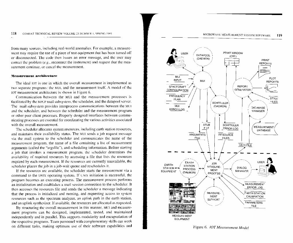
118 COMSAT TECHNICAL REVIEW VOLUME 23 NCMHF: R 1, SPRING 1993
from many sources, including real-world anomalies. For example, a measure-
ment may require the use of a piece of test equipment that has been turned off
or disconnected. The code then issues an error message, and the user may
correct the problem (e.g., reconnect the instrument) and request that the mea-
surement continue, or cancel the measurement.
Measurement architecture
The ideal IO'r is one in which the overall measurement is implemented astwo separate programs: the MUI, and the measurement itself. A model of thelOT measurement architecture is shown in Figure 6.
Communication between the MUI and the measurement processes isfacilitated by the MPCP mail subsystem, the scheduler, and the datapool server.The mail subsystem provides interprocess communications between the MUIand the scheduler, and between the scheduler and the measurement programor other peer client processes. Properly designed interfaces between commu-nicating processes are essential for coordinating the various activities associatedwith the overall measurement.
The scheduler allocates system resources, including earth station resources,and maintains their availability status. The MCI sends a job request messagevia the mail system to the scheduler and communicates the name of themeasurement program, the name of a file containing a list of measurementarguments (called the "argsfile" ). and scheduling information. Before startinga job that invokes a measurement program, the scheduler determines theavailability of required resources by accessing a file that lists the resourcesrequired by each measurement. If the resources are currently unavailable, thescheduler places the job in a job-wait queue and reschedules it.
If the resources are available, the scheduler starts the measurement via acommand to the UNIX operating system. If UNIX initiation is successful, theprogram becomes an executing process. The measurement process performsan initialization and establishes a mail session connection to the scheduler. Itthen accesses the resources file and sends the scheduler a message indicatingthat the process is initialized and running, and requesting access to systemresources such as the spectrum analyzer, an uplink path in the earth station,and an uplink synthesizer. If available, the resources are allocated as requested.
By structuring the overall measurement in this manner, Mu1 and measure-ment programs can be designed, implemented, tested, and maintainedindependently and in parallel. This supports modularity and encapsulation ofthe respective programs. Team personnel with complementary skills can workon different tasks, making optimum use of their software capabilities and
SNFCECRAFO jlCONFIGURATION /
MUI
ERROR LOG
MICROWAVE MEASUREMENT SYSTEM SOFTWARE
STUB
FILE
7 EARTH JOBEARTH STATION
PROCESS K--r MENTiEQUIPMENT '(DAEMON,)/ N PROCESS
MEASUREMENT
EQUIPMENT
REPORTS
MEASUREMENTERROR LOG
PARAMETERS
FILE
Figure 6. JOT Measurement Model
PRINT WINDOW
(CRT)
119

120 COMSAT TECHNICAL REVIEW VOLUME 23 NUMBER I, SPRING 1993
experience. Each program developer uses the most appropriate programming
paradigm. For example, since (he user interacts with the Mel via a mouse and
keyboard, the Mul must respond to unpredictable events (e.g., a mouse click or
the pressing of a key) and is therefore implemented using an event-oriented
programming paradigm. The measurement program, on the other hand, inter-
acts with the microwave measurement and earth station equipment in a
predictable manner, and thus is implemented in an algorithmic, procedure-
oriented programming paradigm (although it can be interrupted by unexpec-
ted behavior when an instrument issues a service request interrupt on the
IEEE-488 bus).
Data-driven implementation
The MMS software is implemented by using text files and avoiding hard-coding wherever possible, As shown in Figure 6, text files are used to exchangeinformation between processes, as a complement to interprocess mailcommunications. The following files are used, and will be discussed in context:MUI input, measurement argument, stub, resource, spacecraft configuration,earth station calibration data, measurement parameter, and print and plot style.Since these files are structured during the system design phase, they can beconstructed to hold any information desired, and can be customized to meetcustomer requirements. Thus, the files provide flexibility and adaptability tothe measurement system design.
Both the file management procedures and storage format are standardizedwithin the MMS software. File operations such as open. read, write, and closeare performed via calls to an Mven library. Files are formatted in a standardCOMSAT Data File Format (coSDAF) and stored as ASCII-coded text. COSDAFfiles can be viewed, edited, and imported into other application programs.
System behavior can be altered by editing the files, which minimizes theneed to recompile the program when changes are required. For example, theappearance of an MUI window on the display is controlled by an MCI input file.The number of Mul controls, their position, and type (e.g., pushbuttons, editfields, and pop-up menu selections) are easily changed by editing this file.
Although MMS files are easily edited, they are static in the sense that theygenerally remain unchanged for a particular sequence of lot measurements. Infact, once constructed, they seldom change, although they can be modifiedwhen necessary. The spacecraft configuration file, for example, includesinformation regarding spacecraft characteristics, channel characteristics suchas center frequency and bandwidth, transmit and receive beams, transpondergain settings, and orbital parameters. Another file, the frequency plan, identifieschannels and/or carrier slots, their center frequencies and bandwidths, powerthreshold levels for alarms, expected signal modulation, and other frequency-
MICROWAVE MBASUREMI.NT SYS TEM SOFTWARE 121
related information. Other files, such as the earth station calibration file, storecalibration information such as antenna gain is frequency and coupler valuevs frequency.
The measurement process reads particular files when required. The use ofcommon files by different measurement processes guarantees uniformity ofinformation. Also, since the user does not have to constantly reenter the sameinformation through the keyboard, user input errors and fatigue are reduced.
User interface design
Effective operation of a measurement system is highly dependent on thedesign, behavior, flexibility, ease of use, and consistency of the user interface.More than 30 years of human-machine interface research (References 6 and 7,for example) have indicated that the most effective technique is a graphicallybased interface that allows a user to indicate a desired action by "pointing andclicking" in windows on the display by using a mouse device. The keyboard isused to enter parameter values and data. This technique is in contrast to theolder command-line-based interface that requires the user to accuratelyremember and type in esoteric command codes. Graphically based interfacesare now common on many computer systems, such as the popular AppleMacintosh [8] and desktop computers running Microsoft Windows. TheX Window-based MtiI enables the ioT system user to specify measurementparameters. It contains edit fields, pushbuttons, toggle buttons, and radiobuttons. Buttons are actuated by pointing and clicking with the mouse. Atypical Mel is shown in Figure 7.
Muts and other windows meet the following IoT system operationalrequirements:
• Permit the user to easily, quickly, and intuitively set up IOTmeasurements.
• Enable the user to search through the measurement database to retrievefiles meeting user-specified criteria.
• Enable the user to process high volumes of measurement data intoplots and printouts.
• Inform the user of input range and type errors.
• Inform the system operator of errors encountered during measurementsand other activities.
• Require minimal training, so new users can gain proficiency rapidly.
• Preserve operational flexibility for nonroutine activities, such asanomaly investigations.

122 COMSAT TECHNICAL REVIEW VOLUME 23 NUMBER I, SPRING 1993 N MICROWAVE MEASUREMENT SYSTEM SOFTWARE 123
XF DIEIRP
Spacecraft
S/G 1-F2
55P: ZO F, 0.0 N
Ha Be..:T. Beam:
Bea.
Chamois:
EB
SW
A
4N
SO CNFG: EB -A-IAA-1Y-SW -32
udaaea
'5. LiM1 75.0IaOW
Search BW : 3.00..
o IPFOEDF
Non Interactive
0
Wartlet
m Cleartight cmuna
Heavy Clouds
Fog
Bak,
Snow
Start E/S EIHP : 65.0 dBW
2nC Can- , Frey: 10.0 'NHz
EIRP
2nd CariIer Saturatbh
Screen Plot a Screen PrInt
neanle
Start Date: 14 Jun 91 TMIS:
Stop Date: 14 .&IN Hl Time:
Interval DaYisl:0
Figure 7. FLUX/EIRP Measurement User Interface Window
Some IOT measurements can be run automatically, without the presence ofan operator, while others are interactive and require operator inputs through-out the measurement. Some measurements can be run in either mode (selectableby the user as the "Non Interactive" option shown in Figure 7), which can betoggled on or off by clicking the mouse.
Implementation of an effective user interface requires careful thought andconsiderable effort. All MUI6 and other windows are implemented using OpenSoftware Foundation's OSF/Motif toolkit and style guidelines [7]. MUIS areimplemented to be consistent in behavior and similar in appearance. Buttonsand controls that perform the same function from one MUI to another arepositioned in the same location, so that the user who has learned one Mul has afamiliar model to follow. When opened, Muls are displayed with defaultparameter values and control settings, and have a `form-fill-in"/menu-selectionpresentation format. The default values are read from an ASCII file, which is
easily modified. If an input is invalid (e.g.. an out-of-range value is typed in),the user is immediately notified of the error and prompted for another input.
Often, several input parameters are coupled in a dependency relationship topreserve maximum operational flexibility. If a user specifies a parameter thatis coupled to others, the related parameter or parameters will also be changedautomatically. For example, the user may be required to specify a bandwidth,a step size, and the number of steps to be performed by a measurement. Theseparameters may be coupled such that specifying the number of steps and stepsize automatically determines the bandwidth parameter as their product.
MU1-measurement process interface
Once the user has configured the measurement via the MCI, the specifiedparameters and controls are communicated to the measurement process via acommand-line interface similar to the standard UNIX system command interface.In normal operation, the user initiates a particular measurement by filling inthe appropriate MUI and scheduling the measurement. The MUI is displayed ona workstation or X-Terminal. The user then presses the OK button on the MUi(see Figure 7), and the MUI communicates this information to the measurementprocess via the scheduler. At the scheduled time, the scheduler checks to see ifthe required resources are available, starts the measurement process, establishesa mail connection to the process, and allocates the requested resources.
To preserve maximum system flexibility, measurement programs can berun without an MUI workstation or X-Terminal by using a standard character-based ASCII terminal. A user can run an JOT measurement at the host earthstation from a remote site, such as the user's home, by using a personal orportable computer and modem. For example, during an anomaly investigation,it may be desirable to alter the normal flow of system operation or to make aparticular series of measurements not implemented by the IOT system mull.This flexibility is achieved as described below.
Following UNIX conventions, an IOT measurement program can be invokedfrom a connected terminal by typing the name of the executable program andoptional arguments as follows:
meas_name [-opt <opt_arg> ...]
where meas_name is the name of the measurement program, -opt specifiesan option, and <opt_arg> specifies an argument to an option. For example,the command line to invoke the IPFD/EIRP measurement with options set for a3-MHz search bandwidth and saturation is
flux_eirp -Search_bw 3.0 -Saturation
124 COMSAT TECHNICAL REVIEW VOLUME 23 NUMBER I. SPRING 1993
The IPFD/EIRP measurement program is invoked and instructed to set thesearch bandwidth on the spectrum analyzer to 3.0 MHz and perform themeasurement at saturation. The arguments available to each IOT measurementare customized for that particular measurement. Any control available in theMUI can be entered as a command-line argument.
A measurement typically requires numerous controls and parameter settings.Normally, the MIDI handles all controls: however, the number of controls canpresent a problem for manual entry via a command line. Since the command istransitory, whenever a measurement is repeated (perhaps with different options),the measurement command and its arguments must be reentered-a tediousand error-prone process. One solution is to place measurement arguments intoan arguments file. Once constructed, this file is permanent. regardless of theoptions stored. The argsfile can be configured with a set of default options.
To accommodate the use of the argsfile, the measurement program extendsthe conventional UNIX command-line invocation with one additional argument-args <argsfile>. The -args option instructs the measurement process toobtain its command-line arguments from the file named in the parameter.<argsfile>. If an argsfile has been created for the IPFD/EIRP measurement. themeasurement program can be invoked from the UNIX command line as follows:
flux_eirp -args my_args
where the file my_args contains the arguments -Search bw 3.0 and-Saturation. Once again, a data-driven design approach is used to preservemaximum operational flexibility and adaptability.
The ability of the measurement program to receive its arguments from anargsfile provides the necessary interface between the MUI and the measurementprogram. When the MUI window (e.g., Figure 7) is opened, the parameters aredisplayed with default settings which the user is free to alter to accommodatea specific measurement configuration. When the measurement specification iscomplete, the user presses OK. The Mui program then creates an argsfilecontaining the specified arguments and parameters for use by the measurementprocess (as depicted in Figure 6). Use of the argsfile minimizes the number ofentries required from the user, since most of the defaults are unchanged.
Measurement program implementation
The measurement program focuses on the measurement task itself. Forexample, although the measurement process (a program in execution) outputsa data file of results, it is not responsible for storing, displaying, printing, orplotting the data. These tasks are managed by other processes. Similarly, themeasurement program is decoupled from the particular spacecraft upon which
MICROWAVE MEASI)RLMENT SYSTLM SOFTWARE 125
it will perform the measurement, and spacecraft information is communicatedfrom the Mui program via the argsfile.
Measurement programs are implemented in a modular manner using object-oriented design and implementation techniques [9]. This results in a highdegree of encapsulation. Using the class terminology of object-orientedprogramming, a generic "Measurement" class is implemented with attributes(such as data declarations, data structures, and methods) that are common toall IOT measurements. Measurement-class methods include performinginitialization and establishing a mail session with the scheduler, opening files,checking arguments passed via the argsfile for validity, configuring uplinkand downlink equipment, performing up- and downlink measurements, storingthe final output data, pausing the measurement, and cancelling the measurementwhen requested by the user. Since these common tasks comprise the bulk ofthe measurement, it is appropriate to aggregate them into a generic class.
Measurement programs are coded in C++, a language designed to supportobject-oriented programming and the construction of classes of objects withinheritance relationships. Figure 8 illustrates the class structuring and inheri-tance relationships of some of the IOT measurements. The implementationof measurement programs as classes of objects allows the developer to"leverage" code using inheritance, as explained below. This enhances relia-bility because each software element is tested thoroughly every time it isleveraged and reused. As a result, greater emphasis can be placed on measure-ment technique, rather than measurement mechanics.
Inheritance enables the measurement developer to leverage code as follows.Using the inheritance properties of C++ 1101, an EIRP measurement isimplemented as a subclass (or derived class) of the generic Measurementclass. The EIRP measurement inherits all of the data structures and methods ofthe "parent" Measurement class, and implements additional structures andmethods as well.
The gain transfer, in-band frequency response, and spurious outputmeasurements are subclasses derived from the EIRP class. Gain transfer is anEIRP measurement performed at different uplink power levels of a test signal;frequency response is an EIRP measurement performed at different frequenciesin a spacecraft transponder channel; and spurious output is an EIRP measurementperformed on a specific spurious signal received from the communicationssatellite. These measurements inherit the data structures and methods from theparent EIRP class, as well as from the "grandparent" Measurement class, withadditional structures and methods implemented to accommodate measurement-specific requirements. Thus, the developer of the gain transfer measurementcan focus on issues unique to that particular measurement, while reusing or
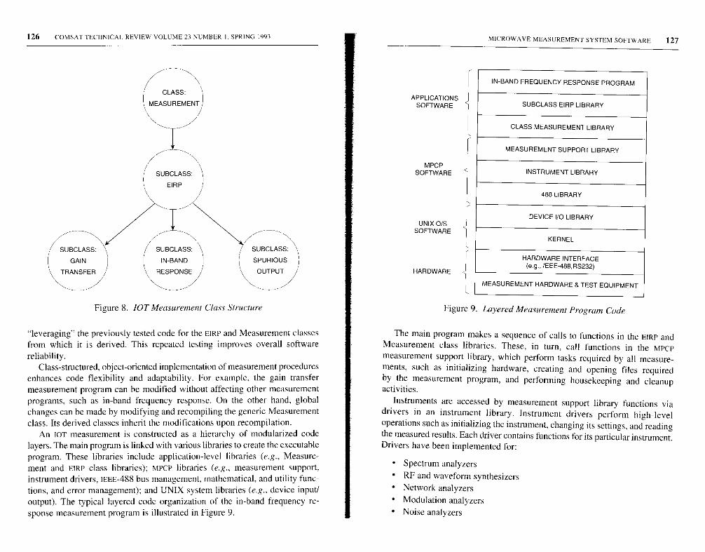
126 COMSAT TECIINICAI. REVIEW VOLUME 23 NUMBER 1,SPRING 1993 a MICROWAVE MEASUREMENT SYSTEM SOFTWARE 127
IN-BAND FREQUENCY RESPONSE PROGRAM
APPLICATIONSSOFTWARE
CLASS MEASUREMENT LIBRARY
MEASUREMENT SUPPORT LIBRARY
MPCPSOFTWARE
488 LIBRARY
UNIX O/SSOFTWARE
SUBCLASS EIRP LIBRARY
INSTRUMENT LIBRARY
DEVICE I/O LIBRARY
KERNEL
SUBCLASS:
GAIN
/ SUBCLASS: \ 7 SUBCLASS:
IN-BAND SPURIOUS
HARDWARE
HARDWARE INTERFACE(e.g., IEEE-488 ,RS232)
1 TRANSFER
Figure 8. JOT Measuremem Class Structure
"leveraging" the previously tested code for the EIRE and Measurement classesfrom which it is derived. This repeated testing improves overall software
reliability.Class-structured, object-oriented implementation of measurement procedures
enhances code flexibility and adaptability. For example, the gain transfermeasurement program can be modified without affecting other measurementprograms, such as in-band frequency response. On the other hand, globalchanges can be made by modifying and recompiling the generic Measurementclass. Its derived classes inherit the modifications upon recompilation.
An IOT measurement is constructed as a hierarchy of modularized codelayers. The main program is linked with various libraries to create the executableprogram. These libraries include application-level libraries (e.g., Measure-ment and EIRP class libraries); MPCP libraries (e.g., measurement support,
instrument drivers, IEEE-488 bus management, mathematical, and utility func-tions, and error management); and UNIX system libraries (e.g., device input/output). The typical layered code organization of the in-band frequency re-sponse measurement program is illustrated in Figure 9.
\ RESPONSE / \ OUTPUT /
MEASUREMENT HARDWARE & TEST EQUIPMENT
Figure 9. Layered Measurement Program Code
The main program makes a sequence of calls to functions in the EIRP andMeasurement class libraries. These, in turn , call functions in the MPCPmeasurement support library, which perform tasks required by all measure-ments, such as initializing hardware, creating and opening files requiredby the measurement program, and performing housekeeping and cleanupactivities.
Instruments are accessed by measurement support library functions viadrivers in an instrument library. Instrument drivers perform high-leveloperations such as initializing the instrument, changing its settings, and readingthe measured results. Each driver contains functions for its particular instrument.Drivers have been implemented for:
• Spectrum analyzers
• RF and waveform synthesizers• Network analyzers
• Modulation analyzers
• Noise analyzers
128 COMSAT IF(HXICAL REVIEW VOLUME 23 NUMBER I. SPRING 1993
• Frequency counters
• Power meters
• Voltmeters• RF switch controllers• Data acquisition units.
The driver provides a simple interface with the software developer usingthe instrument. Because data integrity is a principal concern, the driver iscapable of detecting and reporting errors that may arise from interactions withthe instrument, and handles the instrument's software control capabilities.This enables the developer to focus on instrument usage, rather than on thedetailed mechanics of communicating with the instrument.
Instrument drivers communicate with instruments via the IEEE-488 bus byusing the MPCP 488 library, which provides high-level bus management functioncalls to the driver. The library performs atomic i/o with a given instrument, sothat an i/o transaction. once started, cannot be interrupted. This allows thesame instrument to be shared by multiple processes.
The 488 library also performs such functions as sending an Interface Clearsignal to all instruments, writing a command string to an instrument, reading aresponse string from an instrument, addressing an instrument to talk or listen,retrieving the bus and address of an instrument when multiple buses arepresent, and performing a serial poll of an instrument to obtain its status byte.These functions are generally called by the instrument drivers, but can also becalled by other programs for communication with other IEEE-488-compatibledevices such as computers or special-purpose hardware. The 488 library frees
its user from bus management details.Functions in the 488 library call low-level, primitive functions supplied
with the UNIX operating system device VO library. These primitives interactwith the UNIX kernel (which directly controls the IEEE-488 bus) through aninterface card. A cable connects the workstation's interface card with theinstruments, which are daisy-chained onto the IEEE-488 bus through cables.
An instrument may he used in the shared mode in which it is checked outfrom the scheduler, or may he managed completely by a device process. In theshared mode, the instrument (if available) is checked out from the scheduleras described previously. The measurement is not allowed to run if any of therequired instrumentation or other resources are unavailable. In the secondcase, the instrument is fully managed by a device process. All requests areissued to the instrument in the form of messages to the device process. whichthen communicates with the particular device or instrument. The device is notalways a measurement instrument, but may be another computer that controlsand communicates with such earth station equipment as the uplink power
ICROW AVE MEASUREMENT SYSTEM SOL IWARL' 129
meter, radiometer, or antenna control unit. In general, the shared mode isemployed for instruments that are used occasionally by some measurements,while the device process is employed for instruments used by all measurements(e.g., to communicate with a separate earth station control computer).
Other MPCP libraries, including utility libraries, a mathematics library, andthe error handling library, are also linked to the measurement program. Severalutility libraries provide useful functions required by IoT measurements or byother libraries, such as calculating EIRP, flux density, path loss, spacecraftgain, spreading factor, and slant range. The math library contains numerousmathematical functions routinely required in or and other measurementsystems, such as numerical integration and linear regression analysis. Theerror handling library, which is used universally by all components of thesoftware system, is described below.
Measurement programs execute as processes to perform actualmeasurements. In object-oriented terminology, a measurement process is an"instantiation" of the measurement; that is, it is an instance of a measurementprogram executing with parameters specified by the user.
A measurement process accesses several files, as illustrated in Figure 6.When the user specifies and schedules a measurement in an MUI window, theMUI process creates an argsfile and a stubfile. The stubfile contains annotationsfor the specific measurement (e.g., the spacecraft selected, earth station name,weather conditions, comments, and the date and time) which do not affect themeasurement itself. The measurement process obtains arguments from theargsfile and opens the stubfile, to which it appends measurement data. Theprocess reads the resource file for the resources it requires, and the earthstation calibration file for earth station antenna and coupler calibration data.The process may also access a parameters file for measurement-specificparameters.
Also, during measurement execution, the measurement process configuresand controls the microwave measurement equipment for data acquisition, andcommunicates with the scheduler. It interacts with the earth station daemonprocess to obtain relevant information, and issues dialog windows to the uservia a dialog manager process. Real-time measurement data are displayed onthe workstation monitor as the measurement progresses (as depicted inFigure 6), along with the status of the measurement. The final measurementdata file is stored in the database, printed, and plotted.
Error subsystem design
Error detection and management are critical considerations in the designand implementation of a computer-controlled IOT system or similar
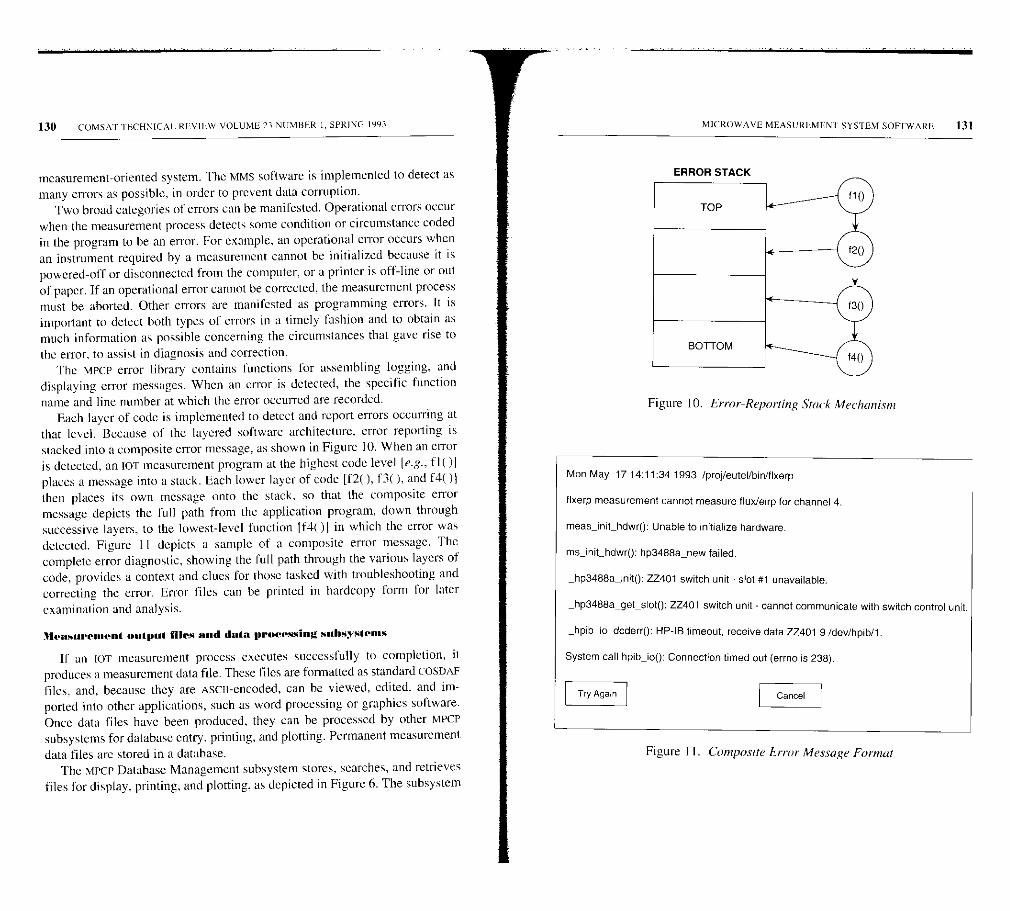
130 COMSAT'[ ECHNICAI, REVIEW VOLUME 23 NUMBER I. SPRING 1993
measurement-oriented system. The MMS software is implemented to detect asmany errors as possible, in order to prevent data corruption.
Two broad categories of errors can be manifested. Operational errors occurwhen the measurement process detects some condition or circumstance codedin the program to be an error. For example, an operational error occurs whenan instrument required by a measurement cannot be initialized because it ispowered-off or disconnected from the computer, or a printer is off-line or outof paper. If an operational error cannot be corrected, the measurement processmust be aborted. Other errors are manifested as programming errors. It isimportant to detect both types of errors in a timely fashion and to obtain asmuch information as possible concerning the circumstances that gave rise to
the error, to assist in diagnosis and correction.The MPCP error library contains functions for assembling logging, and
displaying error messages. When an error is detected, the specific functionname and line number at which the error occurred are recorded.
Each layer of code is implemented to detect and report errors occurring atthat level. Because of the layered software architecture, error reporting isstacked into a composite error message, as shown in Figure 10. When an erroris detected, an lOT measurement program at the highest code level [e.g., fl OIplaces a message into a stack. Each lower layer of code [f2( ), f3( ), and f4( )ithen places its own message onto the stack, so that the composite errormessage depicts the full path from the application program, down throughsuccessive layers, to the lowest-level function [t'4()OI in which the error wasdetected. Figure I1 depicts a sample of a composite error message. Thecomplete error diagnostic, showing the full path through the various layers ofcode, provides a context and clues for those tasked with troubleshooting andcorrecting the error. Error files can be printed in hardcopy form for later
examination and analysis.
Measurement output files and data processing subsystems
If an IOT measurement process executes successfully to completion, itproduces a measurement data file. These files are formatted as standard COSDAFfiles, and. because they are ASCII-encoded, can be viewed, edited, and im-ported into other applications, such as word processing or graphics software.Once data files have been produced, they can be processed by other MPCPsubsystems for database entry, printing, and plotting. Permanent measurement
data files are stored in a database.The MPCP Database Management subsystem stores, searches, and retrieves
files for display, printing, and plotting, as depicted in Figure 6. The subsystem
MICROWAVE MEASUREMENT SYSTEM SOFTWARE 131
ERROR STACK
BOTTOM
Figure 10. Error-Reporting Stack Mechanism
Mon May 17 14:11:34 1993 /proj/eutel/bin/flxerp
flxerp measurement cannot measure flux/eirp for channel 4.
meas_init_hdwro: Unable to initialize hardware.
ms_init_hdwro: hp3488a_new failed.
_hp3488a_inito: ZZ401 switch unit - slot #1 unavailable.
_hp3488a_getsloto: ZZ401 switch unit - cannot communicate with switch control unit.
_hpib_io_dcderro: HP-lB timeout, receive data ZZ401 9 /dev/hpib/l.
System call hpib_ioo: Connection timed out (errno is 238).
Try Again Cancel
Figure I I. Composite Error Message Format
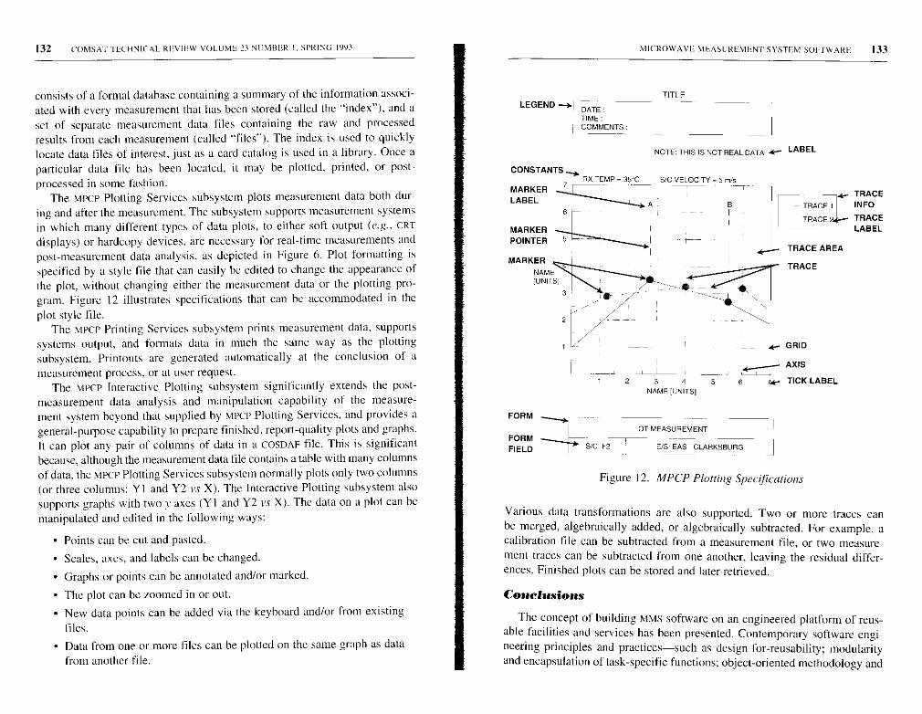
132 COMSAT TECHNICAL REVIEW VOLUME 23 NUMBER I, SPRING 1993 S MICROWAVE ME:ASUREMENr SYSTEM SOFTWARE 133
consists of a formal database containing a summary of the information associ-ated with every measurement that has been stored (called the "index"), and aset of separate measurement data files containing the raw and processedresults from each measurement (called "files"). The index is used to quicklylocate data files of interest, just as a card catalog is used in a library. Once aparticular data file has been located, it may be plotted, printed, or post-
processed in some fashion.The MPCP Plotting Services subsystem plots measurement data both dur-
ing and after the measurement. The subsystem supports measurement systemsin which many different types of data plots, to either soft output (e.g., CRT
displays) or hardcopy devices, are necessary for real-time measurements andpost-measurement data analysis, as depicted in Figure 6. Plot formatting isspecified by a style file that can easily be edited to change the appearance ofthe plot, without changing either the measurement data or the plotting pro-gram. Figure 12 illustrates specifications that can be accommodated in the
plot style file.The MPCP Printing Services subsystem prints measurement data, supports
systems output, and formats data in much the same way as the plottingsubsystem. Printouts are generated automatically at the conclusion of ameasurement process, or at user request.
The MPCP Interactive Plotting subsystem significantly extends the post-measurement data analysis and manipulation capability of the measure-ment system beyond that supplied by MPCP Plotting Services, and provides ageneral-pupose capability to prepare finished, report-quality plots and graphs.It can plot any pair of columns of data in a COSDAF file. This is significantbecause, although the measurement data file contains a table with many columnsof data, the MPCP Plotting Services subsystem normally plots only two columns(or three columns: Yl and Y2 vs X). The Interactive Plotting subsystem alsosupports graphs with two Y axes (Yl and Y2 is X). The data on a plot can be
manipulated and edited in the following ways:
• Points can be cut and pasted.
• Scales, axes, and labels can be changed.
• Graphs or points can be annotated and/or marked.
• The plot can be zoomed in or out.
• New data points can be added via the keyboard and/or from existing
files.
• Data from one or more files can be plotted on the same graph as data
from another file.
LEGEND --.- DATE
TIME :COMMENTS'.
CONSTANTS y
MARKERLABEL
RX TEMP = 35'C7 --
FORM _;
FORMFIELD
TITLE
NOTE: THIS IS NOT REAL DATA * LABEL
S/C VELOCITY=5 M5
B
TRACE
- TRACE I INFO
TRACE TRACELABEL
GRID
AXIS
I 2 3 4 5 6 >t- TICK LABELNAME [UNITS]
S/C'. F2
IOT MEASUREMENT
EIS: EAST CLARKSBURG J
Figure 12. MPCP Plotting Specifications
Various data transformations are also supported. Two or more traces canbe merged, algebraically added, or algebraically subtracted. For example, acalibration file can be subtracted from a measurement file, or two measure-ment traces can be subtracted from one another, leaving the residual differ-ences. Finished plots can he stored and later retrieved.
Conclusions
The concept of building MMS software on an engineered platform of reus-able facilities and services has been presented. Contemporary software engi-neering principles and practices-such as design-for-reusability; modularityand encapsulation of task-specific functions; object-oriented methodology and
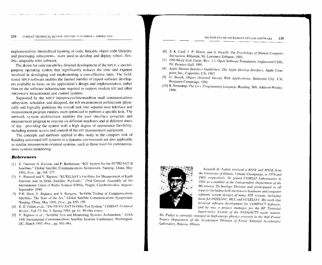
134 COMSAT TECHNICAL REV IEW VOLUME 23 NUMBER 1. SPRING 1993
implementation; hierarchical layering of code; linkable object code libraries;and processing subsystems-were used to develop and deploy robust, flex-
ible, adaptable MMS software.The desire for code reusability directed development of the MPCP, a special-
purpose operating system that significantly reduces the time and expenseinvolved in developing and implementing a cost-effective MMS. The field-tested MPCP software enables the limited number of expert software develop-ers available to focus on the application's design and implementation, ratherthan on the software infrastructure required to support modern TOT and othermicrowave measurement and control systems.
Supported by the MPCP interprocess/intermachine mail communicationssubsystem, scheduler, and datapool, the IOT measurement architecture physi-cally and logically partitions the overall task into separate user interface andmeasurement program entities, each optimized to perform a specific task. Thenetwork system architecture enables the user interface program andmeasurement program to execute on different machines and at different timesof day-providing the system with a high degree of operational flexibility,including remote access and control of the IO'r measurement equipment.
The concepts and methods applied in this study to the complex task ofbuilding automated IOT systems in a dynamic environment are also applicableto similar measurement-oriented systems, such as those used for communica-tions systems monitoring.
References
III
121
131
Y. Tharaud, B. Kasstan, and P. Barthmann, "IOT System for the EUTELSAT 11Satellites," Global Satellite Communications Symposium, Nanjing, China, May
1991. Proc., pp. 168-177.Y. Tharaud and V. Riginos, "EUTELSAT's Facilities for Measurement of EarthStations and In-Orbit Satellite Payloads," 23rd General Assembly of theInternational Union of Radio Science (URSI), Prague, Czechoslovakia, August-
September 1990.P-H. Shen, V. Riginos, and S. Bangara, "In-Orbit Testing of CommunicationsSatellites: The State of the Art," Global Satellite Communications Symposium,Nanjing, China, May 1991, Prot, pp. 150-159.
141 K. D. Follett et al., "The EUTELSAT In-Orbit Test System," COMSAT Technical
[5]Review, Vol. 23, No. 1, Spring 1993, pp. 61-99 (this issue).V. Riginos et al., "In-Orbit Test and Monitoring Systems Architecture," AIAA14th International Communications Satellite Systems Conference, Washington,DC. March 1992. Prot, pp. 951-961.
MICROWAVE MEASUREMENTSYSIEM SOFTWARE 135
[6] S. K. Card, T. P. Moran, and A. Newell, The Psychology of Human-ComputerInteraction, Hillsdale, NJ: Lawrence Erlhaum. 1983.
[71 OSF/Motif Style Guide, Rev. 1.1, Open Software Foundation, Englewood Cliffs,NJ: Prentice-Hall, 1991.
181 Apple Human Interface Guidelines: The Apple Desktop Interface, Apple Com-puter, Inc., Cupertino, CA, 1987.
[9] G. Beech, Object Oriented Design With Applications, Redwood City, CA:Benjamin-Cummings, 1991.
1101 B. Stroustrup, The C++ Programming Language. Reading, MA: Addison-Wesley.1986.
Kenneth D. Follett received a BSFE and MSEE fromthe University of Illinois, Urbana-Champaign, in /979 and
1981, respectively. He joined COMSAT Laboratories in
1981 as a member of the Transponders Department of theMicrowave Technology Division and participated in all
aspects (including both microwave hardware and, onipulersoftware system design) of rnanr /OT systems, including
those for INTELSA T, MCI, and EU'TELSA T. His work alsoinvolved software development for COMPACT Software,
and lie was a project manager for the RF TerminalSupervisory System of the NASA/ACTS earth station .
Mr. Fullett is currently engaged in high-energy physics research in the Anti-Proton
Source Department of the Accelerator Division oj' Fermi National AcceleratorLaboratory, Batavia, illnnois.
136
Walter D. Kelley, Jr., earned a BS in electrical
engineering at the Catholic Univer-sitr of America,
Washington, D_C, in 1974; and an MBA at Mmymount
University, Arlington, VA, in 1983. In 1991, he joined the
Transponders Department of the Satellite and Systems
Technologies Division at COMSAT Laboratories as it Mem-
ber of the Technical Staff At COMSAT, he has participated
in development of the 107 system for Hughes Connnunica-
tions' DirecTv' an lOT system for EUTELSAT and the
NASA/ACTS ground station control and status subsstenr.
Vasilis E. Riginos received a BE, MEng. and PhD in
electrophysics from the Stevens Institute of Technology,
Hoboken, NJ, in 1964, 1970, and 1973, respectively. He is
currently Manager of the Transponders Department of the
Satellite and S:vstenns Technologies Division at COMSAT
Laboratories, where he is respottsihle for directing re sea, (it
and development on conmtunicuhons system performance
as applied to satellite transponders. He also supervises
research and development in advanced microwave circuits
.such as high-power amplifiers, regenerative receivers,
filters, and multiplexers. Dr. Rigin.c participated in the
evaluation of the Inmarsat program, and has been project managerfor the GTE ATEF
IOT system, the INTE'LSAT Maritime Conunumications Subsystem lOT station, the
EUTELSAT lOTsystem, and the Hughes DirecTv' IOT system. He is a member of
Sigma Xi, AAAS. IEEE, and the American Physical Society.
Pei-Hong Shen received a BS and MS in genetics, and
an MS in computer science, from Washington State
University in 1983, 1984, and 1986, respectively. From
/978 to 1981, she studied biology and genetics while
attending Fudan University in Shanghai. Peoples Republic
of China. Ms. Shen is currently a Senior Member of the
Technical Staff in the Transponders Department of the
Satellite and Systents Technologies Division at COMSAT
Laboratories, where she is primarily responsible for design
mid development of .software for communications satellite
applications. Since joining COMSAT in 1987, she has been
involved in the design and development of the billowing .systems: NASA/ACTS,
EUTELSAT IOT. mid Hughes ' DirecTVTs1 lOT She is a member of the IEEE Computer
Society.
COMSAT TECHNICAL REVIEW VOLUME. 23 NEMBER I, SPRING 199, MICROWAVE. MEASIJREMEN'C SYSTEM SOFTWARE 137
Steven L. Teller received an AS and AA from HarperCollege in 1979; and a BA in information and computer
sciences from Hood College in 1991. He is currently a
Member of the Technical Staff in the 7tansponders
Department of the Satellite and Systems Technologies
Division at COMSAT Laboratories. Since joining COMSAT,
he has been involt ed in t a imts aspects of the JOT of
communications satellites, including the NASA/ACIS RF
terminal supervisor, and lOT for EUTELSAT, MCI,
INTELSAT GTE, and the Hughes DirecT,IM system, He
has been responsible for software vs mamtal measurementverification during system development, in-plant testing, and on-site testing. He was
also involved in prototsping mid testing various new mea siltentent schemes, and was a
major contributor to final system installation testing.

CTIC Note
Geostationary communications satellite log foryear-end 1992
L. W. KEMP AND D. C. MAY
(Manuscript received August II, 1993)
The following tables list in-orbit geostationary communications satellitesand planned networks for which advance publications had been submitted tothe International Telecommunication Union (ITU) Radio Regulations Board(formerly the International Frequency Registration Board IIFRBJ) as of year-end 1992. They are intended to provide a summary index of key parametersfor existing and proposed satellites, as well as a reference guide to theircorresponding ITU filings.
For the purpose of this compilation, geostationary satellites are defined assatellites having an orbit period approximately equivalent to one sidereal dayand an apogee and perigee of roughly the same height. Satellites with a north-south inclination greater than 5° have been excluded from consideration.Communications satellites are defined as networks operating in the frequencybands assigned to the fixed, mobile, or broadcasting satellite services.
Table I (.see p. 141) lists in-orbit satellites in order by their current orbitallocation, as published in the National Aeronautics and Space Administration(NASA) situation reports and other public sources. In each instance, the mostrecent available data were used, and in some cases the current orbital locationshown in this table is different than the location actually occupied in Decem-ber 1992. For comparison, the orbital location registered with the ITU isshown in the adjoining column and, where possible, orbit eccentricity andnorth-south inclination are also provided as a further indication of station-keeping status.
The remaining data in Table I, including network designation, registeringcountry or organization, frequency bands, and service type, are derived fromthe relevant special sections of the Radio Regulations Board weekly circulars.For satellites not yet launched, a subset of this information is provided inTable 2 (see p. 170).
Louis W. Kemp is a Systems Planner with the Engineering and Operations Depart-ment of COMSAT World Systems.
Douglas C. May is a Senior Advisor with the INTELSAT Policy and Representa-tion Department of COMSAT World Systems.
139
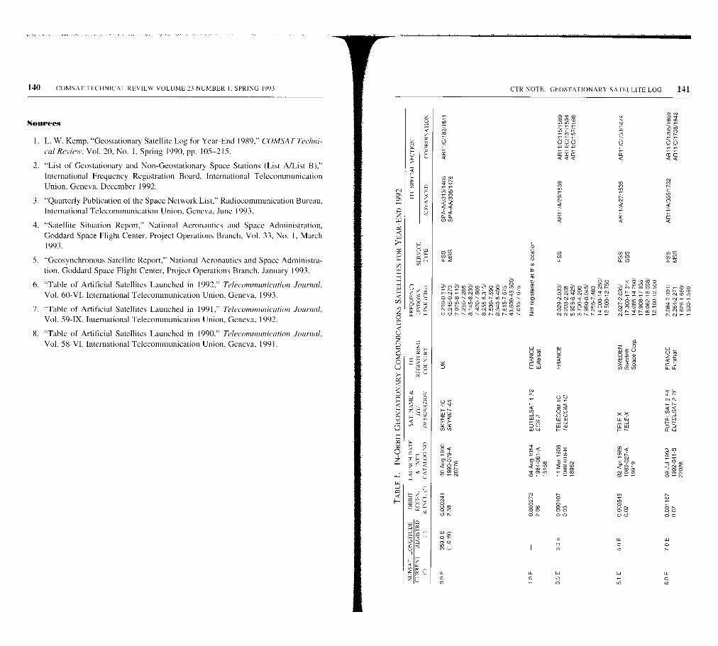
140 COMSA I IICIINICAI. REVIEW VOLUME 23 NUMBER I. SPRING 1993
Sunrees
I. L. W. Kemp. "Geostationary Satellite Log for Year-End 1989," ('OMSATTeehni-cal Review. Vol. 20, No. 1, Spring 1990, pp. 105-215.
2. "List of Geostationary and Non-Geostationary Space Stations (List A/List B),"
International Frequency Registration Board. International TelecommunicationUnion. Geneva. December 1992.
3. "Quarterly Publication of the Space Network List," Radiocommunication Bureau,International Telecommunication Union, Geneva. June 1993.
4. "Satellite Situation Report," National Aeronautics and Space Administration,Goddard Space Flight Center, Project Operations Branch, Vol. 33, No. I, March1993.
5. "Geosynchronous Satellite Report," National Aeronautics and Space Administra-
tion, Goddard Space Flight Center, Project Operations Branch, January 1993.
6. "Table of Artificial Satellites Launched in 1992." Teleeommuok'ation Journal,Vol. 60-VI, International Telecommunication Union, Geneva, 1993.
7. "Table of Artificial Satellites Launched in 1991;' Telecomrmmicatiou Journal,Vol. 59-IX, International Telecommunication Union, Geneva, 1992.
8. "Table of Artificial Satellites Launched in 1990." Telecommunication Journal,Vol. 58-V1, International Telecommunication Union, Geneva, 1991.
CTR NOTE_ GEOS LAT ION ARY SA III LITE LOG
°>o
OOl^r or-Tt'-m^>r- Z
m Co e
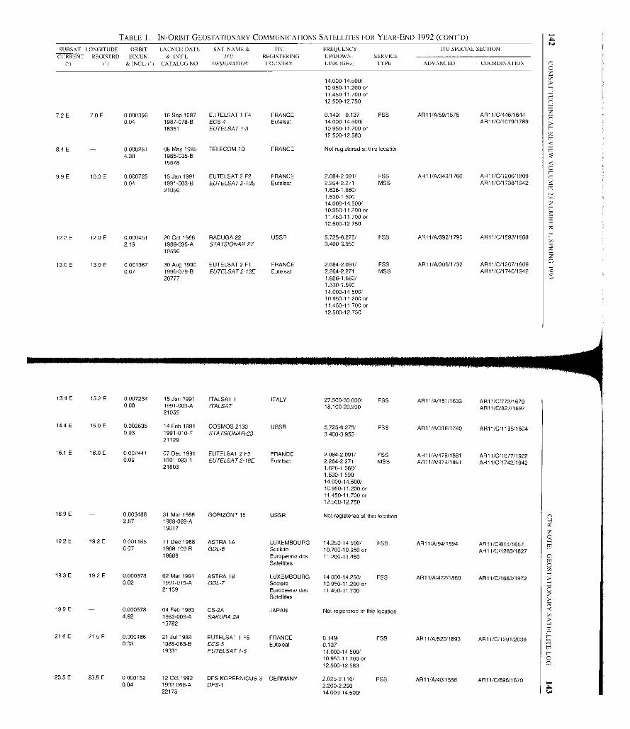
TABLE 1. IN-ORBIT GEOSTATIONARY COMMUNICATIONS SATELLITES FOR YEAR-END 1992 (C0NT'D)
S11BSAT LONGITUDE ORBIT LALNCII DATE SAT. NAMES ITO FREQLENCY ITO SPECIAL SECTION
CURRENT
C)
REGISTRD
( )
ECCEN.
& INCL. I`1
& INFL
CATALOG NO.
I/L'OESIGNA110N
REGISTERING
COUNTRY
[P/DOWN- SERVICE
LINK IGH,.) TYPE ADVANCED COORDINATION
14 00014 500/10950-11.200 or11.450-11 700 or12500-12 750
7.2 E 7.0E 0000356 16 Sep 1987 EUTELSAT 1 F4 FRANCE 0.149/ 0.137 FSS ARI 1/A/59/1578 AR11/0/446/16440.04 1987-078-B ECS 4 Eutelsat 14.00014-500/ AR11/0/1079/1789
18351 EUTELSAT 1.3 10.950-11 700 or12.50012.583
8.4 E 0.000261 08 May 1985 TELECOM 1 B FRANCE Not registered at this location4.38 1985-035-B
15678
99E 10.0 E 0.000725 15 Jan 1991 EUTELSAT 2 F2 FRANCE 2.084-2.091/ FSS AR11/N349/1766 ARE 1/0/1206/1809004 1991-003-B EUTELSAT2-10E Eutelsat 2264-2271 MSS AR11/0/1738/1942
21056 1.626-1.660/1.5301.59014-000-14-500/10.950-1 12 00 or11.450-11 700 or12.500-12.750
122 E 12-0 E 0.000451 20 Oct 1988 RADUGA 22 USSR 5725-6.275/ FSS AR11/A/392/1799 AR11/0/1593/18882.19 1988-095-A STATSIONAR-27 3.400-3.950
19596
13.0 E 13-0 E 0-001387 30 Aug 1990 EUTELSAT 2 Fl FRANCE 2-084-2 091/ FSS ARt l/A1306/1732 AR11/0/1207118090-07 1990-079-B EUTELSAT2-13E Eutelsat 2264-2271 MSS AR11/0/1740/1942
20777 1.626-1.660/1.530-1.59014.000-14.500/10.950-11.200 or11.450-11.700 or1250012.750
134 E 132 E 0007234 15 Jan 1991 ITALSAT 1 ITALY 27.50030 .000/ FSS AR11 /A/ 151/1633 AR11 /0/772/16790.08 1991003 -A ITALSAT 18.100 AR11 /0/827/1697
21055
14.4 E 15 . 0 E 0.002635 14 Feb 1991 COSMOS 2133 USSR 5725-6 .275/ FSS AR11 /A/318/1740 AR11 /0/1195/18040.93 1991 -010-F STATSIONAR-23 3400-3950
21129
16.1 E 16.0 E 0 . 002441 07 Dec 1991 EUTELSAT 2 F3 FRANCE 2.0842.091 / F55 AR11 /A/478/ 1861 AR11 /0/1677/19220.09 1991 -083-1 EUTELSAT 2-16E Eutelsat 22642 .271 MSS AR11 /A479/1861 AR11 /C/17401942
21803 1.526-1.660/1.530-1.59014.000-14.500/10.950-11.200 or11 450-11.700 or12.500-12.750
16.9 E 0.003488 31 Mar 1988 GORIZONT 15 USSR Not registered at this location2.87 1988-028-A
19017
19.2 E 19 2 E 0 . 001165 11 Dec 1988 ASTRA 1A LUXEMBOURG 14.250- 14.500/ EBB AR11/A194 /1594 ARI 1 /0/614/16570.07 1988 - 109-B GDL-6 Societe 10.700-10.950 or AR11/C/1283/I 827
19688 Europeene desSatellites
11 200-11.450
19.3 E 19.2 E 0 . 000373 02 Mar 1991 ASTRA 1 B LUXEMBOURG 14.000-14.250/ FSS AR11 /A/472 /1860 AR11 /0/1663/19720.02 1991-015-A GDL-7 Societe 10 . 950-11.200 or
21139 Europeene desSatellites
11 450-11.700
19.9 E 0.000578 04 Feb 1983 CS2A JAPAN Not registered at this location4.92 1983006 -A SAKURA 2A
13782
21.6 E 21 . 5 E 0.000486 21 Jul 1988 EUTELSAT 1 F5 FRANCE 0-149/ FSS AR11 /10520/1893 AR11 /0/1291/20390.03 1988-063 - B ECS-5 Eutelsat 0.137
19331 EUTELSAT 1-5 14.000- 14500/10.950 - 11.700 or12.500-12.583
23.5E 23.5 E 0.000152 12 Oct 1992 DES KOPERNICUS 3 GERMANY 2.0252. 110/ FSS AR11 /1040/1556 AR11/0/695/16700.04 1992 - 066-A DFS-1 2.200-2 290
22175 14.000- 14.500/
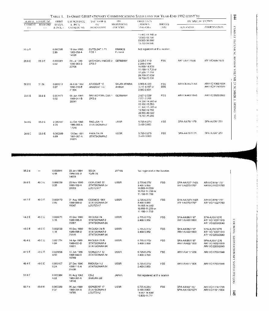
TABLE I. IN-ORBIT GEOSTATIONARY COMMUNICAI IONS SATELLITES FOR YEAR-END 1992 (CONT'D)
SC II5AT. I ONGITI DE ORBIT LAUNCH DAT E SAL NAYIFS ITD IREQCSNCY I I L SPECIAI SECTION
CURRENT
PI
REGISTRD
11
ECCE'-
& INCL -iI
K INIL
CA FALOC NO.
fit REGISTERING
IJN IGGNA flON COUNTRY
L PIDOWN- SERVICE
I INKICHrI TYPE ADVANCED COORDINATION
11 450-11 700 or12500-12.75029.500-30.000119 700-20.200
255E 0.000285 18 Jun 1983 EUTELSAT I F1 FRANCE Not registered at this location2.95 1983-058-A ECS I Eutelsat
14128
28.6 E 28 .5 E 0000581 24 Jul 1990 DES KOPERNICUS 2 GERMANY 2.025-2.110 FSS AR11/N41/1556 AR11/0/698/1670002 1990-063-B DFS-2 2.200-2.290
20706 14.00014.500/11 450-11.700 or12500-12 750
29.70030.000/19.700-20 200
308 E 31.0E 0 .002312 26 Feb 1992 ARABSAT 1C SAUDI ARABIA 5909-6.422/ F55 AR11/A/345/1764 AR11/0/ 1366/18540-07 1992-010-B ARABSAT I-C Arabsat 3.710-4.197 or BSS AR11/0/2124/2025
21894 2560-2.634
33 5E 33 5E 0014730 198905 J DES KOPERNICUS 1 GERMANY 029/ F552 027-2 ARI1/4/ 465/1840 AR11/0 12025/2002. . .0.02
un1989-041-B DFS-5
. .2201-2.203
.
20041 14.000-14 500 or13.150-13 250/11 350-11.700 or
12500-12 75029.500-30.000/19.700-20.200
34.4 E 35.0 E 0000107 25 Oct 1986 RADUGA 19 USSR 5.725-6.275/ EBB SPA-AA/76/1179 SPA A,1,26,1251425 1986-082-A STATSIONAR-2 3.400-3.950
17046
34.6E 350E 0000059 19 Dec 1991 RADUGA28 USSR 5725 6275, FSS SPA-AA/76/1179 SPA-AJ/26/1251
0.69 1991-087-A STATSIONAR-2 3400 395021821
35.2 E 0.000941 23 Jan 1984 BS-2A JAPAN Not registered at this location4.08 1984-005-A YURI 2A
14659
39.8E 40 . 0E 0.000059 23 Nov 1990 GORIZONT 22 USSR 5725-6-275/ FSS SPA-AN1271/1425 AR11/C/878/17370.35 1990-102-A STATSIONAR-24 34003950 AR1 l/A/270/1707 AR11/0/1122/1793
20953 LOUTCH7 14000-14.500/10.950- 11.200 or11.450-11.700
407 E 40.0 E 0.003173 01 Aug 1988 COSMOS 1961 USSR 5725-6.275/ FSS SPA-AA/1271/1425 AR11/0/878/17372.85 1988-066-D STATSIONAR-24 3400-3.950 AR11/A/270/1707 API 1/0/1122/1793
19347 LOUTCH-7 14.000.14.500/10.950-11,200 or17.450-11.700
44.3E 45.0 E 0.000071 15 Dec 1989 RADUGA 24 USSR 5.725-6.275/ FSS SPA-AA/96/1197 SPA AU/51/12761.16 1989 -098-A STATSIONAR -9 3.400-3.950 AR11 /41402/1803 AR11 /C/1632/1919
20367 STATSIONAR-94 AR11 /0/2203/2040
45.0 E 45.0 E 0002030 15 Dec 1989 RADUGA 24 R USSR 5725-6275/ F55 SPA-A4196/1197 SPA-AJ/51/12761.18 1989 -098-D STATSIONAR -9 3400-3 . 950 AR11 /41402 / 1803 AR11 /0/1632/1919
20370 574 TSIONAR-94 AR11/0/2203/2040
45 4 E 45 . 0 E 0.001774 14 Apr 1989 RADUGA 23 R USSR 5.725-6 . 275/ FSS SPA -A4196/1197 SPA-AJ151/12761.84 1989030 - D STATSIONAR-9 3.400-3 . 950 AR11 /A/402 /1803 ART 1 /C/1632/1919
19931 STATSIONAR9A AR11/0/2203/2040
47.9 E 490 E 0000296 10 Jun 1986 GORIZONT 12 USSR 5.7250275 / ESS AR11 /4/411/1806 AR11 /C/1753/19484.50 1986044-A STATSIONAR-24 3 400-3.950
16769
404 E 49 -0 E 0.000107 27 Dec 1990 RADUGA 1 -2 USSR 5725-6275/ FSS AR11 /41411/1806 AR11 /0/1753/19480.24 1990 - 116-A STATSIONAR -24 3400-3.950
21038
51.9 E 0000388 05 Aug 1983 CS-2 JAPAN Not registered at this location422 1983-081 -A SAKURA2B
14248
52.7 E 53 . 0 E 0000330 26 Jan 1989 GORIZONT 17 USSR 5.725 -6.225/ FSS SPA-A4/93/1197 AR11 /0/1114/17932.37 1989-004-A STA75IONAH-5 3.400-3.900 SPA-AA/150/1271 AR11/0/1191/1804
19765 LOUTCH-2 14007-14439/10939 11 711
AA
AU

TABLE 1. IN-ORBIT GEOSTATIONARY COMMUNICATIONS SATELLITES FOR YEAR-END 1992 (CONT'D)
SURSAT 1 ONGITEDE ORBIT LALNCII DATE SA I. NAME & ITU FREQUENCY I J SPECIAI SECTION
CURRENT REGISTRD
f)
ECCLN.
& INCL(')
& INIL
CAt At DO NO-
)If,IJSIGA4TION
REGISTERING
COUNTRY
UP/DOWN- SERVICE
LINK(GHz) TYPE ADVANCED COORDINATION
52.7 E 530 E 0000111 27 Nov 1992 GORIZONT 27 USSR 5725- 6.225/ FSS SPA-AA/93/1197 AR11/C/1114117931-08 1992-082-A STA TSIONAR-5 Intersputnik 3,400.3 -900 SPA-AA,150/1271 ARI 1 /C/119111804
22245 LOUTCH-2 14.00714 439/10.939-11 711
53.0 E 53 . 0 E 0.000427 11 Dec 1988 SKYNET 4B UK 0 . 290-0 .315/ MSS AR11 /A184/1588 AR11 /C/867/17370.54 1988-109 -A SKYNET-4C 0.245-0.270 FSS AR11/C/871/1737
19687 7 . 975-8.110/7.250-7.2858.145-8.230/7.420-7.5058.225-8.315/7.530-7.5908.340-8.400/7.615-7.67543.500-45.500/7.615-7.675
54.0 E 53.0 E 0.000424 26 Nov 1987 COSMOS 1897 USSR 5725-6225/ FSS SPA-AA/93/1197 AR11/C/1114/1793348 1987-096-A STA TSIONA5-5 Intersputnik 3400-3 . 900 SPA-AA/15011271 AR11/C/1191/1804
18575 LOUTCH-2 14.007-14439/10.939-11 711
552E 0.000842 18 Jun 1985 ARABSAT IB SAUDI ARABIA Not registered at this location0.99 1985-048-C
15825
56.9 E 57.0 E 0.005188 19 Oct 1983 INTELSAT 51`7 USA 5.925-6425/ FSS SPA-AA/262/1423 SPA-AJ/374/15112.49 1983-105-A INTELSAT 5- Intelsat 3 .7004200
14421 INDOC3 14.000-14.500/10.950-11 700
58.4 E 0.000960 21 Jul1988 INSAT 1C INDIA Not registered at this location2.80 1988-063-A
19330
587E 0.000580 26 Aug 1982 ANIK 01 CANADA Not registered at this location1 ,45 1982-082-A
13431
0.001378 18 Nov 19864.14 1986-090-A
17083
60.8E 60.0 E 0.007495 23 Jun 1990 INTELSAT 6 IN0.04 1990 -056-A INTELSAT6 60E Intelsat
20667
0.000237 27 Oct 19890 1989-087-A
20315
INTELSAT 6 F2 USAINTELSAT 6 63E Intelsat
0.000593 30 Oct 1990 INMARSAT 2 F1 UK1.82 1990-093-A INMARSAT2 IOR I Inmarsat
20918
0.000344 28 Sep 1982 INTELSAT 5 F5 USA2.79 1982-097 -A INTELSAT5- Intelsat
13595 INOOC4
0.002653 26 Apr 1988 COSMOS 1940 USSR2.86 1988-034-D STATSIONAR-20
19076
0.000142 15 Feb 1990 RADUGA 25 USSR1.00 1990-016-A STATSIONAR-20
20499
0.000285 21 Jun 1989 RADUGA 1-1 USSR1.62 1989-048 -A STATSIONAR-20
20083
71.7 E 72.0 E 0.000593 10 Jan 1990 LEASAT 52.66 1990-002-8 FLTSATCOM-
20410 INDOC
0240-0322/ NISS0.240-0.322 FSS0.335-0.400/0.335-0.4007.970-8.010/7.255-7 265
API 1/A01/1584 A81 I/C/626/1658AR1 1/C/1 624/1905
AR11/A/ 368/1782 AR11/C/1269/1819
AR11/A/ 178/1644 AR11/C/1840/1968
SPA AA/253/1149 SPA-AJ/375/1511
ARI l/A/316/1740 AR11/0/1193/1804
AR11/A/316/1740 AR11/C/I 193/1804
API 1/A/316/1740 AR1 I/C/1193/1804
Not registered at this location
5.850-6.425/ FSS3.625-4.20014.000 -14.500/10.950-11.700
5.850-6425/ 'SS3.625-4.20014.000-14.500/10.950-11.700
1.626-1.649/ MSS1.530-1.5486.170-6.180/3.945-3.9556.425-6.443/3.600-3.623
5.925-6.425/ ESE3700-4,20014.000-14.500/10.950-17.700
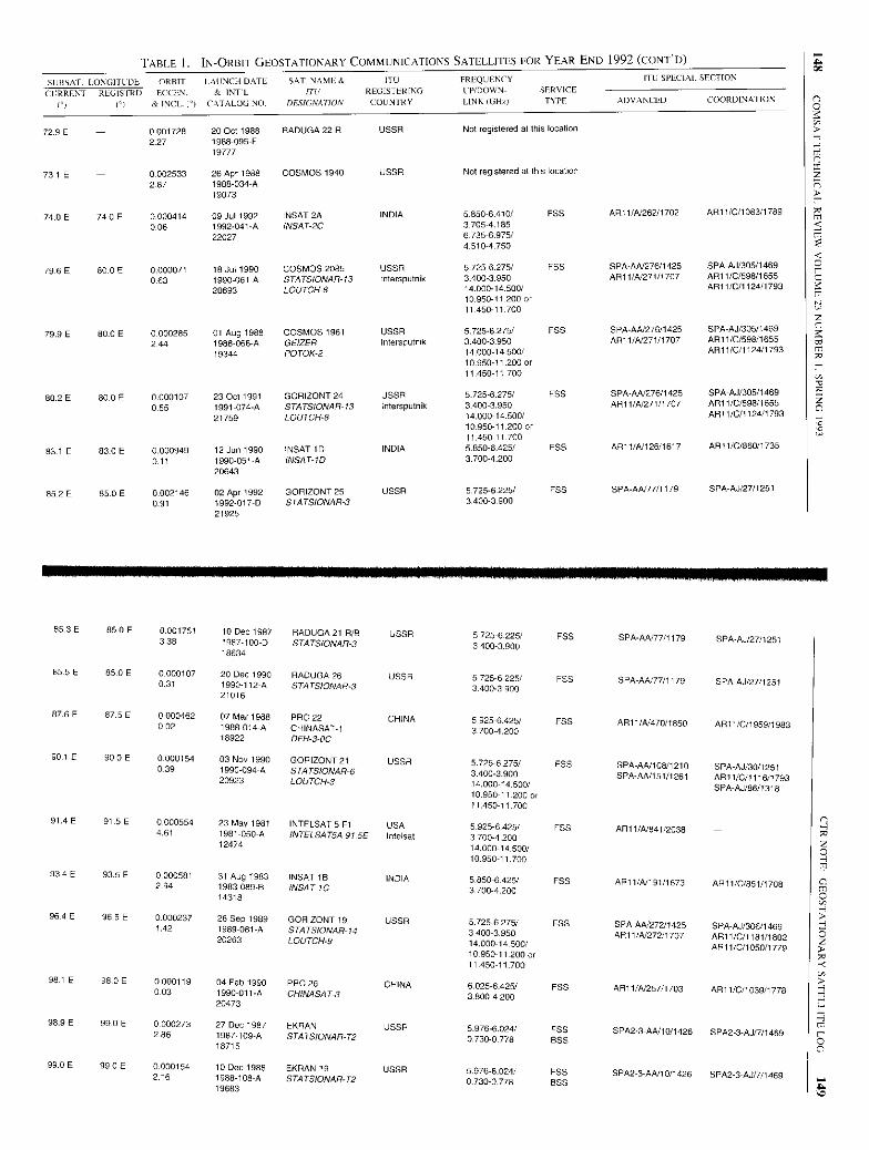
TABLE I. IN-ORBIT GEOSTATIONARY COMMUNICATIONS SATELLITES FOR YEAR-END 1992 (C0NT'D)
SUBSAF LONGITUDE ORBIT LAUNCH DATE SAT- NAME& ITO FREQUENCY ITU SPECIAL SECTION
CURRENT REGISTRD ECCEN. & INTL ITL/ REGISTERING Up/DOWN- SERVICE
(') (°) & INCL. ') CATALOG NO. DESIGNATION COUNTRY LINK (GHz) TYPE ADVANCED COORDINATION
72.9 E - 0.001728 20 Oct 1988 RADUGA 22 R USSR Not registered at this location227 1988-095-F
19777
73.1 E - 0002533 26 Apr 1988 COSMOS 1940 USSR Not registered at this location
2.87 1988-034-A19073
740E 74.0E 0000414 09 Jul 1992 INSAT 2A INDIA 5850-6.410/ FSS AR11/AJ262/1702 AR11/0/1083/1789
0.06 1992-041-A INSAT-2C 3705-4.18522027 67356975/
4.510-4750
79.6 E 80.0 E 0.000071 18 Jul 1990 COSMOS 2085 USSR 5 725-6.275/ FSS SPA-AN276/1425 SPA-AJ/305/1469
0.63 1990-061-A STATSIONAR-13 Intersputnik 34003.950 AR11/A/271/1707 AR11/C/598/1655
20693 LOUTCH8 14.000-14-500/ ALI 1/C/1124/179310.950-11 200 or11 450-11.700
79.9 E 60.0 E 0.000285 01 Aug 1988 COSMOS 1961 USSR 5.7256 275/ FSS SPA-AN276/1425 SPA-AJ/305/1469
244 1988-066-A GEIZER Intersputnik 3.400-3-950 AR11/A/271/1707 AR1 1/C/598/1655
19344 POTOK-2 14.000-14-500/ AR11/0/11241179310.950-11200 or11.450-11 700
802E 80.0E 0.000107 23 Oct 1991 GORIZONT 24 USSR 5.725-6.275/ FSS SPA-AA/276/1425 SPA-AJ/305/1469
0.55 1991-074-A STATSIONAR-13 Intersputnik 34003.950 AR11/4/271/1707 AR11/0/598/1655
21759 LOUTCH-8 14.00014.500/ AR11/C/I 124/179310.950-11.200 or11,450-11,700
83.1 E 630E 0.000949 12 Jun 1990 INSAT ID INDIA 5.850-6425/ FSS AR11/A/ 126/1617 ARt 1/C/860/1735
0.11 1990-051-A INSAT-1D 3.700-4.20020643
852E 85.0E 0.002146 02 Apr 1992 GORIZONT 25 USSR 5.725-6225/ FSS SPA-AN77/1179 SPA-AJ/27/1251
0.91 1992-017-D STATSIONAR-3 3.400-3.90021925
85.3 E 85.0 E 0.001751 10 Dec 1987 RADUGA 21 R/B USSR 5.725-6.225/ FSS SPA-AAO7/1179 SPA-AJ/27/12513.38 1987-100-D STATSIONAR-3 3400-390018634
85.5 E 85.0 E 0.000107 20 Dec 1990 RADUGA 26 USSR 5.725-6.225/ FSS SPA-AA/77/1179 SPA-AJ/27/12510.31 1990-112-A STATSIONAR-3 3400-3 90021016
87.6 E 87.5 E 0.000462 07 Mar 1988 PRC 22 CHINA 5.925-6.425/ FSS AR11/4/470/1850 AR11/C/1959/19830.02 1988-014-A CHINASAT-1 3700-4.20018922 OFH-3-0C
90.1E 900E 0.000154 03 Nov 1990 GORIZONT 21 USSR 5.725-6.275/ FSS SPA-AN108/1210 SPA-AJ/30/1251039 1990-094-A STATSIONAR-6 3.400-3.900 SPA-AA/151/1261 AR11/0/1116/179320923 LOUTCH-3 14.000-14.500/ SPA-AJ/86/131810.950-11.200 or11.450-11.700
91.4E 91.5 E 0.000554 23 May 1981 INTELSAT 5 F1 USA 5.925-6.425/ 'SS AR11/4/841/20384.61 1981-050-A INTELSAT5.4 91.5E Intelsat 3.700-4 20012474 14.000-14.500/
10.950-11.700
934E 93.5E 0.000581 31 Aug 1983 INSAT IA INDIA 5.850-6425/ FSS AR11/A/191/1673 ARI 1/C/851/1708294 1983-089-B INSAT-IC 3.700-4.20014318
96 4 E 96.5 E 0.000237 28 Sep 1989 GORIZONT 19 USSR 5 725-6 275/ FSS SPAAA/272/1425 SPA-AJ/306/14691.42 1989-081-A STATSIONAR-14 3400-3.950 AR11/A/2721707 AR11/0/1181/180220263 LOUTCH-9 14.000-14soo/ AR11/C/1050I 77910.950-11.200 or11 450-11.700
98.1 E 98.0 E 0.000119 04 Feb 1990 PRO 26 CHINA 6.025-6.425/ FSS AR11/A/257/1703 AR1 l/C/1039/1778003 1990-011-A CHINASAT-3 3.800-4.20020473
98.9E 99.0 E 0000273 27 Dec 1987 EKRAN USSR 5.976-6.024/ FSS SPA2-3-AA/10/1426 SPA2-3-AJ/7/14692.86 1987109-A 57475/0540-72 0.730-0.778 BSS18715
99.0E 99.0 E 0.000154 10 Dec 1988 SKEAN 19 USSR 5.9766.024/ 'SS SPA2-3-AA/10/1426 SPA23-AJ/7/14692.16 1988-108-A STATSIONAR-T2 0.730-0.778 BSS19683
AOR
Lb
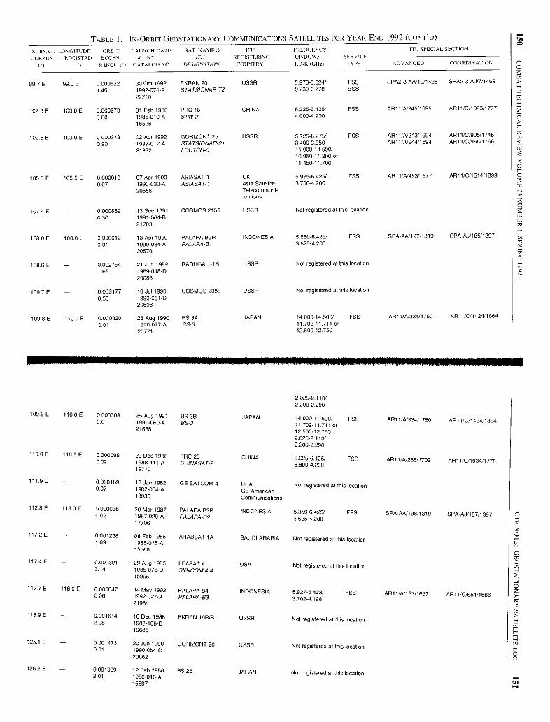
TABLE I. IN-ORBIT GEOSTATIONARY COMMUNICATIONS SATELLITES FOR YEAR-END 1992 (CONT'D)
SUESAT. LONGITUDE ORIIIF LAUNCH DATE SAT- NAME & ITII FRNQDENCY ITI: SPECIAL SECTION
ILRRENI REGISTRD ECCEN & INTL ITi/ REGISTERING DP/DOWN- SERVICE
( I & INCL (`) CATALOG NO. DESIGNATION COUNTRY LINKrOlIL TYPE ADVANCED COORDINA I ION
997E 99.0E 0.000522 30 Oct 1992 EKRAN 20 USSR 5.976-6024/ FSS SPA2-3-AA/10/1426 5PA2-3-AJ/7/1469
1.45 1992-074-A STATSIONAR-T2 0730-0778 BSS22210
102.6 E 103.0 E 0000273 01 Feb 1986 ERIC 18 CHINA 6225-6425/ FSS AR11/31245/1695 ART 1/C/1023/1777
3 88 1986010-A STW-2 4,000-420016526
102.6 E 103.0 E 0000273 02 Apr 1992 GORIZONT 25 USSR 5.7256 275/ FSS AR11/31243/1694 AR11/C/905/1748
090 1992-017-A STATSIONAR-21 34003950 AR11/A/244/1694 AR11/C/966/1766
21922 LOUTCH-5 14.000-14.500/10.950-17.200 or11450-11.700
105.5E 105.5E 0000012 07 Apr 1990 ASIASAT I UK 5.925-6425/ FSS AR11/31493/1877 ARi 1/C/1614/1899
0.07 1990-030-A ASIASAT-I Asia Satellite 3700-4.20020558 Telecommuni-
1074 E - 0000852 13 Sep 1991 COSMOS 2155
cations
USSR Not registered at this location0 30 1991-064-B
21703
108.0 E 108.0 E 0000012 13 Apr 1990 PALAPA B2R INDONESIA 5.8506.425/ F55 SPA-AA/197/1319 SPA-AJ/185/1397
001 1990-034-A PALAPA-61 36254.20020570
108.6 E - 0.002754 21 Jun 1989 RADUGA 1-1 R USSR Not registered at this location1.65 1989-048-D
20086
109 7 E - 0.003177 18 Jul 1990 COSMOS 2085 USSR Not registered at this location
056 1990-061-D20696
109.8 E 110.0 E 0.000320 28 Aug 1990 BS 3A JAPAN 1400014.500/ FSS AR11/41334/1750 API I/C/1424/1664
001 1990-077-A BS-3 11702-11.711 or20771 12.500-12 750
0
2.025-2.110/2.200-2.290
109.9 E 110.0 E 0000308 25 Aug 1991 85 3B JAPAN 14.000-14.500/ FSS AR11/31334/1750 API 1/C/1424/18640.01 1991060-A BS -3 11 702-11 711 or21668 12.50012.750
2.025-2.110/2200 2,290
110.6E 110.5E 0.000095 22 Dec 1988 PRC 25 CHINA 6.025-6.425/ FSS AR11/31256/1702 AR11/C/1034/1778002 1988-111-A CHINASAT-2 3.800-4.20019710
111.9 E - 0000189 16 Jan 1982 GE SATCOM 4 USA Not registered at this location097 1982-004-A GE American
13035 Communications
112.8 E 113.0 E 0.000036 20 Mar 1987 PALAPA B2P INDONESIA 5.850-6425/ F5S SPA-AA/198/1319 SPA-AJ/187/13970.02 1987-029-A PALAPA-B2 3.625-4.20017706
117.2 E - 0.001258 08 Feb 1985 ARASSAT 1A SAUDI ARABIA Not registered at this location1.69 1985-015-A
15560
1174 E - 0.000391 29 Aug 1985 LEASAT 4 USA Not registered at this location3.14 1985-076-D SYNCOM 4-415995
117 7 E 118.0E 0.000047 14 May 1992 PALAPA B4 INDONESIA 5.927-6.423/ FSS ARI 1/3/157/1637 AR11/C/654/16660.06 1992-027-A PALAPA-B3 3.702-4.19821964
118.9 E - 0.001614 10 Dec 1988 EKRAN 19R/B USSR Not registered at this location2.08 1988-108-D
19686
125.1 E - 0.001473 20 Jun 1990 GORIZONT 20 USSR Not registered at this location0.61 1990-054-D
20662
126.2 E - 0.001909 12 Feb 1986 BS 2B JAPAN Not registered at this location2.01 1986-016-A
16597 U
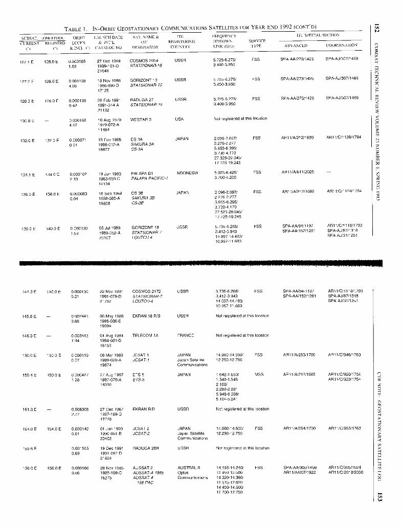
TABLE 1. IN-ORBIT GEOSTATIONARY COMMUNICATIONS SATELLITES FOR YEAR-END 1992 (CONT'D)
SIIBSAE. LONGITUDE ORBIT LAL NCH DATE SVI NAME & ITL FREQUENCYVICE
ITL SPECIAL SLCIION
T REGISrRD LCCFN(1I - - & AAT'L //t- REGIS INRING UP/DOWN- SERTYPE ADVANCED COORDINATION
1"t I1 &ECI1°I CAIALOGNO. DFSIGNATIOA' COt NI NY I.INKoCH,
127.1 E 128.0 E 0.003185 27 Dec 1989 COSMOS 2054 USSR 5.725-6.275/ FSS SPA-AA/273/1425 SPA-AJ/307/1459
1.08 1989-101-G 574 TSIONAR-15 3400-3.950
21648
1272 E 128 0 E 0001138 18 Nov 1986 GORIZONT 13 USSR 5725 6275/ FSS SPA-AA/273/1425 SPA-AJ/307/1469
4 06 1986-090-D STATSIONAR-15 3 400-3.950
17125
128.3 E 128 0 E 0000130 28 Feb 1991 RADUGA 27 USSR 5725 62751 FSS SPA-AA1273/1425 SPA-AJ/307/1469
042 1991-014-A ST4TSIONAR-15 3400-3.950
21132
130.8 E - 0000166 10 Aug 1979 WESTAR 3 USA Not registered at this location
4 47 1979-072-A11484
132-0 E 132.0 E 0.000071 19 Feb 1988 CS 3A JAPAN 2.098-2.097/ FSS AR11/A/21211680 AR11/0/1128/1794
0.01 1988-012-A SAKURA34 2.276-2277
18877 CS-3A 5.955.6395/37304.17027525-29.045/17 725-19.245
1341 E 134.0 E 0.000107 19 Jun 1983 PALAPA Rt INDONESIA 5.925-6.425/ FSS AR11/4/ 811/2025
2 33 1983-059-C PALAPA PACIFIC-1 3 700-4.200
14134
136.0E 136 0 E 0000083 16 Sep 1988 CS 3B JAPAN 2.0962097/ FSS AR11/4/212/1680 AR11/C/1128/1794
0 04 1988086-A SAKURA 38 2276-2.277
19508 CS-3B 5.955-6-395/37304 17027.525-29-045/17 725-19 245
139 9 E 140 0 E 0.000130 05 Jut 1989 GORIZONT 18 USSR 5735-6.268/ FSS SPA-AA/94/1197 API 1/0/1118/1793.
1 53 1989-052-A STATSIONAR-7 3,412-3.943 SPA-AA/152/1261 SPA-AJ/87/1318.
20107 LOUTCH-4 14007-14.493/ SPA-AJ/31/125110.957-t1 683
141.3 E 140.0 E 0.000130 22 Nov 1991 COSMOS 2172 USSR 5735-6.268/ FSS SPA-AA/94-1197 API 1/0/1118/1793
0.21 1991-079-D STATSIONAR-7 3.412-3.943 SPA-AA/152/1261 SPA-AJ/87/1318
21792 LOUTCH-4 14.007-14.493/ SPA-AJ/31/125110957-11.683
145.8 E - 0.002445 06 May 1988 EKRAN 18 R/B USSR Not registered at this location3.66 1988-036-E
19094
146.3 E - 0.003443 04 Aug 1984 TELECOM 1 A FRANCE Not registered at this location1.94 1984081-B
15159
150.0 E 1500E 0.000119 06 Mar 1989 JCSAT 1 JAPAN 14-000-14.500/ FSS AR11/4/253/1700 AR11/0/946/1763
0.07 1989-020-A JCSA T-1 Japan Satellite 12250-12.750
19874 Communications
150.4 E 150.0 E 0000427 27 Aug 1987 ETS 5 JAPAN 1. 642-1 -650/ MSS AR11/4/217/1685 AR11/0/920/17541 1987-070-A ETS-5 1.5409-548 AR11/0/923/1754
18316 2.100/2,280-22815.948-6.396/5.104-5241
151.3 E 0006308 27 Dec 1987 EKRAN R/B USSR Not registered at this location2.77 1987-109.0
1 718 8
154.0 E 154.0 E 0.000142 01 Jan 1990 JCSAT 2 JAPAN 14.000-14.500/ FSS ARI I /41254/1700 AR11/0/953/17630.01 1990-001-B 30547.2 Japan Satellite 12.250-12.750
20402 Communications
155.6 E 0.001565 19 Dec 1991 RADUGA 28R USSR Not registered at this location0.69 1991-087-D
21824
156.0 E 1560 E 0.000166 28 Nov 1985 AUSSAT 2 AUSTRALIA 14.195-14.240/ FSS SPA-AA/300/1456 API 1/0/305/16240.06 1985-109-C AUSS47-A 156E Opmb 12450-12.500 AR11/4/607/1922 AR11/0/2018/2000
16275 AUSSAT-A Communications 14.320-14360/156 PAC 12.575-12.620
14 450-14.500/12.700-12 750
0

TABLE 1. IN-ORBIT GEOSTATIONARY COMMUNICATIONS SATELLITES FOR YEAR-END 1992 (CONT'D)
SUBSAT. LONGITUDE ORBIT LAUNCH DATE SAT. NAME & [It FREQUENCY ITII SPECIAL SECTION
CCRRLNU
1'1
REGIS I RD
Cl
ECCEN.
& INCL (')
& INI L
CATALOG NO.
/'/(/ RECtSTERINO
DESIGNATION COUNTRY
LP/DOWN- SERVICE
1 INK CID) TYPE ADVANCED COORDINATION
160.0 E 160.0 E 0.000119 27 Aug 1985 AUSSAT 1 AUSTRALIA 14.195-14 240 / FSS SPA -AA/299/1456 AR11/C/296/16240.01 1985-076.8 AUSSAT-A 160E OpWS 12450-12.500 AR11 /A/606 /1922 AR11 /0/2019/2000
15993 AUSSAT-A Communications 14.320 - 14.360/160 PAC 12.575-12.620
14 450-14.500/12.700-12.750
160.2 E 160.0 E 0.000356 13 Aug 1992 OPTUS 81 AUSTRALIA 14.000-14 . 500/ FSS AR11 /A/355/1772 AR11/C/2041/2005(111 1992- 054-A AUSSATBI Optus 12.200-12.750 MSS API I/A/379/1796 AR11 /C/654/1666
22087 AUSSATBI -MOB Communications 1.646-1.660 / AR11/A/360/1779 AR11 /C/1807/1963AUSSAT BI -N2 1.545 -1.559 AR11 /A/785/2009 AR11 /C/2209/2040
161.9 E 1(i E 0.000391 26 Feb 1992
AUSSAT-B 160E MXL
SUPERBIRD Bt JAPAN 7 .925-8.025/ FSS AR11 /A/341/1762 AR1 1 /C/1307/18360.04 1992-010-A SUPERBIRD-B Space 7 . 295-7 .375 MSS
21893 Communications 14.002 - 14.398/Corp . 12.352 -12.748
27.575-29.115/17775 19315
161.9 E 0.001507 09 Jun 1982 WESTAR 5 USA Not registered at this location0.70 1982-058-A
13269
164.0 E 164 . 0 E 0.000083 16 Sep 1987 AUSSAT K3 AUSTRALIA 14.000- 14.500/ FSS SPA-AA/301 /1456 AR11 /0/314/16240.02 1987 -078-A AUSSAT-A 164E Opme 12.250-12750 API 1/1/215/1684 AR11 /0/1008/1773
18350 AUSSAT-A1 4E PAC
Communications
173.0 E 0.003788 04 Apr 1986
6
COSMOS 1738 USSR Not registered at this location4.97 1986-027-F
16676
174.0 E 174.0 E 0.000344 22 Mar 1985 INTELSAT 5A-10 USA 5.925-8425/ FSS AR11 /1/65/1580 AR11 /0/680/1668040 1985-025-A INTELSATSA PACT Intelsat 3.700-4 . 200 AR1 I/C/1642/1917
15629 14.000-14.500/10.950-11.700
177.0E 1770 E 0.000356 30 Jun 1985 INTELSAT5A-11 USA 5925 6425/ FEE AR11/A/66/1580 AR11/C /678/16680.04 1985-055-A INTELSATSA PAC2 Intelsat 3 700-4 200 AR11/C/1643/1917
15873 14.000-14.500/10.950-11.700
178.3 E 178-0 E 0.000368 16 Dec 1991 INMARSAT 2 F3 UK 1 . 626-1-649/ MSS AR11 /1/545/1904 AR11 /0/1764/19532.06 1991-084 - B INMARSAT POR-2 Inmarsat 1.530-1.548
21814 6 . 170-6.160/3.945-3.9556.4258443/
3.600-3.623
180.0 E 180 . 0 E 0.000320 05 Mar 1984 INTELSAT 5A -8 USA 1 . 626-1.649/ MSS SPA-AA/255/1419 AR11 /0/682/1668( 180.0 W ) ( 180.0 W) 1.46 1984- 023-A INTELSATS PAC3 Intelsat 1 .530-1.548 FSS SPA-AA/332/1476 AR11 /0/692/1669
14786 INTELSAT MCS 5.925-6 . 425/ AR11 /0/859/1735PAC A 3700-4200
14.00014.500/10.950 - 11.700
182.2 E 183 . 0 E 0.000012 31 Aug 1984 LEASAT 2 USA 0.240-0.322 / MSS API 1 /A/335 /1762 API I /C/1862/1968(177.8) (177.0 W) 3.99 1984-093 -C SYNCOM 4-2 0.240-0 .322 FSS AR11 /C/1869/1968
15236 FLTSATCOM-A 0.335-0 400/W PAC 0.335-0 400
79798010/7.255-7.265
1824 E - 0001890 23 Nov 1990 GORIZONT 22 USSR Not registered at this location(177.6 W ) 037 1990-102-D
21046
183.0 E 183 . 0 E 0-000344 15 Dec 1981 INTELSAT 5 F3 USA 5.925-0.425/ FSS SPA-A5/254/1419 AR11 /C/1813/1964(177.0 W) (177.0 W ) 3.35 1981 -119-A INTELSAT5 183E Intelsat 3 . 700-0.200
12994 14.000- 14.500/10.950-11.700
183.9 E - 0.002877 20 Dec 1990 RADUGA 26R USSR Not registered at this location(176.1 W) 021 1990-112-0
21019
185.6 E 186 . 0 E 0.007206 02 Aug 1991 TIDES F5 R/B USA 2-034-2 .037/ EBB AR11 /1/502/1883 AR11/C/1710/1936(174.4 W) ( 174.0 W ) 0.03 1991-0548 TORS 174W Columbia 2-208-2.213 AR11 /1/421/1815
21639 USASAT- 14E Communications 14.287-15.537/13.075-14.3755.925-6.425/3.700-4.200
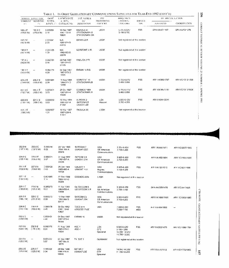
TABLE I. IN-ORBIT GEOS IATIONARY COMMUNICATIONS SATELLITES FOR YEAR-END 1992 (CONT'D)
SI:BSAT-LONGITUDE OItRIT IAIINCH DATE SAT- NAYIE& ITV FRBQCENCY I I L SPECIAL SEC II ON
CURRENTI I
REGISPRD
PI
FCCFN-
& INCL. ('1
S INTL
CATALOG NO-
(/U
DLSIGNATION
REGISTERING
COUNTRY
CP/DOWN- SERVICE
LINKIGW-I IYPE ADAANC ED COORDINATION
189.5 E 190.0 E 0.000261 10 Dec 1987 RADUGA 21 USSR 5.725-6.025/ FSS SPA-AN97/1197 SPA-AJ/52/1276(1705 W) (170.0 W) 318 1987-100-A STATSIONAR-10 3.400-3.700
18631 STATSIONAR-10A
192 2 E - 0.001241 N/A EKRAN 20R USSR Not registered at this location(167.8 W) 2.33 1992-074-D
22213
1926 E - 0001125 N/A GORIZONT 27R USSR Not registered at this location(1674W) L09 1992-082-D
22248
197.4 E - 0002724 28 Feb 1991 RADUGA 27R USSR Not registered at this location(1626 W) 0.44 1991-014-D
21135
198.1 E - 0.002174 04 Sep 1987 EKRAN 16 R/B USSR Not registered at this location(161.9W) 424 1987073-D
18331
2052 E 205.0 E 0.001984 18 Aug 1988 GORIZONT 16 USSR 5.725-6.275/ FSS AR11/N385/1797 ART 1/O/1313/1836(154.8 W) (155.0 W) 2.39 1988-071-D STATSIONAR-26 3400-3.950
19400
207-3E 2054E 0.000401 28 Oct 1987 COSMOS 1894 USSR 5725-6-275/ FSS AR11/A/385/1797 AR11/0/1313/1836(152.7 W) (1550 W) 3.73 1987.091-A STATSIONAR-26 34003-950
18443
220 9 E 221.0 E 0000059 29 May 1991 AURORA 2 USA 5 925-6 425/ FSS AR11/81844/2041(1391 W) (139.0W) 0.03 1991-037-A SATCOM-C5 Alascom 3700-0200
21392 USASAT221
221 7 E - 0002937 19 Mar 1987 RADUGA 20 USSR Not registered at this location(138.3 W) 431 1987-028-A
17611
222.9 E 223.0 E 0.000296 20 Nov 1990 SATCOM C1 USA 5.925-6425/ FSS AR11/N690/1971 AR11/0/2007/1993(137.1 W) (137.0 At 0.02 1990-100-A USASAT-22G GE American 3 700-4.200
20945 Communications
224.9 E 225 0 E 0.000071 31 Aug 1992 SATCOM C4 USA 5.925-6.425/ FSS ARI 1/A1483/1864 AR11/0/2005/1993(135.1 W) (135.0 W) 007 1992-057-A USASAT2IA GE American 3700-4.200
22096 Communications
227.1 E 227.0 E 0000130 28 Jun 1983 GALAXY 1 USA 5.925-6.425/ FSS AR1 1 /A/1 20/1615 AR11/C/821/1698(132.9 W) (133.0 W) 0-03 1983-065-A USA SAT-11D Hughes 3700-4200
14158 Communications
227.1 E - 0.001065 27 Dec 1989 COSMOS 2054 USSR Not registered at this location(1329 W) 1 14 1989-101-0
20394
229.1 E 229.0 E 0.000273 11 Apr 1983 GE SATCOM 6 USA 5.925-6.425/ FSS SPA-AN329/1476 AR11/0/347/1625(130.9W) (131.0W) 0.07 1983-030-A US SATCOM 3-R GE American 3.700-4200
13984 Communications
229.3 E 229.0 E 0.000373 10 Sep 1992 SATCOM C3 USA 5.925-6425/ FSS AR11/A/1600/1920 AR11/C/2009/1993(1307W) (131.OW) 0-09 1992-060.8 USASAT22H GE American 3700-4.200
22117 Communications
229.9 E 230 0 E 0.000178 30 Oct 1982 DSCS 3 F1 USA 7.900-8.400/ FSS AR11/A/404/1805(1301 W) (130.0 W) 245 1982-106-B USGCSS PH2E 72504750 MSS
13637
230.5 E - 0.000451 04 Sep 1987 EKRAN 16 USSR Not registered at this location(129-5 W) 4 46 1987-073-A
18328
232.0 E 232.0 E 0.000178 27 Aug 1985 ASC 1 USA 5.925-6.425/ FSS AR11/N202/1676 AR11/0/1066/1784(128.0 W) (128.0 W) 0.01 1985-076-C ASC-1 GTE 3.700-4.200
15994 Spacenet 14.000-14.500/11.700-12.200
234.5 E - 0.001212 21 Nov 1987 TV SAT 1 GERMANY Not registered at this location(125.5 W) 3.57 1987-095-A
18570
235 0 E 235.0 E 0.000059 28 Mar 1986 GSTAR 2 USA 14.000-14.500/ FSS AR11 /A/ 576/1912 AR11/C/1772/1953(125.0 W) (125.0 W) 0.04 1986-026-A USA54 T235 GTE 11 700-12.200
16649 Spacenet
r
r_
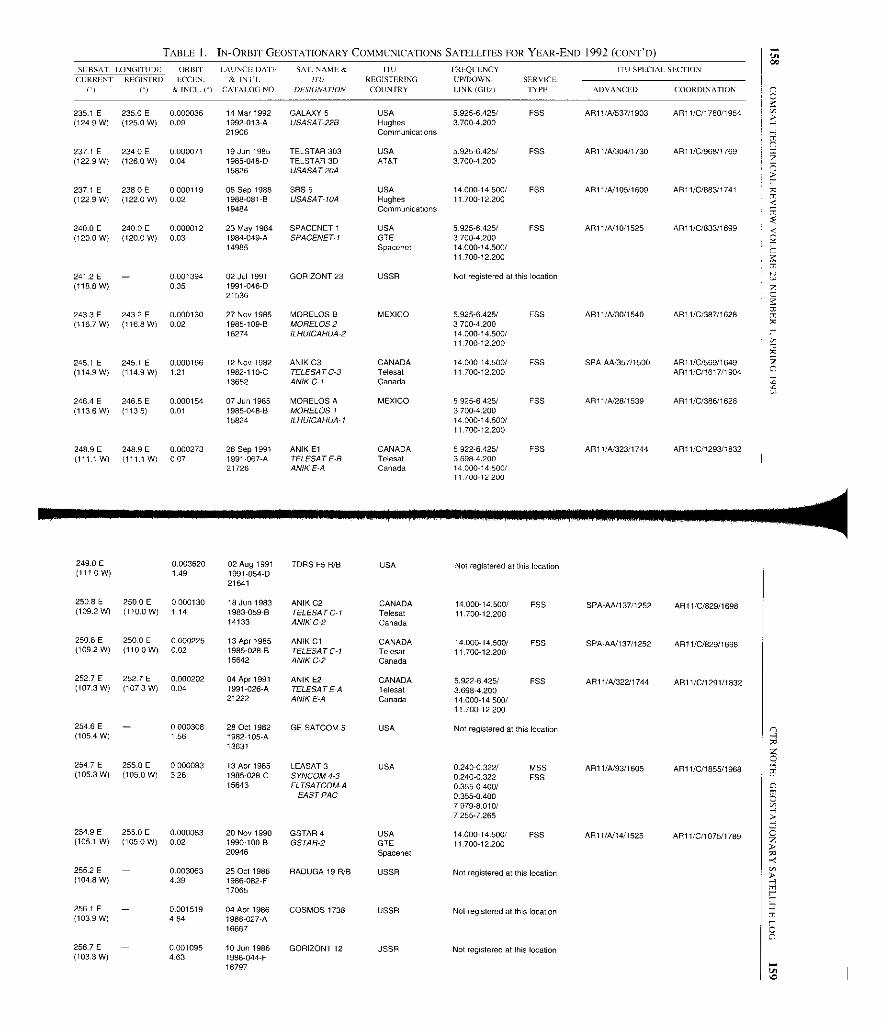
TABLE 1. IN-ORBIT GEOSTATIONARY COMMUNICATIONS SATELLITES FOR YEAR-END 1992 (CONTb)
SL'BSAT. LONGITUDE ORBIT LAUNCH DATE SAr. NAME & IIU FREQLENCY I I U SPECIAL SECTION
CURRENT RECISTRD LCCEN.
& INCL. C)
& INIL
CAIALOG NO./it
DESIGNATION
REGISTERINGCOON MY
L'P/DOWN- SERVICE
LINK (GiW TYPE ADVANCED COORDINATION
235.1 E 235.0 E 0.000036 14 Mar 1992 GALAXY 5 USA 5.925-6.425/ FSS AR11/A/537/1903 AR11/G/1780/1954(124.9 W) (125.0 W) 0.09 1992-013-A USASAT-228 Hughes 3.700-4.200
21906 Communications
237.1 E 234.0 E 0.000071 19 Jun 1985 TELSTAR 303 USA 5.925-6.425/ FSS AR11/N304/1730 AR11/0/968/1769(122.9 W) (126.0 W) 0.04 1985-048-D TELSTAR 3D AT&T 3.700-4.200
15826 USASAT-20A
237.1 E 238.0 E 0.000119 08 Sep 1988 SSS S USA 14.000-14.500/ FSS AR1 1/A/105/1609 API l/C/883/1741(122.9 W) (122.0 W) 0.02 1988-081-B USASAT-10A Hughes 11.700-12200
19484 Communications
240.0 E 240.0E 0.000012 23 May 1984 SPACENET 1 USA 5.925-6425/ FSS AR11/A/10/1525 ARI 1/0/833/1699(1200 W) (120.0 W) 0.03 1984-049-A SPACENET-1 GTE 3700-4.200
14985 Spacenet 14.000-14.500/11.700-12.200
241.2 E - 0001394 02 Jul 1991 GORIZONT 23 USSR Not registered at this location(118.6 W) 035 1991-046-D
21536
243.3 E 2432 E 0.000130 27 Nov 1985 MORELOS B MEXICO 5.925-6.425/ FSS AR11/A30/1540 AR11/C/387/1626(1167 W) (116.8 W) 002 1985-109-B MORELOS 2 3.700-4.200
16274 ILHU1CAHUA-2 14.000-14.500/11.700-12.200
245.1 E 245.1 E 0000166 12 Nov 1982 ANIK C3 CANADA 14.000-14.500/ FSS SPA-AN357/1500 AR11/0/569/1649(114.9 W) (114.9 W) 1.21 1982-110-C TELESATC-3 Telesat 11.700-12200 API 1/0/1617/1904
13652 ANIKC-I Canada
246.4 E 246.5E 0.000154 07 Jun 1985 MORELOS A MEXICO 5925-6425/ F55 AR1 t/A/28/1539 AR11/0/386/1626(113.6 W) (113.5) 0.01 1985-048-B MORELOS 1 3.700-4.200
15824 ILHUICAHUA-1 14.000.14.500/11.700-12.200
248.9E 248.9E 0.000273 26 Sep 1991 ANIK El CANADA 5.922-6.425/ FSS AR11/A/ 323/1744 AR11/0/1293/1832(1111 W) (111.1 W) 0,07 1991.067-A TELESAT E-B Telesat 3.698-4.200
21726 ANIK E-A Canada 14.000-14 500/11.700-12.200
249.0 E - 0.003620 02 Aug 1991 TDRS F5 R/B USA Not registered at this location(111-0 W) 1 49 1991-054-D
21641
250.8 E 250.0 E 0.000130 18 Jun 1983 ANIK C2 CANADA 14.000-14.500/ FSS SPA-AW13711252 AR11/0/829/1698(109.2W) (110.0 W) 1.14 1983-059-B TELESAT C-1 Telesat 11.700-12.200
14133 ANIKC-2 Canada
250.8 E 250.0 E 0.000225 13 Apr 1985 ANIK Cl CANADA 14.000-14.500/ FSS SPA-AN137/1252 AR11/C/629/1696(109.2 W) (110.0 W) 0.02 1985-028-B TELESAT C-1 Telesat 11.700-12.200
15642 ANIKC-2 Canada
252.7 E 252 7 E 0.000202 04 Apr 1991 ANIK E2 CANADA 5.922-6425/ FSS AR11/A/322/1744 AR11/C/1291/1832(107.3 W) (107.3 W) 0.04 1991-026-A TELESATE-A Telesat 3.698-4.200
21222 ANIK E-A Canada 14.000-14.500/11,700-12.200
254.6 E - 0.000308 28 Oct 1982 GE SATCOM 5 USA Not registered at this location(105.4 W) 1.56 1982-105-A
13631
254.7 E 255.0 E 0.000083 13 Apr 1985 LEASAT 3 USA 0.240-0.322/ MSS AR11/A/93/1605 AR11/C/1855/1968(105.3 W) (105.0 W) 3.26 1985-028-C SYNCOM4-3 0.240-0.322 FSS
15643 FLTSATCOM-A 0.355-0.400/EAST PAC 0355-0,400
7.979-8.010/7 255-7265
254.9 E 255.0E 0.000083 20 Nov 1990 GSTAR 4 USA 14.000-14.500/ FSS AR1 l/A/14/1525 API 1/C/1075/1789(105.1 W) (101 0.02 1990-100-B GSTAR-2 GTE 11.70012200
20946 Spacenet
255.2 E - 0.003063 25 Oct 1986 RADUGA 19 R/B USSR Not registered at this location(104.8 W) 4.39 1986082-F
17065
256.1 E - 0.001519 04 Apr 1986 COSMOS 1738 USSR Not registered at this location(103.9 W) 4.64 1986-027-A
16667
256.7 E - 0.001095 10 Jun 1986 GORIZONT 12 USSR Not registered at this location(103.3 W) 4.63 1986-044-F
16797 Inb

TABLE I. IN-ORBIT GEOSTATIONARY COMMUNICATIONS SATELLITES FOR YEAR-END 1992 (CONT'D)
SFBSAT LONGI I LDE ORBIT LAUNCH BA IF SAT- NAME & ITII FREQUENCY ITU SPECIAL SECTION
CURRENT REGISIRD
( I I I
ECCFN-
&INCL1-1
& INFI.
CATALOGNO
IT6^
DESIGNATION
REGISTERING
COUNTRY
IuP/DOWN- Si
IINK IGHLI T) Pb ADVANCED COORDINAI ION
257.0 E 2570 E 0.000119 08 May 1985 GSTAR 1 USA 14.000-14.500/ FSS API I/A115/1525 ART 1/C/1073/1784
(103.0 W) (103.0 W) 0.05 1985-035-A GSTAR-1 GTE 11.700-1220015677 Spacenet
259.0 E 259 0 E 0.000225 13 Apr 1991 SPACENET 4 USA 5.925-6.425/ FSS ART 1/.4/12/1525 ARI I/C/1842/1968
(101.0 W) (101 0 W) 0.01 1991-028-A (formerly ASC-2) GTE 3.700-4.20021227 USASAT-7D Spacenet 14.00014.500/
11.700-12 200
259.1 E - 0.001747 26 Nov 1987 COSMOS 1897 USSR Not registered at this location(100.9 W) 3.08 19870960
18578
259.1 E - 0.000095 20 Nov 1981 GE SATCOM 3R USA Not registered at this location
(100.9 W) 1.69 1981-114A12967
260.6 E 260 0 E 0.001447 05 Dec 1986 USA 20 USA 43.500-45.500/ MSS AR11/.4150/1561
(994W) (100.a W) 0.42 1986-096-A FLTSATCOM EPAC 20.200-21.200 SPA-AA/85/1186
17181 FLTSATCOM -B 0.240-0.329/EAST PAC 0.240-0.329
0.335-0.400/0.335-0 4007.975-8.025/7.255-7.265
260.9 E 261.0 E 0.000154 12 Oct 1990 GBS 6 USA 14.000-14.500/ FSS SPA-AA/124/1235 SPA-AJ/61/1280
(99.1 W) (99.0 W) 006 1990-091-A USASAT-68 Hughes 11.700-12.20020872 Communications
261.0 E 261.0 E 0.000213 12 Oct 1990 GALAXY 6 USA 5.925-6 425/ FSS API 1IN299/1722 AR11/0/962/1765
(99.0 W) (99.0 W) 0.05 1990-091-B WESTAR 6-S Hughes 3700-420020873 Communications
261.8 E - 0.003726 03 Nov 1990 GORIZONT 21 USSR Not registered at this location
(98.2W) 036 1990-094-D20926
aO
263.0E 2830 E 0.000213 24 Sap 1981 SBS 2 USA 14 . 000-14 .500/ FSS ART 1 /A134/1553 AR11 /0/325/1624(97-0 W) ( 970 W ) 4.36 1981-096-A USASAT-64 Comsat 11 700- 12.200
12855
264.0E 263 . 0E 0.000166 28 Jul 1983 TELSTAR 301 USA 5.925 -6.425/ FSS ART 1 /.4/8/1524 API 1 /0/879/1738(96.0 W ) (97.0 W) 0.03 1983-077-A TELSTAR-3A AT&T 3. 7004200
14234
264.9 E 265 . 0 E 0.000213 11 Nov 1982 SRS 3 USA 14 . 00014.500/ FSS ART 1 /.4/35/1553 AR11 /0/331/1624(95.1 W) (950 Vo l 1.16 1982-1108 USASAT-6C Comsat 11 700-12.200
13651
266.5 E 286.5E 0.000186 21 Sep 1984 GALAXY 3 USA 5.925-6.425/ FSS AR11 /A1122/1615 API 1 /0/824/1697(93.5 W ) (93.5 W) 0.03 1984-101 -A USASAT-72B Hughes 37004-200
15308 Communications
266.9 E 267 . 0 E 0.000273 08 Sep 1988 GSTAR 3 USA 14.000-14.500/ FSS ART 1 /.4/222 /1 687 AR11 /0/998/1772(93.1 W) (93 . 0 W) 4.56 1988-081-A USASAT- 16A GTE 11 . 70012200
19483 Spacenet
288.9 E 2690 E 0.000130 31 Aug 1984 SBS 4 USA 14-000-14. 500/ ESE AR11 /A/10111609 ART 1 /0/818/1596(91.1 W) (91.0 W) 002 1984-093-B USA54 T9A Hughes 11 700-12.200
15235 Communications
268.9E 269 . 0E 0000242 28 Oct 1992 GALAXY 7H USA 14 . 000-14.500/ FSS ART 1/A/I01/1609 AR11 /0/818/1696( 91.1 W) (91.0W) 008 1992-072-A USASAT-9A Hughes 11.700-12.200 SPA-AA/37/1152 SPA-AJ/197/1406
22205 WESTAR - 3 Communications 5.927-6.403/3702-4,178
273.0E 273.0E 0.000107 11 Mar 1988 SPACENET3R USA 5.925-6 . 425/ FSS AR11/A/13/1525 ART 1 /0/834/1699(87.0 W ) ( 86.0 W ) 0.02 1988-018 - A SPACENET 3 GTE 37004,200
18951 Spacenet 14-000-14.500/11 700-12.200
275.0 E 275 . 0 E 0.000166 12 Jan 1986 GE SATCOM KU -1 USA 14 . 000-14.500/ ESS ART 1 /.4/103/1609 AR11 /0/1052/1780(85.0 W ) (85.0 W) 002 1986-003 - B USASAT-9C GE American 11.700-12200
16482 Communications
275.1 E 274.0 E 0.000273 01 Sep 1984 TELSTAR 302 USA 5.925-0 .425/ EBB AR11 /A/9/1524 API 1 /0/1084/1790(84.9 W ) ( 86.0 W) 001 1984-093-D TELSTAR 3C AT&T 3.700-4.200
15237 USASAT-3C
275.4 E - 0.003883 15 Feb 1990 RADUGA 25 R USSR Not registered at this location(84.6 W) 0.98 1990-016-D
20502

TABLE I. IN-ORBIT GEOSTATIONARY COMMUNICATIONS SATELLITES FOR YEAR-END 1992 (CONT'D)
.SURSAT LONGITLOF. ORBIT IAt NCIU DATE SAT. NAME& ITC FREQUENCY ITl1 SPECIAL SEC I ION
CLRRENt REGISTRD ECCEN. & IN[ 1. 17t REGISIERING UP/DOWN SERVICETYPELINK GH ADVANCED COORDINA rIOS
!_] (1) & INCL.C) CATALOG NO. DESIGNATION COUNTRY .at
2780 E - 0.000154 09 Nov 1984 ANIK D2 CANADA Not registered at this location
(82-0 W) 0.07 1984113-B15383
279 0 E 279 0 E 0.000178 28 Nov 1985 GE SATCOM KU-2 USA 14.000-14.500/ FSS AR11/N104/1609 AR11/C/1053/1760
(81.0 W) (81-0W) 001 1985-109-D USASAT-9D GE American 11.700-12.200
16276 Communications
2794 E - 0 000130 26 Feb 1982 WESTAR 4 USA Not registered at this location
(80.6 W) 1.06 1982-014-A13069
285.9E 286.0 E 0.000142 22 Sep 1983 GALAXY 2 USA 5.9256425/ FSS SPA-AA312/1465 AR11/0/812/1689
(74.1 W) (74.0 W) 0.01 1983-098-A USASAT-7A Hughes 3400-4.200
14355 Communications
287.9 E 288.0 E 0.000285 08 Sep 1983 GE SATCOM 2R USA 5.925-6.425/ FSS AR1 I/N37/1553 AR11/0/221/1617
(721 W) (72.0W) 002 1983-094-A USASAT-8B GE American 3.700-4200
14328 Communications
290.0 E 290.0 E 0000178 26 Mar 1986 BRASILSAT 2 BRAZIL 5.925 6 425/ FSS AR11/N16/1526 AR11/0/94/1576
(700 W) (70.0W) 007 1986-026B16650
SBTS At 3700-4200
290.7 E - 0012118 31 Mar 1988 GORIZONT 15 USSR Not registered at this location
(69.3 W) 2.96 1988-028-D19020
291.0E 291.0 E 0000320 10 Nov 1984 SPACENET 2 USA 5.925-6.425/ FSS AR11/N11/1525 AR11/0/835/1699
(69.0 W) (690 W) 0.01 1984-114-A USASAT-7C GTE 3.700-4.200
15385 Spacenet 14.000-14.500/11.700-12 200
294.7 E - 0.001315 10 Sep 1992 COSMOS 2209 USSR Not registered at this location
65 3 W 1 19 1992-059-D( . ) .22115
295.0 E 2950 E 0.000320 08 Feb 1985 BRASILSAT 1 BRAZIL 5-925 6425/ F55 AR11/N17/1526 AR11/G/99/1576
(65.0 W) (65-0 W) 0.05 1985-015-B SBTS A2 3.700-420015561
297.5 E - 0.000055 13 Sep 1991 COSMOS 2155 USSR Not registered at this location
(62 5 W) 0.27 1991-064-A
21702
305.7 E 306.0 E 0.000769 15 Apr 1992 INMARSAT 2 F4 UK 1.6261.649/ MSS AR11/A/775/2006
(54.3 W) (54.0 W) 2.26 1992-021-B INMARSAT2AOR Immanent 1.530-1.54821940 WEST- 6170 6 18W
3945-39556.425-6 443/3.600-3.623
306.8 E - 0.001351 06 May 1988 EKRAN 18 USSR Not registered at this location(53.2 W) 379 1988036-A
19090
307.0 E 307.0 E 0.000142 17 May 1988 INTELSAT 5A F13 USA 59266.425/ FSS AR11/N116/1609 AR11/C/674/1667
(53.0 W) (53.0 W) 0.04 1988-040-A INTELSAYSA Intelsat 3.700-4200 AR11/N126/1617 AR11/C/1640/191719121 CONTI 14.000-14-500/ AR11/0/704/1673
10.950-11700 or11 700-11.950 or
12500 12 750
310.1 E 310.0E 0.000296 19 May 1983 INTELSAT 5 F6 USA 1626-1.649/ MSS AR11/A/75/l586 AR11/C/592/1652
(49.9 W) (50.0 W) 1.78 1983-047-A INTELSAT5 Intelsat 1-530-1.546 FSS SPA-AA/212/1348 AR11/0/19481198014077 CONTZ 5-925-0.425/
INTELSATMCS 37004200ATL A 14000-14 5001
10.950-11 700
310.3 E - 0.003149 14 Jul 1992 GORIZONT 26 USSR Not registered at this location(49.7 W) 1.23 1992-043D
22044
313.3 E - 0003514 27 Dec 1990 RADUGA 1-2R USSR Not registered at this location(46.7 W) 020 1990-116-D
21041
3149E 315.0 E 0.000130 15 Jun 1988 PANAMSAT 1 USA 14.000-14.500/ FSS AR11IN199/1675 AR11/C/866/1736
(45.1 W) (45.0 W) 0-04 1988051-C PAS 1 Pan American 10.950-11.200 or AR11IN154/1635 AR11/C/755/1676
19217 USASAT-131 Satellite 11 700-12.200 or AR11/C/1423/1864USASAT-13F 12.500-12.750
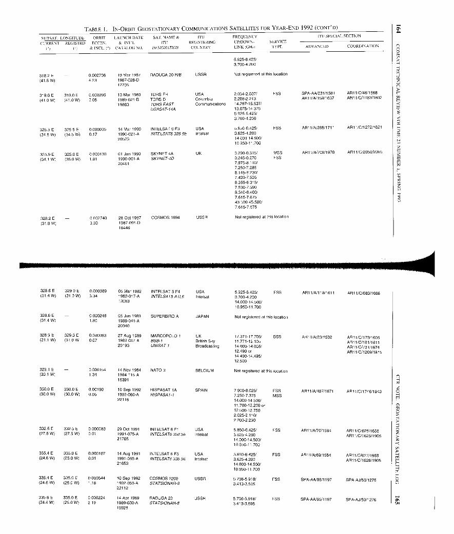
TABLE I. IN-ORBIT GEOSTATIONARY COMMUNICATIONS SATELLITES FOR YEAR-END 1992 (CONT'D)
SUBSAP. tDNGITUDL ORBIT LAUNCH DATE SAT. NAME & ITt1 FREQUENCY ITII SPECIAL SECTION
CURRENT REGIS TRD ECCEN. & INT L ITC REGISTERING LP/DOWN- SLRVICE
I'1 YI & IN(LI") CATALOG NO. OFSICVATION COUNTRY LINKIGHzt TYPE ADVANCED COORDINATION
5.9256 425/3.7004 200
318 ,2 E - 0002708 19 Mar 1987 RADUGA 20 R/B USSR Not registered at this location
(41-8 W) 423 1987-028-017705
319.0 E 319.0 E 0.000296 13 Mar 1989 TDRS FH USA 2.034-2.037/ FSS SPA AA 231/1381 AR11/0/46/1568
(41.0 W) (41.0 W) 006 1989-021-B TORSO Columbia 2.208-2213 AR11/A/158/1637 AR11/C/I 183/1802
19883 TDRS EAST Communications 14.287-15.537/USASAT-14A 13.075-14.375
5925 6425137004200
325.5E 325.5E 0.000035 14 Mar 1990 INTELSAT 6 1 USA 5850 6.425, F55 AR11/A/288/1711 AR11/C/127211821
(345W) (34-5W) 017 1990-021-A INTELSAT63255E Intelsat 3-6254.20020523 14.000-14.500/
10.950-11 700
325.9 E 325 0 E 0-000130 01 Jan 1990 SKYNET 4A UK 0.290-0.315/ MSS AR11/A/708/1978 AR11/0/2050/2005
(34.1 W) (35.0 W) 1-81 1990-001-A SKYNET-40 0.245-0.270 FSS20401 7.975-8 110/
7.250-72858.145-8 230/7.420-7.5058.2558.315/7530 75908340-8,400/7615 7,67543.500-45.500/7615 7675
3282E -(31.8 W)
0002740 28 Oct 1987 COSMOS 1894 USSR Not registered at this location330 1987-091-D
18446
328.6 E 329.0 E 0.000389 05 Mar 1982 INTELSAT 5 1 USA 5.925-6.425/ FSS AR11/A/11811611 AR11/0/683/1668(31 .4 W) (31.0 W) 334 1982-017A INTELSAT5 ATL6 Intelsat 3.700-4 200
13083 14.000-14.500/10.950-11.700
328.6 E - 0.000248 05 Jun 1989 SUPERBIRD A JAPAN Not registered at this location(31.4 W) 1.80 1989-041-A
20040
328.9 E 329.0 E 0.000083 27 Aug 1989 MARCOPOLO 1 UK 17-371-17.705/ BSS AR11/A/23/1532 AR11/C/173/1605(31.1 W) (31-0 W 007 1989-067-A SSB- 1 British Sky 11 771-12.105 AR11/C/181/1611
20193 UNISAT-I Broadcasting 14-000-14.005/ AR11/C/731/167412490 or AR11/C/1209/181514 490-14.495/12500
329.1 E - 0.000154 14 Nov 1984 NATO 3 BELGIUM Not registered at this location(30.1 W) 1.34 1984-115A
15391
330.0E 330.0 E 0.00190 10 Sep 1992 HISPASAT 1A SPAIN 7.900-8.025/ FSS AR11/A/48711871 API 1/C/1746/1943(30.0 W) (30.0 W) 0-05 1992-060-A HISPASATI 7.250-7.375 MSS
22116 14.00014.500/11700-12.200 or12500-127502.025-2.110/2200-2,290
332.5E 332.5E 0.000083 29 Oct 1991 INTELSAT 6 Fl USA 5.850-6.425/ FSS AR11/N70/1584 AR11/C/628/1658(27.5W) (27-5W) 0.01 1991-075-A (NTELSATB 3325E Intelsat 3.625-4.200 AR] 1/C/1625/I 90521765 14.000-14.500/
10.950-17.700
335.4 E 335.0 E 0.000107 14 Aug 1991 INTELSAT 6 F5 USA 5.850-6425/ FSS API 1/A/69/1584 ARI 1/C/627/1658(24.6W) (25-0 W) 0.01 1991-055-A INTELSA T6335. 5E Intelsat 3.625-4.200 AR11/C/I 626/1905
21653 14 0110.950-11700
335.4 E 335.0 E 0.000544 10 Sep 1992 COSMOS 2209 USSR 5736-5.918/ FSS SPA-AA/95/1197 SPA-AJ/50/1276(24.6 W) (25.0 W) 1 18 1992-059-A STATSIONAR-S 3413-3,595
22112
335.6 E 335.0 E 0.000224 14 Apr 1989 RADUGA 23 USSR 5.736-5.918/ FSS SPA-AA/95/1197 SPA-AJ/50/1276(24 4 W) (25.0 W) 2.19 1989-030-A STATSIONAR-6 3.413-3.595
19928
SN
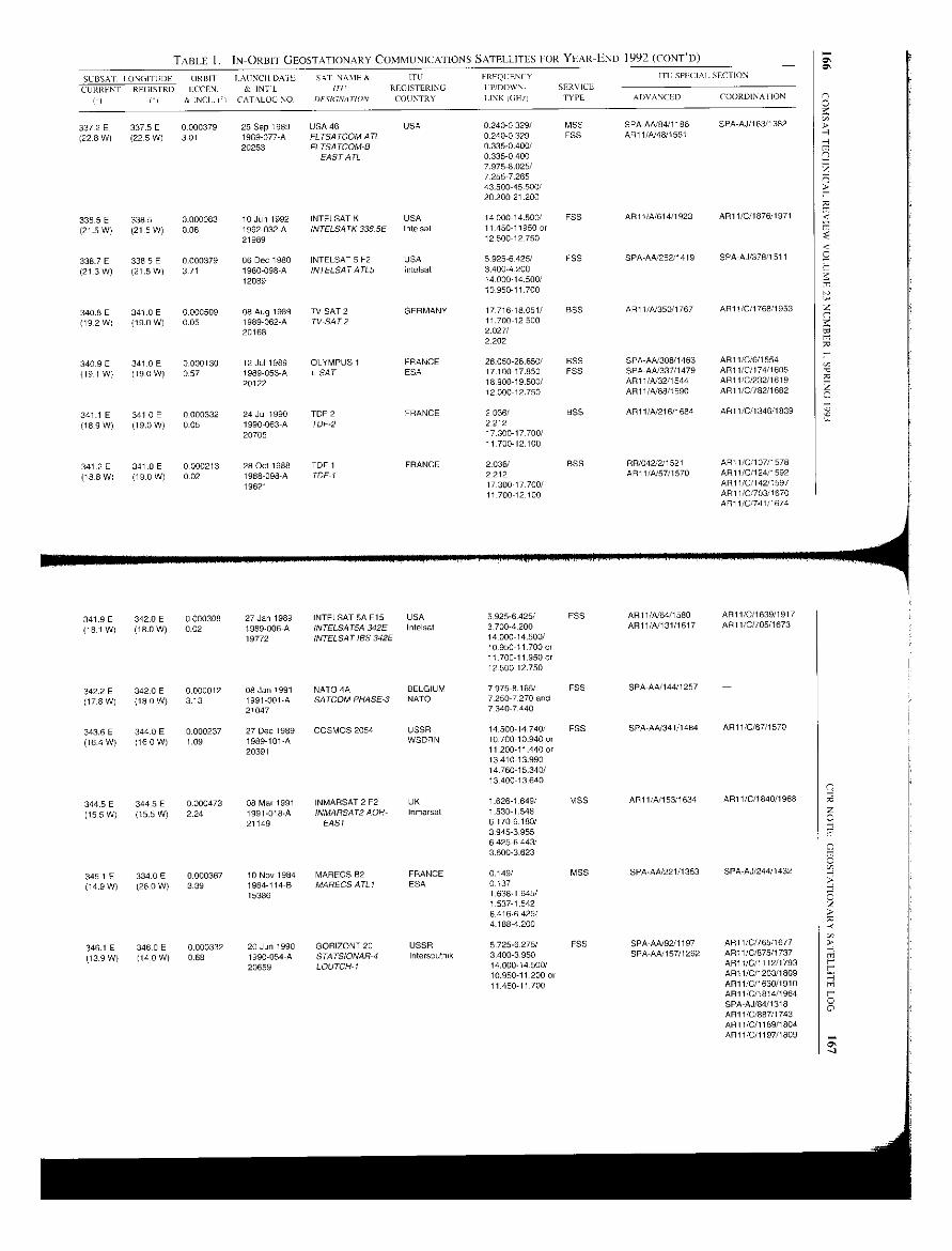
TABLE 1. IN-ORBIT GEOSTATIONARY COMMUNICATIONS SATELLITES I-OR YEAR-END 1992 (CONT'D)
SLBSAI. I -ONGITUDE ORBIT LAUNCH DAI L SAT- NAME & ITI1 FREQUENCY ITC SPECIAL SECTION
CURRENT
FI
REAISTRD
O
ECCHN-
& INCI ft
& INTL
CATALOG NO.
ITC/
DI'SICNATION
REGISTERING
COUNTRY
UP/DOWN-
LINKIGHZI
SERVICE
TYPE ADVANCED COORDINA ZION
337.2 E 337.5 E 0.000379 25 Sep 1989 USA 46 USA 0.240-0.329/ MSS SPA-A4T84/1186 SPA-AJ/163/1382
(22.8 W) (22.5 W) 3.01 1989-077 A FLTSATCOMATL 0240-0.329 FSS AR11/A/48/1561
20253 FLTSATCOM-8 0.335-0.400/EAST ATL 0.335-0.400
7.975-8.025/7255 7.26543.500-45.500/20200-21.200
338.5E 3385 0.000083 10 Jun 1992 INTELSAT K USA 14.000-14.500/ FSS AR11/4614/1923 AR11/0/1676/1971
(21.5 W) (21.5 W) 0.06 1992-032-A INTELSATK 338.5E Intelsat 11 450-11950 or21989 12.500-12 750
338.7 E 338.5 E 0.000379 06 Dec 1980 INTELSAT 5 F2 USA 5.925-8425/ FSS SPA-AA/252/1419 SPA-AJ/378/1511
(213W) (21.5W) 371 1980-098A INTELSAT ATLS Intelsat 3.400-420012089 14.000-14.500/
10.950-11.700
340.8 E 341.0 E 0.000509 08 Aug 1989 TV SAT 2 GERMANY 17.716-18.051/ BSS AR1 l/A/350/1767 AR11/0/1768/1953
(19.2 W) (19.0 W) 0.05 1989-062-A TV-SAT2 11.700-12.50020168 2.027/
2202
340.9 E 341.0 E 0.000130 12 Jul 1989 OLYMPUS 1 FRANCE 28050-28.650/ BSS SPA-AA/308/1463 AR11/0/6/1554
(19.1 W) (190 W) 0.57 1989-053-A L-SAT ESA 17.100-17.850 FSS SPA-AA/337/1479 AR11/C/174/1605
20122 18.90019.500/ AR11/A/32/1544 AR 11/C/232/161912.000-12.750 AR1 1/A/88/1590 API 1/01782/1682
341 1 E 341.0 E 0000332 24 Jul 1990 TDF 2 FRANCE 2.036/ BSS AR11/-8/216/1684 API 1/0/1346/1839
(18-9 W) (19.0 W) 0-05 1990-063A TDF-2 221220705 17.300-17.700/
11.700-12.100
341.2 E 341-0 E 0.000213 28 Cot 1988 TDF 1 FRANCE 2036/ BSS RR/042/2/1521 ARt 1/0/107/I 578
(18.8 W) (19.0 W) 0.02 1988 098 A TDF1 2212 AR11/A/57/1570 AR11/0/124/1592
19621 17.300-17-700/ AR11/C/142/159711 700-12100 API 1/0O03/1670
AR11/C/741/1674
341.9E 342.0 E 0.000308 27 Jan 1989 INTELSAT 5A F15 USA 5.925-6425/ FSS AR11/A64/1580 AR11/C/1639/1917
(18.1 W) (18.0 W) 0-02 1989-006-A INTELSATSA 342E I ntelsat 3.700-4.200 AR11/4/ 131/1617 AR11/0/705/1673
19772 INTELSAT IBS 342E 14 000-14.500/10 950-11.700 or11 700-11.950 or12.500-12.750
342.2 E 342.0 E 0.000012 08 Jan 1991 NATO 4A BELGIUM 7.975-8.165/ FSS SPA-A41144/1257 -
(17.8W) (180W) 3.13 1991001-A SATCOM PHASE-3 NATO 7250-7.270 and21047 7.340-7.440
343.6E 344.0 E 0.000237 27 Dec 1989 COSMOS 2054 USSR 1450014.740/ FSS SPA-AA/341/1484 AR11/0/67/1570
(164 W) (16.0 W) 1.09 1989-101-A WSDRN 1070010.940 or20391 11 200-11.440 or
13410-13.99014 760-15.340/13,400 13 640
344.5E 344.5E 0.000473 08 Mar 1991 INMARSAT 2 F2 UK 1.626-1.649/ MSS AR1 1/-81153/1634 ARM 1/C/1840/1968
(15.5 W) (15.5 W) 2.24 1991-018-A INMARSAT2 AOR- Inmarsat 15301.54821149 EAST 6.170-6.180/
3.945-3.9556 425-6 443/3.600-3.623
345.1 E 334.0 E 0.000367 10 Nov 1984 MARECS 62 FRANCE 0.149/ MSS SPA-AA/221/1353 SPA-AJ/244/1432
(14.9 W) (26-0 W) 3-39 1984-114-B MARECS ATLI ESA 0.13715386 1.638-1.645/
1.537-15426,416-6 425/4,188-4200
346.1 E 346.0 E 0.000332 20 Jun 1990 GORIZONT 20 USSR 5.725-6275/ FSS SPA-AA/92/1197 AR11/C1765/1677
(13-9 W) (14-0 W) 0.68 1990054-A STATSIONAR 4 Intersputnik 3.400-3.950 SPA-AA/157/1262 ART 1/C/875/1737
20659 10070H-I 14.00014-500/ AR11/0/1112/1793
10.950-11 200 or AR11/C/1203/180911.450-11.700 AR11/C/1630/1910
AR11/C/1814/1964SPA-AJ/84/1318API 1/0/887/1743AN 11/0/1189/1804AN 11/0/1197/1809
C'-4
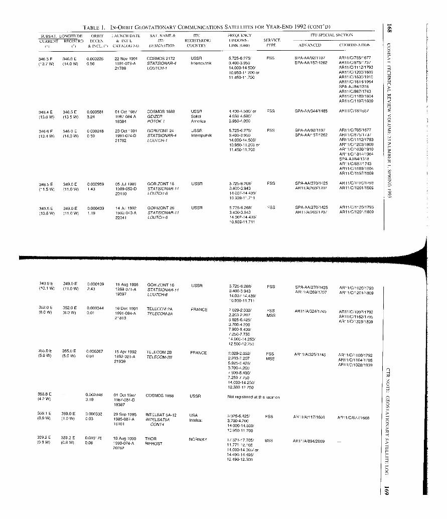
TABLE 1. IN-ORBIT GEOSTATIONARY COMMUNICATIONS SATELLITES FOR YEAR-END 1992 (CONT'D)
5U85AT. LONGITUDE ORBIT IAUNCH DATE SAI- NAME& ITC FREQUENCY ITO SPECIAL SECTION
CURRENT REGISTRD 000EN. & INTL ITU REGISTERING IIP/DOWN- SERVICE
[I Ci & INCL. ('I CATALOG NO. DESIGNATION COLE FRY IINK (GHZI IYPE ADVANCED COORDINATION
346.3 E 346.0 E 0.000225 22 Nov 1991 COSMOS 2172 USSR 5.725.6 275/ FSS SPA-AN92/1197 ARi 1/0/765/1677
(137 W) (14.0 W) 0-56 1991.079-A STATSIONAR-4 Intersputnik 3.4003-950 SPA-AA/157/1262 AR11/0/875/173721789 LOUTCH-1 14.000-14.500/ AR11/C/1112/1793
10.950-11.200 or AR11/0/1203/180911.450-11 700 AR11/C/1630/1910
AR11/C/1814/1964SPA -A./84/1318AR 11/0/887/1743AR 11/0/1189/1804AR1 1/C/1 19711809
346.4 E 346.5 E 0.000581 01 Oct 1987 COSMOS 1888 USSR 4.4004.500/ or FSS SPA-AN344/1485 AR11/0/18/1557
(13.6 W) (13.5 W) 3.24 1987-084A GEIZER Sokol 4.630-4.680/18384 POTOK-I America 3.950-4.000
346.6E 346.0E 0.000248 23 Oct 1991 GORIZONT 24 USSR 5.725-6275/ FSS SPA-AN92/1197 AR11/0/765/1677
(134 W) (14.0 W) 0.59 1991-074-D STATSIONAR-4 Intersputnik 3400-3.950 SPA-AA/157/1262 AR11/C/875/l73721762 LOUTCH-1 14.000-14-500/ AR11/0/1112/1793
10.950-11.200 or AR11/C/1203/180911450 11 700 AR1 I/C/1630/1910
AR11/C/1814/1964SPA AU/84/1318AR11/C/887/1743AR 11/0/1189/1804AR1I/C/1197/1809
348.5E 349.0 E 0002959 05 Jul 1989 GORIZONT 18 USSR 5.725-6268/ FSS SPA-AA/270/1425 AR11/0/1120/1793
(11.5 W) (11.0 W) 1 43 1989-052-D STATSIONAR 11 3.400-3-943 AR11/A/269/1707 AR11/C/1201/180920110 LOUTCH6 14.007-14439/
10.939-11 711
349.5E 349.0E 0.000439 14 Jul 1992 GORIZONT 26 USSR 5.725-6.268/ FSS SPA-AN27011425 AR11/0/1120/1793
(10.5 W) (11 0 W) 1.19 1992-043-A S1ATSIONAR-11 3.400-3.943 AR11/N269/1707 AR11/0/1201/180922041 LOUTCH-6 14.007-14 439/
10.939-11 711
349.9 E(10 1 W
349.0 E 0.000109 18 Aug 1988 GORIZONT 16 USSR 5.725-6268/ FSS SPA-AN270/1425 ARi 1/0/1120/1793. ) (11.0 W) 2.43 1988-071-A STATS/ONAR 11 3.400-3.943 AR11IN26911707 AR1 l/C/1201/180919397 LOUTCH-6 14.007-14.439/10.939-11.711
352.0 E8
352.0 E 0.000344 16 Dec 1991 TELECOM 2A FRANCE 2.029-2.032/ FSS AR11/A/324/1745 AR11/C/1097/17 2( -0 W) (8.0 W) 0.01 1991-084-A TELECOM-2A 2203-2.207 MSS9
ARI 1/C/1162/179521813 5.925-6.425/ AR11/0/1325/18393.700-4 2007-900-8.400/7.250-775014.000-14.250/12500-12750
355.0 E5 0 W
355.0 E 0.000367 15 Apr 1992 TELECOM 2B FRANCE 2.029-2.032/ F5S AR11/N325/1745 AR11/C/1100/1792( - ) (5.0 W) 0-01 1992-021-A TELECOM-2B 2.203-2.207 MSS AR11/C/1164/179521939 5.925-6.425/ AR11/C/1328/18393700 4.2007.900-8.400/7.250-775014.000-14.250/12.500-12.750
355.8 E 0.002048 01 Oct 1987 COSMOS 1888 USSR Not registered at this location(4.2 W) 3.19 1987-084-D18387
359.1 E0 9 W
359.0 E 0.000332 29 Sep 1985 INTELSATSA-12 USA 5-925-6.425/ FSS AR11/NI 17/1609 ARC t/C/677/1668( . ) (U0 W) 0.03 1985-087-A INTELSATSA Intelsat 37004.20016101 CONT4 14.00014-500/
10.950-11700
359.2 E 359.2 E 0.000178 18 Aug 1990 THOR NORWAY 17-371-17705/ BSS ARE 1/k894/2069(0 8 W) (0.8 W) 0.06 1990-074-A BIFROST 11.771-12.10520762 14.000-14.005/ or
14.490-14.495/12.490-12.500
P
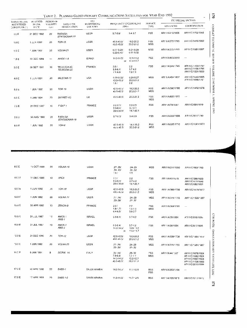
TABLE 2. PLANNED GLOSTATIONARY COMMUNICATIONS SATElL1TES I OR YEAR-END 1992
SUITS ATELLITE PI ANNED PERIOI) OF ITl1 ITU SPECIAL SECTION
REGISTEREDLONGITUDE ()
IN-USEDATE
VALIDITY SAIL' I ITEIycxl DESIGNATION
REGISTERINGCOUNTRY
FREQUENCY I:P/DOWNLI,NK
IGHq
SERVICETYPE ADVANCED COORDINA1ION
10E 31 DEC 1992 20 RADUGA USSR 5.7 -5.9/ 343,7 F55 ART 1/A410/1806 API 1/0/1752/1948
1.0 E 1 JUN 1992 20
STATSIONAR-22
TOR-15 USSR 42.5-43.5/ 18.2-20.2 ESS AR11/N372/1790 ART 1/0/1418/1862
43.5-45.5/ 20.2-21.2 MSS
1.0 E 1 JUN 1992 20 VOLNA-21 USSR 0 .27-0.28/ 0.240. 29 MSS ART 1 /A375/ 1793 API 1 /0/1581/1887
0330.40/ 0 31-0.32
1.5 E 30 DEC 1994 - AMOS I-A ISRAEL 14.0-14.5/ 10.9-11.2 FSS AR11/N803/2019 -or 114117
3 0E 30 SEP 1991 10 TELECOM 2C FRANCE 2.0/ 2.2 FSS AR11/N326/1745 AR11/0/1103/1792.
TELECOM-2C 5.9-6.4/ 3]-0.2 ART I/C/1166/1795
79-8.0/ 72-7.4 AR11/0/1331/1839
4 0 E 1 JUN 1991 20 MILSTAR-13 USA 0.29-0 . 32/ 0.24 -0.27 MSS AR11/A/ 454 /1837 ART 1 /0/154911885.
43.5-45.5/ 20.2-212 AR11/0/1658/1761
1.8/ 2.2
5.0 E 1 JUN 1992 20 TOR19 USSR 42.5-43.5/ 18.220.2 ESE AR11 /A390/1798 AR11/0/1492/1878
43.5-45 . 5/ 20.2212 MSS
6.0E 1 JAN 1994 20 SKYNET-4G UK 43.5-45.5/ 20.2-21.2 F55 AR11/4/692/1972 -M55
7.0E 31 DEC 1987 10 F-SAT I FRANCE 2-0-21/ 22-2.3 FSS ART 1/4/79/1587 ART 1/0/564/1649
59-64/ 3.7-4.1
29.5-30.0/ 197-20.1
8.0E 30 AUG 1990 20 RADUGA USSR 57-6.3/ 3.43-9 FSS API 1/4/220/1686 AR11/C/911/1749
8 0 E 1 JUN 1992 20
STATSIONAR-18
TOR-8 USSR 42.5-03 . 5/ 182-20.2 FSS ARI 1/A285/1710 AR11 /C/1361/1851
43.5-45.5/ 20.2-21.2 MSS
8.0E 15 OCT 1990 20 VOLNA-15 USSR . 27-.28/ 24-29 MSS AR11 /4/241 /1693 ART 1/0/953/1769.34-.40/ 31-.321.6/ 1.5
10.0E 31 DEC 1988 10 APEX FRANCE 2.9/ 2,2 FS5 AR1I/A/62/1578 AR11/C/388/16285.9-6.4/ 3742 ART 1/0/479/I 64829.5-30 .0/ 19.7-20.1 ART 1/C/582/1651
12.0 E I JUN 1992 20 TOR_ 18 USSR 42.5-03-5/ 18.2-20.2 ESE AR11/4/389/1798 AR11/0/1479/187743.5-45.5/ 20.2-21.2 MSS
12.0 E 1 JUN 1992 20 VOLNA-27 USSR 2-.28/ -24-29 MSS AR11/4/378/1793 AR11/0/1590/188733-39/ .31-.32
15.0E 30 APR 1992 10 ZENON-8 FRANCE 2.0/ 22 F55 ALI 1/4/364/1781 -1.6-1.7/ 1.5-1.6 MSS646.5/ 36-37
15.0E 31 JUL 1987 10 AMOS I ISRAEL 5-9-6.4/ 3742 FSS API 1/4/39/1554 AR11/0/816/1695
15.0 E 31 JUL 1987 10
AMSI
AMOS 2 ISRAEL 59-64/ 3.7 -4.2 F55 AR11/N39/1554 ART 1/C/817/1695AMS-2 140-145/ 10.9-11.2
or 11.4-11.7
15.0E 31 DEC 1990 20 TOR-12 USSR 42.5-43.5/ 18-2-20.2 FSS ART 1/4/309/1736 AR11/0/1444/187243.5-45.5/ 20.2-21.2 MSS
15.0 E 1 JUN 1992 20 VOLNA-23 USSR 27-.28/ -24-.29 MSS AR11/4/376/1793 AR11/0/1584/188733-.39/ 31-.32
16.0E 5 JAN 1994 8 SICRAL-lA ITALY .3340/ .23-.32 F55 AR11/4/44/1557 ARTI/C/1678/I 92479-8.4/ 7.2-77 M55 ART 1/C/1682/192414.0-14 .2/ 122-127 ART 1/0/1687/192443.5-45.5/ 20.2-21 2 AR11/0/1728/1993
AR11/C/2013/1998
17.0 E 30 APR 1992 20 SASS-1 SAUDI ARABIA 14.0-14.5/ 11.7-12.5 BSS AR11/4/353/1768
17.0 E 17 APR 1993 20 SAGS 1-2 SAUDI ARABIA 14.0-14-5/ 11.7-12.5
FSS
855 AR11/4/125/1616 ART 1/0/1212/1815
J
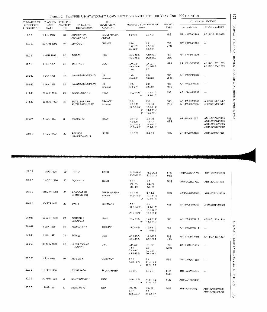
TABLE 2. PLANNED GEOSTAILONARY COMMUNICATIONS SATELLITES FOR YEAR-END 1992 (CON I"D)
SURSATEIIJTE PLANNFD PERIOD OI ITC ITC SPECIAL SECTION
REGISTERED IN-USE VALIDITY SA I I,],] FEE REGIS ILRING FREQUENCY UP/DOWNI- INK SERVICE
LONGITUDE (°) DATE lyn) DESIGNATION COLNIRY GIb) TYPE ADVANCED COORDINATION
19.0E 1 JUN 1994 20 ARABSAT 2AARABSAT2-A
SAUDI ARABIAArabsat
5.9-6,4/ 37-42 FSS AR11 /A/679/1963 ARI 1 /0/2128/2029
19.0E 30 APR 1992 10 ZENON-C FRANCE 2.0/ 22 FSS AR11 /4/365/1781 -1.6-1.7/ 1.5-1.6 MSS6.4-6.5/ 3637
19.0 E 1 MAR 1993 20 TOR-26 USSR 42.5-43 . 5/ 182202 FSS AR11/4./459/1839 -43.5-45 . 5/ 202212 MSS
19.0 E 1 FEB 1991 20 MILSTAR-9 USA 29-32/ 24 27 MSS AR11 I4./450 /1837 AR11 /0/1533/1885
435-45 .5/ 20.2-212 AR11 /0/1654/19191.8/ 2.2
20.0 E 1 JAN 1998 20 INMARSAT4 GSO-ID UK 1.6/ 2.5 FSS ARI 1 /A/824/2032 -Inmarsat 64-6.6/ 3.6-3.8 MSS
20.0 E 1 JAN 1998 20 INMARSAT4 GSO-2D UK 19/ 2.2 FSS API 1 /A/831/2032 -In marsat 6.4-6.7/ 3.6-3.9 MSS
21.0 E 30 APR 1993 20 BABYLONSAT-3 IRAQ 14.0-14.5/ 10.9-11 . 2 FSS AR11 /A/441/1832 -or 114-11 7
21.5 E 30 NOV 1993 20 EUTELSAT 2 F6 FRANCE 2.0/ 23 FSS AR11 /A/654/1957 AR11 /0/1967/1987
EUTELSAT2 -21.5E Eulelsat 1617/ 1.5-1-6 MSS AR11 /A/686/1969 AR11 /0/1968/198714.0-145 / 10.9-11.2
or 11.4-11,7or 12.5127
22.0 E 2 JAN 1994 8 SICRAL-/B ITALY .33.40 / 23-.32 FSS AR11 /4/45/1557 AR11 /0/1680/19247.9-8.4/ 72-77 MSS AR11 /0/1864/192414.0-14.2/ 122-127 AR11 /0/1687/192443.5-45 . 5/ 202-21.2 AR11 /0/1732/1993
23.0 E 1 AUG 1990 20 RADUGASTATSIONAR-19
USSR 576.3/ 3.4-3-9 F55 AR11 /4/221/1686 AR11 /0/916/1752
23.0 E 1 AUG 1990 20 TOR-7 USSR 42.5-43 . 5/ 18.2-20.2 FSS AR11/4./284 /1710 AR11 /0/1356/185143.5-45 . 5/ 20.2- 21 2 MSS
23.0 E 15 OCT 1990 20 VOLNA-17 USSR 1.6/ 15 MSS API 1 /4/242 /1693 AR11 /0/985/176927-.28/ 24.2934-.40/ 31 -.32
26.0 E 20 MAY 1996 20 ARABSAT 2B SAUDI ARABIA 5.9.6.4/ 3.7-4-2 ESS AR11 /A/680 / 1983 AR11 /0/2131/2029ARABSA T 2-B Arabsat 14 . 0-14-5/ 10 .9-11-2
or 11.4-11.5
26.0 E 15 SEP 1992 20 DFS-6 GERMANY 2.0/ 2.2 FSS ARI 1 /4/547/1906 AR11 /0/2112/202014.0-14 .5/ 11411-7
or 12.5-12729.0-30 . 0/ 19.7-20.2
26.0 E 30 APR 1991 20 ZOHREH 2 IRAN 14-0-14.5/ 10.9-11.2 F55 AR11 /4/297/1719 API 1/C/1235/1818ZOHREH-2 or 11.411.7
26.0E 1 JUN 1995 20 TORKSAT-KI TURKEY 14.0-14.5 / 10.9-11.2 F55 ARI 1 /4/797/2014 -or 11.4-11.7
27.0 E 1 JUN 1992 20 TOR20 USSR 425-43. 5/ 182-20 . 2 FSS ARI 1 /4/391/1798 AR11 /0/1484/187743.5-45 . 5/ 20.221.2 MSS
28.0 E 30 NOV 1992 20 FLTSATCOM-C USA 29- 32/ 24.27 FSS ALI VA 702/1973 -INOOCI 1.8/ 2.2 MSS
7.9-80/ 7.2-7.343.5-45. 5/ 20.2-21 2
28.5 E 1 JUN 1995 10 KEPLER 1 GERMANY 2.0/ 2.2 FSS API 1 /4/496/1880 -14.0-14.5 / 114-117
or 12.5-127
29 15 FEB 1995 - STRATSAT-1 SAUDI ARABIA 79-8-4/ 72-77 FSSMSS
AR11/4/835/2033 -
30.0 E 30 APR 1993 20 BABYLONSAT-I IRAQ 14-014.5/ 10.9-11.2 FSS AR1 1/4/439/1832 -or 114-11.7
30.0 E 1 MAR 1991 20 MILSTAR-10 USA 29-.32/ 24-.27 MSS AR11 /4/451/1837 AR11/0/1537/18851-8/ 2.2 AR11 /0/1655/176143.5-45.5/ 20.2-21.2
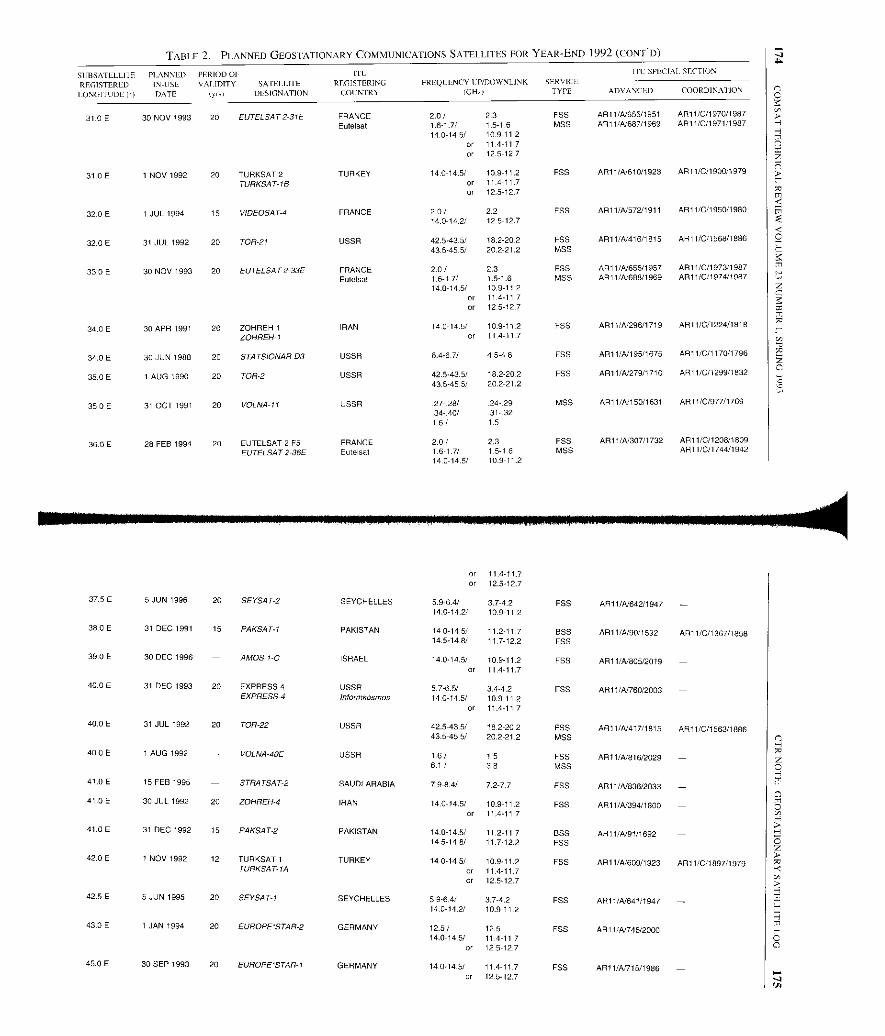
TABLE 2. PLANNED GROSTATIONARY COMMUNICATIONS SATELLITES FOR YEAR-END 1992 (CONT'D)
SIIBSATLLLI IF PLANNED PERIOD OF ITC ITC YPECIAI SECTION
REGISTEREDLONGITUDE (')
IN-USEDATE
AT DEFY SATELLITE(vi r) DESIGNATION
REGISTERINGCOUNTRY
FREQLLNCY I:P/DOWNLINK
(GID)
SERVICETYPE ADVANCED COORDINATION
31.0E 30 NOV 1993 20 EUTELSAT2-31E FRANCE 2.0/ 2.3 FSS AR11/A/655/1951 AR11/C/1970/1987
Eutelsat 1 .6-1.7/ 1.5-1.6 MSS AR11 /A/687/1969 AR11/0/1971/1987
14.0-14.5/ 10.9-11.2or 11.4-11.7or 12.5-12.7
31.0E 1 NOV 1992 20 TURKSAT 2 TURKEY 14.0-14.5/ 10.9-11.2 FSS ART 1 /A1610/1923 AR 11/0/1900/1979
TURKSAT-1B or 11.4-11.7or 12.5-12.7
32.0 E 1 JUL 1994 15 VIDEOSAT-4 FRANCE 2.0 / 22 FSS ARII/A/572/1911 ART 1/0/ 1950/1980
14.0-14.2/ 12.5-12.7
32.0 E 31 JUL 1992 20 TOR-21 USSR 42.5-43.5/ 18.2-20.2 FSS ART 1/A/416/1815 AR11/0/1568/1886
43.5-45.5/ 20.2-21.2 MSS
33 0 E 30 NOV 1993 20 EUTELSAT 2-33E FRANCE 20/ 2.3 F55 AR11/A656/1957 API 1 /0/1973/1987.Eutelsal 1 .6-1 7/ 1.5.1-6 MSS AR11/A/608/1969 AR11 /C/1974/1987
14.0-14 5/ 10.9-11.2or 11.4-11.7
or 12.5-127
34.0 E 30 APR 1991 20 ZOHREH 1 IRAN 14 .0-14.5/ 10.911 2 FSS AR11/A/296/1719 AR11/0/1224/1818
ZOHREH-I or 114-117
34.0 E 30 JUN 1988 20 STATSIONAR-D3 USSR 6.4-67/ 4.5-4.8 E55 AR11/A195/1675 AR 11/0/1170/1796
350 E 1 AUG 1990 20 TOR-2 USSR 42.543.5/ 18.2-20.2 F55 AR11/A1279/1710 AR11/0/1299/1832
43.5-45.5/ 20.2-21.2
35.0E 31 OCT 1991 20 VOLNA-11 USSR 27- 28/ 24. 29 MSS AR11/A/15011631 ART 1/0/977/1769
34- 40/ 31 321.6/ 15
36.0 E 28 FEB 1994 20 EUTELSAT 2 F5 FRANCE 2.0/ 2.3 FSS API 1 /A/307/1732 AR11/0/1208/1809
EUTELSAT2-36E Eutelsat 1.6-1 7/ 1.5-1.6 MSS ART 1/O/1744/1942
14.0-14.5/ 109 11.2
or 11.411.7or 12.5-12.7
37.5E 5 JUN 1996 20 SEYSAT-2 SEYCHELLES 5.9-6.4/ 3742 FSS ART 1 /A/642/1947 -14.0-142/ 10.9-112
38.0 E 31 DEC 1991 15 PAKSAT-1 PAKISTAN 14-0-14.5/ 11.2-117 BSS AR11/4/90/1592 AR11/0/1367/185814.5-14 .8/ 11.7-12.2 EBB
39.0 E 30 DEC 1996 - AMOS I-C ISRAEL 14.014.5/ 10.9-11.2 F5S AR11/A/605/2019 -or 11.4-11.7
40.0 E 31 DEC 1993 20 EXPRESS 4 USSR 5.7-6.5/ 3.4-4.2 EBB ART 1/A/760/2003 -EXPRESS-4 Inlormkosmos 14.0-14-5/ 10.8-11-2
or 11.4-11.7
40.0 E 31 JUL 1992 20 TOR-22 USSR 42.54351 18.2-20 2 F55 API 1/4/417/1615 AR11/0/1563/186643.5-45.5/ 20.2-21.2 MSS
40 0 E 1 AUG 1992 - VOLNA-40E USSR 1.6/ 1.5 F55 AR11/A/816/2029 -6.1 / 3.8 MSS
41.0E 15 FEB 1995 - STRATSAT-2 SAUDI ARABIA 7.9-8.4/ 7.2-7.7 FSS ART 1/4/836/2033 -
41.0 E 30 JUL 1992 20 ZOHREH-4 IRAN 14.0-14.5/ 10.911.2 EBB ART VA/394/1800 -or 11.4-11.7
41.0 E 31 DEC 1992 15 PAKSAT-2 PAKISTAN 14.0-14.5/ 11.2-11.7 B55 ARI 1/4/91/1692 -14-5-14.8/ 11.7-12.2 FSS
42.0 E I NOV 1992 12 TURKSAT 1 TURKEY 14.0-14.5/ 10.9-11.2 F55 AR11/4/609/1923 ART 1 /C/1897/1979TURKSAT-IA or 11,4-11 .7
or 12 .5-12.7
42.5E 5JUN 1995 20 SEVSAT-I SEYCHELLES 5.9-6.4/ 3.7-4.2 EBB ART 1/A/641/1947 -14.0-14.2/ 10.911 2
43.0 E 1 JAN 1994 20 EUROPE'STAR-2 GERMANY 12.5 / 12.5 FSS AR11/AI746/2000 -14.0-145/ 11.4-11
or 12.5-127
45.0 E 30 SEP 1993 20 EUROPE-STAR-1 GERMANY 14.0-14.5/ 114117 FSS ART1 /A'715/1986 -or 12.5-12.7
L
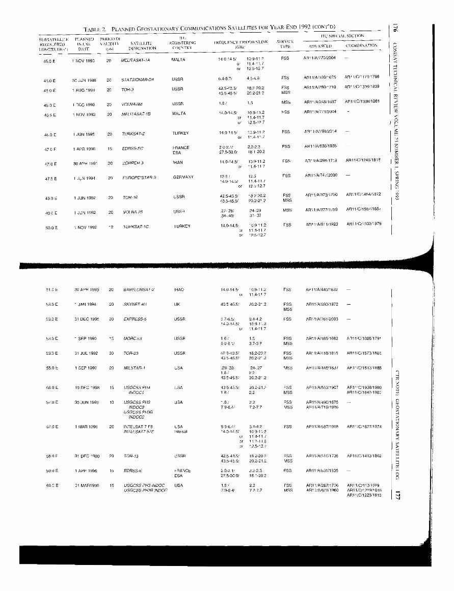
R YEAR-END 1992 (C0N1'D)SATELLITES FOTABLE 2. PLANNED GEOSTATIONARY COMMUNICATIONS
SUBS AIEI.LIFE PLANNED PERIOD OP IllITC SPECIAL SECT ION
BILLS IFIREDLONGITUDE (C)
IN-LSEDATE
N Al IDITY SATELLITEIn'sl DESIGNATION
REGISTERINGCOUNTRY
FREQUENCY CP/D(N5I.1.NK
(GNu
SERVICE
TYPE ADVANCED COORDINATIONCI
0 E45 1 NOV 1993 20 MELITASAT-IA MALTA 14-014-5/ 10.9-11.2 FSS AR11/A/770/2004 -.
oror
114-11712.51212,7
-a
7
45.0 E 30 JUN 1988 20 STATSIONAR-O4 USSR 6.4.07/ 4.5-4.8 F55 ARI 1/A/196/1675 AR11/C/117111796 27
0 E45 1 AUG 1990 20 TOR-3 USSR 42.5-43.5/ 18.2-20 2 F55 API 1/ 5/280/1710 AR 11/C/l 336/1839.
43.5-45.5/ 20.2-21.2 MSS
45.0 E I DEC 1990 20 VOLNA-3M USSR 1.5 MSS API AR 11/C/1398/1861 t
45 5 E 1 NOV 1993 20 MELITASAT-13 MALTA 14.0-14.5/ 10.9-11.2 FPS AS 11/ A/ 771/2004
or 11.4-11.70
or 125-127 r
0 E46 1 JUN 1995 20 TURKSAT-2 TURKEY 14.0145/ 10.9-112 PAS AR11/A/798/2014 -.
or 11 4-1111,7
470 E 1 APR 1996 15 EDRSS-EC FRANCE 2.0-2.1/ 2.2-2.3 FSS API 1/A/630/1935 - Z_
ESA 275-300/ 18.1-202 3-
140 145/ 109-112 F55 AR1I/A/298/1719 AR11/C/1246/1818 m47.0 E 30 APR 1991 20 ZOHREH-3 IRAN
or 11 4-117A
5E47 1 JUN 1994 20 EUROPE'STAR-3 GERMANY 125/ 125 FSS AR11/A/747/2000 - -CA.
140-14.5 / 114-117or 12.5-127
490E 1 JUN 1992 20 TOR 16 USSR 42.5-43.5/ 18 2-20 2 FSS AR11/5/373/1790 ARII /C/1454/1872
43.545.5/ 20.2-21.2 MSS
490 E 1 JUN 1992 20 VOLNA-25 USSR 27-.28/ 24.29 MSS API 1 /5377/1793 AR11 /C/1587/1887
.34:40 / 31-.32
0 E50 I NOV 1992 12 TURKSAT-IC TURKEY 14 014-5/ 10.9-11.2 FSS AR11 I5/611/1923 API 1/0/1903/1979.
or 11.4-11 7or 12.5 127
51.0E 30 APR 1993 20 BABYLONSAT-2
53 0 E 1 JAN 1994 20 SKYNET-4H
53 0 E 31 DEC 1995 20 EXPRESS -5
53 0 E 1 SEP 1990 15 MORE-53
53.0 E 31 JUL 1992 20 TOR-23
55.0 E 1 SEP 1990 20 MILSTAR-4
10 USGCSS PH3INDOC2
USGCSS PH3BINDOC2
1 MAR 1996 20 INTELSAT 7 FBINTELSAT757L
RAQ
5 76.5/ 3.4-4.214-014.5/ 10.9-112
or 11 4-117
42.5-43.51 18.2-20243.5-45 .5/ 20.2212
59-6.4/ 34-4214-014.5/ 10.911 2
or 11 4-11 7
or 11.7-11.9or 125127
42.5-43.5/ 18.2-20.243.5-45 5/ 20.2-21 2
2.0-2.11 22-2.327.5-30.0/ 18.1-20.2
31 MAR1996 15 USGCSS PRY INDOC USAUSGCSS PH3B INDOC
FS5MSS
API 1/A'693/I 972 -
E55MRS
AR11/4/ 185/1662 API I/C/l086/1791
FSSMRS
AR11/A/418/1815 API 1/C/1573/1886
MSS AR11,1A'4451837 AR11/0151T'1085
F55 AR11/A/55311907 AR11/C11938/1980MSS AR11/C11842/1980
FSS AR11/A/490/1875MSS AR1 I/A/71911986
E55 AR11/A/587/1918 AR11/C/1877/1974
F55 AR11/A/310/1736 ALI 1/C/1413/1862M55
FPS AR11/A/267/1706 AR11/C/413/1629
API I/C/1223/I 816

TABLE 2. PLANNED GEOSTATIONARY COMMUNICATIONS SATELLITES FOR YEAR-END 1992 (CONT'D)
SIIBSATELLITE PLANNED PERIOD OF NUVI E
ITL SPECIAL SECTION
REGISTERED
LONGITUDE P)
IN-USE
DATE
VALIDITY SATELLITE
(yn) DESIGNATION
REGISTERING
COUNTRY
FREQUENCY UP/DOWNLINK
(OH,)
SER C
TYPE ADVANCED COORDINATION
60.0E 31 DEC 1998 15 VSGCSS PH4 IN0002 USA 43.5-45.5/ 20.2-21.2 FSS AR11/A554/1907 AR11/0/19431198016/ 2.2 MSS AR11/C/1947/1980
62.0 E 31 JUL 1992 20 TOR-24 USSR 425-43.5/ 18.2-20.2 FSS API1/A419/1815 AR11/0/15951189043.5-45.5/ 20.2-21.2 MSS
64.0 E 31 NOV 1994 20 INMARSAT3 I00-1 UK 1-6/ 1.5 FSS AR11/A598/1920 AR11/0/1991/1989Inammat 32/ 39 MISS
64/ 3.6
64.0 E 1 JAN 1998 20 INMARSAT4 GS04E UK LE / 2.5 FSS AR11/N825/2032 -Inmarsat 6.4-6.6/ 3.6-3.8 MSS
64.0 E 1 JAN 1998 20 INMARSAT4 GSO-2E UK 19/ 2.2 FSS AR11IN832/2032 -Inmarsat 6.4-6.7/ 3.6-3.9 MSS
65.0 E 1 JUN 1994 20 INMARSAT3 IOR-2 UK 1.6-1 7/ 1.5-1.6 FSS AR11/A791/2011 AR11/0/2224/2043Inmarsat 6.2/ 3.9 MSS
6-4/ 3.6
65.0 E 31 JUL 1992 20 TOR-25 USSR 42.5-43.5/ 18.2-20.2 FSS AR11/A420/1815 AR11/0/1600/189043.5-45.5/ 20.2-21.2 MSS
66.0 E 1 AUG 1993 20 INTELSAT 7 F4 USA 5.9-64/ 34-4.2 FSS AR11/N580/1918 AR11/0/1880/1974INTELSATT 66E Intelsat 14.0-14.5/ 10.911.2
or 11.4-11.7or 11.7-11.9or 125-12.7
68.0 E 1 AUG 1993 20 PANAMSAT 6 USA 5.9-6.4/ 3,742 FSS AR11/N74B/2000 -PAS-6 Pan American 14.0-14.5/ 11.4-11.7USASAT-141 Satellite or 12.2-12.7
69.0 E 31 DEC 1990 20 TOR-14 USSR 42.5-43.5/ 18.2-20.2 FSS AR11/A311/1736 AR11/0/1449/187243.5-45.5/ 20.2-21.2 MSS
70.0 E 3 FEB 1994 TONGASAT-H70 TONGA 14.0-14.5/ 10.9-112 FSS API l/N851/2050 -Friendly Islands 5.9-6.4/ 3.7-4.2
70.0 E 1 JUN 1992 20 TOR-17
Satellite
USSR 42.503.5/ 18-2-20.2 FSS AR11/A'371/1790 AR11/0/1474/187743.5-45.5/ 20.2-21.2 MSS
70 1 JUN 1992 20 VOLNA-19 USSR .27.28/ 24.29 MSS AR11/4/374/1793 AR11/0/1578/1887.34:40/ 31 32
70.0 E 1 NOV 1991 10 UNICOM 2 USA 14.0-14-5/ 112-11.7 FSS AID 1/.344/1763 API 1/0/1435/ 1871USASAT-13N Unicorn or 12.5-12.7
72.) E 30 NOV 1992 20 FLTSATCOM-C
Salelliie
USA .29-32/ 24-27 FSS AR11/4/703/1973 -INOOC2 7.9-8.0/ 7.2-7.3 MSS
1.8/ 2243.5-45.5/ 20.2-21.2
72.0 E 1 AUG 1993 20 PANAMSAT-7 USA 5.9-6.4/ 2.7-4.2 FSS AR11/N749/2000 -PAS-7 Pan American 14.0-14.5/ 11.4-11 7USASAT-14J Satellite or 122-12.7
73.5E 15 FEB 1995 STRATSAT-3 SAUDI ARABIA 7.9-84/ 72-7.7 FSS AR11/A837/2033 -
73.5E 1 NOV 1992 12 TURKSAT-ID TURKEY 14-0-14.5/ 10.9-11.2
MSS
FSS ARI 1/.612/1923 -or 11.4-11.7or 12.5-12.7
74.0E 30 JAN 1994 20 INSAT 2KC INDIA 14.0-14-5/ 10-9-11-2 FSS AR11/A/741/1997 -or 11 4-11.7
75.0E 30 NOV 1992 20 FLTSATCOM-C USA 29-.32/ .24-27 FSS AR11/A704/1973 -INDO03 7.9-8.0/ 72-73
1-8/ 2243.5-45.5/ 20.2-21.2
77.0E 1700T1989 20 CSSRD-2 USSR 14.6/ 11.2 FSS AR1I/A188/1672 -or 12.6
150/ 13.5

TABLE 2. PLANNED GEOSTATIONARY COMMUNICATIONS SATELLITES FOR YEAR-END 1992 (CONED)
SCBSATELLI IL PLANNED PERIOD OP ITL'
ITE SPECIAL SEC LION
REGISTEREDLONGITUDE II
IN-USEDAII.
VALIDITY SA ILLI [IFlyol DISIGNAI ION
REGISTERINGCOUNTRY
NI -INKFRFQI/ENCY CP/DON
IGHZ
SERVICETYPE AIJY ANCED COORDINAI ION
775E 1 APR 1993 20 ASIASAT 2 UK 5-8-671 3.4-4.2 FSS AR11/A161711929 AR11/0/1896/1978ASIASAT-D Asia Satellite 14.0-14-5/ 10.9-11.2 AR111N782/2007 AR11/0/2235/2049ASIASAT-DKI Telecom or 11411.7
or 122-12.7
78.5 E 1 JAN 1994 15 THAICOM 2 THAILAND 5.9-6-4/ 37-4.2 P55 AR11/A/727/1988 AR11/C/2186/2036THAICOM-A2 Shinawstra 14.0-14.5/ 109-11.2
Computer or 114-11.7
or 122-127
80.0 E 31 DEC 1994 20 EXPRESS-6 USSR 5.7-6.5/ 34-42 F55 AR1 l/A/762/2003 -14.0-14.5/ 10.9-112
o1 11 4-11 7
81.5 E 1 MAR 1994 1D FOTON-2 USSR 6.5-6-6/ 4647 FSS ALL 1/41236/1692 AR11/C/1 01511776
81.5E 30 JAN 1995 20 INSAT-2KA INDIA 14.0-14.5/ 109-112 FSS ALI 1/41739/1997 -or 11.4-11.7
83.0 E 31 JAN 1990 20 INSAT 2G INDIA 5.6-64/ 3.7-4.2 FSS AR11/4/260/1702 AR11/C/1081/1789INSAT-2A 67-7.0/ 4.54.7
83.3 E 1 NOV 1995 20 TONGASAT AP-KU-4 TONGA 140-145/ 11.7-12.2 FSS AR11/41673/1960 AR11/0/2004/1990Friendly Islands or 12.2-12.7
85.0 E 30 JUN 1988 20 STATSIONAR-D5
Satellite
USSR 6.4-6-7/ 454.8 FEE AR11/A/197/1675 AR11/0/1172/1796
85.0 E 1 AUG 1990 20 TOR-4 USSR 42543.5/ 18.2-202 F55 ARI 1/41281/1710 AR11/0/1341/183943.5-45 IN 20.2-21.2 MSS
85-0 E 1 DEC 1990 20 SOLAR 5M USSR 15/ 1.5 MSS AR11/A/250/1697 AR11/C/1400/1861ARt 1/A/470/I850
90.0 E 31 DEC 1994 20 EXPRESS -7 USSR 5]-6.5/ 3.4-42 FSS AR11/41763/200314.0-14.5/ 109-112
or 11.4-11.7
SO
90.0 E 1 SEP 1990 15 MORE-90 USSR 1.6/ 15 F55 AR11/A/ 184/1662 ARI1/C/ 1090/17916.0-6.1/ 37-3.8 MSS
90.0 E 1 OCT 1990 20 MILSTAR-5 USA 0.29-0.32/ 0.24027 MSS AR11/4/ 446/1837 AR11/C/I 517/188518/ 2.2 AR11/0/1650/191943.5-45.5/ 20.2-21.2
915E 1 APR 1994 - MEASAT-I MALAYSIA 5.9-67/ 34-4.2 FSS AR11/A4839/2031 -14.0-14.51 10.9-11.2
or 11.4-117or 12.2-12.7
91.5 E 1 APR 1994 - INTEL SAT791.5E USA 59 34/ 3.4-4.2 FSS AR1I/A/860/2054 -Intelsat 14.01 10.9-112
or 114-117or 11.7-119or 12.5-12.7
93.5E 20 JAN 1996 20 INSAT 2KE INDIA 14.0-14.5/ 10-911.2 FSS AR11/41740/1997 -INSAT-2K8 or 11.4117
93.5E 31 MAR 1990 20 INSAT 2B INDIA 596-4/ 37 42 FSS AR11/4261/1702 AR11/0/1082/1789INSAT-2B 67-70/ 4.5-4.7
95.0E 1 APR 1994 MEASAT-3 MALAYSIA 5.9-6.7/ 344.2 FSS AR11/A/854/2053 -14.0-14.5/ 10.9-11.2
or 114-11 7or 12212.7
95 0 E 1 JUN 1986 20 CSDRN USSR 14.6/ 10-8 or 11.3 FSS SPA-AA/342/1484 AR11/0/69/157015.0/ 13-5 or 137
950E 1 APR 1994 - INTELSAT795E USA 5.9-64/ 3.4-4.2 FSS AR11/A/861/2054 -Intelsat 14-0-14-5/ 10.9-11.2
or 11.4-11.7or 11.7-11.9or 12.2-12.7
96.5E 31 DEC 1995 20 EXPRESS-8 USSR 57-6.5/ 3.4-4.2 FSS AR11/4/764/2003 -14.0-14.5/ 10.9-11 2
or 11.4-11 7
iC
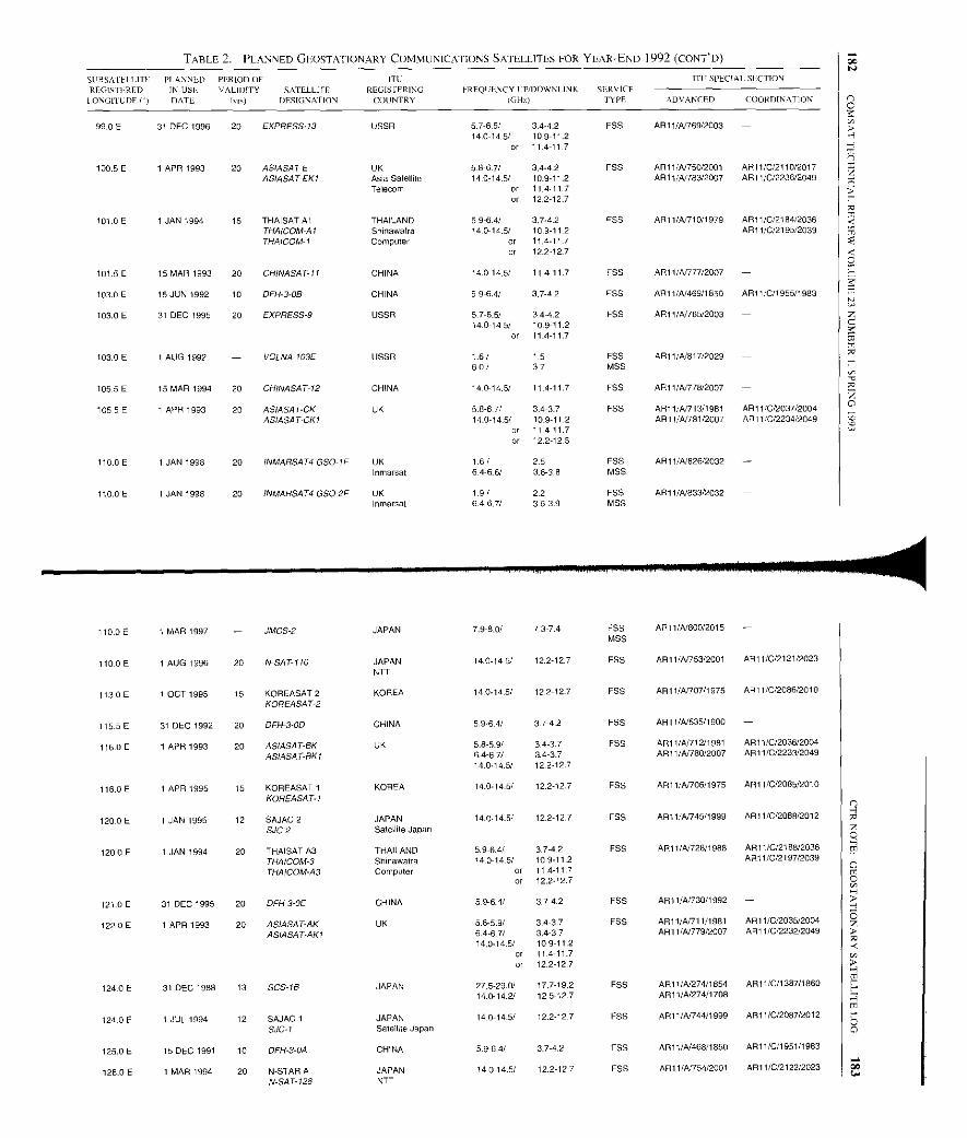
TABLE 2. PLANNED GF.OSTATIONARY COMMUNICATIONS SATELLITES FOR YEAR-END 1992 (CONT"D)
SUBSAI EILITE PLANNED PERIOD OF ITCI
ITII SPECIAL SECTION
REGISTEREDLONGITUDE P)
IN-USLDATE
VALIDITY SATELLITEErrs) DESIGNATION
REGIS IERINGCOUNTRY
FREQUENCY LP/DOWNLINK(GH')
SERV CETYPE ADVANCED COORDINATION
99.0 E 31 DEC 1996 20 EXPRESS-13 USSR 57-6.5/ 3,442 FSS AR11/41769/2003 -14.0-14.5/ 10.9-11.2
or 11 4-11.7
100.5 E 1 APR 1993 20 ASIASAT E UK 58-6.7/ 34-42 FSS ARI 1IN750/2001 AR1 l/C/2110/2017ASIASAT-EKI Asia Satellite 140-14.5/ 10.9-11.2 AR11/Ai783/2007 AR11/C/2236/2049
Telecom or 11.4-11.7or 12.2-127
101.0E 1 JAN 1994 15 THAISAT Al THAILAND 59-6.4/ 3.7-42 FSS AR11/A/710/1979 AR11/C/2184/2036THAICOM-AI Shinawatra 14.0-14.5/ 10.9-112 AR11/C/2195/2039THAICOM-I Computer or 11.4-117
or 12.2-127
101.5 E 15 MAR 1993 20 CHINASAT-11 CHINA 14.0-14.5/ 11 4-11.7 LIDS AR11/A077/2007
103.0E 15 JUN 1992 10 DFH-3-0B CHINA 59-6.4/ 3.7-42 F55 AR11/A/469/1850 AR11/C/1955/1983
103.0 E 31 DEC 1995 20 EXPRESS-9 USSR 5.7-6.5/ 34-4.2 ESP AR11/4/765/200314.0-14.5/ 10.9-11.2
or 11 4-11.7
103.0 E 1 AUG 1992 - VOLNA-103E USSR 1 6 / 1.5 FSS ARI 1/A/817/2029 -60/ 37 MSS
105 5 E 15 MAR 1994 20 CHINASAT-12 CHINA 140-14.5/ 114-11.7 FSS AR11/4/776/2007
105.5E 1 APR 1993 20 ASIASAT-CK UK 5.8-67/ 3,437 FSS AR11/4/ 713/1981 AR11/0/2037/2004ASIASAT-CKI 14.0-14-5/ 109-11.2 APi 1/A/781/2007 AR11/C/2234/2049
or 11 4-11.7or 122-12.5
110.0 E 1 JAN 1998 20 INMARSAT4 GSO-IF UK 1 61 2.5 ESP AR11/A/826/2032 -Inmarsat 6.4-6.6 3.63 8 MSS
110.0E 1 JAN 1998 20 INMARSAT4 GSO-2F UK 1.9/ 2.2 F5S ART 1/N833/2032 -Inmarsat 6,46,7/ 3.6-3.9 MSS
110.0E 1 MAR 1997 JMCS-2 JAPAN 7.9-8.0/ 73-7.4 F55MSS
AR11/A/800/2015 -
110.0E 1 AUG 1996 20 N-SAT110 JAPANNTT
14.0-14.5/ 12.2-12.7 FSS AR11/41753/2001 A911/0/2121/2023
113.0E 1 OCT 1995 15 KOREASAT 2KOREASAT-2
KOREA 14.0-14.5/ 122-12.7 F55 AR11/41/707/1975 AR11/C/2086/2010
115 5 E 31 DEC 1992 20 Di H-3-OD CHINA 5.9-64/ 37-4.2 F55 AR1 1/A/535/1900 -
116 0 E 1 APR 1993 20 ASIASATBK UK 5.8-5.9/ 3.4-37 FSS AR11/4712/1981 A91 1/C/2036/2004
ASIASAT-SKI 6.4-671 3.4-3.7 AR11/A/780/2007 AR11/C/2233/204914.0-145/ 12.2-12.7
116.0 E 1 APR 1995 15 KOREASAT 1KOREASAT-1
KOREA 14.0-14-5/ 12.2-12.7 F55 AR11/41406/1975 AR11/C/2085/2010
120 0 E 1 JAN 1995 12 SAJAC 2SJC-2
JAPANSatellite Japan
14.0-14.5/ 122-12.7 F55 AR11/4)745/1999 ARI 1/0/2088/2012
120.0 E 1 JAN 1994 20 THAISAT AS THAILAND 5.9-6.4/ 3.7-42 FSS AR11/41728/1988 AR11/0/2188/2036
THAICOM-3 Shinawatra 14-0-14-5/ 10.9-11.2 AR11/0/2197/2039
THAICOM-A3 Computer or 11.4-11.7or 12.2.12.7
121 0 E 31 DEC 1995 20 DFH-3-0E CHINA 5.96.4/ 3.7-4.2 FSS ARi 1/41730/1992 -
1220 E 1 APR 1993 20 ASIASAT-AK UK 5.8-5-9/ 3.4-37 FSS AR11/4/711/1981 API 1/0/2035/2004
ASIASAT-AKI 6.4-67/ 34-3.7 AR11/41779/2007 AR 11/0/2232/204914.0-14.5/ 10.9-11.2
or 11 4-11.7or 122-127
124.0 E 31 DEC 1988 13 SOS IS JAPAN 27.5-29.0/ 17.7-19.2 FSS AR11/41274/1854 ARi 1/0/1387/186014.0142/ 12.5127 AR11/A/274/1708
124.0E 1 JUL 1994 12 SAJAC 1SJC-I
JAPANSatellite Japan
140-149 12.2-127 FSS ARI 1/AA44/1999 AR11/0/2087/2012
125.0 E 15 DEC 1991 10 DFH-3-OA CHINA 5.9-6.4/ 374.2 FSS AR11/4468/1650 AR11/0/1951/1983
128.0 E 1 MAR 1994 20 N-STAR AN-SAT-128
JAPANNTT
14-014.5/ 12.2-127 FSS ARI 1/41754/2001 AR11/C/2122/2023W
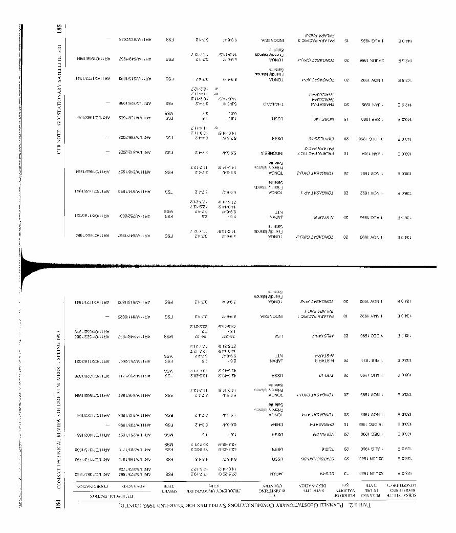
00
- SZOZ/ELeN/L IHV 553 ZP-L'£ M9-69 VIS3NOU NIC OVd VdP7Vd
E 01313Vd VdVIVd SL S66L OnV l 3 0461
-1111855474L' II IS64-0PL spuelsl Alpuapi
P861/996LO/1 LHV 1964/6P9N/LLHV 953 Z4-LE IV8-69 VONOl 6-nMg1VSVONO1 OF 966L NnP 6Z 39641
Ip61/E7Ll/O/L 4HV £681/SLS/V/ILHV SS3 3P-L£ /4'969
allllale9spuelsl Alpuau3
VONOl P-dVIVSVONOI OF Z66L AON t 3 9264
L 3L F9LLFDV LLZ L 1-6 OL
to/o
/SPL0PLPVdNOOIVHl
PW001VH1- 8864/6413/LLHV SS3 Z6-L E 1P'9-6S ONV1IVH1 PV-1VSIVHI OF S66L NVP 1 30 211
SSW /£ /09L6L4/7601/0/LLHV 799LB8IN4 LHV SS3 9L /9I HSSn 0/1-3HOIN SL 0664 338 L 30064
444-411 JO
Z 11-601 /5.41044EOOZ/99L3/LItlV SS3 ZPPB /59-LS 68811 Ol-SS3NdX3 OF 9664030 LE 30064
- 4202/Z19/V/1 LHV SS3 ZP-L£ /69.65 VIS]NOONIJ Dvd VdPIVd
Z 01310Vd VdVIVd OL P66L NVP 1 3 06EL
P96L/99610/t LHV I96L/9V9N/LLHV SS3LZL-Ll L
7PYE/S'PI-OVL
/99-69
OI!IISIESspuelsl Alpuapi
VONO1 E-I1N/OIVSVCNOI 09 6661 AON l 3 08£l
L66L/ZLLL/O/LLHV £681/4493/F LHV SSA 7PLE /9959
llll^le5spuelsl AlPUSU3
VONO1 0 dVIVSVONOl OF 4664 AON L 3 0 8EL
Z LZYLL /014-5'6
SSWGZL-ZZL
7'4-L'Cis PkOtl
/D969 llN1406/84 IZ/133 IHV L00Z/L9LN/1 LHV SSA 9e /96 NVIVP 9-NVIS-N 07 S66L OnV l 309EI
a1111a1e5L 61-4 LL /SPL-0PL spuelsl Alpuau3
6861/99610/1 WHV 4561/1P9/V/ILHV SS3 ZP-L£ /4964 VONOI Z-nh/O lVSVONOI OF £664 AON L 3 OPEL
4664/4644/O/LFUV £684/£4S/V/ILHV SS3 0 dVIVSVONOI OF Z66L AON L 309£4
IOVd VdVIVd- 5707 / LL9N/LLHV SSA 7PYE /V9-6S VIS3NOONI L OI31OVd VdVIVd 0L 366L AVW 1 30.6£4
C)0
30b
IS F OF IS 9r-9 et646 L/Z991/0/I IHV 66 /84S98L/5754/0/LLHV LEBL/8PPN:'1 LHV SSW LZ-bZ 'Es 6F VSn Z8V1STIW OF 0664030 L 10'£EL
7LZELL /8 FCSLELZL-Z7l /SPL0PL
SSW ZP-L£ /V969 llN V-HVIS-NLZOZ/S4 2/0/1 LHV LODE/ LSL/V/LLHV SS3 56 /9Z NVdVP 0 HVIS-N OF P66L 933 L 302£1
SSW Z LE$07 IS 9t SCP8E8 L/07£4/0/LLHV 1444/0663/LLHV SSA Zoe99L /S£P9ZP HSSn OLS01 OF 066L 9nV 1 300£L
a11119188
17 3L L L IS I, L-0P 1 spuelsl Alpuau3
9664/4964/13/LLHV LS6F/9P9N/1 LHV SS3 Lb-L9 /4969 VONOI 1n)/O IV6VON01 OF E66L PEON L 0OCL
al!Ila18S
spuelsl Alpueu3
4664/13644 /0/LLHV £694 /ZL9N/LLHV SSi Z V-L£ /99 69 VONOI V8VIVSVONOI OF Z66L AON L 300£1
- 9664/E£LN/L IHV SSi ZPB£ 09-09 VNIHO P-I VSVNIHO OL 7664030 SL 30OCL
19SIIeOt4/O4LHV L69L/LSZN/1 LHV SSW 91 /9L 95Sn W6VN70A OF 066L 0301 3084F
SSW Z Le ZO7 ISSP-SE686SF/S1£I/O/LLHV 0441/£973/UWV SSA ZO7-Z 8L /S£6-SZ6
9641/ELL t/O/L LHV 519LORD 4//LLHV SSA 899P //9-V9
80LL/E6N/LLHV LEL9EL /Z rl-OPF098E/6861/0/11HV P98L/E61v/LLHV 993 664-444 /067-414
01110159spuelsl Alpuaud
VONO1
68811 91101 07 0664 OnV 1 3 0944
HSSn 90-8VNOISIVIS OF 8864 Nnf 0E 308ZL
NVdVP VP SOS EL 8864 Nn] 0E 30974
NON.VNIO300J (I3)SV A(IV /36 !1101 UJIN10J .<Olll'NOIS3O (1'] /1VO 0 H(IllLONOI
3JIAN3S NNIINMOO/dn AJKIIOfN3 ONI331S1)3N 31I'Tl31VS AlI(IIIVA W1 N1 13339 .1SIO/N
1011J3S IVIJIIS l1] all 301101N3d Of1NNV1d III II3.VS9J5
(0,1500) Z661 CINm-NVIA NQI SH1I103IVS SNOIIVOINIIMOj ANVNOI-VISO-19 CI9NNV-ld Z H18V],
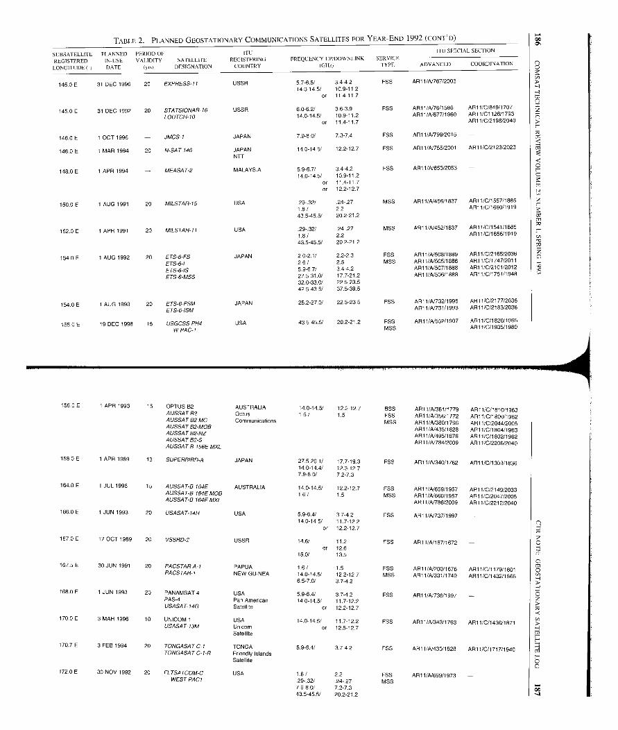
TABLE 2. PLANNED GEOSTATIONARY COMMUNICATIONS SATELLITES FOR YEAR-END 1992 (CONT'D)
SCBSATELITL PLANNED PERIOD OE ITU ITU Si SLCTION
REGISTERED IN-USE VALIDITY SATELLITE REGISTERING FREQCLNCY I:P/DOWNLINK SERVICECOORDINATION
LONGITUDE( DATE (1o1 DESIGNATION COUNTRY (GH,/ TYPE ADVANCED
145.0E 31 DEC 1996 20 EXPRESS-11 USSR 57-6.5/ 34-4.2 ESE AR11/A/767/2003 -14-014.5/ .109 112
or 11411 7
145.0 E 31 DEC 1992 20 STATSIONAR-16 USSR 6.0-62/ 3.6-3.9 FSS AR11/A/76/1586 AR11/C/849/1707
LOUTCH-10 14.0-14.5/ 10-911.2 AR11/A/677/1960 API I/C112611793
or 114-117 ALL 1/C/2198/2040
146.0E 1 OCT 1996 - JMCS-I JAPAN 7.9-80/ 7.3-74 FSS AP11/A799/2015 -
146.0 E I MAR 1994 20 N-SAT-146 JAPAN 14.0-14.5/ 12.2-127 FSS API 1/A755/2001 AR11/0/2123/2023
148.0 E 1 APR 1994 - MEASAT-2
NTT
MALAYSIA 5.9-6.7/ 34-4.2 FSS AR11/A/853/2053 -
14.0-14.5/ 10.9-112or 11.4-11 7or 122-127
150 0 E 1 AUG 1991 20 MILSTAR-15 USA 29-.32/ 24-27 MSS ARI l/A/456/1837 API 1/0/1557/1685.
1.8/ 22 AR11/C/1660/1919
43.5-45.5/ 20 2-21.2
152 0 E 1 APR 1991 20 MILSTAR-11 USA 29-.32/ 24-.27 MSS AR11/A/452/1837 API 1/0/1541/1885.
1.8/ 2.2 AR11/C/1656/1919
43.545.5/ 20 2-21.2
154.0 E 1 AUG 1992 20 ETS-6-FS JAPAN 2.0-2.1/ 2.2-2.3 FSS AR11/A/508/1889 AR11/C/2165/2036
ETS-6-I 2.6/ 2.5 MSS AR11/A1505/1888 AR11/C/1747/2011
ETS-6-IS 5-9E7/ 3.44.2 AR1 1/41507/1886 AR11/C/2101/2012
ETS-6-MSS 27.5-31.0/ 177-21.2 AR11/4/506/1888 AR11/0/1751/1948
32.0-33.0/ 22523.542.5-43.5/ 37539.5
154 0 E 1 AUG 1993 20 ETS-6-FSM JAPAN 25.2-27.0/ 22.5-23.5 FSS AR11/41732/1996 AR11/C/2177/2036
ETS-6-ISM AR11/41731/1993 AR11/C/2183/2036
155 0 E 19 DEC 1998 15 USGCSS PH4 USA 43.5-45.5/ 202 21.2 ESS AR11/41552/1907 AR11/0/1820/1965.
W PAC-1 MSS AR11/C/l 935/1980
1560E 1 APR 1993 15 OPTUS B2 AUSTRALIA 14.0-14-5/ 12.2-12-7 BSS AR11/41361/1779 ARII/C/1810/1963A USSATB2 Optus 1.6/ 1.5 FSS AR11/41356/1772 AR11/0/1800/1962A USSAT 62 MC Communications MSS AR11/41380/1796 AR11/0/2044/2005AUSSAT B2-MOB AR11/4/435/1828 AR11/0/1804/1963AUSSATB2-NZ ARI 1/4/495/1578 AR11/C/1802/1962AUSSAT B2-SAUSSAT-B 156E MXL
ALI 1/4/784/2009 API 1/0/2206/2040
158.0 E 1 APR 1989 13 SUPERBIRD-A JAPAN 27.5-20.1/ 17.7-19-3 FSS AR11/4/340/1762 AR1 l/C/1303/183614.0-14 4/ 12.312-77.9-8.0/ 7.2-7.3
164.0 E 1 JUL 1996 15 Al 164E AUSTRALIA 14-0-14.5/ 12.2-127 FSS AR11/4/659/1957 AR11/0/2149/2033AUSSAT-B 164E MOB 16/ 1-5 MSS AR11/4/660/1957 AR11/0/2047/2005AUSSAT-B 164E MXL AR11/41785/2009 AR11/0/2212/2040
166.0 E 1 JUN 1993 20 USASAT-14H USA 5.9 6 4/ 37-4.2 FSS AR11/A/737/199714.0-14.5/ 11.7-12.2
or 12.2-127
167.0E 17 OCT 1989 20 VSSRD-2 USSR 14.6/ 11.2 FSS AR11/A/187/1672 -or 12.6
15.0/ 13.5
1675 E 30 JUN 1991 20 PACSTAR A-I PAPUA 1-6/ 1.5 FSS AR11/A/200/1676 AR1I/C/1179/1801PACSTAR-I NEW GUINEA 14-014.5/ 12.2-127 MSS AR11/41331/1749 ANN 1/0/1432/1866
6.5-7.0/ 37-4,2
168.0 E 1 JUN 1993 20 PANAMSAT4 USA 5.9-6.4/ 3.7-4.2 FSS AR11/4/736/1997 -PAS-4 Pan American 14.0-14.5/ 11.7-12.2USASAT-14G Satellite or 12.2-127
170.0 E 3 MAR 1996 10 UNICOM 1 USA 14.0-14.5/ 11.7-122 FSS API 1/4/343/1763 AR11/0/1436/1871USASA T- 13M Unicorn
Satelliteor 12.5-127
170.7E 3FEB 1994 20 TONGASATC-ITONGA SAT C-I-R
TONGAFriendly IslandsSatellite
5.964/ 374-2 FSS AR11/4/430/1828 AR11/0/1717/1940
172.0 E 30 NOV 1992 20 FL TSATCOM-C USA 1.6 / 22 FSS AR11/4/699/1973 -WEST PACT 29-.32/ 24-.27 MSS
79-8.0/ 7.2-7.343.5-45.5/ 20.2-21.2
T
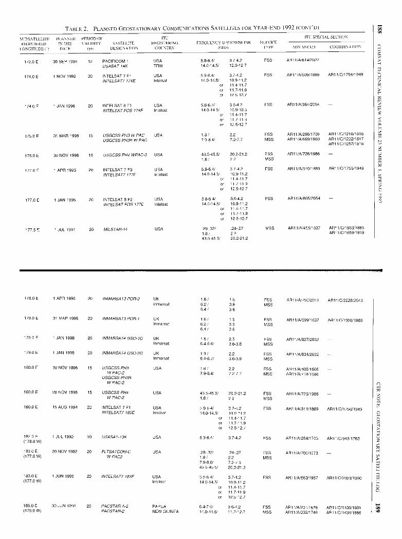
TABLE 2. PLANNED GEOSTA I ION ARY COMMUNICATIONS SATELLITES FOR YEAR-END 1992 (CONT'D)
SI BSATELLI IF PLANNED PERIOD 01 ITC'
ITC SPECIAL SECIION
REGISTERED IN-USE V Al IDITY SA IFI.IITE REGISTERING FRFQCENCY UP/UO'VNIINK IRNILL
I ONGITUDE ( DATE ryr-I DESIGNATION 0)1 NTRI' I(AU, I YEE ADVAN( ED COORDINA II ON
172.0 E 30 SEP 1994 12 PACIFICOM 1 USA 5.96.4/ 3742 FSS AR11/A/814/2027 -
USASAT-14K TRW 14.0-14.5/ 120 12 7
174.0 E 1 NOV 1992 20 INTELSAT 7 F1 USA 5.9-6.4/ 37-4.2 FPS AR11/A/509/1889 AR11 /0/1754/1949
INTELSAT7 174E Intelsat 14.014.5/ 109-11.2or 114-117
or 11.7-11.9
or 125-12.7
174.0 E 1 JAN 1996 20 INTELSAT 8 F1 USA 5.8-64/ 3.6-42 FSS API 1/A/864/2054 -
INTELSAT FOS 174E Intelsat 14.0-14.5/ 10-9.12-5or 11 4-11 7
or 11 7-11.9
or 12.5-12.7
175.0E 31 MAR 1996 15 USGCSS PH3 W PAC USA 1-8/ 2.2 FSS AR11 /A/266/1706 AR11/G/1216/1816
USGCSS PH3B W PAC 79-84/ 7.2-77 MSS AR11/N669/1960 AR11/0/1222/1817AR11/C/1257/1818
175.0 E 30 NOV 1996 15 USGCSS PH4 WPAC-3 USA 43.5-45-5/ 202-21.2 FSS AR1 I/N726/1986
1.8/ 2.2 MSS
177 0 E 1 APR 1993 20 INTELSAT 7 F3 USA 5.9-6.4/ 37-4.2 PAS AR11/4/ 510/ 1889 AR11 /0/1755/1949
INTELSAT7177E Intelsat 14.0-14.5/ 109 11.2or 11 4-11.7or .117 11 9or 12.5-12 7
177.0 E 1 JAN 1996 20 INTELSAT 8 F2 USA 5.8.6 4/ 3 .6-4.2 FSS AR1 VA/865/2054 -
INTELSAT FOS 177E Intelsat 14.0-14.5/ 109-11.2or 114-117
or 117-11.9
or 12.5-12.7
177.5 E 1 JUL 1991 20 MILSTAR-14 USA .29.32/ 24-27 MSS AR11/4(455/1837 AR11/0/1553/168518/ 2.2 AR11 /C/1659/191943.5-45.5/ 202 212
178.0 E 1 APR 1996 20 INMARSAT3 POP-2 UK 1.6/ 1-5 FSS AR11/A/790/2011 AR11/0/2228/2043nmarsat 6.2/ 3-9 MSS
641 3.6
179.0 E 31 MAR 1995 20 INMARSAT3 POR-I UK 1.6/ 1.5 FSS AR11/4(599/1637 AR11/0/1996/1989Inmarsat 62/ 3.9 MSS
6.4/ 3.6
179.0 E 1 JAN 1998 20 INMARSAT4 GSO-IG UK 1.6/ 2.5 F55 AR11/4(827/2032 -Inmarsal 3.6-3.8 MSS
179 0 E 1 JAN 1998 20 INMARSAT4 GSO-2G UK 1.9/ 2.2 FSS ARI 1IN834/2032 -Inmarsat 6.46.7/ 3.6-3.9 MSS
180.0 E 30 NOV 1996 15 USGCSSPH3 USA 1.8/ 22 FSS AR11/A/408/1806 -W PAC -2
USGCSS PH3BW PAC-2
7-9-84/ 72-77 MSS AR11/4(718/1986
180.0E 20 NOV 1996 15 USGCSS PH4 USA 43.5-45 . 5/ 202-21.2 FSS AR11/A725/1986 -W PAC-2 1.8/ 2.2 MSS
180-0E 15 AUG 1994 20 INTELSAT 7 F1 USA 6964/ 3742 F55 AR11/4(511/1889 AR11/0/1756/1949INTELSAT7180E Intelsat 14-0-14.5/ 109-112
or 11.4-11 71.7-11.9
or 12.512.7
182.0E 1 JUL 1990 10 USASAT-13K USA 37-4.2 FSS ARIl/N264/1703 ARIL/C/945/ 1763(178-0 W)
183.0E 30 NOV 1992 20 FLTSATCOM-C USA 29-.32/ 24.27 FS5 AR11/N700/1973 -(1772 W) W PAC2 1.8 / 2.2 MSS
79-8.0/ 7.2-7343.5-45.5/ 20.2-21 2
183.0 E 1 JUN 1996 20 INTELSAT7 183F USA 5964/ 3742 FSS AR11/A1663/1957 AR11/0/2003/1990(177.0 W) Intelsat 14.0-14.5 10.9-11.2
or 114-11 7or 11.7-11.9
or 12.5-127
185.0E 30 JUN 1991 20 PACSTAR A-2 PAPUA 6.4-7.0/ 3.6-4.2 FSS AR11/A.201/1676 ARt 1/0/1180/ 1801(175-0 W) PACSTAR-2 NEW GUINEA 14.014.5/ 117.12.7 MSS AR11/A/332/1749 API I/C/1434/1866
ccz
00b
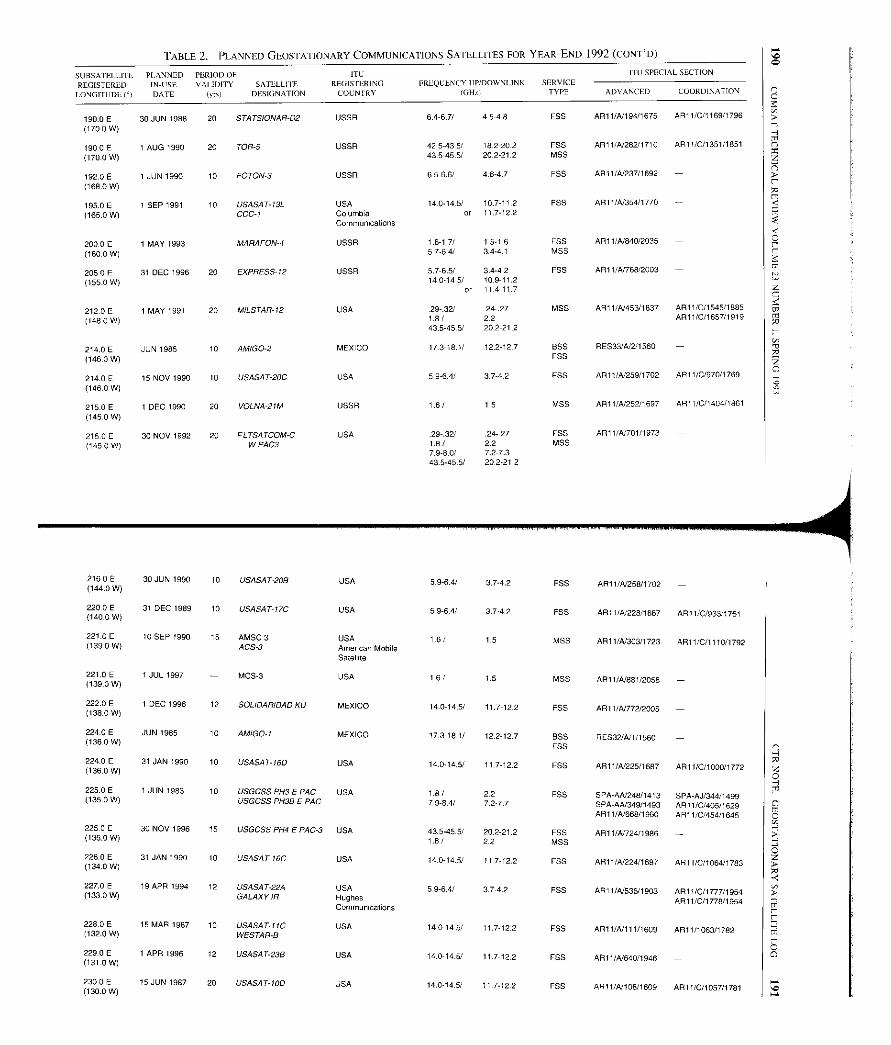
TABLE 2. PLANNED GEOSTATIONARY COMMUNICATIONS SATELLITES FOR YEAR-END 1992 (CONT'D)
SUBSATELLITE PLANNED PERIOD OF ITL' II LI SPECIAL SECTION
REGISTERED IN-USE VALIDITY SATELLITE REGISTERING FREQUENCY LIP/DOWNLINK SERVICE
LONGITUDE I°1 DATE (yr) DESIGNATION COUNTRY IGHz1 TYPE ADVANCED COORDINATION
190.0E 30 JUN 1988 20 STATSIONAR-D2 USSR 6.4-6.7/ 4.5-4.8 FSS AR11/N194/1675 AR11/C/1169/1796
(1700 W)
190.0 F 1 AUG 1990 20 TOR-5 USSR 42.5-43.5/ 18221 FSS AR11/A/282/1710 ART 1/C/1351/1851
(1 70.0 W) 43.5-45.5/ 202-21.2 MSS
192.0E 1 JUN 1990 10 FOTON-3 USSR 6.5-6.6/ 46-47 FSS AR11/A/237/1692 -
(168 .0 W)
195.0 E 1 SEP 1991 10 USASAT-13L USA 14.0-145/ 10.7-11.2 FSS AR11IX354/1770 -
(165.0 W) CCC-I ColumbiaCommunications
or 117-122
200.0 E 1 MAY 1993 - MARAFON-4 USSR 1.6-1.7/ 1,5 16 FSS AR11/A/840/2035 -
(160.0 W) 5 7-64/ 3.4-4.1 MSS
205.0 E 31 DEC 1996 20 EXPRESS-12 USSR 5.7-6.5/ 34-42 FSS AR11/AT768/2003 -
(155-0 W) 14.0-14.5/ 10-311.2or 11.4-11.7
212.0 E 1 MAY 1991 20 MILSTAR-12 USA 29-.31 24-.27 MSS A911/N453/1837 AR11/0/1545/1885
(1480 W) 1.8/ 22 ARI1/C/1657/1919
43.545.5/ 202-212
214.0 E JUN 1985 10 AMIGO-2 MEXICO 17.3-18.1/ 12.2-127 BSS RES33/A/2/1560 -
(146.0 W) FSS
214.0 E 15 NOV 1990 10 USASAT-20C USA 5.9-6 4/ 3.7-4.2 FSS AR11/4./259/1702 AR11/0/970/1769
(1460 W)
215.0 E 1 DEC 1990 20 VOLNA-21M USSR 1.6/ 1.5 MSS AR11/A/252/1697 AR11/C/1404/1861
(145-0 W)
215.0 E 30 NOV 1992 20 FLTSATCOM-C USA 29-.32/ 24-27 FSS AR11/A/701/1973 -
(145.0 W) W PAC3 1.8 / 22 MSS7.9-8.0/ 7.2-7.343.5-45.5/ 20.2-21.2
2160 E 30 JUN 1990 10 USASAT-20B USA 5-9-6.4/ 3.7-4.2 FSS AR1I/A/258/1702 -(144.0 W)
220.0 E 31 DEC 1989 10 USASAT-17C USA 59-6.4/ 3.7-4.2 FSS ARI 1/-0/228/1667 AR11/0/933/1761(140.0 W)
221.0 E 10 SEP 1990 15 AMSC 3 USA 1.6/ 1.5 MSS AR11/4/303/1723 AR11/0/1110/1792(1390 W) ACS-3 American MobileSatellite
221.0 E I JUL 1997 - MCS-3 USA 1.6/ 15 MSS Al 1/A/881/2058 -(139.0 W)
222.0 E 1 DEC 1996 12 SOLIDARIDAD KU MEXICO 14.0-14.5/ 11.7-122 FSS AR11/A/772/2005 -(138.0 W)
224.0 E JUN 1985 10 AMIGO-I MEXICO 17.3-181/ 12.2-12.7 BSS RES32/A11/1560 -(1360 W)FSS
224.0 E 31 JAN 1990 10 USASAT-16D USA 14.0-14.5/ 117-12.2 FSS AR11/4/225/1687 AR11/C/1000/1772(136.0 W)
225.0 E 1 JUN 1983 10 USGCSS PH3 E PAC USA 1.8/ 2.2 FSS SPA-AN248/1413 SPA-AJ/344/1499(135.0 W) USGCSS PH3D E PAC 7.9-8.4/ 7.2-7.7 SPA-AN349/1493 AR11/0/405/1629AR11/4/868/1960 AR11/C/454/1645
225.0 E 30 NOV 1996 15 USGCSS PH4 F PAC-3 USA 43.5-45.5/ 20.2-21.2 FSS AR11/4724/1986 -(135.0 W) 1.8/ 2.2 MSS
226.0 E 31 JAN 1990 10 USA SA T-16C USA 14.0-14.5/ 117-12,2 FSS AR11/41224/1587 AR11/C/1064/1783(134.0 W)
227.0 E 19 APR 1994 12 USASAT-22A USA 5.9-6.4/ 3.7-4.2 FSS AR11/41536/1903 Al 1/C/1777/1954(133.0 W) GALAXYIR HughesCommunications
AR11/C/l 778/1954
228.0 E 15 MAR 1987 10 USASAT-11C USA 14.0-14.5/ 11.7-122 FSS AR11/A/111/1609 AR11/1063/1782(132.0 W) WESTAR-B
229.0 E 1 APR 1996 12 USASAT-23B USA 14.0-14.5/ 11.7-12.2 FSS AR11/41640/I 946 -(131 0 W)
2300E 15 JUN 1987 20 USASAT40D USA 14.0-14.5/ 117-12.2 FSS AR11/41106/1609 ARI 1/0/1057/1781(130.0 W)

TABLE 2. PLANNED GEOSTATIONARY COMMUNICATIONS SATELLITES FOR YEAR-END 1992 (CONT'D)
SL RSATLLLITE PLANNED PEItIODOF ITLREGISTERED INUSE VALIDITY SA IEIIJTE REGISTERING
I ONGITIIDL I°) DATE I'll) DLSSIGNATR)N COUNTRY
I I I SPEaaL S1 I LION
C
FRLQAJENCY LP/DOW VI INK SERV9CF(GHI TYP6 ADV ANCED COORDINATION
0 E230 30 NOV 1996 15 USGCSS P1)3 USA 181 22 FSS AR11/A/40711806 -.(130.0 W) E PAC -2
USGCSS PH35E PAC-2
7.9-8.41 72 77 MSS ALI 1/A1717/1986
230.0 E 30 NOV 1996 15 USGCSS PH4 E PAC 2 USA 43.5-45.5/ 20 2-21.2 FSS AR11/A/723/1986 -
(130.0 W) 18/ 22 MSS
230.0E 15 JUN 1992 10 USRDSS WEST USA 1.6/ 25 FSS ALI 1/A/ 175/1641 -
(130 0 W) 65/ 51 MSS
231.0E 18JUL1994 10 USASAT-24A USA 5.9-6.4/ 37 42. F55 AR) 1/A/ 577/1912 AR1 l/C/1873/1970
(129.0 W) 14.0-14.5/ 11 7-12.2
233.0 E 31 AUG 1993 10 USASAT-21B USA 5.954/ 3742 FSS AR11 /A/484/1864 -
(127.0 W)
234.0 E 15 SEP 1987 20 USASAT-IOC USA 14.0-14.5/ 11.7-12.2 F55 API I/A/107/1609 AR11/C/989/1769
(126.0 W)
236.0 E 1 NOV 1988 10 USASAT-10B USA 14.0-14.5/ 117-12.2 FSS AR11/A/106/1609 AR11/0/105411781
(124.0 W)
239 0E 18 JUL1994 10 GTE GSTAR1R USA 140-14.5/ 117-122 FAN ALI 1/4/575/1912 AR11/C/1759/1952.
(121.0 W) USASAT-23C GTE Spacenet AR11/C/1760/I 952
240 0 E 1 NOV 1990 20 MILSTAR-6 USA 29-32/ 24-. 27 MSS AR11/A/447/1837 AR) 1/011522/1885.
(1200 W) 1.8/ 22 AR11/C/1651/1919
43.5-45.51 20.2-21.2
241.0 E 30 NOV 1991 10 OMRDSS WEST USA 16/ 25 FSS AR11/A/458/1039 -
(119.0 W) 65/ 51 MSS
247 0 E 31 JUL 1994 14 SOLIDARIDAD F2 MEXICO 16/ 15 FSS AR11/41873/2055 AR11/C/2240/2055.
(113.0 W) SOLIDARIDAD-2 14.0-14.5/ 11.7-12.2 MSS AR11/A120/1539
SOLIDARIOAD 2MSOLIDARIDAD 2MA
59-6,4/ 3.7-4.2 ALP 1/N738/I997
250.8 E 31 JUL 1994 14 SOLIDARIDAD F1 MEXICO 1.6/ 15 F55 AR11 /41872 /2055 AR11 /C/2190/2039(109.2 W ) SOLIDARIDAD-1 140-14.51 117-12.2 MSS AR11 /A1486/I 840
SOLIDARIDAD IMSOLIDARIDAD IMA
59-64/ 37-4.2 AR11/A /735/1996
251.0E 19 DEC 1998 15 USGCSS PH4 USA 1.8/ 22 FSS AR11/41551/1907 AR11 /C/1927/1980(109.0 W) E PAC-1 43.5-45.5/ 20.2-21 2 MSS AR11 /C/1931/1980
251.0 E 21 MAR 1994 12 SIMON BOLIVAR - 3 VENEZUELA 5.9-6.4/ 37 42 FSS AR11/41574/1912 AR11 /C/1818/1964(109.0 W) ASETA
253.5 E 1 JAN 1997 10 MSAT CANADA 1.6/ 15 MSS AR11 /4156/1583 API 1 /0/936/1761(106 .5 W) MSAT- tA Telesat Mobile 140/ 11.7 API 1/4/300/1723 AR11 /C/1774/1954
14.5/ 122 API 1141438/I 831AR11/A/806/2022
254.0 E 21 MAR 1994 10 SIMON BOLIVAR-I VENEZUELA 59-6.4/ 3.7-4.2 FSS ARI1 /A/422 /1817 AR11 /C/1816/1964(1060 W) ASETA
HA
255.0 E 30 NOV 1992 20 FLTSATOOM-C USA .29-. 32 / .24- 27 FSS AR11 /A1697/1973 - z(105.0 W) EPACI 1.8/ 22 MSS C
7.9-1 7.2-7.3 m435455/ 20.2-21.2
257.0E 18 JUL 1994 10 GTE SPACENET 1 R USA 5.9-6.4/ 3.7-4.2 F55 AR11 /41578/1912 AR11 /C/1761/1952(1030 W) USASAT-24B GTE Spacenet 14.0-14.5/ 11.7-12.2 AR11/C/1762/I 952
257.0E 21 MAR 1994 SIMON BOLIVAR -2 VENEZUELA 5.9-6.4/ 3,7-42 FSS AR11/41573/1912 AR11 /C/1817/1964(103.0 W) ASETA
259.0 E 30 MAY 1994 MOS-) USA 1.6/ 15 MSS AR 11 /4/849/2048 -(101 .0 W)
259.0 E I JUL 1990 10 USASAT-16B USA 14.0-14.5/ 117-122 FSS AR11/41223/1687 AR11 /C/999/1772(101.0 W)
2590 E I JUL 1990 10 USASAT-17A USA 59-64/ 3.7-4.2 F55 AR11 /A/226/1687 API 1 /C/931/1755(101.0 W)
260.0 E 10 SEP 1990 15 AMSC 1 USA 1.6/ 1.5 MSS API I /A/301/1723 AR11 /C/110611792(100.0 W) ACS -I American Mobile
Satellite
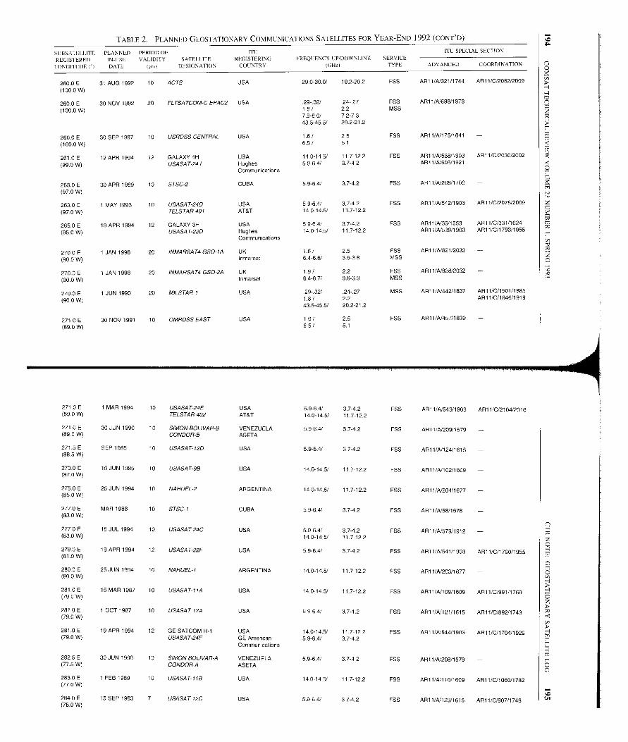
TABLE 2. PLANNED GEOSTATIONARY COMMUNICATIONS SATELLITES FOR YEAR-END 1992 (CONT'D)
SLBSA IFI LITE PLANNLU PERIOD OE ITI: ITL SPECIAL SECTION
REGISTERED IN-CSL VALIDITY SATEI IITE REGISTERING FREQUENCY LP/DOWNI INK SERVICE
LONGITUDE I9 DATE pmt DESIGNATION COUNTRY IGHD TYPE ADVANCED COORDINATION
260.0E 31 AUG 1992 10 ACTS USA 290 300/ 19.2-20.2 FSS AR11/N321/1744 AR11/C/2082/2009
(100.0 W)
260.0E 30 NOV 1992 20 FLTSATCOM-C EPAC2 USA 29- 32/ .24. 27 FS5 ART 1/N698/1973 -
(100.0 W) 18/ 2.2 17.9-80/ 7,2.7.343.5-45.5/ 20.2-21.2
260.0 E 30 SEP 1987 10 USRDSS CENTRAL USA 1.6/ 2.5 FSS AR11/N17511641 -
(100.0 W) 6.5/ 5.1
261.0 E 19 APR 1994 12 GALAXY 4H USA 14.0-14.5/ 117-122 ESS ART 1/N538/1903 AR11/C/2030/2002
(99.0 W) USASAT-24J HughesCommunications
5.9-6 4/ 3.7-4.2 ARI1/N605/1921
263.0E 30 APR 1989 10 STSC-2 CUBA 5.9-64/ 3.7-4.2 FSS AR11/N268/1706 -
(97.0 W)
263.0 E 1 MAY 1993 10 USASAT-24D USA 5 9-6.4/ 37-42 F55 API 1/A/542/1903 AR11/C/2075/2009
(97.0 W) TELSTAR 401 AT&T 14.0-14.5/ 11,7 122
265.0E 19 APR 1994 12 GALAXY 3H USA 5.9-64/ 3,742 F55 ARII/N35/1553 AR1vC/331/1624
(95.0 W) USASAT-22D HughesCommunications
14.0-14.5/ 11.7-12.2 AR11/A/539/1903 ART 1/C/1793/1955
270.0 E 1 JAN 1998 20 INMARSAT4 GSO-IA UK 1.6/ 25 FSS AR11/N821/2032 -
(90 0 W) Itinerant 6.4-6.6/ 3.6-3.8 MSS
2700 E 1 JAN 1998 20 INMARSAT4 GSO-2A UK 19/ 2.2 F55 ARI1/N828/2032 -
(90.0 W) Inmarsat 64-67/ 3.6-3.9 MSS
270.0 E 1 JUN 1990 20 MILSTAR-I USA 29-.32/ .24-.27 MSS AR1 l/N442/1837 AR11/C/1501/1885
(90 0 W) 1.8/ 2.2 AR11/C/1646/I 919
43.5-45.5/ 20.2-21.2
271.0 E 30 NOV 1991 10 OMRDSS EAST USA 16/ 2.5 F55 AR11/N457/1839 -
(89.0 W) 65/ 51
271.0 E 1 MAR 1994 10 USASAT-24E USA 5.9-5 4/ 37-4.2 F55 AR11/N543/1903 AR11/0/2104/2016(89-0 W) TELSTAR 402 AT&T 14.0-14.5/ 11.7-122
271.0 E 30 JUN 1990 10 SIMON BOLIVAR-5 VENEZUELA 5.9-6 4/ 3.7-4.2 FSS ART 1 /N209/1679 -(89.0 W) CONDOR-B ASETA
271 5 E SEP 1985 10 USASAT-12D USA 5.9-64/ 37-4.2 FSS ART 1/A/124/1615 -(88.5 W)
273.0 E 15 JUN 1985 10 USASAT-9B USA 140 145/ 11 ]-12 2 F55 AR11/N102/1609 -(87.0 W)
275.0 E 25 JUN 1994 10 Ni ARGENTINA 14.0-14.5/ 117-122 FSS ARI1/N204/1677 -(85 0 W)
277.0 E MAR 1988 10 STSC-I CUBA 5.9-64/ 37 42 F55 ARI1/N58/1578 -(83.0 W)
277.0 E 18 JUL 1994 10 USASAT-24C USA 5.9-6.4/ 3.7-4.2 FES AR1I/N579/1912 -(83-0 W) 14.0-14.5/ 11.7-12.2
279.0 E 19 APR 1994 12 USASAT-22F USA 5.96.4/ 3742 FSS AR11/N541/1903 AR11/C/1790/1955(81.0 W)
280 0 E 25 JUN 1994 10 NAHUEL-I ARGENTINA 14.0-14.5/ 11]-12.2 FSS AR11/N203/1677 -(80.0 W)
281.0E 15 MAR 1987 10 USASAT-I to USA 14-014-5/ 11.7-12.2 F55 AR11/N109/1609 ARII/C/991/1769(79 0 W)
281.0 E 1 OCT 1987 10 USASAT-12A USA 5.9-6 4/ 3.7-4.2 F55 ART 1/A/121/1615 API l/C/892/1743(790 W)
281.0E 19 APR 1994 12 GE SATCOM H-1 USA 14-014.5/ 11.7-122 F55 ARI I/N544/1903 AR11/C/1704/1929(79.0 W) USASAT-24F GE American
Communications5.9-6.4/ 37 42
282.5 E 30 JUN 1990 10 SIMON BOLIVAR-A VENEZUELA 5.9-6.4/ 3 7-4.2 FSS AR11/N208/1579 -(77.5 W) CONDOR-A ASETA
283.0 E 1 FEB 1989 10 USASAT-11B USA 14.0-14.5/ 117-12.2 FSS AR11/NI 10/1609 ART 1/C/1060/1782(770 W)
284.0E 15 SEP 1983 7 USASAT-12C USA 5.9-6.4/ 37-4.2 FES AR1 l/N123/1615 ART 1/C/907/1748(76.0 W)
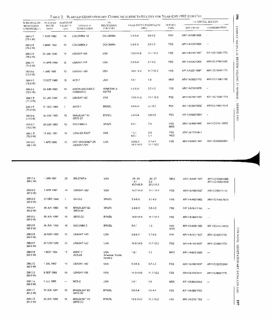
TABLE 2. PLANNED GEOSTATIONARY COMMUNICATIONS SATELLITES FOR YEAR-END 1992 (CONT'D)
SC BSATELLII E PLANNED PERIOD OF 111 11 LI SPECIAL SLCI ION
REGISTEREDI ONGITUDE CI
IN-ISEDATE
VALIDITY SATLLLI IE
I'll, DESIGN-- ION
REGIS I EKINGCOUNTRY
IULQC ENCY I:P/DOWNLINK
IGH'
SERVICETYPE ADVANCLI) COORDINATION
284 6 E 1 MAR 1993 10 COLOMBIA 1A COLOMBIA 5.8-6.4/ 3.6-4.2 FSS AR11/4/428/1825 -
(75 4 W)
285.0 E 1 MAR 1993 10 COLOMBIA 2 COLOMBIA 5.8-64/ 36-4.2 ESS AR11/A/429/1825 -
(75.0 W)
285.0 E 31 JAN 1990 10 USASAT-18A USA 140-14.5/ 117-12.2 EBB ARI I /-/230/1687 AR 11/C/1002/1773
(75.0W)
2860E 19 APR 1994 12 USASAT-22E USA 59-6.4/ 37-42 FSS AR1 1 /-/540/1903 AR11/0/1796/1955
(74.0 W)
287.0 E I JAN 1990 10 USASAT-188 USA 14-0-145/ 117-122 FSS AR11/42231/1687 AR11/0/100411773
(73.0 W)
288 0 E 15 SEP 1990 15 ACS-2 USA 1.6/ 1.5 MSS AR11/42302/1723 AR11/0/1108/1792
(720 W)
288.0E 30 JUN 1990 10 SIMON BOLIVAR-C VENEZUELA 5.9-6.41 37-42 FSS AR1I/A/210/1679 -
(72.0 W) CONDOR-C ASETA
289.0 F 31 JAN 1990 20 USASAT-18C USA 14.0-14.5/ 11.7-12.2 FSS AR11/42232/1687 AR11/0/1005/1773
(71.0 W)
290.0 E 31 DEC 1989 7 SATS-1 BRAZIL 5.9-6.4/ 37-4.2 FSS AR11/42399/1802 AR11/0/1461/1874
(70-0 W)
290.0 E 30 JUN 1995 15 BRAZILSAT B1 BRAZIL 58-6.4/ 3.642 ESS AR11/A/629/1934 -
(70.0 W) SETS61
290.0 E 30 JUN 1993 15 SISCOMIS3 BRAZIL 80/ 73 FSS AR11/42499/1882 AR1110/2161/2033
(760 W) MSS
290.0E 15 JUL 1991 10 USRDSS EAST USA 1.6/ 25 ESS AR11/42174/1641 -
(70.0 W) 65/ 51 MSS
291.0E 1 APR 1996 10 GTE SPACENET 2R USA 5964/ 37-42 EBB AR11/4/643/1947 ARI 1/0/2038/2004
(69.0 W ) USASAT-24H 14.0-14.5 ,' 117-12.2
292.0 E 1 JAN 1991 20 MILSTAR-8 USA 29-.32/ .24 27 MSS AR11/42449 1837 AR11/0/1529/1885(68.0 W) 16/ 2.2 ARII/C/1653/1919
43-5-45.5/ 20.2-21.2
293.0 E 3 APR 1987 10 USASAT-15D USA 14.0-14.5/ 117-122 EBB AR11/42165/1637 AR11/0/997/1770(67.0 W)
295.0E 31 DEC 1989 7 SATS-2 BRAZIL 5.9-6.4/ 37-42 FSS API 1/-/400/1802 AR11/0/1462/1874(650 W)
295 0 E 30 JUN 1992 15 BRAZILSAT B2 BRAZIL 5.8-6.4/ 3.6-4.2 FSS AR11/A/367/1785 -(65-0 W) SETS 82
295.0 E 30 JUN 1992 15 SETS C2 BRAZIL 14.0-14.5/ 117-122 F55 AR11/A/369/1785 -(65 0 W)
295.0 E 30 JUN 1993 15 SISCOMIS 2 BRAZIL 80/ 73 EBB API 1/-/498/1882 AR11/0/2157/2033(65.0 W) MSS
296.0 E 30 NOV 1990 10 USASAT-14D USA 5.9-6 4/ 37-42 EBB AR11/4/161/1637 AR11/0/930/1755(64 0 W)
296.0 E 30 NOV 1990 10 USASAT-15C USA 14.0-14 .5/ 11]-12.2 FSS AR11/42164/1637 AR11/C/996/1770(64.0 W)
298.0 E 1 NOV 1994 15 AMSC 2 USA 16/ 1.5 MSS AR11/A/603/1920 -(62.0 W) ACS-2A American Mobile
Satellite
298.0 E 1 JUL 1992 10 USASAT-14C USA 59-6.4/ 3.7-4.2 EBB AR11/42160/1637 AR11/0/2215/2041(620 W)
298.0E 9 SEP 1989 10 USASAT-158 USA 14.0-14.5/ 117-122 EBB AR11/42163/1637 ARI 1/0/993/1770(62.0 W)
298.0 E 1 JUL 1995 - MCS-2 USA 1.6/ 1.5 MSS AR11/42860/2058 -(62.0 W)
299.0 E 30 JUN 1992 15 BRAZILSAT B3 BRAZIL 5.8-6.4/ 3642 F65 AR11/A/368/1785 -(61.0 W) SETS B3
299.0E 30 JUN 1992 15 BRAZILSATC3 BRAZIL 14.0-14.5/ 117-12-2 F55 AR11/42370/1785 -(61.0 W) SLITS C3
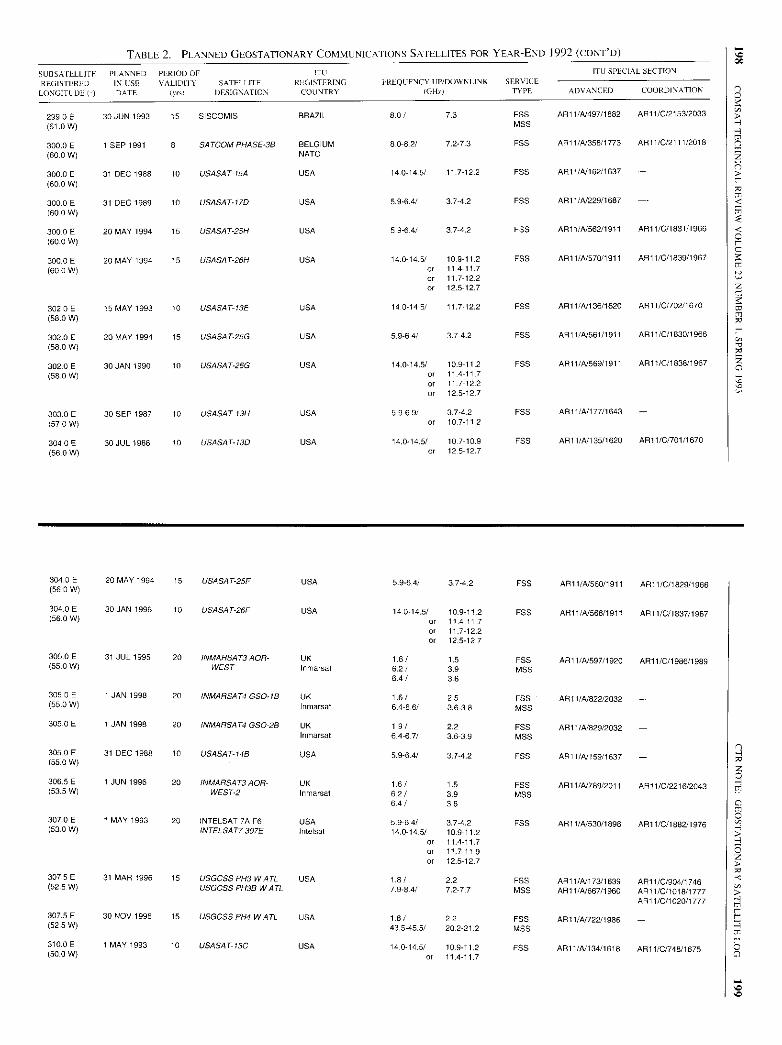
TABLE 2. PLANNED GEOSTATIONARY COMMUNICATIONS SATELLITES FOR YEAR-END 1992 (CONT'D)
SUBS AILLLITF PLANNED PERIOD OF ITU ITII SPECIAL SECTION
REGISTEREDLONGITUDE(')
INCSTDATE
VALIDITY SATELLITE(yrn DESIGNATION
REGISTERINGCOUNTRY
IRLQI/ENCY UP/DOWNLINK(GHr)
SERVICETYPE ADVANCED COORDINATION
299.0E 30 JUN 1993 15 SISCOMIS BRAZIL 8-0/ 7.3 FSS ARi 1/N497/1882 AR11/0/2153/2033
(61.0 W) MSS
300.0 E 1 SEP 1991 8 SATCOMPHASE-36 BELGIUM 8-0-82/ 7.2-7.3 FSS AR11/4/358/1773 AR11/0/211112018
(60.0 W) NATO
300.0 E 31 DEC 1988 10 USASAT-15A USA 14-0.14-5/ 11.7-12.2 FSS APi I/A/I 62/1637 -
(60.0 W)
3000E 31 DEC 1989 10 USASAT 17D USA 5.9-6.4/ 3742 FSS AR11/N229/1887 -
(60 0 W)
3000 E 20 MAY 1994 15 USASAT-25H USA 5.9-6.4/ 3742 FSS A91 1/N562/ 1911 AR11 /0/1831/1966
(60.0 W)
300.0 E 20 MAY 1994 15 USASAT-26H USA 14.0-14-5/ 10.9-11.2 FSS AR11/A/570/1911 AR 11/0/1839/1967
(600 W) or 114-11.7
or 11.7-12.2or 12.5-12.7
302.0 E 15 MAY 1993 10 USASAT-13E USA 14.0-14.5/ 11.7 -12.2 FSS AR11/N136/1620 AR11/0002/1670
(58.0 W)
302.0 E 20 MAY 1994 15 USASAT-25G USA 5.9-64/ 3.74.2 FSS AR11/N561/1911 AR11/C/1830/1966
(58.0 W)
302.0 E 30 JAN 1990 10 USASAT-26G USA 14.0-14.5/ 10-4112 FSS ARi 1/N569/1911 AR11/0/1838/1967
(580 W) or 114-11.7
or 117-122
or 12.5-127
303.0E 30 SEP 1987 10 USASAT-131-1 USA 59>.9/ 3.7-4.2 FSS AR11/N177/1643 -
(57.0 W) or 10.7-11.2
304.0E 30 JUL 1988 10 USASAT-130 USA 14.0-14.5/ 107-10.9 FSS AR11/N135/1620 AR11/0/701/1670
(56-0 W) or 12.5-127
304.0E 20 MAY 1994 15 USASAT-25F USA 5-9-6.4/ 37-4.2 FSS AR 11/4/560/1911 API 1/0/182911966(56.0 W)
304.0E 30 JAN 1996 10 USASAT-26F USA 14.0-14.5/ 10.9-11.2 FSS AR11/4/568/1911 AR11/0/1837/1967(56-0 W) or 11.4-117
or 11.7-12.2or 12.5-127
305.0 E 31 JUL 1995 20 INMARSAT3 AOR- UK 1.6/ 1.5 FSS AR11/N597/1920 AR11/0/1986/1989(55.0 W) WEST Inmarsai 6.2/ 3.9 MSS
6.4 / 3.6
305.0E 1 JAN 1998 20 INMARSAT4 GSO-16 UK 1.6/ 2.5 FSS AR11/4/822/2032 -(55-0 W) Inmarsai 6.4-66/ 3.6-3.8 MSS
305.0E I JAN 1998 20 INMARSAT4 GSO-2B UK 1.9/ 2.2 FSS AR11/4/829/2032 -Inmarsai 6.4-6.7/ 3.6-3.9 MSS
305.0E 31 DEC 1988 10 USAS4T-148 USA 5.9-6.4/ 3.7-4.2 FSS API 1/4/159/1637 -(55-0 W)
306.5E 1 JUN 1996 20 INMARSAT3 AOR- UK 1.6/ 1.5 FSS AR11/4/789/2011 AR11/0/2216/2043(53.5 W) WEST-2 Inmarsai 62/ 3.9 MSS
64/ 38
307.0E I MAY 1993 20 INTELSAT 7A F6 USA 5.9-64/ 3.74.2 FSS AR11/4/530/1898 ARi 1/0/1882/1976(53 0 W) INTELSAT7307E Intelsat 14.0-14.5/ 10.9-112
or 11.4-117or 11.7-11.9or 12.5-127
307.5E 31 MAR 1996 15 USGCSS PH3 WATL USA 1.8/ 2.2 FSS AR11/4/173/1639 AR11/0/904/1746(52.5 W) USGCSS PH35 WATL 7.9-64/ 7.2-77 MSS AR11/4/867/1960 ARIl/C/1018/1777
AR11/C/1020/1777
307.5E 30 NOV 1996 15 USGCSS PH4 WATL USA 1-8/ 22 FSS AR11/A/722/1986(52.5 W) 43.5-45.5/ 20.2-21.2 MSS
310.0 E 1 MAY 1993 10 USAS4T-130 USA 14.0-14.5/ 10.9-11.2 FSS API 1/N134/1618 AR11/0/748/1675(50.0 W) or 11.4-11.7
Z;cc
b
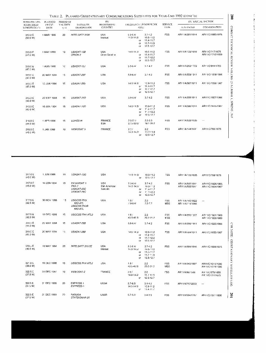
TABLE 2. PLANNED GEOSTATIONARY COMMUNICATIONS SATELLITES FOR YEAR-END 1992 (CONED)
SUBSATELLITL PLANNED PERIOD 01: ITCP D WNIINK SERVICE
ITC SPECIAL SECPION
REGISTEREDLONGITUDE ii
INUSE
DATE
VALIDITY SATELLITE
iyn) DESIGN Al ION
REGISTERINGCOI:NTRY
FREQUENCY U / OIGllz) TYPE ADVANCED COORDINATION
310 0 E 1 MAR 1996 20 INTELGAT7310E USA 596--4/ 3.7-4.2 P55 AR1 1/A581/1914 AR11/C/1883/1976(50-0W) Intelsat 140-14.5/ 10.9-11.2
or 11.4-11.7or 11.7-11.9or 12.5-12.7
313-0E I MAY 1993 10 USASAT-13B USA 140-145/ 10.9-11.2 FSS AR11/A/I 33/ 1618 AR11/CO47/1675(47.0 W) ORION-2 Orion Satellite or 11.411.7 AR11/0/1712/1939
or 11.7-12.2or 12.5-127
313.0 E 1 AUG 1990 10 US4SAT-13J USA 5-9.64/ 3.7-4.2 F55 API I/A/263/1703 AR1 I/C/944/1763(47.0 W)
313.0E 20 MAY 1994 15 USASAT-25E USA 5.9-64/ 37-42 FSS AR11/A/559/191 I AR1 1/C/1 828/1956(47.0 W)
313.0E 10 JUN 1994 15 USASAT-26E USA 140-14.5/ 10.9-11.2 FSS AR11/A/567/1911 AR11/C/1836/1967(47.0 W) or 11 4-11 7
or 11 7-12 2
or 12.5-127
315.0 E 20 MAY 1994 15 USASAT-250 USA 60-6.4/ 374.2 FSS AR11/4/558/191 I AR1 1/C/1 827/1966(45.0 W)
315.0E 10 JUN 1994 15 19A547-260 USA 14-0-145/ 10.9-11.2 F55 AR11/4/566/1911 API 1/C/1835/1967
(45-0 W) or 11.4-117or 117-122or 12.5-127
316.0 E 1 APR 1996 15 EDRSS-W FRANCE 20-2.1/ 2.2-2.3 FES AR11/A/633/1935 -(44.0W) ESA 27.5-30.0/ 18-1-202
316.5E 1 JAN 1988 10 VIDEOSAT-3 FRANCE 2.0/ 2.2 F55 AR11/4148/1631 AR11/C/766/1678(43-5 W) 14.0-142/ 117-11.9
or 12.5-127
317.0 E 1 JUN 1988 10 USASAT-13G USA 14-0-14-5/ 10.9-11.2 ,SS AR11/4/155/1635 AR 11/C/756/1676(43.0 W) or 12.5-127
317.0E 10 JUN 1994 15 PANAMSAT11 USA 5.9-6.4/ 37-4.2 FSS AR11/4/557/1911 AR11/C/1826/1966(43.0 W) PAS 2 Pan American 14.0-14.5/ 10-9-11-2 API 1/4565/1911 AR11/C/1834/1967
USASAT-25C Satellite or 11.4-117USASAT-26C or 11 7-12.2
or 12.5-127
317.5E 30 NOV 1986 15 USGCSS PH3 USA 1-8/ 2.2 F55 AR11/A/140/1622 -(42.5 W) MID-ATL 7-9-84/ 7.2-77 MSS AR1 (/4/716/1986
317.5 E 19 DEC 1998 15
USGCSS PH3BMID-ATL
USGCSS PH4 ATL3 USA 18/ 2.2 FSS AR11/4/550/1907 AR11/C/1921/1980(42.5 W) 43.5-45.5/ 202-212 MSS AR11/C/1925/1980
3190E 20 MAY 1994 15 USASAT-25B USA 5.9-6.4/ 37-4.2 FSS AR11/A/556/191 I ARI l/C/1825/1966(410 W)
319.0 E 20 MAY 1994 15 USASAT-26B USA 14-0-14-5/ 10.9-11.2 FSS AR11/4/564/1911 AR11/C/1833/1967(41.0 W) or 11.4-117
or 11.7-12.2or 12.5-12 7
319.5E 10 MAY 1994 20 11 319.5E USA 5.9-6.4/ 37-4-2 FSS ALI 1/4584/1916 API I/C/1884/1976(40.5 W) Intelsat 14.0-14.5/ 10.9-11-2
or 11.4-117or 11.7-11.9or 12.5-127
321.0 E 19 DEC 1998 15 USGCSS P1-14 ATL2 USA 18/ 2.2 FSS AR11/4/549/1907 AR110/1915/1980(39.0 W) 43-5-45-5/ 20.2-21.2 MSS AR11/C/1919/1980
322.5 E 31 DEC 1987 10 VIDEOSAT-2 FRANCE 20/ 2.2 FSS AR11/A/86/1598 AR11/C/575/1650(37.5 W) 14-014.2/ 11.7-11.9 AR11/0/727/1673
or 12.5-127
322.5E 31 DEC 1996 20 EXPRESS 1 USSR 57-6.5/ 34-42 FSS AR11/4/757/2003 -(37 5 W) EXPRESS-I 14.0-14.5/ 10-9.11-2
or 11 4 11 7
322-5 E 31 DEC 1989 20 RADUGA USSR 5.7.6.2/ 34-3.9 FES AR11/4/384/1797 AR11/C/1311/1836(37.5 W) STATSIONAR-25
N00
N0
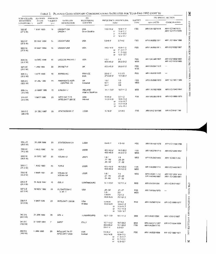
TABLE 2. PLANNED GEOSTATIONARY COMMUNICATIONS SATELLITES FOR YEAR-END 1992 (CONT D)
SURSATELLITL PLANNED PERIOD OF ITL ITO SPECIAL SECTION
REGISTERED IN-USE VALIDITY SATELLITE REGISTERING FREQUENCY UP/DOWNLINK SERVICE
LONGITIDE DATE lynl DESIGNATION COLNTRY (GIIZ) TYPE ADVANCED COORDINATION
322.5E 1 MAY 1993 10 USASAT-13A USA 14-0-14.5/ 10-9-112 EBB AR11/N132/1618 AR11/0/746/1675
(375 W) ORION-I Orion Satellite or 114-117 AR11/0/1711/1939or 117-122or 12.5-127
322.5 E 20 MAY 1994 15 USASAT-25A USA 5.9-64/ 37.4-2 EBB AR11/N555/1911 AR11/0/1824/1986
(37.5 W)
322.5 E 20 MAY 1994 15 USASAT-26A USA 14-0-145/ 10.9-112 F55 AR11IN563/1911 AR11/0/1832/1967
(37.5 W) or 11.4-11.7or 11.7-12.2or 12.5-127
325.0E 19 DEC 1998 15 USGCSS PH4 ATLI USA 1.8/ 2.2 FSS AR11/N548/1907 AR11/0/1909/1980
(35.0 W) 43.5-45.5/ 20.2-21.2 MSS AR11/0/1913/1980
327.0 E 1 JAN 1994 20 SKYNET-41 UK 43.5-45.5/ 20.2-212 EBB AR11/N694/1972
(33.0 W) MSS
328.0 E 1 APR 1996 15 EDRSS-WO FRANCE 2.0-21/ 2.2-2.3 FSS AR11/N632/1935 -
(32.0 W) ESA 27.5-30.0/ 18.1-20.2
328.0 E 31 JUL 1995 20 INMARSAT3 AOR- UK 1-6/ 1.5 EBB AR11/N596/1920 AR11/C/1981/1989
(32 .0 W) CENTRAL-2A Inmarsat 62/ 39 MSS64/ 3.6
329.0 E 31 MAR 1990 15 EIRESAT-1 IRELAND 127-13.2/ 10.7-112 BSS AR11/N182/1656 AR11/0/1349/1550
(31.0 W) Atlantic Satellites
329.0 E 1 MAR 1996 20 INTELSAT 7 F5 USA 5.9-6.4/ 3.7-4.2 FSS AR11/N585/1916 AR11/0/1886/1976
(31 .0 W) INTELSAT7329. 0E Intelsat 14.0-14.5/ 10.9-11.2or 114-117or 117-11.9or 12.5-127
333.5E 31 DEC 1987 20 STATSIONAR-17 USSR 57-6.3/ 3.4-4.0 EBB AR11/N219/1686 AR11/0/910/1749
(265 W)
333.5 E(26.5 W)
30 JUN 1988 20 STATSIONAR-DI USSR 6.4-6.7/ 4.5-4.8 FSS AR11/N193/1675 AR11/C/1168/1796
333.5E I AUG 1990 20 TOR-1 USSR 42.5-43.5/ 182-20.2 F55 ASH 1/41278/1710 AR11/0/1295/1 S32(26-5 W) 43.5-45.5/ 20.221.2 MSS
333.5E 31 DEC 1987 20 VOLNA-13 USSR 1.6/ 1.5 MSS API1/41240/1693 API 1/0/980/1769(26.5 W) .27-28/ 24.29.34 40/ 31-.32
335.0 E 1 AUG 1990 20 TOR-9 USSR 42.5-43-5/ 182-20 .2 F55 AR11/41289/1711 AR11/0/1440/1872(25 0 W) 43.5-45. 5/ 202-21,2 MSS
335.0 E 1 MAR 1991 20 VOLNA-IA USSR 1.6/ 1-5 MSS AR11 /41291/1712 AR11/0/126211819(25-0 W) VOLNA-I84 27-. 28/ .24-29 ARI 1/41248/ 1697 AR11 /0/1396/18613440/ -31 -.32
335.6 E(24.4 W)
31 AUG 1987 10 GDL-5 LUXEMBOURG 127-13.2/ 10.7-11.2 BSS API 1 /4193/1594 AR11/0/612/1657
337.5E 30 NOV 1992 20 FL TSATCOM-C USA 29-.32/ .24-.27 FSS ARI 1/41695/I973 -(22.5 W) E ATLI 1.8/ 2.2 MSS7.9-8.0/ 7.2-7.343.5-45.5/ 202-21.2
338.5E 1 MAR 1996 20 INTELSAT7 338.5E USA 5.9-64/ 3.7-4.2 EBB AR11 /41582/1914 ARII /C/1889/1977(21.5 W) Intelsat 14.0-14.5/ 10.9-11.2or 114-11.7or 117-11.9or 12.5-127
340.0 E(20 0 W)
31 JAN 1989 25 GOL-4 LUXEMBOURG 12.7-132/ 10.7-11.2 BSS AR11/4192/1594 AR11/0/510/1657
341.0 E 31 MAR 1991 7 SARIT ITALY 12.7-13.2/ 197-20.2 BSS SPA-A41371/1457 AR11/0/1334/1839(19.0 W) 29.5-30.0/ 197-20.2 F55 AR11/A/294/17162.0-2.1/ 22-2.3
342.0 E 1 JAN 1995 20 INTELSAT 7A F7 USA 5.9-6.4/ 3.7-4.2 EBB API 1/41533/1895 AR11 /0/1890/1977(10 .0 W) INTELSAT7342E I ntelsat 14.0-14.5/ 10.9-11.2or 11.4-117or 11.7-11.9or 12.5-127
N
N
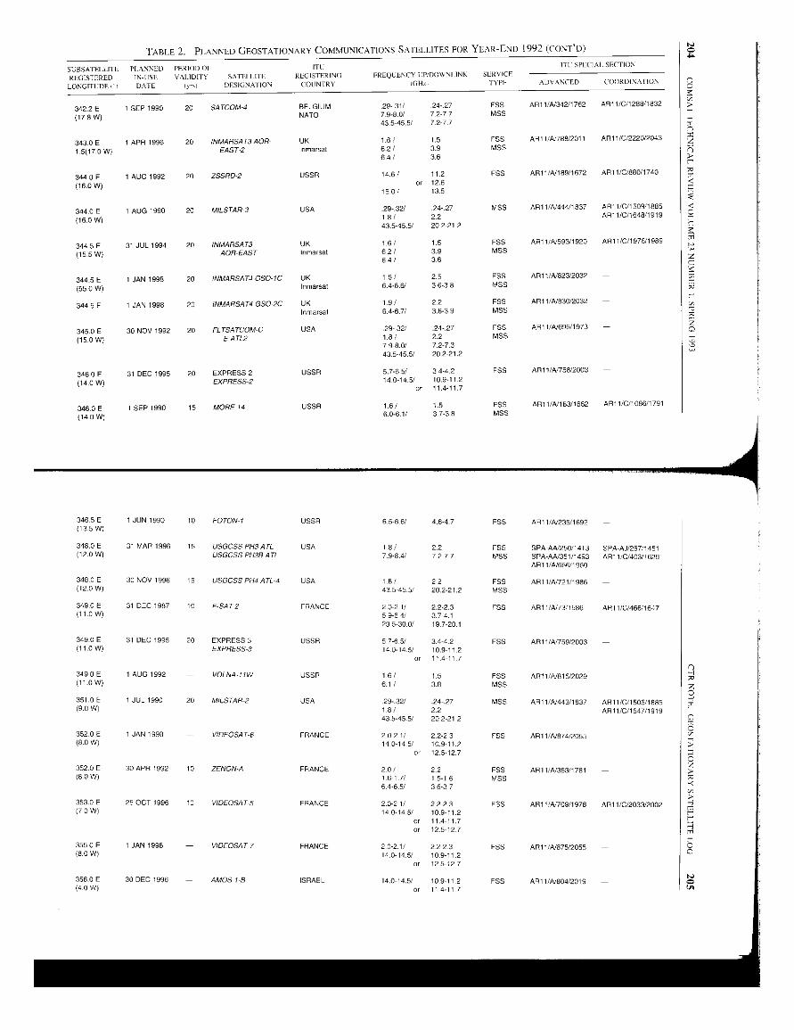
TABLE 2. PLANNED GEOSTATIONARY COMMUNICATIONS SATELLITES FOR YEAR-END 1992 (CONT'D)
SUBSATELLITE PLANNED PERIOD Of ITL ITC SPECIAL- SECTION
REGISTEREDLONGITI:UP I I
IN-USEDATE
VALIDITY
Iy I
SATELLITEDESIGNAI ION
RLGISTERINGCOUNTRY
FREQLENCY UP/DOWNI INK
IGH,,
SERVICE
IYPF ADVANCED COORDINAI ION
342.2 E 1 SEP 1990 20 SATCOM-4 BELGIUM .29.31/ 24-27 FSS ARI l/A/342/1762 AR11/G11288/1632
(178W) NATO 79-80/ 72-77 MSS43.5-45.5/ 72-77
3430E 1 APR 1996 20 INMARSAT3 AOR- UK 1.6/ 1.5 ESS AR11/4/788/2011 AR11/0/2220/2043
1.5(17.0 W) EAST-2 Inmarsat 6.2 / 3.9 MSS6.4/ 3.6
344-0 E 1 AUG 1992 20 ZSSRD-2 USSR 14.6/ 11.2 FSS AR11/A/ 189/1672 API 1/0/880/1740
(16.0 W) or 12.615.01 13.5
344.0 E 1 AUG 1990 20 MILSTAR-3 USA .29-.32/ 24-.27 MSS AR11/4/444/1837 AR1 1/C/1 509/1885
(16.0W) 18/ 22 AR11/C/1648/1919
43.5-45.5/ 202-21.2
344-5 E 31 JUL 1994 20 INMARSAT3 UK 1.6 / 1.5 FSS AR11/4/593/1920 API 1/0/1976/1989
(155W) AOR-EAST Inmarsat 6.2/ 3.9 MSS64/ 3-6
344.5 E 1 JAN 1998 20 INMARSAT4 GSO-IC UK 1,6 1 2.5 FSS AR11/A/823/2032 -
(55-0 W) Inmarsat 6.486/ 3.6-3-8 MSS
344.5 E 1 JAN 1998 20 INMARSAT4 GSO 2C UK 19/ 22 FSS AR11IN830/2032 -
Inmarsal 64-671 3.6-3.9 MSS
345.0 E 30 NOV 1992 20 FL TSATCOM-C USA 29-.32/ .24-27 FSS AR11/A/695/1973 -
(15.0W) EATL2 1.8/ 2.2 MSS798.0/ 7.2-7.343.5-45.5/ 20 2-21.2
346.0 E 31 DEC 1995 20 EXPRESS 2 USSR 5.7-65/ 3,442 FSS AR11/4/758/2003 -
(14 0 W) EXPRESS-2 14.0-14.5/ 10.9-11 2.or 11.4-11 7
346.0 E 1 SEP 1990 15 MORE14 USSR 1.6/ 1.5 FSS ARI 1/A/183/1662 AR1 1/C/1 086/1791
(14.0 W) 6.0-61/ 3738 MSS
346.5 E 1 JUN 1990 10 FOTON-1 USSR 65-6.6/ 4.6.4.7 FSS AR11/A/235/1692 -(13 .5 W)
348.0 E 31 MAR 1996 15 USGCSS PH3ATL USA 18/ 2.2 FSS SPA-AA/250/1413 SPA-AJ/287/1451(1 2.O W) USGCSS OOZE ATL 79.8.4/ 7.2-77 MSS SPA-AA/351/1493 AR11/C/403/1629
AR1I/A1666/1960
348.0 E 30 NOV 1996 15 USGCSS PH4 ATL-4 USA 19/ 2.2 FSS AR11/A/721/1985(12.0 W) 435 455/ 20.2-21.2 MSS
349.0 E 31 DEC 1987 10 F-SAT2 FRANCE 2.0-21/ 2.2-2.3 FSS A911/4/73/1566 AR11/0/466/1647(11.0 W) 5.9-6 4/ 3.7-4.1
29-5-30.0/ 19.7-20.1
349 0 E 31 DEC 1995 20 EXPRESS 3 USSR 57-6.5/ 3.4-42 FSS API 1/4/759/2003 -(11.0 W) EXPRESS-3 140-145/ 10.911 2
or 11.4-11 7
349.0 E 1 AUG 1992 VOLNA IIW USSR 1.6/ 1.5 FSS AR11/A/815/2029 -(11.0 W) 61/ 3.8 MSS
351.0 E 1 JUL 1990 20 MILSTAR-2 USA 29-32/ .24-.27 MSS AR11/4/443/1637 ARI 1/0/1505/1885(9.0 W) 1-8/ 2.2 AR11/C/1647/1919
43.545.5/ 20.2-212
352.0 E 1 JAN 1998 - VIDEOSAT-6 FRANCE 20-21/ 2.2-2.3 FSS AR11/A/874/2055 -(8.0 W) 14.0-14.5/ 10.911.2
or 12.5.12.7
352.0 E 30 APR 1992 10 ZENON-A FRANCE 201 2.2 EBB AR11/A/363/1781 -(8.0 W) 161 7/ 1.5-1.6 MSS
64-6.5/ 3.6-3.7
353.0 E 25 OCT 1996 10 VIDEOSAT-5 FRANCE 2.0-21/ 2.2-2.3 FSS AR11I4/709/1978 AR11/G/2033/2002(7.0 W) 14.0-14.5/ 10.9-11.2
or 11.4-11.7or 12 7
355.0 E 1 JAN 1998 VIDEOSAT-7 FRANCE 2.0-2.1/ 22-2.3 FSS AR11/4/675/2055 -(8-0 W) 14.0-14.5/ 109112
or 125-127
356.0 E 30 DEC 1996 - AMOS I-B ISRAEL 14.0-14.5/ 10-911-2 F55 AR11/41804/2019 -(4_0 W) or 11.4-11.7
Pa
L
EHA
z0
NCto

206 COMSAT TECHNICAL REVIEW VOLUME 23 NUMHER I. SPRING 1993
m
H
w v,m LL LL
Z.)0
8 6 6
° "0 N
0 aZ
w
3; FU
Z Z0 C
W
J
o3 03 03
V' C
n oo.J Cn_ n^
Translations of Abstracts
Architectures des systemes de telecommunicationsINTELSAT a Pere du RNIS
D. M. CHITRE ET W. S. OEI
Sommaire
Cet article pr6sente une sdrie d' architectures pour le systeme de satellites INTELSATen one de I'ulilissation do rescau numdrique avec integration des services (RNIS) alarge bande or a bande 6troite. Ces architectures marquent one evolution du systemeINTELSAT depuis le role traditionnel qui est celui d'un support de transmissionphysique jusq'aux fonctions plus complexes de commutation et de signalisation dansIc cadre du RNIS. En utilisant ]'information contenue dans les messages de signalisationdu RNIS et on accomplissant certaines fonctions d'un nivcau sup6rieur an sein dusysteme a satellites en rant que sous-rdseau, on pent exploiter les technologies adapteesaux besoins du systeme or les points forts inh6rents pour am6liorer le soutien fonctionneldo r6seau. II est en outre possible d'6linriner des insuffisances 6ventuelles dues an
temps de propagation. Pour to RNIS a large bande (RNIS-LB), l'article d6crit on trajetde migration distinct parfaitement adapte aux technologies de transmission du r6seauoptique synchrone or de la hierarchic numdrique synchrone. Cette approche peutevenmellement conduire an traitement a bord des fonctions du RNIS-LB en mode detransl'ert asynchrone.
Conception et homologation du simulateur de vol del'AOCS ITALSAT
A. RAMOS, R. L. MINCIOTTI, T. HAMPSCH, G. ALLISON,
E. W. HARE ET J. W. OPIEKUN
Sommaire
Un simulateur du sous-systeme de commande d'orientation or d'orbite (AOCS) dusatellite ITALSAT a ere mis an point pour I'Agence spatiale italienne. Cc dispositif,qui fonctionne en temps reel et en boucle, est connu sous le nom de °simulateur de volde I'AOCS ITALSAT (IAFSIM)." L'Article fait le point sur la conception,I'homologation or les applications de I'IAFSIM, or cite des exemplcs d'essaisd'homologation des modes d'utilisation de I'AOCS an tours des diverses phases de lamission ITALSAT. Des applications futures de I'IAFSIM sont 6galemant examinees.
207

212 COMSAT TECHNICAL REVIEW VOLUME 23 NUMBER I. SPRING 1993
(MPCP) proporciona componentes ntoduIarcs de software que ban silo desarrol l ados yprobados para programar medieiones. interprocesar comunicaciones y compartir recursosc information sobre sistemas. Sus biblioteeas de e6digos respaldan interfaces graficaspara el usuario, control de instrumentos, gesti6n do harra colcetora de instrumentos demedici6n. asi como deteecion y notificaciOn de errores. Sus subsistemas deprocesamiento do darns respaldan la gesti6n de bases de dams, la produccirul doinformes y el analisis interactivo de datos.
Al trabajar on red con el sisterna operativo V do UNIX, el software MMS pararnulltiples usuarios y tareas respalda el funcionamiento on red de zona local a extenso,induyendo el acceso y control a distancia del equipo de mediciones para pruebas en6rbita. Se pone on practica por medio de una arquitectura de sisterna de procesamicnto
distribuido entre varias estaciones de trabajo diferentes. Con has comunicaciones entre
procesos y maquinas que proporciona of sisterna de eorreo MPCP, in interfaz con elusuario y los programas de mediciones separados se pueden ejecutar en maquinasdiferentes on mementos distintos. ofreciendo mas flexibilidad a has operaciones.
En este artieulo se describe el diseno y In implementaei6n del software MMS. Losconceptos y m6todos presentados tambi€n so pueden aplicar a otros sistemas demediciones (tales como Ins utilizados para of monitoreo del sistema de eomunieaciones)en los qua hay quo poner coto ,it crecicnte eosto del software.
Author Index, CTR 1992
The following is a list of articles that appeared in COMSAT TechnicalReview for 1992. The list is cross-referenced based on COMSAT authors(only). The code number at the end of each entry should be used whenordering reprints from Corporate Records, COMSAT Corporation, 22300COMSAT Drive, Clarksburg, MD 20871-9475.
ARNSTEIN, D. S.. X. T. Vuong, C. B. Cotner, and H. M. Daryanani. "The IMMicroscope: A New Approach to Nonlinear Analysis of Signals in Satellite Com-munications Systems," COMSAT Technical Review, Vol. 22, No. 1, Spring 1992,pp. 93-123 ICTR92/382J.
BEDFORD, R.,** A. Bernlzen ** J. A. Lunsford, Y. lshi,* H. Nakamura? and
T. Kimura,* "The INTELSAT SSTDMA Reference and Monitoring Station,"COMSAT Technical Review, Vol. 22, No. 2, Fall 1992. pp. 281-325 ICTR92/386].
BENNETT, S. B.,** "INTELSAT 603 `Rehoosted' to Synchronous Orbit," COMSATTechnical Review, Vol. 22. No. 1, Spring 1992, pp. 73-91 ICTR92/381].
BROWN, M. P., Jr.** F. A. S. Loureiro,** and M. Stojkovic,** "Earth StationConsiderations for INTELSAT VI," COMSAT Technical Review, Vol. 22, No. I,Spring 1992, pp. 5-17 [CTR92/378 J.
COTNER, C. B.. sec Arnstcin, D. S.
DARYANANI, H. M., sec Arnstcin, D. S.
DIMOLITSAS, S., J. H. Rieser. and H. Feldman,* "Real-Time Transmission ofGroup 3 Facsimile Over Interconnected Public Switched Digital Mobile SatelliteNetworks," COMSAT Technical Review, Vol. 22, No. 1. Spring 1992, pp. 125-147[CTR92/3831.
FARIS, F. R., sec Poklemba, J. J.GUPTA. R. K., see Tamboli. S. P.INUKAI, T., we Maranon, C. L.
KULLMAN, C. L.,** S. J. Smith,*" K. P. Chaudhry,** R. Bedford,** P. W. Roach,*"P. Nethersole,* and G. J. Burns * "Deployment, Test, and Transition to Operationof the INTELSAT SSTDMA System." COMSAT Technical Review, Vol. 22, No. 2,Fall 1992, pp. 523 548 1 CTR92/3921.
LEE, L-N., and A. K. Sinha,x* "Video Transmission and Processing in theINTELSAT VI Era:" COMSAT Technical Review, Vol. 22, No. I, Spring 1992,pp. 57-71 ICTR92/380].
LUNSFORD, J. A., J. F. Phiel** R. Bedford,*" and S. P. Tamboli,"* "The INTELSATSSTDMA System Design," COMSAT Technical Review, Vol. 22, No. 2, Fall 1992,pp. 227-279 ICTR92/3851.
L.UNSFORD, J. A., see Bedford, R.; Maranon, C. L.; and Mizuike, T.
Non-COMSAT author.INTELSAT author.
213
214 COMSAT TECHNICAL REVIEW VOLUME 23 NUMBER I. SPRING 1993
LUZ, F. H.,** D. Sinkfield,** and N. Engelberg,* "The INTELSAT SSTDMA
Headquarters Subsystem." COMSAT Technical Review, Vol. 22, No. 2, Fall 1992,
pp. 367--407 [CTR9213881.MARANON, C. L..** J. A. Lunsford, T. Inukai, and F. H. Luz,** "INTELSAT VI
SSTDMA Subsystem Timing Source Oscillator Control," COMSAT Technical
Review, Vol. 22, No. 2, Fall 1992, pp. 409-446 ICTR92/3891.MIZUIKE, T.,* L. N. Nguyen,** K. P. Chaudhry,** J. A. Lunsford, and P. A. Trusty,
"Generation of Burst Time Plans for the INTELSAT VI SSTDMA System,"
COMSAT Technical Review, Vol. 22, No.2, Fall 1992, pp. 327-366 ICTR92/387].
ONUFRY. M., G-P. Forcina,** W. S. Oei,** T. Oishi,** J. F. Phiel,** and
J. H. Rieser, "DCME in the INTELSAT VI Era" COMSAT Technical Review,
Vol. 22. No. I, Spring 1992. pp. 19-55 [CTR92/3791.PETTERSSON, B. A.,** A. K. Kwan,** S. B. Sanders,** F. L. Khoo,** and
T. J. Duffy,** "The Satellite Control Center and its Role in Testing and Operation
of the INTELSAT VI SSTDMA System," COMSAT Technical Review, Vol. 22.
No. 2, Fall 1992, pp. 485-522 [CTR92/391].POKLEMBA, J. 1., and F. R. Faris, "A Digitally Implemented Modern: Theory and
Emulation Results," COMSAT Technical Review, Vol. 22. No. 1, Spring 1992,
pp. 149-195 ICTR92/3841.RIESER, J. H., see Dimolitsas, S.; and Onufry, M.TAMBOLI, S. P.,** X. Zhu,** K. N. Wilkins,** and R. K. Gupta, "The
INTELSAT VI SSTDMA Network Diagnostic System," COMSAT Technical
Review, Vol. 22, No. 2, Fall 1992, pp. 447-483 ICTR92/390].
TRUSTY, P. A., see Mizuike, T.V UONG, X. T., see Arnstein, D. S.
Index of 1992 Publicationsby COMSAT Authors
The following is a list of 1992 publications by authors at COMSAT Corpo-ration. The list is cross-referenced based on COMSAT authors (only). Copiesof these publications may he obtained by contacting the COMSAT authors atCOMSAT Corporation, 22300 COMSAT Drive, Clarksburg, MD 20871-9475.
AGARWAL, A., see White, L.ARNSTEIN, D. S., and J. W. Lee,* "AJ Performance of Smart AGC" in MILSATCOM
Networks: A Review of Space System Design Principles and Applications," AIAA14th International Communication Satellite Systems Conference, Washington, DC,March 1992, Session 2, A Collection of Technical Papers. Pt. 1, pp. 23-31. AIAAPaper No. 92-1806-CP.
ARNSTEIN, D., C. Pike,** and G. Estep, "On-Board Al Enhancement Using Adap-
tive Nonlinear Processing: Practical Aspects of Smart AGC Implementation," IEEE
Military Communications Conference (MILCOM). San Diego, CA, October 1992,
Sec. 7, Conf. Rec., pp. 7.5.1-7.5.7.
ASSAL, F. T., see Gupta, R. K. ((wo papers); Sorhello, R. M. (three papers); Zaghloul,A. I.; and Mott, R.
ATIA, A., see Ha.-gag M.ATKIN, G. E.,** and Khalona, R. A., "Steiner System Signal Sets Over the Gaussian
Channel." IEEE Transactions on Information Theo'v, Vol. 38, No. 2, March 1992,
pp.469-472.
BAZ, A., see Haggag, M.BHARGAVA, S., see Lee, L-N.BHASIN, K. B.,* S. S. Toncich,* C. M. Chorey,* R. R. Bonetti, and A. E. Williams,
"Performance of a Y-Ba-Cu-O Superconducting Filter/GaAs Low Noise AmplifierHybrid Circuit," IEEE MTT-S International Microwave Symposium, Albuquerque,NM, June 1992, Digest, Vol. 1, pp. 481-483.
BHASKAR, B. R. U., "Low Rate Coding of Audio by a Predictive Transform Coderfor Efficient Satellite Transmission." AIAA 14th International Communication
Satellite Systems Conference, Washington, DC, March 1992, A Collection of Tech-nical Papers, Pt. 3, pp. 140B-141 0. AIAA Paper No. 92-1994-CP.
BOHEIM, K. B.,* and R. J. Council, "National Transportable TelecommunicationsCapability: Commercial Satellite and Cellular Communications for EmergencyPreparedness," AIAA 14th International Communication Satellite Systems Confer-ence, Washington, DC, March 1992, A Collection of Technical Papers, Pt. I, pp.349-352. AIAA Paper No. 92-1848-CP.
Non-COMSAT author. Non-COMSAT author.
INTELSAT author. INTELSAT author.215