VOLTAGE UNBALANCE CORRECTION IN GRID SIDE BY USING MULTI VARIABLE FILTER IN THE PRESENCE OF FUZZY...
10
Volume 4, Issue 5 AUG 2015 IJRAET VOLTAGE UNBALANCE CORRECTION IN GRID SIDE BY USING MULTI VARIABLE FILTER IN THE PRESENCE OF FUZZY LOGIC CONTROLLER HEENA TABASSUM (PG Scholar) 1 GUNDALA SRINIVASA RAO (Ph.D) 2 1 Department of EEE, SV Engineering college, JNTU (HYD) 2 Assistant Professor, Department of EEE, SV Engineering college, JNTU (HYD) Abstract—This paper presents the control of a grid interfacing inverter with integrated voltage unbalance correction by using fuzzy logic . It is proposed to add an additional function tothe inverter to decrease the negative-sequence voltage at the point of connection with the utility grid. Based on symmetric sequence voltage decomposition and using an improved multi- variable filter, the grid-interfacing inverter intentionally absorbs a small amount of negative- sequence current from the grid, thereby helping to correct the negative-sequence voltage. The integrated function and proposed control has been verified in simulations and compared with conventional pi controller. I. INTRODUCTION For practical three-phase power systems, problems ofvoltage unbalance exist. The problems are mainly causedby unbalanced distribution of single-phase and nonlinear loads. Together, these induce unequal voltage dropsacross transformers and line impedances. These negativesequence voltages are especially troublesome in practicalapplications, contrary to zero-sequence components whichdo not exist in three-wire systems. The effects of voltageunbalance are quite severe for electrical machines, powerelectronic converters, and drives [1]. There are power electronic converters designed formitigation of voltage unbalance of the utility grid thatwork by regulating reactive power [2][3], but this approach is not suitable for underground cables where theresistance of a cable dominates its inductance. To maintaina balanced voltage at the load terminals, an often usedidea is to inject a series voltage [4][5]. It is straightforwardto mitigate the voltage unbalance problem with suchconverters, but a disadvantage is that they are unused oronly lightly loaded when there are no voltage unbalanceproblems. For dealing with other power quality problemsthan voltage unbalance, so-called unified power quality conditioners (UPQC) are proposed and continuouslyimproved. However, the UPQC has no energy storagecapabilities [6], and should be extended to cope withdistributed generation (DG) [7].Facing the emerging application of distributed generation, power electronics-based grid-interfacing inverters areplaying an important role interfacing DGs to the utilitygrid. In addition to conventional delivery of electricity,ancillary functionality for improvement of power qualityproblems is being introduced into grid-interfacing inverters [8][9]. This does not require more hardware, since thefeedback variables for this control are already available.By controlling the negative-sequence currents, which induce opposite negative-sequence voltage drops on theline impedances, the objective of eliminating negativesequence voltages at the point of connection (PoC) withthe grid may be achieved.To investigate the effectiveness of the proposed function, a three-phase four-wire inverter is used to controlvoltage unbalance correction. The employed inverter operates normally when the utility voltages are balanced, andwhen unbalanced, performs compensation automaticallyfor negative-sequence voltage, based on utility voltageunbalance factor (VUF) [1]. To this aim, the analysis ofnegative- sequence current control and a high performancedetection for symmetrical sequences are introduced inthe following. Then, the inverter control scheme andreference signal generation are presented. Finally, theproposed fuzzy logic control methods are verified by simulations, andexperimentally tested using a matlab software.
Transcript of VOLTAGE UNBALANCE CORRECTION IN GRID SIDE BY USING MULTI VARIABLE FILTER IN THE PRESENCE OF FUZZY...

Volume 4, Issue 5 AUG 2015
IJRAET
VOLTAGE UNBALANCE CORRECTION IN GRID SIDE BY USING MULTI VARIABLE FILTER IN THE PRESENCE OF FUZZY LOGIC
CONTROLLER
HEENA TABASSUM (PG Scholar) 1
GUNDALA SRINIVASA RAO (Ph.D) 2
1Department of EEE, SV Engineering college, JNTU (HYD)
2Assistant Professor, Department of EEE, SV Engineering college, JNTU (HYD)
Abstract—This paper presents the control of a grid interfacing inverter with integrated voltage unbalance correction by using fuzzy logic . It is proposed to add an additional function tothe inverter to decrease the negative-sequence voltage at the point of connection with the utility grid. Based on symmetric sequence voltage decomposition and using an improved multi-variable filter, the grid-interfacing inverter intentionally absorbs a small amount of negative-sequence current from the grid, thereby helping to correct the negative-sequence voltage. The integrated function and proposed control has been verified in simulations and compared with conventional pi controller.
I. INTRODUCTION
For practical three-phase power systems, problems ofvoltage unbalance exist. The problems are mainly causedby unbalanced distribution of single-phase and nonlinear loads. Together, these induce unequal voltage dropsacross transformers and line impedances. These negativesequence voltages are especially troublesome in practicalapplications, contrary to zero-sequence components whichdo not exist in three-wire systems. The effects of voltageunbalance are quite severe for electrical machines, powerelectronic converters, and drives [1].
There are power electronic converters designed formitigation of voltage unbalance of the utility grid thatwork by regulating reactive power [2][3], but this approach is not suitable for underground cables where theresistance of a cable dominates its inductance. To maintaina balanced voltage at the load terminals, an often usedidea is to inject a series voltage [4][5]. It is straightforwardto mitigate the voltage unbalance problem with suchconverters, but a disadvantage is that they are unused oronly lightly
loaded when there are no voltage unbalanceproblems. For dealing with other power quality problemsthan voltage unbalance, so-called unified power quality conditioners (UPQC) are proposed and continuouslyimproved. However, the UPQC has no energy storagecapabilities [6], and should be extended to cope withdistributed generation (DG) [7].Facing the emerging application of distributed generation, power electronics-based grid-interfacing inverters areplaying an important role interfacing DGs to the utilitygrid. In addition to conventional delivery of electricity,ancillary functionality for improvement of power qualityproblems is being introduced into grid-interfacing inverters [8][9].
This does not require more hardware, since thefeedback variables for this control are already available.By controlling the negative-sequence currents, which induce opposite negative-sequence voltage drops on theline impedances, the objective of eliminating negativesequence voltages at the point of connection (PoC) withthe grid may be achieved.To investigate the effectiveness of the proposed function, a three-phase four-wire inverter is used to controlvoltage unbalance correction. The employed inverter operates normally when the utility voltages are balanced, andwhen unbalanced, performs compensation automaticallyfor negative-sequence voltage, based on utility voltageunbalance factor (VUF) [1]. To this aim, the analysis ofnegative-sequence current control and a high performancedetection for symmetrical sequences are introduced inthe following. Then, the inverter control scheme andreference signal generation are presented. Finally, theproposed fuzzy logic control methods are verified by simulations, andexperimentally tested using a matlab software.
Gurmeet
Typewritten Text
Gurmeet
Typewritten Text
85

Volume 4, Issue 5 AUG 2015
IJRAET
Fig. 1.Three-phase four-wire grid-interfacing inverter at PoC.
II. GRID-INTERFACINGINVERTER WITHINTEGRATEDVOLTAGEUNBALANCECORRECTION
Fig. 1 shows the structure of a three-phase four-wiregrid-interfacing system being connected to the utility gridat the POC through LCL filters. It normally synchronizeswith the utility grid and delivers electrical energy tothe grid from the DC-bus when pre-regulated distributedsources are connected. The voltage unbalance correctionfunction is added, which intentionally regulates negativesequence currents. Note that, in order to obtain a maximum power factor, most grid-interfacing inverters deliveronly positive-sequence currents under either balanced orunbalanced conditions. Therefore, the development of thisproposed controller differs from the conventional one, and its design will be presented in the next sections of thispaper. In view of unbalanced situations, a four-leg invertertopology is used as the circuit to eliminate zero-sequencecurrents.
Fig. 2.Negative-sequence equivalent model.
With the theory of symmetric decomposition for threephase systems [10], unbalanced grid voltages can bedivided into three groups, namely positive, negative, andzero sequence voltages. Similarly,
current quantities canalso be separated. By disregarding the mutual couplingbetween the grid lines in Fig. 1, an equivalent circuitmodel for each group of sequence components can bederived [11]. The diagram for negative-sequence components is shown in Fig. 2, where the superscript “-” denotesnegative sequence. Similarly, the superscript “+” denotespositive sequence. PhasorsV andV (in the following,complex numbers are denoted with a bar subscript) are thenegative-sequence voltages of the utility grid and at thePoC, respectively. CurrentI is the negative-sequencecurrent controlled by the grid-interfacing inverter. Theequivalent line impedance is represented by Zg, theequivalent impedance of the utility grid when the lineimpedances of the three phases are assumed symmetrical.
Accordingly, a phasor diagram showing the change fornegative-sequence fundamental current is drawn in Fig.3. By changing the amplitude and phase of the negativesequence currentI , the negative-sequence voltage V can be regulated through the voltage drops across the lineimpedance. For a given amplitudeI , the voltage changesalong the dashed circle and reaches a minimum value atthe pointMwhereθ−(the phase angle between negativesequence voltage and current) equals the negative ofimpedance angle of Z ’s.
Similarly, zero-sequence voltages at the PoC can becompensated by regulating the zero-sequence currentswithin the system. This paper only concentrates onthe correction of negative-sequence voltages, consideringzero-sequence voltages do not exist in case of threewire systems. Of course, zero-sequence voltages can beisolated by transformers
Gurmeet
Typewritten Text
86

Volume 4, Issue 5 AUG 2015
IJRAET
when needed. Furthermore, I t isnoted that measurements of zero-sequence componentscan be done simply by adding three-phase quantities,while accurate positive- and negative-sequence components are difficult to be determined. Therefore, zerosequence voltage correction can be trivially added tothe control based on the proposed fuzzy logic control scheme fornegative-sequence voltage correction and is not discussedin this paper.
III. CONTROLSCHEME
A. Determination of Negative-sequence Currents Fig. 3 illustrates the basic principle of how to
correctunbalanced voltage at the PoC with sequence-currentcontrol. It is suggested to determine the negative-sequencecurrents based on the voltage unbalance factor. To assessunbalanced voltages at the PoC, the voltage unbalancefactor,KVUFis defined as the ratio between the amplitudeof the negative-sequence voltage V−
sand the amplitude of the positive-sequence voltage V+
s. The followingconstraint equation is proposed to calculate the desiredcurrent amplitude I−
s:
= = K (1) Where I is the amplitude of the positive-sequence current. Then, the resulting I is derived based on the ratioof unbalance voltages at the PoC from (1).However, the voltage unbalance factor at the PoCvaries with the controlled negative-sequence currents,because the controller utilizes feedforward measurementsof K and operates in a open-loop. Consequently,this strategy may cause the value of K in (1) tovary. To ensure a stable correction, a smooth updatemethod forK is added to the control. The flowchart shown in Fig. 4 illustrates how to derive the finalI . The currently measured quantity is referred to asK ( ), and the previous one is K ( )In Fig.4, the minimum threshold (Kmin) of negative-sequencecorrection is defined according to practical demands, anda coefficient denoted by λ is introduced for smoothregulation when decreasing the output value ofK .Note that, for system protection, the current rating of theinverters is always checked before returningI .
The factorKVUF is essential to get the amplitude of negative-sequence currents. Thus the separation of sequence voltages is central to get the value ofKVUF,aswell as to the synchronization with the utility grid. For unbalanced or distorted grid voltages,
a multi-variable filterwas introduced in [12] for detecting the positive-sequencecomponent in the stationary frame. After modification,this filter is able to directly filter out the fundamentalpositive and negative-sequence vectors. The followingmathematically demonstrates the multi-variable filter forsymmetric sequence decomposition.For unbalanced distorted voltages, the positive- andnegative-sequence components are in theα−βframeas expressed by
Fig. 3. Flow chart ofKVUFdetermination B. Positive- and Negative-Sequence Detection
v (t) = v (t) + jv (t)
= V e + V e
(2) Wherekdenotes the harmonic number,ω1 denotes thefundamental radian frequency, and the superscript symbol “o” denotes conjugate.Let us look for a filterG (t), which v (t)can damp all harmonic components of but the fundamental positive-sequence component in the stationary frame. That is, v (t) ∗ G (t) = V (t) (3) Where the “*” denotes a convolution product, and
V = V e + U e, ,…
+∑ U e, ,… (4)
Gurmeet
Typewritten Text
87
Volume 4, Issue 5 AUG 2015
IJRAET
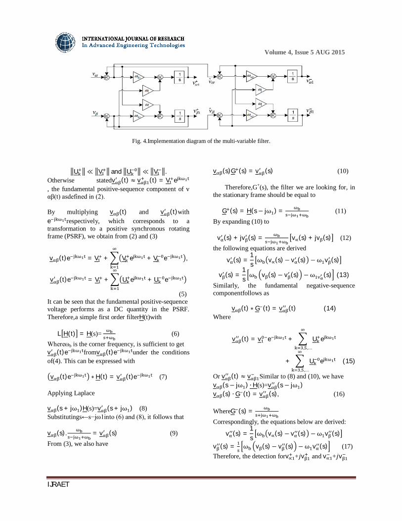
Fig. 4.Implementation diagram of the multi-variable filter.
U ≪ V and U ≪ V . Otherwise statedv (t) ≈ v (t) = V e , the fundamental positive-sequence component of v αβ(t) asdefined in (2). By multiplying v (t) and v (t)with e respectively, which corresponds to a transformation to a positive synchronous rotating frame (PSRF), we obtain from (2) and (3)
v (t)e = V + V e + V e ,
v (t)e = V + U e + U e
(5) It can be seen that the fundamental positive-sequence voltage performs as a DC quantity in the PSRF. Therefore,a simple first order filterH(t)with L H(t) = H(s)= (6) Whereωb is the corner frequency, is sufficient to get v (t)e fromv (t)e under the conditions of(4). This can be expressed with
v (t)e ∗ H(t) = v (t)e (7) Applying Laplace v (s + jω )H(s)=v (s + jω ) (8) Substitutings←s−jω1into (6) and (8), it follows that v (s). = v (s) (9) From (3), we also have
v (s)G (s) = v (s) (10)
Therefore,G+(s), the filter we are looking for, in the stationary frame should be equal to
G (s) = H(s − jω ) = (11) By expanding (10) to
v (s) + jv (s) = v∝(s) + jv (s) (12) the following equations are derived
v (s) =1s ω v∝(s)− v (s) −ω v (s)
v (s) =1s ω v (s)− v (s) −ω (s) (13)
Similarly, the fundamental negative-sequence componentfollows as
v (t) ∗ G (t) = v (t) (14) Where
v (t) = v e + U e, ,…
+ U e, ,…
(15)
Or v (t) ≈ v Similar to (8) and (10), we have v (s − jω ) ∙ H(s)=v (s − jω ) v (s) ∙ G (t) = v (s), (16) WhereG (s) = Correspondingly, the equations below are derived:
v (s) =1s ω v∝(s)− v (s) −ω v (s)
v (s) = ω v (s)− v (s) −ω v (s) (17) Therefore, the detection forv∝ +푗v and v∝ +푗v
Gurmeet
Typewritten Text
88

Volume 4, Issue 5 AUG 2015
IJRAET
are approximately achieved from (13) and (17). These equations can be easily implemented inthe α−βframe by digital control, without complicatedtransformation to the SRF and the inverse transformation. In practical applications, the negative-sequence component is too small to be detected accurately. This is because the input signals involve a large proportion of positivesequence components which are difficult to damp totally. Alternative signals v (t) with v (t) = v (t) + jv (t) = v (t) − v (t) (18) Where the dominant positive-sequence component is v (t) = v (t) + jv (t)Abstracted, and can be usedas input signals. This will improve the filtering effect fornegative-sequence quantities.
Fig. 5 illustrates the implementation diagram of the multiple-variable filter, where the bandwidthωb for thepositive- and negative-sequence filter is denoted byωb1and ωb2 respectively (the values can be different andadapted to practical situations). The central frequencyω1is set at the fundamental frequency of the grid voltage.In case of grid frequency variations the bandwidth can beincreased slightly, or ω1 can be adaptively updated withthe measured fundamental frequency.
A frequency domain multi-variable filter plot is drawnin Fig. 6, based on (10) and the second equation in(16). Due to unity gain and zero phase-shift of thepositive-sequence filter at the central frequency (50Hz),v (t) + jv (t)can be directly derived, see Fig. 5. Thismanipulation is equivalent to a notch filter at the positivefundamental frequency, as shown in Fig. 6.
Fig. 5. Multi-variable filter plot in frequency domain with ω1 =314rad/s, and ωb1=ωb2=20. C. Reference Signals Generation
Fig. 7 shows the block diagram of the inverter’s currentreference generator. It consists of the detection of symmetric sequence voltages with a multi-variable filter, theVUF calculation, average power regulation and the signalsynthesis. The first two processes have been detailed inthe previous two subsections. By utilizing the fundamentalpositive- and negative-sequence components filtered outby the filter, we can obtain
v = v + v
v = v + v (19)
Wherev and v denote the magnitude of fundamental positive- and negative-sequence voltage, respectivelyConsequently, two groups of per-unit signals can bederived with divisions, that isi∝∗ +ji ∗and i∝∗ + ji ∗as shown in Fig. 7. According to the principle describedin section II, negative-sequence currents are designed tokeep a phase-shiftθ−with the negative-sequence voltage.This phase-shift equals
Gurmeet
Typewritten Text
89
Volume 4, Issue 5 AUG 2015
IJRAET
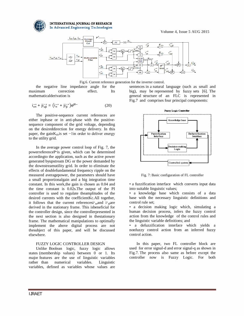
Fig.6. Current reference generation for the inverter control.
the negative line impedance angle for the maximum correction effect. Its mathematicalderivation is
i ∝∗ + ji ∗ = i∝∗ + ji ∗ e (20)
The positive-sequence current references are
either inphase or in anti-phase with the positive-sequence component of the grid voltage, depending on the desireddirection for energy delivery. In this paper, the gainKdiris set −1in order to deliver energy to the utility grid.
In the average power control loop of Fig. 7, the powerreferenceP∗is given, which can be determined accordingto the application, such as the active power generated byupstream DG or the power demanded by the downstreamutility grid. In order to eliminate the effects of doublefundamental frequency ripple on the measured averagepower, the parameters should have a small proportionalgain and a big integration time constant. In this work,the gain is chosen as 0.04 and the time constant is 0.02s.The output of the PI controller is used to regulate theamplitudes of the desired currents with the coefficientKc.All together, it follows that the current referencesi∗sαand i∗sβare derived in the stationary frame. This isbeneficial for the controller design, since the controllerpresented in the next section is also designed in thestationary frame. The mathematical manipulations to optimally implement the above digital process are not thesubject of this paper, and will be discussed elsewhere.
FUZZY LOGIC CONTROLLER DESIGN Unlike Boolean logic, fuzzy logic allows
states (membership values) between 0 or 1. Its major features are the use of linguistic variables rather than numerical variables. Linguistic variables, defined as variables whose values are
sentences in a natural language (such as small and big), may be represented by fuzzy sets [6]. The general structure of an FLC is represented in Fig.7 and comprises four principal components:
Fig. 7: Basic configuration of FL controller
• a fuzzification interface which converts input data into suitable linguistic values; • a knowledge base which consists of a data base with the necessary linguistic definitions and control rule set; • a decision making logic which, simulating a human decision process, infers the fuzzy control action from the knowledge of the control rules and the linguistic variable definitions; and • a defuzzification interface which yields a nonfuzzy control action from an inferred fuzzy control action.
In this paper, two FL controller block are used for error signal-d and error signal-q as shown in Fig.7. The process also same as before except the controller now is Fuzzy Logic. For both
Gurmeet
Typewritten Text
90

Volume 4, Issue 5 AUG 2015
IJRAET
Fig. 8.Structure of the controller for current regulation. Blocks the FL controller consists of seven linguistic variables from input which is; Negative large (NL), Negative Medium (NM),Negative Small(NS), Zero Equivalent (ZE) and Positive Small (PS),Positive Medium (PM), Positive large (PL). Each parameter from linguistic variables for error signal is shown in Fig.9. For delta error, there are seven linguistic variables from input which is; Negative large (NL), Negative Medium (NM),Negative Small(NS), Zero Equivalent (ZE) and Positive Small (PS),Positive Medium (PM), Positive large (PL) Both variables can be depicted as in Fig.10.
Fig. 9: Linguistic variables from error
Fig. 10: Linguistic variables from delta error
Fig.11. Shows each parameter for output signal. TABLE 1
RULE BASE E/DE NL NM NS ZE PS PM PL NL NL NL NL NM NM NS ZE NM NL NL NM NS NS ZE PS NS NL NM NS ZE ZE PS PM ZE PM NS NS PS PS PM PL PS PH NS ZE PS PS PM PL PM NS ZE PS PM PM PL PL PL ZE PS PM PL PL PL PL
IV. SIMULATION
ANDEXPERIMENTALRESULTS
Simulation results from PSIM7.0 are provided to enablethe verification of the reference signals generation. Systemparameters are shown in Table I. In order to easily observethe effects of negative-sequence correction, we intentionally exaggerated the values of the line inductances to thesame order as the filter inductors. Therefore, the inductorsLsa,b,c are combined with the line impedances, reducingthe LCL structure to an LC one. According to the valuesof the line impedances in Table I, we obtain thatθ−
equals−45o. For a straightforward test of the effectivenesscaused by the negative-sequence voltage correction, onlyfundamental positive- and negative-sequence componentsare considered in the grid
Gurmeet
Typewritten Text
91

Volume 4, Issue 5 AUG 2015
IJRAET
voltages as given in TableI. It should be pointed out that the afore-mentionedcontrol scheme and the multi-variable filter can also beimplemented for distorted grid voltages.
(a)
(b)
(c)
Fig.12. Simulation results of the reference currents generation. (a) unbalanced grid voltages in a-b-c frame, (b) the per-unit positivesequence currents i+∗ sα and I +∗ sβin-phase with the positive-sequencevoltage, and (c) the negative-sequence current i−∗sα and i−∗sβlags thenegative-sequence voltage by45oin the α−βframe
To verify the proposed control method with its integrated correction function in a practical set-up, an experiment is carried out with a laboratory prototype that hasthe same system parameters as the simulation. A 15KVAthree-phase programmable AC power source (SPITZENBERGER+SPIES DM 15000/PAS) is used to emulate theunbalanced utility grid. The controller is designed on adSPACE DS1104 setup by using Matlab Simulink. Dueto the long computation time of the controller, a samplingfrequency of 8 kHz is used. The switching frequency istwice the sampling frequency.
Fig. 13. Experimental results of the grid-interfacing inverter withintegrated voltage unbalance correction (a) unbalanced grid voltages,(b) currents delivered by the inverter, and (c) voltages at the PoC.
Fig. 13 (a)-(c) show the experimental waveforms
of thegrid-interfacing inverter with integrated negative-sequencevoltage correction. The plots are the unbalanced gridvoltages, the controlled line currents, and the voltagesat the PoC, respectively. Using unbalanced grid voltages,the inverter delivers mainly positive-sequence currents tothe utility grid and absorbs 10%of the negative-sequencecurrents.
The effectiveness of the multi-variable filter in
detecting positive- and negative-sequence components from
TABLE II SYSTEMPARAMETERS
Descripition Symbol Value Grid voltage
V V V
198V∠0 171.71V∠−125.21 171.71V∠125.21
Line impedence z , , 2mH,0.628Ω Neutral impedence
z 100uH,0.03Ω
Filter inductor L , , 2mH 0.03Ω Filter inductor L 0.67mH 0.03Ω Filter capcitor C , , 5µF DC-bus V 700V Switching freq. f 16kHz
unbalanced voltages is shown in Fig. 14. For observing,these experimental waveforms of the practical controller are reproduced through D/A converters. The RMS value and phase-shift of the positive- and negative-sequence voltages show almost the same results as the calculation results from a−b−cquantities toα−βquantities. To observe the negative-sequence voltage correction, the results are illustrated in the α−βframe by decomposing voltages from thea−b−cframe. As seen in Fig. 15, the amplitude of the negative-sequence voltage at the PoC is reduced, although the decrease is limited to around 10%. Again note that the line impedance parameters have been exaggerated. In a practical utility grid, for instance 200μHline impedance is more realistic, and then the decrease would be
Gurmeet
Typewritten Text
92

Volume 4, Issue 5 AUG 2015
IJRAET
around1%for the same conditions. However, based on multiple modules, the effect of the negative-sequence voltage correction will be more pronounced.
Fig. 14. Experimental waveforms of positive- and negative-sequence voltage detection, where the filtered out fundamental symmetric sequence voltages are derived in theα−βframe.
Fig. 15. Experimental results of the negative-sequence voltage correction. The α, βcomponents of the negative-sequence voltage of the PoCv−sα,βshow a 10%amplitude reduction compared with the negativesequence voltage of the gridv−gα,β
For an investigation of multiple modules based
on theabove described single module, an equivalent circuit isused. Fig. 13 shows the per-phase diagram, where manymodules are located in different nodes on a distributionbus and represented by current sources. In order for distributed voltage unbalance correction to succeed, multipleinverter modules on the same PoC of a feeder shouldshow the same control behavior. With the system structureshown, the VUF value may be transfered to each moduleby an information center where measurements are donecentrally. Alternatively, the measurement can be done bythe inverters locally.
Fig. 16. Experimental waveforms of the negative-sequence voltage correction. The resulting corrected voltages tend to be balanced.
Fig. 15 shows the corrected voltage at the PoC when wesimply provide more negative-sequence current. It can beseen that the three-phase voltages tend to be balanced.This generally indicates the effectiveness of distributedvoltage unbalance correction. However, it must be notedthat the proposed method is only an alternative. It ispreferable in an unbalanced situation with small voltagedeviation, while the conventional methods are suitable for serious situations with large voltage unbalance.
Fig 17. THD value observed in fuzzy logic controller
V. CONCLUSION
In this paper, the basic principle and detailed
fuzzy logic controlof grid-interfacing inverters supporting negative-sequencevoltage correction has been presented. It has been shown that a grid-interfacinginverter, in addition to its normal operation, can helpdecrease the negative-sequence voltage at the PoC. Furthermore, the improved multi-variable filtercan filter out positive- and negative-sequence components accurately in case of unbalanced/distorted situations in thestationary frame under the fuzzy logic controller. As well as THD value decreased too. The functionality and control
Gurmeet
Typewritten Text
93

Volume 4, Issue 5 AUG 2015
IJRAET
schemeare verified by simulation and experimental results of aprototype were given.
V. REFERENCES
[1] Annette von Jouanne and Basudeb (Ben)
Banerjee, “Assessment ofvoltage unbalance,”IEEE Trans. Power Del., vol. 16, no. 4, pp.782-790, Oct. 2001.
[2] Hideaki Fujita, and H. Akagi,“Voltage-regulation performance of ashunt active filter intended for installation on a power distributionsystem,”IEEE Trans. Power Electron., vol 22, no. 3, pp. 1046-1053,May 2007.
[3] Kuang Li, Jinjun Liu, and Zhaoan Wang, and Biao Wei,“Strategiesand operating point optimization of STATCOM control for voltage unbalance mitigation in three-phase three-wire systems,”IEEETrans. Power Del., vol. 22, no. 1, pp. 413-422, Jan. 2007.
[4] Kalyan K. Sen, “SSSC-static synchronous series compensator theory, modeling, and application,”IEEE Trans. Power Del., vol. 13,no. 1, pp. 241-246, Jan. 1998.
[5] Vijay B. Bhavaraju and Prasad N. Enjeti, “An active line conditionerto balance voltages in a three-phase system,”IEEE Trans. Ind.Applicat., vol. 32, no. 2, pp. 287-292, Mar./Apr. 1996.
[6] Hideaki Fujita, H. Akagi, “The unified power quality conditioner:the integration of series- and shunt-active filters,” IEEE Trans.Power Electron., vol.13, no. 2, pp. 315-322, Mar. 1998.
[7] Dusan Graovac, V. A. Katic, and A. Rufer, “ Power quality problemscompensation with universal power quality conditioning system,”IEEE Trans. Power Del. , vol. 22, no. 2, pp. 968-976, Apr. 2007.
[8] Koen J. P. Macken, Koen Vanthournout, Jeroen Van den Keybus,Geert Deconinck, and Ronnie J. M. Belmans, “Distributed Controlof Renewable Generation Units With Integrated Active Filter,”IEEETrans. Power Electron., vol. 19, no. 5, pp. 1353-1360, Sep. 2004.
[9] G. Jos, B.-T. Ooi, D. McGillis, F. D. Galiana and R. Marceau, “Thepotential of distributed generation to provide ancillary services,” inProc. IEEE Power Eng. Soc. Summer Meeting, Seattle, WA, July,2000.
[10] P. M. Andersson, Analysis of faulted power systems, New York:IEEE Press, 1995.
[11] Fei Wang, Jorge L. Duate, Marcel A. M. Hendrix, “Weightingfunction integrated in grid-interfacing converters for unbalancedvoltage correction,” in Proc. International Conf. on RenewableEnergy and Power Quality (ICREPQ), Santander, Spain, 2008.
[12] M. C. Benhabib and S. Saadate, “A new robust experimentallyvalidated phase locked loop for power electronic control,”EuropeanPower Electronics and Drives Journal, vol. 15, no. 3, pp. 36-48,Aug. 2005.
[13] R. Teodorescu, F. Blaabjerg, M. Liserre and P.C. Loh,“Proportional-resonant controllers and filters for grid-connectedvoltage-source converters,”IEE Proc.-Electr. Power Appl., Vol. 153,No. 5, pp. 750-762, September 2006.
HEENA TABASSUM,Completed B.Tech in Electrical &Electronics Engineering in 2013 from RAMANANDATIRTHAENGINEERINGCOLLEGE, NALGONDA affiliated to JNTUH, Hyderabad and currently pursuing M.Tech in Power Electronics at Sri Venkateswara engineering college,Suryapet, Nalgonda district, Telangana. Area of interest includes Power Electronics.E-mail:[email protected]
GUNDALA SRINIVASA RAO,He has obtained his B.Tech degree from SVEC, Suryapet in 2010 and M.Tech in Power Electronics from Jawaharlal Nehru Technological University, Hyderabad in 2012 .he is currently pursuing PhD at KL University..He has 5 years of teaching experience and presently working as Assistant Professor in EEE Dept. at Sri Venkateswara engineering college,Suryapet, Nalgonda district, Telangana state,India .
Gurmeet
Typewritten Text
94