Voltage linearity measurements using a binary Josephson system
7
Voltage Linearity Measurements using a Binary Josephson System Helko E van den Brom 1 , Ernest Houtzager, Gert Rietveld, Roland van Bemmelen, and Oleg Chevtchenko NMi Van Swinden Laboratorium B.V. (NMi VSL), P.O. Box 654, 2600 AR Delft, The Netherlands E-mail: [email protected] Abstract. A fully automated system has been developed for voltage calibrations where fast programmability and extremely low uncertainties are required. This system is based on a binary Josephson junction array with a smallest segment of one single junction. As an important application, the linearity of the 10 mV range of a digital nanovoltmeter was determined with a standard uncertainty better than 1 nV. As a further application of the fast programmability of the binary Josephson system, the standard uncertainty of voltage ratios measured by an 8½-digit digital voltmeter in quantum Hall measurements was measured to be 10×10 -9 . PACS. 06.20.-f Metrology, 06.20.fb Standards and calibration, 06.30.Ka Basic electromagnetic quantities, 84.37.+q Measurements in electric variables Submitted to Measurement Science and Technology 1. Introduction The common way of calibrating a digital voltmeter (DVM) in a certain range is to calibrate one voltage close to full-scale only. Nevertheless, in practice the whole range is used, while the deviation from perfect linearity of the range is neglected. However, for some applications, such as the measurement of voltage ratios, calibration of the linearity of the meter is even more important than calibration of the gain. One of the characteristics of linearity calibrations is that they are valid over a relatively long period: although the voltmeter gain will drift in time, the deviation from linearity is fixed by the pulse width modulation technique used by the analog-to-digital (A/D) converter, which will remain stable in time. The lowest uncertainty in DC voltage calibrations is obtained by using a Josephson array voltage standard. A conventional 10 volt DC Josephson standard is based on a series array of typically 20000 SIS (superconductor – insulator – superconductor) junctions. Each Josephson junction responds to a radio frequency (RF) driving signal by generating a DC voltage that is equal to an integer number (the so-called Shapiro step number) times the driving frequency f divided by the Josephson constant K J = 2e/h, where e denotes the electron charge and h the Planck constant. Unfortunately, the voltage generated by SIS junctions is intrinsically multi- valued; one setting of bias current corresponds to several values of the Shapiro step number (see figure 1). This makes the stability of the voltage sensitive to external noise. Moreover, it 1 Author to whom correspondence should be addressed.
Transcript of Voltage linearity measurements using a binary Josephson system

Voltage Linearity Measurements using a Binary Josephson System
Helko E van den Brom1, Ernest Houtzager, Gert Rietveld, Roland van Bemmelen, and Oleg Chevtchenko NMi Van Swinden Laboratorium B.V. (NMi VSL), P.O. Box 654, 2600 AR Delft, The Netherlands E-mail: [email protected] Abstract. A fully automated system has been developed for voltage calibrations where fast programmability and extremely low uncertainties are required. This system is based on a binary Josephson junction array with a smallest segment of one single junction. As an important application, the linearity of the 10 mV range of a digital nanovoltmeter was determined with a standard uncertainty better than 1 nV. As a further application of the fast programmability of the binary Josephson system, the standard uncertainty of voltage ratios measured by an 8½-digit digital voltmeter in quantum Hall measurements was measured to be 10×10-9. PACS. 06.20.-f Metrology, 06.20.fb Standards and calibration, 06.30.Ka Basic electromagnetic quantities, 84.37.+q Measurements in electric variables Submitted to Measurement Science and Technology
1. Introduction The common way of calibrating a digital voltmeter (DVM) in a certain range is to calibrate one voltage close to full-scale only. Nevertheless, in practice the whole range is used, while the deviation from perfect linearity of the range is neglected. However, for some applications, such as the measurement of voltage ratios, calibration of the linearity of the meter is even more important than calibration of the gain. One of the characteristics of linearity calibrations is that they are valid over a relatively long period: although the voltmeter gain will drift in time, the deviation from linearity is fixed by the pulse width modulation technique used by the analog-to-digital (A/D) converter, which will remain stable in time.
The lowest uncertainty in DC voltage calibrations is obtained by using a Josephson array voltage standard. A conventional 10 volt DC Josephson standard is based on a series array of typically 20000 SIS (superconductor – insulator – superconductor) junctions. Each Josephson junction responds to a radio frequency (RF) driving signal by generating a DC voltage that is equal to an integer number (the so-called Shapiro step number) times the driving frequency f divided by the Josephson constant KJ = 2e/h, where e denotes the electron charge and h the Planck constant. Unfortunately, the voltage generated by SIS junctions is intrinsically multi-valued; one setting of bias current corresponds to several values of the Shapiro step number (see figure 1). This makes the stability of the voltage sensitive to external noise. Moreover, it
1 Author to whom correspondence should be addressed.

Voltage Linearity Measurements using a Binary Josephson System 2
is not straightforward to select the proper step number. An external voltage source is used to force the Josephson array on the step closest to a predefined value; a typical setup approaches the desired value within a few millivolts. Consequently, for automated linearity calibrations using a conventional Josephson standard [1-4], a considerable amount of time and effort is spent on the voltage step selection. Hence, calibrating a DVM in its full range using a conventional Josephson standard is time consuming, which means that the effect of variations in the environmental conditions or non-linear drift of the internal reference of the DVM will be the limiting factor in the uncertainty.
In order to improve on the measurement time and, consequently, on the accuracy, a digital-to-analog (D/A) converter based on a binary sequence of shunted Josephson junctions was proposed [5]. For this purpose, arrays of SNS (superconductor – normal metal – superconductor) junctions were developed [6]. The main advantage of these intrinsically shunted junctions is that their current – voltage characteristics are non-hysteretic: a DC bias current uniquely defines the Josephson voltage virtually instantaneously (see figure 1), which enables high-speed operation and easy programmability by means of varying the bias current through the array. The non-hysteretic behaviour also makes the stability of the output voltage much less sensitive to external noise.
Initial work on programmable Josephson voltage standards based on intrinsically shunted junctions was performed by groups at the National Institute of Standards and Technology (NIST) and at the Physikalisch-Technische Bundesanstalt (PTB). The NIST group developed a 1 volt standard based on a binary array of SNS junctions [7,8]. The RF driving frequency used in that system was 16 GHz, whereas the smallest segment consisted of 128 junctions, resulting in a resolution (i.e., smallest difference between two voltage values) of approximately 4 mV. As an application, the linearity of a DVM was measured in its 1 volt scale. However, the 4 mV resolution makes the setup unsuitable for calibration of nanovoltmeters. The PTB group fabricated programmable Josephson junction arrays of SINIS (superconductor – insulator – normal metal – insulator – superconductor) to be operated at frequencies above 70 GHz with low microwave power [9]. Based on these SINIS junctions, single junction resolution has been obtained in a 1 volt binary Josephson system [10]. As a first application, an automated DC quantum voltmeter was built in order to calibrate resistive dividers.
This paper presents two further applications of a fully automated 1 volt programmable Josephson voltage system with single junction resolution. This system, developed at NMi VSL, is based on a binary Josephson array of 8192 SINIS junctions fabricated at PTB [11] and a bias source developed at the National Physical Laboratory (NPL) [12,13]. First, the linearity of a nanovoltmeter in its 10 mV range is calibrated. Next, voltage ratios as determined by means of a DVM in quantum Hall resistance measurements are calibrated using the same switching conditions as in the actual resistance measurements. The results show that this setup is suitable for the calibration of deviations from linearity of both DVMs and nanovoltmeters, as well as other voltage applications where fast programmability in combination with extremely low uncertainties is required.
Figure 1. DC I–V characteristics for a Josephson junction after irradiating with an RF signal. Left: hysteretic curve for conventional SIS junctions. Right: non-hysteretic curve for intrinsically shunted junctions (SNS or SINIS).
I
V=(h/2e)·f
I

Voltage Linearity Measurements using a Binary Josephson System 3
2. Binary Josephson array voltage standard 2.1. Binary Josephson array The basis of the binary Josephson voltage standard used in the experiments described in this paper is formed by an array of SINIS Josephson junctions, designed and fabricated at PTB. The array was fabricated using the Nb/Al-Al2O3 technology [11]. The critical current and the normal resistance for this array are around 3.8 mA and 24 mΩ per junction, respectively. The chips were designed for operation at RF frequencies around 70 GHz.
The chip layout of the binary Josephson junction array is represented in figure 2. The array consists of 8192 Josephson junctions in total, divided into 14 segments containing a successive binary number (1, 2, 4, 8, 16, …) of junctions in series. Each segment can be biased independently by means of a different current source. This way, any voltage can be generated with a resolution equal to the voltage of one junction. Hence, when driven by an RF frequency f = 70 GHz and biased at the first Shapiro step, the maximum output voltage is 8192 ⋅ f / KJ = 1.1857785156 V and the resolution is 144.7484 µV. With the present equipment, by varying the RF frequency these numbers can be changed by about 1 %. 2.2. Bias source The electronics used to bias the array was developed at NPL in order to facilitate high-speed operation [12]. Up to 15 individually controllable bias modules are available to set the corresponding array segments to –Vi , 0 or +Vi , where Vi is the Josephson voltage of the ith segment. Each bias module is based on a fast 12-bit D/A converter and can be independently tuned using a PC with the appropriate control software. Four of the modules can be operated as true high impedance current sources for generating up to 20 mA, whereas the other modules are in fact voltage sources with an output voltage between –5 V and +5 V and an output impedance of 620 Ω. The latter modules have limited output current, especially when used to bias higher voltage segments. 3. Experimental results 3.1. Comparison to conventional DC Josephson voltage standard As a first critical test of the new binary Josephson setup, we performed a direct comparison of this system with a conventional Josephson standard [13]. The two Josephson standards were
Figure 2. Chip layout of the Josephson array, consisting of 8192 SINIS junctions divided into 14 binary segments in 64 microwave branches, containing 128 junctions each. The number of junctions between each two successive DC contacts is 1, 1, 2, 4, 8, …, 4096. (Courtesy of R. Behr from PTB.)
Voltage Linearity Measurements using a Binary Josephson System 4
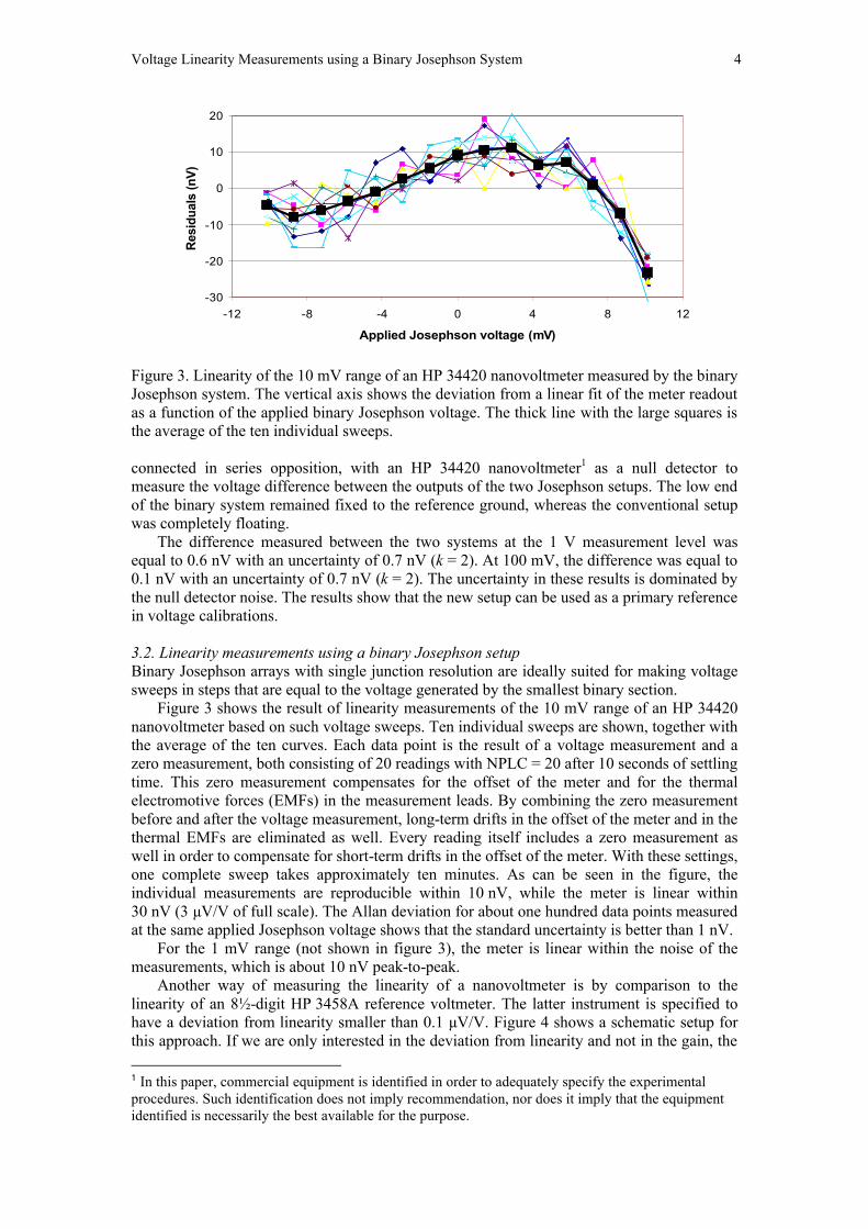
connected in series opposition, with an HP 34420 nanovoltmeter1 as a null detector to measure the voltage difference between the outputs of the two Josephson setups. The low end of the binary system remained fixed to the reference ground, whereas the conventional setup was completely floating.
The difference measured between the two systems at the 1 V measurement level was equal to 0.6 nV with an uncertainty of 0.7 nV (k = 2). At 100 mV, the difference was equal to 0.1 nV with an uncertainty of 0.7 nV (k = 2). The uncertainty in these results is dominated by the null detector noise. The results show that the new setup can be used as a primary reference in voltage calibrations. 3.2. Linearity measurements using a binary Josephson setup Binary Josephson arrays with single junction resolution are ideally suited for making voltage sweeps in steps that are equal to the voltage generated by the smallest binary section.
Figure 3 shows the result of linearity measurements of the 10 mV range of an HP 34420 nanovoltmeter based on such voltage sweeps. Ten individual sweeps are shown, together with the average of the ten curves. Each data point is the result of a voltage measurement and a zero measurement, both consisting of 20 readings with NPLC = 20 after 10 seconds of settling time. This zero measurement compensates for the offset of the meter and for the thermal electromotive forces (EMFs) in the measurement leads. By combining the zero measurement before and after the voltage measurement, long-term drifts in the offset of the meter and in the thermal EMFs are eliminated as well. Every reading itself includes a zero measurement as well in order to compensate for short-term drifts in the offset of the meter. With these settings, one complete sweep takes approximately ten minutes. As can be seen in the figure, the individual measurements are reproducible within 10 nV, while the meter is linear within 30 nV (3 µV/V of full scale). The Allan deviation for about one hundred data points measured at the same applied Josephson voltage shows that the standard uncertainty is better than 1 nV.
For the 1 mV range (not shown in figure 3), the meter is linear within the noise of the measurements, which is about 10 nV peak-to-peak.
Another way of measuring the linearity of a nanovoltmeter is by comparison to the linearity of an 8½-digit HP 3458A reference voltmeter. The latter instrument is specified to have a deviation from linearity smaller than 0.1 µV/V. Figure 4 shows a schematic setup for this approach. If we are only interested in the deviation from linearity and not in the gain, the 1 In this paper, commercial equipment is identified in order to adequately specify the experimental procedures. Such identification does not imply recommendation, nor does it imply that the equipment identified is necessarily the best available for the purpose.
-30
-20
-10
0
10
20
-12 -8 -4 0 4 8 12
Applied Josephson voltage (mV)
Res
idua
ls (n
V)
Figure 3. Linearity of the 10 mV range of an HP 34420 nanovoltmeter measured by the binary Josephson system. The vertical axis shows the deviation from a linear fit of the meter readout as a function of the applied binary Josephson voltage. The thick line with the large squares is the average of the ten individual sweeps.

Voltage Linearity Measurements using a Binary Josephson System 5
value of the resistance ratio of the two resistors in the setup only needs to be stable, whereas the exact value is not important. An obvious way of validating such a measurement setup is by comparing the results to those obtained by the binary Josephson method, as described in the previous section.
Using the reference voltmeter method, linearity measurements on the 10 mV range of the HP 34420 were performed with NPLC = 100. The current source is a Fluke 5720 calibrator used on the 10 mA range. The resistors’ values are R1 = 100 Ω and R2 = 1 Ω. The results, presented in figure 5, show an excellent agreement within 2 nV (0.2 µV/V of full scale) with the binary Josephson method and can be considered as a validation of the reference voltmeter measurement setup. Note that the reference voltmeter is considered perfectly linear in this method; the deviation from the results found using the binary Josephson method of less than 2 nV is mainly caused by this assumption.
In practice, customer calibrations are performed with an uncertainty of typically 10 nV (k = 2) in the 10 mV range, which means that the reference voltmeter method is accurate enough. However, for more demanding applications, such as quantum Hall voltage ratios (see next paragraph), the binary Josephson method is still preferred. 3.3. Application: quantum Hall voltage ratios The lowest uncertainty in DC resistance calibrations is obtained when the resistor under test is compared directly with a quantum Hall resistance (QHR) standard. The most accurate method is based on a cryogenic current comparator (CCC). However, the use of this CCC method is relatively complex and expensive. A good alternative for calibrations of 10 kΩ resistors against the i = 2 and i = 4 QHR plateaus is a fully automated potentiometer method. The two resistors to be compared are connected in series and a DC current of 45 µA is sent through
-30
-20
-10
0
10
20
-12 -8 -4 0 4 8 12
Applied voltage (mV)
Res
idua
ls (n
V)
Figure 5. Linearity of the 10 mV range of an HP 34420 as measured using the current source method (dots) and binary Josephson method (squares, taken from Fig. 3).
Fluke 5720 HP34420
R1
HP3458A
I
I R2
Figure 4. Schematic diagram for determination of the linearity of a (HP 34420) nanovoltmeter using the known linearity of a (HP 3458A) reference meter operating on a higher, more accurate, range. The ratio of the resistors R1 and R2 matches the ratio of the ranges of the voltmeters.

Voltage Linearity Measurements using a Binary Josephson System 6
them. Subsequently, the ratio of the voltages developed over the two resistors is measured [14]. Two HP 3458A DVMs are used in their 1 volt range, where each DVM measures the ratio of the voltages over the 10 kΩ resistor and the QHR values of approximately 12.9064 kΩ or 6.4532 kΩ for the i = 2 and i = 4 plateau, respectively. A switchbox is used to interchange the voltmeters or invert the current direction in order to eliminate possible different systematic errors and offset voltages. In this measurement only voltage ratios are important. Provided that they remain constant, deviations of the DVM gains from their nominal values are eliminated by the measurement procedure. Thus, the main factor of importance in the uncertainty budget now is the linearity of the DVM [15]. Note that the only reason to use two DVMs is to have more statistics and more reliability.
Voltage ratios of approximately 0.45 V to 0.58 V and 0.45 V to 0.29 V were evaluated using the binary Josephson method. The switching procedures are the same as those routinely used in the quantum Hall measurements. The average and Allan deviation of a large set of ratio measurements show the relative linearity deviations for these two ratios to be less than 20 parts in 109 with a standard uncertainty of 10 parts in 109, which is much better than the instrument specifications. These results lead to a measurement uncertainty of 36 nΩ/Ω (k = 2) for the measurement of 10 kO resistors against QHR; this is a 30 % decrease compared to the previous uncertainty [15].
The major benefit of using the binary Josephson method compared to the conventional Josephson array voltage standard is in its intrinsic stability and its speed, which allows us to obtain lower uncertainty in linearity measurements. Since we can use the same switching procedures as in the actual QHR measurements, a single ratio measurement is finished within 128 seconds. This is short enough to avoid most of the 1/f noise region of the HP 3458A internal Zener diode, which we measured independently to start around 100 seconds, in agreement with Ref. [16]. The fact that we are not fully outside the 1/f noise region shows up as a noise floor in the Alan deviation of a large set of ratio measurements starting at averaging times larger than approximately one hour. This noise floor shows that using these switching procedures we cannot obtain uncertainty better than 10 parts in 109. This is almost one order of magnitude lower than in the early work of Cage et al. [14], who used a conventional Josephson setup to determine the linearity of the complete 1 volt range. A single linearity measurement took them typically one hour, which is far into the 1/f noise region of the DVM. 4. Conclusions and future work This work demonstrates the binary Josephson setup to be a powerful tool in linearity measurements and other voltage calibrations where fast programmability and extremely low uncertainties are required. Apart from being user friendly, its major benefit as compared to a conventional Josephson setup is its intrinsic stability and its speed. Because of this speed, it is easier to avoid the 1/f noise region of devices under test.
As a validation of the binary Josephson setup, a direct comparison of this system with the conventional Josephson setup at the 1 V and 100 mV measurement level showed agreement within 1 nV. This proves its suitability as a primary voltage standard.
Linearity measurements on the 10 mV range of a nanovoltmeter were performed using both the binary Josephson method and a method based on comparison to the linearity of a reference voltmeter. The measurements show an excellent agreement within 2 nV and can be considered as a validation of the latter method.
As a further important application of the binary Josephson setup for quantum Hall measurements, specific voltage ratios were determined with a standard uncertainty of 10 parts in 109, which is almost a factor of 10 better than earlier results obtained with a conventional Josephson setup.
Future work will concentrate on generating AC voltage signals using the binary Josephson setup by means of fast switching between different voltage levels. A setup similar to the one described in this paper has already been demonstrated to generate highly accurate AC voltage signals with frequencies of up to a few kilohertz [17,18], with applications for example in power measurements [19].

Voltage Linearity Measurements using a Binary Josephson System 7
Ackownledgements The authors want to thank F. Müller and R. Behr from PTB for the supply of the binary SINIS Josephson array and J.M. Williams from NPL for providing us with the bias source. References [1] Goeke W C, Swerlein R L, Venzke S B and Stever S D 1989 Calibration of an 8½-digit
multimeter from only two external standards Hewlett-Packard J. 40 22-30 [2] Hamilton C A, Lloyd F L, Chieh K and Goeke W C 1989 A 10-V Josephson voltage
standard IEEE Trans. Instrum. Meas. 38 314-6 [3] Giem J I 1991 Sub-ppm linearity testing of a DMM using a Josephson Junction array
IEEE Trans. Instrum. Meas. 40 329-32 [4] Pöpel R 1992 The Josephson effect and voltage standards Metrologia 29 153-74 [5] Hamilton C A, Burroughs C J and Kautz R L 1995 Josephson D/A Converter with
Fundamental Accuracy IEEE Trans. Instrum. Meas. 44 223-5 [6] Benz S P 1995 Superconductor-normal-superconductor Junctions for Programmable
Voltage Standards Appl. Phys. Lett. 67 2714-6 [7] Hamilton C A, Benz S P, Burroughs C J and Harvey T E 1997 SNS programmable
voltage standard IEEE Trans. Appl. Supercond. 7 2472-5 [8] Benz S P, Hamilton C A, Burroughs C J, Harvey T E and Christian L A 1997 Stable
1-volt programmable voltage standard Appl. Phys. Lett. 71 1866-8 [9] Behr R, Schulze H, Müller F, Kohlmann J and Niemeyer J 1999 Josephson arrays at
70 GHz for conventional and programmable voltage standards IEEE Trans. Instrum. Meas. 48 270-3
[10] Behr R, Grimm L, Funck T, Kohlmann J, Schulze H, Müller F, Schumacher B, Warnecke P and Niemeyer J 2001 Application of Josephson series arrays to a DC quantum voltmeter IEEE Trans. Instrum. Meas. 50 185-7
[11] Kieler O, Behr R, Müller F, Schulze H, Kohlmann J and Niemeyer J 2002 Improved 1-V programmable Josephson voltage standard using SINIS junctions Physica C 372-6 309-11
[12] Williams J M, Kleinschmidt P, Janssen T J B M, Pratel P, Behr R, Kohlmann J and Müller F 2002 Synthesis of precision waveforms using a SINIS Josephson Junction Array 2002 CPEM Digest pp 434-435
[13] Behr R, Kohlmann J, Janssen J T B M , Kleinschmidt P, Williams J M, Djordjevic S, Lo-Hive J P, Piquemal F, Hetland P O, Reymann D, Eklund G, Hof C, Jeanneret B, Chevtchenko O, Houtzager E, Van den Brom H, Sosso A, Andreone D, Nissilä J and Helistö P 2003 Analysis of different measurement setups for a programmable Josephson voltage standard IEEE Trans. Instr. Meas. 52 524-9
[14] Cage M E, Yu D Y, Jeckelmann B M, Steiner R L and Duncan R V 1991 Investigating the use of multimeters to measure quantized Hall resistance standards IEEE Trans. Instr. Meas. 40 262-6
[15] Rietveld G and Van Mullem C J 2000 Uncertainty analysis of a DVM-based quantum Hall measurement setup 2000 CPEM Digest pp 90-1
[16] Witt T J and Reymann D 2000 Using power spectra and Allan variances to characterise the noise of Zener-diode voltage standards IEE Proc.-Sci. Meas. Technol. 147 177-82
[17] Behr R, Williams W, Pratel P, Janssen T J B M, Funk T, and Klonz M 2005 Synthesis of precision waveforms using a SINIS Josephson Junction Array IEEE Trans. Instr. Meas. 54 612-5
[18] Behr R, Palafox L, Ramm G, Moser H and Melcher J 2007 Direct comparison of Josephson waveforms using an AC quantum voltmeter IEEE Trans. Instr. Meas. 56 235-8
[19] Benz S P, Hamilton C A, Burroughs C J, Dresselhaus P C, Waltrip B C, Nelson T L, Chong Y, Williams J M, Henderson D, Patel P, Palafox L and Behr R 2007 Development of a 60 Hz power standard using SNS programmable Josephson voltage standards IEEE Trans. Instr. Meas. 56 289-94