VideoBloX Matrix Switcher User Manual - Honeywell Security
136
900.0809 - August 2006 – Rev 1.00 User Manual VideoBloX Matrix Switcher
-
Upload
khangminh22 -
Category
Documents
-
view
3 -
download
0
Transcript of VideoBloX Matrix Switcher User Manual - Honeywell Security

900.0809 - August 2006 – Rev 1.00
User Manual
VideoBloXMatrix Switcher
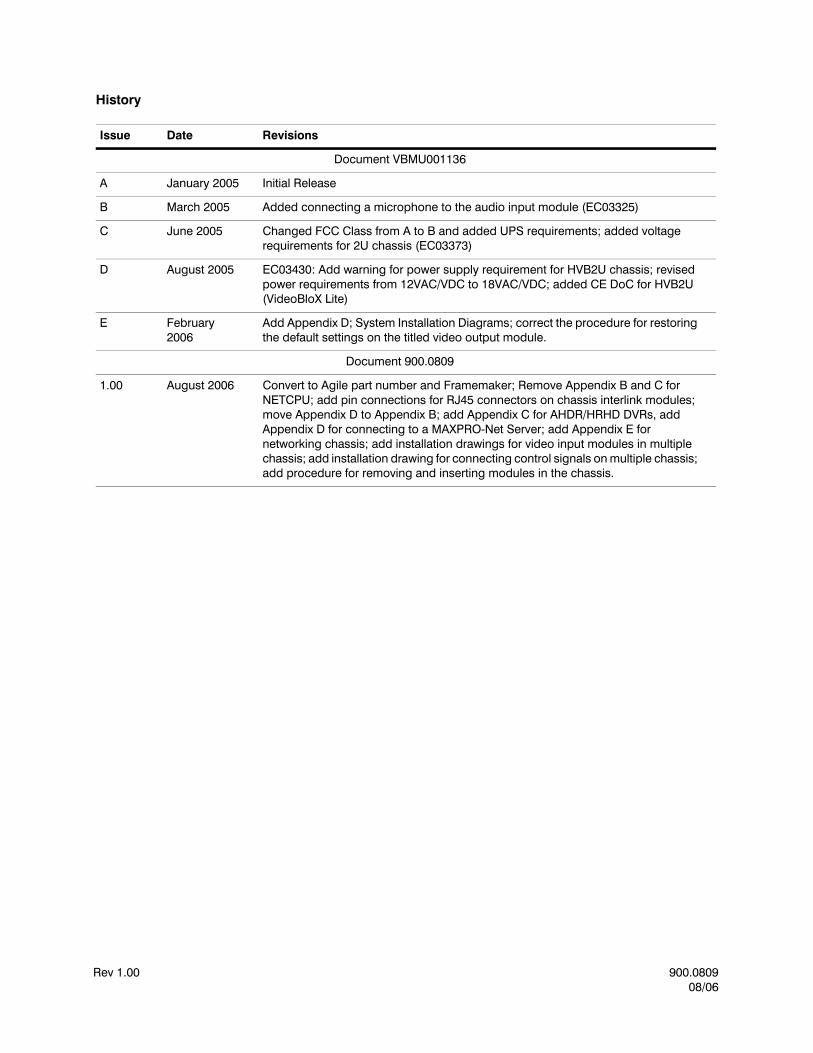
History
Issue Date Revisions
Document VBMU001136
A January 2005 Initial Release
B March 2005 Added connecting a microphone to the audio input module (EC03325)
C June 2005 Changed FCC Class from A to B and added UPS requirements; added voltage requirements for 2U chassis (EC03373)
D August 2005 EC03430: Add warning for power supply requirement for HVB2U chassis; revised power requirements from 12VAC/VDC to 18VAC/VDC; added CE DoC for HVB2U (VideoBloX Lite)
E February 2006
Add Appendix D; System Installation Diagrams; correct the procedure for restoring the default settings on the titled video output module.
Document 900.0809
1.00 August 2006 Convert to Agile part number and Framemaker; Remove Appendix B and C for NETCPU; add pin connections for RJ45 connectors on chassis interlink modules; move Appendix D to Appendix B; add Appendix C for AHDR/HRHD DVRs, add Appendix D for connecting to a MAXPRO-Net Server; add Appendix E for networking chassis; add installation drawings for video input modules in multiple chassis; add installation drawing for connecting control signals on multiple chassis; add procedure for removing and inserting modules in the chassis.
Rev 1.00 900.080908/06

VideoBloX User Manual
Rev 1.00 900.080908/06
i
CONTENTSCompliances and Safeguards . . . . . . . . . . . . . . . . . . . . . . . . . . . . . . . . . . . . . . . ix
FCC COMPLIANCE STATEMENT . . . . . . . . . . . . . . . . . . . . . . . . . . . . . . . . . . . . . ixCANADIAN COMPLIANCE STATEMENT . . . . . . . . . . . . . . . . . . . . . . . . . . . . . . . . . ixEUROPEAN COMPLIANCE STATEMENT . . . . . . . . . . . . . . . . . . . . . . . . . . . . . . . . . xIMPORTANT SAFEGUARDS . . . . . . . . . . . . . . . . . . . . . . . . . . . . . . . . . . . . . . . . xEXPLANATION OF GRAPHICAL SYMBOLS . . . . . . . . . . . . . . . . . . . . . . . . . . . . . . . . xii
About This Document . . . . . . . . . . . . . . . . . . . . . . . . . . . . . . . . . . . . . . . . . . . . xvOverview of Contents. . . . . . . . . . . . . . . . . . . . . . . . . . . . . . . . . . . . . . . . . . . xviRelated Documents . . . . . . . . . . . . . . . . . . . . . . . . . . . . . . . . . . . . . . . . . . . xvii
1 INTRODUCTION. . . . . . . . . . . . . . . . . . . . . . . . . . . . . . . . . . . . . . . . . . . . . 1
PRODUCT DESCRIPTION . . . . . . . . . . . . . . . . . . . . . . . . . . . . . . . . . . . . . . . . . 1FEATURES . . . . . . . . . . . . . . . . . . . . . . . . . . . . . . . . . . . . . . . . . . . . . . . . . 2SYSTEM OVERVIEW . . . . . . . . . . . . . . . . . . . . . . . . . . . . . . . . . . . . . . . . . . . . 2RACK MOUNT SYSTEM CHASSIS. . . . . . . . . . . . . . . . . . . . . . . . . . . . . . . . . . . . . 3REMOVING A MODULE FROM A VIDEOBLOX CHASSIS . . . . . . . . . . . . . . . . . . . . . . . . . 4INSTALLING A MODULE IN A VIDEOBLOX CHASSIS. . . . . . . . . . . . . . . . . . . . . . . . . . . 5
2 REAR CHASSIS . . . . . . . . . . . . . . . . . . . . . . . . . . . . . . . . . . . . . . . . . . . . . 7
POWER SUPPLY MODULE . . . . . . . . . . . . . . . . . . . . . . . . . . . . . . . . . . . . . . . . 74U, 8U, 12U Chassis . . . . . . . . . . . . . . . . . . . . . . . . . . . . . . . . . . . . . . . 72U Chassis . . . . . . . . . . . . . . . . . . . . . . . . . . . . . . . . . . . . . . . . . . . . 8Main Input Power Connection . . . . . . . . . . . . . . . . . . . . . . . . . . . . . . . . . . 9Low Voltage Input Connection . . . . . . . . . . . . . . . . . . . . . . . . . . . . . . . . . . 9Chassis Sync In . . . . . . . . . . . . . . . . . . . . . . . . . . . . . . . . . . . . . . . . . . 9
CHASSIS EXPANSION DRIVER BOARD, HVBCE . . . . . . . . . . . . . . . . . . . . . . . . . . . . . 10Control Expansion Connector . . . . . . . . . . . . . . . . . . . . . . . . . . . . . . . . . . 10Communications Expansion Connector . . . . . . . . . . . . . . . . . . . . . . . . . . . . . 10Control Expansion and Communication Connector Pin-Outs . . . . . . . . . . . . . . . . . . 11
CONNECTING MULTIPLE CHASSIS. . . . . . . . . . . . . . . . . . . . . . . . . . . . . . . . . . . . 12Two Chassis . . . . . . . . . . . . . . . . . . . . . . . . . . . . . . . . . . . . . . . . . . . 12Three Chassis. . . . . . . . . . . . . . . . . . . . . . . . . . . . . . . . . . . . . . . . . . . 13
DIP SWITCH SETTINGS . . . . . . . . . . . . . . . . . . . . . . . . . . . . . . . . . . . . . . . . . . 14RESET PUSH BUTTON. . . . . . . . . . . . . . . . . . . . . . . . . . . . . . . . . . . . . . . . . . . 15SYNC PHASE ADJUSTMENT . . . . . . . . . . . . . . . . . . . . . . . . . . . . . . . . . . . . . . . 15LED INDICATIONS . . . . . . . . . . . . . . . . . . . . . . . . . . . . . . . . . . . . . . . . . . . . . 16
3 CPU MODULE . . . . . . . . . . . . . . . . . . . . . . . . . . . . . . . . . . . . . . . . . . . . . 17
DESCRIPTION . . . . . . . . . . . . . . . . . . . . . . . . . . . . . . . . . . . . . . . . . . . . . . . 17DIP SWITCH SETTINGS . . . . . . . . . . . . . . . . . . . . . . . . . . . . . . . . . . . . . . . . . . 19PUSH BUTTONS . . . . . . . . . . . . . . . . . . . . . . . . . . . . . . . . . . . . . . . . . . . . . . 21
Restore Factory Defaults . . . . . . . . . . . . . . . . . . . . . . . . . . . . . . . . . . . . . 21LED INDICATORS . . . . . . . . . . . . . . . . . . . . . . . . . . . . . . . . . . . . . . . . . . . . . 22

Rev 1.00 900.080908/06
CONTENTS
ii
Display Width Adjustment (C3) . . . . . . . . . . . . . . . . . . . . . . . . . . . . . . . . . . 23Display Color Burst Frequency Adjustment (C5). . . . . . . . . . . . . . . . . . . . . . . . . 23Jumper Settings . . . . . . . . . . . . . . . . . . . . . . . . . . . . . . . . . . . . . . . . . 24Toggle Switch SW1 . . . . . . . . . . . . . . . . . . . . . . . . . . . . . . . . . . . . . . . . 25
FUSES . . . . . . . . . . . . . . . . . . . . . . . . . . . . . . . . . . . . . . . . . . . . . . . . . . . 25CONNECTIONS . . . . . . . . . . . . . . . . . . . . . . . . . . . . . . . . . . . . . . . . . . . . . . 26
RS422 Communication Ports (Master and Satellite) . . . . . . . . . . . . . . . . . . . . . . . 26RS232 Communication Ports (Slave and AUX) . . . . . . . . . . . . . . . . . . . . . . . . . 26I2C Connectors . . . . . . . . . . . . . . . . . . . . . . . . . . . . . . . . . . . . . . . . . . 27CPU Video . . . . . . . . . . . . . . . . . . . . . . . . . . . . . . . . . . . . . . . . . . . . 27Alarm Inputs/Outputs . . . . . . . . . . . . . . . . . . . . . . . . . . . . . . . . . . . . . . . 28
4 COMBO CPU MODULE . . . . . . . . . . . . . . . . . . . . . . . . . . . . . . . . . . . . . . . . 29
DESCRIPTION . . . . . . . . . . . . . . . . . . . . . . . . . . . . . . . . . . . . . . . . . . . . . . . 29DIP SWITCH SETTINGS . . . . . . . . . . . . . . . . . . . . . . . . . . . . . . . . . . . . . . . . . . 30PUSH BUTTONS . . . . . . . . . . . . . . . . . . . . . . . . . . . . . . . . . . . . . . . . . . . . . . 31LED INDICATIONS . . . . . . . . . . . . . . . . . . . . . . . . . . . . . . . . . . . . . . . . . . . . . 31RESTORING FACTORY DEFAULTS . . . . . . . . . . . . . . . . . . . . . . . . . . . . . . . . . . . . 32
5 VIDEO INPUT MODULES . . . . . . . . . . . . . . . . . . . . . . . . . . . . . . . . . . . . . . . 33
DESCRIPTION . . . . . . . . . . . . . . . . . . . . . . . . . . . . . . . . . . . . . . . . . . . . . . . 33CROSS LINK VIDEO INPUT MODULES . . . . . . . . . . . . . . . . . . . . . . . . . . . . . . . . . . 35
VideoBloX Switching System with 128 Video Outputs (2 chassis) . . . . . . . . . . . . . . . 36VideoBloX Switching System with 192 Video Outputs (3 Chassis) . . . . . . . . . . . . . . . 37
DIP SWITCH SETTINGS . . . . . . . . . . . . . . . . . . . . . . . . . . . . . . . . . . . . . . . . . . 38HVB16M16 . . . . . . . . . . . . . . . . . . . . . . . . . . . . . . . . . . . . . . . . . . . . 38HVB16M32 and HVB16M64 . . . . . . . . . . . . . . . . . . . . . . . . . . . . . . . . . . . 39
LED INDICATIONS . . . . . . . . . . . . . . . . . . . . . . . . . . . . . . . . . . . . . . . . . . . . . 41ADJUSTMENTS . . . . . . . . . . . . . . . . . . . . . . . . . . . . . . . . . . . . . . . . . . . . . . 41
Video Input Gain Setting . . . . . . . . . . . . . . . . . . . . . . . . . . . . . . . . . . . . . 41Termination . . . . . . . . . . . . . . . . . . . . . . . . . . . . . . . . . . . . . . . . . . . . 42
FUSES . . . . . . . . . . . . . . . . . . . . . . . . . . . . . . . . . . . . . . . . . . . . . . . . . . . 42
6 VIDEO OUTPUT MODULES . . . . . . . . . . . . . . . . . . . . . . . . . . . . . . . . . . . . . . 43
DESCRIPTION . . . . . . . . . . . . . . . . . . . . . . . . . . . . . . . . . . . . . . . . . . . . . . . 43DIP SWITCH SETTINGS . . . . . . . . . . . . . . . . . . . . . . . . . . . . . . . . . . . . . . . . . . 44VIDEO OUTPUT GAIN ADJUSTMENT . . . . . . . . . . . . . . . . . . . . . . . . . . . . . . . . . . . 44OUTPUT RANGES . . . . . . . . . . . . . . . . . . . . . . . . . . . . . . . . . . . . . . . . . . . . . 44
7 TITLED VIDEO OUTPUT MODULE . . . . . . . . . . . . . . . . . . . . . . . . . . . . . . . . . . 45
DESCRIPTION . . . . . . . . . . . . . . . . . . . . . . . . . . . . . . . . . . . . . . . . . . . . . . . 45DIP SWITCH SETTINGS . . . . . . . . . . . . . . . . . . . . . . . . . . . . . . . . . . . . . . . . . . 46VIDEO OUTPUT GAIN ADJUSTMENT . . . . . . . . . . . . . . . . . . . . . . . . . . . . . . . . . . . 47RESTORING FACTORY DEFAULTS . . . . . . . . . . . . . . . . . . . . . . . . . . . . . . . . . . . . 48DAUGHTER BOARD SETUP . . . . . . . . . . . . . . . . . . . . . . . . . . . . . . . . . . . . . . . . 49
MODULE BOARD SETTING, VIDEO OUTPUTS 1-64 . . . . . . . . . . . . . . . . . . . . . . 49MODULE BOARD SETTING, VIDEO OUTPUTS 1-16 . . . . . . . . . . . . . . . . . . . . . . 50MODULE BOARD SETTING, VIDEO OUTPUTS 17-32 . . . . . . . . . . . . . . . . . . . . . . 50MODULE BOARD SETTING, VIDEO OUTPUTS 33-48 . . . . . . . . . . . . . . . . . . . . . . 51MODULE BOARD SETTING, VIDEO OUTPUTS 49-64 . . . . . . . . . . . . . . . . . . . . . . 51
8 AUDIO INPUT MODULE. . . . . . . . . . . . . . . . . . . . . . . . . . . . . . . . . . . . . . . . 53
DESCRIPTION . . . . . . . . . . . . . . . . . . . . . . . . . . . . . . . . . . . . . . . . . . . . . . . 53DIP SWITCH SETTINGS . . . . . . . . . . . . . . . . . . . . . . . . . . . . . . . . . . . . . . . . . . 54CONFIGURATION JUMPERS . . . . . . . . . . . . . . . . . . . . . . . . . . . . . . . . . . . . . . . 55
Phantom Power Jumpers and 20dB Pad Jumpers . . . . . . . . . . . . . . . . . . . . . . . 55Low Pass and High Pass Filter Jumpers . . . . . . . . . . . . . . . . . . . . . . . . . . . . . 55
VideoBloX User Manual
Rev 1.00 900.080908/06
iii
Gain Adjustment . . . . . . . . . . . . . . . . . . . . . . . . . . . . . . . . . . . . . . . . . 56CMRR Adjustment . . . . . . . . . . . . . . . . . . . . . . . . . . . . . . . . . . . . . . . . 56
CONNECTING A MICROPHONE TO THE AUDIO INPUT MODULE. . . . . . . . . . . . . . . . . . . . 57
9 AUDIO OUTPUT MODULE . . . . . . . . . . . . . . . . . . . . . . . . . . . . . . . . . . . . . . 59
DESCRIPTION . . . . . . . . . . . . . . . . . . . . . . . . . . . . . . . . . . . . . . . . . . . . . . . 59
10 CHASSIS INTERLINK INPUT AND OUTPUT MODULE. . . . . . . . . . . . . . . . . . . . . . . . 61
DESCRIPTION . . . . . . . . . . . . . . . . . . . . . . . . . . . . . . . . . . . . . . . . . . . . . . . 61DIP SWITCH SETTINGS . . . . . . . . . . . . . . . . . . . . . . . . . . . . . . . . . . . . . . . . . . 63CONNECTIONS, HVB32RJ45X8 . . . . . . . . . . . . . . . . . . . . . . . . . . . . . . . . . . . . . . 65
11 SECONDARY COMMUNICATIONS EXPANSION MODULE . . . . . . . . . . . . . . . . . . . . . 67
DESCRIPTION . . . . . . . . . . . . . . . . . . . . . . . . . . . . . . . . . . . . . . . . . . . . . . . 67Jumper Settings . . . . . . . . . . . . . . . . . . . . . . . . . . . . . . . . . . . . . . . . . . . . . . 68
RS232 Settings . . . . . . . . . . . . . . . . . . . . . . . . . . . . . . . . . . . . . . . . . . 68RS422 Settings . . . . . . . . . . . . . . . . . . . . . . . . . . . . . . . . . . . . . . . . . . 69Backplane Communication Settings . . . . . . . . . . . . . . . . . . . . . . . . . . . . . . . 69
12 CPU ARBITRATION CONTROLLER MODULE . . . . . . . . . . . . . . . . . . . . . . . . . . . . 71
DESCRIPTION . . . . . . . . . . . . . . . . . . . . . . . . . . . . . . . . . . . . . . . . . . . . . . . 71OPERATION . . . . . . . . . . . . . . . . . . . . . . . . . . . . . . . . . . . . . . . . . . . . . . . . 72CONNECTIONS . . . . . . . . . . . . . . . . . . . . . . . . . . . . . . . . . . . . . . . . . . . . . . 73SWITCH SETTINGS . . . . . . . . . . . . . . . . . . . . . . . . . . . . . . . . . . . . . . . . . . . . 74FRONT PANEL PUSH BUTTON OPERATION . . . . . . . . . . . . . . . . . . . . . . . . . . . . . . . 75
Appendix A BINARY ADDRESS VALUES . . . . . . . . . . . . . . . . . . . . . . . . . . . . . . . 77
Appendix B SYSTEM INSTALLATION DIAGRAMS . . . . . . . . . . . . . . . . . . . . . . . . . . 79
PURPOSE. . . . . . . . . . . . . . . . . . . . . . . . . . . . . . . . . . . . . . . . . . . . . . . . . . 79
Appendix C CONNECTING AHDR/HRHD DVRs . . . . . . . . . . . . . . . . . . . . . . . . . . . 97
INTRODUCTION . . . . . . . . . . . . . . . . . . . . . . . . . . . . . . . . . . . . . . . . . . . . . . 97HVBPIT44 SETUP . . . . . . . . . . . . . . . . . . . . . . . . . . . . . . . . . . . . . . . . . . . . . 97
DIP Switch Settings . . . . . . . . . . . . . . . . . . . . . . . . . . . . . . . . . . . . . . . . 97Data connections . . . . . . . . . . . . . . . . . . . . . . . . . . . . . . . . . . . . . . . . . 98
VIDEOBLOX SETUP . . . . . . . . . . . . . . . . . . . . . . . . . . . . . . . . . . . . . . . . . . . . 98Video Connections . . . . . . . . . . . . . . . . . . . . . . . . . . . . . . . . . . . . . . . . 98Configuration . . . . . . . . . . . . . . . . . . . . . . . . . . . . . . . . . . . . . . . . . . . 98
CONFIGURING THE AHDR1E . . . . . . . . . . . . . . . . . . . . . . . . . . . . . . . . . . . . . . 100TESTING THE SYSTEM . . . . . . . . . . . . . . . . . . . . . . . . . . . . . . . . . . . . . . . . . 101
Appendix D CONNECTING TO MAXPRO-Net SERVER. . . . . . . . . . . . . . . . . . . . . . . .103
INTRODUCTION . . . . . . . . . . . . . . . . . . . . . . . . . . . . . . . . . . . . . . . . . . . . . 103CONNECTIONS . . . . . . . . . . . . . . . . . . . . . . . . . . . . . . . . . . . . . . . . . . . . . 103DIP Switch Settings. . . . . . . . . . . . . . . . . . . . . . . . . . . . . . . . . . . . . . . . . . . . 104
VideoBloX Chassis Power Supply Module . . . . . . . . . . . . . . . . . . . . . . . . . . . 104HVBMATPIT . . . . . . . . . . . . . . . . . . . . . . . . . . . . . . . . . . . . . . . . . . . 104
LED OPERATION . . . . . . . . . . . . . . . . . . . . . . . . . . . . . . . . . . . . . . . . . . . . . 105
Appendix E NETWORKING TWO VIDEOBLOX MATRICES. . . . . . . . . . . . . . . . . . . . . .109
PURPOSE. . . . . . . . . . . . . . . . . . . . . . . . . . . . . . . . . . . . . . . . . . . . . . . . . 109RECOMMENDATIONS . . . . . . . . . . . . . . . . . . . . . . . . . . . . . . . . . . . . . . . . . . 109ADDRESSING THE CHASSIS . . . . . . . . . . . . . . . . . . . . . . . . . . . . . . . . . . . . . . 110CONNECTIONS . . . . . . . . . . . . . . . . . . . . . . . . . . . . . . . . . . . . . . . . . . . . . 110DIP SWITCH SETTINGS . . . . . . . . . . . . . . . . . . . . . . . . . . . . . . . . . . . . . . . . . 111
Standard CPU. . . . . . . . . . . . . . . . . . . . . . . . . . . . . . . . . . . . . . . . . . 111COMBO CPU . . . . . . . . . . . . . . . . . . . . . . . . . . . . . . . . . . . . . . . . . . 111

Rev 1.00 900.080908/06
CONTENTS
iv
PROGRAMMING WITH Vbloxcfg APPLICATION. . . . . . . . . . . . . . . . . . . . . . . . . . . . . 112TESTING . . . . . . . . . . . . . . . . . . . . . . . . . . . . . . . . . . . . . . . . . . . . . . . . . 113TROUBLESHOOTING . . . . . . . . . . . . . . . . . . . . . . . . . . . . . . . . . . . . . . . . . . 113

VideoBloX User Manual
Rev 1.00 900.080908/06
v
FIGURESFigure 1-1 VideoBloX Matrix Switcher Front View (HVB12U shown) . . . . . . . . . . . . . . . . . . . . 1
Figure 1-2 VideoBloX Matrix Switcher Rear View (HVB4U shown) . . . . . . . . . . . . . . . . . . . . . 3
Figure 1-3 Location of Phillips Screw and Pulling Tool . . . . . . . . . . . . . . . . . . . . . . . . . . . 4
Figure 1-4 Removing a Module from the VideoBloX Chassis. . . . . . . . . . . . . . . . . . . . . . . . 5
Figure 2-1 Power Supply Module (HVB4U, HVB8U, HVB12U) . . . . . . . . . . . . . . . . . . . . . . 7
Figure 2-2 Power Supply Module, HVB2U . . . . . . . . . . . . . . . . . . . . . . . . . . . . . . . . 8
Figure 2-3 Connecting Communication Signals between Two Chassis . . . . . . . . . . . . . . . . . 12
Figure 2-4 Connecting Communication Signals between Three Chassis . . . . . . . . . . . . . . . . 13
Figure 2-5 Chassis DIP Switch Settings . . . . . . . . . . . . . . . . . . . . . . . . . . . . . . . . . 14
Figure 2-6 System Reset Push Button . . . . . . . . . . . . . . . . . . . . . . . . . . . . . . . . . 15
Figure 2-7 Sync Phase Adjustment . . . . . . . . . . . . . . . . . . . . . . . . . . . . . . . . . . . 15
Figure 3-1 Front and Rear Views of CPU Module. . . . . . . . . . . . . . . . . . . . . . . . . . . . . 17
Figure 3-2 HVBCPU DIP Switches . . . . . . . . . . . . . . . . . . . . . . . . . . . . . . . . . . . . 19
Figure 3-3 HVBCPU Push Buttons . . . . . . . . . . . . . . . . . . . . . . . . . . . . . . . . . . . . 21
Figure 3-4 LED Indicators . . . . . . . . . . . . . . . . . . . . . . . . . . . . . . . . . . . . . . . . . 22
Figure 3-5 Display Width Adjustment . . . . . . . . . . . . . . . . . . . . . . . . . . . . . . . . . . 23
Figure 3-6 Display Color Burst Frequency Adjustment . . . . . . . . . . . . . . . . . . . . . . . . . 23
Figure 3-7 Jumper JP3, JP4, JP5 Settings . . . . . . . . . . . . . . . . . . . . . . . . . . . . . . . . 24
Figure 3-8 Jumper P8 Settings . . . . . . . . . . . . . . . . . . . . . . . . . . . . . . . . . . . . . 24
Figure 3-9 Toggle Switch SW1 for CPU Selection . . . . . . . . . . . . . . . . . . . . . . . . . . . . 25
Figure 4-1 Front and Rear View of Combo CPU Module . . . . . . . . . . . . . . . . . . . . . . . . . 29
Figure 4-2 Combo CPU DIP Switch Settings . . . . . . . . . . . . . . . . . . . . . . . . . . . . . . . 30
Figure 4-3 LED Indicators . . . . . . . . . . . . . . . . . . . . . . . . . . . . . . . . . . . . . . . . 31
Figure 4-4 Combo CPU, Restoring Factory Defaults. . . . . . . . . . . . . . . . . . . . . . . . . . . 32
Figure 5-1 Video Input Modules (2 front panel options) . . . . . . . . . . . . . . . . . . . . . . . . . 34
Figure 5-2 Video Input Module (Standard - 16 BNC Inputs. . . . . . . . . . . . . . . . . . . . . . . . 34
Figure 5-3 Video Input Module (Looping BNC Inputs) . . . . . . . . . . . . . . . . . . . . . . . . . . 34
Figure 5-4 Type A, B and C Cross-Link Looping Input Termination Modules . . . . . . . . . . . . . . 35
Figure 5-5 VideoBloX Matrix Switcher with 128 Video Outputs (2 Chassis) . . . . . . . . . . . . . . . 36
Figure 5-6 VideoBloX Matrix Switcher with 192 Video Outputs (3 Chassis) . . . . . . . . . . . . . . . 37
Figure 5-7 DIP Switches SW1 - SW3 . . . . . . . . . . . . . . . . . . . . . . . . . . . . . . . . . . . 38
Figure 5-8 Video Input Gain Enable/Disable (SW2) and Termination (SW1). . . . . . . . . . . . . . . 41
Figure 5-9 Video Gain Adjustment . . . . . . . . . . . . . . . . . . . . . . . . . . . . . . . . . . . . 42
Figure 6-1 8 and 16 Channel Video Output Modules - Front View . . . . . . . . . . . . . . . . . . . . 43
Figure 6-2 8 and 16 Channel Video Output Rear Panel Termination Modules . . . . . . . . . . . . . . 43

Rev 1.00 900.080908/06
FIGURES
vi
Figure 7-1 .Front and Rear Views of Titled Video Output Module . . . . . . . . . . . . . . . . . . . . 45
Figure 7-2 Location of Video Output Daughter Board . . . . . . . . . . . . . . . . . . . . . . . . . . 46
Figure 8-1 Front and Rear Views of Audio Input Module . . . . . . . . . . . . . . . . . . . . . . . . . 53
Figure 8-2 Phantom Power Jumpers and 20dB Pad Jumpers. . . . . . . . . . . . . . . . . . . . . 55
Figure 8-3 Low Pass and High Pass Filter Jumpers . . . . . . . . . . . . . . . . . . . . . . . . . . 55
Figure 8-4 CMRR Adjustment. . . . . . . . . . . . . . . . . . . . . . . . . . . . . . . . . . . . . . 56
Figure 8-5 Connecting a Microphone to an Audio Input . . . . . . . . . . . . . . . . . . . . . . . . . 57
Figure 9-1 Front and Rear Views of 8 and 16 Channel Audio Output Modules . . . . . . . . . . . . . 59
Figure 10-1 HVB32LKO Chassis Interlink Output Module with Rear Terminal HVBRJ45X8. . . . . . . . 61
Figure 10-2 HVB32LKI Chassis Interlink Input Module with Rear Terminal HVBRJ45X8 . . . . . . . . . 61
Figure 10-3 Jumper JP1 - JP4 Settings . . . . . . . . . . . . . . . . . . . . . . . . . . . . . . . . . . 62
Figure 10-4 DIP Switch Settings . . . . . . . . . . . . . . . . . . . . . . . . . . . . . . . . . . . . . . 63
Figure 10-5 RJ45 Connections . . . . . . . . . . . . . . . . . . . . . . . . . . . . . . . . . . . . . . . 65
Figure 11-1 Front and Rear View of Secondary Communications Expansion Module . . . . . . . . . . 67
Figure 11-2 JP1 and JP2 RS232 Jumper Settings . . . . . . . . . . . . . . . . . . . . . . . . . . . . . 68
Figure 11-3 JP3 RS422 Jumper Settings. . . . . . . . . . . . . . . . . . . . . . . . . . . . . . . . . . 69
Figure 12-1 Front and Rear View of CPU Arbitration Module . . . . . . . . . . . . . . . . . . . . . . . 71
Figure 12-2 Typical Rear View of Arbitration Module and 2 CPU Modules in 4U Chassis . . . . . . . . 72
Figure D-1 Connecting Redundant MAXPRO-Net Servers to VideoBloX Matrix Switcher . . . . . . . 107
Figure D-2 Connecting a Single MAXPRO-Net Server to VideoBloX Matrix Switcher . . . . . . . . . 108

VideoBloX User Manual
Rev 1.00 900.080908/06
vii
TABLESTable 1-1 VideoBloX Chassis . . . . . . . . . . . . . . . . . . . . . . . . . . . . . . . . . . . . . . . . 3
Table 2-1 Connector Pin-Outs, Female DB9 . . . . . . . . . . . . . . . . . . . . . . . . . . . . . . . 11
Table 2-2 DIP Switch Settings . . . . . . . . . . . . . . . . . . . . . . . . . . . . . . . . . . . . . . . 14
Table 2-3 Chassis Sync Signal . . . . . . . . . . . . . . . . . . . . . . . . . . . . . . . . . . . . . . 14
Table 2-4 LED Indicators . . . . . . . . . . . . . . . . . . . . . . . . . . . . . . . . . . . . . . . . . 16
Table 3-1 HVBCPU Module Ports . . . . . . . . . . . . . . . . . . . . . . . . . . . . . . . . . . . . . 18
Table 3-2 HVBCPU DIP Switch 1 Settings . . . . . . . . . . . . . . . . . . . . . . . . . . . . . . . . 19
Table 3-3 HVBCPU DIP Switch 2 Settings . . . . . . . . . . . . . . . . . . . . . . . . . . . . . . . . 19
Table 3-4 HVBCPU DIP Switch 3 Settings . . . . . . . . . . . . . . . . . . . . . . . . . . . . . . . . 20
Table 3-5 HVBCPU DIP Switch 4 Settings . . . . . . . . . . . . . . . . . . . . . . . . . . . . . . . . 20
Table 3-6 HVBCPU Push Buttons . . . . . . . . . . . . . . . . . . . . . . . . . . . . . . . . . . . . 21
Table 3-7 HVBCPU LED Indicator Functions . . . . . . . . . . . . . . . . . . . . . . . . . . . . . . . 22
Table 3-8 Toggle Switch SW1 . . . . . . . . . . . . . . . . . . . . . . . . . . . . . . . . . . . . . . . 25
Table 3-9 HVBCPU RS422 Communication Port Pin-Outs . . . . . . . . . . . . . . . . . . . . . . . . 26
Table 3-10 HVBCPU RS232 Communication Port Pin-Outs . . . . . . . . . . . . . . . . . . . . . . . . 26
Table 3-11 I2C Connector Pin-Outs . . . . . . . . . . . . . . . . . . . . . . . . . . . . . . . . . . . . 27
Table 4-1 Combo CPU DIP Switch SW1 Settings. . . . . . . . . . . . . . . . . . . . . . . . . . . . . 30
Table 4-2 Combo CPU DIP Switch SW2 Settings. . . . . . . . . . . . . . . . . . . . . . . . . . . . . 30
Table 4-3 Combo CPU LED Indicator Functions . . . . . . . . . . . . . . . . . . . . . . . . . . . . . 31
Table 5-1 Video Input Modules (Single Chassis) . . . . . . . . . . . . . . . . . . . . . . . . . . . . . 34
Table 5-2 HVB16M16 DIP Switch SW1 Settings . . . . . . . . . . . . . . . . . . . . . . . . . . . . . 38
Table 5-3 HVB16M16 DIP Switch SW2 Settings . . . . . . . . . . . . . . . . . . . . . . . . . . . . . 38
Table 5-4 HVB16M32 and HVB16M64 DIP Switch SW1 Settings. . . . . . . . . . . . . . . . . . . . . 39
Table 5-5 HVB16M32 and HVB16M64 DIP Switch SW2 Settings. . . . . . . . . . . . . . . . . . . . . 40
Table 5-6 HVB16M32 and HVB16M64 DIP Switch SW3 Settings. . . . . . . . . . . . . . . . . . . . . 40
Table 6-1 Video Output Modules . . . . . . . . . . . . . . . . . . . . . . . . . . . . . . . . . . . . . 43
Table 7-1 Titled Video Output Modules . . . . . . . . . . . . . . . . . . . . . . . . . . . . . . . . . . 45
Table 7-2 DIP Switch S1 Settings . . . . . . . . . . . . . . . . . . . . . . . . . . . . . . . . . . . . . 47
Table 8-1 DIP Switch S1 Settings . . . . . . . . . . . . . . . . . . . . . . . . . . . . . . . . . . . . . 54
Table 8-2 DIP Switch S2 Settings . . . . . . . . . . . . . . . . . . . . . . . . . . . . . . . . . . . . . 54
Table 10-1 DIP Switch S1 and S2 Settings . . . . . . . . . . . . . . . . . . . . . . . . . . . . . . . . . 63
Table 10-2 DIP Switch S3 and S4 Settings . . . . . . . . . . . . . . . . . . . . . . . . . . . . . . . . . 64
Table 11-1 JP1 and JP2 Jumper Settings . . . . . . . . . . . . . . . . . . . . . . . . . . . . . . . . . 68
Table 11-2 JP3 Jumper Settings . . . . . . . . . . . . . . . . . . . . . . . . . . . . . . . . . . . . . . 69
Table 12-1 CPU Arbitration Module DIP Switch Settings. . . . . . . . . . . . . . . . . . . . . . . . . . 74

Rev 1.00 900.080908/06
TABLES
viii
Table 12-2 CPU Arbitration Module Front Panel Push Buttons . . . . . . . . . . . . . . . . . . . . . . 75
Table A-1 Binary Address Values . . . . . . . . . . . . . . . . . . . . . . . . . . . . . . . . . . . . . 77
Table C -1 Data Connections. . . . . . . . . . . . . . . . . . . . . . . . . . . . . . . . . . . . . . . . 98
Table D-1 VideoBloX Chassis DIP Switch S1 Settings . . . . . . . . . . . . . . . . . . . . . . . . . 104
Table D-2 HVBMATPIT DIP Switch S1 - S3 Settings . . . . . . . . . . . . . . . . . . . . . . . . . . 104
Table E-1 Chassis Addresses . . . . . . . . . . . . . . . . . . . . . . . . . . . . . . . . . . . . . . 110
Table E-2 Standard CPU ConnectionsSAT RS422 ports110
Table E-3 Combo CPU Connections AUX RS232 Ports . . . . . . . . . . . . . . . . . . . . . . . . 111
Table E-4 Troubleshooting Networked Chassis. . . . . . . . . . . . . . . . . . . . . . . . . . . . . 113

VideoBloX User Manual
Rev 1.00 ix 900.080908/06
Compliances and Safeguards
FCC COMPLIANCE STATEMENT
INFORMATION TO THE USER: This equipment has been tested and found to comply with the limits for a Class B digital device, pursuant to part 15 of the FCC rules. These limits are designed to provide reasonable protection against harmful interference when the equipment is operated in a commercial environment. This equipment generates, uses, and can radiate radio frequency energy and, if not installed and used in accordance with the instruction manual, may cause harmful interference to radio communications. Operation of this equipment in a residential area is likely to cause harmful interference in which case the user will be required to correct the interference at his own expense.
Caution Changes or modifications not expressly approved by the party responsible for compliance could void the user's authority to operate the equipment.
CANADIAN COMPLIANCE STATEMENT
This Class B digital apparatus complies with Canadian ICES-003.
Cet appareil numérique de la Classe B est conforme à la norme NMB-003 du Canada.
Caution Users of the product are responsible for checking and complying with all federal, state, ad local laws and statutes concerning the monitoring and recording of video and audio signals. Honeywell video systems shall not be held responsible for the use of this product in violation of current laws and statutes.

Rev 1.00 x 900.080908/06
Compliances and Safeguards
Caution Changes or modifications not expressly approved by the party responsible for compliance could void the user's authority to operate the equipment.
EUROPEAN COMPLIANCE STATEMENT
This is a Class B product. In a domestic environment this product may cause radio interference in which case the user may be required to take adequate measures.
Caution Users of the product are responsible for checking and complying with all federal, state and local laws and statutes concerning the monitoring and recording of video and audio signals. Honeywell Video Systems shall not be held responsible for the use of this product in violation of current laws and statutes.
IMPORTANT SAFEGUARDS
1. READ INSTRUCTIONS - All safety and operating instructions should be read before the unit is operated.
2. RETAIN INSTRUCTIONS - The safety and operating instructions should be retained for future reference.
3. HEED WARNINGS - All warnings on the unit and in the operating instructions should be adhered to.
4. FOLLOW INSTRUCTIONS - All operating and use instructions should be followed.
5. CLEANING - Unplug the unit from the outlet before cleaning. Do not use liquid cleaners or aerosol cleaners. Use a damp cloth for cleaning.
6. ATTACHMENTS - Do not use attachments not recommended by the product manufacturer as they may result in the risk of fire, electric shock, or injury to persons.
7. WATER AND MOISTURE - Do not use this unit near water or in an unprotected outdoor installation, or any area which is classified as a wet location.
8. ACCESSORIES - Do not place this product on an unstable cart, stand, tripod, bracket, or table. The product may fall, causing serious injury to a child or adult and serious damage to the equipment. Use only with a cart, stand, tripod, bracket, or table recommended by the manufacturer, or sold with the product. Any mounting of the product should follow the manufacturer's instructions and should use a mounting accessory recommended by the manufacturer. Wall or shelf mounting should follow the manufacturer's instructions and should use a mounting kit approved by the manufacturer.
VideoBloX User Manual
Rev 1.00 xi 900.080908/06
9. A product and cart combination should be moved with care. Quick stops, excessive force, and uneven surfaces may cause the product and cart combination to overturn.
10. VENTILATION - Slots and openings in the cabinet and the back or bottom are provided for ventilation and to ensure reliable operation of the equipment and to protect it from overheating. These openings must not be blocked or covered. The openings should never be blocked by placing the product on a bed, sofa, rug, or other similar surface. Equipment should never be placed near or over a radiator or heat register. This product should not be placed in a built-in installation, such as a bookcase or rack unless proper ventilation is provided or the manufacturer's instructions have been adhered to.
11. POWER SOURCES - This product should be operated only from the type of power source indicated on the marking label. If you are not sure of the type of power supplied to your home, consult your product dealer or local power company. For products designed to operate from battery power or other sources, refer to the operating instructions.
12. GROUNDING OR POLARIZATION - The power supply supplied with this unit may be equipped with a polarized alternating-current line plug (a plug having one blade wider than the other). This plug will fit into the power outlet only one way. This is a safety feature. If you are unable to insert the plug fully into the outlet, try reversing the plug. If the plug should still fail to fit, contact your electrician to replace your obsolete outlet. Do not defeat the safety purpose of the polarized plug.
13. OVERLOADING - Do not overload outlets and extension cords as this can result in a risk of fire or electric shock.
14. POWER-CORD PROTECTION - Power supply cords should be routed so that they are not likely to be walked on or pinched by items placed upon or against them, paying particular attention to cords and plugs, convenience receptacles, and the point where they exit from the monitor.
15. OBJECT AND LIQUID ENTRY - Never push objects of any kind into this unit through openings as they may touch dangerous voltage points or short-out parts that could result in a fire or electric shock. Never spill liquid of any kind on the unit.
16. SERVICING - Do not attempt to service this unit yourself as opening or removing covers may expose you to dangerous voltage or other hazards. Refer all servicing to qualified service personnel.
17. DAMAGE REQUIRING SERVICE - Unplug the unit from the outlet and refer servicing to qualified service personnel under the following conditions:
a. When the power-supply cord or plug is damaged.
b. If liquid has been spilled, or objects have fallen into the unit.
c. If the unit has been exposed to rain or water.
d. If the unit does not operate normally by following the operating instructions. Adjust only those controls that are covered by the operating instructions as an improper adjustment of other controls may result in damage and will often require extensive work by a qualified technician to restore the unit to its normal operation.
e. If the unit has been dropped or the enclosure has been damaged.
f. When the unit exhibits a distinct change in performance - this indicates a need for service.
18. REPLACEMENT PARTS - When replacement parts are required, be sure the service technician has used replacement parts specified by the manufacturer or have the same characteristics as the original part. Unauthorized substitutions may result in fire, electric shock or other hazards.

Rev 1.00 xii 900.080908/06
Compliances and Safeguards
19. SAFETY CHECK - Upon completion of any service or repairs to this unit, ask the service technician to perform safety checks to determine that the unit is in proper operating condition.
20. LIGHTNING AND POWER LINE SURGES - For added protection of this unit during a lightning storm, or when it is left unattended and unused for long periods of time, unplug it from the wall outlet and disconnect the cable system. This will prevent damage to the unit due to lightning and power-line surges.
21. HEAT - The product should be situated away from heat sources such as radiators, heat registers, stoves, or other products (including amplifiers) that produce heat.
22. INSTALLATION - Do not install the unit in an extremely hot or humid location, or in a place subject to dust or mechanical vibration. The unit is not designed to be waterproof. Exposure to rain or water may damage the unit.
23. WALL OR CEILING MOUNTING - The product should be mounted to a wall or ceiling only as recommended by the manufacturer.
EXPLANATION OF GRAPHICAL SYMBOLS
Caution Caution. The exclamation point within an equilateral triangle advises the user that failure to take or avoid a specified action could result in loss of data or damage to the equipment.
WARNING! Warning: The exclamation point within an octagon advises users that failure to take or avoid a specified action could result in physical injury to a person or irreversible damage to the equipment.

VideoBloX User Manual
Rev 1.00 xiii 900.080908/06
WARNINGS
WARNING! To reduce the risk of fire or electric shock, do not expose this product to rain or moisture.
WARNING! Do not insert any metallic object through the ventilation grills.
WARNING! This unit must be properly grounded to a good earth ground. Non-observance of this practice may result in a static electricity build-up that may result in an electric shock when external connections are touched.

Rev 1.00 xiv 900.080908/06
Compliances and Safeguards
VideoBloX User Manual
Rev 1.00 900.080908/06
xv
About This Document
This guide describes the installation of the VideoBloX matrix switching chassis and the modules installed in the chassis as well as connecting peripheral equipment to the CPU module such as keyboards for controlling the system. The DIP switch and jumper settings along with any internal adjustments or LED indicators are provided for each module.

Rev 1.00 900.080907/06
xvi
Overview of Contents
This document contains the following chapters and appendixes:
• Chapter 1, INTRODUCTION, describes the product features and a system overview.• Chapter 2, REAR CHASSIS, describes the connections and settings for the chassis
rear panel and the power supply module. The front panel settings and indicators as also provided.
• Chapter 3, CPU MODULE, describes the function of the CPU Module, connector functions and pin-outs, user settings, and LED indicators.
• Chapter 4, COMBO CPU MODULE, describes the function of the combo CPU Module, connector functions and pin-outs, user settings, and LED indicators.
• Chapter 5, VIDEO INPUT MODULES, describes the various video input modules available, rear panel terminations, user settings, and LED indicators.
• Chapter 6, VIDEO OUTPUT MODULES, describes the video output modules available, rear panel terminations. User settings for the video output modules are described in Chapter 7, TITLED VIDEO OUTPUT MODULE.
• Chapter 7, TITLED VIDEO OUTPUT MODULE, describes the available titled video output modules, rear panel terminations, and user settings.
• Chapter 8, AUDIO INPUT MODULE, describes the available audio input modules, rear panel terminations, and user settings.
• Chapter 9, AUDIO OUTPUT MODULE, describes the available audio output modules, rear panel terminations, and user settings.
• Chapter 10, CHASSIS INTERLINK INPUT AND OUTPUT MODULE, describes the input and output interlink modules for connecting multiple chassis to increase the number of inputs of a matrix switching system. Rear panel terminations and user settings are provided.
• Chapter 11, SECONDARY COMMUNICATIONS EXPANSION MODULE describes the expansion module used when two CPUs are fitted into the same chassis. Rear panel terminations and user settings are provided.
• Chapter 12, CPU ARBITRATION CONTROLLER MODULE, describes the function of the arbitration module for system redundancy. Rear panel terminations and user settings are provided.
• Appendix A, BINARY ADDRESS VALUES, provides switch settings for binary addresses.
• Appendix B, SYSTEM INSTALLATION DIAGRAMS, provides installation drawings for connecting peripheral equipment to the VideoBloX system.
• Appendix C, CONNECTING AHDR/HRHD DVRs, provides a step-by-step guide to setting up the AHDR/HRHD Series DVRs and controlling them with a VideoBloX system controller.
• Appendix D, CONNECTING TO MAXPRO-Net SERVER, provides installation drawings for controlling the VideoBloX Matrix Switcher with a MAXPRO-Net Server.
• Appendix E, NETWORKING TWO VIDEOBLOX MATRICES, provides an example of the installation and programming of networking two chassis in different locations (site 1 and site 2).

VideoBloX User Manual
Rev 1.00 900.080908/06
xvii
Related Documents
The following documents provide information on topics related to this guide:
Document Title Part Number
VideoBloX Auxiliary Control IP User Guide 900.0401
VideoBloX, PIT, Auxiliary Port User Guide 900.0403
VideoBloX, PIT, Javelin Application Note 900.0404
VideoBloX, PIT, Intercom User Guide 900.0405
VideoBloX, PIT, Lilin Dome Quick Start Guide 900.0406
VideoBloX, PIT, Sensormatic Ultra IV and AD DeltaDome Quick Start Guide
900.0407
VideoBloX, PIT, VCL Dome Quick Start Guide 900.0408
VideoBloX, PITIF User Guide 900.0409
VideoBloX Lite Switch Settings Application Note 900.0410
VideoBloX Matrix Switcher Configuration Guide 900.0411
VideoBloX GUI (Graphic User Interface) User Guide 900.0412
VideoBloX 422 F.T. Smart Combo User Guide 900.0566
VideoBloX HVBI2C16I/HVBI2C16O User Guide 900.0567
VideoBloX HVB16TPTX User Manual 900.0571
VideoBloX HVB422C4 Installation Manual 900.0590
VideoBloX HVBPIT44 User Manual 900.0595
VideoBloX Software License Registration 900.0690
VideoBloX HVBNETPIT Quick Reference Guide 900.0729
VideoBloX HVBMATPIT User Manual 900.0730
VideoBloX HVB232422 Application Note 900.0735

Rev 1.00 900.080907/06
xviii
Rev 1.00 1 900.080910/06
1
INTRODUCTION
PRODUCT DESCRIPTION
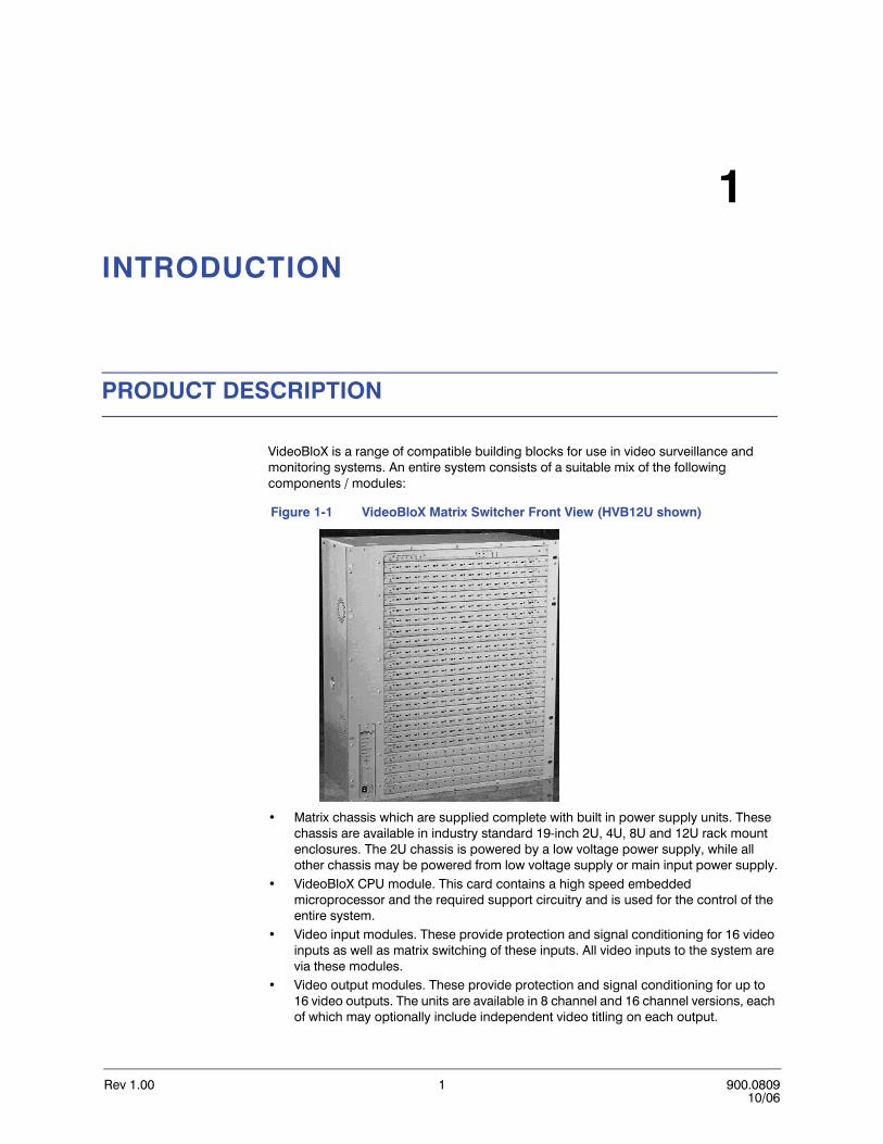
VideoBloX is a range of compatible building blocks for use in video surveillance and monitoring systems. An entire system consists of a suitable mix of the following components / modules:
Figure 1-1 VideoBloX Matrix Switcher Front View (HVB12U shown)
• Matrix chassis which are supplied complete with built in power supply units. These chassis are available in industry standard 19-inch 2U, 4U, 8U and 12U rack mount enclosures. The 2U chassis is powered by a low voltage power supply, while all other chassis may be powered from low voltage supply or main input power supply.
• VideoBloX CPU module. This card contains a high speed embedded microprocessor and the required support circuitry and is used for the control of the entire system.
• Video input modules. These provide protection and signal conditioning for 16 video inputs as well as matrix switching of these inputs. All video inputs to the system are via these modules.
• Video output modules. These provide protection and signal conditioning for up to 16 video outputs. The units are available in 8 channel and 16 channel versions, each of which may optionally include independent video titling on each output.

Rev 1.00 2 900.080908/06
INTRODUCTION
FEATURES
The entire system is based on a modular approach allowing for flexibility in configuring video control systems to suit a wide variety of applications.
• 4080 video inputs to 2048 video outputs• 32 keyboards and or GUIs (Graphic User Interfaces)• 32 on-board alarm inputs expandable to 256 using I2C modules.• 4 on-board relay outputs expandable to 256 using I2C modules.• 6 serial ports• 32 programmable video groups and 512 video scenes - groups (consisting of scenes)
are assigned to keyboards and users for ease of video management.• 1024 (25-steps each) programmable sequences• 64 programmable time-of-day events• 256 x 24 character text message table
SYSTEM OVERVIEW
The configuration of a video surveillance / monitoring control system is highly dependent on the operational requirements of the system. The modular building block approach allows for different system configurations to be readily set up to suit differing application requirements.
Each system must contain at least one VideoBloX chassis. It is possible to interconnect more than one chassis either at the same location or at different locations with suitable data and video interlinks between the various racks. The form of interlink is dependent on the system type and could be hard wired, fiber optics, radio, microwave or other. If there are a large number of video sources at a location which is remote from the monitoring location, then it is generally more cost effective to distribute the matrix switching system by locating a subchassis at the remote site(s). This principle can be repeated for any number of remote sites.
Regardless of the number of subchassis required for a system, there will generally be one chassis, which is allocated as the system master. The master chassis must contain a CPU module. The only time a CPU module is not required in the master chassis is if the VideoBloX chassis are being controlled by a MAXPRO-Net Server.
Generally, all VideoBloX modules have their own on board local power supply units. All signal lines that run to the field are protected against limited over-voltages. Where any processing is required, this is done to the greatest possible extent in a distributed manner, with each module taking care of it's own housekeeping. Local supply voltages are monitored and the module will be reset if the supply falls below the minimum threshold. Watchdog timers monitor the operation of local CPU circuits and reset the circuits if a malfunction is detected. Each module has a DIP switch which is used to set the module address and indications which show the critical system operating parameters (power and communications). A broad range of diagnostics for each module is provided.

VideoBloX User Manual
Rev 1.00 3 900.080908/06
RACK MOUNT SYSTEM CHASSIS
VideoBloX is housed in an industry standard 19" rack mountable chassis. Various chassis heights are available to allow for different sized systems. The number of modules, which may be fitted, is shown in the following table:
VideoBloX modules are mounted from the front of the chassis. The modules are fitted horizontally to allow for vertical system expansion. All modules (except the power supply module) are position independent. Two thumb screws for removing modules from the chassis are provided with each chassis. Refer to REMOVING A MODULE FROM A VIDEOBLOX CHASSIS.
Modules are "hot-swappable" and may be removed and reinserted with the power on. The power supply module is fitted vertically beside the other modules. This module may not be removed with the power switched on and is not position independent.
Figure 1-2 VideoBloX Matrix Switcher Rear View (HVB4U shown)
A separate termination card is inserted at the rear of the chassis. Termination cards for BNC input/output, D type connectors, alarm connectors, etc. are available. Although modules are position independent, it is necessary to match the module with the termination card.
All commonly used adjustments are accessible from the front. Adjustments / switch settings which are made once at the time of installation, or when major reconfiguration is carried out, are accessed by removing a module. Refer to REMOVING A MODULE FROM A VIDEOBLOX CHASSIS.
Table 1-1 VideoBloX Chassis
Model No. Chassis Height Max Modules Typical size
HVB2U 2U 3 32 into 8
HVB4U 4U 7 80 into 16 or 64 into 32
HVB8U 8U 15 192 into 32 or 160 into 64
HVB12U 12U 23 320 into 32 or 288 into 64

Rev 1.00 4 900.080908/06
INTRODUCTION
The VideoBloX chassis incorporates the following components:
• Backplane: The backplane provides for distribution of power and control signals as well as 64 audio or video (or mixed) signals. The distance between modules is 1/2U.
• Cooling System: VideoBloX is equipped with fans, which provide forced cooling to ensure reliable operation for a fully populated chassis in ambient temperatures up to 104 degrees fahrenheit (40 degrees Celsius). Highly efficient, switch mode power supplies are used throughout, which minimizes the power dissipated internally.
• Termination card mounting slots: Located on the rear of the VideoBloX chassis allowing for different style termination cards to be fitted.
• Module mounting slots: Located on the front of the VideoBloX chassis allowing for insertion of the full range of VideoBloX modules, except the power supply unit.
• Power supply slot: Allowing for insertion of the power supply module accessible from the front of the VideoBloX chassis.
REMOVING A MODULE FROM A VIDEOBLOX CHASSIS
The modules are removed from the front of the VideoBloX chassis. Perform the following procedure to remove a module from the VideoBloX chassis.
WARNING! If removing the power supply module, CPU module, or combo CPU module, remove power to the unit. All other cards are hot swappable.
1. Remove the two 3mm Phillips screws on the ends of the module to be removed.
2. Thread the two pulling tools (supplied with the CPU module) into the inner threaded holes on the module to be removed.
Figure 1-3 Location of Phillips Screw and Pulling Tool
2 x Pulling Tool2 x 3mm Phillips Screw (removed)
VideoBloX User Manual
Rev 1.00 5 900.080908/06
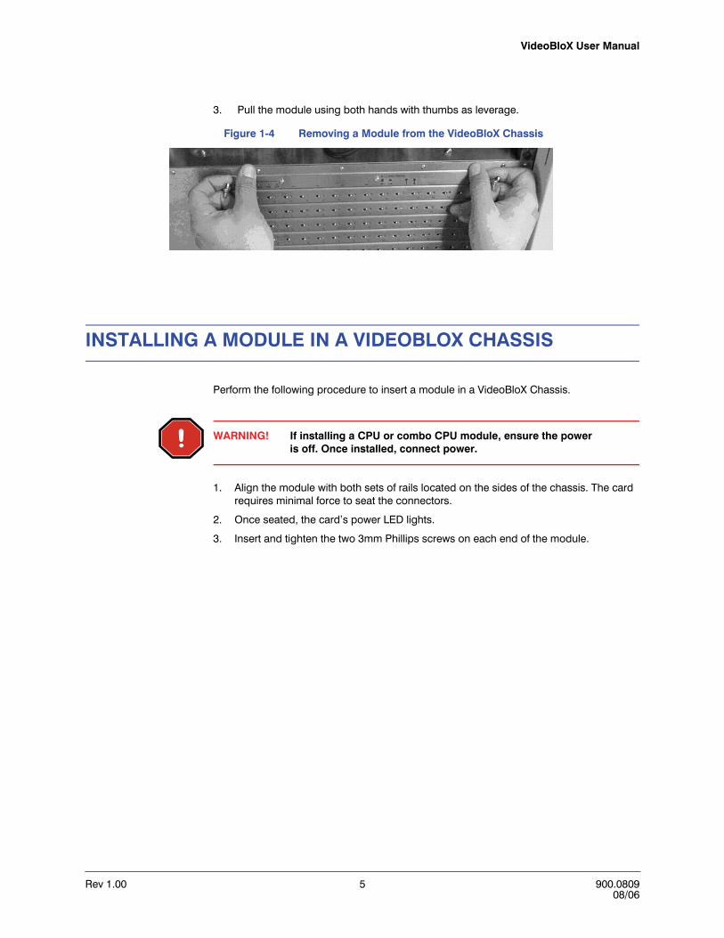
3. Pull the module using both hands with thumbs as leverage.
Figure 1-4 Removing a Module from the VideoBloX Chassis
INSTALLING A MODULE IN A VIDEOBLOX CHASSIS
Perform the following procedure to insert a module in a VideoBloX Chassis.
WARNING! If installing a CPU or combo CPU module, ensure the power is off. Once installed, connect power.
1. Align the module with both sets of rails located on the sides of the chassis. The card requires minimal force to seat the connectors.
2. Once seated, the card’s power LED lights.
3. Insert and tighten the two 3mm Phillips screws on each end of the module.

Rev 1.00 6 900.080908/06
INTRODUCTION

Rev 1.00 7 900.080908/06
2
REAR CHASSIS
POWER SUPPLY MODULE
4U, 8U, 12U Chassis
Figure 2-1 Power Supply Module (HVB4U, HVB8U, HVB12U)
The power supply module for the 4U, 8U, and 12U chassis are the same as shown in the illustration to the right for the HVB4U. The power supply module converts the main input power to an unregulated low voltage DC supply. There are two versions of the power supply to provide 115 VAC or 240 VAC 50 / 60 Hz. It is additionally possible to power a VideoBloX chassis from a 18 to 24 VAC or 18 to 24 VDC supply. Power indications are visible from the front of the chassis. The power supply is equipped with the necessary protection and filtering to ensure regulatory compliance. It is possible to bring backup power into a chassis so that operation is not affected by the failure of the main input power supply. The power supply module provides an unregulated DC output to the backplane and each VideoBloX module is equipped with independent voltage / current regulation circuitry. The VideoBloX power supply has adequate capacity to power all modules within a chassis and also a limited number of external control keyboards. The distance between the chassis and the external control keyboard is also a limiting factor.
A system reset push button is accessible from the front panel after removal of a cover plate. The power supply module also incorporates communication drivers, used to interconnect multiple subracks for assembly of large matrices.
BA
CK
PLA
NE
RS
422
EX
PAN
SIO
NC
OM
MS
CO
NTR
OL
CHASSIS SYNC IN
MAINS
DCFUSE
F 3.15A,250V
AC 100-240V~AC 100-240V~60/50 HZ, 1.4A
WARNINGGROUNDED LINE CORD
MUST BE USED
CAUTIONREPLACE DC FUSE WITHSAME TYPE F 3.15, 250V
DC 19-30V
1 1 66
5
9 5
9
VideoBloXHVB4U

Rev 1.00 8 900.080908/06
REAR CHASSIS
2U Chassis
Figure 2-2 Power Supply Module, HVB2U
The power supply module for the 2U chassis provides a 3-position terminal strip for connection to 18-28 VAC or VDC.
WARNING! The HVB2U chassis must be powered by power supply, part number HPTV2402DWP, to be CE compliant.
Note The 2U Chassis (HVB2U) should be powered by 24 VAC derived from a low capacitance-coupling transformer, such as a split bobbin transformer.
BA
CK
PLA
NE
RS
422
EX
PAN
SIO
N
CO
MM
SC
ON
TRO
L
18-2
8VA
C o
r D
C
F 2A,250V
HVB2U
FUSE
VideoBloX User Manual
Rev 1.00 9 900.080908/06
Main Input Power Connection
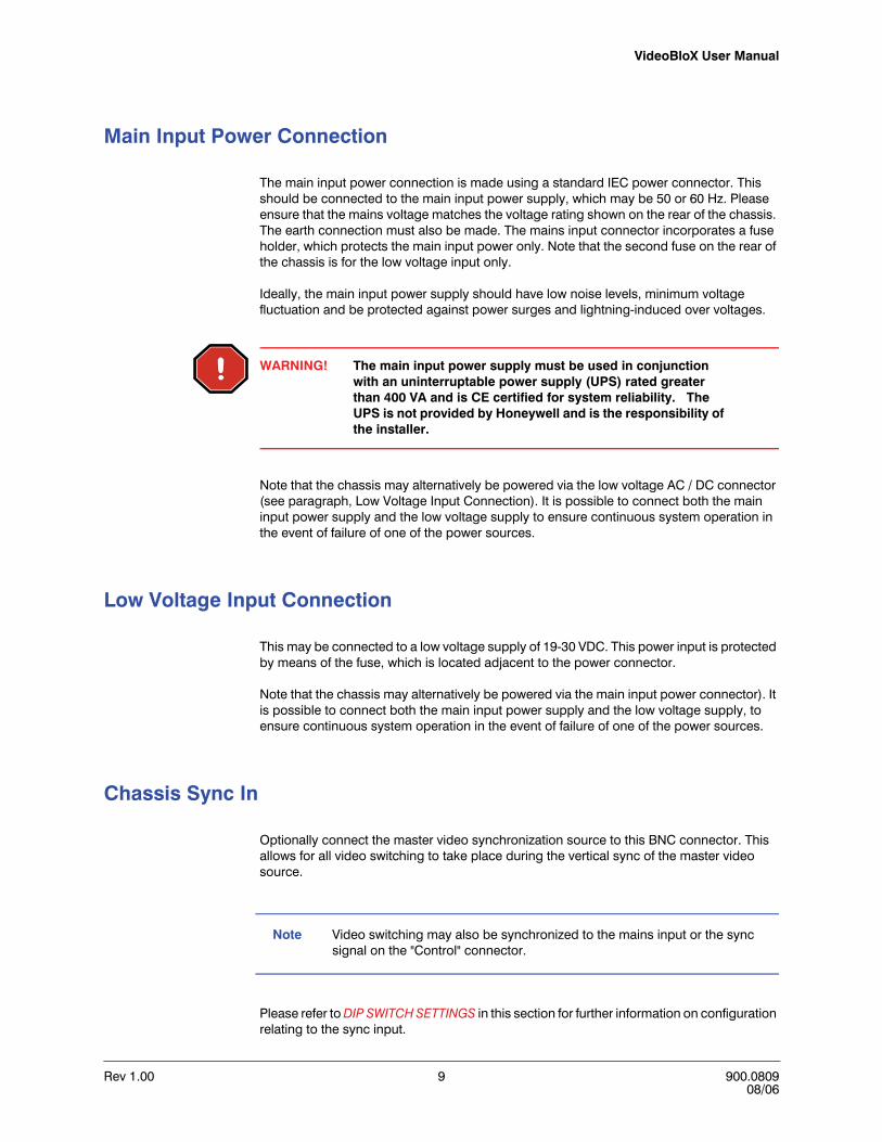
The main input power connection is made using a standard IEC power connector. This should be connected to the main input power supply, which may be 50 or 60 Hz. Please ensure that the mains voltage matches the voltage rating shown on the rear of the chassis. The earth connection must also be made. The mains input connector incorporates a fuse holder, which protects the main input power only. Note that the second fuse on the rear of the chassis is for the low voltage input only.
Ideally, the main input power supply should have low noise levels, minimum voltage fluctuation and be protected against power surges and lightning-induced over voltages.
WARNING! The main input power supply must be used in conjunction with an uninterruptable power supply (UPS) rated greater than 400 VA and is CE certified for system reliability. The UPS is not provided by Honeywell and is the responsibility of the installer.
Note that the chassis may alternatively be powered via the low voltage AC / DC connector (see paragraph, Low Voltage Input Connection). It is possible to connect both the main input power supply and the low voltage supply to ensure continuous system operation in the event of failure of one of the power sources.
Low Voltage Input Connection
This may be connected to a low voltage supply of 19-30 VDC. This power input is protected by means of the fuse, which is located adjacent to the power connector.
Note that the chassis may alternatively be powered via the main input power connector). It is possible to connect both the main input power supply and the low voltage supply, to ensure continuous system operation in the event of failure of one of the power sources.
Chassis Sync In
Optionally connect the master video synchronization source to this BNC connector. This allows for all video switching to take place during the vertical sync of the master video source.
Note Video switching may also be synchronized to the mains input or the sync signal on the "Control" connector.
Please refer to DIP SWITCH SETTINGS in this section for further information on configuration relating to the sync input.

Rev 1.00 10 900.080908/06
REAR CHASSIS
CHASSIS EXPANSION DRIVER BOARD, HVBCE
This PCB plugs in to the power supply module. This board contains the drivers and receivers which are necessary to interconnect master / slave chassis together. This is required when one or more slave chassis are connected to a master chassis. For a system which uses only one chassis, this board is not required.
Installation Procedure:
1. Remove power from chassis.
2. Remove 2X fixing screws which secure the power supply module to the front panel.
3. Remove power supply module from chassis.
4. Line up dual row connector on power supply board with expansion driver board.
5. Carefully press board into place.
6. Fasten board in place with 2 X M3 mounting screws.
7. Insert power supply into chassis, carefully lining up with the chassis connector. Press all the way in.
8. Refasten using 2X fixing screws from Step 2.
Control Expansion Connector
This female DB9 connector allows for connection of RS422 control signals between multiple VideoBloX chassis. The pin-out of this connector is automatically modified depending on the configuration of the chassis being a master or slave. Refer to DIP SWITCH SETTINGS in this section for configuring the chassis as a master or slave. Generally, this connector may be wired pin to pin between one master and multiple slave chassis.
Communications Expansion Connector
This female DB9 connector allows for connection of RS422 serial communications signals between multiple VideoBloX chassis.
The pin-out of this connector is automatically modified depending on configuration for the chassis being a master or slave. Refer to Control Expansion and Communication Connector Pin-Outs for master and slave pin-outs. Generally, this connector may be wired pin-to-pin between one master and multiple slave chassis. Refer to DIP SWITCH SETTINGS for configuring the chassis as a master or slave.

VideoBloX User Manual
Rev 1.00 11 900.080908/06
Control Expansion and Communication Connector Pin-Outs
Throughout the VideoBloX range of products, a common pin-out scheme is used. The communication ports are referred to as Master or Slave, RS422 or RS232. The rear chassis Control and Comm connectors are RS422 connections. Refer to DIP SWITCH SETTINGS below for configuring the chassis as master or slave.
Table 2-1 Connector Pin-Outs, Female DB9
Master RS422 Slave RS422
Pin 1, TX - Pin 1, RX-
Pin 2, TX+ Pin 2, RX+
Pin 3, RX+ Pin 3, TX+
Pin 4, RX - Pin 4, TX-
Pin 5, Ground Pin 5, Ground
Pin 6, 24 VDC Pin 6, 24 VDC
Pin 9, Ground Pin 9, Ground
Rev 1.00 12 900.080908/06
REAR CHASSIS
CONNECTING MULTIPLE CHASSIS
Two Chassis
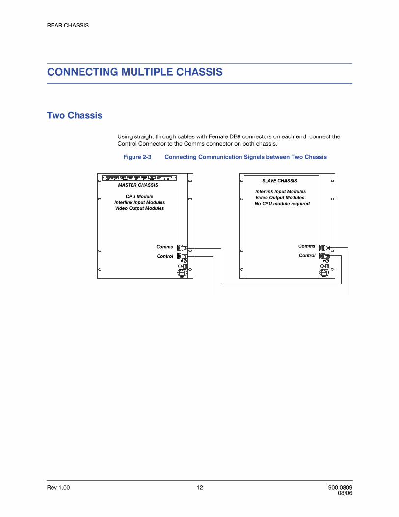
Using straight through cables with Female DB9 connectors on each end, connect the Control Connector to the Comms connector on both chassis.
Figure 2-3 Connecting Communication Signals between Two Chassis
CPU ModuleInterlink Input Modules
Video Output ModulesInterlink Input Modules
No CPU module requiredVideo Output Modules
Control
Comms
Control
Comms
MASTER CHASSISSLAVE CHASSIS

VideoBloX User Manual
Rev 1.00 13 900.080908/06
Three Chassis
Using straight through cables with Female DB9 connectors on each end
1. Connect the Control Connector on the first (master) chassis to the Comms connector on the second chassis (first slave chassis).
2. Connect the Control Connector on the second chassis (first slave chassis) to the Comms connector on the third chassis (second slave chassis).
3. Connect the Control Connector on the third chassis (second slave chassis) to the Comms connector on the first chassis (master chassis).
Figure 2-4 Connecting Communication Signals between Three Chassis
CPU ModuleVideo Input Modules
Interlink Input ModulesVideo Output Modules
Video Input ModulesInterlink Input Modules
No CPU module required
Video Input ModulesInterlink Input Modules
No CPU module required
Control
Comms
Control
Comms
Control
Comms
MASTER CHASSISFIRST SLAVE CHASSIS SECOND SLAVE CHASSIS
Video Output Modules Video Output Modules
Rev 1.00 14 900.080908/06
REAR CHASSIS
DIP SWITCH SETTINGS
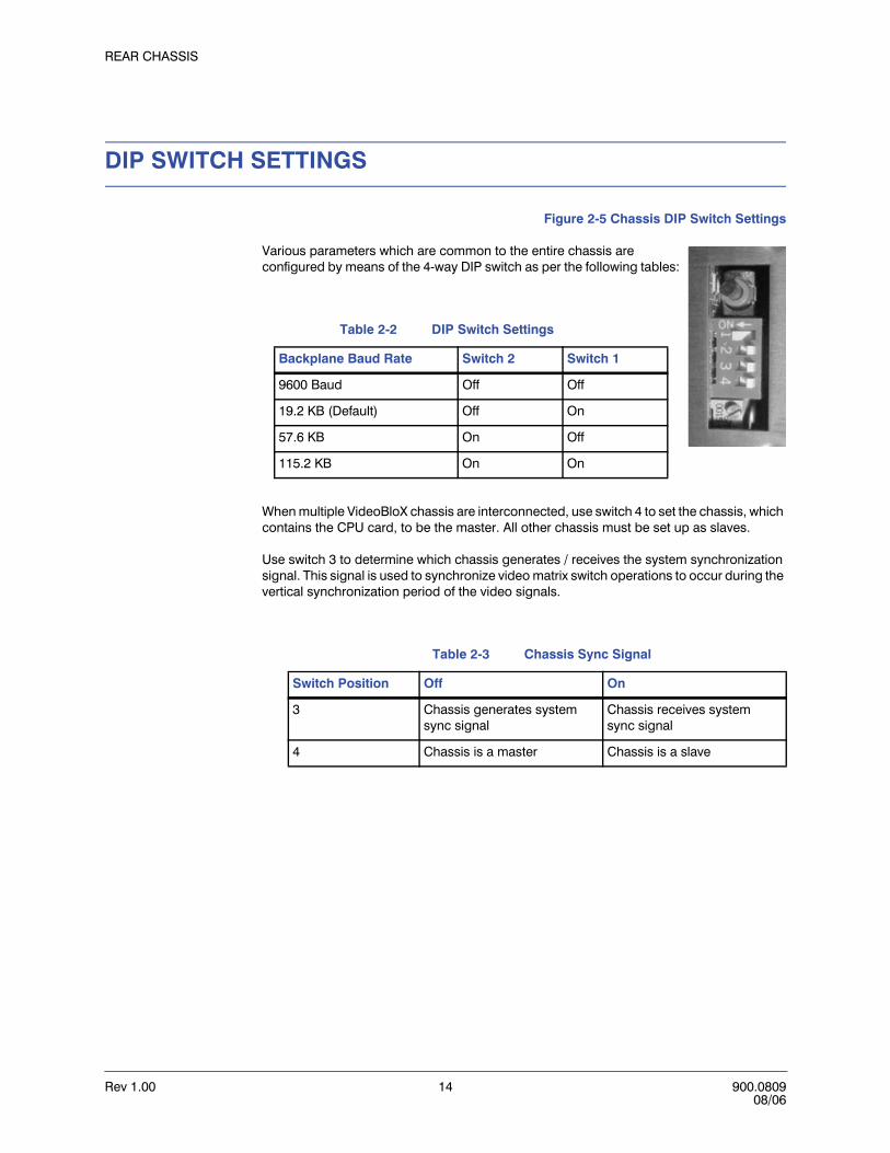
Figure 2-5 Chassis DIP Switch Settings
Various parameters which are common to the entire chassis are configured by means of the 4-way DIP switch as per the following tables:
When multiple VideoBloX chassis are interconnected, use switch 4 to set the chassis, which contains the CPU card, to be the master. All other chassis must be set up as slaves.
Use switch 3 to determine which chassis generates / receives the system synchronization signal. This signal is used to synchronize video matrix switch operations to occur during the vertical synchronization period of the video signals.
Table 2-2 DIP Switch Settings
Backplane Baud Rate Switch 2 Switch 1
9600 Baud Off Off
19.2 KB (Default) Off On
57.6 KB On Off
115.2 KB On On
Table 2-3 Chassis Sync Signal
Switch Position Off On
3 Chassis generates system sync signal
Chassis receives system sync signal
4 Chassis is a master Chassis is a slave

VideoBloX User Manual
Rev 1.00 15 900.080908/06
RESET PUSH BUTTON
Figure 2-6 System Reset Push Button
When this button is pressed, the chassis will be reset. Should the chassis be configured as a master, then all slave chassis will also receive a reset signal.
SYNC PHASE ADJUSTMENT
Figure 2-7 Sync Phase Adjustment
This adjustment determines the sync phase with respect to the mains waveform. When sync is received via the rear panel "Chassis Sync In" BNC or via the "Control" connector, this adjustment will have no effect.
Black ResetPushButton
Sync PhaseAdjustment
Rev 1.00 16 900.080908/06
REAR CHASSIS
LED INDICATIONS
The following table describes the function of each LED on the front panel of the power supply module.
Table 2-4 LED Indicators
LED Name Description
Tx Data Flashes on when there is data present on the backplane transmit data line
Rx Data Flashes on when there is data present on the backplane receive data line
RTS Flashes on when the chassis is transmitting data
Video Sync On when sync input is present
Reset On when the reset signal on the backplane is active
Rev 1.00 17 900.080908/06
3
CPU MODULE
DESCRIPTION
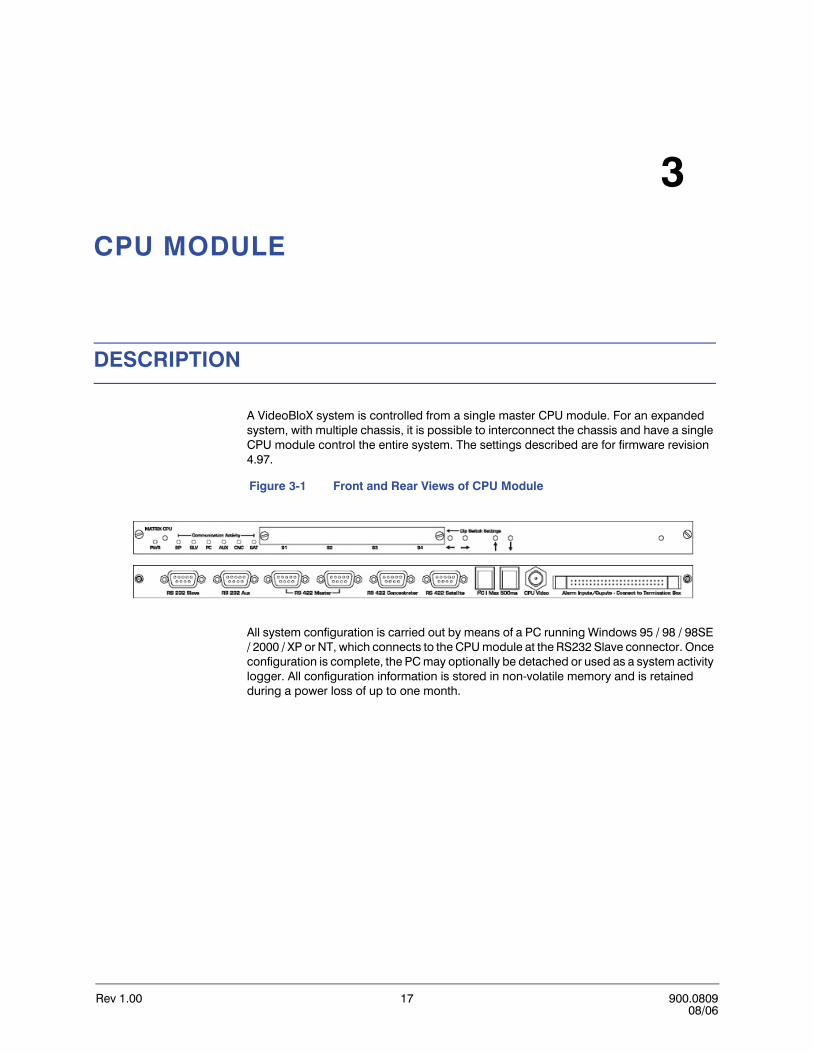
A VideoBloX system is controlled from a single master CPU module. For an expanded system, with multiple chassis, it is possible to interconnect the chassis and have a single CPU module control the entire system. The settings described are for firmware revision 4.97.
Figure 3-1 Front and Rear Views of CPU Module
All system configuration is carried out by means of a PC running Windows 95 / 98 / 98SE / 2000 / XP or NT, which connects to the CPU module at the RS232 Slave connector. Once configuration is complete, the PC may optionally be detached or used as a system activity logger. All configuration information is stored in non-volatile memory and is retained during a power loss of up to one month.

Rev 1.00 18 900.080908/06
CPU MODULE
The CPU module oversees the operation of all modules installed into a chassis or subchassis. The software/operating system is installed into this module. The following hardware subsystems are located within this module:
• High speed processor core• EPROM memory to hold system firmware• Non-volatile RAM memory to store system variables, configuration and downloaded
system code extensions• Watchdog timer and supply voltage monitor to automatically restart system operation
in the event of supply brownouts or software malfunction• Various decoding logic• Power supplies for the CPU module only, including isolated supplies for the two
communication channels which connect to external equipment• Six serial communication channels• 32 Alarm inputs• 4 Alarm relay outputs• DIP switches for COM channel settings
Front panel indications provide basic information relating to the systems overall health and communications activity.
It is possible to install multiple CPU modules into a single chassis. Should this be a requirement, then an additional CPU arbitration module must be installed. The arbitration module reroutes the major CPU communications channels to the configuration PC and the field devices. Should the arbitration module detect a CPU failure, the system can automatically switch over to the backup CPU.
Limited alarm inputs (32) and relay outputs (4) are provided on this module. Inputs and outputs may readily be expanded by the addition of the relevant I2C expansion modules or remote expansion via the RS422 serial communications link. Up to 256 alarm inputs and 256 alarm outputs are supported.
The CPU module has dual processors. Six communications ports provide the following functions:
*Bossware is the native protocol of the VideoBloX system.
Table 3-1 HVBCPU Module Ports
Port Type Description
Master (Female DB9) RS422 Two (2) ports to connect to keyboards, PIT and PTZ using Honeywell Bossware* protocol
Slave (Male DB9) Isolated RS232 Connects to PC for configuration, Operator's GUI and logging.
Aux (Male DB9) Isolated RS232 Connects to 3rd party equipment such as access control to allow for matrix control
Concentrator (Female DB9)
RS422 Reserved
Satellite (Female DB9) RS422 Connects to remote VideoBloX systems to allow "Networked" systems. A crossover RS422 cable is required when connecting two chassis.
VideoBloX User Manual
Rev 1.00 19 900.080908/06
DIP SWITCH SETTINGS
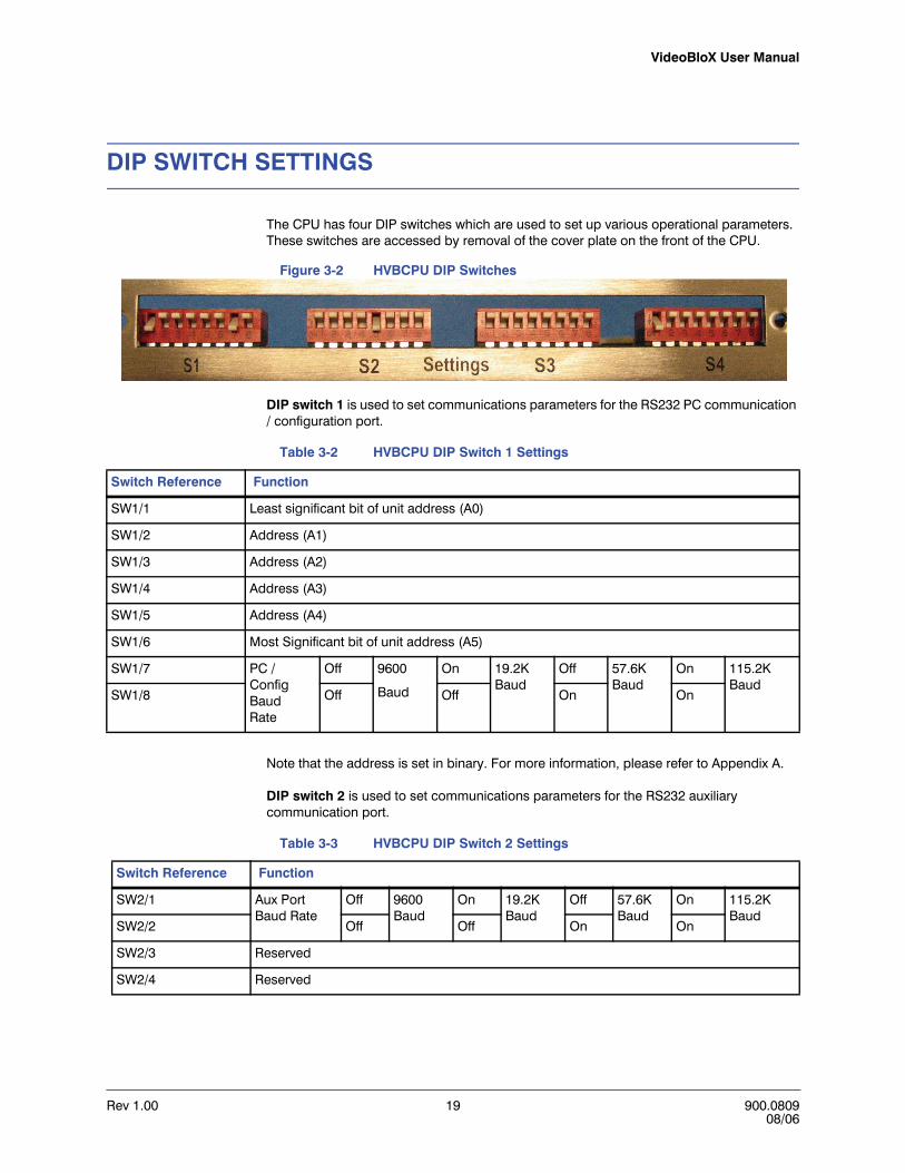
The CPU has four DIP switches which are used to set up various operational parameters. These switches are accessed by removal of the cover plate on the front of the CPU.
Figure 3-2 HVBCPU DIP Switches
DIP switch 1 is used to set communications parameters for the RS232 PC communication / configuration port.
Note that the address is set in binary. For more information, please refer to Appendix A.
DIP switch 2 is used to set communications parameters for the RS232 auxiliary communication port.
Table 3-2 HVBCPU DIP Switch 1 Settings
Switch Reference Function
SW1/1 Least significant bit of unit address (A0)
SW1/2 Address (A1)
SW1/3 Address (A2)
SW1/4 Address (A3)
SW1/5 Address (A4)
SW1/6 Most Significant bit of unit address (A5)
SW1/7 PC / Config Baud Rate
Off 9600
Baud
On 19.2K Baud
Off 57.6K Baud
On 115.2K Baud
SW1/8 Off Off On On
Table 3-3 HVBCPU DIP Switch 2 Settings
Switch Reference Function
SW2/1 Aux Port Baud Rate
Off 9600 Baud
On 19.2K Baud
Off 57.6K Baud
On 115.2K Baud
SW2/2 Off Off On On
SW2/3 Reserved
SW2/4 Reserved

Rev 1.00 20 900.080908/06
CPU MODULE
DIP Switch 3 is used to set communications parameters for the RS422 satellite communication port and the RS422 concentrator port PC communication/configuration port.
DIP switch 4 is used to set various parameters relating to the operation of the system as per the following table.
SW2/5 BossWare Baud Rate
Off 9600 Baud
On 19.2K Baud
Off 57.6K Baud
On 115.2K Baud
SW2/6 Off Off On On
SW2/7 Reserved
SW2/8 Reserved
Table 3-3 HVBCPU DIP Switch 2 Settings
Switch Reference Function
Table 3-4 HVBCPU DIP Switch 3 Settings
Switch Reference Function
SW3/1 Satellite Baud Rate
Off 9600 Baud
On 19.2K Baud
Off 57.6K Baud
On 115.2K Baud
SW3/2 Off Off On On
SW3/3 Reserved
SW3/4 Reserved
SW3/5 Concen-tratrator Baud Rate
Off 9600 Baud
On 19.2K Baud
Off 57.6K Baud
On 115.2K Baud
SW3/6 Off Off On On
SW3/7 Reserved
SW3/8 Reserved
Table 3-5 HVBCPU DIP Switch 4 Settings
Switch Reference Function
SW4/1 Off=>Skip channel on video loss On => include channel on video loss
SW4/2 Off=>Title on Input (Camera 1 title is on all cameras.
On=> Title on Output (Individual camera title displayed)
SW4/3 Video Loss Source
Off Input Card
On MVT Titler
Off Con-cen-trator
On Ignore
SW4/4 Off Off On On
SW4/5 On=>Read back PTZ position (PTZ DC2000 only)
SW4/6 On=>Warn user if duplicate view is selected
SW4/7 Reserved
SW4/8 On=>Local matrix switch for Satellite configuration (i.e. only PTZ control is via satellite)

VideoBloX User Manual
Rev 1.00 21 900.080908/06
PUSH BUTTONS
During normal operation, the front panel push buttons are used to select various diagnostic information display. The diagnostic menus are outputted on the CPU Video BNC connector
Figure 3-3 HVBCPU Push Buttons
Restore Factory Defaults
While powering up the chassis, press the left and right push buttons simultaneously to restore factory defaults.
Caution All user configuration settings will be lost except titles.
Table 3-6 HVBCPU Push Buttons
Push Button Button Function
Left Select previous diagnostic parameter
Right Select next diagnostic parameter
Up Select previous diagnostic screen
Down Select next diagnostic screen
Diagnostics
Rev 1.00 22 900.080908/06
CPU MODULE
LED INDICATORS
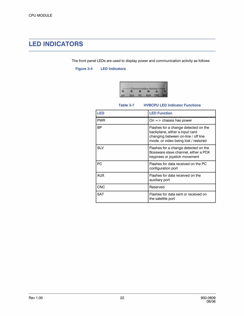
The front panel LEDs are used to display power and communication activity as follows
Figure 3-4 LED Indicators
Table 3-7 HVBCPU LED Indicator Functions
LED LED Function
PWR On => chassis has power
BP Flashes for a change detected on the backplane, either a input card changing between on-line / off line mode, or video being lost / restored
SLV Flashes for a change detected on the Bossware slave channel, either a PCK keypress or joystick movement
PC Flashes for data received on the PC configuration port
AUX Flashes for data received on the auxiliary port
CNC Reserved
SAT Flashes for data sent or received on the satellite port

VideoBloX User Manual
Rev 1.00 23 900.080908/06
ADJUSTMENTS
Display Width Adjustment (C3)
Figure 3-5 Display Width Adjustment
This adjustment is used to set the horizontal width of the diagnostic video display output.
Display Color Burst Frequency Adjustment (C5)
Figure 3-6 Display Color Burst Frequency Adjustment
This adjustment is used to set the frequency of the color burst of the diagnostic video display output. It should be set so that when a color video monitor is connected, the diagnostic screen is shown in color. Adjustment is carried out by determining the positions where the color information is lost and then setting the trimmer to midway between these two positions.

Rev 1.00 24 900.080908/06
CPU MODULE
Jumper Settings
JP 3,4 and 5 are used to select alternate communications channels on the backplane. Note that these will generally be set for the primary communications channel and will only be changed when specialized software is installed which uses the secondary communications channel.
Figure 3-7 Jumper JP3, JP4, JP5 Settings
Jumper P8 is used to define the video format (NTSC or PAL) of the CPU module.
Figure 3-8 Jumper P8 Settings
Note that to change the video mode, it is necessary to change crystal Y1.

VideoBloX User Manual
Rev 1.00 25 900.080908/06
Toggle Switch SW1
Toggle switch SW1 is no longer populated on the HVBCPU board. If you have an older version of the CPU module with this switch populated and are using the an arbitration module in your system, refer to the following table for setting SW1. If there is only one CPU module and no arbitration module is installed in the chassis, SW1 should be set to disabled.
Figure 3-9 Toggle Switch SW1 for CPU Selection
FUSES
The CPU card has two (2) PCB mounted fuses, rated at 4A each. These fuses should only blow in the event of a fault on the board. In such an event, the CPU module should be returned to a Honeywell distributor for repair.
Table 3-8 Toggle Switch SW1
Switch Setting Function
CPUA CPU is assigned CPU 1 in the chassis.
Disabled Only CPU in the chassis
CPUB CPU is assigned CPU2 in the chassis.

Rev 1.00 26 900.080908/06
CPU MODULE
CONNECTIONS
Refer to Appendix B of this manual for sample system block diagrams.
RS422 Communication Ports (Master and Satellite)
All RS422 communications ports use the following pin-outs:
RS232 Communication Ports (Slave and AUX)
All RS232 communications ports use the following pin-outs:
Table 3-9 HVBCPU RS422 Communication Port Pin-Outs
Pin Master Mode Slave Mode
1 RS422 TX[-] RS422 RX[-]
2 RS422 TX[+] RS422 RX[+]
3 RS422 RX[+] RS422 TX[+]
4 RS422 RX[-] RS422 TX[-]
5 RS422 common RS422 common
6 Auxiliary power common Auxiliary power common
7 Transmit Indicator TX[+] Transmit Indicator RX[+]
8 Transmit Indicator TX[-] Transmit Indicator RX[-]
9 Auxiliary power +ve Auxiliary power +ve
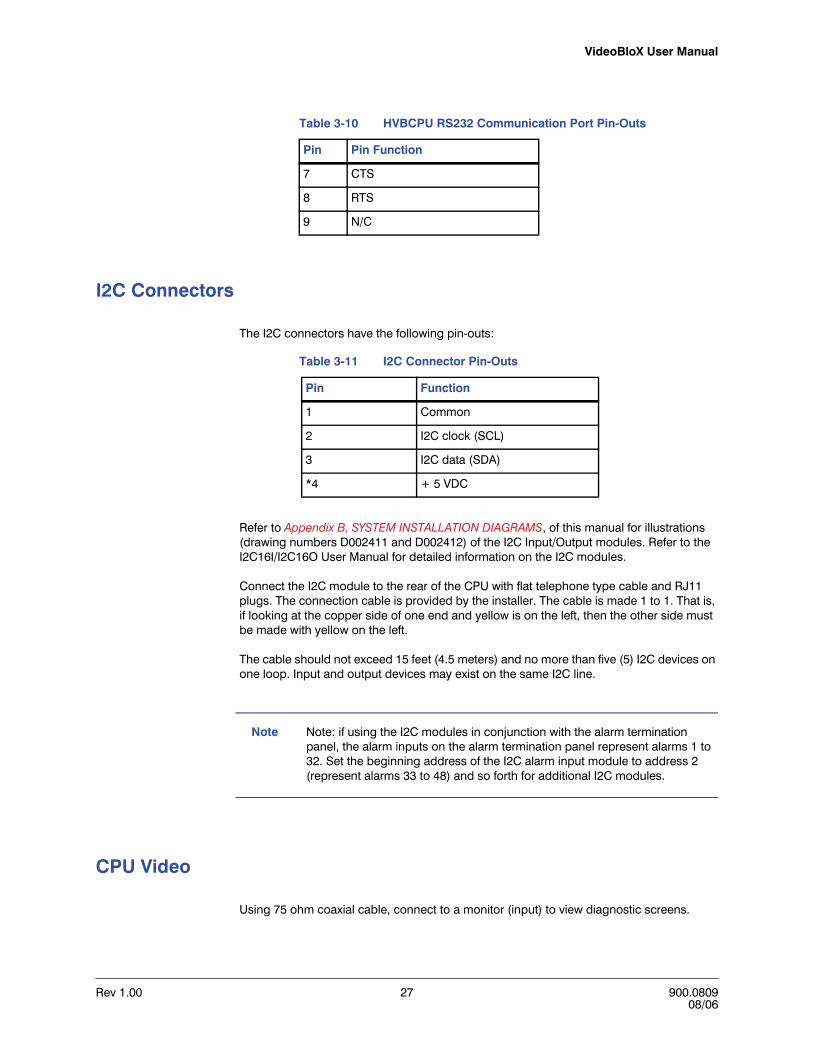
Table 3-10 HVBCPU RS232 Communication Port Pin-Outs
Pin Pin Function
1 N/C
2 TXD
3 RXD
4 N/C
5 RS232 common
6 N/C
VideoBloX User Manual
Rev 1.00 27 900.080908/06
I2C Connectors
The I2C connectors have the following pin-outs:
Refer to Appendix B, SYSTEM INSTALLATION DIAGRAMS, of this manual for illustrations (drawing numbers D002411 and D002412) of the I2C Input/Output modules. Refer to the I2C16I/I2C16O User Manual for detailed information on the I2C modules.
Connect the I2C module to the rear of the CPU with flat telephone type cable and RJ11 plugs. The connection cable is provided by the installer. The cable is made 1 to 1. That is, if looking at the copper side of one end and yellow is on the left, then the other side must be made with yellow on the left.
The cable should not exceed 15 feet (4.5 meters) and no more than five (5) I2C devices on one loop. Input and output devices may exist on the same I2C line.
Note Note: if using the I2C modules in conjunction with the alarm termination panel, the alarm inputs on the alarm termination panel represent alarms 1 to 32. Set the beginning address of the I2C alarm input module to address 2 (represent alarms 33 to 48) and so forth for additional I2C modules.
CPU Video
Using 75 ohm coaxial cable, connect to a monitor (input) to view diagnostic screens.
7 CTS
8 RTS
9 N/C
Table 3-10 HVBCPU RS232 Communication Port Pin-Outs
Pin Pin Function
Table 3-11 I2C Connector Pin-Outs
Pin Function
1 Common
2 I2C clock (SCL)
3 I2C data (SDA)
*4 + 5 VDC
Rev 1.00 28 900.080908/06
CPU MODULE
Alarm Inputs/Outputs
1. Connect the ribbon cable provided between the Alarm Inputs/Outputs Connector on the CPU Module and the Connector (Connect to CPU Alarm Inputs/Outputs Connector) on the Alarm Terminal Block.
2. Connect the Alarm Inputs to the terminal block.
3. Connect the Alarm Outputs to the terminal block.
Refer to Appendix B, Alarm Terminal Panel, Drawing number D002414 for an illustration of connecting alarm inputs/outputs to the termination panel.
Rev 1.00 29 900.080908/06
4
COMBO CPU MODULE
DESCRIPTION
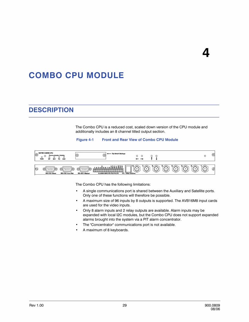
The Combo CPU is a reduced cost, scaled down version of the CPU module and additionally includes an 8 channel titled output section.
Figure 4-1 Front and Rear View of Combo CPU Module
The Combo CPU has the following limitations:
• A single communications port is shared between the Auxiliary and Satellite ports. Only one of these functions will therefore be possible.
• A maximum size of 96 inputs by 8 outputs is supported. The AVB16M8 input cards are used for the video inputs.
• Only 8 alarm inputs and 2 relay outputs are available. Alarm inputs may be expanded with local I2C modules, but the Combo CPU does not support expanded alarms brought into the system via a PIT alarm concentrator.
• The "Concentrator" communications port is not available.• A maximum of 8 keyboards.
Rev 1.00 30 900.080908/06
COMBO CPU MODULE
DIP SWITCH SETTINGS
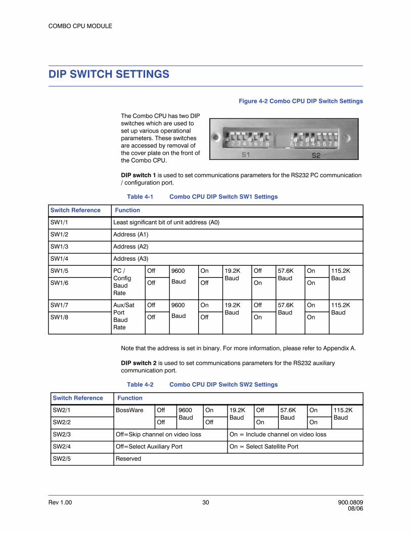
Figure 4-2 Combo CPU DIP Switch Settings
The Combo CPU has two DIP switches which are used to set up various operational parameters. These switches are accessed by removal of the cover plate on the front of the Combo CPU.
DIP switch 1 is used to set communications parameters for the RS232 PC communication / configuration port.
Note that the address is set in binary. For more information, please refer to Appendix A.
DIP switch 2 is used to set communications parameters for the RS232 auxiliary communication port.
Table 4-1 Combo CPU DIP Switch SW1 Settings
Switch Reference Function
SW1/1 Least significant bit of unit address (A0)
SW1/2 Address (A1)
SW1/3 Address (A2)
SW1/4 Address (A3)
SW1/5 PC / Config Baud Rate
Off 9600
Baud
On 19.2K Baud
Off 57.6K Baud
On 115.2K Baud
SW1/6 Off Off On On
SW1/7 Aux/Sat Port Baud Rate
Off 9600
Baud
On 19.2K Baud
Off 57.6K Baud
On 115.2K Baud
SW1/8 Off Off On On
Table 4-2 Combo CPU DIP Switch SW2 Settings
Switch Reference Function
SW2/1 BossWare Off 9600 Baud
On 19.2K Baud
Off 57.6K Baud
On 115.2K Baud
SW2/2 Off Off On On
SW2/3 Off=Skip channel on video loss On = Include channel on video loss
SW2/4 Off=Select Auxiliary Port On = Select Satellite Port
SW2/5 Reserved
VideoBloX User Manual
Rev 1.00 31 900.080908/06
PUSH BUTTONS
Operation of the Combo CPU front panel pushbuttons is similar to that of the CPU, described in Section 3, Push Buttons. Diagnostic output is shared with Monitor Output 1. A time-out disables the diagnostic feature and returns monitor one to normal operation.
LED INDICATIONS
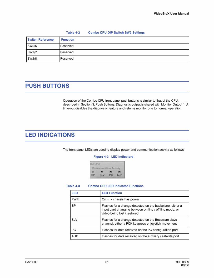
The front panel LEDs are used to display power and communication activity as follows
Figure 4-3 LED Indicators
SW2/6 Reserved
SW2/7 Reserved
SW2/8 Reserved
Table 4-2 Combo CPU DIP Switch SW2 Settings
Switch Reference Function
Table 4-3 Combo CPU LED Indicator Functions
LED LED Function
PWR On => chassis has power
BP Flashes for a change detected on the backplane, either a input card changing between on-line / off line mode, or video being lost / restored
SLV Flashes for a change detected on the Bossware slave channel, either a PCK keypress or joystick movement
PC Flashes for data received on the PC configuration port
AUX Flashes for data received on the auxiliary / satellite port

Rev 1.00 32 900.080908/06
COMBO CPU MODULE
RESTORING FACTORY DEFAULTS
With the Combo CPU out of the rack and disconnected from power,
Figure 4-4 Combo CPU, Restoring Factory Defaults
1. Move jumper JP1 to position 2.
2. Leave JP1 in this position for 10 seconds. This clears the non-volatile memory of the Combo CPU.
3. Return jumper JP1 to position 1.
4. Reinstall the Combo CPU in the rack. When power is applied, the default settings will automatically be loaded.

Rev 1.00 33 900.080908/06
5
VIDEO INPUT MODULES
DESCRIPTION
The video input module brings 16 video signals into the VideoBloX chassis. Each of the inputs may be routed to 1 or more of the 64 backplane channels. All input modules have 16 video inputs, but can be switched to 16, 32, or 64 (maximum) outputs. Older modules have front panel termination switches and some have internal termination jumpers.
VideoBloX input modules are equipped with:
• Their own CPU, switching voltage regulator and fuse. • Older styles have front panel mounted termination switch• Newer styles have an internal termination switch located on the front edge of the
PCB • Front panel accessible gain adjustment (0 to 6db) for each input. This is useful to
restore picture levels for long video runs. Typically a poor signal results in jumping or tearing text. Adjust this potentiometer can eliminate the jumping text. This adjustment can also be useful when the outputs feed a DVR as DVRs are more susceptible to low video levels.
• Internal jumper selectable high frequency compensation to restore lost high frequency signals on long video runs.
• Video Loss detection. Allows triggering of a sequence based on video loss and / or video restored.
• Limited protection against over-voltages, such as those induced by a nearby lightning strike.
• The front panel LED illuminates for power and flicker off briefly when a valid command is sent with the card's address.
.
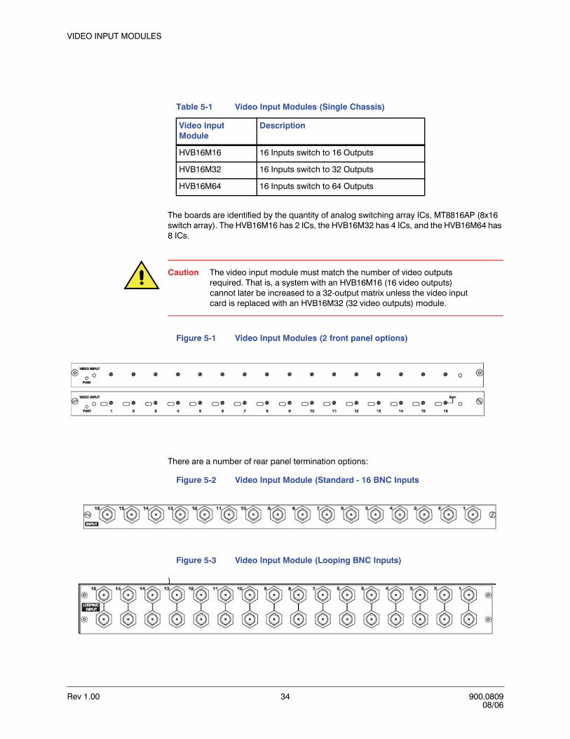
Rev 1.00 34 900.080908/06
VIDEO INPUT MODULES
The boards are identified by the quantity of analog switching array ICs, MT8816AP (8x16 switch array). The HVB16M16 has 2 ICs, the HVB16M32 has 4 ICs, and the HVB16M64 has 8 ICs.
Caution The video input module must match the number of video outputs required. That is, a system with an HVB16M16 (16 video outputs) cannot later be increased to a 32-output matrix unless the video input card is replaced with an HVB16M32 (32 video outputs) module.
Figure 5-1 Video Input Modules (2 front panel options)
There are a number of rear panel termination options:
Figure 5-2 Video Input Module (Standard - 16 BNC Inputs
Figure 5-3 Video Input Module (Looping BNC Inputs)
)
Table 5-1 Video Input Modules (Single Chassis)
Video Input Module
Description
HVB16M16 16 Inputs switch to 16 Outputs
HVB16M32 16 Inputs switch to 32 Outputs
HVB16M64 16 Inputs switch to 64 Outputs

VideoBloX User Manual
Rev 1.00 35 900.080908/06
The looping card allows for looping of video inputs to another matrix switcher chassis or to an external video device, such as a VCR, DVR or multiplexer. Note that if a looping termination card is installed, a blank cover plate will be needed above the input card on the front of the chassis.
Different rear terminations can be used with each input card to alter the connection method to the chassis or card. The standard video input is connected by means of a BNC connector mounted on the rear termination panel.
CROSS LINK VIDEO INPUT MODULES
When a system requires more than 64 video outputs (the maximum allowed in a single rack), cross-looping input rear termination modules may be used. These modules allow for a cross-connection of 8 video inputs from each of the style 'A' and 'C' modules. When connected using coaxial ribbon cables, each chassis receives all 16 video inputs. The 'B' style cross-connection module allows for interconnection of up to 4 VideoBloX chassis.
Figure 5-4 Type A, B and C Cross-Link Looping Input Termination Modules
The following drawings show examples of how the Cross-Link Video Input Modules are installed when more than 64 video outputs are required.
INPUT
8 7 6 5 4 3 2 1
CROSS LINK STYTLE ‘A’ INPUT
LINK 1-16
INPUTCROSS LINK STYTLE ‘B’ INPUT
LOOP OUT LINK 1-16 LOOP OUT LINK 1-16
INPUT
16 15 14 13 12 11 10 9
CROSS LINK STYTLE ‘C’ INPUT

Rev 1.00 36 900.080908/06
VIDEO INPUT MODULES
VideoBloX Switching System with 128 Video Outputs (2 chassis)
Figure 5-5 VideoBloX Matrix Switcher with 128 Video Outputs (2 Chassis)
INPUT
16 15 14 13 12 11 10 9
CROSS LINK STYTLE ‘C’ INPUTINPUT
8 7 6 5 4 3 2 1
CROSS LINK STYTLE ‘A’ INPUT
Chassis #1 (Video Outputs 1-64) Chassis #2 (Video Outputs 64-128)
Video Inputs 1-8 Video Inputs 9-16
HVB16COAXCOAXIAL RIBBON CABLE
LINK 1-16 LINK 1-16
INPUT
16 15 14 13 12 11 10 9
CROSS LINK STYTLE ‘C’ INPUTINPUT
8 7 6 5 4 3 2 1
CROSS LINK STYTLE ‘A’ INPUT
Video Inputs 17-24 Video Inputs 25-32
HVB16COAXCOAXIAL RIBBON CABLE
LINK 1-16 LINK 1-16
INPUT
16 15 14 13 12 11 10 9
CROSS LINK STYTLE ‘C’ INPUTINPUT
8 7 6 5 4 3 2 1
CROSS LINK STYTLE ‘A’ INPUT
Video Inputs 33-40 Video Inputs 41-48
HVB16COAXCOAXIAL RIBBON CABLE
LINK 1-16 LINK 1-16
HVB16M64 and HVB16M64CVideo InputsModulesHVB16M64 and HVB16M64AVideo Inputs Modules

VideoBloX User Manual
Rev 1.00 37 900.080908/06
VideoBloX Switching System with 192 Video Outputs (3 Chassis)
Figure 5-6 VideoBloX Matrix Switcher with 192 Video Outputs (3 Chassis)
INP
UT16
1514
1312
1110
9
CR
OSS
LIN
K S
TY
TLE
‘C’ I
NP
UT
INP
UT
8 7
6 5
4 3
21
CR
OSS
LIN
K S
TY
TLE
‘A’ I
NP
UT
Chas
sis #
1(V
ideo
Out
puts
1-6
4)Ch
assis
#2
(Vid
eo O
utpu
ts 6
5-12
8)
Vide
o In
puts
1-8
Vide
o In
puts
9-1
6
HVB1
6CO
AXCO
AXIA
L RI
BBO
NCA
BLE
LIN
K 1
-16
LIN
K 1
-16
INP
UT16
1514
1312
1110
9
CR
OSS
LIN
K S
TY
TLE
‘C’ I
NP
UT
INP
UT
8 7
6 5
4 3
21
CR
OSS
LIN
K S
TY
TLE
‘A’ I
NP
UT
Vide
o In
puts
17-
24Vi
deo
Inpu
ts 2
5-32
HVB1
6CO
AXCO
AXIA
L RI
BBO
NCA
BLE
LIN
K 1
-16
LIN
K 1
-16
INP
UT16
1514
1312
1110
9
CR
OSS
LIN
K S
TY
TLE
‘C’ I
NP
UT
INP
UT
8 7
6 5
4 3
21
CR
OSS
LIN
K S
TY
TLE
‘A’ I
NP
UT
Vide
o In
puts
33-
40Vi
deo
Inpu
ts 4
1-48
HVB1
6CO
AXCO
AXIA
L RI
BBO
NCA
BLE
LIN
K 1
-16
LIN
K 1
-16
HVB1
6M64
and
HVB
16M
64C
Vide
o In
puts
Mod
ules
HVB1
6M64
and
HVB
16M
64A
Vide
o In
puts
Mod
ules
HVB1
6M64
and
HVB
16M
64B
Vide
o In
puts
Mod
ules
INP
UT
CR
OSS
LIN
K S
TY
TLE
‘B’ I
NP
UT
LOO
P O
UT
LIN
K 1
-16
LOO
P O
UT
LIN
K 1
-16
Chas
sis #
3(V
ideo
Out
puts
129
-192
)
INP
UT
CR
OSS
LIN
K S
TY
TLE
‘B’ I
NP
UT
LOO
P O
UT
LIN
K 1
-16
LOO
P O
UT
LIN
K 1
-16
INP
UT
CR
OSS
LIN
K S
TY
TLE
‘B’ I
NP
UT
LOO
P O
UT
LIN
K 1
-16
LOO
P O
UT
LIN
K 1
-16
HVB1
6CO
AXCO
AXIA
L RI
BBO
NCA
BLE
HVB1
6CO
AXCO
AXIA
L RI
BBO
NCA
BLE
HVB1
6CO
AXCO
AXIA
L RI
BBO
NCA
BLE

Rev 1.00 38 900.080908/06
VIDEO INPUT MODULES
DIP SWITCH SETTINGS
Dependant on the style of input module, DIP switches will be as per one of the following diagrams. Note that the address is set in binary. For more information, please refer to Appendix A.
Figure 5-7 DIP Switches SW1 - SW3
HVB16M16
Tables 5-2 and 5-3 show the DIP switch (SW1 and SW2) settings for the HVB16M16.
Table 5-2 HVB16M16 DIP Switch SW1 Settings
Switch Function
SW1.1 A0
Input Address
SW1.2 A1
SW1.3 A2
SW1.4 A3
SW1.5 A4
SW1.6 A5
SW1.7 A6
SW1.8 A7
Table 5-3 HVB16M16 DIP Switch SW2 Settings
Switch Function
SW2.1 A0 Input Group
AddressSW2.2 A1
SW2.3 A0 Output Group
AddressSW2.4 A1
SW2.5 On Switch 1 to 1

VideoBloX User Manual
Rev 1.00 39 900.080908/06
• DIP Switch S1 (1-8) defines the card address in binary format and is set to represent the camera range. For example, cameras 1-16, set to 1, cameras 17-32, set to 2, etc.
• S2 (1-2) extends the input address range.• S2 (3-4) sets the output range in binary format in groups of 64. • S2 (5) - turn on to cause the module to automatically switch its 16 video inputs to 16
video outputs on power up. In this mode, the address switch determines which group of outputs will be used. This allows for using the modules to make large VDAs, without the need for a CPU.
• S2 (6) - turn on to cause the module to work transparently as a slave to another input module. In this mode, the module does not reply to CPU messages. In this mode, it is possible to have 3 similar matrix switchers, switching RGB video.
• S2 (7) - not used. Reserved for future use.• S2 (8) - allows channel 1 to be used for synchronization (e.g. 2U chassis with DC
power).
HVB16M32 and HVB16M64
Tables 5-4, 5-5. and 5-6 show the DIP switch settings (SW1, SW2, and SW3) for the HVB16M32 and HVB16M64 modules.
SW2.6 On Mute Reply
SW2.7 On Protocol B
SW2.8 On CH1 to Sync
Table 5-3 HVB16M16 DIP Switch SW2 Settings
Switch Function
Table 5-4 HVB16M32 and HVB16M64 DIP Switch SW1 Settings
Switch Function
SW1.1 A0
Input Address
SW1.2 A1
SW1.3 A2
SW1.4 A3
SW1.5 A4
SW1.6 A5
SW1.7 A6
SW1.8 A7

Rev 1.00 40 900.080908/06
VIDEO INPUT MODULES
• DIP Switches S1 (1-8) and S2 (1-3) define the card's address in a binary format and is set to represent the camera range. For cameras 1-16 set the address to 1, cameras 17-32 set to 2, etc.
• DIP Switch S2 (4-8) sets the monitor group in binary format. Example: all off = card is in a chassis for monitors 1-64. S2, 4 on = card is in a chassis for monitors 65-128.
• DIP Switch S3 (1-2) not used, set to off.• DIP Switch S3 (3-5) Only switch 3 has been implemented. When switch 3 is on will
mute reply's back to the CPU. Used for systems that have 2 or more input cards with the same address (e.g. systems with more than 64 outputs)
• S3 (6) is used for testing to switch 16 cameras to the outputs. If the address is 1, cameras 1-16 will be switched to monitors 1-16. If the address is 2, cameras 1-16 will be switched to monitors 17-32, etc.
• S3 (7) is a test mode that will randomly switch cameras to monitors. Used by manufacturing.
• S3 (8) is not used.
Table 5-5 HVB16M32 and HVB16M64 DIP Switch SW2 Settings
Switch Function
SW2.1 A8
Input AddressSW2.2 A9
SW2.3 A10
SW2.4 B0
Output Address
SW2.5 B1
SW2.6 B2
SW2.7 B3
SW2.8 B4
Table 5-6 HVB16M32 and HVB16M64 DIP Switch SW3 Settings
Switch Function
SW3.1 P0Protocol
SW3.2 P1
SW3.3 ON = FUNCTION A
ON = FUNCTION B
ON = FUNCTION B
SW3.4
SW3.5
SW3.6 ON = Switch 1 to 1
SW3.7 ON = Test Mode
SW3.8 No Function
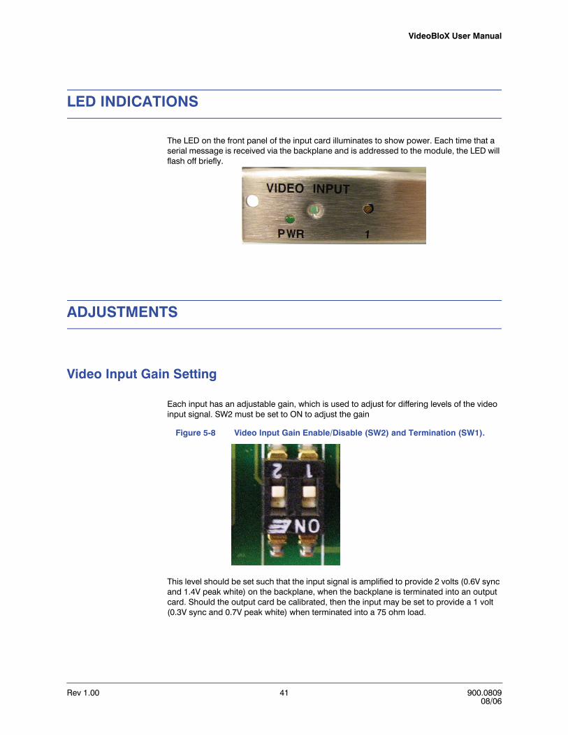
VideoBloX User Manual
Rev 1.00 41 900.080908/06
LED INDICATIONS
The LED on the front panel of the input card illuminates to show power. Each time that a serial message is received via the backplane and is addressed to the module, the LED will flash off briefly.
ADJUSTMENTS
Video Input Gain Setting
Each input has an adjustable gain, which is used to adjust for differing levels of the video input signal. SW2 must be set to ON to adjust the gain
Figure 5-8 Video Input Gain Enable/Disable (SW2) and Termination (SW1).
This level should be set such that the input signal is amplified to provide 2 volts (0.6V sync and 1.4V peak white) on the backplane, when the backplane is terminated into an output card. Should the output card be calibrated, then the input may be set to provide a 1 volt (0.3V sync and 0.7V peak white) when terminated into a 75 ohm load.
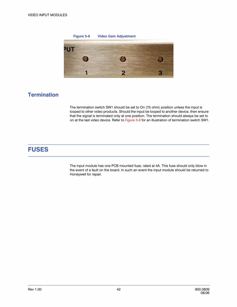
Rev 1.00 42 900.080908/06
VIDEO INPUT MODULES
Figure 5-9 Video Gain Adjustment
Termination
The termination switch SW1 should be set to On (75 ohm) position unless the input is looped to other video products. Should the input be looped to another device, then ensure that the signal is terminated only at one position. The termination should always be set to on at the last video device. Refer to Figure 5-8 for an illustration of termination switch SW1.
FUSES
The input module has one PCB mounted fuse, rated at 4A. This fuse should only blow in the event of a fault on the board. In such an event the input module should be returned to Honeywell for repair.
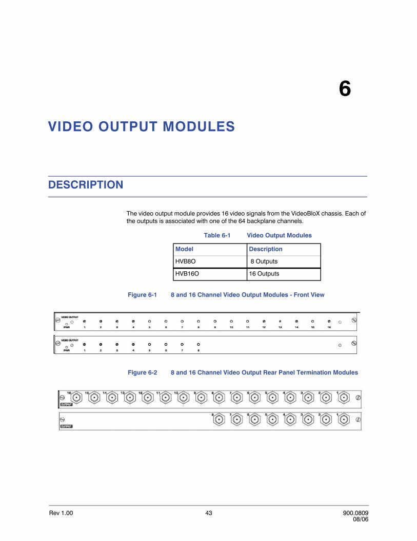
Rev 1.00 43 900.080908/06
6
VIDEO OUTPUT MODULES
DESCRIPTION
The video output module provides 16 video signals from the VideoBloX chassis. Each of the outputs is associated with one of the 64 backplane channels.
Figure 6-1 8 and 16 Channel Video Output Modules - Front View
Figure 6-2 8 and 16 Channel Video Output Rear Panel Termination Modules
Table 6-1 Video Output Modules
Model Description
HVB8O 8 Outputs
HVB16O 16 Outputs

Rev 1.00 44 900.080908/06
VIDEO OUTPUT MODULES
Modules are equipped with:
• Front panel accessible gain adjustment• Limited protection against over-voltages, such as those induced by power surges and
nearby lightning strikes. The output module has a range of jumpers which are populated to determine which group of 16 video outputs the module receives from the backplane.
Caution The user should not modify the jumpers. Output cards should be ordered for specific output channels.
DIP SWITCH SETTINGS
Refer to Chapter 7, TITLED VIDEO OUTPUT MODULE, DIP SWITCH SETTINGS.
VIDEO OUTPUT GAIN ADJUSTMENT
Refer to Chapter 7, TITLED VIDEO OUTPUT MODULE, VIDEO OUTPUT GAIN ADJUSTMENT.
OUTPUT RANGES
The output cards use a daughter board to set the output range (i.e. monitor 1-16 or 17-32, etc.). Refer to the appropriate paragraph in Chapter 7, TITLED VIDEO OUTPUT MODULE, DAUGHTER BOARD SETUP, MODULE BOARD SETTING, VIDEO OUTPUTS 1-64, MODULE BOARD SETTING, VIDEO OUTPUTS 1-16, MODULE BOARD SETTING, VIDEO OUTPUTS 17-32, MODULE BOARD SETTING, VIDEO OUTPUTS 33-48, or MODULE BOARD SETTING, VIDEO OUTPUTS 49-64, for the desired output range and positioning of the daughter board.

Rev 1.00 45 900.080908/06
7
TITLED VIDEO OUTPUT MODULE
DESCRIPTION
The titled video output module provides 16 titled video signals from the VideoBloX chassis. Each of the outputs is associated with one of the 64 backplane channels
Figure 7-1 .Front and Rear Views of Titled Video Output Module
Table 7-1 Titled Video Output Modules
Model Description
HVB8TO 8 Titled Video Outputs
HVB16TO 16 Titled Video Outputs
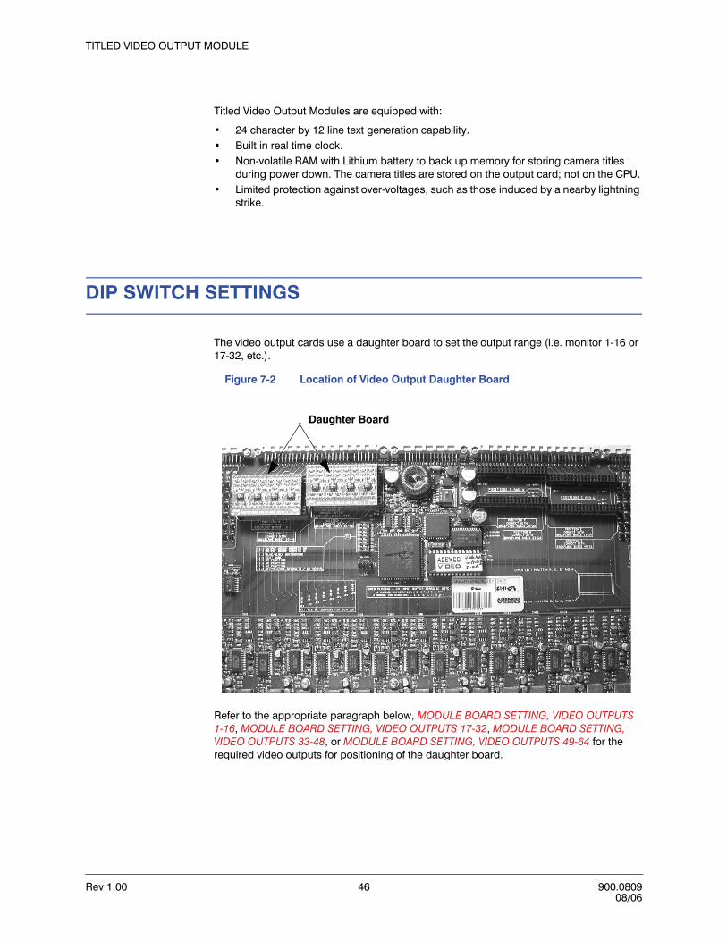
Rev 1.00 46 900.080908/06
TITLED VIDEO OUTPUT MODULE
Titled Video Output Modules are equipped with:
• 24 character by 12 line text generation capability.• Built in real time clock.• Non-volatile RAM with Lithium battery to back up memory for storing camera titles
during power down. The camera titles are stored on the output card; not on the CPU.• Limited protection against over-voltages, such as those induced by a nearby lightning
strike.
DIP SWITCH SETTINGS
The video output cards use a daughter board to set the output range (i.e. monitor 1-16 or 17-32, etc.).
Figure 7-2 Location of Video Output Daughter Board
Refer to the appropriate paragraph below, MODULE BOARD SETTING, VIDEO OUTPUTS 1-16, MODULE BOARD SETTING, VIDEO OUTPUTS 17-32, MODULE BOARD SETTING, VIDEO OUTPUTS 33-48, or MODULE BOARD SETTING, VIDEO OUTPUTS 49-64 for the required video outputs for positioning of the daughter board.
Daughter Board

VideoBloX User Manual
Rev 1.00 47 900.080908/06
Set the Titled Output Module DIP switches as follows:
• S1 (1-2) set the Monitor Group for that output card (e.g. if the card is located in the Monitor group (chassis) of outputs 1-64 then set S1-1 Off and S1-2 Off. If the Monitor Group is 65-128 then set S1-1 On and S1-2 Off and so on in binary count.
• S1 (3) sets the no video screen to blue or black.• S1 (4) places the card in test mode and displays diagnostic info on the output.• S1 (5-7) are not used.• S1 (8) Restores the defaults (clears all titles).
VIDEO OUTPUT GAIN ADJUSTMENT
The default for the output level adjustment is to provide an overall normalized system gain. To set the system for normalized gain, first adjust the input gain as described in Chapter 5, VIDEO INPUT MODULES, Video Input Gain Setting. Then with the output terminated into 75 ohms, adjust the rear panel gain so that the output signal level is the same as the input signal level. Normally either of the methods described could be used. Should it be required to generate a non-standard video signal level, such as boosting the signal to compensate for long cable runs, adjust the gain in order to achieve the desired output signal once the input gain has been adjusted as described.
Table 7-2 DIP Switch S1 Settings
DIP Switch S1
Function
S1.1 Output Group Address A0
S1.2 Output Group Address A1
S1.3 Blue/Black Background
S1.4 Test Mode
S1.5 No Function
S1.6 No Function
S1.7 No Function
S1.8 Off=Restore Defaults On=Normal

Rev 1.00 48 900.080908/06
TITLED VIDEO OUTPUT MODULE
RESTORING FACTORY DEFAULTS
With the output module out of the chassis and disconnected from power,
1. Place DIP switch S1-8 in the Off position.
2. Leave it in the Off position for 10 seconds. This clears the non-volatile memory of the Titled Output module.
3. Return the switch to the ON position.
4. Reinstall the module in chassis. When power is applied to the module, the module defaults to a diagnostic mode and initializes defaults.
5. Perform one of the following to clear the diagnostics:
• Once again, remove the module from the chassis and reinstall it,• Remove power to the chassis and then power it back up while the module is
seated or,• Press the black reset button on the power module cover while the module is
seated
When power is reapplied to the module, the diagnostic mode is cleared.

VideoBloX User Manual
Rev 1.00 49 900.080908/06
DAUGHTER BOARD SETUP
MODULE BOARD SETTING, VIDEO OUTPUTS 1-64
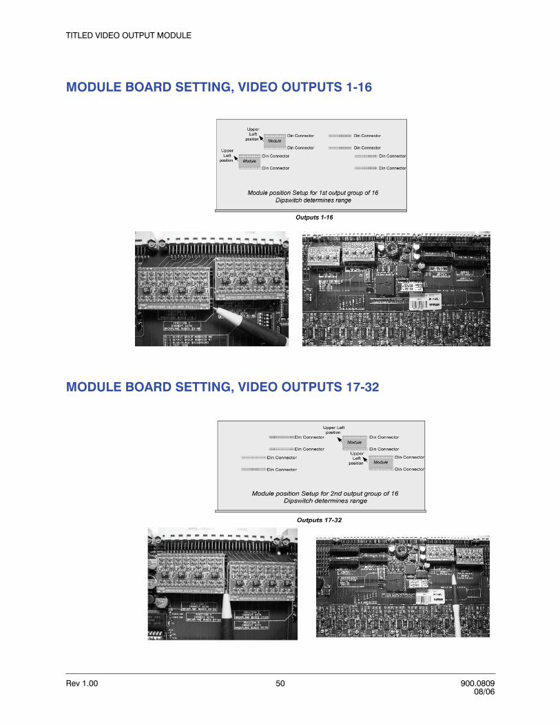
Rev 1.00 50 900.080908/06
TITLED VIDEO OUTPUT MODULE
MODULE BOARD SETTING, VIDEO OUTPUTS 1-16
MODULE BOARD SETTING, VIDEO OUTPUTS 17-32

VideoBloX User Manual
Rev 1.00 51 900.080908/06
MODULE BOARD SETTING, VIDEO OUTPUTS 33-48
MODULE BOARD SETTING, VIDEO OUTPUTS 49-64

Rev 1.00 52 900.080908/06
TITLED VIDEO OUTPUT MODULE

Rev 1.00 53 900.080908/06
8
AUDIO INPUT MODULE
DESCRIPTION
The audio input module brings 16 balanced audio signals into the VideoBloX chassis. Each of the inputs may be routed to 1 or more of the 64 backplane channels.
Figure 8-1 Front and Rear Views of Audio Input Module
VideoBloX audio input modules are equipped with:
• Balanced input capability• Front panel accessible gain adjustment• Front panel signal present and overload (peak) indications• Phantom powering option• 20 dB pad to cater for a wide range of input signal levels.• High pass and low pass filter options
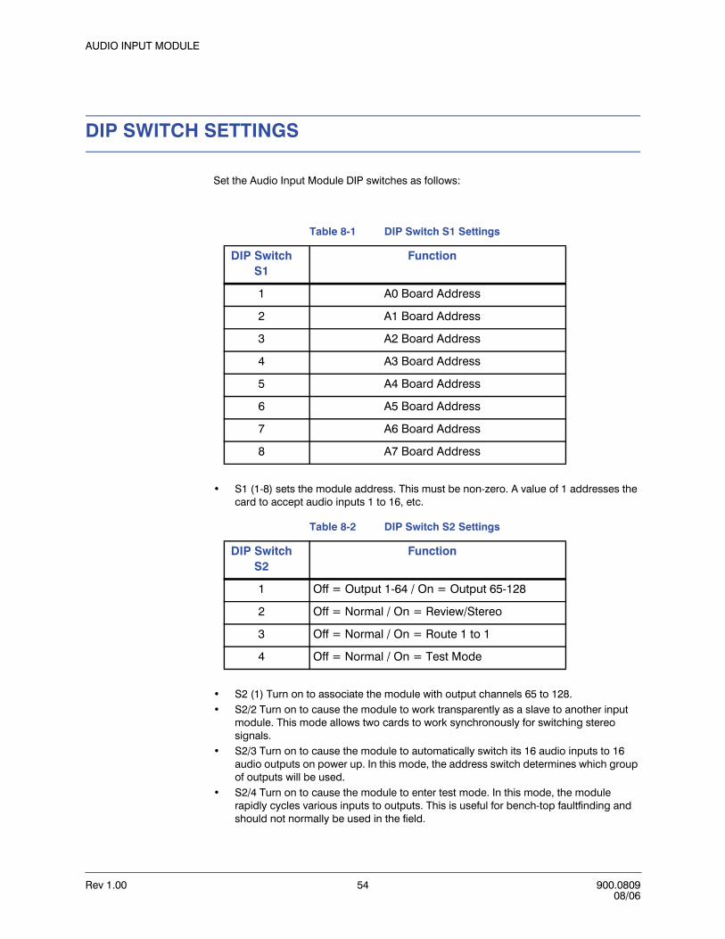
Rev 1.00 54 900.080908/06
AUDIO INPUT MODULE
DIP SWITCH SETTINGS
Set the Audio Input Module DIP switches as follows:
• S1 (1-8) sets the module address. This must be non-zero. A value of 1 addresses the card to accept audio inputs 1 to 16, etc.
• S2 (1) Turn on to associate the module with output channels 65 to 128.• S2/2 Turn on to cause the module to work transparently as a slave to another input
module. This mode allows two cards to work synchronously for switching stereo signals.
• S2/3 Turn on to cause the module to automatically switch its 16 audio inputs to 16 audio outputs on power up. In this mode, the address switch determines which group of outputs will be used.
• S2/4 Turn on to cause the module to enter test mode. In this mode, the module rapidly cycles various inputs to outputs. This is useful for bench-top faultfinding and should not normally be used in the field.
Table 8-1 DIP Switch S1 Settings
DIP Switch S1
Function
1 A0 Board Address
2 A1 Board Address
3 A2 Board Address
4 A3 Board Address
5 A4 Board Address
6 A5 Board Address
7 A6 Board Address
8 A7 Board Address
Table 8-2 DIP Switch S2 Settings
DIP Switch S2
Function
1 Off = Output 1-64 / On = Output 65-128
2 Off = Normal / On = Review/Stereo
3 Off = Normal / On = Route 1 to 1
4 Off = Normal / On = Test Mode
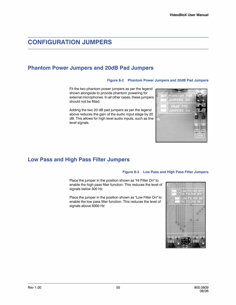
VideoBloX User Manual
Rev 1.00 55 900.080908/06
CONFIGURATION JUMPERS
Phantom Power Jumpers and 20dB Pad Jumpers
Figure 8-2 Phantom Power Jumpers and 20dB Pad Jumpers
Fit the two phantom power jumpers as per the legend shown alongside to provide phantom powering for external microphones. In all other cases, these jumpers should not be fitted.
Adding the two 20 dB pad jumpers as per the legend above reduces the gain of the audio input stage by 20 dB. This allows for high level audio inputs, such as line level signals.
Low Pass and High Pass Filter Jumpers
Figure 8-3 Low Pass and High Pass Filter Jumpers
Place the jumper in the position shown as "Hi Filter On" to enable the high pass filter function. This reduces the level of signals below 300 Hz
Place the jumper in the position shown as "Low Filter On" to enable the low pass filter function. This reduces the level of signals above 6000 Hz

Rev 1.00 56 900.080908/06
AUDIO INPUT MODULE
ADJUSTMENTS
Gain Adjustment
Adjust the front panel gain control to an optimum level for the input source for each channel. This level will result in a bright LED indication for "Signal", with only occasional flashes of the "Peak" LED when the input signal is at the maximum expected level.
CMRR Adjustment
Figure 8-4 CMRR Adjustment
This adjustment sets the common mode rejection for the balanced inputs. It is factory calibrated and should not be adjusted by the user. The optimum level is that where a minimum output signal is obtained when both + and - input signals are driven by the identical signal (inputs shorted).

VideoBloX User Manual
Rev 1.00 57 900.080908/06
CONNECTING A MICROPHONE TO THE AUDIO INPUT MODULE
The following diagram shows how to connect a microphone to the Audio Input Card. Set the phantom power jumpers on the audio input module as described in paragraph Phantom Power Jumpers and 20dB Pad Jumpers
Figure 8-5 Connecting a Microphone to an Audio Input
.

Rev 1.00 58 900.080908/06
AUDIO INPUT MODULE

Rev 1.00 59 900.080908/06
9
AUDIO OUTPUT MODULE
DESCRIPTION
The audio output module provides 16 audio output signals from the VideoBloX chassis. Each of the outputs is associated with one of the 64 backplane channels.
Figure 9-1 Front and Rear Views of 8 and 16 Channel Audio Output Modules
Modules are equipped with:
• Front panel accessible gain adjustment• Balanced (differential) signal output.• Limited protection against over-voltages, such as those induced by a nearby
lightning strike.
The output module has a range of jumpers which are populated to determine which group of 16 audio outputs the module receives from the backplane.
Caution The user should not modify the jumpers. Output cards should be ordered for specific output channels.

Rev 1.00 60 900.080908/06
AUDIO OUTPUT MODULE

Rev 1.00 61 900.080908/06
1010
CHASSIS INTERLINK INPUT AND OUTPUT MODULE
DESCRIPTION
The Chassis Interlink Input and Output Modules allow for multiple chassis to be connected together increasing the number of inputs of a matrix switching system.
Figure 10-1 HVB32LKO Chassis Interlink Output Module with Rear Terminal HVBRJ45X8
Figure 10-2 HVB32LKI Chassis Interlink Input Module with Rear Terminal HVBRJ45X8
Input and Output Interlink modules have the following features:
• 32 input /output channels, allowing for high density interconnects.• Balanced video driver and receivers allow high quality twisted pair connections for
video.
The "Main" chassis of a matrix is that which incorporates the video output modules, which connect to video monitors. All other chassis are "Sub-Racks", which use interlink modules to connect their backplane signals to the main chassis.
CHASSIS INTERLINK29TO32
25TO28
21TO24
17TO20
1TO 4
5TO 8
9TO 12
13TO16
CHASSIS INTERLINK OUTPUT
PWR
CHASSIS INTERLINK29TO32
25TO28
21TO24
17TO20
1TO 4
5TO 8
9TO 12
13TO16
CHASSIS INTERLINK INPUT
PWR

Rev 1.00 62 900.080908/06
CHASSIS INTERLINK INPUT AND OUTPUT MODULE
There are no adjustments / DIP switches on the interlink output module. User configurable jumpers allow this module to be available in two options, channel 1 to 32 and channel 33 to 64. Should a matrix be expanded to more than 64 outputs, these two options are still used and refer to the backplane channels within each subrack. Interlink outputs are connected to interlink inputs in the main chassis by means of cables with RJ45 connectors, each carrying 4 signals.
Figure 10-3 Jumper JP1 - JP4 Settings
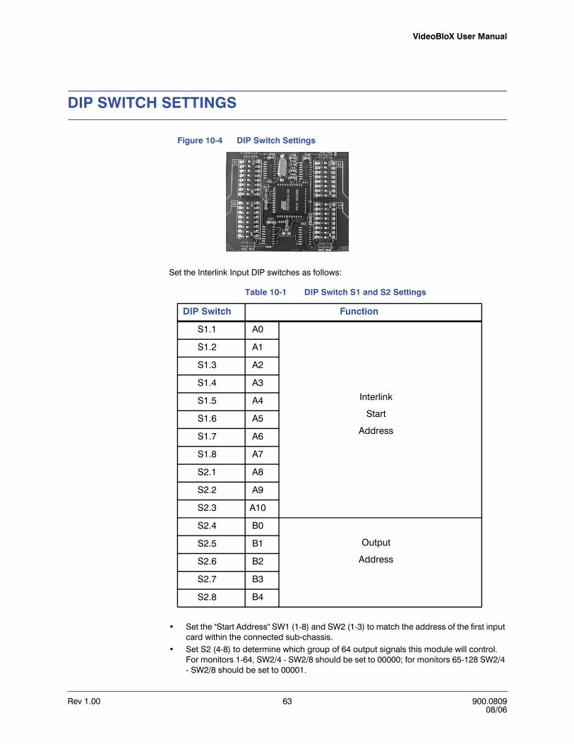
VideoBloX User Manual
Rev 1.00 63 900.080908/06
DIP SWITCH SETTINGS
Figure 10-4 DIP Switch Settings
Set the Interlink Input DIP switches as follows:
• Set the "Start Address" SW1 (1-8) and SW2 (1-3) to match the address of the first input card within the connected sub-chassis.
• Set S2 (4-8) to determine which group of 64 output signals this module will control. For monitors 1-64, SW2/4 - SW2/8 should be set to 00000; for monitors 65-128 SW2/4 - SW2/8 should be set to 00001.
Table 10-1 DIP Switch S1 and S2 Settings
DIP Switch Function
S1.1 A0
Interlink
Start
Address
S1.2 A1
S1.3 A2
S1.4 A3
S1.5 A4
S1.6 A5
S1.7 A6
S1.8 A7
S2.1 A8
S2.2 A9
S2.3 A10
S2.4 B0
Output
Address
S2.5 B1
S2.6 B2
S2.7 B3
S2.8 B4

Rev 1.00 64 900.080908/06
CHASSIS INTERLINK INPUT AND OUTPUT MODULE
• Set the "End Address" SW3 (1-8) and SW4 (1-3) to match the address of the last input card within the connected sub-chassis.
• SW4/4-5 are reserved for future use in selecting protocols.• SW4 (6) is used for testing to switch inputs to the outputs, camera 1 to monitor 1,
camera 2 to monitor 2, camera 15 to monitor 15, etc. • Turn on SW4 (7) to enter test mode. In this mode, the module cycles various inputs to
outputs. This is useful for bench-top fault-finding and should not normally be used in the field.
• SW4 (8) is not used.
Table 10-2 DIP Switch S3 and S4 Settings
DIP Switch Function
S3.1 A0
Interlink
End
Address
S3.2 A1
S3.3 A2
S3.4 A3
S3.5 A4
S3.6 A5
S3.7 A6
S3.8 A7
S4.1 A8
S4.2 A9
S4.3 A10
S4.4 P0
P1Protocol
S4.5
S4.6 Off = Normal / On = Switch 1 to 1
S4.7 Off = Normal / On = Test mode
S4.8 Not Used
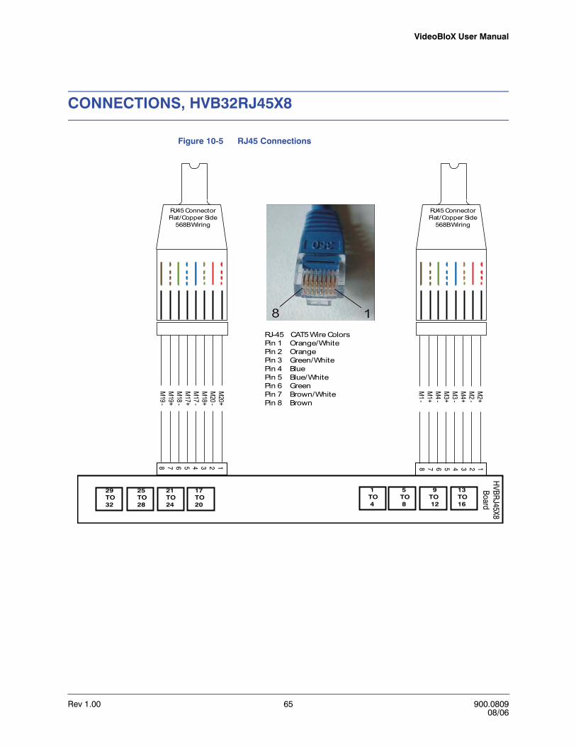
VideoBloX User Manual
Rev 1.00 65 900.080908/06
CONNECTIONS, HVB32RJ45X8
Figure 10-5 RJ45 Connections
1234567812345678
HVBRJ45X8
BoardM
2+M
2 -M
4+M
3 -M
3+M
4 -M
1+M
1 -
M20+
M20 -
M18+
M17 -
M17+
M18 -
M19+
M19 -
RJ45 ConnectorFlat/Copper Side
568BWiring
RJ45 ConnectorFlat/Copper Side
568BWiring
RJ-45 CAT5Wire ColorsPin 1 Orange/WhitePin 2 OrangePin 3 Green/WhitePin 4 BluePin 5 Blue/WhitePin 6 GreenPin 7 Brown/WhitePin 8 Brown
29TO32
25TO28
21TO24
17TO20
1TO 4
5TO 8
9TO 12
13TO16

Rev 1.00 66 900.080908/06
CHASSIS INTERLINK INPUT AND OUTPUT MODULE

Rev 1.00 67 900.080908/06
1111
SECONDARY COMMUNICATIONS EXPANSION MODULE
DESCRIPTION
The Secondary Communications Expansion Module is used to access the secondary backplane communications channel. This channel is generally used when two CPUs are fitted into the same chassis and the second CPU has communications jumpers configured accordingly. Note that this differs from a redundant CPU (as described in section 13) where only one CPU is active at any one time and both CPUs use the same backplane communications channel.
Figure 11-1 Front and Rear View of Secondary Communications Expansion Module
The Secondary Communications Expansion Module has the following features:
• RS232 and/or RS422 communication options.• RS422 / RS232 master or slave connection pin-out.• Capability to connect to backplane communications as a master or slave device.

Rev 1.00 68 900.080908/06
SECONDARY COMMUNICATIONS EXPANSION MODULE
Jumper Settings
RS232 Settings
Figure 11-2 JP1 and JP2 RS232 Jumper Settings
JP1 and JP2 change the pin-out of the RS232 DB9 connector, by swapping the TXD and RXD signals as per the following table.
Pin 1, 4, and 6 are internally connected. Pin 7 and 8 are internally connected.
Table 11-1 JP1 and JP2 Jumper Settings
Pin Slave Master
2 TXD RXD
3 RXD RXD
5 Gnd Gnd

VideoBloX User Manual
Rev 1.00 69 900.080908/06
RS422 Settings
Figure 11-3 JP3 RS422 Jumper Settings
JP3 changes the pinout of the RS422 DB9 connector, by swapping the transmit and receive pairs as per the following table.
Backplane Communication Settings
Set the "BP Connection" to "Master" if the controller is external or to "Slave" if this connection connects to a CPU within the chassis.
Table 11-2 JP3 Jumper Settings
Pin Slave Master
1 RX[-] TX[-]
2 RX[+] TX[+]
3 TX[+] RX[+]
4 TX[-] RX[-]
5 Gnd Gnd
6 +24 VDC +24 VDC
7 RTS[-] RTS[-]
8 RTS[+] RTS[+]
9 Gnd Gnd

Rev 1.00 70 900.080908/06
SECONDARY COMMUNICATIONS EXPANSION MODULE
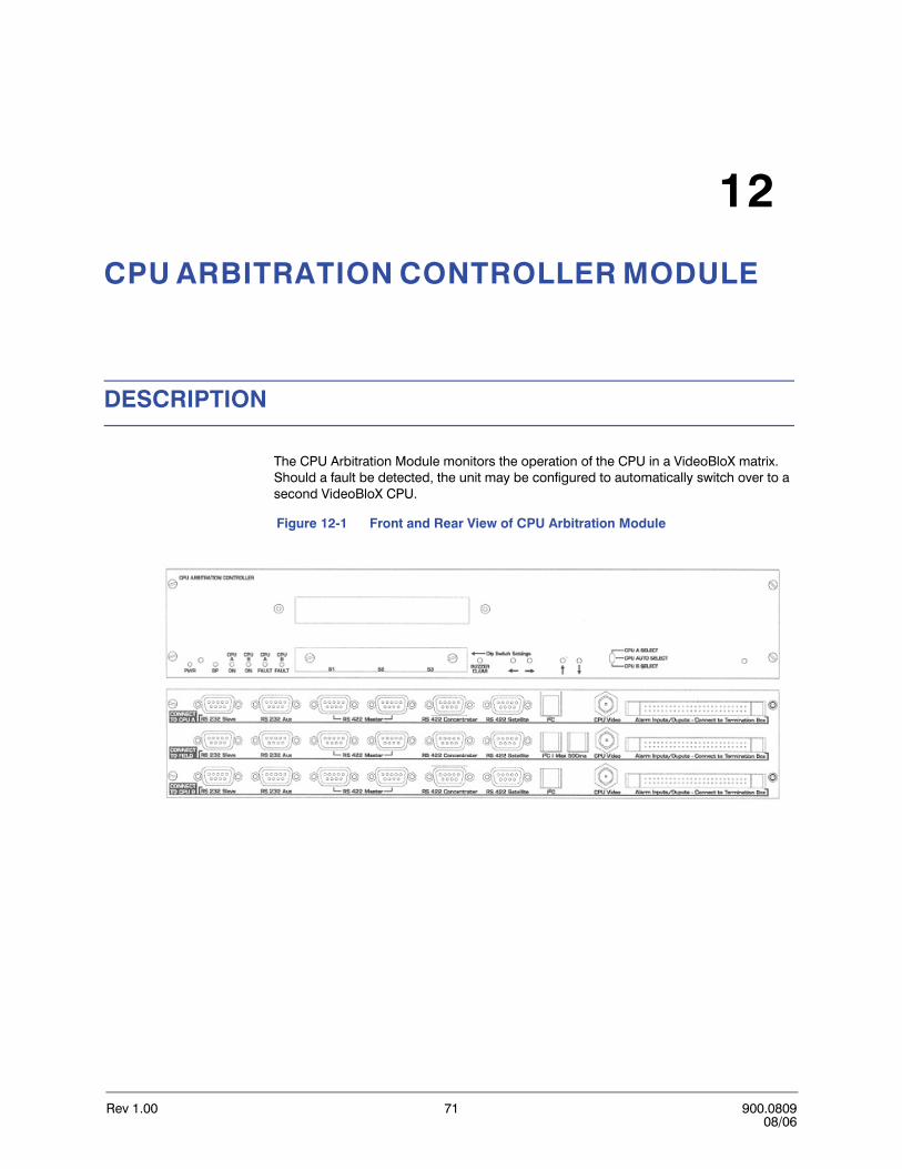
Rev 1.00 71 900.080908/06
1212
CPU ARBITRATION CONTROLLER MODULE
DESCRIPTION
The CPU Arbitration Module monitors the operation of the CPU in a VideoBloX matrix. Should a fault be detected, the unit may be configured to automatically switch over to a second VideoBloX CPU.
Figure 12-1 Front and Rear View of CPU Arbitration Module
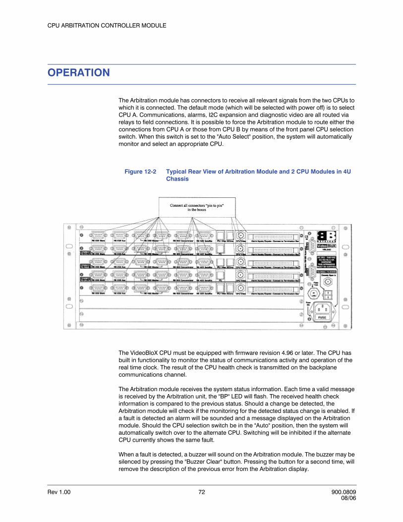
Rev 1.00 72 900.080908/06
CPU ARBITRATION CONTROLLER MODULE
OPERATION
The Arbitration module has connectors to receive all relevant signals from the two CPUs to which it is connected. The default mode (which will be selected with power off) is to select CPU A. Communications, alarms, I2C expansion and diagnostic video are all routed via relays to field connections. It is possible to force the Arbitration module to route either the connections from CPU A or those from CPU B by means of the front panel CPU selection switch. When this switch is set to the "Auto Select" position, the system will automatically monitor and select an appropriate CPU.
Figure 12-2 Typical Rear View of Arbitration Module and 2 CPU Modules in 4U Chassis
The VideoBloX CPU must be equipped with firmware revision 4.96 or later. The CPU has built in functionality to monitor the status of communications activity and operation of the real time clock. The result of the CPU health check is transmitted on the backplane communications channel.
The Arbitration module receives the system status information. Each time a valid message is received by the Arbitration unit, the "BP" LED will flash. The received health check information is compared to the previous status. Should a change be detected, the Arbitration module will check if the monitoring for the detected status change is enabled. If a fault is detected an alarm will be sounded and a message displayed on the Arbitration module. Should the CPU selection switch be in the "Auto" position, then the system will automatically switch over to the alternate CPU. Switching will be inhibited if the alternate CPU currently shows the same fault.
When a fault is detected, a buzzer will sound on the Arbitration module. The buzzer may be silenced by pressing the "Buzzer Clear" button. Pressing the button for a second time, will remove the description of the previous error from the Arbitration display.
VideoBloX User Manual
Rev 1.00 73 900.080908/06
To clear the Arbitration module internal error status, press and hold the "Buzzer Clear" button for 5 seconds.
The active CPU is indicated by illuminating either the "CPU A On" or "CPU B On" LEDs. Should one or more errors be present on a CPU, the associated CPU fault LED will be illuminated.
CONNECTIONS
For a complete description of the functions and pin-outs of the connectors, please refer to Chapter 3, CPU MODULE, CONNECTIONS.
With reference to the above rear view of the arbitration module in a 4U chassis.
• All connections from CPU A are looped into the Arbitration connectors marked "Connect to CPU A".
• All connections from CPU B are looped into the Arbitration connectors marked "Connect to CPU B".
• Connections to field devices are connected to the Arbitration connectors marked "Connect to Field".

Rev 1.00 74 900.080908/06
CPU ARBITRATION CONTROLLER MODULE
SWITCH SETTINGS
DIP switch S1 and S2 select which errors will be monitored by the Arbitration module. When a switch in on, monitoring of the associated operation is enabled.
The remaining DIP switches are currently reserved
Table 12-1 CPU Arbitration Module DIP Switch Settings
Switch S1 or S2 position Monitoring Function
1 Backplane communications
2 Bossware master port communications
3 PC port communications
4 Auxiliary port communications
5 Concentrator port communications
6 Satellite port communications
7 Real time clock
8 Reserved
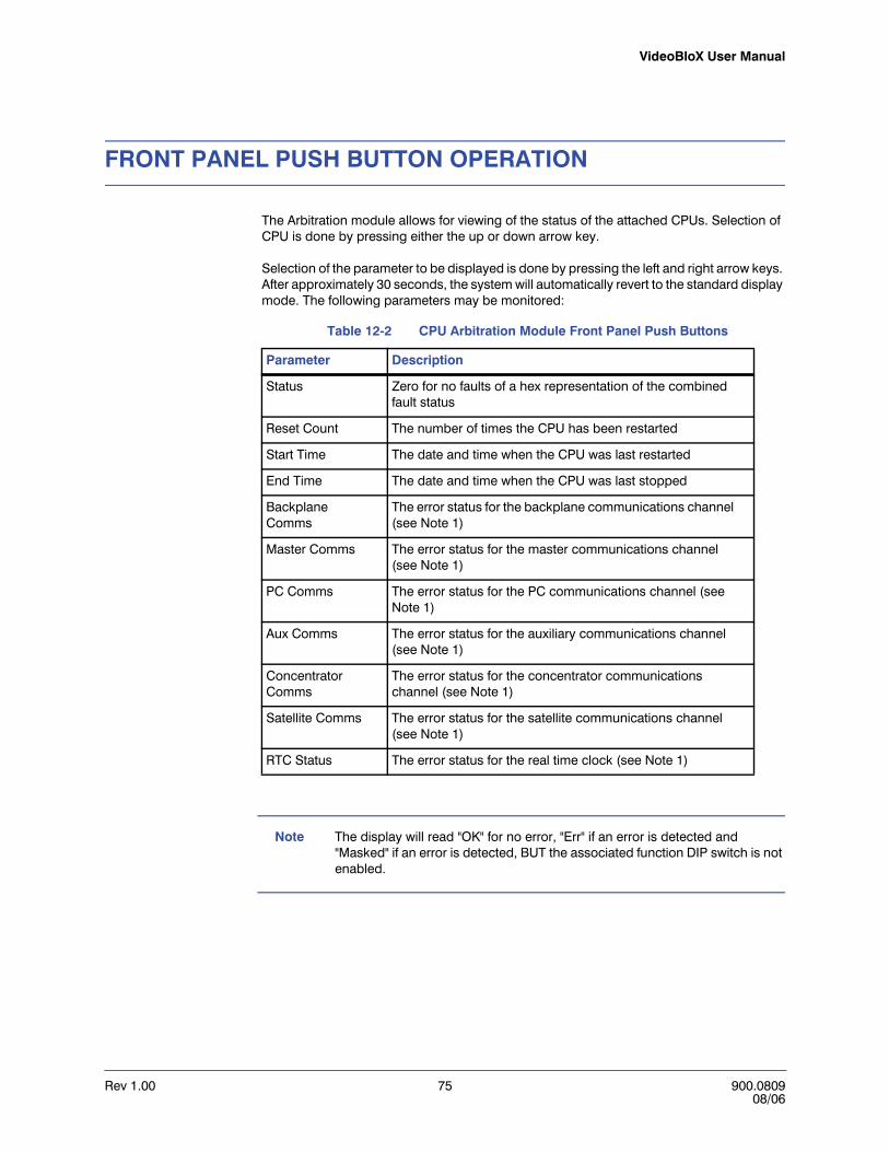
VideoBloX User Manual
Rev 1.00 75 900.080908/06
FRONT PANEL PUSH BUTTON OPERATION
The Arbitration module allows for viewing of the status of the attached CPUs. Selection of CPU is done by pressing either the up or down arrow key.
Selection of the parameter to be displayed is done by pressing the left and right arrow keys. After approximately 30 seconds, the system will automatically revert to the standard display mode. The following parameters may be monitored:
Note The display will read "OK" for no error, "Err" if an error is detected and "Masked" if an error is detected, BUT the associated function DIP switch is not enabled.
Table 12-2 CPU Arbitration Module Front Panel Push Buttons
Parameter Description
Status Zero for no faults of a hex representation of the combined fault status
Reset Count The number of times the CPU has been restarted
Start Time The date and time when the CPU was last restarted
End Time The date and time when the CPU was last stopped
Backplane Comms
The error status for the backplane communications channel (see Note 1)
Master Comms The error status for the master communications channel (see Note 1)
PC Comms The error status for the PC communications channel (see Note 1)
Aux Comms The error status for the auxiliary communications channel (see Note 1)
Concentrator Comms
The error status for the concentrator communications channel (see Note 1)
Satellite Comms The error status for the satellite communications channel (see Note 1)
RTC Status The error status for the real time clock (see Note 1)

Rev 1.00 76 900.080908/06
CPU ARBITRATION CONTROLLER MODULE

Rev 1.00 77 900.080908/06
AAAAA
BINARY ADDRESS VALUESTable A-1 Binary Address Values
A8 A7 A6 A5 A4 A3 A2 A1 Unit Address
Off Off Off Off Off Off Off Off 0-not allowed
Off Off Off Off Off Off Off On 1
Off Off Off Off Off Off On Off 2
Off Off Off Off Off Off On On 3
Off Off Off Off Off On Off Off 4
Off Off Off Off Off On Off On 5
Off Off Off Off Off On On Off 6
Off Off Off Off Off On On On 7

Rev 1.00 78 900.080908/06
BINARY ADDRESS VALUES
Rev 1.00 79 900.080908/06
B
SYSTEM INSTALLATION DIAGRAMS
PURPOSE
This appendix provides installation drawings for connecting peripheral devices to the VideoBloX Matrix Switching System.

Rev 1.00 80 900.080908/06
SYSTEM INSTALLATION DIAGRAMS
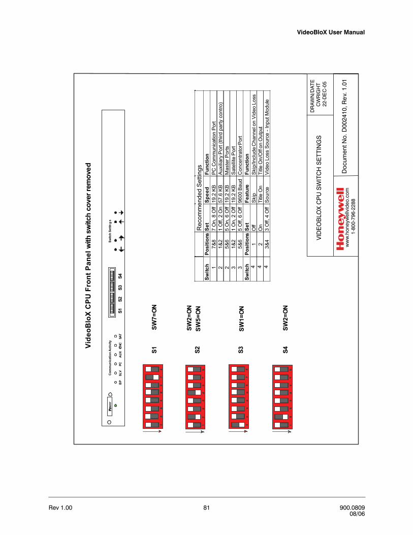
VideoBloX User Manual
Rev 1.00 81 900.080908/06
BP
SLV
PCA
UX
NCSA
T
Com
mun
icat
ion
Act
ivity
wer
Switc
hSe
ttin
gs
S1S2
S4S3
Vide
oBlo
XC
PUFr
ontP
anel
with
switc
hco
verr
emov
ed
Rec
omm
ende
dSe
tting
sSw
itch
Posi
tions
Set
Spee
dFu
nctio
n1
7&8
7O
n,8
Off
19.2
KBPC
Com
mun
icat
ion
Port
21&
21
Off,
2O
n57
.6KB
Aux
iliar
yP
ort(
third
party
cont
ro)
25&
65
On,
6O
ff19
.2KB
Mas
terP
orts
31&
21
On,
2O
ff19
.2KB
Sat
ellit
eP
ort
35&
65
Off,
6O
ff96
00Ba
udC
once
ntra
torP
ort
Switc
hPo
sitio
nsS
etFe
atur
eFu
nctio
n4
1O
ffS
kip
Ski
p/In
clud
eC
hann
elon
Vid
eoLo
ss4
2O
nTi
tleO
nTi
tleO
n/O
ffon
Out
put
43&
43
Off,
4O
ffS
ourc
eVi
deo
Loss
Sour
ce-I
nput
Mod
ule
SW7=
ONS1 S2 S3 S4
SW2=
ONSW
5=ON
SW1=
ON
SW2=
ON
VID
EO
BLO
X C
PU
SW
ITC
H S
ETT
ING
SD
RA
WN
/DA
TEC
WR
IGH
T22
-DE
C-0
5
Doc
umen
t No.
D00
2410
, Re
v. 1
.01
ww
w.h
oney
wel
lvid
eo.c
om
1-80
0-79
6-22
88
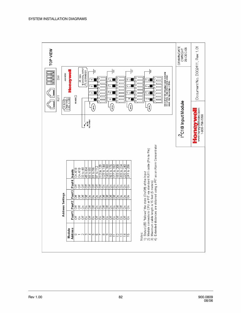
Rev 1.00 82 900.080908/06
SYSTEM INSTALLATION DIAGRAMS

VideoBloX User Manual
Rev 1.00 83 900.080908/06
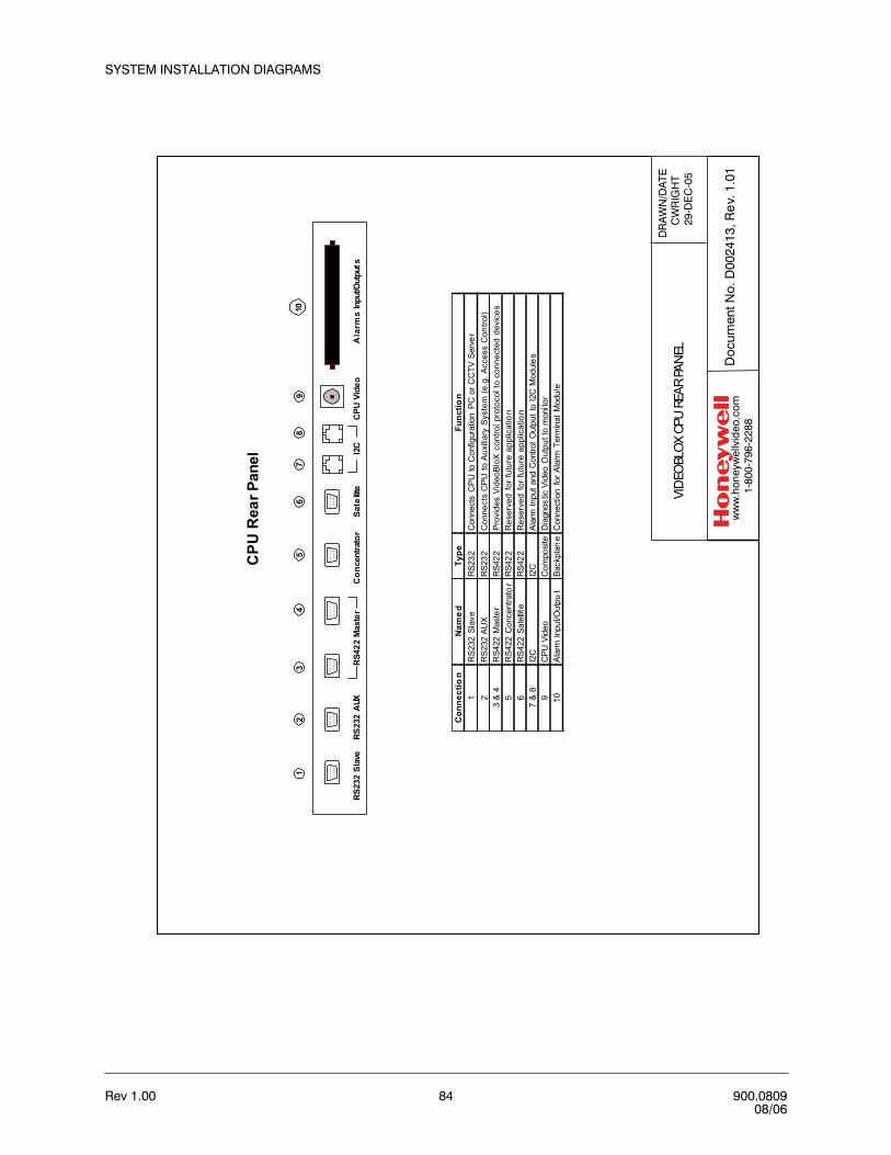
Rev 1.00 84 900.080908/06
SYSTEM INSTALLATION DIAGRAMS
DR
AW
N/D
ATE
CW
RIG
HT
29-D
EC
-05
Doc
umen
t No.
D00
2413
, Re
v. 1
.01
ww
w.h
oney
wel
lvid
eo.c
om
1-80
0-79
6-22
88
CPU
Rea
rPan
el
RS23
2Sl
ave
RS23
2A
UXRS
422
Mas
ter
Con
cent
rato
rSa
tellit
eA
larm
sIn
put/O
utpu
tsI2
CC
PUVi
deo
110
23
45
67
89
Con
nect
ion
Nam
ed
Type
Func
tion
1R
S232
Slav
eR
S232
Con
nect
sC
PUto
Con
figur
atio
nPC
orC
CTV
Serv
er2
RS2
32AU
XR
S232
Con
nect
sC
PU
toA
uxilia
rySy
stem
(e.g
.Acc
ess
Con
trol)
3&
4R
S422
Mas
ter
RS4
22Pr
ovid
esVi
deoB
loX
cont
rolp
roto
colt
oco
nnec
ted
devi
ces
5R
S422
Con
cent
rato
rR
S422
Res
erve
dfo
rfut
ure
appl
icat
ion
6R
S422
Sate
llite
RS4
22R
eser
ved
forf
utur
eap
plic
atio
n7
&8
I2C
I2C
Alar
mIn
puta
ndC
ontro
lOut
putt
oI2
CM
odul
es9
CPU
Vide
oC
ompo
site
Dia
gnos
ticVi
deo
Out
putt
om
onito
r10
Alar
mIn
put/O
utpu
tBa
ckpl
ane
Con
nect
ion
forA
larm
Term
inal
Mod
ule
VID
EOBL
OX C
PU R
EAR
PAN
EL

VideoBloX User Manual
Rev 1.00 85 900.080908/06
DR
AW
N/D
ATE
CW
RIG
HT
29-D
EC
-05
Doc
umen
t No.
D00
2414
, Re
v. 1
.01
ww
w.h
oney
wel
lvid
eo.c
om
1-80
0-79
6-22
88
Typi
calI
nput
NO
/NC
Dry
Cont
act
ALA
RM
TER
MIN
ATI
ON
BO
X
Ala
rmIn
puts
12
34
56
78
910
1112
1314
15
1718
1920
2124
2322
2526
2728
2932
3130
NCNO
CNCNO
OU
T2
CNCNO
OU
T3
CNCNO
OU
T4
C
Rel
ayO
utpu
ts
S
Exte
rnal
Pow
erSu
pply
Con
trol
led
Dev
ice
Not
es:
1)C
onne
ctAT
Pto
CPU
via
ribbo
nca
ble
supp
lied
2)R
elay
Rat
ings
1A
mp
at30
VDC
0.5
Am
pat
24VA
C
3)Al
arm
Inpu
tsar
epu
lled
to5
VDC
by10
Kre
sist
or
Rib
bon
Con
nect
orto
CPU
Ala
rmTe
rmin
atio
n Pa
nel

Rev 1.00 86 900.080908/06
SYSTEM INSTALLATION DIAGRAMS
DR
AW
N/D
ATE
CW
RIG
HT
29-D
EC
-05
Doc
umen
t No.
D00
2415
, Re
v. 1
.01
ww
w.h
oney
wel
lvid
eo.c
om
1-80
0-79
6-22
88
I2C
16O
Loc
al P
ower
OU
TPU
TS
OU
TPU
TS
OU
TPU
TS
OU
TPU
TS
I2 C16
OU
T
+5v
dc
Jum
per
5VD
CLo
wCu
rrent
Devic
e
Inte
rnal
lyPo
wer
edO
utpu
ts
Not
es:
The
I2C
Mod
ule
prov
ides
5VD
Cfo
rcon
nect
edde
vice
s.
1.)I
nsta
llju
mpe
rfro
m5V
DC
onth
epo
wer
term
inal
bloc
kto
the
+te
rmin
alof
any
outp
utpo
int.
2.)C
onne
ctth
eco
ntro
lled
devi
ceto
the
appr
opri
ate
term
inal
s,ob
serv
ing
pola
rity
.
3.)T
heto
talp
ower
avai
labl
eis
100
mA

VideoBloX User Manual
Rev 1.00 87 900.080908/06
DR
AW
N/D
ATE
CW
RIG
HT
29-D
EC
-05
Doc
umen
t No.
D00
2416
, Re
v. 1
.01
ww
w.h
oney
wel
lvid
eo.c
om
1-80
0-79
6-22
88
I2C
16O
Ext
erna
l Pow
er
OU
TPU
TS
OU
TPU
TS
OU
TPU
TS
OU
TPU
TS
I2 C16
OU
TJu
mpe
r
12/2
4/30
VDC
Devic
e
Exte
rnal
lyPo
wer
edO
utpu
ts
+-
Exte
rnal
DC
Pow
erSu
pply
12/2
4/30
VDC
Not
es:
The
Ext
erna
lPow
erS
uppl
yca
nbe
any
DC
supp
ly,
12/2
4or
30V
DC
issh
own.
1.)C
onne
ctth
eE
xter
nalP
ower
Sup
ply
toth
epo
wer
term
inal
bloc
k.Po
sitiv
eco
nnec
tsto
fuse
dte
rmin
al#2
and
nega
tive
conn
ects
togr
ound
term
inal
#4
2.)I
nsta
llju
mpe
rfro
mE
xter
nalV
DC
onth
epo
wer
term
inal
bloc
kto
the
+te
rmin
alof
any
outp
utpo
int.
2.)C
onne
ctth
eco
ntro
lled
devi
ceto
the
appr
opri
ate
term
inal
s,ob
serv
ing
pola
rity
.
3.)T
heto
talp
ower
that
can
bepa
ssed
thro
ugh
the
supp
lyte
rmin
als
is10
Amps
The
Max
imum
pow
erth
atca
nbe
pass
edth
roug
han
ysi
ngle
conn
ectio
nis
8Am
ps

Rev 1.00 88 900.080908/06
SYSTEM INSTALLATION DIAGRAMS
HE
GS
5BL
XV
ideo
Blo
XC
ont
rolle
r
+1
2VD
C
GN
D
RS-
23
2(T
X)R
S-2
32
(RX)
RS
-48
5(D
+)
RS
-48
5(D
-)
+1
2VD
CG
ND
RS-
232
(RX)
RS
-232
(TX
)R
S-4
85(D
+)
RS-
485
(D-)
PS
U1
2VD
C2A
Ho
ney
we
llP
art#
849
193
-008
9
Pa
rt#
140.
0101
RS
232
toR
S42
2C
onve
rter
54
32
1
98
76
Fem
ale
DB
9Fe
mal
eD
B9
RS
232
Pin
3,R
XDP
in2,
TXD
Pin
5,G
ND
V+V-GND - 12
-30
VD
CP
ower
Sup
ply
Par
t#
849
193-
008
9+
TX+
(B)
TX-(
A)
RX+
(B)D
ata
+RX
-(A)
Dat
a-
RTS
+(B
)RT
S-(
A)
CTS
+(B
)C
TS-(
A)
SG
ND
4-W
irew
/Ter
min
ator
RS42
24-
Wire
RS42
2
Vide
oB
loX
CP
UM
odu
le
TX+
toP
in3,
RX+
TX-
toP
in4,
RX-
RX+
toP
in2,
TX+
RX-
toP
in1,
TX-
Par
t#84
9518
-041
96x
6C
ross
over
Cab
le
HV
B23
242
2
12
3
ON
12
3
ON
Not
e:W
hite
Spac
eS
how
sSw
itch
Posi
tion
RS4
22W
ITH
TER
MIN
ATO
RSW
1SW
2S
W3
ON
ON
ON
RS4
22SW
1SW
2S
W3
ON
ON
OFF
``
RS42
2M
aste
r
Con
vert
erC
PU
Mod
ule
Term
inal
Str
ipto
RS
422
Mas
ter
DR
AW
N/D
ATE
CW
RIG
HT
29-D
EC
-05
Doc
umen
tNo.
D00
2417
,Re
v.1.
02
Sing
leH
EGS5
BLX
Key
boar
dto
CPU
ww
w. h
oney
wel
l vi d
eo. c
om
1-80
0-79
6-2 2
88R
evD
ate
1.01
12/0
5R
ebra
nd
1.02
7/06
Rep
lace
PC
Kw
/HE
GS
5BLX
Note
:Par
tnum
berH
EG5B
LXKT
inclu
dest
here
quire
dRS
232
toRS
422
Conv
erte
ran
dtw
o(2
)pow
ersu
pplie
s.

VideoBloX User Manual
Rev 1.00 89 900.080908/06
DR
AW
N/D
ATE
CW
RIG
HT
29-D
EC
-05
Doc
umen
t No.
D00
2418
, Re
v. 1
.02
ww
w.h
oney
wel
lvid
eo.c
om
1-80
0-79
6-22
88
Mul
tiple
Key
boar
ds to
CPU
RS42
2M
aste
r
Loca
lPow
ersu
pply
12to
24VD
Cor 12
to24
VAC
Mas
ter
Cha
nne
lsto
field
devi
ces
Slav
eCh
anne
l
RS42
2Po
rt E
xpan
der
RS23
2to
RS42
2Co
nver
ter
Term
inal
Box
(sup
plie
d w
ithHE
GS5B
LX)
HEGS
5BLX
Cont
rolle
r
RS23
2to
RS42
2Co
nver
ter
Term
inal
Box
(sup
plie
d w
ithHE
GS5B
LX)
HEGS
5BLX
Cont
rolle
r
Rev
D
ate
1.01
12/
05
R
ebra
nd
1.02
7/
06
R
epla
ce P
CK
w/H
EG
S5B
LX
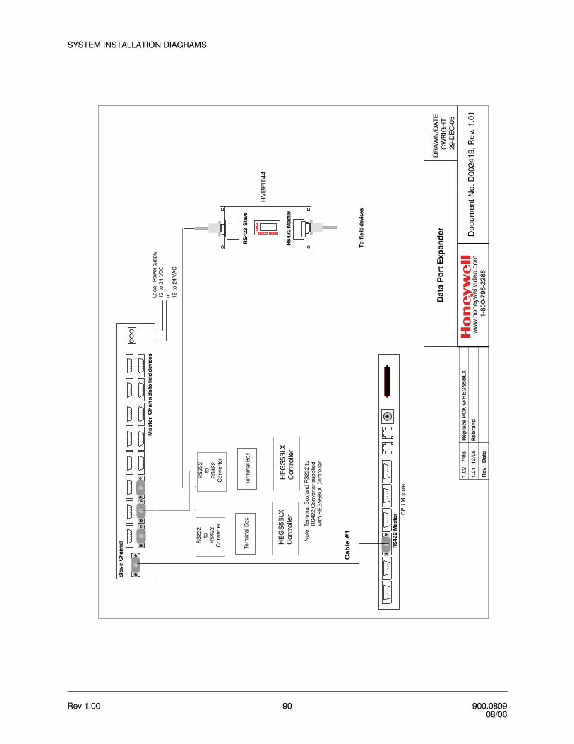
Rev 1.00 90 900.080908/06
SYSTEM INSTALLATION DIAGRAMS
DR
AW
N/D
ATE
CW
RIG
HT
29-D
EC
-05
Doc
umen
t No.
D00
2419
, Re
v. 1
.01
ww
w.h
oney
wel
lvid
eo.c
om
1-80
0-79
6-22
88
Dat
aP
ort
Exp
and
er
RS
422
Mas
ter
Cab
le#
1
Loca
lPo
wer
supp
ly12
to24
VDC
or 12to
24VA
C
Ma
ster
Ch
ann
els
tofie
ldde
vice
s
Sla
ve
Cha
nnel
1234568 7
1 RS
422
Mas
ter
234568 7 1
23
456
87
1
234568 7 1
RS
422
Sla
ve
Tofi
eld
devi
ces
RS
232
toR
S42
2C
onve
rter
Term
inal
Box
HE
GS
5BLX
Con
trolle
r
Rev
D
ate
1.01
12/
05
R
ebra
nd
1.02
7/
06
R
epla
ce P
CK
w/H
EG
S5B
LX
HV
BP
IT44
Not
e:Te
rmin
al B
ox a
nd R
S23
2 to
R
S42
2 C
onve
rter
sup
plie
d
with
HE
GS
5BLX
Con
trol
ler
RS
232
toR
S42
2C
onv
erte
r
Term
inal
Bo
x
HE
GS
5BLX
Con
trolle
r
CP
U M
odul
e

VideoBloX User Manual
Rev 1.00 91 900.080908/06
RS42
2M
aste
r
1234568 7
1 RS4
22Sl
ave
234568 7 1
23
456
87
1
234568 7 1
RS42
2M
aste
rD
IPSw
itch
Setti
ngs
ForR
apid
Dom
esSW
#1-2
"on"
SW#1
-all
"off"
Sw
#3-1
and8
"on"
Cab
le#1
RS4
22co
nnec
tion
toDo
mes
PIT
Mas
terC
hann
elPI
N#1
-TXD
(-)to
Dom
eD
ata
(-)Pi
n#2
TXD
(+)t
oD
ome
Dat
a(+
)
Ade
mco
Vide
oDo
mes
For
RS4
85"T
wis
ted
Pair"
oper
atio
n,ju
mpe
rLK
3on
the
Dom
eC
ircui
tBoa
rdm
ustb
efitt
edac
ross
pins
2&3,
and
dom
esm
ustb
ead
dres
sed
with
thei
rcor
resp
ondi
ngca
mer
ain
putn
umbe
r.Max
imum
distan
ce
for"
Twis
ted
Pair"
cont
rolu
sing
one
shie
lded
,22
AWG
,tw
iste
d,pa
iris
5000
feet(1
520
mete
rs).
Term
inat
eth
ela
stdo
me
only
Term
inat
ion
Jum
per
LK1
onth
eD
ome
Circu
itBo
ard
mus
tbe
fitte
dac
ross
pins1
&2
for
Term
inat
ed(O
N),
orac
ross
pins
2&3
for
Unt
erm
inat
ed(O
FF).
All
dom
esre
quir
e24
VAC
Inpu
tVol
tage
.Fo
rin
door
dom
es,u
se24
VAC
at40
VAou
tputp
erdo
me.
Foro
utdo
ordo
mes
,use
24VA
Cat
80V
Aou
tputp
erdo
me.
DR
AW
N/D
ATE
CW
RIG
HT
29-D
EC
-05
Doc
umen
t No.
D00
2420
, Re
v. 1
.01
ww
w.h
oney
wel
lvid
eo.c
om
1-80
0-79
6-22
88
PIT4
22to
Rapi
dDom
es
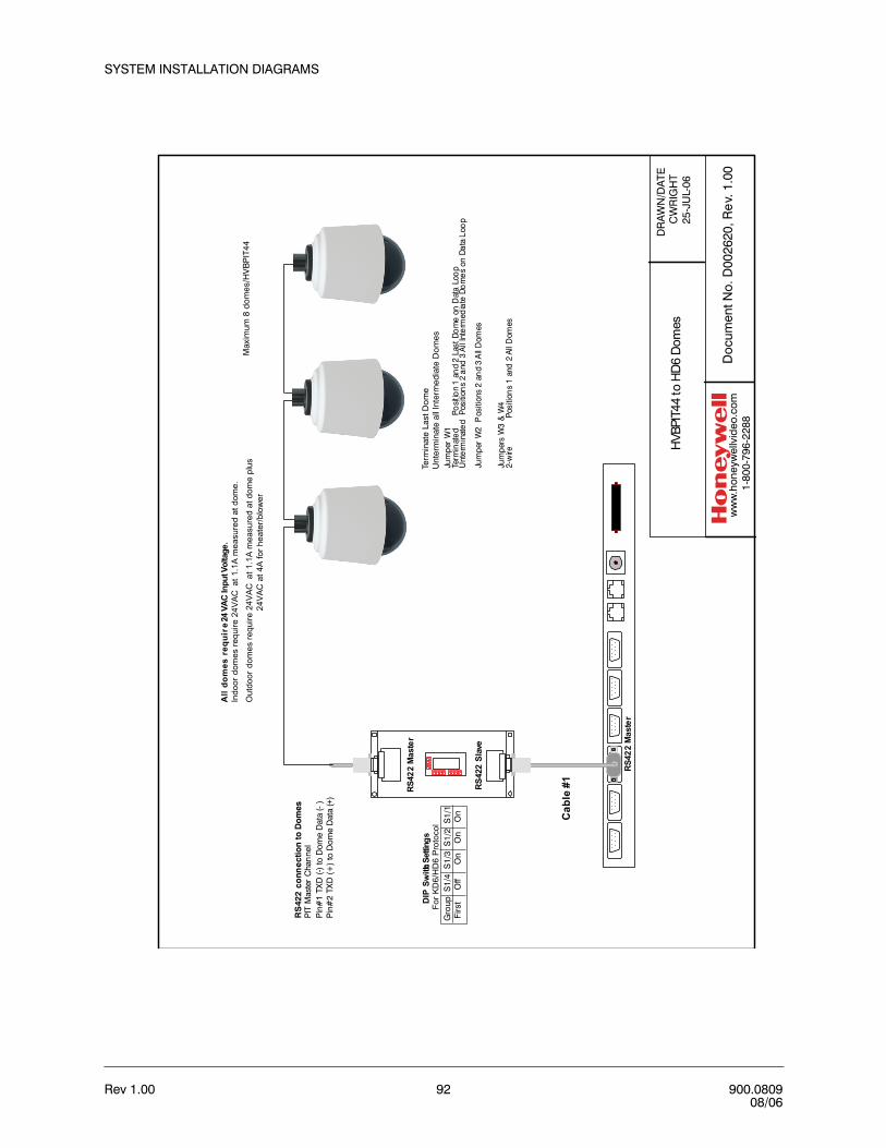
Rev 1.00 92 900.080908/06
SYSTEM INSTALLATION DIAGRAMS
RS42
2M
aste
r
1234568 7
RS4
22Sl
ave
234568 7 1
23
456
87
1
234568 7 1
RS42
2M
aste
r
DIP
Switch
Setti
ngs
ForK
D6/
HD
6 Pr
otoc
ol
Cab
le#1
RS
422
conn
ect
ion
to D
om
esPI
TM
aste
rC
han
nel
Pin
#1
TXD
(-)to
Dom
eD
ata
(- )
Pin
#2
TXD
(+)
toD
ome
Dat
a (+
)
All
dom
esre
quir
e24
VAC
Inpu
tVol
tage
.In
door
dom
es re
quire
24V
ACat
1.1A
mea
sure
d at
dom
e.
Out
door
dom
es re
quire
24V
ACat
1.1
A m
easu
red
at d
ome
plus
24V
AC a
t 4A
for h
eate
r/blo
wer
DR
AW
N/D
ATE
CW
RIG
HT
25-J
UL-
06
Doc
umen
t No.
D00
2620
, Re
v. 1
.00
ww
w.h
oney
wel
lvid
eo.c
om
1-80
0-79
6-22
88
HVBP
IT44
to H
D6D
omes
Term
inat
e La
st D
ome
Unt
erm
inat
e al
l Int
erm
edia
te D
omes
Jum
per
W1
Jum
per
W2
Jum
pers
W3
&W
4
Term
inat
edPo
sitio
n1
and
2La
stDo
me
onD
ata
Loo
pU
nter
min
ated
Posi
tion
s2
and
3Al
lInt
erm
edia
teDo
mes
onDa
taLo
op
Pos
ition
s2
and
3A
llD
omes
2-w
irePo
sitio
ns
1an
d2
AllD
omes
Max
imum
8 d
omes
/HV
BP
IT44
Gro
up S
1/4
S1/
3 S
1/2
S1/
1 F
irst
O
ff
On
O
n
On

VideoBloX User Manual
Rev 1.00 93 900.080908/06
DR
AW
N/D
ATE
CW
RIG
HT
29-D
EC
-05
Doc
umen
t No.
D00
2421
, Re
v. 1
.01
ww
w.h
oney
wel
lvid
eo.c
om
1-80
0-79
6-22
88
Con
figur
atio
n PC
to C
PU
RS23
2Sl
ave
Cab
le#2
Con
figur
atio
nPC
with
Vid
eoB
loX
Con
figan
dop
tiona
lNet
GU
Iso
ftwar
e
Not
e:1.
)Cab
le#2
(sup
plie
dw
ithsy
stem
)2.
)Usi
ngVi
deoB
loX
Con
fig, s
etB
aud
Rat
eof
PC
tom
atch
Bau
dR
ate
ofth
eP
C/S
lave
Port
(Def
ault
19.2
KB
)

Rev 1.00 94 900.080908/06
SYSTEM INSTALLATION DIAGRAMS
DR
AW
N/D
ATE
CW
RIG
HT
29-D
EC
-05
Doc
umen
t No.
D00
2422
, Re
v. 1
.01
ww
w.h
oney
wel
lvid
eo.c
om
1-80
0-79
6-22
88
Net
wor
ked
GU
Is
RS23
2Sl
ave
Cab
le#2
CC
TVSe
rver
with
CC
TVSe
rver
,V
ideo
BloX
Con
figan
dN
etG
UI
softw
are
Not
e:1.
)Cab
le#2
(sup
plie
dw
ithsy
stem
)2.
)Usi
ngVi
deoB
loX
Con
fig,s
etB
aud
Rat
eof
PC
tom
atch
Bau
dR
ate
ofth
eP
C/S
lave
Port
(Def
ault
19.2
KB
)
Wor
ksta
tion
with
Vide
oBlo
XC
onfig
and
Net
GU
Iso
ftwar
e
Wor
ksta
tion
with
Vide
oBlo
XC
onfig
and
Net
GU
Iso
ftwar
e
TCP/
IPN
etw
ork
Not
e:In
stal
lVid
eoC
aptu
reca
rd(H
aupp
auge
WIN
TV)a
ndco
nnec
tto
Vide
oO
utpu
ton
mat
rixsw
itch
for"
live"
vide
oon
the
desk
top.

VideoBloX User Manual
Rev 1.00 95 900.080908/06
DR
AW
N/D
ATE
CW
RIG
HT
29-D
EC
-05
Doc
umen
t No.
D00
2423
, Re
v. 1
.01
ww
w.h
oney
wel
lvid
eo.c
om
1-80
0-79
6-22
88
Sate
llite
Sys
tem
BackplaneRS422Expansion
Control Comms
Cha
ssis
Syn
cIn
AC
100
-125
VAC
50/6
0Hz
0.8
A
Fuse
10A
12-3
0V
DC
/24
VAC
RS2
32sl
aveR
S23
2Au
xR
S42
2M
aster
RS
422
Sat
telli
teI2
CM
ax50
0mA
CP
UV
ideo
Inpu
t
12
34
56
78
910
1112
1314
1516
Inpu
t
12
34
56
78
910
1112
1314
1516
Inpu
t
12
34
56
78
910
1112
1314
1516
Inpu
t
12
34
56
78
910
1112
1314
1516
Out
put
12
34
56
78
910
1112
1314
1516
Out
put
12
34
56
78
910
1112
1314
1516
Alar
minp
uts
-out
puts
RS
422
Conc
PBJ
AR
Cam
7-
Mon
3
12
3
45
67
89
0E
nter
PB
BackplaneRS422Expansion
Control Comms
Cha
ssis
Sync
In
AC 1
00 -
125
VAC
50/6
0H
z0.
8A
Fuse
10A
12-3
0VD
C/
24VA
C
RS
232
slave
RS2
32Au
xR
S422
Mas
terR
S422
Satte
llite
I2C
Max
500m
AC
PU
Vide
o
Inpu
t
12
34
56
78
910
1112
1314
1516
Inpu
t
12
34
56
78
910
1112
1314
1516
Inpu
t
12
34
56
78
910
1112
1314
1516
Inpu
t
12
34
56
78
910
1112
1314
1516
Out
put
12
34
56
78
910
1112
1314
1516
Out
put
12
34
56
78
910
1112
1314
1516
Alar
min
puts
-out
puts
RS4
22C
onc
PBJ
AR
Cam
7-
Mon
3
12
3
45
67
89
0E
nter
PB
H-H
oldV
-Hol
dBrig
htCon
trast
H-H
oldV
-Hol
dBrig
htCon
trast
H-H
oldV
-Hol
dBrig
htCon
trast
H-H
oldV
-Hol
dBrig
htCon
trast
Vide
oBrid
ge
12
34
Vide
oBrid
ge
12
34
Vide
oBrid
ge
12
34
Vide
oBrid
ge
12
34
Rou
ter R
oute
r
RS42
2
RS42
2
Vide
o
Vide
o
Vid
eoBr
idge
Vid
eoBr
idge
LAN
/WAN
Sta
ticIP
Addre
ss
Sta
ticIP
Addre
ss
Mon
itorO
ut Mon
itorO
ut
Cam
eraf
rom
Vid
eoBr
idge
Cam
eraf
rom
Vid
eoBr
idge
Satte
lite
Publ
icSw
itche
dNe
twork
s
AVB
422C
4
Loca
lCon
trol
Loca
land
Rem
oteC
ontro
l
Satte
lite
Satte
lite

Rev 1.00 96 900.080908/06
SYSTEM INSTALLATION DIAGRAMS
Notes:

Rev 1.00 97 900.080908/06
CCCC
CONNECTING AHDR/HRHD DVRs
INTRODUCTION
This appendix is a step-by-step guide to setting up the AHDR/HRHD Series DVRs and controlling them with a VideoBloX system controller. An HVBPIT44 protocol translator is required for this control. Please refer to the individual component installation manuals for specific information on each product.
HVBPIT44 SETUP
DIP Switch Settings
Set the PIT to DEVICE mode.
1. Set S1 DIP switches 1,2,3,4, on: set S1 DIP switches 5,6,7,8 off
2. Set S2 all DIP switches off.
3. Set S3 DIP switches 2,3,4,6,8 on; set S3 DIP switches 1,5,7 off
This sets the PIT's Slave port to 19,2KB (ensure this matches your CPU RS422 port) and the PIT's Master port to 9600KB.

Rev 1.00 98 900.080908/06
CONNECTING AHDR/HRHD DVRs
Data connections1. Using a 9-way pin-to-pin cable, connect the PIT slave port to the Master RS422 port
on the VideoBloX CPU. Note: the PIT derives its power from the CPU when a 9-way pin-to-pin cable is used.
2. Connect the PIT master port to the AHDR/HRHD rear panel RS485 connector.
When the PIT is powered up, the 2 LEDs will remain lit solid.
VIDEOBLOX SETUP
Video Connections1. Connect a camera or monitor output to the Video IN of the AHDR/HRHD.
2. Connect the Video OUT (not loop out) of the AHDR/HRHD to an input on the VideoBloX. (Remember the input, you will need the number later)
ConfigurationCopy the device files AHDR.db and AHDR.mb to the following folder on the hard drive where the VideoBloX configuration software is installed.
C:\Program Files\Honeywell\VBloXCFG\DBF
3. Start the VideoBloX Configuration program.
Start > Programs > VBloXCFG > Vbloxcfg
4. Click on
Table C -1 Data Connections
PIT Master Port AHDR/HRHD RS485
Pin 1 TX- RX-
Pin 2, TX+ RX+

VideoBloX User Manual
Rev 1.00 99 900.080908/06
5. Click on the CONTROL tab. Set the parameters as shown in the screen shot below.
The DATABASE FILE is selected by clicking the notepad button beside the window and selecting the appropriate AHDR.db file from the list.
The SWITCH OFFSET number will be the camera input your AHDR/HRHD is connected to subtract 1. For example, if you connected the output of the AHDR/HRHD to input 33 on the VideoBloX, the SWITCH OFFSET will be 32. 32+1 is the camera input that will be switched to the monitor when you call up the AHDR/HRHD from the system controller.
6. After the parameters have been entered as shown above, click the Download button.
7. Choose the Titles tab and disable DATE and TITLE from the camera input you have chosen for the AHDR/HRHD input, click the Download button.
8. You may test the programming parameters by pressing the VCR button on the system controller.
a. If the DEVICE TYPE was set as 1 in the control window then pressing it once will bring up AHDR on the controller display.
b. If the DEVICE TYPE was set as 2 in the control window then pressing it twice will bring up AHDR on the controller display and so on.
9. Press 1, then ENTER; AHDR 1 Select will be displayed.
10. Press PLAY and the following will appear on the display. DVR 1:Play/Pause.
11. While pressing the key several times monitor the LEDs on the PIT and each should flicker on each key-press. This will indicate that VideoBloX is communicating with the PIT and transferring the data to the Master port.

Rev 1.00 100 900.080908/06
CONNECTING AHDR/HRHD DVRs
CONFIGURING THE AHDR1E
1. At the system controller, call up the AHDR video input by using the CAM selection.
2. Press MENU and enter the password, (left, right, up, down, enter is default).
3. Select REMOTE CONTROL from the DEVICE menu.
4. Set the REMOTE CONTROL to ON.
5. Set the UNIT ID to 1
6. Set communications to; 9600,8,1,none.
7. Select OK and exit programming.
Other parameters for operating the AHDR1E/HRHD series DVRs may be found in the product manual.
The AHDR1E/HRHD will now be ready to control.
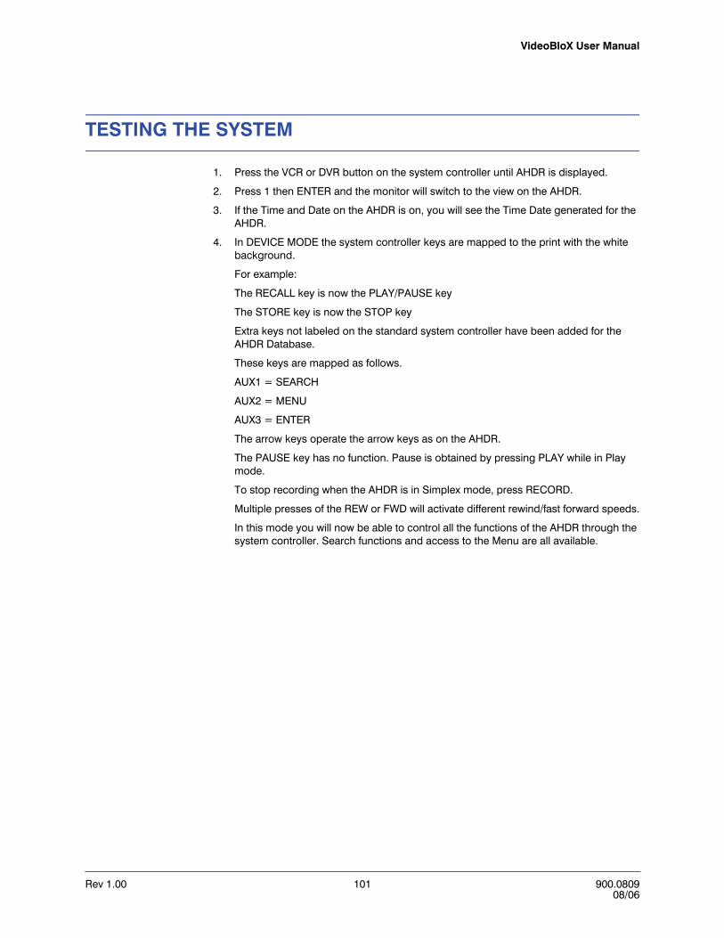
VideoBloX User Manual
Rev 1.00 101 900.080908/06
TESTING THE SYSTEM
1. Press the VCR or DVR button on the system controller until AHDR is displayed.
2. Press 1 then ENTER and the monitor will switch to the view on the AHDR.
3. If the Time and Date on the AHDR is on, you will see the Time Date generated for the AHDR.
4. In DEVICE MODE the system controller keys are mapped to the print with the white background.
For example:
The RECALL key is now the PLAY/PAUSE key
The STORE key is now the STOP key
Extra keys not labeled on the standard system controller have been added for the AHDR Database.
These keys are mapped as follows.
AUX1 = SEARCH
AUX2 = MENU
AUX3 = ENTER
The arrow keys operate the arrow keys as on the AHDR.
The PAUSE key has no function. Pause is obtained by pressing PLAY while in Play mode.
To stop recording when the AHDR is in Simplex mode, press RECORD.
Multiple presses of the REW or FWD will activate different rewind/fast forward speeds.
In this mode you will now be able to control all the functions of the AHDR through the system controller. Search functions and access to the Menu are all available.

Rev 1.00 102 900.080908/06
CONNECTING AHDR/HRHD DVRs
Rev 1.00 103 900.080908/06
DDDD
CONNECTING TO MAXPRO-Net SERVER
INTRODUCTION
This appendix provides installation diagrams and DIP Switch settings for controlling a VideoBloX system with Redundant MAXPRO-Net Servers and a MAXPRO-Net Server without Redundancy.
Required hardware:
• PC running MAXPRO-Net software• VideoBloX Chassis (CPU module is not required)• VideoBloX HVBMATPIT Matrix Protocol Translator
CONNECTIONS
Refer to Figures D-1 and D-2.
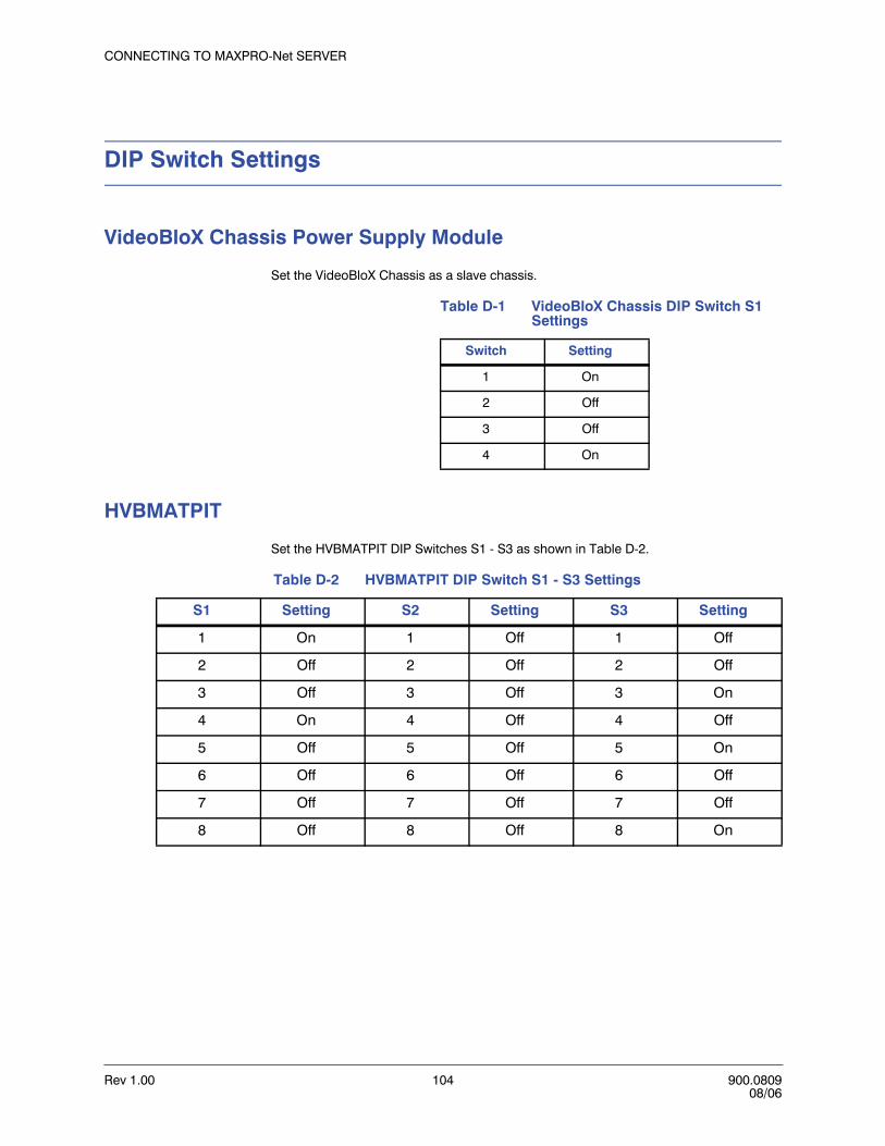
Rev 1.00 104 900.080908/06
CONNECTING TO MAXPRO-Net SERVER
DIP Switch Settings
VideoBloX Chassis Power Supply Module
Set the VideoBloX Chassis as a slave chassis.
HVBMATPIT
Set the HVBMATPIT DIP Switches S1 - S3 as shown in Table D-2.
Table D-1 VideoBloX Chassis DIP Switch S1 Settings
Switch Setting
1 On
2 Off
3 Off
4 On
Table D-2 HVBMATPIT DIP Switch S1 - S3 Settings
S1 Setting S2 Setting S3 Setting
1 On 1 Off 1 Off
2 Off 2 Off 2 Off
3 Off 3 Off 3 On
4 On 4 Off 4 Off
5 Off 5 Off 5 On
6 Off 6 Off 6 Off
7 Off 7 Off 7 Off
8 Off 8 Off 8 On

VideoBloX User Manual
Rev 1.00 105 900.080908/06
LED OPERATION
After completing installation;
1. Both LEDs on the HVBMATPIT should be lit solid.
2. The TX, RX and RTS data LEDs on the VideoBloX power supply module should be flashing.
3. The Video Input Card LEDs should be flashing.
4. Upon receipt of a valid command from the MAXPRO-Net PC, both yellow and green LEDs on the PIT should flicker.

Rev 1.00 106 900.080908/06
CONNECTING TO MAXPRO-Net SERVER
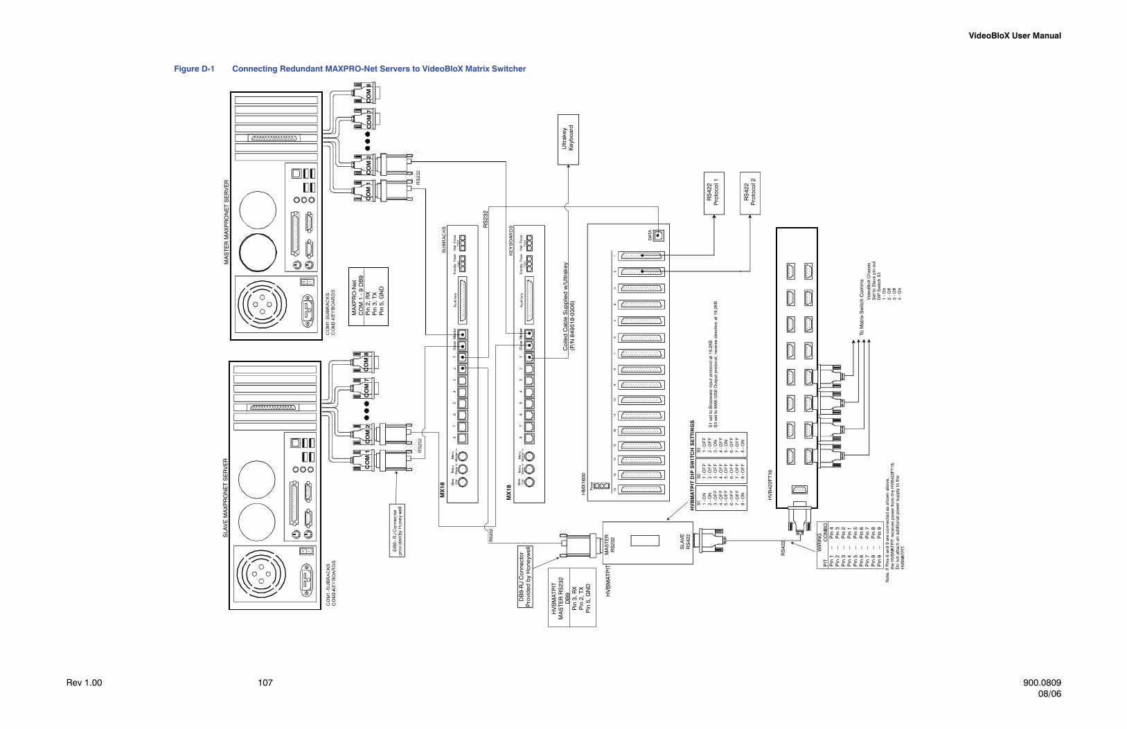
VideoBloX User Manual
Rev 1.00 107 900.080908/06
Figure D-1 Connecting Redundant MAXPRO-Net Servers to VideoBloX Matrix Switcher
Ultr
akey
Key
bo
ard
DAT
A
RS
422
Pro
toco
l1
RS
422
Pro
toco
l2
ToM
atrix
Sw
itch
Com
ms
RS
422
WIR
ING
PIT
CO
MB
OP
in1
--P
in4
Pin
2--
Pin
3P
in3
--P
in2
Pin
4--
Pin
1P
in5
--P
in5
Pin
6--
Pin
6P
in7
--P
in7
Pin
8--
Pin
8P
in9
--P
in9
SLA
VE
RS
422
MA
STE
RR
S23
2H
VB
MA
TPIT
DB
9-R
JC
onn
ecto
rP
rovi
ded
by
Ho
neyw
ell
RS
232
HM
X16
00
HV
B42
2FT1
6
RS
232
S1 1-O
N2
-ON
3-O
FF
4-O
FF
5-O
FF
6-O
FF
7-O
FF
8-O
N
S3 1-O
FF
2-O
FF
3-O
N4
-OF
F5
-ON
6-O
FF
7-O
FF
8-O
N
S2 1-O
FF
2-O
FF
3-O
FF
4-O
FF
5-O
FF
6-O
FF
7-O
FF
8-O
FF
HV
BM
AT
PIT
DIP
SW
ITC
HS
ETT
ING
S
MA
STE
RM
AX
PR
ON
ET
SE
RV
ER
SLA
VE
MA
XP
RO
NE
TS
ER
VE
R
MX
18
MX
18
CO
M1
CO
M2
CO
M7
CO
M8
CO
M1
CO
M2
CO
M7
CO
M8
MA
XP
RO
-Net
CO
M1
-9
DB
9P
in2,
RX
Pin
3,TX
Pin
5,G
ND
Co
iled
Cab
leS
upp
lied
w/U
ltrak
ey(P
/N84
9518
-030
6)
HV
BM
ATP
ITM
AS
TER
RS
232
DB
9P
in3,
RX
Pin
2,TX
Pin
5,G
ND
No
te:
If P
ins
6 an
d 9
are
con
nec
ted
as s
how
n a
bov
e,
th
e H
VB
MA
TPIT
rec
eive
s p
ower
from
the
HV
B42
2FT
16.
Do
not
atta
ch a
n a
dditi
ona
l pow
er s
upp
ly to
the
HV
BM
AT
PIT
.
S1
set
to B
ossw
are
inp
ut p
roto
col a
t 19.
2KB
S3
set
to M
AX-1
000
Out
put
pro
toco
l, re
vers
e di
rect
ion
at 1
9.2K
B
Vid
eoB
loX
Ch
assi
sS
et to
Sla
ve p
in-o
ut
DIP
Sw
itch
S1
1 - O
n2
- Off
3 - O
ff4
- On

CONNECTING TO MAXPRO-Net SERVER
Rev 1.00 108 900.080908/06
Figure D-2 Connecting a Single MAXPRO-Net Server to VideoBloX Matrix Switcher
Rev 1.00 109 900.080908/06
EEEE
NETWORKING TWO VIDEOBLOX MATRICES
PURPOSE
This appendix provides step-by-step instructions for connecting two VideoBloX matrices to allow the operator of Site 2 to view cameras from Site 1.
RECOMMENDATIONS
It is highly recommended, if possible, to set the two systems up side-by-side to configure and program. As the communications between networked systems typically span a wide distance, troubleshooting is considerable easier and less time consuming with all the components in one location. Once operational, the only variable introduced when the systems are in place are the communication connections.
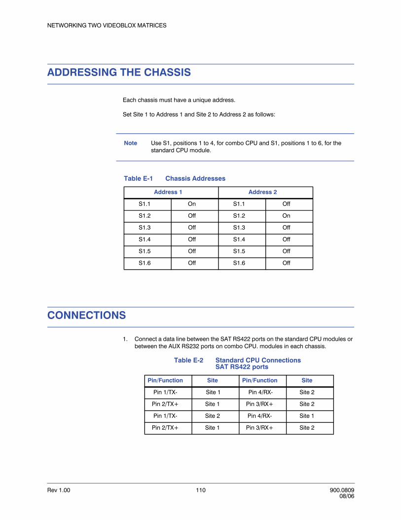
Rev 1.00 110 900.080908/06
NETWORKING TWO VIDEOBLOX MATRICES
ADDRESSING THE CHASSIS
Each chassis must have a unique address.
Set Site 1 to Address 1 and Site 2 to Address 2 as follows:
Note Use S1, positions 1 to 4, for combo CPU and S1, positions 1 to 6, for the standard CPU module.
CONNECTIONS
1. Connect a data line between the SAT RS422 ports on the standard CPU modules or between the AUX RS232 ports on combo CPU. modules in each chassis.
Table E-1 Chassis Addresses
Address 1 Address 2
S1.1 On S1.1 Off
S1.2 Off S1.2 On
S1.3 Off S1.3 Off
S1.4 Off S1.4 Off
S1.5 Off S1.5 Off
S1.6 Off S1.6 Off
Table E-2 Standard CPU ConnectionsSAT RS422 ports
Pin/Function Site Pin/Function Site
Pin 1/TX- Site 1 Pin 4/RX- Site 2
Pin 2/TX+ Site 1 Pin 3/RX+ Site 2
Pin 1/TX- Site 2 Pin 4/RX- Site 1
Pin 2/TX+ Site 1 Pin 3/RX+ Site 2
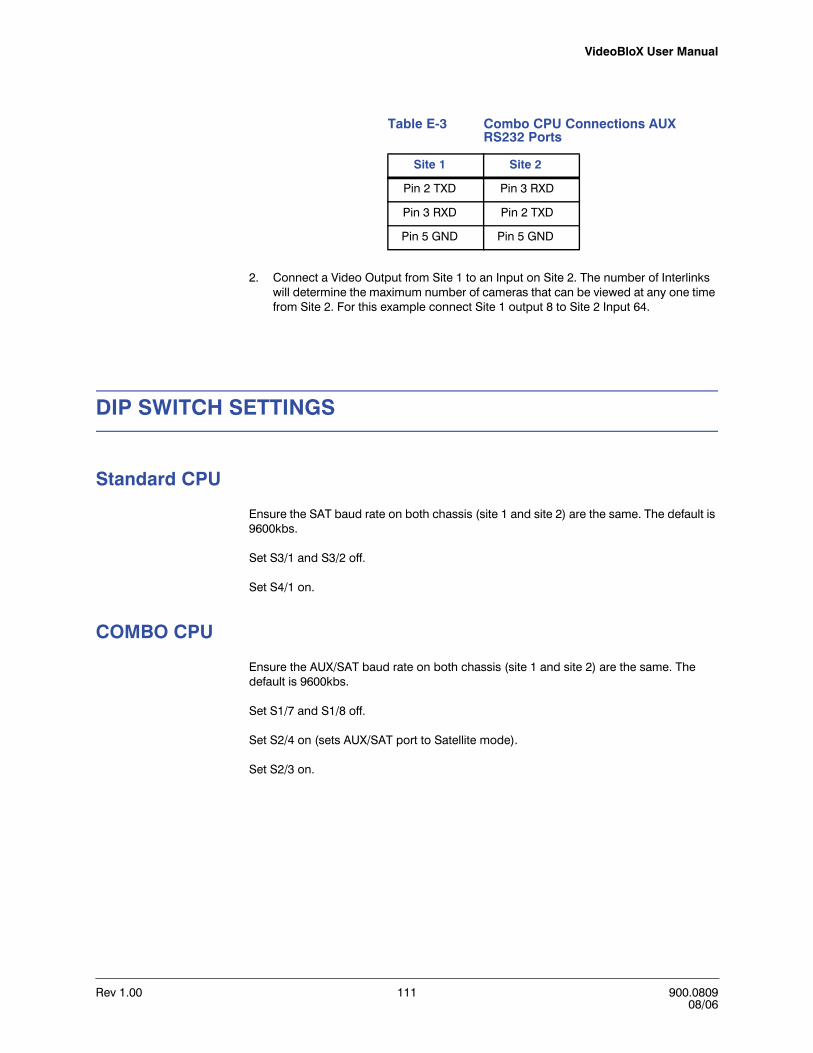
VideoBloX User Manual
Rev 1.00 111 900.080908/06
2. Connect a Video Output from Site 1 to an Input on Site 2. The number of Interlinks will determine the maximum number of cameras that can be viewed at any one time from Site 2. For this example connect Site 1 output 8 to Site 2 Input 64.
DIP SWITCH SETTINGS
Standard CPU
Ensure the SAT baud rate on both chassis (site 1 and site 2) are the same. The default is 9600kbs.
Set S3/1 and S3/2 off.
Set S4/1 on.
COMBO CPU
Ensure the AUX/SAT baud rate on both chassis (site 1 and site 2) are the same. The default is 9600kbs.
Set S1/7 and S1/8 off.
Set S2/4 on (sets AUX/SAT port to Satellite mode).
Set S2/3 on.
Table E-3 Combo CPU Connections AUX RS232 Ports
Site 1 Site 2
Pin 2 TXD Pin 3 RXD
Pin 3 RXD Pin 2 TXD
Pin 5 GND Pin 5 GND
Rev 1.00 112 900.080908/06
NETWORKING TWO VIDEOBLOX MATRICES
PROGRAMMING WITH Vbloxcfg APPLICATION
1. Backup each database folder (DBF) in the configuration software under a new name so that the two site databases do not get confused. This is done manually by renaming the DBF folder in C:\Program Files\Honeywell\VBloXCFG using Windows renaming conventions.
Caution Be sure to use the Site 1 database folder (DBF) when connected to Site 1 and Site 2 database (DBF) when connected to Site 2.
2. Site 1Set up Site 1 as a normal system with all PTZs operating and camera switching operational. For this example, Site 1 has 32 cameras.
3. Site 2Set up Site 2 local cameras (if applicable) as usual and assign them a group of input numbers. For this example, cameras 33 to 48.
a. Set up the Site 1 cameras on Site 2 CPU as follows:
• Input 1 will be the first camera from Site 1.
• Set the Input Detail Satellite to address 1.
• Set the Physical I/P to the Input number on Site 1 matrix, and, for this example, 1.
• Repeat this procedure for all 32 Inputs
Caution If the camera on Site 1 is a PTZ, then set the Type to PTZ. The address is not used, but must not be 0.
• Download all Inputs.
• Click on the Interconnects button and ensure the table is for Address 1.
• Assign how Site 1 is connected to Site 2. For this example Local Input is 64 and Remote Output is 8 for 1 trunk.
• Download the table
• The titles for the Site 1 cameras can be disabled as the title will be generated from Site 1.

VideoBloX User Manual
Rev 1.00 113 900.080908/06
TESTING
From Site 2:
1. Select a Site 1 camera. For this example, select camera 1 and ensure the SAT LED (Standard CPU) or the AUX LED (Combo CPU) flashes when the Enter button is pressed on the HEGS5BLX Controller.
2. Simultaneously the corresponding LED on Site 1 CPU will flash.
3. Ensure the correct camera comes up.
TROUBLESHOOTING
Table E-4 Troubleshooting Networked Chassis
Problem Solution
Site 2 LED does not flash when a Site 1 camera is selected
• The system does not know this is a satellite camera. Ensure the camera input detail is set to ADD1 in Satellite for the camera and DOWNLOAD.
• No Interconnects have been set. Check the Interconnect settings and DOWNLOAD
Site 2 LED flashes but Site 1 LED does not
• Check communication cable pin outs, baud rates and chassis address.
• Verify page 17 of the Diagnostic video from the CPU shows a real time assignment of the cameras to the Links.

Rev 1.00 114 900.080908/06
NETWORKING TWO VIDEOBLOX MATRICES


Honeywell Video Systems (Head Office)2700 Blankenbaker Pkwy, Suite 150Louisville, KY 40299, USAwww.honeywellvideo.com℡ +1.800.796.2288
Honeywell Security Australia Pty Ltd.Unit 5, Riverside Centre, 24-28 River Road WestParramatta, NSW 2150, Australiawww.ademco.com.au℡ +61.2.8837.9300
Honeywell Security Asia Pacific33/F Tower A, City Center, 100 Zun Yi RoadShanghai 200051, Chinawww.security.honeywell.com/cn℡ +86 21.2527.4568
Honeywell Security AsiaFlat A, 16/F, CDW Building, 388 Castle Peak RoadTsuen Wan, N.T., Hong Kongwww.security.honeywell.com/hk℡ +852.2405.2323
Honeywell Security FranceParc Gutenberg, 8, Voie La Cardon91120, Palaiseau, Francewww.honeywell.com/security/fr℡ +33.01.64.53.80.40
Honeywell Security Italia SpAVia Treviso 2 / 431020 San VendemianoTreviso, Italywww.honeywell.com/security/it℡ +39.04.38.36.51
Honeywell Security EspañaMijancas 1. 3a PlantaP.Ind. Las Mercedes28022 Madrid, Spainwww.security.honeywell.com/es℡ +34.902. 667.800
Honeywell Video Systems Northern EuropeNetwerk 1211446 WV Purmerend, The Netherlandswww.SecurityHouse.nl℡ +31.299.410.200
Honeywell Video Systems UK Ltd.Aston Fields Road, Whitehouse Ind EstRuncorn, Cheshire, WA7 3DL, UKwww.honeywellvideo.com℡ +0844 8000 235
Honeywell Security South AfricaUnit 6 Galaxy Park, 17 Galaxy AvenueLinbro Park, P.O. Box 599042100 Kengray, Johannesburg, South Africawww.honeywell.co.za℡ +27.11.574.2500
Honeywell Security DeutschlandJohannes-Mauthe-Straße 14D-72458 Albstadt, Germanywww.honeywell.com/security/de℡ +49.74 31.8 01.0
Honeywell Security PolandChmielewskiego 22a, 70-028Szczecin, Polskawww.ultrak.pl℡ +48.91.485.40.60
Honeywell Security Czech RepublicHavránkova 33, BrnoDolní Heršpice, 619 00, Czech Republicwww.olympo.cz℡ +420.543.558.111
Honeywell Security Slovakia RepublicVajnorská 142, 83104 BratislavaSlovakiawww.olympo.sk℡ +421.2.444.54.660
© 2006 Honeywell International Inc. All rights reserved. No part of this publication may be reproduced by any means without written permission from Honeywell Video Systems. The information in this publication is believed to be accurate in all respects. However, Honeywell Video Systems cannot assume responsibility for any consequences resulting from the use thereof. The information contained herein is subject to change without notice. Revisions or new editions to this publication may be issued to incorporate such changes.
Document 900.0809 08/06 Rev 1.00
www.honeywellvideo.com+1.800.796.CCTV (North America only)


![Matrix floating[1]](https://static.fdokumen.com/doc/165x107/63234342078ed8e56c0ac6f9/matrix-floating1.jpg)