Investment analysis of alternative fruit tree sprayers in Michigan orchards
Upload
khangminh22Category
view
0download
0
VENTURI AIRSPRAYERS
Form: L50S2-1200Book.indd
Parts Manual For Model L50S2-1200
300 Gallon Capacity
July 2013


TABLE OF CONTENTS
SECTION DESCRIPTION ................................................ PAGE 1 Introduction .................................................................................. 1 1.1 Purchaser’s Responsibility ..................................................................... 1 1.2 Serial Number Information .................................................................. 1
2 Replacement Parts ..................................................................2 - 29 2.1 Frame Assembly...................................................................................2-4 2.2 Tank Assembly .....................................................................................5-6 2.3 Tank Fittings & Cover ........................................................................7-8 2.4 Hand Wash Tank .................................................................................... 9 2.5 Fan Housing Assembly ........................................................................ 10 2.6 Fan Support Assembly ......................................................................... 11 2.7 Fan Support Breakdown ...................................................................... 12 2.8 Belt Tension Roller ............................................................................... 13 2.9 Lubrication Tubing ............................................................................... 14 2.10 Main Pulley ............................................................................................ 15 2.11 Overrunning Clutch ............................................................................. 16 2.12 Liquid Flow Path .............................................................................17-19 2.13 Pumps & Routing ............................................................................20-21 2.14 Pressure Regulator & 3 Way Valve ..................................................... 22 2.15 Suction Filter Assembly ....................................................................... 23 2.16 Pump Assembly ...............................................................................24-25 2.16.1 Agitation Pump Assembly .......................................................26-27 2.17 Control Valve ........................................................................................ 28 2.18 Electro Valves ...................................................................................29-30 2.19 Pump & Fan Belts ................................................................................ 31 2.20 Axle & Wheel Hubs ............................................................................. 32 2.21 Driveshaft .............................................................................................. 33 3 Limited Warranty .........................................................................34
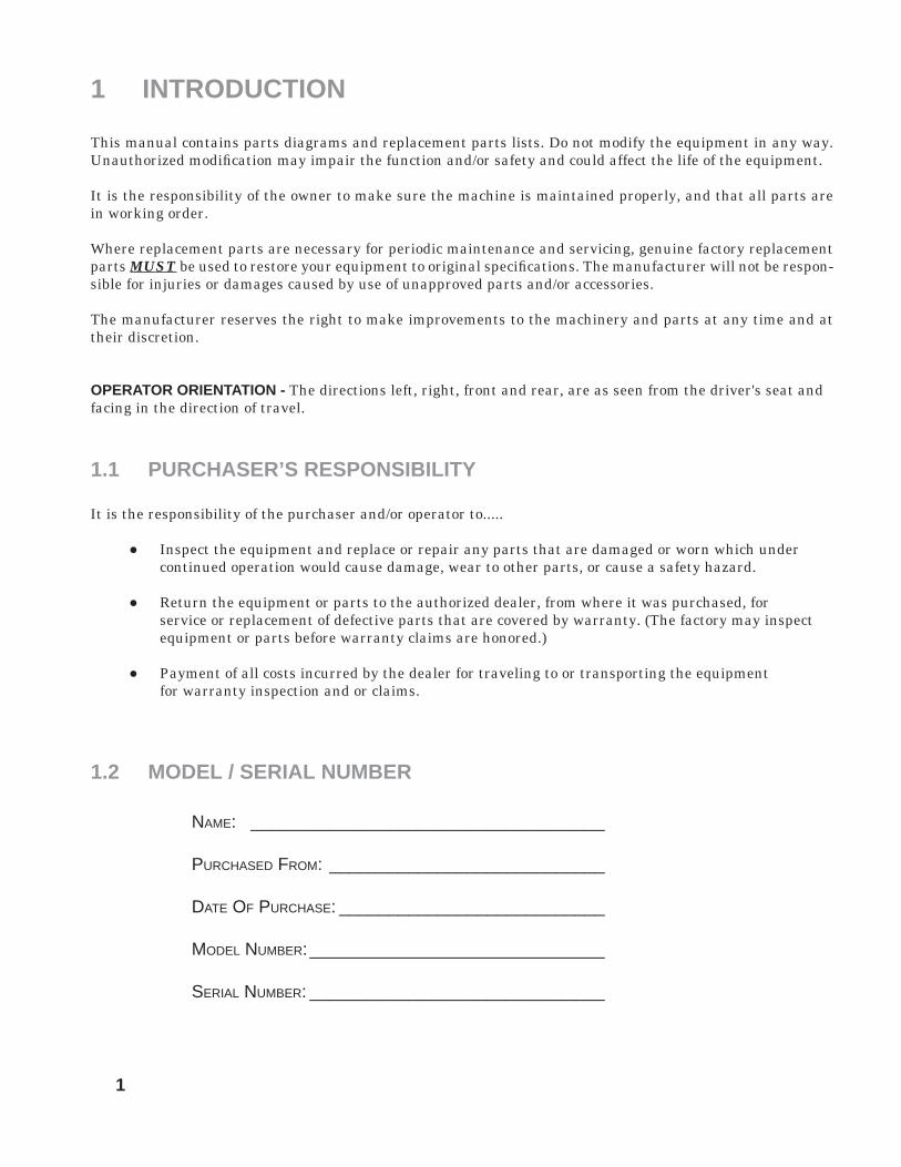
1 INTRODUCTION
This manual contains parts diagrams and replacement parts lists. Do not modify the equipment in any way. Unauthorized modifi cation may impair the function and/or safety and could affect the life of the equipment.
It is the responsibility of the owner to make sure the machine is maintained properly, and that all parts are in working order.
Where replacement parts are necessary for periodic maintenance and servicing, genuine factory replacement parts MUST be used to restore your equipment to original specifi cations. The manufacturer will not be respon-sible for injuries or damages caused by use of unapproved parts and/or accessories.
The manufacturer reserves the right to make improvements to the machinery and parts at any time and at their discretion.
OPERATOR ORIENTATION - The directions left, right, front and rear, are as seen from the driver's seat and facing in the direction of travel.
1.1 PURCHASER’S RESPONSIBILITY
It is the responsibility of the purchaser and/or operator to.....
● Inspect the equipment and replace or repair any parts that are damaged or worn which under continued operation would cause damage, wear to other parts, or cause a safety hazard.
● Return the equipment or parts to the authorized dealer, from where it was purchased, for service or replacement of defective parts that are covered by warranty. (The factory may inspect equipment or parts before warranty claims are honored.)
● Payment of all costs incurred by the dealer for traveling to or transporting the equipment for warranty inspection and or claims.
1.2 MODEL / SERIAL NUMBER
NAME: ____________________________________
PURCHASED FROM: ____________________________
DATE OF PURCHASE: ___________________________
MODEL NUMBER: ______________________________
SERIAL NUMBER: ______________________________
1

2.1 MAIN FRAME ASSEMBLY
2 REPLACEMENT PARTS
2

3
2.1 FRAME ASSEMBLY
REF. QTY. PART NO. DESCRIPTION
1 1 40.131.700 Drawbar 2 1 40.206.000 Joint Washer 3 1 40.244.000 Plate 4 4 RP.008.000 Washer D.8 5 5 TE.008.020T Screw TE 8 x 20 6 1 02.175.000 Looking Handle 7 6 TE.014.030T Screw TE M14 x 30 8 2 RP.006.018 Washer D.6 x 18 9 1 DA.006.0AG Self Locking Nut - High M6 10 2 20.505.000 Pin Jack Stand 11 3 CP.006.040I Pin D.6 Lg. 40 12 3 00.100.004 Split Pin D.4 13 2 40.203.000 Fork 14 8 RP.016.000 Washer D.16 15 4 TE.016.050T Screw TE M16 x 50 16 4 D0.16.5587G Nut M16 17 2 40.202.000 Bush 18 2 40.201.000 Pin Power Lift 19 2 RD.022.000 Tab Washer D.22 20 2 DI.022.5593F Castle Nut (6 Slots) M22 21 2 CP.004.040 Split Pin D.4 L=40 22 5 TE.006.016T Screw TE M6 x 16 23 1 05.747.000 Housing Fixing Plate 24 5 RP.010.030 Washer D.10 x 30 mm 25 4 RP.008.024 Washer D.8 x 24 26 1 40.205.001 Upper Coupling 27 12 RP.012.000 Washer D.12 28 4 D0.14.5587G Nut M14 29 4 D0.12.5587G M12 Nut 30 6 TE.012.030T Screw TE 12 x 30 31 9 RD.006.000 Tab Washer D.6 32 1 02.441.000 Shaft Cone D.240 33 3 TE.006.025T Screw TE M6 x 25 34 11 D0.06.5588G Nut M6 35 1 20.778.000 Bush 36 1 04.076.000 Pin 37 1 40.129.000 Axle 38 1 TE.012.040T Bolt TE M12 x 40 39 2 40.019.000 Hub 6 Colonnette 40 1 TE.010.025T Screw TE 10 x 25T 41 2 D0.08.5588G Nut M8 42 1 02.992.000 Bracket 43 1 04.882.000 Lower Bend D.175

4
2.1 FRAME ASSEMBLY
REF. QTY. PART NO. DESCRIPTION 44 2 TE.010.050T Screw M10 - 50 45 2 D0.10.5587G Nut M10 46 2 05.616.000 Pipe Clamp D.175 47 2 02.978.000SX Bracket 48 2 MT.012.000 Washer D.12 49 2 DA.012.0AG Self Locking Nut M12 50 2 21.004.000 Belt Stretcher For Pump 51 2 02.964.000 CD 32 Pump Spring 52 2 DOT.12.5587 M12 Brass Nut 53 2 40.217.001 Support Foot 54 1 20.533.100 Special Washer Ø100 SP 10 mm 55 1 TE.012.050T Screw TE M12 x 50T 56 8 21.183.000 Cap Stop 57 2 TE.008.025T Screw TE M8 x 25 58 1 40.332.001 Vertical Pin 59 8 RP.014.000 Washer D.14 60 4 TE.014.040T Screw TE M14 x 40 61 1 20.309.200 Pin Ø32 62 1 SE.005.026 Spring Pin D5 x 26 63 1 02.439.000 Pin D.10 64 1 20.785.100 Guide Ring 65 1 40.194.200 Joint 66 1 IS.010.001 Greaser 67 1 ID.006.001 Greaser 68 1 DA.022.0BG Self Locking Nut M22 69 1 TE.022.130 Screw DIN EN 24016 - M22 x 130 70 1 RP.008.032 Washer D.8 x 32 71 1 RP.022.000 Washer D.22 72 1 40.251.001 Support Foot 73 1 05.723.160 Front Housing For 2 Pumps 74 1 05.723.150 Front Housing For 1 Pump 75 1 05.723.060 Front Housing For 2 Pumps 76 2 RD.006.000 Tab Washer D.6 77 2 TE.006.016T Screw TE M6 x 16 78 2 D0.06.5589G Nut M6 79 1 40.333.000 Fan Clutch Lid 80 2 RP.006.000 Washer D.6 81 2 DC.06.5721I Nut DIN 1587 6 x 1-6-10 82 1 05.723.050 Front Housing For 1 Pump

5
2.2 MAIN TANK ASSEMBLY - 300 GALLON
REF. QTY. PART NO. DESCRIPTION 1 1 02.404.100 Basket Filter 400 x 330 2 1 02.298.000 Basket Filter D.204 3 1 02.476.100 Threaded Lid D.255 With Rope 4 1 02.481.280 Nylon Band 60 mm L=2800 5 1 02.481.253 Nylon Band 60 mm L=2530 6 4 20.512.000 Bracket 7 4 20.513.000 Shaped Plate 8 8 TE.006.020T Screw TE M6 x 20 9 8 RP.006.000 Washer D.6 10 8 DA.006.0AG Self Locking Nut - High M6 11 4 RP.010.000 Washer D.10 12 4 TE.010.080T Bolt M10 x 80 13 4 TE.006.060I INOX M6 x 60 TE Screw 14 4 DC.06.5721I Nut DIN 1587 6 x 1-6-10 15 4 DOT.10.5587 M10 Brass Nut

6
2.2 MAIN TANK ASSEMBLY- 300 GALLON
REF. QTY. PART NO. DESCRIPTION 16 1 02.135.000 Complete Piston Valve 17 3 FC.026.5.028 Hose Clamp 26.5 - 28 18 2 02.032.000 Gasket D.26 x 40 Sp.2 19 2 00.541.000 Nut 3/4" 20 1 00.131.000 1" Vortix Damper Drive 21 1 00.055.037 D.25 Hosetail 22 4 OR.000.132 23.81 x 2.62 O-Ring Gasket 23 5 00.055.24.2 1" Fly Nut 24 3 F0.023.035I Stainless Steel Clip 25 1 00.055.038 Curved Union With R.H. D.19 26 1 40.035.001 Perforated Hose 1" L=1200 27 1 TF.001.000 Packing 28 As Req'd 02.212.000 Hose D.19 x 26 L=800 (Per Foot) 29 2 FN.035.000 Sticker 30 3 TE.005.016I Screw TE M5 x 16 31 3 RP.005.015I Washer D.5 x 15 32 1 FG.040.000 Sticker 33 6 02.355.000 Nylon Assembly Clamp 34 As Req'd 20.212.000 Hose D.19 x 26 L=200 (Per Foot) 35 1 FC.030.5.032 Hose Clamp 30.5 - 32 36 1 02.290.000 Hosetail D.19 3/4" Male 37 3 00.055.022 Straight Hose R.H. D.19 38 As Req'd 20.212.000 Hose D.19 x 26 L=700 (Per Foot) 39 1 20.794.000 Pipe 90° R.H. 25 3/4" GAS F 40 1 00.058.028 Straight Hose R.H. D.30 41 1 OR.003.112 O-Ring D.28.24 x 2.62 42 1 F0.025.040I Stainless Steel Clip 43 1 00.058.006 1" 1/4 Fly Nut 44 1 FC.023.5.025 Hose Clamp 23.5 - 25 45 As Req'd 02.372.000 Hose D.19 L=1600 (Per Foot) 46 1 FC.022.5.024 Hose Clamp 22.5 - 24 47 As Req'd 20.809.000 Hose D25 x 35 L=1100 (Per Foot) 48 As Req'd 02.238.000 Hose D.30 L=1600 (Per Foot) 49 As Req'd 02.212.000 Hose D.19 x 26 L=900 (Per Foot) 50 1 00.542.000 Nut 1"

7
2.3 TANK FITTINGS & COVERS
8
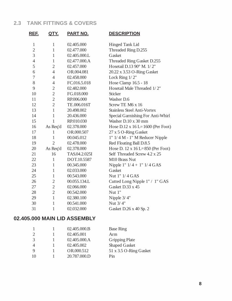
2.3 TANK FITTINGS & COVERS
REF. QTY. PART NO. DESCRIPTION 1 1 02.405.000 Hinged Tank Lid 2 1 02.477.000 Threaded Ring D.255 3 1 02.405.000.L Gasket 4 1 02.477.000.A Threaded Ring Gasket D.255 5 2 02.457.000 Hosetail D.13 90° M. 1/2" 6 4 OR.004.081 20.22 x 3.53 O-Ring Gasket 7 4 02.458.000 Lock Ring 1/2" 8 4 FC.016.5.018 Hose Clamp 16.5 - 18 9 2 02.482.000 Hosetail Male Threaded 1/2" 10 2 FG.018.000 Sticker 11 2 RP.006.000 Washer D.6 12 2 TE.006.016T Screw TE M6 x 16 13 1 20.498.002 Stainless Steel Anti-Vortex 14 1 20.436.000 Special Garnishing For Anti-Whirl 15 1 RP.010.030 Washer D.10 x 30 mm 16 As Req'd 02.378.000 Hose D.12 x 16 L=1600 (Per Foot) 17 1 OR.000.507 27 x 5 O-Ring Gasket 18 1 00.045.012 1" 1/4 M - 1" M Reducer Nipple 19 2 02.478.000 Red Floating Ball D.8.5 20 As Req'd 02.378.000 Hose D. 12 x 16 L=850 (Per Foot) 21 16 TAS.04.2.025I Self Threaded Screw 4.2 x 25 22 1 DOT.10.5587 M10 Brass Nut 23 1 00.345.000 Nipple 1" 1/4 + 1" 1/4 GAS 24 1 02.033.000 Gasket 25 1 00.543.000 Nut 1" 1/4 GAS 26 2 00.055.134.L Cutted Long Nipple 1" / 1" GAS 27 2 02.066.000 Gasket D.33 x 45 28 2 00.542.000 Nut 1" 29 1 02.380.100 Nipple 3/4" 30 1 00.541.000 Nut 3/4" 31 1 02.032.000 Gasket D.26 x 40 Sp. 2 02.405.000 MAIN LID ASSEMBLY
1 1 02.405.000.B Base Ring 2 1 02.405.001 Arm 3 1 02.405.000.A Gripping Plate 4 1 02.405.002 Shaped Gasket 9 1 OR.000.512 51 x 3.5 O-Ring Gasket 10 1 20.787.000.D Pin

9
2.4 HAND WASH TANK
REF. QTY. PART NO. DESCRIPTION
1 1 40.322.000 Hand Washing Tank 2 1 40.323.000 Fixing Bracket 3 2 40.324.100 Bracket 4 1 02.460.000 Female Threaded Tank Lid 5 1 00.055.044 Nipple 1/2" - 3/4" GAS 6 2 02.030.010 Gasket 7 1 02.497.000 3/4" Female Valve 8 2 RP.005.015I Washer D.5 x 15 9 2 RP.006.000 Washer D.6 10 2 TE.005.016I Screw TE M5 x 16 11 2 TE.006.016T Screw TE M6 x 16 12 2 TE.008.016T Screw TE M8 x 16 13 2 TE.010.020T Screw TE M10 x 20 14 2 RP.010.000 Washer D.10 15 2 RP.008.000 Washer D.8 16 1 OR.004.081 20.22 x 3.53 O-Ring Gasket 17 2 RD.006.000 Tab Washer D.6

10
2.5 FAN HOUSING ASSEMBLY
REF. QTY. PART NO. DESCRIPTION 1 1 50.120.000 Fan 50 Cover 2 1 05.730.000 50 Fan Housing 3 1 05.731.000Z D.535 Clamp 4 8 RP.010.030 Washer D.10 x 30 mm 5 4 RP.010.040 Washer D.10 x 40 6 4 D0.10.5587G Nut M10 7 2 20.088.000 Back Cover Bracket 8 1 05.732.000 Fan 50 9 4 RP.010.000 Washer D.10 10 2 TE.010.080T M10 x 80 Bolt 11 2 DOT.10.5587 M10 Brass Nut 12 1 05.654.200 Fan Net Protection 13 4 RP.006.018 Washer D.6 x 18 14 4 TE.006.016T Screw TE M6 x 16
11
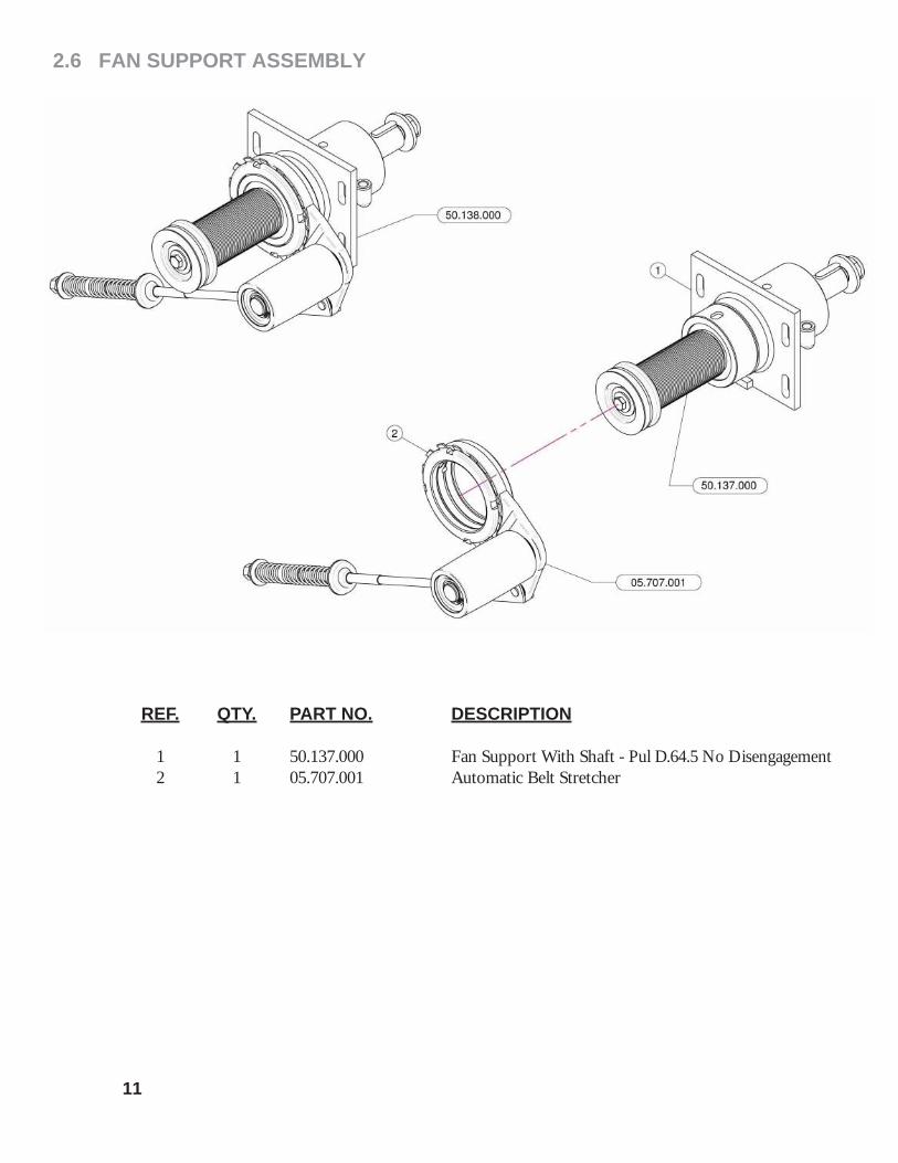
2.6 FAN SUPPORT ASSEMBLY
REF. QTY. PART NO. DESCRIPTION 1 1 50.137.000 Fan Support With Shaft - Pul D.64.5 No Disengagement 2 1 05.707.001 Automatic Belt Stretcher

12
2.7 FAN SUPPORT BREAKDOWN
REF. QTY. PART NO. DESCRIPTION
1 1 50.110.000 Nude Fan Support 2 1 50.119.060 Shaft With Pulley D.60 3 2 BASL.50.80.10 Viton Lip Seals -IEL (50-80-10) 4 1 K0.022.208 Roller Bearing 22-208 5 1 50.112.000 Spacer 6 1 K0.021.307 Roller Bearing 21-307 7 1 50.113.000 Spacer 8 1 I0.080.000 Internal D.80 Circlip 9 1 L.10.08.40 Feather Key 10 x 8 x 40 10 1 50.114.000 Spacer 11 1 20.789.000 Male/Female 90o Elbow 12 1 50.115.000 Dust Cover 13 1 20.820.000 Washer 14 1 DA.022.0BF Self-Locking Nut M22 x 1.5 15 1 05.746.000 Pulley For Pump D.82 (2 x 3V) 16 1 SE.006.020 Spring Pin D.6 x 20 17 1 RP.010.040 Washer D.10 x 40 18 1 RP.010.028 Washer D.10 x 28 19 1 TE.010.025FT Bolt TE M10 x 25

2.8 BELT TENSION ROLLER
REF. QTY. PART NO. DESCRIPTION
1 1 05.696.000 Idler Support 2 1 E0.100.000 External D.100 Circlip 3 1 MB.020.000 Tooth Lock Washer 4 1 04.593.000 Pin 5 1 05.704.000 Register Nut 6 1 00.100.002 Clip 7 1 05.697.000 Pivot 8 1 KM.005.000 Nut KM5 9 1 E0.025.000 External D.25 Circlip 10 2 I0.052.000 Internal D.52 Circlip 11 1 05.631.101 Spacer 12 1 05.630.000 Roller 13 1 04.585.000 Anti-Dust Cover 14 2 K6.205.2RS Roller Bearing 6205-2RS 15 1 05.653.000 Belt Stretcher Fork 16 1 20.260.000 Special Washer D.12 17 1 04.093.000 Spring 18 1 RP.019.000 Washer D.19 19 1 04.583.000 Special Screw 20 1 D0.12.5587G M12 Nut
13

14
2.9 LUBRICATION TUBING
REF. QTY. PART NO. DESCRIPTION 1 1 20.790.000 Drain Pipe 3/8" 2 1 40.266.000 Oil Exhaust Plug 3 1 02.013.000 Plug G1/4" 4 1 00.414.100 Straight Hose D.11 1/4" With Bleed 5 1 02.355.000 Nylon Assembly Clamp 6 As Req'd 02.217.000 Hose D.8 x 13 L=250 (Per Foot) 7 1 FC.014.5.016 Hose Clamp 8 1 20.792.000 Straight Hose D.11 G 1/4" For Breather 9 1 50.116.000 Filling Plug With Dipstick 10 1 50.122.000 Filling Pipe L=451

15
2.10 MAIN PULLEY
REF. QTY. PART NO. DESCRIPTION 1 1 04.719.000 Gasket 2 1 04.066.000 Body 3 1 03.701.000 Rotor 4 1 ID.010.001 Grease Nipple 5 1 00.480.J50 Pulley Diameter 480 J 50 6 2 02.502.002 Pin 7 1 05.632.01C Clutch 8 4 TE.012.050F Bolt M12 x 50 9 4 DO.12.5587F Nut M12 PG 5587F 10 2 02.502.001 Spring

16
2.11 OVERRUNNING CLUTCH
REF. QTY. PART NO. DESCRIPTION 1 1 05.632.000 Lower Support 2 1 04.565.000 Lower Shaft Spacing Bar 3 1 K6.307.2RS Bearing 4 1 04.589.000 Lower Shaft 5 1 K6.306.2RS Bearing 6 2 I0.072.000 Spacing Bar 7 1 20.810.000 Special Washer For Lower Support 8 1 TE.012.025FT Bolt TE M12 x 1.25 9 1 04.590.000 Spacer 10 1 04.555.001 Cover 11 4 TE.012.090 Screw TE M12 x 90 12 4 RP.012.036 Washer D12 x 36 13 4 D0.12.5587G M12 Nut

17
2.12 LIQUID FLOW PATH

18
2.12 LIQUID FLOW PATH
REF. QTY. PART NO. DESCRIPTION
1 1 02.157.073 Pump 2 2 02.374.000 M./F. 1"F/ 1"1/4M Reduction 3 4 OR.003.112 O-Ring D.28.24 x 2.62 4 3 00.058.006 1" 1/4 Fly Nut 5 1 00.058.004 D.30 Hosetail 6 8 F0.025.040I Stainless Steel Clip 7 1 02.447.000 3 Way Valve 8 8 D0.06.5588G Nut M6 9 4 RP.006.018 Washer D.6 x 18 10 4 RP.006.000 Washer D.6 11 1 OR.003.106 O-Ring D.26.65 x 2.62 12 1 00.493.000 1" 1/4 Fly Nut 13 1 02.339.000 45° Hosetail 14 2 02.291.000 Female Hosetail Thread 1" 15 2 00.422.000 Male Connector RH 30 1" GAS 16 9 OR.004.118 29.75 x 3.53 O-Ring Gasket 17 1 20.424.300 Bracket For Regulation Group 18 8 RP.008.000 Washer D.8 19 2 TE.008.025T Screw TE M8 x 25 20 4 D0.08.5588G Nut M8 21 1 02.450.110 Line Filter 1" 1/4 Female 22 2 DA.008.0AG Self Locking Nut M8 23 2 TE.008.130 Screw M8 x 130 24 2 OR.000.144 O-Ring D.39.69 x 3.53 25 1 02.390.08C Electro Valves 26 1 TM.014.000 Male Plug 1/4" 27 1 21.084.000 Hosetail 90° Wes 8/R1/4 28 2 FC.013.5.015 Hose Clamp 29 1 40.304.000 Fixing Bracket 30 1 24.072.000 Brass Fly Nut 1/2" 31 1 02.287.000 Fly Nut 1/2" 32 1 02.379.020 Straight Union R.H. 10 33 1 20.769.000 Gasket D.19.2/11.5 x 2.5 34 1 02.445.000 Pressure Gauge Ø100 INOX 0-6 Bar 35 1 02.470.000 Pressure Gauge Guard 36 1 02.274.000 Female Tesse 1" 37 1 00.045.012 1" 1/4 M - 1" M Reducer Nipple 38 1 02.293.000 1" M - 3/4" M Reducer Nipple 39 2 00.058.028 Straight Hose R.H. D.30 40 1 00.055.034 Nipple 1" / 1" GAS 41 1 OR.000.508 30 x 3 O-Ring Gasket

19
2.12 LIQUID FLOW PATH
REF. QTY. PART NO. DESCRIPTION 42 1 21.058.300 Three Ways Valve 43 1 21.182.000 Packing 1" M 44 1 21.183.000 Cap Stop 45 3 RP.008.024 Washer D.8 x 24 46 1 TE.008.016T Screw TE M8 x 16 47 1 02.182.000 Female 3/4" Cap 48 1 02.030.010 Gasket 49 2 00.055.24.2 1" Fly Nut 50 4 F0.023.035I Stainless Steel Clip 51 2 00.055.021 Straight Hose R.H. D.25 52 1 OR.002.125 31.47 x 1.78 O-Ring Gasket 53 2 OR.000.132 23.81 x 2.62 O-Ring Gasket 54 1 20.819.000 D.25 Hosetail 55 2 FC.021.5.023 Hose Clamp 21.5 - 23 56 As Req'd 02.211.000 Hose D.16 L=1100 (Per Foot) 57 As Req'd 02.211.000 Hose D.16 L=1100 (Per Foot) 58 2 00.055.046 Curved Union With R.H. D.17 59 2 02.349.000 17 x 23 x 3 Flat Gasket 60 2 00.055.045 3/4" Fly Nut 61 2 FC.023.5.025 Hose Clamp 23.5 - 25 62 As Req'd 02.217.000 Hose D.8 x 13 L=400 (Per Foot) 63 As Req'd 20.770.000 Hose D.25 x 32 L=510 (Per Foot) 64 As Req'd 20.852.000 Hose D.30 x 41 L=900 (Per Foot) 65 As Req'd 20.852.000 Hose D.30 x 41 L=1540 (Per Foot) 66 1 00.422.100 Male Connector RH 30 1" GAS 67 1 21.149.000 Valve 1" F. F. 68 As Req'd 20.852.000 Hose D.30 x 41 L=200 (Per Foot) 69 As Req'd 20.852.000 Hose D.30 x 41 L=1600 (Per Foot) 70 1 02.403.000 Straight Hose R.H. D.25 - 1" 71 1 50.355.100 Product Note Support 72 As Req'd 20.809.000 Hose D.25 x 32 L=380 (Per Foot)
20
2.13 PUMPS & ROUTING

21
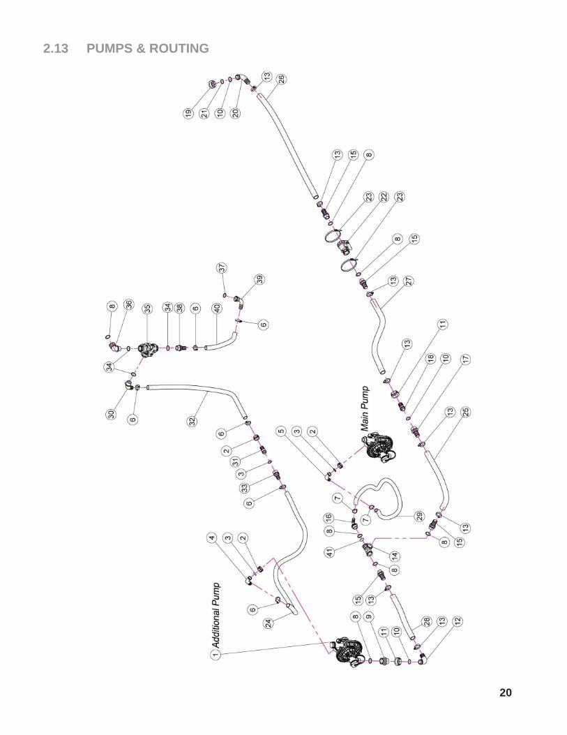
2.13 PUMPS & ROUTING
REF. QTY. PART NO. DESCRIPTION 1 1 02.157.075 Pump 2 3 00.055.24.2 1" Fly Nut 3 3 OR.000.132 23.81 x 2.62 O-Ring Gasket 4 1 00.055.037 D.25 Hosetail 5 1 00.055.038 Curved Union With R.H. D.19 6 6 F0.023.035I Stainless Steel Clip 7 2 FC.027.5.029 Hose Clamp 27.08 - W8 8 7 OR.004.118 29.75 x 3.53 O-Ring Gasket 9 1 02.374.000 M./F. 1"F/1"1/4 M Reduction 10 3 OR.003.112 O-Ring D.28.24 x 2.62 11 2 00.058.006 1" 1/4 Fly Nut 12 1 00.058.004 D.30 Hosetail 13 8 F0.025.040I Stainless Steel Clip 14 1 02.274.000 Female Tesse 1" 15 4 00.422.000 Male Connector RH 30 1" GAS 16 1 21.193.000 Hosetail 90° 1" R.H. 17 1 00.423.000 Male Connector RH 30 1" 1/4 GAS 18 1 00.058.028 Straight Hose R.H. D.30 19 1 00.493.000 1" 1/4 Fly Nut 20 1 00.483.000 D.30 1-1/4" Hosetail 21 1 OR.003.106 O-Ring D.26.65 x 2.62 22 1 04.109.000 Two Way Valves 23 2 02.356.000 Nylon Asembly Clamp 24 As Req'd 20.809.000 Hose D.25 L=120 (Per Foot) 25 As Req'd 20.852.000 Hose D.30 L=500 (Per Foot) 26 As Req'd 20.852.000 Hose D.30 L=110 (Per Foot) 27 As Req'd 20.852.000 Hose D.30 L=700 (Per Foot) 28 As Req'd 20.852.000 Hose D.30 L=400 (Per Foot) 29 As Req'd 02.212.000 Hose D.19 L=1200 (Per Foot) 30 1 24.068.000 D.25 Hosetail 31 1 00.055.021 Straight Hose R.H. D.25 32 As Req'd 20.809.000 Hose D.25 L=550 (Per Foot) 33 1 02.403.000 Straight Hose R.H. D.25 - 1" 34 3 OR.000.508 30 x 3 O-Ring Gasket 35 1 21.058.100 Three Ways Valve Complete 36 1 24.054.000 Hosetail M-F 1" 37 1 OR.000.134 O-Ring D.25.8 x 3.53 38 1 02.403.000 Straight Hose R.H. D.25 - 1" 39 1 20.794.000 Pipe 90° R.H. 25 3/4" GAS F 40 As Req'd 20.809.000 Hose D.25 L=250 (Per Foot) 41 1 40.386.000 Washer With Hole D.4 x Tee-Piece Union 2° Pump
22
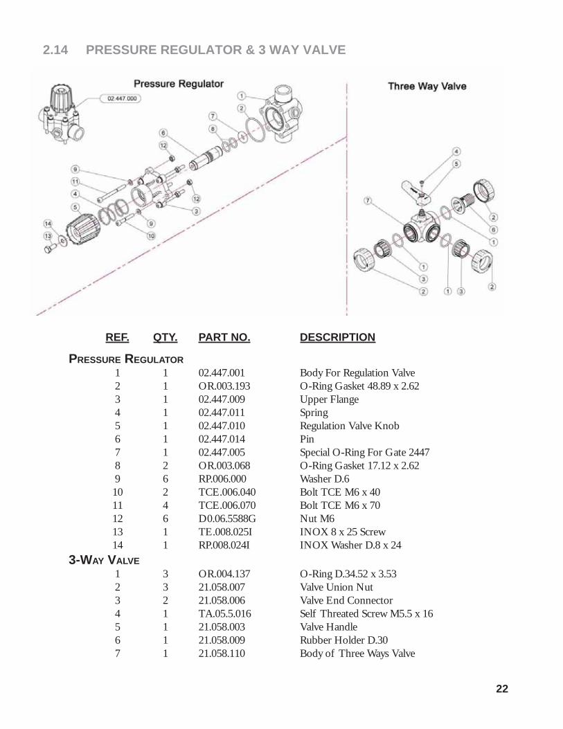
2.14 PRESSURE REGULATOR & 3 WAY VALVE
REF. QTY. PART NO. DESCRIPTION
PRESSURE REGULATOR 1 1 02.447.001 Body For Regulation Valve 2 1 OR.003.193 O-Ring Gasket 48.89 x 2.62 3 1 02.447.009 Upper Flange 4 1 02.447.011 Spring 5 1 02.447.010 Regulation Valve Knob 6 1 02.447.014 Pin 7 1 02.447.005 Special O-Ring For Gate 2447 8 2 OR.003.068 O-Ring Gasket 17.12 x 2.62 9 6 RP.006.000 Washer D.6 10 2 TCE.006.040 Bolt TCE M6 x 40 11 4 TCE.006.070 Bolt TCE M6 x 70 12 6 D0.06.5588G Nut M6 13 1 TE.008.025I INOX 8 x 25 Screw 14 1 RP.008.024I INOX Washer D.8 x 243-WAY VALVE 1 3 OR.004.137 O-Ring D.34.52 x 3.53 2 3 21.058.007 Valve Union Nut 3 2 21.058.006 Valve End Connector 4 1 TA.05.5.016 Self Threated Screw M5.5 x 16 5 1 21.058.003 Valve Handle 6 1 21.058.009 Rubber Holder D.30 7 1 21.058.110 Body of Three Ways Valve

23
2.15 SUCTION FILTER ASSEMBLY
02.450.010
REF. QTY. PART NO. DESCRIPTION 1 1 02.450.001 Line Filter Body 2 1 02.450.003 Ring Nut Filter In Line 3 1 02.450.011 Lid Filter With Unloading 4 1 OR.000.178 O-Ring D.74.63 x 5.33 5A 1 02.450.004C Cartridge w/ O-Ring 50 Mesh (Blue) 5B 1 02.450.204C Cartridge w/ O-Ring 80 Mesh (Grey) 5C 1 02.450.104C Cartridge w/ O-Ring 32 Mesh (White)
24
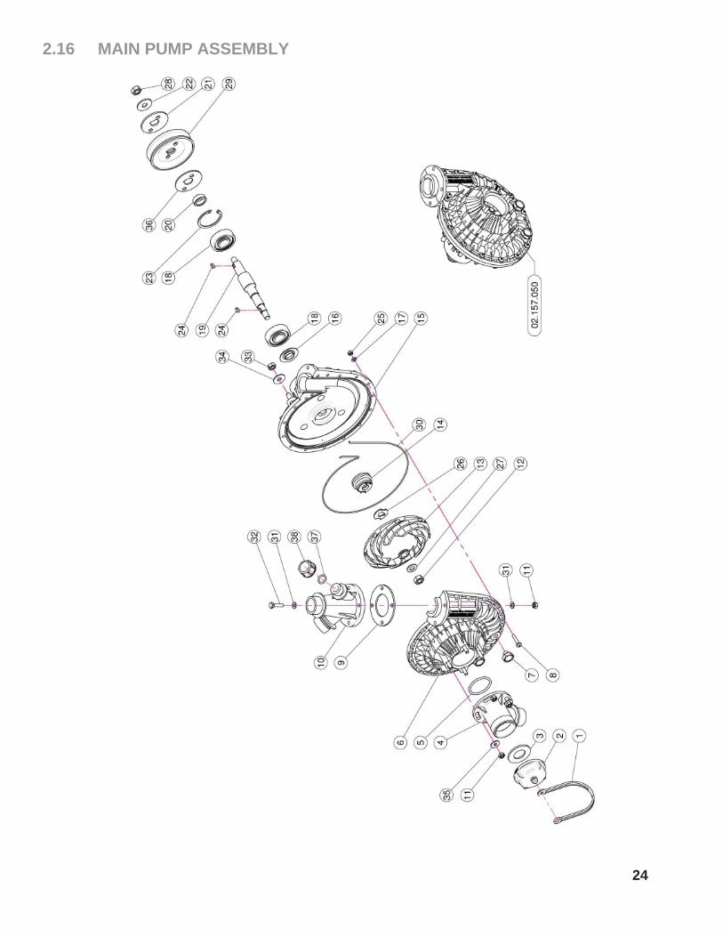
2.16 MAIN PUMP ASSEMBLY

25
2.16 MAIN PUMP ASSEMBLY
REF. QTY. PART NO. DESCRIPTION
1 1 21.183.000 Cap Stop 2 1 02.120.000 Rapid Thread Cap 3 1 02.130.000 24 x 46 x 3 Rubber Gasket 4 1 02.116.000 Suction Fitting 5 1 OR.000.144 O-Ring D.36.69 x 3.53 6 1 02.152.010 Housing 7 2 TM.010.015 M10 x 1.5 Cap 8 17 TC.05.25.85 Cross Slotted Screw M5 x 25 9 1 02.179.000 Rubber Gasket 10 1 02.113.000 Delivery Fitting 11 8 DOT.06.5587 M6 Brass Nut 5587 12 1 DOT.10.5587 M10 Brass Nut 13 1 02.153.000 CD 32 Pump Impeller 14 1 00.085.024CS Mechanical Seal 15 1 02.151.010 Pump Casing 16 1 20.406.000 Special Cover For Pump 17 17 RP.005.000 Washer D.5 18 2 K6.303.2RS Roller Bearing 19 1 02.155.010 CD 32 Pump Shaft 20 1 02.722.000 Bush 21 1 02.723.001 Special Washer mm3 22 1 RP.010.030 Washer D.10 x 30 mm 23 1 I0.047.000 Internal D.47 Circlip 24 2 L.05.05.10 5 x 5 x 10 Tang 25 17 DOT.05.5587 M5 Brass Nut (5587) 26 1 02.114.000 INOX Special Washer 27 1 RP.010.00I Washer D.10 INOX 28 1 D0.10.5588G M10 6S Big Lead Nut 5588 29 1 02.723.002 Pulley For Pump D.82.5 x 1 3V 30 1 OR.C02.070 R Cord D.2 L=700 31 8 RP.006.000 Washer D.6 32 4 TE.006.025T Screw TE M6 x 25 33 3 D0.08.5588G M8 6S Big Lead Nut 5588 34 3 RP.008.024 Washer D.8 x 24 35 3 RP.006.018 Washer D.8 x 18 36 1 02.723.005 Special Washer mm2 37 1 OR.000.117 13.1 x 18.34 x 2.62 O-Ring Gasket 38 1 TF.012.000 Blank Cap 1/2"

26
2.16.1 AGITATION PUMP ASSEMBLY

2.16.1 AGITATION PUMP ASSEMBLY
27
REF. QTY. PART NO. DESCRIPTION
1 1 21.183.000 Cap Stop 2 1 02.120.000 Rapid Thread Cap 3 1 02.130.000 24 x 46 x 3 Rubber Gasket 4 1 02.116.000 Suction Fitting 5 1 OR.000.144 O-Ring D.39.69 x 3.53 6 1 02.152.010 Housing 7 2 TM.010.015 M10 x 1.5 Cap 8 17 TC.05.25.85 Cross Slotted Screw M5 x 25 9 1 02.179.000 Rubber Gasket 10 1 02.113.000 Delivery Fitting 11 8 DOT.06.5587 M6 Brass Nut 5587 12 1 DOT.10.5587 M10 Brass Nut 13 1 02.153.000 CD32 Pump Impeller 14 1 00.085.024CS Mechanical Seal 15 1 02.151.010 Pump Casing 16 1 20.406.000 Special Cover For Pump 17 17 RP.005.000 Washer D.5 18 2 K6.303.2RS Roller Bearing 19 1 02.155.010 CD32 Pump Shaft 20 1 02.722.000 Bush 21 1 02.723.001 Special Washer 3 mm 22 1 RP.010.030 Washer D.10 x 30 mm 23 1 I0.047.000 Internal D.47 Circlip 24 2 L.05.05.10 5 x 5 x 10 Tang 25 17 DOT.05.5587 M5 Brass Nut (5587) 26 1 02.114.000 INOX Special Washer 27 1 RP.010.00I Washer D.10 INOX 28 1 D0.10.5588G M10 6S Big Lead Nut 5588 29 1 02.723.000 Pulley For Pump D.82.5 x 1 3 V 30 1 OR.C02.070 OR Cord D.2 L=700 31 8 RP.006.000 Washer D.6 32 4 TE.006.025T Screw TE M6 x 25 33 3 D0.08.5588G M8 6S Big Lead Nut 5588 34 3 RP.008.024 Washer D.8 x 24 35 3 RP.006.018 Washer D.6 x 18 36 2 02.723.005 Special Washer 2 mm 37 1 TF.012.000 Blank Cap 1/2" 38 1 OR.000.117 13.1 x 18.34 x 2.62 O-Ring Gasket 39 1 TF.001.000 Packing 40 1 24.100.000 Gasket D.30 x 3

28
2.17 CONTROL VALVE
REF. QTY. PART NO. DESCRIPTION 1 1 21.030.005 Switch 2V 2P On-Off 10A 3 2 21.030.007 Switch Cap D.12 4 2 RP.006.018 Washer D.6 x 18 5 1 DA.006.0AG Self Locking Nut - High M6 6 1 21.030.008 12V Power Jack 7 1 TE.006.025T Screw TE M6 x 25 8 1 21.030.004 10 Ah Fuse 9 1 21.030.002 Moving Fixing Bracket 10 1 21.030.003 Fixing Knob 11 1 20.111.000 Bracket 12 1 20.107.000 Female Bayonet Support

29
2.18 ELECTRIC VALVE ASSEMBLY

30
2.18 ELECTRIC VALVE ASSEMBLY
02.390.029
REF. QTY. PART NO. DESCRIPTION 1 1 02.390.007 Valve Body 2 1 02.390.008 Gasket 3 1 02.390.020 Pin 4 1 02.390.013 Stop Ring 5 1 02.390.014 Washer 7.2 x 12 INOX 6 1 02.390.015 Lower Valve 7 1 02.390.016 O-Ring 8 1 02.390.009 Superior Valves 9 1 02.390.011 Spring 10 1 21.130.005 Fork 11 1 02.390.028 Solenoid Valve 12 1 OR.002.075 D.18.77 x 1.78 O-Ring
02.390.08C 1 1 02.390.017 Valve Flange 2 8 RP.008.000 Washer D.8 3 4 DA.008.0AG Self Locking Nut M8 4 3 OR.003.156 O-Ring Gasket 39.34 x 2.62 5 2 02.390.029 Solenoid Valve 6 1 02.390.018 Connector 7 4 TE.008.150 Screw TE M8 x 150 8 2 OR.000.130 22.22 x 2.62 O-Ring Gasket 9 2 02.406.000 Hosetail D.16

31
2.19 PUMP & FAN BELTS
REF. QTY. PART NO. DESCRIPTION 1 4 RP.012.036 Washer D12 x 36 2 4 D0.12.5587G M12 Nut 3 1 TE.010.060T Screw TE M10 x 60 4 1 02.736.000 90 G. M10 x 1 Fitting 5 1 02.738.040 Greaser Extension M10 x 1 L=400 6 1 ID.010.001 Grease Nipple 7 1 02.737.000 Accessori 8 2 C0.500.03V V-Belt 9 1 C0.690.J50 Poly V-Belt 10 4 RP.012.000 Washer D.12 11 4 TE.012.040T Bolt TE M12 x 40
32
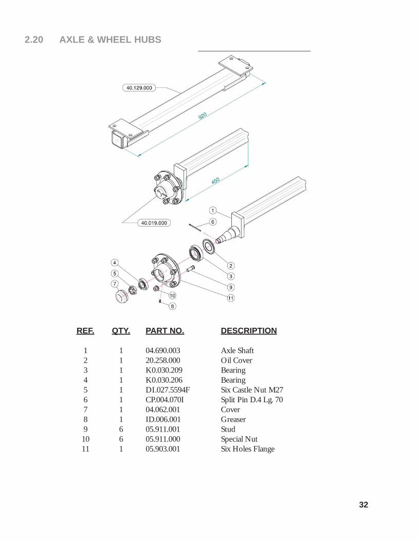
2.20 AXLE & WHEEL HUBS
REF. QTY. PART NO. DESCRIPTION 1 1 04.690.003 Axle Shaft 2 1 20.258.000 Oil Cover 3 1 K0.030.209 Bearing 4 1 K0.030.206 Bearing 5 1 DI.027.5594F Six Castle Nut M27 6 1 CP.004.070I Split Pin D.4 Lg. 70 7 1 04.062.001 Cover 8 1 ID.006.001 Greaser 9 6 05.911.001 Stud 10 6 05.911.000 Special Nut 11 1 05.903.001 Six Holes Flange

33
2.21 DRIVESHAFT - AB6105
REF. PART NO. DESCRIPTION
1 A622138 Quick Release Yoke 1 3/8" x 6 Spline 2 A622 Cross Bearing (2 Required) 3 A6254 Outer Tube Yoke 4 A544 Outer Drive Tube 5 A454 Inner Drive Tube 6 A1065 Poll Pin (2 Required) 7 A6245 Inner Tube Yoke 8 AB121 Quick Release Button 9 AS30090 Safety Guard Complete With Bearing 10 AS301 Release Lever Kit 11 ASB3 Bearing Kit

34
3 LIMITED WARRANTY
GEARMORE, INC., warrants each new Gearmore product to be free from defects in material and work-manship for a period of twelve (12) months from date of purchase to the original purchaser. This warranty shall not apply to implements or parts that have been subject to misuse, negligence, accident, or that have been altered in any way.
Our obligation shall be limited to repairing or replacement of any part, provided that such part is returned within thirty (30) days from date of failure to Gearmore through the dealer from whom the purchase was made, transportation charges prepaid.
This warranty shall not be interpreted to render us liable for injury or damages of any kind or nature, direct, consequential or contingent, to person or property. This warranty does not extend to loss of crops, loss because of delay in harvesting or any other expenses, for any other reasons.
Gearmore in no way warranties engines, tires, or other trade accessories, since these items are warranted separately by these respective manufacturers.
Gearmore reserves the right to make improvements in design or changes in specifi cation at any time, without incurring any obligations to owners or units previously sold.
Please be advised that all warranty work done by your dealer must be approved by Gearmore before work begins.
GEARMORE, INC.13477 Benson Ave.
Chino, CA 91710Always refer to and heed machine operating warning decals on machine.
To validate the warranty on this product, please log-in to our website - www.gearmore.com. You will fi nd "warranty registration" listed at the top of our homepage.
Copyright © 2022 FDOKUMEN