VC3500 User's Manual - PAC Solutions
241
VC3500 User’s Manual Software Version: 3.X Manual Number: MCO35 Manual Release Date: July 1999
-
Upload
khangminh22 -
Category
Documents
-
view
0 -
download
0
Transcript of VC3500 User's Manual - PAC Solutions

VC3500 User’s ManualSoftware Version: 3.X
Manual Number: MCO35
Manual Release Date: July 1999

© 1998 Valco Cincinnati, Inc. All Rights Reserved.
This manual is furnished with the VC3500 control and may only be used or copied in accordance with the terms ofpurchase.
No part of this manual may be reproduced, stored in a retrieval system, or transmitted, in any form or by any means,electronic, mechanical, recording, or otherwise, without the prior written permission of Valco Cincinnati, Inc. Theinformation in this manual is furnished for educational purposes only, is subject to change without notice, andshould not be construed as a commitment by Valco Cincinnati, Inc.
This manual was written and designed at Valco Cincinnati, Inc., 411 Circle Freeway Drive, Cincinnati, Ohio 45246.
Part Number: MC035
Printed in the USA
Valco Cincinnati Incorporated411 Circle Freeway DriveCincinnati, Ohio 45246TEL: (513) 874-6550FAX: (513) 874-3612
Valco Cincinnati LimitedHortonwood 32Telford, TF1 4 EU, EnglandTEL: (+44) 1952-677911FAX: (+44) 1952-677945
Valco GmbHStorkower Strasse 615749 Gallun,GermanyTEL: (+49) 33764 8700FAX: (+49) 33764 87070

CE Declaration of Conformity(according to EN 45014)
Manufacturer: Valco Cincinnati, Incorporated411 Circle Freeway DriveCincinnati, OH 45246USA
declares that the product:
Product Name: Glue ControllerProduct Model(s): VC3500Year of Manufacture: 1998
conforms to the following standards:
Safety: EN 60204-1
EMC Emissions: EN 50081-2EN 55011, Class A
EMC Immunity: EN 50082-2EN 61000-4-2EN 61000-4-3EN 61000-4-4
Degrees of Protection: EN60529-1, IP54
and complies with the requirements of:
Low Voltage Directive 73/23/EECEMC Directive 89/336/EEC
Office of CE ConformanceCincinnati, Ohio USA
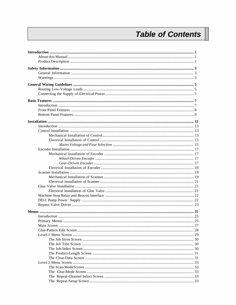
Table of Contents
Introduction ...................................................................................................................................................................... 1About this Manual ................................................................................................................................................. 1Product Description .............................................................................................................................................. 1
Safety Information .......................................................................................................................................................... 3General Information ............................................................................................................................................. 3Warnings ................................................................................................................................................................. 3
General Wiring Guidelines ........................................................................................................................................... 5Routing Low-Voltage Leads ............................................................................................................................... 5Connecting the Supply of Electrical Power...................................................................................................... 5
Basic Features .................................................................................................................................................................. 7Introduction ............................................................................................................................................................ 7Front Panel Features ............................................................................................................................................. 8Bottom Panel Features .......................................................................................................................................... 9
Installation ........................................................................................................................................................................ 13Introduction ............................................................................................................................................................ 13Control Installation ............................................................................................................................................... 13
Mechanical Installation of Control......................................................................................................... 13Electrical Installation of Control ............................................................................................................ 15
Mains Voltage and Fuse Selection ............................................................................................. 15Encoder Installation .............................................................................................................................................. 17
Mechanical Installation of Encoder ....................................................................................................... 17Wheel-Driven Encoder ................................................................................................................. 17Gear-Driven Encoder ................................................................................................................... 17
Electrical Installation of Encoder ........................................................................................................... 18Scanner Installation ............................................................................................................................................... 19
Mechanical Installation of Scanner........................................................................................................ 19Electrical Installation of Scanner............................................................................................................ 21
Glue Valve Installation ......................................................................................................................................... 21Electrical Installation of Glue Valve ...................................................................................................... 21
Machine-Stop Relay and Beacon Interface ...................................................................................................... 22DD-1 Pump Power Supply ................................................................................................................................. 22Bypass Valve Driver............................................................................................................................................. 23
Menus ................................................................................................................................................................................. 25Introduction ............................................................................................................................................................ 25Primary Menus ...................................................................................................................................................... 25Main Screen ........................................................................................................................................................... 27Glue-Pattern Edit Screen ...................................................................................................................................... 28Level-1 Menu Screen ........................................................................................................................................... 29
The Job Store Screen ................................................................................................................................ 30The Job Title Screen ................................................................................................................................. 30The Job-Index Screen ............................................................................................................................... 30The Product-Length Screen ..................................................................................................................... 31The Clear-Data Screen ............................................................................................................................. 31
Level-2 Menu Screen ........................................................................................................................................... 33The Scan-ModeScreen ............................................................................................................................. 33The Glue-Mode Screen ........................................................................................................................... 33The Repeat-Channel Select Screen ....................................................................................................... 33The Repeat-Setup Screen ........................................................................................................................ 33

Level-3 Menu Screen ........................................................................................................................................... 34The Clear-Data Screen ............................................................................................................................. 35The Minimum-Speed-Setting Screen .................................................................................................... 35The Cell-to-Gun-Setting Screen ............................................................................................................. 35
Level-4 Menu Screen ........................................................................................................................................... 36The Product-Length Screen ..................................................................................................................... 37The Manual-Ratio-Compensation Screen ............................................................................................. 37The Automatic-Ratio-Compensation Screen ........................................................................................ 37The On/Off-Compensation-Setting Screen ........................................................................................... 37
Level-5 Menu Screen ........................................................................................................................................... 38The Inch/Metric Screen ............................................................................................................................ 38The PIN-Code Screen ............................................................................................................................... 39
Level-6 Menu Screen ........................................................................................................................................... 39
Initial Setup....................................................................................................................................................................... 41Introduction ............................................................................................................................................................ 41Initial Setup ............................................................................................................................................................ 41
Disable Glue Valves for All Channels .................................................................................................. 41Specify Inches or Millimeters ................................................................................................................. 41Specify Minimum Gluing Speed ............................................................................................................ 42Set Cell-to-Gun Dimensions ................................................................................................................... 42Specify Ratio Compensation .................................................................................................................. 42
Manual Ratio Compensation ....................................................................................................... 42Automatic Ratio Compensation .................................................................................................. 43
Specify On and Off Compensation ....................................................................................................... 43Unknown Compensation Value ................................................................................................... 44
Restrict Screen Access ............................................................................................................................. 44Return to the Main Screen ....................................................................................................................... 44
Operation .......................................................................................................................................................................... 45Introduction ............................................................................................................................................................ 45Creating a Job ........................................................................................................................................................ 45Saving a Job ........................................................................................................................................................... 46Loading a Job ......................................................................................................................................................... 46Repeating Glue Patterns ....................................................................................................................................... 47Clearing Data ......................................................................................................................................................... 47Specifying the Scanner Mode ............................................................................................................................. 47Specifying the Glue Mode ................................................................................................................................... 48Specifying the Delay and Pattern Values .......................................................................................................... 49Specifying the Product Length ........................................................................................................................... 49
Troubleshooting ............................................................................................................................................................... 51Introduction ............................................................................................................................................................ 51
Internal Components ..................................................................................................................................................... 55Introduction ............................................................................................................................................................ 55CPU Board ............................................................................................................................................................. 56Channel 3 and 4 Logic Board ............................................................................................................................. 57Analog Board ......................................................................................................................................................... 57LED Board ............................................................................................................................................................. 57Interface Board ...................................................................................................................................................... 58Valve Driver Board ............................................................................................................................................... 59Power Supply Board ............................................................................................................................................. 60RS232 Board .......................................................................................................................................................... 61EPC Board .............................................................................................................................................................. 62Relay Board ............................................................................................................................................................ 63

Specifications .................................................................................................................................................................... 65
Part-Number List ............................................................................................................................................................ 67How to Order Parts ............................................................................................................................................... 67VC3500 Parts List ................................................................................................................................................. 67Optional Parts List ................................................................................................................................................ 69Recommended Spare Parts List—Mechanical ................................................................................................. 69Recommended Spare Parts List—Electrical..................................................................................................... 70Recommended Spare Parts List—DD-1 Pump ................................................................................................ 71
Warranty ........................................................................................................................................................................... 73
Service ................................................................................................................................................................................ 75
Appendix A —The Repeat Function .......................................................................................................................... 77Using the Repeat Function .................................................................................................................................. 77
Appendix B —The RS232 Communications Interface ......................................................................................... 79RS232 Communications Interface ..................................................................................................................... 79Location Codes ...................................................................................................................................................... 79Data Format ............................................................................................................................................................ 80Sending Information from Host to VC3500 ..................................................................................................... 81
Example of Sending Data ........................................................................................................................ 81Receiving Information from VC3500 ............................................................................................................... 82
Example of Receiving Data ..................................................................................................................... 82
Appendix C—Additional Scanner Mode Configuration ...................................................................................... 83Introduction ............................................................................................................................................................ 83Using One Scanner to Trigger Four Independent Glue Valves .................................................................... 83Applying Up To Four Patterns from a Single Glue Valve ............................................................................. 83Applying Up To Eight Patterns from a Single Glue Valve ............................................................................ 84
Appendix D—The VC3500J Control ......................................................................................................................... 87Introduction ............................................................................................................................................................ 87Overview ................................................................................................................................................................ 87Installation of Product Scanner........................................................................................................................... 87Electrical Installation of Remote Learn Button ............................................................................................... 87Operation ................................................................................................................................................................ 88Menu Buttons ......................................................................................................................................................... 88
Appendix E—Maintenance Procedures .................................................................................................................... E-1Introduction ............................................................................................................................................................ E-1Daily Maintenance ................................................................................................................................................ E-1Weekly Maintenance ............................................................................................................................................ E-23-Month Maintenance .......................................................................................................................................... E-36-Month Maintenance .......................................................................................................................................... E-412-Month Maintenance ........................................................................................................................................ E-5

Valco Cincinnati 1
Introduction
About this Manual
Valco Cincinnati has prepared this manual as an aid for installing, operating, and servicing the VC3500 control.This manual provides specific information about the unit, and general guidelines and references when discussingother equipment such as glue systems, scanners, encoders, and dispensing valves.
If you need more information, please contact your Valco Cincinnati representative.
Product Description
Valco’s VC3500 is a sophisticated microprocessor control that provides precise adhesive delivery. The control canbe designed for either two-channel, two-valve applications or four-channel, four-valve applications.
The VC3500 is used for applications where consistent glue patterns are required at high machine speeds and duringspeed changes. The VC3500 provides complex glue patterns that can be difficult or impossible to obtain with othersystems. The control operator can use the control’s front-panel touch-screen to edit glue patterns while the parentmachine is operating.
The VC3500 features a user-friendly, multi-language display; multiple pattern placement; speeds of up to 2000 feet(610 m) per minute; internal flow control; and optional RS-232 communications with external devices. The VC3500control can store up to 99 fully programmed jobs.

Valco Cincinnati 3
General Information
It is the purchaser’s responsibility to ensure that all local, county, state, and national codes, regulations, rules, andlaws relating to safety and safe operating conditions are met and followed.
The best safeguard is trained personnel. The purchaser is responsible for providing personnel who are adequatelytrained to install, operate, and maintain Valco components and systems.
This section contains information that is essential to the safety of personnel. Safety information is included through-out the rest of the manual as well. The following safety conventions are used to indicate potential safety hazards:
Warnings
All personnel involved with the installation, operation, and maintenance of the equipment must read and thoroughlyunderstand the following warnings:
WARNING! Promptly repair or replace all worn or damaged electrical wiringand equipment wires to avoid danger to personnel.
WARNING! Properly route all electrical wires to avoid danger to personneland damage to moving parts of machine.
WARNING! Disconnect all power before opening the control. Only qualifiedpersonnel should open and service the control.
WARNING! This symbol indicates the presence of un-insulated dangerousvoltage within the product’s enclosure. This voltage may cause electricalshock or fire. Failure to observe precaution may result in death, personalinjury, and/or equipment damage.
WARNING! This convention is used to alert the user to important installation,operation, and/or maintenance information. Failure to observe precautionmay result in personal injury or death.
CAUTION! This convention is used to alert the user to important installation,operation, and/or maintenance information. Failure to observe precautionmay result in damage to equipment.
Safety Information
Safety Instructions Manual Name
Valco Cincinnati4
WARNING! When making adjustments or performing checkout procedures,stay clear of any moving mechanical parts and do not touch exposed electri-cal equipment or electrical connectors.
WARNING! Keep pump cover and electrical enclosures closed except duringsetup, service, and checkout procedures.
WARNING! Promptly repair or replace all worn or damaged parts.

Valco Cincinnati 5
Routing Low-Voltage Leads
When routing low-voltage leads, follow these guidelines:
• Do not route low-voltage leads in the same conduit as wires carrying a high-current load.
• Do not route low-voltage leads adjacent to, or across wires carrying a high-current load. If low-voltageleads must cross or run parallel to wires carrying high current, keep the leads at least 6" (152 mm) fromhigh-current wires.
• Do not splice or solder leads.
• Trim leads to the required length. Leads should be only as long as necessary for installation.
• All wiring should be in conduits or wireways.
Connecting the Supply of Electrical Power
Electrical connections should be made only by experienced service per-sonnel!
The control must be connected to a “clean” supply of electrical power. Use a dedicated circuit if possible—if adedicated circuit is not available, do not connect the control to a circuit that supplies high-amperage equipment. Useanother circuit such as a lighting circuit.
General Wiring Guidelines
Electrical installation should be accomplished only by experienced servicepersonnel!

Valco Cincinnati 7
Introduction
This section describes the basic features of the 3500 control.
Basic Features
Figure 1. Front Panel of VC3500
5
1
2
3a3 b
4
6a6 b6c6 d6e6f6g6h

Basic Features VC3500 User’s Manual
Valco Cincinnati8
Front-Panel Features
The following are descriptions of the features on the front panel (see Figure 1).
1 Touch-screen display
All glue pattern parameters are entered and displayed using the touch-screen.
2 Valve enable switches
“|”—Valve is enabled and ready to dispense glue under program control.
“0”—Valve is disabled and will not dispense glue.
PURGE—Valve will dispense glue as long as the switch is manually held in this position.
3 Valve indicator lights (items 3a and 3b are valve indiator lights)
3a Valve enable indicator lights
This light illuminates when the valve enable switch is placed in the “|” (enabled) position (seeitem 2). This light will not illuminate when the valve enable switch is placed in the “0” (disabled)position.
3 b Valve dispensing indicator lights
This light illuminates when the valve is dispensing glue (purge function or a programmed command).
4 Scanner indicator lights
This light illuminates when the scanner detects product.
5 Glue pressure adjustment
You press this button to adjust glue pressure (“+” = increase and “ -” = decrease)
6 Status indicator lights
Items 6a through 6h are status indicator lights.
6a Less than minimum speed
“<X/MIN” illuminates when the speed of the parent machine is less than the minimum speed setting .
6 b Greater than minimum speed
“>X/MIN” illuminates when the speed of the parent machine is greater than the minimum speed setting.
6c Jam
This light illuminates when a scanner detects a product that is longer than the product length value enteredin the control.
6 d Encoder
This light illuminates when encoder pulses are received by the control.
6e 56V
“56V” illuminates when the 56-volt valve peak voltage is supplied.
6f 12V coil hold voltage
“12V” illuminates when the 12-volt valve hold voltage is supplied.
6g 12V input supply voltage
This light illuminates when the 12-volt supply for scanners and the encoder is operational. This light willbe illuminated under normal operating conditions.
6h 5V logic supply voltage
This light illuminates when the 5-volt logic supply is operational. This light will be illuminated undernormal operating conditions.

Basic FeaturesVC3500 User’s Manual
Valco Cincinnati 9
Bottom Panel Features
The following are descriptions of the features on the bottom panel (Figure 2).
1 Air exhaust output
This output is for air to exhaust to the atmosphere. It is not normally connected.
2 Air input
Input for regulated air, 80-100 psi (6.5–8 bar).
3 Computer interface
DB-9 socket for optional RS232 communications (standard DTE)
4 Air output
This output is connected to the glue source to provide speed-dependent glue pressure.
5 Optional machine interface (items 5a and 5b are machine interface connectors)
5a Beacon/horn connector
See the “Installation” section for wiring details.
5 b Machine interface relay connector
See the “Installation” section for wiring details.
6 Power module
This main power supply connection uses an IEC standard line cord (supplied). The fuse drawer in thismodule provides fuses for both sides of the main supply and selection of either 115 or 230VAC. The on/off switch for the control is also located on this module.
Note! Ensure that the proper fuse configuration is installed to suit the power source. (See the “Installation”section for details.)
7 Line cord clampTwo clamps are included in the installation kit. One clamp fits the included European line cord and theother clamp fits the included North American line cord. You use two 4-40x 3/8² screws to attach clamp toenclosure.
Basic Features VC3500 User’s Manual
Valco Cincinnati10
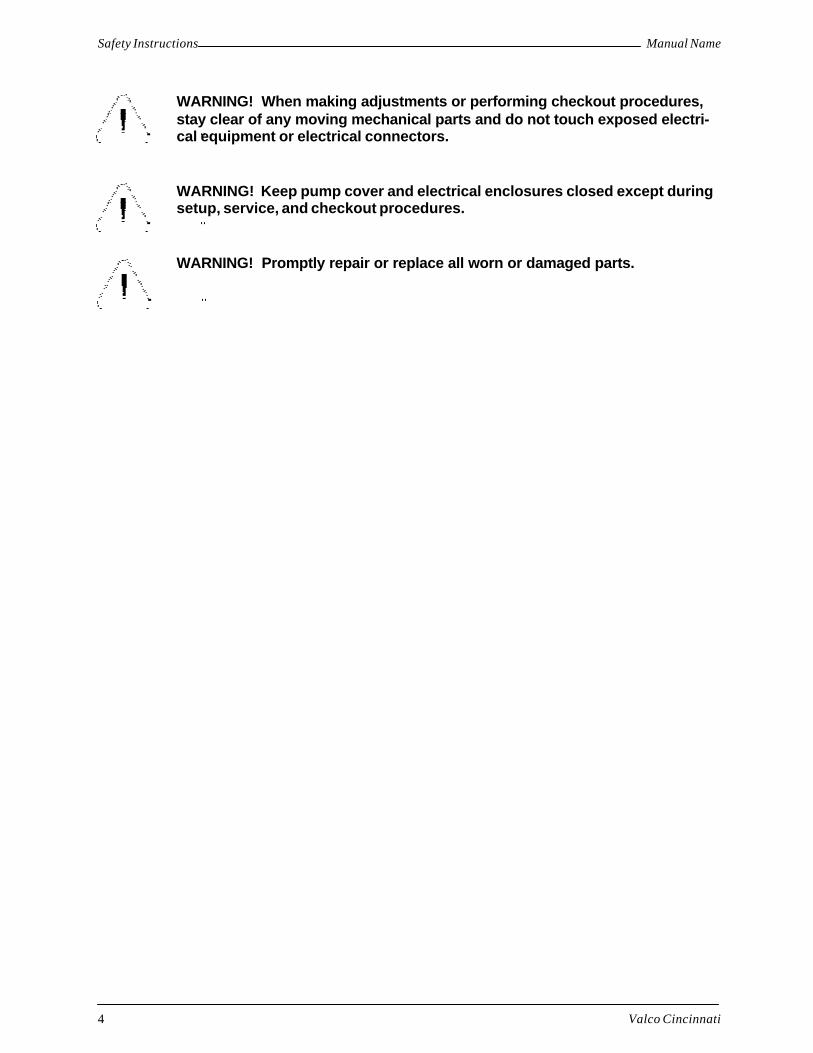
Figure 2. Bottom Panel of VC3700
5a. beacon/horn connector
5b. relay connector
1. air exhaust
2. air input
3. RS232 communications interface
4. regulated air (out) to glue regulator (Figure 3)
street tee, F-F-M, 1/8
adapters, F-M, 1/8 x 1/8
gauge, 0-60 psi
7. line-cord clamp
screws, 4-40 thread
6. power entry module
During installation, choose anycombination of two fittings for tubing diameter:
male connector, 3/8 x 1/8 and male elbow, 1/4 x 1/8 or
male connector, 3/8 x 1/8 and male elbow, 1/4 x 1/8

Basic FeaturesVC3500 User’s Manual
Valco Cincinnati 11
shock arrestor
T-handle (providesminimum pressure setting)
sealing nut(must be tightenedfor proper operation)
to VC3500 regulated air port
adhesive supply
glue regulator
to glue station
shutoff valve
Figure 3. Glue Regulator

Valco Cincinnati 13
Introduction
This section contains both mechanical and electrical installation instructions. Read the “Safety” section in thismanual before attempting these procedures.
Electrical installation should be accomplished onlyby experienced service personnel!
Refer to Figure 8 for detailed layout of internal connections.
Control Installation
Mechanical Installation of ControlThe control should be installed on the operator’s side of the parent machine, in a location where vibrations will notoccur. The control should require less than 25 feet (8 m) of wiring to reach the glue station, sensor,and shaft encoder(longer wiring is available on request). A 5/16" (8 mm) hex wrench can be used to unlock the door of the controlenclosure.
To install the control, follow these steps:
1. Attach the control to a stationary, vertical surface, using the mounting holes located inside the control enclosure(see Figure 6).
Note! The control may also be mounted either to Valco’s machine-mount pedestal or mobile-system pedestal(see Figures 4 and 5).
Installation
Figure 4. Machine-Mount System Pedestal
Manifold with (4)3/8" NPTports
25.75"(654 mm)
9.33"(237 mm)
13"(330 mm)
0-125 psiregulator/filterassembly shown
1.25"(31.8 mm)
3" (76 mm)
.406" (10.3m) diameter

Installation VC3500 User’s Manual
Valco Cincinnati14
Figure 5. Mobile System Pedestal
Figure 6. Mounting Hole Dimensions
)
66.3"(1684 mm)
24.3" (617 mm) 19.6" (498 mm)

InstallationVC3500 User’s Manual
Valco Cincinnati 15
Electrical Installation of ControlThe main’s supply must be 115/230 VAC, 50/60 Hz, 2/1 A. The 115/230 power requirement is field-switchable.The power module accepts a standard IEC line cord (supplied).
To connect the line cord, follow these steps:
1. Attach the line cord clamp to the bottom surface of the VC3500, using the two screws on either side of the powermodule.
2. Insert the line cord into the power module
3. Tighten the line cord clamp to prevent inadvertent loss of power.
Note! The line cord supplied can either be directly wired to a branch circuit or (with the proper plug type)plugged into a 115 or 230 VAC outlet socket. The wire colors of the supplied line cord are as follows:
Mains Voltage and Fuse Selection
The fuse holder on the bottom panel of the power module contains the fuse drawer, which allows for either 115VACor 230VAC operation (Figure 7).
To replace or check mains fuses, follow these steps:
1. Remove all electric power from the unit.
2. Remove the line cord.
3. Use a small screwdriver to open the hinged door ofthe fuse holder.
4. Remove the fuse drawer (ensure that the fuses inthe holder remain in place).
5. The drawer is labeled “230V” and “115V.” Rotate thedrawer to the appropriate voltage.
6. For line-to-neutral operation, use the shorting clip(jumper) and one fuse. Shorting clip must be on leftside (when rotated to read the correct voltage). Forline-to-line operation, use two fuses.
7. Replace the drawer in the fuse holder and close thedoor of the fuse holder.
8. The operating voltage shows through the window inthe fuse holder door. Ensure that voltage is correct.
9. Replace the line cord.
Wire Type International Line Cord Color North American Line Cord Color
Line Brown Black
Neutral Blue White
Ground Green/Yellow Green
Figure 7. Fuse Drawer
230V (USA)line-to-line
230V (Europe) or115VAC (USA)line-to-neutralshorting clip
115V/230V

Installation VC3500 User’s Manual
Valco Cincinnati16
Figure 8. Internal Connections Diagram

InstallationVC3500 User’s Manual
Valco Cincinnati 17
Encoder Installation
Mechanical Installation of EncoderAn encoder must be installed in order for the control to determine the speed of the parent machine. For best results,100 pulses per inch (25.4 mm) of product travel should be supplied to the VC3500. If less than 100 pulses per inch(25.4 mm) are supplied, poor resolution may result in pattern placement errors. If more than 100 pulses per inch(25.4 mm) are supplied, the maximum specified speed of 2000 feet/min (610 m/min) must be reduced.
There are two primary types of encoders:
• Wheel-driven encoder
• Gear-driven encoder
Wheel-Driven Encoder
If using a wheel-driven encoder (Figure 9), a VCE-1000 encoder with a 10-inch measuring wheel is recommended.
To install a wheel-driven encoder, follow these steps:
1. Mount the encoder’s bracket to the frame of the parent machine.
2. Ensure that the wheel of the encoder rides securely against the belt and does not slip.
3. In the level-4 menu screen, set ratio compensation to 100 pulses.
Gear-Driven Encoder
The following formula can be used to determine the correct combination of gear teeth and encoder for approxi-mately 100 pulse per inch (25.4 mm):
Teeth-S x Counts = Pulses per inch (25.4 mm) of travelTeeth-E Travel
Teeth-S=Number of teeth on the line-shaft driver gear
Teeth-E=Number of teeth on the encoder driven gear
Counts=Number of encoder pulses per revolution
Travel= Product travel in inches (or millimeters divided by 25.4) per revolution of the drive shaft
Figure 9. Example of a Wheel-Driven Encoder

Installation VC3500 User’s Manual
Valco Cincinnati18
Example:
Using a 92-tooth split line shaft gear (driver), a 24-tooth encoder driven gear, a 500-pulse encoder, and 18 inches(or 457 millimeters divided by 25.4) of travel per drive shaft revolution.
92 x 500 = 106.4824 18
Therefore, the ratio compensation setting should be 106.5.
To install a gear-driven encoder (Figure 10), follow these steps:
1. Install the driver gear on the line shaft. Tighten the set-screws.
2. Position and install the encoder so that it is square with the driver gear.
3. Raise or lower the encoder to tighten the belt against the driver gear. (Ensure that the two sides of the belt are notpressed together under the wheel.) Due to the low torque required, the belt should not be extremely tight.
Note! At least 7-9 teeth should engage in the line shaft driver gear. It may be necessary to fabricate an adjustablebracket to connect the encoder base to the parent machine frame.
Electrical Installation of EncoderA 12VDC encoder must be used with the VC3500 control. The cable used to connect the encoder to the controlshould have a minimum of three conductors (18-22 AWG) and a shield.
To connect the encoder to the control, follow these steps:
1. Insert the encoder cable into the control enclosure through a cord grip located on the bottom panel of the control.
2. Connect the encoder to the three-terminal connector (located inside the control) labeled“ENCODER”.
Figure 10. Typical Installation of a Gear-Driven Encoder
drive gear
minimum7-9 teeth
line shaft (drive)
driven gear
machine base machine baseadju
stab
le m
ount
ing
supp
lied
by c
usto
mer
Valco shaft encoder
11” (279 mm)

InstallationVC3500 User’s Manual
Valco Cincinnati 19
Note! Connections are as follows (see Figure 8 for wire colors):
Pin 1: +12VDC—black
Pin 2: Encoder channel signal—red
Pin 3: Return—white
2. Connect the shield wire to the protective earth (P.E.) terminals located near the cord grip base plate.
3. Tighten the cord grip used by the encoder cable.
Note! An optional encoder/scanner A-B switch is available to enable one of two possible encoder/scanner pairs.This switch mounts to the base plate (Figure 11).
Scanner Installation
Mechanical Installation of ScannerAt least one product scanner should be installed to detect the leading edge of the product. A single scanner can beused to start the glue patterns of both channel 1 and channel 2 or the channels can have two separate scanners.
To install the scanner, follow these steps:
1. Position the scanner assembly brackets upstream from the glue station (Figures 12 and 13).
2. Set the scanner 1.5 to 2.0 inches (38mm to 51mm) above the product.
Note! The scanner must see through an open area on the parent machine with no obstructions.
Note! The distance between the scanner and the glue valve’s nozzle (cell-to-gun distance) cannot exceed thedistance from the leading edge of a product to the leading edge of the next product (repeat dimension).The minimum distance allowed between the scanner and the glue valve will be greater at high parentmachine speed. The following is a general guide:
Figure 11. Wiring Diagram for Optional A-B Switch

Installation VC3500 User’s Manual
Valco Cincinnati20
Speed Minimum Cell-to-Gun Distance
100 ft/min (30.5 m/min) 1" (25.4 mm)
500 ft/min (152.4 m/min) 2" (51 mm)
1000 ft/min (304.8 m/min) 4" (102 mm)
1500 ft/min (457 m/min) 6" (152 mm)
2000 ft/min (610 m/min) 8" (203 mm)
2' (51 mm)
product flow
minimum = see chart above
to VC3700
to VC3700scanner
cell-to-gun
Figure 12. Top-Down Glue Station
Figure 13. Top-Down, Bottom-UpCombination Glue Station
6.5
10.0

InstallationVC3500 User’s Manual
Valco Cincinnati 21
Electrical Installation of Scanner
The cable used to connect the scanner(s) to the VC3500 control should have a minimum of three conductors (18-22AWG) and a shield.
To connect the scanner to the control, follow these steps:
1. Insert the scanner cable into the control enclosure through a cord grip located on the bottom panel of the control.
2. Connect the scanner cable to one of the three-terminal connectors labeled “scanner-1”, “scanner-2”, “scanner 3”,or “scanner 4”. (A two-channel control only has “scanner 1” and scanner 2”.)
Note! On a two-channel control, the “scanner-1” connector must be used for the scanner installed for channel 1.This scanner can also be used to control channel 2. If separate scanners are desired to control channel 1and channel 2, the “scanner-1” connector must be used for the scanner installed for channel 1, and the“scanner-2” connector must be used for the scanner installed for channel 2.
On a four-channel control, the “scanner-3” connector must be used for the scanner installed for channel3. This scanner can also be used to control channel 4. If separate scanners are desired to control channel 3and channel 4, the “scanner-3” connector must be used for the scanner installed for channel 3, and the“scanner-4” connector must be used for the scanner installed for channel 4.
Connections are as follows:
Pin 1: +12VDC—red
Pin 2: Scanner signal—green
Pin 3: Return—black
3. Connect shield wire(s) to the protective earth (P.E.) terminals located near cord-grip base plate.
4. Tighten the cord grip used by the scanner cable(s).
Glue Valve Installation
Electrical Installation of Glue ValveThe glue valve cable should have a minimum of two conductors (18-20 AWG) and a shield (four conductors and ashield if a remote purge is required).
To connect the glue valve to the control, follow these steps:
1. Insert the glue valve cable into the control through a cord grip located on the bottom panel of the control.
2. Connect glue valve cable to the connectors labeled “valve-1” or “valve-2.”
Note! On a two-channel control, the “valve-1” connector must be used as the interface point for the glue valvecontrolled by channel 1. The “valve-2” connector must be used as the interface point for the glue valvecontrolled by channel 2 (Figure 8).
On a four-channel control, the bottom valve driver board is for channels 1 and 2. The top driver board isfor channels 3 and 4.

Installation VC3500 User’s Manual
Valco Cincinnati22
Connections are as follows:
Pin 1: Purge output—yellow
Pin 2: Purge return—black
Pin 3: Valve output—red
Pin 4: Valve return—white
3. The shield wire should be connected to the protective earth (P.E.) terminals located near the cord grip base plate.
4. Tighten the cord grip used by the valve cable.
Machine-Stop Relay and Beacon Interface
An optional machine stop relay and beacon interface (option D1) is required to indicate a jam condition or glueinspection fault to the parent machine. Normally open and normally closed contacts are provided at a male connec-tor mounted to the cord grip base plate. Contact rating is 24VDC or 60VAC at 2A.
When a jam condition is detected, the machine stop relay is energized. The relay is de-energized when the speed ofthe parent machine drops below the minimum speed setting (see the level-3 menu screen). The front-panel jamindicator also illuminates.
A field-wireable mating connector (Figure 13a) is provided to wire the relay contacts to the parent machine stopcircuit (cable must be supplied by customer). Connections are as follows:
Pins 1 and 2: Normally closed contact
Pins 3 and 4: Normally open contact
Pin 1: 12VDC
Pin 2: Not used
Pin 3: Jam (red) light
Pin 4: Audible alarm signal
A pre-wired cable is provided with the beacon.
DD-1 Pump Power Supply
A source is available to supply power for a DD-1 pump at connector J6 of the power supply board (151xx368). Thissupply is 32VDC, fused at 1.6A, with connections as follows:
Pin 1: 0V
Pin 2: 32VDC
Note! Since the DD-1 pump is configured to accept an AC source and then rectify it to DC, polarity of a DCsource is not relevant.
An optional beacon with audible alert (Figure 2) can be remotelymounted to indicate a jam condition. A female connector mounted tothe cord-grip base plate provides the connection point for beacon/alarmsignals. Connections are as follows:
rubber grommet
rubber grommet
0.23"
0.31"
Figure 13a. Field-Wireable MatingConnector

InstallationVC3500 User’s Manual
Valco Cincinnati 23
Bypass Valve Driver
A bypass valve (or dump valve) may be needed to divert excess glue in the glue line away from the applicator toavoid puddling during startups and quick stops. A 12VDC, 1A driver is available at connector J8 of the interfaceboard. Connections are as follows:
Pin 1: 12V
Pin 2: Signal

Valco Cincinnati 25
Menus
Introduction
This section contains descriptions of the control’s menus, which are displayed on screens. The control’s screens aretouchscreens, which means that you push the buttons on the actual screen display. For specific operating proce-dures, see the “Operation” section.
Primary Menus
The VC3500 contains the following primary menu screens (Figure 14):
• Main screen—The main screen is the screen that displays when power is supplied to the control.
• Level-1 menu screen—The level-1 menu screen provides access to the job store screen, the job titlescreen, the job index screen, the product length screen, and the clear current data screen.
• Level-2 menu screen—The level-2 menu screen provides access to the scan mode screen, the glue modescreen (two-channel model only), and the repeat function.
• Level-3 menu screen—The level-3 menu screen provides access to the clear data screen, the minimumspeed screen, and the cell-to-gun screen.
• Level-4 menu screen—The level-4 menu screen provides access to the product length screen, the ratiocompensation screen, and the channel compensation screens.
• Level-5 menu screen—The level-5 menu screen provides access to the glue QC screen (two-channelmodel only), the inch/metric screen, and the PIN code screen.
• Level-6 menu screen—The level-6 menu screen provides access to language selection.
These menu screens and their functions are described in the following paragraphs.

Menus VC3500 User’s Manual
Valco Cincinnati26
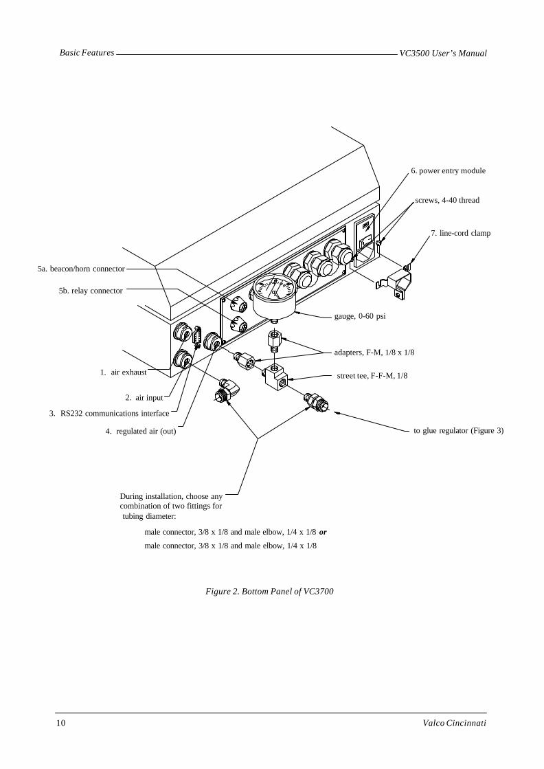
Figure 14. Main Menu Screen, Glue Pattern Edit Screen, and Level-1through Level-6 Menu Screens
Main Menu Screen
PSI CONFIG
CONFIGEXIT
MORE
EXIT
MORE
SCAN MODE
GLUE MODE
EXIT
MORE
CLEAR DATA
CELL-GUN 1
CELL-GUN 2
MIN SPEED
CELL-GUN 3
CELL-GUN 4
EXIT ENGLISH
FRANÇAIS
DEUTSCH
EXIT
MORE
JOB STORE >>><<<
ITALIANO
ESPAÑOL
NEDERLANDS
EXIT
MORE
PRD LENGTH
COMP CHAN1
RATIO COMP
COMP CHAN3
00.00
EXIT
MOREEXIT
MOREEXIT
MOREEXIT
1
2
3
4
6
PRD LENGTH
CLEAR DATA
COMP CHAN2 COMP CHAN4
EXIT
MORE5
MOREEXIT
00.00
00.00
00.00
Level-1 Menu Screen
Level-2 Menu Screen
Level-3 Menu Screen
Level-4 Menu Screen
Level-5 Menu Screen
Level-6 Menu Screen
REPEAT
(If screens 3-6 havebeen restricted, pressing“MORE” will display a 6-digitnumeric keypad.)
REPEAT
GLUE MODE
SCAN MODEEXIT
MORE
2
5 6
3 4
1 2
00.00 00.00
Glue-Pattern Edit Screen
Number field
0000 00000000 0000
GLUE QC
IN/METRIC
PIN

MenusVC3500 User’s Manual
Valco Cincinnati 27
Main Screen
The main screen displays when power is supplied to the control (Figures 15 and 16). The features of the main screenare as follows:
PSI
CHAN 1DEL PAT03.00 "
CONFIG
CHAN 2DEL PAT
2 3 4 5 6
1 7
8 9 10
00.00 00.00
00.00 00.00
Figure 15. Example of a Two-Channel Control with Glue Mode Set to“Delay Pattern”
PSI
CHAN 1DEL PAT
CONFIG
11 12
13 15 14
00.00 00.00
00.00 00.002
03.00 "
Figure 16. Example of a Two-Channel Control with Glue Mode Set to“Delay Pattern Delay Pattern”
1 Glue pressure bar graph
This field displays the pressure supplied to the glue source. The pressure is displayed in either psi or bar,depending on the setup of the control.
2 Glue pattern delay (channel 1)
This field displays the distance from the leading edge of the product to the beginning of the glue pattern.
3 Channel 1 glue pattern edit
This field displays the channel assignment for the delay and pattern length settings seen on the left andright of this display.
4 Software version
This field displays the software version used by the control.

Menus VC3500 User’s Manual
Valco Cincinnati28
5 Inch or mm indicator
This field displays the measurement setup for the control. The inch symbol (") indicates imperial measure-ments and “mm” indicates metric measurements.
6 Glue pattern length (channel 1)
This field displays the length of the glue pattern.
7 Configuration
The level-1 menu screen displays when this button is pressed.
8 Glue pattern delay (channel 2)
This field displays the distance from the leading edge of the product to the beginning of the glue pattern.
9 Channel 2 glue pattern edit
This field displays the channel assignment for the delay and pattern length settings seen on the left andright of this display
10 Glue pattern length (channel 2)
This field displays the distance of the glue pattern.
Note! Items 11-15 pertain to the “delay pattern delay pattern” glue mode.
11 First glue pattern delay
This field displays the distance from leading edge of product to beginning of first glue pattern.
Note! A minimum of 00.01 inches (0001 mm) must be entered for the delay setting to activate the channel.
12 First glue pattern length
This field displays the distance of the glue pattern.
13 Second glue pattern delay
This field displays the distance from end of first glue pattern to beginning of second glue pattern.
14 Second glue pattern length
This field displays the distance of the second glue pattern.
15 Page down
Pressing this button displays pattern information for the next channel.
Glue-Pattern Edit Screen
The glue-pattern edit screen (Figure 18) displays when any of the numbers on the main screen are pressed. Thefunction of each button is as follows:
“+”—This button increases values for the pattern delay and length.
“-”—This button decreasse values for the pattern delay and length.
Symbol in center of the screen—This button returns you to the main screen.
Note! The main screen will appear automatically if the parameters in the glue pattern edit screen have not beenchanged for ten seconds.

MenusVC3500 User’s Manual
Valco Cincinnati 29
Level-1 Menu Screen
The level-1 menu screen (Figure 17) displays when the “CONFIG” button on the main screen is pressed. The smallbox with the numeral “1” indicates the level-1 menu screen. The function of each button is as follows:
EXIT—Pressing this button returns you to the main screen.
MORE—Pressing this button displays the level-2 menu screen.
JOB STORE—Pressing this button displays the job store screen. The job store screen allows you to create a jobname, save a job, and load a job.
PRD LENGTH—Pressing this button displays the product-length screen. The control uses the product-length valuewhen calculating the ratio compensation in the automatic mode, detecting a product jam condition, and enabling thescanner lockout function to ignore holes in the product or dark areas such as printing.
CLEAR DATA—Pressing this button displays the clear-data screen. Pressing the “YES” button in the clear datascreen erases the current job’s delay and glue pattern length settings and returns the product length setting to zero.Pressing the “NO” button in the clear data screen returns you to the level-1 menu screen without erasing any data.
Figure 17. Level-1 Menu Screen and Associated Screens
Job-Store Screen
Job-Title Screen
04EXIT
SAVE
7 8 9
LOAD INDEX
4 5 6
320 1
Product-Length Screen
Job-Index Screen
EXIT
1
JOB STORE >>><<<
PRD LENGTH
CLEAR DATA
Level-1 Menu Screen
MORE
SAVE INDEX
JOB STORE >>><<< PRD LENGTH CLEAR DATA
EXIT
ENTERXXXmm
7 8 9
4 5 6
0 1 2 3
.
NOYES
UP
EXIT
DOWN
BACK
A
CARTON27
SELECT SPACE
EXIT
DOWN
LOAD
CARTON27
UP
SAVE
02

Menus VC3500 User’s Manual
Valco Cincinnati30
The Job Store ScreenThe job store screen (Figure 17) displays when the “JOB STORE” button is pressed on the level-1 menu screen. Thejob store screen is used to assign job numbers. The function of each button is as follows:
EXIT—Pressing this button returns you to the level-1 menu screen.
Numeric Keypad—You use the numeric keypad on the screen to enter a two-digit job number (all job parametersof the active job are saved when the job number is entered).
INDEX—Pressing this button displays the job index screen, which lists job names and numbers.
LOAD—This button displays only after the two-digit job number has been entered. Pressing the “LOAD” buttonloads the job.
SAVE—This button displays only after the two-digit job number has been entered. Pressing this button displays thejob title screen, which allows you to assign a job name to the two-digit job number.
The Job Title ScreenThe job title screen (Figure 17) displays when the “SAVE” button is pressed on the job store screen. The job titlescreen is used to assign a name (up to 10 characters) to the two-digit job number. The function of each button is asfollows:
EXIT—Pressing this button returns you to the level-1 menu screen.
A—This field displays the alphabet, numbers, and special characters.
DOWN—This button is used to scroll down through the alphabet, numbers, and special characters.
UP—This button is used to scroll up through the alphabet, numbers, and special characters.
BACK—Pressing this button moves the cursor backward in the job name field, erasing the displayed letters as itmoves.
SELECT—Pressing this button enters the displayed letter into the job name field.
SPACE—Pressing this button adds a space to the job name.
The Job Index ScreenThe job index screen (Figure 17) displays when the “INDEX” button is pressed on the job store screen. The functionof each button is as follows:
EXIT—Pressing this button returns you to the job store screen.
DOWN—Pressing this button allows you to scroll down the list of job names and numbers. (“01” is the lowest jobnumber possible.)
UP—Pressing this button allows you to scroll up the list of job names and numbers. (“99” is the highest job numberpossible.)
LOAD—Pressing this button loads the job shown in the job name/number display.
SAVE—Pressing this button saves the active job to the name and number seen in the job name/number display(located above the “UP” button).

MenusVC3500 User’s Manual
Valco Cincinnati 31
The Product Length ScreenThe product-length screen (Figure 17) is used to specify product length. The function of each button is as follows:
EXIT—Pressing this button returns you to the level-1 menu screen.
Numeric Keypad—The numeric keypad is used to type a product length.
ENTER—Pressing this button enters the product length.
The Clear-Data ScreenThe clear-data screen (Figure 17) is used to clear the current job’s data. The function of each button is as follows:
YES—Pressing the “YES” button erases the current job’s delay and glue patterns.
NO—Pressing the “NO” button returns you to the level-1 menu screen without erasing any data.

Menus VC3500 User’s Manual
Valco Cincinnati32
Figure 18. Level-2 Menu Screen and Associated Screens
CHANNEL 3
CHANNEL 4
Scanner-Mode Screen(2-channel model)
Glue-Mode Screen(2-channel model only)
GLUE MODE
SCAN MODEEXIT
MORE GLUE MODE
REPEAT2
SCAN MODE REPEAT
Level-2 Menu Screen
CHAN 2 DEL PAT
CHAN 1 DEL PAT
EXIT
Repeat-Channel Select Screen(2-channel model)
This appearsonly on the2-channel model!
Repeat-Channel Select Screen(4-channel model)
EXITCHANNEL 1
CHANNEL 2
Repeat Setup Screen
3
6
EXIT
ENTER00x 0
87
54
21
9
CHANNELS 1- 4
EXIT
CHANNEL 1
CHANNEL 2
EXIT
SCAN 1 or 2 SCAN 1 1-2
EXIT
SCAN 1 or 2 SCAN 1 1-2
Scanner-Mode Screen(4-channel model)
SCAN 3 or 4 SCAN 3 3-4

MenusVC3500 User’s Manual
Valco Cincinnati 33
Level-2 Menu Screen
The level-2 menu screen (Figure 18) displays when the “MORE” button on the level-1 menu screen is pressed. Thesmall box with the numeral 2 indicates the level-2 menu screen. The function of each button is as follows:
EXIT—Pressing this button returns you to the level-1 menu screen.
MORE—Pressing this button advances you to the level-3 menu screen.
SCAN MODE—Pressing this button displays the scanner mode screen.
GLUE MODE (this appears only on the 2-channel model)—Pressing this button displays the glue mode screen.
REPEAT—Pressing this button displays the repeat-function screen.
The Scan-Mode ScreenThe scan-mode screen (Figure 18) is used to select a scanner mode. The function of each button is:
EXIT—Pressing this button returns you to the level-2 menu screen.
SCAN 1 or 2—Pressing this button selects use of independent scanners for channels 1 and 2.
SCAN 1 1-2—Pressing this button selects use of a common scanner (scanner 1) for channels 1 and 2.
The Glue-Mode ScreenThe glue-mode screen (Figure 18) is used to select a glue mode. The function of each button is:
EXIT—Pressing this button returns you to the level-2 menu screen.
CHAN 1 DEL PAT—Pressing this button selects either a single delay pattern (DEL PAT) or a dual delay pattern(DEL PAT DEL PAT) for channel 1.
CHAN 2 DEL PAT—Pressing this button selects either a single delay pattern (DEL PAT) or a dual delay pattern(DEL PAT DEL PAT) for channel 2.
The Repeat-Channel Select ScreenThe repeat-channel select screen (Figure 18) is used to select the repeat-setup screen for channel 1 and/or channel 2.The function of each button is as follows:
EXIT—Pressing this button returns you to the level-2 menu screen.
CHANNEL 1—Pressing this button displays the repeat-setup screen for channel 1.
CHANNEL 2—Pressing this button displays the repeat-setup screen for channel 2.
The Repeat-Setup ScreenThe repeat-setup screen (Figure 18) is used to program the repeat function. The function of each button is asfollows:
EXIT—Pressing this button returns you to the level-2 menu screen.
Numeric Keypad—The numeric keypad is used to specify the number of repetitions.
ENTER—Pressing this button enters the number of repetitions.

Menus VC3500 User’s Manual
Valco Cincinnati34
Level-3 Menu Screen
The level-3 menu screen displays when the “MORE” button on the level-2 menu screen is pressed (Figure 19). Thesmall box with the numeral 3 indicates that this is the level-3 menu screen. The function of each button is asfollows:
EXIT—Pressing this button returns you to the level-2 menu screen.
MORE—Pressing this button advances you to the level-4 menu screen.
CLEAR DATA—Pressing this button displays the clear-data screen, which allows you to erase either the currentjob’s data or all data.
MIN SPEED—Pressing this button displays the minimum-speed-setting screen, which allows you to specify theminimum gluing speed.
CELL-GUN (1-4)—Pressing any of the CELL-GUN buttons displays the cell-to-gun-setting screen, which allowsyou to specify cell-to-gun dimensions.
Figure 19. Level-3 Menu Screens and Related Screens
Level-3 Menu Screen
CLEAR DATA MIN SPEED CELL GUNS 1-4
EXIT
MORE
CLEAR DATA
CELL-GUN 1
CELL-GUN 2
MIN SPEED
3
CELL-GUN 3
CELL-GUN 4
Clear-Data Screen Minimum-Speed-Setting Screen Cell-to-Gun-Setting Screen
WARNING!THIS ACTION WILL DESTROY THECURRENT PRODUCT SETTINGIRRETRIEVABLY. ARE YOU SURE?
YES NOALL
EXIT
0
USE + - KEYS TO SET THECUTOFF SPEED.
EXIT
5
0000mm ENTER 321
4 6
7 8 9CHAN 1
MenusVC3500 User’s Manual
Valco Cincinnati 35
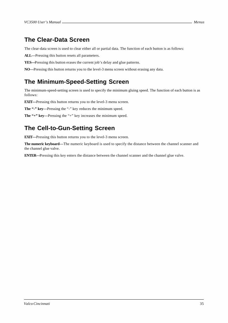
The Clear-Data ScreenThe clear-data screen is used to clear either all or partial data. The function of each button is as follows:
ALL—Pressing this button resets all parameters.
YES—Pressing this button erases the current job’s delay and glue patterns.
NO—Pressing this button returns you to the level-3 menu screen without erasing any data.
The Minimum-Speed-Setting ScreenThe minimum-speed-setting screen is used to specify the minimum gluing speed. The function of each button is asfollows:
EXIT—Pressing this button returns you to the level-3 menu screen.
The “-” key—Pressing the “-” key reduces the minimum speed.
The “+” key—Pressing the “+” key increases the minimum speed.
The Cell-to-Gun-Setting ScreenEXIT—Pressing this button returns you to the level-3 menu screen.
The numeric keyboard—The numeric keyboard is used to specify the distance between the channel scanner andthe channel glue valve.
ENTER—Pressing this key enters the distance between the channel scanner and the channel glue valve.

Menus VC3500 User’s Manual
Valco Cincinnati36
Level-4 Menu Screen
The level-4 menu screen (Figure 20) displays when the “MORE” button on the level-3 menu screen ispressed. The small box with the numeral 4 indicates that this is the level-4 menu screen. The function ofeach button is as follows:
EXIT—Pressing this button returns you to the level-3 menu screen.
MORE—Pressing this button advances you to the level-5 menu screen.
PRD LENGTH— The control uses the product length value when calculating the ratio compensation in theauto mode, detecting a product jam condition and enabling the scanner lockout function to ignore holes inthe product or dark areas such as printing. Pressing this button displays the product length screen.
RATIO COMP—Pressing this button displays the ratio compensation screen. Either a manual or automaticratio compensation method may be used.
COMP CHAN (1-4)—Each channel (valve) has a separate compensation setting (COMP CHAN1, COMPCHAN2, etc.). Pressing any of the COMP CHAN buttons displays the compensation setting screen for thatchannel.
Figure 20. Level-4 Menu Screen and Associated Screens
3
6
ENTER100.0 PULSES 0
87
54
21
9EXIT
.AUTO
EXIT
ON= 00.0
OFF= 00.0 ENTER
.
0 1 2 3
4 5 6
7 8 9
06.00"
Product-Length Screen Manual Ratio-CompensationScreen
On/Off Compensation-SettingScreen
EXIT
MORE
PRD LENGTH
COMP CHAN1
RATIO COMP
COMP CHAN3
4 COMP CHAN2 COMP CHAN4
COMP CHAN 1-4RATIO COMPPRD LENGTH
AUTO
Automatic-Ratio-Compensation Screen
EXIT
SAVE
RUN THE LINE ALLOWINGTHE SCANNER TO SCAN THEWHOLE PRODUCT.
EXIT
3
6
ENTER0000mm 0
87
54
21
9
Level-4 Menu Screen

MenusVC3500 User’s Manual
Valco Cincinnati 37
The Product-Length ScreenThe product-length screen is used to specify product length. The function of each button is as follows:
EXIT—Pressing this button returns you to the level-4 menu screen.
Numeric Keypad—The numeric keypad is used to specify the product length.
ENTER—Pressing this button enters the product length.
The Manual-Ratio-Compensation ScreenThe manual-ratio-compensation screen is used to specify the product length. The function of each button is asfollows:
EXIT—Pressing this button returns you to the level-4 menu screen.
Numeric keypad—The numeric keypad is used to specify the number of encoder pulses per inch (25.4) mm) ofproduct line travel.
ENTER—Pressing this button enters the number of encoder pulses per inch (25.4) mm) of product line travel.
AUTO—Pressing this button displays the automatic ratio compensation screen.
The Automatic-Ratio-Compensation ScreenThe automatic-ratio-compensation screen displays when the “AUTO” button on the ratio-compensation screen ispressed. The automatic-ratio-compensation screen is used to specify the number of encoder pulses per inch (25.4mm) of product line travel. The function of each button is as follows:
EXIT—Pressing this button returns you to the level-4 menu screen.
SAVE—Pressing this button saves the new ratio compensation that is displayed at the bottom of the screen.
The On/Off-Compensation-Setting ScreenThe on/off-compensation-setting screen displays when any of the “COMP CHAN” buttons on the level-4 menuscreen are pressed. The compensation-setting screen is used to specify the turn-on and turn-off times for the valvesthat are driven by each channel. The function of each button is as follows:
EXIT—Pressing this button returns you to the level-4 menu screen.
ON=—Pressing this button allows the turn-on time to be specified.
OFF=—Pressing this button allows the turn-off time to be specified.
Numeric keypad—The numeric keypad is used to specify the turn-on/turn-off time for the channel that you haveselected.
ENTER—Pressing this button enters the turn-on/turn-off time.

Menus VC3500 User’s Manual
Valco Cincinnati38
Level-5 Menu Screen
The level-5 menu screen (Figure 21) displays when the word “MORE” on the level-4 menu screen is pressed. Thesmall box with the numeral 5 indicates that this is the level-5 menu screen. The funtion of each button is as follows:
EXIT—Pressing this button returns you to the level-4 menu screen.
MORE—Pressing this button advances you to the level-6 menu screen.
IN/METRIC—Pressing this button displays the inch/metric screen. When the “inch mode” is selected, all linearmeasurements are displayed and entered in inches, and pressure is displayed in pounds per square inch (psi). Whenthe “metric mode” is selected, all linear measurements are displayed and entered in millimeters, and pressure isdisplayed in “bar.”
PIN—Pressing the “PIN” button displays the PIN-code screen.A four-digit PIN code may be entered in order torestrict access to menus 3-6.
GLUE QC—This button displays on two-channel models, but it does not have a function.
Figure 21. Level-5 Menu Screen and Associated Screens
The “GLUE QC” buttondisplays on two-channelmodels; however, thisfunction is not usable withthe VC3500 control.
EXIT
MORE5
IN/METRIC PIN
GLUE QC
Inch/Metric Screen
EXIT
INCH MODE METRIC MODE
PIN-Code Screen
GLUE QCIN/METRIC PIN
EXIT
NEW PIN
Level-5 Menu Screen
Not applicable
EXIT
NEW PIN
NEW PIN
New-PIN Entry Screen
5 6
3 4
1 2

MenusVC3500 User’s Manual
Valco Cincinnati 39
The PIN-Code ScreenThe PIN-code screen (Figure 21) is used to specify a PIN code in order to restrict screens 3-6. The function of eachbutton is as follows:
EXIT—Pressing this button returns you to the level-5 menu screen.
NEW PIN—Pressing this button displays a 6-digit numeric keypad, which you use to enter a new4-digit PIN code.
Level-6 Menu Screen
The level-6 menu screen (Figure 22) displays when the “MORE” button on the level-5 menu screen is pressed Thesmall box with the numeral 6 indicates that this is the level-6 menu screen. The function of each button is asfollows:
Language buttons—Pressing one of the language buttons causes that language to display on all of the screens.
EXIT—Pressing the “EXIT” button returns you to the level-5 menu screen.
Figure 22. The Level-6 Menu Screen
The Inch/Metric ScreenThe inch/metric screen (Figure 21) is used to specify either inches or millimeters. The function of each button is asfollows:
EXIT—Pressing this button returns you to the level-5 menu screen.
INCH MODE—Pressing this button sets the control to imperial (inch and psi) measurements.
METRIC MODE—Pressing this button sets the control to metric (mm and bar) measurements.
EXIT ENGLISH
FRANÇAIS
DEUTSCH
ITALIANO
ESPAÑOL
NEDERLANDS6

Valco Cincinnati 41
Initial Setup
Introduction
This section contains procedures for initial setup of the control. It may be helpful to refer to the flowcharts pro-vided in the “Menus” section of this manual. The flowcharts are located as follows:
• Primary menu screens—Figure 14 (page 26)
• Level-1 menu screens—Figure 17 (page 29)
• Level-2 menu screens—Figure 18 (page 32)
• Level-3 menu screens—Figure 19 (page 34)
• Level-4 menu screens—Figure 20 (page 36)
• Level-5 menu screens—Figure 21 (page 38)
Initial Setup
To conduct initial setup of the control, complete each of the following procedures.
Disable Glue Valves for All ChannelsTo disable glue valves for all channels, follow these steps:
1. Place channel toggle switches in center position (“0”) to prevent gluing during setup procedure.
Specify Inches or MillimetersTo specify inches or millimeters, follow these steps:
1. Press the “CONFIG” button on the main screen. (The level-1 menu screen displays.)
2. Press the “MORE” button in the level-1 menu screen.
3. Press the MORE button in menu screens 2, 3 and 4. The level-5 menu screen displays.
4. Press the “IN/METRIC” button. The inch/metric screen displays.
5. Press either the “INCH MODE” button or the “METRIC MODE” button. (The arrow points toward themode that you have selected).
Note! When the “inch mode” is selected, all linear measurements are displayed and entered in inches, usingfour digits—two of which are decimal places (example: 10.00 = 10 inches). Pressure is displayed inpounds per square inch (psi). When the “metric mode” is selected, all linear measurements aredisplayed and entered in millimeters, using four digits(example: 1000 = 1000 millimeters). Pressure is displayed in bar.
Note! Small errors (0.04 inch or 1mm) will result in parameters when switching between inch and metricmodes.
6. Press the “EXIT” button to return to the level-5 menu screen.

Initial Setup VC3500 User’s Manual
Valco Cincinnati42
Specify Minimum Gluing SpeedTo specify the minimum gluing speed, follow these steps:
1. Begin operating the production line at the desired minimum speed (the speed at which gluing will begin).
2. Press the “MIN SPEED” button in the level-3 menu screen.
Note! The minimum speed setting screen displays two bar graphs. The top bar graph displays the minimumspeed of the parent machine at which gluing will begin. The bottom bar graph displays the actualspeed of the parent machine. The maximum speed indication of the bar graph is 1000 feet (300meters) per minute. If the parent machine exceeds this speed, the bar graph restarts from the left sideand displays the speed above 1000 feet (300 meters) per minute.
3. Use the plus or minus buttons on the screen to adjust the upper bar graph (minimum speed) so that it is lessthan the lower bar graph (actual machine speed).
4. Press the “EXIT” button when done.
Set Cell-to-Gun DimensionsTo set the cell-to-gun dimensions, follow these steps:
1. Press the “CELL-GUN 1” button in the level-3 menu screen. The cell-to-gun setting screen displays.
2. Using the numeric keypad, enter the distance between the channel 1 scanner and the channel 1 glue valve(this value will display in either inches or millimeters depending on the setup of your control).
Note! Each channel (valve) has a separate cell-to-gun setting (“CELL-GUN 1” and“CELL-GUN 2”).
3. Press the “ENTER” button. The “OK DONE” message displays, indicating that the distance entered hasbeen saved.
Note ! This value should need no adjustment after the initial installation of the control and valves. However,the setting should be checked if the valves or scanners are moved or changed.
4. Press the “EXIT” button to return to the level-3 menu screen.
Note! To set additional cell-to-gun dimensions, you repeat steps 4a. through 4d.
Specify Ratio CompensationTo specify ratio compensation, follow these steps:
1. Press the “RATIO COMP” button in the level-4 menu screen.
2. Set the ratio compensation either manually or automatically (see procedures below).
Manual Ratio Compensation
To set ratio compensation manually, follow these steps:
1. Press the “RATIO COMP” button in the level-4 menu screen. The ratio compensation screen displays.
2. Using the numeric keyboard, input the number of encoder pulses per inch (25.4 mm) of product line travel.
3. Press the “ENTER” button. (The “OK DONE” message displays.)

Initial SetupVC3500 User’s Manual
Valco Cincinnati 43
Automatic Ratio Compensation
To set ratio compensation automatically, follow these steps:
1. Press the “PRD LENGTH” button in the level-4 menu screen. The product length screen displays.
Note! If using jam prevention, you must disable the stop circuit before using automatic ratio compensation.Otherwise, machine will shut down.
2. Using the numeric keypad, enter the exact product length.
3. Press the “ENTER” button. (The “OK DONE” message displays.)
4. Press the “EXIT” button to return to the level-4 menu screen
5. Press the “RATIO COMP” button in the level-4 menu screen. The ratio compensation screen displays.
6. Press the “AUTO” button. The automatic ratio compensation screen displays.
7. Run the line, allowing scanner 1 to scan the whole product.
Note! After the control has determined the number of encoder pulses per inch (25.4 mm) of product linetravel, the value will be displayed in the automatic ratio compensation screen. Product length is seenon the left side of the screen and encoder pulses per inch (25.4 mm) of product travel are seen on theright side of the screen.
8. Press the “SAVE” button to accept the new ratio compensation setting.
Note! Automatic ratio compensation is used to determine a general ratio compensation to a resolution ofseveral pulses.
9. Ensure that ratio compensation is accurate by measuring the length of a glue bead dispensed at low speed.
10. If necessary, use the manual ratio compensation to fine-tune the ratio compensation to a resolution of 0.1pulse.
11. After the ratio compensation has been established, add 2 inches (50 mm) to the product length setting inorder to allow the jam preventer and scanner lockout functions to operate correctly.
Specify On and Off CompensationTo specify on and off compensation, follow these steps:
1. The channel compensation allows a turn-on and turn-off time to be entered for each glue valve. Press the“COMP CHAN1” button in the level-4 menu screen. The compensation setting screen displays.
2. Press the “ON” button.
3. Enter the manufacturer-specified “ON” compensation (turn-on time) in milliseconds for the channel 1 gluevalve.
Note! If compensation value is not known, follow the “Unknown Compensation Value” procedure on thefollowing page.
4. Press the “ENTER” button. (The turn-on time displays in the “ON=” window.)
5. Press the “OFF” button.
6. Enter the manufacturer-specified “OFF” compensation (turn-off time) in milliseconds for the channel 1glue valve.
7. Press the “ENTER” button. (The turn-off time displays in the “OFF=” window.)
Note! To set compensation times for the other channels, you press the appropriate “COMP CHAN2” buttonand enter the turn-on and turn-off times as described above.
8. Press the “EXIT” button to return to the level-4 menu screen.

Initial Setup VC3500 User’s Manual
Valco Cincinnati44
Unknown Compensation Value
When the compensation value is not known, follow these steps:
1. At the level-4 menu screen, set the channel’s on and off compensation to 0 (see the “Initial Setup” section).
2. Adjust the cell-to-gun dimension for the channel until the leading edge of the pattern is correct at lowspeed—that is, less than 75 feet (25m) per minute.
3. Increase machine speed to maximum.
4. Adjust the “ON” compensation until the leading edge of the pattern is correct. (Increasing the ON compen-sation will move the leading edge of the pattern forward at high speeds.)
5. Adjust the “OFF” compensation until the trailing edge of the pattern is correct. (Increasing the “OFF”compensation will move the trailing edge of the pattern forward at high speeds.)
Note! Do not leave “0” on the “Off” compensation setting while having a number higher than “0” on the“On” compensation setting. This will cause the training edge of the pattern to increase in length.
Restrict Screen AccessTo restrict access to screens 3–6, follow these steps:
1. In the level-5 menu screen, press the “PIN” button. The PIN-code screen displays.
2. Press the “NEW PIN” button. (A six-digit numeric keypad and a display window appear.)
Note! If a PIN code has been previously entered, the new PIN code will overwrite the old PIN code—onlyone PIN code is possible.
3. Enter a four-digit PIN code.
Note! Screens 3–6 are now restricted. From now on, the six-digit numeric keypad will display when the“MORE” button is pressed in the level-2 menu screen. To proceed to additional menu levels (3-6), auser must enter the four-digit PIN code.
To provide non-restricted screen access, follow this step:
1. Press the “NEW PIN” button twice in order to delete the PIN code.
Return to the Main ScreenTo return to the main menu screen, follow this step:
1. Press the “EXIT” button in the level-4, level-3, level-2, and level-1 menu screens.

Valco Cincinnati 45
Operation
Introduction
This section contains procedures for operating the control. It may be helpful to refer to the flowcharts provided inthe “Menus” section of this manual. The flowcharts are located as follows:
• Primary menu screens—Figure 14 (page 26)
• Level-1 menu screens—Figure 17 (page 29)
• Level-2 menu screens—Figure 18 (page 32)
• Level-3 menu screens—Figure 19 (page 34)
• Level-4 menu screens—Figure 20 (page 36)
• Level-5 menu screens—Figure 21 (page 38)
Creating a Job
To create a job, follow these steps:
1. Specify the scanner mode (see Page 53).
2. Specify the glue mode (see Page 54).
Note! If the repeat function will be used, see Appendix A.
3. Specify the delay and pattern values (see Page 54).
4. Specify product length (see Page 55).
5. Enable the glue valves:
5a. Place the toggle switches for the desired channels in the enabled position (“|”).
6. Conduct a low-speed check:
6a. Operate the parent machine at low speed.
6b . Observe the glue pattern on the product.
Note! Gluing does not begin until the parent machine is operating at the minimum threshold speed set inthe control. It may be necessary to adjust the minimum speed to apply glue at low speed.
6c. Adjust the values for delay and pattern if necessary.
7. Conduct a high-speed check:
7a. Operate the parent machine at the maximum production speed.
7b . Observe the glue pattern on the product. If the glue pattern is not accurately applied at high speed,follow the channel compensation procedure in the “Initial Setup” section.
8. Adjust the glue pressure:
8a. Use the front-panel glue pressure switch to increase (“+”) or decrease (“-”) the pattern’s glue volume(air pressure) if necessary.
Note! The amount of pressure selected is indicated by the linear bar graph in the center of the screen andby a pressure gauge located underneath the control.

Operation VC3500 User’s Manual
Valco Cincinnati46
Saving a Job
To save a job for future recall, follow these steps:
1. Press the “CONFIG” button on the main screen. (The level-1 menu screen displays.)
2. Press the “JOB STORE” button. (The job-store screen displays.)
3. Perform one of the following actions (3a or 3b):
3a. Enter a two-digit job number (01–99) and then press the “SAVE” button.
3b. Press the “INDEX” button (the job index screen displays). Press the “UP” and “DOWN” buttons tolocate an empty job number location (10 dots in the display field to the left of the number indicate anempty location). When an empty job number location has been found, press the “SAVE” button.
Note! If the location already contains a job, the “WARNING! THIS STORE CONTAINS DATA. DOYOU WISH TO CONTINUE?” message displays. Pressing the “YES” button overwrites thelocation with the new job information. (The job title screen displays.) Pressing the “NO” buttonreturns you to the job index screen, where you can select a different location.
Note! The job title screen displays after completing either of the actions in step 3.
4. In the job title screen, use the “DOWN” and “UP” buttons to select a letter.
5. Press the “SELECT” button to enter the letter into the display. (The cursor will automatically move to theright.)
6. Select additional letters until you have entered the job name.
Note! To erase letters, you press the “BACK” button. To add a space between letters, you press the“SPACE” button.
7. Press the “EXIT” button (the level-1 menu screen displays).
8. Press the “EXIT” button again (the main-menu screen displays).
Loading a Job
To load a job that has previously been saved:
1. Press the “CONFIG” button on the main screen. (The level-1 menu screen displays.)
2. Press the “JOB STORE” button (The job store screen displays.)
3. Perform one of the following actions (3a or 3b):
3a. Enter a job number and then press the “LOAD” button.
3b. Press the “INDEX” button to display the stored jobs (the job index screen displays). Press the “UP” or“DOWN” buttons to locate the desired job name and number. When the desired job name and numberlocation have been found, press the “LOAD” button to initiate the loading process. Press the “EXIT”button. (The job store screen displays.)
Note! After completing either step 3a or step 3b, the “LOADED” message appears in the job numberdisplay. The job that was selected is now the active gluing program.
4. Press the “EXIT” button. (The level-1 menu screen displays.)
5. Press the “EXIT” button again. (The main-menu screen displays.)

VC3500 User’s Manual Operation
Valco Cincinnati 47
Repeating Glue Patterns
For information on how to repeat glue patterns, see Appendix A.
Clearing Data
Both the level-1 menu screen and the level-3 menu screen have “CLEAR DATA” buttons. However, the “CLEARDATA” button in the level-3 menu screen has the capability of erasing all data, and the “CLEAR DATA’’ button inthe level-1 menu screen is capable of clearing data only for the current job.
To clear data, follow these steps:
1. In the level-3 menu screen, press the “CLEAR DATA” button. (The clear-data warning screen displays.)
2. Press one of the three buttons described in 2a., 2b., and 2c.:
2a. Pressing the “YES” button erases the current job’s delay and glue patterns and returns the product-length setting to zero.
Note! Once you press the “YES” button, the data is erased and cannot be retrieved.
2b. Pressing the “NO” button returns you to either the level-1 or the level-3 menu screen without erasingany data.
2c. Pressing the “ALL” button resets the following parameters (level-3 menu screen only):
• Delay and pattern lengths in jobs 1-99 will be erased.• Product length = 0• Scan mode (2-channel model only) = SCAN 1 or 2• Glue mode = DEL PAT• Minimum speed = 0• Cell-to-gun = 0• Ratio compensation = 100• Compensation channels 1-4 = 0• In/metric = metric• Pin code access = deactivated• Language = English
Note! Once you press the “ALL” button, the data is erased and cannot be retrieved.
Specifying the Scanner Mode
Two scanner modes are available for the control:
• SCAN 1 or 2—Scanner 1 is used to scan product for channel 1.Scanner 2 is used to scan product for channel 2.
• SCAN 1 1-2—Scanner 1 is used to scanproduct for both channel 1 and channel 2.

Operation VC3500 User’s Manual
Valco Cincinnati48
To specify the scanner mode, follow these steps:
1. Press the “CONFIG” button on the main screen. (The level-1 menu screen displays.)
2. Press the “MORE” button. (The level-2 menu screen displays.)
3. Press the “SCAN MODE” button in the level-2 menu screen. (The scan-mode screen displays.)
4. Choose a scan mode by pressing the appropriate scan mode button.
Note! The arrow between the two buttons points to the scan mode that is currently selected.
5. Press the “EXIT” button to return to the level-2 menu screen.
For additional scanner configurations, see Appendix C.
Specifying the Glue Mode
With a two-channel control, two glue modes are possible:
• “DEL PAT”—In this mode, a single delay (or skip) dimension and a single pattern dimension are displayedon the main screen. When both channels are in this mode, a single main screen displays the delay andpattern dimensions for channel 1 across the top of the main screen and dimensions for channel 2 across thebottom of the main screen.
• “DEL PAT DEL PAT”—In this mode, a single delay (or skip) dimension and a single pattern dimensionare displayed across the top of the main screen, and a second pair of delay and pattern dimensions aredisplayed across the bottom of the main screen. When either or both channels are in this mode, multiplemain screens display the delay and pattern dimensions for a single channel only.
To select the glue mode, follow these steps:
1. Press the “CONFIG” button on the main screen. (The level-1 menu screen displays.)
2. Press the “MORE” button. (The level-2 menu screen displays.)
3. Press the “GLUE MODE” button. (The glue-mode screen displays.)
Note! Each of the two channel buttons (CHAN 1 and CHAN 2) toggles between DEL PAT andDEL PAT DEL PAT.
4. Press the “CHAN 1” button to set the channel 1 glue mode to either “DEL PAT DEL PAT” or“DEL PAT”.
5. Press the “CHAN 2” button to set the channel 2 glue mode to either “DEL PAT DEL PAT” or“DEL PAT”.
6. Press the “EXIT” button to return to the level-2 menu screen.
• SCAN 3 or 4—Scanner 3 is used to scan product for channel 3.Scanner 4 is used to scan product for channel 4.
• SCAN 3 3-4—Scanner 3 is used to scanproduct for both channel 3 and channel 4.

VC3500 User’s Manual Operation
Valco Cincinnati 49
2. At the first glue pattern delay field, enter the distance from the leading edge of product to the beginning ofthe first glue pattern. This distance will be entered in either inches (01.00 = 1 inch) or millimeters depend-ing on the setup of your control.
3. At the first glue pattern length field, enter the length of the glue pattern. This distance will be entered ineither inches (01.00 = 1 inch) or millimeters depending on the setup of your control.
Note! A minimum of 00.01" or 0001 mm must be entered for the delay setting to activate thechannel.
4. At the second glue pattern delay field, enter the distance from the end of the first glue pattern to thebeginning of the second glue pattern.
5. At the second glue pattern length field, enter the length of the second glue pattern.
6. Press the “PAGE DOWN” button to see pattern information for the next channel.
7. Repeat steps 1 through 6 for channel 2.
Specifying the Product Length
A non-zero value for the product length enables the jam detection and scanner lockout functions. The value enteredshould be approximately 2 inches (50 mm) longer than the actual product. To specify the product length, followthese steps:
1. Press the “CONFIG” button on the main screen. (The level-1 menu screen displays.)
2. Press the “PRD LENGTH” button. (The product-length screen displays.)
3. Using the numeric keypad, input the length of the product plus two inches (50 mm).
4. Press the “ENTER” button. (The “OK DONE” message displays.)
5. Press the “EXIT” button to return to the level-1 menu screen.
Specifying the Delay and Pattern Values
To specify delay and pattern values, follow these steps:
1. At the main-menu screeen, press any of the number fields for channel 1 (Figure 25). The glue pattern editscreen displays.
Note! You use the plus and minus buttons on the glue pattern edit screen to enter values for the delay andfor the glue pattern. The delay fields are located on the left side of the screen and the glue patternfields are located on the right side of the screen.

Operation VC3500 User’s Manual
Valco Cincinnati50
Delay 154 mm
Delay 250 mm
Channel 1 Delays and Patterns
Channel 2 Delays and Patterns
Delay 140 mm
Pattern 160 mm
Pattern 245 mm
Delay 2124 mm
Valve 1
Valve 2
Scanner
Cell-to-gun 1
Cell-to-gun 2
Main screen, channel 1
CHAN 2DEL PAT
BAR CONFIG
CHAN 1DEL PAT
BAR
0054 0062CONFIG
0050 00620040 0060
Main screen, channel 2
0124 00452 1
Pattern 162 mm
Pattern 262 mm
Product flow
Figure 25. Glue Pattern Example
Glue Pattern Example:Scanner mode = “SCAN 1 1-2”Glue mode = “DEL PAT DEL PAT”Inch/metric = Metric

Valco Cincinnati 51
Troubleshooting
Introduction
This section contains possible solutions to problems that you may experience.
Problem Possible Solution
Power
1. Front panel lights andtouchscreen do notilluminate.
1a. Check fuses in the power entry module (bottom panel).
1b. Check that the proper voltage shows through the fuse door of thepower entry module.
1c. Check that the on/off switch is in the on (“|”) position.
1d. Replace power supply board.
2. Lights illuminate but thetouchscreen is dark.
2a. Check the “F1” fuse on the power supply board.
2b. Replace power supply board
2c. Replace touchscreen.
3. 12V input voltage front-panelindicator does not illuminate.
3a. Check the “F1” and “F2” fuses on the power supply board
3b. Replace power supply board.
4. 5V logic voltage front-panelindicator does not illuminate.
4a. Check the “F1” fuse on the power supply board.
4b. Replace power supply board.
Scanner
1. Front-panel scanner indicatordoes not illuminate when aproduct is in the scanner’sdetection field.
1a. Check the distance between the scanner and the product (see theInstallation section of this manual).
1b. Ensure that the scanner cable is connected at the scanner and at thecontrol.
1c. Check for damage to the scanner cable.
1d. Check the “F2” fuse on the power supply board.
2. Front-panel scanner indicatordoes not turn off.
2a. Ensure that the scanner is not too close to a machine element.

Troubleshooting VC3500 User’s Manual
Valco Cincinnati52
Problem Possible Solution
Encoder
1. Front-panel encoder indicatordoes not illuminate when theproduct line is moving.
1a. Ensure that the encoder’s measuring wheel is securely against theparent machine surface and does not slip during operation.
1b Check the “F2” fuse on the power supply board.
1c. Check for damage to the encoder cable.
1d. Replace encoder.
2. “X/MIN” (greater thanminimum speed) front-panelindicator does not illuminate.
2a. The minimum speed setting is too high.
Glue Valve
1. The lower portion of thechannel valve indicator doesnot illuminate.
1a. Check the delay (“DEL”) and pattern (“PAT”) settings. (A delay ofat least “00.01” inches or “0001” millimeters must be entered inorder to activate the channel.)
1b. Check that the channel toggle switch on the front panel is in theenabled (“1”) position.
2. Glue valve does not dispenseglue.
2a. Check the delay (“DEL”) and pattern (“PAT”) settings. (A delay ofat least “00.01” inches or “0001” millimeters must be entered inorder to activate the channel.)
2b. Check that the channel toggle switch on the front panel is in theenabled (“1”) position.
2c. Check that the line speed is above the minimum speed setting.
2d. Check for a clogged glue valve.
2e. Check for damage to the glue valve’s cable.
2f. Check the “F1”, “F2”, and “F3” fuses on the valve driver board.
2g Replace valve driver board.
Glue Pattern
1. At low speed, the delay is tooshort or too long before thepattern starts.
1a. Ensure that the delay value has been correctly entered.
1b. Ensure that the product length has been correctly entered.
1c. Ensure that the ratio compensation has been correctly entered.
1d. Ensure that the cell-to-gun value has been correctly entered.
2. At low speed, the patternlength is too short or toolong.
2a. Ensure that the pattern value has been correctly entered.
2b. Ensure that the product length has been correctly entered.
2c. Ensure that the ratio compensation has been correctly entered.

TroubleshootingVC3500 User’s Manual
Valco Cincinnati 53
Problem Possible Solution
Glue Pattern, continued
3. At high speed, the delay istoo short or too long beforethe pattern begins.
3a. Ensure that the delay value has been correctly entered.
3b. Ensure that the delay is correct at low speed.
3c. Ensure that the turn-on compensation has been correctly entered.
4. At high speed, the patternlength is too short or toolong.
4a. Ensure that the pattern value has been correctly entered.
4b. Ensure that the pattern length is correct at low speed.
4c. Ensure that the turn-off compensation has been correctly entered.

Valco Cincinnati 55
Internal Components
Introduction
This section contains descriptions of the controls’s internal components (Figure 26).
Figure 26. Internal Components of the VC3500
touchscreen
EPC board
power- supplyboard
connectors foroptional RS232 board
CPU board
connectors foroptional channel3 and 4 logic board
valve-driver board
interface boardanalog board LED boardnot shown—optional relayboard for jam preventionand alarm signals

Internal Components VC3500 User’s Manual
Valco Cincinnati56
CPU Board
PN 151xx362
Connectors
J1, J2 Connection for the optional RS232 daughter board
J3 Connection to LCD/touchscreen module via a 20-pin ribbon cable
J4 Connection to glue inspection board (VC3700 only)
J5, J6 Connection for the optional channel 3 and 4 logic daughter board.
J7 (not used) In early models, connection to LED board to deliver analog pressure feedback signalto CPU
J8 Connection to interface board via a 26-pin ribbon cable
J9 Connection for 17VDC supply voltage from the power supply boardIndicators
D1 (Reset) When lit, this red LED indicates that the main processor (68000) is being given ahardware reset.
Jumpers
2/4 Channel Select A wire jumper near the center of the board determines whether two-channel or four-channel software is utilized:
• Installed—A jumper installed dictates that two-channel software is use.• Not installed—No jumper dictates that four-channel software is used.
Switches
A pushbutton near the upper left corner provides a manual reset function.Test Points
TP1 (CLOCK) 8 MHz, 5V digital clock signal from Oscillator U7 for main processor U1.
TP2 (CNTR-CLK) 5V encoder signal gated by a timer from U17 (68230, PB6). These gated encoderpulses are counted by U9 (74HCT293).
Periodically, the 68000 main processor queries this binary count through port linesPA0 through PA7 of U17. The 68000 main processor then calculates line speed fromknowing the number of encoder pulses in a given time period.
TP4 (PRESSURE) This analog signal (0 to 5VDC) represents the air pressure sensed by the EPC-6.
TP3 (MIN SPEED) This signal will be low when the line speed is Greater than minimum speed. Thissignal will be high when the line speed is Lower than minimum speed.
TP5 (+5V) Small pad located near lower right corner of board.
TP6 (GND) A U-shaped pad on the right edge provides the reference for all logic signals.

Internal ComponentsVC3500 User’s Manual
Valco Cincinnati 57
Channel 3 and 4 Logic Board
PN 151xx363
Analog Board
PN 151xx364
Connectors
J1, J2 Connection to the LED boardJumpers
JP1 Low Pressure Limit SelectA low air-pressure limit may be selected for delivery to glue source. Normally, this isset to 0%. Other possible selections are 10, 25, and 50% of full pressure.
Potentiometers
P1 (Bar 0-Adj) Allows adjustment of the pressure bar graph on the LCD/touchscreen to a minimallength for zero speed.
P2 (Gain Adj) Not used. In early models, allowed adjustment to gain of frequency-to-voltageconverter U3. Increasing the gain will increase the analog voltage at J2, pin 3 (to theEPC) for a given frequency of encoder pulses.
Connectors
CO1 Connection to interface board via a 30-pin ribbon cable.J2 Connection for 17VDC supply voltage from the power supply board
J3, J4 Connection to analog daughter board
J5 Connection to EPC via a four-conductor cable
J6, J7 Connection for front-panel channels 1 and 2 enable switches
J10 Connection for front-panel pressure-adjust switch
Connectors
J5, J6 Connection to the CPU board
LED Board
PN 151xx365

Internal Components VC3500 User’s Manual
Valco Cincinnati58
Interface Board
PN 151xx366
Connectors
CO1 Connection to LED board via a 30-pin ribbon cable
CO2 Connection to CPU board via a 26-pin ribbon cable
CO3 Connection to valve driver board(s) via a 20-pin ribbon cable
J1, J2, J3, J4 Connection for product scanners
J5 Connection for encoder
J6 Connection for machine interface board for machine-stop relay
J7 Connection for 17VDC supply voltage from power supply board
J8 Connection for dump-valve (glue by-pass valve)
Replacement Fuses
12 VDC I/O Supply Label—F1Type—PC MountValue—1.5AValco Number—085xx132
Dump Valve Active Label—F2Type—PC MountValue—1.5AValco Number—085xx132
Indicators
D1 (12 V) When lit, this green LED indicates that the 12VDC supply for scanners, encoder, andby-pass valve (dump valve) is operational.
D2 When lit, this yellow LED indicates that the bypass valve is activated and that theparent machine is above minimum speed.
Jumpers
JP1 and JP2 Valve Driver Type
Pins 1 and 2 jumpered—Use of valve driver board
Pins 2 and 3 jumpered—Future use
JP3 Pins 2 and 3 jumpered—Normal
JP4 Pins 2 and 3 jumpered—Normal

Internal ComponentsVC3500 User’s Manual
Valco Cincinnati 59
Valve Driver Board
PN 151xx367
Connectors
J1 Connection to interface board via a 10-pin ribbon cable
J2 Connection for transformer secondary voltages to form the 56VDC peak voltage andthe 12VDC hold voltage
J3 Connection for the first glue valve on this card
J4 Connection for the second glue valve on this cardIndicators
D1 (IN1) When lit, this yellow LED indicates that an input signal has been received from theInterface board to energize glue valve 1.
D2 (IN2) When lit, this yellow LED indicates that an input signal has been received from theinterface board to energize glue valve 2.
D3 (12 V) When lit, this green LED indicates that the 12VDC hold voltage is available toenergize a glue valve.
D4 (15 V) When lit, this green LED indicates that 15VDC input to regulator U3 is present.
D5 (56 V) When lit, this green LED indicates that the 56VDC peak voltage is available toenergize a glue valve.
D6 (HOLD-1) When lit, this yellow LED indicates that the 12VDC hold voltage is applied to gluevalve 1.
D7 (PEAK-1) When lit, this yellow LED indicates that the 56VDC peak voltage is applied to gluevalve 1.
D8 (HOLD-2) When lit, this yellow LED indicates that the 12VDC hold voltage is applied to gluevalve 2.
D9 (PEAK-2) When lit, this yellow LED indicates that the 56VDC peak voltage is applied to gluevalve 2.
D10 (Fault F2) When lit, this red LED indicates a fault with fuse F2.
D11 (Fault F3) When lit, this red LED indicates a fault with fuse F3.Replacement Fuses
Hold voltage currentlimit
Label—F1Type—5 x 20 mmValue—5AValco Number—085xx206
Channel 1 current limit Label—F2Type—PC MountValue—5AValco Number—085xx216
Channel 2 current limit Label—F3Type—PC MountValue—5AValco Number—085xx216

Internal Components VC3500 User’s Manual
Valco Cincinnati60
Jumpers
JP1 Common/Independent Output Control
Pins 1 and 2 jumpered—For the first valve driver board (channels 1 and 2), this causesboth outputs to be controlled from channel 1 program parameters. For the second valvedriver board (channels 3 and 4), this causes both outputs to be controlled from channel3 program parameters.
Pins 2 and 3 jumpered—Allows outputs to be controlled independently
JP2 Fixed/Variable Peak Voltage duration for Channel 1
Pins 1 and 2 jumpered—Forces a fixed peak voltage duration of 3.5mS for channel 1.
Pins 2 and 3 jumpered—Allow adjustment of peak voltage duration of 1mS to 10mSfor channel 1 using potentiometer P1.
JP3 Fixed/Variable Peak Voltage duration for Channel 2
Pins 1 and 2 jumpered—Forces a fixed-peak voltage duration of 3.5mS for channel 2.
Pins 2 and 3 jumpered—Allows adjustment of peak voltage duration of 1mS to 10mSfor channel 2 using potentiometer P2.
JP4 Fixed/Variable Hold Voltage level
Pins 1 and 2 jumpered—Forces a fixed-hold voltage level of 12 V.
Pins 2 and 3 jumpered—Allows adjustment of hold voltage level of 5 V to 12 V usingpotentiometer P3.
Potentiometers
P1 (PTIME1) Provides adjustment between 1mS and 10mS for channel 1 Peak Voltage durationwhen JP2 has a jumper between pins 2 and 3. Clockwise rotation increases duration.
P2 (PTIME2) Provides adjustment between 1mS and 10mS for channel 2 Peak Voltage durationwhen JP3 has a jumper between pins 2 and 3. Clockwise rotation increases duration.
P3 (HOLDV) Provides adjustment between 5V and 12V for hold voltage level when JP4 has ajumper between pins 2 and 3. Clockwise rotation increases hold voltage level.
Power Supply Board
PN 151xx368
Connectors
J1 Connection for transformer secondary voltages to form the DC logic voltages used onother boards.
J2 Connection to supply the 12VDC supply voltage to the LCD/touchscreen’s LEDbacklight
J3 Connection to supply the 17VDC supply voltage to the LED board
J4 Connection to supply the 17VDC supply voltage to the CPU board
J5 Connection to supply the 17VDC supply voltage to the interface board
J7 Connection to supply the 32VDC supply voltage to DD-1 pump

Internal ComponentsVC3500 User’s Manual
Valco Cincinnati 61
Replacement Fuses
CPU/LED current limit Label—F1Type—5 x 20 mmValue—3.15AValco Number—085xx208
I/O current limit Label—F2Type—5 x 20 mmValue—1.6AValco Number—085xx209
DD-1 pump current limit Label—F3Type—5 x 20 mmValue—1.6AValco Number—085xx209
Indicators
D1 (LCD supply) When lit, this green LED indicates that the 12VDC supply voltage is available tolight the LED backlight.
D2 (Logic supply) When lit, this green LED indicates that the 17VDC supply voltage is available topower the CPU board
D3 (Intrfc supply) When lit, this green LED indicates that the 17VDC supply voltage is available topower the interface board.
D4 (Pump supply) When lit, this green LED indicates that the 32VDC supply voltage is available topower the DD-1 pump.
RS232 Board
PN 151xx375
Connectors
J1, J2 Connection to the CPU board
J3 Connection for serial port via ribbon cable
Jumpers
JP1 Hardware/software handshaking:
Pins 2 and 3 jumpered—Normal configuration (software handshaking, CTS and RTSconnected)
Pins 1 and 2, 3, & 4 jumpered—Not used (hardware handshaking)
JP2, JP3 Cable-type selection
Pins 1 and 2 jumpered—Normal configuration (DB9 to DB9 null modem cable)
Pins 2 and 3 jumpered—DB9 to DB25 and special cables
Note! P2 and JP3 must be jumpered in the same manner.

Internal Components VC3500 User’s Manual
Valco Cincinnati62
EPC Board
PN 151xx379
Connectors
J1 Connection for 12VDC power supply, input analog signal, intake output signal, andexhaust/sensor output signal
Indicators
CR1 (12 V supply) When lit, this green LED indicates that the 12VDC supply voltage is available.
CR2 (Intake) When lit, this yellow LED indicates that the Intake solenoid is active.
CR3 (Exhaust) When lit, this yellow LED indicates that the Exhaust solenoid is active.Jumpers
JP1 (E/S Out) Output Signal Select
• Pins 1 and 2 jumpered—Makes the E-OUT signal available at J1, pin 5, allowingan external device to monitor the exhaust solenoid condition.
• Pins 2 and 3 jumpered—Makes the S-OUT signal available at J1, pin 5, allowingan external device to monitor the Sensor (transducer) analog signal.
Potentiometers
P1 (Span) Provides adjustment of transducer signal gain, allowing an anticipated small transducerexcursion to effect a full scale (0 to 12V) change at TP2.
P2 (Zero) Provides adjustment for nulling the pressure transducer signal at zero pressure
P4 (Gain) Provides adjustment of feedback loop gain and affects the hysteresis (and frequency)for switching the intake and exhaust solenoids (not installed on later models)

Internal ComponentsVC3500 User’s Manual
Valco Cincinnati 63
Relay Board
PN 151xx404
Connectors
J1 Connection to drive machine interface relay from either J6 of the Interface board or J1of the glue inspection board
J2 Connection to supply beacon and alarm signals from the glue inspection board(151xx410).
J3 External connector used for interfacing the machine interface relay to the parentmachine stop circuit.
J4 External connector used for interfacing a beacon/alarm for jam and glue-faultconditions.
Indicators
D1 (RLY) When lit, this yellow LED indicates that the machine interface relay is energized.Replacement Fuses
Beacon current limit Label—F1Type—PC MountValue—3AValco Number—085xx207

Valco Cincinnati 65
Specifications
Control Dimensions
Height: 19.55" (497mm)
Depth: 5.6" (142mm)
Width: 13.44" (341mm)
Input voltage: 115/230VAC, 2/1A, 50/60Hz (field-switchable)
Scanners
Inputs: One per channel
Type/voltage: NPN/sinking/12VDC
Configuration: Independent for each channel or one linked to channels 1 and 2 and one linked to3 and 4.
Valve Outputs
Channels: Two (four optional), one valve per channel
Peak voltage: +56V, 1–10ms adjustable (maximum 600W instantaneous per channel, not toexceed 10% duty cycle)
Hold voltage: +5V to +12V, adjustable
Encoder
Inputs: One (40kHz maximum)
Type/voltage: VCE-1000 recommended, 12VDC
Miscellaneous
Maximum gluing speed: 2000 feet (610m) per minute
Maximum glue length: 99.99" (2539mm)
Flow control: Internal (EPC-6)
Maximum glue pressure: 100 psi (7 bar)
Job storage capacity: 99 jobs
Glue patterns: One or two per channel
Scanner lockout function: Internal
Jam preventer function: Internal
Computer hardwareinterface: RS-232 (optional) DB-9 socket, standard DTE
Machine interface relay: Optional—one normally open and one normally closed contact, 60VDC,25VAC, 2A

Valco Cincinnati 67
Part-Number List
How to Order Parts
To order parts, please contact one of the following.
You can also contact a Valco sales representative in your country. If you have any problems or questions regardingthe piston pumps or any other Valco equipment, call Valco’s Technical Service Department at the numbers listedabove.
VC3500 Parts List
Valco Cincinnati LimitedHortonwood 32Telford, TF1 4 EU, EnglandTEL: (+44) 1952-677911FAX: (+44) 1952-677945
Valco Cincinnati GmbHIndustriestrasse 25D-32130 Enger/WestfTEL: (+49) 5223-185511FAX: (+49) 5223-188699
Valco Cincinnati Incorporated411 Circle Freeway DriveCincinnati, Ohio 45246TEL: (513) 874-6550FAX: (513) 874-3612
Description Part #
PC9 adhesive system pedestal, 0-125 psi (1-9.6 bar) glue regulator and manifold 738xx173
PC9 adhesive system pedestal, 0-650 psi (1-45.8 bar) glue regulator and manifold 738xx174
Machine mount, 0-125 psi (1-9.6 bar) glue regulator and manifold 738xx177
Machine mount, 0-650 psi (1-45.8 bar) glue regulator and manifold 738xx178
Beam assembly, for use with 578xx032 trolley bracket 581xx298
Filter/regulator/manifold assembly, 0-125 psi (1-9.6 bar) 593xx245
Filter/regulator/manifold assembly, 0-650 psi (1-45.8 bar) 593xx246
PC board assembly, touch-screen 151xx324
PC board assembly, EPC-6 pressure control 151xx379
PC board assembly, CPU 151xx362
PC board assembly, 2-channel logic with jam preventer and scanner lockout 151xx363
PC board assembly, analog 151xx364
PC board assembly, LED 151xx365
PC board assembly, interface 151xx366
PC board assembly, 2-channel valve driver 151xx367
PC board assembly, power supply 151xx368
PC board assembly, RS232 151xx375
PC board assembly, relay and beacon interface 151xx404

Part-Number List VC3500 User’s Manual
Valco Cincinnati68
Description Part #
Fuse, 2A, 5 x 20mm, power entry module 085xx040
Fuse, 5A, 5 x 20mm, valve driver board, F1 085xx206
Fuse, 5A, PC mount, valve driver board, F2, F3 085xx216
Fuse, 3.15A, 5 x 20mm, power supply board, F1 085xx208
Fuse, 1.6A, 5 x 20mm, power supply board, F2 085xx209
Ribbon cable, 30-pin, LED/Interface 033xx080
Ribbon cable, 20-pin, valve driver/interface 033xx081
Ribbon cable, 26-pin, CPU/interface 033xx082
Ribbon cable, 20-pin, CPU/display 033xx083
Ribbon cable, 10-pin, valve driver to valve driver supply cable 033xx084
Valve driver to valve driver supply cable 030xx442
Transformer panel assembly (includes the following):Transformer, 24VTransformer, 36VTransformer, 28V
036xx119
550xx047550xx032550xx020
Power entry module, 115/230VAC 086xx055
Cord grip panel assembly 084xx002
Channel enable switch assembly 030xx429
Pressure adjust switch assembly 030xx430
Installation kit (includes the following): 781xx136
Fuse, 2a, 5 x 20 mm, power entry module (1)Fuse, 5A, 5 x 20 mm, valve driver board, F1 (2)Fuse, 5A, PC mount, valve driver board, F2, F3 (4)Fuse, 3.15A, 5 x 20 mm, power supply board, F1 (2)Fuse, 1.6A, 5 x 20 mm, power supply board, F2 (2)Fitting, male connector 1/4 x 1/8 (1)Fitting, male connector 3/8 x 1/8 (1)Fitting, male elbow 1/4 x 1/8 (1)Fitting, male elbow 3/8 x 1/8 (1)Hex key (1)Gauge, 0–160 psiAdapter, 1/4 NPT (female)Street “T”, 1/8 NPTCable assembly, line cord (Europe), no end plug (1)Line cord clamp (Europe) (1)Cable assembly, line cord (US), with end plug (1)Line cord clamp (US) (1)Fuse, 5A, PC mount, valve driver board, F2, F3 (4) (alternate fuses for 585 valves)
085xx040085xx206085xx216085xx208085xx209797xx323797xx328797xx338797xx342794xx453786xx002797xx029797xx018030xx422066xx116030xx493066xx120085xx216

Part-Number ListVC3500 User’s Manual
Valco Cincinnati 69
Optional Parts List
Recommended Spare Parts List—Mechanical
Description Quantity Part #
Valve seal kit (366-valve) 1 706xx178*
Repair kit, standard 585 non-contact valve 1 703xx304*
Repair kit, 2-inch extended 585 non-contact valve 1 703xx558*
Repair kit, 4-inch extended 585 non-contact valve 1 703xx305*
Soft-seal stem tip for TF612 and 712 non-contact valve 5 703xx797*
Spring, internal for TF612 and 712 non-contact valve 5 793xx271*
Repair kit for 832 fluid pressure regulator 1 593xx038
Repair kit for DD-1 pump 1 560xx560
12VDC 3-way air solenoid 1 411xx057*
Encoder timing belt 1 788xx300*
Encoder measuring wheel 1 788xx553*
Filter screen, 50-mesh 1 593xx020*
Filter screen, 100-mesh 1 593xx087*
0-ring, glue filter cap 1 745xx059
* Check the type of part on your system before ordering
Description Part #
Snap track for CPU P.C. board 091xx382
Rivets, plastic (for mounting snap track) 091xx374
Extraction tool for chips 781xx174
I.C. Chip Assembly (U4, U5, U18, U19/20) 119xx052
Floppy disk for RS-232 interface (used by OEM for interfacing Valco equipment with OEMequipment)
119xx047
Description Part #
Machine stop relay and beacon interface 084xx008
Beacon with audible alert 481xx033
Beacon cable 030xx555
Connector (field-wireable connector for machine-stop relay) 061xx216
Upgrade kit, 4-channel (used to upgrade 2-channel 3500 only) 084xx012

Part-Number List VC3500 User’s Manual
Valco Cincinnati70
Recommended Spare Parts List—Electrical
Description Quantity Part #
LED scanner assembly 1 280xx105*
Fixed-field sensor 1 280xx093*
VCE-250 encoder 1 155xx027*
VCE-500 encoder 1 155xx029*
VCE-1000 encoder 1 155xx031*
PC board, touchscreen 1 151xx324**
PC board, CPU 1 151xx362**
PC board, channel 3 and channel 4 logic 1 151xx363**
PC board, analog 1 151xx364**
PC board, LED 1 151xx365**
PC board, interface 1 151xx366**
PC board, 2-channel valve driver 1 151xx367**
PC board, power supply 1 151xx368**
PC board, RS232 1 151xx375**
PC board assembly, EPC-6 pressure control 1 151xx379**
Fuse, 2A, power entry module 1 085xx040
Fuse, 5A, valve driver board, F1 1 085xx206
Fuse, 5A, valve driver board, F2, F3 1 085xx216
Fuse, 3.15A, power supply board F1 1 085xx208
Fuse, 1.6A, power supply board F2 1 085xx209
* Check the type of part on your system before ordering
** Customer’s discretion on ordering as a spare part

Part-Number ListVC3500 User’s Manual
Valco Cincinnati 71
Recommended Spare Parts List—DD-1 Pump
Description Quantity Part #
Rebuild and spare parts kit 1 560xx602

Valco Cincinnati 73
Warranty Information
Valco Cincinnati, Inc. warrants its equipment worldwide against defects in material and workmanship as outlined inthis section.
Cold-Glue Equipment and Electronic ControlsOne (1) year from the date of shipment by Valco Cincinnati.
Hot-Melt Units, Hoses, Valves, and Related EquipmentAll components except cast-in heating elements are warranted for a period of six (6) months from the date ofshipment by Valco Cincinnati. Cast-in heaters carry an additional, pro-rated warranty not to exceed three (3) yearsfrom the date of shipment by Valco Cincinnati.
Liability of the company is limited to repair of the product, or replacement of any part shown to be defective, anddoes not extend to defects caused by accidents, misuse, abuse, neglect, tampering or deterioration by corrosion. Thiswarranty does not cover those items determined by Valco Cincinnati, Inc. to be normal wear items such as seals, O-rings, diaphragms, springs, etc.
Reconditioned equipment, unless specified otherwise at the time of purchase, will be warranted as described abovefor a period of ninety (90) days from the date of shipment by Valco Cincinnati.
Components purchased by Valco Cincinnati, Inc. from others for inclusion in its products are warranted only to theextent of the original manufacturer’s warranty. In no event shall Valco Cincinnati, Inc. be liable for indirect orconsequential damages arising out of the use of Valco Cincinnati products.
This warranty is conditioned upon the prepaid return of the equipment claimed to be defective to Valco Cincinnati,Inc. for examination and verification. If claimed defect is verified, repairs or replacements will be made F.O.B.Cincinnati, Ohio, U.S.A. or ex-works Telford, U.K. If the inspection of the equipment does not disclose any defectof workmanship or material, any necessary repairs will be made at a reasonable charge and return transportation willbe charged.
This is the only authorized Valco Cincinnati, Inc. warranty and is in lieu of all other expressed or implied warran-ties, representations or any other obligations on the part of Valco Cincinnati, Inc.
Warranty

Valco Cincinnati 75
Service Needs
If you have problems with your system, please contact your Valco Cincinnati representative. If your need is urgent,we encourage you to contact our corporate office in Cincinnati, Ohio, U.S.A. at (513) 874-6550, or Valco Europe inthe United Kingdom at (+44) 1952-677911. If the problem cannot be resolved on the telephone, Valco willpromptly arrange to have a technical representative visit your facility. Any charges for a service call will be quotedat that time.Any part that fails during the warranty period shall be returned prepaid to Valco Cincinnati by thecustomer for disposition.
Note! Upon request, Valco Cincinnati personnel are available to repair or replace such parts at the customer’sfacility. Charges for this service include travel time and expenses.
If an equipment problem is the result of customer abuse, improper installation or operation, all travel time, labor,parts, and expenses will be charged to the customer.
If the responsibility for a problem cannot be absolutely determined, the customer will be charged for travel time andexpenses only. No charge will be made for parts and labor.
Service

Valco Cincinnati 77
Appendix A
Using the Repeat Function
The repeat function allows a glue pattern to be repeated up to 99x (99 times). This can be used to implement a stitchpattern to reduce quantity of glue consumption. A repeat value of 00x disables the repeat function for that channel.When the repeat function is enabled using a value from 01 to 99, the channel’s second delay and pattern arerepeated that number of times. A value of 01x will repeat the second delay and pattern one time (it will be per-formed two times).
Example:
To repeat a glue sequence of 0.5” delay (gap) and 0.5” pattern (glue) for 20 inches on channel 1, follow these steps:
1. At the level-2 menu, press the “GLUE MODE” button. The glue mode screen displays (Figure 27).
2. Set the glue mode for channel 1 to DEL PAT DEL PAT (press the CHAN 1 button to toggle between thetwo selections).
3. Press “EXIT” to return to main screen.
Figure 27. The Glue Mode Screen
Figure 28. Glue-Pattern Edit Screen
4. At the main screen, touch one of the four-digit numbers on the top half of the screen. The glue-pattern editscreen displays (Figure 28).
5. Using the plus and minus keys, set the first delay (left parameter) to 00.50.
6. Using the plus and minus keys, set the first pattern (right parameter) to 00.50. (the first inch of thetotal 20 inches has now been programmed).
7. Press the symbol in the middle of the screen to return to the main screen.
EXIT
CHAN 2 DEL PAT
CHAN 1 DEL PAT DEL PAT
0000 0000

Appendix A VC3500 User’s Manual
Valco Cincinnati78
8. At the main screen, touch one of the four-digit numbers on the bottom half of the screen. The glue-patternedit screen displays (Figure 28).
9. Using the plus and minus keys, set the second delay (left parameter) to 00.50.
10. Using the plus and minus keys, set the second pattern (right parameter) to 00.50. (the second inch of thetotal 20 inches has now been programmed).
11. Press the symbol in the middle of the screen to return to the main screen.
12. Press the “CONFIG” button.
13. Press the “MORE” button in the level-1 menu screen. (The level-2 menu screen displays.)
14. Press the “REPEAT” button. (The repeat-function screen displays.)
15. Press channel 1. (The repeat setup screen for channel 1 displays.)
16. To program 18 additional inches of delay-pattern, press “1”, and then press “8”.
17. Press the “ENTER” button. The “OK DONE” message displays in the edit box and 18x displays in therepeat factor box (lower left corner).
18. Press the exit key to return to the level-2 menu.
19. Repeat steps 1-18 for channel 2.
20. Run the machine and check the pattern.
21. Adjust the first delay and pattern to move the last repeated glue pattern where desired.

Valco Cincinnati 79
Appendix B
RS232 Communications Interface
Do not install this upgrade with the power on. OTHERWISE, DEATH, PER-SONAL INJURY, OR EQUIPMENT DAMAGE COULD OCCUR.
The RS232 is an upgrade/option that allows information to be sent or received between the control and a remotehost computer. The RS232 upgrade/option consists of the following:
• Printed circuit board
• Internal cabling
• 20-foot serial data communications cable with DB-9 female connections on each end
• DOS-compatible demo disk.
Note! The RS232 board is sensed by the control automatically and requires no special setup by the user.
Location Codes
Location codes are required to instruct the control where to store its data.
Note! The VC3500 will not respond to data shown in location codes pertaining to channels 3 and 4. It will alsonot respond to data shown in location codes 3,4 and 7,8 unless the respective glue modes are set.
1 Channel 1—Delay length2 Channel 1—Pattern length3 Channel 1—2nd Delay length4 Channel 1—2nd Pattern length5 Channel 2—Delay length6 Channel 2—Pattern length7 Channel 2—2nd Delay length8 Channel 2—2nd Pattern length9 Channel 3—Delay length10 Channel 3—Pattern length11 Channel 3—2nd Delay length12 Channel 3—2nd Pattern length13 Channel 4—Delay length14 Channel 4—Pattern length15 Channel 4—2nd Delay length16 Channel 4—2nd Pattern length17 Channel 1—Cell-to-gun distance18 Channel 2—Cell-to-gun distance19 Channel 3—Cell-to-gun distance20 Channel 4—Cell-to-gun distance21 Channel 1—Turn-on compensation22 Channel 2—Turn-on compensation23 Channel 3—Turn-on compensation24 Channel 4—Turn-on compensation

Appendix B VC3500 User’s Manual
Valco Cincinnati80
25 Channel 1—Turn-off compensation26 Channel 2—Turn-off compensation27 Channel 3—Turn-off compensation28 Channel 4—Turn-off compensation29 Product scanned length30 Ratio compensation31 Glue mode channel 1:
0000 for Delay-pattern0100 for Delay-pattern-Delay-pattern-mode
32 Glue mode channel 2:0000 for Delay-pattern0100 for Delay-pattern-Delay-pattern-mode
33 Measurement mode:0000 for metric mode0200 for inch mode
34 Scan mode:0000—Normal mode. Independent scanners for channels 1 through 4.0100—Scanner 1 triggers channels 1 and 2. Independent scanners for Channel 3 and 4.0200—Independent scanners for Channels 1 and 2. Scanner 3 triggers Channels 3 and 4.0300—Scanner 1 triggers channels 1and 2. Scanner 3 triggers channels 3 and 4.
35 Speed in feet per minute (receive only). Bytes 4-1 are hexadecimal digits.36 Repeat factor for channel 1 (0 = no repeat)37 Repeat factor for channel 2 (0 = no repeat)38 Repeat factor for channel 3 (0 = no repeat)39 Repeat factor for channel 4 (0 = no repeat)40 Marker station distance from glue station41 Marker skip distance from leading edge of product42 Marker mark distance43 Tolerance codes for glue inspection
1 = +0.2 inches (5mm)2 = +0.4 inches (10mm)3 = + 0.8 inches (20mm)
100 Regenerate or redraw front screen (send only)101 Reset the control (send only)
Data Format
Four bytes of data are always sent or received with preceding zeros completing the four bytes. The most significantbyte (MSB, byte 4) is sent or received first. The least significant byte (LSB, byte 1) is sent or received last. Eachdata type is the ANSI code of the data being sent or received. ANSI codes for characters 0-9 are shown in Table 1.
Table 1. ANSI Codes for Characters 1-9
Character ANSI Code0 481 492 503 514 525 536 547 558 569 57

Appendix BVC3500 User’s Manual
Valco Cincinnati 81
Note! The Visual Basic “Chr$” function returns a one-character string whose ANSI code is the argument.
Distance-type data in inch units assume two decimal places. Therefore, if 0,1,0,0 were sent, either 01.00 inches or0100mm would be specified, depending on the inch/metric setting of the control. Time-type data (in milliseconds)assume one decimal place. Therefore, if 0,0,5,5 were sent, 005.5 ms would be specified. Data for ratio compensa-tion (in pulses per inch) also use one decimal place.
Sending Information from Host to VC3500
Information may only be sent or received by the control if the main screen (the screen containing the pressure bargraph) is visible. Data can be sent or received while the control is gluing. However, the programmer must take carenot to leave the data partly sent, since the control will appear to lockout the touch screen and minimum speeddetection! This can leave the control open to undesirable effects. It is possible to regain control from this situationby sending groups of at least six zeros to the control from the host, but it is always better to send or receive thecomplete data format.
Transfer of information uses the following format at 9600 baud, no parity, 8 data bits and 1 stop bit:
1. Send send-request byte from host.
Send-request byte = 254dec.
2. Receive ACK (acknowledge) byte from VC3500.
This indicates that the control will start looking for the data. After the request byte is received, the controlreturns ACK (255dec). If this byte is not returned after 500ms, the host must terminate the send.
3. Send byte 4, byte 3, byte 2, byte 1, location code from host.
Byte 4=Msb and byte 1=Lsb.
Note! If the command is sent to redraw the front screen, the ACK signal can take up to 2 seconds torespond.
Example of Sending DataExample:
Channel 1—Delay length = 100mm (1.00 inches)Channel 1—Pattern length = 100mm (1.00 inches)
To send this information, follow these steps:
1. Send 254.
2. Wait for ACK.
3. Send 0,1,0,0,1.
4. Send 254.
5. Wait for ACK.
6. Send 0,1,0,0,2.
The front screen needs to be redrawn only after all the pattern data is sent, and only if the screen that the data isreferenced to is visible. The control will respond to new data and update the glue line automatically upon receptionof each new data packet, regardless of the information displayed by the screen.
It is better to send the redraw command after all of the data is transferred to the control, so that the data is sent atmaximum speed. Timing problems may be encountered if attempts are made to redraw the screen after each send. Ifredrawing the screen after each send is required, a two-second delay (waiting for ACK) must be allowed for theredraw to take place.

Appendix B VC3500 User’s Manual
Valco Cincinnati82
To redraw the front screen, follow these steps:
1. Send 254.
2. Wait for ACK.
3. Send 0,0,0,0,100 (to redraw the front screen).
To set channel 1 turn-on compensation to 5.5ms:
1. Send 254.
2. Wait for ACK.
3. Send 0,0,5,5,21.
To set ratio compensation to 98.5 pulses:
1. Send 254.
2. Wait for ACK.
3. Send 0,9,8,5,30.
Receiving Information from VC3500
Receive information is required to update a secondary machine user interface, such as that found on a parentmachine control.
The data is requested by the host computer, using the following format:
1. Send receive-request byte (from host).
Receive-request byte = 253dec.
2. Receive ACK byte (from VC3500).
3. Send location code (from host).
4. Receive Byte 4, Byte 3, Byte 2, Byte 1 (from VC3500).
Example of Receiving DataTo display the first glue pattern length, follow these steps:
1. Send 253.
2. Wait for ACK.
3. Send 2.
4. Receive b4,b3,b2,b1.
Note! The measurement mode of the VC3500 control needs to be determined by the host in order forthe host to display the information in inch or metric mode.
Note! When switching between the inch and metric modes via the RS232 link, the data is notconverted accurately.

Valco Cincinnati 83
Appendix C
Introduction
The following configurations may be required for customer applications.
Using One Scanner to Trigger Four Independent Glue Valves
In order to use one scanner to trigger four independent glue valves, follow these steps:
Electrical Connections:
1. The “scanner-1” connector (J1 of interface board) must be used as the interface point for the single scannerused in this configuration. Connect the scanner cable to J1 on the interface board as follows:
Pin 1: +12VDCPin 2: Scanner signalPin 3: Return
2. Install a jumper from J1, pin 2 to J3, pin 2 of the interface board.
Menu Setup:
3. In the level-2 menu screen, press the “SCAN MODE” button.
4. Press the “SCAN 1 1-2” button.
5. Press the “SCAN 3 3-4” button.
Applying Up To Four Patterns from a Single Glue Valve
In order to apply up to four glue patterns from a single glue valve, follow these steps:
Electrical Connections:
1. The “scanner-1” connector (J1 of the interface board) must be used as the interface point for the singlescanner used in this configuration. Connect the scanner cable to J1 on the interface board as follows:
Pin 1: +12VDCPin 2: Scanner signalPin 3: Return
2. Install a wire jumper from J3, pin 3 to J4, pin 3 on the valve driver board in order to parallel the outputs ofChannels 1 and 2.
3. Connect the glue valve cable to J3 on the valve driver board as follows:
Pin 1: Purge inputPin 2: Purge returnPin 3: Valve outputPin 4: Valve return

Appendix C VC3500 User’s Manual
Valco Cincinnati84
Menu Setup and Pattern Entry:
Note! If you have a four-channel control, skip to step 6.
4. In the level-2 menu screen, press the “GLUE MODE” button.
5. Select DEL PAT DEL PAT for both channels 1 and 2. (The “CHAN 1” and “CHAN 2” buttons toggleback and forth between DEL PAT and DEL PAT DEL PAT.)
6. In the level-2 menu screen, press the “SCAN MODE” button.
7. Press the “SCAN 1 1-2” button.
8. In the glue-pattern-edit screens for Channel 1, enter delay and pattern information for the first two patterns.
9. In the glue-pattern-edit screens for Channel 2, enter delay and pattern information for patterns three andfour.
Applying Up To Eight Patterns from a Single Glue Valve
In order to apply up to eight glue patterns from a single glue valve, a four-channel control is required:
Electrical Connections:
1. The “scanner-1” connector (J1 of the interface board) must be used as the interface point for the singlescanner used in this configuration. Connect the scanner cable to J1 on the interface board as follows:
Pin 1: +12VDCPin 2: Scanner signalPin 3: Return
2. Install a wire jumper from J1, pin 2 to J3, pin 2 on the interface board.
3. Install a wire jumper from J3, pin 3 to J4, pin 3 on bottom valve driver board in order to parallel theoutputs of channels 1 and 2.
4. Install a wire jumper from J3, pin 3 to J4, pin 3 on top valve driver board in order to parallel the outputs ofchannels 3 and 4.
5. Install a wire jumper from J4, pin 3 of bottom valve driver board to J4, pin 3 of top valve driver board inorder to parallel the outputs of all four channels.
6. Install a wire jumper from J4, pin 4 of bottom valve driver board to J4, pin 4 of top valve driver board inorder to interconnect the ground references for all four channels.
7. Connect the glue valve cable to J3 on the valve driver board as follows:
Pin 1: Purge inputPin 2: Purge returnPin 3: Valve outputPin 4: Valve return
Menu Setup and Pattern Entry:
8. In the level-2 menu screen, press the “SCAN MODE” button.
9. Press the “SCAN 1 1-2” button and the “SCAN 3 3-4” button.
10. In the glue-pattern edit screens for channel 1, enter delay and pattern information for the first two patterns(see the “Operation” section of this manual).

Appendix CVC3500 User’s Manual
Valco Cincinnati 85
11. In the glue-pattern-edit screens for channel 2, enter delay and pattern information for patterns3 and 4.
12. In the glue-pattern-edit screens for channel 3, enter dealy and pattern information for patterns5 and 6.
13. In the glue-pattern-edit screens for channel 4, enter delay and pattern informatin for patterns7 and 8.

Valco Cincinnati 87
Appendix D
Introduction
This section contains specific information about the VC3500J control, which is a single-channel control.
Overview
Since the VC3500J is a single-channel control, the main screen displays the delay dimension in the upper left cornerof the screen and the pattern dimension in the upper right corner of the screen. The lower portion of the screendisplays a figure that enables the learn mode when pressed. Once the learn mode is enabled, the control measuresthe product length, subtracts the delay dimension on both the leading and trailing edges, and enters the remaininglength into the pattern dimension. The control then glues any products that pass under the product scanner.
Installation of Product Scanner
In order to achieve optimum measurement capability, care must be taken in locating the product scanner andadjusting its sensitivity. To install the product scanner, follow these steps:
1. Locate the product scanner 1-2 inches above the product.
2. Apply power to the glue control.
3. Place product 0.75 to 1.00 inches below normal product travel.
4. Turn the adjustment screw counterclockwise until the LED is not illuminated.
5. Adjust the product scanner sensitivity by turning the adjustment screw clockwise just until the LED illuminates.
Electrical Installation of Remote Learn Button
The cable used to connect the remote learn button to the VC3500J control should have a minimum of two conduc-tors (18-22 AWG) and a shield.
To connect the remote learn button to the control, follow these steps:
1. Insert the remote learn button cable into the control enclosure through a cord grip located on the bottom panel ofthe control.
2. Connect the remote learn button cable to the three-terminal connector labeled “scanner 2”.
Connections are as follows:
Pin 1: No connection
Pin 2: Signal
Pin 3: Return
3. Connect shield wire to the protective earth (P.E.) terminals located near cord-grip base plate.
4. Tighten the cord grip used by the remote learn button cable.

Appendix D VC3500 User’s Manual
Valco Cincinnati88
Operation
To use the learn mode, follow these steps:
1. Type a delay dimension in the upper left corner of the main screen and press the ENTER key. This is the lengthof product not glued at both the leading and trailing edges.
2. Press the lower part of the main screen to enable the learn mode.
3. Allow one product to pass under the product scanner. (The control measures the product length, subtracts thedelay dimension on both the leading and the trailing edges, and enters the remaining length into the patterndimension.) Normal gluing will begin with the next product.
Note! Either the delay or pattern dimensions may be altered to affect changes in the glue pattern placement.
Menu Buttons
Since the VC3500 is a single-channel control, the following menu buttons are omitted:
Level-2 menu screen—SCAN MODE< GLUE MODE
Level-3 menu screen—CELL-GUN 2, CELL-GUN 3, CELL-GUN 4
Level-4 menu screen—COMP CHAN 2, COMP CHAN 3, COMP CHAN 4

Valco Cincinnati E-1
Appendix E—Maintenance Procedures
Introduction
This appendix contains recommended daily, weekly, 3-month, 6-month, and 12-month maintenance procedures forthe VC3700 system.
The maintenance procedures contained in this appendix are to be used forcold-glue systems only. OTHERWISE, DAMAGE TO EQUIPMENT COULDOCCUR.
Action Date Shift Initials
1. Clean the exterior portion of the glue valves, nozzletips, glue heads, etc.
2. Purge the glue valves if necessary, and ensure properglue flow.
3. Ensure that air and glue pressure settings are correct.
4. If using glue insp ection:
Ensure that sensor is clean. (Lens must be cleanand clear with no scratches.)
Check sensor for proper height adjustment.
Adjust for proper sensitivity if necessary.
Daily Maintenance

Appendix E—Maintenance Procedures VC3500 User’s Manual
Valco CincinnatiE-2
Weekly Maintenance
Actions Date Shift Initials
1. Clean the glue filter thoroughly with water.
2. For electric-coil non-contact valves only—disassemblethe fluid section of the glue valve, and clean the sectionthoroughly with water.
3. If you are using a 585 valve, replace the valve spring.
4. For non-contact valves only—lubricate the valve withTeflon oil (supplied with maintenance kit).
5. Reassemble the fluid section.
6. Using the 3-way purge valve on the output of the gluefilter, purge all air from the system.
7. Purge each valve in the system. (Approximately 1-2ounces of glue should be purged for proper glue flow.)
8. Check for any glue leakage on the needle seat. Replacethe needle/plunger assembly and seat if leaks ordripping occurs.
9. For non-contact valves only—Apply a small amount oflithium grease to the nozzle seat area before attachingthe retaining nut.
10. Check all quick-disconnect fittings for any dried glueor swelling that may restrict the glue flow.
11. Lubricate each quick-disconnect fitting with lithiumgrease or equivalent.

Appendix E—Maintenance ProceduresVC3500 User’s Manual
Valco Cincinnati E-3
3-Month Maintenance
Actions Date Shift Initials
1. Encoder mounting:
a. Check timing belt, gear and pulley teeth, and propertiming belt tension..
b. If using measuring wheel, check for wear andproper wheel tension on machine belt.
c. If using direct-drive encoder, check coupling androtation of shaft for proper alignment.
2. Perform the “Weekly Maintenance” procedure.

Appendix E—Maintenance Procedures VC3500 User’s Manual
Valco CincinnatiE-4
6-Month Maintenance
Actions Date Shift Initials
1. Flush entire glue system, except for the centralpumping system, with a vinegar and water solution(1 gallon of vinegar to 10 gallons of water).
2. Perform the “Weekly Maintenance” procedure.

Appendix E—Maintenance ProceduresVC3500 User’s Manual
Valco Cincinnati E-5
12-Month Maintenance
Actions Date Shift Initials
1. Flush the entire glue system, including the centralpumping system, with a vinegar and water solution(1 gallon of vinegar to 10 gallons of water).
2. Disassemble, thoroughly clean, and rebuild each fluid-regulator assembly and glue valve.
3. Perform the “Weekly Maintenance” procedure.

VC3700 User’s ManualSoftware Version: 3.X
Manual Number: MCO34
Manual Release Date: July 1999

© 1998 Valco Cincinnati, Inc. All Rights Reserved.
This manual is furnished with the VC3700 control and may only be used or copied in accordance with the terms ofpurchase.
No part of this manual may be reproduced, stored in a retrieval system, or transmitted, in any form or by any means,electronic, mechanical, recording, or otherwise, without the prior written permission of Valco Cincinnati, Inc. Theinformation in this manual is furnished for educational purposes only, is subject to change without notice, andshould not be construed as a commitment by Valco Cincinnati, Inc.
This manual written and designed at Valco Cincinnati, Inc.; 411 Circle Freeway Drive; Cincinnati, Ohio; 45246.
Part Number: MC034
Printed in the USA
Valco Cincinnati Incorporated411 Circle Freeway DriveCincinnati, Ohio 45246TEL: (513) 874-6550FAX: (513) 874-3612
Valco Cincinnati LimitedHortonwood 32Telford, TF1 4 EU, EnglandTEL: (+44) 1952-677911FAX: (+44) 1952-677945
Valco Cincinnati GmbHIndustriestrasse 25D-32130 Enger/WestfTEL: (+49) 5223-185511FAX: (+49) 5223-188699

CE Declaration of Conformity(according to EN 45014)
Manufacturer: Valco Cincinnati, Incorporated411 Circle Freeway DriveCincinnati, OH 45246USA
declares that the product:
Product Name: Glue ControllerProduct Model(s): VC3700Year of Manufacture 1998
conforms to the following standards:
Safety: EN 60204-1
EMC Emissions: EN 50081-2EN 55011, Class A
EMC Immunity: EN 50082-2EN 61000-4-2EN 61000-4-3EN 61000-4-4
Degrees of Protection: EN 60529-1, IP54
and complies with the requirements of:
Low Voltage Directive 73/23/EECEMC Directive 89/336/EEC
Office of CE ConformanceCincinnati, Ohio USA

Table of Contents
Introduction ...................................................................................................................................................................... 1About this Manual ................................................................................................................................................. 1Product Description .............................................................................................................................................. 1
Safety Information .......................................................................................................................................................... 3General Information ............................................................................................................................................. 3Specific Information ............................................................................................................................................. 3
General Wiring Guidelines ........................................................................................................................................... 5Routing Low-Voltage Leads ............................................................................................................................... 5Supply of Electrical Power .................................................................................................................................. 5
Basic Features .................................................................................................................................................................. 7Front Panel Features ............................................................................................................................................. 8Bottom Panel Features .......................................................................................................................................... 9
Installation ........................................................................................................................................................................ 13Introduction ............................................................................................................................................................ 13Control Installation ............................................................................................................................................... 13
Mechanical Installation of Control......................................................................................................... 13Electrical Installation of Control ............................................................................................................ 15
Main’s Voltage and Fuse Selection ........................................................................................... 15Encoder Installation .............................................................................................................................................. 17
Mechanical Installation of Encoder ....................................................................................................... 17Wheel-Driven Encoder ................................................................................................................. 17Gear-Driven Encoder ................................................................................................................... 17
Electrical Installation of Encoder ........................................................................................................... 18Scanner Installation ............................................................................................................................................... 19
Mechanical Installation of Scanner........................................................................................................ 19Electrical Installation of Scanner............................................................................................................ 21
Glue Valve Installation ......................................................................................................................................... 21Electrical Installation of Glue Valve ...................................................................................................... 21
Machine-Stop Relay and Beacon Interface ...................................................................................................... 22DD-1 Pump Power Supply .................................................................................................................................. 22Bypass Valve Driver............................................................................................................................................. 22Continuous Gluing ................................................................................................................................................ 23Glue Sensor Installation ....................................................................................................................................... 23
Capacitive Glue Sensor ............................................................................................................................ 23Mechanical Installation ............................................................................................................... 23Electrical Installation ................................................................................................................... 23Capacitive Glue Sensor Adjustment ........................................................................................... 25
UV Sensor .................................................................................................................................................. 25Mechanical Installation ............................................................................................................... 25Electrical Installation ................................................................................................................... 25UV Sensor Time Delay Setting .................................................................................................... 25UV Sensor Sensitivity Setting ...................................................................................................... 26Lens Replacement .......................................................................................................................... 26Maintenance ................................................................................................................................... 26
Product Scanners for Glue Inspection ............................................................................................................... 26Mechanical Installation of Scanner....................................................................................................... 26Electrical Installation of Scanner............................................................................................................ 27
Marker Valve or Kicker/Driver Installation ..................................................................................................... 27Electrical Installation ................................................................................................................................ 27

Menus ................................................................................................................................................................................. 29Introduction ............................................................................................................................................................ 29Primary Menus ...................................................................................................................................................... 29Main Screen ........................................................................................................................................................... 31Glue-Pattern Edit Screen ...................................................................................................................................... 32Level-1 Menu Screen ........................................................................................................................................... 33
The Job-Store Screen ................................................................................................................................ 34The Job-Title Screen ................................................................................................................................. 34The Job-Index Screen ............................................................................................................................... 34The Product-Length Screen ..................................................................................................................... 35The Clear-Data Screen ............................................................................................................................. 35
Level-2 Menu Screen ........................................................................................................................................... 36The Scan-Mode Screen ............................................................................................................................ 36The Glue-Mode Screen ............................................................................................................................ 36The Repeat-Function Screen ................................................................................................................... 36The Repeat-Setup Screen ......................................................................................................................... 36
Level-3 Menu Screen ........................................................................................................................................... 37The Clear-Data Screen ............................................................................................................................. 38The Minimum-Speed-Setting Screen .................................................................................................... 38The Cell-to-Gun Setting Screen .............................................................................................................. 38
Level-4 Menu Screen ........................................................................................................................................... 39The Product-Length Screen ..................................................................................................................... 40The Manual-Ratio-Compensation Screen ............................................................................................. 40The Automatic-Ratio-Compensation Screen ........................................................................................ 40The On/Off Compensation-Setting Screen .......................................................................................... 40
Level-5 Menu Screen ........................................................................................................................................... 42The Inch/Metric Screen ............................................................................................................................ 42The PIN-Code Screen ............................................................................................................................... 42The Glue Inspection Setup Screen ......................................................................................................... 42The Cell-Marker Edit Screen .................................................................................................................. 43The Marker-Skip/Marker-Mark Select Screen ..................................................................................... 43The Marker-Pattern Edit Screen ............................................................................................................. 43
Level-6 Menu Screen ........................................................................................................................................... 43
Initial Setup....................................................................................................................................................................... 45Introduction ............................................................................................................................................................ 45Disable Glue Valves for All Channels .............................................................................................................. 45Specify Inches or Millimeters ............................................................................................................................. 45Specify Minimum Gluing Speed ........................................................................................................................ 46Set the Cell-to-Gun Dimensions ......................................................................................................................... 46Specify Ratio Compensation .............................................................................................................................. 46
Manual Ratio Compensation ................................................................................................................... 46Automatic Ratio Compensation .............................................................................................................. 47
Specify On and Off Compensation ................................................................................................................... 47Unknown Compensation Value .............................................................................................................. 48
Enable Glue QC ..................................................................................................................................................... 48Restrict Screen Access ......................................................................................................................................... 49Return to the Main Screen ................................................................................................................................... 49
Operation .......................................................................................................................................................................... 51Introduction ............................................................................................................................................................ 51Creating a Job ........................................................................................................................................................ 51Saving a Job ........................................................................................................................................................... 52Loading a Job ......................................................................................................................................................... 52Repeating Glue Patterns ....................................................................................................................................... 53Clearing Data ......................................................................................................................................................... 53

Specifying the Scanner Mode ............................................................................................................................. 53Specifying the Glue Mode ................................................................................................................................... 54Specifying the Delay and Pattern Values .......................................................................................................... 55
Troubleshooting ............................................................................................................................................................... 57Introduction ............................................................................................................................................................ 57
Internal Components ..................................................................................................................................................... 61Introduction ............................................................................................................................................................ 61CPU Board ............................................................................................................................................................. 62Channel 3 and 4 Logic Board ............................................................................................................................. 63Analog Board ......................................................................................................................................................... 63LED Board ............................................................................................................................................................. 63Interface Board ...................................................................................................................................................... 64Valve Driver Board ............................................................................................................................................... 65Power Supply Board ............................................................................................................................................. 66RS232 Board .......................................................................................................................................................... 67EPC Board .............................................................................................................................................................. 68Relay Board ............................................................................................................................................................ 69Glue Inspection Board ......................................................................................................................................... 69
Specifications .................................................................................................................................................................... 73
Part-Number List ............................................................................................................................................................ 75How to Order Parts ............................................................................................................................................... 75VC3700 Parts List ................................................................................................................................................. 75Optional Parts List ............................................................................................................................................... 77Recommended Spare Parts List—Mechanical ................................................................................................. 77Recommended Spare Parts List—Electrical..................................................................................................... 78Recommended Spare Parts List—DD-1 Pump ................................................................................................ 79
Warranty ........................................................................................................................................................................... 81Cold-Glue Equipment and Electronic Controls ............................................................................................... 81Hot-Melt Units, Hoses, Valves, and Related Equipment ............................................................................... 81
Service ................................................................................................................................................................................ 83Service Needs ........................................................................................................................................................ 83
Appendix A —The Repeat Function .......................................................................................................................... 85Using the Repeat Function .................................................................................................................................. 85
Appendix B —The RS232 Communications Interface ......................................................................................... 87RS232 Communications Interface ..................................................................................................................... 87Location Codes ...................................................................................................................................................... 87Data Format ............................................................................................................................................................ 88Sending Information from Host to VC3700 ..................................................................................................... 89
Example of Sending Data ........................................................................................................................ 89Receiving Information from VC3700 ............................................................................................................... 90
Example of Receiving Data ..................................................................................................................... 90
Appendix C—Additional Scanner Mode Configuration ...................................................................................... 91Introduction ............................................................................................................................................................ 91Four Patterns from a Single Glue Valve ........................................................................................................... 91
Appendix D—The VC3700J Control ......................................................................................................................... 93Introduction ............................................................................................................................................................ 93Overview ................................................................................................................................................................ 93Installation of Product Scanner........................................................................................................................... 93Installation of Remote Learn Button ................................................................................................................. 93Operation ................................................................................................................................................................ 94Menu Buttons ......................................................................................................................................................... 94

Valco Cincinnati 1
Introduction
About this Manual
Valco Cincinnati has prepared this manual as an aid for installing, operating, and servicing the VC3700 control.This manual provides specific information about the unit, and general guidelines and references when discussingother equipment such as glue systems, scanners, encoders, and dispensing valves.
If you need more information, please contact your Valco Cincinnati representative.
Product Description
Valco’s VC3700 is a sophisticated microprocessor control that provides precise adhesive delivery. It is a two-channel unit designed for use with up to two glue detection sensors. It will also operate up to four jam-preventionsensors.
The VC3700 is used for applications where consistent glue patterns are required at high machine speeds and duringspeed changes. The VC3700 provides complex glue patterns that can be difficult or impossible to obtain with othersystems. The control operator can use the control’s front-panel touch-screen to edit glue patterns while the parentmachine is operating. The VC3700 also provides glue-inspection capabilities.
The VC3700 features a user-friendly, multi-language display; multiple pattern placement; speeds of up to 2000 feet(610 m) per minute; internal flow control; and optional RS-232 communications with external devices. The VC3700control can store up to 99 fully programmed jobs.

Valco Cincinnati 3
General Information
It is the purchaser’s responsibility to ensure that all local, county, state, and national codes, regulations, rules, andlaws relating to safety and safe operating conditions are met and followed.
The best safeguard is trained personnel. The purchaser is responsible for providing personnel who are adequatelytrained to install, operate, and maintain Valco components and systems.
This section contains information that is essential to the safety of personnel. Safety information is included through-out the rest of the manual as well. The following safety conventions are used to indicate potential safety hazards:
Warnings
All personnel involved with the installation, operation, and maintenance of the equipment must read and thoroughlyunderstand the following warnings:
WARNING! Promptly repair or replace all worn or damaged electrical wiringand equipment wires to avoid danger to personnel.
WARNING! Properly route all electrical wires to avoid danger to personneland damage to moving parts of machine.
WARNING! Disconnect all power before opening the control. Only qualifiedpersonnel should open and service the control.
WARNING! This symbol indicates the presence of un-insulated dangerousvoltage within the product’s enclosure. This voltage may cause electricalshock or fire. Failure to observe precaution may result in death, personalinjury, and/or equipment damage.
WARNING! This convention is used to alert the user to important installation,operation, and/or maintenance information. Failure to observe precautionmay result in personal injury or death.
CAUTION! This convention is used to alert the user to important installation,operation, and/or maintenance information. Failure to observe precautionmay result in damage to equipment.
Safety Information

Safety Information VC3700 User’s Manual
Valco Cincinnati4
WARNING! When making adjustments or performing checkout procedures,stay clear of any moving mechanical parts and do not touch exposed electri-cal equipment or electrical connectors.
WARNING! Keep pump cover and electrical enclosures closed except duringsetup, service, and checkout procedures.
WARNING! Promptly repair or replace all worn or damaged parts.

Valco Cincinnati 5
Routing Low-Voltage Leads
When routing low-voltage leads, follow these guidelines:
• Do not route low-voltage leads in the same conduit as wires carrying a high-current load.
• Do not route low-voltage leads adjacent to, or across wires carrying a high-current load. If low-voltageleads must cross or run parallel to wires carrying high current, keep the leads at least 6" (152 mm) fromhigh-current wires.
• Do not splice or solder leads.
• Trim leads to the required length. Leads should be only as long as necessary for installation.
• All wiring should be in conduits or wireways.
Connecting the Supply of Electrical Power
Electrical connections should be made only by experienced service per-sonnel!
The control must be connected to a “clean” supply of electrical power. Use a dedicated circuit if possible—if adedicated circuit is not available, do not connect the control to a circuit that supplies high-amperage equipment. Useanother circuit such as a lighting circuit.
General Wiring Guidelines
Electrical installation should be accomplished only by experienced servicepersonnel!

Valco Cincinnati 7
Introduction
This section describes the basic features of the 3700 control.
Basic Features
Figure 1. Front Panel of VC3700

Basic Features VC3700 User’s Manual
Valco Cincinnati8
Front-Panel Features
The following are descriptions of the features on the front panel (Figure 1).
1 Touch-screen display
All glue pattern parameters are entered and displayed using the touch-screen.
2 Valve enable switches
“|”—Valve is enabled and ready to dispense glue under program control.
“0”—Valve is disabled and will not dispense glue.
PURGE—Valve will dispense glue as long as the switch is manually held in this position.
3 Valve indicator lights (items 3a through 3b are valve indicator lights)
3a Valve enable indicator lights
This light illuminates when the valve enable switch is placed in the “|” (enabled) position (see item 2).This light will not illuminate when the valve enable switch is placed in the “0” (disabled) position.
3 b Valve dispensing indicator lights
This light illuminates when the valve is dispensing glue (purge function or a programmed command).
4 Scanner indicator light
This light illuminates when the scanner detects product.
5 Glue pressure adjustment
You press this button to adjust glue pressure (“+” = increase and “-” = decrease).
6 Status indicator lights (items 6a through 6h are status indicator lights)
6a Less than minimum speed
“<X/MIN” illuminates when the speed of the parent machine is less than the minimum speed setting.
6 b Greater than minimum speed
“>X/MIN” illuminates when the speed of the parent machine is greater than the minimum speed setting.
6c Jam
This light illuminates when a scanner detects a product that is longer than the product length value enteredin the control.
6 d Encoder
This light illuminates when encoder pulses are received by the control.
6e 56V
“56V” illuminates when the 56-volt valve peak voltage is operational. This light will be illuminated undernormal operating conditions.
6f 12V coil hold voltage
“12V” illuminates when the 12-volt valve hold voltage is operational. This light will be illuminated undernormal operating conditions.
6g 12V input supply voltage
This light illuminates when the 12-volt supply for scanners and the encoder is operational. This light willbe illuminated under normal operating conditions.
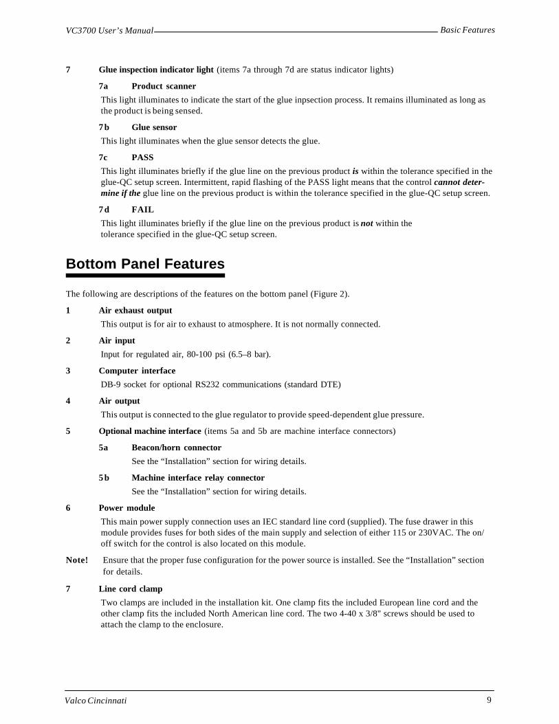
Basic FeaturesVC3700 User’s Manual
Valco Cincinnati 9
7 Glue inspection indicator light (items 7a through 7d are status indicator lights)
7a Product scanner
This light illuminates to indicate the start of the glue inpsection process. It remains illuminated as long asthe product is being sensed.
7 b Glue sensor
This light illuminates when the glue sensor detects the glue.
7c PASS
This light illuminates briefly if the glue line on the previous product is within the tolerance specified in theglue-QC setup screen. Intermittent, rapid flashing of the PASS light means that the control cannot deter-mine if the glue line on the previous product is within the tolerance specified in the glue-QC setup screen.
7 d FAIL
This light illuminates briefly if the glue line on the previous product is not within thetolerance specified in the glue-QC setup screen.
Bottom Panel Features
The following are descriptions of the features on the bottom panel (Figure 2).
1 Air exhaust output
This output is for air to exhaust to atmosphere. It is not normally connected.
2 Air input
Input for regulated air, 80-100 psi (6.5–8 bar).
3 Computer interface
DB-9 socket for optional RS232 communications (standard DTE)
4 Air output
This output is connected to the glue regulator to provide speed-dependent glue pressure.
5 Optional machine interface (items 5a and 5b are machine interface connectors)
5a Beacon/horn connector
See the “Installation” section for wiring details.
5 b Machine interface relay connector
See the “Installation” section for wiring details.
6 Power module
This main power supply connection uses an IEC standard line cord (supplied). The fuse drawer in thismodule provides fuses for both sides of the main supply and selection of either 115 or 230VAC. The on/off switch for the control is also located on this module.
Note! Ensure that the proper fuse configuration for the power source is installed. See the “Installation” sectionfor details.
7 Line cord clamp
Two clamps are included in the installation kit. One clamp fits the included European line cord and theother clamp fits the included North American line cord. The two 4-40 x 3/8" screws should be used toattach the clamp to the enclosure.
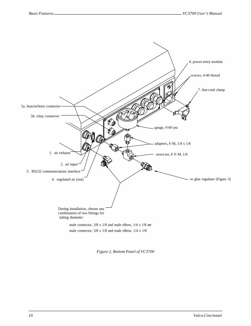
Basic Features VC3700 User’s Manual
Valco Cincinnati10
Figure 2. Bottom Panel of VC3700
5a. beacon/horn connector
5b. relay connector
1. air exhaust
2. air input
3. RS232 communications interface
4. regulated air (out) to glue regulator (Figure 3)
street tee, F-F-M, 1/8
adapters, F-M, 1/8 x 1/8
gauge, 0-60 psi
7. line-cord clamp
screws, 4-40 thread
6. power entry module
During installation, choose anycombination of two fittings for tubing diameter:
male connector, 3/8 x 1/8 and male elbow, 1/4 x 1/8 or
male connector, 3/8 x 1/8 and male elbow, 1/4 x 1/8

Basic FeaturesVC3700 User’s Manual
Valco Cincinnati 11
shock arrestor
T-handle (providesminimum pressure setting)
sealing nut(must be tightenedfor proper operation)
to VC3700 regulated air port
adhesive supply
glue regulator
to glue station
shutoff valve
Figure 3. Glue Regulator

Valco Cincinnati 13
Introduction
This section contains both mechanical and electrical installation instructions. Read the “Safety” section in thismanual before attempting these procedures.
Electrical installation should be accomplished only by experienced servicepersonnel!
Refer to Figure 8 for detailed layout of internal connections.
Control Installation
Mechanical Installation of ControlThe control should be installed on the operator’s side of the parent machine, in a location where vibrations will notoccur. The control should require less than 25 feet (8 m) of wiring to reach the glue station, sensor,and shaft encoder(longer wiring is available on request). A 5/16" (8 mm) hex wrench can be used to unlock the door of the controlenclosure.
To install the control, follow these steps:
1. Attach the control to a stationary, vertical surface, using the mounting holes located inside the control enclosure(see Figure 6).
Note! The control may also be mounted either to Valco’s machine-mount or mobile system pedestals (seeFigures 4 and 5).
Installation
Figure 4. Machine-Mount System Pedestal
Manifold with (4)3/8" NPTports
25.75"(654 mm)
9.33"(237 mm)
13" (330 mm)
0-125 psiregulator/filter
assembly shown
.406" (10.3mm) diameter
1.25"(31.8 mm)
3" (76 mm)

Installation VC3700 User’s Manual
Valco Cincinnati14
Figure 5. Mobile System Pedestal
Figure 6. Mounting Hole Dimensions
66.3"(1684 mm)
24.3" (617 mm) 19.6" (498 mm)
)

InstallationVC3700 User’s Manual
Valco Cincinnati 15
Electrical Installation of ControlThe main’s supply must be 115/230 VAC, 50/60 Hz, 2/1 A. The 115/230 power requirement is field-switchable.The power module accepts a standard IEC line cord (supplied).
To connect the line cord, follow these steps:
1. Attach the line cord clamp to the bottom surface of the VC3700, using the two screws on either side of the powermodule.
2. Insert the line cord into the power module
3. Tighten the line cord clamp to prevent inadvertent loss of power.
Note! The line cord supplied can either be directly wired to a branch circuit or (with the proper plug type)plugged into a 115 or 230 VAC outlet socket. The wire colors of the supplied line cord are as follows:
Mains Voltage and Fuse Selection
The fuse holder on the bottom panel of the power module contains the fuse drawer, which allows for either 115VACor 230VAC operation (Figure 7).
To replace or check mains fuses, follow these steps:
1. Remove all electric power from the unit.
2. Remove the line cord.
3. Use a small screwdriver to open the hinged door ofthe fuse holder.
4. Remove the fuse drawer (ensure that the fuses inthe holder remain in place).
5. The drawer is labeled “230V” and “115V.” Rotate thedrawer to the appropriate voltage.
6. For line-to-neutral operation, use the shorting clip(jumper) and one fuse. Shorting clip must be on leftside (when rotated to read the correct voltage). Forline-to-line operation, use two fuses.
7. Replace the drawer in the fuse holder and close thedoor of the fuse holder.
8. The operating voltage shows through the window inthe fuse holder door. Ensure that voltage is correct.
9. Replace the line cord.
Wire Type International Line Cord Color North American Line Cord Color
Line Brown Black
Neutral Blue White
Ground Green/Yellow Green
Figure 7. Fuse Drawer
230V (USA)line-to-line
230V (Europe) or115VAC (USA)line-to-neutralshorting clip
115V/230V

Installation VC3700 User’s Manual
Valco Cincinnati16
Figure 8. Internal Connections Diagram
+12
V B
RO
WN
INP
UT
BLA
CK
RE
TU
RN
BLU
E
+12
V B
RO
WN
INP
UT
BLA
CK
RE
TU
RN
BLU
E
+12
V B
RO
WN
INP
UT
BLA
CK
RE
TU
RN
BLU
E+1
2 V
BR
OW
NIN
PU
T B
LAC
KR
ET
UR
N B
LUE
+12
V R
ED
INP
UT
OR
AN
GE
RE
TU
RN
BLA
CK
Pur
ge in
put
(bla
u)P
urge
ret
urn
(blk
)V
alve
out
put
(brn
)V
alve
ret
urn
(whi
te)
Pur
ge in
put
(bla
u)P
urge
ret
urn
(blk
)V
alve
out
put
(brn
)V
alve
ret
urn
(whi
te)
+12
V B
RO
WN
INP
UT
BLA
CK
RE
TU
RN
BLU
E+1
2 V
BR
OW
NIN
PU
T B
LAC
KR
ET
UR
N B
LUE

InstallationVC3700 User’s Manual
Valco Cincinnati 17
Gear-Driven Encoder
The following formula can be used to determine the correct combination of gear teeth and encoder for approxi-mately 100 pulse per inch (25.4 mm):
Teeth-S x Counts = Pulses per inch (25.4 mm) of travelTeeth-E Travel
Teeth-S=Number of teeth on the line-shaft driver gear.
Teeth-E=Number of teeth on the encoder driven gear.
Counts=Number of encoder pulses per revolution.
Travel= Product travel in inches (or millimeters divided by 25.4) per revolution of the drive shaft.
Encoder Installation
Mechanical Installation of EncoderAn encoder must be installed in order for the control to determine the speed of the parent machine. For best results,100 pulses per inch (25.4 mm) of product travel should be supplied to the VC3700. If less than 100 pulses per inch(25.4 mm) are supplied, poor resolution may result in pattern placement errors. If more than 100 pulses per inch(25.4 mm) are supplied, the maximum specified speed of 2000 feet/min (610 m/min) must be reduced.
There are two primary types of encoders:
• Wheel-driven encoder
• Gear-driven encoder
Wheel-Driven Encoder
If using a wheel-driven encoder (Figure 9), a VCE-1000 encoder with a 10-inch measuring wheel is recommended.
To install a wheel-driven encoder, follow these steps:
1. Mount the encoder’s bracket to the frame of the parent machine.
2. Ensure that the wheel of the encoder rides securely against the belt and does not slip.
Note! The encoder assembly should be installed on the main drive belt if at all possible. Try not to use a belt thatis driven by the friction of the drive belt, since this may cause slippage and erratic glue patterns.
Figure 9. Example of a Wheel-Driven Encoder

Installation VC3700 User’s Manual
Valco Cincinnati18
Example:
Using a 92-tooth split line shaft gear (driver), a 24-tooth encoder driven gear, a 500-pulse encoder, and 18 inches(or 457 millimeters divided by 25.4) of travel per drive shaft revolution.
92 x 500 = 106.4824 18
Therefore, the ratio compensation setting should be 106.5.
To install a gear-driven encoder (Figure 10), follow these steps:
1. Install the driver gear on the line shaft. Tighten the set-screws.
2. Position and install the encoder so that it is square with the driver gear.
3. Raise or lower the encoder to tighten the belt against the driver gear. (Ensure that the two sides of the belt are notpressed together under the wheel.) Due to the low torque required, the belt should not be extremely tight.
Note! At least 7-9 teeth should engage in the line shaft driver gear. It may be necessary to fabricate an adjustablebracket to connect the encoder base to the parent machine frame.
Figure 10. Typical Installation of a Gear-Driven Encoder
drive gear
minimum7-9 teeth
line shaft (drive)
drivengear
machine base machine base
Adj
usta
ble
mou
ntin
g(s
uppl
ied
by c
usto
mer
)
shaft encoder
11” (279 mm)
Electrical Installation of EncoderA 12VDC encoder must be used with the VC3700 control. The cable used to connect the encoder to the controlshould have a minimum of three conductors (18-22 AWG) and a shield.
To connect the encoder to the control, follow these steps:
1. Insert the encoder cable into the control enclosure through a cord grip located on the bottom panel of the control.
2. Connect the encoder to the three-terminal connector (located inside the control) labeled“ENCODER”.
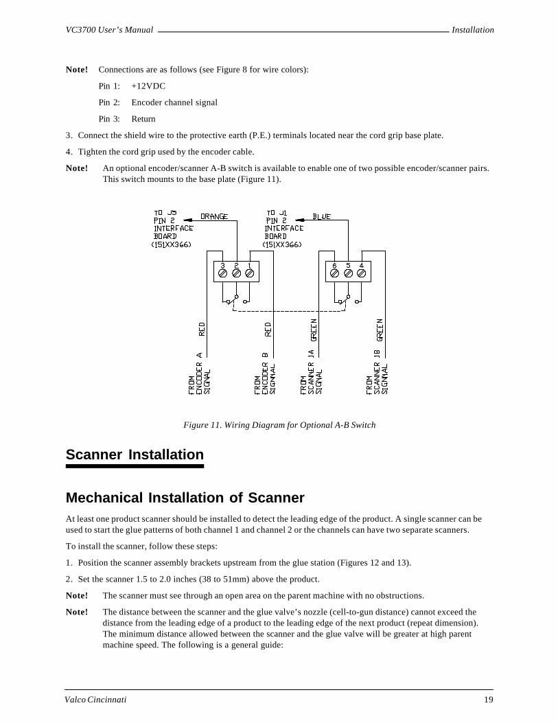
InstallationVC3700 User’s Manual
Valco Cincinnati 19
Note! Connections are as follows (see Figure 8 for wire colors):
Pin 1: +12VDC
Pin 2: Encoder channel signal
Pin 3: Return
3. Connect the shield wire to the protective earth (P.E.) terminals located near the cord grip base plate.
4. Tighten the cord grip used by the encoder cable.
Note! An optional encoder/scanner A-B switch is available to enable one of two possible encoder/scanner pairs.This switch mounts to the base plate (Figure 11).
Scanner Installation
Mechanical Installation of ScannerAt least one product scanner should be installed to detect the leading edge of the product. A single scanner can beused to start the glue patterns of both channel 1 and channel 2 or the channels can have two separate scanners.
To install the scanner, follow these steps:
1. Position the scanner assembly brackets upstream from the glue station (Figures 12 and 13).
2. Set the scanner 1.5 to 2.0 inches (38 to 51mm) above the product.
Note! The scanner must see through an open area on the parent machine with no obstructions.
Note! The distance between the scanner and the glue valve’s nozzle (cell-to-gun distance) cannot exceed thedistance from the leading edge of a product to the leading edge of the next product (repeat dimension).The minimum distance allowed between the scanner and the glue valve will be greater at high parentmachine speed. The following is a general guide:
Figure 11. Wiring Diagram for Optional A-B Switch

Installation VC3700 User’s Manual
Valco Cincinnati20
Speed Minimum Cell-to-Gun Distance
100 ft/min (30.5 m/min) 1" (25.4 mm)
500 ft/min (152.4 m/min) 2" (51 mm)
1000 ft/min (304.8 m/min) 4" (102 mm)
1500 ft/min (457 m/min) 6" (152 mm)
2000 ft/min (610 m/min) 8" (203 mm)
2' (51 mm)
product flow
minimum = see chart above
to VC3700
to VC3700scanner
cell-to-gun
Figure 12. Top-Down Glue Station
Figure 13. Top-Down, Bottom-UpCombination Glue Station
6.5
10.0

InstallationVC3700 User’s Manual
Valco Cincinnati 21
Electrical Installation of Scanner
The cable used to connect the scanner(s) to the VC3700 control should have a minimum of three conductors (18-22AWG) and a shield.
To connect the scanner to the control, follow these steps:
1. Insert the scanner cable into the control enclosure through a cord grip located on the bottom panel of thecontrol.
2. Connect the scanner cable to one of the three-terminal connectors labeled “scanner-1” and “scanner-2.
Note! The “scanner-1” connector must be used for the scanner installed for channel 1. This scanner can alsobe used to control channel 2. If separate scanners are desired to control channel 1 and channel 2, the“scanner-1” connector must be used for the scanner installed for channel 1, and the “scanner-2”connector must be used for the scanner installed for channel 2. Connections are as follows (see Figure8 for wire colors):
Pin 1: +12VDC
Pin 2: Scanner signal
Pin 3: Return
3. Connect shield wire(s) to the protective earth (P.E.) terminals located near cord-grip base plate.
4. Tighten the cord grip used by the scanner cable (s).
Glue Valve Installation
Electrical Installation of Glue ValveThe glue valve cable should have a minimum of two conductors (18-20 AWG) and a shield (four conductors and ashield if a remote purge is required).
To connect the glue valve to the control, follow these steps:
1. Insert the glue valve cable into the control through a cord grip located on the bottom panel of the control.
2. Connect glue valve cable to the connectors labeled “valve-1” or “valve-2.”
Note! The “valve-1” connector must be used for the glue valve controlled by channel 1. The “valve-2”connector must be used for the glue valve controlled by channel 2 (see the Internal Connectionsdiagram). Connections are as follows (see Figure 8 for wire colors):
Pin 1: Purge output
Pin 2: Purge return
Pin 3: Valve output
Pin 4: Valve return
3. The shield wire should be connected to the protective earth (P.E.) terminals located near the cord grip baseplate.
4. Tighten the cord grip used by the valve cable.

Installation VC3700 User’s Manual
Valco Cincinnati22
Machine-Stop Relay and Beacon Interface
An optional machine stop relay and beacon interface (option D1) is required to indicate a jam condition or glueinspection fault to the parent machine. Normally open and normally closed contacts are provided at a male connec-tor mounted to the cord grip base plate. Contact rating is 24VDC or 24VAC at 2A.
When a jam condition is detected, the machine stop relay is energized. The relay is de-energized when the speed ofthe parent machine drops below the minimum speed setting (see the level-3 menu screen). The front-panel jamindicator also illuminates.
A field-wireable mating connector (Figure 13a) is provided to wire the relay contacts to the parent machine stopcircuit. Connections are as follows:
Pins 1 and 2: Normally closed contact
Pins 3 and 4: Normally open contact
DD-1 Pump Power Supply
A source is available to supply power for a DD-1 pump at connector J6 of the power supply board (151xx368). Thissupply is 32VDC, fused at 1.6A, with connections as follows:
Pin 1: 0V
Pin 2: 32VDC
Since the DD-1 pump is configured to accept an AC source and then rectify it to DC, polarity of a DC source is notrelevant.
Bypass Valve Driver
A bypass valve (or dump valve) may be needed to divert excess glue in the glue line away from the applicator toavoid puddling during startups and quick stops. A 12VDC, 1A driver is available at connector J8 of the interfaceboard. Connections are as follows:
Pin 1: 12V
Pin 2: Signal
An optional beacon with audible alert can be remotely mounted toindicate a jam condition. A female connector mounted to the cord-grip base plate provides the connection point for beacon/alarmsignals. Connections are as follows:
Pin 1: 12VDC
Pin 2: Glue fault (blue) light
Pin 3: Jam (red) light
Pin 4: Audible alarm signal
A pre-wired cable is provided with the beacon.
rubber grommet
rubber grommet
0.23"
0.31"
Figure 13a. Field-Wireable Connector
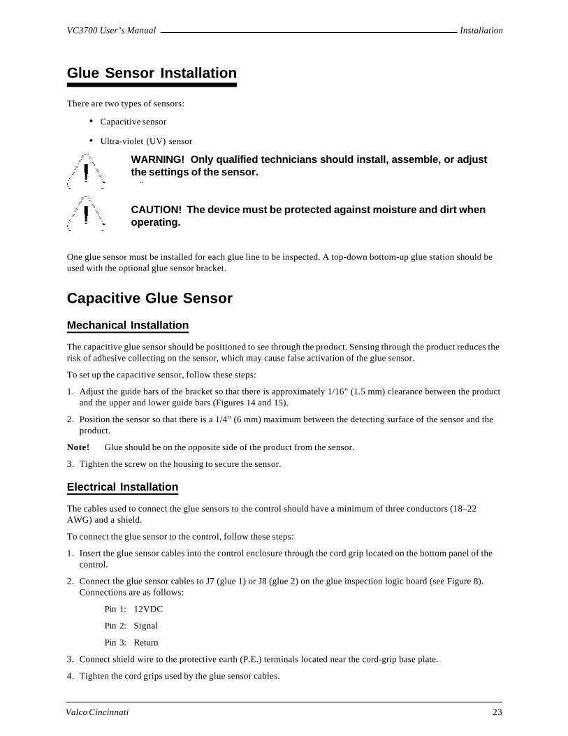
InstallationVC3700 User’s Manual
Valco Cincinnati 23
Glue Sensor Installation
There are two types of sensors:
• Capacitive sensor
• Ultra-violet (UV) sensor
WARNING! Only qualified technicians should install, assemble, or adjustthe settings of the sensor.
CAUTION! The device must be protected against moisture and dirt whenoperating.
One glue sensor must be installed for each glue line to be inspected. A top-down bottom-up glue station should beused with the optional glue sensor bracket.
Capacitive Glue Sensor
Mechanical Installation
The capacitive glue sensor should be positioned to see through the product. Sensing through the product reduces therisk of adhesive collecting on the sensor, which may cause false activation of the glue sensor.
To set up the capacitive sensor, follow these steps:
1. Adjust the guide bars of the bracket so that there is approximately 1/16” (1.5 mm) clearance between the productand the upper and lower guide bars (Figures 14 and 15).
2. Position the sensor so that there is a 1/4” (6 mm) maximum between the detecting surface of the sensor and theproduct.
Note! Glue should be on the opposite side of the product from the sensor.
3. Tighten the screw on the housing to secure the sensor.
Electrical Installation
The cables used to connect the glue sensors to the control should have a minimum of three conductors (18–22AWG) and a shield.
To connect the glue sensor to the control, follow these steps:
1. Insert the glue sensor cables into the control enclosure through the cord grip located on the bottom panel of thecontrol.
2. Connect the glue sensor cables to J7 (glue 1) or J8 (glue 2) on the glue inspection logic board (see Figure 8).Connections are as follows:
Pin 1: 12VDC
Pin 2: Signal
Pin 3: Return
3. Connect shield wire to the protective earth (P.E.) terminals located near the cord-grip base plate.
4. Tighten the cord grips used by the glue sensor cables.

Installation VC3700 User’s Manual
Valco Cincinnati24
Figure 14. Typical Installation (Capacitive Sensor Only)
upper guide bar
sensor
plastic
1/16" (1.5 mm)
glue on this sidelower guide bar
productmaximum 1/4”
Figure 15. Typical Installation (Capacitive Sensor Only)
upper guide barglue on this side
product
sensor
plastic housing
maximum 1/4” (6 mm)
1/16” (1.5 mm)
lower guide bar
Figure 16. Capacitive Glue Sensor
LEDadjustment screw

InstallationVC3700 User’s Manual
Valco Cincinnati 25
Capacitive Glue Sensor Adjustment
To adjust the capacitive glue sensor, follow these steps:
1. Apply a glue pattern to the product.
2. Observe the LED on top of the sensor (Figure 16) while glue is within sensor’s field of view.
3. If the LED is illuminated:
3a. Turn the adjustment screw counterclockwise until the light goes off.
3b. Turn the adjustment screw clockwise until the LED comes on.
3c. Turn the adjustment screw clockwise an additional 1/2 turn.
4. If the LED is not illuminated:
4a. Turn the adjustment screw clockwise until the LED comes on.
4b. Turn the adjustment screw clockwise an additional 1/2 turn.
UV Sensor
Mechanical Installation
The UV glue pattern detection sensor is an optical, electronic sensor. It is used to detect fluorescent objects (such asUV liquid added to glue) optically and without contact.
To install the UV sensor, follow these steps:
1. Mount the sensor onto the guide bracket so that its sensing surface is approximately 1 inch (25mm) above theglue line being sensed.
2. Adjust the guiding bars so that the product has the least horizontal and vertical movement. Pay attention to thescanning range when adjusting the bars.
3. Connect the cable to the plug receptacle on the glue sensor.
Electrical Installation
The cables used to connect the glue sensors to the control should have a minimum of three conductors (18–22AWG) and a shield.
To connect the glue sensor to the control, follow these steps:
1. Insert the glue sensor cables into the control enclosure through the cord grip located on the bottom panel of thecontrol.
2. Connect the glue sensor cables to J7 (glue 1) or J8 (glue 2) on the glue inspection logic board (see Figure 8).Connections are as follows:
Pin 1: 12VDC
Pin 2: Glue sensor signal input
Pin 3: Return
3. Connect shield wire to the protective earth (P.E.) terminals located near the cord-grip base plate.
4. Tighten the cord grips used by the glue sensor cables.
UV Sensor Time Delay Setting
The time-delay switch must be set to “0”.

Installation VC3700 User’s Manual
Valco Cincinnati26
UV Sensor Sensitivity Setting
When the power is switched on, the green LED illuminates (ON). The yellow LED illuminates only when it detectsa luminescent object (for example, UV liquid added to glue).
For objects to be detected against a background without luminescence, follow these steps:
1. Turn the sensitivity adjuster to maximum (clockwise). The luminescence sensor reacts to the luminescent glowand the output is switched.
For objects to be detected against a background with luminescence, follow these steps:
1. Turn the sensitivity adjuster to maximum (clockwise).
2. Position the background (with lower luminescence) in the light spot of the scanner.
3. Turn the sensitivity adjuster counterclockwise until the status indicator just switches off.
4. Note the position.
5. Position the luminescent glue in the light spot of the scanner.
6. Turn the sensitivity adjuster counterclockwise until the status indicator just switches off.
7. Note the position.
8. Reset the sensitivity adjuster to approximately halfway between the two positions.
The UV signal can be viewed using a piece of UV-sensitive copy paper. The UV signal emits several dot signals ina line. These dots should be slightly out of focus and perpendicular to the glue line. A right-angle lens is available torotate the UV signal so it is perpendicular to the glue line.
Lens Replacement
The lens is screwed in and can be replaced by another lens. Scanning distances of 10, 20, 50, 90mm (.39, .78, 1.97,and 3.54 inches, respectively) are available. Standard lens should be 20mm. The luminescence intensitivity might betoo weak if a scanning distance of more than 20 mm is used.
Maintenance
UV-3 sensors do not require any maintenance. However, periodically cleaning the optical lens and checking theconnections is recommended.
Product Scanners for Glue Inspection
Mechanical Installation of ScannerThe product scanners for glue inspection must be located precisely opposite the glue sensors. The sensor must seethe same edge as the scanner used in gluing.
To install the glue sensor, follow these steps:
1. Set the scanner 1.5 inches (38mm) above the product.
Note! The scanner must be able to see through open areas on the parent machine with no obstructions. Valco’sstandard scanner has a sensitivity adjustment on the top of the scanner.

InstallationVC3700 User’s Manual
Valco Cincinnati 27
Electrical Installation of ScannerThe cables used to connect the product scanners to the VC3700 control should have a minimum of three conductors(18–22 AWG) and a shield.
To connect the product scanners to the control, follow these steps:
1. Insert the product scanner cables into the control enclosure through a cord grip located on the bottom panel ofthe control.
2. Connect the product scanner cables to J5 (scanner 1) or J6 (scanner 2) on the glue inspection board (Figure 8).Connections are as follows:
Pin 1: 12VDC
Pin 2: Product scanner signal input
Pin 3: Return
3. Connect shield wire to the protective earth (P.E.) terminals located near the cord-grip base plate.
4. Tighten the cord grips used by the product scanner cables.
Marker Valve or Kicker/Diverter Installation
Mechanical InstallationThe unit must be less than 255 inches (6477 mm) from the product scanner used for glue inspection. It must also beless than 7 products from the scanner.
Electrical InstallationThe cable used to connect the marker valve or kicker/diverter to the control should have a minimum of two conduc-tors (18–22 AWG) and a shield.
To install the marker valve or kicker/diverter, follow these steps:
1. Insert the cable into the control enclosure through the cord grip located on the bottom panel of the control.
2. Connect the cable to J3 (KCK-VLV) on the glue inspection board (Figure 8). Connections are as follows:
Pin 1: Return
Pin 2: Drive signal (sourcing)
3. Connect the shield to the protective earth (P.E.) terminals located near the cord-grip base plate.
4. Tighten the cord grip used by this cable.

Valco Cincinnati 29
Menus
Introduction
This section describes the control’s menus. The menus are displayed on touchscreens, which means that you pushthe button on the actual screen display,
Note! This section contains descriptions only—not procedures. For specific procedures, see the “Initial Setup”and “Operation” sections.
Primary Menus
The VC3700 contains the following primary menu screens (Figure 17):
• Main screen—The main screen is the screen that displays when power is supplied to the control.
• Level-1 menu screen—The level-1 menu screen provides access to the job store screen, the job titlescreen, the job index screen, the product length screen, and the clear current data screen.
• Level-2 menu screen—The level-2 menu screen provides access to the scan mode screen, the glue modescreen (two-channel model only), and the repeat function.
• Level-3 menu screen—The level-3 menu screen provides access to the clear data screen (current job orall), the minimum speed screen, and the cell-to-gun screen.
• Level-4 menu screen—The level-4 menu screen provides access to the product length screen, the ratiocompensation screen, and the channel compensation screens.
• Level-5 menu screen—The level-5 menu screen provides access to the inch/metric screen, the glue QCscreen, and the PIN code screen.
• Level-6 menu screen—The level-6 menu screen provides access to language selection.
These menu screens and their functions are described in the following paragraphs.

Menus VC3700 User’s Manual
Valco Cincinnati30
Level-1 Menu Screen
Level-2 Menu Screen
Level-3 Menu Screen
Level-4 Menu Screen
Level-5 Menu Screen
Level-6 Menu Screen
Main Menu
PSI CONFIG
Number field
0000 00000000 0000
CONFIGEXIT
MORE
EXIT
MORE
SCAN MODE
GLUE MODE
EXIT
MORE
CLEAR DATA
CELL-GUN 1
CELL-GUN 2
MIN SPEED
EXIT ENGLISH
FRANÇAIS
DEUTSCH
EXIT
MORE
JOB STORE >>><<<
ITALIANO
ESPAÑOL
NEDERLANDS
EXIT
MORE
PRD LENGTH
COMP CHAN1
RATIO COMP
00.00
EXIT
EXIT
MOREEXIT
MOREEXIT
1
2
3
4
6
PRD LENGTH
CLEAR DATA
COMP CHAN2
EXIT
MORE5
IN/METRIC
MOREEXIT
00.00
00.00
00.00
REPEAT
GLUE QC
PIN
MORE
(If screens 3-6 havebeen restricted, pressing“MORE” will display a 6-digitnumeric keypad.)
REPEAT
GLUE MODE
SCAN MODEEXIT
MORE
2
5 6
3 4
1 2
00.00 00.00
Glue-Pattern Edit Screen
Figure 17. Main Menu Screen, Glue Pattern Edit Screen, and Level-1through Level-6 Menu Screens

MenusVC3700 User’s Manual
Valco Cincinnati 31
Main Screen
The main screen displays when power is supplied to the control (Figures 18 and 19). The features of the main screenare as follows:
1 Glue pressure bar graph
This field displays the pressure supplied to the glue source. The pressure is displayed in either psi or bar,depending on the setup of the control.
2 Glue pattern delay (channel 1)
This field displays the distance from the leading edge of the product to the beginning of the glue pattern.
3 Channel 1 glue pattern edit
This field displays the channel assignment for the delay and pattern length settings seen on the left andright of this display.
4 Software version
This field displays the software version used by the control.
PSI
CHAN 1DEL PAT03.00 "
CONFIG
CHAN 2DEL PAT
2 3 4 5 6
1 7
8 9 10
00.00 00.00
00.00 00.00
Figure 18. Example of a Control with the Glue Mode Set to“Delay Pattern”
PSI
CHAN 1DEL PAT
CONFIG
11 12
13 15 14
00.00 00.00
00.00 00.002
03.00 "
Figure 19. Example of a Control with the Glue Mode Set to“Delay Pattern Delay Pattern”

Menus VC3700 User’s Manual
Valco Cincinnati32
5 Inch or mm indicator
This field displays the measurement setup for the control. The inch symbol (") indicates imperial measure-ments and “mm” indicates metric measurements.
6 Glue pattern length (channel 1)
This field displays the length of the glue pattern.
7 Configuration
The level-1 menu screen displays when this button is pressed.
8 Glue pattern delay (channel 2)
This field displays the distance from the leading edge of the product to the beginning of the glue pattern.
9 Channel 2 glue pattern edit
This field displays the channel assignment for the delay and pattern length settings seen on the left andright of this display
10 Glue pattern length (channel 2)
This field displays the distance of the glue pattern.
Note! Items 11-15 pertain to the “delay pattern delay pattern” glue mode.
11 First glue pattern delay
This field displays the distance from leading edge of product to beginning of first glue pattern.
12 First glue pattern length
This field displays the distance of the glue pattern.
13 Second glue pattern delay
This field displays the distance from end of first glue pattern to beginning of second glue pattern.
14 Second glue pattern length
This field displays the distance of the second glue pattern.
15 Page down
Pressing this field displays pattern information for the next channel.
Glue-Pattern Edit Screen
The glue-pattern edit screen appears when any of the numbers on the main screen are pressed (Figure 18). Thefunction of each button is as follows:
“+”—This button increases values for the pattern delay and length.
“-”—This button decreases values for the pattern delay and length.
Symbol in center of the screen—This button returns you to the main screen.
Note! The main screen will appear automatically if the parameters in the glue pattern edit screen have not beenchanged for ten seconds.

MenusVC3700 User’s Manual
Valco Cincinnati 33
Level-1 Menu Screen
The level-1 menu screen (Figure 20) displays when the “CONFIG” button on the main menu screen is pressed. Thesmall box with the numeral 1 indicates that this is the level-1 menu screen. The function of each button is asfollows:
EXIT—Pressing this button returns you to the main screen.
MORE—Pressing this button displays the level-2 menu screen.
JOB STORE—Pressing this button displays the job store screen. The job store screen allows you to create a jobname, save a job, and load a job.
PRD LENGTH—Pressing this button displays the product-length screen. The control uses the product-length valuewhen calculating the ratio compensation in the automatic mode, detecting a product jam condition, and enabling thescanner lockout function to ignore holes in the product or dark areas such as printing.
CLEAR DATA—Pressing this button displays the clear-data screen. Pressing the “YES” button in the clear datascreen erases the current job’s delay and glue pattern length settings and returns the product length setting to zero.Pressing the “NO” button in the clear data screen returns you to the main screen without erasing any data.
Clear-Data ScreenJob-Store Screen Product-Length Screen
Level-1 Menu Screen
Figure 20. Level-1 Menu Screen and Associated Screens
Job-Title Screen
UP
EXIT
DOWN
BACK
A
CARTON27
SELECT SPACE
SAVE
Job-Index Screen
EXIT
DOWN
LOAD
CARTON27
UP
SAVE
02
EXIT
ENTERXXXmm
7 8 9
4 5 6
0 1 2 3
.
JOB STORE >>><<< CLEAR DATAPRD LENGTH
04EXIT
SAVE
7 8 9
LOAD INDEX
4 5 6
320 1
INDEX
NOYES
EXIT
1
JOB STORE >>><<<
PRD LENGTH
CLEAR DATA
MORE

Menus VC3700 User’s Manual
Valco Cincinnati34
The Job Store ScreenThe job store screen (Figure 20) is used to assign job numbers. The function of each button is as follows:
EXIT—Pressing this button returns you to the level-1 menu screen.
Numeric Keypad—You use the numeric keypad on the screen to enter a two-digit job number (all job parametersof the active job are saved when the job number is entered).
LOAD—This button displays only after the two-digit job number has been entered. Pressing the “LOAD” buttonloads the job.
SAVE—This button displays only after the two-digit job number has been entered. Pressing this button displays thejob title screen, which allows you to assign a job name to the two-digit job number.
INDEX—Pressing this button displays the job index screen, which lists job names and numbers.
The Job Title ScreenThe job title screen (Figure 20) displays when the “SAVE” button is pressed on the job store screen. The job titlescreen is used to assign a name (up to 10 characters) to the two-digit job number. The function of each button is asfollows:
EXIT—Pressing this button returns you to the level-1 menu screen.
A—This field displays the alphabet, numbers, and special characters.
DOWN—This button is used to scroll down through the alphabet, numbers, and special characters.
UP—This button is used to scroll up through the alphabet, numbers, and special characters.
BACK—Pressing this button moves the cursor backward in the job name field, erasing the displayed letters as itmoves.
SELECT—Pressing this button enters the displayed letter into the job name field.
SPACE—Pressing this button adds a space to the job name.
The Job Index ScreenThe job index screen (Figure 20) displays when the “INDEX” button is pressed on the job store screen. The functionof each button is as follows:
EXIT—Pressing this button returns you to the job store screen.
DOWN—Pressing this button allows you to scroll down the list of job names and numbers. (“01” is the lowest jobnumber possible.)
UP—Pressing this button allows you to scroll up the list of job names and numbers. (“99” is the highest job numberpossible.)
LOAD—Pressing this button loads the job shown in the job name/number display.
SAVE—Pressing this button saves the active job to the name and number seen in the job name/number display(located above the “UP” button).

MenusVC3700 User’s Manual
Valco Cincinnati 35
The Product Length ScreenThe product-length (Figure 20) screen is used to specify product length. The function of each button is as follows:
EXIT—Pressing this button returns you to the level-1 menu screen.
Numeric Keypad—The numeric keypad is used to type a product length.
ENTER—Pressing this button enters the product length.
The Clear-Data ScreenThe clear-data screen (Figure 20) is used to clear the current job’s data. The function of each button is as follows:
YES—Pressing the “YES” button erases the current job’s delay and glue patterns.
NO—Pressing the “NO” button returns you to the level-1 menu screen without erasing any data.
Figure 21. Level-2 Menu Screen and Associated Screens
Scanner-Mode Screen Glue-Mode Screen Repeat-Channel Select Screen
GLUE MODE
SCAN MODEEXIT
MORE GLUE MODE
REPEAT2
SCAN MODE REPEAT
Repeat Setup Screen
3
6
EXIT
ENTER00x 0
87
54
21
9
CHANNEL 1 or 2
Level-2 Menu Screen
EXIT
SCAN 1 or 2 SCAN 1 1-2 CHANNEL 1
CHANNEL 2
EXIT
CHAN 2 DEL PAT
CHAN 1 DEL PAT
EXIT
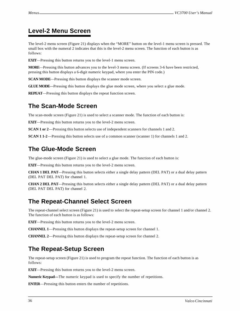
Menus VC3700 User’s Manual
Valco Cincinnati36
Level-2 Menu Screen
The level-2 menu screen (Figure 21) displays when the “MORE” button on the level-1 menu screen is pressed. Thesmall box with the numeral 2 indicates that this is the level-2 menu screen. The function of each button is asfollows:
EXIT—Pressing this button returns you to the level-1 menu screen.
MORE—Pressing this button advances you to the level-3 menu screen. (If screens 3-6 have been restricted,pressing this button displays a 6-digit numeric keypad, where you enter the PIN code.)
SCAN MODE—Pressing this button displays the scanner mode screen.
GLUE MODE—Pressing this button displays the glue mode screen, where you select a glue mode.
REPEAT—Pressing this button displays the repeat function screen.
The Scan-Mode ScreenThe scan-mode screen (Figure 21) is used to select a scanner mode. The function of each button is:
EXIT—Pressing this button returns you to the level-2 menu screen.
SCAN 1 or 2—Pressing this button selects use of independent scanners for channels 1 and 2.
SCAN 1 1-2—Pressing this button selects use of a common scanner (scanner 1) for channels 1 and 2.
The Glue-Mode ScreenThe glue-mode screen (Figure 21) is used to select a glue mode. The function of each button is:
EXIT—Pressing this button returns you to the level-2 menu screen.
CHAN 1 DEL PAT—Pressing this button selects either a single delay pattern (DEL PAT) or a dual delay pattern(DEL PAT DEL PAT) for channel 1.
CHAN 2 DEL PAT—Pressing this button selects either a single delay pattern (DEL PAT) or a dual delay pattern(DEL PAT DEL PAT) for channel 2.
The Repeat-Channel Select ScreenThe repeat-channel select screen (Figure 21) is used to select the repeat-setup screen for channel 1 and/or channel 2.The function of each button is as follows:
EXIT—Pressing this button returns you to the level-2 menu screen.
CHANNEL 1—Pressing this button displays the repeat-setup screen for channel 1.
CHANNEL 2—Pressing this button displays the repeat-setup screen for channel 2.
The Repeat-Setup ScreenThe repeat-setup screen (Figure 21) is used to program the repeat function. The function of each button is asfollows:
EXIT—Pressing this button returns you to the level-2 menu screen.
Numeric Keypad—The numeric keypad is used to specify the number of repetitions.
ENTER—Pressing this button enters the number of repetitions.

MenusVC3700 User’s Manual
Valco Cincinnati 37
Level-3 Menu Screen
The level-3 menu screen (Figure 22) displays when the “MORE” button on the level-2 menu screen is pressed. Thesmall box with the numeral 3 indicates that this is the level-3 menu screen. The function of each button is asfollows:
EXIT—Pressing this button returns you to the level-2 menu screen.
MORE—Pressing this button advances you to the level-4 menu screen.
CLEAR DATA—Pressing this button displays the clear-data screen, which allows you to erase either the currentjob’s data or all data.
MIN SPEED—Pressing this button displays the minimum speed setting screen, which allows you to specify theminimum gluing speed.
CELL-GUN (1-2)—Pressing either of the CELL-GUN buttons displays the cell-to-gun setting screen, which allowsyou to specify cell-to-gun dimensions.
Level-3 Menu Screen
CLEAR DATA MIN SPEED CELL GUNS 1-2
EXIT
MORE
CLEAR DATA
CELL-GUN 1
CELL-GUN 2
MIN SPEED
3
CELL-GUN 3
CELL-GUN 4
Clear-Data Screen Minimum-Speed-Setting Screen Cell-to-Gun-Setting Screen
EXIT
0
USE + - KEYS TO SET THECUTOFF SPEED.
EXIT
5
0000mm ENTER 321
4 6
7 8 9CHAN 1
Figure 22. Level-3 Menu Screen and Associated Screens
WARNING!THIS ACTION WILL DESTROY THECURRENT PRODUCT SETTINGIRRETRIEVABLY. ARE YOU SURE?
YES NOALL

Menus VC3700 User’s Manual
Valco Cincinnati38
The Clear-Data ScreenThe clear-data screen is used to clear either all or partial data. The function of each button is as follows:
ALL—Pressing this button resets all parameters.
YES—Pressing this button erases the current job’s delay and glue patterns.
NO—Pressing this button returns you to the level-3 menu screen without erasing any data.
The Minimum-Speed-Setting ScreenThe minimum-speed-setting screen is used to specify the minimum gluing speed. The function of each button is asfollows:
EXIT—Pressing this button returns you to the level-3 menu screen.
The “-” key—Pressing the “-” key reduces the minimum speed.
The “+” key—Pressing the “+” key increases the minimum speed.
The Cell-to-Gun-Settting ScreenEXIT—Pressing this button returns you to the level-3 menu screen.
The numeric keyboard—The numeric keyboard is used to specify the distance between the channel scanner andthe channel glue valve.
ENTER—Pressing this key enters the distance between the channel scanner and the channel glue valve.

MenusVC3700 User’s Manual
Valco Cincinnati 39
Level-4 Menu Screen
The level-4 menu screen (Figure 23) displays when the “MORE” button on the level-3 menu screen is pressed. Thesmall box with the numeral 4 indicates that this is the level-4 menu screen. The function of each button is asfollows:
EXIT—Pressing this button returns you to the level-3 menu screen.
MORE—Pressing this button advances you to the level-5 menu screen.
PRD LENGTH—Pressing this button displays the product-length screen. The control uses the product length valuewhen calculating the ratio compensation in the auto mode, detecting a product jam condition and enabling thescanner lockout function to ignore holes in the product or dark areas such as printing.
RATIO COMP—Pressing this button displays the ratio compensation screen. Either a manual or automatic ratiocompensation method may be used.
COMP CHAN (1-2)—Each channel (valve) has a separate compensation setting. Pressing either of the COMPCHAN buttons displays the compensation setting screen for that channel.
Figure 23. Level-4 Menu Screen and Associated Screens
Manual Ratio-CompensationScreen
AUTO
Automatic-Ratio-Compensation Screen
EXIT
MORE
PRD LENGTH
COMP CHAN1
RATIO COMP
COMP CHAN3
4 COMP CHAN2 COMP CHAN4
RATIO COMP
Level-4 Menu Screen
Product-Length Screen
EXIT
3
6
ENTER0000mm 0
87
54
21
9
PRD LENGTH
On/Off Compensation-SettingScreen
EXIT
ON= 00.0
OFF= 00.0 ENTER
.
0 1 2 3
4 5 6
7 8 9
COMP CHAN 1-2
3
6
ENTER100.0 PULSES 0
87
54
21
9EXIT
AUTO
06.00"
EXIT
SAVE
RUN THE LINE ALLOWINGTHE SCANNER TO SCAN THEWHOLE PRODUCT.
.

Menus VC3700 User’s Manual
Valco Cincinnati40
The Product-Length ScreenThe product-length screen is used to specify product length. The function of each button is as follows:
EXIT—Pressing this button returns you to the level-4 menu screen.
Numeric Keypad—The numeric keypad is used to specify the product length.
ENTER—Pressing this button enters the product length.
The Manual Ratio-Compensation ScreenThe manual ratio-compensation screen is used to specify the product length. The function of each button is asfollows:
EXIT—Pressing this button returns you to the level-4 menu screen.
Numeric keypad—The numeric keypad is used to specify the number of encoder pulses per inch (25.4) mm) ofproduct line travel.
ENTER—Pressing this button enters the number of encoder pulses per inch (25.4) mm) of product line travel.
AUTO—Pressing this button displays the automatic ratio compensation screen.
The Automatic-Ratio-Compensation ScreenThe automatic-ratio-compensation screen displays when the “AUTO” button on the ratio-compensation screen ispressed. The automatic-ratio-compensation screen is used to specify the number of encoder pulses per inch (25.4mm) of product line travel. The function of each button is as follows:
EXIT—Pressing this button returns you to the level-4 menu screen.
SAVE—Pressing this button saves the new ratio compensation that is displayed at the bottom of the screen.
The On/Off Compensation-Setting ScreenThe on/off compensation-setting screen displays when either the “COMP CHAN1” button or the “COMP CHAN2”button on the level-4 menu screen is pressed. The compensation-setting screen is used to specify the turn-on andturn-off times for the valves that are driven by each channel. The function of each button is as follows:
EXIT—Pressing this button returns you to the level-4 menu screen.
ON=—Pressing this button allows the turn-on time to be specified.
OFF=—Pressing this button allows the turn-off time to be specified.
Numeric keypad—The numeric keypad is used to specify the turn-on/turn-off time for the channel that you haveselected.
ENTER—Pressing this button enters the turn-on/turn-off time.

MenusVC3700 User’s Manual
Valco Cincinnati 41
Figure 24. Level-5 Menu Screens and Related Screens
EXIT
MORE5
IN/METRIC PIN
GLUE QC
Inch/Metric Screen
EXIT
MARKER 0000mm
FAIL NUMBER 0
GREEN 5mm
AMBER 10mm
RED 20mm
EXIT
INCH MODE METRIC MODE
PIN-Code Screen Glue-Inspection Setup Screen
GLUE QC
MARKER
Cell-Marker Edit Screen
IN/METRIC PIN
Level-5 Menu Screen
Marker-Skip/Marker-Mark Select Screen
EXIT
MARKER MARK
MARKER SKIP
EXIT
NEW PIN
EXIT
NEW PIN
NEW PIN
New-PIN Entry Screen
5 6
3 4
1 2
MARKER SKIP or MARKER MARK
EXIT
3
6
ENTER0000mm 0
87
54
21
9
MARKER PATTERN
EXIT
3
6
ENTER0000mm 0
87
54
21
9
VALVE
Marker-Pattern Edit Screen
MARKER PATTERN

Menus VC3700 User’s Manual
Valco Cincinnati42
Level-5 Menu Screen
The level-5 menu screen (Figure 24) displays when the word “MORE” on the level-4 menu screen is pressed. Thesmall box with the numeral 5 indicates that this is the level-5 menu screen. The function of each button is asfollows:
EXIT—Pressing this button returns you to the level-4 menu screen.
MORE—Pressing this button advances you to the level-6 menu screen.
IN/METRIC—Pressing this button displays the inch/metric screen. When “inch mode” is selected, all linearmeasurements are displayed and entered in inches, and pressure is displayed in pounds per square inch (psi). When“metric mode” is selected, all linear measurements are displayed and entered in millimeters, and pressure is dis-played in “bar.”
PIN—Pressing the “PIN” button displays the PIN-code screen. A four-digit PIN code may be entered in order torestrict access to menus 3-6.
GLUE QC—Pressing this button displays the glue inspection setup screen.
The Inch/Metric ScreenThe inch/metric screen (Figure 24) is used to specify either inches or millimeters. The function of each button is asfollows:
EXIT—Pressing this button returns you to the level-5 menu screen.
INCH MODE—Pressing this button sets the control to imperial (inch and psi) measurements.
METRIC MODE—Pressing this button sets the control to metric (mm and bar) measurements.
The PIN Code ScreenThe PIN code screen (Figure 24) is used to specify a PIN code in order to restrict screens 3-6. The function of eachbutton is as follows:
EXIT—Pressing this button returns you to the level-5 menu screen.
NEW PIN—Pressing this button displays a 6-digit numeric keypad, which you use to enter a new4-digit PIN code.
The Glue Inspection Setup ScreenThe glue inspection setup screen (Figure 24) is used to specify the allowable tolerance for glue inspection pass/faildecisions. The function of each button is as follows:
EXIT—Pressing this button returns you to the level-5 menu screen.
MARKER—Pressing this button displays the marker-edit screen.
FAIL NUMBER—Pressing this button increments the number of consecutive glue faults to cause a machine-stopcondition. If the machine-stop relay is not wired to the parent machine, this parameter should be set to zero.
GREEN, AMBER, RED—Pressing one of these buttons selects the allowable tolerance for glue inspection pass/fail decisions.
Range-Select Button ( )—Pressing this button changes the tolerances of definitions for the “GREEN”, “AM-BER”, and “RED” buttons.
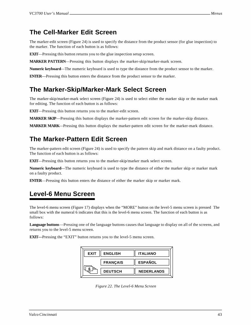
MenusVC3700 User’s Manual
Valco Cincinnati 43
The Cell-Marker Edit ScreenThe marker-edit screen (Figure 24) is used to specify the distance from the product sensor (for glue inspection) tothe marker. The function of each button is as follows:
EXIT—Pressing this button returns you to the glue inspection setup screen.
MARKER PATTERN—Pressing this button displays the marker-skip/marker-mark screen.
Numeric keyboard—The numeric keyboard is used to type the distance from the product sensor to the marker.
ENTER—Pressing this button enters the distance from the product sensor to the marker.
The Marker-Skip/Marker-Mark Select ScreenThe marker-skip/marker-mark select screen (Figure 24) is used to select either the marker skip or the marker markfor editing. The function of each button is as follows:
EXIT—Pressing this button returns you to the marker-edit screen.
MARKER SKIP—Pressing this button displays the marker-pattern edit screen for the marker-skip distance.
MARKER MARK—Pressing this button displays the marker-pattern edit screen for the marker-mark distance.
The Marker-Pattern Edit ScreenThe marker-pattern edit screen (Figure 24) is used to specify the pattern skip and mark distance on a faulty product.The function of each button is as follows:
EXIT—Pressing this button returns you to the marker-skip/marker mark select screen.
Numeric keyboard—The numeric keyboard is used to type the distance of either the marker skip or marker markon a faulty product.
ENTER—Pressing this button enters the distance of either the marker skip or marker mark.
Level-6 Menu Screen
The level-6 menu screen (Figure 17) displays when the “MORE” button on the level-5 menu screen is pressed Thesmall box with the numeral 6 indicates that this is the level-6 menu screen. The function of each button is asfollows:
Language buttons—Pressing one of the language buttons causes that language to display on all of the screens, andreturns you to the level-5 menu screen.
EXIT—Pressing the “EXIT” button returns you to the level-5 menu screen.
Figure 22. The Level-6 Menu Screen
EXIT ENGLISH
FRANÇAIS
DEUTSCH
ITALIANO
ESPAÑOL
NEDERLANDS6
Valco Cincinnati 45
Initial Setup
Introduction
This section contains procedures for initial setup of the control. It may be helpful to refer to the flowcharts pro-vided in the “Menus” section of this manual. The flowcharts are located as follows:
• Primary menu screens—Figure 17 (Page 30)
• Level-1 menu screen and associated screens—Figure 20 (Page 33)
• Level-2 menu screen and associated screens—Figure 21 (Page 35)
• Level-3 menu screen and associated screens—Figure 22 (Page 37)
• Level-4 menu screen and associated screens—Figure 23 (Page 39)
• Level-5 menu screen and associated screens—Figure 24 (Page 41)
Initial Setup
To conduct initial setup of the control, complete each of the following procedures.
Disable Glue Valves for All Channels1. Place channel toggle switches in center position (“0”) to prevent gluing during setup procedure.
Specify Inches or Millimeters1. Press the “CONFIG” button on the main screen. (The level-1 menu screen displays.)
2. Press the “MORE” button in the level-1 menu screen.
3. Press the MORE button in menu screens 2, 3 and 4. The level-5 menu screen displays.
4. Press the “IN/METRIC” button. The inch/metric screen displays.
5. Press either the “INCH MODE” button or the “METRIC MODE” button. (The arrow points toward themode that you have selected).
Note! When the “inch mode” is selected, all linear measurements are displayed and entered in inches, usingfour digits— two of which are decimal places (example: 10.00 = 10 inches). Pressure is displayed inpounds per square inch (psi). When the “metric mode” is selected, all linear measurements aredisplayed and entered in millimeters, using four digits (example: 1000 = 1000 millimeters). Pressureis displayed in “bar.”
Note! Small errors (0.04 or 1mm) will result in parameters when switching between inch and metric modes.
6. Press the “EXIT” button to return to the level-5 menu screen.

Initial Setup VC3700 User’s Manual
Valco Cincinnati46
Specify Minimum Gluing Speed1. Begin operating the production line at the desired minimum speed (the speed at which gluing will begin).
2. Press the “MIN SPEED” button in the level-3 menu screen. The minimum-speed-setting screen displays.
Note! The minimum-speed-setting screen displays two bar graphs. The top bar graph displays the minimumspeed of the parent machine at which gluing will begin. The bottom bar graph displays the actualspeed of the parent machine. The maximum speed indication of the bar graph is 1000 feet (300meters) per minute. If the parent machine exceeds this speed, the bar graph restarts from the left sideand displays the speed above 1000 feet (300 meters) per minute.
3. Use the plus or minus buttons on the screen to adjust the upper bar graph (minimum speed) so that it is lessthan the lower bar graph (actual machine speed).
4. Press the “EXIT” button when done.
Set Cell-to-Gun Dimensions1. Press the “CELL-GUN 1” button in the level-3 menu screen. The cell-to-gun setting screen displays.
2. Using the numeric keypad, enter the distance between the channel 1 scanner and the channel 1 glue valve(this value will display in either inches or millimeters depending on the setup of your control).
Note! Each channel (valve) has a separate cell-to-gun setting (“CELL-GUN 1” and“CELL-GUN 2”).
3. Press the “ENTER” button. The “OK DONE” message displays, indicating that the distance entered hasbeen saved.
Note ! This value should need no adjustment after the initial installation of the control and valves. However,the setting should be checked if the valves or scanners are moved or changed.
4. Press the “EXIT” button to return to the level-3 menu screen.
Note! To set additional cell-to-gun dimensions, you repeat steps 4a. through 4d.
Specify Ratio Compensation1. Press the “RATIO COMP” button in the level-4 menu screen.
2. Set the ratio compensation either manually or automatically (see procedures below).
Manual Ratio Compensation
To set ratio compensation manually, follow these steps:
1. Press the “RATIO COMP” button in the level-4 menu screen. The ratio compensation screen displays .
2. Using the numeric keyboard, input the number of encoder pulses per inch (25.4 mm) of product line travel.
3. Press the “ENTER” button. (The “OK DONE” message displays.)

Initial SetupVC3700 User’s Manual
Valco Cincinnati 47
Automatic Ratio Compensation
To set ratio compensation automatically, follow these steps:
Note! If using jam prevention, you must disable the stop circuit before using automatic ratio compensation.Otherwise, machine will shut down.
1. Press the “PRD LENGTH” button in the level-4 menu screen. The product length screen displays.
2. Using the numeric keypad, enter the exact product length.
3. Press the “ENTER” button. (The “OK DONE” message displays.)
4. Press the “EXIT” button to return to the level-4 menu screen
5. Press the “RATIO COMP” button in the level-4 menu screen. The ratio compensation screen displays.
6. Press the “AUTO” button. The automatic ratio compensation screen displays.
7. Run the line, allowing scanner 1 to scan the whole product.
Note! After the control has determined the number of encoder pulses per inch (25.4 mm) of product linetravel, the value will be displayed in the automatic ratio compensation screen. Product length is seenon the left side of the screen and encoder pulses per inch (25.4 mm) of product travel are seen on theright side of the screen.
8. Press the “SAVE” button to accept the new ratio compensation setting.
Note! Automatic ratio compensation is used to determine a general ratio compensation to a resolution ofseveral pulses.
9. Ensure that ratio compensation is accurate by measuring the length of a glue bead dispensed at low speed.
10. If necessary, use the manual ratio compensation to fine-tune the ratio compensation to a resolution of 0.1pulse.
11. After the ratio compensation has been established, add 2 inches (50 mm) to the product length setting inorder to allow the jam preventer and scanner lockout functions to operate correctly.
Specify On and Off Compensation1. The channel compensation allows a turn-on and turn-off time to be entered for each glue valve. Press the
“COMP CHAN1” button in the level-4 menu screen. The compensation setting screen displays.
2. Press the “ON=” button.
3. Using the numeric keypad, enter the manufacturer-specified “ON” compensation (turn-on time) in millisec-onds for the channel 1 glue valve.
Note! If compensation value is not known, follow the “Unknown Compensation Value” procedure on thefollowing page.
4. Press the “ENTER” button. (The turn-on time displays in the “ON=” window and the “OK DONE” messagedisplays.)
5. Press the “OFF=” button.
6. Using the numeric keypad, enter the manufacturer-specified “OFF” compensation (turn-off time) inmilliseconds for the channel 1 glue valve.

Initial Setup VC3700 User’s Manual
Valco Cincinnati48
7. Press the “ENTER” button. (The turn-off time displays in the “OFF=” window and the “OK DONE”message displays.)
Note! To set compensation times for channel 2, you press the “COMP CHAN2” button and enter the turn-on and turn-off times as described above.
8. Press the “EXIT” button to return to the level-4 menu screen.
Unknown Compensation Value
When the compensation value is not known, follow these steps:
1. At the level-4 menu screen, set the channel’s on and off compensation to 0 (see previous page).
2. Adjust the cell-to-gun dimension for the channel until the leading edge of the pattern is correct at lowspeed—that is, less than 75 feet (25m) per minute.
3. Increase machine speed to maximum.
4. Adjust the “ON” compensation until the leading edge of the pattern is correct. (Increasing the ON compen-sation will move the leading edge of the pattern forward at high speeds.)
5. Adjust the “OFF” compensation until the trailing edge of the pattern is correct. (Increasing the “OFF”compensation will move the trailing edge of the pattern forward at high speeds.)
Enable Glue QC1. At the level-5 menu screen, press the “GLUE QC” button. The glue inspection setup screen displays.
2. Press the “MARKER” button. (The cell-marker edit screen displays.)
3. Using the numeric keypad, enter the distance from the first product scanner used for glue inspection to themarker valve or kicker/diverter.
4. Press the “ENTER” button. (The “OK DONE” message displays.)
5. Press the “MARKER PATTERN” button. (The marker skip/marker mark select screen displays.)
6. Press the “MARKER SKIP” button. (The marker-pattern edit screen displays.)
7. Using the numeric keyboard, enter the distance required on each faulty product before marking(a non-zero setting is required).
8. Press the “ENTER” button. (The “OK DONE” message displays.)
9. Press the “EXIT” button. (The marker skip/marker mark screen displays.)
10. Press the “MARKER MARK” button. (The marker-pattern edit screen displays.)
11. Using the numeric keyboard, enter the length of mark required on each faulty product (a non-zero setting isrequired).
12. Press the “ENTER” button. (The “OK DONE” message displays.)
13. Press the “EXIT” button. (The marker-skip/marker-mark select screen displays.)
14. Press the “EXIT” button again (the cell-marker edit screen displays.)
15. Press the “EXIT” once more (the glue inspection setup screen displays).

Initial SetupVC3700 User’s Manual
Valco Cincinnati 49
16. Press the “FAIL NUMBER” button to increase the number of consecutive glue inspection faultscausing a machine stop. Each time you press this button, the number of faults is increased by 1.
Note! If you accidentally press the button too many times, keep pressing it until the number you wantcomes up again.
Note! A zero in this field prevents the machine-stop relay from initiating a shutdown due to a glue fault.The maximum value is 9. If the machine-stop relay is not wired to the parent machine, the value inthis field should be zero.
17. Press the range-select button to select a higher or lower set of tolerances for the “GREEN”, “AM-BER”, and “RED” tolerance buttons.
18. Press one of the three tolerance buttons (GREEN, AMBER, or RED) to select the amount of error tobe accepted for glue inspection. The toelrance indicator (“eye” symbol) displays next to the toleranceselected.
Note! The high range should be used for capacitive sensors. The low range can be used for most othersensors. The tolerances available in each range are:
Tolerance Button Low Range High Range
GREEN 5 mm 25 mm
AMBER 10 mm 40 mm
RED 20 mm 50 mm
Restrict Screen AccessTo restrict access to screens 3–6, follow these steps:
1. In the level-5 menu screen, press the “PIN” button. The PIN-code screen displays.
2. Press the “NEW PIN” button. (A six-digit numeric keypad and a display window display.)
Note! If a PIN code has been previously entered, the new PIN code will overwrite the old PINcode—only one PIN code is possible.
3. Using the numeric keypad, enter a four-digit PIN code.
Screens 3–6 are now restricted. From now on, the six-digit numeric keypad will display when the “MORE”button is pressed in the level-2 menu screen. To proceed to additional menu levels (3-6), a user must enterthe four-digit PIN code.
To provide non-restricted screen access, follow this step:
1. Press the “NEW PIN” button twice in order to delete the PIN code.
Return to the Main ScreenTo return to the main menu screen, follow this step:
1. Press the “EXIT” button in the level-4, level-3, level-2, and level-1 menu screens.

Valco Cincinnati 51
Operation
Introduction
This section contains procedures for operating the control. It may be helpful to refer to the flowcharts provided inthe “Menus” section of this manual. The flowcharts are located as follows:
• Primary menu screens—Figure 17 (Page 30)
• Level-1 menu screen and associated screens—Figure 20 (Page 33)
• Level-2 menu screen and associated screens—Figure 21 (Page 35)
• Level-3 menu screen and associated screens—Figure 22 (Page 37)
• Level-4 menu screen and associated screens—Figure 23 (Page 39)
• Level-5 menu screen and associated screens—Figure 24 (Page 41)
Creating a Job
To create a job, follow these steps:
1. Specify the scanner mode (see Page 53).
2. Specify the glue mode (see Page 54).
Note! If the repeat function will be used, see Appendix A.
3. Specify the delay and pattern values (see Page 54).
4. Specify product length (see Page 55).
5. Enable the glue valves:
5a. Place the toggle switches for the desired channels in the enabled position (“|”).
6. Conduct a low-speed check:
6a. Operate the parent machine at low speed.
6b . Observe the glue pattern on the product.
Note! Gluing does not begin until the parent machine is operating at the minimum threshold speed set inthe control. It may be necessary to adjust the minimum speed to apply glue at low speed.
6c. Adjust the values for delay and pattern if necessary.
7. Conduct a high-speed check:
7a. Operate the parent machine at the maximum production speed.
7b . Observe the glue pattern on the product. If the glue pattern is not accurately applied at high speed,follow the channel compensation procedure in the “Initial Setup” section.
8. Adjust the glue pressure:
8a. Use the front-panel glue pressure switch to increase (“+”) or decrease (“-”) the pattern’s glue volume(air pressure) if necessary.
Note! The amount of pressure selected is indicated by the linear bar graph in the center of the screen andby a pressure gauge located underneath the control.

Operation VC3700 User’s Manual
Valco Cincinnati52
Saving a Job
To save a job for future recall, follow these steps:
1. Press the “CONFIG” button on the main screen. (The level-1 menu screen displays.)
2. Press the “JOB STORE” button. (The job-store screen displays.)
3. Perform one of the following actions (3a or 3b):
3a. Enter a two-digit job number (01–99) and then press the “SAVE” button.
3b. Press the “INDEX” button (the job index screen displays). Press the “UP” and “DOWN” buttons tolocate an empty job number location (10 dots in the display field to the left of the number indicate anempty location). When an empty job number location has been found, press the “SAVE” button.
Note! If the location already contains a job, the “WARNING! THIS STORE CONTAINS DATA. DOYOU WISH TO CONTINUE?” message displays. Pressing the “YES” button overwrites thelocation with the new job information. (The job title screen displays.) Pressing the “NO” buttonreturns you to the job index screen, where you can select a different location.
Note! The job title screen displays after completing either of the actions in step 3.
4. In the job title screen, use the “DOWN” and “UP” buttons to select a letter.
5. Press the “SELECT” button to enter the letter into the display. (The cursor will automatically move to theright.)
6. Select additional letters until you have entered the job name.
Note! To erase letters, you press the “BACK” button. To add a space between letters, you press the“SPACE” button.
7. Press the “EXIT” button (the level-1 menu screen displays).
8. Press the “EXIT” button again (the main-menu screen displays).
Loading a Job
To load a job that has previously been saved:
1. Press the “CONFIG” button on the main screen. (The level-1 menu screen displays.)
2. Press the “JOB STORE” button (The job store screen displays.)
3. Perform one of the following actions (3a or 3b):
3a. Enter a job number and then press the “LOAD” button.
3b. Press the “INDEX” button to display the stored jobs (the job index screen displays). Press the “UP” or“DOWN” buttons to locate the desired job name and number. When the desired job name and numberlocation have been found, press the “LOAD” button to initiate the loading process. Press the “EXIT”button. (The job store screen displays.)
Note! After completing either step 3a or step 3b, the “LOADED” message appears in the job numberdisplay. The job that was selected is now the active gluing program.
4. Press the “EXIT” button. (The level-1 menu screen displays.)
5. Press the “EXIT” button again. (The main-menu screen displays.)

VC3700 User’s ManualOperation
Valco Cincinnati 53
Repeating Glue Patterns
For information on how to repeat glue patterns, see Appendix A.
Clearing Data
Both the level-1 menu screen and the level-3 menu screen have “CLEAR DATA” buttons. However, the “CLEARDATA” button in the level-3 menu screen has the capability of erasing all data, and the “CLEAR DATA’’ button inthe level-1 menu screen is capable of clearing data only for the current job.
To clear data, follow these steps:
1. In the level-3 menu screen, press the “CLEAR DATA” button. (The clear-data warning screen displays.)
2. Press one of the three buttons described in 2a., 2b., and 2c.:
2a. Pressing the “YES” button erases the current job’s delay and glue patterns and returns the product-length setting to zero.
Note! Once you press the “YES” button, the data is erased and cannot be retrieved.
2b. Pressing the “NO” button returns you to either the level-1 or the level-3 menu screen without erasingany data.
2c. Pressing the “ALL” button resets the following parameters (level-3 menu screen only):
• Delay and pattern lengths in jobs 1-99 will be erased.• Product length = 0• Scan mode (2-channel model only) = SCAN 1 or 2• Glue mode = DEL PAT• Minimum speed = 0• Cell-to-gun = 0• Ratio compensation = 100• Compensation channels 1-4 = 0• In/metric = metric• Pin code access = deactivated• Language = English
Note! Once you press the “ALL” button, the data is erased and cannot be retrieved.
Specifying the Scanner Mode
Two scanner modes are available for the control:
• SCAN 1 or 2—Scanner 1 is used to scan product for channel 1.Scanner 2 is used to scan product for channel 2.
• SCAN 1 1-2—Scanner 1 is used to scanproduct for both channel 1 and channel 2.
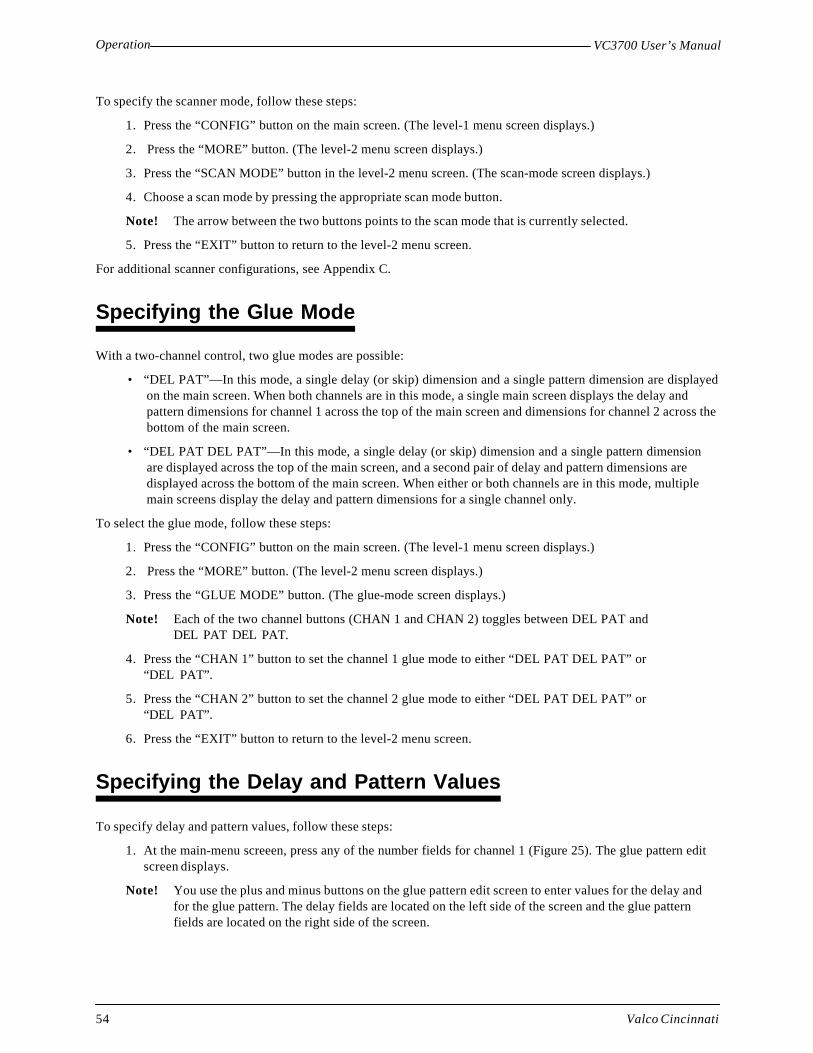
Operation VC3700 User’s Manual
Valco Cincinnati54
To specify the scanner mode, follow these steps:
1. Press the “CONFIG” button on the main screen. (The level-1 menu screen displays.)
2. Press the “MORE” button. (The level-2 menu screen displays.)
3. Press the “SCAN MODE” button in the level-2 menu screen. (The scan-mode screen displays.)
4. Choose a scan mode by pressing the appropriate scan mode button.
Note! The arrow between the two buttons points to the scan mode that is currently selected.
5. Press the “EXIT” button to return to the level-2 menu screen.
For additional scanner configurations, see Appendix C.
Specifying the Glue Mode
With a two-channel control, two glue modes are possible:
• “DEL PAT”—In this mode, a single delay (or skip) dimension and a single pattern dimension are displayedon the main screen. When both channels are in this mode, a single main screen displays the delay andpattern dimensions for channel 1 across the top of the main screen and dimensions for channel 2 across thebottom of the main screen.
• “DEL PAT DEL PAT”—In this mode, a single delay (or skip) dimension and a single pattern dimensionare displayed across the top of the main screen, and a second pair of delay and pattern dimensions aredisplayed across the bottom of the main screen. When either or both channels are in this mode, multiplemain screens display the delay and pattern dimensions for a single channel only.
To select the glue mode, follow these steps:
1. Press the “CONFIG” button on the main screen. (The level-1 menu screen displays.)
2. Press the “MORE” button. (The level-2 menu screen displays.)
3. Press the “GLUE MODE” button. (The glue-mode screen displays.)
Note! Each of the two channel buttons (CHAN 1 and CHAN 2) toggles between DEL PAT andDEL PAT DEL PAT.
4. Press the “CHAN 1” button to set the channel 1 glue mode to either “DEL PAT DEL PAT” or“DEL PAT”.
5. Press the “CHAN 2” button to set the channel 2 glue mode to either “DEL PAT DEL PAT” or“DEL PAT”.
6. Press the “EXIT” button to return to the level-2 menu screen.
Specifying the Delay and Pattern Values
To specify delay and pattern values, follow these steps:
1. At the main-menu screeen, press any of the number fields for channel 1 (Figure 25). The glue pattern editscreen displays.
Note! You use the plus and minus buttons on the glue pattern edit screen to enter values for the delay andfor the glue pattern. The delay fields are located on the left side of the screen and the glue patternfields are located on the right side of the screen.

VC3700 User’s ManualOperation
Valco Cincinnati 55
2. At the first glue pattern delay field, enter the distance from the leading edge of product to the beginning ofthe first glue pattern. This distance will be entered in either inches (01.00 = 1 inch) or millimeters depend-ing on the setup of your control.
3. At the first glue pattern length field, enter the length of the glue pattern. This distance will be entered ineither inches (01.00 = 1 inch) or millimeters depending on the setup of your control.
Note! A minimum of 00.01" or 0001 mm must be entered for the delay setting to activate thechannel.
4. At the second glue pattern delay field, enter the distance from the end of the first glue pattern to thebeginning of the second glue pattern.
5. At the second glue pattern length field, enter the length of the second glue pattern.
6. Press the “PAGE DOWN” button to see pattern information for the next channel.
7. Repeat steps 1 through 6 for channel 2.
Specifying the Product Length
A non-zero value for the product length enables the jam detection and scanner lockout functions. The value enteredshould be approximately 2 inches (50 mm) longer than the actual product. To specify the product length, followthese steps:
1. Press the “CONFIG” button on the main screen. (The level-1 menu screen displays.)
2. Press the “PRD LENGTH” button. (The product-length screen displays.)
3. Using the numeric keypad, input the length of the product plus two inches (50 mm).
4. Press the “ENTER” button. (The “OK DONE” message displays.)
5. Press the “EXIT” button to return to the level-1 menu screen.

Operation VC3700 User’s Manual
Valco Cincinnati56
Delay 154 mm
Delay 250 mm
Channel 1 Delays and Patterns
Channel 2 Delays and Patterns
Delay 140 mm
Pattern 160 mm
Pattern 245 mm
Delay 2124 mm
Valve 1
Valve 2
Scanner
Cell-to-gun 1
Cell-to-gun 2
Main screen, channel 1
CHAN 2DEL PAT
BAR CONFIG
CHAN 1DEL PAT
BAR
0054 0062CONFIG
0050 00620040 0060
Main screen, channel 2
0124 00452 1
Pattern 162 mm
Pattern 262 mm
Product flow
Figure 25. Glue Pattern Example
Glue Pattern Example:Scanner mode = “SCAN 1 1-2”Glue mode = “DEL PAT DEL PAT”Inch/metric = Metric

Valco Cincinnati 57
Troubleshooting
Problem Possible Solution
Power
1. Front panel lights andtouchscreen do notilluminate.
1a. Check fuses in the power entry module (bottom panel).
1b. Check that the proper voltage shows through the fuse door of thepower entry module.
1c. Check that the on/off switch is in the on (“|”) position.
1d. Replace power supply board.
2. Lights illuminate but thetouchscreen is dark.
2a. Check the “F1” fuse on the power supply board.
2b. Replace power supply board
2c. Replace touchscreen.
3. 12V input voltage front-panelindicator does not illuminate.
3a. Check the “F1” and “F2” fuses on the power supply board
3b. Replace power supply board.
4. 5V logic voltage front-panelindicator does not illuminate.
4a. Check the “F1” fuse on the power supply board.
4b. Replace power supply board.Scanner
1. Front-panel scanner indicatordoes not illuminate when aproduct is in the scanner’sdetection field.
1a. Check the distance between the scanner and the product (see theInstallation section of this manual).
1b. Ensure that the scanner cable is connected at the scanner and at thecontrol.
1c. Check for damage to the scanner cable.
1d. Check the “F2” fuse on the power supply board.
2. Front-panel scanner indicatordoes not turn off.
2a. Ensure that the scanner is not too close to a machine element.
Introduction
This section contains possible solutions to problems that you may experience.

Troubleshooting VC3700 User’s Manual
Valco Cincinnati58
Problem Possible Solution
Encoder
1. Front-panel encoder indicatordoes not illuminate when theproduct line is moving.
1a. Ensure that the encoder’s measuring wheel is securely against theparent machine surface and does not slip during operation.
1b Check the “F2” fuse on the power supply board.
1c. Check for damage to the encoder cable.
1d. Replace encoder.
2. “X/MIN” (greater thanminimum speed) front-panelindicator does not illuminate.
2a. The minimum speed setting is too high.
Glue Valve
1. The lower portion of thechannel valve indicator doesnot illuminate.
1a. Check the delay (“DEL”) and pattern (“PAT”) settings. (A delay ofat least “00.01” inches or “0001” millimeters must be entered inorder to activate the channel.)
1b. Check that the channel toggle switch on the front panel is in theenabled (“1”) position.
2. Glue valve does not dispenseglue.
2a. Check the delay (“DEL”) and pattern (“PAT”) settings. (A delay ofat least “00.01” inches or “0001” millimeters must be entered inorder to activate the channel.)
2b. Check that the channel toggle switch on the front panel is in theenabled (“1”) position.
2c. Check that the line speed is above the minimum speed setting.
2d. Check for a clogged glue valve.
2e. Check for damage to the glue valve’s cable.
2f. Check the “F1”, “F2”, and “F3” fuses on the valve driver board.
2g Replace valve driver board.Glue Pattern
1. At low speed, the delay is tooshort or too long before thepattern starts.
1a. Ensure that the delay value has been correctly entered.
1b. Ensure that the product length has been correctly entered.
1c. Ensure that the ratio compensation has been correctly entered.
1d. Ensure that the cell-to-gun value has been correctly entered.
2. At low speed, the patternlength is too short or toolong.
2a. Ensure that the pattern value has been correctly entered.
2b. Ensure that the product length has been correctly entered.
2c. Ensure that the ratio compensation has been correctly entered.

TroubleshootingVC3700 User’s Manual
Valco Cincinnati 59
Problem Possible Solution
Glue Pattern, continued
3. At high speed, the delay istoo short or too long beforethe pattern begins.
3a. Ensure that the delay value has been correctly entered.
3b. Ensure that the delay is correct at low speed.
3c. Ensure that the turn-on compensation has been correctly entered.
4. At high speed, the patternlength is too short or toolong.
4a. Ensure that the pattern value has been correctly entered.
4b. Ensure that the pattern length is correct at low speed.
4c. Ensure that the turn-off compensation has been correctly entered.Glue Inspection
1. Intermittent, rapid flahing ofthe PASS light.
1. Ensure that the glue-QC tolerance doubled is not greater than theglue pattern length specified.
2. Ensure that the glue-QC tolerance is not greater than the delay lengthspecified.

Valco Cincinnati 61
Internal Components
Introduction
This section contains descriptions of the controls’s internal components (Figure 26).
touchscreen
EPC board
power-supplyboard
connectors foroptional RS232
CPU board
valve-driver boardand/or glue-logicinspection board
interface boardanalog board LED board
connectors foroptional channel3 and 4 logic board
Figure 26. Internal Components of the VC3700

Internal Components VC3700 User’s Manual
Valco Cincinnati62
CPU Board
PN 151xx362
Connectors
J1, J2 Connection for the optional RS232 daughter board
J3 Connection to LCD/touchscreen module via a 20-pin ribbon cable
J4 Connection to glue inspection board
J5, J6 Connection for the optional channel 3 and 4 logic daughter board.
J7 (not used) In early models, connection to LED board to deliver analog pressure feedback signalto CPU
J8 Connection to interface board via a 26-pin ribbon cable
J9 Connection for 17VDC supply voltage from the power supply boardIndicators
D1 (Reset) When lit, this red LED indicates that the main processor (68000) is being given ahardware reset.
Jumpers
2/4 Channel Select A wire jumper near the center of the board determines whether two-channel or four-channel software is utilized:
• Installed—A jumper installed dictates that two-channel software is use.• Not installed—No jumper dictates that four-channel software is used.
Switches
A pushbutton near the upper left corner provides a manual reset function.Test PointsTP1 (CLOCK) 8 MHz, 5V digital clock signal from Oscillator U7 for main processor U1.
TP2 (CNTR-CLK) 5V encoder signal gated by a timer from U17 (68230, PB6). These gated encoderpulses are counted by U9 (74HCT293).
Periodically, the 68000 main processor queries this binary count through port linesPA0 through PA7 of U17. The 68000 main processor then calculates line speed fromknowing the number of encoder pulses in a given time period.
TP4 (PRESSURE) This analog signal (0 to 5VDC) represents the air pressure sensed by the EPC-6.
TP3 (MIN SPEED) This signal will be low when the line speed is Greater than minimum speed. Thissignal will be high when the line speed is Lower than minimum speed.
TP5 (+5V) Small pad located near lower right corner of board.
TP6 (GND) A U-shaped pad on the right edge provides the reference for all logic signals.

Internal ComponentsVC3700 User’s Manual
Valco Cincinnati 63
Channels 3 and 4 Logic Board
PN 151xx363
Connectors
J5, J6 Connection to the CPU board
Analog Board
PN 151xx364
Connectors
J1, J2 Connection to the LED boardJumpers
JP1 Low Pressure Limit SelectA low air-pressure limit may be selected for delivery to glue source. Normally, this isset to 0%. Other possible selections are 10, 25, and 50% of full pressure.
Potentiometers
P1 (Bar 0-Adj) Allows adjustment of the pressure bar graph on the LCD/touchscreen to a minimallength for zero speed.
P2 (Gain Adj) Not used. In early models, allowed adjustment to gain of frequency-to-voltageconverter U3. Increasing the gain will increase the analog voltage at J2, pin 3 (to theEPC) for a given frequency of encoder pulses.
Connectors
CO1 Connection to interface board and glue-inspection board via a 40-pin ribbon cable.This cable is split, with the first ten conductors going to the glue-inspection board.
J2 Connection for 17VDC supply voltage from the power supply board
J3, J4 Connection to analog daughter board
J5 Connection to EPC via a four-conductor cable
J6, J7 Connection for front-panel channels 1 and 2 enable switches
J10 Connection for front-panel pressure-adjust switch
LED Board
PN 151xx406

Internal Components VC3700 User’s Manual
Valco Cincinnati64
Interface Board
PN 151xx366
Connectors
CO1 Connection to LED board via a 30-pin ribbon cable
CO2 Connection to CPU board via a 26-pin ribbon cable
CO3 Connection to valve driver board(s) via a 20-pin ribbon cable
J1, J2, J3, J4 Connection for product scanners
J5 Connection for encoder
J6 Connection for machine interface board for machine-stop relay
J7 Connection for 17VDC supply voltage from power supply board
J8 Connection for dump-valve (glue by-pass valve)
Replacement Fuses
12 VDC I/O Supply Label—F1Type—PC MountValue—1.5AValco Number—085xx132
Dump Valve Active Label—F2Type—PC MountValue—1.5AValco Number—085xx132
Indicators
D1 (12 V) When lit, this green LED indicates that the 12VDC supply for scanners, encoder, andby-pass valve (dump valve) is operational.
D2 When lit, this yellow LED indicates that the bypass valve is activated and that theparent machine is above minimum speed.
Jumpers
JP1 and JP2 Valve Driver Type
Pins 1 and 2 jumpered—Use of valve driver board
Pins 2 and 3 jumpered—Future use

Internal ComponentsVC3700 User’s Manual
Valco Cincinnati 65
Valve Driver Board
PN 151xx367
Connectors
J1 Connection to interface board via a 10-pin ribbon cable
J2 Connection for transformer secondary voltages to form the 56VDC peak voltage andthe 12VDC hold voltage
J3 Connection for the first glue valve on this card
J4 Connection for the second glue valve on this cardIndicators
D1 (IN1) When lit, this yellow LED indicates that an input signal has been received from theInterface board to energize glue valve 1.
D2 (IN2) When lit, this yellow LED indicates that an input signal has been received from theinterface board to energize glue valve 2.
D3 (12 V) When lit, this green LED indicates that the 12VDC hold voltage is available toenergize a glue valve.
D4 (15 V) When lit, this green LED indicates that 15VDC input to regulator U3 is present.
D5 (56 V) When lit, this green LED indicates that the 56VDC peak voltage is available toenergize a glue valve.
D6 (HOLD-1) When lit, this yellow LED indicates that the 12VDC hold voltage is applied to gluevalve 1.
D7 (PEAK-1) When lit, this yellow LED indicates that the 56VDC peak voltage is applied to gluevalve 1.
D8 (HOLD-2) When lit, this yellow LED indicates that the 12VDC hold voltage is applied to gluevalve 2.
D9 (PEAK-2) When lit, this yellow LED indicates that the 56VDC peak voltage is applied to gluevalve 2.
D10 (Fault F2) When lit, this red LED indicates a fault with fuse F2.
D11 (Fault F3) When lit, this red LED indicates a fault with fuse F3.Replacement Fuses
Hold Voltage currentlimit
Label—F1Type—5 x 20 mmValue—5AValco Number—085xx206
Channel 1 current limit Label—F2Type—PC MountValue—5AValco Number—085xx216
Channel 2 current limit Label—F3Type—PC MountValue—5AValco Number—085xx216

Internal Components VC3700 User’s Manual
Valco Cincinnati66
Jumpers
JP1 Common/Independent Output Control
Pins 1 and 2 jumpered—Causes both outputs to be controlled from channel 1 programparameters.
Pins 2 and 3 jumpered—Allows outputs to be controlled independently
JP2 Fixed/Variable Peak Voltage duration for Channel 1
Pins 1 and 2 jumpered—Forces a fixed peak voltage duration of 3.5mS for channel 1.
Pins 2 and 3 jumpered—Allow adjustment of peak voltage duration of 1mS to 10mSfor channel 1 using potentiometer P1.
JP3 Fixed/Variable Peak Voltage duration for Channel 2
Pins 1 and 2 jumpered—Forces a fixed-peak voltage duration of 3.5mS for channel 2.
Pins 2 and 3 jumpered—Allows adjustment of peak voltage duration of 1mS to 10mSfor channel 2 using potentiometer P2.
JP4 Fixed/Variable Hold Voltage level
Pins 1 and 2 jumpered—Forces a fixed-hold voltage level of 12V.
Pins 2 and 3 jumpered—Allows adjustment of hold voltage level of 5V to 12V usingpotentiometer P3.
Potentiometers
P1 (PTIME1) Provides adjustment between 1mS and 12mS for channel 1 peak voltage durationwhen JP2 has a jumper between pins 2 and 3. Clockwise rotation increases duration.
P2 (PTIME2) Provides adjustment between 1mS and 12mS for channel 2 peak voltage durationwhen JP3 has a jumper between pins 2 and 3. Clockwise rotation increases duration.
P3 (HOLDV) Provides adjustment between 2V and 13V for hold voltage level when JP4 has ajumper between pins 2 and 3. Clockwise rotation increases hold voltage level.
Power Supply Board
PN 151xx368Connectors
J1 Connection for transformer secondary voltages to form the DC logic voltages used onother boards.
J2 Connection to supply the 12VDC supply voltage to the LCD/touchscreen’s LEDbacklight
J3 Connection to supply the 17VDC supply voltage to the LED board
J4 Connection to supply the 17VDC supply voltage to the CPU board
J5 Connection to supply the 17VDC supply voltage to the interface board
J7 Connection to supply the 32VDC supply voltage to DD-1 pump

Internal ComponentsVC3700 User’s Manual
Valco Cincinnati 67
Replacement Fuses
CPU/LED current limit Label—F1Type—5 x 20 mmValue—3.15AValco Number—085xx208
I/O current limit Label—F2Type—5 x 20 mmValue—1.6AValco Number—085xx209
DD-1 pump current limit Label—F3Type—5 x 20 mmValue—1.6AValco Number—085xx209
Indicators
D1 (LCD supply) When lit, this green LED indicates that the 12VDC supply voltage is available tolight the LED backlight.
D2 (Logic supply) When lit, this green LED indicates that the 17VDC supply voltage is available topower the CPU board
D3 (Intrfc supply) When lit, this green LED indicates that the 17VDC supply voltage is available topower the interface board.
D4 (Pump supply) When lit, this green LED indicates that the 32VDC supply voltage is available topower the DD-1 pump.
RS232 Board
PN 151xx375
Connectors
J1, J2 Connection to the CPU board
J3 Connection for serial port via ribbon cable
Jumpers
JP1 Hardware/software handshaking:
Pins 2 and 3 jumpered—Normal configuration (software handshaking, CTS and RTSconnected)
Pins 1 and 2, 3, & 4 jumpered—Not used (hardware handshaking)
JP2, JP3 Cable-type selection
Pins 1 and 2 jumpered—Normal configuration (DB9 to DB9 null modem cable)
Pins 2 and 3 jumpered—DB9 to DB25 and special cables
Note! P2 and JP3 must be jumpered in the same manner.

Internal Components VC3700 User’s Manual
Valco Cincinnati68
EPC Board
PN 151xx379
Connectors
J1 Connection for 12VDC power supply, input analog signal, intake output signal, andexhaust/sensor output signal
Indicators
CR1 (12 V supply) When lit, this green LED indicates that the 12VDC supply voltage is available.
CR2 (Intake) When lit, this yellow LED indicates that the Intake solenoid is active.
CR3 (Exhaust) When lit, this yellow LED indicates that the Exhaust solenoid is active.Jumpers
JP1 (E/S Out) Output Signal Select
• Pins 1 and 2 jumpered—Makes the E-OUT signal available at J1, pin 5, allowingan external device to monitor the exhaust solenoid condition.
• Pins 2 and 3 jumpered—Makes the S-OUT signal available at J1, pin 5, allowingan external device to monitor the Sensor (transducer) analog signal.
Potentiometers
P1 (Span) Provides adjustment of transducer signal gain, allowing an anticipated small transducerexcursion to effect a full scale (0 to 12V) change at TP2.
P2 (Zero) Provides adjustment for nulling the pressure transducer signal at zero pressure.
P4 (Gain) Provides adjustment of feedback loop gain and affects the hysteresis (and frequency)for switching the intake and exhaust solenoids (not installed on later models).

Internal ComponentsVC3700 User’s Manual
Valco Cincinnati 69
Relay Board
PN 151xx404
y7Connectors
J1 Connection to drive machine interface relay from either J6 of the Interface board or J1of the glue inspection board
J2 Connection to supply beacon and alarm signals from the glue inspection board(151xx410).
J3 External connector used for interfacing the machine interface relay to the parentmachine stop circuit.
J4 External connector used for interfacing a beacon/alarm for jam and glue-faultconditions.
Indicators
D1 (RLY) When lit, this yellow LED indicates that the machine interface relay is energized.Replacement Fuses
Beacon current limit Label—F1Type—PC MountValue—3AValco Number—085xx207
Glue Inspection Board
PN 151xx410
Connectors
J1 (MSTOP) Connection to drive machine interface relay on relay board
J2 (INDICTRS) Connection to supply beacon and alarm signals to Relay board
J3 (KCK-VLV) Connection to drive a spray marker, kicker, or diverter for rejected products
J4 (MARK-SCAN) Not used
J5 (Scanner 1) Connection for product scanner used to initiate glue inspection for Channel 1.
J6 (Scanner 2) Connection for product scanner used to initiate glue inspection for Channel 2
J7 (Glue 1) Connection for glue inspection sensor for channel 1
J8 (Glue 2) Connection for glue inspection sensor for channel 2.
J9 Connection to LED board via a 10-pin ribbon cable
J10 Connection to CPU board via a 20-pin ribbon cable.
J11 Connection for 17VDC supply voltage from the power supply board

Internal Components VC3700 User’s Manual
Valco Cincinnati70
Indicators
D1 This is a multi-segment LED indicator:
MSTOP—When lit, this segment indicates that the machine stop signal relay isactive.
HORN—When lit, this segment indicates that the alarm/horn signal is active.
JAM—When lit, this segment indicates that a jam condition exists.
G-GLT—When lit, this segment indicates the previous product had a glueinspection fault.
KICK—When lit, this segment indicates that the marker/kicker/diverter driveris active.
SCN1—When lit, this segment indicates that the scanner for glue inspectionchannel 1 senses product.
SCN2—When lit, this segment indicates that the scanner for glue inspectionchannel 2 senses product.
GLU1—When lit, this segment indicates that the glue sensor for glue inspectionchannel 1 senses glue.
GLU2—When lit, this segment indicates that the glue sensor for glue inspectionchannel 2 senses glue.
D2 (12 V) When lit, this green LED indicates that the 12VDC supply voltage is availablefor I/O devices.
Replacement Fuses
Marker/Kicker current limit Label—F1Type—PC MountValue—0.75AValco Number—085xx215
I/O current limit Label—F2Type—PC MountValue—3AValco Number—085xx207

Internal ComponentsVC3700 User’s Manual
Valco Cincinnati 71
Jumpers
JP1 Horn activation:
Pins 1 and 2 jumpered—glue fault and jam faultPins 2 and 3 jumpered—glue fault only
JP2 Glue fault signal duration:
JP2A—0.2 secondsJP2B—0.3 secondsJP2C—0.5 secondsNone—1.0 seconds
JP4 (Irton Data) Engineering use only
JP5 (Serial Comm) Engineering use only—When jumper is installed, diagnostic data is available at JP4.
JP6 Future
JP7 Channel 1 rear-flap check:
Pins 1 and 2 jumpered—enabledPins 2 and 3 jumpered—disabled
JP8 Channel 2 rear-flap check:
Pins 1 and 2 jumpered—enabledPins 2 and 3 jumpered—disabled
JP9 (Test) Engineering use only

Valco Cincinnati 73
Specifications
Control Dimensions
Height: 19.55” (497mm)
Depth: 5.6” (142mm)
Width: 13.44” (341mm)
Input voltage: 115/230VAC, 2/1A, 50/60Hz (field-switchable)
Scanners
Inputs: One per channel
Type/voltage: NPN/sinking/12VDC
Configuration: Independent for each channel or one linked to channels 1 and 2
Valve Outputs
Channels: Two, one valve per channel
Peak voltage: +56V, 1–10ms adjustable (maximum 600W instantaneous per channel, not toexceed 10% duty cycle)
Hold voltage: +5V to +12V, adjustable
Encoder
Inputs: One (40kHz maximum)
Type/voltage: VCE-1000 recommended, 12VDC
Miscellaneous
Maximum gluing speed: 2000 feet (610m) per minute
Maximum glue length: 99.99” (2539mm)
Flow control: Internal (EPC-6)
Maximum glue pressure: 100 psi (7 bar)
Job storage capacity: 99 jobs
Glue patterns: One or two per channel
Scanner lockout function: Internal
Jam preventer function: Internal
Computer hardwareinterface: RS-232 (optional) DB-9 socket, standard DTE
Machine interface relay: One normally open and one normally closed contact, 24VDC, 24`VAC, 2A
Introduction
This section contains specifications for the VC3700 control.

Specifications VC3700 User’s Manual
Valco Cincinnati74
Glue Inspection
Channels: Two
Glue sensor type/voltage: NPN, sinking, 12VDC
Product sensor type/voltage: NPN, sinking, 12VDC
Spray marker driver: Sinking, 12VDC, 1A
Pass/Fail tolerance bands: + 0.2 inches, 0.4 inches, 0.8 inches

Valco Cincinnati 75
Part-Number List
How to Order Parts
To order parts, please contact one of the following.
Valco Cincinnati, Inc. (USA) Valco Cincinnati LimitedCustomer Service Department Hortonwood 32411 Circle Freeway Drive Telford TF1 4EUCincinnati, Ohio 45246 United KingdomTEL: (513) 874-6550 TEL: (+44) 1952-677911FAX: (513) 874-3612 FAX: (+44) 1952-677945
You can also contact a Valco sales representative in your country. If you have any problems or questions regardingthe piston pumps or any other Valco equipment, call Valco’s Technical Service Department at the numbers listedabove.
VC3700 Parts List
Description Part #
PC9 adhesive system pedestal, 0-125 psi (1-9.6 bar) glue regulator and manifold 738xx173
PC9 adhesive system pedestal, 0-650 psi (1-45.8 bar) glue regulator and manifold 738xx174
Machine mount, 0-125 psi (1-9.6 bar) glue regulator and manifold 738xx177
Machine mount, 0-650 psi (1-45.8 bar) glue regulator and manifold 738xx178
Beam assembly, for use with 578xx032 trolley bracket 581xx298
Filter/regulator/manifold assembly, 0-125 psi (1-9.6 bar) 593xx245
Filter/regulator/manifold assembly, 0-650 psi (1-45.8 bar) 593xx246
PC board assembly, touch-screen 151xx324
PC board assembly, EPC-6 pressure control 151xx379
PC board assembly, CPU 151xx362
PC board assembly, 2-channel logic with jam preventer and scanner lockout 151xx363
PC board assembly, analog 151xx364
PC board assembly, LED 151xx406
PC board assembly, interface 151xx366
PC board assembly, 2-channel valve driver 151xx367
PC board assembly, power supply 151xx368
PC board assembly, RS232 151xx375
PC board assembly, relay and beacon interface 151xx404
PC board assembly, glue inspection logic 151xx410

Part-Number List VC3700 User’s Manual
Valco Cincinnati76
Description Part #
Fuse, 2A, 5 x 20mm, power entry module 085xx040
Fuse, 5A, 5 x 20mm, valve driver board, F1 085xx206
Fuse, 5A, PC mount, valve driver board, F2, F3 085xx216
Fuse, 3.15A, 5 x 20mm, power supply board, F1 085xx208
Fuse, 1.6A, 5 x 20mm, power supply board, F2 085xx209
Ribbon cable, 40-pin, LED/Interface 033xx087
Ribbon cable, 20-pin, valve driver/interface 033xx081
Ribbon cable, 26-pin, CPU/interface 033xx082
Ribbon cable, 20-pin, CPU/display 033xx083
Ribbon cable, 20-pin, glue inspect 033xx088
Transformer panel assembly (includes the following):Transformer, 24VTransformer, 36VTransformer, 28V
036xx119
550xx047550xx032550xx020
Power entry module, 115/230VAC 086xx055
Cord grip panel assembly 084xx002
Channel enable switch assembly 030xx429
Pressure adjust switch assembly 030xx430
Installation kit (includes the following): 781xx136
Fuse, 2a, 5 x 20 mm, power entry module (1)Fuse, 5A, 5 x 20 mm, valve driver board, F1 (2)Fuse, 5A, PC mount, valve driver board, F2, F3 (4)Fuse, 3.15A, 5 x 20 mm, power supply board, F1 (2)Fuse, 1.6A, 5 x 20 mm, power supply board, F2 (2)Fitting, male connector 1/4 x 1/8 (1)Fitting, male connector 3/8 x 1/8 (1)Fitting, male elbow 1/4 x 1/8 (1)Fitting, male elbow 3/8 x 1/8 (1)Hex key (1)Gauge, 0–160 psiAdapter, 1/4 NPT (female)Street “T”, 1/8 NPTCable assembly, line cord (Europe), no end plug (1)Line cord clamp (Europe) (1)Cable assembly, line cord (US), with end plug (1)Line cord clamp (US) (1)Fuse, 5A, PC mount, valve driver board, F2, F3 (4) (alternate fuses for 585 valves)
085xx040085xx206085xx216085xx208085xx209797xx323797xx328797xx338797xx342794xx453786xx002797xx029797xx018030xx422066xx116030xx493066xx120085xx216

Part-Number ListVC3700 User’s Manual
Valco Cincinnati 77
Optional Parts List
Recommended Spare Parts List—Mechanical
Description Quantity Part #
Valve seal kit (366-valve) 1 706xx178*
Repair kit, standard 585 non-contact valve 1 703xx304*
Repair kit, 2-inch extended 585 non-contact valve 1 703xx558*
Repair kit, 4-inch extended 585 non-contact valve 1 703xx305*
Soft-seal stem tip for TF612 and 712 non-contact valve 5 703xx797*
Spring, internal for TF612 and 712 non-contact valve 5 793xx271*
Repair kit for 832 fluid pressure regulator 1 593xx038
Repair kit for DD-1 pump 1 560xx560
12 VDC 3-way air solenoid 1 411xx057*
Encoder timing belt 1 788xx300*
Encoder measuring wheel 1 788xx553*
Filter screen, 50-mesh 1 593xx020*
Filter screen, 100-mesh 1 593xx087*
0-ring, glue filter cap 1 745xx059
* Check the type of part on your system before ordering
Description Part #
Beacon with audible alert 481xx033
Beacon cable 030xx555
Description Part #
Snap track for CPU P.C. board 091xx382
Rivets, plastic (for mounting snap track) 091xx374
Extraction tool for chips 781xx174
I.C. Chip Assembly (U4, U5, U18, U19/20) 119xx052
Floppy disk for RS-232 interface (used by OEM for interfacing Valco equipment with OEMequipment)
119xx047

Part-Number List VC3700 User’s Manual
Valco Cincinnati78
Recommended Spare Parts List—Electrical
Description Quantity Part #
LED scanner assembly 1 280xx105*
Fixed-field sensor 1 280xx093*
VCE-250 encoder 1 155xx027*
VCE-500 encoder 1 155xx029*
VCE-1000 encoder 1 155xx031*
PC board, touchscreen 1 151xx324**
PC board, CPU 1 151xx362**
PC board, channel 3 and channel 4 logic 1 151xx363**
PC board, analog 1 151xx364**
PC board, LED 1 151xx406**
PC board, interface 1 151xx366**
PC board, 2-channel valve driver 1 151xx367**
PC board, power supply 1 151xx368**
PC board, RS232 1 151xx375**
PC board assembly, EPC-6 pressure control 1 151xx379**
PC board assembly, glue inspection 1 151xx410**
PC board assembly, machine stop/beacon interface 1 151xx404
Fuse, 2A, power entry module 1 085xx040
Fuse, 5A, valve driver board, F1 1 085xx206
Fuse, 5A, valve driver board, F2, F3 1 085xx216
Fuse, 3.15A, power supply board F1 1 085xx208
Fuse, 1.6A, power supply board F2 1 085xx209
Glue inspection sensor, ultraviolet 1 280xx132**
Glue inspection sensor, capacitive 1 280xx152**
Cable glue sensor, ultraviolet or capacitive 1 0303xx596**
* Check the type of part on your system before ordering
** Customer’s discretion on ordering as a spare part

Part-Number ListVC3700 User’s Manual
Valco Cincinnati 79
Recommended Spare Parts List—DD-1 Pump
Description Quantity Part #
Rebuild and spare parts kit 1 560xx602

Valco Cincinnati 81
Warranty Information
Valco Cincinnati, Inc. warrants its equipment worldwide against defects in material and workmanship as outlined inthis section.
Cold-Glue Equipment and Electronic ControlsOne (1) year from the date of shipment by Valco Cincinnati.
Hot-Melt Units, Hoses, Valves, and Related EquipmentAll components except cast-in heating elements are warranted for a period of six (6) months from the date ofshipment by Valco Cincinnati. Cast-in heaters carry an additional, pro-rated warranty not to exceed three (3) yearsfrom the date of shipment by Valco Cincinnati.
Liability of the company is limited to repair of the product, or replacement of any part shown to be defective, anddoes not extend to defects caused by accidents, misuse, abuse, neglect, tampering or deterioration by corrosion. Thiswarranty does not cover those items determined by Valco Cincinnati, Inc. to be normal wear items such as seals, O-rings, diaphragms, springs, etc.
Reconditioned equipment, unless specified otherwise at the time of purchase, will be warranted as described abovefor a period of ninety (90) days from the date of shipment by Valco Cincinnati.
Components purchased by Valco Cincinnati, Inc. from others for inclusion in its products are warranted only to theextent of the original manufacturer’s warranty. In no event shall Valco Cincinnati, Inc. be liable for indirect orconsequential damages arising out of the use of Valco Cincinnati products.
This warranty is conditioned upon the prepaid return of the equipment claimed to be defective to Valco Cincinnati,Inc. for examination and verification. If claimed defect is verified, repairs or replacements will be made F.O.B.Cincinnati, Ohio, U.S.A. or ex-works Telford, U.K. If the inspection of the equipment does not disclose any defectof workmanship or material, any necessary repairs will be made at a reasonable charge and return transportation willbe charged.
This is the only authorized Valco Cincinnati, Inc. warranty and is in lieu of all other expressed or implied warran-ties, representations or any other obligations on the part of Valco Cincinnati, Inc.
Warranty

Valco Cincinnati 83
Service Needs
If you have problems with your system, please contact your Valco Cincinnati representative. If your need is urgent,we encourage you to contact our corporate office in Cincinnati, Ohio, U.S.A. at (513) 874-6550, or Valco Europe inthe United Kingdom at (+44) 1952-677911. If the problem cannot be resolved on the telephone, Valco willpromptly arrange to have a technical representative visit your facility. Any charges for a service call will be quotedat that time.Any part that fails during the warranty period shall be returned prepaid to Valco Cincinnati by thecustomer for disposition.
Note! Upon request, Valco Cincinnati personnel are available to repair or replace such parts at the customer’sfacility. Charges for this service include travel time and expenses.
If an equipment problem is the result of customer abuse, improper installation or operation, all travel time, labor,parts, and expenses will be charged to the customer.
If the responsibility for a problem cannot be absolutely determined, the customer will be charged for travel time andexpenses only. No charge will be made for parts and labor.
Service

Valco Cincinnati 85
Appendix A
Using the Repeat Function
The repeat function allows a glue pattern to be repeated up to 99x (99 times). This can be used to implement a stitchpattern to reduce quantity of glue consumption. A repeat value of 00x disables the repeat function for that channel.When the repeat function is enabled using a value from 01 to 99, the channel’s second delay and pattern arerepeated that number of times. A value of 01x will repeat the second delay and pattern one time (it will be per-formed two times).
Example:
To repeat a glue sequence of 0.5” delay (gap) and 0.5” pattern (glue) for 20 inches on channel 1, follow these steps:
1. At the level-2 menu, press the “GLUE MODE” button. The glue mode screen displays (Figure 27).
2. Set the glue mode for channel 1 to DEL PAT DEL PAT (press the CHAN 1 button to toggle between thetwo selections).
3. Press “EXIT” to return to main screen.
Figure 27. The Glue Mode Screen
Figure 28. Glue-Pattern Edit Screen
4. At the main screen, touch one of the four-digit numbers on the top half of the screen. The glue-pattern editscreen displays (Figure 28).
5. Using the plus and minus keys, set the first delay (left parameter) to 00.50.
6. Using the plus and minus keys, set the first pattern (right parameter) to 00.50. (the first inch of thetotal 20 inches has now been programmed).
7. Press the symbol in the middle of the screen to return to the main screen.
EXIT
CHAN 2 DEL PAT
CHAN 1 DEL PAT DEL PAT
0000 0000

Appendix A VC3700 User’s Manual
Valco Cincinnati86
8. At the main screen, touch one of the four-digit numbers on the bottom half of the screen. The glue-patternedit screen displays (Figure 28).
9. Using the plus and minus keys, set the second delay (left parameter) to 00.50.
10. Using the plus and minus keys, set the second pattern (right parameter) to 00.50. (the second inch of thetotal 20 inches has now been programmed).
11. Press the symbol in the middle of the screen to return to the main screen.
12. Press the “CONFIG” button.
13. Press the “MORE” button in the level-1 menu screen. (The level-2 menu screen displays.)
14. Press the “REPEAT” button. (The repeat-function screen displays.)
15. Press channel 1. (The repeat setup screen for channel 1 displays.)
16. To program 18 additional inches of delay-pattern, press “1”, and then press “8”.
17. Press the “ENTER” button. The “OK DONE” message displays in the edit box and 18x displays in therepeat factor box (lower left corner).
18. Press the exit key to return to the level-2 menu.
19. Repeat steps 1-18 for channel 2.
20. Run the machine and check the pattern.
21. Adjust the first delay and pattern to move the last repeated glue pattern where desired.

Valco Cincinnati 87
Appendix B
RS232 Communications Interface
Do not install this upgrade with the power on.
The RS232 is an upgrade/option that allows information to be sent or received between the control and a remotehost computer. The RS232 upgrade/option consists of the following:
• Printed circuit board
• Internal cabling
• 20-foot serial data communications cable with DB-9 female connections on each end
• DOS-compatible demo disk.
Note! The RS232 board is sensed by the control automatically and requires no special setup by the user.
Location Codes
Location codes are required to instruct the control where to store its data.
Note! The VC3700 will not respond to data shown in location codes pertaining to channels 3 and 4. It will alsonot respond to data shown in location codes 3,4 and 7,8 unless the respective glue modes are set.
1 Channel 1—Delay length2 Channel 1—Pattern length3 Channel 1—2nd Delay length4 Channel 1—2nd Pattern length5 Channel 2—Delay length6 Channel 2—Pattern length7 Channel 2—2nd Delay length8 Channel 2—2nd Pattern length9 Channel 3—Delay length10 Channel 3—Pattern length11 Channel 3—2nd Delay length12 Channel 3—2nd Pattern length13 Channel 4—Delay length14 Channel 4—Pattern length15 Channel 4—2nd Delay length16 Channel 4—2nd Pattern length17 Channel 1—Cell-to-gun distance18 Channel 2—Cell-to-gun distance19 Channel 3—Cell-to-gun distance20 Channel 4—Cell-to-gun distance21 Channel 1—Turn-on compensation22 Channel 2—Turn-on compensation23 Channel 3—Turn-on compensation24 Channel 4—Turn-on compensation

Appendix B VC3700 User’s Manual
Valco Cincinnati88
25 Channel 1—Turn-off compensation26 Channel 2—Turn-off compensation27 Channel 3—Turn-off compensation28 Channel 4—Turn-off compensation29 Product scanned length30 Ratio compensation31 Glue mode channel 1:
0000 for Delay-pattern0100 for Delay-pattern-Delay-pattern-mode
32 Glue mode channel 2:0000 for Delay-pattern0100 for Delay-pattern-Delay-pattern-mode
33 Measurement mode:0000 for metric mode0200 for inch mode
34 Scan mode:0000—Normal mode. Independent scanners for channels 1 through 4.0100—Scanner 1 triggers channels 1 and 2. Independent scanners for Channel 3 and 4.0200—Independent scanners for Channels 1 and 2. Scanner 3 triggers Channels 3 and 4.0300—Scanner 1 triggers channels 1and 2. Scanner 3 triggers channels 3 and 4.
35 Speed in feet per minute (receive only). Bytes 4-1 are hexadecimal digits.36 Repeat factor for channel 1 (0 = no repeat)37 Repeat factor for channel 2 (0 = no repeat)38 Repeat factor for channel 3 (0 = no repeat)39 Repeat factor for channel 4 (0 = no repeat)40 Marker station distance from glue station41 Marker skip distance from leading edge of product42 Marker mark distance43 Tolerance codes for glue inspection
1 = +0.2 inches (5mm)2 = +0.4 inches (10mm)3 = + 0.8 inches (20mm)
100 Regenerate or redraw front screen (send only)101 Reset the control (send only)
Data Format
Four bytes of data are always sent or received with preceding zeros completing the four bytes. The most significantbyte (MSB, byte 4) is sent or received first. The least significant byte (LSB, byte 1) is sent or received last. Eachdata type is the ANSI code of the data being sent or received. ANSI codes for characters 0-9 are shown in Table 1.
Table 1. ANSI Codes for Characters 1-9
Character ANSI Code0 481 492 503 514 525 536 547 558 569 57

Appendix BVC3700 User’s Manual
Valco Cincinnati 89
Note! The Visual Basic “Chr$” function returns a one-character string whose ANSI code is the argument.
Distance-type data in inch units assume two decimal places. Therefore, if 0,1,0,0 were sent, either 01.00 inches or0100mm would be specified, depending on the inch/metric setting of the control. Time-type data (in milliseconds)assume one decimal place. Therefore, if 0,0,5,5 were sent, 005.5 ms would be specified. Data for ratio compensa-tion (in pulses per inch) also use one decimal place.
Sending Information from Host to VC3700
Information may only be sent or received by the control if the main screen (the screen containing the pressure bargraph) is visible. Data can be sent or received while the control is gluing. However, the programmer must take carenot to leave the data partly sent, since the control will appear to lockout the touch screen and minimum speeddetection! This can leave the control open to undesirable effects. It is possible to regain control from this situationby sending groups of at least six zeros to the control from the host, but it is always better to send or receive thecomplete data format.
Transfer of information uses the following format at 9600 baud, no parity, 8 data bits and 1 stop bit:
1. Send send-request byte from host.
Send-request byte = 254dec.
2. Receive ACK (acknowledge) byte from VC3500/3700.
This indicates that the control will start looking for the data. After the request byte is received, the controlreturns ACK (255dec). If this byte is not returned after 500ms, the host must terminate the send.
3. Send byte 4, byte 3, byte 2, byte 1, location code from host.
Byte 4=Msb and byte 1=Lsb.
Note! If the command is sent to redraw the front screen, the ACK signal can take up to 2 seconds torespond.
Example of Sending DataExample:
Channel 1—Delay length = 100mm (1.00 inches)Channel 1—Pattern length = 100mm (1.00 inches)
To send this information, follow these steps:
1. Send 254.
2. Wait for ACK.
3. Send 0,1,0,0,1.
4. Send 254.
5. Wait for ACK.
6. Send 0,1,0,0,2.
The front screen needs to be redrawn only after all the pattern data is sent, and only if the screen that the data isreferenced to is visible. The control will respond to new data and update the glue line automatically upon receptionof each new data packet, regardless of the information displayed by the screen.
It is better to send the redraw command after all of the data is transferred to the control, so that the data is sent atmaximum speed. Timing problems may be encountered if attempts are made to redraw the screen after each send. Ifredrawing the screen after each send is required, a two-second delay (waiting for ACK) must be allowed for theredraw to take place.

Appendix B VC3700 User’s Manual
Valco Cincinnati90
To redraw the front screen, follow these steps:
1. Send 254.
2. Wait for ACK.
3. Send 0,0,0,0,100 (to redraw the front screen).
To set channel 1 turn-on compensation to 5.5ms, follow these steps:
1. Send 254.
2. Wait for ACK.
3. Send 0,0,5,5,21.
To set ratio compensation to 98.5 pulses, follow these steps:
1. Send 254.
2. Wait for ACK.
3. Send 0,9,8,5,30.
Receiving Information from VC3700
Receive information is required to update a secondary machine user interface, such as that found on a parentmachine control.
The data is requested by the host computer, using the following format:
1. Send receive-request byte (from host).
Receive-request byte = 253dec.
2. Receive ACK byte (from VC3700).
3. Send location code (from host).
4. Receive Byte 4, Byte 3, Byte 2, Byte 1 (from VC3700).
Example of Receiving DataTo display the first glue pattern length, follow these steps:
1. Send 253.
2. Wait for ACK.
3. Send 2.
4. Receive b4,b3,b2,b1.
Note! The measurement mode of the VC3700 control needs to be determined by the host in order for thehost to display the information in inch or metric mode.
Note! When switching between the inch and metric modes via the RS232 link, the data is not convertedaccurately.

Valco Cincinnati 91
Appendix C
Introduction
The following configuration may be required for customer applications.
Four Patterns from a Single Glue Valve
In order to apply up to four glue patterns from a single glue valve, follow these steps:
Electrical Connections:
1. The “scanner-1” connector (J1 of the interface board) must be used as the interface point for the singlescanner used in this configuration. Connect the scanner cable to J1 on the interface board as follows:
Pin 1: +12VDCPin 2: Scanner signalPin 3: Return
2. Install a wire jumper from J3, pin 3 to J4, pin 3 on the valve driver board in order to parallel the outputs ofChannels 1 and 2.
3. Connect the glue valve cable to J3 on the valve driver board as follows:
Pin 1: Purge inputPin 2: Purge returnPin 3: Valve outputPin 4: Valve return
Menu Setup and Pattern Entry:
4. In the level-2 menu screen, press the “GLUE MODE” button.
5. Select DEL PAT DEL PAT for both channels 1 and 2. (The “CHAN 1” and “CHAN 2” buttons toggleback and forth between DEL PAT and DEL PAT DEL PAT.)
6. In the level-2 menu screen, press the “SCAN MODE” button.
7. Press the “SCAN 1 1-2” button.
8. In the glue-pattern-edit screens for Channel 1, enter delay and pattern information for the first two patterns.
9. In the glue-pattern-edit screens for Channel 2, enter delay and pattern information for patterns three andfour.

Valco Cincinnati 93
Appendix D
Introduction
This section contains specific information about the VC3700J control, which is a single-channel control.
Overview
Since the VC3700J is a single-channel control, the main screen displays the delay dimension in the upper left cornerof the screen and the pattern dimension in the upper right corner of the screen. The lower portion of the screendisplays a figure that enables the learn mode when pressed. Once the learn mode is enabled, the control measuresthe product length, subtracts the delay dimension on both the leading and trailing edges, and enters the remaininglength into the pattern dimension. The control then glues any products that pass under the product scanner.
Installation of Product Scanner
In order to achieve optimum measurement capability, care must be taken in locating the product scanner andadjusting its sensitivity. To install the product scanner, follow these steps:
1. Locate the product scanner 1-2 inches above the product.
2. Apply power to the glue control.
3. Place product 0.75 to 1.00 inches below normal product travel.
4. Turn the adjustment screw counterclockwise until the LED is not illuminated.
5. Adjust the product scanner sensitivity by turning the adjustment screw clockwise just until the LED illuminates.
Electrical Installation of Remote Learn Button
The cable used to connect the remote learn button to the VC3700J control should have a minimum of two conduc-tors (18-22 AWG) and a shield.
To connect the remote learn button to the control, follow these steps:
1. Insert the remote learn button cable into the control enclosure through a cord grip located on the bottom panel ofthe control.
2. Connect the remote learn button cable to the three-terminal connector labeled “scanner 2”.
Connections are as follows:
Pin 1: No connection
Pin 2: Signal
Pin 3: Return
3. Connect shield wire to the protective earth (P.E.) terminals located near cord-grip base plate.
4. Tighten the cord grip used by the remote learn button cable.

Appendix D VC3700 User’s Manual
Valco Cincinnati94
Operation
To use the learn mode, follow these steps:
1. Type a delay dimension in the upper left corner of the main screen and press the ENTER key. This is the lengthof product not glued at both the leading and trailing edges.
2. Press the lower part of the main screen to enable the learn mode.
3. Allow one product to pass under the product scanner. (The control measures the product length, subtracts thedelay dimension on both the leading and the trailing edges, and enters the remaining length into the patterndimension.) Normal gluing will begin with the next product.
Note! Either the delay or pattern dimensions may be altered to affect changes in the glue pattern placement.
Menu Buttons
Since the VC3700 is a single-channel control, the following menu buttons are omitted:
Level-2 menu screen—SCAN MODE< GLUE MODE
Level-3 menu screen—CELL-GUN 2, CELL-GUN 3, CELL-GUN 4
Level-4 menu screen—COMP CHAN 2, COMP CHAN 3, COMP CHAN 4

Valco Cincinnati E-1
Appendix E—Maintenance Procedures
Introduction
This appendix contains recommended daily, weekly, 3-month, 6-month, and 12-month maintenance procedures forthe VC3700 system.
The maintenance procedures contained in this appendix are to be used forcold-glue systems only. OTHERWISE, DAMAGE TO EQUIPMENT COULDOCCUR.
Action Date Shift Initials
1. Clean the exterior portion of the glue valves, nozzletips, glue heads, etc.
2. Purge the glue valves if necessary, and ensure properglue flow.
3. Ensure that air and glue pressure settings are correct.
4. If using glue insp ection:
Ensure that sensor is clean. (Lens must be cleanand clear with no scratches.)
Check sensor for proper height adjustment.
Adjust for proper sensitivity if necessary.
Daily Maintenance

Appendix E—Maintenance Procedures VC3700 User’s Manual
Valco CincinnatiE-2
Weekly Maintenance
Actions Date Shift Initials
1. Clean the glue filter thoroughly with water.
2. For electric-coil non-contact valves only—disassemblethe fluid section of the glue valve, and clean the sectionthoroughly with water.
3. If you are using a 585 valve, replace the valve spring.
4. For non-contact valves only—lubricate the valve withTeflon oil (supplied with maintenance kit).
5. Reassemble the fluid section.
6. Using the 3-way purge valve on the output of the gluefilter, purge all air from the system.
7. Purge each valve in the system. (Approximately 1-2ounces of glue should be purged for proper glue flow.)
8. Check for any glue leakage on the needle seat. Replacethe needle/plunger assembly and seat if leaks ordripping occurs.
9. For non-contact valves only—Apply a small amount oflithium grease to the nozzle seat area before attachingthe retaining nut.
10. Check all quick-disconnect fittings for any dried glueor swelling that may restrict the glue flow.
11. Lubricate each quick-disconnect fitting with lithiumgrease or equivalent.

Appendix E—Maintenance ProceduresVC3700 User’s Manual
Valco Cincinnati E-3
3-Month Maintenance
Actions Date Shift Initials
1. Encoder mounting:
a. Check timing belt, gear and pulley teeth, and propertiming belt tension..
b. If using measuring wheel, check for wear andproper wheel tension on machine belt.
c. If using direct-drive encoder, check coupling androtation of shaft for proper alignment.
2. Perform the “Weekly Maintenance” procedure.

Appendix E—Maintenance Procedures VC3700 User’s Manual
Valco CincinnatiE-4
6-Month Maintenance
Actions Date Shift Initials
1. Flush entire glue system, except for the centralpumping system, with a vinegar and water solution(1 gallon of vinegar to 10 gallons of water).
2. Perform the “Weekly Maintenance” procedure.

Appendix E—Maintenance ProceduresVC3700 User’s Manual
Valco Cincinnati E-5
12-Month Maintenance
Actions Date Shift Initials
1. Flush the entire glue system, including the centralpumping system, with a vinegar and water solution(1 gallon of vinegar to 10 gallons of water).
2. Disassemble, thoroughly clean, and rebuild each fluid-regulator assembly and glue valve.
3. Perform the “Weekly Maintenance” procedure.

VC3500/VC3700Troubleshooting Manual
Manual Number: MC048
Release Date: May 1999

© 1998 Valco Cincinnati, Inc. All Rights Reserved.
This manual is for internal use only.
No part of this manual may be reproduced, stored in a retrieval system, or transmitted, in any form or by any means,electronic, mechanical, recording, or otherwise, without the prior written permission of Valco Cincinnati, Inc. Theinformation in this manual is furnished for educational purposes only, is subject to change without notice, andshould not be construed as a commitment by Valco Cincinnati, Inc.
This manual was written and designed at Valco Cincinnati, Inc., 411 Circle Freeway Drive, Cincinnati, Ohio 45246.
Part Number: MC048
Printed in the USA
Valco Cincinnati Incorporated411 Circle Freeway DriveCincinnati, Ohio 45246TEL: (513) 874-6550FAX: (513) 874-3612
Valco Cincinnati LimitedHortonwood 32Telford, TF1 4 EU, EnglandTEL: (+44) 1952-677911FAX: (+44) 1952-677945
Valco GmbHStorkower Str.15749 Gallun,GermanyTEL: (+49) 337 648 700FAX: (+49) 337 648 7070

VC3500/VC3700 Troubleshooting Manual
Valco Cincinnati Page i
SYSTEM LEVEL DOCUMENTS......................................................................................... 1
ABBREVIATIONS/DEFINITIONS...................................................................................... 2
REFERENCE DOCUMENT LIST ....................................................................................... 3 SYSTEM LEVEL .................................................................................................................................3 BOARD LEVEL...................................................................................................................................3 TEST PROCEDURES ...........................................................................................................................4
SYSTEM LEVEL DESCRIPTION....................................................................................... 5 INPUT POWER ...................................................................................................................................5 MAIN CONTROL................................................................................................................................6 GLUE PRESSURE CONTROL...............................................................................................................7 USER INTERFACE ..............................................................................................................................7 INPUT/OUTPUT .................................................................................................................................7 GROUND REFERENCES .....................................................................................................................8
CPU (CENTRAL PROCESSING UNIT) BOARD - 151XX362 ......................................... 9 SERVICE ACCESS POINTS .................................................................................................................9 SCHEMATIC DESCRIPTION ..............................................................................................................10
CHANNEL 3 & 4 LOGIC BOARD - 151XX363................................................................ 12 SERVICE ACCESS POINTS ...............................................................................................................12 SCHEMATIC DESCRIPTION ..............................................................................................................12
ANALOG BOARD - 151XX364........................................................................................... 12 SERVICE ACCESS POINTS ...............................................................................................................12 SCHEMATIC DESCRIPTION ..............................................................................................................12
LED BOARD - 151XX365 (VC3500) OR 151XX406 (VC3700)........................................ 14 SERVICE ACCESS POINTS ...............................................................................................................14 SCHEMATIC DESCRIPTION ..............................................................................................................14
INTERFACE BOARD - 151XX366..................................................................................... 15 SERVICE ACCESS POINTS ...............................................................................................................15 SCHEMATIC DESCRIPTION ..............................................................................................................15
VALVE DRIVER BOARD - 151XX367.............................................................................. 17 SERVICE ACCESS POINTS ...............................................................................................................17 SCHEMATIC DESCRIPTION ..............................................................................................................18

VC3500/VC3700 Troubleshooting Manual
Valco Cincinnati Page ii
POWER SUPPLY BOARD - 151XX368............................................................................. 20 SERVICE ACCESS POINTS ...............................................................................................................20 SCHEMATIC DESCRIPTION ..............................................................................................................20
RS232 BOARD - 151XX375 ................................................................................................. 21 SERVICE ACCESS POINTS ...............................................................................................................21 SCHEMATIC DESCRIPTION ..............................................................................................................21
EPC BOARD - 151XX379 .................................................................................................... 22 SERVICE ACCESS POINTS ...............................................................................................................22 SCHEMATIC DESCRIPTION ..............................................................................................................22
RELAY BOARD - 151XX404 .............................................................................................. 24 SERVICE ACCESS POINTS ...............................................................................................................24 SCHEMATIC DESCRIPTION ..............................................................................................................24
GLUE INSPECTION BOARD - 151XX410 (VC3700 ONLY) ......................................... 25 SERVICE ACCESS POINTS ...............................................................................................................25 SCHEMATIC DESCRIPTION ..............................................................................................................26
OPERATION NOTES .......................................................................................................... 28 PIN ACCESS....................................................................................................................................28
TROUBLESHOOTING FLOW CHART........................................................................... 29
CE CONFORMANCE.......................................................................................................... 30

VC3500/VC3700 Troubleshooting Manual
Valco Cincinnati Page 1
System Level Documents

VC3500/VC3700 Troubleshooting Manual
Valco Cincinnati Page 2
Abbreviations/Definitions CPU Central Processor Unit board EPC Electro-Pneumatic Control module LCD Liquid Crystal Display and Touchscreen module LED Light Emitting Diode board PEM Power Entry Module RS232 RS232 communications board XF1 Transformer 1, 24 VAC, 175 VA XF2 Transformer 2, 36 VAC, 80 VA XF3 Transformer 3, 28 VAC, 80 VA

VC3500/VC3700 Troubleshooting Manual
Valco Cincinnati Page 3
Reference Document List
System level 999xC084-04 Functional Block Diagram, VC3500 999xC084-05 Functional Block Diagram, VC3700 999xB084-01 Customer Connections 084xx003
Page 1 Wiring Diagram Page 2 Exterior Assembly Page 3 Interior Assembly
084xx005 Jam Relay Cabinet assembly and wiring, Obsolete 084xx020 Jam Relay Cabinet assembly and wiring
Board level
Assembly Drawings 151xx362 CPU board 151xx363 Channel 3 & 4 Logic board 151xx364 Analog board 151xx365 LED board, VC3500 only 151xx366 Interface board 151xx367 Valve Driver board 151xx368 Power Supply board 151xx375 RS232 communications board 151xx379 EPC board 151xx404 Machine Interface Relay board 151xx406 LED board, VC3700 only 151xx407 Grounding Board 151xx410 Glue Inspection board
Schematics 999xD151-198 CPU board 999xB151-199 Channel 3 & 4 Logic board 999xC151-200 Analog board 999xD151-201 LED board, VC3700 only 999xD151-202 Interface board 999xD151-203 Valve Driver board 999xB151-204 Power Supply board 999xB151-208 RS232 communications board 999xC151-209 EPC board 999xD151-218 LED board, VC3700 only 999xD151-219 Glue Inspection board 999xA151-220 Machine Interface Relay board

VC3500/VC3700 Troubleshooting Manual
Valco Cincinnati Page 4
Test Procedures ETS010 Transformer Panel (036xx119) ETS011 CPU Board (151xx362) ETS012 Analog board (151xx364) ETS013 LED board (151xx365) ETS014 Power Supply board (151xx368) ETS015 Interface board (151xx366) ETS016 Valve Driver board (151xx367) ETS017 Base Unit (084xx003) (Not a complete control) ETS021 EPC board (151xx379) ETS030 RS232 board (151xx375) ETS032 VC3500J (with Learn Mode)

VC3500/VC3700 Troubleshooting Manual
Valco Cincinnati Page 5
System Level Description
Input Power
PEM (Power Entry Module) The PEM is a VDE/IEC approved module that performs several functions; voltage selection, on-off control, over-current protection, and EMI filtering. The PEM accepts an IEC320 approved line cord to provide the VC3500 either 230 VAC or 115 VAC. Voltage selection is accomplished by removing the fuse drawer and replacing it so that the correct voltage is displayed in the fuse door window. The fuse drawer places the primary windings of transformers XF1, XF2, and XF3 in series when in the 230vac setting, and in parallel when in the 115vac setting. The double pole fuse drawer accepts either 5x20 mm IEC fuses, or 1/4 x 1 1/4 inch UL fuses. For line-to-neutral operation, use the shorting clip (jumper) and one fuse. The shorting clip must be on the left side of the fuse drawer (when rotated to read the correct voltage). For line-to-line operation, use two fuses. For operation from a single phase power main, a single fuse should be installed on the 'hot' side of the line only and a shorting jumper should be installed on the 'neutral' side. For operation from a three-phase power main, dual fuses should be installed. The PEM provides on-off control through a double pole switch. Finally, a filter is utilized to prevent line noise from interfering with the operation of the VC3500, and to prevent high frequency signals generated within the VC3500 from appearing on the power lines.
XF1 (Transformer 1) A41-175-24 The primary winding of Transformer 1 is connected to the PEM and so will have either 230 VAC or 115 VAC applied to its primary terminals. The secondary voltage of 12 VAC (dual secondary windings in parallel) is delivered to J2 of the Valve Driver Boards where it is converted to a variable 5 to 12 vdc for the Valve Hold Voltage.
XF2 (Transformer 2) A41-80-36 The primary winding of Transformer 2 is connected to the PEM and so will have either 230 VAC or 115 VAC applied to its primary terminals. The secondary voltage of 36 VAC (dual secondary windings in series) is delivered to J2 of the Valve Driver Boards where it is converted to 56 vdc for the Valve Peak Voltage.
XF3 (Transformer 3) A41-80-28 The primary winding of Transformer 3 is connected to the PEM and so will have either 230 VAC or 115 VAC applied to its primary terminals. The secondary voltage of 14 VAC (dual independent windings) is delivered to J1 of the Power Supply board where it is converted to several DC voltages for use throughout the system.

VC3500/VC3700 Troubleshooting Manual
Valco Cincinnati Page 6
Power Supply board The Power Supply board's input connector J1 receives 24vac from the secondary winding of Transformer 3 (two 12vac windings in series). J2 provides access for a regulated 12 vdc, 1A, current protected, source for the backlight of the LCD/Touchscreen module. J3 provides access for an unregulated 17 vdc source for illumination of LED light bars on the LED board. J4 provides access for an unregulated 17 vdc source for the CPU board. J5 provides access for an unregulated 17 vdc source for the Interface board. J7 provides access for an unregulated 32 vdc source for a DD-1 pump.
Main Control
CPU (Central Processor Unit) board The CPU board provides all logic control functions of the VC3500 including the following:
� A main processor oversees communications with the LCD/Touchscreen Module, Channel Logic processors, Scanner Lockout Processors, and RS232 communications board.
� Battery backed memory is available to hold parameters for 99 glue programs. � Reset/Watchdog circuitry ensures the main processor does not get caught in a non-
recoverable program loop. � Channel Logic processors for channels 1 & 2. � Scanner Lockout processor for channels 1 & 2.
Channel Logic 3 & 4 board The Channel Logic board for channels 3 & 4 is an optional daughter board that attaches directly to the CPU board using connectors J5 and J6. It includes the following:
� Channel Logic processors for channels 3 & 4. � Scanner Lockout processor for channels 3 & 4.
RS232 communications board The RS232 communications board is an optional daughter board that attaches directly to the CPU board using connectors J1 and J2. It provides capability of interfacing the VC3500 to another RS232 compatible device for program download and storage. A flat ribbon cable connects the internal RS232 port to a DB-9 male connector on the bottom surface of the VC3500 for easy access.
Glue Inspection Logic board (VC3700 only) The Glue Inspection Logic board gets pattern information from the CPU board and sensor information directly at its terminals. It then controls pass/fail indicator lights on the front panel, Machine Interface Relay, spray marker/kicker/diverter, and lights and horn on beacon

VC3500/VC3700 Troubleshooting Manual
Valco Cincinnati Page 7
Glue Pressure Control
Analog board The Analog board determines (along with the EPC-6) the necessary air pressure to be applied to the glue source from 1.) the line speed determined from the frequency of encoder pulses, and 2.) the "Glue Pressure" pushbutton/toggle on the front panel. The pressure value requested, stored in a digital potentiometer, is sent to the EPC module to control the air pressure. The pressure transducer signal from the EPC-6 is fed back to this board, buffered, then sent to the CPU board to inform the main processor.
EPC (Electro-Pneumatic Control) module The EPC controls air pressure to the glue source as a function of line speed. Three air ports exist on a single manifold mounted to the EPC. From top to bottom, they are:
� Shop air input � Speed dependent air output � Exhaust air
User Interface
LCD/Touchscreen module The LCD/Touchscreen displays glue program and system level parameters. It also provides the means for user input via a multi-level menu. A “backdoor” PIN code of ‘362436’ can be used to gain access to menus beyond Menu 2. This code is in addition to a customer defined 4-digit PIN, and should not be revealed to customers.
LED board The LED board displays on/off status of glue valves, scanners, encoder, and system power supplies. It also displays whether the line is below or above minimum speed and the jam condition. Glue valves can be individually "Enabled" for gluing programs, disabled ("0"), or turned on for purging ("1") using front panel pushbutton/toggle switches. Signals from these switches are routed through the Interface board to the CPU board. On a VC3700, indicators display the status of the Glue Inspection process.
Input/Output
Interface board The Interface board provides a connection point and signal conditioning for the following signals: � Scanner signal inputs are optically isolated and can be connected to J1, J2, J3, and J4. A
scanner with an operating voltage of 12 VDC must be used. � The Encoder signal input is optically isolated and is connected to J5. An encoder with
an operating voltage of 12 VDC must be used. � A Jam signal, available at J6, is an active-low, open-collector signal that can be used to
drive a relay with a coil voltage of 12 VDC, 150mA maximum. � A Dump Valve Control signal, available at J7, is an active-low, open collector signal that
can be used to control a dump valve circuit of 12 VDC, 750mA maximum.

VC3500/VC3700 Troubleshooting Manual
Valco Cincinnati Page 8
Valve Driver board The Valve Driver board receives pattern information from the CPU board and through the Interface board at connector J1 for its two channels. Connector J2 is the input for voltages of 30 VAC and 24 VAC for driving valves. A spike voltage of 56 VDC is generated on board and has an adjustable time duration via a potentiometer. An adjustable hold voltage (5 to 12 VDC) is also generated on board. Connectors J3 and J4 are the connection points for two valves.
Machine Interface Relay board The Machine Interface Relay board includes the relay to interface to a machine’s stop circuit for either a Jam condition or a Glue Inspection fault. Connector J3 is accessible through the base plate, and it’s mating field-wirable connector is used to make the wiring connection to the machine’s stop circuit.
Ground References
Protective Earth (Lined ground symbol with circle) To satisfy the European Community's safety directive, all electrical and electronic mounting surfaces are bonded to a single point referred to as 'protective earth' and denoted by a lined ground symbol within a circle. This point is located towards the bottom of the main panel. On later models, a terminal board (151xx407) is provided to allow multiple connections to this point.
Input Ground (Lined ground symbol) In order to provide noise isolation for the logic circuits, a separate power supply circuit is provided for scanners, encoder, jam signal and dump-valve signal. Bridge rectifier BR2 (on the Power Supply board) rectifies 14VAC to an unregulated 17VDC. This 17 VDC leaves the Power Supply board via connector J5 and enters the Interface board via J7. A 12V regulator (U1) on the Interface board supplies a regulated 12 V supply voltage for scanners and encoder.
Valve Output Ground (Filled triangle ground symbol) The power source to drive glue valves comes from transformers XF1 (Peak voltage) and XF2 (Hold voltage). In order to provide noise isolation for the logic circuits, these supplies are isolated from other references via -isolators on the Interface board.
Logic Ground (Open triangle ground symbol) Logic ground is isolated from chassis (earth) ground and is used as a reference for all other circuits that do not leave the control.

VC3500/VC3700 Troubleshooting Manual
Valco Cincinnati Page 9
CPU (Central Processing Unit) board - 151xx362 (Reference Schematic 999xD151-198)
Service Access Points
Connectors J1, J2 Connection for the optional RS232 daughter board. J3 Connection to LCD/Touchscreen module via a 20 pin ribbon cable. J4 Connection to Glue Inspection board (VC3700 only). J5, J6 Connection for the optional Channel 3 & 4 Logic daughter board. J7 (not used) In early models, connection to LED board to deliver analog pressure
feedback signal to CPU. J8 Connection to Interface board via a 26 pin ribbon cable. J9 Connection for 17 VDC supply voltage from the Power Supply board.
Indicators D1 (Reset) When lit, this red LED indicates that the main processor (68000) is
being given a hardware reset.
Jumpers 2/4 Channel Select A wire jumper near the center of the board determines whether two-
channel or four-channel software is utilized. Installed: A jumper installed dictates that two-channel software is used. Not Installed : No jumper dictates that four-channel software is used.
Switches A pushbutton near the upper left corner provides a manual reset function.
Test Points TP1 (CLOCK) 8 MHz, 5 V digital clock signal from Oscillator U7 for Main Processor
U1. TP2 (CNTR-CLK) 5 V Encoder signal gated by a timer from U17 (68230, PB6). These
gated encoder pulses are counted by U9 (74HCT293). Periodically, the 68000 main processor queries this binary count through port lines PA0 through PA7 of U17. The 68000 main processor then calculates line speed from knowing the number of encoder pulses in a given time period.
TP3 (MIN SPEED) This signal will be low when the line speed is Greater than minimum speed. This signal will be high when the line speed is Lower than minimum speed.
TP4 (PRESSURE) This analog signal (0 to 5 vdc) represents the air pressure sensed by the EPC-6.
TP5 (+5V) Small pad located near lower right corner of board. TP6 (GND) A U-shaped pad on the right edge provides the reference for all logic
signals.

VC3500/VC3700 Troubleshooting Manual
Valco Cincinnati Page 10
Schematic Description
Main Processor A 68000 (U1) performs the following functions: • Control of LCD/Touchscreen module. • Storage of glue programs. • Communications with Channel Logic processors.
Reset/Watchdog Circuit A DS1232 (U6) provides both reset and watchdog functions. "/DTACK" must occur every 150mS (typical) or a reset will occur. The reset signal is buffered by open-collector drivers (U8) because the "/HALT" and "/RESET" signals can be both read and driven by the 68000.
Clock Circuits An 8 MHz oscillator (U7) provides timing for the 68000. The 87C51's (U18, 19, 20) each have a 12 MHz crystal.
Address Decode Circuit and /DTACK 74HCT138's (U10,12) provide all address decoding. These decoding signals are OR'ed together to derive the "/DTACK" signal required by the 68000. A "/DTACK" signal returned to the 68000 indicates that a peripheral device has read or written data to the bus, and therefore the 68000 can continue with the next program step.
Operating System Memory 27C512 PROM's (U4,5) are used to store the operating system. Two-channel software resides in the lower half, and four-channel software resides in the upper half. A jumper near the center of the board should be installed (or switch set to 'ON') so the lower half of memory is enabled (two-channel). This jumper should be cut (or switch set to 'OFF') to enable the upper half of memory (four-channel).
Battery-Backed Program Memory BQ4011 RAM's (U2,3) store program parameters
Touchscreen Interface 74HCT245 bi-directional buffers (U15,16) pass the data and control signals to the LCD/Touchscreen. U15 is fixed to only send address and control signals. U16 is controlled by "R/W" to determine the direction of data flow.
Encoder Count Circuit (Speed Calculation) A timer within U17 (68230) outputs an active-low signal for 100mS from its port at PB6 to U8.3. This open-collector output (U8.4), when high, allows encoder pulses to pass to the clock input of a 74HCT393 counter (U9.1). Periodically, the 68000 will read this counter's 8-bit output through port PA of U17 (68230) and calculate the line speed. The 68000 uses this information to size the length of the bar graph in the Minimum Speed screen to indicate line speed.
Auxiliary Port Signals (U14-68230) Port PC of U14 is used as the data link between the 68000 and the Channel Logic processors (U19,20). Port PB of U14 is used to control the flow of data between these devices.

VC3500/VC3700 Troubleshooting Manual
Valco Cincinnati Page 11
Scanner Lockout Function U18 (87C51) provides the Scanner Lockout function and Jam Indication for Channels 1 & 2.
Channel Logic Function U20 (87C51) provides the Channel Logic function for Channel 1. U19 (87C51) provides the Channel Logic function for Channel 2.
Analog Pressure Circuit A buffered representation of the sensed air pressure ("ANALOG BAR GRAPH" from U4.7 of the Analog board) is presented to the positive input of an A/D converter (U21 - LTC1096). The serial output of this device is read by the 68000 through port PB0 of U17. The 68000 uses this information to size the length of the pressure bar graph on the LCD/Touchscreen.

VC3500/VC3700 Troubleshooting Manual
Valco Cincinnati Page 12
Channel 3 & 4 Logic board - 151xx363 (Reference Schematic 999xB151-199)
Service Access Points
Connectors J5, J6 Connection to the CPU board.
Schematic Description
Scanner Lockout Function U1 (87C51) provides the Scanner Lockout function and Jam Indication for Channels 3 & 4.
Channel Logic Function U2 (87C51) provides the Channel Logic function for Channel 3. U3 (87C51) provides the Channel Logic function for Channel 4.
Analog board - 151xx364 (Reference Schematic 999xD151-200)
Service Access Points
Connectors J1, J2 Connection to the LED board.
Jumpers JP1 Low Pressure Limit Select
A low air pressure limit may be selected for delivery to glue source. Normally, this is set to 0%. Other possible selections are 10, 25, and 50% of full pressure.
Potentiometers P1 (Bar 0-Adj) Allows adjustment of the pressure bar graph on the LCD/Touchscreen to
a minimal length for zero speed. P2 (Gain Adj) Not used. In early models, allowed adjustment to gain of frequency-to-
voltage converter U3. Increasing the gain will increase the analog voltage at J2, pin 3 (to the EPC) for a given frequency of encoder pulses.
Schematic Description
12v Analog Supply The 12v supply for analog circuits is derived from the LED board at connector J2, pin 10. Choke L1 provides current stability.
5v Logic Supply The 5v supply for logic circuits is derived from the LED board at connector J2, pin 9.

VC3500/VC3700 Troubleshooting Manual
Valco Cincinnati Page 13
Glue Pressure Pushbutton/toggle Interface A demand for increase in glue pressure enters the board at connector J2, pin 2. This active-high signal is presented to the digital pot U1, pin 2 to place it in an "UP" mode. At the same time, the active-low signal at U1, pin 7 enables the chip to count pulses at pin 1 from a free-running oscillator circuit. The resistor in the digital pot provides the negative feedback from op-amp U4, pin 14.
Speed Tracking Circuit Encoder pulses from connector J1, pin 10 are input to Frequency-to-voltage converter U3 at pin 6. Op-amp output U4, pin 14 allows this voltage (and the glue pressure) to be varied by adjusting Digital Pot U1. Op-amp output U4, pin 1 acts as an adder to add an offset (determined from setting of Jumper JP1) to be added to the previous op-amp stage. This provides a low limit to the drive signal for the EPC-6, therefore a low limit to air pressure that supplied to the glue source.
Pressure Bar Graph Driver The buffered analog signal from the pressure transducer on the EPC-6 is present at connector J2, pin 4. Op-amp output U4, pin 7 provides zero-adjust of the LCD/Touchscreen pressure bar graph through potentiometer P1. This analog output signal is sent to the CPU board, converted to a digital signal, then is used by the 68000 main processor to display the glue pressure bar graph.

VC3500/VC3700 Troubleshooting Manual
Valco Cincinnati Page 14
LED board - 151xx365 (VC3500) or 151xx406 (VC3700) (Reference Schematic 999xD151-201 or 999sD151-218)
Service Access Points
Connectors CO1 VC3500: Connection to Interface board via a 30 pin ribbon cable. VC3500: Connection to Interface board and Glue Inspection Board via a
40 pin ribbon cable. This cable is split with the first 10 conductors going to the Glue Inspection Board.
J2 Connection for 17 VDC supply voltage from the Power Supply board. J3, J4 Connection to Analog daughter board. J5 Connection to EPC via a four conductor cable. J6, J7 Connection for front panel Channels 1 & 2 Enable switches. J8, J9 Connection for front panel Channels 3 & 4 Enable switches. VC3700
only. J10 Connection for front panel Pressure Adjust switch.
Schematic Description
5v Logic Supply A 7805 (U6) provides a regulated 5v supply for logic on this board. Resistor R2 is in series with the regulator to provide some voltage drop to decrease the power dissipation across the regulator.
12v EPC-6 Supply A 7812 (U7) provides the supply voltage for the EPC-6.
Valve Enable Switch Inputs Valve enable and purge signals for four channels are conditioned by schmitt trigger gates from U2 and U3 before being sent to the Interface board.
LED Drivers In general, ULN2803's are used to drive the LED light bars for the front panel indicators. These are merely DIP-packaged npn transistors. The signal for the Encoder LED light bar is first sent to the monostable multivibrator U8 (74HC221) to provide a blink for every encoder level change (or transition).
Encoder Buffer The encoder signal from connector CO1, pin 4 is buffered and level-shifted from 5v to 12v by npn transistor Q1 before it is sent to the Analog board.

VC3500/VC3700 Troubleshooting Manual
Valco Cincinnati Page 15
Interface board - 151xx366 (Reference Schematic 999xD151-202)
Service Access Points
Connectors CO1 Connection to LED board via a 30 pin ribbon cable. CO2 Connection to CPU board via a 26 pin ribbon cable. CO3 Connection to Valve Driver board(s) via a 20 pin ribbon cable. J1, J2, J3, J4 Connection for product scanners. J5 Connection for encoder. J6 Connection for Machine Interface Board for machine stop relay. J7 Connection for 17 VDC supply voltage from the Power Supply board. J8 Connection for dump-valve (glue by-pass valve).
Replacement Fuses Function Label Type Value Valco Number 12vdc I/O Supply F1 PC Mount 1.5A 085xx132 Dump Valve Active F2 PC Mount 1.5A 085xx132
Indicators D1 (12V) When lit, this green LED indicates that the 12vdc supply for scanners,
encoder, and by-pass valve (dump valve) is operational. D2 When lit, this yellow LED indicates that the by-pass valve is activated
and that the parent machine is above minimum speed.
Jumpers JP1 & JP2 Valve Driver Type
Pins 1 & 2 jumpered: Use of 151xx367 Valve Driver Board. Pins 2 & 3 jumpered: Future use.
JP3 Future Pins 2 & 3 jumpered: Normal.
JP4 Future Pins 2 & 3 jumpered: Normal.
Schematic Description
Ground Reference The ground reference used on this board for encoder and scanner inputs is isolated from other grounds used in the system. Opto-isolators on the Interface board provide this isolation.

VC3500/VC3700 Troubleshooting Manual
Valco Cincinnati Page 16
PAL Logic A 20V8 PAL (U9) provides all logic between input and output signals. PAL equations and the equivalent gate logic circuit is included on Schematic 999xD151-202.
Scanner and Encoder Inputs A 12 VDC on-board regulator provides an isolated power source for scanners, encoder, Jam signal, and Dump Valve Control signal. Scanner 1 through Scanner 4 and Encoder signals should have open-collector, active low outputs. These signals each have a small filter circuit (3-terminal capacitors), then are optically-coupled to logic circuits referenced to digital ground (symbol denoted by an open triangle). These logic signals are then transferred to 1) the LED board to drive status indicators, and 2) the CPU board for signal processing. The 3-terminal capacitors are provided to pass fast transients to ground without damaging other components. Input protection diodes to ground ensure that a large negative spike will not cause damaging currents to flow through the opto-isolators. The encoder input circuit requires a fast response of 40 kHz, so a 6N137 device was used.
At the maximum rate of 2000 feet per minute, using a 1000 pulse encoder, and a 10 inch wheel; (2000 ft/min) * (100 pulses/inch) * (1 min/ 60 sec) * (12 in/ft) = 40 kHz
All other opto-isolators use the slower 2630's.
Jam Output The Jam Output signal at J6 uses an open-collector circuit to energize the coil of a 12 vdc relay when a jam condition occurs. This signal is turned off (goes to 12 vdc) when the parent machine speed drops below minimum speed. This circuit can drive a maximum load of 500mA. This output signal is normally connected to J1 of the Machine Interface Relay board (151xx404) to drive relay RL1. This relay provides an immediate machine stop. A delayed stop for special machine control is available when Jam Relay Cabinet (084xx020) is used. Both a standard relay (for immediate stop) and a timer relay (160xx183) is installed.
Dump-Valve Control Output The Dump-Valve Control Output signal at J8 uses an open-collector circuit to normally energize the coil of a 12 vdc relay. When machine speed falls below minimum speed, this signal is turned off (goes to 12 vdc) to turn off the dump valve. This circuit can drive a maximum load of 750mA.
Valve Driver Signals The signal to fire a valve can be sent to the Valve Driver board when one of the following conditions occur (controlled by gates U9,10):
1. The "/PURGE" signal on connector CO1 (derived from the front panel Channel Enable switch) must be low, or
2. The "/VAL-CH" signal on connector CO1 (derived from the front panel Channel Enable switch) must be low AND the "/CHAN-OUT" signal on connector CO2 (from the Channel Logic IC on the CPU board) must be low.
The outputs of valve drive signals as well as Peak and Hold voltage status signals from the Valve Driver board are also isolated to provide noise immunity for logic and analog circuits. The ground reference used for valve driver signals is denoted by a filled-in triangle.

VC3500/VC3700 Troubleshooting Manual
Valco Cincinnati Page 17
Valve Driver board - 151xx367 (Reference Schematic 999xD151-203)
Service Access Points
Connectors J1 Connection to Interface board via a 10 pin ribbon cable. J2 Connection for transformer secondary voltages to form the 56 vdc peak
voltage and the 12 vdc hold voltage. J3 Connection for the first glue valve on this card. J4 Connection for the second glue valve on this card.
Indicators D1 (IN1) When lit, this yellow LED indicates that an input signal has been
received from the Interface board to energize glue valve 1. D2 (IN2) When lit, this yellow LED indicates that an input signal has been
received from the Interface board to energize glue valve 2. D3 (12V) When lit, this green LED indicates that the 12 vdc hold voltage is
available to energize a glue valve. D4 (15V) When lit, this green LED indicates that 15 vdc input to regulator U3 is
present. D5 (56V) When lit, this green LED indicates that the 56 vdc peak voltage is
available to energize a glue valve. D6 (HOLD-1) When lit, this yellow LED indicates that the 12 vdc hold voltage is
applied to glue valve 1. D7 (PEAK-1) When lit, this yellow LED indicates that the 56 vdc peak voltage is
applied to glue valve 1. D8 (HOLD-2) When lit, this yellow LED indicates that the 12 vdc hold voltage is
applied to glue valve 2. D9 (PEAK-2) When lit, this yellow LED indicates that the 56 vdc peak voltage is
applied to glue valve 2. D10 (Fault F2) When lit, this red LED indicates a fault with Fuse F2. D11 (Fault F3) When lit, this red LED indicates a fault with Fuse F3.
Replacement Fuses Function Label Type Value Valco Number Hold Voltage current limit F1 5 x 20 mm 5A 085xx206 Channel 1 current limit F2 PC Mount 5A 085xx216 Channel 2 current limit F3 PC Mount 35A 085xx216

VC3500/VC3700 Troubleshooting Manual
Valco Cincinnati Page 18
Jumpers JP1 Common/Independent Output Control
Pins 1 & 2 jumpered: For the first Valve Driver board (Channels 1 & 2), this causes both outputs to be controlled from Channel 1 program parameters. For the second Valve Driver board (Channels 3 & 4, VC3500 only), this causes both outputs to be controlled from Channel 3 program parameters. Pins 2 & 3 jumpered: Allows outputs to be controlled independently.
JP2 Fixed/Variable Peak Voltage duration for Channel 1 Pins 1 & 2 jumpered: Forces a fixed Peak Voltage duration of 3.5mS for Channel 1. Pins 2 & 3 jumpered: Allow adjustment of Peak Voltage duration of 1mS to 10mS for Channel 1 using potentiometer P1.
JP3 Fixed/Variable Peak Voltage duration for Channel 2 Pins 1 & 2 jumpered: Forces a fixed Peak Voltage duration of 3.5mS for Channel 2. Pins 2 & 3 jumpered: Allow adjustment of Peak Voltage duration of 1mS to 10mS for Channel 2 using potentiometer P2.
JP4 Fixed/Variable Hold Voltage level Pins 1 & 2 jumpered: Forces a fixed Hold Voltage level of 12v. Pins 2 & 3 jumpered: Allows adjustment of Hold Voltage level of 5v to 12v using potentiometer P3.
Potentiometers P1 (PTIME1) Provides adjustment between 1mS and 12mS for Channel 1 Peak
Voltage duration when JP2 has a jumper between pins 2 & 3. Clockwise rotation increases duration.
P2 (PTIME2) Provides adjustment between 1mS and 12mS for Channel 2 Peak Voltage duration when JP3 has a jumper between pins 2 & 3. Clockwise rotation increases duration.
P3 (HOLDV) Provides adjustment between 2v and 13v for Hold Voltage level when JP4 has a jumper between pins 2 & 3. Clockwise rotation increases hold voltage level.
Schematic Description
Ground Reference The ground reference used on this board is isolated from other grounds used in the system. Opto-isolators on the Interface board provide this isolation.
56v Peak Supply Transformer XF1 supplies 36vac to connector J2, Pins 1 & 2. Bridge rectifier BR2 provides an unregulated 56v for the valve Peak Voltage. A sample of this voltage exits this board via J1, pin 10, to drive the 56vdc coil voltage LED indicator on the front panel.

VC3500/VC3700 Troubleshooting Manual
Valco Cincinnati Page 19
12v Hold Supply Transformer XF2 supplies 12vac to connector J2, Pins 4 & 5. Bridge rectifier BR1 provides rectification. Fuse F1 provides over-current circuit protection. Voltage regulator U3 will provide either a fixed 12v Hold Voltage (JP4, pins 1 & 2 jumped), or a variable 5v to 12v (JP4, pins 2 & 3 jumped). A sample of this voltage exits this board via J1, pin 9, to drive the 12vdc coil voltage LED indicator on the front panel.
5v Logic Supply A 7805 (U4) is supplied from the 12v Hold Voltage. Choke L1 provides current stability during high demands of the Hold Voltage.
Valve Driver Control (Valve 1) An active-low signal on connector J1, pin 1 triggers 556 timer U2 to begin the Peak Voltage duration timing. The 556 timer active-high output turns on npn transistor Q2, which in turn drives the high current IGFET Q6 to pass the Peak Voltage to the Valve output at connector J3 for a period of 1ms to 5ms. Diode CR5 and capacitor C17 isolate the current demands of this channel from the other channel. Resistor R17 provides a bleed-off path for the charge on capacitor C17 when the VC3500 is turned off. At the same time that the 556 timer is triggered to begin its timing, npn transistor Q1 is turned on, which in turn drives the high current IGFET Q5 to pass the Hold Voltage to the Valve output at connector J3. Diodes CR11 and CR12 act as a gate to allow the highest voltage to pass through to the output. Zener diode CR7 limits the level of the negative voltage spike that occurs when the valve is turned off (due to energy storage). Diode CR8 blocks the effects of a forward-biased zener diode when the output voltage is positive. Fuse F2 provides over-current circuit protection. A remote purge button can be connected to connector J3, pin 1 (signal) and pin 2 (return). This signal is fed back to the beginning of the valve driver circuit to manually enable the valve. Filtering of noise spikes due to the capacitive coupling along the glue valve cable into this board’s purge circuit is accomplished with a 1kohm resistor connected to 5v and a 0.1uF capacitor connected to ground.

VC3500/VC3700 Troubleshooting Manual
Valco Cincinnati Page 20
Power Supply Board - 151xx368 (Reference Schematic 999xB151-204)
Service Access Points
Connectors J1 Connection for transformer secondary voltages to form the dc logic
voltages used on other boards. J2 Connection to supply the 12vdc supply voltage to the
LCD/Touchscreen’s LED backlight. J3 Connection to supply the 17vdc supply voltage to the LED board. J4 Connection to supply the 17vdc supply voltage to the CPU board. J5 Connection to supply the 17vdc supply voltage to the Interface board
and Glue Inspection board (VC3700 only). J7 Connection to supply the 32vdc supply voltage to the DD-1 Pump.
Replacement Fuses Function Label Type Value Valco Number CPU/LED current limit F1 5 x 20 mm 3.15A 085xx208 I/O current limit F2 5 x 20 mm 1.6A 085xx209 DD-1 Pump current limit F3 5 x 20 mm 1.6A 085xx209
Indicators D1 (LCD Supply) When lit, this green LED indicates that the 12 vdc supply voltage is
available to light the LED backlight. D2 (Logic Supply) When lit, this green LED indicates that the 17 vdc supply voltage is
available to power the CPU board. D3 (Intrfc Supply) When lit, this green LED indicates that the 17 vdc supply voltage is
available to power the Interface board. D4 (Pump Supply) When lit, this green LED indicates that the 32 vdc supply voltage is
available to power the DD-1 Pump.
Schematic Description Two isolated DC supplies are provided. Bridge rectifier BR1 rectifies 14VAC to an unregulated 17VDC. Capacitor C1 provides filtering. Fuse F1 limits the combined current demand from the LED board, CPU board, and LCD/Touchscreen. LED D2 indicates that an unregulated 17 VDC (approximately) is available when illuminated for the LED board, CPU board, and regulator U1. Capacitors C4 & C5 provide input filtering for regulator U1 for better line regulation. Capacitor C3 provides output filtering for regulator U1 for better load regulation. LED D1 indicates that 12VDC for the LCD/Touchscreen is available when illuminated. Bridge rectifier BR2 rectifies 14VAC to an unregulated 17VDC. Capacitor C2 provides filtering. Fuse F2 limits the current demand from the Interface board. LED D3 indicates that an unregulated 17VDC is available when illuminated. This supply is isolated and used for incoming encoder and scanner signals on the Interface board. Fuse F3 limits the current demand from the DD-1 Pump. Diodes CR3 and CR4, along with capacitors C6 and C7, form a voltage doubler and filter the output at J7 to about 32 vdc.

VC3500/VC3700 Troubleshooting Manual
Valco Cincinnati Page 21
RS232 Board - 151xx375 (Reference Schematic 999xB151-208)
Service Access Points
Connectors J1, J2 Connection to the CPU board. J3 Connection for serial port via ribbon cable.
Jumpers JP1 Hardware/Software Handshaking
Pins 2 & 3 jumpered: Normal configuration. Software handshaking, CTS and RTS connected. Pins 1 & 2, 3 & 4 jumpered: Not used. Hardware handshaking.
JP2 & JP3 Cable Type Selection Pins 1 & 2 jumpered: Normal configuration. DB9 to DB9 Null Modem Cable. Pins 2 & 3 jumpered: DB9 to DB25 and special cables.
Note: JP2 and JP3 must be jumpered in the same manner.
Schematic Description U1 (PAL20V8) contains all address decoding and miscellaneous logic. The PAL equations are included on drawing 999XB151-208. U3 (NS16C552) is an industry standard Dual UART. U2 (MAX232A) is a single chip RS232 level converter Crystal Y1 provides clock timing for U3. 1.84 Mhz is divided down within U3 to provide a Baud rate of 9600 for RS232 communications timing. Other parameters for data transfer are:
Baud Rate 9600 Start Bits 1 Data Bits 8 Stop Bits 1

VC3500/VC3700 Troubleshooting Manual
Valco Cincinnati Page 22
EPC Board - 151xx379 (Reference Schematic 999xC151-209)
Service Access Points
Connectors J1 Connection for 12vdc power supply, input analog signal, Intake output
signal, and Exhaust/Sensor output signal.
Indicators CR1 (12v Supply) When lit, this green LED indicates that the 12 vdc supply voltage is
available. CR2 (Intake) When lit, this yellow LED indicates that the Intake solenoid is active. CR3 (Exhaust) When lit, this yellow LED indicates that the Exhaust solenoid is active.
Jumpers JP1 (E/S Out) Output Signal Select Pins 1 & 2 jumpered: Makes the E-OUT signal available at J1, pin 5,
allowing an external device to monitor the Exhaust solenoid condition. Pins 2 & 3 jumpered: Makes the S-OUT signal available at J1, pin 5, allowing an external device to monitor the Sensor (transducer) analog signal.
Potentiometers P1 (Span) Provides adjustment of transducer signal gain, allowing an anticipated
small transducer excursion to effect a full scale (0 to 12v) change at TP2.
P2 (Zero) Provides adjustment for nulling the pressure transducer signal at zero pressure.
P4 (Gain) Not installed on later models. Provides adjustment of feedback loop gain and affects the hysteresis (and frequency) for switching the Intake and Exhaust solenoids.
Schematic Description Diode D1 protects the circuit from applying the 12 to 24vdc supply in reverse polarity. Voltage regulator U2 provides a ground reference for the LM324 Op Amps and is 0.7vdc lower than the ground reference supplied by U4 for the analog signals. This difference is due to D2. Voltage regulator U4 provides a 12v supply for the LM324 Op Amps and is 0.7vdc higher than the 12vdc generated by U2 for the analog signals. This scheme allows for quasi “rail-to-rail” Op Amp output signals. Op Amp U5, output pin 7, buffers the input command signal. U1 (LM334) is a current source that provides a constant current source for the pressure transducer. Op Amp U3, output pins 7 & 8, buffers the pressure transducer signal and offers some gain adjust with the SPAN pot (P1). Op Amp U3, output pins 1 & 14, provides zero adjustment with the ZERO pot (P2).

VC3500/VC3700 Troubleshooting Manual
Valco Cincinnati Page 23
Op Amp U5, output pin 8, compares the buffered input command signal with the buffered transducer signal. The GAIN pot (P4) provides adjustment of feedback loop gain and affects the hysteresis (and frequency) for switching the Intake and Exhaust solenoids. Op Amp U5, output pin 1, controls the Intake solenoid. Op Amp U5, output pin 14, controls the Exhaust solenoid.

VC3500/VC3700 Troubleshooting Manual
Valco Cincinnati Page 24
Relay Board - 151xx404 (Reference Schematic 999xA151-220)
Service Access Points
Connectors J1 Connection to drive Machine Interface relay from either J6 of the
Interface board (151xx366) or J1 of the Glue Inspection board (151xx410).
J2 Connection to supply beacon and alarm signals from the Glue Inspection board (151xx410).
J3 External connector used for interfacing the Machine Interface relay to the parent machine stop circuit.
J4 External connector used for interfacing a Beacon/Alarm for Jam and Glue Fault conditions.
Indicators D1 (RLY) When lit, this yellow LED indicates that the Machine Interface relay is
energized.
Replacement Fuses Function Label Type Value Valco Number Beacon current limit F1 PC Mount 3A 085xx207
Schematic Description Diode CR1 provides flyback voltage protection due to relay RL1. Varistors V1 and V2 provides suppression of contact arcing for relay RL1.

VC3500/VC3700 Troubleshooting Manual
Valco Cincinnati Page 25
Glue Inspection Board - 151xx410 (VC3700 Only) (Reference Schematic 999xD151-219)
Service Access Points
Connectors J1 (MSTOP) Connection to drive Machine Interface relay on Relay board (151xx404). J2 (INDICTRS) Connection to supply beacon and alarm signals to Relay board
(151xx404). J3 (KCK-VLV) Connection to drive a spray marker, kicker, or diverter for rejected
products. J4 (MARK-SCAN) Not Used. J5 (Scanner 1) Connection for product scanner used to initiate glue inspection for
Channel 1. J6 (Scanner 2) Connection for product scanner used to initiate glue inspection for
Channel 2. J7 (Glue 1) Connection for Glue Inspection Sensor for Channel 1. J8 (Glue 2) Connection for Glue Inspection Sensor for Channel 2. J9 Connection to LED board via a 10 pin ribbon cable. J10 Connection to CPU board via a 20 pin ribbon cable. J11 Connection for 17 VDC supply voltage from the Power Supply board.
Indicators D1 Multi-segment LED indicator:
MSTOP When lit, this segment indicates that the Machine Stop signal relay is active.
HORN When lit, this segment indicates that the alarm/horn signal is active. JAM When lit, this segment indicates a Jam condition exists. G-FLT When lit, this segment indicates the previous product had a glue
inspection fault. KICK When lit, this segment indicates that the marker/kicker/diverter driver is
active. SCN1 When lit, this segment indicates that the scanner for Glue Inspection
Channel 1 senses product. SCN2 When lit, this segment indicates that the scanner for Glue Inspection
Channel 2 senses product. GLU1 When lit, this segment indicates that the glue sensor for Glue Inspection
Channel 1 senses glue. GLU2 When lit, this segment indicates that the glue sensor for Glue Inspection
Channel 2 senses glue. D2 (12V) When lit, this green LED indicates that the 12 vdc supply voltage is
available for I/O devices.

VC3500/VC3700 Troubleshooting Manual
Valco Cincinnati Page 26
Replacement Fuses Function Label Type Value Valco Number Marker/Kicker current limit F1 PC Mount 0.75A 085xx215 I/O current limit F2 PC Mount 3 A 085xx207
Jumpers JP1 Horn Activation Function
Pins 1 & 2 jumpered: Horn activated for Glue Fault and Jam Fault. Pins 2 & 3 jumpered: Horn activated for Glue Fault only.
JP2 Glue Fault Signal Duration (seconds) JP2A JP2B JP2C Time
1.0 s installed 0.5 s installed 0.3 s
installed 0.2 s
JP4 (Irton Data) Engineering Use Only. JP5 (Serial Comm) Engineering Use Only. When jumper installed, diagnostic data is
available at JP4. JP6 Future. JP7 Channel 1 Rear Flap Check
Pins 1 & 2 jumpered: Enabled (normal configuration) Pins 1 & 3 jumpered: Disabled (useful if a capacitive sensor is used with a large sensing area).
JP8 (Test) Channel 2 Rear Flap Check Pins 1 & 2 jumpered: Enabled (normal configuration) Pins 1 & 3 jumpered: Disabled (useful if a capacitive sensor is used with a large sensing area).
JP9 (Test) Engineering Use Only. When jumper installed, diagnostic data is available at JP7 & JP8.
Schematic Description
Ground Reference The ground reference used on this board for scanner and glue sensor inputs is isolated from other grounds used in the system. Opto-isolators on this board provide this isolation.
Scanner and Glue Sensor Inputs A 12 VDC on-board regulator provides an isolated power source for scanners, glue sensors, Machine Stop signal, Glue Light signal, Jam Light signal, Horn signal, and Kicker/Marker signal. Scanner 1 and 2 (Product Sensor) and Glue Sensor 1 and 2 signals should have open-collector, active low outputs. These signals are optically-coupled to logic circuits referenced to digital ground (symbol denoted by an open triangle). These logic signals are then transferred to the Glue Inspection Channel Logic I.C.’s U10 and U11 for signal processing.

VC3500/VC3700 Troubleshooting Manual
Valco Cincinnati Page 27
Glue Inspection Master Logic U9 (87C51) provides the interface between the CPU board and the Glue Inspection Channel Logic I.C.’s. It also controls any common outputs such as Machine Stop, Glue Light, Jam Light, Horn, and Kicker/Marker signals. This chip may me monitored by first installing JP5 to enable serial communications, then attaching an Irton data display to connector JP4. Pattern data from the CPU board is input into the first five pins of Port 1 (signals JP/SL0, JP/SL1, JP/SL2, JP/SL3, JP/SL4). Other signals used by this I.C. from the CPU board are MIN_SPD and ENCODER.
Glue Inspection Channel Logic U10 (87C51) provides the Glue Inspection Channel Logic function for Channel 1. U11 (87C51) provides the Glue Inspection Channel Logic function for Channel 2. Product Sensor and Glue Sensors are inputs to these devices. Pass and Fail LED’s located on the front panel for each channel are controlled by these devices. Glue parameters are received from the CPU board via the Glue Inspection Master Logic IC (U9).
Output Activation Time A 555 one-shot timer circuit (U8) provides the timing to make signals active such as Glue Light and Horn. JP2 jumper positions determine the length of time these signals are active. See chart above.

VC3500/VC3700 Troubleshooting Manual
Valco Cincinnati Page 28
Operation Notes
PIN Access The customer may select one 4-digit PIN to restrict access to menu levels 3 and higher. The proprietary PIN available for Valco personnel use only is a 6-digit code: 362436.

VC3500/VC3700 Troubleshooting Manual
Valco Cincinnati Page 29
Troubleshooting Flow Chart Malfunction Description See Section Absence of Glue A Bypass Valve B DD-1 Pump D Encoder Light E Front Panel F Glue Volume G Glue Inspection I Jam J Machine Stop M Pattern Placement P Scanner Light S Warning Beacon W EPC Adjustment X Analog Board Adjustment Y

Glue Valve does not dispense glue
Channel Toggle Switch on front panel must be in the '1' position
Is Channel Toggle Switch
enabled?
Run Machine without product
Enable Channel
E1
help
Starting point of troubleshooting process
Required manual operation
Decision blockno
yes
Corrective action
Help and additional information
Offpage reference
Symbol Key

Glue Valve does not dispense glue
Ismachine above
Minimum Speed?
Channel Toggle Switch on front panel must be in the '1' position
Is Channel Toggle Switch
enabled?
'>X/MIN' LED on front panel should be lit. If not,increase machine speed or decrease minimum speed setting in Level 3 menu screen.
no
yes
no
yes
Run Machine without product
Run machine above minimum speed
Enable Channel
Is Encoderlight on front
panel on?
no
yes
E1
Go to Encoder Light Malfunction page (E1) to make further checks on Encoder.
Absence of Glue
help
help
A2Go to Absence of Glue page (A2) to make further checks.
help
A1
help
Stop Machine
Is Control's
exhaust port on continuously?
yes1. Air input and output lines may not be connected to the correct port. See manual for correct connections.2. Replace EPC (151xx379).
no

DoesScanner light on front panel
flash?
no
yes
S1
Go to Scanner Light Malfunction page (S1) to make further checks on Scanner.
help
A2
Run Machine with product
Absence of Glue(cont.)
A3Go to Glue Absence page (A3) to make further checks.
help

Is DELAY value zero?
Is PATTERN value zero?
no
no
Increase DELAY value. A DELAY value of at least "00.01" inches or "0001" mm is required to activate the channel.
yes
yes
* Increase PATTERN value. A PATTERN value of at least "00.01" inches or "0001" mm is required to activate the channel.
Stop Machine
Increase DELAY value
Increase DELAY value
help
help
A3Absence of Glue
(cont.)
Does Valve light on
front panel flash?
no
V1
Go to Valve Light Malfunction page (V1) to make further checks on Valve.
help
yes
1. Check that ribbon cable between 151xx366 Interface board and 151xx362 CPU board is secure.2. Check that ribbon cable between 151xx366 Interface board and 151xx365 LED board is secure.3. Replace 151xx366 Interface board.4. Replace 151xx362 CPU board.5. Replace 151xx365 LED board.
Is the main screen
displayed on touchscreen?
Exit Menu screens until main screen is displayed.
no
yes
A1Go to Glue Absence page (G1) to repeat checks. help

Is56v coil LED
on front panel on?
yes
Is 56v LEDon Valve Driver
board on?
no no 1. Check that connector J2 on 151xx367 Valve Driver board is secure.2. Replace 151xx367 Valve Driver board.
1. Check that ribbon cable at J1 of 151xx367 Valve Driver board is secure.2. Replace 151xx366 Interface Board.3. Replace 151xx367 Valve Driver Board.3. Replace 151xx365/406 LED Board.
yes
Can Valve be heard clicking
on and off?
no
yes
Does Purge button on front panel dispense
glue?
no
yes1. Check that ribbon cable between 151xx362 CPU board and 151xx366 Interface board is secure.2. Replace 151xx366 nterface Board.3. Replace CPU board 151xx362.
1. Check that regulated shop air going into VC3500 is 80 to 100 psi.2. Adjust T-handle glue regulator so that output glue pressure is about 20 psi.3. Check for a clogged glue valve.
Is12v coil LED
on front panel on?
yes
Is 15v LED on Valve Driver
board on?
no no1. Check that connector J2 on 151xx367 Valve Driver board is secure.2. CheckFuse F1 on 151xx367 Valve Driver Board.3. Replace 151xx367 Valve Driver board.
1. Check that ribbon cable at J1 of 151xx367 Valve Driver board is secure.2. Replace 151xx366 Interface Board.3. Replace 151xx367 Valve Driver board.4. Replace 151xx365/406 LED Board.
yes
Valve light on front panel flashes but
glue is not dispensed
Stop Machine
A4
A5 Go to Absence of Glue page (A5) to make further checks.
help
A1
Absence of Glue
Go to Absence of Gue page (A1) to repeat checks. help
(cont.)

Does IN LED on Valve Driver
board flash?
Do PEAK & HOLD LEDs on
Valve Driver board flash?
(cont.)A5
yes 1. Check/replace fuses F2 & F3 on 151xx367 Valve Driver board.2. Check for correct termination of valve cables at J3 & J4 of 151xx367 Valve Driver board.3. Change jumper JP4 of 151xx367 Valve Driver Board to position 1-2.4. Change jumpers JP2 and JP3 of 151xx367 Valve Driver Board to position 1-2.5, Check for damage to glue valve's cable.6. Replace glue valve cable and/or glue valve.
no
1. Replace 151xx367 Valve Driver board.yes
no
1. Check that ribbon cable between 151xx366 Interface board and 151xx367 Valve Driver board is secure.2. Replace 151xx366 Interface board.
A1
Absence of Glue
Go to Absence of Glue page (A1) to repeat checks. help

Bypass Valve Malfunction
At above minimum speed, measure dc volts on Interface board 151xx366 from J5 pin 3 to J8 pin 2.
Bypass valve does not recirculate glue during machine stop
Run Machine above minimum speed without
product
no
yes
Is DMM available for measuring voltages?
no
yesCan bypass valve be heard
clicking?
When machine changes from above minimum speed to below minimum speed, and vice versa, the bypass valve should be heard clicking or vibration felt.
help
Control iand bypass valve are functioning properly. Check air lines and glue source.
1. Check wiring at connector J8 on 151xx366 Interface board.2. Check for correct wiring at bypass valve.3. Check for damaged cable connecting dump valve to control.
Is this measurement approximately
0vdc?
At below minimum speed, measure dc volts on Interface board 151xx366 from J5 pin 3 to J8 pin 2.
Is this measurement approximately
12vdc?
Replace 151xx366 Interface board.no
yes
no
yesControl and bypass valve are functioning properly. Check air lines and glue source.
B1

DD-1 Pump Malfunction
Run machine above minimum speed and allow glue to flow either by purging or normal product gluing.
DD-1 Pump does not function
yes
noIs LED D1 in DD-1
illuminated?
1. Check Fuse F3 on 151xx368 Power Supply board.2. Replace 151xx368 Power Supply board.
1. Check wiring at connector J7 on 151xx368 Power Supply board.2. Check for correct wiring at Pump controller.3. Check for damaged cable connecting Pump controller to control.
Do LED's D6 & D7 in DD-1
alternately turn on & off?
Replace Pump control.no
yes
Control and Pump control are functioning properly. Check air lines and glue lines.
D1
Is 151xx368 Power Supply
LED D4 lit?
no
yes
Do LED's D3 & D5 in DD-1
alternately turn on & off?
yes
no

Encoder light on front panel does not light
Run Machine without product
Encoder Light MalfunctionE1
Is Encoder Wheel
engaged tightly with machine?
Is Encoder Cable securely
fastened to Encoder?
Is Encoder Cable
damaged?
Secure Encoder to machine.
Secure Encoder Cable to Encoder.
Replace Encoder Cable.
Does speed bar in Minimum Speed screen
function?
1. Check that ribbon cable between 151xx366 Interface board and 151xx365/406 LED board is secure.2. Replace 151xx365/406 LED board.
yes
no
yes
no
no
no
yes
yes
In Minimum Speed Screen, accessed from Menu Level 3, the lower bar indicates actual machine speed. This bar should vary as the machine speed varies. The upper bar is adjustable and indicates the minimum speed setting.help
E2Go to Encoder Light Malfunction page (E2) to make further checks on Encoder.
help
G1Go to Glue Absence page (G1) to repeat checks. help

Is Encoder cable correctly
terminated inside control?
Correct tthe erminations inside control.
1. Replace Encoder, and/or2. Replace 151xx366 Interface Board.
yes
no
See Manual for correct terminations.help
(cont.)E2
Is 12v I/O lamp on front
panel on?
1. Check connections at J7 of 151xx366 Interface board.2. Check connections at J5 of 151xx368 Power Supply board.
The symbol for this light is an arrow entering a box.
help
no
noyes
yesIs DMM
available for measuring voltages?
E3
Is LED D3 of 151xx368
Power Supply board on?
1. Check fuse F2 on 151xx368 Power Supply board.2. Check connectiions at J1 of 151xx368 Power Supply board.3. Replace 151xx368 Power Supply board.
yes
no
Go to Encoder Light Malfunction page (E3) to make further checks on Encoder.
help
G1
Encoder Light Malfunction
Go to Glue Absence page (G1) to repeat checks. help

Measure dc volts on 151xx366 Interface board from J5 pin 3 to J5 pin 1.
(cont.)E3
Is this measurement approximately
12vdc?
Measure dc volts on I151xx366 nterface board from J7 pin 2 to J7 pin 1.
Is this measurement approximately
17vdc?
1. Replace Encoder, and/or2. Replace 151xx366 Interface Board.
yes
no
Replace 151xx366 Interface Board.
Measure dc volts on Power Supply board 151xx368 from J5 pin 1 to J5 pin 2.
Is this measurement approximately
17vdc?
1. Check connections at J5 of 151xx368 Power Supply board . 2. Check connections at J7 of 151xx366 Interface board.
yes
no
yes
no
Measure ac volts on Power Supply board 151xx368 from J1 pin 1 to J1 pin 2.
Is this measurement approximately
14vac?
1. Check/replace fuse F2 on 151xx368 Power Supply Board.2. Replace 151xx368 Power Supply board.
yes
no
Replace transformer A41-80-28.
G1
Encoder Light Malfunction
Go to Glue Absence page (G1) to repeat checks. help

Front panel lights and/or touchscreen
do not illuminate
Front Panel Malfunction
Go to Front Panel Malfunction page (F4) to make further checks on CPU board.
F2
1. Check connections at J3 on 151xx368 Power Supply board.2. Check connections at J2 on 151xx365/406 LED board.3. Replace 151xx365/406 LED board.
yes
no
Is DMM available for measureing voltages?
yes
no
Are all LED's on 151xx368 Power Supply illuminated?
Have all fuses been checked on 151xx368
Power Supply?
yes
no Check fuses on 151xx368 Power Supply Board.
The following LED's should be lit:'56v' & '12v' (coil symbols), '12v' (arrow/box symbol), '5v' (logic symbol), and either '<X/MIN' or '>X/MIN'
Stop Machine
Does touchscreen illuminate?
Have fuses been checked in Power Entry
Module?
1. Check fuses in Power Entry Module.2. Check that mains power is on.
The fuses in Power Entry Module are accessible from exterior bottom surface of cabinet. The line cord must be removed in order to open fuse door.help
1. Check connections at J1 on 151xx368 Power Supply board.2. Replace 151xx368 Power Supply board.
no
yes
Go to Front Panel Malfunction page (F2) to make further checks on Power Supply.
help
F4
Is DMM available for measureing voltages?
F3
Go to Front Panel Malfunction page (F3) to make further checks on Power Supply.
help
help
no
yes no
yes
help

Front Panel Malfunction
Measure ac volts on Power Supply board 151xx368 from J1 pin 3 to J1 pin 4.
(cont.)F2
Is this measurement approximately
14vac?
Replace 151xx368 Power Supply board.yes
F1Go to Front Panel Malfunction page (F1) to repeat checks. help
Replace transformer A41-80-28.
no

Front Panel Malfunction
Measure dc volts on 151xx365 LEDboard from J2 pin 1 to J2 pin 2.
(cont.)F3
Is this measurement approximately
17vdc?
Replace 151xx365/406 LED board.yes
F1Go to Front Panel Malfunction page (F1) to repeat checks. help
1. Check connections at J3 on 151xx368 Power Supply board.2. Check connections at J2 on 151xx365/406 LED board.
no
Measure dc volts on 151xx368 Power Supply board from J3 pin 1 to J3 pin 2.
Is this measurement approximately
17vdc?
yes
no
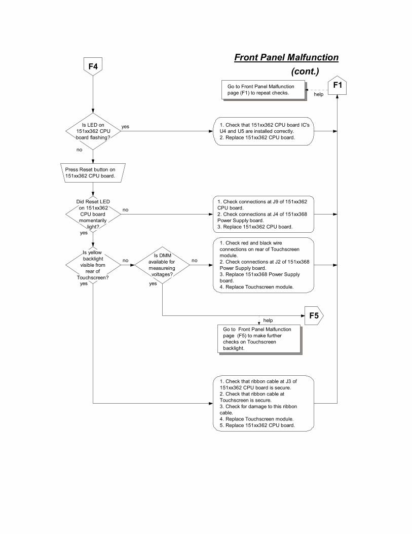
Is LED on 151xx362 CPU board flashing?
1. Check that 151xx362 CPU board IC's U4 and U5 are installed correctly.2. Replace 151xx362 CPU board.
yes
no
Front Panel Malfunction
Press Reset button on 151xx362 CPU board.
(cont.)F4
Did Reset LED on 151xx362 CPU board momentarily
light?
1. Check connections at J9 of 151xx362 CPU board.2. Check connections at J4 of 151xx368 Power Supply board.3. Replace 151xx362 CPU board.
yes
F1Go to Front Panel Malfunction page (F1) to repeat checks. help
no
Is yellow backlight
visible from rear of
Touchscreen?
no
yes
1. Check red and black wire connections on rear of Touchscreen module.2. Check connections at J2 of 151xx368 Power Supply board.3. Replace 151xx368 Power Supply board.4. Replace Touchscreen module.
Is DMM available for measureing
voltages?
no
1. Check that ribbon cable at J3 of 151xx362 CPU board is secure.2. Check that ribbon cable at Touchscreen is secure.3. Check for damage to this ribbon cable.4. Replace Touchscreen module.5. Replace 151xx362 CPU board.
yes
F5Go to Front Panel Malfunction page (F5) to make further checks on Touchscreen backlight.
help

Front Panel Malfunction(cont.)F5
1. Adjust backlight intensity.2. Replace Touchscreen module.
F1Go to Front Panel Malfunction page (F1) to repeat checks. help
1. Check connections at red and black wire connections on rear of Touchscreen module.2. Check connections at J2 of 151xx368 Power Supply board.
Measure dc volts on 151xx368 Power Supply board from J2 pin 1 to J2 pin 2.
Is this measurement approximately
12vdc?
yes
no
Measure dc volts on Touchscreen module from black wire to red wire.
Is this measurement approximately
12vdc?
yes
no
1. Check/replace fuse F1 on 151xx368 Power Supply board.2. Replace 151xx368 Power Supply board.
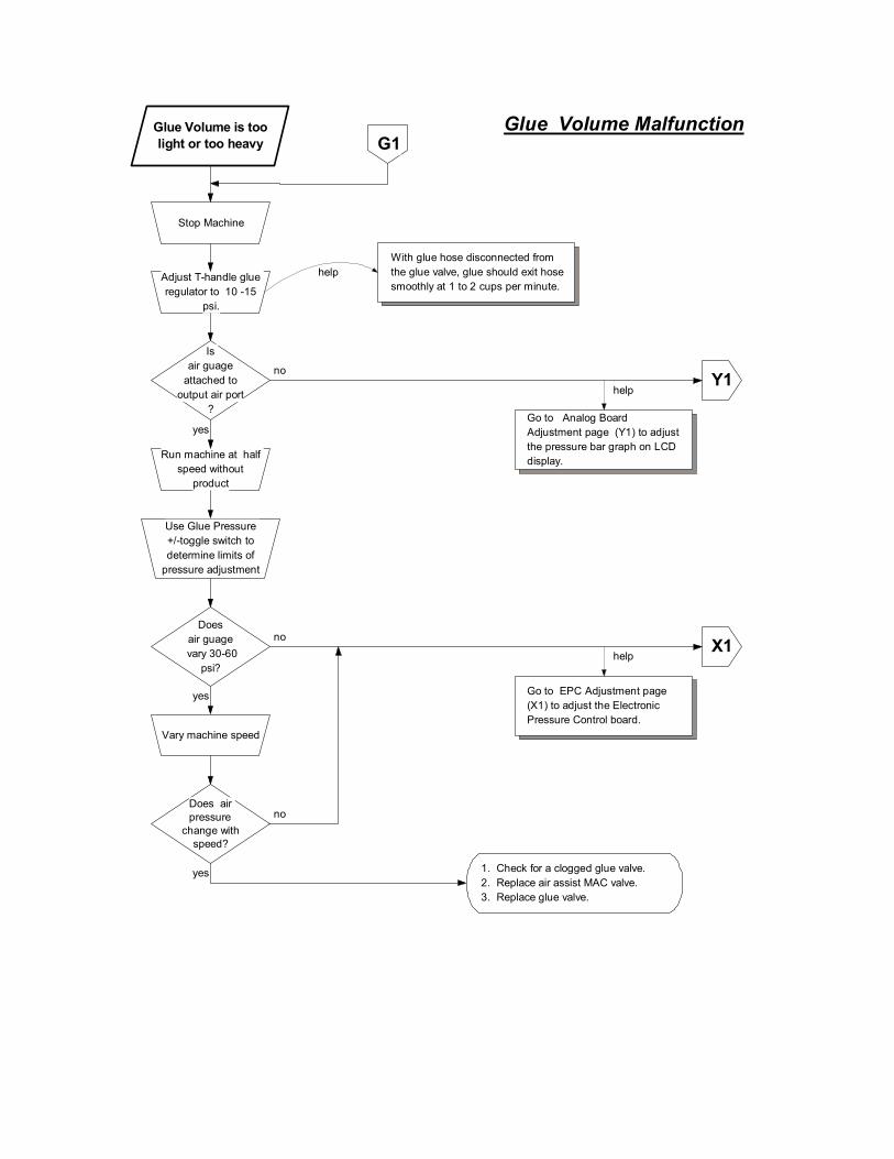
Glue Volume MalfunctionGlue Volume is too light or too heavy
Stop Machine
Does air guage
vary 30-60 psi?
Run machine at half speed without
product
Adjust T-handle glue regulator to 10 -15
psi.
Does air pressure
change with speed?
Vary machine speed
no
yes
With glue hose disconnected from the glue valve, glue should exit hose smoothly at 1 to 2 cups per minute.
help
X1
Go to EPC Adjustment page (X1) to adjust the Electronic Pressure Control board.
help
yes
no
G1
1. Check for a clogged glue valve.2. Replace air assist MAC valve.3. Replace glue valve.
Use Glue Pressure +/-toggle switch to determine limits of
pressure adjustment
Is air guage
attached to output air port
?
yes
no Y1
Go to Analog Board Adjustment page (Y1) to adjust the pressure bar graph on LCD display.
help

1. Check minimum speed setting.2 Check that "Faults" in Glue QC screen is not zero.3. Check that "MarkerDistance" in Glue QC screen is not zero.4. Check that "Marker Skip" in Glue QC screen is not zero.5. Check that "MarkerMark" in Glue QC screen is not zero.6. Check that product sensor for Glue Inspection channel is functioning.7. Check that Glue Sensor is functioning.8. Check ribbon cable from 151xx362 CPU board J4 to 151xx410 Glue Inspection board J10.
Glue Inspection MalfunctionGlue Inspection does not function I1

Jam Malfunction
During jam condition,measure dc volts on151xx366 Interfaceboard from J6 pin 3to J6 pin 2.
Jams occur withoutstopping machine
Run Machinewithout product,then trip scanner
indefinitely
no
yes
Is DMMavailable formeasuringvoltages?
no
yesIs Jamindicator on
front panel lit?
Keep the scanner tripped indefinitely by tripping the scanner,or short J1 pin 2 to J1 pin 3 on 151xx366 Interface board.
help
Control and jam relay are functioningproperly. Check air lines and glue source.
1. Check wiring at connector J6 on151xx366 Interface board.2. Check for correct wiring at Jaminterface relay.3. Check for damaged cable connectingJam interface relay to control.
Is thismeasurementapproximately
12vdc?
Without Jamcondition, measuredc volts on Interfaceboard 151xx366 fromJ6 pin 3 to J6 pin 2.
Is thismeasurementapproximately
0vdc?
Replace 151xx366 Interface board.no
yes
no
yes Control is functioningproperly. Check air lines and glue source.
J1
Is jam interfacerelay
energized?
yes
no
Remove device that iscausing the Jamcondition to revert tonormal operation.
Jam indicator symbol consists of 2 rollers with 2 productsentering simultaneously.
help

Machine Stop MalfunctionJam Condition does not cause Machine
Stop M1
Red Jam Indicator lit during Jam
?
yes
noJam condition does not exist.
Machine stops after Jam Condition
?
no
yesControl is functioning properly.
Relay LED lit during Jam Condition
?
no
yes 1. Check wiring from Machine Interface connector to Machine Stop circuit.2. Replace 151xx404 Machine Interface board.
Is this a VC3700
?
no
yes1. Check cable wiring from 151xx410 Glue Inspection board J1 to 151xx404 Machine Interface board J1.2. Replace 151xx410 Glue Inspection board.
Is MSTOP Indicator lit on
151xx410?
no
yes
For VC3700:1. Check minimum speed setting.2. Check ribbon cable from 151xx362 CPU board J4 to 151xx410 Glue Inspection board J10.3. Check seating of U9, U10, U11 on 151xx410 Glue Inspection board.4. Replace 151xx410 Glue Inspection board.
For VC3500:1. Check minimum speed setting.2. Check wiring from 151xx366 Interface board J6 to 151xx404 Machine Interface board J3.3. Replace 151xx366 Interface board.

Glue pattern placement is
incorrect
Incorrect Placement of Glue
Glue several products with
machine at low speed
P1
At low speed, Is delay before gluing
correct?
no
yes
At lowspeed, Is the pattern length
correct?
no
yes
1. Check that the Delay value has been entered correctly.2. Check that the Ratio Compensation value has been entered correctly.3. Check that the Cell-to-Gun value has been entered correctly.
1. Check that the Pattern value has been entered correctly.2. Check that the Ratio Compensation value has been entered correctly.
Glue several products with
machine at high speed
At high speed, Is delay before gluing
correct?
no
yes
At highspeed, Is the pattern length
correct?
no
yes
1. Adjust the On Compensation setting.
1. Adjust the Off Compensation setting.
Control is functioning properly.

Scanner light on front panel does not
flash on and off
Stop Machine
S1
Is scanner sensitivity adjusted correctly?
Is Scanner cable securely
fastened to Scanner?
Is Scanner Cable
damaged?
Adjust scanner sensitivity.
Secure Scanner Cable to Scanner.
Replace Scanner Cable.
Does LED on back of scanner
flash during manual trigger?
yes
no
yes
no
no
no
yes
yes
Check scanner by placing an object in its light path. The scanner's LED should light to indicate activation.
help
S2
Is Scanner cable correctly
terminated inside control?
Correct terminations.
yes
no
See Manual for correct terminations.help
1. Check that ribbon cable between 151xx366 Interface board and 151xx365/406 LED board is secure.2. Replace 151xx366 Interface board.3. Replace 151xx365/406 LED board.
Scanner sensitivity should be adjusted so that it senses objects only 1.5 inches (40mm) past actual product. Use adjustment screw located on its back surface.
help
Go to Scanner Light Malfunction page (S2) to make further checks on Scanner.
help
G1
Scanner Light Malfunction
Go to Glue Absence page (G1) to repeat checks.
help

Is Scanner cable correctly
terminated inside control?
Correct the terminations inside control.
1. Replace Scanner and/or2. Replace 151xx366 Interface Board.
yes
no
See Manual for correct terminations.help
(cont.)S2
Is 12v I/O lamp on front
panel on?
1. Check connections at J7 of 151xx366 Interface board.2. Check connections at J5 of 151xx368 Power Supply board.
The symbol for this light is an arrow enteing a box.
help
no
noyes
yesIs DMM
available for measuring voltages?
S3
Is LED D3 of 151xx368
Power Supply board on?
1. Check fuse F2 on 151xx368 Power Supply board.2. Check connectiions at J1 of 151xx368 Power Supply board.3. Replace 151xx368 Power Supply board.
yes
no
Go to Scanner Light Malfunction page (S3) to make further checks on Encoder.
help
G1
Scanner Light Malfunction
Go to Glue Absence page (G1) to repeat checks. help

Measure dc volts on 151xx366 Interface board from J1 pin 3 to J1 pin 1.
(cont.)S3
Is this measurement approximately
12vdc?
Measure dc volts on 151xx366 Interface board from J7 pin 2 to J7 pin 1.
Is this measurement approximately
17vdc?
1. Replace Scanner and/or2. Replace 151xx366 Interface Board.
yes
no
Replace 151xx366 Interface Board.
Measure dc volts on Power Supply board 151xx368 from J5 pin 1 to J5 pin 2.
Is this measurement approximately
17vdc?
1. Check connections at J5 of 151xx368 Power Supply board . 2. Check connections at J7 of 151xx366 Interface board.
yes
no
yes
no
Measure ac volts on Power Supply board 151xx368 from J1 pin 1 to J1 pin 2.
Is this measurement approximately
14vac?
1. Check/replace fuse F2 on 151xx368 Power Supply Board.2. Replace 151xx368 Power Supply board.
yes
no
Replace transformer A41-80-28.
G1
Scanner Light Malfunction
Go to Glue Absence page (G1) to repeat checks. help

1. Check minimum speed setting.2. Check fuse F1 on 151xx404 Machine Interface board.4. Check wiring from 151xx404 Machine Interface board connector to beacon.5. Check bulbs in beacon.6. Check horn enable switch on beacon.
Warning Beacon MalfunctionBeacon Lights or Horn do not function W1

EPC AdjustmentEPC Adjustment Procedure
Stop Machine
Rotate all pots on 151xx379 EPC
counter-clockwiseRotate each pot counter-clockwise about 20 turns or until a click is felt or heard during each rotation.
help
X1
IsDEC LED
(CR3) illuminated
?
yes
no
Rotate P1 (SPAN) 8 turns clockwise
Rotate P2 (ZERO) 8 turns clockwise
Rotate P4 (GAIN) 3 1/2 turns clockwise
IsINC LED (CR2)
illuminated?
yes
no
1. Rotate P1 (SPAN) one half turn at a time clockwise until the DEC LED is not illuminated (3 turns maximum).2. Then rotate P1 one more half turn clockwise.
1. Rotate P1 (SPAN) one half turn at a time counter-clockwise until the INC LED is not illuminated (3 turns maximum).2. Then rotate P1 one more half turn counter-clockwise.
EPC is adjusted properly.
The EPC (151xx379) is factory set. No further adjustments should be necessary. This procedure should only be performed if an adjustment is absolutely necessary.
Warning:
help
This Pot may not be installed in later versions of 151xx379.
help

Analog Board AdjustmentAnalog Board Adjustment Procedure
Stop Machine
Rotate P1 (ZERO) on 151xx364 fully counter-clockwise
Rotate P1 on 151xx366 Analog board counter-clockwise about 20 turns.
help
Y1
Rotate P2 (GAIN) on 151xx364 fully
clockwise
Adjust P1 (ZERO) until bar graph is just
visible.
Run machine at maximum speed
Analog board is adjusted properly.
If installed, rotate P2 on 151xx364 Analog board counter-clockwise about 20 turns.
help
The length of the pressure bar graph on the LCD display should be very short (about 1/16 inch). If bar is not visible, rotate P1 clockwise. If bar is too long, rotate P1 counter-clockwise.
help
Adjust Glue Pressure to Maximum
Hold the Glue Pressure (+) toggle on VC3500 front panel for 10 seconds to ensure maximum pressure.
help
Adjust P2 (GAIN) counter-clockwise for
full bar graph
If P2 is installed, maximize the pressure bar graph on the LCD display by adjusting P2 (GAIN Pot) on 151xx364.
help
Stop Machine
Ispressure bar
barely visible at zero speed
?
yes
no
The Analog board (151xx364) is factory set. No further adjustments should be necessary. This procedure should only be performed if an adjustment is absolutely necessary.
Warning:
help

VC3500/VC3700 Troubleshooting Manual
Valco Cincinnati Page 30
CE Conformance Testing for CE conformance was performed at Laboratory Test Services, Incorporated in Massachusetts and Valco Cincinnati, Incorporated during the month of December, 1995.


![Pep Pac [1962] - Internet Archive](https://static.fdokumen.com/doc/165x107/6333c77d3108fad7760f3690/pep-pac-1962-internet-archive.jpg)