
VANDAYAR ENGINEERING COLLEGE - THANJAVUR
27
VANDAYAR ENGINEERING COLLEGE - THANJAVUR GE6261-COMPUTER AIDED DRAFTING AND MODELING LABORATORY LAB MANUAL For Second Semester B.E/B.Tech Students (For Non - Circuit Branches) Compiled By A.EDWIN, M.E., Assistant professor/Mech Vandayar Engineering College – Thanjavur
-
Upload
khangminh22 -
Category
Documents
-
view
2 -
download
0
Transcript of VANDAYAR ENGINEERING COLLEGE - THANJAVUR

VANDAYAR
ENGINEERING COLLEGE - THANJAVUR
GE6261-COMPUTER AIDED DRAFTING
AND MODELING LABORATORY
LAB MANUAL
For Second Semester B.E/B.Tech Students (For Non - Circuit Branches)
Compiled By
A.EDWIN, M.E.,
Assistant professor/Mech
Vandayar Engineering College – Thanjavur

CONTENT
EXERCISE NO. NAME OF THE EXERCISES PAGE NO.
A INTRODUCTION OF AUTOCAD
1 SIMPLE / MULTI-LINE FIGURES
2 TITLE BLOCK
3 GEOMETRICAL CURVES (PARABOLA AND
INVOLUTE CURVES)
4 REGULAR SOLIDS (PRISM, PYRAMID,)
5 PICTORIAL VIEWS (SIMPLE OBJECTS)
6 PLAN OF RESIDENTIAL BUILDING
7 SIMPLE STEEL TRUSS
8 SECTIONAL VIEWS (PRISM, PYRAMID,)
9 ISOMETRIC PROJECTION (SIMPLE OBJECTS)
10 3-D MODELS (SIMPLE OBJECTS)

CADD-Computer Aided Designing and Drafting
CADD is an electronic tool that enables us to make quick and accurate drawings. CADD has number of advantages over drawings created on a drawing board. Electronic drawings can be modified quite easily and can be represented in a variety of formats.
CADD extends its power to yet another branch of engineering called computer aided
manufacturing (CAM).CADD and manufacturing program are often integrated into one system called CAD-CAM. This system import CADD drawings into CAM program to automate the
manufacturing process. When the design is finalized, the drawings are brought into a CAD-CAM
system that uses numerical data from the CADD drawing for actual manufacturing. There is separate category of programs called Computer Aided Engineering (CAE) that can use
CADD drawing for engineering analysis. The CAE programs have a number of applications in
Structural Design, Civil Engineering, Mechanical Engineering and Electrical Engineering. The Mechanical engineer can test a machine assembly and also a prototype electronic model and test it
without building a physical model. Expectations form CADD
We can do amazing things with CADD that we never thought possible while creating
drawings with pen or pencil. The following are some of the important capabilities that make CADD a powerful tool.
Presentations
Flexibility in editing
Unit and accuracy levels
Storage and access for drawings
Sharing CADD drawings
Presentations
There are a number of ready-made presentations symbols available in CADD that can be used to enhance the look of drawings. In addition to prepare impressive presentations on paper, we
can use CADD to make an on-screen presentations. Advanced CADD programs ever allow us to
create an animated image.
Flexibility in editing CADD allows us to work with great accuracy. If we need to create highly accuracy geometric
shapes, CADD is the answer. It can help avoid time-consuming mathematical calculations.
Unit and accuracy level We can work with as high precession as 1/1000
th of an inch.
Storage and access of drawing
A computer electronic filing system has the following advantages over the traditional
filing
system. It is quick and convenient to organize CADD drawing in a computer.
It enables us to create a highly organized environment.
An electronic drawing never gets old and faded.
Sharing CADD Drawing
The electronic drawing can be shared by a number of users, allowing them to Co-ordinate projects and
work as a team. This is accomplished by connecting different computer via a network
About AutoCAD AutoCAD is a Computer Aided Design (CAD) program used by just about every
Engineering and Design office in the world. Although there are alternative CAD packages, AutoCAD is by far the most widely used system. Autodesk's AutoCAD is the industry leader in
CAD packages. Used by Civil Engineers, Architects, Mechanical and Electrical Engineers,
Aeronautical Engineers plus many other disciplines.
There have been several versions of AutoCAD over the years, with each new version
introducing new and more powerful features than its predecessor. The latest version of AutoCAD (at
the time of writing) is AutoCAD 2011. Any courses, whether through community colleges or online
universities, that are related to Engineering or Architecture should be considered incomplete if they do not introduce students to AutoCAD.
Accurate, scale drawings can be created and published using AutoCAD powerful features.
3D 'models' can also be created giving the designer absolute control over the design from start to finish. The computerised model can be viewed through a 360º angle, and even 'rendered' with a
texture on screen to give an idea of the finished product.
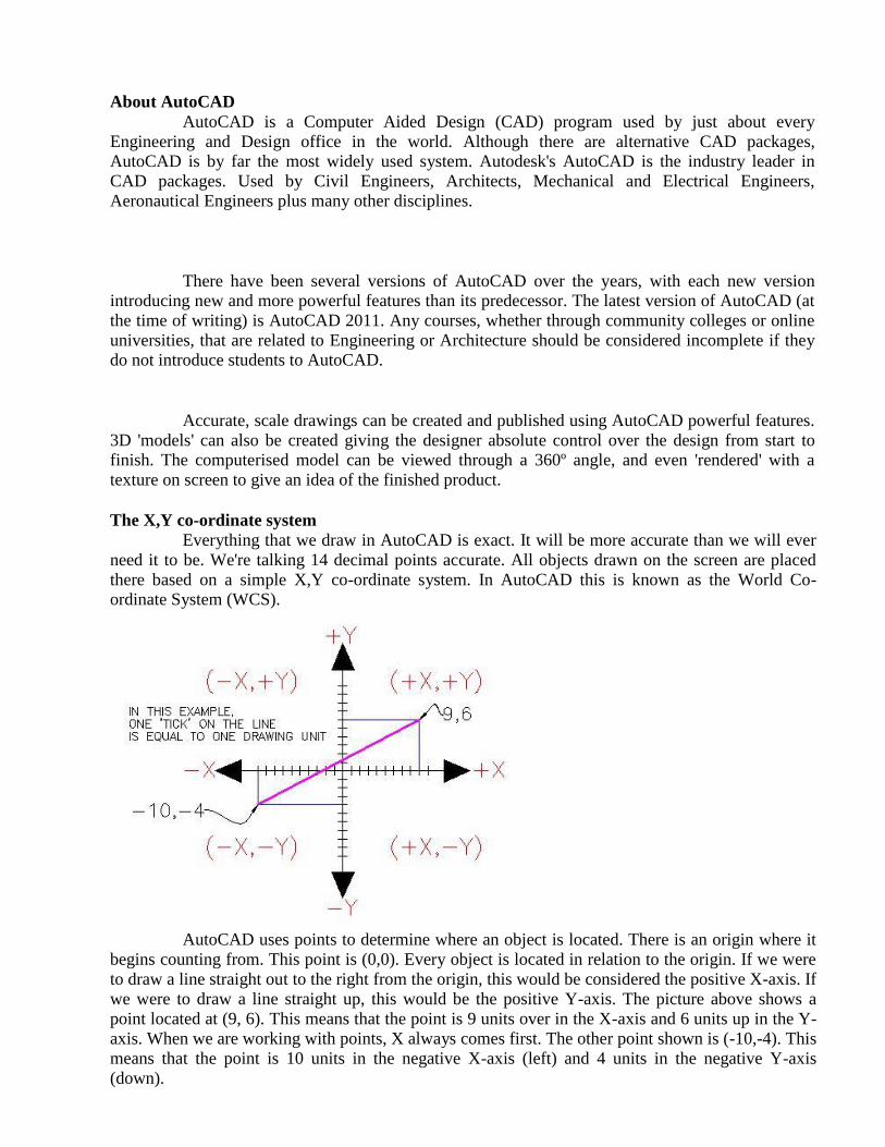
The X,Y co-ordinate system Everything that we draw in AutoCAD is exact. It will be more accurate than we will ever
need it to be. We're talking 14 decimal points accurate. All objects drawn on the screen are placed
there based on a simple X,Y co-ordinate system. In AutoCAD this is known as the World Co-ordinate System (WCS).
AutoCAD uses points to determine where an object is located. There is an origin where it
begins counting from. This point is (0,0). Every object is located in relation to the origin. If we were
to draw a line straight out to the right from the origin, this would be considered the positive X-axis. If
we were to draw a line straight up, this would be the positive Y-axis. The picture above shows a
point located at (9, 6). This means that the point is 9 units over in the X-axis and 6 units up in the Y-
axis. When we are working with points, X always comes first. The other point shown is (-10,-4). This
means that the point is 10 units in the negative X-axis (left) and 4 units in the negative Y-axis
(down).

A line has two points, a start point and an end point. AutoCAD works with the points to
display the line on the screen. Most of the time we will not have an indication of where the origin
is.We may need to draw a line from the endpoint of an existing line. To do this we use relative points. These work the same way, but we have to add the @ symbol (shift+2) to tell AutoCAD that
this next point is relative from the last point entered.
i.e. ABSOLUTE POINTS are exact points on the drawing space.
RELATIVE POINTS are relative to an OBJECT on the drawing space.
Angular Measurement AutoCAD measures angles in a particular way also.
When drawing lines at an angle, we have to begin measuring the angle from 0 degrees, which is at the 3 o'clock position. If we drew a line at 90 degrees, it would go straight up. The example shows a line drawn at +300 degrees (270+30), or -60 degrees. Entering Points in AutoCAD
We can enter points directly on the command line using three different systems. The one we use will depend on which is more applicable for the situation. The three systems are as follows:
ABSOLUTE CO-ORDINATES - Using this method, we enter the points as they relate to the origin of the WCS. To enter a point just enters in the exact point as X, Y. RELATIVE CO-ORDINATES - This allows us to enter points in relation to the first point we have
entered. After we've entered one point, the next would be entered as @X, Y. This means that
AutoCAD will draw a line from the first point to another point X units over and Y units up relative to the previous point.
POLAR CO-ORDINATES - We would use this system if we know that we want to draw a line a
certain distance at a particular angle. We would enter this as @D<A. In this case, D is the distance
and A is the angle. Example: @10<90 will draw a line 10 units straight up from the first point. The three ways of entering co-ordinates shown above are the ONLY way AutoCAD
accepts input. First decide which style we need to use, and then enter as shown. Remember that X is
always before Y (alphabetical). Don't forget the '@' symbol when we are entering relative points.
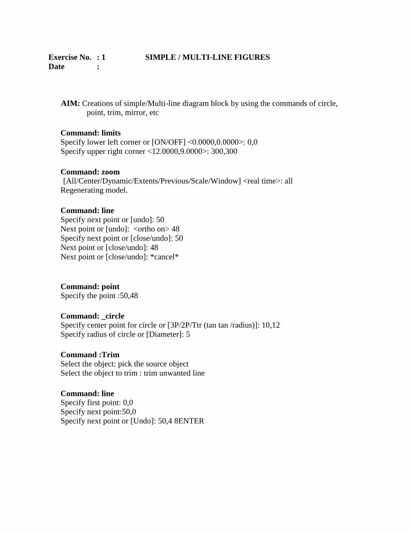
Exercise No. : 1 SIMPLE / MULTI-LINE FIGURES
Date :
AIM: Creations of simple/Multi-line diagram block by using the commands of circle,
point, trim, mirror, etc
Command: limits Specify lower left corner or [ON/OFF] <0.0000,0.0000>: 0,0
Specify upper right corner <12.0000,9.0000>: 300,300
Command: zoom [All/Center/Dynamic/Extents/Previous/Scale/Window] <real time>: all
Regenerating model.
Command: line Specify next point or [undo]: 50
Next point or [undo]: <ortho on> 48
Specify next point or [close/undo]: 50
Next point or [close/undo]: 48
Next point or [close/undo]: *cancel*
Command: point Specify the point :50,48
Command: _circle Specify center point for circle or [3P/2P/Ttr (tan tan /radius)]: 10,12
Specify radius of circle or [Diameter]: 5
Command :Trim Select the object: pick the source object
Select the object to trim : trim unwanted line
Command: line Specify first point: 0,0 Specify next point:50,0
Specify next point or [Undo]: 50,4 8ENTER
RESULT: Thus simple/Multi-line Drawing Was Created Successfully Using Auto Cad
Software

Exercise No. : 2 TITLE BLOCK FIGURES
Date :
AIM: Creations of title block diagram block by using the commands of circle, point, trim,
mirror, etc
Command: limits Specify lower left corner or [ON/OFF] <0.0000,0.0000>: 0,0
Specify upper right corner <12.0000,9.0000>: 300,300
Command: zoom [All/Center/Dynamic/Extents/Previous/Scale/Window] <real time>: all
Regenerating model.
Command: line Specify next point or [Undo]: <Ortho on> 170
Specify next point or [Undo]: 60
Specify next point or [Close/Undo]: 170
Specify next point or [Close/Undo]: 60
Specify next point or [Close/Undo]: 10
Specify next point or [Close/Undo]: 170
Specify next point or [Close/Undo]: 40
Specify next point or [Close/Undo]: 170
Specify next point or [Close/Undo]: 10
Specify next point or [Close/Undo]: 170
Specify next point or [Close/Undo]: 10
Specify next point or [Close/Undo]: 170
Specify next point or [Close/Undo]: *Cancel*
Command: _circle Specify center point for circle or [3P/2P/Ttr (tan tan /radius)]: 150,30
Specify radius of circle or [Diameter]: 6
Command :Trim Select the object: pick the source object
Select the object to trim : trim unwanted line
Command: line Specify next point or [Undo]: 2.5
Specify next point or [Undo]: 170
Specify next point or [Close/Undo]: 5
Specify next point or [Close/Undo]: 170
Specify next point or [Close/Undo]: 5
Specify next point or [Close/Undo]: 170
Specify next point or [Close/Undo]: *Cancel*
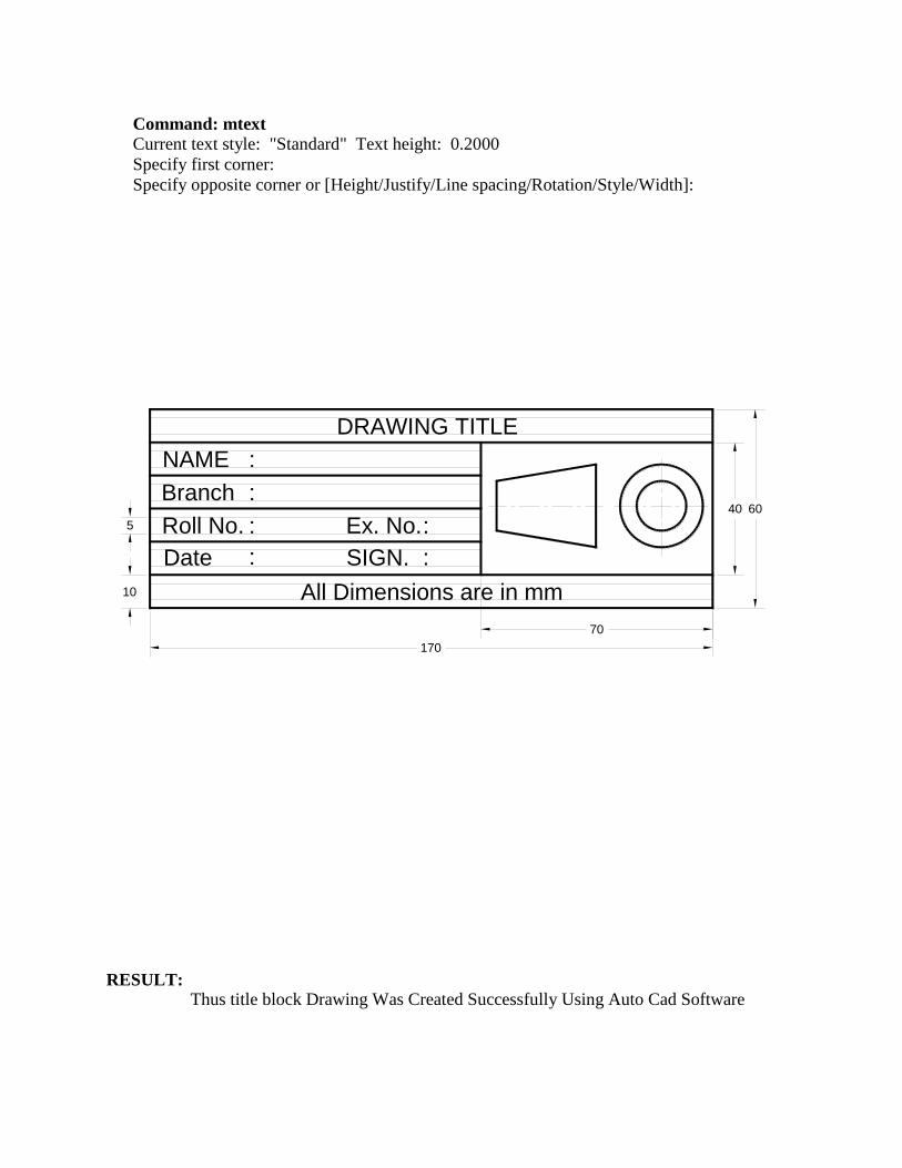
Command: mtext
Current text style: "Standard" Text height: 0.2000
Specify first corner:
Specify opposite corner or [Height/Justify/Line spacing/Rotation/Style/Width]:
RESULT: Thus title block Drawing Was Created Successfully Using Auto Cad Software
DRAWING TITLE
NAME
Branch
Roll No. Ex. No.
Date SIGN.
All Dimensions are in mm
:
:
:
:
:
:
10
170
6040
70
5
Exercise No. : 3 GEOMETRICAL CURVES (PARABOLA AND INVOLUTE) FIGURES
Date :
AIM: Creations of geometrical curves (parabola and involute) diagram block by using
the commands of circle, point, trim, mirror, etc
Command: limits Specify lower left corner or [ON/OFF] <0.0000,0.0000>: 0,0
Specify upper right corner <12.0000,9.0000>: 300,300
Command: zoom [All/Center/Dynamic/Extents/Previous/Scale/Window] <real time>: all
Regenerating model.
Command: line Specify next point or [Undo]: <Ortho on> 170
Specify next point or [Undo]: 60
Specify next point or [Close/Undo]: 170
Specify next point or [Close/Undo]: 60
Specify next point or [Close/Undo]: 10
Specify next point or [Close/Undo]: 170
Specify next point or [Close/Undo]: 40
Specify next point or [Close/Undo]: 170
Specify next point or [Close/Undo]: 10
Specify next point or [Close/Undo]: 170
Specify next point or [Close/Undo]: 10
Specify next point or [Close/Undo]: 170
Specify next point or [Close/Undo]: *Cancel*
Command: _circle Specify center point for circle or [3P/2P/Ttr (tan tan /radius)]: 150,30
Specify radius of circle or [Diameter]: 6
Command :Trim Select the object: pick the source object
Select the object to trim : trim unwanted line
Command: line Specify next point or [Undo]: 2.5
Specify next point or [Undo]: 170
Specify next point or [Close/Undo]: 5
Specify next point or [Close/Undo]: 170
Specify next point or [Close/Undo]: 5
Specify next point or [Close/Undo]: 170
Specify next point or [Close/Undo]: *Cancel*

Command: mtext
Current text style: "Standard" Text height: 0.2000
Specify first corner:
Specify opposite corner or [Height/Justify/Line spacing/Rotation/Style/Width]:
RESULT: Thus Geometrical Curves (Parabola And Involute) Drawing Was Created
Successfully Using Auto Cad Software
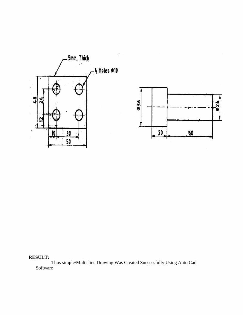
Exercise No. : 4 REGULAR SOLIDS (PRISM, PYRAMID,) FIGURES
Date :
AIM: Creations of Regular Solids (Prism, Pyramid) diagram block by using the
commands of circle, point, trim, mirror, etc
Command: limits Specify lower left corner or [ON/OFF] <0.0000,0.0000>: 0,0
Specify upper right corner <12.0000,9.0000>: 300,300
Command: zoom [All/Center/Dynamic/Extents/Previous/Scale/Window] <real time>: all
Regenerating model.
Command: polygon Enter number of sides <4>: 6
Specify center of polygon or [Edge]: pick any point
Enter an option: I
Specify radius of the circle: 30
Command: _circle Specify center point for circle or [3P/2P/Ttr (tan tan /radius)]: 150,30
Specify radius of circle or [Diameter]: 6
Command :Trim Select the object: pick the source object
Select the object to trim : trim unwanted line
Command: line Specify next point or [Undo]: 0
Specify next point or [Undo]: 60
Specify next point or [Close/Undo]:30
Specify next point or [Close/Undo]: *Cancel*
Command: mtext
Current text style: "Standard" Text height: 0.2000
Specify first corner:
Specify opposite corner or [Height/Justify/Line spacing/Rotation/Style/Width]:

RESULT: Thus Regular Solids (Prism, Pyramid) Drawing Was Created Successfully Using Auto Cad Software
A pentagonal prism of base side 30mm and axis
length 60mm is resting on HP on one of its bases
with a side of base parallel to VP. Draw its
projections.
A hexagonal pyramid of base side 30mm and
axis length 60mm is resting on HP on its
base with two of its base sides perpendicular
to VP. Draw its projections
Exercise No. : 5 PICTORIAL VIEWS (SIMPLE OBJECTS) FIGURES
Date :
AIM: Creations of pictorial views (simple objects) diagram block by using the
commands of circle, point, trim, mirror, etc
Command: limits Specify lower left corner or [ON/OFF] <0.0000,0.0000>: 0,0
Specify upper right corner <12.0000,9.0000>: 300,300
Command: zoom [All/Center/Dynamic/Extents/Previous/Scale/Window] <real time>: all
Regenerating model.
Command: line Specify next point or [Undo]: <Ortho on>90
Specify next point or [Undo]: 50
Specify next point or [Close/Undo]:60
Specify next point or [Close/Undo]: *Cancel*
Command: _circle Specify center point for circle or [3P/2P/Ttr (tan tan /radius)]: 150,30
Specify radius of circle or [Diameter]: 6
Command :Trim Select the object: pick the source object
Select the object to trim : trim unwanted line
Command: mtext
Current text style: "Standard" Text height: 0.2000
Specify first corner:
Specify opposite corner or [Height/Justify/Line spacing/Rotation/Style/Width]:
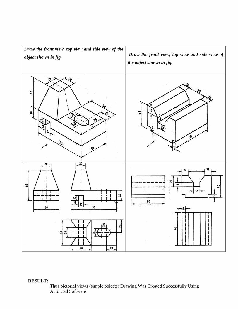
Draw the front view, top view and side view of the
object shown in fig.
Draw the front view, top view and side view of
the object shown in fig.
RESULT: Thus pictorial views (simple objects) Drawing Was Created Successfully Using Auto Cad Software
Exercise No. : 6 PLAN OF RESIDENTIAL BUILDING FIGURES
Date :
AIM: Creations Plan of residential building diagram block by using the commands of
circle, point, mline, trim, mirror, etc
Command: limits Specify lower left corner or [ON/OFF] <0.0000,0.0000>: 0,0
Specify upper right corner <12.0000,9.0000>: 300,300
Command: zoom [All/Center/Dynamic/Extents/Previous/Scale/Window] <real time>: all
Regenerating model.
Command: mline
Current settings: Justification = Top, Scale = 1.00, Style = STANDARD
Specify start point or [Justification/Scale/STyle]: s
Enter mline scale <1.00>: 2
Current settings: Justification = Top, Scale = 2.00, Style = STANDARD
Specify start point or [Justification/Scale/STyle]:
Specify next point: <Ortho on>
Specify next point or [Undo]:
Specify next point or [Close/Undo]:
Specify next point or [Close/Undo]: *Cancel*
Command :Trim Select the object: pick the source object
Select the object to trim : trim unwanted line
Command: snap Specify snap spacing or [ON/OFF/Aspect/Rotate/Style/Type] <0.5000>: style
Enter snap grid style [Standard/Isometric] <S>: isometric
Specify vertical spacing <0.5000>: ENTER
Command: copy Select the object: select the line
Specify base of displacement: pick the point ENTER
Command: Hatch Command: hatch Select internal point: pick points ENTER
Command: rotate Select objects: select S1
Specify base point: pick right side Specify rotation angle or [Reference]: - 46
Specify next point or [Close/Undo]: close
Command: move Select object: C1
Specify base point: T1(corner point)
Specify second point: C1(corner point)
RESULT: Thus Plan of residential building Drawing Was Created Successfully Using Auto Cad Software
Exercise No. : 7 SIMPLE STEEL TRUSS FIGURES
Date :
AIM: Creations of simple steel truss diagram block by using the commands of circle, point,
trim, mline, mirror, etc
Command: limits Specify lower left corner or [ON/OFF] <0.0000,0.0000>: 0,0
Specify upper right corner <12.0000,9.0000>: 300,300
Command: zoom [All/Center/Dynamic/Extents/Previous/Scale/Window] <real time>: all
Regenerating model.
Command: mline
Current settings: Justification = Top, Scale = 1.00, Style = STANDARD
Specify start point or [Justification/Scale/STyle]: s
Enter mline scale <1.00>: 2
Current settings: Justification = Top, Scale = 2.00, Style = STANDARD
Specify start point or [Justification/Scale/STyle]:
Specify next point: <Ortho on>
Specify next point or [Undo]:
Specify next point or [Close/Undo]:
Specify next point or [Close/Undo]: *Cancel*
Command :Trim Select the object: pick the source object
Select the object to trim : trim unwanted line
Command: snap Specify snap spacing or [ON/OFF/Aspect/Rotate/Style/Type] <0.5000>: style
Enter snap grid style [Standard/Isometric] <S>: isometric
Specify vertical spacing <0.5000>: ENTER

Command: copy Select the object: select the line
Specify base of displacement: pick the point ENTER
Command: Hatch Command: hatch Select internal point: pick points ENTER
Command: rotate Select objects: select S1
Specify base point: pick right side Specify rotation angle or [Reference]: - 46
Specify next point or [Close/Undo]: close
Command: move Select object: C1
Specify base point: T1(corner point)
Specify second point: C1(corner point)
RESULT: Thus simple steel truss Drawing Was Created Successfully Using Auto Cad Software
Exercise No. : 8 SECTIONAL VIEWS (PRISM, PYRAMID) FIGURES
Date :
AIM: Creations sectional views (prism, pyramid) diagram block by using the
commands of circle, point, trim, mirror, etc
Command: limits Specify lower left corner or [ON/OFF] <0.0000,0.0000>: 0,0
Specify upper right corner <12.0000,9.0000>: 300,300
Command: zoom [All/Center/Dynamic/Extents/Previous/Scale/Window] <real time>: all
Regenerating model.
Command: line Specify next point or [Undo]: <Ortho on> 50
Specify next point or [Undo]: 90
Specify next point or [Close/Undo]: *Cancel*
Command: circle Specify center point for circle or [3P/2P/Ttr (tan tan /radius)]: 150,30
Specify radius of circle or [Diameter]: 22.5
Command :Trim Select the object: pick the source object
Select the object to trim : trim unwanted line
Command: Hatch Command: hatch Select internal point: pick points ENTER
Command: rotate Select objects: select S1
Specify base point: pick right side Specify rotation angle or [Reference]: - 46
Specify next point or [Close/Undo]: close
Command: move Select object: C1
Specify base point: T1(corner point)
Specify second point: C1(corner point)
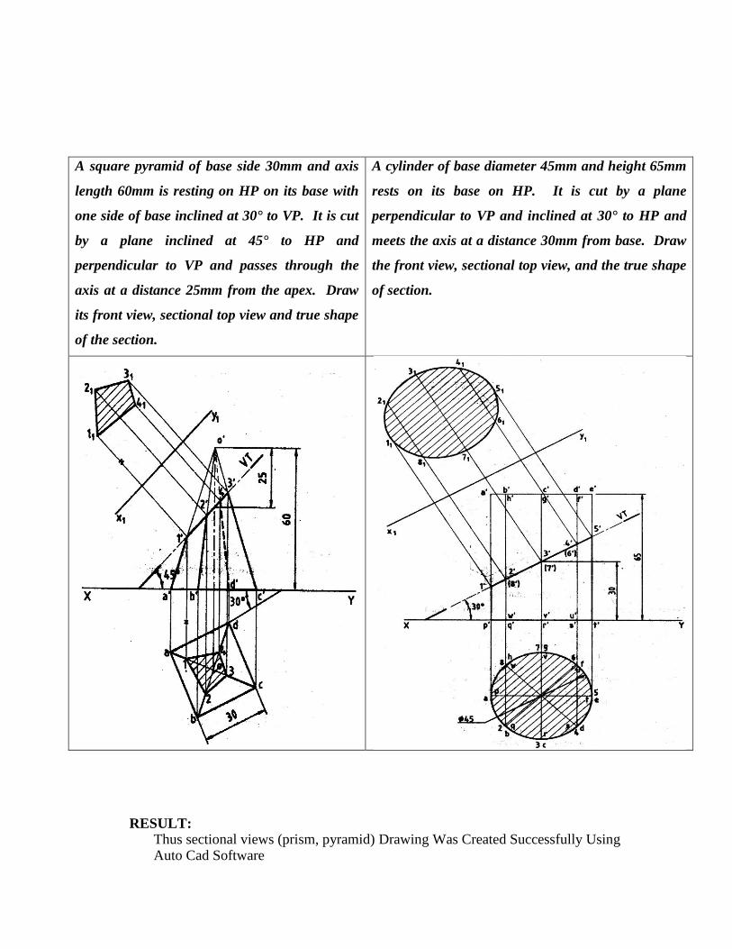
A square pyramid of base side 30mm and axis
length 60mm is resting on HP on its base with
one side of base inclined at 30° to VP. It is cut
by a plane inclined at 45° to HP and
perpendicular to VP and passes through the
axis at a distance 25mm from the apex. Draw
its front view, sectional top view and true shape
of the section.
A cylinder of base diameter 45mm and height 65mm
rests on its base on HP. It is cut by a plane
perpendicular to VP and inclined at 30° to HP and
meets the axis at a distance 30mm from base. Draw
the front view, sectional top view, and the true shape
of section.
RESULT: Thus sectional views (prism, pyramid) Drawing Was Created Successfully Using Auto Cad Software

Exercise No. : 9 ISOMETRIC PROJECTION (SIMPLE OBJECTS)
FIGURES
Date :
AIM: Creations of isometric projection (simple objects) diagram block by using the
commands of circle, point, trim, mirror, etc
Command: limits Specify lower left corner or [ON/OFF] <0.0000,0.0000>: 0,0
Specify upper right corner <12.0000,9.0000>: 300,300
Command: zoom [All/Center/Dynamic/Extents/Previous/Scale/Window] <real time>: all
Regenerating model.
Command: line Specify next point or [Undo]: <Ortho on> 170
Specify next point or [Undo]: 60
Specify next point or [Close/Undo]: 170
Specify next point or [Close/Undo]: 170
Specify next point or [Close/Undo]: *Cancel*
Command: _circle Specify center point for circle or [3P/2P/Ttr (tan tan /radius)]: 150,30
Specify radius of circle or [Diameter]: 6
Command :Trim Select the object: pick the source object
Select the object to trim : trim unwanted line
Command: Offset Specify offset distance or [Through] <25.0000>: 25 Select object to offset or <exit>: LINE 1
Specify point on side to offset: ↑ UPSIDE
Select object to offset or <exit>: ENTER
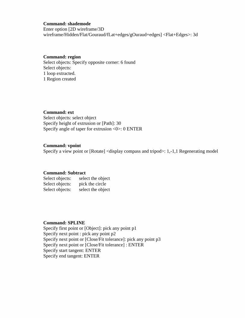
Command: shademode Enter option [2D wireframe/3D
wireframe/Hidden/Flat/Gouraud/fLat+edges/gOuraud+edges] <Flat+Edges>: 3d
Command: region Select objects: Specify opposite corner: 6 found
Select objects: 1 loop extracted.
1 Region created
Command: ext Select objects: select object
Specify height of extrusion or [Path]: 30 Specify angle of taper for extrusion <0>: 0 ENTER
Command: vpoint Specify a view point or [Rotate] <display compass and tripod>: 1,-1,1 Regenerating model
Command: Subtract Select objects: select the object
Select objects: pick the circle Select objects: select the object
Command: SPLINE Specify first point or [Object]: pick any point p1
Specify next point : pick any point p2
Specify next point or [Close/Fit tolerance]: pick any point p3
Specify next point or [Close/Fit tolerance] : ENTER Specify start tangent: ENTER
Specify end tangent: ENTER
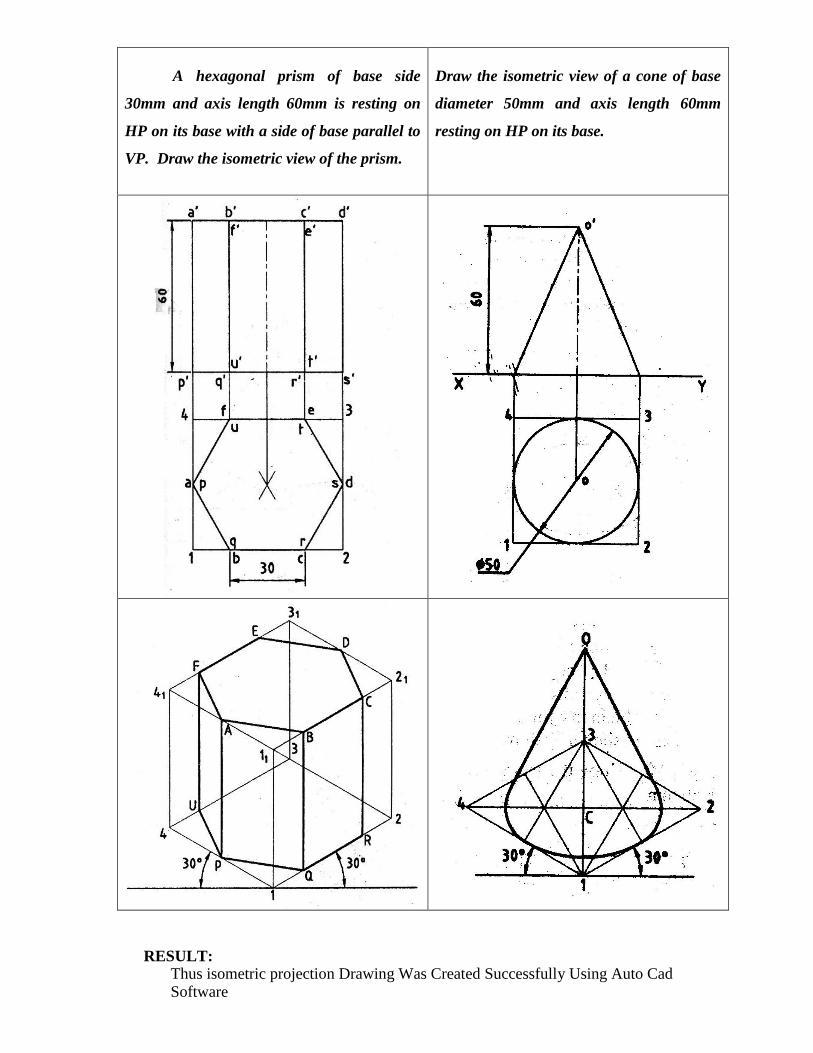
A hexagonal prism of base side
30mm and axis length 60mm is resting on
HP on its base with a side of base parallel to
VP. Draw the isometric view of the prism.
Draw the isometric view of a cone of base
diameter 50mm and axis length 60mm
resting on HP on its base.
RESULT: Thus isometric projection Drawing Was Created Successfully Using Auto Cad Software
Exercise No. :10 3-D MODELS (SIMPLE OBJECTS)
FIGURES
Date :
AIM: Creations of 3-D Models diagram block by using the commands of circle, point,
trim, mirror, etc
Command: limits Specify lower left corner or [ON/OFF] <0.0000,0.0000>: 0,0
Specify upper right corner <12.0000,9.0000>: 300,300
Command: zoom [All/Center/Dynamic/Extents/Previous/Scale/Window] <real time>: all
Regenerating model.
Command: line Specify next point or [Undo]: <Ortho on> 170
Specify next point or [Undo]: 60
Specify next point or [Close/Undo]: 170
Specify next point or [Close/Undo]: *Cancel*
Command: _circle Specify center point for circle or [3P/2P/Ttr (tan tan /radius)]: 150,30
Specify radius of circle or [Diameter]: 6
Command :Trim Select the object: pick the source object
Select the object to trim : trim unwanted line

Command: Offset Specify offset distance or [Through] <25.0000>: 25 Select object to offset or <exit>: LINE 1
Specify point on side to offset: ↑ UPSIDE
Select object to offset or <exit>: ENTER
Command: shademode Enter option [2D wireframe/3D
wireframe/Hidden/Flat/Gouraud/fLat+edges/gOuraud+edges] <Flat+Edges>: 3d
Command: region Select objects: Specify opposite corner: 6 found
Select objects: 1 loop extracted.
1 Region created
Command: ext XTRUDE
Select objects: select object
Specify height of extrusion or [Path]: 30 Specify angle of taper for extrusion <0>: 0 ENTER
Command: vpoint Specify a view point or [Rotate] <display compass and tripod>: 1,-1,1 Regenerating model
Command: Subtract Select objects: select the object
Select objects: pick the circle Select objects: select the object
Command: SPLINE Specify first point or [Object]: pick any point p1
Specify next point : pick any point p2
Specify next point or [Close/Fit tolerance]: pick any point p3
Specify next point or [Close/Fit tolerance] : ENTER Specify start tangent: ENTER
Specify end tangent: ENTER
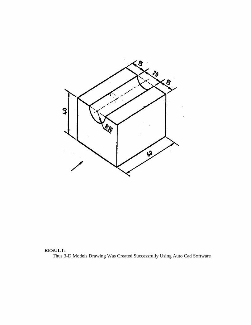
RESULT: Thus 3-D Models Drawing Was Created Successfully Using Auto Cad Software