Sudharsan Engineering College - Vidyarthiplus
441
WWW.VIDYARTHIPLUS.COM WWW.VIDYARTHIPLUS.COM HOD-CSE Sudharsan Engineering College Sathiyamangalam Pudukkottai DEPARTMENT OF COMPUTER SCIENCE AND ENGINEERING OOAD LAB MANUAL Sub. Code/Sub. Name: CS2357-Object Oriented Analysis and Design Year/Sem: III/VI Submitted by V.P.Gladis Pushpa Rathi Assoc.Prof/CSE
-
Upload
khangminh22 -
Category
Documents
-
view
4 -
download
0
Transcript of Sudharsan Engineering College - Vidyarthiplus

WWW.VIDYARTHIPLUS.COM
WWW.VIDYARTHIPLUS.COM HOD-CSE
Sudharsan Engineering College
Sathiyamangalam
Pudukkottai
DEPARTMENT OF COMPUTER SCIENCE AND ENGINEERING
OOAD LAB MANUAL
Sub. Code/Sub. Name: CS2357-Object Oriented Analysis and Design
Year/Sem: III/VI
Submitted by
V.P.Gladis Pushpa Rathi
Assoc.Prof/CSE

WWW.VIDYARTHIPLUS.COM
WWW.VIDYARTHIPLUS.COM HOD-CSE
CS2357 OOAD LAB
OBJECTIVE:
To develop a mini-project following the 12 exercises listed below.
1. To develop a problem statement.
2. Develop an IEEE standard SRS document. Also develop risk management and project plan (Gantt chart).
3. Identify Use Cases and develop the Use Case model.
4. Identify the business activities and develop an UML Activity diagram.
5. Identity the conceptual classes and develop a domain model with UML Class diagram.
6. Using the identified scenarios find the interaction between objects and represent them using UML
Interaction diagrams.
7. Draw the State Chart diagram.
8. Identify the User Interface, Domain objects, and Technical services. Draw the partial layered, logical
architecture diagram with UML package diagram notation.
9. Implement the Technical services layer.
10. Implement the Domain objects layer.
11. Implement the User Interface layer.
12. Draw Component and Deployment diagrams.
Suggested domains for Mini-project.
1. Passport automation system.
2. Book bank
3. Exam Registration
4. Stock maintenance system.
5. Online course reservation system
6. E-ticketing
7. Software personnel management system
8. Credit card processing
9. e-book management system
10. Recruitment system
11. Foreign trading system
12. Conference Management System
13. BPO Management System

WWW.VIDYARTHIPLUS.COM
WWW.VIDYARTHIPLUS.COM HOD-CSE
EXNO: 1a PASSPORT AUTOMATION SYSTEM
AIM
To develop the Passport Automation System using rational rose tools, visual basic
and MS access.
PROBLEM ANALYSIS AND PROJECT PLAN
To simplify the process of applying passport, software has been created by
designing through rational rose tool, using visual basic as a front end and
Microsoft access as a back end. Initially the applicant login the passport
automation system and submits his details. These details are stored in the database
and verification process done by the passport administrator, regional administrator
and police the passport is issued to the applicant.
PROBLEM STATEMENT
1. Passport Automation System is used in the effective dispatch of passport to
all of the applicants. This system adopts a comprehensive approach to
minimize the manual work and schedule resources, time in a cogent manner.
2. The core of the system is to get the online registration form (with details
such as name, address etc.,) filled by the applicant whose testament is
verified for its genuineness by the Passport Automation System with respect
to the already existing information in the database.

WWW.VIDYARTHIPLUS.COM
WWW.VIDYARTHIPLUS.COM HOD-CSE
3. This forms the first and foremost step in the processing of passport
application. After the first round of verification done by the system, the
information is in turn forwarded to the regional administrator's (Ministry of
External Affairs) office.
4. The application is then processed manually based on the report given by the
system, and any forfeiting identified can make the applicant liable to penalty
as per the law.
5. The system forwards the necessary details to the police for its separate
verification whose report is then presented to the administrator. After all the
necessary criteria have been met, the original information is added to the
database and the passport is sent to the applicant.
SOFTWARE REQUIREMENTS SPECIFICATION
SNO SOFTWARE REQUIREMENTS
SPECIFICATION
1.0
1.1
1.2
1.3
1.4
1.5
1.6
1.7
Introduction
Purpose
Scope
Definition, Acronyms and
Abbreviations
Reference
Technology to be used
Tools to be used
Overview
WWW.VIDYARTHIPLUS.COM
WWW.VIDYARTHIPLUS.COM HOD-CSE
2.0
2.1
2.2
2.3
2.4
2.5
2.6
2.7
Overall description
Productive description
Software interface
Hardware interface
System function
User Characteristic
Constraints
Assumption and Dependences
1.0 INTRODUCTION
Passport Automation System is an interface between the Applicant and the
Authority responsible for the Issue of Passport. It aims at improving the efficiency
in the Issue of Passport and reduces the complexities involved in it to the
maximum possible extent.
1.1 PURPOSE
If the entire process of 'Issue of Passport' is done in a manual manner then it
would take several months for the passport to reach the applicant. Considering the
fact that the number of applicants for passport is increasing every year, an
Automated System becomes essential to meet the demand. So this system uses
several programming and database techniques to elucidate the work involved in
this process. As this is a matter of National Security, the system has been carefully
verified and validated in order to satisfy it.
1.2 SCOPE
The System provides an online interface to the user where they can fill in
their personal details. The authority concerned with the issue of passport can
use this system to reduce his workload and process the application in a
speedy manner.Provide a communication platform between the applicant
and the administrator Transfer of data between the Passport Issuing
Authority and the Local Police for verification of applicant's information.
1.3 DEFINITIONS, ACRONYMS AND THE ABBREVIATIONS

WWW.VIDYARTHIPLUS.COM
WWW.VIDYARTHIPLUS.COM HOD-CSE
1. Administrator - Refers to the super user who is the Central Authority who
has been vested with the privilege to manage the entire system. It can be any
higher official in the Regional Passport Office of Ministry of External
Affairs.
2. Applicant - One who wishes to obtain the Passport.
3. PAS - Refers to this Passport Automation System.
1.4 REFERENCES IEEE Software Requirement Specification format.
1.5 TECHNOLOGIES TO BE USED • Microsoft Visual Basic 6.0
1.6 TOOLS TO BE USED • Rational Rose tool (for developing UML Patterns)
1.7 OVERVIEW
SRS includes two sections overall description and specific requirements - Overall
description will describe major role of the system components and inter-
connections. Specific requirements will describe roles & functions of the actors.
2.0 OVERALL DESCRIPTION
2.1 PRODUCT PERSPECTIVE
The PAS acts as an interface between the 'applicant' and the 'administrator'. This
system tries to make the interface as simple as possible and at the same time not
risking the security of data stored in. This minimizes the time duration in which the
user receives the passport.
2.2 SOFTWARE INTERFACE
1. Front End Client - The applicant and Administrator online interface is built
using Microsoft Visual Basic 6.0.
2. Back End – MS Access database
2.3 HARDWARE INTERFACE
The server is directly connected to the client systems. The client systems have
access to the database in the server.

WWW.VIDYARTHIPLUS.COM
WWW.VIDYARTHIPLUS.COM HOD-CSE
2.4 SYSTEM FUNCTIONS
1. Secure Registration of information by the Applicants.
2. Message box for Passport Application Status Display by the Administrator.
3. Administrator can generate reports from the information and is the only
authorized personnel to add the eligible application information to the
database.
2.5 USER CHARACTERISTICS
1. Applicant - They are the people who desires to obtain the passport and
submit the information to the database.
2. Administrator - He has the certain privileges to add the passport status and to
approve the issue of passport. He may contain a group of persons under him
to verify the documents and give suggestion whether or not to approve the
dispatch of passport.
3. Police - He is the person who upon receiving intimation from the PAS,
perform a personal verification of the applicant and see if he has any
criminal case against him before or at present. He has been vetoed with the
power to decline an application by suggesting it to the Administrator if he
finds any discrepancy with the applicant. He communicates via this PAS.
2.6 CONSTRAINTS
1. The applicants require a computer to submit their information.
2. Although the security is given high importance, there is always a chance of
intrusion in the web world which requires constant monitoring.
3. The user has to be careful while submitting the information. Much care is
required.
2.7 ASSUMPTIONS AND DEPENDENCIES
1. The Applicants and Administrator must have basic knowledge of computers
and English Language.
2. The applicants may be required to scan the documents and send.
UML DIAGRAMS

WWW.VIDYARTHIPLUS.COM
WWW.VIDYARTHIPLUS.COM HOD-CSE
Sno UML DIAGRAMS 1 Use Case diagram
2 Class diagram
3 Interaction diagram
4 Sequence diagram
5 Collaboration diagram
6 State Chart diagram
7 Activity diagram
8 Component diagram
9 Deployment diagram
10 Package diagram
DOCUMENTATION OF USECASE DIAGRAM
WWW.VIDYARTHIPLUS.COM
WWW.VIDYARTHIPLUS.COM HOD-CSE
a. The actors in use case diagram are Applicant, regional administrator,
database, passport Administrator, Police.
b. The use cases are Login, givedetails, logout, collectdetails,
verification, issue.
c. The actors use the use case are denoted by the arrow
d. The login use case checks the username and password for applicant,
regional administrator, passport administrator and police.
e. The submit details use case is used by the applicant for submitting his
details
f. The check status use case is used by the applicant for checking the
status of the application process.
g. The get details, verify and store verification use case is used by
passport administrator, regional administrator, and police.
h. The details use case is used for getting the details form the database
for verification
2. The verify use case is used for verifying the details by comparing the data in
the database.
a. The store verification use case is to update the data in the database
b. And finally the issue passport use case is used by the passport
administrator for issuing passport who’s application verified
successfully by all the actor .
CLASSDIAGRAM
A class is drawn as rectangle box with three compartments or components
separated by horizontal lines. The top compartment holds the class name and
middle compartment holds the attribute and bottom compartment holds list of
operations.

WWW.VIDYARTHIPLUS.COM
WWW.VIDYARTHIPLUS.COM HOD-CSE
DOCUMENTATION OF CLASS DIAGRAM
a. APPLICANT-The applicant has attribute such as name and password
and operations are login, givedetails and logout. The applicant login
and fill the details that are required for applying the passport .After
applying the person can view the status of the passport verification
process
b. THE DATABASE-The database has attributed such as name and
operation is store. The purpose is to store the data.
c. REGIONAL ADMINISTRATOR- The regional administrator has
attribute such as name and operation are get details, verify details and
send. The regional administrator get the details form database and
verify with their database

WWW.VIDYARTHIPLUS.COM
WWW.VIDYARTHIPLUS.COM HOD-CSE
d. PASSPORT ADMINISTRATOR-The passport administrator has
attributed such as name and operation are get details, verify details
and issue. The passport administrator get the details form database
and verify with their database , update the verification and issue the
passport
e. THE POLICE-The police has attribute such as name and operation
are get details, verify details and send. The police get the details form
database and verify with their database , update the verification in the
database
SEQUENCE DIAGRAM
A sequence diagram shows an interaction arranged in time sequence,
It shows object participating in interaction by their lifeline by the message they
exchange arranged in time sequence. Vertical dimension represent time and
horizontal dimension represent object.

WWW.VIDYARTHIPLUS.COM
WWW.VIDYARTHIPLUS.COM HOD-CSE
DOCUMENTATION OF SEQUENCE DIAGRAM.
a. The applicant login the database and give his details and database
store the details.
b. The passport administrator get the details from the database and do
verification and the forward to regional administrator.
c. The regional administrator get details form passport administrator and
perform verification and send report to passport administrator.

WWW.VIDYARTHIPLUS.COM
WWW.VIDYARTHIPLUS.COM HOD-CSE
d. The police get the details form passport administrator and perform
verification and send report to passport administrator
COLLABORATION DIAGRAM
A collaboration diagram is similar to sequence diagram but the message in number
format. In a collaboration diagram sequence diagram is indicated by the numbering
the message. A collaboration diagram, also called a communication diagram or
interaction diagram, A sophisticated modeling tool can easily convert a
collaboration diagram into a sequence diagram and the vice versa. A collaboration
diagram resembles a flowchart that portrays the roles, functionality and behavior of
individual objects as well as the overall operation of the system in real time
STATE CHART DIAGRAM
The state chart diagram contains the states in the rectangle boxes and starts in
indicated by the dot and finish is indicated by dot encircled. The purpose of state
chart diagram is to understand the algorithm in the performing method.
DOCUMENTATION OF STATE CHART DIAGRAM
a. The states of the passport automation system are denoted in the state
chart diagram
b. Login state represent authentication for login the passport automation
system.
c. In this state, it checks whether the applicant has provided all the
details that is required.
d. Police, regional administrator and passport administrator get
necessary details and verification of the applicant are denoted from
the Get detail state and verification state

WWW.VIDYARTHIPLUS.COM
WWW.VIDYARTHIPLUS.COM HOD-CSE
ACTIVITY DIAGRAM An activity diagram is a variation or special case of a state machine in which the
states or activity representing the performance of operation and transitions are
triggered by the completion of operation. The purpose is to provide view of close
and what is going on inside a use case or among several classes. An activity is
shown as rounded box containing the name of
operation
DOCUMENTATION OF ACTIVITY DIAGRAM
a. The activities in the passport automation system are login, submit
details, get details, issue passport and penalty and verification.
b. In the login activity applicant give username and password and then
login into the passport automation system after then fill the details that
are required for application.
c. After the verification procedure completed successfully the passport is
issued to the applicant.
COMPONENT DIAGRAM
The component diagram is represented by figure dependency and it is a graph of
design of figure dependency. The component diagram's main purpose is to show

WWW.VIDYARTHIPLUS.COM
WWW.VIDYARTHIPLUS.COM HOD-CSE
the structural relationships between the components of a systems. It is represented
by boxed figure. Dependencies are represented by communication assosiation.
DOCUMENTATION OF COMPONENT DIAGRAM
a. The components in the passport automation system are passport
automation system, applicant, passport administrator, regional
administrator, and police.
b. Applicant ,passport administrator, regional administrator and police
are dependent on passport automation system are shown by the dotted
arrow
DEPLOYMENT DIAGRAM It is a graph of nodes connected by communication association. It is represented by
a three dimensional box. A deployment diagram in the unified modeling language
serves to model the physical deployment of artifacts on deployment targets.
Deployment diagrams show "the allocation of artifacts to nodes according to the
Deployments defined between them. It is represented by 3-dimentional box.

WWW.VIDYARTHIPLUS.COM
WWW.VIDYARTHIPLUS.COM HOD-CSE
Dependencies are represented by communication association. The basic element of
a deployment diagram is a node of two types
DEVICE NODE–
A physical computing resource with processing and memory service to execute
software, such as a typical computer or a mobile phone.
EXECUTION ENVIRONMENT NODE
This is a software computing resource that runs within an outer node and which
itself provides a service to host an execute other executable software element.
DOCUMENTATION OF DEPLOYMENT DIAGRAM
The device node is passport automation system and execution environment node
are applicant passport administrator, regional administrator, and police.
PACKAGE DIAGRAM
A package diagram is represented as a folder shown as a large rectangle with a top
attached to its upper left corner. A package may contain both sub ordinate package
and ordinary model elements. All uml models and diagrams are organized into
package. A package diagram in unified modeling language that depicts the
dependencies between the packages that make up a model. A Package Diagram
(PD) shows a grouping of elements in the OO model, and is a Cradle extension to

WWW.VIDYARTHIPLUS.COM
WWW.VIDYARTHIPLUS.COM HOD-CSE
UML. PDs can be used to show groups of classes in Class Diagrams (CDs), groups
of components or processes in Component Diagrams (CPDs), or groups of
processors in Deployment Diagrams (DPDs).
There are three types of layer. They are
o User interface layer
o Domain layer
o Technical services layer
WWW.VIDYARTHIPLUS.COM
WWW.VIDYARTHIPLUS.COM HOD-CSE

WWW.VIDYARTHIPLUS.COM
WWW.VIDYARTHIPLUS.COM HOD-CSE
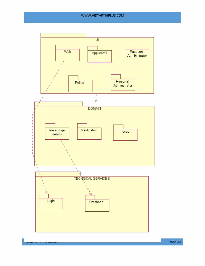
DOCUMENTATION OF PACKAGE DIAGRAM
The three layer in the passport automation system are user interface layer, domain
layer, technical service layer
a. The user interface layer- represents the user interface components
such as web, applicant, passport administrator, police, and regional
administrator.
b. The domain layer- has major actions such as give and get details,
verification and issues.
c. Technical service layer- authenticated user only can access the
technical services.
FORMS:
FORM1:

WWW.VIDYARTHIPLUS.COM
WWW.VIDYARTHIPLUS.COM HOD-CSE
FORM2:

WWW.VIDYARTHIPLUS.COM
WWW.VIDYARTHIPLUS.COM HOD-CSE

WWW.VIDYARTHIPLUS.COM
WWW.VIDYARTHIPLUS.COM HOD-CSE
FORM3:

WWW.VIDYARTHIPLUS.COM
WWW.VIDYARTHIPLUS.COM HOD-CSE
FORM4:

WWW.VIDYARTHIPLUS.COM
WWW.VIDYARTHIPLUS.COM HOD-CSE

WWW.VIDYARTHIPLUS.COM
WWW.VIDYARTHIPLUS.COM HOD-CSE
FORM5:

WWW.VIDYARTHIPLUS.COM
WWW.VIDYARTHIPLUS.COM HOD-CSE

WWW.VIDYARTHIPLUS.COM
WWW.VIDYARTHIPLUS.COM HOD-CSE
FORM6:

WWW.VIDYARTHIPLUS.COM
WWW.VIDYARTHIPLUS.COM HOD-CSE
FORM7:
SOURCE CODE:
FORM1 Private Sub Command1_Click()
Dim app As Applicant
Set app = New Applicant
app.Login

WWW.VIDYARTHIPLUS.COM
WWW.VIDYARTHIPLUS.COM HOD-CSE
End Sub
Private Sub Command2_Click()
Dim pass As PassportAdministrator
Set pass = New PassportAdministrator
pass.Login
End Sub
Private Sub Command3_Click()
Dim reg As RegionalAdminstrator
Set reg = New RegionalAdminstrator
reg.Login
End Sub
WWW.VIDYARTHIPLUS.COM
WWW.VIDYARTHIPLUS.COM HOD-CSE
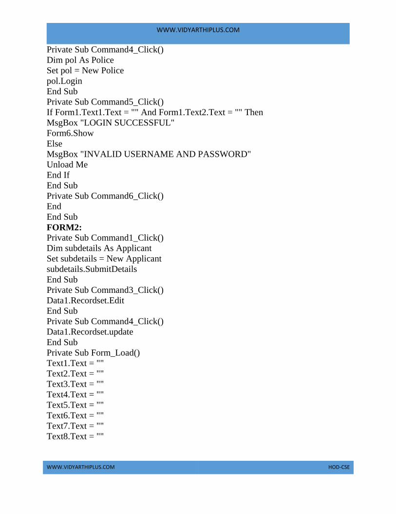
Private Sub Command4_Click()
Dim pol As Police
Set pol = New Police
pol.Login
End Sub
Private Sub Command5_Click()
If Form1.Text1.Text = "" And Form1.Text2.Text = "" Then
MsgBox "LOGIN SUCCESSFUL"
Form6.Show
Else
MsgBox "INVALID USERNAME AND PASSWORD"
Unload Me
End If
End Sub
Private Sub Command6_Click()
End
End Sub
FORM2: Private Sub Command1_Click()
Dim subdetails As Applicant
Set subdetails = New Applicant
subdetails.SubmitDetails
End Sub
Private Sub Command3_Click()
Data1.Recordset.Edit
End Sub
Private Sub Command4_Click()
Data1.Recordset.update
End Sub
Private Sub Form_Load()
Text1.Text = ""
Text2.Text = ""
Text3.Text = ""
Text4.Text = ""
Text5.Text = ""
Text6.Text = ""
Text7.Text = ""
Text8.Text = ""

WWW.VIDYARTHIPLUS.COM
WWW.VIDYARTHIPLUS.COM HOD-CSE
End Sub
FORM3: Private Sub a_Click()
Data2.Recordset.AddNew
End Sub
Private Sub Command1_Click()
Dim search As PassportAdministrator
Set search = New PassportAdministrator
search.update
End Sub
Private Sub Command2_Click()
If Data1.Recordset.BOF Then
MsgBox "NO DATA FOUND"
Else
Data1.Recordset.MovePrevious
End If
End Sub
Private Sub Command3_Click()
If Data1.Recordset.EOF Then
MsgBox "NO DATA FOUND"
Else
Data1.Recordset.MoveNext
End If
End Sub
Private Sub Command4_Click()
Form1.Show
Unload Me
End Sub
Private Sub Command5_Click()
Data1.Recordset.MoveFirst
End Sub
Private Sub Command6_Click()
Data1.Recordset.MoveLast
End Sub
Private Sub Command7_Click()
Data1.Recordset.Edit

WWW.VIDYARTHIPLUS.COM
WWW.VIDYARTHIPLUS.COM HOD-CSE
Data1.Recordset.Fields(9) = "successful"
Data1.Recordset.update
End Sub
Private Sub Command8_Click()
Data1.Recordset.Edit
Data1.Recordset.Fields(9) = "unsuccessful"
Data1.Recordset.update
End Sub
Private Sub ve_Click()
Dim verify As PassportAdministrator
Set verify = New PassportAdministrator
verify.update
End Sub
FORM4: Private Sub Command1_Click()
Dim search As RegionalAdminstrator
Set search = New RegionalAdminstrator
search.verify
End Sub
Private Sub Command2_Click()
Data1.Recordset.Edit
Data1.Recordset.Fields(10) = "successful"
Data1.Recordset.update
End Sub
Private Sub Command3_Click()
Data1.Recordset.Edit
Data1.Recordset.Fields(10) = "unsuccessful"
Data1.Recordset.update
End Sub
Private Sub Command4_Click()
Form1.Show
Unload Me
End Sub
Private Sub Command5_Click()
Dim update As RegionalAdminstrator
Set update = New RegionalAdminstrator
update.update

WWW.VIDYARTHIPLUS.COM
WWW.VIDYARTHIPLUS.COM HOD-CSE
End Sub
Private Sub Command6_Click()
Data1.Recordset.MoveLast
End Sub
Private Sub Command7_Click()
Data1.Recordset.MoveFirst
End Sub
Private Sub Command8_Click()
If Data1.Recordset.BOF Then
MsgBox "NO DATA FOUND"
Else
Data1.Recordset.MovePrevious
End If
End Sub
Private Sub Command9_Click()
If Data1.Recordset.EOF Then
MsgBox "NO DATA FOUND"
Else
Data1.Recordset.MoveNext
End If
End Sub
FORM5:
Private Sub Command1_Click()
Dim search As Police
Set search = New Police
search.verify
End Sub
Private Sub Command2_Click()
Data2.Recordset.Edit
Data2.Recordset.Fields(11) = "successful"
Data2.Recordset.update
End Sub
Private Sub Command3_Click()
Data2.Recordset.Edit
Data2.Recordset.Fields(11) = "unsuccessful"
Data2.Recordset.update
End Sub

WWW.VIDYARTHIPLUS.COM
WWW.VIDYARTHIPLUS.COM HOD-CSE
Private Sub Command4_Click()
Form1.Show
Unload Me
End Sub
Private Sub Command6_Click()
Data2.Recordset.MoveLast
End Sub
Private Sub Command7_Click()
Data2.Recordset.MoveFirst
End Sub
Private Sub Command8_Click()
If Data2.Recordset.BOF Then
MsgBox "NO DATA FOUND"
Else
Data2.Recordset.MovePrevious
End If
End Sub
Private Sub Command9_Click()
If Data2.Recordset.EOF Then
MsgBox "NO DATA FOUND"
Else
Data2.Recordset.MoveNext
End If
End Sub
FORM6: Private Sub Command1_Click()
Dim checkstate As Applicant
Set checkstate = New Applicant
checkstate.CheckStatus
End Sub
Private Sub Command2_Click()
Form1.Show
Unload Me
End Sub
UML CODINGS:
APPLICANT:
WWW.VIDYARTHIPLUS.COM
WWW.VIDYARTHIPLUS.COM HOD-CSE
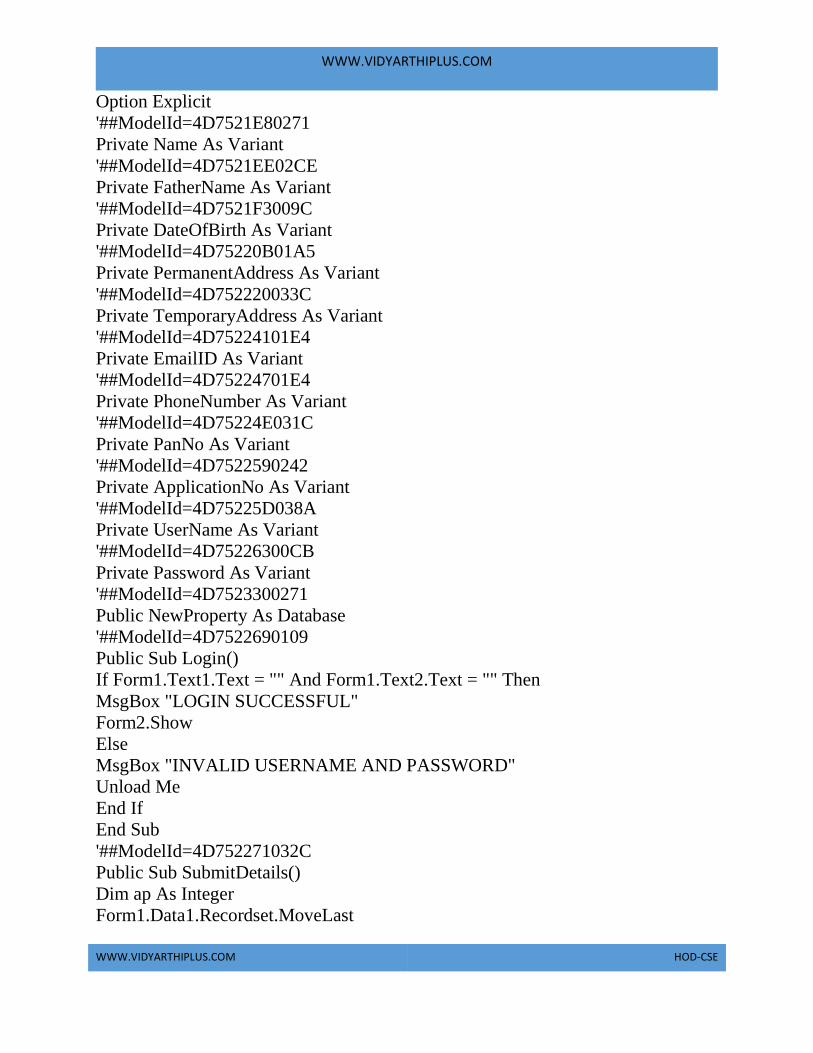
Option Explicit
'##ModelId=4D7521E80271
Private Name As Variant
'##ModelId=4D7521EE02CE
Private FatherName As Variant
'##ModelId=4D7521F3009C
Private DateOfBirth As Variant
'##ModelId=4D75220B01A5
Private PermanentAddress As Variant
'##ModelId=4D752220033C
Private TemporaryAddress As Variant
'##ModelId=4D75224101E4
Private EmailID As Variant
'##ModelId=4D75224701E4
Private PhoneNumber As Variant
'##ModelId=4D75224E031C
Private PanNo As Variant
'##ModelId=4D7522590242
Private ApplicationNo As Variant
'##ModelId=4D75225D038A
Private UserName As Variant
'##ModelId=4D75226300CB
Private Password As Variant
'##ModelId=4D7523300271
Public NewProperty As Database
'##ModelId=4D7522690109
Public Sub Login()
If Form1.Text1.Text = "" And Form1.Text2.Text = "" Then
MsgBox "LOGIN SUCCESSFUL"
Form2.Show
Else
MsgBox "INVALID USERNAME AND PASSWORD"
Unload Me
End If
End Sub
'##ModelId=4D752271032C
Public Sub SubmitDetails()
Dim ap As Integer
Form1.Data1.Recordset.MoveLast

WWW.VIDYARTHIPLUS.COM
WWW.VIDYARTHIPLUS.COM HOD-CSE
ap = Data1.Recordset.Fields(0)
Data1.Recordset.AddNew
ap = ap + 1
Form1.Data1.Recordset.Fields(0) = ap

WWW.VIDYARTHIPLUS.COM
WWW.VIDYARTHIPLUS.COM HOD-CSE
Form1.Data1.Recordset.Fields(1) = Text1.Text
Form1.Data1.Recordset.Fields(2) = Text2.Text
Form1.Data1.Recordset.Fields(3) = Text3.Text
Form1.Data1.Recordset.Fields(4) = Text4.Text
Form1.Data1.Recordset.Fields(5) = Text5.Text
Form1.Data1.Recordset.Fields(6) = Text6.Text
Form1.Data1.Recordset.Fields(7) = Text7.Text
Form1.Data1.Recordset.Fields(8) = Text8.Text
Form1.Data1.Recordset.Fields(9) = "Under Process"
Form1.Data1.Recordset.Fields(10) = "Under Process"
Form1.Data1.Recordset.Fields(11) = "Under Process"
Form1.Data1.Recordset.update
Form1.Show
Unload Me
End Sub
'##ModelId=4D7522760261
Public Sub CheckStatus()
Dim Currentdb As Database
Set Currentdb = OpenDatabase("D:\PASSPORTPROJECT1\PASSPORT.mdb")
Dim Data As Recordset
Set Data = Currentdb.OpenRecordset("applicant", dbOpenDynaset)
Data.FindFirst "([ApplicationNo])=" & Form6.Text1.Text
If Data.NoMatch Then
MsgBox "No such record"
Else
MsgBox "success"
Form6.Text1.Text = Data.Fields(0)
Form6.Label5 = Data.Fields(1)
Form6.Label7 = Data.Fields(9)
Form6.label9 = Data.Fields(10)
Form6.Label11 = Data.Fields(11)
End If
Data.Close
End Sub
DATA BASE:
Option Explicit
'##ModelId=4D7522A30222
Private Name As Variant
'##ModelId=4D75233C005D

WWW.VIDYARTHIPLUS.COM
WWW.VIDYARTHIPLUS.COM HOD-CSE
Public NewProperty As PassportAdministrator
'##ModelId=4D75233E006D

WWW.VIDYARTHIPLUS.COM
WWW.VIDYARTHIPLUS.COM HOD-CSE
Public NewProperty2 As RegionalAdminstrator
'##ModelId=4D75234202BF
Public NewProperty3 As Police
'##ModelId=4D7522A50186
Public Sub store()
End Sub
PASSPORT ADMINSTRATOR: Option Explicit
'##ModelId=4D7522A90128
Private UserName As Variant
'##ModelId=4D7522F9035B
Private Password As Variant
'##ModelId=4D7522B20232
Public Sub Login()
If Form1.Text1.Text = "passadmin" And Form1.Text2.Text = "12345" Then
MsgBox "LOGIN SUCCESSFUL"
Form1.Text1.Text = ""
Form1.Text2.Text = ""
Form1.Text1.SetFocus
Form3.Show
Else
MsgBox "INVALID USERNAME OR PASSWORD"
Form1.Text1.Text = ""
Form1.Text2.Text = ""
Form1.Text1.SetFocus
End If
End Sub
'##ModelId=4D7522BA004E
Public Sub verify()
Set Currentdb = OpenDatabase("D:\PASSPORTPROJECT1\passport.mdb")
Dim Data As Recordset
Set Data = Currentdb.OpenRecordset("PassportAdministrator", dbOpenDynaset)
If Form3.Text1.Text = "" Then
MsgBox "select any data"
Else
Data.FindFirst "([PanNo])=" & Form3.Text1.Text
If Data.NoMatch Then
MsgBox "No such record"
Else

WWW.VIDYARTHIPLUS.COM
WWW.VIDYARTHIPLUS.COM HOD-CSE
MsgBox "success"
Form3.Text7.Text = Data.Fields(1)

WWW.VIDYARTHIPLUS.COM
WWW.VIDYARTHIPLUS.COM HOD-CSE
Form3.Text8.Text = Data.Fields(2)
End If
End If
End Sub
'##ModelId=4D7522BF01D4
Public Sub update()
If Form3.Text2.Text = Form3.Text7.Text And Form3.Text3.Text =
Form3.Text8.Text Then
Form3.Data1.Recordset.Edit
Form3.Data1.Recordset.Fields(9) = "successful"
Form3.Data1.Recordset.update
MsgBox "success"
Else
MsgBox "no "
Form3.Text7.Text = ""
Form3.Text8.Text = ""
End If
End Sub
POLICE: Option Explicit
'##ModelId=4D7522E1001F
Private UserName As Variant
'##ModelId=4D75232601D4
Private Password As Variant
'##ModelId=4D7522E30251
Public Sub Login()
If Form1.Text1.Text = "poladmin" And Form1.Text2.Text = "12345" Then
MsgBox "LOGIN SUCCESSFUL"
Form1.Text1.Text = ""
Form1.Text2.Text = ""
Form1.Text1.SetFocus
Form5.Show
Else
MsgBox "INVALID USERNAME OR PASSWORD"
Form1.Text1.Text = ""
Form1.Text2.Text = ""
Form1.Text1.SetFocus
End If
End Sub
WWW.VIDYARTHIPLUS.COM
WWW.VIDYARTHIPLUS.COM HOD-CSE
'##ModelId=4D7522E8008C
Public Sub verify()
Dim Currentdb As Database
Set Currentdb = OpenDatabase("D:\PASSPORTPROJECT1\passport.mdb")
Dim Data As Recordset

WWW.VIDYARTHIPLUS.COM
WWW.VIDYARTHIPLUS.COM HOD-CSE
Set Data = Currentdb.OpenRecordset("Police", dbOpenDynaset)
If Form5.Text1.Text = "" Then
MsgBox "select any data"
Else
Data.FindFirst "([PanNo])=" & Form5.Text1.Text
If Data.NoMatch Then
MsgBox "No such record"
Else
MsgBox "success"
If Data.Fields(5) = "Notallowed" Then
MsgBox "not allowed"
Else
MsgBox "allowed"
End If
End If
End If
Data.Close
End Sub
'##ModelId=4D7522EA02BF
Public Sub update()
End Sub
REGIONAL ADMINSTRATOR:
Option Explicit
'##ModelId=4D7522C80222
Private UserName As Variant
'##ModelId=4D75231A0109
Private Password As Variant
'##ModelId=4D7522CB02CE
Public Sub Login()
If Form1.Text1.Text = "regadmin" And Form1.Text2.Text = "12345" Then
MsgBox "LOGIN SUCCESSFUL"
Form1.Text1.Text = ""
Form1.Text2.Text = ""
Form1.Text1.SetFocus
Form4.Show
Else
MsgBox "INVALID USERNAME OR PASSWORD"
Form1.Text1.Text = ""
Form1.Text2.Text = ""

WWW.VIDYARTHIPLUS.COM
WWW.VIDYARTHIPLUS.COM HOD-CSE
Form1.Text1.SetFocus
End If
End Sub

WWW.VIDYARTHIPLUS.COM
WWW.VIDYARTHIPLUS.COM HOD-CSE
'##ModelId=4D7522CE01A5
Public Sub verify()
Dim Currentdb As Database
Set Currentdb = OpenDatabase("D:\PASSPORTPROJECT1\passport.mdb")
Dim Data As Recordset
Set Data = Currentdb.OpenRecordset("RegionalAdminstrator", dbOpenDynaset)
If Form4.Text1.Text = "" Then
MsgBox "select any data"
Else
Data.FindFirst "([PanNo])=" & Form4.Text1.Text
If Data.NoMatch Then
MsgBox "No such record"
Else
MsgBox "success"
Form4.Text6.Text = Data.Fields(1)
Form4.Text7.Text = Data.Fields(2)
Form4.Text8.Text = Data.Fields(3)
Form4.Text9.Text = Data.Fields(4)
End If
End If
End Sub
'##ModelId=4D7522D002BF
Public Sub update()
If Form4.Text2.Text = Text6.Text And Form4.Text3.Text = Form4.Text7.Text
And Form4.Text4.Text = Form4.Text8.Text And Form4.Text5.Text =
Form4.Text9.Text Then
MsgBox "Details match"
Else
MsgBox "Details donot match"
End If
End Sub
RESULT:
Thus the project to develop passport automation system was developed using
Rational Rose Software and to implement the software in Visual Basic is done
successfully.

WWW.VIDYARTHIPLUS.COM
WWW.VIDYARTHIPLUS.COM HOD-CSE
EXNO: 1b PASSPORT AUTOMATION SYSTEM
AIM
To develop the Passport Automation System using rational rose tools, Java and MS
access
PROBLEM ANALYSIS AND PROJECT PLAN
To simplify the process of applying passport, software has been created by
designing through rational rose tool, using visual basic as a front end and
Microsoft access as a back end. Initially the applicant login the passport
automation system and submits his details. These details are stored in the database
and verification process done by the passport administrator, regional administrator
and police the passport is issued to the applicant.
PROBLEM STATEMENT
a. Passport Automation System is used in the effective dispatch of
passport to all of the applicants. This system adopts a comprehensive
approach to minimize the manual work and schedule resources, time
in a cogent manner.
b. The core of the system is to get the online registration form (with
details such as name, address etc.,) filled by the applicant whose
testament is verified for its genuineness by the Passport Automation
System with respect to the already existing information in the
database.
c. This forms the first and foremost step in the processing of passport
application. After the first round of verification done by the system,
the information is in turn forwarded to the regional administrator's
(Ministry of External Affairs) office.

WWW.VIDYARTHIPLUS.COM
WWW.VIDYARTHIPLUS.COM HOD-CSE
d. The application is then processed manually based on the report given
by the system, and any forfeiting identified can make the applicant
liable to penalty as per the law.
e. The system forwards the necessary details to the police for its separate
verification whose report is then presented to the administrator. After
all the necessary criteria have been met, the original information is
added to the database and the passport is sent to the applicant.

WWW.VIDYARTHIPLUS.COM
WWW.VIDYARTHIPLUS.COM HOD-CSE
SOFTWARE REQUIREMENTS SPECIFICATION
SNO SOFTWARE
REQUIREMENTS
SPECIFICATION 1.0
1.1
1.2
1.3
1.4
1.5
1.6
1.7
Introduction
Purpose
Scope
Definition, Acronyms
and Abbreviations
Reference
Technology to be used
Tools to be used
Overview
2.0
2.1
2.2
2.3
2.4
2.5
2.6
2.7
Overall description
Productive description
Software interface
Hardware interface
System function
User Characteristic
Constraints
Assumption and
Dependences
1.0 INTRODUCTION
Passport Automation System is an interface between the Applicant and the
Authority responsible for the Issue of Passport. It aims at improving the efficiency
in the Issue of Passport and reduces the complexities involved in it to the
maximum possible extent.
1.1 PURPOSE
If the entire process of 'Issue of Passport' is done in a manual manner then it
would take several months for the passport to reach the applicant. Considering the
fact that the number of applicants for passport is increasing every year, an
Automated System becomes essential to meet the demand. So this system uses
several programming and database techniques to elucidate the work involved in

WWW.VIDYARTHIPLUS.COM
WWW.VIDYARTHIPLUS.COM HOD-CSE
this process. As this is a matter of National Security, the system has been carefully
verified and validated in order to satisfy it.
1.2 SCOPE
a. The System provides an online interface to the user where they can fill
in their personal details
b. The authority concerned with the issue of passport can use this system
to reduce his workload and process the application in a speedy
manner. • Provide a communication platform between the applicant
and the administrator. Transfer of data between the Passport Issuing
Authority and the Local Police for verification of applicant's
information.
1.3 DEFINITIONS, ACRONYMS AND THE ABBREVIATIONS •
Administrator - Refers to the super user who is the Central Authority who has been
vested with the privilege to manage the entire system. It can be any higher official
in the Regional Passport Office of Ministry of External Affairs. • Applicant - One
who wishes to obtain the Passport. • PAS - Refers to this Passport Automation
System.
1.4 REFERENCES IEEE Software Requirement Specification format.
1.5 TECHNOLOGIES TO BE USED • Microsoft Visual Basic 6.0
1.6 TOOLS TO BE USED • Rational Rose tool (for developing UML Patterns)
1.7 OVERVIEW
SRS includes two sections overall description and specific requirements - Overall
description will describe major role of the system components and inter-
connections. Specific requirements will describe roles & functions of the actors.
2.0 OVERALL DESCRIPTION

WWW.VIDYARTHIPLUS.COM
WWW.VIDYARTHIPLUS.COM HOD-CSE
2.1 PRODUCT PERSPECTIVE
The PAS acts as an interface between the 'applicant' and the 'administrator'. This
system tries to make the interface as simple as possible and at the same time not
risking the security of data stored in. This minimizes the time duration in which the
user receives the passport.
2.2 SOFTWARE INTERFACE
a. Front End Client - The applicant and Administrator online interface
is built using Java
b. Back End – MS Access database.
2.3 HARDWARE INTERFACE
The server is directly connected to the client systems. The client systems have
access to the database in the server.
2.4 SYSTEM FUNCTIONS
a. Secure Registration of information by the Applicants.
b. Message box for Passport Application Status Display by the
Administrator.
c. Administrator can generate reports from the information and is the
only authorized personnel to add the eligible application information
to the database.
2.5 USER CHARACTERISTICS
a. Applicant - They are the people who desires to obtain the passport and
submit the information to the database.
b. Administrator - He has the certain privileges to add the passport status
and to approve the issue of passport. He may contain a group of
persons under him to verify the documents and give suggestion
whether or not to approve the dispatch of passport.
c. Police - He is the person who upon receiving intimation from the
PAS, perform a personal verification of the applicant and see if he has
any criminal case against him before or at present. He has been vetoed
with the power to decline an application by suggesting it to the
Administrator if he finds any discrepancy with the applicant. He
communicates via this PAS.
2.6 CONSTRAINTS

WWW.VIDYARTHIPLUS.COM
WWW.VIDYARTHIPLUS.COM HOD-CSE
o The applicants require a computer to submit their information.
o Although the security is given high importance, there is always a
chance of intrusion in the web world which requires constant
monitoring.
o The user has to be careful while submitting the information. Much
care is required.
2.7 ASSUMPTIONS AND DEPENDENCIES
o The Applicants and Administrator must have basic knowledge of
computers and English Language.
o The applicants may be required to scan the documents and send.
UML DIAGRAMS
Sno UML DIAGRAMS 1 Use Case diagram
2 Class diagram
3 Interaction diagram
4 Sequence diagram
5 Collaboration diagram
6 State Chart diagram
7 Activity diagram
8 Component diagram
9 Deployment diagram
10 Package diagram
USE CASE DIAGRAM
Use case is shown as an ellipse containing the name of use case .An actor is shown
as a stick figure with the name below it. Use case diagram is a graph of actors.

WWW.VIDYARTHIPLUS.COM
WWW.VIDYARTHIPLUS.COM HOD-CSE
DOCUMENTATION OF USECASE DIAGRAM
a. The actors in use case diagram are Applicant, regional administrator,
database, passport Administrator, Police.
b. The use cases are Login, givedetails, logout, collectdetails,
verification, issue.
c. The actors use the use case are denoted by the arrow
CLASSDIAGRAM
A class is drawn as rectangle box with three compartments or components
separated by horizontal lines. The top compartment holds the class name and
middle compartment holds the attribute and bottom compartment holds list of
operations.

WWW.VIDYARTHIPLUS.COM
WWW.VIDYARTHIPLUS.COM HOD-CSE
DOCUMENTATION OF CLASS DIAGRAM
o The classes are Applicant, database, regional administrator, passport
administrator, and police.
o The applicant has attribute such as name and password and operations
are login, givedetails and logout.
o The database has attribute such as name and operation is store.
o The regional administrator has attribute such as name and operation
are get details, verify details and send.

WWW.VIDYARTHIPLUS.COM
WWW.VIDYARTHIPLUS.COM HOD-CSE
o The passport administrator has attribute such as name and operation
are get details, verify details and issue.
o The police has attribute such as name and operation are get details,
verify details and send.
SEQUENCE DIAGRAM
A sequence diagram shows an interaction arranged in time sequence,
It shows object participating in interaction by their lifeline by the message they
exchange arranged in time sequence. Vertical dimension represent time and
horizontal dimension represent object.
DOCUMENTATION OF SEQUENCE DIAGRAM.
o The applicant login the database and give his details and database
store the details.
o The passport administrator get the details from the database and do
verification and the forward to regional administrator.

WWW.VIDYARTHIPLUS.COM
WWW.VIDYARTHIPLUS.COM HOD-CSE
o The regional administrator get details form passport administrator and
perform verification and send report to passport administrator.
o The police get the details form passport administrator and perform
verification and send report to passport administrator.
COLLABORATION DIAGRAM
A collaboration diagram is similar to sequence diagram but the message in number
format. In a collaboration diagram sequence diagram is indicated by the numbering
the message
DOCUMENTATION OF COLLABORATION DIAGRAM
a. The applicant, passport administrator, regional administrator, police
and database functions are show in sequence number

WWW.VIDYARTHIPLUS.COM
WWW.VIDYARTHIPLUS.COM HOD-CSE
b. The applicant first login the passport automation system and submit
his details the passport administrator, regional administrator and
police verification are denoted.
STATE CHART DIAGRAM
The state chart diagram contains the states in the rectangle boxes and starts in
indicated by the dot and finish is indicated by dot encircled. The purpose of state
chart diagram is to understand the algorithm in the performing method.
DOCUMENTATION OF STATE CHART DIAGRAM
a. The states of the passport automation system are denoted in the state
chart diagram
b. Login state represent authentication for login the passport automation
system.
c. In this state, it checks whether the applicant has provided all the
details that is required.
d. Police, regional administrator and passport administrator get
necessary details and verification of the applicant are denoted from
the Get detail state and verification state
ACTIVITY DIAGRAM
An activity diagram is a variation or special case of a state machine in which the
states or activity representing the performance of operation and transitions are
triggered by the completion of operation.
The purpose is to provide view of close and what is going on inside a use case or
among several classes. An activity is shown as rounded box containing the name of
operation.

WWW.VIDYARTHIPLUS.COM
WWW.VIDYARTHIPLUS.COM HOD-CSE
DOCUMENTATION OF ACTIVITY DIAGRAM
a. The activities in the passport automation system are login, submit
details, get details, issue passport and penalty and verification.
b. In the login activity applicant give username and password and then
login into the passport automation system after then fill the details that
are required for application.
c. After the verification procedure completed successfully the passport is
issued to the applicant.

WWW.VIDYARTHIPLUS.COM
WWW.VIDYARTHIPLUS.COM HOD-CSE
COMPONENT DIAGRAM
The component diagram is represented by figure dependency and it is a graph of
design of figure dependency.
DOCUMENTATION OF COMPONENT DIAGRAM
a. The components in the passport automation system are passport
automation system, applicant, passport administrator, regional
administrator, and police.

WWW.VIDYARTHIPLUS.COM
WWW.VIDYARTHIPLUS.COM HOD-CSE
b. Applicant ,passport administrator, regional administrator and police
are dependent on passport automation system are shown by the dotted
arrow
DEPLOYMENT DIAGRAM
It is a graph of nodes connected by communication association. It is represented by
a three dimensional box. The basic element of a deployment diagram is a node of
two types
DEVICE NODE
A physical computing resource with processing and memory service to execute
software, such as a typical computer or a mobile phone.
EXECUTION ENVIRONMENT NODE
This is a software computing resource that runs within an outer node and which
itself provides a service to host an execute other executable software element.
DOCUMENTATION OF DEPLOYMENT DIAGRAM
The device node is passport automation system and execution environment node
are applicant passport administrator, regional administrator, and police.

WWW.VIDYARTHIPLUS.COM
WWW.VIDYARTHIPLUS.COM HOD-CSE
PACKAGE DIAGRAM
A package diagram is represented as a folder shown as a large rectangle with a top
attached to its upper left corner. A package may contain both sub ordinate package
and ordinary model elements. All uml models and diagrams are organized into
package

WWW.VIDYARTHIPLUS.COM
WWW.VIDYARTHIPLUS.COM HOD-CSE

WWW.VIDYARTHIPLUS.COM
WWW.VIDYARTHIPLUS.COM HOD-CSE
DOCUMENTATION OF PACKAGE DIAGRAM
a. The three layer in the passport automation system are user interface
layer, domain layer, technical service layer
b. The user interface layer represents the user interface components such
as web, applicant, passport administrator, police, and regional
administrator.
c. The domain layer has major actions such as give and get details,
verification and issues.
d. Technical service layer, authenticated user only can access the
technical services.
FORMS
FORM 1

WWW.VIDYARTHIPLUS.COM
WWW.VIDYARTHIPLUS.COM HOD-CSE
FORM 2

WWW.VIDYARTHIPLUS.COM
WWW.VIDYARTHIPLUS.COM HOD-CSE

WWW.VIDYARTHIPLUS.COM
WWW.VIDYARTHIPLUS.COM HOD-CSE
FORM 3

WWW.VIDYARTHIPLUS.COM
WWW.VIDYARTHIPLUS.COM HOD-CSE

WWW.VIDYARTHIPLUS.COM
WWW.VIDYARTHIPLUS.COM HOD-CSE
FORM 4

WWW.VIDYARTHIPLUS.COM
WWW.VIDYARTHIPLUS.COM HOD-CSE

WWW.VIDYARTHIPLUS.COM
WWW.VIDYARTHIPLUS.COM HOD-CSE
FORM 5

WWW.VIDYARTHIPLUS.COM
WWW.VIDYARTHIPLUS.COM HOD-CSE

WWW.VIDYARTHIPLUS.COM
WWW.VIDYARTHIPLUS.COM HOD-CSE
FORM 6

WWW.VIDYARTHIPLUS.COM
WWW.VIDYARTHIPLUS.COM HOD-CSE
WWW.VIDYARTHIPLUS.COM
WWW.VIDYARTHIPLUS.COM HOD-CSE
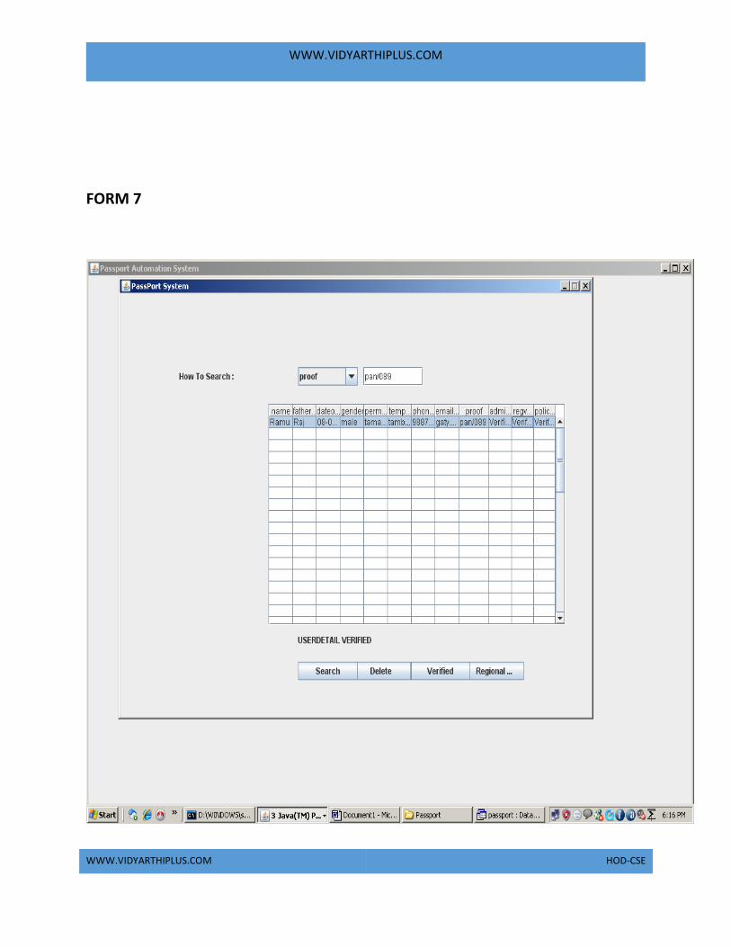
FORM 7

WWW.VIDYARTHIPLUS.COM
WWW.VIDYARTHIPLUS.COM HOD-CSE
SOURCE CODE
LoginDemo.java \\LoginForm import javax.swing.*;
import java.awt.*;
import java.awt.event.*;
import java.sql.*;
class LoginDemo
{
JButton SUBMIT;
JFrame f;
JLabel label1,label2;
final JTextField text1;
final JPasswordField text2;
LoginDemo()
{
f=new JFrame();
f.getContentPane().setLayout(null);
label1 = new JLabel();
label1.setText("UserName:");
label1.setBounds(400,50,100,20);

WWW.VIDYARTHIPLUS.COM
WWW.VIDYARTHIPLUS.COM HOD-CSE
text1 = new JTextField(25);
text1.setBounds(500,50,100,20);
label2 = new JLabel();
label2.setText("Password:");
label2.setBounds(400,80,100,20);
text2 = new JPasswordField(25);
text2.setBounds(500,80,100,20);
SUBMIT=new JButton("Login");
SUBMIT.setBounds(400,110,100,20);
// NEWUSER=new JButton("Create Account");
//NEWUSER.setBounds(500,110,200,20);
f.add(label1);
f.add(text1);
f.add(label2);
f.add(text2);
f.add(SUBMIT);
//f.add(NEWUSER);
f.setSize(1024,768);
f.setTitle("Passport Automation System");
f.setVisible(true);
SUBMIT.addActionListener(new ActionListener()
{
public void actionPerformed(ActionEvent ae)
{
String value1=text1.getText();
String value2=text2.getText();
String user1="";
String pass1="";
String user2="";
String pass2="";
try
{ Class.forName("sun.jdbc.odbc.JdbcOdbcDriver");
Connection con = DriverManager.getConnection("Jdbc:Odbc:pass","","");
Statement st = con.createStatement();
ResultSet res = st.executeQuery("SELECT * FROM login where
username='"+value1+"' and password='"+value2+"'");
while (res.next())
{user1 = res.getString("username");
pass1 = res.getString("password");

WWW.VIDYARTHIPLUS.COM
WWW.VIDYARTHIPLUS.COM HOD-CSE
}if(value1.equals(user2) && value2.equals(pass2))
{ JOptionPane.showMessageDialog(null,"Incorrect login or
password","Error",JOptionPane.ERROR_MESSAGE);
}else if(value1.equals(user1) && value2.equals(pass1))
{ CreateAccount acc=new CreateAccount();
acc.setTitle("Passport Automation System:Data Entry");

WWW.VIDYARTHIPLUS.COM
WWW.VIDYARTHIPLUS.COM HOD-CSE
} else
{
JOptionPane.showMessageDialog(null,"Incorrect login or
password","Error",JOptionPane.ERROR_MESSAGE);
} }
catch(Exception e)
{
System.out.println(e.getMessage());
} } }); }
public static void main(String arg[])
{
LoginDemo frame=new LoginDemo();
}}
CreateAccount.java \\Data Entry Form
import javax.swing.*;
import java.awt.*;
import java.sql.*;
import java.awt.event.*;
import java.lang.String.*;
class CreateAccount extends JFrame
{
JTextField text1,text2,text3,text31,text4,text5,text6,text7,text8;
JLabel label1,label2,label3,label31,label4,label5,label6,label7,label8;
JPanel panel;
JButton button1,button2,button3;
String re=" ";
CreateAccount()
{
text1=new JTextField(15);
text2=new JTextField(15);
text3=new JTextField(15);
text31=new JTextField(15);
text4=new JTextField(15);
text5=new JTextField(15);
text6=new JTextField(15);
text7=new JTextField(15);
text8=new JTextField(15);
label1=new JLabel("Name");
label2=new JLabel("Fathername");

WWW.VIDYARTHIPLUS.COM
WWW.VIDYARTHIPLUS.COM HOD-CSE
label3=new JLabel("D.O.B");
label31=new JLabel("Gender");
label4=new JLabel("PermanentAddress");
label5=new JLabel("Temporary Address");
label6=new JLabel("Proof");

WWW.VIDYARTHIPLUS.COM
WWW.VIDYARTHIPLUS.COM HOD-CSE
label7=new JLabel("Contact Number");
label8=new JLabel("Emailid");
button1=new JButton("Save");
button2=new JButton("Verification");
button3=new JButton("Reset");
panel=new JPanel(new GridLayout(11,2));
panel.add(label1);
panel.add(text1);
panel.add(label2);
panel.add(text2);
panel.add(label3);
panel.add(text3);
panel.add(label31);
panel.add(text31);
panel.add(label4);
panel.add(text4);
panel.add(label5);
panel.add(text5);
panel.add(label6);
panel.add(text6);
panel.add(label7);
panel.add(text7);
panel.add(label8);
panel.add(text8);
panel.add(button1);
panel.add(button2);
panel.add(button3);
button1.addActionListener(new ActionListener()
{
public void actionPerformed(ActionEvent ae)
{
String value1=text1.getText();
String value2=text2.getText();
String value3=text3.getText();
String value31=text31.getText();
String value4=text4.getText();
String value5=text5.getText();
String value6=text6.getText();
String value7=text7.getText();

WWW.VIDYARTHIPLUS.COM
WWW.VIDYARTHIPLUS.COM HOD-CSE
String value8=text8.getText();
try
{
Class.forName("sun.jdbc.odbc.JdbcOdbcDriver");
Connection con = DriverManager.getConnection("Jdbc:Odbc:pass","","");
Statement st = con.createStatement();

WWW.VIDYARTHIPLUS.COM
WWW.VIDYARTHIPLUS.COM HOD-CSE
int k=st.executeUpdate("insert into
userdetails(name,fathername,dateofbirth,gender,permanentaddress,temporaryaddre
ss,phoneno,emailid,proof)
values('"+value1+"','"+value2+"','"+value3+"','"+value31+"','"+value4+"','"+value5
+"','"+value7+"','"+value8+"','"+value6+"')");
JOptionPane.showMessageDialog(null,"Data is successfully inserted");
}
catch(Exception e)
{
System.out.println(e);
}
}
});
add(panel);
setSize(200,400);
setVisible(true);
button2.addActionListener(new ActionListener()
{
public void actionPerformed(ActionEvent ae)
{
if(ae.getSource()==button2)
{
a f2=new a();
f2.setSize(800,600);
f2.setTitle("Passport Administrator Verification");
f2.show();
}
else
{
}
}
});
button3.addActionListener(new ActionListener()
{
public void actionPerformed(ActionEvent ae)
{
text1.setText(re);
text2.setText(re);
text3.setText(re);

WWW.VIDYARTHIPLUS.COM
WWW.VIDYARTHIPLUS.COM HOD-CSE
text31.setText(re);
text4.setText(re);
text5.setText(re);
text6.setText(re);
text7.setText(re);
text8.setText(re);

WWW.VIDYARTHIPLUS.COM
WWW.VIDYARTHIPLUS.COM HOD-CSE
}
});
}
public static void main(String args[])
{
CreateAccount acc=new CreateAccount();
}
}
a.java \\ Passport adminstrator
import javax.swing.*;
import java.awt.*;
import java.awt.event.*;
import java.sql.*;
class a extends JFrame implements ActionListener,ItemListener
{
JButton search,del,reg,verify;
JLabel name,find;
JComboBox list;
JTextField text;
Container con,con1;
String searchtext,searchfield,sql;
ResultSet rs;
ResultSet rs1;
JTable table;
Object rows[][];
int tval=0,tval1=0;
JScrollPane scrollPane;
String ver="Verified";
a()
{
con=getContentPane();
con.setLayout(null);
con1=getContentPane();
con1.setLayout(null);
rows=new Object[50][13];
Object headers[] =
{"name","fathername","dateofbirth","gender","permanentaddress","temporaryaddr
ess","phoneno","emailid","proof","adminverify","regverify","policeverify"};
table = new JTable(rows, headers);

WWW.VIDYARTHIPLUS.COM
WWW.VIDYARTHIPLUS.COM HOD-CSE
scrollPane = new JScrollPane(table);
scrollPane.setBounds(250,150,500,300);
scrollPane.setBackground(Color.WHITE);

WWW.VIDYARTHIPLUS.COM
WWW.VIDYARTHIPLUS.COM HOD-CSE
con.add(scrollPane);
search=new JButton("Search");
search.setBounds(300,500,100,25);
con.add(search);
search.addActionListener(this);
del=new JButton("Delete");
del.setBounds(390,500,100,25);
con.add(del);
del.addActionListener(this);
verify=new JButton("Verified");
verify.setBounds(490,500,100,25);
con.add(verify);
verify.addActionListener(this);
reg=new JButton("Regional Verification");
reg.setBounds(580,500,100,25);
con.add(reg);
reg.addActionListener(this);
name=new JLabel("How To Search :");
name.setBounds(100,100,200,25);
con.add(name);
find=new JLabel("");
find.setBounds(300,450,350,40);
con.add(find);
text=new JTextField();
text.setBounds(410,100,100,25);
con1.add(text);
text.addActionListener(this);
list=new JComboBox();
list.setModel(new DefaultComboBoxModel(new String[] { "Select","proof" }));
list.setBounds(300,100,100,25);
con1.add(list);
list.addItemListener(this);
}
public void actionPerformed(ActionEvent ae)
{

WWW.VIDYARTHIPLUS.COM
WWW.VIDYARTHIPLUS.COM HOD-CSE
if(ae.getSource()==text)
find.setText("");
if(ae.getSource()==del)
{
String getdel=JOptionPane.showInputDialog(search, "Enter the Proofno
","PassPort",1);
try{
Class.forName("sun.jdbc.odbc.JdbcOdbcDriver");
Connection cntn3=DriverManager.getConnection("Jdbc:Odbc:pass","","");
Statement ste3=cntn3.createStatement();
ste3.executeUpdate("delete from userdetails where proof ='"+getdel+"'");
find.setText("USERDETAIL DELETED");
}
catch(Exception dele)
{
}
}
if(ae.getSource()==verify)
{
try{
Class.forName("sun.jdbc.odbc.JdbcOdbcDriver");
Connection cntn3=DriverManager.getConnection("Jdbc:Odbc:pass","","");
Statement ste3=cntn3.createStatement();
String rt=text.getText();
ste3.executeUpdate("UPDATE userdetails SET adminverify='"+ver+"' where
proof='"+rt+"'");
find.setText("USERDETAIL VERIFIED");
}
catch(Exception dele)
{
}
}
if(ae.getSource()==reg)
{
try
{
b g2=new b();
g2.setTitle("Regional Officer Verification");

WWW.VIDYARTHIPLUS.COM
WWW.VIDYARTHIPLUS.COM HOD-CSE
}
catch(Exception reg)
{
}
}
if(ae.getSource()==search)
{
if(searchfield==null)
find.setText("Please Select Search Category..,");
else
{
sql="select * from userdetails where ";
sql+=searchfield;
sql+="='"+text.getText()+"'";
System.out.println(sql); // the query for sql statement
try{
Class.forName("sun.jdbc.odbc.JdbcOdbcDriver");
Connection cntn=DriverManager.getConnection("Jdbc:Odbc:pass","","");
Statement ste1=cntn.createStatement();
rs1=ste1.executeQuery(sql);
tval=0;
while(rs1.next())
{
table.setValueAt(""+rs1.getString(1),tval,0);
table.setValueAt(""+rs1.getString(2),tval,1);
table.setValueAt(""+rs1.getString(3),tval,2);
table.setValueAt(""+rs1.getString(4),tval,3);
table.setValueAt(""+rs1.getString(5),tval,4);
table.setValueAt(""+rs1.getString(6),tval,5);
table.setValueAt(""+rs1.getString(7),tval,6);
table.setValueAt(""+rs1.getString(8),tval,7);
table.setValueAt(""+rs1.getString(9),tval,8);
table.setValueAt(""+rs1.getString(10),tval,9);
table.setValueAt(""+rs1.getString(11),tval,10);
table.setValueAt(""+rs1.getString(12),tval,11);
tval++;
}
if(tval==0)

WWW.VIDYARTHIPLUS.COM
WWW.VIDYARTHIPLUS.COM HOD-CSE
find.setText("Details Not Availabel( "+searchfield+" : "+text.getText()+" )\n Tri
Again...,");
}
catch(Exception e)
{
JOptionPane.showMessageDialog(search,"Sorry,DataBase Problem,","PassPort
System,",JOptionPane.INFORMATION_MESSAGE);

WWW.VIDYARTHIPLUS.COM
WWW.VIDYARTHIPLUS.COM HOD-CSE
}
}
}
}
public void itemStateChanged(ItemEvent ie)
{
find.setText("");
text.setText("");
list.removeItem("Select");
for(int i=0;i<tval;i++)
{
table.setValueAt("",i,0);
//table.setValueAt("",i,1);
//table.setValueAt("",i,2);
}
searchfield=""+ie.getItem();
setSize(800,600);
setTitle("PassPort System");
setDefaultCloseOperation(JFrame.EXIT_ON_CLOSE);
setVisible(true);
setResizable(false);
}
public static void main(String[] argv)
{
a f2=new a();
}
}
b.java \\Regional officer form
import javax.swing.*;
import java.awt.*;
import java.awt.event.*;
import java.sql.*;
class b extends JFrame implements ActionListener
{
JButton SUBMIT,verify,police;
JFrame f;
JLabel label1,label2;
final JTextField text1, text2;
b()

WWW.VIDYARTHIPLUS.COM
WWW.VIDYARTHIPLUS.COM HOD-CSE
{

WWW.VIDYARTHIPLUS.COM
WWW.VIDYARTHIPLUS.COM HOD-CSE
f=new JFrame();
f.getContentPane().setLayout(null);
label1 = new JLabel();
label1.setText("Name:");
label1.setBounds(400,50,100,20);
text1 = new JTextField(25);
text1.setBounds(500,50,100,20);
label2 = new JLabel();
label2.setText("Proof no:");
label2.setBounds(400,80,100,20);
text2 = new JTextField(25);
text2.setBounds(500,80,100,20);
SUBMIT=new JButton("find");
SUBMIT.setBounds(400,110,100,20);
verify=new JButton("verified");
verify.setBounds(500,110,100,20);
police=new JButton("Police Verification");
police.setBounds(600,110,110,20);
police.addActionListener(this);
f.add(label1);
f.add(text1);
f.add(label2);
f.add(text2);
f.add(SUBMIT);
f.add(verify);
f.add(police);
f.setTitle("Passport Automation System:Regional Officer Verification");
f.setSize(900,500);
f.setVisible(true);
SUBMIT.addActionListener(new ActionListener()
{
public void actionPerformed(ActionEvent ae)
{
String value1=text1.getText();
String value2=text2.getText();
String user1="";
String pass1="";
String user2="";
String pass2="";

WWW.VIDYARTHIPLUS.COM
WWW.VIDYARTHIPLUS.COM HOD-CSE
String ver="Verified";
try

WWW.VIDYARTHIPLUS.COM
WWW.VIDYARTHIPLUS.COM HOD-CSE
{
Class.forName("sun.jdbc.odbc.JdbcOdbcDriver");
Connection con = DriverManager.getConnection("Jdbc:Odbc:pass","","");
Statement st = con.createStatement();
ResultSet res = st.executeQuery("SELECT * FROM RegionalDatabase where
Name='"+value1+"' and Proof='"+value2+"'");
while (res.next())
{
user1 = res.getString("Name");
pass1 = res.getString("Proof");
}
if(value1.equals(user2) && value2.equals(pass2))
{
JOptionPane.showMessageDialog(null,"Type the name and
Proof","Error",JOptionPane.ERROR_MESSAGE);
}
else if(value1.equals(user1) && value2.equals(pass1))
{
JOptionPane.showMessageDialog(null,"USER DETAIL FOUND");
Class.forName("sun.jdbc.odbc.JdbcOdbcDriver");
Connection con2 = DriverManager.getConnection("Jdbc:Odbc:pass","","");
Statement st2 = con2.createStatement();
ResultSet res2 = st2.executeQuery("UPDATE userdetails SET regverify='"+ver+"'
where name='"+value1+"' and Proof='"+value2+"'");
}
else
{
JOptionPane.showMessageDialog(null,"DETAILS NOT
FOUND","Error",JOptionPane.ERROR_MESSAGE);
}
}
catch(Exception e)
{
// System.out.println(e.getMessage());
}
}
});
}
public void actionPerformed(ActionEvent ae)

WWW.VIDYARTHIPLUS.COM
WWW.VIDYARTHIPLUS.COM HOD-CSE
{
if(ae.getSource()==police)
{
try
{
c g3=new c();
}

WWW.VIDYARTHIPLUS.COM
WWW.VIDYARTHIPLUS.COM HOD-CSE
catch(Exception police)
{
}
}
}
public static void main(String arg[])
{
b g2=new b();
}
}
c.java \\Police Verification Form
import javax.swing.*;
import java.awt.*;
import java.awt.event.*;
import java.sql.*;
class c
{
JButton SUBMIT,verify;
JFrame f;
JLabel label1,label2,label3;
final JTextField text1, text2,text3;
c()
{
f=new JFrame();
f.getContentPane().setLayout(null);
label1 = new JLabel();
label1.setText("Name:");
label1.setBounds(400,50,100,20);
text1 = new JTextField(25);
text1.setBounds(500,50,100,20);
label2 = new JLabel();
label2.setText("permanentaddress");
label2.setBounds(400,80,100,20);
text2 = new JTextField(25);
text2.setBounds(500,80,100,20);
label3 = new JLabel();
label3.setText("temporaryaddress");
label3.setBounds(400,110,100,20);
text3 = new JTextField(25);
WWW.VIDYARTHIPLUS.COM
WWW.VIDYARTHIPLUS.COM HOD-CSE
text3.setBounds(500,110,100,20);

WWW.VIDYARTHIPLUS.COM
WWW.VIDYARTHIPLUS.COM HOD-CSE
SUBMIT=new JButton("find");
SUBMIT.setBounds(400,150,100,20);
verify=new JButton("verified");
verify.setBounds(500,150,200,20);
f.add(label1);
f.add(text1);
f.add(label2);
f.add(text2);
f.add(label3);
f.add(text3);
f.add(SUBMIT);
f.add(verify);
f.setTitle("Passport Automation System:Police Verification");
f.setSize(900,500);
f.setVisible(true);
SUBMIT.addActionListener(new ActionListener()
{
public void actionPerformed(ActionEvent ae)
{
String value1=text1.getText();
String value2=text2.getText();
String value3=text3.getText();
String user1="";
String pass1="";
String pass3="";
String user2="";
String pass2="";
String pass4="";
String ver="Verified";
try
{
Class.forName("sun.jdbc.odbc.JdbcOdbcDriver");
Connection con = DriverManager.getConnection("Jdbc:Odbc:pass","","");
Statement st = con.createStatement();
ResultSet res = st.executeQuery("SELECT * FROM PoliceDb where
Name='"+value1+"' and permanentaddress='"+value2+"' and
temporaryaddress='"+value3+"'");
while (res.next())
{

WWW.VIDYARTHIPLUS.COM
WWW.VIDYARTHIPLUS.COM HOD-CSE
user1 = res.getString("Name");
pass1 = res.getString("permanentaddress");
pass3 =res.getString("temporaryaddress");
}
if(value1.equals(user2) && value2.equals(pass2) && value3.equals(pass4) )
{

WWW.VIDYARTHIPLUS.COM
WWW.VIDYARTHIPLUS.COM HOD-CSE
JOptionPane.showMessageDialog(null,"Type the name and
Proof","Error",JOptionPane.ERROR_MESSAGE);
}
else if(value1.equals(user1) && value2.equals(pass1) && value3.equals(pass3))
{
JOptionPane.showMessageDialog(null,"USER DETAIL FOUND");
Class.forName("sun.jdbc.odbc.JdbcOdbcDriver");
Connection con2 = DriverManager.getConnection("Jdbc:Odbc:pass","","");
Statement st2 = con2.createStatement();
ResultSet res2 = st2.executeQuery("UPDATE userdetails SET
policeverify='"+ver+"' where name='"+value1+"' and
permanentaddress='"+value2+"' and temporaryaddress='"+value3+"'");
}
else
{
JOptionPane.showMessageDialog(null,"DETAILS NOT
FOUND","Error",JOptionPane.ERROR_MESSAGE);
}
}
catch(Exception e)
{
// System.out.println(e.getMessage());
}
}
});
}
public static void main(String arg[])
{ c g3=new c();}}
RESULT:
Thus the project to implement Passport Automation System using java has been
successfully designed.

WWW.VIDYARTHIPLUS.COM
WWW.VIDYARTHIPLUS.COM HOD-CSE
EX NO:2 BOOK BANK MANAGEMENT SYSTEM
AIM
To develop a project of Book bank management system using Rational Rose
Software and to implement the software in Visual Basic.
PROBLEM ANALYSIS AND PROJECT DESIGN
The book bank management system is an software in which a member can register
themselves and then he can borrow books from the book bank. It mainly
concentrates on providing books for engineering students.
PROBLEM STATEMENT
The process of members registering and purchasing books from the book bank are
described sequentially through following steps:
a. First the member registers himself if he was new to the book bank.
b. Old members will directly select old member button..
c. They select their corresponding year.
d. After selecting the year they fill the necessary details and select the
book and he will be directed towards administrator
e. The administrator will verify the status and issue the book.
SOFTWARE REQUIREMENT SPECIFICATION
S.NO CONTENTS
INTRODUCTION

WWW.VIDYARTHIPLUS.COM
WWW.VIDYARTHIPLUS.COM HOD-CSE
1.
2.
OBJECTIVE
3.
OVERVIEW
4.
GLOSSARY
5.
PURPOSE
6.
SCOPE
7.
FUNCTIONALITY
8.
USABILITY
9.
PERFORMANCE
10.
RELIABILITY

WWW.VIDYARTHIPLUS.COM
WWW.VIDYARTHIPLUS.COM HOD-CSE
FUNCTIONAL REQUIREMENTS
11.
EXTERNAL INTERFACE
REQUREMENTS
1. INTRODUCTION
This system would be used by members who are students of any college to check
the availability of the books and borrow the books, and then the databases are
updated. The purpose of this document is to analyze and elaborate on the high-
level needs and features of the book bank management system. It also tells the
usability, reliability defined in use case specification.
2. OBJECTIVE
The main objective of the system are was to design an online book-bank
monitoring system to enable a central monitoring mechanism of the book-bank be
more faster and less error prone. Apart from this,
a. To help the students acquire the right books for the syllabus at the
right time.
b. To ensure availability of basic textbooks to students against limited
funds and To develop students ability to handle property loaned to
them
.
3. OVERVIEW

WWW.VIDYARTHIPLUS.COM
WWW.VIDYARTHIPLUS.COM HOD-CSE
The overview of this project is to design a tool for book bank so that it can be used
by any book banks to lend their books as well as colleges.
4. GLOSSARY
TERMS DESCRIPTION
MEMBER The one who registers himself and
purchase books from the bank.
DATABASE Database is used to store the details
of members and books.
ADMINISTRATOR The one who verifies the
availability of book and issue them
USER Member
SOFTWARE REQUIREMENT
SPECIFICATION
This software specification
documents full set of features and
function for online recruitment
system that is performed in
company website.
5. PURPOSE
The purpose of the book bank management system is to reduce the manual
intervention .
6. SCOPE
The scope of this book bank management system is to act as a tool for book bank
administrator for quick reference, availability of the books.
7. FUNCTIONALITY
Many members will be waiting to take the book from the book bank at a single
day. To serve all the members
8. USABILITY

WWW.VIDYARTHIPLUS.COM
WWW.VIDYARTHIPLUS.COM HOD-CSE
User interface makes the Recruitment system to be efficient. That is the system
will help the member to register easily and helps them to get their books easily.
The system should be user friendly.
9. PERFORMANCE
It describes the capability of the system to perform the recruitment process of the
applicant without any error and performing it efficiently.
10. RELIABILITY
The book bank management system should be able to serve the applicant
withcorrect information and day-to-day update of information.
11. FUNCTIONAL REQUIREMENTS
Functional requirements are those refer to the functionality of the system.
That is the services that are provided to the member who borrows book.
12. EXTERNAL INTERFACE REQUIREMANTS
SOFTWARE REQUIREMENTS
1. Front end: IBM rational rose enterprise edition.
2. Back end: visual basic 8.0.
HARDWARE REQUIREMENTS
1. Processor : pentium 4.
2. RAM : 256 mb
3. Operating syatem : Microsoft windows xp.
4. Free disk space : 1gb
UML DIAGRAMS

WWW.VIDYARTHIPLUS.COM
WWW.VIDYARTHIPLUS.COM HOD-CSE
The following UML diagrams describe the process involved in the online
recruitment system
a. Use case diagram
b. Class diagram
c. Sequence diagram
d. Collaboration diagram
e. State chart diagram
f. Activity diagram
g. Component diagram
h. Deployment diagram
i. Package diagram
USE CASE DIAGRAM
A use case is a methodology used in system analysis to identify, clarify, and
organize system requirements. The use case is made up of a set of possible
sequences of interactions between systems and users in a particular environment
and related to a particular goal. It is represented using ellipse.
Actor is any external entity that makes use of the system being modeled. It is
represented using stick figure.
DOCUMENTATION OF USE CASE DIAGRAM
The actors in this use case diagram are member and database. The use cases are the
activities performed by actors.
a. The member will register himself in the book bank.
b. After registration he will select the year to which he belongs
c. After selecting he will select books
d. Database will verify the status of book and the books will be given.

WWW.VIDYARTHIPLUS.COM
WWW.VIDYARTHIPLUS.COM HOD-CSE
CLASS DIAGRAM
A class diagram in the unified modeling language (UML) is a type of static
structure diagram that describes the structure of a system by showing the system's
classes, their attributes, and the relationships between the classes. It is represented
using a rectangle with three compartments. Top compartment have the class name,
middle compartments the attributes and the bottom compartment with operations.
DOCUMENTATION OF CLASS DIAGRAM This class diagram has 8 classes:
o Member details class- is the class name. Its attributes are name,
father name, date of birth, address, phone number, member id,
college, degree, course and semester. Its operations are registration,
authentication, and year selection.
o Administrator- is the class name. Its attributes are name, address,
phone, mail id. Its operations are authentication, verification and issue
books.
o Year-is the class name. Its attribute is year selection. Its operations
are 1st year,2nd year, 3rd year,4th year.
o Issue for 1st year-is the class name. Its attributes are member code,
member name, book code, book name, and quantity. Its operation is
issue
Issue for 2nd year-is the class name. Its attributes are member code,
member name, book code, book name, and quantity. Its operation is
issue
o Issue for 3rd year-is the class name. Its attributes are member code,
member name, book code, book name, and quantity. Its operation is
issue

WWW.VIDYARTHIPLUS.COM
WWW.VIDYARTHIPLUS.COM HOD-CSE
SEQUENCE DIAGRAM
A sequence diagram in Unified Modeling Language (UML) is a kind of interaction
diagram that shows how processes operate with one another and in what order. It is
a construct of a Message Sequence Chart. There are two dimensions.
1. Veritcal dimension-represent time.
2. Horizontal dimension-represent different objects.
DOCUMENTATION OF SEQUENCE DIAGRAM
The sequence diagram describes the sequence of steps to show
a. The member registers himself in book bank
b. He will select the year
c. He select the books given and the database will update the status of
book.
d. Then administrator will log in and verify the status of books.
e. If the book is available he will issue the book.
COLLABRATION DIAGRAM
A collaboration diagram, also called a communication diagram or interaction
diagram,. A sophisticated modeling tool can easily convert a collaboration diagram
into a sequence diagram and the vice versa. A collaboration diagram resembles a
flowchart that portrays the roles, functionality and behavior of individual objects as
well as the overall operation of the system in real time
DOCUMENTATION OF COLLABORATION DIAGRAM
The collaboration diagram is to show how the member registers himself and
borrow the book from the book bank. Here the sequence is numbered according to
the flow of execution.

WWW.VIDYARTHIPLUS.COM
WWW.VIDYARTHIPLUS.COM HOD-CSE
STATE CHART DIAGRAM
The purpose of state chart diagram is to understand the algorithm involved in
performing a method. It is also called as state diagram. A state is represented as a
round box, which may contain one or more compartments. An initial state is
represented as small dot. An final state is represented as circle surrounding a small
dot.
DOCUMENTATION OF STATE CHART DIAGRAM
This state diagram describes the behavior of the system.
a. In the first state the member registers himself in book bank
b. After that he will select the year in next state.
c. In the next state he will select the books.
d. In the next state database will update the status of book.
e. In the next state administrator will log in.
f. After authentication he will verify the availability of book.
g. If available he will issue the book.
h.
ACTIVITY DIAGRAM
Activity diagrams are graphical representations of workflows of stepwise activities
and actions with support for choice, iteration and concurrency. In the Unified
Modeling Language, activity diagrams can be used to describe the business and
operational step-by-step workflows of components in a system. An activity
diagram shows the overall flow of control. An activity is shown as an rounded box
containing the name of the operation

WWW.VIDYARTHIPLUS.COM
WWW.VIDYARTHIPLUS.COM HOD-CSE
DOCUMENTATION OF ACTIVITY DIAGRAM
This activity diagram flow of stepwise activities performed in book bank
management system.
a. The member registers himself in book bank
b. After that he will select the year.
c. He will select the books.
d. Database will update the status of book.
e. Database will update the details
f. Then the administrator will log in to his account.

WWW.VIDYARTHIPLUS.COM
WWW.VIDYARTHIPLUS.COM HOD-CSE
g. After authentication he will verify the availability of book.
h. If available he will issue the book.
COMPONENT DIAGRAM
The component diagram's main purpose is to show the structural relationships
between the components of a system. It is represented by boxed figure.
Dependencies are represented by communication association
DOCUMENTATION OF COMPONENT DIAGRAM
The main component in this component diagram is online book bank management
systems. And member details, issue for first year, issue for second year issue for
third year and issue for fourth year are components comes under the main
component
DEPLOYMENT DIAGRAM
A deployment diagram in the unified modeling language serves to model the
physical deployment of artifacts on deployment targets. Deployment diagrams
show "the allocation of artifacts to nodes according to the Deployments defined

WWW.VIDYARTHIPLUS.COM
WWW.VIDYARTHIPLUS.COM HOD-CSE
between them. It is represented by 3-dimentional box. Dependencies are
represented by communication association.
DOCUMENTATION OF DEPLOYMENT DIAGRAM
The processor in this deployment diagram is the book bank which is the main part
and which are the some of the main activities performed in the system. And issue
for first year, issue for second year issue for third year and issue for fourth year are
some activities performed in this system.
PACKAGE DIAGRAM
A package diagram in unified modeling language that depicts the dependencies
between the packages that make up a model. A Package Diagram (PD) shows a
grouping of elements in the OO model, and is a Cradle extension to UML. PDs can
be used to show groups of classes in Class Diagrams (CDs), groups of components
or processes in Component Diagrams (CPDs), or groups of processors in
Deployment Diagrams (DPDs).
There are three types of layer. They are
o User interface layer
o Domain layer
o Technical services layer
DOCUMENTATION OF PACKAGE DIAGRAM
The three layers in the online recruitment system are

WWW.VIDYARTHIPLUS.COM
WWW.VIDYARTHIPLUS.COM HOD-CSE
a. The User interface layer - consists of the web and member details.
This layer describes how the member goes to book bank and registers
himself..
b. The Domain layer – shows the activities that are performed in the
book bank management system. The activities are register and book
issues..
c. The Technical service layer - the member details and verification
details are stored in the database.
FORMS
FORM 1

WWW.VIDYARTHIPLUS.COM
WWW.VIDYARTHIPLUS.COM HOD-CSE
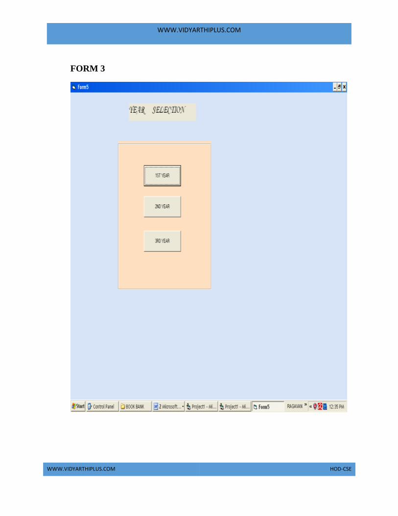
WWW.VIDYARTHIPLUS.COM
WWW.VIDYARTHIPLUS.COM HOD-CSE
FORM 3

WWW.VIDYARTHIPLUS.COM
WWW.VIDYARTHIPLUS.COM HOD-CSE
FORM 4

WWW.VIDYARTHIPLUS.COM
WWW.VIDYARTHIPLUS.COM HOD-CSE

WWW.VIDYARTHIPLUS.COM
WWW.VIDYARTHIPLUS.COM HOD-CSE
FORM 5

WWW.VIDYARTHIPLUS.COM
WWW.VIDYARTHIPLUS.COM HOD-CSE
FORM 6

WWW.VIDYARTHIPLUS.COM
WWW.VIDYARTHIPLUS.COM HOD-CSE

WWW.VIDYARTHIPLUS.COM
WWW.VIDYARTHIPLUS.COM HOD-CSE
FORM 7

WWW.VIDYARTHIPLUS.COM
WWW.VIDYARTHIPLUS.COM HOD-CSE
FORM 8

WWW.VIDYARTHIPLUS.COM
WWW.VIDYARTHIPLUS.COM HOD-CSE

WWW.VIDYARTHIPLUS.COM
WWW.VIDYARTHIPLUS.COM HOD-CSE
FORM 9

WWW.VIDYARTHIPLUS.COM
WWW.VIDYARTHIPLUS.COM HOD-CSE

WWW.VIDYARTHIPLUS.COM
WWW.VIDYARTHIPLUS.COM HOD-CSE
SOURCE CODE:
Administrator. Class
Option Explicit
'##Model Id=4D5A2FC4038A
Private name As Variant
'##Model Id=4D6CB83B006D
Private address As Variant
'##Model Id=4D6CB84902DE
Private phone As Variant
'##Model Id=4D6CB8510000
Private mail id As Variant
'##Model Id=4D5A34780280
Public New Property As year
'##Model Id=4D5A348B0290
Public NewProperty2 As database
'##Model Id=4D5A31B30119
Public Sub authentication ()
On Error Go To Error Handler
'## your code goes here...
If Form10.Text1.Text = "admin" And Form10.Text2.Text = "1234" Then
MsgBox "login successfully"
Form9.Show
Else
MsgBox "invalid password"
End If
Exit Sub
ErrorHandler:
Call Raise Error (My Unhandled Error, "authentication Sub")
End Sub

WWW.VIDYARTHIPLUS.COM
WWW.VIDYARTHIPLUS.COM HOD-CSE
'##Model Id=4D5A31E402BF
Public Sub verification ()
On Error Go To Error Handler
'## your code goes here...
Exit Sub
Error Handler:
Call Raise Error (My Unhandled Error , "verification Sub")
End Sub
'##Model Id=4D6CB8E403B9
Public Sub issue_books()
On Error Go To Error Handler
'## your code goes here...
Exit Sub
Error Handler:
Call Raise Error (My Unhandled Error, "issue_books Sub")
End Sub
Database .class Option Explicit
'##Model Id=4D5A2FB00128
Private name As Variant

WWW.VIDYARTHIPLUS.COM
WWW.VIDYARTHIPLUS.COM HOD-CSE
'##Model Id=4D51082601C5
Public Sub update ()
On Error Go To Error Handler
'## your code goes here...
Exit Sub
Error Handler:
Call Raise Error (My Unhandled Error , "update Sub")
End Sub
Year . Class
Option Explicit
'##Model Id=4D5A317F00DA
Private year_selection As Variant
'##Model Id=4D5A319B0128
Public Sub 1styear()
On Error GoTo ErrorHandler
'## your code goes here...
Exit Sub
ErrorHandler:
Call RaiseError(MyUnhandledError, "styear Sub")
End Sub
'##ModelId=4D5A319F00CB
Public Sub 2nd_year()
On Error GoTo ErrorHandler
'## your code goes here...
Exit Sub
ErrorHandler:
Call RaiseError(MyUnhandledError, "nd_year Sub")
End Sub
'##ModelId=4D5A31A2032C
Public Sub 3rd_year()
On Error GoTo ErrorHandler
'## your code goes here...
Exit Sub
ErrorHandler:
Call RaiseError(MyUnhandledError, "rd_year Sub")
End Sub
Issue for first year. class Option Explicit
'##ModelId=4D5A3381006F

WWW.VIDYARTHIPLUS.COM
WWW.VIDYARTHIPLUS.COM HOD-CSE
Private member_code As Variant
'##ModelId=4D5A33810070
Private member_name As Variant

WWW.VIDYARTHIPLUS.COM
WWW.VIDYARTHIPLUS.COM HOD-CSE
'##ModelId=4D5A33810072
Private book_name As Variant
'##ModelId=4D5A347B03B9
Public NewProperty As year
'##ModelId=4D5A3381006E
Public Sub issue_for_first()
On Error GoTo ErrorHandler
'## your code goes here...
Form6.Data1.Recordset.AddNew
Form6.Text5.Text = Form6.Text5.Text + 1
Form6.Text4.Text = Form6.Text4.Text - 1
If (Form6.Text4.Text <= 0) Then
MsgBox "only four books can be selected"
Form8.Show
End If
Exit Sub
ErrorHandler:
Call RaiseError(MyUnhandledError, "issue_for_first Sub")
End Sub
Issue for second year class Option Explicit
'##ModelId=4D5A33D902EE
Private member_code As Variant
'##ModelId=4D5A33DC03D8
Private member_name As Variant
'##ModelId=4D5A33E30167
Private book_name As Variant
'##ModelId=4D5A347C03D8
Public NewProperty As year
'##ModelId=4D5A33ED00BB
Public Sub issue_for_second()
On Error GoTo ErrorHandler
'## your code goes here...
Data1.Recordset.AddNew
Form7.Text5.Text = Form7.Text5.Text + 1
Form7.Text4.Text = Text4.Text - 1
If (Form7.Text4.Text <= 0) Then
MsgBox "only four books can be selected"
Form8.Show

WWW.VIDYARTHIPLUS.COM
WWW.VIDYARTHIPLUS.COM HOD-CSE
End If
Exit Sub
ErrorHandler:
Call RaiseError(MyUnhandledError, "issue_for_second Sub")
End Sub
Issue for third year class Option Explicit

WWW.VIDYARTHIPLUS.COM
WWW.VIDYARTHIPLUS.COM HOD-CSE
'##ModelId=4D5A33F2036B
Private member_code As Variant
'##ModelId=4D5A33FA00EA
Private member_name As Variant
'##ModelId=4D5A34010399
Private book_name As Variant
'##ModelId=4D5A347E0138
Public NewProperty As year
'##ModelId=4D5A340F01B5
Public Sub issue_for_third()
On Error GoTo ErrorHandler
'## your code goes here...
Form8.Data1.Recordset.AddNew
Form8.Text5.Text = Form8.Text5.Text + 1
Form8.Text4.Text = Form8.Text4.Text - 1
If (Form8.Text4.Text <= 0) Then
MsgBox "only four books can be selected"
Form8.Show
End If
Exit Sub
ErrorHandler:
Call RaiseError(MyUnhandledError, "issue_for_third Sub")
End Sub
Form 1 Private Sub Command1_Click()
Form1.Show
End Sub
Private Sub Command2_Click()
Form9.Show
End Sub
Private Sub Command3_Click()
Form5.Show
End Sub
Form 2 Private Sub Command1_Click()
Data1.Recordset.AddNew
End Sub
Private Sub Command2_Click()
Data1.Recordset.update

WWW.VIDYARTHIPLUS.COM
WWW.VIDYARTHIPLUS.COM HOD-CSE
Form2.Show
End Sub
Form 3
Private Sub Command1_Click()
Form4.Show
End Sub
Private Sub Command2_Click()
Form6.Show

WWW.VIDYARTHIPLUS.COM
WWW.VIDYARTHIPLUS.COM HOD-CSE
End Sub
Private Sub Command3_Click()
Form7.Show
End Sub
Form 4 Private Sub Command2_Click()
Dim fi As Issue for first year
Set fi =new Issue for first year
fi.issue_for_first
End Sub
Private Sub Command3_Click()
Data1.Recordset.update
End Sub
Private Sub Form_Load()
Text4.Text = 5
Text5.Text = 0
End Sub
Private Sub List1_Click()
Text3.Text = List1.Text
End Sub
Form 5 Private Sub Command2_Click()
Dim se As Issue for second year
Set se =new Issue for second year
se.issue_for_second
End Sub
Private Sub Command3_Click()
Data1.Recordset.update
End Sub
Private Sub Form_Load()
Text4.Text = 5
Text5.Text = 0
End Sub
Private Sub List1_Click()
Text3.Text = List1.Text
End Sub
Form 6 Private Sub Command2_Click()
Dim th As Issue for third year

WWW.VIDYARTHIPLUS.COM
WWW.VIDYARTHIPLUS.COM HOD-CSE
Set th =new Issue for third year
th.issue_for_third
End Sub
Private Sub Command3_Click()
Data1.Recordset.update
End Sub
Private Sub Form_Load()
Text4.Text = 5

WWW.VIDYARTHIPLUS.COM
WWW.VIDYARTHIPLUS.COM HOD-CSE
Text5.Text = 0
End Sub
Private Sub List1_Click()
Text3.Text = List1.Text
End Sub
Form 7 private Sub Command1_Click()
Dim au As Administrator
Set au =new Administrator
au. authentication
End Sub
Private Sub Command2_Click()
Unload Me
End Sub
RESULT
Thus the project to develop book bank management system using Rational Rose
Software and to implement the software in Visual Basic was done successfully

WWW.VIDYARTHIPLUS.COM
WWW.VIDYARTHIPLUS.COM HOD-CSE
EXNO:3a EXAM REGISTRATION SYSTEM
AIM
To develop a project Exam Registration using Rational Rose Software and to
implement the software in Visual Basic.
PROBLEM ANALYSIS AND PROJECT PLANNING
The Exam Registration is an application in which applicant can register themselves
for the exam. The details of the students who have registered for the examination
will be stored in a database and will be maintained. The registered details can then
be verified for any fraudulent or duplication and can be removed if found so. The
database which is verified can be used to issue hall tickets and other necessary
materials to the eligible students.
PROBLEM STATEMENT
The process of students accessing the registration application and applying for the
examination by filling out the form with proper details and then the authorities
verify those details given for truth and correctness are sequenced through steps
a. The students access exam registration application.
b. They fill out the form with correct and eligible details.
c. They complete the payment process.
d. The authorities verify or check the details.
e. After all verification the exam registration database is finalized.

WWW.VIDYARTHIPLUS.COM
WWW.VIDYARTHIPLUS.COM HOD-CSE
SOFTWARE REQUIREMENT SYSTEM
12. INTRODUCTION
13. OBJECTIVE
14. OVERVIEW
15. GLOSSARY
16. PURPOSE
17. SCOPE
18. FUNCTIONALITY

WWW.VIDYARTHIPLUS.COM
WWW.VIDYARTHIPLUS.COM HOD-CSE
19. USABILITY
20. PERFORMANCE
21. RELIABILITY
22. FUNCTIONAL REQUIREMENTS
1. INTRODUCTION
Exam Registration application is an interface between the Student and the
Authority responsible for the Exams. It aims at improving the efficiency in the
registration of exams and reduces the complexities involved in it to the maximum
possible extent.
2. OBJECTIVE
The main objective of Exam Registration System is to make applicants register
themselves and apply for the exam. Exam Registration System provides easy
interface to all the users to apply for the exam easily.
3. OVERVIEW
The overview of the project is to design an exam registration tool for the
registration process which makes the work easy for the applicant as well as the
Authorities of Exam. Authorities of the exam can keep track of and maintain the
database of the registered applicants for the exams.
4. GLOSSARY
TERMS DESCRIPTION
WWW.VIDYARTHIPLUS.COM
WWW.VIDYARTHIPLUS.COM HOD-CSE
APPLICANT OR STUDENT Applicant can register himself by filling
out the registration form and finally
paying the payment for attending the
exam.
DATABASE Database is used to maintain and store
the details of registered applicants.
SOFTWARE REQUIREMENT
SPECIFICATION
This software specification documents
full set of features and function for online
recruitment system that is performed in
company website.
5. PURPOSE
The purpose of exam registration system is to register for the exam in an easier
way and to maintain the registered details in an effective manner.
6. SCOPE
The scope of this Exam Registration process is to provide an easy interface to the
applicants where they can fill their details and the authorities maintain those details
in an easy and effective way.
7. FUNCTIONALITY
The main functionality of registration system is to make the registration and
database for it to be maintained in an efficient manner.
8. USABILITY
User interface makes the Exam Registration system to be efficient. That is the
system will help the applicant to register easily and helps the authorities to
maintain details effectively. The system should be user friendly.
9. PERFORMANCE

WWW.VIDYARTHIPLUS.COM
WWW.VIDYARTHIPLUS.COM HOD-CSE
It describes the capability of the system to perform the registration process of the
applicant without any error and performing it efficiently.
10.RELIABILITY
The Exam Registration system should be able to serve the applicant with correct
information and day-to-day update of information.
11. FUNCTIONAL REQUIREMENTS
Functional requirements are those refer to the functionality of the system. That is
the services that are provided to the applicant who apply for the Exam.
12. EXTERNAL INTERFACE REQUIREMANTS
SOFTWARE REQUIREMENTS
1. Front end: IBM rational rose enterprise edition.
2. Back end: visual basic 8.0.
HARDWARE REQUIREMENTS
1. Processor : pentium 4.
2. RAM : 256 mb
3. Operating syatem : Microsoft windows xp.
4. Free disk space : 1gb
UML DIAGRAMS
The following UML diagrams describe the process involved in the online
recruitment system
a. Use case diagram
b. Class diagram
c. Sequence diagram
d. Collaboration diagram
e. State chart diagram
f. Activity diagram
g. Component diagram
h. Deployment diagram

WWW.VIDYARTHIPLUS.COM
WWW.VIDYARTHIPLUS.COM HOD-CSE
i. Package diagram
USE CASE DIAGRAM
A use case is a methodology used in system analysis to identify, clarify, and
organize system requirements. The use case is made up of a set of possible
sequences of interactions between systems and users in a particular environment
and related to a particular goal. It is represented using ellipse.
Actor is any external entity that makes use of the system being modelled. It is
represented using stick figure
DOCUMENTATION OF USE CASE DIAGRAM
The actors in this use case diagram are Student, Interface and Database. The
usecases are the activities performed by actors.
a. Student Fills out the form in the form filling process.
b. The interface checks and validates registered details.
c. Then the database is searched for details and verified.
d. Database stores the details and returns acknowledgement.

WWW.VIDYARTHIPLUS.COM
WWW.VIDYARTHIPLUS.COM HOD-CSE
CLASS DIAGRAM
A class diagram in the unified modeling language (UML) is a type of static
structure diagram that describes the structure of a system by showing the system's
classes, their attributes, and the relationships between the classes. It is represented
using a rectangle with three compartments. Top compartment have the class name,
middle compartment the attributes and the bottom compartment with operations.
DOCUMENTATION OF CLASS DIAGRAM
This class diagram has three classes applicant, recruiter and database.
a. Students – is the class name. Its attributes are name, Address, DOB,
Gender, College, Subjects, Semester, Year, Degree, Branch and
Payment. The operations performed in the students class are form
filling, search database and receiving acknowledgement.
b. Registrations Interface – is the class name. Its attributes are Login,
Password and database. The operations performed are form
verification, store in database and send acknowledgement.
c. Database – is the class name. The operations performed are storing
Search and storing the values.
SEQUENCE DIAGRAM

WWW.VIDYARTHIPLUS.COM
WWW.VIDYARTHIPLUS.COM HOD-CSE
A sequence diagram in Unified Modeling Language (UML) is a kind of interaction
diagram that shows how processes operate with one another and in what order. It is
a construct of a Message Sequence Chart. There are two dimensions.
1. Veritcal dimension-represent time.
2. Horizontal dimension-represent different objects.
DOCUMENTATION OF SEQUENCE DIAGRAM
The sequence diagram describes the sequence of steps to show
a. The applicant filling form and registering for exam.

WWW.VIDYARTHIPLUS.COM
WWW.VIDYARTHIPLUS.COM HOD-CSE
b. The verification done by the interface and sending acknowledgement
for registration.
c. Searching the database with login and displaying it for maintenance.
COLLABRATION DIAGRAM
A collaboration diagram, also called a communication diagram or interaction
diagram,. A sophisticated modeling tool can easily convert a collaboration diagram
into a sequence diagram and the vice versa. A collaboration diagram resembles a
flowchart that portrays the roles, functionality and behavior of individual objects as
well as the overall operation of the system in real time
DOCUMENTATION OF COLLABRATION DIAGRAM
The collaboration diagram is to show how the Student registers and the authorities
maintains the details of the registered students in the registration system. Here the
sequence is numbered according to the flow of execution.

WWW.VIDYARTHIPLUS.COM
WWW.VIDYARTHIPLUS.COM HOD-CSE
STATE CHART DIAGRAM
The purpose of state chart diagram is to understand the algorithm involved in
performing a method. It is also called as state diagram. A state is represented as a
round box, which may contain one or more compartments. An initial state is
represented as small dot. A final state is represented as circle surrounding a small
dot.
DOCUMENTATION OF STATE CHART DIAGRAM
This state diagram describes the behaviour of the system.
a. First state is form filling where the student fill the form to registration
system.
b. The next state is form verification by the interface.
c. Then store the details in the database.
d. The student receives acknowledgement for registering.
e. Search database with login information.
f. Display the searched data in the interface.
ACTIVITY DIAGRAM
Activity diagrams are graphical representations of workflows of stepwise activities
and actions with support for choice, iteration and concurrency. In the Unified
Modeling Language, activity diagrams can be used to describe the business and
operational step-by-step workflows of components in a system. An activity

WWW.VIDYARTHIPLUS.COM
WWW.VIDYARTHIPLUS.COM HOD-CSE
diagram shows the overall flow of control. An activity is shown as an rounded box
containing the name of the operation.
DOCUMENTATION OF ACTIVITY DIAGRAM
This activity diagram flow of stepwise activities performed in recruitmnet system.
a. First the student fills the form.
b. The student details are verified and stored in database.
c. Acknowledgement sent is received by student.

WWW.VIDYARTHIPLUS.COM
WWW.VIDYARTHIPLUS.COM HOD-CSE
d. Search database with login and if data present in the database.
e. The searched data is displayed if available.
COMPONENT DIAGRAM
The component diagram's main purpose is to show the structural relationships
between the components of a system. It is represented by boxed figure.
Dependencies are represented by communication association.
DOCUMENTATION OF COMPONENT DIAGRAM
The main component in this component diagram is Exam Registration system. And
register, verification and search details are the components comes under the main
component.
DEPLOYMENT DIAGRAM
A deployment diagram in the unified modeling language serves to model the
physical deployment of artifacts on deployment targets. Deployment diagrams
show "the allocation of artifacts to nodes according to the Deployments defined
between them. It is represented by 3-dimentional box. Dependencies are
represented by communication assosiation.

WWW.VIDYARTHIPLUS.COM
WWW.VIDYARTHIPLUS.COM HOD-CSE
DOCUMENTATION OF DEPLOYMENT DIAGRAM
The processor in this deployment diagram is the Exam Registration system which
is the main part and the devices are the register, verify and search which are the
some of the main activities performed in the system.
PACKAGE DIAGRAM
A package diagram in unified modeling language that depicts the dependencies
between the packages that make up a model. A Package Diagram (PD) shows a
grouping of elements in the OO model, and is a Cradle extension to UML. PDs can
be used to show groups of classes in Class Diagrams (CDs), groups of components
or processes in Component Diagrams (CPDs), or groups of processors in
Deployment Diagrams (DPDs).
There are three types of layer. They are
a. User interface layer
b. Domain layer
c. Technical services layer

WWW.VIDYARTHIPLUS.COM
WWW.VIDYARTHIPLUS.COM HOD-CSE
DOCUMENTATION OF PACKAGE DIAGRAM
The three layers in the online recruitment system are
a. The User interface layer - consists of the form and login. This layer
describes how the applicant logins to the search and apply for the
exam.
b. The Domain layer – shows the activities that are performed in the
Exam Registration system. The activities are register and search the
database.
c. The Technical service layer – get student details and the selected
applicant details are stored in the database.
FORMS

WWW.VIDYARTHIPLUS.COM
WWW.VIDYARTHIPLUS.COM HOD-CSE
7. Source Code
Students: Option Explicit
'##ModelId=4D2137EC15D6
Private name As Variant
'##ModelId=4D3627BF0157
Private address As Variant
'##ModelId=4D424904184B
Private dob As Variant
'##ModelId=4D413519007D
Private subjects As Variant
'##ModelId=4D4136D9037A
Private college As Variant
'##ModelId=4D41381923B5
Public NewProperty As reg website
Dim v1 As reg website
'##ModelId=4D91482B0167

WWW.VIDYARTHIPLUS.COM
WWW.VIDYARTHIPLUS.COM HOD-CSE
'##ModelId=4C71253D02AF
Public Sub Form Filling()
End Sub
'##ModelId=4598050E03D8
Public Sub Registration()
End Sub
Registration Website: Option Explicit
'##ModelId=4D4135610399
Private qualification As Variant
'##ModelId=4D413565000F
Private login details As Variant
'##ModelId=4D41356F0203
Private fee details As Variant
'##ModelId=4D4136E200EA
Private exam dates As Variant
'##ModelId=4D4136E200EA
Public NewProperty As university database
'##ModelId=4598067E032C
Public NewProperty2 As university database
'##ModelId=4598069501B5
Public NewProperty3 As university database
'##ModelId=459805A10128
Public Sub verification()
End Sub
'##ModelId=459805A10128
Public Sub processing()
End Sub
'##ModelId=4D5A317F00DA
Public Sub registration()
End Sub
University Database: Option Explicit
'##ModelId=459806A30280
Public NewProperty As students
'##ModelId=4598060A02BF
Public Sub verify_the_details()
End Sub
'##ModelId=45980463F57B5

WWW.VIDYARTHIPLUS.COM
WWW.VIDYARTHIPLUS.COM HOD-CSE
Public Sub storing registration()
End Sub
Form1:

WWW.VIDYARTHIPLUS.COM
WWW.VIDYARTHIPLUS.COM HOD-CSE
Dim ob1 as students
Private sub cmdregistrationform_click()
Set ob1=new students
ob1.Form_Filling
End sub
Public Sub Form_Filling()
datcollege.Recordset.AddNew
cmdSaveRecord.Enabled = True
cmdMovePrevious.Enabled = False
cmdMoveNext.Enabled = False
cmdNewRecord.Enabled = False
cmdDeleteRecord.Enabled = False
Form1.Show
End Sub
Dim ob2 as students
Private sub cmdregistrationform_click()
Set ob2=new students
ob2.Next
End sub
Private Sub cmdMoveNext_Click()
Form1.Show
End Sub
Private Sub next()
datcollege.Recordset.MoveNext
If datcollege.Recordset.EOF = True Then
datAuthors.Recordset.MoveLast
End If
Form1.Show
End Sub
Dim ob3 as students
Private sub cmdregistrationform_click()
Set ob3=new students
ob3.Previous
End sub
Private Sub previous()
Form1.show
End Sub
Dim ob4 as students
Private sub cmdregistrationform_click()

WWW.VIDYARTHIPLUS.COM
WWW.VIDYARTHIPLUS.COM HOD-CSE
Set ob4=new students
ob4. Storing_registration
End Sub
Public Sub Storing_registration()
If MsgBox("Are you sure you want to save this record?", _
vbQuestion + vbYesNo + vbDefaultButton2, _

WWW.VIDYARTHIPLUS.COM
WWW.VIDYARTHIPLUS.COM HOD-CSE
"Confirm") = vbNo Then
datcollege.Recordset.Update
Exit Sub
End If
cmdSaveRecord.Enabled = False
cmdMovePrevious.Enabled = True
cmdMoveNext.Enabled = True
cmdDeleteRecord.Enabled = True
cmdNewRecord.Enabled = True
Form1.Show
End Sub
Private Sub cmdSaveRecord_Click()
Form1.Show
End Sub
Public Sub Processing()
datcollege.Recordset.MovePrevious
Form1.show
End Sub
Dim ob5 as students
Private sub cmdregistrationform_click()
Set ob5=new students
ob5. Delete
End Sub
Public Sub Delete()
On Error GoTo Delete_Error
If MsgBox("Are you sure you want to delete this record?", _
vbQuestion + vbYesNo + vbDefaultButton2, _
"Confirm") = vbNo Then
Exit Sub
End If
datcollege.Recordset.Delete
cmdMoveNext_Click
Exit Sub
Delete_Error:
MsgBox "This record cannot be deleted. Error code = " _
& Err.Number & vbCrLf & Err.Description, _
vbCritical, "Cannot Delete"
End Sub
Private Sub cmdDeleteRecord_Click()

WWW.VIDYARTHIPLUS.COM
WWW.VIDYARTHIPLUS.COM HOD-CSE
form1.show
End Sub
RESULT
Thus the project to develop Exam Registration system using Rational Rose
Software and to implement the software in Visual Basic is done successfully.
EXNO:3b EXAM REGISTRATION SYSTEM
AIM
To develop a project Exam Registration using Rational Rose Software and to
implement the software in Java.
PROBLEM ANALYSIS AND PROJECT PLANNING
The Exam Registration is an application in which applicant can register themselves
for the exam. The details of the students who have registered for the examination
will be stored in a database and will be maintained. The registered details can then
be verified for any fraudulent or duplication and can be removed if found so. The
database which is verified can be used to issue hall tickets and other necessary
materials to the eligible students.
PROBLEM STATEMENT
The process of students accessing the registration application and applying for the
examination by filling out the form with proper details and then the authorities
verify those details given for truth and correctness are sequenced through steps
o The students access exam registration application.
o They fill out the form with correct and eligible details.
o They complete the payment process.
o The authorities verify or check the details.
o After all verification the exam registration database is finalized.

WWW.VIDYARTHIPLUS.COM
WWW.VIDYARTHIPLUS.COM HOD-CSE
SOFTWARE REQUIREMENT SPECIFICATION S.No SPECIFICATIONS
1.
INTRODUCTION
2.
OBJECTIVE
3.
OVERVIEW
4.
GLOSSARY
5.
PURPOSE
6.
SCOPE
7.
FUNCTIONALITY
8.
USABILITY
9.
PERFORMANCE

WWW.VIDYARTHIPLUS.COM
WWW.VIDYARTHIPLUS.COM HOD-CSE
10.
RELIABILITY
11.
FUNCTIONAL
REQUIREMENTS
1. INTRODUCTION
Exam Registration application is an interface between the Student and the
Authority responsible for the Exams. It aims at improving the efficiency in the
registration of exams and reduces the complexities involved in it to the maximum
possible extent.
2. OBJECTIVE
The main objective of Exam Registration System is to make applicants register
themselves and apply for the exam. Exam Registration System provides easy
interface to all the users to apply for the exam easily.
3. OVERVIEW
The overview of the project is to design an exam registration tool for the
registration process which makes the work easy for the applicant as well as the
Authorities of Exam. Authorities of the exam can keep track of and maintain the
database of the registered applicants for the exams.
4. GLOSSARY
TERMS DESCRIPTION
APPLICANT OR STUDENT Applicant can register himself by filling
out the registration form and finally
paying the payment for attending the
exam.

WWW.VIDYARTHIPLUS.COM
WWW.VIDYARTHIPLUS.COM HOD-CSE
DATABASE Database is used to maintain and store the
details of registered applicants.
SOFTWARE REQUIREMENT
SPECIFICATION
This software specification documents
full set of features and function for online
recruitment system that is performed in
company website.
5. PURPOSE
The purpose of exam registration system is to register for the exam in an easier
way and to maintain the registered details in an effective manner.
6. SCOPE
The scope of this Exam Registration process is to provide an easy interface to the
applicants where they can fill their details and the authorities maintain those details
in an easy and effective way.
7. FUNCTIONALITY
The main functionality of registration system is to make the registration and
database for it to be maintained in an efficient manner.
8. USABILITY
User interface makes the Exam Registration system to be efficient. That is the
system will help the applicant to register easily and helps the authorities to
maintain details effectively. The system should be user friendly.
9. PERFORMANCE
It describes the capability of the system to perform the registration process of the
applicant without any error and performing it efficiently.
10. RELIABILITY
The Exam Registration system should be able to serve the applicant with correct
information and day-to-day update of information.
11. FUNCTIONAL REQUIREMENTS

WWW.VIDYARTHIPLUS.COM
WWW.VIDYARTHIPLUS.COM HOD-CSE
Functional requirements are those refer to the functionality of the system. That is
the services that are provided to the applicant who apply for the Exam.
UML DIAGRAMS
The following UML diagrams describe the process involved in the online
recruitment system
a. Use case diagram
b. Class diagram
c. Sequence diagram
d. Collaboration diagram
e. State chart diagram
f. Activity diagram
g. Component diagram
h. Deployment diagram
i. Package diagram
USE CASE DIAGRAM
A use case is a methodology used in system analysis to identify, clarify, and
organize system requirements. The use case is made up of a set of possible
sequences of interactions between systems and users in a particular environment
and related to a particular goal. It is represented using ellipse.
Actor is any external entity that makes use of the system being modelled. It is
represented using stick figure.
DOCUMENTATION OF USE CASE DIAGRAM

WWW.VIDYARTHIPLUS.COM
WWW.VIDYARTHIPLUS.COM HOD-CSE
The actors in this use case diagram are Student, Interface and Database. The
usecases are the activities performed by actors.
o Student Fills out the form in the form filling process.
o The interface checks and validates registered details.
o Then the database is searched for details and verified.
o Database stores the details and returns acknowledgement.
CLASS DIAGRAM
A class diagram in the unified modeling language (UML) is a type of static
structure diagram that describes the structure of a system by showing the system's
classes, their attributes, and the relationships between the classes. It is represented
using a rectangle with three compartments. Top compartment have the class name,
middle compartment the attributes and the bottom compartment with operations.
DOCUMENTATION OF CLASS DIAGRAM
WWW.VIDYARTHIPLUS.COM
WWW.VIDYARTHIPLUS.COM HOD-CSE
This class diagram has three classes applicant, recruiter and database.
a. Students – is the class name. Its attributes are name, Address, DOB,
Gender, College, Subjects, Semester, Year, Degree, Branch and
Payment. The operations performed in the students class are form
filling, search database and receiving acknowledgement.
b. Registrations Interface – is the class name. Its attributes are Login,
Password and database. The operations performed are form
verification, store in database and send acknowledgement.
c. Database – is the class name. The operations performed are storing
Search and storing the values.
SEQUENCE DIAGRAM
A sequence diagram in Unified Modeling Language (UML) is a kind of interaction
diagram that shows how processes operate with one another and in what order. It is
a construct of a Message Sequence Chart. There are two dimensions.
1.Veritcal dimension-represent time.
2.Horizontal dimension-represent different objects.
DOCUMENTATION OF SEQUENCE DIAGRAM
The sequence diagram describes the sequence of steps to show
a. The applicant filling form and registering for exam.
b. The verification done by the interface and sending acknowledgement
for registration.
c. Searching the database with login and displaying it for maintenance.

WWW.VIDYARTHIPLUS.COM
WWW.VIDYARTHIPLUS.COM HOD-CSE
COLLABRATION DIAGRAM
A collaboration diagram, also called a communication diagram or interaction
diagram,. A sophisticated modeling tool can easily convert a collaboration diagram
into a sequence diagram and the vice versa. A collaboration diagram resembles a
flowchart that portrays the roles, functionality and behavior of individual objects as
well as the overall operation of the system in real time
DOCUMENTATION OF COLLABRATION DIAGRAM
The collaboration diagram is to show how the Student registers and the authorities
maintains the details of the registered students in the registration system. Here the
sequence is numbered according to the flow of execution.
STATE CHART DIAGRAM
The purpose of state chart diagram is to understand the algorithm involved in
performing a method. It is also called as state diagram. A state is represented as a
round box, which may contain one or more compartments. An initial state is
represented as small dot. A final state is represented as circle surrounding a small
dot.

WWW.VIDYARTHIPLUS.COM
WWW.VIDYARTHIPLUS.COM HOD-CSE
DOCUMENTATION OF STATE CHART DIAGRAM
This state diagram describes the behaviour of the system.
a. First state is form filling where the student fill the form to registration
system.
b. The next state is form verification by the interface.
c. Then store the details in the database.
d. The student receives acknowledgement for registering.
e. Search database with login information.
f. Display the searched data in the interface.

WWW.VIDYARTHIPLUS.COM
WWW.VIDYARTHIPLUS.COM HOD-CSE
ACTIVITY DIAGRAM
Activity diagrams are graphical representations of workflows of stepwise activities
and actions with support for choice, iteration and concurrency. In the Unified
Modeling Language, activity diagrams can be used to describe the business and
operational step-by-step workflows of components in a system. An activity
diagram shows the overall flow of control. An activity is shown as an rounded box
containing the name of the operation.
DOCUMENTATION OF ACTIVITY DIAGRAM
This activity diagram flow of stepwise activities performed in recruitmnet system.
a. First the student fills the form.
b. The student details are verified and stored in database.
c. Acknowledgement sent is received by student.
d. Search database with login and if data present in the database.
e. The searched data is displayed if available.
COMPONENT DIAGRAM
The component diagram's main purpose is to show the structural relationships
between the components of a system. It is represented by boxed figure.
Dependencies are represented by communication association.
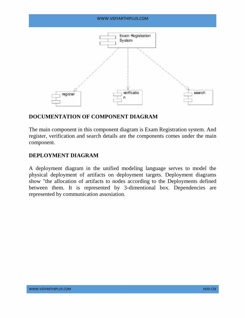
WWW.VIDYARTHIPLUS.COM
WWW.VIDYARTHIPLUS.COM HOD-CSE
DOCUMENTATION OF COMPONENT DIAGRAM
The main component in this component diagram is Exam Registration system. And
register, verification and search details are the components comes under the main
component.
DEPLOYMENT DIAGRAM
A deployment diagram in the unified modeling language serves to model the
physical deployment of artifacts on deployment targets. Deployment diagrams
show "the allocation of artifacts to nodes according to the Deployments defined
between them. It is represented by 3-dimentional box. Dependencies are
represented by communication assosiation.

WWW.VIDYARTHIPLUS.COM
WWW.VIDYARTHIPLUS.COM HOD-CSE
Exam Registration system Register verify search
DOCUMENTATION OF DEPLOYMENT DIAGRAM
The processor in this deployment diagram is the Exam Registration system which
is the main part and the devices are the register, verify and search which are the
some of the main activities performed in the system.
PACKAGE DIAGRAM
A package diagram in unified modeling language that depicts the dependencies
between the packages that make up a model. A Package Diagram (PD) shows a
grouping of elements in the OO model, and is a Cradle extension to UML. PDs can
be used to show groups of classes in Class Diagrams (CDs), groups of components
or processes in Component Diagrams (CPDs), or groups of processors in
Deployment Diagrams (DPDs).
There are three types of layer. They are
o User interface layer
o Domain layer

WWW.VIDYARTHIPLUS.COM
WWW.VIDYARTHIPLUS.COM HOD-CSE
o Technical services layer
DOCUMENTATION OF PACKAGE DIAGRAM The three layers in the online recruitment system are
a. The User interface layer - consists of the form and login. This layer
describes how the applicant logins to the search and apply for the
exam.
b. The Domain layer – shows the activities that are performed in the
Exam Registration system. The activities are register and search the
database.
c. The Technical service layer – get student details and the selected
applicant details are stored in the database.
FORMS
FORM 1
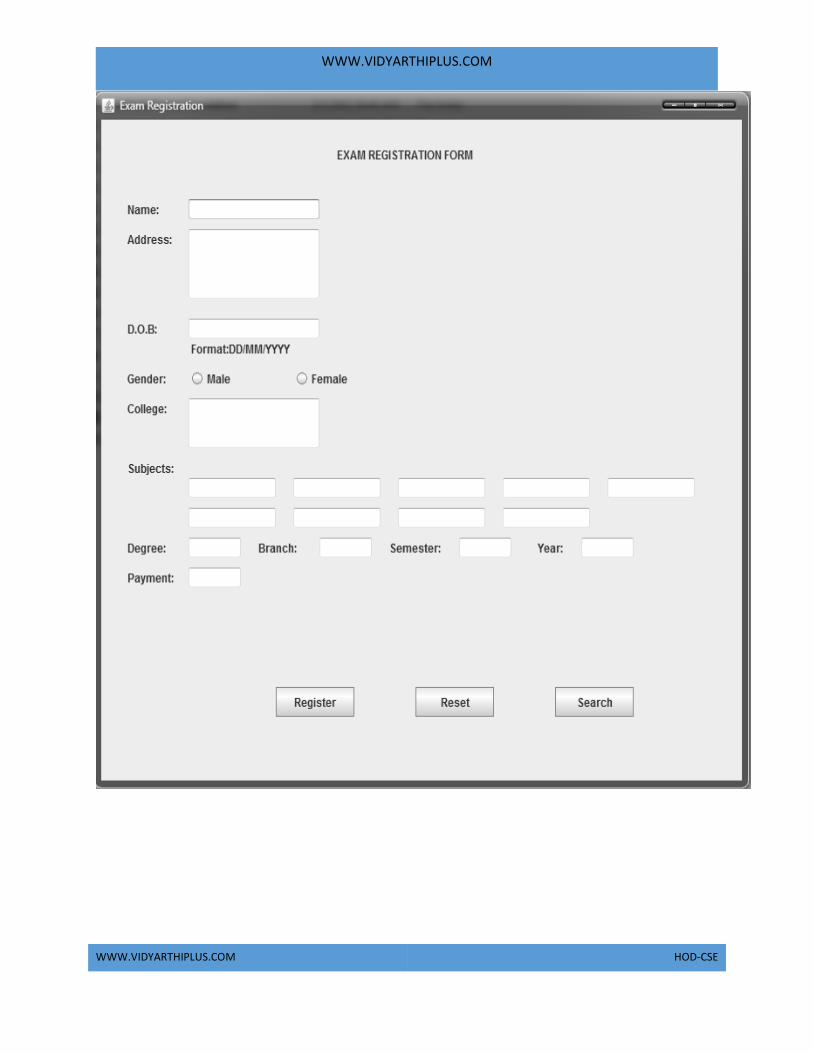
WWW.VIDYARTHIPLUS.COM
WWW.VIDYARTHIPLUS.COM HOD-CSE

WWW.VIDYARTHIPLUS.COM
WWW.VIDYARTHIPLUS.COM HOD-CSE
FORM 2

WWW.VIDYARTHIPLUS.COM
WWW.VIDYARTHIPLUS.COM HOD-CSE

WWW.VIDYARTHIPLUS.COM
WWW.VIDYARTHIPLUS.COM HOD-CSE
FORM 4

WWW.VIDYARTHIPLUS.COM
WWW.VIDYARTHIPLUS.COM HOD-CSE
FORM 5

WWW.VIDYARTHIPLUS.COM
WWW.VIDYARTHIPLUS.COM HOD-CSE
FORM 6

WWW.VIDYARTHIPLUS.COM
WWW.VIDYARTHIPLUS.COM HOD-CSE
Source Code import javax.swing.JButton;
import javax.swing.JFrame;
import javax.swing.JPanel;
import javax.swing.SwingUtilities;

WWW.VIDYARTHIPLUS.COM
WWW.VIDYARTHIPLUS.COM HOD-CSE
import javax.swing.*;
import java.awt.event.*;
import java.io.*;
import java.awt.*;
import java.sql.*;
public class ExamRegist extends JPanel implements ActionListener {
JLabel mn,l1,l2,l3,nt,l4,l5,l6,l7,l8,l9,l10,l11;
JRadioButton r1,r2;
TextField t1,t2,t3,t5,t6,t7,t8,t9,t10,t11,t12,t13,t14,t15,t16,t17,t18,t19;
JButton b1,b2,b3;
String s;
static JPasswordField pw;
public ExamRegist()
{
mn = new JLabel("EXAM REGISTRATION FORM");
l1 = new JLabel("Name:"); t1 = new TextField(20);
l2 = new JLabel("Address:"); t2 = new TextField(120);
l3 = new JLabel("D.O.B:"); t3 = new TextField(1);
nt = new JLabel(" Format:DD/MM/YYYY");
l4 = new JLabel("Gender:");
ButtonGroup rg=new ButtonGroup();
r1 = new JRadioButton("Male"); rg.add(r1);
r2 = new JRadioButton("Female"); rg.add(r2);
l5 = new JLabel("College:"); t5 = new TextField(50);
l6 = new JLabel("Subjects:");
t6 = new TextField(15); t7 = new TextField(15);
t8 = new TextField(15); t9 = new TextField(15);
t10 = new TextField(15); t11 = new TextField(15);
t12 = new TextField(15); t13 = new TextField(15);
t14 = new TextField(15);
l7 = new JLabel("Degree:"); t15 = new TextField(10);
l8 = new JLabel("Branch:"); t16 = new TextField(10);
l9 = new JLabel("Semester:"); t17 = new TextField(10);
l10 = new JLabel("Year:"); t18 = new TextField(10);
l11 = new JLabel("Payment:"); t19 = new TextField(10);
b1 = new JButton("Register"); b2 = new JButton("Reset");
b3=new JButton("Search");
pw=new JPasswordField(20);
b1.addActionListener(this);

WWW.VIDYARTHIPLUS.COM
WWW.VIDYARTHIPLUS.COM HOD-CSE
b2.addActionListener(this);

WWW.VIDYARTHIPLUS.COM
WWW.VIDYARTHIPLUS.COM HOD-CSE
b3.addActionListener(this);
r1.addActionListener(this);
r2.addActionListener(this);
setLayout(null);
add(mn);
add(l1); add(t1);
add(l2); add(t2);
add(l3); add(t3);
add(nt);
add(l4); add(r1); add(r2);
add(l5); add(t5);
add(l6); add(t6); add(t7); add(t8); add(t9);
add(t10); add(t11); add(t12); add(t13); add(t14);
add(l7); add(t15);
add(l8); add(t16);
add(l9); add(t17);
add(l10); add(t18);
add(l11); add(t19);
add(b1); add(b2); add(b3);
mn.setBounds(270,10,190,50);
l1.setBounds(30, 80, 50, 20);
t1.setBounds(100, 80, 150, 20);
l2.setBounds(30, 110, 60, 20);
t2.setBounds(100, 110, 150, 70);
l3.setBounds(30, 200, 50, 20);
t3.setBounds(100, 200, 150, 20);
nt.setBounds(100,220,150,20);
l4.setBounds(30, 250, 50, 20);
r1.setBounds(100,250,100,20);
r2.setBounds(220,250,100,20);
l5.setBounds(30, 280, 50, 20);
t5.setBounds(100, 280, 150, 50);
l6.setBounds(30, 340, 60, 20);
t6.setBounds(100, 360, 100, 20);
t7.setBounds(220, 360, 100, 20);
t8.setBounds(340, 360, 100, 20);
t9.setBounds(460, 360, 100, 20);
t10.setBounds(580, 360, 100, 20);
t11.setBounds(100, 390, 100, 20);

WWW.VIDYARTHIPLUS.COM
WWW.VIDYARTHIPLUS.COM HOD-CSE
t12.setBounds(220, 390, 100, 20);
t13.setBounds(340, 390, 100, 20);
t14.setBounds(460, 390, 100, 20);
l7.setBounds(30,420,50,20);
t15.setBounds(100,420,60,20);
l8.setBounds(180,420,50,20);
t16.setBounds(250,420,60,20);
l9.setBounds(330,420,60,20);
t17.setBounds(410,420,60,20);
l10.setBounds(500,420,50,20);
t18.setBounds(550,420,60,20);
l11.setBounds(30,450,60,20);
t19.setBounds(100,450,60,20);
b1.setBounds(200,570,90,30);
b2.setBounds(360,570,90,30);
b3.setBounds(520,570,90,30);
}
public void actionPerformed(ActionEvent evt)
{
String act = evt.getActionCommand();
boolean b;
if(b=r1.isSelected())
{
s= "Male";
}
else
{
s ="Female";
}
if(act.equals("Register"))
{
regop();
}
else if(act.equals("Reset"))
{
res();
}
if(evt.getSource()==b3)
{

WWW.VIDYARTHIPLUS.COM
WWW.VIDYARTHIPLUS.COM HOD-CSE
String str=JOptionPane.showInputDialog(ExamRegist.pw,"Enter Password","Staff
Login",JOptionPane.OK_OPTION);
if(str.equalsIgnoreCase("exm"))
{
JOptionPane.showMessageDialog(null, "You are successfully Logged In","Login
Successfull",JOptionPane.INFORMATION_MESSAGE);
new srch();
}
else
{
JOptionPane.showMessageDialog(null, "INVALID PASSWORD.","Password
Error",JOptionPane.INFORMATION_MESSAGE);
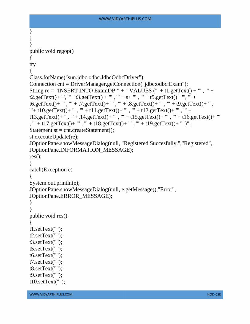
WWW.VIDYARTHIPLUS.COM
WWW.VIDYARTHIPLUS.COM HOD-CSE
}
}
}
public void regop()
{
try
{
Class.forName("sun.jdbc.odbc.JdbcOdbcDriver");
Connection cnt = DriverManager.getConnection("jdbc:odbc:Exam");
String re = "INSERT INTO ExamDB " + " VALUES ('" + t1.getText() + "' , '" +
t2.getText()+ "', '" +t3.getText() + "' , '" + s+ "' , '" + t5.getText()+ "', '" +
t6.getText()+ "' , '" + t7.getText()+ "' , '" + t8.getText()+ "' , '" + t9.getText()+ "',
'"+ t10.getText()+ "' , '" + t11.getText()+ "' , '" + t12.getText()+ "' , '" +
t13.getText()+ "', '" +t14.getText()+ "' , '" + t15.getText()+ "' , '" + t16.getText()+ "'
, '" + t17.getText()+ "' , '" + t18.getText()+ "' , '" + t19.getText()+ "' )";
Statement st = cnt.createStatement();
st.executeUpdate(re);
JOptionPane.showMessageDialog(null, "Registered Succesfully.","Registered",
JOptionPane.INFORMATION_MESSAGE);
res();
}
catch(Exception e)
{
System.out.println(e);
JOptionPane.showMessageDialog(null, e.getMessage(),"Error",
JOptionPane.ERROR_MESSAGE);
}
}
public void res()
{
t1.setText("");
t2.setText("");
t3.setText("");
t5.setText("");
t6.setText("");
t7.setText("");
t8.setText("");
t9.setText("");
t10.setText("");

WWW.VIDYARTHIPLUS.COM
WWW.VIDYARTHIPLUS.COM HOD-CSE
t11.setText("");
t12.setText("");
t13.setText("");
t14.setText("");
t15.setText("");
t16.setText("");
t17.setText("");
t18.setText("");
t19.setText("");
}

WWW.VIDYARTHIPLUS.COM
WWW.VIDYARTHIPLUS.COM HOD-CSE
public static void main(String[] args) {
JFrame frame = new JFrame();
frame.getContentPane().add(new ExamRegist());
frame.setTitle("Exam Registration");
frame.setDefaultCloseOperation(JFrame.EXIT_ON_CLOSE);
frame.setSize(750, 700);
frame.setVisible(true);
}
}
class srch extends JFrame implements ActionListener,ItemListener
{
JTable tab;
JLabel l;
JButton b1;
JComboBox ls;
JTextField f1;
Object res[][];
String sql,searchfield;
ResultSet rs,rs1;
int tval=0,tval1=0;
JScrollPane scr;
srch()
{
res=new Object[200][40];
Object
hs[]={"Name","Address","DOB","Gender","College","sub1","sub2","sub3","sub4"
,"sub5","sub6","sub7","sub8","sub9","Degree","Branch","Semester","Year","Paym
ent"};
tab=new JTable(res,hs);
scr=new JScrollPane(tab);
scr.setBackground(Color.WHITE);
b1=new JButton("Search");
l=new JLabel("Search Parameters");
f1=new JTextField();
String[] item={"Name","Address"};
ls=new JComboBox(item);
add(b1);
add(l);
add(scr);
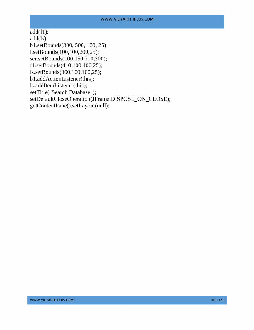
WWW.VIDYARTHIPLUS.COM
WWW.VIDYARTHIPLUS.COM HOD-CSE
add(f1);
add(ls);
b1.setBounds(300, 500, 100, 25);
l.setBounds(100,100,200,25);
scr.setBounds(100,150,700,300);
f1.setBounds(410,100,100,25);
ls.setBounds(300,100,100,25);
b1.addActionListener(this);
ls.addItemListener(this);
setTitle("Search Database");
setDefaultCloseOperation(JFrame.DISPOSE_ON_CLOSE);
getContentPane().setLayout(null);

WWW.VIDYARTHIPLUS.COM
WWW.VIDYARTHIPLUS.COM HOD-CSE
setSize(850,700);
setVisible(true);
}
public void actionPerformed(ActionEvent ev)
{
String s=(String)ls.getSelectedItem();
if(ev.getSource()==b1)
{
if(s.equals("Name"))
{
sql = "select * from ExamDB where Name='" + f1.getText() + "'";
}
else if(s.equals("Address"))
{
sql="select * from ExamDB where Address='" + f1.getText() + "'";
}
try
{
Class.forName("sun.jdbc.odbc.JdbcOdbcDriver");
Connection cnt1=DriverManager.getConnection("jdbc:odbc:Exam");
Statement st=cnt1.createStatement();
rs1=st.executeQuery(sql);
tval=0;
while(rs1.next())
{
tab.setValueAt(""+rs1.getString(1),tval,0);
tab.setValueAt(""+rs1.getString(2),tval,1);
tab.setValueAt(""+rs1.getString(3),tval,2);
tab.setValueAt(""+rs1.getString(4),tval,3);
tab.setValueAt(""+rs1.getString(5),tval,4);
tab.setValueAt(""+rs1.getString(6),tval,5);
tab.setValueAt(""+rs1.getString(7),tval,6);
tab.setValueAt(""+rs1.getString(8),tval,7);
tab.setValueAt(""+rs1.getString(9),tval,8);
tab.setValueAt(""+rs1.getString(10),tval,9);
tab.setValueAt(""+rs1.getString(11),tval,10);
tab.setValueAt(""+rs1.getString(12),tval,11);
tab.setValueAt(""+rs1.getString(13),tval,12);
tab.setValueAt(""+rs1.getString(14),tval,13);

WWW.VIDYARTHIPLUS.COM
WWW.VIDYARTHIPLUS.COM HOD-CSE
tab.setValueAt(""+rs1.getString(15),tval,14);
tab.setValueAt(""+rs1.getString(16),tval,15);
tab.setValueAt(""+rs1.getString(17),tval,16);
tab.setValueAt(""+rs1.getString(18),tval,17);
tab.setValueAt(""+rs1.getString(19),tval,18);
tval++;
}
if(tval==0)
{
JOptionPane.showMessageDialog(b1, "Registration not avialable","Error",
JOptionPane.ERROR_MESSAGE);
}

WWW.VIDYARTHIPLUS.COM
WWW.VIDYARTHIPLUS.COM HOD-CSE
}
catch(Exception el)
{
System.out.println(el);
JOptionPane.showMessageDialog(b1, "Sorry,Database Problem","Error",
JOptionPane.ERROR_MESSAGE);
}
}
}
public void itemStateChanged(ItemEvent ie)
{
f1.setText("");
for(int i=0;i<tval;i++)
{
tab.setValueAt("",i,0);
tab.setValueAt("",i,1);
tab.setValueAt("",i,2);
tab.setValueAt("",i,3);
tab.setValueAt("",i,4);
tab.setValueAt("",i,5);
tab.setValueAt("",i,6);
tab.setValueAt("",i,7);
tab.setValueAt("",i,8);
tab.setValueAt("",i,9);
tab.setValueAt("",i,10);
tab.setValueAt("",i,11);
tab.setValueAt("",i,12);
tab.setValueAt("",i,13);
tab.setValueAt("",i,14);
tab.setValueAt("",i,15);
tab.setValueAt("",i,16);
tab.setValueAt("",i,17);
tab.setValueAt("",i,18);
}
searchfield=""+ie.getItem();
}
}
RESULT

WWW.VIDYARTHIPLUS.COM
WWW.VIDYARTHIPLUS.COM HOD-CSE
Thus the project to develop Exam Registration system using Rational Rose
Software and to implement the software in Java is done successfully.
Ex. No: 4a STOCK MAINTENANCE SYSTEM
AIM
To develop a project stock maintenance system using Rational Rose Software and
to implement the software in Visual Basic.
PROBLEM ANALYSIS AND PROJECT PLANNING
The Stock Maintenance System, initial requirement to develop the project about
the mechanism of the Stock Maintenance System is caught from the customer. The
requirement are analyzed and refined which enables the end users to efficiently use
Stock Maintenance System. The complete project is developed after the whole
project analysis explaining about the scope and the project statement is prepared.
PROBLEM STATEMENT
The process of stock maintenance system is that the customer login to the
particular site to place the order for the customer product. The stock maintenance
system are described sequentially through steps
a. The customer login to the particular site.
b. They fill the customer details.
c. They place the orders for their product.
d. The vendor login and views the customer details and orders.
SOFTWARE REQUIREMENT SPECIFICATION
S.NO CONTENT
1 INTRODUCTIO

WWW.VIDYARTHIPLUS.COM
WWW.VIDYARTHIPLUS.COM HOD-CSE
N
2 OBJECTIVE
3 OVERVIEW
4 GLOSSARY
5 PURPOSE
6 SCOPE
7 FUNCTIONALI
TY
8 USABILITY
9 PERFORMANC
E
10 RELIABILITY
11 FUNCTIONAL
REQUIRMENTS
1. INTRODUCTION
This software specification documents full set of features and function for online
stock maintenance system that is performed in company website. In this we give
specification about the customer orders. It tells the usability, reliability defined in
use case specification.
2. OBJECTIVE
The main objective of the stock maintenance system is to maintain the stock. It
provides the vendor to maintain the stock in an precise manner.
3. OVERVIEW
The overview of the project is to design an online tool for the recruitment process
which eases the work for the customer as well as the companies. Companies can
create their company forms according to their wish in which the applicant can
register.
4. GLOSSARY
TERMS DESCRIPTION

WWW.VIDYARTHIPLUS.COM
WWW.VIDYARTHIPLUS.COM HOD-CSE
CUSTOMER The customer can have the username
and password after login to the
system. After login they directed to
fill the customer details. And the
customer places their order. After
placing orders they lead to verify all
the details in a single form. Then
they places the order successfully.
VENDOR Vendor has the login id. After login
vendor verify the customer details
and orders. And maintain the stocks.
DATABASE Database is used to verify the
customer details and orders.
SOFTWARE REQUIREMENT
SPECIFICATION
This software specification
documents full set of features and
function for stock maintenance
system that is performed in
company website.
5. PURPOSE
The purpose of stock maintenance system is to maintain the stock in an precise
manner.
6. SCOPE
The scope of this stock maintenance system is to maintain the stock.
7. FUNCTIONALITY
The main functionality of the stock maintenance system is to maintain the stock.
8. USABILITY
User interface makes the stock maintenance system to be efficient. That is the
system will help the customer to place the details and orders easily and helps the
vendor to maintain the stock accurate. The system should be user friendly.

WWW.VIDYARTHIPLUS.COM
WWW.VIDYARTHIPLUS.COM HOD-CSE
9. PERFORMANCE
It describes the capability of the system to maintain the stock without any loss of
stock and performing it efficiently.
10. RELIABILITY
The stock maintenance system should be able to maintain the stock with correct
updates from day to day placement of new orders from customer.
11. FUNCTIONAL REQUIREMENTS
Functional requirements are those refer to the functionality of the system. That is
the services that are provided to the customer who places the orders.
UML DIAGRAMS
The following UML diagrams describe the process involved in the online
recruitment system
a. Use case diagram
b. Class diagram
c. Sequence diagram
d. Collaboration diagram
e. State chart diagram
f. Activity diagram
g. Component diagram
h. Deployment diagram
i. Package diagram
USE CASE DIAGRAM
A use case is a methodology used in system analysis to identify, clarify, and
organize system requirements. The use case is made up of a set of possible

WWW.VIDYARTHIPLUS.COM
WWW.VIDYARTHIPLUS.COM HOD-CSE
sequences of interactions between systems and users in a particular environment
and related to a particular goal. It is represented using ellipse.
Actor is any external entity that makes use of the system being modeled. It is
represented using stick figure.
DOCUMENTATION OF USE CASE DIAGRAM
The actors in this use case diagram are customer, vendor and database. The use
cases are the activities performed by actors.
CUSTOMER:
a. Customer logins to the particular system and fills the customer details
and places the orders.
2. DATABASE:
a. All the details and orders given by customer are updated in the
database.
3. VENDOR:

WWW.VIDYARTHIPLUS.COM
WWW.VIDYARTHIPLUS.COM HOD-CSE
a. Vendor logins and verify the customer orders and the stock details.
CLASS DIAGRAM
A class diagram in the unified modeling language (UML) is a type of static
structure diagram that describes the structure of a system by showing the system's
classes, their attributes, and the relationships between the classes. It is represented
using a rectangle with three compartments. Top compartment have the class name,
middle compartment the attributes and the bottom compartment with operations.
DOCUMENTATION OF CLASS DIAGRAM
1. This class diagram has three classes’ customer, vendor and database.
a. Customer – is the class name. Its attributes are username, password,
name, phone no and address. The operations performed in the
customer class are login and places the orders.
b. Vendor – is the class name. Its attributes are views the database.

WWW.VIDYARTHIPLUS.COM
WWW.VIDYARTHIPLUS.COM HOD-CSE
c. Database – is the class name. The operations performed are storing
customer details, and their orders.
SEQUENCE DIAGRAM
A sequence diagram in Unified Modeling Language (UML) is a kind of interaction
diagram that shows how processes operate with one another and in what order. It is
a construct of a Message Sequence Chart. There are two dimensions.
1. Veritcal dimension-represent time.
2. Horizontal dimension-represent different objects.
DOCUMENTATION OF SEQUENCE DIAGRAM The sequence diagram describes the sequence of steps to show
o The customer login in to the system and fills the customer details.
o Then the customer places the order. It updated to the database.

WWW.VIDYARTHIPLUS.COM
WWW.VIDYARTHIPLUS.COM HOD-CSE
o The vendor login to the system and views the customer orders and the
stock details.
COLLABRATION DIAGRAM
A collaboration diagram, also called a communication diagram or interaction
diagram,. A sophisticated modeling tool can easily convert a collaboration diagram
into a sequence diagram and the vice versa. A collaboration diagram resembles a
flowchart that portrays the roles, functionality and behavior of individual objects as
well as the overall operation of the system in real time
DOCUMENTATION OF COLLABRATION DIAGRAM

WWW.VIDYARTHIPLUS.COM
WWW.VIDYARTHIPLUS.COM HOD-CSE
The collaboration diagram is to show how the customer login and places the orders
in the system. Here the sequence is numbered according to the flow of execution.
STATE CHART DIAGRAM
The purpose of state chart diagram is to understand the algorithm involved in
performing a method. It is also called as state diagram. A state is represented as a
round box, which may contain one or more compartments. An initial state is
represented as small dot. An final state is represented as circle surrounding a small
dot.

WWW.VIDYARTHIPLUS.COM
WWW.VIDYARTHIPLUS.COM HOD-CSE
DOCUMENTATION OF STATE CHART DIAGRAM
This state diagram describes the behavior of the system.
• First state is login where the customer login to the system.
• The next state is to fill the customer details.

WWW.VIDYARTHIPLUS.COM
WWW.VIDYARTHIPLUS.COM HOD-CSE
• And the next state is to place the orders.
Update database with the orders and details of customer
ACTIVITY DIAGRAM
Activity diagrams are graphical representations of workflows of stepwise activities
and actions with support for choice, iteration and concurrency. In the Unified
Modeling Language, activity diagrams can be used to describe the business and
operational step-by-step workflows of components in a system. An activity
diagram shows the overall flow of control. An activity is shown as an rounded box
containing the name of the operation.
DOCUMENTATION OF ACTIVITY DIAGRAM
This activity diagram flow of stepwise activities performed in stock maintenance
system.
First the customer login then fills the details.

WWW.VIDYARTHIPLUS.COM
WWW.VIDYARTHIPLUS.COM HOD-CSE
a. The customer places the order according to their needs.
b. After placing the order the database is updated.
c. Vendor login to the system and verifies the customer orders and stock
details.
COMPONENT DIAGRAM
The component diagram's main purpose is to show the structural relationships
between the components of a systems. It is represented by boxed figure.
Dependencies are represented by communication assosiation.
DOCUMENTATION OF COMPONENT DIAGRAM
The main component in this component diagram is stock maintenance systems.
And customer database details and update database then vendor views the database
are the components comes under the main component.

WWW.VIDYARTHIPLUS.COM
WWW.VIDYARTHIPLUS.COM HOD-CSE
DEPLOYMENT DIAGRAM
A deployment diagram in the unified modeling language serves to model the
physical deployment of artifacts on deployment targets. Deployment diagrams
show "the allocation of artifacts to nodes according to the Deployments defined
between them. It is represented by 3-dimentional box. Dependencies are
represented by communication assosiation.
DOCUMENTATION OF DEPLOYMENT DIAGRAM
The processor in this deployment diagram is the stock maintenance system which
is the main part and the devices are the filling customer details and placing orders
then vendor views which are the some of the main activities performed in the
system.
PACKAGE DIAGRAM
A package diagram in unified modeling language that depicts the dependencies
between the packages that make up a model. A Package Diagram (PD) shows a
grouping of elements in the OO model, and is a Cradle extension to UML. PDs can
be used to show groups of classes in Class Diagrams (CDs), groups of components
or processes in Component Diagrams (CPDs), or groups of processors in
Deployment Diagrams (DPDs).
There are three types of layer. They are
1. User interface layer Software objects representing domain concepts that fulfill application
reqirements, such as calculation of a sale total.
2. Domain layer Layer that contains domain objects to handle application logic work
3. Technical services layer
General purpose object and sub system that provide supporting technical
services, such as interfacing with a database logging

WWW.VIDYARTHIPLUS.COM
WWW.VIDYARTHIPLUS.COM HOD-CSE
DOCUMENTATION OF PACKAGE DIAGRAM The three layers in the online recruitment system are
o The User interface layer - consists of the web and login. This layer
decribes how the applicant logins to the website and places the order.
o The Domain layer – shows the activities that are performed by the
customer to place the orders.
o The Technical service layer - the vendor logins and verifies the
customer orders and stock details

WWW.VIDYARTHIPLUS.COM
WWW.VIDYARTHIPLUS.COM HOD-CSE
FORMS
FORM 1

WWW.VIDYARTHIPLUS.COM
WWW.VIDYARTHIPLUS.COM HOD-CSE
FORM 2

WWW.VIDYARTHIPLUS.COM
WWW.VIDYARTHIPLUS.COM HOD-CSE
FORM 3

WWW.VIDYARTHIPLUS.COM
WWW.VIDYARTHIPLUS.COM HOD-CSE
FORM 4

WWW.VIDYARTHIPLUS.COM
WWW.VIDYARTHIPLUS.COM HOD-CSE
FORM 5

WWW.VIDYARTHIPLUS.COM
WWW.VIDYARTHIPLUS.COM HOD-CSE

WWW.VIDYARTHIPLUS.COM
WWW.VIDYARTHIPLUS.COM HOD-CSE
FORM 6
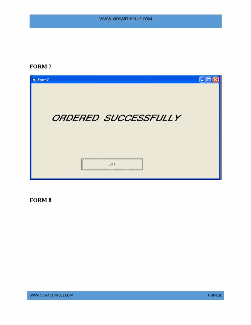
WWW.VIDYARTHIPLUS.COM
WWW.VIDYARTHIPLUS.COM HOD-CSE
FORM 7
FORM 8

WWW.VIDYARTHIPLUS.COM
WWW.VIDYARTHIPLUS.COM HOD-CSE
SOURCE CODE CUSTOMER
Option Explicit
'##ModelId=4D47C9A90242
Private cust_name As Variant
'##ModelId=4D47C9B100EA
Private address As Variant
'##ModelId=4D47C9B5008C
Private phone_no As Variant
'##ModelId=4D47C93A008C
Public NewProperty As placing_orders
'##ModelId=4D47C947006D
Public NewProperty2 As database3
'##ModelId=4D47C98A01E4
Public NewProperty3 As database3
'##ModelId=4D47C98D036B
Public NewProperty4 As placing_orders
'##ModelId=4D47C9C00186

WWW.VIDYARTHIPLUS.COM
WWW.VIDYARTHIPLUS.COM HOD-CSE
Public Sub submit()
End Sub
FORM 1
SUBMIT BUTTON
Private Sub Command1_Click()
Form6.Text1.Text = Form1.sgs.Text
Form6.Text2.Text = Form1.Text2.Text
Form6.Text3.Text = Form1.Text3.Text
Form2.Show
End Sub
EXIT BUTTON
Private Sub Command2_Click()
Unload Me
End Sub
PLACING ORDERS Option Explicit
'##ModelId=4D47C9FE00AB
Private select_goods As Variant
'##ModelId=4D47C93D031C
Public NewProperty As database3
'##ModelId=4D47C9910222
Public NewProperty2 As database3
'##ModelId=4D47CA0E0232
Public Sub submit()
End Sub
FORM 2 SUBMIT COMMAND
Private Sub Command1_Click()
Dim p As placing_orders
Set p = New placing_orders
p.submit
End Sub
Public Sub submit()
If (Form2.Combo1.Text = "MONITOR") Then
Form6.Text4.Text = Form2.Combo1.Text
Form3.Show
End If
If (Form2.Combo1.Text = "HARD DISC") Then
Form6.Text4.Text = Form2.Combo1.Text

WWW.VIDYARTHIPLUS.COM
WWW.VIDYARTHIPLUS.COM HOD-CSE
Form4.Show
End If
If (Form2.Combo1.Text = "KEYBOARD") Then
Form6.Text4.Text = Form2.Combo1.Text
Form5.Show
End If
End Sub
DATABASE '##ModelId=4D47C9A90242
Private cust_name As Variant
'##ModelId=4D47C9B100EA
Private address As Variant
'##ModelId=4D47C9B5008C
Private phone_no As Variant
'##ModelId=4D47C93A008C
Public NewProperty As placing_orders
'##ModelId=4D47C947006D
Public Sub submit()
End Sub
FORM 8 Private Sub Command1_Click()
Form2.Show
End Sub
Private Sub Command2_Click()
Text1.Text = Text1.Text - Text3.Text
Adodc1.Recordset.Fields(2) = Text1.Text
Form6.Text5.Text = Form5.Label2
Form6.Text6.Text = Form5.Text3.Text
Form6.Show
Form8.Text11.Text = Form3.Text1.Text
Adodc1.Recordset.Update
End Sub
Private Sub Command3_Click()
Text2.Text = Text2.Text - Text4.Text
Adodc1.Recordset.Fields(3) = Text2.Text
Form6.Text5.Text = Form5.Label3
Form6.Text6.Text = Form5.Text4.Text
Form6.Show
Form8.Text12.Text = Form3.Text2.Text

WWW.VIDYARTHIPLUS.COM
WWW.VIDYARTHIPLUS.COM HOD-CSE
Adodc1.Recordset.Update
End Sub
RESULT Thus the project stock maintenance system using Rational Rose Software and
implement the software in Visual Basic is executed successfully.

WWW.VIDYARTHIPLUS.COM
WWW.VIDYARTHIPLUS.COM HOD-CSE
EX.NO:4b STOCK MAINTENANCE SYSTEM
AIM
To develop a project Stock Maintenance system using Rational Rose Software and
to implement the software in Java.
PROBLEM ANALYSIS AND PROJECT PLANNING
Stock Maintenance gives an idea about how products are maintained in the
particular concern. The products that are to be purchased, the products that are to
be sold are maintained here. This project also gives idea about the faults in the
purchased product and the products that are to be replaced also been given. Further
some additional details of the current stock that is available in the store are also
given. Stock maintenance in this project is done in an authorized way. The
password and user id has been set here. As a whole the marketing process can be
improved if the stock is maintained properly.
PROBLEM STATEMENT
The stock has to be maintained properly since the whole marketing process can be
improved. Stock maintenance in this project gives the idea about how products are
maintained in a particular concern. The stock details which includes the amount of
stock available, the stock is to be purchased, the date or the time it is being bought
or delivered, the amount that is already available are maintained in this project.
Stock maintenance system the stock maintenance in this project is understood by
going through the modules that is being involved. The whole economic status is
being improved properly if stock is maintained.
SOFTWARE REQUIREMENT SPECIFICATION 1 INTRODUCTION
2 OBJECTIVE
3 OVERVIEW

WWW.VIDYARTHIPLUS.COM
WWW.VIDYARTHIPLUS.COM HOD-CSE
4 GLOSSARY
5 PURPOSE
6 SCOPE
7 FUNCTIONALITY
8 USABILITY
9 PERFORMANCE
10 RELIABILITY
11 FUNCTIONAL
REQUIREMENTS
1. INTRODUCTION
Stock Maintenance gives an idea about how products are maintained in the
particular concern. The products that are to be purchased, the products that are to
be sold are maintained here. This project also gives idea about the faults in the
purchased product and the products that are to be replaced also been given. Further
some additional details of the current stock that is available in the store is also
given. Stock maintenance in this project is done in an authorized way.
2. OBJECTIVE
The main objective of this project is to overcome the work load and time
consumption which makes the maintenance of the stock in an organization as a
tedious process. This project provides complete information about the details of the
stock to the users. This project identifies the amount of stock available, the product
that is purchased faults in the product, products that are replaced, products that
have been sold, and the date at which the products are bought and sold in a
particular concern. Separate modules have been created for purchasing, viewing
stock details, selling, details and delivery details.
3. OVERVIEW
The overview of the project is to Storing of information about the stock values and
updating the stock values for each organization which is using this system, keeps
track of all the information about the stock exchange that are made by the
customers, having registration feature of adding up new customers to the
organization are provided in this system.
4. GLOSSARY

WWW.VIDYARTHIPLUS.COM
WWW.VIDYARTHIPLUS.COM HOD-CSE
TERMS DESCRIPTION
SUPPLIER Supplier will get order from the store
keeper and he will supply the stock as
ordered.
STORE KEEPER Store keeper will purchase the supplies
from the supplier and will be updating
the stock details in the database.
DATABASE Database is used to store the details of
stock.
ADMIN Handles all the support features and the
technical works in the application.
SOFTWARE REQUIREMENT
SPECIFICATION
This software specification documents
full set of features and function for stock
management system that is performed in
application.
5. PURPOSE
The purpose of stock management system is to store and maintain the stock details
in a store effectively.
6. SCOPE
The scope of this Stock maintenance is to maintain the stock details after the
purchase and re stocking from the supplier.
7. FUNCTIONALITY
The main functionality of stock maintenance system is to store the stock details for
a store.
8. USABILITY
User interface makes the stock maintenance system to be efficient. That is the
system will help the admin to maintain stock details easily and helps the store to
handle the stocks effectively. The system should be user friendly.
9. PERFORMANCE

WWW.VIDYARTHIPLUS.COM
WWW.VIDYARTHIPLUS.COM HOD-CSE
It describes the capability of the system to perform the stock maintenance system
of the store without any error and performing it efficiently.
10. RELIABILITY
The stock maintenance system should be able to serve the store keeper with correct
information and day-to-day update of stock details.
11. FUNCTIONAL REQUIREMENTS
Functional requirements are those refer to the functionality of the system. That is
the services that are provided to the storekeeper who maintains stocks in a store.
UML DIAGRAMS
The following UML diagrams describe the process involved in the stock
maintenance system
a. Use case diagram
b. Class diagram
c. Sequence diagram
d. Collaboration diagram
e. State chart diagram
f. Activity diagram
g. Component diagram
h. Deployment diagram
i. Package diagram
USE CASE DIAGRAM
A use case is a methodology used in system analysis to identify, clarify, and
organize system requirements. The use case is made up of a set of possible
sequences of interactions between systems and users in a particular environment
and related to a particular goal. It is represented using ellipse.

WWW.VIDYARTHIPLUS.COM
WWW.VIDYARTHIPLUS.COM HOD-CSE
Actor is any external entity that makes use of the system being modelled. It is
represented using stick figure.
DOCUMENTATION OF USE CASE DIAGRAM
The actors in this use case diagram are Supplier, Store Keeper and Database. The
usecases are the activities performed by actors.
a. Supplier will supply the items according to the quotation which will
be purchased by the store keeper.
b. Store keeper will login and update the stock in the database.
c. The database will be updated according to the purchase done and it
will be up to date.
2. The use cases in the use case diagram are Quotation & Purchase, login,
stock, purchase.
a. Quotation & Purchase will gives us the status of the quotation details
and the purchase order details
b. Login will gives us the entry for the user of this project.
c. Stock will gives us the details about the total stock available.
d. Purchase will gives us the details about the details and the history of
items purchased.
CLASS DIAGRAM
A class diagram in the unified modeling language (UML) is a type of static
structure diagram that describes the structure of a system by showing the system's
classes, their attributes, and the relationships between the classes. It is represented
using a rectangle with three compartments. Top compartment have the class name,
middle compartment the attributes and the bottom compartment with operations.

WWW.VIDYARTHIPLUS.COM
WWW.VIDYARTHIPLUS.COM HOD-CSE
DOCUMENTATION OF CLASS DIAGRAM
1. This class diagram has three classes applicant, recruiter and database.
a. Supplier – is the class name. Its attributes are id, name, address and
payment mode. The operations performed in the Supplier class are get
order, supply goods and get money.
b. Storekeeper – is the class name. Its attributes are id, name, Dob,
Designation, salary, user id and password. The operations performed
are check stock, give order, receive goods and give money.
c. Database – is the class name. Its attributes are product name, license,
expiry date and updates. The operations performed are store details,
update, insert, delete, verify and display.
d. Admin – is the class name. Its attributes are id, name, Dob, user id
and password. The operations performed are update the s\w,
troubleshoot and manage the queries.
SEQUENCE DIAGRAM
A sequence diagram in Unified Modeling Language (UML) is a kind of interaction
diagram that shows how processes operate with one another and in what order. It is
a construct of a Message Sequence Chart. There are two dimensions.
1.Veritcal dimension-represent time.
2.Horizontal dimension-represent different objects.
DOCUMENTATION OF SEQUENCE DIAGRAM
The sequence diagram describes the sequence of steps to show

WWW.VIDYARTHIPLUS.COM
WWW.VIDYARTHIPLUS.COM HOD-CSE
a. The store keeper checks the stock.
b. Gives order to the supplier.
c. Supplier supplies the goods.
d. Store keeper checks the goods.
e. Database provides user id and pass.
f. Store keeper updates the stock and stores it in database.
g. Pay money to the Supplier.
COLLABORATION DIAGRAM
A collaboration diagram, also called a communication diagram or interaction
diagram,. A sophisticated modeling tool can easily convert a collaboration diagram
into a sequence diagram and the vice versa. A collaboration diagram resembles a
flowchart that portrays the roles, functionality and behavior of individual objects as
well as the overall operation of the system in real time
DOCUMENTATION OF COLLABORATION DIAGRAM
The first collaboration diagram is to show how the applicant login and storing
stock details in the stock maintenance system. Here the sequence is numbered
according to the flow of execution.
STATE CHART DIAGRAM
The purpose of state chart diagram is to understand the algorithm involved in
performing a method. It is also called as state diagram. A state is represented as a
round box, which may contain one or more compartments. An initial state is
represented as small dot. A final state is represented as circle surrounding a small
dot.

WWW.VIDYARTHIPLUS.COM
WWW.VIDYARTHIPLUS.COM HOD-CSE
DOCUMENTATION OF STATE CHART DIAGRAM
This state diagram describes the behavior of the system.
a. First state is login where the storekeeper login to the stock
maintenance system.
b. The next state is check the stock followed by giving order.
c. Then purchase the goods.
d. The store keeper check the goods.
e. Update database with goods purchased.
f. Pay money for the purchased goods.

WWW.VIDYARTHIPLUS.COM
WWW.VIDYARTHIPLUS.COM HOD-CSE
ACTIVITY DIAGRAM
Activity diagrams are graphical representations of workflows of stepwise activities
and actions with support for choice, iteration and concurrency. In the Unified
Modeling Language, activity diagrams can be used to describe the business and
operational step-by-step workflows of components in a system. An activity
diagram shows the overall flow of control. An activity is shown as an rounded box
containing the name of the operation.
DOCUMENTATION OF ACTIVITY DIAGRAM
This activity diagram flow of stepwise activities performed in recruitment system.
a. First the storekeeper login then checks stock.
b. The stock details are verified and the order is given.
c. Goods are purchased.
d. Products are checked.
e. Update the stock details in the database.
COMPONENT DIAGRAM
The component diagram's main purpose is to show the structural relationships
between the components of a systems. It is represented by boxed figure.
Dependencies are represented by communication association.

WWW.VIDYARTHIPLUS.COM
WWW.VIDYARTHIPLUS.COM HOD-CSE
Stock Maintenance system purchase verify store
DOCUMENTATION OF COMPONENT DIAGRAM
The main component in this component diagram is stock maintenance systems.
And Supplier, storekeeper and database are the components come under the main
component.
DEPLOYMENT DIAGRAM
A deployment diagram in the unified modeling language serves to model the
physical deployment of artifacts on deployment targets. Deployment diagrams
show "the allocation of artifacts to nodes according to the Deployments defined
between them. It is represented by 3-dimentional box. Dependencies are
represented by communication association.
DOCUMENTATION OF DEPLOYMENT DIAGRAM
The processor in this deployment diagram is the stock maintenance system which
is the main part and the devices are the purchase, verify and store which are the
some of the main activities performed in the system.
PACKAGE DIAGRAM

WWW.VIDYARTHIPLUS.COM
WWW.VIDYARTHIPLUS.COM HOD-CSE
A package diagram in unified modeling language that depicts the dependencies
between the packages that make up a model. A Package Diagram (PD) shows a
grouping of elements in the OO model, and is a Cradle extension to UML. PDs can
be used to show groups of classes in Class Diagrams (CDs), groups of components
or processes in Component Diagrams (CPDs), or groups of processors in
Deployment Diagrams (DPDs).
There are three types of layer. They are
a. User interface layer: consists of the form and login. This layer
describes how the storekeeper logins and maintains the stock.
b. Domain layer: shows the activities that are performed in the stock
maintenance system. The activities are purchased stock, database
verification.
c. Technical services layer: the update stock details, verification stock
details and stored in the database.

WWW.VIDYARTHIPLUS.COM
WWW.VIDYARTHIPLUS.COM HOD-CSE

WWW.VIDYARTHIPLUS.COM
WWW.VIDYARTHIPLUS.COM HOD-CSE
FORMS
FORM 1
FORM 2

WWW.VIDYARTHIPLUS.COM
WWW.VIDYARTHIPLUS.COM HOD-CSE
FORM 3
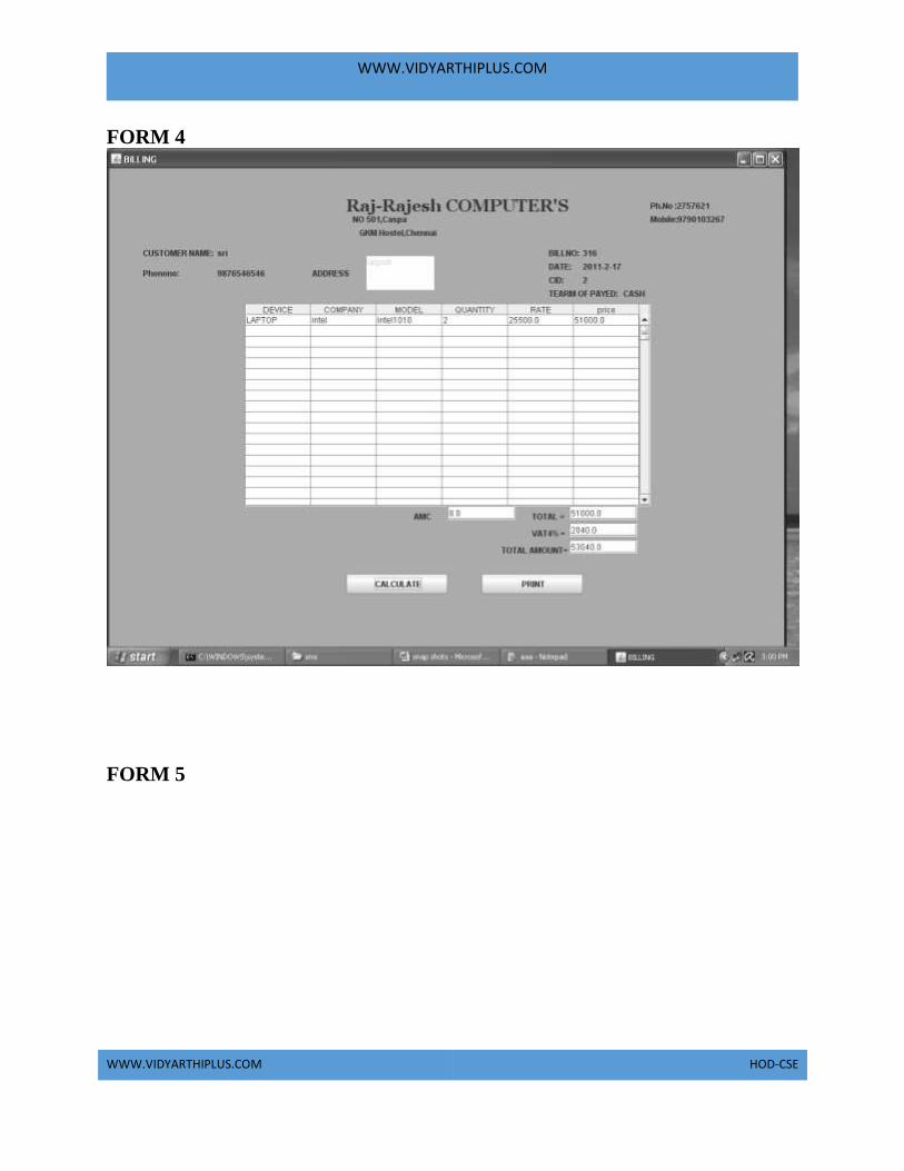
WWW.VIDYARTHIPLUS.COM
WWW.VIDYARTHIPLUS.COM HOD-CSE
FORM 4
FORM 5

WWW.VIDYARTHIPLUS.COM
WWW.VIDYARTHIPLUS.COM HOD-CSE
FORM 6

WWW.VIDYARTHIPLUS.COM
WWW.VIDYARTHIPLUS.COM HOD-CSE
FORM 7
FORM 8

WWW.VIDYARTHIPLUS.COM
WWW.VIDYARTHIPLUS.COM HOD-CSE
SOURCE CODE import javax.swing.*;
import java.awt.*;
import java.awt.event.*;
import java.util.*;
import java.sql.*;
import javax.swing.table.*;
import java.util.*;
import java.text.*;
import javax.swing.text.*;
import javax.swing.DefaultCellEditor;

WWW.VIDYARTHIPLUS.COM
WWW.VIDYARTHIPLUS.COM HOD-CSE
import javax.swing.JComboBox;
import javax.swing.JFrame;
import javax.swing.JScrollPane;
import javax.swing.JTable;
import javax.swing.table.AbstractTableModel;
import java.awt.print.*;
import java.awt.Font;
import java.awt.Graphics;
import java.awt.Graphics2D;
import java.awt.print.PageFormat;
import java.awt.print.Printable;
import java.awt.print.PrinterException;
import java.awt.print.PrinterJob;
import javax.swing.table.TableModel;
class Home extends JFrame implements ActionListener,ItemListener
{
JButton nxt,ext;
JRadioButton sale,service,emp,cus,pur;
JLabel hd;
Container con;
String st="nil",st1,sql,srno;
static String sspno;
Home()
{
hd=new JLabel("HOME");
Font f1=new Font("Georgia",1,25);
hd.setFont(f1);
ImageIcon pim=new ImageIcon("G:\\123\\button\\Next.gif");
ImageIcon pim1=new ImageIcon("G:\\123\\button\\Close.gif");
nxt=new JButton("NEXT",pim);
ext=new JButton("EXIT",pim1);
sale=new JRadioButton("SALES");
service=new JRadioButton("SERVICE");
cus=new JRadioButton("CUSTOMER");
emp=new JRadioButton("EMPLOYEE");
//amc=new JRadioButton("A M C");
pur=new JRadioButton("PURCHASING");
ButtonGroup bg=new ButtonGroup();
bg.add(sale);

WWW.VIDYARTHIPLUS.COM
WWW.VIDYARTHIPLUS.COM HOD-CSE
bg.add(service);
bg.add(pur);
bg.add(emp);
WWW.VIDYARTHIPLUS.COM
WWW.VIDYARTHIPLUS.COM HOD-CSE
bg.add(cus);
con=getContentPane();
con.setBackground(new Color(150,250,255));
//con.setBackground(pim);
con.setLayout(null);
int w=150,h=30;
//addComponent(pim,250,15,500,100);
addComponent(hd,350,15,500,100);
addComponent(nxt,450,450,150,30);
addComponent(ext,250,450,w,h);
addComponent(sale,350,200,w,h);
addComponent(pur,350,250,w,h);
nxt.addActionListener(this);
ext.addActionListener(this);
sale.addItemListener(this);
service.addItemListener(this);
emp.addItemListener(this);
//amc.addItemListener(this);
cus.addItemListener(this);
pur.addItemListener(this);
addWindowListener(new myap());
/*try
{
Class.forName("sun.jdbc.odbc.JdbcOdbcDriver");
Connection cntn=DriverManager.getConnection("Jdbc:Odbc:s1","","");
Statement ste=cntn.createStatement();
ResultSet rs=ste.executeQuery("select stock from stock");
while(rs.next())
{
String sd=rs.getString(1);
int c=Integer.parseInt(sd);
if(c<10)
{
JOptionPane.showMessageDialog(this,"your stock is low level "); }
}
cntn.close();
ste.close();
}
catch(Exception e)

WWW.VIDYARTHIPLUS.COM
WWW.VIDYARTHIPLUS.COM HOD-CSE
{
System.out.println(e);
}*/
}
public void addComponent(Component c,int xx,int yy,int wd,int ht)
{
c.setBounds(xx,yy,wd,ht);
con.add(c);
}
WWW.VIDYARTHIPLUS.COM
WWW.VIDYARTHIPLUS.COM HOD-CSE
public void itemStateChanged(ItemEvent ie)
{
if(ie.getSource()==sale)
{
st="Sale";
}
else if(ie.getSource()==service)
{
st="service";
}
else if(ie.getSource()==emp)
{
st="emp";
}
else if(ie.getSource()==cus)
{
st="cus";
}
else if(ie.getSource()==pur)
{
st="pur";
}
}
public void actionPerformed(ActionEvent ae1)
{
if(ae1.getSource()==nxt)
{
if(st=="nil")
{
JOptionPane.showMessageDialog((Component) null,"Select AnyOne
Option","SRI COMPUTER.,",JOptionPane.INFORMATION_MESSAGE);
}
else
{
if(st.equals("cus"))
{
this.hide();
Cus c1=new Cus();
c1.setTitle("CUSTOMER");

WWW.VIDYARTHIPLUS.COM
WWW.VIDYARTHIPLUS.COM HOD-CSE
c1.setSize(aaa.ww,aaa.hh);
c1.setVisible(true);
}
else if(st.equals("Sale"))
{
aaa.ccc="sss";

WWW.VIDYARTHIPLUS.COM
WWW.VIDYARTHIPLUS.COM HOD-CSE
this.hide();
SaleForm s1=new SaleForm();
s1.setTitle("SALES");
s1.setSize(aaa.ww,aaa.hh);
s1.setVisible(true);
}
else if(st.equals("pur"))
{
this.hide();
Pur p1=new Pur();
p1.setTitle("PURCHASING");
p1.setSize(aaa.ww,aaa.hh);
p1.setVisible(true);
}
else if(st.equals("emp"))
{
this.hide();
employee1 p1=new employee1();
p1.setTitle("EMPLOYEE");
p1.setSize(aaa.ww,aaa.hh);
p1.setVisible(true);
}
else if(st.equals("service"))
{
this.hide();
service1 p1=new service1();
p1.setTitle("SERVICE");
p1.setSize(aaa.ww,aaa.hh);
p1.setVisible(true);
}
else
{
}
}
}
else if(ae1.getSource()==ext)
{
int res=JOptionPane.showConfirmDialog((Component) null,"Conform Exit","SRI
COMPUTER.,", JOptionPane.YES_NO_OPTION);

WWW.VIDYARTHIPLUS.COM
WWW.VIDYARTHIPLUS.COM HOD-CSE
if(res==JOptionPane.YES_OPTION)
{
System.exit(0);
}
}
}
}
class SaleForm extends JFrame implements ActionListener,ItemListener
{
static JLabel head;
static JButton sale,bac,rep,edbill;

WWW.VIDYARTHIPLUS.COM
WWW.VIDYARTHIPLUS.COM HOD-CSE
Container con;
static String ch;
SaleForm()
{
con=getContentPane();
con.setBackground(new Color(50,200,255));
con.setLayout(null);
head=new JLabel("SALES");
ImageIcon pim5=new ImageIcon("G:\\123\\button\\osb[1].gif");
ImageIcon pim1=new ImageIcon("G:\\123\\button\\Previous.gif");
ImageIcon pim2=new ImageIcon("G:\\123\\button\\Edit.gif");
ImageIcon pim6=new ImageIcon("G:\\123\\button\\gifpreview.gif");
sale=new JButton("SALES",pim6);
edbill=new JButton("Editing Bill",pim2);
rep=new JButton("Reports",pim5);
bac=new JButton("BACK",pim1);
Font f1=new Font("Georgia",1,25);
head.setFont(f1);
addComponent(head,450,50,200,40);
addComponent(sale,400,200,200,50);
addComponent(edbill,400,300,200,50);
addComponent(rep,400,400,200,50);
addComponent(bac,400,500,200,50);
sale.addActionListener(this);
edbill.addActionListener(this);
rep.addActionListener(this);
bac.addActionListener(this);
addWindowListener(new myap());
}
public void itemStateChanged(ItemEvent ie)
{
}
public void actionPerformed(ActionEvent ae)
{
if(ae.getSource()==sale)
{
this.hide();
Sale s=new Sale();
s.setTitle("Sales");
WWW.VIDYARTHIPLUS.COM
WWW.VIDYARTHIPLUS.COM HOD-CSE
s.setSize(aaa.ww,aaa.hh);
s.setVisible(true);
}
else if(ae.getSource()==edbill)
{
aaa.cbill="EMPTY";
aaa.ccc="edit";
aaa.haha=0;
aaa.h=0;
aaa.yu=0;

WWW.VIDYARTHIPLUS.COM
WWW.VIDYARTHIPLUS.COM HOD-CSE
this.hide();
Bill b=new Bill();
b.setTitle("BILLING");
b.setSize(aaa.ww,aaa.hh);
b.setVisible(true);
}
else if(ae.getSource()==rep)
{
this.hide();
Reportforsales b=new Reportforsales();
b.setTitle("Report");
b.setSize(aaa.ww,aaa.hh);
b.setVisible(true);
}
else if(ae.getSource()==bac)
{
this.hide();
Home h1=new Home();
h1.setTitle("STOCK MAINTENANCE SYSTEM");
h1.setSize(aaa.ww,aaa.hh);
h1.setVisible(true);
}
}
public void addComponent(Component c,int xx,int yy,int wd,int ht)
{c.setBounds(xx,yy,wd,ht);
con.add(c);
}
}
class Pur extends JFrame implements ActionListener
{
static JButton lap,des,phe,bac,rep;
static JLabel label;
Container con;
Pur()
{
con=getContentPane();
con.setBackground(new Color(50,200,255));
con.setLayout(null);
ImageIcon pim1=new ImageIcon("G:\\123\\button\\Previous.gif");

WWW.VIDYARTHIPLUS.COM
WWW.VIDYARTHIPLUS.COM HOD-CSE
ImageIcon pim5=new ImageIcon("G:\\123\\button\\osb[1].gif");
lap=new JButton("LAPTOP");
des=new JButton("DESKTOP");
phe=new JButton("PHERIPERLS");
bac=new JButton("BACK",pim1);
rep=new JButton("REPORTS",pim5);
int w=150,h=50;
label=new JLabel("PURCHASING DETAILS");
Font f1=new Font("Georgia",1,25);
label.setFont(f1);

WWW.VIDYARTHIPLUS.COM
WWW.VIDYARTHIPLUS.COM HOD-CSE
addComponent(lap,400,250,w,h);
addComponent(des,400,300,w,h);
addComponent(phe,400,350,w,h);
addComponent(rep,400,400,w,h);
addComponent(bac,400,450,w,h);
addComponent(label,300,100,450,h);
lap.addActionListener(this);
des.addActionListener(this);
phe.addActionListener(this);
bac.addActionListener(this);
rep.addActionListener(this);
addWindowListener(new myap());}
public void addComponent(Component c,int xx,int yy,int wd,int ht)
{
c.setBounds(xx,yy,wd,ht);
con.add(c);
}public void actionPerformed(ActionEvent ae1)
{if(ae1.getSource()==lap)
{
this.hide();
Lappur lp=new Lappur();
lp.setTitle("LAPTOP");
lp.setSize(aaa.ww,aaa.hh);
lp.setVisible(true);}
else if(ae1.getSource()==des)
{ this.hide();
Despur dp=new Despur();
dp.setTitle("DESKTOP");
dp.setSize(aaa.ww,aaa.hh);
dp.setVisible(true);
}
else if(ae1.getSource()==phe)
{
this.hide();
Phepur pp=new Phepur();
pp.setTitle("PHERIPERLS");
pp.setSize(aaa.ww,aaa.hh);
pp.setVisible(true);
}

WWW.VIDYARTHIPLUS.COM
WWW.VIDYARTHIPLUS.COM HOD-CSE
else if(ae1.getSource()==rep)
{
this.hide();
Reportforpurchasing h1=new Reportforpurchasing();
h1.setTitle("REPORTS");
h1.setSize(aaa.ww,aaa.hh);
h1.setVisible(true);
}
else
{this.hide();
Home h1=new Home();

WWW.VIDYARTHIPLUS.COM
WWW.VIDYARTHIPLUS.COM HOD-CSE
h1.setTitle("STOCK MAINTENANCE SYSTEM");
h1.setSize(aaa.ww,aaa.hh);
h1.setVisible(true);}
}
}
RESULT Thus the project to develop Stock Maintenance system using Rational Rose
Software and to implement the software in Java is done successfully.

WWW.VIDYARTHIPLUS.COM
WWW.VIDYARTHIPLUS.COM HOD-CSE
EXNO 5 ONLINE COURSE RESERVATION SYSTEM
AIM To design an object oriented model for course reservation system.
PROBLEM ANALYSIS AND PROJECT PLANNING:
The requirement form the customer is got and the requirements about the course
registration are defined. The requirements are analyzed and defined so that is
enables the student to efficiency select a course through registration system. The
project scope is identified and the problem statement is prepared.
PROBLEM STATEMENT
a. Whenever the student comes to join the course he/she should be
provided with the list of course available in the college.
b. The system should maintain a list of professor who is teaching the
course. At the end of the course the student must be provided with the
certificate for the completion of the course.
SYSTEM REQUIEMENT SPECIFICATION
GLOSSARY Generally a glossary is performed to define the entire domain used in the problem.
It defines about the storage items that are familiar to the uses it provided these
definitions and information about the attribute we are using in the particular project
to the use,
DEFINITIONS The glossary contain the working definition for the key concept in the course
registration system

WWW.VIDYARTHIPLUS.COM
WWW.VIDYARTHIPLUS.COM HOD-CSE
COURSE The course which are offered by the institution
COURSE CATALOG The un a bridged for all the course offered by the institution.
GRADE The ranking of a particular student for a particular course offered
PROFESSOR A person who reaches the course
CERTIFICATE It is the proof for the completion the course
REGISTER One who register the course for the student
OBJECTIVES
a. The main purpose of creating the document about the software is to
know about the list of the requirement in the software project part of
the project to be developed.
b. It specifies the requirement to develop a processing software part that
completes the set of requirement.
SCOPE
a. In this specification, we define about the system requirements that are
about from the functionality of the system.
b. It tells the users about the reliability defined in usecase specification
FUNCTIONALITY Many members of the process line to check for its occurrences and transaction, we
are have to carry over at sometimes
USABILITY
The user interface to make the transaction should be effectively

WWW.VIDYARTHIPLUS.COM
WWW.VIDYARTHIPLUS.COM HOD-CSE
PERFORMANCE It is the capability about which it can performed function for many user at
sometimes efficiently (ie) without any ever occurrences
RELIABILITY The system should be able to the user through the day to day transaction
USERCASE DIAGRAM
a. Use case is a sequence of transaction in a system whose task is to
yield result of measurable value to individual author of the system
b. Use case is a set of scenarios together by a common user goal
c. A scenario is a sequence of step describing as interaction between a
user and a system
DOCUMENTATION FOR USE CASE DIAGRAM The use case diagram in the course registration system illustrates the sequence of
steps followed in the system related to the actions of the system
LOGIN

WWW.VIDYARTHIPLUS.COM
WWW.VIDYARTHIPLUS.COM HOD-CSE
This usecase gives a entry to the student,professor and the register
SELECT COLLEGE AND COURSE
This use case list out the various courses offered by the institution
SUBMIT GRADES This usecase given the marks scored by the system
MAINTAIN PROFESSOR INFORMATION
This usecase maintain the information about professor in the system
MAINTAIN STUDENT INFORMATION This usecase maintain the information about the professor in the system
CLOSE REGISTRATION This usecase describes the certification of the student when he/she finishes the
course
CLASS DIAGRAM: A class diagram describes the type of objectors in the system the various kinds of
static relationship that exist among them.

WWW.VIDYARTHIPLUS.COM
WWW.VIDYARTHIPLUS.COM HOD-CSE
DOCUMENTATION OF CLASS DIAGRAM
a. The various classes involved in the system are registered student
record, professor record all admistration grade and close registration
b. The student register for the course
c. After the course gets over each student will be asked to write a test
d. Test mark are analyzed for the issue grade sheet after certification the
registration of the student in closes.
SEQUENCE DIAGRAM
A sequence diagram is one that includes the object of the projects and tells the
lifetimes and also various action performed between objects.

WWW.VIDYARTHIPLUS.COM
WWW.VIDYARTHIPLUS.COM HOD-CSE

WWW.VIDYARTHIPLUS.COM
WWW.VIDYARTHIPLUS.COM HOD-CSE
DOCUMENTATION OF SEQUECE DIAGRAM
a. The single use case in the course registration is taken and sequence of
operation followed in the usecase
b. In the registration for the course usecase diagram illustration on the
process of registering and select a course
c. The student enters the institution and gets a catalog about the list of
course offered by the system
d. The student can select a particular usecase and registration for the
course
e. In the record usecase submit grade at the end of each course each
student will be asked to write a test.The result will evaluavate for the
issue of grade sheet and the grade are submitted

WWW.VIDYARTHIPLUS.COM
WWW.VIDYARTHIPLUS.COM HOD-CSE
COLLOBORATIION DIAGRAM
It is same as the sequence diagram that involved the project with the only
difference that we give the project with the only difference that we give sequence
number to each process.

WWW.VIDYARTHIPLUS.COM
WWW.VIDYARTHIPLUS.COM HOD-CSE
DOCUMENTATION OF COLLOBORATION DIAGRAM
a. The diagram is also similar to sequence diagram but the difference is
the various operations involves in the particular use case will be
numbered. In this diagram the sequence of steps.
b. Getting the catalog to now about the course
c. Selecting the course to study
d. The final step is to register for the selected course
e. In this submit garde usecase the sequence of step is:
f. At the end of the course the student will write a test
g. The test marks is validated to issue grade sheet
h. The certification is done to the student for the particular courses.
i.

WWW.VIDYARTHIPLUS.COM
WWW.VIDYARTHIPLUS.COM HOD-CSE
STATE DIAGRAM
It is a technique to describe the behavior of the system. It describes all the possible
states that a particular object gets into theobject oriented technique. State diagram
are drawn for a single class to show to the lifetime behaviour of a single objects
DOCUMENTATION OF THE STATE DIAGRAM
1. The various states are login student, register for course, maintain student and
professor record, submit grade and close registration
2. The state diagram describes the behaviour of the system
3. The main purpose of the system is to register the student for a course
4. After the student enrolls the course maintain the record for the student and
professor
5. After the test being conducted each student mark will be analysed for the
grade sheet purpose
6. After the certification the registration is closed
ACTIVIY DIAGRAM

WWW.VIDYARTHIPLUS.COM
WWW.VIDYARTHIPLUS.COM HOD-CSE
It includes all the activities of particular project and various steps using join and
forks
DOCUMENTATION OF ACTIVITY DIAGRAM
a. The user login in to the course registration system
b. He/she select a particular course form the list of available course
c. After the student register into the course the institution start the bill
operation and record is maintain
d. The professor also start maintains the student record
e. At the end of the course based on the result grade the grade sheet or
certificate is issued to the student
f. The registration is closed for the particular student

WWW.VIDYARTHIPLUS.COM
WWW.VIDYARTHIPLUS.COM HOD-CSE
SOFTWARE DEVELOPMENT AND DEBUGING
a. Using rational rose software the software development and debugging
is done
b. This gives the over view of the project by the generation of defition
and implementation of packages classes with all the relationship
method and constructor
c. We debug the diagram using log file and rectify the immoral
relationship that exist among them and finally produce the project
perfect diagram which gives exact print of the project
d.
SOFTWARE TESTING
a. In this step we prepare there plan for testing the diagram
b. We perform the validation for the various data involved into the
projects
COMPONENT DIAGRAM
The component diagram is represented by figure dependency and it is a graph of
design of figure dependency. The component diagram's main purpose is to show
the structural relationships between the components of a systems. It is represented
by boxed figure. Dependencies are represented by communication association

WWW.VIDYARTHIPLUS.COM
WWW.VIDYARTHIPLUS.COM HOD-CSE
DOCUMENTATION OF COMPONENT DIAGRAM
a. The components of the online course reservation are course details,
login, and college details
b. The course details, login and college details are dependent on the
online course reservation are show by the dotted arrows
DEPLOYMENT DIAGRAM
It is a graph of nodes connected by communication association. It is represented by
a three dimensional box. A deployment diagram in the unified modeling language
serves to model the physical deployment of artifacts on deployment targets.
Deployment diagrams show "the allocation of artifacts to nodes according to the
Deployments defined between them. It is represented by 3-dimentional box.
Dependencies are represented by communication association. The basic element of
a deployment diagram is a node of two types
DEVICE NODE – A physical computing resource with processing and memory
service to execute software, such as a typical computer or a mobile phone.

WWW.VIDYARTHIPLUS.COM
WWW.VIDYARTHIPLUS.COM HOD-CSE
EXECUTION ENVIRONMENT NODE-- This is a software computing resource
that runs within an outer node and which itself provides a service to host an
execute other executable software element.
DOCUMENTATION OF DEPLOYMENT DIAGRAM
The device node is online course reservation and execution nodes are course
details, login and college details
PACKAGE DIAGRAM
A package diagram is represented as a folder shown as a large rectangle with a top
attached to its upper left corner. A package may contain both sub ordinate package
and ordinary model elements. All uml models and diagrams are organized into
package. A package diagram in unified modeling language that depicts the
dependencies between the packages that make up a model. A Package Diagram
(PD) shows a grouping of elements in the OO model, and is a Cradle extension to
UML. PDs can be used to show groups of classes in Class Diagrams (CDs), groups
of components or processes in Component Diagrams (CPDs), or groups of
processors in Deployment Diagrams (DPDs).
There are three types of layer. They are
a. User interface layer

WWW.VIDYARTHIPLUS.COM
WWW.VIDYARTHIPLUS.COM HOD-CSE
b. Domain layer
c. Technical services layer
DOCUMENTATION OF PACKAGE DIAGRAM
• The three layer of online course reservation are user interface layer, domain layer
and technical service layer
a. The user interface layer- represent the user interface component
such as web where the student login

WWW.VIDYARTHIPLUS.COM
WWW.VIDYARTHIPLUS.COM HOD-CSE
b. The domain layer- has the major action such as select college, select
course, request for seat and request for hostel.
c. Technical service layer-only authenticated user can access the
technical service
FORMS
FORM1

WWW.VIDYARTHIPLUS.COM
WWW.VIDYARTHIPLUS.COM HOD-CSE
FORM 4
FORM 5

WWW.VIDYARTHIPLUS.COM
WWW.VIDYARTHIPLUS.COM HOD-CSE
FORM 6

WWW.VIDYARTHIPLUS.COM
WWW.VIDYARTHIPLUS.COM HOD-CSE
FORM7

WWW.VIDYARTHIPLUS.COM
WWW.VIDYARTHIPLUS.COM HOD-CSE
SOURCE CODE
FORM1 Private Sub Command1_Click()
Dim log As student1
Set log = New student1
log.study
End Sub
Private Sub Command2_Click()
Unload Me
End Sub
FORM2 Private Sub Command1_Click()
Dim course As college
Set course = New college
course.admission

WWW.VIDYARTHIPLUS.COM
WWW.VIDYARTHIPLUS.COM HOD-CSE
End Sub
Private Sub Command2_Click()
End
End Sub
FORM3 Private Sub Command1_Click()
Text1.Text = Text1.Text - 1
Text2.Text = Text2.Text - 1
End Sub

WWW.VIDYARTHIPLUS.COM
WWW.VIDYARTHIPLUS.COM HOD-CSE
Private Sub Command2_Click()
Text1.Text = Text1.Text - 1
Text3.Text = Text3.Text - 1
End Sub
Private Sub Command3_Click()
Form6.Show
Unload Me
End Sub
FORM4
Private Sub Command1_Click()
Text1.Text = Text1.Text - 1
Text2.Text = Text2.Text - 1
End Sub
Private Sub Command2_Click()
Text1.Text = Text1.Text - 1
Text3.Text = Text3.Text - 1
End Sub
Private Sub Command3_Click()
Form6.Show
Unload Me
End Sub
FORM5
Private Sub Command1_Click()
Text1.Text = Text1.Text - 1
Text2.Text = Text2.Text - 1
End Sub
Private Sub Command2_Click()
Text1.Text = Text1.Text - 1
Text3.Text = Text3.Text - 1
End Sub
Private Sub Command3_Click()
Form6.Show
Unload Me
End Sub
FORM6
Private Sub Command1_Click()
End
End Sub
UML CODES

WWW.VIDYARTHIPLUS.COM
WWW.VIDYARTHIPLUS.COM HOD-CSE
COLLEGE Option Explicit
'##ModelId=4D18FCC202EE
Private collegeno As Variant
'##ModelId=4D18FCFD004E
Private collegename As Variant
'##ModelId=4D18FD0103C8

WWW.VIDYARTHIPLUS.COM
WWW.VIDYARTHIPLUS.COM HOD-CSE
Private course As Variant
'##ModelId=4D18FD07033C
Public Sub admission()
If (Form2.Combo1.Text = "CSE") Then
Form3.Show
Unload Form2
End If
If (Form2.Combo1.Text = "ECE") Then
Form4.Show
Unload Me
End If
If (Form2.Combo1.Text = "EEE") Then
Form5.Show
Unload form2
End If
End Sub
COURSE Option Explicit
'##ModelId=4D18FD5801D4
Private Mechanical As Variant
'##ModelId=4D18FD5D0290
Private EEE As Variant
'##ModelId=4D18FD630138
Private CSE___IT As Variant
'##ModelId=4D18FD69034B
Private ECE As Variant
'##ModelId=4D18FD6C02BF
Private MBA As Variant
'##ModelId=4D18FE3F034B
Public NewProperty As college
CSE_IT Option Explicit
'##ModelId=4D18FE260203
'##ModelId=4D18FDC101C5
Private os_lab As Variant
'##ModelId=4D18FDCA01E4
Private Internet_lab As Variant
'##ModelId=4D18FDD30222
Private Case_tool_lab As Variant

WWW.VIDYARTHIPLUS.COM
WWW.VIDYARTHIPLUS.COM HOD-CSE
'##ModelId=4D18FDD9033C
Private Network_lab As Variant
'##ModelId=4D22343E0186
Private mcourseObject As New course
'##ModelId=4D18FDE501E4
Public Sub Terminate()
End Sub
'##ModelId=4D22343E01A5
Private Property Set course_(ByVal RHS As college)

WWW.VIDYARTHIPLUS.COM
WWW.VIDYARTHIPLUS.COM HOD-CSE
' Set mcourseObject. = RHS
End Property
'##ModelId=4D22343E01E4
Private Property Get course_() As college
'Set course_ = mcourseObject.
End Property
ECE Option Explicit
'##ModelId=4D18FE2E006D
'##ModelId=4D18FDF4030D
Private Digital_lab As Variant
'##ModelId=4D18FDFB0157
Private microprocessor_lab As Variant
'##ModelId=4D18FE0102DE
Private Electronic_lab As Variant
'##ModelId=4D22343E007D
Private Property Set course_(ByVal RHS As college)
End Property
'##ModelId=4D22343E00BB
Private Property Get course_() As college
End Property
EEE
Option Explicit
'##ModelId=4D18FE230000
'##ModelId=4D18FD98006D
Private Electronic_lab As Variant
'##ModelId=4D18FDA8001F
Private Electrical_lab As Variant
'##ModelId=4D18FDAE01F4
Private control_system As Variant
'##ModelId=4D22343E02BF
Private mcourseObject As New course
'##ModelId=4D22343E02CE
Private Property Set course_(ByVal RHS As college)
Set mcourseObject. = RHS
End Property
'##ModelId=4D22343E030D
Private Property Get course_() As college
Set course_ = mcourseObject.
WWW.VIDYARTHIPLUS.COM
WWW.VIDYARTHIPLUS.COM HOD-CSE
End Property
MBA Option Explicit
'##ModelId=4D18FE5503A9
'##ModelId=4D18FD7E0148
Private communication As Variant
'##ModelId=4D18FD8500AB

WWW.VIDYARTHIPLUS.COM
WWW.VIDYARTHIPLUS.COM HOD-CSE
Private marketing As Variant
'##ModelId=4D18FD8A01C5
Private management As Variant
'##ModelId=4D22343E03A9
Private mcourseObject As New course
'##ModelId=4D22343E03C8
Private Property Set course_(ByVal RHS As college)
Set mcourseObject. = RHS
End Property
'##ModelId=4D22343F000F
Private Property Get course_() As college
Set course_ = mcourseObject.
End Property
MECHANICAL Option Explicit
'##ModelId=4D18FE4B001F
Implements course
'##ModelId=4D18FD28036B
Private Lathe As Variant
'##ModelId=4D18FD3F0119
Private workshop As Variant
'##ModelId=4D22343F0157
Private mcourseObject As New course
'##ModelId=4D18FD4500AB
Public Sub production()
End Sub
'##ModelId=4D22343F0167
Private Property Set course_NewProperty(ByVal RHS As college)
Set mcourseObject.NewProperty = RHS
End Property
'##ModelId=4D22343F01A5
Private Property Get course_NewProperty() As college
Set course_NewProperty = mcourseObject.NewProperty
End Property
STUDENT
Option Explicit
'##ModelId=4D223035000F
Private name As Variant
'##ModelId=4D2230380222

WWW.VIDYARTHIPLUS.COM
WWW.VIDYARTHIPLUS.COM HOD-CSE
Private rollno As Variant
'##ModelId=4D22303C0242
Private mark As Variant
'##ModelId=4D22304102CE
Public Sub study()
If Form1.Text1.Text = "palani" And Form1.Text2.Text = "123456" Then
MsgBox "login successful"
Form2.Show
Unload Form1

WWW.VIDYARTHIPLUS.COM
WWW.VIDYARTHIPLUS.COM HOD-CSE
Else
MsgBox "invalid password"
End If
End Sub
RESULT
Thus the project to develop online course reservation system was developed using
Rational Rose Software and to implement the software in Visual Basic is done
successfully.

WWW.VIDYARTHIPLUS.COM
WWW.VIDYARTHIPLUS.COM HOD-CSE
EXNO:6 E-TICKETING
AIM
To develop the E-Ticketing System using Rational Rose Software and to
implement the software in visual basic.
PROBLEM ANALYSIS AND PROJECT PLANNING
In the E-Ticketing system the main process is a applicant have to login the
database then the database verifies that particular username and password then the
user must fill the details about their personal details then selecting the flight and
the database books the ticket then send it to the applicant then searching the flight
or else cancelling the process.
PROBLEM STATEMENT
The E-Ticketing system is the initial requirement to develop the project about the
mechanism of the E-ticketing system what the process do at all.
a. The requirement are analyzed and refined which enables the end users
to efficiently use the E-ticketing system.
b. The complete project is developed after the whole project analysis
explaining about scope and project statement is prepared.
c. The main scope for this project is the applicant should reserved for the
flight ticket.

WWW.VIDYARTHIPLUS.COM
WWW.VIDYARTHIPLUS.COM HOD-CSE
d. First the applicant wants to login to the database after that the person
wants to fill their details.
e. Then the database will seach for ticket or else the person will
cancelled the ticket if he/she no need.
SRS DOCUMENT
S.NO TABLE OF CONTENTS
1 INTRODUCTION
1.1 Purpose
1.2 Scope
1.3 References
1.4 Technology To Be Used
1.5 Tools Be Used
1.6 Overview
2 OVERALL DESCRIPTION 2.1 Functionality
2.2 Usability
2.3 Performance
2.4 Reliability
1.1Purpose
The applicant should login to the database for reserving the ticket.

WWW.VIDYARTHIPLUS.COM
WWW.VIDYARTHIPLUS.COM HOD-CSE
In the specification use define about the system requirements that are part from the
functionality of the system. It tells the usability, reliability defined in the use case
specification.
1.3 References IEEE Software Requirement Specification format.
1.4 Technology To Be Used Microsoft Visual Basic 6.0
1.5 Tools Be Used Rational Rose tool (for developing UML Patterns)
1.6 Overview
SRS includes two sections overall description and specific requirements - Overall
description will describe major role of the system components and inter-
connections. Specific requirements will describe roles & functions of the actors.
2. OVERALL DESCRIPTION
2.1 Functionality The database should be act as an main role of the e-ticketing system it can be
booking the ticket in easy way.
2.2 Usability The User interface makes the Credit Card Processing System to be efficient.
2.3 Performance It is of the capacities about which it can perform function for many users
at the same times efficiently that are without any error occurrence.
2.4 Reliability The system should be able to process the user for their corresponding request.
UML DIAGRAMS
The project can be explained diagrammatically using the following diagrams.
a. Use case diagram
b. Class diagram
c. Sequence diagram

WWW.VIDYARTHIPLUS.COM
WWW.VIDYARTHIPLUS.COM HOD-CSE
d. Collaboration diagram
e. State chart diagram
f. Activity diagram
g. Component diagram
h. Deployment diagram
i. Package diagram
USE CASE DIAGRAM
A use case is a methodology used in system analysis to identify, clarify, and
organize system requirements. The use case is made up of a set of possible
sequences of interactions between systems and users in a particular environment
and related to a particular goal. It is represented using ellipse.
Actor is any external entity that makes use of the system being modelled. It is
represented using stick figure
DOCUMENTATION OF USE CASE DIAGRAM
The actors in this use case diagram are applicant, and E-ticketing DataBase. The
use cases are the activities performed by actors.
The actors in this use case diagram are
a. Applicant - logins the E-Ticketing and filling the required data fields.
WWW.VIDYARTHIPLUS.COM
WWW.VIDYARTHIPLUS.COM HOD-CSE
b. E-Ticketing DataBase-verify the login and filling the details and
selected applicant details are stored in it.
The use cases in this use case diagram are
Login - applicant enter their username and password to enter in to the
E-Ticketing form.
Filling Details –applicants are used to enter the details in the requiredForm.
Selecting Flight –it is used to selecting the flight for the applicants.
Book Ticket – it is used to book the ticket through the E-Ticketing database.
Search –it is used to search the flight details.
Cancel Ticket- it is used to cancel the ticket through the E-Ticketing DataBase.
CLASS DIAGRAM
A class diagram in the unified modeling language (UML) is a type of static
structure diagram that describes the structure of a system by showing the system's
classes, their attributes, and the relationships between the classes. It is represented
using a rectangle with three compartments. Top compartment have the classname,
middle compartment the attributes and the bottom compartment with operations.
DOCUMENTATION OF CLASS DIAGRAM This class diagram has two classes applicant, E-Ticketing DataBase.
a. Applicant - logins the E-Ticketing and filling the required data fields.
b. E-Ticketing DataBase-verify the login and filling the details and
selected applicant details are stored in it.
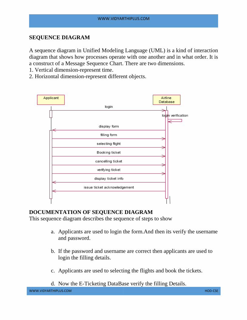
WWW.VIDYARTHIPLUS.COM
WWW.VIDYARTHIPLUS.COM HOD-CSE
SEQUENCE DIAGRAM
A sequence diagram in Unified Modeling Language (UML) is a kind of interaction
diagram that shows how processes operate with one another and in what order. It is
a construct of a Message Sequence Chart. There are two dimensions.
1. Vertical dimension-represent time.
2. Horizontal dimension-represent different objects.
DOCUMENTATION OF SEQUENCE DIAGRAM This sequence diagram describes the sequence of steps to show
a. Applicants are used to login the form.And then its verify the username
and password.
b. If the password and username are correct then applicants are used to
login the filling details.
c. Applicants are used to selecting the flights and book the tickets.
d. Now the E-Ticketing DataBase verify the filling Details.

WWW.VIDYARTHIPLUS.COM
WWW.VIDYARTHIPLUS.COM HOD-CSE
e. And then the E-Ticketing DataBase display the ticket information.
f. Incase of any sudden change of the plan,the applicant can cancel the
ticket.
COLLABRATION DIAGRAM
A collaboration diagram, also called a communication diagram or interaction
diagram,. A sophisticated modeling tool can easily convert a collaboration diagram
into a sequence diagram and the vice versa. A collaboration diagram resembles a
flowchart that portrays the roles, functionality and behavior of individual objects as
well as the overall operation of the system in real time.
DOCUMENTATION OF COLLABRATION DIAGRAM
This collaboration diagram is to show how the applicant login and register in the
E-Ticketing system. Here the sequence is numbered according to the flow of
execution.
This collaboration diagram is to show the selection process of the applicant for the
ticket booking. The flow of execution of this selection process is represented using
the numbers.
STATE CHART DIAGRAM
The purpose of state chart diagram is to understand the algorithm involved in
performing a method. It is also called as state diagram. A state is represented as a
round box, which may contain one or more compartments. An initial state is

WWW.VIDYARTHIPLUS.COM
WWW.VIDYARTHIPLUS.COM HOD-CSE
represented as small dot. A final state is represented as circle surrounding a small
dot.
DOCUMENTATION OF STATE CHART DIAGRAM This state diagram describes the behaviour of the system.
• First state is login where the applicant login to the E-Ticketing system.
• The next state is filling details the applicant are used to fill the form.
• Then applicant used to selecting the flight.
• The applicant appears for book ticket and search details from E-Ticketing
DataBase.
ACTIVITY DIAGRAM Activity diagrams are graphical representations of workflows of stepwise activities
and actions with support for choice, iteration and concurrency. In the Unified
Modeling Language, activity diagrams can be used to describe the business and
operational step-by-step workflows of components in a system. An activity
diagram shows the overall flow of control. An activity is shown as an rounded box
containing the name of the operation.

WWW.VIDYARTHIPLUS.COM
WWW.VIDYARTHIPLUS.COM HOD-CSE
DOCUMENTATION OF ACTIVITY DIAGRAM This activity diagram describes the behaviour of the system.
a. First state is login where the applicant login to the E-Ticketing
system.
b. The next state is filling details the applicant are used to fill the form.
c. Then applicant used to selecting the flight.
d. The applicant appears for book ticket and search details from E-
Ticketing DataBase.
COMPONENT DIAGRAM The component diagram's main purpose is to show the structural relationships
between the components of a system. It is represented by boxed figure.
Dependencies are represented by communication association.

WWW.VIDYARTHIPLUS.COM
WWW.VIDYARTHIPLUS.COM HOD-CSE
DOCUMENTATION OF COMPONENT DIAGRAM
The main component in this component diagram is E-Ticketing systems. And
Login, Filling Details and selecting flights applicants are the components comes
under the main component.
DEPLOYMENT DIAGRAM
A deployment diagram in the unified modeling language serves to model the
physical deployment of artifacts on deployment targets. Deployment diagrams
show "the allocation of artifacts to nodes according to the Deployments defined
between them. It is represented by 3-dimentional box. Dependencies are
represented by communication association.
DOCUMENTATION OF DEPLOYMENT DIAGRAM
The processor in this deployment diagram is the E-Ticketing system which is the
main part and the devices are the login, appear for the filling details and selecting
flights applicant which are the some of the main activities performed in the system.
PACKAGE DIAGRAM
A package diagram in unified modeling language that depicts the dependencies
between the packages that make up a model. A Package Diagram (PD) shows a
grouping of elements in the OO model, and is a Cradle extension to UML. PDs can
be used to show groups of classes in Class Diagrams (CDs), groups of components

WWW.VIDYARTHIPLUS.COM
WWW.VIDYARTHIPLUS.COM HOD-CSE
or processes in Component Diagrams (CPDs), or groups of processors in
Deployment Diagrams (DPDs).
There are three types of layer. They are
a. User interface layer -
b. Domain layer
c. Technical services layer
FORMS
FORM1
FORM2

WWW.VIDYARTHIPLUS.COM
WWW.VIDYARTHIPLUS.COM HOD-CSE
FORM3

WWW.VIDYARTHIPLUS.COM
WWW.VIDYARTHIPLUS.COM HOD-CSE
FORM4
FORM5
SOURCE CODE

WWW.VIDYARTHIPLUS.COM
WWW.VIDYARTHIPLUS.COM HOD-CSE
FORM3 Private Sub Command1_Click()
Adodc1.Recordset.AddNew
End Sub
Private Sub Command2_Click()
Adodc1.Recordset.MoveNext
End Sub
Private Sub Command3_Click()
Adodc1.Recordset.MovePrevious
End Sub
Private Sub Command4_Click()
Adodc1.Recordset.MoveLast
End Sub
Private Sub Command5_Click()
Adodc1.Recordset.Update
End Sub
Private Sub Command6_Click()
Unload Me
End Sub
Private Sub Command7_Click()
Adodc1.Recordset.Delete
End Sub
Private Sub Command8_Click()
Form3.Show
End Sub
FORM1 Private Sub Command1_Click()

WWW.VIDYARTHIPLUS.COM
WWW.VIDYARTHIPLUS.COM HOD-CSE
If txtus.Text = "admin" Then
If txtpass.Text = "admin" Then
MsgBox "login sucess"
Form1.Show
Unload Me
Else
MsgBox "The password you entered is incorrect.Please retype the password.",
vbCritical,
"Wrong Entry"
txtpass.Text = ""
End If
Else
MsgBox "The username and password you entered is incorrect.Please retype the
username and password.", vbCritical, "Wrong Entry"
txtus.Text = ""
txtpass.Text = ""
End If
End Sub
Private Sub Command2_Click()
Unload Me
End Sub
FORM5
Private Sub Command1_Click()
Adodc2.Recordset.AddNew
End Sub
Private Sub Command2_Click()
Adodc2.Recordset.MoveNext
End Sub
Private Sub Command3_Click()
Adodc2.Recordset.MovePrevious
End Sub
Private Sub Command4_Click()
Adodc2.Recordset.MoveLast
End Sub
Private Sub Command5_Click()
Adodc2.Recordset.Update
End Sub
Private Sub Command6_Click()
Adodc2.Recordset.Delete

WWW.VIDYARTHIPLUS.COM
WWW.VIDYARTHIPLUS.COM HOD-CSE
End Sub
Private Sub Command7_Click()
Unload Me
End Sub
RESULT Thus the project to develop E-Ticketing system using Rational Rose Software and
to implement the project in Visual Basic is done successfully.
EX NO:7 EMPLOYEE MANAGEMENT SYSTEM
AIM To develop a project employee management system using the Rational Rose
Software from the UML diagram and to implement the software in Visual Basic.
PROJECT ANALYSIS AND PROJECT PLANNING The employee management system is used to manage our personnel things such as
maintaining databases in offices etc. this project is easy for the CEO to handle the
details. This is personally used for CEO.
PROBLEM STATEMENT The CEO must enter the name and password to login the form and select the
particular employee to view the details about that employee and maintaining the
employee details personally. This process of employee management system are
described sequentially through following steps,
• The CEO login to the employee management system.
• He/she search for the list of employees.
• Then select the particular employee.
• Then view the details of that employee.
• After displaying the employee details then logout.
SOFT REQUIREMENT SPECIFICATION: S.NO TABLE OF CONTENTS
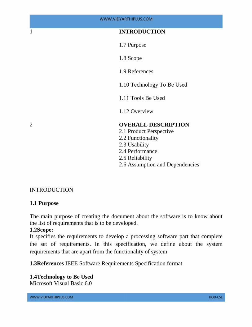
WWW.VIDYARTHIPLUS.COM
WWW.VIDYARTHIPLUS.COM HOD-CSE
1 INTRODUCTION
1.7 Purpose
1.8 Scope
1.9 References
1.10 Technology To Be Used
1.11 Tools Be Used
1.12 Overview
2 OVERALL DESCRIPTION 2.1 Product Perspective
2.2 Functionality
2.3 Usability
2.4 Performance
2.5 Reliability
2.6 Assumption and Dependencies
INTRODUCTION
1.1 Purpose
The main purpose of creating the document about the software is to know about
the list of requirements that is to be developed.
1.2Scope:
It specifies the requirements to develop a processing software part that complete
the set of requirements. In this specification, we define about the system
requirements that are apart from the functionality of system
1.3References IEEE Software Requirements Specification format
1.4Technology to Be Used Microsoft Visual Basic 6.0

WWW.VIDYARTHIPLUS.COM
WWW.VIDYARTHIPLUS.COM HOD-CSE
1.5ToolsBeUsed Rational Rose tool (for developing UML Patterns)
1.6Overview SRS includes two sections overall description and specific
requirements - Overall description will describe major role of the system
components and inter-connections. Specific requirements will describe roles &
functions of the actors.
OVERALL DESCRIPTION
2.1 Product Perspective The SPMP acts as an interface between the user and the database. This tries to
handle the personnel databases easily.
2.2Functionality: Many members of the process live to check for the occurrence and transaction, we
all have to carry over at sometime.
2.3 Usability The User interface makes the employee Management System to be efficient.
2.4 Performance
It is the capability about which it can perform function for many users at the same
time for the efficiency (i.e.) without any error occurrences.
2.5 Reliability The system should be able to the user through the day to day transactions.
2.6 Assumptions and dependencies The user must have the basic knowledge of computer and English language. The
user must correctly login the database
UML DIAGRAMS: The following UML diagrams describe the process involved in the online
recruitment system
• Use case diagram
• Class diagram
• Sequence diagram

WWW.VIDYARTHIPLUS.COM
WWW.VIDYARTHIPLUS.COM HOD-CSE
• Collaboration diagram
• State chart diagram
• Activity diagram
• Component diagram
• Deployment diagram
• Package diagram
The project can be explained diagrammatically using the following diagrams.
USE CASE DIAGRAM
The use cases are a set of scenarios to guide together by a common user goal. A
scenario is the sequence of steps describing an interaction between a user and their
system.
List of employeeLoginCEOEmployee detailsDatabase
DOCUMENTATION OF USE CASE DIAGRAM
The use case diagram in the employee management system illustrates the sequence
of sequencing and describing an interaction between a CEO and a system.
Login:
This use case gives as entry to the CEO and the database.
List of employee: This will create the situation for the CEO to select particular employee from the
available list.
Employee details: The CEO can able to view the details of the employee using this use case.
ACTIVITY DIAGRAM

WWW.VIDYARTHIPLUS.COM
WWW.VIDYARTHIPLUS.COM HOD-CSE
The Activity diagram describes the sequencing of activity will support for both
conditional and parallel. An activity is a variant of state diagram.
DOCUMENTATION OF ACTIVITY DIAGRAM
The CEO Logins to the employee management system. He/she selects a particular
employee from the list of available employee. The CEO can view the details of the
particular employee by clicking the respective button. After viewing the details he
is logout from the system.
CLASS DIAGRAM
The Class diagram the types of object in the system a various kinds of static
relation ships that exists among them.
DOCUMENTATION OF CLASS DIAGRAM The Classes used in this project are

WWW.VIDYARTHIPLUS.COM
WWW.VIDYARTHIPLUS.COM HOD-CSE
CEO: The CEO has to login the form by specifying the name and password of
him.
Database: The database checks whether the CEO has given the name and
password accordingly if not the error message will be displayed.
Available employees: The database is connects to the list of available employees
and the CEO if wants then select the employee from it.
SEQUENCE DIAGRAM: It is a kind of interaction diagram in which an object is shown as a box at the top of
the dash vertical line. This vertical line is called object life time. The life time
represent the object’s life during interaction object deletion is shown with a large
x.
DOCUMENTATION OF SEQUENCE DIAGRAM
The CEO must enter his name and password to login the employee management
system. The verification process is undergone by the database .If the details are
correct he can enter to the system otherwise error is displayed. After login the
details of the particular employee is viewed by the CEO. Finally he is logged out
from the system.
COLLABORATION DIAGRAM In a collaboration diagram object are shown as icons as on. A collaboration
diagram arrow indicates the message send within the given use case. The sequence
is indicated by numbering the messages.
DOCUMENTATION OF COLLABORATION DIAGRAM
It is same as the sequence diagram that involves the object of the project with the
only differences that we give the sequence no to the each process
The CEO must enter his name and password to login the employee management
system. The verification process is undergone by the database .If the details are
correct he can enter to the system otherwise error is displayed. After login the
detail of the particular employee is viewed by the CEO. Finally he is logged out
from the system.

WWW.VIDYARTHIPLUS.COM
WWW.VIDYARTHIPLUS.COM HOD-CSE
STATE CHART DIAGRAM
It is a technique to describe the behavior of the system.It determines all the
possible states as that of particular object gets into the object oriented
technique.State diagrams are drawn for a single class so status to the lifetime
behavior of a single objector.
DOCUMENTATION OF THE STATE CHART DIAGRAM:
The various states are the login, lists of employees, selects a employee, display the
information about the employee, logout.
The state chart diagram describes the behavior of the system. The main purpose of
the system is to maintain an employee details personally. For that the CEO Login
to the employee management system. He/she selects a particular employee from
the list of available employee. The CEO has to view the details of the particular
employee by clicking the respective button. The CEO views the details then finally
he is logout from the system.
PACKAGE DIAGRAM
A package is represented as folder among shown as large rectangle with a tab
attached its upper left corner. A package may contain both subordinated package
both ordinary model can be organized into packages. There are three types of
layers,
a. User interface layer
b. Domain layer
c. Technical layer
DOCUMENTATION OF PACKAGE DIAGRAM The three layers in the online recruitment system are
The User interface layer - consists of the web and login. This layer describes how
the applicant logins to the website and apply for the job.
The Domain layer – shows the activities that are performed in the online
recruitment system. The activities are register, attend test and select talented
applicant.

WWW.VIDYARTHIPLUS.COM
WWW.VIDYARTHIPLUS.COM HOD-CSE
The Technical service layer - the applicant details, verification details and the
selected applicant details are stored in the database.
COMPONENT DIAGRAM
Components are a slightly fuzzy concept in the UML, because both classes and
components can be used to model the same thing. A component represents a
modular part of a system that encapsulates its contents and whose manifestation is
replaceable within its environment. A component defines its behavior in terms of
provided and required interfaces. As such, a component serves as a type, whose
conformance is defined by these provided and required interfaces.

WWW.VIDYARTHIPLUS.COM
WWW.VIDYARTHIPLUS.COM HOD-CSE
DOCUMENTATION OF COMPONENT DIAGRAM
In this diagram there link between the actors is present in the SPMS that could be
shown in diagrammatically way in the component diagram. Each every actor is
having a directional link to process further details present in the system.
DEPLOYMENT DIAGRAM A deployment diagram shows the assignment of concrete software artifacts (such
as executable files) to computational nodes (something with processing services).
It shows the deployment of software elements to the physical architecture and the
communication (usually on a network) between physical elements.
A deployment diagram usually shows an example set of instances (rather than
classes
FORMS
FORM 1

WWW.VIDYARTHIPLUS.COM
WWW.VIDYARTHIPLUS.COM HOD-CSE
FORM 2

WWW.VIDYARTHIPLUS.COM
WWW.VIDYARTHIPLUS.COM HOD-CSE

WWW.VIDYARTHIPLUS.COM
WWW.VIDYARTHIPLUS.COM HOD-CSE
FORM 3
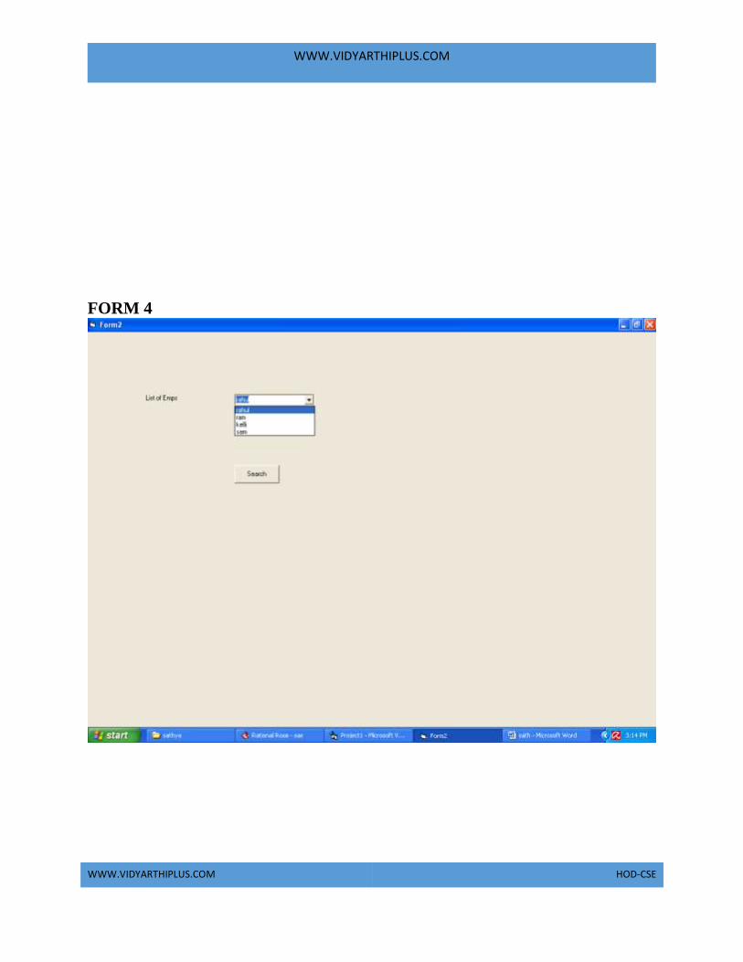
WWW.VIDYARTHIPLUS.COM
WWW.VIDYARTHIPLUS.COM HOD-CSE
FORM 4

WWW.VIDYARTHIPLUS.COM
WWW.VIDYARTHIPLUS.COM HOD-CSE
FORM 5

WWW.VIDYARTHIPLUS.COM
WWW.VIDYARTHIPLUS.COM HOD-CSE
FORM 6

WWW.VIDYARTHIPLUS.COM
WWW.VIDYARTHIPLUS.COM HOD-CSE
SOURCE CODE
Class modules
CEO Option Explicit
'##ModelId=4D413303009C
Private name As Variant
'##ModelId=4D41330502BF
Private Emp_no As Variant
'##ModelId=4D41330E01F4
Private DOB As Variant
'##ModelId=4D413434035B
Public NewProperty As database
'##ModelId=4D413322005D
Public Sub view()
End Sub
'##ModelId=4D41410F01B5
Public Sub update()
WWW.VIDYARTHIPLUS.COM
WWW.VIDYARTHIPLUS.COM HOD-CSE
End Sub
'##ModelId=4D41411401C5
Public Sub login()
End Sub
EMPLOYEE Option Explicit
'##ModelId=4D41409D0399
Private name As Variant

WWW.VIDYARTHIPLUS.COM
WWW.VIDYARTHIPLUS.COM HOD-CSE
'##ModelId=4D4140A400EA
Private DOB As Variant
'##ModelId=4D4140B10290
Private salary As Variant
'##ModelId=4D4140B801C5
Private exp As Variant
'##ModelId=4D4140BC01F4
Private ph_no As Variant
'##ModelId=4D4140E8007D
Public NewProperty As database
DATABASE: Option Explicit
'##ModelId=4D41334C02FD
Private pruducts As Variant
'##ModelId=4D41414000EA
Private projects As Variant
'##ModelId=4D4134380196
Public NewProperty As database_admin
'##ModelId=4D4140F00290
Public NewProperty2 As employee
'##ModelId=4D4133930271
Public Sub store_data()
End Sub
'##ModelId=4D4133A00271
Public Sub update()
End Sub
'##ModelId=4D4133A601A5
Public Sub insert()
End Sub
'##ModelId=4D41414A032C
Public Sub enquiry()
End Sub
'##ModelId=4D4133AC00BB
Public Sub delete()
End Sub
'##ModelId=4D4133AF002E
Public Sub verify()
End Sub
'##ModelId=4D4133B2034B

WWW.VIDYARTHIPLUS.COM
WWW.VIDYARTHIPLUS.COM HOD-CSE
Public Sub display()
End Sub
FORMS
Form 1: If Form1.Text1.Text = "admin" And Form1.Text2.Text = "admin" Then
MsgBox "login successful"
Form1.Hide
Form2.Show
Else

WWW.VIDYARTHIPLUS.COM
WWW.VIDYARTHIPLUS.COM HOD-CSE
MsgBox "invalid password"
End If
Dim v1 As CEO1
Private Sub command1_Click ()
Set v1 = New CEO1
v1.login
End Sub
Form 2: If (Form2.Combo1.Text = "rahul") Then
Form2.Hide
Form3.Show
End If
If (Form2.Combo1.Text = "ram") Then
Form2.Hide
Form4.Show
End If
If (Form2.Combo1.Text = "Kelli") Then
Form2.Hide
Form5.Show
End If
If (Form2.Combo1.Text = "Sam") Then
Form2.Hide
Form6.Show
End If
Dim v2 As database
Private Sub command1_Click ()
Set v2 = New database
v2.display
End Sub
Form 3: Private Sub command1_Click ()
Form3.Hide
Form2.Show
End Sub
Form 4:
Private Sub command1_Click ()
Form4.Hide
Form2.Show
End Sub

WWW.VIDYARTHIPLUS.COM
WWW.VIDYARTHIPLUS.COM HOD-CSE
Form 5: Private Sub command1_Click ()
Form5.Hide
Form2.Show
End Sub
Form 6: Private Sub command1_Click ()
Form6.Hide
Form2.Show
End sub
RESULT Thus the project is to develop an EMPLOYEE MANAGEMENT SYSTEM using
the Rational Rose Software from the UML diagram and to implement the
employee details and successfully executed using visual basic and rational rose.

WWW.VIDYARTHIPLUS.COM
WWW.VIDYARTHIPLUS.COM HOD-CSE
EX NO:8 CREDIT CARD PROCESSING SYSTEM
AIM To develop a project credit card system using the Rational Rose Software from the
UML diagram and to implement the software in Visual Basic
PROBLEM ANALYSIS AND PROJECT PLANNING The Credit Card Processing System which is use to purchasing an item from any
shop mall, and it is used to maintain the limitation of credit card balance and
current transaction process could be update via credit card machine. This project
mainly used for large amount of item can be easy to buy from anywhere and
required transaction process should be maintained them.
PROBLEM STATEMENT The customer should select the item to be purchase from the shop by using credit
card payment then the vendor should give a bill for the selected item .The customer
should give his card to swap and request for the kind of amount transaction. After
processing the transaction, the CREDIT CARD MACHINE should give the
balance print statement or receipt.
• Customer should select the item from the shop.

WWW.VIDYARTHIPLUS.COM
WWW.VIDYARTHIPLUS.COM HOD-CSE
• Vendor makes the bill for the selected item.
• Customer gives the credit card to the vendor to swap the card.
• They required amount transaction is done by the card reader.
• Vendor will issue the balance statement to the customer.
• Customers put the signature in the receipt and return to the vendor.
SOFTWARE REQUIREMENT SPECIFICATION
S.NO TABLE OF
CONTENTS
1 INTRODUCTION
1.13 Purpose
1.14 Scope
1.15 References
1.16 Technology To Be Used
1.17 Tools Be Used
1.18 Overview

WWW.VIDYARTHIPLUS.COM
WWW.VIDYARTHIPLUS.COM HOD-CSE
2 OVERALL DESCRIPTION 2.1 Product Perspective
2.2 Functionality
2.3 Usability
2.4 Performance
2.5 Reliability
2.6 Assumption and
Dependencies
1.3
In the specification use define about the system requirements that are part from the
functionality of the system. It tells the usability, reliability defined in the use case
specification.
1.3 REFERENCES IEEE Software Requirement Specification format.
1.4 TECHNOLOGY TO BE USED Microsoft Visual Basic 6.0
1.5 TOOLS TO BE USED Rational Rose tool (for developing UML Patterns)
1.6 OVERVIEW SRS includes two sections overall description and specific
requirements - Overall description will describe major role of the system
components and inter-connections. Specific requirements will describe roles &
functions of the actors.
2. OVERALL DESCRIPTION
2.1 PRODUCT PERSPECTIVE The CCP acts as an interface between the
'Customer' and the 'Card Reader'. This system tries to make the transaction as
simple as possible and at the same time not risking the security of data transaction
process. This minimizes the time duration in which the user receives the item.
2.2 FUNCTIONALITY Many members of the process lives to checking for the occurrence and transaction
we all have to carry over sometimes user interface to make the transaction to be
efficient.

WWW.VIDYARTHIPLUS.COM
WWW.VIDYARTHIPLUS.COM HOD-CSE
2.3 USABILITY The User interface makes the Credit Card Processing System to be efficient.
2.4 PERFORMANCE
It is of the capacities about which it can perform function for many users
at the same times efficiently that are without any error occurrence.
2.5 RELIABILITY
The system should be able to process the user for their corresponding request.
2.6 ASSUMPTION AND DEPENDENCIES The Vendor and Customer must have basic knowledge of computers and English
Language. The vendor may be required to delivered the item purchased by the
customer.
UML DIAGRAMS The following UML diagrams describe the process involved in the online
recruitment system
a. Use case diagram
b. Class diagram
c. Sequence diagram
d. Collaboration diagram
e. State chart diagram
f. Activity diagram
g. Component diagram
h. Deployment diagram
i. Package diagram
USE CASE DIAGRAM

WWW.VIDYARTHIPLUS.COM
WWW.VIDYARTHIPLUS.COM HOD-CSE
The use cases are a set of scenarios to guide together by a common user goal. A
scenario is the sequence of steps describing an interaction between a user and their
system.
DOCUMENTATION OF USE CASE DIAGRAM The actors in this use case diagram are customer, vendor and card reader. The use
cases are the activities performed by actors.
The actors in this use case diagram are
• Customer – used to purchase some item from the shop by using credit card
payment.
• Vendor – used to issue a bill for selected item and verify the card holder
signature and then delivery the item.
• Card reader – its make the amount transaction for required credit card and print
the balance statement.
The use cases in this use case diagram are
Purchase item – customer enter the shop to purchase some item by using credit
card payment.
• Bill issue – vendor will make a bill for the selected item.
• Swap the card – vendor will swap the card.
• Make transaction– card reader will processes the amount transaction.
• Print the statement – after the transaction, balance amount should be printed.
• Signature – customer should put the signature and give it to vendor.
• Deliver the item–vendor issued to deliver a item.
ACTIVITY DIAGRAM

WWW.VIDYARTHIPLUS.COM
WWW.VIDYARTHIPLUS.COM HOD-CSE
An activity diagram is a variation or special case of a state machine in which the
states or activity representing the performance of operation and transitions are
triggered by the completion of operation. The purpose is to provide view of close
and what is going on inside a use case or among several classes. An activity is
shown as rounded box containing the name of operation.
DOCUMENTATION OF ACTIVITY DIAGRAM The customer’s activity should contained an purchase item by using credit card and
then his referred to check the current transaction processing its completed or not.
The vendor should issue a bill copy to the customer and its swap the card to make
amount transaction by using card reader. The vendor should give required
statement to customer will deliver the item from the shop.
CLASS DIAGRAM The Class diagram the types of object in the system an the various kinds of static
relation ships that exists among them.
DOCUMENTATION OF CLASS DIAGRAM
The Classes used in this project are:
• Customer – is the class name. Its attributes are name, age, signature, and card
number. The operations performed in the customer class are purchase item and
swap the credit card.
• Vendor – is the class name. Its attributes are name, address, and phone number.
The operations performed are make bill and then delivered item purchased by the
customer.
• Card Reader – is the class name. Its attributes are machine number, software
and company. The operations performed are make the transaction and print balance
statement.
SEQUENCE DIAGRAM
It is a kind of interaction diagram in which an object is shown as a box at the top of
the dash vertical line. This vertical line is called object life time. The life time

WWW.VIDYARTHIPLUS.COM
WWW.VIDYARTHIPLUS.COM HOD-CSE
represent the object’s life during interaction object deletion is shown with a large
x.
DOCUMENTATION OF SEQUENCE DIAGRAM The customer wants to purchase some item from the shop; Vendor makes a bill for
the selected item. The Customer gives the credit card to the vendor to the swap the
card. The further transaction is proceeding for if the credit card is validated.
Vendor will issue the required balance statement to the customer. Customer put the
signature in the receipt and returns the one copy of statement to the vendor.
COLLABORATION DIAGRAM In a collaboration diagram object are shown as icons as on. A collaboration
diagram arrow indicates the message send within the given use case. The sequence
is indicated by numbering the messages.
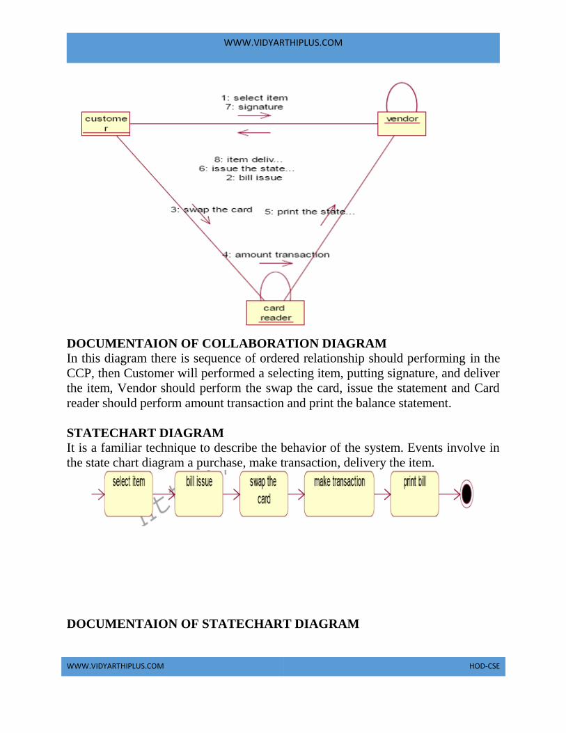
WWW.VIDYARTHIPLUS.COM
WWW.VIDYARTHIPLUS.COM HOD-CSE
DOCUMENTAION OF COLLABORATION DIAGRAM In this diagram there is sequence of ordered relationship should performing in the
CCP, then Customer will performed a selecting item, putting signature, and deliver
the item, Vendor should perform the swap the card, issue the statement and Card
reader should perform amount transaction and print the balance statement.
STATECHART DIAGRAM It is a familiar technique to describe the behavior of the system. Events involve in
the state chart diagram a purchase, make transaction, delivery the item.
DOCUMENTAION OF STATECHART DIAGRAM

WWW.VIDYARTHIPLUS.COM
WWW.VIDYARTHIPLUS.COM HOD-CSE
The Entire process of CCP could be shown in the start state to goal state behavior
should be performed by the Customer, Vendor and Card reader in this credit card
processing system.
PACKAGE DIAGRAM A package is represented as folder among shown as large rectangle with a tab
attached its upper left corner. A package may contain both subordinated package
both ordinary model can be organized into packages.
There are three types of layers includes in package diagram:
• User interface layer
• Domain layer
• Technical layer
DOCUMENTATION OF PACKAGE DIAGRAM
The three layers in the credit card processing system are
The User interface layer - consists of the Card reader and Vendor. This layer
describes how the customer is used to purchasing and makes it transaction process.
• The Domain layer – shows the activities that are performed in the Credit card
processing system. The activities are purchase the item, make transaction and
delivered item.
• The Technical service layer – To verify a required Customer Signature.

WWW.VIDYARTHIPLUS.COM
WWW.VIDYARTHIPLUS.COM HOD-CSE
COMPONENT DIAGRAM
The component diagram is represented by figure dependency and it is a graph of
design of figure dependency.
DOCUMENTATION OF COMPONENT DIAGRAM In this diagram there link between the actor is present in the CCP, that could be
shown in diagrammatically way in the component diagram. Each every actor is
having a bidirectional link to process further details present in the system.
DEPLOYMENT DIAGRAM A deployment diagram in the unified modeling language serves to model the
physical deployment of artifacts on deployment targets. Deployment diagrams
show "the allocation of artifacts to nodes according to the Deployments defined
between them. It is represented by 3-dimentional box. Dependencies are
represented by communication association.
DOCUMENTATION OF DEPLOYMENT DIAGRAM
The processor in this deployment diagram is the credit card processing system
which is the main part and the devices are the purchase item, swap the card, make
transaction, verify signature, delivery item which are the some of the main
activities performed in the system.

WWW.VIDYARTHIPLUS.COM
WWW.VIDYARTHIPLUS.COM HOD-CSE
FORMS:
FORM 1
FORM 2
FORM 3

WWW.VIDYARTHIPLUS.COM
WWW.VIDYARTHIPLUS.COM HOD-CSE
FORM 4

WWW.VIDYARTHIPLUS.COM
WWW.VIDYARTHIPLUS.COM HOD-CSE
SOURCE CODE
CARD READER: Option Explicit
'##ModelId=4D4136130261
Private machine__number As Variant
'##ModelId=4D413619031C
Private software As Variant
'##ModelId=4D4136680177
Private company_name As Variant
Dim v1 As vendors
'##ModelId=4D4136B6030D
'##ModelId=4D4136CB0222
Public Sub print_receipt()
End Sub
CUSTOMERS: Option Explicit
WWW.VIDYARTHIPLUS.COM
WWW.VIDYARTHIPLUS.COM HOD-CSE
'##ModelId=4D4134EC01E4
Private name As Variant
'##ModelId=4D4134EF0167
Private age As Variant
'##ModelId=4D413504036B
Private signature As Variant
'##ModelId=4D413519007D
Private card_number As Variant
'##ModelId=4D4136D9037A
Public NewProperty As vendors
Dim v1 As vendors
'##ModelId=4D4135250167
'##ModelId=4D41353E02AF
Public Sub swap()
End Sub
VENDORS:
Option Explicit
'##ModelId=4D4135610399
Private name As Variant
'##ModelId=4D413565000F
Private address As Variant
'##ModelId=4D41356F0203
Private machine_num As Variant
'##ModelId=4D4136E200EA
Public NewProperty As card_reader
Dim v2 As card_reader
'##ModelId=4D4135BA03A9
Public Sub make_bill()
Form3.Show
End Sub
'##ModelId=4D4135CA029F
Public Sub delivery_item()
Form3.Show
End Sub
Form1:
Dim r1 As customers
Private Sub Command1_Click()
Set r1 = New customers
r1.purchase_item

WWW.VIDYARTHIPLUS.COM
WWW.VIDYARTHIPLUS.COM HOD-CSE
End Sub
Private Sub Command2_Click()
Unload Me
End Sub
Public Sub purchase_item()
Form2.Show
End Sub
Form2: Dim r2 As vendors
Private Sub Command1_Click()
Set r2 = New vendors
r2.delivery_item
End Sub
Private Sub Command2_Click()
Form1.Show
End Sub
Form3: Dim r3 As card_reader
Private Sub Command1_Click()
Set r3 = New card_reader
r3.make_transaction
End Sub
Public Sub make_transaction()
Form4.Show
End Sub
RESULT Thus the project to develop credit card processing system using Rational Rose
Software and to implement the project in Visual Basic is done successfully.

WWW.VIDYARTHIPLUS.COM
WWW.VIDYARTHIPLUS.COM HOD-CSE
EX.NO: 9 E-BOOK MANAGEMENT SYSTEM
AIM To develop a project E-Book Management system using Rational Rose Software
and to implement the software in Java.
PROBLEM ANALYSIS AND PROJECT PLANNING Ebook Management System gives an idea about how books are maintained in the
particular websites. The books that are to be purchased, the books that are to be
sold are maintained here. . Further some additional details of the current books that
is available in the store are also given. Ebook Management System in this project
is done in an authorized way. The password and user id has been set here.
PROBLEM STATEMENT The website has to be maintained properly since the whole ebook purchase process
can be improved. Ebook management in this project gives the idea about how
ebooks are maintained in a particular concern. The book details which includes the
number of books available ,no of pages and price. Ebook management system the
Ebook management in this project is understood by going through the modules that
is being involved.
SOFTWARE REQUIREMENT SPECIFICATION 1 INTRODUCTION
2 OBJECTIVE
3 OVERVIEW
4 GLOSSARY
5 PURPOSE
6 SCOPE
7 FUNCTIONALITY
8 USABILITY
9 PERFORMANCE
10 RELIABILITY
11 FUNCTIONAL
REQUIREMENTS
WWW.VIDYARTHIPLUS.COM
WWW.VIDYARTHIPLUS.COM HOD-CSE
1. INTRODUCTION Ebook managemnt gives an idea about how ebooks are maintained in the particular
concern. The ebooks that are to be purchased, the ebooks that are to be sold are
maintained here. Further some additional details of the current ebook list that is
available in the website is also given. Ebook management in this project is done in
an authorized way.
2. OBJECTIVE The main objective of this project is to overcome the work load and time
consumption which makes the maintenance of the ebook in an organization as a
tedious process. This project provides complete information about the details of the
ebook to the customers. This project identifies the amount of book available, .
Separate modules have been created for purchasing, viewing book details, and
delivery details.
3. OVERVIEW The overview of the project is to Storing of information about the ebooks and
updating the ebook list for each organization which is using this system, keeps
track of all the information about the ebooks purchased that are made by the
customers, having registration feature of adding up new customers to the
organization are provided in this system.
4. GLOSSARY TERMS DESCRIPTION
CUSTOMER Customer will purchase the books
from the Website .
DATABASE Database is used to store the books
and details of books.
ADMIN Handles all the support features and
the technical works in the
application.

WWW.VIDYARTHIPLUS.COM
WWW.VIDYARTHIPLUS.COM HOD-CSE
SOFTWARE REQUIREMENT
SPECIFICATION
This software specification
documents full set of features and
function for ebook management
system that is performed in
application.
5. PURPOSE The purpose of ebook management system is to store and sell the books in a
website effectively.
6. SCOPE The scope of this ebook management is to maintain the book details after the
purchase and list of reaming books available in the same book type.
7. FUNCTIONALITY
The main functionality of ebook maintenance system is to store and sell ebooks for
a website.
8. USABILITY User interface makes the ebook management system to be efficient. That is the
system will help the admin to maintain stock details easily and helps the store to
handle the stocks effectively. The system should be user friendly.
9. PERFORMANCE It describes the capability of the system to perform the ebook management system
of the store without any error and performing it efficiently.
10. RELIABILITY
The ebook management system should be able to serve the customer with correct
information and day-to-day update of ebook list details.
11. FUNCTIONAL REQUIREMENTS Functional requirements are those refer to the functionality of the system. That is
the services that are provided to the webstie which maintains ebooks in online
database.
UML DIAGRAMS The following UML diagrams describe the process involved in the stock
maintenance system

WWW.VIDYARTHIPLUS.COM
WWW.VIDYARTHIPLUS.COM HOD-CSE
Use case diagram
Class diagram
Sequence diagram
Collaboration diagram
State chart diagram
Activity diagram
Component diagram
Deployment diagram
Package diagram
USE CASE DIAGRAM A use case is a methodology used in system analysis to identify, clarify, and
organize system requirements. The use case is made up of a set of possible
sequences of interactions between systems and users in a particular environment
and related to a particular goal. It is represented using ellipse.
Actor is any external entity that makes use of the system being modelled. It is
represented using stick figure.
DOCUMENTATION OF USE CASE DIAGRAM
The actors in this use case diagram are Supplier, Store Keeper and Database. The
usecases are the activities performed by actors.
• The website will give the books available.

WWW.VIDYARTHIPLUS.COM
WWW.VIDYARTHIPLUS.COM HOD-CSE
• Customer will login and check the list of ebooks in the database.
• The database will be updated according to the purchase done and it will be up to
date.The use cases in the use case diagram are Quotation & Purchase, login,
stock, purchase.
• Select books will gives us the status of the purchasing order details
• Login will gives us the entry for the customer of this project.
• Database will gives us the details about the total ebook available.
• Purchase will gives us the details about the details and the history of ebooks
purchased.
CLASS DIAGRAM A class diagram in the unified modeling language (UML) is a type of static
structure diagram that describes the structure of a system by showing the system's
classes, their attributes, and the relationships between the classes. It is represented
using a rectangle with three compartments. Top compartment have the class name,
middle compartment the attributes and the bottom compartment with operations.
DOCUMENTATION OF CLASS DIAGRAM This class diagram has three classes applicant, recruiter and database.

WWW.VIDYARTHIPLUS.COM
WWW.VIDYARTHIPLUS.COM HOD-CSE
• Customer – is the class name. Its attributes are name, address and cont no. The
operations performed in the Supplier class are get order, supply goods and get
money.
• Books – is the class name. Its attributes are operating system, computer
architecture,dbms,web technology and ooad. The operations performed are select
and buy.
• Database – is the class name. Its attribute is operation. The operations performed
is store .
SEQUENCE DIAGRAM A sequence diagram in Unified Modeling Language (UML) is a kind of interaction
diagram that shows how processes operate with one another and in what order. It is
a construct of a Message Sequence Chart. There are two dimensions.
1.Veritcal dimension-represent time.
2.Horizontal dimension-represent different objects.
DOCUMENTATION OF SEQUENCE DIAGRAM The sequence diagram describes the sequence of steps to show
• The Customer enters the Ebook website.
• The list of books available are listed.
• Customer checks the book list.

WWW.VIDYARTHIPLUS.COM
WWW.VIDYARTHIPLUS.COM HOD-CSE
• Database provides user id and pass.
• Customer selects the book.
• Pay money to the Website.
COLLABORATION DIAGRAM A collaboration diagram, also called a communication diagram or interaction
diagram,. A sophisticated modeling tool can easily convert a collaboration diagram
into a sequence diagram and the vice versa. A collaboration diagram resembles a
flowchart that portrays the roles, functionality and behavior of individual objects as
well as the overall operation of the system in real time
DOCUMENTATION OF COLLABORATION DIAGRAM The first collaboration diagram is to show how the customer login and getting
details of ebooks in the ebook management system. Here the sequence is numbered
according to the flow of execution.
STATE CHART DIAGRAM
The purpose of state chart diagram is to understand the algorithm involved in
performing a method. It is also called as state diagram. A state is represented as a
round box, which may contain one or more compartments. An initial state is
represented as small dot. A final state is represented as circle surrounding a small
dot.

WWW.VIDYARTHIPLUS.COM
WWW.VIDYARTHIPLUS.COM HOD-CSE
DOCUMENTATION OF STATE CHART DIAGRAM This state diagram describes the behavior of the system.
• First state is login where the customer login to the ebook management system.
• The next state is check the list of books in order.
• Then select buy the book.
• Enter the account detail and purchase the book.
ACTIVITY DIAGRAM Activity diagrams are graphical representations of workflows of stepwise activities
and actions with support for choice, iteration and concurrency. In the Unified
Modeling Language, activity diagrams can be used to describe the business and
operational step-by-step workflows of components in a system. An activity
diagram shows the overall flow of control. An activity is shown as an rounded box
containing the name of the operation.

WWW.VIDYARTHIPLUS.COM
WWW.VIDYARTHIPLUS.COM HOD-CSE
DOCUMENTATION OF ACTIVITY DIAGRAM This activity diagram flow of stepwise activities performed in recruitment system.
• First Customer login then checks books available.
• The book list are verified and is given in a ordered format.

WWW.VIDYARTHIPLUS.COM
WWW.VIDYARTHIPLUS.COM HOD-CSE
• The needed book is selected.
• Enter your account details and purchase the book .
COMPONENT DIAGRAM The component diagram's main purpose is to show the structural relationships
between the components of a systems. It is represented by boxed figure.
Dependencies are represented by communication association.
DOCUMENTATION OF COMPONENT DIAGRAM The main component in this component diagram is online recruitment systems.
And Supplier, storekeeper and database are the components come under the main
component.
DEPLOYMENT DIAGRAM A deployment diagram in the unified modeling language serves to model the
physical deployment of artifacts on deployment targets. Deployment diagrams
show "the allocation of artifacts to nodes according to the Deployments defined
between them. It is represented by 3-dimentional box. Dependencies are
represented by communication association.

WWW.VIDYARTHIPLUS.COM
WWW.VIDYARTHIPLUS.COM HOD-CSE
DOCUMENTATION OF DEPLOYMENT DIAGRAM The processor in this deployment diagram is the online recruitment system which
is the main part and the devices are the select and payment which are the some of
the main activities performed in the system.
PACKAGE DIAGRAM A package diagram in unified modeling language that depicts the dependencies
between the packages that make up a model. A Package Diagram (PD) shows a
grouping of elements in the OO model, and is a Cradle extension to UML.

WWW.VIDYARTHIPLUS.COM
WWW.VIDYARTHIPLUS.COM HOD-CSE
PDs can be used to show groups of classes in Class Diagrams (CDs), groups of
components or processes in Component Diagrams (CPDs), or groups of processors
in Deployment Diagrams (DPDs).
There are three types of layer. They are
• User interface layer: consists of the form and login. This layer describes how
the customer logins and books maintained in website.
• Domain layer: shows the activities that are performed in the ebook management
system. The activities are books are purchased from the websote
• Technical services layer: the update the account details and buy the book by
payment through the account
FORMS
FORM 1
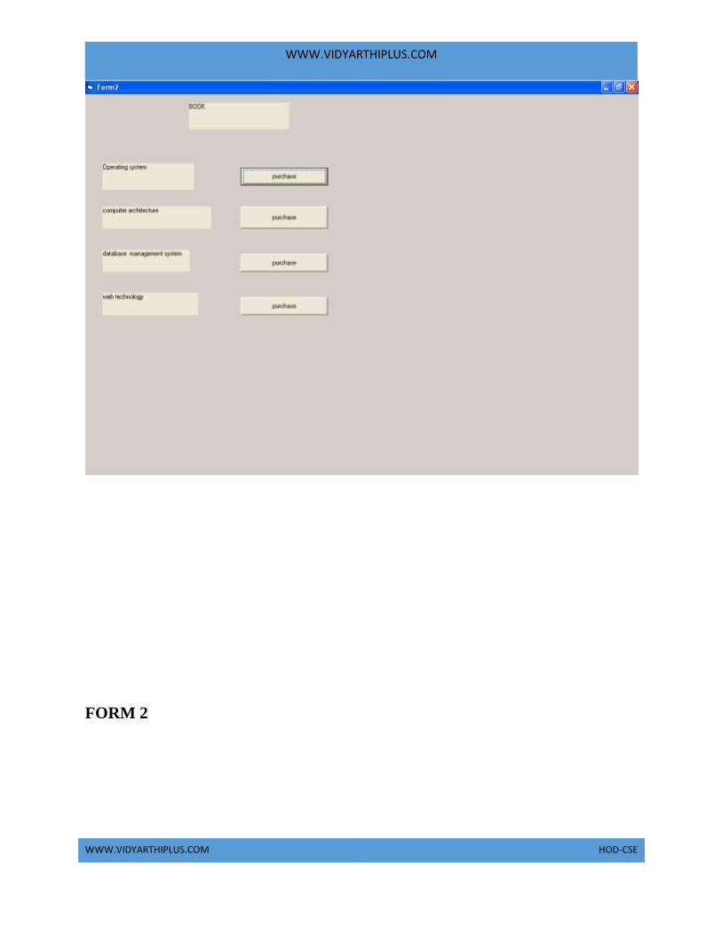
WWW.VIDYARTHIPLUS.COM
WWW.VIDYARTHIPLUS.COM HOD-CSE
FORM 2

WWW.VIDYARTHIPLUS.COM
WWW.VIDYARTHIPLUS.COM HOD-CSE
FORM 3

WWW.VIDYARTHIPLUS.COM
WWW.VIDYARTHIPLUS.COM HOD-CSE
SOURCE CODE
CUSTOMER
FORM1
Option Explicit
'##ModelId=4D63700C0148
Private name As Variant
'##ModelId=4D63701003C8
Private address As Variant
'##ModelId=4D637016007D
Private contact_no As Variant
'##ModelId=4D637027031C
Private account_no As Variant
'##ModelId=4D63714C02BF
Public NewProperty As books
'##ModelId=4D63715201C5
Public NewProperty2 As Database
'##ModelId=4D63706000BB
Public Sub login()
End Sub
Private Sub Command1_Click()
If Text1.Text = "pandi" And Text2.Text = "**" Then
MsgBox "login sucessfully"
Form2.Show
Else
MsgBox "invalid password"
End If
End Sub
Private Sub Command2_Click()
Unload Me
End Sub
BOOK
FORM2

WWW.VIDYARTHIPLUS.COM
WWW.VIDYARTHIPLUS.COM HOD-CSE
Option Explicit
'##ModelId=4D63709803C8
Private operating_system As Variant
'##ModelId=4D6370AA008C
Private computer_architecture As Variant
'##ModelId=4D6370B30138
Private dbms As Variant
'##ModelId=4D6370B603C8
Private web_technology As Variant
'##ModelId=4D6370C0034B
Private ooad As Variant
'##ModelId=4D6370C50167
'##ModelId=4D6370650213
Public Sub payment()

WWW.VIDYARTHIPLUS.COM
WWW.VIDYARTHIPLUS.COM HOD-CSE
End Sub
Public Sub select()
End Sub
'##ModelId=4D6370D0000F
Public Sub buy()
End Sub
Private Sub Command1_Click()
Form3.Show
End Sub
Private Sub Command2_Click()
Form3.Show
End Sub
Private Sub Command3_Click()
Form3.Show
End Sub
Private Sub Command4_Click()
Form3.Show
End Sub
Private Sub Label2_Click()
End Sub
FORM3 Private Sub Command1_Click()
Form4.Show
End Sub
RESULT Thus the project to develop Ebook Management System using Rational Rose
Software and to implement the software in Java is done successfully.

WWW.VIDYARTHIPLUS.COM
WWW.VIDYARTHIPLUS.COM HOD-CSE
EXNO: 10 ONLINE RECRUITMENT SYSTEM
AIM To develop a project on online recruitment system using Rational Rose Software
and to implement the project in Visual Basic.
PROBLEM ANALYSIS AND PROJECT PLANNING The Online Recruitment System is an online website in which applicant can
register themselves and then attend the exam. Examination will be conducted at
some venue. The details of the examination, venue & Date of the examination will
be made available to them through the website. Based on the outcome of the exam
the applicant will be short listed and the best applicant is selected for the job.
PROBLEM STATEMENT The process of applicants is login to the recruitment system and register for the job
through online. The resume is processed by the company and the required
applicant is called for the test. On the basis of the test marks, they are called for
next level of interview. Finally the best applicant is selected for the job. This
process of online recruitment system are described sequentially through following
steps,
• The applicant login to the online recruitment system.
• They register to the company for the job.
• They appear for examination.
• Based on the outcome of the exam, the best applicant is selected.

WWW.VIDYARTHIPLUS.COM
WWW.VIDYARTHIPLUS.COM HOD-CSE
• The recruiter informs the applicant about their selection.
SOFTWARE REQUIREMENT SPECIFICATION
SNO SPECIFICATION
1 INTRODUCTION
2 OBJECTIVE
3 OVERVIEW
4 GLOSSARY
5 PURPOSE
6 SCOPE
7 FUNCTIONALITY
8 USABILITY
9 PERFORMANCE
10 RELIABILITY
11 FUNCTIONAL
REQUIREMENTS
1. INTRODUCTION
This software specification documents full set of features and function for online
recruitment system that is performed in company website. In this we give
specification about the system requirements that are apart from the functionality of
the system to perform the recruitment of the jobseekers. It tells the usability,
reliability defined in use case specification.

WWW.VIDYARTHIPLUS.COM
WWW.VIDYARTHIPLUS.COM HOD-CSE
2. OBJECTIVE The main objective of Online Recruitment System is to make applicants register
themselves online and apply for job and attend the exam. Online Recruitment
System provides online help to the users all over the world.
3. OVERVIEW The overview of the project is to design an online tool for the recruitment process
which ease the work for the applicant as well as the companies. Companies can
create their company forms according to their wish in which the applicant can
register.
4. GLOSSARY
TERMS DESCRIPTION APPLICANT Applicant can register himself. After
registration, he will be directed to
his homepage. Here he can update his
profile, change password and see the
examination details and all.
RECRUITER Recruiter verify applicant details and
conduct examination, approve or
disapprove applicant attending
examination and provides results about
the selected applicant.
DATABASE Database is used to verify login and store
the details of selected applicants.
WWW.VIDYARTHIPLUS.COM
WWW.VIDYARTHIPLUS.COM HOD-CSE
READER Anyone visiting the site to read about
online recruitment system.
USER Applicant and the reader
SOFTWARE REQUIREMENT
SPECIFICATION
This software specification documents
full set of features and function for online
recruitment system that is performed in
company website.
The main functionality of recruitment system is to recruit the applicant for the job
in their company.
8. USABILITY User interface makes the Recruitment system to be efficient. That is the system
will help the applicant to register easily and helps the companies to recruit the
applicant effectively. The system should be user friendly.
9. PERFORMANCE It describes the capability of the system to perform the recruitment process of the
applicant without any error and performing it efficiently.
10. RELIABILITY The online recruitment system should be able to serve the applicant with correct
information and day-to-day update of information.
11. FUNCTIONAL REQUIREMENTS Functional requirements are those refer to the functionality of the system. That is
the services that are provided to the applicant who apply for the job.
UML DIAGRAMS The following UML diagrams describe the process involved in the online
recruitment system
• Use case diagram
• Class diagram

WWW.VIDYARTHIPLUS.COM
WWW.VIDYARTHIPLUS.COM HOD-CSE
• Sequence diagram
• Collaboration diagram
• State chart diagram
• Activity diagram
• Component diagram
• Deployment diagram
• Package diagram
USE CASE DIAGRAM A use case is a methodology used in system analysis to identify, clarify, and
organize system requirements. The use case is made up of a set of possible
sequences of interactions between systems and users in a particular environment

WWW.VIDYARTHIPLUS.COM
WWW.VIDYARTHIPLUS.COM HOD-CSE
and related to a particular goal. It is represented using ellipse.Actor is any external
entity that makes use of the system being modelled. It is represented using stick
figure.

WWW.VIDYARTHIPLUS.COM
WWW.VIDYARTHIPLUS.COM HOD-CSE
DOCUMENTATION OF USE CASE DIAGRAM
The actors in this use case diagram are applicant, recruiter and database. The use
cases are the activities performed by actors.
The actors in this use case diagram are
• Applicant - logins the recruitment system and register for the job and attend the
test conducted at some venue.
• Recruiter - send the interview details, select talented applicant and send
appointment letter to them.
Databases - verify the login and register details and selected applicant details are
stored in it.
The use cases in this use case diagram are
• Login - applicant enter their username and password to enter in to the recruitment
system
• Register – applicant register in to the recruitment system for job.
• Send interview details – recruiter send interview details to the applicant.
• Attend test – applicant appears for the test.
• Select talented applicant – based on the outcome of test talented applicant is
selected.
• Send appointment letter – appointment letter is sent to the selected applicant by
recruiter.

WWW.VIDYARTHIPLUS.COM
WWW.VIDYARTHIPLUS.COM HOD-CSE
CLASS DIAGRAM A class diagram in the unified modeling language (UML) is a type of static
structure diagram that describes the structure of a system by showing the system's
classes, their attributes, and the relationships between the classes. It is represented
using a rectangle with three compartments. Top compartment have the classname,
middle compartment the attributes and the bottom compartment with operations.
DOCUMENTATION OF CLASS DIAGRAM This class diagram has three classes applicant, recruiter and database.
• Applicant – is the class name. Its attributes are username, password, name,
phone no and address. The operations performed in the applicant class are login,
register and giving applicant details.
• Recruiter – is the class name. Its attributes are name, designation, phone no,
marks in apps and marks in technical. The operations performed are selecting
applicants based on apps and technical.
• Database – is the class name. The operations performed are storing applicant
details, verifying login and storing selected applicant details.
SEQUENCE DIAGRAM A sequence diagram in Unified Modeling Language (UML) is a kind of interaction
diagram that shows how processes operate with one another and in what order. It is
a construct of a Message Sequence Chart. There are two dimensions.
1. Vertical dimension-represent time.

WWW.VIDYARTHIPLUS.COM
WWW.VIDYARTHIPLUS.COM HOD-CSE
2. Horizontal dimension-represent different objects.
FOR SELECTING APPLICANT
DOCUMENTATION OF SEQUENCE DIAGRAM
REGISTER This sequence diagram describes the sequence of steps to show
• The applicant login in to the recruitment system and register for job.
• The verification done in the database and recruiter
• The interview details are send to the applicant by recruiter.
SELECTING APPLICANT

WWW.VIDYARTHIPLUS.COM
WWW.VIDYARTHIPLUS.COM HOD-CSE
This sequence diagram shows steps to show
• The applicant attend aptitute test and they are short listed based on evaluation
• The applicant appear for technical round
• The talented applicant is selected.
• This detail is stored in the database.
COLLABRATION DIAGRAM A collaboration diagram, also called a communication diagram or interaction
diagram,. A sophisticated modeling tool can easily convert a collaboration diagram
into a sequence diagram and the vice versa. A collaboration diagram resembles a
flowchart that portrays the roles, functionality and behavior of individual objects as
well as the overall operation of the system in real time
FOR REGISTER
DOCUMENTATION OF COLLABRATION DIAGRAM

WWW.VIDYARTHIPLUS.COM
WWW.VIDYARTHIPLUS.COM HOD-CSE
REGISTER This collaboration diagram is to show how the applicant login and register in the
recruitment system. Here the sequence is numbered according to the flow of
execution.
SELECTING APPLICANT This collaboration diagram is to show the selection process of the applicant for the
job. The flow of execution of this selection process is represented using the
numbers.
STATE CHART DIAGRAM
The purpose of state chart diagram is to understand the algorithm involved in
performing a method. It is also called as state diagram. A state is represented as a
round box, which may contain one or more compartments. An initial state is
represented as small dot. A final state is represented as circle surrounding a small
dot.
DOCUMENTATION OF STATE CHART DIAGRAM This state diagram describes the behaviour of the system.

WWW.VIDYARTHIPLUS.COM
WWW.VIDYARTHIPLUS.COM HOD-CSE
• First state is login where the applicant login to the recruitment system.
• The next state is register where the applicant register for job.
• Then verify the applicant details and sent interview details.
• The applicant appears for test.
• Update database with details of selected applicant.
ACTIVITY DIAGRAM
Activity diagrams are graphical representations of workflows of stepwise activities
and actions with support for choice, iteration and concurrency. In the Unified
Modeling Language, activity diagrams can be used to describe the business and
operational step-by-step workflows of components in a system. An activity
diagram shows the overall flow of control. An activity is shown as an rounded box
containing the name of the operation.

WWW.VIDYARTHIPLUS.COM
WWW.VIDYARTHIPLUS.COM HOD-CSE
DOCUMENTATION OF ACTIVITY DIAGRAM This activity diagram flow of stepwise activities performed in recruitment system.
• First the applicant login then registers.
• The applicant details are verified and interview details are send to applicant by
recruiter.
• Applicants appear for test.
• Recruiter select talented applicant.
• Update the selected applicant details in the database.

WWW.VIDYARTHIPLUS.COM
WWW.VIDYARTHIPLUS.COM HOD-CSE
COMPONENT DIAGRAM The component diagram's main purpose is to show the structural relationships
between the components of a system. It is represented by boxed figure.
Dependencies are represented by communication association.
DOCUMENTATION OF COMPONENT DIAGRAM
The main component in this component diagram is online recruitment systems.
And register, attend test and select talented applicants are the components comes
under the main component.
DEPLOYMENT DIAGRAM A deployment diagram in the unified modeling language serves to model the
physical deployment of artifacts on deployment targets. Deployment diagrams
show "the allocation of artifacts to nodes according to the Deployments defined
between them. It is represented by 3-dimensional box. Dependencies are
represented by communication association.

WWW.VIDYARTHIPLUS.COM
WWW.VIDYARTHIPLUS.COM HOD-CSE
DOCUMENTATION OF DEPLOYMENT DIAGRAM The processor in this deployment diagram is the online recruitment system which
is the main part and the devices are the register, appear for test and select talented
applicant which are the some of the main activities performed in the system.
PACKAGE DIAGRAM A package diagram in unified modeling language that depicts the dependencies
between the packages that make up a model. A Package Diagram (PD) shows a
grouping of elements in the OO model, and is a Cradle extension to UML. PDs can
be used to show groups of classes in Class Diagrams (CDs), groups of components
or processes in Component Diagrams (CPDs), or groups of processors in
Deployment Diagrams (DPDs).
There are three types of layer. They are
• User interface layer - software objects representing domain concepts that fulfill
application requirements, such as calculation a sale total.
• Domain layer – layer that contains domain objects to handle application logic
work.

WWW.VIDYARTHIPLUS.COM
WWW.VIDYARTHIPLUS.COM HOD-CSE
• Technical services layer – general purpose objects and subsystems that provide
supporting technical services, such as interfacing with a database or error logging.
DOCUMENTATION OF PACKAGE DIAGRAM The three layers in the online recruitment system are
• The User interface layer - consists of the web and login. This layer describes
how the applicant logins to the website and apply for the job.
• The Domain layer – shows the activities that are performed in the online
recruitment system. The activities are register, attend test and select talented
applicant.
• The Technical service layer - the applicant details, verification details and the
selected applicant details are stored in the database.
FORMS
FORM1

WWW.VIDYARTHIPLUS.COM
WWW.VIDYARTHIPLUS.COM HOD-CSE
FORM2

WWW.VIDYARTHIPLUS.COM
WWW.VIDYARTHIPLUS.COM HOD-CSE
FORM3
FORM4

WWW.VIDYARTHIPLUS.COM
WWW.VIDYARTHIPLUS.COM HOD-CSE
FORM5

WWW.VIDYARTHIPLUS.COM
WWW.VIDYARTHIPLUS.COM HOD-CSE
FORM6

WWW.VIDYARTHIPLUS.COM
WWW.VIDYARTHIPLUS.COM HOD-CSE
FORM7

WWW.VIDYARTHIPLUS.COM
WWW.VIDYARTHIPLUS.COM HOD-CSE

WWW.VIDYARTHIPLUS.COM
WWW.VIDYARTHIPLUS.COM HOD-CSE

WWW.VIDYARTHIPLUS.COM
WWW.VIDYARTHIPLUS.COM HOD-CSE

WWW.VIDYARTHIPLUS.COM
WWW.VIDYARTHIPLUS.COM HOD-CSE
SOURCE CODE
APPLICANT Option Explicit
'##ModelId=4D5CED1B0324
Private UserName As String
'##ModelId=4D5CED1B0325
Private Password As String
'##ModelId=4D5CED1B0326
Private Phoneno As Integer
'##ModelId=4D5CED1B0327
Private Address As String
'##ModelId=4D5CED1B0328
Private Name As String
'##ModelId=4D5CED1B0313
Public NewProperty As database1
'##ModelId=4D5CED1B032B
Public NewProperty2 As applicant1
'##ModelId=4D5CED1B0321

WWW.VIDYARTHIPLUS.COM
WWW.VIDYARTHIPLUS.COM HOD-CSE
Public Sub register()
End Sub
'##ModelId=4D5CED1B0322
Public Sub login()
End Sub
'##ModelId=4D5CED1B0323
Public Sub applicant_details()

WWW.VIDYARTHIPLUS.COM
WWW.VIDYARTHIPLUS.COM HOD-CSE
End Sub
Recruiter1 Option Explicit
'##ModelId=4D5CED1B0335
Private Name As String
'##ModelId=4D5CED1B0336
Private Designation As String
'##ModelId=4D5CED1B0337
Private Phoneno As Integer
'##ModelId=4D5CED1B0338
Private Marks_in_Aps As Integer
'##ModelId=4D5CED1B0339
Private Marks_in_tech As Integer
'##ModelId=4D5CED1B033C
Public NewProperty22 As database1
'##ModelId=4D5CED1B032B
Public NewProperty2 As applicant1
'##ModelId=4D5CED1B0331
Public Sub Aps_test()
End Sub
'##ModelId=4D5CED1B0332
Public Sub Aps1_test()
End Sub
'##ModelId=4D5CED1B0333
Public Sub Tech_Round()
End Sub
'##ModelId=4D5CED1B0334
Public Sub Tech1_Round()
End Sub
Database1 Option Explicit
'##ModelId=4D5CED1B0313
Public NewProperty As database1
'##ModelId=4D5CED1B033C
Public NewProperty22 As database1
'##ModelId=4D5CED1B030E
Public Sub apps_details()
End Sub
'##ModelId=4D5CED1B030F

WWW.VIDYARTHIPLUS.COM
WWW.VIDYARTHIPLUS.COM HOD-CSE
Public Sub tech_details()
End Sub
'##ModelId=4D5CED1B0310
Public Sub selected_applicant_details()
End Sub
FORM1 Private Sub Command1_Click()
Dim obj1 As applicant1

WWW.VIDYARTHIPLUS.COM
WWW.VIDYARTHIPLUS.COM HOD-CSE
Set obj1 = New applicant1
obj1.login
End Sub
Public Sub login()
If Form1.Text1.Text = "recruit" And Form1.Text2.Text = "recruit" Then
MsgBox "login successfully"
Form2.Show
Else
MsgBox "invalid password"
End If
End Sub
FORM2 Private Sub Command1_Click()
Dim obj2 As applicant1
Set obj2 = New applicant1
obj2.register
End Sub
Public Sub register()
Form3.Show
End Sub
FORM3 Private Sub Command1_Click()
Dim obj3 As applicant1
Set obj3 = New applicant1
obj3.applicant_details
End Sub
Public Sub applicant_details()
If Form3.Text1.Text = "" Then
MsgBox "Enter the name"
ElseIf Form3.Text2.Text = "" Then
MsgBox "Enter the Address"
ElseIf Form3.Text3.Text = "" Then
MsgBox "Enter the Phoneno"
ElseIf Form3.Text4.Text = "" Then
MsgBox "Enter the Educational qualification"
ElseIf Form3.Text5.Text = "" Then
MsgBox "Enter the Percentage"
End If
If Val(Form3.Text5.Text) < 75 Then

WWW.VIDYARTHIPLUS.COM
WWW.VIDYARTHIPLUS.COM HOD-CSE
MsgBox "you are not up to the qualification.you are not registered"
Else
MsgBox "you are registered successfully"
Form4.Show
End If
End Sub

WWW.VIDYARTHIPLUS.COM
WWW.VIDYARTHIPLUS.COM HOD-CSE
FORM4 Private Sub Command1_Click()
Dim obj4 As recruiter1
Set obj4 = New recruiter1
obj4.Aps_test
End Sub
Private Sub Form_Load()
Dim obj5 As database1
Set obj5 = New database1
obj5.apps_details
End Sub
Public Sub Aps_test()
Form5.Show
End Sub
Public Sub apps_details ()
Form4.Adodc1.ConnectionString = "Provider=Microsoft.Jet.OLEDB.4.0;Data
Source=C:\Documents and Settings\Student\My Documents\recu1.mdb;Persist
Security Info=False"
Form4.Adodc1.RecordSource = "select * from suk"
Set Form4.DataGrid1.DataSource = Form4.Adodc1
End Sub
FORM5
Private Sub Command1_Click()
Dim obj6 As recruiter1
Set obj6 = New recruiter1
obj6.Aps1_test
End Sub
Private Sub Form_Load()
Dim obj7 As database1
Set obj7 = New database1
obj7.tech _details
End Sub
Public Sub Aps1_test()
Form6.Show
End Sub
Public Sub tech_details()
Form5.Adodc1.ConnectionString = "Provider=Microsoft.Jet.OLEDB.4.0;Data
Source=C:\Documents and Settings\Student\My Documents\recu1.mdb;Persist
Security Info=False"

WWW.VIDYARTHIPLUS.COM
WWW.VIDYARTHIPLUS.COM HOD-CSE
Form5.Adodc1.RecordSource = "select * from suk_query"
Set Form5.DataGrid1.DataSource = Form5.Adodc1

WWW.VIDYARTHIPLUS.COM
WWW.VIDYARTHIPLUS.COM HOD-CSE
End Sub
FORM6 Private Sub Command1_Click()
Dim obj8 As recruiter1
Set obj8 = New recruiter1
obj8.Tech_Round
End Sub
Private Sub Form_Load()
Dim obj7 As database1
Set obj7 = New database1
obj7.selected_applicant_details
End Sub
Public Sub selected_applicant_details()
Form6.Adodc1.ConnectionString = "Provider=Microsoft.Jet.OLEDB.4.0;Data
Source=C:\Documents and Settings\Student\My Documents\recu1.mdb;Persist
Security Info=False"
Form6.Adodc1.RecordSource = "select * from tech"
Set Form6.DataGrid1.DataSource = Form6.Adodc1
End Sub
FORM7 Private Sub Form_Load()
Dim obj0 As recruiter1
Set obj0 = New recruiter1
obj0.Tech1_Round
End Sub
Public Sub Tech1_Round()
Form7.Adodc1.ConnectionString = "Provider=Microsoft.Jet.OLEDB.4.0;Data
Source=C:\Documents and Settings\Student\My Documents\recu1.mdb;Persist
Security Info=False"
Form7.Adodc1.RecordSource = "select * from tech_query"
Set Form7.DataGrid1.DataSource = Form7.Adodc1
End Sub
RESULT Thus the project to develop online recruitment system using Rational Rose
Software and to implement the project in Visual Basic is done successfully.

WWW.VIDYARTHIPLUS.COM
WWW.VIDYARTHIPLUS.COM HOD-CSE
EXNO:11 FOREIGN TRADING SYSTEM
AIM To design a project Foreign Trading System using Rational Rose Software and to
implement the software in Visual Basic
PROJECT ANALYSIS AND PROJECT PLANNING The initial requirements to develop the project about the mechanism of the Foreign
Trading System is bought from the trader. The requirements are analyzed and
refined which enables the analyst (administrator) to efficiently use the Foreign
Trading System.The complete project analysis is developed after the whole project
analysis explaining about the scope and the project statement is prepared.
PROBLEM STATEMENT
The steps involved in Foreign Trading System are:
• The forex system begins its process by getting the username and password from
the trader.
• After the authorization permitted by the administrator, the trader is allowed to
perform the sourcing to know about the commodity details.
• After the required commodities are chosen, the trader places the order.
• The administrator checks for the availability for the required commodities and
updates it in the database.
• After the commodities are ready for the trade, the trader pays the amount to the
administrator.

WWW.VIDYARTHIPLUS.COM
WWW.VIDYARTHIPLUS.COM HOD-CSE
• The administrator in turn provides the bill by receiving the amount and updates it
in the database.
• The trader logouts after the confirmation message has been received.
SOFTWARE REQUIREMENT SPECIFICATION
SNO SPECIFICATION
1 INTRODUCTION
2 OBJECTIVE
3 OVERVIEW
4 GLOSSARY
5 PURPOSE
6 SCOPE
7 FUNCTIONALITY
8 USABILITY
9 PERFORMANCE
10 RELIABILITY
11 FUNCTIONAL REQUIREMENTS
1. INTRODUCTION International trade is exchange of capital, goods, and services across
international borders or territories. In most countries, it represents a significant
share of gross domestic product (GDP). While international trade has been present
throughout much of history (see Silk Road, Amber Road), its economic, social, and
political importance has been on the rise in recent centuries.Industrialization,
advanced transportation, globalization, multinational corporations, and outsourcing
are all having a major impact on the international trade system. Increasing
international trade is crucial to the continuance of globalization. Without

WWW.VIDYARTHIPLUS.COM
WWW.VIDYARTHIPLUS.COM HOD-CSE
international trade, nations would be limited to the goods and services produced
within their own borders.
2. OBJECTIVE The main objective of Foreign Trading System is to make the traders to do trading
process easily through online as the forex is open 24 hours a day.
3. OVERVIEW The overview of the project is to design an online tool for the foreign trading
process and it oversees the implementation, administration and operations covered
in foreign trade.
4. GLOSSARY
TERM DESCRIPTION
TRADER Person who trades for the commodities.
ADMINISTRATOR One who coordinates the entire trading
process.
DATABASE All the transaction details are stored
here.
READER Person who is viewing the website.
USER The traders and the viewers are the
users.
SOFTWARE REQUIREMENT
SPECIFICATION
This software specification documents
full set of features and function for
foreign trading system.
5. PURPOSE

WWW.VIDYARTHIPLUS.COM
WWW.VIDYARTHIPLUS.COM HOD-CSE
The primary purpose of the forex is to assist international trade and investment, by
allowing businesses to convert one currency to another currency. That is, In a
typical foreign exchange transaction, a trader purchases a quantity of one currency
by paying the quantity of another currency.
6. SCOPE The are a lot of advantages in Forex Trading as compared to many other financial
trading ,like futures or stock trading.The Forex market is open 24 hour a day.Being
the market available 24 hours a day,this gives the trader to choose which time they
would like to trade.It requires only minimum beginning capital to start the Forex
trade.Forex Trading has outstanding liquidity as it never closes.
7. FUNCTIONALITY
Transfer purchasing power between countries. Obtain credit for international trade
transactions. Minimize exposure to the risks of exchange rate changes.
8. USABILITY The interface to make the trader acess the system will be efficient.
9. PERFORMANCE The capability that the system performs on the whole will be efficient and reliable
without any error occurrence.
10. RELIABILITY The system should be able to maintain its function throughout the transactions in
the future.
11. FUNCTIONALITY REQUIREMENTS Functional requirements refers to the functionality of the system. The services that
are provided to the trader who trades.
UML DIAGRAMS The following UML diagrams describe the process involved in the foreign trading
system.
• Use case diagram
• Class diagram

WWW.VIDYARTHIPLUS.COM
WWW.VIDYARTHIPLUS.COM HOD-CSE
• Sequence diagram
• Collaboration diagram
• State chart diagram
• Activity diagram
• Component diagram
• Deployment diagram
• Package diagram
USE CASE DIAGRAM
A use case diagram purpose is to present a graphical overview of the functionality
provided by the system in terms of actors, their goals, and any dependencies

WWW.VIDYARTHIPLUS.COM
WWW.VIDYARTHIPLUS.COM HOD-CSE
between those use cases.A use case is an interaction between users and a system in
a particular environment. It captures the goal of the users and the responsibility of
the system to the user. It is represented using ellipse. Actor is a user playing a role
with respect to the system. A single actor may perform many usecases. It is
represented using a stick figure along with a label.
DOCUMENTATION OF USE CASE DIAGRAM The actors in this use case diagram are trader, administrator and database.The
usecases are the activities that are represented in the ellipse.
Trader logins the foreign trading system and perform the sourcing to select the
required commodities and places the order.
The administrator checks for ordered commodities , after the commodities are
ready trader pays the amount.
The administrator provides the items along with the bill.
The database stores the all the details and updates it whenever there is a change in
any part of the trading process.
CLASS DIAGRAM A class diagram is a type of static structure diagram that describes the structure of
a system. The classes in the class diagram represent both the main objects and or
interactions in the application.The class diagram is represented using rectangular
boxes each of which contains three parts:
• The upper part holds the name of the class.
• The middle part contains the attributes of the class.
• The bottom part gives the operations or methods the class undertakes.

WWW.VIDYARTHIPLUS.COM
WWW.VIDYARTHIPLUS.COM HOD-CSE
DOCUMENTATION OF CLASS DIAGRAM This class diagram consists of four class trader, administrator, account and item.
• Trader-is the class name. It consists of username, password, accountno as
attributes. The operations performed are login, sourcing, placeorder, pay and
logout.
• Admin-is the class name. It consists of name, id as attributes. The operations
performed are bill and Trace order.
• Item-is the class name . It consists of name, id, availability and cost.
• Account-is the class name. It consists of accountno , balance and due as
attributes.
SEQUENCE DIAGRAM
A sequence diagram in unified modeling language is a kind of interaction diagram
that shows how processes operate with one another and in what order. It is a
construct of a Message Sequence Chart. Sequence diagrams are sometimes called
event diagrams, event scenarios, and timing diagrams. This diagram shows a
parallel vertical lines called lifelines. There are two dimensions in this diagram

WWW.VIDYARTHIPLUS.COM
WWW.VIDYARTHIPLUS.COM HOD-CSE
1. Vertical dimension-represents time.
2. Horizontal dimension-represent different object
TraderTraderAdministratorAdministratorDatabaseDatabaseLoginSourcingPlace
orderUpdate orderPay update account details bill logout
DOCUMENTATION OF SEQUENCE DIAGRAM
The sequence diagram represents:
• The trader logins and performs the sourcing (viewing the availability and
amount) to select the required commodities.
• Trader places the order to the administrator then the admin tracks order and
update the details in the database.
• The bill is provided to the trader as per the viewed amount and the trader pays for
it.

WWW.VIDYARTHIPLUS.COM
WWW.VIDYARTHIPLUS.COM HOD-CSE
• The trader after receiving the commodities successfully logout from the database.
COLLABORATION DIAGRAM
A collaboration diagram belongs to a group of UML diagrams called Interaction
Diagrams. collaboration diagrams, like sequence diagrams, show how the objects
interact over the course of time. collaboration diagrams show the sequence by
numbering the messages on the diagram.
DOCUMENTATION OF COLLABORATION DIAGRAM The collaboration diagram shows how the trader performs the sourcing and places
order for which the administrator provides the bill and updates it in the database.
STATE CHART DIAGRAM The state chart is used to model dynamic nature of a system. They define different
states of an object during its lifetime. And these states are changed by events. So
these diagrams are useful for reactive systems i.e.., a system that responds to

WWW.VIDYARTHIPLUS.COM
WWW.VIDYARTHIPLUS.COM HOD-CSE
external or internal events. It describes the flow of control from one state to other
state. The initial state is represented using the small dot. The final state is
represented using a circle surrounded by a small dot
DOCUMENTATION OF STATE CHART DIAGRAM The state diagram represents the following states.
• The trader logins the register in the first state and performs sourcing in the second
state.
The trader places the order in the third state.
• The trader receives the bill in the fourth state and pay the required amount in fifth
state.
• The trader logouts from the system in the sixth state
ACTIVITY DIAGRAM This diagram represents the graphical representation of workflows of stepwise
activities and actions with support for choice, iteration and concurrency. It shows
the overall flow of control.
DOCUMENTATION OF ACTIVITY DIAGRAM This activity diagram represents the flow of stepwise activities performed in
foreign trading system.
• The first action represents the trader logins to the system.
• The second action is the place where the trader places the order.
• The decision state is the state where the trader decides to place the order.
• If the trader places the order, fill the form for the required commodities.
• The next activity is that the administrator provides the bill for those commodities.
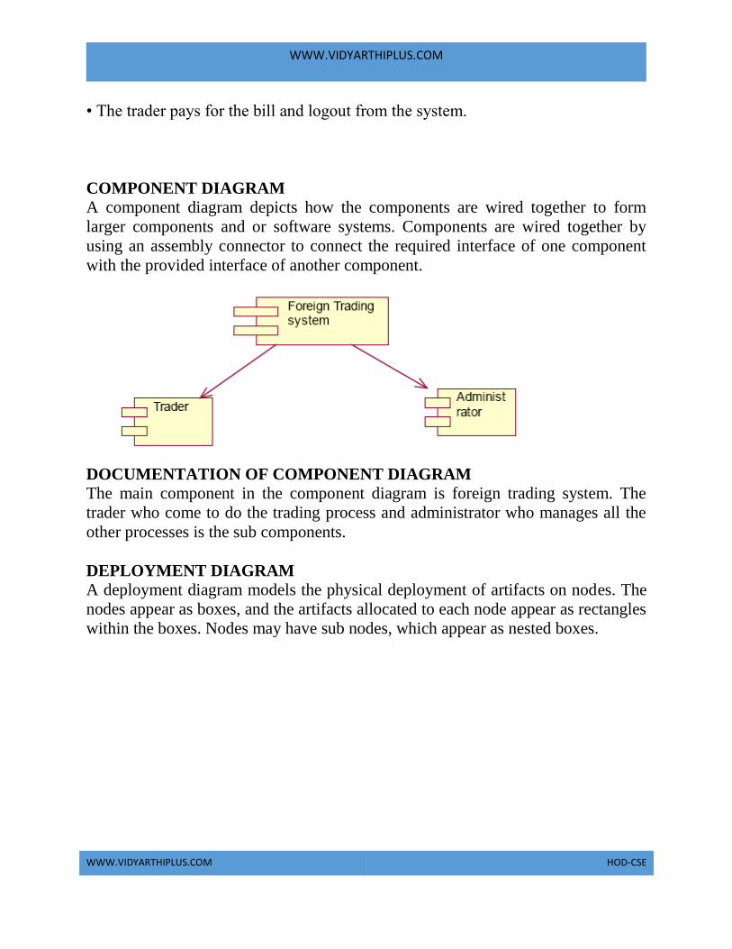
WWW.VIDYARTHIPLUS.COM
WWW.VIDYARTHIPLUS.COM HOD-CSE
• The trader pays for the bill and logout from the system.
COMPONENT DIAGRAM
A component diagram depicts how the components are wired together to form
larger components and or software systems. Components are wired together by
using an assembly connector to connect the required interface of one component
with the provided interface of another component.
DOCUMENTATION OF COMPONENT DIAGRAM The main component in the component diagram is foreign trading system. The
trader who come to do the trading process and administrator who manages all the
other processes is the sub components.
DEPLOYMENT DIAGRAM A deployment diagram models the physical deployment of artifacts on nodes. The
nodes appear as boxes, and the artifacts allocated to each node appear as rectangles
within the boxes. Nodes may have sub nodes, which appear as nested boxes.

WWW.VIDYARTHIPLUS.COM
WWW.VIDYARTHIPLUS.COM HOD-CSE
DOCUMENTATION OF DEPLOYMENT DIAGRAM The processor in this diagram is the foreign trading system. The devices are the
trader and administrator who perform the main activities in the system.
PACKAGE DIAGRAM A package diagram in the unified modeling language depicts the dependencies
between the packages that make up a model. It provides a way to group the
elements. There are three types of layers in package diagram. They are
• User interface layer
• Domain layer
• Technical services layer
User interface layer The user interface layer may call upon its directly subordinate application logic
layer, and also upon elements of a lower technical service layer, for logging and so
forth.
Domain layer

WWW.VIDYARTHIPLUS.COM
WWW.VIDYARTHIPLUS.COM HOD-CSE
Software objects representing domain concepts (for example, a software class
administrator) that fulfill application requirements, such as tracing order and
providing the bill.
Technical services layer General purpose objects and subsystems that provide supporting technical services,
such as interfacing with a database or error logging.These services are usually
application-independent.
DOCUMENTATION OF PACKAGE DIAGRAM The three layers in the foreign trading system are
• User interface layer – consists of web and login. This layer describes how the
trader logins to the website and trades for the commodities.
• Domain layer – shows the activities that are performed inside the trading system.
The activities are place order, pay for the bill and logouts.
• Technical service layer – The sourcing and updating the details are performed in
this layer.
FORMS
FORM1

WWW.VIDYARTHIPLUS.COM
WWW.VIDYARTHIPLUS.COM HOD-CSE
FORM2

WWW.VIDYARTHIPLUS.COM
WWW.VIDYARTHIPLUS.COM HOD-CSE
FORM3
FORM4
FORM5

WWW.VIDYARTHIPLUS.COM
WWW.VIDYARTHIPLUS.COM HOD-CSE
FORM6
FORM7

WWW.VIDYARTHIPLUS.COM
WWW.VIDYARTHIPLUS.COM HOD-CSE
SOURCE CODE
ACCOUNT Option Explicit
'##ModelId=4D64958501F4
Private accoutno As Integer
'##ModelId=4D64958E0186
Private balance As Integer
'##ModelId=4D64959B0290
Private due As Integer
'##ModelId=4D6612990290
Public Sub accountno()
MsgBox "your transaction is successfull"

WWW.VIDYARTHIPLUS.COM
WWW.VIDYARTHIPLUS.COM HOD-CSE
Form6.Show
End Sub
'##ModelId=4D66130F0128
Public Sub accountpay()
MsgBox "your transaction failed. Do your trading again"
Form5.Show
End Sub

WWW.VIDYARTHIPLUS.COM
WWW.VIDYARTHIPLUS.COM HOD-CSE
ADMINISTRATOR '##ModelId=4D6496030128
Public NewProperty As item
'##ModelId=4D6CAE4001F4
Public Sub paybill2()
Form7.Text3.Text = Form7.Text3.Text - Form7.Text5.Text
End Sub
'##ModelId=4D649563003E
Public Sub bill1()
Form4.Text1.Text = Form3.Text4.Text * Form3.Text5.Text
Form4.Show
End Sub
'##ModelId=4D6CA397008C
Public Sub bill2()
Form8.Text1.Text = Form7.Text4.Text * Form7.Text5.Text
Form8.Show
End Sub
'##ModelId=4D64956F0399
Public Sub traceorder()
Form5.Adodc1.ConnectionString = "Provider=Microsoft.Jet.OLEDB.4.0;Data
Source=C:\Documents and Settings\Student\Desktop\datum\db.mdb;Persist
Security Info=False"
Form5.Adodc1.RecordSource = "select itemname from itemtable"
Set Form5.DataGrid1.DataSource = Form5.Adodc1
Form3.Text5.Text = ""
End Sub
'##ModelId=4D6612B70186
Public Sub paybill1()
Form3.Text3.Text = Form3.Text3.Text - Form3.Text5.Text
End Sub
ITEM Option Explicit
'##ModelId=4D6495B600CB
Private name As String
'##ModelId=4D6495BC0213
Private id As Integer
'##ModelId=4D6495CA0251

WWW.VIDYARTHIPLUS.COM
WWW.VIDYARTHIPLUS.COM HOD-CSE
Private rate As Integer
'##ModelId=4D6495D103C8
Private available As Integer
'##ModelId=4D6612C202CE
Public Sub getperfume()
Form3.Text3.Text = Form3.Text3.Text - Form3.Text5.Text
Form4.Show
End Sub
'##ModelId=4D6612D30167
Public Sub getdoll()
Form7.Text3.Text = Form7.Text3.Text - Form7.Text5.Text
Form8.Show
End Sub
TRADER '##ModelId=4D64952500BB
Public Sub login()
If Form1.Text1.Text = "ramya" And Form1.Text2.Text = "ramya" Then
MsgBox "logined successfully"
Form5.Show
Else
MsgBox "invalid login"
End If
End Sub
'##ModelId=4D64952901C5
Public Sub sourcing()
If Form5.Combo1.Text = "perfume" Then
Form3.Show
End If
If Form5.Combo1.Text = "dolls" Then
Form7.Show
End If
End Sub
'##ModelId=4D649531005D
Public Sub placeorder()
Form5.Show
End Sub
'##ModelId=4D64953600FA
Public Sub pay()
Form2.Show

WWW.VIDYARTHIPLUS.COM
WWW.VIDYARTHIPLUS.COM HOD-CSE
End Sub

WWW.VIDYARTHIPLUS.COM
WWW.VIDYARTHIPLUS.COM HOD-CSE
'##ModelId=4D64953903B9
Public Sub logout()
Form1.Show
End Sub
FORM1 Private Sub Command1_Click()
Dim a1 As trader
Set a1 = New trader
a1.login
End Sub
FORM2 Private Sub Command1_Click()
Dim a7 As account
Set a7 = New account
a7.accountno
End Sub
Private Sub Command3_Click()
Dim x As account
Set x = New account
x.accountpay
End Sub
FORM3
Private Sub Command1_Click()
Dim a3 As item
Set a3 = New item
a3.getperfume
Dim x3 As administrator
Set x3 = New administrator
x3.paybill1
End Sub
Private Sub Command2_Click()
Dim a4 As trader
Set a4 = New trader
a4.placeorder
End Sub
FORM4 Private Sub Command2_Click()
Dim a5 As trader

WWW.VIDYARTHIPLUS.COM
WWW.VIDYARTHIPLUS.COM HOD-CSE
Set a5 = New trader
a5.pay
End Sub
Private Sub Form_Load()
Dim a As administrator
Set a = New administrator
a.bill1
End Sub
FORM5
Private Sub Command1_Click()
Dim a2 As trader
Set a2 = New trader
a2.sourcing
End Sub
Private Sub Form_Load()
Dim a0 As administrator
Set a0 = New administrator
a0.traceorder
End Sub
FORM6 Private Sub Command1_Click()
Dim a6 As trader
Set a6 = New trader
a6.logout
End Sub
FORM7 Private Sub Command1_Click()
Dim a3 As item
Set a3 = New item
a3.getdoll
Dim x2 As administrator
Set x2 = New administrator
x2.paybill2
End Sub
Private Sub Command2_Click()
Dim a4 As trader
Set a4 = New trader
a4.placeorder
End Sub

WWW.VIDYARTHIPLUS.COM
WWW.VIDYARTHIPLUS.COM HOD-CSE
FORM8 Private Sub Command2_Click()
Dim a8 As trader
Set a8 = New trader

WWW.VIDYARTHIPLUS.COM
WWW.VIDYARTHIPLUS.COM HOD-CSE
a8.pay
End Sub
Private Sub Form_Load()
Dim a7 As administrator
Set a7 = New administrator
a7.bill2
End Sub
RESULT
Thus the project to develop foreign trading system using Rational Rose software
and to implement the software in Visual Basic is done successfully.

WWW.VIDYARTHIPLUS.COM
WWW.VIDYARTHIPLUS.COM HOD-CSE
EXNO: 12 CONFERENCE MANAGEMENT SYSTEM
AIM To develop a project on Conference management system using Rational Rose
Software and to implement the project in Visual Basic.
PROBLEM ANALYSIS AND PROJECT PLANNING
The Conference Management System is an online website in which candidate can
submit the paper and register themselves and then attend the conference. The paper
will be reviewed. The details of the conference, date and time will be made
available to them through the website. After getting the confirmation details the
candidate should submit the revised and camera ready paper. Then the registration
process will be done.
PROBLEM STATEMENT The process of the candidates is to login the conference system and submit the
paper through online. Then the reviewer reviews the paper and sends the
acknowledgement to the candidate either paper selected or rejected. This process
of on conference management system are described sequentially through following
steps,
• The candidate login to the conference management system.
• The paper title is submitted.
• The paper is been reviewed by the reviewer.
• The reviewer sends acknowledgement to the candidate.
• Based on the selection, the best candidate is selected.

WWW.VIDYARTHIPLUS.COM
WWW.VIDYARTHIPLUS.COM HOD-CSE
• Finally the candidate registers all details.
SOFTWARE REQUIREMENT SPECIFICATION
SNO SPECIFICATION 1 INTRODUCTION
2 OBJECTIVE
3 OVERVIEW
4 GLOSSARY
5 PURPOSE
6 SCOPE
7 FUNCTIONALITY
8 USABILITY
9 PERFORMANCE
10 RELIABILITY
11 FUNCTIONAL
REQUIREMENTS
INTRODUCTION This software specification document consist full set of features and function for
online conference management system. In this we give specification about the
system requirements that are apart from the functionality of the system to perform
the candidate paper valuation. It tells the usability, reliability defined in use case
specification.

WWW.VIDYARTHIPLUS.COM
WWW.VIDYARTHIPLUS.COM HOD-CSE
OBJECTIVE The main objective of Conference Management System is to accomplish paper
submission online, update the presentation details and confirm registration.
Conference management system provides online help to the users all over the
world.
OVERVIEW The overview of the project is to design a process which ease the work for the
candidate as well as the reviewer. Candidate can easily submit the paper and go for
registration.
GLOSSARY
TERMS DESCRIPTION
CANDIDATE The candidate can login and submit the
paper to the reviewer. After getting
acknowledgement the candidate will
submit the revised and camera ready paper
then registration process
will be carried out.
REVIEWER Reviewer will reviews the paper and
sending acknowledgement to the candidate
DATABASE Database is used to verify login and store
the details of selected candidates.
SOFTWARE REQUIREMENT
SPECIFICATION
This software specification documents full
set of features
and function for conference management
system.

WWW.VIDYARTHIPLUS.COM
WWW.VIDYARTHIPLUS.COM HOD-CSE
PURPOSE The purpose of the conference management system is that the system can easily
review the process. The main process in this document is the submission of paper
by the candidate, reviewing process by the reviewer and sending of
acknowledgement to the candidates whose paper is selected.
SCOPE The scope of this conference management process is to select the best candidate
from the list of candidates based on their performance in the process.
FUNCTIONALITY The main functionality of conference system is to select the candidate for the
presentation in conference.
USABILITY
The user interface to make the process should be effective that is the system will
help the candidates to register easily. The system should be user friendly.
PERFORMANCE It describes the capability of the system to perform the conference process of the
candidate without any error and performing it efficiently.
RELIABILITY The conference system should be able to serve the applicant with correct
information and day-to-day update of information.
FUNCTIONAL REQUIREMENTS
Functional requirements are those that refer to the functionality of the system that
is the services that are provided to the candidate who register for the conference.
UML DIAGRAMS The following UML diagrams describe the process involved in the conference
management system.
• Use case diagram
• Class diagram

WWW.VIDYARTHIPLUS.COM
WWW.VIDYARTHIPLUS.COM HOD-CSE
• Sequence diagram
• Collaboration diagram
• State chart diagram
• Activity diagram
• Component diagram
• Deployment diagram
• Package diagram
USE CASE DIAGRAM A use case is a methodology used in system analysis to identify, clarify, and
organize system requirements. The use case is made up of a set of possible
sequences of interactions between systems and users in a particular environment
WWW.VIDYARTHIPLUS.COM
WWW.VIDYARTHIPLUS.COM HOD-CSE
and related to a particular goal. It is represented using ellipse. Actor is any external
entity that makes use of the system being modeled. It is represented using stick
figure.
DOCUMENTATION OF USE CASE DIAGRAM The actors in this use case diagram are candidate, reviewer and database. The use
cases are the activities performed by actors.
The actors in this use case diagram are
• Candidate - Logins the conference system and submits the paper then do the
registration process.
• Reviewer – Review the paper , select best candidate and send acknowledgement
to them.
• Databases - verify the login and register details and selected candidate details are
stored in it.
The use cases in this use case diagram are
• Login - Candidate enter their username and password to login to the conference
system.
Paper sumbission – Candidate submits the paper.
• Review the paper– The paper is been reviewed by the reviewer and the paper is
selected.
• Paper confirmation details – The reviewer can send the confirmation details to
the candidate.
• Revised and camera ready paper – After the paper is selected and the camera
ready paper should be submitted to the reviewer by candidate.
• Registration – After submitting the revised paper the candidate wants to register.

WWW.VIDYARTHIPLUS.COM
WWW.VIDYARTHIPLUS.COM HOD-CSE
CLASS DIAGRAM A class diagram in the unified modeling language (UML) is a type of static
structure diagram that describes the structure of a system by showing the system's
classes, their attributes, and the relationships between the classes. It is represented
using a rectangle with three compartments. Top compartment have the class name,
middle compartment the attributes and the bottom compartment with operations.
DOCUMENTATION OF CLASS DIAGRAM
This class diagram has three classes candidate, reviewer and database.
• Candidate – Its attributes are name , collegename , department , paper title. The
operations performed in the candidate class are login, submit the paper, submit
revised and camera ready paper and registration.
• Reviewer – Its attributes are name, department, reviewer ID The operations
performed are review the paper and send the paper confirmation details.
• Database –The operations performed are storing candidate details and verifying
login .
SEQUENCE DIAGRAM A sequence diagram in Unified Modeling Language (UML) is a kind of interaction
diagram that shows how processes operate with one another and in what order. It is
a construct of a Message Sequence Chart. There are two dimensions.
1. Vertical dimension-represent time.
2. Horizontal dimension-represent different objects.
SEQUENCE DIAGRAM FOR LOGIN

WWW.VIDYARTHIPLUS.COM
WWW.VIDYARTHIPLUS.COM HOD-CSE
SEQUENCE DIAGRAM FOR SUBMITTING PAPER
DOCUMENTATION OF SEQUENCE DIAGRAM
LOGIN This sequence diagram describes the sequence of steps to show
• The candidate login in to the conference system and register for job.
• The verification done in the database .
PAPER SUBMISSION This sequence diagram shows steps to show
• The candidate sumbit the paper.
• The reviewer reviews the paper and sends acknowlegement to the candidate.
• The candidate submits revised and camera ready paper.
• This candidate will registers their detials.
COLLABRATION DIAGRAM
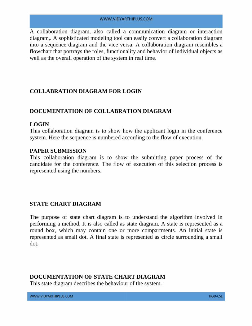
WWW.VIDYARTHIPLUS.COM
WWW.VIDYARTHIPLUS.COM HOD-CSE
A collaboration diagram, also called a communication diagram or interaction
diagram,. A sophisticated modeling tool can easily convert a collaboration diagram
into a sequence diagram and the vice versa. A collaboration diagram resembles a
flowchart that portrays the roles, functionality and behavior of individual objects as
well as the overall operation of the system in real time.
COLLABRATION DIAGRAM FOR LOGIN
DOCUMENTATION OF COLLABRATION DIAGRAM
LOGIN This collaboration diagram is to show how the applicant login in the conference
system. Here the sequence is numbered according to the flow of execution.
PAPER SUBMISSION This collaboration diagram is to show the submitting paper process of the
candidate for the conference. The flow of execution of this selection process is
represented using the numbers.
STATE CHART DIAGRAM
The purpose of state chart diagram is to understand the algorithm involved in
performing a method. It is also called as state diagram. A state is represented as a
round box, which may contain one or more compartments. An initial state is
represented as small dot. A final state is represented as circle surrounding a small
dot.
DOCUMENTATION OF STATE CHART DIAGRAM This state diagram describes the behaviour of the system.

WWW.VIDYARTHIPLUS.COM
WWW.VIDYARTHIPLUS.COM HOD-CSE
• First state is login where the candidate login to the conference system.
• The next state is submitting the paper .
• Then review the paper if it is selected the process will continue..
• The candidate should submit revised and camera ready paper.
• Then registration process will be carried out.
ACTIVITY DIAGRAM
Activity diagrams are graphical representations of workflows of stepwise activities
and actions with support for choice, iteration and concurrency. In the Unified
Modeling Language, activity diagrams can be used to describe the business and
operational step-by-step workflows of components in a system. An activity
diagram shows the overall flow of control. An activity is shown as an rounded box
containing the name of the operation.
DOCUMENTATION OF ACTIVITY DIAGRAM This activity diagram flow of stepwise activities performed in recruitment system.
• First the candidate login to the database.
• Then the candidate should submit the paper.
• If it is selected the acknowledgement will send to the candidate.
• After submitting revised paper the registration proces will be done.
COMPONENT DIAGRAM

WWW.VIDYARTHIPLUS.COM
WWW.VIDYARTHIPLUS.COM HOD-CSE
The component diagram's main purpose is to show the structural relationships
between the components of a system. It is represented by boxed figure.
Dependencies are represented by communication association.
DOCUMENTATION OF COMPONENT DIAGRAM The main component in this component diagram is conference management
system. And submit the paper, review the paper and registration.
DEPLOYMENT DIAGRAM A deployment diagram in the unified modeling language serves to model the
physical deployment of artifacts on deployment targets. Deployment diagrams
show "the allocation of artifacts to nodes according to the Deployments defined
between them. It is represented by 3-dimensional box. Dependencies are
represented by communication association.

WWW.VIDYARTHIPLUS.COM
WWW.VIDYARTHIPLUS.COM HOD-CSE
DOCUMENTATION OF DEPLOYMENT DIAGRAM The processor in this deployment diagram is the conference management system
which is the main part and the devices are the candidate, appear for do conference ,
reviewer will reviews paper , database will store all details which are the some of
the main activities performed in the system.
PACKAGE DIAGRAM A package diagram in unified modeling language that depicts the dependencies
between the packages that make up a model. A Package Diagram (PD) shows a
grouping of elements in the OO model, and is a Cradle extension to UML. PDs can
be used to show groups of classes in Class Diagrams (CDs), groups of components
or processes in Component Diagrams (CPDs), or groups of processors in
Deployment Diagrams (DPDs).
There are three types of layer. They are
• User interface layer - software objects representing domain concepts that fulfill
application requirements, such as calculation of a sale total.
• Domain layer – layer that contains domain objects to handle application logic
work.
• Technical services layer – general purpose objects and subsystems that provide
supporting technical services, such as interfacing with a database or error logging.
DOCUMENTATION OF PACKAGE DIAGRAM The three layers in the online recruitment system are
• The User interface layer - consists of the web and login. This layer describes
how the candidate login.
• The Domain layer – shows the activities that are performed in the conference
management system. The activities are paper submission , review paper ,
registration.

WWW.VIDYARTHIPLUS.COM
WWW.VIDYARTHIPLUS.COM HOD-CSE
• The Technical service layer - the verification details and the selected candidate
details will stored into the database.
FORMS
FORM1
FORM2
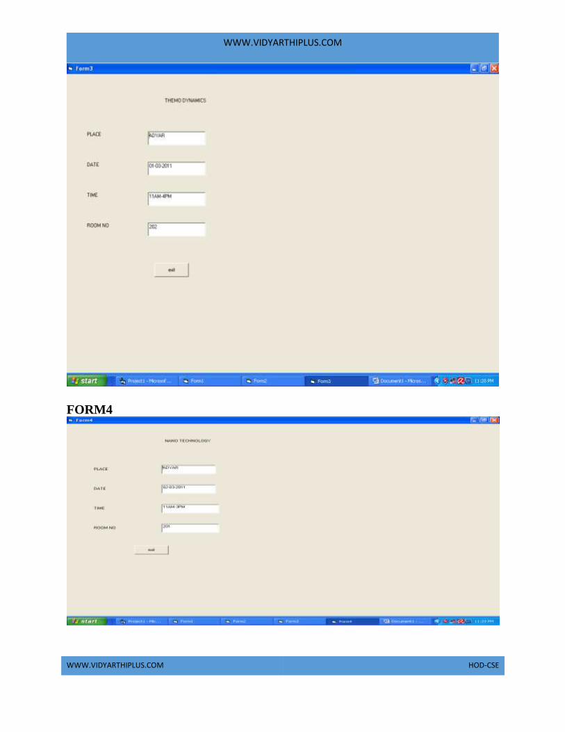
WWW.VIDYARTHIPLUS.COM
WWW.VIDYARTHIPLUS.COM HOD-CSE
FORM4
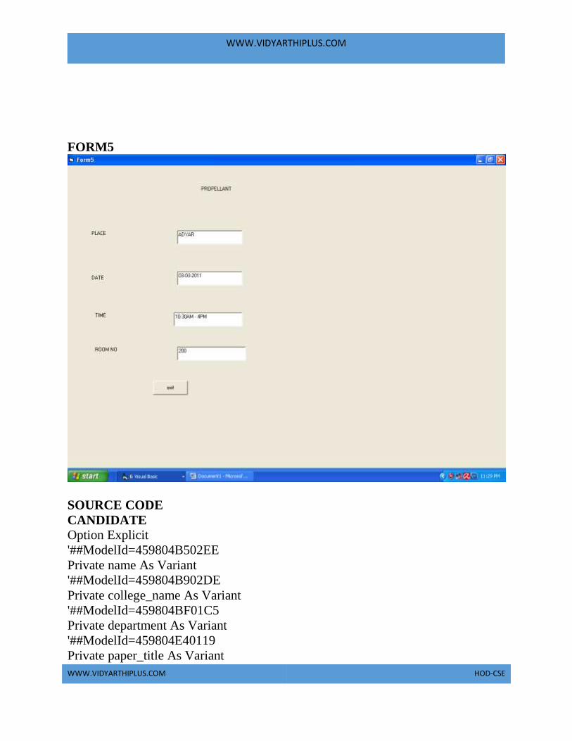
WWW.VIDYARTHIPLUS.COM
WWW.VIDYARTHIPLUS.COM HOD-CSE
FORM5
SOURCE CODE
CANDIDATE Option Explicit
'##ModelId=459804B502EE
Private name As Variant
'##ModelId=459804B902DE
Private college_name As Variant
'##ModelId=459804BF01C5
Private department As Variant
'##ModelId=459804E40119
Private paper_title As Variant

WWW.VIDYARTHIPLUS.COM
WWW.VIDYARTHIPLUS.COM HOD-CSE
'##ModelId=45980653030D
Public NewProperty As reviewer1
'##ModelId=45980507034B
Public Sub login()
End Sub
'##ModelId=4598050E03D8
Public Sub submit_the_paper()
End Sub
'##ModelId=4598051302FD
Public Sub revised_and_camera_ready_paper_submission()
End Sub
'##ModelId=4598053F009C
Public Sub registration()

WWW.VIDYARTHIPLUS.COM
WWW.VIDYARTHIPLUS.COM HOD-CSE
End Sub
DATABASE Option Explicit
'##ModelId=459806A30280
Public NewProperty As candidate1
'##ModelId=4598060A02BF
Public Sub verify_the_ID()
End Sub
'##ModelId=4598062A01F4
Public Sub allow_to_the_reviewer()
End Sub
REVIEWER Option Explicit
'##ModelId=45980565035B
Private reviewer_name As Variant
'##ModelId=45980568036B
Private reviewer_department As Variant
'##ModelId=459805920251
Private reviewer_ID As Variant
'##ModelId=4598065C008C
Public NewProperty As database1
'##ModelId=4598067E032C
Public NewProperty2 As database1
'##ModelId=4598069501B5
Public NewProperty3 As database1
'##ModelId=459805A10128
Public Sub review_the_paper()
End Sub
'##ModelId=459805B0038A
Public Sub sending_paper_confirmation_details()
End Sub
FORM 1 Private Sub Command1_Click()
Dim a As candidate1
Set a = New candidate1
Call a.login
End Sub
Private Sub Command2_Click()
Unload Me

WWW.VIDYARTHIPLUS.COM
WWW.VIDYARTHIPLUS.COM HOD-CSE
End Sub

WWW.VIDYARTHIPLUS.COM
WWW.VIDYARTHIPLUS.COM HOD-CSE
Public Sub login()
If Form1.Text1.Text = "rss" And Form1.Text2.Text = "rss" Then
MsgBox "login sucessfully!!!"
Form2.Show
Else
MsgBox "invalid username or password"
End If
End Sub
FORM2
Private Sub Command1_Click()
Dim a As candidate1
Set a=New candidate1
Call a.subregistration
End Sub
Public Sub subregistration()
Private Sub Command1_Click()
If(Combo1.text=”101”)Then
Form3.Show
End If
If(Combo1.text=”102”)Then
Form4.Show
End If
If(Combo1.text=”103”)Then
Form5.Show
End If
End Sub
FORM 3 Private Sub Command1_Click()
Dim a As candidate1
Set a = New candidate1
Call a.verify_the_ID
End Sub

WWW.VIDYARTHIPLUS.COM
WWW.VIDYARTHIPLUS.COM HOD-CSE
Public verify_the_ID()
Form2.Show
End Sub
FORM 4 Private Sub Command1_Click()
Dim a As database1
Set a = New database1
Call a.verify_the_ID
End Sub
Public Sub verify_the_ID()
Form2.Show
End Sub
FORM 5 Private Sub Command1_Click()
Dim a As database1
Set a = New database1
Call a. verify_the_ID
End Sub
Public Sub verify_the_ID()
Form2.Show
RESULT
Thus the project to develop conference management system using Rational Rose
Software and to implement the project in Visual Basic is done successfully.

WWW.VIDYARTHIPLUS.COM
WWW.VIDYARTHIPLUS.COM HOD-CSE
EXNO:13 BUSINESS PROCESS OUTSOURCING MANAGEMENT
SYSTEM
AIM To develop a project Business process outsourcing(BPO) management system
Using Rational Rose software and to implement the software in Visual Basic.
PROBLEM ANALYSIS AND PROJECT PLANNING Generally outsourcing can be defined as an organization entering into a contract
with another organization to operate and managed one or more of its business
processes.
There are many problems faced by the BPO one among them is meeting their
targets and leaving the concern very often and switch to another company.In this
project we deal with the inbound system of the BPO.In inbound system the agent
calls the customer from his database to sell his product.
PROBLEM STATEMENT In this BPO inbound system , the process undergoing is that the agent tries to sell
his product so that the agent gets the details of the customer from the database and
pitches about his product and makes the sales successful. The communication is
done through the telephone. Telephone is the major component used for this
customer satisfaction service. The steps are as follows:
• The agent login to the website and enters the username and password .It checks
for authorization .
• If the username and password is correct ,it allows the agent to get the details of
the customer from the database.

WWW.VIDYARTHIPLUS.COM
WWW.VIDYARTHIPLUS.COM HOD-CSE
• Now the agent makes the call to the customer and pitches about the product.
• If the customer is satisfied ,agent sells the product else disconnects the call.
• Agent proceeds with the another call.
SOFTWARE REQUIREMENT SPECIFICATION
1 INTRODUCTION
2 OBJECTIVE
3 PURPOSE
4 SCOPE
5 GLOSSARY
6 OVERVIEW
7 OVERALL DESCRIPTION
8 REFERENCES
9 FUNCTIONALITY
10 USABILITY
11 PERFORMANCE
12 SYSTEM ENVIRONMENT
13 FUNCTIONAL
REQUIREMENTS
1. INTRODUCTION BPO is typically categorized into back office outsourcing-which includes internal
business functions such as human resources or finance and accounting, and front
office outsouring-which includes customer related services such as contact center
services. BPO that is contracted outside a company’s country is called offshore
outsourcing.BPO that is contracted to a company’s neighbouring country is called

WWW.VIDYARTHIPLUS.COM
WWW.VIDYARTHIPLUS.COM HOD-CSE
nearshore outsourcing.Given the proximity of BPO to the information technology
industry,it is categorized as an information technology enabled service or
ITES.Knowledge process outsourcing(KPO) and legal process outsourcing(LPO)
are some of the sub-segments of business process outsourcing industry.In the
following SRS the front office outsourcing is explained in detail.
2. PURPOSE The purpose of this system is to provide information about the customer need from
inside and outside world.With the reduction in communication costs and improved
bandwidths and associated infrastructure,BPO as a segment is witnessing massive
growth.One of the key challenges that BPO campanies is that to provide data
entry/data validation services is an efficient and effective way of getting the source
documents from different customers and accurately route the same of different
operators for processing.
3. SCOPE
Developing a good BPO management system.BPO is a way in which it helps to
increase companys flexibility.As part of BPO,documents need to be managed
between the outsourcing company and the offshore company.Multiple clients need
to be managed by the BPO company.
4. GLOSSARY
TERM DESCRIPTION
Customer Person who is seeking information.
Agent People who receives the query.
Database Collection of all information monitored
by the BPO system.
Reader Anyone visiting the site to read about
BPO management system.
Software requirement
specification
A document that completely describes all
the functions of
a proposed system and the constrains
under which it
must operate.
User Customer and reader
7. REFERENCES

WWW.VIDYARTHIPLUS.COM
WWW.VIDYARTHIPLUS.COM HOD-CSE
Business process outsourcing the competitive advantage by Rick L. Click,Thomas
N.Duening-2005. Srs document is referred from the standard IEEE format from
fundamentals of software engineering by Rajib Mall(2004)page no:356
8. FUNCTIONALITY Many customers of the process to check for its occurance and other works.we all
have to carry over at same time.
9. USABILITY
The user interface to make the bpo management to be efficient.
10. PERFORMANCE It is the capability about which it can perform function for many user efficiently at
the same time without any error occurance
11. SYSTEM ENVIRONMENT
The BPO system is embedded in a larger system involving several management
systems.we describe this environment as communication system between customer
and agent through voice chat.The administrator of the system uses FTP for moving
files from one place to another.
12. FUNCTIONAL REQUIREMENTS
Functional requirements are those refer to the functionality of the system.i.e. what
services it will provide to the user. Non functional (supplementary) requirements
pertain to other information needed to produce the system correctly and detailed
separately.
UML DIAGRAMS The following UML diagrams describe the process involved in the online
recruitment system
• Use case diagram
• Class diagram
• Sequence diagram
• Collaboration diagram
• State chart diagram
• Activity diagram

WWW.VIDYARTHIPLUS.COM
WWW.VIDYARTHIPLUS.COM HOD-CSE
• Component diagram
• Deployment diagram
• Package diagram
USE CASE DIAGRAM A use case is a methodology used in system analysis to identify, clarify, and
organize system requirements. The use case is made up of a set of possible
sequences of interactions between systems and users in a particular environment
and related to a particular goal. It is represented using ellipse.Actor is any external
entity that makes use of the system being modelled. It is represented using stick
figure.
DOCUMENTATION OF USE CASE DIAGRAM The actors in this use case diagram are Process agent ,Customer and Database. The
usecases are the activities performed by actors.
USE CASE Use case is a collection of failure and related success scenarios that describe the
actor using a system to support a goal.
ACTOR The Actor is a user playing a role with respect to the system. A single actor may
perform many use cases. Similarly a user case can have many users performing the
operation.
PROCESS AGENT The ultimate Goal of the process agent is to make sale. The operation performed by
him/her is he/she will first call the customer then pitches there product for sale. If
the customer is interested the agents mark it has a sale else disconnects the call and
moves to another customer.
DATABASE The database is neither a computer nor a memory where all the customers’ details
will be stored. It consists of the customer name, customer address, and customer
phone number. Further details of the customer can also be added in the future by
the agent.
CUSTOMER

WWW.VIDYARTHIPLUS.COM
WWW.VIDYARTHIPLUS.COM HOD-CSE
Customer plays a vital role in the BPO industry. Agent calls the customer from the
database. Once the call gets connected and the customer is happy with the product
which is pitched by the agent then he/she will show interest for buying the product
else he/she will reject the product and disconnect the call.
CLASS DIAGRAM A class diagram in the unified modeling language (UML) is a type of static
structure diagram that describes the structure of a system by showing the system's
classes, their attributes, and the relationships between the classes. It is represented
using a rectangle with three compartments. Top compartment have the class
name,middle comparment the attributes and the bottom compartment with
operations.
DOCUMENTATION OF CLASS DIAGRAM This class diagram has three classes process agent, customer and database.
• Agent – is the class name. Its attributes are username, password, name, phoneno
and address. The operations performed by the agent class are login, giving details
to customer and selling the product.

WWW.VIDYARTHIPLUS.COM
WWW.VIDYARTHIPLUS.COM HOD-CSE
• Customer – is the class name. Its attributes are name, phoneno, address . The
operations performed are attending the call,asks about the product.
• Database – is the class name. The operations performed are storing customer
details, verifying login and updating the customer details.
SEQUENCE DIAGRAM A sequence diagram in Unified Modeling Language (UML) is a kind of interaction
diagram that shows how processes operate with one another and in what order. It is
a construct of a Message Sequence Chart. There are two dimensions.
1.Veritcal dimension-represent time.
2.Horizontal dimension-represent different objects.
DOCUMENTATION OF SEQUENCE DIAGRAM The single use case in the BPO management system is taken and sequence of
operations followed in the usecase.
The BPO has the following sequence of process:
1.Agent fetches the data from the database
2.database provides the details of the customer to agent and agent dials to the
customer.
3.Customer responds to the agent and agent pitches his/her product.
4.If necessary customer buys else discards.
5.Agent updates the call history
6.proceeds with the another call.
COLLABRATION DIAGRAM
A collaboration diagram, also called a communication diagram or interaction
diagram,. A sophisticated modeling tool can easily convert a collaboration diagram
into a sequence diagram and the vice versa. A collaboration diagram resembles a
flowchart that portrays the roles, functionality and behavior of individual objects as
well as the overall operation of the system in real time.
DOCUMENTATION OF COLLABRATION DIAGRAM

WWW.VIDYARTHIPLUS.COM
WWW.VIDYARTHIPLUS.COM HOD-CSE
This diagram is similar to sequence diagram.But the difference is the various
operations involved in the particular use case will be numbered.In this diagram,the
sequence of step is
• Fetches the customer details from the database.
• Database provides the customer details.
• Agent dials the customer.
• Customer responds to the agent call.
The agent pitches about his/her product to the customer.
If necessary customer buys else disconnects the call
The agent updates the call history.
The agent proceeds with the another call.
STATE CHART DIAGRAM It is also called as State diagram .The purpose of state diagram is to understand the
algorithm in problem statement.
A state is represented as a rounded box, Which may contain one or more
compartments. Compartments are all optional.
Types of compartment:
*Name compartment- holds name of the state
*Internal transition- holds internal actions or activities.
State chart is shown as the small dot .
Final state is shown as circle surrounding a small dot.
DOCUMENTATION OF STATE CHART DIAGRAM The various states are login,fetches data from database, calls the customer, pitches
the product, sales the product, proceeds with another call.
The state chart diagram describes the behavior of the system.
1. The main purpose of the system is to sale the product to the customer.
2. After login, the agent gets details of customer from database.
3. the agent calls the customer.
4. The agent pitches about the product.

WWW.VIDYARTHIPLUS.COM
WWW.VIDYARTHIPLUS.COM HOD-CSE
5. If customer interested , the agent buys the product else discards.
6. Agent proceeds with the another call.
ACTIVITY DIAGRAM Activity diagrams are graphical representations of workflows of stepwise activities
and actions with support for choice, iteration and concurrency. In the Unified
Modeling Language, activity diagrams can be used to describe the business and
operational step-by-step workflows of components in a system. An activity
diagram shows the overall flow of control. An activity is shown as an rounded box
containing the name of the operation.
DOCUMENTATION OF ACTIVITY DIAGRAM Activity Diagram is shows the flow of the activity which is carried out in the BPO
management. It is more or less equal to the flow chart which we use in our
programming languages. It consists of states such as login , fetches the data, calls
the customer, pitches the product, makes the sale and etc……
Initial node: The filled in circle is the starting point of the diagram. An initial
node isn’t required although it does make it significantly easier to read the
diagram.
• Activity final node. The filled circle with a border is the ending point. An
activity diagram can have zero or more activity final nodes.
• Activity. The rounded rectangles represent activities that occur. An activity may
be physical, such as Inspect Forms, or electronic, such as display the BPO details.
• Flow/edge. The arrows on the diagram. Although there is a subtle difference
between flows and edges I have never seen a practical purpose for the difference
although I have no doubt one exists. I’ll use the term flow.
COMPONENT DIAGRAM The component diagram's main purpose is to show the structural relationships
between the components of a systems. It is represented by boxed figure.
Dependencies are represented by communication assosiation.

WWW.VIDYARTHIPLUS.COM
WWW.VIDYARTHIPLUS.COM HOD-CSE
DOCUMENTATION OF COMPONENT DIAGRAM The main component in this component diagram is BPO management systems.
And the agent calls customer, pitches about his product and makes the sale are the
main component comes under the component diagram.
DEPLOYMENT DIAGRAM A deployment diagram in the unified modeling language serves to model the
physical deployment of artifacts on deployment targets. Deployment diagrams
show "the allocation of artifacts to nodes according to the Deployments defined
between them. It is represented by 3-dimentional box. Dependencies are
represented by communication assosiation.
DOCUMENTATION OF DEPLOYMENT DIAGRAM The processor in this deployment diagram is the BPO management system which
is the main part and the devices are the agent, customer and to sell the product to
the customer are the main activities performed in the system.
PACKAGE DIAGRAM A package diagram in unified modeling language that depicts the dependencies
between the packages that make up a model. A Package Diagram (PD) shows a
grouping of elements in the OO model, and is a Cradle extension to UML. PDs can
be used to show groups of classes in Class Diagrams (CDs), groups of components
or processes in Component Diagrams (CPDs), or groups of processors in
Deployment Diagrams (DPDs).

WWW.VIDYARTHIPLUS.COM
WWW.VIDYARTHIPLUS.COM HOD-CSE
There are three types of layer. They are
• User interface layer
• Domain layer
• Technical services layer
DOCUMENTATION OF PACKAGE DIAGRAM The three layers in the BPO management systems are
• The User interface layer - consists of the web and login. This layer decribes
how
The agent logs on to the website and gets the customer details.
The Domain layer – shows the activities that are performed in the BPO
rmanagement system.The agent makes the call and he pitches about the product to
customer and makes sale.Finally agent aborts the call and proceeds with another
call.
• The Technical service layer –the customer details are shown in the database.If
the customer buys product it makes the sale entry.
FORMS
FORM 1

WWW.VIDYARTHIPLUS.COM
WWW.VIDYARTHIPLUS.COM HOD-CSE
FORM 2

WWW.VIDYARTHIPLUS.COM
WWW.VIDYARTHIPLUS.COM HOD-CSE
FORM 3

WWW.VIDYARTHIPLUS.COM
WWW.VIDYARTHIPLUS.COM HOD-CSE
FORM 4
FORM 5
FORM 6

WWW.VIDYARTHIPLUS.COM
WWW.VIDYARTHIPLUS.COM HOD-CSE
FORM 7
FORM 8

WWW.VIDYARTHIPLUS.COM
WWW.VIDYARTHIPLUS.COM HOD-CSE
SOURCE CODE:
FORM 1: customer
Option Explicit
'##ModelId=4D62041B005D
Private NAME As Variant
'##ModelId=4D62041F01F4
Private address As Variant
'##ModelId=4D6204240119
Private phone_no As Variant
'##ModelId=4D6205B7008C

WWW.VIDYARTHIPLUS.COM
WWW.VIDYARTHIPLUS.COM HOD-CSE
Public NewProperty As process_agent
'##ModelId=4D62042F0271
Public Sub attends_call()
End Sub
'##ModelId=4D62043B036B
Public Sub asks_query()
End Sub
database
Option Explicit
'##ModelId=4D620452000F
Private NAME As Variant
'##ModelId=4D62059502DE
Public NewProperty As process_agent
'##ModelId=4D620459007D
Public Sub get_details()
End Sub
'##ModelId=4D620569006D
Public Sub update_details()
End Sub
Public NewProperty As customer
'##ModelId=4D6205AE00FA
Public NewProperty2 As database
'##ModelId=4D6203E2000F
Public Sub makes_call()
If Form1.Text1.Text = "bpo" And Form1.Text2.Text = "123" Then
MsgBox "Login successfull"
Else
MsgBox "Invalid password"
End If
Form2.Show
End Sub
'##ModelId=4D6203EA02AF

WWW.VIDYARTHIPLUS.COM
WWW.VIDYARTHIPLUS.COM HOD-CSE
Public Sub pitches_about_product()
Form2.Show
End Sub
'##ModelId=4D62040401A5
Public Sub make_sales()
If (Form2.Combo1.Text = "Anand") Then
Form3.Show
End If
If (Form2.Combo1.Text = "Brindha") Then
Form4.Show
End If
If (Form2.Combo1.Text = "Rubini") Then
Form5.Show
End If
End Sub
'##ModelId=4D620409030D
Public Sub ends_the_call()
Form2.Show
End Sub
RESULT Thus the project to develop BPO management system using Rational Rose
Software and to implement the software in Visual Basic is done successfully.

WWW.VIDYARTHIPLUS.COM
WWW.VIDYARTHIPLUS.COM HOD-CSE