Thiagarajar College of Engineering
200
M.E. Degree (Manufacturing Engineering) - 2014-2015 i Board of studies meeting on 07.11.14 Approved in 49th Academic Council meeting on 04.12.2014 CURRICULUM AND DETAILED SYLLABI FOR M.E DEGREE (Manufacturing Engineering) PROGRAMME CORE AND ELECTIVE COURSES FOR THE STUDENTS ADMITTED FROM THE ACADEMIC YEAR 2014-2015 ONWARDS THIAGARAJAR COLLEGE OF ENGINEERING (A Government Aided ISO 9001-2008 certified Autonomous Institution affiliated to Anna University) MADURAI – 625 015, TAMILNADU Phone: 0452 – 2482240, 41 Fax: 0452 2483427 Web: www.tce.edu
-
Upload
khangminh22 -
Category
Documents
-
view
6 -
download
0
Transcript of Thiagarajar College of Engineering

M.E. Degree (Manufacturing Engineering) - 2014-2015
i
Board of studies meeting on 07.11.14 Approved in 49th Academic Council meeting on 04.12.2014
CURRICULUM AND DETAILED SYLLABI
FOR
M.E DEGREE (Manufacturing Engineering) PROGRAMME
CORE AND ELECTIVE COURSES
FOR THE STUDENTS ADMITTED FROM THE
ACADEMIC YEAR 2014-2015 ONWARDS
THIAGARAJAR COLLEGE OF ENGINEERING (A Government Aided ISO 9001-2008 certified Autonomous Institution affiliated to Anna University)
MADURAI – 625 015, TAMILNADU Phone: 0452 – 2482240, 41
Fax: 0452 2483427 Web: www.tce.edu

M.E. Degree (Manufacturing Engineering) - 2014-2015
ii
Board of studies meeting on 07.11.14 Approved in 49th Academic Council meeting on 04.12.2014
THIAGARAJAR COLLEGE OF ENGINEERING, MADURAI – 625 015 (A Govt. Aided ISO 9001 – 2008 Certified, Autonomous Institution Affiliated to Anna University)
DEPARTMENT OF MECHANICAL ENGINEERING Vision:
“Be a globally renowned school of engineering in mechanical sciences” Mission: As a department, we are committed to
• Develop ethical and competent engineers by synergizing world class teaching, learning and research
• Establish state-of-art laboratories and to provide consultancy services to fulfill the expectations of industry and needs of the society
• Inculcate entrepreneurial qualities for creating, developing and managing global engineering ventures
• Motivate the students to pursue higher studies and research
Programme Educational Objectives (PEOs) of M.E. (Manufacturing Engineering) The post graduate programme in Manufacturing Engineering provides education and training to: PEO 1
• Graduates will apply a broad and fundamental knowledge, and up-to-date skills in performing professional work in manufacturing engineering and management.
PEO 2
• Graduates will offer complete manufacturing solutions incorporating the use of standards and practical constraints with due consideration to the economic, environmental, and social concerns.
PEO3
• Graduates will play a productive role in industrial or governmental organizations as an associate of multi-disciplinary and cross-functional teams, with an appreciation for the value of ethic and cultural diversity and an understanding of contemporary issues.
PEO 4
• Graduates will engage in manufacturing research and consultancy to pursue lifelong learning.

M.E. Degree (Manufacturing Engineering) - 2014-2015
iii
Board of studies meeting on 07.11.14 Approved in 49th Academic Council meeting on 04.12.2014
Programme Outcomes (POs) of M.E. (Manufacturing Engineering) Post Graduating Students of M.E. Manufacturing Engineering programme will have
PO No.
Graduate Attributes
Programme Outcomes
PO1 Scholarship of Knowledge
Acquire in-depth knowledge with wider and global perspective with an ability to discriminate, evaluate, analyse and synthesize existing and new knowledge, and integration of the same for enhancement of knowledge in Manufacturing Engineering.
PO2 Critical Thinking
Analyse complex manufacturing engineering problems critically, apply independent judgement for synthesising information to make intellectual and/or creative advances for conducting research in a wider theoretical, practical and policy context.
PO3 Problem Solving
Think laterally and originally, conceptualise and solve manufacturing engineering problems, evaluate a wide range of potential solutions for those problems and arrive at feasible, optimal solutions after considering public health and safety, cultural, societal and environmental factors in the core areas of expertise.
PO4 Research Skill
Extract information pertinent to unfamiliar problems through literature survey and experiments, apply appropriate research methodologies, techniques and tools, design, conduct experiments, analyse and interpret data, demonstrate higher order skill and view things in a broader perspective, contribute individually/in group(s) to the development of scientific/ technological knowledge in manufacturing engineering.
PO5 Usage of modern tools
Create, select, learn and apply appropriate techniques, resources, and modern engineering and IT tools, including prediction and modelling, to complex manufacturing engineering activities with an understanding of the limitations.
PO6
Collaborative and Multidisciplinary work
Possess knowledge and understanding of group dynamics, recognise opportunities and contribute positively to collaborative-multidisciplinary scientific research, demonstrate a capacity for self-management and teamwork, decision-making based on open-mindedness, objectivity and rational analysis in order to achieve common goals and further the learning of themselves as well as others.
PO7 Project Management and Finance
Demonstrate knowledge and understanding of engineering and management principles and apply the same to one’s own work, as a member and leader in a team, manage projects efficiently in manufacturing engineering and multidisciplinary environments after considering the economical and financial factors.
PO8 Communication
Communicate with the engineering community, and with society at large, regarding complex manufacturing engineering activities confidently and effectively, such as, being able to comprehend and write effective reports and design documentation by adhering to appropriate standards, make effective presentations, and give and receive clear instructions.
PO9 Life-long Learning
Recognise the need for, and have the preparation and ability to engage in life-long learning independently, with a high

M.E. Degree (Manufacturing Engineering) - 2014-2015
iv
Board of studies meeting on 07.11.14 Approved in 49th Academic Council meeting on 04.12.2014
PO No.
Graduate Attributes
Programme Outcomes
level of enthusiasm and commitment to improve knowledge and competence continuously.
PO10
Ethical Practices and Social Responsibility
Acquire professional and intellectual integrity, professional code of conduct, ethics of research and scholarship, consideration of the impact of research outcomes on professional practices and an understanding of responsibility to contribute to the community for sustainable development of society.
PO11 Independent and Reflective Learning
Observe and examine critically the outcomes of one’s actions and make corrective measures subsequently, and learn from mistakes without depending on external feedback.
M.E. Degree (Manufacturing Engineering) - 2014-2015
v
Board of studies meeting on 07.11.14 Approved in 49th Academic Council meeting on 04.12.2014
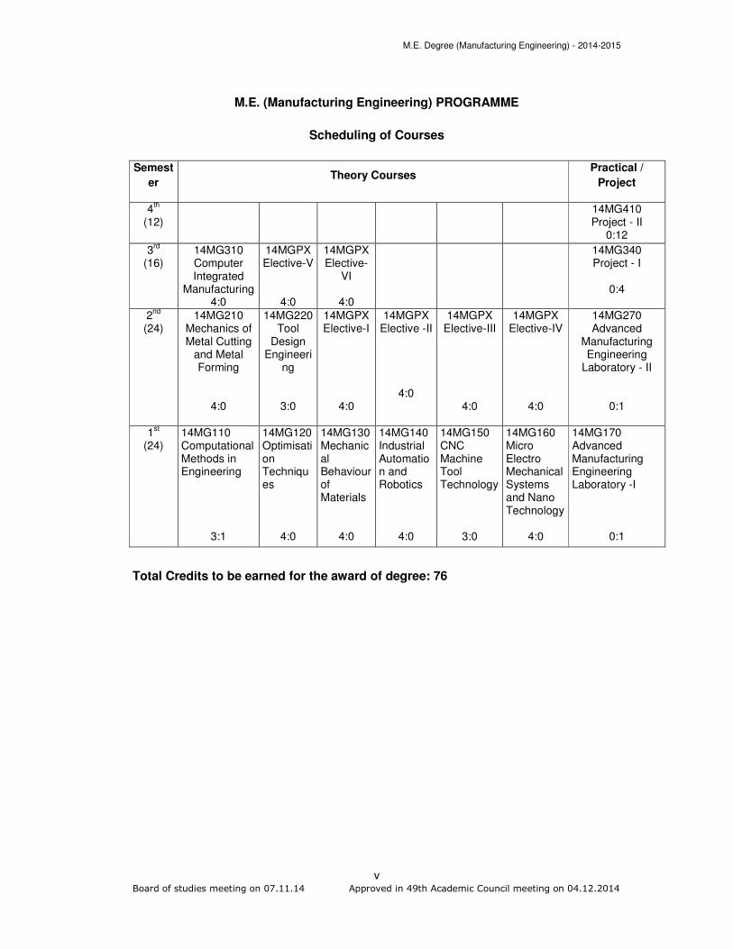
M.E. (Manufacturing Engineering) PROGRAMME
Scheduling of Courses
Semest
er Theory Courses
Practical /
Project
4th
(12) 14MG410
Project - II 0:12
3rd
(16)
14MG310 Computer Integrated
Manufacturing 4:0
14MGPX Elective-V
4:0
14MGPX Elective-
VI
4:0
14MG340 Project - I
0:4
2nd
(24)
14MG210 Mechanics of Metal Cutting
and Metal Forming
4:0
14MG220 Tool
Design Engineeri
ng
3:0
14MGPX Elective-I
4:0
14MGPX Elective -II
4:0
14MGPX Elective-III
4:0
14MGPX Elective-IV
4:0
14MG270 Advanced
Manufacturing Engineering
Laboratory - II
0:1
1st
(24) 14MG110 Computational Methods in Engineering
3:1
14MG120 Optimisation Techniques
4:0
14MG130 Mechanical Behaviour of Materials
4:0
14MG140 Industrial Automation and Robotics
4:0
14MG150 CNC Machine Tool Technology
3:0
14MG160 Micro Electro Mechanical Systems and Nano Technology
4:0
14MG170 Advanced Manufacturing Engineering Laboratory -I
0:1
Total Credits to be earned for the award of degree: 76

M.E. Degree (Manufacturing Engineering) - 2014-2015
vi
THIAGARAJAR COLLEGE OF ENGINEERING, MADURAI – 625 015 (A Govt. Aided ISO 9001 – 2008 Certified, Autonomous Institution Affiliated to Anna University)
M.E Degree (Manufacturing Engineering) PROGRAMME
SUBJECTS OF STUDY
(For the candidates admitted from 2014-2015 onwards) FIRST SEMESTER
Course code
Name of the Course Category No. of Hours /
Week credits L T P
THEORY
14MG110 Computational Methods in Engineering
BS 3 1 - 4
14MG120 Optimization Techniques PC 4 - - 4
14MG130 Mechanical Behaviour of Materials PC 4 - - 4
14MG140 Industrial Automation and Robotics
PC 3 1 - 4
14MG150 CNC Machine Tool Technology PC 3 - - 3
14MG160 Micro Electro Mechanical Systems and Nano Technology
PC 4 - - 4
PRACTICAL
14MG170 Advanced Manufacturing Engineering Laboratory - I
PC - - 2 1
Total 24
** BS- Basic Sciences; HSS-Humanities and Social Sciences; ES-Engineering Sciences; PC- Programme Core; PE-Programme Elective; GE-General Elective; OC-One Credit Course; TC- Two Credit Course; SS-Self-Study Course (in the list of Programme Electives)
Note: 1 Hour Lecture / 1 Hour Tutorial is equivalent to 1 credit 2 Hours Practical is equivalent to 1 credit

M.E. Degree (Manufacturing Engineering) - 2014-2015
vii
THIAGARAJAR COLLEGE OF ENGINEERING, MADURAI – 625 015 (A Govt. Aided ISO 9001 – 2008 Certified, Autonomous Institution Affiliated to Anna University)
M.E. DEGREE (Manufacturing Engineering) PROGRAMME
SCHEME OF EXAMINATIONS (For the candidates admitted from 2014-2015 onwards)
FIRST SEMESTER
Sl. No
Course code
Name of the Course
Duration of
Terminal Exam. in Hrs.
Marks Minimum Marks
for Pass
Continuous Assessment
Terminal Exam
**
Max. Marks
Terminal Exam
Total
THEORY
1 14MG110 Computational Methods in Engineering
3 50 50 100 25 50
2 14MG120 Optimisation Techniques
3 50 50 100 25 50
3 14MG130 Mechanical Behaviour of Materials
3 50 50 100 25 50
4 14MG140 Industrial Automation and Robotics
3 50 50 100 25 50
5 14MG150 CNC Machine Tool Technology
3 50 50 100 25 50
6 14MG160
Micro Electro Mechanical Systems and Nano Technology
3 50 50 100 25 50
PRACTICAL
7 14MG170
Advanced Manufacturing Engineering Laboratory I
3 50 50 100 25 50
** Terminal Examination will be conducted for maximum marks of 100 and subsequently be reduced to 50 marks for the award of terminal examination marks.
M.E. Degree (Manufacturing Engineering) - 2014-2015
viii
THIAGARAJAR COLLEGE OF ENGINEERING, MADURAI – 625 015 (A Govt. Aided ISO 9001 – 2008 Certified, Autonomous Institution Affiliated to Anna University)
M.E. DEGREE (Manufacturing Engineering) PROGRAMME
SUBJECTS OF STUDY (For the candidates admitted from 2014-2015 onwards)
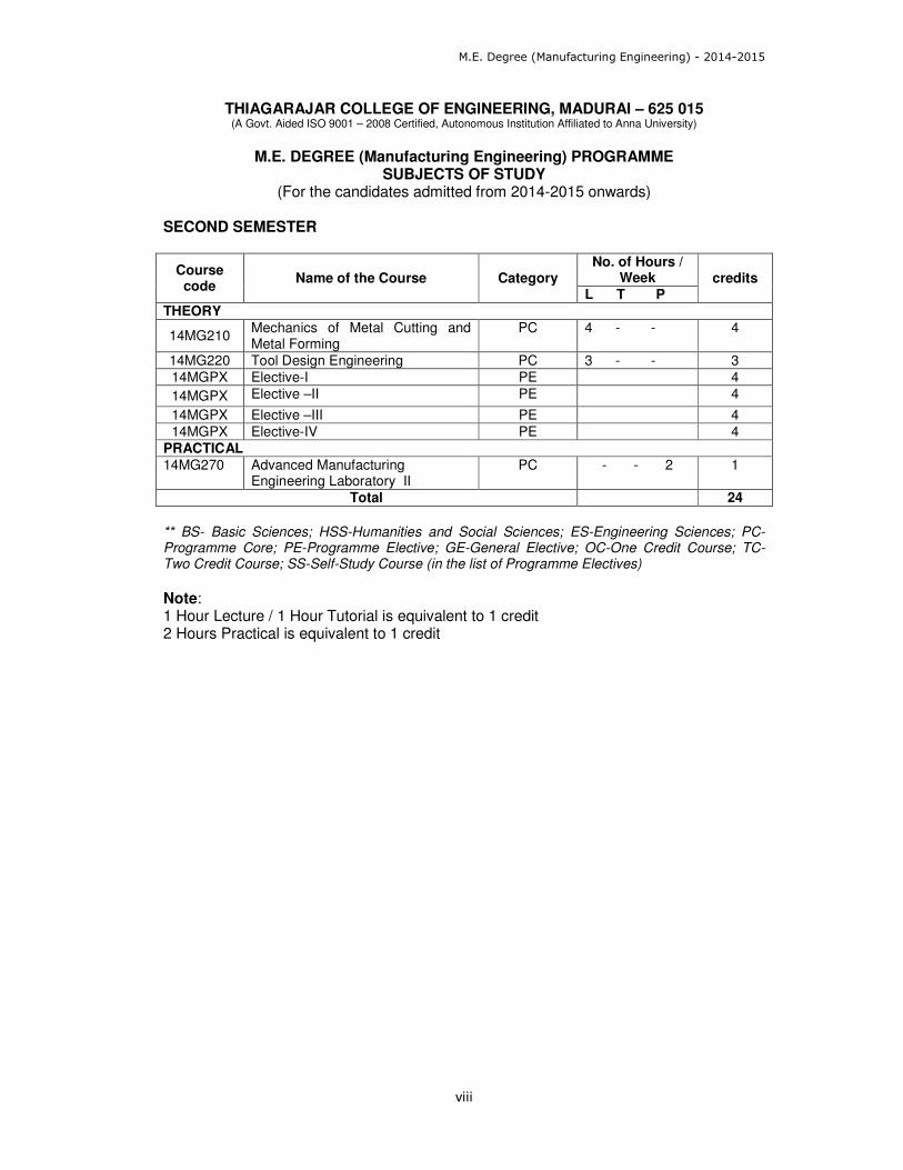
SECOND SEMESTER
Course code
Name of the Course Category No. of Hours /
Week credits L T P
THEORY
14MG210 Mechanics of Metal Cutting and Metal Forming
PC 4 - - 4
14MG220 Tool Design Engineering PC 3 - - 3
14MGPX Elective-I PE 4
14MGPX Elective –II PE 4
14MGPX Elective –III PE 4
14MGPX Elective-IV PE 4
PRACTICAL
14MG270 Advanced Manufacturing Engineering Laboratory II
PC - - 2 1
Total 24
** BS- Basic Sciences; HSS-Humanities and Social Sciences; ES-Engineering Sciences; PC- Programme Core; PE-Programme Elective; GE-General Elective; OC-One Credit Course; TC- Two Credit Course; SS-Self-Study Course (in the list of Programme Electives)
Note: 1 Hour Lecture / 1 Hour Tutorial is equivalent to 1 credit 2 Hours Practical is equivalent to 1 credit

M.E. Degree (Manufacturing Engineering) - 2014-2015
ix
THIAGARAJAR COLLEGE OF ENGINEERING, MADURAI – 625 015 (A Govt. Aided ISO 9001 – 2008 Certified, Autonomous Institution Affiliated to Anna University)
M.E. DEGREE (Manufacturing Engineering) PROGRAMME
SCHEME OF EXAMINATIONS (For the candidates admitted from 2014-2015 onwards)
SECOND SEMESTER
Sl. No
Course code
Name of the Course
Duration of
Terminal Exam. in
Hrs.
Marks Minimum Marks
for Pass
Continuous Assessment
Terminal Exam
**
Max. Marks
Terminal Exam
Total
THEORY
1 14MG210
Mechanics of Metal Cutting and Metal Forming
3 50 50 100 25 50
2 14MG220 Tool Design Engineering
3 50 50 100 25 50
3 14MGPX Elective - I 3 50 50 100 25 50
4 14MGPX Elective –II 3 50 50 100 25 50
5 14MGPX Elective - III 3 50 50 100 25 50
6 14MGPX Elective- IV 3 50 50 100 25 50
PRACTICAL
7 14MG270
Advanced Manufacturing Engineering Laboratory II
3 50 50 100 25 50
** Terminal Examination will be conducted for maximum marks of 100 and subsequently be reduced to 50 marks for the award of terminal examination marks.
M.E. Degree (Manufacturing Engineering) - 2014-2015
x
THIAGARAJAR COLLEGE OF ENGINEERING, MADURAI – 625 015 (A Govt. Aided ISO 9001 – 2008 Certified, Autonomous Institution Affiliated to Anna University)
M.E. DEGREE (Manufacturing Engineering) PROGRAMME
SUBJECTS OF STUDY (For the candidates admitted from 2014-2015 onwards)
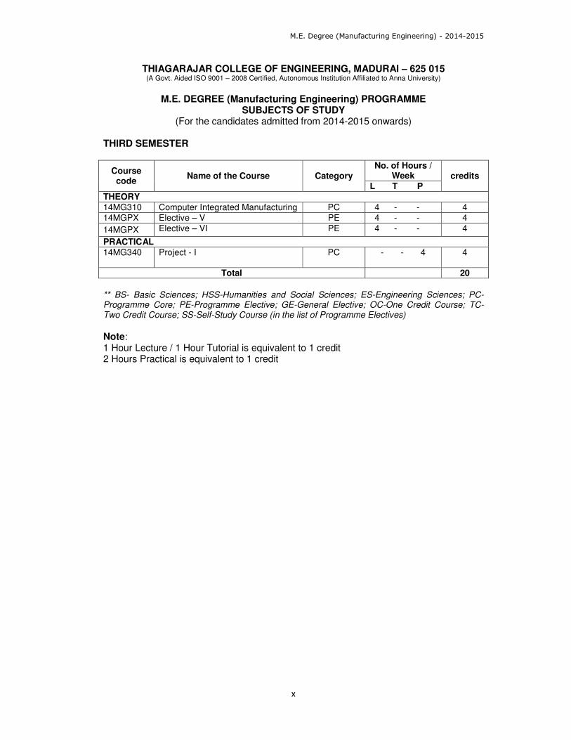
THIRD SEMESTER
Course code
Name of the Course Category No. of Hours /
Week credits L T P
THEORY
14MG310 Computer Integrated Manufacturing PC 4 - - 4
14MGPX Elective – V PE 4 - - 4
14MGPX Elective – VI PE 4 - - 4
PRACTICAL
14MG340
Project - I
PC - - 4 4
Total 20
** BS- Basic Sciences; HSS-Humanities and Social Sciences; ES-Engineering Sciences; PC- Programme Core; PE-Programme Elective; GE-General Elective; OC-One Credit Course; TC- Two Credit Course; SS-Self-Study Course (in the list of Programme Electives)
Note: 1 Hour Lecture / 1 Hour Tutorial is equivalent to 1 credit 2 Hours Practical is equivalent to 1 credit
M.E. Degree (Manufacturing Engineering) - 2014-2015
xi
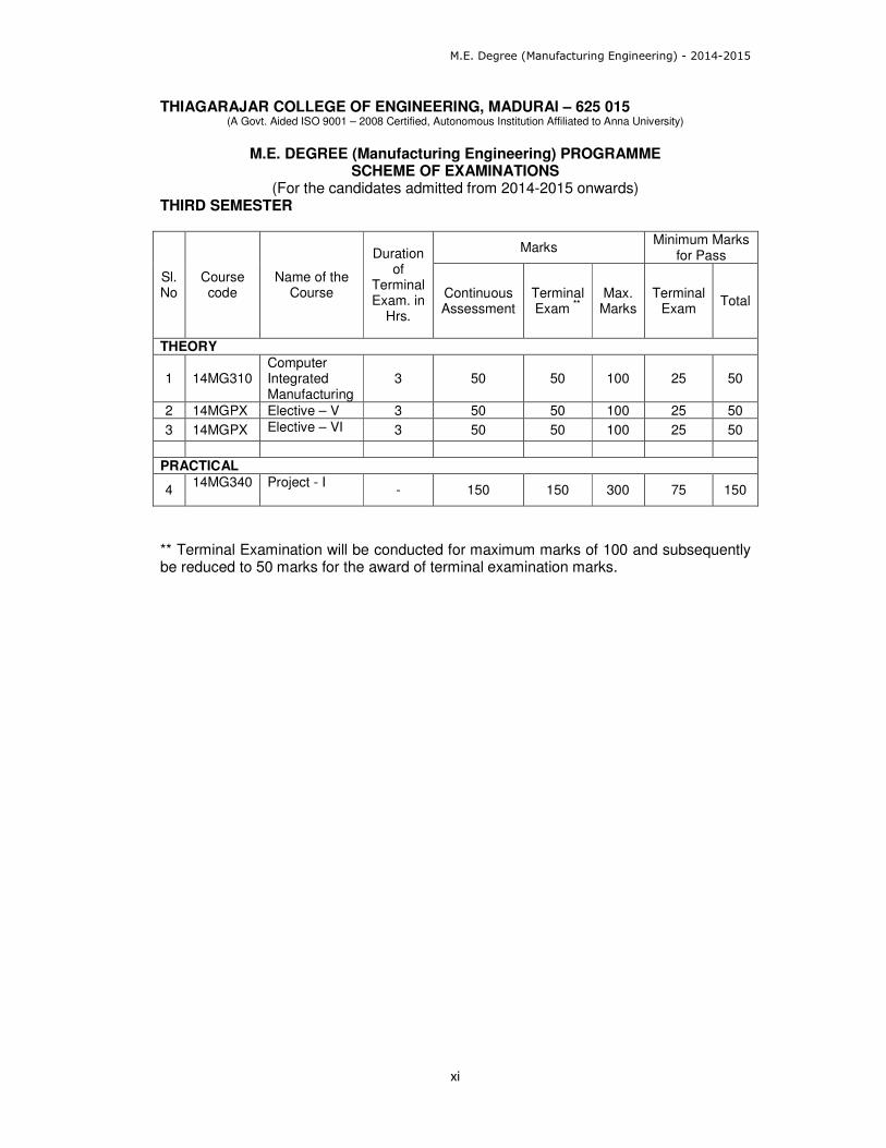
THIAGARAJAR COLLEGE OF ENGINEERING, MADURAI – 625 015 (A Govt. Aided ISO 9001 – 2008 Certified, Autonomous Institution Affiliated to Anna University)
M.E. DEGREE (Manufacturing Engineering) PROGRAMME
SCHEME OF EXAMINATIONS (For the candidates admitted from 2014-2015 onwards)
THIRD SEMESTER
Sl. No
Course code
Name of the Course
Duration of
Terminal Exam. in
Hrs.
Marks Minimum Marks
for Pass
Continuous Assessment
Terminal Exam
**
Max. Marks
Terminal Exam
Total
THEORY
1 14MG310 Computer Integrated Manufacturing
3 50 50 100 25 50
2 14MGPX Elective – V 3 50 50 100 25 50
3 14MGPX Elective – VI 3 50 50 100 25 50
PRACTICAL
4 14MG340
Project - I
- 150 150 300 75 150
** Terminal Examination will be conducted for maximum marks of 100 and subsequently be reduced to 50 marks for the award of terminal examination marks.
M.E. Degree (Manufacturing Engineering) - 2014-2015
xii
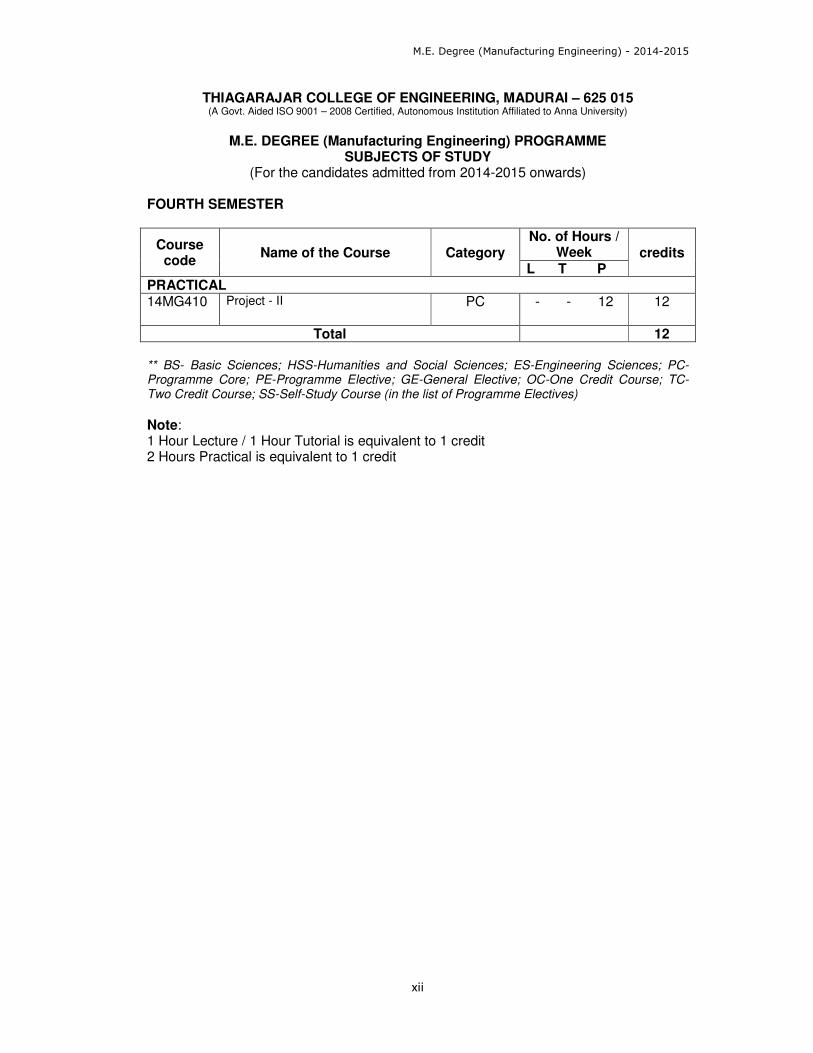
THIAGARAJAR COLLEGE OF ENGINEERING, MADURAI – 625 015 (A Govt. Aided ISO 9001 – 2008 Certified, Autonomous Institution Affiliated to Anna University)
M.E. DEGREE (Manufacturing Engineering) PROGRAMME
SUBJECTS OF STUDY (For the candidates admitted from 2014-2015 onwards)
FOURTH SEMESTER
Course code
Name of the Course Category No. of Hours /
Week credits L T P
PRACTICAL 14MG410
Project - II
PC - - 12 12
Total 12 ** BS- Basic Sciences; HSS-Humanities and Social Sciences; ES-Engineering Sciences; PC- Programme Core; PE-Programme Elective; GE-General Elective; OC-One Credit Course; TC- Two Credit Course; SS-Self-Study Course (in the list of Programme Electives)
Note: 1 Hour Lecture / 1 Hour Tutorial is equivalent to 1 credit 2 Hours Practical is equivalent to 1 credit
M.E. Degree (Manufacturing Engineering) - 2014-2015
xiii
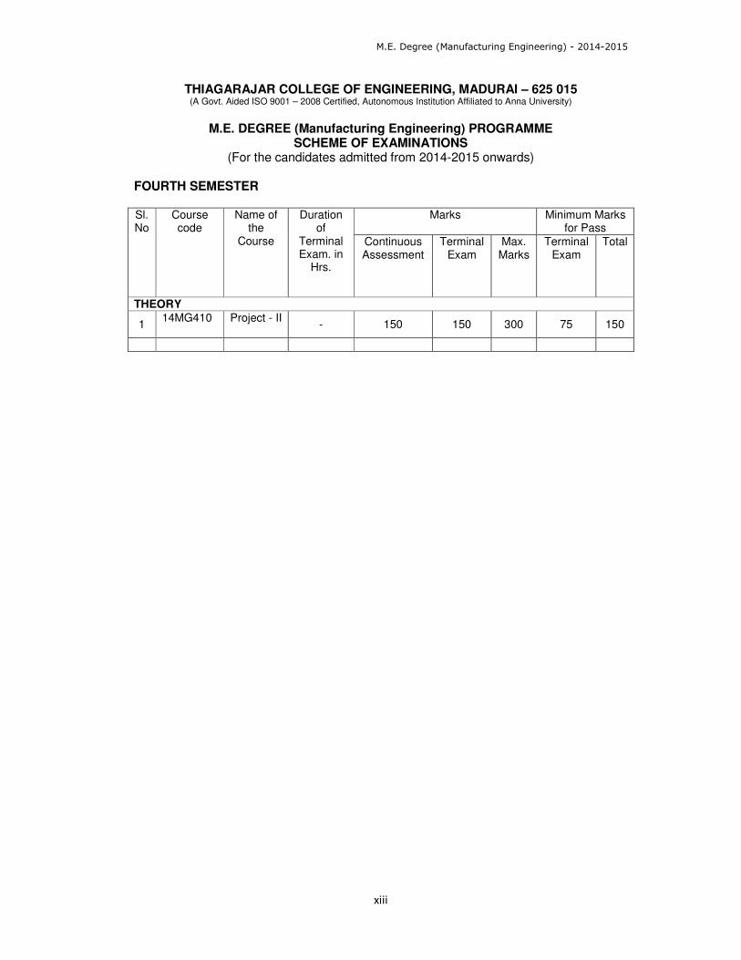
THIAGARAJAR COLLEGE OF ENGINEERING, MADURAI – 625 015 (A Govt. Aided ISO 9001 – 2008 Certified, Autonomous Institution Affiliated to Anna University)
M.E. DEGREE (Manufacturing Engineering) PROGRAMME
SCHEME OF EXAMINATIONS (For the candidates admitted from 2014-2015 onwards)
FOURTH SEMESTER Sl. No
Course code
Name of the
Course
Duration of
Terminal Exam. in
Hrs.
Marks Minimum Marks for Pass
Continuous Assessment
Terminal Exam
Max. Marks
Terminal Exam
Total
THEORY
1 14MG410
Project - II
- 150 150 300 75 150
M.E. Degree (Manufacturing Engineering) - 2014-2015
xiv
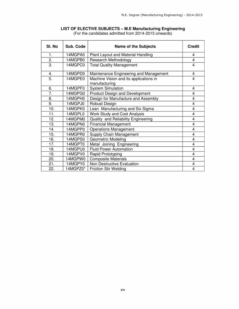
LIST OF ELECTIVE SUBJECTS – M.E Manufacturing Engineering (For the candidates admitted from 2014-2015 onwards)
Sl. No Sub. Code Name of the Subjects Credit
1. 14MGPA0 Plant Layout and Material Handling 4
2. 14MGPB0 Research Methodology 4
3. 14MGPC0 Total Quality Management 4
4. 14MGPD0 Maintenance Engineering and Management 4
5. 14MGPE0 Machine Vision and its applications in manufacturing
4
6. 14MGPF0 System Simulation 4
7. 14MGPG0 Product Design and Development 4
8. 14MGPH0 Design for Manufacture and Assembly 4
9. 14MGPJ0 Robust Design 4
10. 14MGPK0 Lean Manufacturing and Six Sigma 4
11. 14MGPL0 Work Study and Cost Analysis 4
12. 14MGPM0 Quality and Reliability Engineering 4
13. 14MGPN0 Financial Management 4
14. 14MGPP0 Operations Management 4
15. 14MGPR0 Supply Chain Management 4
16. 14MGPS0 Geometric Modeling 4
17. 14MGPT0 Metal Joining Engineering 4
18. 14MGPU0 Fluid Power Automation 4
19. 14MGPV0 Rapid Prototyping 4
20. 14MGPW0 Composite Materials 4
21. 14MGPY0 Non Destructive Evaluation 4
22. 14MGPZ0* Friction Stir Welding 4

M.E. Degree (Manufacturing Engineering) - 2014-2015
1
Board of studies meeting on 07.11.14 Approved in 49th Academic Council meeting on 04.12.2014
Category L T P Credit
BS 3 1 0 4
Preamble
The course aims at giving adequate exposure in the theory of Initial Value Problems
(IVPs) and Boundary Value Problems(BVPs) in Ordinary Differential Equations (ODEs)
and Partial Differential Equations(PDEs) and various methods (Computational methods)
for getting both Analytical as well as Numerical solutions for them.
Prerequisite
Course Name: Numerical Methods
Course Outcomes
On the successful completion of the course, students will be able to
CO.No.
Course Outcome Blooms
Level
Expected
Proficiency
Expected
attainment
level
CO1. Compute Numeric/ Approximate solutions for BVPs using several weighted residual methods
Apply 70 60
CO2. Solve PDEs numerically using the available familiar methods
Apply 70 60
CO3. Solve the special type of PDEs using some methods involving implicit and explicit schemes
Apply 70 60
CO4. Compute the solution for the IVPs using finite element methods and grasp the advantages of them over the other traditional methods
Apply 70 60
CO5. Interpret the theory of Boundary Value Problems arising in the study of engineering problems and their applications
Apply 70 60
Mapping with Programme Outcomes
COs PO1 PO2 PO3 PO4 PO5 PO6 PO7 PO8 PO9 PO10 PO11
CO1 S M L L
CO2 S M L L
CO3 S M L L CO4 S M L L CO5 S M L L S- Strong; M-Medium; L-Low
14MG110 COMPUTATIONAL METHODS IN
ENGINEERING
M.E. Degree (Manufacturing Engineering) - 2014-2015
2
Board of studies meeting on 07.11.14 Approved in 49th Academic Council meeting on 04.12.2014
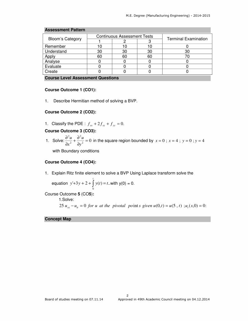
Assessment Pattern
Bloom’s Category Continuous Assessment Tests
Terminal Examination 1 2 3
Remember 10 10 10 0
Understand 30 30 30 30 Apply 60 60 60 70 Analyse 0 0 0 0 Evaluate 0 0 0 0 Create 0 0 0 0
Course Level Assessment Questions
Course Outcome 1 (CO1):
1. Describe Hermitian method of solving a BVP.
Course Outcome 2 (CO2):
1. Classify the PDE : .02 =++ yyxyxx fff
Course Outcome 3 (CO3):
1. Solve: 02
2
2
2
=∂
∂+
∂
∂
y
u
x
u in the square region bounded by 4;0;4;0 ==== yyxx
with Boundary conditions
Course Outcome 4 (CO4):
1. Explain Ritz finite element to solve a BVP Using Laplace transform solve the
equation ..)(23'0
∫ =+++
t
ttyyy with y(0) = 0.
Course Outcome 5 (CO5):
1.Solve:
:0)0,(;),5(),0(int025 ===− xututugivenspopivotaltheatuforuu tttxx
Concept Map

M.E. Degree (Manufacturing Engineering) - 2014-2015
3
Board of studies meeting on 07.11.14 Approved in 49th Academic Council meeting on 04.12.2014
Syllabus
Boundary value problems: Boundary value problems in ODE - Different kinds of BVP,
Analytical method - perturbation method - Hermitian method .Numerical Methods-
Iteration method - Finite difference method - Ritz’s finite element method .Weighted
residual methods- collocation method- moment method- least square method- Galerkin
method.
Partial Differential Equations: Classification of PDE – Solution to Parabolic equation -
Bender Schmidt scheme- Crank – Nicholson method. Elliptic equation- Leibmann’s
iterative scheme - collocation method - least square method - Relaxation method.
Integral Equations: Classification – Solution to Integral equations by iteration and finite
difference methods. Solution through software: Introduction to software - Solution of
Boundary Value Problems from Ordinary Differential Equations through Mapple and
Mathematica - Solution of Boundary Value Problems from Partial Differential Equations
through Mapple and Mathematica.
Reference Books
1. M.K.Jain, S.R.K.Iyengar, R.K.Jain, “Numerical Methods for Scientific and
Engineering Computations” New Age International publishers, 4th Edition 2003
2. Collatz , “The Numerical Treatment of Differential Equations “ , Springer Verlog, 1966
3. Sastry ,”Introductory Methods of Numerical Analysis”, 2nd Edition , Prentice Hall of
India ,1998
4. Robert J.Schilling, Sandra.L Harris, “Applied Numerical Methods for Engineers
using Matlab and C “, Thomson books / Cole , 1999
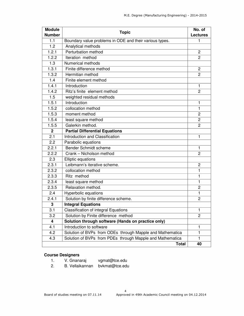
Course Contents and Lecture Schedule
Module
Number Topic
No. of
Lectures
1 Boundary value problems -BVPs
M.E. Degree (Manufacturing Engineering) - 2014-2015
4
Board of studies meeting on 07.11.14 Approved in 49th Academic Council meeting on 04.12.2014
Module
Number Topic
No. of
Lectures
1.1 Boundary value problems in ODE and their various types. 1
1.2 Analytical methods
1.2.1 Perturbation method 2
1.2.2 Iteration method 2
1.3 Numerical methods
1.3.1 Finite difference method 2
1.3.2 Hermitian method 2
1.4 Finite element method
1.4.1 Introduction 1
1.4.2 Ritz’s finite element method 2
1.5 weighted residual methods
1.5.1 Introduction 1
1.5.2 collocation method 1
1.5.3 moment method 2
1.5.4 least square method 2
1.5.5 Galerkin method. 2
2 Partial Differential Equations
2.1 Introduction and Classification 1
2.2 Parabolic equations
2.2.1 Bender Schmidt scheme 1
2.2.2 Crank – Nicholson method 2
2.3 Elliptic equations
2.3.1 Leibmann’s iterative scheme. 2
2.3.2 collocation method 1
2.3.3 Ritz method 1
2.3.4 least square method 1
2.3.5 Relaxation method. 2
2.4 Hyperbolic equations 1
2.4.1 Solution by finite difference scheme. 2
3 Integral Equations
3.1 Classification of integral Equations 1
3.2 Solution by Finite difference method 2
4 Solution through software (Hands on practice only)
4.1 Introduction to software 1
4.2 Solution of BVPs from ODEs through Mapple and Mathematica 1
4.3 Solution of BVPs from PDEs through Mapple and Mathematica 1
Total 40
Course Designers
1. V. Gnanaraj [email protected]
2. B. Vellaikannan [email protected]

M.E. Degree (Manufacturing Engineering) - 2014-2015
5
Board of studies meeting on 07.11.14 Approved in 49th Academic Council meeting on 04.12.2014
Preamble
Optimization is a scientific approach to decision making that seeks to best design and
operate a system, usually under conditions requiring the allocation of scarce resources.
Various techniques of optimization have been dealt on the title “Operations Research”.
Because of the complexity of most real-world optimization problems, it has been
necessary for researchers and practitioners to reduce the complexity of the problem by
either simplifying the problem or constraining it by making reasonable assumptions. In
this course, the practical aspects of optimization methodology, with a major focus on the
techniques and stratagems relevant to manufacturing, design and operations
applications. Attention is given primarily to techniques applicable to problems in linear,
integer, dynamic and non-linear programming, and network models. Besides, intelligent
search heuristics are introduced to understand the concepts so as to apply them in
solving large-scale problems.
Prerequisite
. Matrix Manipulations
Course Outcomes
On the successful completion of the course, students will be able to
CO.No.
Course Outcome Blooms
Level
Expected
Proficiency
Expected
attainment
level
CO1 Compute mathematical models of Linear Programming (LP), Integer Programming (IP), Dynamic Programming (DP), Networks and Non-linear Programming (NLPP) problems
Apply 70 60
CO2 Evaluate the behaviour of Linear Programming Problems under different range of parameters
Analyse 60 50
CO3 Solve Integer Programming Problems (IPP) using branch and bound, and cutting plane method
Apply 70 60
CO4 Compare deterministic Dynamic Programming Problems using tabular approach and assess the performance under different conditions
Analyse 60 50
CO5 Decide on a suitable network model and apply appropriate technique for flow and project scheduling problems.
Analyse 60 50
CO6 Solve unconstrained and constrained Non-Linear Programming Problems (NLPP) using appropriate techniques.
Apply 70 60
CO7 Explain the concept and working of emerging intelligent search techniques
Understand 80 70
14MG120 OPTIMIZATION TECHNIQUES Category L T P Credit
PC 4 0 0 4

M.E. Degree (Manufacturing Engineering) - 2014-2015
6
Board of studies meeting on 07.11.14 Approved in 49th Academic Council meeting on 04.12.2014
such as Genetic Algorithm (GA), Ant Colony Optimization (ACO), Particle Swarm Optimization (PSO), Simulated Annealing Algorithm (SAA) and Tabu Search (TS).
Mapping with Programme Outcomes
COs PO1 PO2 PO3 PO4 PO5 PO6 PO7 PO8 PO9 PO10 PO11
CO1 S M L L
CO2 S S M M
CO3 S M L L
CO4 S S M M
CO5 S S M M
CO6 S M L L
CO7 M L
S- Strong; M-Medium; L-Low
Assessment Pattern
Bloom’s Category Continuous Assessment Tests
Terminal Examination 1 2 3
Remember 8 8 8 8
Understand 12 12 12 12
Apply 60 60 60 60
Analyse 20 20 20 20
Evaluate 0 0 0 0
Create 0 0 0 0
Course Level Assessment Questions
Course Outcome 1 (CO1):
1. A company produces two types of goods A and B that require gold and silver. Each
unit of type A requires 3 grams of silver and 1 gram of gold while B requires 1 grams
of silver and 2 grams of gold. The company can produce 9 grams of silver and 8
grams of gold. If each unit of type A brings a profit of Rs.40 and that of type B Rs.50,
determine the number of units of each type that should be produced to maximize the
profit. Formulate the LP Model and find the optimal product mix and the
corresponding profit of the company using revised simplex method.
2. A firm manufactures two products A and B on which the profits earned per unit are
Rs. 3 and Rs. 4, respectively. Each product is processed on two machines M1 and
M2. Product A requires one minute of processing time on M1 and two minutes on
M2, while B requires one minute on M1 and one minute on M2. Machine, M1 is
available for not more than 7 hours 30 minutes, while machine M2 available for 10
hours during any working day. Formulate the problem as LPP to find the number of
units of products A and B to be manufactured to get maximum profit and solve this
LPP using the result of the its dual problem.

M.E. Degree (Manufacturing Engineering) - 2014-2015
7
Board of studies meeting on 07.11.14 Approved in 49th Academic Council meeting on 04.12.2014
Course Outcome 2 (CO2):
1. A company produces both interior and exterior paints from two raw materials, M1 and
M2.The following table 2 provides the basic data of the problem:
Table 2
Tonnes of raw material per tonne of
Exterior
Paint Interior Paint
Maximum Daily Availability
(Tonnes)
Raw Material, M1 6 4 24
Raw Material, M2 1 2 6
Profit per tonne
(Rs.’000)
5 4
A market survey indicates that the daily demand for interior paint cannot exceed that for
exterior paint by more than 1 tonne. Also, the maximum daily demand for interior paint is
2 tonnes. The company wants to determine the optimum (best) product mix of interior
and exterior paints that maximizes the total daily profit. Use simplex method to obtain the
optimal solution.
2. The problem of maximising the overall profits for product mix with given the resource
constraints is formulated as linear program given as: Maximise Z = 3x1 + 5x2;
Subject to: x1≤ 4; 3x1 + 2x2 ≤ 0; x1, x2 ≥ 0 . The optimal table is given in Table 1.
Table 1
Cj 3 5 0 0
bi CB
Basic
Variables x1 x2 S1 S2
0 S1 1 0 1 0 4
5 x2 2
3 1 0
2
1 9
Cj-Zj 2
9− 0 0
2
5− Z = 45
If a new product (variable) x3 is included in the existing product mix. The profit per
unit of the new product is Rs. 7 and its rates of consumption in the constraints are 1
and 2, respectively. Check whether the inclusion of the new product changes the
optimality and if it changes the optimality, find the revised optimal solution.
3. Solve the dual of the following LPP and determine the values of the primal decision
variables.
Maximise Z = 3x1 + 2x2
Subject to constraints, x1 + x2 ≥ 1
x1 + x2 ≤ 7
x1 + 2x2 ≤10
x1 ,x2 ≥ 0
Course Outcome 3 (CO3):
1. A company manufacturer two types of products, P1 and P2. Each product uses lathe
and milling machine. The processing time per unit of P1 on the lathe is 5 hours and
on the milling machine is 4 hours. The processing time per unit of P2 on the lathe is
10 hours and on the milling machine is 4 hours. The maximum number of hours
M.E. Degree (Manufacturing Engineering) - 2014-2015
8
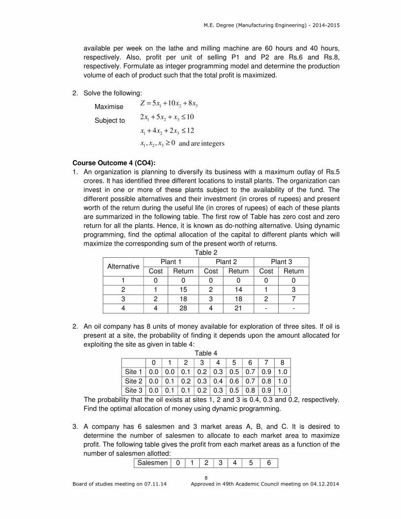
Board of studies meeting on 07.11.14 Approved in 49th Academic Council meeting on 04.12.2014
available per week on the lathe and milling machine are 60 hours and 40 hours,
respectively. Also, profit per unit of selling P1 and P2 are Rs.6 and Rs.8,
respectively. Formulate as integer programming model and determine the production
volume of each of product such that the total profit is maximized.
2. Solve the following:
Maximise 321 8105 xxxZ ++=
Subject to 1052 321 ≤++ xxx
1224 321 ≤++ xxx
0,, 321 ≥xxx
integers are and
Course Outcome 4 (CO4):
1. An organization is planning to diversify its business with a maximum outlay of Rs.5
crores. It has identified three different locations to install plants. The organization can
invest in one or more of these plants subject to the availability of the fund. The
different possible alternatives and their investment (in crores of rupees) and present
worth of the return during the useful life (in crores of rupees) of each of these plants
are summarized in the following table. The first row of Table has zero cost and zero
return for all the plants. Hence, it is known as do-nothing alternative. Using dynamic
programming, find the optimal allocation of the capital to different plants which will
maximize the corresponding sum of the present worth of returns.
Table 2
Alternative Plant 1 Plant 2 Plant 3
Cost Return Cost Return Cost Return
1 0 0 0 0 0 0
2 1 15 2 14 1 3
3 2 18 3 18 2 7
4 4 28 4 21 - -
2. An oil company has 8 units of money available for exploration of three sites. If oil is
present at a site, the probability of finding it depends upon the amount allocated for
exploiting the site as given in table 4:
Table 4
0 1 2 3 4 5 6 7 8
Site 1 0.0 0.0 0.1 0.2 0.3 0.5 0.7 0.9 1.0
Site 2 0.0 0.1 0.2 0.3 0.4 0.6 0.7 0.8 1.0
Site 3 0.0 0.1 0.1 0.2 0.3 0.5 0.8 0.9 1.0
The probability that the oil exists at sites 1, 2 and 3 is 0.4, 0.3 and 0.2, respectively.
Find the optimal allocation of money using dynamic programming.
3. A company has 6 salesmen and 3 market areas A, B, and C. It is desired to
determine the number of salesmen to allocate to each market area to maximize
profit. The following table gives the profit from each market areas as a function of the
number of salesmen allotted:
Salesmen 0 1 2 3 4 5 6

M.E. Degree (Manufacturing Engineering) - 2014-2015
9
Board of studies meeting on 07.11.14 Approved in 49th Academic Council meeting on 04.12.2014
Area
A 38 41 48 58 66 72 83
B 40 42 50 60 66 75 82
C 60 64 68 78 90 102 109
Use dynamic programming technique to solve the above problem.
Course Outcome 5 (CO5):
1. A project consists of 9 activities and the three time estimates are given in table 5.
Table 5
Activities Activity Duration in Days
I j Optimistic Most likely Pessimistic
1 2 3 6 15
2 3 6 12 30
3 5 5 11 17
7 8 4 19 28
5 8 1 4 7
6 7 3 9 27
4 5 3 6 15
1 6 2 5 14
2 4 2 5 8
a. Find the probability of completing the project before 31 weeks?
b. What is the chance of project duration exceeding 46 weeks?
4. Consider the following project and discuss how the project schedule will be affected
by events: a) Job H is delayed by 10 more days and b) Job F and G are completed 1
day ahead of schedule.
Job A B C D E F G H I
Predecessor - - A,B A,B B D,E C,F D,E G,H
Time (days) 15 10 10 10 5 5 20 10 15
5. A network as shown in figure 3, has the maximum flow of 70 units between ‘S’ and
‘n’. If the direction of the arc between nodes 1 and 4, has been reversed, is there
any changes in the flow? If so, determine the revised maximum flow between the
source, S to sink, n and justify the same.
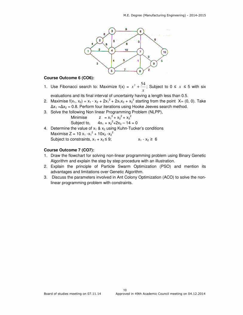
6. A company is interested in laying telephone cable in an area with 10 major locations,
as shown in figure. The number on each arc represents the distances between the
nodes connected by the arc. Suggest the company to provide the optimal lay scheme
to connect all the locations.
S n
3
4
1
2
30
80 10
60
20 10
40
70
100
M.E. Degree (Manufacturing Engineering) - 2014-2015
10
Board of studies meeting on 07.11.14 Approved in 49th Academic Council meeting on 04.12.2014
Course Outcome 6 (CO6):
1. Use Fibonacci search to: Maximize f(x) = x
x542
+ ; Subject to 0 ≤ x ≤ 5 with six
evaluations and its final interval of uncertainty having a length less than 0.5.
2. Maximise f(x1, x2) = x1 - x2 + 2x12 + 2x1x2 + x2
2 starting from the point X= (0, 0). Take
∆x1 =∆x2 = 0.8. Perform four iterations using Hooke Jeeves search method.
3. Solve the following Non linear Programming Problem (NLPP),
Minimise z = x12 + x2
2 + x32
Subject to, 4x1 + x22+2x3 – 14 = 0
4. Determine the value of x1 & x2 using Kuhn-Tucker’s conditions
Maximise Z = 10 x1 -x12 + 10x2 -x2
2
Subject to constraints, x1 + x2 ≤ 9; x1 - x2 ≥ 6
Course Outcome 7 (CO7):
1. Draw the flowchart for solving non-linear programming problem using Binary Genetic
Algorithm and explain the step by step procedure with an illustration.
2. Explain the principle of Particle Swarm Optimization (PSO) and mention its
advantages and limitations over Genetic Algorithm.
3. Discuss the parameters involved in Ant Colony Optimization (ACO) to solve the non-
linear programming problem with constraints.

M.E. Degree (Manufacturing Engineering) - 2014-2015
11
Board of studies meeting on 07.11.14 Approved in 49th Academic Council meeting on 04.12.2014
Concept Map
Syllabus
Linear Programming: Formulation - Graphical Method and Simplex Method – Primal
Vs. Dual relationships - Sensitivity Analysis - Dual Simplex Method; Integer
Programming: Formulation - Branch and Bound Method - Cutting Plane Method;
Dynamic Programming - Concepts - Mathematical description – Deterministic Dynamic
Programming - Tabular approach; Goal Programming – Concepts – solution for multiple
objective problems; Network Model: Network Construction – Terminologies - Shortest
route problems, Minimal Spanning Tree problems, Maximal Flow problems; Critical Path
Method (CPM) – crashing - Programme Evaluation and Review Technique (PERT);
Nonlinear Programming (Unconstrained Problem) -Basic Concepts – Fibanocci and
Golden Section search - Hooks and Jeeves search - Gradient Projection – Nonlinear
Programming (with Equality Constraints) Lagrangian Multiplier - Equality constrained
optimization -Projected Gradient Methods with equality constraints; Nonlinear
Programming (Inequality Constraints): Khun concept - Khun Tucker conditions;
Intelligent search heuristics: Concept – principle and parameters of GA, ACO, PSO,
SAA & TS.
Reference Books / Learning Resources
1. Hamdy A. Taha, “Operations Research - An Introduction”, 7th Edition, MacMillan Co.,
2010.
2. Ravindran, Don. T. Phillips, and James J. Solberg, “Operations Research - Principles
and Practice”, Second Edition, John Wiley and Sons, 2007
3. Srinath. L. S., “PERT and CPM Principles and Applications”, Affiliated East West
Press Pvt. Ltd., New Delhi, 2001
4. Frederick Hillier, Gerald Lieberman, “Introduction to Operations Research” Seventh
Edition, Tata McGraw Hill, 2010
M.E. Degree (Manufacturing Engineering) - 2014-2015
12
Board of studies meeting on 07.11.14 Approved in 49th Academic Council meeting on 04.12.2014
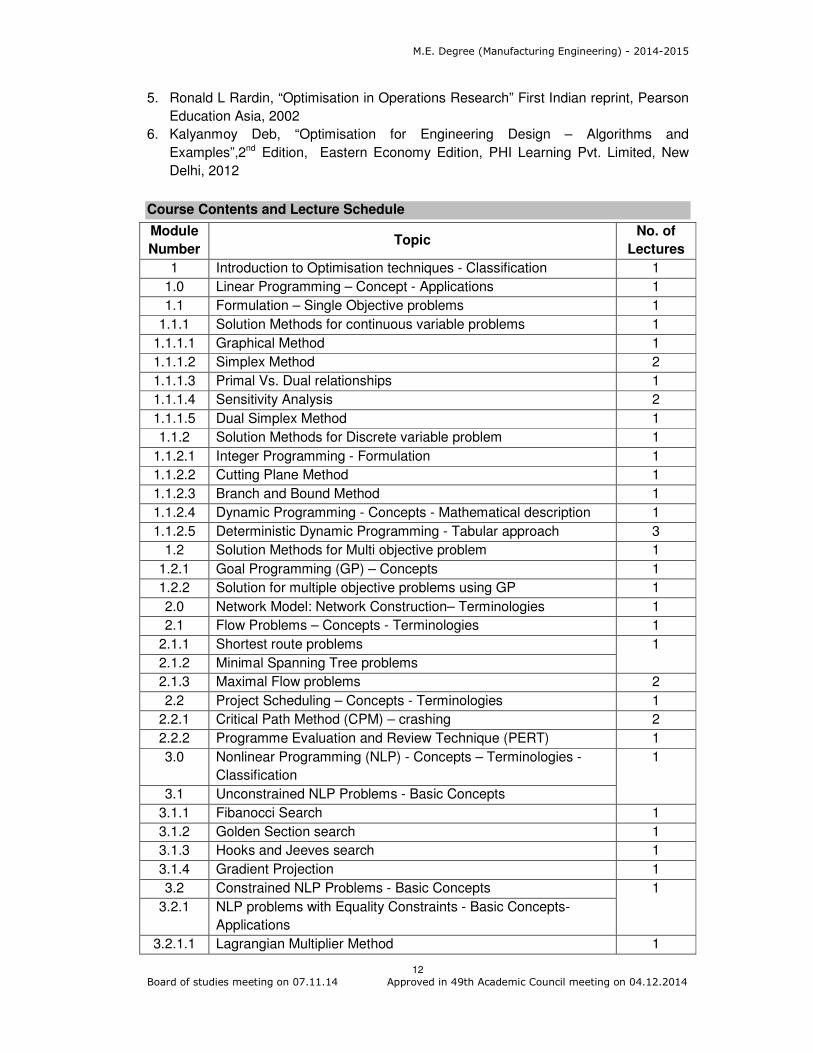
5. Ronald L Rardin, “Optimisation in Operations Research” First Indian reprint, Pearson
Education Asia, 2002
6. Kalyanmoy Deb, “Optimisation for Engineering Design – Algorithms and
Examples”,2nd Edition, Eastern Economy Edition, PHI Learning Pvt. Limited, New
Delhi, 2012
Course Contents and Lecture Schedule
Module
Number Topic
No. of
Lectures
1 Introduction to Optimisation techniques - Classification 1
1.0 Linear Programming – Concept - Applications 1
1.1 Formulation – Single Objective problems 1
1.1.1 Solution Methods for continuous variable problems 1
1.1.1.1 Graphical Method 1
1.1.1.2 Simplex Method 2
1.1.1.3 Primal Vs. Dual relationships 1
1.1.1.4 Sensitivity Analysis 2
1.1.1.5 Dual Simplex Method 1
1.1.2 Solution Methods for Discrete variable problem 1
1.1.2.1 Integer Programming - Formulation 1
1.1.2.2 Cutting Plane Method 1
1.1.2.3 Branch and Bound Method 1
1.1.2.4 Dynamic Programming - Concepts - Mathematical description 1
1.1.2.5 Deterministic Dynamic Programming - Tabular approach 3
1.2 Solution Methods for Multi objective problem 1
1.2.1 Goal Programming (GP) – Concepts 1
1.2.2 Solution for multiple objective problems using GP 1
2.0 Network Model: Network Construction– Terminologies 1
2.1 Flow Problems – Concepts - Terminologies 1
2.1.1 Shortest route problems 1
2.1.2 Minimal Spanning Tree problems
2.1.3 Maximal Flow problems 2
2.2 Project Scheduling – Concepts - Terminologies 1
2.2.1 Critical Path Method (CPM) – crashing 2
2.2.2 Programme Evaluation and Review Technique (PERT) 1
3.0 Nonlinear Programming (NLP) - Concepts – Terminologies -
Classification
1
3.1 Unconstrained NLP Problems - Basic Concepts
3.1.1 Fibanocci Search 1
3.1.2 Golden Section search 1
3.1.3 Hooks and Jeeves search 1
3.1.4 Gradient Projection 1
3.2 Constrained NLP Problems - Basic Concepts 1
3.2.1 NLP problems with Equality Constraints - Basic Concepts-
Applications
3.2.1.1 Lagrangian Multiplier Method 1
M.E. Degree (Manufacturing Engineering) - 2014-2015
13
Board of studies meeting on 07.11.14 Approved in 49th Academic Council meeting on 04.12.2014
Module
Number Topic
No. of
Lectures
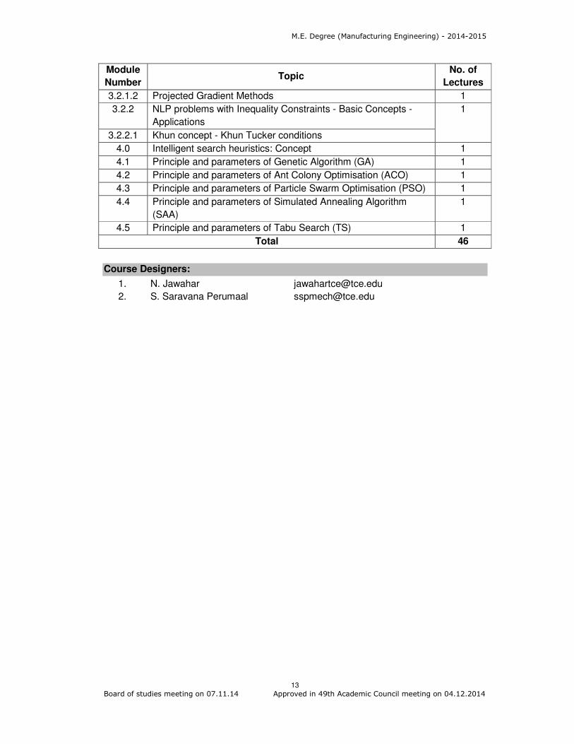
3.2.1.2 Projected Gradient Methods 1
3.2.2 NLP problems with Inequality Constraints - Basic Concepts -
Applications
1
3.2.2.1 Khun concept - Khun Tucker conditions
4.0 Intelligent search heuristics: Concept 1
4.1 Principle and parameters of Genetic Algorithm (GA) 1
4.2 Principle and parameters of Ant Colony Optimisation (ACO) 1
4.3 Principle and parameters of Particle Swarm Optimisation (PSO) 1
4.4 Principle and parameters of Simulated Annealing Algorithm
(SAA)
1
4.5 Principle and parameters of Tabu Search (TS) 1
Total 46
Course Designers:
1. N. Jawahar [email protected]
2. S. Saravana Perumaal [email protected]

M.E. Degree (Manufacturing Engineering) - 2014-2015
14
Board of studies meeting on 07.11.14 Approved in 49th Academic Council meeting on 04.12.2014
Category L T P Credit
PC 4 0 0 4
Preamble
Plastic deformation occurs when large numbers of dislocations move and multiply so as
to result in macroscopic deformation. In other words, it is the movement of dislocations in
the material which allows for deformation. If we want to enhance a material's mechanical
properties, we simply need to introduce a mechanism which prohibits the mobility of
these dislocations. Fracture mechanics is the field of mechanics concerned with the
study of the propagation of cracks in materials. It uses methods of analytical solid
mechanics to calculate the driving force on a crack and those of experimental solid
mechanics to characterize the material's resistance to fracture.
The objective of this course is to impart knowledge in the fields of Strengthening
Mechanisms, Fracture Mechanics, Fatigue, Creep and Fracture of metals.
Prerequisite
Nil
Course Outcomes
On the successful completion of the course, students will be able to
CO.No.
Course Outcome Blooms
Level
Expected
Proficiency
Expected
attainment
level
CO1 Explain the various Strengthening Mechanisms
Understand 80 70
CO2 Examine the Fracture and its mechanics
Apply 70 60
CO3 Choose the fatigue properties of Metals Apply 70 60
CO4 Choose the creep mechanisms Apply 70 60
CO5 Interpret various types of fracture failure
Apply 70 60
Mapping with Programme Outcomes
COs PO1 PO2 PO3 PO4 PO5 PO6 PO7 PO8 PO9 PO10 PO11
CO 1 M L
CO 2 S M L L
CO 3 S M L L
CO 4 S M L L
CO 5 S M L L
S- Strong; M-Medium; L-Low
14MG130 MECHANICAL BEHAVIOUR OF
MATERIALS
M.E. Degree (Manufacturing Engineering) - 2014-2015
15
Board of studies meeting on 07.11.14 Approved in 49th Academic Council meeting on 04.12.2014
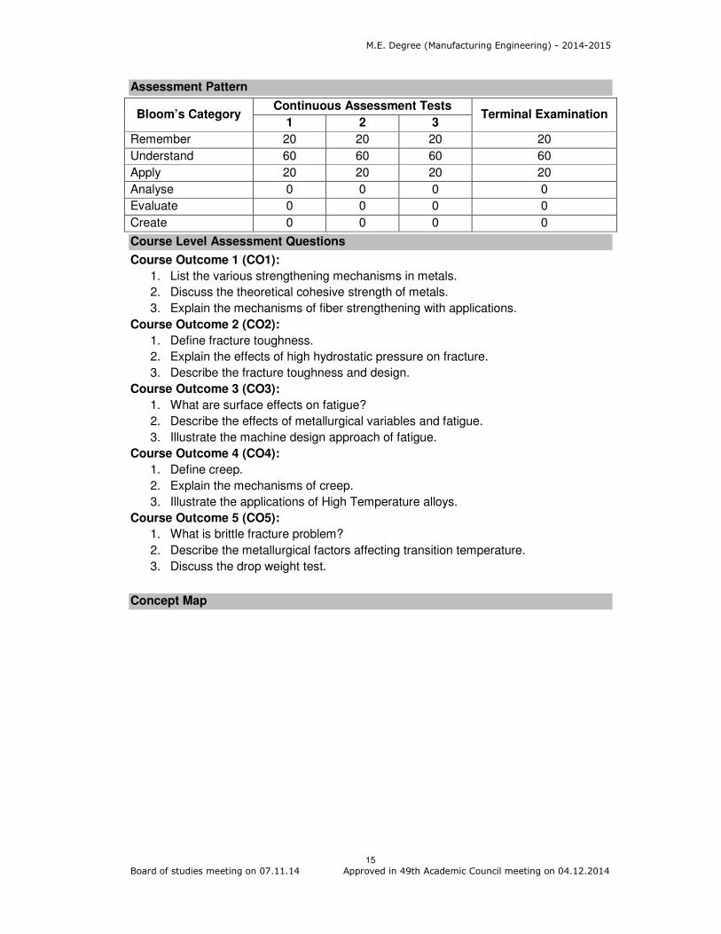
Assessment Pattern
Bloom’s Category Continuous Assessment Tests
Terminal Examination 1 2 3
Remember 20 20 20 20
Understand 60 60 60 60
Apply 20 20 20 20
Analyse 0 0 0 0
Evaluate 0 0 0 0
Create 0 0 0 0
Course Level Assessment Questions
Course Outcome 1 (CO1):
1. List the various strengthening mechanisms in metals.
2. Discuss the theoretical cohesive strength of metals.
3. Explain the mechanisms of fiber strengthening with applications.
Course Outcome 2 (CO2):
1. Define fracture toughness.
2. Explain the effects of high hydrostatic pressure on fracture.
3. Describe the fracture toughness and design.
Course Outcome 3 (CO3):
1. What are surface effects on fatigue?
2. Describe the effects of metallurgical variables and fatigue.
3. Illustrate the machine design approach of fatigue.
Course Outcome 4 (CO4):
1. Define creep.
2. Explain the mechanisms of creep.
3. Illustrate the applications of High Temperature alloys.
Course Outcome 5 (CO5):
1. What is brittle fracture problem?
2. Describe the metallurgical factors affecting transition temperature.
3. Discuss the drop weight test.
Concept Map

M.E. Degree (Manufacturing Engineering) - 2014-2015
16
Board of studies meeting on 07.11.14 Approved in 49th Academic Council meeting on 04.12.2014
Syllabus
Strengthening Mechanisms: Introduction - Grain Boundaries and Deformation -
Strengthening from grain boundaries - low angle grain boundaries - Yield point
phenomenon - strain aging - solid solution strengthening - Deformation of two phase
aggregates - Strengthening from fine particles - Fiber strengthening - Strengthening due
to point defects - Martensite strengthening - cold worked structure - strain hardening -
annealing of cold worked metal - Bauschinger effect - Preferred Orientation. Fracture
Mechanics: Fracture - Types of fracture in Metals - Theoretical Cohesive strength of
metals - Griffith theory of brittle fracture - Fracture of single crystals - Metallographic
aspects - Fractography - Dislocation theories of brittle fracture - Ductile fracture - Notch
effects - concept of fracture curve - Fracture under combined stresses - Effect of high
hydrostatic pressure on fracture.- Fracture Mechanics - Strain energy release rate -
stress intensity factor - Fracture toughness and design. Fatigue: Stress cycles - S - N
curve - Statistical nature - Effect of mean stress - cycle stress - strain curve - low cycle
fatigue - strain life equation - structural features - Fatigue crack Propagation - Effect of
stress concentration - size effect - surface effects & fatigue - Fatigue under combined
effects - cumulative fatigue damage & sequence effects - Effect of Metallurgical variables
and fatigue - Design for fatigue - machine design approach - local strain approach -
corrosion fatigue - Effect of temperature on fatigue. Creep: Creep and Stress Rupture -
High temperature materials problem - Time dependent Mechanical Behaviour - creep
curve - stress rupture test - structural changes - Mechanisms - Deformation mechanism
Maps - Activation energy for steady state creep - super plasticity - fracture at elevated
temperature - High Temperature alloys - Presentation of Engineering creep data -

M.E. Degree (Manufacturing Engineering) - 2014-2015
17
Board of studies meeting on 07.11.14 Approved in 49th Academic Council meeting on 04.12.2014
Prediction of long time properties - creep under combined stresses - creep and fatigue
interaction. Fracture: Brittle fracture - Brittle fracture problem - significance of transition
temperature curve - metallurgical factors affecting transition temperature - Drop weight
test and other large scale tests - Fracture analysis diagram - Temper Embrittlement -
Environment sensitive fracture - flow and fracture under very rapid rates of loading.
Reference Books
1. George E. Dieter, “Mechanical Metallurgy”, Third Edition, McGraw Hill Education
(India) Pvt Ltd, New Delhi, 2013.
2. Bhargava, A. K and Sharma, C. P. “Mechanical Behaviour and testing of Materials”
PHI Learning Pvt. Ltd., 2014.
3. Thomas H. Courtney, “Mechanical Behaviour of Materials”, 2nd Edition, Mc Graw Hill,
2005
4. Roy A. Lindberg, “Processes and Materials of Manufacture”, 4th Edition, Prentice Hall
of India, 1998.
Course contents and Lecture schedule
Module
Number Topics
No. of
Lectures
1.0 Strengthening Mechanisms
1.1 Introduction - Grain Boundaries and Deformation - Strengthening
from grain boundaries - low angle grain boundaries 2
1.2 Yield point phenomenon - strain aging - Solid solution
strengthening 2
1.3 Deformation of two phase aggregates - Strengthening from fine
particles 1
1.4 Fiber strengthening - Strengthening due to point defects -
Martensite strengthening 2
1.5 Cold worked structure - strain hardening - annealing of cold
worked metal 2
1.6 Bauschinger effect - Preferred Orientation 1
2.0 Fracture Mechanics
2.1 Fracture - Types of fracture in Metals - Theoretical cohesive
strength of metals
1
2.2 Griffith theory of brittle fracture - Fracture of single crystals 2
2.3 Metallographic aspects – Fractography - Dislocation theories of
brittle fracture - Ductile fracture
2
2.4 Notch effects - concept of fracture curve - Fracture under
combined stresses - Effect of high hydrostatic pressure on
fracture
2
2.5 Fracture Mechanics - Strain energy release rate - stress intensity
factor - Fracture toughness and design.
2
3.0 Fatigue
3.1 Stress cycles - S - N curve - Statistical nature - Effect of mean
stress - cycle stress
2
3.2 Strain curve - Low cycle fatigue - strain life equation 2

M.E. Degree (Manufacturing Engineering) - 2014-2015
18
Board of studies meeting on 07.11.14 Approved in 49th Academic Council meeting on 04.12.2014
Module
Number Topics
No. of
Lectures
3.3 Structural features - Fatigue crack Propagation - Effect of stress
concentration - size effect - surface effects & fatigue
2
3.4 Fatigue under combined effects - Cumulative fatigue damage &
sequence effects
2
3.5 Effect of Metallurgical variables and fatigue 1
3.6 Design for fatigue - machine design approach - local strain
approach - corrosion fatigue - Effect of temperature on fatigue 2
4.0 Creep
4.1 Creep and Stress Rupture - High temperature materials problem
- Time dependent Mechanical Behaviour
2
4.2 Creep curve - stress rupture test - structural changes 2
4.3 Mechanisms - Deformation mechanism Maps - Activation energy
for steady state creep
2
4.4 Super plasticity - fracture at elevated temperature - High
Temperature alloys
2
4.5 Presentation of Engineering creep data - Prediction of long time
properties - creep under combined stresses - creep and fatigue
interaction.
2
5.0 Fracture
5.1 Brittle fracture - Brittle fracture problem - significance of transition
temperature curve
2
5.2 Metallurgical factors affecting transition temperature 1
5.3 Drop weight test and other large scale tests - Fracture analysis
diagram
2
5.4 Temper Embrittlement - Environment sensitive fracture - flow and
fracture under very rapid rates of loading.
2
Total 47
Course Designers
1. Dr. T. Sornakumar [email protected]
2. Dr. M. Kathiresan [email protected]

M.E. Degree (Manufacturing Engineering) - 2014-2015
19
Board of studies meeting on 07.11.14 Approved in 49th Academic Council meeting on 04.12.2014
Category L T P Credit
PC 4 0 0 4
Preamble
Automation is a technology concerned with the application of mechanical, electronic, and
computer-based systems to operate and control production. Automation and Robotics
are two closely related technologies. This course aims at learning the basics of
Automation, Flexible Manufacturing Systems, Automated Materials Handling and
Storage Systems, Robot Kinematics, Robot Programming and its industrial applications.
Prerequisite
Knowledge on Mechanical engineering/ manufacturing processes
Course Outcomes
On the successful completion of the course, students will be able to
CO.No.
Course Outcome Blooms
Level
Expected
Proficiency
Expected
attainment
level
CO1 Explain the types of automation, types of machine tools and material handling equipments used for automation
Understand 80 70
CO2
Explain the principles of automation, types of production systems and management support systems involved in automation
Understand
80 70
CO3
Explain the basic components and their functions of automated production line, automated assembly system, FMS, AS/RS, AGV and Robot Kinematics and its industrial applications
Understand
80 70
CO4
Compute the cycle time, process time, indexing time of indexing devices, efficiency of the production line, production rate and production cost.
Apply 70 60
CO5 Compute the gripper force and Make path program of robots
Apply 70 60
CO6 Select the suitable layouts, material handling devices or sensors for various industrial applications
Apply 70 60
Mapping with Programme Outcomes
COs PO1 PO2 PO3 PO4 PO5 PO6 PO7 PO8 PO9 PO10 PO11
CO1 M L
CO2 M L
CO3 M L
CO4 S M L L
14MG140 INDUSTRIAL AUTOMATION AND
ROBOTICS
M.E. Degree (Manufacturing Engineering) - 2014-2015
20
Board of studies meeting on 07.11.14 Approved in 49th Academic Council meeting on 04.12.2014
CO5 S M L L
CO6 S M L L
S- Strong; M-Medium; L-Low
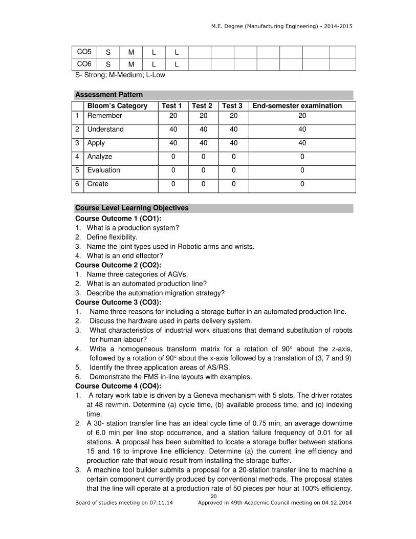
Assessment Pattern
Bloom’s Category Test 1 Test 2 Test 3 End-semester examination
1 Remember 20 20 20 20
2 Understand 40 40 40 40
3 Apply 40 40 40 40
4 Analyze 0 0 0 0
5 Evaluation 0 0 0 0
6 Create 0 0 0 0
Course Level Learning Objectives
Course Outcome 1 (CO1):
1. What is a production system?
2. Define flexibility.
3. Name the joint types used in Robotic arms and wrists.
4. What is an end effector?
Course Outcome 2 (CO2):
1. Name three categories of AGVs.
2. What is an automated production line?
3. Describe the automation migration strategy?
Course Outcome 3 (CO3):
1. Name three reasons for including a storage buffer in an automated production line.
2. Discuss the hardware used in parts delivery system.
3. What characteristics of industrial work situations that demand substitution of robots
for human labour?
4. Write a homogeneous transform matrix for a rotation of 90° about the z-axis,
followed by a rotation of 90° about the x-axis followed by a translation of (3, 7 and 9)
5. Identify the three application areas of AS/RS.
6. Demonstrate the FMS in-line layouts with examples.
Course Outcome 4 (CO4):
1. A rotary work table is driven by a Geneva mechanism with 5 slots. The driver rotates
at 48 rev/min. Determine (a) cycle time, (b) available process time, and (c) indexing
time.
2. A 30- station transfer line has an ideal cycle time of 0.75 min, an average downtime
of 6.0 min per line stop occurrence, and a station failure frequency of 0.01 for all
stations. A proposal has been submitted to locate a storage buffer between stations
15 and 16 to improve line efficiency. Determine (a) the current line efficiency and
production rate that would result from installing the storage buffer.
3. A machine tool builder submits a proposal for a 20-station transfer line to machine a
certain component currently produced by conventional methods. The proposal states
that the line will operate at a production rate of 50 pieces per hour at 100% efficiency.

M.E. Degree (Manufacturing Engineering) - 2014-2015
21
Board of studies meeting on 07.11.14 Approved in 49th Academic Council meeting on 04.12.2014
On similar transfer lines, the probability of station breakdown per cycle is equal for all
stations and p=0.005 breakdowns/cycle. It is also estimated that the average
downtime per line stop will be 0.8min. The starting casting that is machined on the
line costs Rs.120 per part. The line operates at a cost of Rs.4000 per hour. The 20
cutting tolls (one tool per station) last for 50 parts each, and the average cost per tool
= Rs80 per cutting edge. Based on this data, compute (a) production rate, (b) line
efficiency, and (c) cost per unit piece produced on the line.
4. A ten-station transfer machine has an ideal cycle time of 30 sec. The frequency of
line stops is 0.075 stops per cycle. When a line stop occurs, the average downtime is
4.0 min. Determine (a) average production rate in piece/hour, (b) line efficiency, and
(c) proportion downtime.
Course Outcome 5 (CO5):
1. A 5 kg rectangular block is gripped in the middle and lifted vertically at a velocity of 1
m/s. If it accelerates to a velocity of 27.5m/s2 and the coefficient of friction between
the gripping pads and the block is 0.48, calculate the minimum force that would
prevent the slippage.
2. Discuss the Robot programming languages in brief.
3. Distinguish between the first generation and second generation robot languages.
Course Outcome 6 (CO6):
1. How do external sensors differ from internal sensors?
2. Select the suitable sensor for the following applications (a) to indicate distance (b) to
indicate the presence (c) Inspection.
3. Compare the several possible layouts of the segmented in-line configuration of an
automated production line.
Concept Map

M.E. Degree (Manufacturing Engineering) - 2014-2015
22
Board of studies meeting on 07.11.14 Approved in 49th Academic Council meeting on 04.12.2014
Syllabus
Production systems: Facilities – Manual work systems, worker-machine systems and
automated systems. Manufacturing support systems, Automation in Production systems
– Automated Manufacturing systems, Computerised manufacturing support systems,
Manual labour in Production systems, Automation principles and strategies.
Automated Production Lines: Fundamentals- System configurations, Workpants
transfer mechanisms, Storage buffers, and Control of the production line. Applications –
Machining systems and System Design Considerations. Analysis of Transfer lines –
Transfer lines with No internal parts storage, Transfer lines with internal storage buffers.
Automated Assembly Systems: System configurations, Parts delivery at workstations,
and applications.
Flexible Manufacturing Systems: Introduction, Types of FMS, FMS Components, FMS
Applications and Benefits.
Automated Material Transport systems & Automated Storage systems: Automated
Guided Vehicle (AGV) Systems, Types of vehicles, AGV applications, Vehicle Guidance
Technology, Vehicle Management and Vehicle safety. Automated Storage/Retrieval
Systems (ASRS) and Carousel Storage Systems.
Robotics : Robot Fundamentals - Definition - Anatomy – Specifications, Robot
Kinematics - Forward and Reverse Kinematics (Transformation) of Two and Three
Degrees of Freedom Robot Arm, Robot End-effectors - Classification - Types of Gripper,
Drive Systems for Grippers, Hooks, Scoops and other Miscellaneous Devices, Gripper
Force Analysis. Mapping - General mapping and Compound mapping. Sensors -
Actuators - Types of Sensors, Robot Languages: Robot Languages and Programming,
Classification of Robot languages and Robot Software. Applications of Robotics.
Reference Books
1. Mikell. P. Groover, “Automation Production Systems, and Computer Integrated
Manufacturing”, Third Edition, PHI Learning Pvt. Ltd, New Delhi, 2008.
2. D.M.Considine and G.D. Considine, "Standard Hand book of Industrial Automation",
Chapman and Hall, New Jersey, 1986.
3. P. Radhakrishnan, S. Subramanyan and V. Raju, ‘CAD/CAM/CIM’, New Age
International (P) Ltd., New Delhi, 2009
4. Deb, "Robotics Technology and Flexible Automation", Tata McGraw Hill, New Delhi
2010
5. Popov and E.I. Yurevih, “Robotics", MIR Publications, Moscow, 1987.
6. Yoram Koren, "Robotics for Engineers", Tata McGraw Hill - International Edition,
1989.
Course contents and Lecture Schedule
Module
Number Topics
No. of
Lectures
1 Production systems
1.1 Facilities – Manual work systems 1
1.2 Worker-machine systems and Automated systems, Manufacturing
support systems 1

M.E. Degree (Manufacturing Engineering) - 2014-2015
23
Board of studies meeting on 07.11.14 Approved in 49th Academic Council meeting on 04.12.2014
Module
Number Topics
No. of
Lectures
1.3 Automation in Production systems – Automated Manufacturing
system 1
1.4 Computerised manufacturing support systems, Manual labour in
Production systems 2
1.5 Automation principles and strategies. 2
2 Automated Production Lines
2.1 Fundamentals- System configurations 1
Workpants transfer mechanisms, Storage buffers, and Control of
the production line. 2
2.2 Applications – Machining systems and System Design
Considerations. 2
2.3 Analysis of Transfer lines – Transfer lines with No internal parts
storage, 2
Transfer lines with internal storage buffers. 1
3 Automated Assembly Systems
3.1 System configurations 1
3.2 Parts delivery at workstations, and applications. 2
4 Flexible Manufacturing Systems
4.1 Flexible Manufacturing Systems – Introduction 1
4.2 Types of FMS 1
4.3 FMS Components 2
4.4 FMS Applications and Benefits 1
5 Automated Material Transport systems
5.1 Types of vehicles, Automated Guided Vehicle (AGV) applications,
Vehicle Guidance Technology, Vehicle Management and Vehicle
safety.
2
5.2 Automated Storage systems: Automated Storage/Retrieval
Systems (ASRS)
2
5.3 Carousel Storage Systems 1
6 Robotics
6.1 Robot Fundamentals - Definition - Anatomy – Specifications 1
6.2 Robot Kinematics - Forward and Reverse Kinematics
(Transformation) of Two and Three Degrees of Freedom Robot
Arm
2
6.3 Robot End-effectors - Classification - Types of Gripper 2
Drive Systems for Grippers, Hooks, Scoops and other
Miscellaneous Devices
2
6.4 Gripper Force Analysis 2
6.5 Mapping - General mapping and Compound mapping. 2
6.6 Sensors - Actuators - Types of Sensors 2
6.7 Robot Languages: Robot Languages and Programming 1
Classification of Robot languages and Robot Software 1
6.8 Applications of Robotics. 1
Total 45

M.E. Degree (Manufacturing Engineering) - 2014-2015
24
Board of studies meeting on 07.11.14 Approved in 49th Academic Council meeting on 04.12.2014
Course Designers
1. V. Dhanalakshmi [email protected]
2. PL. K. Palaniappan [email protected]
M.E. Degree (Manufacturing Engineering) - 2014-2015
25
Board of studies meeting on 07.11.14 Approved in 49th Academic Council meeting on 04.12.2014
Category L T P Credit
PC 3 0 0 3
Preamble
The introduction of lower cost CNC machines radically changed the manufacturing
industry. With the increased automation of manufacturing processes with CNC
machining, considerable improvements in consistency and quality have been achieved
with no strain on the operator. CNC reduces the frequency of errors and provided the
operators with more time to perform additional tasks. CNC also allows for more flexibility
in the way parts are held in the manufacturing process and the time required changing
the machine to produce different components.
Prerequisite
NIL
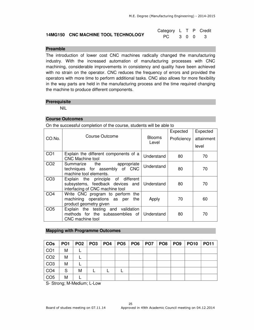
Course Outcomes
On the successful completion of the course, students will be able to
CO.No.
Course Outcome Blooms
Level
Expected
Proficiency
Expected
attainment
level
CO1 Explain the different components of a CNC Machine tool
Understand 80 70
CO2 Summarize the appropriate techniques for assembly of CNC machine tool elements.
Understand
80 70
CO3 Explain the principle of different subsystems, feedback devices and interfacing of CNC machine tool
Understand 80 70
CO4 Write CNC program to perform the machining operations as per the product geometry given
Apply 70 60
CO5 Explain the testing and validation methods for the subassemblies of CNC machine tool
Understand 80 70
Mapping with Programme Outcomes
COs PO1 PO2 PO3 PO4 PO5 PO6 PO7 PO8 PO9 PO10 PO11
CO1 M L
CO2 M L
CO3 M L
CO4 S M L L L
CO5 M L
S- Strong; M-Medium; L-Low
14MG150 CNC MACHINE TOOL TECHNOLOGY
M.E. Degree (Manufacturing Engineering) - 2014-2015
26
Board of studies meeting on 07.11.14 Approved in 49th Academic Council meeting on 04.12.2014
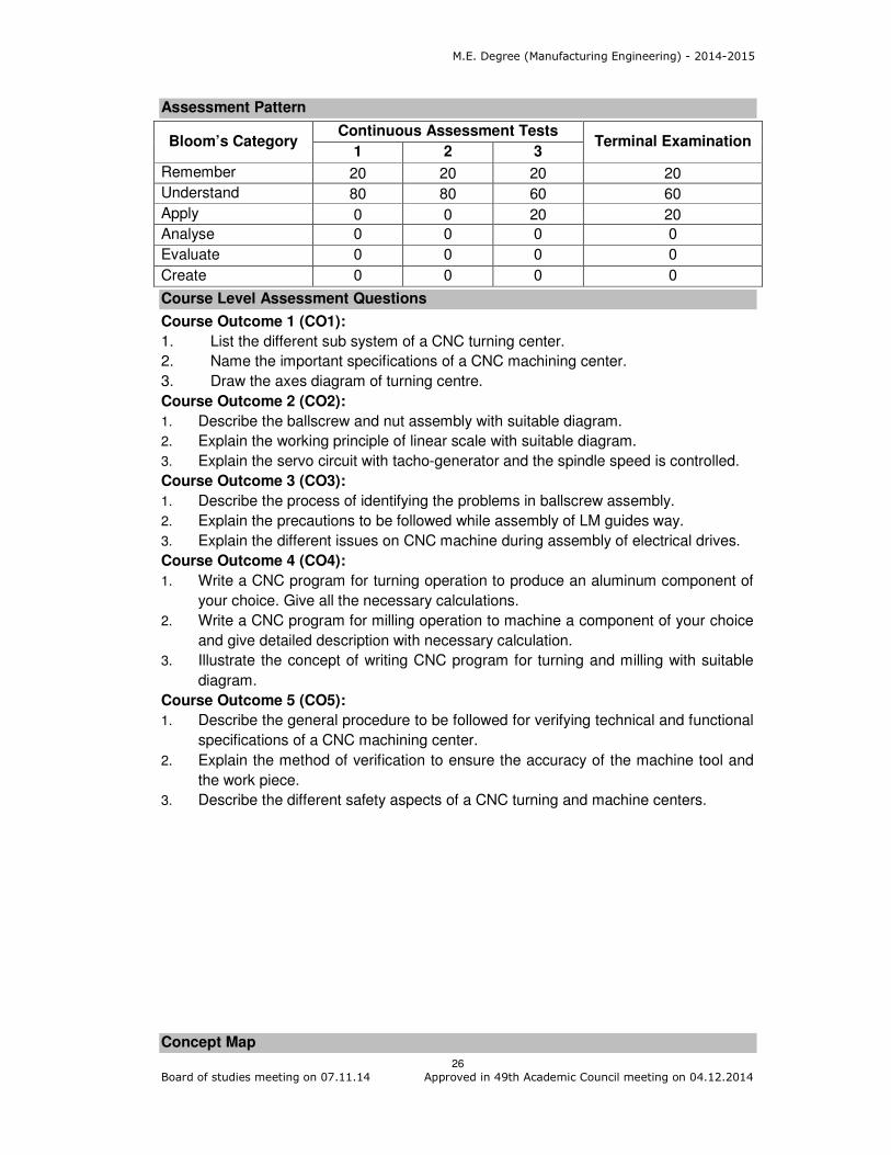
Assessment Pattern
Bloom’s Category Continuous Assessment Tests
Terminal Examination 1 2 3
Remember 20 20 20 20
Understand 80 80 60 60
Apply 0 0 20 20
Analyse 0 0 0 0
Evaluate 0 0 0 0
Create 0 0 0 0
Course Level Assessment Questions
Course Outcome 1 (CO1):
1. List the different sub system of a CNC turning center.
2. Name the important specifications of a CNC machining center.
3. Draw the axes diagram of turning centre.
Course Outcome 2 (CO2):
1. Describe the ballscrew and nut assembly with suitable diagram.
2. Explain the working principle of linear scale with suitable diagram.
3. Explain the servo circuit with tacho-generator and the spindle speed is controlled.
Course Outcome 3 (CO3):
1. Describe the process of identifying the problems in ballscrew assembly.
2. Explain the precautions to be followed while assembly of LM guides way.
3. Explain the different issues on CNC machine during assembly of electrical drives.
Course Outcome 4 (CO4):
1. Write a CNC program for turning operation to produce an aluminum component of
your choice. Give all the necessary calculations.
2. Write a CNC program for milling operation to machine a component of your choice
and give detailed description with necessary calculation.
3. Illustrate the concept of writing CNC program for turning and milling with suitable
diagram.
Course Outcome 5 (CO5):
1. Describe the general procedure to be followed for verifying technical and functional
specifications of a CNC machining center.
2. Explain the method of verification to ensure the accuracy of the machine tool and
the work piece.
3. Describe the different safety aspects of a CNC turning and machine centers.
Concept Map

M.E. Degree (Manufacturing Engineering) - 2014-2015
27
Board of studies meeting on 07.11.14 Approved in 49th Academic Council meeting on 04.12.2014
Syllabus
CNC Systems: Configuration of the CNC systems, Specifications of CNC Turning and
Machining center, Advantages of the CNC machines, CNC Turning center development,
CNC machining center development, Tool monitoring on CNC machines. Design of
machine tool elements: Machine structure, Guide ways, feed drives, Spindle bearing
and measuring systems. CNC Machine Assembly Techniques: Guide ways, Ball screw
and nut assembly, Feedback elements, spindle bearings, mounting accuracy of the
spindles, Assembly precautions for assembling spindle bearings. Machine Drives:
Spindle drives, Feed drives, DC motors, DC servomotors, AC servomotors. Feedback
devices: Encoders, Relays, Solenoids, Sensors and their types. Interfacing: Parallel
and Serial Communications. Programming: Coordinate systems, Axes motion and
Nomenclature, Structure of part program, Tool compensation, Word address format,
FANUC control system, CNC part programming for CNC Turning center, CNC part
programming for CNC Machining center. Testing and Verification: Verification of
technical and functional aspects, Verification of CNC machine during idle running,
Computer aided analysis of thermal effects, Analysis of dynamic behavior of CNC
machine tools, Verification of machine tool accuracy and work piece accuracy, Metal
M.E. Degree (Manufacturing Engineering) - 2014-2015
28
Board of studies meeting on 07.11.14 Approved in 49th Academic Council meeting on 04.12.2014
removal capacity testing, Rigidity and reliability testing of CNC machines, Safety aspects
of CNC machine tools.
Reference Books
1. Hindustan Machine Tool Ltd, “Mechatronics”, Tata McGraw hill, 2000.
2. N. Mathivanan, “Micro processors, PC Hardware and Interfacing”, Prentice Hall of
India, 2003.
3. Yusuf Altintas, “Manufacturing Automation”, Cambridge universal Press, 2012
4. Peter Smid, “CNC Programming Handbook”, Industrial Press Inc., 2008
5. Newton C. Braga, “Mechatronics Source Book”, Eswar Press, 2003.
6. Ken Evans, “Programming of CNC Machines”, Industrial Press Inc., 2007
7. P N. Rao, “CAD/CAM Principles and Applications”, Tata McGraw Hill, 2010.
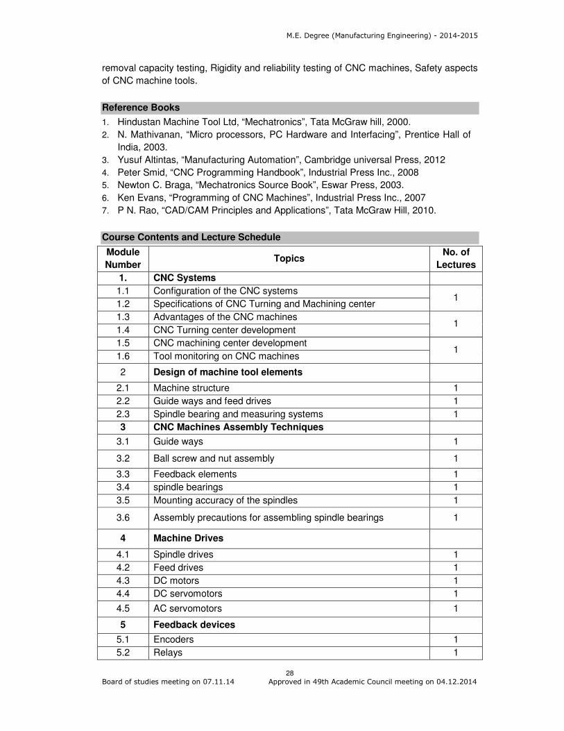
Course Contents and Lecture Schedule
Module
Number Topics
No. of
Lectures
1. CNC Systems
1.1 Configuration of the CNC systems 1
1.2 Specifications of CNC Turning and Machining center
1.3 Advantages of the CNC machines 1
1.4 CNC Turning center development
1.5 CNC machining center development 1
1.6 Tool monitoring on CNC machines
2 Design of machine tool elements
2.1 Machine structure 1
2.2 Guide ways and feed drives 1
2.3 Spindle bearing and measuring systems 1
3 CNC Machines Assembly Techniques
3.1 Guide ways 1
3.2 Ball screw and nut assembly 1
3.3 Feedback elements 1
3.4 spindle bearings 1
3.5 Mounting accuracy of the spindles 1
3.6 Assembly precautions for assembling spindle bearings 1
4 Machine Drives
4.1 Spindle drives 1
4.2 Feed drives 1
4.3 DC motors 1
4.4 DC servomotors 1
4.5 AC servomotors 1
5 Feedback devices
5.1 Encoders 1
5.2 Relays 1

M.E. Degree (Manufacturing Engineering) - 2014-2015
29
Board of studies meeting on 07.11.14 Approved in 49th Academic Council meeting on 04.12.2014
Module
Number Topics
No. of
Lectures
5.3 Solenoids 1
5.4 Sensors and their types 1
6 Interfacing
6.1 Parallel and Serial Communication 1
7 Programming
7.1 Coordinate systems, Axes motion and Nomenclature 1
7.2 Structure of part program 1
7.3 Tool compensation 1
7.4 Word address format 1
7.5 FANUC control system 1
7.6 CNC part programming for CNC Turning center 1
7.7 CNC part programming for CNC Machining center 1
8 Testing and Verification
8.1 Verification of technical and functional aspects 1
8.2 Verification of CNC machine during idle running 1
8.3 Computer aided analysis of thermal effects 1
8.4 Analysis of dynamic behavior of CNC machine tools 1
8.5 Verification of machine tool accuracy and work piece accuracy 1
8.6 Metal removal capacity testing 1
8.7 Rigidity and reliability testing of CNC machines 1
8.8 Safety aspects of CNC machine tools
Total 36
Course Designers:
1. C. Paramasivam [email protected]
2. M. Balamurali [email protected]

M.E. Degree (Manufacturing Engineering) - 2014-2015
30
Board of studies meeting on 07.11.14 Approved in 49th Academic Council meeting on 04.12.2014
Category L T P Credit
PC 4 0 0 4
Preamble
Micro-Electro-Mechanical Systems, (MEMS) can be defined as miniaturized mechanical
and electro-mechanical elements fabricated using microfabrication techniques.
Dimensions vary from one micron to several millimeters. MEMS devices can vary from
relatively simple structures having no moving elements, to electromechanical systems
with multiple moving elements. Nanotechnology is the engineering of functional systems
at the molecular scale. This covers both current work and concepts that are more
advanced. In its original sense, 'nanotechnology' refers to the projected ability to
construct items using techniques and tools being developed today to make complete,
high performance products.
The objective of this course is to impart knowledge to the students on micro
electromechanical systems, various fabrication techniques and micro actuators and to
impart knowledge to the students about the science of nano materials and
Characterization of Nano Materials.
Prerequisite
Nil
Course Outcomes
CO.No. Course Outcome Blooms Level
Expected Proficiency
Expected Attainment
Level
CO1 Explain the overview of MEMS and Microsystems
Understand 80 70
CO2 Choose the Materials, Fabrication Processes and Micro System Packaging
Apply 70 60
CO3 Use Micro Devices and Materials Apply 70 60
CO4 Explain the Science of Nano Materials
Understand 80 70
CO5 Explain the Characterization of Nano Materials
Understand 80 70
Mapping with Programme Outcomes
COs PO1 PO2 PO3 PO4 PO5 PO6 PO7 PO8 PO9 PO10 PO11
CO1 M L
CO2 S M L L
CO3 S M L L
CO4 M L
CO5 M L
S- Strong; M-Medium; L-Low
14MG160 MICRO ELECTRO MECHANICAL
SYSTEMS AND NANO TECHNOLOGY

M.E. Degree (Manufacturing Engineering) - 2014-2015
31
Board of studies meeting on 07.11.14 Approved in 49th Academic Council meeting on 04.12.2014
Assessment Pattern
Bloom’s Category Continuous Assessment Tests
Terminal Examination 1 2 3
Remember 20 20 20 20
Understand 60 60 60 60
Apply 20 20 20 20
Analyse 0 0 0 0
Evaluate 0 0 0 0
Create 0 0 0 0
Course Level Assessment Questions
Course Outcome 1 (CO1):
1. Define MEMS.
2. Explain in detail the micro fluidics.
Course Outcome 2 (CO2):
1. What is the function of a photoresist?
2. Explain in detail the various CVD processes for MEMS applications.
3. Illustrate the LIGA process with an example.
Course Outcome 3 (CO3):
1. What is a Micro actuator?
2. Describe the principle of working of flow sensors.
3. Design a silicon die for a pressure sensor.
Course Outcome 4 (CO4):
1. What is the effect of nanoscale dimensions on biological systems?
2. Describe the effects of the nano scale dimensions on thermal properties.
Course Outcome 5 (CO5):
1. List the applications of scanning electron microscopy.
2. Explain in detail the principle of working of X-ray diffraction.

M.E. Degree (Manufacturing Engineering) - 2014-2015
32
Board of studies meeting on 07.11.14 Approved in 49th Academic Council meeting on 04.12.2014
Concept Map
Syllabus
Over View of MEMS and Microsystems: Definition – historical development –
fundamentals – properties, micro fluidics, design and fabrication micro-system,
microelectronics, working principle and applications of micro system. Materials,
Fabrication Processes and Micro System Packaging: Substrates and wafers, silicon
as substrate material, mechanical properties of Si, Silicon Compounds silicon piezo
resistors, Galium arsenide, quartz, polymers for MEMS, conductive polymers.
Photolithography, photo resist applications, light sources, ion implantation, diffusion
process, oxidation – thermal oxidation, silicon dioxide, chemical vapour deposition,
sputtering - deposition by epitaxy – etching – bulk and surface micro machining – LIGA
process - Micro system packaging –packaging considerations – levels of micro system
packaging, die level, device level and system level. Micro Devices and Materials:
Sensors – classification – signal conversion ideal characterization of sensors - micro
actuators, mechanical sensors – measurands, displacement sensors, and pressure and

M.E. Degree (Manufacturing Engineering) - 2014-2015
33
Board of studies meeting on 07.11.14 Approved in 49th Academic Council meeting on 04.12.2014
flow sensors, smart materials. Science of Nano Materials: Classification of nano
structures – effect of the nanometer length scale, effects of nano scale dimensions on
various properties – structural, thermal, chemical, mechanical, magnetic, optical and
electronic properties – effect of nanoscale dimensions on biological systems. Fabrication
methods – Top down processes – bottom up process. Characterization of Nano
Materials: Introduction to Characterization of Nano Materials.
Reference Book
1. Tai – Ran Hsu, “MEMS and Microsystems Design and Manufacture”, Tata-McGraw
Hill, New Delhi, 2002.
2. Mark Madou, “Fundamentals of Microfabrication”, CRC Press, New York, 2002
3. Norio Taniguchi, “Nano Technology”, Oxford University Press, New York, 2003
4. Mohamed Gad-el-Hak, “The MEMS Hand Book”, CRC Press, New York, London.
5. Charles P Poole, Frank J Owens, “Introduction to Nano technology”, John Wiley and
Sons, 2003
6. Julian W. Hardner Micro Sensors, “Principles and Applications”, CRC Press 1994
7. Choudhury, Prosenjit Rai, “MEMS and MOEMS Technology and Applications” PHI
Learning Pvt. Ltd, New Delhi, 2009.
Course Content and Lecture Schedule
Module
Number Topics
No. of
Lectures
1.0 Over View of MEMS and Microsystems
1.1 Definition – historical development – fundamentals 1
1.2 Properties, micro fluidics 1
1.3 Design and fabrication micro-system 1
1.4 Microelectronics 1
1.5 Working principle and applications of micro system. 2
2.0 Materials, Fabrication Processes and Micro System Packaging
2.1 Substrates and wafers, silicon as substrate material, mechanical
properties of Si, Silicon Compounds
2
2.2 Silicon piezo resistors, Galium arsenide, quartz, polymers for
MEMS, conductive polymers. 3
2.3 Photolithography, photo resist applications, light sources 2
2.4 Ion implantation, diffusion process, Oxidation – thermal
oxidation, silicon dioxide, chemical vapour deposition, sputtering
- deposition by epitaxy – etching – bulk and surface micro
machining – LIGA process
4
2.5 Micro system packaging – packaging considerations – levels of
micro system packaging, die level, device level and system level.
3
3.0 Micro Devices and Materials
3.1 Sensors – classification – signal conversion, ideal
characterization of sensors
2
3.2 Micro actuators, mechanical sensors 3
3.3 Measurands, displacement sensors, pressure and flow sensors. 3

M.E. Degree (Manufacturing Engineering) - 2014-2015
34
Board of studies meeting on 07.11.14 Approved in 49th Academic Council meeting on 04.12.2014
Module
Number Topics
No. of
Lectures
3.4 Smart materials 2
4.0 Science of Nano Materials
4.1 Classification of nano structures 2
4.2 Effect of the nanometer length scale effects of nano scale
dimensions on various properties – structural, thermal, chemical,
mechanical, magnetic, optical and electronic properties
3
4.3 Effect of nanoscale dimensions on biological systems. 3
4.4 Fabrication methods – Top down processes 2
4.5 Fabrication methods – Bottom up process. 3
5.0 Characterization of Nano Materials
5.1 Introduction to Characterization of Nano Materials 3
Total 46
Course Designers
1. T. Sornakumar [email protected]
2. G. Kumaraguruparan [email protected]

M.E. Degree (Manufacturing Engineering) - 2014-2015
35
Board of studies meeting on 07.11.14 Approved in 49th Academic Council meeting on 04.12.2014
Category L T P Credit
PC 0 0 2 1
Preamble
Manufacturing needs automation in the field of solid modeling, analysis and inspection.
This practical is intended to have hands exercises in the area of creating solid models
using third party design package and few aspects of inspection with various metrological
instruments.
Prerequisite
• NIL
• Course Outcomes
• On the successful completion of the course, students will be able to
(CO) Course Outcome Bloom’s Level
Expected Proficiency
Expected Attainment
Level CO1 Draw 2D and 3D models of Engineering
components Apply 70 60
CO2 Develop assembly models of Engineering components
Apply 70 60
CO3 Infer the influence of process parameters on surface quality in Turning and Milling operations
Analyse 60 50
CO4 Produce a single point cutting tool using tool and cutter grinder and measure the tool signature
Apply 70 60
CO5 Operate CMM, Profile Projector, Auto Collimator and Tool makers microscope for linear and angular measurements
Apply 70 60
• Mapping with Programme Outcomes
COs PO1 PO2 PO3 PO4 PO5 PO6 PO7 PO8 PO9 PO10 PO11
CO1 S M L L M M L L
CO2 S M L L M M L L
CO3 S S M M M L L
CO4 S M L L M L L
CO5 S M L L M M L L
• S- Strong; M-Medium; L-Low
• Assessment Pattern
Bloom’s Category Continuous Assessment Tests
Terminal Examination 1 2 3
Remember 0 0 0 0
Understand 0 0 0 0
Apply 0 0 100 100
Analyse 0 0 0 0
14MG170 ADVANCED MANUFACTURING
ENGINEERING LABORATORY - I

M.E. Degree (Manufacturing Engineering) - 2014-2015
36
Board of studies meeting on 07.11.14 Approved in 49th Academic Council meeting on 04.12.2014
Evaluate 0 0 0 0
Create 0 0 0 0
• For continuous assessment, totally 12 exercises need to be completed by the
students from CAD modeling and machining practices.
• For final evaluation, TWO questions will be given with 50 marks each from CAD
modeling and machining practices.
Syllabus
I. Modelling using CAD package
1. Development of 2D Sketches.
2. Development of 3D Models like Piston and Bracket.
3. Assembly Modeling like Screw Jack, Stop Valve.
II. Machining and Inspection
1. Working on any one of the machines –Lathe, CNC Lathe, and Milling Mahcines to
identify the influence of process parameter on surface quality
2. Preparation of single point cutting tool using Tool and cutter Grinder and inspect the
tool signature.
3. Profile and dimensional measurement using CMM, Profile Projector, Tool makers
microscope, Autocollimator.
Course Designers:
1. C. Muruganantham [email protected]
2. PLK. Palaniappan [email protected]
3. C. Paramasivam [email protected]

M.E. Degree (Manufacturing Engineering) - 2014-2015
37
Board of studies meeting on 07.11.14 Approved in 49th Academic Council meeting on 04.12.2014
Category L T P Credit
PC 4 0 0 4
Preamble
Metal cutting and forming processes are the core production processes and the
economy of these processes depends on the proper selection and control of parameters.
This requires the fundamental knowledge on the mechanisms involved in those
processes. In this core course, the fundamental mechanisms of the metal cutting and
forming are exposed, which are very essential for any production and manufacturing
engineer.
Prerequisite
• Principles of Metal Cutting and Metal Forming processes
• Working of machine tools and metal forming equipments
Course Outcomes
On the successful completion of the course, students will be able to
CO.No.
Course Outcome Blooms
Level
Expected
Proficiency
Expected
attainment
level
CO1 Discuss the forces, stresses acting on in a single point tool during machining
Understand 80 70
CO2 Explain the effect of temperature, speed, feed and depth of cut in an orthogonal machining
Understand 80 70
CO3 Explain characteristics of tool wears and their process conditions Understand 80 70
CO4 Illustrate the effect of cutting parameters on tool life
Apply 70 60
CO5 Choose appropriate tool material for specified machining process
Apply 70 60
Mapping with Programme Outcomes
COs PO1 PO2 PO3 PO4 PO5 PO6 PO7 PO8 PO9 PO10 PO11
CO1 M L
CO2 M L
CO3 M L
CO4 S M L L
CO5 S M L L
S- Strong; M-Medium; L-Low
14MG210 MECHANICS OF METAL CUTTING
AND METAL FORMING

M.E. Degree (Manufacturing Engineering) - 2014-2015
38
Board of studies meeting on 07.11.14 Approved in 49th Academic Council meeting on 04.12.2014
Assessment Pattern
Bloom’s Category Continuous Assessment Tests
Terminal Examination 1 2 3
Remember 20 20 20 20
Understand 40 40 40 40
Apply 40 40 40 40
Analyse 0 0 0 0
Evaluate 0 0 0 0
Create 0 0 0 0
Course Level Assessment Questions
Course Outcome 1 (CO1):
1. What do you mean by Apparent mean shear strength of work material?
2. How work-tool temperature is measured during metal cutting process?
3. List out the factors affecting the machinability of metals?
Course Outcome 2 (CO2):
1. Explain the various forms of tool wear in metal cutting?
2. Explain the effect of lubrication in metal cutting?
3. Derive the expression using Merchant’s theory for the following
i) Forces involved in Cutting ii) Stresses iii) Velocity relationship
Course Outcome 3 (CO3):
1. Discuss the various standards of nomenclature of a single point tool and indicate
the relationship between the standards.
2. Discuss any two defects in rolling process due to variations in rolling load
3. Differentiate True Stress – Strain with conventional Stress-strain with a simple
illustration.
Course Outcome 4 (CO4):
1. A large batch of steel shafts is to be rough turned to 76 mm diameter for 300 mm
of their length at a feed of 0.25mm. A brazed type carbide tool is to be used, and
the appropriate constants in Taylor’s tool life equation for the conditions
employed are as follows: n= 0.25, and vr = 4.064m/s when tr = 60 s. The initial
cost of machine was Rs.10,800 and is to be amortized over 5 years. The
operator’s wage will be assumed to be Rs.0.0015/sec and the operator and
machine overheads are 100 percent. Tool changing and resetting time on the
machine is 300 sec and cost of regrinding the tool is Rs.2.00. The initial cost of a
tool Rs. 6.00 and on the average, it can be reground 10 times. Finally, the
nonproductive time for each component is 120 s. Find the total cost and total
production time.
2. A 200 mm long and 60mm diameter bar is to be turned on a lathe with a feed rate
of 0.15mm/rev. The operating cost is Rs. 0.50 per minute while the tool cost is
Rs.10.00 per edge. The tool changing time is about 2 minutes. Assume weight of
workpiece as 0.14 kg. The following two workpiece materials have been used.
Material Cost/kg Tool- Life equation
X Rs.100 Vt0.10 = 67
Y Rs.120 Vt0.16 = 90

M.E. Degree (Manufacturing Engineering) - 2014-2015
39
Board of studies meeting on 07.11.14 Approved in 49th Academic Council meeting on 04.12.2014
Calculate tool-life values and optimum cutting velocities for minimum cost with no
consideration for material cost, and maximum production rate criteria for both
workpiece materials. State which material should be chosen for total minimum
cost.
3. In an orthogonal cutting, the cutting tool has a rake angle = 10º. The chip
thickness before the cut =0.5 mm and the chip thickness after the cut = 2.8 mm.
The cutting force and thrust force are measured during cutting operation:
Fc=1559N and Ft=1271 N. The width of the orthogonal cutting operation = 3mm.
Calculate the shear plane angle, shear strain and shear strength of work material.
Course Outcome 5 (CO5):
1. During the machining of mild steel with 0º-10º-6º-6º -8º-90º-1mm cutting tool the
following observations have been obtained:
Depth of cut = 2mm; Feed = 0.25 mm/rev; Cutting speed = 200 m/min; Chip
thickness = 0.39 mm; Tangential force = 320 N; Axial force = 170 N. Calculate
i) Shear force and normal force on shear plane, ii) Friction force and normal force
on rake face, c) kinetic coefficient of friction and iv) specific cutting energy of
cutting.
2. A 300 mm long and 60mm diameter bar is to be turned on a lathe with a feed rate
of 0.15mm/rev. The operating cost is Rs. 0.50 per minute while the tool cost is
Rs.10.00 per edge. The tool changing time is about 2 minutes. Assume weight of
workpiece as 0.14 kg. The cost of the material is Rs.100/kg and its Tool life
equation is Vt0.10 = 67. Calculate tool-life values and optimum cutting velocities for
minimum cost with no consideration for material cost, and maximum production
rate criteria for workpiece material.
3. During the machining of mild steel with 0º-15º-6º-6º -8º-90º-1mm cutting tool the
following observations have been obtained:
Depth of cut = 4mm; Feed = 0.35 mm/rev; Cutting speed = 300 m/min; Chip
thickness = 0.40 mm; Tangential force = 350 N; Axial force = 2000 N. Calculate
i) Shear force and normal force on shear plane, ii) Friction force and normal force
on rake face, c) kinetic coefficient of friction and iv) specific cutting energy of
cutting.

M.E. Degree (Manufacturing Engineering) - 2014-2015
40
Board of studies meeting on 07.11.14 Approved in 49th Academic Council meeting on 04.12.2014
Concept Map
Syllabus
Mechanics of Metal Cutting - Terms and Definitions – Chip Formation – Types of chips –
Forces in orthogonal and oblique cutting – Specific Cutting Energy – Apparent Mean
Shear Strength of the work material – Theories of Ernst and Merchant, Lee and Shaffler,
Oxley and Palmer – Friction in metal Cutting. Temperatures in Metal Cutting - Heat
generation in Metal Cutting – Temperature Distribution in Metal Cutting – Temperature in
Primary and Secondary Deformation Zones – Effect of Cutting parameters on
Temperatures – Measurement of Cutting Temperatures. Tool wear and Tool life- Tool
Wear: Causes, Mechanisms and types – Tool life Criteria – Effect of a Built-up Edge,
Tool Angles, Speed and Feed on Tool life, Machinability – Factors affecting the
Machinability of Metals. Tool material, Cutting Fluids and Surface Roughness. Tool
materials – Classification and typical applications of tool Materials – Types, selection and
actions of cutting fluids - Coolants and lubricants – Causes of surface roughness - Effect
of nose radius on surface roughness. Economics of Metal Cutting Operations - Choice of
Feed and Cutting Speed – Tool Life for Minimum Cost and Minimum Production Time –
Estimation of factors that determine Optimum Conditions – Machining at Maximum
Efficiency. Nomenclature of Cutting Tools -Systems of Cutting Tool Nomenclature
(British Maximum Rake, American Standards Association, German System) – Coating of
cutting tools, Setting System – Grinding tool angles.
Elementary Theory of Plasticity - Introduction - Flow Curve – True Stress and True Strain
– Yielding Criteria for Ductile Metals – Combined Stress Tests – Yield Locus –
Anisotropy in Yielding – Yield Surface and Normality– Plastic Stress-Strain Relations.
Mechanics of Metal working - Classification of Forming Process – Mechanics of Metal
working – Flow-Stress Determination – Temperature in Metalworking – Strain-Rate
Effects –Friction and Lubrication.

M.E. Degree (Manufacturing Engineering) - 2014-2015
41
Board of studies meeting on 07.11.14 Approved in 49th Academic Council meeting on 04.12.2014
Reference Books
1. Geoffrey Boothroyd, “Fundamentals of Metal Machining and Machine Tools”,
McGraw Hill Book Company, London 2005.
2. George E. Dieter. “Mechanical Metallurgy”, Third Edition, McGraw Hill Education
(India) Pvt Ltd, New Delhi, 2013.
3. Bhattacharya, “Metal Cutting Theory and Practice”, New Central Book Agency (P),
Ltd., Edition. 2008
4. G. Kuppusamy. “Principles of Metal Cutting”, Universities Press (India) Ltd., 1996.
5. B.L. Juneja, G.S. Sekhon and N.Seth, “Fundamentals of Metal cutting and Machine
Tools”, 2nd Edition, New age International (P) Ltd, New Delhi, 2001.
6. P.C. Pandey and C.K. Singh. “Production Engineering Sciences”, Standard
Publishers Distributors. New Delhi. 2006
7. HMT, “Production Technology”, Tata McGraw Hill Publishing Company Ltd., New
Delhi. 2004
Course Contents and Lecture Schedule
Module
Number Topic
No. of
Lectures
1. Mechanics of Metal Cutting - Terms and Definitions – Chip
Formation – Types of chips
2
2. Forces in orthogonal and oblique cutting – Specific Cutting Energy
– Apparent Mean Shear Strength of the work material
2
3. Theories of Ernst and Merchant, Lee and Shaffer, Oxley and
Palmer
2
4. Friction in metal Cutting 1
5. Heat generation in Metal Cutting – Temperature Distribution in
Metal Cutting – Temperature in Primary and Secondary
Deformation Zones
1
6. Effect of Cutting parameters on Temperatures 1
7. Measurement of Cutting Temperatures 1
8. Tool Wear: Causes, Mechanisms and types – Tool life Criteria 2
9. Effect of a Built-up Edge, Tool Angles, Speed and Feed on Tool
life, Machinability
2
10. Factors affecting the Machinability of Metals 1
11. Tool materials – Classification and typical applications of tool
Materials
2
12. Types, selection and actions of cutting fluids - Coolants and
lubricants – Causes of surface roughness
2
13. Effect of nose radius on surface roughness. 1
14. Choice of Feed and Cutting Speed 1
15. Life for Minimum Cost and Minimum Production Time 1
16. Estimation of factors that determine Optimum Conditions 1
17. Machining at Maximum Efficiency 1
18. Systems of Cutting Tool Nomenclature (British Maximum Rake,
American Standards Association, German System)
Coating of cutting tools
2

M.E. Degree (Manufacturing Engineering) - 2014-2015
42
Board of studies meeting on 07.11.14 Approved in 49th Academic Council meeting on 04.12.2014
Module
Number Topic
No. of
Lectures
19. Interrelations between different systems of nomenclature 1
20. Setting System – Grinding tool angles 1
21. Elementary Theory of Plasticity - Flow Curve 2
22. True Stress and True Strain – Yielding Criteria for Ductile Metals 2
23. Combined Stress Tests – Yield Locus – Anisotropy in Yielding –
Yield Surface and Normality
3
24. Plastic Stress-Strain Relations 2
25. Classification of Forming Process – Mechanics of Metal working 2
26. Flow-Stress Determination 1
27. Temperature in Metalworking – Strain-Rate Effects 2
28. Friction and Lubrication 2
Total 45
Course Designers:
1. K. Chockalingam [email protected]
2. S. Saravana Perumaal [email protected]

M.E. Degree (Manufacturing Engineering) - 2014-2015
43
Board of studies meeting on 07.11.14 Approved in 49th Academic Council meeting on 04.12.2014
Category L T P Credit
PC 3 0 0 3
(Use of approved data books are permitted in the terminal examination)
Preamble
Sheet metal blanking and piercing are shearing processes in which a punch and die are
used to modify sheet metal. Sheet metal forming processes include the following:
bending, forming and drawing. Press tools are commonly used in hydraulic, pneumatic,
and mechanical presses to produce components at high volumes. Jigs and fixtures are
production tools used to accurately manufacture duplicate and interchangeable parts.
Cutting tool is any tool that is used to remove material from the workpiece by means of
shear deformation. Cutting may be accomplished by single-point or multipoint tools and
used in turning, shaping, planning and remove material by means of one cutting edge.
Milling and drilling tools and grinding tools are also multipoint tools. Each grain of
abrasive functions as a microscopic single-point cutting edge (although of high negative
rake angle), and shears a tiny chip.
Limit Gauges are also called GO and NOGO gauges. One of the sides or ends of the
gauge is made to correspond to maximum and the other end to the minimum permissible
size. The function of limit gauges is to determine whether the actual dimensions of the
work are within or outside the specified limits.
The objective of this course is to teach the students to the area design of sheet metal
blanking and piercing dies; design of bending, forming and drawing dies; design of Jigs
and Fixtures; design of cutting tools, design of NC machine tooling and design of limit
gauges to meet the industrial needs.
Prerequisite
Nil
Course Outcomes
CO.No.
Course Outcome Blooms
Level
Expected proficiency
Expected attainment level
CO1 Illustrate the design of sheet metal blanking and piercing dies
Apply 70 60
CO2 Illustrate the design of bending, forming and drawing dies
Apply 70 60
CO3 Design of Jigs and Fixtures Apply 70 60 CO4 Design of cutting tools Apply 70 60
CO5 Design of NC machine tooling Apply 70 60 CO6 Design of gauges Apply 70 60
14MG220 TOOL DESIGN ENGINEERING

M.E. Degree (Manufacturing Engineering) - 2014-2015
44
Board of studies meeting on 07.11.14 Approved in 49th Academic Council meeting on 04.12.2014
Mapping with Programme Outcomes
COs PO1 PO2 PO3 PO4 PO5 PO6 PO7 PO8 PO9 PO10 PO11
CO1 S M L L
CO2 S M L L
CO3 S M L L
CO4 S M L L
CO5. S M L L
CO6. S M L L
S- Strong; M-Medium; L-Low
Assessment Pattern
Bloom’s Category Continuous Assessment Tests
Terminal Examination 1 2 3
Remember 20 20 20 20
Understand 40 40 40 40
Apply 40 40 40 40
Analyse 0 0 0 0
Evaluate 0 0 0 0
Create 0 0 0 0
Course Level Assessment Questions
Course Outcome 1 (CO1):
1. What is the shut height of a press?
2. Explain in detail the compound die.
3. Design a blanking die to blank the C15 steel washer of Outer diameter 20mm and
Inner diameter 15 mm and of thickness 2 mm.
Course Outcome 2 (CO2):
1. What is coining?
2. Describe the variables that affect metal flow during drawing?
3. Discuss the design steps in drawing of a symmetrical cup with a shell height of 38
mm and a shell diameter of 73 mm of C15 steel. The thickness is 1.6 mm and the
corner radius is 3.2 mm.
Course Outcome 3 (CO3):
1. Differentiate Locating and Clamping.
2. Describe in detail the boring Fixtures.
3. Design a drill jig for drilling 4 holes in the flange of the housing component shown
in figure.

M.E. Degree (Manufacturing Engineering) - 2014-2015
45
Board of studies meeting on 07.11.14 Approved in 49th Academic Council meeting on 04.12.2014
Course Outcome 4 (CO4):
1. List the cutting tools used in a lathe.
2. Explain in detail the twist drill.
3. Illustrate the design steps of any plain milling cutter.
Course Outcome 5 (CO5):
1. What are the advantages of magnetic chucks?
2. Explain in detail the automatic tool changers in NC machine tools.
3. Illustrate the tool presetting for a CNC Vertical machining center.
Course Outcome 6 (CO6):
1. What are the types of limit gauges?
2. Describe the various types of plug gauges?
3. Design a plain plug limit gauge for measurement of hole of diameter 20 H7.
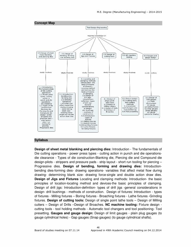
M.E. Degree (Manufacturing Engineering) - 2014-2015
46
Board of studies meeting on 07.11.14 Approved in 49th Academic Council meeting on 04.12.2014
Concept Map
Syllabus
Design of sheet metal blanking and piercing dies: Introduction - The fundamentals of
Die cutting operations - power press types - cutting action in punch and die operations-
die clearance - Types of die construction-Blanking die, Piercing die and Compound die
design-pilots - strippers and pressure pads - strip layout - short run tooling for piercing –
Progressive dies. Design of bending, forming and drawing dies: Introduction-
bending dies-forming dies- drawing operations- variables that affect metal flow during
drawing- determining blank size- drawing force-single and double action draw dies.
Design of Jigs and Fixtures Locating and clamping methods: Introduction- the basic
principles of location-locating method and devices-the basic principles of clamping.
Design of drill jigs: Introduction-definition- types of drill jigs -general considerations in
design- drill bushings - methods of construction. Design of fixtures: Introduction - types
of fixtures - Milling fixtures – Boring fixtures - Broaching fixtures - Lathe fixtures -Grinding
fixtures. Design of cutting tools: Design of single point lathe tools – Design of Milling
cutters – Design of Drills –Design of Broaches. NC machine tooling: Fixture design -
cutting tools - tool holding methods - Automatic tool changers and tool positioning- Tool
presetting. Gauges and gauge design: Design of limit gauges - plain plug gauges (to
gauge cylindrical holes) - Gap gauges (Snap gauges) (to gauge cylindrical shafts).
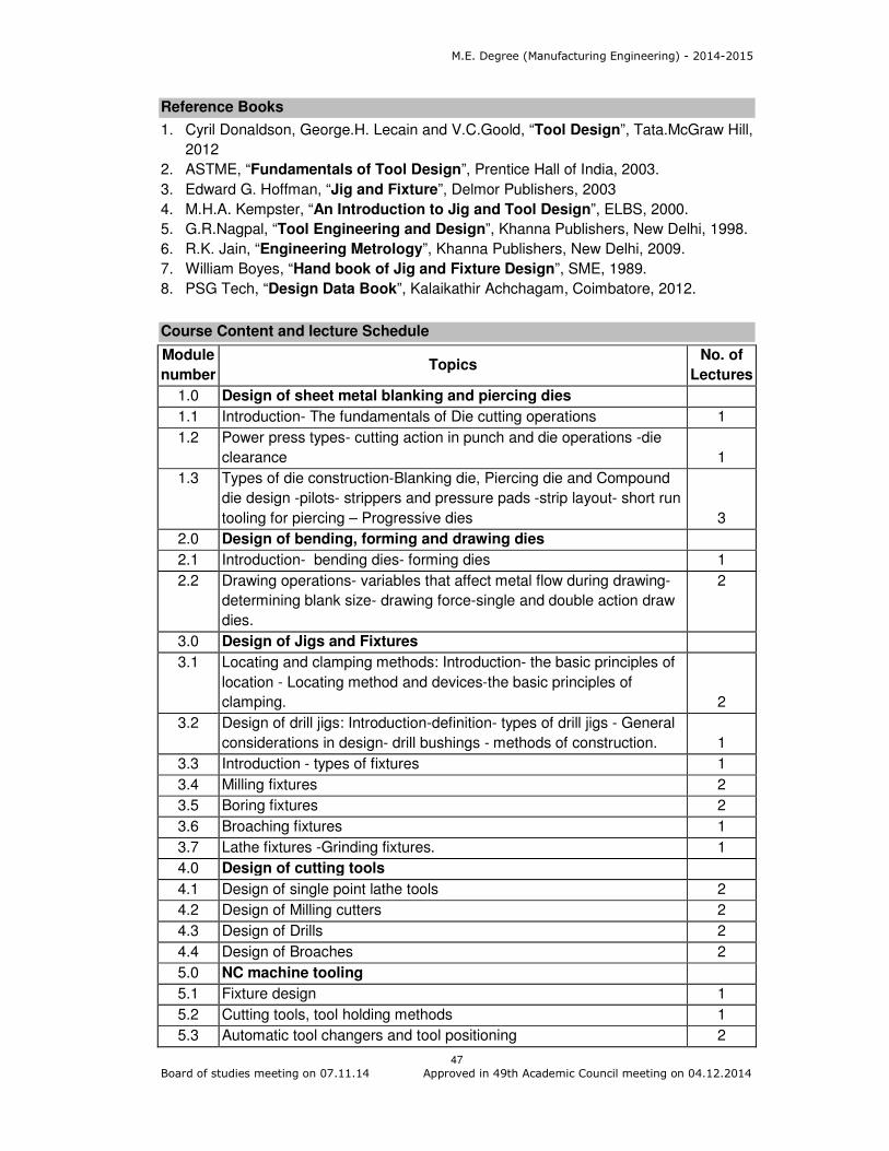
M.E. Degree (Manufacturing Engineering) - 2014-2015
47
Board of studies meeting on 07.11.14 Approved in 49th Academic Council meeting on 04.12.2014
Reference Books
1. Cyril Donaldson, George.H. Lecain and V.C.Goold, “Tool Design”, Tata.McGraw Hill,
2012
2. ASTME, “Fundamentals of Tool Design”, Prentice Hall of India, 2003.
3. Edward G. Hoffman, “Jig and Fixture”, Delmor Publishers, 2003
4. M.H.A. Kempster, “An Introduction to Jig and Tool Design”, ELBS, 2000.
5. G.R.Nagpal, “Tool Engineering and Design”, Khanna Publishers, New Delhi, 1998.
6. R.K. Jain, “Engineering Metrology”, Khanna Publishers, New Delhi, 2009.
7. William Boyes, “Hand book of Jig and Fixture Design”, SME, 1989.
8. PSG Tech, “Design Data Book”, Kalaikathir Achchagam, Coimbatore, 2012.
Course Content and lecture Schedule
Module
number Topics
No. of
Lectures
1.0 Design of sheet metal blanking and piercing dies
1.1 Introduction- The fundamentals of Die cutting operations 1
1.2 Power press types- cutting action in punch and die operations -die
clearance 1
1.3 Types of die construction-Blanking die, Piercing die and Compound
die design -pilots- strippers and pressure pads -strip layout- short run
tooling for piercing – Progressive dies 3
2.0 Design of bending, forming and drawing dies
2.1 Introduction- bending dies- forming dies 1
2.2 Drawing operations- variables that affect metal flow during drawing-
determining blank size- drawing force-single and double action draw
dies.
2
3.0 Design of Jigs and Fixtures
3.1 Locating and clamping methods: Introduction- the basic principles of
location - Locating method and devices-the basic principles of
clamping. 2
3.2 Design of drill jigs: Introduction-definition- types of drill jigs - General
considerations in design- drill bushings - methods of construction. 1
3.3 Introduction - types of fixtures 1
3.4 Milling fixtures 2
3.5 Boring fixtures 2
3.6 Broaching fixtures 1
3.7 Lathe fixtures -Grinding fixtures. 1
4.0 Design of cutting tools
4.1 Design of single point lathe tools 2
4.2 Design of Milling cutters 2
4.3 Design of Drills 2
4.4 Design of Broaches 2
5.0 NC machine tooling
5.1 Fixture design 1
5.2 Cutting tools, tool holding methods 1
5.3 Automatic tool changers and tool positioning 2
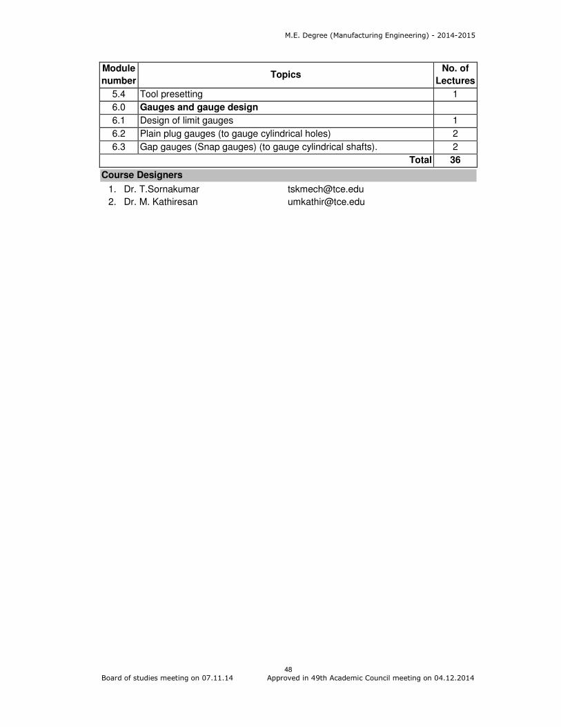
M.E. Degree (Manufacturing Engineering) - 2014-2015
48
Board of studies meeting on 07.11.14 Approved in 49th Academic Council meeting on 04.12.2014
Module
number Topics
No. of
Lectures
5.4 Tool presetting 1
6.0 Gauges and gauge design
6.1 Design of limit gauges 1
6.2 Plain plug gauges (to gauge cylindrical holes) 2
6.3 Gap gauges (Snap gauges) (to gauge cylindrical shafts). 2
Total 36
Course Designers
1. Dr. T.Sornakumar [email protected]
2. Dr. M. Kathiresan [email protected]

M.E. Degree (Manufacturing Engineering) - 2014-2015
49
Board of studies meeting on 07.11.14 Approved in 49th Academic Council meeting on 04.12.2014
Category L T P Credit
PC 0 0 2 1
Preamble
Manufacturing needs automation in the field of generation of CNC codes for various
machining operations, simulation of manufacturing systems, Robot programming,
Simulation for casting validation, Simulation of pneumatic, hydraulic and, electro
hydraulic circuits for operations like sequencing, cascading.
Prerequisite
Advanced Manufacturing Engineering Laboratory – I
Course Outcomes
On the successful completion of the course, students will be able to
CO.No.
Course Outcome Blooms
Level
Expected proficiency
Expected attainment level
CO1 Apprise the geometric models of Engineering components
Analyse 60 50
CO2 Generate CNC codes various machining operations and Operate CNC machines
Apply 70 60
CO3 Evaluate robot program through simulation
Analyse 60 50
CO4 Simulate manufacturing systems and casting processes Analyse 60 50
CO5 Construct pneumatic, hydraulic and electro hydraulic circuits for various industrial operations
Apply 70 60
Mapping with Programme Outcomes
COs PO1 PO2 PO3 PO4 PO5 PO6 PO7 PO8 PO9 PO10 PO11
CO1 S S M M M M L L
CO2 S M L L M M L L
CO3 S S M M M M L L
CO4 S S M M M M L L
CO5 S M L L M M L L
S- Strong; M-Medium; L-Low
Assessment Pattern
Bloom’s Category Continuous Assessment Tests
Terminal Examination 1 2 3
Remember - - 0 0
Understand - - 0 0
Apply - - 100 100
14MG270 ADVANCED MANUFACTURING
ENGINEERING LABORATORY - II
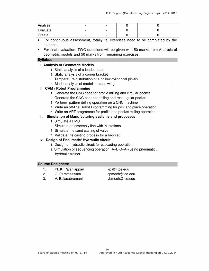
M.E. Degree (Manufacturing Engineering) - 2014-2015
50
Board of studies meeting on 07.11.14 Approved in 49th Academic Council meeting on 04.12.2014
Analyse - - 0 0
Evaluate - - 0 0
Create - - 0 0
• For continuous assessment, totally 12 exercises need to be completed by the
students.
• For final evaluation, TWO questions will be given with 50 marks from Analysis of
geometric models and 50 marks from remaining exercises.
Syllabus
I. Analysis of Geometric Models
1. Static analysis of a loaded beam
2. Static analysis of a corner bracket
3. Temperature distribution of a hollow cylindrical pin-fin
4. Modal analysis of model airplane wing .
II. CAM / Robot Programming
1. Generate the CNC code for profile milling and circular pocket
2. Generate the CNC code for drilling and rectangular pocket
3. Perform pattern drilling operation on a CNC machine
4. Write an off-line Robot Programming for pick and place operation
5. Write an APT programme for profile and pocket milling operation
III. Simulation of Manufacturing systems and processes
1. Simulate a FMC
2. Simulate an assembly line with ‘n’ stations
3. Simulate the sand casting of valve
4. Validate the casting process for a brocket
IV. Design of Pneumatic/ Hydraulic circuit
1. Design of hydraulic circuit for cascading operation
2. Simulation of sequencing operation (A+B-B+A-) using pneumatic /
hydraulic trainer
Course Designers:
1. PL.K. Palaniappan [email protected]
2. C. Paramasivam [email protected]
3. V. Balasubramani [email protected]
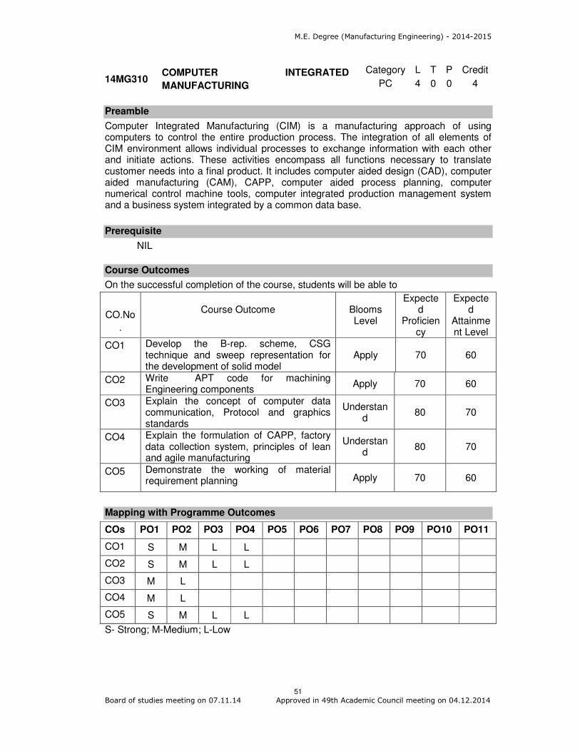
M.E. Degree (Manufacturing Engineering) - 2014-2015
51
Board of studies meeting on 07.11.14 Approved in 49th Academic Council meeting on 04.12.2014
Category L T P Credit
PC 4 0 0 4
Preamble
Computer Integrated Manufacturing (CIM) is a manufacturing approach of using computers to control the entire production process. The integration of all elements of CIM environment allows individual processes to exchange information with each other and initiate actions. These activities encompass all functions necessary to translate customer needs into a final product. It includes computer aided design (CAD), computer aided manufacturing (CAM), CAPP, computer aided process planning, computer numerical control machine tools, computer integrated production management system and a business system integrated by a common data base.
Prerequisite
NIL
Course Outcomes
On the successful completion of the course, students will be able to
CO.No
.
Course Outcome Blooms
Level
Expected
Proficiency
Expected
Attainment Level
CO1 Develop the B-rep. scheme, CSG technique and sweep representation for the development of solid model
Apply 70 60
CO2 Write APT code for machining Engineering components
Apply 70 60
CO3 Explain the concept of computer data communication, Protocol and graphics standards
Understand
80 70
CO4 Explain the formulation of CAPP, factory data collection system, principles of lean and agile manufacturing
Understand
80 70
CO5 Demonstrate the working of material requirement planning Apply 70 60
Mapping with Programme Outcomes
COs PO1 PO2 PO3 PO4 PO5 PO6 PO7 PO8 PO9 PO10 PO11
CO1 S M L L
CO2 S M L L
CO3 M L
CO4 M L
CO5 S M L L
S- Strong; M-Medium; L-Low
14MG310 COMPUTER INTEGRATED
MANUFACTURING
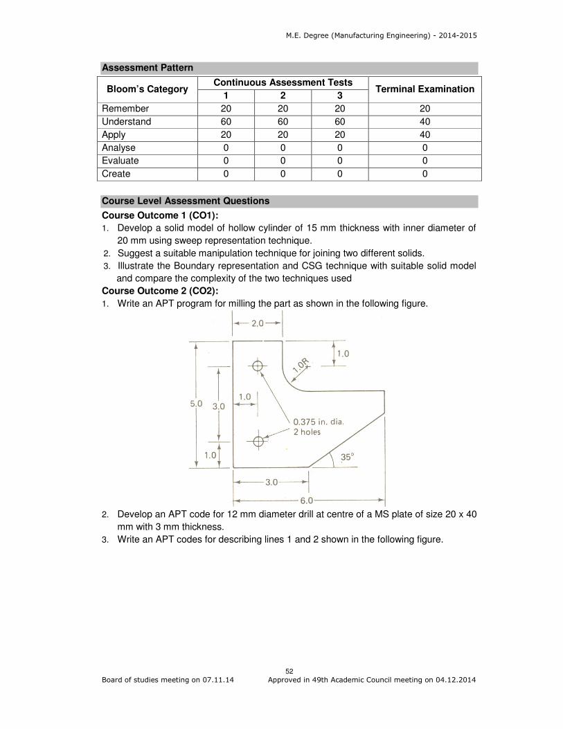
M.E. Degree (Manufacturing Engineering) - 2014-2015
52
Board of studies meeting on 07.11.14 Approved in 49th Academic Council meeting on 04.12.2014
Assessment Pattern
Bloom’s Category Continuous Assessment Tests
Terminal Examination 1 2 3
Remember 20 20 20 20
Understand 60 60 60 40
Apply 20 20 20 40
Analyse 0 0 0 0
Evaluate 0 0 0 0
Create 0 0 0 0
Course Level Assessment Questions
Course Outcome 1 (CO1):
1. Develop a solid model of hollow cylinder of 15 mm thickness with inner diameter of
20 mm using sweep representation technique.
2. Suggest a suitable manipulation technique for joining two different solids.
3. Illustrate the Boundary representation and CSG technique with suitable solid model
and compare the complexity of the two techniques used
Course Outcome 2 (CO2):
1. Write an APT program for milling the part as shown in the following figure.
2. Develop an APT code for 12 mm diameter drill at centre of a MS plate of size 20 x 40
mm with 3 mm thickness.
3. Write an APT codes for describing lines 1 and 2 shown in the following figure.

M.E. Degree (Manufacturing Engineering) - 2014-2015
53
Board of studies meeting on 07.11.14 Approved in 49th Academic Council meeting on 04.12.2014
Course Outcome 3 (CO3):
1. Develop IGES neutral format for circle of radius 20 mm with centre (10, 5, 0) and a
straight line with two ends (0, 0) and (15, 25).
2. Develop DXF neutral format for a point located at (10, 2, 8) and circle of diameter 40
mm with (0, 0, 0) as centre.
3. Explain the general procedure for framing of data along with the types of data error.
Course Outcome 4 (CO4):
1. Explain the concept of Generative type CAPP.
2. Describe about the computerised machinability data systems.
3. Discuss about the integration and implementation issues of CAPP and its advantage
and limitation.
Course Outcome 5 (CO5):
1. Illustrate the principle of MRP functioning with suitable master scheduling data.
2. Suggest a suitable data collection method for mass production of oil seal and
explain.
3. Discuss about any two automatic identification methods generally followed in a job
shop production environment.
Concept Map

M.E. Degree (Manufacturing Engineering) - 2014-2015
54
Board of studies meeting on 07.11.14 Approved in 49th Academic Council meeting on 04.12.2014
Syllabus
Fundamentals Elements: Nature of CIM, Evolution of CIM, CIM hardware and software.
Computer Aided Design: Design process, solid modeling techniques, creating
manufacturing database. Computer Aided Manufacturing: Elements of CNC machine
tools, Computer assisted part programming–APT language, CAD based programming,
Computer Communication: Hierarchy of computers in manufacturing, Serial and
parallel communication, Local area network, Protocols: Manufacturing Automation
Protocol and Technical Office Protocol, CAD/CAM data exchange-Method of data
exchange, Evolution of data exchange, Neutral file format: DXF, IGES and PDES.
Business function and shop floor data collection: Material Requirement Planning,
Inputs to MRP, Working of MRP, MRP output reports, Capacity Planning, Cost planning
and control, Computer Aided Process Planning: Retrieval type and Generative type
CAPP, Benefits, Computerised machinability data systems, Integration and
Implementation issues, Shop floor control: Functions, information flow, Factory Data
collection systems, Automatic Identification methods, automated data collection systems,
Technological Development: Agile manufacturing, Lean manufacturing, Comparison of
Agile and Lean manufacturing.
Reference Books
1. Vajpayee S. Kant, “Principles of Computer Integrated Manufacturing”, Prentice Hall
of India Learning, 2009.
2. Ibrahim Zeid, “Mastering CAD/CAM”, Tata McGraw Hill Education (P) Ltd., Special
Indian Edition, 2008.
3. Mikell P.Groover, “Automation, Production Systems and Computer Integrated
Manufacturing”, Prentice Hall of India Learning, Third Edition, 2014.
4. David Bedworth, “Computer Integrated Design and Manufacturing”, Tata Mc Graw
Hill publishing company Ltd, 1998.
5. Yorem Koren and Joseph Ben-Uri, “Numerical Control of Machine tools”, Khanna
Publishers, 1988.
6. P. Radhakrishnan, S. Subramanyan and V. Raju, “CAD/CAM/CIM”, New Age
International (P) Ltd., New Delhi, 2009.
7. Sureder Kumar and A.K.Jha, “Technology of Computer Aided Design and
manufacturing” Dhanpat rai and sons, Delhi, 1993.
Course Contents and Lecture Schedule
Module
Number Topics
No. of
Lectures
1. Fundamentals Elements: Nature of CIM, Evolution of CIM 1
1.1 CIM hardware 1
1.2 CIM software
2. Computer Aided Design: Design process 1
2.1 Solid modeling techniques 2
2.2 Creating manufacturing database 1
3. Computer Aided Manufacturing: Elements of CNC machine
tools
1

M.E. Degree (Manufacturing Engineering) - 2014-2015
55
Board of studies meeting on 07.11.14 Approved in 49th Academic Council meeting on 04.12.2014
Module
Number Topics
No. of
Lectures
3.1 Computer assisted part programming–APT language 2
3.2 CAD based programming 2
3.3 Computer Communication 2
3.3.1 Hierarchy of computers in manufacturing 2
3.3.2 Serial and parallel communication 1
3.3.3 Local area network
3.4 Protocols-Manufacturing Automation Protocol 1
Technical Office Protocol
3.5 CAD/CAM data exchange-Method of data exchange 1
3.5.1 Evolution of data exchange 2
3.5.2 Neutral file format-DXF
IGES and PDES
4. Business function and shop floor data collection
4.1 Material Requirement Planning-Inputs to MRP 2
4.1.1 Working of MRP 2
4.1.2 MRP output reports 2
4.1.3 Capacity Planning
4.2 Cost planning and control 1
4.3 Computer Aided Process Planning-Retrieval type 2
Generative type CAPP, Benefits of CAPP 2
4.4 Computerised machinability data systems 1
4.5 Integration and Implementation issues 2
4.6 Shop floor control-functions, information flow 1
4.7 Factory Data collection systems 2
4.8 Automatic Identification methods 3
4.9 Automated data collection systems 2
5. Technological Development
5.1 Agile manufacturing 2
5.2 Lean manufacturing
5.3 Comparison of Agile and Lean manufacturing 2
Total 46
Course Designers:
1. T. Sornakumar [email protected]
2. C. Paramasivam [email protected]

M.E. Degree (Manufacturing Engineering) - 2014-2015
55 Board of studies meeting on 07.11.14 Approved in 49th Academic Council meeting on 04.12.2014
Category L T P Credit
PE 4 0 0 4
Preamble
The workplace is one of the prime resources to deliver products/services with the
expected level of quality at least cost. To achieve the organizational effectiveness,
proper utilization of the workplace has to be ensured. This course has been designed to
highlight the fundamental issues, concepts and the methodologies related to Plant layout
and material handling
Prerequisite
NIL
Course Outcomes
On the successful completion of the course, students will be able to
CO.No.
Course Outcome Blooms
Level
Expected
Proficiency
Expected
attainment
level
CO1 Describe the facility location determinants and methods
Understand 80 70
CO2 Solve different types of facility location models
Apply 70 60
CO3 Design the layouts of manufacturing systems and service organizations
Apply 70 60
CO4 Make clusters of machine and components using different techniques
Apply 70 60
CO5 Illustrate the activities for the work station in order to make balanced flow line using heuristic algorithms.
Apply 70 60
CO6 Describe about material handling system.
Understand 80 70
Mapping with Programme Outcomes
COs PO1 PO2 PO3 PO4 PO5 PO6 PO7 PO8 PO9 PO10 PO11
CO1. M L
CO2. S M L L
CO3. S M L L
CO4. S M L L
CO5. S M L L
CO6. M L
S- Strong; M-Medium; L-Low
14MGPA0 PLANT LAYOUT AND MATERIAL
HANDLING

M.E. Degree (Manufacturing Engineering) - 2014-2015
56 Board of studies meeting on 07.11.14 Approved in 49th Academic Council meeting on 04.12.2014
Assessment Pattern
Bloom’s Category Continuous Assessment Tests
Terminal Examination 1 2 3
Remember 20 20 20 20
Understand 40 40 40 40
Apply 40 40 40 40
Analyse 0 0 0 0
Evaluate 0 0 0 0
Create 0 0 0 0
Course Level Assessment Questions
Course Outcome 1 (CO1):
1. List the issues of facility location.
2. Identify the factors to be considered for location selection.
3. Write the equation to compute the Euclidian distance.
4. Discuss about different types of facility location problem.
Course Outcome 2 (CO2):
1. The following table shows a matrix of travel times between possible locations for
ambulance stations and areas in a city. Governing body’s policy suggests that
ambulance stations must be at most 30 minutes away from all population areas.
Find the best locations for achieving this.
Possible I II III IV V VI VII
Locations A 5 11 20 33 27 36 33
B 33 35 17 10 53 41 18
C 18 39 41 12 33 22 37
D 13 6 43 25 38 33 20
E 35 47 41 45 50 51 43
2. Discuss the various techniques of locating a single facility
Course Outcome 3 (CO3):
1. A company consists of the following functional areas. Design a layout using the
construction algorithm ALDEP.
A – Wood cutting 1280 Sq. feet
B – Receiving 512
C – Framing 1280
D – Upholstery 1120
E – Fabric Storage 960
F – Fabric cutting 960
G- Sewing 640
H – Shipping 800

M.E. Degree (Manufacturing Engineering) - 2014-2015
57 Board of studies meeting on 07.11.14 Approved in 49th Academic Council meeting on 04.12.2014
I – Offices 800
J – General Storage 480
2. The data for designing a layout are given below. Follow the steps of the CRAFT
algorithm & develop a final CRAFT layout using the pair wise interchange
technique. Use unit cost matrix
Initial Layout
Course Outcome 4 (CO4):
1. Identify the logical part families and machine groups by applying ROC technique.
The part-machine incidence matrix is given in the table.
Parts
Machine
I II III IV V
1 1 0 0 0 0
2 0 1 0 0 1
3 1 0 0 1 0
4 0 1 1 0 0
5 0 0 0 1 0
2. Identify the logical part families and machine groups by applying ROC-2
technique. The part-machine incidence matrix is shown below.
Parts
Machine
I II III IV V
1 1 0 0 0 0
2 0 1 0 0 1
3 1 0 0 1 0
4 0 1 1 0 0
5 0 0 0 1 1
- A B C D
A - 2 4 4
B 1 - 1 3
C 2 1 - 2
D 4 1 0 -
40
50 30
40 40
20
20
A B
C D

M.E. Degree (Manufacturing Engineering) - 2014-2015
58 Board of studies meeting on 07.11.14 Approved in 49th Academic Council meeting on 04.12.2014
Course Outcome 5 (CO5):
1. A company produces 50 products per hour on its production line. The
operations involved are given below. Balance the line for the given production
rate using Ranked positional weight method. Determine the workstations
required and balance delay.
Work
Element
Immediate
Predecessor
Estimated
time (Sec)
A - 20
B - 10
C - 15
D B,C 10
E D 25
F E 15
G F 30
H G 30
I A,H 20
J I 25
2. The operations involved in an organization are given below. Balance the line
using Kilbridge and Wester method. Determine the balance delay. Assume that
number of workstations is Three.
Work
Element
Immediate
Predecessor
Estimated
time (Sec)
a - 10
b - 10
c - 15
d b,c 10
e d 35
f e 15
g f 30
h g 30
i a,h 20
j i 15
Course Outcome 6 (CO6):
1. Illustrate the basic material handling equipments with suitable example
2. Describe the criteria and guidelines for the design of Unit load system.
3. Discuss about AS/AR system in comparison with the conventional warehousing
system with an example.
4. Discuss about the choice of material handling system for a heavy manufacturing
industry. Illustrate the pros and cons of the system under study.
.
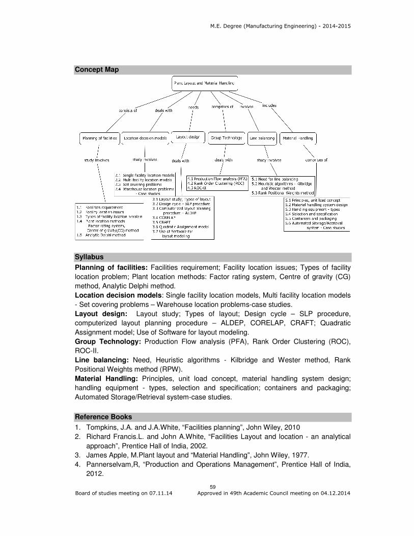
M.E. Degree (Manufacturing Engineering) - 2014-2015
59 Board of studies meeting on 07.11.14 Approved in 49th Academic Council meeting on 04.12.2014
Concept Map
Syllabus
Planning of facilities: Facilities requirement; Facility location issues; Types of facility
location problem; Plant location methods: Factor rating system, Centre of gravity (CG)
method, Analytic Delphi method.
Location decision models: Single facility location models, Multi facility location models
- Set covering problems – Warehouse location problems-case studies.
Layout design: Layout study; Types of layout; Design cycle – SLP procedure,
computerized layout planning procedure – ALDEP, CORELAP, CRAFT; Quadratic
Assignment model; Use of Software for layout modeling.
Group Technology: Production Flow analysis (PFA), Rank Order Clustering (ROC),
ROC-II.
Line balancing: Need, Heuristic algorithms - Kilbridge and Wester method, Rank
Positional Weights method (RPW).
Material Handling: Principles, unit load concept, material handling system design;
handling equipment - types, selection and specification; containers and packaging;
Automated Storage/Retrieval system-case studies.
Reference Books
1. Tompkins, J.A. and J.A.White, “Facilities planning”, John Wiley, 2010
2. Richard Francis.L. and John A.White, “Facilities Layout and location - an analytical
approach”, Prentice Hall of India, 2002.
3. James Apple, M.Plant layout and “Material Handling”, John Wiley, 1977.
4. Pannerselvam,R, “Production and Operations Management”, Prentice Hall of India,
2012.
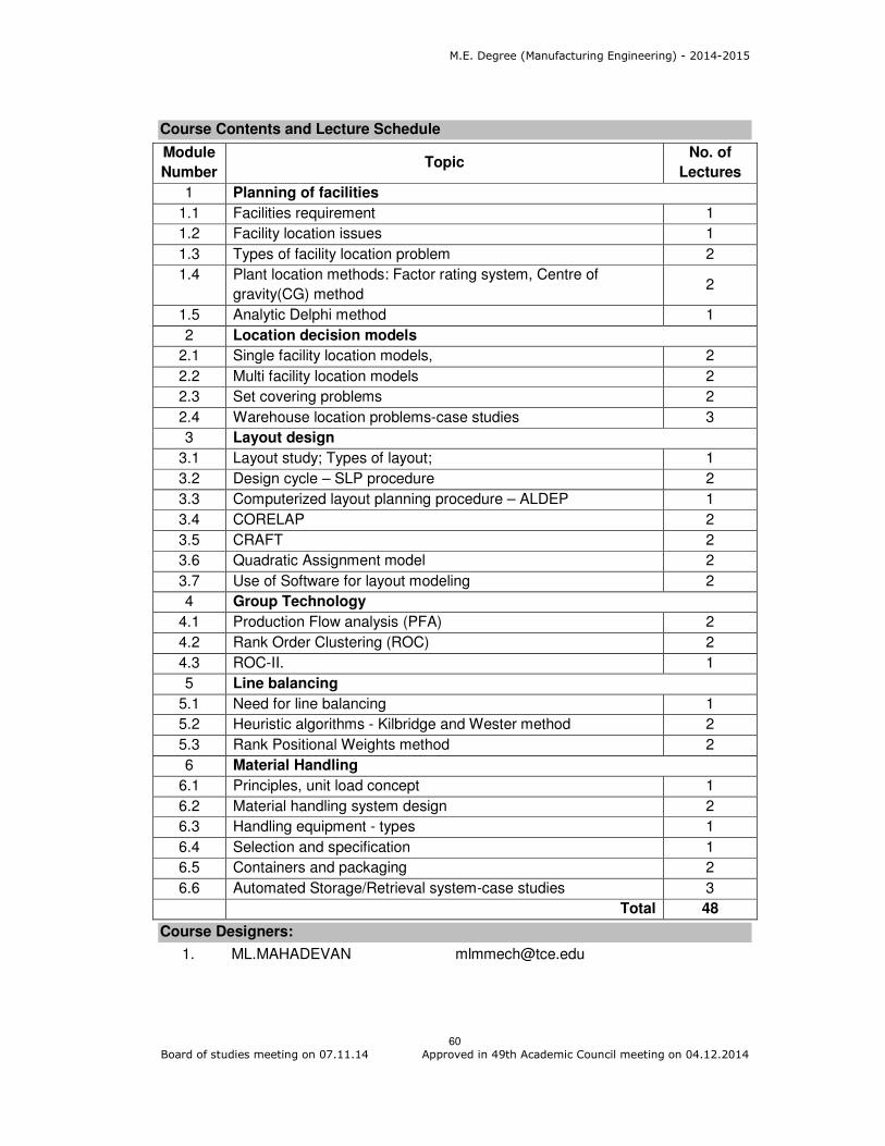
M.E. Degree (Manufacturing Engineering) - 2014-2015
60 Board of studies meeting on 07.11.14 Approved in 49th Academic Council meeting on 04.12.2014
Course Contents and Lecture Schedule
Module
Number Topic
No. of
Lectures
1 Planning of facilities
1.1 Facilities requirement 1
1.2 Facility location issues 1
1.3 Types of facility location problem 2
1.4 Plant location methods: Factor rating system, Centre of
gravity(CG) method 2
1.5 Analytic Delphi method 1
2 Location decision models
2.1 Single facility location models, 2
2.2 Multi facility location models 2
2.3 Set covering problems 2
2.4 Warehouse location problems-case studies 3
3 Layout design
3.1 Layout study; Types of layout; 1
3.2 Design cycle – SLP procedure 2
3.3 Computerized layout planning procedure – ALDEP 1
3.4 CORELAP 2
3.5 CRAFT 2
3.6 Quadratic Assignment model 2
3.7 Use of Software for layout modeling 2
4 Group Technology
4.1 Production Flow analysis (PFA) 2
4.2 Rank Order Clustering (ROC) 2
4.3 ROC-II. 1
5 Line balancing
5.1 Need for line balancing 1
5.2 Heuristic algorithms - Kilbridge and Wester method 2
5.3 Rank Positional Weights method 2
6 Material Handling
6.1 Principles, unit load concept 1
6.2 Material handling system design 2
6.3 Handling equipment - types 1
6.4 Selection and specification 1
6.5 Containers and packaging 2
6.6 Automated Storage/Retrieval system-case studies 3
Total 48
Course Designers:
1. ML.MAHADEVAN [email protected]

M.E. Degree (Manufacturing Engineering) - 2014-2015
61 Board of studies meeting on 07.11.14 Approved in 49th Academic Council meeting on 04.12.2014
Category L T P Credit
PE 4 0 0 4
Preamble
Research Methodology will enable the Researchers to develop the most appropriate methodology for their Research Studies. The mission of the course is to impart research skills to the beginners and help improve the quality of Research by the existing researchers. This course aims at giving adequate exposure in research process, data analysis techniques, report writing. Methodologies are often conflated with methods and techniques of data analyses, with limited understanding of the logic underlying the various techniques and methods. Further, engineering sciences also increasingly draw from developments in natural sciences and technology studies to enhance its explanatory domain. This has also strengthened the scope for trans-disciplinary research drawing upon perspectives from varied disciplines. Choice of methods is guided by the nature of the research questions posed. There is a scope for the researcher to learn from each other, and importantly understand the validity of the approaches that each study adopts.
Prerequisite
NIL
Course Outcomes
On the successful completion of the course, students will be able to CO 1. Explain the relationship between theory and research.
Remember
CO 2. Describe and compare the major quantitative and qualitative research methods in engineering research.
Understand
CO 3. Understand the importance of research ethics and integrate research ethics into the research process.
Understand
CO 4. Propose a research study and justify the theory as well as the methodological decisions, including sampling and measurement.
Apply
CO 5. Construct an effective questionnaire that employs several types of survey questions.
Apply
CO 6. Assess and critique a published journal article that uses one of the primary research methods in the engineering field.
Apply
Mapping with Programme Outcomes
COs PO1
PO2
PO3
PO4
PO5
PO6
PO7
PO8
PO9
PO10
PO11
PO12
CO1. S M M L L L L L L L L L
CO2. S S L L L L L L L L L L
CO3. S M M L L L L L L L L L
CO4. S S L L L L L L L L L L
CO5.
S S M L L L L L L L L L
CO6.
S S M L L L L L L L L L
S- Strong; M-Medium; L-Low
14MGPB0 RESEARCH METHODOLOGY

M.E. Degree (Manufacturing Engineering) - 2014-2015
62 Board of studies meeting on 07.11.14 Approved in 49th Academic Council meeting on 04.12.2014
Assessment Pattern
Bloom’s Category
Continuous Assessment Tests
Terminal Examination
1 2 3 Remember 20 20 20 20 Understand 80 40 60 40 Apply 0 40 20 40 Analyse 0 0 0 0 Evaluate 0 0 0 0 Create 0 0 0 0
Course Outcome 1 (CO1):
1. Define Research. 2. What are the types of research? 3. List the steps of research process. 4. Define Data. Give examples of data. 5. Name the stages of report writing. 6. State the basic assumptions of the analysis of variance.
Course Outcome 2 (CO2):
1. Distinguish between fundamental research and applied research. Give examples. 2. List the types of chart and compare them. 3. Distinguish between Null hypothesis and alternative hypothesis. 4. What do you mean by multivariate techniques? Explain their significance in
context of research studies. 5. Describe the technique of analysis of variance for one-way and two-way
classifications. 6. Write short notes on characteristics of a good research report.
Course Outcome 3 (CO3):
1. A hotel management is interested in determining the percentage of the hotel guests who stay for more than 3 days. The reservation manager wants to be 95 percent confident that the percentage has been estimated to be within ±3% of the true value. What is the most conservative sample size needed for this problem?
2. In an international airport, the service time of a terminal follows exponential
distribution. The service rate of a terminal serving the flights is 30 per day. Find the probability that the service time of the terminal in clearing a flight is :
a. less than 0.5 hr. b. more than 0.75 hr.
3. In a Mainframe computer centre, execution time of programs follows exponential
distribution. The average execution time of the programs is 5 minutes. Find the probability that the execution time of the programs is :
a. less than 4 minutes b. more than 6 minutes
Course Outcome 4 (CO4):
1. A certain process produces 10 percent defective articles. A supplier of new raw
material claims that the use of his material would reduce the proportion of
defectives. A random sample of 400 units using this new material was taken out

M.E. Degree (Manufacturing Engineering) - 2014-2015
63 Board of studies meeting on 07.11.14 Approved in 49th Academic Council meeting on 04.12.2014
of which 34 were defective units. Can the supplier’s claim be accepted? Test at 1
percent level of significance.
2. Set up an analysis of variance table for the following per acre production data for
three varieties of wheat, each grown on 4 plots and state if the variety differences
are significant
Plot of land
Per acre production data
Variety of wheat A B C
1 6 5 5 2 7 5 4 3 3 3 3 4 8 7 4
3. The following are the numbers of artifacts dug up by two archaeologists at an ancient cliff dwelling on 30 days.
By X 1 0 2 3 1 0 2 2 3 0 1 1 4 1 2 1 3 5 2 1 3 2 4 1 3 2 0 2 4 2
By Y 0 0 1 0 2 0 0 1 1 2 0 1 2 1 1 0 2 2 6 0 2 3 0 2 1 0 1 0 1 0
Use the sign test at 1% level of significance to test the null hypothesis that the two archaeologists, X and Y are equally good at finding artifacts against the alternative hypothesis that X is better?
Course Outcome 5 (CO5):
1. A Study compared the effects of four 1-month point of purchase promotion on sales. The unit sales for five stores using all four promotions in different months as follows.
Free sample 78 87 81 89 85
One pack gift 94 91 87 90 88
Cents off 73 78 69 83 76
Refund by mail 79 83 78 69 81
Do the promotions produce different effects on sales?
2. A research company has designed three different systems to cleanup oil spills. The following table contains the results, measured by how much surface area in (square meter) is cleared in 1 hour. The data were found by testing each method in several trials. Are the three systems equally effective? Use the 0.05 level of significance? A 55 60 63 56 59 55
B 57 53 64 49 62
C 66 52 61 57
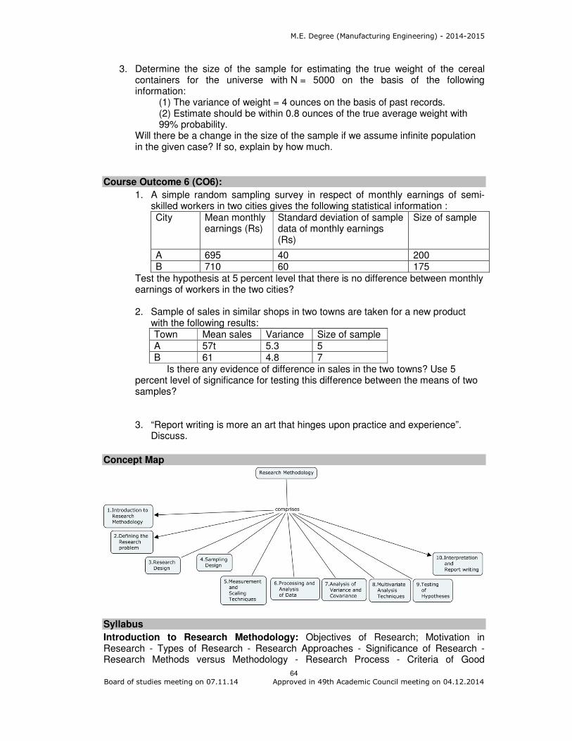
M.E. Degree (Manufacturing Engineering) - 2014-2015
64 Board of studies meeting on 07.11.14 Approved in 49th Academic Council meeting on 04.12.2014
3. Determine the size of the sample for estimating the true weight of the cereal containers for the universe with N = 5000 on the basis of the following information:
(1) The variance of weight = 4 ounces on the basis of past records. (2) Estimate should be within 0.8 ounces of the true average weight with 99% probability.
Will there be a change in the size of the sample if we assume infinite population in the given case? If so, explain by how much.
Course Outcome 6 (CO6):
1. A simple random sampling survey in respect of monthly earnings of semi-skilled workers in two cities gives the following statistical information : City Mean monthly
earnings (Rs) Standard deviation of sample data of monthly earnings (Rs)
Size of sample
A 695 40 200 B 710 60 175
Test the hypothesis at 5 percent level that there is no difference between monthly earnings of workers in the two cities? 2. Sample of sales in similar shops in two towns are taken for a new product
with the following results: Town Mean sales Variance Size of sample A 57t 5.3 5 B 61 4.8 7
Is there any evidence of difference in sales in the two towns? Use 5 percent level of significance for testing this difference between the means of two samples? 3. “Report writing is more an art that hinges upon practice and experience”.
Discuss.
Concept Map
Syllabus
Introduction to Research Methodology: Objectives of Research; Motivation in Research - Types of Research - Research Approaches - Significance of Research - Research Methods versus Methodology - Research Process - Criteria of Good

M.E. Degree (Manufacturing Engineering) - 2014-2015
65 Board of studies meeting on 07.11.14 Approved in 49th Academic Council meeting on 04.12.2014
Research. Defining the Research Problem: Selecting the Problem - Necessity of Defining the Problem - Technique Involved in Defining a Problem. Research Design: Need for Research Design - Features of a Good Design - Important Concepts Relating to Research Design - Different Research Designs - Basic Principles of Experimental Designs. Sampling Design: Implications of a Sample Design - Steps in Sampling Design - Criteria for Selecting a Sampling Procedure - Characteristics of Good Sample Design- Different types of Sample Designs - Random Sample from an Indicate Universe- Complex Random Sampling Designs - Standard error. Measurement and Scaling Techniques: Measurement Scales - Sources of Error in Measurement - Tests of Sound Measurement - Technique of Developing Measurement Tools - Scaling - Meaning of Scaling - Scale Classification Bases - Important Scaling Techniques. Processing and Analysis of Data: Processing Operations - Elements/Types of Analysis - Statistics in Research - Measures of Central Tendency - Measures of Dispersion - Measures of Asymmetry (Skewness) - Measures of Relationship - Simple Regression Analysis - Multiple Correlation and Regression Partial Correlation - Association in Case of Attributes. Analysis of Variance and Covariance: Analysis of Variance (ANOVA) - The Basic Principle of ANOVA - ANOVA Technique - Setting up Analysis of Variance Table - Short-cut Method for One-way ANOVA - Coding Method - Two-way ANOVA - ANOVA in Latin-Square Design - Analysis of Co-variance (ANOCOVA) - ANOCOVA Technique - Assumptions in ANOCOVA. Multivariate Analysis Techniques: Classification of Multivariate techniques - Variables in multivariate analysis, important multivariate techniques - Rotation in factor analysis - R – type - Q – type factor analyses - Path analyses. Testing of Hypotheses: Non parametric or Distribution free test - Relationship between spear man’s r’s and Kendall’s W - Characteristics of distribution – Free or non parametric tests. Interpretation and Report Writing: Technique of Interpretation - Precaution in Interpretation - Different Steps in Writing Report - Layout of the Research Report - Types of Reports - Oral Presentation- Mechanics of Writing a Research Report - Precautions for Writing Reports.
Reference Books
1. Dawson, Catherine,Practical Research Methods,New Delhi, UBS Publishers’Distributors 2002
2. Kothari, C.R.,2014, Second Edition, Research Methodology- Methods and Techniques, New Delhi, Wiley Eastern Limited.
3. Kumar, Ranjit, 2005, Research Methodology-A Step-by-Step Guide for beginners,(2nd.ed.),Singapore, Pearson Education
4. Khan Zode V.V., “Research Methodology and Trends”, APH Publishing corporation 2007.
5. Best J.W., “Research in Education”, Prentice Hall Inc, Newyork, USA, 2005. 6. William G. Zikmand, “Business Research Method”, Dryden, 2003 7. Panneerselvam R, ”Research Methodology”, Prentice Hall of India,2012
Course Contents and Lecture Schedule
S.No Topics No. of Lectures 1 Introduction to Research Methodology
1.1 Objectives of Research; Motivation in Research 1
1.2 Types of Research 1.3 Research Approaches 1 1.4 Significance of Research 1 1.5 Research Methods versus Methodology 1 1.6 Research Process
1 1.7 Criteria of Good Research 2 Defining the Research Problem
2.1 Selecting the Problem 2

M.E. Degree (Manufacturing Engineering) - 2014-2015
66 Board of studies meeting on 07.11.14 Approved in 49th Academic Council meeting on 04.12.2014
S.No Topics No. of Lectures 2.2 Necessity of Defining the Problem 2 2.3 Technique Involved in Defining a Problem 1 3 Research Design
3.1 Need for Research Design 1 3.2 Features of a Good Design
3.3 Important Concepts Relating to Research Design 1 3.4 Different Research Designs 1 3.5 Basic Principles of Experimental Designs 1 4 Sampling Design
4.1 Implications of a Sample Design 1
4.2 Steps in Sampling Design 4.3 Criteria for Selecting a Sampling Procedure
1 4.4 Characteristics of Good Sample Design 4.5 Different types of Sample Designs 1 4.6 Random Sample from an Indicate Universe 1 4.7 Complex Random Sampling Designs
2 4.8 Standard error 5 Measurement and Scaling Techniques
5.1 Measurement Scales 1
5.2 Sources of Error in Measurement 5.3 Tests of Sound Measurement 1 5.4 Technique of Developing Measurement Tools 1 5.5 Scaling
1 5.6 Meaning of Scaling 5.7 Scale Classification Bases 5.8 Important Scaling Techniques 1 6 Processing and Analysis of Data
6.1 Processing Operations 1 6.2 Elements/Types of Analysis
6.3 Statistics in Research 6.4 Measures of Central Tendency
1 6.5 Measures of Dispersion 6.6 Measures of Asymmetry (Skewness) 6.7 Measures of Relationship 1 6.8 Simple Regression Analysis 1 6.9 Multiple Correlation and Regression Partial
Correlation 1
6.10 Association in Case of Attributes 1 7 Analysis of Variance and Covariance
7.1 Analysis of Variance (ANOVA) 1 7.2 The Basic Principle of ANOVA
7.3 ANOVA Technique
2 7.4 Setting up Analysis of Variance Table 7.5 Short-cut Method for One-way ANOVA 7.6 Coding Method 7.7 Two-way ANOVA
1 7.8 ANOVA in Latin-Square Design 7.9 Analysis of Co-variance (ANOCOVA)
2 7.10 ANOCOVA Technique 7.11 Assumptions in ANOCOVA.
8 Multivariate Analysis Techniques

M.E. Degree (Manufacturing Engineering) - 2014-2015
67 Board of studies meeting on 07.11.14 Approved in 49th Academic Council meeting on 04.12.2014
S.No Topics No. of Lectures 8.1 Classification of Multivariate techniques
1 8.2 Variables in multivariate analysis 8.3 important multivariate techniques 1 8.4 Rotation in factor analysis 1 8.5 R – type - Q – type factor analyses 1 8.6 Path analyses 1
9 Testing of Hypotheses
9.1 Non parametric or Distribution free test 1 9.2 Relationship between spear man’s r’s and
Kendall’s W - Characteristics of distribution 2
9.3 Free or non parametric tests 1 10 Interpretation and Report Writing
10.1 Technique of Interpretation 1
10.2 Precaution in Interpretation 10.3 Different Steps in Writing Report 1 10.4 Layout of the Research Report 1 10.5 Types of Reports 1 10.6 Oral Presentation 1 10.7 Mechanics of Writing a Research Report
1 10.8 Precautions for Writing Reports
Total 52
Course Designers:
Dr. M.Palani Natha Raja [email protected]

M.E. Degree (Manufacturing Engineering) - 2014-2015
68 Board of studies meeting on 07.11.14 Approved in 49th Academic Council meeting on 04.12.2014
Category L T P Credit
PE 4 0 0 4
Preamble:
Quality is the mantra for success or even for the survival of any organization in this
competitive global market. Total Quality Management (TQM) is an enhancement to the
traditional way of doing business. It is a proven technique to guarantee survival in world-
class competition. It integrates fundamental management techniques, existing
improvement efforts, and technical tools under a disciplined approach. At the end of the
course the students are expected to recognize the quality issues in an organization and
analyze the ways to solve those using TQM techniques, and demonstrate skills in using
modern TQM tools and software to analyze problems.
Prerequisite
Probability and Statistics
Quality Engineering
Course Outcomes
On the successful completion of the course, students will be able to
CO.No.
Course Outcome
Blooms Level
Expected Proficiency
Expected Attainment
Level
CO1 Describe the principles of TQM Understand 80 70
CO2 Describe the concepts of Statistical process control
Understand 80 70
CO3 Relate the tools and techniques of TQM in an organization
Apply 70 60
CO4 Show the need for Quality systems of international standards
Apply 70 60
Mapping with Programme Outcomes
COs PO1 PO2 PO3 PO4 PO5 PO6 PO7 PO8 PO9 PO10 PO11
CO1 M L
CO2 M L
CO3 S M L L
CO4 S M L L
S- Strong; M-Medium; L-Low
Assessment Pattern
Bloom’s Category Test 1 Test 2 Test 3
End Semester
examination
1 Remember 20 20 20 20
2 Understand 30 30 30 30
3 Apply 50 50 50 50
14MGPC0 TOTAL QUALITY MANAGEMENT

M.E. Degree (Manufacturing Engineering) - 2014-2015
69 Board of studies meeting on 07.11.14 Approved in 49th Academic Council meeting on 04.12.2014
4 Analyze 0 0 0 0
5 Evaluate 0 0 0 0
6 Create 0 0 0 0
Course Level Assessment Questions
Course Outcome 1 (CO1):
1. Define TQM.
2. What is the need for quality planning?
3. What is a customer?
4. What are 5S?
5. List any four concepts under KAIZEN umbrella.
6. What is a ‘defect’ and ‘defective’?
Course Outcome 2 (CO2):
1. Discuss in detail the role of senior management.
2. How can you retail your customer in the organization’s business?
3. Explain about Juran’s Trilogy.
4. Differentiate between specification limit and control limit.
5. How will you calculate process capability ratio?
6. Explain the six basic steps in bench marking process.
Course Outcome 3 (CO3):
1. In plastic moulding process, the results of the inspection of 10 lots of 125 items
each are given in the following table.
Lot No. 1 2 3 4 5 6 7 8 9 10
No. of defectives 4 8 9 2 12 6 7 5 4 7
(i) Compute trial control limits
(ii) Plot the appropriate chart
(iii) Draw the conclusion
2. The following observations are made in a crankshaft machining process.
Sample No. Observations
1 2 3 4
1 20.21 20.19 20.25 20.15
2 20.24 20.19 20.23 20.17
3 20.17 20.16 20.20 20.18
4 20.10 20.14 20.18 20.09
5 20.04 20.03 20.05 19.97
6 20.04 19.97 19.99 20.01
7 20.09 20.05 20.00 20.03
8 19.99 19.98 20.01 19.97
(i) Compute the trial control limits for X and R charts.
(ii) Construct and R chart
(iii) Comment of the process.
(iv) Calculate the process capability
(v) Compute percent defective if any
Course Outcome 4 (CO4):

M.E. Degree (Manufacturing Engineering) - 2014-2015
70 Board of studies meeting on 07.11.14 Approved in 49th Academic Council meeting on 04.12.2014
1. The piston for a petrol engine is made in lots of 150 each. The lots are subjected
to 100% inspection. 25 such lots are inspected and the number of defectives
found was 125.
a. Compute the control limits for a p charts.
b. Compute the control limits for the np chart
2. Build the house of quality matrix to show the inter relationship between the
customer requirements and technical descriptors for a manufacturing system.
3. Discuss the mandatory items of ISO 14000.
4. Explain the steps to be followed in implementing quality system ISO 9000:2000.
Concept Map
Syllabus
Introduction: Fundamentals of TQM – Historical developments – important
philosophies- (Deming, Juran, Crossby) and their impact of quality – Quality planning,
Quality statement – TQM implementation stages Principles of TQM: Customer
satisfaction – customer perception of quality, customer complaints, Employee
involvement – Juran Trilogy, PDSA cycle, 5S, Kaizen. Process Monitoring: Seven tools
of quality, statistical fundamentals – Normal curve charts for variables and attributes,
Process Capability analysis. TQM Techniques: Quality Functions Deployment (QFD) –
house of Quality, QFD process and benefits, Benchmarking process, TPM – Concepts,
FMEA – concept, stages. Quality Management Systems: Need for ISO 9001: 2008 –
Elements, Implementation, Documentation and Auditing. ISO14000 – Concept
requirements and benefits – Case studies.
Reference Books
1. Shridhara Bhat, “TQM – Text and Cases”, Himalaya publishing House, 2010
2. Berk, Joseph and Berk, S., “The Essence of TQM”, Prentice Hall of India, 1998.
3. Narayana and Sreenivasan, “Quality Management – Concepts and Tasks”, New
Age International, 2007
4. Sharma, D.D, “Total Quality Management”, Sultan Chand & Sons, 2005.
5. Dale H.Besterfiled, Carol Besterfiled-Michna. Glen H. Beseterfiled and Mary
Besterfield-Sacre., “Total Quality Management”, Pearson Education Asia, 2013.
Course Contents and lecture Schedule
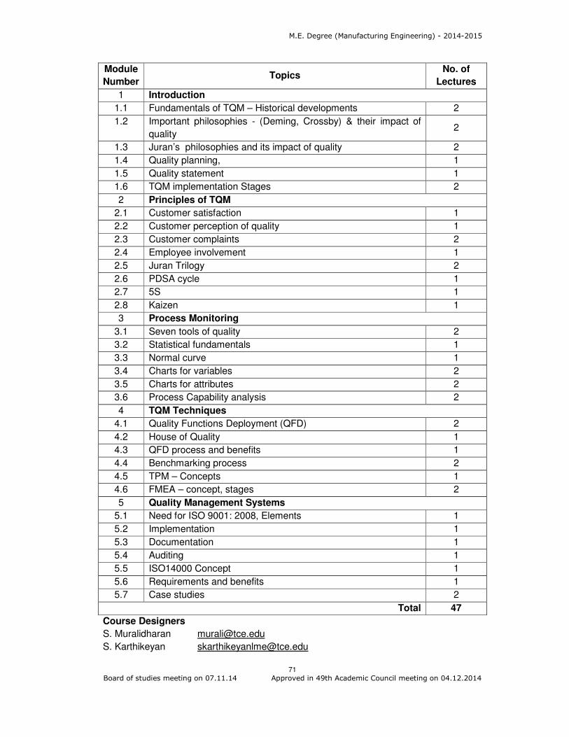
M.E. Degree (Manufacturing Engineering) - 2014-2015
71 Board of studies meeting on 07.11.14 Approved in 49th Academic Council meeting on 04.12.2014
Module
Number Topics
No. of
Lectures
1 Introduction
1.1 Fundamentals of TQM – Historical developments 2
1.2 Important philosophies - (Deming, Crossby) & their impact of
quality 2
1.3 Juran’s philosophies and its impact of quality 2
1.4 Quality planning, 1
1.5 Quality statement 1
1.6 TQM implementation Stages 2
2 Principles of TQM
2.1 Customer satisfaction 1
2.2 Customer perception of quality 1
2.3 Customer complaints 2
2.4 Employee involvement 1
2.5 Juran Trilogy 2
2.6 PDSA cycle 1
2.7 5S 1
2.8 Kaizen 1
3 Process Monitoring
3.1 Seven tools of quality 2
3.2 Statistical fundamentals 1
3.3 Normal curve 1
3.4 Charts for variables 2
3.5 Charts for attributes 2
3.6 Process Capability analysis 2
4 TQM Techniques
4.1 Quality Functions Deployment (QFD) 2
4.2 House of Quality 1
4.3 QFD process and benefits 1
4.4 Benchmarking process 2
4.5 TPM – Concepts 1
4.6 FMEA – concept, stages 2
5 Quality Management Systems
5.1 Need for ISO 9001: 2008, Elements 1
5.2 Implementation 1
5.3 Documentation 1
5.4 Auditing 1
5.5 ISO14000 Concept 1
5.6 Requirements and benefits 1
5.7 Case studies 2
Total 47
Course Designers
S. Muralidharan [email protected]
S. Karthikeyan [email protected]
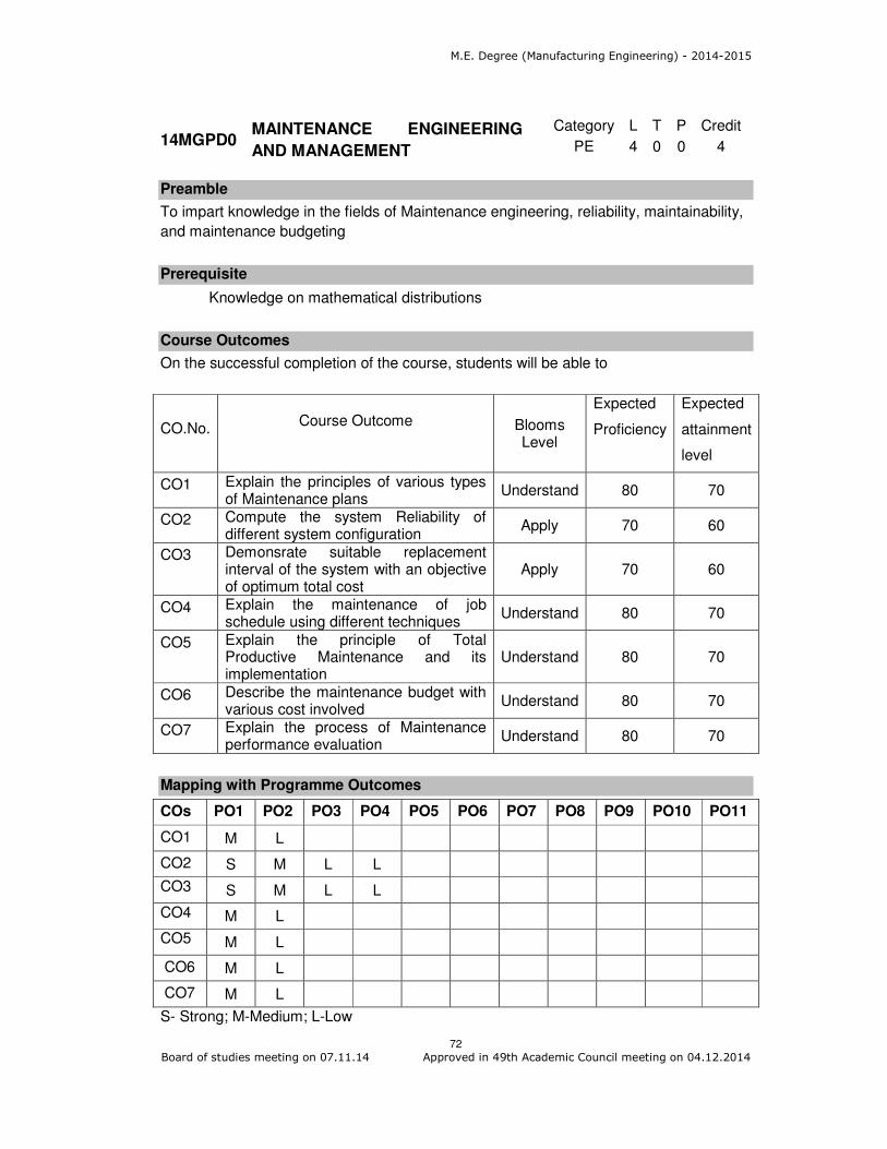
M.E. Degree (Manufacturing Engineering) - 2014-2015
72 Board of studies meeting on 07.11.14 Approved in 49th Academic Council meeting on 04.12.2014
Category L T P Credit
PE 4 0 0 4
Preamble
To impart knowledge in the fields of Maintenance engineering, reliability, maintainability,
and maintenance budgeting
Prerequisite
Knowledge on mathematical distributions
Course Outcomes
On the successful completion of the course, students will be able to
CO.No.
Course Outcome Blooms
Level
Expected
Proficiency
Expected
attainment
level
CO1 Explain the principles of various types of Maintenance plans
Understand 80 70
CO2 Compute the system Reliability of different system configuration
Apply 70 60
CO3 Demonsrate suitable replacement interval of the system with an objective of optimum total cost
Apply 70 60
CO4 Explain the maintenance of job schedule using different techniques
Understand 80 70
CO5 Explain the principle of Total Productive Maintenance and its implementation
Understand 80 70
CO6 Describe the maintenance budget with various cost involved
Understand 80 70
CO7 Explain the process of Maintenance performance evaluation
Understand 80 70
Mapping with Programme Outcomes
COs PO1 PO2 PO3 PO4 PO5 PO6 PO7 PO8 PO9 PO10 PO11
CO1 M L
CO2 S M L L
CO3 S M L L
CO4 M L
CO5 M L
CO6 M L
CO7 M L
S- Strong; M-Medium; L-Low
14MGPD0 MAINTENANCE ENGINEERING
AND MANAGEMENT
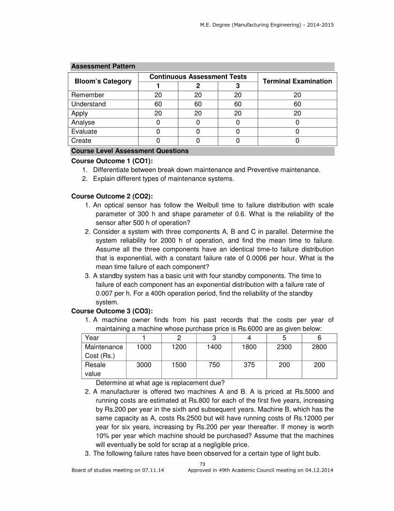
M.E. Degree (Manufacturing Engineering) - 2014-2015
73 Board of studies meeting on 07.11.14 Approved in 49th Academic Council meeting on 04.12.2014
Assessment Pattern
Bloom’s Category Continuous Assessment Tests
Terminal Examination 1 2 3
Remember 20 20 20 20
Understand 60 60 60 60
Apply 20 20 20 20
Analyse 0 0 0 0
Evaluate 0 0 0 0
Create 0 0 0 0
Course Level Assessment Questions
Course Outcome 1 (CO1):
1. Differentiate between break down maintenance and Preventive maintenance.
2. Explain different types of maintenance systems.
Course Outcome 2 (CO2):
1. An optical sensor has follow the Weibull time to failure distribution with scale
parameter of 300 h and shape parameter of 0.6. What is the reliability of the
sensor after 500 h of operation?
2. Consider a system with three components A, B and C in parallel. Determine the
system reliability for 2000 h of operation, and find the mean time to failure.
Assume all the three components have an identical time-to failure distribution
that is exponential, with a constant failure rate of 0.0006 per hour. What is the
mean time failure of each component?
3. A standby system has a basic unit with four standby components. The time to
failure of each component has an exponential distribution with a failure rate of
0.007 per h. For a 400h operation period, find the reliability of the standby
system.
Course Outcome 3 (CO3):
1. A machine owner finds from his past records that the costs per year of
maintaining a machine whose purchase price is Rs.6000 are as given below:
Year 1 2 3 4 5 6
Maintenance
Cost (Rs.)
1000 1200 1400 1800 2300 2800
Resale
value
3000 1500 750 375 200 200
Determine at what age is replacement due?
2. A manufacturer is offered two machines A and B. A is priced at Rs.5000 and
running costs are estimated at Rs.800 for each of the first five years, increasing
by Rs.200 per year in the sixth and subsequent years. Machine B, which has the
same capacity as A, costs Rs.2500 but will have running costs of Rs.12000 per
year for six years, increasing by Rs.200 per year thereafter. If money is worth
10% per year which machine should be purchased? Assume that the machines
will eventually be sold for scrap at a negligible price.
3. The following failure rates have been observed for a certain type of light bulb.

M.E. Degree (Manufacturing Engineering) - 2014-2015
74 Board of studies meeting on 07.11.14 Approved in 49th Academic Council meeting on 04.12.2014
End of
week
1 2 3 4 5 6 7
Probability
of failure
0.05 0.15 0.25 0.46 0.68 0.88 1.00
The cost of replacing an individual failed bulb is Rs.1.25. If the cost of group
replacement is 80 paise per bulb, determine among individual and group
replacement policies which one is better.
Course Outcome 4 (CO4):
1. Explain about planning and scheduling of maintenance
2. Illustrate the different techniques used in maintenance scheduling.
Course Outcome 5 (CO5):
1. Describe about the various components of TPM.
2. Discuss the steps in implementation of TPM.
Course Outcome 6 (CO6):
1. Explain the various components of maintenance costs.
2. Describe about the preparation of Maintenance budget and its uses.
Course Outcome 7 (CO7):
1. Explain about the maintenance performance indices and its usage.
2. Discuss about the outcomes of maintenance audit.
Concept Map
Syllabus
Maintenance: Objectives and Functions, Concepts and Nature of Maintenance, Tero
Technology, 5 Zero concepts, Reliability Based Maintenance (RBM), Creative
Maintenance. Maintenance and Profitability – Quality, Reliability and Maintainability
(QRM) – Productivity, Quality and quality circle in Maintenance Engineering.
Maintenance systems: Planned and unplanned maintenance. Break down maintenance,

M.E. Degree (Manufacturing Engineering) - 2014-2015
75 Board of studies meeting on 07.11.14 Approved in 49th Academic Council meeting on 04.12.2014
Corrective maintenance, Preventive maintenance, Predictive maintenance, Condition
Based Maintenance Systems (CBMS), Design – out maintenance, Selection of
maintenance system.
Reliability: Basic concepts – hazard plotting techniques, Exponential and Weibull
reliability functions- Maximum likelihood estimation techniques – System reliability –
redundancy – simple standby system – r out n configuration – reliability determination
using Markov modeling – reliability evaluation using fault tree analysis, FMEA, RCM,
Maintainability analysis, Design for maintainability.
Replacement Policies - Basic concepts – optimal replacement policy for equipment
whose operating cost increase with use – optimal replacement of items subject to failure
– individual/Group replacement policy – optimal replacement interval for capital
equipment with maximization of discounted profits.
Maintenance Planning and Scheduling: Job planning – job scheduling – scheduling
techniques – short term planning, Long term planning – Systematic maintenance –
codification and cataloging, Manuals. Maintenance Time Standard (MTS), Job cards, Job
execution, monitoring, feedback and control, Maintenance records and documentation.
Total Productive Maintenance (TPM) – Basic systems, steps in TPM implementation -
Productivity circles.
Maintenance organization: Formal and informal – centralized and decentralized –
external maintenance services – captive shop facilities – working arrangements.
Maintenance Budgeting: Costing and cost control – Behavior of maintenance costs –
Types and components of maintenance costs. Cost and factors Influencing maintenance
jobs. Budget and Budgeting of maintenance cost. Cost control – preparation of
maintenance budget and budgetary control.
Training for maintenance personnel: Objectives, modes of training/development. Training
sources, agencies, institutions - Planning and Designing programmes, Evaluation,
Benefits.
Computer Managed Maintenance System (CMMS): Objectives, Approach towards
computerization – scope of computerization – Equipment classification – codification for
break downs – preparation of work orders and job schedules – follow up and
documentation – material management module.
Maintenance Effectiveness and performance evaluation: Analysis of maintenance
performance. Reference indices, Maintenance productivity measurement - Performance
measuring parameters - Maintenance Audit.
Reference Books
1. Sushil Kumar Srivastava, “Industrial Maintenance Management”, S. Chand &
Company Ltd., 2007
2. Anteny Kelly, “Strategic Maintenance planning”, Butterworth-Heinemann, 2006.
3. Gopalakrishnan, P. Banerji, A.K, “Maintenance and Spare Parts Management”, PHI,
Learning Pvt. Ltd, New Delhi, 2013
4. A.K.S.Jardine and A.H.C. Tsang, “Maintenance, replacement, and reliability: theory
and applications”, CRC/Taylor & Francis, 2006.
5. L.S.Srinath, “Reliability Engineering”, 4th Edition, Affiliated East West Press. New
Delhi 2005.
6. C. Balagurusamy, “Reliability Engineering”, Tata McGraw Hill Pvt. Ltd. 2003.

M.E. Degree (Manufacturing Engineering) - 2014-2015
76 Board of studies meeting on 07.11.14 Approved in 49th Academic Council meeting on 04.12.2014
7. A.K. Gupta, “Reliability & Tero Technology”, Macmillan India Ltd., 2004.
Course Contents and Lecture Schedule
Module
Number Topics
No. of
Lectures
1.0 Maintenance
1.1 Objectives and Functions, Concepts and Nature of
Maintenance 1
1.2 Tero Technology, 5 Zero concepts 1
1.3 Reliability Based Maintenance (RBM), Creative
Maintenance(CM) 1
1.4 Maintenance and Profitability – Quality, Reliability and
Maintainability (QRM) 1
1.5 Productivity, Quality and quality circle (QC) in Maintenance
Engineering 1
1.6 Planned and unplanned maintenance-Break down
maintenance (BM), Corrective maintenance(CM), Preventive
maintenance (PM)
2
1.7 Predictive maintenance, Condition Based Maintenance
Systems (CBMS) 1
1.8 Design – out maintenance, Selection of maintenance system 2
2.0 Reliability
2.1 Basic concepts – hazard plotting techniques, Exponential and
Weibull reliability functions- Maximum likelihood estimation
techniques
2
2.2 System reliability – redundancy – simple standby system 2
2.3 r out n configuration – reliability determination using Markov
modeling
1
2.4 Reliability evaluation using fault tree analysis, FMEA, RCM 1
2.5 Maintainability analysis 1
2.6 Design for maintainability 1
3.0 Replacement Policies
3.1 Basic concepts – optimal replacement policy for equipment
whose operating cost increase with use
2
3.2 Optimal replacement of items subject to failure –
individual/Group replacement policy – optimal replacement
interval for capital equipment with maximization of discounted
profits
2
4.0 Maintenance Planning and Scheduling
4.1 Job planning – job scheduling – scheduling techniques – short
term planning, Long term planning
1
4.2 Systematic maintenance – codification and cataloging,
Manuals.
1
4.3 Maintenance Time Standard (MTS), Job cards, Job execution, 2

M.E. Degree (Manufacturing Engineering) - 2014-2015
77 Board of studies meeting on 07.11.14 Approved in 49th Academic Council meeting on 04.12.2014
Module
Number Topics
No. of
Lectures
monitoring, feedback and control, Maintenance records and
documentation.
4.4 Total Productive Maintenance (TPM) – Basic systems, steps in
TPM implementation – Productivity circles
2
5.0 Maintenance organization
5.1 Formal and informal – centralized and decentralized 1
5.2 External maintenance services – captive shop facilities –
working arrangements.
1
Maintenance Budgeting:
5.3 Costing and cost control – Behavior of maintenance costs –
Types and components of maintenance costs. budget and
budgetary control
2
5.4 Cost and factors Influencing maintenance jobs 1
5.5 Budget and Budgeting of maintenance cost. Cost control –
preparation of maintenance budget and budgetary control
2
Training for maintenance personnel
5.6 Objectives, modes of training/development. Training sources,
agencies, institutions
2
5.7 Planning and Designing programmes, Evaluation, Benefits 2
6.0 Computer Managed Maintenance System (CMMS)
6.1 Objectives, Approach towards computerization – scope of
computerization
1
6.2 Equipment classification – codification for break downs –
preparation of work orders and job schedules – follow up and
documentation
1
6.3 Material management module 1
7.0 Maintenance Effectiveness and performance evaluation
7.1 Analysis of maintenance performance. Reference indices 2
7.2 Maintenance productivity measurement - Performance
measuring parameters - Maintenance Audit
2
Total 46
Course Designers:
1. A.MANOHARAN [email protected]
2. ML.MAHADEVAN [email protected]

M.E. Degree (Manufacturing Engineering) - 2014-2015
78 Board of studies meeting on 07.11.14 Approved in 49th Academic Council meeting on 04.12.2014
Category L T P Credit
PE 4 0 0 4
Preamble
Machine Vision has become a key technology in the area of manufacturing and quality
control. Increasing quality demands require inspection of every single part which in turn
will lead to much more wide spread use of visual inspection systems. Furthermore the
documentation requirements and quality control standards can only be met by fully
automated networked inspection systems. The Success of developing machine vision
system depends on the understanding all parts of the imaging chain. Hence this course
discusses about image acquisition, lens and illumination systems, image preprocessing
and processing, segmentation and classification techniques used in a typical machine
vision application.
Prerequisite
Laplace Transforms
Course Outcomes
On the successful completion of the course, students will be able to
CO.No.
Course Outcome Blooms
Level
Expected
Proficiency
Expected
attainment
level
CO1 Explain the components of a machine vision system
Understand 80 70
CO2 Use appropriate camera, lens and lighting system for a machine vision system
Apply
70 60
CO3 Apply image preprocessing, post processing algorithms like segmentation to solve Application and case studies
Apply 70 60
Mapping with Programme Outcomes
COs PO1 PO2 PO3 PO4 PO5 PO6 PO7 PO8 PO9 PO10 PO11
CO1 M L
CO2 S M L L
CO3 S M L L
S- Strong; M-Medium; L-Low
Assessment Pattern
Bloom’s Category Continuous Assessment Tests
Terminal Examination 1 2 3
Remember 30 20 20 10
Understand 50 50 40 40
14MGPE0 MACHINE VISION AND ITS
APPLICATION IN MANUFACTURING

M.E. Degree (Manufacturing Engineering) - 2014-2015
79 Board of studies meeting on 07.11.14 Approved in 49th Academic Council meeting on 04.12.2014
Apply 20 30 40 50
Analyse 0 0 0 0
Evaluate 0 0 0 0
Create 0 0 0 0
Course Level Assessment Questions
Course Outcome 1 (CO1):
1. Explain the working principle of CCD sensor array
2. Describe in detail about various image acquisition modes.
3. Explain the advantages of CMOS sensors over CCD sensors.
Course Outcome 2 (CO2):
1. Determine the focal length of a lens of a vision system requiring a magnification
of 0.06 and a working distance of 80 cm.
2. Determine the Magnification of the vision system and the size of the pixel on the
sensor, if the size of 200 X 200 solid state sensor array is 40mmX40mm and the
size of the object to be measured is 60mmX60mm.
3. Determine the focal length, magnification, Depth of field for an industrial
installation inspecting flat plates on a moving conveyor belt with front lighting.
You have a solid state camera with 100X 100 array sensor. Sensor dimensions
.03X.03 cm. Distance between the lens and work piece is 60 cm.b F-Stop is 8,
and there are 16 grey level and 30 images / second. Object dimensions are 7.5 X
7.5 X 1.2 cm. The object occupies 50% of sensor array.
Course Outcome 3 (CO3):
1. Select and illustrate a suitable Machine Vision Technique used for Inspection of
Threads in Nuts in a Batch Production Process.
2. A surveillance camera is embedded in one of the walls of a room . The optical
axis of the camera is perpendicular to the wall, and the lens centre is in the plane
of the wall. The focal length of the lens is .05m.The X-Z plane of the camera is
parallel to the X-Y Plane of the world coordinate system. The image plane is
behind the wall. Find the image plane coordinates of (a) the room corner A and
(b) the head of a person 2m tall standing at a distance of 3m X 2m from the
corner
3. Determine the dimensions of the largest object that can be imaged by a vision
system with a magnification of 0.1, a 5 X 5 mm sensor array with 50 X 50
elements. The distance from the object to the lens is 60 cm and F-Stop is 16.
Concept Map

M.E. Degree (Manufacturing Engineering) - 2014-2015
80 Board of studies meeting on 07.11.14 Approved in 49th Academic Council meeting on 04.12.2014
Syllabus
Image Acquisition Solid State Sensors CCD Sensor Operation, Properties, Image
Degradation. Standard Video Cameras: Basic Structure, Sampling of Line Signal and
Extension of Video Standards, Image Quality, Progressive Scan Cameras,
Asynchronous Camera, Digital Camera, Line Scan Cameras, Line Scan Cameras and its
Properties. Transmission to Computer: Basic operation of Frame Grabber and Direct
Digital transmission. Optics and Illumination Optical foundations: F number, Thin Lens
Imaging Equation, Depth of Field, Typical Imaging Situations, Aberrations, Lens
Selection, Special Optical devices. Light Sources, Types of Light Filters, Types of
Lighting: Diffuse, Directed, Telecentric, Structured, Bright field, Dark Field, Incident and
Transmitted Lighting.
Image Preprocessing Gray Scale Transformations: Look up tables, Linear Gray level
scaling, Contrast enhancement, Histogram equalization, Local Contrast Enhancement.
Image Arithmetic: Image Addition, Subtraction and Averaging, Minimum and Maximum of
two images. Types of Filters: Linear Filters, Median Filter, Morphological and Non Linear
Filters, Fourier Transform Applications. Image Segmentation Threshold Determination
from Histogram, Gray Level Histogram, Generalizations of Thresholding Contour
Tracing: Pixel Correctedness, Generating Object Contours, Contour representation Edge
based Methods: Edge probing and Edge Detection Template matching: Basic Operation,
Optimizing and Comments on Template Matching. Applications: Dimensional Checking:
Simple gauging, Shape Checking, Angle Gauging, High accuracy Gauging, Calibration.
Presence Verification: Simple Presence verification, Simple Gauging for assembly
verification, Glue Check under UV Light, Pin type Verification Alignment Checking.
Reference Books
1. C. Demant, B.Streicher Abel, P.Waszkewitz “Industrial Image Processing and Visual
Quality control in manufacturing”. Springer, 1999.
2. Alexander Hornberg, “Handbook of Machine Vision”, Wiley VCH, 2006
3. Gerald C. Holst, “CCD Arrays Cameras and Displays” Second Edition, SPIE Optical
Engineering Press, 1998.
4. K.S.Fu,R.C.Gonzalez,C.S.G.Lee “Robotics Control, Sensing, Vision and
Intelligence.” Tata McgrawHill, 2008
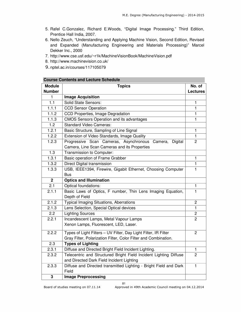
M.E. Degree (Manufacturing Engineering) - 2014-2015
81 Board of studies meeting on 07.11.14 Approved in 49th Academic Council meeting on 04.12.2014
5. Rafel C.Gonzalez, Richard E.Woods, “Digital Image Processing.” Third Edition,
Prentice Hall India, 2007.
6. Nello Zeuch, “Understanding and Applying Machine Vision, Second Edition, Revised
and Expanded (Manufacturing Engineering and Materials Processing)” Marcel
Dekker Inc., 2000
7. http://www.cse.usf.edu/~r1k/MachineVisionBook/MachineVision.pdf
8. http://www.machinevision.co.uk/
9. nptel.ac.in/courses/117105079
Course Contents and Lecture Schedule
Module
Number
Topics No. of
Lectures
1 Image Acquisition
1.1 Solid State Sensors: 1
1.1.1 CCD Sensor Operation 1
1.1.2 CCD Properties, Image Degradation 1
1.1.3 CMOS Sensors Operation and its advantages 1
1.2 Standard Video Cameras:
1.2.1 Basic Structure, Sampling of Line Signal 1
1.2.2 Extension of Video Standards, Image Quality 1
1.2.3 Progressive Scan Cameras, Asynchronous Camera, Digital
Camera, Line Scan Cameras and its Properties
2
1.3 Transmission to Computer:
1.3.1 Basic operation of Frame Grabber 1
1.3.2 Direct Digital transmission 1
1.3.3 USB, IEEE1394, Firewire, Gigabit Ethernet, Choosing Computer
Bus
1
2 Optics and Illumination
2.1 Optical foundations: 1
2.1.1 Basic Laws of Optics, F number, Thin Lens Imaging Equation,
Depth of Field
1
2.1.2 Typical Imaging Situations, Aberrations 2
2.1.3 Lens Selection, Special Optical devices 1
2.2 Lighting Sources 2
2.2.1 Incandescent Lamps, Metal Vapour Lamps
Xenon Lamps, Fluorescent, LED, Laser.
2
2.2.2 Types of Light Filters – UV Filter, Day Light Filter, IR Filter
Gray Filter, Polarization Filter, Color Filter and Combination.
2
2.3 Types of Lighting
2.3.1 Diffuse and Directed Bright Field Incident Lighting. 1
2.3.2 Telecentric and Structured Bright Field Incident Lighting Diffuse
and Directed Dark Field Incident Lighting
2
2.3.3 Diffuse and Directed transmitted Lighting - Bright Field and Dark
Field
1
3 Image Preprocessing
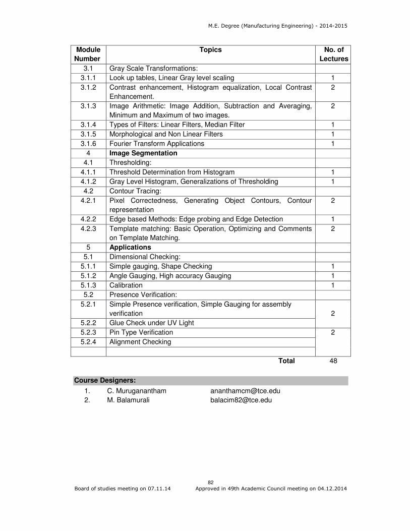
M.E. Degree (Manufacturing Engineering) - 2014-2015
82 Board of studies meeting on 07.11.14 Approved in 49th Academic Council meeting on 04.12.2014
Module
Number
Topics No. of
Lectures
3.1 Gray Scale Transformations:
3.1.1 Look up tables, Linear Gray level scaling 1
3.1.2 Contrast enhancement, Histogram equalization, Local Contrast
Enhancement.
2
3.1.3 Image Arithmetic: Image Addition, Subtraction and Averaging,
Minimum and Maximum of two images.
2
3.1.4 Types of Filters: Linear Filters, Median Filter 1
3.1.5 Morphological and Non Linear Filters 1
3.1.6 Fourier Transform Applications 1
4 Image Segmentation
4.1 Thresholding:
4.1.1 Threshold Determination from Histogram 1
4.1.2 Gray Level Histogram, Generalizations of Thresholding 1
4.2 Contour Tracing:
4.2.1 Pixel Correctedness, Generating Object Contours, Contour
representation
2
4.2.2 Edge based Methods: Edge probing and Edge Detection 1
4.2.3 Template matching: Basic Operation, Optimizing and Comments
on Template Matching.
2
5 Applications
5.1 Dimensional Checking:
5.1.1 Simple gauging, Shape Checking 1
5.1.2 Angle Gauging, High accuracy Gauging 1
5.1.3 Calibration 1
5.2 Presence Verification:
5.2.1 Simple Presence verification, Simple Gauging for assembly
verification
2
5.2.2 Glue Check under UV Light
5.2.3 Pin Type Verification 2
5.2.4 Alignment Checking
Total 48
Course Designers:
1. C. Muruganantham [email protected]
2. M. Balamurali [email protected]

M.E. Degree (Manufacturing Engineering) - 2014-2015
83 Board of studies meeting on 07.11.14 Approved in 49th Academic Council meeting on 04.12.2014
Category L T P Credit
PE 4 0 0 4
Preamble
System Simulation is the imitation of some real thing, state of affairs, or process. The act
of simulating something generally entails representing certain key characteristics or
behaviours of a selected physical or abstract system. Simulation is used in many
contexts, such as simulation of technology for performance optimization, safety
engineering, testing, training, education, and video games. Training simulators include
flight simulators for training aircraft pilots in order to provide them with a lifelike
experience. Simulation is also used for scientific modeling of natural systems or human
systems in order to gain insight into their functioning. Simulation can be used to show the
eventual real effects of alternative conditions and courses of action.
Prerequisite
• 14MG220 Tool Design Engineering
• 14MG150 CNC Machine Tool Technology
Course Outcomes
On the successful completion of the course, students will be able to
CO.No.
Course Outcome Blooms
Level
Expected
Proficiency
Expected
attainment
level
CO1 Explain the concepts, types and applications of simulation, steps in simulation study
Understand 80 70
CO2 Explain how computer simulation can be used to model complex systems
Understand 80 70
CO3 Solve related decision problems Apply 70 60
CO4 Apply the statistical methods used in simulation analysis
Apply 70 60
CO5 Discuss the techniques of random number generator and testing of random numbers
Understand 80 70
CO6 Choose suitable generator for a given application
Apply 70 60
CO7 Design a computer simulation and conduct input modeling validation, output analysis
Apply 70 60
CO8 Compare simulation packages with programming language
Analyse 60 50
14MGPF0 SYSTEM SIMULATION

M.E. Degree (Manufacturing Engineering) - 2014-2015
84 Board of studies meeting on 07.11.14 Approved in 49th Academic Council meeting on 04.12.2014
Mapping with Programme Outcomes
COs PO1 PO2 PO3 PO4 PO5 PO6 PO7 PO8 PO9 PO10 PO11
CO1 M L
CO2 M L
CO3 S M L L
CO4 S M L L
CO5 M L
CO6. S M L L
CO7. S M L L
CO8. S S M M
S- Strong; M-Medium; L-Low
Assessment Pattern
Bloom’s Category Continuous Assessment Tests
Terminal Examination 1 2 3
Remember 20 20 20 20
Understand 20 20 20 20
Apply 60 60 50 50
Analyse 0 0 10 10
Evaluate 0 0 0 0
Create 0 0 0 0
Course Level Assessment Questions
Course Outcome 1 (CO1):
1. Define Endogenous and Exogenous events.
2. List the tests that are used to validate the properties of random numbers.
3. What are the parameters for the following distributions?
a) Gamma distribution b) Normal distribution
Course Outcome 2 (CO2):
1. Describe and explain the properties of linear models.
2. What are the steps in the development of a model of input data? Explain.
3. Mention the factors that are to be considered in selecting a simulation
Language.
Course Outcome 3 (CO3):
1. A new bus route is to be added to a city, and the traffic manager is to determine how
many extra buses will be needed. What are the three key attributes of the
passengers and buses that he should consider? If the company manager wants to
asses the effect of the new route on the transit system as a whole, how would you
suggest he aggregate the features of the new line to form part of a total system
model? Would you suggest a continuous or discrete model for the traffic manager
and the general manager?

M.E. Degree (Manufacturing Engineering) - 2014-2015
85 Board of studies meeting on 07.11.14 Approved in 49th Academic Council meeting on 04.12.2014
2. The sequence of numbers 0.37, 0.59, 0.88, 0.48 and 0.21 has been generated. Use
the Kolmogorov-Smirnov test with 05.0=α to determine if the hypothesis that the
numbers are uniformly distributed on the interval ( 0,1 ) can be rejected.
Course Outcome 4 (CO4):
1. Draw a flow chart which represents the various steps involved in the simulation
Process
2. Develop an Acceptance-Rejection technique for generating a Poisson random
variable with mean 2.0=α
Course Outcome 5 (CO5):
1. A robot is used to install the doors on automobiles along an assembly line. It was
thought that the installation times followed a normal distribution. The robot is
capable of accurately measuring installation times. A sample of 20 installation times
was automatically taken by the robot with the following results, where the values are
in seconds.
99.79 99.56 100.17 100.33
100.26 100.41 99.98 99.83
100.23 100.27 100.02 100.47
99.55 99.62 99.65 99.82
9.96 99.90 100.06 99.85
Determine the estimators for normal distribution.
2. Records pertaining to the monthly number of job related injuries at an underground
coal mine were being studied by a federal agency The values for the past 100
months are as follows.
------------------------------------------------------------------------
Injuries per month 0 1 2 3 4 5 6
-----------------------------------------------------------------------
Frequency of occurrence 35 40 13 6 4 1 1
----------------------------------------------------------------------
Apply the Chi-square test to these data to test the hypothesis that the underlying
distribution is Poisson. Use a level of significance of 05.0=α
Course Outcome 6 (CO6):
1. Develop a random variate generator for exponential distribution.
2. Mention the factors that are to be considered in selecting a simulation language
for a particular application.
3. Considering an Engineering educational system, identify the entities, attributes
and activities of the system.
Course Outcome 7 (CO7):
1. The following data are randomly generated from a gamma Distribution
7.036 5.224 3.917 6.513
4.599 7.563 7.172 5.132
5.259 2.759 4.278 2.696

M.E. Degree (Manufacturing Engineering) - 2014-2015
86 Board of studies meeting on 07.11.14 Approved in 49th Academic Council meeting on 04.12.2014
6.212 2.407 1.857 5.002
4.612 2.003 6.908 3.326
Determine the maximum likelihood estimators of the gamma distribution?
2.The following data represent the time to perform transactions in a bank, measured in
minutes. 0.74, 1.28, 1.46, 2.36, 0.35, 0.78, 0.91, 4.44, 0.14, 3.08, 3.24, 1.10, 1.59, 1.47,
1.17, 1.27, 9.12, 11.5, 2.42, 1.77. Develop an input model for this data.
Course Outcome 8 (CO8):
1. The following data are randomly generated from a gamma Distribution
7.036 5.224 3.917 6.513
4.599 7.563 7.172 5.132
5.259 2.759 4.278 2.696
6.212 2.407 1.857 5.002
4.612 2.003 6.908 3.326
2. Determine the maximum likelihood estimators of the gamma distribution?
a. 19.The following data represent the time to perform transactions in a
bank, measured in minutes. 0.74, 1.28, 1.46, 2.36, 0.35, 0.78, 0.91, 4.44,
0.14, 3.08, 3.24, 1.10, 1.59, 1.47, 1.17, 1.27, 9.12, 11.5, 2.42, 1.77.
Develop an input model for this data.
3. Course Outcome 9 (CO9):
a. 20. Give GPSS block diagrams and write program. Parts are being made
at the rate of one every 6 minutes. They are of two types, A and B, and
are mixed randomly, with about 10% being type B. A separate inspector is
assigned to examine each type of part. The inspection of A parts takes 4
±2 minutes and B parts take 20 ± 10 minutes. Both inspectors reject about
10% of the parts they inspect. Simulate for a total of 1000 type A parts
accepted.
b. 21. A tool crib has exponential inter-arrival and service times and serves a
very large group of mechanics. The mean time between arrivals is 4
minutes. It takes 3 minutes on the average for a tool crib attendant to
serve a mechanic. The attendant is paid Rs. 40 per hour and the
mechanic is paid Rs. 60 per hour. Would it be advisable to have a second
tool crib attendant?
Concept Map
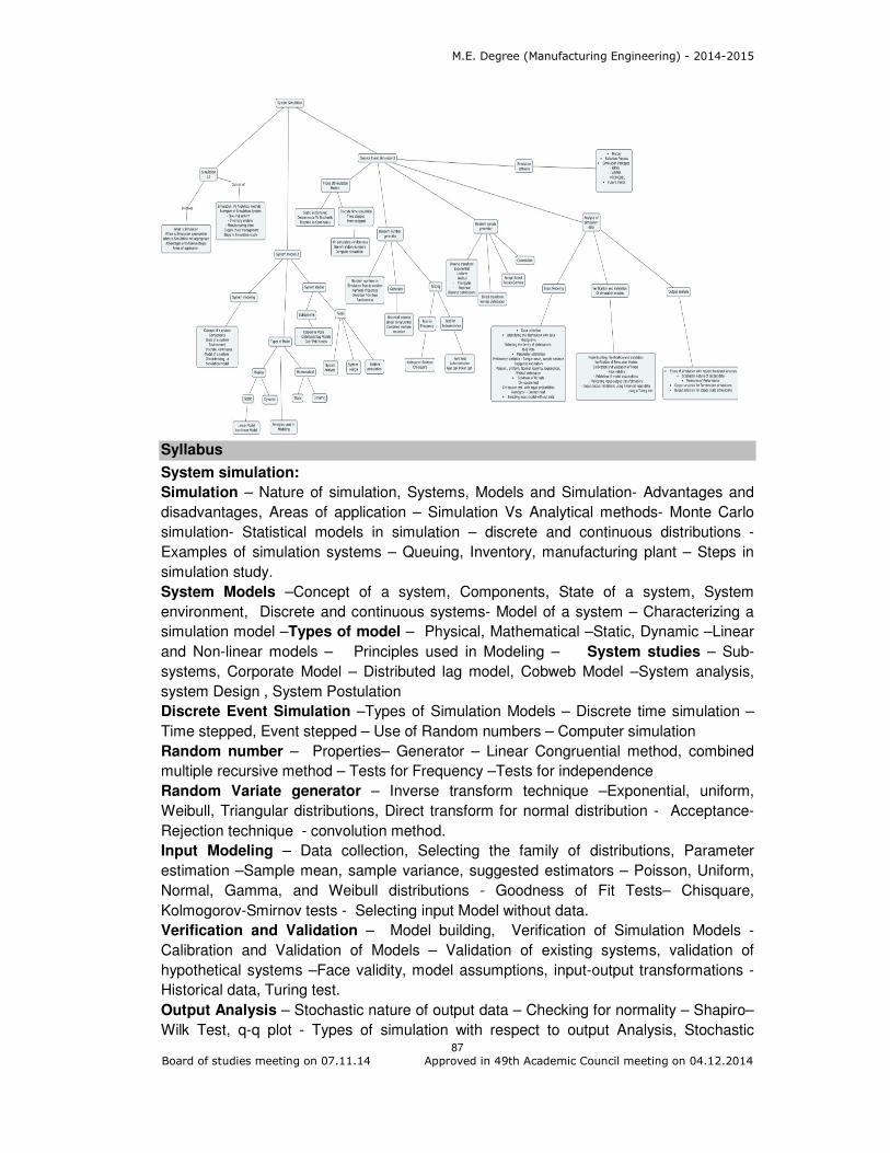
M.E. Degree (Manufacturing Engineering) - 2014-2015
87 Board of studies meeting on 07.11.14 Approved in 49th Academic Council meeting on 04.12.2014
Syllabus
System simulation:
Simulation – Nature of simulation, Systems, Models and Simulation- Advantages and
disadvantages, Areas of application – Simulation Vs Analytical methods- Monte Carlo
simulation- Statistical models in simulation – discrete and continuous distributions -
Examples of simulation systems – Queuing, Inventory, manufacturing plant – Steps in
simulation study.
System Models –Concept of a system, Components, State of a system, System
environment, Discrete and continuous systems- Model of a system – Characterizing a
simulation model –Types of model – Physical, Mathematical –Static, Dynamic –Linear
and Non-linear models – Principles used in Modeling – System studies – Sub-
systems, Corporate Model – Distributed lag model, Cobweb Model –System analysis,
system Design , System Postulation
Discrete Event Simulation –Types of Simulation Models – Discrete time simulation –
Time stepped, Event stepped – Use of Random numbers – Computer simulation
Random number – Properties– Generator – Linear Congruential method, combined
multiple recursive method – Tests for Frequency –Tests for independence
Random Variate generator – Inverse transform technique –Exponential, uniform,
Weibull, Triangular distributions, Direct transform for normal distribution - Acceptance-
Rejection technique - convolution method.
Input Modeling – Data collection, Selecting the family of distributions, Parameter
estimation –Sample mean, sample variance, suggested estimators – Poisson, Uniform,
Normal, Gamma, and Weibull distributions - Goodness of Fit Tests– Chisquare,
Kolmogorov-Smirnov tests - Selecting input Model without data.
Verification and Validation – Model building, Verification of Simulation Models -
Calibration and Validation of Models – Validation of existing systems, validation of
hypothetical systems –Face validity, model assumptions, input-output transformations -
Historical data, Turing test.
Output Analysis – Stochastic nature of output data – Checking for normality – Shapiro–
Wilk Test, q-q plot - Types of simulation with respect to output Analysis, Stochastic
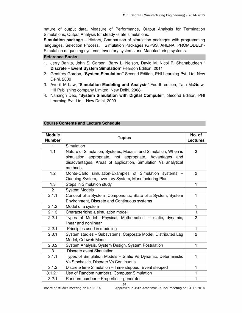
M.E. Degree (Manufacturing Engineering) - 2014-2015
88 Board of studies meeting on 07.11.14 Approved in 49th Academic Council meeting on 04.12.2014
nature of output data, Measure of Performance, Output Analysis for Termination
Simulations, Output Analysis for steady -state simulations.
Simulation package – History, Comparison of simulation packages with programming
languages, Selection Process, Simulation Packages (GPSS, ARENA, PROMODEL)*-
Simulation of queuing systems, Inventory systems and Manufacturing systems.
Reference Books
1. Jerry Banks, John S. Carson, Barry L. Nelson, David M. Nicol P. Shahabudeen “
Discrete – Event System Simulation” Pearson Edition, 2011
2. Geoffrey Gordon, “System Simulation” Second Edition, PHI Learning Pvt. Ltd, New
Delhi, 2009
3. Averill M Law, “Simulation Modeling and Analysis” Fourth edition, Tata McGraw-
Hill Publishing company Limited, New Delhi, 2008.
4. Narsingh Deo, “System Simulation with Digital Computer”, Second Edition, PHI
Learning Pvt. Ltd., New Delhi, 2009
Course Contents and Lecture Schedule
Module
Number Topics
No. of
Lectures
1 Simulation
1.1 Nature of Simulation, Systems, Models, and Simulation, When is
simulation appropriate, not appropriate, Advantages and
disadvantages, Areas of application, Simulation Vs analytical
methods,
2
1.2 Monte-Carlo simulation-Examples of Simulation systems –
Queuing System, Inventory System, Manufacturing Plant
2
1.3 Steps in Simulation study 1
2 System Models
2.1.1 Concept of a System ,Components, State of a System, System
Environment, Discrete and Continuous systems
1
2.1.2 Model of a system 1
2.1 3 Characterizing a simulation model 1
2.2.1 Types of Model –Physical, Mathematical – static, dynamic,
linear and nonlinear
2
2.2.1 Principles used in modeling 1
2.3.1 System studies – Subsystems, Corporate Model, Distributed Lag
Model, Cobweb Model
2
2.3.2 System Analysis, System Design, System Postulation 1
3 Discrete event Simulation
3.1.1 Types of Simulation Models – Static Vs Dynamic, Deterministic
Vs Stochastic, Discrete Vs Continuous
1
3.1.2 Discrete time Simulation – Time stepped, Event stepped 1
3.1.2.1 Use of Random numbers, Computer Simulation 1
3.2.1 Random number – Properties - generator 1

M.E. Degree (Manufacturing Engineering) - 2014-2015
89 Board of studies meeting on 07.11.14 Approved in 49th Academic Council meeting on 04.12.2014
Module
Number Topics
No. of
Lectures
3.2.2 Random number testing – Frequency. Independence 3
3.3.1 Random Variate generator – Inverse transform technique –
Exponential, Uniform, Weibull, Triangular distributions
2
3.3.2 Direct transform for Normal distribution, Acceptance-Rejection
technique, Convolution Method
2
3.4 Analysis of Simulation data
3.4.1.1 Input modeling – Data collection, Selecting the family of
distributions
2
3.4.1.2 Input modeling – Parameter estimation – sample mean, sample
variance, suggested estimators – Poisson, Exponential, Uniform,
Normal, Gamma, and weibull distributions
2
3.4.1.3 Goodness of Fit Tests – Chisquare and Kolmogorov tests 2
3.4.1.4 Selecting input model without data 1
3.4.2.1 Verification and Validation –Model building, Calibration and
validation of Models –Validation of existing systems, Validation
of hypothetical systems – Face validity
2
3.4.2.2 Model assumptions, Input-output transformations –Historical
data, Turing Test
2
3.4.3.1 Output analysis – stochastic nature of output data – Checking
for normality –Shapiro Wilk Test, q-q plot - Types of simulation
with respect to output Analysis, Stochastic nature of output data,
Measure of Performance, Output Analysis for Termination
Simulations, Output Analysis for steady -state simulations.
4
3.5 Simulation Software
3.5.1 History 1
3.5.2 Selection of Simulation software -example 1
3.5.3 Simulation in GPSS / ARENA / PROMODEL *– Queuing
problem, Inventory Problem , Manufacturing Problem
5
Total 47
Course Designers:
1 S. Karthikeyan [email protected]

M.E. Degree (Manufacturing Engineering) - 2014-2015
90 Board of studies meeting on 07.11.14 Approved in 49th Academic Council meeting on 04.12.2014
Category L T P Credit
PE 3 1 0 4
Preamble
The course aims at giving adequate exposure to design process and to solve the real
time creative product design and development approach. The course also deals with
various methods involved in product design and development. It also deals with patent
rights, procedure sale of patent right.
Prerequisite
14MG120 : Optimisation Techniques
14MG130 : Mechanical Behaviour of Materials
Course Outcomes
On the successful completion of the course, students will be able to
CO.No.
Course Outcome Blooms
Level
Expected
Proficiency
Expected
attainment
level
CO1. Explain the concept of product design and its applications
Understand 80 70
CO2. Classify the product planning process based on the customer need
Understand 80 70
CO3. Review the final specification of the product
Understand 80 70
CO4. Identify the best concept based on concept selection process
Apply 70 60
CO5 Choose and implement the suitable product architecture
Apply 70 60
CO6 Use the successful product development strategies, product planning activities, specifications, various methods for concept selection and architecture planning
Apply 70 60
Mapping with Programme Outcomes
COs PO1 PO2 PO3 PO4 PO5 PO6 PO7 PO8 PO9 PO10 PO11
CO1 M L
CO2 M L
CO3 M L
CO4 S M L L
CO5 S M L L
CO6 S M L L
S- Strong; M-Medium; L-Low
14MGPG0 PRODUCT DESIGN AND
DEVELOPMENT

M.E. Degree (Manufacturing Engineering) - 2014-2015
91 Board of studies meeting on 07.11.14 Approved in 49th Academic Council meeting on 04.12.2014
Assessment Pattern
Bloom’s Category Continuous Assessment Tests
Terminal Examination 1 2 3
Remember 20 20 20 20
Understand 20 20 20 20
Apply 60 60 60 60
Analyse 0 0 0 0
Evaluate 0 0 0 0
Create 0 0 0 0
Course Level Assessment Questions
Course Outcome 1 (CO1):
1. Define product design.
2. Define the term concept scoring?
3. What is metrics?
Course Outcome 2 (CO2):
1. Distinguish between functional design and production design, with suitable
examples.
2. Compare incidental interaction and fundamental interaction.
3. Draw proposed product architecture for a digital camera with chunks details.
Course Outcome 3 (CO3):
1. Convert need statement to metrics for ball pen.
2. Justify the final specification arrived from a metrics for a digital camera through
QFD
3. Discuss the innovation criteria for product success in the life cycle of a product.
Course Outcome 4 (CO4):
1. Draw a schematic for a wrist watch using only functional element.
2. Evaluate concept selection methods for five automobiles you might consider for
purchasing.
3. Discuss the innovation criteria for product success in the life cycle of a product.
Course Outcome 5 (CO5):
1. Draw proposed product architecture for a digital camera with chunks details.
2. What is industrial design?
3. Compare incidental interaction and fundamental interaction.
Course Outcome 6 (CO6):
1. What is pre project planning?
2. Draw the logic diagram for two claims for patterns with example.

M.E. Degree (Manufacturing Engineering) - 2014-2015
92 Board of studies meeting on 07.11.14 Approved in 49th Academic Council meeting on 04.12.2014
3. Explain the procedure for applying pattern Perform concept screening for five
pencil holder concept. Assume the pencil holders are for the member of product
development team who is continually moving from site to site.
Concept Map
Syllabus
PRODUCT PLANNING- Product Planning Process- Identify Opportunities- Evaluating
and Prioritizing Projects- Allocating Resources and Timing- Pre-Project Planning-Reflect
on the Results and the Process-Identifying Customer Needs- Raw Data from Customers-
Interpreting Raw Data in Terms of Customer Needs-Organizing the Needs into a
Hierarchy-Establishing the Relative Importance of the Needs- Case study for motor
driven nailer -Reflecting on the Results and the Process -PRODUCT SPECIFICATIONS
- Specification Establishment -Establishing Target Specifications-QFD-Setting the Final
Specifications-Concept Generation-The Activity of Concept Generation-Clarify the
Problem- Search Externally-Search Internally-Explore Systematically-– Reflect on the
Results and the Process - Case study for motor driven nailer CONCEPT SELECTION-
Overview of Methodology-Concept Screening-Concept Testing-Define the Purpose of
the Concept Test- Choose a Survey Population- Choose a Survey Format-
Communicate the Concept- Measure Customer Response-– Interpret the Results-
Reflect on the Results and the Process- Case study for motor driven nailer PRODUCT
ARCHITECTURE- Product Architecture-Implications of the Architecture-Establishing the
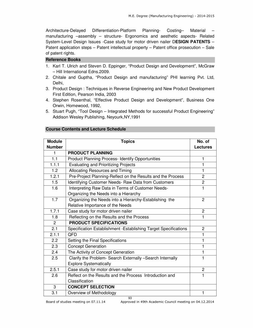
M.E. Degree (Manufacturing Engineering) - 2014-2015
93 Board of studies meeting on 07.11.14 Approved in 49th Academic Council meeting on 04.12.2014
Architecture-Delayed Differentiation-Platform Planning- Costing– Material –
manufacturing –assembly – structure- Ergonomics and aesthetic aspects- Related
System-Level Design Issues -Case study for motor driven nailer DESIGN PATENTS –
Patent application steps – Patent intellectual property – Patent office prosecution – Sale
of patent rights.
Reference Books
1. Karl T. Ulrich and Steven D. Eppinger, “Product Design and Development”, McGraw
– Hill International Edns.2009.
2. Chitale and Guptha, “Product Design and manufacturing” PHI learning Pvt. Ltd,
Delhi,
3. Product Design : Techniques in Reverse Engineering and New Product Development
First Edition, Pearson India, 2003
4. Stephen Rosenthal, “Effective Product Design and Development”, Business One
Orwin, Homewood, 1992,
5. Stuart Pugh, “Tool Design – Integrated Methods for successful Product Engineering”
Addison Wesley Publishing, Neyourk,NY,1991
Course Contents and Lecture Schedule
Module
Number
Topics No. of
Lectures
1 PRODUCT PLANNING
1.1 Product Planning Process- Identify Opportunities 1
1.1.1 Evaluating and Prioritizing Projects 1
1.2 Allocating Resources and Timing 1
1.2.1 Pre-Project Planning-Reflect on the Results and the Process 2
1.5 Identifying Customer Needs- Raw Data from Customers 2
1.6 Interpreting Raw Data in Terms of Customer Needs-
Organizing the Needs into a Hierarchy
1
1.7 Organizing the Needs into a Hierarchy-Establishing the
Relative Importance of the Needs
2
1.7.1 Case study for motor driven nailer 2
1.8 Reflecting on the Results and the Process 1
2 PRODUCT SPECIFICATIONS
2.1 Specification Establishment -Establishing Target Specifications 2
2.1.1 QFD 1
2.2 Setting the Final Specifications 1
2.3 Concept Generation 1
2.4 The Activity of Concept Generation 1
2.5 Clarify the Problem- Search Externally –Search Internally
Explore Systematically
1
2.5.1 Case study for motor driven nailer 2
2.6 Reflect on the Results and the Process Introduction and
Classification
1
3 CONCEPT SELECTION
3.1 Overview of Methodology 1
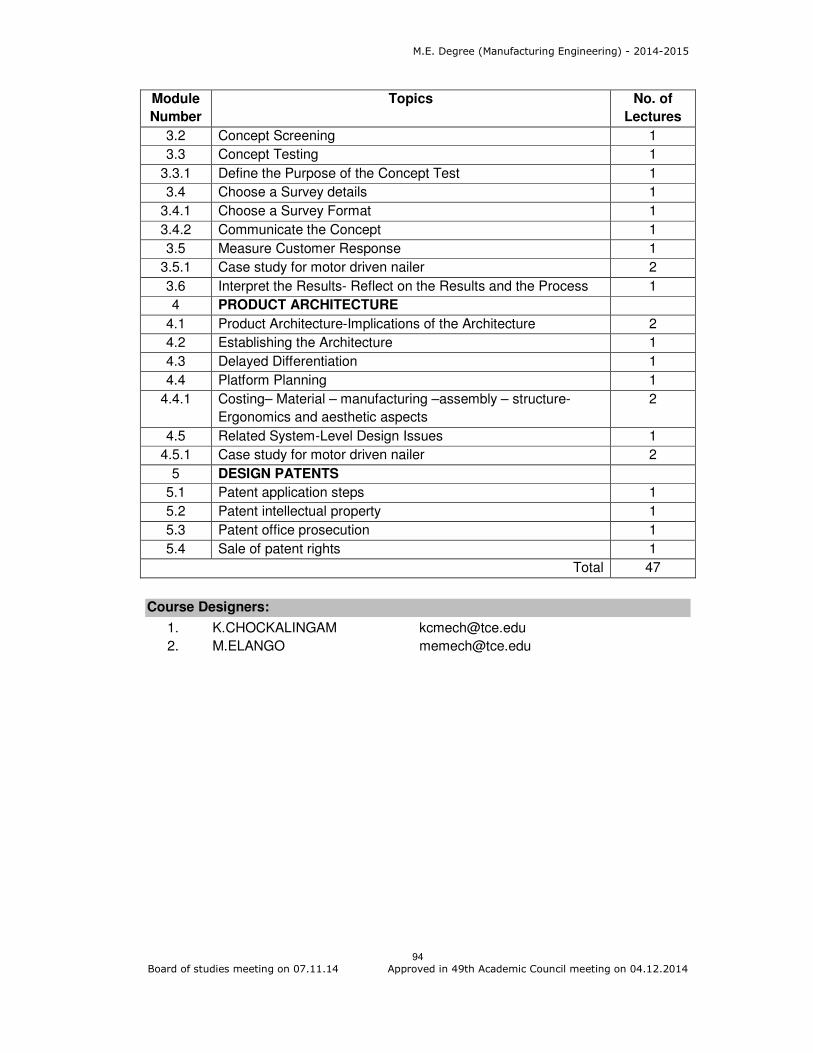
M.E. Degree (Manufacturing Engineering) - 2014-2015
94 Board of studies meeting on 07.11.14 Approved in 49th Academic Council meeting on 04.12.2014
Module
Number
Topics No. of
Lectures
3.2 Concept Screening 1
3.3 Concept Testing 1
3.3.1 Define the Purpose of the Concept Test 1
3.4 Choose a Survey details 1
3.4.1 Choose a Survey Format 1
3.4.2 Communicate the Concept 1
3.5 Measure Customer Response 1
3.5.1 Case study for motor driven nailer 2
3.6 Interpret the Results- Reflect on the Results and the Process 1
4 PRODUCT ARCHITECTURE
4.1 Product Architecture-Implications of the Architecture 2
4.2 Establishing the Architecture 1
4.3 Delayed Differentiation 1
4.4 Platform Planning 1
4.4.1 Costing– Material – manufacturing –assembly – structure-
Ergonomics and aesthetic aspects
2
4.5 Related System-Level Design Issues 1
4.5.1 Case study for motor driven nailer 2
5 DESIGN PATENTS
5.1 Patent application steps 1
5.2 Patent intellectual property 1
5.3 Patent office prosecution 1
5.4 Sale of patent rights 1
Total 47
Course Designers:
1. K.CHOCKALINGAM [email protected]
2. M.ELANGO [email protected]

M.E. Degree (Manufacturing Engineering) - 2014-2015
95 Board of studies meeting on 07.11.14 Approved in 49th Academic Council meeting on 04.12.2014
Category L T P Credit
PE 4 0 0 4
Preamble
The term "design for manufacture" (DFM) means the design for ease of manufacture of
the collection of parts that will form the product after assembly and "design for assembly"
(DFA) means the design of the product for ease of assembly. Thus, "design for
manufacture and assembly" (DFMA) is a combination of DFA and DFM. DFMA is used:
• As the basis for concurrent engineering studies to provide guidance to the design
team in simplifying the product structure, to reduce manufacturing and assembly
costs, and to quantify the improvements.
• As a benchmarking tool to study competitors' products and quantify
manufacturing and assembly difficulties.
Prerequisite
• Elements of Product Development
• Principles of Manufacturing Processes – Casting, Forming, Machining and
Joining processes
• Assembly Processes
• Course Outcomes
• On the successful completion of the course, students will be able to
CO.No.
Course Outcome Blooms
Level
Expected proficiency
Expected attainment level
CO1 Explain the elements and steps involved in concurrent engineering approach
Understand 80 70
CO2 Explain the importance of the Design for Manufacture and Assembly (DFMA)
Understand 80 70
CO3 Compute the tolerance requirements in the process of DFMA
Apply 70 60
CO4 Explain the of design guidelines for sand casting, die casting, machining, and sheet metal forming processes
Understand 80 70
CO5 Explain the principles and guidelines of design for assembly of components in manual, automated and robot assembly system
Understand 80 70
CO6 Apprise the redesign of component for ease of manufacturing and assembly
Analyse 60 50
•
• Mapping with Programme Outcomes
COs PO1 PO2 PO3 PO4 PO5 PO6 PO7 PO8 PO9 PO10 PO11
CO1: M L
CO2: M L
CO3: S M L L
14MGPH0 DESIGN FOR MANUFACTURE AND
ASSEMBLY
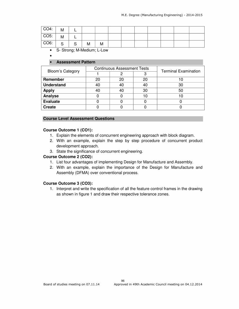
M.E. Degree (Manufacturing Engineering) - 2014-2015
96 Board of studies meeting on 07.11.14 Approved in 49th Academic Council meeting on 04.12.2014
CO4: M L
CO5: M L
CO6: S S M M
• S- Strong; M-Medium; L-Low
•
• Assessment Pattern
Bloom’s Category Continuous Assessment Tests
Terminal Examination 1 2 3
Remember 20 20 20 10
Understand 40 40 40 30
Apply 40 40 30 50
Analyse 0 0 10 10
Evaluate 0 0 0 0
Create 0 0 0 0
Course Level Assessment Questions
Course Outcome 1 (CO1):
1. Explain the elements of concurrent engineering approach with block diagram.
2. With an example, explain the step by step procedure of concurrent product
development approach.
3. State the significance of concurrent engineering.
Course Outcome 2 (CO2):
1. List four advantages of implementing Design for Manufacture and Assembly.
2. With an example, explain the importance of the Design for Manufacture and
Assembly (DFMA) over conventional process.
Course Outcome 3 (CO3):
1. Interpret and write the specification of all the feature control frames in the drawing
as shown in figure 1 and draw their respective tolerance zones.
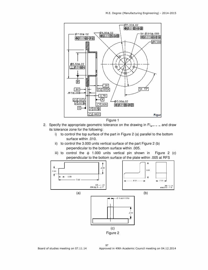
M.E. Degree (Manufacturing Engineering) - 2014-2015
97 Board of studies meeting on 07.11.14 Approved in 49th Academic Council meeting on 04.12.2014
Figure 1
2. Specify the appropriate geometric tolerance on the drawing in Figure 2 and draw
its tolerance zone for the following:
i) to control the top surface of the part in Figure 2 (a) parallel to the bottom
surface within .010.
ii) to control the 3.000 units vertical surface of the part Figure 2 (b)
perpendicular to the bottom surface within .005.
iii) to control the ϕ 1.000 units vertical pin shown in Figure 2 (c)
perpendicular to the bottom surface of the plate within .005 at RFS
(a) (b)
(c)
Figure 2

M.E. Degree (Manufacturing Engineering) - 2014-2015
98 Board of studies meeting on 07.11.14 Approved in 49th Academic Council meeting on 04.12.2014
3. Read the drawing given in Figure 3 with the pin and the hole and write the
descriptions for the feature control frames available in the figure.
Figure 3
Course Outcome 4 (CO4):
1. Explain any two guidelines for ease of sheet metal forming with examples.
2. With suitable sketches, explain the effect of chamfer design on insertion
operations.
3. Prepare a check list for design guidelines of robot assembly system.
Course Outcome 5 (CO5):
1. Explain the principles and guidelines of design for assembly of components in
manual assembly system
2. Prepare a check list for design guidelines of robot assembly system.
3. Explain the guidelines of design for automated assembly system with suitable
examples.
Course Outcome 6 (CO6):
1. Suggest and justify the suitable modifications on the design of the following
components as shown in figure 4 for ease of casting.
(i) (ii)
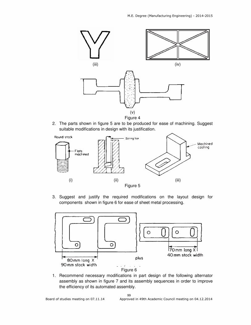
M.E. Degree (Manufacturing Engineering) - 2014-2015
99 Board of studies meeting on 07.11.14 Approved in 49th Academic Council meeting on 04.12.2014
(iii) (iv)
(v)
Figure 4
2. The parts shown in figure 5 are to be produced for ease of machining. Suggest
suitable modifications in design with its justification.
(i) (ii) (iii)
Figure 5
3. Suggest and justify the required modifications on the layout design for
components shown in figure 6 for ease of sheet metal processing.
Figure 6
1. Recommend necessary modifications in part design of the following alternator
assembly as shown in figure 7 and its assembly sequences in order to improve
the efficiency of its automated assembly.

M.E. Degree (Manufacturing Engineering) - 2014-2015
100 Board of studies meeting on 07.11.14 Approved in 49th Academic Council meeting on 04.12.2014
Figure 7
Concept Map
Syllabus
Concurrent Engineering approach: definition, steps involved - Myths and realities of
product development - Role of Design for Manufacture and Assembly in concurrent
engineering. Tolerancing System: Importance - Feature and geometric tolerances -
Process capability - surface finish - Cumulative effect of tolerances. Datum systems:
Degrees of freedom - Grouped datum systems - Different types, two and three mutually
perpendicular grouped datum planes - Grouped datum system with spigot and recess,
pin and hole - Grouped datum system with spigot and recess pair and tongue - Slot pair -
Transnational and Rotational accuracy. True position theory: Comparison between co-
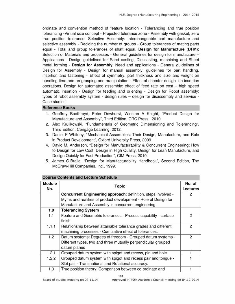
M.E. Degree (Manufacturing Engineering) - 2014-2015
101 Board of studies meeting on 07.11.14 Approved in 49th Academic Council meeting on 04.12.2014
ordinate and convention method of feature location - Tolerancing and true position
tolerancing -Virtual size concept - Projected tolerance zone - Assembly with gasket, zero
true position tolerance. Selective Assembly: Interchangeable part manufacture and
selective assembly - Deciding the number of groups - Group tolerances of mating parts
equal - Total and group tolerances of shaft equal. Design for Manufacture (DFM):
Selection of Materials and processes - General guidelines for design for manufacture –
Applications - Design guidelines for Sand casting, Die casting, machining and Sheet
metal forming - Design for Assembly: Need and applications - General guidelines of
Design for Assembly - Design for manual assembly: guidelines for part handling,
insertion and fastening - Effect of symmetry, part thickness and size and weight on
handling time and on grasping and manipulation - Effect of chamfer design on insertion
operations. Design for automated assembly: effect of feed rate on cost – high speed
automatic insertion - Design for feeding and orienting - Design for Robot assembly:
types of robot assembly system - design rules – design for disassembly and service -
Case studies.
Reference Books
1. Geoffrey Boothroyd, Peter Dewhurst, Winston A Knight, “Product Design for
Manufacture and Assembly”, Third Edition, CRC Press, 2010
2. Alex Krulikowski, “Fundamentals of Geometric Dimensioning and Tolerancing”,
Third Edition, Cengage Learning, 2012.
3. Daniel E Whitney, “Mechanical Assemblies: Their Design, Manufacture, and Role
in Product Development”, Oxford University Press, 2009
4. David M. Anderson, “Design for Manufacturability & Concurrent Engineering; How
to Design for Low Cost, Design in High Quality, Design for Lean Manufacture, and
Design Quickly for Fast Production”, CIM Press, 2010.
5. James G.Bralla, “Design for Manufacturability Handbook”, Second Edition, The
McGraw-Hill Companies, Inc., 1999.
Course Contents and Lecture Schedule
Module
No. Topic
No. of
Lectures
Concurrent Engineering approach: definition, steps involved -
Myths and realities of product development - Role of Design for
Manufacture and Assembly in concurrent engineering
2
1.0 Tolerancing System
1.1 Feature and Geometric tolerances - Process capability - surface
finish
2
1.1.1 Relationship between attainable tolerance grades and different
machining processes - Cumulative effect of tolerances.
2
1.2 Datum systems: Degrees of freedom - Grouped datum systems -
Different types, two and three mutually perpendicular grouped
datum planes
2
1.2.1 Grouped datum system with spigot and recess, pin and hole 1
1.2.2 Grouped datum system with spigot and recess pair and tongue -
Slot pair - Transnational and Rotational accuracy.
1
1.3 True position theory: Comparison between co-ordinate and 1
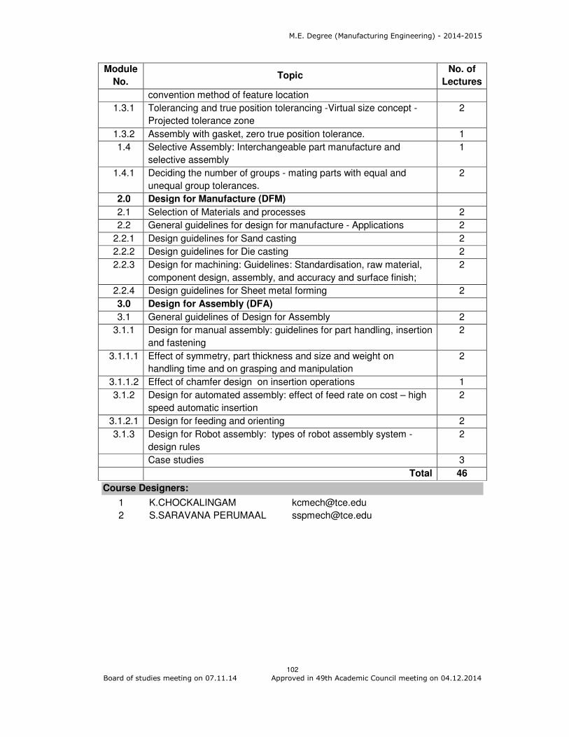
M.E. Degree (Manufacturing Engineering) - 2014-2015
102 Board of studies meeting on 07.11.14 Approved in 49th Academic Council meeting on 04.12.2014
Module
No. Topic
No. of
Lectures
convention method of feature location
1.3.1 Tolerancing and true position tolerancing -Virtual size concept -
Projected tolerance zone
2
1.3.2 Assembly with gasket, zero true position tolerance. 1
1.4 Selective Assembly: Interchangeable part manufacture and
selective assembly
1
1.4.1 Deciding the number of groups - mating parts with equal and
unequal group tolerances.
2
2.0 Design for Manufacture (DFM)
2.1 Selection of Materials and processes 2
2.2 General guidelines for design for manufacture - Applications 2
2.2.1 Design guidelines for Sand casting 2
2.2.2 Design guidelines for Die casting 2
2.2.3 Design for machining: Guidelines: Standardisation, raw material,
component design, assembly, and accuracy and surface finish;
2
2.2.4 Design guidelines for Sheet metal forming 2
3.0 Design for Assembly (DFA)
3.1 General guidelines of Design for Assembly 2
3.1.1 Design for manual assembly: guidelines for part handling, insertion
and fastening
2
3.1.1.1 Effect of symmetry, part thickness and size and weight on
handling time and on grasping and manipulation
2
3.1.1.2 Effect of chamfer design on insertion operations 1
3.1.2 Design for automated assembly: effect of feed rate on cost – high
speed automatic insertion
2
3.1.2.1 Design for feeding and orienting 2
3.1.3 Design for Robot assembly: types of robot assembly system -
design rules
2
Case studies 3
Total 46
Course Designers:
1 K.CHOCKALINGAM [email protected]
2 S.SARAVANA PERUMAAL [email protected]

M.E. Degree (Manufacturing Engineering) - 2014-2015
103 Board of studies meeting on 07.11.14 Approved in 49th Academic Council meeting on 04.12.2014
Category L T P Credit
PE 4 0 0 4
Preamble
Robust Design is a proven development philosophy focused on achieving target
reliability. Approaching this aggressive goal requires that Robust Design principles be an
early and integral part of the development cycle. Cost of Product performance Issues not
only leads to erosion of profit, but also leads to loss of reputation and competitive
advantage in Global economy. It is absolutely essential to understand the root cause of
issues, either in Predictive Design of New Products or in Fixing Field issues of existing
products or even enhancing the productivity in a Manufacturing environment. The
objective is to make the end-product immune to factors that could adversely affect
performance. A Robust Design flow is used to implement and analyze the design to
ensure system reliability. The objective of a Robust Design flow is to meet performance
requirements with the highest possible system reliability and the most reasonable
systems cost. Robust design saves considerable time and efforts in trouble shooting,
identifying quality inputs and in rectifying the total system.
Prerequisite
14MA110 :Statistics
Course Outcomes
On the successful completion of the course, students will be able to
CO.No.
Course Outcome Blooms
Level
Expected
Proficiency
Expected
attainment
level
CO1 CO1: Explain the need, importance and benefit of robust design over conventional design approach
Understand 80 70
CO2 CO 2: Identify DoE model and perform DoE
Understand 80 70
CO3 CO 3: Use and Interpret results of DoE using case studies
Apply 70 60
CO4 CO 4: Practice DoE on real time problems
Apply 70 60
CO5 CO 5: Examine when to use Branch of from Full to Fractional Factorial DoE
Analyse 60 50
Mapping with Programme Outcomes
COs PO1 PO2 PO3 PO4 PO5 PO6 PO7 PO8 PO9 PO10 PO11
CO1 M L
CO2 M L
CO3 S M L L
CO4 S M L L
14MGPJ0 ROBUST DESIGN

M.E. Degree (Manufacturing Engineering) - 2014-2015
104 Board of studies meeting on 07.11.14 Approved in 49th Academic Council meeting on 04.12.2014
CO5 S S M M
S- Strong; M-Medium; L-Low
Assessment Pattern
Bloom’s Category Continuous Assessment Tests
Terminal Examination 1 2 3
Remember 20 20 20 20
Understand 80 40 60 20
Apply 0 40 20 40
Analyse 0 0 0 20
Evaluate 0 0 0 0
Create 0 0 0 0
Course Outcome 1 (CO1):
1. Cite the unbalanced data in DOE?
2. What is fixed effect model?
3. What do you mean by Hypothesis?
4. State the advantages of Confounding?
5. Plot a sample linear graph
6. Plot the taguchi's quality curve.
7. What is Random effect model?
Course Outcome 2 (CO2):
1. Describe the guidelines for designing experiments and elaborate the key points.
2. Briefly explain about the Blocking in experimental design with suitable examples.
3. Brief explain about the following with example, Response Surface
Methodology, Partial Confounding and Fractional factorials
4. Write the Step by step procedure to optimize the manufacturing process
by Taguchi Methods.
5. State and explain the robust design concepts through quality Loss function.
Course Outcome 3 (CO3):
1. The compressive strength is being studied. Four different mixing techniques are
a) Test the hypothesis that mixing us techniques affect the strength of the
concrete. Use =0.5
b) Use Tukeys test to make comparisons between pairs of means.
Estimate the treatment effects.
2. An engineer is analyzing the effect of bottle types, (A, B, C, D) on the filling time for
a soft drinks. Four workers are selected for the study and to account for this source of
variability, the engineer uses the Latin Square shown below. Analyse the data from
being investigated. The following data have been collected.
Mixing Technique Compressive strength
1 313 300 287 289
2 320 330 298 315
3 280 290 299 305
4 260 270 260 277

M.E. Degree (Manufacturing Engineering) - 2014-2015
105 Board of studies meeting on 07.11.14 Approved in 49th Academic Council meeting on 04.12.2014
this experiment ( = 0.5) and draw appropriate conclusions.
3. A process engineer is trying to improve the life of a cutting tool. He has run a 2 3
experiment using cutting speed (A), metal hardness (B) and cutting angle (c) as the
factors. The data from two replicates are shown here. (A) Do any of the factors affect
tool life (b) What combination of factor levels produces the longest tool life? (C)C s
there a combination of cutting speed and cutting angle that always gives good results
regardless of metal hardness.
4. A 2 3 design has been used to investigate the effect of four factors on the resistivity of
a silicon wafer. The data from this experiment are shown here.
a) Estimate the factor effects. Plot the effect estimates on a normal probability scale.
b) Plot the residuals from the model Vs the predicted resistivity. Is there any indication
on this plot of model adequacy.
Bottle type Workers
1 2 3 4
1 C=11 B=10 D= 14 A=8
2 B=8 C=12 A =10 B=12
3 A=9 D=11 B=7 C-15
4 D=9 A=8 C=18 B=6
Run Replicate
I II
(1) 221 311
a 325 435
b 354 348
ab 552 472
C 440 453
Ac 406 377
Be 605 503
a be 392 419
Run A B B D Resistivity
1 - - - - 33.2
2 + - - + 4.6
3 - + - + 31.2
4 + + - - 9.6
5 - - + + 162.4
6 + - + - 39.4
7 - + + - 158.6
8 + + + + 40.6
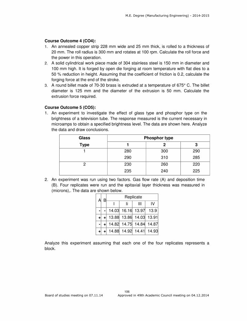
M.E. Degree (Manufacturing Engineering) - 2014-2015
106 Board of studies meeting on 07.11.14 Approved in 49th Academic Council meeting on 04.12.2014
Course Outcome 4 (CO4):
1. An annealed copper strip 228 mm wide and 25 mm thick, is rolled to a thickness of
20 mm. The roll radius is 300 mm and rotates at 100 rpm. Calculate the roll force and
the power in this operation.
2. A solid cylindrical work piece made of 304 stainless steel is 150 mm in diameter and
100 mm high. It is forged by open die forging at room temperature with flat dies to a
50 % reduction in height. Assuming that the coefficient of friction is 0.2, calculate the
forging force at the end of the stroke.
3. A round billet made of 70-30 brass is extruded at a temperature of 675° C. The billet
diameter is 125 mm and the diameter of the extrusion is 50 mm. Calculate the
extrusion force required.
Course Outcome 5 (CO5):
1. An experiment to investigate the effect of glass type and phosphor type on the
brightness of a television tube. The response measured is the current necessary in
microamps to obtain a specified brightness level. The data are shown here. Analyze
the data and draw conclusions.
2. An experiment was run using two factors. Gas flow rate (A) and deposition time
(B). Four replicates were run and the epitaxial layer thickness was measured in
(microns),. The data are shown below.
A BReplicate
I Ii III IV
- - 14.03 16.16 13.97 13.9
+ + 13.88 13.86 14.03 13.91
- + 14.82 14.75 14.84 14.87
+ + 14.88 14.92 14.41 14.93
Analyze this experiment assuming that each one of the four replicates represents a
block.
Glass Phosphor type
Type 1 2 3
1 280 300 290
290 310 285
2 230 260 220
235 240 225

M.E. Degree (Manufacturing Engineering) - 2014-2015
107 Board of studies meeting on 07.11.14 Approved in 49th Academic Council meeting on 04.12.2014
Concept Map
Syllabus
Introduction: Basic Concepts - Planning of Experiments, Steps, Need, and Technology-
Factors, Levels, Variables, Experimental error, Replication, Randomization, Blocking,
and Confounding. Single factor experiments: ANOVA Rational, Sum of Squares,
Effect of coding, Fixed effects Model, Random effect model - Test of means -
Randomized block design - Latin square design. Factorial Experiments: Fixed and
Random factors main and interaction effects, rules of EMS, calculations and practical
applications - Fractional factorials Confounding: Confounding in the 2K factorial design,
3K factorial design, partial confounding other confounding systems. Orthogonal Array
Designs: Orthogonal arrays and linear graphs, Determination of optimum operating
conditions, Response surface methodology, Taguchi methods.
Reference Books
1. Douglas C. Montgomery, "Design and Analysis of Experiments", Fifth Edition,
John Wiley and Sons, New York, 2013
2. Angela Dean and Daniel Voss,” Design and Analysis of Experiments”, First
Indian reprint, Springer International edition,2006
3. Douglas C. Montgomery, " Introduction to Statistical Quality Control", Fourth
Indian Edition, John Wiley and Sons, New York, 2004.
4. William W. Hines, Douglas C. Montgomery, David M.Goldsman and Connie
M.Borror, “Introduction to Statistical Quality Control", Fourth Indian Edition,
John Wiley and Sons, New York, 2003.
5. Philips J. Ross, "Taguchi Techniques for Quality Engineering", Second Edition,
McGraw Hill Education (India) Pvt Ltd, 2005

M.E. Degree (Manufacturing Engineering) - 2014-2015
108 Board of studies meeting on 07.11.14 Approved in 49th Academic Council meeting on 04.12.2014
Course Contents and Lecture Schedule
Module Number
Topics No. Of
Periods
1. Introduction
1.1 Basic Concepts 1
1.2 Planning of Experiments 1
1.2.1 Steps, Need and Technology 1
1.3 Factors, Levels, Variables, Experimental error 1
1.4 Replication, 1
1.5 Randomization, 1
1.6 Blocking 1
1.7 Confounding 1
2. Single factor experiments
2.1 ANOVA Rational 2
2.2 Sum of Squares 1
2.3 Effect of coding 2
2.4 Fixed effects Model 2
2.5 Random effect model 2
2.6 Test of means 2
2.7 Randomized block design 2
2.8 Latin square design 2
3. Factorial Experiments
3.1 Fixed and Random factors 2
3.2 main and interaction effects 2
3.3 Rules of EMS 2
3.4 Calculations and practical applications 2
3.5 Fractional Factorials 2
4 Confounding
4.1 Confounding in the 2K factorial design 2
4.2 3k factorial design 2
5 Orthogonal Array Designs
5.1 Orthogonal arrays and linear graphs 2
5.2 Determination of optimum operating conditions 2
5.3 Response surface methodology 2
5.4 Taguchi methods 2
Total 46
Course Designers:
1. M. Palaninatharaja [email protected]
2. S. Karthikeyan [email protected]
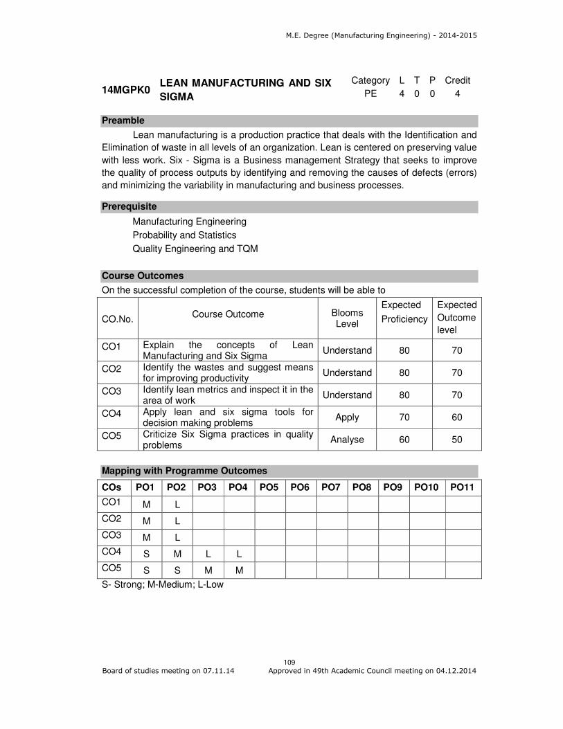
M.E. Degree (Manufacturing Engineering) - 2014-2015
109 Board of studies meeting on 07.11.14 Approved in 49th Academic Council meeting on 04.12.2014
Category L T P Credit
PE 4 0 0 4
Preamble
Lean manufacturing is a production practice that deals with the Identification and
Elimination of waste in all levels of an organization. Lean is centered on preserving value
with less work. Six - Sigma is a Business management Strategy that seeks to improve
the quality of process outputs by identifying and removing the causes of defects (errors)
and minimizing the variability in manufacturing and business processes.
Prerequisite
Manufacturing Engineering
Probability and Statistics
Quality Engineering and TQM
Course Outcomes
On the successful completion of the course, students will be able to
CO.No.
Course Outcome Blooms
Level
Expected
Proficiency
Expected
Outcome
level
CO1 Explain the concepts of Lean Manufacturing and Six Sigma
Understand 80 70
CO2 Identify the wastes and suggest means for improving productivity
Understand 80 70
CO3 Identify lean metrics and inspect it in the area of work
Understand 80 70
CO4 Apply lean and six sigma tools for decision making problems
Apply 70 60
CO5 Criticize Six Sigma practices in quality problems
Analyse 60 50
Mapping with Programme Outcomes
COs PO1 PO2 PO3 PO4 PO5 PO6 PO7 PO8 PO9 PO10 PO11
CO1 M L
CO2 M L
CO3 M L
CO4 S M L L
CO5 S S M M
S- Strong; M-Medium; L-Low
14MGPK0 LEAN MANUFACTURING AND SIX
SIGMA

M.E. Degree (Manufacturing Engineering) - 2014-2015
110 Board of studies meeting on 07.11.14 Approved in 49th Academic Council meeting on 04.12.2014
Assessment Pattern
Bloom’s Category Test 1 Test 2 Test 3 End-semester examination
1 Remember 20 20 20 20
2 Understand 30 30 20 20
3 Apply 50 50 40 40
4 Analyze 0 0 20 20
5 Evaluation 0 0 0 0
6 Create 0 0 0 0
Course Level Assessment Questions
Course Outcome 1 (CO1):
1. What is the purpose of reducing waste?
2. What are the various types of lean metrics?
3. Define Process flow & Pitch.
4. What is Takt time?
5. What is six sigma?
6. Define DMAIC.
Course Outcome 2 (CO2):
1. Discuss how Lean concept is helping for corporate decision making.
2. Explain the factors influencing the current state map from Future state map.
3. Explain the objectives of SMED.
4. Discuss on Kano Model.
5. Explain the various steps in six sigma roadmap.
6. Discuss the capability and limitation of SPC six sigma tool.
Course Outcome 3 (CO3):
1. For a Textile Industry the following are main problems. How would you solve the
following issues? which lean tool you would use, Justify it.
A. High Inventory
B. Frequent breakdown
C. Process variability
2. Compare Push vs. Pull system. Demonstrate Pull system is suitable for Lean
Manufacturing taking Dell Industry supply chain.
3. In a Copper smelter Maintenance the following are problems
A. Frequent Breakdowns
B. All Planned Maintenance activities are rescheduled

M.E. Degree (Manufacturing Engineering) - 2014-2015
111 Board of studies meeting on 07.11.14 Approved in 49th Academic Council meeting on 04.12.2014
C. No Preventive maintence available
Execute the Total Productive Maintenance for solving above said problems
4. Put in to practice the PFA chart for the products and machines given below and
draw New cellular Layout
5. Use DMAIC principles to get best fit in to a Library Management system
6. Execute DMADV principles for organizing a student industrial tour.
Course Outcome 4 (CO4)
1. For an automobile manufacturing company the following is the summary sheet
After several brain storming and a thorough study of the shop floor, it was
observed that the tube subassembly line consists various forms of non-value-adding
activities as follows:
High lead time Accumulation of high inventory Unnecessary material flow High material
travel distance Poor Mean-Time-Between-Failure ,underutilized manpower.
Organize the lean manufacturing practice using lean tools such as VSM, change
overtime reduction and achieve the following targets
A. Reducing change-over time to 10 minutes.
B. Increasing the line productivity by 25%.
C. Reducing the WIP to 200 units improving the material flow.
Product / Machines 1 2 3 4 5
A X X X
B X
C X X X
D X
E X X X
x-indicates operation in that machine

M.E. Degree (Manufacturing Engineering) - 2014-2015
112 Board of studies meeting on 07.11.14 Approved in 49th Academic Council meeting on 04.12.2014
2. Analyze how kaizen can be used as a lean tool to solve the case study given
below.
A company is mainly focused on manufacturing as per customer’s design. HV
Axle Ltd. currently has a capacity of about 3, 24,000axles per annum ( inclusive of all
varieties), total annual sales volume is US$50 Million-US$100Million and total
employees are 1154, out of which 846 persons work in Axle division where the case
study was taken up. In this division 510 employees are permanent as operator’s level
and 336 in supervisory. This work is on HVAL, Rear Axle (Assembly Line 1) in which
target production is 300 Axles per shift but the current production is 210 Axles per
shift (8 Hours). This is due to lack of multi-skilled development, lack of training to
operators, no proper utilization of resources, and Noninvolvement of staff in Kaizen
Program etc. Our main motto was to achieve the target production and find the
factors which are responsible for lack of the production in the company. For
completing a Rear Axle assemblies there are 35 work-stations corresponding 56
operators.
Problems faced in company are:
� Number of operators likely to exceed in assembly line.
� Low production efficiency.
� High product cost.
� Low Turnover of company.
� Maintaining the Quality.
� Lack of system simplification.
3. From the given information box, draw the current state map, identify the wastes,
draw the future state map suitably. Justify your answers. Also compare the takt
time in both cases.
Part Number WP/CAS/001 WP Casting
Family Casting Machine shop
Customer demand 4000/month variation +400
Manufacturing data Operation
Data collected by Vinayaga
Cycle time(Minutes) 2
Change over time(Minutes) 20
Uptime 90%
% Defective 5% rework
Batch size 110 (10 numbers
added to demand)
Number of shifts 2(8.5 hr per shift)
Number of Operators 1 per shift
Available time (Minutes) 450
Work in progress 650 numbers
Course Outcome 5 (CO5)

M.E. Degree (Manufacturing Engineering) - 2014-2015
113 Board of studies meeting on 07.11.14 Approved in 49th Academic Council meeting on 04.12.2014
1. A Restaurant conducted consumer surveys and focus groups and identified the most
important customer requirements as Healthy food, speedy service, an easy to read
menu board, accurate order filling and perceived value. Develop of a set of technical
requirements to incorporate into the design of a new facility and a house of quality
relationship matrix to assess how well the requirements address these expectations.
2. Maintaining accuracy of books on shelves in a library is an important task. Consider
the following problems that are often observed.
a. Books are not placed in the correct shelf, which include books that are
checked out and returned and books taken off from shelves
b. New or returned books are not checked out consequently, online catalog
doesn’t show availability. Organize a Poka-yoka system for mitigating
above problems.
3. A flow chart for a fast food drive through window is shown below. Categorize the
important quality characteristics inherent in the process and suggest possible
improvements using DMAIC cycle
CONCEPT MAP
Customer
gives order
Employee
repeats
order and
gives total
Customer
waits and
drives
through
Employee
repeats
total
Employee
Process order Customer
and food
reach
Customer
gives money
Employee
gives food
and change
Customer
enjoys food
and pulls
away

M.E. Degree (Manufacturing Engineering) - 2014-2015
114 Board of studies meeting on 07.11.14 Approved in 49th Academic Council meeting on 04.12.2014
Syllabus
Lean Manufacturing evolution of lean; traditional versus lean manufacturing; ford
production system concept of lean; Toyota’s foray in lean, Customer Need; lean tools-
Process mapping value stream management- 3 M;7 types of Muda; 7 major losses
reduction. cell layout; line balancing; concept of kaizen; steps involved in kaizen
deployment; kanban concepts ; types of Kanban ; and practical application ; push vs
pull; changeover time reduction - single minute exchange of die; concept of TPM; poka-
yoke; 5S; maintenance - preventive, time based and condition based; autonomous
maintenance, JIT, Autonomation, DFMA; lean metrics identify lean metrics; kaizen
cloud identification in VSM ; lean assessment. improving targets and benchmarks; Six
Sigma SIPCO,QFD; voice of the customer, kano models, , cost of poor quality (COPQ),
six sigma tools and techniques- statistical process control six sigma methods –
DMAIC, Preparation phase: Organizational success factors – leadership, six sigma as
strategic initiative, internal communication strategy and tactics, formal launch,
organizational structure, six sigma training plan, project selection, assessing
organizational readiness, pitfalls. work as a process – vertical functions and horizontal
processes. Define phase: DMAIC phases, overview, project charter – voice of the
customer – high level process map –project team – case study. Measure and analyse
phase: types of measures – introduction to statistical methods – sampling plan – data
collection – choosing statistical software – measure tools – process maps, pareto charts,
cause and effect diagrams, histograms, six sigma measurements – measurement
system analysis – process capability calculations. analyze– process analysis –
hypothesis testing – statistical tests and tables – tools for analyzing relationships among
variables – survival analysis. Improve and control phase: process redesign –
generating improvement alternatives – design of experiments – pilot experiments –
cost/benefit analysis – implementation plan. Control phase control plan – process
scorecard – failure mode and effects analysis –final project report and documentation.
DMADV,DFSS–six sigma in manufacturing and services case studies& Sustainability of
Lean Six Sigma and six sigma certificates.
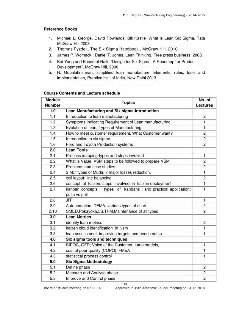
M.E. Degree (Manufacturing Engineering) - 2014-2015
115 Board of studies meeting on 07.11.14 Approved in 49th Academic Council meeting on 04.12.2014
Reference Books
1. Michael L. George, David Rowlands, Bill Kastle ,What is Lean Six Sigma, Tata
McGraw-Hill,2003
2. Thomas Pyzdek, The Six Sigma Handbook , McGraw-Hill, 2010
3. James P. Womack , Daniel T. Jones, Lean Thinking, Free press business, 2003.
4. Kai Yang and Basemel-Haik, “Design for Six-Sigma: A Roadmap for Product
Development”, McGraw Hill, 2008
5. N. Gopalakrishnan, simplified lean manufacture: Elements, rules, tools and
implementation, Prentice Hall of India, New Delhi 2013.
Course Contents and Lecture schedule
Module
Number Topics
No. of
Lectures
1.0 Lean Manufacturing and Six sigma-Introduction
1.1 Introduction to lean manufacturing 2
1.2 Symptoms Indicating Requirement of Lean manufacturing 1
1.3 Evolution of lean, Types of Manufacturing 1
1.4 How to meet customer requirement, What Customer want? 2
1.5 Introduction to six sigma 2
1.6 Ford and Toyota Production systems 2
2.0 Lean Tools
2.1 Process mapping-types and steps involved 1
2.2 What is Value, VSM,steps to be followed to prepare VSM 2
2.3 Problems and case studies 2
2.4 3 M;7 types of Muda; 7 major losses reduction. 1
2.5 cell layout; line balancing 2
2.6 concept of kaizen; steps involved in kaizen deployment; 1
2.7 kanban concepts ; types of kanbans ; and practical application;
push vs pull
1
2.8 JIT 1
2.9 Autonomation, DFMA, various types of chart 2
2.10 SMED,Pokayoka,5S,TPM,Maintenance of all types 2
3.0 Lean Metrics
3.1 identify lean metrics 2
3.2 kaizen cloud identification in vsm 1
3.3 lean assessment. improving targets and benchmarks 1
4.0 Six sigma tools and techniques
4.1 SIPOC, QFD; Voice of the Customer, kano models, 1
4.2 cost of poor quality (COPQ), FMEA 1
4.3 statistical process control 1
5.0 Six Sigma Methodology
5.1 Define phase 2
5.2 Measure and Analyse phase 2
5.3 Improve and Control phase 2

M.E. Degree (Manufacturing Engineering) - 2014-2015
116 Board of studies meeting on 07.11.14 Approved in 49th Academic Council meeting on 04.12.2014
Module
Number Topics
No. of
Lectures
5.4 DMADV & DFSS 3
5.5 Case studies in manufacturing 2
5.6 Case studies in Service industries 2
5.7 Sustainability of Lean Manufacturing and Six sigma, six sigma
certificates
1
Total 46
Course Designers
1. S. Muralidharan [email protected]

M.E. Degree (Manufacturing Engineering) - 2014-2015
117 Board of studies meeting on 07.11.14 Approved in 49th Academic Council meeting on 04.12.2014
Category L T P Credit
PE 3 1 0 4
Preamble
Work study is a business efficiency technique combining the Time Study work
with the Motion Study work. It is a major part of scientific management. The two
techniques became integrated and refined into a widely accepted method applicable to
the improvement and upgrading of work systems. This integrated approach to work
system improvement is known as methods engineering and it is applied today to
industrial as well as service organizations, including banks, schools and hospitals. Time
and motion study have to be used together in order to achieve rational and reasonable
results. It is particularly important that effort be applied in motion study to ensure
equitable results when time study is used. Motion study can be considered the
foundation for time study. The time study measures the time required to perform a given
task in accordance with a specified method and is valid only so long as the method is
continued. Once a new work method is developed, the time study must be changed to
agree with the new method.
Pre requisites
Production Planning and Control
Scheduling
Course Outcomes
On the successful completion of the course, students will be able to
CO.No.
Course Outcome Blooms
Level
Expected
Proficiency
Expected
attainment
level
CO1 Explain the concepts, types, applications and steps in work study
Understand 80 70
CO2 Explain how work study can be used to calculate man machine systems and solve related problems
Understand 80 70
CO3 Explain the various measurement techniques in time and motion study
Understand 80 70
CO4 Apply statistical methods for productivity measurement
Apply 70 60
CO5 Design ergonomics based structures for real life products
Apply 70 60
Mapping with Programme Outcomes
COs PO1 PO2 PO3 PO4 PO5 PO6 PO7 PO8 PO9 PO10 PO11
CO 1 M L
CO 2 M L
CO 3 M L
14MGPL0 WORK STUDY AND COST
ANALYSIS
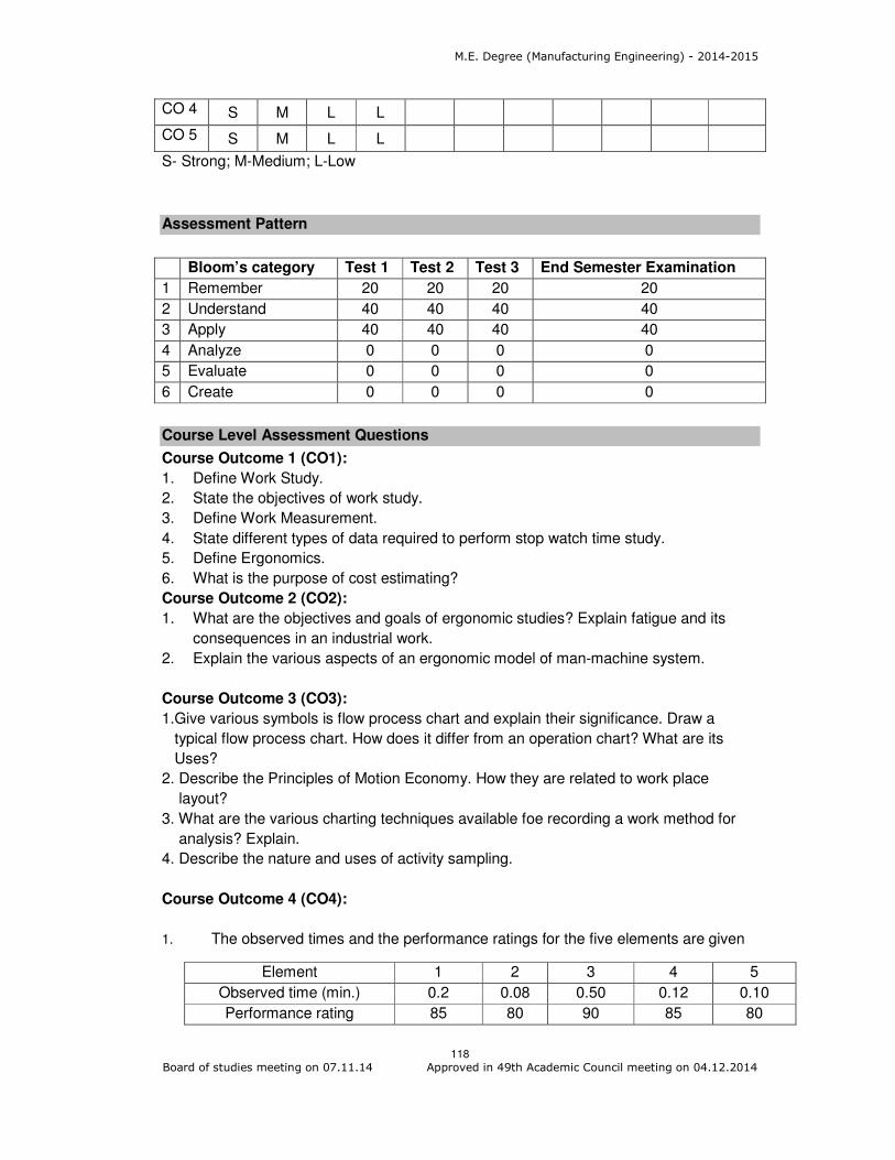
M.E. Degree (Manufacturing Engineering) - 2014-2015
118 Board of studies meeting on 07.11.14 Approved in 49th Academic Council meeting on 04.12.2014
CO 4 S M L L
CO 5 S M L L
S- Strong; M-Medium; L-Low
Assessment Pattern
Bloom’s category Test 1 Test 2 Test 3 End Semester Examination
1 Remember 20 20 20 20
2 Understand 40 40 40 40
3 Apply 40 40 40 40
4 Analyze 0 0 0 0
5 Evaluate 0 0 0 0
6 Create 0 0 0 0
Course Level Assessment Questions
Course Outcome 1 (CO1):
1. Define Work Study.
2. State the objectives of work study.
3. Define Work Measurement.
4. State different types of data required to perform stop watch time study.
5. Define Ergonomics.
6. What is the purpose of cost estimating?
Course Outcome 2 (CO2):
1. What are the objectives and goals of ergonomic studies? Explain fatigue and its
consequences in an industrial work.
2. Explain the various aspects of an ergonomic model of man-machine system.
Course Outcome 3 (CO3):
1.Give various symbols is flow process chart and explain their significance. Draw a
typical flow process chart. How does it differ from an operation chart? What are its
Uses?
2. Describe the Principles of Motion Economy. How they are related to work place
layout?
3. What are the various charting techniques available foe recording a work method for
analysis? Explain.
4. Describe the nature and uses of activity sampling.
Course Outcome 4 (CO4):
1. The observed times and the performance ratings for the five elements are given
Element 1 2 3 4 5
Observed time (min.) 0.2 0.08 0.50 0.12 0.10
Performance rating 85 80 90 85 80
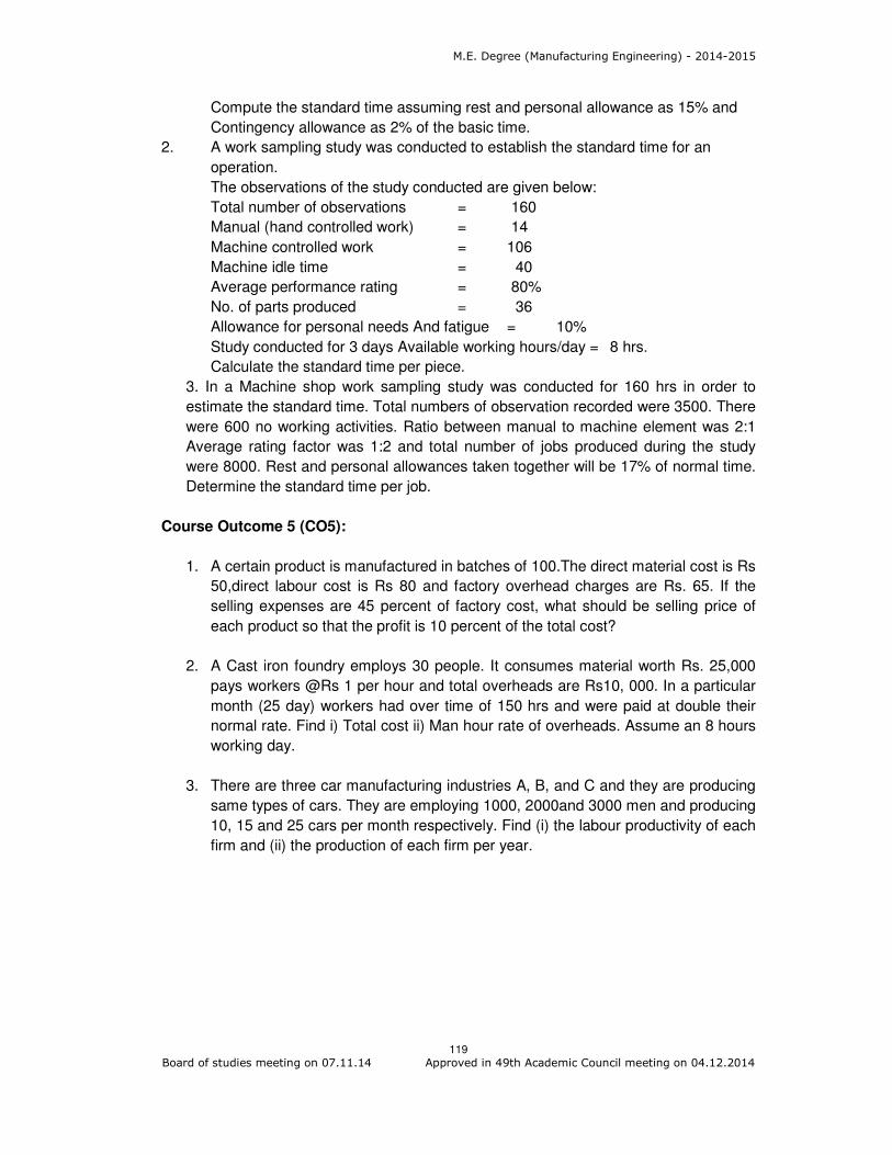
M.E. Degree (Manufacturing Engineering) - 2014-2015
119 Board of studies meeting on 07.11.14 Approved in 49th Academic Council meeting on 04.12.2014
Compute the standard time assuming rest and personal allowance as 15% and
Contingency allowance as 2% of the basic time.
2. A work sampling study was conducted to establish the standard time for an
operation.
The observations of the study conducted are given below:
Total number of observations = 160
Manual (hand controlled work) = 14
Machine controlled work = 106
Machine idle time = 40
Average performance rating = 80%
No. of parts produced = 36
Allowance for personal needs And fatigue = 10%
Study conducted for 3 days Available working hours/day = 8 hrs.
Calculate the standard time per piece.
3. In a Machine shop work sampling study was conducted for 160 hrs in order to
estimate the standard time. Total numbers of observation recorded were 3500. There
were 600 no working activities. Ratio between manual to machine element was 2:1
Average rating factor was 1:2 and total number of jobs produced during the study
were 8000. Rest and personal allowances taken together will be 17% of normal time.
Determine the standard time per job.
Course Outcome 5 (CO5):
1. A certain product is manufactured in batches of 100.The direct material cost is Rs
50,direct labour cost is Rs 80 and factory overhead charges are Rs. 65. If the
selling expenses are 45 percent of factory cost, what should be selling price of
each product so that the profit is 10 percent of the total cost?
2. A Cast iron foundry employs 30 people. It consumes material worth Rs. 25,000
pays workers @Rs 1 per hour and total overheads are Rs10, 000. In a particular
month (25 day) workers had over time of 150 hrs and were paid at double their
normal rate. Find i) Total cost ii) Man hour rate of overheads. Assume an 8 hours
working day.
3. There are three car manufacturing industries A, B, and C and they are producing
same types of cars. They are employing 1000, 2000and 3000 men and producing
10, 15 and 25 cars per month respectively. Find (i) the labour productivity of each
firm and (ii) the production of each firm per year.

M.E. Degree (Manufacturing Engineering) - 2014-2015
120 Board of studies meeting on 07.11.14 Approved in 49th Academic Council meeting on 04.12.2014
Concept Map
Syllabus:
Productivity and Work Study: Productivity and standard of living, Techniques to
reduce work content and ineffective time. Productivity matrix, Quality route to
productivity, better asset utilization, wages and salary, job evaluation, job description, job
analysis and merit rating, Leveraging IT for improved productivity – Case studies. Work
Study - Introduction - Human factors. Method Study: Introduction - Selection of jobs –
Recording – Tools and Techniques - Charts, Diagrams, Template and Models -
Examining - Developing the improved method - Principles of motion economy. Work
Measurement: Introduction to Work Measurement - Time study equipments - Selecting
the job to be studied and making a Time Study- Rating - Allowances to Standard Time -
Setting Time Standard for work with machines - Examples of time study. Other
Techniques of work measurement - Production study - Activity Sampling - Synthesis -
Analytical Estimating - Predetermined Motion Time Systems. The use of Time standards
- Organization of a work study department. Ergonomics: Psycho physiological Data –
Anthropometry, information displays – Man Machine System - Working Environment –
chair and table heights. Strength and force of body movements – speed and accuracy of
motor responses. Activity Based Costing: Definition - Purpose - cost estimation Vs
cost accounting - components cost - Direct cost - indirect cost - overhead expenses.
Estimation of cost elements - set up time and economic lot size - tool change time -
Inspection time - performance factors – overheads. different methods of apportioning
overheads - Data required for cost estimating -Steps in making a cost estimate -
estimation of production cost of simple components - problems.

M.E. Degree (Manufacturing Engineering) - 2014-2015
121 Board of studies meeting on 07.11.14 Approved in 49th Academic Council meeting on 04.12.2014
Reference books
1. ILO, “Introduction to Work Study”, Universal Publishing Corporation, Bombay, 1992
2. Mundel, “Motion and Time Study”, Prentice Hall of India, 1998
3. Ralph M. Barnes, “Motion and Time Study”, John Wiley and Sons, 1990.
4. Niebel Benjamin. W., “Motion and Time Study”, Richard D. Irwin Inc., 1982.
5. Dalela. S,“Workstudy and Ergonomics”, Standard Publishers Distributors, New
Delhi,1999.
6. Sunderesh Heragu “ Facilities Design” PWS publishing company, 2008
7. James M. Apple “Plant Layout and material Handling” The Ronald press company,
1991
8. Singh. C. K., “Mechanical Costing, Estimation and Project Planning”, Standard
Publishers Distributors, New Delhi, 1996.
Course Contents and Lecture Schedule
Module
Number Topics
No. Of
Periods
1. Productivity and Work Study
1.1 Productivity and standard of living 1
1.2 Techniques to reduce work content and ineffective time 1
1.3 Productivity matrix 1
1.3.1 Quality route to productivity 1
1.3.2 better asset utilization
1.4 Wages and Salary 2
1.4.1 job evaluation 2
1.4.2 job description
1.4.3 job analysis
1.4.5 merit rating 1
1.5 Leveraging IT for improved productivity – Case studies. 1
1.6 Work Study - Introduction - Human factors. 1
2. Method Study
2.1 Introduction 1
2.2 Selection of jobs 1
2.3 Recording – Tools and Techniques 1
2.3.1 Charts 1
2.3.2 Diagrams 1
2.3.3 Template and Models 1
2.4 Examining 1
2.5 Developing the improved method 1
2.6 Principles of motion economy 1
3. Work Measurement

M.E. Degree (Manufacturing Engineering) - 2014-2015
122 Board of studies meeting on 07.11.14 Approved in 49th Academic Council meeting on 04.12.2014
Module
Number Topics
No. Of
Periods
3.1 Introduction to Work Measurement 1
3.2 Time study equipments 1
3.3 Selecting the job to be studied and making a Time Study 1
3.4 Rating - Allowances to Standard Time 1
3.4.1 Setting Time Standard for work with machines - Examples of
time study.
1
3.5 Other Techniques of work measurement 1
3.5.1 Production study - Activity Sampling 1
3.5.2 Synthesis - Analytical Estimating - Predetermined Motion Time
Systems
2
3.6 The use of Time standards - Organization of a work study
department.
1
4. Ergonomics
4.1 Psycho physiological Data – Anthropometry 1
4.2 Information displays – Man Machine System 1
4.3 Working Environment –chair and table heights. 1
4.4 Strength and force of body movements – speed and accuracy of
motor responses
2
5. Activity Based Costing
5.1 Definition - Purpose 1
5.2 cost estimation Vs cost accounting 1
5.3 components cost
5.3.1 Direct cost 2
5.3.2 indirect cost
5.3.3 overhead expenses
5.4 Estimation of cost elements
5.4.1 set up time and economic lot size 2
5.4.2 tool change time - Inspection time - Performance factors 1
5.5 overheads
5.5.1 different methods of apportioning overheads 1
5.5.2 Data required for cost estimating
5.6 Steps in making a cost estimate 1
5.7 Estimation of production cost of simple components - problems 2
Total 46
Course Designers:
1. S. Muralidharan [email protected]
2. S. Karthikeyan [email protected]

M.E. Degree (Manufacturing Engineering) - 2014-2015
123 Board of studies meeting on 07.11.14 Approved in 49th Academic Council meeting on 04.12.2014
Category L T P Credit
PE 4 0 0 4
Preamble
It is a process by which entities review the quality of all factors involved in production.
Quality control emphasizes testing of products to uncover defects, and reporting to
management who make the decision to allow or deny the release, whereas quality
assurance attempts to improve and stabilize production, and associated processes, to
avoid, or at least minimize, issues that led to the defects in the first place.
Prerequisite
Knowledge on mathematical distributions
Course Outcomes
On the successful completion of the course, students will be able to
CO.No.
Course Outcome Blooms
Level
Expected
Proficiency
Expected
attainment
level
CO1 Construct the process control charts – variables, attributes
Apply 70 60
CO2 Examine the process control charts Analyse 60 50
CO3 Illustrate Multivariate quality control Understand 80 70
CO4 Prepare and comment the Sampling plans – single, double and multiple
Apply 70 60
CO5 Compute the system Reliability of different system configuration
Apply 70 60
CO6 Investigate the ways to improve the system reliability through redundancy and standby modes
Analyse 60 50
CO7 Describe the ways to implement the system certification
Understand 80 70
Mapping with Programme Outcomes
COs PO1 PO2 PO3 PO4 PO5 PO6 PO7 PO8 PO9 PO10 PO11
CO1 S M L L
CO2 S S M M
CO3 M L
CO4 S M L L
CO5. S M L L
CO6. S S M M
CO7 M L
S- Strong; M-Medium; L-Low
14MGPM0 QUALITY AND RELIABILITY
ENGINEERING
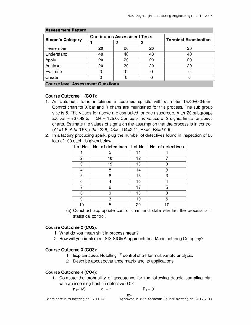
M.E. Degree (Manufacturing Engineering) - 2014-2015
124 Board of studies meeting on 07.11.14 Approved in 49th Academic Council meeting on 04.12.2014
Assessment Pattern
Bloom’s Category Continuous Assessment Tests
Terminal Examination 1 2 3
Remember 20 20 20 20
Understand 40 40 40 40
Apply 20 20 20 20
Analyse 20 20 20 20
Evaluate 0 0 0 0
Create 0 0 0 0
Course level Assessment Questions
Course Outcome 1 (CO1):
1. An automatic lathe machines a specified spindle with diameter 15.00±0.04mm.
Control chart for X bar and R charts are maintained for this process. The sub group
size is 5. The values for above are computed for each subgroup. After 20 subgroups
ΣX bar = 627.48 & ΣR = 125.0. Compute the values of 3 sigma limits for above
charts. Estimate the values of sigma on the assumption that the process is in control.
(A1=1.6, A2= 0.58, d2=2.326, D3=0, D4=2.11, B3=0, B4=2.09).
2. In a factory producing spark, plug the number of defectives found in inspection of 20
lots of 100 each, is given below:
Lot No. No. of defectives Lot No. No. of defectives
1 5 11 4
2 10 12 7
3 12 13 8
4 8 14 3
5 6 15 3
6 4 16 4
7 6 17 5
8 3 18 8
9 3 19 6
10 5 20 10
(a) Construct appropriate control chart and state whether the process is in
statistical control.
Course Outcome 2 (CO2):
1. What do you mean shift in process mean?
2. How will you implement SIX SIGMA approach to a Manufacturing Company?
Course Outcome 3 (CO3):
1. Explain about Hotelling T2 control chart for multivariate analysis.
2. Describe about covariance matrix and its applications
Course Outcome 4 (CO4):
1. Compute the probability of acceptance for the following double sampling plan
with an incoming fraction defective 0.02
n1= 65 c1 = 1 R1 = 3
M.E. Degree (Manufacturing Engineering) - 2014-2015
125 Board of studies meeting on 07.11.14 Approved in 49th Academic Council meeting on 04.12.2014
n2 = 90 c2 = 2 R2 = 3
Also compute ATI, ASN for N = 750.
2. Write the Step by step procedure to construct OC curve for double sampling plan
with an incoming fraction defective 0.02
n1= 65 c1 = 1 R1 = 3
n2 = 90 c2 = 2 R2 = 3 N = 750.
Course Outcome 5 (CO5):
1. There are 3 modules A, B & C in a system. A is a 2 out of 4 system with
component reliability of 0.7. Module B is a 4 out of 7 system with component
reliability of 0.65. And module C is of 5/8 system with component reliability of
0.9. Compute the system reliability if A&B is in series and C is in parallel with
A&B.
2. An optical sensor has followed the Weibull time to failure distribution with
scale parameter of 300 h and shape parameter of 0.6. What is the reliability of
the sensor after 500 h of operation?
3. Consider a system with three components A, B and C in parallel. Determine
the system reliability for 2000 h of operation, and find the mean time to
failure. Assume all the three components have an identical time-to failure
distribution that is exponential, with a constant failure rate of 0.0006 per
hour. What is the mean time failure of each component?
4. A standby system has a basic unit with four standby components. The time
to failure of each component has an exponential distribution with a failure
rate of 0.007 per h. For a 400h operation period, find the reliability of the
standby system.
Course Outcome 6 (CO6):
1. Propose a system configuration in order to improve its reliability with the known
component reliability.
2. A standby system has a basic unit with two standby components. The time to
failure of each component has an exponential distribution with a failure rate of
0.004 per h. For a 600h operation period, compute the reliability of the standby
system. Develop ways to improve the standby system reliability.
Course Outcome 7 (CO7):
1. Discuss about the documentation process in ISO 9001: 2000 system.
2. Discuss about the design and implementation of quality management system for
a higher learning education organization.
Concept Map
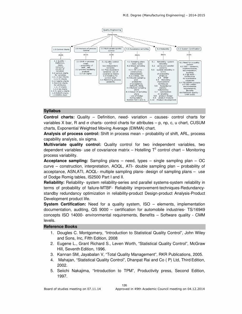
M.E. Degree (Manufacturing Engineering) - 2014-2015
126 Board of studies meeting on 07.11.14 Approved in 49th Academic Council meeting on 04.12.2014
Syllabus
Control charts: Quality – Definition, need- variation – causes- control charts for
variables X bar, R and σ charts- control charts for attributes – p, np, c, u chart, CUSUM
charts, Exponential Weighted Moving Average (EWMA) chart.
Analysis of process control: Shift in process mean – probability of shift, ARL, process
capability analysis, six sigma.
Multivariate quality control: Quality control for two independent variables, two
dependent variables- use of covariance matrix – Hotelling T2 control chart – Monitoring
process variability.
Acceptance sampling: Sampling plans – need, types – single sampling plan – OC
curve – construction, interpretation, AOQL, ATI- double sampling plan – probability of
acceptance, ASN,ATI, AOQL- multiple sampling plans- design of sampling plans – use
of Dodge Romig tables, IS2500 Part I and II.
Reliability: Reliability- system reliability-series and parallel systems-system reliability in
terms of probability of failure-MTBF- Reliability improvement-techniques-Redundancy-
standby redundancy optimization in reliability-product Design-product Analysis-Product
Development product life.
System Certification: Need for a quality system, ISO – elements, implementation
documentation, auditing, QS 9000 – certification for automobile industries- TS/16949
concepts ISO 14000- environmental requirements, Benefits – Software quality - CMM
levels.
Reference Books
1. Dougles C. Montgomery, “Introduction to Statistical Quality Control”, John Wiley
and Sons, Inc, Fifth Edition, 2008
2. Eugene L., Grant Richard S., Leven Worth, “Statistical Quality Control”, McGraw
Hill, Seventh Edition, 1996.
3. Kannan SM, Jayabalan V, “Total Quality Management”, RKR Publications, 2005.
4. Mahajan, “Statistical Quality Control”, Dhanpat Rai and Co ( P) Ltd, Third Edition,
2002.
5. Seiichi Nakajima, “Introduction to TPM”, Productivity press, Second Edition,
1997.

M.E. Degree (Manufacturing Engineering) - 2014-2015
127 Board of studies meeting on 07.11.14 Approved in 49th Academic Council meeting on 04.12.2014
6. Sharma DD, “Total Quality Management”, Sultan Chand and Sons, 2002.
7. Connor, P.D.T.O., "Practical Reliability Engineering ", John Wiley (1993).
8. Green A.E., and Bourne A.J. "Reliability, Technology ", Wiley Inter science, 1991.
Course contents and Lecture Schedule
Module
Number Topics
No. Of
Periods
Control charts
1.1 Quality – Definition, need, variation , causes of Variation 1
1.2 control charts for variables
1.2.1 X Charts 2
1.2.2 R Charts
1.2.3 σ charts 1
1.3 control charts for attributes
1.3.1 P Chart 1
1.3.2 np Chart 1
1.3.3 C and u chart 2
1.4 CUSUM charts
1.5 Exponential Weighted Moving Average (EWMA) chart. 1
2. Analysis of process control
2.1 Shift in process mean – probability of shift , ARL 1
2.2 process capability analysis 2
2.3 six sigma
3 Multivariate quality control
3.1 Quality control for two independent variables 1
3.2 Two dependent variables- use of covariance matrix 1
3.3 Hotelling T2 control chart 1
3.4 Monitoring process variability. 1
4 Acceptance sampling
4.1 Sampling plans – need, types 1
4.2 Single sampling plan 2
4.2.1 OC curve – construction, interpretation
4.2.2 AOQL, ATI
4.3 Double sampling plan - probability of acceptance, ASN,ATI,
AOQL
1
4.4 Multiple sampling plans 1
4.5 Design of sampling plans - use of Dodge Romig tables, IS2500
Part I and II.
2
5 Reliability
5.1 Reliability- system reliability 2
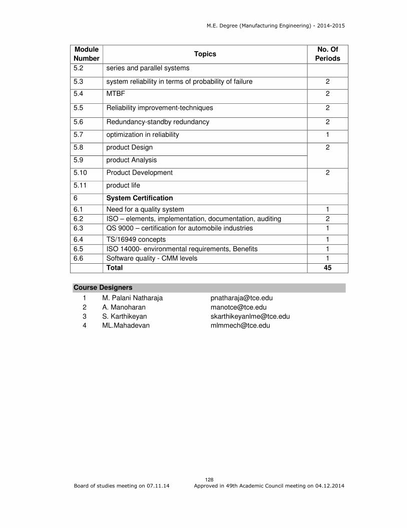
M.E. Degree (Manufacturing Engineering) - 2014-2015
128 Board of studies meeting on 07.11.14 Approved in 49th Academic Council meeting on 04.12.2014
Module
Number Topics
No. Of
Periods
5.2 series and parallel systems
5.3 system reliability in terms of probability of failure 2
5.4 MTBF 2
5.5 Reliability improvement-techniques 2
5.6 Redundancy-standby redundancy 2
5.7 optimization in reliability 1
5.8 product Design 2
5.9 product Analysis
5.10 Product Development 2
5.11 product life
6 System Certification
6.1 Need for a quality system 1
6.2 ISO – elements, implementation, documentation, auditing 2
6.3 QS 9000 – certification for automobile industries 1
6.4 TS/16949 concepts 1
6.5 ISO 14000- environmental requirements, Benefits 1
6.6 Software quality - CMM levels 1
Total 45
Course Designers
1 M. Palani Natharaja [email protected]
2 A. Manoharan [email protected]
3 S. Karthikeyan [email protected]
4 ML.Mahadevan [email protected]

M.E. Degree (Manufacturing Engineering) - 2014-2015
129 Board of studies meeting on 07.11.14 Approved in 49th Academic Council meeting on 04.12.2014
Category L T P Credit
PE 4 0 0 4
Preamble
Financial Management is a science which deals with managing the monetary
transactions in an organization. The field is related with relying on accounting and
enables an engineer in taking useful financial and costing related decisions by providing
scientific tools and techniques.
Prerequisite
Nil
Course outcomes
On the successful completion of the course, students will be able to
CO.No.
Course Outcome Blooms
Level
Expected proficiency
Expected attainment level
CO1 Explain basic concepts of financial management, functions of finance and tools and techniques of finance
Understand 80 70
CO2 Prepare and interpret important financial statements like profit& Loss account ,Balance sheet, Budgets
Apply 70 60
CO3 Compute accurately working capital and fixed capital requirements of the organization
Apply 70 60
CO4 Evaluate appropriate sources of finance
Analyse 60 50
CO5 Evaluate investment decisions Analyse 60 50
CO6 Prepare appropriate capital structure for an organization
Apply 70 60
Mapping with Programme Outcomes
COs PO1 PO2 PO3 PO4 PO5 PO6 PO7 PO8 PO9 PO10 PO11
CO 1 M L
CO 2 S M L L
CO 3 S M L L
CO 4 S S M M
CO 5 S S M M
CO 6 S M L L
S- Strong; M-Medium; L-Low
14MGPN0 FINANCIAL MANAGEMENT
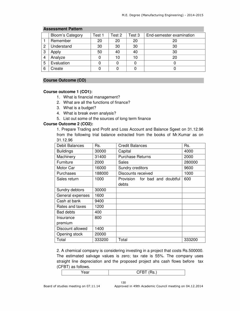
M.E. Degree (Manufacturing Engineering) - 2014-2015
130 Board of studies meeting on 07.11.14 Approved in 49th Academic Council meeting on 04.12.2014
Assessment Pattern
Bloom’s Category Test 1 Test 2 Test 3 End-semester examination
1 Remember 20 20 20 20
2 Understand 30 30 30 30
3 Apply 50 40 40 30
4 Analyze 0 10 10 20
5 Evaluation 0 0 0 0
6 Create 0 0 0 0
Course Outcome (CO)
Course outcome 1 (CO1):
1. What is financial management?
2. What are all the functions of finance?
3. What is a budget?
4. What is break even analysis?
5. List out some of the sources of long term finance
Course Outcome 2 (CO2):
1. Prepare Trading and Profit and Loss Account and Balance Sgeet on 31.12.96
from the following trial balance extracted from the books of Mr.Kumar as on
31.12.96
Debit Balances Rs. Credit Balances Rs.
Buildings 30000 Capital 4000
Machinery 31400 Purchase Returns 2000
Furniture 2000 Sales 280000
Motor Car 16000 Sundry creditors 9600
Purchases 188000 Discounts received 1000
Sales return 1000 Provision for bad and doubtful
debts
600
Sundry debtors 30000
General expenses 1600
Cash at bank 9400
Rates and taxes 1200
Bad debts 400
Insurance
premium
800
Discount allowed 1400
Opening stock 20000
Total 333200 Total 333200
2. A chemical company is considering investing in a project that costs Rs.500000.
The estimated salvage values is zero; tax rate is 55%. The company uses
straight line depreciation and the proposed project ahs cash flows before tax
(CFBT) as follows.
Year CFBT (Rs.)
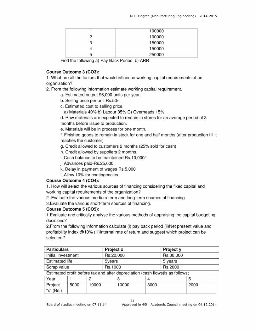
M.E. Degree (Manufacturing Engineering) - 2014-2015
131 Board of studies meeting on 07.11.14 Approved in 49th Academic Council meeting on 04.12.2014
1 100000
2 100000
3 150000
4 150000
5 250000
Find the following a) Pay Back Period b) ARR
Course Outcome 3 (CO3):
1. What are all the factors that would influence working capital requirements of an
organization?
2. From the following information estimate working capital requirement.
a. Estimated output 96,000 units per year.
b. Selling price per unit Rs.50/-
c. Estimated cost to selling price.
a) Materials 40% b) Labour 35% C) Overheads 15%
d. Raw materials are expected to remain in stores for an average period of 3
months before issue to production.
e. Materials will be in process for one month.
f. Finished goods to remain in stock for one and half months (after production till it
reaches the customer)
g. Credit allowed to customers 2 months (25% sold for cash)
h. Credit allowed by suppliers 2 months.
i. Cash balance to be maintained Rs.10,000/-
j. Advances paid-Rs.25,000.
k. Delay in payment of wages Rs.5,000
l. Allow 10% for contingencies.
Course Outcome 4 (CO4):
1. How will select the various sources of financing considering the fixed capital and
working capital requirements of the organization?
2. Evaluate the various medium-term and long-term sources of financing.
3.Evaluate the various short-term sources of financing.
Course Outcome 5 (CO5):
1.Evaluate and critically analyse the various methods of appraising the capital budgeting
decisions?
2.From the following information calculate (i) pay back period (ii)Net present value and
profitability index @10% (iii)Internal rate of return and suggest which project can be
selected?
Particulars Project x Project y
Initial investment Rs.20,000 Rs.30,000
Estimated life 5years 5 years
Scrap value Rs.1000 Rs.2000
Estimated profit before tax and after depreciation (cash flows)is as follows;
Year 1 2 3 4 5
Project
“x” (Rs.)
5000 10000 10000 3000 2000

M.E. Degree (Manufacturing Engineering) - 2014-2015
132 Board of studies meeting on 07.11.14 Approved in 49th Academic Council meeting on 04.12.2014
Project
“y” (Rs.)
20,000 10,000 5,000 3,000 2,000
Course Outcome 6 (CO6):
1. Devise a suitable capital structure for an organization which relies more on debt
capital and less on equity capital.
2. The management of Samata Company, subscribing to the net operating income
approach, believes that its cost of debt and overall cost of capital will remain at 8 per
cent and 12 per cent, respectively. If the equity shareholders of the firm demand a return
of 20 per cent, what should be the proportions of debt and equity in the firm’s capital
structure? Assume that there are no taxes.
Concept Map
Syllabus
Financial Management- An Overview - Indian Financial System - Financial Analysis and
Planning - Financial Statements - Balance Sheet - Income Statement
Financial Statement Analysis - Types of Financial ratios - Predictive power of financial
ratios-Funds Flow Analysis - Fund flow statement- Total resources basis - Working
capital basis- cash basis- Leverage - Operating Financial and Total cost .
Financial Planning and Implementation
ABC analysis, Cost volume profit Analysis - Budgeting - Financial Forecasting-Working
Capital Management - Factors influencing working capital requirements - Working capital
policy- Cash Management -Cash budgeting - Long term cash forecasting- Receivables
Management - Credit policy variables- Credit evaluation- Control of receivables.
Investment decisions -Capital Budgeting –Pay Back Period Method, Average Rate of
Return, Internal Rate of Return, Profitability Index- Appraisal criteria - Risk Analysis of -
Selection of a Project -Cost of Capital.
Financing Decisions -Long Term Financing - Sources of long term finance - Primary
market for long term securities - Public issue - Rights issue- Private placement- Stock
market - Function of the stock market - Regulation -Financial Institutions.
Capital Structure - Theory - Various approaches - Planning the capital structure -

M.E. Degree (Manufacturing Engineering) - 2014-2015
133 Board of studies meeting on 07.11.14 Approved in 49th Academic Council meeting on 04.12.2014
Dividend policy and share valuation - Dividend policy models - Practical Aspects - Legal
and procedural aspects.
Reference Books
1. Prasanna Chandra, “Fundamentals of Financial Management”, Tata McGraw Hill,
2008
2. KY. Khan and P.K. Jain, “ Financial Management”, Tata McGraw Hill, 2007
3. Khan and Jain, “ Theory and Problems of Financial Management”, Tata Mc Graw Hill
Publishing Co, 1999
4. Pandey, “Financial Management”, Vikas Publishing House Pvt. Ltd., 2007
Course Contents and Lecture schedule
Module
Number Topics
No. of
Lectures
1.0 Basic Aspects of Financial Management
1.1 Financial Management Overview 2
1.2 Indian Financial System 2
1.3 Financial Analysis and Planning 2
2.0 Financial Statement Analysis
2.1 Financial Statements 2
2.2 Ratio Analysis 2
2.3 Fund Flow Analysis 2
2.4 Leverage Operating Financial and Total Cost 2
3.0 Financial Planning and Implementation
3.1 ABC analysis, Cost Volume Profit Analysis 2
3.2 Budgeting 2
3.3 Working capital Management 2
3.4 Cash Budgeting 2
3.5 Receivables Management 2
4.0 Investment Decisions
4.1 Capital Budgeting 2
4.2 Pay Back Period Method 2
4.3 Average Rate of Return 1
4.4 Interest Rate of Return 2
4.5 Profitability Index 1
4.6 Risk Analysis 2
4.7 Cost of Capital 2
5.0 Financing Decisions
5.1 Long Term Financing 1
5.2 Stock Market 1
5.3 Financial Institutions 2
5.4 Capital Structure 3
5.5 Dividend Policy Models 2
5.6 Various Aspects of Dividend Policy 2
Total 46

M.E. Degree (Manufacturing Engineering) - 2014-2015
134 Board of studies meeting on 07.11.14 Approved in 49th Academic Council meeting on 04.12.2014
Course Designers with E-Mail ID
1. Dr. S. Muralidharan [email protected]
2. Dr. S.Dhanasekaran [email protected]
3. Dr. R. Muruganandham [email protected]

M.E. Degree (Manufacturing Engineering) - 2014-2015
135 Board of studies meeting on 07.11.14 Approved in 49th Academic Council meeting on 04.12.2014
Category L T P Credit
PE 4 0 0 4
Preamble:
Operation Management (OM) is the process of managing people and resources in order
to create a product or a service. OM has been the key element in the improvement in
the productivity around the world. The major concerns of operations management study
are Strategies, Process analysis, Facility Location and Layout Planning, Forecasting,
Aggregate Sales and Operations Planning, Inventory Management, Materials
Requirement Planning (MRP), Operations Scheduling ,Just –In-Time and Lean Systems.
The goal is to create a competitive advantage for industrial and production engineering
students of post graduate level by conveying a set of skills and tools that they can apply
in their profession.
Prerequisite
Knowledge on Mathematics and Operation Research
Course Outcomes
On the successful completion of the course, students will be able to
CO.No.
Course Outcome Blooms
Level
Expected
Proficiency
Expected
attainment
level
CO1 CO 1: Explain strategies for operations, aggregate planning, forecasting, inventory, MRP and scheduling, and Concept of JIT and Lean manufacturing.
Understand 80 70
CO2 CO2: Select suitable aggregate plan, forecast model, and inventory model, MRP schedules and lot sizing methods
Analyse 60 50
CO3 CO3: Draw process flow chart and determine process performance and productivity measures
Apply 70 60
CO4 CO4: Compute forecast, order quantity, and safety stock levels
Apply 70 60
CO5 CO5: Criticize suitable facility location and layout plan
Analyse 60 50
CO6 CO6: Compute optimal sequence and Schedule the jobs in single machine, flow shop and job shop environments
Apply 70 60
Mapping with Programme Outcomes
COs PO1 PO2 PO3 PO4 PO5 PO6 PO7 PO8 PO9 PO10 PO11
CO 1. M L
14MGPP0 OPERATIONS MANAGEMENT
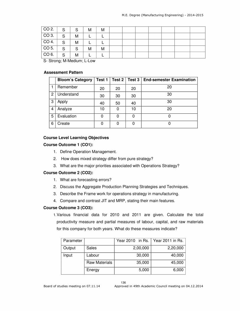
M.E. Degree (Manufacturing Engineering) - 2014-2015
136 Board of studies meeting on 07.11.14 Approved in 49th Academic Council meeting on 04.12.2014
CO 2. S S M M
CO 3. S M L L
CO 4. S M L L
CO 5. S S M M
CO 6. S M L L
S- Strong; M-Medium; L-Low
Assessment Pattern
Bloom’s Category Test 1 Test 2 Test 3 End-semester Examination
1 Remember 20 20 20 20
2 Understand 30 30 30 30
3 Apply 40 50 40 30
4 Analyze 10 0 10 20
5 Evaluation 0 0 0 0
6 Create 0 0 0 0
Course Level Learning Objectives
Course Outcome 1 (CO1):
1. Define Operation Management.
2. How does mixed strategy differ from pure strategy?
3. What are the major priorities associated with Operations Strategy?
Course Outcome 2 (CO2):
1. What are forecasting errors?
2. Discuss the Aggregate Production Planning Strategies and Techniques.
3. Describe the Frame work for operations strategy in manufacturing.
4. Compare and contrast JIT and MRP, stating their main features.
Course Outcome 3 (CO3):
1. Various financial data for 2010 and 2011 are given. Calculate the total
productivity measure and partial measures of labour, capital, and raw materials
for this company for both years. What do these measures indicate?
Parameter Year 2010 in Rs. Year 2011 in Rs.
Output Sales 2,00,000 2,20,000
Input Labour 30,000 40,000
Raw Materials 35,000 45,000
Energy 5,000 6,000

M.E. Degree (Manufacturing Engineering) - 2014-2015
137 Board of studies meeting on 07.11.14 Approved in 49th Academic Council meeting on 04.12.2014
Capital 50,000 50,000
Other 2,000 3,000
2. Consider the construction of a simple 8” X 10” wood picture frame. The picture
frame consists of four wood pieces that are cut from the wood molding, four
staples to hold the frame together, a piece of glass, a backing board made of
cardboard, six points to hold the glass and backing board to the frame, and a clip
for hanging the picture frame from the wall.
i) Construct an assembly chart for the picture frame.
ii) Construct a flow process chart for the entire process from receiving materials to
final inspection.
3. Draw the process flow chart for an example product of industrial importance.
Course Outcome 4 (CO4):
1. Historical demand for a product is:
Month Demand
January 12
February 11
March 15
April 12
May 16
June 15
a. Using weighted moving average with weights of 0.60, 0.30, and 0.10, find the
July forecast.
b. Using a simple three-month moving average, find the July forecast.
c. Using single exponential smoothing with a = 0.2 and a June forecast = 13, find
the July forecast. Make whatever assumptions you wish.
Using simple linear regression analysis, calculate the regression equation for the
preceding demand data.
2. Tucson Machinery, Inc., manufactures numerically controlled machines, which
sell for an average price of $0.5 million each. Sales for these NCMs for the past
two years were as follows:
Quarter Quantity
(Units) Quarter
Quantity
(Units)
2005 2006
I 12 I 16

M.E. Degree (Manufacturing Engineering) - 2014-2015
138 Board of studies meeting on 07.11.14 Approved in 49th Academic Council meeting on 04.12.2014
II 18 II 24
III 26 III 28
IV 16 IV 18
(a) Hand fit a line.
(b) Find the trend and seasonal factors
(c) Forecast sales for 2007.
3. Give the following information, analyse and suggest suitable inventory management
system by answering the following questions. The item is demanded 50 weeks a
year.
Item cost
Order cost
Annual holding
cost (%)
Annual demand
Average demand
$10.00
$25.00
33% of item cost
25,750
515 per week
Standard deviation of weekly
demand
Lead time
Service level
25 per week
1 week
95%
i) State the order quantity and recorder point.
ii) Determine the annual holding and order costs.
iii) How many units per order cycle would you expect to the short?
iv) It a price break of $50 per order was offered for purchase quantities of over
2,000, would you take advantage of it? How much would you save on an annual
basis?
Course Outcome 5 (CO5):
1. A new plant to be established will receive raw material from three suppliers P, Q,
and R and supply finished products to three warehouses U, V, and W. The sources
of raw material and the destination points may be considered as the existing
facilities. The coordinates of the existing facilities and the amount of material
movement between the existing facilities and the new facility are as follows:
Serial No. Existing
facility
Coordinates Material movement to and from
new facility wi X Y
1 P 300 300 400
2 Q 350 500 600
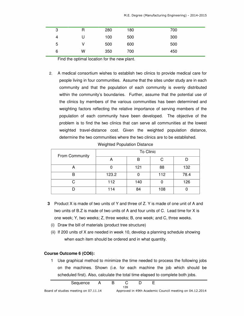
M.E. Degree (Manufacturing Engineering) - 2014-2015
139 Board of studies meeting on 07.11.14 Approved in 49th Academic Council meeting on 04.12.2014
3 R 280 180 700
4 U 100 500 300
5 V 500 600 500
6 W 350 700 450
Find the optimal location for the new plant.
2. A medical consortium wishes to establish two clinics to provide medical care for
people living in four communities. Assume that the sites under study are in each
community and that the population of each community is evenly distributed
within the community’s boundaries. Further, assume that the potential use of
the clinics by members of the various communities has been determined and
weighting factors reflecting the relative importance of serving members of the
population of each community have been developed. The objective of the
problem is to find the two clinics that can serve all communities at the lowest
weighted travel-distance cost. Given the weighted population distance,
determine the two communities where the two clinics are to be established.
Weighted Population Distance
From Community To Clinic
A B C D
A 0 121 88 132
B 123.2 0 112 78.4
C 112 140 0 126
D 114 84 108 0
3 Product X is made of two units of Y and three of Z. Y is made of one unit of A and
two units of B.Z is made of two units of A and four units of C. Lead time for X is
one week; Y, two weeks; Z, three weeks; B, one week; and C, three weeks.
(i) Draw the bill of materials (product tree structure)
(ii) If 200 units of X are needed in week 10, develop a planning schedule showing
when each item should be ordered and in what quantity.
Course Outcome 6 (CO6):
1 Use graphical method to minimize the time needed to process the following jobs
on the machines. Shown (i.e. for each machine the job which should be
scheduled first). Also, calculate the total time elapsed to complete both jobs.
Sequence A B C D E

M.E. Degree (Manufacturing Engineering) - 2014-2015
140 Board of studies meeting on 07.11.14 Approved in 49th Academic Council meeting on 04.12.2014
Job 1 Time (Hrs) 2 6 5 4 7
Sequence C B D A E
Job 2 Time (Hrs) 6 5 7 4 8
2 Consider the following 3 machines and 5 jobs flow shop problem. Check whether
Johnson’s rule can be extended to this problem. If so, what is the optimal
schedule and corresponding make span?
3. Consider the
following single
machine scheduling problem with weights.
Job 1 2 3 4 5
Processing time 15 4 5 14 8
Weights 1 2 1 2 3
Determine the sequence which will minimize the weighted mean flow time of the
problem.
Concept Map
Job Machine
1
Machine
2
Machine
3
1 11 10 12
2 13 8 20
3 15 6 15
4 12 7 19
5 20 9 7
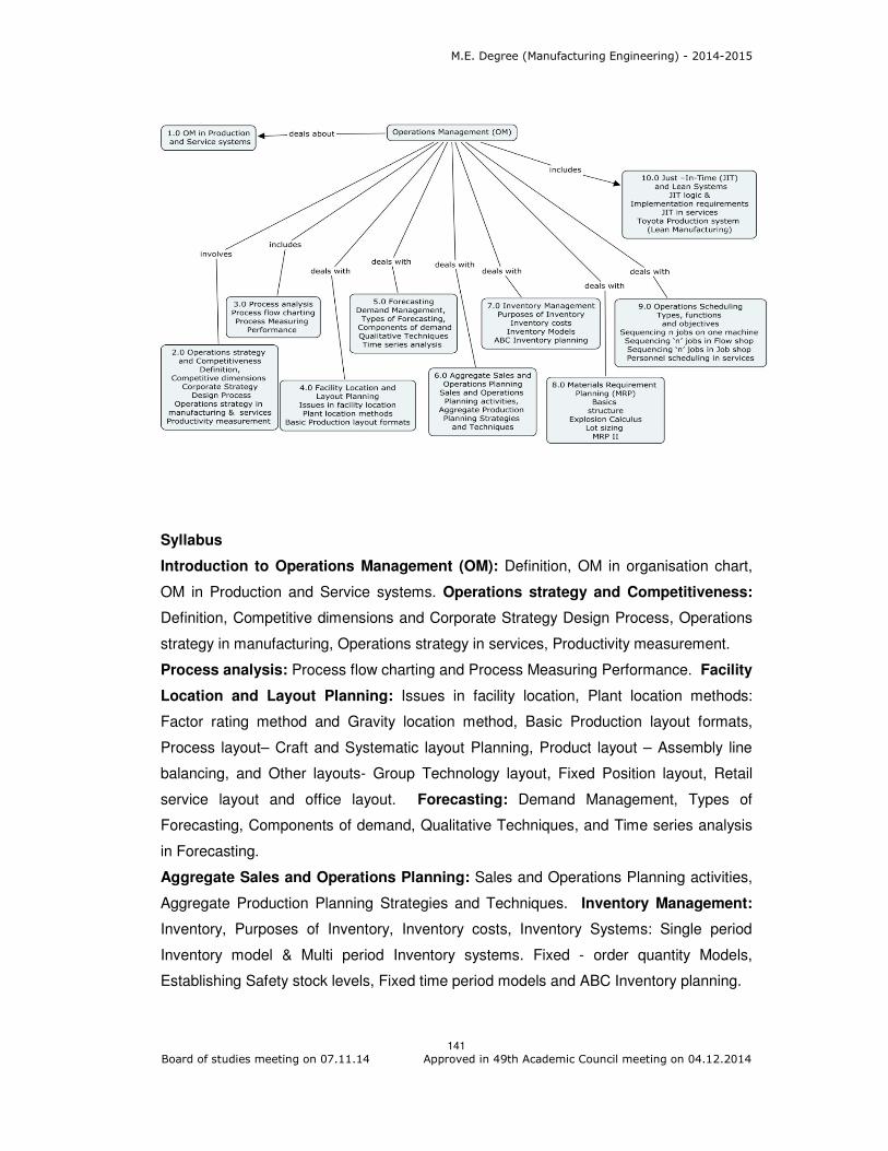
M.E. Degree (Manufacturing Engineering) - 2014-2015
141 Board of studies meeting on 07.11.14 Approved in 49th Academic Council meeting on 04.12.2014
Syllabus
Introduction to Operations Management (OM): Definition, OM in organisation chart,
OM in Production and Service systems. Operations strategy and Competitiveness:
Definition, Competitive dimensions and Corporate Strategy Design Process, Operations
strategy in manufacturing, Operations strategy in services, Productivity measurement.
Process analysis: Process flow charting and Process Measuring Performance. Facility
Location and Layout Planning: Issues in facility location, Plant location methods:
Factor rating method and Gravity location method, Basic Production layout formats,
Process layout– Craft and Systematic layout Planning, Product layout – Assembly line
balancing, and Other layouts- Group Technology layout, Fixed Position layout, Retail
service layout and office layout. Forecasting: Demand Management, Types of
Forecasting, Components of demand, Qualitative Techniques, and Time series analysis
in Forecasting.
Aggregate Sales and Operations Planning: Sales and Operations Planning activities,
Aggregate Production Planning Strategies and Techniques. Inventory Management:
Inventory, Purposes of Inventory, Inventory costs, Inventory Systems: Single period
Inventory model & Multi period Inventory systems. Fixed - order quantity Models,
Establishing Safety stock levels, Fixed time period models and ABC Inventory planning.

M.E. Degree (Manufacturing Engineering) - 2014-2015
142 Board of studies meeting on 07.11.14 Approved in 49th Academic Council meeting on 04.12.2014
Materials Requirement Planning (MRP): MRP basics & MRP system structure,
Explosion Calculus, Lot sizing in MRP systems: Lot-for-Lot, Economic Order Quantity,
Silver Meal Heuristics, and Least Unit Cost. MRP II. Operations Scheduling:
Scheduling – Types, functions and objectives, Sequencing n jobs on one machine –
Schedule using Priority dispatch rules (FCFS, SPT,EDD, LCFS, and Critical Ratio).
Sequencing ‘n’ jobs in Flow shop – Johnson, CDS and Palmer Algorithms. Sequencing
‘n’ jobs in Job shop – Two jobs on M machines, Gantt chart. Personnel scheduling in
services. Just –In-Time (JIT) and Lean Systems: JIT logic, Toyota Production system
(Lean Manufacturing), JIT Implementation requirements and JIT in services.
Reference Books
1. Chase, Jacobs, Aquilano, “Production and Operations Management”, Tenth
Edition, Irwin McGraw Hill Companies Inc., 2004.
2. Everette. Adam. Jr.Ronald J.Ebert, “Production and Operations Management”,
Eight Indian Reprinting, PHI 1997.
3. Steven Nahmias, “Production and Operations Analysis”, Third Edition, Irwin
McGraw Hill Companies Inc., 1997.
4. Paneer Selvam.R, “Production and Operations Management”, Third Edition,
Prentice-hall of India, 2012.
5. Mahabatra, “Computer Aided Production Management”, Prentice-hall Of India
Pvt.ltd, 2004.
6. Chary, “Theory and Problems in Production and Operations Management”,
Second reprint, Tata McGraw Hill, 1996
7. Seetharama L.Narasimhan, Dennis W.McLeavy, Peter.J.Billington, “Production
Planning and Inventory Control”, PHI, 1997.
Course Contents and Lecture schedule
Module Number
Topics No. of
Lectures
1.0 Introduction to Operations Management (OM)
1.1 Definition, OM in organisation chart 2
1.2 OM in Production and Service systems
2.0 Operations strategy and Competitiveness:
2.1 Definition, Competitive dimensions and Corporate
Strategy Design Process
1
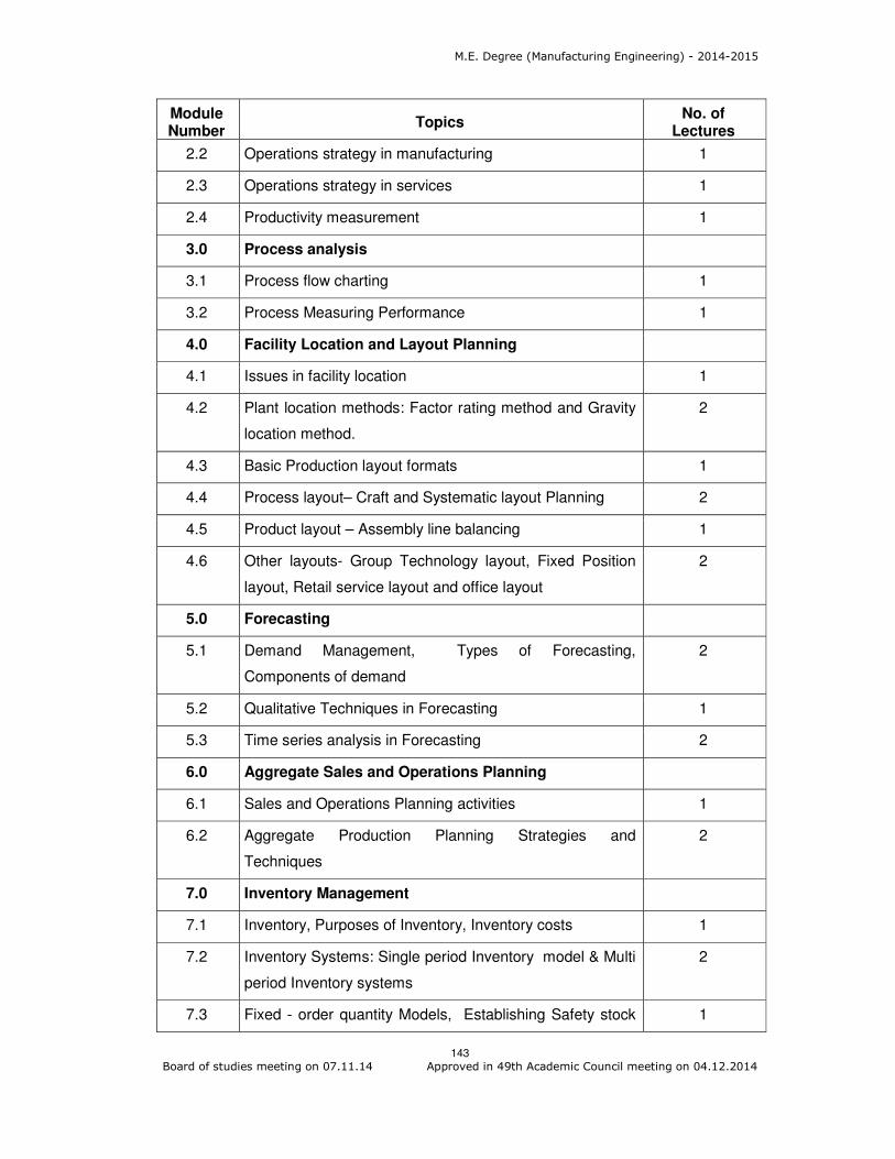
M.E. Degree (Manufacturing Engineering) - 2014-2015
143 Board of studies meeting on 07.11.14 Approved in 49th Academic Council meeting on 04.12.2014
Module Number
Topics No. of
Lectures
2.2 Operations strategy in manufacturing 1
2.3 Operations strategy in services 1
2.4 Productivity measurement 1
3.0 Process analysis
3.1 Process flow charting 1
3.2 Process Measuring Performance 1
4.0 Facility Location and Layout Planning
4.1 Issues in facility location 1
4.2 Plant location methods: Factor rating method and Gravity
location method.
2
4.3 Basic Production layout formats 1
4.4 Process layout– Craft and Systematic layout Planning 2
4.5 Product layout – Assembly line balancing 1
4.6 Other layouts- Group Technology layout, Fixed Position
layout, Retail service layout and office layout
2
5.0 Forecasting
5.1 Demand Management, Types of Forecasting,
Components of demand
2
5.2 Qualitative Techniques in Forecasting 1
5.3 Time series analysis in Forecasting 2
6.0 Aggregate Sales and Operations Planning
6.1 Sales and Operations Planning activities 1
6.2 Aggregate Production Planning Strategies and
Techniques
2
7.0 Inventory Management
7.1 Inventory, Purposes of Inventory, Inventory costs 1
7.2 Inventory Systems: Single period Inventory model & Multi
period Inventory systems
2
7.3 Fixed - order quantity Models, Establishing Safety stock 1
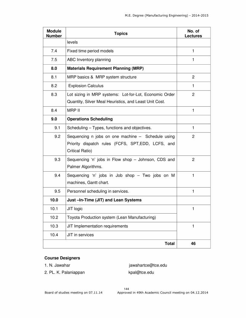
M.E. Degree (Manufacturing Engineering) - 2014-2015
144 Board of studies meeting on 07.11.14 Approved in 49th Academic Council meeting on 04.12.2014
Module Number
Topics No. of
Lectures
levels
7.4 Fixed time period models 1
7.5 ABC Inventory planning 1
8.0 Materials Requirement Planning (MRP)
8.1 MRP basics & MRP system structure 2
8.2 Explosion Calculus 1
8.3 Lot sizing in MRP systems: Lot-for-Lot, Economic Order
Quantity, Silver Meal Heuristics, and Least Unit Cost.
2
8.4 MRP II 1
9.0 Operations Scheduling
9.1 Scheduling – Types, functions and objectives. 1
9.2 Sequencing n jobs on one machine – Schedule using
Priority dispatch rules (FCFS, SPT,EDD, LCFS, and
Critical Ratio)
2
9.3 Sequencing ‘n’ jobs in Flow shop – Johnson, CDS and
Palmer Algorithms.
2
9.4 Sequencing ‘n’ jobs in Job shop – Two jobs on M
machines, Gantt chart.
1
9.5 Personnel scheduling in services. 1
10.0 Just –In-Time (JIT) and Lean Systems
10.1 JIT logic 1
10.2 Toyota Production system (Lean Manufacturing)
10.3 JIT Implementation requirements 1
10.4 JIT in services
Total 46
Course Designers
1. N. Jawahar [email protected]
2. PL. K. Palaniappan [email protected]

M.E. Degree (Manufacturing Engineering) - 2014-2015
145 Board of studies meeting on 07.11.14 Approved in 49th Academic Council meeting on 04.12.2014
Category L T P Credit
PE 4 0 0 4
Preamble Supply Chain Management (SCM) is the management of a network of interconnected businesses in the ultimate provision of product and service packages required by end customers. Supply chain management spans all movement and storage of raw materials, work-in-process inventory, and finished goods from point of origin to point of consumption. Organizations increasingly find that they must rely on effective Supply Chain, or networks, to compete in the global market and networked economy. Concept of business relationships extends beyond traditional enterprise boundaries and seeks to organize entire business processes throughout a value chain of multiple components. During the past decades, globalization, outsourcing and information technology have enabled to successfully operate solid collaborative supply networks in which each specialized business partner focuses on only a few key strategic activities. This inter-organizational supply network can be acknowledged as a new form of organization. Prerequisite
Knowledge on Mathematics
Course Outcomes
On the successful completion of the course, students will be able to
CO.No.
Course Outcome Blooms
Level
Expected
Proficiency
Expected
attainment
level
CO1 Explain issues important in the design of the logistics network, inventory management and risk pooling
Understand 80 70
CO2 Explain the value of information, Distribution strategies, and strategic alliances
Understand 80 70
CO3 Explain the International Supply Chain Management, supplier integration, customer value and Information Technology
Understand 80 70
CO4 Calculate the distribution cost, bullwhip effect, order quantity, and safety stock levels
Apply 70 60
CO5 Demonstrate case studies about distribution strategies, strategic alliances, and coordinated product design
Apply 70 60
CO6 Show ways of improving customer value, supplier integration, mass customization and integrating SC and IT
Apply 70 60
14MGPR0 SUPPLY CHAIN MANAGEMENT

M.E. Degree (Manufacturing Engineering) - 2014-2015
146 Board of studies meeting on 07.11.14 Approved in 49th Academic Council meeting on 04.12.2014
Mapping with Programme Outcomes
COs PO1 PO2 PO3 PO4 PO5 PO6 PO7 PO8 PO9 PO10 PO11
CO 1. M L
CO 2. M L
CO 3. M L
CO 4. S M L L
CO 5. S M L L
CO 6. S M L L
S- Strong; M-Medium; L-Low Assessment Pattern
Bloom’s Category Test 1 Test 2 Test 3 End-semester examination
1 Remember 20 20 20 20 2 Understand 40 40 40 40 3 Apply 40 40 40 40 4 Analyze 0 0 0 0 5 Evaluation 0 0 0 0 6 Create 0 0 0 0
Course Level Learning Objectives
Course Outcome 1 (CO1):
1. Define SCM.
2. Give the issues important in the design of the logistics network.
3. Explain the key requirements and features of any decision-support system for
network design.
Course Outcome 2 (CO2):
1. Explain the three distinct outbound distribution strategies.
2. Describe various types of Retailer-Supplier Partnerships?
3. Explain the factors that are to be considered to determine whether a particular
strategic alliance is appropriate or not.
Course Outcome 3 (CO3):
1. Why SC integration is difficult? Explain.
2. What is Electronic Commerce?
3. Explain the requirements for global strategy implementation.
Course Outcome 4 (CO4):
1. Consider a manufacturer shipping a single fully loaded truck form Chennai to Indore.
The manufacturer is using a TL carrier whose rate is Rs16.00 per mile per truck load.
Calculate the transportation cost for this shipment. The longitude and latitude of
Chennai is 13° 04' and 80° 17' and longitude and latitude of Indore is 22º43' and
75º49'.
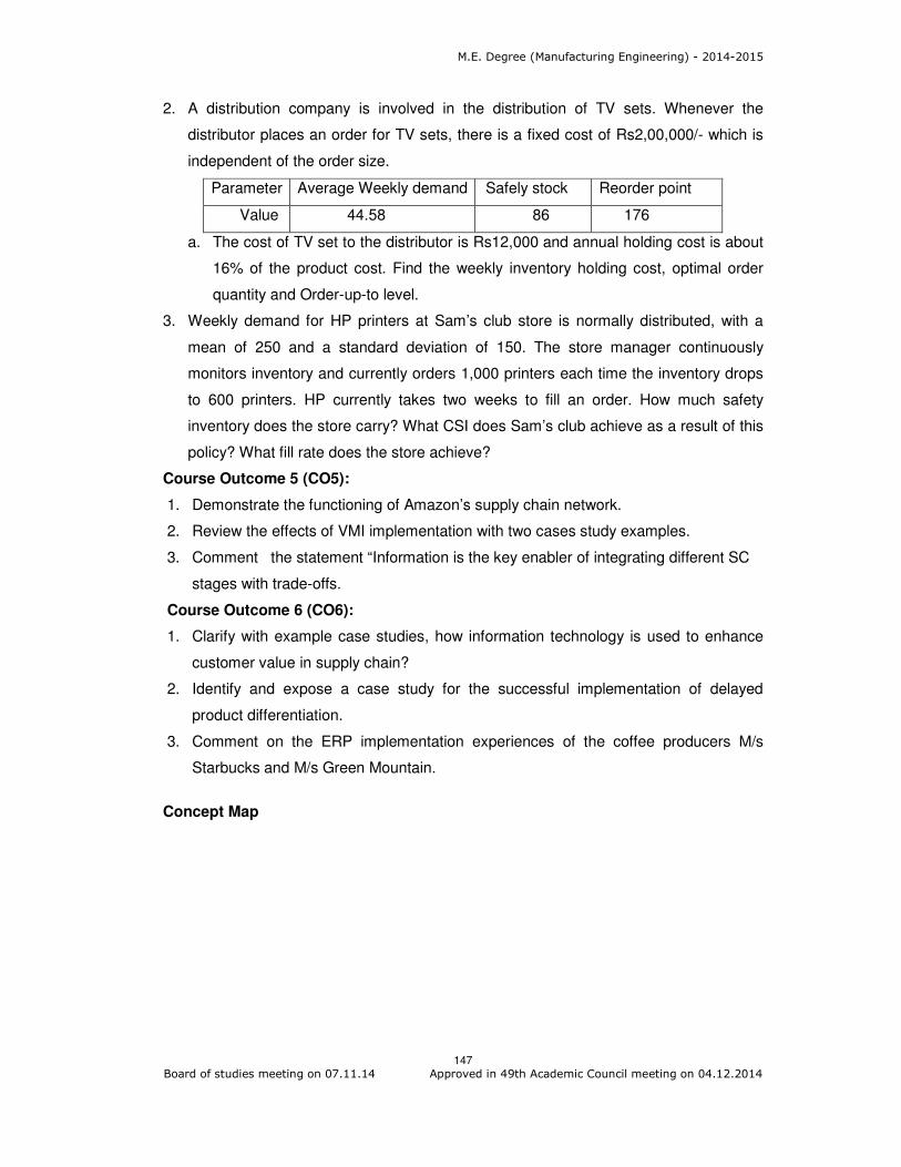
M.E. Degree (Manufacturing Engineering) - 2014-2015
147 Board of studies meeting on 07.11.14 Approved in 49th Academic Council meeting on 04.12.2014
2. A distribution company is involved in the distribution of TV sets. Whenever the
distributor places an order for TV sets, there is a fixed cost of Rs2,00,000/- which is
independent of the order size.
Parameter Average Weekly demand Safely stock Reorder point
Value 44.58 86 176
a. The cost of TV set to the distributor is Rs12,000 and annual holding cost is about
16% of the product cost. Find the weekly inventory holding cost, optimal order
quantity and Order-up-to level.
3. Weekly demand for HP printers at Sam’s club store is normally distributed, with a
mean of 250 and a standard deviation of 150. The store manager continuously
monitors inventory and currently orders 1,000 printers each time the inventory drops
to 600 printers. HP currently takes two weeks to fill an order. How much safety
inventory does the store carry? What CSI does Sam’s club achieve as a result of this
policy? What fill rate does the store achieve?
Course Outcome 5 (CO5):
1. Demonstrate the functioning of Amazon’s supply chain network.
2. Review the effects of VMI implementation with two cases study examples.
3. Comment the statement “Information is the key enabler of integrating different SC
stages with trade-offs.
Course Outcome 6 (CO6):
1. Clarify with example case studies, how information technology is used to enhance
customer value in supply chain?
2. Identify and expose a case study for the successful implementation of delayed
product differentiation.
3. Comment on the ERP implementation experiences of the coffee producers M/s
Starbucks and M/s Green Mountain.
Concept Map
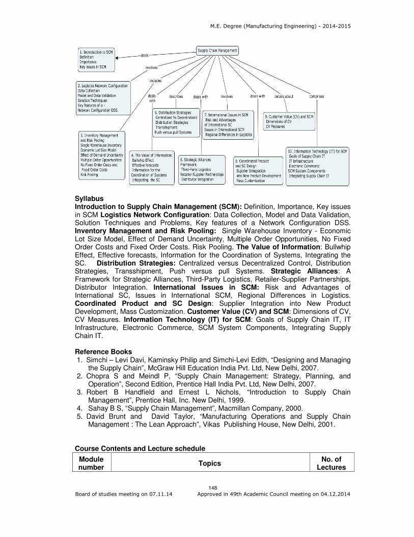
M.E. Degree (Manufacturing Engineering) - 2014-2015
148 Board of studies meeting on 07.11.14 Approved in 49th Academic Council meeting on 04.12.2014
Syllabus Introduction to Supply Chain Management (SCM): Definition, Importance, Key issues in SCM Logistics Network Configuration: Data Collection, Model and Data Validation, Solution Techniques and Problems, Key features of a Network Configuration DSS. Inventory Management and Risk Pooling: Single Warehouse Inventory - Economic Lot Size Model, Effect of Demand Uncertainty, Multiple Order Opportunities, No Fixed Order Costs and Fixed Order Costs. Risk Pooling. The Value of Information: Bullwhip Effect, Effective forecasts, Information for the Coordination of Systems, Integrating the SC. Distribution Strategies: Centralized versus Decentralized Control, Distribution Strategies, Transshipment, Push versus pull Systems. Strategic Alliances: A Framework for Strategic Alliances, Third-Party Logistics, Retailer-Supplier Partnerships, Distributor Integration. International Issues in SCM: Risk and Advantages of International SC, Issues in International SCM, Regional Differences in Logistics. Coordinated Product and SC Design: Supplier Integration into New Product Development, Mass Customization. Customer Value (CV) and SCM: Dimensions of CV, CV Measures. Information Technology (IT) for SCM: Goals of Supply Chain IT, IT Infrastructure, Electronic Commerce, SCM System Components, Integrating Supply Chain IT. Reference Books 1. Simchi – Levi Davi, Kaminsky Philip and Simchi-Levi Edith, “Designing and Managing
the Supply Chain”, McGraw Hill Education India Pvt. Ltd, New Delhi, 2007. 2. Chopra S and Meindl P, “Supply Chain Management: Strategy, Planning, and
Operation”, Second Edition, Prentice Hall India Pvt. Ltd, New Delhi, 2007. 3. Robert B Handfield and Ernest L Nichols, “Introduction to Supply Chain
Management”, Prentice Hall, Inc. New Delhi, 1999. 4. Sahay B S, “Supply Chain Management”, Macmillan Company, 2000. 5. David Brunt and David Taylor, “Manufacturing Operations and Supply Chain
Management : The Lean Approach”, Vikas Publishing House, New Delhi, 2001. Course Contents and Lecture schedule
Module number
Topics No. of
Lectures

M.E. Degree (Manufacturing Engineering) - 2014-2015
149 Board of studies meeting on 07.11.14 Approved in 49th Academic Council meeting on 04.12.2014
Module number
Topics No. of
Lectures
1.0 Introduction to Supply Chain Management (SCM)
1.1 Definition, Importance
1
1.2 Key issues in SCM 2
2.0 Logistics Network Configuration
2.1 Data Collection, Model and Data Validation 2
2.2 Solution Techniques and Problems 2
2.3 Key features of a Network Configuration DSS 1
3.0 Inventory Management and Risk Pooling
3.1 Single Warehouse Inventory - Economic Lot Size Model 2
3.2 Effect of Demand Uncertainty, Multiple Order Opportunities, No Fixed Order Costs and Fixed Order Costs.
2
3.3 Risk Pooling 1
4.0 The Value of Information
4.1
Bullwhip Effect
1
4.2 Effective forecasts 1
4.3 Information for the Coordination of Systems 1
4.4 Integrating the Supply Chain 2
5.0 Distribution Strategies
5.1 Centralized versus Decentralized Control 1
5.2 Distribution Strategies, Transshipment 2
5.3 Push versus pull Systems 1
6.0 Strategic Alliances
6.1 Framework for Strategic Alliances 2
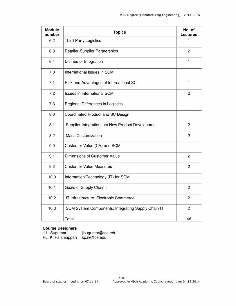
M.E. Degree (Manufacturing Engineering) - 2014-2015
150 Board of studies meeting on 07.11.14 Approved in 49th Academic Council meeting on 04.12.2014
Module number
Topics No. of
Lectures
6.2 Third-Party Logistics 1
6.3 Retailer-Supplier Partnerships 2
6.4 Distributor Integration 1
7.0 International Issues in SCM
7.1 Risk and Advantages of International SC 1
7.2 Issues in International SCM 2
7.3 Regional Differences in Logistics 1
8.0 Coordinated Product and SC Design
8.1 Supplier Integration into New Product Development 2
8.2 Mass Customization 2
9.0 Customer Value (CV) and SCM
9.1 Dimensions of Customer Value 2
9.2 Customer Value Measures 2
10.0 Information Technology (IT) for SCM
10.1 Goals of Supply Chain IT 2
10.2 IT Infrastructure, Electronic Commerce 2
10.3 SCM System Components, Integrating Supply Chain IT 2
Total 46 Course Designers J.L. Sugumar [email protected] PL. K. Palaniappan [email protected]
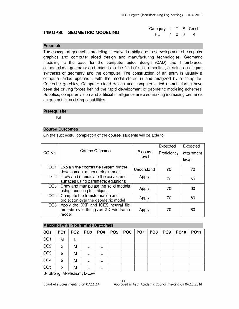
M.E. Degree (Manufacturing Engineering) - 2014-2015
151 Board of studies meeting on 07.11.14 Approved in 49th Academic Council meeting on 04.12.2014
Category L T P Credit
PE 4 0 0 4
Preamble
The concept of geometric modeling is evolved rapidly due the development of computer
graphics and computer aided design and manufacturing technologies. Geometric
modeling is the base for the computer aided design (CAD) and it embraces
computational geometry and extends to the field of solid modeling, creating an elegant
synthesis of geometry and the computer. The construction of an entity is usually a
computer aided operation, with the model stored in and analyzed by a computer.
Computer graphics, Computer aided design and computer aided manufacturing have
been the driving forces behind the rapid development of geometric modeling schemes.
Robotics, computer vision and artificial intelligence are also making increasing demands
on geometric modeling capabilities.
Prerequisite
Nil
Course Outcomes
On the successful completion of the course, students will be able to
CO.No.
Course Outcome Blooms
Level
Expected
Proficiency
Expected
attainment
level
CO1 Explain the coordinate system for the development of geometric models
Understand 80 70
CO2 Draw and manipulate the curves and surfaces using parametric equations
Apply
70 60
CO3 Draw and manipulate the solid models using modeling techniques
Apply 70 60
CO4 Compute the transformation and projection over the geometric model
Apply 70 60
CO5 Apply the DXF and IGES neutral file formats over the given 2D wireframe model
Apply 70 60
Mapping with Programme Outcomes
COs PO1 PO2 PO3 PO4 PO5 PO6 PO7 PO8 PO9 PO10 PO11
CO1 M L
CO2 S M L L
CO3 S M L L
CO4 S M L L
CO5 S M L L
S- Strong; M-Medium; L-Low
14MGPS0 GEOMETRIC MODELING
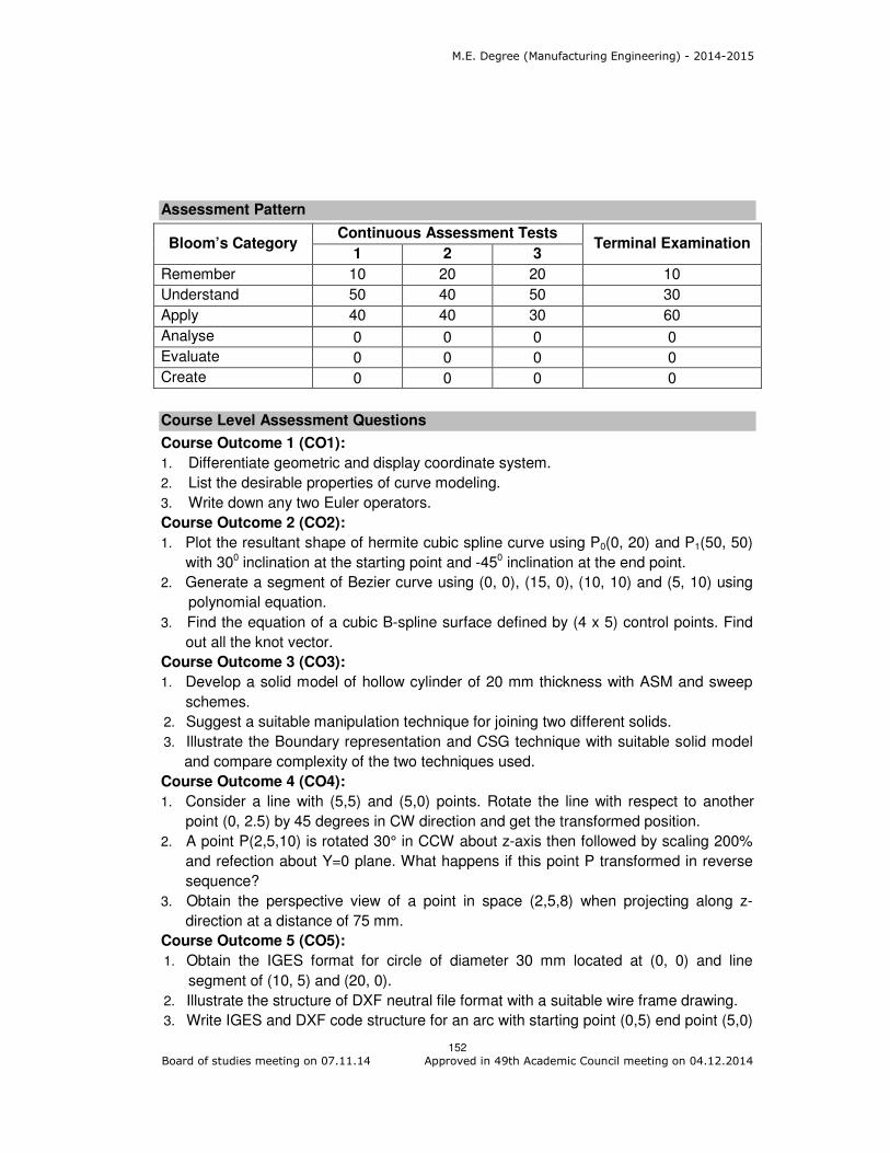
M.E. Degree (Manufacturing Engineering) - 2014-2015
152 Board of studies meeting on 07.11.14 Approved in 49th Academic Council meeting on 04.12.2014
Assessment Pattern
Bloom’s Category Continuous Assessment Tests
Terminal Examination 1 2 3
Remember 10 20 20 10
Understand 50 40 50 30
Apply 40 40 30 60
Analyse 0 0 0 0
Evaluate 0 0 0 0
Create 0 0 0 0
Course Level Assessment Questions
Course Outcome 1 (CO1):
1. Differentiate geometric and display coordinate system.
2. List the desirable properties of curve modeling.
3. Write down any two Euler operators.
Course Outcome 2 (CO2):
1. Plot the resultant shape of hermite cubic spline curve using P0(0, 20) and P1(50, 50)
with 300 inclination at the starting point and -450 inclination at the end point.
2. Generate a segment of Bezier curve using (0, 0), (15, 0), (10, 10) and (5, 10) using
polynomial equation.
3. Find the equation of a cubic B-spline surface defined by (4 x 5) control points. Find
out all the knot vector.
Course Outcome 3 (CO3):
1. Develop a solid model of hollow cylinder of 20 mm thickness with ASM and sweep
schemes.
2. Suggest a suitable manipulation technique for joining two different solids.
3. Illustrate the Boundary representation and CSG technique with suitable solid model
and compare complexity of the two techniques used.
Course Outcome 4 (CO4):
1. Consider a line with (5,5) and (5,0) points. Rotate the line with respect to another
point (0, 2.5) by 45 degrees in CW direction and get the transformed position.
2. A point P(2,5,10) is rotated 30° in CCW about z-axis then followed by scaling 200%
and refection about Y=0 plane. What happens if this point P transformed in reverse
sequence?
3. Obtain the perspective view of a point in space (2,5,8) when projecting along z-
direction at a distance of 75 mm.
Course Outcome 5 (CO5):
1. Obtain the IGES format for circle of diameter 30 mm located at (0, 0) and line
segment of (10, 5) and (20, 0).
2. Illustrate the structure of DXF neutral file format with a suitable wire frame drawing.
3. Write IGES and DXF code structure for an arc with starting point (0,5) end point (5,0)
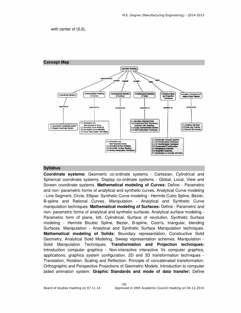
M.E. Degree (Manufacturing Engineering) - 2014-2015
153 Board of studies meeting on 07.11.14 Approved in 49th Academic Council meeting on 04.12.2014
with center of (0,0).
Concept Map
Syllabus
Coordinate systems: Geometric co-ordinate systems - Cartesian, Cylindrical and
Spherical coordinate systems. Display co-ordinate systems - Global, Local, View and
Screen coordinate systems. Mathematical modeling of Curves: Define - Parametric
and non- parametric forms of analytical and synthetic curves. Analytical Curve modeling
- Line Segment, Circle, Ellipse. Synthetic Curve modeling - Hermite Cubic Spline, Bezier,
B-spline and Rational Curves. Manipulation - Analytical and Synthetic Curve
manipulation techniques. Mathematical modeling of Surfaces: Define - Parametric and
non- parametric forms of analytical and synthetic surfaces. Analytical surface modeling -
Parametric form of plane, loft, Cylindrical, Surface of revolution. Synthetic Surface
modeling - Hermite Bicubic Spline, Bezier, B-spline, Coon's, triangular, blending
Surfaces. Manipulation - Analytical and Synthetic Surface Manipulation techniques.
Mathematical modeling of Solids: Boundary representation, Constructive Solid
Geometry, Analytical Solid Modeling, Sweep representation schemes. Manipulation -
Solid Manipulation Techniques. Transformation and Projection techniques:
Introduction computer graphics - Non-interactive interactive Vs computer graphics,
applications, graphics system configuration. 2D and 3D transformation techniques -
Translation, Rotation, Scaling and Reflection. Principle of concatenated transformation.
Orthographic and Perspective Projections of Geometric Models. Introduction to computer
aided animation system. Graphic Standards and mode of data transfer: Define

M.E. Degree (Manufacturing Engineering) - 2014-2015
154 Board of studies meeting on 07.11.14 Approved in 49th Academic Council meeting on 04.12.2014
graphics standard, geometrical data, direct and indirect data transfer. Neutral file formats
- Data Exchange Format (DXF) and Initial Graphics Exchange Specification (IGES).
Reference Book
1. Ibrahim Zeid, "Mastering CAD/CAM", Tata McGraw Hill Education (P) Ltd., Special
Indian Edition, 2013.
2. Amarendra N Sinha and Arun D Udai, "Computer Graphics", Tata McGraw Hill
Education (P) Ltd., Second reprint, 2009.
3. Michael E. Mortenson, "Geometric Modeling", Industrial Press, Third edition,
2006.
4. Rogers, "Mathematical Elements for computer Graphics", Tata Mcgraw Hill
Education Private Limited, 2009.
5. Rajiv Chopra, “Computer Graphics: A Practical Approach, Concepts,
Principles, Case Studies”, S.Chand and Company Ltd., First Edition, 2011.
Course Contents and Lecture Schedule
Module
Number Topics
No. of
Lectures
1 Coordinate systems
1.1 Geometric co-ordinate systems - Cartesian, Cylindrical and
Spherical coordinate systems
1
1.2 Display co-ordinate systems - Global, Local, View and Screen
coordinate systems
1
2 Mathematical modeling of Curves
2.1 Parametric and non-parametric forms of analytical and synthetic
curves
1
2.2 Analytical Curve modeling - Line Segment, Circle, Ellipse. 2
2.3 Synthetic Curve modeling - Hermite cubic spline, Bezier curve 2
Synthetic Curve modeling - B-spline and Rational Curves 2
2.4 Manipulation - Analytical and synthetic curve manipulation
techniques
1
3 Mathematical modeling of Surfaces
3.1 Parametric and non-parametric forms of analytical and synthetic
surfaces
2
3.2 Analytical surface modeling - Parametric form of plane, loft
surface
2
Analytical surface modeling - Cylindrical, Surface of revolution 1
3.3 Synthetic Surface modeling - Hermite bicubic spline, Bezier
surface
2
Synthetic Surface modeling - B-spline, Coon's, Triangular,
Blending Surfaces
2
Synthetic Surface modeling - triangular, blending Surfaces 1

M.E. Degree (Manufacturing Engineering) - 2014-2015
155 Board of studies meeting on 07.11.14 Approved in 49th Academic Council meeting on 04.12.2014
3.4 Manipulation - Analytical and synthetic surface manipulation
techniques
2
4 Mathematical modeling of Solids
4.1 Boundary representation scheme 1
4.2 Constructive Solid Geometry, Analytical Solid Modeling 1
4.3 Sweep representation scheme 1
4.4 Manipulation - Solid Manipulation Techniques 1
5 Transformation and Projection techniques
5.1 Introduction computer graphics - Non-interactive Vs Interactive
computer graphics, applications, graphics system configuration
2
5.2 2D transformation techniques - Translation, Rotation 1
2D transformation techniques - Scaling and Reflection 1
5.3 3D transformation techniques - Translation, Rotation 2
3D transformation techniques - Scaling and Reflection 2
5.4 Principle of concatenated transformation 1
5.5 Orthographic Projections of Geometric Models
5.6 Perspective Projections of Geometric Models 1
5.7 Introduction to computer aided animation system 2
6 Graphic Standards and mode of data transfer
6.1 Graphics standard 1
Geometrical data 2
6.2 Mode of data transfer - Direct and indirect data transfer 2
6.3 Neutral file formats - Data Exchange Format (DXF) and Initial
Graphics Exchange Specification (IGES)
2
Total 45
Course Designers:
1. C. Paramasivam [email protected]
2. M. Balamurali [email protected]

M.E. Degree (Manufacturing Engineering) - 2014-2015
156 Board of studies meeting on 07.11.14 Approved in 49th Academic Council meeting on 04.12.2014
Category L T P Credit
PE 4 0 0 4
Preamble: Metal joining is one among the manufacturing processes for joining the
components by welding processes. Welding is required in the manufacture of various
parts of boiler, air craft, automobiles, ships, nuclear reactor etc. Metal joining is a
controlled process used to fuse metals. There are several techniques of metal joining of
which welding is one of the more basic forms. Welding is a fabrication process that joins
materials, usually metals or thermoplastics, by causing coalescence . This is often done
by melting the workpieces and adding a filler material to form a pool of molten material
that cools to become a strong joint, but sometimes pressure is used in conjunction with
heat , or by itself, to produce the weld. Many different energy sources can be used for
welding, including a gas flame, an electric arc, a laser, an electron beam, friction,
and ultrasound. While often an industrial process, welding can be done in many different
environments, including open air, underwater and in space. The end product is obtained
by joining the two similar or dissimilar materials by selecting suitable welding process.
Advanced welding processes are developed to improve the quality of the product, reduce
the cost and preserve the environment.
Prerequisite
14MG130 Mechanical Behaviour of Materials
Course Outcomes
On the successful completion of the course, students will be able to
CO.No. Course Outcome
Blooms Level
Expected
Proficiency
Expected
attainment
level
CO1 Explain the principles and process capabilities of various fusion and solid state joining processes
Understand 80 70
CO2 Choose the suitable process parameters of various types of welding techniques
Apply 70 60
CO3 Describe heat transfer and molten metal flow in various metal joining processes
Understand 80 70
CO4 Describe the metallurgical changes during the joining processes in the weld zone.
Understand 80 70
CO5 Interpret the weldability of various ferrous and non ferrous metals
Apply 70 60
CO6 Identify the stress distortion and relieving techniques in the metal joining process
Understand 80 70
C07 Identify the defects and causes in metal joining processes
Understand 80 70
14MGPT0 METAL JOINING ENGINEERING

M.E. Degree (Manufacturing Engineering) - 2014-2015
157 Board of studies meeting on 07.11.14 Approved in 49th Academic Council meeting on 04.12.2014
Mapping with Programme Outcomes
COs PO1 PO2 PO3 PO4 PO5 PO6 PO7 PO8 PO9 PO10 PO11
CO1 M L
CO2 S M L L
CO3 M L
CO4 M L
CO5. S M L L
CO6. M L
CO7 M L
S- Strong; M-Medium; L-Low
Assessment Pattern
Bloom’s Category Continuous Assessment Tests
Terminal Examination 1 2 3
Remember 20 20 20 20
Understand 50 50 50 50
Apply 30 30 30 30
Analyse 0 0 0 0
Evaluate 0 0 0 0
Create 0 0 0 0
Course Level Assessment Questions
Course Outcome 1 (CO1):
1. What is resistance welding?
2. State the applications of gas tungsten arc welding process.
3. Explain resistance seam welding process with neat sketches.
Course Outcome 2 (CO2):
1. Select a suitable process to weld boiler shell and explain with necessary sketches.
2. How will you weld a dissimilar metal? Justify your selection.
3. An aluminium name plate is to be fixed on a cast iron machine member, select a
suitable welding process to fix the name plate and justify your selection with
necessary illustrations.
Course Outcome 3 (CO3):
1. Explain the one dimensional heat transfer rate with necessary diagram
2. Discuss the Rosenthal’ s Equation for heat flow in welding.
3. Discuss the cooling rate of welding in and around the welding
Course Outcome 4 (CO4):
1. Define weld metallurgy.
2. How to control the grain size in the welding
3. Explain the weld metal solidification technique
Course Outcome 5 (CO5):
1. Define weldability
2. Discuss how to join the dissimilar material in the welding process.
3. Suggest a suitable welding technique to join stainless steel material.
Course Outcome 6 (CO6):
1. What is weld distortion?
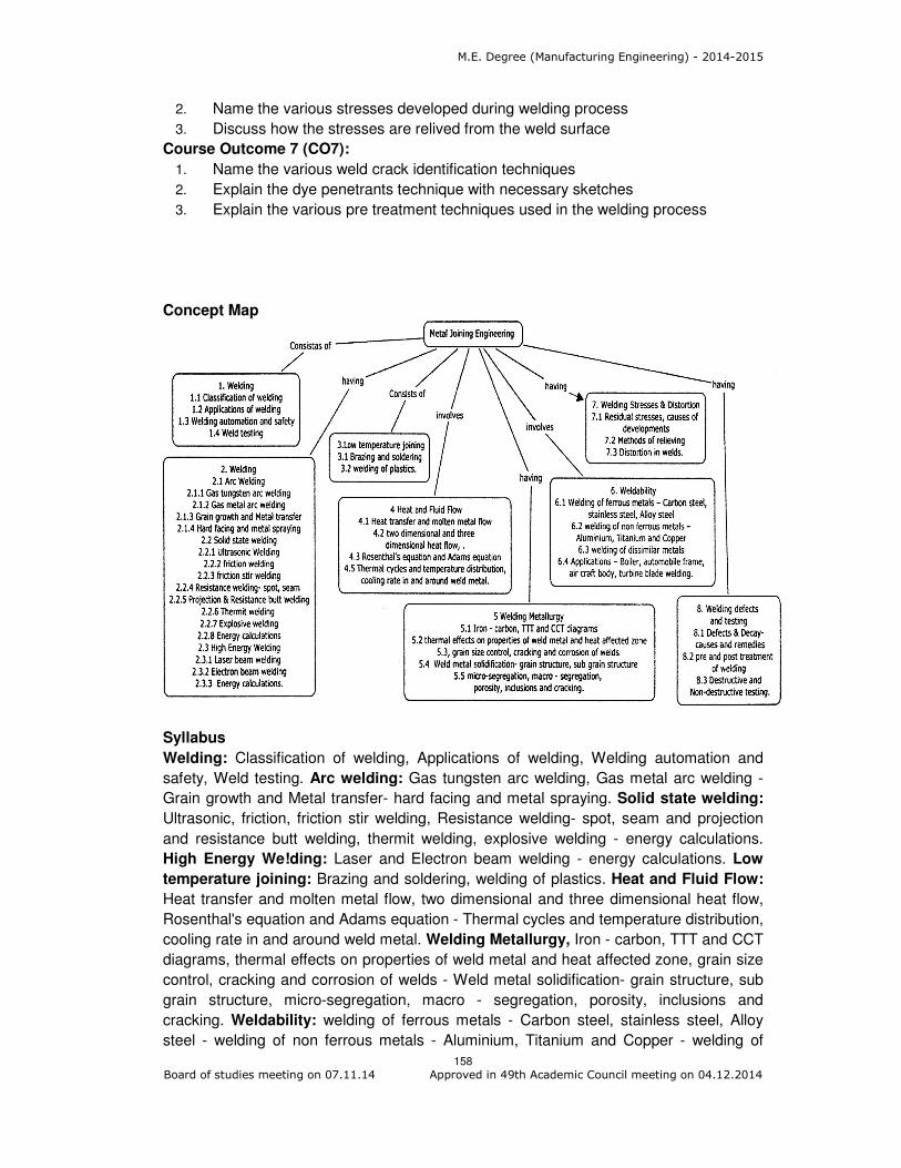
M.E. Degree (Manufacturing Engineering) - 2014-2015
158 Board of studies meeting on 07.11.14 Approved in 49th Academic Council meeting on 04.12.2014
2. Name the various stresses developed during welding process
3. Discuss how the stresses are relived from the weld surface
Course Outcome 7 (CO7):
1. Name the various weld crack identification techniques
2. Explain the dye penetrants technique with necessary sketches
3. Explain the various pre treatment techniques used in the welding process
Concept Map
Syllabus
Welding: Classification of welding, Applications of welding, Welding automation and
safety, Weld testing. Arc welding: Gas tungsten arc welding, Gas metal arc welding -
Grain growth and Metal transfer- hard facing and metal spraying. Solid state welding:
Ultrasonic, friction, friction stir welding, Resistance welding- spot, seam and projection
and resistance butt welding, thermit welding, explosive welding - energy calculations.
High Energy We!ding: Laser and Electron beam welding - energy calculations. Low
temperature joining: Brazing and soldering, welding of plastics. Heat and Fluid Flow:
Heat transfer and molten metal flow, two dimensional and three dimensional heat flow,
Rosenthal's equation and Adams equation - Thermal cycles and temperature distribution,
cooling rate in and around weld metal. Welding Metallurgy, Iron - carbon, TTT and CCT
diagrams, thermal effects on properties of weld metal and heat affected zone, grain size
control, cracking and corrosion of welds - Weld metal solidification- grain structure, sub
grain structure, micro-segregation, macro - segregation, porosity, inclusions and
cracking. Weldability: welding of ferrous metals - Carbon steel, stainless steel, Alloy
steel - welding of non ferrous metals - Aluminium, Titanium and Copper - welding of

M.E. Degree (Manufacturing Engineering) - 2014-2015
159 Board of studies meeting on 07.11.14 Approved in 49th Academic Council meeting on 04.12.2014
dissimilar metals - Applications - Boiler, automobile frame, air craft body, turbine blade
welding. Welding Stresses & Distortion: Residual stresses, causes of developments,
methods of relieving - Distortion in welds. Welding defects and testing: Defects and
decay - causes and remedies, pre and post treatment of welding, Destructive and Non-
destructive testing.
Reference Books
1. Little R.L, "Welding and Welding Technology" - Tata McGraw Hill Publishing Ltd,
New Delhi, 2001
2. Parmer R.S, "Welding Engineering and Technology", 2nd Edition Khanna
publishers, Delhi, 2010.
3. Sindo Kou, "Welding Metallurgy", Wiley Interscience, USA, 2003.
4. Davies, A.C, "Welding", 10th Edition, Cambridge University press, 1996.
5. Howard B. Cary, "Modern Welding Technology", Prentice Hall Inc, New Jersey,
2001
6. Khanna, O.P, "A Text Book of Welding Technology", - Dhanpat Rai Publications
(P) Ltd., New Delhi, 1998.
7. AWS Welding Handbook, Volume 1, Welding Science & Technology, American
Welding Society, 2001.
8. AWS Welding Handbook, Volume 2, Welding Processes, Part 1, American Welding
Society, 2004.
9. AWS Welding Handbook, Volume 3, Welding Processes, Part 2, American Welding
Society, 2004.
Course contents and Lecture schedule
Module
Number Topics
No. of
Lectures
1 Welding
1.1 Classification of welding 1
1.2 Applications of welding 1
1.3 Welding automation and safety
1.4 Weld testing 1
2 Welding
2.1 Arc welding
2.1.1 Gas Tungsten Arc Welding 1
2.1.2 Gas Metal Arc Welding 1
2.1.3 Grain Growth and Metal transfer 1
2.1.4 Hard facing and metal spraying 1
2.2 Solid state welding
2.2.1 Ultrasonic welding 1
2.2.2 Friction welding 1
2.2.3 Friction stir welding 1
2.2.4 Resistance welding, Spot, seam welding processes

M.E. Degree (Manufacturing Engineering) - 2014-2015
160 Board of studies meeting on 07.11.14 Approved in 49th Academic Council meeting on 04.12.2014
Module
Number Topics
No. of
Lectures
2.2.5 Projection and Resistance butt welding processes 1
2.2.6 Thermit welding 1
2.2.7 Explosive welding
2.2.8 Energy calculations 1
2.3 High Energy Welding
2.3.1 Laser beam welding 1
2.3.2 Electron beam welding 1
2.3.3 Energy calculations. 1
3 Low temperature joining
3.1 Brazing and soldering 1
3.2 welding of plastics 1
4. Heat and Fluid Flow
4.1 Heat transfer and molten metal flow, 1
4.2 two dimensional and three dimensional heat flow, 2
4.3 Rosenthal's equation and Adams equation 1
4.4 Thermal cycles and temperature distribution, cooling rate in and
around weld metal. 2
5 Metallurgy of welding
5.1 Iron-carbon, TTT and CCT diagrams 1
5.2 Thermal effects on properties of weld metal and heat affected zone 1
5.3 grain size control, cracking and corrosion of welds 1
5.4 Weld metal solidification-grain structure, sub grain structure 1
5.5 Micro - segregation, macro-segregation, porosity, inclusions and
cracking. 1
6 Weldability
6.1 welding of ferrous metals - Carbon steel, stainless steel, Alloy steel 2
6.2 welding of non ferrous metals - Aluminium, Titanium and Copper 2
6.3 welding of dissimilar metals 1
6.4 Applications - Boiler, automobile frame, air craft body, turbine blade
welding. 1
7 Welding Stresses & Distortion
7.1 Residual stresses, causes of developments, 1
7.2 methods of relieving 1
7.3 Distortion in welds. 1
8 Welding defects and testing
8.1 Defects and Decay- causes and remedies 1
8.2 Pre and post treatment 1
8.3 Destructive testing and Non-destructive testing 2

M.E. Degree (Manufacturing Engineering) - 2014-2015
161 Board of studies meeting on 07.11.14 Approved in 49th Academic Council meeting on 04.12.2014
Module
Number Topics
No. of
Lectures
Total 46
Course Designers:
1. M. KATHIRESAN [email protected]
2. P. MARAN [email protected]

M.E. Degree (Manufacturing Engineering) - 2014-2015
162 Board of studies meeting on 07.11.14 Approved in 49th Academic Council meeting on 04.12.2014
Category L T P Credit
PE 3 1 0 4
Preamble
The course aims at giving adequate exposure to hydraulic and pneumatic systems and
Design of hydraulic and pneumatic circuits. The course gives various circuit design
methods needed for the industrial automation
Prerequisite
14MG140 : Industrial Automation and Robotics
14MG150 : CNC Machine Tool Technology
Course Outcomes
On the successful completion of the course, students will be able to
CO.No. Course Outcome
Blooms Level
Expected
Proficiency
Expected
attainment
level
CO1 Explain the theory related to Fluid power and arising in the study of engineering problems and their applications
Understand 80 70
CO2 Choose the pumps and motors for the given applications
Apply
70 60
CO3 Design the hydraulic and pneumatic circuits based on the required movement and sequence
Apply
70 60
CO4 Calculate speed, pressure, direction control for the hydraulic and pneumatic circuits
Apply 70 60
Mapping with Programme Outcomes
COs PO1 PO2 PO3 PO4 PO5 PO6 PO7 PO8 PO9 PO10 PO11
CO1 M L
CO2 S M L L
CO3 S M L L
CO4 S M L L
S- Strong; M-Medium; L-Low
Assessment Pattern
Bloom’s Category Continuous Assessment Tests
Terminal Examination 1 2 3
Remember 20 20 20 20
Understand 20 20 20 20
Apply 60 60 60 60
Analyse 0 0 0 0
14MGPU0 FLUID POWER AUTOMATION

M.E. Degree (Manufacturing Engineering) - 2014-2015
163 Board of studies meeting on 07.11.14 Approved in 49th Academic Council meeting on 04.12.2014
Evaluate 0 0 0 0
Create 0 0 0 0
Course Level Assessment Questions
Course Outcome 1 (CO1):
1. Define positive displacement pump
2. List the parameters for selection a pump
3. What are the various types of hydraulic motors?
4. State the importance of Hydro pneumatic circuits.
Course Outcome 2 (CO2):
1. Explain the cascade method of circuit design with example.
2. Distinguish between mechanical and Electro Hydraulic Servo Systems
3. List the selection parameters for a pump.
Course Outcome 3 (CO3):
1. Draw the ladder diagram for A+B+C-A-B-C+ and explain its operation
2. Design a circuit for the A+B+A-B- using Karnaugh map method .
3. Design a hydraulic circuits for a material handling in heat treatment plant
Course Outcome 4 (CO4):
1. Explain the application of pressure Compensated flow control valve.
2. Distinguish between mechanical and Electro Hydraulic Servo Systems
3. Discuss in detail the 4/3 direction control valve with example.
4. Compare the meter-in and meter-out circuits
Concept Map
Syllabus
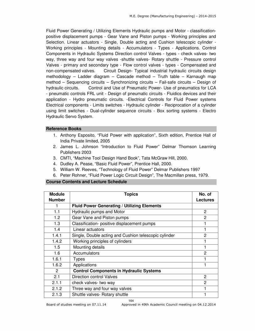
M.E. Degree (Manufacturing Engineering) - 2014-2015
164 Board of studies meeting on 07.11.14 Approved in 49th Academic Council meeting on 04.12.2014
Fluid Power Generating / Utilizing Elements Hydraulic pumps and Motor - classification-
positive displacement pumps - Gear Vane and Piston pumps - Working principles and
Selection. Linear actuators - Single, Double acting and Cushion telescopic cylinder -
Working principles - Mounting details - Accumulators - Types - Applications. Control
Components in Hydraulic Systems Direction control Valves - types - check valves- two
way, three way and four way valves -shuttle valves- Rotary shuttle - Pressure control
Valves - primary and secondary type - Flow control valves - types - Compensated and
non-compensated valves. Circuit Design- Typical industrial hydraulic circuits design
methodology – Ladder diagram – Cascade method – Truth table – Karnaugh map
method – Sequencing circuits – Synchronizing circuits – Fail-safe circuits – Design of
hydraulic circuits. Control and Use of Pneumatic Power- Use of pneumatics for LCA
- pneumatic controls FRL unit - Design of pneumatic circuits - Fluidics devices and their
application - Hydro pneumatic circuits. -Electrical Controls for Fluid Power systems
Electrical components - Limits switches - Hydraulic cylinder - Reciprocation of a cylinder
using limit switches - Dual-cylinder sequence circuits - Box sorting systems - Electro
Hydraulic Servo System.
Reference Books
1. Anthony Esposito, “Fluid Power with application”, Sixth edition, Prentice Hall of
India Private limited, 2005
2. James L. Johnson “Introduction to Fluid Power” Delmar Thomson Learning
Publishers 2003
3. CMTI, “Machine Tool Design Hand Book”, Tata McGraw Hill, 2000.
4. Dudley A. Pease, “Basic Fluid Power”, Prentice Hall, 2000.
5. William W. Reeves, “Technology of Fluid Power” Delmar Publishers 1997
6. Peter Rohner, “Fluid Power Logic Circuit Design”, The Macmillan press, 1979.
Course Contents and Lecture Schedule
Module
Number
Topics No. of
Lectures
1 Fluid Power Generating / Utilizing Elements
1.1 Hydraulic pumps and Motor 2
1.2 Gear Vane and Piston pumps 2
1.3 Classification- positive displacement pumps 1
1.4 Linear actuators 1
1.4.1 Single, Double acting and Cushion telescopic cylinder 2
1.4.2 Working principles of cylinders 1
1.5 Mounting details 1
1.6 Accumulators 2
1.6.1 Types 1
1.6.2 Applications 1
2 Control Components in Hydraulic Systems
2.1 Direction control Valves 2
2.1.1 check valves- two way 2
2.1.2 Three way and four way valves 1
2.1.3 Shuttle valves- Rotary shuttle 1

M.E. Degree (Manufacturing Engineering) - 2014-2015
165 Board of studies meeting on 07.11.14 Approved in 49th Academic Council meeting on 04.12.2014
Module
Number
Topics No. of
Lectures
2.2 Pressure control Valves 1
2.2.1 primary and secondary type 1
2.3 Flow control valves 2
2.3.1 Flow control valves - types 2
2.3.2 Non-compensated valves 1
2.3.3 Compensated valves. 1
2.4 Electro Hydraulic Servo System 1
3 Circuit Design
3.1 Typical industrial hydraulic circuits design methodology 1
3.2 Ladder diagram 2
3.3 Cascade method Truth table 1
3.4 Karnaugh map method 1
3.5 Sequencing circuits 1
3.6 Fail-safe circuits 1
3.7 Synchronizing circuits 1
3.8 Reciprocation of a cylinder using limit switches 1
4 Control and Use of Pneumatic Power
4.1 Use of pneumatics for LCA 2
4.2 Design of pneumatic circuits 1
4.3 pneumatic controls FRL unit 1
4.4 Fluidics devices and their application Hydro pneumatic
circuits
2
4.5 Electrical components Limits switches
Dual-cylinder sequence circuits - Box sorting systems
2
Total 46
Course Designers:
1. M.ELANGO [email protected]
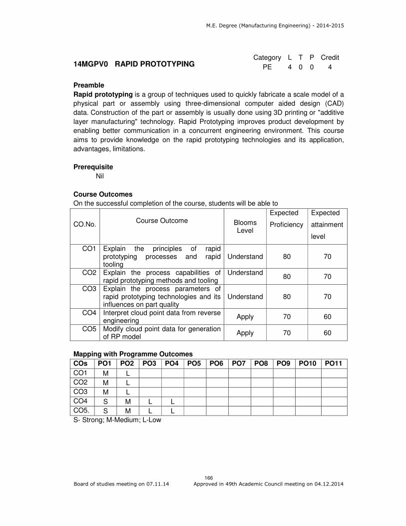
M.E. Degree (Manufacturing Engineering) - 2014-2015
166 Board of studies meeting on 07.11.14 Approved in 49th Academic Council meeting on 04.12.2014
Category L T P Credit
PE 4 0 0 4
Preamble
Rapid prototyping is a group of techniques used to quickly fabricate a scale model of a
physical part or assembly using three-dimensional computer aided design (CAD)
data. Construction of the part or assembly is usually done using 3D printing or "additive
layer manufacturing" technology. Rapid Prototyping improves product development by
enabling better communication in a concurrent engineering environment. This course
aims to provide knowledge on the rapid prototyping technologies and its application,
advantages, limitations.
Prerequisite
Nil
Course Outcomes
On the successful completion of the course, students will be able to
CO.No.
Course Outcome Blooms
Level
Expected
Proficiency
Expected
attainment
level
CO1 Explain the principles of rapid prototyping processes and rapid tooling
Understand 80 70
CO2 Explain the process capabilities of rapid prototyping methods and tooling
Understand
80 70
CO3 Explain the process parameters of rapid prototyping technologies and its influences on part quality
Understand 80 70
CO4 Interpret cloud point data from reverse engineering
Apply 70 60
CO5 Modify cloud point data for generation of RP model
Apply 70 60
Mapping with Programme Outcomes
COs PO1 PO2 PO3 PO4 PO5 PO6 PO7 PO8 PO9 PO10 PO11
CO1 M L
CO2 M L
CO3 M L
CO4 S M L L
CO5. S M L L
S- Strong; M-Medium; L-Low
14MGPV0 RAPID PROTOTYPING

M.E. Degree (Manufacturing Engineering) - 2014-2015
167 Board of studies meeting on 07.11.14 Approved in 49th Academic Council meeting on 04.12.2014
Assessment Pattern
Bloom’s Category Continuous Assessment Tests
Terminal Examination 1 2 3
Remember 20 20 20 20
Understand 40 40 40 40
Apply 40 40 40 40
Analyse 0 0 0 0
Evaluate 0 0 0 0
Create 0 0 0 0
Course Level Assessment Questions
Course Outcome 1 (CO1):
1. Explain the principle of Stereolithography (SLA) processes.
2. Discuss the working principle of Fusion Deposition Modelling (FDM).
3. Discuss the solid ground process steps in details with suitable diagrams.
Course Outcome 2 (CO2):
1. Differentiate direct and indirect tooling process.
2. Explain silicon rubber tooling processes in detail.
3. Explain laminate tooling and discuss its limitations.
Course Outcome 3 (CO3):
1. Explain the process parameters of solid ground curing.
2. Discuss the process parameters to be considered in selective laser sintering
3. Identify the process parameters considered for laminated object manufacturing.
Course Outcome 4 (CO4):
1. How the conversion of CT/MRI scan data can be done.
2. How was the surface Generation from points on cloud are done and explain in
detail.
3. Differentiate soft tooling with hard tooling.
Course Outcome 5 (CO5):
1. Discuss the applications and limitations of SGC process.
2. Suggest few application of RP in product design, automotive industry and medical
field.
3. Explain in details about the application of cloud point data for generation of RP
model.
Concept Map
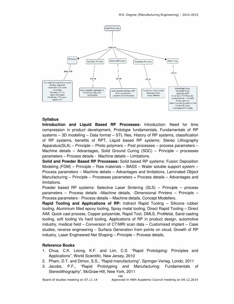
M.E. Degree (Manufacturing Engineering) - 2014-2015
168 Board of studies meeting on 07.11.14 Approved in 49th Academic Council meeting on 04.12.2014
Syllabus
Introduction and Liquid Based RP Processes: Introduction: Need for time
compression in product development, Prototype fundamentals, Fundamentals of RP
systems – 3D modelling – Data format – STL files, History of RP systems, classification
of RP systems, benefits of RPT, Liquid based RP systems: Stereo Lithography
Apparatus(SLA) – Principle – Photo polymers – Post processes – process parameters –
Machine details – Advantages, Solid Ground Curing (SGC) – Principle – processes
parameters – Process details - Machine details – Limitations.
Solid and Powder Based RP Processes: Solid based RP systems: Fusion Deposition
Modeling (FDM) – Principle – Raw materials – BASS – Water soluble support system –
Process parameters – Machine details – Advantages and limitations, Laminated Object
Manufacturing – Principle – Processes parameters = Process details – Advantages and
limitations.
Powder based RP systems: Selective Laser Sintering (SLS) – Principle – process
parameters – Process details –Machine details, -Dimensional Printers – Principle –
Process parameters - Process details – Machine details, Concept Modellers.
Rapid Tooling and Applications of RP: Indirect Rapid Tooling – Silicone rubber
tooling, Aluminium filled epoxy tooling, Spray metal tooling, Direct Rapid Tooling – Direct
AIM. Quick cast process, Copper polyamide, Rapid Tool, DMLS, ProMetal, Sand casting
tooling, soft tooling Vs hard tooling, Applications of RP in product design, automotive
industry, medical field – Conversion of CT/MRI scan data – Customised implant – Case
studies, reverse engineering – Surface Generation from points on cloud, Growth of RP
industry, Laser Engineered Net Shaping – Principle – Process details,
Reference Books
1. Chua, C.K. Leong, K.F. and Lim, C.S. “Rapid Prototyping: Principles and
Applications”, World Scientific, New Jersey, 2010
2. Pham, D.T. and Dimov, S.S., “Rapid manufacturing”, Springer-Verlag, Londo, 2011
3. Jacobs, P.F., “Rapid Prototyping and Manufacturing: Fundamentals of
Stereolithography”, McGraw-Hill, New York, 2011
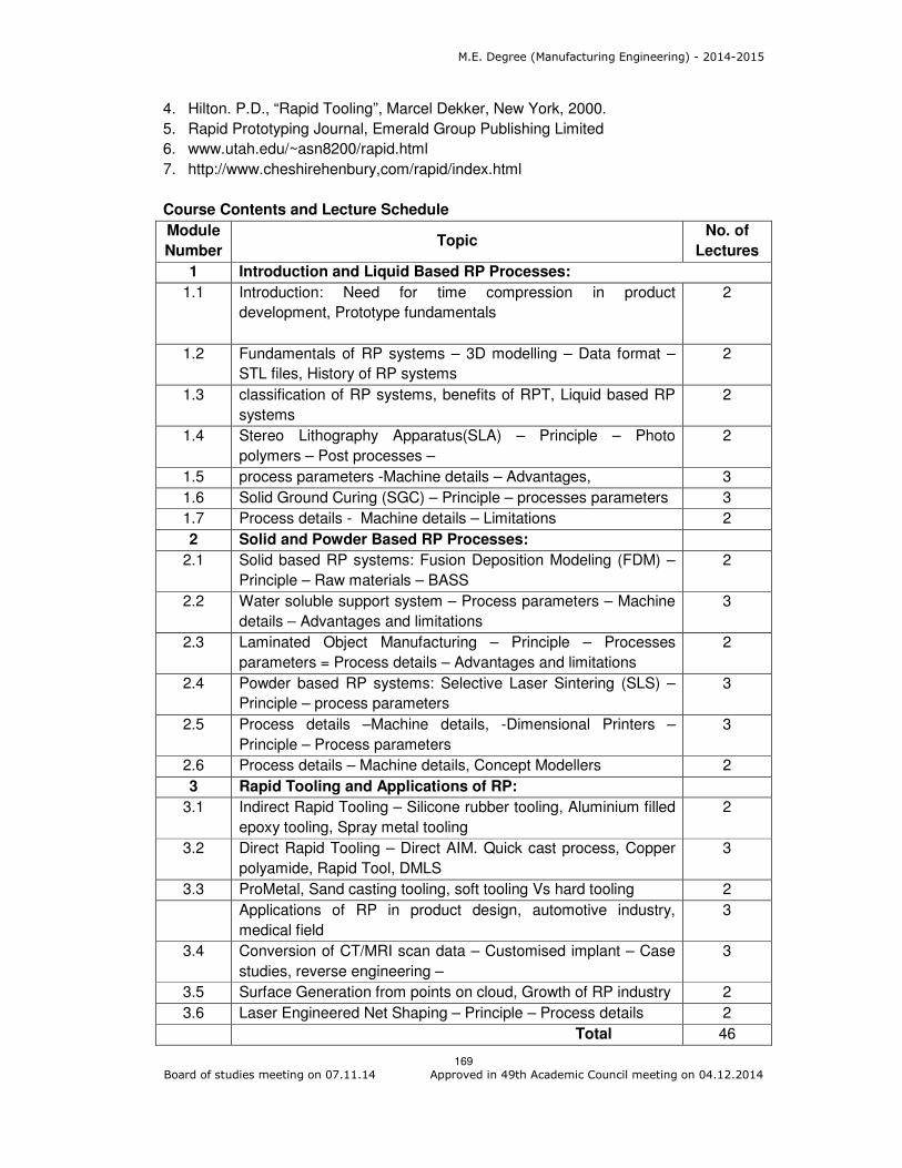
M.E. Degree (Manufacturing Engineering) - 2014-2015
169 Board of studies meeting on 07.11.14 Approved in 49th Academic Council meeting on 04.12.2014
4. Hilton. P.D., “Rapid Tooling”, Marcel Dekker, New York, 2000.
5. Rapid Prototyping Journal, Emerald Group Publishing Limited
6. www.utah.edu/~asn8200/rapid.html
7. http://www.cheshirehenbury,com/rapid/index.html
Course Contents and Lecture Schedule
Module
Number Topic
No. of
Lectures
1 Introduction and Liquid Based RP Processes:
1.1 Introduction: Need for time compression in product
development, Prototype fundamentals
2
1.2 Fundamentals of RP systems – 3D modelling – Data format –
STL files, History of RP systems
2
1.3 classification of RP systems, benefits of RPT, Liquid based RP
systems
2
1.4 Stereo Lithography Apparatus(SLA) – Principle – Photo
polymers – Post processes –
2
1.5 process parameters -Machine details – Advantages, 3
1.6 Solid Ground Curing (SGC) – Principle – processes parameters 3
1.7 Process details - Machine details – Limitations 2
2 Solid and Powder Based RP Processes:
2.1
Solid based RP systems: Fusion Deposition Modeling (FDM) –
Principle – Raw materials – BASS
2
2.2 Water soluble support system – Process parameters – Machine
details – Advantages and limitations
3
2.3 Laminated Object Manufacturing – Principle – Processes
parameters = Process details – Advantages and limitations
2
2.4 Powder based RP systems: Selective Laser Sintering (SLS) –
Principle – process parameters
3
2.5 Process details –Machine details, -Dimensional Printers –
Principle – Process parameters
3
2.6 Process details – Machine details, Concept Modellers 2
3 Rapid Tooling and Applications of RP:
3.1 Indirect Rapid Tooling – Silicone rubber tooling, Aluminium filled
epoxy tooling, Spray metal tooling
2
3.2 Direct Rapid Tooling – Direct AIM. Quick cast process, Copper
polyamide, Rapid Tool, DMLS
3
3.3 ProMetal, Sand casting tooling, soft tooling Vs hard tooling 2
Applications of RP in product design, automotive industry,
medical field
3
3.4 Conversion of CT/MRI scan data – Customised implant – Case
studies, reverse engineering –
3
3.5 Surface Generation from points on cloud, Growth of RP industry 2
3.6 Laser Engineered Net Shaping – Principle – Process details 2
Total 46

M.E. Degree (Manufacturing Engineering) - 2014-2015
170 Board of studies meeting on 07.11.14 Approved in 49th Academic Council meeting on 04.12.2014
Course Designers:
1. K. CHOCKALINGAM [email protected]
2. J. UMAR MOHAMED [email protected]

M.E. Degree (Manufacturing Engineering) - 2014-2015
171 Board of studies meeting on 07.11.14 Approved in 49th Academic Council meeting on 04.12.2014
Category L T P Credit
PE 4 0 0 4
Preamble
Composite materials (also called composition materials or shortened to composites) are
materials made from two or more constituent materials with significantly different
physical or chemical properties, that when combined, produce a material with
characteristics different from the individual components. The individual components
remain separate and distinct within the finished structure. The new material may be
preferred for many reasons: common examples include materials which are stronger,
lighter or less expensive when compared to traditional materials. This course covers the
fundamentals of composite material and manufacturing of various composite materials
Prerequisite
Mechanical Behaviour of Materials
Course Outcomes
On the successful completion of the course, students will be able to
CO.No. Course Outcome
Blooms Level
Expected
Proficiency
Expected
attainment
level
CO1 Explain the various Fibers and Matrix Materials
Understand 80 70
CO2 Illustrate the various polymer matrix composites processing methods
Apply 70 60
CO3 Explain the Lamina Constitutive Equations
Understand 80 70
CO4 Choose the various processing methods of metal matrix composites
Apply 70 60
CO5 Examine the processing of ceramic matrix composites and carbon - carbon Composites
Apply 70 60
Mapping with Programme Outcomes
COs PO1 PO2 PO3 PO4 PO5 PO6 PO7 PO8 PO9 PO10 PO11
CO1 M L
CO2 S M L L
CO3 M L
CO4 S M L L
CO5 S M L L
S- Strong; M-Medium; L-Low
14MGPW0 COMPOSITE MATERIALS
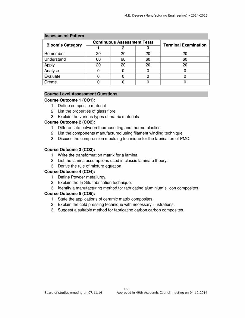
M.E. Degree (Manufacturing Engineering) - 2014-2015
172 Board of studies meeting on 07.11.14 Approved in 49th Academic Council meeting on 04.12.2014
Assessment Pattern
Bloom’s Category Continuous Assessment Tests
Terminal Examination 1 2 3
Remember 20 20 20 20
Understand 60 60 60 60
Apply 20 20 20 20
Analyse 0 0 0 0
Evaluate 0 0 0 0
Create 0 0 0 0
Course Level Assessment Questions
Course Outcome 1 (CO1):
1. Define composite material
2. List the properties of glass fibre
3. Explain the various types of matrix materials
Course Outcome 2 (CO2):
1. Differentiate between thermosetting and thermo plastics
2. List the components manufactured using filament winding technique
3. Discuss the compression moulding technique for the fabrication of PMC.
Course Outcome 3 (CO3):
1. Write the transformation matrix for a lamina
2. List the lamina assumptions used in classic laminate theory.
3. Derive the rule of mixture equation.
Course Outcome 4 (CO4):
1. Define Powder metallurgy.
2. Explain the In Situ fabrication technique.
3. Identify a manufacturing method for fabricating aluminium silicon composites.
Course Outcome 5 (CO5):
1. State the applications of ceramic matrix composites.
2. Explain the cold pressing technique with necessary illustrations.
3. Suggest a suitable method for fabricating carbon carbon composites.

M.E. Degree (Manufacturing Engineering) - 2014-2015
173 Board of studies meeting on 07.11.14 Approved in 49th Academic Council meeting on 04.12.2014
Concept Map
Syllabus
Fibers and Matrix Materials : Fibers – Fabrication, Structure, properties and
applications – Glass fiber, Boron fiber, carbon fiber, organic fiber, ceramic and
metallic fibers - whiskers–Fabrication of Matrix materials – polymers, metals and
ceramics and their properties – interfaces – Wettability – Types of bonding at the
interface – Tests for measuring interfacial strength - Physical and chemical properties.
Processing of Polymer Matrix Composites: Classification of Polymers – Properties
of Thermo and Thermosetting Plastics – Extrusion, Polymer matrix composites: hand
layup, spray, filament winding, Pultrusion, resin transfer moulding, autoclave
moulding - bag moulding, compression moulding with Bulk Moulding Compound and
sheet Moulding Compound – thermoplastic matrix composites – film stacking, diaphragm
forming, thermoplastic tape laying, injection moulding – interfaces in PMCs -
structure, properties and application of PMCs –recycling of PMCs.
Lamina Constitutive Equations: Lamina Assumptions – Macroscopic Viewpoint.
Generalized Hooke’s Law. Reduction to Homogeneous Orthotropic Lamina – Isotropic
limit case, Orthotropic Stiffness matrix (Qij), Typical Commercial material properties, Rule
of Mixtures. Generally Orthotropic Lamina –Transformation Matrix, Transformed
Stiffness. Laminate Constitutive Equations – Coupling Interactions, Balanced Laminates,
Symmetric Laminates, Angle Ply Laminates, Cross Ply Laminates.
Processing of Metal Matrix Composites: Metallic matrices: Aluminium, titanium,
magnesium, copper alloys – processing of MMCs: liquid state, Solid state, in situ
fabrication techniques – diffusion bonding – powder metallurgy techniques
interfaces in MMCs – mechanical properties – machining of MMCs – Applications.

M.E. Degree (Manufacturing Engineering) - 2014-2015
174 Board of studies meeting on 07.11.14 Approved in 49th Academic Council meeting on 04.12.2014
Processing of Ceramic Matrix Composites and Carbon-Carbon Composites:
Processing of CMCs: cold pressing, sintering, reaction bonding, liquid infiltration, lanxide
process – in situ chemical reaction techniques: chemical vapour deposition, chemical
vapour impregnation, sol-gel – interfaces in CMCs – mechanical properties and
applications of CMCs – Carbon-carbon Composites – applications.
Reference Books
1. Krishnan K Chawla, Composite Materials: Science and Engineering, International
Edition, Springer, 2012
2. Mallick P.K., Fiber Reinforced Composites: Materials, Manufacturing and Design,
CRC press, New Delhi, 2010
3. Jamal Y. Sheikh-Ahmad, Machining of Polymer Composites, Springer, USA, 2009.
4. Mallick, P.K. and Newman.S., Composite Materials Technology, Hanser Publishers,
2003.
5. Said Jahanmir, Ramulu M. and Philp Koshy, Machining of Ceramics and
Composites, Marcel Dekker Inc., New York, 1999
Course contents and Lecture schedule
Module
Number Topics
No. of
Lectures
1.0 Fibers and Matrix Materials
1.1 Fibers – Fabrication, Structure, properties and applications 2
1.2 Glass fiber, Boron fiber, carbon fiber, organic fiber, ceramic
and metallic fibers - whiskers 2
1.3 Fabrication of Matrix materials – polymers, metals and
ceramics and their properties – interfaces – Wettability 2
1.4 Types of bonding at the interface 2
1.5 Tests for measuring interfacial strength 2
1.6 Physical and chemical properties 1
2.0 Processing of Polymer Matrix Composites
2.1 Classification of Polymers – Properties of Thermo and
Thermosetting Plastics
2
2.2 Processing methods: Polymer matrix composites: hand layup,
spray, filament winding, Pultrusion, resin transfer moulding,
autoclave moulding - bag moulding, compression moulding with
Bulk Moulding Compound and sheet moulding Compound
3
2.3 thermoplastic matrix composites – film stacking, diaphragm
forming, thermoplastic tape laying, injection moulding
interfaces in PMCs
3
2.4 Structure, properties and application of PMCs 2
2.5 recycling of PMCs 1
3.0 Lamina Constitutive Equations
3.1 Lamina Assumptions – Macroscopic Viewpoint. Generalized
Hooke’s Law.
2
3.2 Reduction to Homogeneous Orthotropic Lamina – Isotropic limit 2

M.E. Degree (Manufacturing Engineering) - 2014-2015
175 Board of studies meeting on 07.11.14 Approved in 49th Academic Council meeting on 04.12.2014
Module
Number Topics
No. of
Lectures
case, Orthotropic Stiffness matrix
3.3 Typical Commercial material properties, Rule of Mixtures.
Generally Orthotropic Lamina –Transformation Matrix,
Transformed Stiffness.
3
3.4 Laminate Constitutive Equations – Coupling Interactions,
Balanced Laminates, Symmetric Laminates, Angle Ply
Laminates, Cross Ply Laminates.
3
4.0 Processing of Metal Matrix Composites:
4.1 Metallic matrices: Aluminium, titanium, magnesium, copper alloys 3
4.2 processing of MMCs: liquid state, Solid state, in situ fabrication
techniques
3
4.3 diffusion bonding – powder metallurgy techniques interfaces
in MMCs
2
4.4 Mechanical properties – machining of MMCs – Applications. 2
5.0 Processing of Ceramic Matrix Composites and Carbon-
Carbon Composites
5.1 Processing of CMCs: cold pressing, sintering, reaction bonding,
liquid infiltration
2
5.2 lanxide process – in situ chemical reaction techniques: chemical
vapour deposition, chemical vapour impregnation,
1
5.3 sol-gel – interfaces in CMCs – mechanical properties and
applications of CMCs
2
5.4 Carbon-carbon Composites – applications. 2
Total 47
Course Designers
1. M. Kathiresan [email protected]
2. V. Balasubramani [email protected]
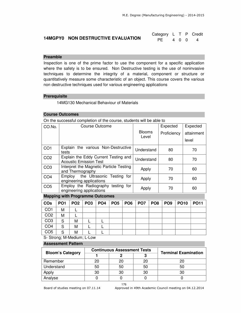
M.E. Degree (Manufacturing Engineering) - 2014-2015
176 Board of studies meeting on 07.11.14 Approved in 49th Academic Council meeting on 04.12.2014
Category L T P Credit
PE 4 0 0 4
Preamble
Inspection is one of the prime factor to use the component for a specific application
where the safety is to be ensured. Non Destructive testing is the use of noninvasive
techniques to determine the integrity of a material, component or structure or
quantitatively measure some characteristic of an object. This course covers the various
non destructive techniques used for various engineering applications
Prerequisite
14MG130 Mechanical Behaviour of Materials
Course Outcomes
On the successful completion of the course, students will be able to
CO.No. Course Outcome
Blooms Level
Expected
Proficiency
Expected
attainment
level
CO1 Explain the various Non-Destructive tests
Understand 80 70
CO2 Explain the Eddy Current Testing and Acoustic Emission Test
Understand 80 70
CO3 Interpret the Magnetic Particle Testing and Thermography
Apply 70 60
CO4 Employ the Ultrasonic Testing for engineering applications
Apply 70 60
CO5 Employ the Radiography testing for engineering applications
Apply 70 60
Mapping with Programme Outcomes
COs PO1 PO2 PO3 PO4 PO5 PO6 PO7 PO8 PO9 PO10 PO11
CO1 M L
CO2 M L
CO3 S M L L
CO4 S M L L
CO5 S M L L
S- Strong; M-Medium; L-Low
Assessment Pattern
Bloom’s Category Continuous Assessment Tests
Terminal Examination 1 2 3
Remember 20 20 20 20
Understand 50 50 50 50
Apply 30 30 30 30
Analyse 0 0 0 0
14MGPY0 NON DESTRUCTIVE EVALUATION

M.E. Degree (Manufacturing Engineering) - 2014-2015
177 Board of studies meeting on 07.11.14 Approved in 49th Academic Council meeting on 04.12.2014
Evaluate 0 0 0 0
Create 0 0 0 0
Course Level Assessment Questions
Course Outcome 1 (CO1):
1. Define NDT.
2. Discuss the Liquid Penetrant Testing with necessary illustrations.
3. State the benefits of using visual inspection.
Course Outcome 2 (CO2):
1. State the principle of ECT.
2. Describe the Acoustic emission testing process with necessary illustrations.
3. Discuss how to detect the fatigue crack by using AET.
Course Outcome 3 (CO3):
1. Mention the principle of MPT.
2. Discuss how thermography is used to find the cracks on a coated surface.
3. Explain the various equipments used in the magnetic particle testing
Course Outcome 4 (CO4):
1. What is the principle of ultrasonic testing?
2. Explain the transmission testing process with necessary illustrations.
3. Suggest a suitable process to find the porosity and intergranular cracks and also
explain the process.
Course Outcome 5 (CO5):
1. State the principle of radiography?
2. Discuss the effect of radiation on thin film.
3. Identify a suitable process to find the interior air pocket in an extruded product.
Concept Map
Syllabus

M.E. Degree (Manufacturing Engineering) - 2014-2015
178 Board of studies meeting on 07.11.14 Approved in 49th Academic Council meeting on 04.12.2014
Non-Destructive Testing: An Introduction, Visual Inspection & Liquid Penetrant
Testing Types of non-destructive methods, Comparison of Destructive and Non
destructive Tests, Visual Inspection, Optical aids used for visual inspection, Applications.
Physical principles, procedure for penetrant testing, Penetrant testing materials,
Penetrant testing methods-water washable, Post – Emulsification methods, Applications
Eddy Current Testing & Acoustic Emission Test: Principles, Instrumentation for
ECT, Absolute, differential probes, Techniques – High sensitivity techniques, Multi
frequency, Phased array ECT, Applications. Principle of AET, Instrumentation,
Applications - testing of metal pressure vessels, Fatigue crack detection in
aerospace structures.
Magnetic Particle Testing & Thermography : Principle of MPT, procedure used for
testing a component, Equipment used for MPT, Magnetizing techniques,
Applications. Principle of Thermography, Infrared Radiometry, Active thermography
measurements, Applications – Imaging entrapped water under an epoxy coating,
Detection of carbon fiber contaminants.
Ultrasonic Testing: Principle, Ultrasonic transducers, Ultrasonic Flaw detection
Equipment, Modes of display A- scan, B-Scan, C- Scan, Applications, Inspection
Methods - Normal Incident Pulse-Echo Inspection, Normal Incident Through-
transmission Testing, Angle Beam Pulse-Echo testing, Time of Flight Diffraction
(TOFD) Technique, Applications of Normal Beam Inspection in detecting fatigue
cracks, Inclusions, Slag, Porosity and Intergranular cracks - Codes, standards,
specification and procedures and case studies in ultrasonic test.
Radiography: Principle of Radiography, x-ray and gamma ray sources- safety
procedures and standards, Effect of radiation on Film, Radiographic imaging, Inspection
Techniques – Single wall single image, Double wall Penetration, Multiwall Penetration
technique, Real Time Radiography - Codes, standards, specification and procedures.
Case studies on defects in cast, rolled, extruded, welded and heat treated components -
Comparison and selection of various NDT techniques.
Reference Books
1. M. Thavasimuthu, T. Jayakumar, Baldev Raj “Practical Non Destructive Testing”,
Third Edition, Narosa Book Distributors Pvt Ltd, New Delhi, 2002
2. Peter J. Shull “Non Destructive Evaluation: Theory, Techniques and Applications”,
First Edition, Marcel Dekker, Inc., New York, 2002
3. Krautkramer. J., “Ultra Sonic Testing of Materials”, Fourth Edition, Springer (India)
Private Limited, New Delhi, 2003.
4. ASM Metals Handbook Vol 17: Non Destructive testing.
5. ASME Sec V - Non - Destructive Testing.
6. ASTM Standards
a. E 94, Standard Guide for Radiographic Examination.
b. E 142, Standard Method for Controlling Quality of Radiographic Testing.
c. E 164, Standard Practice for Ultrasonic Contact Examination of Weldments.
d. E 165, Standard Test Method for Liquid Penetrant Examination.
e. E 1444, Standard Practice for Magnetic Particle Examination.
Course contents and Lecture schedule

M.E. Degree (Manufacturing Engineering) - 2014-2015
179 Board of studies meeting on 07.11.14 Approved in 49th Academic Council meeting on 04.12.2014
Module
Number Topics
No. of
Lectures
1.0 Non-Destructive Testing
1.1 Introduction, Visual Inspection & Liquid Penetrant Testing 2
1.2 Types of non-destructive methods, Comparison of Destructive
and Non destructive Tests 2
1.3 Visual Inspection, Optical aids used for visual inspection,
Applications 2
1.4 Physical principles, procedure for penetrant testing,
Penetrant testing materials 2
1.5 Penetrant testing methods - water washable, Post –
Emulsification methods, Applications 3
2.0 Eddy Current Testing & Acoustic Emission
2.1 Principles, Instrumentation for ECT, Absolute, differential
probes techniques, High sensitivity techniques
3
2.2 Multi frequency, Phased array ECT, Applications
2.3 Principle of AET, Instrumentation, Applications 3
2.4 Testing of metal pressure vessels, Fatigue crack detection in
aerospace structures.
2
3.0 Magnetic Particle Testing & Thermography
3.1 Principle of MPT, procedure used for testing a component, 2
3.2 Equipment used for MPT, Magnetizing techniques, Applications. 2
3.3 Principle of Thermography, Infrared Radiometry, Active
thermography measurements
2
3.4 Case studies and applications 2
4.0 Ultrasonic Testing
4.1 Principle, Ultrasonic transducers, Ultrasonic Flaw detection
Equipment,
2
4.2 Modes of display A- scan, B Scan, C- Scan, Applications,
Inspection Methods - Normal Incident Pulse-Echo Inspection,
2
4.3 Normal Incident Through - transmission Testing, Angle Beam
Pulse-Echo testing
2
4.4 Time of Flight Diffraction Technique, Applications of Normal
Beam Inspection in detecting fatigue cracks, Inclusions,
Slag, Porosity and Intergranular cracks - Codes, standards,
specification and procedures and case studies in ultrasonic test.
3
5.0 Radiography
5.1 Principle of Radiography, x-ray and gamma ray sources 2
5.2 safety procedures and standards, 1
5.3 Effect of radiation on Film, Radiographic imaging techniques 2
5.4 Inspection Techniques – Single wall single image, Double wall
Penetration, Multiwall Penetration technique, Real Time
Radiography - Codes, standards, specification and procedures
2
5.5 Case studies on defects in cast, rolled, extruded, welded and
heat treated components - Comparison and selection of various
2

M.E. Degree (Manufacturing Engineering) - 2014-2015
180 Board of studies meeting on 07.11.14 Approved in 49th Academic Council meeting on 04.12.2014
Module
Number Topics
No. of
Lectures
NDT
Total 46
Course Designer:
1. M. Kathiresan [email protected]

M.E. Degree (Manufacturing Engineering) - 2014-2015
181 Board of studies meeting on 07.11.14 Approved in 49th Academic Council meeting on 04.12.2014
Category L T P Credit
PE 4 0 0 4
Preamble
Friction-stir welding (FSW) is a solid-state joining process (the metal is not melted) that uses a third body tool to join two facing surfaces. Heat is generated between the tool and material which leads to a very soft region near the FSW tool. It then mechanically intermixes the two pieces of metal at the place of the joint, then the softened metal (due to the elevated temperature) can be joined using mechanical pressure (which is applied by the tool), much like joining clay, or dough. It is primarily used on aluminium, and most often on extruded aluminium (non-heat treatable alloys), and on structures which need superior weld strength without a post weld heat treatment. This course aims to provide working principle of FSW, Material deformation, joint formation, equipment and Industrial applications of FSW.
Prerequisite
Nil
Course Outcomes
On the successful completion of the course, students will be able to
CO.No. Course Outcome
Blooms Level
Expected
Proficiency
Expected
attainment
level
CO1 Explain the working principle of friction stir welding process
Understand 80 70
CO2 Explain the working principles of machines/equipments used for friction stir welding process
Understand 80 70
CO3 Choose the process parameters involved in friction stir welding process
Apply 70 60
CO4 Examine the suitable conditions or joining methods for fabrication/assembly of products
Apply 70 60
Mapping with Programme Outcomes
COs PO1 PO2 PO3 PO4 PO5 PO6 PO7 PO8 PO9 PO10 PO11
CO1 M L
CO2 M L
CO3 S M L L
CO4 S M L L
S- Strong; M-Medium; L-Low
14MGPZ0 FRICTION STIR WELDING
(2016-17)
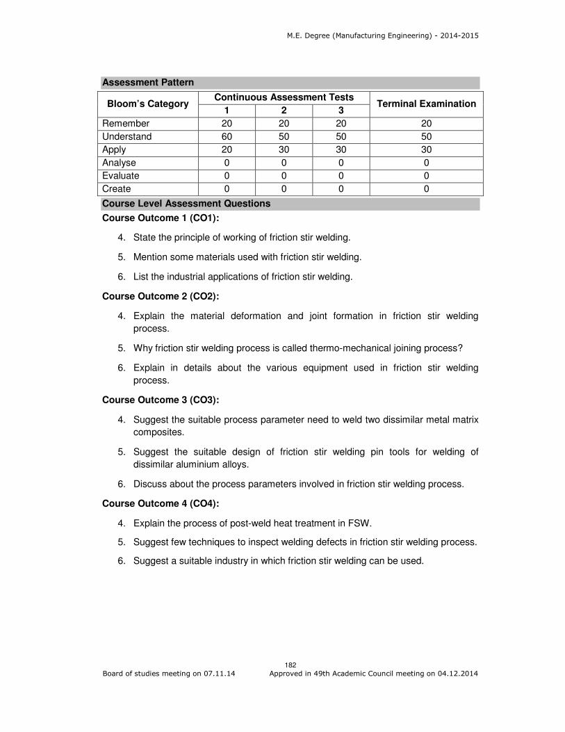
M.E. Degree (Manufacturing Engineering) - 2014-2015
182 Board of studies meeting on 07.11.14 Approved in 49th Academic Council meeting on 04.12.2014
Assessment Pattern
Bloom’s Category Continuous Assessment Tests
Terminal Examination 1 2 3
Remember 20 20 20 20
Understand 60 50 50 50
Apply 20 30 30 30
Analyse 0 0 0 0
Evaluate 0 0 0 0
Create 0 0 0 0
Course Level Assessment Questions
Course Outcome 1 (CO1):
4. State the principle of working of friction stir welding.
5. Mention some materials used with friction stir welding.
6. List the industrial applications of friction stir welding.
Course Outcome 2 (CO2):
4. Explain the material deformation and joint formation in friction stir welding
process.
5. Why friction stir welding process is called thermo-mechanical joining process?
6. Explain in details about the various equipment used in friction stir welding
process.
Course Outcome 3 (CO3):
4. Suggest the suitable process parameter need to weld two dissimilar metal matrix
composites.
5. Suggest the suitable design of friction stir welding pin tools for welding of
dissimilar aluminium alloys.
6. Discuss about the process parameters involved in friction stir welding process.
Course Outcome 4 (CO4):
4. Explain the process of post-weld heat treatment in FSW.
5. Suggest few techniques to inspect welding defects in friction stir welding process.
6. Suggest a suitable industry in which friction stir welding can be used.

M.E. Degree (Manufacturing Engineering) - 2014-2015
183 Board of studies meeting on 07.11.14 Approved in 49th Academic Council meeting on 04.12.2014
Concept Map
Syllabus
Introduction to Friction stir welding (FSW) process: an overview, principles,
Comparison of friction stir welding to other welding processes, Welding tools used for
friction stir welding , Parameter effects, Materials used with friction stir welding , Joint geometries, Joint preparation, Post-weld heat treating,
Material deformation and joint formation in friction stir welding: A thermo-
mechanical joining process, Plastic deformation in relation to material properties, Process parameter, temperature and heat loss relationships, Material flow and property
relationships of the resultant friction stir welded joint
Friction stir welding equipment: Requirements of friction stir welding coming from the process and applications, Overview of the machine requirements for friction stir welding,
Friction stir welding machine controller requirements, Closed-loop control and friction stir
welding, Control of robotic friction stir welding, Other controller requirements, Other
machine requirements, Part tooling requirements, Friction stir welding pin tools,
Machines currently available in the market place.
Inspection and quality control in friction stir welding: Weld quality requirements,
online monitoring and statistical process control, Destructive testing-Offline testing: non-destructive testing.
Industrial applications of friction stir welding: Introduction- Shipbuilding and offshore,
Aerospace, Railway, Automotive, Other industry sectors.
The future of friction stir welding: Process aspects of friction stir welding, Materials
aspects of friction stir welding.
Reference Books
1. Rajiv Sharan Mishra, Partha Sarathi De, Nilesh Kumar “Friction Stir Welding and
Processing” Springer International Publishing Switzerland, 2014.

M.E. Degree (Manufacturing Engineering) - 2014-2015
184 Board of studies meeting on 07.11.14 Approved in 49th Academic Council meeting on 04.12.2014
2. Daniela Lohwasser and Zhan Chen M. “Friction stir welding from basics to
applications”, Woodhead Publishing India Private Limited, New Delhi, 2010.
3. Mohammad Kazem Besharati Givi and Parviz Asadi “Advances in Friction Stir
Welding and Processing” Woodhead Publishing Limited, UK, 2014.
4. Nilesh Kumar, Rajiv S. Mishra, John A. Baumann “Residual Stresses in Friction
Stir Welding”, Butterworth-Heinemann publications , USA, 2014.
Course contents and Lecture schedule
Module
Number Topics
No. of
Lectures
1.0 Introduction to Friction stir welding (FSW) process
1.1 Introduction, an overview, principles, Comparison of friction
stir welding to other welding processes, 2
1.2 Welding tools used for friction stir welding , Parameter
effects 2
1.3 Materials used with friction stir welding , Joint geometries, 2
1.4 Joint preparation, Post-weld heat treating 2
2.0 Material deformation and joint formation in friction stir
welding
2.1 A thermo-mechanical joining process, Plastic deformation in
relation to material properties
2
2.2 Process parameter, temperature and heat loss relationships 3
2.3 Material flow and property relationships of the resultant
friction stir welded joint
3
3.0 Friction stir welding equipment
3.1 Requirements of friction stir welding coming from the
process and applications, Overview of the machine
requirements for friction stir welding
2
3.2 Friction stir welding machine controller requirements,
Closed-loop control and friction stir welding
2
3.3 Control of robotic friction stir welding, Other controller
requirements
2
3.4 Other machine requirements, Part tooling requirements 2
3.5 Friction stir welding pin tools, Machines currently available
in the market place
2
4.0 Inspection and quality control in friction stir welding
4.1 Weld quality requirements, online monitoring and statistical
process control
2
4.2 Offline testing: non-destructive testing 2
5.0 Industrial applications of friction stir welding
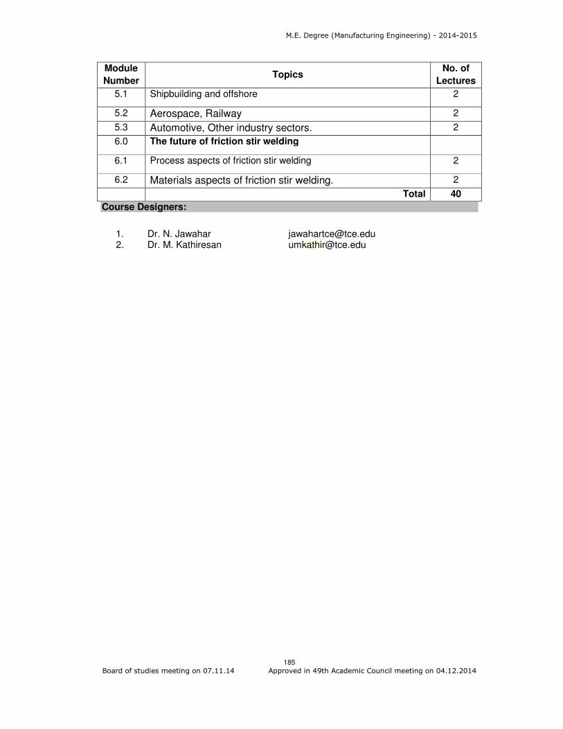
M.E. Degree (Manufacturing Engineering) - 2014-2015
185 Board of studies meeting on 07.11.14 Approved in 49th Academic Council meeting on 04.12.2014
Module
Number Topics
No. of
Lectures
5.1 Shipbuilding and offshore 2
5.2 Aerospace, Railway 2
5.3 Automotive, Other industry sectors. 2
6.0 The future of friction stir welding
6.1 Process aspects of friction stir welding 2
6.2 Materials aspects of friction stir welding. 2
Total 40
Course Designers:
1. Dr. N. Jawahar [email protected] 2. Dr. M. Kathiresan [email protected]