
v5j15.pdf - Khulna University of Engineering & Technology
12
Journal of Engineering Science 05(1), 2014, 103-114 STUDY ON THE FIELD PERFORMANCE OF GRANULAR PILE AS A GROUND IMPROVEMENT TECHNIQUE Md. Ikramul Hoque 1* and Muhammed Alamgir 2 1 Planning and Development, Khulna University of Engineering & Technology, Bangladesh 2 Department of Civil Engineering, Khulna University of Engineering & Technology, Bangladesh Received: 08 June 2014 Accepted: 25 June 2014 ABSTRACT This paper is concerned with the performance of granular pile as ground improved technique installed at a selected site of south-west region of Bangladesh. Granular pile is considered as one of the most versatile and cost effective ground improvement methods to improve the marginal sites. The installation technique has a significant influence on the performance of this method. However, there is a proven record of successful application of rammed-displacement method in the installation of granular piles in the soft ground of Bangladesh. The sub-soil consists of fine-grained soil of very soft to soft consistency up to a greater depth. In the construction of sand pile Sylhet sand is used as the granular materials. Granular piles of 300 mm diameter and 8.25 m length were installed. Load tests were conducted on 0.30m diameter plate resting at a depth of 0.91m from the existing ground surface on both the natural and improved ground. The plate load test was also conducted on the natural ground at the foundation depth and on the top of sand piles after one month and one year of installation of granular piles. Standard penetration tests were also conducted to observe the change in soil stiffness due to the installation of sand pile. The test results reveal that the bearing capacity of the normal ground was increased by the installation of granular piles. Comparing to the natural ground, the bearing capacity of improved ground was increased by 200% to 250%. The cost of foundation using mat and pre-cast pile foundation increased approximately by 114% and 154%, respectively, while compared with that of sand pile improved ground. Field investigation reveals that the granular pile using Sylhet sand and installation by rammed-displacement technique can be used successfully as a suitable ground improvement method to improve the bearing capacity of the soft ground. Keywords: Bearing capacity, Granular materials, Rammed displacement, Soft ground. 1. INTRODUCTION Construction of granular piles is considered as one of the most versatile and cost effective ground improvement technique compared to the other methods such as preloading, dredging and replacement, dynamic compaction etc. Granular piles, a fairly recent ground improvement technique, have been used successfully in several projects throughout the world. Granular piles are generally cylindrical in shape and composed of compacted gravel, crushed stone or sand. Various techniques of installation have been conceived depending on technical ability, efficiency and local condition. In Europe and USA, the vibro-floatation technique is widely used while in Japan, the vibro-compozer method is used. In India, granular piles are constructed by simple bored piling equipment. In this study field investigation is carried out on the construction of granular piles by rammed- displacement and its various aspects. Granular piles with different types of granular materials were constructed in a typical soft ground of south western region of Bangladesh. Load tests were done over the constructed granular piles and the results show that the bearing capacity of the improved ground increased by 2.00 to 2.50 times than that of the natural ground. One of the oldest historical examples of the use of granular piles (stone column) is found in the 1830’s where French Military Engineers used it to support heavy foundations of iron works at the artillery arsenal in Bayoune (Hughes et al., 1975). The modern origin of the granular piles actually began 60 years ago in the 1930’s in Germany by their Russian Émigré. After the beginning of the modern phase of the use of granular piles, the theoretical background, analysis and design aspects, and installation techniques have been developed by various researchers and the practicing engineers. As a result in the recent years, this method of ground improvement has been proved to be a most popular versatile and cost effective technique. The vibro-compaction method is used to improve the density of cohesionless soil using a vibroflot which sinks in the ground under its own weight and with the assistance of water and vibration. The vibro-replacement method is used to improve cohesive soils with more than 18% passing no. 200 U.S standard sieve. The vibroflot sinks into the ground under its own weight assisted by water or air jets as a flushing medium until it reaches the predetermined depth (Baumann and Bauer, 1974 and Engelhardt and Golding, 1975). JES an international Journal * Corresponding author: [email protected] KUET@JES, ISSN 2075-4914/05(1), 2014
-
Upload
khangminh22 -
Category
Documents
-
view
2 -
download
0
Transcript of v5j15.pdf - Khulna University of Engineering & Technology

Journal of Engineering Science 05(1), 2014, 103-114
STUDY ON THE FIELD PERFORMANCE OF GRANULAR PILE AS A GROUND IMPROVEMENT TECHNIQUE
Md. Ikramul Hoque1* and Muhammed Alamgir2
1Planning and Development, Khulna University of Engineering & Technology, Bangladesh 2Department of Civil Engineering, Khulna University of Engineering & Technology, Bangladesh
Received: 08 June 2014 Accepted: 25 June 2014
ABSTRACT
This paper is concerned with the performance of granular pile as ground improved technique installed at a selected site of south-west region of Bangladesh. Granular pile is considered as one of the most versatile and cost effective ground improvement methods to improve the marginal sites. The installation technique has a significant influence on the performance of this method. However, there is a proven record of successful application of rammed-displacement method in the installation of granular piles in the soft ground of Bangladesh. The sub-soil consists of fine-grained soil of very soft to soft consistency up to a greater depth. In the construction of sand pile Sylhet sand is used as the granular materials. Granular piles of 300 mm diameter and 8.25 m length were installed. Load tests were conducted on 0.30m diameter plate resting at a depth of 0.91m from the existing ground surface on both the natural and improved ground. The plate load test was also conducted on the natural ground at the foundation depth and on the top of sand piles after one month and one year of installation of granular piles. Standard penetration tests were also conducted to observe the change in soil stiffness due to the installation of sand pile. The test results reveal that the bearing capacity of the normal ground was increased by the installation of granular piles. Comparing to the natural ground, the bearing capacity of improved ground was increased by 200% to 250%. The cost of foundation using mat and pre-cast pile foundation increased approximately by 114% and 154%, respectively, while compared with that of sand pile improved ground. Field investigation reveals that the granular pile using Sylhet sand and installation by rammed-displacement technique can be used successfully as a suitable ground improvement method to improve the bearing capacity of the soft ground.
Keywords: Bearing capacity, Granular materials, Rammed displacement, Soft ground.
1. INTRODUCTION
Construction of granular piles is considered as one of the most versatile and cost effective ground improvement technique compared to the other methods such as preloading, dredging and replacement, dynamic compaction etc. Granular piles, a fairly recent ground improvement technique, have been used successfully in several projects throughout the world. Granular piles are generally cylindrical in shape and composed of compacted gravel, crushed stone or sand. Various techniques of installation have been conceived depending on technical ability, efficiency and local condition. In Europe and USA, the vibro-floatation technique is widely used while in Japan, the vibro-compozer method is used. In India, granular piles are constructed by simple bored piling equipment. In this study field investigation is carried out on the construction of granular piles by rammed-displacement and its various aspects. Granular piles with different types of granular materials were constructed in a typical soft ground of south western region of Bangladesh. Load tests were done over the constructed granular piles and the results show that the bearing capacity of the improved ground increased by 2.00 to 2.50 times than that of the natural ground.
One of the oldest historical examples of the use of granular piles (stone column) is found in the 1830’s where French Military Engineers used it to support heavy foundations of iron works at the artillery arsenal in Bayoune (Hughes et al., 1975). The modern origin of the granular piles actually began 60 years ago in the 1930’s in Germany by their Russian Émigré. After the beginning of the modern phase of the use of granular piles, the theoretical background, analysis and design aspects, and installation techniques have been developed by various researchers and the practicing engineers. As a result in the recent years, this method of ground improvement has been proved to be a most popular versatile and cost effective technique. The vibro-compaction method is used to improve the density of cohesionless soil using a vibroflot which sinks in the ground under its own weight and with the assistance of water and vibration. The vibro-replacement method is used to improve cohesive soils with more than 18% passing no. 200 U.S standard sieve. The vibroflot sinks into the ground under its own weight assisted by water or air jets as a flushing medium until it reaches the predetermined depth (Baumann and Bauer, 1974 and Engelhardt and Golding, 1975).
JES
an international Journal
* Corresponding author: [email protected] KUET@JES, ISSN 2075-4914/05(1), 2014

104 Md. Ikramul Hoque and Muhammed Alamgir Study on the Field Performance of …..
The vibro-compozer method is popularized in Japan and is used for stabilizing soft clays in the presence of high ground water level (Aboshi et al., 1979; Aboshi and Suematsu, 1985; Barksdale and Bachus, 1983). In cased borehole method, the piles are constructed by ramming granular materials in the prebored holes in stages using a heavy falling weight (usually of 15 to 20 kN) from a height of 1.0 to 1.5 m (Datye and Nagaraju, 1975; Datye, 1978; Datye and Nagaraju, 1981 and Bergado et al., 1987).
A large number of laboratory and field tests have been conducted in order to quantity the applicability of this ground improvement technique to improve the behavior of soft ground. Hughes and Withers, (1974) and Hughes et al., (1975) made a systematic study to identify the failure mechanism of single granular pile and suggested, bulging, as the mostly likely mode of failure. The findings of laboratory and field investigation on granular piles treated ground can be obtained from Madhav, (1982), Charles and Watts, (1983), Kimura et al., (1985), Bergado and Lamb, (1987), Bergade et al., (1988), Leung and Tan, (1993) and Alamgir et al., (1996). In Bangladesh, sand piles have been used successfully in some ground improvement projects. Alamgir and Zaher, (1999a) reported that a large number of sand piles were installed in soft cohesive soils in south-western region of Bangladesh where a six-vent regulator was constructed. Some research works were conducted in the department of Civil Engineering, Khulna University of Engineering & Technoloogy to see the response of soft ground improved by columnar inclusion as a part of post graduate research (Zaher, 2000; Hossain, 2009).
2. Construction of Granular Pile
The sub-soil condition of Khulna University of Engineering and Technology (KUET) campus at Khulna, Bangladesh was investigated in which granular piles were installed. The installation methods are described in the following sections. Locally available granular materials and the manual labor intensive installation technique were employed. To obtain a vivid picture on the effectiveness, granular piles were considered.
2.1 Location of Project Site
The investigation site of this research works is located at the KUET campus, Khulna i.e. south-west part of Bangladesh. The KUET campus is situated 12 km from Khulna city center and to the 1 km west of Khulna-Jessore highway. The campus map of KUET and the location of investigated site at the campus layout are shown in Figure 1 with respect to Bangladesh map.
Figure 1: Location of investigated site of the conducted field research works
2.2 Sub Soil Condition
From most of the past records, it is found that the sub-soil of KUET campus consists of soft soil layers containing organic. Sub-soil investigation in field and laboratory was determined at different layers to a
- KUET Campus
- Test Site
Journal of Engineering Science 05(1), 2014, 103-114 105
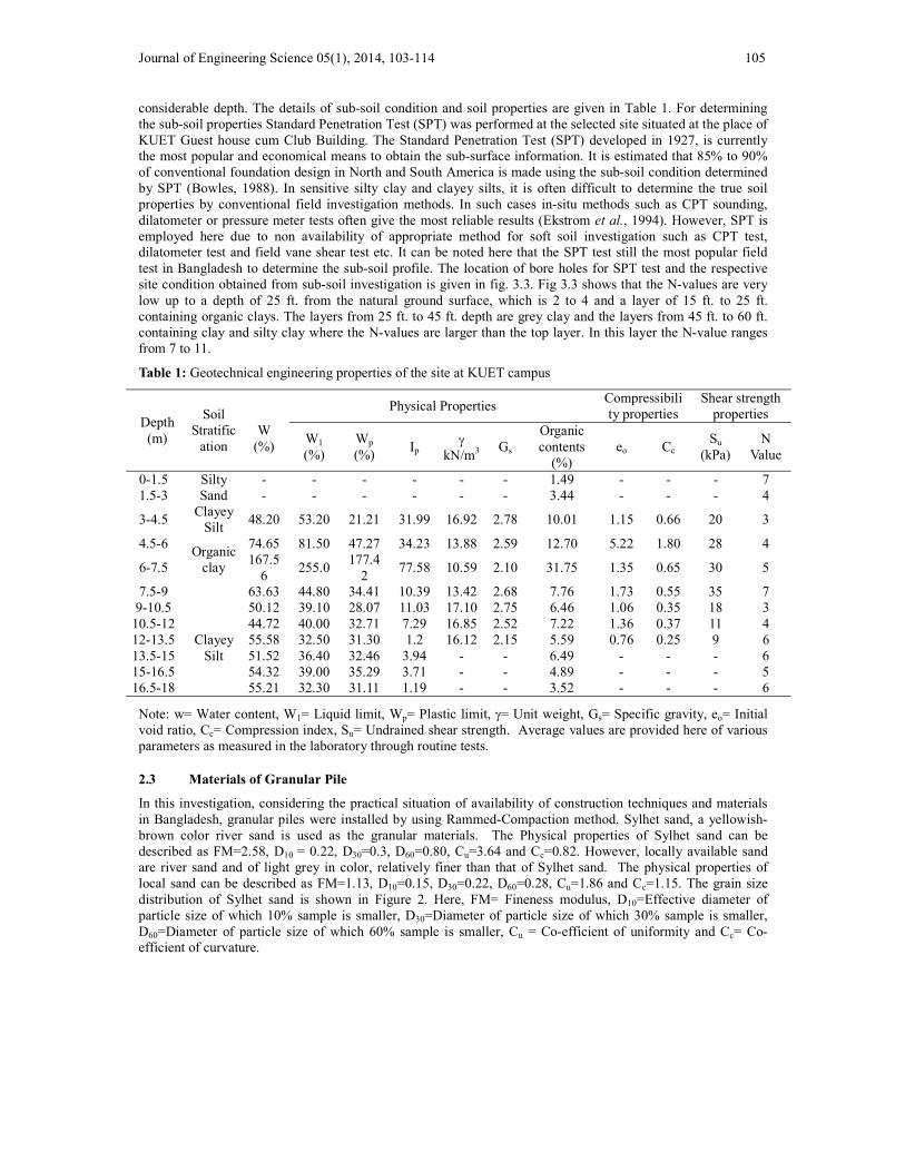
considerable depth. The details of sub-soil condition and soil properties are given in Table 1. For determining the sub-soil properties Standard Penetration Test (SPT) was performed at the selected site situated at the place of KUET Guest house cum Club Building. The Standard Penetration Test (SPT) developed in 1927, is currently the most popular and economical means to obtain the sub-surface information. It is estimated that 85% to 90% of conventional foundation design in North and South America is made using the sub-soil condition determined by SPT (Bowles, 1988). In sensitive silty clay and clayey silts, it is often difficult to determine the true soil properties by conventional field investigation methods. In such cases in-situ methods such as CPT sounding, dilatometer or pressure meter tests often give the most reliable results (Ekstrom et al., 1994). However, SPT is employed here due to non availability of appropriate method for soft soil investigation such as CPT test, dilatometer test and field vane shear test etc. It can be noted here that the SPT test still the most popular field test in Bangladesh to determine the sub-soil profile. The location of bore holes for SPT test and the respective site condition obtained from sub-soil investigation is given in fig. 3.3. Fig 3.3 shows that the N-values are very low up to a depth of 25 ft. from the natural ground surface, which is 2 to 4 and a layer of 15 ft. to 25 ft. containing organic clays. The layers from 25 ft. to 45 ft. depth are grey clay and the layers from 45 ft. to 60 ft. containing clay and silty clay where the N-values are larger than the top layer. In this layer the N-value ranges from 7 to 11.
Table 1: Geotechnical engineering properties of the site at KUET campus
Depth (m)
Soil Stratific
ation
W
(%)
Physical Properties Compressibility properties
Shear strength properties
W1
(%) Wp
(%) Ip
kN/m3 Gs
Organic contents
(%) eo Cc
Su
(kPa)
N Value
0-1.5 Silty Sand
- - - - - - 1.49 - - - 7 1.5-3 - - - - - - 3.44 - - - 4
3-4.5 Clayey
Silt 48.20 53.20 21.21 31.99 16.92 2.78 10.01 1.15 0.66 20 3
4.5-6 Organic
clay
74.65 81.50 47.27 34.23 13.88 2.59 12.70 5.22 1.80 28 4
6-7.5 167.5
6 255.0
177.42
77.58 10.59 2.10 31.75 1.35 0.65 30 5
7.5-9 63.63 44.80 34.41 10.39 13.42 2.68 7.76 1.73 0.55 35 7 9-10.5
Clayey Silt
50.12 39.10 28.07 11.03 17.10 2.75 6.46 1.06 0.35 18 3 10.5-12 44.72 40.00 32.71 7.29 16.85 2.52 7.22 1.36 0.37 11 4 12-13.5 55.58 32.50 31.30 1.2 16.12 2.15 5.59 0.76 0.25 9 6 13.5-15 51.52 36.40 32.46 3.94 - - 6.49 - - - 6 15-16.5 54.32 39.00 35.29 3.71 - - 4.89 - - - 5 16.5-18 55.21 32.30 31.11 1.19 - - 3.52 - - - 6
Note: w= Water content, W1= Liquid limit, Wp= Plastic limit, = Unit weight, Gs= Specific gravity, eo= Initial void ratio, Cc= Compression index, Su= Undrained shear strength. Average values are provided here of various parameters as measured in the laboratory through routine tests.
2.3 Materials of Granular Pile
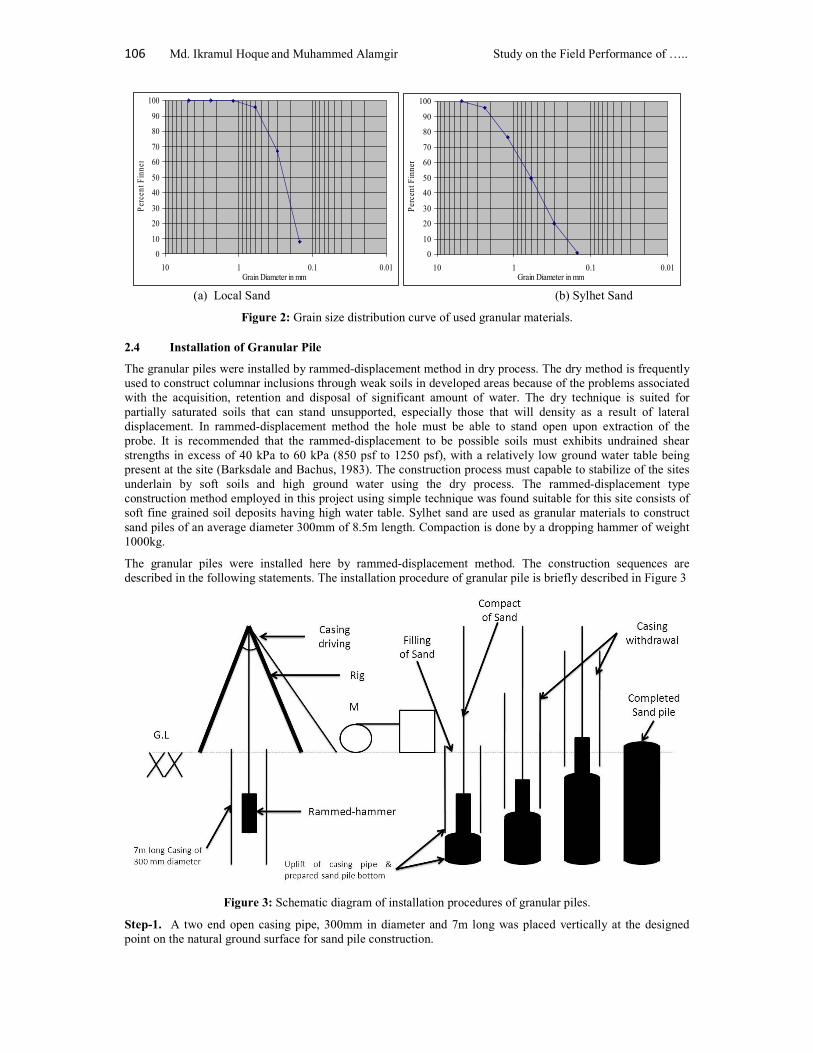
In this investigation, considering the practical situation of availability of construction techniques and materials in Bangladesh, granular piles were installed by using Rammed-Compaction method. Sylhet sand, a yellowish-brown color river sand is used as the granular materials. The Physical properties of Sylhet sand can be described as FM=2.58, D10 = 0.22, D30=0.3, D60=0.80, Cu=3.64 and Cc=0.82. However, locally available sand are river sand and of light grey in color, relatively finer than that of Sylhet sand. The physical properties of local sand can be described as FM=1.13, D10=0.15, D30=0.22, D60=0.28, Cu=1.86 and Cc=1.15. The grain size distribution of Sylhet sand is shown in Figure 2. Here, FM= Fineness modulus, D10=Effective diameter of particle size of which 10% sample is smaller, D30=Diameter of particle size of which 30% sample is smaller, D60=Diameter of particle size of which 60% sample is smaller, Cu = Co-efficient of uniformity and Cc= Co-efficient of curvature.
106 Md. Ikramul Hoque and Muhammed Alamgir Study on the Field Performance of …..
0
10
20
30
40
50
60
70
80
90
100
0.010.1110Grain Diameter in mm
Per
cent
Fin
ner
0
10
20
30
40
50
60
70
80
90
100
0.010.1110Grain Diameter in mm
Per
cent
Fin
ner
(a) Local Sand (b) Sylhet Sand
Figure 2: Grain size distribution curve of used granular materials.
2.4 Installation of Granular Pile
The granular piles were installed by rammed-displacement method in dry process. The dry method is frequently used to construct columnar inclusions through weak soils in developed areas because of the problems associated with the acquisition, retention and disposal of significant amount of water. The dry technique is suited for partially saturated soils that can stand unsupported, especially those that will density as a result of lateral displacement. In rammed-displacement method the hole must be able to stand open upon extraction of the probe. It is recommended that the rammed-displacement to be possible soils must exhibits undrained shear strengths in excess of 40 kPa to 60 kPa (850 psf to 1250 psf), with a relatively low ground water table being present at the site (Barksdale and Bachus, 1983). The construction process must capable to stabilize of the sites underlain by soft soils and high ground water using the dry process. The rammed-displacement type construction method employed in this project using simple technique was found suitable for this site consists of soft fine grained soil deposits having high water table. Sylhet sand are used as granular materials to construct sand piles of an average diameter 300mm of 8.5m length. Compaction is done by a dropping hammer of weight 1000kg.
The granular piles were installed here by rammed-displacement method. The construction sequences are described in the following statements. The installation procedure of granular pile is briefly described in Figure 3
Figure 3: Schematic diagram of installation procedures of granular piles.
Step-1. A two end open casing pipe, 300mm in diameter and 7m long was placed vertically at the designed point on the natural ground surface for sand pile construction.
Journal of Engineering Science 05(1), 2014, 103-114 107
Step-2. The casing pipe was then inserted vertically into the ground about 300mm to 450mm depth at its own weight just by applying some pressure manually. At first a plug is made by the designated sand up to 750mm of casing pipe at bottom level.
Step-3. The rammed-hammer 250mm in diameter, 3.0m long and weight 1000kg was placed inside the casing pipe. The rammed-hammer displaced the soil from beneath the casing pipe and the casing pipe was driven by its own weight till reached the designated position (depth) into the ground. Here one casing pipe of 7.0m long was driven inside the ground.
Step-4. After reaching the designated depth, the sand plug is broken by providing excess energy then the rammed-hammer is withdrawn from the casing pipe.
Step-5. Casing pipe was then lifted up by about 1m from its original bottom position. The designated granular materials were poured into the hole about 1m layer thickness measured from the bottom. The poured granular materials was then densified by rammed-hammer till the required compactness achieved.
Step-6. Casing pipe was then withdrawn from inside the ground that left the bottom portion of the hole unsupported and the top portion supported by the casing pipe. It was observed that the bottom portion of the hole standing safely without any lateral support.
Step-7. Then hole was poured by the selected granular materials in layers and hence 10 to 15 drops compacted each layer was densified by rammed-hammer till the designated compactness was reached. In general, the thickness of each layer was about 1.0m and 0.65m to 0.75m before and after densification respectively and the free fall height of the rammed-hammer was 0.75m to 1.0m.
Step-8. After the top of granular piles were reached about 1.0m to 1.5m below the ground surface the casing pipe was withdrawn and left the remaining hole unsupported.
Step-9. Then step 5 was continued until the granular piles were constructed up to the ground level.
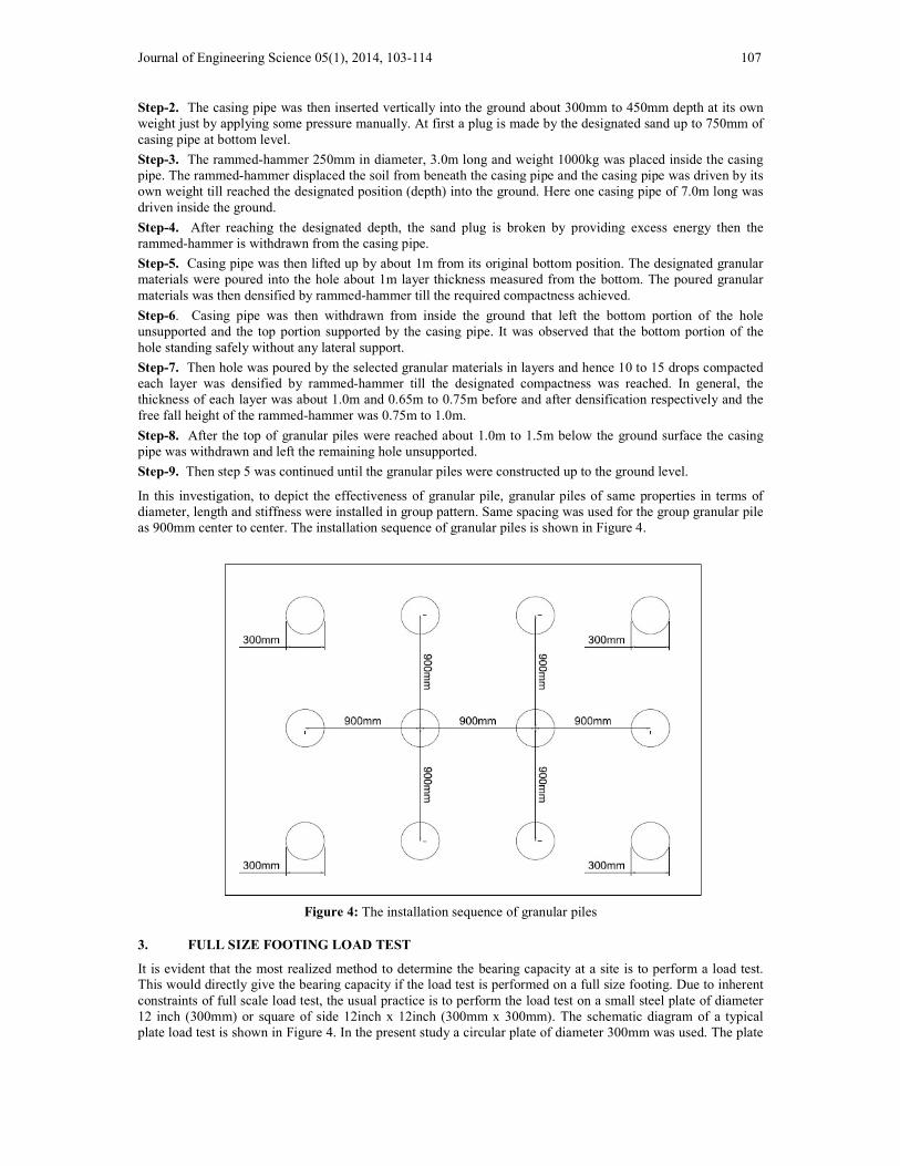
In this investigation, to depict the effectiveness of granular pile, granular piles of same properties in terms of diameter, length and stiffness were installed in group pattern. Same spacing was used for the group granular pile as 900mm center to center. The installation sequence of granular piles is shown in Figure 4.
Figure 4. The installation sequence of granular piles.
Figure 4: The installation sequence of granular piles
3. FULL SIZE FOOTING LOAD TEST
It is evident that the most realized method to determine the bearing capacity at a site is to perform a load test. This would directly give the bearing capacity if the load test is performed on a full size footing. Due to inherent constraints of full scale load test, the usual practice is to perform the load test on a small steel plate of diameter 12 inch (300mm) or square of side 12inch x 12inch (300mm x 300mm). The schematic diagram of a typical plate load test is shown in Figure 4. In the present study a circular plate of diameter 300mm was used. The plate
108 Md. Ikramul Hoque and Muhammed Alamgir Study on the Field Performance of …..
load tests conducted in the present investigation are shown in Figure 5 and 6. Each load increment is one-tens of the estimated capacity. The procedure has been standardized as ASTM D1194, which is essentially as follows:
Step-1. To take decision on the type of load application. If it is a reaction against piles, they should be driven first to avoid excessive vibration and loosening of the soil in the excavation where the load test is performed.
Step-2. A pit is excavated to the depth at which the test is performed. The test pit should be at least four times as wide as the plate and the depth is same as the depth of foundation.
Step-3. The necessary load is to place on the plate and settlement to be recorded from two dial gauges accurate to 0.25mm. Observation on a load increment should be taken until the rate of settlement is to reach beyond the capacity of dial gauge. Load increments should be approximately one-fifth of the estimated bearing capacity of the soil. Time intervals should not be more than one hour and should be same duration for all the load increments.
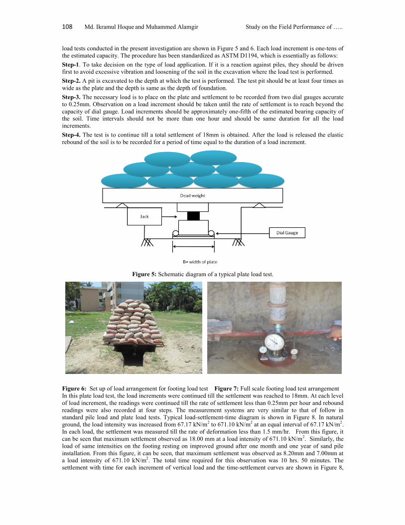
Step-4. The test is to continue till a total settlement of 18mm is obtained. After the load is released the elastic rebound of the soil is to be recorded for a period of time equal to the duration of a load increment.
Figure 5: Schematic diagram of a typical plate load test.
Figure 6: Set up of load arrangement for footing load test Figure 7: Full scale footing load test arrangement In this plate load test, the load increments were continued till the settlement was reached to 18mm. At each level of load increment, the readings were continued till the rate of settlement less than 0.25mm per hour and rebound readings were also recorded at four steps. The measurement systems are very similar to that of follow in standard pile load and plate load tests. Typical load-settlement-time diagram is shown in Figure 8. In natural ground, the load intensity was increased from 67.17 kN/m2 to 671.10 kN/m2 at an equal interval of 67.17 kN/m2. In each load, the settlement was measured till the rate of deformation less than 1.5 mm/hr. From this figure, it can be seen that maximum settlement observed as 18.00 mm at a load intensity of 671.10 kN/m2. Similarly, the load of same intensities on the footing resting on improved ground after one month and one year of sand pile installation. From this figure, it can be seen, that maximum settlement was observed as 8.20mm and 7.00mm at a load intensity of 671.10 kN/m2. The total time required for this observation was 10 hrs. 50 minutes. The settlement with time for each increment of vertical load and the time-settlement curves are shown in Figure 8,

Journal of Engineering Science 05(1), 2014, 103-114 109
for both the natural and treated ground at an elapsed time of one month and one year after the installation sand piles.
Figure 8: Load-settlement response with time for both the untreated and treated ground
4. RESULT AND DISCUSSION
The load-settlement response of natural ground are shown in Figure 9. From this figure it can be seen that the settlement increases with the application of load increment. From the plate load test at the designated on the natural ground, it was observed that the plate moved downward without giving any resistance after the application of load beyond 671.70kN/m2. At this load intensity the settlement is 18.00mm
The plate load test was performed on the single pile immediately after the installation of sand pile to determine the load carrying capacity of single sand pile. The load carrying capacity of the single sand pile was measured as 671.70kN/m2 for the settlement of 8.20 mm. The settlement profile of the single sand pile reinforced ground is shown in Figure 9 for the increase of load intensity. This figure shows that the settlement of the improved ground increases with increases the load intensity. This field test result also shows that the load carrying capacity of the single sand pile was measured as 671.70 kN/m2, which is about 2.0 times less than that of natural ground.
In the same improved ground, the plate load test was conducted again on the single pile one year after the installation of sand pile to determine the load carrying capacity of single sand pile. The load carrying capacity of the single sand pile was measured as 671.70kN/m2 for the settlement of 7.00 mm. The settlement profile of the single sand pile reinforced ground is shown in Figure 9 for the increase of load intensity. This figure shows that the settlement of the improved ground increases at the load intensity increases. The field test result shows that the load carrying capacity of the single sand pile is 671.70 kN/m2, which is about 2.50 times less than that of natural ground for the same settlement.
4.1 Comparison of Plate Load Test Results
The field test results indicating the improvement of load carrying capacity due to the installation of granular piles in different conditions were compared in this section with that of natural ground. Comparison is also made among the different improvement conditions.
4.1.1 One month after sand pile installation
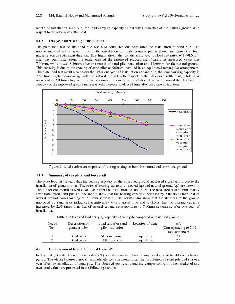
The plate load test on the sand pile was performed immediately i.e one month after the installation sand pile. The improvement of natural ground due to the installation of single granular pile is shown in Figure 9 in load intensity versus settlement diagram. This figure shows that for the same level of load intensity (671.70kN/m2), the settlement of the improved reduced significantly as measured value was 8.20mm, while it was 18.00mm for the natural ground. The result shows that the bearing capacity of natural ground increased significantly due to the installation of granular piles irrespective of the types of materials. The plate load test revealed that after one
110 Md. Ikramul Hoque and Muhammed Alamgir Study on the Field Performance of …..
month of installation sand pile, the load carrying capacity is 2.0 times than that of the natural ground with respect to the allowable settlement.
4.1.2 One year after sand pile installation
The plate load test on the sand pile was also conducted one year after the installation of sand pile. The improvement of natural ground due to the installation of single granular pile is shown in Figure 9 in load intensity versus settlement diagram. This figure shows that for the same level of load intensity, 671.70kN/m2, after one year installation, the settlements of the improved reduced significantly as measured value was 7.00mm, while it was 8.20mm after one month of sand pile installation and 18.00mm for the natural ground. This capacity is due to the spacing of sand piles as 900mm installed in an equilateral rectangular arrangement. The plate load test result also shows that after one year of installation of sand pile, the load carrying capacity is 2.50 times higher comparing with the natural ground with respect to the allowable settlement, while it is measured as 2.0 times higher just after one month of sand pile installation. The results reveal that the bearing capacity of the improved ground increases with increase of elapsed time after sand pile installation.
0
2
4
6
8
10
12
14
16
18
20
0 100 200 300 400 500 600 700 800
Load intens ity (kN/m2)
Sett
lem
ent (
mm
)
Natural Soil
Sand (Onemonth aftersand pileins tallation)Sand (Oneyear aftersand pileins tallation)
Figure 9: Load-settlement response of footing resting on both the natural and improved ground
4.1.3 Summary of the plate load test result
The plate load test reveals that the bearing capacity of the improved ground increased significantly due to the installation of granular piles. The ratio of bearing capacity of treated (qt) and natural ground (qn) are shown in Table 2 for one month as well as one year after the installation of sand piles. The measured results immediately after installation sand pile i.e. one month show that the bearing capacity increased by 2.00 times than that of natural ground corresponding to 7.00mm settlement. The results also show that the stiffness of the ground improved by sand piles influenced significantly with elapsed time and it shows that the bearing capacity increased by 2.50 times than that of natural ground corresponding to 7.00mm settlement, after one year of installation.
Table 2: Measured load carrying capacity of sand pile compared with natural ground
No. of Test
Description of granular piles
Load test after sand pile installation
Location of plate qt/qn (Corresponding to 7.00
mm settlement) 1 Sand piles After one month Top of pile 2.00 2 Sand piles After one year Top of pile 2.50
4.2 Comparison of Result Obtained from SPT
In this study, Standard Penetration Tests (SPT) was also conducted on the improved ground for different elapsed period. The elapsed periods are: (i) immediately i.e. one month after the installation of sand pile and (ii) one year after the installation of sand pile. The obtained test results and the comparison with other predicted and measured values are presented in the following sections.
Journal of Engineering Science 05(1), 2014, 103-114 111
4.2.1 One month after sand pile installation
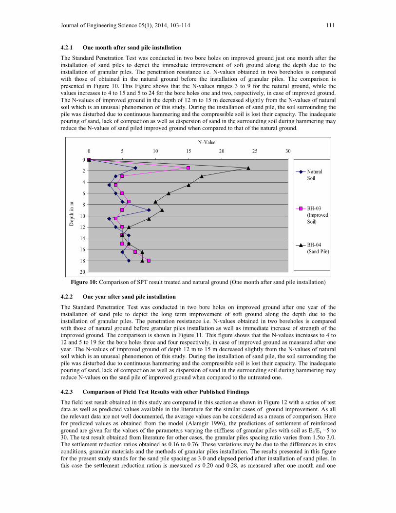
The Standard Penetration Test was conducted in two bore holes on improved ground just one month after the installation of sand piles to depict the immediate improvement of soft ground along the depth due to the installation of granular piles. The penetration resistance i.e. N-values obtained in two boreholes is compared with those of obtained in the natural ground before the installation of granular piles. The comparison is presented in Figure 10. This Figure shows that the N-values ranges 3 to 9 for the natural ground, while the values increases to 4 to 15 and 5 to 24 for the bore holes one and two, respectively, in case of improved ground. The N-values of improved ground in the depth of 12 m to 15 m decreased slightly from the N-values of natural soil which is an unusual phenomenon of this study. During the installation of sand pile, the soil surrounding the pile was disturbed due to continuous hammering and the compressible soil is lost their capacity. The inadequate pouring of sand, lack of compaction as well as dispersion of sand in the surrounding soil during hammering may reduce the N-values of sand piled improved ground when compared to that of the natural ground.
0
2
4
6
8
10
12
14
16
18
20
0 5 10 15 20 25 30
N-Value
Dep
th in
m
NaturalSoil
BH-03 (ImprovedSoil)
BH-04 (Sand Pile)
Figure 10: Comparison of SPT result treated and natural ground (One month after sand pile installation)
4.2.2 One year after sand pile installation
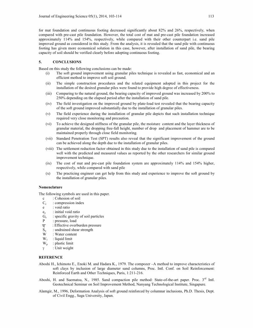
The Standard Penetration Test was conducted in two bore holes on improved ground after one year of the installation of sand pile to depict the long term improvement of soft ground along the depth due to the installation of granular piles. The penetration resistance i.e. N-values obtained in two boreholes is compared with those of natural ground before granular piles installation as well as immediate increase of strength of the improved ground. The comparison is shown in Figure 11. This figure shows that the N-values increases to 4 to 12 and 5 to 19 for the bore holes three and four respectively, in case of improved ground as measured after one year. The N-values of improved ground of depth 12 m to 15 m decreased slightly from the N-values of natural soil which is an unusual phenomenon of this study. During the installation of sand pile, the soil surrounding the pile was disturbed due to continuous hammering and the compressible soil is lost their capacity. The inadequate pouring of sand, lack of compaction as well as dispersion of sand in the surrounding soil during hammering may reduce N-values on the sand pile of improved ground when compared to the untreated one.
4.2.3 Comparison of Field Test Results with other Published Findings
The field test result obtained in this study are compared in this section as shown in Figure 12 with a series of test data as well as predicted values available in the literature for the similar cases of ground improvement. As all the relevant data are not well documented, the average values can be considered as a means of comparison. Here for predicted values as obtained from the model (Alamgir 1996), the predictions of settlement of reinforced ground are given for the values of the parameters varying the stiffness of granular piles with soil as Ec/Es =5 to 30. The test result obtained from literature for other cases, the granular piles spacing ratio varies from 1.5to 3.0. The settlement reduction ratios obtained as 0.16 to 0.76. These variations may be due to the differences in sites conditions, granular materials and the methods of granular piles installation. The results presented in this figure for the present study stands for the sand pile spacing as 3.0 and elapsed period after installation of sand piles. In this case the settlement reduction ration is measured as 0.20 and 0.28, as measured after one month and one

112 Md. Ikramul Hoque and Muhammed Alamgir Study on the Field Performance of …..
year, respectively. The variation of settlement reduction ratio with spacing for the data is considerable, however, the results agreed well with the predicted values as reported in the literature for higher stiffness of the granular piles. While the results are not conclusive, since not enough well documented data are available from the field, these figures support the validity of present study conducted in the field.
0
2
4
6
8
10
12
14
16
18
20
0 2 4 6 8 10 12 14 16 18 20
N-Value
Dep
th in
m
NaturalSoil
BH-03 (ImprovedSoil)
BH-04 (Sand Pile)
Figure 11: Comparison of SPT result treated and natural ground (One year after sand pile installation)
Figure 12: Validation of the field test result of present study with the predicted and measured values of settlement reduction ratio obtained by other researchers in similar cases
4.2.4 Comparison of Cost of Sand Pile with the Conventional Foundation System
The cost involved for using ground improvement technique with sand piles are also investigated and hence compared with the cost of conventional foundation system such as mat and pile, generally practiced in soft soil condition. The total cost of mat foundation has dominated by the cost of reinforcing steel which is approximately 160% and 72% more the cost of reinforcing steel than the continuous footing with sand pile and pre-cast pile foundation, respectively. On the other hand, the total estimated construction and installation cost
Journal of Engineering Science 05(1), 2014, 103-114 113
for mat foundation and continuous footing decreased significantly about 82% and 26%, respectively, when compared with pre-cast pile foundation. However, the total cost of mat and pre-cast pile foundation increased approximately 114% and 154%, respectively, while compared with their other counterpart i.e. sand pile improved ground as considered in this study. From the analysis, it is revealed that the sand pile with continuous footing has given more economical solution in this case, however, after installation of sand pile, the bearing capacity of soil should be verified clearly before adopting continuous footing.
5. CONCLUSIONS
Based on this study the following conclusions can be made: (i) The soft ground improvement using granular piles technique is revealed as fast, economical and an
efficient method to improve soft soil ground.
(ii) The simple construction procedures and the related equipment adopted in this project for the installation of the desired granular piles were found to provide high degree of effectiveness.
(iii) Comparing to the natural ground, the bearing capacity of improved ground was increased by 200% to 250% depending on the elapsed period after the installation of sand pile.
(iv) The field investigation on the improved ground by plate-load test revealed that the bearing capacity of the soft ground improved substantially due to the installation of granular piles.
(v) The field experience during the installation of granular pile depicts that such installation technique required very close monitoring and precaution.
(vi) To achieve the designed stiffness of the granular pile, the moisture content and the layer thickness of granular material, the dropping free-fall height, number of drop and placement of hammer are to be maintained properly through close field monitoring.
(vii) Standard Penetration Test (SPT) results also reveal that the significant improvement of the ground can be achieved along the depth due to the installation of granular piles.
(viii) The settlement reduction factor obtained in this study due to the installation of sand pile is compared well with the predicted and measured values as reported by the other researchers for similar ground improvement technique.
(ix) The cost of mat and pre-cast pile foundation system are approximately 114% and 154% higher, respectively, while compared with sand pile
(x) The practicing engineer can get help from this study and experience to improve the soft ground by the installation of granular piles.
Nomenclature
The following symbols are used in this paper. c : Cohesion of soil Cc : compression index e : void ratio eo : initial void ratio Gs : specific gravity of soil particles P : pressure, load q : Effective overburden pressure Su : undrained shear strength W : Water content W1 : liquid limit Wp : plastic limit : Unit weight
REFERENCE
Aboshi H., Ichimoto E., Enoki M. and Hadara K., 1979. The compozer –A method to improve characteristics of soft clays by inclusion of large diameter sand columns, Proc. Intl. Conf. on Soil Reinforcement: Reinforced Earth and Other Techniques, Paris, 1:211-216.
Aboshi, H. and Suematsu, N., 1985. Sand compaction pile method: State-of-the-art paper. Proc. 3rd Intl. Geotechnical Seminar on Soil Improvement Method, Nanyang Technological Institute, Singapure.
Alamgir, M., 1996, Deformation Analysis of soft ground reinforced by columnar inclusions, Ph.D. Thesis, Dept. of Civil Engg., Saga University, Japan.
114 Md. Ikramul Hoque and Muhammed Alamgir Study on the Field Performance of …..
Alamgir, M., Miura, N. and Poorooshasb, H.B., 1996. Effect of Granular Fill on Settlement of Column-Reinforced Ground, 31st Annual Conf. of Japanese Geotechnical Society, pp.1505-1506.
Alamgir, M. and Zaher, S.M., 1999(a). Field Performance of Sand Piles in Improving Soft Ground, 43rd National Convention of Institute of Engineers Bangladesh (IEB), Dhaka, Bangladesh.
Alamgir, M. and Miura, N., 1999. Observed and Predicted Behaviour of column-Reinforced Composite Ground, 2nd Intl. Symp. On Pre-failure Characteristics of Geomaterials, IS Torino, AABalkema, 833-840.
Balaam, N. P., and Booker, J. R., 1981. Analysis of rigid raft supported by granular piles”, Intl. Journal for Num. and Anal. Methods in Geomech. 5, 379-403.
Barksdale, R.D. and Bachus R.C., 1983. Design and construction of stone columns, 1. Report No. FHWA/ RD-83/026, National Technical Information Service. Springfield, Virginia, U.S.A.
Bargado, D. T., and Lam, F. L., 1987. Full scale load test of granular piles with different densities and different proportion of gravel and sand in the soft Bangkok clay, Soils and Foundations, 27, 1, 86-93.
Bargado, D. T., Panichayatum, B., Sampaco, C.L. and Miura, N., 1988. Reinforcement of soft Bangkok clay using granular piles, Proc. Intl. Geotechnical Symposium on Theory and Practice of Earth Reinforcement, Fukuoka, Japan, 179-184.
Bowles, J. E., 1988. Foundation design and analysis, McGraw-Hill International Edition: Civil Engineering Series, 4th Edition, Singapore.
Baumann, V. and Bauer, G. E. A., 1974. The performance of foundation on various soils stabilized by vibro-compaction method, Canadian Geotechnical Journal. 11, 509-530.
Charles, J. A and Watts, K. S., 1983. Compressibility of soft clay reinforcement with granular columns, Proc. 8th Europian Conf. on SMEE, Helsinki, a, 347-352.
Datye, K. R., and Nagaraju, S. S., 1975. Installation and testing of rammed stone columns, Proc. IGS Specially Session, 5th Asian Regional Conf. on SMFE, Banglore, India, 101-104.
Datye, K.R., 1978. Special construction techniques, Proc. IGS Conf. on Geotech. Engineering, New Delhi, India, 30-44.
Datye, K.R. and Nagaraju, S.S., 1981. Design approach and Field control for stone columns, Proc. 10th ICSMEF, Stockholm, Sweden, 3, 637-640.
Engelhardt, K. and Golding, H.C., 1975. Field testing to evaluate stone column performance in a seismic area, Geotechnique, 25, 1, 61-69.
Hossain, M. J., 2009. Performance Study of Geopier as a Ground Improvement Technique in Khulna Region, M.Sc. Engg. Thesis, Department of Civil Engineering, KUET, Bangladesh.
Hughes, J. M. O. and Withers, N. J., 1974. Reinforcing soft cohesive soil with stone columns, Ground Engineering, 7, 3, 42-49.
Hughes, J. M. O., Withers, N. J., and Greenwood, D. A., 1975. A field trial of the reinforcing effect of a stone column in soil, Geotechnique, 25, 1, 31-44.
Kimuru, T., Nakase, A., Kusakabe, O. and Saitoh, K., 1985. Behavior of soil improved by sand compaction piles, Proc. 11th ICSMFE, San Francisco, 2, 1109-1112.
Leung, C.F. and Tan, T.S., 1993. Load distribution in soft clay reinforced by sand columns, Proc. Intl. Conf. on Soft Soil Engineering, Nov.8-11, Guangzhou, China, 779-784.
Madhav, M.R., 1982. Recent development in the use and analysis of granular piles, Proc. Symposium on Recent Development in Ground Improvement Techniques, Bangkok, Thailand, 117-129.
Madhav, M. R., Alamgir, M. and Miura, N., 1994. Improving granular column capacity by geogrid reinforcement, 5th Intl. Conf. on Geotextiles, Geomembranes and Related Products, Singapore, 5-9 September, 351-355.
Zaher, S. M., 2000. Effectiveness of granular Piles Installed by Vibro-displacement Method in Improving Soft Soil, M. Engg. Thesis, Department of Civil Engg., KUET, Bangladesh.