Utilization of CD and DVD Pick-Up Heads for Scratch ... - MDPI
11
applied sciences Article Utilization of CD and DVD Pick-Up Heads for Scratch Inspection of Magnetic Disk in Dynamic State Using Microcontroller Achinee Polsawat 1,2 , Warunee Tipcharoen 3 and Apirat Siritaratiwat 1, * 1 Department of Electrical Engineering, Faculty of Engineering, KhonKaen University, KhonKaen 40002, Thailand; [email protected] 2 Department of Electronic Technology, Faculty of Industrial Technology, Ubon Ratchathani Rajaphat University, Ubon Ratchathani 34000, Thailand 3 Seagate Co. Ltd., 1627 Teparak, Samutprakarn 10270, Thailand; [email protected] or [email protected] * Correspondence: [email protected] or [email protected] Received: 24 August 2020; Accepted: 29 September 2020; Published: 1 October 2020 Featured Application: This work demonstrates the utilization of CD/DVD pick-up heads for scratch inspection on magnetic disk. Abstract: A non-destructive technique to inspect a scratch on all magnetic disks in the beginning process of hard disk drive (HDD) manufacturing by using CD and DVD pick-up heads as the detector is proposed. It requires a 100% disk inspection of micrometer-sized scratches in a quick measurement with low cost inventing. Most of the previous studies were in static state but this is the first time to be done in dynamic study using the microcontroller in order to promptly serve for industrial utilization. The size, position, and shape characteristic of scratches are examined using light reflection technique. The results show that, when the laser beam is targeted on a magnetic disk in a position, either scratch or non-scratch, the reflected light intensity differs. The DVD pick-up head can detect the width and the surface characteristic of the scratches, which is similar to the results from scanning electron microscope (SEM) for all scratches sizes less than 100 μm. It is also found that using a DVD pick-up head provides a better resolution of shape characteristic and roughness of scratches surface than a CD pick-up head. Hence, the scratch size of 10s μm scale on the magnetic disk can be accurately characterized by this proposed technique, which can be further utilized for magnetic disk inspection in the hard disk drive manufacturing process. Keywords: scratch detection; four error signal; CD pick-up head; DVD pick-up head 1. Introduction Scratch detection on magnetic disk is an important process of a quality inspection of hard disk drive (HDD) manufacturing because the scratches could possibly affect reading/writing performance of the HDD [1]. Scratches mainly occur due to contamination in the HDD assembly process, or crashing between magnetic recording head and disk [2]. Thus, the scratch inspection is a crucial process to reject latently damaged disks before further processes. In order to detect scratches, many tools have been employed, such as scanning electron microscope (SEM) and atomic force microscope (AFM). They were introduced because of their clarified resolution for detecting a scratch and its depth by images [3]. However, they are complicated in terms of utilization procedures and the light microscope with less complication than those proposed with a low resolution gain of about 100× [4]. Although these three methods are surface free-contact techniques, they are Appl. Sci. 2020, 10, 6897; doi:10.3390/app10196897 www.mdpi.com/journal/applsci
-
Upload
khangminh22 -
Category
Documents
-
view
2 -
download
0
Transcript of Utilization of CD and DVD Pick-Up Heads for Scratch ... - MDPI

applied sciences
Article
Utilization of CD and DVD Pick-Up Heads forScratch Inspection of Magnetic Disk in Dynamic StateUsing Microcontroller
Achinee Polsawat 1,2 , Warunee Tipcharoen 3 and Apirat Siritaratiwat 1,*1 Department of Electrical Engineering, Faculty of Engineering, KhonKaen University,
KhonKaen 40002, Thailand; [email protected] Department of Electronic Technology, Faculty of Industrial Technology,
Ubon Ratchathani Rajaphat University, Ubon Ratchathani 34000, Thailand3 Seagate Co. Ltd., 1627 Teparak, Samutprakarn 10270, Thailand; [email protected] or
[email protected]* Correspondence: [email protected] or [email protected]
Received: 24 August 2020; Accepted: 29 September 2020; Published: 1 October 2020�����������������
Featured Application: This work demonstrates the utilization of CD/DVD pick-up heads forscratch inspection on magnetic disk.
Abstract: A non-destructive technique to inspect a scratch on all magnetic disks in the beginningprocess of hard disk drive (HDD) manufacturing by using CD and DVD pick-up heads as the detectoris proposed. It requires a 100% disk inspection of micrometer-sized scratches in a quick measurementwith low cost inventing. Most of the previous studies were in static state but this is the first time to bedone in dynamic study using the microcontroller in order to promptly serve for industrial utilization.The size, position, and shape characteristic of scratches are examined using light reflection technique.The results show that, when the laser beam is targeted on a magnetic disk in a position, either scratchor non-scratch, the reflected light intensity differs. The DVD pick-up head can detect the widthand the surface characteristic of the scratches, which is similar to the results from scanning electronmicroscope (SEM) for all scratches sizes less than 100 µm. It is also found that using a DVD pick-uphead provides a better resolution of shape characteristic and roughness of scratches surface than aCD pick-up head. Hence, the scratch size of 10s µm scale on the magnetic disk can be accuratelycharacterized by this proposed technique, which can be further utilized for magnetic disk inspectionin the hard disk drive manufacturing process.
Keywords: scratch detection; four error signal; CD pick-up head; DVD pick-up head
1. Introduction
Scratch detection on magnetic disk is an important process of a quality inspection of hard diskdrive (HDD) manufacturing because the scratches could possibly affect reading/writing performance ofthe HDD [1]. Scratches mainly occur due to contamination in the HDD assembly process, or crashingbetween magnetic recording head and disk [2]. Thus, the scratch inspection is a crucial process to rejectlatently damaged disks before further processes.
In order to detect scratches, many tools have been employed, such as scanning electron microscope(SEM) and atomic force microscope (AFM). They were introduced because of their clarified resolutionfor detecting a scratch and its depth by images [3]. However, they are complicated in terms of utilizationprocedures and the light microscope with less complication than those proposed with a low resolutiongain of about 100× [4]. Although these three methods are surface free-contact techniques, they are
Appl. Sci. 2020, 10, 6897; doi:10.3390/app10196897 www.mdpi.com/journal/applsci

Appl. Sci. 2020, 10, 6897 2 of 11
expensive, destructive, and time-consuming. In order to cover up these disadvantages, the scratchinspection with a satisfied resolution in a quick process was developed using a thermal infrared camerato detect the surface heat and it was found that heat appears only on the surface, not scratch [5].A magnetic disk, in the real process, rotates at a certain velocity and researchers have proposed variouspossibilities to detect a scratch dynamically. One showed an inventory of an optical pickup unit forlight reflection into the charge coupled device (CCD) with polarizers and Infrared- (IR) cut filters forintensification of the laser beam [6]. However, for better resolution, machine vision inspection methodsusing various algorithms to examine the 2D surface images have also been studied but they can onlybe measured in static state [7]. In addition, it is still a vast cost of investment for industry.
Therefore, a new technique of low cost, easy process, and scratch detectability has been presentedby using ordinary laser doppler and CD pick-up head to inspect surface details because of its advantageson the measurement of object roughness and the identification of scratch location, in a compromisingprocess [8,9]. Moreover, numerous studies have recently shown interesting results of using DVDpick-up head to detect the reflective DNA layers on a DNA chip slide as its potentiality to show theshape of the DNA and count the number of cells [10]. The DVD pick-up head has been developed forbetter precision by reflecting the beam to photo detector integrated chip (PDIC), as a receiver, and then,the reflected laser light from PDIC is focused and analyzed on four quadrant sensors of photodiodedetector [11].
This study proposes a developed invention of non-destructive detection technique to inspect a10 + µm scale of scratches on a rotating magnetic disk. The current process of scratch inspection inmanufacturing randomly chooses disks and it causes failures found in further processes. The assemblyprocesses of latent failure disks lead to the cost of operation. Therefore, this instrument can quicklyinspect big scratches of all media disk and a disk with a scratch found in this beginning of themanufacturing process will be thrown away at once. The CD and DVD pick-up heads with 790 and650 nm wavelengths, respectively, are firstly combined and developed by using PDIC to specify theposition and the shape of scratches for a wide range of wavelength selection. This aims to supportthe invention of its ability to specify the scratch location. The shapes of scratches are also examinedby SEM to verify the experimental results. The scratches of 55–332 µm size are tested because of theindustrial requirement for rejection criteria. In addition, an optimistic rotating speed of magnetic diskto improve performances of CD and DVD pick-up heads has to be investigated.
2. Materials and Methods
2.1. Determination of Scratch Position and Width
The scratch position can be calculated by finding a distance (∆s) based on the rotating velocity (v)from a radially moving reference point on the CD/DVD pick-up head as shown in Equation (1) andFigure 1. The distance along the circumstance is increased when the radius increases:
v =∆s∆t
. (1)
The scratch width is calculated from the sampling rate of a number of sampling in 1 cycle per distanceas the magnetic disk movement is relative to the time. The radio frequency (RF) signal measurement isachieved by using the waveAce 2012 oscilloscope with a 40–300 MHz bandwidth and a maximum2 GS/s sampling rate. In order to find the location of the scratch, a microcontroller will control astepping motor to move a disk in circular axis and a pick-up head to move along the radius axis.

Appl. Sci. 2020, 10, 6897 3 of 11Appl. Sci. 2020, 10, x FOR PEER REVIEW 3 of 11
s
Figure 1. Measurement of scratch width and position using developed CD/DVD pick-up head.
The scratch width is calculated from the sampling rate of a number of sampling in 1 cycle per distance as the magnetic disk movement is relative to the time. The radio frequency (RF) signal measurement is achieved by using the waveAce 2012 oscilloscope with a 40–300 MHz bandwidth and a maximum 2 GS/s sampling rate. In order to find the location of the scratch, a microcontroller will control a stepping motor to move a disk in circular axis and a pick-up head to move along the radius axis.
2.2. Focus Error Signal Technique
A laser beam, generated by the DVD pick-up head, was introduced to propagate onto a surface of the disk and then, reflected to a portion of 4 quadrant sensors of a photodiode detector for a pre-cise focus [12]. However, the focal range of reflection light of the DVD pick-up head covers more than one quadrant of the photodiode detector and the focus error signal (FES) technique was pro-posed [13].
A CD pick-up head with different wavelength is firstly, in this paper, combined with the DVD pickup head for not only making a comparison but also, increasing the ranges of wavelength or scratch details. In order to overcome the misalignment problem between focal distances of the re-flection light, the technique of focus error signals (FES) is then developed as shown in Figure 2 and following Equations (2) and (3) for CD/DVD modes. The symbolic modes of the CD/DVD are sets of A, B, C, D and of a, b, c, d, respectively.
Figure 1. Measurement of scratch width and position using developed CD/DVD pick-up head.
2.2. Focus Error Signal Technique
A laser beam, generated by the DVD pick-up head, was introduced to propagate onto a surface ofthe disk and then, reflected to a portion of 4 quadrant sensors of a photodiode detector for a precisefocus [12]. However, the focal range of reflection light of the DVD pick-up head covers more than onequadrant of the photodiode detector and the focus error signal (FES) technique was proposed [13].
A CD pick-up head with different wavelength is firstly, in this paper, combined with the DVDpickup head for not only making a comparison but also, increasing the ranges of wavelength or scratchdetails. In order to overcome the misalignment problem between focal distances of the reflectionlight, the technique of focus error signals (FES) is then developed as shown in Figure 2 and followingEquations (2) and (3) for CD/DVD modes. The symbolic modes of the CD/DVD are sets of A, B, C, Dand of a, b, c, d, respectively.
FESCD = (VA + VC) − (VB + VD) (2)
FESDVD = (Va + Vc) − (Vb + Vd) (3)Appl. Sci. 2020, 10, x FOR PEER REVIEW 4 of 11
Figure 2. Developed focus error signal of the CD/DVD pick-up head.
퐹퐸푆 = (푉 + 푉 ) − (푉 + 푉 ) (2)
퐹퐸푆 = (푉 + 푉 ) − (푉 + 푉 ) (3)
2.3. RF Amplifier of Signals
However, the output signal is too small to be analyzed and so, an amplifier circuit has to be designed. In addition, for further enhancement of signal amplitude, the RF amplifier circuit is ex-tended to transform a light signal from four photodiode detectors to four current signals. The tech-nique is then developed to integrate the signals by using the RF summing amplifier circuit, as shown in Figure 3 and Equations (4) and (5) for the CD/DVD set, respectively.
Figure 3. Circuit diagram of the developed photodiode detector and signal amplifier.
Figure 2. Developed focus error signal of the CD/DVD pick-up head.

Appl. Sci. 2020, 10, 6897 4 of 11
2.3. RF Amplifier of Signals
However, the output signal is too small to be analyzed and so, an amplifier circuit has to bedesigned. In addition, for further enhancement of signal amplitude, the RF amplifier circuit is extendedto transform a light signal from four photodiode detectors to four current signals. The technique is thendeveloped to integrate the signals by using the RF summing amplifier circuit, as shown in Figure 3 andEquations (4) and (5) for the CD/DVD set, respectively.
RFsignalCD = A + B + C + D, (4)
RFsignalDVD = a + b + c + d. (5)
Appl. Sci. 2020, 10, x FOR PEER REVIEW 4 of 11
Figure 2. Developed focus error signal of the CD/DVD pick-up head.
퐹퐸푆 = (푉 + 푉 ) − (푉 + 푉 ) (2)
퐹퐸푆 = (푉 + 푉 ) − (푉 + 푉 ) (3)
2.3. RF Amplifier of Signals
However, the output signal is too small to be analyzed and so, an amplifier circuit has to be designed. In addition, for further enhancement of signal amplitude, the RF amplifier circuit is ex-tended to transform a light signal from four photodiode detectors to four current signals. The tech-nique is then developed to integrate the signals by using the RF summing amplifier circuit, as shown in Figure 3 and Equations (4) and (5) for the CD/DVD set, respectively.
Figure 3. Circuit diagram of the developed photodiode detector and signal amplifier.
Figure 3. Circuit diagram of the developed photodiode detector and signal amplifier.
Since the wavelength of CD, 790 nm, is larger than that of DVD, 650 nm, the photodiode detectorsare chosen to automatically switch a laser beam of two different wavelength modes. The specificationsof CD and DVD pick-up heads are compared in Table 1.
Table 1. Specifications of the CD/DVD pick-up head set of the Sanyo SF-HD 65 model.
Specification CD Pick-Up Head DVD Pick-Up Head
Laser wavelength (nm) 790 650
Focusing area (Standard operating position) (mm) ≥ +0.8 ≥ −0.7
Laser diode (LD)Threshold current (mA) 20–40 25–45
Operating current (mA) 35–70 35–90
Drive voltage (V) 4.5–5.5 -
Photodiode (PD) Operating supplied voltage (V) 4.5–5.5 -
Reference voltage (V) 2.1 ± 0.1 -
Play mode voltage (V) ≥3.5 ≤0.7
Radio Frequency (RF) signal (mVp-p) 1760 ± 440 1560 ± 390
Focus Error Signal (FES) (A + C) − (B + D) (a + c) − (b + d)
S-curve voltage (mVp-p) 530 ± 212 860 ± 301
Emission power output of objective lens (mW) 0.23 0.31

Appl. Sci. 2020, 10, 6897 5 of 11
2.4. Design of Microcontroller
Since the industrial inspection process is normally run in dynamic state, a rotating magneticdisk is to be controlled by using the microcontroller. This is firstly designed to fit the requirementof the industrial procedure by adapting an advanced RISC machine (ARM) Atmel, ATmega328Pmicroprocessor to control rotating stepping motor and pick-up heads as shown in Figure 4.
Appl. Sci. 2020, 10, x FOR PEER REVIEW 5 of 11
푅퐹푠푖푔푛푎푙 = 퐴 + 퐵 + 퐶 + 퐷, (4)
푅퐹푠푖푔푛푎푙 = 푎 + 푏 + 푐 + 푑. (5)
Since the wavelength of CD, 790 nm, is larger than that of DVD, 650 nm, the photodiode detec-tors are chosen to automatically switch a laser beam of two different wavelength modes. The speci-fications of CD and DVD pick-up heads are compared in Table 1.
Table 1. Specifications of the CD/DVD pick-up head set of the Sanyo SF-HD 65 model.
Specification CD Pick-Up Head DVD Pick-Up Head Laser wavelength (nm) 790 650
Focusing area (Standard operating position) (mm) ≥ +0.8 ≥ −0.7
Laser diode (LD) Threshold current (mA) 20–40 25–45 Operating current (mA) 35–70 35–90
Drive voltage (V) 4.5–5.5 -
Photodiode (PD) Operating supplied voltage (V) 4.5–5.5 -
Reference voltage (V) 2.1 ± 0.1 - Play mode voltage (V) ≥3.5 ≤0.7
Radio Frequency (RF) signal (mVp-p) 1760 ± 440 1560 ± 390 Focus Error Signal (FES) (A + C) − (B + D) (a + c) − (b + d) S-curve voltage (mVp-p) 530 ± 212 860 ± 301
Emission power output of objective lens (mW)
0.23 0.31
2.4. Design of Microcontroller
Since the industrial inspection process is normally run in dynamic state, a rotating magnetic disk is to be controlled by using the microcontroller. This is firstly designed to fit the requirement of the industrial procedure by adapting an advanced RISC machine (ARM) Atmel, ATmega328P mi-croprocessor to control rotating stepping motor and pick-up heads as shown in Figure 4.
Figure 4. A designed schematic diagram of the microcontroller to control the rotating stepping mo-tor and pick-up heads.
2.5. Verification of Scratch Size Detection and Characterization
In order to confirm the experimental results of scratch detection done by this proposed tech-nique, the SM and SEM are performed to characterize scratches. These two techniques have to be done in the last process of this study because the magnetic disk must be destroyed. The SM with 8–40× magnification is used to scan the visible scratches, while the SEM (JEOL No. JSM-6010LA) with
Figure 4. A designed schematic diagram of the microcontroller to control the rotating stepping motorand pick-up heads.
2.5. Verification of Scratch Size Detection and Characterization
In order to confirm the experimental results of scratch detection done by this proposed technique,the SM and SEM are performed to characterize scratches. These two techniques have to be donein the last process of this study because the magnetic disk must be destroyed. The SM with 8–40×magnification is used to scan the visible scratches, while the SEM (JEOL No. JSM-6010LA) with5–300,000×magnification at 400–700 nm wavelength is used to measure the size and shape of scratches.
3. Experimental Setup
This study presents a newly invented experimental setup by using a microcontroller for controllingthe rotating velocity of a magnetic disk in order to precisely detect the position and width of the scratch.A combined CD/DVD pick-up head is firstly initiated with the developed FES technique for eithercomparison study or more wavelength selection/scratch-width detectability. The PDIC technique isalso adapted to gain precision of focal range. In order to obtain a clarified signal, an amplifier systemhas also been improved.
The block diagram of this experiment is shown in Figure 5 and its real experimental setup shownin Figure 6. It is composed of the 2014-Sanyo SF-HD65 model of CD/DVD pick-up heads equippedwith a stepping motor and its controller, a set of four quadrant photo sensors and a set of photodiodedetectors, an RF amplifier circuit, and an RF summing amplifier circuit.
It is seen that a 2.5 inch magnetic disk is placed on a 1500 rpm stepping motor and controlledby our newly designed microcontroller. A light beam of red light of 650 or 790 nm wavelengths isgenerated by the CD or DVD pick-up head, respectively, and then reflected deliberately from a diskonto a certain portion of four quadrants of photo detectors or sensors. The 4-photodiodes will thenchoose the signals of the CD or DVD and be amplified by the RF amplifier and integrated by thesumming amplifier.
The laser diode (LD) part requires a 35 mA operating current and a 4.5–5.5 V driving voltage.An RF amplifier works at a 2.15–5.00 V input signal. The focus areas of the lens of the CD and DVDpickup heads are 0.47 and 0.6 mm, respectively. The working distance (WD) of the CD and DVD

Appl. Sci. 2020, 10, 6897 6 of 11
pick-up heads are set at an appropriate range of 1.30 and 1.67 mm and its focal distance of 3.05 and3.07 mm, respectively.
Appl. Sci. 2020, 10, x FOR PEER REVIEW 6 of 11
5–300,000× magnification at 400–700 nm wavelength is used to measure the size and shape of scratches.
3. Experimental Setup
This study presents a newly invented experimental setup by using a microcontroller for con-trolling the rotating velocity of a magnetic disk in order to precisely detect the position and width of the scratch. A combined CD/DVD pick-up head is firstly initiated with the developed FES tech-nique for either comparison study or more wavelength selection/scratch-width detectability. The PDIC technique is also adapted to gain precision of focal range. In order to obtain a clarified signal, an amplifier system has also been improved.
The block diagram of this experiment is shown in Figure 5 and its real experimental setup shown in Figure 6. It is composed of the 2014-Sanyo SF-HD65 model of CD/DVD pick-up heads equipped with a stepping motor and its controller, a set of four quadrant photo sensors and a set of photodiode detectors, an RF amplifier circuit, and an RF summing amplifier circuit.
Figure 5. A block diagram of combined CD/DVD pick-up heads for the scratch detection system.
Figure 6. An experimental setup of the scratch detection system and the enlarged picture of the CD/DVD pick-up head operation part.
Figure 5. A block diagram of combined CD/DVD pick-up heads for the scratch detection system.
Appl. Sci. 2020, 10, x FOR PEER REVIEW 6 of 11
5–300,000× magnification at 400–700 nm wavelength is used to measure the size and shape of scratches.
3. Experimental Setup
This study presents a newly invented experimental setup by using a microcontroller for con-trolling the rotating velocity of a magnetic disk in order to precisely detect the position and width of the scratch. A combined CD/DVD pick-up head is firstly initiated with the developed FES tech-nique for either comparison study or more wavelength selection/scratch-width detectability. The PDIC technique is also adapted to gain precision of focal range. In order to obtain a clarified signal, an amplifier system has also been improved.
The block diagram of this experiment is shown in Figure 5 and its real experimental setup shown in Figure 6. It is composed of the 2014-Sanyo SF-HD65 model of CD/DVD pick-up heads equipped with a stepping motor and its controller, a set of four quadrant photo sensors and a set of photodiode detectors, an RF amplifier circuit, and an RF summing amplifier circuit.
Figure 5. A block diagram of combined CD/DVD pick-up heads for the scratch detection system.
Figure 6. An experimental setup of the scratch detection system and the enlarged picture of the CD/DVD pick-up head operation part.
Figure 6. An experimental setup of the scratch detection system and the enlarged picture of theCD/DVD pick-up head operation part.
4. Results and Discussion
4.1. Comparison of Scratch Measurements of CD, DVD and SM with Refereed SEM
Three deliberated scratches of about 55, 94, and 332 µm are marked on a controllable rotating disk.The RF output of the CD/DVD pick-up heads is amplified by the RF summing amplifier circuit andthen, measured by the oscilloscope. The maximum recording length are 45,000 samples. The maximumoptimizing numbers of sampling of the CD/DVD pick-up heads within a cycle of the rotating disk arefound at 2813 and 2548, respectively, using the speed for the disc rotate at 1500 rpm.
The width and position of the scratches can be measured by the estimated number of samplingwithin a cycle. The scratches position is calculated as the rotating distance of the magnetic disk persampling number within 1 cycle. It is found that the 1st, 2nd, and 3rd scratches are located on themagnetic disk at the distance of 118.07, 128.44, and 138.93 mm, respectively, from the starting point.

Appl. Sci. 2020, 10, 6897 7 of 11
4.2. Comparison of Scratch Size Detected by CD Pick-Up Head, DVD Pick-Up Head and SM
The output signals of 3 different scratches detected by CD and DVD pick-up heads are shown inFigures 7 and 8, respectively. The inset shows the magnified signal at the scratch point. The scratchsize is referred to the scratch width which is later measured by SEM with magnification of 300,000×.It is seen that the widths of the 1st scratch detected by the CD and DVD pick-up heads are ~68.97 and~68.94 µm, respectively, while those of the 2nd scratch detected by the CD and DVD pickup headsare ~110.35 and ~110.30 µm, respectively. The biggest scratch of the 3rd one is measured by the CDpick-up in an order of 337.18 µm size and the DVD pick-up head of 337.82 µm size. These results arecompared with SM and SEM measurements as shown in Table 2.
Appl. Sci. 2020, 10, x FOR PEER REVIEW 7 of 11
It is seen that a 2.5 inch magnetic disk is placed on a 1500 rpm stepping motor and controlled by our newly designed microcontroller. A light beam of red light of 650 or 790 nm wavelengths is generated by the CD or DVD pick-up head, respectively, and then reflected deliberately from a disk onto a certain portion of four quadrants of photo detectors or sensors. The 4-photodiodes will then choose the signals of the CD or DVD and be amplified by the RF amplifier and integrated by the summing amplifier.
The laser diode (LD) part requires a 35 mA operating current and a 4.5–5.5 V driving voltage. An RF amplifier works at a 2.15–5.00 V input signal. The focus areas of the lens of the CD and DVD pickup heads are 0.47 and 0.6 mm, respectively. The working distance (WD) of the CD and DVD pick-up heads are set at an appropriate range of 1.30 and 1.67 mm and its focal distance of 3.05 and 3.07 mm, respectively.
4. Results and Discussion
4.1. Comparison of Scratch Measurements of CD, DVD and SM with Refereed SEM
Three deliberated scratches of about 55, 94, and 332 µm are marked on a controllable rotating disk. The RF output of the CD/DVD pick-up heads is amplified by the RF summing amplifier circuit and then, measured by the oscilloscope. The maximum recording length are 45,000 samples. The maximum optimizing numbers of sampling of the CD/DVD pick-up heads within a cycle of the ro-tating disk are found at 2813 and 2548, respectively, using the speed for the disc rotate at 1500 rpm.
The width and position of the scratches can be measured by the estimated number of sampling within a cycle. The scratches position is calculated as the rotating distance of the magnetic disk per sampling number within 1 cycle. It is found that the 1st, 2nd, and 3rd scratches are located on the magnetic disk at the distance of 118.07, 128.44, and 138.93 mm, respectively, from the starting point.
4.2. Comparison of Scratch Size Detected by CD Pick-Up Head, DVD Pick-Up Head and SM
The output signals of 3 different scratches detected by CD and DVD pick-up heads are shown in Figures 7 and 8, respectively. The inset shows the magnified signal at the scratch point. The scratch size is referred to the scratch width which is later measured by SEM with magnification of 300,000×. It is seen that the widths of the 1st scratch detected by the CD and DVD pick-up heads are ~68.97 and ~68.94 µm, respectively, while those of the 2nd scratch detected by the CD and DVD pickup heads are ~110.35 and ~110.30 µm, respectively. The biggest scratch of the 3rd one is meas-ured by the CD pick-up in an order of 337.18 µm size and the DVD pick-up head of 337.82 µm size. These results are compared with SM and SEM measurements as shown in Table 2.
Figure 7. Distance and amplitude measurements of 3 scratches detected by the CD pick-up head.
Appl. Sci. 2020, 10, x FOR PEER REVIEW 8 of 11
Figure 7. Distance and amplitude measurements of 3 scratches detected by the CD pick-up head.
Figure 8. Distance and amplitude measurements of 3 scratches detected by the DVD pick-up head.
Table 2. Comparisons of width measurements and percentage errors of 3 scratches measured by CD, DVD, SM, and SEM.
Type of Measurement
1st Scratch 2nd Scratch 3rd Scratch Width (μm)
Error (%)
Width (μm)
Error (%)
Width (μm)
Error (%)
CD Pick-up head 68.97 25.40 110.35 17.39 337.18 1.56 DVD Pick-up head 68.94 25.35 110.30 17.34 337.82 1.75
SM 30 45.45 70 25.53 230 30.72 SEM (Reference) 55 - 94 - 332 -
It is useful to observe the oscillation of signals detected by the CD and DVD pick-up heads to study the details of signal. It is seen in Figure 8 that signals of the DVD pick-up head are more sen-sitive than those of the CD pick-up head as shown in Figure 7. This shows that the DVD pick-up head can better detect details of the surface roughness than those of the CD pick-up head. It results in more accuracy of scratch width and characteristic.
From Table 2, it is found that the results of CD and DVD pick-up heads tested on a rotating disk are better than those of a static SM test. The errors of about 17.39–25.40% are found satisfyingly for the DVD pick-up head and those of about 17.34–25.35% for the CD pick-up head as a scratch is under 100 µm size. However, for the biggest scratch of the 3rd one, it is clearly seen that newly in-vented CD/DVD pick-up heads provides an extraordinary promising result with just a few percent-ages of error.
Therefore, by observation of 3 sizes of marked scratches, both CD/DVD pick-up heads show better scratch characteristic and simpler position locating than those of the SM for the <100 µm scratch but for the >100 µm scratch; CD/DVD pick-up heads show a remarkably result similarly to that of SEM.
4.3. Characteristic Comparison of Scratch Detected by CD and DVD Pick-Up Heads
An important detail of the scratch needed to study is the shape characteristics and those de-tected by the CD pick-up head, DVD pick-up head, and SEM are essentially compared. It is seen in Table 3 that shape characteristics of scratches detected by CD and DVD pick-up heads are similar to
Figure 8. Distance and amplitude measurements of 3 scratches detected by the DVD pick-up head.

Appl. Sci. 2020, 10, 6897 8 of 11
Table 2. Comparisons of width measurements and percentage errors of 3 scratches measured by CD,DVD, SM, and SEM.
Type ofMeasurement
1st Scratch 2nd Scratch 3rd ScratchWidth (µm) Error (%) Width (µm) Error (%) Width (µm) Error (%)
CD Pick-up head 68.97 25.40 110.35 17.39 337.18 1.56DVD Pick-up head 68.94 25.35 110.30 17.34 337.82 1.75
SM 30 45.45 70 25.53 230 30.72SEM (Reference) 55 - 94 - 332 -
It is useful to observe the oscillation of signals detected by the CD and DVD pick-up heads tostudy the details of signal. It is seen in Figure 8 that signals of the DVD pick-up head are more sensitivethan those of the CD pick-up head as shown in Figure 7. This shows that the DVD pick-up head canbetter detect details of the surface roughness than those of the CD pick-up head. It results in moreaccuracy of scratch width and characteristic.
From Table 2, it is found that the results of CD and DVD pick-up heads tested on a rotating diskare better than those of a static SM test. The errors of about 17.39–25.40% are found satisfyingly for theDVD pick-up head and those of about 17.34–25.35% for the CD pick-up head as a scratch is under100 µm size. However, for the biggest scratch of the 3rd one, it is clearly seen that newly inventedCD/DVD pick-up heads provides an extraordinary promising result with just a few percentages of error.
Therefore, by observation of 3 sizes of marked scratches, both CD/DVD pick-up heads show betterscratch characteristic and simpler position locating than those of the SM for the <100 µm scratch butfor the >100 µm scratch; CD/DVD pick-up heads show a remarkably result similarly to that of SEM.
4.3. Characteristic Comparison of Scratch Detected by CD and DVD Pick-Up Heads
An important detail of the scratch needed to study is the shape characteristics and those detectedby the CD pick-up head, DVD pick-up head, and SEM are essentially compared. It is seen in Table 3that shape characteristics of scratches detected by CD and DVD pick-up heads are similar to thosemeasured by SEM. These 3 scratches are examined to confirm their shapes by SEM as shown in Figure 9.The shape characteristics of the scratches detected by this proposed technique can specify the cause ofscratches on magnetic disks in the hard disk manufacturing processes.
Table 3. Shape characteristics of 3 scratches measured from the CD pick-up head, DVD pick-up head,and SEM.
Type of EquipmentShape Characteristics of the Scratches
1st Scratch 2nd Scratch 3rd Scratch
Scale
Appl. Sci. 2020, 10, x FOR PEER REVIEW 9 of 11
those measured by SEM. These 3 scratches are examined to confirm their shapes by SEM as shown in Figure 9. The shape characteristics of the scratches detected by this proposed technique can speci-fy the cause of scratches on magnetic disks in the hard disk manufacturing processes.
Table 3. Shape characteristics of 3 scratches measured from the CD pick-up head, DVD pick-up head, and SEM.
Type of Equipment
Shape Characteristics of the Scratches 1st Scratch 2nd Scratch 3rd Scratch
Scale 30휇푚 80휇푚 200휇푚
CD
DVD
SEM
Figure 9. Shape characteristic measured by SEM of (a) 55 µm, (b) 94 µm, (c) 332 µm scratch.
4.4. Rotating Speed and Scratch Sizes Detected by CD and DVD Pick-Up Heads
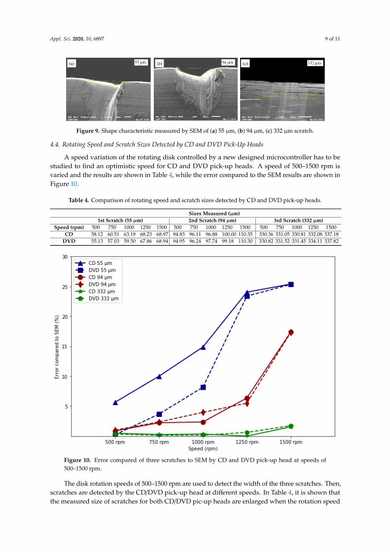
A speed variation of the rotating disk controlled by a new designed microcontroller has to be studied to find an optimistic speed for CD and DVD pick-up heads. A speed of 500–1500 rpm is varied and the results are shown in Table 4, while the error compared to the SEM results are shown in Figure 10.
Table 4. Comparison of rotating speed and scratch sizes detected by CD and DVD pick-up heads.
Sizes Measured (μm) 1st Scratch (55 μm) 2nd Scratch (94 μm) 3rd Scratch (332 μm)
Speed (rpm)
500 750 1000 1250 1500 500 750 1000 1250 1500 500 750 1000 1250 1500
CD 58.12 60.51 63.19 68.23 68.97 94.83 96.11 96.88 100.00 110.35 330.36 331.05 330.81 332.08 337.18 DVD 55.13 57.03 59.50 67.86 68.94 94.95 96.24 97.74 99.18 110.30 330.82 331.52 331.45 334.11 337.82
30 µm
Appl. Sci. 2020, 10, x FOR PEER REVIEW 9 of 11
those measured by SEM. These 3 scratches are examined to confirm their shapes by SEM as shown in Figure 9. The shape characteristics of the scratches detected by this proposed technique can speci-fy the cause of scratches on magnetic disks in the hard disk manufacturing processes.
Table 3. Shape characteristics of 3 scratches measured from the CD pick-up head, DVD pick-up head, and SEM.
Type of Equipment
Shape Characteristics of the Scratches 1st Scratch 2nd Scratch 3rd Scratch
Scale 30휇푚 80휇푚 200휇푚
CD
DVD
SEM
Figure 9. Shape characteristic measured by SEM of (a) 55 µm, (b) 94 µm, (c) 332 µm scratch.
4.4. Rotating Speed and Scratch Sizes Detected by CD and DVD Pick-Up Heads
A speed variation of the rotating disk controlled by a new designed microcontroller has to be studied to find an optimistic speed for CD and DVD pick-up heads. A speed of 500–1500 rpm is varied and the results are shown in Table 4, while the error compared to the SEM results are shown in Figure 10.
Table 4. Comparison of rotating speed and scratch sizes detected by CD and DVD pick-up heads.
Sizes Measured (μm) 1st Scratch (55 μm) 2nd Scratch (94 μm) 3rd Scratch (332 μm)
Speed (rpm)
500 750 1000 1250 1500 500 750 1000 1250 1500 500 750 1000 1250 1500
CD 58.12 60.51 63.19 68.23 68.97 94.83 96.11 96.88 100.00 110.35 330.36 331.05 330.81 332.08 337.18 DVD 55.13 57.03 59.50 67.86 68.94 94.95 96.24 97.74 99.18 110.30 330.82 331.52 331.45 334.11 337.82
80 µm
Appl. Sci. 2020, 10, x FOR PEER REVIEW 9 of 11
those measured by SEM. These 3 scratches are examined to confirm their shapes by SEM as shown in Figure 9. The shape characteristics of the scratches detected by this proposed technique can speci-fy the cause of scratches on magnetic disks in the hard disk manufacturing processes.
Table 3. Shape characteristics of 3 scratches measured from the CD pick-up head, DVD pick-up head, and SEM.
Type of Equipment
Shape Characteristics of the Scratches 1st Scratch 2nd Scratch 3rd Scratch
Scale 30휇푚 80휇푚 200휇푚
CD
DVD
SEM
Figure 9. Shape characteristic measured by SEM of (a) 55 µm, (b) 94 µm, (c) 332 µm scratch.
4.4. Rotating Speed and Scratch Sizes Detected by CD and DVD Pick-Up Heads
A speed variation of the rotating disk controlled by a new designed microcontroller has to be studied to find an optimistic speed for CD and DVD pick-up heads. A speed of 500–1500 rpm is varied and the results are shown in Table 4, while the error compared to the SEM results are shown in Figure 10.
Table 4. Comparison of rotating speed and scratch sizes detected by CD and DVD pick-up heads.
Sizes Measured (μm) 1st Scratch (55 μm) 2nd Scratch (94 μm) 3rd Scratch (332 μm)
Speed (rpm)
500 750 1000 1250 1500 500 750 1000 1250 1500 500 750 1000 1250 1500
CD 58.12 60.51 63.19 68.23 68.97 94.83 96.11 96.88 100.00 110.35 330.36 331.05 330.81 332.08 337.18 DVD 55.13 57.03 59.50 67.86 68.94 94.95 96.24 97.74 99.18 110.30 330.82 331.52 331.45 334.11 337.82
200 µm
CD
Appl. Sci. 2020, 10, x FOR PEER REVIEW 9 of 11
those measured by SEM. These 3 scratches are examined to confirm their shapes by SEM as shown in Figure 9. The shape characteristics of the scratches detected by this proposed technique can speci-fy the cause of scratches on magnetic disks in the hard disk manufacturing processes.
Table 3. Shape characteristics of 3 scratches measured from the CD pick-up head, DVD pick-up head, and SEM.
Type of Equipment
Shape Characteristics of the Scratches 1st Scratch 2nd Scratch 3rd Scratch
Scale 30휇푚 80휇푚 200휇푚
CD
DVD
SEM
Figure 9. Shape characteristic measured by SEM of (a) 55 µm, (b) 94 µm, (c) 332 µm scratch.
4.4. Rotating Speed and Scratch Sizes Detected by CD and DVD Pick-Up Heads
A speed variation of the rotating disk controlled by a new designed microcontroller has to be studied to find an optimistic speed for CD and DVD pick-up heads. A speed of 500–1500 rpm is varied and the results are shown in Table 4, while the error compared to the SEM results are shown in Figure 10.
Table 4. Comparison of rotating speed and scratch sizes detected by CD and DVD pick-up heads.
Sizes Measured (μm) 1st Scratch (55 μm) 2nd Scratch (94 μm) 3rd Scratch (332 μm)
Speed (rpm)
500 750 1000 1250 1500 500 750 1000 1250 1500 500 750 1000 1250 1500
CD 58.12 60.51 63.19 68.23 68.97 94.83 96.11 96.88 100.00 110.35 330.36 331.05 330.81 332.08 337.18 DVD 55.13 57.03 59.50 67.86 68.94 94.95 96.24 97.74 99.18 110.30 330.82 331.52 331.45 334.11 337.82
DVD
Appl. Sci. 2020, 10, x FOR PEER REVIEW 9 of 11
those measured by SEM. These 3 scratches are examined to confirm their shapes by SEM as shown in Figure 9. The shape characteristics of the scratches detected by this proposed technique can speci-fy the cause of scratches on magnetic disks in the hard disk manufacturing processes.
Table 3. Shape characteristics of 3 scratches measured from the CD pick-up head, DVD pick-up head, and SEM.
Type of Equipment
Shape Characteristics of the Scratches 1st Scratch 2nd Scratch 3rd Scratch
Scale 30휇푚 80휇푚 200휇푚
CD
DVD
SEM
Figure 9. Shape characteristic measured by SEM of (a) 55 µm, (b) 94 µm, (c) 332 µm scratch.
4.4. Rotating Speed and Scratch Sizes Detected by CD and DVD Pick-Up Heads
A speed variation of the rotating disk controlled by a new designed microcontroller has to be studied to find an optimistic speed for CD and DVD pick-up heads. A speed of 500–1500 rpm is varied and the results are shown in Table 4, while the error compared to the SEM results are shown in Figure 10.
Table 4. Comparison of rotating speed and scratch sizes detected by CD and DVD pick-up heads.
Sizes Measured (μm) 1st Scratch (55 μm) 2nd Scratch (94 μm) 3rd Scratch (332 μm)
Speed (rpm)
500 750 1000 1250 1500 500 750 1000 1250 1500 500 750 1000 1250 1500
CD 58.12 60.51 63.19 68.23 68.97 94.83 96.11 96.88 100.00 110.35 330.36 331.05 330.81 332.08 337.18 DVD 55.13 57.03 59.50 67.86 68.94 94.95 96.24 97.74 99.18 110.30 330.82 331.52 331.45 334.11 337.82
SEM
Appl. Sci. 2020, 10, x FOR PEER REVIEW 9 of 11
those measured by SEM. These 3 scratches are examined to confirm their shapes by SEM as shown in Figure 9. The shape characteristics of the scratches detected by this proposed technique can speci-fy the cause of scratches on magnetic disks in the hard disk manufacturing processes.
Table 3. Shape characteristics of 3 scratches measured from the CD pick-up head, DVD pick-up head, and SEM.
Type of Equipment
Shape Characteristics of the Scratches 1st Scratch 2nd Scratch 3rd Scratch
Scale 30휇푚 80휇푚 200휇푚
CD
DVD
SEM
Figure 9. Shape characteristic measured by SEM of (a) 55 µm, (b) 94 µm, (c) 332 µm scratch.
4.4. Rotating Speed and Scratch Sizes Detected by CD and DVD Pick-Up Heads
A speed variation of the rotating disk controlled by a new designed microcontroller has to be studied to find an optimistic speed for CD and DVD pick-up heads. A speed of 500–1500 rpm is varied and the results are shown in Table 4, while the error compared to the SEM results are shown in Figure 10.
Table 4. Comparison of rotating speed and scratch sizes detected by CD and DVD pick-up heads.
Sizes Measured (μm) 1st Scratch (55 μm) 2nd Scratch (94 μm) 3rd Scratch (332 μm)
Speed (rpm)
500 750 1000 1250 1500 500 750 1000 1250 1500 500 750 1000 1250 1500
CD 58.12 60.51 63.19 68.23 68.97 94.83 96.11 96.88 100.00 110.35 330.36 331.05 330.81 332.08 337.18 DVD 55.13 57.03 59.50 67.86 68.94 94.95 96.24 97.74 99.18 110.30 330.82 331.52 331.45 334.11 337.82
Appl. Sci. 2020, 10, 6897 9 of 11
Appl. Sci. 2020, 10, x FOR PEER REVIEW 9 of 11
those measured by SEM. These 3 scratches are examined to confirm their shapes by SEM as shown in Figure 9. The shape characteristics of the scratches detected by this proposed technique can speci-fy the cause of scratches on magnetic disks in the hard disk manufacturing processes.
Table 3. Shape characteristics of 3 scratches measured from the CD pick-up head, DVD pick-up head, and SEM.
Type of Equipment
Shape Characteristics of the Scratches 1st Scratch 2nd Scratch 3rd Scratch
Scale 30휇푚 80휇푚 200휇푚
CD
DVD
SEM
Figure 9. Shape characteristic measured by SEM of (a) 55 µm, (b) 94 µm, (c) 332 µm scratch.
4.4. Rotating Speed and Scratch Sizes Detected by CD and DVD Pick-Up Heads
A speed variation of the rotating disk controlled by a new designed microcontroller has to be studied to find an optimistic speed for CD and DVD pick-up heads. A speed of 500–1500 rpm is varied and the results are shown in Table 4, while the error compared to the SEM results are shown in Figure 10.
Table 4. Comparison of rotating speed and scratch sizes detected by CD and DVD pick-up heads.
Sizes Measured (μm) 1st Scratch (55 μm) 2nd Scratch (94 μm) 3rd Scratch (332 μm)
Speed (rpm)
500 750 1000 1250 1500 500 750 1000 1250 1500 500 750 1000 1250 1500
CD 58.12 60.51 63.19 68.23 68.97 94.83 96.11 96.88 100.00 110.35 330.36 331.05 330.81 332.08 337.18 DVD 55.13 57.03 59.50 67.86 68.94 94.95 96.24 97.74 99.18 110.30 330.82 331.52 331.45 334.11 337.82
Figure 9. Shape characteristic measured by SEM of (a) 55 µm, (b) 94 µm, (c) 332 µm scratch.
4.4. Rotating Speed and Scratch Sizes Detected by CD and DVD Pick-Up Heads
A speed variation of the rotating disk controlled by a new designed microcontroller has to bestudied to find an optimistic speed for CD and DVD pick-up heads. A speed of 500–1500 rpm isvaried and the results are shown in Table 4, while the error compared to the SEM results are shown inFigure 10.
Table 4. Comparison of rotating speed and scratch sizes detected by CD and DVD pick-up heads.
Sizes Measured (µm)1st Scratch (55 µm) 2nd Scratch (94 µm) 3rd Scratch (332 µm)
Speed (rpm) 500 750 1000 1250 1500 500 750 1000 1250 1500 500 750 1000 1250 1500CD 58.12 60.51 63.19 68.23 68.97 94.83 96.11 96.88 100.00 110.35 330.36 331.05 330.81 332.08 337.18
DVD 55.13 57.03 59.50 67.86 68.94 94.95 96.24 97.74 99.18 110.30 330.82 331.52 331.45 334.11 337.82Appl. Sci. 2020, 10, x FOR PEER REVIEW 10 of 11
Figure 10. Error compared of three scratches to SEM by CD and DVD pick-up head at speeds of 500–1500 rpm.
The disk rotation speeds of 500–1500 rpm are used to detect the width of the three scratches. Then, scratches are detected by the CD/DVD pick-up head at different speeds. In Table 4, it is shown that the measured size of scratches for both CD/DVD pic-up heads are enlarged when the rotation speed increased. The error is also increased when the velocity is fast. This is possible due to the high speed resulting in a loss of focus on the disk and the unstable easily [14]. Thus, an optimiz-ing scratch can be obtained at low speed of disk rotation.
5. Conclusions
The new adaptive scratch detection technique using CD and DVD pick-up heads as a proposed detector with 3 different types of scratches on the magnetic disk are measured. The light reflection technique is initially performed to identify the size, position, and shape characteristic of scratches. It is found that either the CD or DVD pick-up head can be greatly performed as the scratch detector. The size and location of the scratch can be more precisely examined by CD/DVD pick-up heads than ordinary SM. In addition, it is shown that for a large scratch, the CD/DVD pick-up heads show a very promising result refereed by SEM. However, a low speed of disk rotation is found to provide less errors. Therefore, from the results, the CD/DVD pick-up heads can be utilized to identify the location and size of the scratch on a disk-media in hard disk drive manufacturing for a quick non-destructive inspection.
Author Contributions: Conceptualization, A.P. and A.S.; methodology, A.S.; formal analysis, A.P. and A.S.; investigation, A.P.; resources, W.T.; data curation, A.P. and W.T.; writing original draft preparation, A.P.; writ-ing-review and editing, A.S.; supervision, A.S. All authors have read and agreed to the published version of the manuscript.
Funding: This research received no external funding.
Figure 10. Error compared of three scratches to SEM by CD and DVD pick-up head at speeds of500–1500 rpm.
The disk rotation speeds of 500–1500 rpm are used to detect the width of the three scratches. Then,scratches are detected by the CD/DVD pick-up head at different speeds. In Table 4, it is shown thatthe measured size of scratches for both CD/DVD pic-up heads are enlarged when the rotation speed

Appl. Sci. 2020, 10, 6897 10 of 11
increased. The error is also increased when the velocity is fast. This is possible due to the high speedresulting in a loss of focus on the disk and the unstable easily [14]. Thus, an optimizing scratch can beobtained at low speed of disk rotation.
5. Conclusions
The new adaptive scratch detection technique using CD and DVD pick-up heads as a proposeddetector with 3 different types of scratches on the magnetic disk are measured. The light reflectiontechnique is initially performed to identify the size, position, and shape characteristic of scratches.It is found that either the CD or DVD pick-up head can be greatly performed as the scratch detector.The size and location of the scratch can be more precisely examined by CD/DVD pick-up heads thanordinary SM. In addition, it is shown that for a large scratch, the CD/DVD pick-up heads show a verypromising result refereed by SEM. However, a low speed of disk rotation is found to provide less errors.Therefore, from the results, the CD/DVD pick-up heads can be utilized to identify the location and sizeof the scratch on a disk-media in hard disk drive manufacturing for a quick non-destructive inspection.
Author Contributions: Conceptualization, A.P. and A.S.; methodology, A.S.; formal analysis, A.P. and A.S.;investigation, A.P.; resources, W.T.; data curation, A.P. and W.T.; writing original draft preparation, A.P.;writing-review and editing, A.S.; supervision, A.S. All authors have read and agreed to the published version ofthe manuscript.
Funding: This research received no external funding.
Acknowledgments: Authors would like to thank Pimai Sawangpol and Kesinee Chantharasophon from UbonRatchathani Rajabhat University for measurement technic, and Pairor Sangwang and Worakarn Wongsaichuafrom Ubon Ratchathani University for instrument support.
Conflicts of Interest: The authors declare that there is no conflict of interest regarding the publication of this paper.
References
1. Odgaard, P.F.; Stoustrup, J.; Andersen, P. Detection of surface defects on compact discs. J. Control Sci. Eng.2007, 10, 1–9. [CrossRef]
2. Furukawa, M.; Xu, J.; Shimizu, Y.; Kato, Y. Scratch-induced demagnetization of perpendicular magnetic disk.IEEE Trans. Magn. 2008, 44, 3633–3636. [CrossRef]
3. Russell, P.; Batchelor, D. SEM and AFM: Complementary techniques for surface investigations. Microsc. Anal.2001, 1, 9–12.
4. Hocken, R.J.; Chakraborty, N.; Brown, C. Optical metrology of surfaces. CIRP Ann. 2005, 54, 705–719.[CrossRef]
5. Todtong, Y.; Kaewrawang, A.; Sivaratana, R.; Kruesubthaworn, A.; Thompson, S.M.; Siritaratiwat, A. Thermalimage refinement approach for scratches on a magnetic disk evaluated at various angles. Instrum. Sci. Technol.2013, 41, 365–381. [CrossRef]
6. Wang, W.-M.; Cheng, C.-H.; Molnar, G.; Hwang, I.-S.; Huang, K.-Y.; Danzebrink, H.-U.; Hwu, E.-T. Opticalimaging module for astigmatic detection system. Rev. Sci. Instrum. 2016, 87, 1–4. [CrossRef] [PubMed]
7. Zhang, H.-Y.; Wang, Z.-H.; Fu, H.-Y. Automatic scratch detector for optical surface. Opt. Express 2019, 27,20910–20927. [CrossRef] [PubMed]
8. Zhu, S.; Zhou, W.; Song, Y. Detecting oscillation amplitude and defects of hard disk rotating in high speed bylaser Doppler technique. Measurement 2012, 45, 74–78. [CrossRef]
9. Polsawat, A.; Suwannata, N.; Siritaratiwat, A.; Kruesubthaworn, A. A Signal analysis of scratch-detection onmagnetic disc by using light reflection approach. Appl. Mech. Mater. 2015, 781, 203–206. [CrossRef]
10. Hwu, E.T.; Anja, B. Hacking CD/DVD/Blu-ray for Biosensing. ACS Sens. 2018, 3, 1222–1232. [CrossRef][PubMed]
11. Siaudinyte, L.; Juska, V.; Dumbrava, V.; Pagodinas, D.; Brucas, D.; Rybokas, M.; Thomas, K.; Grattan, V.;Krikstaponis, B. Measurement and determination of encoder disc surface parameters in x-z planes using aconventional optical disc reading head. Measurement 2019, 152, 1–7.
12. Hwu, E.T.; Hung, S.K.; Yang, C.W.; Huang, K.-Y.; Hwang, I.-S. Real-time detection of linear and angulardisplacements with a modified DVD optical head. Nanotechnology 2008, 19, 115501. [CrossRef] [PubMed]

Appl. Sci. 2020, 10, 6897 11 of 11
13. Huang, H.L.; Liu, C.H.; Jywe, W.Y.; Wang, M.S.; Jeng, Y.R.; Duan, L.L.; Hsu, T.-H. Development of a DVDpickup-based four-degrees-of-freedom motion error measuring system for a single-axis linear movingplatform. Proc. Inst. Mech. Eng. Part B J. Eng. Manuf. 2009, 224, 37–50. [CrossRef]
14. Hnilicka, B.; Besancon-Voda, A.; Schroder, H.-J.; Filardi, G. Modelling the focus error characteristic of a DVDplayer. Proc. IEEE 2002, 2, 629–630.
© 2020 by the authors. Licensee MDPI, Basel, Switzerland. This article is an open accessarticle distributed under the terms and conditions of the Creative Commons Attribution(CC BY) license (http://creativecommons.org/licenses/by/4.0/).