Using micro-FTIR spectroscopy to measure volatile contents in small and unexposed inclusions hosted...
14
Using micro-FTIR spectroscopy to measure volatile contents in small and unexposed inclusions hosted in olivine crystals A.R.L. Nichols ⁎ , R.J. Wysoczanski 1 Institute for Research on Earth Evolution (IFREE), Japan Agency for Marine Earth Science and Technology (JAMSTEC), 2–15 Natsushima-cho, Yokosuka, Kanagawa 237-0061, Japan Received 10 August 2006; received in revised form 16 April 2007; accepted 16 April 2007 Editor: R.L. Rudnick Abstract A new technique is described that makes it possible to use micro-Fourier Transform Infra-Red (micro-FTIR) spectroscopy to determine H 2 O and CO 2 concentrations in unexposed melt inclusions hosted in olivine crystals. Previously, inclusions have had to be doubly polished, and even then it has been problematic to obtain pure glass spectra through inclusions smaller than 100 μm. The new technique involves calculating the proportion of inclusion in transmittance spectra taken through the inclusion and the olivine host, which, when combined with accurate overall thickness determinations from interference fringe patterns on reflectance spectra, allows the inclusion thickness to be calculated. This thickness can then be used with the absorbance of volatile species in the transmittance spectra to calculate accurate and precise analyte concentrations. Application of this technique will greatly ease sample preparation and allow the H 2 O and CO 2 concentrations to be measured in many more olivine hosted inclusions than was previously possible by FTIR. The minimum size of an inclusion that can be completely analysed will be limited by the analytical sensitivity of FTIR, and the resolution of other in situ analytical techniques used to fully characterise the geochemistry of inclusions. © 2007 Elsevier B.V. All rights reserved. Keywords: Melt inclusions; Olivine; H 2 O; CO 2 ; Transmittance micro-FTIR spectroscopy; Reflectance micro-FTIR spectroscopy 1. Introduction Volatiles, particularly H 2 O and CO 2 , play a funda- mental role in global geodynamics and mantle processes. Their transfer at subduction zones, from the downward plate into the mantle wedge, causes melting and resultant volcanism at subduction zones (e.g., Fyfe and McBirney, 1975; McCulloch and Gamble, 1991; Luhr, 1992; Stol- per and Newman, 1994; Sobolev and Chaussidon, 1996; Wysoczanski et al., 2006a). It has also been argued that they are important in melting at mantle plumes (e.g., Moore, 1965; Moore, 1970; Schilling et al., 1980, 1983; Poreda et al., 1986; Garcia et al., 1989; Metrich et al., 1991; Green and Falloon, 1998; Wallace, 1998; Jamtveit et al., 2001; Nichols et al., 2002), and even at particular locations along mid-ocean ridges (Ligi et al., 2005). Furthermore, dissolved volatiles influence the rheolog- ical properties of magma, and as a result, magma move- ment (Richet et al., 1996; Whittington et al., 2000; Giordano et al., 2005). However, unless the eruption of magma has occurred at pressure, under considerable Chemical Geology 242 (2007) 371 – 384 www.elsevier.com/locate/chemgeo ⁎ Corresponding author. Tel.: +81 468 67 9782; fax: +81 468 67 9625. E-mail address: [email protected] (A.R.L. Nichols). 1 Present address: School of Geography, Environment and Earth Sciences, Victoria University of Wellington, PO Box 600, Wellington, New Zealand. 0009-2541/$ - see front matter © 2007 Elsevier B.V. All rights reserved. doi:10.1016/j.chemgeo.2007.04.007
-
Upload
independent -
Category
Documents
-
view
1 -
download
0
Transcript of Using micro-FTIR spectroscopy to measure volatile contents in small and unexposed inclusions hosted...

(2007) 371–384www.elsevier.com/locate/chemgeo
Chemical Geology 242
Using micro-FTIR spectroscopy to measure volatile contents in smalland unexposed inclusions hosted in olivine crystals
A.R.L. Nichols ⁎, R.J. Wysoczanski 1
Institute for Research on Earth Evolution (IFREE), Japan Agency for Marine Earth Science and Technology (JAMSTEC),2–15 Natsushima-cho, Yokosuka, Kanagawa 237-0061, Japan
Received 10 August 2006; received in revised form 16 April 2007; accepted 16 April 2007
Editor: R.L. Rudnick
Abstract
A new technique is described that makes it possible to use micro-Fourier Transform Infra-Red (micro-FTIR) spectroscopy todetermine H2O and CO2 concentrations in unexposed melt inclusions hosted in olivine crystals. Previously, inclusions have had tobe doubly polished, and even then it has been problematic to obtain pure glass spectra through inclusions smaller than 100 μm. Thenew technique involves calculating the proportion of inclusion in transmittance spectra taken through the inclusion and the olivinehost, which, when combined with accurate overall thickness determinations from interference fringe patterns on reflectance spectra,allows the inclusion thickness to be calculated. This thickness can then be used with the absorbance of volatile species in thetransmittance spectra to calculate accurate and precise analyte concentrations. Application of this technique will greatly ease samplepreparation and allow the H2O and CO2 concentrations to be measured in many more olivine hosted inclusions than was previouslypossible by FTIR. The minimum size of an inclusion that can be completely analysed will be limited by the analytical sensitivity ofFTIR, and the resolution of other in situ analytical techniques used to fully characterise the geochemistry of inclusions.© 2007 Elsevier B.V. All rights reserved.
Keywords: Melt inclusions; Olivine; H2O; CO2; Transmittance micro-FTIR spectroscopy; Reflectance micro-FTIR spectroscopy
1. Introduction
Volatiles, particularly H2O and CO2, play a funda-mental role in global geodynamics andmantle processes.Their transfer at subduction zones, from the downwardplate into the mantle wedge, causes melting and resultantvolcanism at subduction zones (e.g., Fyfe andMcBirney,
⁎ Corresponding author. Tel.: +81 468 67 9782; fax: +81 468 679625.
E-mail address: [email protected] (A.R.L. Nichols).1 Present address: School of Geography, Environment and Earth
Sciences, Victoria University of Wellington, PO Box 600, Wellington,New Zealand.
0009-2541/$ - see front matter © 2007 Elsevier B.V. All rights reserved.doi:10.1016/j.chemgeo.2007.04.007
1975; McCulloch and Gamble, 1991; Luhr, 1992; Stol-per and Newman, 1994; Sobolev and Chaussidon, 1996;Wysoczanski et al., 2006a). It has also been argued thatthey are important in melting at mantle plumes (e.g.,Moore, 1965; Moore, 1970; Schilling et al., 1980, 1983;Poreda et al., 1986; Garcia et al., 1989; Metrich et al.,1991; Green and Falloon, 1998; Wallace, 1998; Jamtveitet al., 2001; Nichols et al., 2002), and even at particularlocations along mid-ocean ridges (Ligi et al., 2005).Furthermore, dissolved volatiles influence the rheolog-ical properties of magma, and as a result, magma move-ment (Richet et al., 1996; Whittington et al., 2000;Giordano et al., 2005). However, unless the eruption ofmagma has occurred at pressure, under considerable

372 A.R.L. Nichols, R.J. Wysoczanski / Chemical Geology 242 (2007) 371–384
water or ice load for example, volatiles are lost from themagma and lava via degassing prior to quenching, and itis impossible to assess primary or even pre-eruption bulkvolatile concentrations from the volatile contents of theglassy groundmass (Delaney et al., 1978; Gerlach, 1986;Dixon and Stolper, 1995; Dixon, 1997; Newman andLowenstern, 2002). An alternative to the glassy ground-mass is to analyse tiny samples of melt that are trappedby crystals as they grow in the magma. Some crystallinephases (i.e., those without cleavage), depending on theirthermo-barometric ascent path, may act as pressurevessels, which if they remain intact isolate the trappedmelt from pressure changes affecting the bulk magma.Thus, the melt inclusion may preserve an original, or lessdegassed, volatile content than that in the bulk magma,reflecting the magma at the time of entrapment andcrystal growth. If, within a sample, crystals have trappedmelt inclusions at different times, the inclusions'composition may highlight how the melt has evolved.However, problems exist with measuring these. Micro-Fourier Transform Infra-Red (micro-FTIR) spectrosco-py, micro-Raman spectroscopy, secondary ion massspectrometry (SIMS), and nuclear microprobe (Bureauet al., 2003) have all been used, but the study of small(b20 μm) melt inclusions still remains an analyticalchallenge.
In this paper we present a new technique for ana-lysing volatiles in small inclusions (down to 10 μm insize) within olivine hosts using micro-FTIR spectros-copy. The technique exploits some of the difficultiesassociated with analysing small inclusions by transmit-tance and reflectance micro-FTIR spectroscopy. Themajor difficulty in transmittance micro-FTIR spectros-copy is removing host crystal contamination from thespectra. We show how this contamination can be used todetermine the thickness of the host crystal in the beampath. This is then subtracted from the overall thicknessto give that of the inclusion, which can then be used tocalculate the concentration of volatiles. Often reflec-tance micro-FTIR spectroscopy cannot be used to de-termine volatile contents, as interference fringes thatappear on the spectra overwhelm the volatile peaks.However, these fringes can be used to obtain the overallthickness of exactly the same spot as was analysed intransmitted light, without the need to transfer it to adigital displacement gauge and all the associated risksthat this entails. The technique can be used even if theinclusion is unexposed; all that is required is to preparetwo parallel polished surfaces of the host crystal. Thetechnique broadens the size range of inclusions that canbe successfully analysed by micro-FTIR spectroscopyand eases sample preparation. Furthermore, if the crystal
hosts more than one inclusion the technique enablesthem to be analysed quickly through the host crystal,without the need for each inclusion to be exposed.
2. Existing analytical techniques for H2O and CO2
measurements in melt inclusions
Several analytical techniques are used to measurevolatile contents in silicate glasses. Initially, bulk ex-traction (see review by Ihinger et al., 1994) was used,but the large sample sizes required limited its usefulnessfor inclusion analysis. The development of microana-lytical techniques over the last 30 years have made themeasurement of the volatile content of smaller meltinclusions possible, but difficulties still exist. Electronprobe microanalysis (EPMA) can be used to determinethe concentration of some volatile elements (notably S,F and Cl), but in the case of H2O the indirect method ofsubtracting the total of the other elements from 100%results in high detection limits and poor precision,N0.5 wt.% (Devine et al., 1995); and it can only beapplied to estimate H2O contents in H2O-rich (N1 wt.%)samples.
SIMS has much lower detection limits (30 ppm), andmeasures H2O contents to a much higher precision(b0.2 wt.%) than EPMA (Hauri et al., 2002). It has beensuccessfully used to analyse the volatile contents ofinclusions down to 10–15 μm in size (e.g., Hauri et al.,2002; Hauri, 2002; Hervig et al., 2003; Atlas et al.,2006). However, the technique is destructive and re-quires exposure and polishing of at least one surface ofthe inclusion. It is also necessary to calibrate against aset of well characterised standard glasses with variableH2O contents and a similar composition to that beinganalysed (Ihinger et al., 1994; Hauri et al., 2002; Herviget al., 2003). Depending on calibration procedure, thetechnique is highly dependent on composition owing tomatrix effects, and it is also worth bearing in mind that athigher H2O contents the calibration curves diverge sig-nificantly and do not reproduce the standard data so well(Hauri et al., 2002).
Recently, confocal micro-Raman spectroscopy hasbeen developed to measure H2O in melt inclusions(Thomas, 2000; Chabiron et al., 2004; Zajacz et al.,2005; Thomas et al., 2006; Behrens et al., 2006; DiMuro et al., 2006). The technique is non-destructive,and furthermore, if the host crystal is transparent, inclu-sions do not need to be exposed, so the entire inclusionpopulation within a host crystal can be analysed. Spatialresolution is 1–2 μm and H2O contents between 0.1 and20 wt.% can be measured. The technique requires ca-librations, which depend on composition and various

373A.R.L. Nichols, R.J. Wysoczanski / Chemical Geology 242 (2007) 371–384
analytical parameters, including spectrometer settingsand the depth of inclusion below the surface. As a resultcalibrations may not be transferable between laborato-ries. In addition, attempts to measure H2O speciationhave met with mixed success (Zajacz et al., 2005; Beh-rens et al., 2006; Di Muro et al., 2006). However, recentdevelopments suggest that it may be possible to measuretotal H2O contents from granitic to basaltic compositionswithout relying on calibrations (Thomas and Davidson,2006), simplifying the measurement, and permittingdirect laboratory comparisons.
FTIR spectroscopy has been widely used to quantifythe amounts and speciation of H2O and CO2 in silicateglasses (e.g., Stolper, 1982a,b; Fine and Stolper, 1985;Newman et al., 1986; Dixon et al., 1988, 1997; Dan-yushevsky et al., 2000; Dixon and Clague, 2001;Simons et al., 2002; Nichols et al., 2002; Wysoczanskiet al., 2006a). The use of micro-FTIR permits a spatialresolution to about 10 μm and detection limits are at theppm level. In general measurements are performed intransmitted light, where an IR beam is directed through asample slice that must be polished on both surfaces. Inthe resulting spectra different species can be recognisedand quantified based on the wavenumber and the spectraof absorbed energy, using the Beer–Lambert law:
ci ¼ Mid Aqd td e
ð1Þ
where ci is the concentration of the species i (in wt.%),Mi is the molecular weight of the species of i (g/mol), Ais the absorbance (height or area) of the relevant vibra-tion band, ρ is the sample density (g/l), t is the thick-ness of the area analysed (cm), and ε is the molarabsorptivity (l/mol·cm). Even for slices of bulk silicateglass uncertainties in density, molar absorptivity andthickness cause uncertainties estimated at 10% relative(Dixon et al., 1988). In analysing volatiles in meltinclusions there are additional practical disadvantages.Exposing and polishing inclusions on both sides isdifficult and laborious, and in the case of the smallestand irregularly shaped inclusions impossible. The usualway to measure thickness, via a digital displacementgauge, is generally inappropriate for inclusions. Forsmall inclusions (b50 μm) the precision of the thick-ness measurements (repeated measurements on the samespot indicate ±3 μm) contribute a significant source oferror. Furthermore, it is difficult to be certain that the spotanalysed (analytical spot size as small as 10 μm) ispositioned directly under the needle used to measure thethickness, and the needle (generally greater than 450 μm)is much larger than the area analysed. If the prepared
wafer is perfectly flat, and the two polished surfacesperfectly parallel, then this is not a problem, but if there isany relief on the surface, which can often be the case forinclusions, where the host crystal can present reliefcompared to the inclusion, additional uncertainties willarise. Finally, there is considerable danger of the samplebecoming damaged or even lost during the thicknessmeasurement using the digital displacement gauge. Toovercome such problems, Agrinier and Jendrzejewski(2000) used the FTIR spectra of glass chips to infera density–thickness product, which, if the density isknown, can be used to recover the thickness of theanalysed sample.
A further problem with micro-FTIR spectroscopy isthat, even after careful sample preparation and position-ing of the IR beam on doubly exposed inclusions of lessthan 100 μm in size, a contribution to the spectra fromthe host crystal may still remain (e.g., Hervig et al.,2003; Atlas et al., 2006), so the measured thickness doesnot refer solely to the inclusion. The technique of Agri-nier and Jendrzejewski (2000) does not help, because asthe density–thickness product depends on composition,the relationship will be affected by contamination fromthe host crystal. In these cases (and where the sample istoo fragile to use the direct method), inclusion thicknesshas been estimated based upon the geometry of theinclusion (e.g., Signorelli et al., 1999; Luhr, 2001; Atlaset al., 2006; Wysoczanski and Tani, 2006). Even withvery careful measurements, thickness contributes 25%to 60% of the overall error in inclusions 80 to 25 μm insize, respectively. Furthermore, if the inclusion is irre-gularly shaped (i.e., thickness varies greatly across theinclusion) it is very difficult to determine the thicknessof the actual area of the inclusion analysed with anyconfidence. As a result, inclusion studies using FTIRhave focused on only the largest and most regularlyshaped inclusions (e.g., Luhr, 2001), leading to a pos-sible bias.
Recently, in order to avoid the problems associatedwith the determination of thickness, and to ease thesample preparation, efforts have been made to develop atechnique using reflectance micro-FTIR microscopy(Hervig et al., 2003; King et al., 2005). This requiresonly one surface of the inclusion to be exposed andpolished, and through successive polishing steps, it ispossible to analyse all the melt inclusions within a singlehost crystal. Inclusions prepared in such a way are alsosuitable for analysis by many other techniques, such asEPMA, SIMS and Laser-Ablation Inductively-Coupled-Plasma Mass-Spectrometry (LA-ICP-MS). The fact thatthe detector receives less energy from a reflective sur-face than can be transmitted through the sample means

374 A.R.L. Nichols, R.J. Wysoczanski / Chemical Geology 242 (2007) 371–384
that in order to detect the absorbance H2O contents mustexceed 1 wt.%. It has also proved problematic to use thistechnique on inclusions less than 100 μm, becausecontamination from the host crystal overwhelms theH2O signal, making concentration determinations im-possible (Hervig et al., 2003). Furthermore, if the sam-ples are prepared too thin or two surfaces are polished,interference fringe patterns from the surfaces will alsooverwhelm the H2O signal.
Clearly, a technique requiring minimal sample prepa-ration, and capable of analysing small (10 μm) inclu-sions, containing less then 1 wt.% H2O, is desired toobtain multiple accurate and precise H2O and CO2
concentrations of melt inclusions.
3. Sample characteristics and preparation
The technique proposed here has been developedfor measuring H2O and CO2 concentrations using ba-saltic melt inclusions, hosted in olivine phenocrysts,from two suites of samples, which are characterised bydifferent volatile contents. 1) Tholeiitic basalts thaterupted subglacially on Iceland, and contain inclusionswith H2O contents ranging from 0.08 to 0.67 wt.% andCO2 up to 703 ppm (for more information on thesamples see Nichols et al., 2002). 2) Inclusions fromarc basalts that erupted subaerially on the Izu Penin-sula, Japan, with H2O contents ranging from 0.26 to4.03 wt.% and CO2 up to 450 ppm (Wysoczanski et al.,2006a,b).
The basalt bulk samples were crushed and sieved to asize (250–500 or 500–1000 μm) where the olivinegrains were mostly free of glass but were still intact, andinclusion-bearing crystals were picked from the fraction.The crystals were then mounted on a glass slide usingCrystalbond 509 (Aremco Products, Inc.). The refrac-tive index of this adhesive is close to that of olivineallowing the inclusions to be seen much more clearlyunder a petrographic microscope, and allowing theirtextures and those of the host to be examined. Theexposed irregular surface was ground to provide asuitably large flat area, and polished using silica carbidegrit and 3 and 1 μm diamond paste. The crystal was thenturned over, by melting the adhesive on a hot plate, sothe flat surface faced down, and a second surface, pa-rallel to the first, was ground flat and polished asbefore. Finally, the crystal was removed from the glassslide and immersed in acetone, to dissolve any attachedadhesive. The result was a wafer of inclusion-bearingolivine, with two parallel polished surfaces, whichwould allow the IR beam to pass through with minimalscattering.
4. Analytical conditions
The micro-FTIR spectroscopy was performed on aVarian FTS Stingray 7000 Micro Image Analyser spec-trometer at the Institute for Research on Earth Evolution(IFREE), Japan Agency for Marine Earth Science andTechnology (JAMSTEC). Spectra were collected over512 or 1024 scans at a resolution of 8 cm−1 using aheated ceramic (globar) infra-red source and a Ge-coated KBr beamsplitter. An attached UMA 600 mic-roscope was used to focus the beam on the area ofinterest. The beam path within the spectrometer benchand microscope was continuously purged with N2 gasand the laboratory was kept as dry as possible to mini-mise any interference from atmospheric H2O or CO2 onthe measured spectra. The polished crystals were placedon a H2O-free IR-invisible KBr disk, which supportedthe crystals. Background analyses were taken throughthe disk, before the crystal was positioned in the beampath to measure sample spectra. For reflectance spectra,backgrounds were taken on a gold-coated plate, whichhas a reflectance coefficient of unity (100% reflectance).For spot analyses, a liquid-nitrogen cooled HgCdTe2(MCT) detector was used, and the aperture varied from20 to 50 μm square, depending on inclusion size. Thisset up permitted collection of spectra across the mid-IRregion (6000–700 cm−1). Some spectra were also ex-tracted from spectroscopic images, which were collectedfollowing the same procedure as the conventional spotanalyses. The images were collected using an attachedVarian Inc. Lancer Focal Plane Array (FPA) cameraacross an area 350×350 μm. The FPA camera consistsof a MCT array detector with 4096 channels (64×64),which collect spectra over the spectral range 4000–900 cm−1. Thus, the channel, or spectral, resolutionacross the 350×350 μm area is 5 μm. Any of the 4096spectra from the image could be extracted for individualtreatment. (For a more detailed discussion of spectro-scopic imaging and the set up see Wysoczanski andTani, 2006.)
5. How to use host crystal contamination to indirectlydetermine inclusion thickness
5.1. Assignment of bands in transmittance spectra
In basaltic glasses total H2O is calculated using thevibration band at around 3500 cm−1 that corresponds tothe fundamental OH-stretching vibration (Stolper,1982a). The contribution of molecular H2O to the totalH2O is calculated using the absorbance at 1630 cm−1
(Fig. 1a). In this study molar absorptivity coefficients of

Fig. 1. Representative spectra through basaltic inclusions and their olivine hosts. (a) Transmittance micro-FTIR spectra from Izu Peninsula sampleIZ26-12, olivine crystal 18, normalised to an overall thickness of 100 μm. Top, spectra through the pure inclusion (inclusion 1) showing total H2O (at3543 cm−1) and molecular H2O (at 1639 cm−1) peaks from which concentrations can be calculated. Bottom, pure olivine spectra exhibiting a series ofspectral bands between approximately 2000 and 1600 cm−1. Middle, spectra through a mixture of the same inclusion and the olivine host(contaminated) exhibiting a lower total H2O peak and smaller olivine spectral bands than in the respective pure spectra. (b) Reflectance micro-FTIRspectra, through the same spot as the pure inclusion transmittance spectra above, showing how the interference fringes are used to determine theoverall thickness through thin samples. Fringes in clean domains of the spectra (i.e., in which there is no overlap with features related to the volatile orolivine bands) are chosen. (c) Transmittance micro-FTIR spectra, normalised to an overall thickness of 100 μm, through Iceland sample RP5 crystal12 inclusion 2, contaminated with olivine, showing that the olivine bands do not interfere with the CO3
2− doublet. Peak heights are calculated from thebaselines marked by dashed lines.
375A.R.L. Nichols, R.J. Wysoczanski / Chemical Geology 242 (2007) 371–384
63±5 and 25±3 l/mol·cm, respectively (Dixon et al.,1988), were used to calculate species concentrationsfrom the height of the peaks above a linear baseline.Glass density was calculated from its oxide composi-tion, measured by EPMA, using the model of Lange(1997). The presence of CO2 in basaltic glass is indi-cated by the antisymmetric stretch of distorted CO3
2−
groups, which generates a doublet with peaks at around1515 cm−1 and 1435 cm−1. CO2 concentrations werecalculated from the average of the height of each ofthese peaks above a linear baseline using a molar ab-sorptivity of 375±20 l/mol·cm (Fine and Stolper, 1985)(Fig. 1c). In the inclusions studied here molecularCO2, with a vibration band around 2350 cm−1, was notdetected.
FTIR spectra, of the mid-IR region, through olivinecrystals are dominated by a series of second order Si–O
overtone and combination bands between approximate-ly 2000 and 1600 cm−1 (Fig. 1a and c). These are relatedto the significantly more intense fundamental peaks ofthe magnesium silicate structure at lower wavenumbers(Jamtveit et al., 2001; Matveev et al., 2005). Impor-tantly, the intensity of the overtone bands depends on thecrystallographic orientation as well as the thickness ofthe analysed area. Contamination of inclusion spectra bythe olivine host can be recognised if these overtonebands appear in the spectra (Fig. 1a). Their presenceindicates that the inclusion does not constitute the wholevolume analysed, and that the thickness measured forthat area is the total thickness of the inclusion and host.As a result this cannot be entered into Eq. (1) to give thetotal H2O or CO2 content of the inclusion. However,importantly the olivine bands do not interfere with eitherthe total H2O peak or the CO3
2− doublet (Fig. 1c).

376 A.R.L. Nichols, R.J. Wysoczanski / Chemical Geology 242 (2007) 371–384
5.2. Measurement of overall thickness using reflectancespectra
It has been shown that it is possible to use the in-terference fringes that occur on reflectance spectra ofsamples, with parallel polished surfaces, to determinethe thickness of the area in which the spectra have beenmeasured (Nishikida et al., 1996; Tamic et al., 2001;Wysoczanski and Tani, 2006; Sun et al., 2007).Nishikida et al. (1996) show that for a thin silica film(3.5 μm), the wavelength of the interference fringepattern is directly proportional to the thickness and therefractive index of the sample, as follows:
t ¼ m2nðv1 � v2Þ ð2Þ
where t is the thickness of the area analysed (cm), m isthe number of waves that occur in the selected intervalof wavenumbers (between v1 and v2), n is the refractiveindex of the material through which the spectra havebeen measured, and v1 and v2 are the highest and lowestwavenumbers over the interval (cm−1) (Fig. 1b). Apply-ing this relationship to the interference fringe patternbetween 2000 cm−1 and 2700 cm−1 has been shown toprovide the best results in glass chips (Wysoczanski andTani, 2006; Sun et al., 2007). Fig. 2 compares thick-nesses determined using the interference fringes with
Fig. 2. Comparison between thicknesses of wafers of glass determinedusing interference fringes, between 2000 and 2700 cm−1 on reflectancespectra, and measured using a digital displacement gauge. The glasssamples are from the Manus Basin and range from basalt (51.76 wt.%SiO2) to rhyodacite (74.76 wt.% SiO2) in composition (Sun et al.,2007). Line indicates perfect agreement.
those measured using a digital displacement gauge for asuite of samples from theManus Basin (Sun et al., 2007),with compositions ranging from basalt (51.76 wt.%SiO2) to rhyodacite (74.76 wt.% SiO2). Irrespective ofcomposition there is excellent agreement, with a stan-dard deviation of 3 μm.
Where olivine is in the beam path interference fringesfrom a clean domain, away from possible interferenceswith features in the reflectance spectra related to eitherthe volatile or olivine peaks, were chosen (i.e., between2100 and 2700 cm−1, Fig. 1b). A median refractiveindex for each olivine crystal was calculated at its for-sterite content, using the linear relationship in Deer et al.(1992). Over the range of forsterite contents for the hostcrystals in this study (75 to 87), the maximum uncer-tainty in the refractive index is ±1.2%. If an inclusionwas doubly exposed a refractive index of 1.546 wasused for basalt (Kumagai and Kaneoka, 2003).
There are several advantages to this technique overthe conventional thickness measurements using a digitaldisplacement gauge. Most importantly micro-FTIRspectrometers can be switched between transmissionand reflection mode without moving the sample. Withdigital displacement gauges, as the sample has to bemoved from the microscope stage to the gauge, and alsobecause the needle covers a much larger area than thatanalysed, there will always be some uncertainty as towhether the thickness being measured is the actual areaanalysed. The greatest uncertainty in using interferencefringes is associated with the refractive index, which inFo-rich olivines is ±1.1%, increasing to ±1.4% in Fa-olivines. Using digital displacement gauges thicknessescan be determined to no better than ±3 μm, similar to thestandard deviation between thicknesses determinedfrom interference fringes and those measured with dig-ital displacement gauges on the same spot (Fig. 2).However, the uncertainty for measurements with a dig-ital displacement gauge does not consider whether theneedle has been accurately positioned on the analysisspot. In addition, in the case of thin and small samples,in particular, there is always the risk that the needlesused on digital displacement gauges will crush thesample or the sample will be lost in transferring thesample to the gauge. Therefore, determination of thick-ness from interference fringes on reflectance spectraprovide a method as accurate as the conventional digitaldisplacement gauge, but one that is much more suitablefor thin samples. It should be noted, however, thatreflectance spectra can only be used to determine thick-ness where the sample is thin enough for the spectra toexhibit interference fringes. In the case of olivine crys-tals we have found that interference fringes occur in

377A.R.L. Nichols, R.J. Wysoczanski / Chemical Geology 242 (2007) 371–384
samples less than 150 μm thick. Where just glass isbeing analysed samples will have to be somewhat thin-ner. In summary, this technique is particularly suitablefor measuring the thickness of thin samples, which arethe most difficult to accurately measure with a digitaldisplacement gauge. Where reflectance spectra did notexhibit interference fringes, thicknesses were measuredwith the digital displacement gauge or optically byphotographing the inclusion under the microscope, andmeasuring it against an objective micrometer photo-graphed at the same magnification.
5.3. Procedure to obtain inclusion thickness fromcontaminated spectra
Spectra were first taken through the olivine withoutany inclusion or groundmass glass in the beam path.
Fig. 3. Images of olivine crystal 8, sample B1 from Iceland. (a) Image frSpectroscopic images of (b) the total H2O peak (at 3550 cm−1), (c) the height oarea of all the olivine spectral bands between 2000 and 1600 cm−1. The higheby deepest blue. As absorbance is dependent on concentration, thickness,concentration. The image of the total H2O peak clearly defines the melt incluImages of the olivine spectral bands show that their intensity is relatively hinclusion where the crystal thins or is not present.
Then without rotating the crystal the inclusion waspositioned and focused in the beam path and transmit-tance and reflectance spectra were measured. If therewas evidence of olivine contamination in the inclusionspectra (Si–O bands at 2000–1600 cm−1), then thefollowing procedure could be undertaken to determinethe thickness of the inclusion.
The initial spectra from the olivine host crystal werenormalised to the thickness obtained for the olivinegrain using the interference fringes on the reflectancespectra. Similarly, the olivine contaminated inclusionspectra were normalised. The bands between 2000 and1600 cm−1 in the pure olivine and the contaminatedspectra (Fig. 1a) were then used to calculate the pro-portion of olivine in the beam path of the contaminatedinclusion spectra. Finally, this is converted to thicknessand subtracted from the overall thickness of the area
om petrographic microscope showing a clear brown melt inclusion.f one of the olivine bands at approximately 2000 cm−1 and (d) the totalst absorbances are indicated by the deepest red colouration, the lowestdensity and molar absorptivity, the intensity doesn't simply reflectsion, with the peak in the host olivine being below the detection limits.omogeneous across the crystal only declining at the edges and at the

Fig. 4. The total area between the olivine spectral bands and thebaseline, related to the thickness of the olivine crystal. 265 data pointsfrom 109 randomly oriented crystals.
378 A.R.L. Nichols, R.J. Wysoczanski / Chemical Geology 242 (2007) 371–384
analysed to give the thickness of the inclusion in thebeam path:
inct ¼ olþinct � olþinct ðolþincA2000�1600 =olþinct
olA2000�1600 =olt
Þ ð3Þ
where t is thickness (cm), A2000–1600 the absorbanceof a clearly definable feature (a peak height or area)of the olivine peaks between approximately 2000 and1600 cm−1, inc indicates inclusion, ol the analysis throughpure olivine, and ol + inc the analysis through the inclusioncontaminated with olivine. Once the thickness of theinclusion has been determined it can be entered intoEq. (1) with the absorbance of the volatile peak of in-terest measured in the contaminated spectra to calculatethe volatile content of the inclusion.
6. Results and discussion
One concern is that the olivine spectral peaks are nothomogeneous across a crystal. Spectrographic images(whose intensity is determined by peak height (or area),molar absorptivity and thickness) of homogenous oliv-ine will only vary in intensity due to changes in thick-ness. Images of olivine crystals studied here show thatthe intensity of the olivine bands are indeed uniformacross the crystal, dropping only where the crystal thinsat its edges (Fig. 3c and d). Therefore it appears entirelyreasonable to use the change in olivine spectral peakswith and without an inclusion present to determine theinclusion's thickness. However, it is important to re-member that owing to the peaks' dependence on crys-tallographic orientation (Jamtveit et al., 2001; Matveevet al., 2005) that the crystal should not be rotatedbetween pure olivine, and olivine and inclusion mea-surements. Interestingly, although the individual bandschange, depending on crystallographic orientation, itappears that they compensate for each other, and theoverall area between the overtone bands and the base-line does not change. This is confirmed by relating thisarea to the thickness of randomly orientated olivinecrystals from this study (Fig. 4). It is possible that thisrelationship depends on composition, conditions ofcrystal growth and zoning, for example, but across therange of olivine compositions in this study (Fo contents75 to 87) the olivine spectral bands are related to thethickness of the olivine crystal. Further work is requiredto examine whether this relationship holds across awider range of olivine compositions than were used inthis study. However, within one crystal in which com-position does not vary (i.e., it is not heavily zoned),composition will not affect the relationship between the
olivine bands and thickness. Such a relationship has alsobeen used by Matveev et al. (2006) to calculate thethickness of olivine crystals more accurately than usinga digital displacement gauge.
In order to check the validity of the proposed tech-nique, large inclusions were initially prepared with onesurface exposed, measurements conducted as outlinedabove, and the second side then exposed so that theinclusion could be analysed in the conventional manner,without any olivine in the beam path. Smaller inclusionswere prepared with either one surface exposed or leftunexposed and several measurements were taken oneach inclusion with different amounts of host olivine inthe beam path. This allowed the consistency of thevolatile contents at different inclusion thicknesses,calculated using the new technique, within the sameinclusion to be verified, and also enabled us to check ifthe presence of olivine in the spectra had any adverseeffect.
In principle, the absorbance of any clearly definablefeature (to calculate height), or region (to calculate area),in the Si–O overtone and combination bands of theolivine, between 2000 and 1600 cm−1, could be used inEq. (3), as long as the choice is consistent between thepure olivine and contaminated inclusion spectra fromany crystal. We compared the results using variousfeatures of the olivine spectral bands; the height of peaksat approximately 2000 and 1800 cm−1 above a linearbaseline, and the overall area between the overtonebands and a linear baseline (Fig. 1). The closest agree-ments between H2O contents determined from spectra

379A.R.L. Nichols, R.J. Wysoczanski / Chemical Geology 242 (2007) 371–384
through just the inclusion and from spectra contaminat-ed with olivine were obtained using the height ofthe peak at the highest wavenumber, i.e., at around2000 cm−1. We suggest that this is due to the con-tribution of molecular H2O, which absorbs energy at1630 cm−1, and therefore overlaps and adds to theolivine spectral bands at lower wavenumbers (Fig. 1a).However, as this peak tends to be narrow, it is notexpected to contribute to the high wavenumber end ofthe olivine bands. By maximising the distance from themolecular H2O peak, if molecular H2O is detectable,any affects are minimised. It is important to note,though, that because the olivine bands overlap with themolecular H2O peak it will not be possible to obtainH2O speciation directly from contaminated spectra. Atechnique to resolve the absorbance of the molecularH2O peak in inclusion spectra contaminated with olivineis currently being developed. Because the 2000 cm−1
peak is not the clearest peak, and in some orientationsdisappears completely (see Fig. 4 in Matveev et al.,2005), prior to commencing any analysis, the crystalshould be rotated in order to maximise this peak andincrease the accuracy of its determination. We estimatethat the uncertainty in the height of this peak is up to10%, which is affected by the signal to noise ratio of theFTIR spectra and the baseline treatment. We comparedfitting a linear with fitting a spline baseline, and onlywhere the baseline was steep around the olivine spectralbands, and the olivine contribution small, did we finddifferences in the 2000 cm−1 peak height of over 5%. Asa result, because it is simpler and more reproducible weapplied linear baselines.
There is good agreement between H2O contentsmeasured when the inclusions were exposed on bothsides, allowing thicknesses to be determined directly(A, in wt.%), and H2O contents from earlier measure-ments of the same inclusion before exposure, wherethicknesses were determined using Eq. (3) (B, in wt.%)(Table 1 and Fig. 5a).
B ¼ 0:945⁎Aþ 0:064 R2 ¼ 0:997; n ¼ 13
This confirms that where contamination from theolivine host is present in the inclusion spectra (i.e., theinclusion is small, or several inclusions occur within ahost crystal), the technique outlined above can be usedto obtain thickness, enabling volatile contents of theinclusion(s) to be calculated. The standard deviationbetween the H2O contents from the same inclusion withthicknesses measured in different ways is 0.08 wt.%.This reflects uncertainties in the thickness arising fromspectra treatment, in particular the choice of baseline
and the low intensities of the 2000 cm−1 peak. Agree-ments between H2O contents calculated from the sameinclusion with different proportions of olivine in thebeam path (C and D, in wt.%) confirm the consistencyof the technique (Table 1 and Fig. 5b).
C ¼ 0:971⁎Dþ 0:036 R2 ¼ 0:988; n ¼ 34
If any CO2 peaks are detected in the contaminatedinclusion spectra the thicknesses from Eq. (3) can alsobe used to calculate CO2 concentrations. CO2 contentsmeasured in the same inclusion with different propor-tions of olivine in the beam path (E and F, in ppm) alsocorrelate (Table 1 and Fig. 5c).
E ¼ 0:981⁎F þ 13:677 R2 ¼ 0:922; n ¼ 12
The agreement is not as strong as for H2O, and thebest fit does not pass through the origin, but this isprobably due to the greater uncertainty associated withdetermination of CO2, owing in particular to the posi-tioning of the baseline, rather than the thickness. Thestandard deviation between CO2 contents obtained fromspectra taken through doubly exposed inclusions, wherethicknesses were measured directly, and CO2 contentsobtained for the same inclusion where thicknesses weredetermined using Eq. (3) is 30 ppm. However, this needsto be evaluated further as it is based on only 4 inclusions.
Currently we have only developed the technique forolivine crystals, which is the preferred mineral to use inmelt inclusion studies, particularly in basaltic systems.This is because, owing to its hardness and lack of mul-tiple cleavage, it is more likely to survive eruption andthe preparation process intact. In principle, if other hostminerals have characteristic spectral bands that areclearly definable and homogeneous, the same techniquecan be applied using the most suitable absorbances.Currently work is underway to examine whether this isthe case.
The method described above should be applied toinclusions that are impossible to doubly expose, or whenthe analyst wants to measure several inclusions within acrystal without exposing them. If it is possible, doubleexposure and the measurement of inclusion thicknessdirectly will be more accurate, because with the newmethod there are uncertainties arising from the treatmentof the spectra, in addition to that from the measurementof the overall thickness. However, if the sample is thinenough, we would always urge that the thickness isdetermined using the interference fringes on reflectancespectra; this guarantees that the thickness of the exactspot analysed is measured, and there is less chance of
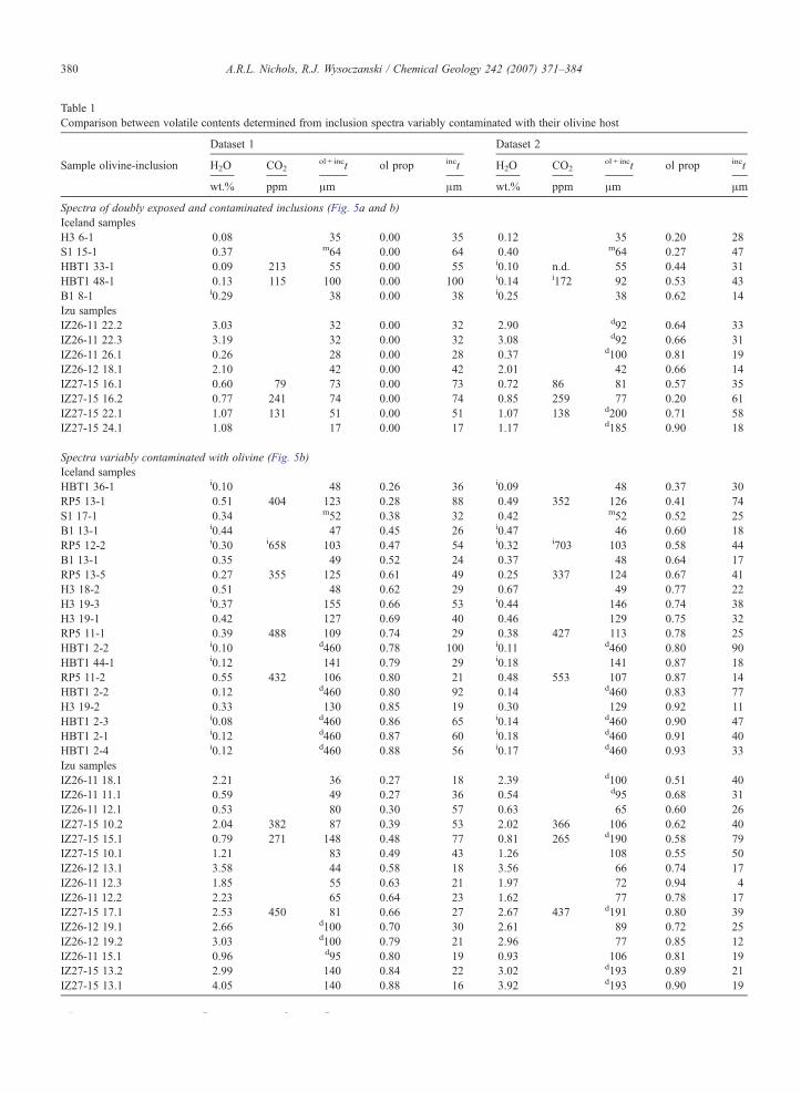
Table 1Comparison between volatile contents determined from inclusion spectra variably contaminated with their olivine host
Dataset 1 Dataset 2
Sample olivine-inclusion H2O CO2ol + inct ol prop inct H2O CO2
ol + inct ol prop inct
wt.% ppm μm μm wt.% ppm μm μm
Spectra of doubly exposed and contaminated inclusions (Fig. 5a and b)Iceland samplesH3 6-1 0.08 35 0.00 35 0.12 35 0.20 28S1 15-1 0.37 m64 0.00 64 0.40 m64 0.27 47HBT1 33-1 0.09 213 55 0.00 55 i0.10 n.d. 55 0.44 31HBT1 48-1 0.13 115 100 0.00 100 i0.14 i172 92 0.53 43B1 8-1 i0.29 38 0.00 38 i0.25 38 0.62 14Izu samplesIZ26-11 22.2 3.03 32 0.00 32 2.90 d92 0.64 33IZ26-11 22.3 3.19 32 0.00 32 3.08 d92 0.66 31IZ26-11 26.1 0.26 28 0.00 28 0.37 d100 0.81 19IZ26-12 18.1 2.10 42 0.00 42 2.01 42 0.66 14IZ27-15 16.1 0.60 79 73 0.00 73 0.72 86 81 0.57 35IZ27-15 16.2 0.77 241 74 0.00 74 0.85 259 77 0.20 61IZ27-15 22.1 1.07 131 51 0.00 51 1.07 138 d200 0.71 58IZ27-15 24.1 1.08 17 0.00 17 1.17 d185 0.90 18
Spectra variably contaminated with olivine (Fig. 5b)Iceland samplesHBT1 36-1 i0.10 48 0.26 36 i0.09 48 0.37 30RP5 13-1 0.51 404 123 0.28 88 0.49 352 126 0.41 74S1 17-1 0.34 m52 0.38 32 0.42 m52 0.52 25B1 13-1 i0.44 47 0.45 26 i0.47 46 0.60 18RP5 12-2 i0.30 i658 103 0.47 54 i0.32 i703 103 0.58 44B1 13-1 0.35 49 0.52 24 0.37 48 0.64 17RP5 13-5 0.27 355 125 0.61 49 0.25 337 124 0.67 41H3 18-2 0.51 48 0.62 29 0.67 49 0.77 22H3 19-3 i0.37 155 0.66 53 i0.44 146 0.74 38H3 19-1 0.42 127 0.69 40 0.46 129 0.75 32RP5 11-1 0.39 488 109 0.74 29 0.38 427 113 0.78 25HBT1 2-2 i0.10 d460 0.78 100 i0.11 d460 0.80 90HBT1 44-1 i0.12 141 0.79 29 i0.18 141 0.87 18RP5 11-2 0.55 432 106 0.80 21 0.48 553 107 0.87 14HBT1 2-2 0.12 d460 0.80 92 0.14 d460 0.83 77H3 19-2 0.33 130 0.85 19 0.30 129 0.92 11HBT1 2-3 i0.08 d460 0.86 65 i0.14 d460 0.90 47HBT1 2-1 i0.12 d460 0.87 60 i0.18 d460 0.91 40HBT1 2-4 i0.12 d460 0.88 56 i0.17 d460 0.93 33Izu samplesIZ26-11 18.1 2.21 36 0.27 18 2.39 d100 0.51 40IZ26-11 11.1 0.59 49 0.27 36 0.54 d95 0.68 31IZ26-11 12.1 0.53 80 0.30 57 0.63 65 0.60 26IZ27-15 10.2 2.04 382 87 0.39 53 2.02 366 106 0.62 40IZ27-15 15.1 0.79 271 148 0.48 77 0.81 265 d190 0.58 79IZ27-15 10.1 1.21 83 0.49 43 1.26 108 0.55 50IZ26-12 13.1 3.58 44 0.58 18 3.56 66 0.74 17IZ26-11 12.3 1.85 55 0.63 21 1.97 72 0.94 4IZ26-11 12.2 2.23 65 0.64 23 1.62 77 0.78 17IZ27-15 17.1 2.53 450 81 0.66 27 2.67 437 d191 0.80 39IZ26-12 19.1 2.66 d100 0.70 30 2.61 89 0.72 25IZ26-12 19.2 3.03 d100 0.79 21 2.96 77 0.85 12IZ26-11 15.1 0.96 d95 0.80 19 0.93 106 0.81 19IZ27-15 13.2 2.99 140 0.84 22 3.02 d193 0.89 21IZ27-15 13.1 4.05 140 0.88 16 3.92 d193 0.90 19
H2O contents determined using the 3550 cm−1 peak height.
380 A.R.L. Nichols, R.J. Wysoczanski / Chemical Geology 242 (2007) 371–384

Fig. 5. (a) Comparison between H2O contents measured for doubly exposed inclusions (pure inclusion) and H2O contents for the same inclusion withonly one, or neither, surface exposed (contaminated inclusion). The thicknesses of the doubly exposed inclusions are measured directly, thethicknesses of the inclusions with spectra contaminated with olivine are derived from the olivine band. (b) Comparison between H2O contentsdetermined for the same inclusions with variable amounts of olivine in the beam path. Filled symbols are from (a), open symbols compare the sameinclusions with different proportions of olivine in the beam path. Datasets refer to Table 1. (c) Comparison of CO2 contents calculated for spectrathrough the same inclusions with different proportions of olivine in the beam path. Datasets refer to Table 1. Lines represent perfect agreement.
381A.R.L. Nichols, R.J. Wysoczanski / Chemical Geology 242 (2007) 371–384
sample destruction than if a digital displacement gaugeis used.
To date, although transmission micro-FTIR spectros-copy has become a routine and accurate method to
H2O contents determined using the 3550 cm−1 peak height.CO2 contents determined using the average of 1515 and 1435 cm−1 peak hen.d. Not detected (inclusion too thin).ol + inct Denotes the overall thickness of the area analysed.ol prop Denotes the proportion of the beam path that comprises the olivineinct Denotes the thickness of the inclusion.i Denotes that spectra were extracted from spectroscopic images, others spotUnmarked thicknesses measured using reflectance spectra; where interferencm Thicknesses determined using a microscope objective micrometer.d Thicknesses determined using digital displacement gauge.Dataset numbers correspond to axes in Fig. 5b and c.
Notes to Table 1:
quantify H2O and CO2 species dissolved in silicateglasses, owing to the difficulties associated with pre-paring and measuring the thickness of inclusions it hasonly been reliable for the largest or most regular shaped.
ights.
host, calculated using the peak at 2000 cm−1.
analyses.e fringes did not occur:
382 A.R.L. Nichols, R.J. Wysoczanski / Chemical Geology 242 (2007) 371–384
This has led to unrepresentative inclusion volatile data-sets. By using the contaminated spectra to calculateinclusion thickness we are able to analyse the volatiles ininclusions that were previously inaccessible to FTIRanalysis. Furthermore, because the way in which theinclusion thickness is calculated relies upon the pro-portional make up of the beam path, the accuracy is notinfluenced by inclusion shape. In this study we havesuccessfully obtained H2O contents through inclusionsof a wide variety of shapes at thicknesses down to 4 μm.The lower limits of the technique are controlled by thedetection limits of the spectra; the absorption by thevolatile species must be detectable above the back-ground. Therefore, where H2O contents are low, inclu-sions will have to be larger. In addition, inclusions mustbe large enough to be analysed by other geochemicaltechniques (e.g., EPMA and LA-ICP-MS) in order tomeasure their compositions. This is needed, firstly, todetermine which molar absorption coefficient to apply tothe absorbance data, and secondly, to set the volatile datainto context with other geochemical parameters, makingthem much more valuable. The latter reason also appliesto other techniques used to measure volatiles in inclu-sions. The higher limits are controlled by the absorbanceat which the detector becomes saturated, in which caseeither less intense overtone bands have to be utilised, orthe inclusion has to be made thinner. In the case of H2O,at concentrations greater than 5 wt.% even very thinsamples will saturate the detector at 3500 cm−1. As aresult, overtone bands at higher wavenumbers (7100,5200 and 4500 cm−1) have to be used. Importantly thebands caused by the olivine structure are at lower wave-numbers, so they will not interfere with the overtonebands either, and the same technique can be applied. Insummary, the technique described here enables FTIRspectroscopy to be used to measure volatile contents inolivine hosted inclusions that could not be analysed byFTIR before. As a result, larger datasets can be collected,permitting more robust statistical analyses of, for exam-ple, pre-eruptive volatile contents, magma mixing, andcrystallisation processes.
As the use of SIMS and confocal micro-Ramanspectroscopy to analyse inclusions continue to evolve,and through the technique we have developed thatallows transmittance micro-FTIR spectroscopy to beapplied to small inclusions, the geological communitynow have an increasingly large analytical armoury withwhich to target melt inclusions. The different analyticaltechniques complement one another. All the techniquesrely on some form of compositional dependent calibra-tion, so the initial choice of technique will depend onhow well the technique has been calibrated for the
composition of interest. For example, so far the appli-cability of confocal micro-Raman spectroscopy to iron-rich Si-poor glasses (e.g., basalts) has not been fullyassessed. The expected H2O content should be consid-ered; recent developments in confocal micro-Raman(Thomas and Davidson, 2006) suggest that this providesbetter accuracy at lower H2O contents than before,whereas at higher H2O contents the calibration curvesfor SIMS do not reproduce the data so well (Hauri et al.,2002). If H2O speciation is required, confocal micro-Raman, or if the inclusion is large enough to exposeboth sides FTIR, should be used; SIMS is unable todetermine speciation. Either confocal micro-Raman ormicro-FTIR spectroscopy is appropriate to use if samplepreservation is an important consideration as they arenon-destructive. If a crystal contains more than oneinclusion, Raman and FTIR allow the inclusions to beanalysed quickly, without the need to expose each in-clusion. After volatile analysis, any interesting inclusioncan be exposed for further analysis by other techniques.SIMS (10–15 μm) and particularly micro-Raman spec-troscopy (3 μm) have excellent spatial resolution, andnow for inclusions hosted in olivine so does micro-FTIRspectroscopy. SIMS has a great advantage over the othertechniques in that it permits simultaneous analysis ofmany other elements. Finally, and perhaps most impor-tantly, the greatest influence over the choice of methodwill be what technique is available to the analyst; due tothe costs, SIMS are not nearly as numerous as FTIR andRaman spectrometers.
7. Conclusions
This study demonstrates that it is possible to usemicro-FTIR spectroscopy to determine the H2O andCO2 contents of olivine hosted melt inclusions that werepreviously regarded as too small or too irregularlyshaped. The difficulties arise in measuring the thicknessof these inclusions, which is required to calculate H2Oand CO2 contents from FTIR spectra. Such inclusionsare difficult to prepare, their spectra are often contam-inated with the olivine crystal, and even if the thicknessof the sample wafer can be measured accurately it doesnot refer solely to the inclusion. However, this conta-mination enables the thickness of the olivine crystal inthe beam path to be calculated, which when combinedwith the overall thickness, allows the inclusion thick-ness to be quantified. This can then be used to calculatethe volatile contents of the inclusion. However, becausethe olivine spectral bands overlap with the molecularH2O peak, currently H2O speciation cannot be mea-sured, although there is no such problem with CO2.

383A.R.L. Nichols, R.J. Wysoczanski / Chemical Geology 242 (2007) 371–384
This development complements SIMS and confocalmicro-Raman spectroscopy, which have been recentlyapplied to the analysis of volatiles in inclusions. To-gether FTIR, Raman and SIMS will enable inclusions tobe analysed more easily and rapidly, and, perhaps mostimportantly, make the analysis of small inclusions (assmall as 10 μm) more routine. As a result, it should bepossible to analyse virtually the entire inclusion popu-lation within a sample, thus providing better constraintson, for example, pre-eruptive volatile contents, magmamixing and crystallisation processes, than was previous-ly possible.
Further work is currently underway to apply the sameprinciples (i.e., using absorbance bands from the hostcrystal to calculate its thickness in contaminated spectra)to other minerals, in addition to olivine, and to accessmolecular H2O, and thus H2O speciation, in spectracontaminated with the olivine host.
Acknowledgements
ARLN was supported by a JSPS Fellowship duringthis study. The authors also wish to thank S. Kaneko forthe useful discussions. Reviews by R. L. Rudnick, ananonymous reviewer and, in particular, A. Di Murosignificantly improved the manuscript.
References
Agrinier, P., Jendrzejewski, N., 2000. Overcoming problems of densityand thickness measurements in FTIR volatile determinations: aspectroscopic approach. Contrib. Mineral. Petrol. 139, 265–272.
Atlas, Z.D., Dixon, J.E., Sen, G., Finny, M., Martin-Del Pozzo, A.L.,2006. Melt inclusions from Volcán Popocatépetl and Volcán deColima, Mexico: melt evolution due to vapour-saturated crystal-lization during ascent. J. Volcanol. Geotherm. Res. 153, 221–240.
Behrens, H., Roux, J., Neuville, D.R., Siemann, M., 2006. Quanti-fication of dissolved H2O in silicate glasses using confocal micro-Raman spectroscopy. Chem. Geol. 229, 96–112.
Bureau, H., Trocellier, P., Shaw, C., Khodja, H., Bolfan-Casanova, N.,Demouchy, S., 2003. Determination of the concentration of waterdissolved in glasses and minerals using nuclear microprobe. Nucl.Instrum. Methods Phys. Res., B Beam Interact. Mater. Atoms 210,449–454.
Chabiron, A., Pironon, J., Massare, D., 2004. Characterization of waterin synthetic rhyolitic glasses and natural melt inclusions by Ramanspectroscopy. Contrib. Mineral. Petrol. 146, 485–492.
Danyushevsky, L.V., Batiza, R., Eggins, S.M., Christie, D.M., 2000.H2O abundance in depleted tomoderately enrichedmid-ocean ridgemagmas; Part I: incompatible behaviour, implications for mantlestorage, and origin of regional variations. J. Petrol. 41, 1329–1364.
Deer, W.A., Howie, R.A., Zussman, J., 1992. An Introduction to theRock-FormingMinerals. LongmanScientific andTechnical. 696 pp.
Delaney, J.R., Muenow, D.W., Graham, D.G., 1978. Abundance anddistribution of water, carbon, and sulfur in the glassy rims of sub-marine pillow basalts. Geochim. Cosmochim. Acta 42, 581–594.
Devine, J.D., Gardner, J.E., Brack, H.P., Layne, G.D., Rutherford,M.J.,1995. Comparison of microanalytical methods for estimating H2Ocontents of silicic volcanic glasses. Am. Mineral. 80, 319–328.
Di Muro, A., Villemant, B., Montagnac, G., Scaillet, B., Reynard, B.,2006. Quantification of water content and speciation in naturalsilicic glasses (phonolite, dacite, rhyolite) by confocal microRa-man spectrometry. Geochim. Cosmochim. Acta 70, 2868–2884.
Dixon, J.E., 1997. Degassing of alkalic basalts. Am. Mineral. 82,368–378.
Dixon, J.E., Clague, D.A., 2001. Volatiles in basaltic glasses fromLoihiseamount, Hawaii: evidence for a relatively dry plume component.J. Petrol. 42, 627–654.
Dixon, J.E., Stolper, E.M., 1995. An experimental study of water andcarbon dioxide solubilities in MORB liquids. Part II: applicationsto degassing. J. Petrol. 36, 1633–1646.
Dixon, J.E., Stolper, E., Delaney, J.R., 1988. Infrared spectroscopicmeasurements of CO2 and H2O in Juan de Fuca Ridge basalticglasses. Earth Planet. Sci. Lett. 90, 87–104.
Dixon, J.E., Clague, D.A., Wallace, P., Poreda, R., 1997. Volatiles inalkalic basalts from the North Arch Volcanic Field, Hawaii: exten-sive degassing of deep submarine-erupted alkalic series lavas.J. Petrol. 38, 911–939.
Fine, G., Stolper, E., 1985.Dissolved carbon dioxide in basaltic glasses:concentration and speciation. Earth Planet. Sci. Lett. 76, 263–278.
Fyfe, W.S., McBirney, A.R., 1975. Subduction and the structure ofandesitic volcanic belts. Am. J. Sci. 275, 285–297.
Garcia, M.O., Muenow, D.W., Aggrey, K.E., O'Neil, J.R., 1989. Majorelement, volatile and stable isotope geochemistry of Hawaiiansubmarine tholeiitic glasses. J. Geophys. Res. 94, 10525–10538.
Gerlach, T.M., 1986. Exsolution of H2O, CO2, and S during erup-tive episodes at Kilauea volcano, Hawaii. J. Geophys. Res. 91,12177–12185.
Giordano, D., Nichols, A.R.L., Dingwell, D.B., 2005. Glass transitiontemperatures of natural hydrous melts: a relationship with shearviscosity and implications for the welding process. J. Volcanol.Geotherm. Res. 142, 105–118.
Green, D.H., Falloon, T.J., 1998. Pyrolite: a Ringwood concept and itscurrent expression. In: Jackson, I.N.S. (Ed.), The Earth's Mantle:Composition, Structure, and Evolution. Cambridge UniversityPress, pp. 311–380.
Hauri, E., 2002. SIMS analysis of volatiles in silicate glasses, 2:isotopes and abundance in Hawaiian melt inclusions. Chem. Geol.183, 115–141.
Hauri, E., Wang, J., Dixon, J.E., King, P.L., Mandeville, C., Newman,S., 2002. SIMS analysis of volatiles in silicate glasses 1. Calib-ration, matrix effects and comparisons with FTIR. Chem. Geol.183, 99–114.
Hervig, R.L., Mazdab, F.K., Moore, G., McMillan, P.F., 2003. Ana-lyzing hydrogen (H2O) in silicate glass by secondary ion massspectrometry and reflectance Fourier transform infrared spectrosco-py. In: De Vivo, B., Bodnar, R.J. (Eds.), Melt inclusions in volcanicsystems methods, applications and problems. Elsevier, pp. 83–103.
Ihinger, P.D., Hervig, R.L., McMillan, P.F., 1994. Analytical methodsfor volatiles in glasses. In: Carroll, M.R., Holloway, J.R. (Eds.),Volatiles in Magmas. Reviews in Mineralogy, vol. 30. Mineralog-ical Society of America, pp. 67–121.
Jamtveit, B., Brooker, R., Brooks, K., Larsen, L.M., Pederson, T.,2001. The water content of olivines from the North AtlanticVolcanic Province. Earth Planet. Sci. Lett. 186, 401–415.
King, P.L., Dalby, K.D., Lui, D.K., Griffin, T., 2005. A new reflectanceIR spectroscopy method for analyzing H2O in rhyolitic to basalticglasses. Geochim. Cosmochim. Acta 69 (Suppl. 1), A744.

384 A.R.L. Nichols, R.J. Wysoczanski / Chemical Geology 242 (2007) 371–384
Kumagai, H., Kaneoka, I., 2003. Relationship between submarineMORB glass textures and atmospheric component of MORBs.Chem. Geol. 200, 1–24.
Lange, R.A., 1997. A revised model for the density and thermalexpansivity of K2O–Na2O–CaO–MgO–Al2O3–SiO2 liquids from700 to 1900 K: extension to crustal magmatic temperatures.Contrib. Mineral. Petrol. 130, 1–11.
Ligi, M., Bonatti, E., Cipriani, A., Ottolini, L., 2005.Water-rich basaltsat mid-ocean ridge cold spots. Nature 434, 66–69.
Luhr, J.F., 1992. Slab-derived fluids and partial melting in subductionzones: insights from two contrasting Mexican volcanoes (Colimaand Ceboruco). J. Volcanol. Geotherm. Res. 54, 1–18.
Luhr, J.F., 2001. Glass inclusions and melt volatile contents at Parí-cutin Volcano, Mexico. Contrib. Mineral. Petrol. 142, 261–283.
Matveev, S., Portnyagin, M., Ballhaus, C., Brooker, R., Geiger, C.A.,2005. FTIR spectrum of phenocryst olivine as an indicator of silicasaturation in magmas. J. Petrol. 46, 603–614.
Matveev, S., Creighton, S., Stachel, T., 2006. OH in peridotitic olivinesentrained in kimberlite magmas. Geochim. Cosmochim. Acta 70(Suppl. 1), A403.
McCulloch, M.T., Gamble, J.A., 1991. Geochemical and geodynami-cal constraints on subduction zone magmatism. Earth Planet. Sci.Lett. 102, 358–374.
Metrich, N., Sigurdsson, H., Meyer, P.S., Devine, J.D., 1991. The 1783Lakagigar eruption in Iceland: geochemistry, CO2 and sulfur de-gassing. Contrib. Mineral. Petrol. 107, 435–447.
Moore, J.G., 1965. Petrology of deep-sea basalt near Hawaii. Am.J. Sci. 263, 40–52.
Moore, J.G., 1970. Water content of basalt erupted on the ocean floor.Contrib. Mineral. Petrol. 28, 272–279.
Newman, S., Lowenstern, J.B., 2002. VolatileCalc: a silicate melt-H2O–CO2 solution model written in Visual Basic for excel.Comput. Geosci. 28, 597–604.
Newman, S., Stolper, E.M., Epstein, S., 1986. Measurement of waterin rhyolitic glasses: calibration of an infrared spectroscopic tech-nique. Am. Mineral. 71, 1527–1541.
Nichols, A.R.L., Carroll, M.R., Höskuldsson, Á., 2002. Is the Icelandhot spot also wet? Evidence from the water contents of undegassedsubmarine and subglacial pillow basalts. Earth Planet. Sci. Lett.202, 77–87.
Nishikida, K., Nishio, E., Hannah, R.W., 1996. Selected Applicationsof Modern FT-IR Techniques. Gordon and Breach. 200 pp.
Poreda, R., Schilling, J.-G., Craig, H., 1986. Helium and hydrogenisotopes in ocean-ridge basalts north and south of Iceland. EarthPlanet. Sci. Lett. 78, 1–17.
Richet, P., Lejeune, A.-M., Holtz, F., Roux, J., 1996. Water and theviscosity of andesite melts. Chem. Geol. 128, 185–197.
Schilling, J.-G., Bergeron, M.B., Evans, R., 1980. Halogens in themantle beneath the North Atlantic. Philos. Trans. R. Soc. Lond., A297, 147–178.
Schilling, J.-G., Zajac, M., Evans, R., Johnston, T., White, W., Devine,J.D., Kingsley, R., 1983. Petrologic and geochemical variationsalong the Mid-Atlantic Ridge from 29°N to 73°N. Am. J. Sci. 283,510–586.
Signorelli, S., Vaggelli, G., Romano, C., 1999. Pre-eruptive volatile(H2O, F, Cl, S) contents of phonolitic magmas feeding the 3550-year old Avellino eruption from Vesuvius, southern Italy. J. Volca-nol. Geotherm. Res. 93, 237–256.
Simons, K., Dixon, J., Schilling, J.-G., Kingsley, R., Poreda, R., 2002.Volatiles in basaltic glasses from the Easter-Salas y GomezSeamount Chain and Easter Microplate: implications for geochem-ical cycling of volatile elements. Geochem. Geophys. Geosyst. 3.doi:10.1029/2001GC000173.
Sobolev, A.V., Chaussidon, M., 1996. H2O concentrations in primarymelts from supra-subduction zones and mid-ocean ridges: impli-cations for H2O storage and recycling in the mantle. Earth Planet.Sci. Lett. 137, 45–55.
Stolper, E., 1982a. Water in silicate glasses: an infrared spectroscopicstudy. Contrib. Mineral. Petrol. 81, 1–17.
Stolper, E., 1982b. The speciation of water in silicate melts. Geochim.Cosmochim. Acta 46, 2609–2620.
Stolper, E., Newman, S., 1994. The role of water in the petrogenesis ofMariana trough magmas. Earth Planet. Sci. Lett. 121, 293–325.
Sun, W.D., Binns, R.A., Fan, A.C., Kamenetsky, V.S., Wysoczanski,R., Wei, G.J., Hu, Y.H., Arculus, R.J., 2007. Chlorine in submarinevolcanic glasses from the eastern Manus basin. Geochim. Cosmo-chim. Acta 71, 1542–1552.
Tamic, N., Behrens, H., Holtz, F., 2001. The solubility of H2O andCO2 in rhyolitic melts in equilibrium with a mixed CO2–H2O fluidphase. Chem. Geol. 174, 333–347.
Thomas, R., 2000. Determination of water contents of granite meltinclusions by confocal laser Raman microprobe spectroscopy. Am.Mineral. 85, 868–872.
Thomas, R., Davidson, P., 2006. Progress in the determination of waterin glasses and melt inclusions with Raman spectroscopy: a shortreview. Z. Geol. Wiss. 34, 159–163.
Thomas, R., Kamenetsky, V.S., Davidson, P., 2006. Laser Ramanspectroscopic measurements of water in unexposed glass inclu-sions. Am. Mineral. 91, 467–470.
Wallace, P.J., 1998. Water and partial melting in mantle plumes:inferences from the dissolved H2O concentrations of Hawaiianbasaltic magmas. Geophys. Res. Lett. 25, 3639–3642.
Whittington, A., Richet, P., Holtz, F., 2000. Water and the viscosity ofdepolymerised aluminosilicate melts. Geochim. Cosmochim. Acta64, 3725–3736.
Wysoczanski, R.J., Tani, K., 2006. Spectroscopic FTIR imaging ofwater species in silicic volcanic glasses and melt inclusions: anexample from the Izu–Bonin arc. J. Volcanol. Geotherm. Res. 156,302–314.
Wysoczanski, R.J., Wright, I.C., Gamble, J.A., Hauri, E.H., Luhr, J.F.,Eggins, S.M., Handler, M.R., 2006a. Volatile contents of Kerma-dec Arc–Havre Trough pillow glasses; fingerprinting slab-derivedaqueous fluids in the mantle sources of arc and back-arc lavas.J. Volcanol. Geotherm. Res. 152, 51–73.
Wysoczanski, R.J., Tani, K., Tatsumi, Y., 2006b. High- and lower-alumina basalticmelt inclusions from theHigashi–IzuMonogeneticVolcano Group, Japan. Geochim. Cosmochim. Acta 70 (Suppl. 1),A711.
Zajacz, Z., Halter, W., Malfait, W.J., Bachmann, O., Bodnar, R.J.,Hirschmann, M.M., Mandeville, C.W., Morizet, Y., Müntener, O.,Ulmer, P., Webster, J.D., 2005. A composition-independent quan-titative determination of the water content in silicate glasses andsilicate melt inclusions by confocal Raman spectroscopy. Contrib.Mineral. Petrol. 150, 631–642.