
USER MANUAL - QBot 2 for QUARC - made|for|science GmbH
27
CAPTIVATE. MOTIVATE. GRADUATE. USER MANUAL QBot 2 for QUARC Set Up and Configuration
-
Upload
khangminh22 -
Category
Documents
-
view
5 -
download
0
Transcript of USER MANUAL - QBot 2 for QUARC - made|for|science GmbH
CAPTIVATE. MOTIVATE. GRADUATE.
USER MANUALQBot 2 for QUARC Set Up and Configuration

© 2015 Quanser Inc., All rights reserved.
Quanser Inc.119 Spy CourtMarkham, OntarioL3R [email protected]: 1-905-940-3575Fax: 1-905-940-3576
Printed in Markham, Ontario.
For more information on the solutions Quanser Inc. offers, please visit the web site at:http://www.quanser.com
This document and the software described in it are provided subject to a license agreement. Neither the software nor this document may beused or copied except as specified under the terms of that license agreement. Quanser Inc. grants the following rights: a) The right to reproducethe work, to incorporate the work into one or more collections, and to reproduce the work as incorporated in the collections, b) to create andreproduce adaptations provided reasonable steps are taken to clearly identify the changes that were made to the original work, c) to distributeand publically perform the work including as incorporated in collections, and d) to distribute and publicly perform adaptations. The above rightsmay be exercised in all media and formats whether now known or hereafter devised. These rights are granted subject to and limited by thefollowing restrictions: a) You may not exercise any of the rights granted to You in above in any manner that is primarily intended for or directedtoward commercial advantage or private monetary compensation, and b) You must keep intact all copyright notices for the Work and provide thename Quanser Inc. for attribution. These restrictions may not be waved without express prior written permission of Quanser Inc.
QBOT 2 - User Manual 2

1 IntroductionThe Quanser QBot 2 (Figure 1.1) is an innovative autonomous ground robot system incorporating a robusteducational ground vehicle with the Microsoft Kinect and a Quanserr embedded target. The QBot 2 is comprisedof a Yujin Robot Kobuki platform, a Microsoft Kinect RGB camera and depth sensor, and a Quanserr DAQ with awireless embedded computer (also refered to as the target computer). The embedded computer system mountedon the vehicle uses the Gumstix DuoVero computer [1] to run QUARCr, Quanserr's real-time control software, andinterface with the QBot 2 data acquisition card (DAQ).
Figure 1.1: The Quanser QBot 2
The interface to the target computer is Matlabr Simulinkr with QUARCr. The QBot 2 is accessible through threedifferent block sets: the Quanserr Hardware-In-the-Loop (HIL) block set to read from sensors and/or write tooutputs, the Quanserr Stream API blockset to perform communications over wired and wireless communicationchannels, the Quanserr Multimedia blockset to read RGB and depth image data from the Kinect sensor, and TheMathWorksr Computer Vision System toolbox to perform image processing. Controllers are developed in Simulinkrwith QUARCr on the host computer, and these models are cross-compiled and downloaded to the target (Gumstix[1]) seamlessly. A diagram of this configuration is shown in Figure 1.2.
Figure 1.2: Communication Hierarchy
The general system description, component nomenclature, specifications, and model parameters are all given inSection 2. Section 3 goes into detail on how to setup the QBot 2. Lastly, Section 4 contains a troubleshooting guide.
QBOT 2 - User Manual DRAFT - April 14, 2015

1.1 PrerequisitesTo successfully operate the QBot 2, the prerequisites are:
1. To be familiar with the components of the QBot 2.
2. To have QUARCr version 2.5 or later installed and properly licensed.
3. The MathWorksr Computer Vision System toolbox: http://www.mathworks.com/products/computer-vision/
4. Microsoft Kinect SDK v1.8 installed: http://www.microsoft.com/en-ca/download/details.aspx?id=40278
5. Microsoft Kinect for Windows Developer Toolkit v1.8 installed:http://www.microsoft.com/en-ca/download/details.aspx?id=40276
6. To be familiar with using QUARCr control and monitor the vehicle in real-time, and in designing a controllerthrough Simulinkr. See Reference [2] for more details.
1.2 References[1] Gumstix: http://gumstix.com/[2] QUARC User Manual (type doc quarc in Matlab to access)
QBOT 2 - User Manual 4

2 ComponentsThe QBot 2 is made up of four main components: the Kobuki robot platform, the QBot 2 data acquisition card (DAQ),the Gumstix DuoVero embedded computer, and the Kinect sensor. This section outlines these components in moredetail.
2.1 The Kobuki Robot Platform
The QBot 2 uses an Kobuki mobile robot platform (Figure 2.1). The QBot 2 follows the Quanserr standard for bodyframe axes, where the x-axis is in the forward direction, the y-axis is to the left, and the z-axis is up. The diameterof the vehicle is 34 cm, and its height (without attachments) is 10 cm. The Kobuki is driven by two differential drivewheels with built-in encoders. The Kobuki comes with a bumper sensor as well as a built-in gyroscope and cliffsensors. The embedded computer target can access data from these sensors.
Figure 2.1: The Kobuki mobile robot platform
The QBot 2 is powered by a Lithium ion battery pack (Figure 2.2a) provided by Yujin Robot. The battery fitsunderneath the QBot 2, and can last continuously for about 3 hours after a full charge. The battery takes lessthan 3 hours to charge. While charging, the power light pulses slowly with an orange colour. A battery charger isprovided (Figure 2.2b). To recharge the QBot 2, plug in the battery charger and connect it to the charger input porton the QBot 2 next to the ON/OFF switch (Figure 2.2c).
QBOT 2 - User Manual DRAFT - April 14, 2015

(a) The QBot 2 battery
(b) The QBot 2 charger (c) The QBot 2 charger input
Figure 2.2: The QBot 2 battery and charger input
2.2 System Specifications and Model ParametersTable 2.1 lists the main parametrs associated with the QBot 2.
Symbol Description Value Unit
D Diameter of the QBot 2 0.35 m
d Distance between the left and right wheels 0.235 m
h Height of the QBot 2 (with Kinect mounted) 0.27 m
νmax Maximum speed of the QBot 2 0.7 m/s
m Total mass of the QBot 2 3.79 kg
Table 2.1: QBot 2 specifications
2.3 The QBot 2 Data Acquisition Card (DAQ)The QBot 2 DAQ contains the wiring and circuitry integrating the DuoVero embedded computer, Kobuki robot, Kinectsensor, and additional input/output (I/O) components connected to the DAQ. Figure 2.3 shows the QBot 2 DAQ with
QBOT 2 - User Manual 6

accessible I/O headers for the user including SPI, I2C, UART, digital I/O, analog input, encoder input, and PWMoutput. More details on accessing the QBot 2 I/O is found in 2.6. The QBot 2 DAQ connects to the Kinect sensorvia a USB port (see Figure 2.4). The QBot 2 DAQ connects to the Kobuki via a ribbon cable (see Figure 2.4). TheQBot 2 DAQ is powered via a cable connected to the Kobuki 12 V, 5 A power source (see Figure 2.4).
Figure 2.3: The QBot 2 DAQ
Figure 2.4: The QBot 2 DAQ connectors
The QBot 2 DAQ also provides five headers for users to use when integrating additional I/O components. Eachheader is a double row where each pin in the first row is electrically connected to the pin in the second row directlyopposite. This allows users to connect a sensor to one row and map the connection from the DAQ I/O to the pins inthe mating row similar to a breadboard. Figure 2.5 shows the location of the headers.
QBOT 2 - User Manual DRAFT - April 14, 2015

Figure 2.5: The QBot 2 DAQ sensor mounting rows
2.3.1 Digital Input/Output Pins (DIO)
The user DIO channels (Figure 2.6) are set as inputs by default. The DIO channels need to be configured as eitherinputs (or outputs, but not both) using the HIL Initialize block. Also, if an output needs to be in a known state onpower up, it is recommended that a 10k resistor is put from the I/O to 5 V or GND as needed. The DIO channels areaccessed through the HIL API.
Figure 2.6: The QBot 2 DAQ user digital I/O
2.3.2 Analog inputs
The QBot 2 provides four user analog input channels (Figure 2.7) that are rated for signals between 0 − 5 V anduses 12-bit analog to digital converters (ADCs). The analog inputs are accessed through the HIL API.
QBOT 2 - User Manual 8

Figure 2.7: The QBot 2 DAQ user analog inputs
2.3.3 Encoder inputs
The QBot 2 provides two user encoder input channels (Figure 2.8). Each encoder input channel has an A and Bpulse as well as a Z index signal. The encoders are sampled at 100 kHz. The encoder inputs are accessed throughthe HIL API.
Figure 2.8: The QBot 2 DAQ user encoder inputs
QBOT 2 - User Manual DRAFT - April 14, 2015
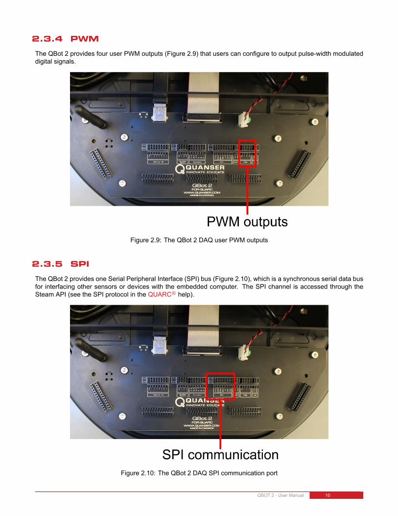
2.3.4 PWM
The QBot 2 provides four user PWM outputs (Figure 2.9) that users can configure to output pulse-width modulateddigital signals.
Figure 2.9: The QBot 2 DAQ user PWM outputs
2.3.5 SPI
The QBot 2 provides one Serial Peripheral Interface (SPI) bus (Figure 2.10), which is a synchronous serial data busfor interfacing other sensors or devices with the embedded computer. The SPI channel is accessed through theSteam API (see the SPI protocol in the QUARCr help).
Figure 2.10: The QBot 2 DAQ SPI communication port
QBOT 2 - User Manual 10

2.3.6 UART
The QBot 2 provides one UART serial port (Figure 2.11) that can be used to interface with 3.3 V (TTL) serial devices.The UART is accessed through the Steam API (see the serial protocol in the QUARCr help).
Figure 2.11: The QBot 2 DAQ UART communication port
2.3.7 I2C
The QBot 2 provides one inter-integrated circuit (I2C) serial bus (Figure 2.12) for interfacing with external sensorsand devices. The I2C channel is accessed through the Steam API (see the I2C protocol in the QUARCr help).
Figure 2.12: The QBot 2 DAQ I2C communication port
QBOT 2 - User Manual DRAFT - April 14, 2015

2.4 Gumstix DuoVero Embedded Computer
The Gumstix DuoVero is a small-scale embedded computer that runs the QUARCr runtime. With QUARCr
installed, code generated from Matlabr Simulinkr is cross-compiled, downloaded, and executed directly on theDuoVero. The DuoVero is connected directly to the QBot 2 DAQ on the bottom side of the PCB. The DuoVeroalso comes with integrated 802.11 b/g/n WiFi to allow wireless connection between the target Gumstix and the hostcomputer and/or other vehicles.
2.5 The Kinect SensorThe Microsoft Kinect sensor is an integrated RGB camera and depth sensor used in a variety of experiments (Figure2.13a). The Kinect camera provides RGB image capture and 11-bit depth sensing at a resolution of 640× 480. TheKinect's depth sensor utilizes infrared light and has a range of 0.5 m to 6 m. Due to the type of infrared sensor, theQBot 2 Kinect should only be used indoors in locations without direct sunlight for best results.
(a) The QBot 2 with Kinect sensor (b) The QBot 2 Kinect thumb screws
(c) The QBot 2 Kinect tilted at 0 degrees and 21.5 degrees
Figure 2.13: The QBot 2 Kinext sensor
QBOT 2 - User Manual 12

The QBot 2 Kinect is mounted on a structure that allows the Kinect to be oriented horizontally as well as tilteddownward for various viewing positions. The QBot 2 Kinect structure has four thumb screws (two on each side)as shown in Figure 2.13b. To adjust the Kinect's viewing angle, loosen all of the thumb screws slightly but do notremove them all the way. Tilt the Kinect to the desired angle and tighten all of the thumb screws. The maximumand minimum angles are designed to allow the kinect to be oriented facing stright ahead (tilted at 0 degrees) as wellas at an angle of 21.5 degrees such that the ground in front of the QBot 2 in the viewing angle as shown in Figure2.13c.
2.6 QBot 2 sensors interface
This section describes the blocks that are used to read the QBot 2 sensors in Simulinkr and write outputs to theQBot 2 motors. The QUARCr Hardware-In-the-Loop (HIL) blockset it used to communicate with Quanserr dataacquisition cards. For detailed information on the HIL blockset see the QUARCr HIL user guide in the Matlabr helpunder QUARC Targets | User's Guide | Accessing Hardware.
2.6.1 QBot 2 I/O
The QBot 2 provides an interface to the I/O of the Kobuki robot platform including its wheel encoders, sensors, andmotor outputs as well as several DAQ I/O channels for user expansion, which can be used to interface to a varietyof third-party sensors and actuators. The I/O of the QBot 2 DAQ includes:
• 4 analog inputs
• 8 reconfigurable digital I/O
• 4 PWM outputs
• 2 encoder inputs
• 1 UART
• 1 SPI
• 1 I2C
2.3 shows the location of the I/O listed above on the QBot 2 DAQ.
The Kobuki platform provides the following I/O:
• 2 wheel encoder inputs
• 2 wheel speed outputs
• 2 digital LED outputs
• 4 digital power enable outputs
• 3 analog and digital cliff sensors
• 2 analog motor current inputs
• 3 digital bumper sensors
• 3 digital wheel drop sensors
• 3 digital buttons
• 2 overcurrent sensors
• 2 wheel PWM measurements
QBOT 2 - User Manual DRAFT - April 14, 2015

• 3-axis gyroscope
• 1 Z-axis angle measurement (heading)
• 1 battery voltage sensor
The analog, digital, and robot and DAQ I/O listed above is accessed using the QUARCr HIL blockset. TheUART, SPI, and I2C communication channels are accessed through the QUARCr Stream blockset. For moreinformation on accessing communication stream data see the QUARCr help under QUARC Targets | User's Guide| Communications. Table 2.2 lists the HIL blocks used to communicate with the QBot 2's data acquisition hardware.
Block Description
The HIL Initialize block selects the DAQ board and configures the boardparameters. The HIL Initialize block is named via the Board name parameter,and all other HIL blocks reference the corresponding HIL Initialize through itsname. The HIL blocks will interface to the DAQ specified in the HIL InitializeBoard type parameter qbot2.
The HIL Read Write block is used to read sensor measurements from the DAQand robot and write motor commands to the QBot 2 motors. The inputs andoutputs are specified with numeric channel numbers given in Table 2.4 andTable 2.3, respectively.
The HIL Watchdog block is used to set the timeout limit for the watchdog timer.For the QBot 2 DAQ board, if there is no motor output command received fora consecutive period of time exceeding the watchdog timeout value then thewatchdog will trigger, forcing the motor outputs to 0. The default timeout valuefor the watchdog is 50 ms unless specified otherwise with this block. This blockcan be used to change the timeout value if 50 ms is not suitable.
Table 2.2: HIL blocks
QBOT 2 - User Manual 14

Channel type Write channel numbers Description Units
Analog none -
PWM 0 - 3 User PWM outputs %
Digital 0 - 7 Reconfigurable digital I/O
8 User LED on QBot 2 DAQ
9 LED1 red colour
10 LED1 green colour
11 LED2 red colour
12 LED2 green colour
13 Enable 3.3V power
14 Enable 5V power
15 Enable 12V/5A power
16 Enable 12V/1.5A power
Other 2000 Right wheel speed m/s
2001 Left wheel speed m/s
16000 Predefined sound (0=on sound, 1=off sound,2=recharge, 3=button, 4=error, 5=task start,6=task end)
-
Table 2.3: QBot 2 output channels
QBOT 2 - User Manual DRAFT - April 14, 2015

Channel type Read channel numbers Description Units
Analog 0 - 3 User analog inputs V
4 Supply voltage (battery) V
5 Right cliff sensor V
6 Central cliff sensor V
7 Left cliff sensor V
8 Right motor current A
9 Left motor current A
Encoder 0 - 1 User encoder inputs counts
2 Right wheel (2578 counts per revolution) counts
3 Left wheel (2578 counts per revolution) counts
Digital 0 - 7 User reconfigurable digital I/O
8 Right bumper
9 Central bumper
10 Left bumper
11 Right wheel drop
12 Left wheel drop
13 Right cliff detected
14 Central cliff detected
15 Left cliff detected
16 Button B0
17 Button B1
18 Button B2
19 Right overcurrent
20 Left overcurrent
Other 13000-13001 User encoder 0-1 index position counts
12000 Timestamp s
16000 Charge state (0=discharging, 2=dockingcharged, 6=docking charging, 18=adaptercharged, 22=adapter charging)
-
11000 Right wheel PWM %
11001 Left wheel PWM %
1002 Z-axis angle rad
3000 X-axis angular velocity rad/s
3001 Y-axis angular velocity rad/s
3002 Z-axis angular velocity rad/s
Table 2.4: QBot 2 input channels
QBOT 2 - User Manual 16

2.6.2 QBot 2 Kinect
The QBot 2 is integrated with a Microsoft Kinect sensor, which is capable of capturing RGB image data as well as12-bit depth data at several resolutions and framerates. The Kinect sensor data is available through the QUARCr
Multimedia blockset under QUARC Targets/Multimedia in the Simulink Library Browser. Table 2.5 shows the variousblocks used to interface with the Kinect and describes their purpose. Note: to use the QUARCr Kinect blocks,you will need to have the Microsoft Kinect SDK v1.8 and the Microsoft Kinect for Windows Developer Toolkit v1.8installed on the host PC.
Block Description
The Kinect Initialize block is required to initialize the Kinect sensor and providea name for the Kinect that other blocks use to associate with that sensor.
The Kinect Video Capture block is used to capture RGB or greyscale imagesfrom the Kinect sensor. You can specify the desired resolution as well as theoutput format (RGB or greyscale). The Video Capture block outputs a booleannew signal to indicate when a new frame is available so that it can be used totrigger image processing only once per frame.
The Kinect Get Depth block is used to output a depth-mapped image at thespecified resolution. The Kinect can measure depth from 0.5 m to 6 m.
The Kinect Get Image block is used to acquire RGB or greyscale images fromthe Kinect. The image sensor type can be specified as the color or infraredimage sensor. The image resolution can be selected as either 640 × 480 or1280×960. The image frame number is output from the block and can be usedto trigger image processing when a new image is available.
The Display Image block is used to display image data on the host computer.The Display Image block accepts greyscale and RGB image matrices as itsinput. The Display Image block acts like a scope and is not synchronizedwith the model; in other words, if the Display Image block cannot keep up withthe performance of the model it will not block the model thread(s). Since theDisplay Image block requires the images to be transmitted between the targetand the host it is recommended that the images used for display purposes bedownsampled or sent at a slower rate.
Table 2.5: Kinect blocks
QBOT 2 - User Manual DRAFT - April 14, 2015

3 Setup3.1 Setting up the QBot 2Follow these steps to setting up the QBot 2:
1. Connect the battery inside the Kobuki robot.
2. Press the power button shown in Figure 2.2c. This should turn on both vehicle and QBot 2 DAQ and Gumstixcomputer. After you make sure that this works, turn off the robot and follow the steps below to establish networkconnection.
3.2 Establishing Network ConnectionThe QBot 2 package comes with a pre-configured wireless router and automatically connects to the WiFi networkQuanser_UVS. It uses TCP/IP connection for communicating with the host computer and/or other Quanserrunmanned vehicles. The Host PC and each of the vehicles must have unique IP addresses and the range ofthese addresses are defined below (suggested):
Host PC(s) 192.168.2.10 to 192.168.2.19
Quanser vehicles (Gumstix) 192.168.2.20 to 192.168.2.254
These Steps outlined below for setting up the host computer wireless connection only need to be performed once.
1. Power up and turn on the wireless router.
2. After turning on the router that is provided, wait for about 60 seconds for the wireless network to establish andthen turn on the QBot 2 power and wait for it to boot up (approximately 60 seconds).
3. Connect your PC network card to any of the ports of the router (e.g. port number 1 to 4) using the networkcable provided (you can also connect to the Quanser_UVS or Quanser_UVS-5G wireless network if yourcomputer has wireless adapters, however, wired connection between your PC and the router is preferred forbetter performance). If you choose wireless connectivity between your PC and the router, you should use thepassword UVS_wifi to connect to the wifi network.
4. Using theWindows Network Connection utility in theWindows Task Bar, open the Network and Sharing Center.
QBOT 2 - User Manual 18

Figure 3.1: Open network settings. The Unidentified network is related to the wired connection to the router. If you areusing a wired connection to the router and you don't have wireless adapter, you will not see Quanser_UVS network.
5. Click on Change adapter settings.
6. Right-click on the Local Area Connection x, Unidentified network connection and click Properties. If you chosewireless connectivity between your PC and the router, choose the Wireless Network Connection instead, rightclick on it and click Properties.
7. Under This connection uses the following items:, select Internet Protocol Version 4 (TCP/IPv4) and clickProperties.
Figure 3.2: Network properties
8. Instead of obtaining an IP address of the computer automatically, select Use the following IP address and enterthe following:
QBOT 2 - User Manual DRAFT - April 14, 2015

IP address: 192.168.2.10 (For multiple host PCs, use different IP addresses within the valid range)Subnet mask: 255.255.255.0
Figure 3.3: IP settings
9. Make sure you can ping the router by typing ping 192.168.2.1 in the Run box in Windows (go to the Start menuand search for Run and click Run, Figure 3.4). If the connection to the router is successful you will see the pingreplies in the command window. If you cannot ping the router, check network connectivity and your IP addressbefore going to the next steps.
10. If the QBot 2 is powered on, the QBot 2 can be pinged by typing ping {IP of the QBot 2} in the Run box inWindows (go to the Start menu and click Run, Figure 3.4). The QBot 2 IP address is labeled on the DAQ PCBas shown in Figure 3.5. If the connection is successful you will see the ping replies in the command window.If you cannot ping the robot, power cycle the QBot 2 and wait for about 60 seconds to reboot.Note: You may need to disable Windows firewall to establish a connection.
Figure 3.4: Pinging the QBot 2
QBOT 2 - User Manual 20

Figure 3.5: QBot 2 IP address label
3.3 Configuring models for the QBot 2 targetNote: This section applies only to files that are run on theGumstix target (i.e., on theQBot 2) such as qbot_2_control_v1.mdl.Simulinkr should have a new menu item called QUARC once QUARCr has been installed. The following steps arerequired to setup a new QUARCr model for the QBot 2:
1. Create a new Simulinkr model, or open an existing model to be run on the Gumstix.
2. Click on the QUARC menu, then select Options.
3. The System target file under Code Generation should be quarc_linux_duovero.tlc. Browse through thesystem target list to locate the proper file if necessary (Figure 3.6).
Figure 3.6: QUARCr Option Menu
4. In order to run the QUARCr model on the target vehicle, the target's IP address must be specified. To setupthe default target address for all linux-duovero targets, go to the QUARC menu and select Preferences. TheTarget type parameter should be set to linux_duovero. Replace the Default Model URI with the IP addressof the desired target vehicle, e.g., tcpip://192.168.2.20:17001.Alternatively, to set the target address for the current model only open the model options under the QUARC |Options menu and choose Code Generation > Interface on the left hand pane. Under the MEX-file arguments,type '-w -d /tmp -uri %u', 'tcpip://{IP of Gumstix}:17001'. Include the single quotation marks(Figure 3.7). Replace {IP of Gumstix} with the IP of your Gumstix, e.g. 'tcpip://192.168.2.20:17001'.
QBOT 2 - User Manual DRAFT - April 14, 2015
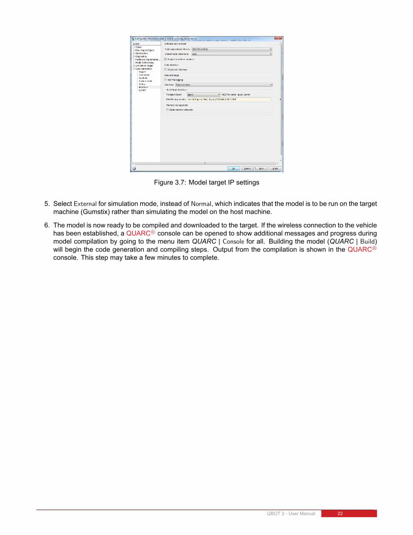
Figure 3.7: Model target IP settings
5. Select External for simulation mode, instead of Normal, which indicates that the model is to be run on the targetmachine (Gumstix) rather than simulating the model on the host machine.
6. The model is now ready to be compiled and downloaded to the target. If the wireless connection to the vehiclehas been established, a QUARCr console can be opened to show additional messages and progress duringmodel compilation by going to the menu item QUARC | Console for all. Building the model (QUARC | Build)will begin the code generation and compiling steps. Output from the compilation is shown in the QUARCr
console. This step may take a few minutes to complete.
QBOT 2 - User Manual 22

4 TroubleshootingFor any issue, the first and easiest troubleshooting solution on any electronic device is to reboot the device. Turn offthe QBot 2, then turn it back on again. For troubleshooting any problem with the QBot 2, it is always a good idea toopen the QUARCr console in case additional information is printed to the console by going to the QUARCr menuand clicking on Console for all. . .. The console must be opened after the QBot 2 has booted and established a WiFiconnection. If the console is opened successfully it establishes a connection to the target and the console windowhas the title QUARC Console for * at tcpip://192.168.2.xxx:17000, where xxx corresponds to the IP addressof the QBot 2.
If you are still unable to resolve the issue after reading through this section, contact [email protected] for furtherassistance.
Q1 You cannot ping the QBot 2Make sure the router is on and the WiFi light on the router is on. Check that the network adapter of the hostPC is connected to the router (or the wireless network Quanser_UVS or Quanser_UVS-5G) and is configuredaccording to the network configuration procedure outlined in this manual (Section 3.2). Verify that you cansuccessfully ping the QBot 2 by going to the Windows Start | Run and typing ping 192.168.2.xxx, wherexxx corresponds to the IP address of your QBot 2. Turn off the QBot 2 power and remove the DAQ PCB byremoving the six screws shown in Figure 4.1 and verify that the Gumstix and antenna are properly connected.Make sure the Gumstix and antenna are securely connected and retry the above steps to establish a wirelessconnection. Recycle the power or turn on the robot and wait for approximately 60 seconds.
Q2 The model fails to build/connect or the QUARC console does not successfully openTurn on the QBot 2 and look at the QBot 2 DAQ PCB between the DAQ and the Kobuki chassis base. Whenthe QBot 2 powers up, you will see a green LED come on on the bottom of the DAQ. After approximately 30seconds, a red LED will flash to indicate the QBot 2 WiFi is powering on, and is attempting to connect to theWiFi network. If the red LED flashes and remains on, then the WiFi module is functioning and is able to find thewireless network. If the red LED flashes and then turn off, the QBot 2 is not connected to the wireless network.Check that the network adapter of the host PC is connected to the router (or the wireless network Quanser_UVSor Quanser_UVS-5G) and is configured according to the network configuration procedure outlined in thismanual (3.2). Verify that you can successfully ping the QBot 2 by going to the Windows Start | Run andtyping ping 192.168.2.xxx, where xxx corresponds to the IP address of your QBot 2. If the red LED neverflashes, the wireless antenna or Gumstix may be disconnected. Turn off the QBot 2 power and remove theDAQ PCB by removing the six screws shown in Figure 4.1 and verify that the Gumstix and antenna are properlyconnected. Make sure the Gumstix and antenna are securely connected and retry the above steps to establisha wireless connection.
QBOT 2 - User Manual DRAFT - April 14, 2015

Figure 4.1: The QBot 2 DAQ mounting screws
Q3 The QBot 2 sensors are not being read correctly or they are stuck at some constant valueUsing the HIL Read block, output all possible channels. Check these outputs using scopes and displays, anddetermine if the problem lies with a particular sensor, or set of sensors, or if the issue is global across allsensors.
Q4 The Simulinkr model appears to run slowly (i.e., the simulation time runs slower than actual time), or theconsole displays the message Sampling rate is too fast for base rate
(a) The maximum sample rate recommended for the QBot 2 is 1000 Hz(sampletime0.001 s). However, ifthere are complex calculations (such as image processing) performed within the model, then this couldpotentially limit the sample rate of the model (suggested sample rate of 100 Hz or 50 Hz). Try reducing themodel sample rate in the menu QUARC | Options | Solver by increasing the Fixed-step size (fundamentalsample time) parameter.
(b) To determine the execution time of blocks or subsystems within the model, use the Computation Timeblock found in the QUARC library | Sources | Time. This block outputs the computation time of a functioncall subsystem, measured using an independent high-resolution time source. Blocks can be placed insidea function call subsystem and connected to the Computation Time block to determine their execution timeduring each sample instant. This helps identify the bottlenecks in the model (blocks/subsystems with thehighest execution time) and can identify blocks/subsystems whose computation time is greater than thesample time of the model. Try increasing the sample time of those blocks whose computation time isgreater than the sample time of the model so that the blocks run in a slower rate thread.
(c) If you are using image processing blocks, ensure that they are only executed when there is new imagedata available or at a slower rate than the image acquisition rate. Otherwise, the embedded computeris spending time processing image data that has already been processed, which can cause the model'scomputation time to increase undesirably. For complex image processing, consider lowering the rate ofthe image processing blocks and/or downsampling the source images to a lower resolution to speed upprocessing time.
(d) If you are using image processing blocks, ensure that signal duration is set to 1 by going to Tools | ExternalMode Control Panel | Signal & Triggering | Duration menu on the model (The default value is 10000).
Q5 Trying to start the QBot 2 model results in the error Unable to locate the dynamic link library or shared objectThis error indicates that the QBot 2 driver is not found on the target. Make sure that the model target type is setto quarc_linux_duovero by navigating to the QUARCr menu QUARC | Options | Code Generation pane and
QBOT 2 - User Manual 24

changing the System target file to quarc_linux_duovero.tlc. Open a console through the QUARCr menuQUARC| Console for all, and verify that the console window displays the target IP of your QBot 2 in the windowtitle.
Q6 Building a model fails when the error Not enough system resources are available to perform the operationWhen several models are compiled, the disk space on the Gumstix may become full, and you will no longerhave space to build models. Using the clean option in the QUARCr menu under QUARC | Clean all willremove all generated code and compiled code for the current model, but this will only free up the space usedby the current model. To view all models currently downloaded on the target select Manage target under theQUARCr menu. The current model’s target must be powered on and ready to accept a connection. The targetinformation is displayed including all models that have been downloaded to the target. To clear all downloadedmodels select all the models in the list and click Remove. Note: this will only remove generated code from thetarget and will not delete the source models on the host PC.
QBOT 2 - User Manual DRAFT - April 14, 2015

5 Technical SupportTo obtain support from Quanser, go to http://www.quanser.com/ and click on the Tech Support link. Fill in the formwith all the requested software and hardware information as well as a description of the problem encountered. Also,make sure your e-mail address and telephone number are included. Submit the form and a technical support personwill contact you.
QBOT 2 - User Manual 26

Solutions for teaching and research. Made in Canada.
[email protected] +1-905-940-3575 QUANSER.COM
Solutions for teaching and research in robotics and autonomous systems
With Quanser robotic systems, you can introduce control concepts related to stationary and mobile robotics, from vibration analysis, resonance and planar position control to sensors, computer, vision-guided control to unmanned systems control. All of the experiments/platforms are compatible with MATLAB®/Simulink®.
©2014 Quanser Inc. All rights reserved.
2 DOF Robot 2 DOF Gantry 2 DOF Inverted Pendulum
2 DOF Serial Flexible Joint 2 DOF Serial Flexible Link2 DOF Planar Robot
QBot 2
QBall 2 Unmanned Vehicle Systems Lab
6 DOF Denso Open Architecture Robot