User Guide - Vigil Security Systems
44
User Guide CK-10, CT-10, CP-10, CK-20, CT-20, CP-20, CP-30, CP-50, CK-60, CT-60, CP-60, CP-100 & CP-200 Designed and Manufactured in the United Kingdom
-
Upload
khangminh22 -
Category
Documents
-
view
0 -
download
0
Transcript of User Guide - Vigil Security Systems

User Guide
CK-10, CT-10, CP-10, CK-20, CT-20, CP-20,
CP-30, CP-50, CK-60, CT-60, CP-60, CP-100 & CP-200
Designed and Manufactured
in the United Kingdom

2
Notes

3
Contents
1. About your Security System .............................................................................................. 5
Introduction ............................................................................................................................................. 5
About this Manual ................................................................................................................................. 5
Alarm Transmission System ................................................................................................................ 5
Zones and Areas .................................................................................................................................... 5
Access code ............................................................................................................................................. 5
NFC Tags .................................................................................................................................................. 6
Keypads ..................................................................................................................................................... 6
Emergency Keys ..................................................................................................................................... 9
2. Operating your Security System ..................................................................................... 12
Introduction ........................................................................................................................................... 12
User Menu .............................................................................................................................................. 12
Before Arming the Security System ............................................................................................... 12
Full Arming Your Security System .................................................................................................. 13
Part Arming your Security System .................................................................................................. 14
Disarming your security system ...................................................................................................... 15
Area full arming .................................................................................................................................... 16
Area part arming .................................................................................................................................. 17
Area disarming ..................................................................................................................................... 18
Resetting after an alarm .................................................................................................................... 19
Resetting after a Fault Condition ....................................................................................................20
Omitting Zones..................................................................................................................................... 21
Changing Your Code ..........................................................................................................................22
Turn chime on/off ................................................................................................................................23
System Event Logs ...............................................................................................................................24
View event log ......................................................................................................................................25
View mandatory log ............................................................................................................................25

4
View chime log .....................................................................................................................................26
Print Log .................................................................................................................................................26
System Tests ..........................................................................................................................................32
Test Bell & Strobe ................................................................................................................................33
Walk Test Zones ...................................................................................................................................34
View Inactive Zones ............................................................................................................................35
View Zone Status .................................................................................................................................36
View Module Status ............................................................................................................................ 37
Do a Test Call ........................................................................................................................................38
Review Voice Messages .....................................................................................................................38
Send SMS Message .............................................................................................................................39
3. Additional Features ........................................................................................................... 40
4. Troubleshooting ................................................................................................................. 41

5
1. About your Security System
Introduction
Your security system is made up of several component parts comprising of a control panel,
one or more remote keypads, external sounder and various detection devices that are
connected to either the control panel or zone expansion modules. The control panel houses
the system’s electronics and stand-by battery and is normally installed out of sight in a utility
room or under stairs cupboard etc.
The remote keypad provides the user interface for the system and is used to send commands
to the system and to display the current system status via a graphic display. The remote keypad
also provides audible feedback annunciation of fault and alarm tones. Remote keypads are
normally mounted in convenient locations inside the protected premises, near to the points of
entry and exit.
Please read this manual carefully and have your installer instruct you on your system’s
operation. Become familiar with the features that have been implemented on your system. All
users of this system should be equally instructed in its use.
About this Manual
This manual provides a thorough explanation of all system functions that are available to the
master user, including basic system operation, user code programming, remote control and
troubleshooting.
Alarm Transmission System
Your security system maybe fitted with an automatic alarm transmission system, which will
communicate alarms, faults and other events to a 24hr manned Alarm Receiving Centre (ARC).
If you accidently cause a false alarm activation, immediately call the ARC to prevent an
unnecessary emergency response.
Zones and Areas A zone is an input that is normally used to monitor a single detection device like a motion
detector, glass-break detector, door contact or shock sensor etc. An area is one or more zones
grouped together to allow independent arming and disarming of areas.
Access code As a user of the security system, you will be assigned a 4, 5 or 6 digit access code. Access codes
are used to arm and disarm the system. Some access codes can perform additional system
functions, such as programming system options, omitting zones and performing system tests.

6
Your access code may not allow you to access certain system functions. For instance, if your
code is only allowed to arm the system you will not be able to disarm the system, once the
system is armed.
NFC Tags
NFC (Near Field Communication) tags can be assigned to users of the system. The tag behaves
just like an access code when presented to the NFC reader built into the keypad. NFC
technology is built into credit cards, bank cards, smart phones and other devices.
Keypads
One or more remote keypads will be installed throughout the protected premises, usually close
to the entry and exit door.
Keypad Layout: RK-400-LCD & RK-450-LCD
1. LCD display
2. NFC reader – present your NFC tag in this area (not on CK-10 or CT-10)
3. Status Icons
4. Keyboard – see below
Keyed Keypad buttons Actions
u Arm system and to navigate upwards in the menu
p Part arm system and to navigate down in the menu
r Chime tone selection and can be used to enter menu
o Omit zones and if held for 1 second can work to go ‘back’ in a
menu
0 If held for 1 second can be used to toggle options and outputs
✓ Selection button
X Cancel Button. Press and hold for 1 second to delete a selection.

7
Keypad Layout: CK-10, CK-20, CK-60, RK-500, RK-550, MK-700 & RK-700
1. LCD display
2. NFC reader – present your NFC tag in this area (not on CK-10 or CT-10)
3. Status Icons
4. System status LED
5. Ambient light sensor – used automatically adjusts the keyboard and LCD backlight level
6. Keyboard – see below
Keyed Keypad buttons Actions
A Arm system
P Part arm system
a Area arm system
E Selection button
c Chime tone selection
B Escape button
C Cancel button

8
Touchscreen Keypad Layout: CT-10, CT-20, CT-60, TK-650
1. Full colour touch display
2. NFC Reader – present your NFC tag in this area (not on CK-10 or CT-10)
3. Status Icons
4. System status LED
Touch Keypad buttons Function
Arm system
Part arm system
Area arm system
Selection button
Chime tone selection
Escape button
Cancel button

9
Status Icons
The system status area on the display is used to show the following information:
Status Icon Indicates
#$%K Battery is charging/ is charged
L Mains power is connected
& Mains power is disconnected
p External strobe is flashing
M External bell is sounding
N Chime is enabled
Q WiFi module connected
T GSM module connected
H Ethernet module connected
Z Phone line connected
3 User programmed timer running
[ User programmed alarm running
Status LED
The keypad has a single multi-colour LED and is used to Indicate the following:
Colour System Status
Blue Normal operation, all zones are healthy
Green User menu selected and system is ready for arming
Yellow One or more zones are active, system may not arm
Red Alarm active
Emergency Keys
The keypad provides 3 different emergency functions. Depending on the setup of your system,
activation from these keys can alert the local police, key holders and security personal via your
Alarm Receiving Centre (ARC).
The emergency keys for each keypad can be individual enabled or disabled and may
not be enabled on your installation due to local standards and police requirements.
The Panic alarm (Police) function for each keypad can be programmed for either an
audible or silent operation.
Keyed Keypad Emergency Keys
To activate the emergency functions, press together the keys shown below for a duration of 1
second:

10
Emergency Alarm Keys
Fire Press 1 & 3
Panic Alarm (PA) Press 4 & 6
Medical Press 7 & 9
Touch Keypad Emergency Keys
1. To activate the emergency keys on your touch screen keypad you will need to be on the
Home screen:
2. From the top part of the screen select one of the emergency functions, for example ‘Fire’:
3. You will then be prompted to press the Fire Alarm icon, and then select the icon again
to confirm the activation. This is in place to ensure it is a confirmed event and not an
accidental button press:

11
4. Press the ‘CONFIRM’ icon to generate the selected emergency or press the ‘Back’ icon
to cancel.

12
2. Operating your Security System
Introduction
Before attempting to operate your security system, please ensure that you have familiarised
yourself with the procedures covered in this section of the manual.
User Menu On entering a valid access code or presentation of a tag the keypad will display the ‘User Menu’.
This menu is used to perform all system operations including arming, disarming, testing and
system configuration.
Before Arming the Security System Before attempting to arm your security system, ensure that all protected areas are secure by
closing any doors and windows etc. If the system is not ready for arming the keypads show the
zones that are active (if enabled by your installer) and the keypad status LED will illuminate in
yellow:
If your system has the ‘Global Keypad Information” option enable by your installer, the
keypad will show zone status information for all zones. If the option is disabled, the
keypad will only show zones status information for zones that are assigned to the same
area as the keypad.

13
Full Arming Your Security System The full arming mode is used for protecting all detection zones within your allocated areas and
is normally used when leaving the premises or area unoccupied. Before attempting to full arm,
check that your areas are ready for arming. To full arm your area(s), please proceed as follows:
1. Enter code or present tag to select the user menu.
2. From the user menu, use the U/ u and D/ p keys to scroll to Full arm
system’:
3. Press E or k to full arm, the exit tone will start and the keypad will instruct you to
exit the protected area:
4. The keypad will then indicate that the system is Fully Armed.

14
Part Arming your Security System The part arming mode only protects predefined detection zones. The system has 3 ‘Part arm’
modes which allows for flexible arming configurations, e.g., ‘Part arm 1’ could be configured to
arm only downstairs zones, whereas ‘Part arm 2’ could be configured to arm only perimeter
zones. To part arm your area(s), please proceed as follows:
1. Enter code or present tag to select the user menu.
2. From the user menu, use the U/ u and D/ p keys to scroll to ‘Part arm
1’:
3. Use the L/ o and R/ r keys to change the part arm mode (1, 2 or 3), then
press E or k to part arm.
4. The exit tone will start and the keypad will instruct you to exit the protected area:
5. The keypad will then indicate that the system is part armed:
Part arm settings will be pre-programmed by your installation company.

15
Disarming your security system When the system or area is armed, you must enter the protected area via the designated entry
route. Upon entering the premises, the entry timer and entry tone will start. To successfully
disarm the alarm, a valid access code or tag must be entered before the entry timer expires.
To disarm your area(s), please proceed as follows:
1. Enter the protected area by the designated entry point, the entry tone will sound and
the keypad will show the following screen:
2. Enter your code or present tag, the entry tone will silence and the keypad screen will
indicate that the system has just been disarmed:
3. After a short delay the keypad will then return to normal operation:

16
Area full arming Zones can be grouped together to make ‘area sets’. Area sets are often used in multi tenanted
buildings where there is a communal entrance and separate living spaces/areas of work. Users
can arm individual or multiple area sets. To full arm selected areas, please proceed as follows:
1. Enter code or present tag to select the user menu.
2. From the user menu, use the U/ u and D/ p keys to scroll to ‘Area full
arm’:
3. Press E or k to select, the ‘arm areas’ menu is now displayed:
` Area will be armed
a Area will remain unarmed
4. Use the U/ u and D/ p keys to select the ‘Area’. Then use the L/ o and R/ r keys to toggle the selected area on or off. Once you have selected the
areas that you would like to arm, press E or k to confirm.
5. The exit tone will start and the keypad will instruct you to exit the protected area:
6. The keypad will then indicate that the areas that are fully armed:

17
Area part arming Zones can be grouped together to make ‘Area Sets’. Area Sets are often used in multi tenanted
houses where there is a communal entrance and separate living spaces. Users can arm
individual or multiple area sets. To part arm selected areas, please proceed as follows:
1. Enter your code or present tag to select the user menu.
2. From the user menu, use the U/ u and D/ p keys to scroll to ‘Area part
arm 1’:
3. Use the L/ o and R/ r keys to change the part arm mode (1, 2 or 3), then
press E or k to select, the ‘part arm areas’ menu is now displayed:
` Area will be part armed
a Area will remain unarmed
4. Use the U/ u and D/ p keys to select the ‘Area’. Then use the L/ o
and R/ r keys to toggle the selected area on or off. Once you have selected the
areas that you would like to part arm, press E or k to confirm.
5. The exit tone will start and the keypad will instruct you to exit the protected area:
6. The keypad will then indicate that the areas that are part armed:
Part arm settings will be pre-programmed by your installation company.

18
Area disarming
Normally when entering a protected area via the designated entry route, the area is disarmed
after a valid access code or tag presentation. Sometimes it is desirable to disarm one or more
areas before entering them via the designated entry route. To disarm your selected areas,
please proceed as follows:
1. The keypad will show the areas that are currently full armed:
2. Enter your code or present tag, the ‘disarm areas’ menu is displayed:
` Area will be disarmed.
a Area will remain armed.
3. Use the U/ u and D/ p keys to select the ‘Area’. Then use the L/ o
and R/ r keys to toggle the selected area on or off. Once you have selected the
areas that you would like to disarm, press E or k to confirm.
4. The selected areas are disarmed and the keypad displays any areas that have remained
armed:

19
Resetting after an alarm To reset after an alarm has occurred, please proceed as follows:
1. If your system has gone into an alarm condition, the screen will alternate between the
following two displays:
2. Enter your code or present tag to silence any internal and external sounders. The reason
for the alarm will then be displayed on the keypad screen. For example:
3. Enter your code or present the tag again:
4. If you are aware of the cause of the alarm condition, press E or k to reset the alarm
condition and return the security system back to normal operation.
5. If after pressing E or k to reset the alarm condition the following screen appears,
please contact your alarm installation company for further assistance:
6. Press E or k again to exit and return to the user menu.
Alarms can also be reset manually in the user menu, use the arrow keys to scroll down
to ‘Reset Alarms’ and press E or k
20
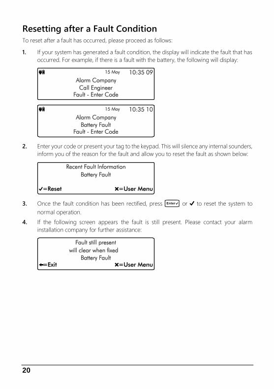
Resetting after a Fault Condition To reset after a fault has occurred, please proceed as follows:
1. If your system has generated a fault condition, the display will indicate the fault that has
occurred. For example, if there is a fault with the battery, the following will display:
2. Enter your code or present your tag to the keypad. This will silence any internal sounders,
inform you of the reason for the fault and allow you to reset the fault as shown below:
3. Once the fault condition has been rectified, press E or k to reset the system to
normal operation.
4. If the following screen appears the fault is still present. Please contact your alarm
installation company for further assistance:
21
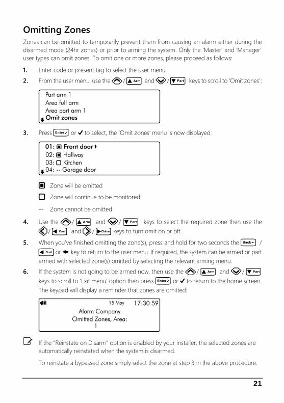
Omitting Zones Zones can be omitted to temporarily prevent them from causing an alarm either during the
disarmed mode (24hr zones) or prior to arming the system. Only the ‘Master’ and ‘Manager’
user types can omit zones. To omit one or more zones, please proceed as follows:
1. Enter code or present tag to select the user menu.
2. From the user menu, use the U/ u and D/ p keys to scroll to ‘Omit zones’:
3. Press E or k to select, the ‘Omit zones’ menu is now displayed:
` Zone will be omitted
a Zone will continue to be monitored
-- Zone cannot be omitted
4. Use the U/ u and D/ p keys to select the required zone then use the
L/ o and R/ r keys to turn omit on or off.
5. When you’ve finished omitting the zone(s), press and hold for two seconds the B /
o or @ key to return to the user menu. If required, the system can be armed or part
armed with selected zone(s) omitted by selecting the relevant arming menu.
6. If the system is not going to be armed now, then use the U/ u and D/ p
keys to scroll to ‘Exit menu’ option then press E or k to return to the home screen.
The keypad will display a reminder that zones are omitted:
If the “Reinstate on Disarm” option is enabled by your installer, the selected zones are
automatically reinstated when the system is disarmed.
To reinstate a bypassed zone simply select the zone at step 3 in the above procedure.

22
Changing Your Code User codes are unique to each user and can be 4,5 or 6 digits in length. Users can change their
code at any time by following the procedure below:
Before changing your code, it is strongly recommended to note the new code. If you
forget your code later it must be changed by a master user of the system or the
installation company.
1. Enter code or present tag to select the user menu.
2. From the user menu, use the U/ u and D/ p keys to scroll to ‘Change
my code’:
3. Press E or k to select, the ‘Change code’ menu is now displayed:
4. Enter your old passcode, if correct you will be prompted for a new code:
5. Enter your new code then press E or k to confirm. The system will return back to
the user menu screen:
6. Use the U/ u and D/ p keys to scroll to ‘Exit menu’ option then press
E or k to return to the home screen.
If after entering your new code the screen returns to the ‘Enter New Code’ screen, the
code you have entered is invalid. Please try again with a different code.

23
Turn chime on/off This option allows the chime feature to be turned on or off for each area. If the chime feature
is switched on, then monitored zones that are activated during the disarmed state will cause
the system to generate a chime tone.
1. Ensure that the ‘Turn chime on/off’ menu is selected, see page 40.
` Area chime is on
a Area chime is off
-- Area not available
2. Use the U/ u and D/ p keys to select the ‘Area’. Then use the L/ o
and R/ r keys to toggle the selected area on or off.
3. Hold the B / o or @ key for 2 seconds to exit the menu.

24
System Event Logs The system event logs menu contains options for the viewing and printing of various event
data that is recorded by your system. This menu is only available to the ‘Master’ and ‘Manager’
user types.
1. Enter your code or present your tag to select the user menu.
2. From the user menu, use the arrow keys to scroll down to ‘View System Log’:
3. Press E or k to select, the ‘System Event Logs’ sub menu is now displayed:
4. From the ‘System Event Logs’ menu, use the arrow keys to scroll to the required event
log option:
View event log: Please refer to page 25.
View mandatory log: Please refer to page 25.
View chime log: Please refer to page 26.
Print log: Please refer to page 26.

25
View event log All system events such as arming, disarming, alarm and faults are recorded in the system log
along with the date and time.
1. Ensure that the ‘View event log’ option is selected from the ‘System Event Logs’ menu:
2. Scroll back and forward through the log using the U/ u and D/ p keys.
View Log Screen Information
Line 1: Event type, see page 27 for a complete list of event type and descriptions.
Line 2: Zone or user text.
Line 3: Event Area(s) then date and time.
Line 4: Event Type Filter, use the L/ o and R/ r keys to change the
event filter type:
• All Events
• Alarms
• Tampers
• Faults
• Open & Close
• Tests
• Restore
• Custom
Then event number is displayed far right.
View mandatory log All mandatory events as defined in EN50131-1 are recorded in the mandatory event log.
Information displayed is as per the system event log above.

26
View chime log Displays up to the last 50 zones that have chimed.
1. Ensure that the ‘View chime log’ option is selected from the ‘System Event Logs’ menu:
2. Scroll back and forward through the chime log using the U/ u and D/ p keys.
View Log Screen Information
Line 1: Not used.
Line 2: The zone number that has chimed.
Line 3: The zone description.
Line 4: Then event number is displayed far right.
Print Log This option allows the user to print a system log. To use this option a serial printer must be
connected to the control panel by your alarm installer.
1. Ensure that the ‘System Events Log’ menu is selected:
Scroll down to the ‘Print log’ option, then press E or k, if there is a serial printer connected
to the system, the log will start to print.

27
Log Event Description
Intruder Alarm XX Intruder alarm activated by zone XX.
Intruder Restore XX Intruder zone XX restore.
Perimeter Alarm XX Perimeter alarm activated by zone XX.
Perimeter Restore XX Perimeter zone XX restore.
24Hr Alarm XX 24-hour alarm activated by zone XX.
24Hr Restore XX 24-hour zone XX restore.
Entry Alarm XX Entry alarm activated by zone XX.
Entry Restore XX Entry zone XX restore.
Warning Alarm XX Warning alarm activated by zone XX.
Warning Restore XX Warning zone XX restore.
Medical Alarm XX Medical alarm activated by zone XX.
Medical Restore XX Medical zone XX restore.
Fire Alarm XX Fire alarm activated by zone XX.
Fire Restore XX Fire zone XX restore.
PA Alarm XX Panic alarm activated by zone XX.
PA Restore XX Panic alarm zone XX restore.
PA Silent Alarm XX Silent panic alarm activated by zone XX.
PA Silent Restore XX Silent panic alarm XX restore.
PA Confirmed XX Confirmed PA alarm activated by zone XX.
PA Confirmed Restore XX Confirmed PA zone XX restored.
PA Confirmed Silent XX Confirmed Silent PA alarm activated by zone XX.
PA Con. Silent Restore XX Confirmed Silent PA zone XX restored.
Aux Alarm XX Auxiliary alarm activated by zone XX.
Aux Restore XX Auxiliary zone XX restore.
Monitor Alarm XX Monitor alarm activated by zone XX.
Monitor Restore XX Monitor zone XX restore.
Zone XX Omitted Zone XX Omitted.
Zone XX Reinstated Zone XX Reinstated.
Tamper XX Alarm Tamper alarm activated by zone XX.
Tamper XX Restore Tamper zone XX restore.
Zone XX Fault Alarm Fault alarm activated by zone XX.
Zone XX Fault Restore Fault on zone XX has restored.
Zone XX Mask Alarm Mask alarm activated by zone XX.
Zone XX Mask Restore Mask alarm on zone XX has restored.

28
Log Event Description
Low Battery Alarm XX Low battery alarm from wireless device on zone XX.
Low Battery Restore XX Low battery alarm on zone XX has restored.
Omit Key Active XX Key omits activated by zone XX.
Omit Key Restore XX Key omits by zone XX has restored.
Keyswitch Active XX Keyswitch connected to zone XX is active.
Keyswitch Restore XX Keyswitch connected to zone XX has restored.
Security Key Active XX Security keyswitch connected to zone XX is active.
Security Key Restore XX Security keyswitch connected to zone XX has restored.
Alarm Active Intruder Alarm is active.
Bells Active Bell output is active.
Re-arm Lockout Zone Re-arm lockout has occurred and no more alarms can be generated for
the armed period.
Confirmed Alarm Confirmed alarm generated (two different zones activated).
Confirmed PA Alarm Confirmed PA alarm generated.
Remote Access XX Remote access via PC number XX.
User XX User access by user XX.
Access XX Access user code type by user XX.
Duress XX Duress alarm by user XX.
User Tag XX User XX proximity tag access.
User Remote XX User XX wireless remote has accessed the system.
User XX Lockout User XX has been locked out from using the system.
User Tag XX Lockout User XX proximity tag has been locked out from using the system.
Code Tamper X Code tamper (invalid code) generated at keypad X.
Userr XX DELETED User XX deleted from the system.
Exit Started XX Exit mode started by user XX.
Exit Started Timer X Exit mode started by control timer X.
Exit Started Zone XX Exit mode started by zone XX.
Exit Stopped Exit mode stopped.
Exit Failed by zone XX Exit mode failed by zone XX.
Entry Started XX Entry mode stared by zone XX.
Entry Timeout Entry timeout alarm.
System Armed System armed.
Keyswitch Arm Keyswitch Armed.
Quick Armed Quick Armed.
Part Armed 1 Part armed 1.
Part Armed 2 Part armed 2.

29
Log Event Description
Part Armed 3 Part armed 3.
System Disarmed System disarmed.
Arming Failed Arming failed.
Armed With ATS Fault The system was armed with an Alarm Transmission System (ATS) fault.
Auto Armed The system was automatically armed.
Auto Disarmed The system was automatically disarmed.
Remote Armed The system was automatically armed remotely.
Remote Disarmed The system was automatically disarmed remotely.
System Power Up The system was powered up.
AC Failed The mains AC supply has been switched off.
AC Restore The mains ac supply has been restored.
Battery Fault #X Battery fault #? (1: Presence Fail; 2: Load Test Fail).
Battery Restore Battery fault restored.
Low Battery Alarm The system standby battery voltage is low (The system is running on
battery only).
Time/Date Changed The system time and date has been changed.
Engineer on site The engineer access code has been entered.
Engineer off site The engineer has logged off.
Bell Fuse Alarm The bell fuse has gone open circuit (electronic fuse).
Bell Fuse Restore The bell fuse has restored.
Aux Fuse Alarm The auxiliary 12V fuse has gone open circuit (electronic fuse).
Aux Fuse Restore The auxiliary 12V fuse has restored.
Battery Fuse Alarm The battery fuse has gone open circuit (electronic fuse).
Battery Fuse Restore The battery fuse has restored.
Network Fuse Alarm The network fuse has gone open circuit (electronic fuse).
Network Fuse Restore The network fuse has restored.
Box Tamper Alarm The control panel box tamper has been activated.
Box Tamper Restore The control panel box tamper has restored.
Keypad X Tamper Keypad X box tamper has been activated.
Keypad X Tamp Rest Keypad X box tamper has restored.
Exp X Tamper Alarm Expander X tamper alarmed.
Exp X Tamper Restore Expander X tamper is restored.
Bell X Tamper Alarm Network Bell X tamper alarmed.
Bell X Tamper Restore Network Bell X tamper is restored.
Keypad XX Lost Keypad XX on network lost.
Keypad XX Found Keypad XX on network found.

30
Log Event Description
Expander XX Lost Expander XX on network lost.
Expander XX Found Expander XX on network found.
Bell X Lost Network Bell X on network lost.
Bell X Found Network Bell X on network found.
Walktest Started User walk test mode started.
Walktest Ended User walk test mode ended.
Bell Test Started User bell test started.
Bell Test Ended User bell test ended.
Auto Test Call An automatic test call was sent to the Alarm Receiving Centre (ARC).
Manual Test Call A manual (user) test call was sent to the Alarm Receiving Centre (ARC).
Timer X On Control Timer X is on.
Timer X Off Control Timer X is off.
Zone Test XXX Days Zone soak test has started and will run for XXX days.
Zone XX Test Fail Zone XX has failed whilst on test.
First Knock XX First activation from zone XX. The zone has the “Double Knock”
attribute.
Beam Pair 1st XX First activation from zone XX. The zone has the “Beam Pair” attribute.
Alarm Aborted The user has disarmed the system within the abort delay period.
Bell Tamper Alarm The bell tamper alarm has been activated.
Bell Tamper Restore The bell tamper has restored.
Bell X Fault Alarm Network Bell X fault.
Bell X Fault Restore Network Bell X restored
ATS Fault The Alarm Transmission System (ATS) has detected a fault with the
transmission path (telephone line/GSM/IP).
ATS Restored The ATS Fault has restored.
Keypad PA X A panic alarm was generated at keypad X by pressing keys 7 and 9.
Keypad Fire X A fire alarm was generated at keypad X by pressing keys 1 and 3.
Keypad Medical X A medical alarm was generated at keypad X by pressing keys 4 and 6.
Output XX Fault The control panel has detected a fault on panel output XX.
Output XX Restore The fault on panel output XX has restored.
Cleaner On-Site XX A cleaner access code has been entered.
Cleaner Off-Site XX A cleaner has logged off.
Com X Module Alarm The communication module has been disconnected/lost from com port
X
Com X Module Restore The communication module has been connected/found from com port
X

31
Log Event Description
Zone XX Count Alarm Zone XX has reached the “Count Logging” threshold.
Tag PA XX Alarm PA alarm triggered by XX tag.
Radio Output XX Flt The control panel has detected a fault on radio output XX.
Alarm Reset Alarm has been reset.
RNRR Reset Random Number Remote Reset (A reset has been performed remotely)
Zone XX on Test Zone XX has been put on soak test.
Exp X Bat Fault Powered Expander X battery fault.
Exp X Bat Restore Powered Expander X battery fault restored.
Exp X AC Fault Powered Expander X AC fault.
Exp X AC Restore Powered Expander X AC fault restored.

32
System Tests The system tests menu contains multiple different tests and diagnostics that can be performed
on the system to ensure correct operation of the security system. This menu is only available
to the ‘Master’ and ‘Manager’ user types.
1. Enter your code or present tag to select the user menu.
2. From the user menu, use the arrow keys to scroll down to ‘System tests’:
3. Press E or k to select, the ‘System tests’ menu is now displayed:
4. From the ‘System tests’ menu, use the arrow keys to scroll to the required test menu:
Test Bell & Strobe: Please refer to page 33.
Walk test zones: Please refer to page 34.
View Inactive zones: Please refer to page 35.
View zone status: Please refer to page 36.
View module status: Please refer to page 37.
Do a test Call: Please refer to page 38.
Review voice messages: Please refer to page 38.
Send SMS Message: Please refer to page 39.
33
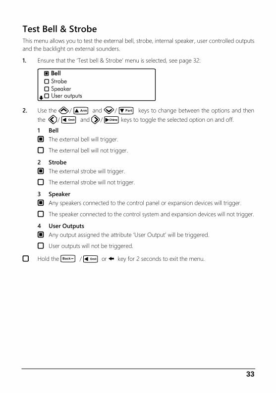
Test Bell & Strobe This menu allows you to test the external bell, strobe, internal speaker, user controlled outputs
and the backlight on external sounders.
1. Ensure that the ‘Test bell & Strobe’ menu is selected, see page 32:
2. Use the U/ u and D/ p keys to change between the options and then
the L/ o and R/ r keys to toggle the selected option on and off.
1 Bell
` The external bell will trigger.
a The external bell will not trigger.
2 Strobe
` The external strobe will trigger.
a The external strobe will not trigger.
3 Speaker
` Any speakers connected to the control panel or expansion devices will trigger.
a The speaker connected to the control system and expansion devices will not trigger.
4 User Outputs
` Any output assigned the attribute ‘User Output’ will be triggered.
a User outputs will not be triggered.
a Hold the B / o or @ key for 2 seconds to exit the menu.

34
Walk Test Zones This menu allows the programmed zones to be walk tested to ensure they are activating when
required.
1. Ensure that the ‘Walk test zones’ menu is selected, see page 32:
2. Activate the zones by walking in front of movement detectors and opening doors or
windows that have sensor fitted.
Walk Test Zones Screen Information
Line 1: How many zones have been ‘walk tested’ since entering the menu and how
many zones remain to be walk tested (this is dependent on how many zones are
programmed).
Line 2: A scrolling list of walk tested zones and the current zone status.
Line 3: A scrolling list of walk tested zones and the zone text (name).
Line 4: The system can be set to create a chime tone when a detector is activated. The
different chime options are selected by pressing c/ r or N. The options
available are as follows:
• Always chime
• New devices chime
• Silent
• Chime only zone ##
3. Hold the B / o or @ key for 2 seconds to exit the menu.
35
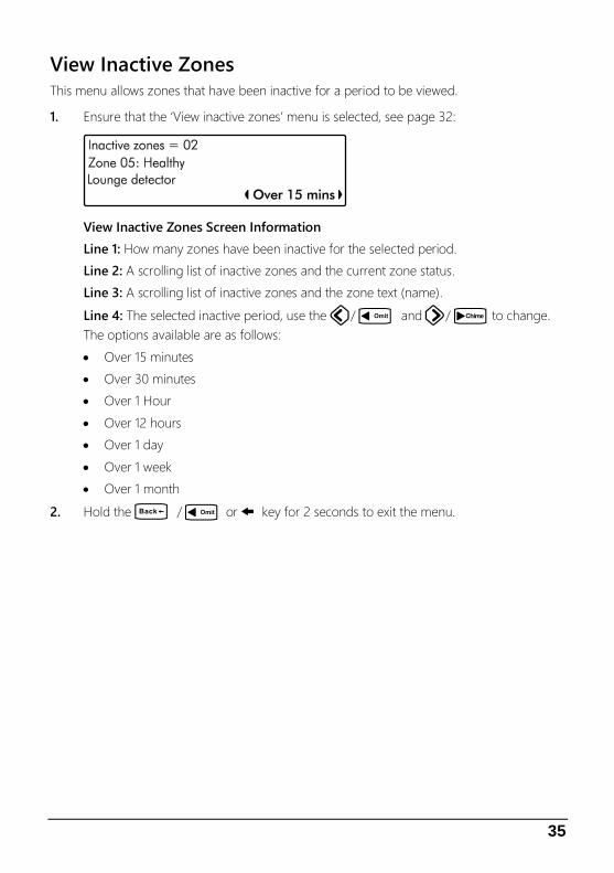
View Inactive Zones This menu allows zones that have been inactive for a period to be viewed.
1. Ensure that the ‘View inactive zones’ menu is selected, see page 32:
View Inactive Zones Screen Information
Line 1: How many zones have been inactive for the selected period.
Line 2: A scrolling list of inactive zones and the current zone status.
Line 3: A scrolling list of inactive zones and the zone text (name).
Line 4: The selected inactive period, use the L/ o and R/ r to change.
The options available are as follows:
• Over 15 minutes
• Over 30 minutes
• Over 1 Hour
• Over 12 hours
• Over 1 day
• Over 1 week
• Over 1 month
2. Hold the B / o or @ key for 2 seconds to exit the menu.

36
View Zone Status This menu allows each zone to be independently monitored and viewed.
1. Ensure that the ‘View zone status’ menu is selected, see page 32:
View Zone Status Screen Information
Line 1: Zone number and any programmed zone text.
Line 2: The status of the zone, including resistance (if applicable) and zone count (how
many times the zone has activated).
Line 3: Each set of numbers represents a zone count for each day of the week. The first
set of numbers represents Monday and the last set Sunday. Each time a zone activates
on a Monday the first set of numbers will increment, on a Tuesday the second set etc.
The zone must have the ‘Record Activity’ attribute to use this feature.
Line 4: The left side shows the last time the zone was activated. The right side shows
the status screen mode, use the L/ o and R/ r keys to change the
mode, the following modes are available:
• Status (View zone status)
• Reset count (press E or k to reset zone count)
• Reset Day (press E or k to reset zone day counts)
• Reset All (press E or k to reset all counts)
2. Use the U/ u and D/ p keys to change the zone to view.
3. Hold the B / o or @ key for 2 seconds to exit the menu.

37
View Module Status This menu allows you to view the status of any communication modules installed on the system.
1. Ensure that the ‘View module status’ menu is selected, see page 32:
GSM Module Screen Information
Line 1: If the module is currently ‘Fitted’ or ‘Not fitted’.
Line 2: The most update signal reading from the sim card.
Line 3: The remaining credit on the sim card if using PAYG.
Line 4: The selected module, use the L/ o and R/ r keys to change.
Wi-Fi Module Screen Information
Line 1: If the module is currently ‘Fitted’ or ‘Not fitted’
Line 2: A signal reading from the Wi-Fi module.
Line 3: The SSID of the network the unit is connected to. Use the U/ u and
D/ p keys to display further information: IP Address, IP Mask and IP Gateway.
Ethernet Module Screen Information
Line 1: If the module is currently ‘Fitted’ or ‘Not fitted’
Line 2: The IP address assigned to the module.
Line 3: The IP Mask assigned to module. Use the U/ u and D/ p keys
to display further information: Gateway Address and IP Port.

38
PSTN Module Screen Information
Line 1: If the module is currently ‘Fitted’ or ‘Not fitted’
Line 2: The phoneline status ‘Good’, ‘Engaged’ or ‘Bad’.
Line 3: The number of saved answer machine messages.
2. Hold the B / o or @ key for 2 seconds to exit the menu.
Do a Test Call Selecting this option will cause connected communication device to send a test call to the alarm
receiving centre using the programmed in information (contact number/ Account number/
protocol).
1. Ensure that the ‘Do test call’ menu is selected, see page 32:
2. Press E or k to initiate a test call.
Review Voice Messages The system has 15 programmable voice messages; each message can be up to 16 seconds
long. The messages can be recorded using software and uploaded into the control panel.
Alternatively, voice messages can be recorded from a telephone handset.
1. Ensure that the ‘Review voice messages’ menu is selected, see page 32:
2. Use the L/ o and R/ r keys to select the voice message (1-15). Press E
or k to play the message or press C or D to clear and record a new message.
3. Press D/ p to select System Message Part:

39
4. Use the L/ o and R/ r keys to select the system message (1-75). Press
E or k to play the message.
Send SMS Message This menu allows the user to send a SMS message to a telephone number of their choosing.
The system must be fitted with either a GSM or PSTN module to use this feature.
1. Ensure that the ‘Send SMS message’ menu is selected, see page 32:
2. Use the number keys to enter a valid mobile telephone number.
3. Press D/ p to select Message:
4. Use the number keys to enter the message then press E or k to send the SMS
message.
40
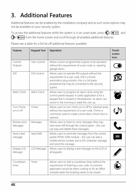
3. Additional Features Additional features can be enabled by the installation company and as such some options may
not be available on your security system.
To access the additional features whilst the system is in an unset state, press L/ o and
R/ r from the home screen and scroll through all enabled additional features.
Please see a table for a full list off additional features available:
Feature Keypad Text Operation Touch
screen
Icon
Control
Outputs
User Control Allows custom programmed outputs to be operated
without the requirement of a user code i.e. opening
garage doors. X10 X10 Control Allows users to operate X10 outputs without the
requirement of a user code. X10 is a home
automation plug solution, this is a 3rd party
peripheral that may be connected to the security
system.
Alarm Clock Alarm Clock Allows users to program an alarm clock using the
control panels keypad. A useful application is for a
keypad that is situated in the bedroom, an alarm can
sound in the morning to wake the user up.
Turn Chime
on or off
Chime Allows users to turn chime on or off for selected areas
without the requirement of a user code. Chime is
commonly used to create a tone when a front door is
opened.
Review voice
Messages
Messages Allows users to listen to voice messages they may
have been left through the control panel – the user
can play and delete these messages. Send a text
message
Send SMS Allows users to send text messages from the control
panels PSTN/ GSM module – the user can add a
mobile phone number and a 255-character message
and send this message.
Display LCD
Message
LCD Message Allows users to display a text message on the LCD of
all keypads.
Countdown
timer
Timer Allows users to start a countdown timer without the
requirement of entering a user code. A common
application would be when cooking or for an office
complex when the building needs to be closed.

41
4. Troubleshooting
Message
displayed on
screen
When I might see
this message
Potential reasons for
message
Suggested methods to
resolve
Zone 01 Active When attempting
to arm
The zone is reporting back
to the main control panel
an open state
Check the device to ensure
it is not a door/ window
that has been left open
Zone 01 Masked Normal operation The zone is reporting that
an object is potentially
obstructing its view
Check the area where the
detector is located for
anything that may be
obstructing the detector
Zone 01 Tamper Normal operation The zones lid is not making
a tight connection
Check the lid of the device
to ensure it is securely
fastened
Zone 01 Alarm After an alarm
condition
The zone has recently been
alarmed and is awaiting a
reset
Enter your user code and
select ‘Reset Alarms’
Omitted Zones Normal operation A user has manually
disabled certain zones from
operating on the system
Ask an installer or master
user to help reinstate the
zones if required
Confirm Devices Normal operation A networked device on the
security system has been
removed
Contact the installation
company
Battery Fault Normal operation The main panel battery has
become low voltage or
removed
The internal battery should
be replaced every 2-3
years
AC Fail Normal operation The mains to the control
panel has been
disconnected or lost
Check to ensure there is
not a power cut, or contact
the installation company
Tamper (Bell/
Panel Lid/ Aux/
Keypad/
Expander)
Normal operation The devices lid is not
making contact properly
Check the lid of the device
to ensure it is securely
fastened

Notes

43

44
© 2020
INS023