UR M53 “Calculation of Crankshafts for I.C. Engines”
31
IACS History File + TB, Part A Page 1 of 3 UR M53 “Calculation of Crankshafts for I.C. Engines” Part A. Revision History Version no. Approval date Implementation date when applicable Rev.2 (Jan 2011) 06 Jan 2011 1 Jan 2012 Rev.1 (Dec 2004) Dec 2004 1 Jan 2007 New (1986) 1986 - • Rev.2 (Jan 2011) .1 Origin of Change: Request by non-IACS entity (CIMAC) .2 Main Reason for Change: CIMAC raised the issue that the empirical stress concentration factors in the calculation rules in the UR M53 do not cover some of the currently used crankshaft designs. Therefore in order to assist, the alternative method for calculation of Stress Concentration Factors in the web fillet radii of crankshafts by utilizing Finite Element Method was agreed. .3 List of non-IACS Member classification societies contributing through the TC Forum and/or participating in IACS Working Group: None .4 History of Decisions Made: CIMAC submitted its proposal during the IACS-CIMAC (WG2) Sept. 2008 meeting. The proposal was then discussed in the Machinery Panel. After reviewing the proposal the Machinery Panel had comments which were later clarified by CIMAC. However the IACS Machinery Panel had concerns with the extent of validation, as the validation was made for one test previously and that no further validation data was available. After further discussion it was agreed to insert it as an appendix and use it as an alternative approach when the prescriptive method does not apply. .5 Other Resolutions Changes None .6 Dates: Original Proposal: September 2008 Made by CIMAC (WG2) Panel Approval: September 2010 GPG Approval: 06 January 2011 (Ref: 10171_IGc)
-
Upload
khangminh22 -
Category
Documents
-
view
3 -
download
0
Transcript of UR M53 “Calculation of Crankshafts for I.C. Engines”

IACS History File + TB, Part A
Page 1 of 3
UR M53 “Calculation of Crankshafts for I.C. Engines” Part A. Revision History Version no. Approval date Implementation date
when applicable Rev.2 (Jan 2011) 06 Jan 2011 1 Jan 2012 Rev.1 (Dec 2004) Dec 2004 1 Jan 2007 New (1986) 1986 - • Rev.2 (Jan 2011) .1 Origin of Change:
Request by non-IACS entity (CIMAC)
.2 Main Reason for Change: CIMAC raised the issue that the empirical stress concentration factors in the calculation rules in the UR M53 do not cover some of the currently used crankshaft designs. Therefore in order to assist, the alternative method for calculation of Stress Concentration Factors in the web fillet radii of crankshafts by utilizing Finite Element Method was agreed. .3 List of non-IACS Member classification societies contributing through the TC Forum and/or participating in IACS Working Group: None .4 History of Decisions Made: CIMAC submitted its proposal during the IACS-CIMAC (WG2) Sept. 2008 meeting. The proposal was then discussed in the Machinery Panel. After reviewing the proposal the Machinery Panel had comments which were later clarified by CIMAC. However the IACS Machinery Panel had concerns with the extent of validation, as the validation was made for one test previously and that no further validation data was available. After further discussion it was agreed to insert it as an appendix and use it as an alternative approach when the prescriptive method does not apply. .5 Other Resolutions Changes None .6 Dates:
Original Proposal: September 2008 Made by CIMAC (WG2) Panel Approval: September 2010 GPG Approval: 06 January 2011 (Ref: 10171_IGc)

• Rev.1 (Dec 2004) See TB in Part B. • New (1986) No TB document available.

Part B
Page 3 of 3
Part B. Technical Background List of Technical Background (TB) documents: Annex 1 TB for Rev.1 (Dec 2004)
See separate TB document in Annex 1.
◄▼► Annex 2 TB for Rev. 2 (Jan 2011)
See separate TB document in Annex 2.
◄▼► Note: There is no separate Technical Background (TB) document for New (1986).

CIMAC Crankshaft Working Group (WG4)Documentation and remarks to IACS WP/MCH comments
July 2. 2003, M. W. Rasser / Chairman
CIMAC Proposal for Revised M53IACS WP/MCH Comments
Comments have been received from members and these essentially stem fromthe need to provide technical justification for the changes and new requirements.
For the proposals to be accepted and incorporated as Unified Requirements wehave to provide a technical justification for the requirements and it is noted thatwe have not received any additional technical documentation other than the 30pages expanded from the original 15.
Identification of the changes and the background to each change and addition isrequired as part of the technical justification.
Some comments received include:
1) Fig 5 and Fig 7For crankshafts with overlap and recessed fillets, the web thickness W appears tobe taken at the outside of the web which is different from that indicated in Fig 5for a crankshaft without overlap, where W is taken from the centre of therecessed fillet.
CIMAC remark:The definition of W for cranks with overlap is identical to M53-issue 1986, and istaken from the outside of the web.The definition of W for cranks without overlap is newly introduced, see Fig. 5.The newly introduced definition of W is proposed based on the fact that all 2-stroke manufacturers have crankshafts in operation for long time which do notfulfil the M53 with respect to the limitation of TH (TH ≤ RH).The proposal is therefore to define a reduced web thickness in such a way that itends at the centre of RH. The definition also matches the relevant cross sectionmore closely.
Ajay Asok Kumar
Text Box
Part B, Annex 1

2) M53.2.2.2Statement there are to be no barred speed ranges above a speed ratio of λ>0.8 ofrated speed. It is not unusual to have barred speed ranges above a speed ratio ofλ>0.8 for the one cylinder misfiring condition in two stroke engines and it issuggested that the sentence should be modified to read. There are to be nobarred speed ranges above a speed ratio of λ>0.8 for normal firing conditions.
CIMAC remark:Agreed. The wording is included in the latest draft M53 revision.
3) M53.6• K factor for cast steel crankshaft (was 0.93) has been removed and replaced by
“is to be agreed between engine manufacturer and the Classification Society.”No technical justification has been given about the inadequacy of theprevious value considering that semi-built cast steel crankshafts are widelyused. It is considered that a specific value should be established in the UR.Also it is considered necessary to establish basic requirements regardingfatigue testing of crankshafts or specimens and to include these in the UR.
CIMAC remark:The K factor for cast steel cranks has been removed and replaced by thecomment on agreement between engine builders and Classification Society. Thewording was agreed between CIMAC and the IACS representative Mr. E.Sandberg in a meeting held on 15/16 April 1999.The reason for the modified wording was that the previous figure of 0.93 was notconsidered realistic according to crankshaft manufacturer data. In currentpractice only 2-stroke engines use cast steel cranks with special treatment (e.g.stroke peening). Those engines never use the K figure, as given in UR M53 –issue 1986, but get individual approval from Classification Societies.The wording as proposed is now consistent with the procedures followed sincemany years.

• Regarding the provision of alternative means of determining of fatiguestrength based on testing of specimens taken from a full size crankthrow it isproposed a size correction factor should be established, or to developprocedures for specimen testing in order to provide for a common basis ofacceptance of such fatigue test results.
CIMAC remark:CIMAC see the development of a common basis for the acceptance of fatiguetest results outside the scope of the UR M53 revision. The wording in M53.6 asproposed is now consistent with the procedures followed since many years.
4) M53.2.1.3The calculation of alternating bending stress does not take into accountalternating axial stress. For crosshead type engines LR Rules take into accountaxial alternating stress derived from forced-damped calculations.The section includes a procedure for calculating alternating bending andtorsional stresses in outlet of oil bore. LR Rules do not publish a procedure butrequire that a fatigue strength calculation or alternative fatigue test results maybe required to demonstrate acceptability of the design. Whilst no objection israised to the proposed approach its accuracy is crucially dependent on theevaluation of the stress concentration for the oil hole. In the absence of adetailed justification, LR would continue to require, perhaps as an alternative tothe proposed calculation method full fatigue analysis or experimental results.
5) M53.3The dimensional ratio r lower limit is extended to 0.015, LR Rules limit this to0.03. It is not clear on what grounds this extension is proposed.
CIMAC remark:The discussion to extended the range of the parameter “r” from the current valueof 0.03 down to lower values dates back some years. Meanwhile technicalprogress has obviated this range extension, as it is unlikely that moderncrankshaft designs show fillet radii with the parameter “r” below 0.03.
The latest draft M53 therefore goes back to the original range for the parameter“r” with a lower limit of 0.03.

6) M53.4These stresses indicate that the misalignment component considered is∀10N/mm2 and that for the crosshead engines, assuming the same level ofmisalignment the axial component is ∀20N/mm2.
LR would recommend that the value of ∀20N/mm2 should be used only asguidance where no axial vibration calculations are available. It is considered thatthis value may be too high for a majority of systems operating away from axial ortorsional (cross coupled effect should be considered) natural frequencies.
CIMAC remark:CIMAC agree with this recommendation, nevertheless the wording of the URM53 – issue 1986 is carried over to the latest draft M53.
7) M53.8The background to the expression in paragraph 8.2 is requested.

CIMAC remark:

Literature• „Auslegung elastisch-plastisch beanspruchter Pressverbände“ Author Franz
Gustav Kollmann published in "Forschung Ing.-Wes." Vol. 44 (1978) NR. 1, p.1 – 11
• DIN 7190 "Pressverbände, Berechnungsgrundlagen und Gestaltungsregeln"
A reply to the points raised a copy of the development process for the proposedchanges that include technical justifications would assist in the final acceptanceof the proposals by the WP/MCH.
Norman RattenburyLloyd’s Register of Shipping26th September 2001

Annex to TB of UR M53(Rev.1, Dec 2004) 02/10/2000
UR M53 REVISED EDITION
MAIN DIFFERENCE
BETWEEN DECIDED WORDING DURING
CIMAC W.G. MEETING (15/16th APRIL 1999)
AND FINAL WORDING PRESENTED
IACS/CIMAC COMMON MEETING
(11th NOVEMBER 1999)
⇓
§ 53.2.2.2. « CALCULATION OF NOMINALALTERNATING TORSIONAL STRESS »
NEW TEXT IS ONLY CLEARERON DEFINITION, METHOD
AND USE OF METHOD.
Annex to TB of UR M53(Rev.1, Dec 2004) 02/10/2000
PRESENTATION OF CIMAC W.G. C.D. WORK
DURING COMMON MEETING CIMAC/IACS
HELD IN OSLO 11th OF NOVEMBER 1999
Annex to TB of UR M53(Rev.1, Dec 2004) 02/10/2000
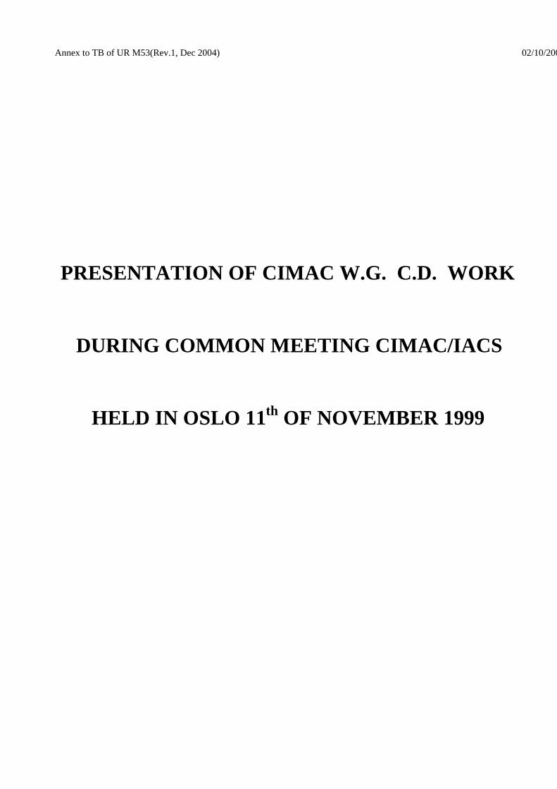
UR M53
CIMAC PROPOSALSYNTHESIS
WHAT WAS NOT CHANGED
- CALCULATION PRINCIPLE
- NOMINAL STRESS CALCULATIONS
- STRESS CONCENTRATION FACTORS CALCULATIONS
- FATIGUE STRENGTH FORMULA
- SHRINKFIT CALCULATIONS IN CASE OF SEMI-BUILT CRANKSHAFT
- MINIMUM SAFETY COEFFICIENT FACTOR FIGURE

Annex to TB of UR M53(Rev.1, Dec 2004) 10/11/1999
UR M53
CIMAC PROPOSALSYNTHESIS
WHY NO CHANGE ?
• AFTER YEARS OF EXPERIENCE, PRESENT METHOD GIVES GENERALLY PRETTY GOOD RESULTS ON THE SAFE SIDE.
• IT MINIMIZES AMOUNT OF WORK.
• IT SHOULD BE EASIER TO COME TO AN AGREEMENT ON UPDATED VERSION BETWEEN BOTH PARTIES.

Annex to TB of UR M53(Rev.1, Dec 2004) 10/11/1999
UR M53
CIMAC PROPOSALSYNTHESIS
WHY CHANGES ?
• IN ORDER TO HAVE A SAFER DESIGN OF CRANKSHAFT (SAFETY FACTOR AROUND OIL HOLE).
• IN ORDER TO BE MORE WELL SUITED TO NOWADAYS CRANKSHAFT DESIGN (EXTENSION OF CONCENTRATION FACTOR RANGE AND GEOMETRICAL PARAMETERS OF SEMI-BUILT CRANKSHAFT).
• IN ORDER TO AVOID MISTAKE IN APPLYING THE U.R. BY AVOIDING AMBIGUOUS DEFINITIONS.
• IN ORDER TO OPEN THE U.R. TO ALTERNATIVE ASSESSMENT PROCEDURES (SURFACE TREATMENT, FATIGUE STRENGTH, F.E. CALCULATIONS, …).

Annex to TB of UR M53(Rev.1, Dec 2004) 11/10/1999
UR M53
CIMAC PROPOSALSYNTHESIS
MAIN IMPROVEMENTS ALREADY PRESENTEDTO IACS AND DOCUMENTED
• SAFETY FACTOR CALCULATION AROUND CRANKPIN OIL HOLE (ONLY IN CASE OF DIAMETRAL ONE).
• EXTENSION OF SOME CONCENTRATION FACTORS RANGE (ONLY WHEN FEASIBLE ACCORDING TO PREVIOUS EXPERIMENTAL RESULTS).
• IMPROVED DEFINITIONS OF CALCULATION PRINCIPLE, VARIOUS STRESSES AND STRESS CONCENTRATION FACTORS. (IN CONSISTENCY WITH ANALYSIS METHOD USED AT CREATION OF PRESENT U.R.).
• CLARIFICATION CONCERNING GEOMETRIC PARAMETERS OF CRANKSHAFT. (SPECIALLY IN CASE OF 2 STROKES ENGINES)
Annex to TB of UR M53(Rev.1, Dec 2004) 10/11/1999
UR M53
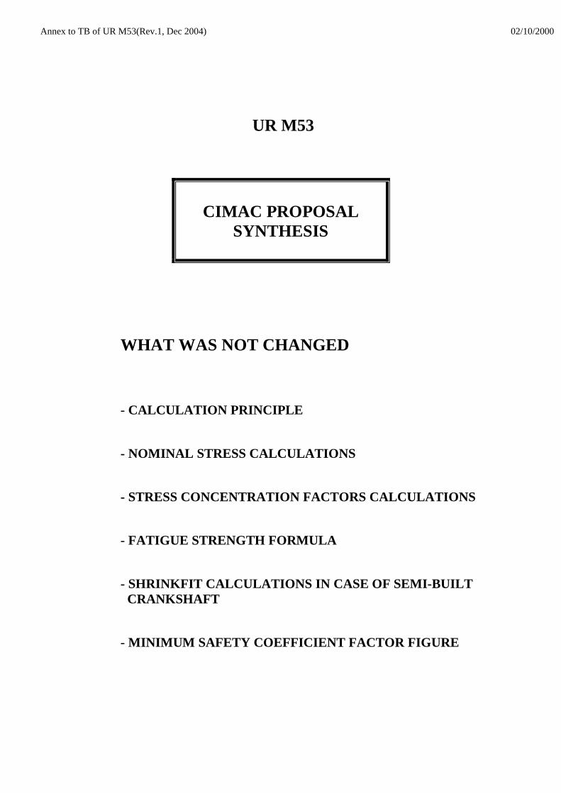
CIMAC PROPOSALSYNTHESIS
WHAT WAS IMPROVED SINCE OUR LASTMEETING ACCORDING TO IACS/WP REQUESTS
• MORE PRECISE DEFINITION OF EQUIVALENT ALTERNATING STRESSES USED IN U.R.
THESE DEFINITIONS ARE SUPPORTED BY 2 APPENDIXESINCLUDED IN CIMAC PROPOSED TEXT :
- APPENDIX 1 FOR STRESSES IN FILLETS
- APPENDIX 2 FOR STRESSES AROUND OIL HOLE
• NEW PARAGRAPH CONCERNING FATIGUE STRENGTH OF CRANKSHAFT TO ALLOW – AS AN ALTERNATIVE – CLASSIFICATION SOCIETY APPROVED EXPERIMENTAL METHODS BASED ON SAMPLE RESULTS (AND NOT ON FULL SCALE CRANKTHROW).

Annex to TB of UR M53(Rev.1, Dec 2004) 02/10/2000
UR M53
IACS POSITION AFTER PRESENTATIONOF CIMAC UR M53 REVISED TEXT :
• NEW PROPOSAL IS CLEARER AND DOES NOT NEED
MUCH INTRODUCTION AND SUPPORT INFORMATION.
• SOME PRECISIONS AND MODIFICATIONS ARE
STILL ASKED TO CIMAC C.D. W.G.
• DETAILED REVIEW AND EVALUATION OF
PROPOSAL IS REQUESTED TO EACH MEMBER
OF IACS/WP/MCH BEFORE END OF YEAR 2000.

Annex to TB of UR M53(Rev.1, Dec 2004) 02/10/2000
Revision of Unified Requirements UR M53, Calculation of Crankshafts for InternalCombustion Engines – Task 8.
Mr. Bertrand, chairman CIMAC WG-Crankshaft Dimensions (CD) gave a presentation on the subject andinformed about the new CIMAC proposal for revised UR M53. It was emphasized that fundamental partshad not been altered, but that weak areas had been improved and volume thus increased from earlier 15pages to now 30.
In the presentation and the subsequent discussion the following was highlighted :
- The new proposal is clearer than earlier versions and do not need much introduction and supportinformation. However, when submitting the final proposal to WP/MCH, CIMAC was requested to providedocumentary evidence of :
(a) Specific reasons for individual requirement changes.(b) That the changes have the full support of all associated manufacturers of 2 and 4
stroke engines.
- Current proposal is to be considered as a temporary proposal. Even when accepted and included in theIACS UR, the work within CIMAC, aiming at further improvements, will continue in line with the technicaldevelopment.
- Shrink fit criteria are not covered by the current proposal. This is a task for future development/revisions.
- The new proposal is covering steel crankshafts, and is not suitable for crankshafts made from cast iron.
- It is important that criteria are well defined. GL’s experience from last IACS audit clearly illustrated howdifficult it could be to explain to an auditor on what basis approval was made when not in compliance withcurrent UR M53.
- The new proposal (ref. top of page 4) have a paragraph which opens for the use of other criteria than thosegiven in the UR itself. A number of WP/MCH’s members found this somewhat confusing and expressed thatlack of common minimum requirements, could involve that members in principle were free to accept designson a subjective basis. This could mean that we do not have Unified Requirements, but UnifiedRecommendations. Is this considered sufficient for crankshafts ?
- With basis in above, it was considered mandatory that the UR M53 gave clear criteria/definition as towhat could be considered as « equivalent methods ». Accordingly, and upon request, Mr. Sandberg, DNVproduced a proposal for definition/interpretation of the term « equivalent » intended applied for the newproposal to UR M53. The proposal with ref. to M53, page 4, amendment to 1.1 scope : ……. equivalence tothese rules, reads : « Equivalence is understood as : No alteration in principles affecting non apparentsafety factors, i.e. the assumption of max bending and max torsion coinciding in time and position is to bemaintained together with the acceptability factor. Empirical methods as e.g. calculation of nominalstresses, stress concentration factors, combination of stresses, fatigue strength, etc may be replaced bymore relevant methods of ……… »
It was agreed that :0. Copy of the presentation given by Mr. Bertrand should be submitted WP/MCH’s chairman (preferably in
electronic form) for distribution to the WP/MCH members. Status : Not yet received. Reminder ishereby given.
1. All WP/MCH members should evaluate above definition together with the already distributed proposal for revision of UR M53.
2. All WP/MCH members should perform a detail review of the proposal submitted (together with abovedefinition of equivalency) and revert with their comments to WP/MCH’s chairman within end of thisyear. In this respect due attention should also be paid to the language and terms used. (In some places,translation to English (from French and German) have resulted in some unfortunate terms/wording,which need to be evaluated and considered corrected, e.g. W is defined as second moment of area).
Annex to TB of UR M53(Rev.1, Dec 2004) 02/10/2000
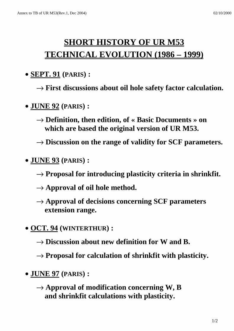
SHORT HISTORY OF UR M53TECHNICAL EVOLUTION (1986 – 1999)
• SEPT. 91 (PARIS) :
→ First discussions about oil hole safety factor calculation.
• JUNE 92 (PARIS) :
→ Definition, then edition, of « Basic Documents » onwhich are based the original version of UR M53.
→ Discussion on the range of validity for SCF parameters.
• JUNE 93 (PARIS) :
→ Proposal for introducing plasticity criteria in shrinkfit.
→ Approval of oil hole method.
→ Approval of decisions concerning SCF parametersextension range.
• OCT. 94 (WINTERTHUR) :
→ Discussion about new definition for W and B.
→ Proposal for calculation of shrinkfit with plasticity.
• JUNE 97 (PARIS) :
→ Approval of modification concerning W, Band shrinkfit calculations with plasticity.
1/2

Annex to TB of UR M53(Rev.1, Dec 2004) 02/10/2000
• JUNE 98 (COPENHAGEN) :
→ 1st complete rewording of UR M53 incorporating :
* Oil hole safety coeff. calculation method
* Extension range of SCF factors
* Clear definitions of various parameters consistently
with « Basic Documents »
* Cancellation of proposed method about plasticityeffects during shrinkfit
→ 1st discussion about future of UR M53
• APRIL 99 (ST NAZAIRE) :
→ Definitive revision of UR M53 agreed by all W.G. members with addition of :
* Appendix for clear explanation of SCF.
* Possibility of σDW determination by alternativeexperimental method.
→ State of art in crankshaft design presented by each W.G. member.
• OCT. 99 :
→ Presentation to IACS WP/MCH of previous revised edition of UR M53 (with only one editorial modification).
2/2

Part B, Annex 2
Technical Background for UR M53 Rev.2, Jan 2011
1. Scope and objectives The present UR M53 does not cater for some of the current designs of crankshaft and the Industry through CIMAC have proposed an alternative calculation procedure. 2. Engineering background for technical basis and rationale The analytical method in UR M53 is based on empirical formulae developed from strain gauge measurements of various crank geometries. Use of these formulae beyond any of the various validity ranges can lead to erroneous results in either direction, i.e. results that are more inaccurate than indicated by the mentioned standard deviations. Therefore the FEM-based method is highly recommended and this Technical Background is taken from the work undertaken by CIMAC. The SCF’s calculated according to the rules of this document are defined as the ratio of stresses calculated by FEM to nominal stresses in both journal and pin fillets. When used in connection with the present method in M53 von Mises stresses shall be calculated for bending and principal stresses for torsion or when alternative methods are considered. 3. Source/derivation of the proposed IACS Resolution See Proposal by CIMAC WG4 ST-08-044 dated 29.06.2009. 4. Summary of Changes intended for the revised Resolution: See Proposal by CIMAC WG4 ST-08-044 dated 29.06.2009. 5. Points of discussions or possible discussions Proposal by CIMAC WG4 ST-08-044 dated 29.06.2009 was subject to extensive discussion regarding the validity of the proposal. A major concern was the lack of far reaching validation offered. It was for this reason that the proposal has been accepted as an alternative only where the current prescriptive rules in UR M53 are out of bounds and not as a means to replace UR M53 in its entirety. 6. Attachments if any Proposal by CIMAC WG4 (IACS UR M53, Appendix III “Guidance for calculation of Stress Concentration Factors in the web fillet radii of crankshafts by utilizing Finite Element Method”

CO-ORDINATING WORKING GROUP
"CLASSIFICATION SOCIETIES – DIESEL"
(WG2)
Proposal by CIMAC WG4
ST-08-044 29.06.2009
IACS UR M53, Appendix III
“Guidance for calculation of
Stress Concentration Factors
in the web fillet radii of crankshafts by utilizingFinite Element Method”
C O N S E I L I N T E R N A T I O N A LDES MACHINES A COMBUSTION
I N T E R N A T I O N A L C O U N C I LO N C O M B U S T I O N E N G I N E S
-2-
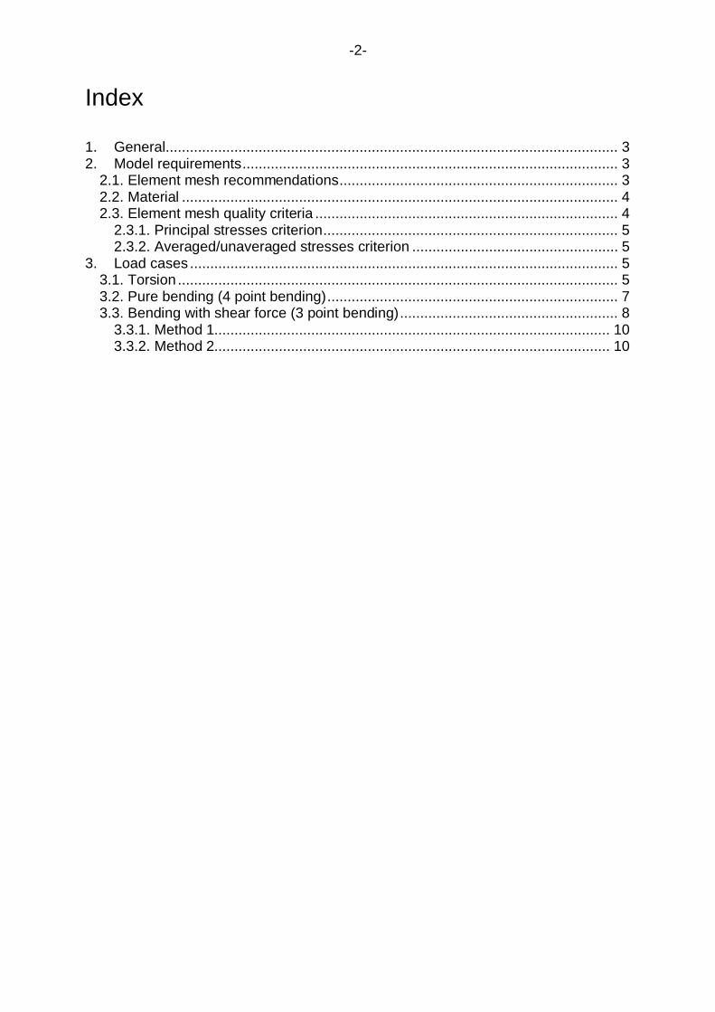
Index
1. General................................................................................................................ 32. Model requirements............................................................................................. 3
2.1. Element mesh recommendations..................................................................... 32.2. Material ............................................................................................................ 42.3. Element mesh quality criteria ........................................................................... 4
2.3.1. Principal stresses criterion......................................................................... 52.3.2. Averaged/unaveraged stresses criterion ................................................... 5
3. Load cases .......................................................................................................... 53.1. Torsion ............................................................................................................. 53.2. Pure bending (4 point bending)........................................................................ 73.3. Bending with shear force (3 point bending)...................................................... 8
3.3.1. Method 1.................................................................................................. 103.3.2. Method 2.................................................................................................. 10

-3-
1. General
The objective of the analysis is to substitute the analytically calculated StressConcentration Factors (SCF) at the crankshaft fillets by suitable Finite ElementMethod (FEM) calculated figures. The analytical method is based on empiricalformulae developed from strain gauge measurements of various crank geometries.Use of these formulae beyond any of the various validity ranges can lead toerroneous results in either direction, i.e. results that are more inaccurate thanindicated by the mentioned standard deviations. Therefore the FEM-based method ishighly recommended.
The SCF’s calculated according to the rules of this document are defined as the ratioof stresses calculated by FEM to nominal stresses in both journal and pin fillets.When used in connection with the present method in M53 von Mises stresses shallbe calculated for bending and principal stresses for torsion or when alternativemethods are considered.
The procedure as well as evaluation guidelines are valid for both solid cranks andsemibuilt cranks (except journal fillets).
The analysis is to be conducted as linear elastic FE analysis, and unit loads ofappropriate magnitude are to be applied for all load cases.
The calculation of SCF at the oil bores is at present not covered by this document.
It is advised to check the element accuracy of the FE solver in use, e.g. by modellinga simple geometry and comparing the stresses obtained by FEM with the analyticalsolution for pure bending and torsion.
Boundary Element Method (BEM) may be used instead of FEM.
2. Model requirements
The basic recommendations and perceptions for building the FE-model arepresented in 2.1. It is obligatory for the final FE-model to fulfil the requirement in 2.3.
2.1. Element mesh recommendations
In order to fulfil the mesh quality criteria it is advised to construct the FE model for theevaluation of Stress Concentration Factors according to the followingrecommendations:
o The model consists of one complete crank, from the main bearing centreline tothe opposite side main bearing centreline.
o Element types used in the vicinity of the fillets: 10 node tetrahedral elements 8 node hexahedral elements 20 node hexahedral elements
o Mesh properties in fillet radii. The following applies to ±90 degrees incircumferential direction from the crank plane:

-4-
Maximum element size a=r/4 through the entire fillet as well as in thecircumferential direction. When using 20 node hexahedral elements, theelement size in the circumferential direction may be extended up to 5a. In thecase of multi-radii fillet r is the local fillet radius. (If 8 node hexahedralelements are used even smaller element size is required to meet the qualitycriteria.)
Recommended manner for element size in fillet depth direction First layer thickness equal to element size of a Second layer thickness equal to element to size of 2a Third layer thickness equal to element to size of 3a
o Minimum 6 elements across web thickness.o Generally the rest of the crank should be suitable for numeric stability of the
solver.o Counterweights only have to be modelled only when influencing the global
stiffness of the crank significantly.o Modelling of oil drillings is not necessary as long as the influence on global
stiffness is negligible and the proximity to the fillet is more than 2r, see figure 2.1.o Drillings and holes for weight reduction have to be modelled.o Submodeling may be used as far as the software requirements are fulfilled.
Figure 2.1. Oil bore proximity to fillet.
2.2. Material
UR M53 does not consider material properties such as Young’s Modulus (E) andPoisson’s ratio ( ). In FE analysis those material parameters are required, as strain isprimarily calculated and stress is derived from strain using the Young’s Modulus andPoisson’s ratio. Reliable values for material parameters have to be used, either asquoted in literature or as measured on representative material samples.
For steel the following is advised: E= 2.05·105 MPa and =0.3.
2.3. Element mesh quality criteria
If the actual element mesh does not fulfil any of the following criteria at the examinedarea for SCF evaluation, then a second calculation with a refined mesh is to beperformed.

-5-
2.3.1. Principal stresses criterion
The quality of the mesh should be assured by checking the stress component normalto the surface of the fillet radius. Ideally, this stress should be zero. With principalstresses 1, 2 and 3 the following criterion is required:
321321 ,,max03.0,,min
2.3.2. Averaged/unaveraged stresses criterion
The criterion is based on observing the discontinuity of stress results over elementsat the fillet for the calculation of SCF:
Unaveraged nodal stress results calculated from each element connected to anodei should differ less than by 5 % from the 100 % averaged nodal stressresults at this nodei at the examined location.
3. Load cases
To substitute the analytically determined SCF in UR M53 the following load caseshave to be calculated.
3.1. Torsion
In analogy to the testing apparatus used for the investigations made by FVV thestructure is loaded pure torsion. In the model surface warp at the end faces issuppressed.
Torque is applied to the central node located at the crankshaft axis. This node actsas the master node with 6 degrees of freedom and is connected rigidly to all nodes ofthe end face.
Boundary and load conditions are valid for both in-line and V-type engines.

-6-
Figure 3.1 Boundary and load conditions for the torsion load case.
For all nodes in both the journal and crank pin fillet principal stresses are extractedand the equivalent torsional stress is calculated:
2,
2,
2max 313221
equiv
The maximum value taken for the subsequent calculation of the SCF:
N
equiv
T,
N
equiv
T,
where N is nominal torsional stress referred to the crankpin and respectively journalas per UR M53 2.2.2 with the torsional torque T:
PN W
T
Load:Torque Tapplied tocentral node
Multi-point constraint:All nodes of crosssection are rigidlyconnected to centralnode (= master)
y
xz
BoundaryConditions:DOFs for allnodes arefully restrainedu x,y,z = 0

-7-
3.2. Pure bending (4 point bending)
In analogy to the testing apparatus used for the investigations made by FVV thestructure is loaded in pure bending. In the model surface warp at the end faces issuppressed.
The bending moment is applied to the central node located at the crankshaft axis.This node acts as the master node with 6 degrees of freedom and is connectedrigidly to all nodes of the end face.
Boundary and load conditions are valid for both in-line- and V- type engines.
Figure 3.2 Boundary and load conditions for the pure bending load case.
For all nodes in both the journal and pin fillet von Mises equivalent stresses equiv areextracted. The maximum value is used to calculate the SCF according to:
N
equiv
B,
N
equiv
B,
BoundaryConditions:DOFs for allnodes arefully restrainedu x,y,z = 0
Load:In-planebending bymoment Mapplied atcentral node
Multi-point constraint:All nodes of crosssection are rigidlyconnected to centralnode (= master)
y
xz

-8-
Nominal stress N is calculated as per UR M53 2.1.2.1 with the bending moment M:
eqwN W
M
3.3. Bending with shear force (3-point bending)
This load case is calculated to determine the SCF for pure transverse force (radialforce, Q ) for the journal fillet.
In analogy to the testing apparatus used for the investigations made by FVV, thestructure is loaded in 3-point bending. In the model, surface warp at the both endfaces is suppressed. All nodes are connected rigidly to the centre node; boundaryconditions are applied to the centre nodes. These nodes act as master nodes with 6degrees of freedom.
The force is applied to the central node located at the pin centre-line of theconnecting rod. This node is connected to all nodes of the pin cross sectional area.Warping of the sectional area is not suppressed.
Boundary and load conditions are valid for in-line and V-type engines. V-type enginescan be modelled with one connecting rod force only. Using two connecting rod forceswill make no significant change in the SCF.

-9-
Figure 3.3. Boundary and load conditions for the 3-point bending load case of an in-line engine.
Figure 3.4 Load applications for in-line and V-type engines.
The maximum equivalent von Mises stress 3P in the journal fillet is evaluated.The SCF in the journal fillet can be determined in two ways as shown below.
Multi-pointconstraint:All nodes ofcross sectionare connectedto a centralnode (= master)
Load:Force F3p appliedat central node atconnecting rod centreline.
BoundaryConditions:Displacements formaster node arefully restrainedux,y,z = 0;
(rotationsare free)
y
xz
BoundaryConditions:Displacements in yand z directions formaster node arerestrainedu y,z = 0.ux, (axialdisplacement androtations are free)
Boundary Conditions:Displacement in z directionfor master node isrestrained, uz = 0;uy, ux and (axial,
vertical displacements androtations are free)
-10-
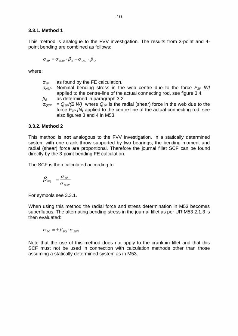
3.3.1. Method 1
This method is analogue to the FVV investigation. The results from 3-point and 4-point bending are combined as follows:
QPQBPNP 333
where:
3P as found by the FE calculation.N3P Nominal bending stress in the web centre due to the force F3P [N]
applied to the centre-line of the actual connecting rod, see figure 3.4.B as determined in paragraph 3.2.Q3P = Q3P/(B·W) where Q3P is the radial (shear) force in the web due to the
force F3P [N] applied to the centre-line of the actual connecting rod, seealso figures 3 and 4 in M53.
3.3.2. Method 2
This method is not analogous to the FVV investigation. In a statically determinedsystem with one crank throw supported by two bearings, the bending moment andradial (shear) force are proportional. Therefore the journal fillet SCF can be founddirectly by the 3-point bending FE calculation.
The SCF is then calculated according to
PN
PBQ
3
3
For symbols see 3.3.1.
When using this method the radial force and stress determination in M53 becomessuperfluous. The alternating bending stress in the journal fillet as per UR M53 2.1.3 isthen evaluated:
BFNBQBG
Note that the use of this method does not apply to the crankpin fillet and that thisSCF must not be used in connection with calculation methods other than thoseassuming a statically determined system as in M53.