
Untitled - The Pestinger Family
103
-
Upload
khangminh22 -
Category
Documents
-
view
0 -
download
0
Transcript of Untitled - The Pestinger Family

1 2 A C++ Programming Tutorialby Mike Podanoffsky
2 2 Characterizing Processor Performanceby Rick Naro
2 6 Designing with PC/104by Rick Lehrbaum
3 6 An LCD and Keypad Module for the SPIby Brian Millier
OUR BONUS HOME AUTOMATION d BUILDING COiVTROL
SECTION BEGINS ON PAGE 47 OF THIS ISSUE!
8 2 q
9 2 q
9 8 q
1 0 6 q
Firmware FurnaceJourney to the Protected Land: With Interrupts, Timing is EverythingEd Nisley
From the BenchVaporwear: Revealing Your HumidityTeff Bachiochi
Silicon UpdateA Saab StoryA Tale of Speed and AccelerationTom Cantrell
Embedded TechniquesUsing Keyboard I/O as an Embedded Interfacelohn Dybowski
Editor’s INKKen DavidsonA Reaffirmation
New Product Newsedited by Harv Weiner
ConnecTimeExcerpts fromthe Circuit Cellar BBSconducted byKen Davidson
Steve’s Own INKSteve Ciarcia
One of Those Days
Advertiser’s Index
Circuit Cellar INK Issue #57 April 1995 3
Edited by Harv Weiner
SERIAL EPROM EMULATORSoftec Microsystems [the basic version in-
introduces a serial EPROM cludes a l-Mb emulationemulator that doesn’t re- RAM). In addition toquire removal of the system loading the object code ;microprocessor. Unlike in- the rate of 115,200 bps,circuit emulators that re- receives the traditionalplace the microprocessor binary, Motorola-S, andwith a pod, the EMUR7 Intel hex formats. Thereplaces and emulates the EMUR7 connects to a
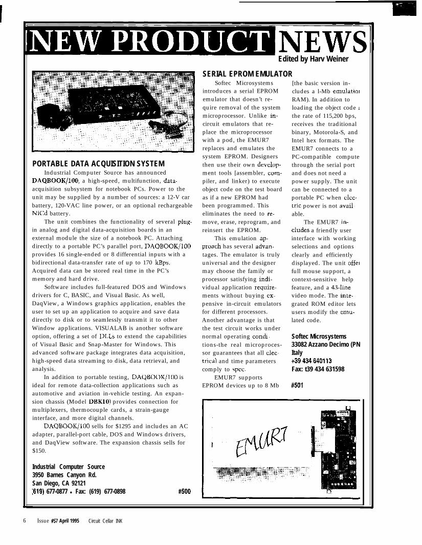
PORTABLE DATA ACQUISITION SYSTEMsystem EPROM. Designers PC-compatible computethen use their own develop- through the serial port
Industrial Computer Source has announced ment tools [assembler, com- and does not need aDAQBOOK/lOO, a high-speed, multifunction, data- piler, and linker) to execute power supply. The unitacquisition subsystem for notebook PCs. Power to the object code on the test board can be connected to aunit may be supplied by a number of sources: a 12-V car as if a new EPROM had portable PC when elec-battery, 120-VAC line power, or an optional rechargeable been programmed. This tric power is not avail-NiCd battery. eliminates the need to re- able.
The unit combines the functionality of several plug- move, erase, reprogram, and The EMUR7 in-in analog and digital data-acquisition boards in an reinsert the EPROM. eludes a friendly userexternal module the size of a notebook PC. Attaching This emulation ap- interface with workingdirectly to a portable PC’s parallel port, DAQBOOK/lOO preach has several advan- selections and optionsprovides 16 single-ended or 8 differential inputs with a tages. The emulator is truly clearly and efficientlybidirectional data-transfer rate of up to 170 kBps. universal and the designer displayed. The unit offerAcquired data can be stored real time in the PC’s may choose the family or full mouse support, amemory and hard drive. processor satisfying indi- context-sensitive help
Software includes full-featured DOS and Windows vidual application require- feature, and a @-linedrivers for C, BASIC, and Visual Basic. As well, ments without buying ex- video mode. The inte-DaqView, a Windows graphics application, enables the pensive in-circuit emulators grated ROM editor letsuser to set up an application to acquire and save data for different processors. users modify the emu-directly to disk or to seamlessly transmit it to other Another advantage is that lated code.Window applications. VISUALAB is another software the test circuit works underoption, offering a set of DLLs to extend the capabilities normal operating condi- Softec Microsystemsof Visual Basic and Snap-Master for Windows. This tions-the real microproces- 33082 Azzano Decimo (PNadvanced software package integrates data acquisition, sor guarantees that all elec- Italyhigh-speed data streaming to disk, data retrieval, and trical and time parameters +39434640113analysis. comply to spec. Fax: t39 434 631598
In addition to portable testing, DAQBOOK/lOO is EMUR7 supportsideal for remote data-collection applications such as EPROM devices up to 8 Mb #501automotive and aviation in-vehicle testing. An expan-sion chassis (Model DBKlO) provides connection formultiplexers, thermocouple cards, a strain-gaugeinterface, and more digital channels.
DAQBOOK/lOO sells for $1295 and includes an ACadapter, parallel-port cable, DOS and Windows drivers,and DaqView software. The expansion chassis sells for$150.
Industrial Computer Source3950 Barnes Canyon Rd.San Diego, CA 92121:619) 677-0877 l Fax: (619) 677-0898 #500
6 Issue #57 April 1995 Circuit Cellar INK
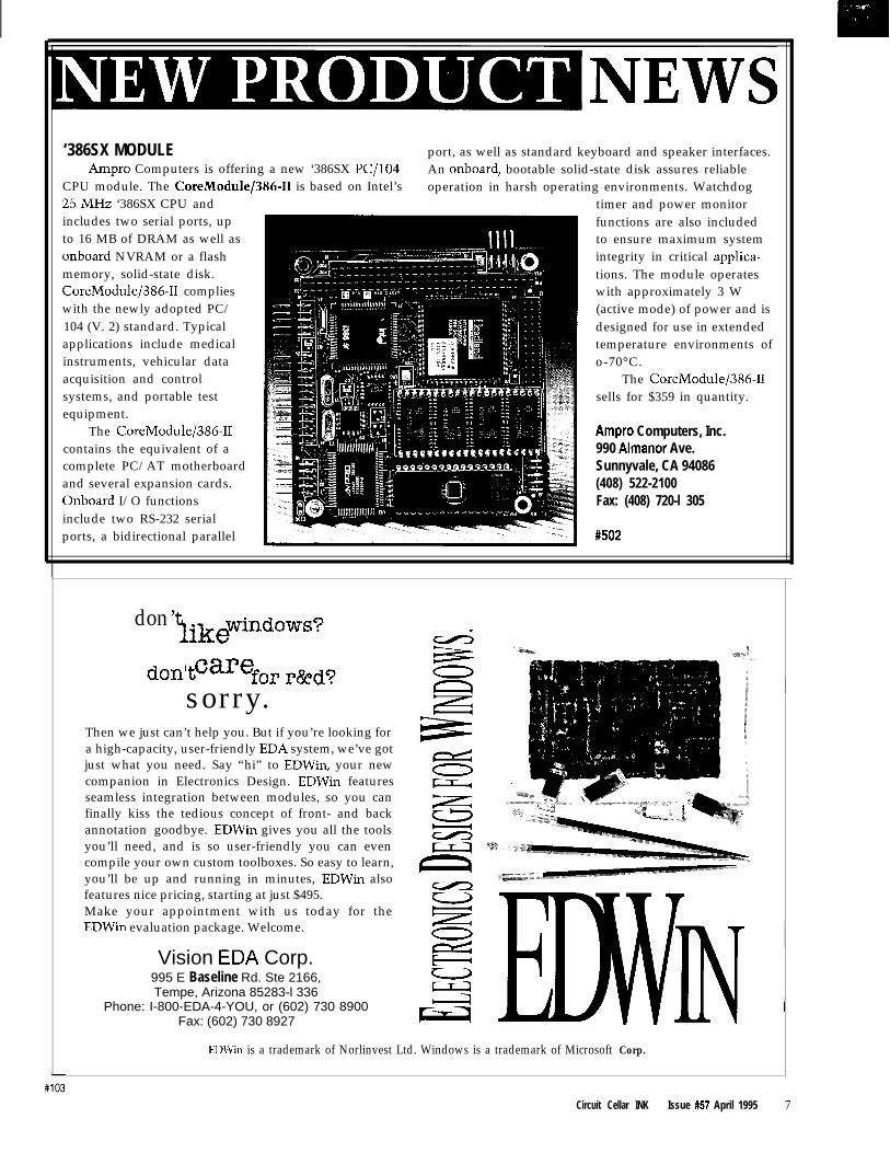
‘386SX MODULE port, as well as standard keyboard and speaker interfaces.Ampro Computers is offering a new ‘386SX PC/104 An onboard, bootable solid-state disk assures reliable
CPU module. The CoreModule/386-II is based on Intel’s operation in harsh operating environments. Watchdog25MHz ‘386SX CPU and timer and power monitorincludes two serial ports, up functions are also includedto 16 MB of DRAM as well as to ensure maximum systemonboard NVRAM or a flash integrity in critical applica-memory, solid-state disk. tions. The module operatesCoreModule/386-II complies with approximately 3 Wwith the newly adopted PC/ (active mode) of power and is104 (V. 2) standard. Typical designed for use in extendedapplications include medical temperature environments ofinstruments, vehicular data o-70°C.acquisition and control The CoreModule/386-IIsystems, and portable test sells for $359 in quantity.equipment.
The CoreModule/386-II Ampro Computers, Inc.contains the equivalent of a 990 Almanor Ave.complete PC/AT motherboard Sunnyvale, CA 94086and several expansion cards. (408) 522-2100Onboard I/O functions Fax: (408) 720-l 305include two RS-232 serialports, a bidirectional parallel #502
don’tlki ewindows?
don’tCarefop r&dosorry. -
Then we just can’t help you. But if you’re looking fora high-capacity, user-friendly EDA system, we’ve gotjust what you need. Say “hi” to EDWin, your newcompanion in Electronics Design. EDWin featuresseamless integration between modules, so you canfinally kiss the tedious concept of front- and backannotation goodbye. EDWin gives you all the toolsyou’ll need, and is so user-friendly you can evencompile your own custom toolboxes. So easy to learn,you’ll be up and running in minutes, EDWin alsofeatures nice pricing, starting at just $495.Make your appointment with us today for the =/=,
EDWin evaluation package. Welcome.zz
Vision EDA Corp. e995 E Baseline Rd. Ste 2166,Tempe, Arizona 85283-l 336
Phone: I-800-EDA-4-YOU, or (602) 730 8900 :
Fax: (602) 730 8927 LIvI’iIN
EDWin is a trademark of Norlinvest Ltd. Windows is a trademark of Microsoft Corp.
Circuit Cellar INK Issue #57 April 1995 7
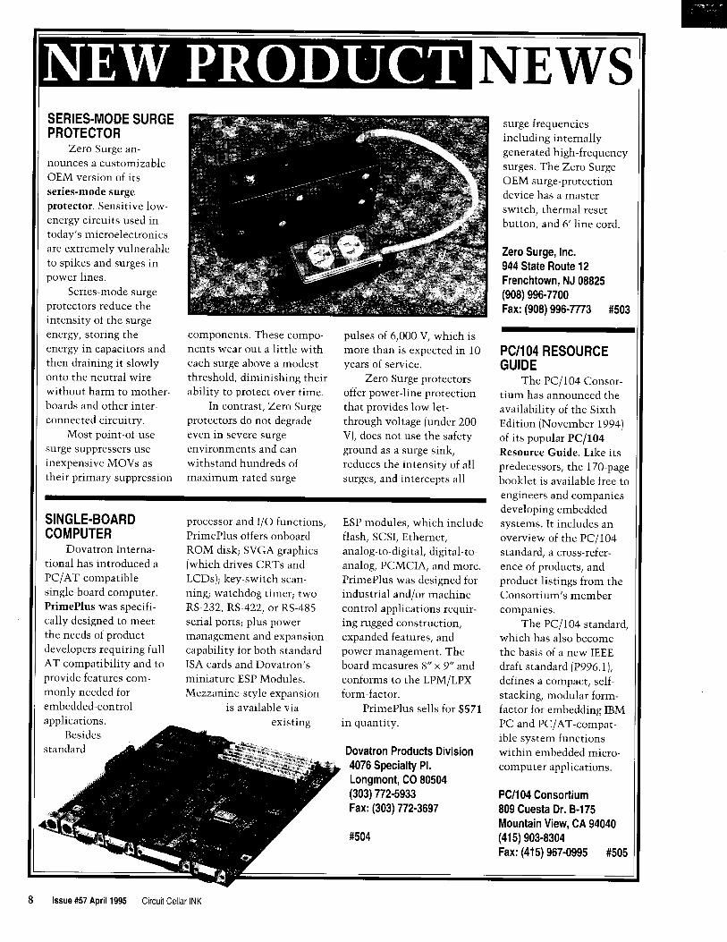
IN~JD D~D~~NEWSANSI-FORTH up to 512 KB of battery- for data logging, robotics, orDATALOGGER AND
in solving controlbacked RAM, EEPROM, or machine control. Up to 33 I/ problems. A PC library of
CONTROLLER flash memory. In addition, a 0 lines, two RS-232 serial ANSI-Forth softwareSaelig Company 40.MB miniature hard drive lines, an PC bus, real-time makes stepper-motor
introduces a tailor-made is available and 32 digital clock, and watchdog timer control, interruptdata-collection system inputs may be monitored. make an economical, handling, real-timethat can be read by a PC An onboard S-channel, versatile controller for a multitasking, dataand features removable lo-bit A/D converter and 3- wide range of applications. logging, serial I/O,card memory. The channel, 8-bit D/A con- Although small, it is packed keyboard, and LCDTDS2020 Data Logger verter make the 4” x 3” with important features driving easy. WhenModule adheres to the board extremely versatile which make it easy to use logging data in standbyofficial Forth language mode, it will run on 500definition. Forth is an uA, so a 9-V battery lastseasily-learned, high-levellanguage ideal for fast The TDS2020 sellscontrol and well-suited for $499 for the starterto real-time embedded pack, which includes asystems. comprehensive manual
The TDS2020 is a and PC software.16.bit control computer
The Saelig Company532 CMOS microproces-sor running at 20 MHz. Itis available with 16 KB ofANSI-Forth kernel, a full Fax: (716) 425-3835symbolic assembler, 45KB of program space, and
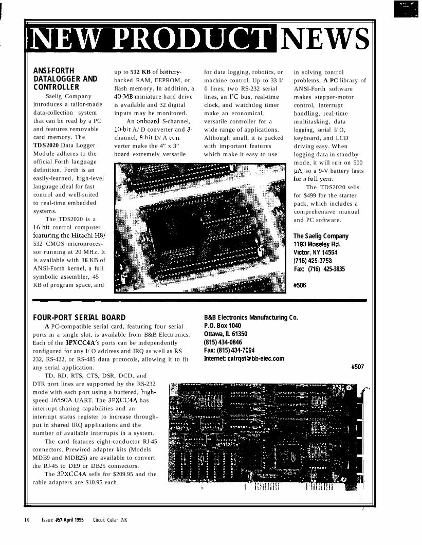
FOUR-PORT SERIAL BOARD B&B Electronics Manufacturing Co.A PC-compatible serial card, featuring four serial P.O. Box 1040
ports in a single slot, is available from B&B Electronics. Ottawa, IL 61350Each of the 3PXCC4A’s ports can be independently (815) 434-0846configured for any I/O address and IRQ as well as RS- Fax: (815) 434-7094232, RS-422, or RS-485 data protocols, allowing it to fit Internet: catrqstebb-elec.comany serial application. #507
TD, RD, RTS, CTS, DSR, DCD, andDTR port lines are supported by the RS-232mode with each port using a buffered, high-speed 1655012 UART. The 3PXCC4A hasinterrupt-sharing capabilities and aninterrupt status register to increase through-put in shared IRQ applications and thenumber of available interrupts in a system.
The card features eight-conductor RJ-45connectors. Prewired adapter kits (ModelsMDB9 and MDB25) are available to convertthe RJ-45 to DE9 or DB25 connectors.
The 3PXCC4A sells for $209.95 and thecable adapters are $10.95 each.
1
10 Issue #57 April 1995 Circuit Cellar INK
CHIPSET FEATURESELECTRONIC GEARING
velocity contouring) alongwith high-resolution, 16-bit
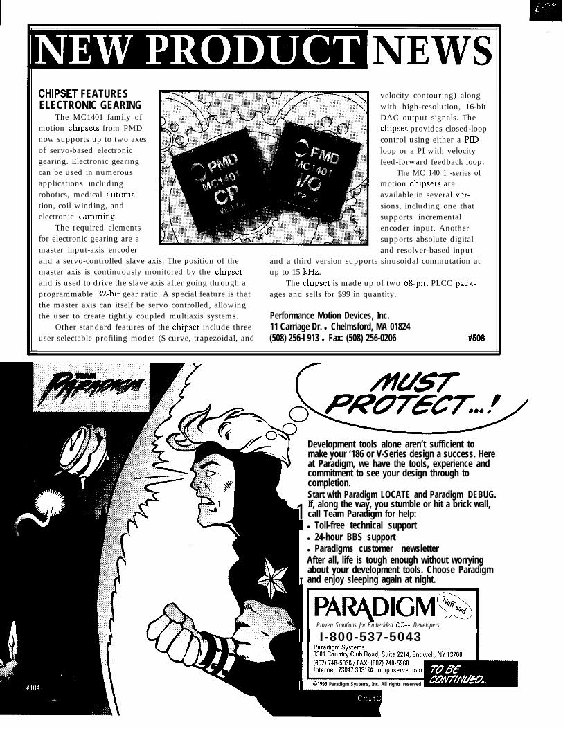
The MC1401 family of DAC output signals. Themotion chipsets from PMD chipset provides closed-loopnow supports up to two axes control using either a NDof servo-based electronic loop or a PI with velocitygearing. Electronic gearing feed-forward feedback loop.can be used in numerous The MC 140 1 -series ofapplications including motion chipsets arerobotics, medical automa- available in several ver-tion, coil winding, and sions, including one thatelectronic camming. supports incremental
The required elements encoder input. Anotherfor electronic gearing are a supports absolute digitalmaster input-axis encoder and resolver-based inputand a servo-controlled slave axis. The position of the and a third version supports sinusoidal commutation atmaster axis is continuously monitored by the chipset up to 15 kHz.and is used to drive the slave axis after going through a The chipset is made up of two 6%pin PLCC pack-programmable X&bit gear ratio. A special feature is that ages and sells for $99 in quantity.the master axis can itself be servo controlled, allowingthe user to create tightly coupled multiaxis systems. Performance Motion Devices, Inc.
Other standard features of the chipset include three 11 Carriage Dr. l Chelmsford, MA 01824user-selectable profiling modes (S-curve, trapezoidal, and (508) 256-l 913 l Fax: (508) 256-0206 #508
Proven Solutions for Embedded C/Ctt Developers
Development tools alone aren’t sufficient tomake your ‘186 or V-Series design a success. Hereat Paradigm, we have the tools, experience and
1commitment to see your design through tocompletion.Start with Paradigm LOCATE and Paradigm DEBUG._
1If, along the way, you stumble or hit a brick wall,call Team Paradigm for help:
I
l Toll-free technical supportl 24-hour BBS supportl Paradigms customer newsletterAfter all, life is tough enough without worryingabout your development tools. Choose Paradigmand enjoy sleeping again at night.
11 I-800-537-5043 I
1 01995 Paradigm Systems, Inc. All rights reserved

FEATURESA c+t
Programming Tutorial
Mike Podanoffsky
CharacterizingProcessor Performance
Designing with PC/i 04
An LCD and KeypadModule for the SPI
A Ctt Proaramming Tutorialu
0 his articleshould probably
be entitled “C++ ForThose Who Already
Know C,” but I’ll try to be generalenough for everyone. C++ was born atAT&T in the 1980s. It was a set ofobject-oriented extensions to C, analready popular language. The changefrom C’s largely procedural view toC++‘s object view marks a fundamen-tal paradigm shift-one that changeshow all programs and all programmingproblems are viewed.
Listing 1 demonstrates thissweeping claim. As you can see, this isa simple and perfectly correct portionof a C program. But, what is wrongwith it?
The code is typical of C whichpublishes DATA L I B as a public struc-ture. The logic that manipulates itsmembers is sprinkled throughoutmany different application programs. Ifthe DATA L I B structure was changed,every program using it would need tobe altered or at least recompiled. Withthis procedural framework, knowledgeis said to be distributed.
With C++, programs do not knowor have direct access to members of adata structure. Instead, they call afunction, specifically known as amember function or method, toretrieve members of the data structure.
12 Issue #57 April 1995 Circuit Cellar INK
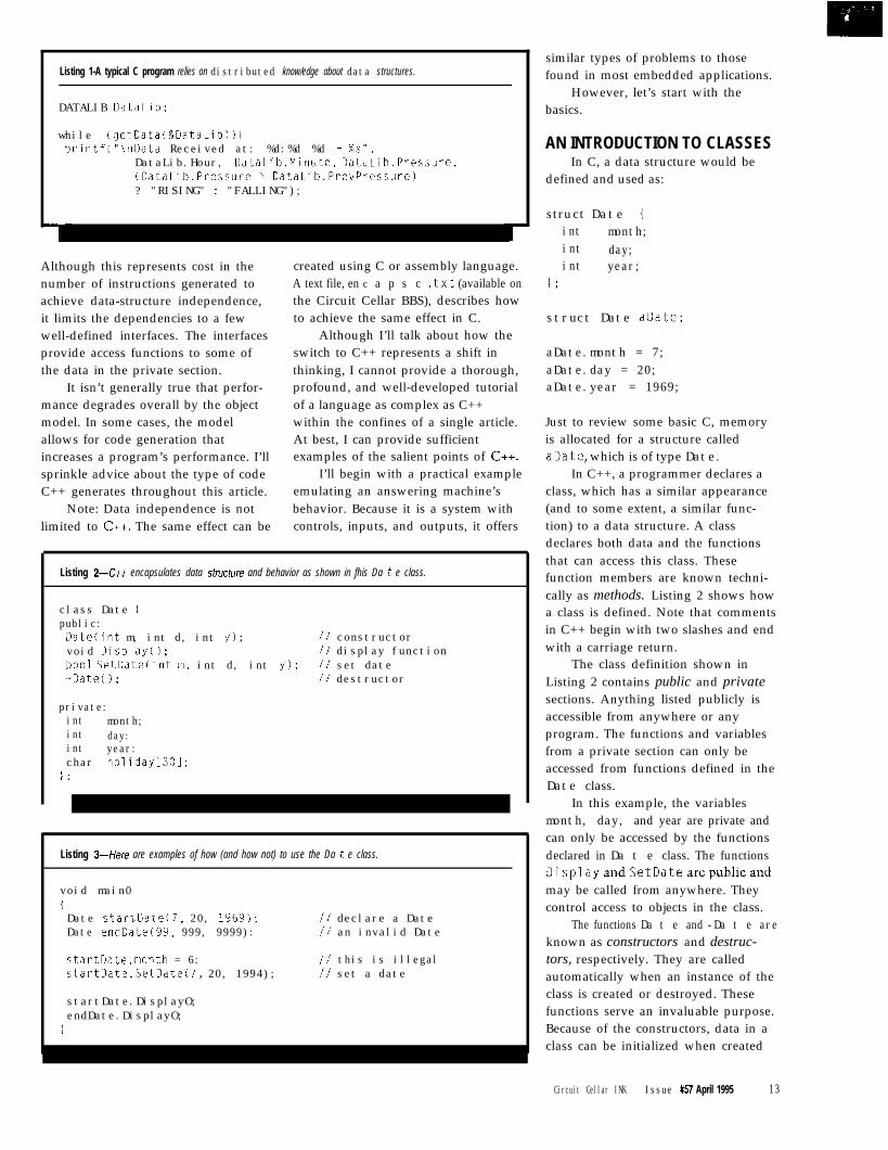
Listing 1-A typical C program relies on distributed know/edge about data structures.
DATALIB Dataiib;
while (getData(&DataLib)) iprintf("\nData Received at: %d:%d %d - %s",
DataLib.Hour, DataLib.Minute, DataLib.Pressure,(DataLib.Pressure > DataLib.PrevPressure)? "RISING" : "FALLING");
Although this represents cost in thenumber of instructions generated toachieve data-structure independence,it limits the dependencies to a fewwell-defined interfaces. The interfacesprovide access functions to some ofthe data in the private section.
It isn’t generally true that perfor-mance degrades overall by the objectmodel. In some cases, the modelallows for code generation thatincreases a program’s performance. I’llsprinkle advice about the type of codeC++ generates throughout this article.
Note: Data independence is notlimited to C++. The same effect can be
created using C or assembly language.A text file, en c a p s c . t x t (available onthe Circuit Cellar BBS), describes howto achieve the same effect in C.
Although I’ll talk about how theswitch to C++ represents a shift inthinking, I cannot provide a thorough,profound, and well-developed tutorialof a language as complex as C++within the confines of a single article.At best, I can provide sufficientexamples of the salient points of C++.
I’ll begin with a practical exampleemulating an answering machine’sbehavior. Because it is a system withcontrols, inputs, and outputs, it offers
Listing 2-h encapsulates data sfructure and behavior as shown in fhis Da t e class.
class Date ipublic:Datecint m, int d, int y); // constructorvoid DisplayO; // display functionboo1 SetDate(int m, int d, int y); // set date-DateO; // destructor
private:int month;int day:int year:char holiday[301;
1 ;
Listing 34iere are examples of how (and how not) to use the Da t e class.
void main0iDate startDate(7, 20, 1969); ii declare a DateDate endDate(99, 999, 9999): // an invalid Date
startDate.month = 6: // this is illegalstartDate.SetDate(?, 20, 1994); // set a date
startDate.DisplayO;endDate.DisplayO;
1
similar types of problems to thosefound in most embedded applications.
However, let’s start with thebasics.
AN INTRODUCTION TO CLASSESIn C, a data structure would be
defined and used as:
struct Date 1int month;int day;int year;
I ;
struct Date aDate;
aDate.month = 7;aDate.day = 20;aDate.year = 1969;
Just to review some basic C, memoryis allocated for a structure calledaDate, which is of type Date.
In C++, a programmer declares aclass, which has a similar appearance(and to some extent, a similar func-tion) to a data structure. A classdeclares both data and the functionsthat can access this class. Thesefunction members are known techni-cally as methods. Listing 2 shows howa class is defined. Note that commentsin C++ begin with two slashes and endwith a carriage return.
The class definition shown inListing 2 contains public and privatesections. Anything listed publicly isaccessible from anywhere or anyprogram. The functions and variablesfrom a private section can only beaccessed from functions defined in theDate class.
In this example, the variablesmonth, day, and year are private andcan only be accessed by the functionsdeclared in Da t e class. The functionsDisplayandSetDatearepublicandmay be called from anywhere. Theycontrol access to objects in the class.
The functions Da t e and -Da t e areknown as constructors and destruc-tors, respectively. They are calledautomatically when an instance of theclass is created or destroyed. Thesefunctions serve an invaluable purpose.Because of the constructors, data in aclass can be initialized when created
Circuit Cellar INK Issue #57 April 1995 13
and allocated resources can be freedwhen destroyed.
Listing 3 demonstrates how aprogram uses a class. Two Da t. eobjects are instantiated (created):startDate and endDat.e. Eachdeclaration causes the constructor, theDa t. e function, for this class to becalled. The constructor initializes theobject. Unlike other functions,constructors and destructors cannotfail and cannot readily report errorseven if the parameters passed arewrong! Contructors have no way ofreturning errors. Because of this, it isimperative that constructors alwaysinitialize an object to a safe state, evenwhen illegal parameters are passed.
Thestatement startDate.monthis illegal because month is a privatemember of the Date class and cannotbe directly accessed. One solution is toadd a Set MO n t h method. As defined sofar, a date can be set or displayed byusing its public functions Set Da t eand Display.
CONSTRUCTORS ANDDESTRUCTORS
Instantly, a C programmer canrecognize the value constructors anddestructors provide. With them, anobject always has the opportunity toproperly initialize prior to its use.This, as with other C++ features, is farmore important when an object iscomplex, containing linked lists andsubstructures. Constructors anddestructors are part of the object modeland are enforced by the language itself.
A typical constructor appears inListing 4. The syntax Da t e : : Da t eidentifies this as a function belongingto the Date class. The class nameappears to the left and is separatedfrom the function or method name bydouble colons. Constructors alwayshave the same name as the class towhich they belong.
There can be, in fact, severalconstructors defined, each supportingdifferent arguments types. This is afeature of C++ functions and methodsand is not limited to just constructors.C++ matches function calls based onthe argument list and not just on thefunction name. This way differentmember functions can be defined with
14 lssue#57April1995 Circuit Cellar INK
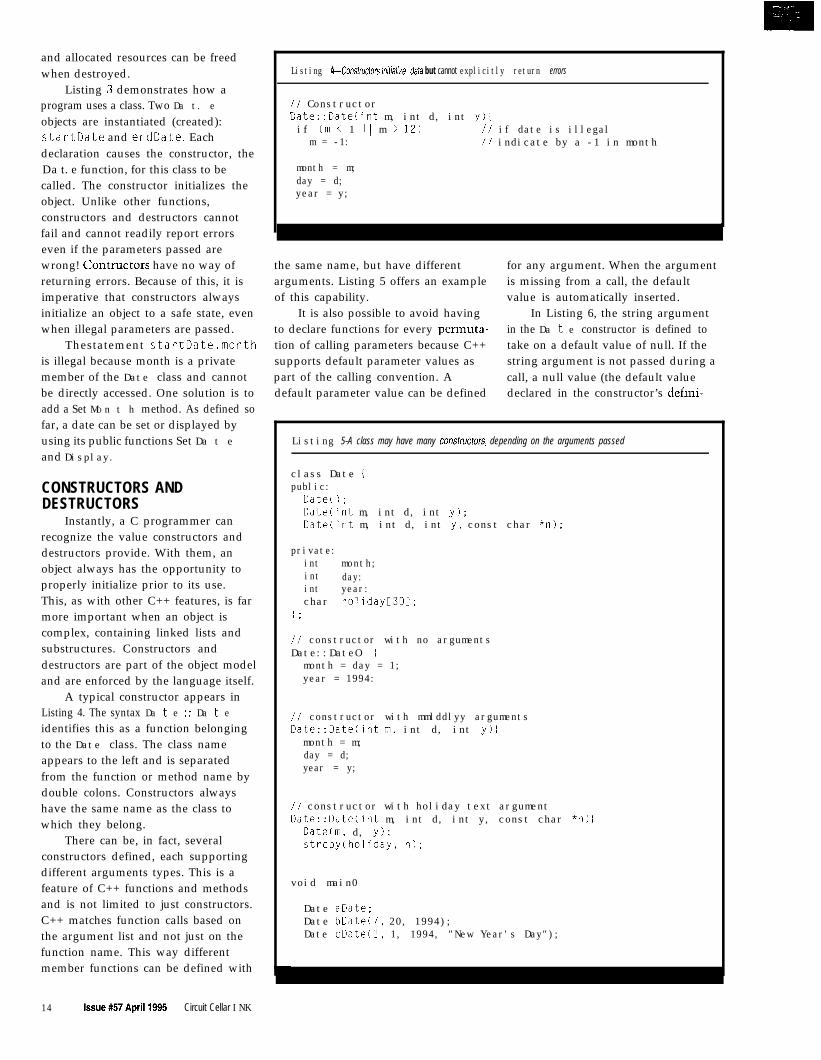
Listing 4-Conslructorsinitial~ze data but cannot explicitly return errors
// ConstructorDate::Date(int m, int d, int y)lif Cm < 1 1) m > 12) // if date is illegal
m = -1: // indicate by a -1 in month
month = m;day = d;year = y;
the same name, but have different for any argument. When the argumentarguments. Listing 5 offers an example is missing from a call, the defaultof this capability. value is automatically inserted.
It is also possible to avoid having In Listing 6, the string argumentto declare functions for every permuta- in the Da t e constructor is defined totion of calling parameters because C++ take on a default value of null. If thesupports default parameter values as string argument is not passed during apart of the calling convention. A call, a null value (the default valuedefault parameter value can be defined declared in the constructor’s defini-
Listing 5-A class may have many conskuctors, depending on the arguments passed
class Date ipublic:DateO;DateCint m, int d, int y);Date(int m, int d, int y, const char *n);
private:int month;int day:int year:char holiday[301;
i;
// constructor with no argumentsDate::DateO {
month = day = 1;year = 1994:
// constructor with mmlddlyy argumentsDate::Date(int m, int d, int y) 1
month = m;day = d;year = y;
// constructor with holiday text argumentDate::Date(int m, int d, int y, const char *n) (
DateCm, d, y);strcpy(holiday, n);
void main0
Date aDate:Date bDate(7, 20, 1994);Date cDate(l, 1, 1994, "New Year's Day");
tion) is supplied during the call.Default parameters are not limited toconstructors.
Finally, you almost always need tocreate this next special case of aconstructor for all of your objects. Itwould be highly desirable to create anew object by passing it a reference toan already existing object. For ex-ample, it is desirable to be able toinitialize a date object with the valueof another date object.
This type of constructor is called acopy constructor because the result isthat the new object becomes a copy ofthe referenced object [see Listing 7).
Constructors are optional. If noconstructor is defined, a dummyconstructor is automatically created bythe compiler. The dummy constructoris called but does nothing, not eveninitialize the data structure’s contents.This dummy constructor’s function isnecessary for several reasons. How-ever, it is mostly important formaintaining consistency in callingconventions when calling C++ func-tions from C or assembly language.
A destructor is called when aspecific instance of a class is no longerwithin scope (i.e., when it will nolonger be necessary, which is typicallywhen a function terminates). Destruc-tors are also optional and a dummyconstructor is created by the compilerwhen it is not declared. A destructorhas the same name as the class towhich it belongs and is preceded bythe - symbol, as in -Date.
CREATING CLASSESDYNAMICALLY
As with any C program, when anobject is declared inside the scope ofbraces, allocation for it is typicallymade on the stack. The life of theobject is only within the execution ofthe code in the braced section. Objectscan also be instantiated within aprogram’s global section or declareddynamically.
In C, dynamic allocation ismanaged through use of the ma 11 o cand free functions. Space is allocatedfrom the heap. These functions stillwork in C++, but they will not call thecorresponding constructor and destruc-tor. Instead, objects in C++ can be
1 6 Issue #57 April 1995 Circuit Cellar INK
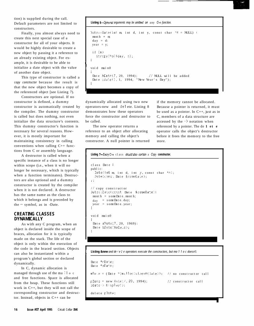
Listing 6-Optional arguments may be omitfed on any Ctt function.
Date::Date(int m, int d, int y, const char *n = NULL) imonth = m;day = d:year = y;
if (n)strcpy(holiday, n);
1
I void main0IDate bDate(7, 20, 1994); // NULL will be addedDate cDate(l, 1, 1994, "New Year's Day");
I
dynamically allocated using two new if the memory cannot be allocated.operators-new and de1 ete. Listing 8 Because a pointer is returned, it mustdemonstrates how these operators be used as a pointer. In C++, just as inforce the constructor and destructor to C, members of a data structure arebe called. accessed by the - > notation when
The new operator returns a referenced by a pointer. The de 1 et ereference to an object after allocating operator calls the object’s destructormemory and calling the object’s before it frees the memory to the freeconstructor. A null pointer is returned store.
I Listing 7-Every Ctt class shouldalso contain a Copy constructor.
class Date Ipublic:
Datecint m, int d, int y. const char *n);
I Datecconst Date &someDate);1 :
// copy constructorDate::Date(const Date &someDate) {month = someDate.month;day = someDate.day;year = someDate.year;
I
I void main0IDate aDatei7, 20, 1969):Date bDate(&aDate);
1
I Listing &new and de 1 e t e operators execute the constructors, but ma 1 1 o c doesn’t.
Date *mDate;Date *pDate;
mDate = (Date *)malloc(sizeof(Date)); // no constructor call
pDate = new Date(7, 20, 1994);pDate-> DisplayO;
// constructor call
delete pDate;
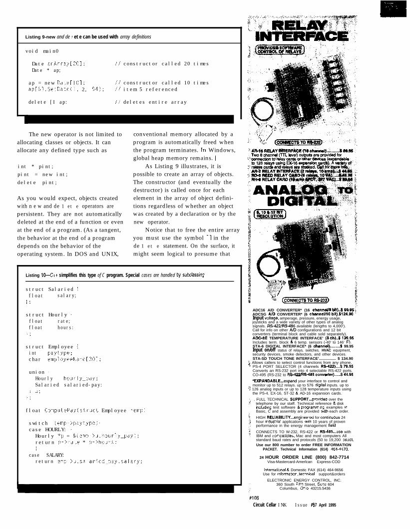
Listing 9-new and de 7 et e can be used with array definitions
void main0
Date anArray[ZOI;Date * ap;
// constructor called 20 times
ap = new Date[lOl: // constructor called 10 timesap[il.SetDate(l, 2, 94); // item 5 referenced
delete [I ap: // deletes entire array
The new operator is not limited toallocating classes or objects. It canallocate any defined type such as
int * pint;pint = new int;delete pint;
As you would expect, objects createdwith n e w and de 1 et e operators arepersistent. They are not automaticallydeleted at the end of a function or evenat the end of a program. (As a tangent,the behavior at the end of a programdepends on the behavior of theoperating system. In DOS and UNIX,
conventional memory allocated by aprogram is automatically freed whenthe program terminates. In Windows,global heap memory remains. ]
As Listing 9 illustrates, it ispossible to create an array of objects.The constructor (and eventually thedestructor) is called once for eachelement in the array of object defini-tions regardless of whether an objectwas created by a declaration or by thenew operator.
Notice that to free the entire arrayyou must use the symbol [ I in thede 1 et e statement. On the surface, itmight seem logical to presume that
Listing 104% simplifies this type of C program. Special cases are handled by subclassing
struct Salaried jfloat salary;
/ ;
struct Hourly jfloat rate;float hours:
I:
struct Employee 1int paytype;char employeeName[301:
union {Hourly hourly_pay:Salaried salaried-pay:
I u;1 :
float ComputePay(struct Employee *emp)
switch (emp->paytype) icase HOURLY: iHourly *p = &(emp->u.hourly_pay);return p->rate * p->hours:1
case SALARY:return emp->u.salaried_pay.salary:
f (CONNECTS ro fwb23$ADC16 A/D CONVERTER* (16 channef/S bit)..$69.96 ;ADCSG AID CONVERTER* (6 chsnneVl0 bH).$124.90 ’Input voltage, amperage, pressure, energy usage,joysticks and a wide variety of other types of analogsignals. RS-422/RS-466 available (lengths to 4,000’).Call for info on other AID configurations and 12 bitconverters (terminal block and cable sold separately).ADGBE TEMPERATURE INTERFACE’ (8 ch)..$l39.95Includes term. block & 6 temp. sensors (-40’ to 146’ F).STA-6 DIGITAL INTERFACE* (6 channel).........9 99.95Input on/off status of relays, switches, HVAC equipment,security devices, smoke detectors, and other devices.STA-SD TOUCH TONE INTERFACE’................ $ 134.90
2 Allows callers to select control functions from any phone.* PS-4 PORT SELECTOR (4 channels RS-422)....$79.95
Converts an RS-232 port into 4 selectable RS-422 ports.CO-495 (RS-232 to RS-422lRS-485 converter)......$44.95
‘EXPANDABLE...expand your interface to control andmonitor up to 512 relays. up to 576 digltal inputs. up to
Y 126 analog inputs or up to 128 temperature inputs usingthe PS-4. EX-16, ST-32 & AD-16 expansion cards.
. FULL TECHNICAL SUPPORT...provided over thetelephone by our staff. Technical reference & diskincluding test software & programmlng examples inBasic, C and assembly are provided with each order.
HIGH RELIABILITY...engineered for cont!nuous 24hour industrial applications w&h 10 years of provenperformance in the energy management field
CONNECTS TO W-232, RS-422 or RS-485...use withIBM and compatibles, Mac and most computers Allstandard baud rates and protocols (50 to 19,200 baud).Use our 800 number to order FREE INFORMATION
PACKET. Technical Information (614) 464.4470.
24 HOUR ORDER LINE (800) 842-7714Visa-Mastercard-Amerlcan Express-COD
lnternatlonal & Domestic FAX (614) 464-9656Use for informatlon. techmcal support&orders
ELECTRONIC ENERGY CONTROL, INC.360 South Fifth Street, Suite 604
Columbus, Ohlo 43215.5436
#106Circuit Cellar INK Issue #57 April 1995
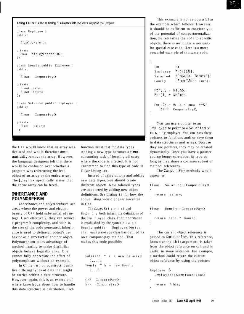
class Employee 1public:
DisplayNameO;
private:char employeeName[301;
1 :
class Hourly:public Employee Ipublic:
. .float ComputePayO:
private:float rate:float hours:
I :
class Salaried:public Employee ipublic:
.float ComputePayO;
private:float salary;
1 :L
Listing 1 l--The C code in Listing IO collapses info this much simplified Ctt program.
would be confusion over whether a
the C++ would know that an array was
program was referencing the leadobject of an array or the entire array.
declared and would therefore auto-
The [ 1 syntax specifically states thatthe entire array can be freed.
matically remove the array. However,the language designers felt that there
uncommon to find this type of code in
function must test for data types.
C (see Listing 10).
Adding a new type becomes a time-consuming task of locating all caseswhere the code is affected. It is not
Instead of using unions and addingnew data types, you should createdifferent objects. New salaried typesare supported by adding new objectdefinitions. See Listing 11 for how theabove listing would appear rewrittenin C++.
INHERITANCE ANDPOLYMORPHISM
Inheritance and polymorphism areareas where the power and elegantbeauty of C++ hold substantial advan-tage. Used effectively, they can reducea program’s complexity, and with it,the size of the code generated. Inherit-ance is used to define an object’s be-havior as a superset of another object.Polymorphism takes advantage ofmethod naming to make dissimilarobjects behave logically alike. Onecannot fully appreciate the effect ofpolymorphism without an example.
In C, the u n i on construct identi-fies differing types of data that mightbe carried within a data structure.However, again, this is an example ofwhere knowledge about how to handlethis data structure is distributed. Each
The classes Sa 1 a r i ed andHO u r 1 y both inherit the definitions ofthe Emp 1 oyee class. That inheritanceis established by the syntax c 1 a s sHourly:public Employee.Noticethat each pay-type class has defined itsown compute-pay method. Thatmakes this code possible:
Salaried * s = new Salaried
( 1;. . .Hourly * h = new Hourly
( 1;. . .
s-> ComputePayO;h-> ComputePayO;
This example is not as powerful asthe example which follows. However,it should be sufficient to convince youof the potential of compartmentaliza-tion. By relegating the code to specificobjects, there is no longer a necessityfor special-case code. Here is a morepowerful example of the same code:
1int k;Employee *Ptr[201;Salaried sEmp("A1 Jones”);Hourly hEmp("John Doe");
Ptr[Ol = &sEmp;PtrCll = &hEmp;
for (k = 0; k < max; ++k)Ptr-> ComputePayO;
i
You can use a pointer to anEmployeetopointtoaSalariedorHo u r 1 y employee. You can pass thesepointers to functions and/or save themin data structures and arrays. Becausethey are pointers, they may be createddynamically. Once you have a pointer,you no longer care about its type aslong as they share a common subset ofmethod references.
The ComputePay methods wouldappear as:
float Salaried::ComputePayO
ireturn salary;
I
float Hourly::ComputePayO
1return rate * hours;
I
The current object reference ispassed to ComputePay. This reference,known as the t h i s argument, is takenfrom the object reference on call and isuseful in some instances. For example,a method could return the currentobject reference by using the pointer:
Employee &Employee::SomeFunctionO
ireturn *this;
i
Circuit Cellar INK Issue #57 April 1995 19
OPERATOR OVERLOADINGOperator overloading permits the
C++ compiler to change the behaviorof most operators to fit the semanticsof the objects on which they operate.For example, we presume that theaddition operator works on integersand real numbers. However, we coulddefine a F r a c t i on s class that wouldbehave as follows:
Fracti ons a(l, 2);Fract ons b(1, 4);Fract ons c ;
c = a + b; II answer: 3/4
I won’t go into greater detail onoperator overloading here. However, Ihave posted samples of operatoroverloading in the BBS files. BecauseC++ permits overloading, it canredirect output as is shown in the nextsection.
tout AND ci nco u t and c i n are standard stream
controls for C++. cou t and c i n behavemuch like pri ntf and scanf do in C.YOU could use it by:
tout << "Hello," << 2 <<"the World! II
It prints “Hello, 2 the World!” onthe stream device, which is typicallythe monitor. co u t is used prevalentlyin C++, although pri ntf and fpri ntffunctions would work as do all of theother C function library functions. Theadvantage is that it is no longernecessary to embed %s and %d in theoutput statement. Someday, p r i n t fwill appear as arcane as punched cards.
c out is defined as an
Listing 12-Operator overload redirects stream input or output.
ostream& operator<<(const char *I;ostream& operator<<(const unsigned char *)ostream& operator<<(const signed char *);ostream& operator<<(char):
ostream& operator<<(short);ostream& operator<<(unsigned short):ostream& operator<<(int);ostream& operator<<(unsigned int):ostream& operator<<(long);ostream& operator<<(unsigned long);ostream& operator<<(float);ostream& operator<<(double);. . .
ostream& ostream::operator<<(double 4) 1static char asciiL321;gcvt(g, 15, ascii);return ascii;
ostream& ostream::operator<<(signed char c) ireturn operator<<((unsigned char) c);
consider the following. Presume thatan object is defined of type Log. Itshould be possible to use overloadingto redirect output to this object:
Log logfile("abc");
logfile << "Hello," << 2 <<"the World!\n"
Although device redirectionalready exists, a Log object can be usedto record a great deal more stateinformation about your program.Finally, consider the same effect witha Ma i 1 object:
Mail mail("username", "1-508.555-1234");
mail << "Hello, Mike:\n\nHereis my answer" << anytext <<"signed: \n"
Having established some of thebasics, we need to move on to a morereal-world example.
A (MORE) REAL-WORLDEXAMPLE
This example is not of a realanswering machine, but is a contrivedexample demonstrating design prin-ciples. Although everyone knows thebasic operation of a telephone answer-ing machine, converting that knowl-edge into C++ can prove to be achallenge for beginners. Like learningto drive a car, it’s different when you
object of class o s t r e am,definedin ostream. h inyour favorite compiler. Tosupport this type of, function-ality, the << operator mustbe overloaded for eachacceptable data type. Theoutput stream code eventu-ally calls some code thatconverts the received datatype to ASCII (Listing 12).
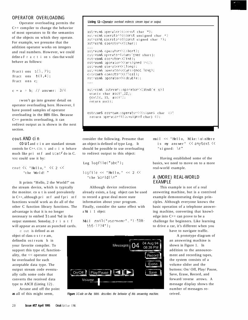
Arcane and off the pointas all of this might seem, Figure I-Code on the BBS describes the behavior of this answering machine.
20 Issue #57 April 1995 Circuit Cellar INK
have to navigate traffic.A prototype diagram of
an answering machine isshown in Figure 1. Inaddition to the announce-ment and recording tapes,the system consists of avolume slider and thebuttons: On/Off, Play/Pause,Save, Erase, Record, andforward/reverse arrows. Amessage display shows thenumber of messages re-ceived.
Listing 13- 1 as t A c t ion is an object reference and can be used to call member functions.
Button * lastAction;. .
lastAction = &record;.
if (playPause.IsButtonDownO) ilastAction->RewindO: // either tapelastAction->PlayO; // either tape
problem. So, we’ll just assume that we
Although this is a hardware-independent solution, it is only
can make a function call to either C or
because no hardware has been devel-
assembler that will execute require-
oped-mind you, the 8051 would
ments such as enable recording.
make an excellent chip to solve thisdesign. I hope this introduction to C++
t i on object reference. Listing I3
helps you understand some basic C++
demonstrates how this is handled.
principles that will eventually moti-
Well-crafted C++ programs giveyou a much better sense of the coding
vate you to learn the language.
style and simplistic beauty of the
The code for the system consistsof one main loop waiting for some-thing to happen such as the phoneringing or the Play/Pause button beingpressed. An object is defined for ageneric Butt. o n. The purpose of thisobject is to perform hardware-depen-dent functions such as reading thecurrent button state.
Button is super classed by twomore refined buttons: Ho 1 d B u t t o nand Toggl eButton. The presumptionis that the physical button has only anup or down state. Toggl eButtontreats the button as if it toggles back tothe up position after its value is read.It does this by ignoring its physicalstate if it hasn’t changed since the lastread.
To read the value on an objectsuch as a button, you could ask for itsvalue. However, it may be smarter andmore removed from the physicalenvironment to ask whether thebutton is up or down:
if (playPause.IsButtonDownO)i . . . I
The product’s behavior demandsrewinding and replaying either thegreeting or recording tapes dependingon which buttons are pressed. This ishandled by maintaining the 1 a s t Ac
Finally, both Borland and Micro-soft have excellent developmentsystems with integrated environmentsthat you can play with. But regardlessof what software package you have,remember there is no better andquicker way to learn than to just startcoding. 0
M i k e Podanof fsky has worked for over
20 years in computers, specializing inpersonal computers and databasesystems. He is currently working atLotus Development on major data-base products. He is author of Dissect-ing DOS, published by Addison-Wesley. He may be reached [email protected].
Software for this article is avail-able from the Circuit Cellar BBSand on Software On Disk for thisissue. Please see the end of“ConnecTime” in this issue fordownloading and orderinginformation.
401 Very Useful402 Moderately Useful403 Not Useful
8051 Family Emulator istruly Low Cost!
The DrylCE Plus is a modular emulatordeslgned to get maximum flexibilityand functtonality for your hard earneddollar. The common base unitsupports numerous 805 1 familyprocessor pods that are low in price.Features include: Execute tobreakpoint, Line-by-Line Assembler,Disassembler, SFR access, Fill, Set andDump Internal or External RAM andCode, Dump Registers, and more.The DrylCE Plus base unit is priced ata meager $299, and most pods runonly an additional $149. Pods areavailable to support the 8031/2.8751/2,8OC154,8OC451,8OC535,8OC537. 8OC550, 8OC552/62,8OC652, 8OC851, 8OC320 a n dmore. Interface through your serialport and a comm program. Call for abrochure or use INTERNET. We’re [email protected] or ftp at ftp.hte.com
Our $149 DrylCE model is whatyou’re looking for. Not an evaluationboard - much more powerful. Samefeatures as the DrylCEPlus, but limitedto just the 803 l/32 processor.
jo, if you’re still doing the U VWaltz (Burn-2-3, Erase-2-3). ordebugging through the limited window3OM emulators give, call us nowfor-ellef! Our customers say our products3re fl the best Performance/Price‘mulators available!
HiTech Equipment Carp
H_ ;;%z_z~Y*,
S ince 1983
- (619) 566-1892 -,T pi
Internet e-mail: [email protected] ftp: ftp.hte.com
#108Circuit Cellar INK Issue #57 April 1995 21
calling for the high precision anddynamic range of floating-pointarithmetic, you could use softwareemulation in place of an external mathcoprocessor.
Software design issues also affectthe performance of the system. Choiceof language, compiler, and memorymodel have a direct impact and mustcertainly be considered. An even moreimportant consideration is how wellthe software is designed. If it doesn’tuse the most efficient algorithms anddata structures, it could prove to beone of those applications that bringseven the fastest computer to its knees.
To counteract the dearth ofrelevant documentation, this articleoffers a detailed look at the perfor-mance tradeoffs of the Intel ‘186microprocessor family. Specifically,we’ll be looking at the Intel ‘186EBand ‘188EB, which are used for all thetiming measurements. While most ofyou likely use a different microproces-sor family, many of the performanceissues cross architectural boundaries.With a little imagination, you canapply these findings to your owndesign circumstances.
Rick Naro
CharacterizingProcessor Performance
b
V
icroprocessorvendors often
provide a great deal of’ documentation for their
products. There are data sheets, usermanuals, application notes.. . . Con-spicuously missing, however, is usefulinformation on optimizing processorand system performance.
Even if you design your embeddedsystem hardware to run flat out andoptimized performance is not aproblem, there are still plenty ofsoftware design issues to consider.And, if you need to minimize the costof a design-who doesn’t in a high-volume embedded application-understanding the relationshipbetween the CPU bandwidth, memory,peripherals, and software developmenttools is key to success.
The choices of cutting perfor-mance to achieve a lower design costare many. You might vary the size ofthe microprocessor external bus pathsto eliminate devices. You could addwait states and use slower memory
BUS BANDWIDTHThe Intel ‘186-family consists of
16-bit microprocessors with 16.bitinternal data paths. However, whenthe first family members were intro-duced, Intel prepared two versions-the 8086 and the 8088.
For those who remember back to198 1 when IBM was designing the firstPC, you may recall that IBM made aconscious choice to use the 8088. Itsuse of an 8-bit external bus reducedhardware costs. Little has changedsince then. You still have a choice of‘186 and ‘188 family members wherethe only difference is the use of 16. or8-bit external data paths.
As in 1981, a system designedaround the ‘188 is less expensive since
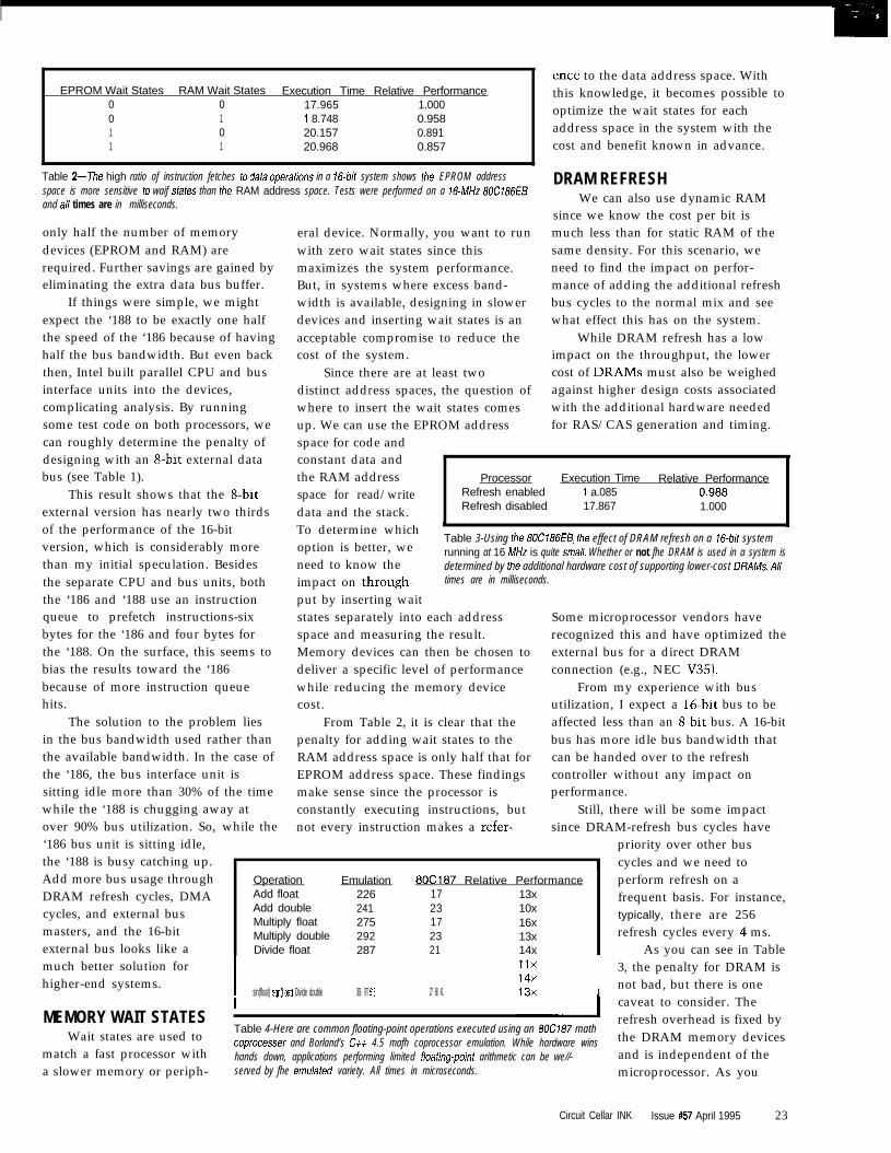
devices which cost lessthan higher-speeddevices. You could runthe system clock at anonstandard frequency,perhaps saving the need Table l--Even though the d-bit bus of the ‘188 is only half as wide as the
for an additional crystal16-bit bus on fhe ‘186, the former achieves better than 60% of the /after’s
oscillator. In applicationsperformance. Both systems are idenfical in a// other aspects. A// times arein milliseconds.
22 Issue #57 April 1995 Circuit Cellar INK
EPROM Wait States RAM Wait States Execution Time Relative Performance0 0 17.965 1.0000 1 i 8.748 0.9581 0 20.157 0.8911 1 20.968 0.857
Table 2--The high ratio of instruction fetches to data operafions in a If?-bif system shows the EPROM addressspace is more sensitive to waif states than the RAM address space. Tests were performed on a If?-MHz 80Cf86EBand a// times are in milliseconds.
only half the number of memorydevices (EPROM and RAM) arerequired. Further savings are gained byeliminating the extra data bus buffer.
If things were simple, we mightexpect the ‘188 to be exactly one halfthe speed of the ‘186 because of havinghalf the bus bandwidth. But even backthen, Intel built parallel CPU and businterface units into the devices,complicating analysis. By runningsome test code on both processors, wecan roughly determine the penalty ofdesigning with an S-bit external databus (see Table 1).
eral device. Normally, you want to runwith zero wait states since thismaximizes the system performance.But, in systems where excess band-width is available, designing in slowerdevices and inserting wait states is anacceptable compromise to reduce thecost of the system.
Since there are at least twodistinct address spaces, the question ofwhere to insert the wait states comesup. We can use the EPROM addressspace for code and
This result shows that the 8bitexternal version has nearly two thirdsof the performance of the 16-bitversion, which is considerably morethan my initial speculation. Besidesthe separate CPU and bus units, boththe ‘186 and ‘188 use an instructionqueue to prefetch instructions-sixbytes for the ‘186 and four bytes forthe ‘188. On the surface, this seems tobias the results toward the ‘186because of more instruction queuehits.
constant data andthe RAM addressspace for read/writedata and the stack.To determine which ’option is better, we
Table 3-Using the 80Ci86E5, the effect of DRAM refresh on a 16-bit system
need to know therunning at 16 MHz is quite small. Whether or not fhe DRAM is used in a system isdetermined by the additional hardware cost of supporting lower-cost DRAMS. A//
impact on through- times are in milliseconds.
put by inserting waitstates separately into each addressspace and measuring the result.Memory devices can then be chosen todeliver a specific level of performancewhile reducing the memory devicecost.
The solution to the problem liesin the bus bandwidth used rather thanthe available bandwidth. In the case ofthe ‘186, the bus interface unit issitting idle more than 30% of the timewhile the ‘188 is chugging away at
while theover 90% bus utilization. So,‘186 bus unit is sitting idle,the ‘188 is busy catching up.Add more bus usage throughDRAM refresh cycles, DMAcycles, and external busmasters, and the 16-bitexternal bus looks like amuch better solution forhigher-end systems.
From Table 2, it is clear that thepenalty for adding wait states to theRAM address space is only half that forEPROM address space. These findingsmake sense since the processor isconstantly executing instructions, butnot every instruction makes a refer-
IOperation Emulation 6OC167 Relative Performance perform refresh on aAdd float 226 17 13xAdd double 241 23 10x
frequent basis. For instance,
Multiply float 275 17 16xtypically, there are 256
Multiply double 292 23 13x refresh cycles every 4 ms.Divide float 287 21 14x As you can see in Table
I sin(float) sqr-t(float) Divide double 306 977 518 27 68 41
MEMORY WAIT STATESWait states are used to
match a fast processor witha slower memory or periph-
ence to the data address space. Withthis knowledge, it becomes possible tooptimize the wait states for eachaddress space in the system with thecost and benefit known in advance.
DRAM REFRESHWe can also use dynamic RAM
since we know the cost per bit ismuch less than for static RAM of thesame density. For this scenario, weneed to find the impact on perfor-mance of adding the additional refreshbus cycles to the normal mix and seewhat effect this has on the system.
While DRAM refresh has a lowimpact on the throughput, the lowercost of DRAMS must also be weighedagainst higher design costs associatedwith the additional hardware neededfor RAS/CAS generation and timing.
Processor Execution Time Relative PerformanceRefresh enabled i a.085 0.988Refresh disabled 17.867 1.000
Some microprocessor vendors haverecognized this and have optimized theexternal bus for a direct DRAMconnection (e.g., NEC V35).
From my experience with busutilization, I expect a 16.bit bus to beaffected less than an 8-bit bus. A 16-bitbus has more idle bus bandwidth thatcan be handed over to the refreshcontroller without any impact onperformance.
Still, there will be some impactsince DRAM-refresh bus cycles have
priority over other bus1 cycles and we need to
I
3, the penalty for DRAM isnot bad, but there is one
I caveat to consider. The
Table 4-Here are common floating-point operations executed using an 80C187 mathrefresh overhead is fixed by
coprocesser and Borland’s Ctt 4.5 mafh coprocessor emulation. While hardware wins the DRAM memory deviceshands down, applications performing limited floafing-point arithmetic can be we//- and is independent of theserved by fhe emulafed variety. All times in microseconds. microprocessor. As you
Circuit Cellar INK Issue #57 April 1995 23

slow the processor down orreduce the available busbandwidth, the samenumber of refresh cyclesmust be performed in thesame refresh interval. So, if
/
YOU cut vour bus band- Table B-These are the most common Id-bit real-mode memow models encountered,width, expect to see the in a real-mode IBM PC or compatible. Tiny and huge memory models are left out as
overhead of DRAM refreshbeing unnecessary for the typical embedded system.
increase.
FLOATING-POINTPERFORMANCE
Although the cost of floating-pointhardware continues to drop, thedecision to add a hardware mathcoprocessor is still an expensiveproposition in any design. The alterna-tive is software emulation of the mathcoprocessor. While this is more costeffective, it requires the availability ofexcess CPU throughput to take overfrom the missing hardware.
On the surface, the high floating-point penalty may appear insurmount-able, but in the real world, an embed-ded controller doesn’t spend anythingclose to 100% of its time on floating-point calculations. To decide if asoftware coprocessor can meet thesystem requirements, we need to
The penalty for havinga large code address space isinsignificant. But, the largedata address space costs 5%of the total bandwidth.
The moral of the storyis to stick to the small ormedium memory models.
outside this article’s scope, let’s lookat what we can control.
The Intel 80x86 microprocessorsare famous (or infamous) for their useof segmented address space. Compil-ers, such as Borland C++, support avariety of memory models dependingon the need to access 64 KB or 1 MB ofthe code and data address spaces. Forthose not familiar with the Intelarchitecture, four memory models arecommon. As you can see from Table 5,there are differences a design canexploit.
Use far pointers selectively whenaccess to more than 64 KB of data isrequired.
UNDERSTANDINGINTERRUPT LATENCY
Recall in the section on memorywait states, we saw that the EPROMaddress space was more sensitive towait states than the RAM addressspace. But, unlike wait states, theoverhead for a 1 -MB code address spaceis only limited to the CALL and RET
Interrupt latency involves thedelay in responding to an event andhas several components-the time tocomplete the current instruction, thetime to save the processor state on thestack, and the time to get to applica-tion code where the interrupt is finallyserviced. The balance of the time spentservicing the interrupt is the interruptservice time.
Although the first two delays areout of our hands, the time it takes toget in and out of the interrupt serviceroutine is ripe for optimization. It isimportant to know just what the
Memory ModelSmall
Medium
interrupt latency of a high-level language is so you can
Execution Time Relative Performance16.807 1.000 decide if an assembly lan-16.905 0.994 guage routine improves
reflect this additionaloverhead.
know the difference inperformance between the twoimplementations using themost common floating-pointoperations.
In addition to thecomparisons between thefloating-point operations inTable 4, it would help toknow how much slack CPU
Compact 17.735 0.948Large 17.869 0.941
Table 5-Comparing the relative performance of the same application in eachmemory mode/ on a S-bit system, the largest performance penalty comes fromthe use of far data pointers. A// times are in milliseconds.
performance.Modern compilers like
Borland C++ and MicrosoftVisual C++ perform a greatdeal of optimization. But bothcompilers always push the
entire processor state on the stack,even if only a fraction is actually used.
is available. A system running nearfull capacity is not a candidate for asoftware emulation. However, some-times spending money on a faster CPUand more memory to increase theavailable throughput to handle thesoftware emulation can be the winningstrategy that results in overall system-cost reduction.
COMPILER MEMORY MODELEnough on hardware! What about
software design decisions that affectapplication performance?
Of course, the biggest contributorsto efficient software are algorithmsand design. Since these issues exist
instructions using the longer segmentand offset formats. However, predict-ing the behavior of the data addressspace is another matter and is ham-pered by complexity.
Local variables allocated inregisters or on the stack are alwaysaccessed without penalty as is moststatically allocated data. The penaltyarises when far pointers are used. Notonly are more pushes and popsrequired to pass parameters, the actualaccessing of the data also takes longerwith the need to load a segmentregister. From Table 6, we can see thatthe results of running the sameapplication in each memory model
On the test ‘186EB system, a C++interrupt handler with a single I/Ocommand takes a total of 15.4 us toexecute. If the same code is rewrittenin assembly language, the time can bereduced to just 7.7 us. It is worthnoting that the assembly languageadvantage is temporary. More complexinterrupt handlers require you to savemore of the processor state, whicheventually equalizes the overhead.
Still, in my opinion, great assem-bly language programmers have anedge over the compiler in writingoptimized code.
2 4 Issue #57 April 1995 Circuit Cellar INK
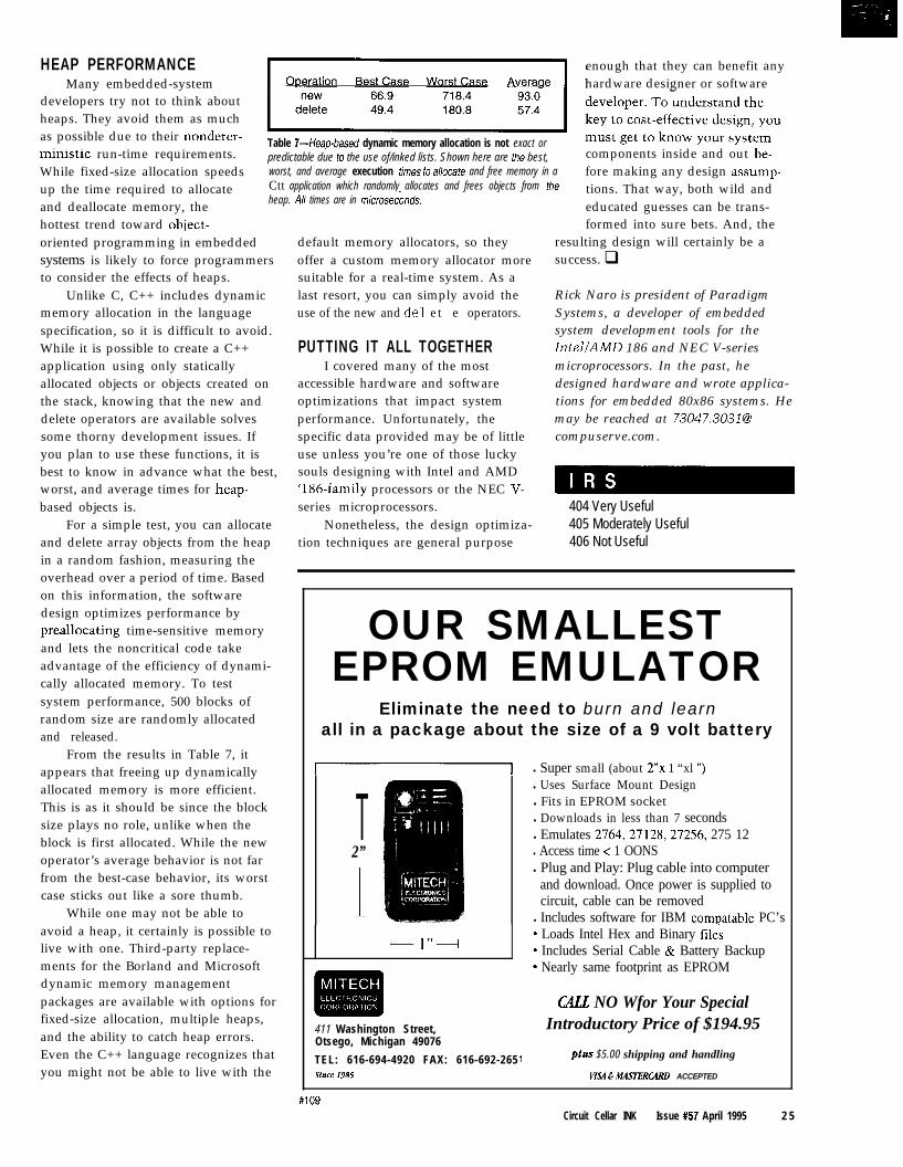
HEAP PERFORMANCEMany embedded-system
developers try not to think aboutheaps. They avoid them as muchas possible due to their nondeter-ministic run-time requirements.While fixed-size allocation speedsup the time required to allocateand deallocate memory, thehottest trend toward object-oriented programming in embeddedsystems is likely to force programmersto consider the effects of heaps.
Unlike C, C++ includes dynamicmemory allocation in the languagespecification, so it is difficult to avoid.While it is possible to create a C++application using only staticallyallocated objects or objects created onthe stack, knowing that the new anddelete operators are available solvessome thorny development issues. Ifyou plan to use these functions, it isbest to know in advance what the best,worst, and average times for heap-based objects is.
For a simple test, you can allocateand delete array objects from the heapin a random fashion, measuring theoverhead over a period of time. Basedon this information, the softwaredesign optimizes performance bypreallocating time-sensitive memoryand lets the noncritical code takeadvantage of the efficiency of dynami-cally allocated memory. To testsystem performance, 500 blocks ofrandom size are randomly allocatedand released.
From the results in Table 7, itappears that freeing up dynamicallyallocated memory is more efficient.This is as it should be since the blocksize plays no role, unlike when theblock is first allocated. While the newoperator’s average behavior is not farfrom the best-case behavior, its worstcase sticks out like a sore thumb.
While one may not be able toavoid a heap, it certainly is possible tolive with one. Third-party replace-ments for the Borland and Microsoftdynamic memory managementpackages are available with options forfixed-size allocation, multiple heaps,and the ability to catch heap errors.Even the C++ language recognizes thatyou might not be able to live with the
enough that they can benefit anyhardware designer or software
Table 7--Heap-based dynamic memory allocation is not exact orpredictable due to the use of/inked lists. Shown here are the best, components inside and out be-worst, and average execution times to allocafe and free memory in aCtt application which randomly allocates and frees objects from the
fore making any design assump-tions. That way, both wild and
heap. All times are in microsecbnds. educated guesses can be trans-formed into sure bets. And, the
resulting design will certainly be asuccess. q
default memory allocators, so theyoffer a custom memory allocator moresuitable for a real-time system. As alast resort, you can simply avoid theuse of the new and de1 et e operators.
PUTTING IT ALL TOGETHERI covered many of the most
accessible hardware and softwareoptimizations that impact systemperformance. Unfortunately, thespecific data provided may be of littleuse unless you’re one of those luckysouls designing with Intel and AMD‘186-family processors or the NEC V-series microprocessors.
Nonetheless, the design optimiza-tion techniques are general purpose
Rick Naro is president of ParadigmSystems, a developer of embeddedsystem development tools for theIntel/AMD 186 and NEC V-seriesmicroprocessors. In the past, hedesigned hardware and wrote applica-tions for embedded 80x86 systems. Hemay be reached at [email protected].
404 Very Useful405 Moderately Useful406 Not Useful
#lUY
OUR SMALLESTEPROM EMULATOR
Eliminate the need to burn and learnall in a package about the size of a 9 volt battery
-1 l Super small (about 2”~ 1 “xl “)
T2”
1
I---- 1”+
411 Washington Street,Otsego, Michigan 49076
TEL: 616-694-4920 FAX: 616-692-265Since ,985
l Uses Surface Mount Designl Fits in EPROM socketl Downloads in less than 7 secondsl Emulates 2764,27 128,27256, 275 12l Access time < 1 OONSl Plug and Play: Plug cable into computer
and download. Once power is supplied tocircuit, cable can be removed
l Includes software for IBM compatable PC’s
1
Loads Intel Hex and Binary filesIncludes Serial Cable & Battery BackupNearly same footprint as EPROM
CALL NO Wfor Your SpecialIntroductory Price of $194.95
phs $5.00 shipping and handling
VISA G ntASTERolRD ACCEPTED
Circuit Cellar INK Issue #57 April 1995 2 5
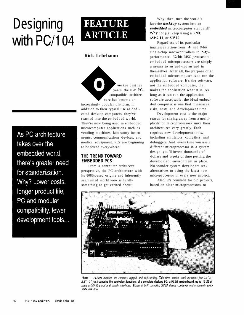
Designingwith PC/l 04
Rick Lehrbaum
ver the past tenyears, the IBM PC-
compatible architec-ture has become an
increasingly popular platform. Inaddition to their typical use as dedi-cated desktop computers, they’vereached into the embedded world.They’re now being used in embeddedmicrocomputer applications such asvending machines, laboratory instru-ments, communications devices, andmedical equipment. PCs are beginningto be found everywhere!
THE TREND TOWARDEMBEDDED PCS
From a computer architect’sperspective, the PC architecture withits 808%based origins and inherentlysegmented world view is hardlysomething to get excited about.
Why, then, turn the world’sfavorite desktop system into anembedded microcomputer standard?Why not just keep using a Z80,68HC11, or 80512
Regardless of its particularimplementation-from 4- and g-bitsingle-chip microcontrollers to high-performance, %-bit RISC processors-embedded microprocessors are simplya means to an end-not an end inthemselves. After all, the purpose of anembedded microcomputer is to run theapplication software. It’s the software,not the embedded computer, thatmakes the application what it is. Aslong as it can run the applicationsoftware acceptably, the ideal embed-ded computer is one that minimizesrisks, costs, and development time.
Development cost is the majorreason for shying away from a multi-plicity of microprocessors since theirarchitectures vary greatly. Eachrequires new development tools,including emulators, compilers, anddebuggers. And, every time you use adifferent microprocessor in a systemdesign, you’ll invest thousands ofdollars and weeks of time putting thedevelopment environment in place.No wonder system developers seekalternatives to using the latest newmicroprocessor in every new project.
Also, it’s common for old projects,based on older microprocessors, to
Photo i-PC/104 modules are compact, rugged, and self-stacking. This three module stack measures just 3.6”~3.8”~ Y, yet it contains fhe equivalent functions of a complete desktop PC: a PC/AT motherboard, up to 16 MB ofsysfem DRAM, seriaial and parallel interfaces, ffhemet LAN controller, SVGA display contro//er, and a bootable solid-stafe disk drive.
26 Issue #57 April 1995 Circuit Cellar INK
0.250 dia. pad0.125 dia. hole
0 . 3 5 0 /,_- (4 plcs.) 3 . 2 5 0 4 0 5 0
~~ /-
0.100 typ. 0.100 typ.‘t ---+I ItI I I I
!. _ .
0.195 ;
0YP.j 1
_:, SecondaryI side
I 0 . 0 2 5 sq.: (tYP )
Jl ;
J2 ;_ _
II 1‘ 0 . 4 3 5 0 . 4 2 0
* NOTE: I/O mating connectors may not Option 1:extend outside these boundarw. Stackthrough bus
OptIon 2,Non-stackthrough bus
become difficult or even impossible tomaintain, as familiarity with the olderarchitectures and their developmenttools fades.
All this has stimulated a desire forhardware and software standards. Onthe software side, this means using C,C++, and object-oriented programmingmethods. Programmers increasinglyrely on familiar software environmentssuch as UNIX, DOS, or Windows, andinterface standards like TCl?/IP, GUIs,and so on.
But what about hardware stan-
With over 200 million desktop PCs inuse worldwide and nearly a millionnew ones sold each week, the PCarchitecture has been dubbed theIndustry Standard Architecture (ISA).
This is why the PC architecture isgaining increasing acceptance as anembedded microcomputer standard.Using an embedded-PC architectureleads to significant savings in develop-ment time and money. PC develop-ment tools are plentiful, cost-effective,and easy to use. PC-compatiblechipsets and peripherals are abundant.
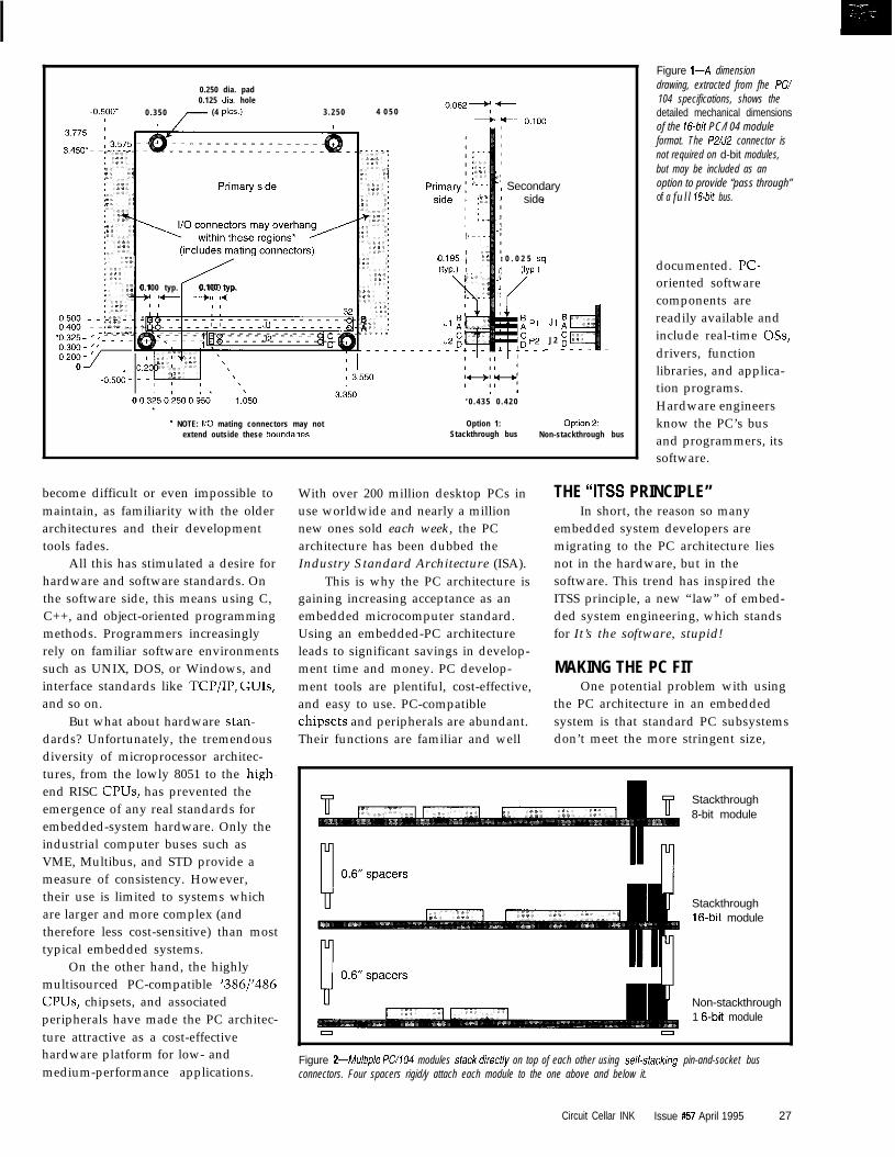
Figure l--A dimensiondrawing, extracted from fhe PC/104 specifications, shows thedetailed mechanical dimensionsof the 16-bit PC/l 04 moduleformat. The PZ/JZ connector isnot required on d-bit modules,but may be included as anoption to provide “pass through”of a full Id-bit bus.
documented. PC-oriented softwarecomponents arereadily available andinclude real-time OSs,drivers, functionlibraries, and applica-tion programs.Hardware engineersknow the PC’s busand programmers, itssoftware.
THE “IT% PRINCIPLE”In short, the reason so many
embedded system developers aremigrating to the PC architecture liesnot in the hardware, but in thesoftware. This trend has inspired theITSS principle, a new “law” of embed-ded system engineering, which standsfor It’s the software, stupid!
MAKING THE PC FITOne potential problem with using
the PC architecture in an embeddedsystem is that standard PC subsystems
dards? Unfortunately, the tremendous Their functions are familiar and well don’t meet the more stringent size,diversity of microprocessor architec-tures, from the lowly 8051 to the high-end RISC CPUs, has prevented theemergence of any real standards for
Stackthrough8-bit module
embedded-system hardware. Only theindustrial computer buses such asVME, Multibus, and STD provide ameasure of consistency. However,their use is limited to systems whichare larger and more complex (and
Stackthrough16-bit module
therefore less cost-sensitive) than mosttypical embedded systems.
On the other hand, the highlymultisourced PC-compatible ‘386/‘486CPUs, chipsets, and associatedperipherals have made the PC architec-ture attractive as a cost-effectivehardware platform for low- andmedium-performance applications.
Non-stackthrough1 g-bit module
0
Figure 2--Multiple PC/104 modules sfack direcf/y on top of each other using self-sfacking pin-and-socket busconnectors. Four spacers rigid/y attach each module to the one above and below it.
Circuit Cellar INK Issue #57 April 1995 27

power, ruggedness, and reliabilityrequirements of most embeddedapplications. This is natural since PCsare optimized for the highly price-sensitive desktop personal-computingmarket.
But, you can avoid this problem bydesigning a custom, chip-level embed-ded PC directly into the embeddedsystem’s hardware. This way you cantake advantage of PC chipsets, compo-nents, and software in an embeddedenvironment.
The trouble with this approach isthat it doesn’t eliminate many of thecosts and risks you want to avoid byusing an off-the-shelf PC architecture.You still end up designing and debug-ging a CPU subsystem, licensing andporting a BIOS, and in many otherways needlessly reinventing thewheel.
Although PC/l 04 modules havebeen around since 1987 (in the form ofAmpro’s MiniModules), it was notuntil Ampro released a formal specifi-cation to the public domain in 1992that interest in PC/104 skyrocketed.Since then, hundreds of PC/l04modules have been announced by themore than 140 members of thenonprofit PC/ 104 Consortium. In1994, PC/l04 achieved a significantmilestone when Intel endorsed it as arecommended way to expand designsbased on Intel’s new embedded ‘386CPUS.
In 1992, a working group of theIEEE embarked on a project to stan-dardize a small form-factor version ofthe PC/AT bus, which was also basedon PC/104. The new IEEE “P996.1”draft standard, which conforms closely
Since standard PCsubsystems aren’t well-suited to the targetedenvironments, the desireto use PC architecture inembedded systems thuscontains an inherentcontradiction. This iswhat inspired thecreation and rapidacceptance of the PC/104 embedded-PCmodules standard (seePhoto 1).
WHAT IS PC/104?PC/104 offers full
hardware and softwarecompatibility with thestandard desktop PC(and PC/AT) architec-ture, but in an ultra-compact (3.6” x 3.8”),self-stacking, modularform. PC/l04 defines astandard way to repack-age desktop PC func-tions for the ruggednessand reliability con-straints of embeddedsystems. Consequently,PC/104 offers anattractive PC-compatiblealternative to traditionalmicroprocessor-basedembedded systems.
to PC/104’s specification, is nowapproaching IEEE approval.
WHAT’S IN THE PC/104STANDARD?
As mentioned above, the keydifferences between PC/104 and thenormal PC hardware standard aremainly mechanical. Instead of theusual PC or PC/AT expansion cardform-factor (12.5” x 4.8”), eachmodule’s size is reduced to approxi-mately 3.6” x 3.8”.
Two bus formats for 8- and 16-bitmodules are provided. However,unlike the 8- and 16-bit versions of thenormal PC bus, 8 and 16-bit PC/104modules are the same size. Figure 1shows the detailed mechanicaldimensions of the 16.bit PC/104module format. An g-bit module has
Pin Jl/PlNumber Row A
Jl/PlRow B
J2/P2Row C’
J2/P2Row D’
0 - - o v o v1 IOCHCHK* o v SBHE* MEMCSl6*2 SD7 RESETDRV LA23 lOCSl6*3 SD6 +5 v LA22 IRQlO4 SD5 IRQ9 LA21 IRQll5 SD4 -5 v LA20 IRQ126 SD3 DRQ2 LA19 IRQ157 SD2 -12 v LA18 IRQ148 SD1 ENDXFR* LA17 DACKO*9 SD0 +12v MEMR’ DRQO10 IOCHRDY (KEY)* MEMW* DACK5*11 AEN SMEMW SD8 DRQ512 SAl9 SMEMR* SD9 DACKG*13 SA18 low* SD10 DRQ614 SA17 IOR* SD1 1 DACK7*15 SA16 DACK3* SD12 DRQ716 SA15 DRQ3 SD13 +5 v17 SA14 DACKl* SD14 MASTER*18 SA13 DRQl SD15 o v19 SA12 REFRESH* (KEY)* o v20 SAl 1 SYSCLK -21 SAlO IRQ7 -22 SA9 IRQ6 - -23 SA8 IRQ5 -24 SA7 IRQ4 -25 SA6 IRQ3 - -26 SA5 DACK2* - -27 SA4 TC - -28 SA3 BALE -29 SA2 +5 v - -30 SAl o s c -31 SAO o v -32 o v o v - -
NOTES:1. Rows C and D are not required on 8-bit modules, but may be included.2. BlO and Cl9 are key locations.
Table l--The PC/104 names comes from the use of 104 bus signals. Each PC/104 bus signalisequivalent to a corresponding signal of the normal PC/AT bus.
no P2/J2 bus connector.To eliminate the
complexity, cost, andbulk of conventionalmotherboards, back-planes, and card cages,PC/104 modulesimplement a self-stacking (also referred toas stackthrough) busconnector. Multiplemodules are stackeddirectly on top of eachother without additionalbussing or mountingcomponents. Four nylonor metal spacers (0.b” inlength] are normallyused to rigidly attachthe PC/104 modules toeach other as shown inFigure 2.
Rugged and reliable64. and 40.positionmale/female headerconnectors replace thestandard PC’s 62. and36-position (Pl and P2)edge-card bus connec-tors. The PC/104 busconnectors feature twopin-and-socket rows on0.1” centers and nor-mally have gold-platedcontacts. Both Samtecand Astron, twoconnector companies,
28 Issue #57 April 1995 Circuit Cellar INK

currently offer alternatesourcing of the approved busconnectors.
PC/IO4 bus signals arefunctionally identical to theircounterparts on the PC/ATbus. Their assignments to the104 positions on the PC/104header-bus are listed in Table1.
To reduce power con-sumption to around l-2 W permodule and minimize chipcount, the bus drive wasreduced from the normal PC’s24 mA to 4 mA. This permits
74HC126 or equivalent
Figure 3-This schematic shows a fypical means of implementing the PC/104bus interrupt-sharing option. While interrupt sharing is not required, if is frequentlyprovided by B-bit PC/104 modules that implemenf communications andnefworking functions.
an option, as well. Ifyou plan to terminate aPC/104 bus, be sure touse the AC method oftermination defined inthe PC/104 specifica-tion rather than pureresistive termination.
Plain resistivetermination, usually2201330 R betweeneach signal and ground,exceeds available buscurrent. On the other
7 1 kc2
Remove jumper Install jumper +for normal P996 on one device
bus operation per IRQ
HCT logic and many VLSI ICs todirectly drive the bus without addi-tional buffer chips.
Many developers wonder howmany modules can be used on a singlePC/104 bus. The answer is not simplyrelated to K/104’s reduced bus drivecurrent. Actually, the low 4-mA drivedoes not result in a small number ofpermissible bus modules. For mostembedded systems, there is plenty ofbus drive. In fact, since the maximuminput load spec is 0.4 mA per bussignal, a 4-mA bus drive current cantheoretically handle ten bus loads!
In practice, factors such as signaltrace lengths and connector impedancetransitions limit the number ofmodules you can reliably use tobetween six and eight. The actuallimit, for a particular system, dependson total bus length, number of stackedconnectors, environmental issues, andthe specific modules used. Also don’tforget to consider voltage drops on thebus power signals due to multiplestacked modules.
Bus termination is
3 0 Issue #57 April 1995 Circuit Cellar INK
hand, the recommended AC termina-tion consists of a series R/C networkbetween each signal and ground. Thisapproach draws no static current andprovides a better impedance match forthe bus.
If you’re not sure whether or nottermination is needed in your system,it’s best to provide a way to add itlater. A number of PC/104 vendorsoffer special plug-in PC/104 termina-tors, which provide the method of ACtermination recommended by thePC/104 spec. These terminators can beadded at any PC/104 bus stackinglocation. You can also include posi-tions for tiny SIP termination net-works directly on PC/ 104 modules orinterfacing boards you design.
When you use the PC architecturein embedded applications, it’s notuncommon to run out of bus interruptchannels. This is especially true ofbyte-oriented (Shit) interfaces such asserial ports because the 8-bit subset ofthe PC bus contains six interrupt lines,
standardized system func-tions. Unfortunately, sincethe bus interrupt lines areactive high, the commontechnique of wire-ORingmultiple interrupt requestson a single-interrupt inputline (used with other buses) isnot possible.
To circumvent thisproblem, the PC/IO~ specincludes a recommendedmeans for multiple interrupt-ing sources (on one or moremodules) to share a single businterrupt. A sample interrupt-
sharing circuit appears in Figure 3.
PC/104 IN REAL APPLICATIONSAlthough configuration and
application possibilities for PC/104modules are practically limitless, thereare a few ways the modules tend to beused in actual embedded systems.
l Stand-alone module stacksAs illustrated in Figure 4, stacks of
PC/l 04 modules can be used likeultracompact bus boards, but withoutthe usual requirement for backplanesor card cages. Often, a PC/104 modulestack is bolted somewhere inside theembedded system’s enclosure in aconvenient location that wouldotherwise simply be dead space. In thismanner, an entire PC can be embeddeddirectly within a system that wouldotherwise require an external PC.
There are also a variety of off-the-shelf PC/ 104 stack enclosures thathost from three to six PC/104 mod-ules. Enclosed PC/104 stacks like
L
most of which are dedicated to these can be self-contained systems orcan be used as sub-systems within largersystems. These PC/104system enclosures aredesigned for a varietyof environments(commercial, indus-trial, and vehicular)and are available withoptions like PC/104form-factor powersupplies (for 8-80-VAC/DC inputs), shockmounts, and quick-release mechanisms.
Figure 4-PC/104 modules can be usedas stand-alone sfacks with all required system functionsprovided by PC/l04 modules stacked together. In fhis approach, the modules function like aminiaturized backplane bus.
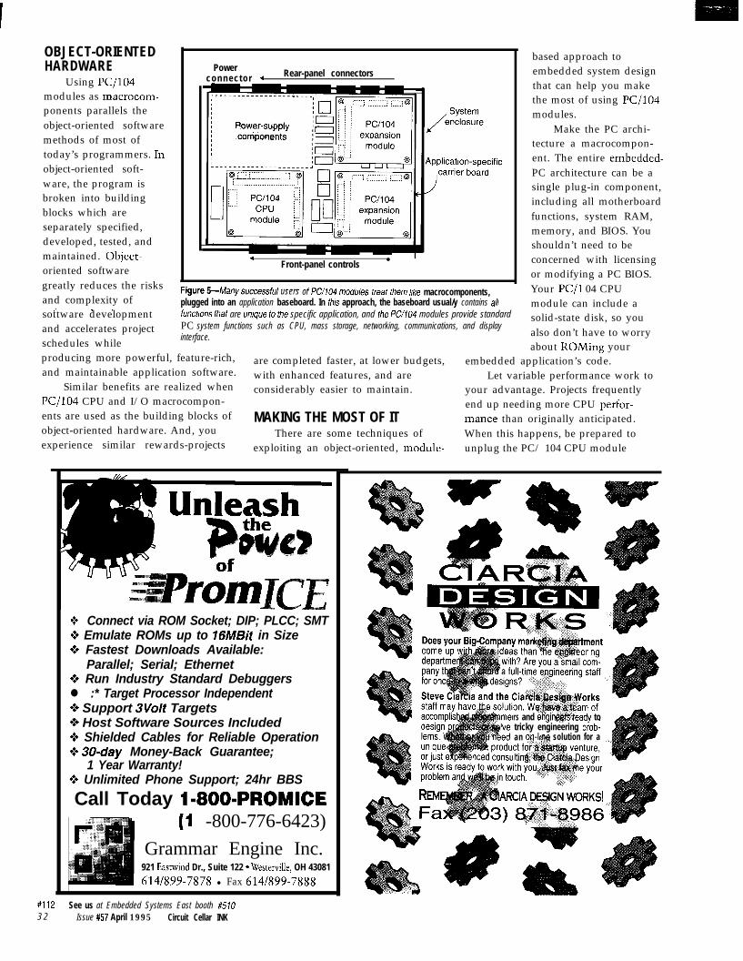
l Macrocomponent applicationsIn Figure 5, another common
method of using PC/104 is shown.Here it is used as macrocomponentsthat plug into a custom, application-specific baseboard. The PC/104baseboard typically contains allinterfaces and logic that aren’t avail-able (or desirable) on the PC/104modules. Typically, the baseboardincludes power supply components,signal conditioning, external I/Oconnectors, and so on.
What’s interesting about themacrocomponent approach is insteadof plugging the I/O into the computer,you plug the computer into the I/O!It’s a new embedded-system paradigm.This approach lets you focus moreenergy on the application’s uniquerequirements, and less on (re)inventinga basic (micro) computer architecture.With this approach, the systembecomes a hybrid of out-sourcedmodules (the PC/104 modules) plus acustom-designed board (the baseboard).
Often, the baseboard providesmultiple PC/104 stack locations. Thismeans that the modules can bedistributed horizontally, therebykeeping a low profile so there’s roomfor upgrades and expansion in thefuture. Whenever possible, leave extravertical space (at least 0.6”) so thePC/IO~ module’s self-stacking bus canbe used for future upgrades andoptions. This space also provides roomfor temporary addition of modules forsystem debug, test, and service.
The shape and size of the base-board is completely arbitrary. Thebaseboard typically takes the shape ofthe desired end system, so its shapecan be anything-square, round,rectangular, customized.
l Mezzanine bus applicationsA third and increasingly common
way for PC/IO~ modules to be used isas I/O expansion daughter modules onPC-compatible single-board computers(SBCs). This approach, known as a PC/104 mezzanine bus, is now found onnearly every new PC-compatible SBC,including both stand-alone (proprietaryform-factor) SBCs and passive back-plane (PC-expansion-card form-factor)industrial PCs.
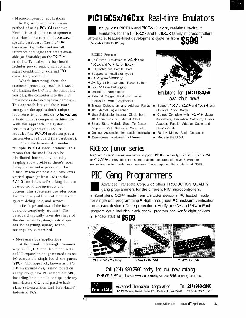
PIG1 6C5xll6Cxx Real-time Emulatorsintroducing RICE16 and RICExx-Juniors, real-time in-circuitemulators for the PIC16C5x and PIClGCxx family microcontrollers:
affordable, feature-filled development systems from’ Suqgeeted Retail for U.S. only $599 *
RICE16 Features:Real-time Emulation to 2OMHz for16C5x and 1OMHz for 16&x
PC-Hosted via Parallel PortSupport all oscillator type5
0K Program Memory8K by 24-bit real-time Trace Buffer
Source Level Debugging
Unlimited Breakpoints Emulators for 16C71184/64External Trigger Break with either
“AND/OR” with BreakpointsTrigger Outputs on any Address Range12 External Logic Probes
User-Selectable Internal Clock from40 frequencies or External ClockSingle Step, Multiple Step, To Cursor,
Step over Call, Return to Caller, etc.On-line Assembler for patch instruction
Easy-to-use windowed &ware
available now!n Support 16C71,16CE54 and 16C64 with
Optional Probe Cardsn Comes Complete with TASMIG Macro
Assembler, Emulation Software, PowerAdapter, Parallel Adapter Cable and
User’s Guidem 30-day Money Back Guarantee
n Made in the U.S.A.
RICE-xx Junior seriesRICE-xx “Junior” series emulators support; PIC16C5x family, PlC16C71, PlC16C04
or PIC16C64. They offer the same real-time features of RICE16 with therespective probe cards less real-time trace capture. Price starts at $599.
PIC Gang ProgrammersAdvanced Transdata Corp. aI50 offers PRODUCTION QUALITYgang programmers for the different PIC microcontrollers.
n Sand-alone COPY mode from a master device n PC-hosted modefor single unit programming m High throughput w Checksum verificationon master device w Code protection m Verify at 4.5V and 5.5V w Eachprogram cycle includes blank check, program and verify eight devicesn Price5 start at $599
PGMlGG: for 1X5x family PGM47: for 16Ci’1/04 PGM17G: for 17C42
Call (214) 980-2960 today for our new catalog.ForRICEl6.ZlP and other product demos, call our BBS at (214) 980-0067.
Advanced Transdata Corporation Tel (214) 980.298014330 Midway Road. Suite 128. Dallas, Texas 75244 Fax (214) 900-2937
#illCircuit Cellar INK Issue #57 April 1995 31
OBJECT-ORIENTEDHARDWARE
Using PC/104modules as macrocom-ponents parallels theobject-oriented softwaremethods of most oftoday’s programmers. Inobject-oriented soft-ware, the program isbroken into buildingblocks which areseparately specified,developed, tested, andmaintained. Object-oriented softwaregreatly reduces the risksand complexity of
r 1 .
Powerconnector 4 Rear-panel connectors
4Front-panel controls
l
users or rww4 moaules freaf fnem /Ike macrocomponents,plugged into an application baseboard. In fhis approach, the baseboard usual/y contains a//,sottware development
and accelerates projectschedules while
functions that are unique fo the specific application, and the PC/104 modules provide standardPC system functions such as CPU, mass storage, networking, communications, and displayinterface.
based approach toembedded system designthat can help you makethe most of using ~/lo4modules.
Make the PC archi-tecture a macrocompon-ent. The entire embedded-PC architecture can be asingle plug-in component,including all motherboardfunctions, system RAM,memory, and BIOS. Youshouldn’t need to beconcerned with licensingor modifying a PC BIOS.Your PC/l 04 CPUmodule can include asolid-state disk, so youalso don’t have to worryabout ROMing your
producing more powerful, feature-rich,and maintainable application software.
are completed faster, at lower budgets, embedded application’s code.
Similar benefits are realized whenwith enhanced features, and are Let variable performance work to
PC/104 CPU and I/O macrocompon-considerably easier to maintain. your advantage. Projects frequently
ents are used as the building blocks of MAKING THE MOST OF ITend up needing more CPU perfor-
object-oriented hardware. And, youmance than originally anticipated.
experience similar rewards-projectsThere are some techniques of When this happens, be prepared to
exploiting an object-oriented, module- unplug the PC/ 104 CPU module
+ Connect via ROM Socket; DIP; PLCC; SMT9 Emulate ROMs up to 16MBit in Size0% Fastest Downloads Available:
Parallel; Serial; Ethernet0% Run Industry Standard Debuggersl :* Target Processor Independent0 Support 3Volt Targets+ Host Software Sources Included0 Shielded Cables for Reliable Operation0 30-day Money-Back Guarantee;
1 Year Warranty!Q Unlimited Phone Support; 24hr BBS
Call Today I-8001PROMICE(I -800-776-6423)
Grammar Engine Inc.921 Eastwind Dr., Suite 122 * Westerville, OH 43081
614/899-7878 l Fax 614/899-7888
rs and eriginf$eiWeady totricky engineering prob-an on-h solution for a
#112 See us at Embedded Systems East booth #5103 2 Issue #57 April 1995 Circuit Cellar INK
you’re using and replace it with a broad range of CPU types and perfor-faster one. Can you imagine doing this mantes.with an 8051, 68HCl1, or a discrete Allow for performance and feature80386SX? options and upgrades. No doubt,
Also, keep in mind the option of you’ve been in the position of havingkick-starting a project by initially to provide both high performance andusing a faster PC/104 CPU module low cost within one design. Now, youthan required to get the application up can provide both by offering multipleand running quickly. Later, you can price and performance options. In acost reduce by optimizing the software PC/I04-based system, a single baseand substituting a slower (and less design supports multiple feature orexpensive) CPU module. cost configurations. You can offer ‘486
To anticipate these possibilities, performance at the high end and 8088select PC/104 CPU modules that are economy at the low end. You canmembers of a CPU family offering a provide a wide variety of communica-
by Jean J. Labrosse -Embedded Systems Building Blocks, Complete andReady-to-Use Modules in C contains software modulesyou can use to design embedded systems and explainshow to use these modules and modify them as needed.Labrosse orovides hiahlv oortable. fullv functionina codefor many common p&esses: keyboard scanning,display interfaces, timers and clocks, discrete I/O,analog I/O, and serial communications. Labrosseprovides basic building blocks for all these processesfreeing you to work on the fun and unique parts of yourdesigns.R&D Publications, 1995, 620 pp. ISBN O-13-359779-2V74 with disk. . . . .$49.95
PC/OS by Jean J. LabrosseThis book explains the design and implementation of theMicro-Controller Operating System, a portable,ROMable, preemptive, real-time, multitasking kernel formicroprocessors. The system is written in C withassembly language code for the target microprocessorkept to a minimum. It can be ported to anymicroprocessor that provides a stack pointer and allowsthe CPU registers to be pushed onto and popped fromthe stack. The system can manage up to 63 tasks, withperformance comparable to many commerciallyavailable kernels. The text explains the fundamentals ofmultitasking real-time systems, details the designdecisions of this kernel, and includes a user’s manual forthe system.R&D Publications, 1992, 266 pp. ISBN 0-13-031352-lW62 with disk. . . . . $54.90
tions options based on PC/104 serial,modem, Ethernet, or even wirelessLAN plug-in modules.
Take advantage of sophisticatedPC functions. In contrast to traditionalmicrocontroller-based designs, yourPC/104-based system design can drawon a rich set of PC technologies. Yourdesigns need not be limited by whatyou can do yourself!
Here are some readily availableoptions:
l user-friendly graphical user inter-faces (GUIs) instead of character orLED displays
l popular mass storage devices (floppy,IDE hard disks, SCSI drives, orPCMCIA cards with flash-file-system support software ) instead ofROM or battery-backed RAM
l full-function LANs (Ethernet,Arcnet, Token Ring) instead ofslower RS-232 or RS-485 multidropinterfaces
l various SCSI or PCMCIA devicesl a wide range of off-the-shelf, applica-
tion-oriented PC/104 modules(digital and analog I/O, motioncontrol, etc.) complete with ready-to-use PC-compatible softwaredrivers
Maximize system life expectancy.A system based on PC/104 moduleshas a longer life span than that of atraditional monolithic embeddedsystem. Some of this longevity stemsfrom the fact that when a monolithicsystem design no longer meets therequirements of its users, you may befaced with a redesign.
On the other hand, with a module-based system, it is often possible toupgrade the system to a higherperformance CPU, faster or alternativeperipheral interfaces, and enhancedsoftware. Thus, a PC/104-basedsystem design might survive two orthree times longer than a monolithicone.
If you must replicate or service aparticular design over several years,the risk of component obsolescencebecomes an important issue. Mono-lithic designs are in trouble when oneof the chips used in the system is nolonger offered by its manufacturer.
Circuit Cellar INK Issue #57 April 1995 33
Beware! This problem is especiallynasty when the system contains PC-compatible chipsets due to theextremely rapid evolution of desktopPC technology! The half-life of a PCchipset is about 3 Comdexes, where 1Comdex = 6 months.
In a modular, PC/IO4-basedsystem, you are buffered from havingto struggle with individual IC obsoles-cence problems. When a particular ICon a PC/104 module is unavailable,your module supplier should provideyou with an equivalent substitutemodule. If not, you always have theoption of locating an alternate modulesomewhere else that performs asimilar function. Hopefully, anobsolete IC will never force you to aboard-level redesign.
KEEP YOUR OPTIONS OPEN!If you want to take full advantage
of the flexibility that a PC/104-basedsystem design can offer for futureoptions, upgrades, and substitutions,you must treat each PC/I04 module asa generic function block.
Why?This modularity ensures that you
can substitute equivalent modules forthe ones you must replace (restassured, you will need to replace someeventually!). However, there are somespecific guidelines for increasingmodularity.
Avoid using the chip-specificfeatures of PC chipsets. Unless aparticular function in a PC chipset ispart of the PC standard (or at least partof a well-defined and multiple-sourcedsuperset), fight the temptation to useit! By building your application on
generic functionality, the system youdesign is protected from componentobsolescence through module-levelsubstitution. Only a system based ongeneric PC/104 function blocks readilyoffers alternate sourcing of modules,high- and low-performance substitu-tions, and future backwards-compat-ible migration paths.
Wrap software drivers aroundnonstandard functions. Despite thedesire to keep things generic, there aretimes when you need to use functionsthat aren’t part of the normal PCstandard. In these situations, it’simportant to keep a software layerbetween the application program andthe nonstandard hardware.
With this object-oriented hard-ware and software approach, you havethe flexibility of being able to alterhardware without rewriting the mainapplication code. This is true as longas .the hardware differences areadequately masked by an interveningsoftware layer.
For this reason, try to select PC/104 modules that come with BIOS orsoftware drivers for all nonstandardhardware functions. This assures yourability to maintain a common functionset despite future hardware changesthat may be required or desired.
CONCLUSIONPC/104 embedded-PC modules
offer highly efficient building blocksfor designing embedded systems usingthe popular and user-friendly IBM-PCarchitecture. With more than 140vendors offering off-the-shelf PC/104modules and additional hardware andsoftware vendors announcing PC/104
ABOUT THE PC/104 CONSORTIUMFebruary 1991, the nonprofit PC/104 Consortium was formed with the
objective of maintaining and distributing the PC/104 Specification andpublishing listings of PC/104 products and vendors. Its membership nownumbers over I35 companies, all of which offer PC/IO4 modules andrelated goods and services.
There are no licenses or fees required to use PC/104. Users andmanufacturers of PC/104 modules do not need to be members of the PC/104 Consortium. However, Consortium members gain the use of the PC/104 logo and are included in the PC/104 Resource Guide as well as othercompany and product listings.
For further information on PC/104, see the contact information above.
4 Issue #57 April 1995 Circuit Cellar INK
products nearly every week, we canexpect to see PC/104 in an increasingnumber of embedded systems for atleast another decade.
Consider using PC/IO4 modules tocreate a flexible object-orientedhardware architecture for your nextembedded system project, as analternative to the traditional embeddedmicrocontroller approach in which youcompletely “reinvent the wheel” foreach project! q
Rick Lehrbaum cofounded AmproComputers where he served as vicepresident of engineering from 1983-1991. Now, in addition to his duties asAmpro’s vice president of strategicprograms, Rick chairs the PC/104Consortium and the IEEEP996.1working group, which is developing anIEEE version of K/104. He may bereached at rickl@ampro. corn.
PC/l 04 Specification, PC/l 04Resource Guide, and PC/l 04Product IndexPC/104 ConsortiumP.O. Box 4303Mountain View, CA 94040(415) 9038304Fax: (415) 967-0995Fax on demand: (408) 720-0515
IEEEP996 Draft SpecificationIEEE Publications(908) 981-1393
Using the PC Architecture inEmbedded ApplicationsAmpro Computers, Inc.990 Almanor Ave.Sunnyvale, CA 94086(408) 522-2100Fax: (408) 720-1305
The XT/AT HandbookAnnabooks(619) 673-0870Fax: (619) 693-1432
.
407 Very Useful408 Moderately Useful409 Not Useful
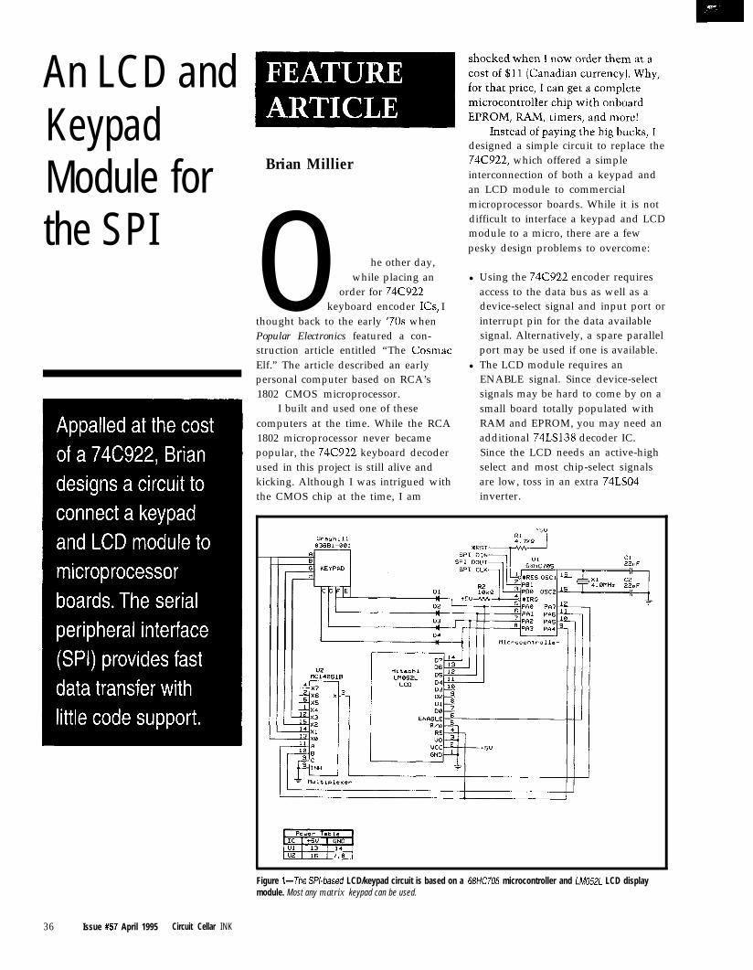
An LCD andKeypadModule forthe SPI
Brian Millier
0 he other day,while placing an
order for 74C922keyboard encoder ICs, I
thought back to the early ’70s whenPopular Electronics featured a con-struction article entitled “The CosmacElf.” The article described an earlypersonal computer based on RCA’s1802 CMOS microprocessor.
I built and used one of thesecomputers at the time. While the RCA
designed a simple circuit to replace the74C922, which offered a simpleinterconnection of both a keypad andan LCD module to commercialmicroprocessor boards. While it is notdifficult to interface a keypad and LCDmodule to a micro, there are a fewpesky design problems to overcome:
l Using the 74C922 encoder requiresaccess to the data bus as well as adevice-select signal and input port orinterrupt pin for the data availablesignal. Alternatively, a spare parallelport may be used if one is available.
l The LCD module requires anENABLE signal. Since device-selectsignals may be hard to come by on asmall board totally populated withRAM and EPROM, you may need an
1802 microprocessor never became additional 74LSl38 decoder IC.popular, the 74C922 keyboard decoder Since the LCD needs an active-highused in this project is still alive and select and most chip-select signalskicking. Although I was intrigued with are low, toss in an extra 74LSO4the CMOS chip at the time, I am inverter.
Figure l--The PI-based LCD/keypad circuit is based on a 68HC705 microcontroller and LM052L LCD displaymodule. Most any matrix keypad can be used.
36 Issue #57 April 1995 Circuit Cellar INK
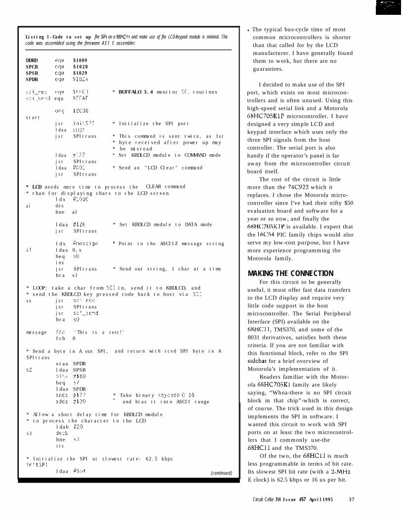
Listing l-Code to set up fhe SW on a 68HC11 and make use of fhe LCD/keypad module is minimal. Thiscode was assembled using the freeware AS1 1 assembler.
DDRD equ $1009SPCR equ $1028SPSR equ $1029SPDR equ $lOZA
sci_rec equ $FFCD * BUFFALO 3.4 monitor SC1 routinessci_send equ $FFAF
ergstart
jsrldaajsr
ldaa 11127 * Set KBDLCD module to COMMAND modejsr SPItransldaa i/o01 * Send an "LCD Clear" commandjsr SPItrans
$2000
initSP1 * Initialize the SPI port11127SPItrans * This command is sent twice, as 1st
* byte received after power up may* be misread
* LCD needs more time to process the CLEAR command* than for displaying chars to the LCD screen
ldx i/l000al dex
bne al
ldaa #126 * Set KBDLCD module to DATA modejsr SPItrans
Sl
ldx #message * Point to the ASCIIZ message stringldaa 0,xbeq SOinxjsr SPItrans * Send out string, 1 char at a timebra sl
* LOOP: take a char from SC1 in, send it to KBDLCD, and* send the KBDLCD key pressed code back to host via SC1so jsr sci_ret
jsr SPItransjsr sci_sendbra SO
message fee 'This is a test!'fcb 0
* Send a byte in A out SPI, and return with rcvd SPI byte in ASPItrans
staa SPDRs2 ldaa SPSR
bita #$80beq s2ldaa SPDRanda #$7f * Take binary keycode O-16adda #$30 * and bias it into ASCII range
* Allow a short delay time for KBDLCD module* to process the character to the LCD
ldab 1120s3 decb
bne s3rts
* Initialize the SPI at slowest rate: 62.5 kbpsinitSP1
ldaa #$5f (continued)
l The typical bus-cycle time of mostcommon microcontrollers is shorterthan that called for by the LCDmanufacturer. I have generally foundthem to work, but there are noguarantees.
I decided to make use of the SPIport, which exists on most microcon-trollers and is often unused. Using thishigh-speed serial link and a Motorola68HC705KlP microcontroller, I havedesigned a very simple LCD andkeypad interface which uses only thethree SPI signals from the hostcontroller. The serial port is alsohandy if the operator’s panel is faraway from the microcontroller circuitboard itself.
The cost of the circuit is littlemore than the 74C922 which itreplaces. I chose the Motorola micro-controller since I’ve had their nifty $50evaluation board and software for ayear or so now, and finally the68HC705KlP is available. I expect thatthe 16C54 PIC family chips would alsoserve my low-cost purpose, but I havemore experience programming theMotorola family.
MAKING THE CONNECTIONFor this circuit to be generally
useful, it must offer fast data transfersto the LCD display and require verylittle code support in the hostmicrocontroller. The Serial PeripheralInterface (SPI) available on the68HCl1, TMS370, and some of the8031 derivatives, satisfies both thesecriteria. If you are not familiar withthis functional block, refer to the SPIsidebar for a brief overview ofMotorola’s implementation of it.
Readers familiar with the Motor-ola 68HC705Kl family are likelysaying, “Whoa-there is no SPI circuitblock in that chip”-which is correct,of course. The trick used in this designimplements the SPI in software. Iwanted this circuit to work with SPIports on at least the two microcontrol-lers that I commonly use-the68HCll and the TMS370.
Of the two, the 68HCll is muchless programmable in terms of bit rate.Its slowest SPI bit rate (with a ~-MHZE clock) is 62.5 kbps or 16 us per bit.
Circuit Cellar INK Issue #57 April1995 37
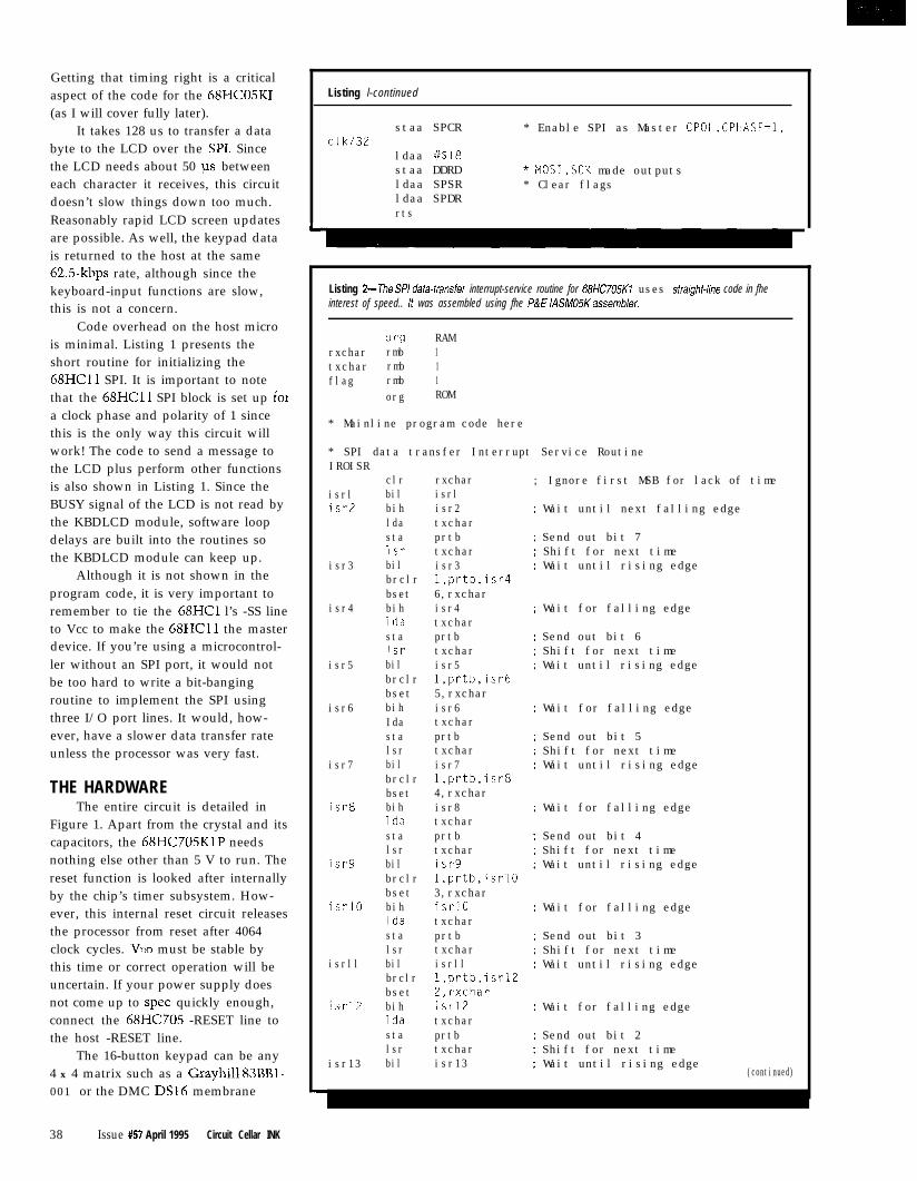
Getting that timing right is a criticalaspect of the code for the 68HC05KI(as I will cover fully later).
It takes 128 us to transfer a databyte to the LCD over the SIX Sincethe LCD needs about 50 us betweeneach character it receives, this circuitdoesn’t slow things down too much.Reasonably rapid LCD screen updatesare possible. As well, the keypad datais returned to the host at the same625kbps rate, although since thekeyboard-input functions are slow,this is not a concern.
Code overhead on the host microis minimal. Listing 1 presents theshort routine for initializing the68HCll SPI. It is important to notethat the 68HCll SPI block is set up foia clock phase and polarity of 1 sincethis is the only way this circuit willwork! The code to send a message tothe LCD plus perform other functionsis also shown in Listing 1. Since theBUSY signal of the LCD is not read bythe KBDLCD module, software loopdelays are built into the routines sothe KBDLCD module can keep up.
Although it is not shown in theprogram code, it is very important toremember to tie the 68HCl l’s -SS lineto Vcc to make the 68HCll the masterdevice. If you’re using a microcontrol-ler without an SPI port, it would notbe too hard to write a bit-bangingroutine to implement the SPI usingthree I/O port lines. It would, how-ever, have a slower data transfer rateunless the processor was very fast.
THE HARDWAREThe entire circuit is detailed in
Figure 1. Apart from the crystal and itscapacitors, the 68HC705KlP needsnothing else other than 5 V to run. Thereset function is looked after internallyby the chip’s timer subsystem. How-ever, this internal reset circuit releasesthe processor from reset after 4064clock cycles. VDO must be stable bythis time or correct operation will beuncertain. If your power supply doesnot come up to spec quickly enough,connect the 68HC705 -RESET line tothe host -RESET line.
The 16-button keypad can be any4 x 4 matrix such as a Grayhill 83BBl-001 or the DMC DSl6 membrane
38 Issue #57 April 1995 Circuit Cellar INK
Listing l-continued
staa SPCR * Enable SPI as Master CPOL,CPHASE=l,elk/32
ldaa i/$18staa DDRD * MOSI,SCK made outputsldaa SPSR * Clear flagsldaa SPDRrts
Listing P-The SF’/ dafa-fransfer interrupt-service routine for 68HC705K1 uses sfraight-line code in fheinterest of speed.. It was assembled using fhe f&E IASM05Kassembler.
erg RAMrxchar rmb 1txchar rmb 1flag rmb 1
org ROM
* Mainline program code here
* SPI data transfer Interrupt Service RoutineIROISR
isrlisr2
isr3
isr4
isr5
isr6
isr7
isr8
isr9
isrl0
isrll
isrl2
isr13
clr rxcharbil isrlbih isr2lda txcharsta prtblsr txcharbil isr3brclr l,prtb,isr4bset 6,rxcharbih isr4Ida txcharsta prtblsr txcharbil isr5brclr l,prtb,isr6bset 5,rxcharbih isr6Ida txcharsta prtblsr txcharbil isr7brclr l,prtb,isr8bset 4,rxcharbih isr8Ida txcharsta prtblsr txcharbil isr9brclr l.prtb,isrlObset 3,rxcharbih isrl0Ida txcharsta prtblsr txcharbil isrllbrclr l,prtb,isrlZbset P,rxcharbih isrl2Ida txcharsta prtblsr txcharbil isr13
; Ignore first MSB for lack of time
; Wait until next falling edge
; Send out bit 7: Shift for next time: Wait until rising edge
: Wait for falling edge
: Send out bit 6: Shift for next time; Wait until rising edge
; Wait for falling edge
; Send out bit 5; Shift for next time: Wait until rising edge
; Wait for falling edge
; Send out bit 4; Shift for next time: Wait until rising edge
; Wait for falling edge
; Send out bit 3; Shift for next time; Wait until rising edge
; Wait for falling edge
: Send out bit 2; Shift for next time; Wait until rising edge
(continued)
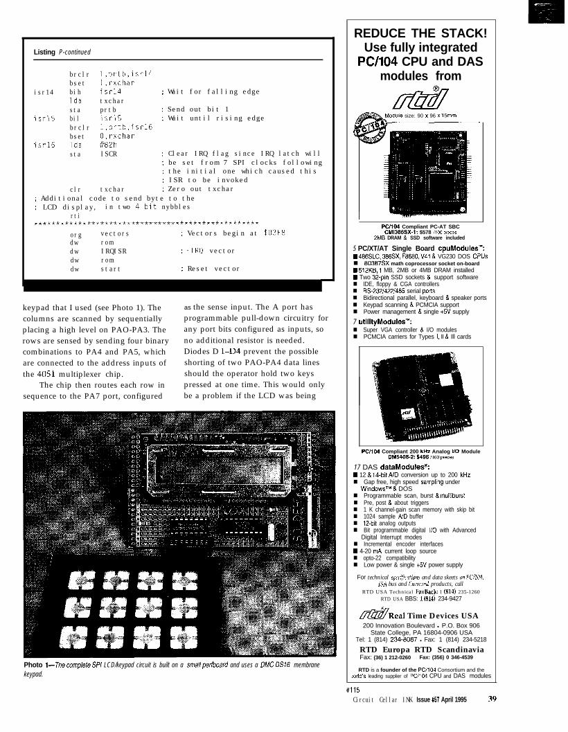
Listing P-continued
isr14
isrl5
isrl6
brclrbsetbihIdastabilbrclrbsetIdasta
clr txchar
l,prtb,isrl41,rxcharisrl4 ; Wait for falling edgetxcharprtb ; Send out bit 1isrl5 : Wait until rising edgel,prtb,isrl60,rxchar1/82hISCR : Clear IRQ flag since IRQ latch will
; be set from 7 SPI clocks following; the initial one which caused this: ISR to be invoked; Zero out txchar
: Additional code to send byte to the; LCD display, in two 4-bit nybbles
rti***************************************************
org vectors ; Vectors begin at $03F8dw romdw IRQISR ; -1RQ vectordw romdw start ; Reset vector
keypad that I used (see Photo 1). Thecolumns are scanned by sequentiallyplacing a high level on PAO-PA3. Therows are sensed by sending four binarycombinations to PA4 and PA5, whichare connected to the address inputs ofthe 4051 multiplexer chip.
The chip then routes each row insequence to the PA7 port, configured
as the sense input. The A port hasprogrammable pull-down circuitry forany port bits configured as inputs, sono additional resistor is needed.Diodes D l-D4 prevent the possibleshorting of two PAO-PA4 data linesshould the operator hold two keyspressed at one time. This would onlybe a problem if the LCD was being
Photo l--The cornplefe SPI LCD/keypad circuit is built on a smallperfboard and uses a CJMC DS16 membranekeypad.
REDUCE THE STACK!Use fully integrated
PC/104 CPU and DASmodules from
odule size: 90 x 96 x 15mm
PC/104 Compliant PC-AT SBCCMi386SX-1: $578 iv.?0 pieces
2MB DRAM & SSD software included
5 PC/XT/AT Single Board cpuklodules’“:W 486SLC, 386SX, F8680, V41& VG230 DOS C?Usn 80387SX math coprocessor socket on-boardN 512K6, 1 MB, 2MB or 4MB DRAM installedW Two 32-pin SSD sockets & support softwaren IDE, floppy & CGA controllersn Rs-23214221485 serial portsn Bidirectional parallel, keyboard & speaker portsn Keypad scanning & PCMCIA supportn Power management & single +5V supply
7 utilityModules’“:n Super VGA controller & I/O modulesn PCMCIA carriers for Types I, II & Ill cards
PC/l04 Compliant 200 kHz Analog 110 ModuleDM5406-2: $498,,00 pieces
17 DAS dataModules@:W 12 & 14-bit A/D conversion up to 200 kHzn Gap free, high speed sampling under
WindowsTM & DOSn Programmable scan, burst & multiburstn Pre, post & about triggersn 1 K channel-gain scan memory with skip bitn 1024 sample AJD buffern 12-bit analog outputsn Bit programmable digital l/O with Advanced
Digital Interrupt modesn Incremental encoder interfacesw 4-20 mA current loop sourcen opto-22 compatibilityn Low power & single +5V power supply
For technical specific&m- and data skeets on K/104,1SA bus and Ewocard products, call
RTD USA Technical FaxBack: 1 (814) 235-1260RTD USA BBS: 1@14) 234-9427
&Real Time Devices USA200 Innovation Boulevard l P.O. Box 906
State College, PA 16804-0906 USATel: 1 (814) 234-8087 l Fax: 1 (814) 234-5218
RTD Europa RTD ScandinaviaFax: (36) 1 212-0260 Fax: (356) 0 346-4539
RTD is a founder of the PC/104 Consortium and the/orId’s leading supplier of PC/l04 CPU and DAS modules
#115Circuit Cellar INK Issue #57 April 1995 39
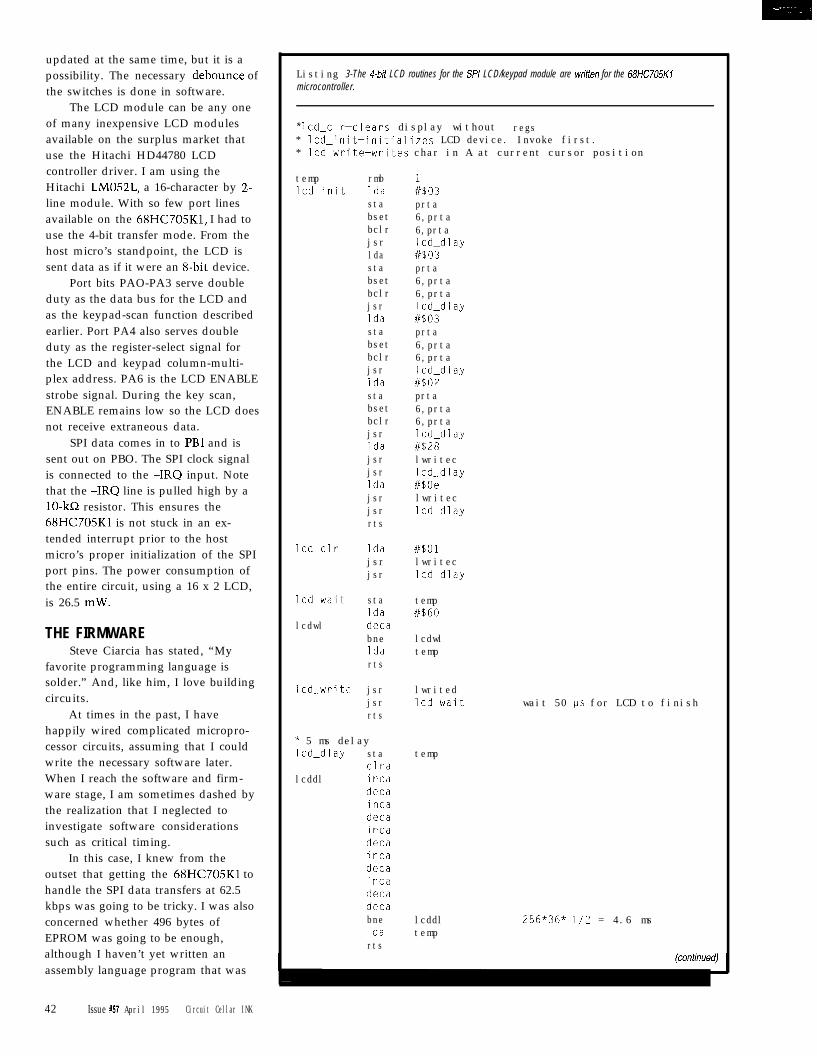
updated at the same time, but it is apossibility. The necessary debounce ofthe switches is done in software.
The LCD module can be any oneof many inexpensive LCD modulesavailable on the surplus market thatuse the Hitachi HD44780 LCDcontroller driver. I am using theHitachi LM052L, a 16-character by 2-line module. With so few port linesavailable on the 68HC705K1, I had touse the 4-bit transfer mode. From thehost micro’s standpoint, the LCD issent data as if it were an g-bit device.
Port bits PAO-PA3 serve doubleduty as the data bus for the LCD andas the keypad-scan function describedearlier. Port PA4 also serves doubleduty as the register-select signal forthe LCD and keypad column-multi-plex address. PA6 is the LCD ENABLEstrobe signal. During the key scan,ENABLE remains low so the LCD doesnot receive extraneous data.
SPI data comes in to PBl and issent out on PBO. The SPI clock signalis connected to the -1RQ input. Notethat the -1RQ line is pulled high by alo-kn resistor. This ensures the68HC705Kl is not stuck in an ex-tended interrupt prior to the hostmicro’s proper initialization of the SPIport pins. The power consumption ofthe entire circuit, using a 16 x 2 LCD,is 26.5 mW.
THE FIRMWARESteve Ciarcia has stated, “My
favorite programming language issolder.” And, like him, I love buildingcircuits.
At times in the past, I havehappily wired complicated micropro-cessor circuits, assuming that I couldwrite the necessary software later.When I reach the software and firm-ware stage, I am sometimes dashed bythe realization that I neglected toinvestigate software considerationssuch as critical timing.
In this case, I knew from theoutset that getting the 68HC705Kl tohandle the SPI data transfers at 62.5kbps was going to be tricky. I was alsoconcerned whether 496 bytes ofEPROM was going to be enough,although I haven’t yet written anassembly language program that was
42 Issue #57 April 1995 Circuit Cellar INK
Listing 3-The 4bit LCD routines for the SPI LCD/keypad module are written for the 68HC705K1microcontroller.
* lcd_clr-clears display without regs* led_init-initializes LCD device. Invoke first.* lcd_writeewrites char in A at current cursor position
templed_init
lcd&clr
led_wait
lcdwl
led_write
rmbldastabsetbclrjsrldastabsetbclrjsrIdastabsetbclrjsrIdastabsetbclrjsrIdajsrjsrIdajsrjsrrts
Idajsrjsr
staIdadecabneIdarts
jsrjsrrts
* 5 ms delaylcd_dlay sta
clralcddl inca
decaincadecaincadecaincadecaincadecadecabneIdarts
8$03prta6,prta6,prtalcd_dlayi/$03prta6,prta6,prtalcd_dlay//SO3prta6,prta6,prtalcd_dlay#SO2prta6,prta6,prtalcd_dlayi/$28lwriteclcd_dlayi/BOelwritecled_dlay
i/B01lwritecled_dlay
temp#$60
lcdwltemp
lwritedlcd&wait
temp
lcddltemp
wait 50 ids for LCD to finish
256*36* 112 = 4.6 ms
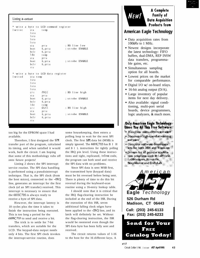
Listing 3-continued
* write a byte to LCD command registerlwritec sta temp
lsralsralsralsrasta prta ; RS line lowbset 6,prta ; strobe ENABLEbclr 6,prtaIda tempsta prtabset 6,prta ; strobe ENABLEbclr 6,prtarts
* write a byte to LCD data registerlwrited sta temp
lsralsralsralsraora i/%10 ; RS line highsta prtabset 6,prta ; strobe ENABLEbclr 6,prtaIda tempora i/s10 ; RS line highsta prtabset 6,prta ; strobe ENABLEbclr 6,prtarts
too big for the EPROM space I had some housekeeping, then enters aavailable. polling loop to wait for the next SPI
Therefore, I first designed the WI clock. The first WI data bit (MSB) istransfer part of the program, calculatedits timing, and when satisfied it wouldwork, built the circuit. I am hopingthat some of this methodology rubs offonto future projects!
Listing 2 shows the SPI interruptservice routine. The SPI data handlingis performed using a pseudointerrupttechnique. That is, the SPI clock (fromthe host micro), connected to the -1RQline, generates an interrupt for the firstclock (of an SPI transfer) received. Thisinterrupt is necessary to ensure thatthe 68HC705 is always ready toreceive a byte of SPI data.
However, the interrupt latency is10 cycles plus the time it takes tofinish the instruction being executed.This is too long a period for the68HC705 to send and receive a bit.
The trick is to settle for 7-bittransfers, which are suitable for theLCD. The keypad-data output needsonly 4 bits. The first SPI clock invokesthe interrupt-service routine, does
simply ignored. The 68HC705 has B I Hand B I L instructions for tightly pollingthe IRQ pin level. Using these instruc-tions and tight, replicated, inline code,the program can both send and receivethe SPI data with no problems.
Since SPI data is sent MSB first,the transmitted byte (keypad data)must be bit reversed before being sent.There is plenty of time to do this bitreversal during the keyboard-scanroutine using a 16-entry lookup table.
I should note that it is critical thatthe IRQ flag-clearing instruction beincluded at the end of the ISR. Duringthe execution of this ISR, sevenadditional falling clock edges havebeen applied to the -1RQ line, and itslatch will definitely be set. Withoutthe flag-clearing instruction, the ISRwould be reentered even though theSPI data byte has been fully sent andreceived.
The circuit returns values of 1-16to the host for the 16 different keys. A
American Eagle Technology
Data acquisition rates from1OOkHz to 1 MHz.Newest designs incorporatethe latest technology: FIFObuffers, dual-DMA, REP INSWdata transfers, programma-ble gains, etc.Simultaneous samplingoption for all boards.Lowest prices on the marketfor comparable performance.Digital I/O w/ on-board relays.16-bit analog output (D/A).Large inventory of popularitems for next day delivery.Also available: signal condi-tioning, multi-port serialboards, device programmers,logic analyzers, & much more.
Amer ican
Eagle Technology526 Durham RdMadison, CT 06443
Call: (203) 245-6133Fax: (203) 245-6233
#117Circuit Cellar INK issue #57 April1995 4 3
value of zero is sent when no keys Cursor mode (125)-the next byte(s)have been pressed since the last sent move the cursor to the re-inquiry from the host. quested position
Remember that the 96-characterASCII set can be transmitted to theLCD using seven bits. To send data tothe command register for such opera-tions as display clearing, I have“stolen” three seldom-used charactervalues (125-127) for that purpose. Thedefinitions of these three commandsare as follows:
Data mode ( 126 J-the next bytej s) sentgo to the data register of the LCD
Command mode (127)-the nextbyte(s) sent go to the commandregister of the LCD
All necessary commands to theLCD are seven bits long with theexception of the cursor-movement
command, which has an additionalmode assigned to it. All values passedto the LCD while in this mode haveDB7 set high as required for cursormovement.
The necessary code (with atten-dant timing constraints) to set up theLCD display properly in 4-bit modeexecutes when the 68HC705 ispowered up. The host micro need notworry about this other than to wait 15ms or so after reset before sending any
Serial Peripheral InterfaceThe Serial Peripheral Interface (SPI) is a high-speed, The CLOCK signal needs further explanation. The
TTL-compatible, full-duplex, synchronous, data-transfer rate of data transfer depends on the CLOCK rate. In theprotocol. It has been implemented as a functional block 68HC11, the clock rate is based on the processor clockon many modern microcontrollers including the divided by the constants 2, 4, 16, or 32. The standard68HCl1, TMS370, and some derivatives of the 8051 processor clock rate for the 68HCll is 2 MHz. Thisfamily. While they’re not all that common, there are project uses the /32 option, as the 68HC705Kl in theperipheral ICs designed for this serial bus. keyboard and LCD module cannot respond to higher
For instance, Maxim and Linear Technology make rates. This selection provides a transfer rate of 62.5 kbps.multichannel 12-bit ADCs. Texas Instruments makes Incidentally, the TMS370 provides a much more pro-ADCs and power driver ICs (these make excellent grammable SPI clock-rate selection with a divisor ratiostepper motor drivers). Motorola’s LCD driver ICs use a of up to 1024 on its internal clock.serial interface, which can be driven by the SPI. These The 68HCll SPI block offers both the clock polarityare just a few examples of available devices. and phase to be programmed. Through this, the SPI
The SE’1 functional block, which I outline, is works with peripheral ICs made by many manufacturers.implemented by Motorola in their 68HCll family. Due to the way in which the 68HC705Kl firmwareThere are slight differences in the implementation of works, it is important that both the clock phase andthis protocol in other manufacturers’ products, but the polarity be set to 1 for this project.principle is the same. The SPI is a full-duplex protocol
Data transfer is serial and, unlike the more com- . Unlike other common, full-duplex protocols suchmon RS-232 standard, is synchronous. Since this bus as the RS-232 where there is not necessarily a 1: 1was originally intended to provide communication relationship between the amount of data sent and thatamong microcontrollers in a multiprocessor environ- received, the SPI does impose this constraint. For everyment, the concept of a master and slave is used. byte sent out by the master, a byte is simultaneously
In environments, where both devices on the bus are clocked in to the master. Whether the slave actually“intelligent” and therefore capable of originating sends back data is immaterial. The master assembles amessages on their own, the protocol allows only one of byte of data from the signal seen on its MIS0 line duringthe devices to be the master. So, only the master can the time its data byte is being sent out.initiate messages; the slave receives and responds to For the purpose of sending data from the master tothese messages. In a project such as this one, the host an output-only peripheral such as a DAC, this incomingmicrocontroller must be programmed as the master; the byte would be ignored. In the case of an SPI device suchkeyboard and LCD module is the slave. (Program code as an ADC, which must be triggered and then read, theand implementation are detailed in the article.) common method is for the ADC to return the last
The SPI uses three signals to transfer the data: reading it took at the time that it is receiving its triggerMOSI (Master Out Slave In), MIS0 (Master In Slave command for the new conversion. ln this project, theOut), and CLOCK. Since the 68HCll is the host or module returns the last key pressed whenever it receivesMaster processor, the MOSI line carries data to the LCD an incoming LCD data byte.and the MIS0 carries data from the keypad to the host The 68HCll SPI block, while very flexible, has a[they would be reversed if the 68HCll were the slave). fixed 8-bit word length. The TMS370 SPI block has a
The i n i t S P I procedure in Listing 1 gives the fully programmable word length of l-8 bits. While thecorrect sequence of 68HCll instructions for setting the SPI is certainly not as flexible as the PC bus, it is muchSPI properly. Note also that the -SS line of the 68HCll easier to use when only a small number of devices needmust be tied to VCC to enable it as the master. to be connected together.
44 Issue #57 April 1995 Circuit Cellar INK
data to the LCD and keypad circuit.For those who want to use these LCDmodules in 4-bit mode in their ownapplications, I have shown the re-quired code in Listing 3. The HitachiHC44780 data manual is a comprehen-sive source of information on program-ming these modules.
So the builder can see if the circuitis working properly prior to beingconnected to a host WI port, the68HC705 sends out the sign-onmessage “CIC WI LCDKBD” after itinitializes the LCD module. Onceconnected to a host, the first LCDcommand should be to clear the LCDof the sign-on message.
To read the keypad, the host sendsa byte to the SPI. The key code isreturned in the WI data register with azero indicating no key presses sincethe last poll. If you want to read thekeypad without also writing to theLCD, send code 126, which sets updata mode (the mode most commonlyused). Note that this circuit “remem-bers” the last key pressed since thelast host polling. This feature ensures
that if critical timing sequences areperformed, the host is able to checkthe keypad less frequently.
WRAP-UPI hope this article prompts anyone
who hasn’t bothered to make use ofthe SPI to give this simple, yet useful,circuit a try. It can be breadboarded inabout an hour or so. q
Brian Millier has worked as aninstrumentation engineer for the last12 years in the Chemistry Departmentof Dalhousie University, Halifax, NS,Canada. In his leisure time, heoperates Computer Interface Consult-ants and has a full electronic musicstudio in his basement. He may bereached at [email protected].
LCD moduleTimeline Inc.23650 Telo Ave.Torrence, CA 90505(3 10) 7845488
MC68HC705KlPJameco Ltd.1355 Shoreway Rd.Belmont, CA 94002-4100(415) 592-8097
Motorola Technical ManualsMotorola Literature DistributionP.O. Box 20912Phoenix, AZ 85036.(602) 244-6900
A programmed 68HC705KlP isavailable for $15 plus $3 postageand handling (U.S. currency) from:
Brian MillierComputer Interface ConsultingP.O. Box 65, Site 17, R.R. 3Armdale, NSCanada B3L 4J3(902) 876-8645E-mail: [email protected]
410 Very Useful411 Moderately Useful412 Not Useful
Odds are that some time during the day youwill stop for a traffic signal, look at a messagedisplay or listen to a recorded announcementcontrolled by a Micromint RTCl80. We’veshipped thousands of RTCl8Os to OEMs.Check out why they chose the RTCl80 bycalling us for a data sheet and price list now.
MICROMINT, INC.4 Park Street, Vernon, CT 06066(203) 871-6170*Fax (203) 872-2204
in Europe: (44) 0285-658122ain Canada: (514) 336.9426*in Australia: (3) 467-7194mDistributor Inquiries Welcome
Circuit Cellar INK Issue #57 April 1995
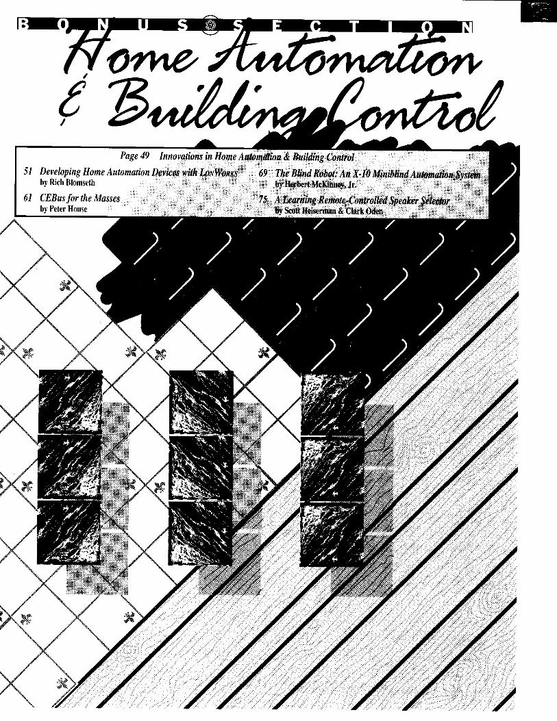
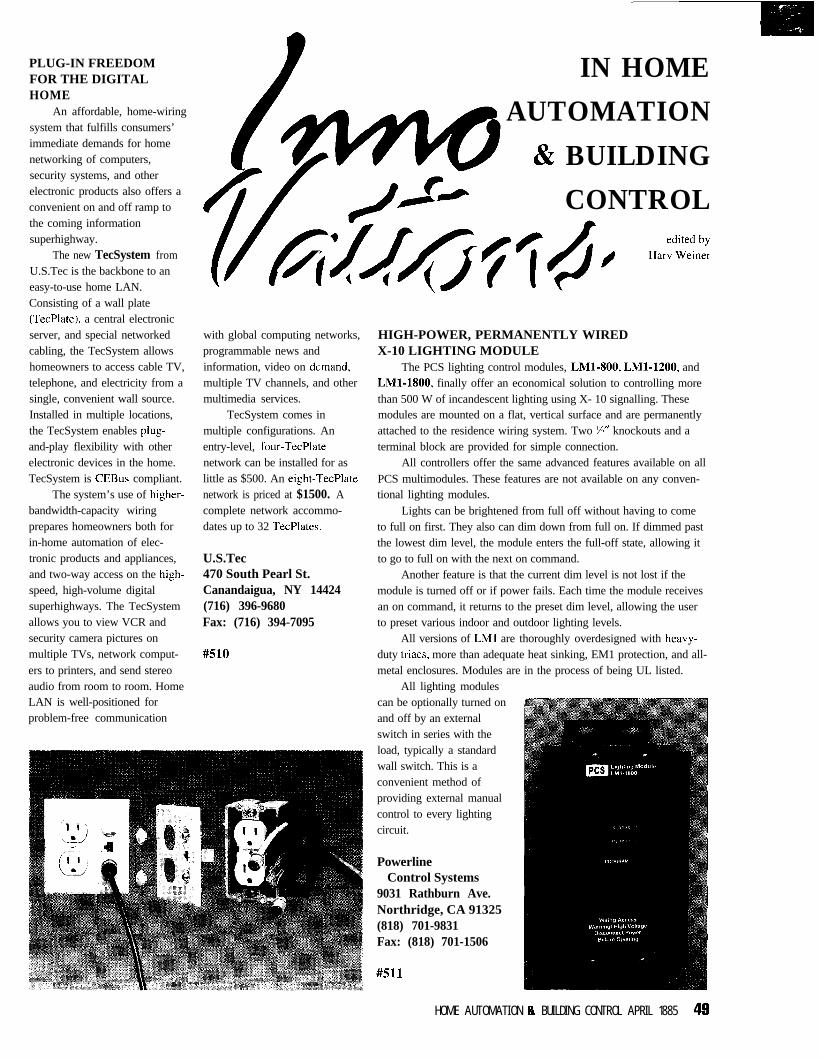
PLUG-IN FREEDOMFOR THE DIGITALHOME
An affordable, home-wiringsystem that fulfills consumers’immediate demands for homenetworking of computers,security systems, and otherelectronic products also offers aconvenient on and off ramp tothe coming informationsuperhighway.
The new TecSystem fromU.S.Tec is the backbone to aneasy-to-use home LAN.Consisting of a wall plate(TecPlate), a central electronicserver, and special networkedcabling, the TecSystem allowshomeowners to access cable TV,telephone, and electricity from asingle, convenient wall source.Installed in multiple locations,the TecSystem enables plug-and-play flexibility with otherelectronic devices in the home.TecSystem is CEBus compliant.
The system’s use of higher-bandwidth-capacity wiringprepares homeowners both forin-home automation of elec-tronic products and appliances,and two-way access on the high-speed, high-volume digitalsuperhighways. The TecSystemallows you to view VCR andsecurity camera pictures onmultiple TVs, network comput-ers to printers, and send stereoaudio from room to room. HomeLAN is well-positioned forproblem-free communication
with global computing networks,programmable news andinformation, video on demand,multiple TV channels, and othermultimedia services.
TecSystem comes inmultiple configurations. Anentry-level, four-TecPlatenetwork can be installed for aslittle as $500. An eight-TecPlatenetwork is priced at $1500. Acomplete network accommo-dates up to 32 TecPlates.
U.S.Tec470 South Pearl St.Canandaigua, NY 14424(716) 396-9680Fax: (716) 394-7095
#510
IN HOME
AUTOMATION
& BUILDING
CONTROL
HIGH-POWER, PERMANENTLY WIREDX-10 LIGHTING MODULE
The PCS lighting control modules, LMl-800, LMl-1200, andLMl-1800, finally offer an economical solution to controlling morethan 500 W of incandescent lighting using X- 10 signalling. Thesemodules are mounted on a flat, vertical surface and are permanentlyattached to the residence wiring system. Two ‘Yz” knockouts and aterminal block are provided for simple connection.
All controllers offer the same advanced features available on allPCS multimodules. These features are not available on any conven-tional lighting modules.
Lights can be brightened from full off without having to cometo full on first. They also can dim down from full on. If dimmed pastthe lowest dim level, the module enters the full-off state, allowing itto go to full on with the next on command.
Another feature is that the current dim level is not lost if themodule is turned off or if power fails. Each time the module receivesan on command, it returns to the preset dim level, allowing the userto preset various indoor and outdoor lighting levels.
All versions of LMl are thoroughly overdesigned with heavy-duty triacs, more than adequate heat sinking, EM1 protection, and all-metal enclosures. Modules are in the process of being UL listed.
All lighting modulescan be optionally turned onand off by an externalswitch in series with theload, typically a standardwall switch. This is aconvenient method ofproviding external manualcontrol to every lightingcircuit.
PowerlineControl Systems
9031 Rathburn Ave.Northridge, CA 91325(818) 701-9831Fax: (818) 701-1506
#511
HOME AUTOMATION 8 BUILDING CONTROL APRIL 1885 48
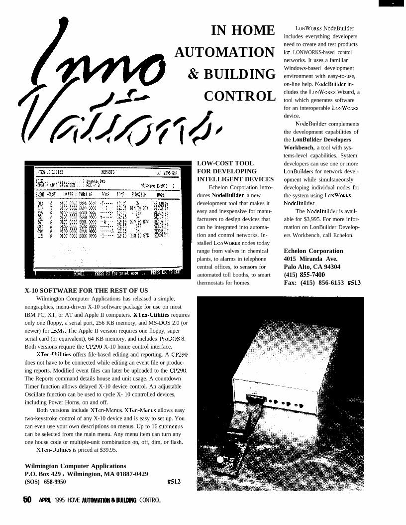
IN HOME
AUTOMATION
& BUILDING
CONTROLt
X-10 SOFTWARE FOR THE REST OF USWilmington Computer Applications has released a simple,
nongraphics, menu-driven X-10 software package for use on mostIBM PC, XT, or AT and Apple II computers. XTen-Utilities requiresonly one floppy, a serial port, 256 KB memory, and MS-DOS 2.0 (ornewer) for IBMs. The Apple II version requires one floppy, superserial card (or equivalent), 64 KB memory, and includes ProDOS 8.Both versions require the CP290 X-10 home control interface.
XTen-Utilities offers file-based editing and reporting. A CP290does not have to be connected while editing an event file or produc-ing reports. Modified event files can later be uploaded to the CP290.The Reports command details house and unit usage. A countdownTimer function allows delayed X-10 device control. An adjustableOscillate function can be used to cycle X- 10 controlled devices,including Power Horns, on and off.
Both versions include XTen-Menus. XTen-Menus allows easy
two-keystroke control of any X-10 device and is easy to set up. Youcan even use your own descriptions on menus. Up to 16 submenuscan be selected from the main menu. Any menu item can turn anyone house code or multiple-unit combination on, off, dim, or flash.
XTen-Utilities is priced at $39.95.
Wilmington Computer ApplicationsP.O. Box 429 l Wilmington, MA 01887-0429(SOS) 658-9950 #512
LOW-COST TOOLFOR DEVELOPINGINTELLIGENT DEVICES
Echelon Corporation intro-duces NodeBuilder, a newdevelopment tool that makes iteasy and inexpensive for manu-facturers to design devices thatcan be integrated into automa-tion and control networks. In-stalled LONWORKS nodes todayrange from valves in chemicalplants, to alarms in telephonecentral offices, to sensors forautomated toll booths, to smartthermostats for homes.
LONWORKS NodeBuilderincludes everything developersneed to create and test productsfor LONWORKS-based controlnetworks. It uses a familiarWindows-based developmentenvironment with easy-to-use,on-line help. NodeBuilder in-cludes the LONWORKS Wizard, atool which generates softwarefor an interoperable LONWORKSdevice.
NodeBuilder complementsthe development capabilities ofthe LonBuilder DevelopersWorkbench, a tool with sys-tems-level capabilities. Systemdevelopers can use one or moreLonBuilders for network devel-opment while simultaneouslydeveloping individual nodes forthe system using LONWORKSNodeBuilder.
The NodeBuilder is avail-able for $3,995. For more infor-mation on LonBuilder Develop-ers Workbench, call Echelon.
Echelon Corporation4015 Miranda Ave.Palo Alto, CA 94304(415) 855-7400Fax: (415) 856-6153 #513
50 APRlL 1995 HOME AUTOMATlON & BlUlDlNC C O N T R O L
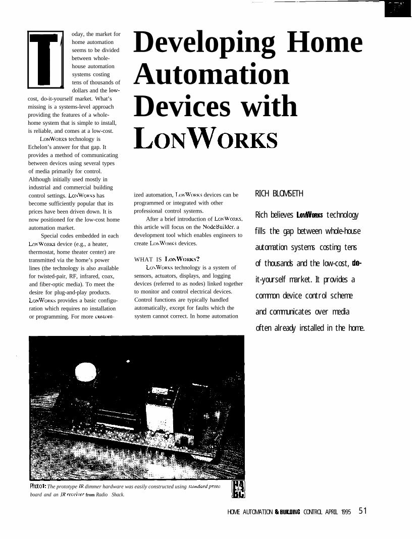
1oday, the market forhome automationseems to be dividedbetween whole-house automationsystems costingtens of thousands ofdollars and the low-
cost, do-it-yourself market. What’smissing is a systems-level approachproviding the features of a whole-home system that is simple to install,is reliable, and comes at a low-cost.
LONWORKS technology isEchelon’s answer for that gap. Itprovides a method of communicatingbetween devices using several typesof media primarily for control.Although initially used mostly inindustrial and commercial buildingcontrol settings. LONWORKS hasbecome sufficiently popular that itsprices have been driven down. It isnow positioned for the low-cost homeautomation market.
Special codes embedded in eachLONWORKS device (e.g., a heater,thermostat, home theater center) aretransmitted via the home’s powerlines (the technology is also availablefor twisted-pair, RF, infrared, coax,and fiber-optic media). To meet thedesire for plug-and-play products.LONWORKS provides a basic configu-ration which requires no installationor programming. For more custom-
Developing HomeAutomationDevices withLONWORKS
ized automation, L~NWORKS devices can beprogrammed or integrated with otherprofessional control systems.
After a brief introduction of LONWORKS,
this article will focus on the NodeBuilder, adevelopment tool which enables engineers tocreate LONWORKS devices.
WHAT IS LONWORKS?
LONWORKS technology is a system ofsensors, actuators, displays, and loggingdevices (referred to as nodes) linked togetherto monitor and control electrical devices.Control functions are typically handledautomatically, except for faults which thesystem cannot correct. In home automation
RICH BLOMSETH
Rich believes LONWORKS technology
fills the gap between whole-house
automation systems costing tens
of thousands and the low-cost, do-
it-yourself market. It provides a
common device control scheme
and communicates over media
often already installed in the home.
Photo 1: The prototype IR dimmer hardware was easily constructed using standardproto
board and an IR receiver from Radio Shack.
HOME AUTOMATION I3 RUILOINC CONTROL APRIL 1995 5 1
applications, a control network may providesafety (e.g., monitoring security, fire alarms,and pool and spa areas), control (e.g., reg-ulating room temperature, lighting, draper-ies, and irrigation systems), and entertain-ment (e.g., managing A/V equipment).
Neuron chips, the heart of LONWORKStechnology, contain the protocol (LONTALK)that enables them to communicate with otherNeuron chips. Since Neuron chips can beconnected directly to the sensors and outputsthey supervise, a single Neuron chip handlesprocessing of sensor and output status,execution of control programs, and commu-nications with other Neuron chips.
For nodes requiring more processing orI/O power, the Neuron chip can also be usedas a communications coprocessor for anyother processor. The Neuron chip thereforeprovides a scalable solution that can be usedeven on complex nodes which include a hostcomputer and network interface.
LONWORKS also provides interoper-ability with other control systems. Networkmanagement software, tools for installingcomplex networks, and routers enablecommunications between the differentcommunications media.
RIDING THE POWER LINESPower-line signaling is ideal for home-
automation communications because itrequires no new wires. As well, powerwiring already reaches every device thatneeds to be controlled.
Although power-line signaling deviceshave been available for years, they have twosignificant drawbacks-they are unreliableand lack two-way communication. Intermit-tent noise sources, impedance changes, andattenuation conspire to make the power linea hostile path for power-line signaling.
To counteract these problems, LON-WORKS combines narrowband signaling withsignal processing and error correctionalgorithms in its transceivers. The trans-ceiver features include:
l low-overhead error correction to enable thesystem to receive corrupted packets whilemaintaining a high throughput
l adaptive carrier-detect algorithm thatautomatically tracks changes in power-line noise levels
l impulse-rejection technology to improveperformance in the presence of impulsivenoise sources such as triac-controlleddimmers
ktillg 1: By declaring LONMARK objects and network variables for an IR dimmer, any device
on the same network con communicate with the dimmer.
#pragma set_node_sd_string “El. I R D i m m e r C o n t r o l l e r ”n e t w o r k o u t p u t sd_string (“@Oil.“) SNVT_switch nvoSwitch;n e t w o r k o u t p u t sd_string (“@013.“) SNVT_count nvoRawHwData;
l/O Device Name and DirectionBit, nybble, byte input and outputBitshift input and outputDual slope inputEdgedivide outputEdgelog inputFrequency output1% input and outputInfrared inputLeveldetect inputMagcard and Magtrackl inputMuxbus input and outputNeurowire input and outputPulsecount outputPulsewidth outputOneshot outputOntime and Period inputParallel input and outputPulsecount and Totalcount inputQuadrature inputSerial input and outputTouch input and outputTriac outputTriggeredcount outputWiegand input
DescrhtionDirect binary I/OUp to 16 bits of clocked serial dataComparitor input for 16-bit dual-slope A/DWaveform equal to fraction of inputEdge to edge timing of an input streamSquare wave output of specified frequencyPhilips K-compatible serial I/OEncoded input from an IR demodulatorDetect logic zero levelIS0781 1 track 1 and 2 magnetic card readersMultiplexed address and data busSPI and Microwire compatible serial I/OOutput specified number of pulsesOutput specified frequency and duty cycleSingle output pulse of specified periodPulsewidth and period measurement8-bit bidirectional I/OTransition count over fixed or total intervalShaft encoder rotary position input8-bit asynchronous serial I/ODallas Touch 1 -wire bus I/OPulse delayed with respect to input edgePulse controlled by counting input edgesWiegand card reader input
Table 1: Built-in Neuron C I/O objects simplifjr interfaces to most common I/O devices.
ktillg 2: IR dimmer software declarations for I/O objects configure the Neuron chip’s
internal hardware for the IR dimmer I/O devices.
IO-0 o u t p u t b i t ioLED = 1:IO_4 i n p u t q u a d r a t u r e ioDia1 ;IO_6 i n p u t i n f r a r e d i n v e r t clack(7) ioIRData:IO-6 i n p u t b i t ioIRDataLeve1 :IO_7 i n p u t 1 e v e l d e t e c t ioButton;
LiStillg a: The complete IR dimmer software listing shows how little code is requiredfor a
complex application.
// I R D I M M E R . N C - D i m m e r c o n t r o l l e r w i t h m a n u a l a n d// i n p u t s . C o m p a t i b l e w i t h t h e S o n y RM-V10 r e m o t e// T h i s r e m o t e p u t s o u t t h r e e (3) i d e n t i c a l c o d e s// c l o s u r e .
n f r a r e dc o n t r o l .f o r e a c h k e y
// max_period = 2 . 6 m s ; l o w b i t = 1 . 1 m s ; h i g h b i t . = 1 . 9 m s/I// O b j e c t I D TypeII 0 0 S w i t c h s e n s o r o b j e c t , SNVT_switch
i i p r a g m a set_node_sd_string “@l. I R D i m m e r C o n t r o l l e r ”iipragma enabl e_io_pull upsi i p r a g m a num_addr_table_entries 3 continued
IA&52 APRIL 1995 HOME AUTOMATION & BUllOlNC CONTROL
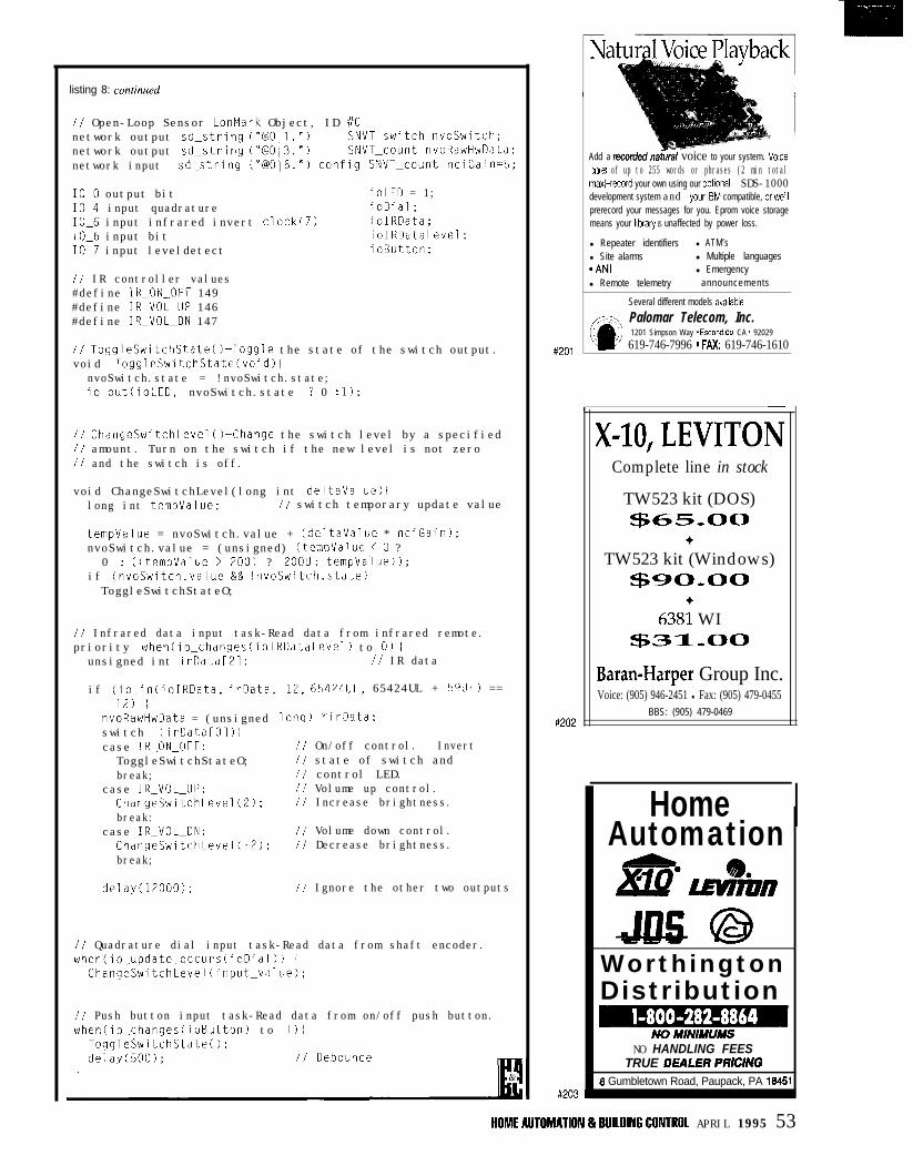
listing 8: continued
// Open-Loop Sensor LonMark Object, ID ii0network output sd_string ("@011.") SNVT_switch nvoswitch;network output sd_string ("@O/3.") SNVT_count nvoRawHwData;network input sd_string i"@O16.") config SNVT_count nciGain=5;
IO-0 output bit ioLED = 1;IO_4 input quadrature ioDia1;IO_6 input infrared invert clack(7) ioIRData;IO_6 input bit ioIRDataLeve1;IO_7 input leveldetect ioButton;
// IR controller values#define IR_ON_OFF 149#define IR_VOL_lJP 146#define IR_VOL_DN 147
// ToggleSwitchStateOFToggle the state of the switch output.void ToggleSwitchState(void1 i
nvoSwitch.state = !nvoSwitch.state;io_out(ioLED, nvoSwitch.state ? 0 : 1):
// ChangeSwitchLevelO-Change the switch level by a specified// amount. Turn on the switch if the new level is not zero// and the switch is off.
void ChangeSwitchLevel(long int deltavalue) 1long int tempvalue; // switch temporary update value
tempvalue = nvoSwitch.value + (deltavalue * nciGain1;nvoSwitch.value = (unsigned) (tempValue < 0 ?
0 : ((tempvalue > 200) ? ZOOIJ : tempvalue));if (nvoSwitch.value && !nvoSwitch.state)ToggleSwitchStateO;
// Infrared data input task-Read data from infrared remote.priority when(io_changes(ioIRDataLevel) to 0) i
unsigned int irData[Zl; /I IR data
if (io_in(ioIRData. irData,12) i
nvoRawHwData = (unsignedswitch (irData[Ol) 1case IR_ON_OFF:ToggleSwitchStateO;break;
case IR_VOL_UP:ChangeSwitchLevel(2);break:
case IR_VOL_DN:ChangeSwitchLevel(-2);break;
12, 65424UL, 65424UL + 59UL) ==
lonq) *irData;
ii On/off control. Invertli state of switch and// control LED.// Volume up control.// Increase brightness.
// Volume down control.// Decrease brightness.
delay(12000); // Ignore the other two outputs
// Quadrature dial input task-Read data from shaft encoder.when(io_update_occurs(ioDial)) i
ChangeSwitchLevel(input_value);
// Push button input task-Read data from on/off push button.when(io_changes(ioButton) to 1) 1
ToqqleSwitchStateO;deiay(500); II Debounce
t
#201
#202
#203
Add a recorded nafh voice to your system. Voicelibraries of up to 255 words or phrases (2 min totalmax)-record your own using our optlonal SDS-1000development system and yourlBM compatible, orwe’llprerecord your messages for you. Eprom voice storagemeans your lhbraty IS unaffected by power loss.
l Repeater identifiers l ATM’sl Site alarms l Multiple languages*ANI l Emergencyl Remote telemetry announcements
Several different models avallable
Palomar Telecom, Inc.1201 Simpson Way * Escondldo, CA * 92029
619-746-7996 * FM 619-746-1610
-
X-10,LEVITONComplete line in stock
TW523 kit (DOS)ZfG65,00
+TW523 kit (Windows)
~90_00
6-3s: WI$31_00
Baran-Harper Group Inc.Voice: (905) 946-2451 l Fax: (905) 479-0455
BBS: (905) 479-0469
HomeAutomation
WorthingtonDistribution
NOMINIMUMSNO HANDLING FEES
TRUE DEALERPRiCING16 Gumbletown Road, Paupack, PA 18451
HOMEAlJTOMATlON&BUllDlNCCONTROL APRIL 1995 53
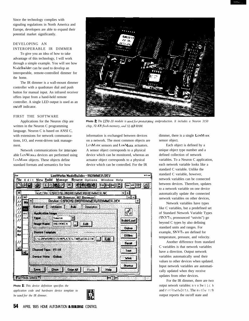
Since the technology complies withsignaling regulations in North America andEurope, developers are able to expand theirpotential market significantly.
DEVELOPING ANINTEROPERABLE IR DIMMER
To give you an idea of how to takeadvantage of this technology, I will workthrough a simple example. You will see howNodeBuilder can be used to develop aninteroperable, remote-controlled dimmer forthe home.
The IR dimmer is a wall-mount dimmercontroller with a quadrature dial and pushbutton for manual input. An infrared receiveroffers input from a hand-held remotecontroller. A single LED output is used as anon/off indicator.
FIRST THE SOFTWAREApplications for the Neuron chip are
written in the Neuron C programminglanguage. Neuron C is based on ANSI C,with extensions for network communica-tions, I/O, and event-driven task manage-ment.
Network communications for interoper-able LONWORKS devices are performed usingLONMARK objects. These objects definestandard formats and semantics for how
Photo 2: The LTM-IO module is usedforprotoQping andproduction. It includes a Neuron 3150
chip, 32.KBjlash memory, and 32.KB RAM.
information is exchanged between deviceson a network. The most common objects areLONMARK sensors and LONMARK actuators.A sensor object corresponds to a physicaldevice which can be monitored, whereas anactuator object corresponds to a physicaldevice which can be controlled. For the IR
*I t.mVhrks NodeEktildci - IRDIMMERDEV .*
Eile E d i t view Build Manage Browse Options Window Help
Photo & This device definition specifies the
application code and hardware device template to
be used.for the IR dimmer.I#
&
54 APRIL 1885 HOME AUTOMATION 8 8lRLlJlNG CONTROL
dimmer, there is a single LONMARKsensor object.
Each object is defined by aunique object type number and adefined collection of networkvariables. To a Neuron C application,each network variable looks like astandard C variable. Unlike thestandard C variable, however,network variables can be connectedbetween devices. Therefore, updatesto a network variable on one deviceautomatically update the connectednetwork variables on other devices,
Network variables have typeslike C variables, but a predefined setof Standard Network Variable Types(SNVTs; pronounced “snivits”) gobeyond C types by also definingstandard units and ranges. Forexample, SNVTs are defined fortemperature, pressure, and velocity.
Another difference from standardC variables is that network variableshave a direction. Output networkvariables automatically send theirvalues to other devices when updated.Input network variables are automati-cally updated when they receiveupdates from other devices.
For the IR dimmer, there are twooutput network variables: n v o Sw i t c hand nvoRawHwData. The nvoSwitchoutput reports the on/off state and
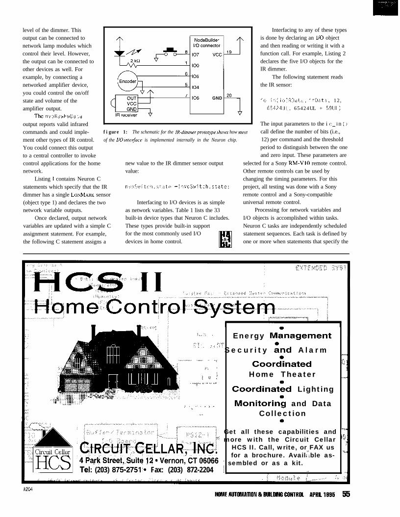
level of the dimmer. Thisoutput can be connected tonetwork lamp modules whichcontrol their level. However,the output can be connected toother devices as well. Forexample, by connecting anetworked amplifier device,you could control the on/offstate and volume of theamplifier output.
ThenvoRawHwDataoutput reports valid infraredcommands and could imple-ment other types of IR control.You could connect this outputto a central controller to invoke
7 106 GND 2o
control applications for the home new value to the IR dimmer sensor outputnetwork. value:
Listing 1 contains Neuron Cstatements which specify that the IRdimmer has a single LONMARK sensor(object type 1) and declares the twonetwork variable outputs.
nvoSwitch.state =!nvoSwitch.state;
Once declared, output networkvariables are updated with a simple Cassignment statement. For example,the following C statement assigns a
Interfacing to I/O devices is as simpleas network variables. Table 1 lists the 33built-in device types that Neuron C includes.These types provide built-in supportfor the most commonly used I/Odevices in home control.
figure 1: The schematic for the IR-dimmer prototype shows how most
of the I/O inter&e is implemented internally in the Neuron chip.
Interfacing to any of these typesis done by declaring an I/O objectand then reading or writing it with afunction call. For example, Listing 2declares the five I/O objects for theIR dimmer.
The following statement readsthe IR sensor:
io_in(ioIRData, irData, 12,65424UL, 65424UL + 59UL)
The input parameters to the i o-i n ( 1call define the number of bits (i.e.,12) per command and the thresholdperiod to distinguish between the oneand zero input. These parameters are
selected for a Sony RM-VlO remote control.Other remote controls can be used bychanging the timing parameters. For thisproject, all testing was done with a Sonyremote control and a Sony-compatibleuniversal remote control.
Processing for network variables andI/O objects is accomplished within tasks.Neuron C tasks are independently scheduledstatement sequences. Each task is defined byone or more when statements that specify the
:,,.,, / Energy Mkagement,,‘i. ,‘P.,. .“’ Secur i ty k-wi A larm
-,TjIIT. ,:,5, ,, ..,CoorGnated tJ< ’
/f1 *’ / Home Theater_ .“~p” + I v.x -7*
Coordinatid Lighting_* -”in”~n.“q~,q.~::. .&...~.j nj; ““:_,_(ni”nL/_i~~:d8”*_elgb i 1 ,.. . ,- 6 ,.,i Monitorin; and Data
,- Collection0
Get all these capabilities and ymore with the Circuit Cellar jL
HCS II. Call, write, or FAX us*for a brochure. Available as-
’ sembled or as a kit.Tel: (203) 875-2751,. Fax: (203) 872-2204 i I :.
; I
#204
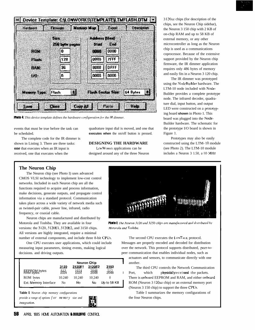
PhOtO 4: This device template defines the hardware conq‘igumtionfor the IR dimmer.
events that must be true before the task canbe scheduled.
The complete code for the IR dimmer is
quadrature input dial is moved, and one thatexecutes when the on/off button is pressed.
shown in Listing 3. There are three tasks: DESIGNING THE HARDWAREone that executes when an IR input is LONWORKS applications can be
received, one that executes when the designed around any of the three Neuron
3 120~~ chips (for description of thechips, see the Neuron Chip sidebar),the Neuron 3 150 chip with 2 KB ofon-chip RAM and up to 58 KB ofexternal memory, or any othermicrocontroller as long as the Neuronchip is used as a communicationscoprocessor. Because of the extensivesupport provided by the Neuron chipfirmware, the IR dimmer applicationrequires only 486 bytes of memoryand easily fits in a Neuron 3 120 chip.
The IR dimmer was prototypedusing the NodeBuilder hardware. TheLTM-10 node included with Node-Builder provides a complete prototypenode. The infrared decoder, quadra-ture dial, input button, and outputLED were constructed on a prototyp-ing board shown in Photo 1. Thisboard was plugged into the Node-Builder hardware. The schematic forthe prototype I/O board is shown inFigure I.
Prototypes may also be easilyconstructed using the LTM- 10 module(see Photo 2). The LTM-10 moduleincludes a Neuron 3 1.50, a IO-MHz
The Neuron ChipThe Neuron chip (see Photo I) uses advanced
CMOS VLSI technology to implement low-cost controlnetworks. Included in each Neuron chip are all thefunctions required to acquire and process information,make decisions, generate outputs, and propagate controlinformation via a standard protocol. Communicationtakes place across a wide variety of network media suchas twisted-pair cable, power line, infrared, radiofrequency, or coaxial cable.
Neuron chips are manufactured and distributed byMotorola and Toshiba. They are available in fourversions: the 3120,3120El, 3120E2, and 3150 chips.All versions are highly integrated, require a minimalnumber of external components, and include three 8-bit CPUs.
One CPU executes user applications, which could includemeasuring input parameters, timing events, making logicaldecisions. and driving outputs.
c Neuron ChiD
The second CPU executes the LONTALK protocol.Messages are properly encoded and decoded for distributionover the network. This protocol supports distributed, peer-to-peer communication that enables individual nodes, such as
actuators and sensors, to communicate directly with oneanother.
EEPROM bytesRAM bytes
ROM bvtes
3120--3120El 3126E2 3150 The third CPU controls the Network Communication512 1024 2048 5121024 1024 2048 2048 Port, which physically and packets.sends receives the
10.240 10.240 10.240 0I
There is onboard EEPROM and RAM, and either onboardExt. Me&my Interface No
Table I: Neuron chip memory configurations
provide a range of options for memory size and
inteamtion.
ROM (Neuron 3 120~~ chip) or an external memory port(Neuron 3 150 chip) to support the three CPUs.
Table I summarizes the memory configurations ofthe four Neuron chips.
56 APRIL 1885 HOME AUTOMATION & RUILUING CONTROL
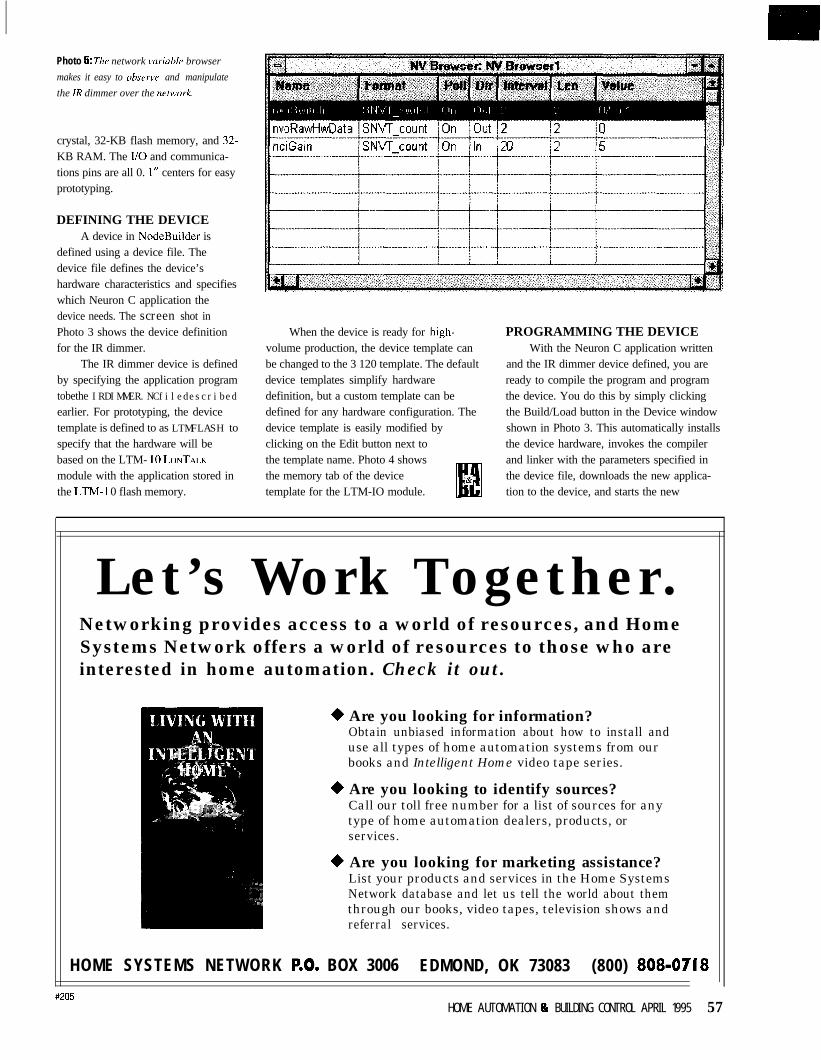
Photo 5: The network variuble browser
makes it easy to obsenv and manipulate
the IR dimmer over the nutwork.
crystal, 32-KB flash memory, and 32.KB RAM. The I/O and communica-tions pins are all 0. I” centers for easyprototyping.
DEFINING THE DEVICEA device in NodeBuilder is
defined using a device file. Thedevice file defines the device’shardware characteristics and specifieswhich Neuron C application thedevice needs. The screen shot inPhoto 3 shows the device definitionfor the IR dimmer.
The IR dimmer device is definedby specifying the application programtobethe IRDIMMER.NCfiledescribedearlier. For prototyping, the devicetemplate is defined to as LTMFLASH tospecify that the hardware will bebased on the LTM- IO LONTALKmodule with the application stored inthe LTM-I 0 flash memory.
When the device is ready for high-volume production, the device template canbe changed to the 3 120 template. The defaultdevice templates simplify hardwaredefinition, but a custom template can bedefined for any hardware configuration. Thedevice template is easily modified byclicking on the Edit button next tothe template name. Photo 4 showsthe memory tab of the devicetemplate for the LTM-IO module.
PROGRAMMING THE DEVICEWith the Neuron C application written
and the IR dimmer device defined, you areready to compile the program and programthe device. You do this by simply clickingthe Build/Load button in the Device windowshown in Photo 3. This automatically installsthe device hardware, invokes the compilerand linker with the parameters specified inthe device file, downloads the new applica-tion to the device, and starts the new
Let’s Work Together.Networking provides access to a world of resources, and HomeSystems Network offers a world of resources to those who areinterested in home automation. Check it out.
+ Are you looking for information?Obtain unbiased information about how to install anduse all types of home automation systems from ourbooks and Intelligent Home video tape series.
+ Are you looking to identify sources?Call our toll free number for a list of sources for anytype of home automation dealers, products, orservices.
+ Are you looking for marketing assistance?List your products and services in the Home SystemsNetwork database and let us tell the world about themthrough our books, video tapes, television shows andreferral services.
HOME SYSTEMS NETWORK p.0, BOX 3006 EDMOND, OK 73083 (800) 808-07 ‘18
#205HOME AUTOMATION Ip BUILDING CONTROL APRIL 1995 57
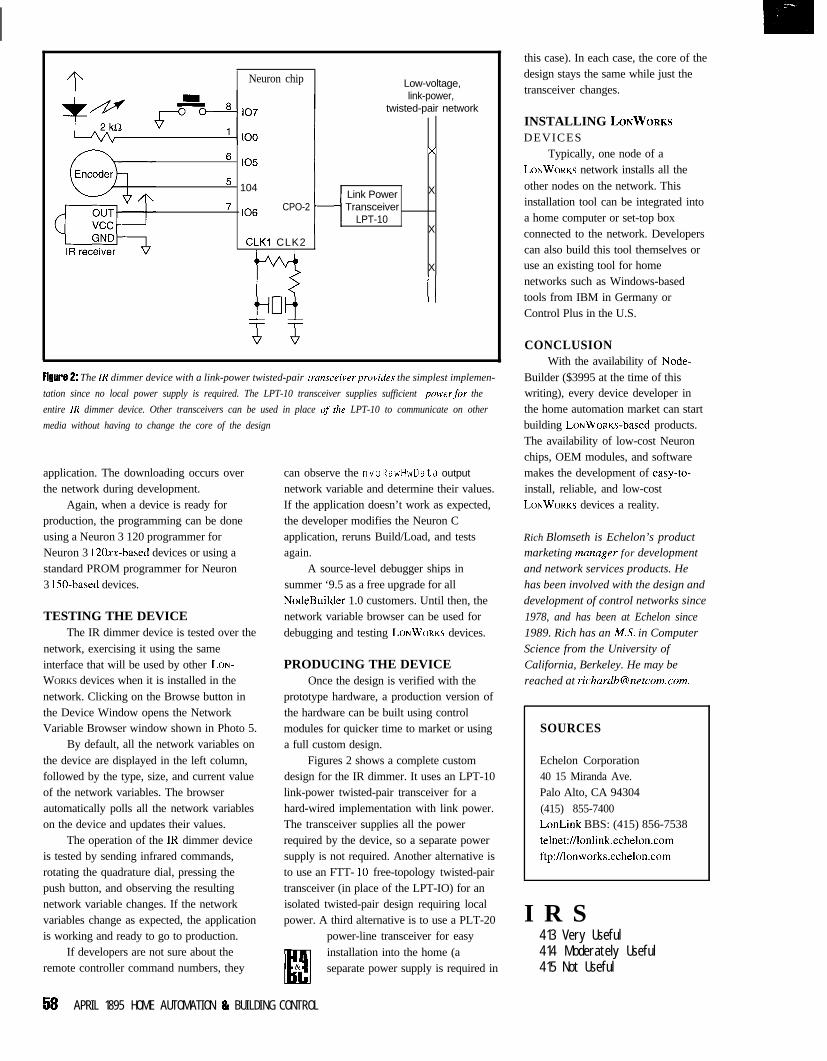
Neuron chip Low-voltage,link-power,
twisted-pair network
6 105x
5 104Link Power X
7 106 CPO-2 TransceiverLPT-10
XCLKl CLK2
n
X
FiglIt% 2: The 1R dimmer device with a link-power twisted-pair transceiverprovides the simplest implemen-
tation since no local power supply is required. The LPT-10 transceiver supplies sufficient powerfor the
entire IR dimmer device. Other transceivers can be used in place of the LPT-10 to communicate on other
media without having to change the core of the design
application. The downloading occurs overthe network during development.
Again, when a device is ready forproduction, the programming can be doneusing a Neuron 3 120 programmer forNeuron 3 120xX-based devices or using astandard PROM programmer for Neuron3 150-based devices.
TESTING THE DEVICEThe IR dimmer device is tested over the
network, exercising it using the sameinterface that will be used by other LON-WORKS devices when it is installed in thenetwork. Clicking on the Browse button inthe Device Window opens the NetworkVariable Browser window shown in Photo 5.
By default, all the network variables onthe device are displayed in the left column,followed by the type, size, and current valueof the network variables. The browserautomatically polls all the network variableson the device and updates their values.
The operation of the IR dimmer deviceis tested by sending infrared commands,rotating the quadrature dial, pressing thepush button, and observing the resultingnetwork variable changes. If the networkvariables change as expected, the applicationis working and ready to go to production.
If developers are not sure about theremote controller command numbers, they
can observe the nvoRawHwData output
network variable and determine their values.If the application doesn’t work as expected,the developer modifies the Neuron Capplication, reruns Build/Load, and testsagain.
A source-level debugger ships insummer ‘9.5 as a free upgrade for allNodeBuilder 1.0 customers. Until then, thenetwork variable browser can be used fordebugging and testing LONWORKS devices.
PRODUCING THE DEVICEOnce the design is verified with the
prototype hardware, a production version ofthe hardware can be built using controlmodules for quicker time to market or usinga full custom design.
Figures 2 shows a complete customdesign for the IR dimmer. It uses an LPT-10link-power twisted-pair transceiver for ahard-wired implementation with link power.The transceiver supplies all the powerrequired by the device, so a separate powersupply is not required. Another alternative isto use an FTT- 10 free-topology twisted-pairtransceiver (in place of the LPT-IO) for anisolated twisted-pair design requiring localpower. A third alternative is to use a PLT-20
power-line transceiver for easyinstallation into the home (aseparate power supply is required in
this case). In each case, the core of thedesign stays the same while just thetransceiver changes.
INSTALLING LONWORKSDEVICES
Typically, one node of aLONWORKS network installs all theother nodes on the network. Thisinstallation tool can be integrated intoa home computer or set-top boxconnected to the network. Developerscan also build this tool themselves oruse an existing tool for homenetworks such as Windows-basedtools from IBM in Germany orControl Plus in the U.S.
CONCLUSIONWith the availability of Node-
Builder ($3995 at the time of thiswriting), every device developer inthe home automation market can startbuilding LoNWoRKs-based products.The availability of low-cost Neuronchips, OEM modules, and softwaremakes the development of easy-to-install, reliable, and low-costLONWORKS devices a reality.
Rich Blomseth is Echelon’s productmarketing manager for developmentand network services products. Hehas been involved with the design anddevelopment of control networks since
1978, and has been at Echelon since1989. Rich has an MS. in ComputerScience from the University ofCalifornia, Berkeley. He may bereached at [email protected].
SOURCES
Echelon Corporation40 15 Miranda Ave.Palo Alto, CA 94304(415) 855-7400LonLink BBS: (415) 856-7538telnet:Nlonlink.echelon.comftp:Nlonworks.echelon.com
I R S413 Very Useful414 Moderately Useful415 Not Useful
58 APRIL 1895 HOME AUTOMATION & BUILDING CONTROL
EBus is theElectronic IndustriesAssociation’s (EIA)open standard IS-60describing a methodof communicationbetween electronicproducts in the
home using five different media:power line, twisted pair, coax,broadcast RF, and infrared. A sixthmedium, fiber optic, has a section leftopen and is undefined at this time.
CEBus is a complete, packet-oriented, peer-to-peer network using aCarrier Sense Multiple Access withCollision Detection and CollisionResolution (CSMAKDCR) protocol.The CEBus standard defines every-thing needed up to and including thelanguage used for application-to-application communication called theCEBus Common ApplicationLanguage (CAL).
In this article, I’ll introduce youto packet construction and show youhow to create CAL messages thatcontrol a CEBus light switch. Hangon-or the details may swamp you!
CEBUS AND CALThe CEBus protocol is described
using the OWISO seven-layer model.CEBus uses four of those layers:application, network, data link, andphysical. Note the actual applicationfunction (e.g., a light switch) is dis-tinct from application layer protocol.
WHY CAL?The CEBus application language
is a set of common language and dataconstructs created to enable
Mr. Lightswitch25 House St., Unit 19
&* Boca Raton, FL 01011
*&k
CEBus forthe Masses
interoperability between products used inresidential automation. This interoperabilityis available between different manufacturers’products even without prior knowledge ofthe products.
For example, information to controlCompany X’s light module or stereo ispublished by the EIA or the CEBus IndustryCouncil (CIC). This information is known tothe world without having to know anythingspecific regarding Company X’s designimplementation of how they use a class Aamplifier to control a vacuum-encased,electrothermal photon emitter-otherwiseknown as a light bulb.
PACKET STRUCTUREA CEBus packet frame can be broken
down into several parts: the Link ProtocolData Unit (LPDU), the Network ProtocolData Unit (NPDU), the Application ProtocolData Unit (APDU), and the CAL message. Idescribe these different parts using a mailed
letter (see Figure 1) as an example.Figure 2 shows a breakdown of a packetstructure illustrating the different parts.
LPDUHEADERThe LPDU header contains the
control field and the source and destina-tion addresses. In the letter mailingscenario, the control field represents thepostal service used to send the letter. Thecontrol field specifies the packet type,
PETER HOUSE
Picking up where other CEBus
articles in /lVKleft off, Peter
introduces us to packet construc-
tion and CAL messages. By the end,
you’ll be able to control a real-live
CEBus light switch!
HOME AUTOMATION & RUlllllNC CONTROL APRIL 1555 6 1
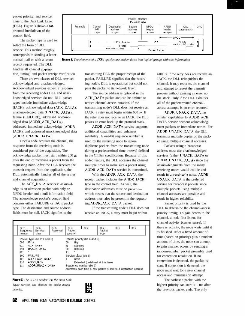
Packet structureCPL and RF onlv1
Preamble Control Destination Source NPDU APDU CAL CRCfield address address header header statement(s)1 byte 4 bytes 4 bytes 1 -n bytes 1 -n bytes
I I I+APDU-4 1
packet priority, and serviceclass to the Data Link Layer(DLL). Figure 3 shows a bit-oriented breakdown of thecontrol field.
The packet type is used toselect the form of DLL ; LPD;p;;der ,,,.. bytes j j
maximum 41 bytesservice. This method roughlycorresponds to sending a letternormal mail or with a return FiglID? 2: The elements of a CEBus packet are broken down into logical groups with size information
receipt requested. The DLLhandles all channel acquisi-tion, timing, and packet-receipt verification.
There are two classes of DLL service:acknowledged and unacknowledged.Acknowledged services expect a responsefrom the receiving nodes DLL and unac-knowledged services do not. DLL packettypes include immediate acknowledge(IACK), acknowledged data (ACK_DATA),unacknowledged data (UNACK_DATA),failure (FAILURE), addressed acknowl-edged data (ADDR_ACK_DATA),addressed immediate acknowledge (ADDR_IACK), and addressed unacknowledged data(ADDR_UNACK_DATA).
Once a node acquires the channel, theresponse from the receiving node isconsidered part of the acquisition. Theacknowledge packet must start within 200 psafter the end of receiving a packet from therequesting node. After the DLL receives thetransmit request from the application, theDLL automatically handles all of the retriesand channel acquisition.
fields must be null. IACK signifies to the
The ACK_DATA services’ acknowl-edge is an ultrashort packet with only anNPDU header and a null information field.The acknowledge packet’s control fieldcontains either FAILURE or IACK packettype. The destination and source address
transmitting DLL the proper receipt of thepacket. FAILURE signifies that the receiv-ing node’s DLL is operational but could notpass the packet to its network layer.
The source address is optional in theACK_DATA packet and can be omitted to
reduce channel-access duration. If thetransmitting node’s DLL does not receive anIACK, a retry must begin within 600 ps. Ifthe retry does not receive an IACK, the DLLpasses an error back up the protocol stack.
ADDR_ACK_DATA service supportsadditional capabilities and enhancesreliability. A one-bit sequence number isused by the receiving node to ignoreduplicate packets from the transmitting nodeduring a predetermined time interval definedin the CEBus specification. Because of thisadded feature, the DLL accesses the channelmultiple times to make sure a packet usingADDR_ACK_DATA service is transmitted.
receive an IACK, a retry must begin within
With the ADDR_ACK_DATA, thereceipt packet includes the ADDR_IACKtype in the control field. As well, thedestination addresses must be present-which means that the source and destinationaddress must also be present in the request-ing ADDR_ACK_DATA packet.
If the transmitting node’s DLL does not
bit 7 bit 6Sequence Servicenumber class
bit 5 bit 4 1 bit 3 bit 2 1 bit 1 1 bit 0Reserved Packet Packet
pnority type
Packet type (bit 2,1 and 0)000 IACK001 ACKPDATA010 UNACKPDATA011 *100 FAILURE101 ADDR_ACK_DATA110 ADDR_IACK111 ADDR_UNACK-DATA
Packet priority (bit 4 and 3)00 High01 Standard10 Deferred11 *Service class (bit 6)0 Basic1 Extended (undefined at this time)Sequence number (bit 7)Alternates each time a new packet is sent to a destination address
FigIN? 3: The LPDU header sets the Data Link
Layer services and chooses the media access
priority.
600 p. If the retry does not receive anIACK, the DLL relinquishes thechannel. It may reaccess the channeland attempt to repeat the transmitprocess without passing an error upthe stack. Only if the DLL exhaustsall of the predetermined channel-access attempts is an error reported.
ADDR_UNACK_DATA hassimilar capabilities to ADDR_ACK_DATA service without acknowledg-ment packets or immediate retries. ForADDR_UNACK_DATA, the DLLtransmits multiple copies of the pack-et using multiple channel accesses.
Packets using a broadcastaddress must use unacknowledgedservices (either UNACK_DATA orADDR_UNACK_DATA) since theacknowledgments from the manyreceiving nodes would collide andresult in unreceivable noise. ADDR_UNACK_DATA is the preferredservice for broadcast packets sincemultiple packets using multiplechannel accesses are possible andresult in higher reliability.
Packet priority is used by theDLL to determine the channel-accesspriority timing. To gain access to thechannel, a node first listens forchannel activity (carrier sense). Ifthere is activity, the node waits until itis finished. After a fixed amount oftime (based on priority) plus a randomamount of time, the node can attemptto gain channel access by sending arandom-number packet preamble usedfor contention resolution. If nocontention is detected, the packet issent. If contention is detected, thenode must wait for a new channelaccess and transmission attempt.
The earliest a packet with thehighest priority can start is 1 ms afterthe previous packet ends. The only
62 APRIL 18R5 HOME AUTOMATION 8 BUlllllNG CONTROL
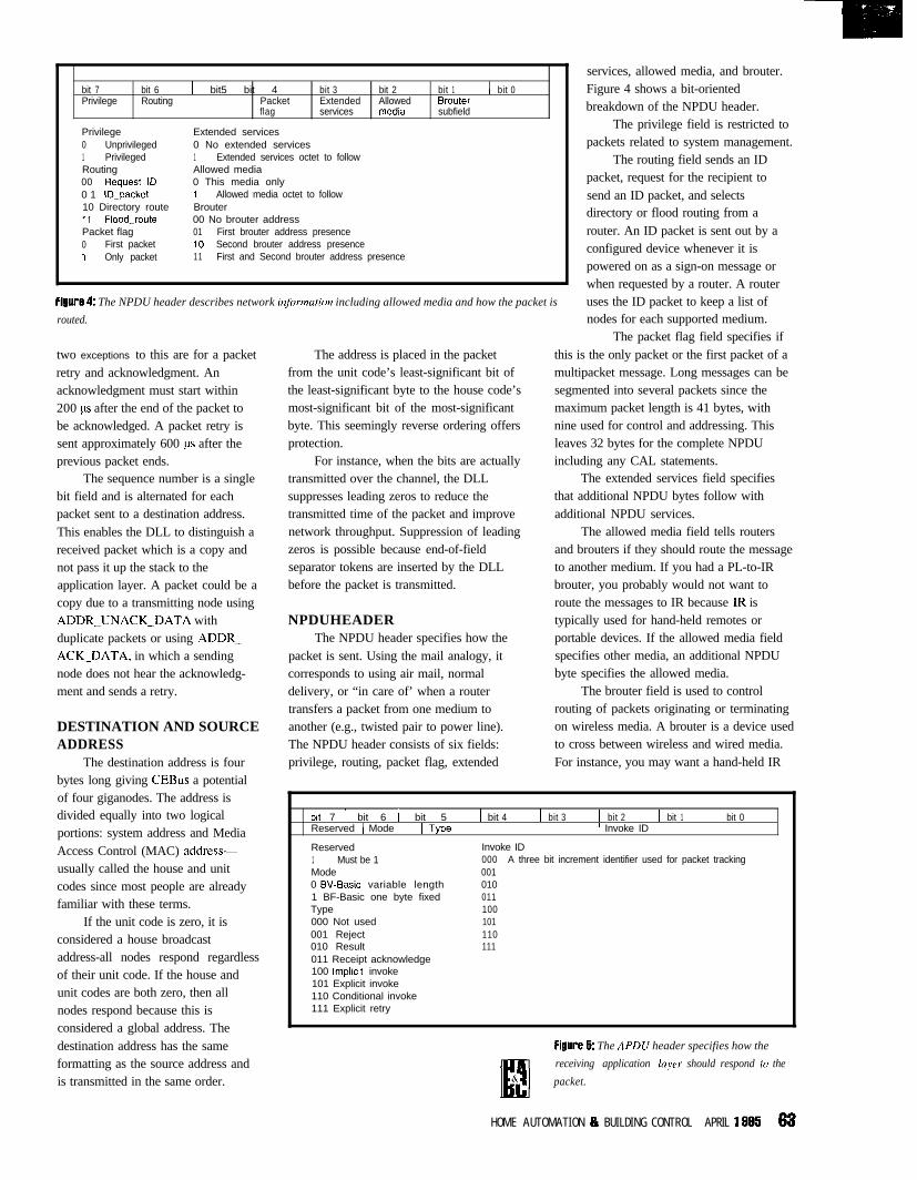
bit 7 bit 6 1 bit5 bit 4 bit 3 bit 2 bit 1 1 bit 0Privilege Routing Packet Extended Allowed Brouter
flag services medra subfield
Privilege Extended services0 Unprivileged 0 No extended services1 Privileged 1 Extended services octet to followRouting Allowed media00 Request_lD 0 This media only0 1 ID-packet 1 Allowed media octet to follow10 Directory route Brouter11 Flooddroute 00 No brouter addressPacket flag 01 First brouter address presence0 First packet 10 Second brouter address presence1 Only packet 11 First and Second brouter address presence
FigIll?? 4: The NPDU header describes network inf~vmation including allowed media and how the packet is
routed.
two exceptions to this are for a packetretry and acknowledgment. Anacknowledgment must start within200 ps after the end of the packet tobe acknowledged. A packet retry issent approximately 600 us after theprevious packet ends.
The sequence number is a singlebit field and is alternated for eachpacket sent to a destination address.This enables the DLL to distinguish areceived packet which is a copy andnot pass it up the stack to theapplication layer. A packet could be acopy due to a transmitting node usingADDR_UNACK_DATA withduplicate packets or using ADDR_ACK_DATA, in which a sendingnode does not hear the acknowledg-ment and sends a retry.
DESTINATION AND SOURCEADDRESS
The destination address is fourbytes long giving CEBus a potentialof four giganodes. The address isdivided equally into two logicalportions: system address and MediaAccess Control (MAC) address-usually called the house and unitcodes since most people are alreadyfamiliar with these terms.
If the unit code is zero, it isconsidered a house broadcastaddress-all nodes respond regardlessof their unit code. If the house andunit codes are both zero, then allnodes respond because this isconsidered a global address. Thedestination address has the sameformatting as the source address andis transmitted in the same order.
The address is placed in the packetfrom the unit code’s least-significant bit ofthe least-significant byte to the house code’smost-significant bit of the most-significantbyte. This seemingly reverse ordering offersprotection.
For instance, when the bits are actuallytransmitted over the channel, the DLLsuppresses leading zeros to reduce thetransmitted time of the packet and improvenetwork throughput. Suppression of leadingzeros is possible because end-of-fieldseparator tokens are inserted by the DLLbefore the packet is transmitted.
NPDUHEADERThe NPDU header specifies how the
packet is sent. Using the mail analogy, itcorresponds to using air mail, normaldelivery, or “in care of’ when a routertransfers a packet from one medium toanother (e.g., twisted pair to power line).The NPDU header consists of six fields:privilege, routing, packet flag, extended
services, allowed media, and brouter.Figure 4 shows a bit-orientedbreakdown of the NPDU header.
The privilege field is restricted topackets related to system management.
The routing field sends an IDpacket, request for the recipient tosend an ID packet, and selectsdirectory or flood routing from arouter. An ID packet is sent out by aconfigured device whenever it ispowered on as a sign-on message orwhen requested by a router. A routeruses the ID packet to keep a list ofnodes for each supported medium.
The packet flag field specifies ifthis is the only packet or the first packet of amultipacket message. Long messages can besegmented into several packets since themaximum packet length is 41 bytes, withnine used for control and addressing. Thisleaves 32 bytes for the complete NPDUincluding any CAL statements.
The extended services field specifiesthat additional NPDU bytes follow withadditional NPDU services.
The allowed media field tells routersand brouters if they should route the messageto another medium. If you had a PL-to-IRbrouter, you probably would not want toroute the messages to IR because IR istypically used for hand-held remotes orportable devices. If the allowed media fieldspecifies other media, an additional NPDUbyte specifies the allowed media.
The brouter field is used to controlrouting of packets originating or terminatingon wireless media. A brouter is a device usedto cross between wireless and wired media.For instance, you may want a hand-held IR
brt 7 1 bit 6 1 bit 5Reserved ) Mode t TypeReserved1 Must be 1Mode0 W-Basic variable length1 BF-Basic one byte fixedType000 Not used001 Reject010 Result011 Receipt acknowledge100 lmpkcit invoke101 Explicit invoke110 Conditional invoke111 Explicit retry
1 bit 4 1 bit 3 1 bit 2 1 bit 1 1 bit 01 Invoke ID
Invoke ID000 A three bit increment identifier used for packet tracking001010011100101110111
FigIll?? 5: The APDU header specifies how the
receiving application layer should respond to the
packet.
H O M E A U T O M A T I O N IO BU ILD ING CONTROL APRIL 1 axi 63
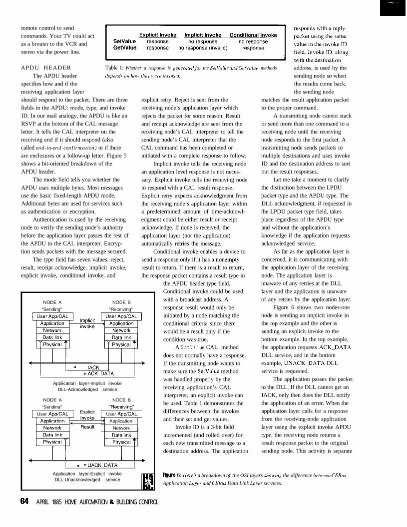
remote control to sendcommands. Your TV could actas a brouter to the VCR andstereo via the power line.
APDU HEADER Table 1: Whether a response is generated,for the SetValue and GetValue methods address, is used by theThe APDU header
specifies how and if thereceiving application layershould respond to the packet. There are threefields in the APDU: mode, type, and invokeID. In our mail analogy, the APDU is like anRSVP at the bottom of the CAL messageletter. It tells the CAL interpreter on thereceiving end if it should respond (alsocalled end-to-end confirmation) or if thereare enclosures or a follow-up letter. Figure 5shows a bit-oriented breakdown of theAPDU header.
The mode field tells you whether theAPDU uses multiple bytes. Most messagesuse the basic fixed-length APDU mode.Additional bytes are used for services suchas authentication or encryption.
Authentication is used by the receivingnode to verify the sending node’s authoritybefore the application layer passes the rest ofthe APDU to the CAL interpreter. Encryp-tion sends packets with the message secured.
The type field has seven values: reject,result, receipt acknowledge, implicit invoke,explicit invoke, conditional invoke, and
NODE A
“Sending”
NODE B
“Receiving”
Application layer-Implicit invokeDLL-Acknowledged service
NODE A
“Sendina”
NODE B
“Receivina”u
User App/CAL Explicit User App/CAL
Application
Network
explicit retry. Reject is sent from thereceiving node’s application layer whichrejects the packet for some reason. Resultand receipt acknowledge are sent from thereceiving node’s CAL interpreter to tell thesending node’s CAL interpreter that theCAL command has been completed orinitiated with a complete response to follow.
Implicit invoke tells the receiving nodean application level response is not neces-sary. Explicit invoke tells the receiving nodeto respond with a CAL result response.Explicit retry expects acknowledgment fromthe receiving node’s application layer withina predetermined amount of time-acknowl-edgment could be either result or receiptacknowledge. If none is received, theapplication layer (not the application)automatically retries the message.
Conditional invoke enables a device tosend a response only if it has a nonemptyresult to return. If there is a result to return,the response packet contains a result type in
the APDU header type field.Conditional invoke could be usedwith a broadcast address. Aresponse result would only beinitiated by a node matching theconditional criteria since therewould be a result only if thecondition was true.
A SetVal ue CAL methoddoes not normally have a response.If the transmitting node wants tomake sure the SetValue methodwas handled properly by thereceiving application’s CALinterpreter, an explicit invoke canbe used. Table 1 demonstrates thedifferences between the invokesand their set and get values.
Invoke ID is a 3-bit fieldincremented (and rolled over) foreach new transmitted message to adestination address. The application
4 I I I I ,
l ’ UACK_DATA
Application layer-Explicit invokeDLL-Unacknowledged service
sending node so whenthe results come back,the sending node
matches the result application packetto the proper command.
A transmitting node cannot stackor send more than one command to areceiving node until the receivingnode responds to the first packet. Atransmitting node sends packets tomultiple destinations and uses invokeID and the destination address to sortout the result responses.
Let me take a moment to clarifythe distinction between the LPDUpacket type and the APDU type. TheDLL acknowledgment, if requested inthe LPDU packet type field, takesplace regardless of the APDU typeand without the application’sknowledge if the application requestsacknowledged service.
As far as the application layer isconcerned, it is communicating withthe application layer of the receivingnode. The application layer isunaware of any retries at the DLLlayer and the application is unawareof any retries by the application layer.
Figure 6 shows two nodes-onenode is sending an implicit invoke inthe top example and the other issending an explicit invoke to thebottom example. In the top example,the application requests ACK_DATADLL service, and in the bottomexample, UNACK_DATA DLLservice is requested.
The application passes the packetto the DLL. If the DLL cannot get anIACK, only then does the DLL notifythe application of an error. When theapplication layer calls for a responsefrom the receiving-node applicationlayer using the explicit invoke APDUtype, the receiving node returns aresult response packet to the originalsending node. This activity is separate
&UU?! 6: Herr’s a breakdown qf the OSI layers slmving the difference betweerz CEBus
Application Layer and CEBm Data Link Layer services.
64 APRIL 1885 HOME AUTOMATION 8 BUILDING CONTROL
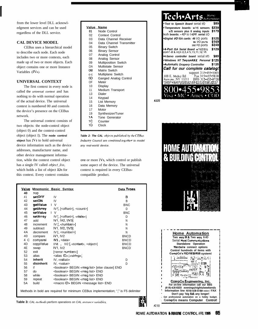
from the lower level DLL acknowl-edgment services and can be usedregardless of the DLL service.
CAL DEVICE MODELCEBus uses a hierarchical model
to describe each node. Each nodeincludes two or more contexts, eachmade up of two or more objects. Eachobject contains one or more InstanceVariables (IVs).
UNIVERSAL CONTEXTThe first context in every node is
called the universal context and hasnothing to do with normal operationof the actual device. The universalcontext is numbered 00 and controlsthe device’s presence on the CEBusnetwork.
The universal context consists oftwo objects: the node-control object(object 0) and the context-controlobject (object I). The node control
object has IVs to hold universaldevice information such as the deviceaddresses, manufacturer name, andother device management informa-tion, while the context control objecthas a single IV called object_list,
which holds a list of object IDS forthis context. Every context contains
Value Name01 Node Control02 Context Control03 Data Channel Receiver04 Data Channel Transmitter05 Binary Switch06 Binary Sensor07 Analog Control08 Analog Sensor09 Multiposition SwitchOA Multistate Sensor06 Matrix Switcho c Multiplane SwitchOD Ganged Analog ControlOF Meter10 Display11 Medium Transport13 Dialer14 Keypad15 List Memory16 Data Memory17 Motor19 Synthesizer/Tuner1A Tone Generator1c Counter1D Clock
Table 2: The CAL objects published hy the CEBus
Industry Council are combined together to model
any real-world device.
one or more IVs, which control or publishsome aspect of the device. The universalcontext is required in every CEBus-compatible product.
Value Mnemonic Basic Svntax Data Tvnes40 nw41 setOFF IV 642 setON IV B43 getvalue I V BNC44 getArray IV [, [<offset>], <count>] D45 setValue I V BNC46 setArray IV [, [<offset>], <data>] D47 add IVl, IV2, [IV31 N48 increment IV [, <number>] N49 subtract IVl, IV2, [IV31 N4A decrement IV [, <number>] N40 compare IVl, IV2 BNCD4 C comparei IV1 , <data> BNCD4D copyvalue IV1 , IV2 [, <context>, <object>] BNCD4E swap IVl, IV2 BNCD52 exit [<error number>]53 alias <alias ID> [<string>]54 inherit IV, <value> D55 disinherit IV, <value> D56 if <boolean> BEGIN <msg list> [else clause] END57 do <boolean> BEGIN <msg list> END58 while <boolean> BEGIN <msg list> END59 repeat <boolean> BEGIN <msg list> END5A build <macro ID> BEGIN <message list> END
Methods in bold are required for minimum CEBus implementation; “,‘I is F5 delimiter
Table 3: CAL merhods perform operations on CAL inskznce variables.E
&
b.I
Text to Speech Board serial I/O
Temperature boards: w/16 sensorsw/8 sensors plus 8 analog inputs
0th boards: - 40’ to 1467, serial I/ODigital l/O ISA cards: 46 I/O ports
96 I/O ports192 I/O ports
I-Porf ISA Serial Board w/l 6550soml-8&irq’s2,3,4,5,10,11,12,15I-Servo controller board serial l/O
Windows NT TelcomFAX Personal4otomatic Drapery Controller
:all fur our complete catalog1support 3 I5*455.1003
08 E. Molloy Rd Fax 315.455.5838~vracuse. NY 13211 BBS 315.45508728
Home AutomationTwo wav IR 8 Two wav X-IOSerial H&t Commun&tions
Standalone OperationHardwire connect options
Control hundreds of items withCompCo’s RlDlREBlRlB system!
Corndo Enqineerinq, Inc.For on-line information call our BBS
(615)-436-6333 evenings/nights/weekendsInformation line 16151-436-5189 voice I FAX
Don’t pay ‘big S$$ any longer!Get professional automation on a hobby budget.
CompCo means Computer Control!
ROME AUTOMATION 8 BUlllUN6 CONTROL APRIL 1895 65
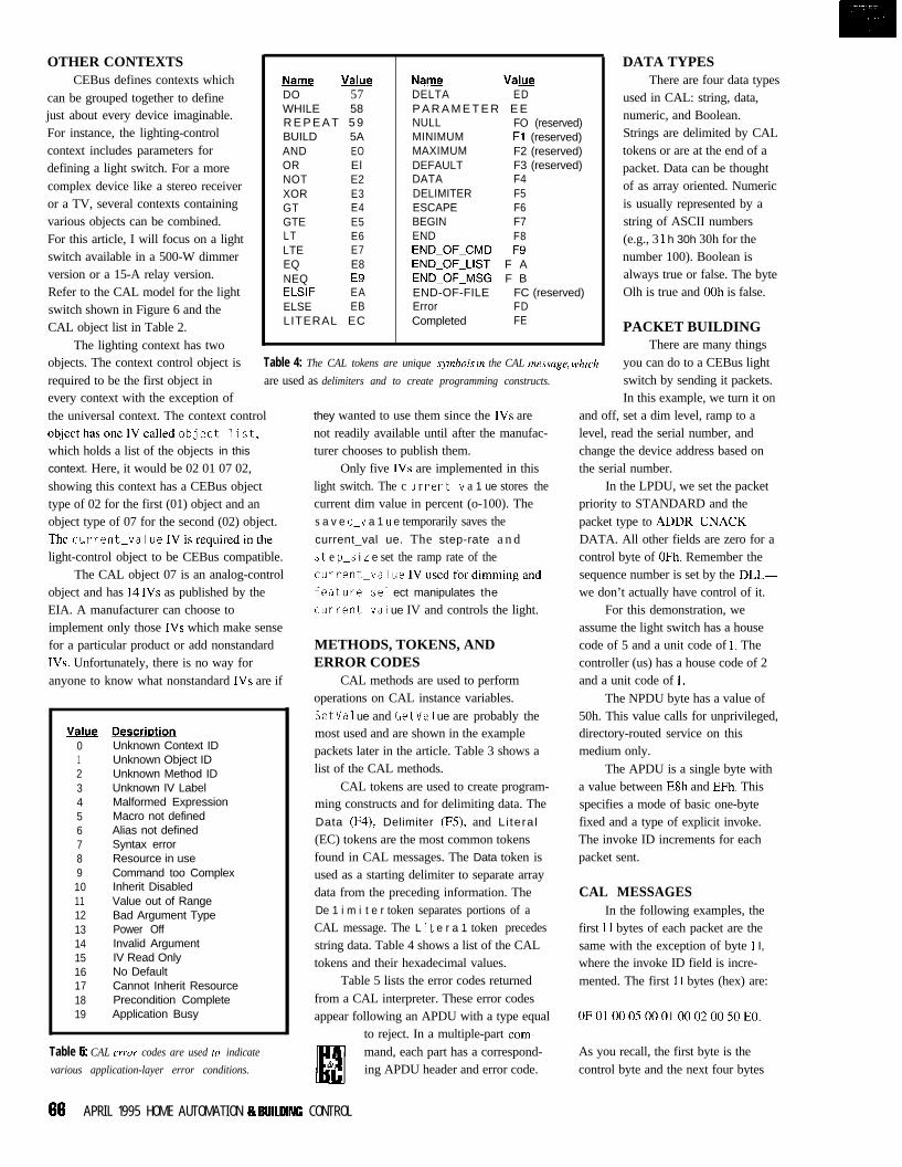
OTHER CONTEXTS DATA TYPESCEBus defines contexts which
can be grouped together to definejust about every device imaginable.For instance, the lighting-controlcontext includes parameters fordefining a light switch. For a morecomplex device like a stereo receiveror a TV, several contexts containingvarious objects can be combined.For this article, I will focus on a lightswitch available in a 500-W dimmerversion or a 15-A relay version.Refer to the CAL model for the lightswitch shown in Figure 6 and theCAL object list in Table 2.
Name &y&DO 57WHILE 58R E P E A T 5 9BUILD 5AAND EOOR ElNOT E2XOR E3GT E4GTE E5LT E6LTE E7EQ E8NEQ E9ELSIF EAELSE EBLITERAL EC
Name &&&sDELTA EDP A R A M E T E R E ENULL FO (reserved)MINIMUM Fl (reserved)MAXIMUM F2 (reserved)DEFAULT F3 (reserved)DATA F4DELIMITER F5ESCAPE F6BEGIN F7END F8END_OF_CMD F9END_OF_LIST F AEND_OF_MSG F BEND-OF-FILE FC (reserved)Error FDCompleted FE
There are four data typesused in CAL: string, data,numeric, and Boolean.Strings are delimited by CALtokens or are at the end of apacket. Data can be thoughtof as array oriented. Numericis usually represented by astring of ASCII numbers(e.g., 3 1 h 30h 30h for thenumber 100). Boolean isalways true or false. The byteOlh is true and OOh is false.
PACKET BUILDINGThe lighting context has two
objects. The context control object is Table 4: The CAL tokens are unique symbols rn the CAL message, which
are used as delimiters and to create programming constructs.required to be the first object in
There are many thingsyou can do to a CEBus lightswitch by sending it packets.In this example, we turn it onevery context with the exception of
the universal context. The context controlobjecthasoneIVcalledobject_list,which holds a list of the objects in this
context. Here, it would be 02 01 07 02,showing this context has a CEBus objecttype of 02 for the first (01) object and anobject type of 07 for the second (02) object.Thecurrent-ValueIVisrequiredinthelight-control object to be CEBus compatible.
The CAL object 07 is an analog-controlobject and has 14 IVs as published by theEIA. A manufacturer can choose toimplement only those IVs which make sensefor a particular product or add nonstandardIVs. Unfortunately, there is no way foranyone to know what nonstandard IVs are if
Value DescriDtion0 Unknown Context ID1 Unknown Object ID2 Unknown Method ID3 Unknown IV Label4 Malformed Expression5 Macro not defined6 Alias not defined7 Syntax error8 Resource in use9 Command too Complex10 Inherit Disabled11 Value out of Range12 Bad Argument Type13 Power Off14 Invalid Argument15 IV Read Only16 No Default17 Cannot Inherit Resource18 Precondition Complete19 Application Busy
Table 5: CAL error codes are used to indicate
various application-layer error conditions.
they wanted to use them since the IVs arenot readily available until after the manufac-turer chooses to publish them.
Only five IVs are implemented in thislight switch. The c LI r rent-v a 1 ue stores thecurrent dim value in percent (o-100). Thes a v e d-v a 1 u e temporarily saves thecurrent_val ue. The step-rate a n ds t e p-s i L e set the ramp rate of thecurrent_valueIVusedfordimmingandfeature-se1 ect manipulates the
current~val ue IV and controls the light.
METHODS, TOKENS, ANDERROR CODES
CAL methods are used to performoperations on CAL instance variables.SetVal ue and GetVal ue are probably themost used and are shown in the examplepackets later in the article. Table 3 shows alist of the CAL methods.
CAL tokens are used to create program-ming constructs and for delimiting data. TheData (F4), Delimiter (F5), and Li tera l
(EC) tokens are the most common tokensfound in CAL messages. The Data token isused as a starting delimiter to separate arraydata from the preceding information. TheDe 1 i m i t e r token separates portions of aCAL message. The L i t e r a 1 token precedesstring data. Table 4 shows a list of the CALtokens and their hexadecimal values.
Table 5 lists the error codes returnedfrom a CAL interpreter. These error codesappear following an APDU with a type equal
to reject. In a multiple-part com-mand, each part has a correspond-ing APDU header and error code.
and off, set a dim level, ramp to alevel, read the serial number, andchange the device address based onthe serial number.
In the LPDU, we set the packetpriority to STANDARD and thepacket type to ADDR_UNACK_DATA. All other fields are zero for acontrol byte of OFh. Remember thesequence number is set by the DLL-we don’t actually have control of it.
For this demonstration, weassume the light switch has a housecode of 5 and a unit code of 1. Thecontroller (us) has a house code of 2and a unit code of 1.
The NPDU byte has a value of50h. This value calls for unprivileged,directory-routed service on thismedium only.
The APDU is a single byte witha value between E8h and EFh. Thisspecifies a mode of basic one-bytefixed and a type of explicit invoke.The invoke ID increments for eachpacket sent.
CAL MESSAGESIn the following examples, the
first 11 bytes of each packet are thesame with the exception of byte 1 I,where the invoke ID field is incre-mented. The first 1 I bytes (hex) are:
0F010005000100020050E0.
As you recall, the first byte is thecontrol byte and the next four bytes
66 APRIL 1995 HOME AUTOMATION & 9UllDlNC CONTROL
are the destination-address informa-tion in right-to-left order, followed bythe source address, also in right-to-leftorder. The next two bytes are theNPDU and APDU headers.
ON, OFF, OR DIMThe on command uses the
Set V a 1 LI e method to send a value of37htothe feature-select IV.Thissets the current value to 100 by thedefinitionof feature-select. Thebytes (hex) then are:
21 02 45 66 F5 37. The LPDU (50) shows a standard
The 21 is the ID of the lighting context, 02 isthe object number of the analog control, 45is the SetVal ue method, 66 is thefeature-se1 ect IV (i.e., ASCII “f’), F5 isa delimiter, and 37 is an ASCII “7”. Thecomplete packet is:
OF01 00050001 00020050E821 024566 F5 37.
The response to this packet is:
OF010002000100050050DOFE.
Let Your Development Fly!Choose Hitex pmfessional twls for yourembedded microprccessof design and getyour prcject Off the ground ahead ofschedule. Hit@ builds all types of micro-pmcessw development twts, from
Call Hitex for your free demopackage and learn how smoothand efficient development withprofessional tcois really can be!
sophisticated in-circuit emulators to remotedebuggers, monitors and simulators.
HiTOOLS Inc.
Complete solutions are available for:‘2055 Gateway Placesuite 400
tithe complete 6051 family San Jose, CA 95110~80C66/88,60C186/166EAIEB/ECiXl., P
60266, v2ON30/v40N60(406) 451-3965
0 l -KG46HITEXr’8038BDX/SxICX/EX~6OC166/166/167
Fax (406) 441-9486
fwnity630x. 6633x. 66340
packet priority and a packet type of ADDR_UNACK_DATA, which does not require aresponse from the DLL to acknowledgepacket receipt. The source and destinationaddresses are reversed since the device isnow sending to the controller instead ofreceiving from it. The NPDU (EO) is thesame as transmitted. The APDU has thesame mode, but the type field shows that it isa result packet with the result of FE, which isthe completed CAL token.
Whew! I think I’ll have someone get upand turn the switch on next time.
The packet to turn the light off isidentical, except the value for the feat u repse 1 ec t IV changes to 33h and the invokeID field for the APDU is incremented byone. Setting the feature-se1 ect to 33halsosavesthecurrent_valueinthes a v e d-v a 1 u e IV before setting thec u r r e n t_v a 1 u e to 0. This offers the featureof having the light later restore to theprevious dim setting.
The result packet is the same, exceptthe invoke ID matches the invoke ID wesent, which is what the invoke ID is intendedfor. We could issue several commands tothis light switch. Since the result packets areall identical, except for the invoke ID, wecan use this field to track the responses to thepackets sent. The complete sent packet is:
0F010005000100020050E921024566 FS 33
and the response is:
OF01 00020001 00050050Dl FE.
To dim the light, we set the c u r re n t_va 1 ue IV to the dim level desired. In thisexample, we’ll use 50%. With a packet of 2102 45 43 FS 35 30, the 21 is the ID of thelighting context, 02 is the object number ofthe analog control. 45 is the SetVal uemethod, 43 is the current-value IV(ASClI “C”), F5 is a delimiter, and 35 30 isASCII for “5” and “0” or 50%. The completepacket is:
0F0l0001001400150050EA21024543 F5 35 30.
The result packet is once again identical,except for the invoke ID:
OF01 00020001 00050050D2FE.
HOME AUTOMATION BI BUILDING CONTROL APRIL 1995 67
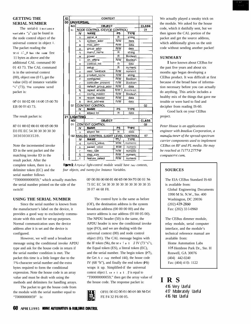
GETTING THESERIAL NUMBER
The serial-ii instancevariable “s"can be found inthe node control object of theuniversal context in object I.The packet reading these ri al_# has the same first11 bytes as above and theadditional CAL command 0001 43 73. The CAL commandis in the universal context(00), object one (0 I ), get thevalue (43) of instance variable“s” (73). The complete sendpacket is:
0F010002001400150070EB 00 01 43 73.
The result packet is:
8F010002000100050050D3 FE EC 54 30 30 30 30 30303030303539.
Note the incremented invokeID in the sent packet and thematching invoke ID in theresult packet. After thecomplete token, there is adelimiter token (EC) and theserial number follows
CONTEXTJNIVERSAL INO31
Iable 1 RNV 1 Boolean
obiect list1 PS 1 TYPE 1
data
_. . . . _ohiect list0 --1--- ..--
, data
32 ANALOG CONTROL (LIGHT LEVEL CONTROL) 07,” 1 kIdME ’ DE ’ TYPEc I “UIIIIII_“UIYI ,.,.. , numeric
value I R/w I numeric
Figure 6: A typical light-control module would have two contexts,four objects, and twenty-jive Instance Variables.
“T000000000059,” which actually matches 0F000000000100050050F0000156
the serial number printed on the side of the 73 EC EC 54 30 30 30 30 30 30 30 30 30 35
switch! 39 F7 44 68 F8.
USING THE SERIAL NUMBERSince the serial number is known from
the manufacturer’s label on the device, itprovides a good way to exclusively commu-nicate with this unit for set-up purposes.Normal communication uses the deviceaddress after it is set and the device isconfigured.
However, we will send a broadcastmessage using the conditional invoke APDUtype and ask for the house code in return ifthe serial number condition is met. Thepacket this time is a little longer due to theI %-character serial number and the extrabytes required to form the conditionalexpression. Note the house code is an arrayvalue and must be dealt with using themethods and delimiters for handling arrays.
The control byte is the same as before
(OF), the destination address is the systembroadcast address (00 00 00 00) and thesource address is our address (01 00 05 00).The NPDU header (50) is the same, theAPDU header is now the conditional invoketype (FO), and we are dealing with theuniversal context (00) and node controlobject (01). The CAL message begins withthe IF token (56), the se r i a 1 _I/ IV (73 “s”),the Equal token (ES), a literal token (EC),and the serial number. The begin token (F7),the Get A r ray method (44), the house codeIV (68 “h”), and finally the end token (F8)wraps it up. Simplified-if the universalcontext object I, se r i a 1 -iI is equal to“T00000000059,” then get the array value ofthe house code. The response packet is:
The packet to get the house code fromthe module with the serial number equal to“T00000000059” is:
OF01 0002000100050050D4FE F4 32 F6 00 05.
We actually played a sneaky trick onthe module. We asked for the housecode, which it dutifully sent, but wethen ignore the CAL portion of thepacket and get the source address,which additionally gives us the unitcode without sending another packet!
SUMMARYI have known about CEBus for
the past five years and about sixmonths ago began developing aCEBus product. It was difficult at firstbecause of the broad base of informa-tion necessary before you can actuallydo anything. This article includes ahealthy mix of the things that gave metrouble or were hard to find anddecipher from reading IS-60.
Good luck on your CEBusproject.
Peter House is an applicationsengineer with Intellon Corporation, amangfacturer of the spread-spectrumcarrier components used to implementCEBus on RF and PL media. He may
be reached at [email protected].
SOURCES
The EIA CEBus Standard IS-60is available from:
Global Engineering Documents1990 M St. N.W., Ste. 400Washington, DC 20036(202) 429-2860Fax: (202) 33 l-0960
The CEBus dimmer module,relay module, serial computerinterface, and the module’stechnical reference manual areavailable from:
Home Automation LabsI05 Hembree Park Dr., Ste. HRoswell, GA 30076(404) 442-0240Fax: (404) 4 lo- 1122
I R S416 Very Useful417 Moderately Useful416 Not Useful
66 APRIL1995 HOMEAUTOMATlON&9UlLOtNGCONTROL
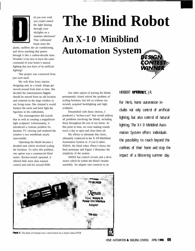
id you ever wishyou could controlthe light blazingthrough yourskylights on asummer afternoon?That collimatedbeam sears the
plants, nullifies the air conditioning,and slices anything that passesthrough it like a carbon-dioxide laser.Wouldn’t it be nice to have the samecommand of your home’s naturallighting that you have of its artificiallighting?
This project was conceived fromjust such need.
My wife Kim loves interiordesigning and, as a result, things getmoved around from time to time. Shedecided the entertainment Ctagereshould be moved from its old locationand centered on the large window inour living room. She claimed it wouldbalance the room and back light thefigurines in the cubbyholes.
The rearrangement did exactlythat as well as creating a magnificentlight sculpture! Unfortunately, itintroduced a contrast problem fordaytime TV viewing and rendered thewindow’s two miniblinds nearlyinaccessible.
Operating the blinds became adreaded task which involved scalingthe furniture. To solve this problem,one option was a commercial blindmotor. Rocker-switch operated, itoffered little more than manualcontrol and sold for around $300.
The Blind RobotAn X-10 MiniblindAutomation Syste
Our other option of leaving the blindspermanently closed solved the problem ofscaling furniture, but left us without ourrecently acquired backlighting and lightsculpture.
Dissatisfied with those choices, Ipondered a “techno-cure” that would addressall problems involving the blinds, includingthose throughout the rest of our home. Atthis point in time, we were making roundstwice a day to open and close them all.
My efforts to eliminate this chore,ultimately coalesced in the X- 10 MiniblindAutomation System or. if you’d rather,XMAS, the blind robot. Photo I shows thefinal prototype and Figure 1 illustrates thesimplicity of the system.
XMAS has control circuits and a drivemotor which fit within the blind’s headerassembly. An adapter unit connects to an
HERBERT MCKINNEY, JR.
For Herb, home automation in-
cludes not only control of artificial
lighting, but also control of natural
lighting. The X-l 0 Miniblind Auto-
mation System offers individuals
the possibility to reach beyond the
confines of their home and stop the
impact of a blistering summer day.
Power *upply EkPower Une Intwface s a
Adapter
HOME AUTOMATION Ip BUILDING CONTROL APRIL 1 BB5 69
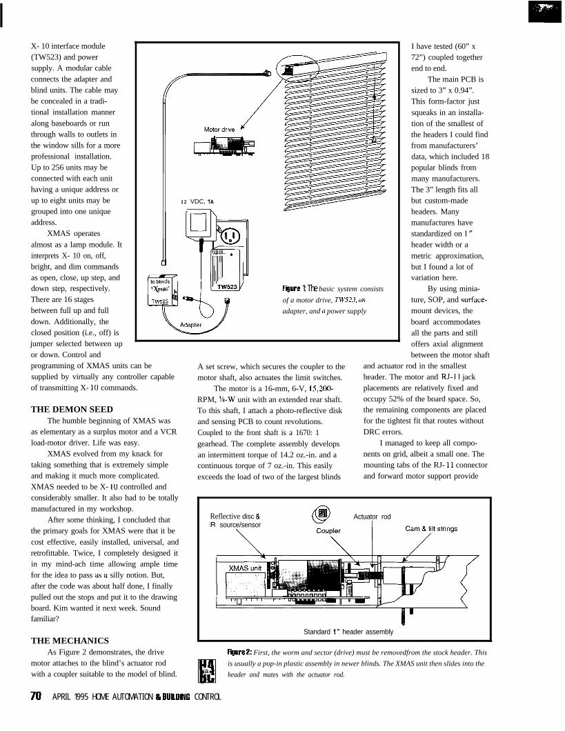
X- 10 interface module(TW523) and powersupply. A modular cableconnects the adapter andblind units. The cable maybe concealed in a tradi-tional installation manneralong baseboards or runthrough walls to outlets inthe window sills for a moreprofessional installation.Up to 256 units may beconnected with each unithaving a unique address orup to eight units may begrouped into one uniqueaddress.
XMAS operatesalmost as a lamp module. Itinterprets X- 10 on, off,bright, and dim commandsas open, close, up step, anddown step, respectively.There are 16 stagesbetween full up and fulldown. Additionally, theclosed position (i.e., off) isjumper selected between upor down. Control andprogramming of XMAS units can besupplied by virtually any controller capableof transmitting X- 10 commands.
12 VDC, 1 A
, \
FigUre 1: The basic system consists
of a motor drive, TW523, cln
adapter, and a power supply
A set screw, which secures the coupler to themotor shaft, also actuates the limit switches.
The motor is a 16-mm, 6-V, 15,200-RPM, i/8-W unit with an extended rear shaft.To this shaft, I attach a photo-reflective diskand sensing PCB to count revolutions.Coupled to the front shaft is a 1670: 1gearhead. The complete assembly developsan intermittent torque of 14.2 oz.-in. and acontinuous torque of 7 oz.-in. This easily
The main PCB issized to 3” x 0.94”.This form-factor justsqueaks in an installa-tion of the smallest ofthe headers I could findfrom manufacturers’data, which included 18popular blinds frommany manufacturers.The 3” length fits allbut custom-madeheaders. Manymanufactures havestandardized on 1 wheader width or ametric approximation,but I found a lot ofvariation here.
By using minia-ture, SOP, and surface-mount devices, theboard accommodatesall the parts and stilloffers axial alignmentbetween the motor shaft
and actuator rod in the smallestheader. The motor and RJ-I 1 jackplacements are relatively fixed andoccupy 52% of the board space. So,the remaining components are placedfor the tightest fit that routes withoutDRC errors.
THE DEMON SEEDThe humble beginning of XMAS was
as elementary as a surplus motor and a VCRload-motor driver. Life was easy.
XMAS evolved from my knack fortaking something that is extremely simpleand making it much more complicated.XMAS needed to be X- 10 controlled andconsiderably smaller. It also had to be totallymanufactured in my workshop.
I have tested (60” x72”) coupled togetherend to end.
I managed to keep all compo-nents on grid, albeit a small one. Themounting tabs of the RJ- 11 connector
exceeds the load of two of the largest blinds and forward motor support provide
After some thinking, I concluded that Reflective disc &IR source/sensor
Actuator rod
the primary goals for XMAS were that it becost effective, easily installed, universal, andretrofittable. Twice, I completely designed itin my mind-ach time allowing ample timefor the idea to pass as,a silly notion. But,after the code was about half done, I finallypulled out the stops and put it to the drawingboard. Kim wanted it next week. Soundfamiliar?
THE MECHANICSAs Figure 2 demonstrates, the drive
Standard 1 m header assembly
FiglIt?? 2: First, the worm and sector (drive) must be removedfrom the stock header. This
motor attaches to the blind’s actuator rod
EY
is usually a pop-in plastic assembly in newer blinds. The XMAS unit then slides into the
with a coupler suitable to the model of blind. & header and mates with the actuator rod.
70 APRIL 1995 HOME AUTOMATION R 9UlllRNG CONTROL
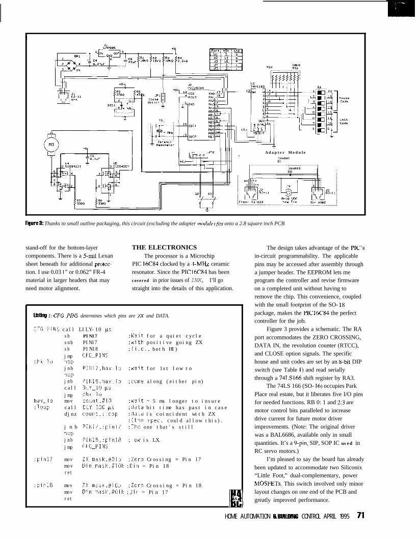
Adapter Module:
IN4BB3DI
L--
Figure 8: Thanks to small outline packaging, this circuit (excluding the adapter module)fits onto a 2.8 square inch PCB
stand-off for the bottom-layer THE ELECTRONICScomponents. There is a 5-mil Lexan The processor is a Microchipsheet beneath for additional protec- PIC l6C84 clocked by a ~-MHZ ceramiction. I use 0.03 1” or 0.062” FR-4 resonator. Since the PIC16C84 has beenmaterial in larger headers that may covered in prior issues of INK, I’ll goneed motor alignment. straight into the details of this application.
LiStill! 1: CFG_PINS determines which pins are ZX and DATA.
The design takes advantage of the PIG’sin-circuit programmability. The applicablepins may be accessed after assembly througha jumper header. The EEPROM lets meprogram the controller and revise firmwareon a completed unit without having toremove the chip. This convenience, coupledwith the small footprint of the SO- 18package, makes the PIC16C84 the perfectcontroller for the job.
CFG_PINS call LILY-10 KSsb PIN17 ;Wait for a quiet cyclesnb PIN17 ;with positive going ZXsb PIN18 ;(i.e., both HI)jmp CFGGPINS
chk_loI
napjnb PIN17,hav-lo ;wait for 1st low tonapjnb PIN18,hav-lo ;come along (either pin)call DLY_lO psjmp chk_lo
hav_lo mov count,#lO ;wait - 5 ms longer to insure:loop call DLYK500 ks :data bit time has past in case
djnz count,:loop :data is coincident with ZX:(the spec. could allow this).
j n b PIN17,:pinl7 :The one that's stillnapjnb PIN18,:pinl8 :low is LX.jmp CFGGPINS
Figure 3 provides a schematic. The RAport accommodates the ZERO CROSSING,DATA IN, the revolution counter (RTCC),and CLOSE option signals. The specifichouse and unit codes are set by an &bit DIPswitch (see Table 1) and read seriallythrough a 74LS166 shift register by RA3.
The 74LS 166 (SO- 16) occupies ParkPlace real estate, but it liberates five I/O pinsfor needed functions. RB 0: 1 and 2:3 aremotor control bits paralleled to increasedrive current for future motor driverimprovements. (Note: The original driverwas a BAL6686, available only in smallquantities. It’s a 9-pin, SIP, SOP IC used inRC servo motors.)
:pinl7 mov ZX_mask,#Olb ;Zero Crossing = Pin 17mov Din-mask,#lOb :Din = Pin 18ret
I’m pleased to say the board has alreadybeen updated to accommodate two Siliconix“Little Foot,” dual-complementary, powerMOSFETs. This switch involved only minorlayout changes on one end of the PCB andgreatly improved performance.
:pinl8 mov ZX_mask,#lOb ;Zero Crossing = Pin 18mov Din_mask,#Olb ;Din = Pin 17ret
E!&
HOME AUTOMATION 8 BUILUING CONTROL APRIL 1995 71
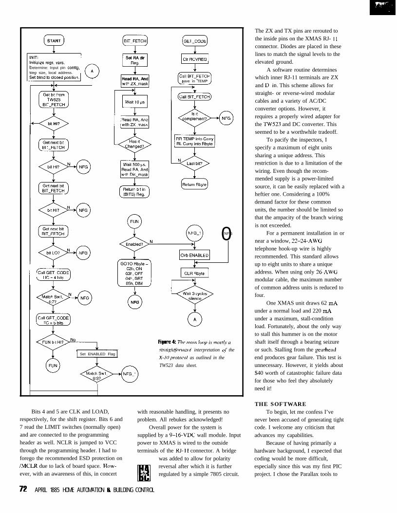
ISTART
lnitialaze regs, vars.Determine: Input pin config,step size, local address.
I-c>bit HI?
+lSet RA dir
f-lRead RA, Andwith ZX_mask
0NFG
save in TEMP
0NFG
Wait 3 cyclessilence9A
Set ENABLED Flag.straightforward interpretation qf the
X-IOprotocol as outlined in the
TW523 data sheet.
Bits 4 and 5 are CLK and LOAD,respectively, for the shift register. Bits 6 and7 read the LIMIT switches (normally open)and are connected to the programmingheader as well. NCLR is jumped to VCCthrough the programming header. I had toforego the recommended ESD protection on/MCLR due to lack of board space. How-ever, with an awareness of this, in concert
with reasonable handling, it presents noproblem. All rebukes acknowledged!
Overall power for the system issupplied by a 9-16-VDC wall module. Inputpower to XMAS is wired to the outsideterminals of the RJ-I I connector. A bridge
was added to allow for polarity
U
reversal after which it is further& regulated by a simple 7805 circuit.
72 APRIL 1885 HOME AUTOMATION & BUILDING CONTROL
The ZX and TX pins are rerouted tothe inside pins on the XMAS RJ- I Iconnector. Diodes are placed in theselines to match the signal levels to theelevated ground.
A software routine determineswhich inner RJ-11 terminals are ZXand D-in. This scheme allows forstraight- or reverse-wired modularcables and a variety of AC/DCconverter options. However, itrequires a properly wired adapter forthe TW.523 and DC converter. Thisseemed to be a worthwhile tradeoff.
To pacify the inspectors, Ispecify a maximum of eight unitssharing a unique address. Thisrestriction is due to a limitation of thewiring. Even though the recom-mended supply is a power-limitedsource, it can be easily replaced with aheftier one. Considering a 100%demand factor for these commonunits, the number should be limited sothat the ampacity of the branch wiringis not exceeded.
For a permanent installation in ornear a window, 22-24-AWGtelephone hook-up wire is highlyrecommended. This standard allowsup to eight units to share a uniqueaddress. When using only 26.AWGmodular cable, the maximum numberof common address units is reduced tofour.
One XMAS unit draws 62 mAunder a normal load and 220 mAunder a maximum, stall-conditionload. Fortunately, about the only wayto stall this hummer is on the motorshaft itself through a bearing seizureor such. Stalling from the gearheadend produces gear failure. This test isunnecessary. However, it yields about$40 worth of catastrophic failure datafor those who feel they absolutelyneed it!
THE SOFTWARETo begin, let me confess I’ve
never been accused of generating tightcode. I welcome any criticism thatadvances my capabilities.
Because of having primarily ahardware background, I expected thatcoding would be more difficult,especially since this was my first PICproject. I chose the Parallax tools to

take advantage of my residual 80.~assembler experience, whichexpedited the task.
As the flowchart in Figure 4indicates, the software consists of amain loop which lies in wait for a startcode from the TW523. It then snaresand interprets house, unit, andfunction codes, and subsequentlydirects calls to peripheral controlroutines. A multifunction interruptroutine initially calculates step sizes,then monitors motor movement andeffects limit stops.
The I N IT routine is a little moreinvolved than the flow diagramindicates. After initializing INTCON,OPTION, port direction registers, andthe variables, the I NIT routine callsCONFIG-PINS (Listing 1). CONFIG-P I N S determines which of pins 17 and18 are the ZX and D-in signals forlater use in the B I T-FETCH routine.
BIT-FETCHistheroutinethatreads the TW523. A call to GET-ADD Rreads the local HC/UC serially fromthe shift register into Paddr. It is latercompared with the TW523 received
code. I N IT then runs the motor between thehigh and low limits while accumulating thenumber of revolutions betwixt the twain withthe RTCC using the RT interrupt (therevolutions accumulate in the SVC-I NTroutine).
RTCC rollovers are stored in the upperbyte of Ra n g e while RTCC leftovers areplaced in the lower byte of Range. Range isthen divided by 16 to obtain St p S i z, whichis later loaded back into the RTCC togenerate the interrupt that stops the motorafter each step of bright or dim.
I N I T has already read the JP 1 jumperto decide which way to drive the motor tothe first (open) limit. After reversing themotor, it leaves the blind in the closedposition when the second limit has beenfound. Notably, the routines MTR-I_ P andMTR_DN always correspond to bright anddim, respectively, but on and off depend onthe JPI condition. On is the center, openposition and off is selected between the up ordown position with JPI.
CAVIAR & CAVEATSFrom the start, I searched for a IAn
small-outline motor driver since
board space was so limited. My eventualdiscovery of the Si9942DY MOSFETdrivers was as appetizing as a tin of fineRussian roe-the Siliconix chips aren’t asexpensive, but they’re almost as rare inquantities under 500.
I finally obtained some samples andperformed the upgrade. The pair of SO-%significantly reduce motor run-on afterremoving the drive signal. The free-wheelingdiodes, coupled with the fact that the low-side MOSFETs can conduct during themotor’s off state, effectively produceautomatic braking.
The improvement was so dramatic thatI removed a call to the BRAKE routine thatpreviously terminated the STEP function.This enabled the main loop to run nearly 200ms faster in the STEP mode. The result wasmore clearly defined steps and almost athree-fold increase in the continuous steprate.
I chose not to incorporate the X- 10 all-units-off and -on commands into mypersonal units. I may include those com-mands in the future strictly for compatibility.When CEBus technology stabilizes andminiaturizes (hopefully), I will then
Get Your Copy of TheBest Source of HomeAutomation ProductsAbsolutely Free.
Largest Selection of Home Automation products in the World
Call 24hrs for Free 64 page Color Catalog
(800-762-7846)
Hundreds of hard-to-find home automation and wireless controlproducts. Computer control of your home, security systems, sur-veillance cameras, infra red audio/video control, HVAC, pet careautomation, wiring supplies and much more
H O M E AUTOMATiON SY S T E M S, IN C.151 Kalmus Dr. Ste M6 Costa Mesa CA 92626Questions 7141708-0610 Fax 7141708-0614
____________________~~_~~~~~~~~~~~~~~~~_~_____
What Do You NeedTo Be a
WINNERIn the Fast-Growing
Home Automation Industry?
Find out when you join theHome Automation Association (HAA)!
Clip and fax today for more information.
NameTitleCompanyAddressCityState/ZipPhoneFax
Home Automation AssociationFax: 202/223-9569
E-mail:75250.1274@?compuserve.com
Voice: 202/223-9669cc1295
____________________~__~~~~~~~~~~~~~~~~~~~~~~~.
#*’ 3 HOME AUTOMATION Ip BUILDING CONTROL APRIL 1995 73#212
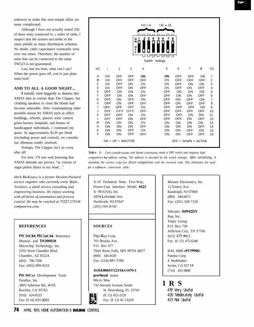
endeavor to make this now-simple affair yetmore complicated.
Although I have not actually tested 256of these units connected to x miles of cable, Isuspect that the system succumbs to thesame pitfalls as many distribution schemes.No doubt, cable capacitance eventually winsover rise times. Therefore, the number ofunits that can be connected to the sameTW523 is not guaranteed.
Last, but not least, what can I say?When the power goes off, you’re just plainoutta luck!
AND TO ALL A GOOD NIGHT...I initially tried doggedly to dismiss this
XMAS idea as cornier than The Clapper, butclimbing speakers to close the blinds hadbecome untenable. After contemplating otherpossible arenas for XMAS such as officebuildings, schools, passive solar control,green houses, hospitals, and homes ofhandicapped individuals, I continued myquest. At approximately $120 per blind(excluding power and control), we considerour dilemma totally resolved.
Perhaps, The Clapper isn’t so cornyafter all!
For now, I’ll rest well knowing thatXMAS defends our privacy “as visions ofsugar plums dance in my head.. .”
Herb McKinney is a former Hewlett-Packardservice engineer who currently owns Multi-
Technics, a small service consulting andengineering business. He enjoys workingwith all forms of automation and processcontrol. He may be reached at [email protected].
REFERENCES
PIC16C84, PIC16C84 ReferenceManual, and DS30081BMicrochip Technology, Inc.2355 West Chandler Blvd.Chandler, AZ 85224(602) 786-7200Fax: (602) 899-9210
PIC16Cxx Development ToolsParallax, Inc.3805 Atherton Rd., #102Rocklin, CA 95765(916) 624-8333Fax: (9 16) 624-8003
HC=A UC=15
++*rIrlnnnrlnrl,
,uLJuuuuu
I
Switch settings
HC 1 2 3 4 5 6 7 a UC
A ON OFF OFFB ON OFF OFFC ON OFF OND ON OFF ONE OFF ON ONF OFF ON ONG OFF ON OFFH OFF ON OFFI OFF OFF OFFJ OFF O F F O F FK OFF OFF ONL OFF OFF ONM ON ON ONN ON ON ON0 ON ON OFFP ON ON OFF
ON = UP = INACTIVE
ONOFFON
OFFONOFFONOFFONOFFON
OFFONOFFONOFF
ON OFF OFF ON 1ON OFF OFF OFF 2ON OFF ON ON 3ON OFF ON OFF 4OFF ON ON ON 5OFF ON ON OFF 6OFF ON OFF ON 7OFF ON OFF OFF 8OFF OFF OFF ON 9OFF OFF OFF OFF 10OFF OFF ON ON 11OFF OFF ON OFF 12ON ON ON ON 13ON ON ON OFF 14ON ON OFF ON 15ON ON OFF OFF 16
OFF = DOWN = ACTIVE
Table 1: Cost considerations and layout construints made a DIP switch and negative logic
compulsory for address setting. The address is encoded by the switch settings. After serializing, itassumes the correct order,for direct comparison with the received code. This eliminates the need
for a software conversion table.
X-10 Technical Note: Two-Way,Power-Line Interface Model #S23X- 10 (USA), Inc.185A LeGrand Ave.Northvale, NJ 07647(201) 784-9700
SOURCES
D&-Key Corp.701 Brooks Ave.P.O. Box 677Thief River Falls, MN 56701.0677(800) 344-4539Fax: (218) 681-3380
1616E006ST123/16A1670:1gearhead motorMicro Moe742 Second Avenue South
St. Petersburg, FL 33701(8 13) 822-2529Fax: (8 13) 82 l-6220
Mouser Electronics, Inc.12 Emery Ave.Randolph, NJ 07869(800) 346-6873Fax: (201) 328-7120
Siliconix Si9942DYRep, Inc.Temic GroupP.O. Box 728Jefferson City, TN 37760(615) 475-9012Fax: (6 15) 475-6340
BAL 6686 (#T39900)Futuba Corp.4 StedebakerIrvine, CA 927 18(714) 455-9888
I R S419 Very Useful420 Moderately Useful421 Not Useful
74 APRIL 1995 HOME AUTOMATION 8 9UHDlNG CONTROL
he RemoteControlled SpeakerSelector (RCSS)addresses thechallenge ofcreating a conve-nient, multiroomlistening environ-
ment for the home. Most stereosystems have manual A/B speakerselection which provides music to oneof two rooms or both rooms simulta-neously (A+B). If that’s not enough,an external speaker selector can beadded easily.
But what if you’re outside in thepool and the urge to swim laps to“Born in the USA” suddenly grabsyou? In this scenario, you must goinside, negotiate a polished kitchenfloor with wet feet, and switch thestereo to play over the pool speak-ers-not exactly the dream of homeautomation.
Some high-end systems addressthe problem of multiroom listening byusing proprietary modulationschemes. These schemes multiplexaudio and two-way data over user-installed coax to each room. Theproblem with this solution is that aperfectly good stereo system has to bereplaced.
Alternatively, a few add-ondevices can be used with existingstereo systems in one way oranother-some use X- 10, infrared, orcombinations thereof. However, thesesystems are fairly expensive, oftencompromise amplifier safety byswitching only one side of the output,or lack user feedback, which isessential in remote switching.
DEVICE DESCRIPTIONThe RCSS is an add-on home-
stereo component designed for loud-speaker selection from virtually anyinfrared (IR) remote c,ontroller. Aninnovative learning algorithm andhigh-integration microcontroller makethe RCSS “smart” as well as inexpen-sive with its low parts count.
The RCSS can be used with off-the-shelf IR repeater systems forseparate room-speaker selection. Thislets a listener select speakers fromwhatever room they are in without
A LearningRemote-ControlledSpeaker Selector
having to physically make a selection at theamplifier or receiver location. Since mostexisting stereo systems can already beremotely controlled with an off-the-shelf IRrepeater, the RCSS adds the speaker-selectfunction that most stereo systems lack. Withthe RCSS, the user obtains multiroomlistening convenience while retaining theirexisting audio equipment. A diagram of theRCSS is provided in Figure 1.
SYSTEM OVERVIEWSpecific highlights of the RCSS
include:
l Learning algorithm-The RCSS offersmaximum flexibility. It can be controlledby virtually any IR remote controller,regardless of manufacturer. Low-costgeneric IR remotes can be used forselection control.
l Four speaker pairs-Four independentspeaker pairs can be selected with theRCSS.
l Manual operation-A front-panel pushbutton provides manual selection ofindividual speaker pairs as well as dual-pair combinations for two-room listening.
l Indicator lights-Four green LEDs givevisual status of speaker selection(s). A redLED marks learn status (on = learnmode). The red LED flutters on initialpowerup to show that the RCSS needsprogramming.
l Confirmation tone-A dual-frequencyconfirmation tone is sent to theselected speaker pair before themusic source is switched in. The
SCOTT HEISERMAN & CLARK ODEN
Scott and Clark set out to find
remote-speaker selection without
replacing their current stereo
system or spending too much
money. The ultimate solution: an
add-on component with an innova-
tive intrared learning algorithm
and a highly integrated
microcontroller.
HOME AUTOMATION & BUILDING CONTROL APRIL 1 BB5 7 5
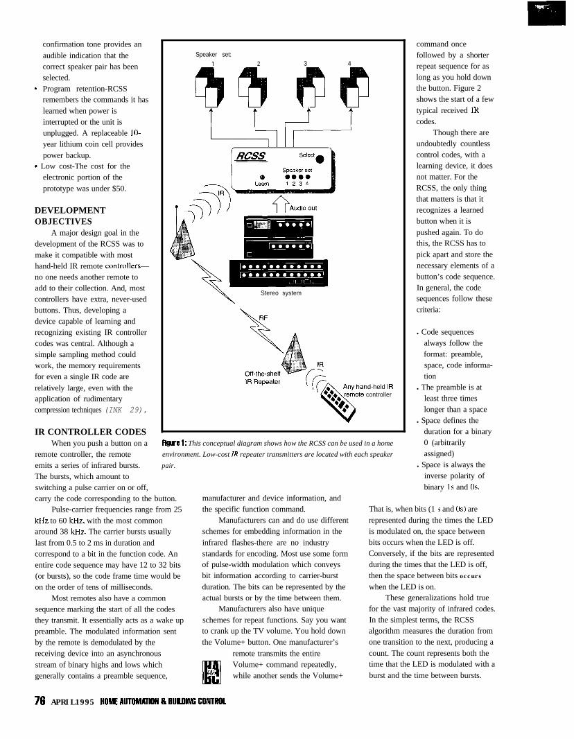
confirmation tone provides anaudible indication that thecorrect speaker pair has beenselected.
9 Program retention-RCSSremembers the commands it haslearned when power isinterrupted or the unit isunplugged. A replaceable IO-year lithium coin cell providespower backup.
9 Low cost-The cost for theelectronic portion of theprototype was under $50.
DEVELOPMENTOBJECTIVES
A major design goal in thedevelopment of the RCSS was tomake it compatible with mosthand-held IR remote controllers-no one needs another remote toadd to their collection. And, mostcontrollers have extra, never-usedbuttons. Thus, developing adevice capable of learning andrecognizing existing IR controllercodes was central. Although asimple sampling method couldwork, the memory requirementsfor even a single IR code arerelatively large, even with theapplication of rudimentarycompression techniques (INK 29).
IR CONTROLLER CODESWhen you push a button on a
remote controller, the remoteemits a series of infrared bursts.The bursts, which amount toswitching a pulse carrier on or off,
Speaker set:1 2 3 4
T L-J T
I I I I
-a Stereo system
nd-held IRcontroller
FigW? 1: This conceptual diagram shows how the RCSS can be used in a home
environment. Low-cost IR repeater transmitters are located with each speaker
pair.
carry the code corresponding to the button.Pulse-carrier frequencies range from 25
kHz to 60 kHz, with the most commonaround 38 kHz. The carrier bursts usuallylast from 0.5 to 2 ms in duration andcorrespond to a bit in the function code. Anentire code sequence may have 12 to 32 bits(or bursts), so the code frame time would beon the order of tens of milliseconds.
Most remotes also have a commonsequence marking the start of all the codesthey transmit. It essentially acts as a wake uppreamble. The modulated information sentby the remote is demodulated by thereceiving device into an asynchronousstream of binary highs and lows whichgenerally contains a preamble sequence,
manufacturer and device information, andthe specific function command.
Manufacturers can and do use differentschemes for embedding information in theinfrared flashes-there are no industrystandards for encoding. Most use some formof pulse-width modulation which conveysbit information according to carrier-burstduration. The bits can be represented by theactual bursts or by the time between them.
Manufacturers also have uniqueschemes for repeat functions. Say you wantto crank up the TV volume. You hold downthe Volume+ button. One manufacturer’s
remote transmits the entireVolume+ command repeatedly,while another sends the Volume+
command oncefollowed by a shorterrepeat sequence for aslong as you hold downthe button. Figure 2shows the start of a fewtypical received IRcodes.
Though there areundoubtedly countlesscontrol codes, with alearning device, it doesnot matter. For theRCSS, the only thingthat matters is that itrecognizes a learnedbutton when it ispushed again. To dothis, the RCSS has topick apart and store thenecessary elements of abutton’s code sequence.In general, the codesequences follow thesecriteria:
l Code sequencesalways follow theformat: preamble,space, code informa-tion
l The preamble is atleast three timeslonger than a space
l Space defines theduration for a binary0 (arbitrarilyassigned)
l Space is always theinverse polarity ofbinary 1s and OS.
That is, when bits (1 s and OS) arerepresented during the times the LEDis modulated on, the space betweenbits occurs when the LED is off.Conversely, if the bits are representedduring the times that the LED is off,then the space between bits occurswhen the LED is on.
These generalizations hold truefor the vast majority of infrared codes.In the simplest terms, the RCSSalgorithm measures the duration fromone transition to the next, producing acount. The count represents both thetime that the LED is modulated with aburst and the time between bursts.
76 APRIL1995 HOMEAUTOM~ION8BUILD#GCONTROL
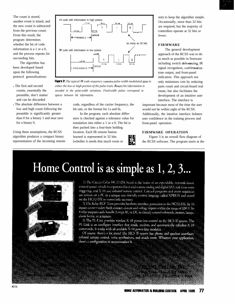
The count is stored,another event is timed, andthe new count is subtractedfrom the previous count.From this result, theprogram determineswhether the bit of codeinformation is a 1 or a 0,and the process repeats forsucceeding bits.
The algorithm hasbeen developed basedupon the followingprotocol generalizations:
IR code with Information in high pulses:42ms 16rnS 16rnS 05ms
1 184rnE
JPR..!+’ Q$
as many as 32 bits
IR code with information in low pulses:OSrnS
24ms 1 1
12ms 12rn5 OE.lnS
+-PREAMBLESPACE
l The first and secondcounts, essentially thepreamble, don’t matterand can be discarded
Figure 2: The typical IR code sequence contains pulse-width modulated data in
either the low or high portion of the pulse train. Binary bit information is
encoded in the pulse-width variations. Fixed-width pulses correspond to
spaces between bit information.
l The absolute difference between alow and high count following thepreamble is significantly greaterthan 0 for a binary 1 and near zerofor a binary 0.
Using these assumptions, the RCSSalgorithm produces a compact binaryrepresentation of the incoming remote
code, regardless of the carrier frequency, thebit rate, or the format for 1 s and OS.
In the program, each absolute differ-ence is checked against a tolerance value fortranslation into either a 1 or a 0. The bit isthen packed into a four-byte holdinglocation. Each IR remote buttonlearned is represented in 32 bits IMn(whether it needs that much room or &
IM
not) to keep the algorithm simple.Occasionally, more than 32 bitsare required, but the majority ofcontrollers operate at 32 bits orfewer.
FIRMWAREThe general development
approach of the RCSS was to doas much as possible in firmwareincluding switch debouncing, IRsignal recognition, confirmation-tone output, and front-panelindication. This approach notonly minimizes cost by reducingparts count and circuit-board realestate, but also facilitates thedevelopment of an intuitive userinterface. The interface is
important because most of the time the userwould not be within sight of the RCSS.Additionally, the intuitive interface bolstersuser confidence in the training process andfront-panel operation.
FIRMWARE OPERATIONFigure 3 is an overall flow diagram of
the RCSS software. The program starts at the

beginning of ROM (location$0200) with a series ofqualified initializations. Theports are defined, then port Ais read. If the lower four bitsof port A are cleared-anormally illegal state-thentheT E M P 2 register is loaded with$FF as a first-time powerupflag for use later in theprogram. Other qualifiedinitializations include clearingthe IR code storage locations(C 0 DE), common registers, andcount variables. This portionof the program is recycled bydifferent routines to conserve
Flutter Learn LEDYes
program memory.After qualified I I
initializations, the computeroperating properly (COP)register is reset. This paves theway for a series of bit-levelinterrogations. First, port A,bit 4 is checked for manualswitch closure. If the switch isclosed, control is transferred tothe MANSW routine.
I
4NO
Next, the Learn switch,bit 1 of port B, is checked forclosure. If it has been pushed,both the first LED (speaker set1) and the Learn LED are lit.The program then monitors forIR input. If the Learn switchhas not been pushed, T EM P 2 ischecked for $FF and the LearnLED is toggled if it is $FF.
Finally, bit 0 of port B ischecked for IR input. If noneis present, the program returnsto reset the COP register. Itcontinues this loop until IR isdetected at bit 0 of port B.
When port B, bit 0 finallygoes low-signaling IRinput-program control is
Figure 8: A modular approach was used in the development of RCSSfirmware when
possible. This overall flow diagram shows that some routines are recycled to make
best use of the 68HC705’s tiny 0.5 KB of ROM and 32 bytes of RAM.
transferred to the READ routine. The IR datais serially sampled at a 0.1 -ms rate andstored in indexed code RAM locations. Afterinput, control is transferred to the ST0 RE
4STORE
Move CODE tostorage location, light
next LED
SWOUT
Switch in selectedswakers and outwt --+’
confirmation tone
routine.STORE first checks for learn mode. If
the learn register, TEMP2, is set to 1, 2, 3, or4, code bytes are transferred to the appropri-ate storage locations. If not in the learnmode, program control is transferred to theRECOG routine.
R EC 0 G sequentially compares storedbytes with the code read in. If there is nomatch, the program returns to the beginningwhere sequential checks are performedagain. If there is a match, control istransferred to the SWOUT routine.
SW 0 UT performs speaker and sourcerelay switching and debouncing, and output
confirmation-tone generation. Afterthe switching is complete, theprogram returns to ST ART
The program fullyutilizes the 68HC705microcontroller toprovide IR codelearning and recognitionas well as an intuitiveuser interface. All RAMand most of the ROM isused. Real-timeinterrupts are not usedbecause of RAMlimitations and theysimply are not needed.The microcontrolleroperates in themicrosecond world,whereas IR codes are inthe millisecond domain.
HARDWAREThe hardware
components and layoutare designed for a highdegree of integration,low parts count, andshort wiring runs. Allcomponents areavailable from severalsources.
The RCSS isdesigned so that allwiring connections aremade at the rear panel,with the front panel ofthe aluminum enclosurereserved for operatingcontrols and indicators.Construction is by hardwiring, but the circuitboard may be removedfrom the case byunfastening the frontand rear panels. Thisdesign provides for highreliability while usingcommonly availablecomponents. Figure 4
shows the schematic layout.
POWER SUPPLYPower enters the RCSS at rear-
panel power connector Jl, a 3.5mmphone jack. A 1 N4004 diode protectsthe circuitry from reverse voltageshould a power source of oppositepolarity be plugged into the rearpanel. A I-pF ceramic capacitor filtersthe power input, and a MOV provides
78 APRIL 1995 HOME AUTOMATION 8 9UILUfNC CONTROL

surge protection for voltage spikesover 33 V to the voltage regulator(U5). U5 is a 5-V linear regulator in aTO220 package. The 5-V output ofthe regulator is bypassed by both a0. I -pF and a 0.01 -p_F capacitor.
Battery backup and switchover isaccomplished by U4, a MaximMAX704 supervisory circuit designedfor use with microprocessors. Duringnormal operation, U4 simply passesthe 5-V supply to the Ulmicrocontroller V,, pin. However, ifthe 5-V supply drops below 4.4 V, U4holds the microcontroller reset pinlow and switches the V,, supply to a3-V lithium battery.
This scheme provides backuppower for the microcontroller RAM.Thus, the microcontroller RAM isnonvolatile and its contents areretained in the event of a poweroutage. Even frequent, short-durationpower interruptions do not signifi-cantly reduce the battery’s life belowits expected shelf life.
All other power connections aremade to the 5-V regulator output.
MICROCONTROLLERU I is a Motorola MC68HC705Kl
microcontroller. Ul receives data from theinfrared module at port PBO. The Select andLearn switches are read at ports PA4 andPB I, respectively. A 4.000-MHz crystalclocks the microcontroller. Port PA6 isconfigured as an output to control the inputaudio-source relay driver. Output ports PA0through PA3 control the four speaker audio-output relay drivers. Output port PA5generates a confirmation tone, which is sentto one of four speaker outputs. Output portPA7 drives an LED driver for learn-modeindication. The IRQ line is pulled up(disabled).
Under software control, themicrocontroller reads and learns infraredcodes, or reads IR codes and selects speaker-pair outputs. Ul also disconnects the audio-source input, generates a confirmation tone,and reconnects the audio-source input whena new output is selected.
RELAYS AND LEDSRelays Kl-K6 are all Aromat
JW-series relays, which can switchup to 5 A. Kl and K2 are input
I#&
relays that have two form-C contacts each,thereby enabling the hot and ground signalsfrom both channels of a stereo amplifier tobe disconnected during confirmation-tonegeneration. During tone generation, Kl andK2 select local ground and tone from Ulport PA5 to be sent to the output relays.
K3 through K6 all have two form-Acontacts, which switch only the hot (+)signal from each channel input, either on oroff. All relay drivers are PNP transistorscontained within U2 and U3 transistorpackages. The PNP relay drivers areprotected from inductive kickback by lN914diodes across the relay coils. The outputrelay driver U2 also drives four green, front-panel LEDs for indicating front-panel outputselection. One of the U3 transistors drivesthe red LED for front-panel indication of thelearn mode.
SWITCHES, HARDWARE,AND IR MODULE
The front-panel, momentary push-button switch Select is read by Ul tosequentially select the speaker output fromthe front panel. The rear-panel Learn switchis read by Ul to put the unit in learn mode.
3’hDIGIT LCD PANEL METER-Available now at an unheard of
priceof$l5pluss&hN e w ! N o t s u r p l u s !
Specifications:Maximum input: k199.9 mV
additional ranges provided throughexternal resistor dividers
Display: 3%digit LCD, 0.5 in. figure height,jumper-selectable decimal point
Conversion: Dual slope conversion, 2-3readings per sec.
Input Impedance: z 100M ohmPower: 9-l 2 VDC @ 1 mA DC
Circuit Cellar, Inc.4 Park Street, Suite 12, Vernon, CT 06066Tel: (203) 8752751 Fax: (203) 872-2204
X-IO SALE THIS MONTH ONLYLAMP WALL SWITCH 8 APPLIANCE MODULES$129IDZ ; AUTOMATK DRAPERY OPENERRC6500 KEYCHAIN REMOTE&BASE $ 1 9 COMPLETE SYSTEM K,T 5349
PR511 FLOOD LIGHT MOTION DETECTOR $38 ~ s* &hSD533 SUNOOWNER $12 1 lNCRED,BLE SOFTWARE UPGRADE FORPA5800 PERSONAL ASSISTANCE CONSOLE$% ; x-10 CPZWP S49 95
MC460 MINI CONTROLLERS (Box 014, $?9 ; EASIER TO EDIT 8 SUNRiSEiSUNSET
STARTER KITS Get ready for SpringDrip watering landscape kitContainer drip watering kit
28.99 ~These kits are expandable14.99 Complete catalogs and prrces
Drip soaker vegetable kit 28.99 ‘are sent with kits or send $524.volt 314’ automatic anti-syphon valve 24.24 #for catalog and plannmg guideUM506 to control valve w/X-IO 19.97 iredeemable on first order
BOOKS. LITERATURE AND SOFTWARE“A PRACTICAL GUIDE TO HOME AUTOMATION’ 518 99 “THE HOME AUTOMATION NETWORV $1 C‘VILEPHONE WIRING SYSTEM9 52 50“HOW TO TROUBLESHOOT PREMISE WlRlNG SYSTEMS FASTER AND MORE EFFICIENTLY $3 95“DECORA HOME CONTROL TECHNICAL MANUAL 5.3 99 “3D LANDSCAPING’ (WINDOWS) 579 95“GET WIRED”‘PC BASED BOOK ON HOME WlRiNG $29 9!“30 OEC,? (WINDOWS) 579 95~~~____ _~~_._~__
NEWKX-TQ500 QOOMHz CORDLESS TELEPHONE $19920053 I-BUTTON REMOTE CAR STARTER $255
BECAUSE OF THE WEIGHT THE IRRIGATION CATALOGS AREONLY SENT TO EITHER PEOPLE PURCHASING A STARTER KIT OF
THOSE SENDING IN $5 FOR POSTAGE AND HANDLINGTO BE PLACED ON OUR MAILING LIST JUST PLACE ONE ORDER
DEALERS WRITE OR FAX ON COMPANY LETTERHEAD
#215HOME AUTOMATION & BUlLlllNG CONTROL APRIL 1995 78
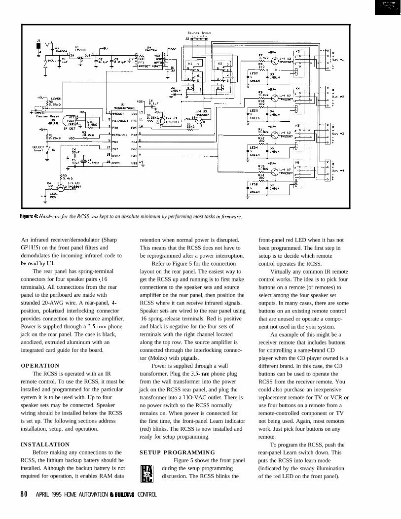
‘Ir
Figllri? 4: Hardware,for the RCSS WLIS kept to an absolute minimum by performing most tasks infirmware.
An infrared receiver/demodulator (SharpGPIUS) on the front panel filters anddemodulates the incoming infrared code tobereadbyul.
The rear panel has spring-terminalconnectors for four speaker pairs (I 6terminals). All connections from the rearpanel to the perfboard are made withstranded 20-AWG wire. A rear-panel, 4-position, polarized interlocking connectorprovides connection to the source amplifier.Power is supplied through a 3.5mm phonejack on the rear panel. The case is black,anodized, extruded aluminum with anintegrated card guide for the board.
OPERATIONThe RCSS is operated with an IR
remote control. To use the RCSS, it must beinstalled and programmed for the particularsystem it is to be used with. Up to fourspeaker sets may be connected. Speakerwiring should be installed before the RCSSis set up. The following sections addressinstallation, setup, and operation.
INSTALLATIONBefore making any connections to the
RCSS, the lithium backup battery should beinstalled. Although the backup battery is notrequired for operation, it enables RAM data
retention when normal power is disrupted.
layout on the rear panel. The easiest way toget the RCSS up and running is to first makeconnections to the speaker sets and source
This means that the RCSS does not have to
amplifier on the rear panel, then position theRCSS where it can receive infrared signals.
be reprogrammed after a power interruption.
Speaker sets are wired to the rear panel using16 spring-release terminals. Red is positive
Refer to Figure 5 for the connection
and black is negative for the four sets ofterminals with the right channel locatedalong the top row. The source amplifier isconnected through the interlocking connec-tor (Molex) with pigtails.
Virtually any common IR remotecontrol works. The idea is to pick four
front-panel red LED when it has not
buttons on a remote (or remotes) to
been programmed. The first step in
select among the four speaker setoutputs. In many cases, there are somebuttons on an existing remote control
setup is to decide which remote
that are unused or operate a compo-
control operates the RCSS.
nent not used in the your system.An example of this might be a
receiver remote that includes buttonsfor controlling a same-brand CDplayer when the CD player owned is adifferent brand. In this case, the CDbuttons can be used to operate theRCSS from the receiver remote. Youcould also purchase an inexpensivereplacement remote for TV or VCR oruse four buttons on a remote from aremote-controlled component or TVnot being used. Again, most remoteswork. Just pick four buttons on anyremote.
Power is supplied through a walltransformer. Plug the 3.5mm phone plugfrom the wall transformer into the powerjack on the RCSS rear panel, and plug thetransformer into a 1 IO-VAC outlet. There isno power switch so the RCSS normallyremains on. When power is connected forthe first time, the front-panel Learn indicator(red) blinks. The RCSS is now installed andready for setup programming.
SETUP PROGRAMMINGFigure 5 shows the front panel
H during the setup programminga! discussion. The RCSS blinks the
To program the RCSS, push therear-panel Learn switch down. Thisputs the RCSS into learn mode(indicated by the steady illuminationof the red LED on the front panel).
80 APRIL 1995 HOME AUTOMATION 8 9UILOlNC CONTROL
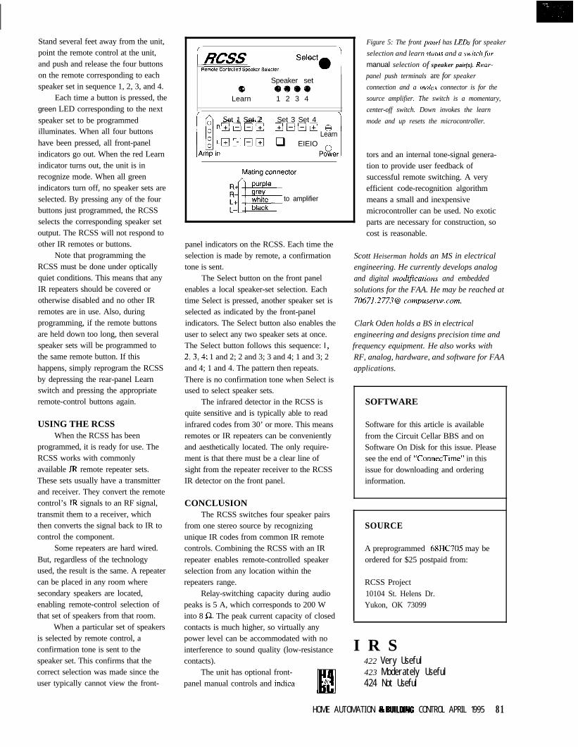
Stand several feet away from the unit,point the remote control at the unit,and push and release the four buttonson the remote corresponding to eachspeaker set in sequence 1, 2, 3, and 4.
Each time a button is pressed, thegreen LED corresponding to the nextspeaker set to be programmedilluminates. When all four buttonshave been pressed, all front-panelindicators go out. When the red Learnindicator turns out, the unit is inrecognize mode. When all greenindicators turn off, no speaker sets areselected. By pressing any of the fourbuttons just programmed, the RCSSselects the corresponding speaker setoutput. The RCSS will not respond toother IR remotes or buttons.
Note that programming theRCSS must be done under opticallyquiet conditions. This means that anyIR repeaters should be covered orotherwise disabled and no other IRremotes are in use. Also, duringprogramming, if the remote buttonsare held down too long, then severalspeaker sets will be programmed tothe same remote button. If thishappens, simply reprogram the RCSSby depressing the rear-panel Learnswitch and pressing the appropriateremote-control buttons again.
USING THE RCSSWhen the RCSS has been
programmed, it is ready for use. TheRCSS works with commonlyavailable IR remote repeater sets.These sets usually have a transmitterand receiver. They convert the remotecontrol’s IR signals to an RF signal,transmit them to a receiver, whichthen converts the signal back to IR tocontrol the component.
Some repeaters are hard wired.But, regardless of the technologyused, the result is the same. A repeatercan be placed in any room wheresecondary speakers are located,enabling remote-control selection ofthat set of speakers from that room.
When a particular set of speakersis selected by remote control, aconfirmation tone is sent to thespeaker set. This confirms that thecorrect selection was made since theuser typically cannot view the front-
Speaker set
Learn 1 2 3 4
Set 1 Set 2 Set 3 Set 4Elo!Ilrz 8
Learnq EIEIO
:PoQer
to amplifier
panel indicators on the RCSS. Each time theselection is made by remote, a confirmationtone is sent.
The Select button on the front panelenables a local speaker-set selection. Eachtime Select is pressed, another speaker set isselected as indicated by the front-panelindicators. The Select button also enables theuser to select any two speaker sets at once.The Select button follows this sequence: 1,2,3,4; 1 and 2; 2 and 3; 3 and 4; 1 and 3; 2and 4; 1 and 4. The pattern then repeats.There is no confirmation tone when Select isused to select speaker sets.
The infrared detector in the RCSS isquite sensitive and is typically able to readinfrared codes from 30’ or more. This meansremotes or IR repeaters can be convenientlyand aesthetically located. The only require-ment is that there must be a clear line ofsight from the repeater receiver to the RCSSIR detector on the front panel.
CONCLUSIONThe RCSS switches four speaker pairs
from one stereo source by recognizingunique IR codes from common IR remotecontrols. Combining the RCSS with an IRrepeater enables remote-controlled speakerselection from any location within therepeaters range.
Relay-switching capacity during audiopeaks is 5 A, which corresponds to 200 Winto 8 Q. The peak current capacity of closedcontacts is much higher, so virtually anypower level can be accommodated with nointerference to sound quality (low-resistancecontacts).
The unit has optional front-panel manual controls and indica-
Figure 5: The front panel has LEDS for speaker
selection and learn status and a switchfor
manual selection of speaker pair(s). Rear-
panel push terminals are for speaker
connection and a molex connector is for the
source amplifier. The switch is a momentary,
center-off switch. Down invokes the learn
mode and up resets the microcontroller.
tors and an internal tone-signal genera-tion to provide user feedback ofsuccessful remote switching. A veryefficient code-recognition algorithmmeans a small and inexpensivemicrocontroller can be used. No exoticparts are necessary for construction, socost is reasonable.
Scott Heiserman holds an MS in electricalengineering. He currently develops analogand digital modiJications and embeddedsolutions for the FAA. He may be reached at70671.2773@ compuserve.com.
Clark Oden holds a BS in electricalengineering and designs precision time andfrequency equipment. He also works withRF, analog, hardware, and software for FAAapplications.
SOFTWARE
Software for this article is availablefrom the Circuit Cellar BBS and onSoftware On Disk for this issue. Pleasesee the end of “ConnecTime” in thisissue for downloading and orderinginformation.
SOURCE
A preprogrammed 68HC705 may beordered for $25 postpaid from:
RCSS Project10104 St. Helens Dr.Yukon, OK 73099
I R S422 Very Useful423 Moderately Useful424 Not Useful
HOME AUTOMATION Ip 9UlllUNG CONTROL APRIL 1995 81
DEPARTMENTSFirmware Furnace
From the Bench
Silicon Update
a Embedded Techniaues
ConnecTime
Ed Nisley
Journey to the Protected Land:With Interrupts, 1 ImIngis Everything
n my time line,it’s mid-December
r and the Pentium FPU‘firestorm threatens to
consume Intel’s credibility, if not theirfuture. On your time line, it’s lateMarch and you know how the storyends. All I can say now is that I’m gladfor my plain old 486DX2. Sometimesthe thick edge of the wedge is theplace to be!
Just as all programs have bugs, allhardware has quirks. If you neverstumble upon the circumstances thattrigger a quirk, its presence doesn’tmatter to you. Knowing that a quirkexists can either help you avoid it orjustify buying something else. Thatmay explain why it’s so difficult to geterrata lists-if a bug isn’t mentioned,does it really exist?
This month, we’ll reinforce theerror handlers that catch our ownbugs, then measure a hardwareinterrupt’s response time when ittriggers a task switch. The venerable8259 Programmable Interrupt Control-ler and all its LSI progeny have aninteresting, well-documented quirkthat most folks have never encoun-tered; you’ll get the story here!
IN CASE OF EMERGENCY...Ever since we first flipped into 32-
bit protected mode, a simple errorhandler has watched for protection
82 Issue #57 April 1995 Circuit Cellar INK

Listing l--The unexpected error handler deals with interrupfs that are not caught by any other handler. Theerror handler sefup code fills the IDT wifh 256 inferrupf gates aimed at these 256 stub routines. Each stubpushes the Interrupt ID on the sfack and fask switches info the handler by execufing a FAR CA L Lcontaining its ES selecfor. Although fhe stubs include an /RET fo return control to the failing fask, the FFTSerror handler simply displays an error dump and halts the system.
NUM_TASK_VECTORS = 256 ; all possible interrupts
CODESEGALIGN 2 ; get a nice offsetPROC ErrTaskVectors
@ID = 0REPT NUM_TASK_VECTORSDB 06Ah ; PUSH immediate byte, MSB = OOh06 @@@IDDB 09Ah ; FAR CALL with imm seg:offsetDD 0 ; offset is not used hereDW TSSERRORS ; seg causes task switchIRET ; return from interrupt (ha!)
@@ID = @ID+1ENDM
ENDP ErrTaskVectors
TASK_VECT_SIZE = $ ErrTaskVectors total length of all stubsTASK_VECT_STEP = TASK_VECT_SIZEINUM_TASK_VECTORS ; stub size
violations. Without the support of theCPU’s multitasking hardware, how-ever, it’s difficult to write an errorhandler that doesn’t mess things upwhile attempting to display an errormessage.
As a result, the only indication ofan error was a cryptic pattern on theFirmware Development Board andparallel port LEDs identifying thefailing instruction. While that may bebetter than real-mode pinball panic ora system freeze, we can do muchbetter using separate tasks for the errorhandlers. You knew multitasking wasgoing to come in handy for something,didn’t you2
Figure 1 shows the sequence ofevents after the CPU detects an errorin protected mode while running atask. If the IDT entry corresponding tothat error contains an interrupt or trapgate (the other choice is a task gate,which we’ll discuss shortly), the CPUpushes the current EFLAGS, CS, andEIP registers onto the stack. Someerrors also produce an error code tohelp identify the problem, which theCPU pushes atop EIP, rendering asimple I RET impossible. Figure 3 inINK 50 tabulates the predefinedinterrupts, their types, and whether
they produce an error code. (Note thatthere is a table of acronyms at the endof the article for those who didn’tquite follow the past few sentences.)
Failing instruction
, Interrupt gate
The interrupt or trap gate directsthe CPU to a stub routine that pushesthe interrupt ID number. Without thatvalue on the stack, the handler cannottell which interrupt activated it. Thealternative is 256 separate interrupthandlers, which seems excessive evento me. Listing 1 shows the macro thatgenerates 256 stubs leading to our newerror handler.
Each stub includes a synthetic FARCALL withthe TSS_ERRORS selectorinthe segment position. That selectorcorresponds to the TSS of the error-handler task. The CPU reacts to thisFAR CALL by storing the failed task’sstate in its TSS and task switching tothe error handler. As always, the CPUloads a new state from the incomingTSS, ensuring that all the registers aresafe from harm and the new stack isentirely separate from the old one.
If you thought task switching wascomplex last month, hold onto yourkeyboards. Figure 2 shows the situa-tion just after the task switch. Thestub’s FAR CALL triggers two newactions during the task switch: theCPU stores the failed task’s TSSselector in the error handler’s TSS
Stub codeI4 PUSH Int ID
CALL Error Handler
Figure l-When an error occurs ina protected-mode instruction theCPU pushes the current flags andfhe CSEIP registers before passingfhrougb an IDT interrupt gafe. Someerrors also generate an error codethat identifies the failing segment.The stub code shown in Listing 1pushes the intern@ ID andexecutes a FAR CALL taskswitch to the error handler.
.
.
.Stack TSS
- Failing task - I Error Handler task I
CS:EIP
-+---- Back Link
I I TSS
Figure 2-The error handler’s TSS Backlink field holds the failed task’s JSS selector. The error handler accessesfhe stacked values using the SSESP values from that TSS. Note that the sfacked CSEIP points to the failedinstruction and the CS:E/P in the TSS points to the instruction after the FAR CA L L in fhe stub routine.
Circuit Cellar INK Issue #57 April 1995 83
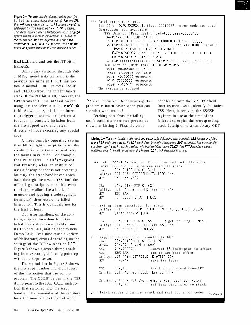
Figure 3-The error handler displays values from fhefailed task’s stack, dumps fields from ifs ES and LDT,then halts fhe system. Demo Task 1 causes a variefy of(deliberate!) errors based on the LPTI DIP switches.This dump occurred after a floating-point op in a ‘386SXsystem without a numeric coprocessor. As shown onthe second line, the CPU defected the error in theinsfrucfion af 000C:0000013Fin Demo Task 1. Isn’t thisbetter than pinball panic or no error indication at all?
Backlink field and sets the NT bit inEFLAGS.
Unlike task switches through FARJ M Ps, nested tasks can return to theprevious task using an I RET instruc-tion. A normal I RET restores CS:EIPand EFLAGS from the current task’sstack. If the NT bit is set, however, theCPU treats an I RET as a task switchusing the TSS selector in the Backlinkfield. As we’ll see, this lets an inter-rupt trigger a task switch, perform afunction in complete isolation fromthe interrupted task, and returndirectly without executing any specialcode.
A more complex operating systemthan FFTS might attempt to fix up thecondition causing the error and retrythe failing instruction. For example,the CPU triggers I n t 0 6 (“SegmentNot Present”) when an instructionuses a descriptor that is not present (Pbit = 0). The error handler can reachback through the nested TSS, find theoffending descriptor, make it present(perhaps by allocating a block ofmemory and reading a code segmentfrom disk), then restart the failedinstruction. This is obviously not forthe faint of heart!
Our error handlers, on the con-trary, display the values from thefailed task’s stack, dump fields fromits TSS and LDT, and halt the system.Demo Task 1 can now cause a varietyof (deliberate!) errors depending on thesettings of the DIP switches on LPTl.Figure 3 shows a screen dump result-ing from executing a floating-point opwithout a coprocessor.
The second line in Figure 3 showsthe interrupt number and the addressof the instruction that caused theproblem. The CS:EIP values in the TSSdump point to the FAR CALL instruc-tion that switched into the errorhandler. The remainder of the registershave the same values they did when
84 Issue #57 April 1995 Circuit Cellar INK
*** Fatal error detected...Int 07 at 000C:0000013F, flags 00010087, error code not usedCoprocessor not available
TSS Dump of [Demo Task 11 Sel=1050 Base=00130AOOBacklink=OOOO LDT Sel=1058CS:EIP=0030:00000561 EFLAGS=00000087 CR3=00000000SS:ESP=0024:00000FEC EBP=00000000 IOMapBase=OOOO Trap=0000
DS=0014 ES=0000 FS=OOZO GS=OOlCEAX=00000007 EBX=0000013F ECX=00000000 EDX=00000378EDI= ESI=00000000
SS:ESP O/OOOO:OOOOOOOO 1/0000:00000000 2/0000:00000000LDT Dump of [Demo Task 11 LDT Sel=10580004: 00302380 00008COOOOOC: 37300178 004098100014: OOZOOOlB 00409314OOlC: 7BCOO103 0040934A0024: 6B800FFF 0040934A
*** The system is stopped
:he error occurred. Reconstructing the handler extracts the Backlink fieldproblem is much easier when you can from its own TSS to identify the failedsee what went wrong! TSS. Next, it recovers the SS:ESP
Fetching data from the failing registers in use at the time of thetask’s stack is a three-step process as failure and copies the correspondingshown in Listing 2. First, the error stack descriptor to a temporary GDT
Listing 2-This error handler code reads the Back/ink field from the error handler’s ES, locates the failedtask’s TSS, and copies the task’s LDT stack descriptor info a temporary GDT descriptor. The error handlercan fhen copy the task’s stacked values info local variables using ES:ESf. The FFTS handler includesadditional code to hand/e errors when the kernel’s GDT stack descriptor is in use.
--- fetch backlink from our TSS to the task with the errormove ESP into ES1 so we can read the stack
LEA EAX,[(TSS PTR O).BackLink]CallSys CGT_TASK_GETFIELD,[TaskID],EAXMOV [ErrTSSl,EAX
LEACallSysMOVMOV
EAX,[(TSS PTR O).ESPlCGT_TASK_GETFIELD,[ErrTSS],EAXESI,EAX[ErrStackPtr.Offl,EAX
;--- set upCallSysMOV
temp descriptor for stackCGT_MEM_FINDEMPTY,GDT_TEMP_BASE,GDTGDT_ALIAS[TempStackSell,EAX
LEACallSysMOV
EAX,[(TSS PTR O).SSl : get failing SS descCGT_TASK_GETFIELD,[ErrTSSI,EAX[ErrStackPtr.Segl,AX
;--- copy stack descriptor from LDT to GDTLEA EBX,[(TSS PTR O).TaskLDTlMOVZX EAX,[ErrStackPtr.Seg]AND EAX,OFFF8h ; convert SS descriptor to offsetADD EBX,EAX ; add to LDT base offsetCallSys CGT_TASK_GETFIELD,[ErrTSSl,EBXMOV EDX,EAX ; save for later
ADD EBX.4 ; fetch second dword from LDTCallSys CGT_TASK_GETFIELD,[ErrTSSl,EBX
CallSys CGT_MEM_PUTDESC,[TempStackSell,GDTGDT_ALIAS,\EDX,EAX ; set temp descriptor to stack
:--- fetch values from that stack and sort out error codes(continued)
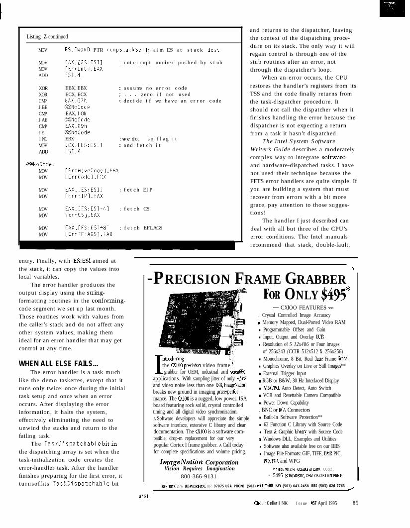
Listing Z-continued
MOV ES,[WORD PTR TempStackSell ; aim ES at stack desc
MOVMOVADD
EAX,[ES:ESIl ; interrupt number pushed by stub[ErrIntl,EAXESI,4
XORXORCMPJBECMPJAECMPJEINCMOVADD
EBX,EBX ; assume no error codeECX,ECX ; . . . zero if not usedEAX,07h : decide if we have an error code@NoCodeEAX,lOh@NoCodeEAX,09h@NoCodeEBX : we do, so flag itECX,[ES:ESII : and fetch itESI,4
@NoCode:MOVMOV
IErrHaveCodel,EBXLErrCodel,ECX
MOVMOV
EAX,[ES:ESIl ; fetch EIP[ErrEIPl.EAX
MOVMOV
EAX,[ES:ESI+4] ; fetch CSIErrCSl,EAX
MOVMOV
EAX,[ES:ESI+8] ; fetch EFLAGS[ErrEFLAGSl,EAX
entry. Finally, with ESESI aimed atthe stack, it can copy the values intolocal variables.
The error handler produces theoutput display using the string-formatting routines in the conforming-code segment we set up last month.Those routines work with values fromthe caller’s stack and do not affect anyother system values, making themideal for an error handler that may getcontrol at any time.
WHEN ALL ELSE FAILS...The error handler is a task much
like the demo taskettes, except that itruns only twice: once during the initialtask setup and once when an erroroccurs. After displaying the errorinformation, it halts the system,effectively eliminating the need tounwind the stacks and return to thefailing task.
The TaskDispatchable bitinthe dispatching array is set when thetask-initialization code creates theerror-handler task. After the handlerfinishes preparing for the first error, itturnsoffits TaskDispatchable bit
and returns to the dispatcher, leavingthe context of the dispatching proce-dure on its stack. The only way it willregain control is through one of thestub routines after an error, notthrough the dispatcher’s loop.
When an error occurs, the CPUrestores the handler’s registers from itsTSS and the code finally returns fromthe task-dispatcher procedure. Itshould not call the dispatcher when itfinishes handling the error because thedispatcher is not expecting a returnfrom a task it hasn’t dispatched.
The Intel System SoftwareWriter’s Guide describes a moderatelycomplex way to integrate software-and hardware-dispatched tasks. I havenot used their technique because theFFTS error handlers are quite simple. Ifyou are building a system that mustrecover from errors with a bit moregrace, pay attention to those sugges-tions!
The handler I just described candeal with all but three of the CPU’serror conditions. The Intel manualsrecommend that stack, double-fault,
-PRECISION FRAME GRABBER ’
Tntroducing
1the CXlOO-precision video frame 1grabber for OEM, industrial and scientic
applications. With sampling jitter of only *3 nSand video noise less than one ISB, ImageNationbreaks new ground in imaging price/perfor-mance. The CXlOO is a rugged, low power, ISAboard featuring rock solid, crystal controlledtiming and all digital video synchronization.A Software developers will appreciate the simplesoftware interface, extensive C library and cleardocumentation. The CXlOO is a software com-patible, drop-m replacement for our verypopular Cortex I frame grabber. A Call todayfor complete specifications and volume pricing.
ImageNation CorporationVision Requires Imagination
800-366-9131
FOR ONLY $495*- CXlOO FEATURES -
. Crystal Controlled Image Accuracym Memory Mapped, Dual-Ported Video RAMn Programmable Offset and Gainn Input, Output and Overlay LUTsn Resolution of 5 12x486 or Four Images
of 256x243 (CCIR 512x512 & 256x256)n Monochrome, 8 Bit, Real Tie Frame Grabsn Graphics Overlay on Live or Still Images**m External Trigger Inputm RGB or B&W, 30 Hz Interlaced Displayn NTSUPAI Auto Detect, Auto Switchm VCR and Resettable Camera Compatiblen Power Down Capability. BNC or RCA Connectorsn Built-In Software Protection**n 63 Function C Library with Source Codel Text & Graphic Libraq with Source Codem Windows DLL, Examples and Utilitiesn Software also available free on our BBSn Image File Formats: GIF, TIFF, BMP PIC,
PCX,TGA and WPG** IIJFSE oi’rlo~s ,+v%l!91MBLE Ar FXI’IU COST.
* 5495 ISDOMESTIC,OEMSINGLELlhlTPRICE.
#121
Ro. BOX 276 BEAVERTON, OR 97075 USA PHONE (503) 641.7408 FAX (503) 643-2458 BBS (503) 626-7763/
Circuit Cellar INK Issue #57 April 1995 85
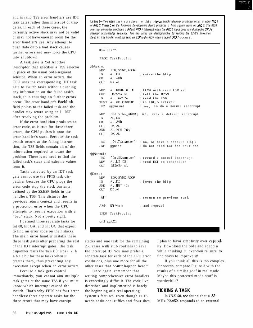
and invalid TSS error handlers use IDTtask gates rather than interrupt or trapgates. In each of these cases, thecurrently active stack may not be validor may not have enough room for theerror handler’s use. Any attempt topush data onto a bad stack causesfurther errors and may force the CPUinto shutdown.
Listing 3-The system task-switches to this interrupf handler whenever an interrupt occurs on either IRQ 5or /RQ 7. Timer 0 on the Firmware Development Board produces a 1-ms square wave on IRQ 5. The 8259interrupt controller produces a default IRQ 7 interrupt when the IRQ 5 input goes low during fhe CPU’Sinterrupt acknowledge sequence. The two cases are distinguishable by reading the 8259’s /n-ServiceRegister. The handler must not send an EOI to fhe 8259 when a default IRQ 7 occurs.
UseTaskCS
PROC TaskProcIntA task gate is Yet Another
Descriptor that specifies a TSS selectorin place of the usual code-segmentselector. When an error occurs, theCPU uses the corresponding IDT taskgate to switch tasks without pushingany information on the failed task’sstack, thus ensuring no further errorsoccur. The error handler’s Backlinkfield points to the failed task and thehandler may return using an I RETafter resolving the problem.
If the error condition produces anerror code, as is true for these threeerrors, the CPU pushes it onto theerror handler’s stack. Because the taskswitch occurs at the failing instruc-tion, the TSS fields contain all of theinformation required to locate theproblem. There is no need to find thefailed task’s stack and exhume valuesfrom it.
Tasks activated by an IDT taskgate cannot use the FFTS task dis-patcher because the CPU plops theerror code atop the stack contentsdefined by the SS:ESP fields in thehandler’s TSS. This disturbs theprevious return context and results ina protection error when the CPUattempts to resume execution with a“bad” stack. Not a pretty sight.
@@Again:MOV EDX,SYNC_ADDRIN AL,DX ; raise the blipOR AL,40hOUT DX,AL
MOV AL,00001011b ; OCW3 with read ISR setOUT 18259A,AL ; tell the 8259IN AL,I8259A ; read the ISRTEST AL,00100000b ; is IRQ 5 active?JNZ @@Normal ; yes, so do a normal interrupt
MOV EDX,SYNC_ADDR ; no, mark a default interruptIN AL,DXOR AL,ZOhOUT DX,ALAND AL,NOT 20hOUT DX,AL
INC iInt7CounterI : no, we have a default IRQ 7JMP @@Done : do not send EOI for this one
@@Normal:INC [Int5Counterl ; record a normal interruptMOV AL,NS_EOI ; send EOI to controllerOUT 18259A,AL
@Done:MOV EDX,SYNC_ADDRIN AL,DX ; lower the blipAND AL,NOT 40hOUT DX,AL
IRET ; return to previous task
JMP @@Again ; and repeat!
ENDP TaskProcInt
I defined three separate tasks forInt 08, Int OA, and Int OC that expectto find an error code on their stacks.The main error handler installs thesethree task gates after preparing the restof the IDT interrupt gates. The taskdispatcher resets the Ta s k D i s pa t c ha b 1 e bit for these tasks when itcreates them, thus preventing anyexecution except when an error occurs.
EndTaskCS
stacks and one task for the remaining I plan to favor simplicity over capabil-253 cases with stub routines to save ity. Download the code and spend athe interrupt ID. You may prefer a while thinking it over-you’re sure toseparate task for each of the CPU error find ways to improve it!conditions, plus one more for all theother cases that “can’t happen here.”
Because a task gets control Once again, remember thatimmediately, you cannot aim multiple writing comprehensive error handlerstask gates at the same TSS if you must is exceedingly difficult. The code I’veknow which interrupt caused the described and implemented is barelyswitch. That’s why FFTS has four error the beginning of a real operatinghandlers: three separate tasks for the system’s features. Even though FFTSthree errors that may have corrupt needs additional ruffles and flourishes,
If you think all this is too complexfor words, compare Figure 3 with theresults of a similar goof in real mode.Maybe this protected-mode stuff isworthwhile?
TICKING A TASKIn INK 50, we found that a 33.
MHz ‘386SX responds to an external
86 Issue #57 April 1995 Circuit Cellar INK
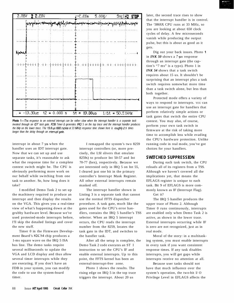
,; . . . . . . . . . .
Photo l--The response to an external interrupt can be rather slow when the interrupt handler is a separate taskinvoked through an IDT task gate. RI5 Timer 0 generates IRQ 5 on the top trace and the interrupt handler producesthe blio on the lower trace. The 19.&s 1680 w/es at 33 MHz) response time shown here is rough/y25 timeslonger than the delay through an intem& gak
interrupt in about 7 us when thehandler uses an IDT interrupt gate.Now that we can set up and useseparate tasks, it’s reasonable to askwhat the response time for a completecontext switch might be. The CPU is
I modified Demo Task 2 to set up
obviously performing more work on
the machinery required to produce aninterrupt and then display the resultson the VGA. This gives you a real-time
our behalf while switching from one
view of what’s happening down at thegrubby hardware level. Because we’ve
task to another. So, how long does it
used protected-mode interrupts before,I’ll skip the detailed listings and cover
take?
the new stuff.Timer 0 in the Firmware Develop-
ment Board’s 82C54 chip produces a1-ms square wave on the IRQ 5 ISAbus line. The demo tasks requireseveral milliseconds to update theVGA and LCD display and thus allowseveral timer interrupts while theyare executing. If you don’t have anFDB in your system, you can modifythe code to use the system-boardtimer.
88 Issue #57 April 1995 Circuit Cellar INK
I remapped the system’s two 8259interrupt controllers (or, more pre-cisely, the LSI slivers that emulate8259s) to produce Int 50-57 and Int70-77 (hex), respectively. Because we
The interrupt handler shown in
are interested only in IRQ 5 on Int 55,
Listing 3 is a separate task that cannotuse the normal FFTS dispatcherprocedure. A task gate, much like the
I cleared just one bit in the primary
gates used for the CPU’s error han-dlers, contains the IRQ 5 handler’s TSS
controller’s Interrupt Mask Register.
selector. When an IRQ 5 interruptoccurs, the CPU reads the interrupt
All other external interrupts remain
number from the 8259, locates thetask gate in the IDT, and switches to
masked off.
the handler task.After all the setup is complete, the
Demo Task 2 code executes an ST Iinstruction to set the CPU’s IF andenable external interrupts. Up to thispoint, the FFTS kernel has been anexternal-interrupt-free zone.
Photo 1 shows the results. Therising edge on IRQ 5 in the top tracetriggers the interrupt. About 20 us
later, the second trace rises to showthat the interrupt handler is in control.The ‘386SX CPU runs at 33 MHz, soyou are looking at about 650 clockcycles of delay. A few microsecondsvanish while producing the outputpulse, but this is about as good as itgets.
Dig out your back issues. Photo 1
in INK 50 shows a 7-us responsethrough an interrupt gate (the cap-tion’s “7 ms” is a typo). Photo 1 inINK 54 shows that a task switchrequires about 15 us. It shouldn’t besurprising that an interrupt plus a taskswitch requires somewhat more timethan a task switch alone, but less thanboth together.
Protected mode offers a variety ofways to respond to interrupts. YOU canuse an interrupt gate for handlers thatperform relatively simple actions ortask gates that switch the entire CPUcontext. You may also, of course,perform your own task switch infirmware at the risk of taking moretime to accomplish less while evadingthe CPU’s hardware protection. Unlikerunning code in real mode, you’ve gotchoices for your handlers.
SWITCHED SUPPRESSIONDuring each task switch, the CPU
reloads all of its registers from a TSS.Although we haven’t covered all theimplications yet, that means theEFLAGS register is unique to eachtask. Bit 9 of EFLAGS is more com-monly known as IF (Interrupt Flag).
Get it?The IRQ 5 handler produces the
upper trace of Photo 2. AlthoughTimer 0 runs continuously, interruptsare enabled only when Demo Task 2 isactive, as shown in the lower trace.External interrupts occurring while IFis zero are not recognized, just as inreal mode.
Moral of the story: in a multitask-ing system, you must enable interruptsin every task if you want consistentresponse times. If any task disablesinterrupts, you will get gaps whileinterrupts receive no attention at all.
Because user tasks should nothave that much influence over thesystem’s operation, the two-bit I/OPrivilege Level in EFLAGS affects the
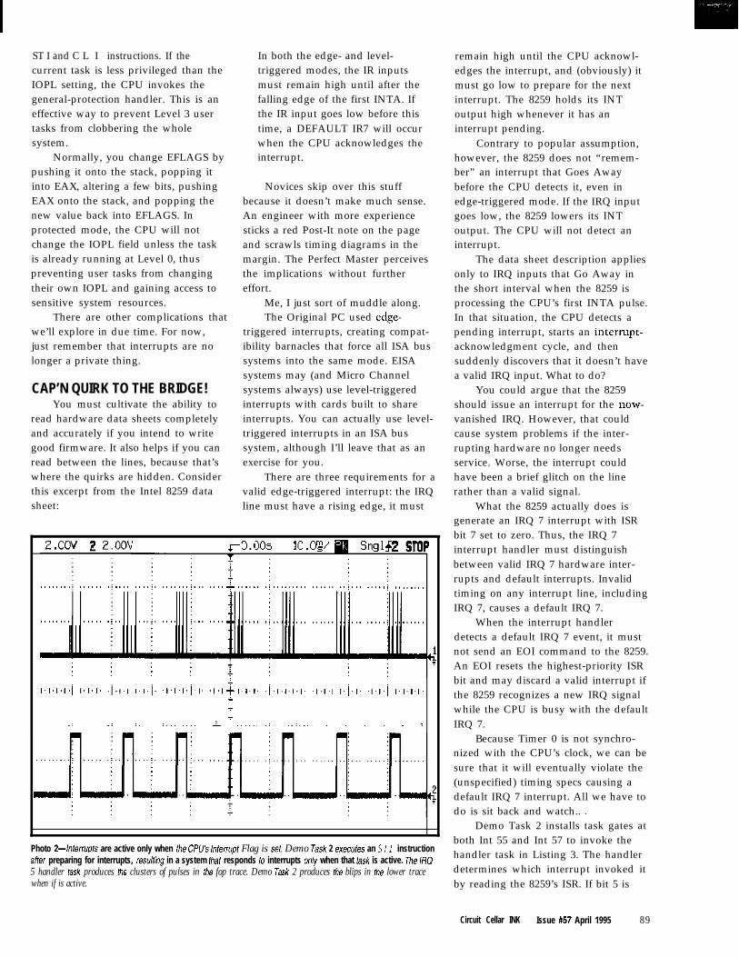
ST I and C L I instructions. If thecurrent task is less privileged than theIOPL setting, the CPU invokes thegeneral-protection handler. This is aneffective way to prevent Level 3 usertasks from clobbering the wholesystem.
Normally, you change EFLAGS bypushing it onto the stack, popping itinto EAX, altering a few bits, pushingEAX onto the stack, and popping thenew value back into EFLAGS. Inprotected mode, the CPU will notchange the IOPL field unless the taskis already running at Level 0, thuspreventing user tasks from changingtheir own IOPL and gaining access tosensitive system resources.
There are other complications thatwe’ll explore in due time. For now,just remember that interrupts are nolonger a private thing.
sheet:
CAP’N QUIRK TO THE BRIDGE!You must cultivate the ability to
read hardware data sheets completelyand accurately if you intend to writegood firmware. It also helps if you canread between the lines, because that’swhere the quirks are hidden. Considerthis excerpt from the Intel 8259 data
In both the edge- and level-triggered modes, the IR inputsmust remain high until after thefalling edge of the first INTA. Ifthe IR input goes low before thistime, a DEFAULT IR7 will occurwhen the CPU acknowledges theinterrupt.
Novices skip over this stuffbecause it doesn’t make much sense.An engineer with more experiencesticks a red Post-It note on the pageand scrawls timing diagrams in themargin. The Perfect Master perceivesthe implications without furthereffort.
Me, I just sort of muddle along.The Original PC used edge-
triggered interrupts, creating compat-ibility barnacles that force all ISA bussystems into the same mode. EISAsystems may (and Micro Channelsystems always) use level-triggeredinterrupts with cards built to shareinterrupts. You can actually use level-triggered interrupts in an ISA bussystem, although I’ll leave that as anexercise for you.
line must have a rising edge, it must
There are three requirements for avalid edge-triggered interrupt: the IRQ
i .i.,., j. I.,.4
,.,.,.,. ,.,.,. ,.,. .,.,.,. .l.l+l .,.,. .j.,.,.,.,. .,.,., ,.I.,. .,.,.j ,.,.,.,.L
7
7
_: _: :. :,_. _.._ I .._... .: ._:._. . . . . . .
Photo 24nferrupfs are active only when the CPU’s lnferrupf Flag is set Demo Task 2 exe&es an S TI instructionaffer preparing for interrupts, resulfing in a system fhaf responds to interrupts only when that task is active. The IRQ5 handler task produces the clusters of pulses in the fop trace. Demo Task 2 produces the blips in the lower tracewhen if is active.
remain high until the CPU acknowl-edges the interrupt, and (obviously) itmust go low to prepare for the nextinterrupt. The 8259 holds its INToutput high whenever it has aninterrupt pending.
Contrary to popular assumption,however, the 8259 does not “remem-ber” an interrupt that Goes Awaybefore the CPU detects it, even inedge-triggered mode. If the IRQ inputgoes low, the 8259 lowers its INToutput. The CPU will not detect aninterrupt.
The data sheet description appliesonly to IRQ inputs that Go Away inthe short interval when the 8259 isprocessing the CPU’s first INTA pulse.In that situation, the CPU detects apending interrupt, starts an interrupt-acknowledgment cycle, and thensuddenly discovers that it doesn’t havea valid IRQ input. What to do?
You could argue that the 8259should issue an interrupt for the now-vanished IRQ. However, that couldcause system problems if the inter-rupting hardware no longer needsservice. Worse, the interrupt couldhave been a brief glitch on the linerather than a valid signal.
What the 8259 actually does isgenerate an IRQ 7 interrupt with ISRbit 7 set to zero. Thus, the IRQ 7interrupt handler must distinguishbetween valid IRQ 7 hardware inter-rupts and default interrupts. Invalidtiming on any interrupt line, includingIRQ 7, causes a default IRQ 7.
When the interrupt handlerdetects a default IRQ 7 event, it mustnot send an EOI command to the 8259.An EOI resets the highest-priority ISRbit and may discard a valid interrupt ifthe 8259 recognizes a new IRQ signalwhile the CPU is busy with the defaultIRQ 7.
Because Timer 0 is not synchro-nized with the CPU’s clock, we can besure that it will eventually violate the(unspecified) timing specs causing adefault IRQ 7 interrupt. All we have todo is sit back and watch.. .
Demo Task 2 installs task gates atboth Int 55 and Int 57 to invoke thehandler task in Listing 3. The handlerdetermines which interrupt invoked itby reading the 8259’s ISR. If bit 5 is
Circuit Cellar INK Issue #57 April 1995 89
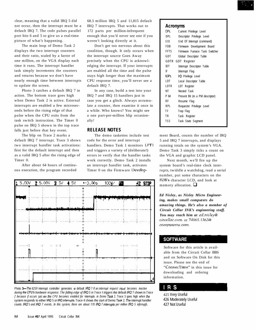
clear, meaning that a valid IRQ 5 didnot occur, then the interrupt must be adefault IRQ 7. The code pulses parallel
The main loop of Demo Task 2
port bits 6 and 5 to give us a real-time
displays the two interrupt countersand their ratio, scaled by a factor of
picture of what’s happening.
one million, on the VGA display eachtime it runs. The interrupt handlertask simply increments the countersand returns because we don’t havenearly enough time between interruptsto update the screen.
Photo 3 catches a default IRQ 7 inaction. The bottom trace goes highwhen Demo Task 2 is active. Externalinterrupts are enabled a few microsec-onds before the rising edge of thatpulse when the CPU exits from thetask switch instruction. The Timer 0pulse on IRQ 5 shown in the top tracefalls just before that key event.
The blip on Trace 2 marks adefault IRQ 7 interrupt. Trace 3 showstwo interrupt handler task activations:first for the default interrupt and thenas a valid IRQ 5 after the rising edge ofTimer 0.
After about 64 hours of continu-ous execution, the program recorded
68.3 million IRQ 5 and 11,815 defaultIRQ 7 interrupts. That works out to172 parts per million-infrequent
Don’t get too nervous about thiscondition, though. It only occurs whenthe interrupt source Goes Away
enough that you’d never see one if you
precisely when the CPU is acknowl-
weren’t looking directly at it.
edging the interrupt. If your interruptsare enabled all the time and the pulsestays high longer than the maximumCPU response time, you’ll never see adefault IRQ 7.
In any case, build a test into yourIRQ 7 and IRQ 15 handlers just incase you get a glitch. Always accumu-late a counter, then examine it once ina while. Who knows? You might seea one part-per-million blip occasion-ally!
RELEASE NOTESThe demo taskettes include test
code for the error and interrupthandlers. Demo Task 1 monitors LPTland triggers a variety of (deliberate!)errors to verify that the handler taskswork correctly. Demo Task 2 installsan interrupt handler task, activatesTimer 0 on the Firmware Develop-
7
Ti
--I2
;
i
. . . . . . . . .j _. j. ; + .; ..I.,, . . . ..I
i I
Photo 3-The 8259 interrupt controller generates a default IRQ 7 if an interrupt request inpuf becomes inactiveduring the CPUb hardware response. The falling edge of /Xl 5 in Trace 1 triggers the default /FlQ 7 shown in Trace2 because if occurs just as the CPU becomes enabled for interrupts in Demo Task 2. Trace 3 goes high when thesystem responds to either IRQ 5 or If?0 inferrupts. Trace 4 shows the start of Demo Task 2. The interrupt handlercounts IRQ 5 and IRQ 7 events. In this system, there are about 170 RQ 7 inferrupfs per million RQ 5 inferrupfs.
AcronymsCPL Current Privilege Level
DPL Descriptor Privilege Level
EOI End Of Interrupt (command)
FDB Firmware Development Board
FFTS Firmware Furnace Task Switcher
GDT Global Descriptor Table
GDTR GDT Register
IDT Interrupt Descriptor Table
IF Interrupt Flag
IOPL I/O Privilege Level
LDT Local Descriptor Table
LDTR LDT Register
NT Nested Task
P bit Present Bit (in a PM descriptor)
RF Resume Flag
RPL Requestor Privilege Level
TF Trap Flag
TR Task Register
TSS Task State Segment
ment Board, counts the number of IRQ5 and IRQ 7 interrupts, and displaysrunning totals on the system’s VGA.Demo Task 3 simply ticks a count onthe VGA and graphic LCD panel.
Next month, we’ll fire up thesystem board’s real-time clock inter-rupts, twiddle a watchdog, read a serialnumber, put some characters on theFDB’s character LCD, and look atmemory allocation. q
Ed Nisley, as Nisley Micro Engineer-ing, makes small computers doamazing things. He’s also a member ofCircuit Cellar INK’s engineering staff.You may reach him at [email protected]. or [email protected].
Software for this article is avail-able from the Circuit Cellar BBSand on Software On Disk for thisissue. Please see the end of“ConnecTime” in this issue fordownloading and orderinginformation.
425 Very Useful426 Moderately Useful427 Not Useful
90 Issue #57 April 1995 Circuit Cellar INK

Jeff Bachiochi
Vaporwear:Revealing Your Humidity
ou’ve probablyheard someone
comment about
from an ache or pain. What they areactually feeling is the change inhumidity as their bones and jointsswell or shrink from a change in theair’s moisture content. We livesomewhere between the extremes of adesert’s lack of moisture and a sauna’sabundance of it.
Take those muggy summer days(please); they can be brutal. The airseems so heavy. And, for good rea-son-it actually is. Humid air issaturated with water vapor. In thisgaseous state, the water heeds thesame rules as the other gases whichcombine to make air.
The relationship between air’spressure, volume, and temperature aredefined in the Ideal Gas Law:
pv-T -K
where P is pressure, V is volume, T istemperature, K is the gas constanttimes the number of moles of gas. Inother words, pressure and volume areinversely proportional, whereastemperature is proportional to bothpressure and volume.
Water is in a significant part of ourlives. It’s in our bodies, what we eat,and the air we breathe. The moisture
content of air can be measured byweighing all the water-vapor mol-ecules with respect to other gasmolecules-not an easy task fortweezers, a magnifying glass, and apostage scale.
However, it can be calculatedfrom knowing the dew/frost point(DFP) of the air. The DFP temperaturerepresents the temperature that thewater in the air becomes saturated andcondenses into water or ice. Thewarm, moist air we exhale on a coolmorning is chilled to dew point andinstantly condenses into waterdroplets or fog. Measuring the exacttemperature at which the condensa-tion takes place lets the relativehumidity (RH) be calculated.
Humidity affects us on a personallevel within our own comfort zone. Itis important to note here that humid-ity is just as important to otheractivities that operate in severeenvironments. Industrial furnaces orupper atmospheric experiments posespecial problems to the measurementof humidity and require speciallydesigned sensors and/or samplingequipment.
But, let’s try to remain within ourcomfort zone here for the remainder ofthis discussion.
COMFORT ZONEMEASUREMENTS
For most of us, while the outsidetemperature varies within a range of O-lOO”F, our artificial living environ-ment stays within 6575°F. Those ofus with base-board heat don’t havemuch control over humidity. Wemight keep a kettle of water on thewood stove or run a humidifier to keepa bit of humidity in the air, but ingeneral most of us don’t have ahygrometer on the wall next to thethermostat.
Before we added on to our cottagehere in New England, it was heated bya hot-air system. This old system,antiquated as it was, did have ahumidistat located within the centralair duct. Whenever hot air was movingthrough the duct, a fine mist of watervapor was introduced in an attempt tocontrol the humidity. I never actuallyfelt the effects of the humidistat
92 Issue #57 April 1995 Circuit Cellar INK

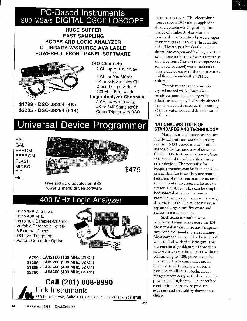
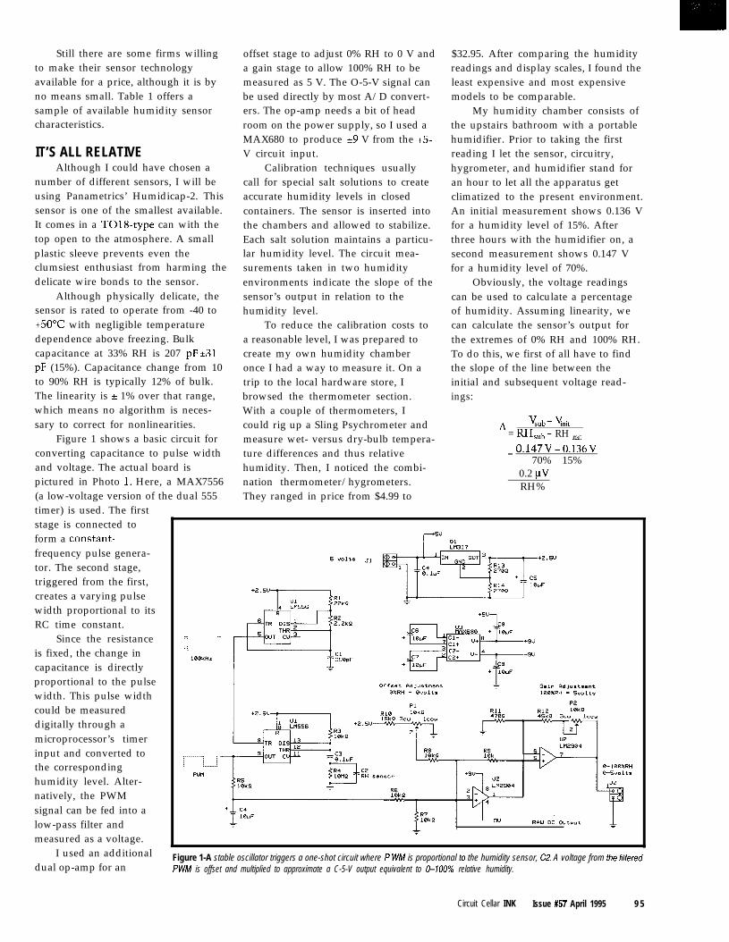
Still there are some firms willingto make their sensor technologyavailable for a price, although it is byno means small. Table 1 offers asample of available humidity sensorcharacteristics.
IT’S ALL RELATIVEAlthough I could have chosen a
offset stage to adjust 0% RH to 0 V anda gain stage to allow 100% RH to bemeasured as 5 V. The O-5-V signal canbe used directly by most A/D convert-ers. The op-amp needs a bit of headroom on the power supply, so I used aMAX680 to produce 29 V from the +5-V circuit input.
number of different sensors, I will beusing Panametrics’ Humidicap-2. Thissensor is one of the smallest available.It comes in a T018-type can with thetop open to the atmosphere. A smallplastic sleeve prevents even theclumsiest enthusiast from harming thedelicate wire bonds to the sensor.
Although physically delicate, thesensor is rated to operate from -40 to+5O”C with negligible temperaturedependence above freezing. Bulkcapacitance at 33% RH is 207 pF t31pF (15%). Capacitance change from 10to 90% RH is typically 12% of bulk.The linearity is f 1% over that range,which means no algorithm is neces-sary to correct for nonlinearities.
Calibration techniques usuallycall for special salt solutions to createaccurate humidity levels in closedcontainers. The sensor is inserted intothe chambers and allowed to stabilize.Each salt solution maintains a particu-lar humidity level. The circuit mea-surements taken in two humidityenvironments indicate the slope of thesensor’s output in relation to thehumidity level.
My humidity chamber consists ofthe upstairs bathroom with a portablehumidifier. Prior to taking the firstreading I let the sensor, circuitry,hygrometer, and humidifier stand foran hour to let all the apparatus getclimatized to the present environment.An initial measurement shows 0.136 Vfor a humidity level of 15%. Afterthree hours with the humidifier on, asecond measurement shows 0.147 Vfor a humidity level of 70%.
Figure 1 shows a basic circuit forconverting capacitance to pulse widthand voltage. The actual board ispictured in Photo 1. Here, a MAX7556(a low-voltage version of the dual 555timer) is used. The firststage is connected toform a constant-frequency pulse genera-tor. The second stage,triggered from the first,creates a varying pulsewidth proportional to itsRC time constant.
Since the resistance :-: ..,: : : :: : : :is fixed, the change in : : :L
1BBkHZ
To reduce the calibration costs toa reasonable level, I was prepared tocreate my own humidity chamberonce I had a way to measure it. On atrip to the local hardware store, Ibrowsed the thermometer section.With a couple of thermometers, Icould rig up a Sling Psychrometer andmeasure wet- versus dry-bulb tempera-ture differences and thus relativehumidity. Then, I noticed the combi-nation thermometer/hygrometers.They ranged in price from $4.99 to
Obviously, the voltage readingscan be used to calculate a percentageof humidity. Assuming linearity, wecan calculate the sensor’s output forthe extremes of 0% RH and 100% RH.To do this, we first of all have to findthe slope of the line between theinitial and subsequent voltage read-ings:
%b - YnitA = RHsUb - RH ,nit
= O.l47V-0.136V70% - 15%
0.2 uvRH%
capacitance is directlyproportional to the pulsewidth. This pulse widthcould be measureddigitally through amicroprocessor’s timerinput and converted tothe correspondinghumidity level. Alter-natively, the PWMsignal can be fed into alow-pass filter andmeasured as a voltage.
I used an additionaldual op-amp for an
Figure 1-A stable oscillator triggers a one-shot circuit where P WM is proportional lo the humidity sensor, CZ. A voltage from the filteredPWM is offset and multiplied to approximate a C-5-V output equivalent to C-UN% relative humidity.
$32.95. After comparing the humidityreadings and display scales, I found theleast expensive and most expensivemodels to be comparable.
Circuit Cellar INK Issue #57 April 1995 9 5
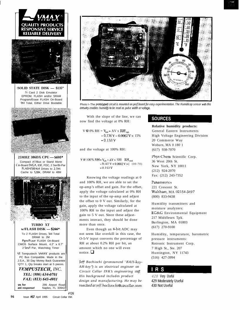
SOLID STATE DISK - $135”% Card 2 Disk Emulator
EPROM, FLASH and/or SRAMProgram/Erase FLASH On-Board1M Total, Either Drive Bootable
25MHZ 386DX CPU - $695*Compact AT/Bus or Stand Alone
In-Board SVGA, IDE, FDC, 2 Ser/Bi-ParFLASH/SRAM Drives to 2.5M
Cache to 128K, DRAM to 48M
TURBO XTw/FLASH DISK - $266*To 2 FLASH Drives, 1M Total
DRAM to 2MPgm/Erase FLASH On-Board
CMOS Surface Mount, 4.2” x 6.7”2 Ser/l Par, Watchdog Timer
{II Tempustech VMAX. products arePC Bus Compatible. Made in the
J.S.A., 30 Day Money Back Guarantee‘QTY 1, Qty breaks start at 5 pieces.
TEMPUSTECH, INC.TEL:(800)634-0701FAX:(813)643-4981
:ax for 295 Airport Roadast response! Naples, FL 33942
96 Issue #57 April 1995 Circuit Cellar INK
Photo l--The profotyped circuit is mounted on perf board for easy experimentation. The Humidicap sensor wifh thiscircuit/y enables humidify to be read as pulse width or volfage.
With the slope of the line, we cannow find the voltage at 0% RH:
V @ 0% RH = yni, - AV x RH,,,,=O.l36V-0.0002Vx 15%=O.l33V
and the voltage at 100% RH:
V@ lOO%RH=V,,,+AVx lOO-RH,,,
=0.147V+O.O002Vx( 100-70)
=O.l53V
Knowing the voltage readings at 0and 100% RH, we are able to set theop-amp’s offset and gain. For the offset,apply the voltage calculated at 0% RHto the input of the op-amp and adjustthe offset to 0 V out. Similarly, for thegain, apply the voltage calculated at100% RH to the input and adjust thegain to 5 V out. Since these adjust-ments interact, they should be donemore than once.
Even though an 8-bit ADC maynot seem like overkill in this case, theO-5-V input converts the percentage ofRH at about 0.2% RH per bit, anamount which no one will evennotice. q
/eff Bachiochi (pronounced “BAH-key-AH-key”) is an electrical engineer onCircuit Cellar INK’s engineering staff.
His background includes productdesign and manufacturing. He may [email protected].
Relative humidity products:General Eastern InstrumentsHigh Voltage Engineering Division20 Commerce WayWoburn, MA 0 180 1(617) 938-7070
Phys-Chem Scientific Corp.36 West 20th St.New York, NY 10011(212) 924-2070Fax: (212) 243-7352
Panametrics221 Crescent St.Waltham, MA 02154-3497(800) 833-9438
Humidity transmitters andmoisture analyzers:EG&G Environmental Equipment217 Middlesex Tpk.Burlington, MA 01803(617) 270-9100
Humidity, temperature, barometricpressure instruments:Rotronic Instrument Corp.7 High St., Ste. 207Huntington, NY 11743(516) 427-3994
428 Very Useful429 Moderately Useful430 Not Useful
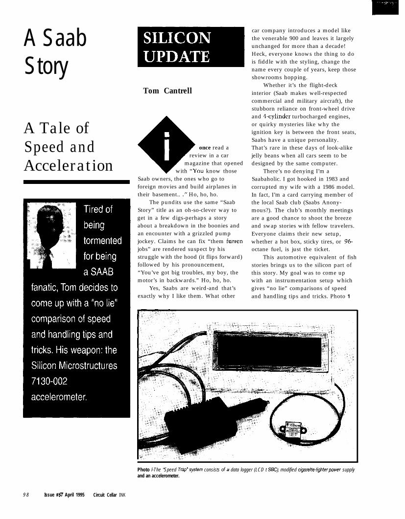
A SaabStory
Tom CantrellWhether it’s the flight-deck
interior (Saab makes well-respectedcommercial and military aircraft), thestubborn reliance on front-wheel driveand 4-cylinder turbocharged engines,or quirky mysteries like why theignition key is between the front seats,Saabs have a unique personality.
once read a That’s rare in these days of look-alikereview in a car jelly beans when all cars seem to be
magazine that opened designed by the same computer.with “You know those There’s no denying I’m a
Saabaholic. I got hooked in 1983 andcorrupted my wife with a 1986 model.In fact, I’m a card carrying member ofthe local Saab club (Saabs Anony-mous?). The club’s monthly meetingsare a good chance to shoot the breezeand swap stories with fellow travelers.Everyone claims their new setup,whether a hot box, sticky tires, or 96-octane fuel, is just the ticket.
Saab owners, the ones who go toforeign movies and build airplanes intheir basement.. .” Ho, ho, ho.
The pundits use the same “SaabStory” title as an oh-so-clever way toget in a few digs-perhaps a storyabout a breakdown in the boonies andan encounter with a grizzled pumpjockey. Claims he can fix “them furrenjobs” are rendered suspect by hisstruggle with the hood (it flips forward)followed by his pronouncement,“You’ve got big troubles, my boy, themotor’s in backwards.” Ho, ho, ho.
Yes, Saabs are weird-and that’sexactly why I like them. What other
A Tale ofSpeed andAcceleration
car company introduces a model likethe venerable 900 and leaves it largelyunchanged for more than a decade!Heck, everyone knows the thing to dois fiddle with the styling, change thename every couple of years, keep thoseshowrooms hopping.
This automotive equivalent of fishstories brings us to the silicon part ofthis story. My goal was to come upwith an instrumentation setup whichgives “no lie” comparisons of speedand handling tips and tricks. Photo 1
Photo l-The “Speed Trap”system consists of a data logger (LCD t SC), modified cigaretie-lighter power supplyand an accelerometer.
9 8 Issue #57 April 1995 Circuit Cellar INK
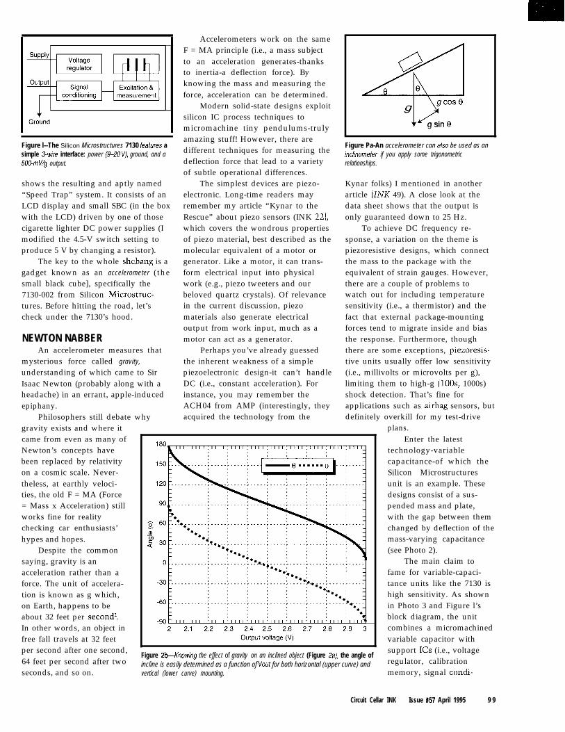
Figure l--The Silicon Microstructures 7130 feafures asimple 3wire interface: power (9-20 V), ground, and a500-mV/g output.
shows the resulting and aptly named“Speed Trap” system. It consists of anLCD display and small SBC (in the boxwith the LCD) driven by one of thosecigarette lighter DC power supplies (Imodified the 4.5-V switch setting toproduce 5 V by changing a resistor).
The key to the whole shebang is agadget known as an accelerometer (thesmall black cube], specifically the7130-002 from Silicon Microstruc-tures. Before hitting the road, let’scheck under the 7130’s hood.
NEWTON NABBERAn accelerometer measures that
Accelerometers work on the sameF = MA principle (i.e., a mass subjectto an acceleration generates-thanksto inertia-a deflection force). Byknowing the mass and measuring theforce, acceleration can be determined.
Modern solid-state designs exploitsilicon IC process techniques tomicromachine tiny pendulums-trulyamazing stuff! However, there aredifferent techniques for measuring thedeflection force that lead to a varietyof subtle operational differences.
The simplest devices are piezo-electronic. Long-time readers mayremember my article “Kynar to theRescue” about piezo sensors (INK 22),which covers the wondrous propertiesof piezo material, best described as themolecular equivalent of a motor orgenerator. Like a motor, it can trans-form electrical input into physicalwork (e.g., piezo tweeters and ourbeloved quartz crystals). Of relevancein the current discussion, piezomaterials also generate electricaloutput from work input, much as amotor can act as a generator.
the inherent weakness of a simplepiezoelectronic design-it can’t handleDC (i.e., constant acceleration). Forinstance, you may remember theACH04 from AMP (interestingly, theyacquired the technology from the
Perhaps you’ve already guessed
0
~
6 e
ggcos0
g sin 0
Figure Pa-An accelerometer can also be used as aninclinomefer if you apply some trigonometricrelationships.
Kynar folks) I mentioned in anotherarticle (INK 49). A close look at thedata sheet shows that the output isonly guaranteed down to 25 Hz.
tive units usually offer low sensitivity
To achieve DC frequency re-sponse, a variation on the theme is
(i.e., millivolts or microvolts per g),
piezoresistive designs, which connectthe mass to the package with the
limiting them to high-g (loos, 1000s)
equivalent of strain gauges. However,there are a couple of problems towatch out for including temperaturesensitivity (i.e., a thermistor) and the
shock detection. That’s fine for
fact that external package-mountingforces tend to migrate inside and biasthe response. Furthermore, though
applications such as airbag sensors, but
there are some exceptions, piezoresis-
definitely overkill for my test-drivegravity exists and where it
mysterious force called gravity,
came from even as many ofNewton’s concepts havebeen replaced by relativity
understanding of which came to Sir
on a cosmic scale. Never-theless, at earthly veloci-
Isaac Newton (probably along with a
ties, the old F = MA (Force= Mass x Acceleration) stillworks fine for reality
headache) in an errant, apple-induced
checking car enthusiasts’hypes and hopes.
epiphany.Philosophers still debate why
plans.Enter the latest
technology-variablecapacitance-of which theSilicon Microstructuresunit is an example. Thesedesigns consist of a sus-pended mass and plate,with the gap between themchanged by deflection of themass-varying capacitance(see Photo 2).Despite the common
saying, gravity is anacceleration rather than aforce. The unit of accelera-tion is known as g which,on Earth, happens to beabout 32 feet per secondI.In other words, an object infree fall travels at 32 feetper second after one second,64 feet per second after twoseconds, and so on.
Figure Pb-Knowing the effect of gravity on an inclined object (Figure 2a), the angle ofincline is easily determined as a function of Vout for both horizontal (upper curve) andvertical (lower curve) mounting.
The main claim tofame for variable-capaci-tance units like the 7130 ishigh sensitivity. As shownin Photo 3 and Figure l’sblock diagram, the unitcombines a micromachinedvariable capacitor withsupport ICs (i.e., voltageregulator, calibrationmemory, signal condi-
Circuit Cellar INK Issue #57 April 1995 9 9
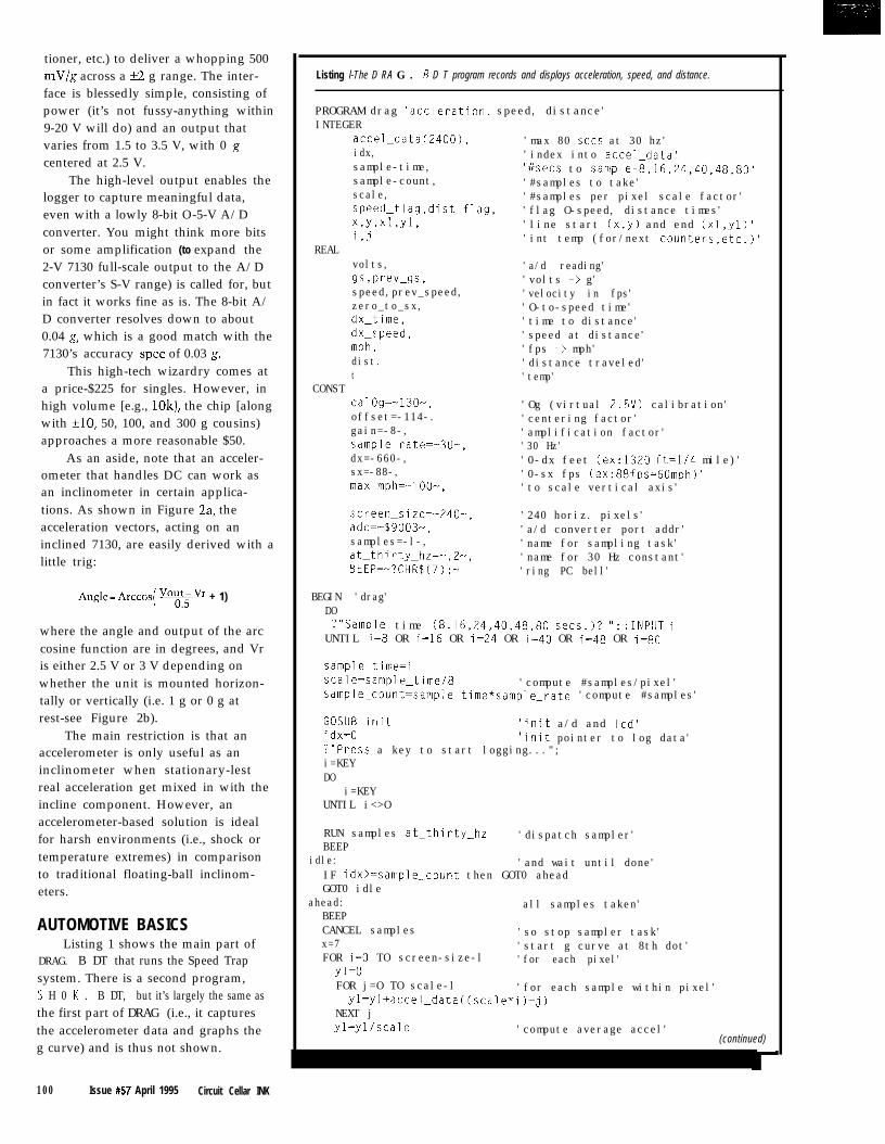
tioner, etc.) to deliver a whopping 500mV/g across a +2 g range. The inter-face is blessedly simple, consisting ofpower (it’s not fussy-anything within9-20 V will do) and an output thatvaries from 1.5 to 3.5 V, with 0 gcentered at 2.5 V.
The high-level output enables thelogger to capture meaningful data,even with a lowly 8-bit O-5-V A/Dconverter. You might think more bitsor some amplification (to expand the2-V 7130 full-scale output to the A/Dconverter’s S-V range) is called for, butin fact it works fine as is. The 8-bit A/D converter resolves down to about0.04 g, which is a good match with the7130’s accuracy spec of 0.03 g.
This high-tech wizardry comes ata price-$225 for singles. However, inhigh volume [e.g., lOk), the chip [alongwith f10, 50, 100, and 300 g cousins)approaches a more reasonable $50.
As an aside, note that an acceler-ometer that handles DC can work asan inclinometer in certain applica-tions. As shown in Figure 2a, theacceleration vectors, acting on aninclined 7130, are easily derived with alittle trig:
Angle- Arccos( “T + 1)
where the angle and output of the arccosine function are in degrees, and Vris either 2.5 V or 3 V depending onwhether the unit is mounted horizon-tally or vertically (i.e. 1 g or 0 g atrest-see Figure 2b).
The main restriction is that anaccelerometer is only useful as aninclinometer when stationary-lestreal acceleration get mixed in with theincline component. However, anaccelerometer-based solution is idealfor harsh environments (i.e., shock ortemperature extremes) in comparisonto traditional floating-ball inclinom-eters.
AUTOMOTIVE BASICSListing 1 shows the main part of
DRAG. B DT that runs the Speed Trapsystem. There is a second program,S H 0 K . B DT, but it’s largely the same asthe first part of DRAG (i.e., it capturesthe accelerometer data and graphs theg curve) and is thus not shown.
100 Issue #57 April 1995 Circuit Cellar INK
Listing l-The D RA G . 5 D T program records and displays acceleration, speed, and distance.
PROGRAM drag 'accleration. speed, distance'INTEGER
accel_data(2400),idx,sample-time,sample-count,scale,speed_flag,dist_flag,X,Y,Xl,Yl,i,j
REALvolts,gs,prev_gs,speed,prev_speed,zero_to_sx,dx_time,dx_speed,mph,dist.t
CONSTcalOg=-130-,offset=-114-.gain=-8-,sample-rate=-30-,dx=-660-,sx=-88-,max_mph=-loo-.
'max 80 sets at 30 hz''index into accel_data''i/sets to sample-8,16,24,40,48,80''#samples to take''#samples per pixel scale factor''flag O-speed, distance times''line start (x,y) and end (xl,yl)''int temp (for/next counters.etc.1'
'a/d reading''volts m> g''velocity in fps''O-to-speed time''time to distance''speed at distance''fps -> mph''distance traveled''temp'
'Og (virtual 2.5V) calibration''centering factor''amplification factor''30 Hz''0-dx feet (ex:1320 ft=1/4 mile)''0-sx fps (ex:88fps=60mph)''to scale vertical axis'
screen-size=-240-,adc=-$9003-,
'240 horiz. pixels''a/d converter port addr'
samples=-l-, 'name for sampling task'at_thirty_hz=-,2-, 'name for 30 Hz constant'BEEP=-?CHRS(7);- 'ring PC bell'
BEGIN 'drag'DO?"Sample time (8,16,24.40,48,80 sets.)? "; :INPUT i
UNTIL i=8 OR i=16 OR i=24 OR i=40 OR i=48 OR i=80
sample_time=iscale=sample_time/8 'compute #samples/pixel'sample_count=sample_time*sample_rate 'compute #samples'
GOSUB init 'init a/d and led'idx=O 'init pointer to log data'?"Press a key to start logging...";i=KEYDO
i=KEYUNTIL i<>O
RUN samples at_thirty_hzBEEP
'dispatch sampler'
idle: 'and wait until done'IF idx>=sample_count then GOT0 aheadGOT0 idle
ahead:BEEP
all samples taken'
CANCEL samplesx=7
'so stop sampler task''start g curve at 8th dot'
FOR i=O TO screen-size-l 'for each pixel'yl=OFOR j=O TO scale-l 'for each sample within pixel'yl=yl+accel_data((scale*i)+j)
NEXT jyl=yllscale 'compute average accel'
(continued)
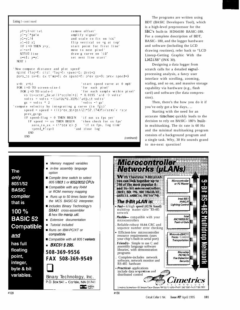
Listing l-continued
yl=ylmoffsetyl=yl*gainyl=y1/4yl=63mylIF i=O THEN y=ylx1=x+1GOSUB linex=x1: y=yl
NEXT i
remove offset'amplify signal'and scale to fit on led'flip vertical so +g at top'start point for first line'move to next pixel'draw g curve on led'set next line start'
'Now compute distance and plot speed'speed_flag=O: distLflag=O: speed=O: dist=Ozero_to_sx=O: dx_time=O: dx_speed=O: prev_gs=O: prev_speed=O
x=8: y=63 'start speed curve at 0 mph'FOR i=O TO screen-size-l 'for each pixel'
FOR j=O TO scale-l 'for each sample within pixel'volts=accel_data((i*scale)+j) * 0.0195 'a/d -> volts'volts = volts - (calOg*O.O195)'adjust volts'gs = volts * 2 'volts -> gs'
'compute velocity by integrating g curve (in fps)'speed = speed + (((prev_gs+gs)/2)*32.17405)/samplerateprev_gs=gsIF speed-flag = 0 THEN BEGIN 'if not sx fps yet'
IF speed >= sx THEN BEGIN 'then check for sx fps'zero_to_sx = (i*scale)+j 'if sx fps, log time'speed-flag=1 'and close log'
ENDEND (continued)
The programs are written usingBDT (BASIC Developers Tool), whichis a high-level preprocessor for theSBC’s built-in HD64180 BASIC-180.For a complete description of BDT,BASIC- 180, and the logger hardwareand software (including the LCDdrawing routines), refer back to “LCDLineup-Getting Graphic With theLM213B” (INK 30).
Designing a data logger fromscratch calls for a detailed signal-processing analysis, a fancy userinterface with scrolling, zooming,scaling, and so on, and massive storagecapability via hardware (e.g., flashcard) and software (for data compres-sion).
Then, there’s the how you do it ifyou’ve only got a few days.. . .
Starting with the need for anaccurate timebase quickly leads to thedecision to rely on BASIC- 180’s built-in multitasking. The tic rate is 60 Hzand the minimal multitasking programconsists of a background program anda single task. Why, 30 Hz sounds grandto me-next question!
n Memory mapped variables
n in-line assembly languageoption
w Compile time switch to select805 l/803 1 or 8052/8032 CPlJs
H Compatible with any RAMor ROM memory mapping
n Runs up to 50 times faster thanthe MCS BASIC-52 interpreter.
w includes Binary Technology’sSXA51 cross-assembler& hex file manip. util.
n Extensive documentation
n Tutorial included
w Runs on IBM-PC/XT orcompatibile
w Compatible with all 805 1 variants
n BXC51 $295.
508-369-9556FAX 508-369-9549
qBinary Technology, Inc.P.O.Box541 l Carlisle.MA01741
+ Fast--A high speed (62.5k baud)multidrop master/slave RS-485network
. F/exib/+ compatible with yourmicrocontrollers
. Reliable-robust 16.bit CRC andsequence number error checking
b Efficient-low microcontrollerresource requirements (usesyour chip’s built-in serial port)
. Friend/y- Simple to use C andassembly language softwarelibraries, with demonstrationprograms
. Complete-includes networksoftware, network monitor andRS-485 hardware
F Practical- applications
Process Control
include data acquisdistributed control
Cimetrics Technoloov~55Tem~lePlace~Bosron. MAO2111.1300*Ph617.350.7550~Fx617350.7552
#130Circuit Cellar INK Issue #57 April 1995 101
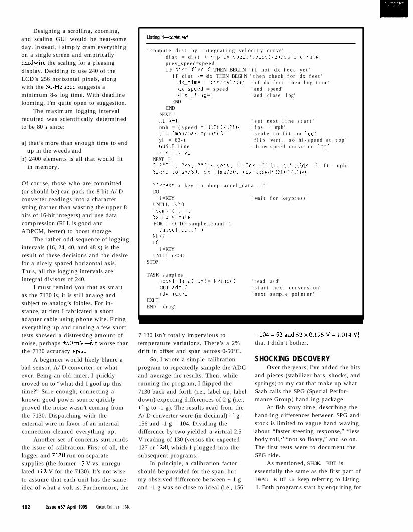
Designing a scrolling, zooming,and scaling GUI would be neat-someday. Instead, I simply cram everythingon a single screen and empiricallyhardwire the scaling for a pleasingdisplay. Deciding to use 240 of theLCD’s 256 horizontal pixels, alongwith the 30-Hz spec suggests aminimum 8-s log time. With deadlinelooming, I’m quite open to suggestion.
The maximum logging intervalrequired was scientifically determinedto be 80 s since:
a] that’s more than enough time to endup in the weeds and
b) 2400 elements is all that would fitin memory.
Of course, those who are committed(or should be) can pack the 8-bit A/Dconverter readings into a characterstring (rather than wasting the upper 8bits of 16-bit integers) and use datacompression (RLL is good andADPCM, better) to boost storage.
The rather odd sequence of loggingintervals (16, 24, 40, and 48 s) is theresult of these decisions and the desirefor a nicely spaced horizontal axis.Thus, all the logging intervals areintegral divisors of 240.
I must remind you that as smartas the 7130 is, it is still analog andsubject to analog’s foibles. For in-stance, at first I fabricated a shortadapter cable using phone wire. Firingeverything up and running a few shorttests showed a distressing amount ofnoise, perhaps f50 mV-far worse thanthe 7130 accuracy spec.
A beginner would likely blame abad sensor, A/D converter, or what-ever. Being an old-timer, I quicklymoved on to “what did I goof up thistime?” Sure enough, connecting aknown good power source quicklyproved the noise wasn’t coming fromthe 7130. Dispatching with theexternal wire in favor of an internalconnection cleaned everything up.
Another set of concerns surroundsthe issue of calibration. First of all, thelogger and 7130 run on separatesupplies (the former +5 V vs. unregu-lated +12 V for the 7130). It’s not wiseto assume that each unit has the sameidea of what a volt is. Furthermore, the
Listing 1-confinued
'compute dist by integrating velocity curve'dist = dist + ((prev-speed+speed)/Z)/samplerateprev_speed=speedIF dist-flag=0 THEN BEGIN 'if not dx feet yet'
IF dist >= dx THEN BEGIN 'then check for dx feet'dx_time = (i*scale)+j 'if dx feet then log time'dx_speed = speed 'and speed'dist_flag=l 'and close log'
ENDEND
NEXT jx1=x+1 'set next line start'mph = (speed * 3600)/5280 'fps -> mph't = (mphlmax_mph)*63 'scale to fit on led'yl = 63-t 'flip vert. so hi-speed at top'GOSUB line 'draw speed curve on led'x=x1: y=yl
NEXT I?:?"O-";:? sx;:?"fps sets, "..?dx..?' ft. s,";:?dx;:?" ft. mph"?zero_to_sx/30, dx_time/30,';dx~;peed*3600)/5280
?"Press a key to dump accel_data..."DO
i=KEY 'wait for keypress'UNTIL i<>O?sample_time?sample-rateFOR i=O TO sample_count-1
?accel_data(i)
2”’ ii=KEY
UNTIL i<>OSTOP
TASK samplesaccel_data(idx)=INP(adc) 'read a/d'OUT adc,O 'start next conversion'idx=idx+l 'next sample pointer'
EXITEND 'drag'
7 130 isn’t totally impervious totemperature variations. There’s a 2%drift in offset and span across 0-50°C.
-104=52and52x0.195V=1.014V)that I didn’t bother.
So, I wrote a simple calibrationprogram to repeatedly sample the ADCand average the results. Then, whilerunning the program, I flipped the7130 back and forth (i.e., label up, labeldown) expecting differences of 2 g (i.e.,+l g to -1 g). The results read from theA/D converter were (in decimal) +l g =156 and -1 g = 104. Dividing thedifference by two yielded a virtual 2.5V reading of 130 (versus the expected127 or 128), which I plugged into thesubsequent programs.
SHOCKING DISCOVERYOver the years, I’ve added the bits
and pieces (stabilizer bars, shocks, andsprings) to my car that make up whatSaab calls the SPG (Special Perfor-mance Group) handling package.
At fish story time, describing thehandling differences between SPG andstock is limited to vague hand wavingabout “faster steering response,” “lessbody roll, ” “not so floaty,” and so on.The first tests were to document theSPG ride.
In principle, a calibration factor As mentioned, SHOK. BDT isshould be provided for the span, but essentially the same as the first part ofmy observed difference between + 1 g DRAG. B DT so keep referring to Listingand -1 g was so close to ideal (i.e., 156 1. Both programs start by enquiring for
102 Issue #57 April 1995 Circuit Cellar INK
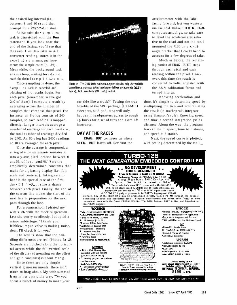
the desired log interval (i.e.,between 8 and 80 s) and thenprompt for a keypress to start.
At that point, the s a mp 1 estask is dispatched with the Runstatement. If you look near theend of the listing, you’ll see thatthe s amp 1 es task takes an A/Dconverter reading, stores it in thea cc e 1 _d a t a array, and incre-ments the sample count (i dx).Meanwhile, the background tasksits in a loop, waiting for i dx toreach the desired s a m p 1 e-co u n t .
Once sampling is done, thes amp 1 es task is canceled andplotting of the results begin. Foreach pixel (remember, we’ve got240 of them), I compute a result byaveraging across the number ofsamples that compose that pixel. Forinstance, an 8-s log consists of 240samples, so each reading is mappeddirectly. Longer intervals average anumber of readings for each pixel (i.e.,the total number of readings dividedby 240). An 80-s log has 2400 readings,so 10 are averaged for each pixel.
Once the average is computed, astring of y 1= statements mutates itinto a y-axis pixel location between 0and63. offset andgain are theempirically determined constants thatmake for a pleasing display (i.e., fullscale and centered). Taking care tohandle the special case of the firstpixel ( I F i =O.. .), a line is drawnbetween each pixel. Finally, the end ofthe current line makes the start of thenext line in preparation for the nextpass through the loop.
For a comparison, I pirated mywife’s ‘86 with the stock suspension.Lest she worry needlessly, I adopted aminor subterfuge: “I think yourfribblewumpus valve is making noise,dear. I’ll check it for you.”
The results show that the han-dling differences are real (Photos 4a-d).Seconds are notched along the horizon-tal access while the full vertical scaleof the display (depending on the offsetand gain constants) is about f0.5 g.
Since these are only simplevertical g measurements, there isn’tmuch to brag about. My wife summedit up in her own pithy way, “So youspent a bunch of money to make your
Photo 2-The 7130-002s onboard supporl circuits help the variablecapacitance g-sensor (silver package) deliver an accurate &X5%typical), high sensitivity (500 M/g) output.
car ride like a truck?” Testing the truebenefits of the SPG package (loo-MPHsweepers, skid pad, etc.) will onlyhappen if headquarters agrees to coughup bucks for a set of tires and extra lifeinsurance.
DAY AT THE RACESDRAG. BDT continues on where
SHOK. BDT leaves off. Remount the
*Dallas Semiconductor’s DS80C320*3Cc% “lore effiwnt than the a051*Three 16bh ~mer/Cauntersl 13 Interrupts (6 Ext. 7 Int)*A second 1 E&ii Data Pointer,384 ‘+tes of Internal RAM*Programmable Watchdogl amwnout Protection*Powerfail Reset/Interrupt*PowerOn Reset*Fully supported by Franklin CSI
accelerometer with the labelfacing forward, lest you waste arun like I did. Unlike S H 0 K, DRAGcomputes actual gs, so take careto level the accelerometer rela-tive to the road and not the car. Imounted the 7130 on a short-angle bracket that I could bend toaccount for a few degrees of rake.
Much as before, the remain-ing portion of DRAG. B DT stepsthrough each pixel and eachreading within the pixel. How-ever, this time the result isconverted to volts, adjusted withthe 2.5-V calibration factor andturned into gs.
Knowing acceleration andtime, it’s simple to determine speed bymultiplying the two and accumulatingthe result (in mathspeak, integrateusing Simpson’s rule). Knowing speedand time, a second integration yieldsdistance. Along the way, the programtracks time to speed, time to distance,and speed at distance.
Next, the speed curve is plotted,with scaling determined by the ma x_
Semiconductor’s n e w aOSl-compatible OSaOC320With i ts 2X clock speed [25MHz] and 3X cycle eff iciency, aninswction can execute in 160”s: en 8051 e q u i v a l e n t s p e e d
of 62.5MHz!!! Equally ~mpreswe is the T-128’s h i g h - s p e e d N V R A Minterface. Any of the 12aK R A M m a y b e p r o g r a m m e d d i r e c t l y f r o m a P C fde t h r o u g h t h e c o n s o l e :e l i m i n a t i n g E P R O M s a n d a s s o c i a t e d t o o l s . P r o g r a m D e v e l o p m e n t h a s n e v e r b e e n faster o r m o r ec o n v e n i e n t , e v e n w i t h t h e f i n e s t E P R O M emulator.The T-128 features PORT 0 bias and EA-select forOSf37C520 upgrade.
BASIC520*Modified BASIC52 lnteroreter IBASIC-5201
l Entre 12aK Memory Mappopulated with fast NVRAM(64K OATAt64K CODE1
*All memory pmgrammed an&ard*Partltlonable asa3oE/DATA/UvERU!4ll Gxie Space is WrirePmCedablel satmf~~OataPmtecbo”
Now Fast Enough for New Applications*Stack BASIC Programs and Autorun*CALL ASM Rotines for Maximum Speed
M*Three a-bit Parallel Portsl Twa Ful!-Ouplex RS232 Serial Parts‘Decoded Deuce I/O Strobes*SOPin Bus Connector
UPGRADE‘DS87C520 processor [33MHzl‘l”strUCtI0” cycle: 12 1 ns-8.25 MIPS‘8051 eqwalenc 82.5 MHz*Internal 16K ROM/l K SRAM
Comes Ready to Runwith powerrdrptar/cabla assembly.
Includss utility diskette withDETNLED TECHNICAL MANUAl
$199 in WV.
#131Circuit Cellar INK Issue #57 April 1995 103
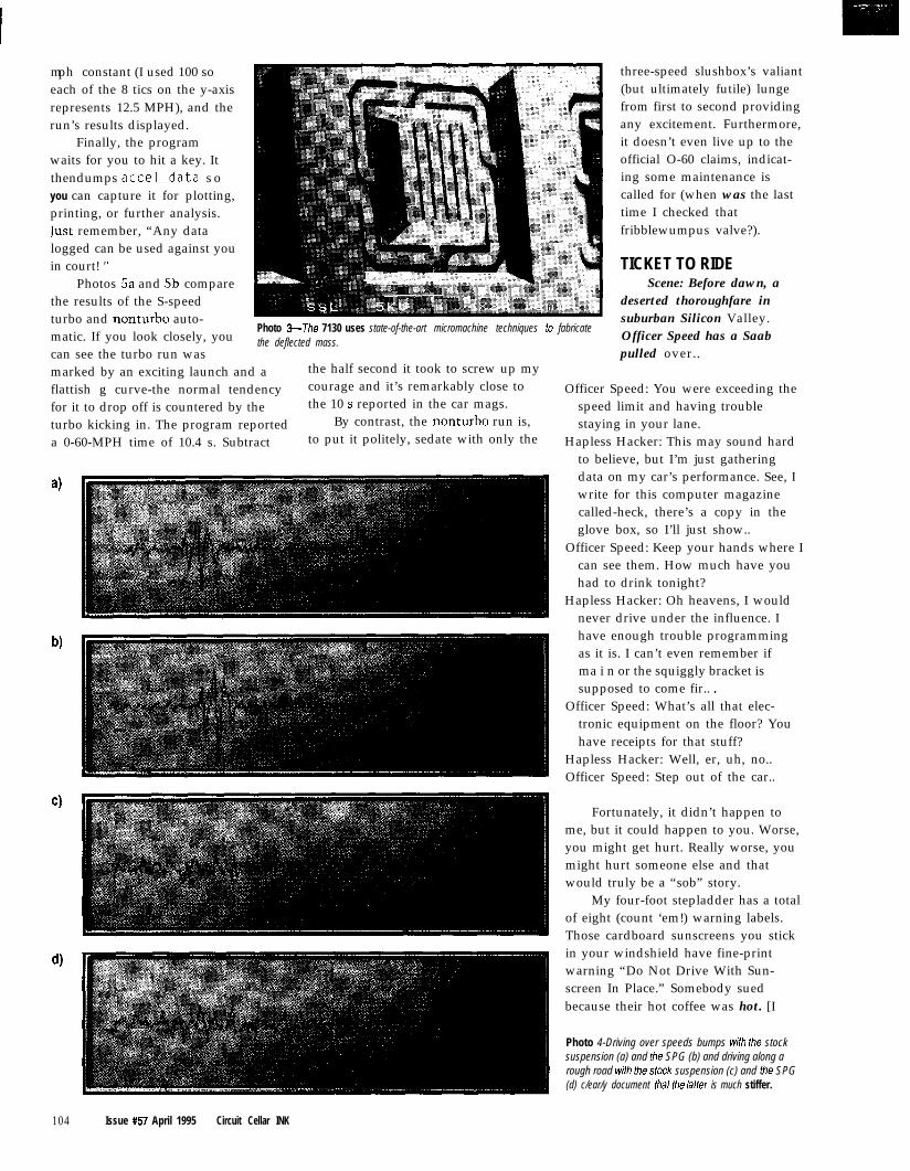
mph constant (I used 100 soeach of the 8 tics on the y-axisrepresents 12.5 MPH), and therun’s results displayed.
Finally, the programwaits for you to hit a key. Itthendumps accel_data soyou can capture it for plotting,printing, or further analysis.Iust remember, “Any datalogged can be used against youin court! ”
Photos Sa and 5b comparethe results of the S-speedturbo and nonturbo auto-matic. If you look closely, youcan see the turbo run was
Photo 3-The 7130 uses state-of-the-art micromachine techniques to fabricatethe deflected mass.
marked by an exciting launch and a the half second it took to screw up my
flattish g curve-the normal tendency courage and it’s remarkably close to
for it to drop off is countered by the the 10 s reported in the car mags.
turbo kicking in. The program reported By contrast, the nonturbo run is,
a 0-60-MPH time of 10.4 s. Subtract to put it politely, sedate with only the
4
b)
d)
three-speed slushbox’s valiant(but ultimately futile) lungefrom first to second providingany excitement. Furthermore,it doesn’t even live up to theofficial O-60 claims, indicat-ing some maintenance iscalled for (when was the lasttime I checked thatfribblewumpus valve?).
TICKET TO RIDEScene: Before dawn, a
deserted thoroughfare insuburban Silicon Valley.Officer Speed has a Saabpulled over..
Officer Speed: You were exceeding thespeed limit and having troublestaying in your lane.
Hapless Hacker: This may sound hardto believe, but I’m just gatheringdata on my car’s performance. See, Iwrite for this computer magazinecalled-heck, there’s a copy in theglove box, so I’ll just show..
Officer Speed: Keep your hands where Ican see them. How much have youhad to drink tonight?
Hapless Hacker: Oh heavens, I wouldnever drive under the influence. Ihave enough trouble programmingas it is. I can’t even remember ifma i n or the squiggly bracket issupposed to come fir.. .
Officer Speed: What’s all that elec-tronic equipment on the floor? Youhave receipts for that stuff?
Hapless Hacker: Well, er, uh, no..Officer Speed: Step out of the car..
Fortunately, it didn’t happen tome, but it could happen to you. Worse,you might get hurt. Really worse, youmight hurt someone else and thatwould truly be a “sob” story.
My four-foot stepladder has a totalof eight (count ‘em!) warning labels.Those cardboard sunscreens you stickin your windshield have fine-printwarning “Do Not Drive With Sun-screen In Place.” Somebody suedbecause their hot coffee was hot. [I
Photo 4-Driving over speeds bumps wifh the stocksuspension (a) and the SPG (b) and driving along arough road with the stock suspension (c) and the SPG(d) c/ear/y document that the latter is much stiffer.
104 Issue #57 April 1995 Circuit Cellar INK

wish I could sue for all the times I got“hot” coffee that wasn’t.)
Thus, I feel obligated to issue thewarning:
Don’t debug and drive. Alwaysremember to buckle up and backup.
That’s it for now, gotta run.Tonight’s the opening of the One-
World Film Festival, and before that, Iwant to spend a few minutes down-stairs with my new landing gear. q
Tom Cantrell has been an engineer inSilicon Valley for more than ten yearsworking on chip, board, and systemsdesign and marketing. He can bereached at (510) 657-0264 or by fax at(510) 657-5441.
Photo 5-The turbo has plenty of power, but calls forskilled launch technique to exploit it (a) while the regular900 seems to need a tuneup (b).
Software for this article is avail-able from the Circuit Cellar BBSand on Software On Disk for thisissue. Please see the end of“ConnecTime” in this issue fordownloading and orderinginformation.
Silicon Microstructures, Inc.46725 Fremont Blvd.Fremont, CA 94538Attn: Jim Knell(510) 490-5010Fax: (510) 490-l 119
431 Very Useful432 Moderately Useful433 Not Useful
The BCC52 controller continues to beMicromint’s best selling single-board com-puter. Its cost-effective architecture needsonly a power supply and terminal to becomea complete development system or single-board solution in an end-use system. TheBCC52 is programmable in BASIC-52, (afast, full floating point interpreted BASIC), orassembly language.
The BCC52 contains five RAM/ROMsockets, an “intelligent” 2764/128 EPROM - -programmer, three 8-bit parallel ports, anauto-baud rate detect serial console port, a serial printer port, and much more.
PROCESSOR.8OC52 S-bit CMOS processor w/BASIC-52-Three 16.bii counter/timers*Six interrupts*Much morel
INpUT/OUTpUTl Console RS232 - autobaud detect8 Line printer RS-232*Three S-bit parallel ports* EXPANDABLE!
- Compabbk with 12 BCC evpanwn boards
B C C 5 2 Controller board irilh BASIC-52 and SK RAM $1 89.00 slngleaty.BCC52C Low-power CMOS verwn of the SCC52 $199 .00BCC521 -40°C lo t&5% tndustrial temperature version $ 2 9 4 . 0 0BCC52CX Low-power CMOS, expanded SCC52 wi32K RAM $ 2 5 9 . 0 0
CALL FOR OEM PRICING
MICROMINT, INC. 4Park~treet,Vernon,~~06066
#119 132
- 3 PAR (32 BITS MAX)- 32K RAM, EXP 64M-STANDARD PC BUS- LCD, KBD PORT- BATT. BACK. RTC- IRQO-15 (8259 X2)- 0237 DMA 0253 TMR-BUILT-IN LED DISP.-UP TO 8 MEG ROM-CMOS NVRAM
USE TURBO C,BASIC, MASM
RUNS DOS ANDWINDOWS
EVAL KIT $295
“NmRSAL
PROGRAMMER ‘:.;-DOES 8 MEG EPROMS-CMOS, EE, FLASH, NVRAM-EASIER TO USE THAN MOST- POWERFUL SCRIPT ABILITY- MICROCONT. ADAPTERS- PLCC, MINI-DIP ADAPTERS-SUPER FAST ALGORITHMS
OTHER PRODUCTS:8088 SINGLE BOARD COMPUTER . . . . . . . OEM $279.. “95PC FLASH/ROM DISKS16 BIT 16 CHAN ADC-D6,
128K-16M) . . . . . . . . . . . . . . . . . . 21 . . . . . 75C CARD . . . . . . . . . . . . . . . . . . . . . 55...195
WATCHDOG (REBOOTS PC ON HANGUP) . . . . . 27 . . . . . 95l EVAL KITS INCLUDE MANUAL
BRACKET AND SOFTWARE. v) MVS BOX 8505 YR LIMITED WARRANTY
FREE SHIPPINGHRS: MON-FRI IOAM-BPM EST a
$ MERRlMACK,iVH. (508) 792 9507
J
Circuit Cellar INK Issue #57 April 1995 105
John Dybowski
Using Keyboard l/O as anEmbedded Interface
ngineers areoften charged with
the task of makingexisting products do
what they were never intended to do.This may be the natural consequenceof a product’s evolution or the result oftaking the most expeditious path todeveloping something new.
When old designs become buildingblocks for another technology, it’seffective to reuse as much of anexisting design as possible. Undercertain circumstance, there may be noother choice. This is certainly the casewhen using someone else’s product asa component of a larger system.
In using other companies’ prod-ucts, the preferred course of action is,not unexpectedly, the one of leastresistance. Faced with the task ofhooking a new peripheral to anexisting system, you might considerstructuring the new device’s supportcode to look like the one it’s replacing.
The attraction of this commonprogramming trick is that it disturbsthe functioning code as little aspossible. This sort of deceptiveprogramming is really what devicedrivers are all about.
DECEPTIVE DESIGNConsider a thoughtfully designed
display driver as an example. With adefined method of passing input andoutput arguments and generic func-
tions for standard operations such asdevice initialization, the main programcould care less if the actual outputdevice was an LCD, vacuum fluores-cent panel, CRT terminal, or anythingelse with a similar set of features.
At the other extreme, the conse-quences of embedding device depen-dencies directly into your process codecan prove to be intolerably restrictiveshould a change be ultimately re-quired. The fact is, even if you arecontent to specify a specific peripheralfor a given application, who’s to saythe manufacturer will be able todeliver a year from now. Stuff happens.
This is not to say that incorporat-ing device-specific functions in yourcode is necessarily bad. Certainly,there are cases where efficiencydictates that we stray from the ideal-a system processor doesn’t have therequired throughput for a heavilylayered device-support structure.However, be aware of the tradeoffs.Simply put, it’s okay to write bad codeif there’s no other way to do it.
This may seem to be quite afoolish statement. But realize thatthere are definitely a number of verypopular processors that make writinggood code very difficult, if not impos-sible. This is especially true of some ofthe very low-end controllers thatpresent a varied and unending assort-ment of ways to cramp your style-ameager and irregular instruction set,bizarre program-memory pagingschemes, or diabolically restrictedaddressing modes. Sound familiar?
Device drivers essentially offer astylized means of defining parameter-passing conventions between programmodules. The inherent benefits,however, shouldn’t be limited tomodules with a formally definedinterface specification.
It’s often equally advantageous touse this programming techniquewithin the depths of your program forchanging the way calls and inlinefunctions operate. When faced withthe prospect of replacing majorfunction blocks, I go out of my way tomake the new code imitate theoriginal’s I/O conventions. The goal:don’t let the main program knowthere’s a difference.
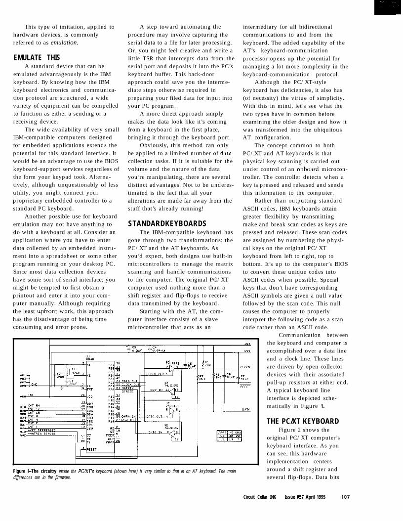
This type of imitation, applied tohardware devices, is commonlyreferred to as emulation.
EMULATE THISA standard device that can be
emulated advantageously is the IBMkeyboard. By knowing how the IBMkeyboard electronics and communica-tion protocol are structured, a widevariety of equipment can be compelledto function as either a sending or areceiving device.
The wide availability of very smallIBM-compatible computers designedfor embedded applications extends thepotential for this standard interface. Itwould be an advantage to use the BIOSkeyboard-support services regardless ofthe form your keypad took. Alterna-tively, although unquestionably of lessutility, you might connect yourproprietary embedded controller to astandard PC keyboard.
Another possible use for keyboardemulation may not have anything todo with a keyboard at all. Consider anapplication where you have to enterdata collected by an embedded instru-ment into a spreadsheet or some otherprogram running on your desktop PC.Since most data collection deviceshave some sort of serial interface, youmight be tempted to first obtain aprintout and enter it into your com-puter manually. Although requiringthe least upfront work, this approachhas the disadvantage of being timeconsuming and error prone.
A step toward automating theprocedure may involve capturing theserial data to a file for later processing.Or, you might feel creative and write alittle TSR that intercepts data from theserial port and deposits it into the PC’skeyboard buffer. This back-doorapproach could save you the interme-diate steps otherwise required inpreparing your filed data for input intoyour PC program.
A more direct approach simplymakes the data look like it’s comingfrom a keyboard in the first place,bringing it through the keyboard port.
Obviously, this method can onlybe applied to a limited number of data-collection tasks. If it is suitable for thevolume and the nature of the datayou’re manipulating, there are severaldistinct advantages. Not to be underes-timated is the fact that all youralterations are made far away from thestuff that’s already running!
STANDARDKEYBOARDSThe IBM-compatible keyboard has
gone through two transformations: thePC/XT and the AT keyboards. Asyou’d expect, both designs use built-inmicrocontrollers to manage the matrixscanning and handle communicationsto the computer. The original PC/XTcomputer used nothing more than ashift register and flip-flops to receivedata transmitted by the keyboard.
Starting with the AT, the com-puter interface consists of a slavemicrocontroller that acts as an
Figure l--The circuitry inside the PCIXJ’s keyboard (shown here) is very similar to that in an AT keyboard. The maindifferences are in the firmware.
intermediary for all bidirectionalcommunications to and from thekeyboard. The added capability of theAT’s keyboard-communicationprocessor opens up the potential formanaging a lot more complexity in thekeyboard-communication protocol.
Although the PC/XT-stylekeyboard has deficiencies, it also has(of necessity) the virtue of simplicity.With this in mind, let’s see what thetwo types have in common beforeexamining the older design and how itwas transformed into the ubiquitousAT configuration.
The concept common to bothPC/XT and AT keyboards is thatphysical key scanning is carried outunder control of an onboard microcon-troller. The controller detects when akey is pressed and released and sendsthis information to the computer.
Rather than outputting standardASCII codes, IBM keyboards attaingreater flexibility by transmittingmake and break scan codes as keys arepressed and released. These scan codesare assigned by numbering the physi-cal keys on the original PC/XTkeyboard from left to right, top tobottom. It’s up to the computer’s BIOSto convert these unique codes intoASCII codes when possible. Specialkeys that don’t have correspondingASCII symbols are given a null valuefollowed by the scan code. This nullcauses the computer to properlyinterpret the following code as a scancode rather than an ASCII code.
Communication betweenthe keyboard and computer isaccomplished over a data lineand a clock line. These linesare driven by open-collectordevices with their associatedpull-up resistors at either end.A typical keyboard lineinterface is depicted sche-matically in Figure 1.
THE PC/XT KEYBOARDFigure 2 shows the
original PC/XT computer’skeyboard interface. As youcan see, this hardwareimplementation centersaround a shift register andseveral flip-flops. Data bits
Circuit Cellar INK Issue #57 April 1995 1 0 7

Figure 2-The original IBM PC’s keyboard porl consisted of just a shift register and some glue logic and could only receive data from the keyboard.
are shifted in on falling edges of thekeyboard-generated clock and are validfrom before this falling clock edgeuntil after the rising edge of the clock.
The data line registers a high startbit and eight data bits for each trans-mitted code. Looking again to Figure 2,you see that initially a reset signalclears the shift register and its associ-ated flip-flop. As data bits are clockedin, the high start bit propagatesthrough the shift register and appearsat the ninth-bit flip-flop. This assertsan interrupt on the CPU.
At the same time this flip-floppulls the clock line low. This signals abusy state to the keyboard, which isheld until the received character hasbeen processed by the computer. Oncethis busy status clears, the clock lineis released and is pulled high by thepull-up resistor. This indicates to thekeyboard that the interface is availablefor further transmissions.
Curiously, with the interface in itsidle state, the keyboard lets the clock
108 Issue #57 April 1995 Circuit Cellar INK
line pull high, but drives the data linelow. This turns out to be an unfortu-nate decision on the part of the designengineers for it essentially jams thedata line, making bidirectionalcommunication impossible.
As a result, it’s not possible tohave multiple transmitting devices onthe line without adding extra circuitryto minimally disconnect thekeyboard’s data line from the rest ofthe interface. Because of the way makeand break codes are represented, thePC/XT keyboard is capable of encoding128 different key codes. A byte with avalue of O-127 is a make code. Adding80 hex to this basic code creates abreak code. For example, if Olh is themake code, 81h is the break code.
THE AT KEYBOARDThe AT keyboard rectifies some
shortcomings of the PC/XT keyboardwhile introducing a level of complex-ity that seems a bit out of place in akeyboard. Remember that the AT
computer’s keyboard port uses adedicated microcontroller to manageall communications with the key-board. This explains why things getcomplicated. Simply put, with the aidof this additional processing power,getting complicated is easy to do.
The AT interface is defined asbidirectional. The data line is now leftpulled up while no data is beingtransmitted or received so either thekeyboard or the computer can takecontrol of the interface during idletimes. As I’ll show later, this alsoleaves the possibility of adding otherexternal devices that can easily seizecontrol of the interface.
Bidirectional data communicationbetween the keyboard and computerconsists of 1 l-bit datastreams com-posed of a low start bit, eight data bits,an odd parity bit, and a high stop bit.The clock and data relationshipremains similar to that of the PC/XT.A fairly comprehensive [for a key-board) protocol is defined that provides

for error detection and retransmission,abort timing, and a line-contentionrecovery. Additionally, a relativelycomplete command set is specifiedthat describes a number of useful (andnot so useful) functions that thekeyboard and computer can initiate.
As with the PC/XT keyboard, allkeys are handled on a make/breakbasis. The difference is that to handlemore than 128 keys, a differentmethod of denoting break codes isused. Break codes are transmitted asFOh followed by the hex make code.Now a make and break sequence forscan code 1 appears as Olh, FOh, Olh.
The AT’s keyboard-interfaceelectronics are very similar to thoseused in the PC/XT. The computer’sinterface is implemented in firmwarerunning on a microcontroller, so it’spointless to try to depict it schemati-cally. It’s just your typical black box.
NEGOTIATING THE WIREWith both the PC/XT- and AT-
style keyboards, all communicationsare carried out using open-collectordrivers on the clock and data lines.With the PC/XT, there’s not muchmore to a typical transaction thanwhat I’ve already said. This is partiallydue to the fact that the interface iscapable of unidirectional traffic onlyand in part because you can only getinto so much trouble with a shiftregister and some glue.
The situation is a little moreinteresting with the AT. I’ll elaboratemore fully on how the keyboard andcomputer negotiate for control of theline and what happens if there’s aconflict. As stated, when no communi.cation is occurring, the data and clocklines are held at a high level throughpull-up resistors. The use of open-collector drivers allows either end toassert a logic low on either of theinterface lines.
If the computer is doing some-thing, it may elect to hold off akeyboard transmission by pulling theclock line to a low level (inhibitstatus). In a similar fashion, thecomputer signals its intention to begintransmitting by asserting a low levelon the data line while leaving theclock line at a high level (RTS status).
If either condition is in effect, thekeyboard will not attempt to transmit.Note that when the computer assertsrequest-to-send (data line low), it putsits start bit on the line. On recognitionof this event, the keyboard proceeds byemitting 11 clocks. The first 10 strobein the start bit, eight data bits, and theparity bit. After the tenth bit, thekeyboard pulls the data line low andissues one final clock pulse. Thiskeyboard-generated stop bit signals thecomputer that the keyboard hasreceived the transmission. Thecomputer returns to a ready state orputs the interface into inhibit status.
The keyboard checks for inhibitstatus and request-to-send status priorto starting any data transmission.Once a transmission has been initi-ated, the keyboard must continuouslycheck the clock. Should the computerlower the clock line while the key-board is transmitting, the interfaceenters a state called line contention.
What happens now depends onhow far into the sequence the key-board is. If this contending state isrecognized before the rising edge of thetenth clock (the parity bit), thekeyboard releases the clock and datalines and retains the pending data forlater retransmission. If line contentionoccurs after the tenth bit, the trans-mission is assumed to have “gonethrough” and the transfer concludesnormally. On receipt of the keyboard’sdata, the computer puts the interfaceinto inhibit status if it needs extraprocessing time or a response requestis to be issued.
US VERSUS THEMWhen IBM developed the AT
computer, it’s obvious they had theresources to put together a design teamjust to handle the keyboard design. Forthose of us with lesser means, it’simportant to separate the essentialfrom the superfluous. That is, we haveto cut through the fluff. Throughempirical observation, some generali-zations about the operation of the ATkeyboard can be made.
For example, for most keys, onlytheir respective make codes aresignificant. The complementary breakcodes are unessential and make no
.
I
II
I,I
I/
\
I
I
Add these numbers up:8OC552 a ‘51 Compatible Micro40 Bits of Digital I/O8 Channels of 10 Bit A/D3 Serial Ports (RS-232 or 422/485)2 Pulse Width Modulation Outputs6 Capture/Compare Inputs1 Real Time Clock64K bytes Static RAM1 + UVPROM Socket512 bytes of Serial EEPROM1 Watchdog1 Power Fail Interrupt1 On-Board Power Regulation
It adds up to real I/O power!
rhat’s our popular 552SBC, priced3t just $299 in single quantities.Yot enough I/O? There is anexpansion bus, too! Too muchIO? We’ll create a version just forfour needs, and pass the savings3n to you! Development is easy,Jsing our Development Kit: The552SBC-50 Development boardNith ROM Monitor, and an 8051 Ccompiler for just $449.
3ur popular 803 1SBC can now beshipped with your favorite 8051family processor. Models include8OC51 FA, DS8OC320, 8OC550,BOC652, 8OC154, 8OC851 andmore. Call for pricing today!
The DrylCE Plus is a low-costliternative to conventional ICElroducts. Load, single step,nterrogate, disasm, execute to3reakpoint. Only $448 with a pod.:or the 8051 family, including‘hilips and Siemens derivatives.SalI for brochure!
HiTech Equipment Corp.9400 Activity RoadSan Diego, CA 92126(Fax: (6 19) 530-l 4581
S ince 1983
- (619) 566-l 892 -
m piInternet e-mail: [email protected]
Internet ftp: ftp.hte.com
Circuit Cellar INK Issue #57 April 1995 109
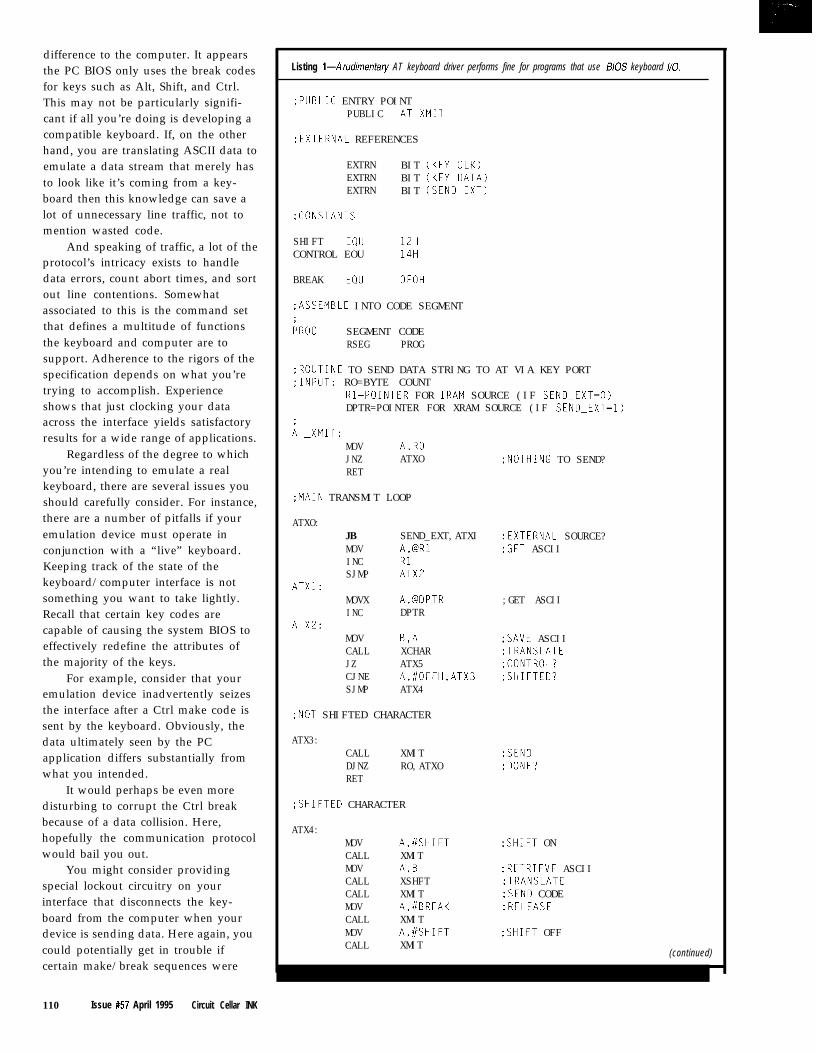
difference to the computer. It appearsthe PC BIOS only uses the break codesfor keys such as Alt, Shift, and Ctrl.This may not be particularly signifi-cant if all you’re doing is developing acompatible keyboard. If, on the otherhand, you are translating ASCII data toemulate a data stream that merely hasto look like it’s coming from a key-board then this knowledge can save alot of unnecessary line traffic, not tomention wasted code.
And speaking of traffic, a lot of theprotocol’s intricacy exists to handledata errors, count abort times, and sortout line contentions. Somewhatassociated to this is the command setthat defines a multitude of functionsthe keyboard and computer are tosupport. Adherence to the rigors of thespecification depends on what you’retrying to accomplish. Experienceshows that just clocking your dataacross the interface yields satisfactoryresults for a wide range of applications.
Regardless of the degree to whichyou’re intending to emulate a realkeyboard, there are several issues youshould carefully consider. For instance,there are a number of pitfalls if youremulation device must operate inconjunction with a “live” keyboard.Keeping track of the state of thekeyboard/computer interface is notsomething you want to take lightly.Recall that certain key codes arecapable of causing the system BIOS toeffectively redefine the attributes ofthe majority of the keys.
For example, consider that youremulation device inadvertently seizesthe interface after a Ctrl make code issent by the keyboard. Obviously, thedata ultimately seen by the PCapplication differs substantially fromwhat you intended.
It would perhaps be even moredisturbing to corrupt the Ctrl breakbecause of a data collision. Here,hopefully the communication protocolwould bail you out.
You might consider providingspecial lockout circuitry on yourinterface that disconnects the key-board from the computer when yourdevice is sending data. Here again, youcould potentially get in trouble ifcertain make/break sequences were
110 Issue #57 April 1995 Circuit Cellar INK
Listing l--A rudimenfary AT keyboard driver performs fine for programs that use B/OS keyboard /IO.
;PUBLIC ENTRY POINTPUBLIC ATpXMIl
;EXTERNAL REFERENCES
EXTRN BIT (KEYPCLK)EXTRN BIT (KEY-DATA)EXTRN BIT (SENDDEXT)
;CONSTANTS
SHIFT EQU 12HCONTROL EOU 14H
BREAK EQU OFOH
:ASSEMBLE INTO CODE SEGMENT
FROG SEGMENT CODERSEG PROG
;ROUTINE TO SEND DATA STRING TO AT VIA KEY PORT;INPUT: RO=BYTE COUNT
Rl=POINTER FOR IRAM SOURCE (IF SENDDEXT=O)DPTR=POINTER FOR XRAM SOURCE (IF SENDDEXT=l)
AT_xMIT:MOV A,ROJNZ ATXORET
;MAIN TRANSMIT LOOP
ATXO:JBMOVINCSJMP
ATXl:MOVXINC
ATXZ:MOVCALLJZCJNESJMP
SEND_EXT,ATXIA,BRlRlATX2
A,BDPTRDPTR
B,AXCHARATX5A,#OFFH,ATX3ATX4
;NOT SHIFTED CHARACTER
ATX3:CALL XMITDJNZ RO,ATXORET
;SHIFTED CHARACTER
ATX4:MOVCALLMOVCALLCALLMOVCALLMOVCALL
A,#SHIFTXMITA,0XSHFTXMITA,#BREAKXMITA.#SHIFTXMIT
;NOTHING TO SEND?
:EXTERNAL SOURCE?:GET ASCII
;GET ASCII
;SAVE ASCII;TRANSLATE;CONTROL?;SHIFTED?
:SEND:DONE?
;SHIFT ON
;RETRIEVE ASCII;TRANSLATE;SEND CODE;RELEASE
;SHIFT OFF
(continued)
Listing l-continued
DJNZ RO,ATXO ;DONE?RET
;CONTROL CHARCTER
iTX5:MOV A,#CONTROL :CONTROL ONCALL XMITMOV A,B :RETRIEVE ASCIICALL XSHFT ;TRANSLATECALL XMIT ;SEND CODEMOV A.//BREAK ;RELEASECALL XMITMOV A,#CONTROL ;CONTROL OFFCALL XMITDJNZ RO,ATXO ;DONERET
IROUTINE To S END A CHA R AC TER ~0 AT KEY PORT;LOCAL REGISTER USAGE: RZ/R4=DELAY LOOP COUNTER
;MIT:R3=BIT COUNTER
;INTERCHARACTER DELAY FIRST
CALL DELAY
;START BIT
(continued)
disassociated. In such a situation, anundetected, lost keyboard transmis-sion would be even more likely.
With a little extra hardware youcould hold off the keyboard while youare transmitting by asserting an inhibitstatus on the [now isolated) keyboardinterface. In such a scenario, constantline monitoring of all transmissionsfrom the keyboard and computerwould be necessary.
What all this boils down to is thatyou require a little smarts of theperson operating the equipment or youcan put a lot of smarts in your equip-ment. Sometimes, the former consti-tutes an unreasonable assumption.Then again, you have to give realisticconsideration to the system’s operat-ing conditions. The fact might be thatin some cases a persoti would reallyhave to work to break it.
Putting things into perspective,the situation I described is not nearlyas much of a problem in a typicalsystem implementation as would seemat first. However, looking at things ona detailed level flags the hazards of aparticular approach. Walking the line
between too much and too little isalways difficult and often involvessubjective judgment calls. Sure, youcan render a design to handle alleventualities, but you might price yourproduct right out of the market.
KEY CODE ANDUNEXPECTED APPLICATIONS
In keeping with my usual premiseof starting simple, I’ll present arudimentary transmit-only AT-keyboard emulation driver. Forflexibility, the code includes an ASCII-to-scan-code translator.
As an interesting side note, thiscode is similar to something I devel-oped several years ago as part of aremote computer-control center. Itturns out that some of the mostintriguing applications may be totallyunexpected and unforeseen, which isexactly what happened. Through afortunate sequence of events, one ofmy systems eventually found its wayinto the hands of some rather inven-tive software developers. It was justthe thing they were looking for.
#l
W O R L D ’ S S M A L L E S T
The PC/II +i includes:
. 486~x~~CPU at25MHzor33MHz clock frequency
. Full 8~ Cache with Fkxting Point
. Ethernet local Area Network i
l local Bus Super VGA Video/LCD ‘1
. Up to 2MByies FlashTM with TFFS
. 4 or 16MBytes User DRAM
. PC/l 04 or ISA Bus compatible option (wih adapter)
. 4”~ 4” Format; 6 watk power consumption at t5 volt only
TM486
Embedded PC withFlea ting Point,Ethernet & Super
Dx VGA OnIy4"x4"
486Dx and Flash are reglsteredtrademarks of Intel Carpasaw PC, ATof IBM, megatelofMegatelComputer(1986)Corp. (416)245-2953l e***oe**e,*eaa***
125 Wendell Ave. l Weston, Ont. l M9N 3K9 l Fax: (416) 245-6505 megatel”
Circuit Cellar INK Issue #57 April 1995 111
FREEData AcquisitionCatalog
acquisition catalog
from the inventors of
plug-in data acquisition.
Featuring new low-cost
A/D boards optimized
for Windows,
DSP Data Acquisition,
and the latest
Windows software.
Plus, informative
technical tips and
application notes.
Call for your free copy
l-800-648-6589
ADACAmerican Data Acquis i t ion Corporat ion70 Tower Office Park, Woburn, MA 01801p h o n e 6 1 7 - 9 3 5 - 3 2 0 0 f a x 6 1 7 - 9 3 8 - 6 5 5 3
#135112 Issue #57 April 1995 Circuit Cellar INK
Listing l-continued
CLR KEY-DATANOPCLR KEY_CLKMOV R2,#5DJNZ R2.BSETB KEYPCLK
~SETUP FOR LOOP
MOV R3,#9MOV C,PCPL C
;MAIN BIT BANGING LOOP
iXI:RRCMOVNOPCLRMOVDJNZSETBDJNZ
;SEND STOP BIT
SETBNOPCLRMOVDJNZSETBRET
AKEY_DATA,C
KEYPCLKR2,#5R2.8KEYPCLKR3,CXl
KEY-DATA
KEY_CLKR2,#5RZ,$KEYPCLK
:DATA LOW
;CLOCK LOW
;CLOCK HIGH
;BIT COUNTER:ODD PARITY
:SETUP DATA
;CLOCK LOW
;CLOCK HIGH;DONE?
:DATA HIGH
;CLOCK LOW
;CLOCK HIGH
;lO-mS INTER-CHARACTER DELAY ROUTINE
AELAY:MOV R4,#20
DELAYl:MOV RZ,#OF8HDJNZ R2,$DJNZ R4,DELAYlRET
:PRIMARY TRANSLATE ROUTINE
~CHAR:INC AMOVC A,@A+PCRET
:PRIMARY LOOKUP TABLE;O=CONTROL CHARACTER, FF=SHIFTED
DB oooH,oooH,oooH,OOOH,OOOH,OOOH.OOOH,OOOHDB o66H,ooDH,oooH,OOOH,OOOH,O5AH,OOOH,OOOHDB oooH.oOOH,OOOH,OOOH,OOOH,OOOH,OOOH,OOOHDB ~~~H~OOOH,OOOH,OOOH,OOOH,OOOH,OOOH,OOOHDB 029H,OFFH,oFFH,OFFH,OFFH,OFFH,OFFH,052HDB oFFH,oFFH,OFFH,OFFH,O4lH,04EH.049H,O4AHDB o45H~o16H,01EH,026H,025H,02EH,036H,03DHDB o3EH,o46H,OFFH,04CH,OFFH,O55H,OFFH,OFFHDB oFFH,OFFH,OFFH,OFFH,OFFH,OFFH,OFFH,OFFHDB OFFH,OFFH,OFFH,OFFH,OFFH,OFFH,OFFH,OFFHDB OFFH,OFFH,OFFH,OFFH,OFFH,OFFH,OFFH,OFFHDB OFFH,oFFH,oFFH,054H,05DH,05BH,OFFH,oFFH
(continued)
These people had written a rathercomplex PC application and wereadamant about testing it thoroughlybefore permitting even a beta release.Manually testing from the keyboardwas not deemed feasible due to thenumber of input permutations and thelikelihood of operator error.
At the same time, they wereskeptical about the possibly disruptiveeffect of performing the final testingusing the special TSR they had usedduring the initial check out. In shortorder, they had written a specialprogram designed to run on a dedicatedcomputer that operated the remotecomputer-control system as a robottypist. The test sequence ran atmaximum speed for 24 hours a dayover a period of three weeks! Due ingreat part to this test plan, when thesoftware shipped, it was remarkablybug free.
Anyway, back to the code. Listing1 is the AT-keyboard emulation driverpresented in its entirety. The programincludes both an ASCII-to-scan-codetranslation algorithm and a bit-bangedscan-code transmission routine. This803 1 assembly-language code canaccept its input string in eitherinternal or external RAM. The charac-ter count is passed in register RO, theinternal RAM data pointer uses Rl,and the external RAM data pointeruses DPTR. The bit variable S END_E XT determines whether the inputstring resides in internal or externalRAM.
On entry, RO is checked. If it doesnot contain 0, (an errant null string),the code falls through to the maindata-transmission loop. Now a databyte is picked out of the appropriatedata area in accordance with theSEND_EXT bit flag.
The initial ASCII translation isperformed by XC HA R, which returnseither the actual scan code or a specialindicator. If the returned value isneither OOh nor FFh, then no furtherprocessing is required. The scan codeis dispatched to XM I T and is clockedout to the computer. A returned valueof FFh indicates the ASCII characterrequires a shift operation whereas aOOh means the ASCII characterinvolves a control operation.
114 Issue #57 April 1995 Circuit Cellar INK
Listing 1-confinued
DB 00EH,01CH,032H,021H,023H,024H,02BH,034HDB 033H,043H,03BH,042H,04BH,03AH,031H,044HDB o4DH,o15H,O2DH,01BH,02CH,03CH,02AH,OlDHDB o22H,O35H,01AH,OFFH,OFFH,OFFH,OFFH,o7lH
;SECONDARY CHARCTER TRANSLATE ROUTINE
~SHFT:INC AMOVC A,@A+PCRET
ISECONDARY LOOKUP TABLE
DBDBDBDBDBD8DBDBDBDBDBDBDBDBDBDB
END
The shift code is handled by firstoutputting a shift make code. Asecondary lookup using X S H FT trans-lates the original ASCII code to a scancode. This code is transmitted, fol-lowed by a break code and a shift code(shift break sequence). The procedurefor a control code is similar, except thesequence is framed with a control scancode. These basic steps repeat until thecharacter count in RO is exhausted.
The code works okay, but is notwithout its problems. No attempt ismade to determine the actual opera-tional status of the keyboard-to-computer interface. The rather flagrantassumption is made that the interfaceis in normal mode-that is, not in astate such as Shift, Ctrl, Alt, CapsLock, and so on.
Also, note that strings involving alot of shifted sequences suffer asignificant performance penalty sinceeach ASCII character results in thetransmission of three codes in additionto the translated scan code: a shift,break, and shift. Obviously, if I were to
improve this program, keeping track ofmy own shift status would be one ofthe first areas I’d address.
Next month, I’ll wrap up with adiscussion of the AT-keyboard com-mand set, scan-code tables, and a fewother details I was forced to omit thismonth because of space constraints.I’ll conclude with a demonstration of areal application based on the materialpresented. l&
/ohn Dybowski is an engineer in-volved in the design and manufactureof embedded controllers and commu-nications equipment with a specialfocus on portable and battery-oper-ated instruments. He is also owner ofMid-Tech Computing Devices. Iohnmay be reached at (203) 684-2442 orat john.dybowski@circellar,com.
434 Very Useful435 Moderately Useful436 Not Useful
The Circuit Cellar BBS300/l 2001240019600114.4k bps24 hours/7 days a week(203) 871-1988-Four incoming linesInternet E-mail: [email protected]
It’s been a busy month of upgrades on the BBS. We received a newversion of the BBS software that completely replaces the file sectioninterface with one that allows full-screen selection of files for batchdownloads. There are lots of other small improvements as well.
Our Internet provider also upgraded their pipeline from a 56kline to a Tl. We should see an improvement in mail and newsgroupdelivery times as a result.
In this month’s threads, I start with a discussion of the properway to measure an RS-422 line. Since it’s a differential signal, it’s notas easy as touching a single scope probe to the line.
Next, we look at decoding a low-speed datastream comingthrough a trunked radio system. There is more to this thread thanwould fit within these pages, so if it sparks your interest, give theBBS a call and read the whole thing.
Finally, if’s time to cut some foam with a heated wire, but howdo you design the drive electronics for such a wire?
Measuring RS-422 signals
Msg#:l2291From: Dan Walker To: All Users
What is the proper way to measure RS-422 if you wantto check the amplitude and the condition of the waveform?I have been measuring from the positive terminal to groundwith a Fluke Scopemeter. I have heard some people say youshould measure from the positive terminal to the negativeterminal with the scope.
Msg#:l2926From: James Meyer To: Dan Walker
I’d measure first one side with respect to ground andthen the other. In most cases, they will be mirror images ofeach other. If they aren’t, then something’s not quite rightsomewhere.
If you take only *one* measurement, either side toground or differentially between sides, you could misssomething important.
Msg#:13133From: John Wettroth To: Dan Walker
Gosh, you’ve got an isolated scope-just measure frompositive to negative. It is a differential standard and looks atthe difference between positive and negative. The idea is to
by Ken Davidson
reject all the common-mode crud that is present on bothwires. Your Fluke Scopemeter is the ideal instrument tomake these types of measurements. If you measure onewire or one wire at a time, you really can’t tell anythingunless there is no common-mode noise and there is a pathto ground somewhere. Theoretically, the signals have norelation to ground, in practice there is a *7-volt common-mode limit.
Msg#:l7242From: Pellervo Kaskinen To: Dan Walker
As is so often, it depends.. .If you have limited facilities, you measure what you
can. If that does not appear to adequately cover yourinformation needs about the waveforms, you take the nextmore complicated approach.
I personally prefer always making two measurementson the differential signals, maybe three. The two measure-ments can be any combination of the actual differencesignal and one polarity versus common or the two signalsagainst common at the same time. In the last case, I canmentally process the difference.
But most of the time it is just so simple to turn the twochannels of the scope into a quasidifferential mode. If I havethe two signal lines attached and a difference displayed,then I can turn one input selector to grounded position andI see the individual signal of the other line. I can flip thisover as many times as I want with minimal effort.
The reason I want to see the individual signal(s) is thatthere can be a common-mode level in excess of the receiveror transmitter capability. The differential display may ormay not reveal that possibility. On the other hand, it is thedifferential signal that is supposed to carry the information.If I do not measure that, I’m assuming too much. 8-)
Low-speed data
Msg#:l7234From: Ben Stedman To: All Users
I’m looking for suggestions on how to decode somelow-speed data that’s used in a trunked radio system. Thedata is used to steer mobile radios to the proper repeater and
Circuit Cellar INK lssue#57 April1995 115

to identify them to the system to provide a small measureof privacy. The particulars are:
Bit rate: 300 bpsMessage length: 40 bitsRepetition rate: continuous
As far as I know, there is no framing on the individualparts of the message, however there is a sync patternconsisting of 101011000 (9 bits) at the start of each message.
The entire message looks like this:
9 bits sync1 bit area5 bits goto repeater5 bits home repeater8 bits id code5 bits free repeater7 bits checksum
Should I monitor the incoming bits until a match isfound with the sync pattern and then save the next 31 bits?Or should I read 40 bits into a buffer and then scan thebuffer for the sync pattern? Or is there some other goodmethod?
I plan on using a PIC or an 803 1 to do the processingand then display the information an a LCD. Thanks inadvance for any ideas and comments.
Msgkl7252From: Russ Reiss To: Ben Stedman
As they say, Ben, there are many ways to skin a cat.Any method that gets the job done is usually OK, but itwould seem to me that it is simpler to just keep monitoringthe input until you see the sync code, then grab the follow-ing 3 1 bits and use them. Otherwise, you need to feedeverything into a circular buffer, mark the location of thesync (when you find it), and keep everything else in syncwith that position. It certainly can be done, but soundsmore complex than the first approach, and I can’t see what’sgained by it. Just be sure that the sync pattern is trulyunique and cannot appear as some combination of data inother fields (presumably the designer of the encodingtechnique thought of this!) :)
Sounds like an ideal project for a PIC chip. You mightcheck out my June ‘94 article in INK for how simpledevelopment would be with a PIC16C84. Their EEPROMcapability makes them ideal for “interactive” developmentof a project like this. Seldom does the code work right thefirst time, and once you get it running, you always think ofnew things to add. You typically end up unplugging, UVerasing, and reinstalling many, many chips in this process.
116 Issue #57 April 1995 Circuit Cellar INK
That’s why I so much enjoy onboard reprogrammablemicros like the ‘84.
Msgkl9588From: James Meyer To: Ben Stedman
I would start out by putting the pulse string into mydesktop PC first. A little bit of fiddling around with variousmethods of detection there would be *much* easier thanthe compile.. .burn.. .crash.. .recompile.. .erase.. .burn.. .crashmethod of starting out directly on the microcontroller.
Either that, or I would use a simulator program for thetarget micro that I could run on the PC.
Meyer’s Maxim #42: “A peek at the answer is worth athousand guesses.”
At least it worked for me during high school.. :-)
Msg#:21006From: Dave Tweed To: Ben Stedman
What you have is called a “framed” data stream, andthe Y-bit pattern is called the “frame pattern.” Finding andmaintaining frame alignment in a potentially noisy (i.e., fullof bit errors) channel is nontrivial, but not terribly difficult,either.
First of all, you cannot assume that the frame patternwill not appear elsewhere in the data stream. The only wayto confirm that you have the correct frame alignment is tocheck that it repeats at the expected 40-bit frame period.False frame patterns will not.
The general technique is to have two states in thesoftware: in-frame and out-of-frame. When you are out-of-frame, you search the incoming data bit-by-bit until youfind a valid frame pattern, then go in-frame. When you arein-frame, you split out the individual data fields, and thencheck for another frame pattern.
Here’s where things get tricky-if you don’t findanother frame pattern, you do not necessarily want to goout-of-frame immediately. You may want to see if only oneor two bits are wrong and stay in-frame if so. You maysimply want to wait for another frame period and only goout of frame if you fail to see the frame pattern two or threetimes in a row.
Note that you do not necessarily need to buffer theincoming data; you can do all of this on the fly as the bitscome in.
By the way, 300 bps sounds easy-the systems I buildnormally do this sort of thing at I.544 Mbps and up. I alsohave some experience with trunking radio systems.
Also, the 7-bit “checksum” on a 40-bit message soundsmore like an error-correcting code-you can use it both toverify frame alignment and to greatly improve the overallreliability of the data. In a *really* noisy environment, youcould even go so far as to apply the error-correction algo-

rithm at every possible frame alignment when out-of-frame.In this case, you’d need the 40-bit buffer.
Msg#:21608From: Ben Stedman To: Dave Tweed
Thanks for the info concerning framed data streams. Ithink it will be relatively straightforward to code thetechnique you suggest.
As far as the 7-bit error-correcting code at the end ofeach packet goes, I have no definitive information as to howit is calculated, but since this is an “educational experi-ence” project, I can just ignore it for now.
However, the next step is to attempt to *encode* thisinformation as well, and I guess I’ll need to study those last7 bits carefully.
Msg#:23757From: Michael Millard To: Ben Stedman
From your description and my knowledge of trunkingformats, it looks like you are describing an EF Johnson LTRformat. This comes in Uniden, Kenwood, Trident, Zetron,and other flavors, but for the sake of backward compatibil-
ity, none change the actual repeater data bus. At least not atthe tower site location. Mobile formats may differ slightlydepending upon signaling options.
LTR is an open-system architecture. You can saveyourself a lot of headache by just asking for the specifica-tion from the respective manufacturers or see the EFJohnson Trunking System Specification Literature.
Wire heating
Msg#:34799From: Andrew Dignan To: All Users
I am trying to find a way to keep a wire at a constanttemperature. The wire is cutting through a foam insulatingmaterial, the ends being a foam core wing for aircraft. Atpresent I am using an AC variable transformer to controlthe temperature but am looking for something a little morecontrolled and automatic. I would guess that a constant-current power supply would be the answer? Are therecircuits out there that can handle this? The power demands
P C S A N D S C H E M A T I C T O O L S2 for the price of 1
** features comparable to packages costing thousands!** must be tried to,be believed**“easiest product to use for designing PCBs”
** customers call it “the 8th wonder of the world!”
! !REDUCED! !R4 SYSTEMS INC,I 1 DO GORHAM ST. SUITE 1 1 B-332NEWMARKET ONTARIOCANADA L3Y 7Vl
9 0 5 8 9 8 - 0 6 6 5 F A X
F R E E D E M OW R I T E O R CALI
T O D A Y7
9 0 5 8 9 8 - 0 6 8 3
NEW! UNIVERSAL DALLASDEVELOPMENT SYSTEM from $199!
It’s a complete 8051-family single board computer!One board accommodates any 40 DIP DS5000,40 SIMMDS2250,40 SIMM DS2252, or 72 SIMM DS2251, 8051superset processor! Snap one out, snap another in.Programs via PC serial port. Program lock & encrypt.LCD interface, keypad decoder, RS232 serial port, a-bitADC, four relay driver outputs, four buffered inputs.Power with 5VDC regulated or 6-13 VDC unregulatedLarge prototyping area, processor pins routed to headersOptional enclosures, keypads, LCDs, everything you needBCl51 Pro BASIC Compiler w/50+ Dallas keywords $399SYSTRONIX@ T E L : 801.534.1017 F A X : 801.534.1019
555 South 300 East, Salt Lake City, UT, USA 84111
#136
Circuit Cellar INK Issue #57 April 1995 117

are from 50 to 100 watts. Any suggestions? Thanks ahead oftime.
Msg#:34824From: James Keenan To: Andrew Dignan
I have made my own foam cutter using a variabletransformer and a transformer salvaged from a microwaveoven. The variable transformer feeds the primary side of themicrowave transformer. The microwave transformer hashad the secondary winding removed and replaced with 12wraps of lo-AWG insulated wire. This whole mess heats a30” length of 0.032” wire made of 304 stainless steel (Acft.safety wire). This circuit is not automatic, but it works verywell and keeps the “zap” factor in the safe range. Experi-ment with the number of wraps around the microwavetransformer so you have the desired temperature of the wireat midrange on the variable transformer.
I think a constant-current power supply will not do youany good because it has no control of how fast the wireloses heat.
Did you consider some sort of motorized drive for yourwire bow to achieve a constant cutting rate?
Msg#:35476From: Andrew Dignan To: James Keenan
James, thanks for the input. I do have something inmind for controlling the bow. I have written a program thatgenerates airfoils on the screen. I am working on creating astepper motor drive. It involves driving two x-y axis tablesat each end of the wing. I am doing it for the fun of it! Youcan spend $2000 to $3000 and get a system to do this, butyou can’t say, “I built that.”
As for the wire heating, there is a box out there that ismade for this purpose. It will hold the temperature of a wirefairly constant (with in 5”). I don’t know what they aredoing to get this done, so the challenge continues.. .
Msg#:34928From: Lee Staller To: Andrew Dignan
If you truly want to keep the wire temperature con-stant, you must design a circuit that feeds current to thewire such that the wire’s resistance stays constant. Thismeans you must measure both the current through the wireand the voltage across it, and juggle things to keep the ratioconstant.
Your best bet is probably to use AC to power the wire,and maybe an SCR or triac to control the current. Thedifficulty that you face is the need to find sensors that willrespond to the true RMS values of the voltage across thewire and the current through it. Then you need a system(maybe a microcomputer?) that will calculate the product ofthe two measurements. Only then are you in a position to
118 Issue #57 April 1995 Circuit Cellar INK
change the thyristor’s firing angle to compensate forchanges. This is a standard, but not trivial, control systemproblem. You may need the full PID treatment for satisfac-tory operation.
Msg#:36731Dignan T o : L e e Staller
I
Msg#:3?282Dignan
Msg#:42935Dignan
you should see the reason for that choice.
Of course, different materials and different cuttingspeeds may cause a need to adjust the base line (the supplyvoltage). But as Lee mentioned, you would only riced asimple variac to feed the primary of the main transformer.Or YOU could try to use some triac circuits for the samebecause of price concerns.
A triac circuit has a bad tendency of pumping DCthrough the transformer. Most “sloppy” transformers canadapt to it, but some “designed to the limit” transformersmight develop severe convulsions.
Speaking of DC through a transformer, here is a story Ijust heard and explained to the people who told it to me.
It appears there was a defective welding power sourcethat blewup the utility transformer next to the customer’splant. The local distributors sent it back to the manufac-turer for repair. In due time it came back and was deliveredto the customer, installed and tested. In 10 minutes, therewas a big bang outside and all the lights went out. Theutility transformer on the pole had more or less exploded.No fuses or circuit breakers inside the building had opened.What was the cause?
In my theory, the primary rectifier of the switchingpower supply was defective. One leg of the full waverectifier was open. The unit started pumping DC throughthe AC circuit. Since there was no main transformer insidethe welder before the inverter, no local saturation tookplace. Also, the RMS current through the loop was not toohigh to open any fuses or breakers. But the utility trans-former core saturated and its primary current becameenormous. BANG!
I don’t mention the brand of the welder, as this kind ofthing can happen to anybody. Luckily it was not us, though!
Msg#:44145From: Lee Staller To: Pellervo Kaskinen
I can’t resist breaking in here to mention something Isaw in an old GE manual: a neat way of varying the ACvoltage to a transformer without any of the DC problemsthat you mentioned. You put the primary of the step-downtransformer in series with the primary of the transformer tobe controlled. The secondary feeds a bridge rectifier, whichis connected to the collector and emitter of a power transis-tor. This provides a nice, simple, and isolated connection(the BE junction) for your control electronics. By varying thebase current, you vary the equivalent resistance of thetransformer primary in series with the load. Neat?
Wt. invite you to call the Circuit Cellar BBS and exchangemessages and files with other Circuit Cellar readers, It isavailable 24 hours a day and may be reached at (203) 871.
1988. Set your modem for 8 data bits, I stop bit, no parity,and 300, 1200, 2400, 9600, or 14.4k bps. For information onobtaining article software through the Internet, send E-mail to infoQcircellar.com.
Software for the articles in this and past issues ofCircuit Cellar INK may be downloaded from the CircuitCellar BBS free of charge. For those unable to downloadfiles, the software is also available on one 360 KB IBMPC-format disk for only $12.
To order Software on Disk, send check or moneyorder to: Circuit Cellar INK, Software On Disk, P.O.Box 772, Vernon, CT 06066, or use your Visa orMastercard and call (203) 875-2199. Be sure to specifythe issue number of each disk you order. Please add $3for shipping outside the U.S.
-437 Very Useful 438 Moderately Useful 439 Not Useful
8OC52-BASICCHIPSINVOLUMEMicromint’s 80C52-BASIC chip is
an upgraded replacement for the
venerable Intel 8052AH-BASIC
8OC52-BASIC
chip $19.00chip. Ours is designed for indus-
trial use and operates over the
entire industrial temperature
range (-40°C to t85”C). Available
in 40-pin DIP or PLCC.
OEM 100 qt)! $12.00
BASIC-52
prog. manual $15.00
CaIt(203)871-6170orl-SOO-6353355to order-MICROMINT, INC. 4 PARK STREET, VERNON, CT 06066
#119
Circuit Cellar INK Issue #57 April 1995 119

One of Those Days
fter all these years, I think I’m finally losrng it.
This morning, I got ready for work and forgot breakfast on the way out. I had to return to the house to get
the truck keys. But, of course, the alarm was already triggered and, when I pressed the garage-door button. I
nearly pulled it off the tracks because it was still locked. As I skidded out the driveway from what must be the only still-
snow-covered spot in the whole state, I blasted by a neighbor and nearly suffocated him in a cloud of sand.
Ordinarily, I don’t have to be any place in particular. but I knew Ken would be looking for me. Guilt about my long overdue
editorial swirled in my head as I pulled into the Xtra Mart for coffee. I was so distracted that I hardly noticed the little old lady who
thought I wanted to play chicken for the one remaining parking place. She nearly became my new hood ornament.
Getting the self-serve coffee was my next experience. As an engineer, I usually approach even that in a logical manner. I put the
sugar in the cup, I put the cream on top of that, and then I add the coffee. whrch mixes everything. I have to grit my teeth as I watch
others whip up water spouts, which slop coffee all over the place. This morning the cream container needed refilling, the first cup I
picked leaked, they had to search for more of the right-size covers, and somehow I inadvertently got Columbian Raspberry Walnut-
something coffee. Ugh.
When I finally got thti coffee, I got in line behind someone whose idea of breakfast was an extra-large, red-hot, beef and bean
burrito, two hot dogs with chili and sauerkraut, three chocolate-covered doughnuts with sprinkles, and a quart of Coke. The fragrances
wafting from the guy in line behind me convinced me that turning to see his mornrng selection would only add insult to injury.
The two mile trip to the office was mostly uneventful, but arrival presented yet another problem. I’m generally a nice guy and
generous to a fault, The one minor, insignificant, frivolous, negligible, trivial event that really frosts my cookies, however, is pulling into
the parking lot and finding my parking space occupied. The mere fact that a person ignores not one, but two sets of signs announcing
a variety of dire consequences if they park there only suggests that a challenge has been advanced.
Do I call a wrecker and have this bloke unceremoniously dragged off on a hook? Do I push a few levers and leave tire tracks
across the guy’s roof? Or, do I resort to vigilante tactics?
To my knowledge, I’m the only guy in Connecticut with a permanently mounted, 8000~lb. winch on the front of his 4-wheeler. To
date, the only time I used the winch was the last time someone parked in my spot. I reeled out the cable, looped it around the bumper
hitch, and, with a grin that only a Cheshire cat could appreciate, I pressed the control button and bodily removed the offender.
These past thoughts flashed through my mind as I swung into the parking lot. Would this be a personal or professional tow?
Unfortunately, this morning I had neither the will nor the endurance for yet another crisis. Instead, I instantly redirected my aim
and made a perfect 4-point slide into the General Managers parking spot. Knowing her, she’d have the guy’s car ground into little
pieces.
As I opened the building door, I felt I was finally in a place of safety. With a properly placed “Meeting in Progress” sign on my
office door I might yet resurrect the day. That was, until I entered the hallway and came face to face with Ken, “You’re going to have
an editorial for me today. Right, Steve?”
28 Issue #57 April 1995 Circuit Cellar INK