Untitled - My Motovario
560
-
Upload
khangminh22 -
Category
Documents
-
view
3 -
download
0
Transcript of Untitled - My Motovario

I
Table of Contents
Preface ............................................................................................................................. 0-1
Chapter 1 Safety Precautions ........................................................................................ 1-1
1.1 Before Supplying Power to the Inverter ................................................................... 1-1 1.2 Wiring ...................................................................................................................... 1-1 1.3 Before Operation ..................................................................................................... 1-2 1.4 Parameters Setting .................................................................................................. 1-2 1.5 Operation ................................................................................................................. 1-2 1.6 Maintenance, Inspection and Replacement ............................................................. 1-3 1.7 Disposal of the Inverter ............................................................................................ 1-3 1.8 Guaranteed liability exemption ................................................................................ 1-3
Chapter 2 Model Description ......................................................................................... 2-1
2.1 Nameplate Data ...................................................................................................... 2-1 2.2 Model Identification ................................................................................................. 2-1
Chapter 3 Environment and Installation ....................................................................... 3-1
3.1 Environment ........................................................................................................... 3-1 3.2 Installation .............................................................................................................. 3-2
3.2.1 Installation Spaces ......................................................................................... 3-2 3.2.2 External View ................................................................................................. 3-3
3.2.2.1 External View (IP00/ IP20) ................................................................... 3-3 3.2.2.2 External View (IP55) ............................................................................ 3-6
3.2.3 Warning Labels ............................................................................................... 3-7 3.2.4 Removing the Front Cover and Keypad .......................................................... 3-8
3.2.4.1 Standard Type (IP00/IP20) ............................................................... 3-9 3.2.4.2 Built-in Filter Type (IP20/IP00) ........................................................... 3-16 3.2.4.3 Water proof Type (IP55) .................................................................... 3-18 3.3 Inverter Wiring ...................................................................................................... 3-20 3.3.1 Wire Gauges and Tightening Torque ............................................................. 3-20 3.3.2 Wiring Peripheral Power Devices .................................................................. 3-22 3.3.3 General Wiring Diagram ................................................................................ 3-24 3.3.3.1 General Wiring Diagram (For Standard H & C type) ......................... 3-24 3.3.3.2 General Wiring Diagram (For Enhanced E & G type) ........................ 3-25 3.3.4 Single/ Multi- Pump Dedicated Wiring Diagram ............................................. 3-26 3.3.4.1 For Standard H & C type.................................................................... 3-26 3.3.4.2 For Enhanced E & G type .................................................................. 3-29 3.3.5 Wiring for Control Circuit Terminals ............................................................... 3-32 3.3.5.1 Wiring for Control Circuit Terminals (For Standard H & C type) ........ 3-32 3.3.5.2 Wiring for Control Circuit Terminals (For Enhanced E & G type) ...... 3-35 3.3.6 Wiring for Main Circuit Terminals .................................................................. 3-38 3.3.6.1 Wiring for Main Circuit Terminals (For Standard H & C type) ............ 3-38 3.3.6.2 Wiring for Main Circuit Terminals (For Enhanced E & G type) .......... 3-43 3.3.7 Wiring Precautions ........................................................................................ 3-54 3.3.8 Input Power and Cable Length ...................................................................... 3-56 3.4 Inverter Specifications .......................................................................................... 3-57 3.5 Inverter De-rating Based on Carrier Frequency ................................................... 3-61 3.6 Inverter De-rating Based on Temperature ............................................................ 3-65 3.7 Inverter Dimensions .............................................................................................. 3-66 3.7.1 Standard Type (IP00/IP20) ........................................................................... 3-66 3.7.2 Standard Type with Built-in Filter (IP00/IP20) ............................................... 3-75

II
3.7.3 Water proof Type (IP55) .............................................................................. 3-77
Chapter 4 Keypad and Programming Functions .......................................................... 4-1
4.1 LED Keypad ............................................................................................................ 4-1 4.1.1 Keypad Display and Keys ............................................................................... 4-1 4.1.2 Seven Segment Display Description ............................................................... 4-3 4.1.3 LED Indicator Description ............................................................................... 4-5 4.1.4 Power-up Monitor ........................................................................................... 4-7 4.1.5 Modifying Parameters/ Set Frequency Reference .......................................... 4-8 4.1.6 Operation Control ......................................................................................... 4-10 4.2 LCD keypad ........................................................................................................... 4-11 4.2.1 Keypad Display and Keys ............................................................................. 4-11 4.2.2 Keypad Menu Structure ............................................................................... 4-13 4.3 Parameters ............ ……………………………………………………………………..4-17 4.4 Description of Parameters .................................................................................... 4-71 4.5 Built-in PLC Function .......................................................................................... 4-309 4.5.1 Basic Command .......................................................................................... 4-309 4.5.2 Basic Command Function ............................................................................ 4-310 4.5.3 Application Functions ................................................................................... 4-311 4.6 Modbus Protocol Descriptions ........................................................................... 4-319 4.6.1 Communication Connection and Data Frame .............................................. 4-319 4.6.2 Register and Data Format ........................................................................... 4-323 4.7 BacNET Protocol Descriptions .......................................................................... 4-343 4.7.1 BACnet Services.......................................................................................... 4-343 4.7.2 BACnet Protocol Structure ........................................................................... 4-344 4.7.3 BACnet Specifications ................................................................................. 4-345 4.7.4 BACnet Object Properties ............................................................................ 4-346 4.8 MetaSys N2 Communication Protocol ............................................................... 4-349 4.8.1 Introduction and Setting ............................................................................... 4-349 4.8.2 MetaSys N2 Specification ............................................................................ 4-349 4.8.3 Definition of MetaSys N2 Communication Protocol ..................................... 4-350 4.8.4 MetaSys N2 Communication Protocol in F510 Model .................................. 4-351
Chapter 5 Check Motor Rotation and Direction ........................................................... 5-1
Chapter 6 Speed Reference Command Configuration ................................................ 6-1
6.1 Reference from Keypad .......................................................................................... 6-1 6.2 Reference from External Analog Signal (0-10V / 4-20mA) .................................... 6-2 6.3 Reference from Serial Communication RS485 (00-05=3) ....................................... 6-4 6.4 Reference from two Analog Inputs ......................................................................... 6-6 6.5 Change Frequency Unit from Hz to rpm ................................................................. 6-6
Chapter 7 Operation Method Configuration (Run / Stop) ........................................... 7-1
7.1 Run/Stop from the Keypad (00-02=0) – Default Setting ......................................... 7-1 7.2 Run/Stop from External Switch / Contact or Pushbutton (00-02=1) ........................ 7-2 7.3 Run/Stop from Serial Communication RS485 (00-02=3) ......................................... 7-3
Chapter 8 Motor and Application Specific Settings ..................................................... 8-1
8.1 Set Motor Nameplate Data (02-01, 02-05) ............................................................... 8-1 8.2 Acceleration and Deceleration Time (00-14, 00-15) ............................................... 8-2

III
8.3 Torque Compensation Gain (01-10) ........................................................................ 8-3 8.4 Automatic Energy Savings Function (11-19) ........................................................... 8-4 8.5 Emergency Stop ...................................................................................................... 8-6 8.6 Direct / Unattended Startup .................................................................................... 8-7 8.7 Analog Output Setup ............................................................................................... 8-8
Chapter 9 Using PID Control for Constant Flow / Pressure Applications .................. 9-1
9.1 What is PID Control? ............................................................................................... 9-1 9.2 Connect Transducer Feedback Signal (10-01) ....................................................... 9-3 9.3 Engineering Units ................................................................................................... 9-4 9.4 Sleep / Wakeup Function ........................................................................................ 9-5
Chapter 10 Troubleshooting and Fault Diagnostics .................................................. 10-1
10.1 General .............................................................................................................. 10-1 10.2 Fault Detection Function .................................................................................... 10-1 10.3 Warning / Self-diagnosis Detection Function ..................................................... 10-7 10.4 Auto-tuning Error ............................................................................................. 10-15 10.5 PM Motor Auto-tuning Error .............................................................................. 10-16 10.6 General troubleshooting ................................................................................... 10-17 10.7 Troubleshooting of the Inverter ......................................................................... 10-18 10.7.1 Quick troubleshooting of the Inverter ........................................................ 10-18 10.7.2 Troubleshooting for OC, OL error displays ............................................... 10-20 10.7.3 Troubleshooting for OV, LV error .............................................................. 10-21 10.7.4 The motor can not run .............................................................................. 10-22 10.7.5 Motor Overheating .................................................................................... 10-23 10.7.6 Motor runs unbalanced ............................................................................. 10-24 10.8 Routine and periodic inspection ........................................................................ 10-25 10.9 Maintenance ..................................................................................................... 10-26
Chapter 11 Inverter Peripheral devices and Options ................................................. 11-1
11.1 Braking Resistors and Braking Units ................................................................. 11-1 11.2 AC Line Reactors................................................................................................ 11-5 11.3 Input Noise Filters .............................................................................................. 11-7 11.4 Input Current and Fuse Specifications ............................................................... 11-9 11.5 Other options ................................................................................................... 11-11 11.6 Communication options ................................................................................... 11-16 11.7 Others Options ................................................................................................. 11-17 11.8 NEMA1 Kit ........................................................................................................ 11-18 11.9 PROFIBUS high speed communication expansion card ................................... 11-19 11.9.1 Communication hardware and data structure ........................................... 11-19 11.9.2 Product specifications ............................................................................... 11-20 11.9.3 Installation instructions ............................................................................. 11-21 11.9.4 LED indicator descriptions ........................................................................ 11-23 11.9.5 Driver parameter setting descriptions ....................................................... 11-24 11.9.6 Connection instructions ............................................................................ 11-24 11.9.7 Meanings of each character ..................................................................... 11-25 11.9.8 PKW regional access parameters ............................................................. 11-26 11.9.9 Troubleshooting ........................................................................................ 11-28 11.9.10 GSD File ................................................................................................. 11-29 11.10 CANopen high speed communication expansion card ................................... 11-30 11.10.1 Communication hardware and data structure ......................................... 11-30 11.10.2 Product specifications ............................................................................. 11-31
IV
11.10.3 Installation instructions ........................................................................... 11-32 11.10.4 Transmission rate, maximum transmission distance and cable length ... 11-34 11.10.5 LED indicator descriptions ...................................................................... 11-34 11.10.6 Driver parameter setting descriptions ..................................................... 11-35 11.10.7 Connection instructions .......................................................................... 11-35 11.10.8 Object index list ...................................................................................... 11-37 11.10.9 Troubleshooting ...................................................................................... 11-42 11.10.10 EDS file ................................................................................................. 11-43 11.11 Introduction to the EtherCAT high speed communication expansion module . 11-44 11.11.1 Communication hardware and data structure ......................................... 11-44 11.11.2 Product specifications ............................................................................. 11-45 11.11.3 Installation instructions ........................................................................... 11-45 11.11.4 LED indicator descriptions ...................................................................... 11-46 11.11.5 Object index list ...................................................................................... 11-47 11.11.6 Troubleshooting ...................................................................................... 11-49 11.11.7 xml file .................................................................................................... 11-49 11.12 I/O expansion card .......................................................................................... 11-50 11.12.1 Hardware and data structure .................................................................. 11-50 11.12.2 Product specifications ............................................................................. 11-50 11.12.3 Installation instructions ........................................................................... 11-51 11.12.4 Driver parameter setting descriptions ..................................................... 11-51 11.13 DC reactor ...................................................................................................... 11-52 11.14 Sinusoidal output reactor ................................................................................ 11-54 11.15 DC24V power expansion card ........................................................................ 11-56 11.15.1 JN5-PS-DC24V Product specifications ................................................... 11-56
Appendix-A Instructions for UL .................................................................................... A-1

0-1
Preface
The F510 product is an inverter designed to control a three-phase induction motor. Please read this manual carefully to ensure correct operation, safety and to become familiar with the inverter functions. The F510 inverter is an electrical / electronic product and must be installed and handled by qualified service personnel. Improper handling may result in incorrect operation, shorter life cycle, or failure of this product as well as the motor. All F510 documentation is subject to change without notice. Be sure to obtain the latest editions for use or visit our website at http://industrialproducts.teco.com.tw/. Available Documentation:
1. F510 Start-up and Installation Manual 2. F510 Instruction Manual
Read this instruction manual thoroughly before proceeding with installation, connections (wiring), operation, or maintenance and inspection. Ensure you have sound knowledge of the inverter and familiarize yourself with all safety information and precautions before proceeding to operate the inverter.
Please pay close attention to the safety precautions indicated by the warning and
caution symbol.
Warning Failure to ignore the information indicated by the warning symbol may result in death or serious injury.
Caution
Failure to ignore the information indicated by the caution symbol may result in minor or moderate injury and/or substantial property damage.

1-1
Chapter 1 Safety Precautions
Users are advised to carefully read the safety precautions required in this chapter before installing, testing and repairing the system. Any personnel injury and equipment loss caused by illegal operation are irrelevant to the company and bear any responsibility.
1.1 Before Supplying Power to the Inverter
Warning The main circuit must be correctly wired. For single phase supply use input terminals (R/L1,
T/L3) and for three phase supply use input terminals (R/L1, S/L2, T/L3). Terminals U/T1, V/T2, W/T3 must only be used to connect the motor. Connecting the input supply to any of the U/T1, V/T2 or W/T3 terminals will cause damage to the inverter.
Caution To avoid the front cover from disengaging or other physical damage, do not carry the
inverter by its cover. Support the unit by its heat sink when transporting. Improper handling can damage the inverter or injure personnel, and should be avoided.
To avoid the risk of fire, do not install the inverter on or near flammable objects. Install on nonflammable objects such as metal surfaces.
If several inverters are placed inside the same control panel, provide adequate ventilation to maintain the temperature below 40°C/104°F (50°C/122°F without a dust cover) to avoid overheating or fire.
When removing or installing the digital operator, turn off the power first, and then follow the instructions in this manual to avoid operator error or loss of display caused by faulty connections.
Warning This product is sold subject to IEC 61800-3. In a domestic environment this product may
cause radio interference in which case the user may need to apply corrective measures. Over temperature protection function on motor is provided, please follow the description of
control circuit terminals, and refer to the parameter group 08.
1.2 Wiring
Warning Always turn OFF the power supply before attempting inverter installation and wiring of the
user terminals. Always turn OFF the power supply before attempting inverter installation and wiring of the
user terminals. Wiring must be performed by a qualified personnel / certified electrician. Make sure the inverter is properly grounded. (200V Class: Grounding impedance shall be
less than 100Ω. 400V Class: Grounding impedance shall be less than 10Ω.) It is required to disconnect the ground wire in the control board to avoid the sudden surge causing damage on electronic parts if it is improperly grounded.
Please check and test emergency stop circuits after wiring. (Installer is responsible for the correct wiring.)
Never touch any of the input or output power lines directly or allow any input or output power lines to come in contact with the inverter case.
Do not perform a dielectric voltage withstand test (megger) on the inverter or this will result in inverter damage to the semiconductor components.
Caution The line voltage applied must comply with the inverter’s specified input voltage. Connect braking resistor and braking unit to the designated terminals. Do not connect a braking resistor directly to the DC terminals P(+) and N(-),otherwise fire

1-2
may result. Use wire gauge recommendations and torque specifications. Never connect input power to the inverter output terminals U/T1, V/T2, W/T3. Do not connect a contactor or switch in series with the inverter and the motor. Do not connect a power factor correction capacitor or surge suppressor to the inverter
output. Ensure the interference generated by the inverter and motor does not affect peripheral
devices.
1.3 Before Operation
Warning Make sure the inverter capacity matches the parameters 13-00 before supplying power. Reduce the carrier frequency (parameter 11-01) or install the output filter to reduce the
overvoltage or oscillation at the load side and avoid damage to the motor, if the cable from the inverter to the motor is over 80 ft (25m). A high-frequency current can be generated by stray capacitance between the cables and result in an overcurrent trip of the inverter, an increase in leakage current, or an inaccurate current readout.
Be sure to install all covers before turning on power. Do not remove any of the covers while power to the inverter is on, otherwise electric shock may occur.
Do not operate switches with wet hands, otherwise electric shock may result. Do not touch inverter terminals when energized even if inverter has stopped, otherwise
electric shock may result.
1.4 Parameter Setting
Caution Do not connect a load to the motor while performing an auto-tune. Make sure the motor can freely run and there is sufficient space around the motor when
performing a rotational auto-tune.
1.5 Operation
Warning Be sure to install all covers before turning on power. Do not remove any of the covers while
power to the inverter is on, otherwise electric shock may occur. Do not connect or disconnect the motor during operation. This will cause the inverter to trip
and may cause damage to the inverter. Operations may start suddenly if an alarm or fault is reset with a run command active.
Confirm that no run command is active upon resetting the alarm or fault, otherwise accidents may occur.
Do not operate switches with wet hands, otherwise electric shock may result. An external emergency stop switch is enabled when parameter 08-30 is set for the run
permissive function. It provides an independent external hardware emergency switch, which emergently shuts
down the inverter output in the case of danger. If automatic restart after power recovery (parameter 07-00) is enabled, the inverter will start
automatically after power is restored. Make sure it is safe to operate the inverter and motor before performing a rotational
auto-tune. Do not touch inverter terminals when energized even if inverter has stopped, otherwise
electric shock may result. Do not check signals on circuit boards while the inverter is running. After the power is turned off, the cooling fan may continue to run for some time.

1-3
Caution
Do not touch heat-generating components such as heat sinks and braking resistors. Carefully check the performance of motor or machine before operating at high speed,
otherwise Injury may result. Note the parameter settings related to the braking unit when applicable. Do not use the inverter braking function for mechanical holding, otherwise injury may result. Do not check signals on circuit boards while the inverter is running.
1.6 Maintenance, Inspection and Replacement
Warning Wait a minimum of 5 minutes after power has been turned OFF before starting an
inspection. Also confirm that the charge light is OFF and that the DC bus voltage has dropped below 25Vdc. Wait a minimum of 15 minutes while inverter is over 20HP.
Never touch high voltage terminals in the inverter. Make sure power to the inverter is disconnected before disassembling the inverter. Only authorized personnel should perform maintenance, inspection, and replacement
operations. (Take off metal jewelry such as watches and rings and use insulated tools.)
Caution The Inverter can be used in an environment with a temperature range from 14° -104°F
(-10-40°C) and relative humidity of 95% non-condensing. The inverter must be operated in a dust, gas, mist and moisture free environment.
1.7 Disposal of the Inverter
Caution Please dispose of this unit with care as an industrial waste and according to your required
local regulations. The capacitors of inverter main circuit and printed circuit board are considered as
hazardous waste and must not be burned. The Plastic enclosure and parts of the inverter such as the top cover board will release
harmful gases if burned. Equipment containing electrical components may not be disposed of together with
domestic waste. It must be separately collected with electrical and electronic waste according to local and currently valid legislation.
1.8 Guaranteed liability exemption Loss of opportunity caused by the company's products, damage to customers of your
company or your company, damage to non-company products, or compensation for other businesses, whether within the warranty period or not, is not covered by the company.

2-1
P/N BARCODE S/N BARCODE
Chapter 2 Model Description
2.1 Nameplate Data
It is essential to verify the F510 inverter nameplate and make sure that the F510 inverter has the
correct rating so it can be used in your application with the proper sized AC motor.
Unpack the F510 inverter and check the following:
(1) The F510 inverter and quick setting guide are contained in the package.
(2) The F510 inverter has not been damaged during transportation there should be no dents or
parts missing.
(3) The F510 inverter is the type you ordered. You can check the type and specifications on the
main nameplate.
(4) Check that the input voltage range meets the input power requirements.
(5) Ensure that the motor HP matches the motor rating of the inverter.
2.2 Model Identification
F510 - 4 010 – H 3 F N4
Inverter Model and Motor Rating
UL and CE Marks
Input Power Specifications
Output Power Specifications
Series No.
F510 Inverter Series
Voltage Rating
2: 200V
4: 400V
Motor Rating
001: 1HP
002: 2HP
003: 3HP
005: 5HP 008:8HP
150: 150HP
175: 175HP
215: 215HP 535:535HP 800:800HP
Input
Blank: 1Ph/3Ph
3: 3Ph
Noise Filter
Blank: No RFI
F: RFI Filer
Operator Type
H: Standard Type (LED Keypad)
C: Standard Type (LCD Keypad)
E: Enhanced Type (LED Keypad)
G: Enhanced Type (LCD Keypad)
Protection Class
Blank: IP00/IP20
N4: IP55

2-2
Inverter Models – Motor Power Rating:
200V Class
Voltage (Vac) &
Frequency (Hz) F510 Model
Motor Power(Hp)
Applied Motor (kW)
Filter Protection Class (IP55) with without
3ph 200~240V
+10%/-15% 50/60Hz
F510-2001- 1 0.75
F510-2002- 2 1.5
F510-2003- 3 2.2
F510-2005- 5 3.7
F510-2008- 7.5 5.5
F510-2010- 10 7.5
F510-2015- 15 11
F510-2020- 20 15
F510-2025- 25 18.5
F510-2030- 30 22
F510-2040- 40 30
F510-2050- 50 37
F510-2060- 60 45
F510-2075- 75 55
F510-2100- 100 75
F510-2125- 125 94
F510-2150- 150 112
F510-2175- 175 130
2-3
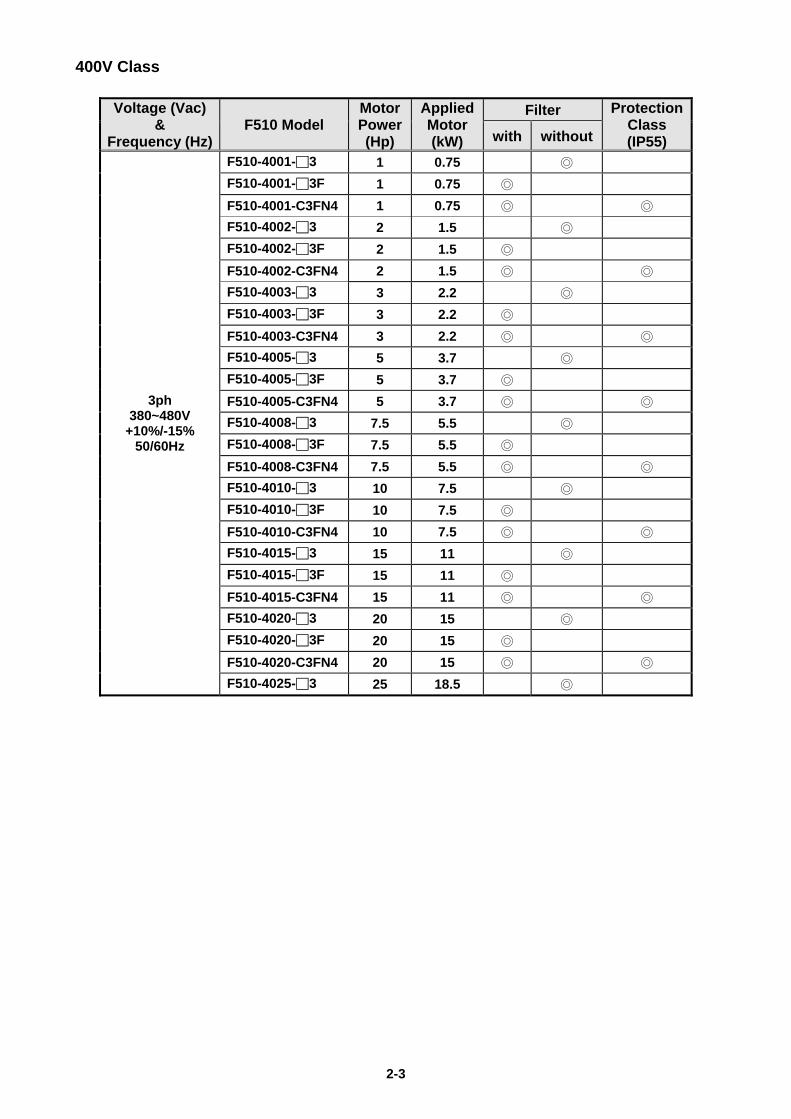
400V Class
Voltage (Vac) &
Frequency (Hz) F510 Model
Motor Power(Hp)
Applied Motor (kW)
Filter Protection Class (IP55) with without
3ph 380~480V
+10%/-15% 50/60Hz
F510-4001-3 1 0.75
F510-4001-3F 1 0.75
F510-4001-C3FN4 1 0.75
F510-4002-3 2 1.5
F510-4002-3F 2 1.5
F510-4002-C3FN4 2 1.5
F510-4003-3 3 2.2
F510-4003-3F 3 2.2
F510-4003-C3FN4 3 2.2
F510-4005-3 5 3.7
F510-4005-3F 5 3.7
F510-4005-C3FN4 5 3.7
F510-4008-3 7.5 5.5
F510-4008-3F 7.5 5.5
F510-4008-C3FN4 7.5 5.5
F510-4010-3 10 7.5
F510-4010-3F 10 7.5
F510-4010-C3FN4 10 7.5
F510-4015-3 15 11
F510-4015-3F 15 11
F510-4015-C3FN4 15 11
F510-4020-3 20 15
F510-4020-3F 20 15
F510-4020-C3FN4 20 15
F510-4025-3 25 18.5

2-4
Voltage (Vac) &
Frequency (Hz) F510 Model
Motor Power(Hp)
Applied Motor (kW)
Filter Protection Class (IP55) with without
3ph 380~480V
+10%/-15% 50/60Hz
F510-4025-3F 25 18.5
F510-4025-C3FN4 25 18.5
F510-4030-3 30 22
F510-4030-3F 30 22
F510-4030-C3FN4 30 22
F510-4040-3 40 30
F510-4040-3F 40 30
F510-4040-C3FN4 40 30
F510-4050-3 50 37
F510-4050-3F 50 37
F510-4050-C3FN4 50 37
F510-4060-3 60 45
F510-4060-3F 60 45
F510-4060-C3FN4 60 45
F510-4075-3 75 55
F510-4075-3F 75 55
F510-4075-C3N4 75 55
F510-4100-3 100 75
F510-4100-C3N4 100 75
F510-4125-3 125 94
F510-4150-3 150 112
F510-4175-3 175 130
F510-4215-3 215 160
F510-4250-3 250 185
F510-4300-3 300 220
F510-4375-3 375 280
F510-4425-3 425 317
F510-4535-3 535 400
F510-4670-3 670 500
F510-4800-3 800 600

3-1
Chapter 3 Environment and Installation
3.1 Environment
The environment will directly affect the proper operation and the life span of the inverter. To
ensure that the inverter will give maximum service life, please comply with the following
environmental conditions:
Protection
Protection Class
IP20/ IP21/ NEMA 1, IP00
IP55/ NEMA 12
Ambient Environment
Operating Temperature
IP20/IP21/IP55: -10°C - +40°C (14 -104 °F)
IP00 (Without Cover): -10°C - +50°C (14-122 °F)
Enhanced type frame 5 is 50°C without de-rating. The maximum operating temperature is 60°C, but it is required to derate 2% of current at each additional 1°C. If several inverters are placed in the same control panel, provide a heat removal means to
maintain ambient temperatures Storage
Temperature -20°C - +70°C (-4 -158 °F)
Humidity 95% non-condensing Relative humidity 5% to 95%, free of moisture. (Follow IEC60068-2-78 standard)
Altitude Altitude: Below 1000 m (3281 ft.)
It is required to derate 1% of current at each additional 100 m. The maximum altitude is 3000 m.
Installation Site
Avoid direct sunlight. Avoid exposure to rain or moisture. Avoid oil mist and salinity. Avoid corrosive liquid and gas. Avoid dust, lint fibers, and small metal filings. Avoid electromagnetic interference (soldering machines, power machines). Keep away from radioactive and flammable materials. Avoid vibration (stamping, punching machines etc.). Add a vibration-proof pad if the situation cannot be avoided.
Shock Maximum acceleration: 1.2G (12m/s²), from 49.84 to 150 Hz Displacement amplitude : 0.3mm (peak value), from 10 to 49.84 Hz (Follow IEC60068-2-6 standard)
3-2
3.2 Installation
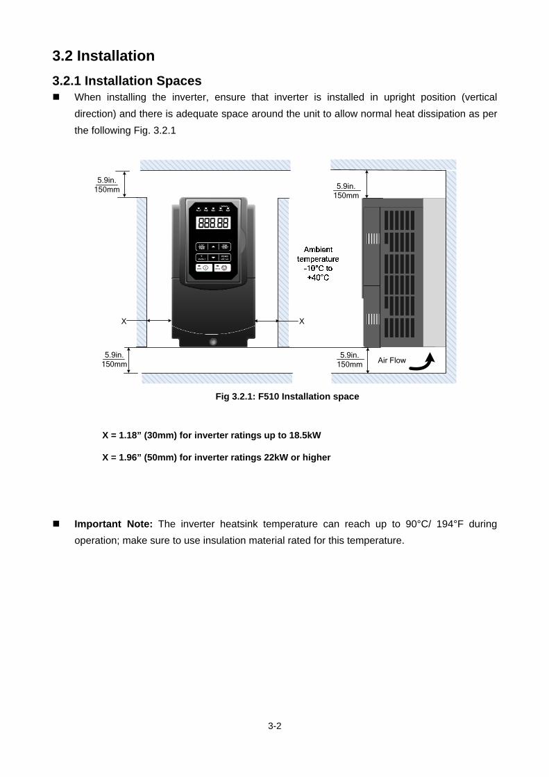
3.2.1 Installation Spaces When installing the inverter, ensure that inverter is installed in upright position (vertical
direction) and there is adequate space around the unit to allow normal heat dissipation as per
the following Fig. 3.2.1
5.9in. 150mm 5.9in.
150mm
Air Flow5.9in.
150mm
X
5.9in. 150mm
X
Fig 3.2.1: F510 Installation space
X = 1.18” (30mm) for inverter ratings up to 18.5kW
X = 1.96” (50mm) for inverter ratings 22kW or higher
Important Note: The inverter heatsink temperature can reach up to 90°C/ 194°F during
operation; make sure to use insulation material rated for this temperature.

3-3
3.2.2 External View
3.2.2.1 External View (IP00/ IP20)
(a) 200V 1-7.5HP/ 400V 1-10HP
(Wall-mounted type, IEC IP00) (Wall-mounted type, IEC IP20, NEMA1)
(b) 200V 10-30HP/ 400V 15-40HP
(Wall-mounted type, IEC IP00) (Wall-mounted type, IEC IP20, NEMA1)

3-4
(c) 200V 40-50HP/ 400V 50-75HP
(Wall-mounted type, IEC IP20, NEMA1)
(d) 200V 60-125HP/ 400V 100-250HP
(Wall-mounted type, IEC IP00) (Wall-mounted type, IEC IP20, NEMA1)

3-5
(e) 200V 150-175HP/ 400V 300-425HP
(Wall-mounted type, IEC IP00) (Wall-mounted type, IEC IP20)
(f) 400V 535-800HP
(Wall-mounted type, IEC IP00) (Wall-mounted type, IEC IP20)

3-6
3.2.2.2 External View (IP55)
(a) 400V 1-25HP (b) 400V 30-100HP
(Wall-mounted type, IEC IP55) (Wall-mounted type, IEC IP55)

3-7
3.2.3 Warning Labels Important:
Warning information located on the front cover must be read upon installation of
the inverter.
(a) 200V: 1-7.5HP/ 400V: 1-10HP (IP20)
(b) 200V: 10-15HP/ 400V: 15-20HP (IP20)
(c) 200V: 20-175HP/ 400V: 25-800HP(IP20)
(d) 400V:1-100HP (IP55)

3-8
3.2.4 Removing the Front Cover and Keypad
Before making any wiring connections to the inverter, the front cover needs to be
removed.
IP00/ IP20 Type
Caution
It is not required to remove the digital operator before making any wiring connections.
Models 200V,1– 30 HP and 400V, 1 – 40 HP have a plastic cover. Loosen the screws and remove the cover to gain access to the terminals and make wiring connections. Place the plastic cover back and fasten screws when wiring connections have been made.
Models 200V, 40 - 175HP and 400V, 50 - 800HP have a metal cover. Loosen the
screws and remove the cover to gain access to the terminals and make wiring connections. Place the metal cover back and fasten screws when wiring connections have been made.
IP55 Type
Caution
It is essential to remove the digital operator before making any wiring connections.
Model 400V, 1 – 25 HP has a plastic cover. Loosen the screws and remove the cover to gain access to the terminals and make wiring connections. Place the plastic cover back and fasten screws when wiring connections have been made, suggested screw locking torque is 8 kgf-cm.
Models 400V, 30 - 100HP has a metal cover. Loosen the screws and remove the cover
to gain access to the terminals and make wiring connections. Place the metal cover back and fasten screws when wiring connections have been made, suggested screw locking torque is 8 kgf-cm.

3-9
3.2.4.1 IP00/ IP20 Type
(a) 200V 1-3HP/ 400V 1-3HP
Step 1: Unscrew Step 2: Remove whole top cover, and
unlock RJ45 connector
Step 3: Make wire connections, lock RJ45 Step 4: Fasten screw
connector and place top cover back

3-10
(b) 200V 5-7.5HP(Standard Type) 5~10HP (Enhanced Type) /400V 5-10HP
Step 1: Unscrew Step 2: Remove cover
Step 3: Make wire connections and place cover back Step 4: Fasten screw

3-11
(c) 200V 10-30HP/ 400V 15-40HP
Step 1: Unscrew Step 2: Remove cover
Step 3: Make wire connections and place cover back Step 4: Fasten screw

3-12
(d) 200V 40-50HP/ 400V 50-75HP (Standard Type) 50~100HP (Enhanced Type)
Step 1: Unscrew cover Step 2: Remove cover
Step 3: Make wire connections and place cover back Step 4: Fasten screw

3-13
(e) 200V 60-125HP/ 400V 100-250HP
Step 1: Unscrew cover Step 2: Remove cover
Step 3: Make wire connections and place cover back Step 4: Fasten screw

3-14
(f) 200V 150-175HP/ 400V 300-425HP
Step 1: Unscrew cover Step 2: Remove cover
Step 3: Make wire connections and place cover back Step 4: Fasten screw

3-15
(g) 400V 535-800HP
Step 1: Unscrew cover Step 2: Remove cover
Step 3: Make wire connections and place cover back Step 4: Fasten screw

3-16
3.2.4.2 Built-in Filter Type (IP20/ IP00)
(a) 400V 1-3HP
Step 1: Unscrew cover Step 2: Remove whole top cover
Step 3: Unlock RJ45 connector, Unscrew filter section Step 4: Remove filter cover
Step 5: Make wire connections, lock RJ45 Step 6: Fasten screw
connector and place top cover back
3-17
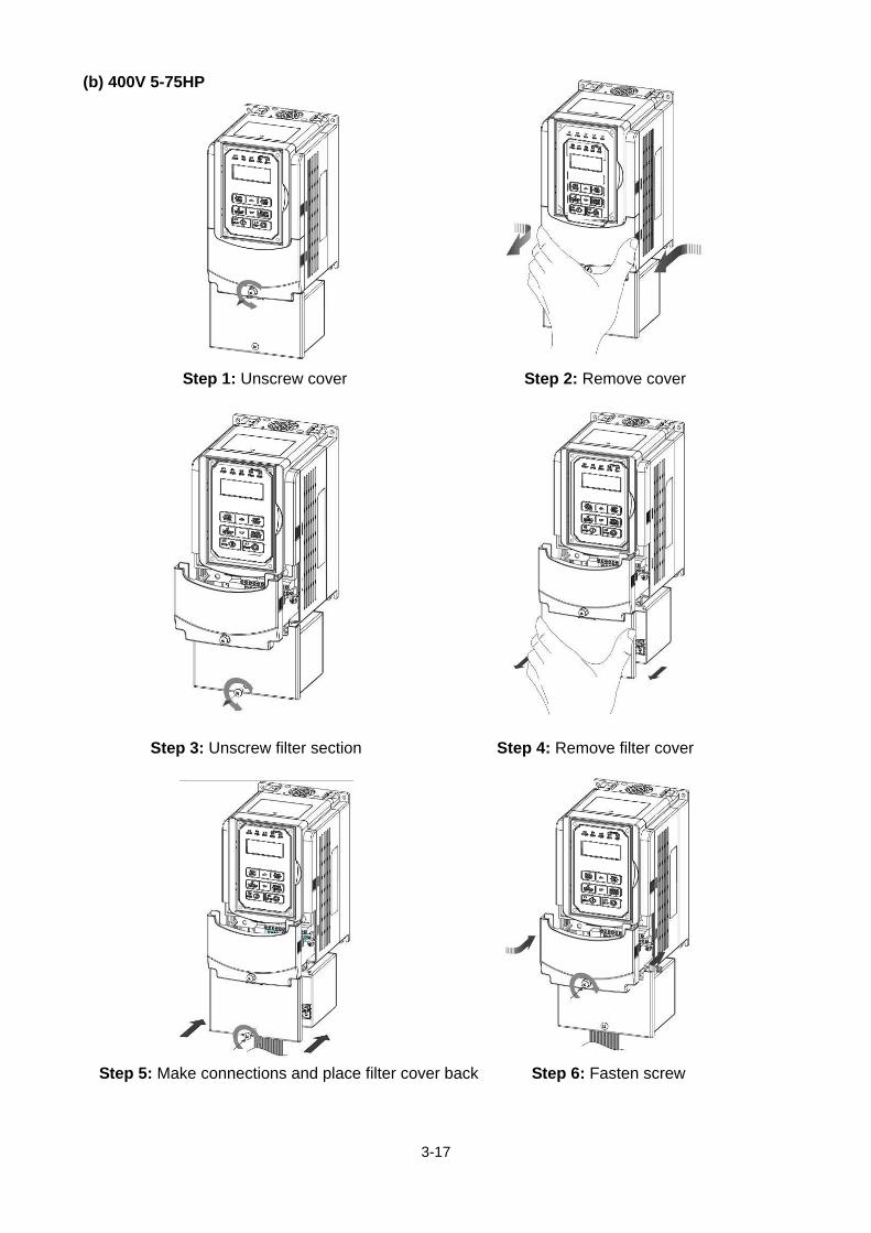
(b) 400V 5-75HP
Step 1: Unscrew cover Step 2: Remove cover
Step 3: Unscrew filter section Step 4: Remove filter cover
Step 5: Make connections and place filter cover back Step 6: Fasten screw

3-18
3.2.4.3 Water proof Type (IP55)
(a) 400V 1-25HP
Step 1: Unscrew operator Step 2: Remove operator
Step 3: Pull out operator and remove power line Step 4: Unscrew cover
Step 5: Check the inside waterproof gasket is not pulled
away from cover while opening the cover
Waterproof gasket

3-19
(b) 400V 30-100HP
Step 1: Unscrew operator Step 2: Remove operator
Step 3: Pull out operator and unlock RJ45 connector Step4: Unscrew cover and remove it
Waterproof gasket
Waterproof gasket

3-20
3.3 Inverter Wiring
3.3.1 Wire Gauges and Tightening Torque
To comply with UL standards, use UL approved copper wires (rated 75° C) and round crimp terminals
(UL Listed products) as shown in table below when connecting to the main circuit terminals. Teco
recommends using crimp terminals manufactured by NICHIFU Terminal Industry Co., Ltd and the
terminal crimping tool recommended by the manufacturer for crimping terminals and the insulating
sleeve.
Table 3.3.1.1 Wire gauges and tightening torque terminal screw size
Wire size mm2 (AWG)
Terminal Screw size
Model of round crimp terminal
Tightening torque kgf.cm (in.lbs)
Model of insulating
sleeve
Model of crimp tool
0.75 (18) M3.5 R1.25-3.5 8.2 to 10 (7.1 to 8.7) TIC 1.25 NH 1
M4 R1.25-4 12.2 to 14 (10.4 to 12.1) TIC 1.25 NH 1
1.25 (16) M3.5 R1.25-3.5 8.2 to 10 (7.1 to 8.7) TIC 1.25 NH 1
M4 R1.25-4 12.2 to 14 (10.4 to 12.1) TIC 1.25 NH 1
2 (14)
M3.5 R2-3.5 8.2 to 10 (7.1 to 8.7) TIC 2 NH 1 / 9
M4 R2-4 12.2 to 14 (10.4 to 12.1) TIC 2 NH 1 / 9
M5 R2-5 22.1 to 24 (17.7 to 20.8) TIC 2 NH 1 / 9
M6 R2-6 25.5 to 30.0 (22.1 to 26.0) TIC 2 NH 1 / 9
3.5/5.5 (12/10)
M4 R5.5-4 12.2 to 14 (10.4 to 12.1) TIC 3.5/5.5 NH 1 / 9
M5 R5.5-5 20.4 to 24 (17.7 to 20.8) TIC 3.5/5.5 NH 1 / 9
M6 R5.5-6 25.5 to 30.0 (22.1 to 26.0) TIC 3.5/5.5 NH 1 / 9
M8 R5.5-8 61.2 to 66.0 (53.0 to 57.2) TIC 3.5/5.5 NH 1 / 9
8 (8)
M4 R8-4 12.2 to 14 (10.4 to 12.1) TIC 8 NOP 60
M5 R8-5 20.4 to 24 (17.7 to 20.8) TIC 8 NOP 60
M6 R8-6 25.5 to 30.0 (22.1 to 26.0) TIC 8 NOP 60
M8 R8-8 61.2 to 66.0 (53.0 to 57.2) TIC 8 NOP 60
14 (6)
M4 R14-4 12.2 to 14 (10.4 to 12.1) TIC 14 NH 1 / 9
M5 R14-5 20.4 to 24 (17.7 to 20.8) TIC 14 NH 1 / 9
M6 R14-6 25.5 to 30.0 (22.1 to 26.0) TIC 14 NH 1 / 9
M8 R14-8 61.2 to 66.0 (53.0 to 57.2) TIC 14 NH 1 / 9
22 (4) M6 R22-6 25.5 to 30.0 (22.1 to 26.0) TIC 22 NOP 60/ 150H
M8 R22-8 61.2 to 66.0 (53.0 to 57.2) TIC 22 NOP 60/ 150H
30/38 (3 / 2) M6 R38-6 25.5 to 30.0 (22.1 to 26.0) TIC 38 NOP 60/ 150H
M8 R38-8 61.2 to 66.0 (53.0 to 57.2) TIC 38 NOP 60/ 150H
50/ 60 (1/ 1/ 0) M8 R60-8 61.2 to 66.0 (53.0 to 57.2) TIC 60 NOP 60/ 150H
M10 R60-10 102 to 120 (88.5 to 104) TIC 60 NOP 150H
70 (2/0) M8 R70-8 61.2 to 66.0 (53.0 to 57.2) TIC 60 NOP 150H
M10 R70-10 102 to 120 (88.5 to 104) TIC 60 NOP 150H
80 (3/0) M10 R80-10 102 to 120 (88.5 to 104) TIC 80 NOP 150H
M16 R80-16 255 to 280 (221 to 243) TIC 80 NOP 150H
100 (4/0)
M10 R100-10 102 to 120 (88.5 to 104) TIC 100 NOP 150H
M12 R100-12 143 to 157 (124 to 136) TIC 100 NOP 150H
M16 R80-16 255 to 280 (221 to 243) TIC 80 NOP 150H

3-21
Main Circuit Terminal Wiring UL approval requires crimp terminals when wiring the drive’s main circuit terminals. Use
crimping tools as specified by the crimp terminal manufacturer. Teco recommends crimp
terminals made by NICHIFU for the insulation cap. The table below matches drives models with crimp terminals and insulation caps.
Closed-Loop Crimp Terminal Size
Drive Model F510
Wire Gauge mm2 , (AWG) Terminal Crimp Terminal Tool Insulation Cap
R/L1 S/L2 T/L3 U/T1 V/T2 W/T3 Screws Model No. Machine No. Model No.
2001/2002/ 2003
2 (14)
M4
R2-4
Nichifu NH 1 / 9 TIC 2
3.5 (12) R5.5-4
TIC 3.5
5.5 (10) TIC 5.5
2005/2008 5.5 (10) M4 R5.5-4 Nichifu NH 1 / 9 TIC 5.5
2010/2015 14 (6) M4 R14-6 Nichifu NOP 60 TIC 8
2030 38 (2) M6 R38-6 Nichifu NOP 60 / 150H TIC 22
2050 80 (3/0) M8 R80-8 Nichifu NOP 60 / 150H TIC 60
2075 150 (4/0) M8 R150-8 Nichifu NOP 150H TIC 80
2125 300 (4/0)*2 M10 R150-10 Nichifu NOP 150H TIC 100
2175 152 (300)*2 M12 R150-12*2 Nichifu NOP 150H TIC 150
4001/4002/ 4003
2 (14) M4
R2-4Nichifu NH 1 / 9
TIC 23.5 (12)
R5.5-4 TIC 3.5
5.5 (10) TIC 5.54005/4008/
4010 5.5 (10) M4 R5.5-4 Nichifu NH 1 / 9 TIC 5.5
4015/4020 8 (8) M6 R8-6 Nichifu NOP 60 TIC 8 4025/4030/
4040 22 (6) M6 R22-6 Nichifu NOP 60 / 150H TIC 14
4050/4060/ 4075
60 (2) M8 R60-8 Nichifu NOP 60 / 150H TIC 38
4100/4125 150 (3/0) M8 R150-8 Nichifu NOP 150H TIC 80 4150/4175/ 4215/4250
300 (4/0)*2 M10 R150-10 Nichifu NOP 150H TIC 100 4300 203 (400)*2 M12 R200-12S*2 Nichifu NOH 300K TIC 200
4375/4425 253 (500)*2 M12 R325-12S*2 Nichifu NOH 300K TIC 325
4535/4670 152 (300)*4 M10 R150-10*4 Nichifu NOP 150H TIC 150
4800 203 (400)*4 M10 R200-10S *4 Nichifu NOH 300K TIC 200

3-22
3.3.2 Wiring Peripheral Power Devices
Caution
After power is shut off to the inverter, the capacitors will slowly discharge. Do NOT touch the
inverter circuitry or replace any components until the “CHARGE” indicator is off.
Do NOT wire or connect/disconnect internal connectors of the inverter when the inverter is
powered up or when powered off and the “CHARGE”” indicator is on.
Do NOT connect inverter output U, V and W to the supply power. This will result in damage to
the inverter.
The inverter must be by properly grounded. Use terminal E to connect earth ground and
comply with local standards.
It is required to disconnect the grounded wire in the control board when the inverter is not
grounded or floating ground power system.
Do NOT perform a dielectric voltage withstand test (megger) on the inverter this will result in
inverter damage to the semiconductor components.
Do NOT touch any of the components on the inverter control board to prevent damage to the
inverter by static electricity.
Caution
Refer to the recommended wire size table for the appropriate wire to use. The voltage
between the power supply and the input of the inverter may not exceed 2%.
Phase-to-phase voltage drop (V) = 3 ×resistance of wire (Ω/km) × length of line m) × current×10-3.
(km=3280 x feet) / (m=3.28 x feet )
Reduce the carrier frequency (parameter 11-01) If the cable from the inverter to the motor is
greater than 25m (82ft). A high-frequency current can be generated by stray capacitance
between the cables and result in an overcurrent trip of the inverter, an increase in leakage
current, or an inaccurate current readout.
To protect peripheral equipment, install fast acting fuses on the input side of the inverter. Refer
to section 11.4 for additional information.

3-23
MCCB
Power supply:
Make sure the correct voltage is applied to avoid damaging the inverter.
Molded-case circuit breaker (MCCB) or fused disconnect: A molded-case circuit breaker or fused disconnect must be installed
between the AC source and the inverter that conforms to the rated voltage and current of the inverter to control the power and protect the inverter.
Do not use the circuit breaker as the run/stop switch for the inverter.
Ground fault detector / breaker:
Install a ground fault breaker to prevent problems caused by current leakage and to protect personnel. Select current range up to 200mA, and action time up to 0.1 second to prevent high frequency failure.
Magnetic contactor: Normal operations do not need a magnetic contactor. When
performing functions such as external control and auto restart after power failure, or when using a brake controller, install a magnetic contactor.
Do not use the magnetic contactor as the run/stop switch for the inverter.
AC line reactor for power quality: When inverters are supplied by a high capacity power source (>
600KVA), an AC reactor can be connected to improve the power factor.
Install Fast Acting Fuse: To protect peripheral equipment, install fast acting fuses in
accordance with the specifications in section 11.4 for peripheral devices.
Input Noise filter: A filter must be installed when there are inductive loads affecting the
inverter. The inverter meets EN55011 Class A, category C3 when the TECO special filter is used. See section 11.3 for peripheral devices.
Inverter: Output terminals T1, T2, and T3 are connected to U, V, and W
terminals of the motor. If the motor runs in reverse while the inverter is set to run forward, swap any two terminals connections for T1, T2, and T3.
To avoid damaging the inverter, do not connect the output terminals T1, T2, and T3 to AC input power.
Connect the ground terminal properly. (200V series: Rg <100; 400V series: Rg <10.)
Output Noise filter: An output noise filter may reduce system interference and induced
noise. Motor: If the inverter drives multiple motors the output rated current of the
inverter must be greater than the total current of all the motors.

3-24
3.3.3 General Wiring Diagram 3.3.3.1 General Wiring Diagram (For Standard H & C type)
The following is the standard wiring diagram for the F510 inverter ( indicates main circuit
terminals and indicates control circuit terminals). Locations and symbols of the wiring terminal
block might be different due to different models of F510. The description of control circuit terminals
and main circuit terminals can be referred to Table 3.3.5.1, 3.3.6.1 and 3.3.6.2
3-25
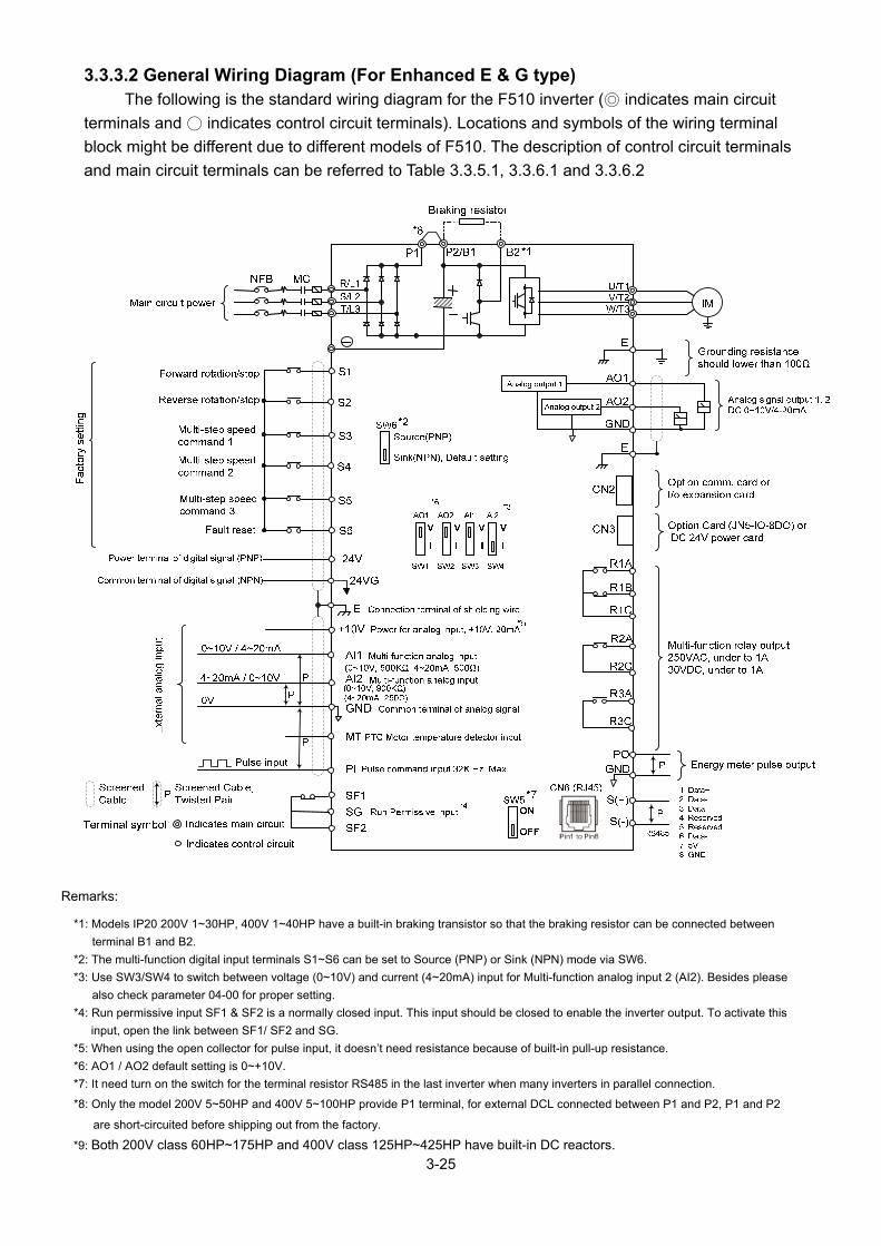
3.3.3.2 General Wiring Diagram (For Enhanced E & G type) The following is the standard wiring diagram for the F510 inverter ( indicates main circuit
terminals and indicates control circuit terminals). Locations and symbols of the wiring terminal
block might be different due to different models of F510. The description of control circuit terminals
and main circuit terminals can be referred to Table 3.3.5.1, 3.3.6.1 and 3.3.6.2
Remarks:
*1: Models IP20 200V 1~30HP, 400V 1~40HP have a built-in braking transistor so that the braking resistor can be connected between
terminal B1 and B2.
*2: The multi-function digital input terminals S1~S6 can be set to Source (PNP) or Sink (NPN) mode via SW6.
*3: Use SW3/SW4 to switch between voltage (0~10V) and current (4~20mA) input for Multi-function analog input 2 (AI2). Besides please
also check parameter 04-00 for proper setting.
*4: Run permissive input SF1 & SF2 is a normally closed input. This input should be closed to enable the inverter output. To activate this
input, open the link between SF1/ SF2 and SG.
*5: When using the open collector for pulse input, it doesn’t need resistance because of built-in pull-up resistance.
*6: AO1 / AO2 default setting is 0~+10V.
*7: It need turn on the switch for the terminal resistor RS485 in the last inverter when many inverters in parallel connection.
*8: Only the model 200V 5~50HP and 400V 5~100HP provide P1 terminal, for external DCL connected between P1 and P2, P1 and P2
are short-circuited before shipping out from the factory.
*9: Both 200V class 60HP~175HP and 400V class 125HP~425HP have built-in DC reactors.
3-26
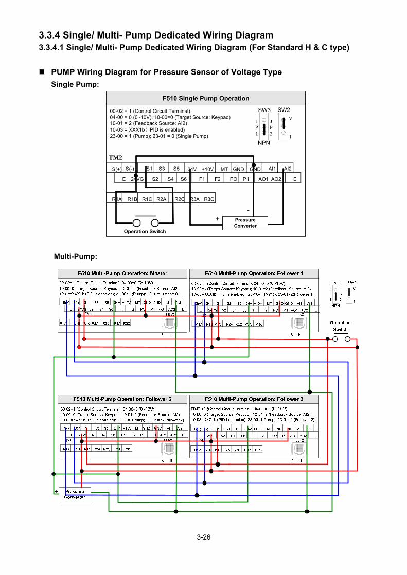
3.3.4 Single/ Multi- Pump Dedicated Wiring Diagram
3.3.4.1 Single/ Multi- Pump Dedicated Wiring Diagram (For Standard H & C type)
PUMP Wiring Diagram for Pressure Sensor of Voltage Type
Single Pump:
Multi-Pump:
F510 Single Pump Operation
Operation Switch
Pressure Converter
TM2
SW2 SW3
NPN
JP1
JP2
V
I
S(+) S(-) S1 S3 S5 AI2
E 24VG S2 S4 S6 F1 F2 PO P I
24V +10V MT GND GND AI1
AO2 E
R1A R1B R1C R2A R2C R3A R3C
AO1
00-02 = 1 (Control Circuit Terminal) 04-00 = 0 (0~10V); 10-00=0 (Target Source: Keypad)10-01 = 2 (Feedback Source: AI2)10-03 = XXX1b( PID is enabled)23-00 = 1 (Pump); 23-01 = 0 (Single Pump)
-+

3-27
PUMP Wiring Diagram for Pressure Sensor of Current Type
Single Pump:
F510 Single Pump Operation
Operation Switch
Pressure Converter
TM2
SW2 SW3
NPN
JP1
JP2
V
I
S(+) S(-) S1 S3 S5 AI2
E 24VG S2 S4 S6 F1 F2 PO P I
24V +10V MT GND GND AI1
AO2 E
R1A R1B R1C R2A R2C R3A R3C
AO1
00-02=1 (Control Circuit Terminal) 04-00=1 (4mA~20mA); 10-00=0 (Target Source: Keypad) 10-01=2 (Feedback Source: AI2)10-03=XXX1b (PID is enabled)23-00=1(Pump); 23-01=0 (Single Pump)
Multi-Pump:
F510 Multi-Pump Operation: Master F510 Multi-Pump Operation: Follower 1
F510 Multi-Pump Operation: Follower 2 F510 Multi-Pump Operation: Follower 3
Operation Switch
Pressure Converter
CON2TM2 CON2
CON2 CON2TM2
A B A B
A B A B
S(+) S(-) S1 S3 S5 AI2
E 24VG S2 S4 S6 F1 F2 PO P I
24V +10V MT GND GND AI1
AO2 E
R1A R1B R1C R2A R2C R3A R3C
AO1
S(+) S(-) S1 S3 S5 AI2
E 24VG S2 S4 S6 F1 F2 PO P I
24V +10V MT GND GND AI1
AO2 E
R1A R1B R1C R2A R2C R3A R3C
AO1
S(+) S(-) S1 S3 S5 AI2
E 24VG S2 S4 S6 F1 F2 PO P I
24V +10V MT GND GND AI1
AO2 E
R1A R1B R1C R2A R2C R3A R3C
AO1
TM2
TM2
S(+) S(-) S1 S3 S5 AI2
E 24VG S2 S4 S6 F1 F2 PO P I
24V +10V MT GND GND AI1
AO2 E
R1A R1B R1C R2A R2C R3A R3C
AO1
00-02=1 (Control Circuit Terminal); 04-00=1 (4~20mA)10-00=0 (Target Source: Keypad); 10-01=2 (Feedback Source: AI2)10-03=XXX1b (PID is enabled); 23-00=1(Pump); 23-01=1 (Master)
00-02=1 (Control Circuit Terminal); 04-00=0 (0~10V)10-00=0 (Target Source: Keypad); 10-01=2 (Feedback Source: AI2)10-03=XXX1b (PID is enabled); 23-00=1(Pump); 23-01=2 (Follower 1)
00-02=1 (Control Circuit Terminal); 04-00=0 (0~10V)10-00=0 (Target Source: Keypad); 10-01=2 (Feedback Source: AI2)10-03=XXX1b (PID is enabled); 23-00=1(Pump); 23-01=3 (Follower 2)
00-02=1 (Control Circuit Terminal); 04-00=0 (0~10V)10-00=0 (Target Source: Keypad); 10-01=2 (Feedback Source: AI2)10-03=XXX1b (PID is enabled); 23-00=1(Pump); 23-01=4 (Follower 3)
SW2 SW3
NPN
JP1
JP2
V
I
Notes: 1. The position of dip switch requires being correct (SW2, SW3).
2. It is required to reconnect after setting Master/ Slave.
3. 24VG and GND require short circuit.

3-28
4. When the communication modes is selected to be multiple pumps in parallel connection (09-
01=3), the baud rate settings (09-02) of Master and Slave are required to be consistent. Refer
to parameter 23-31 for the actions in parallel connection modes.
5. In the wiring of multi-pump current type pressure sensor, it is required to adjust Slave to be
04-07(AI2 Gain) =252.0% and 04-08(AI1 Bias) =25.0%.
6. In multi-pump operation, if one of the inverter does not Power ON, the 24V of connection is
also need to dis-connect to avoid magnetoresistance effect.

3-29
3.3.4.2 Single/ Multi- Pump Dedicated Wiring Diagram (For Enhanced E & G type)
PUMP Wiring Diagram for Pressure Sensor of Voltage Type
Single Pump:
Multi-Pump: (For Enhanced type)

3-30
PUMP Wiring Diagram for Pressure Sensor of Current Type
Single Pump: (For Enhanced type)
F510 Single Pump Operation
Operation Switch
Pressure Converter
TM2
SW2 SW3
NPN
JP1
JP2
V
I
S(+) S(-) S1 S3 S5 AI2
E 24VG S2 S4 S6 F1 F2 PO P I
24V +10V MT GND GND AI1
AO2 E
R1A R1B R1C R2A R2C R3A R3C
AO1
00-02=1 (Control Circuit Terminal) 04-00=1 (4mA~20mA); 10-00=0 (Target Source: Keypad) 10-01=2 (Feedback Source: AI2)10-03=XXX1b (PID is enabled)23-00=1(Pump); 23-01=0 (Single Pump)
Multi-Pump: (For Enhanced type)
Notes: 1. The position of dip switch requires being correct (SW6, SW4).
2. It is required to reconnect after setting Master/ Slave.

3-31
3. 24VG and GND require short circuit.
4. When the communication modes is selected to be multiple pumps in parallel connection (09-
01=3), the baud rate settings (09-02) of Master and Slave are required to be consistent. Refer
to parameter 23-31 for the actions in parallel connection modes.
5. In the wiring of multi-pump current type pressure sensor, it is required to adjust Slave to be
04-07(AI2 Gain) =252.0% and 04-08(AI1 Bias) =25.0%.
6. In multi-pump operation, if one of the inverter does not Power ON, the 24V of connection is
also need to dis-connect to avoid magnetoresistance effect.

3-32
3.3.5 Wiring for Control Circuit Terminals 3.3.5.1 Wiring for Control Circuit Terminals (For Standard H & C type)
Control circuit terminals identification
IP00/IP20 type
200V: 1-3HP,400V: 1-3HP
200V: 5HP~50HP,400V: 5HP~75HP
AI2S(+) S(-) S1 S3 S5 24V +10V MT GND GND AI1
AO1 AO2 E
R1A R1B R1C
E 24VG S2 S4 S6 F1 F2 PO P I
R2A R2C R3A R3C
200V: 60HP~125HP,400V: 100HP~800HP
S(+) S(-) S1 S3 S5 AI2
E 24VG S2 S4 S6 F1 F2 PO P I
24V +10V MT GND GND AI1
AO2 E
R1A R1B R1C R2A R2C R3A R3C
AO1
IP55 type
400V: 1HP~100HP
AI2S(+) S(-) S1 S3 S5 24V +10V MT GND GND AI1
AO1 AO2 E
R1A R1B R1C
E 24VG S2 S4 S6 F1 F2 PO P I
R2A R2C R3A R3C
R2A R2C
R3A R3C
R1A R1B R1C S(+) S(-) S1 S3 S5 24V +10V MT GND GND AI1 AI2
E 24VG S2 S4 S6 F1 F2 PO PI AO1 AO2 E

3-33
Table 3.3.5.1 Description of control circuit terminals
Type Terminal Terminal function Signal level/ information
Digital input signal
S1 2-wire forward rotation/ stop command (default), multi-function input terminals * 1
Signal Level 24 VDC (opto-isolated) Maximum current: 8mA Maximum voltage: 30 Vdc Input impedance: 4.22kΩ
S2 2-wire reversal rotation/ stop command (default), multi-function input terminals * 1
S3 Multi-speed/ position setting command 1 (default), multi-function input terminals * 1
S4 Multi-speed/ position setting command 2 (default), multi-function input terminals * 1
S5 Multi-speed/ position setting command 3 (default), multi-function input terminal* 1
S6 Fault reset (default), multi-function input terminal * 1
24V Power supply
24V Digital signal SOURCE point (SW3 switched to SOURCE ) ±15%, Max. output current: 250mA (The sum of all loads connected)
24VG Common terminal of Digital signals Common point of digital signal SINK ( SW3 switched to SINK )
Analog input signal
+10V Power for external speed potentiometer ±5% (Max. current: 20mA )
MT Motor temperature detector of externally connecting PTC Refer to group 08 setting
AI1 Multi-function analog input for speed reference (0-10V input)From 0 to +10V Input impedance: 10KΩ Resolution: 12bit
AI2 Multi-function analog input terminals *2, can use SW2 to switch voltage or current input (0~10V)/(4-20mA)
From 0 to +10V Input impedance: 200KΩ From 4 to 20 mA Input impedance: 250Ω Resolution: 12bit
GND Analog signal ground terminal ----
E Shielding wire’s connecting terminal (Ground) ----
Analog output signal
AO1 Multi-function analog output terminals *3 (0~10V/ 4-20mA output)
From 0 to 10V Max. current: 2mA From 4 to 20 mA AO2
Multi-function analog output terminals *3 (0~10V/ 4-20mA output)
GND Analog signals ground terminal
Pulse output signal
PO Pulse output, Band width 32KHz Max. Frequency: 32KHz Open Collector output Load: 2.2 KΩ
GND Analog signals ground terminal ----
Pulse input signal
PI Pulse command input, frequency width of 32KHz
L: from 0.0 to 0.5V H: from 4.0 to 13.2V Max. Frequency: 0 - 32KHz Impedance: 3.89 KΩ
GND Analog signals ground terminal ----

3-34
Table 3.3.5.1 Description of control circuit terminals (Continued)
Type Terminal Terminal function Signal level/ information
Relay output
R1A- R1B- R1C
Relay A contact (multi-function output terminal) Relay B contact (multi-function output terminal) Relay contact common terminal, please refer to parameter group 03 in this manual for more functional descriptions.
Rating: 250Vac: 10 mA ~ 1A 30Vdc: 10 mA ~ 1A
R2A-R2C With the same functions as R1A/R1B/R1C Rating: 250Vac: 10 mA ~ 1A 30Vdc: 10 mA ~ 1A R3A-R3C With the same functions as R1A/R1B/R1C
Safety input F1
On: normal operation. Off: emergency stop. (Jumper wired has to be removed to use external safety function to stop.)
24Vdc, 8mA, pull-high
F2 Safety command common terminal 24V Ground RS-485
port S (+)
RS485/MODBUS differential input and output S (-)
Grounding E (G) Grounding to earth Shield the connecting terminal
----
Notes:
*1: Multi-function digital input can be referred to in this manual.
- Group 03: External Terminals Digital Input / Output Function Group.
*2: Multi-function analog input can be referred to in this manual.
- Group 04 - External Terminal Analog Signal Input (Output) Function Group.
*3: Multi-function analog output can be referred to in this manual.
- Group 04 - External Terminal Analog Signal Input (Output) Function Group.
Caution
Maximum output current capacity for terminal 10V is 20mA.
Multi-function analog output AO1 and AO2 are for use for an analog output meter. Do not
use these output for feedback control. Control board’s 24V and 10V are to be used for internal control only. Do not use the
internal power-supply to power external devices.

3-35
3.3.5.2 Wiring for Control Circuit Terminals (For Enhanced E & G type)
Control circuit terminals identification
IP00/IP20 type
200V: 1-3HP,400V: 1-3HP
200V: 5HP~50HP,400V: 5HP~75HP
200V: 60HP~125HP,400V: 125HP~800HP
GND AI1 AI2
E 24VG S2 S4 S6 SF1 SG SF2 PO PI AO1 AO2
S(+) S(-) S1 S3 S5 24V +10V MT GNDR1A R1B R1C R2A R2C R3A R3C
RJ45
GND GND AI1 AI2
E 24VG S2 S4 S6 SF1 SG SF2 PO PI AO1 AO2RJ45
S(+) S(-) S1 S3 S5 24V +10V MTR1A R1B R1C
R2A R2C R3A R3C
AI2
E 24VG S2 S4 S6 SF1 SG SF2 PO PI AO1 AO2
S1 S3 S5 24V +10V MT GND GND AI1
R1A R1B R1C R2A R2C R3A R3C
S(+) S(-)

3-36
Table 3.3.5.2 Description of control circuit terminals
Type Terminal Terminal function Signal level/ information
Digital input signal
S1 2-wire forward rotation/ stop command (default), multi-function input terminals * 1
Signal Level 24 VDC (opto-isolated) Maximum current: 8mA Maximum voltage: 30 Vdc Input impedance: 4.22kΩ
S2 2-wire reversal rotation/ stop command (default), multi-function input terminals * 1
S3 Multi-speed/ position setting command 1 (default), multi-function input terminals * 1
S4 Multi-speed/ position setting command 2 (default), multi-function input terminals * 1
S5 Multi-speed/ position setting command 3 (default), multi-function input terminal* 1
S6 Fault reset (default), multi-function input terminal * 1
24V Power supply
24V Digital signal SOURCE point (SW6 switched to SOURCE ) ±15%, Max. output current: 250mA (The sum of all loads connected)
24VG Common terminal of Digital signals Common point of digital signal SINK ( SW6 switched to SINK )
Analog input signal
+10V Power for external speed potentiometer ±5% (Max. current: 20mA )
MT Motor temperature detector of externally connecting PTC Refer to group 08 setting
AI1 Multi-function analog input for speed reference, use SW3 to switch voltage and current input (0~10V) / (4-20mA)
From 0 to +10V Input impedance: 500KΩ From 4 to 20 mA Input impedance: 500KΩ Resolution: 12bit
AI2 Multi-function analog input terminals *2, can use SW4 to switch voltage or current input (0~10V)/(4-20mA)
From 0 to +10V Input impedance: 900KΩ From 4 to 20 mA Input impedance: 250Ω Resolution: 12bit
GND Analog signal ground terminal ----
E Shielding wire’s connecting terminal (Ground) ----
Analog output signal
AO1 Multi-function analog output terminals *3, use SW1 to switch voltage and current output (0~10V) / (4-20mA)
From 0 to 10V Max. current: 2mA From 4 to 20 mA AO2
Multi-function analog output terminals *3, use SW2 to switch voltage and current output (0~10V) / (4-20mA)
GND Analog signals ground terminal
Pulse output signal
PO Pulse output, Band width 32KHz Max. Frequency: 32KHz Open Collector output Load: 2.2 KΩ
GND Analog signals ground terminal ----
Pulse input signal
PI Pulse command input, frequency width of 32KHz
L: from 0.0 to 0.5V H: from 4.0 to 13.2V Max. Frequency: 0 - 32KHz Impedance: 3.89 KΩ
GND Analog signals ground terminal ----

3-37
Table 3.3.5.2 Description of control circuit terminals (Continued)
Type Terminal Terminal function Signal level/ information
Relay output
R1A- R1B- R1C
Relay A contact (multi-function output terminal) Relay B contact (multi-function output terminal) Relay contact common terminal, please refer to parameter group 03 in this manual for more functional descriptions.
Rating: 250Vac: 10 mA ~ 1A 30Vdc: 10 mA ~ 1A
R2A-R2C With the same functions as R1A/R1B/R1C Rating: 250Vac: 10 mA ~ 1A 30Vdc: 10 mA ~ 1A R3A-R3C With the same functions as R1A/R1B/R1C
Safety input F1
On: normal operation. Off: emergency stop. (Jumper wired has to be removed to use external safety function to stop.)
24Vdc, 8mA, pull-high
F2 Safety command common terminal 24V Ground RS-485
port S (+)
RS485/MODBUS differential input and output S (-)
Grounding E (G) Grounding to earth Shield the connecting terminal
----
Notes:
*1: Multi-function digital input can be referred to in this manual.
- Group 03: External Terminals Digital Input / Output Function Group.
*2: Multi-function analog input can be referred to in this manual.
- Group 04 - External Terminal Analog Signal Input (Output) Function Group.
*3: Multi-function analog output can be referred to in this manual.
- Group 04 - External Terminal Analog Signal Input (Output) Function Group.
Caution
Maximum output current capacity for terminal 10V is 20mA.
Multi-function analog output AO1 and AO2 are for use for an analog output meter. Do not
use these output for feedback control. Control board’s 24V and 10V are to be used for internal control only. Do not use the
internal power-supply to power external devices.

3-38
3.3.6 Wiring for Main Circuit Terminals 3.3.6.1 Wiring for Main Circuit Terminals (For Standard H & C type)
Table 3.3.6.1.1 Description of main circuit terminals (IP00/IP20 Type)
Terminal 200V : 1~30HP 400V : 1~40HP
200V : 40~175HP 400V : 50~800HP
R/L1
Input Power Supply S/L2
T/L3
B1/P B1/P-B2:External braking
resistor
- B2
-:Connect braking module -
U/T1
Inverter output V/T2
W/T3
E/PE/ Ground terminal
Table 3.3.6.1.2 Description of main circuit terminals (IP55 Type)
Terminal 400V
1~100HP
R/L1,S/L2, T/L3 Input Power Supply
U/T1,V/T2, W/T3 Inverter output
B1, B2 Braking resistor connecting terminal *1
⊕1, ⊕2 DC reactor connecting terminal*2
B1, B2, DC power supply (DC+, DC-)
Braking module connecting terminal
( PE) Ground terminal
*1. The model of 400V 25HP (18.5KW) or below is built-in braking transistor. *2. Before connecting DC reactor, please remove short circuit between terminal ⊕1 and ⊕2.

3-39
Main circuit terminals identification and screw size IP20 Type
˙200V : 1-3HP/ 400V: 1-3HP
˙200V: 5-7.5HP/ 400V: 5-10HP
Terminal screw size T
M4 M4
˙200V: 10-15HP/ 400V: 15- 20HP
Terminal screw size T
M4 M4
Terminal screw size
T
M4 M4
T
T

3-40
˙200V: 20-30HP/ 400V: 25-40HP
Terminal screw size T
M6 M6
˙200V: 40-50HP/ 400V: 50-75HP
Terminal screw size T
M8 M8
˙200V: 60-75HP/ 400V: 100-125HP
Terminal screw size Power supply T 400V 100HP M8 M10
200V 60-75HP/ 400V 125HP
M10 M10
˙200V: 100-125HP/ 400V: 150-250HP
Terminal screw size T
M10 M10
T
T
T

3-41
˙200V: 150-175HP/ 400V: 300-425HP
Terminal screw size T
M12 M10
˙400V: 535-800HP
Terminal screw size
T
M10 M10
Note: For 400V 535~800HP, the terminal separate to two, to share the current.
IP55 Type
˙400V: 1-7.5HP
Terminal screw size T
M4 M4
˙400V: 10-15HP
Terminal screw size T
M4 M4

3-42
˙400V: 20-25HP
Terminal screw size T
M6 M6
˙400V: 30-50HP
Terminal screw size T1 M6 M6
˙400V: 60-75HP
Terminal screw size T1 M8 M8
˙400V : 100HP
Terminal screw sizeT1 T2
M8 M10 M8

3-43
3.3.6.2 Wiring for Main Circuit Terminals (For Enhanced E & G type) Table 3.3.6.2.1 Description of main circuit terminals (IP00/IP20 Type)
Terminal 200V : 1~30HP 400V : 1~40HP
200V : 40~175HP 400V : 50~800HP
R/L1
Input Power Supply S/L2
T/L3
B1/P2 B1/P-B2:External braking
resistor
- B2
-:Connect braking module /P1 /P1-B1/P2:External DCL
U/T1
Inverter output V/T2
W/T3
E/PE/ Ground terminal

3-44
Main circuit terminals identification and screw size (For Enhanced E & G type)
IP20 Type
˙200V : 1-3HP/ 400V: 1-3HP
˙200V: 5-15HP/ 400V: 5-25HP
Terminal screw size T
M4 M4
˙200V: 20-30HP/ 400V: 30-40HP
Terminal screw size T
M6 M6
Terminal screw size
T
M4 M4
T

3-45
˙200V: 40-50HP/ 400V: 50-75HP
Terminal screw size T
M8 M8
˙200V: 60-75HP/ 400V: 100-125HP
Terminal screw size Power supply T 400V 100HP M8 M10
200V 60-75HP/ 400V 125HP
M10 M10
˙200V: 100-125HP/ 400V: 150-250HP
Terminal screw size T
M10 M10
˙200V: 150-175HP/ 400V: 300-425HP
Terminal screw size T
M12 M10
T
T

3-46
˙400V: 535-800HP
Terminal screw size
T
M10 M10
Note: For 400V 535~800HP, the terminal separate to two, to share the current.

3-47
Input / Output Power Section Block Diagram
The following diagrams show the basic configuration of the power sections for the range of
horsepower and input voltages. This is shown for reference only and is not a detailed depiction.
(For Enhanced E & G type frame 2~5, which can connect option DC reactor, please refer to
General Wiring Diagram)
IP00/IP20 Type 1. IP20 200V: 1HP 400V: 1~2HP(Standard) 400V:1HP(Enhanced)
2. IP20 200V: 2~30HP 400V: 3~40HP(Standard) 400V:2~40HP(Enhanced)
3. IP20 200V: 40~50HP 400V: 50~75HP 4. IP00/IP20 200V: 60~75HP 400V: 100~125HP
5. IP00/IP20 200V: 100~125HP
6. IP00/IP20 400V: 150~250HP
E
N
P
DCL
SPS C/B
AC/DC
W/T3
R/L1
T/L3 S/L2
U/T1
V/T2
E
N
P
DCL
SPS C/B
AC/DC
R/L1
S/L2
T/L3
U/T1
V/T2
W/T3
U/T1
V/T2
W/T3
SPS
N
P
DCL
C/B
SPS
E
S/L2
T/L3
R/L1
E
CONTROL
CIRCUITS
R/L1
S/L2
T/L3
U/T1
V/T2
W/T3
SPS
E
CONTROL
CIRCUITS
R/L1
S/L2
T/L3
U/T1
V/T2
W/T3
B1/P
SPS
B2
E
CONTROL
CIRCUITS
R/L1
S/L2
T/L3
U/T1
V/T2
W/T3
B1/P
SPS
B2

3-48
7. IP00/IP20 200V: 150~175HP
8. IP00/IP20 400V: 300~425HP
9. IP00/IP20 400V: 535~800HP
IP55 Type
1. IP55 400V: 1~15HP
2. IP55 400V: 20~25HP
E
C/B
R/L1
S/L2
T/L3
U/T1
V/T2
W/T3
B1
SPS
B2
1
2
DCL
Filter
E
C/B
R/L1
S/L2
T/L3
U/T1
V/T2
W/T3
B1
SPS
B2
1
2
DCL
Filter
E
N
W/T3
R/L1
T/L3
S/L2 U/T1
V/T2
SPS C/B
AC/DC
P
E
N
P
DCL
SPS C/B
AC/DC
W/T3
R/L1
T/L3 S/L2
U/T1
V/T2
E
N
P
DCL
SPS C/B
AC/DC
R/L1
S/L2
T/L3
U/T1
V/T2
W/T3

3-49
3. IP55 400V: 30~100HP
E
C/B
R/L1
S/L2
T/L3
U/T1
V/T2
W/T3
SPS
1
2
DCL
Filter

3-50
Cooling Fan Supply Voltage Selection (400V class)
The inverter input voltage range of the F510 400V class models ranges from 380 to 460Vac. In these
models the cooling fan is directly powered from the power supply. Inverter models F510-4150/ 4175/
4215/ 4250/ 4300/ 4375/ 4425/ 4535/ 4670/ 4800-H3 requires the user to select the correct jumper
position based on the inverter input voltage ("400V" is the default position for these models). Please
select the correct position according to the input voltage. If the voltage setting is too low, the cooling
fan will not provide adequate cooling for the inverter resulting in an over-heat error. If the input
voltage is greater than 460Vac, select the “460V” position.
(1) 400V: 150HP~250HP
(2) 400V:300HP~800HP
4KA69X613W01
DM1 25CN
36CN
32CN 31CN
33CN
34CN35CN
FU1
220V
440V
S R
TB3 1
+
220V
26CN
440V
TB4(220V)
380V
1
400/415
1
440V
1
460V
1
SA4(220V)
2
TB2
JP1 JP2 JP3 JP4
4KA69X571W01 4P108C0010103 VER.04
DM1 25CN
36CN
32CN31CN
33CN
34CN 35CN
2
FU1
220V
440V
S R
TB3 1
+
220V
26CN
440V
TB4(220V)
380V1
400/415
1
440V
1
460V
1
SA4(220V)
JP1 JP2 JP3 JP4

3-51
Power Input Wire Size, NFB and MCB Part Numbers
The following table shows the recommended wire size, molded case circuit breakers and magnetic
contactors for each of the F510 models. It depends on the application whether or not to install a
circuit breaker. The NFB must be installed between the input power supply and the inverter input
(R/L1, S/L2, T/L3).
Note: When using a ground protection, make sure the current setting is above 200mA and trip delay time
is 0.1 sec of higher.
Table 3.3.6.3 Wiring Instrument for 200V/400V class (IP00/IP20 type) F510 Model Wire size AWG (mm2)
NFB*3 MC*3 Power supply
Horse power (HP)
Rated KVA
Rated current (A)
Main circuit *1
GroundingE(G)
Control line*2
200V 1 Ø/3Ø
1HP 1.9 5 14~10
(2~5.3) 14~10
(2~5.3)30~14
(0.5~2) TO-50EC(15A) CU-11
2HP 2.9 7.5 14~10
(2~5.3)11~10
(3.5~5.3)30~14
(0.5~2) TO-50EC(20A) CU-11
3HP 4.0 10.6 11~10
(3.5~5.3)11~10
(3.5~5.3)30~14
(0.5~2) TO-50EC(30A) CU-11
200V 3 Ø
5HP 5.5 14.5 11~10
(3.5~5.3)11~10
(3.5~5.3)30~14
(0.5~2) TO-50EC(30A) CU-16
7.5HP 8.0 22 10
(5.3) 10
(5.3) 30~14
(0.5~2) TO-50EC(30A) CU-16
10HP 11.4 30 8
(8.4) 10~8
(5.3~8.4)30~14
(0.5~2) TO-100EC(50A) CU-18
15HP 15 42 8
(8.4) 10~8
(5.3~8.4)30~14
(0.5~2) TO-100EC(50A) CU-27
20HP 21 56 6
(13.3) 8
(8.4) 30~14
(0.5~2) TO-100EC(100A) CU-50
25HP 26 69 4
(21.2) 8
(8.4) 30~14
(0.5~2) TO-100EC(100A) CU-65
30HP 30 80 4
(21.2) 6
(13.3) 30~14
(0.5~2) TO-225E(125A) CU-80
40HP 42 110 2
(33.6) 6
(13.3) 30~14
(0.5~2) TO-225E(150A) CN-100R
50HP 53 138 2/0
(67.4) 4
(21.2) 30~14
(0.5~2) TO-225E(175A) CN-125R
60HP 64 169 3/0 (85)
4 (21.2)
30~14(0.5~2) TO-225E(200A) CN-150
75HP 76 200 4/0
(107.2) 4
(21.2) 30~14
(0.5~2) TO-225E(225A) CN-180
100HP 95 250 300
(152) 4
(21.2) 30~14
(0.5~2) TO-400S(300A) CN-300
125HP 119 312 400
(200) 2
(33.6) 30~14
(0.5~2) TO-400S(400A) CN-300
150HP 137 400 600
(300) 2
(33.6) 30~14
(0.5~2) TO-600S(600A) CN-400
175HP 172 450 500*2P
(250*2P)1/0 (50)
30~14(0.5~2) TO-800S(800A) CN-630
400V 3 Ø
1HP 2.6 3.4 14~10
(2~5.3) 14~10
(2~5.3)30~14
(0.5~2) TO-50EC(15A) CU-11
2HP 3.1 4.1 14~10
(2~5.3) 14~10
(2~5.3)30~14
(0.5~2) TO-50EC(15A) CU-11
3HP 4.1 5.4 14~10
(2~5.3) 14~10
(2~5.3)30~14
(0.5~2) TO-50EC(15A) CU-11
5HP 7.0 9.2 14~10
(2~5.3) 14~10
(2~5.3)30~14
(0.5~2) TO-50EC(15A) CU-18

3-52
F510 Model Wire size AWG (mm2) NFB*3 MC*3 Power
supply Horse power
(HP) Rated KVA
Rated current (A)
Main circuit *1
GroundingE(G)
Control line*2
7.5HP 8.5 12.1 14~10
(2~5.3)11~10
3.5~5.330~14
(0.5~2) TO-50EC(15A) CU-18
10HP 13.3 17.5 10
(5.3) 11~10
3.5~5.330~14
(0.5~2) TO-50EC(20A) CU-18
15HP 18 23 10
(5.3) 10
(5.3) 30~14
(0.5~2) TO-50EC(30A) CU-25
20HP 24 31 8
(8.4) 8
(8.4) 30~14
(0.5~2) TO-100EC(50A) CU-25
25HP 29 38 8
(8.4) 8
(8.4) 30~14
(0.5~2) TO-100EC(50A) CU-35
30HP 34 44 8
(8.4) 8
(8.4) 30~14
(0.5~2) TO-100EC(50A) CU-50
40HP 41 58 6
(13.3) 8
(8.4) 30~14
(0.5~2) TO-100EC(75A) CU-50
50HP 55 73 4
(21.2) 8
(8.4) 30~14
(0.5~2) TO-100EC(100A) CU-65
60HP 67 88 4
(21.2) 6
(13.3) 30~14
(0.5~2) TO-100EC(100A) CN-80
75HP 79 103 2
(33.62) 6
(13.3) 30~14
(0.5~2) TO-225E(150A) CN-100R
100HP 111 145 2/0
(67.4) 4
(21.2) 30~14
(0.5~2) TO-225E(175A) CN-150
125HP 126 168 3/0 (85)
4 (21.2)
30~14(0.5~2) TO-225E(225A) CN-150
150HP 159 208 300
(152) 4
(21.2) 30~14
(0.5~2) TO-400S(300A) CN-300
175HP 191 250 300
(152) 4
(21.2) 30~14
(0.5~2) TO-400S(300A) CN-300
215HP 226 296 400
(200) 2
(33.62) 30~14
(0.5~2) TO-400S(400A) CN-300
250HP 250 328 500
(250) 2
(33.62) 30~14
(0.5~2) TO-400S(400A) CN-400
300HP 332 435 600
(300) 2
(33.62) 30~14
(0.5~2) TO-600S(600A) CN-630
375HP 393 515 500*2P
(250*2P)1/0 (50)
30~14(0.5~2) TO-800S(800A) CN-630
425HP 457 585 500*2P
(250*2P)1/0 (50)
30~14(0.5~2) TE-1000(1000A) CN-630
535HP 526 700 600*2P
(300*2P)1/0 (50)
30~14(0.5~2) TE-1000(1000A) 800
670HP 640 875 600*2P
(300*2P)1/0 (50)
30~14(0.5~2) TE-1200(1200A) 1000
800HP 732 960 600*2P
(300*2P)1/0 (50)
30~14(0.5~2) TE-1200(1200A) 1000
*1. The main circuit terminals: R/L1, S/L2, T/L3 , U/T1, V/T2, W/T3, B1/P, B2, , .
*2. Control line is the terminal wire on the control board.
*3. The NFB and MCB listed in the table are of TECO product numbers, products with same rated specification
of other brands may be used. To reduce electrical noise interference, ensure that a RC surge absorber
(R: 10Ω/ 5W, C: 0.1μf/1000VDC) is added to both sides of MCB coil.

3-53
Table 3.3.6.4 Wiring Instrument for 400V class (IP55 type) F510 Model Wire size(mm2)
NFB*3 MC*3 Power supply
Horse power (HP)
Rated KVA
Rated current
(A)
Main circuit*1
GroundingE(G)
Control line*2
400V 3 Ø
1HP 2.6 3.4 14~10
(2~5.3)11~10
(3.5~5.3)30~14
(0.5~2) TO-50EC(15A) CU-11
2HP 3.1 4.1 14~10
(2~5.3)11~10
(3.5~5.3)30~14
(0.5~2) TO-50EC(15A) CU-11
3HP 4.1 5.4 14~10
(2~5.3)11~10
(3.5~5.3)30~14
(0.5~2) TO-50EC(15A) CU-11
5HP 7.0 9.2 14~10
(2~5.3)11~10
(3.5~5.3)30~14
(0.5~2) TO-50EC(15A) CU-18
7.5HP 8.5 12.1 14~10
(2~5.3)11~10
(3.5~5.3)30~14
(0.5~2) TO-50EC(15A) CU-18
10HP 13.3 17.5 11~10
(3.5~5.3)11~10
(3.5~5.3)30~14
(0.5~2) TO-50EC(20A) CU-18
15HP 18 23 10
(5.3) 10
(5.3) 30~14
(0.5~2) TO-50EC(30A) CU-27
20HP 24 31 8
(8.4) 8
(8.4) 30~14
(0.5~2) TO-100EC(50A) CU-27
25HP 29 38 8
(8.4) 8
(8.4) 30~14
(0.5~2) TO-100EC(50A) CU-38
30HP 34 44 8
(8.4) 8
(8.4) 30~14
(0.5~2) TO-100EC(50A) CU-50
40HP 41 58 6
(13.3) 8
(8.4) 30~14
(0.5~2) TO-100EC(75A) CU-50
50HP 55 73 4
(21.2) 8
(8.4) 30~14
(0.5~2) TO-100EC(100A) CU-65
60HP 67 88 4
(21.2) 6
(13.3) 30~14
(0.5~2) TO-100EC(100A) CN-80
75HP 79 103 2
(33.6) 6
(13.3) 30~14
(0.5~2) TO-225E(150A) CN-100R
100HP 111 145 2/0
(67.4) 4
(21.2) 30~14
(0.5~2) TO-225E(175A) CN-150
*1. The main circuit terminals: R(L1), S(L2), T(L3), , ⊕1, ⊕2, U(T1), V(T2), W(T3),B1, B2 (Polyethylene
power line of 600V is recommended to be used.)
*2. Control line is the terminal wire on the control board.
*3. The NFB and MCB listed in the table are of TECO product numbers, products with same rated specification
of other brands may be used. To reduce electrical noise interference, ensure that a RC surge absorber (R:
10Ω/ 5W, C: 0.1μf/1000VDC) is added to both sides of MCB coil.

3-54
3.3.7 Wiring Precautions
!
Do NOT remove any protective covers or attempt any wiring while input power is applied. Connect all wiring before applying input power. When making wiring changes after power up, remove input power and wait a minimum of five minutes after power has been turned off before starting. Also confirm that the charge lamp is off and that DC voltage between terminals B1/P or (+) and (-) does not exceed 25V, otherwise electric shock may result.
Only authorized personnel should work on the equipment. (Take off metal jewelry such as watches and rings and use insulated tools.), otherwise electric shock or injury may result.
(A) Wiring for control circuit:
(1) Separate the wiring for control circuit terminals from main circuit wiring for terminals (R/L1,
S/L2, T/L3, U/T1, V/T2, and W/T3).
(2) Separate the wiring for control circuit terminals (R1A, R1B, R1C / R2A, R2C /R3A, R3C) from wiring for terminals S1~S6, A01, A02, GND, +10V-, AI1, AI2, and GND wiring.
(3) Use shielded twisted-pair cables (#24 - #14 AWG / 0.5 -2 mm2) shown in Fig. 3.3.7.1 for control circuits to minimize noise problems. The maximum wiring distance should not
exceed 50m (165 ft).
Figure 3.3.7.1 Shielded Twisted-Pair
(B) Wiring for main circuit:
(1) The Input power supply voltage can be connected in any phase sequence to power input
terminals R/L1, S/L2, or T/L3 on the terminal block.
(2) DO NOT connect the AC input power source to the output terminals U/T1, V/T2 and. W/T3.
(3) Connect the output terminals U/T1, V/T2, W/T3 to motor lead wires U/T1, V/T2, and W/T3,
respectively.
(4) Check that the motor rotates forward with the forward run source. If it does not, swap any 2
of the output cables to change motor direction.
(5) DO NOT connect phase correcting capacitors or LC/RC noise filter to the output circuit.

3-55
(C) Grounding:
(1) Connect the ground terminal (E) to ground having a resistance of less than 100Ω.
(2) Do not share the ground wire with other devices, such as welding machines or power tools.
(3) Always use a ground wire that complies with the local codes and standards for electrical
equipment and minimize the length of ground wire.
(4) When using more than one inverter, be careful not to loop the ground wire, as shown below
in Fig. 3.3.7.2.
Figure 3.3.7.2 F510 Inverter Grounding

3-56
3.3.8 Input Power and Cable Length
Cable size
The length of the cables between the input power source and /or the motor and inverter can
cause a significant phase to phase voltage reduction due to the voltage drop across the cables. The
wire size shown in Tables 3.3.6.3 & 3.3.6.4 is based on a maximum voltage drop of 2%. If this value
is exceeded, a wire size having larger diameter may be needed. To calculate phase tot phase voltage
drop, apply the following formula:
Phase-to-phase voltage drop (V) = 3 ×resistance of wire (Ω/km) × length of line m) × current×10-3.
(km=3280 x feet)
(m=3.28 x feet)
Cable length vs. Carrier frequency
The allowable setting of the PWM carrier frequency is also determined by motor cable length
and is specified in the following Table 3.3.8.1.
Table 3.3.8.1 Cable Length vs. Carrier Frequency
Cable length between the inverter and Motor in m (ft.).
< 30
(100)
30 – 50
(100 – 165)
50 – 100
(166 - 328)
> 100
(329)
Recommended carrier frequency allowed Parameter 11-01
16kHz (max)
10 kHz (max)
5 kHz (max)
2 kHz (max)
Installing an AC line reactor
If the inverter is connected to a large-capacity power source (600kVA or more), install an
optional AC reactor on the input side of the inverter. This also improves the power factor on the
power supply side.
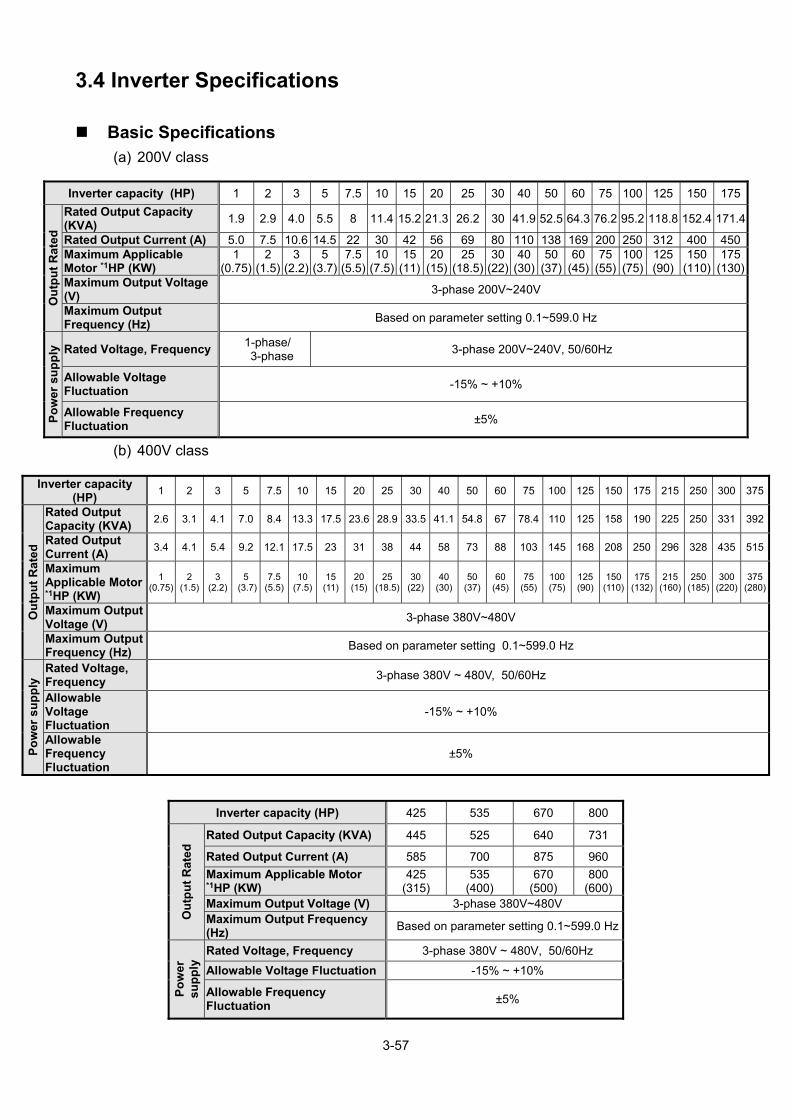
3-57
3.4 Inverter Specifications
Basic Specifications (a) 200V class
(b) 400V class
Inverter capacity (HP) 425 535 670 800
Ou
tpu
t R
ated
Rated Output Capacity (KVA) 445 525 640 731
Rated Output Current (A) 585 700 875 960
Maximum Applicable Motor *1HP (KW)
425 (315)
535 (400)
670 (500)
800 (600)
Maximum Output Voltage (V) 3-phase 380V~480V Maximum Output Frequency (Hz)
Based on parameter setting 0.1~599.0 Hz
Po
wer
su
pp
ly Rated Voltage, Frequency 3-phase 380V ~ 480V, 50/60Hz
Allowable Voltage Fluctuation -15% ~ +10%
Allowable Frequency Fluctuation
±5%
Inverter capacity (HP) 1 2 3 5 7.5 10 15 20 25 30 40 50 60 75 100 125 150 175
Ou
tpu
t R
ated
Rated Output Capacity (KVA)
1.9 2.9 4.0 5.5 8 11.4 15.2 21.3 26.2 30 41.9 52.5 64.3 76.2 95.2 118.8 152.4 171.4
Rated Output Current (A) 5.0 7.5 10.6 14.5 22 30 42 56 69 80 110 138 169 200 250 312 400 450Maximum Applicable Motor *1HP (KW)
1 (0.75)
2 (1.5)
3 (2.2)
5(3.7)
7.5(5.5)
10(7.5)
15(11)
20(15)
25(18.5)
30(22)
40(30)
50(37)
60 (45)
75 (55)
100 (75)
125(90)
150(110)
175(130)
Maximum Output Voltage (V)
3-phase 200V~240V
Maximum Output Frequency (Hz)
Based on parameter setting 0.1~599.0 Hz
Po
wer
su
pp
ly
Rated Voltage, Frequency 1-phase/ 3-phase
3-phase 200V~240V, 50/60Hz
Allowable Voltage Fluctuation
-15% ~ +10%
Allowable Frequency Fluctuation
±5%
Inverter capacity (HP)
1 2 3 5 7.5 10 15 20 25 30 40 50 60 75 100 125 150 175 215 250 300 375
Ou
tpu
t R
ated
Rated Output Capacity (KVA)
2.6 3.1 4.1 7.0 8.4 13.3 17.5 23.6 28.9 33.5 41.1 54.8 67 78.4 110 125 158 190 225 250 331 392
Rated Output Current (A)
3.4 4.1 5.4 9.2 12.1 17.5 23 31 38 44 58 73 88 103 145 168 208 250 296 328 435 515
Maximum Applicable Motor *1HP (KW)
1 (0.75)
2 (1.5)
3 (2.2)
5 (3.7)
7.5 (5.5)
10 (7.5)
15 (11)
20 (15)
25 (18.5)
30 (22)
40 (30)
50 (37)
60 (45)
75 (55)
100 (75)
125 (90)
150 (110)
175 (132)
215(160)
250(185)
300(220)
375(280)
Maximum Output Voltage (V)
3-phase 380V~480V
Maximum Output Frequency (Hz)
Based on parameter setting 0.1~599.0 Hz
Po
wer
su
pp
ly Rated Voltage,
Frequency 3-phase 380V ~ 480V, 50/60Hz
Allowable Voltage Fluctuation
-15% ~ +10%
Allowable Frequency Fluctuation
±5%

3-58
*1: Take standard 4-pole induction motor as the base.
*2: F510 model is designed to be used in normal duty (ND), whose overload capability is 120% for 1 min.
*3: If it is greater than default carrier frequency, you need to adjust the load current based on the de-rating
curve.
200V class Carrier freq.
default setting Carrier freq.
range 400V class
Carrier freq. default setting
Carrier freq. range
1~25HP 2KHz 2~16KHz 1~30HP 4KHz 2~16KHz 30HP 2KHz 2~12KHz 40HP 2KHz 2~16KHz
40~50HP 2KHz 2~12KHz (*4) 50~60HP 4KHz 2~12KHz (*4) 60~125HP 2KHz 2~10KHz (*4) 75~215HP 4KHz 2~10KHz (*4)
- - - 250HP 2KHz 2~8KHz 150~175HP 2KHz 2~5KHz 300~375HP 2KHz 2~5KHz
- - - 425HP 2KHz 2~5KHz - - - 535~800HP 4KHz 2~5KHz
*4: If control mode is set to SLV mode and maximum frequency (01-02) is larger than 80 Hz, the carrier
frequency range is 2~8Hz.
The following table shows the maximum output frequency for each control mode.
Control mode
Other settings Maximum
output frequency
V/F Unlimited 599Hz
SLV
200V 1~15HP, 400V 1~20HP 150Hz 200V 20~30HP, 400V 25HP 110Hz 400V 30~40HP 100Hz 200V 40~125HP, 400V 50~215HP, carrier (11-01) is set as 8K or below 8K.
100Hz
200V 40~125HP, 400V 50~215HP, carrier (11-01) is set as above 8K.
80Hz
200V 150~175HP, 400V 250~800HP 100Hz PMSLV Unlimited 599Hz

3-59
General Specifications
Co
ntr
ol
Ch
arac
teri
stic
s
Operation Modes LED keypad with seven-segment display *5 and LCD keypad (Optional HOA LCD keypad); all LCD keypad with parameter copy function
Control Modes V/F, SLV, PMSLV with space vector PWM mode Frequency Control Range 0.1Hz~599.0Hz Output Frequency Accuracy (Temperature change)
Digital references: ±0.01%(-10 to +40), Analog references: ±0.1% (25±10)
Speed Control Accuracy ±0.5% (Sensorless Vector Control Mode)*1 Frequency Setting Resolution
Digital references: 0.01Hz , Analog references: 0.06Hz/60Hz
Output Frequency Resolution
0.01Hz
Inverter Overload 120%/1 min Frequency Setting Signal DC 0~+10V / 0~20mA or 4~20mA Acceleration/ Deceleration Time
0.0~6000.0 seconds ( separately set acceleration and deceleration time )
Voltage, Frequency Characteristics
Custom V/F curve based on parameters
Braking Torque About 20%
Main Control Functions Auto tuning, Soft-PWM, Over voltage protection, Dynamic braking, Speed search, Restart upon momentary power loss, 2 sets of PID control, Slip Compensation, RS-485 communication standard, Simple PLC function, 2 sets of analog outputs, Safety switch
Other Functions
Accumulated power-on/ run time, 30 sets of fault history records and latest fault record state, Energy-saving function setting, Phase loss protection, Smart braking, DC braking, Dwell,S curve acceleration and deceleration, Up/Down operation, Modbus, BACnet MS/TP and Metasys N2 communication protocol, Display of multi-engineering unit, Local/ Remote switch, SINK/SOURCE input interface selection, User parameter settings
Pro
tect
ion
Fu
nc
tio
n
Stall Prevention Current level can be setting (It can be set separately in acceleration or constant speed; it can be set with or without protection in deceleration)
Instantaneous Over Current (OC) and Output Short-Circuit (SC) Protection
Inverter stops when the output current exceeds 160% of the inverter rated current
Inverter Overload Protection (OL2)
If inverter rated current 120%/1min is exceeded, inverter stops. The factory default carrier frequency is 2~4KHZ*2
Motor Overload Protection (OL1)
Electrical overload protection curve
Over voltage (OV) Protection
If the main circuit DC voltage rises over 410V (200V class)/ 820V (400V class), the motor stops running.
Under voltage (UV) Protection
If the main circuit DC voltage falls below 190V (200V class) /380V (400V class), the motor stops running.
Auto-Restart after Momentary Power Loss
Power loss exceeds 15ms. Auto-restart function available after momentary power loss in 2 sec.;3HP below for 1sec
Overheat(OH) Protection Use temperature sensor for protection.
Ground Fault (GF) Protection
Use current sensor for protection.
DC Bus Charge Indicator When main circuit DC voltage 50V, the CHARGE LED turns on.
Input Phase Loss (IPL) Protection
If the IPL is detected, the motor stops automatically.
Output Phase Loss (OPL) Protection
If the OPL is detected, the motor stops automatically.
Short-circuit current rating (SCCR)
Per UL 508C, the drive is suitable for use on a circuit capable of delivering not more than 100KA symmetrical amperes (rms) when protected by fuses given in the fuse table.
En
viro
nm
ent
Sp
ecif
icat
ion
s
Installation Location Indoor (protected from corrosive gases and dust)
Ambient Temperature -10~+40(14~104) (IP20/NEMA1 or IP55/NEMA12), -10~+50(14~122) (IP00 or top anti-dust cover
removed) without de-rating; with de-rating, its maximum operation temperature is 60(140). (Enhanced type frame 5 is 50°C without de-rating
Storage Temperature -20~+70(-4~+158)
Humidity 95%RH or less (no condensation)
Altitude Altitude: Below 1000 m (3281 ft.), It is required to derate 1% of current at each additional 100 m, the maximum altitude is 3000 m.
Vibration 9.8m/s2 (1.0G), meet IEC 60068-2-6
Pollution Degree IP00/IP20/IP21 meet IEC 60721-3-3 Class 3C2, IP55 meet IEC 60721-3-3 Class 3C3

3-60
*1: Speed control accuracy will be different from the installation conditions and motor types. *2: The factory default carrier frequency is different from models.
Communication Function Built-in RS-485 as standard (Modbus protocol with RJ45/ BACnet/ Metasys N2)
PLC Function Built-in
EMI Protection The built-in noise filter complies with EN61800-3 available for inverters 400V 75HP or below (IP20) / 400V 60HP orbelow (IP55)
EMS Protection in compliance with EN61800-3
Safety Certification
CE Declaration in compliance with EN61800-3 (CE & RE) and EN61800-5-1 (LVD, Low-Voltage Directive)
UL Certification UL508C
Accessories Please refer to chapter 11

3-61
3.5 Inverter De-rating Based on Carrier Frequency
Note: De-rating curve current of carrier frequency means inverter rated current.
(a) 200V Models
Model 2001 2002 2003 2005 2008A 100% 67% 76% 76% 80%B 80% 53% 60% 61% 68%
Model 2010 2015 2020 2025 A 83% 79% 84% 87% B 67% 67% 67% 70%
Model 2030 2040 2050A 92% 77% 83%B 74% 62% 67%
Model 2060 2075 2100A 85% 90% 86%B 68% 72% 69%
Model 2125 2150 2175A 91% 87% 92%B 73% 78% 83%
200V 1~25HP 100%
A
B
0 2KHz 8KHz 16KHz
Rated Current
Ratio
Carrier
Frequency (Fc)
200V 30~50HP 100%
A
B
0 2KHz 6KHz 12KHz
200V 60~175HP 100%
A
B
0 2KHz 5KHz 10KHz
Rated Current
Ratio
Carrier
Frequency (Fc)
Rated Current
Ratio
Carrier
Frequency (Fc)

3-62
400V 1~30HP 100%
A
B
0 4KHz 8KHz 16KHz
400V 40HP 100%
78%
47%
0 2KHz 8KHz 16KHz
400V 50~60HP 100%
A
B
0 4KHz 5KHz 12KHz
Carrier
Frequency (Fc)
(b) 400V Models
Model4001 (IP55)
4002 (IP55)
4003 (IP55)
A 100% 100% 100%B 60% 60% 60%
Model 4001(IP20)
4002 (IP20)
4003 (IP20)
4005 4008
A 100% 83% 78% 100% 76%B 60% 50% 47% 60% 46%
Model 4010 4015 4020 4025 4030A 85% 78% 77% 82% 89%B 51% 47% 46% 49% 53%
Model 4050 4060 A 83% 85% B 66% 68%
Rated Current
Ratio
Carrier
Frequency (Fc)
Carrier
Frequency (Fc)
Rated Current
Ratio
Rated Current
Ratio
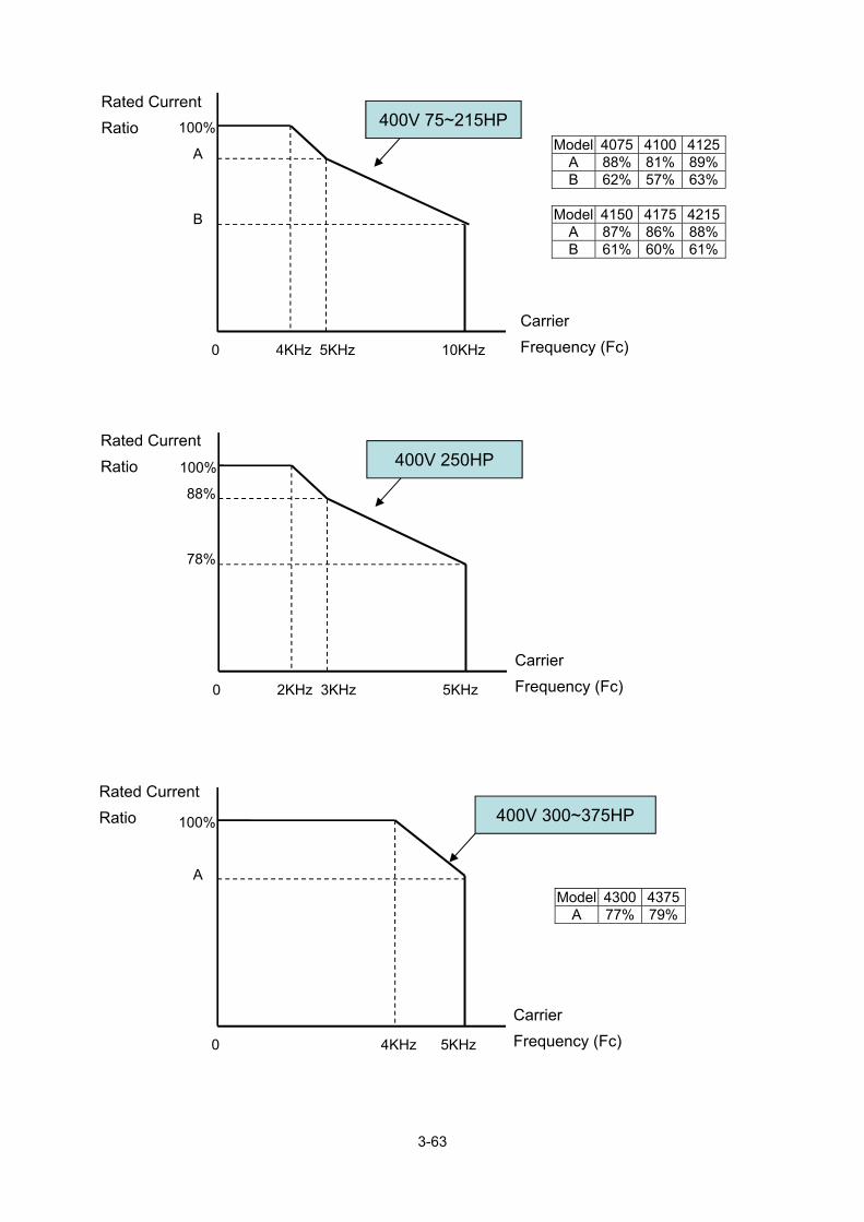
3-63
400V 75~215HP100%
A
B
0 4KHz 5KHz 10KHz
400V 250HP 100%
88%
78%
0 2KHz 3KHz 5KHz
400V 300~375HP 100%
A
0 4KHz 5KHz
Carrier
Frequency (Fc)
Carrier
Frequency (Fc)
Rated Current
Ratio
Rated Current
Ratio
Model 4075 4100 4125A 88% 81% 89%B 62% 57% 63%
Model 4150 4175 4215A 87% 86% 88%B 61% 60% 61%
Model 4300 4375 A 77% 79%
Rated Current
Ratio
Carrier
Frequency (Fc)

3-64
400V 425HP 100%
87%
78%
0 2KHz 3KHz 5KHz
Rated Current
Ratio
Carrier
Frequency (Fc)
Rated Current
Ratio 400V 535~800HP 100%
90%
80%
70%
0 2KHz 3KHz 4KHz 5KHz
Carrier
Frequency (Fc)

3-65
3.6 Inverter De-rating Based on Temperature
Note: User needs to adjust the inverter rated current depending on ambient temperature to ensure
the appropriate industrial application.
Notes for using the PM motor
1. The inverter carry frequency (11-01) need to set upper than 6KHz.
2. The rating current of the inverter at 6KHz carry frequency (11-01) (need refer to the
de-rating curve) must be bigger than the PM motor rating current.
Capacitor reforming Guide after long storage
For correct performance of this product after long storage before use it is important that
Inverter Capacitors are reformed according to the guide below:
Storage time
Procedure to re-apply voltage
≦1year Apply rated voltage(*1) of inverter in the normal way Between 1-2 years
Apply 100% rated voltage of inverter to the product for one hour
≧2 years
Use a variable AC power supply to 1. Connecting 25% of inverter rated voltage for 30 minutes. 2. Connecting 50% of inverter rated voltage for 30 minutes. 3. Connecting 75% of inverter rated voltage for 30 minutes. 4. Connecting 100% of inverter rated voltage for 210 minutes. Once the procedures completed, inverter just can be used normally.
*1:Rated voltage: please connects rated voltage according to model label of inverter.
100%
60%
0 40 60
Rated Current
Ratio
Temperature
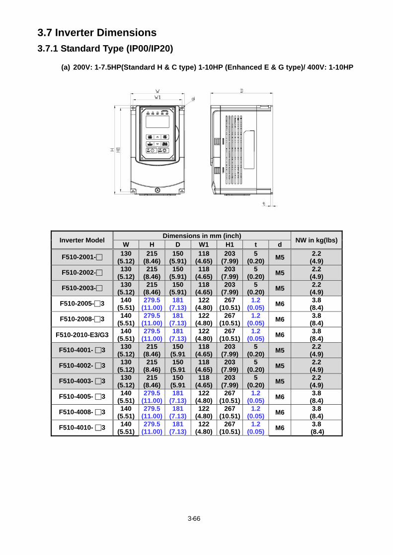
3- 66
3.7 Inverter Dimensions
3.7.1 Standard Type (IP00/IP20)
(a) 200V: 1-7.5HP(Standard H & C type) 1-10HP (Enhanced E & G type)/ 400V: 1-10HP
Inverter Model Dimensions in mm (inch)
NW in kg(lbs)W H D W1 H1 t d
F510-2001- 130 (5.12)
215 (8.46)
150 (5.91)
118 (4.65)
203 (7.99)
5 (0.20)
M5 2.2
(4.9)
F510-2002- 130 (5.12)
215 (8.46)
150 (5.91)
118 (4.65)
203 (7.99)
5 (0.20)
M5 2.2
(4.9)
F510-2003- 130 (5.12)
215 (8.46)
150 (5.91)
118 (4.65)
203 (7.99)
5 (0.20)
M5 2.2
(4.9)
F510-2005-3 140 (5.51)
279.5 (11.00)
181 (7.13)
122 (4.80)
267 (10.51)
1.2 (0.05)
M6 3.8
(8.4)
F510-2008-3 140 (5.51)
279.5 (11.00)
181 (7.13)
122 (4.80)
267 (10.51)
1.2 (0.05)
M6 3.8
(8.4)
F510-2010-E3/G3 140
(5.51) 279.5
(11.00) 181
(7.13)122
(4.80)267
(10.51)1.2
(0.05)M6
3.8 (8.4)
F510-4001- 3 130 (5.12)
215 (8.46)
150 (5.91
118 (4.65)
203 (7.99)
5 (0.20)
M5 2.2
(4.9)
F510-4002- 3 130 (5.12)
215 (8.46)
150 (5.91
118 (4.65)
203 (7.99)
5 (0.20)
M5 2.2
(4.9)
F510-4003- 3 130 (5.12)
215 (8.46)
150 (5.91
118 (4.65)
203 (7.99)
5 (0.20)
M5 2.2
(4.9)
F510-4005- 3 140 (5.51)
279.5 (11.00)
181 (7.13)
122 (4.80)
267 (10.51)
1.2 (0.05)
M6 3.8
(8.4)
F510-4008- 3 140 (5.51)
279.5 (11.00)
181 (7.13)
122 (4.80)
267 (10.51)
1.2 (0.05)
M6 3.8
(8.4)
F510-4010- 3 140 (5.51)
279.5 (11.00)
181 (7.13)
122 (4.80)
267 (10.51)
1.2 (0.05)
M6 3.8
(8.4)
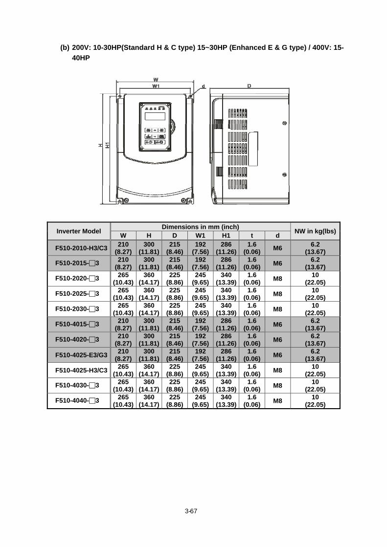
3- 67
(b) 200V: 10-30HP(Standard H & C type) 15~30HP (Enhanced E & G type) / 400V: 15-
40HP
Inverter Model Dimensions in mm (inch)
NW in kg(lbs)W H D W1 H1 t d
F510-2010-H3/C3 210
(8.27) 300
(11.81) 215
(8.46)192
(7.56)286
(11.26)1.6
(0.06)M6
6.2 (13.67)
F510-2015-3 210 (8.27)
300 (11.81)
215 (8.46)
192 (7.56)
286 (11.26)
1.6 (0.06)
M6 6.2
(13.67)
F510-2020-3 265 (10.43)
360 (14.17)
225 (8.86)
245 (9.65)
340 (13.39)
1.6 (0.06)
M8 10
(22.05)
F510-2025-3 265 (10.43)
360 (14.17)
225 (8.86)
245 (9.65)
340 (13.39)
1.6 (0.06)
M8 10
(22.05)
F510-2030-3 265 (10.43)
360 (14.17)
225 (8.86)
245 (9.65)
340 (13.39)
1.6 (0.06)
M8 10
(22.05)
F510-4015-3 210 (8.27)
300 (11.81)
215 (8.46)
192 (7.56)
286 (11.26)
1.6 (0.06)
M6 6.2
(13.67)
F510-4020-3 210 (8.27)
300 (11.81)
215 (8.46)
192 (7.56)
286 (11.26)
1.6 (0.06)
M6 6.2
(13.67)
F510-4025-E3/G3 210
(8.27) 300
(11.81) 215
(8.46)192
(7.56)286
(11.26)1.6
(0.06)M6
6.2 (13.67)
F510-4025-H3/C3 265
(10.43) 360
(14.17) 225
(8.86)245
(9.65)340
(13.39)1.6
(0.06)M8
10 (22.05)
F510-4030-3 265 (10.43)
360 (14.17)
225 (8.86)
245 (9.65)
340 (13.39)
1.6 (0.06)
M8 10
(22.05)
F510-4040-3 265 (10.43)
360 (14.17)
225 (8.86)
245 (9.65)
340 (13.39)
1.6 (0.06)
M8 10
(22.05)

3- 68
(c) 200V: 40-50HP/ 400V: 50-75HP (Standard H & C type) 50~100HP (Enhanced E & G
type)
Inverter Model Dimensions in mm (inch)
NW in kg(lbs)W H D W1 H1 t d
F510-2040-H3/C3 286.5
(11.28) 525
(20.67)252
(9.92)160
(6.30)505
(19.88)3.3
(0.13)M8 28
(52.91)
F510-2050-H3/C3 286.5
(11.28) 525
(20.67)252
(9.92)160
(6.30)505
(19.88)3.3
(0.13)M8 28
(52.91)
F510-4050-H3/C3 286.5
(11.28) 525
(20.67)252
(9.92)160
(6.30)505
(19.88)3.3
(0.13)M8 28
(52.91)
F510-4060-H3/C3 286.5
(11.28) 525
(20.67)252
(9.92)160
(6.30)505
(19.88)3.3
(0.13)M8 28
(52.91)
F510-4075-H3/C3 286.5
(11.28) 525
(20.67)252
(9.92)160
(6.30)505
(19.88)3.3
(0.13)M8 28
(52.91)
F510-2040-E3/G3 288
(11.34) 526
(20.71)272
(10.71)160
(6.30)505
(19.88)3.3
(0.13)M8 27
(59.52)
F510-2050-E3/G3 288
(11.34) 526
(20.71)272
(10.71)160
(6.30)505
(19.88)3.3
(0.13)M8 27
(59.52)
F510-4050-E3/G3 288
(11.34) 526
(20.71)272
(10.71)160
(6.30)505
(19.88)3.3
(0.13)M8 27
(59.52)
F510-4060-E3/G3 288
(11.34) 526
(20.71)272
(10.71)160
(6.30)505
(19.88)3.3
(0.13)M8 27
(59.52)
F510-4075-E3/G3 288
(11.34) 526
(20.71)272
(10.71)160
(6.30)505
(19.88)3.3
(0.13)M8 27
(59.52)
F510-4100-E3/G3 288
(11.34) 526
(20.71)272
(10.71)160
(6.30)505
(19.88)3.3
(0.13)M8 27
(59.52)

3- 69
(d) 200V: 60-125HP/ 400V: 100-250HP (Standard H & C type) 125~250HP (Enhanced E
& G type) (IP00)
Inverter Model Dimensions in mm (inch)
NW in kg(lbs)W H D W1 H1 t d
F510-2060-3 344 (13.54)
580 (22.83)
300 (11.81)
250 (9.84)
560 (22.05)
1.6 (0.06)
M8 40 (88.18)
F510-2075-3 344 (13.54)
580 (22.83)
300 (11.81)
250 (9.84)
560 (22.05)
1.6 (0.06)
M8 40 (88.18)
F510-2100-3 459 (18.07)
790 (31.10)
324.5(12.78)
320 (12.60)
760 (29.92)
1.6 (0.06)
M10 74
(163.14)
F510-2125-3 459 (18.07)
790 (31.10)
324.5(12.78)
320 (12.60)
760 (29.92)
1.6 (0.06)
M10 74
(163.14)
F510-4100-H3/C3 344
(13.54) 580
(22.83)300
(11.81)250
(9.84)560
(22.05)1.6
(0.06)M8 40
(88.18)
F510-4125-3 344 (13.54)
580 (22.83)
300 (11.81)
250 (9.84)
560 (22.05)
1.6 (0.06)
M8 40 (88.18)
F510-4150-E3/G3 344
(13.54) 580
(22.83)300
(11.81)250
(9.84)560
(22.05)1.6
(0.06)M8 40
(88.18)
F510-4150-H3/C3 459
(18.07) 790
(31.10)324.5
(12.78)320
(12.60)760
(29.92)1.6
(0.06)M10
74 (163.14)
F510-4175-3 459 (18.07)
790 (31.10)
324.5(12.78)
320 (12.60)
760 (29.92)
1.6 (0.06)
M10 74
(163.14)
F510-4215-3 459 (18.07)
790 (31.10)
324.5(12.78)
320 (12.60)
760 (29.92)
1.6 (0.06)
M10 74
(163.14)
F510-4250-3 459 (18.07)
790 (31.10)
324.5(12.78)
320 (12.60)
760 (29.92)
1.6 (0.06)
M10 74
(163.14)

3- 70
(e) 200V: 60-125HP/ 400V: 100-250HP (Standard H & C type) 125~250HP (Enhanced E
& G type) (IP20)
Inverter Model Dimensions in mm (inch)
NW in kg(lbs)W H D W1 H1 t d
F510-2060-3 348.5 (13.72)
740 (29.13)
300 (11.81)
250 (9.84)
560 (22.05)
1.6 (0.06)
M8 44
(97.00)
F510-2075-3 348.5 (13.72)
740 (29.13)
300 (11.81)
250 (9.84)
560 (22.05)
1.6 (0.06)
M8 44
(97.00)
F510-2100-3 463.5 (18.25)
1105 (43.50)
324.5(12.78)
320 (12.60)
760 (29.92)
1.6 (0.06)
M10 81
(178.57)
F510-2125-3 463.5 (18.25)
1105 (43.50)
324.5(12.78)
320 (12.60)
760 (29.92)
1.6 (0.06)
M10 81
(178.57)
F510-4100-H3/C3 348.5
(13.72) 740
(29.13)300
(11.81)250
(9.84)560
(22.05)1.6
(0.06)M8
44 (97.00)
F510-4125-3 348.5 (13.72)
740 (29.13)
300 (11.81)
250 (9.84)
560 (22.05)
1.6 (0.06)
M8 44
(97.00)
F510-4150-E3/G3 348.5
(13.72) 740
(29.13)300
(11.81)250
(9.84)560
(22.05)1.6
(0.06)M8
44 (97.00)
F510-4150-H3/C3 463.5
(18.25) 1105
(43.50)324.5
(12.78)320
(12.60)760
(29.92)1.6
(0.06)M10
81 (178.57)
F510-4175-3 463.5 (18.25)
1105 (43.50)
324.5(12.78)
320 (12.60)
760 (29.92)
1.6 (0.06)
M10 81
(178.57)
F510-4215-3 463.5 (18.25)
1105 (43.50)
324.5(12.78)
320 (12.60)
760 (29.92)
1.6 (0.06)
M10 81
(178.57)
F510-4250-3 463.5 (18.25)
1105 (43.50)
324.5(12.78)
320 (12.60)
760 (29.92)
1.6 (0.06)
M10 81
(178.57)

3- 71
(f) 200V: 150-175HP/ 400V: 300-425HP (IP00)
Inverter Model Dimensions in mm (inch)
NW in kg(lbs)W H D W1 W2 H1 t d
F510-2150-3 692 (27.24)
1000 (39.37)
410 (16.14)
530 (20.87)
265 (10.43)
960 (37.80)
1.6 (0.06)
M12 184
(405.65)
F510-2175-3 690 (27.17)
1000 (39.37)
410 (16.14)
530 (20.87)
265 (10.43)
960 (37.80)
1.6 (0.06)
M12 184
(405.65)
F510-4300-3 690 (27.17)
1000 (39.37)
410 (16.14)
530 (20.87)
265 (10.43)
960 (37.80)
1.6 (0.06)
M12 184
(405.65)
F510-4375-3 690 (27.17)
1000 (39.37)
410 (16.14)
530 (20.87)
265 (10.43)
960 (37.80)
1.6 (0.06)
M12 184
(405.65)
F510-4425-3 690 (27.17)
1000 (39.37)
410 (16.14)
530 (20.87)
265 (10.43)
960 (37.80)
1.6 (0.06)
M12 184
(405.65)

3- 72
(g) 200V: 150-175HP/ 400V: 300-425HP (IP20)
Inverter Model Dimensions in mm (inch)
NW in kg(lbs)W H D W1 W2 H1 t d
F510-2150-3 692 (27.24)
1313 (51.69)
410 (16.14)
530 (20.87)
265 (10.43)
960(37.80)
1.6 (0.06)
M12 194
(427.70)
F510-2175-3 692 (27.24)
1313 (51.69)
410 (16.14)
530 (20.87)
265 (10.43)
960(37.80)
1.6 (0.06)
M12 194
(427.70)
F510-4300-3 692 (27.24)
1313 (51.69)
410 (16.14)
530 (20.87)
265 (10.43)
960(37.80)
1.6 (0.06)
M12 194
(427.70)
F510-4375-3 692 (27.24)
1313 (51.69)
410 (16.14)
530 (20.87)
265 (10.43)
960(37.80)
1.6 (0.06)
M12 194
(427.70)
F510-4425-3 692 (27.24)
1313 (51.69)
410 (16.14)
530 (20.87)
265 (10.43)
960(37.80)
1.6 (0.06)
M12 194
(427.70)

3- 73
(h) 400V: 535-800HP (IP00)
Inverter Model Dimensions in mm (inch) NW in
kg(lbs)W H D W1 W2 W3 H1 H2 H3 t d
F510-4535-3 958 (37.72)
1356(53.38)
507 (19.96)
916 (36.06)
158 (6.22)
600 (23.62)
1200(47.24)
300 (11.81)
63.5 (2.50)
6.2 (0.24)
M12335
(739)
F510-4670-3 958 (37.72)
1356(53.38)
507 (19.96)
916 (36.06)
158 (6.22)
600 (23.62)
1200(47.24)
300 (11.81)
63.5 (2.50)
6.2 (0.24)
M12335
(739)
F510-4800-3 958 (37.72)
1356(53.38)
507 (19.96)
916 (36.06)
158 (6.22)
600 (23.62)
1200(47.24)
300 (11.81)
63.5 (2.50)
6.2 (0.24)
M12335
(739)

3- 74
(i) 400V: 535-800HP (IP20)
Inverter Model Dimensions in mm (inch) NW in
kg(lbs) W H D W1 W2 W3 H1 H2 H3 t d
F510-4535-3 958 (37.72)
1756 (69.13)
507 (19.96)
916 (36.06)
158 (6.22)
600 (23.62)
1200(47.24)
300 (11.81)
63.5 (2.50)
6.2 (0.24)
M12350
(772)
F510-4670-3 958 (37.72)
1756 (69.13)
507 (19.96)
916 (36.06)
158 (6.22)
600 (23.62)
1200(47.24)
300 (11.81)
63.5 (2.50)
6.2 (0.24)
M12350
(772)
F510-4800-3 958 (37.72)
1756 (69.13)
507 (19.96)
916 (36.06)
158 (6.22)
600 (23.62)
1200(47.24)
300 (11.81)
63.5 (2.50)
6.2 (0.24)
M12350
(772)

3- 75
3.7.2 Standard Type with Built-in Filter (IP00/IP20)
(a) 400V: 1-10HP
Inverter Model Dimensions in mm (inch)
NW in kg(lbs)W H D W1 H1 H2 t d
F510-4001-3F 130 (5.12)
306 (12.05)
150 (5.91)
118(4.65)
203 (7.99)
215(8.46)
5 (0.20)
M5 3.5
(7.71)
F510-4002-3F 130 (5.12)
306 (12.05)
150 (5.91)
118(4.65)
203 (7.99)
215(8.46)
5 (0.20)
M5 3.5
(7.71)
F510-4003-3F 130 (5.12)
306 (12.05)
150 (5.91)
118(4.65)
203 (7.99)
215(8.46)
5 (0.20)
M5 3.5
(7.71)
F510-4005-3F 140 (5.51)
385.5 (15.18)
181 (7.13)
122(4.80)
267 (10.51)
279(10.98)
1.2 (0.05)
M6 5.5
(12.13)
F510-4008-3F 140 (5.51)
385.5 (15.18)
181 (7.13)
122(4.80)
267 (10.51)
279(10.98)
1.2 (0.05)
M6 5.5
(12.13)
F510-4010-3F 140 (5.51)
385.5 (15.18)
181 (7.13)
122(4.80)
267 (10.51)
279(10.98)
1.2 (0.05)
M6 5.5
(12.13)
(b) 400V: 15-40HP

3- 76
Inverter Model Dimensions in mm (inch)
NW in kg(lbs)W H D W1 H1 H2 t d
F510-4015-3F 210 (8.27)
416.5 (16.40)
215(8.46)
192 (7.56)
286(11.26)
300 (11.81)
1.6 (0.06)
M6 8.0
(17.64)
F510-4020-3F 210 (8.27)
416.5 (16.40)
215(8.46)
192 (7.56)
286(11.26)
300 (11.81)
1.6 (0.06)
M6 8.0
(17.64)
F510-4025-3F 265 (10.43)
500 (19.69)
225(8.86)
245 (9.65)
340(13.39)
360 (14.17)
1.6 (0.06)
M8 12.5
(27.56)
F510-4030-3F 265 (10.43)
500 (19.69)
225(8.86)
245 (9.65)
340(13.39)
360 (14.17)
1.6 (0.06)
M8 12.5
(27.56)
F510-4040-3F 265 (10.43)
500 (19.69)
225(8.86)
245 (9.65)
340(13.39)
360 (14.17)
1.6 (0.06)
M8 12.5
(27.56)
(c) 400V: 50-75HP
Inverter Model Dimensions in mm (inch)
NW in kg(lbs)W H D W1 H1 H2 t d
F510-4050-3F 288 (11.34)
680 (26.77)
Note
220(8.66)
505 (19.88)
525 (20.67)
3.3 (0.13)
M8 32 (70.55)
F510-4060-3F 288 (11.34)
680 (26.77)
220(8.66)
505 (19.88)
525 (20.67)
3.3 (0.13) M8 32
(70.55)
F510-4075-3F 288 (11.34)
680 (26.77)
220(8.66)
505 (19.88)
525 (20.67)
3.3 (0.13) M8 32
(70.55)
Note: Standard type is 252mm (9.92 inch), Enhanced type is 272mm (10.70 inch)

3- 77
3.7.3 Water proof Type (IP55)
(a) 400V: 1-25HP
Inverter Model Dimensions in mm (inch)
NW in kg(lbs)W H D W1 H1 t d
F510-4001-C3FN4 189
(7.44) 284
(11.18)186
(7.32)171
(6.73)266
(10.47)1.2
(0.05)M5
5.1 (11.3)
F510-4002-C3FN4 189
(7.44) 284
(11.18)186
(7.32)171
(6.73)266
(10.47)1.2
(0.05)M5
5.1 (11.24)
F510-4003-C3FN4 189
(7.44) 284
(11.18)186
(7.32)171
(6.73)266
(10.47)1.2
(0.05)M5
5.1 (11.3)
F510-4005-C3FN4 189
(7.44) 284
(11.18)186
(7.32)171
(6.73)266
(10.47)1.2
(0.05)M5
5.1 (11.3)
F510-4008-C3FN4 189
(7.44) 284
(11.18)186
(7.32)171
(6.73)266
(10.47)1.2
(0.05)M5
5.1 (11.3)
F510-4010-C3FN4 230
(9.06) 320
(12.60)210
(8.27)210
(8.27)305
(12.01)2
(0.08)M5
8.6 (19.0)
F510-4015-C3FN4 230
(9.06) 320
(12.60)210
(8.27)210
(8.27)305
(12.01)2
(0.08)M5
8.6 (19.0)
F510-4020-C3FN4 265
(10.43) 396
(15.59)227
(8.94)249
(9.80)380
(14.96)2
(0.08)M5
17 (37.5)
F510-4025-C3FN4 265
(10.43) 396
(15.59)227
(8.94)249
(9.80)380
(14.96)2
(0.08)M5
17 (37.5)

3- 78
(b) 400V: 30-100HP
Inverter Model Dimensions in mm (inch)
NW in kg(lbs)W H D W1 H1 t d
F510-4030-C3FN4 224
(8.82) 527
(20.75)311
(12.24)180
(7.09)505
(19.88)2
(0.08)M10
32.5 (71.7)
F510-4040-C3FN4 224
(8.82) 527
(20.75)311
(12.24)180
(7.09)505
(19.88)2
(0.08)M10
32.5 (71.7)
F510-4050-C3FN4 224
(8.82) 527
(20.75)311
(12.24)180
(7.09)505
(19.88)2
(0.08)M10
32.5 (71.7)
F510-4060-C3FN4 326
(12.83) 695
(27.36)343
(13.50)276
(10.87)671
(26.42)2.3
(0.09)M10
55 (121.3)
F510-4075-C3N4 326
(12.83) 695
(27.36)343
(13.50)276
(10.87)671
(26.42)2.3
(0.09)M10
55 (121.3)
F510-4100-C3N4 326
(12.83) 695
(27.36)343
(13.50)276
(10.87)671
(26.42)2.3
(0.09)M10
55 (121.3)

4-1
Chapter 4 Keypad and Programming Functions
4.1 LED Keypad
4.1.1 Keypad Display and Keys
DISPLAY Description
5 Digit LED Display Monitor inverter signals, view / edit parameters, fault / alarm display.
LED INDICATORS
FAULT LED ON when a fault or alarm is active.
FWD LED ON when inverter is running in forward direction, flashing when stopping.
REV LED On when inverter is running in reverse direction, flashing when stopping.
SEQ LED ON when RUN command is from the external control terminals or from serial communication.
REF LED ON when Frequency Reference command is from the external control terminals or from serial communication.

4-2
KEYS (8) Description
RUN RUN inverter
STOP STOP inverter
Parameter navigation Up, Increase parameter or reference value
Parameter navigation down, decrease parameter or reference value
LOC/REM
Used to switch between Local Mode and Remote Mode REMOTE Mode: Set by parameters, controlled by control circuit terminals, communication or other ways. LOCAL Mode: Controlled by operator. It displays REMOTE Mode at power-up. Users can switch between LOCAL and REMOTE Mode if they press LOC/ REM keys when the inverter stops. Parameter of 23-41 can determine if LOC/REM keys are enabled or not.
DSP/FUN Used to scroll to next screen Frequency screenFunction selectionMonitor parameter
/ RESET Selects active seven segment digit for editing with the keys Used to reset fault condition.
READ / ENTER Used to read and save the value of the active parameter.
Auto-Repeat Keys Holding the UP or DOWN key for a longer period of time will initiate the auto-repeat function resulting in the value of the selected digit to automatically increase or decrease.

4-3
4.1.2 Seven Segment Display Description
Actual LED Display Actual LED Display Actual LED Display Actual LED Display
0 A L Y
1 B n -
2 C o °
3 D P _
4 E q
.
5 F r
6 G S
7 H t
8 I u
9 J V
Display output frequency Frequency Reference Set Frequency Reference LED lights on LED flashes Flashing digit
At power-up, the display will show the frequency reference setting and all LEDs are flashing. Press
the (UP) or (DOWN) key to enter the frequency reference edit mode, use the /RESET key to select which digit to edit (flashing). Use the (UP) or (DOWN) key to modify the value and press the READ / ENTER key to save the frequency reference and switch back to the frequency reference display mode.
During run operation, the display will show the output frequency. Note: When in edit mode and the READ / ENTER is not pressed within 5 sec, the inverter will switch
back to the frequency reference display mode.
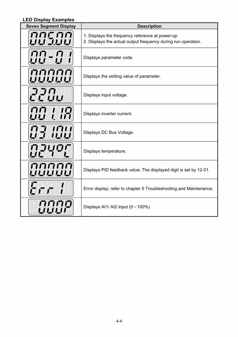
4-4
LED Display Examples Seven Segment Display Description
1. Displays the frequency reference at power-up. 2. Displays the actual output frequency during run operation.
Displays parameter code.
Displays the setting value of parameter.
Displays input voltage.
Displays inverter current.
Displays DC Bus Voltage.
Displays temperature.
Displays PID feedback value; The displayed digit is set by 12-01.
Error display; refer to chapter 5 Troubleshooting and Maintenance.
Displays AI1/ AI2 input (0~100%)

4-5
4.1.3 LED Indicator Description Fault LED
State Description FAULT LED
Off No Fault Active
Illuminated Fault Active
Forward LED
State Description FWD LED
Off Inverter in reverse direction
Illuminated Inverter is running in forward direction
Flashing Forward direction active, no run command
Reverse LED
State Description REV LED
Off Inverter in forward direction
Illuminated Inverter is running in reverse direction
Flashing Reverse direction active, no run command
RUN LED
State Description RUN LED
Off Inverter stopped
Illuminated Inverter running
Flashing Inverter stopped or stopping

4-6
SEQ LED State Description SEQ LED
Off Sequence controlled from keypad
Illuminated Sequence set from external source
REF LED
State Description REF LED
Off Frequency reference set from keypad
Illuminated Frequency reference set from external source
Run / Stop Status Indicators

4-7
4.1.4 Power-up Monitor
Power-up
Changing Monitor at Power-up
12- 00 Display Selection
Range
Highest bit -> 0 0 0 0 0 <- Lowest bit The setting range for each bit is 0 ~ 7 from the highest bit to the lowest bit.
0: No display 4: Temperature
1: Output current 5: PID feedback
2: Output voltage 6: AI1 value
3: DC voltage 7: AI2 value
Example: 12- 00=【10000】

4-8
Example: 12- 00=【12345】
4.1.5 Modifying Parameters/ Set Frequency Reference
Example: Modifying Parameters

4-9
Example: Set Frequency Reference
Inverter stopped: Inverter is running:
Note: When upper or lower limit is reached during editing of the frequency reference, the edit value will
automatically rollover from the lower limit to the upper limit or from the upper limit to the lower limit.

4-10
4.1.6 Operation Control

4-11
4.2 LCD keypad
4.2.1 Keypad Display and Keys
DISPLAY Description
LCD Display Monitor inverter signals, view / edit parameters, fault / alarm display.
LED INDICATORS
FAULT LED ON when a fault or alarm is active.
FWD LED ON when inverter is running in forward direction, flashing when stopping.
REV LED On when inverter is running in reverse direction, flashing when stopping.
SEQ LED ON when RUN command is from the external control terminals or from serial communication.
REF LED ON when Frequency Reference command is from the external control terminals or from serial communication.

4-12
KEYS (8) Description
RUN RUN inverter
STOP STOP inverter
Parameter navigation Up, Increase parameter or reference value
Parameter navigation down, decrease parameter or reference value
LOC/REM
Used to switch between Local Mode and Remote Mode REMOTE Mode: Set by parameters, controlled by control circuit terminals, communication or other ways. LOCAL Mode: Controlled by operator. It displays REMOTE Mode at power-up. Users can switch between LOCAL and REMOTE Mode if they press LOC/ REM keys when the inverter stops. Parameter of 23-41 can determine if LOC/REM keys are enabled or not.
DSP/FUN Used to scroll to next screen Frequence screenFunction selectionMonitor parameter
/ RESET Selects active seven segment digit for editing with the keys Used to reset fault condition.
READ / ENTER Used to read and save the value of the active parameter.
Auto-Repeat Keys Holding the UP or DOWN key for a longer period of time will initiate the auto-repeat function resulting in the value of the selected digit to automatically increase or decrease.
Note: HOA LCD keypad is available with an optional accessory.

4-13
4.2.2 Keypad Menu Structure
Main Menu
The F510 inverter main menu consists of two main groups (modes). The DSP/FUN key is used to switch between the monitor mode and the parameter group mode. Refer to Figure 4.2.2.1.
Mode Description
Monitor Mode View inverter status, signals and fault data.
Parameter Group Mode Access to available parameter groups.
All the available parameter groups are listed in the Parameter Group Mode. Use the up and
down keys to select a group and press READ/ ENTER to access its parameters.
Fig. 4.2.2.1 Parameter Group Structure
Notes: - Always perform auto-tune on the motor before operating the inverter in vector control (sensorless vector or
flux vector). Auto-tuning mode will not be displayed when the inverter is running or when a fault is active.
- To scroll through the available modes, parameter groups or parameter list press and hold the up or down key.
Parameter Group Mode
Parameter Mode
Parameter Edit Mode
DSPFUN
DSPFUN
RUN
READENTER
READENTER
Auto-Tune Mode
DSPFUN
Select parameter
Change parameter setting
Auto-tune motor
Select parameter group

4-14
Power ON
Monitor
Freq Ref
12-17=000.00Hz12-18=0000.0A
12-16=005.00Hz
Flt Freq Ref12-15=000.00Hz
Monitor
Monitor
12-17=000.00Hz12-18=0000.0A
Flt DC Voltage
12-17=000.00Hz12-18=0000.0A
00 Basic Func.
01 V/F Pattern.
02 Motor Parameter
Group DSPFUN
DSPFUN
DSPFUN
DSPFUN
12-14=0000.0V
Monitor ModeParameter Group Selection Mode
Monitor Mode
In monitor mode inverter signals can be monitored such as output frequency, output current and output voltage, etc…) as well as fault information and fault trace. See Fig 4.2.2.2 for keypad navigation.
Fig 4.2.2.2 Monitor Mode

4-15
Programming Mode
In programming mode inverter parameters can be read or changed. See Fig 4.2.2.3 for keypad navigation.
Power ON
DSPFUN
READENT ER
READENT ER
READENT ER
READENT ER
As the above parameter setting
Monitor Freq Ref
12-17=000.00Hz12-18=0000.0A
12-16=005.00Hz
Control MethodEdit 00-00
0 V/F(0~4)<0>
Motor Direction
0 Forward(0~1)<0>
Run Source
0 Digital Op(0~4)<1>
DSPFUN
DSPFUN
DSPFUN
READENT ER
DSPFUN
READENT ER
DSPFUN
Edit 00-01
Edit 00-02
DSPFUN
DSPFUN
DSPFUN
Group
01 V/F Pattern
02 Motor Parameter
00 Basic Func.
Group
02 Motor Parameter
00 Basic Fun.01 V/F Pattern
Group
00 Basic Fun.
01 V/F Pattern
02 Motor Parameter
PARA 00 -00 Control Method -01 Motor Direct ion -02 Run Source
PARA 00 -00 Control Method -01 Motor Direct ion -02 Run Source
PARA 00 -00 Control Method -01 Motor Direct ion -02 Run Source
Parameter Group Selection Mode
Parameter Group Mode
Parameter Edit Mode
DSPFUN
Press / to edit the setting
value or READ/ENTER
to save the changes.
Monitor Mode
Fig 4.2.2.3 Programming Mode
Notes: - The parameters values can be changed from the data set/read screen with the (up) or (down)
and < / RESET shift key.
- To save a parameter press the READ/ENTER key. Return to the previous sub-menu screen press
DSP/FUN key. - Press the (up) or (down) key to scroll parameter groups or parameter list. When pressing
DSP/FUN in the parameter edit mode, it will return to the previous screen of parameter group mode;
when pressing DSP/FUN in the parameter group mode, it will return to the previous screen of
parameter group selection mode. - Refer to section 4.4 for parameter details.

4-16
Language
Parameter Code
Setting Value
Parameter Group Selection Mode
Group G01-01
Parameter Name
0 English(0~0)<0>
Setting Range
Default Value
Fig 4.2.2.4 Parameter Group Selection Mode Screen

4-17
4.3 Parameters Parameter Group Name
Group 00 Basic Parameters Group 01 V/F Control Parameters Group 02 IM Motor Parameters Group 03 External Digital Input and Output Parameters Group 04 External Analog Input and Output Parameters Group 05 Multi-Speed Parameters Group 06 Automatic Program Operation Parameters Group 07 Start/ Stop Parameters Group 08 Protection Parameters Group 09 Communication Parameters Group 10 PID Parameters Group 11 Auxiliary Parameters Group 12 Monitoring Parameters Group 13 Maintenance Parameters Group 14 PLC Setting Parameters Group 15 PLC Monitoring Parameters Group 16 LCD Parameters Group 17 IM Motor Automatic Tuning Parameters Group 18 Slip Compensation Parameters Group 19 Reserved Group 20 Speed Control Parameters Group 21 Torque Control Parameters Group 22 PM Motor Parameters Group 23 Pump & HVAC Group 24 1 to 8 Pump Card Function Group
Parameter Attribute
*1 Parameters can be changed during run operation
Note1: New added or modified parameters in V1.41
Note2: New added or modified parameters in V1.43 Note3: New added or modified parameters in V1.50 Note4: New added or modified parameters in V1.51
Note5: New added or modified parameters in V1.52
Note6: New added or modified parameters in V1.53
Note7: Parameter edit available for V1.53 above
Note8: New added or modified parameters in V1.55
Note9: New added or modified parameters in V1.58
Note10: New added or modified parameters in V1.60
*2 Read-only parameters for communication
*3 Parameter will not reset to default during a factory reset
*4 Read-only parameter
*5 Only displayed in using LED keypad
*6 *7 Modified(*6) and New added (*7) parameters in software V1.4
*8 The value will be modified depend on the setting of 13-08
*9 For enhanced E type & G type only
*10 Only available after I/O expansion card installed

4-18
Group 00 Basic Parameters
Code Parameter Name Setting Range Default Unit Control Mode
AttributeV/F SLV
PMSLV
00-00 Control Mode Selection
0: V/F
0 - O O O *3
1: Reserved 2: SLV
3~4: Reserved
5: PM SLV
00-01 Motor’s Rotation Direction 0: Forward
0 - O O O *1 1: Reverse
00-02 Main Run Command Source Selection
0: Keypad
1 - O O O
1: External Terminal (Control Circuit)
2: Communication Control (RS-485)
3: PLC 4: RTC
00-03 Alternative Run Command Source Selection
0: Keypad
0 - O O O
1: External Terminal (Control Circuit)
2: Communication Control (RS-485)
3: PLC 4: RTC
00-04 Language Selection (for LCD only)
0: English
0 - O O O 1: Simple Chinese 2: Traditional Chinese 3: Turkish
00-05 Main Frequency Command Source Selection
0: Keypad
1 - O O O
1: External Terminal (Analog AI1) 2: Terminal Command UP/ DOWN3: Communication Control
(RS-485) 4: Reserved 5: Reserved 6: RTC
7. AI2 Auxiliary Frequency *7
00-06 Alternative Frequency Command Source Selection
0: Keypad
0 - O O O
1: External Terminal (Analog) 2: Terminal Command UP/ DOWN3: Communication Control
(RS-485) 4: Reserved 5: Reserved 6: RTC 7. AI2 Auxiliary Frequency *7
00-07 Main and Alternative Frequency Command Modes
0: Main Frequency 0 - O O O 1: Main Frequency + Alternative
Frequency
00-08 Communication Frequency Command Range
0.00-599.00 (Note8) 0.00 Hz O O O
00-09 Communication Frequency Command Memory Selection
0: Do not save when power is off. 0 - O O O
1: Save when power is off.

4-19
Group 00 Basic Parameters
Code Parameter Name Setting Range Default Unit Control Mode
AttributeV/F SLV
PMSLV
00-10 Minimum frequency detection
0: Show warning if lower than minimum frequency
1: Run as minimum frequency if lower than minimum frequency
0 - O O O Note2
00-11 Selection of PID Lower Limit
Frequency
0: PID is bound to lower limit
frequency when inverter sleeps.0 - O O O Note1
1: PID is bound to 0Hz when
inverter sleeps. 00-12 Upper Limit Frequency 0.1~109.0 100.0 % O O O 00-13 Lower Limit Frequency 0.0~109.0 0.0 % O O O 00-14 Acceleration Time 1 0.1~6000.0 - s O O O *1 00-15 Deceleration Time 1 0.1~6000.0 - s O O O *1 00-16 Acceleration Time 2 0.1~6000.0 - s O O O *1 00-17 Deceleration Time 2 0.1~6000.0 - s O O O *1
00-18 Jog Frequency 0.00~599.00 (Note8) 6.00 Hz O O O *1
00-19 Jog Acceleration Time 0.1~0600.0 - s O O O *1 00-20 Jog Deceleration Time 0.1~0600.0 - s O O O *1 00-21 Acceleration Time 3 0.1~6000.0 - s O O O *1 00-22 Deceleration Time 3 0.1~6000.0 - s O O O *1 00-23 Acceleration Time 4 0.1~6000.0 - s O O O *1 00-24 Deceleration Time 4 0.1~6000.0 - s O O O *1
00-25 Switch-Over Frequency of Acc/Dec Time 1 and Time 4
0.0~599.00 (Note8) 0.0 Hz O O O
00-26 Emergency Stop Time 0.1~6000.0 5.0 s O O O
00-27 Reserved
00-28 Main Frequency Command Characteristic Selection
0: Positive Characteristic (0~10V/4~20mA is corresponding to 0~100%)
0 - O O O 1: Negative Characteristic
(0~10V/4~20mA is corresponding to 100~0%)
00-29 ~
00-31 Reserved
00-32 Application Selection Presets
0: General
0 - O O O
1: Water Supply Pump
2: Conveyor *7
3: Exhaust fan
4: HVAC
5: Compressor *7
6: Reserved
7: Reserved
00-33 Modified Parameters (only for LCD)
0: Enable 0 - O O O
1: Disable 00-34
~ 00-40
Reserved

4-20
Group 00 Basic Parameters
Code Parameter Name Setting Range Default Unit Control Mode
AttributeV/F SLV
PMSLV
00-41 User Parameter 0
Set 13-06 = 1, and enable user parameter. Setting Range: 00-01 ~24-17, but except 00-41~00-56 and group 17(only used in LCD keypad)
- O O O 00-42 User Parameter 1 - O O O 00-43 User Parameter 2 - O O O 00-44 User Parameter 3 - O O O 00-45 User Parameter 4 - O O O 00-46 User Parameter 5 - O O O 00-47 User Parameter 6 - O O O 00-48 User Parameter 7 - O O O 00-49 User Parameter 8 - O O O 00-50 User Parameter 9 - O O O 00-51 User Parameter 10 - O O O 00-52 User Parameter 11 - O O O 00-53 User Parameter 12 - O O O 00-54 User Parameter 13 - O O O 00-55 User Parameter 14 - O O O 00-56 User Parameter 15 - O O O
Group 01 V/F Control Parameters
Code Parameter Name Setting Range Default Unit Control Mode
AttributeV/F SLV
PMSLV
01-00 V/F Curve Selection 0~FF F - O X X *3 01-01 Reserved
01-02 Maximum Output Frequency 4.8~599.00 (Note8) 50.0/60.0
Hz O O O *6*8
01-03 Maximum Output Voltage 200V: 0.1~255.0 -
V O X X *8 400V: 0.2~510.0 -
01-04 Middle Output Frequency 2 0.0~599.00 (Note8) 0.0 Hz O X X
01-05 Middle Output Voltage 2 200V: 0.0~255.0
0.0 V O X
X*8
400V: 0.0~510.0
01-06 Middle Output Frequency 1 0.0~599.00 (Note8) 30.0 Hz O X
X
01-07 Middle Output Voltage 1 200V: 0.0~255.0 38.5
V O X X *8 400V: 0.0~510.0 77.0
01-08 Minimum Output Frequency 0.0~599.00 (Note8) 1.5 Hz O O O
01-09 Minimum Output Voltage 200V: 0.0~255.0 6.6
V O X X *8 400V: 0.0~510.0 13.2
01-10 Torque Compensation Gain 0.0~2.0 0.5 - O X X *1
01-11 Selection of Torque
Compensation Mode
0: Torque Compensation Mode 0 0 - O X X Note1
1: Torque Compensation Mode 1
01-12 Base Frequency 4.8~599.00 (Note8) 50.0/60.0
Hz O O O *8
01-13 Base Output Voltage 200V: 0.0~255.0 -
V O X X *8 400V: 0.0~510.0 -
01-14 Input Voltage Setting 200V: 155.0~255.0 -
V O O O *8 400V: 310.0~510.0 -
01-15 Torque Compensation Time 0~10000 200 ms O X X

4-21
Group 02 IM Motor Parameters
Code Parameter Name Setting Range Default Unit
Control Mode
AttributeV/F SLV
PMSLV
02-00 No-Load Current 0.01~600.00 KVA A O X X
02-01 Rated Current 25%~200% of inverter’s rated current.
KVA A O O X
02-02 Reserved 02-03 Rated Rotation Speed 0~60000 KVA Rpm O O X
02-04 Rated Voltage 200V: 50.0~240.0 -
V O O X *8 400V: 100.0~480.0 -
02-05 Rated Power 0.01~600.00 KVA kW O O X
02-06 Rated Frequency 4.8~599.00 (Note8) 50.0/60.0
Hz O O X *8
02-07 Poles 2~16 (Even) 4 pole- O O X *6 02-08 Reserved 02-09 Excitation Current 15.0~70.0 KVA % X O X 02-10 Core Saturation Coefficient 1 1~100 KVA % X O X 02-11 Core Saturation Coefficient 2 1~100 KVA % X O X 02-12 Core Saturation Coefficient 3 80~300 KVA % X O X 02-13 Core Loss 0.0~15.0 KVA % O X X 02-14 Reserved 02-15 Resistance between Wires 0.001~60.000 KVA Ω O O X
02-19 No-Load Voltage 200V: 50~240
KVA V X O X 400V: 100~480
02-20 ~
02-32 Reserved
02-33 Leakage Inductance Ratio 0.1~15.0 KVA % X O X 02-34 Slip Frequency 0.10~20.00 KVA Hz X O X
Group 03 External Digital Input and Output Parameters
Code Parameter Name Setting Range Default Unit
Control Mode
AttributeV/F SLV
PMSLV
03-00 Multi-function Terminal Function Setting-S1
0: 2-Wire Sequence (ON: Forward Run Command)
0
-
O O O
1: 2-Wire Sequence (ON: Reverse Run Command)
O O O
03-01 Multi-function Terminal Function Setting-S2
2: Multi-Speed Setting Command 11
O O O 3: Multi-Speed Setting Command 2 O O O
4: Multi-Speed Setting Command 3 O O O
03-02 Multi-function Terminal Function Setting-S3
5: Multi-Speed Setting Command 42
O O O*6
6: Forward Jog Run Command O O O
03-03 Multi-function Terminal Function Setting-S4
7: Reverse Jog Run Command 3
O O O*6 8: UP Frequency Increasing
Command O O O
03-04 Multi-function Terminal Function Setting-S5
9: DOWN Frequency Decreasing Command
4
O O O
*6 10: Acceleration/ Deceleration
Setting Command 1 O O O
11: Acceleration/ Deceleration Inhibition Command
O O O

4-22
Group 03 External Digital Input and Output Parameters
Code Parameter Name Setting Range Default Unit
Control Mode
AttributeV/F SLV
PMSLV
03-05 Multi-function Terminal Function Setting-S6
12: Main/Alternative Run commandSwitching
17
O O O
13: Main/Alternative Frequency Command Switching
14: Emergency Stop (Decelerate to Zero and Stop)
15: External Base block Command (Rotation freely to Stop)
16: PID Control Disable 17: Fault Reset (RESET) 18: Reserved
-
- - - 19: Speed Search 1(from the
maximum frequency) O O X
20: Manual Energy Saving Function
17
O X X
21: PID Integral Reset O O O22~23: Reserved - - -
24: PLC Input
O O O
25: External Fault 26: 3-Wire Sequence
(Forward/ Reverse Command)27: Local/ Remote Selection
28: Remote Mode Selection
29: Jog Frequency Selection 30: Acceleration/ Deceleration
Setting Command 2 31: Inverter Overheating Warning 32: Reserved - - - 33: DC Braking O X X34: Speed Search 2
(from Frequency Command) O X O
35: Timing Function Input O O O
36: PID Soft Start Disable 37~40: Reserved - - - 41: PID Sleep O O O42~46: Reserved - - - 47: Fire Mode (Forced to Run
Mode) O O O
48: KEB Acceleration O X X49: Parameters Writing Allowable O O O50: Unattended Start Protection
(USP) O O O
51~52: Reserved - - -
53: 2-Wire Self Holding Mode (Stop Command)
O O O
54: Switch PID1 and PID2 55: RTC Time Enable 56: RTC Offset Enable 57: Forced Frequency Run 58: Run Permissive Function 63: switch to Tolerance Range of
Constant Pressure 2
64: Reserved - - -

4-23
Group 03 External Digital Input and Output Parameters
Code Parameter Name Setting Range Default Unit
Control Mode
AttributeV/F SLV
PMSLV
65: Short-circuit braking X X O
66~67: Reserved - - -
68: Ext. Fault 2 (Note6)
O O O
69: Ext. Overload (Note6) O O O 03-06 03-07
Reserved
03-08 (S1~S6) DI Scan Time 0: Scan Time 4ms 1: Scan Time 8ms
1 - O O O
03-09 Multi-Function Terminal (S1-S4 Selection)
xxx0b:S1 A Contact xxx1b:S1 B Contact
0000b - O O O
xx0xb:S2 A Contact xx1xb:S2 B Contact x0xxb:S3 A Contact x1xxb:S3 B Contact 0xxxb:S4 A Contact 1xxxb:S4 B Contact
03-10 Multi-Function Terminal (S5-S6 Selection)
xxx0b:S5 A Contact xxx1b:S5 B Contact
0000b - O O O
xx0xb:S6 A Contact xx1xb:S6 B Contact x0xxb: Reserved x1xxb: Reserved 0xxxb: Reserved 1xxxb: Reserved
03-11 Relay (R1A-R1C) Output 0: During Running
1 - O O O *6 1: Fault Contact Output 2: Frequency Agree
03-12 Relay (R2A-R2C) Output
3: Setting Frequency Agree (03-13 ± 03-14)
0 -
O O O
*6
4: Frequency Detection 1 (≧03-13+03-14)
O O O
5: Frequency Detection 2 (<03-13+03-14)
O O O
6: Automatic Restart O O O7~8: Reserved - - - 9: Baseblock O O O
10~11: Reserved - - -
12: Over-Torque Detection O O O
13: Current Agree *714: Mechanical Brake Control
(03-17~18)Note1 O O O
15~17: Reserved - - - 18: PLC Status
O O O
19: PLC Control 20: Zero Speed 21: Inverter Ready 22: Undervoltage Detection 23: Source of Operation Command24: Source of Frequency Command25: Low Torque Detection 26: Frequency Reference Missing27: Timing Function Output 28~31: Reserved - - -

4-24
Group 03 External Digital Input and Output Parameters
Code Parameter Name Setting Range Default Unit
Control Mode
AttributeV/F SLV
PMSLV
32: Communication Control Contacts
O O O
33: RTC Timer 1 O O O34: RTC Timer 2 O O O35: RTC Timer 3 O O O36: RTC Timer 4 O O O37: Detection Output of PID
Feedback Loss *7O O O
38: Brake Release *7 X O X
42: Over-High Pressure Note1 O X X
43: Over-Low Pressure Note1 O X X
44: Loss of Pressure Detection Note1 O X X
45: PID Sleep Note1 O O O
46: Over-High Flow Note1 O O O
47: Over-Low Flow Note1 O O O
48: Shortage of Low Suction Note1 O O O
49: Communication Error Note2 O O O
50: Frequency Detection 3 Note2 O O O
51: Frequency Detection 4 Note2 O O O
52: Frequency Detection 5 Note2 O O O
53: Frequency Detection 6 Note2 O O O
54: Turn on short-circuit braking
Note2 X X O
57: Low Current Detection Note3 O O O
58: Frequency Deceleration
DetectionNote5 O O O
59: Over Temperature Detection
Note6 O O O
03-13 Frequency Detection Level 0.0~599.00 (Note8) 0.0 Hz O O O 03-14 Frequency Detection Width 0.1~25.5 2.0 Hz O O O 03-15 Current Agree Level 0.1~999.9 0.1 A O O O *7
03-16 Delay Time of Current Agree Detection
0.1~10.0 0.1 s X O X *7
03-17 Setting of Mechanical Brake
Release LevelNote1 0.00~599.00 (Note8) 0.00 Hz O O O
03-18 Setting of Mechanical Brake
Operation LevelNote1 0.00~599.00 (Note8) 0.00 Hz O O O
03-19 Relay(R1A-R3C)Type
xxx0b: R1 A Contact xxx1b: R1 B Contact
0000b - O O O
xx0xb: R2 A Contact xx1xb: R2 B Contact x0xxb: R3 A Contact x1xxb: R3 B Contact 0xxxb: R4 A Contact 1xxxb: R4 B Contact *10
03-20 Relay (R4A-R4C) Output Range and definition are the same
as those of 03-11, 03-12 2 - O O O *10
03-21
Photo-coupler Output
Selection (DO2-DOG)
Range and definition are the same
as those of 03-11, 03-12 3 - O O O *10

4-25
Group 03 External Digital Input and Output Parameters
Code Parameter Name Setting Range Default Unit
Control Mode
AttributeV/F SLV
PMSLV
03-22 ~
03-26 Reserved
03-27 UP/DOWN Frequency Hold/ Adjust Selection
0: Keep UP/DOWN frequency when stopping.
0 - O O O
1: Clear UP/DOWN frequency
when stopping.
2: Allow frequency UP/DOWN
when stopping.
3: Refresh frequency at
acceleration. 03-28 Reserved
03-29 Photo-coupler Output Selection (DO2-DOG)
xx0xb: Photo-coupler 2 A Contact
xx1xb: Photo-coupler 2 B Contact 0000b - O O O *10
03-30 Pulse Input Selection 0: Common Pulse Input
0 - O O O *7 1: PWM (Pulse Width Modulation)
03-31 Pulse Input Scaling 50~32000 1000 Hz O O O *1 03-32 Pulse input gain 0.0~1000.0 100 % O O O *1 03-33 Pulse input bias -100.0~100.0 0.0 % O O O *1 03-34 Pulse input filter time 0.00~2.00 0.1 Sec O O O *1 03-35 03-36
Reserved
03-37 Timer ON Delay (DI/DO) 0.0~6000.0 0.0 s O O O 03-38 Timer OFF Delay (DI/DO) 0.0~6000.0 0.0 s O O O
03-39 Relay (R3A-R3C) Output Setting range and definition are the same as those of 03-11 and 03-12.
20 - O O O
03-40 Up/down Frequency Width Setting
0.00~5.00 0.00 Hz O O O *7
03-41 Torque Detection Level 0~150 10 % X O X *7 03-42 Delay Time of Braking Action 0.00~65.00 0.00 s X O X *7
03-43 UP/DOWN Acceleration/
Deceleration Selection
0: Acceleration/ Deceleration Time
1 0 - O O O Note1
1: Acceleration/ Deceleration Time
2 03-44 Frequency Detection Level 2 0.0~599.00 (Note8) 0.0 Hz O O O Note2
03-45 Frequency Detection Width 2 0.1~25.5 2.0 Hz O O O Note2
03-46 Frequency Detection Level 3 0.0~599.00 (Note8) 0.0 Hz O O O Note2
03-47 Frequency Detection Width 3 0.1~25.5 2.0 Hz O O O Note2
03-48 Low Current Detection Level 0.0~999.9 0.1 A O O O Note3
03-49 Low Current Detection Delay
Time 0.00~655.34 (Note6) 0.01 Sec O O O Note3
03-50 Frequency Detection Level 4 0.0~599.00 (Note8) 0.0 Hz O O O Note4
03-51 Frequency Detection Level 5 0.0~599.00 (Note8) 0.0 Hz O O O Note4
03-52 Frequency Detection Level 6 0.0~599.00 (Note8) 0.0 Hz O O O Note4
03-53 Current Agree Level 2 0.0~999.9 0.0 A O O O Note6

4-26
Group 04 External Analog Input and Output Parameters
Code Parameter Name Setting Range Default Unit
Control Mode
AttributeV/F SLV
PM
SLV
04-00 AI Input Signal Type
0: AI1: 0~10V
AI2: 0~10V
1 - O O O
1: AI1: 0~10V
AI2: 4~20mA
2: Reserved
3: Reserved
4: AI1: 4~20mA
AI2: 0~10V *9
5: AI1: 4~20mA
AI2: 4~20mA *9
04-01 AI1 Signal Scanning and
Filtering Time 0.00~2.00 0.03 s O O O
04-02 AI1 Gain 0.0~1000.0 100.0 % O O O *1
04-03 AI1 Bias -100.0~100.0 0 % O O O *1
04-04 Negative AI 0: Disable
0 - O O O Note6 1: Enable
04-05 AI2 Function Setting
0: Auxiliary Frequency
0 -
O O O
1: Frequency Reference Gain O O O 2: Frequency Reference Bias O O O 3: Output Voltage Bias O X O
4: Coefficient of Acceleration and
Deceleration Reduction O O O
5: DC Braking Current O O X
6: Over-Torque Detection Level O O O 7: Stall Prevention Level During
Running O X X
8: Frequency Lower Limit O O O 9: Jump Frequency 4 O O O 10: Added to AI1 O O O 11: Positive Torque Limit X O O 12: Negative Torque Limit X O O 13: Regenerative Torque Limit X O O 14: Positive / Negative Torque
Limit X O O
15: Reserved - - -
16: Torque Compensation X O X
17: Reserved - - -
04-06 AI2 Signal Scanning and
Filtering Time 0.00~2.00 0.03 s O O O
04-07 AI2 Gain 0.0~1000.0 100.0 % O O O *1
04-08 AI2 Bias -100.0~100.0 0 % O O O *1
04-09 AI Input Signal Type of I/O
card
0: AI3:0~10V
1: AI3:-10~10V
2: AI3:4~20mA
0 - O O O *10
04-10 AI3 Function Setting Range and definition are the same
as those of 04-05 10 - O O O *10

4-27
Group 04 External Analog Input and Output Parameters
Code Parameter Name Setting Range Default Unit
Control Mode
AttributeV/F SLV
PM
SLV
04-11 AO1 Function Setting
0: Output Frequency
0 -
O O O
1: Frequency Command O O O
2: Output Voltage O O O
3: DC Voltage O O O
4: Output Current O O O
5: Output Power O O O
6: Motor Speed O O O
7: Output Power Factor O O O
8: AI1 Input O O O
9: AI2 Input O O O
10: Torque Command X O O
11: q-axis Current X O O
12: d-axis Current X O O
13: Speed deviation X X O
14: Reserved - - -
15: ASR Output X X O
16: Reserved - - -
17: q-axis Voltage X O O
18: d-axis Voltage X O O
19~20: Reserved - - -
21: PID Input O O O
22: PID Output O O O
23: PID Target Value O O O
24: PID Feedback Value O O O
25: Output Frequency of the Soft
Starter O O O
26~27: Reserved - - -
28: Communication Control *6 O O O
04-12 AO1 Gain 0.0~1000.0 100.0 % O O O *1
04-13 AO1 Bias -100.0~100.0 0 % O O O *1 04-14 04-15 Reserved
04-16 AO2 Function Setting Setting range and definition are the
same as 04-11 3 - O O O
04-17 AO2 Gain 0.0~1000.0 100.0 % O O O *1
04-18 AO2 Bias -100.0~100.0 0 % O O O *1
04-19 AO Output Signal Type
0: AO1:0~10V AO2:0~10V
0 O O O 1: AO1:0~10V AO2:4~20mA 2: AO1:4~20mA AO2:0~10V 3: AO1:4~20mA AO2: 4~20mA
04-20 Filter Time of AO Signal Scan 0.00~0.50 0.00 s O O O *1
*7
04-21 AI3 Signal Scanning and Filtering Time
0.00~2.00 0.03 s O O O *10
04-22 AI3 Gain 0.0~1000.0 100.0 % O O O *10 04-23 AI3 Bias -100.0~100.0 0 % O O O *10

4-28
Group 05 Multi-Speed Function Group
Code Parameter Name Setting Range Default Unit
Control Mode
AttributeV/F SLV
PM
SLV
05-00 Acceleration and Deceleration
Selection of Multi-Speed
0: Acceleration and deceleration
time are set by 00-14 ~ 00-24 0 - O O O
1: Acceleration and Deceleration
Time are set by 05-17 ~ 05-48
05-01 Frequency Setting of
Speed-Stage 0 0.00~599.00 (Note8) 5.00 Hz O O O *1
05-02 Frequency Setting of Speed-
Stage 1 0.00~599.00 (Note8) 5.00 Hz O O O *7
05-03 Frequency Setting of Speed-
Stage 2 0.00~599.00 (Note8) 10.00 Hz O O O *7
05-04 Frequency Setting of Speed-
Stage 3 0.00~599.00 (Note8) 20.00 Hz O O O *7
05-05 Frequency Setting of Speed-
Stage 4 0.00~599.00 (Note8) 30.00 Hz O O O *7
05-06 Frequency Setting of Speed-
Stage 5 0.00~599.00 (Note8) 40.00 Hz O O O *7
05-07 Frequency Setting of Speed-
Stage 6 0.00~599.00 (Note8) 50.00 Hz O O O *7
05-08 Frequency Setting of Speed-
Stage 7 0.00~599.00 (Note8) 50.00 Hz O O O *7
05-09 Frequency Setting of Speed-
Stage 8 0.00~599.00 (Note8) 5.00 Hz O O O *7
05-10 Frequency Setting of Speed-
Stage 9 0.00~599.00 (Note8) 5.00 Hz O O O *7
05-11 Frequency Setting of Speed-
Stage 10 0.00~599.00 (Note8) 5.00 Hz O O O *7
05-12 Frequency Setting of Speed-
Stage 11 0.00~599.00 (Note8) 5.00 Hz O O O *7
05-13 Frequency Setting of Speed-
Stage 12 0.00~599.00 (Note8) 5.00 Hz O O O *7
05-14 Frequency Setting of Speed-
Stage 13 0.00~599.00 (Note8) 5.00 Hz O O O *7
05-15 Frequency Setting of Speed-
Stage 14 0.00~599.00 (Note8) 5.00 Hz O O O *7
05-16 Frequency Setting of Speed-
Stage 15 0.00~599.00 (Note8) 5.00 Hz O O O *7
05-17 Acceleration Time Setting of
Multi Speed 0 0.1~6000.0 10.0 s O O O
05-18 Deceleration Time Setting of
Multi Speed 0 0.1~6000.0 10.0 s O O O
05-19 Acceleration Time Setting of
Multi Speed 1 0.1~6000.0 10.0 s O O O
05-20 Deceleration Time Setting of
Multi Speed 1 0.1~6000.0 10.0 s O O O
05-21 Acceleration Time Setting of
Multi Speed 2 0.1~6000.0 10.0 s O O O

4-29
Group 05 Multi-Speed Function Group
Code Parameter Name Setting Range Default Unit
Control Mode
AttributeV/F SLV
PM
SLV
05-22 Deceleration Time Setting of
Multi Speed 2 0.1~6000.0 10.0 s O O O
05-23 Acceleration Time Setting of
Multi Speed 3 0.1~6000.0 10.0 s O O O
05-24 Deceleration Time Setting of
Multi Speed 3 0.1~6000.0 10.0 s O O O
05-25 Acceleration Time Setting of
Multi Speed 4 0.1~6000.0 10.0 s O O O
05-26 Deceleration Time Setting of
Multi Speed 4 0.1~6000.0 10.0 s O O O
05-27 Acceleration Time Setting of
Multi Speed 5 0.1~6000.0 10.0 s O O O
05-28 Deceleration Time Setting of
Multi Speed 5 0.1~6000.0 10.0 s O O O
05-29 Acceleration Time Setting of
Multi Speed 6 0.1~6000.0 10.0 s O O O
05-30 Deceleration Time Setting of
Multi Speed 6 0.1~6000.0 10.0 s O O O
05-31 Acceleration Time Setting of
Multi Speed 7 0.1~6000.0 10.0 s O O O
05-32 Deceleration Time Setting of
Multi Speed 7 0.1~6000.0 10.0 s O O O
05-33 Acceleration Time Setting of
Multi Speed 8 0.1~6000.0 10.0 s O O O
05-34 Deceleration Time Setting of
Multi Speed 8 0.1~6000.0 10.0 s O O O
05-35 Acceleration Time Setting of
Multi Speed 9 0.1~6000.0 10.0 s O O O
05-36 Deceleration Time Setting of
Multi Speed 9 0.1~6000.0 10.0 s O O O
05-37 Acceleration Time Setting of
Multi Speed 10 0.1~6000.0 10.0 s O O O
05-38 Deceleration Time Setting of
Multi Speed 10 0.1~6000.0 10.0 s O O O
05-39 Acceleration Time Setting of
Multi Speed 11 0.1~6000.0 10.0 s O O O
05-40 Deceleration Time Setting of
Multi Speed 11 0.1~6000.0 10.0 s O O O
05-41 Acceleration Time Setting of
Multi Speed 12 0.1~6000.0 10.0 s O O O
05-42 Deceleration Time Setting of
Multi Speed 12 0.1~6000.0 10.0 s O O O
05-43 Acceleration Time Setting of
Multi Speed 13 0.1~6000.0 10.0 s O O O
05-44 Deceleration Time Setting of
Multi Speed 13 0.1~6000.0 10.0 s O O O

4-30
Group 05 Multi-Speed Function Group
Code Parameter Name Setting Range Default Unit
Control Mode
AttributeV/F SLV
PM
SLV
05-45 Acceleration Time Setting of
Multi Speed 14 0.1~6000.0 10.0 s O O O
05-46 Deceleration Time Setting of
Multi Speed 14 0.1~6000.0 10.0 s O O O
05-47 Acceleration Time Setting of
Multi Speed 15 0.1~6000.0 10.0 s O O O
05-48 Deceleration Time Setting of
Multi Speed 15 0.1~6000.0 10.0 s O O O
Group 06 Automatic Program Operation Parameters
Code Parameter Name Setting Range Default Unit
Control Mode
AttributeV/F SLV
PM
SLV
06-00 Automatic Operation Mode
Selection
0: Disable
0 - O O X
1: Execute a single cycle operation
mode. Restart speed is based on
the previous stopped speed.
2: Execute continuous cycle
operation mode. Restart speed
is based on the previous stopped
speed.
3: After the completion of a single
cycle, the on-going operation
speed is based on the speed of
the last stage. Restart speed is
based on the previous stopped
speed.
4: Execute a single cycle operation
mode. Restart speed will be
based on the speed of stage 1.
5: Execute continuous cycle
operation mode. Restart speed
will be based on the speed of
stage 1.
6: After the completion of a single
cycle, the on-going operation
speed is based on the speed of
the last stage. Restart speed is
based on the previous stopped
speed.
06-01 Frequency Setting of
Operation-Stage 1 0.00~599.00 (Note8) 5.00 Hz O O X *1
06-02 Frequency Setting of
Operation -Stage 2 0.00~599.00 (Note8) 10.00 Hz O O X *1
06-03 Frequency Setting of
Operation -Stage 3 0.00~599.00 (Note8) 20.00 Hz O O X *1

4-31
Group 06 Automatic Program Operation Parameters
Code Parameter Name Setting Range Default Unit
Control Mode
AttributeV/F SLV
PM
SLV
06-04 Frequency Setting of
Operation -Stage 4 0.00~599.00 (Note8) 30.00 Hz O O X *1
06-05 Frequency Setting of
Operation -Stage 5 0.00~599.00 (Note8) 40.00 Hz O O X *1
06-06 Frequency Setting of
Operation -Stage 6 0.00~599.00 (Note8) 50.00 Hz O O X *1
06-07 Frequency Setting of
Operation -Stage 7 0.00~599.00 (Note8) 50.00 Hz O O X *1
06-08 Frequency Setting of
Operation -Stage 8 0.00~599.00 (Note8) 5.00 Hz O O X *1
06-09 Frequency Setting of
Operation -Stage 9 0.00~599.00 (Note8) 5.00 Hz O O X *1
06-10 Frequency Setting of
Operation -Stage 10 0.00~599.00 (Note8) 5.00 Hz O O X *1
06-11 Frequency Setting of
Operation -Stage 11 0.00~599.00 (Note8) 5.00 Hz O O X *1
06-12 Frequency Setting of
Operation -Stage 12 0.00~599.00 (Note8) 5.00 Hz O O X *1
06-13 Frequency Setting of
Operation -Stage 13 0.00~599.00 (Note8) 5.00 Hz O O X *1
06-14 Frequency Setting of
Operation -Stage 14 0.00~599.00 (Note8) 5.00 Hz O O X *1
06-15 Frequency Setting of
Operation -Stage 15 0.00~599.00 (Note8) 5.00 Hz O O X *1
06-16 Time Setting of Operation
-Stage 0 0.0~6000.0 0.0 s O O X *1
06-17 Time Setting of Operation
-Stage 1 0.0~6000.0 0.0 s O O X *1
06-18 Time Setting of Operation
-Stage 2 0.0~6000.0 0.0 s O O X *1
06-19 Time Setting of Operation
-Stage 3 0.0~6000.0 0.0 s O O X *1
06-20 Time Setting of Operation
-Stage 4 0.0~6000.0 0.0 s O O X *1
06-21 Time Setting of Operation
-Stage 5 0.0~6000.0 0.0 s O O X *1
06-22 Time Setting of Operation
-Stage 6 0.0~6000.0 0.0 s O O X *1
06-23 Time Setting of Operation
-Stage 7 0.0~6000.0 0.0 s O O X *1
06-24 Time Setting of Operation
-Stage 8 0.0~6000.0 0.0 s O O X *1
06-25 Time Setting of Operation
-Stage 9 0.0~6000.0 0.0 s O O X *1
06-26 Time Setting of Operation
-Stage 10 0.0~6000.0 0.0 s O O X *1

4-32
Group 06 Automatic Program Operation Parameters
Code Parameter Name Setting Range Default Unit
Control Mode
AttributeV/F SLV
PM
SLV
06-27 Time Setting of Operation
-Stage 11 0.0~6000.0 0.0 s O O X *1
06-28 Time Setting of Operation
-Stage 12 0.0~6000.0 0.0 s O O X *1
06-29 Time Setting of Operation
-Stage 13 0.0~6000.0 0.0 s O O X *1
06-30 Time Setting of Operation
-Stage 14 0.0~6000.0 0.0 s O O X *1
06-31 Time Setting of Operation
-Stage 15 0.0~6000.0 0.0 s O O X *1
06-32 Direction Selection of
Operation -Stage 0 0: Stop 1: Forward 2: Reverse 0 - O O X
06-33 Direction Selection of
Operation -Stage 1 0: Stop 1: Forward 2: Reverse 0 - O O X
06-34 Direction Selection of
Operation -Stage 2 0: Stop 1: Forward 2: Reverse 0 - O O X
06-35 Direction Selection of
Operation -Stage 3 0: Stop 1: Forward 2: Reverse 0 - O O X
06-36 Direction Selection of
Operation -Stage 4 0: Stop 1: Forward 2: Reverse 0 - O O X
06-37 Direction Selection of
Operation -Stage 5 0: Stop 1: Forward 2: Reverse 0 - O O X
06-38 Direction Selection of
Operation -Stage 6 0: Stop 1: Forward 2: Reverse 0 - O O X
06-39 Direction Selection of
Operation -Stage 7 0: Stop 1: Forward 2: Reverse 0 - O O X
06-40 Direction Selection of
Operation -Stage 8 0: Stop 1: Forward 2: Reverse 0 - O O X
06-41 Direction Selection of
Operation -Stage 9 0: Stop 1: Forward 2: Reverse 0 - O O X
06-42 Direction Selection of
Operation -Stage 10 0: Stop 1: Forward 2: Reverse 0 - O O X
06-43 Direction Selection of
Operation -Stage 11 0: Stop 1: Forward 2: Reverse 0 - O O X
06-44 Direction Selection of
Operation -Stage 12 0: Stop 1: Forward 2: Reverse 0 - O O X
06-45 Direction Selection of
Operation -Stage 13 0: Stop 1: Forward 2: Reverse 0 - O O X
06-46 Direction Selection of
Operation -Stage 14 0: Stop 1: Forward 2: Reverse 0 - O O X
06-47 Direction Selection of
Operation -Stage 15 0: Stop 1: Forward 2: Reverse 0 - O O X

4-33
Group 07: Start /Stop Parameters
Code Parameter Name Setting Range Default Unit
Control Mode
AttributeV/F SLV
PM
SLV
07-00 Momentary Power Loss/ Fault
Restart Selection
0: Disable 0 - O O O
1: Enable
07-01 Fault Auto-Restart Time 0~7200 0 s O O O
07-02 Number of Fault Auto-Restart
Attempts 0~10 0 - O O O
07-03 Reserved
07-04 Direct Start at Power on
0: When the external run command
is enabled, direct start at power
up 1 - O O O
1: When the external run command
is enabled, unable to direct start
at power-up.
07-05 Automatic start delay at
power up 1.0~300.0 3.5 Sec O O O
07-06 DC Injection Braking Start
Frequency 0.0~10.0 0.5 Hz O O O
07-07 DC Injection Braking Current 0~100 50 % O O O
07-08 DC Injection Braking Time at
Stop 0.00~10.00 0.50 s O O O
07-09 Stop Mode Selection
0: Deceleration to Stop
0 -
O O O
1: Coast to Stop O O O
2: DC Braking Stop O O X
3: Coast to Stop with Timer O O O 07-10
~ 07-12
Reserved
07-13 Low Voltage Detection Level 200V: 150~300 190
V O O O 400V: 300~600 380
07-14 Pre-excitation Time 0.00~10.00 2.00 s X O X
07-15 Pre-excitation Level 50~200 100 % X O X *6
07-16 DC Injection Braking Time at
Start 0.00~100.00 0.00 s O O O
07-17 Reserved
07-18 Minimum Base block Time 0.1~5.0 - Sec O O O
07-19 Direction-Detection Speed
Search Operating Current 0~100 50 % O O X
07-20 Speed Search Operating
Current 0~100 20 % O O X
07-21 Integral Time of Speed
Searching 0.1~10.0 2.0 Sec O O X
07-22 Delay Time of Speed
Searching 0.0~20.0 0.2 Sec O O X
07-23 Voltage Recovery Time 0.1~5.0 2.0 Sec O O X
07-24 Direction-Detection Speed
Search Selection
0: Disable 1 - O O X
1: Enable
07-25 Low voltage Detection Time 0.00~1.00 0.02 Sec O O O
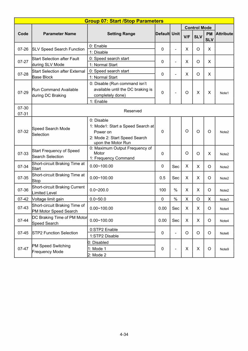
4-34
Group 07: Start /Stop Parameters
Code Parameter Name Setting Range Default Unit
Control Mode
AttributeV/F SLV
PM
SLV
07-26 SLV Speed Search Function 0: Enable
0 - X O X 1: Disable
07-27 Start Selection after Fault
during SLV Mode
0: Speed search start 0 - X O X
1: Normal Start
07-28 Start Selection after External
Base Block
0: Speed search start 0 - X O X
1: Normal Start
07-29 Run Command Available
during DC Braking
0: Disable (Run command isn’t
available until the DC braking is
completely done) 0 - O X X Note1
1: Enable
07-30
07-31 Reserved
07-32 Speed Search Mode
Selection
0: Disable
1: Mode1: Start a Speed Search at
Power on
2: Mode 2: Start Speed Search upon the Motor Run
0 O O O Note2
07-33 Start Frequency of Speed
Search Selection
0: Maximum Output Frequency of Motor
1: Frequency Command 0 O O X Note2
07-34 Short-circuit Braking Time at Start
0.00~100.00 0 Sec X X O Note2
07-35 Short-circuit Braking Time at
Stop 0.00~100.00 0.5 Sec X X O Note2
07-36 Short-circuit Braking Current
Limited Level 0.0~200.0 100 % X X O Note2
07-42 Voltage limit gain 0.0~50.0 0 % X O X Note3
07-43 Short-circuit Braking Time of
PM Motor Speed Search 0.00~100.00 0.00 Sec X X O Note4
07-44 DC Braking Time of PM Motor
Speed Search 0.00~100.00 0.00 Sec X X O Note4
07-45 STP2 Function Selection 0:STP2 Enable
0 - O O O Note6 1:STP2 Disable
07-47 PM Speed Switching
Frequency Mode
0: Disabled
0 - X X O Note9 1: Mode 1
2: Mode 2

4-35
Group 08 Protection Parameters
Code Parameter Name Setting Range Default Unit
Control Mode
AttributeV/F SLV
PM
SLV
08-00 Stall Prevention Function
xxx0b: Stall prevention is enabled
in acceleration.
0000b - O O O
xxx1b: Stall prevention is disabled
in acceleration.
xx0xb: Stall prevention is enabled
in deceleration.
xx1xb: Stall prevention is disabled
in deceleration.
x0xxb: Stall prevention is enabled
in operation
x1xxb: Stall prevention is disabled
in operation
0xxxb: Stall prevention in operation
decelerates based on
deceleration time 1
1xxxb: Stall prevention in operation
decelerates based on
deceleration time 2
08-01 Stall Prevention Level in
Acceleration 20~200 120 % O O O
08-02 Stall Prevention Level in
Deceleration
200V: 330~410 385 V O O O
400V: 660~820 770
08-03 Stall Prevention Level in
Operation 30~200 120 % O X X
08-04 Reserved
08-05 Selection for Motor Overload
Protection (OL1)
xxx0b: Motor Overload Protection
is disabled
0001b - O O O
xxx1b: Motor Overload Protection
is enabled
xx0xb: Cold Start of Motor
Overload
xx1xb: Hot Start of Motor Overload
x0xxb: Standard Motor
x1xxb: Special motor
0xxxb: Reserved
1xxxb: Reserved
08-06 Start-up Mode of Overload
Protection Operation (OL1)
0: Stop Output after Overload
Protection 0 - O O O
1: Continuous Operation after
Overload Protection.
08-07 Motor Overload (OL1)
Protection Level
0: Motor overload (OL1) Protection
0
0 - O O O Note3 1: Motor overload (OL1) Protection
1
2: Motor overload (OL1) Protection
2

4-36
Group 08 Protection Parameters
Code Parameter Name Setting Range Default Unit
Control Mode
AttributeV/F SLV
PM
SLV
08-08 Automatic Voltage Regulation
(AVR)
0: Enable 0 - O O O
1: Disable
08-09 Selection of Input Phase Loss
Protection
0: Disable 0 - O O O
1: Enable
08-10 Selection of Output Phase
Loss Protection
0: Disable 0 - O O O
1: Enable 08-11 08-12 Reserved
08-13 Selection of Over-Torque
Detection
0: Over-Torque Detection is
Disabled.
0 - O O O 1: Start to Detect when Reaching
the Set Frequency.
2: Start to Detect when the
Operation is Begun.
08-14 Selection of Over-Torque
Operation
0: Deceleration to Stop when Over-
Torque is Detected.
0 - O O O
1: Display Warning when Over-
Torque is Detected. Go on
Operation.
2: Coast to Stop when Over Torque
is Detected
08-15 Level of Over-Torque
Detection 0~300 150 % O O O
08-16 Time of Over-Torque
Detection 0.0~10.0 0.1 Sec O O O
08-17 Selection of Low-Torque
Detection
0: Low-Torque Detection is
Disabled.
0 - O O O 1: Start to Detect when Reaching
the Set Frequency.
2: Start to Detect when the
Operation is Begun.
08-18 Selection of Low-Torque
Operation
0: Deceleration to Stop when Low-
Torque is Detected.
0 - O O O
1: Display Warning when Low-
Torque is Detected. Go on
Operation.
2: Coast to Stop when Low-Torque
is Detected
08-19 Level of Low-Torque
Detection 0~300 30 % O O O
08-20 Time of Low-Torque Detection 0.0~10.0 0.1 Sec O O O
08-21 Limit of Stall Prevention in Acc
over Base Speed 1~100 50 % O O O
08-22 Stall Prevention Detection
Time in Operation 2~100 100 ms O O O
08-23 Ground Fault (GF) Selection 0: Disable
0 - O O O 1: Enable

4-37
Group 08 Protection Parameters
Code Parameter Name Setting Range Default Unit
Control Mode
AttributeV/F SLV
PM
SLV
08-24 Operation Selection of
External Fault
0: Deceleration to Stop
0 - O O O 1: Coast to Stop
2: Continuous Operation
08-25 Detection selection of
External Fault
0: Immediately Detect when the
Power is Supplied. 0 - O O O
1: Start to Detect during Operation 08-26
~ 08-29
Reserved
08-30 Selection of Run Permissive
Function
0: Deceleration to Stop 0 - O O O
1: Coast to Stop 08-31
~ 08-34
Reserved
08-35 Fault Selection of Motor
Overheat
0: Disable
0 - O O O 1: Deceleration to Stop
2: Coast to Stop
08-36 Time Coefficient of PTC Input
Filter 0.00 ~ 5.00 2 Sec O O O
08-37 Fan Control Function (Note)
0: Start at Operation
0 - O O O 1: Permanent Start
2: Start at High Temperature
08-38 Delay Time of Fan Off 0~600 60 Sec O O O
08-39 Delay Time of Motor Overheat
Protection 1~300 60 Sec O O O
08-42 PTC Trip Level 0.1~10.0 0.7 V O O O Note1
08-43 PTC Reset Level 0.1~10.0 0.3 V O O O Note1
08-45 PTC Disconnection Detection
0: Disable
0 - O O O Note3 1: Warning
2: Fault
08-46 Temperature Agree Level 0~254°C 0 °C O O O Note6
08-47 Temperature Reset Level 0~254°C 0 °C O O O Note6
08-48 Selection of Fire Mode 0: Disable
1: Enable 0 - O O O Note6
08-49 Multi-Function Input Terminal
Status of Fire Mode
0:Reset after Power Off
1:Reset after Terminal Removed0 - O O O Note6
08-50 Multi-Function Terminal
Status of Fire Mode
XXX0b: S6 A contact
XXX1b: S6 B contact 0000b - O O O Note6
08-51 Motor Speed Setting Source
of Fire Mode
0:Fire Mode Speed(08-52)
1:PID Control
2:AI2 0 - O O O Note6
08-52 Motor Speed of Fire Mode 0.00~100.00 100.00 % O O O Note6
08-53 PID Detection Level of Fire
Mode 0~100 0 % O O O Note6
08-54 Delay Time of Fire Mode PID
Loss 0.0~10.0 1.0 s O O O Note6
08-55 PID Feedback Loss Detection 0:Keep Running 1 - O O O Note6

4-38
Group 08 Protection Parameters
Code Parameter Name Setting Range Default Unit
Control Mode
AttributeV/F SLV
PM
SLV
Selection of Fire Mode 1:Fire Mode Speed (08-52)
2:Maximum Output Frequency
(01-02)
08-56 Detection Level of Fire Mode
AI2 Signal 0.0~100 80.0 % O O O Note6
08-57 Delay Time of Fire Mode AI2
Signal Loss 0.0~10.0 1.0 s O O O Note6
08-58 Selection of Fire Mode AI2
Signal Loss
0:Keep Running
1:Fire Mode Speed (08-52)
2:Maximum Output Frequency
(01-02)
1 - O O O Note6
08-59 Fire Mode Motor Direction 0:Forward
1:Reverse 0 - O O O Note6
08-60 Fire Mode Password 00000~65534 0 - O O O Note6
Note: 1. Standard H & C type, IP20 frame 6~9 do not have 08-37 function.
2. Enhanced E & G type, IP20 frame 6~8 do not have “Start at High Temperature” function.(08-37=2)
3. Enhanced E & G type, IP20 frame 9 do not have 08-37 function.
Group 09: Communication Parameters
Code Parameter Name Setting Range Default Unit
Control Mode
AttributeV/F SLV
PM
SLV
09-00 INV Communication Station
Address 1~31 1 - O O O *2
09-01
Communication Mode
Selection
0: MODBUS
0 - O O O 1: BACNET
2: METASYS
3: PUMP in Parallel Connection
09-02 Baud Rate Setting (bps)
0:1200
4 - O O O *2
*6
1:2400
2:4800
3:9600
4:19200
5:38400
09-03 Stop Bit Selection 0:1 Stop Bit
0 - O O O *2 1: 2 Stop Bit
09-04 Parity Selection
0: No Parity
0 - O O O *2 1: Even Bit
2: Odd Bit
09-05 Communications Data Bits
Selection
0: 8 bits data 0 - O O O Note1
1: 7 bits data
09-06 Communication Error
Detection Time 0.0~25.5 0.0 S O O O
09-07 Fault Stop Selection 0: Deceleration to Stop Based on 3 - O O O

4-39
Group 09: Communication Parameters
Code Parameter Name Setting Range Default Unit
Control Mode
AttributeV/F SLV
PM
SLV
Deceleration Time 1 when
Communication Fault Occurs.
1: Coast to Stop when
Communication Fault Occurs.
2: Deceleration to Stop Based on
Deceleration Time 2 when
Communication Fault Occurs.
3: Keep Operating when
Communication Fault Occurs.
4. Run the Frequency Command
given by AI2
09-08 Comm. Fault Tolerance Count 1~20 1 - O O O
09-09 Waiting Time 5~65 5 ms O O O
09-10 Device Instance Number 1 ~ 254 1 - O O O
Note: Parameters in group 09 are not affected by parameter 13-08 (initialization).
Group 10: PID Parameters
Code Parameter Name Setting Range Default Unit
Control Mode
AttributeV/F SLV
PM
SLV
10-00 PID Target Value Source
Setting
0: PUMP or HVAC function given
(refer to group 23)
1 - O O O
1: AI1 Given
2: AI2 Given
3: Reserved
4: 10-02 Given
5: Reserved Note
6: Frequency Command (00-05)
Note
7: Multi-speed Frequency
Command Note4
10-01 PID Feedback Value Source
Setting
1: AI1 Given
2 - O O O 2: AI2 Given
3: Reserved
4: AI1 - AI2 Given
10-02 PID Target Value 0.0~100.0 0.0 % O O O
10-03 PID Control Mode
xxx0b: PID Disable
0000b - O O O
xxx1b: PID Enable
xx0xb: PID Positive Characteristic
xx1xb: PID Negative Characteristic
x0xxb: PID Error Value of D
Control
x1xxb: PID Feedback Value of D
Control
0xxxb: PID Output
1xxxb: PID Output + Frequency

4-40
Group 10: PID Parameters
Code Parameter Name Setting Range Default Unit
Control Mode
AttributeV/F SLV
PM
SLV
Command
10-04 Feedback Gain 0.01~10.00 1.00 - O O O *1
10-05 Proportional Gain (P) 0.00~10.00 3.00 - O O O *1
10-06 Integral Time (I) 0.00~100.00 0.50 s O O O *1
10-07 Differential Time (D) 0.00~10.00 0.00 s O O O *1
10-08 Reserved
10-09 PID Bias -100.0~100.0 0 % O O O *1
10-10 PID Primary Delay Time 0.00~10.00 0.00 s O O O *1
10-11 PID Feedback Loss Detection
Selection
0: Disable
0 - O O O 1: Warning
2: Fault
10-12 PID Feedback Loss Detection
Level 0~100 0 % O O O
10-13 PID Feedback Loss Detection
Time 0.0~10.0 1.0 s O O O
10-14 PID Integral Limit 0.0~100.0 100.0 % O O O *1 10-15 10-16 Reserved
10-17 Start Frequency of PID Sleep 0.00~599.00 (Note8) 30.00 Hz O O O
10-18 Delay Time of PID Sleep 0.0~255.5 0.0 s O O O
10-19 Frequency of PID Waking up 0.00~599.00 (Note8) 0.00 Hz O O O
10-20 Delay Time of PID Waking up 0.0~255.5 0.0 s O O O 10-21 10-22 Reserved
10-23 PID Limit 0.00~100.0 100.0 % O O O *1
10-24 PID Output Gain 0.0~25.0 1.0 - O O O
10-25 PID Reversal Output
Selection
0: Do not Allow Reversal Output 0 - O O O
1: Allow Reversal Output
10-26 PID Target Acceleration/
Deceleration Time 0.0~25.5 0.0 s O O O
10-27 PID Feedback Display Bias 0~9999 0 - O O O
10-28 Reserved
10-29 PID Sleep Selection
0: Disable
1 - O O O 1: Enable
2: Set by DI
10-30 Upper Limit of PID Target 0.0 ~ 100.0 100.0 % O O O
10-31 Lower Limit of PID Target 0.0 ~ 100.0 0.0 % O O O
10-32 PID Switching Function
0: PID1
0 O O O
1: PID2
2: Set by DI
3: Switch to PID2 when RTC Timer
Enables
10-33 PID Maximum Feedback
Value 1~10000 999 - O O O
10-34 PID Decimal Width 0~4 1 - O O O
10-35 PID Unit 0: %
0 - O O O *6 1: FPM

4-41
Group 10: PID Parameters
Code Parameter Name Setting Range Default Unit
Control Mode
AttributeV/F SLV
PM
SLV
2: CFM
3: PSI
4: GPH
5: GPM
6: IN
7: FT
8: /s
9: /m
10: /h
11: °F
12: inW
13: HP
14: m/s
15: MPM
16: CMM
17: W
18: KW
19: m
20: °C
21: RPM
22: Bar
23: Pa
24: KPa Note4
10-36 PID2 Proportional Gain (P) 0.00~10.00 3.00 - O O O *1
10-37 PID2 Integral Time (I) 0.0~100.0 0.50 s O O O *1
10-38 PID2 Differential Time (D) 0.00~10.00 0.00 s O O O *1
10-39 PID Output Frequency Setting
during disconnection 00.00~599.00 (Note8) 30.00 Hz O O O *6
10-40 Compensation Frequency
Selection of PID Sleep
0: Disable 0 - O O O Note1
1: Enable
10-41
~
10-43
Reserved
10-44 Precharge Frequency 0.0~120.0 0 Hz O O O Note3
10-45 Precharge Time 0~250 0 Sec O O O Note3 10-46 Precharge Target Level 0~10000 0 - O O O Note3 10-47 Proportional Gain 3(P) 0.00~10.00 3.00 O O O Note6
10-48 Integral Time 3(I) 0.00~100.00 0.50 Sec O O O Note6
10-49 Differential Time 3(D) 0.00~10.00 0.00 Sec O O O Note6

4-42
Group 11: Auxiliary Parameters
Code Parameter Name Setting Range Default Unit
Control Mode
AttributeV/F SLV
PM
SLV
11-00 Direction Lock Selection
0: Allow Forward and Reverse
Rotation 1 - O O O
1: Only Allow Forward Rotation
2: Only Allow Reverse Rotation
11-01 Carrier Frequency 0: Carrier Output Frequency Tuning
KVA*a - O O O 1: 1~16: 1~16KHz
11-02 Soft PWM Function Selection
0: Disable 1(V/f)
0(SLV&
PMSLV)
- O O O 1: Soft PWM Function 1
2: Soft PWM Function 2
11-03 Automatic carrier lowering
selection
0: Disable 0 - O X X
1: Enable
11-04 S-curve Time Setting at the
Start of Acceleration 0.00~2.50 0.20 s O O O
11-05 S-curve Time Setting at the
End of Acceleration 0.00~2.50 0.20 s O O O
11-06 S-curve Time Setting at the
Start of Deceleration 0.00~2.50 0.20 s O O O
11-07 S-curve Time Setting at the
End of Deceleration 0.00~2.50 0.20 s O O O
11-08 Jump Frequency 1 0.0~599.00 (Note8) 0.0 Hz O O O
11-09 Jump Frequency 2 0.0~599.00 (Note8) 0.0 Hz O O O
11-10 Jump Frequency 3 0.0~599.00 (Note8) 0.0 Hz O O O
11-11 Jump Frequency Width 0.0~25.5 1.0 Hz O O O
11-12 Manual Energy Saving Gain 0~100 80 % O X X
11-13 Automatic Return Time 0~120 60 Sec O O O *6 11-14
~ 11-17
Reserved
11-18 Manual Energy Saving Frequency 0.00~599.00 (Note8) 0.00 Hz O X X
11-19 Automatic Energy Saving Function
0: Disabled 0 - O X X 1: Enabled
11-20 Filter Time of Automatic
Energy Saving 0~200 140 ms O X X
11-21 Voltage Upper Limit of Energy
Saving Tuning 0~100 100 % O X X
11-22 Adjustment Time of
Automatic Energy Saving 0~5000 20 ms O X X *1
11-23 Detection Level of Automatic
Energy Saving 0~100 10 % O X X
11-24 Coefficient of Automatic
Energy Saving 0.00~655.34 KVA*a - O X X
11-25 ~
11-27 Reserved
11-28 Frequency Gain of Overvoltage Prevention 2 1~200 100 % O X X Note4

4-43
Group 11: Auxiliary Parameters
Code Parameter Name Setting Range Default Unit
Control Mode
AttributeV/F SLV
PM
SLV
11-29 Auto De-rating Selection 0: Disable
0 - O X X 1: Enable
11-30 Variable Carrier Frequency
Max. Limit 2~16 KVA*a KHz O X X
11-31 Variable Carrier Frequency
Min. Limit 1~16 KVA*a KHz O X X
11-32 Variable Carrier Frequency
Proportional Gain 00~99 00 - O X X
11-33 Rise Amount of DC Voltage
Filter 0.1~10.0 0.1 Vdc O X X
Note4
*1
11-34 Fall Amount of DC Voltage
Filter 0.1~10.0 5.0 Vdc O X X
Note4
*1
11-35 Dead band Level of DC
Voltage Filter 0.0~99.0 10.0 Vdc O X X
Note4
*1
11-36 Frequency Gain of OV
Prevention 0.000~1.000 0.050 - O X X
Note2
*1
11-37 Frequency Limit of OV
Prevention 0.00~599.00 (Note8) 5.00 Hz O X X Note2
11-38 Deceleration Start Voltage of OV Prevention
200V: 200~400V 400V: 400~800V
200V: 300
400V: 700
V O X X Note2
11-39 Deceleration Stop Voltage of
OV Prevention
200V: 300~400V
400V: 600~800V
220V:
350
440V:
750
V O X X Note2
11-40 OV Prevention Selection
0: Disable
1: OV Prevention Mode 1
2: OV Prevention Mode 2
3: OV Prevention Mode 3
0 - O X X Note2
11-41 Reference Frequency Loss
Detection
0: Deceleration to Stop when
Reference Frequency
Disappears 0 - O O O
1: Operation is Set by 11-42 when
Reference Frequency
Disappears
11-42 Reference Frequency Loss
Level 0.0~100.0 80.0 % O O O
11-43 Hold Frequency at Start 0.0~599.00 (Note8) 0.0 Hz O O O
11-44 Frequency Hold Time at Start 0.0~10.0 0.0 s O O O
11-45 Hold Frequency at Stop 0.0~599.00 (Note8) 0.0 Hz O O O
11-46 Frequency Hold Time at Stop 0.0~10.0 0.0 s O O O
11-47 EB Deceleration Time 0.0~25.5 0.0 s O X X *1
11-48 KEB Detection Level 200V: 190~210 200
V O X X 400V: 380~420 400

4-44
Group 11: Auxiliary Parameters
Code Parameter Name Setting Range Default Unit
Control Mode
AttributeV/F SLV
PM
SLV
11-49 11-50 Reserved
11-51 Braking Selection of Zero
Speed
0: Disable 0 - O X X
1: Enable
11-52 11-53 Reserved
11-54 Initialization of Cumulative
Energy
0: Do not Clear Cumulative Energy0 - O O O *1
1: Clear Cumulative Energy
11-55 STOP Key Selection
0: Stop Key is Disabled when the
Operation Command is not
Provided by Keypad. 1 - O O O
1: Stop Key is Enabled when the
Operation Command is not
Provided by Keypad.
11-56 UP/DOWN Selection
0: When UP/DOWN in Keypad is
Disabled, it will be Enabled if
Pressing ENTER after
Frequency Modification. 0 - O O O
1: When UP/DOWN in Keypad is
Enabled, it will be Enabled upon
Frequency Modification.
11-57 Reserved
11-58 Record Reference Frequency 0: Disable
0 - O O O *1 1: Enable
11-59 Gain of Preventing Oscillation 0.00~2.50 0.01 O X X *7
11-60 Upper Limit of Preventing
Oscillation 0~100 30 % O X X *7
11-61 Time Parameter of
Preventing Oscillation 0~100 0 O X X *7
11-62 Prevention of Oscillation
Selection
0: Mode 1
1: Mode 2
2: Mode 3
1 O X X *7
11-63 Flux-Strengthening Selection 0: Disable
1 X O X Note1 1: Enable
11-64 Acceleration Speed Gain
Adjustment 0.1~10.0 1.0 - O X X Note3
11-65 Target Main Circuit Voltage 200V: 200V~400V 370
- O X X Note3 400V: 400V~800V 740
11-66 2 Phase/ 3 Phase PWM
Switch Frequency 6.00~60.00 20 Hz O O O Note3
11-67 Detection Range at Soft PWM
Function 2 0~12000 0 Hz X O O Note3
11-68 Detecting Start Frequency at
Soft PWM Function 2 6.00~60.00 20 Hz X O O Note3
11-69 Gain of Preventing Oscillation
3 0.00~200.00 5.00 % O X X Note2

4-45
Group 11: Auxiliary Parameters
Code Parameter Name Setting Range Default Unit
Control Mode
AttributeV/F SLV
PM
SLV
11-70 Upper Limit of Preventing Oscillation 3 0.01~100.00 5.00 % O X X Note2
11-71 Time Parameter of
Preventing Oscillation 3 0~30000 100 ms O X X Note2
11-72 Switch Frequency 1 for
Preventing Oscillation Gain 0.01~300.00 30.00 Hz O X X Note2
11-73 Switch Frequency 2 for
Preventing Oscillation Gain 0.01~300.00 50.00 Hz O X X Note2
*a: KVA means the default value of this parameter will be changed by different capacities of inverter.

4-46
Group 12: Monitoring Parameters
Code Parameter Name Setting Range Default Unit
Control Mode
AttributeV/F SLV
PM
SLV
12-00 Display Screen Selection
(LED)
00000~77777
From the leftmost bit, it displays the
screen when press DSP key in
order.
0: No display
1: Output Current
2: Output Voltage
3: DC Bus Voltage
4: Heatsink Temperature
5: PID Feedback
6: AI1 Value
7: AI2 Value
00321 - O O O *1
*5
12-01 PID Feedback Display Mode
(LED)
0: Display the Feedback Value by
Integer (xxx)
0 O O O *5
1: Display the Feedback Value by
the Value with First Decimal
Place (xx.x)
2: Display the Feedback Value by
the Value with Second Decimal
Place (x.xx)
12-02 PID Feedback Display Unit
Setting (LED)
0: xxxxx (no unit)
0 O O O *5 1: xxxPb (pressure)
2: xxxFL (flow)
12-03 Line Speed Display (LED) 0~60000 1500/
1800
RP
M O O O *5
12-04 Line Speed Display Mode
(LED)
0: Display Inverter Output Frequency
0 O O O *1
*5
1: Line Speed Display at
Integer.(xxxxx)
2: Line Speed Display at One
Decimal Place. (xxxx.x)
3: Line Speed Display at Two
Decimal Places. (xxx.xx)
4: Line Speed Display at Three
Decimal Places. (xx.xxx)

4-47
Group 12: Monitoring Parameters
Code Parameter Name Setting Range Default Unit
Control Mode
AttributeV/F SLV
PM
SLV
12-05 Status display of digital input
terminal (LED / LCD)
LED display is shown as below
no input
correspondences to input and
output
LCD display is shown as below
00 00 00 0 0
Input Terminal(S6)Input Terminal(S5)Input Terminal(S4)Input Terminal(S3)Input Terminal(S2)Input Terminal(S1)
0:OPEN 1:CLOSE
0
Output Terminal(R3)Output Terminal(R2)Output Terminal(R1)
- - O O O
12-06 ~
12-10 Reserved
12-11 Output Current of Current
Fault
Display the output current of
current fault - A O O O
12-12 Output Voltage of Current
Fault
Display the output voltage of
current fault - V O O O
12-13 Output Frequency of Current
Fault
Display the output frequency of
current fault - Hz O O O
12-14 DC Voltage of Current Fault Display the DC voltage of current
fault - V O O O
12-15 Frequency Command of
Current Fault
Display the frequency command of
current fault - Hz O O O
12-16 Frequency Command
If LED enters this parameter, it only
allows monitoring frequency
command.
- Hz O O O
12-17 Output Frequency Display the current output
frequency - Hz O O O
12-18 Output Current Display the current output current - A O O O
12-19 Output Voltage Display the current output voltage - V O O O
12-20 DC Voltage Display the current DC voltage - V O O O
12-21 Output Power Display the current output power - kW O O O

4-48
Group 12: Monitoring Parameters
Code Parameter Name Setting Range Default Unit
Control Mode
AttributeV/F SLV
PM
SLV
12-22 Motor’s Rotation Speed
Display motor’s current rotation
speed
in VF/SLV mode
Motor’s rotation speed = output
power x(120/motor’s pole number)
In PG/SV mode, motor’s rotation
speed is calculated by feedback
frequency.
Max limit is 65535
- rpm O O O
12-23 Output Power Factor Display the current output power
factor - - O O O
12-24 Control Mode
Display control mode
0 : VF
2 : SLV
5 : PM SLV
- - O O O
12-25 AI1 Input
Display the current Al1 input
(0V corresponds to 0%, 10V
corresponds to 100%,)
- % O O O
12-26 AI2 Input
Display the current Al2 input
(0V or 4mA corresponds to 0%,
10V or 20mA corresponds to
100%)
- % O O O
12-27 Motor Torque
Display the current torque
command
(100% corresponds to motor
torque )
- % X O O
12-28 Motor Torque Current (Iq) Display the current q-axis current - % X O O
12-29 Motor Excitation Current (Id) Display the current d-axis current - % X O O
12-30 ~
12-35 Reserved
12-36 PID Input
Display input error of the PID
controller (PID target value - PID
feedback)
(100% corresponds to the
maximum frequency set by 01-02
or 01-16)
- % O O O
12-37 PID Output
Display output of the PID controller
(100% corresponds to the
maximum frequency set by 01-02
or 01-16)
- % O O O
12-38 PID Setting
Display the target value of the PID
controller
(100% corresponds to the
maximum frequency set by 01-02
or 01-16)
- % O O O

4-49
Group 12: Monitoring Parameters
Code Parameter Name Setting Range Default Unit
Control Mode
AttributeV/F SLV
PM
SLV
12-39 PID Feedback
Display the feedback value of the
PID controller
(100% corresponds to the
maximum frequency set by 01-02
or 01-16)
- % O O O
12-40 Reserved
12-41 Heatsink Temperature Display the heatsink temperature
of IGBT temperature. - O O O
12-42 RS-485 Error Code
LCD Display: 00 00 00 0 0
1 : C R C E rro r1 : D ata le n g th E rro r1 : D ata F u n c tio n E rro r1 : P arity E rro r1 : O v erru n E rro r1 : F ram in g E rro r1 : T im e O u t E rro rR e se rv e d
LED Display: (without any error)
LED Display: (with certain error)
1: CRC Error1: Data length Error1: Data Function Error1: Parity Error
1: Framing Error1: Time out ErrorReserved
1: Overrun Error
- - O O O *7
12-43 Inverter Status
LCD Display:
00 00 00 0 0
1: Inverter ready
1: During running
1: During zero speed
1: During speed agree
1: During fault detection (minor fault)
1: During fault detection (major fault)
Reserved
LED Display:
Inverter ready 1
Running 2
Zero Speed 4
Frequency Agree 8
Warning 16
Error 32
Inverter status display is the
summed up value. Ex: Display of
the value 6 means the inverter is
running in zero speed.
101B - O O O

4-50
Group 12: Monitoring Parameters
Code Parameter Name Setting Range Default Unit
Control Mode
AttributeV/F SLV
PM
SLV
12-44 Reserved
12-45 Recent Fault Message Display current fault message - - O O O
12-46 Previous Fault Message Display previous fault message - - O O O
12-47 Previous Two Fault Messages Display previous two fault
messages - - O O O
12-48 Previous Three Fault
Messages
Display previous three fault
messages - - O O O
12-49 Previous Four Fault Messages Display previous four fault
messages - - O O O
12-50 DIO Status of Current Fault
Display the DI/DO status of current
fault
Description is similar to 12-05
- - O O O
12-51 Inverter Status of Current Fault
Display the inverter status of
current fault
Description is similar to 12-43
- - O O O
12-52 Trip Time 1 of Current Fault Display the operation time of
current fault, 12-53 is the days,
while 12-52 is the remaining hours.
- Hr O O O
12-53 Trip Time 2 of Current Fault - day O O O
12-54 Frequency Command of
Previous Fault
Display frequency command of
previous fault - Hz O O O
12-55 Output Frequency of Previous
Fault
Display output frequency of
previous fault - Hz O O O
12-56 Output Current of Previous
Fault
Display output current of previous
fault - A O O O
12-57 Output Voltage of Previous
Fault
Display output voltage of previous
fault - V O O O
12-58 DC Voltage of Previous Fault Display DC voltage of previous
fault - V O O O
12-59 DIO Status of Previous Fault
Display DI/DO status of previous
fault
Description is similar to 12-05
- - O O O
12-60 Inverter Status of Previous
Fault
Display inverter status of
previous fault
Description is similar to 12-43
- - O O O
12-61 Trip time 1 of last fault Display the operation time of last
time’s fault, 12-62 is the days,
while 12-61 is the remaining hours.
- Hr O O O
12-62 Trip time 2 of last fault - day O O O
12-63 Recent warning messages Display the recent warning
messages - - O O O
12-64 Previous warning message Display the previous warning
messages - - O O O
12-65 12-66 Reserved
12-67 Accumulative Energy (kWHr) 0.0 ~ 999.9 kWH
r O O O
12-68 Accumulative Energy (MWHr) 0 ~ 60000 MW
Hr O O O

4-51
Group 12: Monitoring Parameters
Code Parameter Name Setting Range Default Unit
Control Mode
AttributeV/F SLV
PM
SLV
12-69 Accumulative Electricity Price
($) 0 ~ 9999 $ O O O
12-70 Accumulative Electricity Price
(10000$) 0 ~ 60000 $ O O O
12-71 Flow Meter Feedback 1 ~ 50000 GP
M O O O
12-72 RTC Date 12.01.01 ~ 99.12.31 12.01.0
1 O O O
12-73 RTC Time 00:00 ~ 23:59 00:00 O O O
12-74 Operating Pressure Setting 0.01 ~ 25.50 2.00 PSI O X X
12-75 Pressure Feedback Value 0.01 ~ 25.50 - PSI O X X
12-76 Non-Load Voltage 0.0 ~ 600.0 - V X O X
12-77 Flow Meter Target Setting 1 ~ 50000 - GP
M O O O *7
12-78 Reserved
12-79 Pulse Input Percentage 0.0~100.0 - % O O O *7
12-81 Relay Card Display ON: LCD display is 1
OFF: LCD display is 0 - - O O O Note5
12-82 Motor Load 0 ~ 200.0 - % O O O Note6
12-85 AI3 Input
Display the current Al3 input
(-10V corresponds to -100%, 10V
corresponds to 100%)
- % O O O *10
* Models of inverter ratings above 200V 60HP (including 60HP) and 400V 100HP (including 100HP) in
IP20 enclosure do not support functions of heatsink temperature display. All models in IP55 enclosure
support functions of heatsink temperature display.
* Maximum upper limit in motor speed (rpm) of parameter 12-22 is 65534
Group 13 Maintenance Function Group
Code Parameter Name Setting Range Default Unit
Control Mode
AttributeV/F SLV
PM
SLV
13-00 Inverter Rating Selection 00H~FFH - - O O O *4
13-01 Software Version 0.00-9.99 - - O O O *4
13-02 Clear Cumulative Operation
Hours Function
0: Disable to Clear Cumulative
Operation Hours
1: Clear Cumulative Operation
Hours
0 O O O *1
13-03 Cumulative Operation Hours 1 0~23 - hr O O O *4
13-04 Cumulative Operation Hours 2 0~65534 - day O O O *4
13-05 Selection of Accumulative
Operation Time
0: Accumulative time in power on 0 O O O *1 1: Accumulative time in operation
13-06 Parameters Locked
0: Only parameter 13-06 and frequency setting parameters in main screen are writable 2 O O O *1
1: Only user parameter is enabled. 2: All parameters are writable.

4-52
Group 13 Maintenance Function Group
Code Parameter Name Setting Range Default Unit
Control Mode
AttributeV/F SLV
PM
SLV
13-07 Parameter Password Function 00000~65534 00000 - O O O
13-08 Restore Factory Setting
0: No Initialization
0 - O O O
2: 2 wire Initialization
(220/440V, 60Hz)
3: 3 wire Initialization
(220/440V, 60Hz)
4: 2 wire Initialization
(230/415V, 50Hz)
5: 3 wire Initialization
(230/415V, 50Hz)
6: 2 wire Initialization
(200/380V, 50Hz)
7: 3 wire Initialization
(200/380V, 50Hz)
8: PLC Initialization
9: 2 Wire Initialization
(230V/460V, 60Hz)
10: 3 Wire Initialization
(230V/460V, 60Hz)
11: 2 wire Initialization,
230V/400V, 60Hz
12: 3 wire Initialization,
230V/400V, 60Hz
13: 2 wire Initialization,
230V/400V, 50Hz
14: 3 wire Initialization,
230V/400V, 50Hz
15: 2 wire Initialization,
(220/380V, 50Hz) Note4
16: 3 wire Initialization
(220/380V, 50Hz) Note4
13-09 Fault History Clearance
Function
0: Do not Clear Fault History 0 - O O O *1
1: Clear Fault History
13-10 Parameter Password Function
2 0 ~ 9999 0 O O O
13-11 C/B CPLD Ver. 0.00~9.99 - O O O *7
13-12 Option Card Id 0~255 0 O O O *7
13-13 Option Card CPLD Ver. 0.00~9.99 - O O O *7
13-14 Fault Storage Selection
0: Auto Restart Fault Messages are
not saved in fault history. 1 O O O Note1
1: Auto Restart Fault Messages are
saved in fault history.
13-15
~
13-20
Reserved
13-21 Previous Fault Message Display Previous Fault Message - - O O O Note2
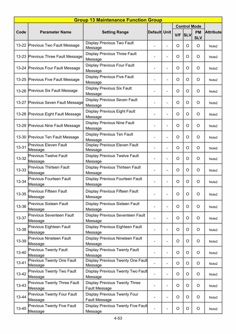
4-53
Group 13 Maintenance Function Group
Code Parameter Name Setting Range Default Unit
Control Mode
AttributeV/F SLV
PM
SLV
13-22 Previous Two Fault Message Display Previous Two Fault Message - - O O O Note2
13-23 Previous Three Fault Message Display Previous Three Fault
Message - - O O O Note2
13-24 Previous Four Fault Message Display Previous Four Fault
Message - - O O O Note2
13-25 Previous Five Fault Message Display Previous Five Fault
Message - - O O O Note2
13-26 Previous Six Fault Message Display Previous Six Fault
Message - - O O O Note2
13-27 Previous Seven Fault MessageDisplay Previous Seven Fault
Message - - O O O Note2
13-28 Previous Eight Fault Message Display Previous Eight Fault
Message - - O O O Note2
13-29 Previous Nine Fault Message Display Previous Nine Fault
Message - - O O O Note2
13-30 Previous Ten Fault Message Display Previous Ten Fault
Message - - O O O Note2
13-31 Previous Eleven Fault Message
Display Previous Eleven Fault Message - - O O O Note2
13-32 Previous Twelve Fault
Message
Display Previous Twelve Fault
Message - - O O O Note2
13-33 Previous Thirteen Fault
Message
Display Previous Thirteen Fault
Message - - O O O Note2
13-34 Previous Fourteen Fault
Message
Display Previous Fourteen Fault
Message - - O O O Note2
13-35 Previous Fifteen Fault
Message
Display Previous Fifteen Fault
Message - - O O O Note2
13-36 Previous Sixteen Fault
Message
Display Previous Sixteen Fault
Message - - O O O Note2
13-37 Previous Seventeen Fault
Message
Display Previous Seventeen Fault
Message - - O O O Note2
13-38 Previous Eighteen Fault
Message
Display Previous Eighteen Fault
Message - - O O O Note2
13-39 Previous Nineteen Fault
Message
Display Previous Nineteen Fault
Message - - O O O Note2
13-40 Previous Twenty Fault
Message
Display Previous Twenty Fault
Message - - O O O Note2
13-41 Previous Twenty One Fault Message
Display Previous Twenty One Fault Message - - O O O Note2
13-42 Previous Twenty Two Fault
Message
Display Previous Twenty Two Fault
Message - - O O O Note2
13-43 Previous Twenty Three Fault
Message
Display Previous Twenty Three
Fault Message - - O O O Note2
13-44 Previous Twenty Four Fault
Message
Display Previous Twenty Four
Fault Message - - O O O Note2
13-45 Previous Twenty Five Fault
Message
Display Previous Twenty Five Fault
Message - - O O O Note2

4-54
Group 13 Maintenance Function Group
Code Parameter Name Setting Range Default Unit
Control Mode
AttributeV/F SLV
PM
SLV
13-46 Previous Twenty Six Fault
Message
Display Previous Twenty Six Fault
Message - - O O O Note2
13-47 Previous Twenty Seven Fault
Message
Display Previous Twenty Seven
Fault Message - - O O O Note2
13-48 Previous Twenty Eight Fault
Message
Display Previous Twenty Eight
Fault Message - - O O O Note2
13-49 Previous Twenty Nine Fault
Message
Display Previous Twenty Nine
Fault Message - - O O O Note2
13-50 Previous Thirty Fault Message Display Previous Thirty Fault
Message - - O O O Note2
Group 14: PLC Setting Parameters
Code Parameter Name Setting Range Default Unit
Control Mode
AttributeV/F SLV
PM
SLV
14-00 T1 Set Value 1 0~9999 0 - O O O Note7
14-01 T1 Set Value 2(Mode 7) 0~9999 0 - O O O Note7 14-02 T2 Set Value 1 0~9999 0 - O O O Note7 14-03 T2 Set Value 2(Mode 7) 0~9999 0 - O O O Note7 14-04 T3 Set Value 1 0~9999 0 - O O O Note7 14-05 T3 Set Value 2(Mode 7) 0~9999 0 - O O O Note7 14-06 T4 Set Value 1 0~9999 0 - O O O Note7 14-07 T4 Set Value 2(Mode 7) 0~9999 0 - O O O Note7 14-08 T5 Set Value 1 0~9999 0 - O O O Note7 14-09 T5 Set Value 2(Mode 7) 0~9999 0 - O O O Note7 14-10 T6 Set Value 1 0~9999 0 - O O O Note7 14-11 T6 Set Value 2(Mode 7) 0~9999 0 - O O O Note7 14-12 T7 Set Value 1 0~9999 0 - O O O Note7 14-13 T7 Set Value 2(Mode 7) 0~9999 0 - O O O Note7 14-14 T8 Set Value 1 0~9999 0 - O O O Note7 14-15 T8 Set Value 2(Mode 7) 0~9999 0 - O O O Note7 14-16 C1 Set Value 0~65534 0 - O O O Note7 14-17 C2 Set Value 0~65534 0 - O O O Note7 14-18 C3 Set Value 0~65534 0 - O O O Note7 14-19 C4 Set Value 0~65534 0 - O O O Note7 14-20 C5 Set Value 0~65534 0 - O O O Note7 14-21 C6 Set Value 0~65534 0 - O O O Note7 14-22 C7 Set Value 0~65534 0 - O O O Note7 14-23 C8 Set Value 0~65534 0 - O O O Note7 14-24 AS1 Set Value 1 0~65534 0 - O O O Note7 14-25 AS1 Set Value 2 0~65534 0 - O O O Note7 14-26 AS1 Set Value 3 0~65534 0 - O O O Note7 14-27 AS2 Set Value 1 0~65534 0 - O O O Note7 14-28 AS2 Set Value 2 0~65534 0 - O O O Note7 14-29 AS2 Set Value 3 0~65534 0 - O O O Note7 14-30 AS3 Set Value 1 0~65534 0 - O O O Note7

4-55
Group 14: PLC Setting Parameters
Code Parameter Name Setting Range Default Unit
Control Mode
AttributeV/F SLV
PM
SLV
14-31 AS3 Set Value 2 0~65534 0 - O O O Note7 14-32 AS3 Set Value 3 0~65534 0 - O O O Note7 14-33 AS4 Set Value 1 0~65534 0 - O O O Note7 14-34 AS4 Set Value 2 0~65534 0 - O O O Note7 14-35 AS4 Set Value 3 0~65534 0 - O O O Note7 14-36 MD1 Set Value 1 0~65534 1 - O O O Note7 14-37 MD1 Set Value 2 0~65534 1 - O O O Note7 14-38 MD1 Set Value 3 0~65534 1 - O O O Note7 14-39 MD2 Set Value 1 0~65534 1 - O O O Note7 14-40 MD2 Set Value 2 0~65534 1 - O O O Note7 14-41 MD2 Set Value 3 0~65534 1 - O O O Note7 14-42 MD3 Set Value 1 0~65534 1 - O O O Note7 14-43 MD3 Set Value 2 0~65534 1 - O O O Note7 14-44 MD3 Set Value 3 0~65534 1 - O O O Note7 14-45 MD4 Set Value 1 0~65534 1 - O O O Note7 14-46 MD4 Set Value 2 0~65534 1 - O O O Note7 14-47 MD4 Set Value 3 0~65534 1 - O O O Note7
Group 15: PLC Monitoring Parameters
Code Parameter Name Setting Range Default Unit
Control Mode
AttributeV/F SLV
PM
SLV
15-00 T1 Current Value 1 0~9999 0 - O O O
15-01 T1 Current Value 2 (Mode 7) 0~9999 0 - O O O
15-02 T2 Current Value 1 0~9999 0 - O O O
15-03 T2 Current Value 2 (Mode 7) 0~9999 0 - O O O
15-04 T3 Current Value 1 0~9999 0 - O O O
15-05 T3 Current Value 2 (Mode 7) 0~9999 0 - O O O
15-06 T4 Current Value 1 0~9999 0 - O O O
15-07 T4 Current Value 2 (Mode 7) 0~9999 0 - O O O
15-08 T5 Current Value 1 0~9999 0 - O O O
15-09 T5 Current Value 2 (Mode 7) 0~9999 0 - O O O
15-10 T6 Current Value 1 0~9999 0 - O O O
15-11 T6 Current Value 2 (Mode 7) 0~9999 0 - O O O
15-12 T7 Current Value 1 0~9999 0 - O O O
15-13 T7 Current Value 2 (Mode 7) 0~9999 0 - O O O
15-14 T8 Current Value 1 0~9999 0 - O O O
15-15 T8 Current Value 2 (Mode 7) 0~9999 0 - O O O
15-16 C1 Current Value 0~65534 0 - O O O
15-17 C2 Current Value 0~65534 0 - O O O
15-18 C3 Current Value 0~65534 0 - O O O
15-19 C4 Current Value 0~65534 0 - O O O
15-20 C5 Current Value 0~65534 0 - O O O
15-21 C6 Current Value 0~65534 0 - O O O
15-22 C7 Current Value 0~65534 0 - O O O

4-56
Group 15: PLC Monitoring Parameters
Code Parameter Name Setting Range Default Unit
Control Mode
AttributeV/F SLV
PM
SLV
15-23 C8 Current Value 0~65534 0 - O O O
15-24 AS1 Results 0~65534 0 - O O O
15-25 AS2 Results 0~65534 0 - O O O
15-26 AS3 Results 0~65534 0 - O O O
15-27 AS4 Results 0~65534 0 - O O O
15-28 MD1 Results 0~65534 0 - O O O
15-29 MD2 Results 0~65534 0 - O O O
15-30 MD3 Results 0~65534 0 - O O O
15-31 MD4 Results 0~65534 0 - O O O
15-32 TD Current Value 0~65534 0 - O O O

4-57
Group 16: LCD Function Parameters
Code Parameter Name Setting Range Default Unit
Control Mode
AttributeV/F SLV
PM
SLV
16-00 Main Screen Monitoring
5~82 (Parameter 12-05~12-82)
When using LCD to operate, the
monitored item displays in the first
line. (default is frequency
command)
16 - O O O *1
*6
16-01 Sub-Screen Monitoring 1
5~82 (Parameter 12-05~12-82)
When using LCD to operate, the
monitored item displays in the
second line. (default is output
frequency)
17 - O O O *1
*6
16-02 Sub-Screen Monitoring 2
5~82(Parameter 12-05~12-82)
when using LCD to operate, the
monitored item displays in the third
line. (default is output current)
18 - O O O *1
*6
16-03 Selection of Display Unit
0~39999: Determine the display way and unit of frequency command
0 - O O O
0: Frequency display unit is 0.01Hz1: Frequency display unit 0.01% 2: Rpm display; motor rotation
speed is set by the control modes to select IM (02-07)/ PM (22-03) motor poles to calculate.
3~39: Reserved 40~9999: Users specify the format, Input 0XXXX represents the display of XXXX at 100%. 10001~19999: Users specify the format; Input 1XXXX represents the display of XXX.X at 100%. 20001~29999: Users specify the format, Input 2XXXX represents the display of XX.XX at 100%. 30001~39999:
Users specify the format, Input 3XXXX represents the display of X.XXX at 100%.
16-04 Selection of Engineering Unit
0: No Unit
0 - O O O *6
1: FPM
2: CFM
3: PSI
4: GPH
5: GPM
6: IN
7: FT
8: /s
9: /m

4-58
Group 16: LCD Function Parameters
Code Parameter Name Setting Range Default Unit
Control Mode
AttributeV/F SLV
PM
SLV
10: /h
11: °F
12: inW
13: HP
14: m/s
15: MPM
16: CMM
17: W
18: KW
19: m
20: °C
21: RPM
22: Bar
23: Pa
24: KPa Note4
16-05 LCD Backlight 0~7 5 - O O O *1
16-06 Reserved
16-07 Copy Function Selection
0: Do not copy parameters
0 - O O O
1: Read inverter parameters and
save to the operator.
2: Write the operator parameters to
inverter.
3: Compare parameters of inverter
and operator.
16-08 Selection of Allowing Reading
0: Do not allow to read inverter
parameters and save it to the
operator. 0 - O O O
1: Allow to read inverter
parameters and save it to the
operator.
16-09 Selection of Operator
Removed (LCD)
0: Keep operating when LCD
operator is removed. 0 - O O O *1
1: Display fault to stop when LCD
operator is removed
16-10 RTC Time Display Setting 0: Hide
0 O O O 1: Display
16-11 RTC Date Setting 12.01.01 ~ 99.12.31 12.01.0
1 O O O
16-12 RTC Time Setting 00:00 ~ 23:59 00:00 O O O
16-13 RTC Timer Function
0: Disable
0 O O O 1: Enable
2: Set by DI
16-14 P1 Start Time 00:00 ~ 23:59 08:00 O O O
16-15 P1 Stop Time 00:00 ~ 23:59 18:00 O O O
16-16 P1 Start Date 1:Mon, 2:Tue, 3:Wed,
4:Thu,:5:Fri,:6:Sat,
1 O O O
16-17 P1 Stop Date 5 O O O

4-59
Group 16: LCD Function Parameters
Code Parameter Name Setting Range Default Unit
Control Mode
AttributeV/F SLV
PM
SLV
7:Sun
16-18 P2 Start Time 00:00 ~ 23:59 08:00 O O O
16-19 P2 Stop Time 00:00 ~ 23:59 18:00 O O O
16-20 P2 Start Date 1:Mon,2:Tue,3:Wed,
4:Thu,:5:Fri,:6:Sat,7:Sun
1 O O O
16-21 P2 Stop Date 5 O O O
16-22 P3 Start Time 00:00 ~ 23:59 08:00 O O O
16-23 P3 Stop Time 00:00 ~ 23:59 18:00 O O O
16-24 P3 Start Date 1:Mon,2:Tue,3:Wed,
4:Thu,:5:Fri,:6:Sat, 7:Sun
1 O O O
16-25 P3 Stop Date 5 O O O
16-26 P4 Start Time 00:00 ~ 23:59 08:00 O O O
16-27 P4 Stop Time 00:00 ~ 23:59 18:00 O O O
16-28 P4 Start Date 1:Mon, 2:Tue, 3:Wed,
4:Thu, 5:Fri, 6:Sat, 7:Sun
1 O O O
16-29 P4 Stop Date 5 O O O
16-30 Selection of RTC Offset
0: Disable
0 O O O 1: Enable
2: Set by DI
16-31 RTC Offset Time Setting 00:00 ~ 23:59 00:00 - O O O
16-32 Source of Timer 1 0: None, 1:P1,
2: P2, 3:P1+P2
4: P3, 5:P1+P3,
6: P2+P3, 7:P1+P2+P3,
8: P4, 9:P1+P4,
10: P2+P4,
11: P1+P2+P4
12: P3+P4
13: P1+P3+P4,
14: P2+P3+P4
15: P1+P2+P3+P4,
16: Off, 17:Off+P1
18: Off+P2,
19: Off+P1+P2
20: Off+P3,
21: Off+P1+P3
22: Off+P2+P3
23: Off+P1+P2+P3
24: Off+P4
25: Off+P1+P4
26: Off+P2+P4
27: Off+P1+P2+P4
28: Off+P3+P4
29: Off+P1+P3+P4
30: Off+P2+P3+P4
31: Off+P1+P2+P3+P4
1 O O O
16-33 Source of Timer 2 2 O O O
16-34 Source of Timer 3 4 O O O
16-35 Source of Timer 4 8 O O O

4-60
Group 16: LCD Function Parameters
Code Parameter Name Setting Range Default Unit
Control Mode
AttributeV/F SLV
PM
SLV
16-36 Selection of RTC Speed
0: Off
0 O O O
1: By Timer 1
2: By Timer 2
3: By Timer 3
4: By Timer 4
5: By Timer 1+2
16-37 Selection of RTC Rotation
Direction
xxx0b: RTC Run1 Forward
Rotation
0000b O O O
xxx1b: RTC Run1 Reverse
Rotation
xx0xb: RTC Run2 Forward
Rotation
xx1xb: RTC Run2 Reverse
Rotation
x0xxb: RTC Run3 Forward
Rotation
x1xxb: RTC Run3 Reverse
Rotation
0xxxb: RTC Run4 Forward
Rotation
1xxxb: RTC Run4 Reverse
Rotation
Group 17: IM Motor Automatic Tuning Parameters
Code Parameter Name Setting Range Default Unit
Control Mode
AttributeV/F SLV
PM
SLV
17-00 Mode Selection of Automatic
Tuning
0: Rotational Auto-tuning
VF:2
SLV:6- O O X
1: Static Auto-tuning
2: Stator Resistance Measurement
3: Reserved
4: Loop Tuning
5: Rotational Auto-tuning
Combination (Item: 4+2+0) Note
6: Static Auto-tuning Combination
(Item: 4+2+1) Note
17-01 Motor Rated Output Power 0.00~600.00 - KW O O X
17-02 Motor Rated Current 0.1~1200.0 - A O O X
17-03 Motor Rated Voltage 200V: 50.0~240.0 -
V O O X 400V:100.0~480.0 -
17-04 Motor Rated Frequency 4.8~599.00 (Note8) 50.0/
60.0Hz O O X
17-05 Motor Rated Speed 0~24000 KVA*a rpm O O X
17-06 Pole Number of Motor 2~16 (Even) 4 Pole O O X *6
17-07 Reserved

4-61
Group 17: IM Motor Automatic Tuning Parameters
Code Parameter Name Setting Range Default Unit
Control Mode
AttributeV/F SLV
PM
SLV
17-08 Motor No-load Voltage 200V: 50~240
KVA*a V O O X 400V: 100~480
17-09 Motor Excitation Current 0.01~600.00
(15%~70% motor rated current) KVA*a A O O X 1
17-10 Automatic Tuning Start 0: Disable
0 - O O X 1: Enable
17-11 Error History of Automatic
Tuning
0: No Error
0 - O O X
1: Motor Data Error 2: Stator Resistance Tuning Error3: Leakage Induction Tuning Error4: Rotor Resistance Tuning Error 5: Mutual Induction Tuning Error 6: Reserved 7: DT Error 8: Motor Acceleration Error 9: Warning
17-12 Leakage Inductance Ratio 0.1 ~ 15.0 3.4 % X O X
17-13 Slip Frequency 0.10 ~ 20.00 1.00 Hz X O X
17-14 Rotational Tuning Mode
Selection
0: VF Mode
1: Vector Mode 0 - O O X Note1
*a: KVA means the default value of this parameter will be changed by different capacities of inverter. 1: It can be set when 17-00=1, 2, 6.
Group 18: Slip Compensation Parameters
Code Parameter Name Setting Range Default Unit
Control Mode
AttributeV/F SLV
PM
SLV
18-00 Slip Compensation Gain at Low
Speed 0.00~2.50
VF:
0.00- O O X *1
SLV:
1.00
18-01 Slip Compensation Gain at High
Speed -1.00~1.00 0.0 - O O X *1
18-02 Slip Compensation Limit 0~250 200 % O X X
18-03 Slip Compensation Filter Time 0.0~10.0 1.0 Sec O X X
18-04 Regenerative Slip
Compensation Selection
0: Disable 0 - O X X
1: Enable
18-05 FOC Delay Time 1~1000 100 ms X O X
18-06 FOC Gain 0.00~2.00 0.1 - X O X
Group 19 Reserved

4-62
Group 20 Speed Control Parameters*
Code Parameter Name Setting Range Default Unit
Control Mode
AttributeV/F SLV
PM
SLV
20-00 ASR Gain 1 0.00~250.00 3.00 - X O O *1
20-01 ASR Integral Time 1 0.001~10.000
SLV:
0.500
PMSLV
:0.08,
Sec X O O *1
20-02 ASR Gain 2 0.00~250.00 3.00 - X O O *1
20-03 ASR Integral Time 2 0.001~10.000
SLV:
0.500
PMSLV
:0.08,
Sec X O O *1
20-04 ASR Integral Time Limit 0~300 200 % X O O 20-05 20-06 Reserved
20-07 Selection of Acceleration and
Deceleration of P/PI
0: PI speed control will be enabled
only in constant speed. For
accel/ decel, only use P control.1 - X O X
1: Speed control is enabled either
in constant speed or accel/
decel.
20-08 ASR Delay Time 0.000~0.500 0.004 Sec X O O
20-09 Speed Observer Proportional
(P) Gain 1 0.00~2.55 0.61 - X O X *1
20-10 Speed Observer Integral(I) Time
1 0.01~10.00 0.05 Sec X O X *1
20-11 Speed Observer Proportional
(P) Gain 2 0.00~2.55 0.61 - X O X *1
20-12 Speed Observer Integral(I) Time
2 0.01~10.00 0.06 Sec X O X *1
20-13 Low-pass Filter Time Constant
of Speed Feedback 1 1~1000 4 ms X O X
20-14 Low-pass Filter Time Constant
of Speed Feedback 2 1~1000 30 ms X O X
20-15 ASR Gain Change Frequency 1 0.0~599.00 (Note8) 4.0 Hz X O O
20-16 ASR Gain Change Frequency 2 0.0~599.00 (Note8) 8.0 Hz X O O
20-17 Torque Compensation Gain at
Low Speed 0.00~2.50 1.00 - X O X *1
20-18 Torque Compensation Gain at
High Speed -10~10 0 % X O X *1
20-19
~
20-32
Reserved
20-33 Constant Speed Detection Level 0.1~5.0 1.0 X O O *7
20-34 Derating of Compensation Gain 0~25600 0 % X O X *7
20-35 Derating of Compensation Time 0~30000 100 ms X O X *7
*: This parameter group is enabled in SLV and PMSLV modes.

4-63
Group 21 Torque Control Parameters
Code Parameter Name Setting Range Default Unit
Control Mode
AttributeV/F SLV
PM
SLV21-00
~ 21-04
Reserved
21-05 Positive Torque Limit 0~160 160 % X O O
21-06 Negative Torque Limit 0~160 160 % X O O
21-07 Forward Regenerative Torque
Limit 0~160 160 % X O O
21-08 Reversal Regenerative Torque
Limit 0~160 160 % X O O
Group 22: PM Motor Parameters-
only available when PM Control Mode is selected
Code Parameter Name Setting Range Default Unit
Control Mode
AttributeV/F SLV
PM
SLV
22-00 Rated Power of PM Motor 0.00~600.00 KVA kW X X O
22-01 PM Motor Rated Voltage 200V: 50.0~240.0
400V: 100.0~480.0
220.0
440.0V X X O Note8
22-02 Rated Current of PM Motor 0.1~999.9 KVA A X X O
22-03 Pole Number of PM Motor 2~96 6 pole
s X X O
22-04 Rated Rotation Speed of PM
Motor
6~60000 (22-04, 22-06, only need
to set one of them, the program will
calculate the other.)
1500 rpm X X O
22-05 Maximum Rotation Speed of
PM Motor 6~60000 1500 rpm X X O
22-06 PM Motor Rated Frequency 4.8~599.00 (Note8) 75.0 Hz X X O
22-07 PM Type Selection 0:SPM
1:IPM 0 X X O Note8
22-08~
22-09 Reserved
22-10 PM SLV Start Current 20 ~ 200%
Motor Rated Current 80 % X X O
22-11 I/F Mode Start Frequency
Switching Point 10 ~ 100% 10.0 % X X O Note2
22-12
22-13 Reserved (Note6)
22-14 PM Motor Armature Resistance 0.001 ~ 30.000 1.000 Ω X X O
22-15 PM Motor D-axis Inductance 0.01 ~ 300.00 10.00 mH X X O
22-16 PM Motor Q-axis Inductance 0.01 ~ 300.00 10.00 mH X X O
22-17 PM No-Load Voltage 200V: 0~250
400V: 0~500
150
300 V X X O Note8
22-18 Flux-Weakening Control 0~120 90 % X X O Note1
22-19 22-20
Reserved
22-21 SLV PM Motor Tuning 0: Disable 0 - X X O

4-64
Group 22: PM Motor Parameters- only available when PM Control Mode is selected
Code Parameter Name Setting Range Default Unit
Control Mode
AttributeV/F SLV
PM
SLV
1: Enable
22-22 Fault History of SLV PM Motor
Tuning
0. No Error
0 -- X X O *4
1~4: Reserved 5: Circuit tuning time out. 6: Reserved 7: Other motor tuning errors 8: Reserved 9: Current Abnormity Occurs while
Loop Adjustment. 10: Reserved 11: Stator Resistance
Measurement Timeout 12: Reserved
22-25 Detection Mode Selection of
Default Magnetic Pole
0: Angle before Stop 2
(Note8)-- X X O Note4 1: Mode 1
2: Mode 2
22-26 Estimator Mode 0~1 (in PMSLV mode) 0 - X X O Note6
22-27 Mode 2 Voltage Command 5~120 (Note8) (22-25=2 or 22-26=1is enabled) 50 % X X O Note4
22-28 Mode 2 Frequency Division
Ratio 0~8 (Note8) (22-25=2 or 22-26=1is enabled) 2 X X O Note4
22-29 Field-Weakening Voltage
Control 80~110 (Note8) 100 % X X O Note4
22-30 SPM Speed Estimation Gain 1~150 85 % X X O Note6
22-31 SPM Speed Estimation Filter
Value 1~2000 60 HZ X X O Note6
22-32 MTPA Selection 0: Disable
0 - X X O Note8 1: Mode 1
22-33 MTPA Gain 0~400% 200 % X X O Note8
22-34 IPM Estimator Gain 1~300 180 - X X O Note8
Group 23 Pump & HVAC Function Parameters
Code Parameter Name Setting Range Default Unit
Control Mode
AttributeV/F SLV
PM
SLV
23-00 Function Selection
0: Disable
0 - O O O 1: Pump
2: HVAC
3: Compressor *7
23-01
Setting of Single & Multiple
Pumps and Master & Slave
Machines
0: Single Pump
0 O O O
1: Master
2: Slave 1
3: Slave 2
4: Slave 3
23-02 Operation Pressure Setting 0.10 ~ 650.00 4.00 PSI O O O *6
23-03 Maximum Pressure of
Pressure Transmitter 0.10 ~ 650.00 10.00 PSI O O O *6

4-65
Group 23 Pump & HVAC Function Parameters
Code Parameter Name Setting Range Default Unit
Control Mode
AttributeV/F SLV
PM
SLV
23-04 Pump Pressure Command
Source
0: Set by 23-02 0 O O O
1: Set by AI
23-05 Display Mode Selection
0: Display of Target and Pressure
Feedback * 0 % O O O
1: Only Display Target Pressure
2: Only Display Feedback Pressure
23-06 Proportion Gain (P) 0.00~10.00 3.00 - O O O
23-07 Integral Time (I) 0.0~100.0 0.5 Sec O O O
23-08 Differential Time (D) 0.00~10.00 0.00 Sec O O O
23-09 Tolerance Range of Constant
Pressure
23-20=0 : 0.01 ~ 650.00
23-20=1 : 1~100 5
%/
PSI O O O *6
23-10 Sleep Frequency of Constant
Pressure 0.00 ~ 599.00 (Note8) 30.00 Hz O O O
23-11 Sleep Time of Constant
Pressure 0.0 ~ 255.5 0.0 Sec O O O
23-12 Maximum Pressure Limit 23-20=0 : 0.00 ~ 650.00
23-20=1 : 0~100 50
%/
PSI O O O *6
23-13 Warning Time of High
Pressure 0.0 ~ 600.0 10.0 Sec O O O
23-14 Stop Time of High Pressure 0.0 ~ 600.0 20.0 Sec O O O
23-15 Minimum Pressure Limit 23-20=0 : 0.00 ~ 650.00
23-20=1 : 0~100 5
%/
PSI O O O *6
23-16 Warning Time of Low Pressure 0.0 ~ 600.0 0.0 Sec O O O
23-17 Fault Stop Time of Low
Pressure 0.0 ~ 600.0 0.0 Sec O O O
23-18 Time of Loss Pressure
Detection 0.0 ~ 600.0 0.0 Sec O O O
23-19 Proportion of Loss Pressure
Detection 0 ~ 100 0 % O O O
23-20 Switching of Pressure and
Percentage
0:Pressure 1 - O O O Note4
1:Percentage
23-21 Reserved
23-22 Slave Trip Frequency 0.00 ~ 599.00 (Note8) 45.00 Hz O O O Note2
23-23 Direction of Water Pressure
Detection
0: Upward Detection 1 - O O O
1: Downward Detection
23-24 Range of Water Pressure
Detection
23-20=0 : 0.00 ~ 65.00
23-20=1 : 0~10 1
%/
PSI O O O *6
23-25 Period of Water Pressure
Detection 0.0 ~ 200.0 30.0 Sec O O O
23-26 Acceleration Time of Water
Pressure Detection 0.1 ~ 6000.0 KVA Sec O O O
23-27 Deceleration Time of Water
Pressure Detection 0.1 ~ 6000.0 KVA Sec O O O
23-28 Forced Run Command 0.00 ~ 599.00 (Note8) 0.00 Hz O O O
23-29 Switching Time of Multiple
Pumps in Parallel 0 ~ 240 3
Hr/
min O O O

4-66
Group 23 Pump & HVAC Function Parameters
Code Parameter Name Setting Range Default Unit
Control Mode
AttributeV/F SLV
PM
SLV
23-30
Detection Time of Multiple
Pumps in Parallel Running
Start
0.0 ~ 30.0 0.0 Sec O O O
23-31 Synchronous Selection of
Multiple Pumps in Parallel
0: Disable
1 O O O 1: Pressure Setting and Run/Stop
2: Pressure Setting
3: Run/Stop
23-32
23-33 Reserved
23-34 Tolerance Range of Constant
Pressure 2
23-20=0 : 0.01 ~ 650.00
23-20=1 : 1~100 5
%/
PSI O O O Note1
23-35 Selection of Multiple Pumps
Shift Operation
0: No function
1: Timer Alternately Selection
2: Sleep Stop Alternately Selection
3: Timer and Sleep Stop
Alternately Selection
4: Multiple Pumps Test Mode
1 O O O Note2
23-36 PUMP Unit Display
0: PSI
0 O O O Note10
1: FPM
2: CFM
3: PSI
4: GPH
5: GPM
6: IN
7: FT
8: /s
9: /m
10: /h
11: °F
12: inW
13: HP
14: m/s
15: MPM
16: CMM
17: W
18: KW
19: m 20: °C
21: RPM
22: Bar
23: Pa
24: KPa Note4
23-37 Leakage Detection Time 0.0~100.0 0.0 Sec O O O *7
23-38 Pressure Variation of Leakage
Detection Restart
23-20=0 : 0.01 ~ 65.00
23-20=1 : 1~10 1
%/
PSI O O O *7
23-39 Pressure Tolerance Range of 23-20=0 : 0.01 ~ 650.00 5 %/ O O O *7

4-67
Group 23 Pump & HVAC Function Parameters
Code Parameter Name Setting Range Default Unit
Control Mode
AttributeV/F SLV
PM
SLV
Leakage Detection Restart 23-20=1 : 1~100 PSI
23-40 Reserved
23-41 Local/ Remote Key 0: Disable
1 O O O 1: Enable
23-42 Energy Recalculating 0: Disable (Energy Accumulating)
0 O O O 1: Enable
23-43 Electricity Price per kWh 0.000 ~ 5.000 0.000 $ O O O
23-44 Selection of Accumulative
Electricity Pulse Output Unit
0: Disable
0 O O O
1: Unit for 0.1kWh
2: Unit for 1kWh
3: Unit for 10kWh
4: Unit for 100kWh
5: Unit for 1000kWh
23-45 Given Modes of Flow Meters
Feedback
0: Disable
1 O O O 1: Analog Input
2: Pulse Input
23-46 Maximum Value of Flow
Meters 1 ~ 50000 10000 GPM O O O
23-47 Target Value of Flow Meters 1 ~ 50000 5000 GPM O O O
23-48 Maximum Flow Value of
Feedback 0.01 ~ 99.00 80.00 % O O O
23-49 Maximum Flow Warning Time
of Feedback 0.0 ~ 255.0 3.0 Sec O O O
23-50 Maximum Flow Stop Time of
Feedback 0.0 ~ 255.0 6.0 Sec O O O
23-51 Minimum Flow Value of
Feedback 0.01 ~ 99.00 10.00 % O O O
23-52 Minimum Flow Warning Time
of Feedback 0.0 ~ 255.0 3.0 Sec O O O
23-53 Minimum Flow Stop Time of
Feedback 0.0 ~ 255.0 6.0 Sec O O O
23-54 Detection Function of Low
Suction
0: Disable
0 O O O 1: PID Error Value
2: Current
3: Current and PID Error Value
23-55 Detection Time of Low Suction 0 ~ 30.0 10.0 Sec O O O
23-56 PID Error Level of Low Suction 0 ~ 30 10 % O O O
23-57 Current Level of Low
Suction(Motor Rated Current) 0 ~ 100 10 % O O O
23-58 Reaction of Low Suction
0: Disable
0 O O O 1: Warning
2: Fault
3: Fault & Restart
23-59 Source of HVAC Pressure
Command
0: Set by 23-47 0 O O O
1: Set by AI
23-60 HVAC Unit Display 0: GPM 0 O O O Note10

4-68
Group 23 Pump & HVAC Function Parameters
Code Parameter Name Setting Range Default Unit
Control Mode
AttributeV/F SLV
PM
SLV
1: FPM
2: CFM
3: PSI
4: GPH
5: GPM
6: IN
7: FT
8: /s
9: /m
10: /h
11: °F
12: inW
13: HP
14: m/s
15: MPM
16: CMM
17: W
18: KW
19: m 20: °C
21: RPM
22: Bar
23: Pa
24: KPa Note4
23-66 Derating of Current Level 10~200 110 % O X X
23-67 Derating of Delay Time 1.0~20.0 10.0 Sec O X X
23-68 Derating of Frequency Gain 1~100 90 % O X X
23-69 OL4 Current Level 10~200 120 % O X X
23-70 OL4 Delay Time 0~20.0 5.0 Sec O X X
23-71 Maximum Pressure Setting 0.10~650.00 10.00 PSI O O O Note3
23-72 Switching Time of Alternation
in Parallel
0: Hour 0 O O O Note4
1: Minute
23-73 Slave Wake-up Selection 0: Disable
0
O O O Note4 1: Enable
23-74 High Pressure Setting
0: Disable
2 O O O Note5 1: High Pressure Warning
2: High Pressure Warning or Error
23-75 Low Pressure Setting
0: Disable
0 O O O Note5 1: Low Pressure Warning
2: Low Pressure Warning or Error
23-76 High Flow Setting
0: Disable
2 O O O Note5 1: High Flow Warning
2: High Flow Warning or Error
23-77 Low Flow Setting
0: Disable
2 O O O Note5 1: Low Flow Warning
2: Low Flow Warning or Error

4-69
Group 23 Pump & HVAC Function Parameters
Code Parameter Name Setting Range Default Unit
Control Mode
AttributeV/F SLV
PM
SLV
23-78 Selection of Loss Pressure
Detection
0: Disable
0 O O O Note5 1: Loss Pressure Warning
2: Low Pressure Error
Group 24 Pump Control Function Parameters
Code Parameter Name Setting Range Default Unit
Control Mode
AttributeV/F SLV
PM
SLV
24-00 Selection of Pump Control
Function
0: Function of 1 to 8 Pump Card is
Disabled
0 - O O O
1: Fixed Modes of Inverter Pump:
First on and Last off; then Stop
All.
2: Fixed Modes of Inverter Pump:
Only Stop Inverter Pump.
3: Fixed Modes of Inverter Pump:
First on and First Off; then Stop
All.
4: Cycle Modes of Inverter Pump:
First on and First Off; then Stop
All.
5: Cycle Modes of Inverter Pump:
Only Stop Inverter Pump.
6: 1 to 3 Relay of Cycle Modes of
Inverter Pump: First on and First
off; then Stop All
7: Cycle Modes of Inverter Pump:
First on and First Off; then Stop
All. And First Boot Relay in
Cycling.Note1
8: Cycle Modes of Inverter Pump 1
to 3 Relay: First on and First Off;
then Stop All. And First Boot
Relay in Cycling.Note1
9: Cycle Modes of Inverter Pump 1
to 3 Relay: Only Stop Inverter
Pump. And First Boot Relay in
Cycling.Note3
24-01 Selection of Relay 2-4 Function
xxx0b: Reserved
0000b O O O
xxx1b: Reserved
xx0xb: Relay 2 Disable
xx1xb: Relay 2 Enable
x0xxb: Relay 3 Disable
x1xxb: Relay 3 Enable
0xxxb: Relay 4 Disable
1xxxb: Relay 4 Enable
24-02 Selection of Relay 5-8 Function xxx0b: Relay 5 Disable 0000b O O O

4-70
Group 24 Pump Control Function Parameters
Code Parameter Name Setting Range Default Unit
Control Mode
AttributeV/F SLV
PM
SLV
xxx1b: Relay 5 Enable
xx0xb: Relay 6 Disable
xx1xb: Relay 6 Enable
x0xxb: Relay 7 Disable
x1xxb: Relay 7 Enable
0xxxb: Relay 8 Disable
1xxxb: Relay 8 Enable
24-03 Duration of Upper Limit
Frequency 1.0 ~ 600.0 300.0 Sec O O O *1
24-04 Duration of Lower Limit
Frequency 1.0 ~ 600.0 300.0 Sec O O O *1
24-05 Switching Time of Magnetic
Contactor 0.1 ~ 20.0 1.00 Sec O O O *1
24-06 Allowable Bias of Pump Switch 0.0 ~ 20.0 0.0 % O O O *1
24-07 Pump Control Source Selection 0: 1 to 8 pump card
0 O O O 1: Built-in 1 to 3 control mode
24-08 Relay Switching Time 0~240 1 Hr/
min O O O Note1
24-09 Frequency/ Target Switch 0: Disable
1: Enable 0 O O O Note3
24-10 Stop Mode Selection on Mode
6/7/9
0: Disable
1: Enable 0 O O O Note3
24-11 High Pressure Limit Level 0~10000 500 - O O O Note4
24-12 Delay Time of High Pressure
Warning 0.0 ~ 600.0 10.0 Sec O O O Note4
24-13 Delay Time of High Pressure
Error 0.0 ~ 600.0 20.0 Sec O O O Note4
24-14 Low Pressure Limit Level 0~10000 0 - O O O Note4
24-15 Delay Time of Low Pressure
Warning 0.0 ~ 600.0 0.0 Sec O O O Note4
24-16 Delay Time of Low Pressure
Error 0.0 ~ 600.0 0.0 Sec O O O Note4
24-17 PID Control during Increasing/
Decreasing pumps
0: PID Control is disabled during
increasing/ decreasing pumps 0 - O O O Note6
1: PID Control is enabled during
increasing/ decreasing pumps

4-71
4.4 Description of Parameters Group 00-Basic Parameters
00- 00 Control Mode Selection
Range
【0】: V/F 【1】: Reserved 【2】: SLV 【3】: Reserved 【4】: Reserved 【5】: PMSLV
The inverter offers the following control modes: 00-00=0: V/F Mode Select the required V/F curve (01-00) based on your motor and application. Perform a stationary auto-tune (17-00=2). If the motor cable length is longer than 50m (165ft), see parameter 17-00 for details.
00-00=2: Sensorless Vector Control
Verify the inverter rating matches the motor rating. Perform rotational auto-tune to measure and store
motor parameters for higher performance operation. Perform non-rotational auto-tune if it’s not possible to
rotate the motor during auto-tune. Refer to parameter group 17 for details on auto-tuning.
00-00=5: PM Sensorless Vector Control
Verify the inverter rating matches the motor rating. Set PM motor data in parameters 22-00 to 22-06. Refer
to parameter 22-21 for details on PM Motor tuning. A braking resistor is recommended to be used to
prevent drive from getting regenerative energy. A braking module is required for Inverters ratings 200V
30HP, 400V/40HP or greater.
Note: Parameter 00-00 is excluded from initialization.
00- 01 Motor’s Rotation Direction
Range 【0】: Forward 【1】: Reverse
Use the FWD/REV key to change motor direction when Run Command Selection (00-02 = 0) is set to keypad control. In keypad control operation the direction is stored in 00-01. Direction of this function will be limited to the motor direction lock selection of parameter 11-00.
00- 02 Main Run Command Source Selection
Range
【0】: Keypad control 【1】: External terminal control 【2】: Communication control 【3】: PLC 【4】: RTC
00-02=0: Keypad Control
Use the keypad to start and stop the inverter and set direction with the forward / reverse key. Refer to
section 4-1 for details on the keypad. 00-02=1: External Terminal Control External terminals are used to start and stop the inverter and select motor direction. The inverter can be operated in 2-wire and 3-wire mode.

4-72
00- 03 Alternative Run Command Source Selection
Range
【0】: Keypad control 【1】: External terminal control 【2】: Communication control 【3】: PLC 【4】: RTC
00-03=0: Keypad Control Use the keys (Stop/ Run or FWD/ REV) in the keypad via the setting of 00-03=0 to run the inverter (please refer to section 4.1 for details on the keypad). 00-03=1: External Terminal Control External terminals are used to start and stop the inverter and select motor direction via the setting of 00-03=1. Note: Assign the function of one of DI (S1 to S6) to be “Run Command Switch Over” (03-00~03-05=12), then the run command source can be switched over between the setting of main (00-02) and alternative (00-03). 2-wire operation For 2-wire operation, set 03-00 (S1 terminal selection) to 0 and 03-01 (S2 terminal selection) to 1.
Terminal S1 Terminal S2 Operation
Open Open Stop Inverter Closed Open Run Forward Open Closed Run Reverse (Only at 11-00=0) Closed Closed Stop Inverter, Display EF9 Alarm after 500ms Parameter 13-08 to 2, 4 or 6 for 2-wire program initialization, multi-function input terminal S1 is set to forward , operation/ stop, and S2 is set for reverse, operation / stop.
Figure 4.4.1 Wiring example of 2-wire

4-73
3-wire operation For 3-wire operation set any of parameters 03-02 to 03-05 (terminal S3 ~ S6) to 26 to enable 3-wire operation in combination with S1 and S2 terminals set to operation command and stop command. Parameter 13-08 for 3-wire program initialization, multi-function input terminal S1 is set to run operation, S2 for stop operation and S5 for forward/reverse command. (Additionally must be 00-02=1, 11-00=0) Note: Terminal S1 must be closed for a minimum of 50ms to activate operation.
Figure 4.4.2 Wiring example of 3-wire
Figure 4.4.3 Timing chart of 3-wire operation

4-74
2-wire self holding (latching) operation Set one of parameters, 03-00 to 03-05 (terminal S1 ~ S6), to 53 in order to enable 2-wire self holding operation. After this mode is enabled, set terminal S1 (03-00=0) to forward and S2 (03-01=1) to reverse run command.
S1
S2
S5 Stop (On: Stop)
24VG
Momentary switches(Push buttons)
Reverse Run Command(On: Run Reverse)
Forward Run Command(On: Run Forward)
Note: Terminal S1, S2 and S5 must be closed for a minimum of 50ms to activate operation. The inverter will display SE2 error when input terminals S1-S6 is set to 53 and 26 simultaneously.
00-02=2: Communication control The inverter is controlled by the RS-485 port. Refer to parameter group 9 for communication setup. 00-02=3: PLC control The inverter is controlled by the inverter built-in PLC logic. Refer to section 4.4. 00-02=4: RTC control The inverter is controlled by RTC timer when run command is set to RTC. Refer to function group 16.

4-75
00- 04 Language Selection (for LCD only)
Range
【0】: English
【1】: Simple Chinese 【2】: Traditional Chinese 【3】: Turkish
It is only for LCD keypad to select. This parameter is not allowed to be modified when 13-08 (restore factory setting) is active but it is still initialized in inverter software V1.3). 00-04 = 0: English Display 00-04 = 1: Simple Chinese Display 00-04 = 2: Traditional Chinese Display 00-04 = 3: Turkish Display
00- 05 Main Frequency Command Source Selection
00- 06 Alternative Frequency Source Selection
Range
【0】: Keypad 【1】: External control (analog AI1) 【2】: Terminal UP / DOWN 【3】: Communication control 【4】: Reserved
【5】: Reserved 【6】: RTC 【7】: AI2 Auxiliary frequency
00-05/00-06= 0: Keypad Use the keypad to enter the frequency reference or by setting parameter 05-01 (frequency reference 1). Note that once the frequency command is switched to alternative one, and 00-06=0, the frequency just can be adjusted via parameter 05-01. Refer to section 4.1.4 for details. 00-05/00-06= 1: External control (Analog Input) When 04-05=0, give frequency reference command from control circuit terminal AI1 (voltage input). If auxiliary frequency is used, refer to the descriptions of multi-speed functions in parameter 03-00~05. When frequency reference command is control by either AI1 or AI2, please regard the following setting: 00-05/ 00-06 are set individually to be 1 and 7. Set AI2 signal type in 04-00 (AI1 is always 0~10V). Set 04-05=0 (Auxiliary frequency setting). Set multi-function terminal function of 03-00~05 to be 13, then frequency reference command can be switched to AI1 control or AI2 control. When 04-05=1, give frequency reference command from control circuit terminal AI1 (voltage input) or AI2 (current input, set by 04-00). Use AI1 terminal when voltage input signal is the main frequency reference command. Use AI2 terminal when current input signal (4-20mA) is the main frequency reference command. Use analog reference from analog input AI1 or AI2 to set the frequency reference (as shown in Figure 4.4.4). Refer to parameter 04-00 to select the signal type.

4-76
Voltage input
Current input
04-00 Setting (Default = 1)
Dipswitch SW2 (Default ‘V’)
Remark Default 04-05=”10”
AI1 – Analog
Input 1 0 ~ 10V ------ ------ ------ ------
AI2 – Analog
Input 2
0 ~ 10V ------ 0: AI2 0~10V Set to ‘V’ Set 04-05=”10” (Note)
------- 4 ~ 20mA 1: AI2 4~20mA Set to “I”
Note: Set parameter 04-05 to 10 to add frequency reference AI2 to AI1.
Figure 4.4.4 Analog input as main frequency reference command (For Enhanced E&G type)
00-05/00-06= 2: Terminal UP / DOWN The inverter accelerates with the UP command closed and decelerates with the DOWN command closed. Please refer to parameter 03-00 ~ 03-05 for additional information. Note: To use this function both the UP and DOWN command have to be selected to any of the input terminals.
00-05/00-06= 3: Communication Control The frequency reference command is set via the RS-485 communication port using the MODBUS RTU/ BacNet/ MetaSys protocol. Refer to parameter group 9 for additional information. 00-05/00-06= 6: RTC
Enables RTC control, reference frequency is controlled by the RTC function, Refer to parameter group 16
for RTC setup. 00-05/00-06=7: AI2 Auxiliary frequency*1
When 04-05 is set to 0 (auxiliary frequency), frequency command is set by multi-function analog input AI2.
Maximum output frequency (01-02, Fmax) =100%; if 04-05 is not set to 0, the frequency is 0. Refer to the
parmeters of 03-00~03-07 for descriptions of multi-speed functions.

4-77
00- 07 Main and Alternative Frequency Command Modes
Range 【0】: Main reference frequency 【1】: Main frequency + alternative frequency
When set to 0, the reference frequency is set by the main reference frequency selection of parameter
00-05. When set to 1, the reference frequency is sum of the main reference frequency (00-05) and
alternative frequency (00-06).
Note: The inverter will display the SE01 error when 00-07 = 1 and parameter 00-05 and 00-06 are set to
the same selection.
When parameter 00-06 is set to 0 (Keypad) the alternative frequency reference is set by parameter 05-01
(Frequency setting of speed-stage 0).
00- 08 Communication Frequency Command – READ ONLY
Range 【0.00~599.00】Hz
Display the frequency reference when 00-05 or 00-06 is set to communication control (3).
00- 09 Communication Frequency Command Memory
Range 【0】: Do not store the communication frequency command at power down
【1】: Store communication frequency reference at power down
Note: This parameter is only effective in communication mode.
00-10 Minimum frequency detection
Range 【0】:Show warning if lower than minimum frequency
【1】:Run as minimum frequency if lower than minimum frequency
00-10=0:
When frequency command is lower than 01-08 (Minimum Output Frequency of Motor 1), it shows STP0
warning.
00-10=1: When frequency command is lower than 01-08 (Minimum Output Frequency of Motor 1), inverter runs as
minimum output frequency of motor 1.
00- 11 Selection of PID Lower Limit Frequency
Range 【0】: PID is bound to lower limit frequency when inverter sleeps. 【1】: PID is bound to 0Hz when inverter sleeps.
When inverter gets to sleep,
00-11=0: PID is bound to lower limit frequency (00-13).
00-11=1: PID is bound to 0 Hz.
Note: Refer to descriptions of parameters 10-17~10-20 for details when inverter gets to sleep.

4-78
00-12 Upper Limit Frequency
Range 【0.1~109.0】%
00-13 Lower Limit Frequency
Range 【0.0~109.0】%
Set the minimum frequency reference as a percentage of the maximum output frequency. Maximum
output frequency depends on frequency parameter 01-02. Notes: - When the frequency lower limit is set to a value greater than 0 and the inverter is started the output
frequency will accelerate to the frequency lower limit with a minimum frequency defined by parameter
01-08.
- Frequency upper limit has to greater or equal to the frequency lower limit otherwise the inverter will
display a SE01 (Set range error).
- Frequency upper and lower limit is active for all frequency reference modes.
Figure 4.4.5 Frequency reference upper and lower limits
Note: The maximum frequency setting in the keypad is according to parameter 01-02 (Maximum Output Frequency) and 00-12 (Upper Frequency limit). The upper frequency limit is not over than 599Hz and maximum limit for AI frequency is 100% to parameter 01-02.
00-14 Acceleration Time 1
Range 【0.1~6000.0】 Sec
00-15 Deceleration Time 1
Range 【0.1~6000.0】 Sec
00-16 Acceleration Time 2
Range 【0.1~6000.0】 Sec
00-17 Deceleration Time 2
Range 【0.1~6000.0】 Sec
00-21 Acceleration Time 3
Range 【0.1~6000.0】 Sec
00-22 Deceleration Time 3
Range 【0.1~6000.0】 Sec
00-23 Acceleration Time 4
Range 【0.1~6000.0】 Sec
00-24 Deceleration Time 4
Range 【0.1~6000.0】 Sec
00-25 Switching Frequency of Acceleration and Deceleration
Range 【0.00~599.00】Hz

4-79
time
time
OutputFrequency
Digital InputTerminal S5( 03 -
04= 10 )
Tacc1 Rate
Tacc2 Rate
Tdec1 Rate
Tdec2 Rate
Acceleration time is the time required to accelerate from 0 to 100% of maximum output frequency.
Deceleration time is the time required to decelerate from 100 to 0% of maximum output frequency.
Motor 1: Maximum frequency is set by parameter 01-02 and Motor 2 Maximum frequency is set by
parameter 01-16.
Note: Actual acceleration and deceleration times can be affected by the inverter driven load.
The default values for the acceleration, deceleration times are dependent on the inverter size.
Size Acceleration / Deceleration
Default Value 200V Class 400V Class 1~15HP 1~20HP 10s
20~30HP 25~40HP 15s 40~175HP 50~800HP 20s
A: Select acceleration and deceleration time via the digital input terminals
The following table shows the acceleration / deceleration selected when the digital input function
Accel/Decel time 1 (#10) and Accel/Decel time 2 1(#30) are used.
Table 4.4.1 Acceleration / deceleration time selection
Accel/decel time 2
(Set 03-00 ~ 03-05 = 30)
Accel/decel time 1
(Set 03-00 to 03-05 = 10)
Acceleration
time
Deceleration
time 0 0 Taccc1 (00-14) Tdec1 (00-15)0 1 Taccc2 (00-16) Tdec2 (00-17)1 0 Taccc3 (00-21) Tdec3 (00-22)
1 1 Taccc4 (00-23) Tdec4 (00-24) 0: OFF, 1: ON
Figure 4.4.6: Terminal S5 switch between Tacc1/Tacc2 and Tdec1/Tdec2
B. Automatically acceleration / deceleration time switch-over based on output frequency
Set acceleration / deceleration switch over frequency parameter 00-25 to a value greater than 0 to
automatically switch between Tacc1 (00-14) / Tdec1 (00-23) and Tacc4 (00-24) / Tdec4 (00-15).
Tacc1 (00-14) / Tdec1 (00-23) are active when the output frequency < 00-25 and Tacc4 (00-24) / Tdec4
(00-15) are active when the output frequency >= 00-25. Refer to the Figure 4.4.7 for details.

4-80
Note: Multi-function input function #10 (Accel/Decel time 1) and #30 (Accel/Decel time 2) have a higher
priority than switch over frequency parameter 00-25.
Figure 4.4.7 Automatic acceleration / deceleration time switch-over based on output frequency
00-18 Jog Frequency
Range 【0.00~599.00】Hz
00-19 Jog Acceleration Time
Range 【0.1~0600.0】Sec
00-20 Jog Deceleration Time
Range 【0.1~0600.0】Sec
Jog acceleration time (00-19) is the time required to accelerate from 0 to 100% of maximum output
frequency. Jog deceleration time (00-20) is the time required to decelerate from 100 to 0% of maximum
output frequency. Motor 1: Maximum frequency is set by parameter 01-02 and Motor 2 Maximum
frequency is set by parameter 01-16.
When run command selection is external terminal control (00-02=1) and the inverter uses the jog
frequency (00-18, default 6.0 Hz) as its frequency reference with 03-00~03-07=6 or 7(6: Forward jog run
command 7: Reverse jog run command).The motor will run by the setting.
00- 26 Emergency Stop Time
Range 【0.0~6000.0】 Sec
The emergency stop time is used in combination with multi-function digital input function #14 (Emergency
stop). When emergency stop input is activated the inverter will decelerate to a stop using the Emergency
stop time (00-26) and display the [EM STOP] condition on the keypad.
Note: To cancel the emergency stop condition the run command has to be removed and emergency stop input deactivated.
Multi-function digital input terminals (03-00 ~ 03-05) are set to 14: When the emergency stop input is
activated the inverter will decelerate to a stop using the time set in parameter 00-26.
Note: After an emergency stop command the run command and emergency stop command have to be
removed before the inverter can be restarted. Please refer to Figure 4.4.8. The emergency stop function
can be used to stop inverter in case of an external event.
Multi-function digital input terminals (03-00 ~ 03-05) set to 15: When the base block input is activated the
inverter output will turn off and the motor will coast to a stop.

4-81
time
time
time
Emergency stop command
S 5 ( 03 - 04 =14 )
Run command
OutputFrequency
ON OFF
ON
Emergency stop deceleration time
100%
- 100%
-10V
10V(20 mA)
0V(4 mA)
Analog input signal
( % ) ( % )
-10V 10V(20 mA)
0V(4 mA)
Analog input signal
(a) Forward Characteristics (b) Reverse Characteristics
Figure 4.4.8 Emergency stop example
00- 28 Selection of Main Frequency Command Characteristic
Range 【0】: Positive characteristic (0~10V/4~20mA = 0~100%)
【1】: Negative / inverse characteristic (0~10V/4~20mA = 100~0%)
00-28= 0: Positive reference curve, 0 – 10V / 4 – 20mA = 0 – 100% main frequency reference.
00-28= 1: Negative reference curve, 0 – 10V / 4 – 20mA = 100 – 0% main frequency reference.
Note: Selection applies to analog input AI1 and AI2.
Note: AI2 will be useful for analog input frequency command when 04-05=0.
Figure 4.4.9 Positive/negative analog input as main frequency reference command.
00- 32 Application
Range
【0】: General
【1】: Water supply pump
【2】: Conveyor 【3】: Exhaust fan 【4】: HVAC 【5】: Compressor 【6】: Reserved 【7】: Reserved
Note: If set 00-32 back to 0, 2 wire initialization (60Hz)(230/400V) setting (13-08=11) will be executed.
Note: Before setting up 00-32 Application, it should do initialized setting (parameter 13-08) first.
Warning: When setting 00-32, the I/O port function changed automatically. To avoid accident,be sure to
confirm the I/O port signal of inverter and external terminal control

4-82
(1) Water supply pump
Parameter Name Value
00-00 Control mode selection 0 : V/F
00-14 Acceleration Time 1 2.0 sec
00-15 Deceleration Time 1 15.0 sec
01-04 Middle Output Frequency 2 50% of rated frequency
01-05 Middle Output Voltage 2 60% of Max. voltage
01-07 Middle Output Voltage 1 8% of Max. voltage
04-00 AI Input Signal Type 1: AI1: 0~10V
AI2: 4~20mA
10-36 PID2 Proportional Gain (P) 1.00
10-37 PID2 Integral Time (I) 1.50 sec
11-00 Direction lock selection 1 : Forward direction only
01-00 V/F curve selection F
07-00 Momentary power loss/ fault restart
selection 1 : Enable
07-32 Speed Search Mode Selection 0 : Disable
08-00 Stall prevention function xx0xb : Stall prevention is enabled in
deceleration
23-00 Function Selection 1: Pump
23-06 Proportion Gain (P) 1.00
23-07 Integral Time (I) 2.50 sec
23-08 Differential Time (D) 0.20 sec
23-24 Range of Water Pressure Detection 3 %
23-25 Period of Water Pressure Detection 20.0 sec
23-26 Acceleration Time of Water Pressure
Detection 15.0 sec
23-27 Deceleration Time of Water Pressure
Detection 25.0 sec
10-03 PID Control Mode xxx1b: PID Enable
(2) Conveyor
Parameter Name Value
00-00 Control mode selection 0: V/F
00-14 Acceleration time 1 3.0 sec
00-15 Deceleration time 1 3.0 sec
07-32 Speed Search Mode Selection 0 : Disable
08-00 Stall prevention function xx0xb: Stall prevention is enabled in
deceleration
(3) Exhaust fan
Parameter Name Value
00-00 Control mode selection 0 : V/F
11-00 Direction lock selection 1 : Forward direction only
01-00 V/F curve selection F
07-00 Momentary power loss/ fault restart
selection 1 : Enable
07-32 Speed Search Mode Selection 1 : Enable
08-00 Stall prevention function xx0xb : Stall prevention is enabled in
deceleration
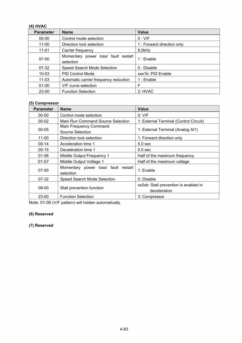
4-83
(4) HVAC
Parameter Name Value
00-00 Control mode selection 0 : V/F
11-00 Direction lock selection 1 : Forward direction only
11-01 Carrier frequency 8.0kHz
07-00 Momentary power loss/ fault restart
selection 1 : Enable
07-32 Speed Search Mode Selection 0 : Disable
10-03 PID Control Mode xxx1b: PID Enable
11-03 Automatic carrier frequency reduction 1 : Enable
01-00 V/F curve selection F
23-00 Function Selection 2: HVAC
(5) Compressor
Parameter Name Value
00-00 Control mode selection 0: V/F
00-02 Main Run Command Source Selection 1: External Terminal (Control Circuit)
00-05 Main Frequency Command
Source Selection 1: External Terminal (Analog AI1)
11-00 Direction lock selection 1: Forward direction only
00-14 Acceleration time 1 5.0 sec
00-15 Deceleration time 1 5.0 sec
01-06 Middle Output Frequency 1 Half of the maximum frequency
01-07 Middle Output Voltage 1 Half of the maximum voltage
07-00 Momentary power loss/ fault restart
selection 1: Enable
07-32 Speed Search Mode Selection 0: Disable
08-00 Stall prevention function xx0xb: Stall prevention is enabled in
deceleration
23-00 Function Selection 3: Compressor
Note: 01-00 (V/F pattern) will hidden automatically.
(6) Reserved
(7) Reserved

4-84
00- 33 Modified Parameters
Range 【0】: Disable
【1】: Enable
Note: only for LCD keypad.
This parameter automatically lists all the adjusted parameters. When the default value is adjusted and
00-33=1, it will list all the parameters different from default values in the advanced modes and these
parameters can be edited directly. The adjusted parameters list displays only when 00-33 is set from 0 to 1
or 00-33=1 at start up.
If user wants to restore to the original editing interface, it is only required to set parameter 00-33=0.
This function can display 250 adjusted parameters. If they are more than 250 parameters, it will list the
adjusted parameters before 250.
Example: set 00-03 (Alternative Run Command Source Selection) to be different default value.
Steps LCD Display Descriptions
1
The starting parameter group (00) in the setting modes of (Up)/ (Down) selection groups.
2
PARA 00 -01. Motor Direction -02. RUN Source -03. Sub RUN Source
Press READ/ ENTER key and (Up)/ (Down) to select alternative run command source (00-03).
3
Edit 00-00 Sub RUN Source
1 Terminal (0 ~4) <2>
Press READ/ ENTER key and adjust the value. The selected setting value will flash.
4
PARA 00 -33. Modify parameter -41. User P1 -42. User P2
Press DSP/ FUN to the menu of modified parameters (00-33).
5
Edit 00-33 Modify parameter
1 Enable (0 ~1) <0>
Press READ/ ENTER key to adjust the value to 1 (The modified parameter is enabled.) The selected setting value will flash.
6
Modify 00 00-03. Sub RUN Source 00-33. Modify parameter
Press DSP/ FUN back to the advanced modes.
Group 00 Basic Func. 01 V/F Pattern 02 Motor Parameter

4-85
User Parameter Setting (00-41 ~ 00-56) (only for LCD )
00- 41 User Parameter 0 Function Setting
00- 42 User Parameter 1 Function Setting
00- 43 User Parameter 2 Function Setting
00- 44 User Parameter 3 Function Setting
00- 45 User Parameter 4 Function Setting
00- 46 User Parameter 5 Function Setting
00- 47 User Parameter 6 Function Setting
00- 48 User Parameter 7 Function Setting
00- 48 User Parameter 8 Function Setting
00- 50 User Parameter 9 Function Setting
00- 51 User Parameter 10 Function Setting
00- 52 User Parameter 11 Function Setting
00- 53 User Parameter 12 Function Setting
00- 54 User Parameter 13 Function Setting
00- 55 User Parameter 14 Function Setting
00- 56 User Parameter 15 Function Setting ‧ User parameter (00-41 ~ 00-56) can select 16 sets of parameters (group 00 ~ 24, but except 00-00/
00-41~00-56/ group 17) and put them into the list to do the fast access setting.
‧ When the access setting of parameter 13-06 is set to 1, user parameter 00-41 ~ 00-56 can be
displayed and changed.
‧ User parameter 00-41 ~ 00-56 can be changed in the advanced modes, exclusive of being in
operation.
‧ Set value in the parameter of 00-41 ~ 00-56 and set 13-06 to 1.
‧ When 13-06=1, only parameter of 00-00 ~ 00-56 can be set or read in the advanced modes. 13-06=1
is enabled in the parameter setting of 00-41~00-56.
‧ When user would like to leave the screen of user parameters, press RESET key and then DSP/FUN
key to select parameter Group 13.

4-86
Example 1: Set 03-00 (Multi-function terminal Function Setting-S1) to user parameter 0 (00-41)
Steps LCD Display Descriptions
1
Select the start parameter group (00) in the advanced modes.
2
PARA 00 -41. User P0 -42. User P1 -43. User P2
Press (READ/ ENTER) key and (Up) / (Down) to select user parameter 0 (00-41).
3
Edit 00-41
User P0=00-41
00-41 User P0 <00-01 - 24-07>
Press (READ/ ENTER) key to the screen of data setting/ read. * The selected setting value will flash.
4
Edit 00-41 User P0=00-41
03-00 S1 Function Sel <00-01 - 24-07>
Press (Left) / (Right) and (Up) / (Down) key to set the value to 03-00 ( Multi-function terminal Function Setting-S1)
5
Edit 00-41 User P0= 03-00
03-00 S1 Function Sel <00-01 - 24-07>
Press (READ/ ENTER) key to save 03-00 and the digit stopsflashing and the screen displays User P0 = 03-00; 03-00 (Multi-function terminal Function Setting-S1) has been defined as 00-41. Few seconds later, the selected digit will flash again.
6
Monitor Freq Ref
12-16=000.00Hz --------------------------------------- 12-17=000.00Hz 12-18=0000.0A
Press (DSP/ FUN) key to the display of main screen. * If users do not press BACK key in one minute, the screen will automatically display the monitor mode shown as the left figure. The automatically return time can be set via 16-06.
Group 00 Basic Func. 01 V/F Pattern 02 Motor Parameter

4-87
. Example 2: After one or more parameters in 00-41 ~ 00-56 are set, user parameters settings
are as follows.
Step LCD Display Descriptions
1
Select the start parameter group (03) in the advanced modes.
2
PARA 13 -06. Access Level -07. Password 1 -08. Initialize
Press (READ/ ENTER) and (Up) / (Down) key to enter theaccess level of parameter (13-06).
3
Edit 13-06 Access Level
--------------------------------------- 1 User Level (0~2) < 2 >
Press (READ/ ENTER) key to enter the screen of the data setting/ read. * The selected setting value will flash.
4
ADV G01-02 Access Level
1 User Level (0-2) < 2 >
Press (Up) / (Down) key to change setting value to 1 (13-06=1, user level) and Press (READ/ ENTER) key to save the setting value (03-00). Then, the digit stops flashing and the screen displays the setting value. Few seconds later, the selected digit will flash again.
User level (13-06=1) can be set by one or more parameters in the user parameters of 00-41 ~ 00-56. If users do not set user parameters, 13-06 will not be set in the user level (setting value=1).
5
PARA 13 -06. Access Level
Press (DSP/FUN) key to the display of subdirectory.
6
Group 00.User Function
Press (DSP/FUN) key to the display of group directory. It is required to press (Up) key to select Group 00 User Function.
7
Monitor Freq Ref
12-16=000.00Hz --------------------------------------- 12-17=000.00Hz
12-18=0000.0A
Press (DSP/ FUN) key to enter the main screen. If user would like to leave the screen of user parameters, press RESET key and then DSP/FUN key to select parameter Group 13. Hotkeys are only enabled in inverter software V1.4.
8
Group 00. User Function00 User 13.Driver Status
13-06 can be selected to be adjusted so leave parameters or enterparameter group 00 to edit user parameters is allowable.
9 PARA 00 -41. S1 Function Sel
Press (READ/ ENTER) key and (Up) / (Down) key to select user parameter 0 (00-41) display.
10
Edit 00-41 S1 Function Sel
00 2-Wire (FWD-RUN) (00~57)
< 00 > < 03-00 >
Press (READ/ ENTER) key to enter the screen of data setting/ read. *The selected setting value will flash.
In this example, 03-00 (Multi-function terminal Function Setting-S1)has been defined as user parameters (00-41). The right bottom location displays the original parameter group.
Group 13 Driver Status 14 PLC Setting 15 PLC Monitor

4-88
01 V/F Pattern
00 Basic Func.Group
[ Main Screen ] [ Main Menu] [ Subdirectroy] [ READ/ ENTER ]
1 2
1 2
ENTER
ENTER
Monitor Freq Ref 12 – 16 = 000 . 00Hz----------------------------------12-17 = 000.00Hz12-18 = 0000.0A
DSP
FUN
02 Motor Parameter
READ
FUN
DSP
PARA 00
-41 User P0
-42 User P1-43 User P2
PARA 00
-54 User P13
-55 User P14-56 User P15
DSP
FUN
DSP
FUN
DSP
FUN
FUN
DSP
READ
Edit 00-41 User P0
---------------------------------------01-00 V/F Pattern. Sel(01-00–24-06)
PARA 00
-00 Control Method
-01 Motor Direction
-02 RUN Source
User Parameter Run Mode Structures
A. Define Parameter Group 0~24 as user parameters except parameter 00-00 and 00-41~00-56. Note: User level (13-06=1) can be set by one or more parameters in the user parameters of 00-41 ~
00-56.
Step LCD Display Descriptions
11
Edit 00-41 S1 Function Sel
06 FJOG (00~57) < 00 > < 03-00 >
Press (Up) / (Down) key to change the setting value to 2. Use (READ/ ENTER) key to save the setting value.
When the selected setting value does not flash again, the setting value will be saved to 00-41 and 03-00 simultaneously.
12
Monitor Freq Ref
12-16=000.00Hz --------------------------------------- 12-17=000.00Hz
12-18=0000.0A
Press (DSP/FUN) key to the display of main screen.
* If users do not press (DSP/ FUN) key in one minute, the screen will automatically display the monitor mode shown as the left figure. The automatically return time can be set via 16-06.

4-89

4-90
Group 01-V/F Control Parameters
01- 00 V/F Curve Selection
Range 【0~FF】 *When restore factory setting (13-08), this parameter will not be changed. The V/F curve selection is enabled for V/F mode. Make sure to set the inverter input voltage parameter 01-14.
There are three ways to set V/F curve:
(1) 01-00 = 0 to E: choose any of the 15 predefined curves (0 to E).
(2) 01-00 = 0F, use 01-02~01-09 and 01-12 ~ 01-13, with voltage limit.
(3) 01-00 = FF: use 01-02~01-09 and 01-12 ~ 01-13, without voltage limit.
The default parameters (01-02 ~ 01-09 and 01-12 ~ 01-13) are the same when 01-00 is set to F (default)
and 01-00 is set to 1.
Parameters 01-02 ~ 01-13 are automatically set when any of the predefined V/F curves are selected.
This parameter will be affected to reset by the initialization parameter (13-08).
Consider the following items as the conditions for selecting a V/F pattern. (1) The voltage and frequency characteristic of motor. (2) The maximum speed of motor.
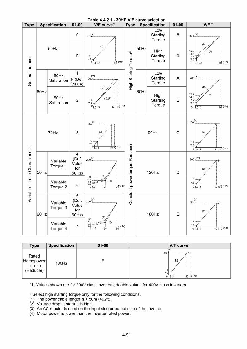
4-91
Table 4.4.2 1 - 30HP V/F curve selection Type Specification 01-00 V/F curve*1 Type Specification 01-00 V/F *1
Gen
eral
pur
pose
50Hz
0
(Hz)
200
500 1.3
(V)
(0)
7.5
2.5
14
Hig
h S
tarin
g T
orqu
e‡
50Hz
Low Starting Torque
8
(Hz)0
(V)
(9)
501.3 2.5
(8)15.214.6
7.77.6
200
F High
Starting Torque
9
60Hz
60Hz Saturation
1
(Hz6001.5
(V)
(2)
(1),(F)
507.5
3
14
200
60Hz
Low Starting Torque
A
(Hz)0
(V)
(B)
601.5 3
(A)15.214.67.77.6
200
F (Def. Value)
50Hz Saturation
2 High
Starting Torque
B
Var
iabl
e T
orqu
e C
hara
cter
istic
72Hz 3
(Hz)720
(V)
(3)
601.5 3
7.514
200
Con
stan
t-po
wer
torq
ue(R
educ
er)
90Hz C
(Hz)90
(V)
(C)
600 1.5
7.5
3
14
200
50Hz
Variable Torque 1
4 (Def. Value
for 50Hz)
(Hz)0
(V)
(5)
501.3 25
(4)
200
6.6 7.5
5538.5
120Hz D
(Hz)1200
(V)
(D)
601.5
7.5
3
14
200
Variable Torque 2
5
60Hz
Variable Torque 3
6 (Def. Value
for 60Hz)
(Hz)0
(V)
(7)
601.5 30
(6)
200
6.6 7.5
5538.5
180Hz E
(Hz)1800
(V)
(E)
601.5
7.5
3
14
200
Variable Torque 4
7
Type Specification 01-00 V/F curve*1
Rated Horsepower
Torque (Reducer)
180Hz F
(Hz)
220
1800
(V)
(E)
601.57.5
3
14
*1. Values shown are for 200V class inverters; double values for 400V class inverters.
‡: Select high starting torque only for the following conditions. (1) The power cable length is > 50m (492ft). (2) Voltage drop at startup is high. (3) An AC reactor is used on the input side or output side of the inverter. (4) Motor power is lower than the inverter rated power.

4-92
Table 4.4.3 40HP and above V/F curve selection Type Specification 01-00 V/F curve*1 Type Specification 01-00 V/F curve*1
Gen
eral
pur
pose
50Hz
0
(Hz)500 1.3
(V)
(0)
8.5
2.5
15
200
Hig
h S
tarin
g T
orqu
e‡ 50Hz
Low Starting Torque
8
(Hz0
(V)
(9)
501.3 2.5
(8)16.015.3
9.08.5
200
F
High Starting Torque
9
60Hz
60Hz Saturation
1
(Hz)6001.5
(V)
(2)
(1),(F)
508.5
3
15
200
60Hz
Low Starting Torque
A
(Hz0
(V)
(B)
601.5 3
(A)16.015.3
9.08.5
200
F (Def. Value)
50Hz Saturation
2 High
Starting Torque
B
Var
iabl
e T
orqu
e C
hara
cter
istic
72Hz 3
(Hz)720
(V)
(3)
601.5 3
8.515
200
Con
stan
t-po
wer
torq
ue(R
educ
er)
90Hz C
(Hz)90
(V)
(C)
600 1.5
8.5
3
15
200
50Hz
Variable Torque 1
4 (Def. Value
for 50Hz
)
(Hz)0
(V)
(5)
501.3 25
(4)
200
8.5
57.5
40
120Hz D
(Hz)1200
(V)
(D)
601.5
8.5
3
15
200
Variable Torque 2
5
60Hz
Variable Torque 3
6 (Def. Value
for 60Hz
)
(Hz)0
(V)
(7)
601.5 30
(6)
200
8.5
57.540
180Hz E
(Hz)1800
(V)
(E)
601.5
8.5
3
15
200
Variable Torque 4
7
*1. Values shown are for 200V class inverters; double values for 400V class inverters.
‡: Select high starting torque only for the following conditions. (1) The power cable length is > 50m (492ft). (2) Voltage drop at startup is high. (3) An AC reactor is used on the input side or output side of the inverter. (4) Motor power lower than the inverter rated power.

4-93
01- 02 Maximum Output Frequency
Range 【4.8~599.0】Hz
01- 03 Maximum Output Voltage
Range 200V:【0.1~255.0】V 400V:【0.2~510.0】V
01- 04 Middle output frequency 2
Range 【0.0~599.0】Hz
01- 05 Middle Output Voltage 2
Range 200V:【0.0~255.0】V 400V:【0.0~510.0】V
01- 06 Middle Output Frequency 1
Range 【0.0~599.0】Hz
01- 07 Middle Output Voltage 1
Range 200V:【0.0~255.0】V 400V:【0.0~510.0】V
01- 08 Minimum Output Frequency
Range 【0.0~599.0】Hz
01- 09 Minimum Output Voltage
Range 200V:【0.0~255.0】V 400V:【0.0~510.0】V
01- 12 Base Frequency
Range 【4.8~599.0】Hz
01- 13 Base Output Voltage
Range 200V:【0.0~255.0】V 400V:【0.0~510.0】V
V/F curve setting (01-02 ~ 01-09 and 01-12 ~ 01-13)
Select any of the predefined V/F curves setting ‘0’ to ‘E’ that best matches your application and the load characteristic of your motor, choose a custom curve setting ‘F’ or ‘FF’ to set a custom curve.
Important:
Improper V/F curve selection can result in low motor torque or increased current due to excitation.
For low torque or high speed applications, the motor may overheat. Make sure to provide adequate cooling
when operating the motor under these conditions for a longer period of time.
If the automatic torque boost function is enabled (parameter 01-10), the applied motor voltage will
automatically change to provide adequate motor torque during start or operating at low frequency. Custom V/F Curve Setting: A custom curve selection allows users to set parameters 01-02 ~ 01-13 whereas a predefined curve selection does not.

4-94
Figure 4.4.10 Custom V/F curve
When setting the frequency related parameters for a custom V/F curve values make sure that: Fmax ≧ Fbase > Fmid2 > Fmid1 >Fmin (01-02) (01-12) (01-04) (01-06) (01-08)
The ‘SE03’ V/F curve tuning error is displayed when the frequency values are set incorrectly. When 01-04 and 01-05 (or 01-18 and 01-09) are set to 0, the inverter ignores the set values of Fmid2 and Vmid2. When the control mode is changed parameter 00-00, 01-08 (Fmin) and 01-09 (Vmin) will automatically be changed to the default setting of the selected control mode.
SLV (Sensorless vector control)
Enter the motor data in parameter group 17 for SV and SLV control mode (00-00) and perform auto-tuning. In the SLV mode the V/F curve normally does not have to be re-adjusted after a successful auto-tune. The maximum output frequency setting 01-02 (Fmax), base frequency 01-12 (Fbase) or minimum output frequency 01-08 (Fmin) can be adjusted but the voltage is automatically adjusted by the internal current controller. Set the base frequency (01-12, Fbase) to the motor rated frequency on the motor nameplate. Perform the auto-tuning procedure after adjusting parameters 02-19 or 17-04 to reduce the voltage at no-load operation. Motor jitter can be reduced by lowering the no-load voltage. Please note that lowering the no-load voltage increases the current at no-load.
Output Voltage (V)
( - 03 ) Vmax
( - 05 ) Vmid
1( - 07) Vmid
2
( - 09) Vmin
Fmin( 01- 08)
Fmid 2( 01- 06)
Fmid1(01- 04)
Fbase(01- 12)
Fmax(01- 02)
OutputFrequency
(Hz)
( - 13) Vbase01
01
01
01
01

4-95
01-10 Torque Compensation Gain
Range 【0.0~2.0】 In V/F mode the inverter automatically adjusts the output voltage to adjust the output torque during start or
during load changes based on the calculated loss of motor voltage.
The rate of adjustment can be changed with the torque compensation gain parameter.
Refer to the torque compensation gain adjustment shown in Figure 4.4.11.
Figure 4.4.11 Torque compensation gain to increase/decrease output torque
Increase value when:
The wiring between the inverter and the motor is too long
The motor size is smaller than the inverter size
Note: Gradually increase the torque compensation value and make sure the output current does not exceed inverter rated current.
Reduce value when:
When experiencing motor vibration
Important: Confirm that the output current at low speed does not exceed the rated output current of the inverter.
01-11 Selection of Torque Compensation Mode
Range 0: Torque Compensation Mode 0
1: Torque Compensation Mode 1
01-11=0: General torque compensation mode.
01-11=1: High-speed torque compensation mode (120~160Hz).
Compensation amount decreases as the frequency increases. Compensation in 0~120Hz is the same as
that in torque compensation mode 0.

4-96
01-14 Input Voltage Setting
Range 200V:【155.0~255.0】V 400V:【310.0~510.0】V
The minimum input voltage of inverter is 0.1V. Set the inverter input voltage (E.g. 200V / 208V / 230V / 240V or 380V / 415V / 440V / 460V / 480V).
This parameter is used as a reference for predefined V/F curve calculation (01-00 = 0 to E), over-voltage
protection level, stall prevention, etc…
Note: It will depend on restore factory setting (13-08) to set the value of voltage
01-15 Torque Compensation Time
Range 【0~10000】ms Set the torque compensation delay time in milliseconds. Only adjust in the following situations:
Increase value when:
When experiencing motor vibration
Decrease value when:
When motor torque response is too slow

4-97
Group 02-IM Motor Parameter
02- 00 No-load Current
Range 【0.01~600.00】A 02- 01 Rated Current
Range 25%~200% of inverter’s rated current.
02-03 Rated Rotation Speed
Range 【0~60000】rpm 02- 04 Rated Voltage
Range 200V:【50.0~240.0】V 400V: 【100.0~480.0】V
02- 05 Rated Power
Range 【0.01~600.00】KW
02-06 Rated Frequency
Range 【4.8~599.0】Hz
02-07 Poles
Range 【2~16】(Even)
02-09 Excitation Current <1>
Range 【15.0~70.0】%
02-10 Core Saturation Coefficient 1 <1>
Range 【0~100】%
02-11 Core Saturation Coefficient 2 <1>
Range 【0~100】%
02-12 Core Saturation Coefficient 3 <1>
Range 【80~300】%
02-13 Core Loss
Range 【0.0~15.0】%
02-15 Resistance between Wires
Range 【0.001~60.000】Ω
02-19 No-Load Voltage
Range 200V:【50~240】V 400V:【100~480】V
02-33 Leakage Inductance Ratio <1>
Range 【0.1~15.0】%
02-34 Slip Frequency <1>
Range 【0.1~20.0】Hz In most case no adjustment is required after performing an auto-tune except when using the inverter in
special applications (e.g. machine tool, positioning, etc…).
Please refer to parameter group 22 for permanent magnet motor parameters.
(1) Number of motor poles (02-07) Set the number of motor pole according to the motor nameplate.
(2) Motor rated power (02-05)
Set the motor power according to the motor nameplate. (3) Motor rated current (02-01)
Set the motor rated current according to the motor nameplate.
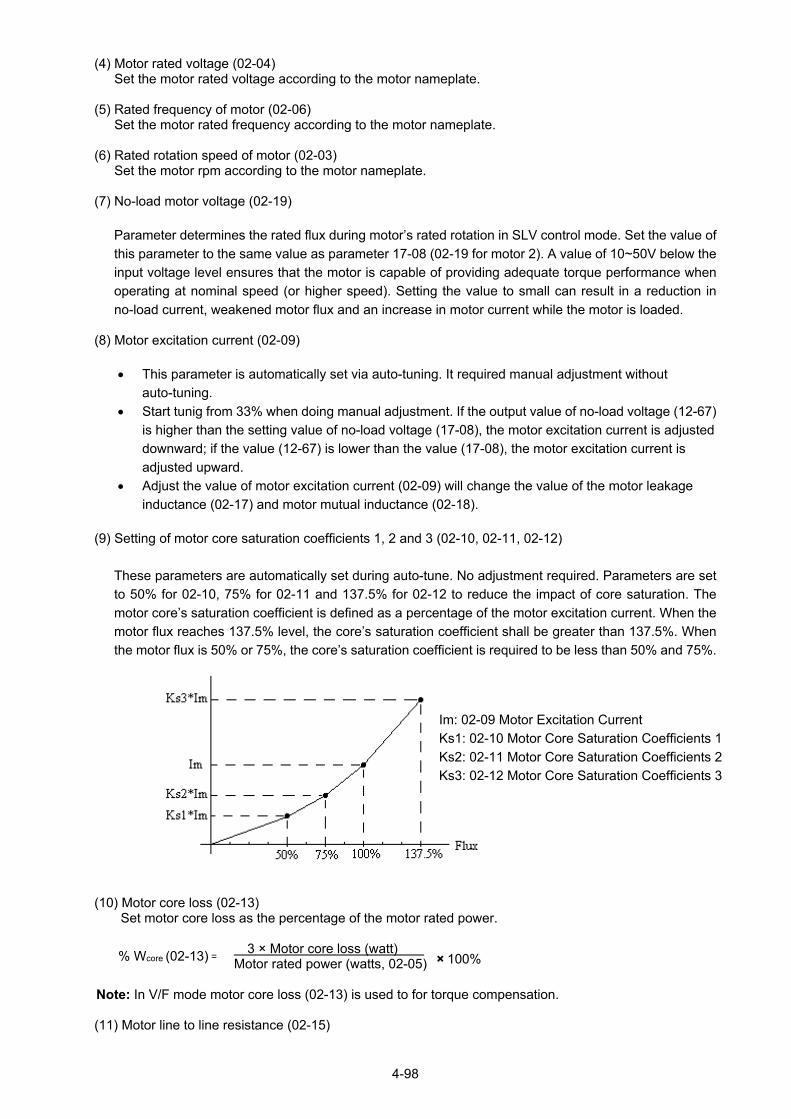
4-98
(4) Motor rated voltage (02-04) Set the motor rated voltage according to the motor nameplate.
(5) Rated frequency of motor (02-06)
Set the motor rated frequency according to the motor nameplate. (6) Rated rotation speed of motor (02-03)
Set the motor rpm according to the motor nameplate.
(7) No-load motor voltage (02-19)
Parameter determines the rated flux during motor’s rated rotation in SLV control mode. Set the value of
this parameter to the same value as parameter 17-08 (02-19 for motor 2). A value of 10~50V below the
input voltage level ensures that the motor is capable of providing adequate torque performance when
operating at nominal speed (or higher speed). Setting the value to small can result in a reduction in
no-load current, weakened motor flux and an increase in motor current while the motor is loaded. (8) Motor excitation current (02-09)
This parameter is automatically set via auto-tuning. It required manual adjustment without
auto-tuning.
Start tunig from 33% when doing manual adjustment. If the output value of no-load voltage (12-67)
is higher than the setting value of no-load voltage (17-08), the motor excitation current is adjusted
downward; if the value (12-67) is lower than the value (17-08), the motor excitation current is
adjusted upward.
Adjust the value of motor excitation current (02-09) will change the value of the motor leakage
inductance (02-17) and motor mutual inductance (02-18).
(9) Setting of motor core saturation coefficients 1, 2 and 3 (02-10, 02-11, 02-12)
These parameters are automatically set during auto-tune. No adjustment required. Parameters are set
to 50% for 02-10, 75% for 02-11 and 137.5% for 02-12 to reduce the impact of core saturation. The
motor core’s saturation coefficient is defined as a percentage of the motor excitation current. When the
motor flux reaches 137.5% level, the core’s saturation coefficient shall be greater than 137.5%. When
the motor flux is 50% or 75%, the core’s saturation coefficient is required to be less than 50% and 75%.
(10) Motor core loss (02-13)
Set motor core loss as the percentage of the motor rated power. 3 × Motor core loss (watt) Motor rated power (watts, 02-05)
Note: In V/F mode motor core loss (02-13) is used to for torque compensation. (11) Motor line to line resistance (02-15)
% Wcore (02-13) = × 100%
Im: 02-09 Motor Excitation Current
Ks1: 02-10 Motor Core Saturation Coefficients 1
Ks2: 02-11 Motor Core Saturation Coefficients 2
Ks3: 02-12 Motor Core Saturation Coefficients 3

4-99
(12) Motor no-load current (02-00).
Value is calculated based on the motor rated frequency (17-05) and motor rated current (17-03).
In V / F control mode, the output current is greater than the no-load current with slip compensation is enabled.
Note: The value of 02-01 needs to be greater than the value set in parameter 02-00, otherwise warning message "SE01" out of range error will be displayed.
Figure 4.4.12 Y-equivalent model of an induction motor (13) Motor Leakage Inductance Ratio (02-33)
This parameter is set by the conversion of manual adjustment function. This adjustment does not
have the magnetic function. Normally, it does not require adjustment.
Definition of leakage inductance ratio is the ratio of leakage inductance to rotor inductance. If
default setting is 3.4%, adjust this ratio changes the parameter of motor leakage inductance. The
formula of this ratio is as follows:
Lr
LlKg
When the ratio of leakage inductance is too high or too low, it may cause the motor jittering with
different sound and without operation. The general setting range is 3.0%~5.0% and 4.0% is the
relatively common value for motor operation normally. The ratio of leakage inductance is adjusted
depending on different motor types. (14) Motor Slip Frequency (02-34)
This parameter is set by the conversion of manual adjustment function. This adjustment does not
have the magnetic function. Normally, it does not require adjustment.
The default setting is 1Hz and the value of motor slip frequency is obtained from motor nameplate.
Take 4-pole motor with 60Hz for example,
Synchronous speed is 18004
60120120
Pole
FrequenceN rpm and the rated speed in the
motor nameplate is 1700 rpm, then HzSlip 67.160
17001800
.
Note: Adjusting the motor slip frequency changes the parameter of rotor resistance and the value of slip
frequency is adjusted depending on different motor types. Note: After executing auto-tuning, parameters which marked <1> will renew the value. Please refer Group
17: Automatic Tuning Parameters for more detail.

4-100
Group 03- External Digital Input and Output Parameters
03- 00 Multi-function terminal function setting – S1 03- 01 Multi-function terminal function setting – S2 03- 02 Multi-function terminal function setting – S3 03- 03 Multi-function terminal function setting – S4 03- 04 Multi-function terminal function setting – S5 03- 05 Multi-function terminal function setting – S6
Range
【0】: 2-Wire Sequence (ON: Forward Run Command)
【1】: 2-Wire Sequence (ON: Reverse Run Command)
【2】: Multi-Speed Setting Command 1
【3】: Multi-Speed Setting Command 2
【4】: Multi-Speed Setting Command 3
【5】: Multi-Speed Setting Command 4
【6】: Forward Jog Run Command
【7】: Reverse Jog Run Command
【8】: UP Frequency Increasing Command
【9】: DOWN Frequency Decreasing Command
【10】: Acceleration/ Deceleration Setting Command 1
【11】: Acceleration/ Deceleration Inhibition Command
【12】: Main/Alternative Run command Switching
【13】: Main/Alternative Frequency Command Switching
【14】: Emergency Stop (Decelerate to Zero and Stop)
【15】: External Baseblock Command (Rotation freely to Stop)*1
【16】: PID Control Disable
【17】: Fault Reset (RESET)
【18】: Reserved
【19】: Speed Search 1(from the maximum frequency)*1
【20】: Manual Energy Saving Function
【21】: PID Integral Reset
【22】~【23】: Reserved
【24】: PLC Input
【25】: External Fault
【26】: 3-Wire Sequence (Forward/ Reverse Command)
【27】: Local/ Remote Selection
【28】: Remote Mode Selection
【29】: Jog Frequency Selection
【30】: Acceleration/ Deceleration Setting Command 2
【31】: Inverter Overheating Warning
【32】: Reserved
【33】: DC Braking*1
【34】: Speed Search 2 (from Frequency Command)*1
【35】: Timing Function Input
【36】: PID Soft Start Disable
【37】~【40】: Reserved
【41】: PID Sleep
【42】~【46】: Reserved
【47】: Fire Mode (Forced to Run Mode)
【48】: KEB Acceleration
【49】: Parameters Writing Allowable
【50】: Unattended Start Protection (USP)
【51】~【52】: Reserved
【53】: 2-Wire Self Holding Mode (Stop Command)

4-101
S1
S2
S3
S4
S5
S6
Related Parameters
03-00
24VG
03-01
03-02
03-03
03-04
03-05
【54】: Switch PID1 and PID2
【55】: RTC Time Enable
【56】: RTC Offset Enable
【57】: Forcing Frequency Run
【58】: Run Permissive Function
【63】: Switch to Tolerance Range of Constant Pressure 2
【64】: Reserved
【65】: Short-circuit braking
【66】: Reserved
【67】: Reserved
【68】: External Fault 2
【69】: External Overload *1: It can not be selected on the items 15, 19, 33, and 34 while using the permanent magnetic (PM)
motor. Refer to the multi-function digital input and related parameters in the following Fig. 4.4.13
Figure 4.4.13 Multi-function digital input and related parameters
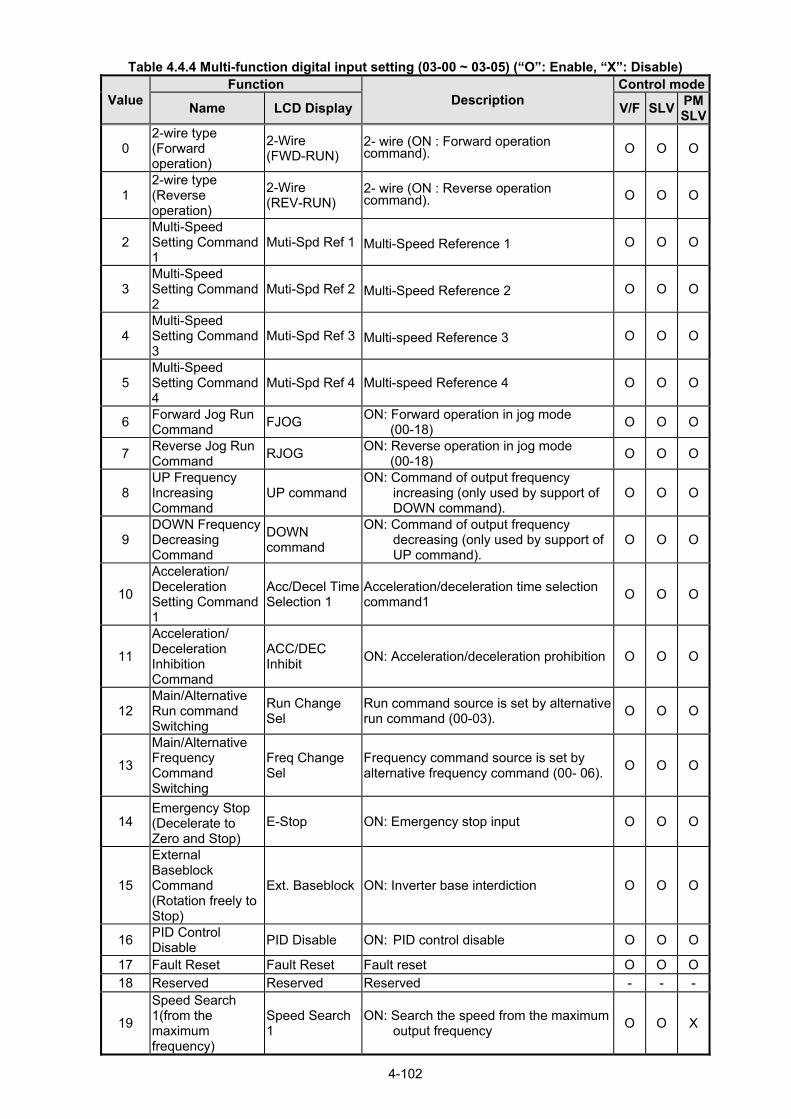
4-102
Table 4.4.4 Multi-function digital input setting (03-00 ~ 03-05) (“O”: Enable, “X”: Disable)
Value Function
Description Control mode
Name LCD Display V/F SLVPMSLV
0 2-wire type (Forward operation)
2-Wire (FWD-RUN)
2- wire (ON : Forward operation command). O O O
1 2-wire type (Reverse operation)
2-Wire (REV-RUN)
2- wire (ON : Reverse operation command). O O O
2 Multi-Speed Setting Command 1
Muti-Spd Ref 1 Multi-Speed Reference 1 O O O
3 Multi-Speed Setting Command 2
Muti-Spd Ref 2 Multi-Speed Reference 2 O O O
4 Multi-Speed Setting Command 3
Muti-Spd Ref 3 Multi-speed Reference 3 O O O
5 Multi-Speed Setting Command 4
Muti-Spd Ref 4 Multi-speed Reference 4 O O O
6 Forward Jog Run Command
FJOG ON: Forward operation in jog mode
(00-18) O O O
7 Reverse Jog Run Command
RJOG ON: Reverse operation in jog mode
(00-18) O O O
8 UP Frequency Increasing Command
UP command ON: Command of output frequency
increasing (only used by support of DOWN command).
O O O
9 DOWN Frequency Decreasing Command
DOWN command
ON: Command of output frequency decreasing (only used by support of UP command).
O O O
10
Acceleration/ Deceleration Setting Command 1
Acc/Decel Time Selection 1
Acceleration/deceleration time selection command1
O O O
11
Acceleration/ Deceleration Inhibition Command
ACC/DEC Inhibit
ON: Acceleration/deceleration prohibition O O O
12 Main/Alternative Run command Switching
Run Change Sel
Run command source is set by alternative run command (00-03).
O O O
13
Main/Alternative Frequency Command Switching
Freq Change Sel
Frequency command source is set by alternative frequency command (00- 06).
O O O
14 Emergency Stop (Decelerate to Zero and Stop)
E-Stop ON: Emergency stop input O O O
15
External Baseblock Command (Rotation freely to Stop)
Ext. Baseblock ON: Inverter base interdiction O O O
16 PID Control Disable
PID Disable ON: PID control disable O O O
17 Fault Reset Fault Reset Fault reset O O O18 Reserved Reserved Reserved - - -
19
Speed Search 1(from the maximum frequency)
Speed Search 1
ON: Search the speed from the maximum output frequency
O O X

4-103
Value Function
Description Control mode
Name LCD Display V/F SLVPMSLV
20 Manual Energy Saving Function
Energy savingON: Manual energy saving control is
based on the settings of 11-12 and 11-18.
O X X
21 PID Integral Reset PID I-Reset ON: PID integral value reset O O O22~23 Reserved Reserved Reserved - - -
24 PLC input PLC Input ON: Digital PLC input O O O25 External fault Ext. Fault ON: External fault alarm O O O
26 3-Wire Sequence (Forward/ Reverse Command)
3-Wire (FWD/REV)
3-wire control (forward/reverse command). ON: Reverse; OFF: Forward. When the parameter is set to 26,terminal S1 and terminal will become operation command and stop command respectively, and their original functions will be closed.
O O O
27 Local/ Remote Selection
Local/Remote
ON: Local mode (via the digital operator) OFF: Frequency command and operation command will be determined according to the setting of parameter (00-02 and 00-05)
O O O
28 Remote Mode Selection
Remote Mode Sel
ON: RS-485 communication OFF: Control circuit terminal
O O O
29 Jog Frequency Selection
JOG Freq Ref ON: Selection jog frequency command O O O
30
Acceleration/ Deceleration Setting Command 2
Acc/Decel Time Selection 2
Acceleration/deceleration time selection command2
O O O
31 Inverter Overheating Warning (OH2)
Overheat AlarmON: Inverter overheat alarm (OH2)
input( will display OH2) O O O
32 Reserved Reserved Reserved - - -
33 DC Braking DC Brake Command
ON: Perform DC braking O X X
34 Speed Search 2 (from Frequency Command)
Speed Search 2
ON: Search speed from set frequency O X O
35 Timing Function Input
Timer Input .Set the time function at 03-37, 03-38 .Set the time function output at 03-11, 03-12
O O O
36 PID Soft Start Disable
PID SFS Disable
ON: PID slow-start off O O O
37~40 Reserved Reserved Reserved - - - 41 PID Sleep PID Sleep ON: PID Sleep O O O
42~46 Reserved Reserved Reserved - - -
47 Fire Mode (Forced to Run Mode)
Fire Mode
ON: Inverter runs in the max. frequency of
motor 1 (parameter 01-02). Note: If fault message of OC, SC, CUV, FUL, STO occur, function of fire mode will stop.
O O O
48 KEB Acceleration KEB Accel. ON: KEB acceleration start O X X
49 Parameters Write-in Allowed
Write EnabledON: All parameters are writable. OFF: Except reference frequency (00-05)
all parameters are write-protected. O O O

4-104
Value Function
Description Control mode
Name LCD Display V/F SLVPMSLV
50 Unattended Start Protection (USP)
USP
ON: After power is input,the inverter ignores the operation command
OFF: After power is input,the inverter will return the operation status before power is cut off.
O O O
51~52 Reserved Reserved Reserved - - -
53 2-Wire Self Holding Mode (Stop Command)
2-Wire (STOP)2-Wire Self Holding Mode (ON: Stop Command).
O O O
54 Switch PID1 and PID2
PID 2 Enable ON: PID1 enabled OFF: PID2 enabled
O O O
55 RTC Time Enable RTC Timer Switch
ON:RTC Time Function Enabled O O O
56 RTC Offset Enable
Offset Time Switch
ON:RTC Offset Enabled O O O
57 Forcing Frequency Run
Force Freq Cmd
ON: Run on Forcing Frequency (23-28) OFF: Determine frequency reference and
run command depending on the setting of parameter (00-02 and 00-05)
O O O
58 Run Permissive Function
Safety Function ON: Stop on the setting of 08-30 O O O
63
Switch to Tolerance Range of Constant Pressure 2
Switch Const.P.Range 2
ON: Use tolerance range of constant pressure 2 (23-34) for PUMP mode
OFF: Use tolerance range of constant pressure 1 (23-09) for PUMP mode
O O O
64 Reserved Reserved Reserved - - -
65 Short-circuit braking
SC Brk ON: Excute short-circuit braking X X O
66 Reserved Reserved Reserved - - - 67 Reserved Reserved Reserved - - - 68 External Fault 2 Ext. Fault 2 ON: the alarm of external Fault O O O69 External Overload Ext. Overload ON: the input of external overload O O O
03-0X =00: 2-wire control: forward operation
03-0X =01: 2-wire control: reverse operation. Refer to the 2-wire operation mode in Figure 4.3.1.
03-0X =02: Multi-speed setting command 1.
03-0X =03: Multi-speed setting command 2.
03-0X =04: Multi-speed setting command 3.
03-0X =05: Multi-speed setting command 4. 03-0X =29: Jog frequency selection (setting =29). Select frequency reference using the multi-function digital input.

4-105
Table 4.4.5 Multi-speed operation selection
Speed
Multi-function digital input (S1 ~ S6)
Frequency selection Jog
frequency
reference
Multi-speed
frequency
4
Multi-speed
frequency
3
Multi-speed
frequency
2
Multi-speed
frequency
1
1 0 0 0 0 0 Frequency command 0 ( 05-01) or main speed frequency*2
2 0 0 0 0 1 (04-05=0) Auxiliary speed frequency or (04-05≠0) Frequency command 1 (05-02) *3
3 0 0 0 1 0 Frequency command 2 (05-03) 4 0 0 0 1 1 Frequency command 3 (05-04) 5 0 0 1 0 0 Frequency command 4 (05-05) 6 0 0 1 0 1 Frequency command 5 (05-06) 7 0 0 1 1 0 Frequency command 6 (05-07) 8 0 0 1 1 1 Frequency command 7 (05-08) 9 0 1 0 0 0 Frequency command 8 (05-09) 10 0 1 0 0 1 Frequency command 9 (05-10) 11 0 1 0 1 0 Frequency command 10 (05-11) 12 0 1 0 1 1 Frequency command 11 (05-12) 13 0 1 1 0 0 Frequency command 12 (05-13) 14 0 1 1 0 1 Frequency command 13 (05-14) 15 0 1 1 1 0 Frequency command 14 (05-15) 16 0 1 1 1 1 Frequency command 15 (05-16) 17 1*1 Jog frequency command (00-18) 0: OFF, 1: ON, : Ignore
*1. Jog frequency terminal has a higher priority than multi-speed reference 1 to 4. *2. When parameter 00-05=0 (frequency reference input = digital operator), multi-speed frequency 1 will be
set by 05-01 frequency reference setting1). When parameter 00-05=1 (frequency reference input=control circuit terminal), multi-speed frequency command 1 is input through analog command terminal AI1 or AI2.
*3. 05-02 is used for auxiliary speed frequency of AI2 as default setting. It is necessary to set 04-05≠0 to
switch 05-02 to be for Frequency command 1. When PID control mode is enabled (10-03= xxx1b), Frequency of Speed - Stage 1 can not switch auxiliary speed frequency even though Multi-function Terminal Function Setting (03-00~03-05)=16 (PID control disable).
Wiring Example: Fig. 4.4.14 and 4.4.15 show an example of a 9-speed operation selection.
Figure 4.4.14 Control Terminal Wiring Example

4-106
1
0 000
00
0
000
000 00
11
1111
1
11
111
Terminal
(S1)
(S5)
(S6)
(S7)
(S8)
Forward RUN
Multi- stepspeed Ref1
Multi- stepspeed Ref2
Multi- stepspeed Ref3
JOG Frequency Ref
speed 1
speed 2
speed 3
speed 4
speed 5
speed 6
speed 7
speed 8
speed 9
*1masterspeed
ref
*2aux.
speedref
t
t
t
t
t
t
Frequency Reference
(05-01) (00-18)
(05-02)
(05-03)
(05-04)
(05-05)
(05-06)
(05-07)
(05-08)
Figure 4.4.15 9-speed timing diagram *1. When 00-05=1, multi-speed frequency reference is set by analog input AI1 or AI2. 03-0X =06: Forward jog run command, uses jog frequency parameter 00-18. 03-0X =07: Reverse jog run command, uses jog frequency parameter 00-18. Notes:
- To excute the Forward jog or Reverse jog command need to set 00-02=1 at first. - Jog command has a higher priority than other frequency reference commands. - Jog command uses stop mode set in parameter 07-09 when Jog command is active > 500ms. - When 11-00 (Direction Lock Selection) set to 1 (Only Allow Forward Rotation), if there is a motor
reverse command, the “RUNER” warning will display. - When 11-00 (Direction Lock Selection) set to 2 (Only Allow Reverse Rotation), if there is a motor
forward command, the “RUNER” warning will display. 03-0X =08: UP frequency accelerating command; set parameter 00-05 Frequency command to 2 to
activate. 03-0X =09: Down frequency decelerating command; set parameter 00-05 Frequency command to 2 to
activate.
Note: - The inverter operates the variation of increasing/ decreasing output frequency via keypad (refer
to parameter 11-56) / external multi-function digital input (terminal S1to S6) when the motor is running.

4-107
- It is required to use two terminals to run UP/ DOWN command when the inverter runs this command via the external multi-function digital input terminal and 00-02=1 (external terminals) & 00-05=2 (terminal command UP/DOWN) & 03-00~03-05=8 (UP command)/ 9 (DOWN command).
- The inverter output frequency runs UP/ DOWN command with the setting of acceleration/ deceleration time.
. Note: SE02 DI terminal Error will be displayed when:
- Only the UP or DOWN command function is set. - Both UP command and Inhibit Acceleration/deceleration command are activated simultaneously. - Both DOWN command and Inhibit Acceleration/deceleration command are activated
simultaneously. For the examples of UP/DOWN control wiring and operation, please refer to Figure 4.4.16 and 4.4.17.
UP Command (Terminal S5)
1 0 0 1
Down Command (Terminal S6)
0 1 0 1
Operation Accel (UP)
Decel (DWN)
Hold Hold
Figure 4.4.16 UP/DOWN wiring and operation example
Figure 4.4.17 Up / Down command timing diagram
UP / DOWN Command Operation
When the Forward Run command is active and the UP or Down command is momentarily activated the
inverter will accelerate the motor up to the lower limit of the frequency reference (00-13).
When using the UP / Down command, the output frequency is limited to the upper limit of frequency
reference (00-12) and the lower limit of frequency reference (00-13).
The UP / DOWN command uses acceleration 1 or 2 / deceleration time 1 or 2 for normal operation Tacc1 /
Tdec1 (00-14, 00-15) or Tacc2 / Tdec 2 (00-16, 00-17).

4-108
Hold Hold
Fref 1
Fref2
*1
*2
PowerSupply
Forward Run
InhibitACC / DECCommand
FrequencyReference
OutputFrequency
Fref 1
Fref2
ON ONOFF
t
t
t
t
t
Refer to 03-40 UP/ DOWN frequency width setting for using other functions of UP/ DOWN. (It is enabled in inverter software V1.4)
Frequency reference retention is active when parameter 11-58 is set to 1 and the frequency reference is
saved when power is lost and retrieved when power is restored. *1: When 11-58 = 1 and the operation command is active, the output frequency will accelerate to the
previously stored frequency command. *2: When 11-58 = 0 and the operation command is active, the output frequency will accelerate to the lower
limit of frequency reference (00-13).
03-0X =10: Acceleration/deceleration 1 selection
03-0X =30: Acceleration/deceleration 2 selection
Refer to the "multi-function digital input terminals select acceleration/ deceleration time” in Table 4.4.1 and
Figure 4.4.6.
03-0X =11: Acceleration/deceleration inhibition command (hold command)
When activated suspends the acceleration / deceleration operation and maintains the output frequency at
current level.
If 11-58 = 1, the frequency reference value is saved when the acceleration/deceleration inhibition
command is active. Deactivating the acceleration / deceleration inhibition command resumes acceleration
/ deceleration.
If 11-58 = 1, the frequency reference value is saved when the acceleration/deceleration inhibition
command is active and even when powering down the inverter. Refer to Fig.4.4.18. for an example.
Figure 4.4.18 Acceleration / deceleration inhibition command operation
*1. When 11-58 = 1, and acceleration / deceleration inhibit command is activated, the frequency reference is stored even when powering down the inverter. When a run command is given (e.g. run forward) and the acceleration / deceleration inhibit command is active, the inverter will accelerate to the previously stored frequency reference.

4-109
t
Run Command
ExternalBaseblock
OutputFrequency
(Speed search)
Coast to stop
Coast to stop
t
t
*2. When 11-58 = 0, and a run command is given and the acceleration / deceleration inhibit command is active, the frequency reference and output frequency will remain at zero. 03-0X =12: Main/Alternative Run command Switching Run command source is set by alternative run command (00-03) when function terminal is active. When function terminal is set to 27 (Local/ Remote control selection), the priority will higher than the switch of main/ alternative run command. 03-0X =13: Main/Alternative Frequency Command Switching Frequency command source is set by alternative frequency command (00- 06) when function terminal is active. When function terminal is set to 27 (Local/ Remote control selection), the priority will higher than the switch of main/ alternative frequency command.
03-0X =14: Emergency stop (decelerate to zero and stop) Refer to the "deceleration time of emergency stop" of parameter 00-26. 03-0X =15: External Baseblock Command (coast to stop)
Execute the base block command by the use of ON / OFF way of multi-function digital input terminal, and
prohibit the inverter output.
During run: When an external base block command is activated, the keypad displays "BBn BaseBlock
(Sn)", indicating the inverter output is turned off (n indicates the digital input number 1 – 6). Upon removing
the base block signal, the motor will run at the frequency reference. If speed seach from frequency
reference is active the inverter output frequency starts from the frequency reference and searches for the
coasting motor speed and continue to operate. If speed search is not active the output frequency starts at
0Hz.
During deceleration: When an external base block command is activated, the keypad displays "BBn
BaseBlock (Sn)", indicating the inverter output is turned off (n indicates the digital input number 1 – 6).
Upon removing the base block signal, the motor is stopped or will coast to a stop and the inverter will
remains in the stop condition.
During acceleration: When an external base block command is activated, the keypad displays "BBn
BaseBlock (Sn)", indicating the inverter output is turned off (n indicates the digital input number 1 – 6).
Upon removing the base block signal, the motor will run at the frequency reference. If speed seach from
frequency reference is active the inverter output frequency starts from the frequency reference and
searches for the coasting motor speed and continue to operate. If speed search is not active the output
frequency starts at 0Hz.
Figure 4.4.19 External base block operation

4-110
03-0X =16: PID control disable.
Note: The frequency will depend on parameter 00-05 (reference frequency) to determine the source of
frequency input. Refer to the descriptions of parameter 00-05 and 00-06 for details. 03-0X =17: Fault reset The output becomes active when the inverter trips on a fault. Upon an inverter fault the inverter output will turn off (base block) and the keypad displays the dedicated fault message. When fault occurs, the following actions can be used to reset the fault:
1. Program one of the multi-function digital inputs (03-00 to 03-05) to 17 (reset fault) and active input.*
2. Press the reset key of the digital operator (RESET).*
3. Recycle power to the inverter. Important Note: If a run command is active during power-up, the
inverter will start running automatically. * To reset an active fault the run command has to be removed. 03-0X =19: Speed Search 1 (from the maximum frequency). 03-0X =34: Speed Search 2 (from the frequency command). Refer to the "speed search" function in the parameter group 7 (start/ stop control function). 03-0X =20: Energy saving enabled
Manual energy savings function is set with parameters 11-12 and 11-18.
For the manual energy saving operation refer to Figure 4.3.78. 03-0X =21: PID integral reset 03-0X =25: External fault Activating the external fault input will turn off the inverter output and the motor will coast to a stop. The keypad displays the external fault message “EFn Ext. Fault (Sn)”, where n is the input terminal number. 03-0X =27: Local / Remote selection. Switch the inverter frequency reference source between Local (keypad) or Remote (control circuit terminals or RS485). Use parameter 00-05 (Main frequency command source selection) and 00-02 (Run command selection) to select the input source. When PID is enabled (10-03=XXX1), parameter 10-00 (target value source) is performed. If 23-00=1, make sure the setting value of parameter 23-04. If 23-00=2, make sure the setting value of parameter 23-59 and 00-02. Note: In 3-wire operation terminal S1 and S2 are reserved for run/stop operation and the Local / Remote function can only be set to digital input terminals S3 to S6 (03-02 to 03-05). Note: To switch between local and remote the inverter has to be stopped.
Input Mode Frequency Reference / Run/Stop Command Source
ON Local
- Frequency reference and Run-Stop from keypad.
- LEDs SEQ and REF are off.
- When PID is enabled, REF indicator OFF presents PID target value is
set by the keypad.
OFF Remote
- Frequency reference source selected by parameter 00-05 and
Run-Stop source selected by parameter 00-02.
- LEDs SEQ and REF are on.
- When PID is enabled, REF indicator ON presents PID target value is
set by the control terminal AI1.

4-111
LCD DigitalOperator
Frequency Referenceand
Run Command
RS – 422 /485communications
Control circuitterminals
ON
OFF
ON
OFF
(
)
( )
( Local Mode )
( Remote Mode )
Set one of 03-00 to 03-05 = 28
Set one of 03-00 to 03-05 = 27
10-03=xxx1B
Target Referenceand
Run Command
10-03=xxx0B
03-0X =28: Remote mode selection Switch between terminal source and communication (RS-422/RS-485) source for frequency reference and operation command. In Remote mode, indicators of SEQ and REF are on; you can use terminals AI1 and AI2 to control the frequency command, and use terminals S1, S2 or communication terminal RS-485 to control the operation command.
Input Mode Frequency Reference / Run/Stop Command Source
ON Communication - Frequency reference and run/stop command control via communication
(RS-422/RS-485).
OFF Terminal - Frequency reference source from AI1 / AI2 input (00-05=1) and
Run-Stop command from terminals S1 / S2 (00-02=1).
Figure 4.4.20 Remote mode operation selection
To switch the frequency reference and operation command input between communication RS-485 and
control terminals the following parameters have to be set:
1. 00-05=1 (use control terminal AI1 or AI2 as reference frequency source)
2. 00-02=1 (use control terminal S1 or S2 for operation command)
3. Set one of the digital input terminals (03-02 to 03-05) to 28 (Operation selection of remote mode)
03-0X =24: PLC Input It is required to match Drive Link program. Ladder diagram is edited in the PLC program. When the message output is conducted, this message will be sent to the inverter.
03-0X =26: 3-Wire Sequence (Forward/ Reverse Command) When the digital input terminals (S3~S6) is set to 26, terminal S1 and S2 will become the run command and stop command. Refer to Fig.4.4.2. 03-0X =29: Jog Frequency Selection When 00-18 (Jog Frequency) is set up, the inverter depends on this frequency for command when it is ON.

4-112
DC injectionBrake
DC injectionBrake
t
01-08(Fmin)
The larger of 01-08 or 07-06
Run Command
DC injectionBraking
CommandOutput
Frequency
(or Jog command)
OFF ON
OFF ON
t
t
03-0X =30: Acceleration/ Deceleration Setting Command 2 When it is ON, the inverter will be active depends on the acceleration time 2 of 00-16 and deceleration time 2 of 00-17.
03-0X =31: Inverter overheat warning
When input is active the inverter displays warning message "OH2" and continues operation. Deactivating
the input reverts back to the original display. Warning message does not require resetting the inverter. 03-0X =33: DC braking When input is active DC-Injection braking is enabled during start and stopping of the inverter.
DC Injection braking is disabled when a run or jog command is active.
Note: Either short-circuits braking command or DC braking command is selected. If these two modes are
both selected, SE02 error (DI Terminal Error) will occur.
Refer to the DC braking time diagram in Fig.4.4.21.
Figure 4.4.21 DC braking timing diagram 03-0X =35: Timing function Refer to the "time function" parameter 03-37 and 03-38.
03-0X =36: PID Soft start disable
Refer to the "PID Control" function of PID function parameter group 10. 03-0X =47: Fire mode (Foreced to operation mode)
When input is active disables all inverter warning and hardware (exclusive of SC) protections. This function
is commonly used in commercial applications where the inverter controls an exhaust fan and needs run to
destruction in case of a fire.
03-0X =48: KEB acceleration
When input is active enables KEB (Kinetic Energy Braking) during acceleration. Refer to the parameter
description of 11-47 and 11-48. Note: To enable set parameter 11-47 to a value greater than 0. 03-0X =49: Parameters write-in allowed When input is active allows parameter to be changed. Note: When none of the digital input terminals are set to function 49, parameter write-in protection is controlled by parameter 13-06.
Input Parameter Save
ON Parameters Write Enabled
OFF Parameters Write Protected

4-113
03-0X =50: Unattended Start Protection (USP)
When input is active prevents inverter from starting automatically when a run command is present at time
of power-up. Please refer to Fig.4.4.21a for more details.
Figure 4.4.21a Unattended Start Protection
03-0X =53: 2-Wire Self Holding Mode (Stop Command). Refer to the “2-wire operation with hold function” of parameter 00-02. 03-0X =54: Switch PID1 and PID2 It will switch PID1 to PID2 when PID2 is ON. 03-0X =55: RTC Time Enable When 16-13 (RTC timer function) = 2 (DI setting) and RTC Time Enable is ON, RTC timer function is enabled. 03-0X =56: RTC Offset Enable When 16-30 (Selection of RTC Offset) = 2 (DI setting) and RTC Offset Enable is ON, the inverter will run depending on RTC offset time setting (16-31). 03-0X =57: Forced Frequency Run This function enables with the corresponding of parameter of 23-28 and the source of frequency command of parameter 00-05 set to the value of 5 (PID given, namely the parameter of10-03 needs to be active). When any one of the multi-function digital input terminal (S1~S6) is set to the value of 16 (the interdiction of PID function), pump will not depend on feedback to do any PID output adjustment; simultaneously another one is set to the value of 57 (forced frequency run) and inverter will have the frequency run setting depending on the parameter of 23-28. Inverter will stop output when digital input terminals (S1~S6) are removed. This function is applied to inverter output being controlled by external pressure sensor (eg. differential pressure switch) when pressure sensor disconnects. 03-0X =58: Run Permissive Function When digital input terminal enables, inverter will stop via the set of parameter 08-30 after Run Permissive Function function is active.
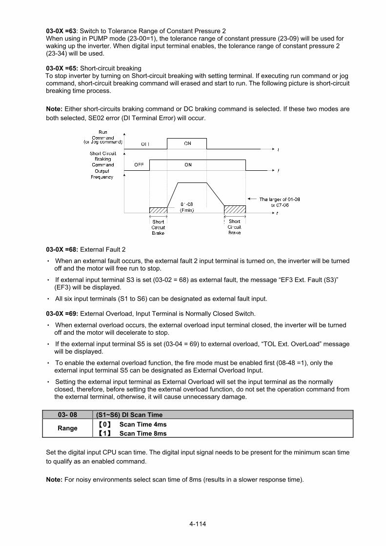
4-114
03-0X =63: Switch to Tolerance Range of Constant Pressure 2 When using in PUMP mode (23-00=1), the tolerance range of constant pressure (23-09) will be used for waking up the inverter. When digital input terminal enables, the tolerance range of constant pressure 2 (23-34) will be used. 03-0X =65: Short-circuit breaking To stop inverter by turning on Short-circuit breaking with setting terminal. If executing run command or jog command, short-circuit breaking command will erased and start to run. The following picture is short-circuit breaking time process.
Note: Either short-circuits braking command or DC braking command is selected. If these two modes are
both selected, SE02 error (DI Terminal Error) will occur.
03-0X =68: External Fault 2
‧ When an external fault occurs, the external fault 2 input terminal is turned on, the inverter will be turned off and the motor will free run to stop.
‧ If external input terminal S3 is set (03-02 = 68) as external fault, the message “EF3 Ext. Fault (S3)” (EF3) will be displayed.
‧ All six input terminals (S1 to S6) can be designated as external fault input. 03-0X =69: External Overload, Input Terminal is Normally Closed Switch.
‧ When external overload occurs, the external overload input terminal closed, the inverter will be turned off and the motor will decelerate to stop.
‧ If the external input terminal S5 is set (03-04 = 69) to external overload, “TOL Ext. OverLoad” message will be displayed.
‧ To enable the external overload function, the fire mode must be enabled first (08-48 =1), only the external input terminal S5 can be designated as External Overload Input.
‧ Setting the external input terminal as External Overload will set the input terminal as the normally closed, therefore, before setting the external overload function, do not set the operation command from the external terminal, otherwise, it will cause unnecessary damage.
03- 08 (S1~S6) DI Scan Time
Range 【0】 Scan Time 4ms
【1】 Scan Time 8ms
Set the digital input CPU scan time. The digital input signal needs to be present for the minimum scan time
to qualify as an enabled command.
Note: For noisy environments select scan time of 8ms (results in a slower response time).

4-115
03- 09 Multi-function Terminal S1-S4 Type Selection
Range
【xxx0b】:S1 A contact 【xxx1b】:S1 B contact
【xx0xb】:S2 A contact 【xx1xb】:S2 B contact
【x0xxb】:S3 A contact 【x1xxb】:S3 B contact
【0xxxb】:S4 A contact 【1xxxb】:S4 B contact
03- 10 Multi-function Terminal S5-S6 Type Selection
Range 【xxx0b】:S5 A contact 【xxx1b】:S5 B contact
【xx0xb】:S6 A contact 【xx1xb】:S6 B contact
Parameter 03-09 and 03-10 selects the digital input type between a normally open and a normally closed
switch/contact. Each bit of 03-09/03-10 presents an input:
03-09= 0 0 0 0 0:normally open switch
s4 s3 s2 s1 1:normally closed switch
03-10= x x 0 0 0:normally open switch
s6 s5 1:normally closed switch
Example: S1 and S2 wired to a normally closed contact / switch set 03-09=0011.
Do not set the operation command parameter 00-02 to terminal control before setting the digital
input type. Failure to comply may cause death or serious injury.
03-11 Relay (R1A-R1C) Output 03-12 Relay (R2A-R2C) Output 03-20 Relay(R4A-R4C) Output *1 03-21 Photo-coupler(DO2-DOG) Output *1 03-39 Relay (R3A-R3C) Output
Range
【0】: During Running
【1】: Fault Contact Output
【2】: Frequency Agree
【3】: Setting Frequency Agree (03-13±03-14)
【4】: Frequency Detection 1 (≧ 03-13 + 03-14)
【5】: Frequency Detection 2 (< 03-13)
【6】: Automatic Restart
【7】~【8】: Reserved
【9】: Baseblock
【10】~【11】:Reserved
【12】: Over-Torque Detection
【13】: Current Agree
【14】: Mechanical Brake Control (03-17~18)
【15】~【17】: Reserved
【18】: PLC Status
【19】: PLC Control
【20】: Zero Speed
【21】: Inverter Ready
【22】: Undervoltage Detection
【23】: Source of Operation Command
【24】:Source of Frequency Command
【25】: Low Torque Detection
【26】: Frequency Reference Missing
【27】: Timing Function Output
【28】~【31】: Reserved

4-116
【32】: Communication Control Contacts
【33】: RTC Timer 1
【34】: RTC Timer 2
【35】: RTC Timer 3
【36】: RTC Timer 4
【37】: Detection Output of PID Feedback Loss
【38】: Brake Release
【42】: Over-High Pressure
【43】: Over-Low Pressure
【44】: Loss of Pressure Detection
【45】: PID Sleep
【46】: Over-High Flow
【47】: Over-Low Flow 【48】: Shortage of Low Suction
【49】: Communication Error
【50】: Frequency Detection 3 (≧ 03-44+03-45)
【51】: Frequency Detection 4 (< 03-44)
【52】: Frequency Detection 5 (≧ 03-46+03-47)
【53】: Frequency Detection 6 (< 03-46)
【54】: Turn on short-circuit braking
【57】: Low Current Detection
【58】: Frequency Deceleration Detection
【59】: Overheat Detection *1: The parameters are available when the I/O expansion card installed.
Default function Related parameter
During Running
Fault signal 03-11
03-12
R1B
R1C
R2A
R2C
R1A
R3A
R3CZero
Speed 03-39
Figure 4.4.22 Multi-function digital output and related parameters
Table 4.4.6 Description of multi-function digital output
Value Function
Description Control Mode
Name LCD Display V/F SLVPMSLV
0 During Running Running ON: During running (Run Command is ON) O O O
1 Fault Contact Output
Fault ON: Fault contact output (except CF00 and
CF01 ) O O O
2 Frequency Agree
Freq. Agree ON: Frequency agree (frequency agree width
detection is set by 03-14 ) O O O
3 Setting Frequency Agree
Setting Freq Agree
ON: Output frequency = allowed frequency detection level (03-13) ± frequency bandwidth (03-14)
O O O
4 Frequency Detection 1
Freq. Detect 1 ON: Output frequency ≧ 03-13 + 03-14 O O O
5 Frequency Detection 2
Freq. Detect 2 OFF: Output frequency ≧ 03-13 + 03-14 O O O

4-117
Value Function
Description Control Mode
Name LCD Display V/F SLVPMSLV
6 Automatic Restart
Auto Restart ON: the period of automatic restart O O O
7~8 Reserved Reserved Reserved - - -
9 Baseblock Baseblock ON: During baseblock O O O
10~11 Reserved Reserved Reserved - - -
12 Over-Torque Detection
Over Torque ON: Over torque detection is ON O O O
13 Current Agree Current Agree ON: Output current > 03-15 O O O
14 Mechanical
Brake Control
(03-17~03-18)
Mechanical Brake Control
ON: Mechanical brake release frequency
OFF: Mechanical brake operation frequency O O O
15~17 Reserved Reserved Reserved - - -
18 PLC Status PLC
statement ON: when 00-02 is set to 3 (PLC operation
command source) O O O
19 PLC Control Control From
PLC ON: Control from PLC O O O
20 Zero Speed Zero SpeedON: Output frequency < Minimum output
frequency (Fmin) O O O
21 Inverter Ready Ready ON: Inverter ready (after power on, no faults) O O O
22 Undervoltage Detection
Low Volt Detected
ON: DC bus voltage = < Low-voltage warning detection level (07-13)
O O O
23 Source of Operation Command
Run Cmd Status
ON: Operation command from LED digital operator (local mode)
O O O
24 Source of Frequency Command
Freq Ref Status
ON: Reference frequency from LED digital operator (local mode)
O O O
25 Low Torque Detection
Under Torque ON: Low-torque detection is ON O O O
26 Frequency Reference Missing
Ref. Loss. ON: Reference frequency loss O O O
27 Timing Function Output
Timer Output Set time function parameter to 03-37 and 03-38,and the time function input is set by parameter from 03-00 and 03-05
O O O
28~31 Reserved Reserved Reserved - - -
32 Communication Control Contacts
Control From Comm
ON: DO is set by communication control. O O O
33 RTC Timer 1 RTC Timer 1ON: 16-36 (RTC Speed Selection) selects Timer 1 and 16-32 (Source of Timer 1) is active in the set time.
O O O
34 RTC Timer 2 RTC Timer 2ON: 16-36 (RTC Speed Selection) selects Timer 2 and 16-33 (Source of Timer 2) is active in the set time.
O O O
35 RTC Timer 3 RTC Timer 3ON: 16-36 (RTC Speed Selection) selects Timer 3 and 16-34 (Source of Timer 3) is active in the set time.
O O O
36 RTC Timer 4 RTC Timer 4ON: 16-36 (RTC Speed Selection) selects Timer 4 and 16-35 (Source of Timer 4) is active in the set time.
O O O
37 Detection Output of PID Feedback Loss
PID Fbk Loss ON: PID Feedback Loss O O O

4-118
Value Function
Description Control Mode
Name LCD Display V/F SLVPMSLV
38 Brake Release Brake Relase ON: Brake Release X O X
42 Over-High
Pressure High PSI ON:High PSI Warning/Fault O X X
43 Over-Low
Pressure Low PSI ON: Low PSI Warning/Fault O X X
44
Loss of
Pressure
Detection
Fb PSI ON: Fb PSI Fault O X X
45 PID Sleep PID Sleep ON: During PID Sleep O O O
46 Over-High Flow Over GPM ON: Over GPM Warning/Fault O O O
47 Over-Low Flow Low GPM ON: Low GPM Warning/Fault O O O
48 Shortage of Low
Suction Low Suction ON: Low Suction Warning/Fault O O O
49 Communication
Error RS-485 Err. ON: Communication Error Warning O O O
50 Frequency
Detection 3 Freq. Detect 3
ON: output frequency > 03-44,Hysteresis range :03-45 O O O
51 Frequency
Detection 4 Freq. Detect 4
OFF: output frequency > 03-44,Hysteresis range :03-45 O O O
52 Frequency
Detection 5 Freq. Detect 5
ON: output frequency > 03-46,Hysteresis range :03-47 O O O
53 Frequency
Detection 6 Freq. Detect 6
OFF: output frequency > 03-46,Hysteresis range :03-47 O O O
54
Turn on
short-circuit
braking
SC Brk ON: Turn on short-circuit breaking X X O
57 Low Current
Detection
Low Current
Detect ON: Output Current ≦ 03-48 Low current
detection level O O O
58
Frequency
Deceleration
Detection
Freq. Decel toON: Output Frequency < Frequency
Command – parameter 03-14 in deceleration
O O O
59 OH Detection OH Detect ON: Heat Sink Fin Temperature >08-46,
hysteresis Zone 08-47 O O O
03-1X=0: During Running
OFF Run command is OFF and the inverter is stopped.
ON Run command is ON or output frequency is greater than 0.
03-1X=1: Fault contact output Output is active during fault condition. Note: Communication error (CF00, CF01) do not activate the fault contact. 03-1X=2: Frequency Agree Output is active when the output frequency falls within the frequency reference minus the frequency detection width (03-14).

4-119
03-1X=3: Setting Frequency Agree Output is active when the output frequency falls within the frequency detection width (03-14) of the set frequency detection level (03-13). 03-1X=4: Frequency detected 1 Output is active when the output frequency rises above the frequency detection level (03-13) + frequency detection width (o3-14) and deactivates when the output frequency falls below frequency detection level (o3-13). 03-1X=5: Frequency detected 2 Output is active when the output frequency is below the frequency detection level (03-13) + frequency detection width (03-14) and turns off when the output frequency falls below frequency detection level. Refer to parameter group 03 for frequency detection function. 03-1X=6: Automatic restart. Output is active during an auto-restart operation. 03-1X=9: Baseblock (B.B.) Output is active when the inverter output is turned off during a Baseblock command. 03-1X=12: Over torque detected (Normally Open) Output is active during an over torque detection see parameters 08-13 ~ 08-16. 03-1X=25: Low torque detected (Normally Open) Output is active during low torque detection see parameters 08-17 ~ 08-20. 03-1X=13: Current Agree When the output current is larger than that in 03-15 and its duration is higher than that in 03-16, this function will be ON. 03-1X=18: PLC status (setting =18) Output is active when operation command parameter (00-02) is set to 3: PLC Control. 03-1X=19: PLC control contact Output is controlled by the PLC logic 03-1X=20: Zero-speed Output is active during zero-speed
Active Output frequency >=minimum output frequency (01-08, Fmin)
Off Output frequency is <=the minimum output frequency

4-120
Figure 4.4.23 Zero-speed operation
03-1X=21: Inverter Ready Output is active when no faults are active and the inverter is ready for operation. 03-1X=22: Undervoltage Detection Output is active when the DC bus voltage falls below the low voltage detection level (07-13). 03-1X=23: Source of operation command Output is active in local operation command.
OFF
Remote mode:
00-02 = 1 or 2, or any one of the multi-function digital input terminals (S1 to S6) set to
function 5 (LOCAL / REMOTE control) is OFF.
SEQ LED of the keypad is ON.
ON
Local mode:
00-02 = 0, or any one of the multi-function digital input terminals (S1 to S6) set to
function 5 (LOCAL / REMOTE control) is active.
SEQ LED of the keypad is OFF.
03-1X=24: Source of frequency command Output is active in local frequency command.
OFF
Remote mode:
00-05 = 1 or 2, or any one of the multi-function digital input terminals (S1 to S6) set to
function 5 (LOCAL / REMOTE control) is OFF.
REF LED of the keypad is ON.
ON
Local mode:
00-05 = 0, or any one of the multi-function digital input terminals (S1 to S6) set to
function 5 (LOCAL / REMOTE control) is active.
REF LED of the keypad is OFF.
03-1X=26: Frequency reference missing
Output is active when the frequency reference is lost. When parameter 11-41 is set to 0 the inverter will decelerate to a stop. When parameter 11-41 is set to 1 operation will continue at the value of parameter 11-42 times the last know frequency reference.
03-1X=27: Time function output
Output is controlled by timer function see parameter 03-37 and 03-38.

4-121
03-1X=32: Communication control contacts
Output is active when communication control is active.
03-1X=37: Detection Output of PID Feedback Loss When PID feedback loss occurs (refer to parameters setting 10-11~10-13), this function will be ON. 03-1X=38: Brake Release When this function is ON, Break release is enabled. Refer to parameters descriptions of 03-41~03-42. 03-1X=42: Over-High Pressure Refer to the setting of parameters 23-12~23-14 for the warning / fault. 03-1X=43: Over-Low Pressure Refer to the setting of parameters 23-15~23-17 for the warning / fault. 03-1X=44: Loss of Pressure Detection Refer to the setting of parameters 23-18~23-19 for the warning / fault. 03-1X=45: PID Sleep PID sleep will be informed. 03-1X=46: Over-High Flow Refer to the setting of parameters 23-48~23-50 for the warning / fault. 03-1X=47: Over-Low Flow Refer to the setting of parameters 23-51~23-53 for the warning / fault. 03-1X=48: Shortage of Low Suction Refer to the setting of parameters 23-54~23-58 for the warning / fault. 03-1X=49: RS-485 communication error When RS-485 communication error, the output terminal is closed, please refer to the description of 09-06~09-07.
03-1X=54: Turn on short-circuit braking Output terminal is closed when Turning on short-circuit braking 03-1X=57: Low Current Detection When output current ≦ 03-48, the relay is active. 03-1X=58: Frequency Deceleration Detection When output frequency < frequency command- 03-14 in deceleration, the relay is active.
03-1X=59: Over Temperature Detection The Heat Sink Temperature > 08-46, the relay is active, the Magnetic Hysteresis Zone is set by 08-47.
03-13 Frequency Detection Level
Range 【0.0~599.0】 Hz 03-14 Frequency Detection Width
Range 【0.1~25.5】 Hz
03-44 Frequency Detection Level 2

4-122
Range 【0.0~599.0】 Hz
03-45 Frequency Detection Width 2
Range 【0.1~25.5】 Hz
03-46 Frequency Detection Level 3
Range 【0.0~599.0】 Hz
03-47 Frequency Detection Width 3
Range 【0.1~25.5】 Hz
03-50 Frequency Detection Level 4
Range 【0.0~599.0】 Hz
03-51 Frequency Detection Level 5
Range 【0.0~599.0】 Hz
03-52 Frequency Detection Level 6
Range 【0.0~599.0】 Hz
Frequency Detection Level: set the multi-function output terminals R1A-R1C, R2A-R2C or R3A-R3C (03-11, 03-12 or 03-39) to the output frequency detection signal. Set frequency and output frequency detection 1 and 2. The time charts for the Frequency Agree Detection operation are shown in the following Table 4.4.7.
Table 4.4.7 Frequency Detection Operation Function Detection operation of frequency confirmation Description
Frequency agree
Output is active when the output frequency falls within the frequency reference minus the frequency detection width (03-14).
Any of the digital outputs function (03-11, 03-12 or 03-39) can be set to 2 (Frequency agree).
Set frequency agree
Output is active when the output frequency falls within the frequency detection width (03-14) of the set frequency detection level (03-13).
Any of the digital outputs function (03-11, 03-12 or 03-39) can be set to 3 (Set frequency agree)
Frequency Deceleration
Detection
time
timeONOFF
FWD
REV
03-14
03-14
Freq ReferenceOutputFrequency
FrequencyDecelerate
Singal
ON
Freq Reference
OFF
Signal of frequency deceleration is ON when output frequency is out of the range between frequency reference minus frequency detection width (03-14)
Any of the digital outputs function (03-11, 03-12 or 03-39) can be set to 58 (Frequency Deceleration Detection)

4-123
Function Detection operation of frequency confirmation Description
Output frequency detection 1
Output frequency detection 1 signal is ON in acceleration when the output frequency rises above the frequency detection level (03-13) + frequency detection width (03-14).
Output frequency detection 1 signal is OFF in deceleration when the output frequency declines to the frequency detection level 4 (03-50).
Any of the digital outputs function (03-11, 03-12 or 03-39) can be set to 4 (Output frequency detection 1).
Output frequency detection 2
Output frequency detection 2 signal is OFF in acceleration when the output frequency rises above the frequency detection level (03-13) + frequency detection width (03-14).
Output frequency detection 2 signal is ON in deceleration when the output frequency declines to the frequency detection level 4 (03-50).
Any of the digital outputs function (03-11, 03-12 or 03-39) can be set to 5 (Output frequency detection 2).
Output frequency detection 3
Output frequency detection 3 signal is ON in acceleration when the output frequency rises above the frequency detection level 2 (03-44) + frequency detection width 2 (03-45).
Output frequency detection 3 signal is OFF in deceleration when the output frequency declines to the frequency detection level 5 (03-51).
Any of the digital outputs function (03-11, 03-12 or 03-39) can be set to 50 (Output frequency detection 3).
Output frequency detection 4
Output frequency detection 4 signal is OFF in acceleration when the output frequency rises above the frequency detection level 2 (03-44) + frequency detection width 2 (03-45).
Output frequency detection 4 signal is ON in deceleration when the output frequency declines to the frequency detection level 5 (03-51).
Any of the digital outputs function (03-11, 03-12 or 03-39) can be set to 51 (Output frequency detection 4).

4-124
Function Detection operation of frequency confirmation Description
Output frequency detection 5
Output frequency detection 5 signal is ON in acceleration when the output frequency rises above the frequency detection level 3 (03-46) + frequency detection width 3 (03-47).
Output frequency detection 5 signal is OFF in deceleration when the output frequency declines to the frequency detection level 6 (03-52).
Any of the digital outputs function (03-11, 03-12 or 03-39) can be set to 52 (Output frequency detection 5).
Output frequency detection 6
Output frequency detection 6 signal is OFF in acceleration when the output frequency rises above the frequency detection level 3 (03-46) + frequency detection width 3 (03-47).
Output frequency detection 6 signal is ON in deceleration when the output frequency declines to the frequency detection level 6 (03-52).
Any of the digital outputs function (03-11, 03-12 or 03-39) can be set to 53 (Output frequency detection 6).

4-125
03-15 Current Agree Level
Range 【0.1~999.9】 A 03-16 Delay Time of Current Agree Detection
Range 【0.1~10.0】 Sec
03-53 Current Agree Level 2
Range 【0.0~999.9】A
Note: The Maximum Value of 03-53 will be limited by Setting Value of 03-15
03-11=13: Relay is active when output current is larger than that in 03-15.
03-15: The suggested setting value is 0.1~ the motor rated current.
03-16: The unit of the setting value (0.1~10.0) is second. In addition, when the Output Current is ≤
03-53, the delay time of relay signal from ON to OFF is 100ms (constant).
Timing Diagram:
03-48 Low Current Detection Level
Range 【0.1~999.9】 A 03-49 Low current Detection Delay Time
Range 【0.00~655.34】 Sec
03-11 =57: Relay is active when output current is lower than that in 03-48.
03-48: Setting value: 0.1~999.9; when it is 0.0, function of low current detection is disabled.
03-49: Setting value: 0.00~655.35 (unit: sec); when the current is continuously lower than the setted
value of parameter 03-48 within the setted time of parameter 03-49, the relay is enabled. The delay
time of relay signal from ON to OFF is 100ms (constant).

4-126
Timing Diagram:
03-49
Constant 100msec
03-48
03-11Relay ON
I Load Current
100%
T
Operation Command
ON
The continuous time set by parameter 03-49 is not
reached, the relay is disabled.
03-17 Setting of Mechanical Brake Release Level
Range 0.00~599.00 Hz 03-18 Setting of Mechanical Brake Operation Level
Range 0.00~599.00 Hz
When 03-11=14,
Relay output starts at acceleration if the output frequency reaches the mechanical brake release level
(03-17).
Relay output stops at deceleration if the output frequency reaches the mechanical brake operation level
(03-18).
When 03-17≤03-18, timing diagram is as follows:
03-17
03-18
03-11=14
Operation
Hz
T
ON OFF
RUN STOP
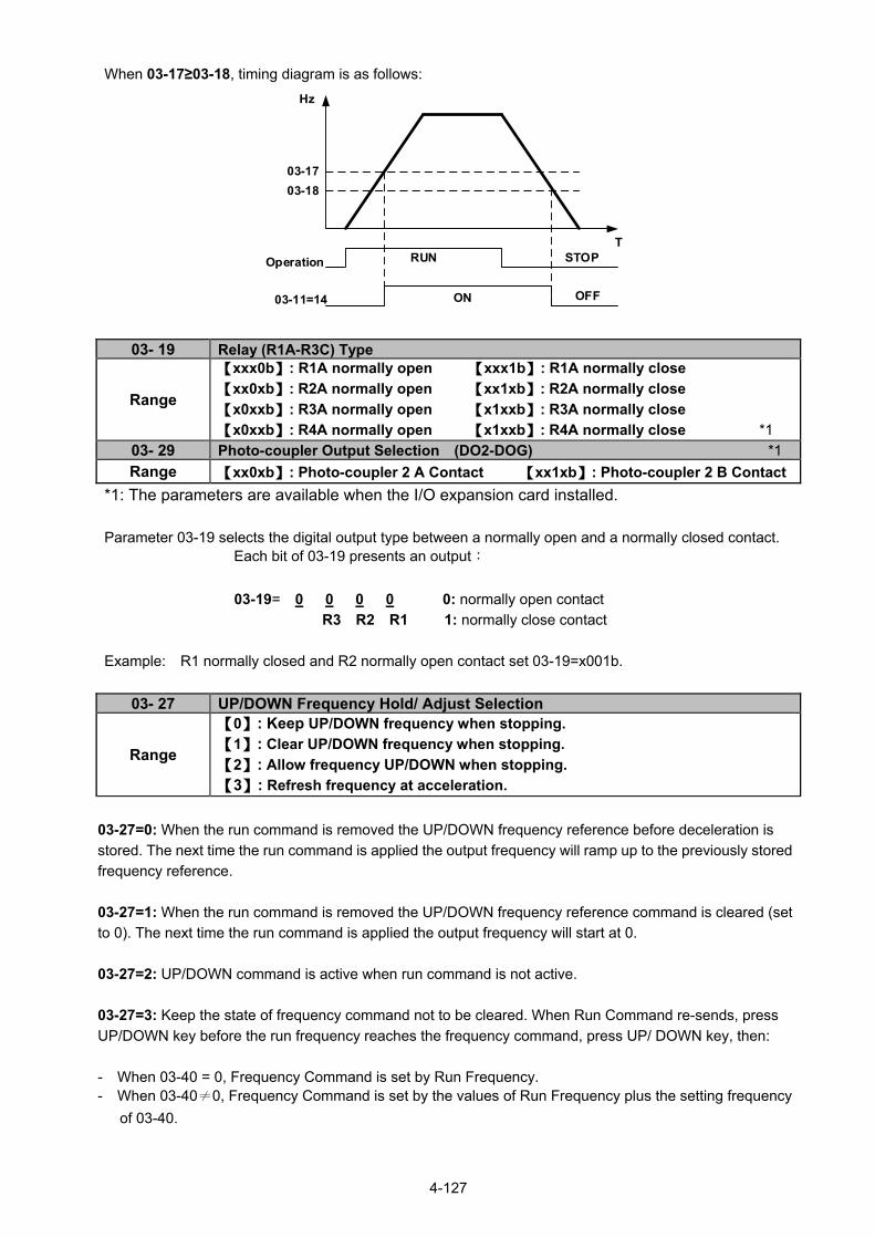
4-127
When 03-17≥03-18, timing diagram is as follows:
03-18
03-17
Operation
03-11=14
Hz
T
ON OFF
RUN STOP
03- 19 Relay (R1A-R3C) Type
Range
【xxx0b】: R1A normally open 【xxx1b】: R1A normally close
【xx0xb】: R2A normally open 【xx1xb】: R2A normally close
【x0xxb】: R3A normally open 【x1xxb】: R3A normally close
【x0xxb】: R4A normally open 【x1xxb】: R4A normally close *1
03- 29 Photo-coupler Output Selection (DO2-DOG) *1
Range 【xx0xb】: Photo-coupler 2 A Contact 【xx1xb】: Photo-coupler 2 B Contact
*1: The parameters are available when the I/O expansion card installed.
Parameter 03-19 selects the digital output type between a normally open and a normally closed contact. Each bit of 03-19 presents an output:
03-19= 0 0 0 0 0: normally open contact
R3 R2 R1 1: normally close contact
Example: R1 normally closed and R2 normally open contact set 03-19=x001b.
03- 27 UP/DOWN Frequency Hold/ Adjust Selection
Range
【0】: Keep UP/DOWN frequency when stopping.
【1】: Clear UP/DOWN frequency when stopping.
【2】: Allow frequency UP/DOWN when stopping.
【3】: Refresh frequency at acceleration.
03-27=0: When the run command is removed the UP/DOWN frequency reference before deceleration is
stored. The next time the run command is applied the output frequency will ramp up to the previously stored
frequency reference.
03-27=1: When the run command is removed the UP/DOWN frequency reference command is cleared (set
to 0). The next time the run command is applied the output frequency will start at 0.
03-27=2: UP/DOWN command is active when run command is not active.
03-27=3: Keep the state of frequency command not to be cleared. When Run Command re-sends, press
UP/DOWN key before the run frequency reaches the frequency command, press UP/ DOWN key, then:
- When 03-40 = 0, Frequency Command is set by Run Frequency. - When 03-40≠0, Frequency Command is set by the values of Run Frequency plus the setting frequency
of 03-40.

4-128
03- 30 Pulse Input Selection *1
Range 【0】: Common Pulse Input
【1】: PWM (Pulse Width Modulation)
*1: It is new added in inverter software V1.4. There are two modes in pulse input selection:
03-30=0: Common Pulse Input Pulse Input (PI) = the selected frequency divided by pulse input scaling (set by 03-31), corresponding to
the maximum output frequency of motor 1 (01-02).
Note: Monitor parameter 12-79 (pulse input percentage) displays the proportional relationship between
input signal and 03-31 (pulse input scaling).
03-30=1: PWM (Pulse Width Modulation)
It is required to input the correct frequency.
PWM= posedge pulse time divided by previous pulse time period, corresponding to the maximum output
frequency of motor 1 (01-02).
Note: Monitor parameter 12-79 (pulse input percentage) displays the proportional relationship between
the positive edge of input signal and time period.
Note: Tolerance range of pulse time period in PWM modes is ±12.5%. If it is over than the range, it is
inactive.
Diagram of pulse input selection:

4-129
03-31 Pulse Input Scaling
Range 【50~32000】Hz
Pulse input scaling, 100% = Maximum pulse frequency.
03- 32 Pulse Input Gain
Range 【0.0~1000.0】%
Target value (03-03) in % = Pulse input frequency scaled to 100% based on maximum pulse frequency (03-31) times the gain (03-32) + bias (03-33).
03-33 Pulse Input Bias
Range 【-100.0~100.0】%
Target value (03-03) in % = Pulse input frequency scaled to 100% based on maximum pulse frequency (03-31) times the gain (03-32) + bias (03-33).
03-34 Pulse Input Filter Time
Range 【0.00~2.00】Sec
* Refer to Fig.4.4.24 for the pulse input specification.
Figure 4.4.24 Pulse input adjustment
Set Pulse Input Setup as Flow Meters Input
Set parameter 23-45 (Given Modes of Flow Meters Feedback) to 2 (Pulse Input) to use the pulse input
terminal PI as the flow meters input. Refer to the description of parameter group 23 for details. Next set the
pulse input scaling (03-31), enter the pulse input frequency to match the maximum output frequency.
Adjust the pulse input filter time (03-34) in case interference or noise is encountered.

4-130
03- 37 Timer ON Delay (DI/DO)
Range 【0.0~6000.0】Sec
03-38 Timer OFF Delay (DI/DO)
Range 【0.0~6000.0】Sec
Enable the timer function be setting one of multi-function input parameters 03-00~03-05 (S1 to S6) to 35
(timer function input) and one of multi-function output parameters 03-11, 03-12, 03-39 (R1A-R1C to R3A-
R3C) to 27 (timer function output).
The timer function can be used to implement a timer relay. Use timing parameter 03-37 and 03-38 to set
the timer ON / OFF delay. Timer output is turned ON when the multi-function timer input is ON for the time specified in parameter 03-37. Timer output is turned OFF after the multi-function timer input is OFF for the time specified in parameter 03-38. Timing example:
ON
ON
ON
ON
Timer input function
03-37 03-38 03-37 03-38
Timer output function
03- 40 Up/down Frequency Width Setting *1
Range 【0.00~5.00】Hz
*1: It is new added in inverter software V1.4. For example: Set terminal S1: 03- 00=【8】(Up Frequency Increasing Command), S2:03- 01=【9】(DOWN
Frequency Decreasing Command) and 03- 40=【】Hz.
Mode1: When 03-40 is set to 0Hz, it will maintain the original up/down function, shown as Fig. 4.4.20.
Mode2: When 03-40 is not set to 0Hz and terminal conduction time is lower than 2 sec, conducting one time leading to frequency variation Hz (setting frequency by 03-40)。

4-131
Terminal S1
Terminal S2
ON ON ON
Hz
T
Hz
Real Output Frequency
ON ON ON
Lower limit of frequency
reference
Upper limit of frequency
reference
Mode3: When 03-40 is not set to 0Hz and terminal conduction time is larger than 2 sec, frequency
variation depends on acceleration/ deceleration.
Terminal S1
Terminal S2
ON
2Sec
OFF
OFF ON
2Sec
T
Setting Frequency(Hz)
Upper limit of frequency
reference Real Output Frequency
H1
t1
H2
t2
Hz
Lower limit of frequency
reference
Notes: H1: setting frequency increment in acceleration, t1: terminal conduction time in acceleration, H2: setting frequency increment in deceleration, t2: terminal conduction time in deceleration.
(t1) Time Conduction Terminal2 Time onAccelerati
Frequency Limit Upper1 H
(t2) Time Conduction Terminal2 Time onDecelerati
Frequency Limit Upper2 H

4-132
03- 41 Torque Detection Level *1Range 【0~150】%
03-42 Delay Time of Braking Action *1Range 【0.00~65.00】Sec
*1: It is new added in inverter software V1.4.
Function of Brake Release:
It requires function of frquecny agree to use, shown as the following figure.
When output frequency is larger than frequency detection level (03-13) and output torque is larger than
torque detection level (03-41) during Inverter operation, it will delay braking action delay time (03-42) and
then release brake.
It is also recommended to be with the use of start and stop frequency locked function (11-43~11-46),
shown as the following figure:
03-43 UP/DOWN Acceleration/ Deceleration Selection
Range 【0】: Acceleration/Deceleration Time 1 【1】: Acceleration/Deceleration Time 2
Calculate the acceleration/ deceleration time of frequency command by switch the function of UP/DOWN
from parameter 03-43. Ex: H1 (set frequency increment at acceleration) and H2 (set frequency
increment at deceleration).

4-133
Ex 1:
03-43=1(Acceleration/ Deceleration Time 2) Acceleration/ Deceleration Time 1 > Acceleration/ Deceleration Time 2
Terminal S1
Terminal S2
Lasting ON
2Sec
OFF
OFF Lasting ON
2Sec
t1
t4
H2
Hz
H4
Hz
UP/DOWN Command Slope
Frequency
Output Frequency
Upper Limit of Frequency Reference
Lower Limit of Frequency Reference
Upper Limit of Frequency Reference
Lower Limit of Frequency Reference
H3
H1
t3
t2
Notes:
H1: Frequency augmentation setting in acceleration, t1: Terminal conduction time in acceleration
H2: Frequency augmentation setting in deceleration, t2: Terminal conduction time in deceleration
t3: Acceleration time in output
H3: Output frequency augmentation in acceleration, t4: Deceleration time in output H4: Output frequency augmentation in deceleration
22Timeon Decelerati
Frequencylimit Upper 2
12 Timeon Accelerati
Frequencylimit Upper 1
tH
tH
4Time1on Decelerati
FrequencyLimit Upper 4
31 Timeon Accelerati
FrequencyLimit Upper 3
tH
tH

4-134
Ex2:
03-43=1(Acceleration/ Deceleration Time 2) Acceleration/ Deceleration Time 1 < Acceleration/ Deceleration Time 2
Terminal S1
Terminal S2
Lasting ON
2Sec
OFF
OFF Lasting ON
2Sec
t1
t2
H2
Hz
H4
UP/DOWN Command Slope
Frequency
Upper Limit Frequency reference
Lower Limit Frequency reference
Upper Limit Frequency reference
Lower Limit Frequency reference
H3
H1
t3 t4
Output Frequency
Notes:
H1: Frequency augmentation setting in acceleration t1: Terminal conduction time in acceleration
H2: Frequency augmentation setting in deceleration t2: Terminal conduction time in deceleration
t3: Acceleration time in output
H3: Output frequency augmentation in acceleration, t4: Deceleration time in output
H4: Output frequency augmentation in deceleration
22Timeon Decelerati
Frequencylimit Upper 2
12 Timeon Accelerati
Frequencylimit Upper 1
tH
tH
4Time1on Decelerati
FrequencyLimit Upper 4
31 Timeon Accelerati
FrequencyLimit Upper 3
tH
tH

4-135
Group 04 External Analog Input and Output Parameters
04- 00 AI Input Signal Type
Range
【0】: AI1 0~10V AI2 0~10V
【1】: AI1 0~10V AI2 4~20mA
【2】: Reserved
【3】: Reserved
【4】: AI1 4~20mA AI2 0~10V
【5】: AI1 4~20mA AI2 4~20mA
04- 09 AI Input Signal Type on I/O expansion card *1
Range 【0】: AI3 0~10V
【1】: AI3 -10~10V
【2】: AI3 4~20mA
04- 01 AI1 Signal Scanning and Filtering Time
Range 【0.00~2.00】Sec
04- 02 AI1 Gain
Range 【0.0~1000.0】%
04- 03 AI1 Bias
Range 【-100~100.0】%
04- 04 AI negative Characteristics
Range 【0】:Disable 【1】:Enable
04- 05 AI2 Function Setting
04- 10 AI3 Function Setting *1
Range
【0】: Auxiliary Frequency
【1】: Frequency Reference Gain
【2】: Frequency Reference Bias
【3】: Output Voltage Bias 【4】: Coefficient of Acceleration and Deceleration Reduction
【5】: DC Braking Current*
【6】: Over-Torque Detection Level
【7】: Stall Prevention Level During Running
【8】: Frequency Lower Limit 【9】: Jump Frequency 4
【10】: Added to AI1
【11】: Positive Torque Limit
【12】: Negative Torque Limit 【13】: Regenerative Torque Limit 【14】: Positive / Negative Torque Limit 【15】: Reserved 【16】: Torque Compensation
【17】: Reserved
04- 06 AI2 Signal Scanning and Filtering Time
Range 【0.00~2.00】Sec
04- 07 AI2 Gain
Range 【0.0~1000.0】%
04- 08 AI2 Bias
Range 【-100.0~100.0】%
04- 21 AI3 Signal Scanning and Filtering Time *1
Range 【0.00~2.00】Sec
04- 22 AI3 Gain *1

4-136
Range 【0.0~1000.0】%
04- 23 AI3 Bias *1
Range 【-100.0~100.0】%
*1: The parameters are available when the I/O expansion card installed. For Standard H & C type: Refer to the followings for the details of parameter 04-00 (AI input signal type) AI2=0~10V, Set 04-00=0, tune SW2 on the control board ro V. AI2=0~20mA, Set 04-00=0, tune SW2 on the control board to I. AI2=4~20mA, Set 04-00=1, tune SW2 on the control board to I. AI2=2~10V, Set 04-00=1, tune SW2 on the control board to V. For Enhanced E & G type: Refer to the followings for the details of parameter 04-00 (AI input signal type) AI1=0~10V, Set 04-00=0 or 1, tune SW3 on the control board to V. AI1=4~20mA, Set 04-00=4 or 5, tune SW3 on the control board to I. AI2=0~10V, Set 04-00=0 or 2 or 4, tune SW4 on the control board to V AI2=4~20mA, Set 04-00=1 or 3 or 5, tune SW4 on the control board to I. For I/O expansion card: Refer to the followings for the details of parameter 04-09 (AI input signal type) AI3=0~10V, Set 04-09=0, tune SW7 on the I/O expansion card to V. AI3=-10~10V, Set 04-09=1, tune SW7 on the I/O expansion card to V. AI3=4~20mA, Set 04-09=2, tune SW7 on the I/O expansion card to I. (1) Analog Input Level Adjustment AI1, AI2, AI3 (04-02, 04-03, 04-04, 04-07, 04-08, 04-22, 04-23)
Each analog input AI1and AI2 has a separate gain and bias parameter associated with it. Analog input signal AI1 can be adjusted with parameter 04-02 and 04-03; Analog input signal AI2 can be adjusted with parameter 04-07 and 04-08, Analog input signal AI3 can be adjusted with parameter 04-22 and 04-23. Refer to Fig.4.4.25.
Figure 4.4.25 Analog inputs and related parameters (For Standard H & C type)
Gain setting: Sets the level in % that corresponds to a 10V or 20mA signal at the analog input.
Bias setting: Sets the level in % that corresponds to a 0V or 4mA signal at the analog input.
Use both gain and bias setting to scale the input signal.

4-137
Gain: 200%
Gain: 100%
200%
100%
10V(20mA)
0V(4mA)
-200%
-10VTerminalAI1,AI2
analog input
Frequency Reference
+100%
-100%
10V(20mA)
0V(4mA)
Bias = positive
Bias = 0%
Bias = Negative
TerminalAI1,AI2
analog input
(a) Gain
(b) Bias
Frequency Reference
-10V
Figure 4.4.26 Gain and bias operations (for frequency reference signal)
04-04 (AI negative characteristics) Through the following figure negative characteristics diagram find out the AI Input 10V, -10V, or 20mA input relative frequency reference to be used for the ratio of maximum output frequency (set the maximum output frequency 01-02 to 100%), the ratio will be presented in reverse.
-10V 10V
100%
0% 0V(4mA) (20mA)

4-138
(1) AI1 signal filtering time (04-01) (2) AI2 signal filtering time (04-06) (3) AI3 signal filtering time (04-21)
All analog inputs (AI1, AI2, AI3) have a 1st order programmable input filter that can be adjusted when noise
is present on each of the incoming analog signal to prevent erratic drive control.
The filter time constant (range: 0.00 to 2.00 seconds) is defined as the time that the input step signal
reaches 63% of its final value.
Note: Increasing the filter time causes the drive operation to become more stable but less responsive to
change to the analog input.
Figure 4.4.27 Filter time constant
(4) AI2 function setting (04-05/04-10) AI2 is multi-function analog input terminal function selection. Refer to Table 4.4.8 for function overview
Table 4.4.8 Multi-function analog input list (04-05/04-10 setting)
Value Function
Description Control mode
Name LCD Display V/F SLV PMSLV
0 Auxiliary Frequency AUX.Freq Ref Max Output Frequency (01-02, Fmax) =100% O O O
1 Frequency Reference Gain (FGAIN) Freq Ref Gain Aggregated gain=
AI1 = 04-02 * FGAIN O O O
2 Frequency Reference Bias (FBIAS) Freq Ref Bias Aggregated bias=
AI1 = 04-03 * FBIAS O O O
3 Output Voltage Bias (VBIAS) Output Volt Bias Aggregate output voltage =V/F
curve voltage + VBIAS O X O
4
Coefficient of Acceleration and Deceleration Reduction (K)
Tacc/Tdec ScalingActual acceleration and deceleration time = accel. and decal. time / K
O O O
5 DC Braking Current DC Inj Current
Adjust the DC braking current (0 ~ 100%) based on analog input. When the inverter rated current = 100%, DC braking current 07-07 is disabled.
O O O

4-139
Value Function
Description Control mode
Name LCD Display V/F SLV PMSLV
6 Over-Torque Detection Level Over Tq Level
Change over-torque detection level based on over-torque detection level, at this time, 08-15 is disabled.
O O O
7 Stall Prevention Level During Running Run Stall Level
Adjust the action level (30% ~ 200%) of stall prevention in operation based on analog input. The inverter rated current =100%
O X O
8 Frequency Lower Limit Ref. Low Bound
Adjust the lower limit (0 ~ 100%) of frequency command based on analog input, the maximum output = 100%. The lower limit of frequency command is the greater one of the actual frequency command’s lower limit 00-13 or the multi-function analog input.
O O O
9 Jump Frequency 4 Jump Freq 4 Jump frequency 4.100% = maximum output frequency
O O O
10 Added to AI1 Add to AI1 Added to AI1.100% = maximum output frequency
O O O
11 Positive Torque Limit Positive Tq Limit 100% = Motor’s rated torque X O O
12 Negative Torque Limit Negative Tq Limit 100% = Motor’s rated torque X O O
13 Regenerative Torque Limit Regen. Tq Limit 100% = Motor’s rated torque X O O
14 Positive / Negative Torque Limit +/- Tq Limit 100% = Motor’s rated torque X O O
15 Torque Limit Tq Limit 100% = Motor’s rated torque X X X
16 Torque Compensation Tq Compensation 100% = Motor’s rated torque X O X
17 Reserved No Function Reserved O O O
Note: When the setting of AI2 and AI3 are the same, use AI2 signal only. 04-05=0: Auxiliary frequency
When parameter 00-05 = 1 (main frequency from external control) the auxiliary speed reference frequency
can be activated via the multi-speed input commands (see table 4.4.5). The auxiliary frequency command
can be set via AI2/AI3. The maximum output frequency is set by 01-02, Fmax =100%.
04-05/04-10=1: Frequency Reference Gain (FGAIN)
Multi-function analog input AI2/AI3 can be used to adjust the frequency reference gain of analog input AI1.
The total frequency reference gain of terminal AI1 is the internal gain set by parameter 04-02 times FGAIN.
The maximum frequency reference for AI1 is 100%.
Figure 4.4.28 Frequency gain adjustment

4-140
Example: When the internal gain of AI1 (04-02) is set to 100% and AI2 to 5V (for example FGAIN = 50%), the reference frequency of terminal AI1 will be 50%, as shown in Fig. 4.4.29.
Figure 4.4.29 Frequency reference gain adjustment (example)
04-05/04-10=2: Frequency Reference bias (FBIAS)
Multi-function analog input terminal AI2 can be used to adjust the frequency reference bias of AI1.
The total frequency reference bias of terminal AI1 is the sum of internal bias set by parameter 04-03 and
FBIAS. The maximum frequency reference for AI1 is 100%.
Figure 4.4.30 Bias adjustment
Example:
Terminal AI1 input is 0V, 04-02 = 100% (AI1 gain), 04-03 = 0% (AI1 bias) and terminal AI2 input is 3V. The
reference frequency will be 30% as shown in Fig.4.4.31.
Figure 4.4.31 Frequency Reference bias adjustment (example)
04-05/04-10=3: Output Voltage Bias (VBIAS)
Multi-function analog input AI2/AI3 can be used to adjust the output voltage. The total output voltage of
inverter is the sum of output voltage based on the selected V/F curve (01-00=F) and VBIAS.
The maximum output voltage will be limited by 01-03, Vmax = 100%
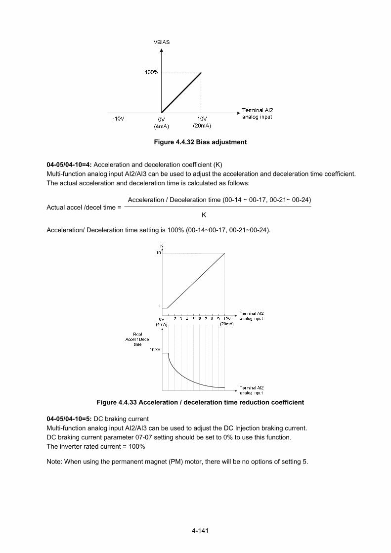
4-141
Figure 4.4.32 Bias adjustment 04-05/04-10=4: Acceleration and deceleration coefficient (K)
Multi-function analog input AI2/AI3 can be used to adjust the acceleration and deceleration time coefficient.
The actual acceleration and deceleration time is calculated as follows:
Acceleration / Deceleration time (00-14 ~ 00-17, 00-21~ 00-24)
Actual accel /decel time = K Acceleration/ Deceleration time setting is 100% (00-14~00-17, 00-21~00-24).
Figure 4.4.33 Acceleration / deceleration time reduction coefficient
04-05/04-10=5: DC braking current
Multi-function analog input AI2/AI3 can be used to adjust the DC Injection braking current.
DC braking current parameter 07-07 setting should be set to 0% to use this function.
The inverter rated current = 100% Note: When using the permanent magnet (PM) motor, there will be no options of setting 5.

4-142
Figure 4.4.34 DC braking current adjustment
04-05/04-10=6: Over-torque detection level
Multi-function analog input AI2/AI3 can be used to adjust the over-torque detection level.
100% of inverter rated current (V/F control mode)
100% motor rated torque (SLV control mode)
If the multi-function analog input is used to adjust the over-torque level, the internal over-torque detection
level (08-15) is disabled.
Figure 4.4.35 Over-torque/less torque detection level adjustment 4-05/04-10=7: Stall prevention level during running
Multi-function analog input AI2/AI3 can be used to adjust the stall prevention level during operation. Inverter rated current = 100%. When AI2 is set to control stall prevention level (04-05 = 7) or AI3 is set to
control stall prevention level (04-10 = 7) and parameter 08-03 (Stall prevention level during operation) is
used, then the lesser of the two value becomes the active stall prevention level during operation.
Example: If the motor power is less than that of the inverter, the operation and the stall prevention of the
motor will be based on the factory settings, multi-function analog input AI2/AI3 can be used to reduce the
stall prevention level during operation.

4-143
Figure 4.4.36 Stall prevention level adjustment during operation 04-05/04-10=8: Frequency lower limit
Multi-function analog input AI2/AI3 can be used to adjust the lower limit of frequency reference. Maximum output frequency (Fmax, 01-02) = 100%. The actual lower limit is determined by the maximum value of 00-13 (frequency lower limit) and level of the multi-function analog input AI2/AI3.
Figure 4.4.37 Adjustment of lower limit of frequency reference

4-144
04-05/04-10=9: Jump frequency 4
Multi-function analog input AI2/AI3 can be used to adjust Jump frequency 4.
Maximum output frequency (01-02, Fmax) = 100%. Setting 11-08 ~ 11-10 to 0.0Hz turns of the Jump
frequency function.
Figure 4.4.38 Jump frequency 4 setting operation
04-05=10 or 04-10=10: Added to AI1
Multi-function analog input AI2/AI3 can be used as a bias level for analog input AI1.
Figure 4.4.39 Added to Al1 as a bias operation
Example: 04-02 (AI1 gain) = 100%, 04-03 (AI2 gain) = 0%, and terminal AI2 level is 2V. If input terminal AI1 is 0V, the internal reference frequency of terminal AI1 will be 20 % 04-05=11: Positive torque limit
Multi-function analog input AI2 can be used to adjust the positive torque limit. 04-05=12: Negative torque limit
Multi-function analog input AI2 can be used to adjust the negative torque limit. 04-05=13: Regenerative torque limit
Multi-function analog input AI2 can be used to adjust the regenerative torque limit.
4-145
04-05=14: Positive / negative torque limits
Multi-function analog input AI2 can be used to adjust both the positive and negative torque limit. For more details on torque limits, please refer to parameter group 21 - torque control group. 04-05=15: Reserved 04-05=16: Torque compensation of speed control
Multi-function analog input AI2 can be used to adjust the torque compensation in closed loop vector mode. For more details on the torque control functions, please refer to parameter group 21 - torque control group.
04-11 AO1 Function Setting
Range
【0】: Output Frequency
【1】: Frequency Command 【2】: Output Voltage 【3】: DC Voltage 【4】: Output Current 【5】: Output Power 【6】: Motor Speed
【7】: Output Power Factor
【8】: AI1 Input
【9】: AI2 Input 【10】: Torque Command
【11】: q-axis Current
【12】: d-axis Current
【13】: Speed Deviation 【14】: Reserved 【15】: ASR Output 【16】: Reserved 【17】: q-axis Voltage
【18】: d-axis Voltage
【19】~【20】: Reserved
【21】: PID Input
【22】: PID Output
【23】: PID Target Value
【24】: PID Feedback Value
【25】: Output Frequency of the Soft Starter
【26】: Reserved
【27】: Reserved
【28】: Communication Control
04-12 AO1 Gain
Range 【0.0~1000.0】%
04-13 AO1 Bias
Range 【-100.0~100.0】%
04-16 AO2 Function Setting
Range Setting range and definition are the same as those of 04-11.
04-17 AO2 Gain
Range 【0.0~1000.0】%
04-18 AO2 Bias
Range 【-100.0~100.0】%
04-19 AO Output Signal Type

4-146
Range
【0】: AO1 0~10V AO2 0~10V 【1】: AO1 0~10V AO2 4~20mA 【2】: AO1 4~20mA AO2 0~10V 【3】: AO1 4~20mA AO2 4~20mA
For the analog output and related parameters, refer to Fig.4.4.40.
Figure 4.4.40 Analog outputs and related parameters
Analog output AO1 and AO2 adjustment (04-12, 04-13 and 04-17, 04-18)
Signal: Use parameter 04-11 to select the analog output signal for AO1 and parameter 04-16 to select the
analog output signal for AO2.
Gain: Use parameter 04-12 to adjust the gain for AO1 and parameter 04-17 to adjust the gain for AO2.
Adjust the gain so that the analog output (10V/20mA) matches 100% of the selected analog output signal
(04-11 for AO1 and 04-16 for AO2).
Bias: Use parameter 04-13 to adjust the bias for AO1 and parameter 04-18 to adjust the bias for AO2.
Adjust the bias so that the analog output (0V/4mA) matches 0% of the selected analog output signal
(04-11 for AO1 and 04-16 for AO2).
Figure 4.4.41 Analog output level adjustment

4-147
Table 4.4.9 Selection of analog output terminals function (04-11 and 04-16)
04-11, 04-16 Parameter setting
Function (Keypad display)
Monitoring ParametersGroup 12
Control Mode
VF SLV PMSLV
0 Output Freq 12-17 O O O 1 Freq Ref 12-16 O O O 2 Output Voltage 12-19 O O O 3 DC Voltage 12-20 O O O 4 Output Current 12-18 O O O 5 Output KW 12-21 O O O 6 Motor Speed 12-22 O O O 7 Output PF 12-23 O O O 8 AI1 Input 12-25 O O O 9 AI2 Input 12-26 O O O 10 Torque Ref 12-27 X O O 11 Current Iq 12-28 X O O 12 Current Id 12-29 X O O 13 Speed Deviation 12-30 X O O 14 Reserved - X X X 15 ASR Output 12-32 X X X 16 Reserved - X X X 17 Voltage Ref Vq - X O O 18 Voltage Ref Vd - X O O
19~20 Reserved - X X X 21 PID Input 12-36 O O O 22 PID Output 12-37 O O O 23 PID Setpoint 12-38 O O O 24 PID Feedback 12-39 O O O 25 Output Freq (SFS) - O O O
26~27 Reserved - X X X 28 Comm Control - O O O
04-20 Filter Time of AO Signal Scan *1
Range 【0.00~0.50】Sec
*1: It is new added in inverter software V1.4.
This function is used for filtering out momentary change of analog output signal.
Note: When this function is added, it will decrease the system reaction but increase interference
protection.

4-148
Group 05 Multi-Speed Parameters
05- 00 Acceleration and Deceleration Selection of Multi-Speed
Range 【0】:Acceleration and deceleration time are set by 00-14 ~ 00-24
【1】:Acceleration and Deceleration Time are set by 05-17 ~ 05-48
05-00=0: Standard Acceleration and deceleration times parameters 00-14 ~ 00-17 / 00-21 ~ 00-24 are
used for multi-speed 0 ~ 15.
05-00=1: Each multi-speed uses a dedicated acceleration and deceleration time parameters 05-17 ~
05-48. There are two different modes for acceleration / deceleration timing when 05-00 is set to 1, see time
example on the next page.
Acceleration time calculation formula
Acceleration time x (set frequency - output frequency)
Time it takes to reach set frequency =
Maximum output frequency
Deceleration time calculation formula Deceleration time x (output frequency - set frequency)
Time it takes to reach set frequency =
Maximum output frequency
Maximum output frequency: Parameter 01-00=F, maximum output frequency set by 01-02, 01-00 ≠ F,
maximum output frequency determined by V/F curve selected (50.0 / 60.0 / 90.0 / 120.0 / 180.0).
Example:01-00=01 (50Hz (maximum output frequency), 05-02=10 Hz (multi-step speed 0), 05-17=5.0s
(Acceleration time), 05-18=20.0 sec. (Deceleration time).
Acceleration time calculation formula 5.0 x 10 Hz
Time it takes to reach set frequency = = 1.0 sec. 50 Hz
Deceleration time calculation formula 20.0 x 10 Hz
Time it takes to reach set frequency = = 4.0 sec. 50 Hz
Example: Acceleration / deceleration timing when 05-00 is set to 1. In this example the following
parameters are set:
00-02=1 (External Terminal Operation)
03-00=0 (Terminal S1: Forward /Stop)
03-01=1 (Terminal S2: Reversal /Stop)
03-02=2 (Terminal S3: Speed 1)
03-03=3 (Terminal S4: Speed 2)
03-03=4 (Terminal S5: Speed 3)
*Speed 1 is required to confirm if AI2 function setting (04-05) is set to 0 (Auxiliary frequency). If 04-05=0, it
will make the frequency of speed 1 set to AI2 auxiliary frequency and the value is determined by AI2. If
function of speed 1 is generally used, set AI2 to other functions except 0 (the recommended value: set 10
ADD to AI1.)

4-149
Acceleration / Deceleration Calculation Mode 1:
If the run command is cycled on and off, acceleration and deceleration time (a ~ f) is calculated based on
the active speed command as follows:
Terminal S1
Terminal S2
Terminal S3
Terminal S4
Run Run RunStop Stop Stop
Off
OffOff
Off
On
On
a b c d e f
Spe
edC
omm
and
0
Spe
edC
omm
and
1
Spe
edC
omm
and
2
05-01
05-02
05-03
T
Hz
in sec.(05-17) x (05-01) (05-18) x (05-01) (05-19) x (05-02)
(01-02) (01-02) (01-02)a = b = c =
(05-20) x (05-02) (05-21) x (05-03) (05-22) x (05-03)
(01-02) (01-02) (01-02)d = e = f = in sec.

4-150
Acceleration / Deceleration Calculation Mode 2:
If the run command is remains on, acceleration and deceleration time (a ~ f) is calculated based on the
active speed command as follows:
Terminal S1
Terminal S2
Terminal S3
Terminal S4
On
17/18
StopOff
OffOff Off On
a b c d e
f
Spe
edC
omm
and
0
Spe
edC
omm
and
1
05-03
05-06
T
Hz
g
h i
Spe
edC
omm
and
2
Spe
edC
omm
and
3
Spe
edC
omm
and
4
Spe
edC
omm
and
5
05-0405-02
05-05
05-01
OnOff Off
Off Off On On OffOff Off
Terminal S519/20 21/22 23/24 25/26 27/28 19/20
Off On
Off Off OffOn On On
in sec.(05-17) x (05-01) (05-19) x [(05-02)-(05-01)] (05-21) x [(05-03) – (05-02)]
(01-02) (01-02) (01-02)a = b = c =
(05-24) x [(05-03) – (05-04)] (05-26) x (05-04) (05-25) x (05-05)
(01-02) (01-02) (01-02)d = e = f = in sec.
(05-27) x (05-05) (05-27) x (05-06) (05-19) x (05-06)
(01-02) (01-02) (01-02)g = h = i = in sec.
05- 01 *Frequency Setting of Speed-Stage 0
Range 【0.0~599.00】 Hz
05-02 *Frequency Setting of Speed- Stage 1 *1
Range 【0.0~599.00】 Hz
05-03 *Frequency Setting of Speed- Stage 2 *1
Range 【0.0~599.00】 Hz
05-04 *Frequency Setting of Speed- Stage 3 *1
Range 【0.0~599.00】 Hz

4-151
05-05 *Frequency Setting of Speed- Stage 4 *1
Range 【0.0~599.00】 Hz
05-06 *Frequency Setting of Speed- Stage 5 *1
Range 【0.0~599.00】 Hz
05-07 *Frequency Setting of Speed- Stage 6 *1
Range 【0.0~599.00】 Hz
05-08 *Frequency Setting of Speed- Stage 7 *1
Range 【0.0~599.00】 Hz
05-09 *Frequency Setting of Speed- Stage 8 *1
Range 【0.0~599.00】 Hz
05-10 *Frequency Setting of Speed- Stage 9 *1
Range 【0.0~599.00】 Hz
05-11 *Frequency Setting of Speed- Stage 10 *1
Range 【0.0~599.00】 Hz
05-12 *Frequency Setting of Speed- Stage 11 *1
Range 【0.0~599.00】 Hz
05-13 *Frequency Setting of Speed- Stage 12 *1
Range 【0.0~599.00】 Hz
05-14 *Frequency Setting of Speed- Stage 13 *1
Range 【0.0~599.00】 Hz
05-15 *Frequency Setting of Speed- Stage 14 *1
Range 【0.0~599.00】 Hz
05-16 *Frequency Setting of Speed- Stage 15 *1
Range 【0.0~599.00】 Hz
*: (When the motor’s maximum output frequency is over than 300Hz, the frequency resolution is
0.1Hz.)
*1: It isnew added in inverter software V1.4. Parameters 05-02~05-16 is required to set the
frequency in parameters 06-01~06-15 in inverter software V1.3.
05-17 Acceleration time setting for multi speed 0
Range 【0.1~6000.0】 Sec
05-18 Deceleration time setting for multi speed 0
Range 【0.1~6000.0】 Sec

4-152
05-19 Acceleration time setting for multi speed 1
Range 【0.1~6000.0】 Sec
05-20 Deceleration time setting for multi speed 1
Range 【0.1~6000.0】 Sec
05-21 Acceleration time setting for multi speed 2
Range 【0.1~6000.0】 Sec
05-22 Deceleration time setting for multi speed 2
Range 【0.1~6000.0】 Sec
05-23 Acceleration time setting for multi speed 3
Range 【0.1~6000.0】 Sec
05-24 Deceleration time setting for multi speed 3
Range 【0.1~6000.0】 Sec
05-25 Acceleration time setting for multi speed 4
Range 【0.1~6000.0】 Sec
05-26 Deceleration time setting for multi speed 4
Range 【0.1~6000.0】 Sec
05-27 Acceleration time setting for multi speed 5
Range 【0.1~6000.0】 Sec
05-28 Deceleration time setting for multi speed 5
Range 【0.1~6000.0】 Sec
05-29 Acceleration time setting for multi speed 6
Range 【0.1~6000.0】 Sec
05-30 Deceleration time setting for multi speed 6
Range 【0.1~6000.0】 Sec
05-31 Acceleration time setting for multi speed 7
Range 【0.1~6000.0】 Sec
05-32 Deceleration time setting for multi speed 7
Range 【0.1~6000.0】 Sec
05-33 Acceleration time setting for multi speed 8
Range 【0.1~6000.0】 Sec
05-34 Deceleration time setting for multi speed 8
Range 【0.1~6000.0】 Sec
05-35 Acceleration time setting for multi speed 9
Range 【0.1~6000.0】 Sec

4-153
05-36 Deceleration time setting for multi speed 9
Range 【0.1~6000.0】 Sec
05-37 Acceleration time setting for multi speed 10
Range 【0.1~6000.0】 Sec
05-38 Deceleration time setting for multi speed 10
Range 【0.1~6000.0】 Sec
05-39 Acceleration time setting for multi speed 11
Range 【0.1~6000.0】 Sec
05-40 Deceleration time setting for multi speed 11
Range 【0.1~6000.0】 Sec
05-41 Acceleration time setting for multi speed 12
Range 【0.1~6000.0】 Sec
05-42 Deceleration time setting for multi speed 12
Range 【0.1~6000.0】 Sec
05-43 Acceleration time setting for multi speed 13
Range 【0.1~6000.0】 Sec
05-44 Deceleration time setting for multi speed 13
Range 【0.1~6000.0】 Sec
05-45 Acceleration time setting for multi speed 14
Range 【0.1~6000.0】 Sec
05-46 Deceleration time setting for multi speed 14
Range 【0.1~6000.0】 Sec
05-47 Acceleration time setting for multi speed 15
Range 【0.1~6000.0】 Sec
05-48 Deceleration time setting for multi speed 15
Range 【0.1~6000.0】 Sec

4-154
Group 06 Automatic Program Operation Parameters
06- 00 Automatic Operation Mode Selection
Range
【0】: Disable
【1, 4】: Execute a single cycle operation. Restart speed is based on the previous stopped
speed. 【2, 5】: Execute continuous cycle operation. Restart speed is based on the previous cycle
stop speed. 【3, 6】: After completion of a single cycle, the on-going operation speed is based on the
speed of the last stage. Restart speed is based on the previous stopped speed
1 to 3: After a stop the inverter will start with the incomplete step when the run command is
re-applied.
4 to 6: After a stop the inverter will start with the first step of the cycle when the run command
is re-applied.
Automatic operation mode uses frequency reference parameters 05-01, 06-01~06-15, operation time
parameters 06-16 ~ 06-31 and direction of operation parameters 06-32~06-47.
Note: The automatic operation mode is disabled when any of the following functions are enabled:
- Frequency wobbling function
- PID function - Parameters 06-16 to 06-31 are set to 0.
Notes:
- When automatic operation mode is enabled multi-step speed reference command 1~4
(03-00~03-07=2~5) is disabled.
- Frequency of multi-step speed 0 is set by 05-01.
- Acceleration/deceleration time is set by parameter 00-14 and 00-15 in automatic operation mode.
Automatic operation frequency reference settings
06-01 *Frequency Setting of Operation -Stage 1 *1
06-02 *Frequency Setting of Operation -Stage 2 *1
06-03 *Frequency Setting of Operation -Stage 3 *1
06-04 *Frequency Setting of Operation -Stage 4 *1
06-05 *Frequency Setting of Operation -Stage 5 *1
06-06 *Frequency Setting of Operation -Stage 6 *1
06-07 *Frequency Setting of Operation -Stage 7 *1
06-08 *Frequency Setting of Operation -Stage 8 *1
06-09 *Frequency Setting of Operation -Stage 9 *1
06-10 *Frequency Setting of Operation -Stage 10 *1
06-11 *Frequency Setting of Operation -Stage 11 *1
06-12 *Frequency Setting of Operation -Stage 12 *1
06-13 *Frequency Setting of Operation -Stage 13 *1
06-14 *Frequency Setting of Operation -Stage 14 *1
06-15 *Frequency Setting of Operation -Stage 15 *1
Range 0.00~599.00 Hz
*1: It is operation frequency in inverter software V1.4. *: (When the motor’s maximum output frequency is over than 300Hz, the frequency resolution is
0.1Hz.)

4-155
Automatic operation time settings
06-16 Time Setting of Operation -Stage 0
06-17 Time Setting of Operation -Stage 1
06-18 Time Setting of Operation -Stage 2
06-19 Time Setting of Operation -Stage 3
06-20 Time Setting of Operation -Stage 4
06-21 Time Setting of Operation -Stage 5
06-22 Time Setting of Operation -Stage 6
06-23 Time Setting of Operation -Stage 7
06-24 Time Setting of Operation -Stage 8
06-25 Time Setting of Operation -Stage 9
06-26 Time Setting of Operation -Stage 10
06-27 Time Setting of Operation -Stage 11
06-28 Time Setting of Operation -Stage 12
06-29 Time Setting of Operation -Stage 13
06-30 Time Setting of Operation -Stage 14
06-31 Time Setting of Operation -Stage 15
Range 0.0~6000.0 Sec
Automatic operation direction settings
06-32 Direction Selection of Operation -Stage 0
06-33 Direction Selection of Operation -Stage 1
06-34 Direction Selection of Operation -Stage 2
06-35 Direction Selection of Operation -Stage 3
06-36 Direction Selection of Operation -Stage 4
06-37 Direction Selection of Operation -Stage 5
06-38 Direction Selection of Operation -Stage 6
06-39 Direction Selection of Operation -Stage 7
06-40 Direction Selection of Operation -Stage 8
06-41 Direction Selection of Operation -Stage 9
06-42 Direction Selection of Operation -Stage 10
06-43 Direction Selection of Operation -Stage 11
06-44 Direction Selection of Operation -Stage 12
06-45 Direction Selection of Operation -Stage 13
06-46 Direction Selection of Operation -Stage 14
06-47 Direction Selection of Operation -Stage 15
Range 0: Stop, 1: Forward, 2: Reversal
Example 1: Automatic operation mode – Single cycle In this example the inverter executes a single cycle and then stops.

4-156
Parameter Settings: 06-00 = 1 (Single cycle operation)
06-32~06-34 = 1 (Forward for operation stage 0 - 2)
06-47 = 2 (Reversal for operation stage 15)
06-35~06-46 = 0 (Stop for operation frequency stage 3 - 14)
05-01 = 15 Hz (Operation frequency stage 0: 15 Hz)
06-01 = 30 Hz (Operation frequency stage 1: 30 Hz)
06-02 = 50 Hz (Operation frequency stage 2: 50 Hz)
06-15 = 20 Hz (Operation frequency stage 15: 20 Hz)
06-16 = 20 sec (Operation time stage 0: 20 sec)
06-17 = 25 sec (Operation time stage 1: 25 sec)
06-18 = 30 sec (Operation time stage 2: 30 sec)
06-31 = 40 sec (Operation time stage 15 :40 sec)
Freq.
50 Hz
30 Hz
15 Hz
20 Hz20s 25s 30s 40s
05-01
06-01
06-02
06-15
06-16 06-17 06-18 06-31
Figure 4.4.42 Single cycle automatic operation (stop)
Example 2: Automatic operation mode – Continuous cycle In this example the inverter repeats the same cycle. Parameter Settings:
06-00 = 2 or 5 (Continuous cycle operation) 06-01~06-47= Enter same setting as that of Example 1.

4-157
Figure 4.4.43 Periodic automatic operation
Example 3: Automatic operation mode – Single cycle and continue running at last speed of the cycle In this example the inverter executes a single cycle and continue running at last speed of the cycle.
Figure 4.4.44 Single cycle automatic operation (continuous)
06-00= 1 to 3:
After a stop the inverter will start with the incomplete step when the run command is re-applied.
06-00= 4 to 6:
After a stop the inverter will start with the first step of the cycle when the run command is re-applied.
Notes: - Acceleration/ deceleration time is set with parameters 00-14 and 00-15 in automatic operation mode. - If the setting value of parameters 06-16~06-31 is 0, automatic operation mode is not active.

4-158
07-02
07-01
1 2 3 4 5 6 7 8 9 10
Group 07: Start /Stop Parameters
07- 00 Momentary Power Loss/Fault Restart Selection
Range 【0】:Disable 【1】:Enable
07-00=0: Inverter trips on “UV” fault if power loss time is greater than 8ms.
07-00=1: Inverter restarts after restarting the power at the momentary power loss.
Note: When 07-00=1, inverter restore automatically the motor rotation after restarting the power even if
momentary power loss occurs.
07- 01 Fault Auto-Restart Time
Range 【0~7200】 Sec
07-01 = 0 sec.: Automatic restart time interval is set by minimum baseblock time (07-18). 07-01 <07-18: Automatic restart time interval is set by minimum baseblock time (07-18). 07-01> 07-18: Automatic restart time interval is set by fault reset time (07-01). Note: Automatic restart time interval is time of 07-18 plus 07-01 and delay time of peed search (07-22). Refer to Fig.4.4.45 for setting automatic restart interval.
Figure 4.4.45 Automatic restart operation
07- 02 Number of Fault Auto-Restart Attempts
Range 【0~10】
When the automatic restart function is enabled the internal automatic restart attempt counter is reset based on the following actions:
a) No fault occurs in 10 minutes or longer after the automatic restart b) Reset command to clear fault via input terminal or using the keypad (ex: press reset/ key) c) Power to the inverter is turned off and back on again Note: Multi-function digital output R1A-R1C, R2A-R2C, R3A-R3C can be programmed to activate during an automatic reset attempt, refer to parameter 03-11, 03-12 and 03-39. Automatic restart operation: a) Fault is detected. The inverter turn off the output, displays the fault on the keypad and waits for the
minimum baseblock time parameter 07-18 to expire before accepting another run / automatic restart command.
b) After the minimum baseblock time (07-18) has expired, the active fault is reset and a speed search
operation is performed. The time between each fault restart attempt is set by parameter 07-01. c) When the total numbers of restart attempts exceed the number of automatic restart attempts set in
parameter 07-02, the inverter will turn off the output and the fault contact is activated.

4-159
Please refer to Figure 4.4.46 for the automatic restart operation.
Figure 4.4.46 Auto-restart operation
The automatic restart function is active for the following faults. Please note that when the fault is not listed
in the table the inverter will not attempt an automatic restart.
Parameter
Name Faults
Numbers of Restart
07-00 UV (under voltage) Unlimited
07-01
07-02
OC (over current) OCA (over current in ACC.)OCC (over current in
constant speed) OCd (over current in DEC) OL1 (motor overload) UT (Under torque detection)IPL (input phase loss)
GF (ground failure) OV (overvoltage) OL2 (Inverter overload) OT (Over-torque detection) OPL (Output phase loss) CF07 (SLV motor control
setting fault) CF08 (PMSLV motor
control setting fault)
Depend on parameter
07-02
Notes: 1. Fault restart function contains momentary power loss restart and auto reset restart.
2. Refer to chapter 10 for the details of troubleshooting and fault diagnostics.
3. Refer to speed search function (07-19~07-24) for the selection of speed search modes.
Note: Automatic restart function is only active in the state of no harm to the safety or to the application devices. Warning - Excessively use of the automatic restart function will damage the inverter.
07- 04 Automatic start at power up
Range 【0】: Automatic start at power up when external run command is enabled 【1】: Without automatic start at power up when external run command is enabled
07- 04 = 0: If the running switch is in conducting state when power supply is on, the inverter will start automatically. 07- 04 =1: If the running switch is not in conducting state when power supply is on , the inverter will not start automatically and STP1 will flash. It is required to switch off the running switch and make it be in conducting state so as to start the inverter.
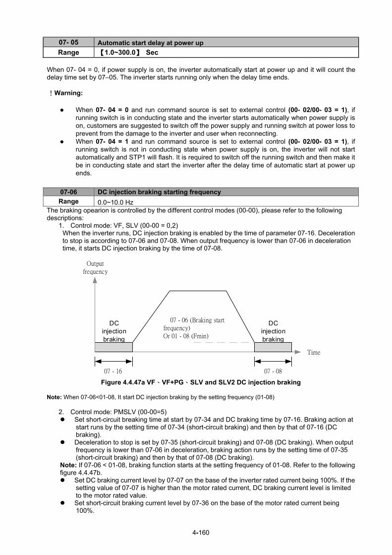
4-160
07- 05 Automatic start delay at power up Range 【1.0~300.0】 Sec
When 07- 04 = 0, if power supply is on, the inverter automatically start at power up and it will count the delay time set by 07–05. The inverter starts running only when the delay time ends. !Warning:
When 07- 04 = 0 and run command source is set to external control (00- 02/00- 03 = 1), if running switch is in conducting state and the inverter starts automatically when power supply is on, customers are suggested to switch off the power supply and running switch at power loss to prevent from the damage to the inverter and user when reconnecting.
When 07- 04 = 1 and run command source is set to external control (00- 02/00- 03 = 1), if running switch is not in conducting state when power supply is on, the inverter will not start automatically and STP1 will flash. It is required to switch off the running switch and then make it be in conducting state and start the inverter after the delay time of automatic start at power up ends.
07-06 DC injection braking starting frequency
Range 0.0~10.0 Hz The braking opearion is controlled by the different control modes (00-00), please refer to the following descriptions:
1. Control mode: VF, SLV (00-00 = 0,2) When the inverter runs, DC injection braking is enabled by the time of parameter 07-16. Deceleration to stop is according to 07-06 and 07-08. When output frequency is lower than 07-06 in deceleration time, it starts DC injection braking by the time of 07-08.
07 - 16 07 - 08
07 - 06 (Braking start frequency)Or 01 - 08 (Fmin)
DC injection braking
DC injection braking
Output frequency
Time
Figure 4.4.47a VF、VF+PG、SLV and SLV2 DC injection braking
Note: When 07-06<01-08, It start DC injection braking by the setting frequency (01-08)
2. Control mode: PMSLV (00-00=5) Set short-circuit breaking time at start by 07-34 and DC braking time by 07-16. Braking action at
start runs by the setting time of 07-34 (short-circuit braking) and then by that of 07-16 (DC braking).
Deceleration to stop is set by 07-35 (short-circuit braking) and 07-08 (DC braking). When output frequency is lower than 07-06 in deceleration, braking action runs by the setting time of 07-35 (short-circuit braking) and then by that of 07-08 (DC braking).
Note: If 07-06 < 01-08, braking function starts at the setting frequency of 01-08. Refer to the following figure 4.4.47b. Set DC braking current level by 07-07 on the base of the inverter rated current being 100%. If the
setting value of 07-07 is higher than the motor rated current, DC braking current level is limited to the motor rated value.
Set short-circuit braking current level by 07-36 on the base of the motor rated current being 100%.

4-161
07 - 06 (Braking Start Frequency) or 01 - 08 (Fmin)
SC Braking
Output frequency
Time
DC Braking
07-34 07-16
SC Braking
DC Braking
07-35 07-08
Figure 4.4.47b PMSLV braking action
07- 07 DC Injection Braking Current
Range 【0~100】%
DC Injection braking current as percentage of the inverter rated current. Increasing this level will increase
the amount of heat generated by the motor windings. Do not set this parameter higher than the level
necessary to hold the motor shaft.
07- 08 DC Injection Braking Time at Stop
Range 【0.00~10.00】Sec
Duration of DC injection braking is during a stop operation. DC injection braking at stop is disabled when
parameter 07-08 is set to 0 sec.
07- 16 DC Injection Braking Time at Start
Range 【0.00~100.00】Sec
Duration of DC injection braking is during a start operation. DC injection braking at start is disabled when
parameter 07-16 is set to 0 sec.
DC Injection Braking Operation
When DC Injection braking is active DC voltage is applied to the motor, increasing the braking current and
resulting in an increase in the strength of the magnetic field trying to lock the motor shaft.
To enable DC injection braking during a start operation set the DC injection braking current (07-07) and
the DC injection braking time (07-16) at start to a value greater than 0. DC injection braking at start can be
used to prevent “wind milling effect” in fan applications.
To enable DC injection braking during a stop operation set the DC injection braking current (07-07) and the
DC injection braking time at stop (07-08) to a value greater than 0.
Notes:
- When parameter 07-16 is set to 0 sec (DC injection braking off). the inverter will start from the minimum
output frequency.
- Increasing the DC braking time (07-08, 07-16) can reduce the motor stop time.
- Increasing the DC braking current (07-07) can reduce the motor stop time.
- During stop operation: If the DC braking start frequency < minimum output frequency (01-08), DC
braking is activated when the output frequency reaches the minimum output frequency level.

4-162
Figure 4.4.47c DC braking operation
DC braking operation can be controlled via any one of the multi-function input terminals (03-00 to 05) function 33. Refer to Fig. 4.4.47 for DC braking operation. DC braking current can be controlled via the multi-function analog input (04-05 or 04-10) function 5. Refer to Fig. 4.4.34.
07- 34 Short-circuit braking time at Start
Range 【0.00~100.00】Sec
07- 35 Short-circuit braking time at Stop
Range 【0.00~100.00】Sec
07- 36 Short-circuit braking current limited level
Range 【0.0~200.0】% PMSLV control mode is available for short-circuit braking. Short-circuit braking is the way to switch IGBT to produce braking torque. Setting value of 07-06, 07-34, 07-35 and 07-36 can adjust the braking action process. If 07-35=0, Inverter starts from the minimum frequency. The setting value of 07-36 depends on the motor rated current being 100%. (ex. motor rated current is 5A, 07-36=100% is 5A) 03-00~03-07=65, it can control Short-circuit braking action.
07- 09 Stop Mode Selection
Range
【0】:Deceleration to Stop 【1】:Coast to Stop
【2】:DC Braking Stop 【3】:Coast to Stop with Timer
When a stop command is issued the inverter stops according to the stop mode selected. There are four types of stop modes, Note: When using the permanent magnet motor, only the option of deceleration to stop mode is available. 07-09=0: Deceleration to stop
When a stop command is issued, the motor will decelerate to the minimum output frequency (01-08) Fmin
and then stop. Deceleration rate depends on the deceleration time (factory default: 00-15).

4-163
When the output frequency reaches the DC braking stop frequency (07-06) or the minimum output
frequency (01-08), DC injection braking is activated and the motor stops. Output frequency when stop command is issued Deceleration time = × deceleration time setting Maximum output frequency Fmax (01-02) Note: S curve setting will add to the overall stop time
Figure 4.4.48 Deceleration to stop
07-09=1: Coast to stop
When a stop command is issued, the motor will coast to a stop. Stop time depends on motor load and
friction of the system. The inverter waits for the time set in the minimum baseblock time (07-18) before accepting the next run command. In SLV mode (00-00=2) the speed search function is automatically enabled upon the next run command. Note: When using a mechanical brake set parameter 07-26 to 1.
Figure 4.4.49 Coast to stop

4-164
07-09=2: DC braking to stop
When a stop command is issued, the inverter will turn off the output (Baseblock) and after the minimum Baseblock time (07-18) has expired activate DC braking (07-07). Refer to Fig.4.4.50.
The DC braking time (tDCDB) of Figure 4.4.50 is determined by the value of 07-08 (DC Braking start time)
and the output frequency at the time the stop command was issued.
(07-08) x 10 x output frequency tDCDB =
Fmax (01-02) Note: Increase the minimum Baseblock time (07-18) in case an Overcurrent trip occurs during the DC
braking.
Figure 4.4.50 DC braking to stop
07-09=3: Coast to stop with timer When a stop command is issued the motor will coast to a stop after the minimum Baseblock time (07-18) has expired. The inverter ignores the run command until the total time of the timer has expired. The total time of the timer is determined by the deceleration time (00-15, 17, 22 or 24) and the output frequency upon stop. Refer to Fig.4.4.51
Figure 4.4.51 Coast to stop with timer

4-165
07- 13 Low Voltage Detection Level
Range 【200V】: 150~300V 【400V】: 300~600V
07- 25 Low voltage Detection Time Range 【0.00~1.00】Sec
Adjust the 07-13 voltage level from 150 to 300 Vdc (200V class) or from 300 to 600 Vdc (400V class).
When the AC input voltage is lower than the 07-13 value (07-13/ 1.414 = AC voltage detection level) for
the time specified in 07-25 the low-voltage error "UV" will displayed. If 07-25 = 0.00 sec., the UV error will
be displayed immediately.
Set preventive measures:
- The inverter input voltage will limit the output voltage. If the input voltage drops excessively, or if the
load is too big, the motor may stall. - If the input voltage drops below the value set in 07-13 then the output is turned off momentarily. The
inverter will not automatically start when power is restored.
07- 14 Pre-excitation Time
Range 【0.00~10.00】Sec
07- 15 Pre-excitation Level
Range 【50~200】%
If a high starting torque is required for the application, especially for a large horsepower motors, the
pre-excitation operation can be used to pre-flux (magnetize) the motor. 07-14: Pre-excitation time When an operation command (forward or reverse) is activated, the inverter will automatically start pre-excitation based on the time set in parameter 07-14. The time for the flux to reach 100% is a function value of motor’s electrical time constant (See figure 4.4.52).
Electrical time constant (quadratic by-pass circuit time constant) is suggested to set 2.00~4.00 Sec. 07-15: Pre-excitation initial level
Use the pre-excitation initial level (07-15) to provide a higher excitation current during the pre-excitation time (07-14), which will increase the speed and stability for motors. In order to quickly magnetize the motor, reduce the pre-excitation time (07-14) and set the pre-excitation level (07-15) to a high level.
If 07-15 is set greater than 100%, providing a high excitation current during the pre-excitation time (07-14),
motor’s magnetization time is shorted. When the setting reaches 200%, magnetization is reduced by
roughly half.
A high pre-excitation level (07-15) might result in excessive motor sound during pre-excitation.
When the flux reaches 100%, pre-excitation current reverts back to 100% and pre-excitation is completed.

4-166
Figure 4.4.52 Pre-excitation operation
07- 18 Minimum Base block Time
Range 【0.1~5.0】Sec
In case of a momentary power failure, the inverter continues to operate after the power has been restored
when parameter 07-00 is set to 1. Once the momentary power failure is detected; the inverter will
automatically shut down the output and maintain B.B for a set time (07-18).
It is expected that after the minimum base block time has expired the residual voltage to be almost zero.
When the momentary power failure time exceeds the minimum base block time (07-18), the inverter will
automatically perform a speed search upon return of power. Refer to the following figure 4.4.53.
Figure 4.4.53 Minimum B.B time and momentary power loss time
Minimum base block time (07-18) is also used to for the DC braking function in combination with speed
search as follows: - Set the minimum base block time required (07-18).
- Execute speed search or DC braking function.
- Increase minimum Baseblock time if over-current "OC" condition occurs.
- After speed search is completed, normal operation continues.

4-167
07- 19 Direction-Detection Speed Search Operating Current
Range 【0~100】%
07- 20 Speed Search Operating Current
Range 【0~100】%
07- 21 Integral Time of Speed Searching
Range 【0.1~10.0】Sec
07- 22 Delay Time of Speed Search
Range 【0.0~20.0】Sec
07-23 Voltage Recovery Time
Range 【0.1~5.0】Sec
07- 24 Direction-Detection Speed Search Selection
Range 【0】: Disable 【1】: Enable
07- 26 SLV Speed Search Function
Range 【0】: Enable 【1】: Disable
07- 27 Start Selection after Fault during SLV Mode
Range 【0】: Speed search start 【1】: Normal Start
07- 28 Start after External Base Block
Range 【0】: Speed search start 【1】: Normal Start
07- 32 Speed Search Mode Selection
Range
【0】: Disable 【1】: Mode1: Start a Speed Search at Power on 【2】: Mode2: Start Speed Search upon the Motor Run
07- 33 Start Frequency of Speed Search Selection
Range 【0】: Maximum Output Frequency of Motor 【1】: Frequency Command
Speed search function is used to find the speed of a coasting motor and continue operation from that point.
The speed search function is active after a momentary power loss.
Speed Search from Multi-function digital inputs
Set the multi-function digital input to external speed search command 1 or 2. External speed search
command 1 (value = 19) and 2 (value = 34) cannot be set at the same time, otherwise "SE02" (digital input
terminal error) warning occurs.
Speed search function must be enabled before applying the run command to ensure proper operation.
See relay logic in Fig. 4.4.54.
Figure 4.4.54 Speed search and operation commands

4-168
Notes: Speed Search Operation - The speed search cannot be used when the motor rated power is greater than the inverter rated power.
- The speed search cannot be used when the motor rated power is two inverter sizes smaller than the
inverter currently used.
- The speed search cannot be used in combination with a high-speed motor.
- If speed search function is used and the control mode is in V / F mode, it is necessary to perform a static
auto-tune.
- If speed search function is used and the control mode is in SLV mode, it is necessary to perform a
rotational auto-tune. Perform a static auto-tune when using long motor leads.
Speed search uses current detecting. Use parameter 07-24 to select detection direction.
07-19: Speed Direction Search Operating Current
- Used in bidirectional speed search only (07-24 = 1).
- Set bidirectional current level.
- Increase value if speed search is not successful at low speeds (above 5Hz)
Note: If value is too high may cause DC braking effect.
07-20: Speed Search Operating Current
- Can be used for bidirectional (07-24 = 1) or unidirectional (07-24 = 0) speed search.
- Sets speed search current Level.
- The set value must be lower than the excitation current (02-09) and must equal to the no-load current. If
the no-load current is unknown it is recommended to set value at 20%.
- Excessive speed search current will cause inverter output to saturate.
- It is recommended to use speed search in case of a momentary power loss. Increase the minimum base
block time (07-18) in case of an over-current condition.
07-21: Integral time of speed searching
- Can be used for bidirectional (07-24 = 1) or unidirectional (07-24 = 0) speed search.
- Set the integral time during speed search.
- If OV occurs, increase the set value to increase the speed search time. Decrease the value if a quick
start is required
07-22: Delay time of speed search
- Use delay time when using a contactor on the inverter output side.
- The inverter speed search starts after the delay time expires.
- Speed search delay time is disabled when set to 0.0 sec. (07-22 = 0.0)
07-23: Voltage recovery time
- Sets the voltage recovery time.
- Sets the time for the inverter to restore the output voltage from 0V to the specified V/f level after speed
search function is completed.
07-24: Direction-Detection Speed Search Selection
07-24=0: Disable Direction-Detection Speed Search
Speed search is executed using speed search operating current defined in parameter 07-20. In case
speed search is not successful (e.g. motor speed is too low) a speed search time-out warning is displayed.

4-169
Set 07-19 to value greater than 0 to enable DC braking at speed search if a time-out occurs frequently.
07-24=1: Enable Direction-Detection Speed Search
At start the current controller will send a step current to the motor (07-19) to determine the motor direction.
Once direction is determined the current controller will perform a speed search using speed search
operating current defined in parameter 07-20. Speed search is executed after a momentary power loss
(external speed search command 2, 03-00 to 03-05 = 34) or from max. frequency (external speed search
command 1, 03-00 to 03-05 = 19). Speed search direction will follow the speed command.
07-26: SLV Speed Search Function
- In SLV mode (00-00 = 2) set the stop mode to the coast stop (07-09 = 1) or to the coast to stop with
timer (07-09 = 3). After a stop command is issued (coast to stop or coast to stop with times) the speed
search function is automatically activated for the next start.
07-26=0: Enable (No mechanical brake is installed)
07-26=1: Disable (Mechanical brake is installed)
07-27: Start Selection after fault during SLV mode
07-27=0: Speed search start: Speed search is executed after a fault in SLV mode.
07-27=1: Normal start: Speed search is not enabled.
Note: Set the parameter to 1 (normal start) after a fault has occurred and a mechanical brake is used to
stop the motor.
07-28: Start after external Baseblock
07-28=0: Speed search start: Speed search is executed after base block is removed.
07-28=1: Normal start: Speed search is not enabled.
07-32: Speed Search Mode Selection
0: Disable: The inverter start to run from the lowest output frequency but it won’t limit the other functions of
trigger speed search.
1: Execute a Speed Search at Power On: The inverter executes a speed search at power on when
entering first run command. It start the motor from found frequency.
2: The inverter will start speed search upon the motor run to find the exact frequency.
07-33: Start Frequency of Speed Search Selection
0: Maximum Output Frequency of Motor: The inverter start speed search from the maximum output
frequency of motor.
1: Frequency Command: The inverter start speed search from setting frequency command.
Notes: - Set parameter to 1 for the control mode of SLV mode (00-00 = 2) when the external base block

4-170
active time is longer than the time the motor needs to come to a complete stop. After the external
base block command is removed the inverter will accelerate from min. frequency.
- The inverter has no choices but can only normally start when using permanent magnetic motor.
Speed search based on current detection (a) Speed search at starting
Figure 4.4.55 Speed search at starting
(b) Speed search in recovery period of momentary power failure
Figure 4.4.56 Speed search in recovery period of momentary power failure
Notes: - If the minimum base block time (07-18) is longer than the momentary power failure time, the speed
search starts operation after the minimum base block time (07-18).
- If the minimum base block time (07-18) is too short, the speed search operation begins immediately
after power has been restored.

4-171
07- 29 Run Command Available during DC Braking
Range 【0】: Disable (Run command isn’t available until the DC braking is completely done)
【1】: Enable After DC braking action starts, if run command selection is set to 0, it will not run until DC braking action ends. If run command selection is set to 1, it is not required to wait for the ending of DC braking action. It can run during DC braking action process.
07- 42 Voltage Limit Gain
Range 【0.0~ 50.0】% When output voltage saturation happen, and the motor running is not normal, increase this parameter to limit the output voltage. But when this parameter is too big, the output torque maybe not enough,please decrease this parameter.
07- 43 Short-circuit Braking Time of PM Motor Speed Search
Range 【0.00~100.00】Sec
07- 44 DC Braking Time of PM Motor Speed Search
Range 【0.00~100.00】Sec
If the motor is in a rotating state due to inertia and the rotation speed is far below the minimum speed
control range, parameters 07-43 and 07-44 are available to perform braking action to let the motor stop
and then restart.
If the motor is in a rotating state due to inertia and the rotation speed is higher than the minimum speed
control range, the motor starts in a certain searched frequency regardless of the setting value of parameter
07-43 or 07-44.
If parameters 07-43 and 07-44 are set to 0, the motor starts in a certain searched frequency after motor’s
speed search stops regardless of motor’s rotarion speed. .
07- 45 STP2 Function Selection
Range 【0】:STP2 is enabled
【1】:STP2 is disabled
If STP2 is enabled, when 00-02=1 and external operation signal is tripped, keypad will display
“Terminal STOP” error when stop command comes from keypad. If STP2 is disabled, when 00-02=1 and external operation signal is tripped, keypad will not display
“Terminal STOP” error when stop command comes from keypad.
07- 47 PM Speed Switching Frequency Mode
Range 【0】: Disabled
【1】: Mode 1
【2】: Mode 2 If switch the three-speed speed switching according to the following figure, use the 00-25 (acceleration/deceleration switching frequency) ≠0 and 22-11 (I/f mode starting frequency switching point) parameters for frequency switching acceleration and deceleration: Invalid: Please refer to the 00-25 parameter frequency for speed switching. Mode 1: After the power is turned on, the speed can be switched, and the speed is switched according to
the following figure.
Mode 2: The speed switching of the following figure can be realized only for the first operation, but the
22-11 switching will be invalid when decelerating.

4-172
time
OutputFrequency
00-25
Tacc4Rate
(00-23)
22-11
Tacc1Rate
(00-14)
Tacc3Rate
(00-21)
Tdec3Rate
(00-22)
Tdec1Rate
(00-15)
Tacc4Rate
(00-25) Note: When 00-25≠0, the switching frequency can't be less than the 22-11 parameter frequency setting,
and this parameter is enabled only in PMSLV mode.
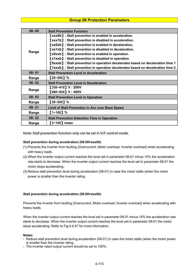
4-173
Group 08 Protection Parameters
08- 00 Stall Prevention Function
Range
【xxx0b】: Stall prevention is enabled in acceleration.
【xxx1b】: Stall prevention is disabled in acceleration.
【xx0xb】: Stall prevention is enabled in deceleration. 【xx1xb】: Stall prevention is disabled in deceleration.
【x0xxb】: Stall prevention is enabled in operation. 【x1xxb】: Stall prevention is disabled in operation.
【0xxxb】: Stall prevention in operation decelerates based on deceleration time 1
【1xxxb】: Stall prevention in operation decelerates based on deceleration time 2
08- 01 Stall Prevention Level in Acceleration
Range 【20~200】%
08- 02 Stall Prevention Level in Deceleration
Range 【330~410】V : 200V 【660~820】V : 400V
08- 03 Stall Prevention Level in Operation
Range 【30~200】%
08- 21 Limit of Stall Prevention in Acc over Base Speed
Range 【1~100】%
08- 22 Stall Prevention Detection Time in Operation
Range 【2~100】msec
Note: Stall prevention function only can be set in V/F control mode.
Stall prevention during acceleration (08-00=xxx0b)
(1) Prevents the inverter from faulting (Overcurrent, Motor overload, Inverter overload) when accelerating
with heavy loads.
(2) When the inverter output current reaches the level set in parameter 08-01 minus 15% the acceleration
rate starts to decrease. When the inverter output current reaches the level set in parameter 08-01 the
motor stops accelerating.
(3) Reduce stall prevention level during acceleration (08-01) in case the motor stalls (when the motor
power is smaller than the inverter rating.
Stall prevention during acceleration (08-00=xxx0b)
Prevents the inverter from faulting (Overcurrent, Motor overload, Inverter overload) when accelerating with
heavy loads.
When the inverter output current reaches the level set in parameter 08-01 minus 15% the acceleration rate
starts to decrease. When the inverter output current reaches the level set in parameter 08-01 the motor
stops accelerating. Refer to Fig.4.4.57 for more information.
Notes: - Reduce stall prevention level during acceleration (08-01) in case the motor stalls (when the motor power
is smaller than the inverter rating. - The inverter rated output current should be set to 100%.

4-174
Figure 4.4.57 Stall prevention during acceleration If the motor is used in the constant power (CH) region, the stall prevention level (08-01) is automatically
reduced to prevent the stall. Stall prevention level during acceleration (Constant horsepower) Stall Prev. Lev. Acceleration (CH) = Stall prevention level in acceleration (08-01) x Fbase (01-12)
Output frequency
Parameter 08-21 is the stall prevention limit value in Constant Horsepower region. Refer to Fig.4.4.58.
Figure 4.4.58 Stall prevention level and limit in acceleration
Stall prevention selection during deceleration (08-00=xx0xb)
Stall prevention during deceleration automatically increases the deceleration time according based on the
DC-bus voltage to prevent over-voltage during deceleration. Refer to Fig.4.4.59 for stall prevention during
deceleration When the DC-bus voltage exceeds the stall prevention level deceleration will stop and the inverter will wait for the DC-bus voltage to fall below the stall prevention level before continuing deceleration. Stall prevention level can be set by 08-02, see Table 4.4.10.

4-175
Table 4.4.10 Stall prevention level
Inverter model 08-02 default value
200V class 385VDC
400V class 770VDC
Note: When using external braking (braking resistor or braking module) disable stall prevention during
deceleration (08-00 to xx1xb).
Figure 4.4.59 Stall prevention selection in deceleration
Stall prevention selection during run (08-00=x0xxb) Stall prevention during run can only be used in V/F control mode for induction motor.
This function prevents the motor from stalling by automatically reducing the output frequency during run.
If the inverter output current rises above the level set in parameter 08-03 for the time specified in
parameter 08-22, the inverter output frequency is automatically decreased following deceleration time 1
(00-15) or deceleration time 2 (00-17).
When the inverter output current falls below the level set in parameter (08-03) minus 2%, normal operation
continues and the output frequency increases to the frequency reference using the acceleration time 1 or
acceleration time 2. Refer to the following Fig.4.4.60.
Note: The stall prevention level during run can be set by using multi-function analog input AI2 (04-05=7) or
AI3(04-10=7).
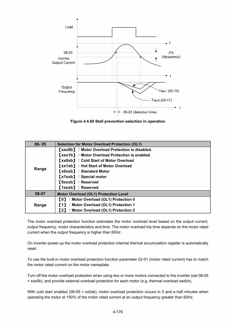
4-176
Figure 4.4.60 Stall prevention selection in operation
08- 05 Selection for Motor Overload Protection (OL1)
Range
【xxx0b】:Motor Overload Protection is disabled.
【xxx1b】:Motor Overload Protection is enabled.
【xx0xb】:Cold Start of Motor Overload 【xx1xb】:Hot Start of Motor Overload
【x0xxb】:Standard Motor 【x1xxb】:Special motor
【0xxxb】:Reserved 【1xxxb】:Reserved
08-07 Motor Overload (OL1) Protection Level
Range 【0】:Motor Overload (OL1) Protection 0 【1】:Motor Overload (OL1) Protection 1 【2】:Motor Overload (OL1) Protection 2
The motor overload protection function estimates the motor overload level based on the output current,
output frequency, motor characteristics and time. The motor overload trip time depends on the motor rated
current when the output frequency is higher than 60Hz.
On inverter power-up the motor overload protection internal thermal accumulation register is automatically
reset.
To use the built-in motor overload protection function parameter 02-01 (motor rated current) has to match
the motor rated current on the motor nameplate.
Turn off the motor overload protection when using two or more motors connected to the inverter (set 08-05
= xxx0b), and provide external overload protection for each motor (e.g. thermal overload switch).
With cold start enabled (08-05 = xx0xb), motor overload protection occurs in 5 and a half minutes when
operating the motor at 150% of the motor rated current at an output frequency greater than 60Hz.

4-177
With hot start enabled (08-05 = xx1xb), motor overload protection occurs in 3 and a half minutes when
operating the motor at 150% of the motor rated current at an output frequency greater than 60Hz.
Refer to the following Fig.4.4.61 for an example of motor overload protection standard curve.
And refer to the setting of 08-07 (Motor overload (OL1) protection level), the overload curve will be
different.
08-07=0:
Low Speed (1.5 Hz)
Hot Start
100% 150% 200%Motor Load Current (%)
(02-01 = 100%)Overl
oa
d P
rote
ct
Tim
e (
min
)
1.5
2.9
7.9
Cold Start
100% 150% 200%Motor Load Current (%)
(02-01 = 100%)Overl
oa
d P
rote
ct
Tim
e (
min
)
2.4
4.5
12.4
Low Speed (1.5 Hz)
08-07=1:

4-178
08-07=2:
Figure 4.4.61 Motor overload protection curve (example: standard motor)
When using force cooled motors (Special inverter motor), thermal characteristics are independent of the
motor speed, set 08-05 = x1xxb.
When 08-05 = x1xxb, overload protection function is based on motor rated current for output frequencies between 6 and 60Hz. If the output frequency is lower than 1Hz, the overload protection function uses 83% of the motor rated current to determine an overload condition.
When 08-05 = x0xxb, overload protection function is based on 70% of the motor rated current for an output frequency of 20Hz. If the output frequency is lower than 1Hz, the overload protection function uses 40% of the motor rated current to determine an overload condition.
Refer to Fig.4.4.62 for motor overload rating at different output frequencies.
Figure 4.4.62 Motor overload rating at different output frequencies

4-179
08- 06 Start-up mode of overload protection operation (OL1)
Range 【0】:Stop Output after Overload Protection 【1】:Continuous Operation after Overload Protection.
08-06=0: When the inverter detects a motor overload the inverter output is turned off and the OL1 fault
message will display on the keypad. Press RESET button on the keypad or activate the reset function
through the multi-function inputs to reset the OL1 fault.
08-06=1: When the inverter detects a motor overload the inverter will continue running and the OL1 alarm
message will flash on the keypad until the motor current falls within the normal operating range.
08- 08 Automatic Voltage Regulation (AVR)
Range 【0】:AVR is enabled 【1】:AVR is disabled
Automatic voltage regulation stabilizes the motor voltage independent of fluctuation to the input voltage. 08-08=0: Automatic voltage regulation is active. It will limit the maximum output voltage. When input three-phase voltage fluctuates and the voltage is smaller than the value of 01-14, the output voltage will fluctuate with the fluctuation of input voltage. 08-08=1: Automatic voltage regulation is not active, motor voltage follows the input voltage fluctuation. When input three-phase voltage fluctuates, the output voltage won’t fluctuate with the fluctuation of input voltage.
08- 09 Selection of Input Phase Loss Protection
Range 【0】:Disable 【1】:Enable
08-09=0: Input phase loss detection is disabled. 08-09=1: Input phase loss detection is enabled. Keypad shows "IPL input Phase Loss" (IPL), when an input phase loss is detected the inverter output is turned off and the fault contact is activated.
Note: The input phase loss detection is disabled when the output current is less than 30% of the inverter
rated current.
08- 10 Selection of Output Phase Loss Protection
Range 【0】:Disable 【1】:Enable
08-10=0: Output phase loss detection is disabled. 08-10=1: Output phase loss detection is enabled. Keypad shows "OPL Output Phase Loss" (OPL), when an output phase loss is detected and the inverter output is turned off and the fault contact is activated.
Note: The output phase loss detection is disabled when the output current is less than 10% of the inverter
rated current.

4-180
08- 13 Selection of Over-Torque Detection
Range 【0】: Over-Torque Detection is Disabled. 【1】: Start to Detect when Reaching the Set Frequency.
【2】: Start to Detect when the Operation is Begun.
08- 14 Selection of Over-Torque Operation
Range 【0】: Deceleration to Stop when Over- Torque is Detected. 【1】: Display Warning when Over- Torque is Detected. Go on Operation.
【2】: Coast to Stop when Over Torque is Detected.
08- 15 Level of Over-Torque Detection
Range 【0~300】%
08- 16 Time of Over-Torque Detection
Range 【0.0~10.0】Sec
08- 17 Selection of Low-Torque Detection
Range 【0】: Low-Torque Detection is Disabled. 【1】: Start to Detect when Reaching the Set Frequency.
【2】: Start to Detect when the Operation is Begun.
08- 18 Selection of Low-Torque Operation
Range 【0】: Deceleration to Stop when Low- Torque is Detected. 【1】: Display Warning when Low- Torque is Detected. Go on Operation.
【2】: Coast to Stop when Low-Torque is Detected.
08- 19 Level of Low-Torque Detection Range 【0~300】%
08- 20 Time of Low-Torque Detection Range 【0.0~10.0】Sec
The over torque detection function monitor the inverter output current or motor torque and can be used to detect increase in inverter current or motor torque (e.g. heavy load). The low torque detection function monitor the inverter output current or motor torque and can be used to detect a decrease in inverter current or motor torque (e.g. belt break). The torque detection levels (08-15, 08-19) are based on the inverter rated output current (100% = inverter rated output current) when operating the inverter in V/F control mode and motor output torque (100% = motor rated torque) when operating the inverter in SLV control mode. Over-torque detection Parameter 08-13 selects over-torque detection function. An over-torque condition is detected when the output current / torque rises above the level set in parameter 08-15 (Over-torque detection level) for the time specified in parameter 08-06 (Over-torque detection time). 08-13=0: Over-torque detection is disabled. 08-13=1: Over-torque detection is enabled when the output frequency reaches the set frequency. 08-13=2: Over-torque detection is enabled during running. Parameter 08-14 selects the way the inverter acts when an over-torque condition is detected. 08-14=0: When an over-torque condition is detected the inverter displays and over-torque detection fault and the motor decelerates to a stop. 08-14=1: When an over-torque condition is detected the inverter displays an over-torque detection alarm and continues to run. 08-14=2: When an over-torque condition is detected the inverter displays and over-torque detection fault and the motor coasts to a stop.

4-181
Figure 4.4.63 Over-torque detection operation
Low-torque detection Parameter 08-18 selects low-torque detection function. An low-torque condition is detected when the output current / torque falls below the level set in parameter 08-19 (low-torque detection level) for the time specified in parameter 08-20 (Low-torque detection time). 08-17=0: Low-torque detection is disabled. 08-17=1: Low-torque detection is enabled when the output frequency reaches the set frequency. 08-17=2: Low-torque detection is enabled during running. Parameter 08-18 selects the way the inverter acts when an over-torque condition is detected. 08-18=0: When a low-torque condition is detected the inverter displays and low-torque detection fault and the motor decelerates to a stop. 08-18=1: When a low-torque condition is detected the inverter displays a low-torque detection alarm and continues to run. 08-18=2: When a low-torque condition is detected the inverter displays and low-torque detection fault and the motor coasts to a stop.
Figure 4.4.64 Low torque detection operation
Over and low torque detection condition can be output to the multi-function digital outputs (R1A-R1C,
R2A-R2C, R3A-R3C) by setting parameters 03-11, 03-12 and 03-39 to 12 or 25. Refer to Fig. 4.4.65 for
more information.

4-182
R1A
R1B
R1C
R2A
R2C
}}
03-11
03-12
03-39
R3A
R3C }
Figure 4.4.65 Over-torque / low torque detection multi-function digital output terminal
08- 23 Ground Fault (GF) Selection
Range 【0】: Disable 【1】: Enable
If the inverter leakage current is greater than 50% of inverter rated current and the ground fault function is
enabled (08-23), the keypad will display a "GF Ground Fault" (GF), motor will coast to a stop and fault
contact is activated.
08- 24 Operation Selection of External Fault
Range
【0】: Deceleration to Stop
【1】: Coast to Stop
【2】: Continuous Operation
When multi-function digital input terminal is set to 25 (the external fault) and this terminal signal is triggered
off, parameter 08-24 (Operation Selection of External Fault) can be selected to stop it. The selection of
stop modes is the same as 07-09.
08- 25 Detection selection of External Fault
Range 【0】: Immediately Detect when the Power is Supplied
【1】: Start to Detect during Operation
The reason for the detection of external faults is determined by parameter 08-25.
When 08-25=0, faults are immediately detected at power up. When 08-25=1, faults are detected when the inverter is running.
08- 30 Selection of Safety Function
Range 【0】: Deceleration to Stop
【1】: Coast to Stop
If multi-function digital input terminal is set to 58 (Safety Function), inverter will stop via the set of 08-30
when this function is enabled.

4-183
08- 37 Fan Control Function
Range
【0】: Start at Operation
【1】: Permanent Start
【2】: Start at High Temperature
08- 38 Delay Time of Fan Off
Range 【0~600】Sec
08-37=0: Start at Operation
Fan starts while inverter is running.
If the inverter stops over the delay time of fan off (08-38), fan is off.
08-37=1: Permanent Start
When the inverter is at power on, fan will start permanently.
08-37=2: Start at High Temperature
When the temperature of heatsink is higher than that of internal setting, fan immediately starts.
If the temperature is lower than internal setting value or the delay time of fan off (08-38) is due, fan will be
off.
Note: Function of fans on is disabled for the models of 60HP or the above (200V) and 100HP or the above
(400V) in IP20 series and is enabled for all the models in IP55 series.
08- 35 Fault Selection of Motor Overheat
Range
【0】: Disable
【1】: Deceleration to Stop
【2】: Coast to Stop
08- 36 Time Coefficient of PTC Input Filter
Range 【0.00 ~ 5.00】
08- 39 Delay Time of Motor Overheat Protection
Range 【1 ~ 300】Sec
08 - 42 PTC Trip Level
Range 【0.1~10】V
08 - 43 PTC Reset Level
Range 【0.1~10】V
08- 45 PTC Disconnection Detection
Range
【0】: Disable
【1】: Warning
【2】: Fault
Protection of motor overheating is enabled via the sensor of motor fan with the temperature impedance chacteristics of positive temperature coefficient (PTC). Thermistor of PTC connects with terminals MT and GND. If motor is overheating, the keypad displays the error code of OH4. 08-35=0: Fault selection of motor overheating is disabled. 08-35=1, 2: Motor stop running while fault of motor overheating occurs. Protection of motor overheating is enabled when the motor temperature rises, and the MT voltage level is higher than 08-42 PTC trip level and the reach of delay time set by 08-39. The keypad will display an “OH4 Motor overheat” and fault output is active. When the motor temperature falls, and the MT voltage level is lower than 08-43 PTC reset level, it can

4-184
reset ‘’OH4 Motor overheat.’’ Note: The stop mode of the inverter fault is set by 08-35.
08-35=1: Deceleration to stop when the inverter fault occurs. 08-35=2: Coast to stop when the inverter fault occurs
Notes:
- If thermistor of PTC does not connect with MT and GND, the keypad will display an “OH4 Motor overheat.”
- The value of the external thermistor of PTC is in compliance with British National Standard. When Tr is 150 in class F and 180 in class H, a. Tr- 5: RPTC ≦ 550Ω, use RPTC value to formula (1), the V value can be set to 08-43 PTC
reset level. b. Tr+ 5: RPTC≧1330Ω, use RPTC value to formula (1), the V value can be set to 08-42 PTC trip
level Notes: 1. If the specification of PTC is different, please follow formula 1 to calculate the value of 8-42 and 8-43.
KRK
KRVV
PTC
PTC
20//10
20//10
2
1
Formula (1)
2. It can be calculated via formula (1) if it is in an empty connection or disconnection state when the
voltage value is between 3.3~4V. if empty connection or disconnection occurs, the inverter trips to PTCLS warning or fault signal. Set fault signal by parameter 08-45. There will be ten seconds to detect once disconnection occurs. If it reconnects withinthe time, PTC signal will not be tripped and it will be recounting on redisconnection.
3. When measuring the voltage-across from MT and GND terminals, the measured voltage is not equal to the input level one. The level one is calculated by formula (1).
Refer to Fig. 4.4.66 for the connecting between the corresponding temperature of thermistor of PTC and terminals.
Figure 4.4.66 (a) PTC Themistor Characteristics (b) PTC Themistor Connections

4-185
08 - 46 Temperature agree level
Range 【0 ~ 254】°C
08 - 47 Temperature reset level
Range 【0 ~ 254】°C
Note: 08-47 maximum value will be limited by 08-46 set value The inverter temperature agree and reset level selection 03-11 set to【59】:
‧ 08-46: The inverter temperature is > 08-46, the relay operates. ‧ 08-47: When the output current is ≤ 08-47, the relay signal from ON to OFF. Down time frequency diagram:
08-46
03-11繼電器 ON
變頻器溫度
T(°C)
Time
08-47
Inverter temperature agree and reset detection
08 - 48 Selection of Fire Mode
Range 【0】: Disable
【1】: Enable
08 - 49 Multi-Function Input Terminal Status of Fire Mode
Range 【0】: Reset after Power Off
【1】: Reset after Terminal Removed
08 - 50 Multi-Function Terminal Status of Fire Mode
Range 【xxx0b】: S6 A Contact
【xxx1b】: S6 B Contact
08 - 51 Motor Speed Setting Source of Fire Mode
Range 【0】:Fire Mode Speed (08-52) 【1】:PID Control 【2】:AI2
08 - 52 Fire Mode Motor Speed
Range 【0.00~100.00】%
08 - 59 Fire Mode Motor Direction
Range 【0】: Forward
【1】: Reverse
08 - 60 Fire Mode Password
Range 【00000 ~ 65534】
When 08-48=0, Fire Mode is disabled.
Frequency Converter Temperature
Relay

4-186
When 08-48=1, Fire Mode is enabled. When fire mode is enabled, S6 will be defined to digital input of fire mode (03-0X=47). When fire mode is enabled, inverter will become to fire mode. No matter inverter is running or stopping, run and frequency command source will be covered by the setting of fire mode, keypad display will show “ FIRE ”, some of protect functions will be ignored, please refer the table 4.3.35, inverter will not stop. When fire mode (03-0X=47) and outour overload (03-0X=68) function is triggered, the other digital inputs will be ignored, the parameters just can be read by communication or keypad display. When 08-49=0, pelase disconnect the power first, remove external trigger signal and then
connect the power. When 08-49=1, no need to disconnect the power, inverter will become to normal mode, run
and frequency will reture to original setting. Note: Only Version V1.53 and above will meet the above functions. Table 4.3.35 These functions will be ignoed when fire mode is triggered
0x2521H Fault Description
4 OH1 (Heat sink over heat)
5 OL1 (Motor overload)
6 OL2 (Inverter overload)
7 OT (Over torque)
25 FB (PID feedback signal error)
26 Keypad Removed
28 CE (Communication error)
46 OH4 (Motor over heat)
49 MtrSw (DI Motor Switch Fault)
58 PF(Protection error)
!Danger:
Fire mode: The drive will run at full speed either in forward or reverse direction and ignore all software protections until any one of the hardware protection is triggered or drive is damaged to achieve the requirement of smoke extraction and reduce the hazard to humans. Each bit of 08-50 presents an input: 08-50= 0 0 0 0 0 : Normal open s6 1 : Normal close Notes: Please set 08-48=0 (fire mode disabled) before setting normal open or normal close contact. Failure to comply may cause death or serious injury. When 08-51=0, motor speed setting will follow 08-52. If the value of 08-52 is 100%, inverter
output frequency will follow the value of 01-02. When 08-51=1, motor speed setting will follow PID control; when fire mode is enabled, PID
control will base on 10-47/10-48/10-49 (please refer the setting value of group 10) When 08-51=2, frequency reference will become to 4-20mA (default setting of 04-00)
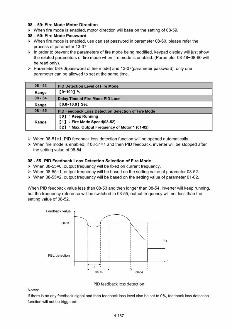
4-187
08 – 59: Fire Mode Motor Direction When fire mode is enabled, motor direction will base on the setting of 08-59. 08 – 60: Fire Mode Password When fire mode is enabled, use can set password in parameter 08-60, please refer the
process of parameter 13-07. In order to prevent the parameters of fire mode being modified, keypad display will just show
the related parameters of fire mode when fire mode is enabled. (Parameter 08-48~08-60 will be read only).
Parameter 08-60(password of fire mode) and 13-07(parameter password), only one parameter can be allowed to set at the same time.
08 - 53 PID Detection Level of Fire Mode
Range 【0~100】%
08 - 54 Delay Time of Fire Mode PID Loss
Range 【0.0~10.0】Sec
08 - 55 PID Feedback Loss Detection Selection of Fire Mode
Range
【0】:Keep Running
【1】:Fire Mode Speed(08-52)
【2】:Max. Output Frequency of Motor 1 (01-02)
When 08-51=1, PID feedback loss detection function will be opened automatically. When fire mode is enabled, if 08-51=1 and then PID feedback, inverter will be stopped after
the setting value of 08-54. 08 - 55 PID Feedback Loss Detection Selection of Fire Mode When 08-55=0, output frequency will be fixed on current frequency. When 08-55=1, output frequency will be based on the setting value of parameter 08-52. When 08-55=2, output frequency will be based on the setting value of parameter 01-02. When PID feedback value less than 08-53 and then longer than 08-54, inverter will keep running, but the frequency reference will be switched to 08-55, output frequency will not less than the setting value of 08-52.
t
08-54
t1
08-54
FBL偵測
08-53
回授值
t
PID feedback loss detection Notes:
If there is no any feedback signal and then feedback loss level also be set to 0%, feedback loss detection
function will not be triggered.
Feedback value
FBL detection

4-188
08 – 56 Detection Level of Fire Mode AI2 Signal
Range 【0~100】%
08 - 57 Delay Time of Fire Mode AI2 Signal Loss
Range 【0.0~10.0】Sec
08 - 58 Selection of Fire Mode AI2 Signal Loss
Range 【0】:Keep Running 【1】:Fire Mode Speed(08-52) 【2】:Max. Output Frequency of Motor 1 (01-02)
When 08-51=2 (AI2), inverter will trigger AI2 feedback loss detection function automatically.
Selection of Fire Mode AI2 Signal Loss (08-58):
When 08-58=0, output frequency will be fixed on current frequency.
When 08-58=1, output frequency will be based on the setting value of parameter 08-52.
When 08-58=2, output frequency will be based on the setting value of parameter 01-02.
If AI2 signal is less than the setting value of 08-56 in 360ms, and the time longer than setting value of
08-57, the frequency reference will be considered to loss.
Analog signal will compare with the previous value at 360ms, if inverter ensure the frequency reference
already loss, frequency reference will base on the value of 08-58. Following is the description of the Frequency Loss Function: When the inverter is in operation and the selected analog command source AI2 disappears, the command will operate according to the setting ratio of 08-58.
The following figure is the operating diagram of analog frequency instruction AI2 when the frequency Instruction is lost.
t
By 08-58Setting
360ms
FrequencyCommand
AI2 Loss Detection
t
08-56
08-57
By AI2Setting
Fig 4.3.76 AI2 frequency reference loss

4-189
Group 09: Communication Parameters
09- 00 INV Communication Station Address
Range 【1~31】
09- 01 Communication Mode Selection
Range
【0】: MODBUS 【1】: BacNET 【2】: MetaSys 【3】: PUMP in Parallel Connection
09- 02 Baud Rate Setting (bps)
Range
【0】: 1200 【1】: 2400 【2】: 4800 【3】: 9600
【4】: 19200
【5】: 38400
09- 03 Stop Bit Selection
Range 【0】: 1 Stop Bit 【1】: 2 Stop Bits
09- 04 Parity Selection
Range 【0】: No Parity 【1】: Even Bit 【2】: Odd Bit
09-05 Communications Data Bits Selection
Range 【0】: 8 bits data 【1】: 7 bits data
09- 06 Communication Error Detection Time
Range 【0.0~25.5】Sec
09- 07 Fault Stop Selection
Range
【0】:Deceleration to Stop Based on Deceleration Time 1 【1】:Coast to Stop when Communication Fault Occurs. 【2】:Deceleration to Stop Based on Deceleration Time 2 【3】:Keep Operating when Communication Fault Occurs. 【4】:Run the Frequency Command given by AI2
09- 08 Comm. Fault Tolerance Count
Range 【1~20】
09- 09 Waiting Time
Range 【5~65】msec
09- 10 Device Instance Number
Range 1~254 The Modbus communication port RJ45 (S+, S-) can be used to monitor, control, program and trouble-shoot the inverter. The built-in RS-485 can support the following communication protocol:
Modbus communication protocol BacNet communication protocol (Refer to section 4.7 for more details) MetaSys communication protocol (Refer to section 4.8 for more details) Pump in Parallel Connection (Refer to parameter group 23 for more details)
Modbus communication can perform the following operations, independent of the frequency command selection (00-05) setting and operation command selection (00-02) setting:

4-190
Monitor inverter signals Read and write parameters. Reset fault Control multi-function inputs
Modbus (RS-485) communication specification:
Items Specification
Interface RS-485
Communication type Asynchronous (start - stop synchronization)
Communication parameters
Baud rate: 1200, 2400, 4800, 9600, 19200 and 38400 bps Data Length: 8 bits (Fixed) Parity: options of none, even and odd bit. For even and odd selection stop bit is fixed at 1 bit.
Communication protocol Modbus RTU / ASCII
Number of inverters Maximum 31 units
Communication wiring and setup (1) Turn off power to the inverter. (2) Connect communication lines of the controller to the inverter (RJ45). (3) Turn power on. (4) Set the required communication parameters via the keypad. (5) Press DSP/FUN key to go back to the main menu. (6) If it is over the automatic return time (11-13) and DSP/FUN key is not pressed, reset the parameter
and press DSP/FUN key to go back to the main menu. Or reconnect the inverter. (7) Start communication between controller and inverter.
Modbus (485) communication architecture
(1) Modbus communication configuration uses a master controller (PC, PLC), communicating to a
maximum of 31 inverters.
(2) The master controller is directly connected to the inverter via the RS-485 interface. If the master
controller has a RS-232, a converter must be installed to convert signals to RS-485 to connect the master
controller to the inverter.
(3) A maximum 31 inverters can be connected to a network, following the Modbus communication
standard. Communication Parameters: 09-00: Inverter station addresses: Range 1-31
09-02: RS-485 communication baud rate setting = 0: 1200 bps (bits / second) = 1: 2400 bps = 2: 4800 bps = 3: 9600 bps = 4: 19200 bps = 5: 38400 bps
09-03: Stop bit selection = 0: 1 stop bit = 1: 2 stop bits 09-04: Parity selection of RS-485 communication = 0: No parity. = 1: even parity. = 2: odd parity.
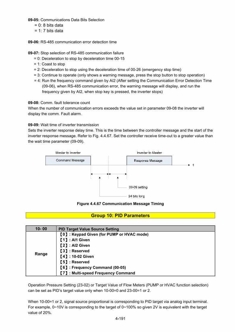
4-191
09-05: Communications Data Bits Selection = 0: 8 bits data
= 1: 7 bits data
09-06: RS-485 communication error detection time
09-07: Stop selection of RS-485 communication failure
= 0: Deceleration to stop by deceleration time 00-15
= 1: Coast to stop
= 2: Deceleration to stop using the deceleration time of 00-26 (emergency stop time)
= 3: Continue to operate (only shows a warning message, press the stop button to stop operation)
= 4: Run the frequency command given by AI2 (After setting the Communication Error Detection Time
(09-06), when RS-485 communication error, the warning message will display, and run the
frequency given by AI2, when stop key is pressed, the inverter stops)
09-08: Comm. fault tolerance count
When the number of communication errors exceeds the value set in parameter 09-08 the inverter will
display the comm. Fault alarm.
09-09: Wait time of inverter transmission
Sets the inverter response delay time. This is the time between the controller message and the start of the
inverter response message. Refer to Fig. 4.4.67. Set the controller receive time-out to a greater value than
the wait time parameter (09-09).
Figure 4.4.67 Communication Message Timing
Group 10: PID Parameters
10- 00 PID Target Value Source Setting
Range
【0】: Keypad Given (for PUMP or HVAC mode)
【1】: AI1 Given
【2】: AI2 Given
【3】: Reserved
【4】: 10-02 Given
【5】: Reserved
【6】: Frequency Command (00-05)
【7】: Multi-speed Frequency Command
Operation Pressure Setting (23-02) or Target Value of Flow Meters (PUMP or HVAC function selection)
can be set as PID’s target value only when 10-00=0 and 23-00=1 or 2.
When 10-00=1 or 2, signal source proportional is corresponding to PID target via analog input terminal.
For example, 0~10V is corresponding to the target of 0~100% so given 2V is equivalent with the target
value of 20%.

4-192
For normal use of PID, set 10-00 to 4 and set PID target value in parameter 10-02.
When 10-00=4, in addtition to the percentage setting of 10-02 (PID target value), it allows PID setting
(12-38) in the main screen monitor. The maximum target value is set via parameter 10-33 (PID maximum
feedback value), the decimals are set via parameter 10-34 (PID decimal width) and the unit is set via
parameter 10-35 (PID unit). For example:
When 10-33 = 999, 10-34 = 1, 10-35 = 3 and 10-02 = 10%, then 12-38 = 9.9 PSI displayed in the main
screen monitor. User can also modify the value of 12-38 in the main screen monitor but the maximum
calue is 99.9 PSI (depending on the setting value of 10-33).
10-00=6 (from frequency command), it means the setpoint is the perecnetage of frequency reference
corresponding to the rated frequency. (ie: setpoint = 50 %, if the frequency reference is 30Hz and the rated
frequency is 60Hz). And this frequency source refers to the setting of 00-05.
When 10-00=7, DI multi-speed frequency command (refer to the setting description of parameter group 3)
is proportionally corresponding to PID target via multi-speed stage frequenfy setting of 05-01~05-16.
Note: Speed-stage 1 cannot set PID target value by switching auxiliary frequency via 04-05=0 or 4-10=0.
10- 01 PID Feedback Value Source Setting
Range
【1】:AI1 Given 【2】:AI2 Given 【3】:Reserved
【4】:AI1 - AI2 Given
Note: Parameter 10-00 and 10-01 cannot be set to the same source. If both parameters are set to the
same source the keypad will show a SE05 alarm.
Note: When AI1 - AI2 is minus, it will be set to zero.
10- 02 PID Target Value
Range 【0.0~100.0】%
10- 03 PID Control Mode
Range
【xxx0b】:PID Disable
【xxx1b】:PID Enable
【xx0xb】:PID Positive Characteristic
【xx1xb】:PID Negative Characteristic
【x0xxb】:PID Error Value of D Control
【x1xxb】:PID Feedback Value of D Cotrol
【0xxxb】:PID Output
【1xxxb】:PID Output + Frequency Command
PID target value source setting(10-00) / PID feedback value source setting(10-01)
Please confirm parameter 04-00 conform the need (0V~10 V or 4mA~20 mА) if AI2 as PID target or PID
feedback. And check the dip switch from control board to the input type (V or I), please refer to wiring
diagram for more detail.
When 10-03 is set to xxx0b, PID will is disabled; if it is set to xxx1b, PID is enabled.
Note:
- LCD keypad will be switched automatically (16-00).
- Main Screen Monitoring will be changed to PID Setting (12-38).

4-193
- Sub-Screen Monitoring 1 will be changed to PID Feedback (12-39).
- Sub-Screen Monitoring 2 will be changed to Output Frequency (12-17).
At this time, if the setting is disabled, it will be switched automatically back to frequency command as the
main page. When switching to PID setting in the LED keypad, it displays the modes selection of parameter
23-05.
Note: when 23-05=0, set the value in the conditions of 10-33 < 1000 and 10-34=1, or the inverter will
display the signal of PID setting error (SE05).
When 10-03 is set to xx0xb, PID output occurs forward; When 10-03= xx1xb: PID output is reverse. PID output is chosen to reverse, If PID input is negative, the
output frequency of PID will gain. On the contrary,
When 10-03 is set to x1xxb, PID control for feedback differential value is enabled; if it is set to x0xxb, basic
PID control is enabled. Refer to Fig.4.4.69 and Fig.4.4.70.
When 10-03 is set to 0xxxb, PID output is enabled and it is corresponding to the frequency of 01-02 at
100%.
When 10-03 is set to 1xxxb, PID output and frequency command are enabled. The output percentage of
frequency command (corresponding to the selected main frequency command of 00-05/ 00-06) will be
cumulated when the inverter starts to run, and PID control starts.
10- 04 Feedback Gain
Range 【0.01~10.00】
10- 05 Proportional Gain (P)
Range 【0.00~10.00】
10- 06 Integral Time (I)
Range 【0.0~100.0】Sec
10- 07 Differential Time (D)
Range 【0.00~10.00】Sec
10- 09 PID Bias Range 【-100~100】%
10- 10 PID Primary Delay Time
Range 【0.00~10.00】%
10-14 PID Integral Limit
Range 【0.0~100.0】%
10-23 PID Limit
Range 【0.00~100.0】%
10-24 PID Output Gain
Range 【0.0~25.0】
10-25 PID Reversal Output Selection
Range 【0】: Do not Allow Reversal Output
【1】: Allow Reversal Output
10-26 PID Target Acceleration/ Deceleration Time
Range 【0.0~25.5】Sec
PID Adjustments
Gain control: The error signal (deviation) between the input command (set value) and the actual control value (feedback). This error signal or deviation is amplified by the proportional gain (P) to control the offset between the set value and the feedback value.

4-194
Integral control: The output of this control is the integral of the error signal (difference between set value
and feedback value) and is used to minimize the offset signal that is left over from the gain control. When
the integral time (I) is increased, the system response becomes slower.
Differential control: This control is the inverse from integral control and tries to guess the behavior of the
error signal by multiplying the error with the differential time. The result is added to the PID input.
Differential control slows down the PID controller response and may reduce system oscillation.
Note: Most applications that PID control (fan and pump) do not require differential control. Refer to Fig. 4.4.68 for PID control operation
Figure 4.4.68 PID Control
PID Control Type The inverter offers two types of PID control: (a) PID control with differential feedback: (10-03 = x1xxb) Make sure to adjust the PID parameters without causing system instability. Refer to Fig. 4.4.69 for PID control for feedback value differential.
Figure 4.4.69 PID control for feedback differential value
(b) Basic PID control: (10-03 = x0xxb) This is the basic type of PID control. Refer to the Fig. 4.4.70.

4-195
Figure 4.4.70 Basic PID control
PID Setup Enable PID control by setting parameter 10-03, PID target value (10-00) and PID feedback value (10-01). 10-00: PID target value = 0: keypad given = 1: analog AI1 given (default) = 2: analog AI2 given = 3: Reserved = 4:10-02
10-01: PID feedback value = 1: Analog AI1 given = 2: Analog AI2 given = 3: Reserved
Figure 4.4.71 PID input selection
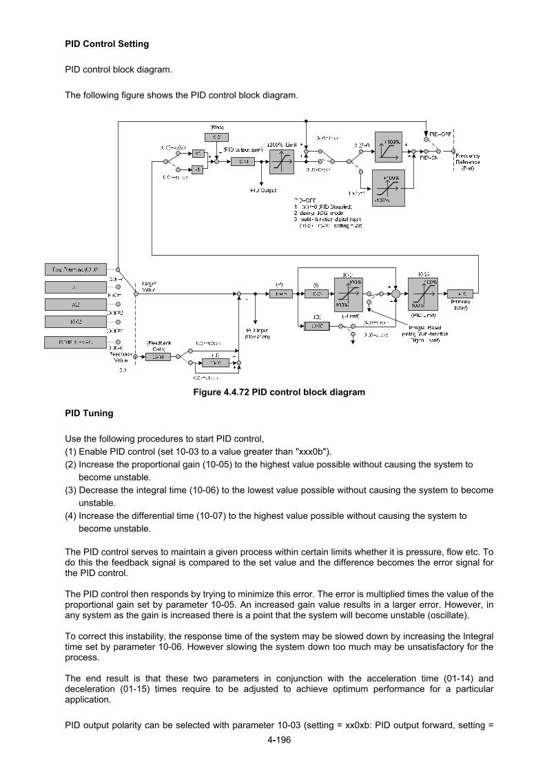
4-196
PID Control Setting
PID control block diagram.
The following figure shows the PID control block diagram.
Figure 4.4.72 PID control block diagram
PID Tuning
Use the following procedures to start PID control,
(1) Enable PID control (set 10-03 to a value greater than "xxx0b").
(2) Increase the proportional gain (10-05) to the highest value possible without causing the system to
become unstable.
(3) Decrease the integral time (10-06) to the lowest value possible without causing the system to become
unstable.
(4) Increase the differential time (10-07) to the highest value possible without causing the system to
become unstable.
The PID control serves to maintain a given process within certain limits whether it is pressure, flow etc. To do this the feedback signal is compared to the set value and the difference becomes the error signal for the PID control.
The PID control then responds by trying to minimize this error. The error is multiplied times the value of the proportional gain set by parameter 10-05. An increased gain value results in a larger error. However, in any system as the gain is increased there is a point that the system will become unstable (oscillate). To correct this instability, the response time of the system may be slowed down by increasing the Integral time set by parameter 10-06. However slowing the system down too much may be unsatisfactory for the process. The end result is that these two parameters in conjunction with the acceleration time (01-14) and deceleration (01-15) times require to be adjusted to achieve optimum performance for a particular application.
PID output polarity can be selected with parameter 10-03 (setting = xx0xb: PID output forward, setting =

4-197
xx1xb: PID output reversal). When the PID output is set for reverse operation the output frequency
decreased when the PID target value increases.
PID feedback value can be adjusted using parameter 10-04 (PID feedback gain) as well as with the analog
input gain and bias for terminal AI1 or AI2.
10-14: PID integral limit: Used to limit the integral output to prevent motor stall or damage to the system
in case of a rapid change in the feedback signal. Reduce the value of 10-14 to increase the inverter
response.
10-23: PID limit: Used to limit the output of the PID control. Maximum output frequency is 100%.
10-10: Primary delay time: Low pass filter situated after the PID limit block that can be used to prevent
PID output resonance. Increase the time constant to a value greater than the resonance frequency cycle
and reduce time constant to increase the inverter response.
10-09: PID bias: Used to adjust the offset of the PID control. The offset value is added to the frequency
reference as compensation. Use parameter 10-24 (PID output gain) to control the amount of
compensation.
In case the PID control output value goes negative, parameter 10-25 (PID reversal output selection) can
be used to reverse the motor direction.
Note: The PID output remains at zero when reverse operation is disabled.
10-26: PID target SFS: Sets the PID target value acceleration and deceleration ramp time. The PID target
SFS can be disabled by setting the multi-function digital inputs 03-00 ~ 03-05 to 36 (PID target SFS is off).
Reduce the acceleration / deceleration time in case load resonance or system instability is encountered. PID Fine Tuning All PID control parameters are related to each other and require to be adjusted to the appropriate values. Therefore, the procedure achieving the minimum steady-state is shown as following: (1) Increase or decrease the proportion (P) gain until the system is stable using the smallest possible
control change.
(2) The integral (I) reduces the system stability which is similar to increasing the gain. Adjust the integral time so that the highest possible proportional gain value can be used without affecting the system stability. An increase in the integral time reduces system response.
(3) Adjust the differential time if necessary to reduce overshoot on startup. The acceleration / deceleration time can also be used for the same purpose.
Fine-tuning PID control parameters:
(1) Reduce overshoot
In case overshoot occurs, reduce the derivative time (D) and increase the integral time (I).

4-198
(2) Stabilize PID control
To quickly stabilize the PID control, reduce the integral time (I) and increase the differential time (D) in case overshoot occurs.
(3) Reduce long-period oscillation
Adjust the integral time (I) in case of long-periodical system oscillation.
(4) Reduce short-period oscillation
Adjusting the differential time (D) and proportional (P) gain when experiencing short-periodical oscillation.
10-11 PID Feedback Loss Detection Selection
Range 【0】: Disable
【1】: Warning
【2】: Fault
10-12 PID Feedback Loss Detection Level
Range 【0~100】%
10-13 PID Feedback Loss Detection Time
Range 【0.0~10.0】Sec
The PID control function provides closed-loop system control. In case PID feedback is lost, the inverter output frequency may be increase to the maximum output frequency. It is recommended to enable to the PID feedback loss when the PID function is used. PID feedback loss detection
10-11=0: Disable
10-11=1: Warning
A feedback loss condition is detected when the PID feedback value falls below the value set in parameter
10-12 (PID feedback loss detection level) for the time set in parameter 10-13 (PID feedback loss detection
time). PID feedback loss warning message "Fb" will be displayed on the keypad and the inverter will
continue to operate.
10-11=2: Fault
A feedback loss condition is detected when the PID feedback value falls below the value set in parameter
10-12 (PID feedback loss detection level) for the time set in parameter 10-13 (PID feedback loss detection
time). PID feedback loss fault message "Fb” will be displayed on the keypad, the inverter stops and the
fault contact is activated.

4-199
Figure 4.4.73 PID feedback loss detection
10-17 *Start Frequency of PID Sleep
Range 【0.00~599.00】Hz
10-18 Delay Time of PID Sleep
Range 【0.0~255.5】Sec
10-19 *Frequency of PID Waking up
Range 【0.00~599.00】Hz
10-20 Delay Time of PID Waking up
Range 【0.0~255.5】Sec
10-29 PID Sleep Selection
Range
【0】: Disable
【1】: Enable
【2】: Set by DI
10-40 Compensation Frequency Selection of PID Sleep
Range 【0】: Disable 【1】: Enable
The PID Sleep function is used to stop the inverter when the PID output falls below the PID sleep level
(10-17) for the time specified in the PID sleep delay time parameter (10-18).
The inverter wakes up from a sleep condition when the PID output (Reference frequency) rises above the
PID wake-up frequency (10-19) for the time specified in the PID wake-up delay time (10-20). Use parameter 10-29 to enable / disable PID sleep function. 10-29 =0: PID Sleep function is disabled. 10-29 =1: PID sleep operation is based on parameters of 10-17 and 10-18. 10-29 =2: PID sleep mode is enabled by multi-function digital input
Refer to Fig.4.4.74 (a), (b) and (c) for PID sleep / wakeup operation. Note: Parameter 10-17 is the general start frequency of PID sleep, and it is not applied to the sleep frequency of constant pressure (parameter 23-10) by PUMP. *: (When the motor’s maximum output frequency is over than 300Hz, the frequency resolution is
0.1Hz.)

4-200
Figure 4.4.74: (a) PID control bock diagram
Figure 4.4.74: (b) Timing diagram PID sleep / wakeup
Figure 4.4.74: (c) Timing diagram of PID sleep compensation frequency/ wakeup
Notes: - Refer to Fig. 4.4.74: (b) for parameter 10-40=0. The PID sleep timer is enabled when the output
frequency (Fout) falls below the PID sleep frequency (10-17). When the sleep timer reaches the
set PID sleep delay time (10-18) the inverter will decelerate to a stop and enter the sleep mode.
- Refer to Fig.4.4.74: (c) for parameter 10-40=1. The PID sleep timer is enabled when the output
frequency (Fout) falls below the PID sleep frequency (10-17). The output frequency changes with
the reference frequency (Fref) when the sleep timer reaches the set PID sleep delay time (10-18),
the motor will run gradually to PID sleep frequency set by 10-17. (It is applicated in the occasion of
fixed frequency.)
- While sleep mode is active and the motor has stopped, the internal PID control is still in operating.
When the reference frequency increases and exceeds the wakeup frequency parameter 10-19 for
the time specified in the wakeup delay time parameter 10-20, the inverter will restart and the
output frequency will ramp up to the reference frequency. Ex: If wakeup frequency < sleep frequency, start upon sleep frequency and the inverter gets into sleep mode by wakeup frequency. If wakeup frequency > sleep frequency, start upon wakeup frequency and the inverter gets into

4-201
sleep mode by sleep frequency. Ex1: Sleep mode is only allowed in positive direction and if 10-25=1 (Allow Reversal Output), the sleep mode needs to be turned off.
- Parameter 10-00 and 10-01 can not be set in the same source. If they are set in the same value, “SE05” (PID selection error message) will be displayed in the keypad.
- When PID sleep selection is enabled or set by DI (10-29= 1 or 2) and PID reversal output selection (10-25)=1 (allow reversal output), “SE05” (PID selection error message) will be displayed in the keypad.
- When PID sleep selection is enabled ot set by DI (10-29= 1or 2) and PID control mode (10-03) = 1xxxb, “SE05” (PID selection error message) will be displayed in the keypad.
Note: When 23-00=1 (Pump), if PID sleep disable, most pump function will be affected.
10-27 PID Feedback Display Bias
Range 【0~9999】 PID Feedback Display Scaling
The PID feedback signal can be scaled to represent actual engineering units. Use parameter 10-33 to set the feedback signal gain for the feedback signal range maximum and parameter 10-27 to the feedback signal minimum.
Example: 0-10V or 4-20mA feedback will be displayed as pressure, use 10-27 to set the pressure for 0V or 4mA feedback signal and use 10-33 to set the pressure for 10V or 20mA. Refer to the Fig.4.4.75 for displaying the unit conversion.
Figure 4.4.75 Feedback signal scaling
Example: Feedback signal: 0V = 0% = 1.0 PSI 10V = 100% = 20.0 PSI Parameter setting: 10-27 = 10 (0% feedback) 10-33 = 200 (100% feedback)
10-30 Upper Limit of PID Target
Range 【0 ~ 100】%
10-31 Lower Limit of PID Target
Range 【0 ~ 100】%
PID target value will be limited to the upper and lower limit range of PID target.
10- 32 PID Switching Function
Range 【0】: PID1 【1】: PID2

4-202
【2】: Set by DI
【3】: Set by RTC
10-32=0: PID 1 function is enabled.
PID target value is set by 10-02 and proportional gain, integral time and differential time are set by 10-05,
10-06 and 10-07. 10-32=1: PID 2 function is enabled. PID target value is set by 10-02 and proportional gain, integral time and differential time are set by 10-36,
10-37 and 10-38. 10-32=2: Set by Digital Input
If the digital input terminal is enabled (digital multi-function terminal is set to 54), PID1 will switch to PID2.
10-32=3: Set by RTC
When RTC timer is enabled, PID1 will switch to PID2.
10- 33 PID Maximum Feedback Value Range 【1~10000】
Function of PID maximum feedback value is the 100% corresponding value of 10-02.
10- 34 PID Decimal Width Range 【0~4】
Function of PID decimal width enables the user to set the decimal point.
For example, if it is set to 1, the keypad displays the first decimal place XXX.X. If it is set to 2, the keypad
displays the second decimal place XX.XX.
10- 35 PID Unit (Only display in LCD Keypad) Range 【0~24】
PID unit enables the user to select the unit for PID target vaule.
When 10-35=0, parameter of 12-38 will be used by the unit of %.
10- 36 PID2 Proportional Gain (P) Range 【0.00~10.00】
10- 37 PID2 Integral Time (I) Range 【0.0~100.0】Sec
10- 38 PID2 Differential Time (D) Range 【0.00~10.00】Sec
Refer to the PID function for more details of PID2 description.
10- 39 *PID Output Frequency Setting during disconnection *1

4-203
Range 【0.00~599.00】Hz
*1: It is new added in inverter software V1.4. *: (When the motor’s maximum output frequency is over than 300Hz, the frequency resolution is
0.1Hz.)
When the warning of PID feedback disconnection occurs (10-11=1), frequency command output depends
on the parameter 10-39. When the disconnection warning is removed, PID control restores.
10-44 Precharge Frequency
Range 【0~120.0】Hz
10-45 Precharge Time
Range 【0~250】Sec
10-46 Precharge Target Level
Range 【0~10000】
When parameter 10-44 is set to precharge frequency and PID control mode is set to be 10-03=XXX1B
(PID enable), the inverter runs by the precharge frequency and stops by the end of precharge time set by
parameter 10-45. When the precharge time stops, the inverter runs by PID control. If PID feedback signal
is equal or higher than the level of precharge target (parameter 10-46), it is not required to wait for the end
of precharge time and the inverter can run by PID control. Refer to the following figure.
10-4510-44
Hz
Sec
Sec
Hz
Fbk 10-46
or
PID control
PID control
The setting description of parameter 10-00=4 can be referred by parameter 10-46. According to the the
setting value of parameter 10-33, change the upper limit of setting value (parameter 10-46), determine the
decimal places (parameter 10-34) and unit display (parameter 10-35).
10- 47 Proportioanl Gain (P) of Fire Mode
Range 【0.00~10.00】
10- 48 Integral Time (I) of Fire Mode
Range 【0.0~100.0】Sec
10- 49 Differential Time (D) of Fire Mode
Range 【0.00~10.00】Sec
PID functions of ire mode, please refer to parameter group 08.

4-204
Group 11: Auxiliary Parameters
11- 00 Direction Lock Selection
Range
【0】: Allow Forward and Reverse Rotation
【1】: Only Allow Forward Rotation
【2】: Only Allow Reverse Rotation
If motor operation direction is set to 1 or 2, the motor can only operate in that specific direction. Run
commands in the opposite direction are not accepted.
Forward or reverse commands can be issued via the control terminals or keypad.
Note: The reverse rotation selection can be used in fan and pump application where reverse rotation is
prohibited.
11- 01 Carrier Frequency
Range 【0】: Carrier Output Frequency Tuning
【1~16】KHz Notes: (1) Value 1 to 16 represents KHz. (2) When 11-01=0, variable carrier frequency is used see parameter 11-30~11-32. (3) For SLV mode, the minimum value of 11-01 is 2 kHz, due to the sample rate, suggest to use 4KHz,
and the motor cable used within 100m. (4) Setting range is determined by the inverter rating (13-00). (5) Refer to section 3 inverter derating based on carrier frequency. (6) A low carrier frequency increases motor noise but reduces motor losses and temperature. (7) A low carrier frequency decreases RFI, EMI interference and motor leakage current. Refer to the carrier frequency Table 4.4.11. Table 4.4.11 Carrier frequency settings
Carrier frequency 1KHz--6KH—10KHz—16KHz Motor noise High ---------------------- low Output current waveform (similar to sinusoidal wave)
Bad ------ Good ------- Bad
Noise interference Low ---------------------- high Leakage current Low ---------------------- high Heat losses Low ---------------------- high
If wire length between the inverter and the motor is too long, the high-frequency leakage current will cause an increase in inverter output current, which might affect peripheral devices. Adjust the carrier frequency to avoid this as shown in Table 4.4.12.
Table 4.4.12 Wire length and carrier frequency
Wire length < 30 Meter (98ft) up to 50 Meter (164 ft)
up to 100 Meter (328ft)
> 100 Meter > 328ft
Carrier frequency (11-01 value )
Max. value 16KHz(11-01=16KHz)
Max. value 10KHz(11-01=10KHz)
Maxi. value 5KHz (11-01=5KHz)
Max. value 2KHz(11-01=2KHz)
Notes:
- Reduce the carrier frequency if the torque does not match the speed. - In V/F control mode, the carrier frequency is determined by parameters 11-30 (Carrier frequency
max. limit), 11-31 (Carrier frequency lower limit) and 11-32 (Carrier frequency proportional gain) after parameter 11-01 is setted to be 0.

4-205
11- 02 Soft PWM Function Selection
Range 【0】: Disable 【1】: Soft PWM 1
【2】: Soft PWM 2
11-02=0: Soft -PWM control disabled. 11-02=1: Soft -PWM control enabled. Soft-PWM 1 control can reduce the ‘metal’ noise produced by the motor, more comfortable for the human ear. At the same time, Soft-PWM also limits RFI noise to a minimum level. The default setting of Soft-PWM control is disabled. When Soft-PWM 1 is enabled, the maximum carrier frequency is limited to 8 kHz. When 11-02=2 (Soft PWM 2 enables), users adjusts 2 Phase/ 3 Phase PWM Switch Frequency (parameter 11-66), detection range at Soft PWM function 2 (parameter 11-67), and detecting start frequency at Soft PWM function 2 (parameter 11-68) by the sensitivity to the sound.
11- 66 2 Phase/ 3 Phase PWM Switch Frequency
Range 【6.00~60.00】
When the inverter’s output frequency is higher than the setting value of parameter 11-66, the modulation
mode will be switched.
11- 67 Detection Range at Soft PWM Function 2
Range 【0~12000】
11- 68 Detecting Start Frequency at Soft PWM Function 2
Range 【6.00~60.00】
When the inverter’s output frequency is higher than the setting value of parameter 11-68, the inverter
starts the function of noise detection and it adjusts electromagnetic noise coming from the motor run upon
the setting value of parameter 11-67.
Note: When 11-02 = 2, the sum values of parameter 11-01 and parameter 11-67 can not be higher
than the inverter’s upper limit of carrier. For the inverter’s proper run, there is affecting mechanism
among these parameters (11-01, 11-02 and 11-67).
a) If the error occurs in setting value of parameter 11-01, it is because parameter 11-02=2 and
the setting value of parameter 11-01 + that of parameter 11-67 > upper limit of the inverter’s carrier frequency. Thus, adjust the setting value of parameter 11-02 or that of parameter 11-67.
b) If the error occurs in setting value of parameter 11-67, it is because parameter 11-02=2 and
the setting value of parameter 11-01 + that of parameter 11-67 > upper limit of the inverter’s carrier frequency. Thus, adjust the setting value of parameter 11-02 or that of parameter 11-01.
c) When 11-02=2, the error occurs in setting value of parameter 11-01 or parameter 11-67.
Please check the setting values of parameter 11-01 + that of parameter 11-67 > upper limit of the inverter’s carrier frequency.
d) If the error occurs in setting parameter 11-02=2, it is because the setting value of parameter
11-01 + that of parameter 11-67 > upper limit of the inverter’s carrier frequency. Thus, adjust the setting value of parameter 11-01 or that of parameter 11-67. Then set parameter 11-02 =2.

4-206
11- 03 Automatic Carrier Lowering Selection
Range 【0】: Disable 【1】: Enable
11-03=0: Automatic carrier frequency reduction during an overheat condition is disabled. 11-03=1: Carrier frequency is automatically lowered in case the inverter heatsink overheats and returns to carrier frequency set in parameter 11-01 when the inverter temperature returns to normal. See section 3.5 for more information.
11- 04 S-curve Time Setting at the Start of Acceleration
11- 05 S-curve Time Setting at the End of Acceleration 11- 06 S-curve Time Setting at the Start of Deceleration
11- 07 S-curve Time Setting at the End of Deceleration
Range 【0.00~2.50】Sec
The S curve function for acceleration / deceleration is used to reduce mechanical impact caused by the
load during momentary starting and stopping of the inverter. To use the S curve function set the time for
acceleration start point (11-04), acceleration end point (11-05), deceleration start point (11-06) and
deceleration end point (11-07). Refer to Fig.4.4.76 for more information.
Figure 4.4.76 S curve characteristic
Total acceleration and deceleration time when the S curve is used:
Accelerating time = Accelerating time 1 (or 2) + (11-04) + (11-05)
2 Deceleration time = Deceleration time 1 (or 2) + (11-06) + (11-07)
2
11- 08 Jump Frequency 1
11- 09 Jump Frequency 2
11-10 Jump Frequency 3
Range 【0.0~599.0】Hz
11-11 Jump Frequency Width
Range 【0.0~25.5】Hz
These parameters allow “jumping over” of certain frequencies that can cause unstable operation due to resonance within certain applications. Note: Prohibit any operation within the jump frequency range. During acceleration and deceleration the frequency is continuous without skipping the jump frequency. To enable jump frequency 1 – 3 (11-08 – 11-10) set the frequency to a value greater than 0.0 Hz. Use the jump frequency width (11-11) to create a jump frequency range. Refer to Fig.4.4.77.
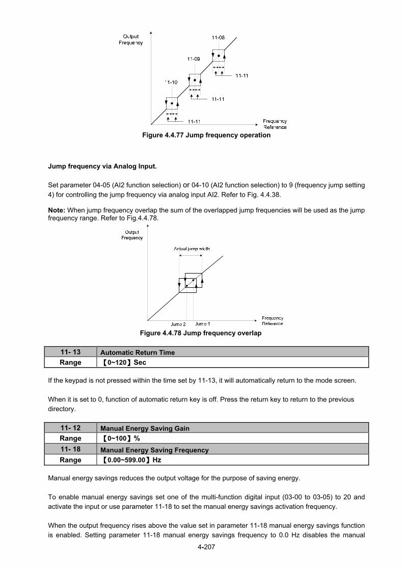
4-207
Figure 4.4.77 Jump frequency operation
Jump frequency via Analog Input. Set parameter 04-05 (AI2 function selection) or 04-10 (AI2 function selection) to 9 (frequency jump setting
4) for controlling the jump frequency via analog input AI2. Refer to Fig. 4.4.38.
Note: When jump frequency overlap the sum of the overlapped jump frequencies will be used as the jump frequency range. Refer to Fig.4.4.78.
Figure 4.4.78 Jump frequency overlap
11- 13 Automatic Return Time Range 【0~120】Sec
If the keypad is not pressed within the time set by 11-13, it will automatically return to the mode screen.
When it is set to 0, function of automatic return key is off. Press the return key to return to the previous
directory.
11- 12 Manual Energy Saving Gain
Range 【0~100】%
11- 18 Manual Energy Saving Frequency
Range 【0.00~599.00】Hz
Manual energy savings reduces the output voltage for the purpose of saving energy.
To enable manual energy savings set one of the multi-function digital input (03-00 to 03-05) to 20 and
activate the input or use parameter 11-18 to set the manual energy savings activation frequency.
When the output frequency rises above the value set in parameter 11-18 manual energy savings function
is enabled. Setting parameter 11-18 manual energy savings frequency to 0.0 Hz disables the manual

4-208
energy savings frequency activation function. Refer to figure 4.4.88 for more information.
Note: Only use manual energy savings functions in combination with light loads. Manual energy saving gain (11-12) determines the output voltage of the inverter when manual energy savings is enabled. Output voltage is percentage gain times the V/F voltage. Manual energy saving control uses the voltage recovery time (07-23) to change the output voltage
Figure 4.4.79 Manual energy saving operation
11- 19 Automatic Energy Saving Function
Range 【0】: Automatic Energy Saving is Disabled.
【1】: Automatic Energy Saving is Enabled.
11- 20 Filter Time of Automatic Energy Saving
Range 【0~200】msec
11- 21 Voltage Upper Limit of Energy Saving Tuning
Range 【0~100】%
11- 22 Adjustment Time of Automatic Energy Saving
Range 【0~5000】msec
11- 23 Detection Level of Automatic Energy Saving
Range 【0~100】%
11- 24 Coefficient of Automatic Energy Saving
Range 【0.00~655.34】
In the V/F control mode the automatic energy saving (AES) function automatically adjusts the output voltage and reduces the output current of the inverter to optimize energy savings based on the load. The output power changes proportional to the motor load. Energy savings is minimal when the load exceeds 70% of the output power and savings become greater when the load decreases. AES function is suitable for the load is stable, just like fan or windmill. If the load is variable, please do not use this function to avoid the output torque is not enough. The parameter of automatic energy saving function has been set at the factory before shipment. In general, it is no need to adjust. If the motor characteristic has significant difference from the TECO standard, please refer to the following commands for adjusting parameters: Enable Automatic Energy Savings Function (1) To enable automatic energy saving function set 11-19 to 1. (2) Filter time of automatic energy saving (11-20) (3) Commissioning parameter of energy saving (11-21 to 11-22)
In AES mode, the optimum voltage value is calculated based on the load power requirement but is also affected by motor temperature and motor characteristic.

4-209
In certain applications the optimum AES voltage needs to be adjusted in order to achieve optimum energy
savings. Use the following AES parameters for manual adjustment:
11-21: Voltage limit value of AES commissioning operation
Set the voltage upper limit during automatic energy saving. 100% corresponds to the settings of parameter
01-03 (Maximum Output Voltage) depending on the inverter class used. Refer to the Fig.4.4.80.
Figure 4.4.80 Voltage limit value of commissioning operation
11-22: Adjustment time of automatic energy saving
Set sample time constant for measuring output power.
Reduce the value of 11-22 to increase response when the load changes.
Note: If the value of 11-22 is too low and the load is reduced the motor may become unstable.
11-23: Detection level of automatic energy saving
Set the automatic energy saving output power detection level.
11-24: Coefficient of automatic energy saving
The coefficient is used to tune the automatic energy saving. Adjust the coefficient while running the
inverter on light load while monitoring the output power. A lower setting means lower output voltage.
Notes: - If the coefficient is set to low the motor may stall.
- Coefficient default value is based on the inverter rating. Set parameter 13-00. If the motor power does
not match the inverter rating.
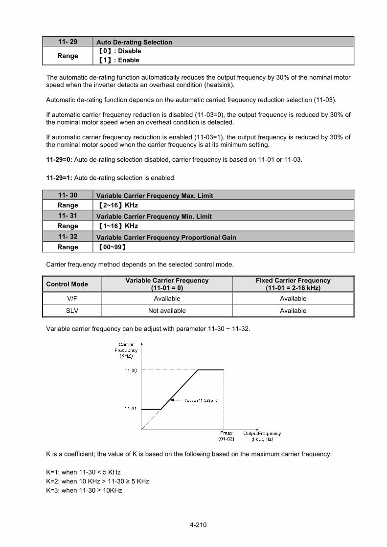
4-210
11- 29 Auto De-rating Selection
Range 【0】: Disable 【1】: Enable
The automatic de-rating function automatically reduces the output frequency by 30% of the nominal motor speed when the inverter detects an overheat condition (heatsink). Automatic de-rating function depends on the automatic carried frequency reduction selection (11-03). If automatic carrier frequency reduction is disabled (11-03=0), the output frequency is reduced by 30% of the nominal motor speed when an overheat condition is detected. If automatic carrier frequency reduction is enabled (11-03=1), the output frequency is reduced by 30% of the nominal motor speed when the carrier frequency is at its minimum setting. 11-29=0: Auto de-rating selection disabled, carrier frequency is based on 11-01 or 11-03.
11-29=1: Auto de-rating selection is enabled.
11- 30 Variable Carrier Frequency Max. Limit
Range 【2~16】KHz
11- 31 Variable Carrier Frequency Min. Limit
Range 【1~16】KHz
11- 32 Variable Carrier Frequency Proportional Gain
Range 【00~99】
Carrier frequency method depends on the selected control mode.
Control Mode Variable Carrier Frequency
(11-01 = 0) Fixed Carrier Frequency
(11-01 = 2-16 kHz)
V/F Available Available
SLV Not available Available
Variable carrier frequency can be adjust with parameter 11-30 ~ 11-32.
K is a coefficient; the value of K is based on the following based on the maximum carrier frequency:
K=1: when 11-30 < 5 KHz
K=2: when 10 KHz > 11-30 ≥ 5 KHz
K=3: when 11-30 ≥ 10KHz

4-211
Notes:
- In V/F control mode if the speed and torque are constant, the variable carrier frequency mode (11-01=0)
can be selected to reduce the carrier frequency based on output frequency.
- If the carrier frequency proportional gain (11-32) > 6 and 11-30 < 11-31, error message "SE01" out of
range will appear on the keypad.
- If the minimum limit (11-31) is set higher than the maximum limit (11-30), the minimum limit will be
ignored and the carrier frequency will be set at the highest limit (11-30).
- In fixed carrier frequency mode (11-01 = 2-16) parameters 11-30, 11-31 and 11-32 are not used.
- In SLV control mode, the maximum limit of the carrier frequency is fixed at 11-30.
11- 28 Frequency Gain of Overvoltage Prevention 2 Range 【1~200】%
11- 33 Rise Amount of DC Voltage Filter Range 【0.1~10.0】V
11- 34 Fall Amount of DC Voltage Filter Range 【0.1~10.0】V
11- 35 Dead band Level of DC Voltage Filter
Range 【0.0~99.0】V
11- 36 Frequency gain of OV prevention
Range 【0.000~1.000】
11- 37 * Frequency limit of OV prevention
Range 【0.00~599.00】Hz
11- 38 Deceleration start voltage of OV prevention
Range 200V :【200~400】V 400V :【400~800】V
11- 39 Deceleration end voltage of OV prevention
Range 200V :【300~400】V 400V :【600~800】V
11- 40 OV prevention selection
Range
【0】: Disable 【1】: OV prevention Mode 1 【2】: OV prevention Mode 2 【3】: OV Prevention Mode 3
* (When the output frequency is bigger than 300Hz, the resolution is 0.1Hz) Overvoltage suppression is used for the application of likely causing to energy recharge. Example: there are two situations causing excessive energy to recharge the inverter in stamping application
(1) When cam clutch is not engaged, the motor will accelerate and start flywheel. When motor decelerates,
the rotation speed will higher than motor speed owing to the large flywheel’s inertia and then recharge the inverter.
(2) When cam clutch is engaged, the motor will start flywheel and compress the spring. When the highest point of the cam moves beyond its center, the spring will release the power to the flywheel and excessive energy output recharge the inverter.

4-212
Figure 4.4.80.a Stamping Operation Over-voltage prevention (OVP) function monitors the DC-bus voltage and adjusts the speed reference, acceleration and deceleration rate, to prevent the inverter from tripping on an overvoltage.
When the speed reference is reduced, the motor will start to decelerate. When the inverter is operating at a fixed output frequency and excessive regenerative energy back to the inverter is detected the inverter will accelerate the motor in order to reduce the DC-bus voltage. Refer to figure 4.4.80.b.
Figure 4.4.80.b operation
When 11-40=1: OV prevention Mode 1
1) DC voltage filter is used to provide a stable reference value for determining the change in DC voltage
change during regenerative operation.
- Adjust the DC voltage filtering increase rate parameter 11-33 (DC Voltage Filter Rise Amount). When
the DC voltage exceeds 11-33 +11-35 (DC Voltage Filter Deadband Level), the output of the filter will
increase.
- Adjust the DC voltage filtering decrease rate parameter 11-34 (DC Voltage Filter Fall Amount). When the
DC voltage exceeds 11-33 +11-35 (DC Voltage Filter Deadband Level), the output of the filter will
decrease.

4-213
- Monitor the DC voltage filter output by 12-20 (DC voltage filter value).
- Set the DC voltage filter decrease rate (11-34) to a greater value than the value of the DC voltage
filtering increase rate (11-33).
2) When the inverter is operation at a fixed output frequency, the OVP function will monitor the DC-bus
voltage to detect regenerative operation.
In case of a regenerative condition the inverter calculates the delta DC bus voltage value and multiplies
the value with parameter 11-36, the result is added to the frequency reference accelerating the motor to
prevent on an overvoltage condition.
When the regenerative energy decreases, the inverter output frequency will return to the actual frequency
reference. Deceleration rate is based on the DC voltage, as shown in Figure 4.4.80.c.
Figure 4.4.80.c OVP deceleration time
3) When the inverter is stopped, the deceleration rate can be set with parameter 00-15 (Tdec1). In case the DC voltage is too high, the inverter will decelerate based on the OVP deceleration time as shown in Figure 4.4.92.
- Set DC-bus voltage in parameter 11-38 (start voltage of OVP deceleration) and set OVP deceleration
rate in 00-22 (Tdec3).
- When the DC voltage reaches this level, it is necessary to decelerate rapidly in order to prevent the delta DC voltage of becoming too large.
- When DC voltage reaches the setting of 11-39 (stop voltage of OVP deceleration), it will decelerate
based on the set value of 00-24 (Tdec4)
- Deceleration rate is linear based on the slope defined by the start point (11-38) and end point (11-39). 4). Enable the OVP function with parameter 11-40 set to 1 or 2. The following parameter default values will be changed when the OVP function is enabled: 00-14(Tacc1)= 5.0 Sec(the frequency reference acceleration rate when DC voltage is too high.) 00-22(Tdec3)= 20.0 Sec(low setting point of OVP deceleration rate). 00-24(Tdec4)= 100.0 Sec(high setting point of OVP deceleration rate). Note: S curve should be disabled when using the OVP function (11-04~11-07=0.0sec).
4-214
When 11-40=2: OV prevention Mode 2
The process of OV prevention mode 2 is the same as that of OV prevention mode 1 but it strengthens
more the part of DC BUS over the deceleration stop voltage of OV prevention (11-39) in Fig.4.4.80.c. It can
accelerate frequency compensation to avoid OV protection by increasing frequency gain of OV prevention
2 (11-28).
11- 64 Acceleration Speed Gain Adjustment
Range 【0.1~10.0】
11- 65 Target Main Circuit Voltage
Range 200V :【200~400】V 400V :【400~800】V
When 11-40 =3 (OV Prevention Mode 3), user can temporarily increase output frequency to avoid OV
occurring and it will be not higher than the maximum output frequency of motor 1. Thus, adjust parameter
01-02 (maximum output frequency of motor 1) depending on the application.
Adjustment modes
If OV still occurs in OV prevention mode 3, increase the setting value of parameter 11-64 in 0.1 units.
When the setting value of parameter 11-64 is higher, the speed and the current increase more.
11- 41 Reference Frequency Loss Detection
Range 【0】 : Deceleration to Stop when Reference Frequency Disappears
【1】 : Operation is Set by 11-42 when Reference Frequency Disappears
11- 42 Reference Frequency Loss Level
Range 【0.0~100.0】%
A reference frequency loss is detected when the frequency command falls 90% within 360ms. When 11-41=1, main frequency command continuously compares with the previous value occurring in 360 ms. When the frequency loss occurs, inverter will operate depending on the following estimated frequency command. Frequency command after frequency loss = the maximum output frequency of motor 1 (01-02) × the level
set in parameter 11-42 Descriptions of frequency loss function: 1) When inverter is on operation and source of selected analog command disappears, the command acts
depending on the setting of parameter 11-42. 2) When reference command restores to the level prior to frequency loss, inverter will restore to the
previous state. Notes: 1. Frequency command (11-42) is corresponding to the maximum output frequency of motor 1 (01-02)
when reference frequency disappears. 2. The disappearance of reference frequency is only for the use of analog signal (1: AI1; 7:AI2) from the
selection of main frequency source (00-05). Refer to Fig.4.4.81 for the process diagram of multi-function digital output (03-11~03-12) when reference frequency loss occurs.

4-215
Figure 4.4.81 Operation for reference frequency loss
11- 43 Hold Frequency at Start
Range 【0.0~599.0】Hz
11- 44 Frequency Hold Time at Start
Range 【0.0~10.0】Sec
11- 45 Hold Frequency at Stop
Range 【0.0~599.0】Hz
11- 46 Frequency Hold Time at Stop
Range 【0.0~10.0】Sec
The hold function is used to temporarily hold the reference frequency in order to prevent stalling the motor or preventing an over current condition during starting or stopping due to load conditions.
During start the inverter will operate at the hold frequency at start for the time specified in the parameter 11-44 in order to establish the magnetic flux. Note: The acceleration of deceleration time does not include the start and stop hold time. Refer to the Fig.
4.4.82.
Figure 4.4.82 Reserved function
When the inverter is in stop mode, this function can also be used to prevent wind milling. In addition, it can be used for the purpose of braking using the motor to consume the braking energy resulting in a better controlled stop. Refer to the DC brake parameter 07-16 for DC braking during start. Notes: - The hold function at start is inactive when the hold frequency at start (11-43) is set to a value less than
Fmin (01-08).

4-216
- The hold function at stop is inactive when the hold frequency at stop (11-45) is set to a value less than Fmin (01-08).
11- 47 KEB Deceleration Time
Range 【0.0~25.5】Sec
11- 48 KEB Detection Level
Range 200V :【190~210】V 400V :【380~420】V
KEB function can be used to keep the inverter from tripping on a under voltage condition due to a
momentary power-loss. To enable the KEB function set parameter 11-47 to a value greater than 0.0 sec.
Upon detection of a power-loss the inverter uses the KEB deceleration time (11-47) to decelerate the
motor and using the regenerative energy from the motor to maintain the DC-bus at a nominal level.
11-48: KEB detection level If the DC-bus voltage falls below the value set in 11-48, the KEB is activated and the inverter starts decelerating according to the value set in 11-47. To accelerate back to the original output frequency one of the digital inputs (03-00 to 03-05) set for 48 (KEB acceleration) has to be activated and the DC voltage has to rise above 11-48 + delta V (Delta V = +10V for 200V series, Delta V = +20 V for 400V series). Refer to the example in Fig.4.4.83.
DC Bus
KEB Detection Level
10V for 200V series20V for 400V series
Output Frequency
RunCommand
KEB Re-acceleration
Command
Re-acceleration
KEB operation
Figure 4.4.83 KEB operation

4-217
11- 51 Braking Selection of Zero Speed
Range 【0】: Disable
【1】: Enable
11-51: Operation selection of zero-speed braking
In V/F control mode, the DC braking operation can be used to the motor shaft.
Set 11-51 to select zero-speed braking operation to 1 to enable this function.
To use DC braking operation set parameter 00-02 (operation command selection) to 1 and parameter
00-05 (frequency reference selection) to 1, the operation command and frequency reference are now set
for external control. When the frequency reference is 0V (or less than 4mA), and the operation command is
turned on, the zero-speed ‘DC’ braking operation is activated and holding torque is generated using DC
braking.
Refer to Fig.4.4.84 for more information on zero-speed DC braking operation.
Note: DC braking 07-07 is limited to 20% of the inverter rated current.
Figure 4.4.84 Zero-speed braking operation
11- 54 Initialization of Cumulative Energy
Range 【0】: Do not Clear Cumulative Energy
【1】: Clear Cumulative Energy
Reset the cumulative energy (KWHr) (12-67) and the cumulative energy (MWHr) (12-68) via parameter
11-54.
11- 55 STOP Key Selection
Range
【0】: Stop Key is Disabled when the Operation Command is not Provided by Keypad.
【1】: Stop Key is Enabled when the Operation Command is not Provided by
Keypad.
11-55= 0: Stop button disabled when operation command is set for terminals (00-02=1) or communication
(00-02=3). 11-55= 1: Stop button enabled.

4-218
11- 56 UP/DOWN Selection
Range
【0】: When UP/DOWN in Keypad is Disabled, it will be Enabled if Pressing ENTER
after Frequency Modification. 【1】: When UP/DOWN in Keypad is Enabled, it will be Enabled upon Frequency
Modification.
11-56= 0: Changing the reference frequency on the keypad in UP/DOWN control requires the ENTER
button to be pressed for the inverter to accept the modified reference frequency.
11-56= 1: Changing the reference frequency on the keypad in UP/DOWN control immediately changes the
reference frequency and there for the output frequency.
Note: The reference frequency can be changed (up or down) via the keypad or by setting one of
multi-functional digital input terminals (03-00 to 03-05) to 8 and 9. Refer to instructions of
(03-00 to 03-05 = 8 or 9).
11- 58 Record Reference Frequency
Range 【0】: Disable
【1】: Enable
This function is enabled only when one of multi-function digital input terminals (03-00 to 03-07) is set to 11
(ACC / DEC Inhibition command).
11-58= 0: When ACC / DEC inhibition command is enabled, the motor will stop accelerating or
decelerating and the frequency at the moment will be used as frequency command. If ACC / DEC inhibition
command is disabled or stop command enabled, the frequency command will set to original frequency.
Besides, when stop command enabled, or the power is cut off and reset. The frequency will be set to 0 Hz
Note: If ACC/DEC inhibition command is enabled before running, it will display STP0 after running, due to
there is no reference frequency record.
11-58= 1: When ACC / DEC inhibition command is enabled, the output frequency will be recorded and to
be used as frequency command. When it switches to stop or the power is cut off and reset, the ACC / DEC
inhibition command is still enabled, the frequency command is still recorded and the frequency command
is set to the frequency that was recorded.
Please refer to the following figure.

4-219
11- 59 Gain of Preventing Oscillation
Range 【0.00~2.50】
Gradually increase the setting value with the unit of 0.01 when the motor is driven leading to the occurrence of oscillation under the state of normal duty.
11- 60 Upper Limit of Preventing Oscillation
Range 【0~100】%
Function of prevention of oscillation upper limit is required to be within the setting value.
11- 61 Time Parameter of Preventing Oscillation
Range 【0~100】
Adjust the response of oscillation function. That is, adjust once delay time parameter of prevention oscillation function.
11- 62 Prevention of Oscillation Selection
Range
【0】: Mode 1
【1】: Mode 2
【2】: Mode 3
When 11-62 is set to 0 and 1, the response to prevention oscillation is slower. When 11-62 is set to 2, the response to prevention oscillation is faster.
11- 63 Flux- Strengthening Selection
Range 【0】: Disable 【1】: Enable
11-63=0: It has no function of flux-strengthening, the no-load current of high speed and low speed are the same.
11-63=1: It has function of flux-strengthening, the torque of low speed is higher, but the no-load current is also higher, it is suitable for big load in low speed.
11- 69 Gain of Preventing Oscillation 3
Range 0.00~200.00 %
Adjust the response of Gain of Preventing Oscillation 3
If vibration with motor in ND mode occurs, please increase by 0.01 unit to set.
11- 70 Upper Limit of Preventing Oscillation 3 Range 0.01~100.00 %
It is required to limit the preventing oscillation 3 upper limit within the setting value.
11- 71 Time Parameter of Preventing Oscillation 3
Range 0~30000 ms Adjust the response of oscillation 3 function. (Time parameter of adjust preventing oscillation function delay.)
11- 72 Switch Frequency 1 for Preventing Oscillation Gain
Range 0.01~300.00 Hz 11- 73 Switch Frequency 2 for Preventing Oscillation Gain Range 0.01~300.00 Hz
Refer to the following figure for the setting of parameters 11-72 and 11-73.

4-220
Group 12: Monitoring Parameters
12- 00 Display Screen Selection (LED)
Range
Highest bit => 0 0 0 0 0 <= lowest bit
The value range of each bit is 0~7 from the highest bit to the lowest bit, 【0】: No display
【2】: Output Voltage
【4】: heatsink Temperature
【6】: AI1 Value
【1】: Output Current
【3】: DC Bus Voltage
【5】: PID Feedback
【7】: AI2 Value
Note: The highest bit is used for power-up monitor. The 4 least significant bits can be used to customize
the display sequence see section 4.1.3.
12- 01 PID Feedback Display Mode (LED)
Range
【0】: Display the Feedback Value by Integer (xxx) 【1】: Display the Feedback Value by the Value with First Decimal Place (xx.x) 【2】: Display the Feedback Value by the Value with Second Decimal Places (x.xx)
12- 02 PID Feedback Display Unit Setting (LED)
Range 【0】: xxxxx(no unit) 【1】: xxxPb(pressure) 【2】: xxxFL(flow)
When 12-00= xxx5, PID Feedback is displayed in LED keypad. Parameter 12-01 will take the value of
parameter 10-33 to convert to be five digits display XXX.XX.
For example, when parameter 10-33= 9999,
12-01=0, the default display is 99;
12-01=1, the default display is 99.9;
12-01=2, the default display is 99.99;
if with the setting value of parameter 12-02, when 12-01=1 and 12-02=1, it displays 99.9Pb five
digits; when 12-01=2 and 12-02=2, it displays 9.99FL and tenth digit 9 will be concealed.

4-221
12- 03 Line Speed Display (LED)
Range 【0~60000】RPM
12- 04 Line Speed Display Mode (LED)
Range
【0】: Display Inverter Output Frequency
【1】: Line Speed Display at Integer.(xxxxx)
【2】: Line Speed Display at One Decimal Place. (xxxx.x)
【3】: Line Speed Display at Two Decimal Places. (xxx.xx)
【4】: Line Speed Display at Three Decimal Places. (xx.xxx)
12-04=0 Inverter displays the line speed at stop, operation or the modification of frequency. 12-04≠0
12-03 is set to the maximum line speed and corresponds to the maximum output frequency.
For example, if the line speed display of 12-03 is 1800, the keypad display is 900 when frequency output is
30Hz.
12- 05 Status Display of Digital Input Terminal (LED/LCD)
Range Read-only
Terminals S1-S6 are represented using two segments of each digit. Segment turns on when input is active.
The bottom segments of each of the first three digits are used to represent the digital outputs (R1, R2, R3).
Segments turn on when output is active.
When operation command is changed to PLC, press RUN key and it will light up.
Example1: S1~S6, R1, R2 and R3 are ON
Example2: S1~S6, R1, R2 and R3 are OFF
Input Terminal(S6)Input Terminal(S5)Input Terminal(S4)Input Terminal(S3)Input Terminal(S2)Input Terminal(S1)
0:OPEN 1:CLOSE
Output Terminal(R3)Output Terminal(R2)Output Terminal(R1)
00 00 00 0 00

4-222
12- 81 Relay Card Display (LED/LCD)
Range Readable only (only for keypad)
Please refer to parameter group 24. 10-03=xxx1b 1 to 8 Relay card is installed. 24-00=1 24-07=0: Relay is ON and RUN. Display sequency: LED display (without output): LCD display:
00 00 00 0 0
Realy Card(R8)Realy Card(R7)Realy Card(R6)Realy Card(R5)Realy Card(R4)Realy Card(R3)Realy Card(R2)Realy Card(R1)
0:OPEN 1:CLOSE
0000
LED display (when input and output is active):
R1 R2 R3 R4R5 R6R7 R8
10-03=xxx1b
Control board Relay is installed. 24-00=1 24-07=1: Relay is ON and RUN. Display sequence: LED display (without output): LCD display:
00 00 00 0 0
Output Terminal(R3)Output Terminal(R2)Output Terminal(R1)
0:OPEN 1:CLOSE
0000
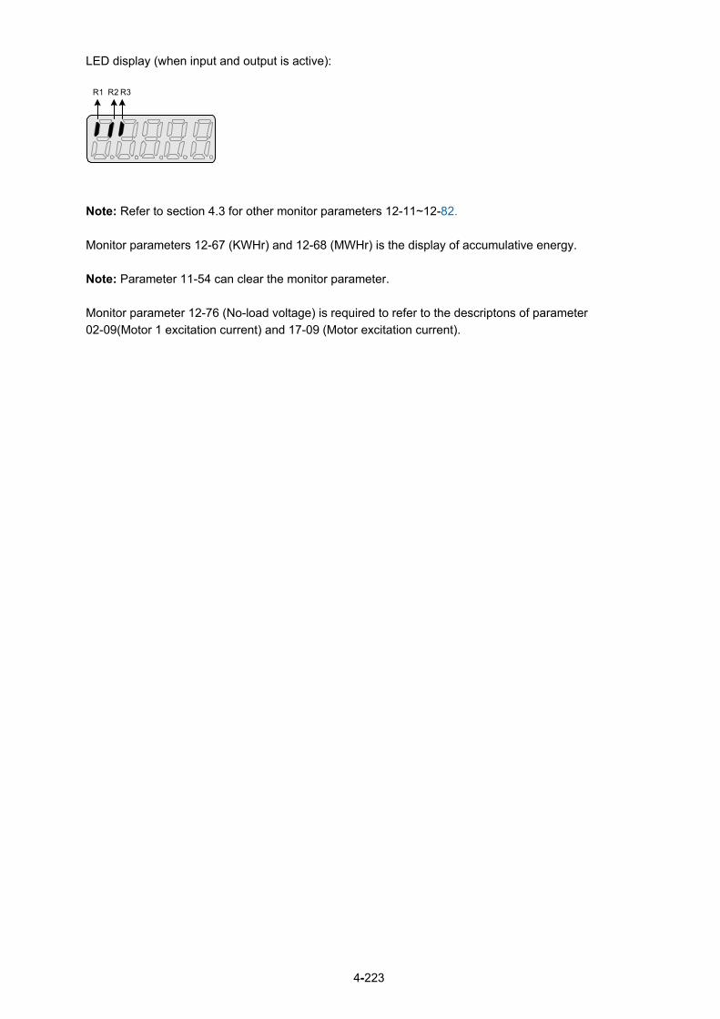
4-223
LED display (when input and output is active):
R1 R2 R3
Note: Refer to section 4.3 for other monitor parameters 12-11~12-82.
Monitor parameters 12-67 (KWHr) and 12-68 (MWHr) is the display of accumulative energy.
Note: Parameter 11-54 can clear the monitor parameter.
Monitor parameter 12-76 (No-load voltage) is required to refer to the descriptons of parameter
02-09(Motor 1 excitation current) and 17-09 (Motor excitation current).

4-224
Group 13 Maintenance Function Group
13- 00 Inverter Rating Selection
Range 00H~FFH
Inverter model 13- 00 display Inverter model 13- 00 display
F510-2001-XXX 201 F510-4001-XXX 401 F510-2002-XXX 202 F510-4002-XXX 402 F510-2003-XXX 203 F510-4003-XXX 403 F510-2005-XXX 205 F510-4005-XXX 405 F510-2008-XXX 208 F510-4008-XXX 408 F510-2010-XXX 210 F510-4010-XXX 410 F510-2015-XXX 215 F510-4015-XXX 415 F510-2020-XXX 220 F510-4020-XXX 420 F510-2025-XXX 225 F510-4025-XXX 425 F510-2030-XXX 230 F510-4030-XXX 430 F510-2040-XXX 240 F510-4040-XXX 440 F510-2050-XXX 250 F510-4050-XXX 450 F510-2060-XXX 260 F510-4060-XXX 460 F510-2075-XXX 275 F510-4075-XXX 475 F510-2100-XXX 2100 F510-4100-XXX 4100 F510-2125-XXX 2125 F510-4125-XXX 4125 F510-2150-XXX 2150 F510-4150-XXX 4150 F510-2175-XXX 2175 F510-4175-XXX 4175
F510-4215-XXX 4215 F510-4250-XXX 4250 F510-4300-XXX 4300 F510-4375-XXX 4375 F510-4425-XXX 4425 F510-4535-XXX 4535 F510-4670-XXX 4670 F510-4800-XXX 4800
13- 01 Software Version
Range 0.00-9.99
13- 02 Clear Cumulative Operation Hours Function
Range 【0】: Disable to Clear Cumulative Operation Hours 【1】: Clear Cumulative Operation Hours
13- 03 Cumulative Operation Hours 1
Range 【0~23】hours
13- 04 Cumulative Operation Hours 2
Range 【0~65534】days
13- 05 Selection of Accumulative Operation Time
Range 【0】: Accumulative time in power on
【1】: Accumulative time in operation
When 13-02 set to 1, the value of 13-03/13-04 will be cleared. 13-05= 0: Inverter logs the time while the inverter is powered-up. 13-05= 1: Inverter logs the time when the inverter is running.

4-225
13- 06 Parameters Locked
Range
【0】: Only parameter 13-06 and frequency command parameters in main screen
are writable 【1】: Only user parameter is enabled. 【2】: All parameters are writable.
When 13-06=0, only parameter 13-06 and frequency command parameter in main screen can be set but
other parameters are read-only.
When 13-06=1, only user parameters (00-41~00-56) are enabled. Please refer to the instruction of
parameters 00-41~00-56.
Note: it is only enabled in LCD keypad.
When 13-06=2, all parameters are writable except for the read-only parameters.
Note:
Main frequency setting is 12-16. The value is equal to frequency setting of speed-stage 0 (05-01) in LCD
keypad.
LED Main Frequency can be set in the main frequency display
13- 07 Parameter Password Function
Range 【00000~65534】
When the setting value of parameter 13-07 is enabled (13-07 > 0), all the parameters can not be adjusted except the frequency in main screen so user needs to input the password to adjust it.
Password setting:
First step:
Enter the function setting at 1st time
or
READ/ENTER
READ/ENTER
DSP/FUN
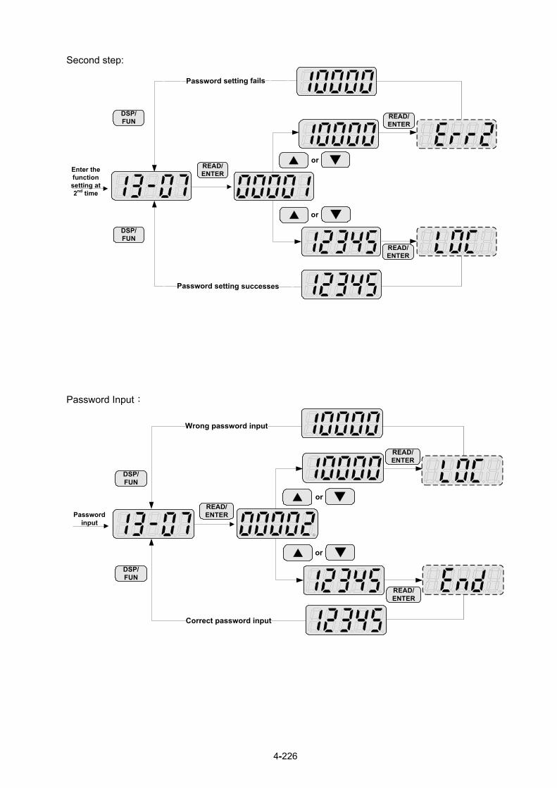
4-226
Second step:
Enter the function setting at 2nd time
or
READ/ENTER
or
READ/ENTER
READ/ENTER
DSP/FUN
DSP/FUN
Password Input:
Password input
or
READ/ENTER
Correct password input
or
READ/ENTER
READ/ENTER
DSP/FUN
DSP/FUN

4-227
13- 08 Restore Factory Setting
Range
【0】: No Initialization 【1】: Reserved
【2】: 2 Wire Initialization (220/440V, 60Hz) 【3】: 3 Wire Initialization (220/440V, 60Hz)
【4】: 2 Wire Initialization (230/415V, 50Hz) 【5】: 3 Wire Initialization (230/415V, 50Hz)
【6】: 2 Wire Initialization (200/380V, 50Hz) 【7】: 3 Wire Initialization (200/380V, 50Hz)
【8】: PLC Initialization
【9】: 2 Wire Initialization (230V/460V, 60Hz)
【10】: 3 Wire Initialization (230V/460V, 60Hz)
【11】: 2 wire Initialization (230V/400V, 60Hz) 【12】: 3 wire Initialization (230V/400V, 60Hz) 【13】: 2 wire Initialization (230V/400V, 50Hz)
【14】: 3 wire Initialization (230V/400V, 50Hz)
【15】: 2 wire Initialization (220V/380V, 50Hz)
【16】: 3 wire Initialization (220V/380V, 50Hz)
【Others】: Reserved Note: Main frequency setting is 12-16. The value is equal to frequency setting of speed-stage 0 (05-01) Use parameter 13-08 to initialize the inverter to factory default. It is recommended to write down the modified parameters before initializing the inverter. After initialization, the value of 13-08 will return to zero automatically. 13-08=2: 2-wire initialization (220V/440V)
Multi-function digital input terminal S1 controls forward operation / stop command, and S2 controls reverse
operation / stop command. Refer to Fig.4.4.1.
Inverter input voltage (01-14) is automatically set to 220V (200V class) or 440V (400V class).
When 01-00 (V/F curve) set to F, Inverter maximum frequency (01-12) is automatically set to 60Hz.
13-08=3: 3-wire initialization (220V/440V) Multi-function digital input terminal S5 controls the forward / reverse direction, and terminals S1 and S2 are set for 3-wire start operation and stop command.Refer to Figure 4.4.2 and Figure 4.4.3 for 3-wire type operation mode.
Inverter input voltage (01-14) is automatically set to 220V (200V class) or 440V (400V class).
When 01-00 (V/F curve) set to F, Inverter maximum frequency (01-12) is automatically set to 60Hz.
13-08=4: 2-wire initialization (230V/415V)
Multi-function digital input terminal S1 controls forward operation / stop command, and S2 controls reverse
operation / stop command. Refer to Fig.4.4.1.
Inverter input voltage (01-14) is automatically set to 230V (200V class) or 415V (400V class).
When 01-00 (V/F curve) set to F, Inverter maximum frequency (01-12) is automatically set to 50Hz.
13-08=5: 3-wire initialization (230V/415V)

4-228
Multi-function digital input terminal S5 controls the forward / reverse direction, and terminals S1 and S2 are set for 3-wire start operation and stop command.
Inverter input voltage (01-14) is automatically set to 230V (200V class) or 415V (400V class).
When 01-00 (V/F curve) set to F, Inverter maximum frequency (01-12) is automatically set to 50Hz.
13-08=6: 2-wire initialization (200V/380V)
Multi-function digital input terminal S1 controls forward operation / stop command, and S2 controls reverse
operation / stop command. Refer to Fig.4.4.1.
Inverter input voltage (01-14) is automatically set to 200V (200V class) or 380V (400V class).
When 01-00 (V/F curve) set to F, Inverter maximum frequency (01-12) is automatically set to 50Hz.
13-08=7: 3-wire initialization (200V/380V) Multi-function digital input terminal S5 controls the forward / reverse direction, and terminals S1 and S2 are set for 3-wire start operation and stop command.
Inverter input voltage (01-14) is automatically set to 200V (200V class) or 380V (400V class).
When 01-00 (V/F curve) set to F, Inverter maximum frequency (01-12) is automatically set to 50Hz.
13-08=8: PLC initialization Clear built-in PLC ladder logic and related values. 13-08=9: 2 wire initialization (230V/460V, 60Hz) Multi-function digital input terminal S1 controls forward operation / stop command, and S2 controls reverse operation / stop command. Refer to Figure 4.4.1. The input voltage (01-14) will be set to 230V (200V class) or 460V (400V class) automatically and when 01-00 (V/F curve) is set to F, the maximum frequency of 01-12 will be set to 60Hz automatically.
13-08=10: 3 wire initialization (230V/460V, 60Hz) Multi-function digital input terminal S7 controls the forward / reverse direction, and terminals S1 and S2 are set for 3-wire start operation and stop command. Refer to Figure 4.4.2 and Figure 4.4.3 for 3-wire type operation mode. The input voltage (01-14) will be set to 230V (200V class) or 460V (400V class) automatically and when 01-00 (V/F curve) is set to F, the maximum frequency of 01-12 will be set to 60Hz automatically. 13-08=11: 2 wire initialization (230V/400V, 60Hz) Multi-function digital input terminal S1 controls forward operation / stop command, and S2 controls reverse operation / stop command. Refer to Figure 4.4.1. The input voltage (01-14) will be set to 230V (200V class) or 400V (400V class) automatically and when 01-00 (V/F curve) is set to F, the maximum frequency of 01-12 will be set to 60Hz automatically.
13-08=12: 3 wire initialization (230V/460V, 60Hz) Multi-function digital input terminal S7 controls the forward / reverse direction, and terminals S1 and S2 are set for 3-wire start operation and stop command. Refer to Figure 4.4.2 and Figure 4.4.3 for 3-wire type operation mode. The input voltage (01-14) will be set to 230V (200V class) or 400V (400V class) automatically and when 01-00 (V/F curve) is set to F, the maximum frequency of 01-12 will be set to 60Hz automatically. 13-08=13: 2 wire initialization (230V/400V, 50Hz)

4-229
Multi-function digital input terminal S1 controls forward operation / stop command, and S2 controls reverse operation / stop command. Refer to Figure 4.4.1. The input voltage (01-14) will be set to 230V (200V class) or 400V (400V class) automatically and when 01-00 (V/F curve) is set to F, the maximum frequency of 01-12 will be set to 50Hz automatically.
13-08=14: 3 wire initialization (230V/460V, 50Hz) Multi-function digital input terminal S7 controls the forward / reverse direction, and terminals S1 and S2 are set for 3-wire start operation and stop command. Refer to Figure 4.4.2 and Figure 4.4.3 for 3-wire type operation mode. The input voltage (01-14) will be set to 230V (200V class) or 400V (400V class) automatically and when 01-00 (V/F curve) is set to F, the maximum frequency of 01-12 will be set to 50Hz automatically.
13-08=15: 2 wire initialization (220V/380V, 50Hz) Multi-function digital input terminal S1 controls forward operation / stop command, and S2 controls reverse operation / stop command. Refer to Fig.4.4.1. The input voltage (01-14) will be set to 220V (200V class) or 380V (400V class) automatically and when 01-00 (V/F curve) is set to F, the maximum frequency of 01-12 will be set to 50Hz automatically.
13-08=16: 3 wire initialization (220V/380V, 50Hz) Multi-function digital input terminal S7 controls the forward / reverse direction, and terminals S1 and S2 are set for 3-wire start operation and stop command. Refer to Figure 4.4.2 and Figure 4.4.3 for 3-wire type operation mode. The input voltage (01-14) will be set to 220V (200V class) or 380V (400V class) automatically and when 01-00 (V/F curve) is set to F, the maximum frequency of 01-12 will be set to 50Hz automatically.
Note: Restore factory setting (13-08) will not modify the setting of 01-00 (V/F curve).
Parameter List: parameters that are not affected by default value No. Parameter Name
00-00 Control Mode Selection00-04 Language Selection 01-00 V/F Curve Selection13-00 Inverter Rating Selection13-03 Cumulative Operation Hours 1 13-04 Cumulative Operation Hours 2 13-05 Selection of Accumulative Operation Time
13- 09 Fault History Clearance Function
Range 【0】: Do not Clear Fault History 【1】: Clear Fault History
13-09=1: Clear inverter fault history including (12-11~12-15/12-45~12-64)
13- 10 Parameter Password Function 2
Range 0 ~ 9999
13- 11 C/B CPLD Ver. *1
Range 【0.00~9.99】
This parameter displays CPLD version on the control board.

4-230
13- 12 Option Card Id *1
Range 【0~255】
This parameter displays option card Id on the control board and it is enabled only with the option card.
【0】: None
【8】: IO-8DO
13- 13 Option Card CPLD Ver. *1
Range 【0.00~9.99】
*1: It is new added in inverter software V1.4.
This parameter displays option card CPLD version on the control board and it is enabled only with option
card.
13- 14 Fault Storage Selection
Range 【0】: Auto Restart Fault Messages are not saved in fault history during Auto-Restart. 【1】: Auto Restart Fault Messages are saved in fault history during Auto-Restart.
13-14=0, Fault messages are not saved in fault history (12-46~12-49 & 13-21~13-50) during the process when auto restart function is active. 13-14=1, Fault messages are saved in fault history (12-46~12-49 & 13-21~13-50) during the process when auto restart function is active.
Note: Parameters 13-21~13-50 are 30 Fault History: When it detect fault, inverter will store to fault history.
If the fault occurs again, parameter 13-21 will change to parameter 13-22.
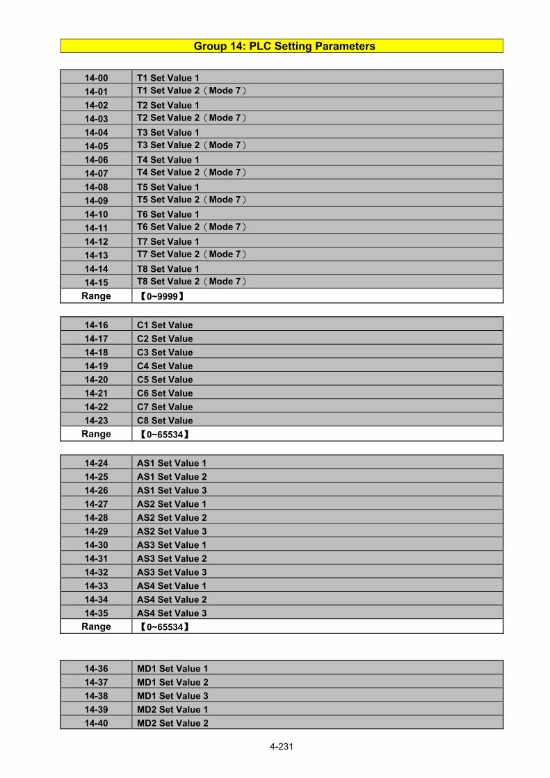
4-231
Group 14: PLC Setting Parameters
14-00 T1 Set Value 1
14-01 T1 Set Value 2(Mode 7)
14-02 T2 Set Value 1
14-03 T2 Set Value 2(Mode 7)
14-04 T3 Set Value 1
14-05 T3 Set Value 2(Mode 7)
14-06 T4 Set Value 1
14-07 T4 Set Value 2(Mode 7)
14-08 T5 Set Value 1
14-09 T5 Set Value 2(Mode 7)
14-10 T6 Set Value 1
14-11 T6 Set Value 2(Mode 7)
14-12 T7 Set Value 1
14-13 T7 Set Value 2(Mode 7)
14-14 T8 Set Value 1
14-15 T8 Set Value 2(Mode 7)
Range 【0~9999】
14-16 C1 Set Value
14-17 C2 Set Value
14-18 C3 Set Value
14-19 C4 Set Value
14-20 C5 Set Value
14-21 C6 Set Value
14-22 C7 Set Value
14-23 C8 Set Value
Range 【0~65534】
14-24 AS1 Set Value 1
14-25 AS1 Set Value 2
14-26 AS1 Set Value 3
14-27 AS2 Set Value 1
14-28 AS2 Set Value 2
14-29 AS2 Set Value 3
14-30 AS3 Set Value 1
14-31 AS3 Set Value 2
14-32 AS3 Set Value 3
14-33 AS4 Set Value 1
14-34 AS4 Set Value 2
14-35 AS4 Set Value 3
Range 【0~65534】
14-36 MD1 Set Value 1
14-37 MD1 Set Value 2
14-38 MD1 Set Value 3
14-39 MD2 Set Value 1
14-40 MD2 Set Value 2

4-232
14-41 MD2 Set Value 3
14-42 MD3 Set Value 1
14-43 MD3 Set Value 2
14-44 MD3 Set Value 3
14-45 MD4 Set Value 1
14-46 MD4 Set Value 2
14-47 MD4 Set Value 3
Range 【0~65534】
Please refer to section 4.5 for more details of built-in PLC function.
Group 15: PLC Monitoring Parameters
15- 00 T1 Current Value 1 15- 01 T1 Current Value 2(Mode 7)
15- 02 T2 Current Value 1 15- 03 T2 Current Value 2(Mode 7)
15- 04 T3 Current Value 1 15- 05 T3 Current Value 2(Mode 7)
15- 06 T4 Current Value 1 15- 07 T4 Current Value 2(Mode 7)
15- 08 T5 Current Value 1 15- 09 T5 Current Value 2(Mode 7)
15- 10 T6 Current Value 1 15- 11 T6 Current Value 2(Mode 7)
15- 12 T7 Current Value 1 15- 13 T7 Current Value 2(Mode 7)
15- 14 T8 Current Value 1 15- 15 T8 Current Value 2(Mode 7)
Range 【0~9999】
15-16 C1 Current Value 15-17 C2 Current Value 15-18 C3 Current Value 15-19 C4 Current Value 15-20 C5 Current Value 15-21 C6 Current Value 15-22 C7 Current Value 15-23 C8 Current Value
Range 【0~65534】
15-24 AS1 Results 15-25 AS2 Results 15-26 AS3 Results 15-27 AS4 Results 15-28 MD1 Results 15-29 MD2 Results 15-30 MD3 Results 15-31 MD4 Results 15-32 TD Current Value
Range 【0~65534】

4-233
Group 16: LCD Function Parameters
16- 00 Main Screen Monitoring
Range 【5~82】
16- 01 Sub-Screen Monitoring 1
Range 【5~82】
16- 02 Sub-Screen Monitoring 2
Range 【5~82】
At power-up the inverter shows two monitor section on the display, main monitor section and the
sub-screen monitor section (smaller font).
Choose the monitor signal to be displayed as the main-screen monitor screen in parameter 16-00, and the
monitor signals to be displayed on the sub-screen monitor in parameters 16-01 and 16-02, similar to
monitor parameters 12-5 ~ 12-82.
Note: The setting value of 16-00, 16-01 and 16-02 can be modified. It also can reset except PID modes
(refer to the setting description of parameter 10-03) and PUMP modes (refer to the setting description of parameter 23-00), but these two modes can be modified in inverter software V1.4.
16- 03 Selection of Display Unit
Range
【0】: Display unit is Hz (Resolution is 0.01Hz)
【1】: Display unit is % (Resolution is 0.01%) 【2】: Rpm display; motor rotation speed is set by the control modes to select IM
(02-07)/ PM (22-03) motor poles to calculate. 【3~39】: Reserved
【40~9999】: 100% is XXXX with no decimals (integer only)
【10001~19999】: 100% is XXX.X with 1 decimal
【20001~29999】: 100% is XX.XX with 2 decimals
【30001~39999】: 100% is X.XXX with 3 decimals
16- 04 Selection of Engineering Unit
Range
【0】: No Unit
【1】: FPM
【2】: CFM
【3】: PSI
【4】: GPH
【5】: GPM
【6】: IN
【7】: FT
【8】: /s
【9】: /m
【10】: /h
【11】: °F
【12】: inW
【13】: HP
【14】: m/s
【15】: MPM
【16】: CMM
【17】: W
【18】: KW
【19】: m 【20】: °C
【21】: RPM *1
【22】: Bar *1

4-234
【23】: Pa *1
【24】: KPa
*1: It is new added in inverter software V1.4.
16-03: Display unit of digital operator
Set the units of the following items to be displayed, the frequency reference (05-01, 00-18, 06-01~06-15)
and the monitoring frequency 12-16, 12-17 (Output frequency)
16-04: Display unit of engineering
When 16-03 = 00040-39999, engineering units are enabled. The displayed set range and the frequency
range of unit (05-01, 06-01~06-15) as well as the monitoring frequency (12-16, 12-17) are changed by
parameters 16-04 and 16-03.
16-03 Set / displayed contents0 0.01 Hz 1 0.01 % (maximum output frequency 01-02=100%)
2 RPM (RPM = 120 x reference frequency / numbers of motor pole. The numbers of motor pole is set by 02-07 in the control modes of V/F or SLV and is set by 22-03 in PMSLV.)
3-39 Reserved
00040 -
39999
Set the decimal point by using the fifth place. i.e.
Sets full display scaling excluding decimals Set the number of decimal places 00040 - 09999 : (Integer only e.g. 1000)
10001 - 19999 : . (1 decimal place e.g. 10.0)
20001 - 29999 : . (2 decimal places, e.g. 10.00)
30001 - 39999 : . (3 decimal places, e.g. 10.000) <example> 16-03 Display Display unit Display example
00040 -
09999
use 16-04 setting
Example: 100 % speed is 0200 > set 16-03=00200 (from 05-01, 06-01 to 06-15, set range from 0040 to 9999). > set 16-04=0 (no unit)
10001 –
19999 .
Example: 100 % speed is 200.0 CFM > set 16-03=12000 (05-01, 06-01 to 06-15, set range
from 0000 to 9999). > set 16-04=2 (CFM) > 60% speed will be displayed as 120.0 CFM
20001 –
29999 .
Example: 100 % speed is 65.00ºC > set 16-03=26500 (05-01, 06-01 to 06-15, set range from 0000 to 9999) > set 16-04=20 (ºC) > 60% of speed is displayed as 39.00 ºC
30001 -
39999 .
Example: 100 % speed is 2.555 m/s > set 16-03=32555 > set 16-04=14 (m/s) > 60% speed is displayed as 1.533 m/s
4-235
16- 05 LCD Backlight Range 【0~7】
Adjust the screen contrast of the digital operator. If it is set to 0, the screen backlight is turned off.
16- 07 Copy Function Selection
Range
【0】: Do not copy parameters
【1】: Read inverter parameters and save to the operator.
【2】: Write the operator parameters to inverter.
【3】: Compare parameters of inverter and operator.
16- 08 Selection of Allowing Reading
Range 【0】: Do not allow to read inverter parameters and save to the operator. 【1】: Allow to read inverter parameters and save to the operator.
LCD digital operator with built-in memory (EEPROM) can be used to store and retrieve parameters:
(1) Read: Save inverter parameters to the digital operator (INV → OP).
(2) Write: Write the parameters from the digital operator to the inverter and save (OP → INV).
(3) Verify: Compare the inverter parameters against the parameters in the digital operator. 16-07=0: No action 16-07=1: Read (all parameters are copied from the inverter to the keypad). 16-07=2: Write (all parameter are copied from the keypad to the inverter). 16-07=3: Verify (Compare the set value of the inverter to the parameter of the digital operator).
Set 16-08 = 0, to prevent the saved parameter data stored in the digital operator from accidentally being overwritten. When parameter 16-08=0 and the read operation is executed (16-07=1) a warning message of "RDP Read Prohibited" will be displayed on the keypad and the read operation is cancelled. Refer to the following steps for copy function operation. For the write-in operation requires the following items to match.
(1) Software version (2) Control method (3) Inverter type (4) Inverter rated capacity and voltage
Set one of the parameters 03-00 to 03-05 (multi-function digital input selection) to 49 (Enable the
parameter write-in function) to enable or disable the parameter write-in function.
When terminal is active, parameters can be copied from the digital operator to the inverter. When the
terminal is not active inverter parameters are prohibited from write-in, excluding the reference frequency
(00-05). Note: Parameter 16-11 (RTC date setting) and 16-12 (RTC time setting) require resetting, after parameter
setting in the keypad is written and saved in the inverter (OP→INV).

4-236
READ:Copy inverter parameters to the keypad
Steps LCD Display (English) Description
1
Select the copy function group (16) from the group menu.
2
Press the Read / Enter key and select parameter (16-07) copy sel.
3
Press the Read / Enter key to display the data setting / read screen
(LCD display is inversed).
4
Change the set value to 1 (read) by using the up arrow key.
5
Use Read / Enter key to enable the read operation, the display is
shown as the left.
The bottom of LCD display will show a bar to indicate the read
progress s.
6
“READ COMPLETE” will be displayed on the keypad when reading
was successful.
The error message of "RDP Read Prohibited" may occur on the
keypad when reading parameters from the inverter is prohibited.
If the error is displayed, press any key to remove the error
message and go back to parameter 16-07.
7
When DSP/FUN key is pressed, the display returns to parameter
16-07.
WRITE: Copy Keypad parameters to the Inverter
Steps LCD Display (English) Description
1
Select the copy function group (16) from the group menu.
2
Press the Read / Enter key and select parameter (16-07) copy sel.
3
Press the Read / Enter key to display the data setting / read screen
(LCD display is inversed).
4
Change the set value to 2 (write) by using the up arrow key.

4-237
Steps LCD Display (English) Description
5
Use Read / Enter key to enable the read operation, the display is
shown as the left.
The bottom of LCD display will show a bar to indicate the read
progress.
6
“WRITE COMPLETE” will be displayed on the keypad when writing was successful.
Until the subsequent display of "SysInit", please power off and
restart.
The error message of “WRE Write Error " may occur on the
keypad when writing parameters to the inverter is prohibited.
If the error is displayed, press any key to remove the error
message and go back to parameter 16-07.
7
When DSP/FUN key is pressed, the display returns to parameter 16-07.
Verify: Compare Inverter Parameters against Keypad Parameters.
Steps LCD Display (English) Description
1
Select the copy function group (16) from the group menu.
2
Press the Read / Enter key and select parameter (16-07) copy sel.
3
Press the Read / Enter key to display the data setting / read screen
(LCD display is inversed).
4
Change the set value to 3 (verify) by using the up arrow key.
5
Use Read / Enter key to enable the read operation, the display is
shown as the left.
The bottom of LCD display will show a bar to indicate the read
progress.
6
“VERIFY COMPLETE” will be displayed on the keypad when writing was successful.
The error message of “VRYE Verify Error " may occur on the
keypad when writing parameters to the inverter is prohibited.
If the error is displayed, press any key to remove the error
message and go back to parameter 16-07.
7
When DSP/FUN key is pressed, the display returns to parameter 16-07.

4-238
Monitor 00:00 Freq Ref
12-16 = 000.00 Hz
12-17 = 000.00 Hz12-18 = 0000.0A
16- 09 Selection of Operator Removed (LCD)
Range 【0】: Keep operating when LCD operator is removed.
【1】: Display fault to stop when LCD operator is removed
16-09=0: Continue operating when keypad is removed. 16-09=1: Trip inverter when keypad is removed while operating in local mode.
16- 10 RTC Time Display Setting
Range 【0】: Hide
【1】: Display
16- 11 RTC Date Setting
Range 【12.01.01 ~ 99.12.31】
16- 12 RTC Time Setting
Range 【00:00 ~ 23:59】 Set the internal clock before using the function of Real Time Clock (RTC). RTC date setting is determined by parameter 16-11 and RTC time setting is determined by parameter 16-12. RTC is displayed in the top of the keypad and refer to Fig.4.4.85 for the selection of RTC time display (16-10) is set to 1.
Figure 4.4.85 RTC Time Display (Example) Notes:
- RTC is not enabled if keypad does not connect with the inverter. - The counting time continues running regardless of the function being hide or display in the
paramerer 16-10 (RTC Time Display Setting). Users can apply the parameters 12-72 and 12-73 to monitor the specific RTC date and time. RTC has the following characteristics:
- Four times a day - Four weeks - Timer offset function (preset time) - Timrer enables via multi-function digital input - Selection for contant time and speed - Timer enables multi-function digital output

4-239
16- 13 RTC Timer Function
Range
【0】: Disable
【1】: Enable
【2】: Set by DI
16- 14 P1 Start Time
16- 15 P1 Stop Time
16- 18 P2 Start Time
16- 19 P2 Stop Time
16- 22 P3 Start Time
16- 23 P3 Stop Time
16- 26 P4 Start Time
16- 27 P4 Stop Time
Range 【00:00 ~ 23:59】
16- 16 P1 Start Date
16- 17 P1 Stop Date
16-20 P2 Start Date
16- 21 P2 Stop Date
16- 24 P3 Start Date
16- 25 P3 Stop Date
16- 28 P4 Start Date
16- 29 P4 Stop Date
Range
【1】: Mon 【2】: Tue 【3】: Wed 【4】: Thu 【5】: Fri 【6】: Sat 【7】: Sun
16- 30 Selection of RTC Offset
Range
【0】: Disable 【1】: Enable 【2】: Set by DI
16- 31 RTC Offset Time Setting
Range 【00:00 ~ 23:59】
16- 32 Source of Timer 1
16- 33 Source of Timer 2
16- 34 Source of Timer 3
16- 35 Source of Timer 4
Range 【0~31】: Refer to Table 4.4.13
16- 36 Selection of RTC Speed
Range
【0】: Off 【1】: By Timer 1 【2】: By Timer 2 【3】: By Timer 3 【4】: By Timer 4
【5】: By Timer 1+2
16- 37 Selection of RTC Rotation Direction
Range 【xxx0 B】: RTC Run1 Forward Rotation 【xxx1 B】: RTC Run1 Reverse Rotation

4-240
【xx0x B】: RTC Run2 Forward Rotation 【xx1x B】: RTC Run2 Reverse Rotation
【x0xx B】: RTC Run3 Forward Rotation 【x1xx B】: RTC Run3 Reverse Rotation
【0xxx B】: RTC Run4 Forward Rotation 【1xxx B】: RTC Run4 Reverse Rotation Source of timer can be selected to link multiple time periods and one time period can be set to multiple timers. Timer is set by the following steps: Start the timer: Timer starts via the setting of RTC timer function (16-13). Set the time period: Set the start & stop time and date. If the setting of start time is equal to that of stop time, timing period is
off. The timer is enabled: Arrange time period to the specific timer (16-32~16-35). Link to parameters: The timer can be linked to the relay output. One relay output can be only linked to one timer( ex. 03-11,
03-12 and 03-39, 16-36). Note: If the stop time is set to 12:00, Motor start to stop from 12:01. Refer to Fig.4.4.86 for RTC structure.
Step 1 Step 2 Step 3 Step 4
(Start the Timer) ( Set the Time Interval) ( Timer is Enabled) ( Link to Parameters)
Start/Stop Timer
(G16- 13)
Time period 1 (G16- 14 - 17)
Time period 2 (G16- 18 - 21)
Time period 3 (G16- 22 - 25)
Time period 4 (G16- 26 -29)
Offset Time (G16- 31)
Offset Time isOn/Off
(G16- 30)
Timer 1 (G16- 32)
Timer 2 (G16- 33)
Timer 3 (G16- 34)
Timer 4 (G16- 35)
.G16- 36 (RTC Speed Selection)
.G03- 11:Relay output (R1A - R1C)
.G03- 12:Relay output (R2A - R2C)
.G03- 39:Relay output (R3A - R3C)
Figure 4.4.86 RTC structure
Refer to the following Table 4.4.13 for the selection of timer operation cycle.
Table 4.4.13 Arrange time period to the timer function 16-32
~ 16-35
O P4 P3 P2 P1 Timer Function Display
0 0 0 0 0 0 Without the selection of timer None 1 0 0 0 0 1 Time Period 1 P1 2 0 0 0 1 0 Time Period 2 P2 3 0 0 0 1 1 Time Period 1 and 2 P1+P2 4 0 0 1 0 0 Time Period 3 P3 5 0 0 1 0 1 Time Period 1 and 3 P1+P3 6 0 0 1 1 0 Time Period 2 and 3 P2+P3 7 0 0 1 1 1 Time Period 1 , 2 and 3 P1+P2+P3 8 0 1 0 0 0 Time Period 4 P4 9 0 1 0 0 1 Time Period 1 and 4 P1+P4 10 0 1 0 1 0 Time Period 2 and 4 P2+P4 11 0 1 0 1 1 Time Period 1 , 2 and 4 P1+P2+P4

4-241
16-32 ~
16-35 O P4 P3 P2 P1 Timer Function Display
12 0 1 1 0 0 Time Period 3 and 4 P3+P4 13 0 1 1 0 1 Time Period 1 , 3 and 4 P1+P3+P4 14 0 1 1 1 0 Time Period 2 , 3 and 4 P2+P3+P4 15 0 1 1 1 1 Time Period 1 , 2 , 3 and 4 P1+P2+P3+P4 16 1 0 0 0 0 Offset selection Offset (O) 17 1 0 0 0 1 Offset and time period 1 O+P1 18 1 0 0 1 0 Offset and time period 2 O+P2 19 1 0 0 1 1 Offset and time period 1 and 2 O+P1+P2 20 1 0 1 0 0 Offset and time period 3 O+P3 21 1 0 1 0 1 Offset and time period 1 and 3 O+P1+P3 22 1 0 1 1 0 Offset and time period 2 and 3 O+P2+P3 23 1 0 1 1 1 Offset and time period 1 , 2 and 3 O+P1+P2+P3 24 1 1 0 0 0 Offset and time period 4 O+P4 25 1 1 0 0 1 Offset and time period 1 and 4 O+P1+P4 26 1 1 0 1 0 Offset and time period 2 and 4 O+P2+P4 27 1 1 0 1 1 Offset and time period 1 , 2 an 4 O+P1+P2+P4 28 1 1 1 0 0 Offset and time period 3 and 4 O+P3+P4 29 1 1 1 0 1 Offset and time period 1 , 3 and 4 O+P1+P3+P4 30 1 1 1 1 0 Offset and time period 2 , 3 and 4 O+P2+P3+P4
31 1 1 1 1 1 Offset and time period 1 , 2 , 3 and 4
O+P1+P2+P3+P4
Reference frequency and motor rotation direction are controlled by RTC function. 16-36=0: RTC speed selection is disabled. 16-36=1: Timer 1 is enabled.
Reference frequency = Frequency Setting of Speed-Stage 0 (05-01) 16-36=2: Timer 2 is enabled. Reference frequency = Frequency Setting of Speed-Stage 0 (05-01) 16-36=3: Timer 3 is enabled. Reference frequency = Frequency Setting of Speed-Stage 0 (05-01) 16-36=4: Timer 4 is enabled. Reference frequency = Frequency Setting of Speed-Stage 0 (05-01) 16-36=5: Timer 1 and 2 are enabled. Reference frequency is enabled by the simultaneous operation of timer 1 and 2. Notes:
- The inverter runs via the start of the specific timer without the influence of other timers. - The selection of RTC speed setting (16-36) is affected by the action of time period 1 to 4 (P1~P4)
which is corresponding to the selection of RTC rotation direction (16-37). For example: When the selection of RTC speed is set to 5 (by timer 1+2), source of run command (00-02) and source of frequecny command (00-05) are required to set to RTC. Thus, reference frequency is controlled by RTC timer 1 and 2 and the inverter continues running.
Refer to Table 4.4.14 for the control of reference frequency. Note: Selection of RTC Rotation Direction (16-37) is limited by the Motor Direction Lock Selection(11-00). Note: The offset 16-37 running direction will select by the direction of the timer 1.

4-242
Mon Tue Wed Thu Fri Sat Sun
24: 00
22: 00
20: 00
18: 00
16: 00
14: 00
12: 00
10: 00
08: 00
06: 00
04: 00
02: 00
00: 00
Time
Day
weekdays weekends
Time period 2(P2)
Time period 4
(P4)
Time period 3
(P3)
Time period 1
(P1)
Table 4.4.14 Reference frequency is determined by timer 1 and 2
Timer 1 Timer 2 Main Frequency CommandSource Selection (00-05)
Source of frequency setting Selection of rotation
direction
0 0 6(RTC) Set by frequency setting of speed-stage 0 (05-01)
By RTC 1 (16-37)
1 0 6(RTC) Set by frequency setting of speed-stage 1 (05-02)
By RTC 2 (16-37)
0 1 6(RTC) Set by frequency setting of speed-stage 2 (05-03)
By RTC 3 (16-37)
1 1 6(RTC) Set by frequency setting of speed-stage 3 (05-04)
By RTC 4 (16-37)
RTC function can not run normally when:
- When multi-function terminal (03-00~03-05) is set to the fire mode. - When KEB function is enabled
Source of main frequency of RTC function is according to Table 4.4.14 and also can refer to main and alternative frequency command modes (00-07).
If main run command source selection (00-02) is set to 0~3 (0: keypad, 1: external terminal, 2: communication control, 3: PLC), refer to Table 4.4.15 for the relationship between main run command and RTC timer status.
Table 4.4.15 Relationship between main run command and RTC timer status
Main run command 00-02
RTC timer x status Inverter status
0~3 0 Inverter can not run (without run command) 0~3 1 Inverter can not run (without run command)
4 0 Inverter can not run (RTC timer is disabled)
4 1 Inverter runs and rotates depending on the function of 16-37.
Take an example for RTC timer connecting with different parameters:
The work time on Monday is 6:00 AM to 10:00 PM.
The work time on Tuesday to Friday is 8:00 AM to 8:00 PM.
The work time on Saturday is 8:00 AM to 6:00 PM.
The work time on Sunday is 8:00 AM to 12:00 PM.
Motor runs on weekdays (Mon. to Fri.) at speed 1 and on weekends at speed 2.
Figure 4.4.87 RTC timer (example)

4-243
Start up the timer in the parameter group 16 (Set the internal time first to enable this function).
Set the correct date and time in the parameters 16-11 and 16-12 and set parameter 16-13 to
1(enable RTC timer function).
Set time period 1 (P1) Start time 1: 16-14 = 06:00:00 (6:00 AM)
Stop time 1: 16-15 = 22:00:00 (10:00 PM)
Start date 1: 16-16 = 1 (Monday)
Stop date 1: 16-17 = 1 (Monday)
Set time period 2 (P2) Start time 2: 16-18 = 08:00:00 (8:00 AM)
Stop time 2: 16-19 = 20:00:00 (8:00 PM)
Start date 2: 16-20 = 2 (Tuesday)
Stop date 2: 16-21 = 5 (Friday)
Set time period 3 (P3) Start time 3: 16-22 = 08:00:00 (8:00 AM)
Stop time 3: 16-23 = 18:00:00 (6:00 PM)
Start date 3: 16-24 = 6 (Saturday)
Stop date 3: 16-25 = 6 (Saturday)
Set time period 4 (P4) Start time 4: 16-26 = 08:00:00 (8:00 AM)
Stop time 4: 16-27 = 12:00:00 (12:00 AM)
Start date 4: 16-28 = 7 (Sunday)
Stop date 4: 16-29 = 7 (Sunday)
Timer 1 is enabled to set all the time periods (P1, P2, P3, P4) 16-32 = 15: Source of timer 1 = P1 + P2 + P3 + P4)
Selection of RTC speed is determined by timer 1 16-36 = 1: Timer 1 is enabled.
Frequency setting is speed-stage 0 (05-01).
Rotation direction (16-37) is set to 0000b.
Then, the rotation direction of time period 1~4 (P1~P4) is corresponding to the setting of 16-37.
Choose two constant speeds (speed 1 & speed 2) 16-36 = 5: Timer 1+2 is enabled.
When timer 1 is enabled, frequency setting is speed-stage 1; while timer 2 is enabled, frequency
setting is speed-stage 2.
Rotation direction (16-37) is set to 0000b.
Then, when timer 1 and timer 2 are active, direction of motor rotation is forward rotation.
Note: Select RTC offset (16-30) and set RTC offset time (16-31) to enable the offset time. Inverter runs
depending on the arranging time period to timer function. Refer to the following Fig.4.4.88.

4-244
Time gap(G16- 31)
t
Multi-function digital input(G03- 00 to 03- 05 = 56)
Offset Time
t
Figure 4.4.88 Operation of offset time For example: Inverter runs at the time period exclusive P1: When 16-36=1 (selection of RTC speed is set to timer 1) and 16-32=17 (offset + PI), RTC offset (16-30) is set by DI and the offset time is set via 16-31. Switch on DI and RTC will immediately start up. If the source of timer is set to 15 (P1+P2+P3+P4), press “STOP” key at the time period 1 (P1). Normally, RTC will start automatically at the next time period (P2) but it can also start via the setting of 16-30 to 2 (set by DI). Inverter re-runs when switching on DI and RTC will immediately start up. Notes:
If press “STOP” key at the time period and inverter can re-run at this time, user can: - Set the selection of RTC offset (16-30) to 2 (set by DI) and set DI to 56 (RTC Offset Enable). - Switch the selection of RTC offset (16-30) to be enabled.
Note:
RTC Accuracy: Temperature Deviation +25(77) +/-3 sec./ day
-20 / +50 (-4/ 122) +/-6 sec./ day

4-245
Group 17: IM Motor Automatic Tuning Parameters
17- 00 Mode Selection of Automatic Tuning
Range
【0】: Rotation Auto-tune
【1】: Static Auto-tune
【2】: Stator Resistance Measurement
【4】: Loop Tuning
【5】: Rotational Auto-tuning Combination (Item: 4+2+0)
【6】: Static Auto-tuning Combination (Item: 4+2+1)
17- 01 Motor Rated Output Power
Range 【0.00~600.00】KW
17- 02 Motor Rated Current
Range 10%~200% of the inverter rated current in V/F control mode
25%~200% of the inverter rated current in SLV control mode 17- 03 Motor Rated Voltage*1
Range 200V:【50.0~240.0】V
400V:【100.0~480.0】V
17- 04 Motor Rated Frequency*2
Range 【4.8~599.0】Hz
17- 05 Motor Rated Speed
Range 【0~24000】rpm
17- 06 Pole Number of Motor
Range 【2~16】pole (Even)
17- 08 Motor No-load Voltage
Range 200V:【50~240】V
400V:【100~480】V
17- 09 Motor Excitation Current Range 【0.01~600.00】A (15%~70% motor rated current)
17- 10 Automatic Tuning Start
Range 【0】: Disable 【1】: Enable
17- 11 Error History of Automatic Tuning
Range
【0】: No Error 【1】: Motor Data Error
【2】: Stator Resistance Tuning Error
【3】: Leakage Induction Tuning Error 【4】: Rotor Resistance Tuning Error 【5】: Mutual Induction Tuning Error
【6】: Reserved
【7】: DT Error 【8】: Motor Acceleration Error 【9】: Warning
17-12 Leakage Inductance Ratio Range 【0.1~15.0】%
17-13 Slip Frequency Range 【0.10~20.00】Hz
17-14 Rotational Tuning Mode Selection
Range 【0】: VF Mode
【1】: Vector Mode
*1. Values of motor rated voltage are for 200V class, double the values for 400V class.
*2. The setting range of motor rated frequency is 0.0 to 599.0 Hz.

4-246
Auto-tuning Based on the motor nameplate set the motor rated output power (17-01), motor output rated current (17-02), motor rated voltage (17-03), motor rated frequency (17-04), motor rated speed (17-05) and number of motor poles (17-06) to perform an auto-tune.
Automatic tuning mode selection (17-00)
17-00=0: Perform rotational auto-tune (High performance auto-tune)
After executing Rotational auto-tuning (17-00), Excitation current (02-09), Core saturation coefficient
1 (02-10), Core saturation coefficient 2 and Core saturation coefficient 3 will renew the value.
17-00=1: Perform a static non-rotational auto-tune
Motor does not rotate during auto-tuning and this tuning causes lower power at low speed.
After executing Static auto-tuning (17-00=1), Proportion of motor leakage inductance (02-33) and
Motor slip (02-34) will renew the value.
17-00=2: Perform stator resistance non-rotational auto-tune (V/F mode) when using long motor leads.
This tuning causes lower power at low speed.
After executing Stator resistance measurement (17-00=2), Resistance between wires (02-15) will
renew the value.
17-00=3: Reserved
17-00=4: Loop tuning makes optimization for current loop response to improve the bandwidth of urrent
and torque.
17-00=5: Rotational auto-tuning combination is three-in-one auto-tuning, including loop tuning
(17-00=4), stator resistance measurement (V / F) (17-00=2), and rotation auto-tuning (17-00=0).
17-00=6: Static auto-tuning combination () is three-in-one auto-tuning, including loop tuning (17-00=4),
stator resistance measurement (V / F) (17-00=2) and static auto-tuning (17-00=1). Motor rated output power (17-01)
Set by inverter capacity (13-00)
Motor rated current (17-02) Set by inverter capacity (13-00) Set the range to 10 %~200 % of the inverter rated current.
Motor rated voltage (17-03) Motor rated frequency (17-04) Motor rated speed (17-05)
When tuning a special motor (e.g. constant power motor, high-speed spindle motor), with a motor rated
voltage or rated motor frequency that is lower than a standard AC motor, it is necessary to confirm the
motor nameplate information or the motor test report. Prevent the inverter output voltage from saturation when the motor rated voltage is higher than the inverter input voltage (see Example 1). Example 1: Motor rated voltage (440V/60Hz) is higher than the inverter input voltage (380V/50 Hz).

4-247
Figure 4.4.89 Rated voltage and frequency settings
Step 1: Set motor rated voltage, 17-03=440V.
Step 2: Set no-load voltage, 17-08=360V, lower the input voltage by 20V when operating in torque control.
Step 3: Set motor rated frequency:
Step 4: Automatically tuning
Parameter 01-12 (Fbase) is automatically set during auto-tuning. Parameter 01-12 (Fbase) is set to the
motor rated frequency.
Step 5: Set the 01-12 (Fbase) to the motor rated frequency on the motor nameplate. If the maximum
output frequency (01-02, Fmax) and base frequency (01-12, Fbase) are different, set the maximum output
frequency when the auto- tuning (01-02, Fmax) is completed.
When the inverter input voltage (or frequency) is higher than the motor rated voltage (or frequency), set the
motor rated voltage (17-03) and the motor rated frequency (17-04) to the rated frequency on the motor
nameplate.
Example 2: The inverter input voltage and frequency (440V/50Hz) are higher than the motor rated voltage
and frequency (380V/33Hz), set 17-03 to 380V (rated motor voltage) and 17-04 to 33Hz (motor rated
frequency).
Number of poles (17-06)
Set the motor pole number with its range is 2, 4, 6, 8 and 16 poles. (It is only 2~8 poles in inverter
software V1.3.
Motor no-load voltage (17-08)
a) Motor no-load voltage is mainly used in SLV mode, set to value 10~50V lower than the input
voltage to ensure good torque performance at the motor rated frequency.
b) Set to 85 ~ 95% of the motor rated voltage. In general, the no-load voltage can be closer to the
motor rated voltage for larger motors, but cannot exceed the motor rated voltage.
c) The motor no-load voltage can be set to a value greater than the actual input voltage. In this case,
the motor can only operates under relatively low frequency. If the motor operates at the rated
frequency an over voltage condition may occur.
d) The higher the motor power is, the higher the no-load voltage is.
e) A smaller no-load voltage will reduce the no-load current.
f) When load is applied the magnetic flux is weakened and the motor current increases.
g) A higher no-load voltage results in a higher the no-load current.
h) When load is applied the magnetic flux weakens and the motor current increases. Increasing the
magnetic flux generates back EMF and results in poor torque control.

4-248
Motor excitation current (17-09)
a) Only the static-type or stator resistance measurement auto-tuning (17-00=1 or 17-00=2) can be
set. This data can be obtained by manual tuning. Normally, it does not require adjusting.
b) Motor excitation current is used for non-rotational auto-tuning.
c) The setting range of motor excitation current is 15%~70% of the motor rated current.
d) If this parameter is not set, the inverter calculates the motor related parameters.
Automatic tuning start (17-10)
Set parameter 17-10 to 1 and press ENTER the inverter will display “Atrdy” for Auto-tune ready. Next,
press RUN key to start the auto-tune procedure. During auto-tuning the keypad will display “Atune “for
Auto-tune in progress. When the motor is successfully tuned, the keypad shows "AtEnd".
Error history of automatic tuning (17-11)
If auto-tuning fails the keypad will display the AtErr" message and the auto-tune cause is shown in
parameter 17-11. Refer to section 5 for troubleshooting and possible automatic tuning error causes.
Note: The motor tuning error history (17-11) shows the tuning result of the last auto-tune. No error is
displayed when auto-tune is aborted or when the last auto-tune was successful.
Motor Leakage Inductance Ratio (17-12)
a) Only stator resistance measurement auto-tuning (17-00=2) can be set and this data can be
obtained by manual tuning. Normally, it does not require adjustment.
b) It is mainly for non-rotational auto-tuning. The default setting is 3.4%. It is required to tune to make
the adjusted parameter value saved into the group 02-33.
c) If this parameter is not set, the inverter calculates the motor related parameters.
Motor Slip Frequency (17-13)
a) Only stator resistance measurement auto-tuning (17-00=2) can be set and this data can be
obtained by manual tuning. Normally, it does not require adjustment.
b) It is mainly for non-rotational auto-tuning. The default setting is 1Hz. It is required to tune to make
the adjusted parameter value saved into the group 02-34.
c) If this parameter is not set, the inverter calculates the motor related parameters.
Notes: - Perform the “Stator resistance measurement” (17-00=2) auto-tune if the inverter/motor leads are
longer than 167ft (50m).
- For the best performance in vector control perform the rotary-type automatic tune (17-00=0) first
(using short motor leads between the inverter and motor) and a “Stator resistance measurement”
(17-00=2) next.
- If a rotary auto-tune (17-00=0) cannot be performed, manually enter the mutual induction (02-18),
excitation current (02-09), core saturation compensation factor 1-3 (02-11 - 02-13).
- Perform the “Stator resistance measurement” (17-00=2) in V/F control when inverter/motor leads are
longer than 167ft (50m).
Rotational Tuning Mode Selection (17-14)
It is only enabled in rotation auto-tuning (17-00=0) and rotational auto-tuning combination (17-00=5).
17-14=0,
Under VF control mode, no-loading can drive general standard induction motors without oscillation.
And it is the most widely used mode.
Note: If VF mode rotational tuning is failed, try Vector mode rotational tuning to run again.

4-249
17-14=1,
Under VF control mode, no-loading drives particular induction motor with oscillation. And such kinds of
motors mostly are high-speed type.
Note: Because Vector mode measures no-load current of motor by internal current vector structure, so
the particular induction motor can avoid the oscillated problem in the VF control mode.
Group 18: Slip Compensation Parameters
18- 00 Slip Compensation Gain at Low Speed
Range 【0.00~2.50 】
18- 01 Slip Compensation Gain at High Speed
Range 【-1.00~1.00】
18- 02 Slip Compensation Limit
Range 【0~250】%
18- 03 Slip Compensation Filter Time
Range 【0.0~10.0】sec
18- 04 Regenerative Slip Compensation Selection
Range 【0】: Disable 【1】: Enable
18- 05 FOC Delay Time
Range 【1~1000】msec
18- 06 FOC Gain
Range 【0.00~2.00】
Slip compensation automatically adjusts the output frequency based on the motor load to improve the
speed accuracy of the motor mainly in V/F mode.
The slip compensation function compensates for the motor slip to match the actual motor speed to the
reference frequency. Slip compensation adjustment in V/F mode 18-00: Slip compensation gain at low speed The adjustment of slip compensation gain at low speed follows the below procedure:
1. Set the rated slip and the motor no-load current (02-00). 2. Set the slip compensation (18-00) to1.0 (factory default setting is 0.0 in V / F control mode)
3. For the operation with a load attached, measure the speed and adjust the slip gain (18-00)
accordingly (increase in steps of 0.1). - If the motor speed is lower than frequency reference, increase the value of 18-00. - If the motor speed is higher than frequency reference, decrease the value of 18-00.
When the output current is greater than the no-load current (02-00), the slip compensation is enabled and the output frequency increases from f1 to f2. Refer to Fig.4.4.90., the slip compensation value is calculated as follows:
[Output current (12-08) – motor no-load current (02-00)]
Slip compensation value = Motor rated sync induction rotation difference x [Motor output rated current (02-01) –motor no-load current (02-00)]

4-250
Figure 4.4.90 Slip compensation output frequency
18-02: Slip compensation limit Sets slip compensation limit in constant torque and the constant power operation (Fig.4.4.91). If 18-02 is 0%, the slip compensation limit is disabled.
Figure 4.4.91 Slip compensation limit
When the slip compensation gain 18-00 at low speed is adjusted, and the actual motor speed is still lower than the reference frequency, the motor may be limited by the slip compensation limit. Note: Make sure that the slip compensation limit 18-02 does not exceed the maximum allowed system
limit.
18-03: Slip compensation filter Set slip compensation filter time in V/F mode 18-04: Regenerating slip compensation selection The selections to enable or disable the slip compensation function during regeneration. To enable slip compensation during regeneration caused by deceleration (SLV mode), set 18-04 to 1 in case speed accuracy is required. When the slip compensation function is used regenerative energy might increase temporarily (18-04= 1) therefore a braking module might be required. SLV mode adjustment 18-00: Slip compensation gain
a) Slip compensation can be used to control the full rang speed accuracy under load condition. b) If the speed is lower than 2 Hz and the motor speed decreases, increase the value of 18-00. c) If the speed is lower than 2 Hz and the motor speed increases, reduce the value of 18-00.
Slip compensation gain uses a single value for the whole speed range. As a result the slip compensation accuracy at low speed is high but slight inaccuracies might occur at high speeds.
Adjust parameter 18-02 together with the compensation value or continue to adjust 18-00 if the speed accuracy at higher speed is not acceptable. Please note adjusting these parameters might impact the accuracy at lower speeds. The impact of 18-00 on the torque and the speed are shown in Fig.4.4.92.
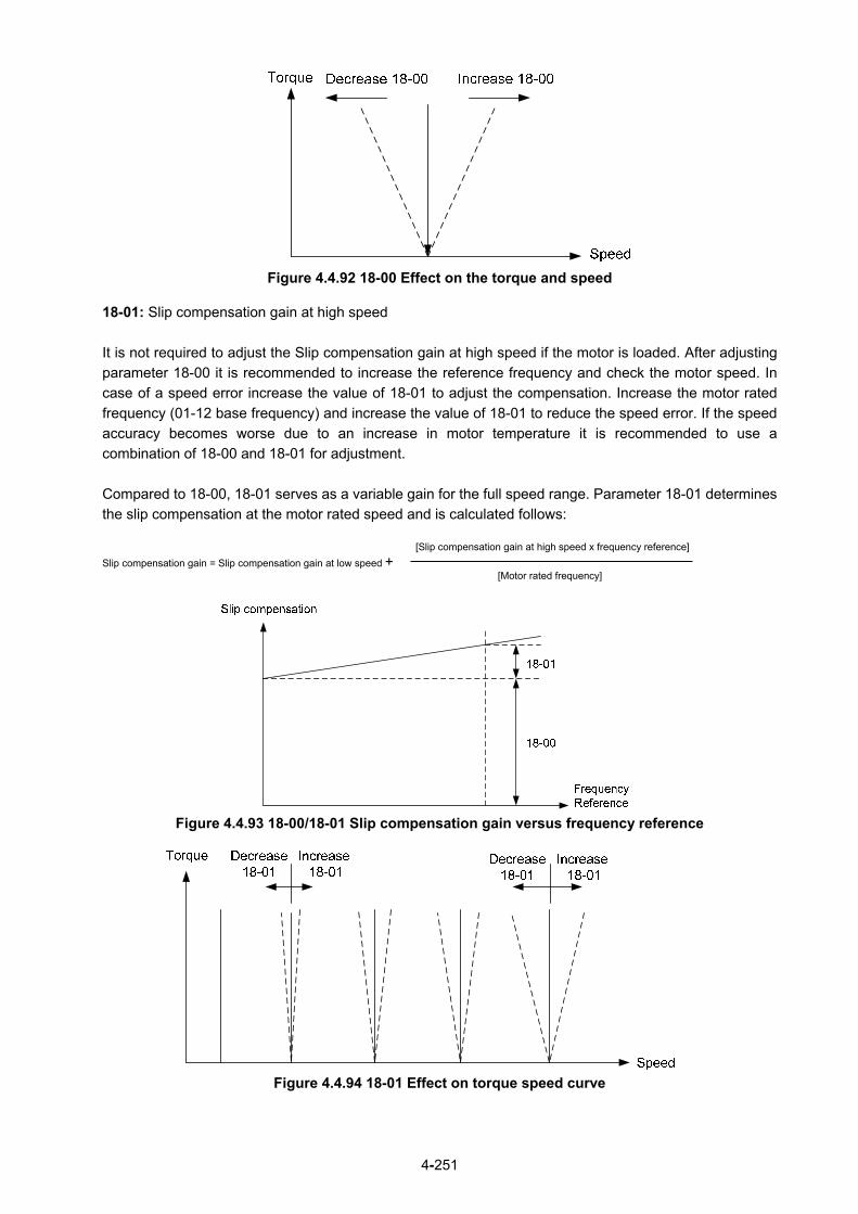
4-251
Figure 4.4.92 18-00 Effect on the torque and speed
18-01: Slip compensation gain at high speed
It is not required to adjust the Slip compensation gain at high speed if the motor is loaded. After adjusting
parameter 18-00 it is recommended to increase the reference frequency and check the motor speed. In
case of a speed error increase the value of 18-01 to adjust the compensation. Increase the motor rated
frequency (01-12 base frequency) and increase the value of 18-01 to reduce the speed error. If the speed
accuracy becomes worse due to an increase in motor temperature it is recommended to use a
combination of 18-00 and 18-01 for adjustment.
Compared to 18-00, 18-01 serves as a variable gain for the full speed range. Parameter 18-01 determines
the slip compensation at the motor rated speed and is calculated follows:
[Slip compensation gain at high speed x frequency reference]
Slip compensation gain = Slip compensation gain at low speed + [Motor rated frequency]
Figure 4.4.93 18-00/18-01 Slip compensation gain versus frequency reference
Figure 4.4.94 18-01 Effect on torque speed curve

4-252
18-05: FOC (Flux Orient Control) delay time
In the SLV mode, the slip compensation of the magnetic flux depends on the torque current and excitation
current. If the motor load rises above 100% while running at the motor rated frequency, the motor voltage
and resistance drops sharply, which may cause the inverter output to saturate and current jitter occur. The
magnetic flux slip compensation will independently control the torque current and the excitation current to
prevent current jitter. For slow speed or fixed speed operation, 18-05 may be increased. For fast operation
adjust 18-06.
18-06: Slip compensation gain
If the motor is jittering at the rated frequency under full load, the value of 18-06 may gradually be reduced
to zero to reduce current jitter.

4-253
Group 20 Speed Control Parameters
20- 00 ASR Gain 1
Range 【0.00~250.00】
20- 01 ASR Integral Time 1 Range 【0.001~10.000】Sec
20- 02 ASR Gain 2 Range 【0.00~250.00】
20- 03 ASR Integral Time 2 Range 【0.001~10.000】Sec
20- 04 ASR Integral Time Limit
Range 【0~300】%
20- 07 Selection of Acceleration and Deceleration of P/PI
Range 【0】: PI speed control will be enabled only in constant speed. For accel/decel,
only use P control. 【1】: Speed control is enabled either in constant speed or accel/decal.
20- 08 ASR Delay Time
Range 【0.000~0.500 】Sec
20- 09 Speed Observer Proportional (P) Gain 1 Range 【0.00~2.55】
20- 10 Speed Observer Integral(I) Time 1Range 【0.01~10.00】Sec
20- 11 Speed Observer Proportional (P) Gain 2 Range 【0.00~2.55】
20- 12 Speed Observer Integral(I) Time 2Range 【0.01~10.00】Sec
20- 13 Low-pass Filter Time Constant of Speed Feedback 1Range 【1~1000】mSec
20- 14 Low-pass Filter Time Constant of Speed Feedback 2 Range 【1~1000】mSec
20- 15 ASR Gain Change Frequency 1 Range 【0.0~599.0】Hz
20- 16 ASR Gain Change Frequency 2 Range 【0.0~599.0】Hz
20- 17 Torque Compensation Gain at Low Speed Range 【0.00~2.50】
20- 18 Torque Compensation Gain at High Speed Range 【-10~10】%
20-33 Constant Speed Detection Level Range 【0.1~5.0】%
The following figure an overview of the automatic speed regulator (ASR) block. SLV control mode:
The ASR function adjusts the output frequency to control the motor speed to minimize the difference
between the frequency reference and actual motor speed.
The ASR controller in SLV mode uses a speed estimator to estimate the motor speed. In order to reduce
speed feedback signal interference, a low-pass filter and speed feedback compensator can be enabled.

4-254
The ASR integrator output can be disabled or limited. The ASR output is passed through a low-pass filter.
20-0020-02
20-0120-03
20-08
Frequency Reference
20-1320-14
20-1720-18
SpeedObserver
20-0920-11
20-1020-12
Motor VoltageMotor Current
P
P
I
I
I Limit
Speed ObserverFeedback
Speed Feedback
CompensatorLP Filter
ObserverError
20-07 = 1 (during accel/decel)20-07 = 0
Speed Control Integral Reset03-00 to 03-05 = 43
Primary delay time
TorqueLimit
TorqueReference
+ +
+
+
+
-
Figure 4.4.95 ASR block diagram (SLV mode)
ASR setting (SLV control mode)
In SLV mode the ASR gain is divided into a high-speed and low-speed section. The speed controller has a
high-speed gain 20-00/20-01 and a low-speed gain 20-02/20-03 that can be set independently.
a) The high/low switch frequency can be set with parameter 20-15 and 20-16. Similar to the ASR
gain, the speed estimator has a high-speed gain 20-09/20-10 and a low-speed gain 20-11/20-12.
b) The speed estimator has a low-pass filter to reduce the speed feedback interference, parameter
20-13 and 20-14 are active at high speed as well as low speed. The switch between the
high-speed and the low-speed is set by parameter 20-15 and 20-16.
c) 20-17 sets the low-speed compensation gain of the speed feedback.
d) 20-18 sets the high-speed compensation gain of the speed feedback.
e) When the frequency reference is rises above the value set in 20-16, the ASR gain used is set by
parameters 20-00 and 20-01.
f) When the frequency reference falls below the value set in 20-15, the ASR gain used is set by
parameters 20-02 and 20-03.
g) Gain time constant is adjusted linearly when the speed command falls within the range of 20-15 to
20-16, for a smooth operation.
Figure 4.4.96 ASR gain setting (SLV mode)
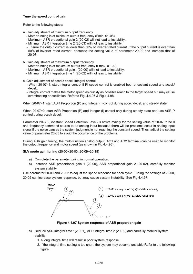
4-255
Tune the speed control gain
Refer to the following steps: a. Gain adjustment of minimum output frequency
- Motor running is at minimum output frequency (Fmin, 01-08). - Maximum ASR proportional gain 2 (20-02) will not lead to instability. - Minimum ASR integration time 2 (20-03) will not leas to instability. - Ensure the output current is lower than 50% of inverter rated current. If the output current is over than 50% of inverter rated current, decrease the setting value of parameter 20-02 and increase that of 20-03.
b. Gain adjustment of maximum output frequency
- Motor running is at maximum output frequency (Fmax, 01-02). - Maximum ASR proportional gain1 (20-00) will not lead to instability. - Minimum ASR integration time 1 (20-02) will not leas to instability.
c. Gain adjustment of accel./ decel. integral control - When 20-07=1, start integral control if PI speed control is enabled both at costant speed and accel./ decel..
- Integral control makes the motor speed as quickly as possible reach to the target speed but may cause overshooting or oscillation. Refer to Fig. 4.4.97 & Fig.4.4.98.
When 20-07=1, start ASR Proportion (P) and Integer (I) control during accel/ decel. and steady state When 20-07=0, start ASR Proportion (P) and Integer (I) control only during steady state and use ASR P control during accel/ decel.. Parameter 20-33 (Constant Speed Detection Level) is active mainly for the setting value of 20-07 to be 0 and frequency command source to be analog input because there will be problems occur in analog input signal if the noise causes the system judgment in not reaching the constant speed. Thus, adjust the setting value of parameter 20-33 to avoid the occurrence of the problems.
During ASR gain tuning, the multi-function analog output (AO1 and AO2 terminal) can be used to monitor the output frequency and motor speed (as shown in Fig.4.4.96). SLV mode gain tuning (20-00~20-03, 20-09~20-18)
a) Complete the parameter tuning in normal operation.
b) Increase ASR proportional gain 1 (20-00), ASR proportional gain 2 (20-02), carefully monitor
system stability.
Use parameter 20-00 and 20-02 to adjust the speed response for each cycle. Tuning the settings of 20-00,
20-02 can increase system response, but may cause system instability. See Fig.4.4.97.
Figure 4.4.97 System response of ASR proportion gain
a) Reduce ASR integral time 1(20-01), ASR integral time 2 (20-02) and carefully monitor system
stability.
1. A long integral time will result in poor system response.
2. If the integral time setting is too short, the system may become unstable Refer to the following
figure.

4-256
While tuning ASR P and I gain the system may overshoot and an over voltage condition can occur. A
braking unit (braking resistor) can be used to avoid an over voltage condition.
1
1
2
2
t
MotorSpeed
1 : 20-01 setting is too short(oscillation occurs)
2 : 20-01 setting is too long(slow response)
Figure 4.4.98 The response of ASR integral time
Both low-speed ASR gain and the high-speed gain can be set to the same values and only require to be
adjusted in case of system instability.
In case tuning of the ASR P and I gain 20-00~20-03 does not improve the system response, reduce the
low-pass filter time constant 20-13~20-14 to increase the bandwidth of the feedback system and re-tune
the ASR gain.
Tune low-speed low-pass filter time constant 20-14, make sure the reference frequency is below
parameter 20-15 value.
Tune high-speed low-pass filter time constant 20-13 at frequency reference, make sure the reference
frequency is above parameter 20-16 value.
Increasing the low-pass filter time constant can limit the bandwidth of the speed feedback system and
may reduce the system response. Increasing the low-pass time reduces the speed feedback signal
interference but may results in sluggish system response when the load suddenly changes. Adjust the
low-pass filter time if the load stays fairly constant during normal operation. The low bandwidth of the
speed feedback must be supported by the low gain of ASR to ensure the stable operation.
Decreasing the low-pass filter time constant may increase the bandwidth of the speed feedback and the
system response. Decreasing the low-pass time may increase the speed feedback interference
resulting in system instability when the load suddenly changes. Decrease the low-pass filter time is a
quick system response is required for rapidly changing loads. The high bandwidth of the speed
feedback allows for a relative high ASR gain.
In case tuning 20-00 ~ 20-03 and the low-pass filter time constant 20-13 do not improve the system
response time, tuning the PI gain 20-09 ~ 20-12 of the speed estimator may be required.
Setting a high gain for the speed estimator (high proportion (P) gain and small integral (I) time)
increases the bandwidth of the speed feedback, but may cause speed feedback interference resulting
in system instability.
Setting a low gain for the speed estimator (small proportion (P) gain and high integral (I) time)
decreases the bandwidth of the speed feedback, may improve speed feedback interference resulting in
a more stable system.
The default values for the ASR can be used in most applications, no adjustment is required. Adjusting
the low-pass filter time and speed estimator gains requires a good understanding of the overall system.
Parameter 20-15 sets the gain switch frequency at low-speed and parameter 20-16 sets the gain switch
frequency at high-speed.
Operating at a speed below 20-15 will result in a larger excitation current for low-speed operation
accuracy. When the frequency reference rises above 20-16, the inverter will output the rated excitation
current at the no-load voltage (02-19).
For general purpose applications parameter 20-15 should be set to a value of 5 ~ 50% of the motor
base frequency.

4-257
If this value is too high, the inverter output may saturate. Parameter 20-16 should be set to a value of
4Hz or more above the value of 20-08.
When experiencing speed jitter at high speed and stable operation during mid-range speed while
operating a heavy load (>100%), it is recommended to reduce the no-load voltage (02-19) or tune the
FOC parameters (18-05 ~ 18-06).
Parameter 20-17 and 20-18 are for compensating speed feedback at low speed and high speed.
Use parameter 20-17 to adjust the torque compensation gain for the low speed range. By tuning
20-17an offset is added to the torque-speed curve. Increase 20-17 when the no-load speed is lower
than the frequency reference. Decrease 20-17 when the no-load speed is higher than the frequency
reference. The effect on the torque-speed curve from 20-17 is shown as the following figure:
Figure 4.4.99 Effect on the torque-speed curve from 20-17
Use parameter 20-18 to adjust the torque compensation gain for middle to high speed range. For most
general purpose applications it is not necessary to adjust the 20-18. By tuning 20-18an offset is added
to the torque-speed curve. Increase 20-18 when the no-load speed is lower than the frequency
reference. Decrease 20-18 when the no-load speed is higher than the frequency reference. The effect
on the torque-speed curve from 20-18 is shown as the following Fig.4.4.100.
Figure 4.4.100 Effect on the torque-speed curve from 20-17
ASR main delay time (20-08).
a) Does not required to be adjusted for general purpose applications
b) When the set value of 20-08 is set high, the speed response will and therefore system response
will decrease improving system stability.
ASR Integral Time Limit (20-04) a) Setting a small value may prevent system response when the load suddenly changes.
Note: - Response specificationsof no-load speed circuit bandwidth at vector control:
1. 50 Hz is at the control modes of SV / PMSV. 2. 10 Hz is at the control modes of SLV / PMSLV.
- Speed response will be affected by kp adjustment, inertia, load and motor temperature, etc. so that the
bandwidth decrease slightly in application.
20- 34 Derating of Compensation Gain
Range 【0.00~25600】
20- 35 Derating of Compensation Time

4-258
Range 【0~30000】mSec
Derating of torque compensation function can reduce derating effect of ASR at shock load. Refer to Fig. 4.4.97 & Fig. 4.4.98. 20-34 Derating of Compensation Gain: This gain effect is the same as the proportional gain of ASR (20-00, 20-02), but it is required to be with the derating compensation time (20-35) of larger speed tolerance to prevent the inverter from oscillation. 20-35 Derating of Compensation Time: This time constant is used for the inhibition of oscillation caused from parameter 20-34, but excessive compensation time constant leading to slower output response is unfavorable to derating compensation. The recommended setting value of 20-34 is 30~50 and that of 20-35 is 50~100ms.
Group 21 Torque Control Parameters
21- 05 Positive Torque Limit
Range 【0~160】%
21- 06 Negative Torque Limit
Range 【0~160】%
21- 07 Forward Regenerative Torque Limit
Range 【0~160】%
21- 08 Reversal Regenerative Torque Limit
Range 【0~160】%
Torque limit can be set in two ways:
- Use torque limit parameters (21-05 to 21-08) to set a fixed torque limit.
- Set the torque limit by using the multi-function analog input (AI2).
There are four torque limits that can be set separately, one for each quadrant:
(I) Positive torque limit in forward direction (21-05 positive torque limit)
(II) Positive torque limit of reverse direction (21-08 negative torque limit)
(III) Negative torque limit in reverse direction (21-06 forward regenerating torque limit)
(IV) Negative torque limit in forward direction (21-07 reversal regenerating torque limit)
Refer to Fig.4.4.101.
Figure 4.4.101 Torque limit setting Torque limit setting by using multi-function analog input AI2 (04-05)

4-259
Table 4.4.16 Torque limit analog input
04-05 (AI2) Function
11 Positive torque limit
12 Negative torque limit 13 Regenerative torque limit (for both forward and reversal directions).
14 Positive/negative torque limit (positive and negative detection torque limit )
Set the analog input terminal (AI2) signal level (04-00), gain (04-07) and bias (04-08)
The default setting for the analog input AI2 is 0 -10V representing 0 – 100% of the motor rated torque).
Fig.4.4.102 shows the relationship between the output torque and the torque limit.
Figure 4.4.102 Analog input torque limit (AI2)
When the analog input is set to positive torque limit (value = 11) the torque limit is active in the third and
fourth quadrant.in the reverse direction (regenerative torque in the second quadrant).
When the analog input is set to negative torque limit (value = 12) the torque limit is active in the third and
fourth quadrant.
When the analog input is set to regenerative torque limit (value = 13) the torque limit is active in the second
and fourth quadrant can be controlled.
When the analog input is set to positive/negative torque limit (value = 14) the torque limit is active in all four
quadrants.
When the analog input is at maximum (10V or 20mA), the torque limit is 100% of the motor rated torque. In
order to increase the torque limit above 100% the analog input gain (04-07) has to set to a value greater
than 100%. For example: 160.0% of the gain will result in the torque limit of 160% of motor rated torque at
10V (20mA) analog input level.

4-260
Group 22: PM Motor Parameters-
only available when PM Control Mode is selected
22- 00 Rated Power of PM Motor
Range 【0.00~600.00】Kw
22-01 PM motor rated voltage
Range 200V: 【50 ~ 240】V 400V: 【100 ~ 480】V
22- 02 Rated Current of PM Motor Range 25%~200% of inverter’s rated current 22- 03 Pole Number of PM Motor Range 【2~96】Poles
22- 04 Rated Rotation Speed of PM Motor Range 【6~60000】rpm
22- 05 Maximum Rotation Speed of PM Motor Range 【6~60000】rpm
22- 06 PM Motor Rated Frequency Range 【4.8~599.0】Hz
22- 07 PM type selection
Range 【0】SPM 【1】IPM
22- 10 PM SLV Start Current Range 【20 ~ 200】%
22- 11 I/F Mode Start Frequency Switching Point Range 【10 ~ 100】%
22- 14 PM Motor Armature Resistance Range 【0.001 ~ 30.000】Ω
22- 15 PM Motor D-axis Inductance Range 【0.01 ~ 300.00】mH
22- 16 PM Motor Q-axis Inductance Range 【0.01 ~ 300.00】mH
22- 17 PM No-Load Voltage
Range 200V: 【0 ~ 250】V
400V: 【0 ~ 500】V
22- 18 Flux-weakening Current Command Restriction Range 【0 ~ 120】%
The PM parameter group can be restored to factory default be initializing the inverter (13-08).
1. PM motor rated power (22-00); PM motor rated voltage (22-01); PM motor rated current (22-02)
Setting the motor nameplate value.
2. PM motor pole number (22-03); PM motor rated rotation speed (22-04); PM motor rated frequency
(22-06). Setting the motor nameplate value. For the PM motor rated rotation speed (22-04) and the
PM motor rated frequency (22-06), just set one of the two and the program will automatically
calculate the other. When setting the PM motor rated rotation speed (22-04), the PM motor’s
maximum rotation speed (22-05) will synchronize and update to the same setting. When using the
flux-weakening function, the PM motor’s maximum rotation speed (22-05) setting value must be
revised. The formula is as follows:

4-261
3. PM motor’s maximum rotation speed (22-05) When using the flux-weakening function, the PM motor’s maximum rotation speed (22-05) must be
set higher than the PM motor’s rated rotation speed (22-04).
4. PM type selection (22-07) When using the SPM motor, the recommended setting is 0. Related adjustable parameters are the
speed estimated gain (22-30) and the speed estimated filter value (22-31).
When using the IPM motor, the recommended setting is 1. Related adjustable parameters are the
speed estimated gain (22-34) and the speed estimated filter value (22-35). 5. PM SLV Start Current (22-10)
Set the torque current at start up and the unit is % of motor rated current.
6. I/F Mode Start Frequency Switching Point (22-11) This function is for the switching point from open-loop to close-loop in PMSLV mode. The unit is percentage for rated speed of motor .It recommends that over 5% for 400V and over 10% for 200V.
7. PM Armature Resistance (22-14)
Set the moto rresistance per phase in unit of 0.001Ω. This parameter is automatically set under the motor auto-tuning (22-21).
Note: The motor resistance is different from the line resistance.
8. PM Motor D-axis Inductance (22-15) Set motor D-axis inductance in unit of 0.01mH. This parameter is automatically set under the motor auto-tuning (22-21).
9. PM Motor Q-axis Inductance (22-16) Set motor Q-axis inductance in unit of 0.01mH. This parameter is automatically set under the motor auto-tuning (22-21).
10. Flux-weakening Current Command Restriction (22-18)
(1) When the MTPA’s selected (22-32) setting is 0, the setting parameter’s (22-05) maximum motor
rotation speed is higher than the parameter’s (22-04) motor rated rotation speed. This will
automatically activate the flux-weakening control. Set this parameter to restrict the maximum
flux-weakening capability. The unit is the motor’s rated current percentage.
(2) When the MTPA’s (22-32) selected setting is 2 or 3, and the output voltage is too high, the
flux-weakening voltage command restriction setting value must be raised.

4-262
22- 21 SLV PM Motor Tuning
Range 【0】: Disable
【1】: Enable
22- 22 Fault History of SLV PM Motor Tuning
Range
【0】: No Error
【5】: Circuit tuning time out 【7】: Other motor tuning errors
【9】: Current Abnormity Occurs while Loop Adjustment
【11】: Stator Resistance Measurement is Timeout
22- 25 Detection Mode Selection of Default Magnetic Pole
Range
【0】: Upon the angle before stopping
【1】: Mode 1
【2】: Mode 2
22-26 Estimator Mode Range 【0~1】 (in PMSLV mode)
22- 27 Voltage Command of Mode 2
Range 【5~120】%
22- 28 Divider Ratio of Mode 2
Range 【0~8】
22- 29 Flux-weakening Voltage Command Restriction
Range 【80~110】%
22-30 Speed Estimated Gain Range 【1~150】%
22-31 Speed Estimated Filter Value
Range 【1~2000】Hz
22-32 MTPA Selection
Range 【0】: Disabled
【1】: Mode 1
22-33 MTPA Gain
Range 【000~400】%
22-34 IPM Estimator Gain
Range 【1 ~300】
SLV PM Motor Tuning (22-21)
WARNING! Sudden start: The inverter and motor may start unexpectedly during Auto-Tuning, which could result in
death or serious injury. Make sure the area surrounding of the motor and load are clear before proceeding
with Auto-Tuning.
WARNING! Electric Shock Hazard High voltage is supplied to the motor when performing an auto-tune, even when the motor is stopped, which could result in death or serious injury. Do not touch the motor before performing the auto-tuning procedure is completed.
WARNING! Holding Brake Do not perform an auto-tuning procedure when the motor is connected to a brake this may result in
incorrect motor data calculation. Disconnect the motor and the load and confirm that the motor can freely
run.
1. Before selecting PM motor tuning, enter the motor data (22-00) - (22-06) according to the motor

4-263
nameplate.
2. a) Use parameter 22-21 to select tuning mode.
b) Next press the enter key to go to the PM motor tuning screen. The keypad will display the
message of "IPrdy" (Ready to Tune).
c) Press run to start the PM motor tuning. The keypad will display the “IPtun" message during
auto-tune.
d) If the motor is successfully tuned, the message of "IPEnd " will be displayed. If auto-tune is
aborted with the stop key, the operator will display the message of " IPbrd " (PM motor tuning
aborted).
Notes:
1. Perform a magnetic pole alignment auto-tune before adjusting the speed loop.
2. It is not required to perform a magnetic pole alignment auto-tune each time the inverter is powered up.
Fault History of SLV PM Motor Tuning (22-22)
If PM motor tuning has failed, the “IPErr” message is shown on the keypad (PM motor tuning failure). Refer
to section 10 for the possible error causes and trouble shooting.
PM motor tuning fault history (22-22) only stores the result of the last auto-tune performed .If auto-tuning
was successful or aborted, no error will be displayed. Detection Mode Selection of Default Magnetic Pole (22-25)
Select the motor activation’s rotor position detection method
Method 0: Do not detect rotor position, start by directly using the angle when the motor was previously
stopped
Method 1: Use input pulse signal to detect rotor position.
Method 2: Use input continuous variable frequency signal to detect rotor position.
Selection of rotor position detection mode when the motor starts: 22-25=0: Angle before Stop
The rotor position is not detected and the motor starts by the angle before Stop
22-25=1: Mode 1
Pulse input signals detect the rotor position and there is jitter in the detection process.
22-25=2, Mode 2
Input continuously variable frequency signals to detect the rotor position.
Estimator Mode (22-26) It is suggested to set 22-26=0 when SPM motor is used. Inverter starts in I/f mode and the relevant
adjustable parameters are 22-10 & 22-11.
It is suggested to set 22-26=1 when IPM motor is used and speed control mode is performed by the
speed control ratio 1:50. Inverter will input the continuously variable frequency signal to motor and the
relevant adjustable parameters are 22-27 & 22-28.

4-264
Mode 2 Voltage Command (22-27) When 22-25=2 (Mode 2), if the rotor jitters at start, it is required to tune up the set value of mode 2 voltage command to ensure the accuracy of the detection angle. Note: When the voltage value is set too high, an overcurrent error may be occurs. Mode 2 Frequency Division Ratio (22-28) When 22-25=2 (Mode 2), the input continuous signal frequency by mode 2 depends on the carrier frequency setting (parameter 11-01). It is recommended that the higher the carrier frequency is required to increase appropriately the frequency ratio to reduce the input continuous signal frequcncy so as to ensure the accuracy of the detection angle. Field-Weakening Voltage Control (22-29) It is set to prevent the output voltage’s saturation. This setting value performs field-weakening control depending on the inverter’s input power supply and voltage to be the limitation of output voltage command. If parameter 22-18 (Flux-Weakening Control) is set too low, the inverter’s output voltage will exceed the voltage command control. Speed Estimated Gain (22-30), Speed Estimated Filter Value (22-31) When Estimator Mode 22-26 set to 0, adjust the speed response performance, the higher the setting value, the faster the motor reacts, however, if the setting value is too high, the control object will generate vibrations and become unstable, also, if the setting value is lower, the speed deviation will increase. Please adjust to the appropriate setting value according to the field equipment. MTPA Selection (22-32)
0: MTPA invalid
1: Distribute D-Q-axis current command according to the torque command. MTPA Gain (22-33)
When the default value is 200%, revising the PM motor’s D-axis inductance (22-15) or Q-axis inductance
(22-16) (such as completing the PM motor adjustment or directly changing the inductance value) will
re-calculate the MTPA Gain (22-33). IPM Estimator Gain (22:34)
When the estimator mode (22-26) setting is 1, the estimator gain is the multiple of the bandwidth. The
larger the setting value, the faster the motor response. However, if the value is too high, the control item
will exhibit vibration and become unstable. The smaller the setting value, the greater the speed deviation.
Please adjust the appropriate setting value according to the site equipment.

4-265
Group 23 Pump & HVAC Function Parameters
23- 00 Function Selection
Range
【0】: Disable
【1】: Pump
【2】: HVAC
【3】: Compressor *1
*1: It is new added in firmware V1.4
Select function of pump or HVAC via parameter 23-00. This function is enabled if PID control mode (10-03)
is enabled. Function of pump or HVAC affects PID target value and if parameter group 23 are enabled.
When 23-00=1, LCD keypad switches automatically the main screen monitoring (16-00) to operating
pressure setting (12-74), the sub-screen monitoring 1 (16-01) to pressure feedback value (12-75) and
sub-screen monitoring 2 (16-02) to output frequency (12-17).
When 23-00=2, LCD keypad switches automatically the main screen monitoring (16-00) to flow meter
target setting (12-77), the sub-screen monitoring 1 (16-01) to flow meter feedback (12-71) and sub-screen
monitoring 2 (16-02) to output frequency (12-17).
When 23-00=3, selection of main frequency command source (00-05) can be set except PID mode and
V/F curve is limited to F (01-00). Middle output voltage (01-07) is automatically set to the half of maximum
output voltage and parameter 01-00 will be hidden.
Notes:
- Refer to the setting value of parameter 23-05 for the display of LED keypad.
- When the control mode 00-00≠0 ((V/F mode), the selection of 23-00=1 (Pump) or 3 (Compressor) is
disabled. (It is new added in inverter software V1.4.) Remarks 3: 23-00 and 24-00 are interlocked. If selecting function selection 23-00, then you
cannot select Pump Control Function Selection 24-00. Vice versa. (V1.51 Newly Added)
23- 01 Setting of Single & Multiple Pumps and Master & Alternative
Range
【0】: Single Pump
【1】: Master
【2】: Slave 1
【3】: Slave 2
【4】: Slave 3
Set the inverter as the Master or Slave 1~3 via parameter 23-01. Refer to Fig.4.4.111 for the functional
process of dual pump start to enable multiple pumps in parallel. It is required to reconnect to write in the
parameter after it is set.
23- 02 Operation Pressure Setting
Range 【0.10 ~ 650.00】PSI
Set the pressure value depending on the pressure transmitter of pump system after setting 10-00 to 0
(keypad given).

4-266
23- 03 Maximum Pressure of Pressure Transmitter
Range 【0.10 ~ 650.00】PSI
Set the maximum preesure value depending on the pressure transmitter of pump system. Parameter
23-02 is limited to this maximum value.
23- 04 Pump Pressure Command Source
Range 【0】: Set by 23-02
【1】: Set by AI
23-71 Maximum Pressure Setting
Range 【0.10 ~ 650.00】PSI
Pressure command source is given the value set by 23-02 (Operation Pressure Setting) or AI. Refer to
parameter 10-00 for the setting of AI terminal.
Note: Refer to section 3.3.4.1 for single/ Multi-pump wiring diagram. 23-02 (Operation pressure setting) is limited by 23-71 (Maximum pressure setting). 23-71 is limited by
23-03 (Maximum Pressure of Pressure Transmitter)
23- 20 Switching of Pressure and Percentage
Range 【0】: Pressure
【1】: Percentage
When 23-20=1, Parameters 23-09, 23-24, 23-34, 23-38 and 23-39 are proceeding to switch percentage on the basis of parameter 23-02 and parameters 23-12 & 23-15 are on the basis of parameter 23-03. When 23-20=0, Parameters 23-09, 23-24, 23-34, 23-38, 23-39, 23-12 and 23-15 is displayed and set via pressure mode. For example, 23-02=4.00PSI, 23-03=10.00PSI, 23-09=0.5PSI, 23-12=5.00PSI When 23-20=01,
((23-09)/ (23-02))*100 => 23-09 = 13% (Rounded to integer) ((23-15)/ (23-03))*100 => 23-15 = 50% (Rounded to integer)
When 23-20=10,
((23-09)/100)* 23-02 => 23-09 = 0.52PSI ((23-15)/100)* 23-03 => 23-15 = 5.00PSI
23- 36 PUMP Unit Display (only for LCD)
Range
【0】: PSI
【1】: FPM
【2】: CFM
【3】: PSI
【4】: GPH
【5】: GPM
【6】: IN
【7】: FT
【8】: /s
【9】: /m
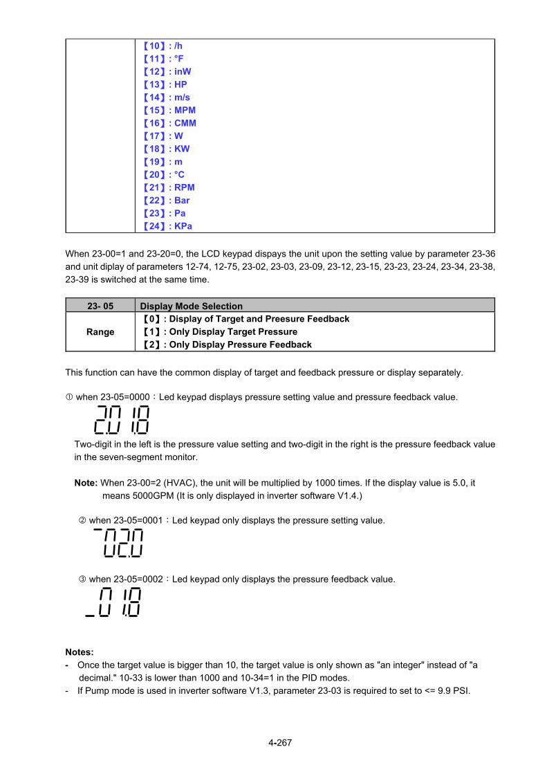
4-267
【10】: /h
【11】: °F
【12】: inW
【13】: HP
【14】: m/s
【15】: MPM
【16】: CMM
【17】: W
【18】: KW
【19】: m
【20】: °C
【21】: RPM
【22】: Bar
【23】: Pa
【24】: KPa
When 23-00=1 and 23-20=0, the LCD keypad dispays the unit upon the setting value by parameter 23-36
and unit diplay of parameters 12-74, 12-75, 23-02, 23-03, 23-09, 23-12, 23-15, 23-23, 23-24, 23-34, 23-38,
23-39 is switched at the same time.
23- 05 Display Mode Selection
Range
【0】: Display of Target and Preesure Feedback
【1】: Only Display Target Pressure
【2】: Only Display Pressure Feedback
This function can have the common display of target and feedback pressure or display separately.
when 23-05=0000:Led keypad displays pressure setting value and pressure feedback value.
Two-digit in the left is the pressure value setting and two-digit in the right is the pressure feedback value
in the seven-segment monitor.
Note: When 23-00=2 (HVAC), the unit will be multiplied by 1000 times. If the display value is 5.0, it
means 5000GPM (It is only displayed in inverter software V1.4.)
when 23-05=0001:Led keypad only displays the pressure setting value.
when 23-05=0002:Led keypad only displays the pressure feedback value.
Notes:
- Once the target value is bigger than 10, the target value is only shown as "an integer" instead of "a
decimal." 10-33 is lower than 1000 and 10-34=1 in the PID modes.
- If Pump mode is used in inverter software V1.3, parameter 23-03 is required to set to <= 9.9 PSI.

4-268
23- 06 Proportion Gain (P)
Range 【0.00~10.00】
23- 07 Integral Time (I)
Range 【0.0~100.0】Sec
23- 08 Differential Time (D)
Range 【0.00~10.00】Sec
Figure 4.4.103 Diagram of pressure feedback value
Table 4.4.17 Guide for PID parameter adjustment
Increase Setting Value Decrease Setting Value Main Feature
Proportional Gain (P) (Pros) Increase response time (Pros) Reduce jittering
Increase
stabilized time (Cons) Might cause pump jittering
(Cons) Slow down response
Integral Time (I) (Pros) Smooth output frequency (Pros) Fast response For smooth
feedback
variations (Cons) Slow down response (Cons) Change rapidly output
frequency
Differential Time (D)
(Pros) Avoid overshooting (Pros) System stability Respond to
system rapid
variations (Cons) System instability or
motor jittering (Cons) Overshooting easily
Notes: - PID parameters can be modified during the inverter is running.
- Cons: disadvantage, Pros: advantage.
Stablized deviation
Overshooting
23-02: Target Pressure Value
Pressure Feedback Signal
Stablized Time

4-269
Figure 4.4.104 Diagram for PID parameter adjustment
23- 09 Tolerance Range of Constant Pressure
Range 【0.01~650.00】PSI *1
【1~100】% *2
23- 34 Tolerance Range of Constant Pressure 2
Range 【0.01 ~ 650.00】PSI *1
【1~100】% *2
*1: 23-20=0, presents the unit and range.
*2: 23-20=1, presents the unit and range.
When pressure feedback value is higher than 23-02 (operation pressure setting), inverter output frequency
will decrease downward into sleep status. PID starts (output frequency will increase) when pressure
feedback value is less than (23-02) – (23-09).
23- 10 *Sleep Frequency of Constant Pressure Range 【0.00~599.00】Hz
*: (When the motor’s maximum output frequency is over than 300Hz, the frequency resolution is
0.1Hz.)
When inverter output frequency falls below 23-10 (sleep frequency of constant pressure), it starts to count
the sleep time (23-11).
23- 11 Sleep Time of Constant Pressure Range 【0.0~255.5】Sec
When the inverter finishes counting the sleep time (23-11), the output frequency falls downward at the
deceleration time (00-15) and gets into sleep status.
Note: Parameter 23-10 (sleep frequency of constant pressure) is dedicated by the pump and it is not applied to parameter 10-17 (start frequency of PID sleep).
Output after PID adjustment
Output before PID adjustment

4-270
Bar
Hz
time
23-11Sleep Delay Time
23-02Target Pressure
Value
23-09Sleep Tolerance
Range
Pressure Feedback
Signal
Output Frequency
Sleep Tolerance Range: |(23-02) – PID Feedback| < 23-09
time
23-10Sleep Frequency
Figure 4.4.105 Diagram for stop time of constant pressure
Note: The purpose of stop time of constant pressure is energy saving.
23- 12 Maximum Pressure Limit
Range 【0.10 ~ 650.00】PSI *1
【0~100】% *2
*1: 23-20=0, presents the unit and range.
*2: 23-20=1, presents the unit and range.
It is convenient for user to limit maximum pressure. When pressure feedback value is higher than
maximum pressure limit, the inverter displays warning signal and then stops.
23- 15 Minimum Pressure Limit
Range 【0.00 ~650.00】PSI *1
【0~100】% *2
*1: 23-20=0, presents the unit and range.
*2: 23-20=1, presents the unit and range.
It is convenient for user to limit minimum pressure. When pressure feedback value is lower than minimum
pressure limit, the inverter displays warning signal and then stops.
Figure 4.4.106 Diagram for pressure feedback limit
23-02 Target Pressure Value
23-12 Maximum Pressure Limit
23-15 Minimum Pressure Limit
Pressure Feedback Signal

4-271
Note: The pressure under the control of PID is between the maximum pressure limit (23-12) and
minimum pressure limit (23-15).
23- 13 Warning Time of High Pressure Range 【0.0 ~ 600.0】Sec
When pressure feedback value is higher than maximum pressure limit, warning time of high pressure
starts to count. If pressure feedback value is lower than maximum pressure limit during counting time, the
warning time will recount and the inverter will display the warning signal of HIPb when the warning time
ends.
23- 14 Stop Time of High Pressure Range 【0.0 ~ 600.0】Sec
When the warning signal of high pressure occurs and pressure feedback value is higher than maximum
pressure limit, stop time of high pressure starts to count. If pressure feedback value is lower than
maximum pressure limit during counting time, the stop time will recount and the inverter will display stop
error signal of OPbFt when the stop time ends.
Note: When user does not want the inverter to be restricted by the maximum pressure, set 23-74=0
(disable) to disable the function of high pressure limit.
Figure 4.4.107 Diagram for warning to stop at high pressure limit
23-12 Maximum Pressure Limit
Bar
23-02 Target Pressure Value
23-15 Minimum Pressure Limit
Pressure Feedback Output
Stop along the deceleration time (00-15)
time
time
Hz
HIPb
T1 < (23-13); Recounting after T1 T2 = (23-13); Keypad flashes and displays HIPb T3 = (23-14); Keypad flashes and displays OPbFt
T1 T2 T3OPbFt

4-272
23- 74 High Pressure Setting
Range 【0】 Disable
【1】 High Pressure Warning
【2】 High Pressure Warning or Error
When 23-74=0, High pressure warning or error is disabled. When 23-74=1, High pressure warning is enabled. High pressure error is disabled. When 23-74=2, High pressure warning or error is enabled. Refer to the instruction of Fig. 4.4.107.
23- 16 Warning Time of Low Pressure Range 【0.0 ~ 600.0】Sec
When pressure feedback value is lower than minimum pressure limit, warning time of low pressure starts
to count. If pressure feedback value is higher than minimum pressure limit during counting time, the
warning time will recount and the inverter will display the warning signal of LoPb when the warning time
ends.
23- 17 Fault Stop Time of Low Pressure Range 【0.0 ~ 600.0】Sec
When the warning signal of low pressure occurs and pressure feedback value is lower than minimum
pressure limit, stop time of low pressure starts to count. If pressure feedback value is higher than minimum
pressure limit during counting time, the stop time will recount and the inverter will display stop error signal
of LPbFt when the stop time ends.
Note: When user does not want the inverter to be restricted by the minimum pressure, set 23-75=0
(disable) to disable the function of low pressure limit.
Figure 4.4.108 Diagram for warning to stop at low pressure limit
23-12 Maximum Pressure Limit
23-02 Target Pressure Value
23-15 Minimum Pressure Limit
Pressure Feedback Output
Stop along the deceleration time (00-15)機
time
time
Bar
Hz
LoPb
T1 < (23-16); Recounting after T1 T2 = (23-16); Keypad flashes and displays LoPb T3 = (23-17); Keypad flashes and displays LPbFt
T1 T2 T3LPbFt

4-273
23- 75 Low Pressure Setting
Range
【0】Disable
【1】Low Pressure Warning
【2】Low Pressure Warning or Error
When 23-75=0, Low pressure warning or error is disabled.
When 23-75=1, Low pressure warning is enabled. Low pressure error is disabled.
When 23-75=2, Low pressure warning or error is enabled. Refer to the instruction of Fig. 4.4.108.
23- 18 Time of Loss Pressure Detection Range 【0.0 ~ 600.0】Sec
23- 19 Proportion of Loss Pressure Detection Range 【0 ~ 100.0】%
23- 78 Selection of Loss Pressure Detection
Range
【0】Disable
【1】Loss Pressure Warning
【2】Low Pressure Error
When 23-19 = 0 or 23-78 = 0, function of loss pressure detection is disabled. When 23-19 > 0, If the feedback pressure value is lower than the value of 【(23-02) x (23-19)】and the
detection time of loss pressure (23-18) passes, the inverter jumps to fault signal (FBLSS).
When 23-78=1, the inverter will display warning signal when detecting the loss pressure. When 23-78=2, the inverter will display error signal when detecting the loss pressure.
23-23 Direction of Water Pressure Detection
Range 【0】: Upward Detection
【1】: Downward Detection
23- 24 Range of Water Preesure Detection
Range 【0.0 ~ 65.00】PSI *1
【0~10】% *2
23- 25 Period of Water Preesure Detection Range 【0.0 ~ 200.0】Sec
23- 26 Acceleration Time of Water Pressure Detection Range 【0.1 ~ 600.0】Sec
23- 27 Deceleration Time of Water Pressure Detection Range 【0.1 ~ 600.0】Sec
*1: 23-20=0, presents the unit and range.
*2: 23-20=1, presents the unit and range.
Acceleration time of water pressure detection (23-26) and deceleration time of water pressure detection
(23-27) are corresponding to the acceleration time 2 (00-16) and the deceleration time 2 (00-17), so the
setting of 23-26 changed with the setting of 00-16. Thus, avoid using multi-speed application function while
using PUMP function.

4-274
Figure 4.4.109 Diagram for upward detection of water pressure
23-25 = 0.0 (sec) means to disable the function of water pressure detection.
When function of water pressure detection is enabled, it can shorten the time of jumping into sleep without
water consumption or with mild water consumption.
If water consumption frequenctly continues, it is recommended to extend the cycle of water pressure
detection (23-25) so as the detection times can be reduced and the occurance of fluttering or instability
during water pressure detection in constant pressure can be avoided.
When upward detection of water pressure starts, water pressure will slightly increase. At this time, it may
cause shortly pressure fluttering or instability if water consumption continues. It is recommended to reduce
the range of water pressure detection (23-24) but it will extend the time of inverter jumping into sleep
without water consumption or with mild water consumption.

4-275
Bar
Hz
timeWater
Consumption Continues
Water Consumption
Stops
23-11Sleep Time of
Constant Pressure
23-10Sleep Frequency
23-24Range of Water Pressure Detection
time
23-02Target Pressure
Value
23-27Decel. Time of Water Pressure Detection
Output Frequency
23-23 = 1Downward Detection of Water Pressure
Pressure Feedback Value
23-25Period of Water
Pressure Detection
Figure 4.4.110 Diagram for downward detection of water pressure
23-25 = 0.0 (sec) means to disable the function of water pressure detection.
When function of water pressure detection is enabled, it can shorten the time of inverter jumping into sleep
without water consumption or with mild water consumption.
If water consumption frequenctly continues, it is recommended to extend the cycle of water pressure
detection (23-25) so as the detection times can be reduced and the occurance of fluttering or instability
during water pressure detection in constant pressure can be avoided.
When downward detection of water pressure starts, the output frequency will decelerate with the
deceleration time of water pressure detection (23-27). Water pressure reduces with the deceleration when
water consumption continues and pressure feedback value rises if the value is lower than that of target
pressure value (23-02) - range of water pressure detection (23-24).
Note: It may cause shortly fluttering or instability during water detection process. User can appropriately
adjust the range of water pressure detection (23-24) to avoid the occurrence of severe flutter.
Mild water consumption result in pressure reducing during deceleration and the inverter’s output frequency
may decrease to sleep frequency. But if pressure feedback value is lower than that of target pressure
value (23-02) - range of water pressure detection (23-24), the output frequency will accelerate again.

4-276
Table 4.4.18 Guide for comparison of water pressure detection direction
Pros Cons
Upward
detection of
water
pressure
Keep the pressure above the target pressure during this process.
For strict and precise applications
If “Pump lift” is too high, operation frequency is higher without water consumption or with mild water consumption. So this detection effect is too restricted to jump into sleep.
Energy-saving of water flow is not obvious and Slave is not easy to sleep under the multiple pumps in parallel.
Downward
detection of
water
pressure
Jump into sleep status without water consumption or with mild water consumption.
For energy-saving purpose, under the multiple pumps in parallel regulate the pumps to the optimum operation state during this process.
Startup sequency is by Master, Slave 1, Slave 2, and Slave 3. Sleep sequency is by Slave 1, Slave 2, and Slave 3 and Master. After the switching time is allowable, alternate Master and Slave reach the average of life expectancy.
Pressure fluctuations may occur during this
process if user inappropriately regulates
the range of water pressure detection
(23-24) and the deceleration time of water
pressure detection (23-27).
23- 28 *Foreced Run Command Range 【0.00 ~ 599.00】Hz
*: (When the motor’s maximum output frequency is over than 300Hz, the frequency resolution is 0.1Hz.)
This function is enabled when PID mode (10-03) is selected.
Pump will not depend on the feedback to make any PID output adjustment and runs the frequency of
00-05 (Frequency command) when multi-function digital input (S1~S6) is set to 16 (PID control disable).
And when the other digital input is set to 57(forced frequency run), inverter sets the frequency to run
depending on the parameter 23-28 (forced run command). If PID function disable is removed, the inverter
is controlled by PID.
Forced run command is applied to the situation when pressure sensor disconnects, control inverter output
via the external pressure sensor (ex. differential pressure switch).
23-29 Switching Time of Multiple Pumps in Parallel
Range 【0 ~ 240】hour/min
23-72 Switching Time of Alternation in Parallel
Range 【0】: Hour
【1】: Minute
23-35 Selection of Multiple Pumps Shift Operation
Range
【0】: No function
【1】: Timer Alternative Selection
【2】: Sleep Stop Alternative Selection
【3】: Timer and Sleep Stop Alternative Selection
【4】: Multiple Pumps Test Mode
If function of multiple pumps in parallel is enabled, the switching way is MasterSlave1 Slave2Slave3
Master … and the switching time is set via parameter 23-29.

4-277
Parameter 23-72 Switching Time of Alternation in Parallel 23-72=0, parameter 23-29 (Switching Time of Multiple Pumps in Parallel) will be in the unit of hour. 23-72=1, parameter 23-29 (Switching Time of Multiple Pumps in Parallel) will be in the unit of minute.
Note: It will recount the time if parameter 23-29 change time and the inverter re-power up.
Selection of Multiple Pumps Shift Operation (23-35) 23-35=1: Timer Alternative Selection The Master and Slave of multiple pumps in parallel will be exchange, after the switching time of multiple pumps in parallel. 23-35=2: Sleep Stop Alternative Selection When the Master and Slave of multiple pumps in parallel are both in sleep mode, and after the detecting time (23-30), the Master and Slave of multiple pumps in parallel will be exchange. Every time the multiple pumps start, the exchange will be processed. Please refer to the diagram of sleep stop alternative selection action. 23-35=3: Timer and Sleep Stop Alternative Selection Timer alternately selected and sleep stop alternately selected will be enabled at the same time.
23-35=4: Multiple Pumps Test Mode When master stop running and the slave need to run, please set 23-35=4, and no exchange between Master and Slave.
23- 30 Detection Time of Multiple Pumps in Parallel Running Start Range 【0.0 ~ 30.0】Sec
When parameter 23-31 is set to 1 or 3, detection time of multiple pumps in parallel running start is enabled. If water pressure can not reach the error range of constant pressure and water flow time is over the detection time (23-30), Master will inform Slave of running start.
23- 31 Synchronous Selection of Multiple Pumps in Parallel
Range
【0】: Disable
【1】: Pressure Setting and Run/ Stop
【2】: Pressure Setting
【3】: Run/Stop 23-31=0: Disabled 23-31=1: Pressure Setting and Run/ Stop Set 23-01 to 1, Pressure setting and Run/ Stop command are modified by Master and Slave follows Master’s command. Run/Stop command from Slave can be regarded as the emergency stop command with the highest priority. 23-31=2: Pressure Setting Set 23-01 to 2, Pressure setting is modified by Master and Slave follows Master’s command to update synchronously. 23-31=3: Run/Stop Set 23-01 to 3, Run/ Stop command is set by Master and Slave follows Master’s command. Run/Stop command from Slave can be regarded as the emergency stop command with the highest priority.

4-278
Notes: 1. When Master modifies the pressure setting, it requires pressing ENTER key to modify the
pressure setting of Slave. 2. When the switching time of multiple pumps in parallel (23-29) changes and reconnection, it will
recount the time.
Bar
Hz
time
time
Hz
timeM
as
ter
Sla
ve
Pressure Feedback Value
23-02Target Pressure
Value
23-09Tolerance Range of Constant Pressure
Output
Frequency
A B C D
23-30Detection
Time
Output Frequency
60Hz
Figure 4.4.111 Dual pumps start up process
A:Dual pumps are enabled during this time. Master starts up first and Slave is in standby to enter
constant-pressure operation. B:Large water consumption results in the higher operation frequency of Master. If water pressure is not
lower than the tolerance range of constant-pressure and the operation time is not over the detection time (23-30), Slave is still in standby.
C:If it is over the detection time (23-30), and Master runs at 60Hz, Master informs Slave of auxiliary
kicking water. After Slave operates, the operation frequency of Master and Slave reduces to the operation of constant-pressure if water consumption is stable.
D:If water consumption is mild, the operation frequency of Master and Slave reduces. Because the water
consumption is less than that of the operation of dual pumps, Slave stops to sleep (please refer to parameter 23-22 for dual pump slave sleep requirements) and only Master runs to reach constant-pressure operation.
Notes: - When 23-35=3, If the operation time is over the switching time (23-29) or sleep to stop under the
operation of dual pumps, the dominance between Master and Slave will exchange to operate.
- When 23-01≠0, the parameter 23-01 of these two inverters can not be simultaneously set to 1 or 2.
That is, the parameter 23-01 of one inverter is set to 1 and that of the other inverter should be set to 2
and vice versa.

4-279
Bar
Hz
time
time
Hz
time
Master
Slave
Pressure Feedback Signal
23-02Operation
Pressure Setting
23-09Tolerance Range of Constant Pressure
Output Frequency
Output
Frequency
A B C D
60Hz
E F
23-30Detection
Time
23-30Detection
Time
60Hz
23-10Sleep Frequency
of Constant Pressure
23-22Slave Trip Frequency
Diagram of sleep stop alternative selection action
Note:
A:Dual pumps are enabled during this time. Higher operation pressure occurs, Master keeps operation
and Slave output frequency decreases. B:Master operation frequency maintains 60Hz. If water pressure doesn’t decrease to the target constant
pressure and Slave continuously decreases to the set trip frequency (23-22), Slave detection time
(23-30) starts and Slave decelerates to stop. C:If milder water consumption and higher water pressure occur and Slave operation command is in sleep
status, Master output frequency decreases to let the water pressure be in constant status when the
detection time (23-30) is over. D:When Master operation frequency decreases to the sleep frequency of constant pressure (23-10),
Master will decrease to stop, water consumption is continuously mild and water pressure will reduce
slowly. E:When water consumption stops, Master jumps into sleep and the pressure remains the same. And
Slave’s detection time (23-30) starts. F:When the detection time (23-30) is over, shift operation stops and virtual Master starts to become
Slave. The inverter operates in constant pressure under the target pressure value.

4-280
23-73 Slave Wake-up Selection
Range 【0】Disable
【1】Enable
When multiple pumps are in parallel and the requirements of slave wake-up can not be achieved in
tolerance range, user can set parameter 23-73=1 and refer to the following conditions to wake up Slave.
1. Master is in full speed operation (01-02 maximum output frequency) but pressure feedback value can
not achieve the target pressure value.
2. Slave is forced to start after 30 seconds + time of (23-30) (even if the requirement of sleep to wake-up
is not achieved and the pressure feedback value is under the tolerance range of constant pressure)
and keeps operations to achieve the target pressure value.
3. It is required to follow the formula (the set method 1) and refer to the following diagram to set the
wake-up requirements.
0201
2223
1400
3023
----------------------- set method 1
23- 22
T00-14
01-02
加速時間1
副機跳脫頻率
最大輸出頻率
1400
0201
3023
2223
1400
0201
3023
2223
1400
0201
3023
2223
NG
F
當23-22(副機跳脫頻率)設定值太大或23-30(並聯輔助打水偵測時間)太短,會使副機進入休模式,使之設定失效。
Diagram of requirements for waking up Slave
23- 22 Slave Trip Frequency Range 【0.00~599.00】Hz
If Master and Slave start to run at the same time, Slave will stop depend on the condition listed as below. When 23-22=0 Hz, if output frequency of Slave is lower than 23-10 (Sleep Frequency of Constant Pressure) and after the time of 23-11 (Sleep Time of Constant Pressure), the Slave will be stop automatically. When 23-22 = 1 ~ 400 Hz (The maximum frequency follow 01-02), if the output frequency of Slave is lower than 23-22, Master will inform Slave to stop and enter sleep mode, or output frequency of Slave is lower than 23-10 (Sleep Frequency of Constant Pressure) and after the time of 23-11 (Sleep Time of Constant Pressure), the Slave will be stop automatically.
Maximum Output Frequency
Slave Disconnect Frequency
Acceleration Time
When the 23-22 (Slave Disconnect Frequency) setting value is too high or 23-30 (Parallel Start Pump Detection Time) is too short, it will make the Slave enter the Sleep Mode, to make the setting ineffective.

4-281
23-37 Leakage Detection Time *3
Range 【0.0~100.0】Sec
23-38 Pressure Variation of Leakage Detection Restart *3
Range 【0.01~65.00】PSI *1
【1~10】% *2
23-39 Pressure Tolerance Range of Leakage Detection Restart *3
Range 【0.01~650.00】PSI *1
【1~100】% *2
*1: 23-20=0, presents the unit and range.
*2: 23-20=1, presents the unit and range. *3: It is new added in inverter software V1.4.
Bar
Hz
time
23-02Operation Pressure
Setting
time
Pressure Feedback Value
Output Frequency
23-37 Leakage
Detection Time
23-37 Leakage
Detection
Time
∆P1
∆P2
Sleep Leakage Detection Restart
Leakage Detection Case1: Pressure Variation > 23-38
Pressure Variation of Leakage Detection Restart ∆P1 < 23-38∆P2 > 23-38
Notes:
- To limit single inverter to use leakage detection. - When 23-37 = 0.0 (sec), switch off this function.
- When pump is at shutdown state, pressure will drop over time if pipeline leaks. Pump will restart if
pressure variation is larger than the value of parameter 23-38 in every detection time (23-37).

4-282
Bar
Hz
time
time
Pressure Feedback Value
Output Frequency
23-37Leakage
Detection Time
∆P1
Sleep
Leakage Detection Case2: Pressure Variation <23-38
Pressure Variation of Leakage Detection Restart∆P1 < 23-38∆P2 < 23-38∆P3 < 23-38
∆P2
∆P3
23-39 Pressure Tolerance Range of Leakage Detection Restart
23-02Operation
Pressure Setting
23-37Leakage
Detection
Time
23-37Leakage
Detection
Time
Notes:
- When 23-37 = 0.0 (sec), switch off this function.
- When pump is at shutdown state, pressure will drop over time if pipeline leaks. Inverter will keep sleep
state if pressure variation is lower than the value of parameter 23-38 in every detection time (23-37) and
pump will restart if pressure variation is larger than that of 23-38 or pressure tolerance range is over the
value of parameter 23-39 in the detection time.
- Properly adjust the relevant leakage detection parameters 23-37, 23-38 and 23-39 to improve the
condition of frequenct pump start and stop caused from the dropping pressure of water system due to
leakage.
- Function of leakage detection is enabled only in the setting of single pump.
23-41 Local/ Remote Key
Range 【0】∶ Disable
【1】∶ Enable User can switch reference frequency of the inverter and give the run command in the local or remote mode. Input source selection is determined by the source of frequency command (00-05) and the operation modes (00-02). When 23-41 = 1 (Enable), you can control the LOC/REM button to switch between the LOCAL control and the Remote control. 23-41=0: Disable User can control FWD/REV key for the switch of Local / Remote key.

4-283
23-41=1: Enable Frequency command is controlled by terminal Al1 and Al2 when SEQ and REFsignal light up and run command is controlled by terminal S1, S2 or RS485. Frequency command is controlled by the keypad when SEQ and REF signal light off. Note: Local mode is controlled by the keypad and remote mode is controlled by control circuit terminals or
RS485 connection.
23-42 Energy Recaculating
Range 【0】: Disable (Energy Accumulating)
【1】: Enable
23-43 Electricity Price per kWh Range 【0.000~5.000】
When the inverter starts up, user can learn the motor accumulative output energy from parameter 12-67 (unit: kWHr) and 12-68 (unit: MWHr). User recalculates energy via the setting of parameter 23-42 to 1. User caculates electricity price via the setting of electricity price per kWh (23-43) and learn the accumulative electricity price from parameter 12-69 and 12-70.
23-44 Selection of Accumulative Electricity Pulse Output Unit
Range
【0】: Disable
【1】: Unit for 0.1kWh
【2】: Unit for 1kWh
【3】: Unit for 10kWh
【4】: Unit for 100kWh
【5】: Unit for 1000kWh
Unit of accumulative electricity pulse output signal (23-44) is for kWh. When accumulating the electricity to the setting unit of parameter 23-44, the pulse output signal of the electric meter or PLC is on lasting 200 msec.
Accumulative Electricity Pulse
Output (PO)
Accumulative Electricity Energy
the Unit Setting of Accumulation
(23-44)
200mSec
off on
Figure 4.4.112 Diagram for accumulative electricity pulse output

4-284
23-45 Given Modes of Flow Meters Feedback
Range
【0】: Disable
【1】: Analog Input
【2】: Pulse Input
23- 46 Maximum Value of Flow Meters Range 【1~50000】GPM
23- 47 Target Value of Flow Meters Range 【1~50000】GPM
23-00=2: HVAC HVAC is enabled when the source of main frequency command (00-05) is set to 5 (PID given) and
PID mode is enabled (10-03).
23-45: Given Modes of Flow Meters Feedback Modes of flow meters feedback is given by analog input (AI) or pulse input (PI) and flow meter
(12-71) displays feedback value. Refer to the instruction of parameter 23-05 for PID display.
23-46: Maximum Value of Flow Meters
Maximum value of flow meters is the maximum value set by the target value of flow meters for HVAC
system.
23-47: Target Value of Flow Meters This function sets the target value of flow meters for HVAC system depending on the setting of
10-00 to 0 (PID target value source is set by keypad.)
23- 60 HVAC Unit Display (only for LCD)
Range
【0】: GPM
【1】:FPM
【2】:CFM
【3】:PSI
【4】:GPH
【5】:GPM
【6】:IN
【7】:FT
【8】:/s
【9】:/m
【10】:/h
【11】:°F
【12】:inW
【13】:HP
【14】:m/s
【15】:MPM
【16】:CMM
【17】:W
【18】:KW
【19】:m
【20】:°C
【21】:RPM
【22】:Bar
【23】:Pa
【24】:KPa
When 23-00=2, the LCD keypad dispays the unit upon the setting value by parameter 23-60 and unit display of parameters 12-71,12-77,23-46,23-47 is switched at the same time.

4-285
23-48 Maximum Flow Value of Feedback
Range 【0.01~99.00】%
It is convenient for user to limit the maximum flow value depending on the different situations. When flow
feedback value is higher than the maximum flow value, the inverter will display warning signal and then
stops.
23- 49 Maximum Flow Warning Time of Feedback Range 【0~255】Sec
When flow feedback is higher than the maximum flow limit, warning time of high flow starts to count. If the
flow feedback is lower than the maximum flow limit during counting time, the warning time will recount and
the inverter will display the warning signal of HFPb when the warning time ends.
23- 50 Maximum Flow Stop Time of Feedback
Range 【0~255】Sec
When the warning signal of high flow occurs and flow feedback is higher than maximum flow limit, stop
time of high flow starts to count. If flow feedback is lower than maximum flow limit during counting time, the
stop time will recount and the inverter will display stop error signal of HIbFt when the stop time ends.
Note: When user does not want the inverter to be restricted by the maximum flow, set 23-76=0 (disable) to
disable the function of high flow limit.
FB
time
23-47 Target Value of Flow
Meters
23-48 Maximum Flow Value of
Feedback
T1 T2 T3Stop along the
Deceleration Time (00-15)
F
Flow Feedback Output
HIPbtHFPb
Figure 4.4.113 Diagram for warning to stop at high flow limit
T1 < (23-49): Recounting after T1. T2 = (23-49): Keypad flashes and displays HFPb T3 = (23-50): Keypad flashes and displays HIPbt

4-286
23- 76 High Flow Setting
Range
【0】Disable
【1】High Flow Warning
【2】High Flow Warning or Error
When 23-76=0, High flow warning or error is disabled.
When 23-76=1, High flow warning is enabled. High flow error is disabled.
When 23-76=2, High flow warning or error is enabled. Refer to the instruction of Fig. 4.4.113.
23-51 Minimum Flow Value of Feedback
Range 【0.01~99.00】%
It is convenient for user to limit the minimum flow value depending on the different situations. When flow
feedback value is lower than the minimum flow value, the inverter will display warning signal and then
stops.
23- 52 Minimum Flow Warning Time of Feedback
Range 【0~255】Sec
When flow feedback is lower than the minimum flow limit, warning time of low flow starts to count. If the
flow feedback is higher than the minimum flow limit during counting time, the warning time will recount and
the inverter will display the warning signal of LFPb when the warning time ends.
23- 53 Minimum Flow Stop Time of Feedback Range 【0~255】Sec
When the warning signal of low flow occurs and flow feedback is lower than minimum flow limit, stop time
of low flow starts to count. If flow feedback is higher than minimum flow limit during counting time, the stop
time will recount and the inverter will display stop error signal of LObFt when the stop time ends.
Note: When user does not want the inverter to be restricted by the minimum flow, set 23-77=0 (disable) to
disable the function of low flow limit.
FB
time
23-47 Target Value of Flow
Meters
23-51Minimum Flow Value of
Feedback
T1 T2 T3 Stop along the Deceleration Time
(00-15)F
Flow Feedback
Output
LFPb LOPbt
Figure 4.4.114 Diagram for low flow limited warning of stop
T1 < (23-52): Recounting after T1. T2 = (23-52): Keypad flashes and displays LFPb T3 = (23-53): Keypad flashes and displays LOPbt

4-287
23- 77 Low Flow Setting
Range
【0】Disable
【1】Low Flow Warning
【2】Low Flow Warning or Error
When 23-77=0, Low flow warning or error is disabled.
When 23-77=1, Low flow warning is enabled. Low flow error is disabled.
When 23-77=2, Low flow warning or error is enabled. Refer to the instruction of Fig. 4.4.114.
23-54 Detection Function of Low Suction
Range
【0】: Disable
【1】: PID Error Value
【2】: Current
【3】: Current and PID Error Value
23- 55 Detection Time of Low Suction
Range 【0~30.0】Sec
23- 56 PID Error Level of Low Suction Range 【0 ~ 30】%
23- 57 Current Level of Low Suction (Motor Rated Current)
Range 【0 ~ 100】%
23- 58 Reaction of Low Suction
Range
【0】: Disable
【1】: Warning
【2】: Fault
【3】: Fault & Restart
The hydraulic application can detect insufficient water in the tank resulting in low suction via HVAC
function. User can select the reaction of low suction (23-58) to run command. Low suction is detected by
parameter 23-54. Refer to Fig.4.4.115 for the process of low suction.
PID Error Level23-56
Reaction of Low Suction23-58
Detection Time 23-55
PID ErrorPID Error
Output Current
Detection of Output Current
23-57
Output Current
Both of Two
PID Enable
Figure 4.4.115 Diagram for the process of low suction
When 23-54=0, detection function of low suction is disabled.
And refer to Table 4.4.19 for the detection logic of parameter 23-54 to select PID error of output current as
the detection signal.

4-288
Table 4.4.19 the detection logic of low suction
23-54 Detection Signal
PID Error Output Current
1 1 0
2 0 1
3 1 1
The detection level is required to be set by PID error level of low suction (23-56) and output current signal
(23-57) after selecting the detection signal.
The state of low suction experiences the detection time of low suction (23-55); when it is over the detection
time, low suction is active.
The reaction of low suction (23-58) is set by user to act. Refer to Table 4.4.20 for the detection signal of
water used.
When 23-58=3, refer to the instruction of parameter 07-01~07-02. Set fault auto-restart time by parameter
07-01 and the maximum number of fault auto-restart attempts is 10 by parameter 07-02.
Table 4.4.20 Detection signal of water used
23-58 Inverter Status Keypad Signal Error Signal
0 Continous Running None None
1 Continous Running LSCFT(Flash) Warning of Low Suction
2 Stop LSCFT Jump to Error for Low
Suction
3 Stop and Restart LSCFT Jump to Error for Low
Suction and Restart
Note: Low suction state is detected by if the signal is higher than PID error level or lower than output
current.
23- 59 Source of HVAC Pressure Command *3
Range 【0】: Set by 23-47
【1】: Set by AI
*3: It is new added in inverter software V1.4.
23-59=0: Target value depends on parameter 23-47.
23-59=1: Convert the proportional target value of flow meters via AI1 input voltage value. Refer to
parameter 10-00 for the setting of AI terminal.
23- 66 Derating of Current Level (for Compressor Current) *3
Range 【10 ~ 200】%
23- 67 Derating of Delay Time *3Range 【1.0 ~ 20.0】Sec
23- 68 Derating of Frequency Gain *3Range 【1~100】%
23- 69 OL4 Current Level *3Range 【10~200】%
23-70 OL4 Delay Time *3Range 【0.0 ~ 20.0】Sec
*3: It is new added in inverter software V1.4.

4-289
The application of water-cooled chiller is when the rated current of compressor operates for 1 to 2 minutes easily to cause damage to compressor so the inverter is required to be set two- stage protection to protect the compressor.
Protection of first stage: When the inverter is at constant speed and the current is higher than the derating of current level (23-66)
(this is the percentage for the rated current of compressor), it will start to count the derating of delay time
(23-67). After the counting time is over the delay one, frequency command can reach the derating of
output frequency and reduce the current load via being multiplied by the derating of frequency gain (23-68).
When the current is lower than the derating of current level, output frequency will be restored to the
frequency command. The action of derating to restore is counted one time. When it repeats more than
three times, the output frequency will stop at the last derating frequency until the current is lower than the
derating of current level (23-66).
For example: Set 23-66=80%, 23-67=10sec, 23-68=90%, the frequency command=60Hz and the rated
current of compressor=30A, then,
when the output current=27A, higher than 24A (30A*80%), 10 sec (the derating of delay time) passes, and
the output frequency=54Hz (frequency command 60Hz*90%), the output current decreases to 25A, also
higher than 24A; then another 10 sec passes, 60Hz*81%=48.6Hz, the output current decreases to 23A,
lower than 24A, so the output frequency is restored to 60Hz and the current rises to 27A. When it repeats
more than three times, the output frequency will stop at 48.6Hz and the output current decreases to 23A. Protection of second stage:
After the current reaches OL4 current level (23-69), the inverter will count the time at the setting value of
OL4 delay time (23-70). When the counting time ends, it will decelerate to stop automatically and display
the warning signal (fault signal, OL4 Compressor Overload).
If fault occurs, PLC can read if the inverter is running from the digital output terminals. If the inverter stops,
terminate the RUN command. If 00-02=0, user can press Reset key; if 00-02=1, terminate the RUN
command of digital input terminal to reach the effect of Reset. Then PLC can be restored to give RUN
command.
Note: It is recommended that the rated current of compressor is required to be lower than that of inverter.
Group 24 Pump Control Function Parameters
24- 00 Selection of Pump Control Function
Range
【0】: Function of 1 to 8 Pump Card and 1 to 3 Relay are Disabled.
【1】: Fixed Modes of Inverter Pump: First on and Last off; then Stop All.
【2】: Fixed Modes of Inverter Pump: Only Stop Inverter Pump.
【3】: Fixed Modes of Inverter Pump: First on and First Off; then Stop All.
【4】: Cycle Modes of Inverter Pump: First on and First Off; then Stop All.
【5】: Cycle Modes of Inverter Pump: Only Stop Inverter Pump.
【6】: 1 to 3 Relay of Cycle Modes of Inverter Pump: First on and First off; then
Stop All. 【7】: 1 to 3 Relay of Cycle Modes of Inverter Pump: First on and First Off; then
Stop All. And First Boot Relay in Cycling. 【8】: Cycle Modes of Inverter Pump: First on and First Off; then Stop All. And
First Boot Relay in Cycling. 【9】: 1 to 3 Relay of Cycle Modes of Inverter Pump: Only Stop Inverter Pump.
And First Boot Relay in Cycling.
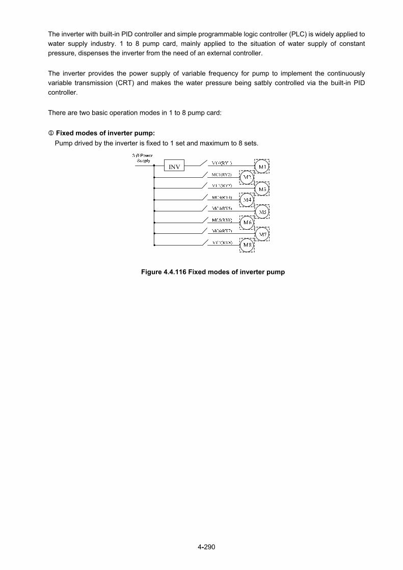
4-290
The inverter with built-in PID controller and simple programmable logic controller (PLC) is widely applied to
water supply industry. 1 to 8 pump card, mainly applied to the situation of water supply of constant
pressure, dispenses the inverter from the need of an external controller.
The inverter provides the power supply of variable frequency for pump to implement the continuously
variable transmission (CRT) and makes the water pressure being satbly controlled via the built-in PID
controller.
There are two basic operation modes in 1 to 8 pump card:
Fixed modes of inverter pump:
Pump drived by the inverter is fixed to 1 set and maximum to 8 sets.
MC1(RY2)
INV
Figure 4.4.116 Fixed modes of inverter pump

4-291
Cycle modes of inverter pump:
Pump drived by the inverter is not fixed to 1 set and maximum to 4 sets.
Figure 4.4.117 Cycle modes of inverter pump
In addition to the two basic operation modes provided from 1 to 8 pump card, it can only use the Relay in
the control board to enable the cycle modes of inverter pump.
* Cycle modes of inverter pump in the control board: Run via a Relay with a pump to start the cycle
modes of inverter pump.
Figure 4.4.118 Cycle modes of inverter pump in the control board
24-00=0: Function of 1 to 8 pump card and 1 to 3 Relay are disabled.
24-00 = 1: in the fixed modes of inverter pump, first on and last off; then stop all.
Pump (motor) drived by the inverter is fixed. Switching off the pump (motor) is by the sequence of the last
on and this mode is applicable to different pump (motor) ratings.
24-00=2: only inverter pump stops in the fixed modes of inverter pump.
When the inverter sends the stop command, only the pump (motor) stops but the Relay keeps on.
24-00=3: in the fixed modes of inverter pump, first on and first off; then stop all.
Switching off the pump (motor) is by the sequence of the first on (longer operation time) to make the pump
(motor) be used for the eq ual frequency and this mode is applicable to the same pump (motor) ratings.
INV
M1
M2
M3
M4
MC0(RY1)
MC2(RY3)
MC4(RY5)
MC6(RY7)
MC1(RY2)
MC3(RY4)
MC5(RY6)
MC7(RY8)
3 Ø Power Supply
F510R1A
R2A
R3A
3φ power
M1
M2
M3
MC0
MC2
MC4
MC1
MC3
MC5
External Control Lines

4-292
24-00=4: in the cycle modes of inverter pump, first on and first off; then stop all.
All the motors besides the pump are drived by the inverter and switching off the pump (motor) is by the
sequence of the first on.
24-00=5: only inverter pump stops in the cycle modes of inverter pump.
When the inverter sends the stop command, only the pump (motor) stops but the Relay keeps on.
24-00=6 : 1 to 3 Relay of Cycle Modes of Inverter Pump: First on and First off; then Stop All.
This mode runs via a Relay with a pump in the cycle modes of inverter pumps. If 24-07=1, only Relay in
the control board is enabled in 1 to 3 Relay of cycle modes and can switch the drive sequence of every
pump.
24-00=7: Cycle Modes of Inverter Pump: First on and First Off; then Stop All. And First Boot Relay
in Cycling.
The first inverter drives the motor depending on the Relay switching time (24-08) to change the inverter’s
position.
24-00=8: Cycle Modes of Inverter Pump 1 to 3 Relay: First on and First Off; then Stop All. And First
Boot Relay in Cycling.
The inverter drives the motor at the first time depending on the Relay switching time (24-08) to change the
inverter’s position. That is, at this mode, the inverter runs in a Relay with a pump. Users can switch the
orders of each pump driving at this cycle mode of 1 to 3 Relay with the setting of parameter 24-07.
24-00=9:Cycle Modes of Inverter Pump 1 to 3 Relay: Only Stop Inverter Pump. And First Boot
Relay in Cycling.
As the fixed modes, first on and first off, but only stop the inverter pump. The inverter drives the motor at
the first time depending on the Relay switching time (24-08) to change the inverter’s position. (The Relay
switching is enabled only in one motor.)
Notes:
- When 1 to 8 pump card is not installed, it is forced to be disabled (24-00=0).
- When parameter 24-00 (pump control selection) is enabled, the selection of DI function to 16 (PID
function disable) and 57 (forced frequency run) are disabled.
- Set 24-07=1 to enable the Relay in the control board to provide the function selection of 1 to 8 pump
cards, or it is still forced to be disabled.
- 1 to 8 pump cards enabled or disabled and the selection modes of water supply are determined by
parameter 24-00.
- PID Setting:
PID function is enabled via the setting of PID control mode (10-03) to xxx1b (PID enable). Set PID
target value source (10-00) to 4 (10-02 given) and the target value is determined by 10-02. If the
feedback value source (10-01) is set to 2 (AI2 given) and AI input signal type (04-00) is set to 0 (AI2:
0~10V), it requires to set the dip switch to V in the control board.

4-293
24- 01 Selection of Relay 2-4 Function
Range
【xxx0b】: Reserved 【xxx1b】: Reserved
【xx0xb】: Relay 2 Disable 【xx1xb】: Relay 2 Enable
【x0xxb】: Relay 3 Disable 【x1xxb】: Relay 3 Enable
【0xxxb】: Relay 4 Disable 【1xxxb】: Relay 4 Enable
24- 02 Selection of Relay 5-8 Function
Range
【xxx0b】: Relay 5 Disable 【xxx1b】: Relay 5 Enable
【xx0xb】: Relay 6 Disable 【xx1xb】: Relay 6 Enable
【x0xxb】: Relay 7 Disable 【x1xxb】: Relay 7 Enable
【0xxxb】: Relay 8 Disable 【1xxxb】: Relay 8 Enable
Fixed modes of inverter pump:
In the fixed modes of inverter pump, RY1 is permanently used and RY2~RY8 is arbitrarily selected to be
used.
Inverter decelerates/ accelerates to lower/ upper limit frequency when user increases/ decreases pumps
and function of PID is temporarily disabled. When the inverter reaches lower/ upper limit frequency,
function of PID restores and the inverter output is determined by the feedback.
Cycle modes of inverter pump: In the cycle modes of inverter pump, RY2 and RY1 are always used. The rest (RY3~RY8) is a group of two,
RY3/RY4, RY5/RY6, and RY7/RY8. If any one of the group is set to be disabled, this group is disabled.
The inverter output disconnects when user increases pumps. When a motor originally drived by the
inverter is switched by commercial AC power supply, it requires the switching time of magnetic contactor
(24-05) to allow the AC power supply input. Then the inverter output drives the next motor, which is
determined by the feedback.
Switch off the motor of the first on when user decreases pumps to make the pump (motor) be the equal
using frequency.
Cycle modes of inverter pump in the control board: In the cycle modes of inverter pump, RY1 is permanently used and RY2~RY3 is arbitrarily selected to be used. 24-01 can only set 0xxx (Relay 4 can not be set.) and 24-02 can only set 0000 (Relay 5-8 can not be set.) so this parameter will be hidden.
24- 03 Duration of Upper Limit Frequency
Range 【1.0 ~ 600.0】Sec
Set the inverter output frequency controlled by PID reaches the upper limit frequency (the proportion
setting by parameter 00-12) via parameter 24-03. 1 to 8 pump card controls the time required for
increasing pumps.
The setting value of duration of upper limit frequency (24-03) is determined by the changing time speed of
system pressure. The setting value of 24-03 is the fewer the better in the range without producing
oscillation of system pressure.
24- 04 Duration of Lower Limit Frequency Range 【1.0 ~ 600.0】Sec
Set the inverter output frequency controlled by PID reaches the lower limit frequency (the proportion
setting by parameter 00-13) via parameter 24-04. 1 to 8 pump card controls the time required for
decreasing pumps.

4-294
The setting value of duration of lower limit frequency (24-04) is determined by the changing time speed of
system pressure. The setting value of 24-04 is the fewer the better in the range without producing
oscillation of system pressure.
24- 05 Switching Time of Magnetic Contactor Range 【0.1 ~ 20.0】Sec
When a motor originally drived by the inverter is switched by the commercial AC power supply or originally
drived by the commercial AC power supply is switched by the inverter, function of parameter 24-05 is used
to avoid the delay of external magnetic contactor resulting in a short circuit of the inverter output and AC
power supply.
The setting value of 24-05 requires being larger than the time from the switch of the inverter Relay signal to
the action of external magnetic contactor. Generally, the off to on time of magnetic contactor is longer than
the on to off time. Set parameter 24-05 depending on the longer time.
Figure 4.4.119 Diagram for the single cycle modes of inverter pump
24- 06 Allowable Bias of Pump Switch Range 【0.0~20.0】%
When increasing or decreasing pumps with PID control to operate in coordination with Relay card, user
has to determine if it is required to increase or decrease allowable value of pump in the situation of inverter
output frequency being closed to upper limit frequency (00-12) or lower limit frequency (00-13).
The setting unit is 0.1% and if the setting is 0.0%, inverter output frequency needs to reach the upper limit
or lower limit value to increase or decrease pump (motor).
For example, 00-12 = 80%, and 00-13 = 20%, then:
- If 24-06 = 0%, when the output frequency needs to reach 80% of the maximum frequency and the
period of time reach the Duration of Upper Limit Frequency (24-03), the pump (motor)
increase; when the output frequency needs to reach 20% of the minimum frequency and the
period of time reach the Duration of Lower Limit Frequency (24-04), the pump (motor)
decrease.
- If 24-06 = 5%, when the output frequency needs to reach 75% of the maximum frequency and the
period of time reach the Duration of Upper Limit Frequency (24-03), the pump (motor)
increase; when the output frequency needs to reach 25% of the minimum frequency and the
period of time reach the Duration of Lower Limit Frequency (24-04), the pump (motor)
decrease.
24- 07 Pump Control Source Selection
Range 【0】: 1 to 8 Pump Card
【1】: Built-in 1 to 3 Control Mode
24-07 = 0: 1 to 8 Pump Card It is Relay in the 1 to 8 pump card used for function of inverter pump.
Inverter
IM
MC1
MC2
AC Power Supply

4-295
24-07 = 1: Built-in 1 to 3 Control Mode It is Relay in the control board used for function of inverter pump.
Only R1A~R3A in the control board can be used and Relay in 1 to 8 pump card cannot be used.
It is required for the following conditions to enable this control mode.
24-00 is only set to 1~3 and 6.
24-01 is only set to 0xxx (Relay 4 is disabled).
24-02 is only set to 0000 (Relay 5~8 are disabled).
Note: If user does not follow the above requirements (24-00, 24-01, 24-02, and 24-07), errors will coour
when user give commands to the inverter.
Refer to the following table for controlling the maximum value of pump under the different setting values of
24-00 and 24-07.
Setting value
of 24-00
Inverter pump
Modes
One pump
with Relay
24-07=0
(Relay in 1 to 8 pump
Option card)
24-07=1
(Relay in the control
board)
1,2,3 Fixed Modes 1 8 PUMP 3 PUMP
4,5,8 Cycle Modes 2 4 PUMP None
6,7,9 Cycle Modes 1 None 3 PUMP
If 24-07=1, R1A is fixed to support Relay 1 controlled by pump and function of parameter 03-11
is disabled.
If 24-07=1 and 24-01= xx1x, R2A supports Relay 2 controlled by pump and function of
parameter 03-12 is disabled. If 24-07 = 1,24-01 = x1xx, R3A supports Relay 3 controlled by pump and function of
parameter 03-39 is disabled.
24- 08 Relay Switching Time Range 【0 ~ 240】hour
Relay switching time is required to be with modes 7 or 8 of parameter 24-00. When the power is on, the
first run motor is the motor 1. If the switching time reaches and all motor are at sleep mode, the motor 2 will
start up and the inverter drives the motor 2. Refer to the following figure for motors change when the Relay
switching time reaches.
Note: It will recount time when parameter 24-00 is enabled or parameter 24-08 changes the Relay
switching time or the power reconnects.

4-296
24- 09 Frequency/ Target Switch
Range 【0】Disable
【1】Enable
24- 10 Stop Mode Selection on Mode 6/7/9
Range 【0】Disable
【1】Enable
When 24-09=0, action of reducing pump starts from the output frequency after PID control agreeing the
level of lower limit frequency and the delay time of lower limit frequency.
When 24-09=1, action of reducing pump starts when PID feedback (12-39)>PID setting (12-38).
When 24-10=1, all relays disconnect at stop and first relay starts to run at operation.
Note: 24-10 is enabled only when 24-00=6, 7, 9. 24- 17 Increase and Decrease Pump Interval PID Control
Range 【0】Increasing / Decreasing Pump Section without PID Control
【1】Increasing / Decreasing Pump Section with PID Control
24-17=0: When increasing / decreasing the pump, in order to balance the current water usage, the Inverter
will decelerate to the Frequency Lower Limit when increasing the pump, conversely, the Inverter will
increase to Frequency Upper Limit when decreasing the pump, then the Inverter will switch back to the
speed required by the PID Control.
24-17=1: When using water at the extreme switch when increasing / decreasing the pump, and in order to
balance the water usage, the Inverter Increasing / Decreasing Pump All Sections can be selected to use
PID to control the Inverter Speed. 24- 11 High Pressure Limit Level
Range 【0~10000】
24- 14 Low Pressure Limit Level
Range 【0~10000】
24-11 High Pressure Limit Level: When pressure feedback value is higher than the set value of highp pressure limit level, the alarm signal
occurs and then inverter stops the operation.
24-14 Low Pressure Limit Level: When pressure feedback value is lower than the set value of low pressure limit level, the alarm signal
occurs and then inverter stops the operation. User can refer to the setting of 10-00=4 to set the value of parameters 24-11& 24-14. Revise the upper
limit value by the setting of parameter 10-33, determine the decimal position by adjusting the setting of
parameter 10-34, and the unit display by parameter 10-35.

4-297
Diagram of pressure feedback value limit
Note: Pressure feedback value will be between the high pressure limit level (24-11) and the low pressure limit level.
12-38 PID Setting
24-11 High Pressure Limit Level
24-14 Low Pressure Limit Level
Pressure Feedback Value

4-298
24- 12 Delay Time of High Pressure Warning
Range 【0.0 ~600.0】Sec
24- 13 Delay Time of High Pressure Error
Range 【0.0 ~ 600.0】Sec
24-12 Delay Time of High pressure Warning
When pressure feedback value is higher than the high pressure limit level, high pressure warning time will
start to count. If the value is lower than the high pressure limit level during the counting time, the warning
time will recount. It will jump to the warning signal “HIPb” when the counting time is over.
24-13 Delay Time of High Pressure Error
When the warning signal of high pressure occurs and pressure feedback value is higher than the high
pressure limit level, high pressure shutdown time will start to count. If the value is lower than the high
pressure limit level during the counting time, the shutdown time will recount. It will jump to the error signal
“OPbFt” when the counting time is over.
Note: If user wouldn’t like to limit to the high pressure level, the high pressure warning time can be set to
zero, and then the high pressure limit function is disabled.
Diagram of high pressure limit warning to shutdown
24-11 High Pressure Limit LevelPSI
12-38 PID Setting
24-14: Low Pressure Limit Level
Pressure Feedback Value Output
Free Operation to Shutdown
time
time
Hz
HIPb OPbFt
T1 < (24-12 Delay Time of High Pressure Warning); recount it after T1. T2 = (24-12 Delay Time of High Pressure Warning); keypad flashes and displays “HIPb.”T3 = (24-13 Delay Time of High Pressure Error); keypad flashes and displays “OPbFt.”
T1 T2 T3

4-299
24- 15 Delay Time of Low Pressure Warning
Range 【0.0 ~ 600.0】Sec
24- 16 Delay Time of Low Pressure Error
Range 【0.0 ~ 600.0】Sec
24-15 Delay Time of Low Pressure Warning
When pressure feedback value is lower than the low pressure limit level, low pressure warning time will
start to count. If the value is higher than the low pressure limit level during the counting time, the warning
time will recount. It will jump to the warning signal “LoPb” when the counting time is over.
24-16 Delay Time of Low Pressure Error
When the warning signal of low pressure occurs and pressure feedback value is lower than the low
pressure limit level, low pressure shutdown time will start to count. If the value is higher than the low
pressure limit level during the counting time, the shutdown time will recount. It will jump to the error signal
“LPbFt” when the counting time is over.
Note: If user wouldn’t like to limit to the low pressure level, the low pressure warning time can be set to
zero, and then the low pressure limit function is disabled.
Diagram of low pressure limit warning to shutdown
Pressure Feedback Value Output
Free Operation to Shutdown
time
time
PSI
Hz
LoPb LPbFt
T1 < (24-15 Delay Time of Low Pressure Warning); recount it after T1. T2 = (24-15 Delay Time of Low Pressure Warning); keypad flashes and displays “LoPb.”T3 = (24-16 Delay Time of Low Pressure Error); keypad flashes and displays “LPbFt.”
T1 T2 T3
12-38 PID Setting
24-11 High Pressure Limit Level
24-14: Low Pressure Limit Level

4-300
The following examples are for the actions of increasing / decreasing pumps in the fixed modes of inverter
pump. Relay 1~Relay 4 in 1 to 8 pump card is set to be enabled. Motor 1 is connected to inverter and
motor 2~4 are connected to AC power supply. MC of AC power supply is mainly controlled by the external
circuit control. Refer to Fig. 4.4.126.
When 24-00=1, 24-06=0 and depending on the above PID setting, the following status occurs.
Output frequency (Fout) reaches the upper limit frequency (00-12) and Fout time is over than the
duration of upper limit frequency (24-03). Then Relay 2 is power on and the connected motor starts
to accelerate.
Figure 4.4.120 Diagram of increasing pump in the fixed modes of inverter pump
T1 = 24-03 Duration of
Upper Limit Frequency

4-301
Output frequency (Fout) decreases to the lower limit frequency (00-13) and the Fout time is over than
the duration of lower limit frequency (24-04). Then Relay 4 is power off and the inverter accelerates
to the upper limit frequency (00-12).
When Fout reaches to the upper limit frequency (00-12), the inverter starts to decelerate.
Figure 4.4.121 Diagram of decreasing pump in the fixed modes of inverter pump
T1 = 24-04 Duration of Lower Limit
Frequency

4-302
The following examples are for the actions of increasing / decreasing pumps in the cycle modes of inverter
pump. Relay 1~Relay 4 in 1 to 8 pump card is set to be enabled. Refer to Fig.4.4.119 for switching of the
motor connected to the inverter or AC power supply. MC of AC power supply is mainly controlled by the
external circuit control. Refer to Fig.4.4.127.
When 24-00=1, 24-06=0 and depending on the above PID setting, the following status occurs.
Output frequency (Fout) reaches the upper limit frequency (00-12) and Fout time is over than the
duration of upper limit frequency (24-03). Then Relay 1 is power off and output frequency of the
inverter does not occur.
Relay 1 and Relay 2 is power on and the inverter starts to accelerate after the switching time of MC
(24-05) ends.
Figure 4.4.122 Diagram of increasing pump in the cycle modes of inverter pump
T1 = 24-03 Duration of Upper Limit Frequency
T2 = 24-05 Switching Time of Magnetic
Contactor (MC)

4-303
Output frequency (Fout) reaches the lower limit frequency (00-13) and Fout time is over than the
duration of lower limit frequency (24-04). Then Relay 1 and Relay 2 is power off
Relay 1 is power on and the inverter starts to decelerate after the switching time of MC (24-05) ends.
Figure 4.4.123 Diagram of decreasing pump in the fixed modes of inverter pump
T1 = 24-04 Duration of Lower Limit Frequency
T2 = 24-05 Switching Time of Magnetic
Contactor (MC)

4-304
The following examples are for the actions of increasing / decreasing pumps in 1 to 3 Relay modes. Relay
1~Relay 3 is corresponding to R1A-R3A. Refer to Fig.4.4.118 for switching of the motor connected to the
inverter or AC power supply. MC of AC power supply is mainly controlled by the external circuit control.
Refer to Fig.4.4.128.
When 24-00=1, 24-06=0 and depending on the above PID setting, the following status occurs.
Output frequency (Fout) reaches the upper limit frequency (00-12) and Fout time is over than the
duration of upper limit frequency (24-03). Then Relay 1 is power off and output frequency of the
inverter does not occur.
Relay 2 is power on and output frequency of the inverter does not still occur after the switching time
of MC (24-05) ends.
Relay 1 is power on and the inverter starts to accelerate after the switching time of MC (24-05) ends.
Figure 4.4.124 Diagram of increasing pump in 1 to 3 Relay modes
T1 = 24-05 Switching Time of
Magnetic Contactor
(MC)
T2 = 24-03 Duration of Upper Limit
Frequency

4-305
When pressure feedback value is larger than the target value, output frequency (Fout) decreases.
Relay 1 is power off when the output frequency reaches to the lower limit frequency (00-13) and Fout
time is over than the duration of lower limit frequency (24-04).
Figure 4.4.125 Diagram of decreasing pump in 1 to 3 Relay modes
T1 = 24 -04 Duration of Lower
Limit Frequency

4-306
Wiring for 1 to 8 Pump Card and 1 to 3 Relay Modes
M8TH7MC7
M7
TH6MC6
M6TH5MC5
M5
TH4MC4
M4TH3MC3
M3
TH2MC2
M2TH1MC1
M1
MC0
PRESSURECOMMAND
PRESSURE SENSOR
RUN
STOP
ON
MC7
OFF
MC *MC *
MC7
TH8
ON
MC6
OFF
MC *MC *
MC6
TH6
ON
MC5
OFF
MC *MC *
MC5
TH5
ON
MC4
OFF
MC *MC *
MC4
TH4
ON
MC3
OFF
MC *MC *
MC3
TH3
ON
MC2
OFF
MC *MC *
MC2
TH2
ON
MC1
OFF
MC *MC *
MC1
TH1
MC0
U
V
W
S1
24VG
S2
10V
GND
E
AI2
RY
2
RY
1
RY-Card COM1-4
R
S
T
U
MCCB2
MCCB1
R
S
T
E
R3A
R3C
N
MCCB3
TH1
TH2
TH3
TH4
TH5
TH6
TH7
B2ALARM
MC0
MC1
MC2
MC3
MC4
MC5
MC6
MC7
MC*
AUTO OPERATE
MANUAL OPERATE
AUTO OPERATE
MANUAL OPERATE
F510
RY
6
RY
7
RY
8
RY
5
RY
4
RY
3
24V
AI1
NPN
PNP
Figure 4.4.126 Wiring for the fixed modes of inveter pump

4-307
Figure 4.4.127 Wiring for the cycle modes of inverter pump

4-308
Figure 4.4.128 Wiring for the cycle modes of inverter pump in the control board

4-309
4.5 Built-in PLC Function
The PLC ladder logic can be created and downloaded using the TECO drive link software.
4.5.1 Basic Command
P
NO / NC
Inputs I i I1I6 / i1i6 Outputs Q Q Q Q Q q Q1Q2 / q1q2 Auxiliary command M M M M M m M1MF / m1mF Special registers V1~V8 Counter function C C c C1~C8 / c1~c8 Timer function T T t T1T8 / t1t8 Analog comparison function G G g G1G8 / g1g8 Operation control function F F f F1~F8 / f1~f8 summation and subtraction
function AS AS1~4
Multiplication and division
function MD MD1~4
Description of registers
V1:Set frequency Range:0.1~400.0Hz
V2:Operation frequency Range:0.1~400.0Hz
V3:AI1 input value Range:0~1000
V4:AI2 input value Range:0~1000
V5:Keypad input value Range:0~1000
V6:Operation current Range:0.1~999.9A
V7:Torque value Range:0.1~200.0%
V8:PID Target Value Range:0.1~400.0Hz
Command Upper Differential Lower Differential Other command
symbol
Differential command D d SET command
RESET command P command P
Open circuit “ “ Short circuit “--”
Connection symbol Definition
Connect components on the left and right side
Connects components on the left , right and top side
Connects components on the left , right , top and bottom side
Connects components on the left , right and bottom side

4-310
4.5.2 Basic Command Function D(d)command function Example 1: I1D [ Q1
Example 2: i1d [ Q1
NORMAL( -[ ) output
I1[Q1
SET()output
I1 Q1
RESET()output
I1 Q1
I1 OFF ON OFF
Q1 OFFON
P output
i1PQ1

4-311
4.5.3 Application Functions 1: Counter Function
Symbol Description
Counter mode (1 ~ 4)
UP/Down counting modes can be set by (I1 ~ f8).
OFF: Count up (0, 1, 2, 3…)
ON: Count down (…3,2,1,0)
Use (I1~f8) to reset counting value
ON: Internal count value is reset and counter output is OFF
OFF: Internal counter value retained
Internal counter value
Counter compare value (AS1~AS4,MD1~MD4,T1~T8,C1~C8,V1~V8,constant)
Counter output (C1 to C8, there are a total of 8 counters)
Counter modes:
Mode 1: Counter value is locked to the set value. The value will not be retained when the power is cut off.
Mode 2: Counter value is not locked. The value will not be retained when the power is cut off.
Mode 3: Counter value is locked. The value will be retained when the power is cut off.
Mode 4: Counter value is not locked. The value will be retained when the power is cut off.
Counter mode 1 Example:
5 20
6
4 0 0 1 1 19 19 20 200 2 2 1 1 0 20 0 20 20
Counter input pulse
2
3
OFF ON ON
ON OFF
OFF ON ON OFF
ON

4-312
Counter mode 2
Note: In this mode the internal counter may increase past the counter compare value, unlike mode 1
where the internal counter value is limited to the counter compare value.
(1) Counter mode 3 is similar to the counter mode 1, with the exception that the counter value is saved
when the drive is powered down and reloaded at power up.
(2) Counter mode 4 is similar to the counter mode 2, with the exception that the counter value is saved
when the drive is powered down and reloaded at power up.

4-313
2 : Timer Function
Symbol Description
Timer mode (0-7)
Timing unit:
1:0.0~999.9 second
2:0~9999 second
3:0~9999 minute
Use (I1~f8) to reset timing value
ON: Internal timing value is reset and timer output is OFF
OFF: Internal timer stays running
Internal timer value
Timer set value (AS1~AS4,MD1~MD4,T1~T8,C1~C8,V1~V8,constant)
Timer output (T1 to T8, there are a total of 8 timers)
Timer mode description:
Example:
[T5]
T5
000.0
010.0
1
1
I1
[Q1]
When I1=ON, the 5th timer starts
T5
When the time reaches the set value of 10.0 seconds,
output T5 is turned ON.
Input under function Program Mode
Input from the Ladder Program
Timer set value Present timing value
Timing unit is 0.1 second Timer Mode1

4-314
(1) Timer mode descript ion 0 (ON-RTC Mode)
6
Timer startOFF
OFF ON
OFF
OFFWhen the set value is reached, the timer output turns on (T1 to T8)
4Timer reset
Internal timer value = 03 RTC Mode Time SetReset internal timer
value and output
ON
(2) Timer mode 1 (ON-delay Timer mode 1)
(3) Timer mode 2 (ON-delay Timer mode 2)
(4) Timer mode 3 (OFF-delay Timer mode 1)

4-315
6Timer start
OFF
OFF
OFF
OFFWhen the set value is reached, the timer output turns on (T1 to T8)
3
T= timer set value
ON
OFFOFFReset timer and output
ON T
ON ON
ON T OFF
ON
OFF
T
(5) Timer mode 4 (OFF-delay Timer mode 2)
(6) Timer mode 5 (FLASH Timer mode 1)
(7) Timer mode 6 (FLASH Timer mode 2)
(8) Timer mode 7 (FLASH Timer mode 3)
Timer start
When the set value is reached, the timer output turns on (T1 to T8)
Timer resetInternal timer value = 0 Internal timer value
t1 t2
Reset internal timer value and output
t1= 1st timer set valuet2= 2nd timer set value

4-316
3: Analog comparator function
1
3
4
2
6
5
Symbol Description
Analog comparator mode (1~3)
Input comparison value selection (AS1~AS4,MD1~MD4,T1~T8,C1~C8,V1~V8)
Current analog input value
Set the reference comparison value (Upper limit)
(AS1~AS4,MD1~MD4,T1~T8,C1~C8,V1~V8, constant )
Set the reference comparison value (lower limit)
(AS1~AS4,MD1~MD4,T1~T8,C1~C8,V1~V8, constant )
Comparator output (G1 to G8, there are a total of 8 comparators)
The description of analog comparison mode:
(1) Analog comparison mode 1 ( ≤ , ON)
(2) Analog comparison mode 2 ( ≥ , ON)
(3) Analog comparison mode 3 ( ≤ ≤ , ON)
Input comparison value selection (V1~V7)
(1) Input comparison value selection = V1: Set frequency
(2) Input comparison value selection = V2: Operation frequency
(3) Input comparison value selection = V3: AI1 input value
(4) Input comparison value selection = V4: AI2 input value
(5) Input comparison value selection = V5: Keypad input value
(6) Input comparison value selection = V6: Operation current
(7) Input comparison value selection = V7: Torque value
(8) Input comparison value selection = V8: PID Target Value
4: Operation control function

4-317
Symbol Description
Forward /Reversal control can be set by ( I1~f8 )
OFF: Forward(FWD)
ON: Reversal(REV)
Speed terminal control can be set by ( I1~f8 )
OFF: Operation based on set frequency
ON: Operation based on frequency of speed
Set frequency (can be constant or V3, V4, V5, V8 )
Speed frequency (can be constant or V3, V4, V5, V8)
Acceleration time (ACC Time)
Deceleration time (DEC Time)
Operation command output (F1 to F8, there are a total of 8 operation control functions)
Example:
5: Summation and subtraction functions
RESULT (calculation result) = V1+ V2- V3

4-318
Symbol Description
Calculation result : RESULT
Addend V1(AS1~AS4,MD1~MD4,T1~T8,C1~C8,V1~V8, constant )
Addend V2(AS1~AS4,MD1~MD4,T1~T8,C1~C8,V1~V8, constant )
Subtrahend V3(AS1~AS4,MD1~MD4,T1~T8,C1~C8,V1~V8, constant )
Coil output of error signal (M1~MF)
Addition and subtraction modes number (AS1~AS4)
6: Multiplication and division modes
RESULT(calculation result)=V1*V2/V3
Symbol Description
Calculation result : RESULT
Multiplier V1(AS1~AS4,MD1~MD4,T1~T8,C1~C8,V1~V8, constant )
Multiplier V2(AS1~AS4,MD1~MD4,T1~T8,C1~C8,V1~V8, constant )
Divisor V3(AS1~AS4,MD1~MD4,T1~T8,C1~C8,V1~V8, constant )
Coil output of error signal(M1~MF)
Multiplication and division modes number (MD1~ MD4)

4-319
4.6 Modbus Protocol Descriptions
4.6.1 Communication Connection and Data Frame The inverter can communicate with a PC or PLC via RS485 or RS232 using the Modbus RTU or Modbus ACSII protocol. The maximum frame length is 80 bytes.
Network Connection
Controller (PLC / HMI or
PC )
F510 Node
Address 01
F510 Node
Address 02
F510 Node
Address 03
F510 Node
Address 1F
CN6 CN6 CN6 CN6 RS-485 Interface
S(+) S(-) S(+) S(-) S(+) S(-) S(+) S(-)
Receiver
Sender
**When several inverters are connected togerher by Modbus, please turn on the terminal resistor switch on the end inverter.
**The distance of communication line with above 200m should have terminal resistors, which ought to be placed at both ends, so as to eliminate reflection phenomenon.
Inverter Model Terminal resistor switch
220V 1HP~50HP SW5
440V 1HP~75HP
220V 60HP~175HP SW4 (Standard H & C)SW5 (Enhanced E & G)440V 100HP~800HP
Use S (+) and S (-) terminals (only for RS-485) or CN6 connector to connect.
CN6 Connector:
Pin Signal Pin Signal
1 RS-485 S+ signal 5 Tx signal
2 RS-485 S- signal 6 RS-485 S- signal
3 RS-485 S+ signal 7 VCC of isolated 5V
power supply
4 Rx signal 8 GND of isolated 5V
power supply
For RS-485 communication, use pin 1 or pin 3 for S (+) and pin 2 or pin 6 for S (-).
8 7 6 5 4 3 2 1
120Ω 1/4w
120Ω 1/4w

4-320
Data Format Frame
Data Frame for ASCII Mode STX(3AH) Start Bit = 3AH Address Hi Communication Address (Station):
2-digit ASCII Code Address Lo Function Hi Function Code (command):
2-digit ASCII Code Function Lo
Command Start Address
Command Start Byte: 4-digit ASCII Code
Command Start Address
Command Start Address
Command Start Address Data length
The length of the command: 4-digit ASCII Code
Data length Data length Data length LRC Check Hi LRC Check Code:
2-digit ASCII Code LRC Check Lo END Hi End Bit:
END Hi = CR(0DH) , END Li = LF(0AH) END Lo
Data Frame for RTU Mode
Master (PLC etc.) sends request to follower (inverter), and the follower sends a response to the master (PC, PLC). The data received is illustrated here. The data length varies depending on the command (Function).
Node Address
Function Code
DATA
CRC CHECK
Signal Interval
** The inverter response time is 10ms.
Node Address 00H: Broadcast to all the drivers 01H: to the No. 01 inverter 0FH: to the No.15 inverter 10H: to the No.16 inverter and so on...., max to No. 254 (FEH)
Function Code 03H: Read the register contents 06H: Write a WORD to register 08H: Loop test
10H: Write several data to register (complex number register write)

4-321
Checksum Calculation LRC
ex. NODE ADDRESS 01H FUNCTION 03H COMMAND 01H
00H + DATA LENGTH 0AH
------------------------------------------ 0FH------------2’s complement
Checksum = F1H CS(H) = 46H (ASCII) CS(L) = 31H (ASCII) CRC
CRC Check: CRC code covers the content from Slave address to DATA. Please calculate it according to the following methods.
(1) Load a 16-bit register with FFFF hex (all1’s). Call this CRC register. (2) Exclusive OR the first 8-bit byte of the message, the low-order byte of the 16-bit CRC register,
putting the result in the CRC register. (3) Shift the CRC register one bit to the right (toward the LSB), Zero-filling the MSB, Extract and
examines the LSB. (4) (If the LSB was 0): Repeat Steps (3) (another shift)
(If the LSB was 1): Exclusive OR the CRC register with the polynomial value A001 hex (1010 0000 0000 0001), putting the result in CRC register.
(5) Repeat Steps (3) and (4) until 8 shifts been performed. When this is done, a complete 8-bit byte will be processed.
(6) Repeat Steps (2) through (5) for next 8-bit byte of the message, Continue doing this until all bytes have been processed. The final content in the CRC register is the CRC value. When sending the CRC value, the Low-order byte should be sent firstly, then the High-order byte. For example, CRC value: 1241 Hex, the high-order byte should be set to 41hex and low-order byte 12hex.
CRC Calculate Program (C language)
UWORD ch_sum (UBYTE long , UBYTE *rxdbuff ) BYTE i = 0; UWORD wkg = 0xFFFF; while ( long-- ) wkg ^= rxdbuff++; for ( i = 0 ; i < 8; i++ ) if ( wkg & 0x0001 ) wkg = ( wkg >> 1 ) ^ 0xa001; else wkg = wkg >> 1; return( wkg );

4-322
Exception Code
ASCII Mode RTU Mode
STX ‘:’ SLAVE Address 02H
Address ‘0’ Function 83H
‘1’ Exception code 52H
Function ‘8’
CRC-16 High C0H
‘6’ Low CDH
Exception
code
‘5’
‘1’
LRC Check ‘2’
‘8’
END ‘CR’
‘LF’
During a communication error, the inverter will respond with an Exception Code and send a message back to the main system consisting of a Function Code that is “ANDED (and 80h)” with 80 Hex. Exception Code Content
01 Function code error
02 Register number error
03 Number error
04 DATA setting error
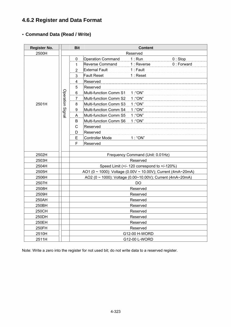
4-323
4.6.2 Register and Data Format Command Data (Read / Write)
Register No. Bit Content
2500H Reserved
2501H
Operation S
ignal
0 Operation Command 1 : Run 0 : Stop
1 Reverse Command 1 : Reverse 0 : Forward
2 External Fault 1 : Fault
3 Fault Reset 1 : Reset
4 Reserved
5 Reserved
6 Multi-function Comm S1 1 :“ON”
7 Multi-function Comm S2 1 :“ON”
8 Multi-function Comm S3 1 :“ON”
9 Multi-function Comm S4 1 :“ON”
A Multi-function Comm S5 1 :“ON”
B Multi-function Comm S6 1 :“ON”
C Reserved
D Reserved
E Controller Mode 1 : “ON”
F Reserved
2502H Frequency Command (Unit: 0.01Hz)
2503H Reserved
2504H Speed Limit (+/- 120 correspond to +/-120%)
2505H AO1 (0 ~ 1000): Voltage (0.00V ~ 10.00V); Current (4mA~20mA)
2506H AO2 (0 ~ 1000): Voltage (0.00~10.00V); Current (4mA~20mA)
2507H DO
2508H Reserved 2509H Reserved 250AH Reserved 250BH Reserved 250CH Reserved 250DH Reserved 250EH Reserved 250FH Reserved 2510H G12-00 H-WORD
2511H G12-00 L-WORD
Note: Write a zero into the register for not used bit; do not write data to a reserved register.

4-324
Monitor Data (Read only)
Register No. Bit Content
2520H
State S
ignal
0 Operation 1 : Run 0 : Stop
1 Direction 1 : Reverse 0 : Forward
2 Inverter ready 1 : Ready 0 : Unready
3 Fault 1 : Abnormal
4 Warning 1 :“ON”
5 Zero Speed 1 :“ON”
6 Ls 440 1 :“ON”
7 Frequency Agree 1 :“ON”
8 Set Frequency Agree 1 :“ON”
9 Frequency Detection 1 1 :“ON”
A Frequency Detection 2 1 :“ON”
B Under Voltage 1 :“ON”
C Baseblock 1 :“ON”
D Freq Ref. not from Comm. 1 :“ON”
E Seq. not from Comm. 1 :“ON”
F Over Torque 1 :“ON”
2521H
Error D
escription
0 Reserved 31 Reserved 1 UV 32 Reserved 2 OC 33 Reserved 3 OV 34 Reserved 4 OH1 35 Reserved 5 OL1 36 Low Suction Fault
6 OL2 37 Low Suction Fault (with retry)
7 OT 38 CF07
8 UT 39 LOPBT(Low Flow Fault)
9 SC 40 HIPBT(High Flow Fault)
10 GF(Ground Fault) 41 Reserved
11 FU(Fuse Broken) 42 LPBFT(Low Pressure Fault)
12 IPL(Input Phase Loss) 43 OPBFT(High Pressure Fault)
13 OPL(Output Phase Loss) 44 FBLSS(PID Feedback Loss)
14 Reserved 45 Reserved
15 Reserved 46 Motor Overheat (OH4)
16 Reserved 47 SS1
17 EF1(External terminal S1 Fault) 48 CF20
18 EF2(External terminal S2 Fault) 49 Reserved
19 EF3(External terminal S3 Fault) 50 OCA(Overcurrent in
acceleration)
20 EF4(External terminal S4 Fault) 51 OCD(Overcurrent in
deceleration)
21 EF5(External terminal S5 Fault) 52 OCC(Overcurrent in constant
speed)
22 EF6(External terminal S6 Fault) 53 Reserved
23 Reserved 54 PTCLS (PTC signal loss)
24 Reserved 55 PF (Protection Fault)
25 FB(PID Feedback Fault) 56 TOL (External Overload)
26 Keypad Removed 57 STO2 27 Reserved 58 Reserved

4-325
Register No. Bit Content
28 CE 59 Reserved 29 STO 60 Reserved 30 Reserved 61 Reserved
2522H
DI S
tate
0 Multi-function Comm S1
1 Multi-function Comm S2
2 Multi-function Comm S3
3 Multi-function Comm S4
4 Multi-function Comm S5
5 Multi-function Comm S6
6 Reserved
7 Reserved 8 Reserved 9 Reserved A Reserved B Reserved C Reserved D Reserved E Reserved F Reserved
2523H Frequency Command (0.01Hz)
2524H Output Frequency (0.01Hz)
2525H Reserved
2526H DC Voltage Command (0.1V)
2527H Output Current (0.1A)
2528H
Warning D
escription
0 No alarm 20 EF4 40 EF 60 LOPb
1 OV 21 EF5 41 Reserved 61 RETRY
2 UV 22 EF6 42 Reserved 62 Reserved 3 OL2 23 Reserved 43 RDP 63 Reserved 4 OH2 24 Reserved 44 Reserved 64 HIPb
5 Reserved 25 Reserved 45 OL1 65 OH1
6 OT 26 CLB 46 HP_ER 66 FIRE
7 Reserved 27 Reserved 47 SE10 67 ES
8 Reserved 28 CT 48 COPUP 68 STP1
9 UT 29 USP 49 BB1 69 BDERR
10 Reserved 30 RDE 50 BB2 70 EPERR
11 Reserved 31 WRE 51 BB3 71 ADCER
12 Reserved 32 FB 52 BB4 72 OL4
13 CE 33 VRYE 53 BB5 73 STP0
14 CALL 34 SE01 54 BB6 74 Reserved
15 Reserved 35 SE02 55 Reserved 75 STP2
16 EF0 36 SE03 56 Reserved 76 RUNER
17 EF1 37 Reserved 57 LOPb 77 LOC
18 EF2 38 SE05 58 HIPb 78 PTCLS
19 EF3 39 HPERR 59 LSCFT 79 FBLSS
2529H DO State
252AH AO1 (0 ~ 1000): Voltage (0.00V ~ 10.00V); Current (4mA~20mA)
252BH AO2 (0 ~ 1000): Voltage (0.00~10.00V); Current (4mA~20mA)
252CH Analog Input 1 (0.1%)
252DH Analog Input 2 (0.1%)
252EH Reserved

4-326
Register No. Bit Content
252FH F510/A510/L510/E510 Check
2532H Relay card status display
Note: Do not write data to a reserved register.
Read Holding Register [03H]
Read consecutive holding registers. The address of the first holding register is specified in the protocol. Example: Read frequency command from the inverter with node address 1.
ASCII Mode
Command message Response Message (Normal) Response Message (Error)
3AH STX 3AH STX 3AH STX
30H Node Address
30H Node Address
30H Node Address
31H 31H 31H
30H Function Code
30H Function Code
38H Function Code
33H 33H 33H
30H
Starting
Register
30H DATA Length
30H Exception Code
43H 32H 34H
31H 31H
Data
34H LRC CHECK
30H 37H 30H
30H
Number of
Registers
37H 0DH END
30H 30H 0AH
30H 37H LRC CHECK
+
31H 33H
44H LRC CHECK
0DH END
46H 0AH
0DH
END
0AH
RTU Mode
Command Message Response Message (Normal) Response Message (Error)
Node Address 01 H Node Address 01H Node Address 01H
Function Code 03H Function Code 03H Function Code 83H
Starting
Register
High 0CH DATA Length 02H Exception Code 04H
Low 10H Data
High 17H CRC-16
High 40H
Number of
Registers
High 00H Low 70H Low F3H
Low 01H CRC-16
High B6H
CRC-16 High 86H Low 50H
Low 9FH

4-327
Loop Back Test [08H]
Check the communication between the master and the follower (inverter). The data used can be arbitrary.
ASCII Mode
Command Message Response Message (Normal) Response Message (Error)
3AH STX 3AH STX 3AH STX
30H Node Address
30H Node Address
30H Node Address
31H 31H 31H
30H Function Code
30H Function Code
38H Function Code
38H 38H 38H
30H
Test Code
30H
Test Code
30H Exception Code
30H 30H 33H
30H 30H 30H LRC CHECK
30H 30H 36H
41H
DATA
41H
DATA
0DH END
0AH
35H 35H
33H 33H
37H 37H
31H LRC CHECK
31H LRC CHECK
42H 42H
0DH END
0DH END
0AH 0AH
RTU Mode
Command Message Response Message (Normal) Response Message (Error)
Node Address 01 H Node Address 01H Node Address 01H
Function Code 08H Function Code 08H Function Code 88H
Test Code High 00H
Test CodeHigh 00H Exception Code 03H
Low 00H Low 00H CRC-16
High 06H
DATA High A5H
DATA High A5H Low 01H
Low 37H Low 37H
CRC-16 High DAH
CRC-16High DAH
Low 8DH Low 8DH

4-328
Write Single Holding Register [06H]
Write single holding register. The register address of the holding register is specified in the message. Example: Write a 60.00Hz frequency command to node address 1.
ASCII Mode
Command Message Response Message (Normal) Response Message (Error)
3AH STX 3AH STX 3AH STX
30H Node Address
30H Node Address
30H Node Address
31H 31H 31H
30H Function Code
30H Function Code
38H Function Code
36H 36H 36H
32H
Starting
Register
32H
Starting
Register
30H Exception Code
35H 35H 33H
30H 30H 30H LRC CHECK
32H 32H
32H
31H
DATA
31H
DATA
0DH END
0AH
37H 37H
37H 37H
30H 30H
34H LRC CHECK
34H LRC CHECK
42H 42H
0DH END
0DH END
0AH 0AH
RTU Mode
Command Message Response Message (Normal) Response Message (Error)
Node Address 01 H Node Address 01H Node Address 01H
Function Code 06H Function Code 06H Function Code 86H
Starting
Register
High 25H Starting
Register
High 25H Exception Code 03H
Low 02H Low 02H CRC-16
High 02H
DATA High 17H
DATA High 17H Low 61H
Low 70H Low 70H
CRC-16 High 2DH
CRC-16High 2DH
Low 12H Low 12H
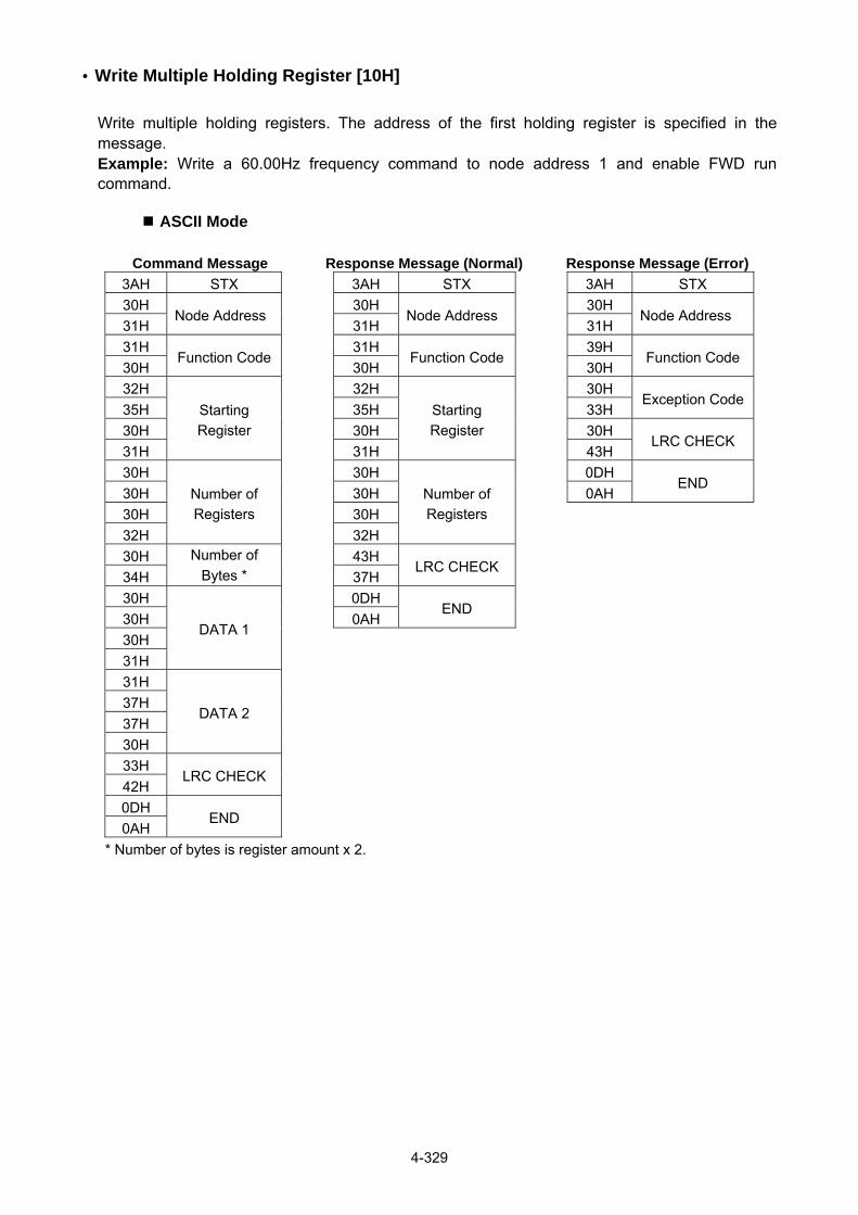
4-329
Write Multiple Holding Register [10H]
Write multiple holding registers. The address of the first holding register is specified in the message. Example: Write a 60.00Hz frequency command to node address 1 and enable FWD run command.
ASCII Mode
Command Message Response Message (Normal) Response Message (Error)
3AH STX 3AH STX 3AH STX
30H Node Address
30H Node Address
30H Node Address
31H 31H 31H
31H Function Code
31H Function Code
39H Function Code
30H 30H 30H
32H
Starting
Register
32H
Starting
Register
30H Exception Code
35H 35H 33H
30H 30H 30H LRC CHECK
31H 31H 43H
30H
Number of
Registers
30H
Number of
Registers
0DH
END 30H 30H 0AH
30H 30H
32H 32H
30H Number of
Bytes * 43H
LRC CHECK
34H 37H
30H
DATA 1
0DH END
30H 0AH
30H
31H
31H
DATA 2
37H
37H
30H
33H LRC CHECK
42H
0DH END
0AH
* Number of bytes is register amount x 2.

4-330
RTU Mode
Command Message Response Message (Normal) Response Message (Error)
Node Address 01H Node Address 01H Node Address 01H
Function Code 10H Function Code 10H Function Code 90H
Starting
Register
High 25H Starting
Register
High 25H Exception Code 03H
Low 01H Low 01H CRC-16
High 0CH
Number of
Registers
High 00H Number of
Registers
High 00H Low 01H
Low 02H Low 02H
Number of Bytes * 04H CRC-16
High 1BH
DATA 1 High 00H Low 04H
Low 01H
DATA 2 High 17H
Low 70H
CRC-16 High 60H
Low 27H
* Number of bytes is register amount x 2.

4-331
Parameter Data and Corresponding Register No.
Function Code Register No. Function Code Register No. Function Code Register No.
Group 0 Group 0 Group 1
0 – 00 0000H 0 – 45 002DH 1 – 00 0100H
0 – 01 0001H 0 – 46 002EH 1 – 01 0101H
0 – 02 0002H 0 – 47 002FH 1 – 02 0102H
0 – 03 0003H 0 – 48 0030H 1 – 03 0103H
0 – 04 0004H 0 – 49 0031H 1 – 04 0104H
0 – 05 0005H 0 – 50 0032H 1 – 05 0105H
0 – 06 0006H 0 – 51 0033H 1 – 06 0106H
0 – 07 0007H 0 – 52 0034H 1 – 07 0107H
0 – 08 0008H 0 – 53 0035H 1 – 08 0108H
0 – 09 0009H 0 – 54 0036H 1 – 09 0109H
0 – 10 000AH 0 – 55 0037H 1 – 10 010AH
0 – 11 000BH 0 – 56 0038H 1 – 11 010BH
0 – 12 000CH 1 – 12 010CH
0 – 13 000DH 1 – 13 010DH
0 – 14 000EH 1 – 14 010EH
0 – 15 000FH 1 – 15 010FH
0 – 16 0010H
0 – 17 0011H
0 – 18 0012H
0 – 19 0013H
0 – 20 0014H
0 – 21 0015H
0 – 22 0016H
0 – 23 0017H
0 – 24 0018H
0 – 25 0019H
0 – 26 001AH
0 – 27 001BH
0 – 28 001CH
0 – 29 001DH
0 – 30 001EH
0 – 31 001FH
0 – 32 0020H
0 – 33 0021H
0 – 34 0022H
0 – 35 0023H
0 – 36 0024H
0 – 37 0025H
0 – 38 0026H
0 – 39 0027H
0 – 40 0028H
0 – 41 0029H
0 – 42 002AH
0 – 43 002BH
0 – 44 002CH

4-332
Function Code Register No. Function Code Register No. Function Code Register No.
Group 2 Group 3 Group 3
2 – 00 0200H 3 – 00 0300H 3 – 33 0321H
2 – 01 0201H 3 – 01 0301H 3 – 34 0322H
2 – 02 0202H 3 – 02 0302H 3 – 35 0323H
2 – 03 0203H 3 – 03 0303H 3 – 36 0324H
2 – 04 0204H 3 – 04 0304H 3 – 37 0325H
2 – 05 0205H 3 – 05 0305H 3 – 38 0326H
2 – 06 0206H 3 – 06 0306H 3 – 39 0327H
2 – 07 0207H 3 – 07 0307H 3 – 40 0328H
2 – 08 0208H 3 – 08 0308H 3 – 41 0329H
2 – 09 0209H 3 – 09 0309H 3 – 42 032AH
2 – 10 020AH 3 – 10 030AH 3 – 43 032BH
2 – 11 020BH 3 – 11 030BH 3 – 44 032CH
2 – 12 020CH 3 – 12 030CH 3 – 45 032DH
2 – 13 020DH 3 – 13 030DH 3 – 46 032EH
2 – 14 020EH 3 – 14 030EH 3 – 47 032FH
2 – 15 020FH 3 – 15 030FH 3 – 48 0330H
2 – 16 0210H 3 – 16 0310H 3 – 49 0331H
2 – 17 0211H 3 – 17 0311H 3 – 50 0332H
2 – 18 0212H 3 – 18 0312H 3 – 51 0333H
2 – 19 0213H 3 – 19 0313H 3 – 52 0334H
2 – 33 0221H 3 – 20 0314H 3 – 53 0335H
2 – 34 0222H 3 – 21 0315H
3 – 22 0316H
3 – 23 0317H
3 – 24 0318H
3 – 25 0319H
3 – 26 031AH
3 – 27 031BH
3 – 28 031CH
3 – 29 031DH
3 – 30 031EH
3 – 31 031FH
3 – 32 0320H

4-333
Function Code Register No. Function Code Register No. Function Code Register No.
Group 4 Group 5 Group 5
4 – 00 0400H 5 – 00 0500H 5 – 33 0521H
4 – 01 0401H 5 – 01 0501H 5 – 34 0522H
4 – 02 0402H 5 – 02 0502H 5 – 35 0523H
4 – 03 0403H 5 – 03 0503H 5 – 36 0524H
4 – 04 0404H 5 – 04 0504H 5 – 37 0525H
4 – 05 0405H 5 – 05 0505H 5 – 38 0526H
4 – 06 0406H 5 – 06 0506H 5 – 39 0527H
4 – 07 0407H 5 – 07 0507H 5 – 40 0528H
4 – 08 0408H 5 – 08 0508H 5 – 41 0529H
4 – 09 0409H 5 – 09 0509H 5 – 42 052AH
4 – 10 040AH 5 – 10 050AH 5 – 43 052BH
4 – 11 040BH 5 – 11 050BH 5 – 44 052CH
4 – 12 040CH 5 – 12 050CH 5 – 45 052DH
4 – 13 040DH 5 – 13 050DH 5 – 46 052EH
4 – 14 040EH 5 – 14 050EH 5 – 47 052FH
4 – 15 040FH 5 – 15 050FH 5 – 48 0530H
4 – 16 0410H 5 – 16 0510H
4 – 17 0411H 5 – 17 0511H
4 – 18 0412H 5 – 18 0512H
4 – 19 0413H 5 – 19 0513H
4 – 20 0414H 5 – 20 0514H
5 – 21 0515H
5 – 22 0516H
5 – 23 0517H
5 – 24 0518H
5 – 25 0519H
5 – 26 051AH
5 – 27 051BH
5 – 28 051CH
5 – 29 051DH
5 – 30 051EH
5 – 31 051FH
5 – 32 0520H

4-334
Function Code Register No. Function Code Register No. Function Code Register No.
Group 6 Group 6 Group 7
6 – 00 0600H 6 – 33 0621H 7 – 00 0700H
6 – 01 0601H 6 – 34 0622H 7 – 01 0701H
6 – 02 0602H 6 – 35 0623H 7 – 02 0702H
6 – 03 0603H 6 – 36 0624H 7 – 03 0703H
6 – 04 0604H 6 – 37 0625H 7 – 04 0704H
6 – 05 0605H 6 – 38 0626H 7 – 05 0705H
6 – 06 0606H 6 – 39 0627H 7 – 06 0706H
6 – 07 0607H 6 – 40 0628H 7 – 07 0707H
6 – 08 0608H 6 – 41 0629H 7 – 08 0708H
6 – 09 0609H 6 – 42 062AH 7 – 09 0709H
6 – 10 060AH 6 – 43 062BH 7 – 10 070AH
6 – 11 060BH 6 – 44 062CH 7 – 11 070BH
6 – 12 060CH 6 – 45 062DH 7 – 12 070CH
6 – 13 060DH 6 – 46 062EH 7 – 13 070DH
6 – 14 060EH 6 – 47 062FH 7 – 14 070EH
6 – 15 060FH 7 – 15 070FH
6 – 16 0610H 7 – 16 0710H
6 – 17 0611H 7 – 17 0711H
6 – 18 0612H 7 – 18 0712H
6 – 19 0613H 7 – 19 0713H
6 – 20 0614H 7 – 20 0714H
6 – 21 0615H 7 – 21 0715H
6 – 22 0616H 7 – 22 0716H
6 – 23 0617H 7 – 23 0717H
6 – 24 0618H 7 – 24 0718H
6 – 25 0619H 7 – 25 0719H
6 – 26 061AH 7 – 26 071AH
6 – 27 061BH 7 – 27 071BH
6 – 28 061CH 7 – 28 071CH
6 – 29 061DH 7 – 29 071DH
6 – 30 061EH 7 – 30 071EH
6 – 31 061FH 7 – 31 071FH
6 – 32 0620H 7 – 32 0720H
7 – 33 0721H
7 – 34 0722H
7 – 35 0723H
7 – 36 0724H
7 – 37 0725H
7 – 38 0726H
7 – 39 0727H
7 – 40 0728H
7 – 41 0729H
7 – 42 072AH
7 – 43 072BH
7 – 44 072CH
7 – 45 072DH

4-335
Function
Code
Register
No.
Function
Code
Register
No.
Function
Code
Register
No.
Function
Code
Register
No.
Group 8 Group 8 Group 9 Group 10
8 – 00 0800H 8 – 44 082CH 9 – 00 0900H 10 – 00 0A00H
8 – 01 0801H 8 – 45 082DH 9 – 01 0901H 10 – 01 0A01H
8 – 02 0802H 8 – 46 082EH 9 – 02 0902H 10 – 02 0A02H
8 – 03 0803H 8 – 47 082FH 9 – 03 0903H 10 – 03 0A03H
8 – 04 0804H 8 – 48 0830H 9 – 04 0904H 10 – 04 0A04H
8 – 05 0805H 8 – 49 0831H 9 – 05 0905H 10 – 05 0A05H
8 – 06 0806H 8 – 50 0832H 9 – 06 0906H 10 – 06 0A06H
8 – 07 0807H 8 – 51 0833H 9 – 07 0907H 10 – 07 0A07H
8 – 08 0808H 8 – 52 0834H 9 – 08 0908H 10 – 08 0A08H
8 – 09 0809H 8 – 53 0835H 9 – 09 0909H 10 – 09 0A09H
8 – 10 080AH 8 – 54 0836H 9 – 10 090AH 10 – 10 0A0AH
8 – 11 080BH 8 – 55 0837H 10 – 11 0A0BH
8 – 12 080CH 8 – 56 0838H 10 – 12 0A0CH
8 – 13 080DH 8 – 57 0839H 10 – 13 0A0DH
8 – 14 080EH 8 – 58 083AH 10 – 14 0A0EH
8 – 15 080FH 8 – 59 083BH 10 – 15 0A0FH
8 – 16 0810H 8 – 60 083CH 10 – 16 0A10H
8 – 17 0811H 10 – 17 0A11H
8 – 18 0812H 10 – 18 0A12H
8 – 19 0813H 10 – 19 0A13H
8 – 20 0814H 10 – 20 0A14H
8 – 21 0815H 10 – 21 0A15H
8 – 22 0816H 10 – 22 0A16H
8 – 23 0817H 10 – 23 0A17H
8 – 24 0818H 10 – 24 0A18H
8 – 25 0819H 10 – 25 0A19H
8 – 26 081AH 10 – 26 0A1AH
8 – 27 081BH 10 – 27 0A1BH
8 – 28 081CH 10 – 28 0A1CH
8 – 29 081DH 10 – 29 0A1DH
8 – 30 081EH 10 – 30 0A1EH
8 – 31 081FH 10 – 31 0A1FH
8 – 32 0820H 10 – 32 0A20H
8 – 33 0821H 10 – 33 0A21H
8 – 34 0822H 10 – 34 0A22H
8 – 35 0823H 10 – 35 0A23H
8 – 36 0824H 10 – 36 0A24H
8 – 37 0825H 10 – 37 0A25H
8 – 38 0826H 10 – 38 0A26H
8 – 39 0827H 10 – 39 0A27H
8 – 40 0828H 10 – 40 0A28H
8 – 41 0829H 10 – 41 0A29H
8 – 42 082AH 10 – 42 0A2AH
8 – 43 082BH 10 – 43 0A2BH

4-336
Function Code Register No. Function Code Register No. Function Code Register No.
Group 10 Group 11 Group 11
10 – 44 0A2CH 11 – 00 0B00H 11 – 44 0B2CH
10 – 45 0A2DH 11 – 01 0B01H 11 – 45 0B2DH
10 – 46 0A2EH 11 – 02 0B02H 11 – 46 0B2EH
10 – 47 0A2FH 11 – 03 0B03H 11 – 47 0B2FH
10 – 48 0A30H 11 – 04 0B04H 11 – 48 0B30H
10 – 49 0A31H 11 – 05 0B05H 11 – 49 0B31H
11 – 06 0B06H 11 – 50 0B32H
11 – 07 0B07H 11 – 51 0B33H
11 – 08 0B08H 11 – 52 0B34H
11 – 09 0B09H 11 – 53 0B35H
11 – 10 0B0AH 11 – 54 0B36H
11 – 11 0B0BH 11 – 55 0B37H
11 – 12 0B0CH 11 – 56 0B38H
11 – 13 0B0DH 11 – 57 0B39H
11 – 14 0B0EH 11 – 58 0B3AH
11 – 15 0B0FH 11 – 59 0B3BH
11 – 16 0B10H 11 – 60 0B3CH
11 – 17 0B11H 11 – 61 0B3DH
11 – 18 0B12H 11 – 62 0B3EH
11 – 19 0B13H 11 – 63 0B3FH
11 – 20 0B14H 11 – 64 0B40H
11 – 21 0B15H 11 – 65 0B41H
11 – 22 0B16H 11 – 66 0B42H
11 – 23 0B17H 11 – 67 0B43H
11 – 24 0B18H 11 – 68 0B44H
11 – 25 0B19H 11 – 69 0B45H
11 – 26 0B1AH 11 – 70 0B46H
11 – 27 0B1BH 11 – 71 0B47H
11 – 28 0B1CH 11 – 72 0B48H
11 – 29 0B1DH 11 – 73 0B49H
11 – 30 0B1EH
11 – 31 0B1FH
11 – 32 0B20H
11 – 33 0B21H
11 – 34 0B22H
11 – 35 0B23H
11 – 36 0B24H
11 – 37 0B25H
11 – 38 0B26H
11 – 39 0B27H
11 – 40 0B28H
11 – 41 0B29H
11 – 42 0B2AH
11 – 43 0B2BH

4-337
Function Code Register No. Function Code Register No. Function Code Register No.
Group 12 Group 12 Group 12
12 – 00 0C00H 12 – 41 0C29H 12 – 81 0C51H
12 – 01 0C01H 12 – 42 0C2AH 12 – 82 0C52H
12 – 02 0C02H 12 – 43 0C2BH
12 – 03 0C03H 12 – 44 0C2CH
12 – 04 0C04H 12 – 45 0C2DH
12 – 05 0C05H 12 – 46 0C2EH
12 – 06 0C06H 12 – 47 0C2FH
12 – 07 0C07H 12 – 48 0C30H
12 – 08 0C08H 12 – 49 0C31H
12 – 09 0C09H 12 – 50 0C32H
12 – 10 0C0AH 12 – 51 0C33H
12 – 11 0C0BH 12 – 52 0C34H
12 – 12 0C0CH 12 – 53 0C35H
12 – 13 0C0DH 12 – 54 0C36H
12 – 14 0C0EH 12 – 55 0C37H
12 – 15 0C0FH 12 – 56 0C38H
12 – 16 0C10H 12 – 57 0C39H
12 – 17 0C11H 12 – 58 0C3AH
12 – 18 0C12H 12 – 59 0C3BH
12 – 19 0C13H 12 – 60 0C3CH
12 – 20 0C14H 12 – 61 0C3DH
12 – 21 0C15H 12 – 62 0C3EH
12 – 22 0C16H 12 – 63 0C3FH
12 – 23 0C17H 12 – 64 0C40H
12 – 24 0C18H 12 – 65 0C41H
12 – 25 0C19H 12 – 66 0C42H
12 – 26 0C1AH 12 – 67 0C43H
12 – 27 0C1BH 12 – 68 0C44H
12 – 28 0C1CH 12 – 69 0C45H
12 – 29 0C1DH 12 – 70 0C46H
12 – 30 0C1EH 12 – 71 0C47H
12 – 31 0C1FH 12 – 72 0C48H
12 – 32 0C20H 12 – 73 0C49H
12 – 33 0C21H 12 – 70 0C46H
12 – 34 0C22H 12 – 71 0C47H
12 – 35 0C23H 12 – 72 0C48H
12– 36 0C24H 12 – 73 0C49H
12 – 37 0C25H 12 – 74 0C4AH
12 – 38 0C26H 12 – 75 0C4BH
12 – 39 0C27H 12 – 76 0C4CH
12 – 40 0C28H 12 – 77 0C4DH
12 – 78 0C4EH
12 – 79 0C4FH
12 – 80 0C50H

4-338
Function Code Register No. Function Code Register No. Function Code Register No.
Group 13 Group 13
13 – 00 0D00H 13 – 48 0D2FH
13 – 01 0D01H 13 – 49 0D30H
13 – 02 0D02H 13 – 50 0D31H
13 – 03 0D03H
13 – 04 0D04H
13 – 05 0D05H
13 – 06 0D06H
13 – 07 0D07H
13 – 08 0D08H
13 – 09 0D09H
13 – 10 0D0AH
13 – 11 0D0BH
13 – 12 0D0CH
13 – 13 0D0DH
13 – 14 0D0DH
13 – 15 0D0EH
13 – 16 0D0FH
13 – 17 0D10H
13 – 18 0D11H
13 – 19 0D12H
13 – 20 0D13H
13 – 21 0D14H
13 – 22 0D15H
13 – 23 0D16H
13 – 24 0D17H
13 – 25 0D18H
13 – 26 0D19H
13 – 27 0D1AH
13 – 28 0D1BH
13 – 29 0D1CH
13 – 30 0D1DH
13 – 31 0D1EH
13 – 32 0D1FH
13 – 33 0D20H
13 – 34 0D21H
13 – 35 0D22H
13 – 36 0D23H
13 – 37 0D24H
13 – 38 0D25H
13 – 39 0D26H
13 – 40 0D27H
13 – 41 0D28H
13 – 42 0D29H
13 – 43 0D2AH
13 – 44 0D2BH
13 – 45 0D2CH
13 – 46 0D2DH
13 – 47 0D2EH

4-339
Function Code Register No. Function Code Register No. Function Code Register No.
Group 14 Group 15 Group 16
14 – 00 0E00H 15 – 00 0F00H 16 – 00 1000H
14 – 01 0E01H 15 – 01 0F01H 16 – 01 1001H
14 – 02 0E02H 15 – 02 0F02H 16 – 02 1002H
14 – 03 0E03H 15 – 03 0F03H 16 – 03 1003H
14 – 04 0E04H 15 – 04 0F04H 16 – 04 1004H
14 – 05 0E05H 15 – 05 0F05H 16 – 05 1005H
14 – 06 0E06H 15 – 06 0F06H 16 – 06 1006H
14 – 07 0E07H 15 – 07 0F07H 16 – 07 1007H
14 – 08 0E08H 15 – 08 0F08H 16 – 08 1008H
14 – 09 0E09H 15 – 09 0F09H 16 – 09 1009H
14 – 10 0E0AH 15 – 10 0F0AH 16 – 10 100AH
14 – 11 0E0BH 15 – 11 0F0BH 16 – 11 100BH
14 – 12 0E0CH 15 – 12 0F0CH 16 – 12 100CH
14 – 13 0E0DH 15 – 13 0F0DH 16 – 13 100DH
14 – 14 0E0EH 15 – 14 0F0EH 16 – 14 100EH
14 – 15 0E0FH 15 – 15 0F0FH 16 – 15 100FH
14 – 16 0E10H 15 – 16 0F10H 16 – 16 1010H
14 – 17 0E11H 15 – 17 0F11H 16 – 17 1011H
14 – 18 0E12H 15 – 18 0F12H 16 – 18 1012H
14 – 19 0E13H 15 – 19 0F13H 16 – 19 1013H
14 – 20 0E14H 15 – 20 0F14H 16 – 20 1014H
14 – 21 0E15H 15 – 21 0F15H 16 – 21 1015H
14 – 22 0E16H 15 – 22 0F16H 16 – 22 1016H
14 – 23 0E17H 15 – 23 0F17H 16 – 23 1017H
14 – 24 0E18H 15 – 24 0F18H 16 – 24 1018H
14 – 25 0E19H 15 – 25 0F19H 16 – 25 1019H
14 – 26 0E1AH 15 – 26 0F1AH 16 – 26 101AH
14 – 27 0E1BH 15 – 27 0F1BH 16 – 27 101BH
14 – 28 0E1CH 15 – 28 0F1CH 16 – 28 101CH
14 – 29 0E1DH 15 – 29 0F1DH 16 – 29 101DH
14 – 30 0E1EH 15 – 30 0F1EH 16 – 30 101EH
14 – 31 0E1FH 15 – 31 0F1FH 16 – 31 101FH
14 – 32 0E20H 15 – 32 0F20H 16 – 32 1020H
14 – 33 0E21H 16 – 33 1021H
14 – 34 0E22H 16 – 34 1022H
14 – 35 0E23H 16 – 35 1023H
14 – 36 0E24H 16 – 36 1024H
14 – 37 0E25H 16 – 37 1025H
14 – 38 0E26H
14 – 39 0E27H
14 – 40 0E28H
14 – 41 0E29H
14 – 42 0E2AH
14 – 43 0E2BH
14 – 44 0E2CH
14 – 45 0E2DH
14 – 46 0E2EH
14 – 47 0E2FH

4-340
Function Code Register No. Function Code Register No. Function Code Register No.
Group 17 Group 18
17 – 00 1100H 18 – 00 1200H
17 – 01 1101H 18 – 01 1201H
17 – 02 1102H 18 – 02 1202H
17 – 03 1103H 18 – 03 1203H
17 – 04 1104H 18 – 04 1204H
17 – 05 1105H 18 – 05 1205H
17 – 06 1106H 18 – 06 1206H
17 – 07 1107H
17 – 08 1108H
17 – 09 1109H
17 – 10 110AH
17 – 11 110BH
17 – 12 110CH
17 – 13 110DH
17 – 14 110EH

4-341
Function Code Register No. Function Code Register No. Function Code Register No.
Group 20 Group 21 Group 22
20 – 00 1400H 21 – 00 1500H 22 – 00 1600H
20 – 01 1401H 21 – 01 1501H 22 – 01 1601H
20 – 02 1402H 21 – 02 1502H 22 – 02 1602H
20 – 03 1403H 21 – 03 1503H 22 – 03 1603H
20 – 04 1404H 21 – 04 1504H 22 – 04 1604H
20 – 05 1405H 21 – 05 1505H 22 – 05 1605H
20 – 06 1406H 21 – 06 1506H 22 – 06 1606H
20 – 07 1407H 21 – 07 1507H 22 – 07 1607H
20 – 08 1408H 21 – 08 1508H 22 – 08 1608H
20 – 09 1409H 22 – 09 1609H
20 – 10 140AH 22 – 10 160AH
20 – 11 140BH 22 – 11 160BH
20 – 12 140CH 22 – 12 160CH
20 – 13 140DH 22 – 13 160DH
20 – 14 140EH 22 – 14 160EH
20 – 15 140FH 22 – 15 160FH
20 – 16 1410H 22 – 16 1610H
20 – 17 1411H 22 – 17 1611H
20 – 18 1412H 22 – 18 1612H
20 – 33 1421H 22 – 19 1613H
20 – 34 1422H 22 – 20 1614H
20 – 35 1423H 22 – 21 1615H
22 – 22 1616H
22 – 23 1617H
22 – 24 1618H
22 – 25 1619H
22 – 26 161AH
22 – 27 161BH
22 – 28 161CH
22 – 29 161DH
22 – 30 161EH
22 – 31 161FH
22 – 32 1620H
22 – 33 1621H
22 – 34 1622H
22 – 35 1623H

4-342
Function Code Register No. Function Code Register No. Function Code Register No.
Group 23 Group 23 Group 24
23 – 00 1700H 23 – 47 172FH 24 – 00 1800H
23 – 01 1701H 23 – 48 1730H 24 – 01 1801H
23 – 02 1702H 23 – 49 1731H 24 – 02 1802H
23 – 03 1703H 23 – 50 1732H 24 – 03 1803H
23 – 04 1704H 23 – 51 1733H 24 – 04 1804H
23 – 05 1705H 23 – 52 1734H 24 – 05 1805H
23 – 06 1706H 23 – 53 1735H 24 – 06 1806H
23 – 07 1707H 23 – 54 1736H 24 – 07 1807H
23 – 08 1708H 23 – 55 1737H 24 – 08 1808H
23 – 09 1709H 23 – 56 1738H 24 – 09 1809H
23 – 10 170AH 23 – 57 1739H 24 – 10 180AH
23 – 11 170BH 23 – 58 173AH 24 – 11 180BH
23 – 12 170CH 23 – 59 173BH 24 – 12 180CH
23 – 13 170DH 23 – 60 173CH 24 – 13 180DH
23 – 14 170EH 23 – 61 173DH 24 – 14 180EH
23 – 15 170FH 23 – 62 173EH 24 – 15 180FH
23 – 16 1710H 23 – 63 173FH 24 – 16 1810H
23 – 17 1711H 23 – 64 1740H 24 – 17 1811H
23 – 18 1712H 23 – 65 1741H
23 – 19 1713H 23 – 66 1742H
23 – 20 1714H 23 – 67 1743H
23 – 21 1715H 23 – 68 1744H
23 – 22 1716H 23 – 69 1745H
23 – 23 1717H 23 – 70 1746H
23 – 24 1718H 23 – 71 1747H
23 – 25 1719H 23 – 72 1748H
23 – 26 171AH 23 – 73 1749H
23 – 27 171BH 23 – 74 174AH
23 – 28 171CH 23 – 75 174BH
23 – 29 171DH 23 – 76 174CH
23 – 30 171EH 23 – 77 174DH
23 – 31 171FH 23 – 78 174EH
23 – 32 1720H
23 – 33 1721H
23 – 34 1722H
23 – 35 1723H
23 – 36 1724H
23 – 37 1725H
23 – 38 1726H
23 – 39 1727H
23 – 40 1728H
23 – 41 1729H
23 – 42 172AH
23 – 43 172BH
23 – 44 172CH
23 – 45 172DH
23 – 46 172EH

4-343
4.7 BACnet Protocol Descriptions
BACnet is in compliance with four-layer of seven-layer structure models in OSI (Open Systems Interconnection) of International Standard Organization (ISO). These four-layer structure models are application layer, network layer, data link layer and physical layer. Besides, BACnet is definced by the view of standard “object” and “property.” All BACnet devices are controlled via the property of objects. Every controller with BACnet devices is considered an object collector so that every controller device can execute different kinds of functions of objects to achieve the communication control and monitor control.
4.7.1 BACnet Services
Services provide some commands to save or control information and some functions to achieve the purpose of monitoring and control. Namely, one BACnet device reveive certain information or command to complete specific work from other BACnet device so the two devices need to support the same service to complete communication. To complete the exchange of these service messages, these communication requirements are specified in the communication protocol of application layer by BACnet. Thus, services are parts of the communication protocol data unit (PDU) in the application layer and build the communication modes via the relationship of Server – Client. Client will send the message of sevice requirements to Server and Server needs to respond to Client to execute this service. Refer to the following fugure.
Application Layer
Network Layer
Data Link Layer
Physical Layer
Application Layer of BACnet
Network Layer of BACnet
ISO- 8802-2(IEEE802.2)
ISO- 8802-3(IEEE802.3)
ARCNET
MS/TP PTP
EIA-485 EIA-232
LonkTalk
OSI Corresponding ModelBACnet Simple Model
R e q u e s t fo r P D U
R e s p o n d to P D U
R e c e iv e
S e n dR e c e iv e
S e n d
R e q u e s t R e s p o n d
C l ie n t S e r v e r

4-344
All BACnet devices have the application programs to manage the requirements of device motion and executing services. Take work station for example, the application program needs to keep the display value of every input so it requires sending the service request to the object of other device to update the display value of input. The application program of the device needs to respond to the service requiremtents. Refer to the following fugure.
4.7.2 BACnet Protocol Structure
BACnet is the communication protocol by way of protocol stack so the pocket is composed of stacked layer types. Refer to the following figure.
When application program sends the BACnet service request for the pocket, it requires requesting for executing BACnet request program in the application layer via application program interface. The requirements of the program are sent to the application layer and application protocol data unit (APDU) consists of Application Protocol Control Information (APCI) and Servie Data of application program. Then APDU passes its messages downward to BACnet request program in the network layer. APDU becomes Network Layer Protocol Data Unit (NPDU) composed of Network Service Data Unit (NSDU) and Network Protocol Control Information (NPCI). And so forth for the data link layer and physical layer to complete the full service for the packet.
BACnet Service Request
Application Program
Application Layer
Network Layer
Data Link Layer
Physical Layer
A-BACnet.Request
N-UNITDATA.Request
DL-UNITDATA.Request
MA-UNITDATA.Request
P-UNITDATA.Request
APCI Service Data APDU
NSDUNPCI NPDU
LSDU LPDULPCI
MSDUMPCI
PSDUPPCI
MPDU
PPDU
Application Program
Object
Object
Object
Object
BACnet Device
Request for Service
Respond to Service
Network
Service requestRead property
Service Reply?

4-345
4.7.3 BACnet Specifications Inverter F510 model is built-in standard BACnet MS/TP communication protocol structure to meet the demand of automatic communication equipment. Control or monitor F510 via BACnet to be allowable to read and modify specific parameter. F510 includes the following supports of standard objects: Inverter Objects Analog Input Analog Output Analog Value Digital Input Digital Output Digital Value
Refer to Table 4.7.3.1 for F510 supporting the property information of object classification. User can collect related properties of objects required via the dedicated communication software of BACnet to give control or monitor command for each object.
Table 4.7.3.1 Object and property supporting list
Proerty Inverter
(DEV)
Analog
Input
(AI)
Analog
Output
(AO)
Analog
Value
(AV)
Digital
Input
(BI)
Digital
Output
(BO)
Digital
Value
(BV)
Object_Identifier V V V V V V V
Object_Name V V V V V V V
Object_Type V V V V V V V
System_Status V
Vendor_Name V
Vendor_ Identifier V
Model_Name V
Firmware_Revision V
Applocation_Software_Supported V
Protocol_Version V
Protocol_Revision V
Protocol_Services_Supported V
Protocol_Object_Type_Supported V
Object_List V
Max_APDU_Length_Accepted V
Segmentation_Supported V
APDU_Timeout V
Number_Of_APDU_Retries V
Max_Masters V
Max_Info_Frames V
Device_Address_Binding V
Location
Presnent_Value V V V V V V
Status_Flags V V V V V V
Event_State V V V V V V
Relibility
Out_Of_Service V V V V
Units V V V
Priority_Array V V
Relinquish_Default V V
Polarity V V V
Inactive_Text
Active_Text

4-346
4.7.4 BACnet Object Properties
This section provides the predetermined configuration of the inverter. User can achieve the optimizazed situation at any necessary modification. Refer to Table 4.7.4.1 for the property information of inverter objects and user can learn the inverter messages from the inverter objects. Refer to Table 4.7.4.2 ~ Table 4.7.4.7 for the related object information that inverter supports. User can control/ read each object with the application requirements.
Table 4.7.4.1 – Inverter property list
Property Inverter
Object_Identifier DEV
Object_Name VFD
Object_Type 8
System_Status 0
Vendor_Name VFD
Vendor_ Identifier 461
Model_Name VFD
Firmware_Revision 0.14
Applocation_Software_Supported 0.14
Protocol_Version 1
Protocol_Revision 5
Protocol_Services_Supported readProperty , writeProperty , who is
Protocol_Object_Type_Supported Analog_Input , Analog_Output, Analog_Value
Binary_ Input, Binary_Output, Binary_Value, Device
Max_Masters 127
Max_Info_Frames 1
Table 4.7.4.2 Analog input property list (READ)
No. Object Name Description Unit Classification Range
AI0 TM2 AIN AI1 inpur Volt R 0 - 10
AI1 TM2 AIN2 AI2 input Volt R 0 - 10
AI2 Error code Recent fault message No Units R 0 – 45
AI3 Freq cmd Frequency command HZ R 0 - 60
AI4 Frequency Output frequency HZ R 0 - 60
AI5 Current Output current Amps R
AI6 Control Mode Control mode No Units R 0 - 2
AI7 Motor R-Volt Motor rated voltage Volt R
AI8 Motor R-HP Motor rated power horsepower R
AI9 Motor R-RPM Motor rated rotation speed No Units R
AI10 Motor R-Hz Motor rated frequency HZ R
AI11 CarrierFreq Carrier frequency KiloHertz R 4 - 16
AI12 Comm Station INV communication station No Units R 1 - 254
AI13 BaudRate Baudrate setting No Units R 0 - 3
AI14 BacnetSel Communication mode
selection No Units R 0 - 1
AI15 DevInstance Inverter number No Units R 1 - 254

4-347
Table 4.7.4.3 – Analog output property list (READ/ WRITE) No. Object Name Description Unit Classification Range
AO0 Set frequency Frequency command HZ R/W 0 - 60
AO1 TB2 AO1 Analog output
voltage 1 Volt R 0 - 10
AO2 TB2 AO2 Analog output
voltage 2 Volt R 0 - 10
AO3 Motor R-Amp Motor rated current Amps R/W 0-65535
AO4 PwrL Sel
Momentary Power
Loss/ Fault Restart
Selection
No Units R 0 - 1
AO5 RestartSel
Number of Fault
Auto-Restart
Attempts
No Units R 0 – 10
AO6 RestartDelay Fault Auto-Restart
Time seconds R 0 - 7200
AO7 FreqCommand1 Speed frequency
setting-stage 0 HZ R/W 0 - 400
AO8 FreqCommand2 Speed frequency
setting-stage 1 HZ R/W 0 - 400
AO9 FreqCommand3 Speed frequency
setting-stage 2 HZ R/W 0 - 400
AO10 FreqCommand4 Speed frequency
setting-stage 3 HZ R/W 0 - 400
AO11 FreqCommand5 Speed frequency
setting-stage 4 HZ R/W 0 - 400
AO12 FreqCommand6 Speed frequency
setting-stage 5 HZ R/W 0 - 400
AO13 FreqCommand7 Speed frequency
setting-stage 6 HZ R/W 0 - 400
AO14 FreqCommand8 Speed frequency
setting-stage 7 HZ R/W 0 - 400
AO15 FreqCommand9 Speed frequency
setting-stage 8 HZ R/W 0 - 400
AO16 FreqCommand10 Speed frequency
setting-stage 9 HZ R/W 0 - 400
AO17 FreqCommand11 Speed frequency
setting-stage 10 HZ R/W 0 - 400
AO18 FreqCommand12 Speed frequency
setting-stage 11 HZ R/W 0 - 400
AO19 FreqCommand13 Speed frequency
setting-stage 12 HZ R/W 0 - 400
AO20 FreqCommand14 Speed frequency
setting-stage 13 HZ R/W 0 - 400
AO21 FreqCommand15 Speed frequency
setting-stage 14 HZ R/W 0 - 400
AO22 FreqCommand16 Speed frequency
setting-stage 15 No Units R/W 0 - 2
AO23 RunMode Main run command
source selection No Units R/W 0 - 2
AO24 ReverseOper Direction locked
command No Units R/W 0 - 1

4-348
No. Object Name Description Unit Classification Range
AO25 StoppingSel Stop modes
selection No Units R/W 0 - 1
AO26 FrequenceComm
Main frequency
command source
selection
No Units R/W 0 - 5
AO27 FreqUpperLim Upper limit frequency HZ R/W 0 - 400
AO28 FreqLowerLim Lower limit
frequency HZ R/W 0 - 400
AO29 Acc Time1 Acceleration time 1 seconds R/W 0 - 3600
AO30 Dec Time1 Deceleration time 1 seconds R/W 0 - 3600
Table 4.7.4.4 Analog value property list (READ/ WRITE)
No. Object Name Description Unit Classification Range
AV0 PID – P Gain Proportional gain (P) No Units R/W 0 - 10
AV1 PID – I Time Integral time (I) No Units R/W 0 - 100
AV2 PID – D Time Differential time (D) No Units R/W 0 – 10
Table 4.7.4.5 Digital input property list (READ)
No. Object Name Description Unit Classification Range
BI0 Run/Stop Operation status Stop /
Run R 0 - 1
BI1 Direction Operation direction FWD/REV R 0 - 1
BI2 ststus Inverter status OK/Fault R 0 - 1
BI3 Abnormal Error occurs Close/
Open R 0 - 1
BI4 DI_1 status S1 status Close/
Open R 0 - 1
BI5 DI_2 status S2 status Close/
Open R 0 - 1
BI6 DI_3 status S3 status Close/
Open R 0 - 1
BI7 DI_4 status S4 status Close/
Open R 0 - 1
BI8 DI_5 status S5 status Close/
Open R 0 - 1
BI9 DI_6 status S6 status Close/
Open R 0 - 1
Table 4.7.4.6 Digital output property list (READ/ WRITE)
No. Object Name Description Unit Classification Range
BO0 RY1 status Relay output 1
status
Close/Open R 0 - 1
BO1 RY2 status Relay output 2
status
Close/Open R 0 - 1
BO2 RY3 status Relay output 3
status
Close/Open R 0 - 1
Table 4.7.4.7 Digital value property list (READ/ WRITE) No. Object Name Description Unit Classification Range
BV0 RUN/STOP RUN/STOP Stop /
Run R/W 0 - 1
BV1 FWD/REV FWD/REV FWD/REV R/W 0 - 1

4-349
4.8 MetaSys N2 Communication Protocol
4.8.1 Introduction and Setting This section mainly describes the communication modes of MetaSys N2 communication protocol. Connect terminal S+ and S- of hardware line RS485 and check if Baudrate setting of parameter 09-02 is 9600bps. If not, inverter requires reconnecting after the communication mode selection of parameter 09-01 is set to 2 (MetaSys).
4.8.2 MetaSys N2 Specification
Serial Communication
Interface RS-485
Maximum Numbers of Connection
255 MetaSys N2 slave standard
Communication Speed
9600 (BPS)
Data Format
Data byte: 8 byte
Stop byte: 1 byte
No parity
Access to Data
15 Analog input
10 Digital input
34 Analog Output
5 Digital output
Supporting Command
Support the following command
0/0 : Time Setting Command
0/4, 0/5 : Poll Command
0/8 : Warm Reset Command
1 : Read Command
2 : Write Command
F : Identify Device Command
The following Override command is enabled but it will not clear automatically after 10 minutes.
7/2/3 : AO Override command
7/2/4 : BO Override command
The following command will respond but not execute this action.
7/3 : Remove Override command
7/2/1 : AI Override command
7/2/2 : BI Override command
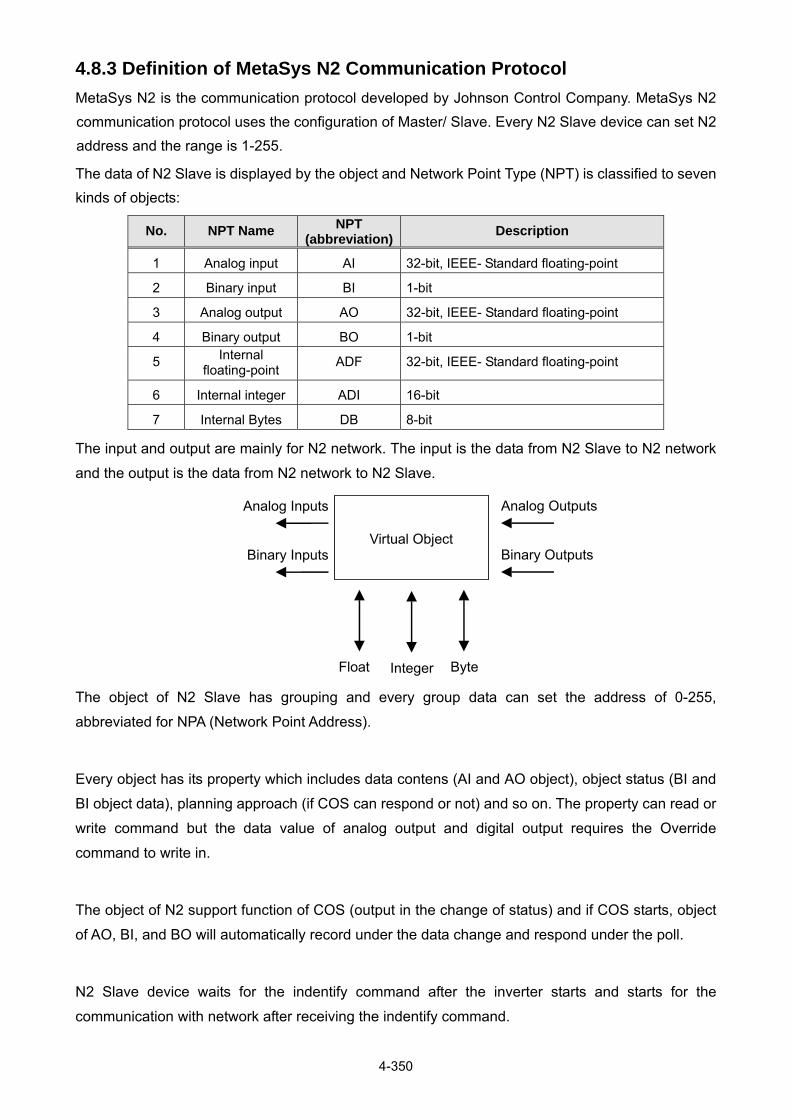
4-350
4.8.3 Definition of MetaSys N2 Communication Protocol
MetaSys N2 is the communication protocol developed by Johnson Control Company. MetaSys N2
communication protocol uses the configuration of Master/ Slave. Every N2 Slave device can set N2
address and the range is 1-255.
The data of N2 Slave is displayed by the object and Network Point Type (NPT) is classified to seven
kinds of objects:
No. NPT Name NPT (abbreviation)
Description
1 Analog input AI 32-bit, IEEE- Standard floating-point
2 Binary input BI 1-bit
3 Analog output AO 32-bit, IEEE- Standard floating-point
4 Binary output BO 1-bit
5 Internal floating-point
ADF 32-bit, IEEE- Standard floating-point
6 Internal integer ADI 16-bit
7 Internal Bytes DB 8-bit
The input and output are mainly for N2 network. The input is the data from N2 Slave to N2 network
and the output is the data from N2 network to N2 Slave.
Virtual Object
Analog Outputs
Binary Outputs
Analog Inputs
Binary Inputs
ByteFloat Integer The object of N2 Slave has grouping and every group data can set the address of 0-255,
abbreviated for NPA (Network Point Address).
Every object has its property which includes data contens (AI and AO object), object status (BI and
BI object data), planning approach (if COS can respond or not) and so on. The property can read or
write command but the data value of analog output and digital output requires the Override
command to write in.
The object of N2 support function of COS (output in the change of status) and if COS starts, object
of AO, BI, and BO will automatically record under the data change and respond under the poll.
N2 Slave device waits for the indentify command after the inverter starts and starts for the
communication with network after receiving the indentify command.

4-351
4.8.4. MetaSys N2 Communication Protocol in F510 Model
F510 models support four NPT, AI, AO, BI and BO but DO NOT support the following functions:
Do not support only for the property or field that JCI used.
Do not support functions of Analog Alarm and Analog Warning in AI. The related fields can
read or write but do not have corresponding action.
Do not support functions of OverRide in AI and BI. The inverter does not have error message
for giving the OverRide command in AI and BI but do not have corresponding action.
Support functions of OverRide in AO and BO but values of AO and BO do not restore to defult
value when removing OverRide function.
The followings are the supporting properties list in AI, AO, BI and BO for F510 models:
(1) AI Property List
No. Data Type Description Notes
1 Byte Object Configuration READ/ WRITE
2 Byte Object Status Only READ
3 Float Analog Input Value Only READ
(2) BI Property List
No. Data Type Description Notes
1 Byte Object Configuration READ/ WRITE
2 Byte Object Status Only READ
(3) AO Property List
No. Data Type Description Notes
1 Byte Object Configuration READ/ WRITE
2 Byte Object Status Only READ
3 Float Current Value READ/ OverRide
(4) BO Property List
No. Data Type Description Notes
1 Byte Object Configuration READ/ WRITE
2 Byte Object Status READ/ OverRide
3 Integer Minimum On-time READ/ WRITE
4 Integer Minimum On-time READ/ WRITE
5 Integer Maximum Cycles/Hour READ/ WRITE

4-352
The followings are parameters F510 models can read and write via MetaSys communication.
Analog input property list (READ)
No. Object Name F510 Parameters Unit Classification Range
AI1 Motor R-RPM 02-03 Motor Rated
Rotation Speed No Units R 0 ~ 60000
AI2 Motor R-Volt 02-04 Motor Rated
Voltage Volt R 0~240.0/0~480.0
AI3 Motor R-HP 02-05 Motor Rated Power horsepower R 0~600.00
AI4 Motor R-Hz 02-06 Motor Rated
Frequency HZ R 0.00 ~ 599.00
AI5 Comm Station 09-00 INV Communication
Station Address No Units R 1 - 254
AI6 CommSel 09-01 Communication
Mode Selection No Units R 0 ~ 3
AI7 BaudRate 09-02 Baud Rate Setting No Units R 0 ~ 5
AI8 CarrierFreq 11-01 Carrier Frequency KiloHertz R 0 ~ 16
AI9 Freq cmd 12-16 Frequency
Command HZ R 0.00 ~ 599.00
AI10 Frequency 12-17 Output Frequency HZ R 0.00 ~ 599.00
AI11 Current 12-18 Output Current Amps R 0.0~6553.5
AI12 Control Mode 12-24 Control Mode No Units R 0 ~ 5
AI13 TM2 AIN 12-25 AI1 Input Volt R 0 ~ 100.0
AI14 TM2 AIN2 12-26 AI2 Input Volt R 0 ~ 100.0
AI15 Error code 12-45 Recent Fault
Message No Units R 0 ~ 45
Analog output property list (READ/ Write)
No. Object Name F510 Parameters Unit Classification Range
AO1 Set frequency Register 2502H HZ R/W 0.00 ~ 599.00
AO2 AO1 Register 2505H Volt/
Amps R 0.00 ~ 100.00
AO3 AO2 Register 2506H Volt/
Amps R 0 .00 ~ 100.00
AO4 RunSource 00-02 Main Run Command
Source Selection No Units R/W 0 ~ 4
AO5 FrequenceComm
00-05 Main Frequency
Command Source
Selection
No Units R/W 0 ~ 6
AO6 FreqUpperLim 00-12 Upper Limit
Frequency HZ R/W 0 – 109
AO7 FreqLowerLim 00-13 Lower Limit
Frequency HZ R/W 0 - 109
AO8 Acc Time1 00-14 Acceleration Time 1 seconds R/W 0 ~ 6000.0
AO9 Dec Time1 00-15 Deceleration Time 1 seconds R/W 0 ~ 6000.0
AO10 Motor R-Amp 02-01 Motor Rated Current Amps R/W 1 ~ 999.9
AO11 FreqCommand1 05-01 Frequency Setting of
Speed-Stage 0 HZ R/W 0.00 ~ 599.00
AO12 FreqCommand2 06-01 Frequency Setting of
Speed-Stage 1 HZ R/W 0.00 ~ 599.00
AO13 FreqCommand3 06-02 Frequency Setting of
Speed-Stage 2 HZ R/W 0.00 ~ 599.00

4-353
No. Object Name F510 Parameters Unit Classification Range
AO14 FreqCommand4 06-03 Frequency Setting of
Speed-Stage 3 HZ R/W 0.00 ~ 599.00
AO15 FreqCommand5 06-04 Frequency Setting of
Speed-Stage 4 HZ R/W 0.00 ~ 599.00
AO16 FreqCommand6 06-05 Frequency Setting of
Speed-Stage 5 HZ R/W 0.00 ~ 599.00
AO17 FreqCommand7 06-06 Frequency Setting of
Speed-Stage 6 HZ R/W 0.00 ~ 599.00
AO18 FreqCommand8 06-07 Frequency Setting of
Speed-Stage 7 HZ R/W 0.00 ~ 599.00
AO19 FreqCommand9 06-08 Frequency Setting of
Speed-Stage 8 HZ R/W 0.00 ~ 599.00
AO20 FreqCommand1006-09 Frequency Setting of
Speed-Stage 9 HZ R/W 0.00 ~ 599.00
AO21 FreqCommand1106-10 Frequency Setting of
Speed-Stage 10 HZ R/W 0.00 ~ 599.00
AO22 FreqCommand1206-11 Frequency Setting of
Speed-Stage 11 HZ R/W 0.00 ~ 599.00
AO23 FreqCommand1306-12 Frequency Setting of
Speed-Stage 12 HZ R/W 0.00 ~ 599.00
AO24 FreqCommand1406-13 Frequency Setting of
Speed-Stage 13 HZ R/W 0.00 ~ 599.00
AO25 FreqCommand1506-14 Frequency Setting of
Speed-Stage 14 HZ R/W 0.00 ~ 599.00
AO26 FreqCommand1606-15 Frequency Setting of
Speed-Stage 15 HZ R/W 0.00 ~ 599.00
AO27 PwrL Sel
07-00 Momentary Power
Loss/Fault Restart
Selection
No Units R 0 ~ 1
AO28 RestartDelay 07-01 Fault Auto-Restart
Time seconds R 0 ~ 7200
AO29 RestartSel
07-02 Number of Fault
Auto-Restart
Attempts
No Units R 0 ~ 10
AO30 StoppingSel 07-09 Stop Mode Selection No Units R/W 0 - 1
AO31 PID – P Gain 10-05 Proportional Gain (P) No Units R/W 0 ~ 10.00
AO32 PID – I Time 10-06 Integral Time (I) No Units R/W 0 ~ 100.00
AO33 PID – D Time 10-07 Differential Time (D) No Units R/W 0 – 10.00
AO34 ReverseOper 11-00 Direction Lock
Selection No Units R/W 0 ~ 2

4-354
Binary input property list (READ)
No. Object Name No Action /
Action Classification Range
BI1 Run/ Stop Stop/ Run R 0 - 1
BI2 Direction Forward/
Reverse R 0 - 1
BI3 Status OK/ Fault R 0 - 1
BI4 Abnormal Off/ On R 0 - 1
BI5 DI_1 Status Off/ On R 0 - 1
BI6 DI_2 Status Off/ On R 0 - 1
BI7 DI_3 Status Off/ On R 0 - 1
BI8 DI_4 Status Off/ On R 0 - 1
BI9 DI_5 Status Off/ On R 0 - 1
BI10 DI_6 Status Off/ On R 0 - 1
Binary output property list (READ/ WRITE)
No. Object Name No Action /
Action Classification Range
BO1 Run/ Stop Stop/ Run R/W 0 - 1
BO2 Forward/
Reverse
Forward/
Reverse R/W 0 - 1
BO3 RY1 Status Off/ On R 0 - 1
BO4 RY2 Status Off/ On R 0 - 1
BO5 RY3 Status Off/ On R 0 - 1
MetaSys N2 Error Code List
Error Code Cause
00 Without receving Identify command at
power up
01 Receive the non-support command
02 Check Code occurs error
03 Receive the data of more than 256 bits
05 Incorrect command length
10 Data is out of the range
11 Save the undefined fields or the fields that
JCI dedicated
12 The parameter position is only for read
command.

5-1
Chapter 5 Check Motor Rotation and Direction
This test is to be performed solely from the inverter keypad. Apply power to the inverter after all the electrical connections have been made and protective covers have been re-attached.
Important: Motor rotation and direction only applies to standard AC motors with a base frequency of
60Hz. For 50Hz or other frequency AC motors please set the max frequency and base frequency in group
01 accordingly before running the motors.
LED Keypad Display At this point, DO NOT RUN THE MOTOR, the LED keypad should display as shown below in Fig. 5.1 and all
LEDs are flashing. Next press the RUN key, all LEDs light on. See Fig 5.2. The motor should now be operating at
low speed running in forward (clockwise) direction. The value shown in the screen will change from 000.00Hz to
005.00Hz. Next press STOP key to stop the motor.
Fig 5.1: LED Keypad (Stopped) Fig 5.2: LED Keypad (Running)

5-2
LCD Keypad Display
At this point, DO NOT RUN THE MOTOR, the LCD keypad should display as shown below in Fig. 5.3 and the
speed reference 12-16=005.00Hz should be blinking at the parameter code “12-16”. Next press the RUN key, see
Fig 5.4. The motor should now be operating at low speed running in forward (clockwise) direction. The parameter
code 12-17 shown at the bottom left corner of the screen will change from 12-17=000.00Hz to 12-17=005.00Hz.
Next press STOP key to stop the motor.
Fref Ref12-16=005.00Hz
Monitor
12-17=000.00Hz12-18=0000.0A
Fref Ref12-16=005.00Hz
Monitor
12-17=005.00Hz12-18=0001.2A
Fig 5.3: Keypad (Stopped) Fig 5.4: Keypad (Running)
Notes: - If the motor rotation is incorrect, power down the inverter.
- After the power has been turned OFF, wait at least ten minutes until the charge indicator
extinguishes completely before touching any wiring, circuit boards or components.
- Using Safety precaution, and referring to section 3.8 exchange any two of the three output
leads to the motor (U/T1, V/T2 and W/T3). After the wiring change, repeat this step and
recheck motor direction.

6-1
Chapter 6 Speed Reference Command Configuration The inverter offers users several choices to set the speed reference source. The most commonly used methods are described in the next sections. Frequency reference command is selected with parameter 00-05. 00-05: Main Frequency Command (Frequency Source) This function sets the frequency command source. Setting Range: 0 to 5 To set parameter 00-05: - After power-up press the DSP/FUN key - Select 00 Basic Fun - Press READ/ ENTER key - Select parameter -05 with the UP/DOWN and keys and press the READ/ ENTER key. In the parameter list move cursor to 00-05 with the UP/DOWN keys and press READ/ ENTER key to select.
00-05 Main Frequency Command Source Selection
Range
0: Keypad
1: External Terminal (Analog AI1)
2: Terminal Command UP / DOWN 3: Communication control (RS-485)
4: Reserved
5: Reserved
6: RTC
7: AI2 Auxiliary Frequency
6.1 Reference from Keypad
Speed reference from the keypad is the default setting. Press the READ/ ENTER key first and use the </RESET, and keys to change the speed reference.

6-2
6.2 Reference from External Analog Signal (0-10V / 4-20mA)
Analog Reference: 0 – 10 V (Setting 00-05 = 1)
(S+) (S-) S1 S3 S5 24V +10V MT GND GND AI1 AI2
E 24VG S2 S4 S6 F1 F2 PO PI AO1 AO2 E
Connect shield to control ground terminal
0 – 10 V+-
Analog Input AI1
Common/0V, GND
Control Terminals / User Terminals
Analog Reference: Potentiometer / Speed Pot (Setting 00-05 = 1)
(S+) (S-) S1 S3 S5 24V +10V MT GND GND AI1 AI2
E 24VG S2 S4 S6 F1 F2 PO PI AO1 AO2 E
Control Terminals / User Terminals
Connect shield to control ground terminal
Potentiometer1 ~ 5K Ohm
Common/0V, GND
Analog Input AI1

6-3
Analog Reference: 4 – 20mA (Setting 00-05 = 7)
(S+) (S-) S1 S3 S5 24V +10V MT GND GND AI1 AI2
S6E 24VG S2 S4 S5 F1 F2 PO PI AO1 AO2 E
Connect shield to control ground terminal
4 – 20mA+-
Analog Input AI2
Common, GND
Control Terminals / User Terminals
SW2
I V
Set switch SW2 to ‘I’(Factory Default)

6-4
6.3 Reference from Serial Communication RS485 (00-05=3)
RS485 PLC / Computer Connection-
+
S-S+
Cable Shield
RS485 Port
8 7 6 5 4 3 2 1
CN6
Control board
To set the speed reference for the inverter via serial communication parameter 00-05 has be set to “3” for frequency command via serial communication. Default Communication Setting is: Address “1”, 9600 Bits/sec, 1 Start Bit, 1 Stop Bit, and No Parity The serial communication link function uses RS485 Modbus RTU protocol and allows for: 1) Monitoring (data monitoring, function data check). 2) Frequency setting. 3) Operation command (FWD, REV, and other commands for digital input). 4) Write function data. Frequency Reference Command Register Inverter Frequency Reference Register: 2502 (Hexadecimal) - Bit 0 – Bit 15: 0.00 ~ 599.00 Hz
6-5
Examples: Frequency Reference Command: 10.00 Hz (Inverter Node Address: 01) Command String (hexadecimal): 01 06 25 02 03 E8 23 B8 To set the frequency reference to 10.00, a value of ‘1000’ (03E8h) has to be send to the inverter. Frequency Reference Command: 30.00 Hz (Inverter Node Address: 01) Command String (hexadecimal): 01 06 25 02 0B B8 24 44 To set the frequency reference to 30.00, a value of ‘3000’ (0BB8h) has to be send to the inverter. Frequency Reference Command: 60.00 Hz (Inverter Node Address: 01) Command String (hexadecimal): 01 06 25 02 17 70 2D 12 To set the frequency reference to 60.00, a value of ‘6000’ (1770h) has to be send to the inverter Note: The last 2 bytes of the command strings consist of a CRC16 checksum, please refer to section
4.5 of the instruction manual for additional information.
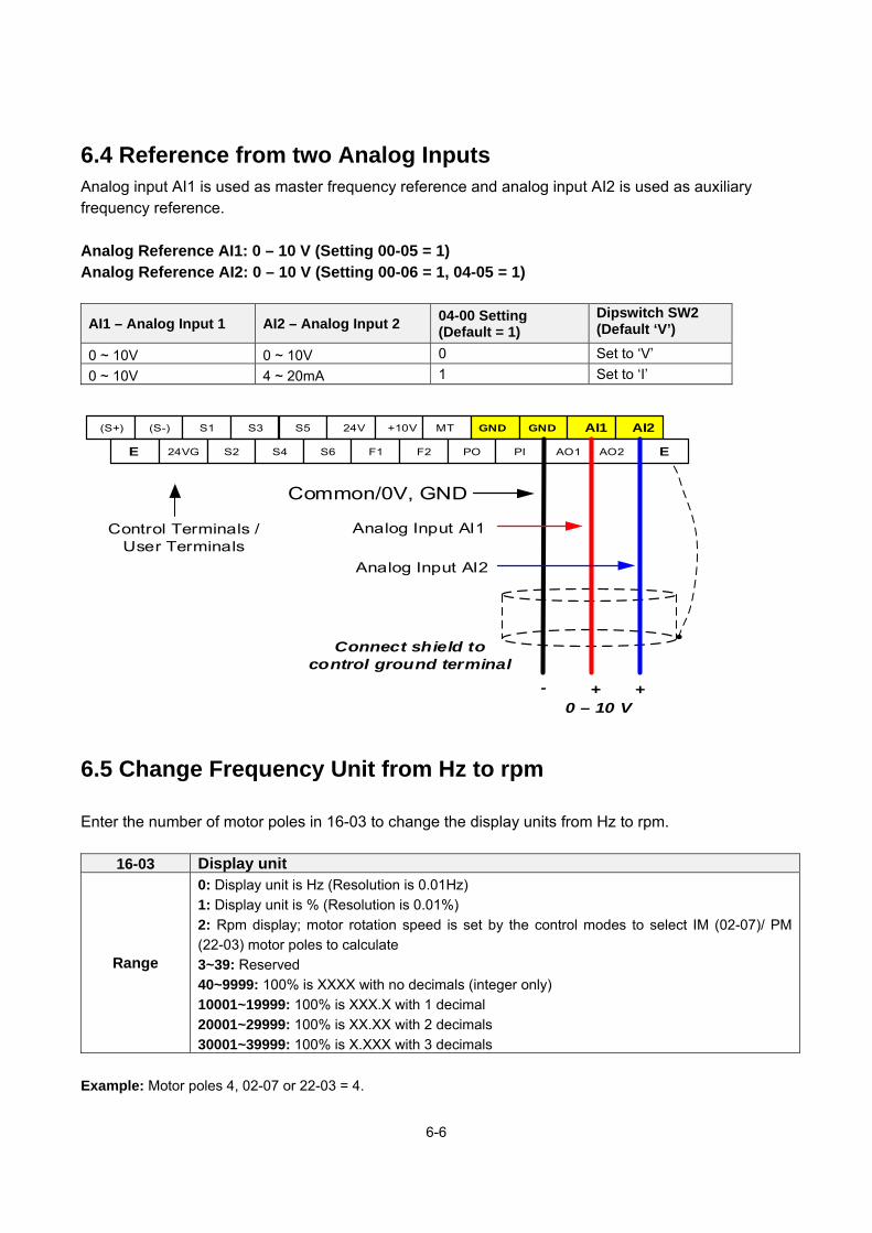
6-6
6.4 Reference from two Analog Inputs Analog input AI1 is used as master frequency reference and analog input AI2 is used as auxiliary frequency reference.
Analog Reference AI1: 0 – 10 V (Setting 00-05 = 1) Analog Reference AI2: 0 – 10 V (Setting 00-06 = 1, 04-05 = 1)
AI1 – Analog Input 1 AI2 – Analog Input 2 04-00 Setting (Default = 1)
Dipswitch SW2 (Default ‘V’)
0 ~ 10V 0 ~ 10V 0 Set to ‘V’
0 ~ 10V 4 ~ 20mA 1 Set to ‘I’
(S+) (S-) S1 S3 S5 24V +10V MT GND GND AI1 AI2
E 24VG S2 S4 S6 F1 F2 PO PI AO1 AO2 E
Connect shield to control ground terminal
0 – 10 V+-
Analog Input AI1
Common/0V, GND
Control Terminals / User Terminals
Analog Input AI2
+
6.5 Change Frequency Unit from Hz to rpm
Enter the number of motor poles in 16-03 to change the display units from Hz to rpm.
16-03 Display unit
Range
0: Display unit is Hz (Resolution is 0.01Hz)
1: Display unit is % (Resolution is 0.01%)
2: Rpm display; motor rotation speed is set by the control modes to select IM (02-07)/ PM
(22-03) motor poles to calculate
3~39: Reserved
40~9999: 100% is XXXX with no decimals (integer only)
10001~19999: 100% is XXX.X with 1 decimal
20001~29999: 100% is XX.XX with 2 decimals
30001~39999: 100% is X.XXX with 3 decimals
Example: Motor poles 4, 02-07 or 22-03 = 4.
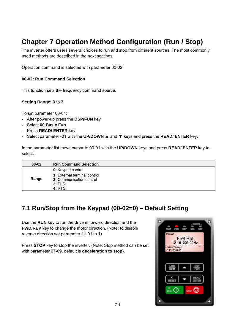
7-1
Chapter 7 Operation Method Configuration (Run / Stop) The inverter offers users several choices to run and stop from different sources. The most commonly used methods are described in the next sections. Operation command is selected with parameter 00-02. 00-02: Run Command Selection This function sets the frequency command source. Setting Range: 0 to 3 To set parameter 00-01: - After power-up press the DSP/FUN key - Select 00 Basic Fun - Press READ/ ENTER key - Select parameter -01 with the UP/DOWN and keys and press the READ/ ENTER key. In the parameter list move cursor to 00-01 with the UP/DOWN keys and press READ/ ENTER key to select.
00-02 Run Command Selection
Range
0: Keypad control
1: External terminal control 2: Communication control 3: PLC 4: RTC
7.1 Run/Stop from the Keypad (00-02=0) – Default Setting
Use the RUN key to run the drive in forward direction and the FWD/REV key to change the motor direction. (Note: to disable reverse direction set parameter 11-01 to 1) Press STOP key to stop the inverter. (Note: Stop method can be set with parameter 07-09, default is deceleration to stop).
Fref Ref12-16=005.00Hz
Monitor
12-17=000.00Hz12-18=0000.0A

7-2
7.2 Run/Stop from External Switch / Contact or Pushbutton
(00-02=1) Use an external contact or switch to Run and Stop the inverter. Permanent Switch / Contact
(S+) (S-) S1 S3 S5 24V +10V MT GND GND AI1 AI2
E 24VG S2 S4 S6 F1 F2 PO PI AO1 AO2 E
Start / Stop Switch(Maintained)
Connect shield to control ground terminal
Forward Command/FWD
Common/24VG
Control Terminals / User Terminals

7-3
7.3 Run/Stop from Serial Communication RS485 (00-02=3)
RS485 PLC / Computer Connection-
+
S-S+
Cable Shield
RS485 Port
8 7 6 5 4 3 2 1
CN6
Control board
To control (Run/Stop) the inverter via serial communication parameter 00-02 has be set to either a “3” for communication control. Default Communication Setting is: Address “1”, 9600 Bits/sec, 1 Start Bit, 1 Stop Bit, and No Parity The serial communication link function uses RS485 Modbus RTU protocol and allows for: 1) Monitoring (data monitoring, function data check). 2) Frequency setting. 3) Operation command (FWD, REV, and other commands for digital input). 4) Write function data. Command Register Inverter Command Register: 2501 (Hexadecimal) Bit 0: Run Forward Bit 1: Run Reverse Bit 2 ~ Bit 15: Refer to the chapter XX of this manual

7-4
Examples: Run Forward Command (Inverter Node Address: 01) Command String (hexadecimal): 01 06 25 01 00 01 12 C6 Run Reverse Command (Inverter Node Address: 01) Command String (hexadecimal): 01 06 25 01 00 03 93 07 Stop Command (Inverter Node Address: 01) Command String (hexadecimal): 01 06 25 01 00 00 D3 06 Note: The last 2 bytes of the command strings consist of a CRC16 checksum, please refer to section 4.5 of the instruction manual for additional information.

8-1
Chapter 8 Motor and Application Specific Settings It is essential that before running the motor, the motor nameplate data matches the motor data in the inverter.
8.1 Set Motor Nameplate Data (02-01, 02-05)
02-05 Rated power of motor 1 The nominal motor rated capacity is set at the factory. Please verify that the motor name plate data matches the motor rated capacity shown in parameter 02-05. The setting should only be changed when driving a motor with a different capacity. Range: 0.00 to 600.00 kW (1HP = 0.746 kW) To set parameter 02-05: - After power-up press the DSP/FUN key - Select 02 Motor Parameter - Press READ/ ENTER key - Select parameter -01 with the UP/DOWN and keys and press the READ/ ENTER key. Default values vary based on the inverter model.
02-01 Rated current of motor The motor rated current is set at the factory based on the inverter model. Enter the motor rated current from the motor nameplate if it does not match the value shown in parameter 02-01. Setting range: 0.01 to 600.00A To set parameter 02-01: - After power-up press the DSP/FUN key - Select 02 Motor Parameter - Press READ/ ENTER key - Select parameter -01 with the UP/DOWN and keys and press the READ/ ENTER key.

8-2
8.2 Acceleration and Deceleration Time (00-14, 00-15)
Acceleration and Deceleration times directly control the system dynamic response. In general, the longer the acceleration and deceleration time, the slower the system response, and the shorter time, the faster the response. An excessive amount of time can result in sluggish system performance while too short of a time may result in system instability. The default values suggested normally result in good system performance for the majority of general purpose applications. If the values need to be adjusted, caution should be exercised, and the changes should be in small increments to avoid system instability. 00-14 Acceleration time 1 00-15 Deceleration time 1 These parameters set the acceleration and deceleration times of the output frequency from 0 to maximum frequency and from maximum frequency to 0. To set parameter 00-14 or 00-15: - After power-up press the DSP/FUN key - Select 00 Basic Fun - Press READ/ ENTER key - Select parameter -14 or -15 with the UP/DOWN and keys and press the READ/ ENTER key. Acceleration and deceleration times are represented by the three most significant (high order) digits. Set acceleration and deceleration times with respect to maximum frequency. The relationship between the set frequency value and acceleration/deceleration times is as follows:
Set Frequency = Maximum Frequency Set Frequency < Maximum Frequency
Note: If the set acceleration and deceleration times are set too low, the torque limiting function or stall prevention
function can become activated if the load torque and or inertia are relatively high. This will prolong the
acceleration and or deceleration times and not allow the set times to be followed. In this case the acceleration and
or the deceleration times should be adjusted.

8-3
8.3 Torque Compensation Gain (01-10)
This parameter sets the relationship between output frequency and output voltage. Constant torque applications have the same torque requirements at low speed as well as at high speed. Initial Setup For Variable Torque / Normal Duty applications set parameter 01-10 to an initial value of 0.5. For Constant Torque / Heavy Duty applications set parameter 01-10 to an initial value of 1.0. 01-10 Torque compensation gain This parameter sets the torque boost for motor. Setting range: 0.0 to 2.0 To set parameter 01-10: - After power-up press the DSP/FUN key - Select 01 V/F Pattern - Press READ/ ENTER key - Select parameter -10 with the UP/DOWN and keys and press the READ/ ENTER key. Increase value when:
The wiring between the inverter and the motor very too long The motor size is smaller than the inverter size
Note: Gradually increase the torque compensation value and make sure the output current does not exceed inverter rated current.
Reduce value when:
Experiencing motor vibration
Over Current Fault
Overload Fault
Important: Confirm that the output current at low speed does not exceed the rated output current of the inverter.
Warning: A larger than required torque compensation gain value creates over-excitation at low
speeds, continued operation may cause the motor to overheat. Check the characteristics of the
motor for additional information.

8-4
8.4 Automatic Energy Savings Function (11-19)
In the V/F control mode the automatic energy saving (AES) function automatically adjusts the output voltage and reduces the output current of the inverter to optimize energy savings based on the load. The output power changes proportional to the motor load. Energy savings is minimal when the load exceeds 70% of the output power and savings become greater when the load decreases. The parameter of automatic energy saving function has been set at the factory before shipment. In general, it is no need to adjust. If the motor characteristic has significant difference from TECO standard, please refer to the following commands for adjusting parameters: Enable Automatic Energy Savings Function To set parameters 11-19 to 11-24: - After power-up press the DSP/FUN key - Select 11 Auxiliary Function Group - Press READ/ ENTER key - Select parameter -19 to -24 with the UP/DOWN and keys and press the READ/ ENTER key. (1) To enable automatic energy saving function set 11-19 to 1. (2) Filter time of automatic energy saving (11-20) (3) Commissioning parameter of energy saving (11-21 to 11-22)
In AES mode, the optimum voltage value is calculated based on the load power requirement but is also affected by motor temperature and motor characteristic. In certain applications the optimum AES voltage needs to be adjusted in order to achieve optimum energy savings. Use the following AES parameters for manual adjustment: 11-21: Voltage limit value of AES commissioning operation Sets the voltage upper limit during automatic energy saving. 100% corresponds to 230V or 460V depending on the inverter class used.
Voltage limit value of commissioning operation

8-5
11-22: Adjustment time of automatic energy saving Sets sample time constant for measuring output power. Reduce the value of 11-22 to increase response when the load changes. Note: If the value of 11-22 is too low and the load is reduced the motor may become unstable. 11-23: Detection level of automatic energy saving Sets the automatic energy saving output power detection level. 11-24: Coefficient of automatic energy saving The coefficient is used to tune the automatic energy saving. Adjust the coefficient while running the inverter on light load while monitoring the output power. A lower setting means lower output voltage.
Notes:
- If the coefficient is set to low the motor may stall.
- Coefficient default value is based on the inverter rating. Set parameter 13-00. If the motor power does not
match the inverter rating.

8-6
8.5 Emergency Stop The emergency stop time is used in combination with multi-function digital input function #14 (Emergency stop). When emergency stop input is activated the inverter will decelerate to a stop using the Emergency stop time (00-26) and display the [EM STOP] condition on the keypad.
Note: To cancel the emergency stop condition the run command has to be removed and emergency stop input
deactivated.
Example: Emergency Stop Switch set for input terminal S5 (03-04 = 14).
(S+) (S-) S1 S3 S5 24V +10V MT GND GND AI1 AI2
E 24VG S2 S4 S6 F1 F2 PO PI AO1 AO2 E
Emergency Stop SwitchConnect shield
to control ground terminal
Emergency StopCommon/24VG
Control Terminals / User Terminals
00-26 Emergency stop time
Range 0.1~6000.0 Sec

8-7
8.6 Direct / Unattended Startup The unattended startup function prevents the inverter from starting automatically when a run command is present at time of power-up. To use USP command set one of the multi-function digital input functions to #50 (USP Startup).
Unattended Startup Protection

8-8
8.7 Analog Output Setup Signal: Use parameter 04-11 to select the analog output signal for AO1 and parameter 04-16 to select the analog output signal for AO2. Gain: Use parameter 04-12 to adjust the gain for AO1 and parameter 04-17 to adjust the gain for AO2. Adjust the gain so that the analog output (10V/20mA) matches 100% of the selected analog output signal (04-11 for AO1 and 04-16 for AO2). Bias: Use parameter 04-13 to adjust the bias for AO1 and parameter 04-18 to adjust the bias for AO2. Adjust the bias so that the analog output (0V/4mA) matches 0% of the selected analog output signal (04-11 for AO1 and 04-16 for AO2). Example: Analog Output 1 Wiring
(S+) (S-) S1 S3 S5 24V +10V MT GND GND AI1 AI2
24VG S2 S4 F1 F2 PO PI AO1 AO2 E
Connect shield to control
ground terminal
Common/GND
Control Terminals / User Terminals
S6
AnalogOutput 1
+-
E
04-11 AO1 function Setting
Range
0: Output frequency
1: Frequency command
2: Output voltage
3: DC voltage
4: Output current
5: Output power 6: Motor speed
7: Output power factor 8: AI1 input
9: AI2 input
10: Torque command 11: q -axis current
12: d-axis current
13: Speed deviation
14: Reserved
15: ASR output
16: Reserved
17: q-axis voltage
18: d-axis voltage
19~20: Reserved 21: PID input
22: PID output 23: PID target value
24: PID feedback value
25: Output frequency of the soft starter 26~27: Reserved
28: Communication control

8-9
04-12 AO1 gain value Range 0.0~1000.0%
04-13 AO1 bias-voltage value Range -100.0~100.0%
04-16 AO2 function Setting Range See parameter 04-11
04-17 AO2 gain value
Range 0.0~1000.0%
04-18 AO2 bias-voltage value
Range -100.0~100.0%
04-19 AO2 Output Signal Type
Range
0: AO1:0~10V AO2:0~10V
1: AO1:0~10V AO2:4~20mA 2: AO1:4~20mA AO2:0~10V
3: AO1:4~20mA AO2: 4~20mA
04-20 Filter Time of AO Signal Scan
Range 0.00~0.50s
Analog output level adjustment

9-1
Chapter 9 Using PID Control for Constant Flow / Pressure
Applications
9.1 What is PID Control?
The PID function in the inverter can be used to maintain a constant process variable such as pressure,
flow, temperature by regulating the output frequency (motor speed). A feedback device (transducer)
signal is used to compare the actual process variable to a specified setpoint. The difference between
the set-point and feedback signal is called the error signal.
The PID control tries to minimize this error to maintain a constant process variable by regulating the
output frequency (motor speed).
The amplitude of the error can be adjusted with the Proportional Gain parameter 10-05 and is directly
related to the output of the PID controller, so the larger gain the larger the output correction.

9-2
Example 1: Example 2:
Gain = 1.0 Gain = 2.0
Set-Point = 80% Set-Point = 80%
Feedback = 78% Feedback = 78%
Error = Set-point - Feedback = 2% Error = Set-point - Feedback = 2%
Control Error = Gain x Error = 2% Control Error = Gain x Error = 4%
Please note that an excessive gain can make the system unstable and oscillation may occur.
The response time of the system can be adjusted with the Integral Gain set by parameter 10-06.
Increasing the Integral Time will make the system less responsive and decreasing the Integral Gain
Time will increase response but may result in instability of the total system.
Slowing the system down too much may be unsatisfactory for the process. The end result is that these
two parameters in conjunction with the acceleration (00-14) and deceleration (00-15) times are
adjusted to achieve optimum performance for a particular application.
For typical fan and pump applications a Proportional Gain (10-05) of 2.0 and an Integral Time (10-06) of 5.0 sec is recommended. 10-03 PID control mode
PID control can be enabled by setting parameter 10-03 to ‘xxx1b’
10-03 PID control mode
Range
xxx0b: PID disable xxx1b: PID enable
xx0xb: PID positive characteristic
xx1xb: PID negative characteristic
x0xxb: PID error value of D control x1xxb: PID feedback value of D control
0xxxb: PID output
1xxxb: PID output +target value

9-3
Commonly used PID control modes 0001b: Forward operation: PID operation enabled, motor speeds increases when feedback signal is smaller than set-point (most fan and pump applications) 0011b: Reverse operation: PID operation enabled, motor slows down when feedback signal is smaller than set-point (e.g. level control applications) To set parameter 10-03: - After power-up press the DSP/FUN key - Select 10 PID Control - Press READ/ ENTER key - Select parameter -03 with the UP/DOWN and keys and press the READ/ ENTER key.
Important: To use the PID function parameter 00-05 (Main Frequency Command Source Selection) has to be set to 5 for PID reference.
9.2 Connect Transducer Feedback Signal (10-01)
The PID function in the inverter
Depending on the type of feedback transducer used, the inverter can be setup for either 0-10V or a 4-20mA feedback transducer.
Feedback Signal 4 – 20mA (10-01 = 2) – SW2 = I
(S+) (S-) S1 S3 S5 24V +10V MT GND GND AI1 AI2
E 24VG S2 S4 S6 F1 F2 PO PI AO1 AO2 E
Connect shield to control ground
terminal
4 – 20mA+-
Analog Input AI2
Common, GND
Control Terminals / User Terminals
SW2
I V
Set switch SW2 to ‘I’

9-4
Feedback Signal 0 – 10V (10-01 = 1) – SW2 = V
(S+) (S+) S1 S3 S5 24V +10V MT GND GND AI1 AI2
E 24VG S2 S4 S6 F1 F2 PO PI AO1 AO2 E
Connect shield to control ground terminal
0 – 10Vdc+-
Analog Input AI2
Common, GND
Control Terminals / User Terminals
SW2
I V
Set switch SW2 to ‘V’
9.3 Engineering Units (only for LCD)
The PID setpoint scaling can be selected with parameter 16-03 and 16-04. Example: 0 – 200.0 PSI Setpoint, set 16-03 to 12000 (1 decimal, range 0 – 200) and 16-04 to 2 (PSI).

9-5
9.4 Sleep / Wakeup Function
The PID Sleep function can be used to prevent a system from running at low speeds and is frequently used in pumping application. The PID Sleep function is turned on by parameter 10-29 set to 1. The inverter output turns off when the PID output falls below the PID sleep level (10-17) for the time specified in the PID sleep delay time parameter (10-18). The inverter wakes up from a sleep condition when the PID output (Reference frequency) rises above the PID wake-up frequency (10-19) for the time specified in the PID wake-up delay time (10-20). 10-29 =0: PID Sleep function is disabled. 10-29 =1: PID sleep operation is based on parameters of 10-17 and 10-18. 10-29 =2: PID sleep mode is enabled by multi-function digital input
Refer to figure 4.4.74 (a) and (b) for PID sleep / wakeup operation.
PID Sleep Function

10-1
Chapter 10 Troubleshooting and Fault Diagnostics
10.1 General Inverter fault detection and early warning / self-diagnosis function. When the inverter detects a fault, a fault message is displayed on the keypad. The fault contact output energizes and the motor will coast to stop (The stop method can be selected for specific faults). When the inverter detects a warning / self-diagnostics error, the digital operator will display a warning or self-diagnostic code, the fault output does not energize in this case. Once the warning is removed, the system will automatically return to its original state.
10.2 Fault Detection Function When a fault occurs, please refer to Table 10.2.1 for possible causes and take appropriate measures. Use one of the following methods to restart: 1. Set one of multi-function digital input terminals (03-00, 03-05) to 17 (Fault reset); activate input 2. Press the reset button on the keypad and clear fault message. 3. Power down inverter wait until keypad goes blank and power-up the inverter again. When a fault occurs, the fault message is stored in the fault history (see group 12 parameters).
Table 10.2.1 Fault information and possible solutions
LED display Description Cause Possible solutions
OC over current The inverter output current
exceeds the overcurrent level (around 200% of the inverter rated current).
Acceleration time is too short. Contactor at the inverter output side. A special motor or applicable
capacity is greater than the inverter rated value.
Short circuit or ground fault.
Extend acceleration time. Check the motor wiring. Disconnect motor and try
running inverter.
OCA over current
The inverter output current exceeds the overcurrent level in acceleration time
Acceleration time is too short
Capacity of motor is bigger than
inverter
Short circuit between winding and
shell of motor
Short circuit between wire and
ground of motor
IGBT broken module
Set the longer acceleration
time
Change to bigger capacity of
inverter
Examine motor
Check the wire
Replace IGBT module
OCC over current The inverter output current
exceeds the overcurrent level in constant speed
Instantaneous change of load
Instantaneous change of current
Change to bigger capacity of
inverter
Add reactor to power source
OCD over current The inverter output current
exceeds the overcurrent level in deceleration time
Deceleration time is too short Set the longer acceleration
time
GF
Ground fault The current to ground exceeds 50% of the inverter rated output current (08-23 = 1, GF function is enabled).
Motor damaged (insulation).
Wire damage or deterioration.
Inverter DCCT sensors defect.
Replace motor.
Check the motor wiring.
Disconnect motor and try
running inverter.
Check resistance between
cables and ground.
Reduce carrier frequency.

10-2
LED display Description Cause Possible solutions
OV Over voltage
DC bus voltage exceeds the OV detection level: 410Vdc: 200V class 820Vdc: 400V class (For 400V class, if input voltage 01-14 is set lower than 400V, the OV detection value will is decreased to 730Vdc).
Deceleration time set too short,
resulting in regenerative energy
flowing back from motor to the
inverter.
The inverter input voltage is too high.
Use of power factor correction
capacitors.
Excessive braking load.
Braking transistor or resistor
defective.
Speed search parameters set
incorrectly.
Increase deceleration time
Reduce input voltage to
comply with the input voltage
requirements or install an AC
line reactor to lower the input
voltage.
Remove the power factor
correction capacitor.
Use dynamic braking unit.
Replace braking transistor or
resistor.
Adjust speed search
parameters.
UV Under voltage
DC bus voltage is lower than the UV detection level or the pre-charge contactor is not active while the inverter is running. 190Vdc: 200V class; 380Vdc: 400V class
(The detection value can be adjusted by 07-13).
The input voltage is too low.
Input phase loss.
Input voltage fluctuation.
Pre-charge contactor damaged.
DC bus voltage feedback signal
value not incorrect.
Check the input voltage.
Check input wiring.
Check power source
Replace pre-charge contactor
Replace control board or
complete inverter.
IPL input phase
loss
Phase loss at the input side of the inverter or input voltage imbalance, active when 08-09 = 1 (enabled).
IPL occurs.
Terminal screws of R/L1, S/L2 or
T/L3 are loose or lost.
Input voltage fluctuation is too big.
Input Voltage is imbalance per phase
Aging of the capacity on main circuit
inside inverter
Check if the main wiring
connection is correct.
Check if the terminal screw
gets loose.
Make sure having stable input
voltage or turn off IPL
detection function.
Replace the circuit board or
inverter
OPL output phase
loss Phase loss at the output side of the inverter, active when 08-10 = 1 (enabled).
Wiring loose in inverter output
terminal.
Motor rated current is less than 10%
of the inverter rated current.
Check output wiring / faster
screws.
Check motor & inverter rating.
OH1 Heatsink
overheat
The temperature of the heat sink is too high. Note: when OH1 fault occurs three times within five minutes, it is required to wait 10 minutes before resetting the fault.
Ambient temperature too high. cooling fan failed Carrier frequency set too high. Load too heavy.
Install fan or AC to cool
surroundings.
Replace cooling fan.
Reduce carrier frequency.
Reduce load / Measure
output current
OH4 Motor
overheating Motor overheating : The input of PTC (Positive Temperature Coefficient ) exceeds the overheat protection level
The surrounding temperature of
motor is too high.
The input of PTC ( Positive
Temperature Coefficient ) exceeds
the overheat protection level.
Check the surrounding temperature of motor.
Check MT and GND terminal wiring be correct.
OL1 Motor
overload Internal motor overload protection tripped, active when protection curve 08-05 = xxx1.
Voltage setting V/F mode too high, resulting in over-excitation of the motor.
Motor rated current (02-01) set incorrectly.
Load too heavy.
Check V/f curve.
Check motor rated current
Check and reduce motor
load, check and operation
duty cycle.
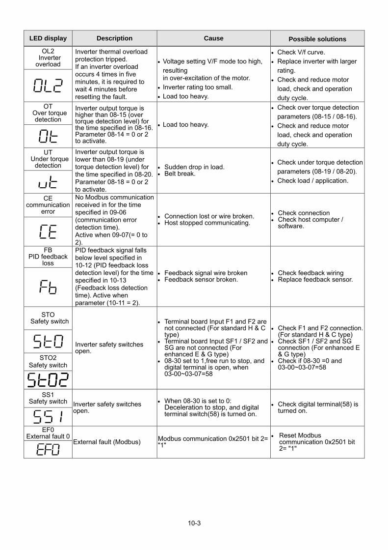
10-3
LED display Description Cause Possible solutions
OL2 Inverter overload
Inverter thermal overload protection tripped. If an inverter overload occurs 4 times in five minutes, it is required to wait 4 minutes before resetting the fault.
Voltage setting V/F mode too high,
resulting in over-excitation of the motor.
Inverter rating too small.
Load too heavy.
Check V/f curve.
Replace inverter with larger
rating.
Check and reduce motor
load, check and operation
duty cycle.
OT Over torque
detection
Inverter output torque is higher than 08-15 (over torque detection level) for the time specified in 08-16. Parameter 08-14 = 0 or 2 to activate.
Load too heavy.
Check over torque detection
parameters (08-15 / 08-16).
Check and reduce motor
load, check and operation
duty cycle.
UT Under torque
detection
Inverter output torque is lower than 08-19 (under torque detection level) for the time specified in 08-20. Parameter 08-18 = 0 or 2 to activate.
Sudden drop in load. Belt break.
Check under torque detection
parameters (08-19 / 08-20).
Check load / application.
CE communication
error
No Modbus communication received in for the time specified in 09-06 (communication error detection time). Active when 09-07(= 0 to 2).
Connection lost or wire broken. Host stopped communicating.
Check connection Check host computer /
software.
FB PID feedback
loss
PID feedback signal falls below level specified in 10-12 (PID feedback loss detection level) for the time specified in 10-13 (Feedback loss detection time). Active when parameter (10-11 = 2).
Feedback signal wire broken Feedback sensor broken.
Check feedback wiring Replace feedback sensor.
STO Safety switch
Inverter safety switches open.
Terminal board Input F1 and F2 are not connected (For standard H & C type)
Terminal board Input SF1 / SF2 and SG are not connected (For enhanced E & G type)
08-30 set to 1,free run to stop, and digital terminal is open, when 03-00~03-07=58
Check F1 and F2 connection. (For standard H & C type)
Check SF1 / SF2 and SG connection (For enhanced E & G type)
Check if 08-30 =0 and 03-00~03-07=58
STO2 Safety switch
SS1 Safety switch Inverter safety switches
open.
When 08-30 is set to 0: Deceleration to stop, and digital terminal switch(58) is turned on.
Check digital terminal(58) is turned on.
EF0
External fault 0 External fault (Modbus) Modbus communication 0x2501 bit 2=
"1"
Reset Modbus communication 0x2501 bit 2= "1"
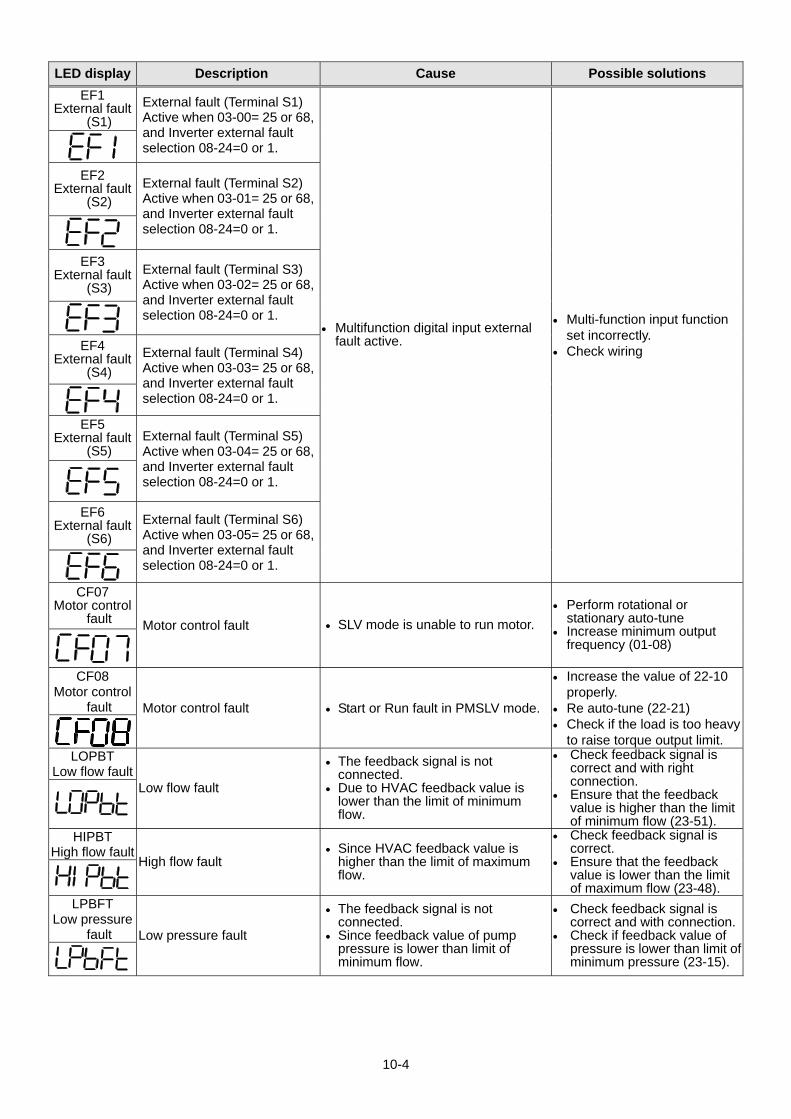
10-4
LED display Description Cause Possible solutions
EF1 External fault
(S1)
External fault (Terminal S1) Active when 03-00= 25 or 68, and Inverter external fault selection 08-24=0 or 1.
Multifunction digital input external fault active.
Multi-function input function set incorrectly.
Check wiring
EF2
External fault (S2)
External fault (Terminal S2) Active when 03-01= 25 or 68, and Inverter external fault selection 08-24=0 or 1.
EF3
External fault (S3)
External fault (Terminal S3) Active when 03-02= 25 or 68, and Inverter external fault selection 08-24=0 or 1.
EF4
External fault (S4)
External fault (Terminal S4) Active when 03-03= 25 or 68, and Inverter external fault selection 08-24=0 or 1.
EF5
External fault (S5)
External fault (Terminal S5) Active when 03-04= 25 or 68, and Inverter external fault selection 08-24=0 or 1.
EF6 External fault
(S6)
External fault (Terminal S6) Active when 03-05= 25 or 68, and Inverter external fault selection 08-24=0 or 1.
CF07
Motor control fault Motor control fault SLV mode is unable to run motor.
Perform rotational or stationary auto-tune
Increase minimum output frequency (01-08)
CF08
Motor control fault Motor control fault Start or Run fault in PMSLV mode.
Increase the value of 22-10 properly.
Re auto-tune (22-21) Check if the load is too heavy
to raise torque output limit. LOPBT
Low flow fault Low flow fault
The feedback signal is not connected.
Due to HVAC feedback value is lower than the limit of minimum flow.
Check feedback signal is correct and with right connection.
Ensure that the feedback value is higher than the limit of minimum flow (23-51).
HIPBT High flow fault
High flow fault Since HVAC feedback value is
higher than the limit of maximum flow.
Check feedback signal is correct.
Ensure that the feedback value is lower than the limit of maximum flow (23-48).
LPBFT Low pressure
fault Low pressure fault
The feedback signal is not connected.
Since feedback value of pump pressure is lower than limit of minimum flow.
Check feedback signal is correct and with connection.
Check if feedback value of pressure is lower than limit of minimum pressure (23-15).

10-5
LED display Description Cause Possible solutions
OPBFT High pressure
fault High pressure fault Since feedback value of pump
pressure is lower than limit of maximum flow.
Check feedback signal is correct.
Check if feedback value of pressure is lower than limit of maximum pressure (23-12).
LSCFT
Low suction fault
Low suction fault
Insufficient water supply of effluent channel leads to insufficient suction
PID difference is higher than its level or current is lower than output current level
Check if water of effluent channel is enough, and water supply is regular.
Check PID difference is higher than its level or current is lower than output current level
CF00 Operator
Communication Error
Errors of data transmission occur in keypad
Keypad and inverter cannot transmit data after power on 5 seconds
Disconnect the operator and then reconnect.
Replace the control board
CF01 Operator
Communication Error 2
Errors of data transmission occur in keypad
Keypad and inverter can transmit data but transmission error occurs for more than 2 seconds
Disconnect the operator and then reconnect.
Replace the control board
CT Fault
Fault occurs in voltage level of three-phase input
Abnormal input voltage, too much noise or malfunctioning control board
Check input voltage signal and the voltage on the control board.
Double Communication
Error Redundant Profibus and Modbus protocol
User may use two communication mechanisms simultaneously
Check only one communication mechanism is used.
PTC Signal
Loss PTC Signal Loss detecting triggers error message
PTC connection trips and has lasted for more than 10 seconds
Check if MT terminal and GND terminal are connected.
OPR
Disconnection Run command is set to keypad mode (00-02=0). But when the inverter runs, the operator is disconnected. Selection of operator removed (16-09) determines if the inverter stops or displays fault signal.
The inverter runs at keypad mode (00-02=0), but warning of operator being disconnected/ removed occurs.
Check if the operator is disconnected or removed.
FBLSS PID Feedback
Signal Loss
When 23-19 > 0, the inverter will display fault signal on the basis of the value of feedback pressure < operation pressure setting (23-02) x detection proportion of loss pressure (23-19) and detection time of loss pressure (23-18) passed, and 23-78=2 in the meanwhile.
Since proportion of loss pressure (23-19) is enabled and over high, the inverter trips to fault. Thus, feedback sensor cannot operate properly or is not installed correctly.
Check if the proportion of loss pressure (23-19) is set correctly.
Make sure the feedback sensor is installed correctly and PID feedback signal operates normally.
SC Short Circuit The inverter output or load
is at short circuit.
Short circuit or grounding fault (08-23=1) occurs from the damage to motor, insulation deterioration or cable breakage.
Check if the load is at correct wiring.

10-6
LED display Description Cause Possible solutions
PF Protection Fault
OH1 error occurs for 3 times in 5 minutes when run command in multi-function digital input terminals is not removed.
Run command in multi-function digital input terminals is not removed.
Remove run command in multi-function digital input terminals.
TOL
External Overload
External overload (enabled only when firemode activated
External overload in multi-function digital input terminals. (Ex. Fan overheat)
Check external overload. Reset external overload of
digital input.

10-7
10.3 Warning / Self-diagnosis Detection Function When the inverter detects a warning, the keypad displays a warning code (flash). Note: The fault contact output does not energize on a warning and the inverter continues operation.
When the warning is no longer active the keypad will return to its original state. When the inverter detected a programming error (for example two parameters contradict each other of are set to an invalid setting), the keypad displays a self-diagnostics code. Note: The fault contact output does not energize on a self-diagnostics error. While a self-diagnostics
code is active the inverter does not accept a run command until the programming error is corrected.
Note: When a warning or self- diagnostic error is active the warning or error code will flash on the
keypad. Refer to Table 10.3.1 for and overview, cause and corrective action for inverter warnings and self-diagnostic errors.
Table 10.3.1 Warning / self-diagnosis and corrective actions
LED display Description Cause Possible solutions
OV (flash)
Over voltage
DC bus voltage exceeds the OV detection level: 410Vdc: 200V class 820Vdc: 400V class (for 440V class, if input voltage 01-14 is set lower than 400V, the OV detection value will is decreased to 700Vdc)
Deceleration time set too
short, resulting in
regenerative energy flowing
back from motor to the
inverter.
The inverter input voltage is
too high.
Use of power factor
correction capacitors.
Excessive braking load.
Braking transistor or resistor
defective.
Speed search parameters
set incorrectly.
Increase deceleration time
Reduce input voltage to
comply with the input
voltage requirements or
install an AC line reactor to
lower the input voltage.
Remove the power factor
correction capacitor.
Use dynamic braking unit.
Replace braking transistor
or resistor.
Adjust speed search
parameters.
UV (flash)
under voltage
DC bus voltage is lower than the UV detection level or the pre-charge contactor is not active while the inverter is running. 190Vdc: 200V class; 380Vdc: 400V class (the detection value can be adjusted by 07-13)
The input voltage is too low. Input phase loss. Input voltage fluctuation. Magnetic contactor
damaged. DC bus voltage feedback
signal value not incorrect.
Check the input voltage. Check input wiring. Check power source Replace magnetic
contactor Replace control board or
complete inverter.
OH1 Heat sink overheating
Heat sink is overheating : The temperature of the heat sink is too high. If heat sink overheating fault has occurred with three timesin five minutes, it is required to wait for 10 minutes before resetting the fault.
Ambient temperature is too high.
The cooling fan has stopped.
Carrier frequency setting is too high.
Check the ambient temperature of the inverter.
Check the fan or dust and dirt in the heat sink.
Check the carrier frequency setting.

10-8
LED display Description Cause Possible solutions
OH2 (flash)
Inverter over heating warning
Inverter overheat warning: Multi-function digital input set to 32. (Terminal S1 ~ S6) Active when 03-00 ~ 03-05 =31).
Multifunction digital input overheat warning active.
Multi-function input function set incorrectly.
Check wiring
OT
(flash) over torque
detection
Inverter output torque is higher than 08-15 (over torque detection level) for the time specified in 08-16. Parameter 08-14 = 0 to activate.
Load too heavy.
Check over torque
detection parameters
(08-15 / 08-16).
Check and reduce motor
load, check and operation
duty cycle. UT
(flash) under torque
detection
Inverter output torque is lower than 08-19 (under torque detection level) for the time specified in 08-20. Parameter 08-18 = 0 to activate.
Sudden drop in load. Belt break.
Check under torque detection parameters (08-19 / 08-20).
Check load / application.
bb1
(flash) External
baseblock External base block (Terminal S1)
Multifunction digital input external baseblock active.
Multi-function input function set incorrectly.
Check wiring
bb2
(flash) External
baseblock External base block (Terminal S2)
bb3
(flash) External
baseblock External base block (Terminal S3)
bb4
(flash) External
baseblock External base block (Terminal S4)
bb5
(flash) External
baseblock External base block (Terminal S5)

10-9
LED display Description Cause Possible solutions
bb6 (flash)
External baseblock External base block
(Terminal S6) Multifunction digital input
external baseblock active.
Multi-function input function set incorrectly.
Check wiring
OL1
Motor overload Internal motor overload protection tripped, active when protection curve 08-05 = xxx1.
Voltage setting V/F mode
too high, resulting in over-excitation of the motor.
Motor rated current (02-01) set incorrectly.
Load too heavy. Voltage setting V/F mode
too high, resulting in over-excitation of the motor.
Inverter rating too small. Load too heavy.
Check V/f curve.
Check motor rated current
Check and reduce motor
load, check and operation
duty cycle.
Check V/f curve.
Replace inverter with
larger rating.
Check and reduce motor
load, check and operation
duty cycle
OL2
Inverter overload Inverter thermal overload protection tripped. If an inverter overload occurs 4 times in five minutes, it is required to wait 4 minutes before resetting the fault
CE (flash)
communication error
No Modbus communication received for 2 sec. Active when 09-07=3.
Connection lost or wire broken.
Host stopped communicating.
Check connection Check host computer /
software.
CLB
over current protection
level B Inverter current reaches the current protection level B.
Inverter current too high. Load too heavy.
Check load and duty cycle
operation.
Retry (flash) retry
Automatic reset has activated, and it displays before the period of 07-01 automatic reset terminates.
The period of 07-01 automatic reset≠0.
The times of 07-02 automatic reset≠0.
It will disappear after the
period of automatic reset.
EF1
( flash ) External fault
(S1)
External fault (Terminal S1) Active when 03-00= 25 or 68, and Inverter external fault selection 08-24=2.
Multifunction digital input external fault active and parameter 08-24 = 2 for operation to continue.
Multi-function input function set incorrectly.
Check wiring Multi-function input
function set incorrectly. Check wiring
EF2
(flash) External fault
(S2)
External fault (Terminal S2) Active when 03-01= 25 or 68, and Inverter external fault selection 08-24=2.
EF3
(flash) External fault
(S3)
External fault (Terminal S3) Active when 03-02= 25 or 68, and Inverter external fault selection 08-24=2.

10-10
LED display Description Cause Possible solutions
EF4 (flash)
External fault (S4)
External fault (Terminal S4) Active when 03-03= 25 or 68, and Inverter external fault selection 08-24=2.
Multifunction digital input external fault active and parameter 08-24 = 2 for operation to continue.
Multi-function input function set incorrectly.
Check wiring Multi-function input
function set incorrectly. Check wiring
EF5
(flash) External fault
(S5)
External fault (Terminal S5) Active when 03-04= 25 or 68, and Inverter external fault selection 08-24=2.
EF6
(flash) External fault
(S6)
External fault (Terminal S6) Active when 03-05= 25 or 68, and Inverter external fault selection 08-24=2.
EF9
(flash) error of
forward/reversal rotation
Forward run and reverse run are active within 0.5 sec of each other. Stop method set by parameter 07-09.
Forward run and reverse run active (see 2-wire control).
Check run command wiring
SE01
Rang setting error
Parameter setting falls outside the allowed range.
Some parameter ranges are
determined by other inverter
parameters which could
cause an out of range
warning when the
dependency parameter is
adjusted. For example:
02-00>02-01, 00-12<00-13
or when 00-07 = 1, 00-05 is
the same with 00-06 or
20-16 <= 20-15.
Check parameter setting.
SE02 Digital input
terminal error
Multi-function input setting error.
Multi-function digital input terminals (03-00 to 03-07) are set to the same function (not including ext. fault and not used.) or UP/DOWN commands are not set at the same time( they must be used together).
UP/DOWN commands (08 and 09) and ACC/DEC commands (11) are set at the same time.
Speed search 1(19,maximum frequency) and Speed search 2 (34,from the set frequency)are set at the same time.
2-wire sequence and 3-wire sequence set at the same time in 03-00~03-07
Check multi-function input setting.

10-11
LED display Description Cause Possible solutions
SE03 V/f curve error
V/f curve setting error.
V/F curve setting error. 01-02 > 01-12 > 01-06 (Fmax) (Fbase) (Fmid1) >01-08;
(Fmin)
Check V/F parameters
SE05 PID selection
error PID selection error.
10-00 and 10-01are set to 1
(AI1) or 2 (AI2)
simultaneously.
When 23-05=0 and 10-33>=
1000 or 10-34≠1.
Check the setting value of parameters 10-00 and 10-01.
Check the setting value of 10-33, 10-34 and 23-05.
HPErr
Model selection error
Inverter capacity setting error: Inverter capacity setting 13-00 does not match the rated voltage.
Inverter capacity setting does not match voltage class (13-00).
Check inverter capacity setting 13-00.
SE09 PI setting error
Inverter PI setting error
Inverter pulse input
selection (03-30) selection
conflicts with PID source
(10-00 and 10-01).
Check pulse input selection (03-30) and PID source (10-00 and 10-01).
FB
(flash) PID feedback
breaking
PID feedback signal falls below level specified in 10-12 (PID feedback loss detection level) for the time specified in 10-13 (Feedback loss detection time). Active when parameter (10-11 = 1).
Feedback signal wire broken
Feedback sensor broken.
Check feedback wiring Replace feedback sensor.
USP
(flash) Unattended
Start Protection Unattended Start Protection (USP) is enabled (enabled at power-up.)
USP at power-up (activated
by multi-function digital
input) is enabled. The
inverter will not accept a
run command.
While the warning is active
the inverter does not
accept a run command.
(See parameter 03-00 -
03-05 = 50).
Remove run command or reset inverter via multi-function digital input (03-00 to 03-07 = 17) or use the RESET key on the keypad to reset inverter.
Activate USP input and re-apply the power.
LFPB Low flow error
Low flow error
The feedback signal is not
connected.
Due to HVAC feedback
value is lower than limit of
minimum flow.
Check feedback signal is
correct and with right
connection.
Check if feedback value is
lower than limit of
minimum flow.
HFPB High flow error
High flow error Due to HVAC feedback
value is lower than limit of
maximum flow.
Check feedback signal is
correct.
Check if feedback value is
lower than limit of
maximum flow.

10-12
LED display Description Cause Possible solutions
L0PB Low pressure
error
Low pressure error
The feedback signal is not
connected.
Due to feedback value of
pump pressure is lower
than limit of minimum flow.
Check feedback signal is
correct and with
connection.
Check if feedback value
of pressure is lower than
limit of minimum
pressure.
HIPB High pressure
error High pressure error
Due to feedback value of
pump pressure is lower
than limit of maximum flow.
Check feedback signal is
correct.
Check if feedback value
of pressure is lower than
limit of maximum
pressure.
LSCFT Low suction
error
Inadequate suction error
Insufficient water of supply
tank leads to insufficient
suction.
PID difference is higher
than its level or current is
lower than output current
level.
Check if water of supply
tank is enough, and water
supply is regular.
Check PID difference is
higher than its level or
current is lower than
output current level
FIRE Fire override
mode Fire override mode
Fire override mode is
active
None
(Fire override mode is not
a kind of warning).
SE10 PUMP/HVAC Setting error
PUMP/HVAC settings of inverter error
PUMP selection of inverter
(23-02)> (23-03).
HVAC selection of inverter
(23-46)< (23-47).
Check pump selection of
inverter (23-02) and
(23-03) settings.
Check HVAC selection of
inverter (23-46) and
(23-47) settings.
COPUP PUMP
communication breaking error
Breaking error of multiple pumps communication
Communication breaking
or disconnection of pump
cascade control.
Check if it has setting
issue or is not properly
connected.
Parameter
Setting Error
Parameter setting error Error of Parameter setting
occurs.
Refer to the instruction
manual or this parameter
is selected to be disabled.
Warning of Direct Start When 07-04 is set to 1, the
inverter can not start directly but displays the warning signal.
Set the digital input
terminal (S1~S6) to run
and simultaneously set
07-04=1.
Check the digital input
terminal and disconnect
it. Then reconnect the DI
terminal after the setting
delay time (07-05) ends.

10-13
LED display Description Cause Possible solutions
External Terminal Stop
Error
External Terminal is main run command source selection (00-02=1) and run command executes but executes stop command from keypad.
Run command executes from external terminal but executes stop command from keypad.
Remove the run command from external terminal
ADC Voltage
Error Abnormal voltage level on the control board
Abnormal input voltage, too
much noise or
malfunctioning control
board.
Check the input voltage
signal and the voltage on
the control board.
EEPROM Archiving Error
EEPROM Poor archiving
EEPROM poor peripheral
circuit
It occurs in parameters
check at inverter boot.
Reconnect and if the
warning signal appears
again, replace the circuit
board.
Contact TECO for more
information.
Control Board Error The control board is not
correspondent with the program.
The control board is not
correspondent with the
program.
Replace the control
board.
Wrong running direction Error Only for run in one direction,
another direction command is not allowed.
Run command for another
direction on the terminal of
control board is active.
Cancel the run command
for another direction on
the terminal of control
board.
PTC Signal Loss PTC Signal Loss detecting
triggers error message
PTC connection trips and
has lasted for more than
10 seconds.
Check if MT terminal and
GND terminal are
connected. Parameters
Locked Parameter password have been locked
Parameter password
function (13-07) starts.
Correct password input at
parameter 13-07
Password
Setting Error Password input at the second time is different from that at the first time when the password lock function enables.
Password input at the
second time is different
from that at the first time
when the password lock
function enables.
Password input at the
second time is the same
as that at the first time
when the password lock
function enables.
Operator Reading Error
Operator cannot read the inverter’s information.
Since signals from the
inverter’s control board are
transmitted error, the
inverter cannot normally
transmit the data to
operator.
Check if the inverter is
normally connected to the
operator. RDE*

10-14
LED display Description Cause Possible solutions
Operator Writing Error
Operator cannot write the information into the inverter.
Data control mode in
operator is not consistent
with that in the inverter.
Data models in operator
are not consistent with that
in the inverter.
Data firmware version in
operator is not consistent
with that in the inverter.
Check the inverter’s
firmware version/ control
mode/ models WRE*
Operator Verifying Error
After operator reads or writes data in the inverter, user can verify it. If the data are not consistent, the inverter displays the signal of verifying error.
The data in the operator
and the inverter is not
consistent.
Check if the inverter is
normally connected to
the operator. VRYE*
Repeat Run Command The inverter is only allowed
unidirectional operation and cannot operate in reverse direction simultaneously.
Check if the external
terminal is given a run
command in reverse
direction.
Cancel the run command
in reverse direction from
the external terminal.
Operator Read Prohibit
Selection of allowing reading (16-08) is set to 0 (Do not allow to read inverter parameters and save it to the operator).
Set parameter 16-08 to 0.
Set parameter 16-08 to 1
(Allow to read inverter
parameters and save it to
the operator). RDP*
External Emergency
Stop Function of external emergency stop starts.
Parameter 03-00~03-08 is
set to 14 (Function of
emergency stop is
enabled.)
Remove & shutdown the
run command of external
emergency stop and
reset it to multi-function
digital input.
Zero Speed Stop Warning
The operation signal is enabled but frequency command is lower than the minimum output frequency (01-08) and DC brake is disabled.
The frequency command
is not set up.
Set up the frequency
command.
Overload of Air Compressor
If the inverter’s output current reaches OL4 current level (23-69), OL4 Delay Time (23-70) passed. When the count is reached, the inverter will automatically decelerate to stop and displays a warning signal.
Since the current level (23-
69) is set to be over low,
the inverter’s output
current is higher than the
standard one or
compressor’s current is
used to be over high.
Check if the compressor
load used is higher than
the standard one.
PID feedback signal loss
When 23-19 > 0, the inverter will according to feedback pressure is less than (pressure transmitter maximum pressure (23-03) x proportion of loss pressure detection (23-19)) value, if the pressure loss detection time (23-18) passed and 23-78 = 1 (loss of pressure detection function) will jump warning signal
23-19 proportion of loss pressure detection is too big
Feedback sensor install failure or not work normal.。
Check 23-19 setting.
Make sure correct
installation and PID
feedback signal.
* RDE、WRE、VRYE、RDP warning signals are only displayed in LCD keypad.

10-15
10.4 Auto-tuning Error When a fault occurs during auto-tuning of a standard AC motor, the display will show the “AtErr” fault and the motor stops. The fault information is displayed in parameter 17-11. Note: The fault contact output does not energize with an auto-tuning fault. Refer to Table 10.4.1, for fault
information during tuning, cause and corrective action.
Table 10.4.1 Auto-tuning fault and corrective actions Error Description Cause Corrective action
01 Motor data input error.
Motor Input data error
during auto-tuning.
Inverter output current
does not match motor
rated current.
Check the motor tuning
data (17-00 to 17-09).
Check inverter capacity
02 Motor lead to lead resistance R1 tuning error. Auto-tuning is not
completed within the
specified time
Auto-tuning results fall
outside parameter setting
range.
Motor rated current
exceeded.
Motor was disconnected.
Check the motor tuning
data (17-00 to 17-09).
Check motor connection.
Disconnect motor load. ‧ Check inverter current
detection circuit and DCCTs.
‧ Check motor installation.
03 Motor leakage inductance tuning error.
04 Motor rotor resistance R2 tuning error.
05 Motor mutual inductance Lm tuning error.
07 Deadtime compensation detection error
08 Motor acceleration error (Rotational type auto-tuning only).
Motor fails to accelerate in
the specified time (00-14=
20sec).
Increase acceleration
time (00-14).
Disconnect motor load.
09 Other auto-tuning errors
No load current is higher
than 70% of the motor
rated current.
Torque reference exceeds
100%.
Errors other than
ATE01~ATE08.
Check the motor tuning
data (17-00 to 17-09). ‧ Check motor connection.

10-16
10.5 PM Motor Auto-tuning Error When a fault occurs during auto-tuning of a PM motor, the display will show the “IPErr” fault and the motor stops. The fault information is displayed in parameter 22-22. Note: The fault contact output does not energize with an auto-tuning fault. Refer to Table 10.5.1, for fault
information during tuning, cause and corrective action.
Table 10.5.1 Auto-tuning fault and corrective actions for PM motor Error Description Cause Corrective action
01 Magnetic pole alignment tuning failure (static).
Inverter output current
does not match motor
current.
Check the motor tuning
data (22-02).
Check inverter capacity
02~04 Reserved
05 Circuit tuning time out. System abnormality during
circuit tuning.
Check for active protection functions preventing auto-tuning.
06 Reserved
07 Other motor tuning errors. Other tuning errors. Check the motor tuning
data (22-02). Check motor connection.
08 Reserved
09 Current out of range during circuit tuning.
Inverter output current
does not match motor
current.
Check the motor tuning
data (22-02).
Check inverter capacity 10 Reserved
11 Parameter tuning and detecting time out.
Error relationship between
voltage and current.
Check if the setting value
of parameter 22-11 is too
low, but its value cannot
exceed 100% of the
inverter.
Check motor connection.

10-17
10.6 General troubleshooting Status Checking point Remedy
Motor runs in wrong direction
Is the wiring for the output terminals correct?
Wiring must match U, V, and W terminals of the motor.
Is the wiring for forward and reverse signals correct?
Check for correct wiring.
The motor speed can not be regulated.
Is the wiring for the analog frequency inputs correct?
Check for correct wiring.
Is the setting of operation mode correct?
Check the Frequency Source set in parameters 00-05/00-06.
Is the load too excessive? Reduce the load.
Motor running speed too high or too low
Check the motor specifications (poles, voltage…) correct?
Confirm the motor specifications.
Is the gear ratio correct? Confirm the gear ratio. Is the setting of the highest output frequency correct?
Confirm the highest output frequency
Motor speed varies unusually
Is the load too excessive? Reduce the load.
Does the load vary excessively? 1.Minimize the variation of the load. 2.Consider increasing the capacities of the inverter
and the motor.
Is the input power unstable or is there a phase loss ?
1.Consider adding an AC reactor at the power input side if using single-phase power.
2.Check wiring if using three-phase power
Motor can not run
Is the power connected to the correct L1, L2, and L3 terminals? is the charging indicator lit ?
1.Is the power applied? 2.Turn the power OFF and then ON again. 3.Make sure the power voltage is correct. 4.Make sure screws are secured firmly.
Is there voltage across the output terminals T1, T2, and T3?
Turn the power OFF and then ON again.
Is overload causing the motor to stall?
Reduce the load so the motor will run.
Are there any abnormalities in the inverter? See error descriptions to check wiring and correct if
necessary. Is there a forward or reverse run command ?
Has the analog frequency signal been input?
1.Is analog frequency input signal wiring correct? 2.Is voltage of frequency input correct?
Is the operation mode setting correct?
Operate through the digital keypad

10-18
10.7 Troubleshooting of the Inverter 10.7.1 Quick troubleshooting of the Inverter
INV Fault
Visually check controller and Drive boards
*to next page
Check burnt and damaged parts
Consult with the supplier
Replace fuse
Consult with the supplier
Consult with the supplier
Check according to displayed fault messages
Replace the pre-charge resistor
Check terminals and wiring
Consult with the supplier
Perform detailed check and consult with the supplier
Is fault known?
Symptoms other than burn out, damage, or fuse
meltdown in the inverter?
Any Symptoms of burn out and damage?
Is the main circuit DM intact?
Fault signal?
Is the fuse intact?
Is the main circuit I.G.B.T intact?
Any visual abnormalities?
Are displays and indicators of the
operating unit working normally?
Is +5V control voltage correct?
Is the DC input voltage controlling the power
correctAny fault display?
What the message ?
Is LED lit?
Replace control board and digital operating unit
Is the error eliminated after replacing control
board?
YES
NO
NO YES
NO
NO
NO
YES
YES
YES
YES
NO
NO
NO
YES
YES
YES
YES
NO NO
YES
NO
YES
NO
YES
NO
YES
NO
Apply the power

10-19
Check Inverter parameters
Replace the control board
Perform parameter initializations
Specify operation control mode
Does the FWD or REV LED light flash?
Is the frequency value displayed on the display?
Are there voltage outputs at terminals U, V and W
Is there any fault display?
Are output currents of each
phase even?
The inverter is OKPerform detailed check and consult with the supplier.
Replace the control board
Replace the control board
Does the control Board function after replacement
YES
YES
YES
NO
NO
YES
NO
NO
NO
YES
YES
NO
NO
From previous page
Set up frequency command
Connect the motor to run
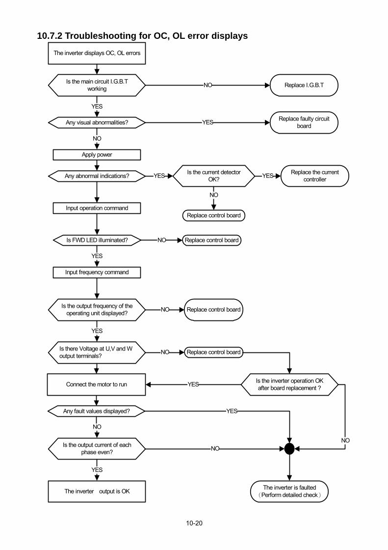
10-20
10.7.2 Troubleshooting for OC, OL error displays
The inverter displays OC, OL errors
The inverter output is OK
Is the output current of each phase even?
Any fault values displayed?
Is there Voltage at U,V and W output terminals?
Is the output frequency of the operating unit displayed?
Is FWD LED illuminated?
Is the main circuit I.G.B.T working
Any visual abnormalities?
Is the current detector OK?
Any abnormal indications?
Is the inverter operation OK after board replacement ?
Replace the current controller
Replace control board
Replace control board
Replace faulty circuit board
Replace I.G.B.T
Replace control board
Replace control board
The inverter is faulted(Perform detailed check)
YES
NO
YES
YES
NO
YES
NO
YES
YES
NO
YES
NO
NO
NO
YES
YES
NONO
Apply power
Input operation command
Input frequency command
Connect the motor to run

10-21
10.7.3 Troubleshooting for OV, LV error
The inverter displays OV, LV
The inverter’s output is OK
Is the current on all phases even?
Any abnormal value?
Is there Voltage at T1,T2,T3 output terminals?
Is the output frequency of the operating unit displayed?
Is FWD LED still illuminated after flash
Is the main circuit fuse intact?
Any visual abnormalities?
Any abnormal indications?
Is the inverter operation OK after board replacement?
Replace the control board
Perform detailed check and consult with the supplier
YES
NO
YES
YES
YES
NO
NO
YES
NO
YES
YES
NO
NO
NO
YES
YES
NO
NO
Connect the motor to run
Input frequency commands
Input operation command
Apply power
Consult with the supplier
Consult with the supplier
Consult with the supplier
Consult with the supplier
Replace the control board

10-22
10.7.4 The motor can not run
The motor can not run
Is MCCB On?
Can MCCB be turned On?
Are voltages between power terminals correct?
Is LED lit?
Is the operation switch in UN? ?
Are there outputs between the U,V, and W terminals of the motor?
Are outputs between U,V,W the same?
1. Motor2. Motor faults3. Incorrect wiring
INVfault
INVfault
The operation switch is set to “RUN” position
INVfault
1.The power is abnormal2.Incorrect wiring
Short circuited wiring
NO
YES
YES
YES
YES
YES
YES
YES
NO
NO
NO
NO
NO
NO

10-23
10.7.5 Motor Overheating
Y E S
Y E S
N O
Y E S
Y E S
N O
N O
Y E S
N O
Is load o r curren t exceed ing the specified va lue ?
C onsider reduc ing the load and increasing the capacities o f the inverte r and m otor
M otor O verheating
Is m otor runn ing a t low speed fo r a long tim e ?
Is m otor vo ltage be tw een U -V ,V -W ,W -U correct?
Is there any de terrence preventing coo ling o f the m otor
B ad connection be tw een d rive and the m otor
S e lect the m otor aga in
IN V fau lts
C lear the de te rrence
C orrect the bad connection

10-24
10.7.6 Motor runs unbalanced
NO
YES
NO
NO
YES
NO
YES
YES
NO
Does it happen during eceleration?
Motor runs unevenly
Is the acceleration time correct?
Are the output voltages between U-V,V-W,W-U balanced?
Is the load fluctuating?
Any mechanical vibration or gear backlash
Increase the Acc/ Dec time
Reduce the load.Increase capacities of INV and the motor.
INV faults
Reduce the load fluctuation or add a flywheel.
Inspect the mechanical system
INV faults
YES

10-25
10.8 Routine and periodic inspection To ensure stable and safe operations, check and maintain the inverter at regular intervals. Use the checklist below to carry out inspection. Disconnect power after approximately 5 minutes to make sure no voltage is present on the output terminals before any inspection or maintenance.
Items Details Checking
period Methods Criteria RemediesDaily 1Year
Environment & Ground connection
Ambient conditions at the installation
Confirm the temperature and humidity at the machine
Measure with thermometer and hygrometer
Temperature: -10 ~40°C/50°C (14~104°F)/(122°F) Humidity: Below 95%RH
Improve the ambient or relocate the drive to a better area.
Installation Grounding
Is the grounding resistance correct?
Measure the resistance with a multi-tester
200Vclass: below 100Ω
Improve the grounding if needed.
Terminals & Wiring
Connection terminals
Any loose parts or terminals?
Visual checkCheck with a screwdriver
Correct installation requirement
Secure terminals and remove rust
Any damage to the base ?
Any corroded Terminals?
Wiring Any broken wires?
Visual checkCorrect wiring requirement
Rectify as necessary Any damage to the wire
insulation?
voltage
Input power voltage
Is the voltage of the main circuit correct?
Measure the voltage with a multi-tester
Voltage must conform with the spec.
Improve input voltage if necessary.
Circuit boards and components
Printed circuit board
Any contamination or damage to printed circuit board?
Visual checkCorrect component condition
Clean or replace the circuit board
Power component
Any dust or debris Clean components
Check resistance between terminals
Measure with a multi-tester
No short circuit or broken circuit in three phase output
Consult with the supplier
Cooling System
Cooling fan
Unusual vibration and noise?
Visual and sound check
Correct cooling
Consult with the supplier
Excessive dust or debris
Visual check
Clean the fan
Heat sink Excessive dust or debris Clean up debris or dust
Ventilation Path
Is the ventilation path blocked?
Clear the path

10-26
10.9 Maintenance To ensure long-term reliability, follow the instructions below to perform regular inspection. Turn the power off and wait for a minimum of 5 minutes before inspection to avoid potential shock hazard from the charge stored in high-capacity capacitors. 1. Maintenance Check List.
Ensure that temperature and humidity around the inverters is as required in the instruction manual, installed away from any sources of heat and the correct ventilation is provided..
For replacement of a failed or damaged inverter consult with the local supplier. Ensure that the installation area is free from dust and any other contamination. Check and ensure that the ground connections are secure and correct. Terminal screws must be tight, especially on the power input and output of the
inverter. Do not perform any insulation test on the control circuit.
2. Insulation test Method .
Single Phase
INV
L1(L)
L3(N)
T1
T2
T3
Dielectric Withstand Voltage Test
Power Source
Motor
Three Phase
INV
L1(L)
L3(N)
T1
T2
T3
Dielectric Withstand Voltage Test
Power Source
MotorL2

11-1
Chapter 11 Inverter Peripheral devices and Options 11.1 Braking Resistors and Braking Units
Inverters ratings 200V 1~30HP/400V 1~40HP (IP20) and 400V 1~25HP (IP55) have a built-in braking transistor. For applications requiring a greater braking torque an external braking resistor can be connected to terminals B1 / P and B2 in protection level of IP20 and to terminals B1 and B2 in protection level of IP55; for inverter ratings above 200V 40HP/400V 50HP (IP20) or 400V 30HP (IP55), external braking units (connected to - of the inverter) and braking resistors (connected to two ends of the detection module B-P0) are required.
Table 11.1.1 List of braking resistors and braking units (IP20)
Inverter Braking unit Braking resistor Braking
torque
(Peak /
Continues)
10%ED
Minimum
Resistance*1 Input
Voltage HP KW Model
Qty
Req. Part Number
Resistor
specification
Qty
Req.
(set)
Resistor
Spec.(W/Ω) &
Dimensions
(L*W*H)mm
Qty
Req.
(pcs) (Ω) (W)
1 Ø /3
Ø
200V
1 0.75 - - JNBR-100W200 100W/200Ω 1 100W/200Ω (196*28*60)
1 119% 17Ω 1000W
2 1.5 - - JNBR-200W100 200W/100Ω 1 200W/100Ω (274*35*76)
1 119% 17Ω 1000W
3 2.2 - - JNBR-260W70 260W/70Ω 1 260W/70Ω
(274*40*78) 1 115% 17Ω 1000W
3 Ø 200V
5 3.7 - - JNBR-450W40 450W/40Ω 1 450W/40Ω
(320*40*78) 1 119% 23Ω 780W
7.5 5.5 - - JNBR-600W28 600W/28Ω 1 600W/28Ω
(395*40*78) 1 115% 17Ω 1000W
10 7.5 - - JNBR-900W20 900W/20Ω 1 900W/20Ω
(470*50*100) 1 119% 17Ω 1000W
15 11 - - JNBR-1R5KW13R6 1500W/13.6Ω 1 1500W/13.6Ω (615*60*110)
1 117% 10.0Ω 1800W
20 15 - - JNBR-2KW10 2000W/10Ω 1 2000W/10Ω
(722*65*115) 1 119% 10.0Ω 1800W
25 18.5 - - JNBR-2R4KW8 2400W/8Ω 1 1200W/16Ω
(535*60*110) 2 in
parallel 119% 6.8Ω 2600W
30 22 JNBR-3KW6R8 3000W/6.8Ω 1 1500W/13.6Ω (615*60*110)
2 in parallel
117% 6.8Ω 2600W
40 30 JNTBU-230 2 JNBR-2KW10 2000W/10Ω 2 2000W/10Ω
(722*65*115) 1 122% 5.5Ω 3300W
50 37 JNTBU-230 2 JNBR-2KW10 2000W/10Ω 2 2000W/10Ω
(722*65*115) 1 102% 5.5Ω 3300W
60 45 JNTBU-230 2 JNBR-3KW6R8 3000W/6.8Ω 2
1500W/13.6Ω (615*60*110)
2 in parallel
120% 5.5Ω 3300W
JNTBU-260 1 JNBR-7R5KW4 7500W/4Ω 1 1500W/20Ω 5 in
parallel 106% 3.8Ω 4500W
75 55 JNTBU-230 2 JNBR-3KW6R8 3000W/6.8Ω 2
1500W/13.6Ω (615*60*110)
2 in parallel
100% 5.5Ω 3300W
JNTBU-260 2 JNBR-4R5KW6R6 4500W/6.6Ω 2 1500W/20Ω
(615*60*110) 3 in
parallel 106% 3.8Ω 4500W
100 75 JNTBU-230 3 JNBR-3KW6R8 3000W/6.8Ω 3 1500W/13.6Ω (615*60*110)
2 in parallel
110% 5.5Ω 3300W

11-2
Inverter Braking unit Braking resistor Braking
torque
(Peak /
Continues)
10%ED
Minimum
Resistance*1 Input
Voltage HP KW Model
Qty
Req. Part Number
Resistor
specification
Qty
Req.
(set)
Resistor
Spec.(W/Ω) &
Dimensions
(L*W*H)mm
Qty
Req.
(pcs) (Ω) (W)
JNTBU-260 2 JNBR-6KW5 6000W/5Ω 2 1500W/20Ω
(615*60*110) 4 in
parallel 107% 3.8Ω 4500W
125 90 JNTBU-230 4 JNBR-3KW6R8 3000W/6.8Ω 4
1500W/13.6Ω (615*60*110)
2 in parallel
116% 5.5Ω 3300W
JNTBU-260 2 JNBR-7R5KW4 7500W/4Ω 2 1500W/20Ω
(615*60*110) 5 in
parallel 110% 3.8Ω 4500W
150 110 JNTBU-230 4 JNBR-3KW6R8 3000W/6.8Ω 4
1500W/13.6Ω (615*60*110)
2 in parallel
100% 5.5Ω 3300W
JNTBU-260 2 JNBR-7R5KW4 7500W/4Ω 2 1500W/20Ω
(615*60*110) 5 in
parallel 92% 3.8Ω 4500W
175 130 JNTBU-230 5 JNBR-3KW6R8 3000W/6.8Ω 5
1500W/13.6Ω (615*60*110)
2 in parallel
106% 5.5Ω 3300W
JNTBU-260 3 JNBR-6KW5 6000W/5Ω 3 1500W/20Ω
(615*60*110) 4 in
parallel 94% 3.8Ω 4500W
3 Ø 400V
1 0.75 - - JNBR-100W750 100W/750Ω 1 100W/750Ω (196*28*60)
1 126% 100Ω 700W
2 1.5 - - JNBR-200W400 200W/400Ω 1 200W/400Ω (274*35*76)
1 120% 100Ω 700W
3 2.2 - - JNBR-300W250 300W/250Ω 1 300W/250Ω
(320*40*78) 1 126% 68Ω 1000W
5 3.7 - - JNBR-500W150 500W/150Ω 1 500W/150Ω
(400*50*100) 1 126% 60Ω 1200W
7.5 5.5 - - JNBR-700W110 700W/110Ω 1 700W/110Ω
(530*50*100) 1 117% 60Ω 1200W
10 7.5 - - JNBR-900W80 900W/80Ω 1 900W/80Ω
(470*50*100) 1 120% 43Ω 1600W
15 11 - - JNBR-1R6KW50 1600W/50Ω 1 1600W/50Ω
(615*60*110) 1 126% 43Ω 1600W
20 15 - - JNBR-2KW40 2000W/40Ω 1 2000W/40Ω
(722*65*115) 1 120% 39Ω 1800W
25 18.5 - - JNBR-2R4KW32 2400W/32Ω 1 1200W/64Ω
(535*60*110) 2 in
parallel 120% 20.5Ω 3500W
30 22 - - JNBR-3KW27R2 3000W/27.2Ω 1 1500W/13.6Ω (615*60*110)
2 in series
118% 13.5Ω 5200W
40 30 - - JNBR-4KW20 4000W/20Ω 1 2000W/40Ω
(722*65*115) 2 in
parallel 120% 13.5Ω 5200W
50 37 JNTBU-430 2 JNBR-2R4KW32 2400W/32Ω 2 1200W/64Ω
(535*60*110) 2 in
parallel 122% 19.2Ω 3800W
60 45 JNTBU-430 2 JNBR-3KW27R2 3000W/27.2Ω 2 1500W/13.6Ω (615*60*110)
2 in series
120% 19.2Ω 3800W
75 55 JNTBU-430 2 JNBR-4KW20 4000W/20Ω 2 2000W/40Ω
(722*65*115) 2 in
parallel 129% 19.2Ω 3800W
100 75 JNTBU-430 3 JNBR-3KW27R2 3000W/27.2Ω 3 1500W/13.6Ω (615*60*110)
2 in series
110% 19.2Ω 3800W
125 90 JNTBU-430 3 JNBR-4KW20 4000W/20Ω 3 2000W/10Ω
(722*65*115) 2 in
series 118% 19.2Ω 3800W

11-3
Inverter Braking unit Braking resistor Braking
torque
(Peak /
Continues)
10%ED
Minimum
Resistance*1 Input
Voltage HP KW Model
Qty
Req. Part Number
Resistor
specification
Qty
Req.
(set)
Resistor
Spec.(W/Ω) &
Dimensions
(L*W*H)mm
Qty
Req.
(pcs) (Ω) (W)
JNTBU-4120 1 JNBR-11R2KW7R2 11200W/7.2Ω 1 1600W/50Ω
(615*60*110) 7 in
parallel 107% 7.6Ω 9000W
150 110 JNTBU-430 4 JNBR-4KW20 4000W/20Ω 4
2000W/10Ω (722*65*115)
2 in series
129% 19.2Ω 3800W
JNTBU-4120 2 JNBR-6R4KW12R5 6400W/12.5Ω 2 1600W/50Ω
(615*60*110) 4 in
parallel 102% 7.6Ω 9000W
175 132 JNTBU-430 4 JNBR-4KW20 4000W/20Ω 4
2000W/10Ω (722*65*115)
2 in series
113% 19.2Ω 3800W
JNTBU-4120 2 JNBR-8KW10 8000W/10Ω 2 1600W/50Ω
(615*60*110) 5 in
parallel 108% 7.6Ω 9000W
215 160 JNTBU-430 5 JNBR-4KW20 4000W/20Ω 5
2000W/10Ω (722*65*115)
2 in series
115% 19.2Ω 3800W
JNTBU-4120 2 JNBR-9R6KW8R3 9600W/8.3Ω 2 1600W/50Ω
(615*60*110) 6 in
parallel 106% 7.6Ω 9000W
250 185 JNTBU-430 6 JNBR-4KW20 4000W/20Ω 6
2000W/10Ω (722*65*115)
2 in series
118% 19.2Ω 3800W
TBU-4120 2 JNBR-11R2KW7R2 11200W/7.2Ω 2 1600W/50Ω
(615*60*110) 7 in
parallel 106% 7.6Ω 9000W
300 220 JNTBU-430 6 JNBR-4KW20 4000W/20Ω 6
2000W/10Ω (722*65*115)
2 in series
102% 19.2Ω 3800W
JNTBU-4120 3 JNBR-9R6KW8R3 9600W/8.3Ω 3 1600W/50Ω
(615*60*110) 6 in
parallel 112% 7.6Ω 9000W
375 280 JNTBU-430 8 JNBR-4KW20 4000W/20Ω 8
2000W/10Ω (722*65*115)
2 in series
107% 19.2Ω 3800W
JNTBU-4120 3 JNBR-9R6KW8R3 9600W/8.3Ω 3 1600W/50Ω
(615*60*110) 6 in
parallel 105% 7.6Ω 9000W
425 315 JNTBU-430 9 JNBR-4KW20 4000W/20Ω 9
2000W/10Ω (722*65*115)
2 in series
107% 19.2Ω 3800W
JNTBU-4120 4 JNBR-8KW10 8000W/10Ω 4 1600W/50Ω
(615*60*110) 5 in
parallel 104% 7.6Ω 9000W
535 400 JNTBU-430 10 JNBR-4KW20 4000W/20Ω 10
2000W/10Ω (722*65*115)
2 in series
96% 19.2Ω 3800W
TBU-4120 5 JNBR-8KW10 8000W/10Ω 5 1600W/50Ω
(615*60*110) 5 in
parallel 113% 7.6Ω 9000W
670 500 JNTBU-430 12 JNBR-4KW20 4000W/20Ω 12
2000W/10Ω (722*65*115)
2 in series
94% 19.2Ω 3800W
TBU-4120 7 JNBR-8KW10 8000W/10Ω 7 1600W/50Ω
(615*60*110) 5 in
parallel 112% 7.6Ω 9000W
800 600 JNTBU-430 14 JNBR-4KW20 4000W/20Ω 14
2000W/10Ω (722*65*115)
2 in series
92% 19.2Ω 3800W
TBU-4120 8 JNBR-8KW10 8000W/10Ω 8 1600W/50Ω
(615*60*110) 5 in
parallel 108% 7.6Ω 9000W

11-4
IP55 煞車電阻及煞車檢出模組一覽表
Inverter Braking Unit Braking resistor Braking
torque
(Peak /
Continues)
10%ED
Minimum
resistance
V HP KW Model Qty
Req V HP KW Model
Qty
Req(Ω) (W)
3 Ø 400V
1 0.75 - - JNBR-100W750 100W/750Ω 1 100W/750Ω (196*28*60)
1 126% 100Ω 700W
2 1.5 - - JNBR-200W400 200W/400Ω 1 200W/400Ω (274*35*76)
1 120% 100Ω 700W
3 2.2 - - JNBR-300W250 300W/250Ω 1 300W/250Ω
(320*40*78) 1 126% 100Ω 700W
5 3.7 - - JNBR-500W150 500W/150Ω 1 500W/150Ω
(400*50*100) 1 126% 68Ω 1000W
7.5 5.5 - - JNBR-700W110 700W/110Ω 1 700W/110Ω
(530*50*100) 1 117% 68Ω 1000W
10 7.5 - - JNBR-900W80 900W/80Ω 1 900W/80Ω
(470*50*100) 1 120% 41Ω 1800W
15 11 - - JNBR-1R5KW50 1500W/50Ω 1 1500W/50Ω
(615*60*110) 1 126% 41Ω 1800W
20 15 - - JNBR-2KW40 2000W/40Ω 1 2000W/40Ω
(722*65*115) 1 120% 20.5Ω 3500W
25 18.5 - - JNBR-2R4KW32 2400W/32Ω 1 1200W/64Ω
(535*60*110) 2 in
parallel 120% 20.5Ω 3500W
30 22 JNTBU-430 1 JNBR-3KW27R2 3000W/27.2Ω 1 1500W/13.6Ω (615*60*110)
2 in series
118% 19.2Ω 3800W
40 30 JNTBU-430 1 JNBR-4KW20 4000W/20Ω 1 2000W/40Ω
(722*65*115) 2 in
parallel 120% 19.2Ω 3800W
50 37 JNTBU-430 2 JNBR-2R4KW32 2400W/32Ω 2 1200W/64Ω
(535*60*110) 2 in
parallel 122% 19.2Ω 3800W
60 45 JNTBU-430 2 JNBR-3KW27R2 3000W/27.2Ω 2 1500W/13.6Ω (615*60*110)
2 in series
120% 19.2Ω 3800W
75 55 JNTBU-430 2 JNBR-4KW20 4000W/20Ω 2 2000W/40Ω
(722*65*115) 2 in
parallel 129% 19.2Ω 3800W
100 75 JNTBU-430 3 JNBR-3KW27R2 3000W/27.2Ω 3 1500W/13.6Ω (615*60*110)
2 in series
110% 19.2Ω 3800W
Note 1: Keep sufficient space between inverter, braking unit and braking resistor and ensure proper cooling
is provided for.

11-5
11.2 AC Line Reactors
An AC line reactor can be used for any of the following:
- Capacity of power system is much larger than the inverter rating.
- Inverter mounted close to the power system (in 33ft / 10 meters).
- Reduce harmonic contribution (improve power factor) back to the power line.
- Protect inverter input diode front-end by reducing short-circuit current.
- Minimize overvoltage trips due to voltage transients. Please select the AC line reactor based on the inverter rating according to the following table.
Table11.2.1 List of AC Line Reactors Model AC reactor
Voltage HP Inductance Value
(mH) Rated Current (A)
1/3200V
1 1.7 15
2 1.1 20
3 0.85 25
3 200V
5 0.7 17
7.5 0.46 25
10 0.34 40
15 0.24 50
20 0.18 70
25 0.15 85
30 0.13 95
40 0.09 140
50 0.07 170
60 0.06 210
75 0.05 250
100 0.04 310
125 0.03 390
150 0.03 490
175 0.02 550
3 400V
1/2 4.9 5 3 3.7 6.5
5/7.5 1.7 15
10 1.2 25
15 0.88 30
20 0.65 40
25 0.53 50
30 0.46 55
40 0.35 70
50 0.28 90
60 0.23 110
75 0.2 130
100 0.14 180
125 0.12 210
150 0.1 260
175/215 0.07 360
250 0.06 400
300 0.05 550
375/425 0.04 720

11-6
Model AC reactor
Voltage HP Inductance Value
(mH) Rated Current (A)
535 0.02 862
670 0.02 1050
800 0.02 1200
Note: AC reactors listed in this table can only be used for the inverter input side. Do not connect AC reactor
to the inverter output side. 200V class 60~175HP (IP20), 400V class 100HP~425HP (IP20 standard H
& C type), 400V class 125HP~425HP (IP20 enhanced E & G type) and 5HP~100HP (IP55) have
built-in DC reactors. If required by the application an AC reactor may be added.
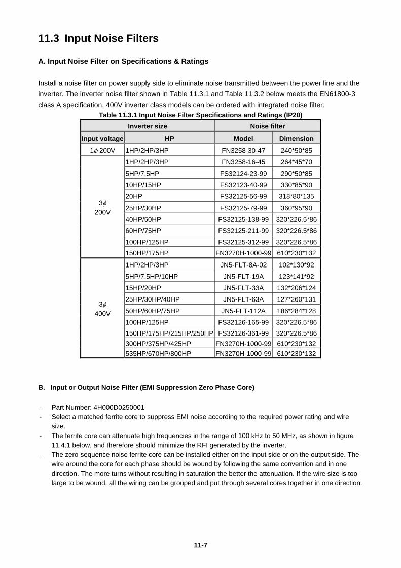
11-7
11.3 Input Noise Filters
A. Input Noise Filter on Specifications & Ratings
Install a noise filter on power supply side to eliminate noise transmitted between the power line and the
inverter. The inverter noise filter shown in Table 11.3.1 and Table 11.3.2 below meets the EN61800-3
class A specification. 400V inverter class models can be ordered with integrated noise filter.
Table 11.3.1 Input Noise Filter Specifications and Ratings (IP20)
Inverter size Noise filter
Input voltage HP Model Dimension
1200V 1HP/2HP/3HP FN3258-30-47 240*50*85
3
200V
1HP/2HP/3HP FN3258-16-45 264*45*70
5HP/7.5HP FS32124-23-99 290*50*85
10HP/15HP FS32123-40-99 330*85*90
20HP FS32125-56-99 318*80*135
25HP/30HP FS32125-79-99 360*95*90
40HP/50HP FS32125-138-99 320*226.5*86
60HP/75HP FS32125-211-99 320*226.5*86
100HP/125HP FS32125-312-99 320*226.5*86
150HP/175HP FN3270H-1000-99 610*230*132
3
400V
1HP/2HP/3HP JN5-FLT-8A-02 102*130*92
5HP/7.5HP/10HP JN5-FLT-19A 123*141*92
15HP/20HP JN5-FLT-33A 132*206*124
25HP/30HP/40HP JN5-FLT-63A 127*260*131
50HP/60HP/75HP JN5-FLT-112A 186*284*128
100HP/125HP FS32126-165-99 320*226.5*86
150HP/175HP/215HP/250HP FS32126-361-99 320*226.5*86
300HP/375HP/425HP FN3270H-1000-99 610*230*132
535HP/670HP/800HP FN3270H-1000-99 610*230*132
B. Input or Output Noise Filter (EMI Suppression Zero Phase Core)
- Part Number: 4H000D0250001
- Select a matched ferrite core to suppress EMI noise according to the required power rating and wire
size.
- The ferrite core can attenuate high frequencies in the range of 100 kHz to 50 MHz, as shown in figure
11.4.1 below, and therefore should minimize the RFI generated by the inverter.
- The zero-sequence noise ferrite core can be installed either on the input side or on the output side. The
wire around the core for each phase should be wound by following the same convention and in one
direction. The more turns without resulting in saturation the better the attenuation. If the wire size is too
large to be wound, all the wiring can be grouped and put through several cores together in one direction.

11-8
101
102
103
104
10-40
-30
-20
-10
0
Interference Frequency (kHz)
atte
uato
in val
ue (dB
)
Figure 11.3.1 Frequency attenuation characteristics (10 windings case)
Figure 11.3.2 Example of EMI Suppression Zero Phase Core Application
Note: All the wiring of phases U/T1, V/T2, W/T3 must pass through the same zero-phase core without
crossing over.
Induction Motor
Ground
Ground

11-9
11.4 Input Current and Fuse Specifications IP20 200V class
Model Horse
power KVA
100% of rated
output current
Rated input
current (3)
Fuse rating
(3)
Rated input
current (1)
F510-2001- 1 1.9 5.0 5.4 20 9.4 F510-2002- 2 2.9 7.5 8.1 30 14.1 F510-2003- 3 4.0 10.6 11.4 50 19.6 F510-2005-3 5 5.5 14.5 16 50 X F510-2008-3 7.5 8.0 22 22.3 50 X F510-2010-3 10 11.4 30 31.6 63 X F510-2015-3 15 15 42 41.7 100 X F510-2020-3 20 21 56 60.9 120 X F510-2025-3 25 26 69 75 150 X F510-2030-3 30 30 80 85.9 200 X F510-2040-3 40 42 110 119.6 250 X F510-2050-3 50 53 138 150 300 X F510-2060-3 60 64 169 186 400 X F510-2075-3 75 76 200 232 500 X F510-2100-3 100 95 250 275 600 X F510-2125-3 125 119 312 343 700 X F510-2150-3 150 152 400 440 800 X F510-2175-3 175 172 450 495 800 X IP20 400V class
Model Horse
power KVA
100% of rated output
current
Rated input
current Fuse rating
F510-4001-3 1 2.6 3.4 3.7 10 F510-4002-3 2 3.1 4.1 4.5 16 F510-4003-3 3 4.1 5.4 5.9 16
F510-4005-3(F) 5 7.0 9.2 9.6 16 F510-4008-3(F) 7.5 8.5 12.1 11.6 25 F510-4010-3(F) 10 13.3 17.5 18.2 40 F510-4015-3(F) 15 18 23 24 50 F510-4020-3(F) 20 24 31 32.3 63 F510-4025-3(F) 25 29 38 41.3 80 F510-4030-3(F) 30 34 44 47.8 100 F510-4040-3(F) 40 41 58 63 120 F510-4050-3(F) 50 55 73 78.3 150 F510-4060-3(F) 60 67 88 95.7 200 F510-4075-3(F) 75 79 103 112 250
F510-4100-3 100 111 145 159 300 F510-4125-3 125 126 168 181 400 F510-4150-3 150 159 208 229 500 F510-4175-3 175 191 250 275 600 F510-4215-3 215 226 296 325 700 F510-4250-3 250 250 328 361 700 F510-4300-3 300 332 435 478 800 F510-4375-3 375 393 515 566 800

11-10
Model Horse
power KVA
100% of rated output
current
Rated input
current Fuse rating
F510-4425-3 425 446 585 643 1000 F510-4535-3 535 526 700 750 1400 F510-4670-3 670 640 875 913 1800 F510-4800-3 800 732 960 1044 2200
IP55 400V class
Model Horse
power KVA
100% of rated
output current
Rated input
current Fuse rating
F510-4001-C3(F)N4 1 2.6 3.4 3.7 10
F510-4002-C3(F)N4 2 3.1 4.1 4.5 16
F510-4003-C3(F)N4 3 4.1 5.4 5.9 16
F510-4005-C3(F)N4 5 7.0 9.2 9.6 20
F510-4008-C3(F)N4 7.5 8.5 12.1 11.6 20
F510-4010-C3(F)N4 10 13.3 17.5 18.2 30
F510-4015-C3(F)N4 15 18 23 24 40
F510-4020-C3(F)N4 20 24 31 34 50
F510-4025-C3(F)N4 25 29 38 41 70
F510-4030-C3(F)N4 30 34 44 48 80
F510-4040-C3(F)N4 40 41 54 59 100
F510-4050-C3(F)N4 50 55 72 68 125
F510-4060-C3(F)N4 60 67 88 96 150
F510-4075-C3N4 75 79 103 112 200
F510-4100-C3N4 100 111 145 140 250
Fuse type: Choose semiconductor fuse to comply with UL.
Voltage Range: For 200V class inverter, use 300V class fuse.
For 400V class inverter, use 500V class fuse.

11-11
11.5 Other options A. JN5-OP-F02 (LCD keypad)
LED keypad is standard for F510 IP20 model and it is optional for LCD keypad. Refer to the following figure.

11-12
B. Blank operation box and digital operator wire ‧Digital operator can detach inverter itself and users apply digital operator wire for remote
operation. Wires have four specifications, inclusive of 1m, 2m, 3m, and 5m. ‧For digital operation remote control, separately blank operation box installed in the original
position of the operator to prevent the entry of foreign matter.
Remote control installation diagram blank operation box
Name Model specification
blank
operation
box
JN5-OP-A03 Black Panel
Name Model specification
LED digital
operator
wire
with blank
operation
box
JN5-CB-01MK 1m
JN5-CB-02MK 2m
JN5-CB-03MK 3m
JN5-CB-05MK 5m Name Model specification
LED digital
operator
wire
JN5-CB-01M 1m
JN5-CB-02M 2m
JN5-CB-03M 3m
JN5-CB-05M 5m

11-13
Dimensions of LED/LCD keypad (IP20):
Figure 11.5.2 Dimensions of LED keypad
Dimensions of LCD keypad (IP55):
Figure 11.5.3 Dimensions of LCD keypad (IP55)

11-14
C. 1 to 8 Pump Card Refer to instruction manual of the option card to install.
JN5-IO-8DO Card: 8 Relay Output Card.
Terminals of JN5-IO-8DO:
Terminal Description
RY1~RY8 Relay1~Relay8 A terminal output
CM1~CM4 Common terminal output
Wiring of JN5-IO-8DO (Example):
D. Copy Unit (JN5-CU) The copy unit is used to copy an inverter parameter setup to another inverter.
RY1
RY2
CM1
RY3
RY4
CM2
RY5
RY6
CM3
RY7
RY8
CM4
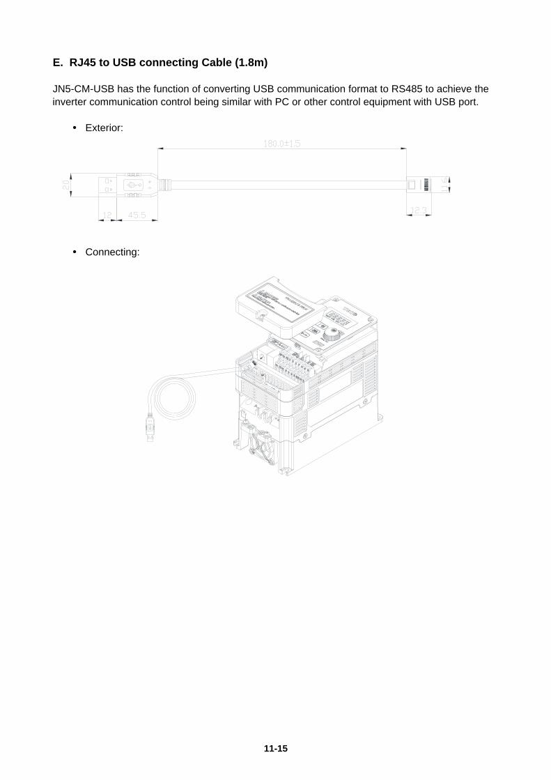
11-15
E. RJ45 to USB connecting Cable (1.8m) JN5-CM-USB has the function of converting USB communication format to RS485 to achieve the inverter communication control being similar with PC or other control equipment with USB port.
Exterior:
Connecting:

11-16
11.6 Communication Options (a) PROFIBUS communication interface module (JN5-CM-PDP) For wiring example and communication setup refer to JN5-CM-PDP communication option manual. (b) DEVICENET communication interface module (JN5-CM-DNET) For wiring example and communication setup refer to JN5-CM-DNET communication option manual. (c) CANopen communication interface module (JN5-CM-CAN) For wiring example and communication setup refer to JN5-CM-CAN communication option manual. (d) TCP-IP communication interface module (JN5-CM-TCPIP) For wiring example and communication setup refer to JN5-CM-TCPIP communication option manual.

11-17
11.7 Others Options A. Protective Cover If inverter is around the environment of dust or metal shavings, it is recommended to purchase the protective covers positioned on both sides of the inverter to prevent unknown objects from invading.
Frame Model 1 JN5-CR-A01 2 JN5-CR-A02 4 JN5-CR-A04
Protective Cover Installation of Protective Cover Inverter with Protective Cover
B. High-speed communication expansion card & I/O expansion card & DC24V power card & Middle layer case
If frame 1~4 of the enhanced inverter need to install 1 to 8 pump card, high-speed communication expansion card or I/O expansion card, middle layer case is necessary, which is option, to install between the top cover and the bottom case, for adding extra space to install the expansion card. For frame 2~4 of enhanced inverter, if only install 1 to 8 pump card, middle layer case is not necessary to use.
Table 1. Expansion card model number Expansion card type Model number Reference chapter
PROFIBUS high-speed comm. JN5-CMHI-PDP 11.9 CANopen high-speed comm. JN5-CMHI-CAN 11.10 EtherCAT high-speed comm. JN5-CMHI-ECAT 11.11
I/O expansion JN5-IO-2DO1AI 11.12 DC24V power card JN5-PS-DC24V 11.15

11-18
Table 2. Middle layer case model number
Frame Middle layer case model number 1 JN5-MD-A01 2 JN5-MD-A02 3 JN5-MD-A03 4 JN5-MD-A04
Middle layer case outline Middle layer case installation diagram
Communication card installation diagram
11.8 NEMA1 Kit If NEMA1 or IP20 protective level is necessary to upgrade, it is recommended to purchase the NEMA1 kit positioned on top and bottom sides of the inverter. The drawings installed in the inverter, please refer to chapter 3.7.
Frame Model 6 JN5-NK-A06 7 JN5-NK-A07 8 JN5-NK-A08 9 JN5-NK-A09
Comm. card Comm. card

11-19
COMM. indicator light
RUN indicator light
ERR indicator light
D-SUB port
Terminal resistance switch
Expansion card screw hole
11.9 PROFIBUS high speed communication expansion card
11.9.1 Communication hardware and data structure This product is the PROFIBUS high-speed communication expansion module; it can perform
remote setting and communication functions through the PROFIBUS bus. It is used on the TECO
A510s/F510 AC motor driver (hereinafter referred to as the “driver”), and allows the driver to
operate on the PROFIBUS network.
ID address switch
Expansion card screw hole
CN5 (Connect to Control Board)

11-20
11.9.2 Product specifications
PROFIBUS ports
Item Specifications
Connector DB-9
Transmission
rate
9.6Kbit/s to 12Mbit/s (automatic detection of transmission rate)
Network
protocols
PROFIBUS communication protocol
AC motor driver port
Item Specifications
Connector Communication card CN5 connector
Transmission
method
SPI high speed communication
Terminal
functions
1. The communication module communicates with the AC motor
driver through this interface.
2. The AC motor driver provides power to the communication
module through this interface.
Communication
protocols
TECO communication protocol

11-21
11.9.3 Installation instructions
PROFIBUS network connection
Definitions of PROFIBUS DP communication port pins are as shown in the figure below.
PROFIBUS network connection
As shown in the figure below, ID addresses (1~125) correspond to SW1 b1~b7.
Function DIP switch
position
DIP switch
status Description
Network
address
setting
b1~b7
1000000 Network
address is 1
0100000 Network
address is 2
1100000 Network
address is 3
............ …….
1011111 Network
address is 125
No function b8 - -
Network address switch setting range: 1~125 (0, 128~255 cannot be used).
Pin Definition Description
1~2 Not assigned -
3 RXD/TXD-P (B-
Line)
Receive/Send data
-P
4 Not assigned -
5 DGND (2M) Data reference
potential
6~7 Not assigned -
8 RXD/TXD-N
(A-Line)
Receive/Send data
-N
9 Not assigned -

11-22
PROFIBUS bus terminal resistor
The first and last station of the PROFIBUS bus must be connected to the bus, and
the bus terminal resistor must be turned on.
Serial transmission
rate(kbps)
Maximum bus length
(m)
9.6 1200
19.2 1200
45.45 1200
93.75 1200
187.5 1000
500 400
1500 200
3000 100
6000 100
12000 100

11-23
11.9.4 LED indicator descriptions The module has two dual-color LED indicators built-in used to quickly diagnose and monitor
the communication statuses between the module itself and the bus.
Module status LED (RUN LED & ERR LED)
Used to monitor whether the equipment is operating normally.
Indicator
statuses Description
Does not light
up
Power not supplied
Orange light
lights up
Communication with the
frequency converter not
established
Red light flashes
(1 Hz)
Communication error
with the frequency
converter
Red light flashes
(4 Hz)
Flip-switch ID address
error
Green light
flashes (4 Hz)
Power supply normal
but DP communication
not established
Green light
lights up
DP communication
normal
Network status LED (COMM LED)
Used to monitor the operability of the communication module PROFIBUS network.
Indicator
statuses Description
Does not light
up
DP communication
not established
Green light
lights up
DP communication
established and
normal

11-24
11.9.5 Driver parameter setting descriptions Used to monitor the operability of the communication module PROFIBUS network.
Users must first confirm related parameter settings on the driver in order to ensure that
the communication module can connect normally.
Parameters Parameter name Settings Settings descriptions
00-02 Operation command source 2 Communication control
00-05 Frequency command source 3 Communication control
11.9.6 Connection instructions
PPO communication
PKW PZD
PKE IND PWE
PZD1
STW
ZSW
PZD2
HSW
HIW
PZD3 PZD4 PZD5 PZD6 PZD7 PZD8 PZD9 PZD10
1st
word
2nd
word
3rd
word
4th
word
1st
word
2nd
word
3rd
word
4th
word
5th
word
6th
word
7th
word
8th
word
9th
word
10th
word
PPO1
PPO2
PPO3
PPO4
PPO5
PKW: Parameter address/value STW: Control character
PZD: Process data ZSW: Status character
PKE: Parameter address HSW: Main settings
IND: Subindex HIW: Main actual value
PWE: Parameter value
PZD Structure default User parameters of the communication module configured through the GSD file. Default
values of the PZD structure are as follows:
STW1 Control character; mapped to the MODBUS address 0x2501 of the driver.
HSW Main setting value; mapped to the MODBUS address 0x2502 of the driver.
ZSW1 Status character; mapped to the MODBUS address 0x2520 of the driver.
HIW Main actual value; mapped to the MODBUS address 0x2524 of the driver.
PLC Master station driver slave station

11-25
PZD3/ PZD4: Not used.
Driver slave station PLC master station
Driver output status; mapped to the MODBUS addresses 0x2520~0x252F of the driver.
The default values of PZD3/PZD4/PZD5/PZD6 are set as follows:
PZD3: Default multi-function terminal block on/off status; mapped to the MODBUS
address 0x2522 of the driver.
PZD4: Default output current; mapped to the MODBUS address 0x2527 of the driver.
PZD5: Default output current; mapped to the MODBUS address 0x2521 of the driver.
PZD6: Default output current; mapped to the MODBUS address 0x2528 of the driver.
11.9.7 Meanings of each character
Control character STW
Bit Description 1 0
0 Operation command Operate Stop
1 Reverse command Reverse Forward
2 External error Error -
3 Error reset Reset -
4~5 Reserved - -
6 Multi-function terminal S1 ON OFF
7 Multi-function terminal S2 ON OFF
8 Multi-function terminal S3 ON OFF
9 Multi-function terminal S4 ON OFF
A Multi-function terminal S5 ON OFF
B Multi-function terminal S6 ON OFF
C Multi-function terminal S7 ON OFF
D Multi-function terminal S8 ON OFF
E Controller mode ON OFF
F Communication setting torque
command ON
Status character ZSW
Bit Meaning 1 0
0 Operation status Operate Stop
1 Direction status Reverse Forward
2 Frequency converter operation
preparation status
Preparation
complete
Not yet
prepared
3 Error Abnormal Normal
4 Warning ON OFF
5 Zero speed ON OFF

11-26
6 Model 440 ON OFF
7 Frequency reached ON OFF
8 Any frequency reached ON OFF
9 Frequency detection one ON OFF
A Frequency detection two ON OFF
B Low voltage ON OFF
C Frequency converter no output ON OFF
D Frequency not according to
communication ON OFF
E SeqNotFromComm ON OFF
F Over-torque ON OFF
11.9.8 PKW regional access parameters The driver can provide request and response information. Due to the request and
response mechanism, the master station must send requests until a communication
response is received. The 4 characters of the PKW region are as follows:
Word 1 Parameter ID(PKE)
bit 15 12 11 0
AK Parameter number(PNU)
Word 2 IND Reserved
Word 3 PWE1
bit 15 8 7 0
Reserved Fault number
Word 4 PWE2 Read/Write parameters
Parameters address PKE
Bit 0~11 (PNU): Parameter address/MODBUS address that includes related parameters.
Parameter address/MODBUS address: Please refer to the MODBUS communication
protocol description chapter in the driver manual for the register numbers, registers and
data format that corresponds to the operation parameters.
Bit 12~15 (AK): Includes the identification characters of requests or responses.

11-27
Request character AK
PLC master station driver slave station
Request Identifier Description
0 No request
1 Read parameter value
2 Modify parameter value
Response character AK
Driver slave station PLC master station
Request Identifier Description
0 No response
1 Request parameter value processed
7 Request parameter value cannot process
Error character
If the request parameter value was not processed, then the error codes that will be kept in
the low-bit PWE1 set are as follows:
Error
code
Description
0 Parameter does not exist
1 The current status parameter cannot be
read/written
2 Parameter value not within range
101 Other SP communication error occurred, such as:
response timeout
Parameter Value PWE
Driver parameters are sent through PWE2 (4th word). In the following example, PWEI (3rd
word) must be set as 0 in the PROFIBUS master station.
Example of the PKW mechanism:
For example: Read parameters 00-05 (frequency command source).
Read the values of 00-05; first set the request identification character as 1, and then refer
to the MODBUS communication protocol description chapter in the driver manual to find
out that the address of 00-05 is 0x0005, then the data sequences are as follows:

11-28
PLC master station driver slave station: 1000 0005 0000 0000
Driver slave station PLC master station: 1000 0005 0000 0004
Request Response
1st word
(PKE)
1000 1st word (PKE) 1000
2nd word
(IND)
0005 2nd word (IND) 0005
3rd word
(PWE1)
0000 3rd word (PWE1) 0000
4th word
(PWE2)
0000 4th word (PWE2) 0004
11.9.9 Troubleshooting There are two indicators on top of the PROFIBUS communication module; when malfunction occurs,
the cause of the malfunction can be confirmed based on the indicator statuses, and troubleshoot
the error by following the descriptions below.
Indicator troubleshooting
Module status LED Indicator
statuses Status name Troubleshooting method
Does not light
up
Power not
supplied to
the
communicat
ion module
1. Confirm whether the driver power is normal.
2. Confirm whether the power terminal of the
communication module is connected to the driver.
Red and green
light flashes
alternately
Self-check
1. The host is under self-check; if it flashes
continuously, disconnect the power and then reconnect
it.
2. Confirm whether the driver communication
connection parameters are properly set (19200, 8, N, 1)
Green light
flashes
the
communicat
ion module
standby
1. Not yet connected with the driver.
Network status LED
Indicator
statuses Status name Description

11-29
Does not light
up
Power not
supplied
1. Confirm whether the driver power is normal.
2. Confirm whether the power terminal of the
communication module is connected to the driver.
Standby 1. Not yet connected with the PROFIBUS host terminal.
11.9.10 GSD File When using the Profibus communication module, if the GSD description file
(JN5-CMHI-PDP_V (latest version).GSD) is needed, please download it from the TECO
official website or request for it from your purchasing sales channel.

11-30
11.10 CANopen high speed communication expansion card
11.10.1 Communication hardware and data structure This product is the CANopen high-speed communication expansion module; it can perform remote
setting and communication functions through the CANopen bus. It can only be used with the TECO
A510s/F510 AC motor driver (hereinafter referred to as the “driver”), and allow the driver to operate
on the CANopen network.

11-31
11.10.2 Product specifications
CANopen ports
Item Specifications
Connector 5-pin open pluggable connector; pin spacing 5.08mm
Transmission
rate
10kbps, 20kbps, 50kbps, 125kbps, 250kbps, 500kbps, 800kbps,
1Mbps
Network
protocols
CANopen communication protocol
AC motor driver port
Item Specifications
Connector Communication card CN5 connector
Transmission
method SPI high speed communication
Terminal
functions
1. The communication module communicates with the AC motor
driver through this interface.
2. The AC motor driver provides power to the communication
module through this interface.
Communication
protocols
TECO communication protocol

11-32
11.10.3 Installation instructions
Communication module contact description
As shown in the figure below, A – Terminal block (TB1)
B, C – Mounting holes
D - RUN LED
E - ERR LED
F – Control board connector (CN5)
G - Rate setting switch
H – ID address setting switch
Terminal block definition
As shown in the figure below, the contact definitions in the order from left to right are
GND, CAN_L, NC, CAN_H and NC.

11-33
ID address setting description As shown in the figure below, ID addresses (1~127) correspond to SW1 b1~b7.
Transmission rate corresponds to SW2 b1~b3.
Function DIP switch
position
DIP switch
status
7654321
Description
Network
address
Setting
SW1
b7—b1
0000000 Cannot be used
0000001 Network address is 1
0000010 Network address is 2
0000011 Network address is 3
............ ............
1111110 Network address is 126
1111111 Network address is 127
CANopen
Transmission
rate setting
SW2
b3—b1
000 10K
001 20K
010 50K
011 125K
100 250K
101 500K
110 800K
111 1M
Network address switch setting range: 1~127 (0, 128~255 cannot be used).
Transmission rate switch setting range: 0~7 (8~15 cannot be used).
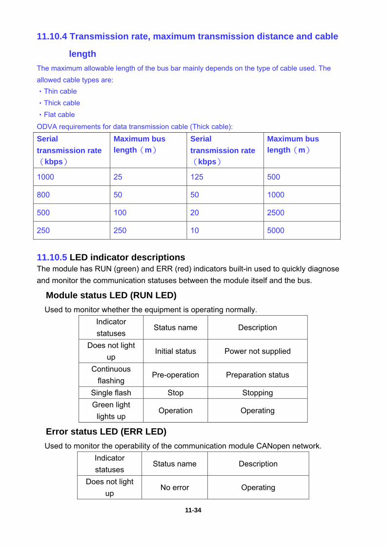
11-34
11.10.4 Transmission rate, maximum transmission distance and cable
length
The maximum allowable length of the bus bar mainly depends on the type of cable used. The
allowed cable types are:
•Thin cable
•Thick cable
•Flat cable
ODVA requirements for data transmission cable (Thick cable):
Serial
transmission rate
(kbps)
Maximum bus
length(m)
Serial
transmission rate
(kbps)
Maximum bus
length(m)
1000 25 125 500
800 50 50 1000
500 100 20 2500
250 250 10 5000
11.10.5 LED indicator descriptions The module has RUN (green) and ERR (red) indicators built-in used to quickly diagnose
and monitor the communication statuses between the module itself and the bus.
Module status LED (RUN LED)
Used to monitor whether the equipment is operating normally.
Indicator
statuses Status name Description
Does not light
up Initial status Power not supplied
Continuous
flashing Pre-operation Preparation status
Single flash Stop Stopping
Green light
lights up Operation Operating
Error status LED (ERR LED) Used to monitor the operability of the communication module CANopen network.
Indicator
statuses Status name Description
Does not light
up No error Operating

11-35
Single flash Warning Packet error
Double flash Error Guard/Heartbeat error
Red light lights
up Disconnected Bus closed
11.10.6 Driver parameter setting descriptions Used to monitor the operability of the communication module CANopen network.
Users must first confirm related parameter settings on the driver in order to ensure that
the communication module can connect normally.
Parameters Parameter name Settings Settings descriptions
00-02 Operation command source 2 Communication control
00-05 Frequency command source 3 Communication control
11.10.7 Connection instructions
Service data object (SDO) This module supports 1 SDO server, which means it can provide SDO service, and the
SDO uses the sending and receiving COB-ID of the predefined connection, 0x580 +
NodeID (sending) and 0x600 + NodeID (receiving).
Each SDO message includes a set of COB-ID (request SDO and response SDO); it
allows performing of access actions within two nodes. SDO can transmit any size of data,
but segment transmission must be used once it exceeds 4 bytes.
The COB IDs of SDO communication are as follows:
Read: Master to slave (request code 0x40) / Master to slave: 600H + Node ID
COB-ID Byte0 Byte1 Byte2 Byte3 Byte4 Byte5 Byte6 Byte7
(600H) + Node
ID
Reque
st
code
Object index Object
subind
ex
Request data
LSB MSB Reserved
Read: Slave response / slave to master: 580H + Node ID
COB-ID Byte0 Byte1 Byte2 Byte3 Byte4 Byte5 Byte6 Byte7
(580H) + Node
ID
Reque
st
code
Object index Object
subind
ex
Request data
LSB MSB bit0~
bit7
Bit8~
bit15
Bit16~
bit23
Bit24~
bit31

11-36
Response code:
43H: Read 4-byte data / 4BH: read 2-byte data / 4FH: read 1-byte data
Write: Master to slave (4-byte data maximum)
COB-ID Byte0 Byte1 Byte2 Byte3 Byte4 Byte5 Byte6 Byte7
(600H) + Node
ID
Reque
st
code
Object index Object
subind
ex
Request data
LSB MSB bit0~
bit7
Bit8~
bit15
Bit16~
bit23
Bit24~
bit31
Request code:
23H: Write a 4-byte data entry
2BH: Write a 2-byte data entry
2FH: Write a 1-byte data entry
Write: Slave to master (response code 0x60H)
COB-ID Byte0 Byte1 Byte2 Byte3 Byte4 Byte5 Byte6 Byte7
(580H) + Node
ID
Reque
st
code
Object index Object
subind
ex
Request data
LSB MSB Reserved
When we use SDO to perform control to the group 25H of the driver control group,
corresponding rules are as follows:
Index
25xxH (register
address)
For example, when we want to perform write/read to 2501H of the control group, the
corresponding SDO object index is the control group register address 2501H.
Perform operation with index 2501H directly and the module will automatically convert to
the A510s 2501H control group register address to perform operation.

11-37
11.10.8 Object index list
Basic index
Index Sub Name Default value R/W Size Remarks
1000H 0 Device type 00010192H R U32
1001H 0 Error register 0 R U8
1005H 0 COB-ID SYNC message 80H R U32
1006H 0 Communication cycle period 0 RW U32
1008H 0 Manufacturer device name A510 R U32
1009H 0 Manufacturer hardware
version 1.0 R U32
100AH 0 Manufacturer software
version 1.00 R U32
1014H 0 COB-ID emergency 00000080H+Node-I
D R U32
1015H 0 Inhibit time EMCY 0 RW U16
1016H 0 number of entries 1 R U8
1 Consumer heartbeat time 0 RW U32Not supported
1017H 0 Producer heartbeat time 0 RW U16
1018H
0 number of entries 3 R U8
1 Vender ID 00000373H R U32
2 Product code 00000100H R U32
3 Revision 00010000H R U32
1200H
0 Server SDO Parameter 2 R U8
1 COB-ID Client Server 0000600H+Node-ID R U32
2 COB-ID Client Server 0000580H+Node-ID R U32
1400H
0 Number of entries 2 R U8
1 COB-ID used by PDO 00000200H+Node-I
D RW U32
2 Transmission Type 0xFF RW U8
1401H
0 Number of entries 2 R U8
1 COB-ID used by PDO 00000300H+Node-I
D RW U32
2 Transmission Type 0xFF RW U8
1600H
0 Number of entries 2 RW U8
1 1.Mapped Object 60400010H RW U32
2 2.Mapped Object 60420010H RW U32
3 3.Mapped Object 0 RW U32
4 4.Mapped Object 0 RW U32

11-38
Index Sub Name Default value R/W Size Remarks
1601H
0 Number of entries 2 RW U8
1 1.Mapped Object 604F0010H RW U32
2 2.Mapped Object 60500010H RW U32
3 3.Mapped Object 0 RW U32
4 4.Mapped Object 0 RW U32
1800H
0 Number of entries 5 R U8 Number of
entries
1 COB-ID used by PDO 180H+Node-ID RW U32
2 Transmission Type 0xFF RW U8 Transmission type
3 Inhibit time 0x64 RW U16 Inhibit time
4 CMS-Priority Group 0 RW U8
5 Event timer 0x64 RW U16Event timer
1801H
0 Number of entries 5 R U8 Number of
entries
1 COB-ID used by PDO 00000280H+Node-I
D RW U32
2 Transmission Type 0xFF RW U8
3 Inhibit time 0x64 RW U16 Inhibit time
4 CMS-Priority Group 0 RW U8
5 Event timer 0x64 RW U16 Event time
4 CMS-Priority Group 0 RW U8
5 Event timer 0x64 RW U16 Event time
2 Transmission Type 0xFF RW U8
3 Inhibit time 0x64 RW U16 Inhibit time
4 CMS-Priority Group 0 RW U8
5 Event timer 0x64 RW U16 Event time
1A00H
0 Number of entries 2 RW U8
1 1.Mapped Object 60400010 RW U32
2 2.Mapped Object 60420010 RW U32
3 3.Mapped Object 0 RW U32
4 4.Mapped Object 0 RW U32
1A01H
0 Number of entries 2 RW U8
1 1.Mapped Object 604F0010 RW U32
2 2.Mapped Object 60500010 RW U32
3 3.Mapped Object 0 RW U32
4 4.Mapped Object 0 RW U32

11-39
DS402 part
Index Sub-
Index Name
Default
value R/W Size Unit
PDO
MAP
603F 0 Error code 0 RO U16 Yes
6040 0 Control word 0 RW U16 Yes
6041 0 Status word 0 RO U16 Yes
6042 0 vl target velocity 0 RW S16 Hz Yes
6043 0 vl velocity demand 0 RO S16 Hz Yes
604F 0 vl ramp function time
Acceleration time 100 RW U16 0.1S Yes
6050 0 vl slow down time
Deceleration time 100 RW U16 0.1S Yes
Driver control group command index
Command DATA (allows reading and writing)
Register
address Bit Content
2500H Reserved
2501H Operation
signal
0 Operation command 1: Operate 0: Stop
1 Reverse command 1: Reverse 0: Forward
2 External error 1: Error
3 Error reset 1: Reset
4 Reserved
5 Reserved
6 Multi-function terminal S1 1: “ON”
7 Multi-function terminal S2 1: “ON”
8 Multi-function terminal S3 1: “ON”
9 Multi-function terminal S4 1: “ON”
A Multi-function terminal S5 1: “ON”
B Multi-function terminal S6 1: “ON”
C Multi-function terminal S7 1: “ON”
D Multi-function terminal S8 1: “ON”
E Controller mode 1: “ON”
F Communication setting torque command 1: “ON”
2502H *Frequency command (Unit: 0.01Hz)
2505H AO1 (0.00V ~ 10.00V)
2510H G12-00 H-WORD
2511H G12-00 L-WORD

11-40
Monitor DATA (read only)
Register
address Bit Content
2520H Status
signal
0 Operation status 1: Operate 0: Stop
1 Direction status 1: Reverse 0: Forward
2 Frequency converter operation preparation status 1:
Preparation complete 0: Preparation not yet complete
3 Error 1: Abnormal
4 Warning 1: “ON”
5 Zero speed 1: “ON”
6 Model 440 1: “ON”
7 Frequency reached 1: “ON”
8 Any frequency reached 1: “ON”
9 Frequency detection one 1: “ON”
A Frequency detection two 1: “ON”
B Low voltage 1: “ON”
C Frequency converter no output 1: “ON”
D Frequency not according to communication 1: “ON”
E Operation not according to communication 1: “ON”
F Over-torque 1: “ON”
2521H Error
description
0 Reserved 31 Reserved
1 UV (Under-voltage) 32 Reserved
2 OC (Over-current) 33 Reserved
3 OV (Over-voltage) 34 Reserved
4 OH1 (Heat sink
overheat) 35 Reserved
5 OL1 (Motor overload) 36 Reserved
6 OL2 (Frequency
converter overload) 37 Reserved
7 OT (Over-torque) 38 CF07 (Motor control fault)
8 UT (Under-torque) 39 Reserved
9 SC (Short circuit) 40 Reserved
10 GF (Ground fault) 41 Reserved
11 FO 42 Reserved
12 IPL (Input phase loss) 43 Reserved
13 OPL (Output phase
loss) 44 Reserved
14 OS 45 Reserved
15 PGO 46 OH4 (Motor overheat)

11-41
Register
address Bit Content
16 DEV 47 Reserved
17 EF1 48 Reserved
18 EF2 49 MtrSw (DI Motor Switch Fault)
19 EF3 50 OCA (Acceleration over-current)
20 EF4
51OCD (Deceleration
over-current)
21 EF5 52 OCC (Operation over-current)
22 EF6 53 CF08
23 EF7 54 PTCLS
24 EF8 55 PF (Protection fault)
25 FB (PID feedback
signal error) 56 TOL
26 OPR(Keypad
Removed) 57 STO2 (Safety switch 2)
27 Reserved 58 Reserved
28 CE 59 Reserved
29 STO (Safety switch 1) 60 Reserved
30 Reserved 61 Reserved
2522H DI status
0 Multi-function
terminal S1 4
Multi-function
terminal S5 8~F Reserved
1 Multi-function
terminal S2 5
Multi-function
terminal S6
2 Multi-function
terminal S3 6
Multi-function
terminal S7
3 Multi-function
terminal S4 7
Multi-function
terminal S8
2523H Frequency command (0.01Hz)
2524H Output frequency (0.01Hz)
2526H DC voltage command (0.1V)
2527H Output current (0.1A)
2528H Warning
description
0 No alarm 30 RDE 60 Reserved
1 OV 31 WRE 61 RETRY
2 UV 32 FB 62 SE07
3 OL2 33 VRYE 63 Reserved
4 OH2 34 SE01 64 Reserved
5 Reserved 35 SE02 65 OH1
6 OT 36 SE03 66 FIRE
7 Reserved 37 Reserved 67 ES

11-42
Register
address Bit Content
8 Reserved 38 SE05 68 STP1
9 UT 39 HPERR 69 BDERR
10 OS 40 EF 70 EPERR
11 PGO 41 Reserved 71 Reserved
12 DEV 42 Reserved 72 Reserved
13 CE 43 RDP 73 STP0
14 CALL 44 Reserved 74 Reserved
15 Reserved 45 OL1 75 STP2
16 EF0 46 Reserved 76 RUNER
17 EF1 47 Reserved 77 LOC
18 EF2 48 Reserved 78 PTCLS
19 EF3 49 BB1 79 Sys Init
20 EF4 50 BB2 80 FBLSS
21 EF5 51 BB3
22 EF6 52 BB4
23 EF7 53 BB5
24 EF8 54 BB6
25 Reserved 55 BB7
26 Reserved 56 BB8
27 Reserved 57 Reserved
28 Reserved 58 Reserved
29 Reserved 59 Reserved
2529H DO status
252AH AO1
252BH AO2
252CH AI 1 input (0.1%)
252DH AI 2 input (0.1%)
252FH L510(s)/ E510(s)/ A510(s)/ F510 Check
11.10.9 Troubleshooting There are two indicators on top of the CANopen communication module; when malfunction occurs,
the cause of the malfunction can be confirmed based on the indicator statuses, and troubleshoot
the error by following the descriptions below.
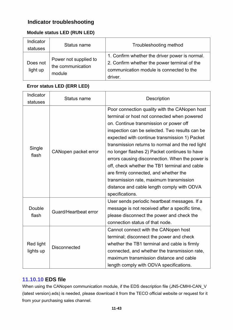
11-43
Indicator troubleshooting
Module status LED (RUN LED) Indicator
statuses Status name Troubleshooting method
Does not
light up
Power not supplied to
the communication
module
1. Confirm whether the driver power is normal.
2. Confirm whether the power terminal of the
communication module is connected to the
driver.
Error status LED (ERR LED)
Indicator
statuses Status name Description
Single
flash CANopen packet error
Poor connection quality with the CANopen host
terminal or host not connected when powered
on. Continue transmission or power off
inspection can be selected. Two results can be
expected with continue transmission 1) Packet
transmission returns to normal and the red light
no longer flashes 2) Packet continues to have
errors causing disconnection. When the power is
off, check whether the TB1 terminal and cable
are firmly connected, and whether the
transmission rate, maximum transmission
distance and cable length comply with ODVA
specifications.
Double
flash Guard/Heartbeat error
User sends periodic heartbeat messages. If a
message is not received after a specific time,
please disconnect the power and check the
connection status of that node.
Red light
lights up Disconnected
Cannot connect with the CANopen host
terminal; disconnect the power and check
whether the TB1 terminal and cable is firmly
connected, and whether the transmission rate,
maximum transmission distance and cable
length comply with ODVA specifications.
11.10.10 EDS file When using the CANopen communication module, if the EDS description file (JN5-CMHI-CAN_V
(latest version).eds) is needed, please download it from the TECO official website or request for it
from your purchasing sales channel.

11-44
11.11 Introduction to the EtherCAT high speed communication
expansion module
11.11.1 Communication hardware and data structure This product is the EtherCAT high-speed communication expansion module (hereinafter referred to
as communication module); it can perform remote setting and communication functions through the
EtherCAT network environment. It can only be used with the TECO A510s/F510 AC motor driver
(hereinafter referred to as a driver), and allow the driver to operate on the EtherCAT network.

11-45
11.11.2 Product specifications
EtherCAT ports
Item Specifications
Connector Dual-port network socket
Network
protocols
EtherCAT communication protocol
AC motor driver port
Item Specifications
Connector Communication card CN5 connector
Terminal
functions
1. The communication module communicates with the AC motor
driver through this interface.
2. The AC motor driver provides power to the communication
module through this interface.
11.11.3 Installation instructions
Communication module contact description
As shown in the figure below, the framed part is the CN5 connector that connects to the
driver.
Communication module network socket
As shown in the figure below, the left socket is input and the right socket is output.
Input Output

11-46
Driver parameter setting description
Users must first confirm related parameter settings on the driver in order to ensure that the
communication module can connect normally.
Parameters Parameter name Settings Settings descriptions
00-02 Operation command source 2 Communication control
00-05 Frequency command source 3 Communication control
11.11.4 LED indicator descriptions The module has two dual-color LED indicators built-in used to quickly diagnose and monitor
the communication statuses between the module itself and the EtherCAT network.
Module status LED2
Used to monitor whether the communication module is operating normally.
Indicator
statuses Status name Description
Does not
light up Power not supplied Power not supplied
Red light
flashes Data transmitting
Driver and communication
expansion module data transmitting
Red/green
light lights
up
Driver data
transmission error
Data transmission error between the
driver and communication expansion
module
Network status LED1
Used to monitor the operability of the communication module EtherCAT network.
Indicator
statuses Status name Description
Does not
light up
Not connected /
INIT
EtherCAT network not connected
(INIT)
Green light
flashes Standby Preparation status (Pre-OP)
Green light
lights up Operation status Operation status (OP)
Red light
lights up Driver data
transmission error
Data transmission error between the
driver and communication expansion
module

11-47
11.11.5 Object index list
Basic index
Index Sub-
Index Name
Default
value R/W Size Remarks
1000H 0 Device type 00000192H R U32
1001H 0 Error register 0 R U8
1008H 0 Manufacturer device name JN5-CM-CA
N R U32
1009H 0 Manufacturer hardware version Version R U32
100AH 0 Manufacturer software version Version R U32
1018H
0 number of entries 4 R U8
1 Vender ID 0000081BH R U32
2 Product code 00000001H R U32
3 Revision 00000001H R U32
1600H
0 Number of entries 2 RW U8
1 1.Mapped Object 60400010H RW U32
2 2.Mapped Object 60420010H RW U32
3 3.Mapped Object 0 RW U32
4 4.Mapped Object 0 RW U32
1601H
0 Number of entries 2 RW U8
1 1.Mapped Object 604F0010H RW U32
2 2.Mapped Object 60500010H RW U32
3 3.Mapped Object 0 RW U32
4 4.Mapped Object 0 RW U32
1A00H
0 Number of entries 3 RW U8
1 1.Mapped Object 60400010 RW U32
2 2.Mapped Object 60420010 RW U32
3 3.Mapped Object 604F0020 RW U32
4 4.Mapped Object 0 RW U32
1A01H
0 Number of entries 3 RW U8
1 1.Mapped Object 604F0020 RW U32
2 2.Mapped Object 60500020 RW U32
3 3.Mapped Object 0 RW U32
4 4.Mapped Object 0 RW U32

11-48
Object part
Index Sub-
Index Name Default value R/W Size Unit
PDO
MAP
603F 0 Error code 0 RO U16 Yes
6040 0 Control word 0 RW U16 Yes
6041 0 Status word 0 RO U16 Yes
6042 0 vl target velocity 0 RW S16 Hz Yes
6043 0 vl velocity demand 0 RO S16 Hz Yes
604F 0 vl ramp function time
Acceleration time
Driver default
value RW U32 0.1S Yes
6050 0 vl slow down time
Deceleration time
Driver default
value RW U32 0.1S Yes

11-49
11.11.6 Troubleshooting There are two indicators on top of the EtherCAT communication module. When a malfunction
occurs, the cause of the malfunction can be confirmed based on the indicator statuses, and
troubleshoot the error by following the descriptions below.
Indicator troubleshooting
Module status LED2
Indicator
statuses Status name Troubleshooting method
Does not
light up Power not supplied
1. Confirm whether the driver power is normal.
2. Confirm whether the power terminal of the
communication module is connected to the
driver.
Red/green
light lights
up
Driver data
transmission error
1. Confirm whether the communication module
has proper contact.
2. Reconnect the power of the driver and
confirm whether the error has been eliminated.
Network status LED1
Indicator
statuses Status name Description
Does not
light up Not connected / INIT
1. Confirm whether the driver power is normal.
2. If connected to EtherCAT, confirm whether it is
in INIT mode.
Red light
lights up
Driver data
transmission error
1. Confirm whether the communication module
has proper contact.
2. Reconnect the power of the driver and confirm
whether the error has been eliminated.
11.11.7 xml file When using the EtherCAT communication module, if the xml description file (JN5-CMHI-ECAT_V
(latest version).xml) is needed, please download it from the TECO official website or request for it
from your purchasing sales channel.

11-50
11.12 I/O expansion card
11.12.1 Hardware and data structure This product is an I/O expansion module; it allows performing of I/O expansion functions through
the SPI bus. Used with the TECO A510s/F510 AC motor driver (hereinafter referred to as a driver).
11.12.2 Product specifications
I/O ports
Item Specifications
Connector TB1 7 external contacts

11-51
AC motor driver port
Item Specifications
Connector Control board CN5 connector
Transmission
method SPI high speed communication
Terminal
functions
TB1 7 external contacts, applicable wire diameter: AWG
20~14 stranded wire
11.12.3 Installation instructions
Contact description
Type Terminal Terminal functions Signal level
Analog
input
signal
AI3
Main speed command input; SW7 can be used to
switch between voltage or current input
(-10~10V)/(4-20mA)
-10V to +10V,
(Input resistance 500KΩ)
4 to 20 mA
(Input resistance: 500Ω)
(12bit resolution)
GND Analog signal shared terminal ----
Relay
Output
R4A-
R4B-
R4C
Relay A contact (multi-function output terminal)
Relay B contact (multi-function output terminal)
Relay shared terminal; please refer to the
manual for its functions.
Terminal capacity:
At 250Vac, 10 mA~1A
At 30Vdc, 10 mA~1A
Digital
Output DO2
Multi-function (open collector transistor) output:
Operating, zero speed, frequency consistent, any
frequency consistent, output frequency,
preparation complete, low-voltage detection,
output occlusion, operation and frequency
commands, over-torque detection, abnormal,
low-voltage, overheat, motor over-load, frequency
converter over-load output, retrying, signal
abnormal, chronograph output…
48Vdc, 2 mA~50mA Optical coupling output
DOG Open collector transistor shared terminal
11.12.4 Driver parameter setting descriptions Please refer to group 3, 4 parameter descriptions in the manual

11-52
11.13 DC reactor Installing a DC reactor at the DC terminal of the frequency converter provides the following
advantages:
• Improves the input current waveform distortion caused by the rectifier in the frequency
converter while maintaining continuous rectified current.
• Suppresses instantaneous current surges and prevents related overheating
phenomenon caused by the rectifier and voltage regulator components due to
instantaneous current surges.
• Reduces harmonic interference problems generated by the frequency converter.
• Improves and increase power factor and reduces AC component pulses at the DC
terminal.
• Compared to AC reactors, the size of DC reactors are smaller and the costs are also
lower.
Table 6.13 DC reactor list
Model DC reactor
V HP Rated current
(A)
Inductance value
(mH) Rated current (A)
200V
1 Ø /3 Ø
1 5 2.9 10
2 7.5 2 15
3 10.6 1.2 20
200V
3 Ø
5 14.5 0.78 35
7.5 22 0.78 35
10 30 0.57 45
15 42 0.39 65
20 56 0.29 85
25 69 0.23 105
30 80 0.2 120
40 110 0.14 165
50 138 0.12 210
60 (built-in) 169 0.1 200
75 (built-in) 200 0.08 260
100 (built-in) 250 0.08 390
125 (built-in) 312 0.08 390
150 (built-in) 400 0.065 520
175 (built-in) 450 0.05 800
400V
3 Ø
1 3.4 10.2 6.5
2 4.1 7 8.5
3 5.4 4.2 11
5 9.2 2.8 20

11-53
Model DC reactor
V HP Rated current
(A)
Inductance value
(mH) Rated current (A)
7.5 12.1 2.8 20
10 17.5 2.1 30
15 23 1.4 35
20 31 1.0 50
25 38 0.83 60
30 44 0.7 70
40 58 0.51 90
50 73 0.41 115
60 88 0.34 140
75 103 0.28 160
100 145 0.2 230
125 (built-in) 168 0.18 240
150 (built-in) 208 0.15 240
175 (built-in) 250 0.22 290
215 (built-in) 296 0.15 370
270 (built-in) 328 0.15 370
300 (built-in) 435 0.12 520
375 (built-in) 515 0.08 800
425 (built-in) 585 0.08 800
535 700 0.05 1000
670 875 0.04 1200
800 960 0.03 1400
Note: When using DC reactors, please first remove the short-circuit copper sheet between
the P1 and P2 terminals, and then fix the current reactor on these two terminals.

11-54
11.14 Sinusoidal output reactor
The parasitic inductance and capacitance that exist in the frequency converter and motor
wiring are determined by the component switching speed and wiring of the frequency
converter. The voltage of the motor terminal will reach as high as twice the DC voltage of
the frequency converter. LC resonance may cause surge voltages at the motor terminal
and cause danger. Installing an AC reactor at the frequency converter output can suppress
voltages (dv/dt). If the wiring length is too long, suppression of surge voltages will become
more difficult. Installing a sinusoidal output filter at the output terminal of the frequency
converter can prevent the motor terminal voltage from generating surges.
Table 6.14 Sinusoidal output reactor list
Model Output reactor
V HP Rated current (A)
HD/ND
Inductance
value (mH) Rated current (A)
200V
1 Ø /3 Ø
1 5 0.61 6
2 7.5 0.38 9.6
3 10.6 0.31 12
200V
3 Ø
5 14.5 0.17 22
7.5 22 0.17 22
10 30 0.12 30
15 42 0.09 42
20 56 0.07 56
25 69 0.05 69
30 80 0.05 79
40 110 0.03 110
50 138 0.03 138
60 169 0.02 169
75 200 0.017 200
100 250 0.013 250
125 312 0.013 312
150 400 0.008 400
175 450 0.008 450
400V
3 Ø
1 3.4 1.7 4.1
2 4.1 1.29 5.4
3 5.4 1.01 6.9
5.4 9.2 0.58 12.1
7.5 12.1 0.58 12.1
10 17.5 0.4 17.5
15 23 0.3 23

11-55
Model Output reactor
V HP Rated current (A)
HD/ND
Inductance
value (mH) Rated current (A)
20 31 0.23 31
25 38 0.18 38
30 44 0.16 44
40 58 0.12 58
50 73 0.1 73
60 88 0.08 88
75 103 0.07 103
100 145 0.05 145
125 168 0.04 168
150 208 0.032 208
175 250 0.027 250
215 296 0.023 296
270 328 0.021 328
300 435 0.015 435
375 515 0.012 515
425 585 0.012 585
535 700 0.01 700
670 875 0.08 875
800 960 0.07 960
Note: 1. The frequency converter has improved IGBT equipment and soft-switching
driver circuit; compared to previous models, it can improve dv/dt by
approximately 50% terminal voltage.
2. The purposes of installing sinusoidal output filters are as follows:
‧ Prolong motor life.
‧ Reduce motor interference.
‧ Reduce frequency converter pulse load.
‧ Improve system stability and efficiency.

11-56
11.15 DC24V power expansion card
This product allows parts of the communication or driver functions to operate normally
before connecting power to the frequency converter.
11.15.1 JN5-PS-DC24V product specifications
Connection terminal
Item Specifications
Input
terminal
24V: 24V±5%, 0.6A
0V: 24V reference ground
Notes
The terminals above cannot be connected to the power and terminals
on the frequency converter itself in order to achieve the goal of safety
isolation.

A-1
Appendix-A Instructions for UL Safety Precautions
DANGER
Electrical Shock Hazard Do not connect or disconnect wiring while the power is on. Failure to comply will result in death or serious injury.
WARNING
Electrical Shock Hazard Do not operate equipment with covers removed. Failure to comply could result in death or serious injury. The diagrams in this section may show drives without covers or safety shields to show details. Be sure to reinstall covers or shields before operating the drives and run the drives according to the instructions described in this manual.
Always ground the motor-side grounding terminal. Improper equipment grounding could result in death or serious injury by contacting the motor case.
Do not touch any terminals before the capacitors have fully discharged. Failure to comply could result in death or serious injury. Before wiring terminals, disconnect all power to the equipment. The internal capacitor remains charged even after the power supply is turned off. After shutting off the power, wait for at least the amount of time specified on the drive before touching any components.
Do not allow unqualified personnel to perform work on the drive. Failure to comply could result in death or serious injury. Installation, maintenance, inspection, and servicing must be performed only by authorized personnel familiar with installation, adjustment, and maintenance of AC drives.
Do not perform work on the drive while wearing loose clothing, jewelry, or lack of eye protection. Failure to comply could result in death or serious injury. Remove all metal objects such as watches and rings, secure loose clothing, and wear eye protection before beginning work on the drive.
Do not remove covers or touch circuit boards while the power is on. Failure to comply could result in death or serious injury.
Fire Hazard Tighten all terminal screws to the specified tightening torque. Loose electrical connections could result in death or serious injury by fire due to overheating of electrical connections.
Do not use an improper voltage source. Failure to comply could result in death or serious injury by fire. Verify that the rated voltage of the drive matches the voltage of the incoming power supply before applying power.
Do not use improper combustible materials. Failure to comply could result in death or serious injury by fire. Attach the drive to metal or other noncombustible material.
NOTICE
Observe proper electrostatic discharge procedures (ESD) when handling the drive and circuit boards. Failure to comply may result in ESD damage to the drive circuitry.
Never connect or disconnect the motor from the drive while the drive is outputting voltage. Improper equipment sequencing could result in damage to the drive.
Do not use unshielded cable for control wiring. Failure to comply may cause electrical interference resulting in poor system performance. Use shielded twisted-pair wires and ground the shield to the ground terminal of the drive.

A-2
NOTICE
Do not modify the drive circuitry. Failure to comply could result in damage to the drive and will void warranty. Teco is not responsible for any modification of the product made by the user. This product must not be modified.
Check all the wiring to ensure that all connections are correct after installing the drive and connecting any other devices. Failure to comply could result in damage to the drive.
UL Standards The UL/cUL mark applies to products in the United States and Canada and it means that UL has performed product testing and evaluation and determined that their stringent standards for product safety have been met. For a product to receive UL certification, all components inside that product must also receive UL certification.
UL/cUL Mark UL Standards Compliance This drive is tested in accordance with UL standard UL508C and complies with UL requirements. To ensure continued compliance when using this drive in combination with other equipment, meet the following conditions: Installation Area Do not install the drive to an area greater than pollution severity 2 (UL standard). Main Circuit Terminal Wiring UL approval requires crimp terminals when wiring the drive’s main circuit terminals. Use crimping tools as specified by the crimp terminal manufacturer. Teco recommends crimp terminals made by NICHIFU for the insulation cap. The table below matches drives models with crimp terminals and insulation caps. Orders can be placed with a Teco representative or directly with the Teco sales department.
Closed-Loop Crimp Terminal Size
Drive Model F510
Wire Gauge mm2 , (AWG) Terminal Crimp Terminal Tool Insulation Cap
R/L1 S/L2 T/L3 U/T1 V/T2 W/T3 Screws Model No. Machine No. Model No.
2001/2002/ 2003
2 (14)
M4
R2-4
Nichifu NH 1 / 9 TIC 2
3.5 (12) R5.5-4
TIC 3.5
5.5 (10) TIC 5.5
2005/2008 5.5 (10) M4 R5.5-4 Nichifu NH 1 / 9 TIC 5.5
2010/2015 14 (6) M4 R14-6 Nichifu NOP 60 TIC 8
2030 38 (2) M6 R38-6 Nichifu NOP 60 / 150H TIC 22
2050 80 (3/0) M8 R80-8 Nichifu NOP 60 / 150H TIC 60
2075 150 (4/0) M8 R150-8 Nichifu NOP 150H TIC 80
2125 300 (4/0)*2 M10 R150-10 Nichifu NOP 150H TIC 100
2175 152 (300)*2 M12 R150-12*2 Nichifu NOP 150H TIC 150
4001/4002/ 4003
2 (14) M4
R2-4Nichifu NH 1 / 9
TIC 23.5 (12)
R5.5-4 TIC 3.5
5.5 (10) TIC 5.5
4005/4008/
4010 5.5 (10) M4 R5.5-4 Nichifu NH 1 / 9 TIC 5.5
4015/4020 8 (8) M6 R8-6 Nichifu NOP 60 TIC 8
4025/4030/ 4040
22 (6) M6 R22-6 Nichifu NOP 60 / 150H TIC 14
4050/4060/ 4075 60 (2) M8
R60-8 Nichifu NOP 60 / 150H TIC 38
4100/4125 150 (3/0) M8 R150-8 Nichifu NOP 150H TIC 80
4150/4175/ 4215/4250 300 (4/0)*2 M10
R150-10 Nichifu NOP 150H TIC 100
4300 203 (400)*2 M12 R200-12S*2 Nichifu NOH 300K TIC 200
4375/4425 253 (500)*2 M12 R325-12S*2 Nichifu NOH 300K TIC 325
4535/4670 152 (300)*4 M10 R150-10*4 Nichifu NOP 150H TIC 150
4800 203 (400)*4 M10 R200-10S *4 Nichifu NOH 300K TIC 200

A-3
Type 1 During installation, all conduit hole plugs shall be removed, and all conduit holes shall be used. PS : About 2175 and 4300~4425, please see additional data page.
Recommended Input Fuse Selection
Drive Model F510
Fuse Type
Manufacturer: Bussmann / FERRAZ SHAWMUT
Model Fuse Ampere Rating (A)
200 V Class Three-Phase Drives
2001 Bussmann 20CT 690V 20A 2002 Bussmann 20CT 690V 20A 2003 Bussmann 30FE 690V 30A
2005 Bussmann 50FE 690V 50A
2008 Bussmann 50FE 690V 50A
2010 Bussmann 63FE 690V 63A
2015 FERRAZ SHAWMUT A50QS100-4 500V 100A 2020 Bussmann 120FEE / FERRAZ A50QS150-4 690V 120A / 500V 150A
2025 FERRAZ SHAWMUT A50QS150-4 500V 150A 2030 FERRAZ SHAWMUT A50QS200-4 500V 200A 2040 FERRAZ SHAWMUT A50QS250-4 500V 250A 2050 FERRAZ SHAWMUT A50QS300-4 500V 300A 2060 FERRAZ SHAWMUT A50QS400-4 500V 400A 2075 FERRAZ SHAWMUT A50QS500-4 500V 500A 2100 FERRAZ SHAWMUT A50QS600-4 500V 600A 2125 FERRAZ SHAWMUT A50QS700-4 500V 700A 2150 Bussmann 170M5464 690V 800A 2175 Bussmann 170M5464 690V 800A
Drive Model F510
Fuse Type
Manufacturer: Bussmann / FERRAZ SHAWMUT
Model Fuse Ampere Rating (A)
400 V Class Three-Phase Drives
4001 Bussmann 10CT 690V 10A 4002 Bussmann 10CT 690V 10A
4003 Bussmann 16CT 690V 16A 4005 Bussmann 16CT 690V 16A 4008 Bussmann 25ET 690V 25A 4010 Bussmann 40FE 690V 40A 4015 Bussmann 50FE 690V 50A 4020 Bussmann 63FE 690V 63A 4025 Bussmann 80FE 690V 80A 4030 Bussmann 100FE / FERRAZ A50QS100-4 690V 100A / 500V 100A
4040 Bussmann 120FEE 690V 120A 4050 FERRAZ SHAWMUT A50QS150-4 500V 150A 4060 FERRAZ SHAWMUT A50QS200-4 500V 200A 4075 FERRAZ SHAWMUT A50QS250-4 500V 250A 4100 FERRAZ SHAWMUT A50QS300-4 500V 300A 4125 FERRAZ SHAWMUT A50QS400-4 500V 400A 4150 FERRAZ SHAWMUT A50QS500-4 500V 500A 4175 FERRAZ SHAWMUT A50QS600-4 500V 600A 4215 FERRAZ SHAWMUT A50QS700-4 500V 700A 4250 FERRAZ SHAWMUT A50QS700-4 500V 700A 4300 Bussmann 170M5464 690V 800A
4375 Bussmann 170M5464 690V 800A
4425 Bussmann 170M5466 690V 1000A
4535 Bussmann 170M6217 690V 1400A
4670 Bussmann 170M6217 690V 1400A
4800 Bussmann 170M6217 690V 1400A

A-4
Motor Over temperature Protection Motor over temperature protection shall be provided in the end use application. Field Wiring Terminals All input and output field wiring terminals not located within the motor circuit shall be marked to indicate the proper connections that are to be made to each terminal and indicate that copper conductors, rated 75°C are to be used. Drive Short-Circuit Rating This drive has undergone the UL short-circuit test, which certifies that during a short circuit in the power supply the current flow will not rise above value. Please see electrical ratings for maximum voltage and table below for current. • The MCCB and breaker protection and fuse ratings (refer to the preceding table) shall be equal to or greater than the short-circuit
tolerance of the power supply being used. • Suitable for use on a circuit capable of delivering not more than ( A ) RMS symmetrical amperes for ( Hp ) Hp in 240 / 480 V class
drives motor overload protection.
• Horse Power ( Hp ) Current ( A ) Voltage ( V )
1 - 50 5,000 240 / 480 51 - 200 10,000 240 / 480 201 - 400 18,000 240 / 480 401 - 600 30,000 240 / 480

A-5
Drive Motor Overload Protection Set parameter 02-01 (motor rated current) to the appropriate value to enable motor overload protection. The internal motor overload protection is UL listed and in accordance with the NEC and CEC. 02-01 Motor Rated Current Setting Range: Model Dependent Factory Default: Model Dependent The motor rated current parameter (02-01) protects the motor and allows for proper vector control when using open loop vector or flux vector control methods (00-00 = 2 or 3). The motor protection parameter 08-05 is set as factory default. Set 02-01 to the full load amps (FLA) stamped on the nameplate of the motor. The operator must enter the rated current of the motor (17-02) in the menu during auto-tuning. If the auto-tuning operation completes successfully (17-00 = 0), the value entered into 17-02 will automatically write into 02-01. 08-05 Motor Overload Protection Selection The drive has an electronic overload protection function (OL1) based on time, output current, and output frequency, which protects the motor from overheating. The electronic thermal overload function is UL-recognized, so it does not require an external thermal overload relay for single motor operation. This parameter selects the motor overload curve used according to the type of motor applied.
Overload Protection Settings Setting Description
---0B Motor Overload Protection is disabled
---1B Motor Overload Protection is enabled
--0-B Cold Start of Motor Overload
--1-B Hot Start of Motor Overload
-0--B Standard Motor
-1--B Special motor Sets the motor overload protection function in 08-05 according to the applicable motor. Setting 08-05 = ---0B. Disables the motor overload protection function when two or more motors are connected to a single inverter. Use an alternative method to provide separate overload protection for each motor such as connecting a thermal overload relay to the power line of each motor. Setting 08-05 = --1-B. The motor overload protection function should be set to hot start protection characteristic curve when the power supply is turned on and off frequently, because the thermal values are reset each time when the power is turned off. Setting 08-05 = -0--B. For motors without a forced cooling fan (general purpose standard motor), the heat dissipation capability is lower when in low speed operation. Setting 08-05 = -1--B. For motors with a forced cooling fan (inverter duty or V/F motor), the heat dissipation capability is not dependent upon the rotating speed. To protect the motor from overload by using electronic overload protection, be sure to set parameter 02-01 according to the rated current value shown on the motor nameplate. Refer to the following "Motor Overload Protection Time" for the standard motor overload protection curve example : Setting 08-05 = -0--B.

A-6
Motor Overload Protection Time
08-06 Start-up mode of overload protection operation
Setting Description
0 Stop Output after Overload Protection
1 Continuous Operation after Overload Protection
08-06=0: When the inverter detects a motor overload the inverter output is turned off and the OL1 fault message will flash on the keypad. Press RESET button on the keypad or activate the reset function through the multi-function inputs to reset the OL1 fault.
08-06=1: When the inverter detects a motor overload the inverter will continue running and the OL1 alarm message will flash on the
keypad until the motor current falls within the normal operating range. Motor over temperature protection shall be provided in the end use application.