UNIVERSITY OF VAASA FACULTY OF TECHNOLOGY ... - Osuva
53
UNIVERSITY OF VAASA FACULTY OF TECHNOLOGY TELECOMMUNICATIONS ENGINEERING Siddhartha Lama PAPR In LTE Uplink: problem and improvement Master’s thesis for the degree of Master of Science in Technology submitted for inspection, Vaasa, on 8 th April 2013. Supervisor Prof. Mohammed Elmusrati Instructor Prof. Tommi Sottinen
-
Upload
khangminh22 -
Category
Documents
-
view
0 -
download
0
Transcript of UNIVERSITY OF VAASA FACULTY OF TECHNOLOGY ... - Osuva
UNIVERSITY OF VAASA
FACULTY OF TECHNOLOGY
TELECOMMUNICATIONS ENGINEERING
Siddhartha Lama
PAPR In LTE Uplink: problem and improvement
Master’s thesis for the degree of Master of Science in Technology submitted for inspection,
Vaasa, on 8th
April 2013.
Supervisor Prof. Mohammed Elmusrati
Instructor Prof. Tommi Sottinen
1
ACKNOWLEDGEMENT
I would like to express my gratitude to all those who gave me the possibility to complete
my thesis project in time.
First and foremost, I am highly indebted to my supervisor Prof. Mohammed Elmusrati and
my instructor Prof. Tommi Sottinen whose stimulating suggestions, experience and vital
encouragement made the completion of this thesis possible. Using this opportunity, I am
pleased to acknowledge that being taught and particularly supervised by Prof. Elmusrati
was really such a great experience worth an accolade.
My heartfelt gratitude would also go to all the staffs of the Tritonia Library for their
remarkable cooperation in lending me reference books.
Last but not the least, I would like to extend my sincere thanks and appreciations towards
my parents for their kind and constant encouragements which helped me write my thesis
morally, and my friends Mr. Tibebu Sime, Mr. Samuel Ailen-Ubhi and Mr. Suraj Ghimire,
who are the alumni of University of Vaasa, for providing me necessary information and
support regarding the relevant references I should use to complete my paper successfully.
Siddhartha Lama
University of Vaasa, Vaasa, Finland
2
Table of Contents
ACKNOWLEDGEMENT ............................................................................................................................ 1
Abstract ......................................................................................................................................................... 7
1. INTRODUCTION .................................................................................................................................... 8
1.1. Overview of Mobile Wireless Standards.......................................................................................... 11
1.2. Introduction to LTE-Advanced ........................................................................................................ 12
1.3. Wireless Spectrum Allocation in LTE-Advanced ............................................................................ 14
1.4. Goal and Scope of the Thesis ........................................................................................................... 15
1.5. Structure of the Thesis...................................................................................................................... 15
2. SYSTEM ARCHITECTURE CONFIGURATION IN LTE-ADVANCED ........................................... 17
2.1. LTE Self-Organizing Networks ....................................................................................................... 20
2.2. IMS Architecture .............................................................................................................................. 21
2.3. Session Management and Routing ................................................................................................... 24
2.4. Introduction to Mobility and Handover............................................................................................ 24
2.4.1. Mobility Scenarios .................................................................................................................... 25
2.4.2. Handover Characteristics in LTE-Advanced............................................................................. 25
3. INRODUCTION TO UPLINK MULTIPLE SCHEME ......................................................................... 27
3.1. Introduction to SC-FDMA ............................................................................................................... 28
3.2. Implementation of FFT/IFFT in uplink transmission ....................................................................... 28
3.3. Uplink Subcarrier Mapping .............................................................................................................. 29
3
4. TECHNIQUES TO REDUCE THE UPLINK SIGNAL PEAKINESS .................................................. 35
4.1. Introduction to PAPR ....................................................................................................................... 35
4.2. Measures of the uplink signal Peakiness .......................................................................................... 38
4.3. Uplink transmission Coverage Gains due to Low PAPR ................................................................. 39
4.4. PAPR Performance with Pulse Shaping ........................................................................................... 43
5. CONCLUSIONS AND THE FUTURE WORKS.................................................................................. 49
4
LIST OF ACRONYMS
2G Second Generation
3G Third Generation
3GPP 3rd
Generation Project Partnership
4G Fourth Generation
ADC Analog-to-Digital Converter
BPF Bandpass Filter
BS Base Station
CCDF Complementary Cumulative Distribution Function
CDMA Code Division Multiple Access
CM Cubic Metric
CP Cyclic Prefix
CSCF Call Session Control Function
DAC Digital-to-Analog Converter
DFDMA Distributed Frequency Division Multiple Access
DFT Discrete Fourier Transform
DL Downlink
ENodeB Enhanced NodeB
EPC Evolved Packet Core
E-UTRA Evolved -UMTS Terrestrial Radio Access
EV-DO Evolution-Data Optimized
FDD Frequency Division Multiplexing
5
FDMA Frequency Division Multiple Access
FFT Fast Fourier Transform
GSM Global System for Mobile Communications
GTP GPRS Tunnel Protocol
HD High Definition
HSDPA High Speed Downlink Packet Access
HSS Home Subscriber Server
IFDMA Interleaved FDMA
IFFT Inverse FFT
IMS IP Multimedia Subsystem
IMT International Mobile Telecommunications
IP Internet Protocol
ISI Inter-symbol Interference
ITU-R International Telecommunication Union Radio Section
LFDMA Localized FDMA
LPF Low Pass Filter
LTE Long-Term Evolution
MIMO Multiple Input Multiple Output
MME Mobility Management Entity
OFDMA Orthogonal Frequency Division Multiple Access
PAPR Peak-to-Average Power Ratio
PCRF Policy Charging and Rules Function
PDN Packet Data Network
6
PGW PDN Gateway
P/S Parallel-to-Serial
PSTN Public Switched Telephone Network
QAM Quadrature Amplitude Modulation
QPSK Quadrature Phase Shift Keying
RAN Radio Access Network
RF Radio Frequency
RSRP Reference Signal Received Power
S/P Serial-to-Parallel
SAE System Architecture Evolution
SC-FDMA Single Carrier- FDMA
SGW Serving Gateway
SON Self-Organizing Network
TDD Time Division Multiplexing
TDMA Time Division Multiple Access
UE User Equipment
UL Unlink
UMTS Universal Mobile Telecommunications System
WCDMA Wideband CDMA
WiMAX Worldwide Interoperability for Microwave Access
7
UNIVERSITY OF VAASA
Faculty of Technology
Author: Siddhartha Lama
Topic of the Thesis: LTE-Advanced Uplink PAPR Improvement
Supervisor: Prof. Mohammed Elmusrati
Instructor: Prof. Tommi Sottinen
Degree: Master of Science in Technology
Department: Department of Computer Science
Degree program: Degree Program in Telecommunications Engineering
Major Subject: Telecommunications Engineering
Year of Entering the University: 2010
Year of Completing the Thesis: 2013 Pages: 53
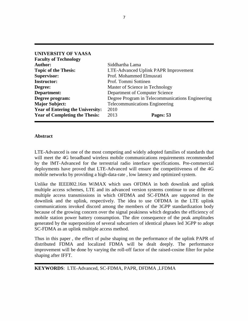
Abstract
LTE-Advanced is one of the most competing and widely adopted families of standards that
will meet the 4G broadband wireless mobile communications requirements recommended
by the IMT-Advanced for the terrestrial radio interface specifications. Pre-commercial
deployments have proved that LTE-Advanced will ensure the competitiveness of the 4G
mobile networks by providing a high-data-rate , low latency and optimized system.
Unlike the IEEE802.16m WiMAX which uses OFDMA in both downlink and uplink
multiple access schemes, LTE and its advanced version systems continue to use different
multiple access transmissions in which OFDMA and SC-FDMA are supported in the
downlink and the uplink, respectively. The idea to use OFDMA in the LTE uplink
communications invoked discord among the members of the 3GPP standardization body
because of the growing concern over the signal peakiness which degrades the efficiency of
mobile station power battery consumption. The dire consequence of the peak amplitudes
generated by the superposition of several subcarriers of identical phases led 3GPP to adopt
SC-FDMA as an uplink multiple access method.
Thus in this paper , the effect of pulse shaping on the performance of the uplink PAPR of
distributed FDMA and localized FDMA will be dealt deeply. The performance
improvement will be done by varying the roll-off factor of the raised-cosine filter for pulse
shaping after IFFT.
KEYWORDS: LTE-Advanced, SC-FDMA, PAPR, DFDMA ,LFDMA
8
1. INTRODUCTION
In pre-industrial age, information was transmitted over line-of-sights distances using smoke
signals, torch signaling, flashing mirrors, signal flares or semaphore flags. To convey
complex messages with these elementary signals over large distances, observation stations
were usually built on hilltops and along roads before these early communications were
replaced by the telephone line. A few decades after the telephone was developed, the idea
to relay information signals in free space was conceived leading to a rapid breakthrough of
radio communications which enable transmissions over large distances with better quality ,
less power and smaller , cheaper devices (Goldsmith 2005: 1-3). In connection with this
advancement of the radio technology, public and private radio communications, television
broadcasts and wireless networking have gained a worldwide popularity and become
inseparable from the daily lives of human beings.
In the last decade, there have been many advances in physical-layer wireless
communication theory and their implementation in systems such as GSM, CDMA2000, 1x
EV-DO and other wireless standards. The interplay between the theoretical concepts and
their implementation in these systems have remained to be of great interest to engineers
who are devoted their time and energy improving the performance of the wireless
communications since the wireless technology is obviously one of the most dynamic areas
in the field of radio communication which has been around for over a century.
The successful implementation of a theoretical concept requires an understanding of how
the system as a whole reacts to the transmission channels. One of these challenging
problems is fading ―the time variation of the channel strengths due to small-scale effect of
multi-path transmissions, as well as large-scale effect due to long-distance signal peak
attenuation/path loss and shadowing by obstacles, while the other problem is the
interference between the transmitter and the receiver in both the uplink and the downlink
cellular systems as wireless users communicate over the air (Tse & Viswanath 2005: 24).
Thus, to encounter these challenges, the design of wireless systems has traditionally
9
focused on increasing the reliability of the air interface which has recently been superseded
by the shift of the design more towards increasing spectral efficiency.
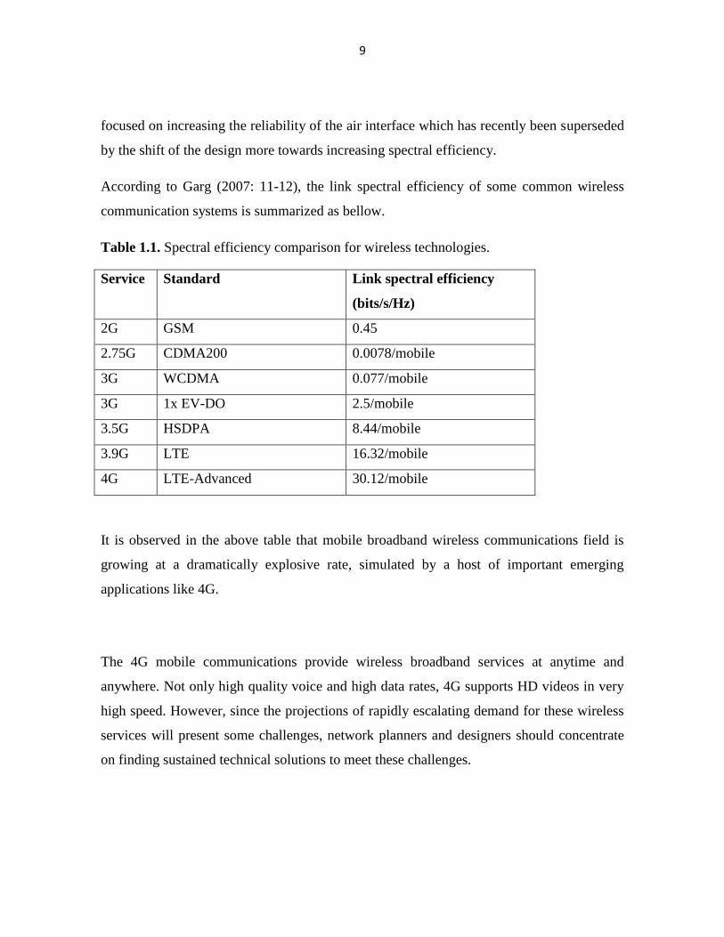
According to Garg (2007: 11-12), the link spectral efficiency of some common wireless
communication systems is summarized as bellow.
Table 1.1. Spectral efficiency comparison for wireless technologies.
Service Standard
Link spectral efficiency
(bits/s/Hz)
2G GSM 0.45
2.75G CDMA200 0.0078/mobile
3G WCDMA 0.077/mobile
3G 1x EV-DO 2.5/mobile
3.5G HSDPA 8.44/mobile
3.9G LTE 16.32/mobile
4G LTE-Advanced 30.12/mobile
It is observed in the above table that mobile broadband wireless communications field is
growing at a dramatically explosive rate, simulated by a host of important emerging
applications like 4G.
The 4G mobile communications provide wireless broadband services at anytime and
anywhere. Not only high quality voice and high data rates, 4G supports HD videos in very
high speed. However, since the projections of rapidly escalating demand for these wireless
services will present some challenges, network planners and designers should concentrate
on finding sustained technical solutions to meet these challenges.
10
According to Nakamura (2009), the IMT-Advanced requirements for the radio interface
technologies and core networks for 4G mobile broadband communications include the
following:
improvement of spectral efficiency ;
different traffic support for real-time and non-real-time applications;
re-use of existing cell site infrastructure ;
flexible spectral allocation;
lower cost per bit;
improved Quality of Service;
increasing coverage;
improvement of latency ,capacity and throughput;
simplified core network; and
optimized IP traffic and services.
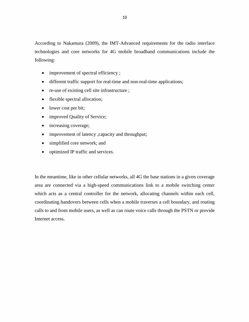
In the meantime, like in other cellular networks, all 4G the base stations in a given coverage
area are connected via a high-speed communications link to a mobile switching center
which acts as a central controller for the network, allocating channels within each cell,
coordinating handovers between cells when a mobile traverses a cell boundary, and routing
calls to and from mobile users, as well as can route voice calls through the PSTN or provide
Internet access.
11
Mobile
Switching
Office
Local
ExchangeLong-distance
Network
Internet
Base
Station
Cellular
Phone
Figure 1.1. General cellular network architecture.
1.1. Overview of Mobile Wireless Standards
There is no doubt that standardization is required for communication systems to effectively
interoperate with each other. Nationally or internationally recognized telecommunications
committees usually adopt standards that are developed by other organizations so that
competing companies will be able to innovate and differentiate their products from other
standardized systems. The drawback of standardization is that the standards process is not
perfect as frictions arising from own agendas and best interests of the customers of the
company participants can lead to unrevitalized failure in technologies. It can also hinder
innovations and improvements to the existing standards.
GSM and cdmaOne were the most prevalent 2G mobile wireless communication standards,
evolved to UMTS with CDMA-2000 in close contention as two of the most competing 3G
technologies. One of the most challenging problems to all radio access technologies is to
divide the finite RF spectrum among the multiple users as efficiently as possible.GSM uses
TDMA and FDMA for user and cell separation while UMTS, cdmaOne and CDMA-2000
use CDMA. Different from these standards are WiMAX which uses OFDMA in both UL

12
and DL transmissions, and LTE system which uses OFDMA in the DL transmission and
SC-FDMA in UL transmission. (Grag 2007: 5-10.)
1.2. Introduction to LTE-Advanced
LTE-Advanced standardization within the 3GPP has reached a mature state to be
commercially deployed within the next few months. It is a natural evolution of 2G GSM
and 3G UMTS, and an advanced version of LTE.
In September 2009, the 3GPP partners made a technical report to the ITU proposing LTE-
Advanced requirements in the technical Specification Group Radio Access Network in LTE
Release 10 & Beyond (Nakamura 2009). The radio interface technologies that were
included in the ITU requirements for IMT-Advanced systems are given below:
a high degree of commonality functionality worldwide;
compatibility of services within IMT and with fixed networks;
capability of interworking with other radio access systems;
high quality mobile services;
user equipment suitable for worldwide use;
user-friendly applications, services and equipment;
worldwide roaming capability; and
enhanced peak date rates (100 Mb/s for high and 1Gb/s for low mobility).
The details of these requirements are summarized in the following table as according to
Rohde and Schwarz (2010).
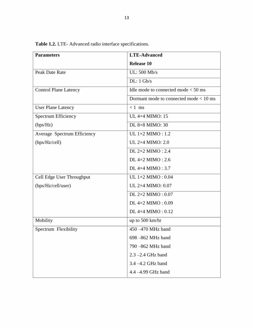
13
Table 1.2. LTE- Advanced radio interface specifications.
Parameters LTE-Advanced
Release 10
Peak Date Rate UL: 500 Mb/s
DL: 1 Gb/s
Control Plane Latency Idle mode to connected mode < 50 ms
Dormant mode to connected mode < 10 ms
User Plane Latency < 1 ms
Spectrum Efficiency
(bps/Hz)
UL 4×4 MIMO: 15
DL 8×8 MIMO: 30
Average Spectrum Efficiency
(bps/Hz/cell)
UL 1×2 MIMO : 1.2
UL 2×4 MIMO: 2.0
DL 2×2 MIMO : 2.4
DL 4×2 MIMO : 2.6
DL 4×4 MIMO : 3.7
Cell Edge User Throughput
(bps/Hz/cell/user)
UL 1×2 MIMO : 0.04
UL 2×4 MIMO: 0.07
DL 2×2 MIMO : 0.07
DL 4×2 MIMO : 0.09
DL 4×4 MIMO : 0.12
Mobility up to 500 km/hr
Spectrum Flexibility 450 –470 MHz band
698 –862 MHz band
790 –862 MHz band
2.3 –2.4 GHz band
3.4 –4.2 GHz band
4.4 –4.99 GHz band
14
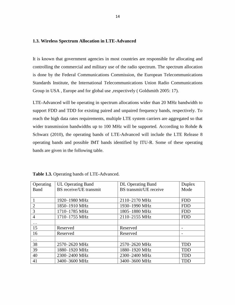
1.3. Wireless Spectrum Allocation in LTE-Advanced
It is known that government agencies in most countries are responsible for allocating and
controlling the commercial and military use of the radio spectrum. The spectrum allocation
is done by the Federal Communications Commission, the European Telecommunications
Standards Institute, the International Telecommunications Union Radio Communications
Group in USA , Europe and for global use ,respectively ( Goldsmith 2005: 17).
LTE-Advanced will be operating in spectrum allocations wider than 20 MHz bandwidth to
support FDD and TDD for existing paired and unpaired frequency bands, respectively. To
reach the high data rates requirements, multiple LTE system carriers are aggregated so that
wider transmission bandwidths up to 100 MHz will be supported. According to Rohde &
Schwarz (2010), the operating bands of LTE-Advanced will include the LTE Release 8
operating bands and possible IMT bands identified by ITU-R. Some of these operating
bands are given in the following table.
Table 1.3. Operating bands of LTE-Advanced.
Operating
Band
UL Operating Band
BS receive/UE transmit
DL Operating Band
BS transmit/UE receive
Duplex
Mode
1 1920–1980 MHz 2110–2170 MHz FDD
2 1850–1910 MHz 1930–1990 MHz FDD
3 1710–1785 MHz 1805–1880 MHz FDD
4 1710–1755 MHz 2110–2155 MHz FDD
…
15 Reserved Reserved -
16 Reserved Reserved -
…
38 2570–2620 MHz 2570–2620 MHz TDD
39 1880–1920 MHz 1880–1920 MHz TDD
40 2300–2400 MHz 2300–2400 MHz TDD
41 3400–3600 MHz 3400–3600 MHz TDD

15
1.4. Goal and Scope of the Thesis
The primary objective of this thesis project is to study the effect of pulse shaping on the
performance of LTE-Advanced uplink PAPR of distributed FDMA and localized FDMA.
The idea to adopt OFDMA as an uplink multiple access scheme was so contentious at early
stage of LTE development and thereby grabbed everybody’s attention because of the
growing concern over the signal peakiness which impairs the efficiency of terminal battery
consumptions. This led the 3GPP partners to have adopted SC-FDMA as a low signal
peakiness uplink multiple access method as the performance improvement could be further
enhanced by varying the roll-off factors of the raised-cosine filter for pulse shaping after
IFFT.
1.5. Structure of the Thesis
Discussed in this chapter is the introduction which gets us familiar with 4G mobile wireless
technologies and some radio interface parameters of LTE-Advanced, the subsequent
chapters in this thesis are organized as follows.
Chapter 2 introduces the configuration of the LTE and its advanced version core network –
a new system architecture which has improved the data transmission capacity of the
wireless broadband communications.
Chapter 3 discusses the uplink multiple access transmission which is employed by
subcarrier mapping and the implementation of FFT/IFFT. This is a unique feature of LTE
and LTE-Advanced systems that the 3GPP standardization body was compelled to adopt in
a bid to lower the signal peaking which derails the performance of the uplink
communications.

16
Chapter 4 covers the measures of the uplink signal peakiness for different modulation sizes,
low PAPR modulations and the raised-cosine pulse shaping techniques to reduce PAPR for
SC-FDMA. This chapter is the main part of the thesis project, in which the roll-off factors
of the pulse shaping will vary to investigate the levels of the uplink signal peakiness.
In chapter 5, conclusions which can summarize the findings in this paper are drawn, as well
as some gaps which must be filled in the future works will be proposed.
17
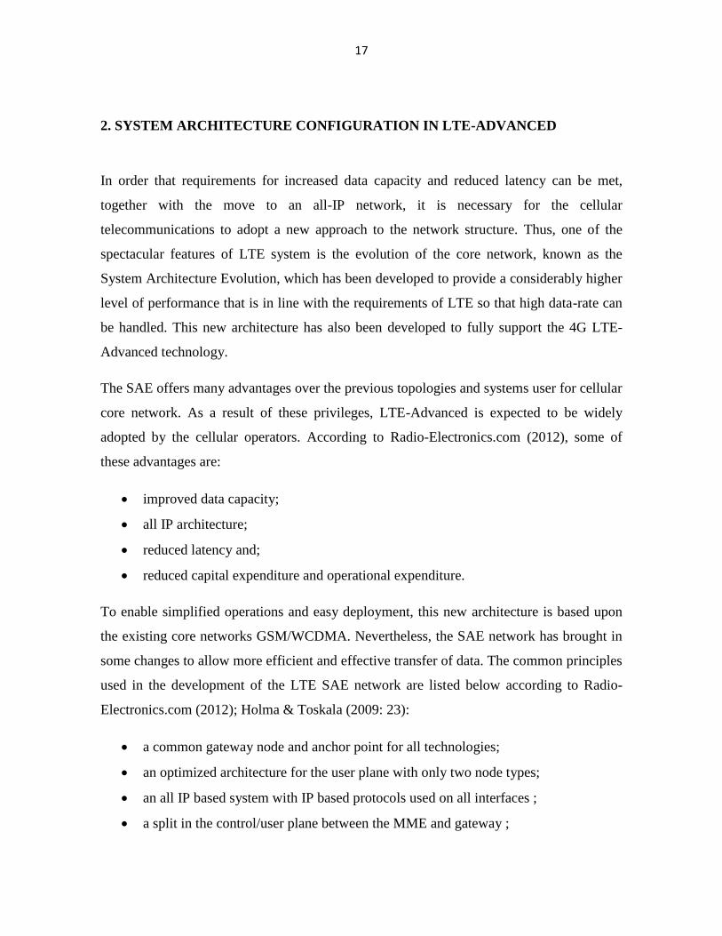
2. SYSTEM ARCHITECTURE CONFIGURATION IN LTE-ADVANCED
In order that requirements for increased data capacity and reduced latency can be met,
together with the move to an all-IP network, it is necessary for the cellular
telecommunications to adopt a new approach to the network structure. Thus, one of the
spectacular features of LTE system is the evolution of the core network, known as the
System Architecture Evolution, which has been developed to provide a considerably higher
level of performance that is in line with the requirements of LTE so that high data-rate can
be handled. This new architecture has also been developed to fully support the 4G LTE-
Advanced technology.
The SAE offers many advantages over the previous topologies and systems user for cellular
core network. As a result of these privileges, LTE-Advanced is expected to be widely
adopted by the cellular operators. According to Radio-Electronics.com (2012), some of
these advantages are:
improved data capacity;
all IP architecture;
reduced latency and;
reduced capital expenditure and operational expenditure.
To enable simplified operations and easy deployment, this new architecture is based upon
the existing core networks GSM/WCDMA. Nevertheless, the SAE network has brought in
some changes to allow more efficient and effective transfer of data. The common principles
used in the development of the LTE SAE network are listed below according to Radio-
Electronics.com (2012); Holma & Toskala (2009: 23):
a common gateway node and anchor point for all technologies;
an optimized architecture for the user plane with only two node types;
an all IP based system with IP based protocols used on all interfaces ;
a split in the control/user plane between the MME and gateway ;
18
a radio access network /core network functional similar to that used on
WCDMA/HSPA;
integration of non-3GPP access technologies using client as well as network based
mobile-IP.
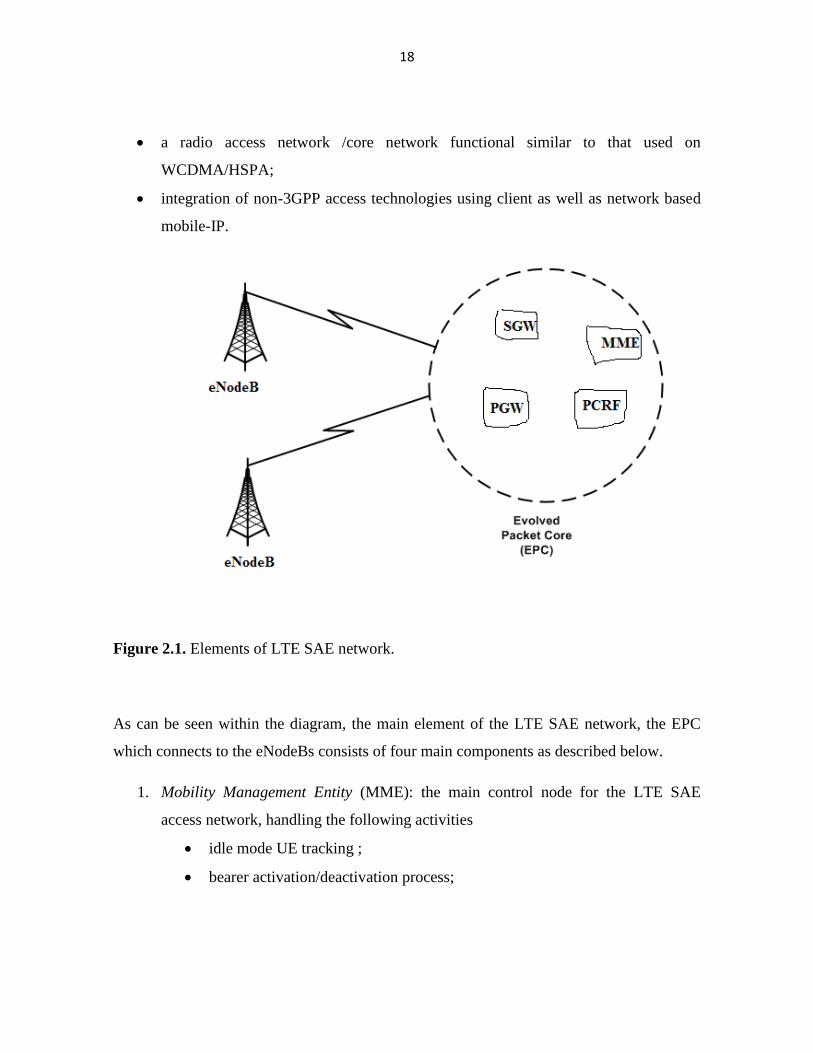
Figure 2.1. Elements of LTE SAE network.
As can be seen within the diagram, the main element of the LTE SAE network, the EPC
which connects to the eNodeBs consists of four main components as described below.
1. Mobility Management Entity (MME): the main control node for the LTE SAE
access network, handling the following activities
idle mode UE tracking ;
bearer activation/deactivation process;

19
choice of SGW for a UE at the initial attach and at time of intra-LTE
handover involving core network node location ;
user authentication by interaction with Home Subscriber Server (HSS) and
implementing roaming restrictions;
provides temporary identities for UEs;
supports lawful interception of signaling ;
paging procedure; and
provides the control plane function for mobility between LTE and 2G/3G
access networks .
2. Serving Gateway (SGW): a data plane element within the LTE SAE, managing the
user plane mobility and also acting as the main border between the RAN and the
core network. It also maintains the data paths between the eNodeBs and PDN
gateways so that when UEs move across areas served by different eNodeBs, the
SGW serves as a mobility anchor ensuring that the data path is maintained.
3. PDN Gateway (PGW): provides connectivity from the UE to external packet data
networks by being the point of exit and entry of traffic for the UE. The UE may
have connectivity with more than one PGW for accessing multiple PDNs. The PGW
performs policy enforcement, packet filtering for each user, charging support,
lawful interception and packet screening.
4. Policy and Charging Rules Function (PCRF): is the node designated in real-time to
detect the service flow, enforce charging policy in a multimedia network. Apart
from its ability to be deployed as a standalone entity, PCRF can be integrated with
different platforms like billing, rating, and charging and subscriber database.
20
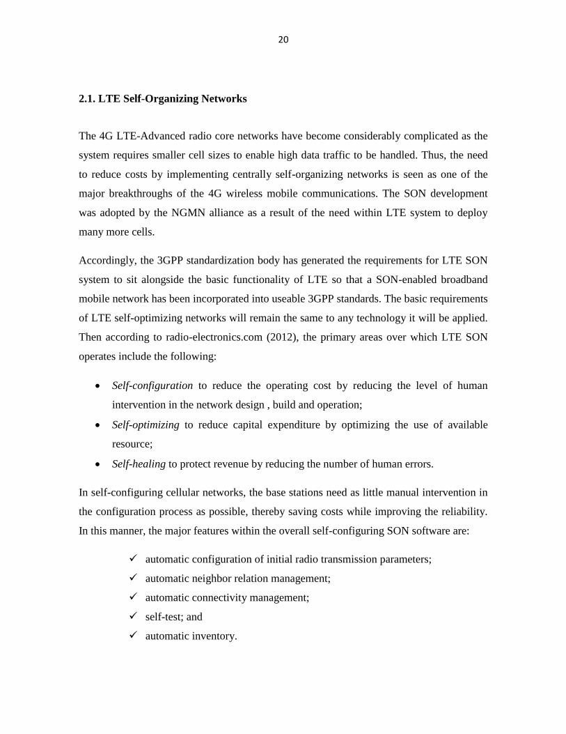
2.1. LTE Self-Organizing Networks
The 4G LTE-Advanced radio core networks have become considerably complicated as the
system requires smaller cell sizes to enable high data traffic to be handled. Thus, the need
to reduce costs by implementing centrally self-organizing networks is seen as one of the
major breakthroughs of the 4G wireless mobile communications. The SON development
was adopted by the NGMN alliance as a result of the need within LTE system to deploy
many more cells.
Accordingly, the 3GPP standardization body has generated the requirements for LTE SON
system to sit alongside the basic functionality of LTE so that a SON-enabled broadband
mobile network has been incorporated into useable 3GPP standards. The basic requirements
of LTE self-optimizing networks will remain the same to any technology it will be applied.
Then according to radio-electronics.com (2012), the primary areas over which LTE SON
operates include the following:
Self-configuration to reduce the operating cost by reducing the level of human
intervention in the network design , build and operation;
Self-optimizing to reduce capital expenditure by optimizing the use of available
resource;
Self-healing to protect revenue by reducing the number of human errors.
In self-configuring cellular networks, the base stations need as little manual intervention in
the configuration process as possible, thereby saving costs while improving the reliability.
In this manner, the major features within the overall self-configuring SON software are:
automatic configuration of initial radio transmission parameters;
automatic neighbor relation management;
automatic connectivity management;
self-test; and
automatic inventory.
21
Once the system has been set up, the operational cost of the system should be optimized to
best meet the demands of the overall network. Thus, the self-optimization routines are
applied when the following events happen in the system:
change in propagation characteristics;
change in traffic patterns; and
change in deployments.
Since faults which can cause major inconvenience to the users of the system network may
occur, the self-healing aspects of the SON network will help the faults be detected and their
effects masked to the users while the cellular network undergoes repairs. Then the number
of areas that are addressed within the scope of self-healing includes the following:
self recovery of software;
self-healing of board faults;
cell outage detection;
cell outage recovery;
cell outage compensation; and
return from cell outage compensation.
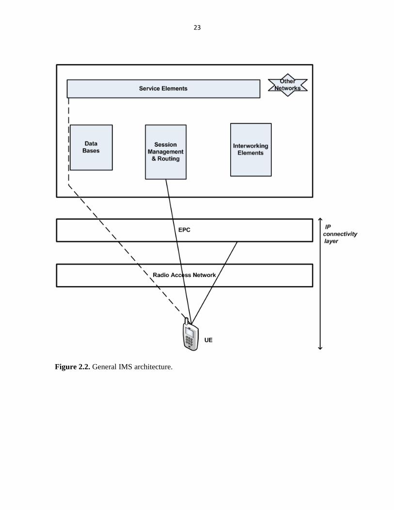
2.2. IMS Architecture
Since LTE system only supports packet switching which runs over the standard IP-network
, telecom operators and service providers which have been providing the 2G and the 3G
voice calls will have to re-engineer their voice call networks. The implementation of this
new adoption is based on the IMS network which provides all the services the Internet
provides.
22
In this way, IMS will help service providers control and charge both mobile and fixed
multimedia services which the users are able to access when roaming and from their home
networks as well. This architectural frame for delivering IP multimedia services uses the
SIP protocols as a signaling mechanism to ease the integration with the internet, thereby
allowing the voice, text and multimedia services to traverse all connected networks ( 3GPP
IMS: 2012). The work has enabled the 3GPP to ensure maximum reusability of internet
standards, preventing the fragmentation of IMS standards.
23
Figure 2.2. General IMS architecture.
24
2.3. Session Management and Routing
For a mobile station to use the services it needs, service signaling is directly run with the
Application Servers. In session management and routing protocols, the CSCFs are in
charge of the UE’s registration in IMS and invoke the databases to gather appropriate
information. Regarding the UE’s service session in IMS, the CSCFs will signal the service
elements to identify the type of connectivity needed for the services. The connection
between the networks is controlled by the Interworking Elements. In addition, CSCF is
playing an important role in handling an emergency call service in IMS, which has got its
own dedicated channel.
2.4. Introduction to Mobility and Handover
Mobility offers a number of advantages to the user equipments as it enables the nomadic
users to get connected anywhere within the providers network. Pre-commercial
deployments of the 4G LTE-Advanced mobile communications have proved that delay-
sensitive services such as voice calls or real-time video streams can be maintained while
travelling by high-speed bullet trains.
Seamless mobility to guarantee a ubiquitous service has been a principal design focus for
the cellular networks. Therefore, it is clear that stringent requirements should be set to
avoid non-real time data loss during the service break in the handover procedure as tearing
down and setting up new connections instead of seamless handovers may degrade the end-
user data experience.
25
2.4.1. Mobility Scenarios
In order to find a suitable cell for initial camping with the best radio conditions based on
cell RSRP measurements—measures signal power from a specific sector while potentially
excluding noise and interference from other sectors, an LTE mobile station is powered on
so that it scans all E-UTRA RF bands and starts to listen to the broadcast channels for
synchronization. When the serving cell is selected, the mobile station accesses the network
to measure intra-frequency neighbor’s candidates for better cell reselection. The mobile
station can also do the inter-frequency measurements of the neighboring cell received from
the broadcast channel. The neighboring cell list contains system neighboring cells and their
frequency carriers, and the end-user’s parameters used in the measurements.
2.4.2. Handover Characteristics in LTE-Advanced
Handover is an important part of cellular communication system as it is used to providing
continuity in cellular architectures of mobile services to a user travelling over cell
boundaries in cellular infrastructure. For a user crossing the cell edge, it is more favorable
to use the radio resources of the new target cell because the signal strength of the old cell
decreases as the user approaches the target cell. The ability of a cellular network to perform
efficient handovers in crucial to offer attractive services as real-time applications or
streaming media are the merits of the 4G mobile networks.
The existence of the radio network connection to only one base station at a time makes
handovers within an LTE and its advanced version tough even though the signaling
connection and user plane tunnel are established to the target cell prior to switching the
radio connection.
26
According to Holma et al. (2010: 167-171), the handover procedure in LTE system consists
of three components, namely handover preparation, handover execution and handover
completion. In the preparation process, data flows between the mobile station and the core
network. At this stage, measurement control which includes UE measurement parameters is
taken. The UE sends the measurement report to the serving eNodeB which establishes the
signaling connection and GTP tunnel to the target cell which ensures the connectivity of the
network connection by performing handover and admission control according to the
availability of the radio resources. In the execution phase, the source eNodeB sends a
handover command to the UE. If there is available resource at the target cell, the UE will
switch the radio connection from the station to the target station. Finally in the handover
completion, the target cell informs the MME that the user plane path has changed. The core
network connection is updated in order for the data start flowing on the new path to the
target cell.
27
3. INRODUCTION TO UPLINK MULTIPLE SCHEME
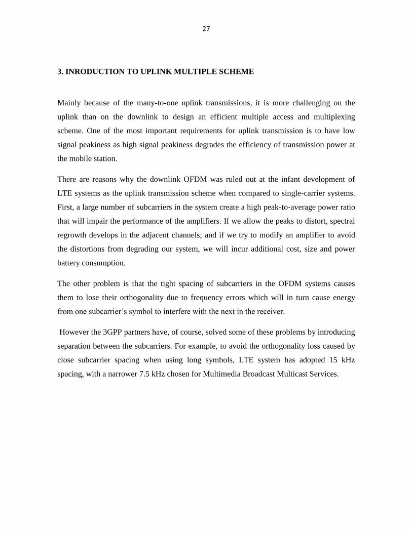
Mainly because of the many-to-one uplink transmissions, it is more challenging on the
uplink than on the downlink to design an efficient multiple access and multiplexing
scheme. One of the most important requirements for uplink transmission is to have low
signal peakiness as high signal peakiness degrades the efficiency of transmission power at
the mobile station.
There are reasons why the downlink OFDM was ruled out at the infant development of
LTE systems as the uplink transmission scheme when compared to single-carrier systems.
First, a large number of subcarriers in the system create a high peak-to-average power ratio
that will impair the performance of the amplifiers. If we allow the peaks to distort, spectral
regrowth develops in the adjacent channels; and if we try to modify an amplifier to avoid
the distortions from degrading our system, we will incur additional cost, size and power
battery consumption.
The other problem is that the tight spacing of subcarriers in the OFDM systems causes
them to lose their orthogonality due to frequency errors which will in turn cause energy
from one subcarrier’s symbol to interfere with the next in the receiver.
However the 3GPP partners have, of course, solved some of these problems by introducing
separation between the subcarriers. For example, to avoid the orthogonality loss caused by
close subcarrier spacing when using long symbols, LTE system has adopted 15 kHz
spacing, with a narrower 7.5 kHz chosen for Multimedia Broadcast Multicast Services.
28
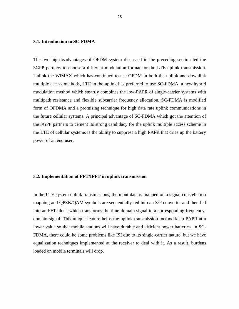
3.1. Introduction to SC-FDMA
The two big disadvantages of OFDM system discussed in the preceding section led the
3GPP partners to choose a different modulation format for the LTE uplink transmission.
Unlink the WiMAX which has continued to use OFDM in both the uplink and downlink
multiple access methods, LTE in the uplink has preferred to use SC-FDMA, a new hybrid
modulation method which smartly combines the low-PAPR of single-carrier systems with
multipath resistance and flexible subcarrier frequency allocation. SC-FDMA is modified
form of OFDMA and a promising technique for high data rate uplink communications in
the future cellular systems. A principal advantage of SC-FDMA which got the attention of
the 3GPP partners to cement its strong candidacy for the uplink multiple access scheme in
the LTE of cellular systems is the ability to suppress a high PAPR that dries up the battery
power of an end user.
3.2. Implementation of FFT/IFFT in uplink transmission
In the LTE system uplink transmissions, the input data is mapped on a signal constellation
mapping and QPSK/QAM symbols are sequentially fed into an S/P converter and then fed
into an FFT block which transforms the time-domain signal to a corresponding frequency-
domain signal. This unique feature helps the uplink transmission method keep PAPR at a
lower value so that mobile stations will have durable and efficient power batteries. In SC-
FDMA, there could be some problems like ISI due to its single-carrier nature, but we have
equalization techniques implemented at the receiver to deal with it. As a result, burdens
loaded on mobile terminals will drop.
29
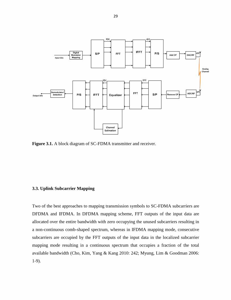
Figure 3.1. A block diagram of SC-FDMA transmitter and receiver.
3.3. Uplink Subcarrier Mapping
Two of the best approaches to mapping transmission symbols to SC-FDMA subcarriers are
DFDMA and IFDMA. In DFDMA mapping scheme, FFT outputs of the input data are
allocated over the entire bandwidth with zero occupying the unused subcarriers resulting in
a non-continuous comb-shaped spectrum, whereas in IFDMA mapping mode, consecutive
subcarriers are occupied by the FFT outputs of the input data in the localized subcarrier
mapping mode resulting in a continuous spectrum that occupies a fraction of the total
available bandwidth (Cho, Kim, Yang & Kang 2010: 242; Myung, Lim & Goodman 2006:
1-9).

30
Let us take the following values for a practicality show because with the number of
subcarriers in system M=1024 in a practical LTE-Advanced, the number of possible
mappings of the N symbols in each block onto the M>N transmission subcarriers will be too
large to consider.
M=12 the number subcarriers in the system
N=4 the data block size
S=3 the number of users
FFT:
1
0
/2N
n
Nnkj
nk exX
X0 X1 X2 X3
X0 0 0 X1 0 0 X2 0 0 X3 0 0
X0 X1 X2 X3 0 0 0 0 0 0 0 0
Figure 3.2. SC-FDMA transmit symbols in frequency domain for M=12, N=4 and S=3.
It is worth noting in figure 3.1 that after subcarrier mapping, the frequency data is
transformed back to the time domain by applying M-point IFFT.
x0 x1 x2 x3
31
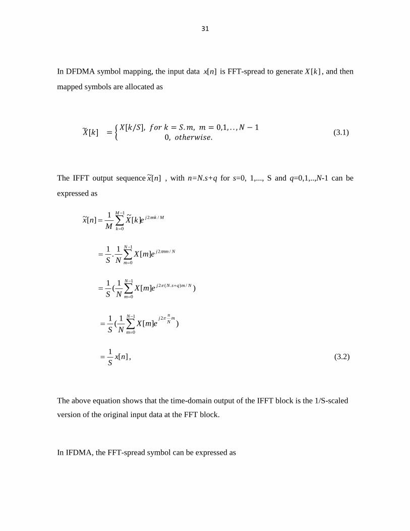
In DFDMA symbol mapping, the input data ][nx is FFT-spread to generate ][kX , and then
mapped symbols are allocated as
{
(3.1)
The IFFT output sequence ][~ nx , with n=N.s+q for s=0, 1,..., S and q=0,1,..,N-1 can be
expressed as
MnkjM
k
ekXM
nx /21
0
][~1
][~
1
0
/2][1
.1 N
m
NnmjemXNS
1
0
/).(2 )][1
(1 N
m
NmqsNjemXNS
1
0
2
)][1
(1 N
m
mN
nj
emXNS
][1
nxS
, (3.2)
The above equation shows that the time-domain output of the IFFT block is the 1/S-scaled
version of the original input data at the FFT block.
In IFDMA, the FFT-spread symbol can be expressed as
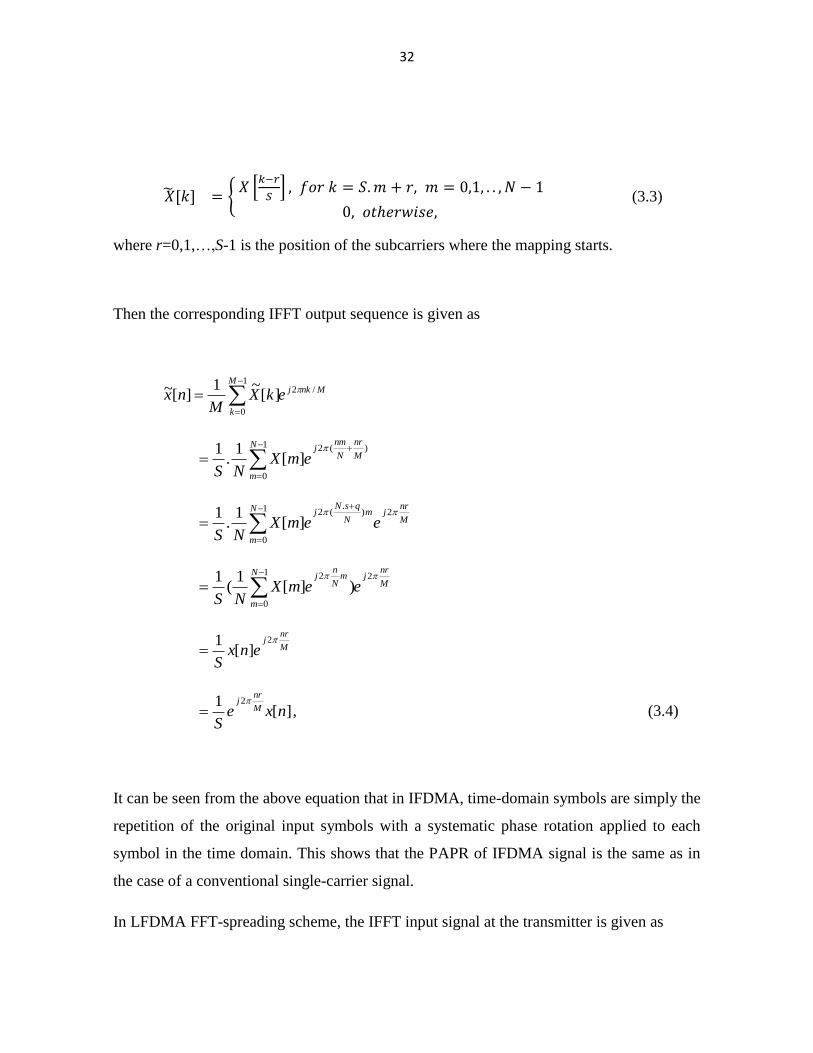
32
{ [
]
(3.3)
where r=0,1,…,S-1 is the position of the subcarriers where the mapping starts.
Then the corresponding IFFT output sequence is given as
MnkjM
k
ekXM
nx /21
0
][~1
][~
1
0
)(2
][1
.1 N
m
M
nr
N
nmj
emXNS
M
nrjN
m
mN
qsNj
eemXNS
21
0
).
(2
][1
.1
M
nrjN
m
mN
nj
eemXNS
21
0
2
)][1
(1
M
nrj
enxS
2
][1
][1 2
nxeS
M
nrj
, (3.4)
It can be seen from the above equation that in IFDMA, time-domain symbols are simply the
repetition of the original input symbols with a systematic phase rotation applied to each
symbol in the time domain. This shows that the PAPR of IFDMA signal is the same as in
the case of a conventional single-carrier signal.
In LFDMA FFT-spreading scheme, the IFFT input signal at the transmitter is given as
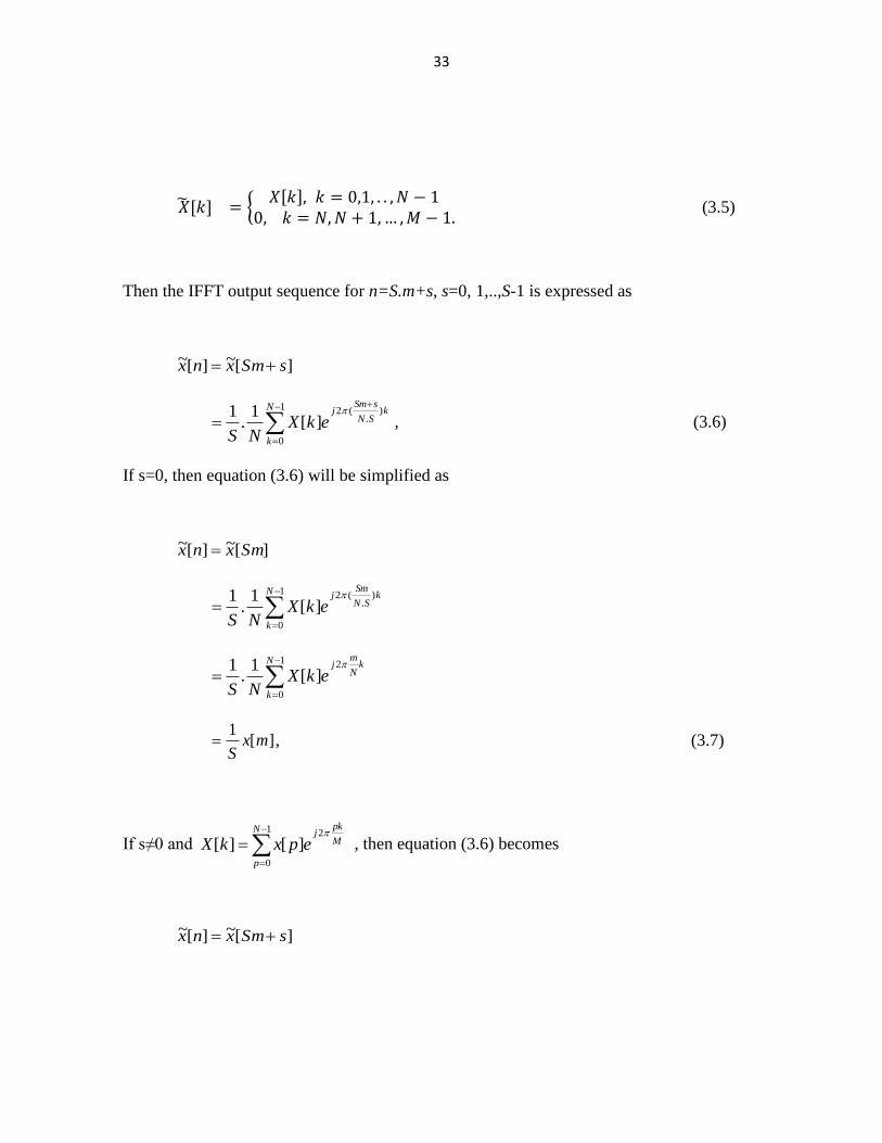
33
{
(3.5)
Then the IFFT output sequence for n=S.m+s, s=0, 1,..,S-1 is expressed as
][~][~ sSmxnx
1
0
).
(2
][1
.1 N
k
kSN
sSmj
ekXNS
, (3.6)
If s=0, then equation (3.6) will be simplified as
][~][~ Smxnx
1
0
).
(2
][1
.1 N
k
kSN
Smj
ekXNS
1
0
2
][1
.1 N
k
kN
mj
ekXNS
][1
mxS
, (3.7)
If s≠0 and
1
0
2
][][N
p
M
pkj
epxkX
, then equation (3.6) becomes
][~][~ sSmxnx
34
1
0 2
/2
)(1
][1).1(
1 N
p j
Ssj
SN
s
N
pme
px
Ne
S
][ˆ.
).sin(
)/sin(1 1
0
)1(2
px
N
p
SN
sSmN
Sse
S
N
p
SN
SmsNj
, (3.8)
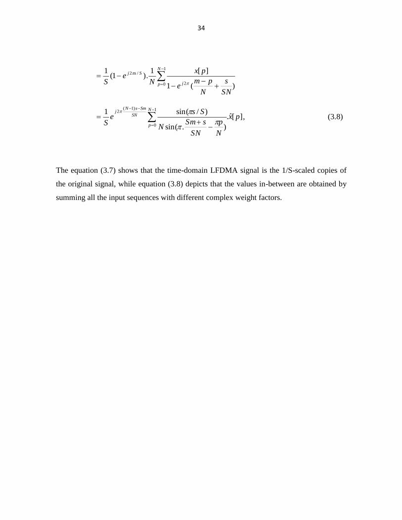
The equation (3.7) shows that the time-domain LFDMA signal is the 1/S-scaled copies of
the original signal, while equation (3.8) depicts that the values in-between are obtained by
summing all the input sequences with different complex weight factors.
35
4. TECHNIQUES TO REDUCE THE UPLINK SIGNAL PEAKINESS
In cellular systems, the downlink transmissions are one-to-many in which the base station
transmits simultaneous signals to multiple UEs in its coverage area, while the uplink
transmissions are many-to-one in a single UE has all its power transmission available to the
base stations. The downlink communication requires a very high transmission power
capability that should be shared among the mobile terminals to get the signals its
destination. However, UEs may not be able to transmit high data rates in the uplink due a
high peak transmission power limitation which would increase a data transmission time.
This adds delays in the system and also a signaling overhead because of an increase in the
number of scheduling grants as a result of the increased number of users requiring
simultaneous transmissions.
One of the possible solutions to increase the data rates of the uplink cellular
communications is to increase the size of the power amplifier. This would in fact be
achieved at the expense of increased power amplifier cost and an end user batter
consumption which is caused by the backoff required due to a high PAPR of the transmit
signal. To achieve maximum power efficiency in the uplink with the same amplifier size,
the signal peakiness needs to be reduced.
4.1. Introduction to PAPR
For amplifiers to avoid the introduction of signal distortion, the circuits must operate in a
linear region so that maximum amplification will be achieved. Nevertheless if there is a
high PAPR, the device is forced to run with lower amplification, thereof the peak power
does not lie in the non-linear gain region. This will dry up batteries on mobile cell-phones
36
more quickly and leads to increased power consumption. Hence, it is very important to
keep a low PAPR on the uplink multiple access techniques.
Let us represent a baseband signal for a complex data sequence ][nx as
k
skTtgnxtx )(][)(~ , (4.1)
where )(tg is a transmit pulse for each symbol ,and sT is the symbol duration.
Mapper +
Filter
g(t)
Filter
g(t)
Binary Data x(t)
X
X
tfc2sin2
tf c2cos2
][ nx I
][ nx Q
)(~ tx I
)(~ tx Q
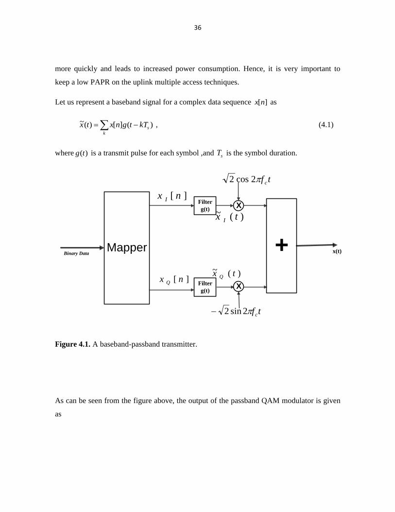
Figure 4.1. A baseband-passband transmitter.
As can be seen from the figure above, the output of the passband QAM modulator is given
as
37
}))(~)(~{(2)(2 tfj
QIcetxjtxtx
})(~{(22 tfj cetx
, (4.2)
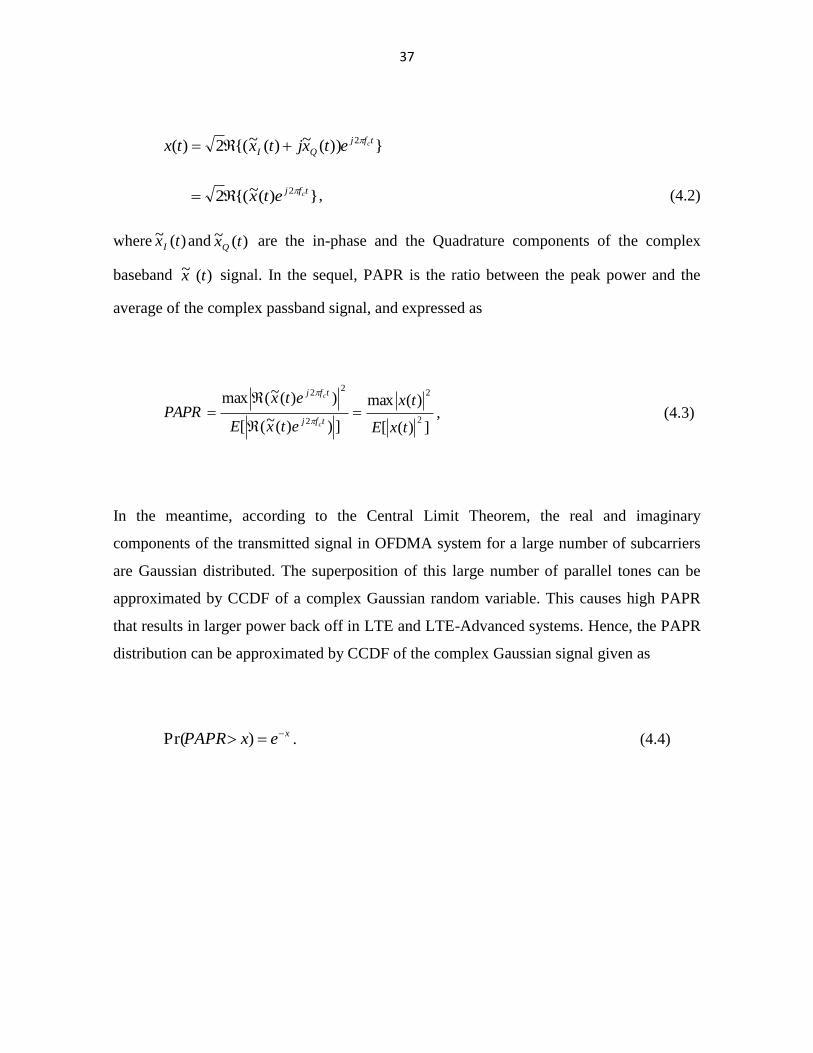
where )(~ txI and )(~ txQ are the in-phase and the Quadrature components of the complex
baseband )(~ tx signal. In the sequel, PAPR is the ratio between the peak power and the
average of the complex passband signal, and expressed as
])([
)(max
]))(~([
))(~(max
2
2
2
22
txE
tx
etxE
etxPAPR
tfj
tfj
c
c
, (4.3)
In the meantime, according to the Central Limit Theorem, the real and imaginary
components of the transmitted signal in OFDMA system for a large number of subcarriers
are Gaussian distributed. The superposition of this large number of parallel tones can be
approximated by CCDF of a complex Gaussian random variable. This causes high PAPR
that results in larger power back off in LTE and LTE-Advanced systems. Hence, the PAPR
distribution can be approximated by CCDF of the complex Gaussian signal given as
xexPAPR )Pr( . (4.4)
38
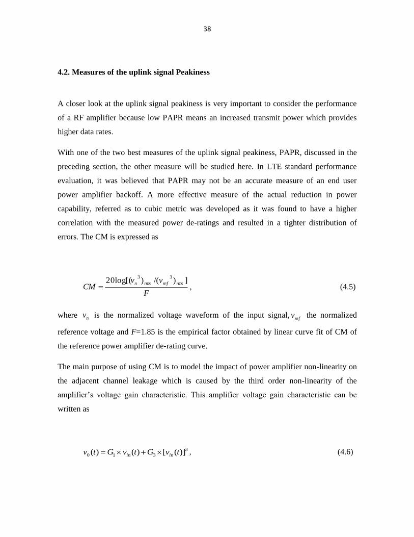
4.2. Measures of the uplink signal Peakiness
A closer look at the uplink signal peakiness is very important to consider the performance
of a RF amplifier because low PAPR means an increased transmit power which provides
higher data rates.
With one of the two best measures of the uplink signal peakiness, PAPR, discussed in the
preceding section, the other measure will be studied here. In LTE standard performance
evaluation, it was believed that PAPR may not be an accurate measure of an end user
power amplifier backoff. A more effective measure of the actual reduction in power
capability, referred as to cubic metric was developed as it was found to have a higher
correlation with the measured power de-ratings and resulted in a tighter distribution of
errors. The CM is expressed as
F
vvCM
rmsrefrmsn ])/()log[(2033
, (4.5)
where nv is the normalized voltage waveform of the input signal,refv the normalized
reference voltage and F=1.85 is the empirical factor obtained by linear curve fit of CM of
the reference power amplifier de-rating curve.
The main purpose of using CM is to model the impact of power amplifier non-linearity on
the adjacent channel leakage which is caused by the third order non-linearity of the
amplifier’s voltage gain characteristic. This amplifier voltage gain characteristic can be
written as
3
310 )]([)()( tvGtvGtv inin , (4.6)
39
where )(tvin is the input voltage to the amplifier , )(0 tv is the output voltage ; 1G and 3G
are the linear and the non-linear amplifier gains dependent on the amplifier design
,respectively.
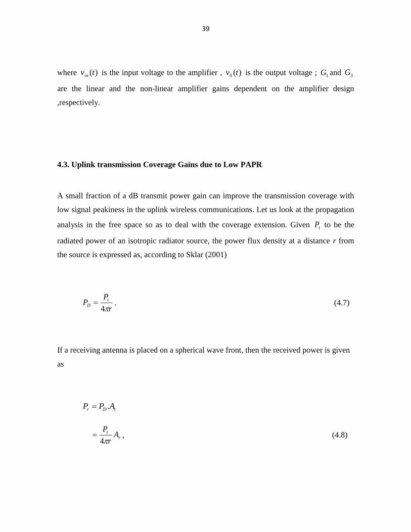
4.3. Uplink transmission Coverage Gains due to Low PAPR
A small fraction of a dB transmit power gain can improve the transmission coverage with
low signal peakiness in the uplink wireless communications. Let us look at the propagation
analysis in the free space so as to deal with the coverage extension. Given tP to be the
radiated power of an isotropic radiator source, the power flux density at a distance r from
the source is expressed as, according to Sklar (2001)
r
PP t
D4
. (4.7)
If a receiving antenna is placed on a spherical wave front, then the received power is given
as
rDr APP .
r
t Ar
P
4 , (4.8)
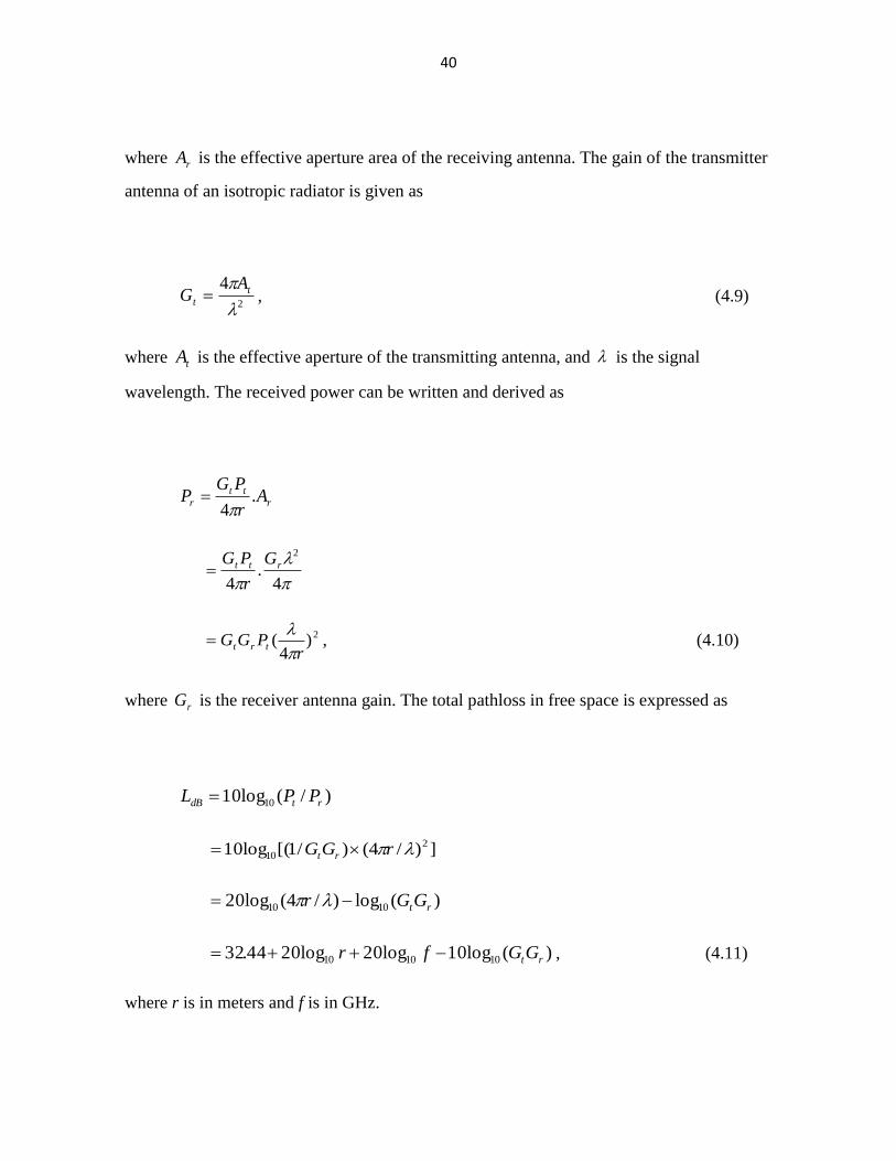
40
where rA is the effective aperture area of the receiving antenna. The gain of the transmitter
antenna of an isotropic radiator is given as
2
4
t
t
AG , (4.9)
where tA is the effective aperture of the transmitting antenna, and is the signal
wavelength. The received power can be written and derived as
r
tt
r Ar
PGP .
4
4.
4
2
rtt G
r
PG
2)4
(r
PGG trt
, (4.10)
where rG is the receiver antenna gain. The total pathloss in free space is expressed as
)/(log10 10 rtdB PPL
])/4()/1[(log10 2
10 rGG rt
)(log)/4(log20 1010 rtGGr
)(log10log20log2044.32 101010 rtGGfr , (4.11)
where r is in meters and f is in GHz.
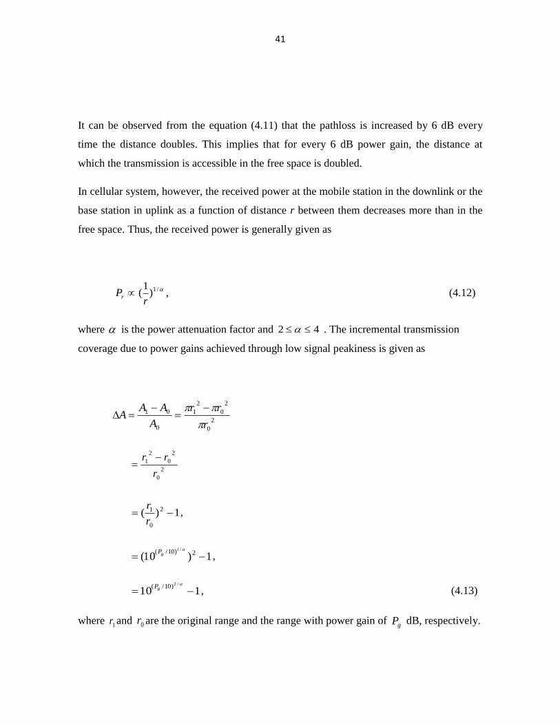
41
It can be observed from the equation (4.11) that the pathloss is increased by 6 dB every
time the distance doubles. This implies that for every 6 dB power gain, the distance at
which the transmission is accessible in the free space is doubled.
In cellular system, however, the received power at the mobile station in the downlink or the
base station in uplink as a function of distance r between them decreases more than in the
free space. Thus, the received power is generally given as
/1)1
(r
Pr , (4.12)
where is the power attenuation factor and 42 . The incremental transmission
coverage due to power gains achieved through low signal peakiness is given as
2
0
2
0
2
1
0
01
r
rr
A
AAA
2
0
2
0
2
1
r
rr
1)( 2
0
1 r
r,
1)10( 2)10/( /1
gP,
110/2)10/(
gP
, (4.13)
where 1r and 0r are the original range and the range with power gain of
gP dB, respectively.
42
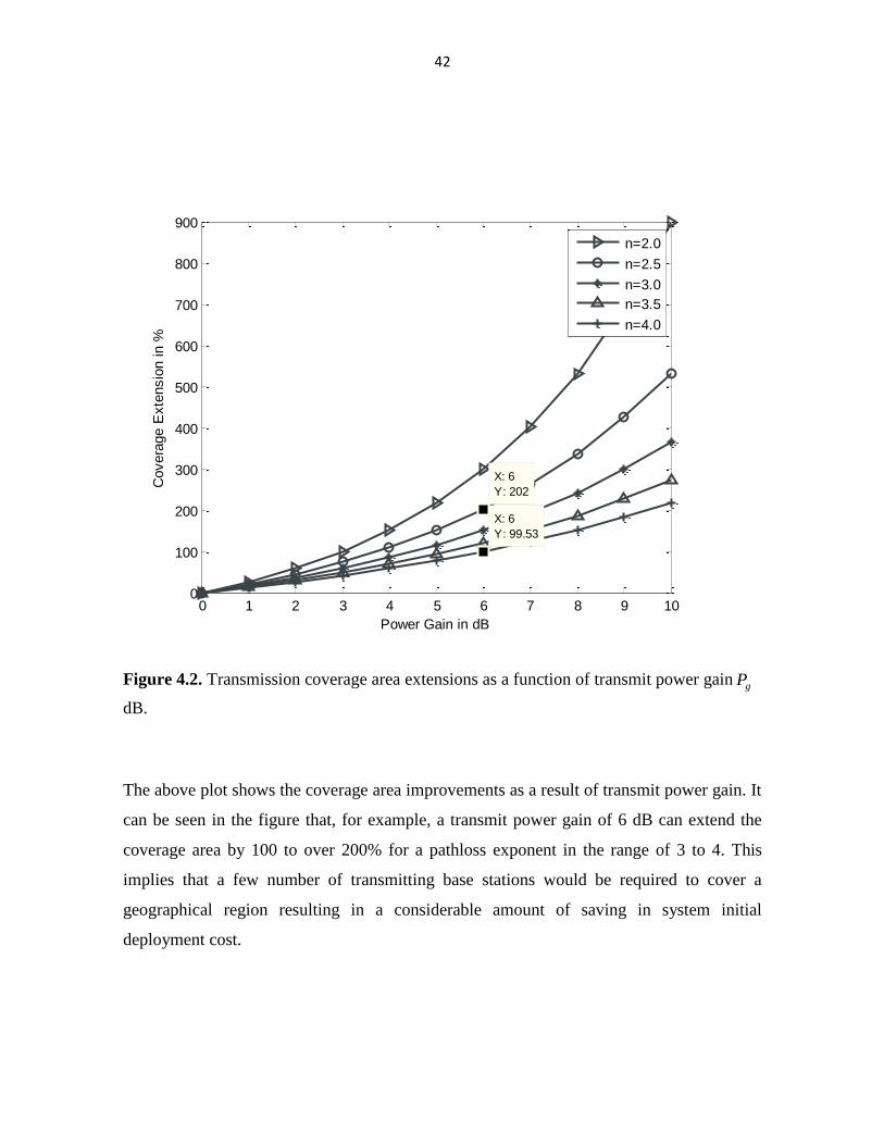
Figure 4.2. Transmission coverage area extensions as a function of transmit power gaingP
dB.
The above plot shows the coverage area improvements as a result of transmit power gain. It
can be seen in the figure that, for example, a transmit power gain of 6 dB can extend the
coverage area by 100 to over 200% for a pathloss exponent in the range of 3 to 4. This
implies that a few number of transmitting base stations would be required to cover a
geographical region resulting in a considerable amount of saving in system initial
deployment cost.
0 1 2 3 4 5 6 7 8 9 100
100
200
300
400
500
600
700
800
900
X: 6
Y: 99.53
Power Gain in dB
Covera
ge E
xte
nsio
n in %
X: 6
Y: 202
n=2.0
n=2.5
n=3.0
n=3.5
n=4.0
43
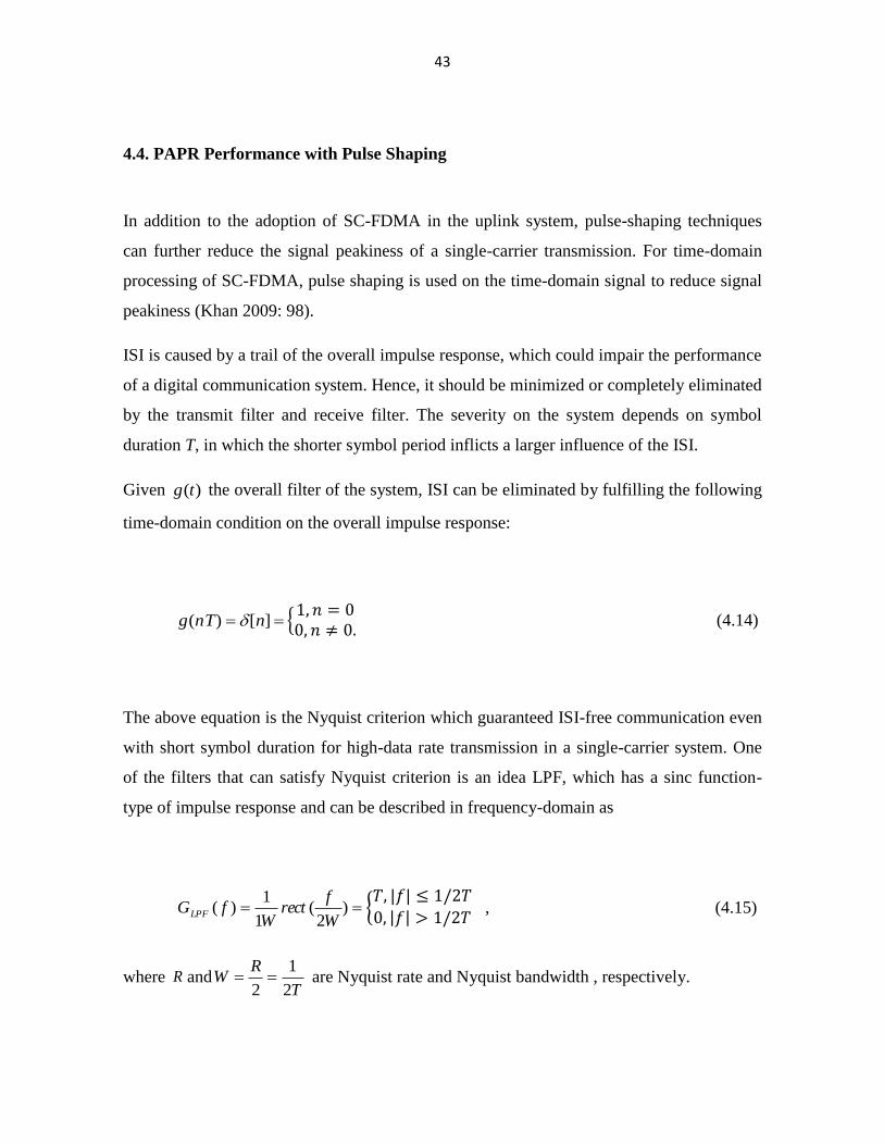
4.4. PAPR Performance with Pulse Shaping
In addition to the adoption of SC-FDMA in the uplink system, pulse-shaping techniques
can further reduce the signal peakiness of a single-carrier transmission. For time-domain
processing of SC-FDMA, pulse shaping is used on the time-domain signal to reduce signal
peakiness (Khan 2009: 98).
ISI is caused by a trail of the overall impulse response, which could impair the performance
of a digital communication system. Hence, it should be minimized or completely eliminated
by the transmit filter and receive filter. The severity on the system depends on symbol
duration T, in which the shorter symbol period inflicts a larger influence of the ISI.
Given )(tg the overall filter of the system, ISI can be eliminated by fulfilling the following
time-domain condition on the overall impulse response:
][)( nnTg {
(4.14)
The above equation is the Nyquist criterion which guaranteed ISI-free communication even
with short symbol duration for high-data rate transmission in a single-carrier system. One
of the filters that can satisfy Nyquist criterion is an idea LPF, which has a sinc function-
type of impulse response and can be described in frequency-domain as
)2
(1
1)(
W
frect
WfGLPF {
, (4.15)
where R andT
RW
2
1
2 are Nyquist rate and Nyquist bandwidth , respectively.
44
Even though the Nyquist bandwidth is the minimum possible bandwidth that is required to
realize the data rate without ISI, the ideal filter is not physically realizable because its
impulse response is not causal. Thus, we need to look for another physically realizable filter
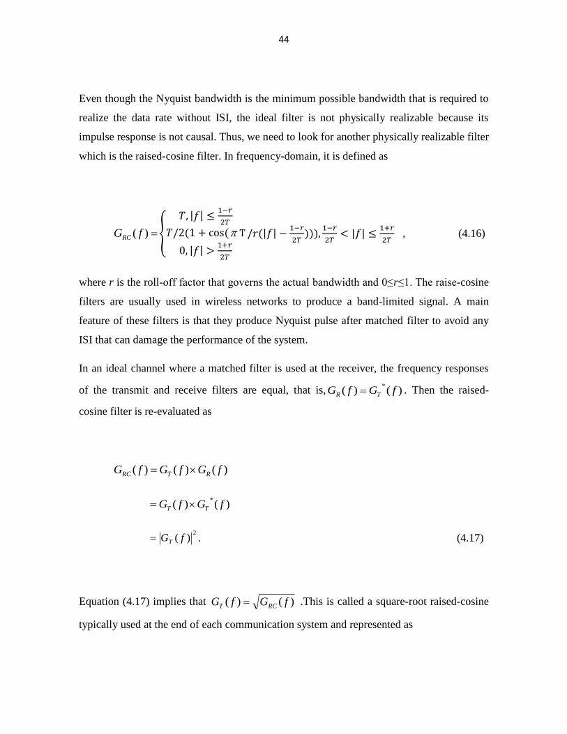
which is the raised-cosine filter. In frequency-domain, it is defined as
)( fGRC {
, (4.16)
where r is the roll-off factor that governs the actual bandwidth and 0≤r≤1. The raise-cosine
filters are usually used in wireless networks to produce a band-limited signal. A main
feature of these filters is that they produce Nyquist pulse after matched filter to avoid any
ISI that can damage the performance of the system.
In an ideal channel where a matched filter is used at the receiver, the frequency responses
of the transmit and receive filters are equal, that is, )()(*
fGfG TR . Then the raised-
cosine filter is re-evaluated as
)()()( fGfGfG RTRC
)()(*
fGfG TT
2)( fGT . (4.17)
Equation (4.17) implies that )()( fGfG RCT .This is called a square-root raised-cosine
typically used at the end of each communication system and represented as
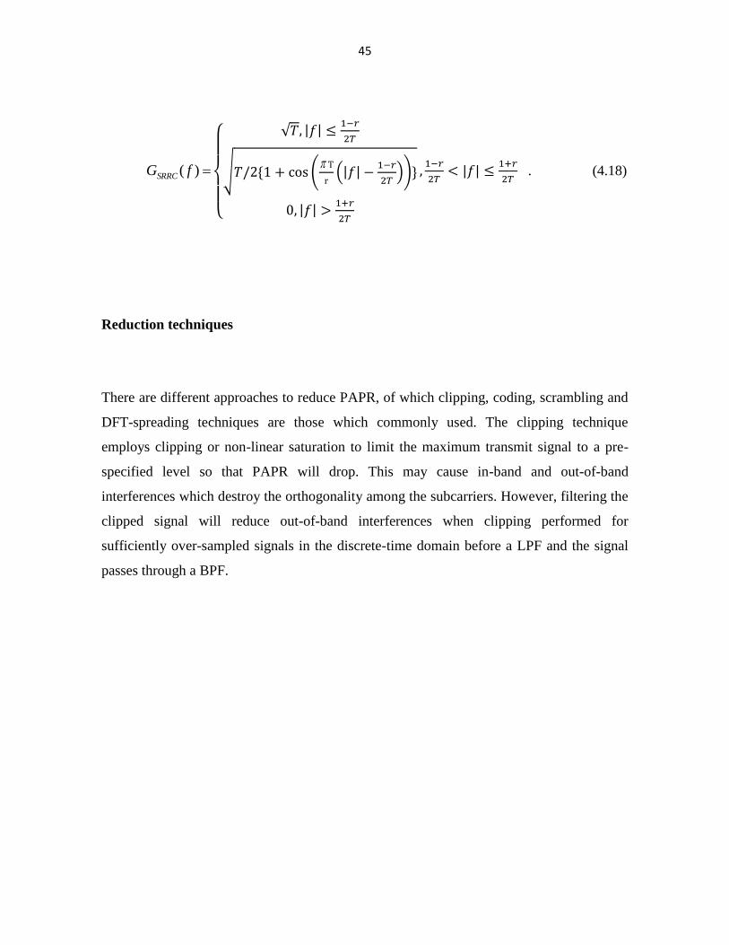
45
)( fGSRRC
{
√
√ (
(
))
. (4.18)
Reduction techniques
There are different approaches to reduce PAPR, of which clipping, coding, scrambling and
DFT-spreading techniques are those which commonly used. The clipping technique
employs clipping or non-linear saturation to limit the maximum transmit signal to a pre-
specified level so that PAPR will drop. This may cause in-band and out-of-band
interferences which destroy the orthogonality among the subcarriers. However, filtering the
clipped signal will reduce out-of-band interferences when clipping performed for
sufficiently over-sampled signals in the discrete-time domain before a LPF and the signal
passes through a BPF.
46
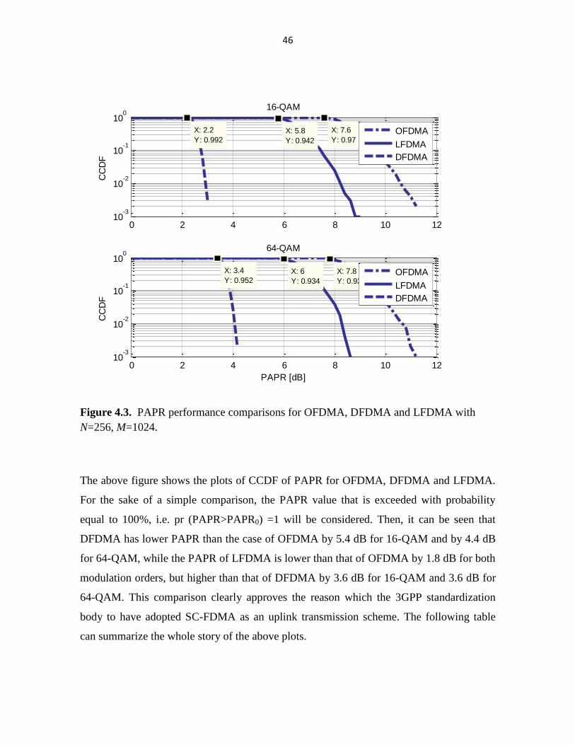
Figure 4.3. PAPR performance comparisons for OFDMA, DFDMA and LFDMA with
N=256, M=1024.
The above figure shows the plots of CCDF of PAPR for OFDMA, DFDMA and LFDMA.
For the sake of a simple comparison, the PAPR value that is exceeded with probability
equal to 100%, i.e. pr (PAPR>PAPR0) =1 will be considered. Then, it can be seen that
DFDMA has lower PAPR than the case of OFDMA by 5.4 dB for 16-QAM and by 4.4 dB
for 64-QAM, while the PAPR of LFDMA is lower than that of OFDMA by 1.8 dB for both
modulation orders, but higher than that of DFDMA by 3.6 dB for 16-QAM and 3.6 dB for
64-QAM. This comparison clearly approves the reason which the 3GPP standardization
body to have adopted SC-FDMA as an uplink transmission scheme. The following table
can summarize the whole story of the above plots.
0 2 4 6 8 10 1210
-3
10-2
10-1
100
X: 2.2
Y: 0.992
CC
DF
16-QAM
X: 5.8
Y: 0.942
X: 7.6
Y: 0.97OFDMA
LFDMA
DFDMA
0 2 4 6 8 10 1210
-3
10-2
10-1
100
X: 6
Y: 0.934
PAPR [dB]
CC
DF
64-QAM
X: 3.4
Y: 0.952
X: 7.8
Y: 0.926OFDMA
LFDMA
DFDMA

47
Table 4.1. PAPR comparison of OFDMA, DFDMA and LFDMA at CCDF=1.
Modulation
order
DFDMA LFDMA OFDMA
16-QAM 2.2 5.8 7.6
64-QAM 3.4 6 7.8
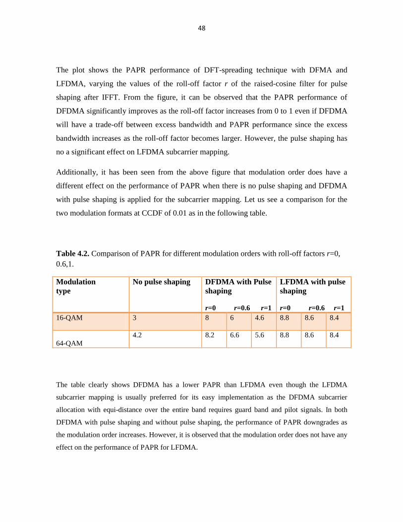
Figure 4.4. PAPR performance comparison between DFDMA and LFDMA with pulse
shaping.
0 1 2 3 4 5 6 7 8 9 1010
-4
10-2
100
CC
DF
16-QAM
0 1 2 3 4 5 6 7 8 9 1010
-4
10-2
100
CC
DF
PAPR in dB
64-QAM
DFDMA with no pulse shaping
LFDMA with no pulse shaping
r=0.8
r=0.6 r=0.2
r=0.4 r=0
DFDM A
LFDM A
r=1
48
The plot shows the PAPR performance of DFT-spreading technique with DFMA and
LFDMA, varying the values of the roll-off factor r of the raised-cosine filter for pulse
shaping after IFFT. From the figure, it can be observed that the PAPR performance of
DFDMA significantly improves as the roll-off factor increases from 0 to 1 even if DFDMA
will have a trade-off between excess bandwidth and PAPR performance since the excess
bandwidth increases as the roll-off factor becomes larger. However, the pulse shaping has
no a significant effect on LFDMA subcarrier mapping.
Additionally, it has been seen from the above figure that modulation order does have a
different effect on the performance of PAPR when there is no pulse shaping and DFDMA
with pulse shaping is applied for the subcarrier mapping. Let us see a comparison for the
two modulation formats at CCDF of 0.01 as in the following table.
Table 4.2. Comparison of PAPR for different modulation orders with roll-off factors r=0,
0.6,1.
Modulation
type
No pulse shaping DFDMA with Pulse
shaping
r=0 r=0.6 r=1
LFDMA with pulse
shaping
r=0 r=0.6 r=1
16-QAM
3 8 6 4.6 8.8 8.6 8.4
64-QAM
4.2 8.2 6.6 5.6 8.8 8.6 8.4
The table clearly shows DFDMA has a lower PAPR than LFDMA even though the LFDMA
subcarrier mapping is usually preferred for its easy implementation as the DFDMA subcarrier
allocation with equi-distance over the entire band requires guard band and pilot signals. In both
DFDMA with pulse shaping and without pulse shaping, the performance of PAPR downgrades as
the modulation order increases. However, it is observed that the modulation order does not have any
effect on the performance of PAPR for LFDMA.
49
5. CONCLUSIONS AND THE FUTURE WORKS
It has been noted that reducing uplink signal peakiness by a few dBs could result in a
significant amount of improvement in coverage area, which is particularly important in the
uplink transmission where the coverage extension is very limited due to the impact of high
battery consumption. This implies huge savings in deployments as SC-FDMA would
require a fewer number of base stations to cover a rural geographical area than that required
by OFDM. The SC-FDMA systems with DFDMA and LFDMA have a better performance
than OFDMA systems. This unique feature has been adopted for uplink transmission in
3GPP LTE and LTE-Advanced, which has been evolved into one of the candidate radio
interface technologies for the IMT-Advanced standards.
The main objective of this thesis project is to study the means to improve the uplink PAPR
in 4G LTE-Advanced, specifically by varying the roll-off factors of raised-cosine for pulse
shaping. In order to prove that the PAPR of SC-FDMA signals of the uplink transmission is
lower than the case of OFDMA signals of the downlink transmission scheme , the PAPR
characteristics of the time domain signals of DFDMA and LFDMA using CCDF of PAPR
are numerically compared in the simulation analysis. The result shows that LFDMA incurs
higher PAPR compared to DFDMA, but it has lower PAPR than that of OFDMA. Another
noticeable fact is that pulse shaping increases PAPR and that roll-off factor of raised-cosine
filter for pulse shaping has a significant impact on the performance of DFDMA.
Nevertheless, with a roll-off factor of raised-cosine filter getting larger, it was seen that the
performance of PAPR for DFDMA steadily increases, whereas that for LFDMA hardly
does.
In conclusion, DFDMA subcarrier mapping is more desirable than LFDMA if you want to
fully exploit the low advantage of SC-FDMA.

50
5.1. Future Works
In the future work of this paper, one should be trying to further reduce the impact of high
PAPR on the uplink signal transmission by applying the same range of the raised-cosine
roll-off factors after the signal has been clipped off the amplitude to a fixed level ,which
improves the signal-to-quantization noise ratio of the system.
51
REFERENCES
3GPP (2012). 3GPP Technologies: IP-Multimedia Subsystem [Online]. IMS [Cited
09.08.2012]. Available from the Internet:
<http://www.3gpp.org/Technologies/Keywords-Acronyms/article/ims>.
Cho, Yong, Chung Kang, Jaek Kim & Won Yang (2010).MIMO OFDM Wireless
Communications with Matlab. Singapore: Wiley.
Goldsmith, Andrea (2005). Wireless Communications. New York: Cambridge University
Press.
Grag, Vijay (2006). Wireless Communications and Networking. San Francisco: Elsevier.
Holma, Harri & Antti Toskala (2009). LTE for UMTS-OFDMA and SC-FDMA Based
Radio Access. Chippenham: Wiley.
Khan, Farooq (2009). LTE for 4G Mobile Broadband: Air Interface Technologies and
Performance. New York: Cambridge University Press.
Myung, Hyung, Junsung Jim & David Goodman (2006). Single Carrier FDMA for Uplink
Transmission. IEEE Vehicular Technology Magazine, 1-9.
Nakamura, Takehiro (2009).Proposal for Candidate Radio Interface Technologies for
52
IMT-Advanced Based on LTE Release 10 and Beyond (LTE-Advanced) [Online].
Beijing: 3GPP IMT-Advanced Evaluation Workshop [cited 23.09.2012]. Available
from the Internet: <http://3gpp.org/IMG/pdf/2009_10_3gpp_IMT.pdf>.
Radio-Electronics.com (2012). 4G LTE- Advanced System Architecture Evolution Tutorials
[Online].LTE SAE [Cited 23.09.2012]. Available from the Internet:
<http://www.radio-electronics.com>.
Rohde& Schwarz (2010): LTE Technology Overview [Online]. LTE [Cited 11.11.2012].
Available from World Wide Web:
<http://www2.rohdeschwarz.com/file_17231/LTE_po_en_folded.pdf>.
Sklar, Bernard (2001). Digital Communications: Fundamentals and Applications. 2nd Ed.
New Jersey: Prentice Hall PTR.
Tse, David & Pramod Viswanath (2005). Fundamentals of Wireless Communication. New
York: Cambridge University Press.