Universiti Teknologi PETRONAS - UTPedia
29
WISE - Wireless Sound Detector by Afdzal Nazri 8535 Dissertation submitted in partial fulfilment of the requirements for the Bachelor of Technology (Hons) (Information and Communication Technology) JANUARY 2008 Universiti Teknologi PETRONAS Bandar Seri Iskandar 31750 Tronoh Perak Darul Ridzuan
-
Upload
khangminh22 -
Category
Documents
-
view
0 -
download
0
Transcript of Universiti Teknologi PETRONAS - UTPedia

WISE - Wireless Sound Detector
by
Afdzal Nazri
8535
Dissertation submitted in partial fulfilment of
the requirements for the
Bachelor of Technology (Hons)
(Information and Communication Technology)
JANUARY 2008
Universiti Teknologi PETRONASBandar Seri Iskandar
31750 Tronoh
Perak Darul Ridzuan

CERTIFICATION of approval
WISE: WIRELESS SOUND DETECTOR
by
Afdzal Nazri
A project dissertation submitted to the
Information Technology Programme
Universiti Teknologi PETRONAS
in partial fulfilment of the requirement for the
BACHELOR OF TECHNOLOGY (Hons)
(INFORMATION COMMUNICATION TECHNOLOGY)
lorshuhani Zamin)
UNIVERSITI TEKNOLOGI PETRONAS
TRONOH, PERAK
January 2008

CERTIFICATION OF ORIGINALITY
This is to certify that I am responsible for the work submitted in this project, that
the original work is my own except as specified in the references and
acknowledgements, and that the original work contained herein have not been
undertaken or done by unspecified sources or persons.
llm April 2008

ABSTRACT
'WISE - WIRELESS SOUND DETECTOR'
Afdzal Nazri (8535)
Universiti Teknologi PETRONAS
BandarSeri Iskandar, 31750,Tronoh,Perak Darul Ridzwan, Malaysia
A switch that can turn on and off based on surrounding sound is proposed in this report.
Not any sound can activate the switch but only high frequency of voice can trigger the
switch. If the sound cannot be detected because of the distance or the surrounding noise,
a wireless device will be used to transmit a modulated signal that carries a high pitch
sound. The signal received will then be processed by the circuit to trigger any electrical
equipment. A good frequency band must be chosen so that no electrical noise that can
interferes the wireless signal and the quality of the signal transmitted must be good. The
developed prototype can be applied as home security applications or application to help
some people, for example small children or disable people to switch on the light and also
to give a warning.
Keywords: Sound activated, wireless transmission, highpitch detector

ACKNOWLEDGEMENT
Alhamdullilah, with the capabilities given by Allah Taala to me, this project successfully
done on time.
Thank you so much to my supervisor, Puan Norshuhani for her excellent guidance
courage, and support from day one I involved inthis project.
Thank you for my friends that gave me ideas on how to improve my project and all the
support given.
Afdzal Nazri
8535, Information Communication Technology
II
TABLE OF CONTENT
ABSTRACT .
LIST OF FIGURES
CHAPTER 1:
CHAPTER 2:
CHAPTER 3:
CHAPTER 4:
CHAPTERS:
APPENDIX
REFERENCES
INTRODUCTION .
1.1 Background of Study .1.2 Problem Statement .
1.3 Objectives and Scopeof Study
LITERATURE REVIEW .
2.1 Wireless Communication
2.2 High SoundPitch Detection.2.3 Signal Booster2.4 Sound Capturing
METHODOLOGY
3.1 Gantt Chart
3.2 Tools required
RESULTS AND DISCUSSION
4.1 Circuit Theory4.2 Clapping Distance4.3 Wireless Device
4.4 Limitation
CONCLUSION AND RECOMMENDATION
5.1 Sound Detection
5.2 Project Application .5.3 Future Works....
HI
I
IV
9
11
12
13
14
15
16
18
19
19
19
20
21
22

List of Figures
Figure 1.1: Frequency Spectrum 3
Figure 2.1: Sound Interference Waveform 5
Figure 2.2: Antenna booster 6
Figure 2.3: Time electric signal 7
Figure 2.4: A simulated room impulse 8
Figure 3.1: Methodology Diagram 10
Figure 3.2: Gantt chart 11
Figure 4.1: Sound detector circuit 14
Figure 4.2: High and low frequency sound 15
Figure 4.3: Radio Frequency Spectrum 16
Figure 4.4: Frequency Modulation Technique Waveform 17
Figure 4.5: High Frequency and Low Frequency Waveform 17
Abbreviations
FM Frequency Modulation
HF High Frequency
MHz Megahertz
GHz Gigahertz
MW Medium Wave
VHF Very High Frequency
UHF Ultrahigh Frequency
SHF Super High Frequency
EHF Extremely High Frequency
PCB Printed Circuit Board
IC Integrated Circuit
SMS Short Messaging System
GSM Global System for Mobile
IV

CHAPTER 1
INTRODUCTION
1.1 Background of Study
Wireless communication is a way to send information to other party without to use a
physical medium such as copper or fibre optic that is has to be connected physically.
Instead, using an air as a medium of transmission, will help to eliminate the cost and
barriers that occupied by thewired transmission system. The distances involved may be
short (a few meters as in television remote control) or very long (thousands or even
millions ofkilometres for radio communications).
In this project, a wireless transmission will be used to send a high pitch sound using a
stable 27 MHz frequency modulation. This band was chosen as it can be used and
seldom be occupied by other band. A crystal is embedded in the circuit to obtain an
exact 27 MHz of frequency. There will be transmitter that will only transmit the sound
using 27MHz frequency and thewave will be captured by the receiver. There is another
circuit that detectthe sound produced and will activate the relay. This relay soonwill be
connected to any electronic or electrical device and will be used to switch on or off the
device.
This system can be use for home security where the system will be trigger by detecting
sound made by intruders or to help small childrenof disablepeople to switch on light as
the wall switch will not be reached by these people.
1.2 Problem Statement
* Switch is too high or far
We can see that for convinence, electrical switches being install high on the walls. This
can be a burden for disable people that using a wheel chair to reach on the switch in
order to switch on or off the electrical equipment. This device also can be use by small
children when theyarenot tall enough to switch on the lights in corridor or stairs light.
• Sound detection fire alarm
Whenever fire alarm rings, some one has to phone the firemen and this procedure will
consume time. By using this device, whenever the alarm bell ringfor emergency, it will
trigger and sendsignal to to fire station wirelessly.
• Frequency Modulation being occupied by to many stations
Forthe device to operate efficiently, Frequency Modulation (FM) wasnot used. Instead
a dedicated frequency, 27 MHz will be use to transmit the signal. This is because that
FM frequency already being occupied with radio stations that may interferes the signal
quality.
13 Objective and Scope of Study
The main objectives of this project are:
• To transmit wireless signal using dedicated frequency (27 MHz)
• To trigger anothersystemonce the signal received
• To enablethe electrical deviceresponseonly to high pitch sound

Study Scope:
The signal will be using 27MHz high frequency where not being occupied. Only certain
sound frequency with the right amplitude ofsound will bedetected bythe device.
The study will be on the wireless signal that use air as a medium oftransmission. With
the signal propogate in a frequenc that is not being occupy by any other signal, a good
quality signal will be received and later will change to a high amplitude signal. As for
the sound recognition, only a certain level of frequency will trigger the switch. The
switch will later be use to on or off any electrical device.
roa/eiengni*.}
Frequency (f)
33aa.
©
v>
<
fir8
o
3ID
3
ii
1U0m
3 MHz
Inp8 s
10m
30M12
1m
30) MHz
VHF UHF
91|H titsSill
10cm
3 GHz
SHF
Wf9.
;8B8 I
1cm
3D GHz
1mm
300GHz
EHF
ExtramdyHighFrequencies
OPTIC
A 3
SBft
P>1;ss
Figure 1.1 Frequency Spectrum
This project canbe done in 32weeks of timebased on the objective stated.
CHAPTER 2
LITERATURE REVIEW
2,1 Wireless Communication
An information that is being transmit using air as a medium is being called wireless
communication. By using the electromagnetic wave to encapsulate the signal, it can be
transferred to another destination that is miles away from the transmitter. In this world,
the electromagnetic wave is from 3MHz up to 300GHz. There are protocols inside this
wave spectrum that ease the transmission procedure. Each of the protocol occupies
certain bandwidth inside the frequency spectrum. Wireless internet occupies 2.4 GHz
frequency while for Frequency Modulation (FM) radio takes 88 MHz to 108 MHz.
As for in this project, the frequency of 27 MHz will be used in order to transmit the
sound wirelessly for around 100 meters apart between the transmitter and the receiver.
In the frequency spectrum, this range of frequency is in the High Frequency (HF) area.
Using this band to transmit the sound signal does not require special license.

2.2 High Sound Pitch Detection
The sensations of frequencies are commonly referred to as the pitch of a sound. A high
pitch sound corresponds to a high frequency and a low pitch sound corresponds to a low
frequency. Many people are capable ofdetecting a difference infrequency between two
separate sounds which is as littleas 2 Hz.
When two sounds with a frequency difference of greater than 7 Hz are played
simultaneously, most people are capable of detecting the presence of a complex wave
pattern resulting from the interference and superposition ofthe two sound waves.
Before Interference
XZLtSZti *—*—♦—i— *——*
During Interference
.-4 4 +
Before Interference DuringInterference
AMTNBefore Interference
i i i
i«-h
DuringInterference
fiefcre Interference DuringInterfereiicej -H i i ! i 1 i i i
i"7Y m 1 ! !Ai
1 *
!i
! 11 lib U-Wr My \7
Before Interference! AfterInterference
251J_J_J_J
—[—I—]—{->/-j r--rV£-—r—iZXi
Figure2.1 SoundInterference Waveform

Wave interference is the phenomenon which occurs when two waves meet while
travelling along the same medium. When two waves interfere, the resulting
displacement ofthe medium at any location is the algebraic sum ofthe displacements ofthe individual waves at that same location. All object has their own nature frequency
each natural frequency which an object orinstrument produces has its own characteristic
vibration patterns. These patterns are only created within the object or instrument atspecific frequencies ofvibration; these frequencies are known as harmonic frequencies,
or merely harmonics. At any frequency other than a harmonic frequency, the resulting
disturbance of the mediumis irregularand non-repeating. [1]
2.3 Signal booster
In this project, two antennas were used to amplify and to get a good quality of the
transmission signal. By using a 1meter antenna, the transmitter and the receiver can be
further apart. Not only that, the noise can be eliminated once antenna is attached to the
circuit.
Figure 2.2: Antenna booster

Every antenna and every antenna feed-line have a characteristic impedance, or
opposition to electrical current. In an ideal situation, the impedances ofline and antenna
match perfectly, and 100 percent ofthe electrical energy sent to the antenna is converted
to radio energy and radiated into the atmosphere. In a less than ideal case, when the
impedances aren't perfectly matched, some of the electrical energy sent to the antenna
won't be converted to radio energy, but will be reflected back down the feed-line. The
energy reflecting back from the antenna causes standing waves of electrical energy in
the feed-line. (An example of standing waves outside the electronics world is found in
river rapids. When water passes around and between boulders it may form a wave that
doesn't go up or down the river, it just stays in one place. That is a standing wave of
water.) The ratio of highest voltage on the line to lowest is the standing wave ratio. In
theperfectly matched system, the SWR is 1:1. [2]
2.4 Sound capturing
Small microphone (such as the common condenser microphones) would result in the
least disturbance of the sound field environment. [3] After receiving a sound,
microphones produce a continues time electric signal, as in figure 2.1.
:NA *"\ ft !1 ^
1 a/M; \i\iv s- \y ~^^ . v '•' 1
/ / ls^"^ 1
y / '/ *.•y Microphone
Figure 2.3: Time electric signal

In addition to background noise, reverberation is another major barrier for sound
detection especially in a hands-free setting, where themicrophone is placed further away
from the speaker. Reverberation is caused by sound reflections by an enclosure such as
walls of a room. Once an acoustic sound is emitted by a speaker in a room, the acoustic
waves travel in all directions. Some of the waves travel directly to the microphone. The
other waves hit the various surfaces of the room (such as wall, ceiling, floor) and parts
of the waves are reflected. The reflected waves can also reach the microphone sometime
later. As a result, the microphone receives multiple copies of the same sound with
various amplitude and time delays. Mathematically, reverberations can e models as the
impulse response between the source and the receiver. Reverberation time refers to the
duration of this impulse response. A commonly used definition for reverberation time is
Teo, which is definedas the time it takes for a soundto reduceto 60dB below its original
level. [3]
Room impulse response in a rectangular enclosure canbe simulated efficiently using the
image method technique [4]. A typical room impulse response obtained using the image
method with intra-sample interpolation is shown in figure 2.2. In thiscase, assumed that
the walls, floor and ceiling having the same reflection coefficient.
Figure 2.4: A simulated room impulse response using the image method with intra-
sample interpolation (Room size 6mX 6m X 2.5m)

CHAPTER 3
METHODOLOGY
Methodology Before any planning are made, investigation were done to make sure that
the product tat going to be built are feasible to be delivered on time within the
knowledge capabilities. Analysis is made to before making planning for the modules.
This is where the study about the feasibility was done, to ensure a quality prototype can
be made.
After severalmodules being design, every single module was developed to make
a single prototype. The prototypes were tested thoroughly on every component to ensure
the functions working properly as desired. If any components are found not working
correctly, the components or module will be redesign.
Soon, all of the module will go for final integration and final testing and
benchmark will be done in order to finalize the project.
This methodology is the combination of modules development, prototyping and
spiral development model. Each of this methodology has its own benefits and weakness
thusby combining them all, making complements to each other.

Analysis
Product Incremental
Prototyping
Single ModuleDevelopment
Feasibilities Studies
Modules Planning
Modules Design
T
Prototyping
Final Integration
Final Testing andBenchmark
Project Finalization
Figure3.1: Methodology Diagram
10
Testing

3.1
Ga
ntt
Ch
art
E3M
icrosoftProject-Project/
Ready
Figure
3.2:G
anttchart
3.2 Tools required
3.2.1 Oscilloscope
This hardware will be use measure on the right amplitude that needs to trigger the
detector. The waveform also was being measuredusing oscilloscope in order to get the
real wave form.
3.2.2 Soldering Iron
As this project will be build from scratch, all the electronic components will be solder
on the PCB board or Vero board. All the components will be connected based on the
schematic design of the circuit.
3.2.3 Project board
Project board was used to check the circuit that it works well before being soldered
onto the Printed Circuit Board (PCB). Each of the components, especially Integrated
Circuit (IC) MC14013BC and LM358 were tested on the project board first. Soldering
process onthe PCB was done once allthecomponents verified.
12

CHAPTER 4
RESULT AND DISCUSSION
Whenever a high frequency sound such as clapping was detected by the
microphone in the detector circuit, the signal will be passed to the amplifier IC. After
amplification was made, the signal then was passed to the another IC that will detect
the high frequency sound as that is the type of sound that will trigger the transistor.
Soon, after the right sound detected, a small voltage was supplied to the transistor and
will switch on the relay
As for the wireless transmitter and receiver, each input signal will be modulated
into 27 MHz frequency signal. The receiver that is always on standby will take any
signal that is in27 MHz frequency and will change the signal back into sound captured
by the receiver.
To make sure that the signal quality that being transmitted is good, antenna
must be used. A good antenna that will boost the signal quality and the distance
between the transmitter and receiver can be made further.
In application wise, this project will help the disable people to switch on
electrical equipment such as lamp or fan in a room by just clapping. As for small
children, they can clap their hand to switch onthe light as the switch will be very high
for these small children to reach. For security purpose, whenever the fire alarm strikes
and made noise, this will trigger the device when the signal is being sent to the fire
station wirelessly and this will surely eliminate a lot of time for someone to make the
emergency call.
13
4,1 Circuit Theory
14R12
M^t*—I1
5 13
3
11CM
I
O
10
4 6 7 8
•R11
;C3
+9VDC
RLY
L1 Q1
GND
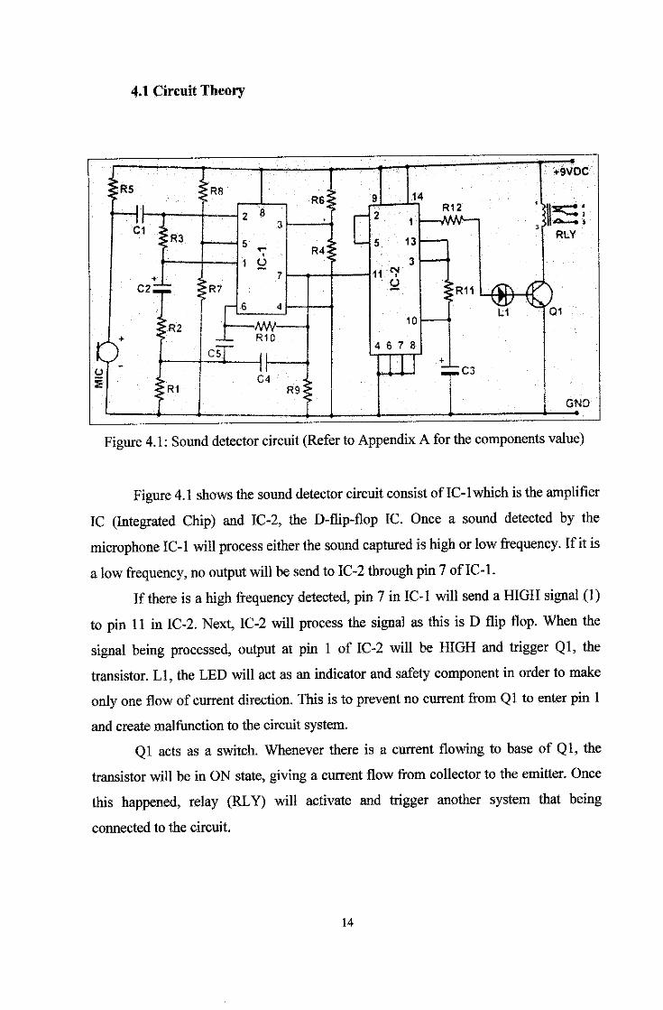
Figure 4.1: Sound detector circuit (Refer to Appendix Afor the components value)
Figure 4.1 shows the sound detector circuit consist ofIC-lwhich is the amplifier
IC (Integrated Chip) and IC-2, the D-flip-flop IC. Once a sound detected by the
microphone IC-1 will process either the sound captured ishigh orlow frequency. Ifit is
a low frequency, no output will besend to IC-2 through pin7 ofIC-1.
If there is a high frequency detected, pin 7 in IC-1 will send a HIGH signal (1)
to pin 11 in IC-2. Next, IC-2 will process the signal as this is D flip flop. When the
signal being processed, output at pin 1 of IC-2 will be HIGH and trigger Ql, the
transistor. LI, the LED will act as an indicator and safety component in order to make
only one flow ofcurrent direction. This is to prevent no current from Ql to enter pin 1
and create malfunction to the circuit system.
Ql acts as a switch. Whenever there is a current flowing to base of Ql, the
transistor will be in ON state, giving a current flow from collector to the emitter. Once
this happened, relay (RLY) will activate and trigger another system that being
connected to the circuit.
14

4.2 Clapping Distance
Tests were done to see how far the circuit can detect the clapping. As near as 10
centimetres, usual human voice was used as an input to the microphone but the circuit
does not triggered. This shows that low frequency voice will not trigger the circuit.
Next, a distance of 100 centimetres was made a human voice again was used and still
the circuit intelligently ignore the voice sound and the circuit remain OFF state.
As for a clap sound, the circuit can detect the sound as far as 10 meters away.
The distance can be more in a room as the sound will reflects from walls to the
microphone. Atest was also done ina corridor to see the effect on how the distance can
befurther. Ina corridor, surrounds byconcrete wall, theclapping sound can bedetected
as far as 20 meters with a quiet surrounding.
In a noisy surrounding, with people chatting and radio switched on, the circuit
still remain in OFF state and changed to ON state when a clap sound detected. This
clap sound, which has a high frequency sound, was made 5 metres away from the
microphone. This shows that the circuit is intelligent enough to differentiate which
soundthat is high and low pitch.
High Frequency: Clapping
Sound
Low Frequency:
Human Voice (Male)
Figure 4.2: High andlowfrequency sound
15
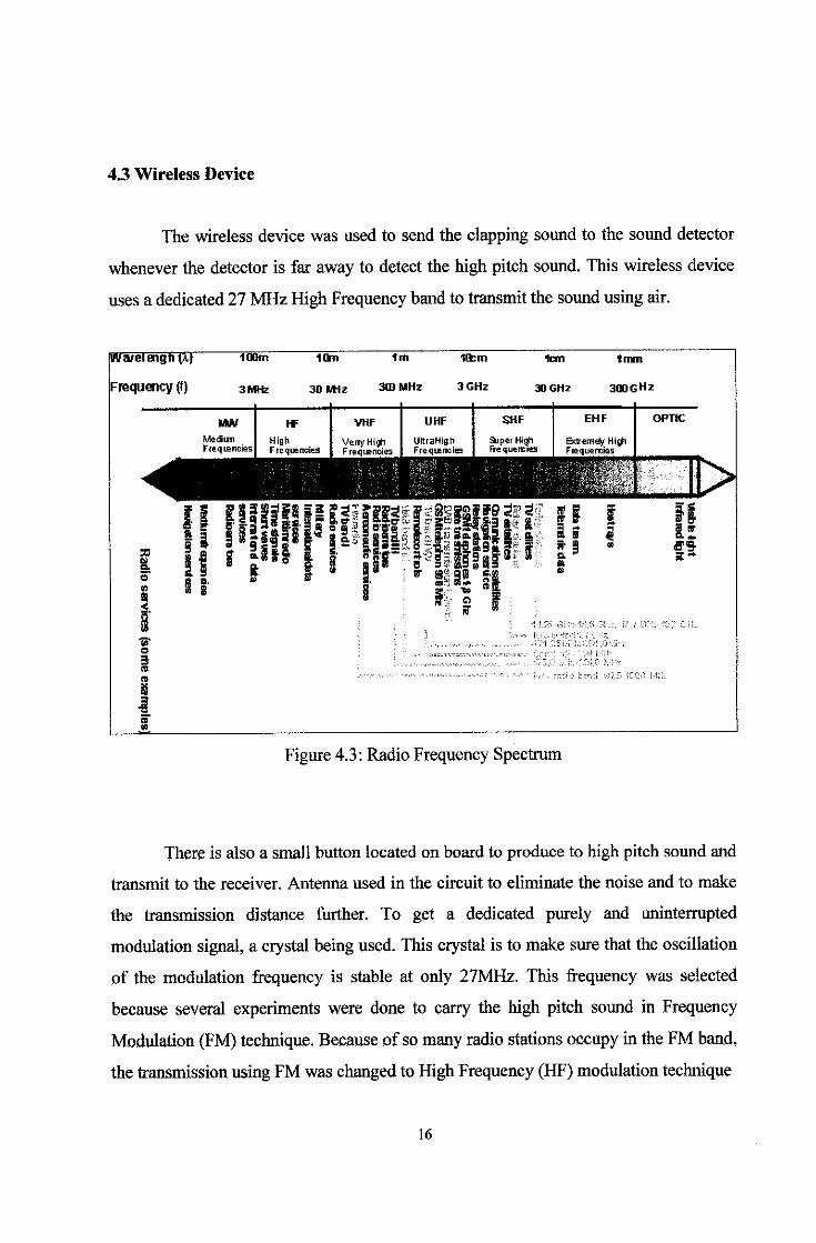
4.3 Wireless Device
The wireless device was used to send the clapping sound to the sound detector
whenever the detector is far away to detect the high pitch sound. This wireless device
usesa dedicated 27 MHzHighFrequency bandto transmit the sound using air.
INa/el engine
Frequency (f)
100m
3 MHz
MW
10m
30 MHz
1m
3(DMHz
VHF UHF
10cm
3 GHz
1cm
30 GHz
1mm
300GHz
SHF
Super HighFrequemies
EHF
ExtremeV HighFrequencies
OPUC
Figure 4.3: Radio Frequency Spectrum
There is also a small button located on board to produce to high pitch sound and
transmit to the receiver. Antenna used in the circuit to eliminate the noise and to make
the transmission distance further. To get a dedicated purely and uninterrupted
modulation signal, a crystal being used. This crystal is to make sure that the oscillation
of the modulation frequency is stable at only 27MHz. This frequency was selected
because several experiments were done to carry the high pitch sound in Frequency
Modulation (FM) technique. Because of so many radio stations occupy in the FMband,
the transmission using FM was changedto High Frequency (HF) modulation technique
16

CONSTANT AMPLITUDE- VARYING FREQUENCY"'
Figure 4.4: Frequency Modulation Technique Waveform
Figure 4.5: High Frequency (Top)and
Low Frequency (Below) waveform
17

4.4 Limitations
Several limitations were detected from this project. Theoretically, the
transmission power can only transmit up to 100 to 150 metres, by using the right
antenna and a good power source. As the distance go further, more noise will be
detected and a false triggering will be made. To overcome this, a goodand cleansignal
without noise must be obtained. In order to do that, the transmitter and the receiver
must be in the range and a good antenna must be use.
The circuit is intelligent enough to eliminate high and low sound pitch. This
made the circuit cannot trigger another circuit thatproduce highpitch sound such as an
electric motor. Electric motors that create a high pitch sound that will make the sound
detector back in OFF state. This makes this circuit does not suitable to trigger a robot or
a blender, that use electric motor as the engine.
18

CHAPTERS
CONCLUSION AND RECOMENDATION
5.1 Sound Detection
The sound detection of the device makes it intelligent while eliminating the unwanted
noise so that the device will not confuse with the undesirable sound. By using the High
Frequency wave signal, any strike sound made internally can be separated from the
transmission signal. The detection must be good enough to take only the sound that
beingtransmitted wirelessly fromthe transmitter.
5.2 Project Application
Imagine a disable person that on a wheel chair who tries to switch on the light but
unfortunately, the switch is too high on the wall. He just can clap his hand and the
switch can turn on. This application also applies to small children and patient on the
hospital bed where switch is too far from them.
This circuit also can be integrated with fire fighting system where if the bell sound,
which is in high pitch sound, the sound can be captured by the transmitter. This sound
will be sent to the receiver wirelessly and trigger the sound detector. The sound
detector will later send alarm signal to the fire station.
19
5.3 Future Works
With a good planning and knowledge, the objective of this project can be archive.
However, there should be an improvement work later. The system should be able to
sendSMS using the GSM network. Thiscanbe done probably usinga GSMmodem.
Better transmission signal should be made possible so that the range of the transmission
can be higher. The study on how to make more powerful signal transmission must be
done as the signal distort as the transmitter move far awayfrom the receiver.
The sound detector must be intelligent enough to eliminate the unwanted noise an only
detects on the high pitch sound. In order to do that, a bettermicrophone must be used
The integrated chip that can eliminate and detectwhich one is unwanted noise must be
integrate with the circuit.
20

Appendix A
RESISTOR INTEGRATED CHIP (IC)
Rl-100i2
R2-10KU
R3 = 180K&
R4 = 6.8KU
R5 = 10KQ
R6 - 8.2 KU
R7 = 6.8KQ
R8 = 10KU
R9=10KU
RIO =100102
R11 = 100KU
R12 =100 a
IC-1 =358 (8 PIN)
IC-2 = 4013 (14 PIN)
TRANSISTOR
Ql -9013
CAPACITOR
CI =0.1 uF
C2 = 1 uE
C3 = 10 up
C4 - 0.01 uP (103)
C5 = 0.01 \xF (103)
OTHER ITEMS
LI = LED
MIC = MICROPHONE
RLY = RELAY 6V ~ 9V DC
21

References
[1] Dr. David Gerhard., 1995, " Pitch Extraction and Fundamental Frequency: History
and Current Techniques," University ofRegina Journal
[2] How does a CB radio antennawork? 30 March 2008
<http://electromcs.howsmffworks.com/question490.htm>
[3] Parham Aarabi. 2006, Phase-BasedSpeech Processing, London, World Scientific
[4] J. B. Allen and D.A. Berkeley. Image methods for efficient simulating small room
acoustics. JournalofAcousticSocietyofAmerica, 65
22