Universal Robots e-Series User Manual UR3e - Amazon S3
193
Universal Robots e-Series User Manual UR3e Original instructions (en)
-
Upload
khangminh22 -
Category
Documents
-
view
1 -
download
0
Transcript of Universal Robots e-Series User Manual UR3e - Amazon S3

Universal Robots e-SeriesUser Manual
UR3eOriginal instructions (en)


Universal Robots e-SeriesUser Manual
UR3e
Version 5.0.2
Original instructions (en)
The information contained herein is the property of Universal Robots A/S and shall not be reproducedin whole or in part without prior written approval of Universal Robots A/S. The information herein issubject to change without notice and should not be construed as a commitment by Universal RobotsA/S. This manual is periodically reviewed and revised.
Universal Robots A/S assumes no responsibility for any errors or omissions in this document.
Copyright © 2009–2018 by Universal Robots A/S
The Universal Robots logo is a registered trademark of Universal Robots A/S.
UR3e/CB5 ii Version 5.0.2
Copy
right
©20
09–2
018by
Universa
lRob
otsA/
S.Allrightsrese
rved
.

Contents
Preface ixWhat Do the Boxes Contain . . . . . . . . . . . . . . . . . . . . . . . . . . . . . . . . . . . . . . ixImportant Safety Notice . . . . . . . . . . . . . . . . . . . . . . . . . . . . . . . . . . . . . . . . xHow to Read This Manual . . . . . . . . . . . . . . . . . . . . . . . . . . . . . . . . . . . . . . . xWhere to Find More Information . . . . . . . . . . . . . . . . . . . . . . . . . . . . . . . . . . . x
I Hardware Installation Manual I-1
1 Safety I-31.1 Introduction . . . . . . . . . . . . . . . . . . . . . . . . . . . . . . . . . . . . . . . . . . . I-31.2 Validity and Responsibility . . . . . . . . . . . . . . . . . . . . . . . . . . . . . . . . . . . I-31.3 Limitation of Liability . . . . . . . . . . . . . . . . . . . . . . . . . . . . . . . . . . . . . . I-41.4 Warning Symbols in this Manual . . . . . . . . . . . . . . . . . . . . . . . . . . . . . . . I-41.5 General Warnings and Cautions . . . . . . . . . . . . . . . . . . . . . . . . . . . . . . . . I-51.6 Intended Use . . . . . . . . . . . . . . . . . . . . . . . . . . . . . . . . . . . . . . . . . . I-81.7 Risk Assessment . . . . . . . . . . . . . . . . . . . . . . . . . . . . . . . . . . . . . . . . I-81.8 Pre-Use Assessment . . . . . . . . . . . . . . . . . . . . . . . . . . . . . . . . . . . . . . I-101.9 Emergency Stop . . . . . . . . . . . . . . . . . . . . . . . . . . . . . . . . . . . . . . . . . I-101.10 Movement Without Drive Power . . . . . . . . . . . . . . . . . . . . . . . . . . . . . . . . I-10
2 Safety-related Functions and Interfaces I-132.1 Introduction . . . . . . . . . . . . . . . . . . . . . . . . . . . . . . . . . . . . . . . . . . . I-132.2 Stop Categories . . . . . . . . . . . . . . . . . . . . . . . . . . . . . . . . . . . . . . . . . I-142.3 Safety Functions . . . . . . . . . . . . . . . . . . . . . . . . . . . . . . . . . . . . . . . . I-142.4 Safety Function . . . . . . . . . . . . . . . . . . . . . . . . . . . . . . . . . . . . . . . . . I-152.5 Modes . . . . . . . . . . . . . . . . . . . . . . . . . . . . . . . . . . . . . . . . . . . . . . I-17
3 Transportation I-19
4 Mechanical Interface I-214.1 Introduction . . . . . . . . . . . . . . . . . . . . . . . . . . . . . . . . . . . . . . . . . . . I-214.2 Workspace of the Robot . . . . . . . . . . . . . . . . . . . . . . . . . . . . . . . . . . . . I-214.3 Mounting . . . . . . . . . . . . . . . . . . . . . . . . . . . . . . . . . . . . . . . . . . . . . I-214.4 Maximum Payload . . . . . . . . . . . . . . . . . . . . . . . . . . . . . . . . . . . . . . . I-24
5 Electrical Interface I-255.1 Introduction . . . . . . . . . . . . . . . . . . . . . . . . . . . . . . . . . . . . . . . . . . . I-25
5.1.1 Control Box Bracket . . . . . . . . . . . . . . . . . . . . . . . . . . . . . . . . . . I-255.2 Ethernet . . . . . . . . . . . . . . . . . . . . . . . . . . . . . . . . . . . . . . . . . . . . . I-255.3 Electrical Warnings and Cautions . . . . . . . . . . . . . . . . . . . . . . . . . . . . . . . I-265.4 Controller I/O . . . . . . . . . . . . . . . . . . . . . . . . . . . . . . . . . . . . . . . . . . I-28
5.4.1 Common specifications for all digital I/O . . . . . . . . . . . . . . . . . . . . . . I-28
Version 5.0.2
Copy
right
©20
09–2
018by
Universa
lRob
otsA/
S.Allrightsrese
rved
.
iii UR3e/CB5

5.4.2 Safety I/O . . . . . . . . . . . . . . . . . . . . . . . . . . . . . . . . . . . . . . . . I-295.4.3 General purpose digital I/O . . . . . . . . . . . . . . . . . . . . . . . . . . . . . . I-335.4.4 Digital Inputs from a button . . . . . . . . . . . . . . . . . . . . . . . . . . . . . . I-345.4.5 Communication with other machines or PLCs . . . . . . . . . . . . . . . . . . . I-345.4.6 General purpose analog I/O . . . . . . . . . . . . . . . . . . . . . . . . . . . . . . I-345.4.7 Remote ON/OFF control . . . . . . . . . . . . . . . . . . . . . . . . . . . . . . . . I-36
5.5 Mains Connection . . . . . . . . . . . . . . . . . . . . . . . . . . . . . . . . . . . . . . . . I-375.6 Robot Connection . . . . . . . . . . . . . . . . . . . . . . . . . . . . . . . . . . . . . . . . I-385.7 Tool I/O . . . . . . . . . . . . . . . . . . . . . . . . . . . . . . . . . . . . . . . . . . . . . I-39
5.7.1 Tool Digital Outputs . . . . . . . . . . . . . . . . . . . . . . . . . . . . . . . . . . I-405.7.2 Tool Digital Inputs . . . . . . . . . . . . . . . . . . . . . . . . . . . . . . . . . . . I-405.7.3 Tool Analog Input . . . . . . . . . . . . . . . . . . . . . . . . . . . . . . . . . . . I-415.7.4 Tool Communication I/O . . . . . . . . . . . . . . . . . . . . . . . . . . . . . . . I-42
6 Maintenance and Repair I-436.1 Safety Instructions . . . . . . . . . . . . . . . . . . . . . . . . . . . . . . . . . . . . . . . I-43
7 Disposal and Environment I-45
8 Certifications I-478.1 Third Party Certification . . . . . . . . . . . . . . . . . . . . . . . . . . . . . . . . . . . . I-478.2 Supplier Third Party Certification . . . . . . . . . . . . . . . . . . . . . . . . . . . . . . . I-478.3 Manufacturer Test Certification . . . . . . . . . . . . . . . . . . . . . . . . . . . . . . . . I-478.4 Declarations According to EU directives . . . . . . . . . . . . . . . . . . . . . . . . . . . I-48
9 Warranties I-499.1 Product Warranty . . . . . . . . . . . . . . . . . . . . . . . . . . . . . . . . . . . . . . . . I-499.2 Disclaimer . . . . . . . . . . . . . . . . . . . . . . . . . . . . . . . . . . . . . . . . . . . . I-49
A Stopping Time and Stopping Distance I-51
B Declarations and Certificates I-55B.1 CE/EU Declaration of Incorporation (original) . . . . . . . . . . . . . . . . . . . . . . . . I-55B.2 Safety System Certificate . . . . . . . . . . . . . . . . . . . . . . . . . . . . . . . . . . . I-56B.3 Environmental Test Certificate . . . . . . . . . . . . . . . . . . . . . . . . . . . . . . . . . I-58B.4 EMC Test Certificate . . . . . . . . . . . . . . . . . . . . . . . . . . . . . . . . . . . . . . I-59
C Applied Standards I-61
D Technical Specifications I-67
II PolyScope Manual II-1
10 Introduction II-310.1 PolyScope Basics . . . . . . . . . . . . . . . . . . . . . . . . . . . . . . . . . . . . . . . . II-3
10.1.1 Header Icons/Tabs . . . . . . . . . . . . . . . . . . . . . . . . . . . . . . . . . . II-310.1.2 Footer Buttons . . . . . . . . . . . . . . . . . . . . . . . . . . . . . . . . . . . . . II-4
10.2 Getting Started Screen . . . . . . . . . . . . . . . . . . . . . . . . . . . . . . . . . . . . . II-5
UR3e/CB5 iv Version 5.0.2
Copy
right
©20
09–2
018by
Universa
lRob
otsA/
S.Allrightsrese
rved
.
11 Quick Start II-711.1 Robot Arm Basics . . . . . . . . . . . . . . . . . . . . . . . . . . . . . . . . . . . . . . . . II-7
11.1.1 Installing the Robot Arm and Control Box . . . . . . . . . . . . . . . . . . . . . . II-711.1.2 Turning Control Box On/Off . . . . . . . . . . . . . . . . . . . . . . . . . . . . . . II-811.1.3 Turning Robot Arm On/Off . . . . . . . . . . . . . . . . . . . . . . . . . . . . . . II-8
11.2 Quick System Start-up . . . . . . . . . . . . . . . . . . . . . . . . . . . . . . . . . . . . . II-8
12 Operational Mode Selection II-1112.1 Operational Modes . . . . . . . . . . . . . . . . . . . . . . . . . . . . . . . . . . . . . . . II-1112.2 3-Position Enabling Device . . . . . . . . . . . . . . . . . . . . . . . . . . . . . . . . . . . II-12
12.2.1 Manual High Speed . . . . . . . . . . . . . . . . . . . . . . . . . . . . . . . . . . II-13
13 Safety Configuration II-1513.1 Safety Settings Basics . . . . . . . . . . . . . . . . . . . . . . . . . . . . . . . . . . . . . II-15
13.1.1 Accessing Safety Configuration . . . . . . . . . . . . . . . . . . . . . . . . . . . II-1513.1.2 Setting a Safety Password . . . . . . . . . . . . . . . . . . . . . . . . . . . . . . II-1613.1.3 Changing the Safety Configuration . . . . . . . . . . . . . . . . . . . . . . . . . . II-1613.1.4 Applying New Safety Configuration . . . . . . . . . . . . . . . . . . . . . . . . . II-1713.1.5 Safety Checksum . . . . . . . . . . . . . . . . . . . . . . . . . . . . . . . . . . . II-17
13.2 Safety Menu Settings . . . . . . . . . . . . . . . . . . . . . . . . . . . . . . . . . . . . . . II-1713.2.1 Robot Limits . . . . . . . . . . . . . . . . . . . . . . . . . . . . . . . . . . . . . . II-1713.2.2 Safety Modes . . . . . . . . . . . . . . . . . . . . . . . . . . . . . . . . . . . . . . II-1913.2.3 Tolerances . . . . . . . . . . . . . . . . . . . . . . . . . . . . . . . . . . . . . . . II-2013.2.4 Joint Limits . . . . . . . . . . . . . . . . . . . . . . . . . . . . . . . . . . . . . . . II-2013.2.5 Planes . . . . . . . . . . . . . . . . . . . . . . . . . . . . . . . . . . . . . . . . . . II-2113.2.6 Tool Position . . . . . . . . . . . . . . . . . . . . . . . . . . . . . . . . . . . . . . II-2313.2.7 Tool Direction . . . . . . . . . . . . . . . . . . . . . . . . . . . . . . . . . . . . . II-2413.2.8 I/O . . . . . . . . . . . . . . . . . . . . . . . . . . . . . . . . . . . . . . . . . . . . II-2613.2.9 Hardware . . . . . . . . . . . . . . . . . . . . . . . . . . . . . . . . . . . . . . . . II-27
14 Run Tab II-2914.1 Program . . . . . . . . . . . . . . . . . . . . . . . . . . . . . . . . . . . . . . . . . . . . . II-2914.2 Variables . . . . . . . . . . . . . . . . . . . . . . . . . . . . . . . . . . . . . . . . . . . . . II-2914.3 Robot Age . . . . . . . . . . . . . . . . . . . . . . . . . . . . . . . . . . . . . . . . . . . . II-3014.4 Move Robot into Position . . . . . . . . . . . . . . . . . . . . . . . . . . . . . . . . . . . . II-30
15 Initialize Tab II-3315.1 Robot Arm State Indicator . . . . . . . . . . . . . . . . . . . . . . . . . . . . . . . . . . . II-3315.2 Active Payload and Installation . . . . . . . . . . . . . . . . . . . . . . . . . . . . . . . . II-3315.3 Initializing the Robot Arm . . . . . . . . . . . . . . . . . . . . . . . . . . . . . . . . . . . II-3415.4 Installation File . . . . . . . . . . . . . . . . . . . . . . . . . . . . . . . . . . . . . . . . . II-34
16 Program Tab II-3716.1 Program Tree . . . . . . . . . . . . . . . . . . . . . . . . . . . . . . . . . . . . . . . . . . II-37
16.1.1 Program Execution Indication . . . . . . . . . . . . . . . . . . . . . . . . . . . . II-3816.1.2 Search Button . . . . . . . . . . . . . . . . . . . . . . . . . . . . . . . . . . . . . II-3816.1.3 Program Tree Toolbar . . . . . . . . . . . . . . . . . . . . . . . . . . . . . . . . . II-3816.1.4 Empty Node . . . . . . . . . . . . . . . . . . . . . . . . . . . . . . . . . . . . . . II-39
Version 5.0.2
Copy
right
©20
09–2
018by
Universa
lRob
otsA/
S.Allrightsrese
rved
.
v UR3e/CB5

16.2 Command Tab . . . . . . . . . . . . . . . . . . . . . . . . . . . . . . . . . . . . . . . . . . II-3916.3 Graphics Tab . . . . . . . . . . . . . . . . . . . . . . . . . . . . . . . . . . . . . . . . . . II-4116.4 Variables Tab . . . . . . . . . . . . . . . . . . . . . . . . . . . . . . . . . . . . . . . . . . II-4216.5 Basic program nodes . . . . . . . . . . . . . . . . . . . . . . . . . . . . . . . . . . . . . . II-42
16.5.1 Move . . . . . . . . . . . . . . . . . . . . . . . . . . . . . . . . . . . . . . . . . . II-4216.5.2 Wait . . . . . . . . . . . . . . . . . . . . . . . . . . . . . . . . . . . . . . . . . . . II-5116.5.3 Set . . . . . . . . . . . . . . . . . . . . . . . . . . . . . . . . . . . . . . . . . . . . II-5216.5.4 Popup . . . . . . . . . . . . . . . . . . . . . . . . . . . . . . . . . . . . . . . . . . II-5216.5.5 Halt . . . . . . . . . . . . . . . . . . . . . . . . . . . . . . . . . . . . . . . . . . . II-5316.5.6 Comment . . . . . . . . . . . . . . . . . . . . . . . . . . . . . . . . . . . . . . . . II-5316.5.7 Folder . . . . . . . . . . . . . . . . . . . . . . . . . . . . . . . . . . . . . . . . . . II-54
16.6 Advanced program nodes . . . . . . . . . . . . . . . . . . . . . . . . . . . . . . . . . . . II-5416.6.1 Loop . . . . . . . . . . . . . . . . . . . . . . . . . . . . . . . . . . . . . . . . . . . II-5416.6.2 SubProgram . . . . . . . . . . . . . . . . . . . . . . . . . . . . . . . . . . . . . . II-5516.6.3 Assignment . . . . . . . . . . . . . . . . . . . . . . . . . . . . . . . . . . . . . . . II-5616.6.4 If . . . . . . . . . . . . . . . . . . . . . . . . . . . . . . . . . . . . . . . . . . . . . II-5616.6.5 Script . . . . . . . . . . . . . . . . . . . . . . . . . . . . . . . . . . . . . . . . . . II-5716.6.6 Event . . . . . . . . . . . . . . . . . . . . . . . . . . . . . . . . . . . . . . . . . . II-5816.6.7 Thread . . . . . . . . . . . . . . . . . . . . . . . . . . . . . . . . . . . . . . . . . II-5816.6.8 Switch . . . . . . . . . . . . . . . . . . . . . . . . . . . . . . . . . . . . . . . . . . II-59
16.7 Wizards . . . . . . . . . . . . . . . . . . . . . . . . . . . . . . . . . . . . . . . . . . . . . II-5916.7.1 Pallet . . . . . . . . . . . . . . . . . . . . . . . . . . . . . . . . . . . . . . . . . . II-5916.7.2 Seek . . . . . . . . . . . . . . . . . . . . . . . . . . . . . . . . . . . . . . . . . . . II-6116.7.3 Force . . . . . . . . . . . . . . . . . . . . . . . . . . . . . . . . . . . . . . . . . . II-64
16.8 URCaps . . . . . . . . . . . . . . . . . . . . . . . . . . . . . . . . . . . . . . . . . . . . . II-6616.8.1 Conveyor Tracking . . . . . . . . . . . . . . . . . . . . . . . . . . . . . . . . . . . II-66
16.9 The First Program . . . . . . . . . . . . . . . . . . . . . . . . . . . . . . . . . . . . . . . . II-67
17 Installation Tab II-6917.1 General . . . . . . . . . . . . . . . . . . . . . . . . . . . . . . . . . . . . . . . . . . . . . . II-69
17.1.1 TCP Configuration . . . . . . . . . . . . . . . . . . . . . . . . . . . . . . . . . . . II-6917.1.2 Mounting . . . . . . . . . . . . . . . . . . . . . . . . . . . . . . . . . . . . . . . . II-7217.1.3 I/O Setup . . . . . . . . . . . . . . . . . . . . . . . . . . . . . . . . . . . . . . . . II-7317.1.4 I/O Signal Type . . . . . . . . . . . . . . . . . . . . . . . . . . . . . . . . . . . . . II-7417.1.5 Assigning User-defined Names . . . . . . . . . . . . . . . . . . . . . . . . . . . . II-7417.1.6 I/O Actions and I/O Tab Control . . . . . . . . . . . . . . . . . . . . . . . . . . . II-7417.1.7 Conveyor Tracking . . . . . . . . . . . . . . . . . . . . . . . . . . . . . . . . . . . II-7517.1.8 Variables . . . . . . . . . . . . . . . . . . . . . . . . . . . . . . . . . . . . . . . . II-7617.1.9 Startup . . . . . . . . . . . . . . . . . . . . . . . . . . . . . . . . . . . . . . . . . II-7717.1.10 Tool . . . . . . . . . . . . . . . . . . . . . . . . . . . . . . . . . . . . . . . . . . . II-78
17.2 Safety . . . . . . . . . . . . . . . . . . . . . . . . . . . . . . . . . . . . . . . . . . . . . . II-7817.3 Features . . . . . . . . . . . . . . . . . . . . . . . . . . . . . . . . . . . . . . . . . . . . . II-79
17.3.1 Using a feature . . . . . . . . . . . . . . . . . . . . . . . . . . . . . . . . . . . . . II-8017.3.2 Adding a Point . . . . . . . . . . . . . . . . . . . . . . . . . . . . . . . . . . . . . II-8017.3.3 Addine a Line . . . . . . . . . . . . . . . . . . . . . . . . . . . . . . . . . . . . . . II-8117.3.4 Plane Feature . . . . . . . . . . . . . . . . . . . . . . . . . . . . . . . . . . . . . . II-8217.3.5 Example: Manually Updating a Feature to Adjust a Program . . . . . . . . . . . II-83
UR3e/CB5 vi Version 5.0.2
Copy
right
©20
09–2
018by
Universa
lRob
otsA/
S.Allrightsrese
rved
.

17.3.6 Example: Dynamically Updating a Feature Pose . . . . . . . . . . . . . . . . . . II-8417.4 Fieldbus . . . . . . . . . . . . . . . . . . . . . . . . . . . . . . . . . . . . . . . . . . . . . II-84
17.4.1 MODBUS client I/O Setup . . . . . . . . . . . . . . . . . . . . . . . . . . . . . . . II-8517.4.2 Ethernet/IP . . . . . . . . . . . . . . . . . . . . . . . . . . . . . . . . . . . . . . . II-88
18 Move Tab II-8918.1 Move Tool . . . . . . . . . . . . . . . . . . . . . . . . . . . . . . . . . . . . . . . . . . . . II-8918.2 Robot . . . . . . . . . . . . . . . . . . . . . . . . . . . . . . . . . . . . . . . . . . . . . . . II-8918.3 Tool Position . . . . . . . . . . . . . . . . . . . . . . . . . . . . . . . . . . . . . . . . . . II-90
18.3.1 Pose Editor Screen . . . . . . . . . . . . . . . . . . . . . . . . . . . . . . . . . . . II-9018.4 Joint Position . . . . . . . . . . . . . . . . . . . . . . . . . . . . . . . . . . . . . . . . . . II-9218.5 Home . . . . . . . . . . . . . . . . . . . . . . . . . . . . . . . . . . . . . . . . . . . . . . . II-9218.6 Freedrive . . . . . . . . . . . . . . . . . . . . . . . . . . . . . . . . . . . . . . . . . . . . . II-92
19 I/O Tab II-9519.1 Robot . . . . . . . . . . . . . . . . . . . . . . . . . . . . . . . . . . . . . . . . . . . . . . . II-9519.2 MODBUS . . . . . . . . . . . . . . . . . . . . . . . . . . . . . . . . . . . . . . . . . . . . . II-96
19.2.1 Inputs . . . . . . . . . . . . . . . . . . . . . . . . . . . . . . . . . . . . . . . . . . II-9619.2.2 Outputs . . . . . . . . . . . . . . . . . . . . . . . . . . . . . . . . . . . . . . . . . II-96
20 Log Tab II-9720.1 Readings . . . . . . . . . . . . . . . . . . . . . . . . . . . . . . . . . . . . . . . . . . . . . II-9720.2 Joint Load . . . . . . . . . . . . . . . . . . . . . . . . . . . . . . . . . . . . . . . . . . . . II-9720.3 Date Log . . . . . . . . . . . . . . . . . . . . . . . . . . . . . . . . . . . . . . . . . . . . . II-9720.4 Saving Error Reports . . . . . . . . . . . . . . . . . . . . . . . . . . . . . . . . . . . . . . II-97
21 File manager II-9921.1 Open... . . . . . . . . . . . . . . . . . . . . . . . . . . . . . . . . . . . . . . . . . . . . . . II-9921.2 New... . . . . . . . . . . . . . . . . . . . . . . . . . . . . . . . . . . . . . . . . . . . . . . . II-10021.3 Save... . . . . . . . . . . . . . . . . . . . . . . . . . . . . . . . . . . . . . . . . . . . . . . II-101
22 Hamburger menu II-10322.1 Help . . . . . . . . . . . . . . . . . . . . . . . . . . . . . . . . . . . . . . . . . . . . . . . II-10322.2 About . . . . . . . . . . . . . . . . . . . . . . . . . . . . . . . . . . . . . . . . . . . . . . . II-10322.3 Settings . . . . . . . . . . . . . . . . . . . . . . . . . . . . . . . . . . . . . . . . . . . . . II-103
22.3.1 Preferences . . . . . . . . . . . . . . . . . . . . . . . . . . . . . . . . . . . . . . . II-10322.3.2 Password . . . . . . . . . . . . . . . . . . . . . . . . . . . . . . . . . . . . . . . . II-10422.3.3 System . . . . . . . . . . . . . . . . . . . . . . . . . . . . . . . . . . . . . . . . . II-104
Glossary II-107
Index II-109
Version 5.0.2
Copy
right
©20
09–2
018by
Universa
lRob
otsA/
S.Allrightsrese
rved
.
vii UR3e/CB5
UR3e/CB5 viii Version 5.0.2
Copy
right
©20
09–2
018by
Universa
lRob
otsA/
S.Allrightsrese
rved
.

Preface
Congratulations on the purchase of your new Universal Robots e-Series robot, UR3e.
The robot can be programmed to move a tool, and communicate with other machines usingelectrical signals. It is an arm composed of extruded aluminium tubes and joints. Using ourpatented programming interface, PolyScope, it is easy to program the robot to move the toolalong a desired trajectory.
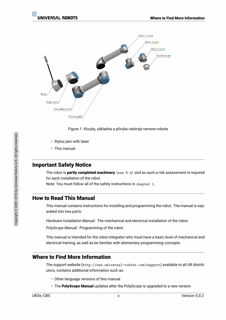
With six joints and a wide scope of flexibility, Universal Robots e-Series collaborative robot armsare designed to mimic the range of motion of a human arm. Using our patented programminginterface, PolyScope, it is easy to program the robot to move tools and communicate with othermachines using electrical signals. Figure 1 illustrates the main components of the robot armand can be used as a reference throughout the manual.
What Do the Boxes ContainWhen you order a complete robot, you receive two boxes. One contains the robot arm, the othercontains:
• Control Box with Teach Pendant
• Mounting bracket for the Control Box
• Mounting bracket for the Teach Pendant
• Key for opening the Control Box
• Mains cable or Power cable compatible to your region
Version 5.0.2
Copy
right
©20
09–2
018by
Universa
lRob
otsA/
S.Allrightsrese
rved
.
ix UR3e/CB5
Where to Find More Information
Figure 1: Klouby, základna a příruba nástroje ramene robota.
• Stylus pen with laser
• This manual
Important Safety NoticeThe robot is partly completed machinery (see 8.4) and as such a risk assessment is requiredfor each installation of the robot.Note: You must follow all of the safety instructions in chapter 1.
How to Read This ManualThis manual contains instructions for installing and programming the robot. The manual is sep-arated into two parts:
Hardware Installation Manual: The mechanical and electrical installation of the robot.
PolyScope Manual: Programming of the robot.
This manual is intended for the robot integrator who must have a basic level of mechanical andelectrical training, as well as be familiar with elementary programming concepts.
Where to Find More InformationThe support website (http://www.universal-robots.com/support) available to all UR distrib-utors, contains additional information such as:
• Other language versions of this manual
• The PolyScope Manual updates after the PolyScope is upgraded to a new version
UR3e/CB5 x Version 5.0.2
Copy
right
©20
09–2
018by
Universa
lRob
otsA/
S.Allrightsrese
rved
.

Where to Find More Information
• The Service Manual with instructions for troubleshooting, maintenance and repair of therobot
• The Script Manual for advanced users
• The URCAPS an online platform for purchasing Universal Robots accessories and periph-erals
Version 5.0.2
Copy
right
©20
09–2
018by
Universa
lRob
otsA/
S.Allrightsrese
rved
.
xi UR3e/CB5
Where to Find More Information
UR3e/CB5 xii Version 5.0.2
Copy
right
©20
09–2
018by
Universa
lRob
otsA/
S.Allrightsrese
rved
.
Part I
Hardware Installation Manual


1 Safety
1.1 IntroductionThis chapter contains important safety information, which must be read and understood by theintegrator of Universal Robots e-Series robots before the robot is powered on for the first time.
In this chapter, the first subsections are general. The later subsections contain specific engi-neering data relevant to enable setting up and programming the robot. Chapter 2 describesand defines safety-related functions particularly relevant for collaborative applications.Instructions and guidance provided in chapter 2 as well as in section 1.7 are particularlyimportant.
It is essential to observe and follow all assembly instructions and guidance provided in otherchapters and parts of this manual.
Special attention shall be paid to text associated with warning symbols.
NOTE:Universal Robots disclaims any and all liability if the robot (armcontrol box and/or teach pendant) is damaged, changed or mod-ified in any way. Universal Robots cannot be held responsible forany damages caused to the robot or any other equipment due toprogramming errors or malfunctioning of the robot.
1.2 Validity and ResponsibilityThe information in this manual does not cover designing, installing and operating a completerobot application, nor does it cover all peripheral equipment that can influence the safety of thecomplete system. The complete systemmust be designed and installed in accordance with thesafety requirements set forth in the standards and regulations of the country where the robot isinstalled.
The integrators of UR robots are responsible for ensuring that the applicable safety laws and reg-ulations in the country concerned are observed and that any significant hazards in the completerobot application are eliminated.
This includes, but is not limited to:
• Performing a risk assessment for the complete robot system
• Interfacing other machines and additional safety devices if defined by the risk assessment
• Setting up the appropriate safety settings in the software
• Ensuring that the user will not modify any safety measures
• Validating that the total robot system is designed and installed correctly
• Specifying instructions for use
• Marking the robot installation with relevant signs and contact information of the integrator
Version 5.0.2
Copy
right
©20
09–2
018by
Universa
lRob
otsA/
S.Allrightsrese
rved
.
I-3 UR3e/CB5

1.4 Warning Symbols in this Manual
• Collecting all documentation in a technical file; including the risk assessment and thisman-ual
Guidance onhow to find and read applicable standards and laws is providedon http://universal-robots.com/support/
1.3 Limitation of LiabilityAny safety information provided in this manual must not be construed as a warranty, by UR,that the industrial manipulator will not cause injury or damage, even if industrial manipulatorcomplies with all safety instructions.
1.4 Warning Symbols in this ManualThe symbols below define the captions specifying the danger levels used throughout this man-ual. The same warning signs are used on the product.
DANGER:This indicates an imminently hazardous electrical situation which,if not avoided, could result in death or serious injury.
DANGER:This indicates an imminently hazardous situation which, if notavoided, could result in death or serious injury.
WARNING:This indicates a potentially hazardous electrical situation which, ifnot avoided, could result in injury or major damage to the equip-ment.
WARNING:This indicates a potentially hazardous situation which, if notavoided, could result in injury or major damage to the equipment.
WARNING:This indicates a potentially hazardous hot surface which, iftouched, could result in injury.
CAUTION:This indicates a situation which, if not avoided, could result in dam-age to the equipment.
UR3e/CB5 I-4 Version 5.0.2
Copy
right
©20
09–2
018by
Universa
lRob
otsA/
S.Allrightsrese
rved
.
1.5 General Warnings and Cautions
1.5 General Warnings and CautionsThis section contains some general warnings and cautions that can be repeated or explained indifferent parts of this manual. Other warnings and cautions are present throughout this manual.
DANGER:Make sure to install the robot and all electrical equipment accord-ing to the specifications and warnings found in chapters 4 and5.
Version 5.0.2
Copy
right
©20
09–2
018by
Universa
lRob
otsA/
S.Allrightsrese
rved
.
I-5 UR3e/CB5

1.5 General Warnings and Cautions
WARNING:
1. Make sure the robot arm and tool/end effector are properlyand securely bolted in place.
2. Make sure the robot arm has ample space to operate freely.
3. Make sure that safety measures and/or robot safety configu-ration parameters have been set up to protect both program-mers, operators and bystanders, as defined in the risk assess-ment.
4. Do not wear loose clothing or jewellery when working with therobot. Make sure long hair is tied back when working with therobot.
5. Never use the robot if it is damaged, for example if joint capsare loose, broken or removed.
6. If the software prompts an error, immediately press emer-gency stop, write down the conditions that led to the error, findthe corresponding error codes on the log screen, and contactyour supplier.
7. Do not connect any safety equipment to standard I/O. Usesafety-related I/O only.
8. Make sure to use the correct installation settings (e.g. Robotmounting angle, mass in TCP, TCP offset, safety configura-tion). Save and load the installations file along with the pro-gram.
9. The freedrive function (Impedance/Backdrive) shall only beused in installations where the risk assessment allows it.Tool/end effectors and obstacles shall not have sharp edgesor pinch points.
10. Make sure to warn people to keep their heads and faces out-side the reach of the operating robot or robot about to startoperating.
11. Be aware of robot movement when using the teach pendant.
12. If determined by the risk assessment, do not enter the safetyrange of the robot or touch the robot when the system is inoperation.
UR3e/CB5 I-6 Version 5.0.2
Copy
right
©20
09–2
018by
Universa
lRob
otsA/
S.Allrightsrese
rved
.
1.5 General Warnings and Cautions
13. Collisions can release high levels of kinetic energy, which aresignificantly higher at high speeds and with high payloads.(Kinetic Energy = 1
2Mass · Speed2)
14. Combining different machines can increase hazards or cre-ate new hazards. Always make an overall risk assessmentfor the complete installation. Depending on the assessed risk,different levels of functional safety can apply; as such, whendifferent safety and emergency stop performance levels areneeded, always choose the highest performance level. Al-ways read and understand themanuals for all equipment usedin the installation.
15. Never modify the robot. A modification might create hazardsthat are unforeseen by the integrator. All authorized reassem-bling shall be done according to the newest version of all rel-evant service manuals.
16. If the robot is purchased with an extra module (e.g. eu-romap67 interface) then look up that module in the respectivemanual.
17. Make sure the users of the robot are informed of the locationof the emergency stop button(s) and are instructed to activatethe emergency stop in case of emergency or abnormal situa-tions.
WARNING:
1. The robot and its controller box generate heat during opera-tion. Do not handle or touch the robot while in operation orimmediately after operation as prolonged contact can causediscomfort. To cool the robot down, power off the robot andwait one hour.
2. Never stick fingers behind the internal cover of the controllerbox.
Version 5.0.2
Copy
right
©20
09–2
018by
Universa
lRob
otsA/
S.Allrightsrese
rved
.
I-7 UR3e/CB5

1.7 Risk Assessment
CAUTION:
1. When the robot is combined, or working, with machines capa-ble of damaging the robot, it is highly recommended to test allfunctions and the robot program separately. It is also recom-mended to test the robot program using temporary waypointsoutside the workspace of other machines.
2. Do not expose the robot to permanent magnetic fields. Verystrong magnetic fields can damage the robot.
1.6 Intended UseUR robots are industrial robots intended to handle tools/end effectors and fixtures, or to processor transfer components or products. For details about the environmental conditions under whichthe robot should operate, see appendices B and D.
UR robots are equipped with special safety-related features, which are purposely designed toenable collaborative operation, where the robot system operates without fences and/or togetherwith a human.
Collaborative operation is only intended for non-hazardous applications, where the completeapplication, including tool/end effector, work piece, obstacles and other machines, is withoutany significant hazards according to the risk assessment of the specific application.
Any use or application deviating from intended use is deemed to be impermissible misuse. Thisincludes, but is not limited to:
• Use in potentially explosive environments
• Use in medical and life critical applications
• Use before performing a risk assessment
• Use outside of stated specifications
• Use as a climbing aid
• Operation outside the permissible operating parameters
1.7 Risk AssessmentOne of themost important things that an integrator needs to do is to perform a risk assessment.In many countries this is required by law. The robot itself is partly completed machinery, as thesafety of the robot installation depends on how the robot is integrated (E.g. tool/end effector,obstacles and other machines).
It is recommended that the integrator uses ISO 12100 and ISO 10218-2 to conduct the risk as-sessment. Additionally the integrator can choose to use the Technical Specification ISO/TS15066 as additional guidance.
The risk assessment that the integrator conducts shall consider all work tasks throughout thelifetime of the robot application, including but not limited to:
UR3e/CB5 I-8 Version 5.0.2
Copy
right
©20
09–2
018by
Universa
lRob
otsA/
S.Allrightsrese
rved
.

1.7 Risk Assessment
• Teaching the robot during set-up and development of the robot installation
• Troubleshooting and maintenance
• Normal operation of the robot installation
A risk assessment must be conducted before the robot arm is powered on for the first time. Apart of the risk assessment conducted by the integrator is to identify the proper safety configura-tion settings, as well as the need for additional emergency stop buttons and/or other protectivemeasures required for the specific robot application.
Identifying the correct safety configuration settings is a particularly important part of developingcollaborative robot applications. See chapter 2 and part II for detailed information.
Some safety-related features are purposely designed for collaborative robot applications. Thesefeatures are configurable through the safety configuration settings and are particularly relevantwhen addressing specific risks in the risk assessment conducted by the integrator:
• Force and power limiting: Used to reduce clamping forces and pressures exerted by therobot in the direction of movement in case of collisions between the robot and the operator.
• Momentum limiting: Used to reduce high transient energy and impact forces in case ofcollisions between robot and operator by reducing the speed of the robot.
• Joint, elbow and tool/end effector position limiting: Particularly used to reduce risks as-sociated with certain body parts. E.g. to avoid movement towards head and neck.
• Tool/end effector orientation limiting: Particularly used to reduce risks associated withcertain areas and features of the tool/end effector and work-piece. E.g. to avoid sharpedges to be pointed towards the operator.
• Speed limitation: Particularly used to ensure a low speed of the robot arm.
The integrator must prevent unauthorized access to the safety configuration by using passwordprotection.A collaborative robot application risk assessment for contacts that are intentional and/or due toreasonably foreseeable misuse is required and must address:
• Severity of individual potential collisions
• Likeliness of occurrence of individual potential collisions
• Possibility to avoid individual potential collisions
If the robot is installed in a non-collaborative robot application where hazards cannot be rea-sonably eliminated or risks cannot be sufficiently reduced by use of the built-in safety-relatedfunctions (e.g. when using a hazardous tool/end effector), then the risk assessment conductedby the integrator must conclude the need for additional protective measures (e.g. an enablingdevice to protect the operator during set-up and programming).
Universal Robots identifies the potential significant hazards listed below as hazards that mustbe considered by the integrator.Note: Other significant hazards can be present in a specific robot installation.
1. Penetration of skin by sharp edges and sharp points on tool/end effector or tool/end effec-tor connector.
2. Penetration of skin by sharp edges and sharp points on obstacles near the robot track.
Version 5.0.2
Copy
right
©20
09–2
018by
Universa
lRob
otsA/
S.Allrightsrese
rved
.
I-9 UR3e/CB5
1.10 Movement Without Drive Power
3. Bruising due to contact with the robot.
4. Sprain or bone fracture due to strokes between a heavy payload and a hard surface.
5. Consequences due to loose bolts that hold the robot arm or tool/end effector.
6. Items falling out of tool/end effector, e.g. due to a poor grip or power interruption.
7. Mistakes due to different emergency stop buttons for different machines.
8. Mistakes due to unauthorized changes to the safety configuration parameters.
Information on stopping times and stopping distances are found in chapter 2 and appendix A.
1.8 Pre-Use AssessmentThe following tests must be conducted before using the robot for the first time or after any mod-ifications are made. Verify that all safety input and output are appropriately and correctly con-nected. Test that all connected safety input and output, including devices common to multiplemachines or robots, are functioning. As such you must:
• Test that emergency stop buttons and input stop the robot and engage brakes.
• Test that safeguard input stop the robot motion. If safeguard reset is configured, checkthat it needs to be activated before motion can be resumed.
• Examine the initialization screen to test that reduced mode can switch the safety mode toreduced mode.
• Test that the operational mode switches the operational mode, see icon in top right cornerof user interface.
• Test that the 3-position enabling device must be pressed to enable motion in manual modeand that the robot is under reduced speed control.
• Test that System Emergency Stop outputs are actually capable of bringing the whole sys-tem to a safe state.
• Test that the system connected to Robot Moving output, Robot Not Stopping output, Re-duced Mode output, or Not Reduced Mode output can actually detect the output changes
1.9 Emergency StopActivate the emergency stop push-button to immediately stop all robot motion.
Note: According to IEC 60204-1 and ISO 13850, emergency devices are not safeguards. Theyare complimentary protective measures and are not intended to prevent injury.
The risk assessment of the robot application shall conclude if additional emergency stop buttonsare need. Emergency stop push-buttonsmust comply with IEC 60947-5-5 (see section 5.4.2).
1.10 Movement Without Drive PowerIn the unlikely event of an emergency, you can use forced back-driving where you must moverobot joint/s, but robot power is either impossible or unwanted.To perform forced back-driving you must push, or pull, the robot arm hard to move the joint.Each joint brake has a friction clutch that enables movement during high forced torque.Note: In a service situation, the brake on the joints can be released without connected power.
UR3e/CB5 I-10 Version 5.0.2
Copy
right
©20
09–2
018by
Universa
lRob
otsA/
S.Allrightsrese
rved
.

1.10 Movement Without Drive Power
WARNING:
• Moving the robot arm manually is intended for urgent emer-gency purposes only and might damage the robot joints.
Version 5.0.2
Copy
right
©20
09–2
018by
Universa
lRob
otsA/
S.Allrightsrese
rved
.
I-11 UR3e/CB5

1.10 Movement Without Drive Power
UR3e/CB5 I-12 Version 5.0.2
Copy
right
©20
09–2
018by
Universa
lRob
otsA/
S.Allrightsrese
rved
.

2 Safety-related Functions and Interfaces
2.1 IntroductionUniversal Robots e-Series robots are equipped with a range of built-in safety functions as wellas safety I/O, digital and analog control signals to or from the electrical interface, to connect toother machines and additional protective devices. Each safety function and I/O is constructedaccording to EN ISO13849-1:2008 (see chapter 8 for certifications) with PerformanceLevel d (PLd) using a category 3 architecture.
See chapter 13 in part II for configuration of the safety functions, inputs and outputs in theuser interface. See chapter 5 for descriptions on how to connect safety devices to I/O.
NOTE:
1. The use and configuration of safety functions and interfacesmust follow the risk assessment procedures for each robotapplication. (see chapter 1 section 1.7)
2. If the robot discovers a fault or violation in the safety system(e.g. if one of the wires in the Emergency Stop circuit is cut ora safety limit is violated) then a Stop Category 0 is initiated.
3. The stopping time should be taken into account as part of theapplication risk assessment
DANGER:
1. The use of safety configuration parameters different fromthose determined by the risk assessment can result in haz-ards that are not reasonably eliminated or risks that are notsufficiently reduced
2. Ensure tools and grippers are connected appropriately so ifthere is an interruption of power, no hazards occurl
3. Use caution with 12V, since an error made by the programmercan cause the voltage to change to 24V, which might damagethe equipment and cause a fire
4. The end effector is not protected by the UR safety system. Thefunctioning of the end effector and/or connection cable is notmonitored
Version 5.0.2
Copy
right
©20
09–2
018by
Universa
lRob
otsA/
S.Allrightsrese
rved
.
I-13 UR3e/CB5
2.3 Safety Functions
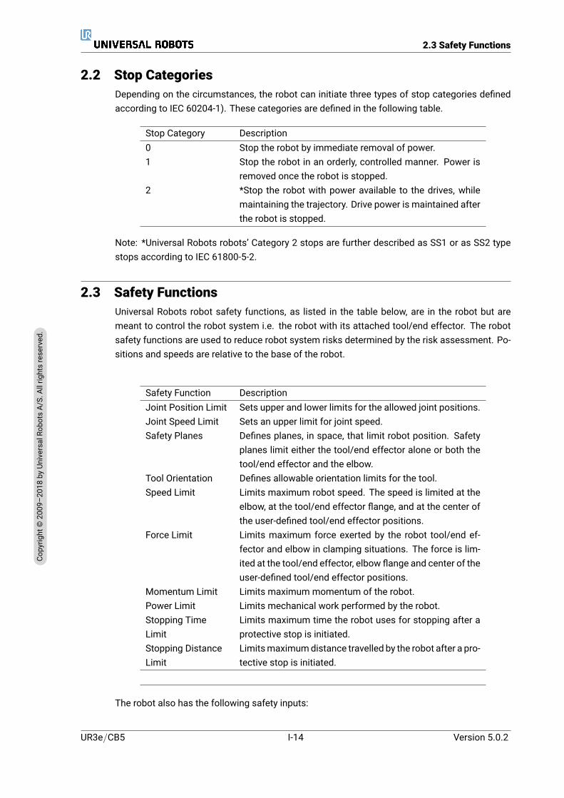
2.2 Stop CategoriesDepending on the circumstances, the robot can initiate three types of stop categories definedaccording to IEC 60204-1). These categories are defined in the following table.
Stop Category Description0 Stop the robot by immediate removal of power.1 Stop the robot in an orderly, controlled manner. Power is
removed once the robot is stopped.2 *Stop the robot with power available to the drives, while
maintaining the trajectory. Drive power is maintained afterthe robot is stopped.
Note: *Universal Robots robots’ Category 2 stops are further described as SS1 or as SS2 typestops according to IEC 61800-5-2.
2.3 Safety FunctionsUniversal Robots robot safety functions, as listed in the table below, are in the robot but aremeant to control the robot system i.e. the robot with its attached tool/end effector. The robotsafety functions are used to reduce robot system risks determined by the risk assessment. Po-sitions and speeds are relative to the base of the robot.
Safety Function DescriptionJoint Position Limit Sets upper and lower limits for the allowed joint positions.Joint Speed Limit Sets an upper limit for joint speed.Safety Planes Defines planes, in space, that limit robot position. Safety
planes limit either the tool/end effector alone or both thetool/end effector and the elbow.
Tool Orientation Defines allowable orientation limits for the tool.Speed Limit Limits maximum robot speed. The speed is limited at the
elbow, at the tool/end effector flange, and at the center ofthe user-defined tool/end effector positions.
Force Limit Limits maximum force exerted by the robot tool/end ef-fector and elbow in clamping situations. The force is lim-ited at the tool/end effector, elbow flange and center of theuser-defined tool/end effector positions.
Momentum Limit Limits maximum momentum of the robot.Power Limit Limits mechanical work performed by the robot.Stopping TimeLimit
Limits maximum time the robot uses for stopping after aprotective stop is initiated.
Stopping DistanceLimit
Limitsmaximumdistance travelled by the robot after a pro-tective stop is initiated.
The robot also has the following safety inputs:
UR3e/CB5 I-14 Version 5.0.2
Copy
right
©20
09–2
018by
Universa
lRob
otsA/
S.Allrightsrese
rved
.

2.4 Safety Function
Safety Input DescriptionEmergency StopButton
Performs a Stop Category 1 informing other machines us-ing the System Emergency Stop output, if that output is de-fined.
Robot EmergencyStop
Performs a Stop Category 1 via Control Box input, inform-ing other machines using the System Emergency Stop out-put, if that output is defined.
System EmergencyStop
Performs a Stop Category 1 on robot only.
Safeguard Stop Performs a Stop Category 2.Safeguard Reset Returns from the Safeguard Stop state, when an edge on
the Safeguard Reset input occurs.Reduced Mode Transitions the safety system to use the Reduced mode
limits.3-Position EnablingDevice
Initiates a Safeguard Stopwhen the enabling device is fullycompressed or fully released. When this happens, the en-abling device inputs are high.
Operational Mode Mode to switch, when needed. NOTE: required when a 3-Position Enabling Device is used.
For interfacing with other machines, the robot is equipped with the following safety outputs:
Safety Output DescriptionSystem EmergencyStop
While this signal is logic low, the Robot Emergency Stopinput is logic low or the Emergency Stop button is pressed.
Robot Moving While this signal is logic high, no single joint of the robotmoves more than 0.1 rad.
Robot Not Stopping Logic high when the robot is stopped or in the processof stopping due to an Emergency Stop or Safeguard Stop.Otherwise it will be logic low.
Reduced Mode Logic low when the safety system is in Reduced Mode.Not Reduced Mode Logic low when the system is not in Reduced Mode.
All safety I/O are dual channel, meaning they are safe when low (e.g., the Emergency Stop isactive when the signals are low).
2.4 Safety FunctionThe safety system acts by monitoring if any of the safety limits are violated or if an EmergencyStop or a Safeguard Stop is initiated.The reactions of the safety system are:
Trigger ReactionEmergency Stop Stop Category 1.Safeguard Stop Stop Category 2.Limit Violation Stop Category 0.Fault Detection Stop Category 0.
Version 5.0.2
Copy
right
©20
09–2
018by
Universa
lRob
otsA/
S.Allrightsrese
rved
.
I-15 UR3e/CB5

2.4 Safety Function
When performing the application risk assessment, it is necessary to take into account the mo-tion of the robot after a stop has been initiated. In order to ease this process, the safety functionsStopping Time Limit and Stopping Distance Limit can be used. These safety functions dynami-cally reduces the speed of the robot motion such that it can always be stopped within the limits.It is important to note that the joint position limits, the safety planes and the tool/end effectororientation limits take the expected stopping distance travel into account i.e. the robot motionwill slow down before the limit is reached.
The functional safety can be summarized as:
Safety Function Tolerance PerformanceLevel
Category
Emergency Stop – d 3Safeguard Stop – d 3Joint Position Limit 5 d 3Joint Speed Limit 1.15 /s d 3Safety Planes 40mm d 3Tool Orientation 3 d 3Speed Limit 50mm/s d 3Force Limit 25N d 3Momentum Limit 3 kg m/s d 3Power Limit 10W d 3Stopping Time Limit 50ms d 3Stopping Distance Limit 40mm d 3
WARNING:There are two exceptions to the force limiting function that are im-portant when designing an application (Figure 2.1). As the robotstretches out, the knee-joint effect can give high forces in the ra-dial direction (away from the base) at low speeds. Similarly, theshort leverage arm, when the tool/end effector is close to the baseand moving around the base, can cause high forces at low speeds.Pinching hazards can be avoided by removing obstacles in theseareas, placing the robot differently, or by using a combination ofsafety planes and joint limits to eliminate the hazard by preventingthe robot moving into this region of its workspace.
WARNING:If the robot is used in manual hand-guiding applications with linearmovements, the speed limit must be set to maximum 250mm/s forthe tool/end effector and elbow unless a risk assessment showsthat higher speeds are acceptable. This will prevent fast move-ments of the robot elbow near singularities.
UR3e/CB5 I-16 Version 5.0.2
Copy
right
©20
09–2
018by
Universa
lRob
otsA/
S.Allrightsrese
rved
.
2.5 Modes
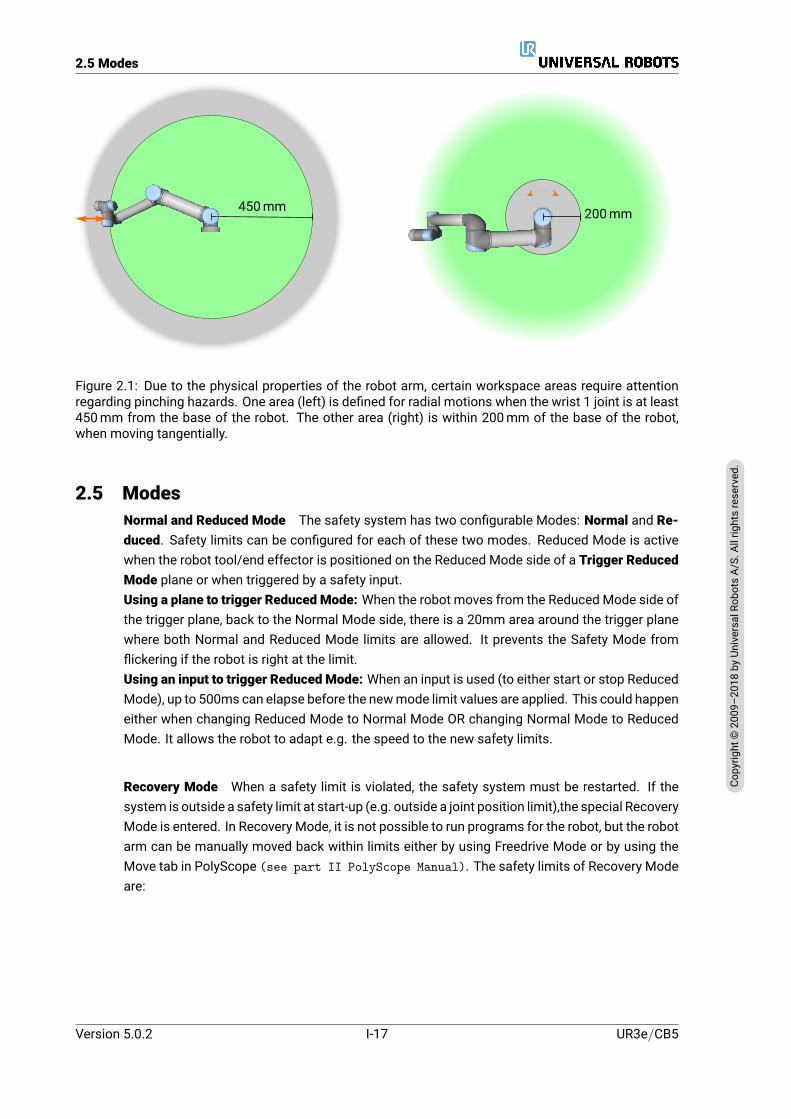
450mm 200mm
Figure 2.1: Due to the physical properties of the robot arm, certain workspace areas require attentionregarding pinching hazards. One area (left) is defined for radial motions when the wrist 1 joint is at least450mm from the base of the robot. The other area (right) is within 200mm of the base of the robot,when moving tangentially.
2.5 ModesNormal and Reduced Mode The safety system has two configurable Modes: Normal and Re-duced. Safety limits can be configured for each of these two modes. Reduced Mode is activewhen the robot tool/end effector is positioned on the Reduced Mode side of a Trigger ReducedMode plane or when triggered by a safety input.Using a plane to trigger Reduced Mode: When the robot moves from the Reduced Mode side ofthe trigger plane, back to the Normal Mode side, there is a 20mm area around the trigger planewhere both Normal and Reduced Mode limits are allowed. It prevents the Safety Mode fromflickering if the robot is right at the limit.Using an input to trigger Reduced Mode: When an input is used (to either start or stop ReducedMode), up to 500ms can elapse before the newmode limit values are applied. This could happeneither when changing Reduced Mode to Normal Mode OR changing Normal Mode to ReducedMode. It allows the robot to adapt e.g. the speed to the new safety limits.
Recovery Mode When a safety limit is violated, the safety system must be restarted. If thesystem is outside a safety limit at start-up (e.g. outside a joint position limit),the special RecoveryMode is entered. In Recovery Mode, it is not possible to run programs for the robot, but the robotarm can be manually moved back within limits either by using Freedrive Mode or by using theMove tab in PolyScope (see part II PolyScope Manual). The safety limits of Recovery Modeare:
Version 5.0.2
Copy
right
©20
09–2
018by
Universa
lRob
otsA/
S.Allrightsrese
rved
.
I-17 UR3e/CB5
2.5 Modes
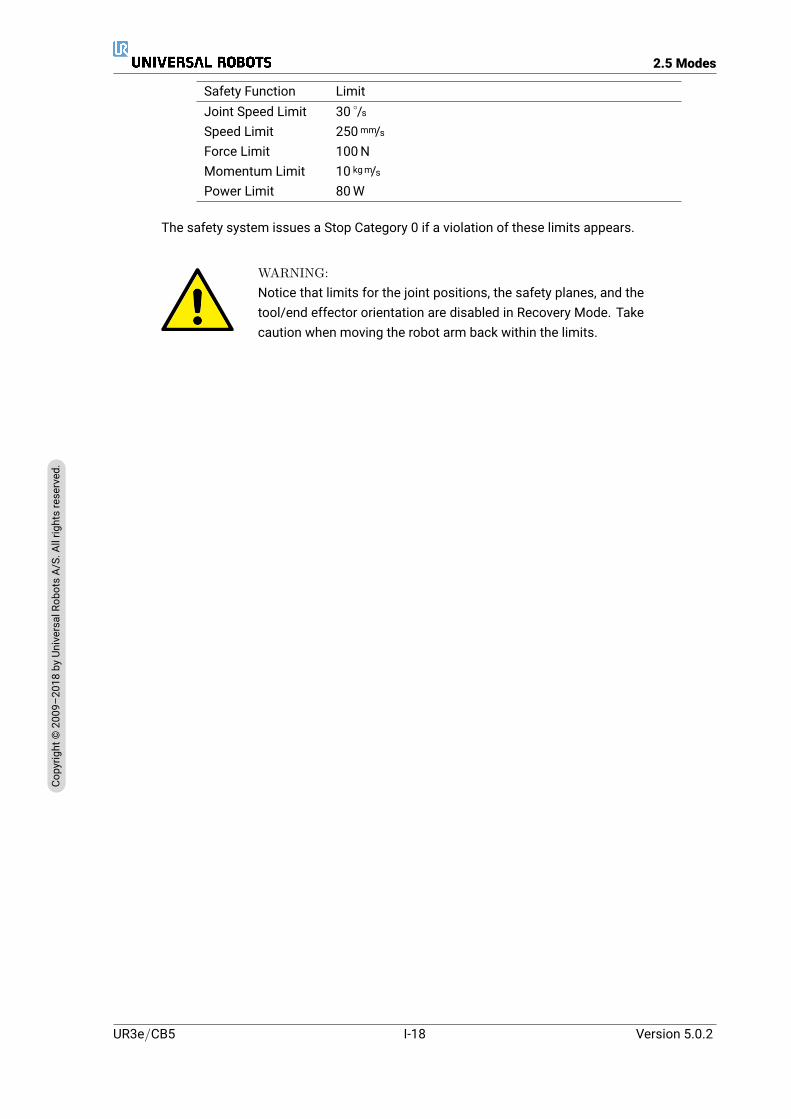
Safety Function LimitJoint Speed Limit 30 /sSpeed Limit 250mm/sForce Limit 100NMomentum Limit 10 kgm/sPower Limit 80W
The safety system issues a Stop Category 0 if a violation of these limits appears.
WARNING:Notice that limits for the joint positions, the safety planes, and thetool/end effector orientation are disabled in Recovery Mode. Takecaution when moving the robot arm back within the limits.
UR3e/CB5 I-18 Version 5.0.2
Copy
right
©20
09–2
018by
Universa
lRob
otsA/
S.Allrightsrese
rved
.

3 Transportation
As supplied on the pallet, the robot and Control Box are a calibrated set. Do not separate themas this would require recalibration.
Only transport the robot in its original packaging. Save the packaging material in a dry place ifyou want to move the robot later.
Whenmoving the robot from its packaging to the installation space, hold both tubes of the robotarm at the same time. Hold the robot in place until all mounting bolts are securely tightened atthe base of the robot.
Lift the Control Box by its handle.
WARNING:
1. Make sure not to overload your back or other bodypartswhen lifting the equipment. Use proper lifting equipment.All regional and national lifting guidelines shall be followed.Universal Robots cannot be held responsible for any damagecaused by transportation of the equipment.
2. Make sure to mount the robot according to the instructions inchapter 4.
Version 5.0.2
Copy
right
©20
09–2
018by
Universa
lRob
otsA/
S.Allrightsrese
rved
.
I-19 UR3e/CB5

UR3e/CB5 I-20 Version 5.0.2
Copy
right
©20
09–2
018by
Universa
lRob
otsA/
S.Allrightsrese
rved
.

4 Mechanical Interface
4.1 IntroductionThis chapter describes the basics of mounting the parts of the robot system. Electrical installa-tion instructions in chapter 5 must be observed.
4.2 Workspace of the RobotThe workspace of the UR3e robot extends 500mm from the base joint. It is important to con-sider the cylindrical volume directly above and directly below the robot base when choosing amounting place for the robot. Moving the tool close to the cylindrical volume should be avoidedbecause it causes the joints to move fast even when the tool is moving slowly, which causes therobot to work inefficiently and makes it difficult to conduct a risk assessment.
Front Tilted
4.3 MountingRobot Arm The Robot Arm is mounted using four 8.8 strength, M6 bolts and four 6.6mmmounting holes at the base. The bolts must be tightened with 9Nm torque.Use the two Ø5 holes provided, with a pin, to accurately reposition Robot Arm. Note: You canpurchase an accurate base counterpart as an accessory. Figure 4.1 shows where to drill holesand mount the screws.
Mount the robot on a sturdy, vibration-less, surface that can withstand at least ten times thefull torque of the base joint and at least five times the weight of the Robot Arm. If the robot ismounted on a linear axis, or a moving platform, then the acceleration of the moving mountingbase is very low. A high acceleration might cause the robot to make a safety stop.
DANGER:Make sure the Robot Arm is properly and securely bolted in place.Unstable mounting can lead to accidents.
Version 5.0.2
Copy
right
©20
09–2
018by
Universa
lRob
otsA/
S.Allrightsrese
rved
.
I-21 UR3e/CB5
4.3 Mounting
110
10 5 FG8
++
0.020 X 8 8.5 min.
5 FG8 ++
0.0240.006 8.5 min.
45°
11
0
4 x 6.6
I
2x
5 ±1
Surface on which the robot is fitted
0.05
D
E
F
C
1 2 3 4
B
A
321 5
C
D
4 6 7 8
A
B
A3UL class
PROPRIETARY AND CONFIDENTIALTHE INFORMATION CONTAINED IN THIS DRAWING IS THE SOLE PROPERTY OF UNIVERSAL ROBOTS. ANY REPRODUCTION IN PART OR AS A WHOLE WITHOUT THE WRITTEN PERMISSION OF UNIVERSAL ROBOTS IS PROHIBITED
REV.
TEL: +45 89 93 89 89 FAX: +45 38 79 89 89 WEB: universal-robots.com
APP.
Engineer:
SIZESHEET 1 OF 1SCALE:1:2
DWG NO.
TITLE:
DATE
NAMERevision History:
531473EN AW-6082 T6
452.13 g
2014-06-16
Flange Base UR3 G5
UNLESS OTHERWISE SPECIFIED:Dimensions are in millimetersRoHS compliant (PB free)Cleaned for chips and oil
NAME DATE
Drawing
Approved
TOLERANCE
SURFACE FINISH
TREATMENT
MATERIAL
WEIGHT
PROJECTION:
DATE
2014-06-16
+/- 0,1 mm +/- 0,5°
Ra 1,6
Anodized nature 10-20µ
jmi
Status change date:
Replace drawing:
-0,1+0,3-0,3
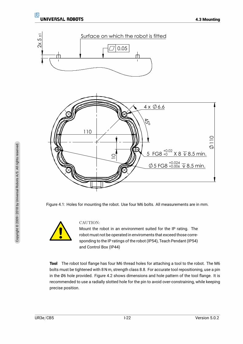
Figure 4.1: Holes for mounting the robot. Use four M6 bolts. All measurements are in mm.
CAUTION:Mount the robot in an environment suited for the IP rating. Therobotmust not be operated in enviroments that exceed those corre-sponding to the IP ratings of the robot (IP54), Teach Pendant (IP54)and Control Box (IP44)
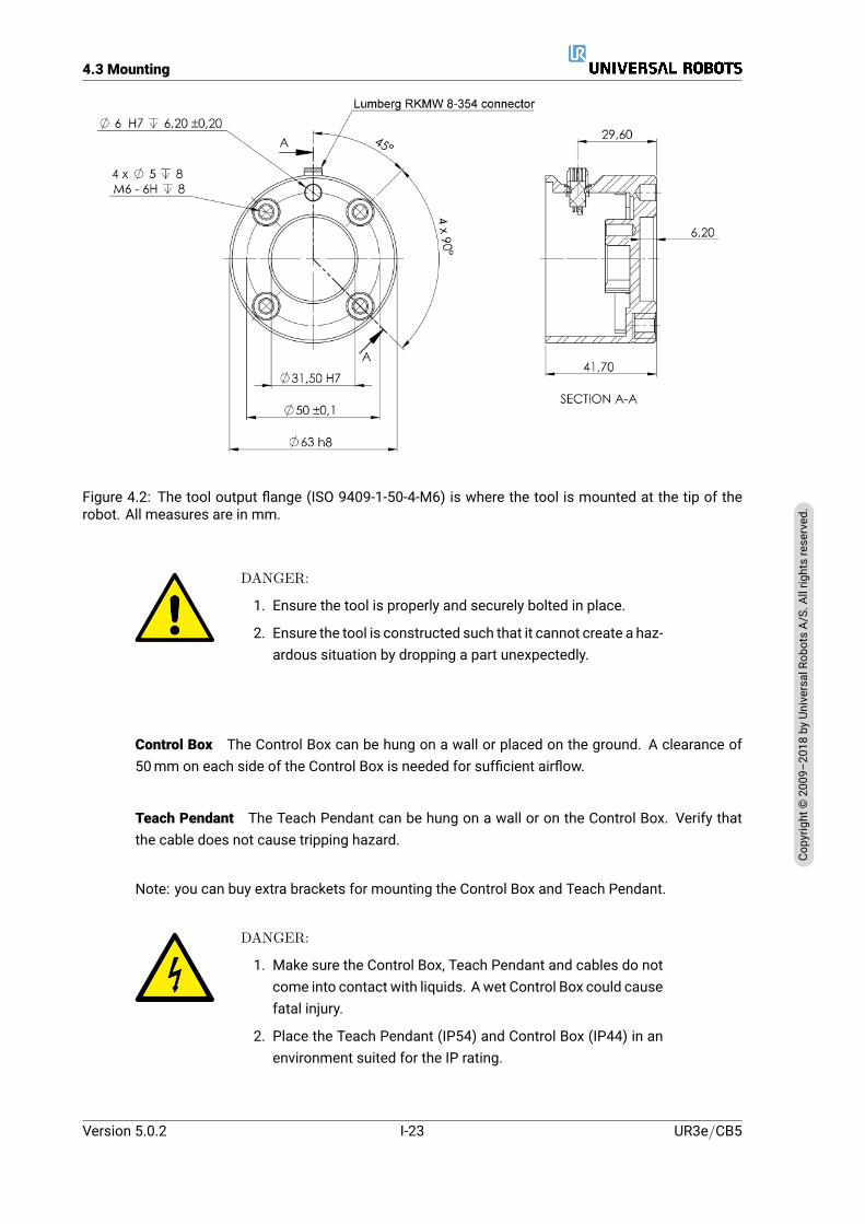
Tool The robot tool flange has four M6 thread holes for attaching a tool to the robot. The M6bolts must be tightened with 8Nm, strength class 8.8. For accurate tool repositioning, use a pinin the Ø6 hole provided. Figure 4.2 shows dimensions and hole pattern of the tool flange. It isrecommended to use a radially slotted hole for the pin to avoid over-constraining, while keepingprecise position.
UR3e/CB5 I-22 Version 5.0.2
Copy
right
©20
09–2
018by
Universa
lRob
otsA/
S.Allrightsrese
rved
.
4.3 Mounting
Figure 4.2: The tool output flange (ISO 9409-1-50-4-M6) is where the tool is mounted at the tip of therobot. All measures are in mm.
DANGER:
1. Ensure the tool is properly and securely bolted in place.
2. Ensure the tool is constructed such that it cannot create a haz-ardous situation by dropping a part unexpectedly.
Control Box The Control Box can be hung on a wall or placed on the ground. A clearance of50mm on each side of the Control Box is needed for sufficient airflow.
Teach Pendant The Teach Pendant can be hung on a wall or on the Control Box. Verify thatthe cable does not cause tripping hazard.
Note: you can buy extra brackets for mounting the Control Box and Teach Pendant.
DANGER:
1. Make sure the Control Box, Teach Pendant and cables do notcome into contact with liquids. A wet Control Box could causefatal injury.
2. Place the Teach Pendant (IP54) and Control Box (IP44) in anenvironment suited for the IP rating.
Version 5.0.2
Copy
right
©20
09–2
018by
Universa
lRob
otsA/
S.Allrightsrese
rved
.
I-23 UR3e/CB5
4.4 Maximum Payload
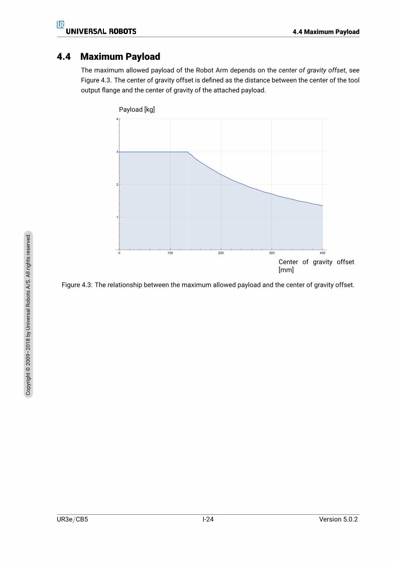
4.4 Maximum PayloadThe maximum allowed payload of the Robot Arm depends on the center of gravity offset, seeFigure 4.3. The center of gravity offset is defined as the distance between the center of the tooloutput flange and the center of gravity of the attached payload.
0 100 200 300 400
1
2
3
4
Center of gravity offset[mm]
Payload [kg]
Figure 4.3: The relationship between the maximum allowed payload and the center of gravity offset.
UR3e/CB5 I-24 Version 5.0.2
Copy
right
©20
09–2
018by
Universa
lRob
otsA/
S.Allrightsrese
rved
.

5 Electrical Interface
5.1 IntroductionThis chapter describes electrical interface groups for the Robot Arm in the Control Box. Exam-ples are given for most types of I/O. The term I/O refers to both digital and analog control signalsto or from the electrical interface groups listed below.
• Mains connection
• Robot connection
• Controller I/O
• Tool I/O
• Ethernet
5.1.1 Control Box BracketOn the underside of the I/O interface groups, there is a bracket with ports that allows for addi-tional connections (illustrated below). The base of the Control Box has a capped opening foreasy connection (see 5.2).
Note: The Fuse must be UL marked, Mini Blade type with maximum current rating: 10A andminimum voltage rating: 32V
5.2 EthernetThe Ethernet interface can be used for:
• MODBUS, EtherNet/IP and PROFINET (see part II).
• Remote access and control.
To connect the Ethernet cable by passing it through the hole at the base of the Control Box, andplugging it into the Ethernet port on the underside of the bracket.Replace the cap at the base of the Control Box with an appropriate cable gland to connect thecable to the Ethernet port.
Version 5.0.2
Copy
right
©20
09–2
018by
Universa
lRob
otsA/
S.Allrightsrese
rved
.
I-25 UR3e/CB5
5.3 Electrical Warnings and Cautions
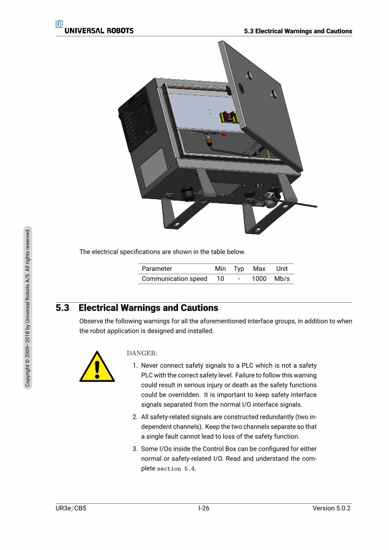
The electrical specifications are shown in the table below.
Parameter Min Typ Max UnitCommunication speed 10 - 1000 Mb/s
5.3 Electrical Warnings and CautionsObserve the following warnings for all the aforementioned interface groups, in addition to whenthe robot application is designed and installed.
DANGER:
1. Never connect safety signals to a PLC which is not a safetyPLCwith the correct safety level. Failure to follow this warningcould result in serious injury or death as the safety functionscould be overridden. It is important to keep safety interfacesignals separated from the normal I/O interface signals.
2. All safety-related signals are constructed redundantly (two in-dependent channels). Keep the two channels separate so thata single fault cannot lead to loss of the safety function.
3. Some I/Os inside the Control Box can be configured for eithernormal or safety-related I/O. Read and understand the com-plete section 5.4.
UR3e/CB5 I-26 Version 5.0.2
Copy
right
©20
09–2
018by
Universa
lRob
otsA/
S.Allrightsrese
rved
.
5.3 Electrical Warnings and Cautions
DANGER:
1. Make sure all equipment not rated for water exposure remaindry. If water is allowed to enter the product, lockout-tagout allpower and then contact your local Universal Robots serviceprovider for assistance.
2. Only use the original cables supplied with the robot only. Donot use the robot for applications where the cables are sub-ject to flexing. Contact your local Universal Robots service iflonger or flexible cables are needed.
3. Negative connections are referred to as Ground (GND) and areconnected to the casing of the robot and the Control Box. Allmentioned GND connections are only for powering and sig-nalling. For PE (Protective Earth) use the M6-size screw con-nections marked with earth symbols inside the Control Box.The grounding conductor shall have at least the current ratingof the highest current in the system.
4. Use caution when installing interface cables to the robot I/O.The metal plate in the bottom is intended for interface ca-bles and connectors. Remove the plate before drilling holes.Make sure that all shavings are removed before reinstallingthe plate. Remember to use correct gland sizes.
CAUTION:
1. The robot has been tested according to international IEC stan-dards for ElectroMagnetic Compatibility (EMC). Disturbingsignalswith levels higher than those defined in the specific IECstandards can cause unexpected behaviors from the robot.Very high signal levels or excessive exposure can damage therobot permanently. EMC problems are found to happen usu-ally in welding processes and are normally prompted by errormessages in the log. Universal Robots cannot be held respon-sible for any damages caused by EMC problems.
2. I/O cables going from the Control Box to other machinery andfactory equipment may not be longer than 30m, unless addi-tional tests are performed.
NOTE:All voltages and currents are in Direct Current (DC) unless other-wise specified.
Version 5.0.2
Copy
right
©20
09–2
018by
Universa
lRob
otsA/
S.Allrightsrese
rved
.
I-27 UR3e/CB5
5.4 Controller I/O
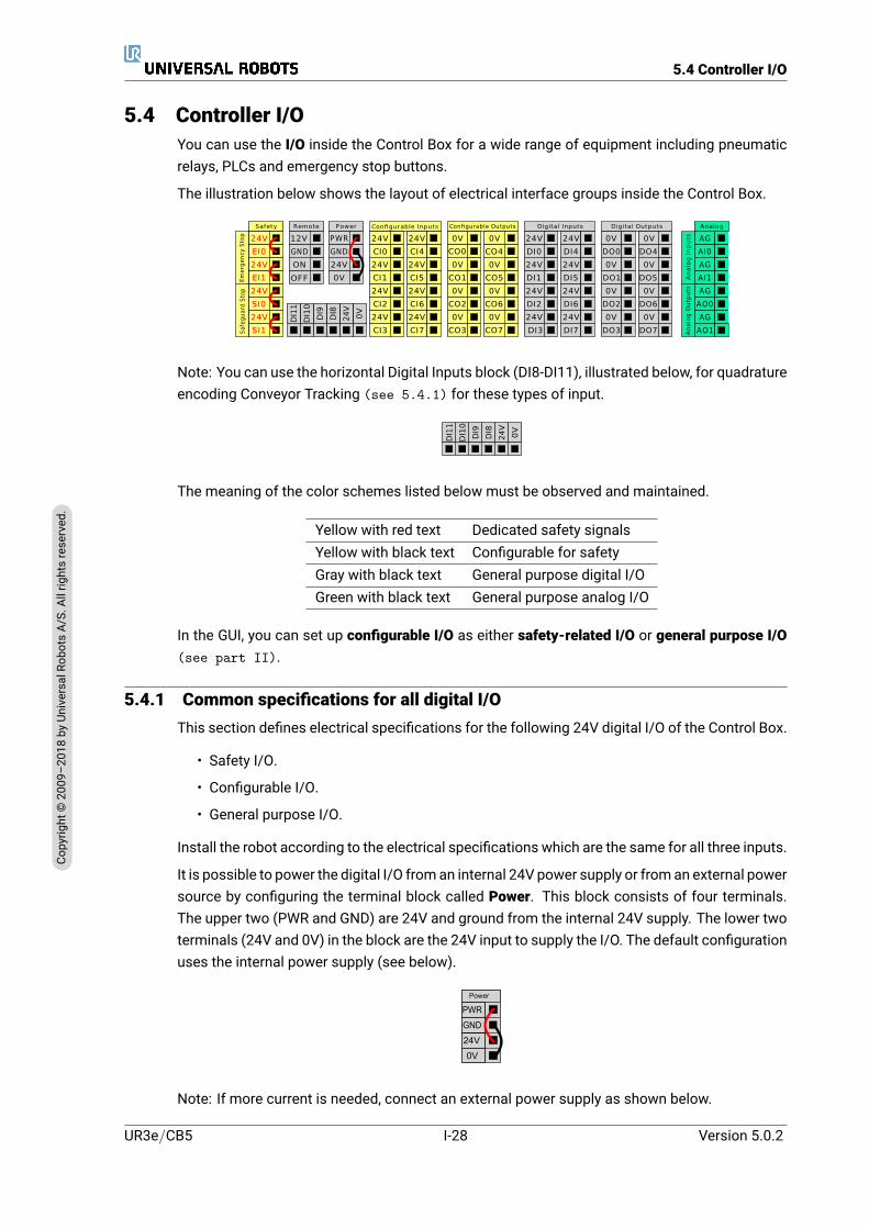
5.4 Controller I/OYou can use the I/O inside the Control Box for a wide range of equipment including pneumaticrelays, PLCs and emergency stop buttons.
The illustration below shows the layout of electrical interface groups inside the Control Box.
24V
EI1
24V
SI0
24V
SI1
24V
EI0
Safety
ON
OFF
12V
Remote
24V
0V
PWR
GND
Power
24V
CI1
24V
CI2
24V
CI3
24V
CI0
Configurable Inputs
24V
CI5
24V
CI6
24V
CI7
24V
CI4
0V
CO1
0V
CO2
0V
CO3
0V
CO0
Configurable Outputs
0V
CO5
0V
CO6
0V
CO7
0V
CO4
24V
DI1
24V
DI2
24V
DI3
24V
DI0
Digital Inputs
24V
DI5
24V
DI6
24V
DI7
24V
DI4
0V
DO1
0V
DO2
0V
DO3
0V
DO0
Digital Outputs
0V
DO5
0V
DO6
0V
DO7
0V
DO4
AG
AI1
AG
AO0
AG
AO1
AG
AI0
Analog
An
alo
g O
utp
uts
An
alo
g I
np
uts
Sa
feg
ua
rd S
top
Em
erg
en
cy S
top
GND
0V
24
V
DI8
DI9
DI1
0
DI1
1
Note: You can use the horizontal Digital Inputs block (DI8-DI11), illustrated below, for quadratureencoding Conveyor Tracking (see 5.4.1) for these types of input.
0V
24V
DI8
DI9
DI10
DI11
The meaning of the color schemes listed below must be observed and maintained.
Yellow with red text Dedicated safety signalsYellow with black text Configurable for safetyGray with black text General purpose digital I/OGreen with black text General purpose analog I/O
In the GUI, you can set up configurable I/O as either safety-related I/O or general purpose I/O(see part II).
5.4.1 Common specifications for all digital I/OThis section defines electrical specifications for the following 24V digital I/O of the Control Box.
• Safety I/O.
• Configurable I/O.
• General purpose I/O.
Install the robot according to the electrical specifications which are the same for all three inputs.
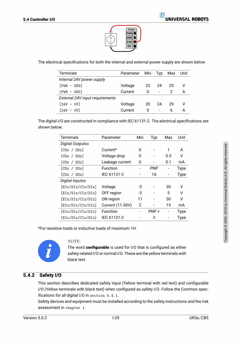
It is possible to power the digital I/O froman internal 24V power supply or froman external powersource by configuring the terminal block called Power. This block consists of four terminals.The upper two (PWR and GND) are 24V and ground from the internal 24V supply. The lower twoterminals (24V and 0V) in the block are the 24V input to supply the I/O. The default configurationuses the internal power supply (see below).
24V
0V
PWR
GND
Power
Note: If more current is needed, connect an external power supply as shown below.
UR3e/CB5 I-28 Version 5.0.2
Copy
right
©20
09–2
018by
Universa
lRob
otsA/
S.Allrightsrese
rved
.
5.4 Controller I/O
24V
0V
PWR
GND
Power
The electrical specifications for both the internal and external power supply are shown below.
Terminals Parameter Min Typ Max UnitInternal 24V power supply[PWR - GND] Voltage 23 24 25 V[PWR - GND] Current 0 - 2 AExternal 24V input requirements[24V - 0V] Voltage 20 24 29 V[24V - 0V] Current 0 - 6 A
The digital I/O are constructed in compliance with IEC 61131-2. The electrical specifications areshown below.
Terminals Parameter Min Typ Max UnitDigital Outputss[COx / DOx] Current* 0 - 1 A[COx / DOx] Voltage drop 0 - 0.5 V[COx / DOx] Leakage current 0 - 0.1 mA[COx / DOx] Function - PNP - Type[COx / DOx] IEC 61131-2 - 1A - TypeDigital Inputss[EIx/SIx/CIx/DIx] Voltage -3 - 30 V[EIx/SIx/CIx/DIx] OFF region -3 - 5 V[EIx/SIx/CIx/DIx] ON region 11 - 30 V[EIx/SIx/CIx/DIx] Current (11-30V) 2 - 15 mA[EIx/SIx/CIx/DIx] Function - PNP + - Type[EIx/SIx/CIx/DIx] IEC 61131-2 - 3 - Type
*For resistive loads or inductive loads of maximum 1H.
NOTE:The word configurable is used for I/O that is configured as eithersafety-related I/O or normal I/O. These are the yellow terminalswithblack text.
5.4.2 Safety I/OThis section describes dedicated safety input (Yellow terminal with red text) and configurableI/O (Yellow terminals with black text) when configured as safety I/O. Follow the Common spec-ifications for all digital I/O in section 5.4.1.Safety devices and equipment must be installed according to the safety instructions and the riskassessment in chapter 1.
Version 5.0.2
Copy
right
©20
09–2
018by
Universa
lRob
otsA/
S.Allrightsrese
rved
.
I-29 UR3e/CB5
5.4 Controller I/O
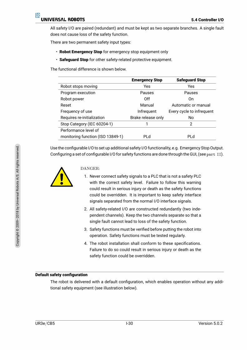
All safety I/O are paired (redundant) and must be kept as two separate branches. A single faultdoes not cause loss of the safety function.
There are two permanent safety input types:
• Robot Emergency Stop for emergency stop equipment only
• Safeguard Stop for other safety-related protective equipment.
The functional difference is shown below.
Emergency Stop Safeguard StopRobot stops moving Yes YesProgram execution Pauses PausesRobot power Off OnReset Manual Automatic or manualFrequency of use Infrequent Every cycle to infrequentRequires re-initialization Brake release only NoStop Category (IEC 60204-1) 1 2Performance level ofmonitoring function (ISO 13849-1) PLd PLd
Use the configurable I/O to set up additional safety I/O functionality, e.g. Emergency StopOutput.Configuring a set of configurable I/O for safety functions are done through theGUI, (see part II).
DANGER:
1. Never connect safety signals to a PLC that is not a safety PLCwith the correct safety level. Failure to follow this warningcould result in serious injury or death as the safety functionscould be overridden. It is important to keep safety interfacesignals separated from the normal I/O interface signals.
2. All safety-related I/O are constructed redundantly (two inde-pendent channels). Keep the two channels separate so that asingle fault cannot lead to loss of the safety function.
3. Safety functions must be verified before putting the robot intooperation. Safety functions must be tested regularly.
4. The robot installation shall conform to these specifications.Failure to do so could result in serious injury or death as thesafety function could be overridden.
Default safety configuration
The robot is delivered with a default configuration, which enables operation without any addi-tional safety equipment (see illustration below).
UR3e/CB5 I-30 Version 5.0.2
Copy
right
©20
09–2
018by
Universa
lRob
otsA/
S.Allrightsrese
rved
.

5.4 Controller I/O
24V
EI1
24V
SI0
24V
SI1
24V
EI0
Safety
Saf
egua
rd S
top
Em
erge
ncy
Sto
p
Connecting emergency stop buttons
Most applications require one or more extra emergency stop buttons. The illustration belowshows how one or more emergency stop buttons can be connected.
24V
EI1
24V
SI0
24V
SI1
24V
EI0
Safety
Saf
egua
rd S
top
Em
erge
ncy
Sto
p
24V
EI1
24V
SI0
24V
SI1
24V
EI0
Safety
Saf
egua
rd S
top
Em
erge
ncy
Sto
p
Sharing the Emergency Stop with other machines
You can set up a shared emergency stop function between the robot and other machines byconfiguring the following I/O functions via the GUI. The Robot Emergency Stop Input cannot beused for sharing purposes. If more than two UR robots or other machines need to be connected,a safety PLC must be used to control the emergency stop signals.
• Configurable input pair: External emergency stop.
• Configurable output pair: System emergency stop.
The illustration below shows how two UR robots share their emergency stop functions. In thisexample the configured I/Os used are CI0-CI1 and CO0-CO1.
24V
CI1
24V
CI2
24V
CI3
24V
CI0
Configurable Inputs
24V
CI5
24V
CI6
24V
CI7
24V
CI4
0V
CO1
0V
CO2
0V
CO3
0V
CO0
Configurable Outputs
0V
CO5
0V
CO6
0V
CO7
0V
CO4
24V
CI1
24V
CI2
24V
CI3
24V
CI0
Configurable Inputs
24V
CI5
24V
CI6
24V
CI7
24V
CI4
0V
CO1
0V
CO2
0V
CO3
0V
CO0
Configurable Outputs
0V
CO5
0V
CO6
0V
CO7
0V
CO4A B
Safeguard stop with automatic resume
An example of a basic safeguard stop device is a door switch where the robot is stopped whena door is opened (see illustration below).
Version 5.0.2
Copy
right
©20
09–2
018by
Universa
lRob
otsA/
S.Allrightsrese
rved
.
I-31 UR3e/CB5
5.4 Controller I/O
24V
EI1
24V
SI0
24V
SI1
24V
EI0
Safety
Saf
egua
rd S
top
Em
erge
ncy
Sto
p
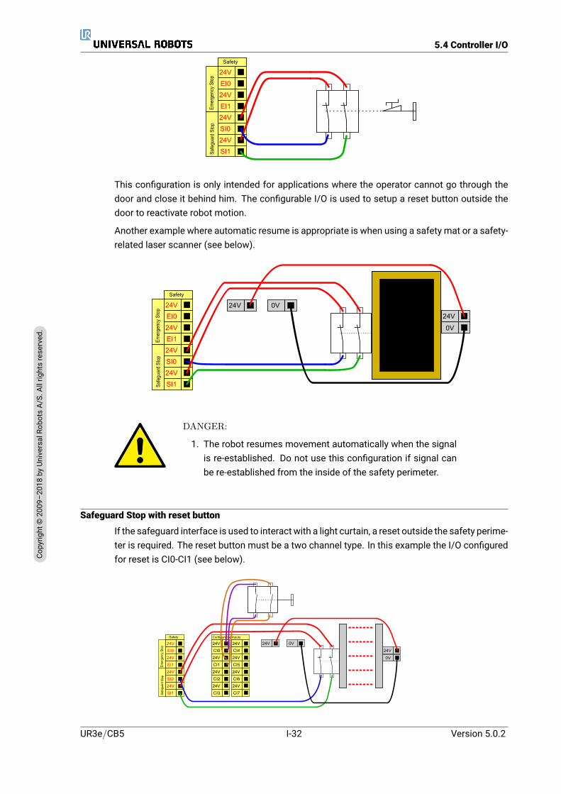
This configuration is only intended for applications where the operator cannot go through thedoor and close it behind him. The configurable I/O is used to setup a reset button outside thedoor to reactivate robot motion.
Another example where automatic resume is appropriate is when using a safety mat or a safety-related laser scanner (see below).
24V
EI1
24V
SI0
24V
SI1
24V
EI0
Safety
Saf
egua
rd S
top
Em
erge
ncy
Sto
p
24V 0V
24V
0V
DANGER:
1. The robot resumes movement automatically when the signalis re-established. Do not use this configuration if signal canbe re-established from the inside of the safety perimeter.
Safeguard Stop with reset button
If the safeguard interface is used to interact with a light curtain, a reset outside the safety perime-ter is required. The reset button must be a two channel type. In this example the I/O configuredfor reset is CI0-CI1 (see below).
24V
EI1
24V
SI0
24V
SI1
24V
EI0
Safety
Saf
egua
rd7S
top
Em
erge
ncy7
Sto
p
24V 0V
24V
0V24V
CI1
24V
CI2
24V
CI3
24V
CI0
Configurable7Inputs
24V
CI5
24V
CI6
24V
CI7
24V
CI4
UR3e/CB5 I-32 Version 5.0.2
Copy
right
©20
09–2
018by
Universa
lRob
otsA/
S.Allrightsrese
rved
.

5.4 Controller I/O
3-Position Enabling Device
The illustration belowshowshow to connect a Three-Position EnablingDevice. See section 12.2for more about 3-Position Enabling Device.
NOTE:The Universal Robots safety system does not support multiple 3-Position Enabling Devices.
Operational Mode Switch
The illustration below shows an Operational Mode Switch. See section 12.1 for more aboutoperational Modes.
5.4.3 General purpose digital I/OThis section describes the general purpose 24V I/O (Gray terminals) and the configurable I/O(Yellow terminals with black text) when not configured as safety I/O. The common specificationsin section 5.4.1 must be observed.
The general purpose I/O can be used t o drive equipment like pneumatic relays directly or forcommunication with other PLC systems. All Digital Outputss can be disabled automaticallywhen program execution is stopped, see part II. In this mode, the output is always low whena program is not running. Examples are shown in the following subsections. These examplesuse regular Digital Outputss but any configurable outputs could also have be used if they are notconfigured to perform a safety function.
Version 5.0.2
Copy
right
©20
09–2
018by
Universa
lRob
otsA/
S.Allrightsrese
rved
.
I-33 UR3e/CB5
5.4 Controller I/O
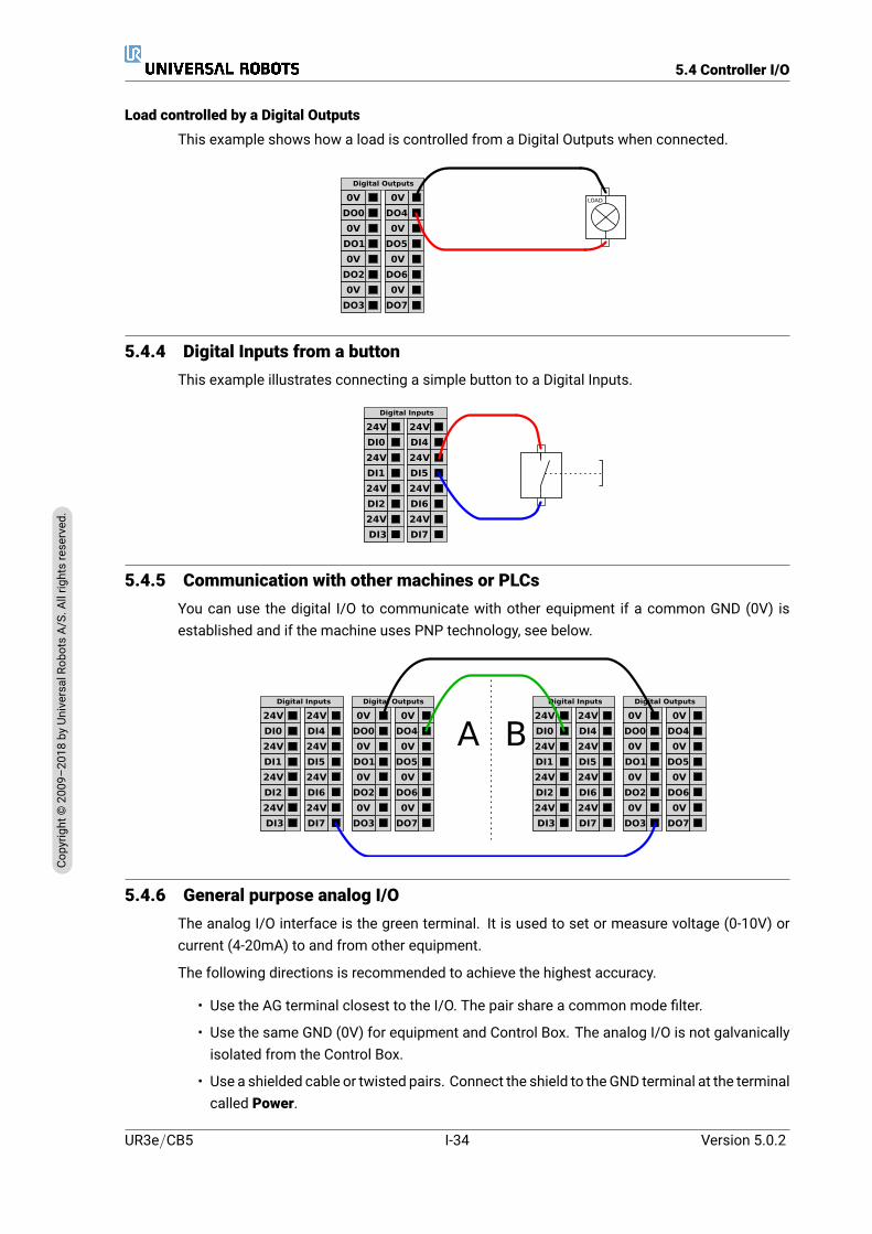
Load controlled by a Digital Outputs
This example shows how a load is controlled from a Digital Outputs when connected.
0V
DO1
0V
DO2
0V
DO3
0V
DO0
Digital Outputs
0V
DO5
0V
DO6
0V
DO7
0V
DO4
LOAD
5.4.4 Digital Inputs from a buttonThis example illustrates connecting a simple button to a Digital Inputs.
24V
DI1
24V
DI2
24V
DI3
24V
DI0
Digital Inputs
24V
DI5
24V
DI6
24V
DI7
24V
DI4
5.4.5 Communication with other machines or PLCsYou can use the digital I/O to communicate with other equipment if a common GND (0V) isestablished and if the machine uses PNP technology, see below.
24V
DI1
24V
DI2
24V
DI3
24V
DI0
Digital Inputs
24V
DI5
24V
DI6
24V
DI7
24V
DI4
0V
DO1
0V
DO2
0V
DO3
0V
DO0
Digital Outputs
0V
DO5
0V
DO6
0V
DO7
0V
DO4
24V
DI1
24V
DI2
24V
DI3
24V
DI0
Digital Inputs
24V
DI5
24V
DI6
24V
DI7
24V
DI4
0V
DO1
0V
DO2
0V
DO3
0V
DO0
Digital Outputs
0V
DO5
0V
DO6
0V
DO7
0V
DO4A B
5.4.6 General purpose analog I/OThe analog I/O interface is the green terminal. It is used to set or measure voltage (0-10V) orcurrent (4-20mA) to and from other equipment.
The following directions is recommended to achieve the highest accuracy.
• Use the AG terminal closest to the I/O. The pair share a common mode filter.
• Use the same GND (0V) for equipment and Control Box. The analog I/O is not galvanicallyisolated from the Control Box.
• Use a shielded cable or twisted pairs. Connect the shield to the GND terminal at the terminalcalled Power.
UR3e/CB5 I-34 Version 5.0.2
Copy
right
©20
09–2
018by
Universa
lRob
otsA/
S.Allrightsrese
rved
.
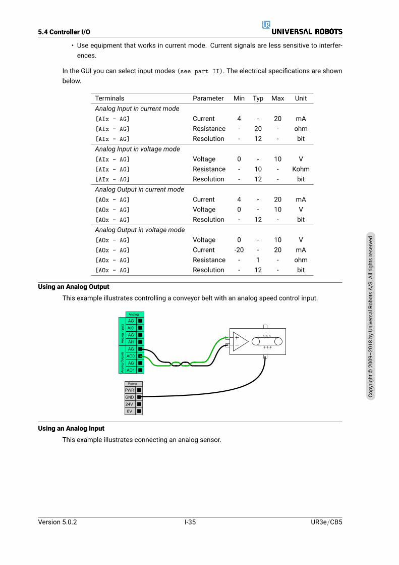
5.4 Controller I/O
• Use equipment that works in current mode. Current signals are less sensitive to interfer-ences.
In the GUI you can select input modes (see part II). The electrical specifications are shownbelow.
Terminals Parameter Min Typ Max UnitAnalog Input in current mode[AIx - AG] Current 4 - 20 mA[AIx - AG] Resistance - 20 - ohm[AIx - AG] Resolution - 12 - bitAnalog Input in voltage mode[AIx - AG] Voltage 0 - 10 V[AIx - AG] Resistance - 10 - Kohm[AIx - AG] Resolution - 12 - bitAnalog Output in current mode[AOx - AG] Current 4 - 20 mA[AOx - AG] Voltage 0 - 10 V[AOx - AG] Resolution - 12 - bitAnalog Output in voltage mode[AOx - AG] Voltage 0 - 10 V[AOx - AG] Current -20 - 20 mA[AOx - AG] Resistance - 1 - ohm[AOx - AG] Resolution - 12 - bit
Using an Analog Output
This example illustrates controlling a conveyor belt with an analog speed control input.
AG
AI1
AG
AO0
AG
AO1
AG
AI0
Analog
Ana
log
Out
puts
Ana
log
Inpu
ts
24V
0V
PWR
GND
Power
Using an Analog Input
This example illustrates connecting an analog sensor.
Version 5.0.2
Copy
right
©20
09–2
018by
Universa
lRob
otsA/
S.Allrightsrese
rved
.
I-35 UR3e/CB5
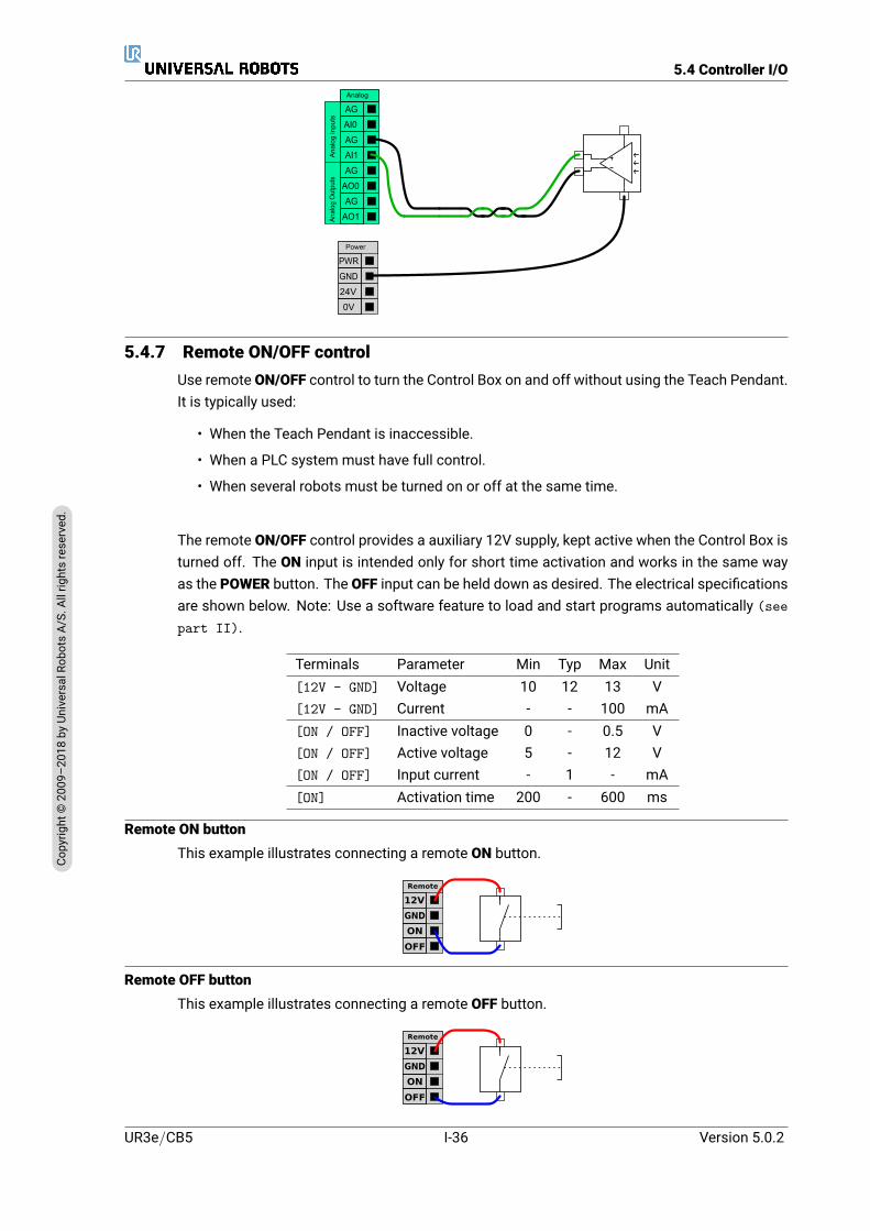
5.4 Controller I/O
AG
AI1
AG
AO0
AG
AO1
AG
AI0
Analog
Ana
log
Out
puts
Ana
log
Inpu
ts
24V
0V
PWR
GND
Power
5.4.7 Remote ON/OFF controlUse remote ON/OFF control to turn the Control Box on and off without using the Teach Pendant.It is typically used:
• When the Teach Pendant is inaccessible.
• When a PLC system must have full control.
• When several robots must be turned on or off at the same time.
The remote ON/OFF control provides a auxiliary 12V supply, kept active when the Control Box isturned off. The ON input is intended only for short time activation and works in the same wayas the POWER button. The OFF input can be held down as desired. The electrical specificationsare shown below. Note: Use a software feature to load and start programs automatically (seepart II).
Terminals Parameter Min Typ Max Unit[12V - GND] Voltage 10 12 13 V[12V - GND] Current - - 100 mA[ON / OFF] Inactive voltage 0 - 0.5 V[ON / OFF] Active voltage 5 - 12 V[ON / OFF] Input current - 1 - mA[ON] Activation time 200 - 600 ms
Remote ON buttonThis example illustrates connecting a remote ON button.
ON
OFF
12V
Remote
GND
Remote OFF buttonThis example illustrates connecting a remote OFF button.
ON
OFF
12V
Remote
GND
UR3e/CB5 I-36 Version 5.0.2
Copy
right
©20
09–2
018by
Universa
lRob
otsA/
S.Allrightsrese
rved
.

5.5 Mains Connection
CAUTION:Do not press and hold the ON input or the POWER button as itswitches off the Control Box without saving. Youmust use theOFFinput for remote off control as this signal allows the Control Box tosave open files and shut down correctly.
5.5 Mains ConnectionThe mains cable from the Control Box has a standard IEC plug at the end. Connect a countryspecific mains plug, or cable, to the IEC plug.
In order to energize the robot, the Control Box must be connected to the mains via the stan-dard IEC C20 plug at the bottom of the Control Box, through a corresponding IEC C19 cord (seeillustration below).
The mains supply is equipped with the following:
• Connection to ground
• Main fuse
• Residual current device
It is recommended to install a main switch to power off all equipment in the robot application asan easy means for lockout-tagout under service. The electrical specifications are shown in thetable below.
Parameter Min Typ Max UnitInput voltage 100 - 265 VACExternal mains fuse (@ 100-200V) 8 - 16 AExternal mains fuse (@ 200-265V) 8 - 16 AInput frequency 47 - 63 HzStand-by power - - <1.5 WNominal operating power 90 150 325 W
Version 5.0.2
Copy
right
©20
09–2
018by
Universa
lRob
otsA/
S.Allrightsrese
rved
.
I-37 UR3e/CB5
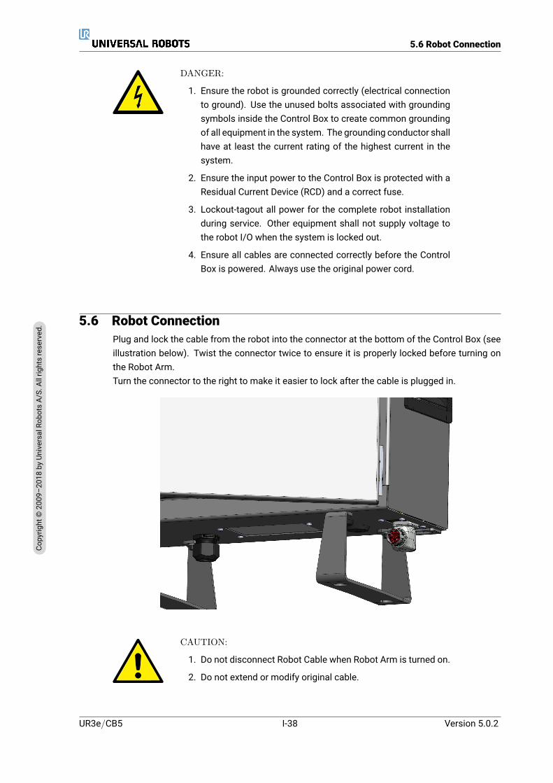
5.6 Robot Connection
DANGER:
1. Ensure the robot is grounded correctly (electrical connectionto ground). Use the unused bolts associated with groundingsymbols inside the Control Box to create common groundingof all equipment in the system. The grounding conductor shallhave at least the current rating of the highest current in thesystem.
2. Ensure the input power to the Control Box is protected with aResidual Current Device (RCD) and a correct fuse.
3. Lockout-tagout all power for the complete robot installationduring service. Other equipment shall not supply voltage tothe robot I/O when the system is locked out.
4. Ensure all cables are connected correctly before the ControlBox is powered. Always use the original power cord.
5.6 Robot ConnectionPlug and lock the cable from the robot into the connector at the bottom of the Control Box (seeillustration below). Twist the connector twice to ensure it is properly locked before turning onthe Robot Arm.Turn the connector to the right to make it easier to lock after the cable is plugged in.
CAUTION:
1. Do not disconnect Robot Cable when Robot Arm is turned on.
2. Do not extend or modify original cable.
UR3e/CB5 I-38 Version 5.0.2
Copy
right
©20
09–2
018by
Universa
lRob
otsA/
S.Allrightsrese
rved
.
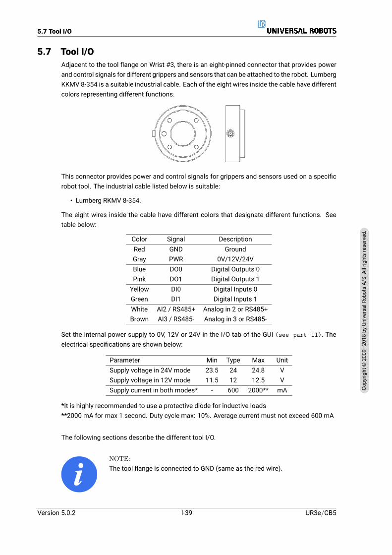
5.7 Tool I/O
5.7 Tool I/OAdjacent to the tool flange on Wrist #3, there is an eight-pinned connector that provides powerand control signals for different grippers and sensors that can be attached to the robot. LumbergKKMV 8-354 is a suitable industrial cable. Each of the eight wires inside the cable have differentcolors representing different functions.
This connector provides power and control signals for grippers and sensors used on a specificrobot tool. The industrial cable listed below is suitable:
• Lumberg RKMV 8-354.
The eight wires inside the cable have different colors that designate different functions. Seetable below:
Color Signal DescriptionRed GND GroundGray PWR 0V/12V/24VBlue DO0 Digital Outputs 0Pink DO1 Digital Outputs 1Yellow DI0 Digital Inputs 0Green DI1 Digital Inputs 1White AI2 / RS485+ Analog in 2 or RS485+Brown AI3 / RS485- Analog in 3 or RS485-
Set the internal power supply to 0V, 12V or 24V in the I/O tab of the GUI (see part II). Theelectrical specifications are shown below:
Parameter Min Type Max UnitSupply voltage in 24V mode 23.5 24 24.8 VSupply voltage in 12V mode 11.5 12 12.5 VSupply current in both modes* - 600 2000** mA
*It is highly recommended to use a protective diode for inductive loads**2000 mA for max 1 second. Duty cycle max: 10%. Average current must not exceed 600 mA
The following sections describe the different tool I/O.
NOTE:The tool flange is connected to GND (same as the red wire).
Version 5.0.2
Copy
right
©20
09–2
018by
Universa
lRob
otsA/
S.Allrightsrese
rved
.
I-39 UR3e/CB5
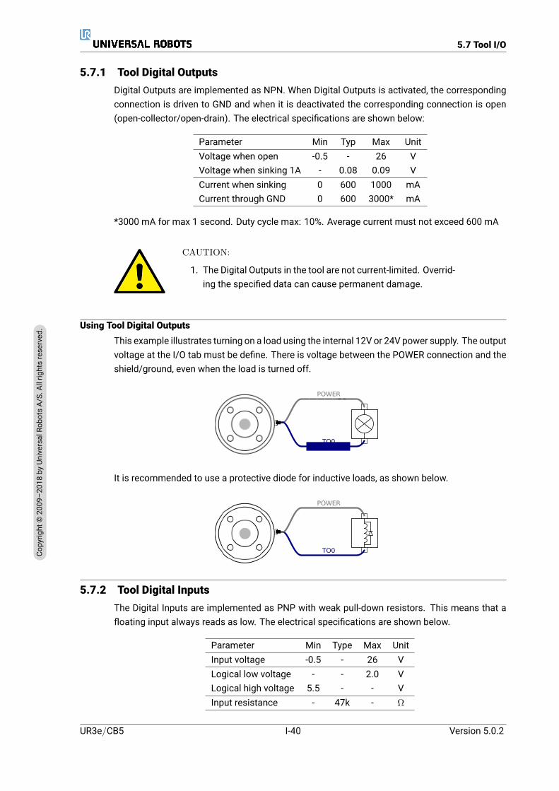
5.7 Tool I/O
5.7.1 Tool Digital OutputsDigital Outputs are implemented as NPN. When Digital Outputs is activated, the correspondingconnection is driven to GND and when it is deactivated the corresponding connection is open(open-collector/open-drain). The electrical specifications are shown below:
Parameter Min Typ Max UnitVoltage when open -0.5 - 26 VVoltage when sinking 1A - 0.08 0.09 VCurrent when sinking 0 600 1000 mACurrent through GND 0 600 3000* mA
*3000 mA for max 1 second. Duty cycle max: 10%. Average current must not exceed 600 mA
CAUTION:
1. The Digital Outputs in the tool are not current-limited. Overrid-ing the specified data can cause permanent damage.
Using Tool Digital OutputsThis example illustrates turning on a load using the internal 12V or 24V power supply. The outputvoltage at the I/O tab must be define. There is voltage between the POWER connection and theshield/ground, even when the load is turned off.
TO0
POWER
It is recommended to use a protective diode for inductive loads, as shown below.
TO0
POWER
5.7.2 Tool Digital InputsThe Digital Inputs are implemented as PNP with weak pull-down resistors. This means that afloating input always reads as low. The electrical specifications are shown below.
Parameter Min Type Max UnitInput voltage -0.5 - 26 VLogical low voltage - - 2.0 VLogical high voltage 5.5 - - VInput resistance - 47k - Ω
UR3e/CB5 I-40 Version 5.0.2
Copy
right
©20
09–2
018by
Universa
lRob
otsA/
S.Allrightsrese
rved
.

5.7 Tool I/O
Using the Tool Digital Inputs
This example illustrates connecting a simple button.
TI0
POWER
5.7.3 Tool Analog InputTool Analog Input are nondifferential and can be set to either voltage (0-10V) or current (4-20mA)on the I/O tab (see part II). The electrical specifications are shown below.
Parameter Min Type Max UnitInput voltage in voltage mode -0.5 - 26 VInput resistance @ range 0V to 10V - 10.7 - kΩResolution - 12 - bitInput voltage in current mode -0.5 - 5.0 VInput current in current mode -2.5 - 25 mAInput resistance @ range 4mA to 20mA - 182 188 Ω
Resolution - 12 - bit
Two examples of using Analog Input are shown in the following subsections.
CAUTION:
1. Analog Inputs are not protected against overvoltage in currentmode. Exceeding the limit in the electrical specification cancause permanent damage to the input.
Using Tool Analog Inputs, Nondifferential
This example shows an analog sensor connection with a nondifferential output. The sensoroutput can be either current or voltage, as long as the input mode of that Analog Input is set tothe same on the I/O tab.Note: You can check that a sensor with voltage output can drive the internal resistance of thetool, or the measurement might be invalid.
GND
POWER
AI8AI2
Version 5.0.2
Copy
right
©20
09–2
018by
Universa
lRob
otsA/
S.Allrightsrese
rved
.
I-41 UR3e/CB5

5.7 Tool I/O
Using Tool Analog Inputs, Differential
This example shows an analog sensor connection with a differential output. Connecting thenegative output part to GND (0V), works in the same way as a nondifferential sensor.
POWER
AI8
GND
AI2
5.7.4 Tool Communication I/O• Signal requests The RS485 signals use internal fail-safe biasing. If the attached devicedoes not support this fail-safe, signal biasing must either be done in the attached tool, oradded externally by adding pull-up resistors to RS485+ and pull-down to RS485-.
• Latency The latency of messages sent via the tool connector ranges from 2ms to 4ms,from the time the message is written on the PC to the start of the message on the RS485.A buffer stores data sent to the tool connector until the line goes idle. Once 1000 bytes ofdata have been received, the message is written on the device.
Baud Rates 9.6k, 19.2k, 38.4k, 57.6k, 115.2k, 1M, 2M, 5MStop Bits 1, 2Parity None, Odd, Even
UR3e/CB5 I-42 Version 5.0.2
Copy
right
©20
09–2
018by
Universa
lRob
otsA/
S.Allrightsrese
rved
.

6 Maintenance and Repair
Youmust performmaintenance and repair work in compliance with all safety instructions in thismanual.
You must perform maintenance, calibration and repair work according to the latest versions ofService Manuals on the support website http://www.universal-robots.com/support.
Only authorized system integrators, or Universal Robots, shall perform repairs.
All parts returned to Universal Robots shall be returned according to the service manual.
6.1 Safety InstructionsAfter maintenance and repair work, checks must be done to ensure the required safety level.Checksmust adhere to valid national or regionalwork safety regulations. The correct functioningof all safety functions shall also be tested.
The purpose of maintenance and repair work is to ensure that the system is kept operationalor, in the event of a fault, to return the system to an operational state. Repair work includestroubleshooting in addition to the actual repair itself.
When working on the robot arm or control box, you must observe the procedures and warningsbelow.
DANGER:
1. Do not change anything in the safety configuration of the soft-ware (e.g. the force limit). The safety configuration is de-scribed in the PolyScope Manual. If any safety parameter ischanged, the complete robot system shall be considered new,meaning that the overall safety approval process, includingrisk assessment, shall be updated accordingly.
2. Replace faulty components using new components with thesame article numbers or equivalent components approved byUniversal Robots for this purpose.
3. Reactivate any deactivated safety measures immediately af-ter the work is completed.
4. Document all repairs and save this documentation in the tech-nical file associated with the complete robot system.
Version 5.0.2
Copy
right
©20
09–2
018by
Universa
lRob
otsA/
S.Allrightsrese
rved
.
I-43 UR3e/CB5

6.1 Safety Instructions
DANGER:
1. Remove the mains input cable from the bottom of the con-trol box to ensure that it is completely unpowered. Deenergizeany other source of energy connected to the robot arm or con-trol box. Take necessary precautions to prevent other personsfrom energizing the system during the repair period.
2. Check the earth connection before re-powering the system.
3. Observe ESD regulations when parts of the robot arm or con-trol box are disassembled.
4. Avoid disassembling the power supplies inside the controlbox. High voltages (up to 600 V) can be present inside thesepower supplies for several hours after the control box hasbeen switched off.
5. Prevent water and dust from entering the robot arm or controlbox.
UR3e/CB5 I-44 Version 5.0.2
Copy
right
©20
09–2
018by
Universa
lRob
otsA/
S.Allrightsrese
rved
.

7 Disposal and Environment
Universal Robots e-Series robotsmust be disposed of in accordancewith the applicable nationallaws, regulations and standards.
Universal Robots e-Series robots are produced with restricted use of hazardous substances toprotect the environment; as defined by the European RoHS directive 2011/65/EU. These sub-stances includemercury, cadmium, lead, chromiumVI, polybrominated biphenyls and polybromi-nated diphenyl ethers.
Fee for disposal and handling of electronic waste of Universal Robots e-Series robots sold onthe Danish market is prepaid to DPA-system by Universal Robots A/S. Importers in countriescovered by the European WEEE Directive 2012/19/EU must make their own registration to thenational WEEE register of their country. The fee is typically less than 1€/robot. A list of nationalregisters can be found here: https://www.ewrn.org/national-registers.
The following symbols are affixed on the robot to indicate conformity with the above legislations:
Version 5.0.2
Copy
right
©20
09–2
018by
Universa
lRob
otsA/
S.Allrightsrese
rved
.
I-45 UR3e/CB5

UR3e/CB5 I-46 Version 5.0.2
Copy
right
©20
09–2
018by
Universa
lRob
otsA/
S.Allrightsrese
rved
.

8 Certifications
This chapter presents certificates and declarations prepared for the product.
8.1 Third Party CertificationThird party certification is voluntary. However, to provide the best service to robot integrators,UR chooses to certify our robots at the following recognized test institutes:
TÜV NORD Universal Robots e-Series robots are safety ap-proved by TÜV NORD, a notified body under themachinery directive 2006/42/EC in EU. You canfind a copy of the TÜV NORD safety approval cer-tificate in appendix B.
DELTA URUniversal Robots e-Series robots are perfor-mance tested by DELTA. You can find electromag-netic compatibility (EMC) and environmental testcertificates in appendix B.
CHINA RoHS Universal Robots e-Series robots conform toCHINA RoHS management methods for control-ling pollution by electronic information products.
8.2 Supplier Third Party Certification
Environment As provided by our suppliers, Universal Robotse-Series robots shipping pallets comply with theISMPM-15 Danish requirements for producingwoodpackagingmaterial and aremarked in accor-dance with this scheme.
8.3 Manufacturer Test Certification
UR Universal Robots e-Series robots undergo contin-uous internal testing and end of line test proce-dures. UR testing processes undergo continuousreview and improvement.
Version 5.0.2
Copy
right
©20
09–2
018by
Universa
lRob
otsA/
S.Allrightsrese
rved
.
I-47 UR3e/CB5
8.4 Declarations According to EU directives
8.4 Declarations According to EU directivesAlthough they are primarily relevant for Europe, some countries outside Europe recognize and/orrequire EU declarations. European directives are available on the official homepage: http://eur-lex.europa.eu.UR robots are certified according to the directives listed below.
2006/42/EC — Machinery Directive (MD)
According to the Machinery Directive 2006/42/EC, Universal Robots e-Series robots are partlycompleted machinery, as such a CEmark is not affixed.If theUR robot is used in a pesticide application, youmust note the presence of directive 2009/127/EC.The declaration of incorporation according to 2006/42/EC annex II 1.B. is shown in appendix B.
2006/95/EC — Low Voltage Directive (LVD)2004/108/EC — Electromagnetic Compatibility (EMC)2011/65/EU — Restriction of the use of certain Hazardous Substances (RoHS)2012/19/EU — Waste of Electrical and Electronic Equipment (WEEE)
In the Declaration of Incorporation in appendix B, declarations of conformity with the abovedirectives are listed.
A CEmark is affixed according to the CEmarking directives above. Information on both electricand electronic equipment waste is in chapter 7.
Information on standards applied during the development of the robot is in appendix C.
UR3e/CB5 I-48 Version 5.0.2
Copy
right
©20
09–2
018by
Universa
lRob
otsA/
S.Allrightsrese
rved
.

9 Warranties
9.1 Product WarrantyWithout prejudice to any claim the user (customer) may have in relation to the dealer or retailer,the customer shall be granted a manufacturer’s Warranty under the conditions set out below:
In the case of new devices and their components exhibiting defects resulting from manufactur-ing and/or material faults within 12 months of entry into service (maximum of 15 months fromshipment), Universal Robots shall provide the necessary spare parts, while the user (customer)shall provide working hours to replace the spare parts, either replace the part with another partreflecting the current state of the art, or repair the said part. This Warranty shall be invalid if thedevice defect is attributable to improper treatment and/or failure to complywith information con-tained in the user guides. ThisWarranty shall not apply to or extend to services performed by theauthorized dealer or the customer themselves (e.g. installation, configuration, software down-loads). The purchase receipt, together with the date of purchase, shall be required as evidencefor invoking the Warranty. Claims under the Warranty must be submitted within two months ofthe Warranty default becoming evident. Ownership of devices or components replaced by andreturned to Universal Robots shall vest in Universal Robots. Any other claims resulting out ofor in connection with the device shall be excluded from this Warranty. Nothing in this Warrantyshall attempt to limit or exclude a Customer’s Statutory Rights nor themanufacturer’s liability fordeath or personal injury resulting from its negligence. The duration of the Warranty shall not beextended by services rendered under the terms of the Warranty. Insofar as no Warranty defaultexists, Universal Robots reserves the right to charge the customer for replacement or repair. Theabove provisions do not imply a change in the burden of proof to the detriment of the customer.In case of a device exhibiting defects, Universal Robots shall not be liable for any indirect, inci-dental, special or consequential damages, including but not limited to, lost profits, loss of use,loss of production or damage to other production equipment.
In case of a device exhibiting defects, Universal Robots shall not cover any consequential dam-age or loss, such as loss of production or damage to other production equipment.
9.2 DisclaimerUniversal Robots continues to improve reliability and performance of its products, and thereforereserves the right to upgrade the product without prior warning. Universal Robots takes everycare that the contents of this manual are precise and correct, but takes no responsibility for anyerrors or missing information.
Version 5.0.2
Copy
right
©20
09–2
018by
Universa
lRob
otsA/
S.Allrightsrese
rved
.
I-49 UR3e/CB5

9.2 Disclaimer
UR3e/CB5 I-50 Version 5.0.2
Copy
right
©20
09–2
018by
Universa
lRob
otsA/
S.Allrightsrese
rved
.
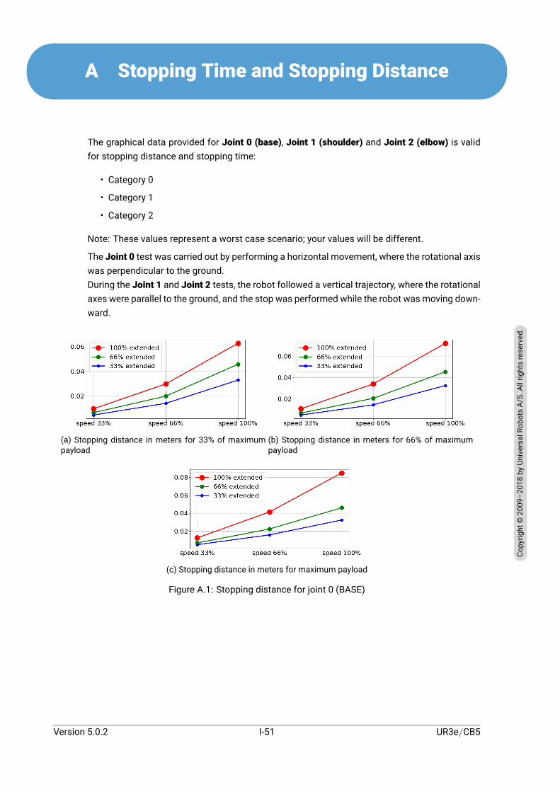
A Stopping Time and Stopping Distance
The graphical data provided for Joint 0 (base), Joint 1 (shoulder) and Joint 2 (elbow) is validfor stopping distance and stopping time:
• Category 0
• Category 1
• Category 2
Note: These values represent a worst case scenario; your values will be different.
The Joint 0 test was carried out by performing a horizontal movement, where the rotational axiswas perpendicular to the ground.During the Joint 1 and Joint 2 tests, the robot followed a vertical trajectory, where the rotationalaxes were parallel to the ground, and the stop was performed while the robot was moving down-ward.
(a) Stopping distance in meters for 33% of maximumpayload
(b) Stopping distance in meters for 66% of maximumpayload
(c) Stopping distance in meters for maximum payload
Figure A.1: Stopping distance for joint 0 (BASE)
Version 5.0.2
Copy
right
©20
09–2
018by
Universa
lRob
otsA/
S.Allrightsrese
rved
.
I-51 UR3e/CB5
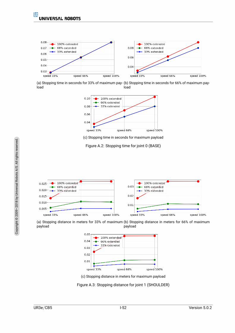
(a) Stopping time in seconds for 33% of maximum pay-load
(b) Stopping time in seconds for 66% of maximum pay-load
(c) Stopping time in seconds for maximum payload
Figure A.2: Stopping time for joint 0 (BASE)
(a) Stopping distance in meters for 33% of maximumpayload
(b) Stopping distance in meters for 66% of maximumpayload
(c) Stopping distance in meters for maximum payload
Figure A.3: Stopping distance for joint 1 (SHOULDER)
UR3e/CB5 I-52 Version 5.0.2
Copy
right
©20
09–2
018by
Universa
lRob
otsA/
S.Allrightsrese
rved
.
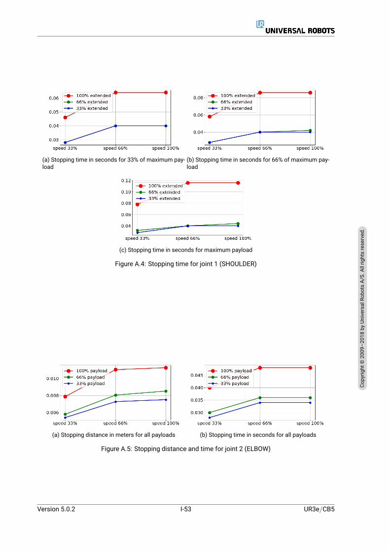
(a) Stopping time in seconds for 33% of maximum pay-load
(b) Stopping time in seconds for 66% of maximum pay-load
(c) Stopping time in seconds for maximum payload
Figure A.4: Stopping time for joint 1 (SHOULDER)
(a) Stopping distance in meters for all payloads (b) Stopping time in seconds for all payloads
Figure A.5: Stopping distance and time for joint 2 (ELBOW)
Version 5.0.2
Copy
right
©20
09–2
018by
Universa
lRob
otsA/
S.Allrightsrese
rved
.
I-53 UR3e/CB5

UR3e/CB5 I-54 Version 5.0.2
Copy
right
©20
09–2
018by
Universa
lRob
otsA/
S.Allrightsrese
rved
.

B Declarations and Certificates
B.1 CE/EU Declaration of Incorporation (original)
According to European Directive 2006/42/EC annex II 1.B.
The manufacturer Universal Robots A/SEnergivej 255260 Odense SDenmark
hereby declares that the product described below
Industrial robot UR3e/CB3
may not be put into service before the machinery in which it will be incorporated is declared in confor-mity with the provisions of Directive 2006/42/EC, as amended by Directive 2009/127/EC, and with theregulations transposing it into national law.
The safety features of the product are prepared for compliance with all essential requirements of Direc-tive 2006/42/EC under the correct incorporation conditions, see product manual. Compliance with allessential requirements of Directive 2006/42/EC relies on the specific robot installation and the final riskassessment.
Relevant technical documentation is compiled according to Directive 2006/42/EC annex VII part B andavailable in electronic form to national authorities upon legitimate request. Undersigned is based on themanufacturer address and authorised to compile this documentation.
Additionally the product declares in conformity with the following directives, according towhich the prod-uct is CE marked:
2014/35/EU — Low Voltage Directive (LVD)2014/30/EU — Electromagnetic Compatibility Directive (EMC)2011/65/EU — Restriction of the use of certain hazardous substances (RoHS)
A complete list of applied harmonized standards, including associated specifications, is provided in theproduct manual.
Odense, April 20th, 2016 R&D
David BrandtTechnology Officer
Version 5.0.2
Copy
right
©20
09–2
018by
Universa
lRob
otsA/
S.Allrightsrese
rved
.
I-55 UR3e/CB5
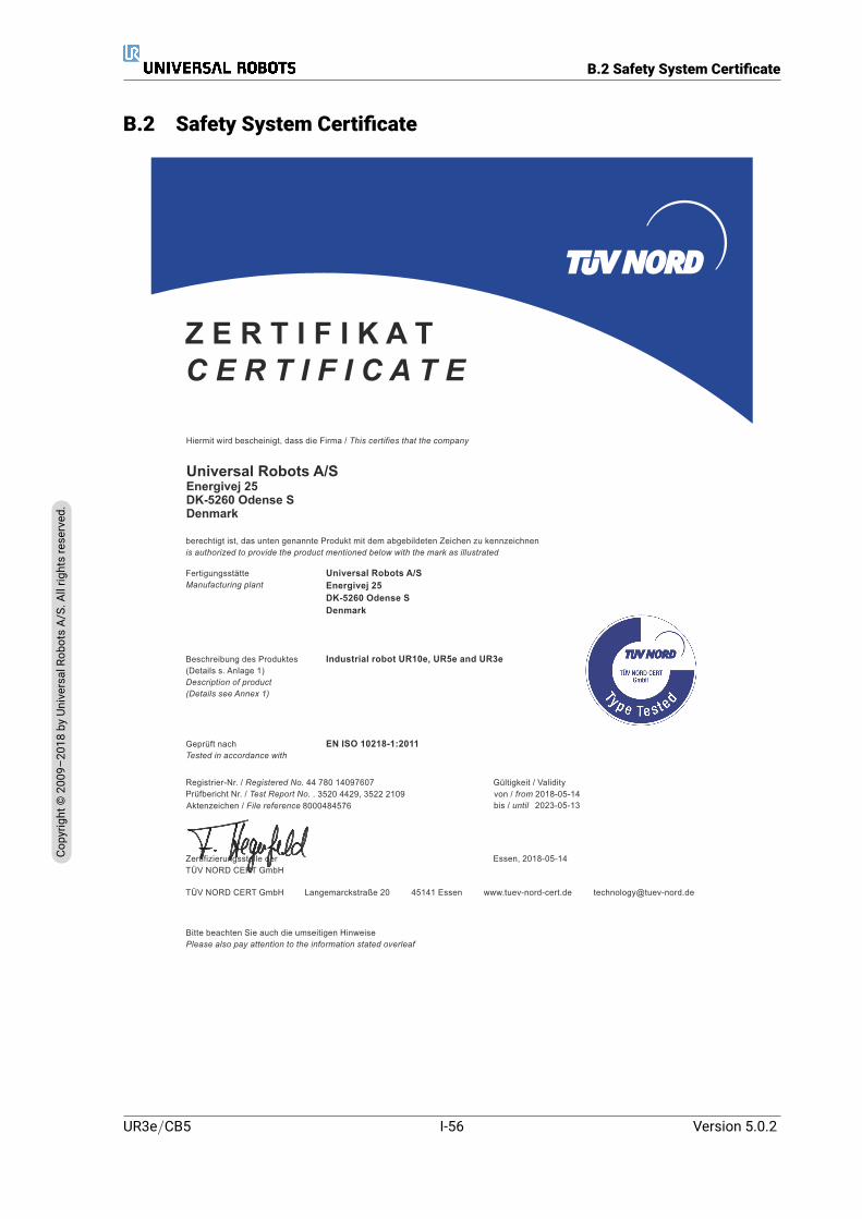
B.2 Safety System Certificate
B.2 Safety System Certificate
Essen, 2018-05-14Zertifizierungsstelle der TÜV NORD CERT GmbH
TÜV NORD CERT GmbH 45141 EssenLangemarckstraße 20 [email protected]
berechtigt ist, das unten genannte Produkt mit dem abgebildeten Zeichen zu kennzeichnenis authorized to provide the product mentioned below with the mark as illustrated
Universal Robots A/SEnergivej 25DK-5260 Odense SDenmark
Hiermit wird bescheinigt, dass die Firma / This certifies that the company
Z E R T I F I K A TC E R T I F I C A T E
FertigungsstätteManufacturing plant
Universal Robots A/SEnergivej 25DK-5260 Odense SDenmark
Beschreibung des Produktes(Details s. Anlage 1)Description of product(Details see Annex 1)
Industrial robot UR10e, UR5e and UR3e
www.tuev-nord-cert.de
Geprüft nachTested in accordance with
EN ISO 10218-1:2011
Registrier-Nr. / Registered No. 44 780 14097607Prüfbericht Nr. / Test Report No. . 3520 4429, 3522 2109
Gültigkeit / Validity
Aktenzeichen / File reference 8000484576
Bitte beachten Sie auch die umseitigen HinweisePlease also pay attention to the information stated overleaf
bis / until 2023-05-13von / from 2018-05-14
.
UR3e/CB5 I-56 Version 5.0.2
Copy
right
©20
09–2
018by
Universa
lRob
otsA/
S.Allrightsrese
rved
.
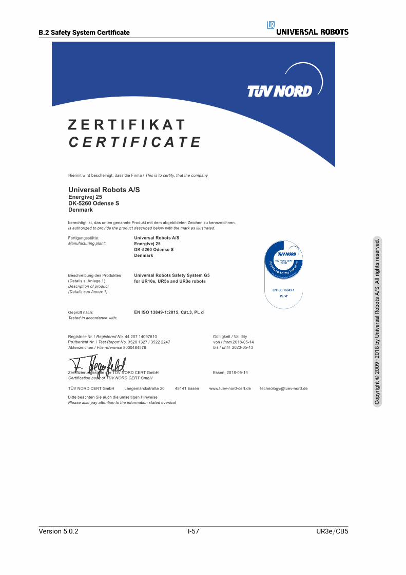
B.2 Safety System Certificate
Essen, 2018-05-14Zertifizierungsstelle der TÜV NORD CERT GmbHCertification body of TÜV NORD CERT GmbH
TÜV NORD CERT GmbH 45141 EssenLangemarckstraße 20 [email protected]
berechtigt ist, das unten genannte Produkt mit dem abgebildeten Zeichen zu kennzeichnen.is authorized to provide the product described below with the mark as illustrated.
Universal Robots A/SEnergivej 25DK-5260 Odense SDenmark
Hiermit wird bescheinigt, dass die Firma / This is to certify, that the company
Z E R T I F I K A TC E R T I F I C A T E
Fertigungsstätte:Manufacturing plant:
Universal Robots A/SEnergivej 25DK-5260 Odense SDenmark
Beschreibung des Produktes(Details s. Anlage 1)Description of product(Details see Annex 1)
Universal Robots Safety System G5for UR10e, UR5e and UR3e robots
www.tuev-nord-cert.de
Geprüft nach:Tested in accordance with:
EN ISO 13849-1:2015, Cat.3, PL d
Registrier-Nr. / Registered No. 44 207 14097610Prüfbericht Nr. / Test Report No. 3520 1327 / 3522 2247
bis / until 2023-05-13von / from 2018-05-14Gültigkeit / Validity
Aktenzeichen / File reference 8000484576
Bitte beachten Sie auch die umseitigen HinweisePlease also pay attention to the information stated overleaf
.
Version 5.0.2
Copy
right
©20
09–2
018by
Universa
lRob
otsA/
S.Allrightsrese
rved
.
I-57 UR3e/CB5

B.3 Environmental Test Certificate
B.3 Environmental Test Certificate
DELTA – a part of FORCE Technology - Venlighedsvej 4 - 2970 Hørsholm - Denmark - Tel. +45 72 19 40 00 - Fax +45 72 19 40 01 - www.delta.dk
Climatic and mechanical assessment
Client Force Technology project no. Universal Robots A/S Energivej 25 5260 Odense S Denmark
117-32120
Product identification UR 3 robot arms UR 3 control boxes with attached Teach Pendants. UR 5 robot arms UR5 control boxes with attached Teach Pendants. UR10 robot arms: UR10 control boxes with attached Teach Pendants. See reports for details.
Force Technology report(s) DELTA project no. 117-28266, DANAK-19/18069 DELTA project no. 117-28086, DANAK-19/17068
Other document(s)
Conclusion The three robot arms UR3, UR5 and UR10 including their control boxes and Teach Pendants have been tested according to the below listed standards. The test results are given in the Force Technology reports listed above. The tests were carried out as specified and the test criteria for environmental tests were fulfilled in general terms with only a few minor issues (see test reports for details). IEC 60068-2-1, Test Ae; -5 ºC, 16 h IEC 60068-2-2, Test Be; +35°C, 16h IEC 60068-2-2, Test Be; +50ºC, 16 h IEC 60068-2-64, Test Fh; 5 – 10 Hz: +12 dB/octave, 10-50 Hz 0.00042 g²/Hz, 50 – 100 Hz: -12 dB/octave, 1,66 grms, 3 x 1½ h IEC 60068-2-27, Test Ea, Shock; 11 g, 11 ms, 3 x 18 shocks
Date Assessor
Hørsholm, 25 August 2017
Andreas Wendelboe Højsgaard M.Sc.Eng.
UR3e/CB5 I-58 Version 5.0.2
Copy
right
©20
09–2
018by
Universa
lRob
otsA/
S.Allrightsrese
rved
.
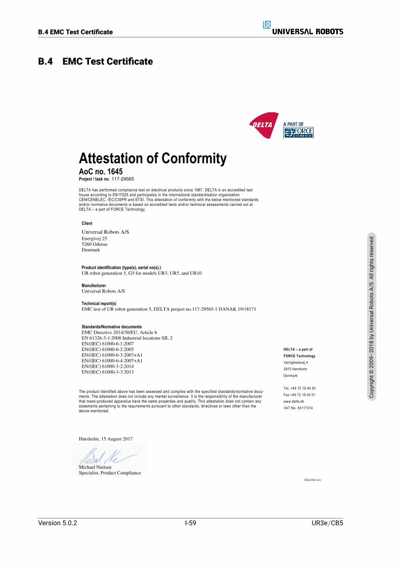
B.4 EMC Test Certificate
B.4 EMC Test Certificate
The product identified above has been assessed and complies with the specified standards/normative docu-ments. The attestation does not include any market surveillance. It is the responsibility of the manufacturer that mass-produced apparatus have the same properties and quality. This attestation does not contain any statements pertaining to the requirements pursuant to other standards, directives or laws other than the above mentioned.
Hørsholm, 15 August 2017
Michael Nielsen Specialist, Product Compliance
DELTA – a part of
FORCE Technology
Venlighedsvej 4
2970 Hørsholm
Denmark
Tel. +45 72 19 40 00
Fax +45 72 19 40 01
www.delta.dk
VAT No. 55117314
20aoctest-uk-j
Attestation of ConformityAoC no. 1645 Project / task no. 117-29565
DELTA has performed compliance test on electrical products since 1967. DELTA is an accredited test house according to EN17025 and participates in the international standardisation organisation CEN/CENELEC, IEC/CISPR and ETSI. This attestation of conformity with the below mentioned standards and/or normative documents is based on accredited tests and/or technical assessments carried out at DELTA – a part of FORCE Technology.
Client
Universal Robots A/S Energivej 25 5260 Odense Denmark
Product identification (type(s), serial no(s).) UR robot generation 5, G5 for models UR3, UR5, and UR10
ManufacturerUniversal Robots A/S
Technical report(s)EMC test of UR robot generation 5, DELTA project no.117-29565-1 DANAK 19/18171
Standards/Normative documentsEMC Directive 2014/30/EU, Article 6 EN 61326-3-1:2008 Industrial locations SIL 2 EN/(IEC) 61000-6-1:2007 EN/(IEC) 61000-6-2:2005 EN/(IEC) 61000-6-3:2007+A1 EN/(IEC) 61000-6-4:2007+A1 EN/(IEC) 61000-3-2:2014 EN/(IEC) 61000-3-3:2013
Version 5.0.2
Copy
right
©20
09–2
018by
Universa
lRob
otsA/
S.Allrightsrese
rved
.
I-59 UR3e/CB5
B.4 EMC Test Certificate
UR3e/CB5 I-60 Version 5.0.2
Copy
right
©20
09–2
018by
Universa
lRob
otsA/
S.Allrightsrese
rved
.

C Applied Standards
This section describes relevant standards applied under the development of the robot arm and controlbox. Whenever a European Directive number is noted in brackets, it indicates that the standard is har-monized according to that Directive.
A standard is not a law. A standard is a document developed by stakeholders within a given industry,defining the normal safety and performance requirements for a product or product group.
Abbreviations mean the following:
ISO International Standardization OrganizationIEC International Electrotechnical CommissionEN European NormTS Technical SpecificationTR Technical ReportANSI American National Standards InstituteRIA Robotic Industries AssociationCSA Canadian Standards Association
Conformity with the following standards is only guaranteed if all assembly instructions, safety instruc-tions and guidance in this manual are followed.
ISO 13849-1:2006 [PLd]ISO 13849-1:2015 [PLd]ISO 13849-2:2012EN ISO 13849-1:2008 (E) [PLd – 2006/42/EC]EN ISO 13849-2:2012 (E) (2006/42/EC)
Safety of machinery – Safety-related parts of control systems
Part 1: General principles for design
Part 2: Validation
The safety control system is designed as Performance Level d (PLd) according to the requirements ofthese standards.
ISO 13850:2006 [Stop Category 1]ISO 13850:2015 [Stop Category 1]EN ISO 13850:2008 (E) [Stop Category 1 - 2006/42/EC]EN ISO 13850:2015 [Stop Category 1 - 2006/42/EC]
Safety of machinery – Emergency stop – Principles for design
Version 5.0.2
Copy
right
©20
09–2
018by
Universa
lRob
otsA/
S.Allrightsrese
rved
.
I-61 UR3e/CB5

The emergency stop function is designed as a Stop Category 1 according to this standard. Stop Category1 is a controlled stop with power to the motors to achieve the stop and then removal of power when thestop is achieved.
ISO 12100:2010EN ISO 12100:2010 (E) [2006/42/EC]
Safety of machinery – General principles for design – Risk assessment and risk reduction
UR robots are evaluated according to the principles of this standard.
ISO 10218-1:2011EN ISO 10218-1:2011(E) [2006/42/EC]
Robots and robotic devices – Safety requirements for industrial robots
Part 1: Robots
This standard is intended for the robot manufacturer, not the integrator. The second part (ISO 10218-2)is intended for the robot integrator, as it deals with the installation and design of the robot application.
ANSI/RIA R15.06-2012
Industrial Robots and Robot Systems – Safety Requirements
This American standard is the ISO standards ISO 10218-1 and ISO 10218-2 combined into one document.The language is changed from British English to American English, but the content is the same.
Note that part two (ISO 10218-2) of this standard is intended for the integrator of the robot system, andnot Universal Robots.
CAN/CSA-Z434-14
Industrial Robots and Robot Systems – General Safety Requirements
This Canadian standard is the ISO standards ISO 10218-1 (see above) and -2 combined into one docu-ment. CSA added additional requirements for the user of the robot system. Some of these requirementsmight need to be addressed by the robot integrator.
Note that part two (ISO 10218-2) of this standard is intended for the integrator of the robot system, andnot Universal Robots.
IEC 61000-6-2:2005IEC 61000-6-4/A1:2010EN 61000-6-2:2005 [2004/108/EC]EN 61000-6-4/A1:2011 [2004/108/EC]
Electromagnetic compatibility (EMC)
Part 6-2: Generic standards - Immunity for industrial environments
Part 6-4: Generic standards - Emission standard for industrial environments
UR3e/CB5 I-62 Version 5.0.2
Copy
right
©20
09–2
018by
Universa
lRob
otsA/
S.Allrightsrese
rved
.
These standards define requirements for the electrical and electromagnetic disturbances. Conformingto these standards ensures that the UR robots perform well in industrial environments and that they donot disturb other equipment.
IEC 61326-3-1:2008EN 61326-3-1:2008
Electrical equipment for measurement, control and laboratory use - EMC requirements
Part 3-1: Immunity requirements for safety-related systems and for equipment intended to perform safety-related functions (functional safety) - General industrial applications
This standard defines extended EMC immunity requirements for safety-related functions. Conformingto this standard ensures that the safety functions of UR robots provide safety even if other equipmentexceeds the EMC emission limits defined in the IEC 61000 standards.
IEC 61131-2:2007 (E)EN 61131-2:2007 [2004/108/EC]
Programmable controllers
Part 2: Equipment requirements and tests
Both normal and safety-rated 24V I/Os are constructed according to requirements of this standard toensure reliable communication with other PLC systems.
ISO 14118:2000 (E)EN 1037/A1:2008 [2006/42/EC]
Safety of machinery – Prevention of unexpected start-up
These two standards are very similar. They define safety principles for avoiding unexpected start-up,both as a result of unintended repowering during maintenance or repair, and as a result of unintendedstart-up commands from a control perspective.
IEC 60947-5-5/A1:2005EN 60947-5-5/A11:2013 [2006/42/EC]
Low-voltage switchgear and controlgear
Part 5-5: Control circuit devices and switching elements - Electrical emergency stop device with mechani-cal latching function
The direct opening action and the safety lock mechanism of the emergency stop button comply withrequirements in this standard.
IEC 60529:2013EN 60529/A2:2013
Degrees of protection provided by enclosures (IP Code)
This standard defines enclosure ratings regarding protection against dust and water. UR robots aredesigned and classified with an IP code according to this standard, see robot sticker.
Version 5.0.2
Copy
right
©20
09–2
018by
Universa
lRob
otsA/
S.Allrightsrese
rved
.
I-63 UR3e/CB5
IEC 60320-1/A1:2007IEC 60320-1:2015EN 60320-1/A1:2007 [2006/95/EC]EN 60320-1:2015
Appliance couplers for household and similar general purposes
Part 1: General requirements
The mains input cable complies with this standard.
ISO 9409-1:2004 [Type 50-4-M6]
Manipulating industrial robots – Mechanical interfaces
Part 1: Plates
The tool flange on UR robots conforms to type 50-4-M6 of this standard. Robot tools should also beconstructed according to this standard to ensure proper fitting.
ISO 13732-1:2006EN ISO 13732-1:2008 [2006/42/EC]
Ergonomics of the thermal environment – Methods for the assessment of human responses to contactwith surfaces
Part 1: Hot surfaces
The UR robots are designed so that the surface temperature is kept under the ergonomic limits definedin this standard.
IEC 61140/A1:2004EN 61140/A1:2006 [2006/95/EC]
Protection against electric shock – Common aspects for installation and equipment
UR robots are constructed in compliance with this standard to provide protection against electricalshock. A protective earth/ground connection is mandatory, as defined in the Hardware Installation Man-ual.
IEC 60068-2-1:2007IEC 60068-2-2:2007IEC 60068-2-27:2008IEC 60068-2-64:2008EN 60068-2-1:2007EN 60068-2-2:2007EN 60068-2-27:2009EN 60068-2-64:2008
Environmental testing
UR3e/CB5 I-64 Version 5.0.2
Copy
right
©20
09–2
018by
Universa
lRob
otsA/
S.Allrightsrese
rved
.
Part 2-1: Tests - Test A: Cold
Part 2-2: Tests - Test B: Dry heat
Part 2-27: Tests - Test Ea and guidance: Shock
Part 2-64: Tests - Test Fh: Vibration, broadband random and guidance
UR robots are tested according to the test methods defined in these standards.
IEC 61784-3:2010EN 61784-3:2010 [SIL 2]
Industrial communication networks – Profiles
Part 3: Functional safety fieldbuses – General rules and profile definitions
This standards defines requirements for safety-rated communication buses.
IEC 60204-1/A1:2008EN 60204-1/A1:2009 [2006/42/EC]
Safety of machinery – Electrical equipment of machines
Part 1: General requirements
The general principles of this standard are applied.
IEC 60664-1:2007IEC 60664-5:2007EN 60664-1:2007 [2006/95/EC]EN 60664-5:2007
Insulation coordination for equipment within low-voltage systems
Part 1: Principles, requirements and tests
Part 5: Comprehensive method for determining clearances and creepage distances equal to or less than2 mm
The electrical circuitry of UR robots is designed in compliance with this standard.
EUROMAP 67:2015, V1.11
Electrical Interface between Injection Molding Machine and Handling Device / Robot
UR robots equipped with the E67 accessorymodule to interface injectionmoldingmachines comply withthis standard.
Version 5.0.2
Copy
right
©20
09–2
018by
Universa
lRob
otsA/
S.Allrightsrese
rved
.
I-65 UR3e/CB5

UR3e/CB5 I-66 Version 5.0.2
Copy
right
©20
09–2
018by
Universa
lRob
otsA/
S.Allrightsrese
rved
.

D Technical Specifications
Robot type UR3eWeight 11.1 kg / 24.5 lbMaximum payload(see section 4.4)
3 kg / 6.6 lb
Reach 500 mm / 19.7 inJoint ranges Unlimited rotation of tool flange, ± 360 for all other jointsSpeed All wrist joints: Max 360 /s
Other joints: Max 180 /s.Tool: Approx. 1 m/s / Approx. 39.4 in/s.
System Update Frequency 500 HzForce Torque Sensor Accuracy 3.5 NPose Repeatability ± 0.03 mm / ± 0.0011 in (1.1 mils)Footprint Ø128 mm / 5.0 inDegrees of freedom 6 rotating jointsControl box size (W× H× D) 460 mm × 445 mm × 260 mm / 18.2 in × 17.6 in × 10.3 inControl box I/O ports 16 digital in, 16 digital out, 2 analog in, 2 analog outTool I/O ports 2 digital in, 2 digital out, 2 analogue inI/O power supply 24 V 2 A in Control Box and 12 V/24 V 600 mA in toolCommunication TCP/IP 1000 Mbit: IEEE 802.3ab, 1000BASE-T
Ethernet socket, MODBUS TCP & EtherNet/IP Adapter,Profinet
Programming PolyScope graphical user interface on12” touchscreen
Noise 70 dB(A)IP classification IP54Cleanroom classification Robot Arm: ISO Class 5
Control Box: ISO Class 6Power consumption Approx. 150 W using a typical programCollaboration operation 17 advanced safety functions. In compliance with:
EN ISO 13849-1:2008, PLd, Cat.3 and EN ISO 10218-1:2011,clause 5.10.5
Materials Aluminium, PP plasticTemperature The robot can work in an ambient temperature range of -5-50 C
At high continuous joint speed, the maximum ambient tempera-ture specification is derated.
Power supply 100-240 VAC, 47-440 HzCabling Cable between robot and Control Box (6 m / 236 in)
Cable between touchscreen and Control Box (4.5 m / 177 in)
Version 5.0.2
Copy
right
©20
09–2
018by
Universa
lRob
otsA/
S.Allrightsrese
rved
.
I-67 UR3e/CB5

UR3e/CB5 I-68 Version 5.0.2
Copy
right
©20
09–2
018by
Universa
lRob
otsA/
S.Allrightsrese
rved
.
Part II
PolyScope Manual


10 Introduction
10.1 PolyScope BasicsThe PolyScope or robot user interface is the touch screen on your Teach Pendant panel. It is thegraphical user interface (GUI) that operates the robot arm and control box, executes and createsrobot programs. PolyScope comprises three zones:
A : Header with tabs/icons that make interactive screens available to you.
B : Footer with buttons that control your loaded program/s.
C : Screen with fields that manage and monitor robot actions.
Note: On start up a Cannot Proceed dialogue can appear. You must select Go to initializationscreen to turn on robot.
10.1.1 Header Icons/Tabs
Run is a simple means of operating the robot using pre-written programs.
Initializemanages robot state. This icon changes color depending on robotstate: green (normal), yellow (idle) and red (stopped).
Program creates and/or modifies robot programs.
Installation configures robot arm settings and external equipment e.g.mounting and safety.
Version 5.0.2
Copy
right
©20
09–2
018by
Universa
lRob
otsA/
S.Allrightsrese
rved
.
II-3 CB5
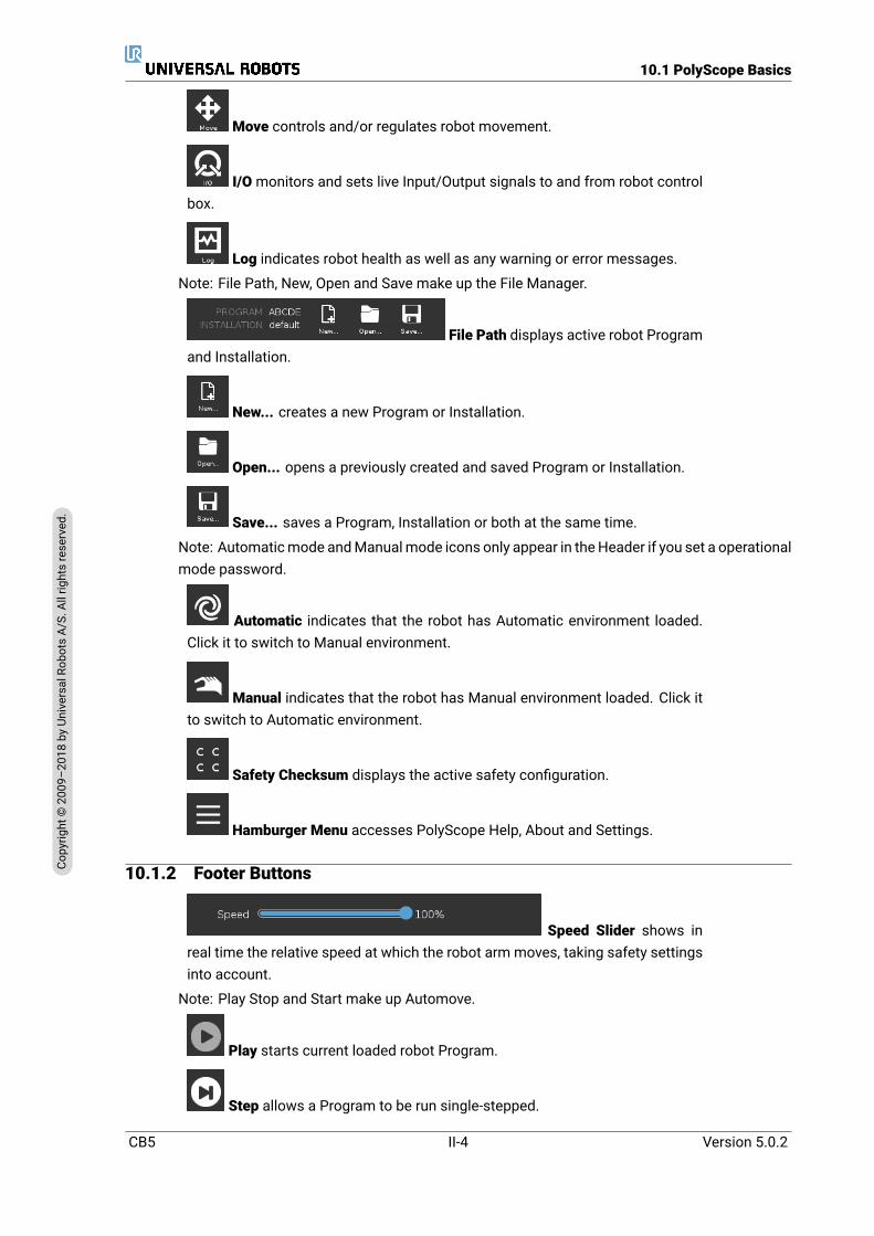
10.1 PolyScope Basics
Move controls and/or regulates robot movement.
I/Omonitors and sets live Input/Output signals to and from robot controlbox.
Log indicates robot health as well as any warning or error messages.
Note: File Path, New, Open and Save make up the File Manager.
File Path displays active robot Programand Installation.
New... creates a new Program or Installation.
Open... opens a previously created and saved Program or Installation.
Save... saves a Program, Installation or both at the same time.
Note: Automaticmode andManualmode icons only appear in theHeader if you set a operationalmode password.
Automatic indicates that the robot has Automatic environment loaded.Click it to switch to Manual environment.
Manual indicates that the robot has Manual environment loaded. Click itto switch to Automatic environment.
Safety Checksum displays the active safety configuration.
Hamburger Menu accesses PolyScope Help, About and Settings.
10.1.2 Footer Buttons
Speed Slider shows inreal time the relative speed at which the robot arm moves, taking safety settingsinto account.
Note: Play Stop and Start make up Automove.
Play starts current loaded robot Program.
Step allows a Program to be run single-stepped.
CB5 II-4 Version 5.0.2
Copy
right
©20
09–2
018by
Universa
lRob
otsA/
S.Allrightsrese
rved
.

10.2 Getting Started Screen
Stop halts current loaded robot Program.
Clock displays real time and date.
Shutdown allows the robot to be powered off or restarted.
10.2 Getting Started Screen
Run a Program, Program the Robot or Configure Robot Installation.Note: When you power on for the first time, if a Cannot Proceed dialog appears, you can Go tothe initialization screen or select Not now to remain on the Getting Started screen.
Version 5.0.2
Copy
right
©20
09–2
018by
Universa
lRob
otsA/
S.Allrightsrese
rved
.
II-5 CB5
10.2 Getting Started Screen
CB5 II-6 Version 5.0.2
Copy
right
©20
09–2
018by
Universa
lRob
otsA/
S.Allrightsrese
rved
.

11 Quick Start
11.1 Robot Arm BasicsThe Universal Robot arm is composed of tubes and joints. You use the PolyScope to coordinatethe motion of these joints, moving the robot and positioning its tool as desired - except for thearea directly above and directly below the base.
Base is where the robot is mounted.
Shoulder and Elbow make larger movements.
Wrists 1 and 2 make finer movements.
Wrist 3 is where you attach the robot tool.
NOTE:Before powering on the robot for the first time, your designated URrobot integrator must:
1. Read and understand the safety information in the HardwareInstallation Manual.
2. Set the safety configuration parameters defined by the risk as-sessment (see chapter 13).
11.1.1 Installing the Robot Arm and Control BoxYou can use PolyScope, once the robot arm is installed and control box is installed and switchedon. Note: a risk assessment is required before using the robot arm to do any work.
1. Unpack the Robot arm and the Control box.
Figure 11.1: Joints of the robot. A: Base, B: Shoulder, C: Elbow and D, E, F:Wrist 1, 2, 3
Version 5.0.2
Copy
right
©20
09–2
018by
Universa
lRob
otsA/
S.Allrightsrese
rved
.
II-7 CB5
11.2 Quick System Start-up
2. Mount the Robot arm on a sturdy and vibration-free surface.
3. Place the Control box on its Foot.
4. Connect the cable to the robot and the control box.
5. Plug in the main control box plug.
DANGER:Tipping hazard. If the robot is not securely placed on a sturdy sur-face, the robot can fall over and cause injury.
See Hardware Installation Manual for detailed installation instructions.
11.1.2 Turning Control Box On/OffThe control boxmainly contains the physical electrical Input/Output that connects the robot arm,the Teach Pendant and any peripherals. You must turn on the control box to be able to power onthe robot arm.(see 15).
1. On your Teach Pendant, press the power button to turn on control box.
2. Wait as text from the underlying operating system, followed by buttons, appear on thescreen.
3. When a Cannot Proceed dialog appears, select Go to initialization screen to access Initial-ize Robot screen.
11.1.3 Turning Robot Arm On/OffOnce you turn on the control box and are directed to the Initialize Robot screen (see 15), youcan power on the robot arm.
1. On the Initialize Robot screen tap ON.
2. Observe the on-screen changes and tap START. Robot arm start up is accompanied bysound and slight movements as joint brakes are released.
3. You can power off the robot arm by tapping OFF.
Note: Robot arm is also powered off automatically when control box is shut down.
11.2 Quick System Start-upBefore using the PolyScope, verify that the robot arm and control box are correctly installed.
1. On the Teach Pendant, press the emergency stop button.
2. On the Teach Pendant, press the power button and allow the system to start, displaying texton the PolyScope.
3. A popup appears on the touch screen indicating that the system is ready and that the robotmust be initialized.
4. In the popup dialog, touch the button to access the initialization screen.
CB5 II-8 Version 5.0.2
Copy
right
©20
09–2
018by
Universa
lRob
otsA/
S.Allrightsrese
rved
.

11.2 Quick System Start-up
5. When the Confirmation of applied Safety Configuration dialog appears, press the ConfirmSafety Configuration button to apply an initial set of safety parameters. These must beadjusted based on a risk assessment.
6. Unlock the emergency stop button to change robot state fromEmergencyStopped toPoweroff.
7. Step outside the reach (workspace) of the robot.
8. On the Initialize Robot screen, touch the ON button and allow robot state to change to Idle.
9. In the Current Payload field, verify that payload mass and selected mounting are correct.You are alerted if themounting detected, basedon sensor data, does notmatch the selectedmounting.
10. On the Initialize Robot screen, touch the Start button, for the robot to release its brakesystem.Note: Robot vibrates and makes clicking sounds indicating it is ready to be programmed
NOTE:You can learn to program your robot on Universal Robots Academyat www.universal-robots.com/academy/
Version 5.0.2
Copy
right
©20
09–2
018by
Universa
lRob
otsA/
S.Allrightsrese
rved
.
II-9 CB5

11.2 Quick System Start-up
CB5 II-10 Version 5.0.2
Copy
right
©20
09–2
018by
Universa
lRob
otsA/
S.Allrightsrese
rved
.

12 Operational Mode Selection
12.1 Operational ModesOperational Modes are enabled when you configure a 3-Postition Enabling Device, or set a pass-word.
Automatic Mode Once activated, the robot can only perform pre-defined tasks. The Move Taband Freedrive Mode are unavailable. You cannot modify or save programs and installations.
Manual Mode Once activated, you can program the robot using the Move Tab, Freedrive Modeand Speed Slider. You can modify or save programs and installations.
Operational mode Manual AutomaticFreedrive x *Move robot with arrows on MoveTab x *Speed Slider x x**Edit & save program & installation xExecute Programs Reduced
speed*x
*Only when a 3-position enabling device is configured** It is possible via the Installation to specify that the Speed Slider is enabled/visible in the runscreen
NOTE:
• A Universal Robots robot is not equipped with a 3-Position En-abling Device. If the risk assessment requires the device, itmust be attached before the robot is used.
• If a 3-Position Enabling Device is not configured, bothFreedrive and Move Tab are enabled. Speed is not reducedin Manual Mode.
WARNING:
• Any suspended safeguards must be returned to full function-ality before selecting Automatic Mode.
• Wherever possible, the Manual Mode of operatio shall be per-formed with all persons outside the safeguard space.
• The device used to switch the robot to OperationalModemustbe placed outside the safeguarded space.
• The user must not enter the safeguarded space when robot isin Automatic Mode.
Version 5.0.2
Copy
right
©20
09–2
018by
Universa
lRob
otsA/
S.Allrightsrese
rved
.
II-11 CB5
12.2 3-Position Enabling Device
The three methods for configuring Operational Mode selection are described in the followingsubsections. Each method is exclusive, meaning that using one method, makes the other twomethods inactive.
Using Operational Mode Safety Input
1. In the Installation Tab, select Safety I/O.
2. Configure the Operational Mode Input. The option to configure appears in the drop-downmenu once the 3-Position Enabling Device input is configured.
3. The robot is in Automatic Mode when the Operational Mode Input is low and in ManualMode when the Operational Mode Input is high.
NOTE:
• The physical mode selector, if used, must completely adhereto ISO 10218-1: article 5.7.1 for selection.
• Before defining an operational input, you must define a 3-Position Enabling Device.
Using PolyScope
1. In PolyScope, select an Operational Mode.
2. To switch between modes, in the Header, select the profile icon.
See 22.3.2 for more information on setting a PolyScope password.
Note: PolyScope is automatically in Manual Mode when the Safety I/O configuration with 3-Position Enabling Device is enabled.
Using Dashboard Server
1. Connect to the Dashboard server.
2. Use the Set Operational Mode commands.
• Set Operational Mode Automatic
• Set Operational Mode Manual
• Clear Operational Mode
See http://universal-robots.com/support/ for more on using the Dashboard server.
12.2 3-Position Enabling DeviceWhen a 3-Position Enabling Device is configured and the Operational Mode is in Manual Mode,the robot can only be moved by pressing the 3-Position Enabling Device.When the Operational Mode is in Automatic Mode, the 3-Position Enabling Device has no effect.
CB5 II-12 Version 5.0.2
Copy
right
©20
09–2
018by
Universa
lRob
otsA/
S.Allrightsrese
rved
.

12.2 3-Position Enabling Device
NOTE:The 3-Position Device, its behavior, its performance characteristicsand operation must thoroughly comply with ISO 10218-1: article5.8.3 for an enabling device.
12.2.1 Manual High SpeedWhen the input is low, the robot is in Safeguard Stop. The Speed Slider is set to an initial valuethat corresponds to 250 mm/s and can be incrementally increased for higher speed. The speedslider is reset to the low value whenever the 3-Position Enabling Device input goes from low tohigh.
NOTE:Use safety joint limits (See 13.2.4) or safety planes(see 13.2.5)to restrict the space the robot can move inwhile utilizing manual high speed.
Version 5.0.2
Copy
right
©20
09–2
018by
Universa
lRob
otsA/
S.Allrightsrese
rved
.
II-13 CB5

12.2 3-Position Enabling Device
CB5 II-14 Version 5.0.2
Copy
right
©20
09–2
018by
Universa
lRob
otsA/
S.Allrightsrese
rved
.
13 Safety Configuration
13.1 Safety Settings BasicsThis section covers how to access the robot safety settings. It is made up of items that help youset up the robot Safety Configuration.
DANGER:Before you configure your robot safety settings, your integratormust conduct a risk assessment to guarantee the safety of per-sonnel and equipment around the robot. A risk assessment is anevaluation of all work procedures throughout the robot lifetime,conducted in order to apply correct safety configuration settings(see Hardware Installation Manual). You must set the follow-ing in accordance with the integrator’s risk assessment.
1. The integrator must prevent unauthorized persons fromchanging the safety configuration e.g. installing passwordprotection.
2. Use and configuration of the safety-related functions andinterfaces for a specific robot application (see HardwareInstallation Manual).
3. Safety configuration settings for set-up and teaching beforethe robot arm is powered on for the first time.
4. All safety configuration settings accessible on this screen andsub-tabs.
5. The integrator must ensure that all changes to the safety con-figuration settings comply with the risk assessment.
13.1.1 Accessing Safety ConfigurationNote: Safety Settings are password protected and can only be configured once a password isset and subsequently used.
1. In your PolyScope header, press the Installation icon.
2. On the left of the screen, in the action menu, press Safety.
3. Observe that the Robot Limits screen displays, but settings are inaccessible.
4. If a Safety password was previously set, enter the password and press Unlock to makesettings accessible. Note: Once Safety settings are unlocked, all settings are now active.
5. Press Lock tab or navigate away from the Safetymenu to lock all Safety item settings again.
Version 5.0.2
Copy
right
©20
09–2
018by
Universa
lRob
otsA/
S.Allrightsrese
rved
.
II-15 CB5

13.1 Safety Settings Basics
You can find more safety system information in the Hardware Installation Manual.
13.1.2 Setting a Safety PasswordYou must set a password to Unlock all safety settings that make up your Safety Configuration.Note: If no safety password is applied, you are prompted to set it up.
1. In your PolyScope header right corner, press the Hamburgermenu and select Settings.
2. On the left of the screen, in the blue menu, press Password and select Safety.
3. In New password, type a password.
4. Now, in Confirm new password, type the same password and press Apply.
5. In the bottom left of the blue menu, press Exit to return to previous screen.
Note: You can press the Lock tab to lock all Safety settings again or simply navigate to a screenoutside of the Safety menu.
13.1.3 Changing the Safety ConfigurationChanges to the Safety Configuration settings must comply with the risk assessment conductedby the integrator (see Hardware Installation Manual).
Recommended procedure:
1. Verify that changes comply with the risk assessment conducted by the integrator.
2. Adjust safety settings to the appropriate level defined by the risk assessment conductedby the integrator.
3. Verify that the settings are applied.
4. Place following text in the operators’ manuals:
CB5 II-16 Version 5.0.2
Copy
right
©20
09–2
018by
Universa
lRob
otsA/
S.Allrightsrese
rved
.
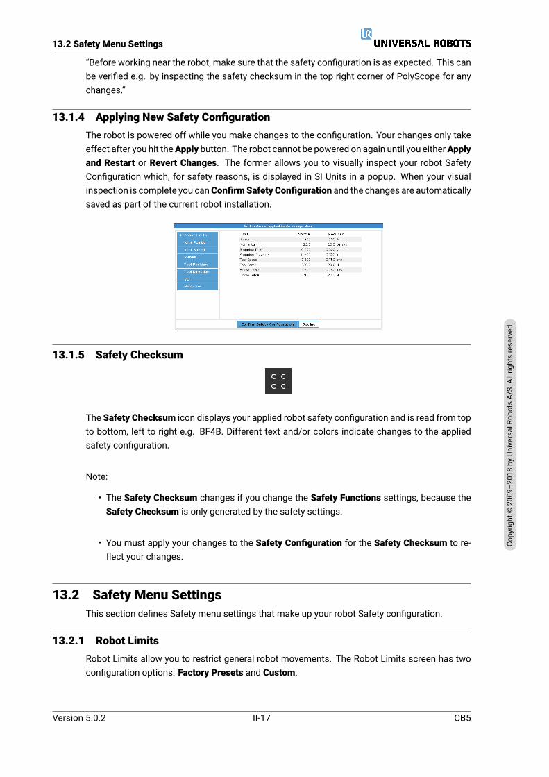
13.2 Safety Menu Settings
“Before working near the robot, make sure that the safety configuration is as expected. This canbe verified e.g. by inspecting the safety checksum in the top right corner of PolyScope for anychanges.”
13.1.4 Applying New Safety ConfigurationThe robot is powered off while you make changes to the configuration. Your changes only takeeffect after you hit theApply button. The robot cannot be powered on again until you eitherApplyand Restart or Revert Changes. The former allows you to visually inspect your robot SafetyConfiguration which, for safety reasons, is displayed in SI Units in a popup. When your visualinspection is complete you canConfirmSafety Configuration and the changes are automaticallysaved as part of the current robot installation.
13.1.5 Safety Checksum
The Safety Checksum icon displays your applied robot safety configuration and is read from topto bottom, left to right e.g. BF4B. Different text and/or colors indicate changes to the appliedsafety configuration.
Note:
• The Safety Checksum changes if you change the Safety Functions settings, because theSafety Checksum is only generated by the safety settings.
• You must apply your changes to the Safety Configuration for the Safety Checksum to re-flect your changes.
13.2 Safety Menu SettingsThis section defines Safety menu settings that make up your robot Safety configuration.
13.2.1 Robot LimitsRobot Limits allow you to restrict general robot movements. The Robot Limits screen has twoconfiguration options: Factory Presets and Custom.
Version 5.0.2
Copy
right
©20
09–2
018by
Universa
lRob
otsA/
S.Allrightsrese
rved
.
II-17 CB5

13.2 Safety Menu Settings
1. Factory Presets is where you can use the slider to select a predefined safety setting . Thevalues in the table are updated to reflect the preset values ranging fromMost Restricted toLeast RestrictedNote: Slider values are only suggestions and do not substitute a proper risk assessment.
2. Custom is where you can set Limits on how the robot functions andmonitor the associatedTolerance.
Power limits maximum mechanical work produced by the robot in the environment.Note: this limit considers the payload a part of the robot and not of the environment.
Momentum limits maximum robot momentum.
Stopping Time limits maximum time it takes the robot to stop e.g. when an emergencystop is activated.
Stopping Distance limits maximum distance the robot tool or elbow can travel while stop-ping.
NOTE:Restricting stopping time and distance affect overall robot speed.For example, if stopping time is set to 300 ms, the maximum robotspeed is limited allowing the robot to stop within 300 ms.
Tool Speed limits maximum robot tool speed.
Tool Force limits the maximum force exerted by the robot tool in clamping situations.
Elbow Speed limits maximum robot elbow speed.
Elbow Force limits maximum force that the elbow exerts on the environment.
The tool speed and force are limited at the tool flange and the center of the two user-definedtool positions, see 13.2.6.
CB5 II-18 Version 5.0.2
Copy
right
©20
09–2
018by
Universa
lRob
otsA/
S.Allrightsrese
rved
.
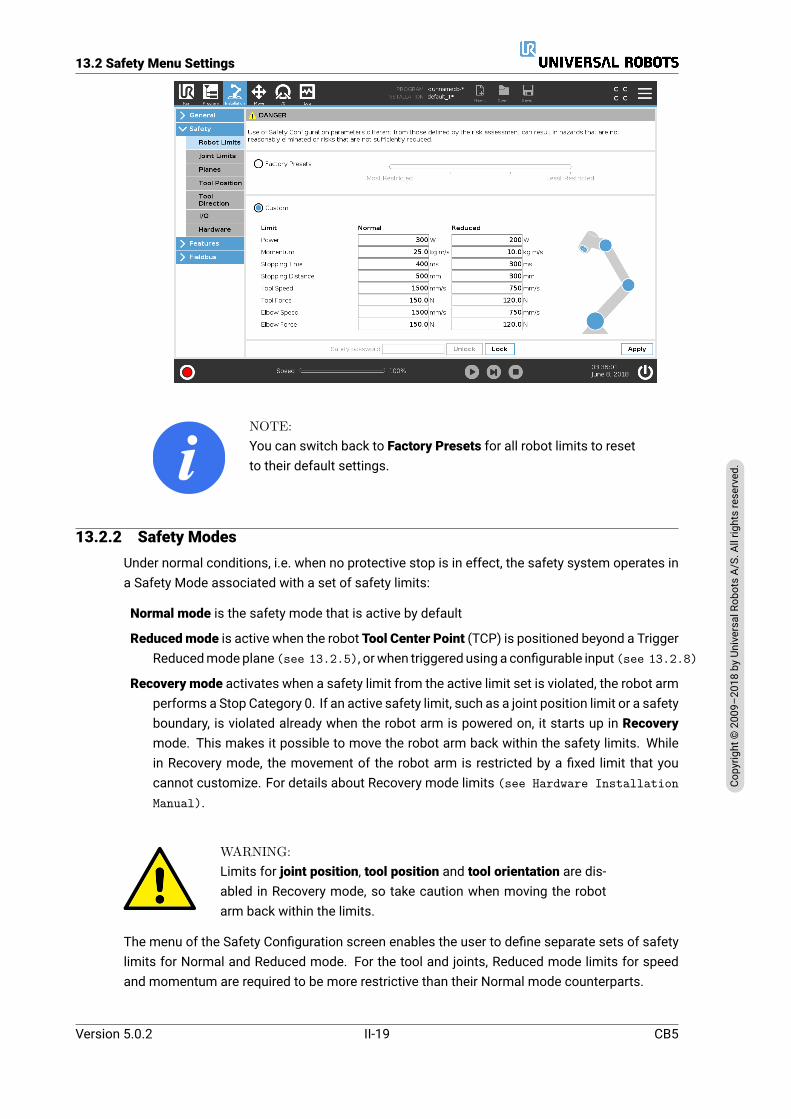
13.2 Safety Menu Settings
NOTE:You can switch back to Factory Presets for all robot limits to resetto their default settings.
13.2.2 Safety ModesUnder normal conditions, i.e. when no protective stop is in effect, the safety system operates ina Safety Mode associated with a set of safety limits:
Normal mode is the safety mode that is active by default
Reducedmode is active when the robot Tool Center Point (TCP) is positioned beyond a TriggerReducedmodeplane (see 13.2.5), orwhen triggered using a configurable input (see 13.2.8)
Recovery mode activates when a safety limit from the active limit set is violated, the robot armperforms a Stop Category 0. If an active safety limit, such as a joint position limit or a safetyboundary, is violated already when the robot arm is powered on, it starts up in Recoverymode. This makes it possible to move the robot arm back within the safety limits. Whilein Recovery mode, the movement of the robot arm is restricted by a fixed limit that youcannot customize. For details about Recovery mode limits (see Hardware InstallationManual).
WARNING:Limits for joint position, tool position and tool orientation are dis-abled in Recovery mode, so take caution when moving the robotarm back within the limits.
The menu of the Safety Configuration screen enables the user to define separate sets of safetylimits for Normal and Reduced mode. For the tool and joints, Reduced mode limits for speedand momentum are required to be more restrictive than their Normal mode counterparts.
Version 5.0.2
Copy
right
©20
09–2
018by
Universa
lRob
otsA/
S.Allrightsrese
rved
.
II-19 CB5
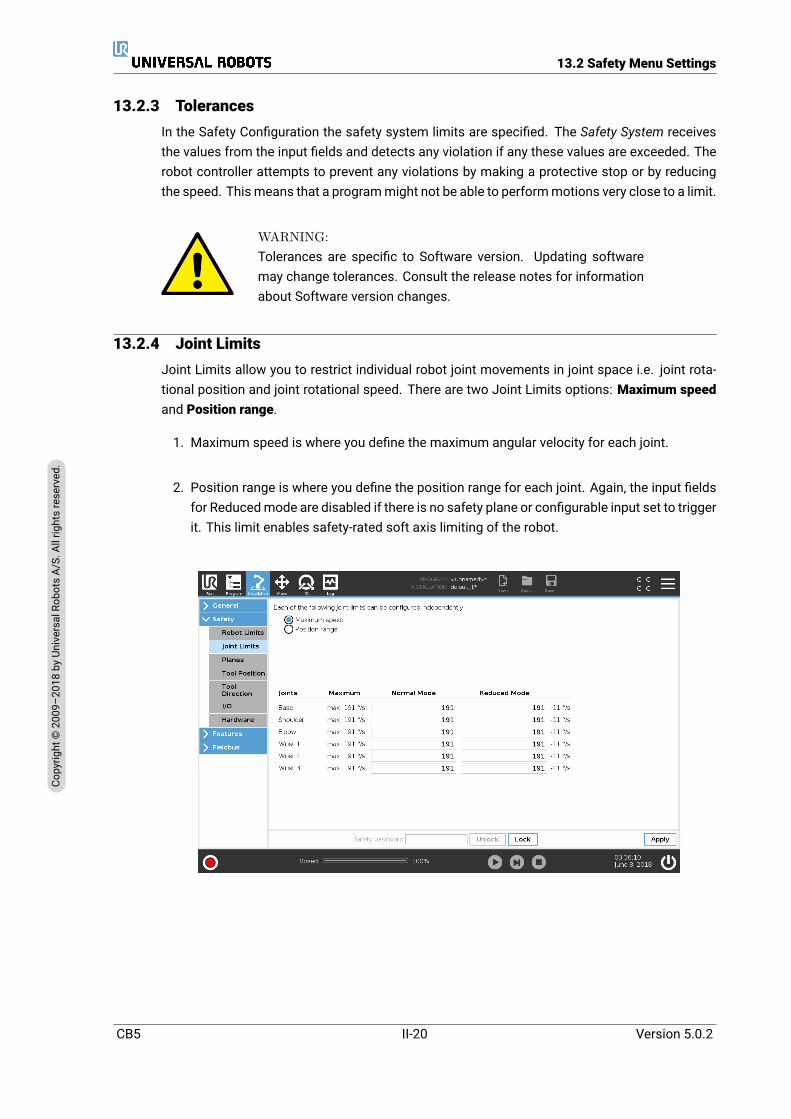
13.2 Safety Menu Settings
13.2.3 TolerancesIn the Safety Configuration the safety system limits are specified. The Safety System receivesthe values from the input fields and detects any violation if any these values are exceeded. Therobot controller attempts to prevent any violations by making a protective stop or by reducingthe speed. Thismeans that a programmight not be able to performmotions very close to a limit.
WARNING:Tolerances are specific to Software version. Updating softwaremay change tolerances. Consult the release notes for informationabout Software version changes.
13.2.4 Joint LimitsJoint Limits allow you to restrict individual robot joint movements in joint space i.e. joint rota-tional position and joint rotational speed. There are two Joint Limits options: Maximum speedand Position range.
1. Maximum speed is where you define the maximum angular velocity for each joint.
2. Position range is where you define the position range for each joint. Again, the input fieldsfor Reducedmode are disabled if there is no safety plane or configurable input set to triggerit. This limit enables safety-rated soft axis limiting of the robot.
CB5 II-20 Version 5.0.2
Copy
right
©20
09–2
018by
Universa
lRob
otsA/
S.Allrightsrese
rved
.

13.2 Safety Menu Settings
13.2.5 Planes
NOTE:Configuring planes is entirely based on features. We recommendyou create and name all features before editing the safety config-uration, as the robot is powered off once the Safety Tab has beenunlocked and moving the robot will be impossible.
Safety planes restrict robot workspace. You can define up to eight safety planes, restricting therobot tool and elbow. You can also restrict elbow movement for each safety plane and disableby deselecting the checkbox. Before configuring safety planes, you must define a feature in therobot installation (see 17.1.3). The feature can then be copied into the safety plane screenand configured.
WARNING:Defining safety planes only limits the defined Tool spheres and el-bow, not the overall limit for the robot arm. This means that spec-ifying a safety plane, does not guarantee that other parts of therobot arm will obey this restriction.
Modes
You can configure each plane with restrictiveModes using the icons listed below.
Disabled The safety plane is never active in this state.
Normal When the safety system is in Normal mode, a normal plane is active and it acts asa strict limit on the position.
Reduced When the safety system is in Reduced mode, a reduced mode plane is active andit acts as a strict limit on the position.
Normal & Reduced When the safety system is either in Normal or Reducedmode, a normaland reduced mode plane is active and acts as a strict limit on the position.
Trigger Reduced Mode The safety plane causes the safety system to switch to Reducedmode if the robot Tool or Elbow is positioned beyond it.
Show Pressing this icon hides or shows the safety plane in the graphics pane.
Delete Deletes the created safety plane (note: there is no undo/redo action here so if aplane is deleted by mistake, it will have to be remade)
Rename Pressing this icon allows you to rename the plane.
Configuring Safety Planes
1. In your PolyScope header, tap Installation.
2. On the left, in the action menu, tap Safety and select Planes.
3. On the top right of the screen, in the Planes field, tap Add plane.
Version 5.0.2
Copy
right
©20
09–2
018by
Universa
lRob
otsA/
S.Allrightsrese
rved
.
II-21 CB5

13.2 Safety Menu Settings
4. On the bottom right of the screen, in the Properties field, set up Name, Copy Feature andRestrictions. Note: In Copy Feature, only Undefined and Base are available. You can reseta configured safety plane by selecting Undefined
If the copied feature is modified in the Features screen, a warning icon appears to the rightof the Copy Feature text. This indicates that the feature is out of sync i.e. the information inthe properties card is not updated to reflect the modifications that may have been made to theFeature.
Elbow
You can enable Restrict Elbow to prevent robot elbow joint from passing through any of yourdefined planes. Disable Restrict Elbow for elbow to pass through planes.
Color Codes
Gray Plane is configured but disabled (A)
CB5 II-22 Version 5.0.2
Copy
right
©20
09–2
018by
Universa
lRob
otsA/
S.Allrightsrese
rved
.

13.2 Safety Menu Settings
Yellow & Black Normal Plane (B)
Blue & Green Trigger Plane (C)
Black Arrow The side of the plane the tool and/or elbow is allowed to be on (For Normal Planes)
Green Arrow The side of the plane the tool and/or elbow is allowed to be on (For Trigger Planes)
Gray Arrow The side of the plane the tool and/or elbow is allowed to be on (For Disabled Planes)
Freedriving Robot
If the robot comes close to certain limits, while in Freedrive (see 18.6), you can experience arepelling force from the robot.
13.2.6 Tool PositionThe Tool Position screen enables more controlled restriction of tools and/or accessories placedon the end of the robot arm.
Robot is where you can visualize your modifications.
Tool is where you can define and configure a tool up to two tools.
Tool_1 is the default tool defined with values x=0.0, y= 0.0, z=0.0 and radius=0.0. These valuesrepresent the robot tool flange.Note:
• Under Copy TCP, you can also select Tool Flange and cause the tool values to go back to 0.
• A default sphere is defined at the tool flange.
For the user defined tools, the user can change:
Radius to change the radius of the tool sphere. The radius is considered when using safetyplanes. When a point in the sphere passes a reducedmode trigger plane, the robot switchesto Reduced mode. The safety system prevents any point on the sphere from passing asafety plane (see 13.2.5).
Version 5.0.2
Copy
right
©20
09–2
018by
Universa
lRob
otsA/
S.Allrightsrese
rved
.
II-23 CB5
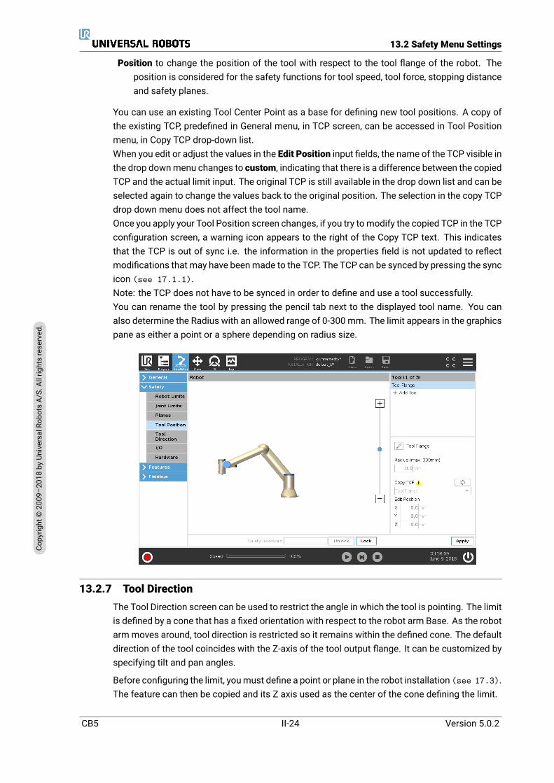
13.2 Safety Menu Settings
Position to change the position of the tool with respect to the tool flange of the robot. Theposition is considered for the safety functions for tool speed, tool force, stopping distanceand safety planes.
You can use an existing Tool Center Point as a base for defining new tool positions. A copy ofthe existing TCP, predefined in General menu, in TCP screen, can be accessed in Tool Positionmenu, in Copy TCP drop-down list.When you edit or adjust the values in the Edit Position input fields, the name of the TCP visible inthe drop downmenu changes to custom, indicating that there is a difference between the copiedTCP and the actual limit input. The original TCP is still available in the drop down list and can beselected again to change the values back to the original position. The selection in the copy TCPdrop down menu does not affect the tool name.Once you apply your Tool Position screen changes, if you try tomodify the copied TCP in the TCPconfiguration screen, a warning icon appears to the right of the Copy TCP text. This indicatesthat the TCP is out of sync i.e. the information in the properties field is not updated to reflectmodifications that may have beenmade to the TCP. The TCP can be synced by pressing the syncicon (see 17.1.1).Note: the TCP does not have to be synced in order to define and use a tool successfully.You can rename the tool by pressing the pencil tab next to the displayed tool name. You canalso determine the Radius with an allowed range of 0-300mm. The limit appears in the graphicspane as either a point or a sphere depending on radius size.
13.2.7 Tool DirectionThe Tool Direction screen can be used to restrict the angle in which the tool is pointing. The limitis defined by a cone that has a fixed orientation with respect to the robot arm Base. As the robotarmmoves around, tool direction is restricted so it remains within the defined cone. The defaultdirection of the tool coincides with the Z-axis of the tool output flange. It can be customized byspecifying tilt and pan angles.
Before configuring the limit, youmust define a point or plane in the robot installation (see 17.3).The feature can then be copied and its Z axis used as the center of the cone defining the limit.
CB5 II-24 Version 5.0.2
Copy
right
©20
09–2
018by
Universa
lRob
otsA/
S.Allrightsrese
rved
.
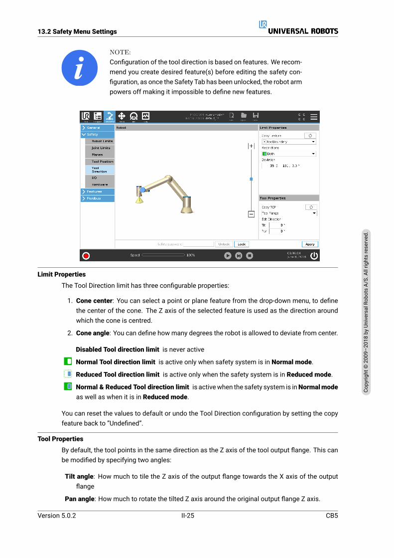
13.2 Safety Menu Settings
NOTE:Configuration of the tool direction is based on features. We recom-mend you create desired feature(s) before editing the safety con-figuration, as once the Safety Tab has been unlocked, the robot armpowers off making it impossible to define new features.
Limit Properties
The Tool Direction limit has three configurable properties:
1. Cone center: You can select a point or plane feature from the drop-down menu, to definethe center of the cone. The Z axis of the selected feature is used as the direction aroundwhich the cone is centred.
2. Cone angle: You can define howmany degrees the robot is allowed to deviate from center.
Disabled Tool direction limit is never active
Normal Tool direction limit is active only when safety system is in Normal mode.
Reduced Tool direction limit is active only when the safety system is in Reduced mode.
Normal & Reduced Tool direction limit is activewhen the safety system is inNormalmodeas well as when it is in Reduced mode.
You can reset the values to default or undo the Tool Direction configuration by setting the copyfeature back to ”Undefined”.
Tool Properties
By default, the tool points in the same direction as the Z axis of the tool output flange. This canbe modified by specifying two angles:
Tilt angle: How much to tile the Z axis of the output flange towards the X axis of the outputflange
Pan angle: How much to rotate the tilted Z axis around the original output flange Z axis.
Version 5.0.2
Copy
right
©20
09–2
018by
Universa
lRob
otsA/
S.Allrightsrese
rved
.
II-25 CB5
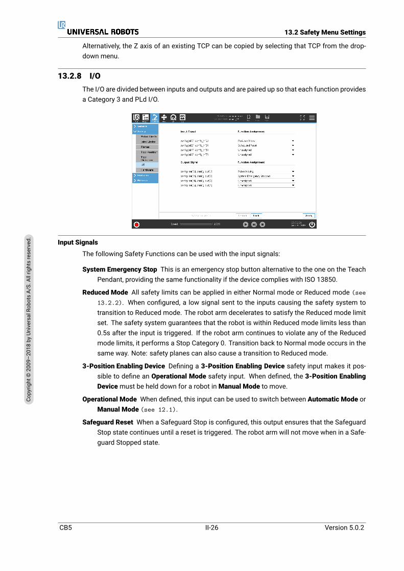
13.2 Safety Menu Settings
Alternatively, the Z axis of an existing TCP can be copied by selecting that TCP from the drop-down menu.
13.2.8 I/OThe I/O are divided between inputs and outputs and are paired up so that each function providesa Category 3 and PLd I/O.
Input Signals
The following Safety Functions can be used with the input signals:
System Emergency Stop This is an emergency stop button alternative to the one on the TeachPendant, providing the same functionality if the device complies with ISO 13850.
Reduced Mode All safety limits can be applied in either Normal mode or Reduced mode (see13.2.2). When configured, a low signal sent to the inputs causing the safety system totransition to Reduced mode. The robot arm decelerates to satisfy the Reduced mode limitset. The safety system guarantees that the robot is within Reduced mode limits less than0.5s after the input is triggered. If the robot arm continues to violate any of the Reducedmode limits, it performs a Stop Category 0. Transition back to Normal mode occurs in thesame way. Note: safety planes can also cause a transition to Reduced mode.
3-Position Enabling Device Defining a 3-Position Enabling Device safety input makes it pos-sible to define an Operational Mode safety input. When defined, the 3-Position EnablingDevicemust be held down for a robot inManual Mode to move.
Operational Mode When defined, this input can be used to switch between Automatic Mode orManual Mode (see 12.1).
Safeguard Reset When a Safeguard Stop is configured, this output ensures that the SafeguardStop state continues until a reset is triggered. The robot arm will not move when in a Safe-guard Stopped state.
CB5 II-26 Version 5.0.2
Copy
right
©20
09–2
018by
Universa
lRob
otsA/
S.Allrightsrese
rved
.
13.2 Safety Menu Settings
WARNING:By default, the Safeguard Reset input function is configured for in-put pins 0 and 1. Disabling it altogether implies that the robot armceases to be Safeguard Stopped as soon as the Safeguard Stopinput becomes high. In other words, without a Safeguard Reset in-put, the Safeguard Stop inputs SI0 and SI1 (see the HardwareInstallation Manual) fully determine whether the SafeguardStopped state is active or not.
Output Signals
You can apply the following Safety functions for output signals. All signals return to low whenthe state which triggered the high signal has ended:
System Emergency Stop Low signal is given when the safety system has been triggered intoan Emergency Stopped state by the Robot Emergency Stop input or the Emergency StopButton. To avoid deadlocks, if the Emergency Stopped state is triggered by the SystemEmergency Stop input, low signal will not be given.
Robot Moving Low signal if the robot is moving, otherwise high.
Robot Not Stopping high signal when the robot is stopped or in the process of stopping due toan emergency stop or safeguard stop. Otherwise it will be logic low.
Reduced Mode Sends a lowsignalwhen the robot arm is placed in Reducedmodeor if the safetyinput is configured with a Reduced Mode input and the signal is currently low. Otherwisethe signal is high.
Not Reduced Mode This is the inverse of the Reduced Mode defined above.
NOTE:Any external machinery receiving its Emergency Stop state fromthe robot through the System Emergency Stop output must com-ply with ISO 13850. This is particularly necessary in setups wherethe Robot Emergency Stop input is connected to an external Emer-gency Stop device. In such cases, the System Emergency Stopoutput becomes high when the external Emergency Stop device isreleased. This implies that the emergency stop state at the exter-nal machinery will be reset with no manual action needed from therobot’s operator. Hence, to comply with safety standards, the ex-ternal machinery must require manual action in order to resume.
13.2.9 HardwareYou can use the robot without attaching the Teach Pendant. Removing the Teach Pendant re-quires defining another Emergency Stop source. You must specify if the Teach Pendant is at-tached to avoid triggering a safety violation.
Selecting Available Hardware
The robot can be used without PolyScope as the programming interface.
Version 5.0.2
Copy
right
©20
09–2
018by
Universa
lRob
otsA/
S.Allrightsrese
rved
.
II-27 CB5
13.2 Safety Menu Settings
1. In the Header tap Installation.
2. In the action menu on left tap Safety and select Hardware.
3. Input Safety password and Unlock the screen.
4. Deselect Teach Pendant to use robot without PolyScope interface.
5. Press Save and restart to implement changes.
CAUTION:If the Teach Pendant is detached or disconnected from the robot,the Emergency Stop button is no longer active. You must removethe Teach Pendant from the vicinity of the robot.
CB5 II-28 Version 5.0.2
Copy
right
©20
09–2
018by
Universa
lRob
otsA/
S.Allrightsrese
rved
.
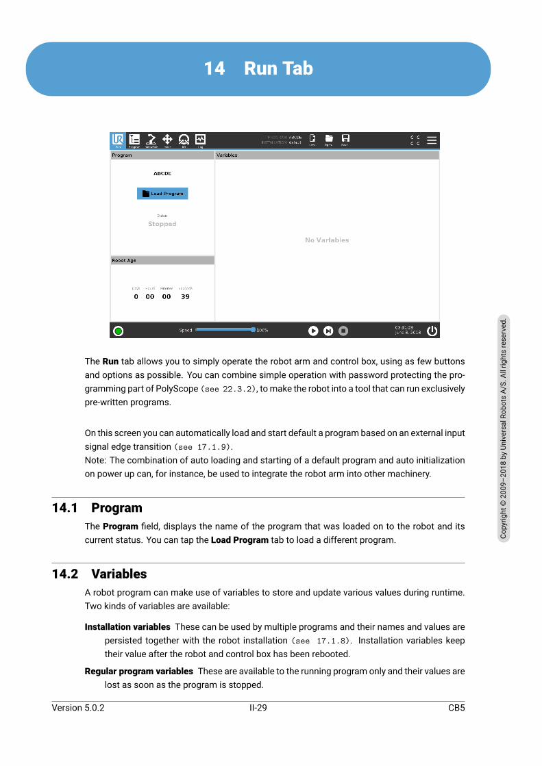
14 Run Tab
The Run tab allows you to simply operate the robot arm and control box, using as few buttonsand options as possible. You can combine simple operation with password protecting the pro-gramming part of PolyScope (see 22.3.2), tomake the robot into a tool that can run exclusivelypre-written programs.
On this screen you can automatically load and start default a program based on an external inputsignal edge transition (see 17.1.9).Note: The combination of auto loading and starting of a default program and auto initializationon power up can, for instance, be used to integrate the robot arm into other machinery.
14.1 ProgramThe Program field, displays the name of the program that was loaded on to the robot and itscurrent status. You can tap the Load Program tab to load a different program.
14.2 VariablesA robot program can make use of variables to store and update various values during runtime.Two kinds of variables are available:
Installation variables These can be used by multiple programs and their names and values arepersisted together with the robot installation (see 17.1.8). Installation variables keeptheir value after the robot and control box has been rebooted.
Regular program variables These are available to the running program only and their values arelost as soon as the program is stopped.
Version 5.0.2
Copy
right
©20
09–2
018by
Universa
lRob
otsA/
S.Allrightsrese
rved
.
II-29 CB5

14.4 Move Robot into Position
The following variable types are available:
bool A boolean variable whose value is either True or False.int A whole number in the range from −2147483648 to 2147483647 (32 bit).float A floating point number (decimal) (32 bit).string A sequence of characters.pose A vector describing the location and orientation in Cartesian space.
It is a combination of a position vector (x, y, z) and a rotation vector(rx, ry, rz) representing the orientation, written p[x, y, z, rx, ry,rz].
list A sequence of variables.
14.3 Robot AgeThis field represents how long ago was the robot turned on for the first time.Note: the numbers represented in this field are not associated with program run time.
14.4 Move Robot into PositionIn the Footer, press the Play button to access the Move Robot into Position screen when youhave to move your robot into a specific position in its workspace. For example: when the robotarm has to move to a particular start position before running a program, or when moving to awaypoint while modifying a program.
Note: Automove is a function made up of three buttons in the Footer: Play, Step and Stop.
AutoHold down the Auto tab to move the robot arm to its start position.Note: You can release the button to stop the motion at any time.
CB5 II-30 Version 5.0.2
Copy
right
©20
09–2
018by
Universa
lRob
otsA/
S.Allrightsrese
rved
.
14.4 Move Robot into Position
AnimationThe animation shows the movement the robot arm is about to perform when you hold down theAuto tab.
CAUTION:
1. Compare the animation with the position of the real robotarm and make sure that the robot arm can safely perform themovement without hitting any obstacles.
2. TheAutomove functionmoves the robot along the shadow tra-jectory. Collisionmight damage the robot or other equipment.
ManualPush theManual tab to access theMove icon screen where the robot arm can be moved man-ually. This is only needed if you do not prefer the animation’s movement.
Version 5.0.2
Copy
right
©20
09–2
018by
Universa
lRob
otsA/
S.Allrightsrese
rved
.
II-31 CB5

14.4 Move Robot into Position
CB5 II-32 Version 5.0.2
Copy
right
©20
09–2
018by
Universa
lRob
otsA/
S.Allrightsrese
rved
.

15 Initialize Tab
15.1 Robot Arm State IndicatorLocated in the Header, the Initialize icon includes a status LED indicating Robot arm runningstate.
• Red indicates theRobot arm is in a stopped state due to different possible reasons.
• Yellow indicates the Robot arm is powered on, but it is not ready for normal operation.
• Green indicates the Robot arm is powered on and ready for normal operation.
On the Initialize Robot screen, the text next to the LED further specifies Robot arm state.
15.2 Active Payload and InstallationWhen the Robot arm is powered on, the payload mass used by the controller is shown in theCurrent Payload text field. Tap the text field to modify the current payload value. Setting thisvalue does not modify the robot’s installation payload (see 17.1.1), but only the payload massused by the controller. Similarly, the installation file name is shown in the Installation file textfield and in the Header. The active installation file name is also displayed in the Header, File Pathnext to Installation.
Before starting up the Robot arm, it is important to verify both the active payload and the activeinstallation correspond to the situation of the Robot arm.
Version 5.0.2
Copy
right
©20
09–2
018by
Universa
lRob
otsA/
S.Allrightsrese
rved
.
II-33 CB5
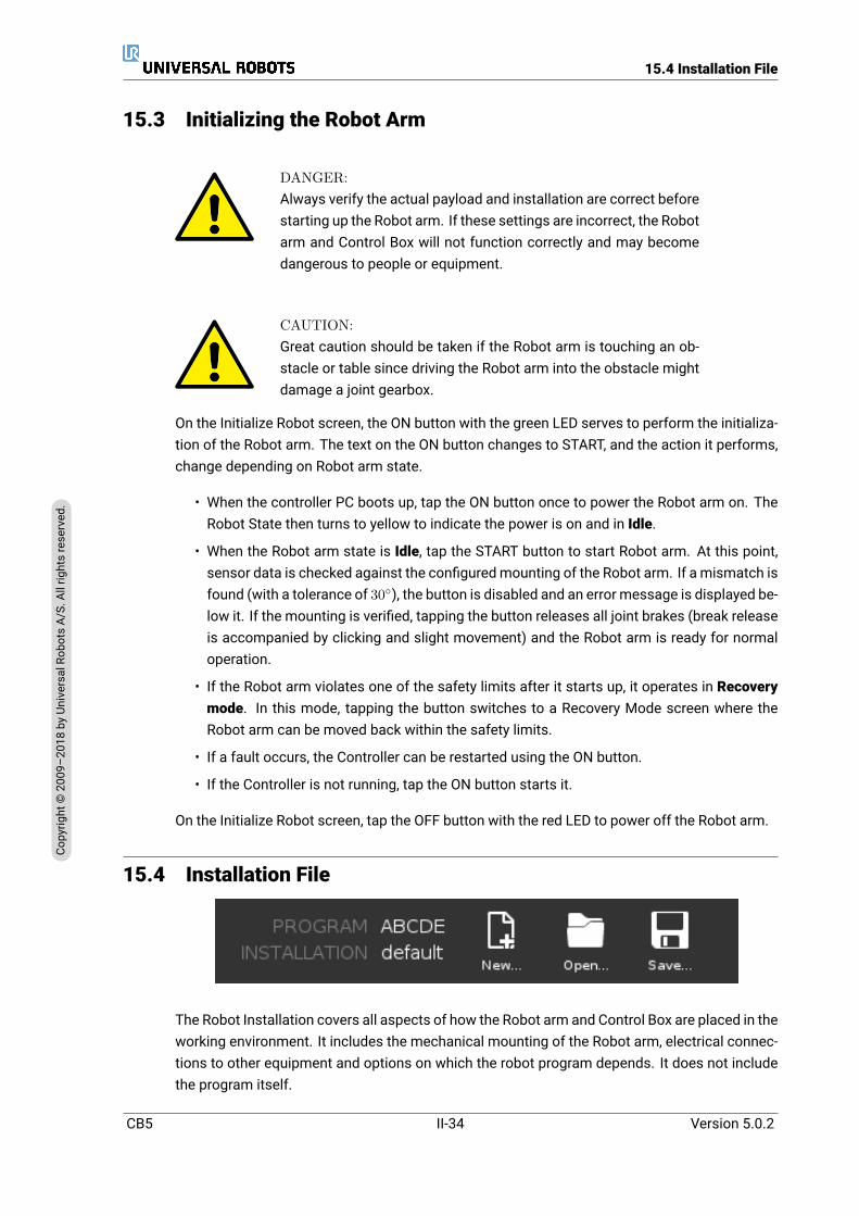
15.4 Installation File
15.3 Initializing the Robot Arm
DANGER:Always verify the actual payload and installation are correct beforestarting up the Robot arm. If these settings are incorrect, the Robotarm and Control Box will not function correctly and may becomedangerous to people or equipment.
CAUTION:Great caution should be taken if the Robot arm is touching an ob-stacle or table since driving the Robot arm into the obstacle mightdamage a joint gearbox.
On the Initialize Robot screen, the ON button with the green LED serves to perform the initializa-tion of the Robot arm. The text on the ON button changes to START, and the action it performs,change depending on Robot arm state.
• When the controller PC boots up, tap the ON button once to power the Robot arm on. TheRobot State then turns to yellow to indicate the power is on and in Idle.
• When the Robot arm state is Idle, tap the START button to start Robot arm. At this point,sensor data is checked against the configuredmounting of the Robot arm. If a mismatch isfound (with a tolerance of 30), the button is disabled and an error message is displayed be-low it. If the mounting is verified, tapping the button releases all joint brakes (break releaseis accompanied by clicking and slight movement) and the Robot arm is ready for normaloperation.
• If the Robot arm violates one of the safety limits after it starts up, it operates in Recoverymode. In this mode, tapping the button switches to a Recovery Mode screen where theRobot arm can be moved back within the safety limits.
• If a fault occurs, the Controller can be restarted using the ON button.
• If the Controller is not running, tap the ON button starts it.
On the Initialize Robot screen, tap the OFF button with the red LED to power off the Robot arm.
15.4 Installation File
The Robot Installation covers all aspects of how the Robot arm and Control Box are placed in theworking environment. It includes the mechanical mounting of the Robot arm, electrical connec-tions to other equipment and options on which the robot program depends. It does not includethe program itself.
CB5 II-34 Version 5.0.2
Copy
right
©20
09–2
018by
Universa
lRob
otsA/
S.Allrightsrese
rved
.
15.4 Installation File
These settings can be set using the various screens under the Installation tab, except for the I/Odomains which are set in the I/O tab (see 19).
It is possible to have more than one installation file for the robot. Created programs created usethe active installation and load this installation automatically when used.
Any changes to an installation must be saved to be preserved after power down. If there areunsaved changes in the installation, a floppy disk icon is shown next to the Load/Save text onthe left side of the Installation tab.
You can save an installation by pressing the Save… or Save As… button. Alternatively, savinga program also saves the active installation. To load a different installation file, use the Loadbutton. In the Robot Installation the Create New button resets all of the settings to their factorydefaults.
CAUTION:Using the robot with an installation loaded from a USB drive is notrecommended. To use an installation stored on a USB drive, firstload it and then save it in the local programs folder using the SaveAs… button.
Version 5.0.2
Copy
right
©20
09–2
018by
Universa
lRob
otsA/
S.Allrightsrese
rved
.
II-35 CB5
15.4 Installation File
CB5 II-36 Version 5.0.2
Copy
right
©20
09–2
018by
Universa
lRob
otsA/
S.Allrightsrese
rved
.
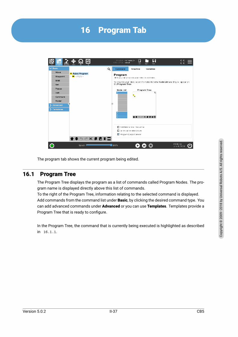
16 Program Tab
The program tab shows the current program being edited.
16.1 Program TreeThe Program Tree displays the program as a list of commands called Program Nodes. The pro-gram name is displayed directly above this list of commands.To the right of the Program Tree, information relating to the selected command is displayed.Add commands from the command list under Basic, by clicking the desired command type. Youcan add advanced commands under Advanced or you can use Templates. Templates provide aProgram Tree that is ready to configure.
In the Program Tree, the command that is currently being executed is highlighted as describedin 16.1.1.
Version 5.0.2
Copy
right
©20
09–2
018by
Universa
lRob
otsA/
S.Allrightsrese
rved
.
II-37 CB5

16.1 Program Tree
16.1.1 Program Execution Indication
The Program Tree contains visual cues informing about the command currently being executedby the robot controller. A small indicator icon is displayed to the left of the command icon,and the name of the executing command and any commands of which this command is a sub-command (typically identified by the / command icons) are highlighted with blue. This aidsthe user in locating the executing command in the tree.
For example, if the robot arm is moving towards a waypoint, the corresponding waypoint sub-command ismarkedwith the icon and its name together with the name of theMove command(see 16.5.1) to which it belongs to are shown in blue.
If the program is paused, the program execution indicator icon marks the last command thatwas in the process of being executed.
Clicking the button with the icon below the Program Tree jumps to the current executing orthe last executed command in the tree. If a command is clicked while a program is running,the Command tab will keep displaying the information related to the selected command. Pressingthe button will make the Command tab continuously show information about the currentlyexecuting commands again.
16.1.2 Search ButtonTap the to perform a text search in the Program Tree. When clicked a search text can beentered and program nodes that match will be highlighted in yellow. Additionally, navigationbuttons are made available to navigate through the matches. Press the icon to exit searchmode.
16.1.3 Program Tree ToolbarUse the toolbar at the base of the Program Tree to modify the Program Tree.
Undo/Redo Buttons
The and buttons serve to undo and redo changes to commands.
CB5 II-38 Version 5.0.2
Copy
right
©20
09–2
018by
Universa
lRob
otsA/
S.Allrightsrese
rved
.

16.2 Command Tab
Move Up & Down
The and buttons change the position of a node.
Cut
The button cuts a node and allows it to be used for other actions (e.g., paste it on other placeon the Program Tree).
Copy
button allows copies a node and allows it to be used for other actions (e.g., paste it on otherplace on the Program Tree).
Paste
The button allows you to paste a node that was previously cut or copied.
Delete
Tap the button to remove a node from the Program Tree.
Suppress
Tap the button to suppress specific nodes on the Program Tree.
Suppressed program lines are simply skipped when the program is run. A suppressed line canbe unsuppressed again at a later time. This is a quick way tomake changes to a programwithoutdestroying the original contents.
16.1.4 Empty Node
Program Nodes cannot be empty. All lines must be specified and defined in the Program Treefor a program to run.
16.2 Command TabUse the Command Tab to configure each ProgramNode on the Program Tree in order to run yourProgram. The information that is displayed changes depending on the type of node you select.
Version 5.0.2
Copy
right
©20
09–2
018by
Universa
lRob
otsA/
S.Allrightsrese
rved
.
II-39 CB5
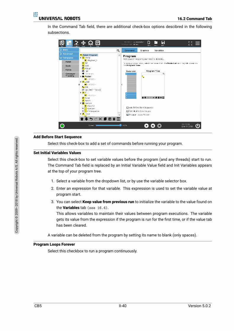
16.2 Command Tab
In the Command Tab field, there are additional check-box options descibred in the followingsubsections.
Add Before Start Sequence
Select this check-box to add a set of commands before running your program.
Set Initial Variables Values
Select this check-box to set variable values before the program (and any threads) start to run.The Command Tab field is replaced by an Initial Variable Value field and Init Variables appearsat the top of your program tree.
1. Select a variable from the dropdown list, or by use the variable selector box.
2. Enter an expression for that variable. This expression is used to set the variable value atprogram start.
3. You can select Keep value from previous run to initialize the variable to the value found onthe Variables tab (see 16.4).This allows variables to maintain their values between program executions. The variablegets its value from the expression if the program is run for the first time, or if the value tabhas been cleared.
A variable can be deleted from the program by setting its name to blank (only spaces).
Program Loops Forever
Select this checkbox to run a program continuously.
CB5 II-40 Version 5.0.2
Copy
right
©20
09–2
018by
Universa
lRob
otsA/
S.Allrightsrese
rved
.

16.3 Graphics Tab
16.3 Graphics Tab
Graphical representation of the current robot program. The path of the TCP is shown in 3D view,with motion segments in black, and blend segments (transitions between motion segments)shown in green. The green dots specify the positions of the TCP at each of the waypoints in theprogram. The 3D drawing of the robot arm shows the current position of the robot arm, and theshadow of the robot arm shows how the robot arm intends to reach the waypoint selected in theleft hand side of the screen.
If the current position of the robot TCP comes close to a safety or trigger plane, or the orientationof robot tool is near the tool orientation boundary limit (see 13.2.5, a 3D representation of theproximate boundary limit is shown.Note: when the robot is running a program, the visualization of boundary limits will be disabled.
Safety planes are visualized in yellow and black with a small arrow representing the plane nor-mal, which indicates the side of the plane on which the robot TCP is allowed to be positioned.Trigger planes are displayed in blue and green and a small arrow pointing to the side of the plane,where the Normalmode limits (see 13.2.2) are active. The tool orientation boundary limit isvisualized with a spherical cone together with a vector indicating the current orientation of therobot tool. The inside of the cone represents the allowed area for the tool orientation (vector).
When the target robot TCP no longer is in the proximity of the limit, the 3D representation dis-appears. If the TCP is in violation or very close to violating a boundary limit, the visualization ofthe limit turns red.
The 3D view can be zoomed and rotated to get a better view of the robot arm. The buttons inthe top-right side of the screen can disable the various graphical components in 3D view. Thebottom button switches on/off the visualization of proximate boundary limits.
The motion segments shown depend on the selected program node. If a Move node is selected,the displayed path is themotion defined by thatmove. If aWaypoint node is selected, the displayshows the following ∼ 10 steps of movement.
Version 5.0.2
Copy
right
©20
09–2
018by
Universa
lRob
otsA/
S.Allrightsrese
rved
.
II-41 CB5

16.5 Basic program nodes
16.4 Variables Tab
The Variables tab shows the live values of variables in the running program, and keeps a list ofvariables and values between program runs. It only appears when it has information to display.The variables are ordered alphabetically by their names. The variable names on this screen areshown with at most 50 characters, and the values of the variables are shown with at most 500characters.
16.5 Basic program nodes16.5.1 Move
The Move command controls the robot motion through the underlying waypoints. Waypointshave to be under aMove command. TheMove command defines the acceleration and the speedat which the robot arm will move between those waypoints.
CB5 II-42 Version 5.0.2
Copy
right
©20
09–2
018by
Universa
lRob
otsA/
S.Allrightsrese
rved
.
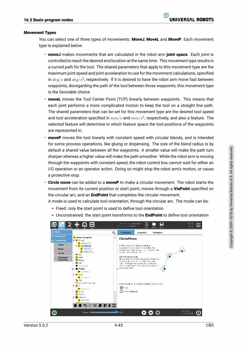
16.5 Basic program nodes
Movement TypesYou can select one of three types of movements: MoveJ, MoveL and MoveP. Each movementtype is explained below.
• moveJ makes movements that are calculated in the robot arm joint space. Each joint iscontrolled to reach the desired end location at the same time. Thismovement type results ina curved path for the tool. The shared parameters that apply to this movement type are themaximum joint speed and joint acceleration to use for themovement calculations, specifiedin deg/s and deg/s2, respectively. If it is desired to have the robot arm move fast betweenwaypoints, disregarding the path of the tool between those waypoints, this movement typeis the favorable choice.
• moveL moves the Tool Center Point (TCP) linearly between waypoints. This means thateach joint performs a more complicated motion to keep the tool on a straight line path.The shared parameters that can be set for this movement type are the desired tool speedand tool acceleration specified in mm/s and mm/s2, respectively, and also a feature. Theselected feature will determine in which feature space the tool positions of the waypointsare represented in.
• moveP moves the tool linearly with constant speed with circular blends, and is intendedfor some process operations, like gluing or dispensing. The size of the blend radius is bydefault a shared value between all the waypoints. A smaller value will make the path turnsharper whereas a higher value will make the path smoother. While the robot arm ismovingthrough the waypoints with constant speed, the robot control box cannot wait for either anI/O operation or an operator action. Doing so might stop the robot arm’s motion, or causea protective stop.
• Circle move can be added to a moveP to make a circular movement. The robot starts themovement from its current position or start point, moves through a ViaPoint specified onthe circular arc, and an EndPoint that completes the circular movement.A mode is used to calculate tool orientation, through the circular arc. The mode can be:
– Fixed: only the start point is used to define tool orientation– Unconstrained: the start point transforms to the EndPoint to define tool orientation
Version 5.0.2
Copy
right
©20
09–2
018by
Universa
lRob
otsA/
S.Allrightsrese
rved
.
II-43 CB5
16.5 Basic program nodes
Shared parameters
The shared parameters in the bottom right corner of the Move screen apply to the movementfrom the previous position of the robot arm to the first waypoint under the command, and fromthere to each of the following waypoints. The Move command settings do not apply to the pathgoing from the last waypoint under that Move command.
TCP selection
The way the robot moves between waypoints is adjusted depending on whether the TCP is setusing a user defined TCP or an active TCP. Use Tool Flange allows this movement to be adjustedin relation to the Tool Flange.
Setting the TCP in a Move
1. Access the Program Tab screen to set the TCP used for waypoints.
2. Under Command, in the drop down menu on the right select the Move type.
3. Under Move, select an option in the Set TCP drop down menu.
4. Select Use active TCP or select a user defined TCP.You can also choose Use Tool Flange
Feature selection the feature space the waypoints under the Move command, that should berepresented when specifying these waypoints (see section 17.3). This means that whensetting a waypoint, the program will remember the tool coordinates in the feature space of theselected feature. There are a few circumstances that need detailed explanation:
Relative waypoints The selected feature has no effect on relative waypoints. The relativemove-ment is always performed with respect to orientation of the Base.
Variable waypoints When the robot armmoves to a variable waypoint, the tool target position iscalculated as the coordinates of the variable in the space of the selected feature. Therefore,the robot arm movement for a variable waypoint changes if another feature is selected.
Feature variable You can change a feature’s position while the program is running by assigninga pose to its corresponding variable.
CB5 II-44 Version 5.0.2
Copy
right
©20
09–2
018by
Universa
lRob
otsA/
S.Allrightsrese
rved
.
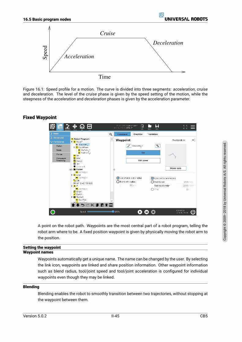
16.5 Basic program nodes
Time
Speed
Acceleration
Cruise
Deceleration
Figure 16.1: Speed profile for a motion. The curve is divided into three segments: acceleration, cruiseand deceleration. The level of the cruise phase is given by the speed setting of the motion, while thesteepness of the acceleration and deceleration phases is given by the acceleration parameter.
Fixed Waypoint
A point on the robot path. Waypoints are the most central part of a robot program, telling therobot arm where to be. A fixed position waypoint is given by physically moving the robot arm tothe position.
Setting the waypointWaypoint names
Waypoints automatically get a unique name. The name can be changed by the user. By selectingthe link icon, waypoints are linked and share position information. Other waypoint informationsuch as blend radius, tool/joint speed and tool/joint acceleration is configured for individualwaypoints even though they may be linked.
Blending
Blending enables the robot to smoothly transition between two trajectories, without stopping atthe waypoint between them.
Version 5.0.2
Copy
right
©20
09–2
018by
Universa
lRob
otsA/
S.Allrightsrese
rved
.
II-45 CB5
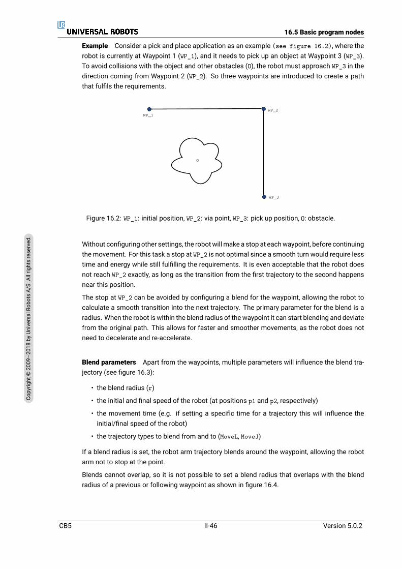
16.5 Basic program nodes
Example Consider a pick and place application as an example (see figure 16.2), where therobot is currently at Waypoint 1 (WP_1), and it needs to pick up an object at Waypoint 3 (WP_3).To avoid collisions with the object and other obstacles (O), the robot must approach WP_3 in thedirection coming from Waypoint 2 (WP_2). So three waypoints are introduced to create a paththat fulfils the requirements.
WP_1WP_2
WP_3
O
Figure 16.2: WP_1: initial position, WP_2: via point, WP_3: pick up position, O: obstacle.
Without configuring other settings, the robotwillmake a stop at eachwaypoint, before continuingthemovement. For this task a stop at WP_2 is not optimal since a smooth turn would require lesstime and energy while still fulfilling the requirements. It is even acceptable that the robot doesnot reach WP_2 exactly, as long as the transition from the first trajectory to the second happensnear this position.
The stop at WP_2 can be avoided by configuring a blend for the waypoint, allowing the robot tocalculate a smooth transition into the next trajectory. The primary parameter for the blend is aradius. When the robot is within the blend radius of thewaypoint it can start blending and deviatefrom the original path. This allows for faster and smoother movements, as the robot does notneed to decelerate and re-accelerate.
Blend parameters Apart from the waypoints, multiple parameters will influence the blend tra-jectory (see figure 16.3):
• the blend radius (r)
• the initial and final speed of the robot (at positions p1 and p2, respectively)
• the movement time (e.g. if setting a specific time for a trajectory this will influence theinitial/final speed of the robot)
• the trajectory types to blend from and to (MoveL, MoveJ)
If a blend radius is set, the robot arm trajectory blends around the waypoint, allowing the robotarm not to stop at the point.
Blends cannot overlap, so it is not possible to set a blend radius that overlaps with the blendradius of a previous or following waypoint as shown in figure 16.4.
CB5 II-46 Version 5.0.2
Copy
right
©20
09–2
018by
Universa
lRob
otsA/
S.Allrightsrese
rved
.

16.5 Basic program nodes
r
WP_1WP_2
WP_3
p1
p2
O
Figure 16.3: Blend over WP_2 with radius r, initial blend position at p1 and final blend position at p2. O isan obstacle.
WP_1WP_2
WP_3
WP_4
*
Figure 16.4: Blend radius overlap not allowed (*).
Conditional blend trajectories The blend trajectory is affected both by the waypoint where theblend radius is set and the following one in the program tree. That is, in the program in figure 16.5the blend around WP_1 is affected by WP_2. The consequence of this becomes more apparentwhen blending around WP_2 in this example. There are two possible ending positions and to de-termine which is the next waypoint to blend to, the robot must evaluate the current reading of thedigital_input[1] already when entering the blend radius. That means the if...then expression(or other necessary statements to determine the following waypoint, e.g. variable waypoints) isevaluated before we actually reach WP_2 which is somewhat counter-intuitive when looking atthe program sequence. If a waypoint is a stop point and followed by conditional expressionsto determine the next waypoint (e.g. the I/O command) it is executed when the robot arm hasstopped at the waypoint.
Version 5.0.2
Copy
right
©20
09–2
018by
Universa
lRob
otsA/
S.Allrightsrese
rved
.
II-47 CB5
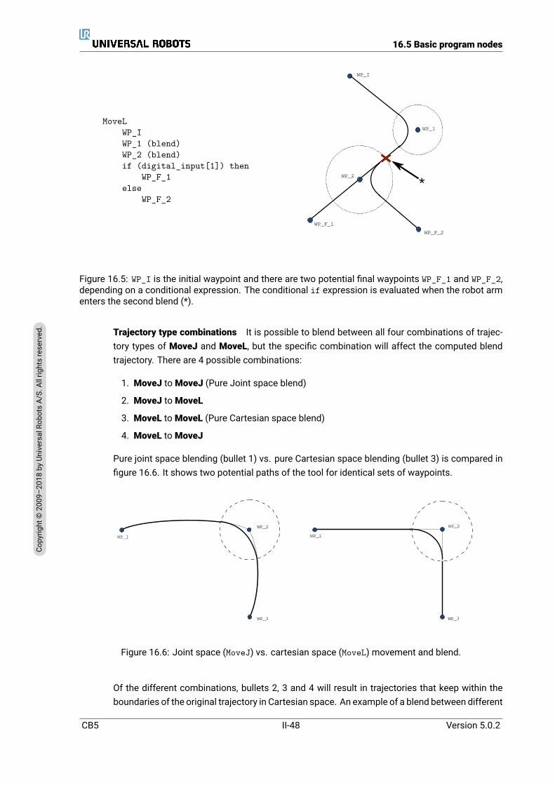
16.5 Basic program nodes
MoveLWP_IWP_1 (blend)WP_2 (blend)if (digital_input[1]) then
WP_F_1else
WP_F_2
WP_I
WP_1
WP_2
WP_F_1
WP_F_2
*
Figure 16.5: WP_I is the initial waypoint and there are two potential final waypoints WP_F_1 and WP_F_2,depending on a conditional expression. The conditional if expression is evaluated when the robot armenters the second blend (*).
Trajectory type combinations It is possible to blend between all four combinations of trajec-tory types of MoveJ and MoveL, but the specific combination will affect the computed blendtrajectory. There are 4 possible combinations:
1. MoveJ toMoveJ (Pure Joint space blend)
2. MoveJ toMoveL
3. MoveL toMoveL (Pure Cartesian space blend)
4. MoveL toMoveJ
Pure joint space blending (bullet 1) vs. pure Cartesian space blending (bullet 3) is compared infigure 16.6. It shows two potential paths of the tool for identical sets of waypoints.
WP_1
WP_2
WP_3
WP_1
WP_2
WP_3
Figure 16.6: Joint space (MoveJ) vs. cartesian space (MoveL) movement and blend.
Of the different combinations, bullets 2, 3 and 4 will result in trajectories that keep within theboundaries of the original trajectory in Cartesian space. An example of a blend between different
CB5 II-48 Version 5.0.2
Copy
right
©20
09–2
018by
Universa
lRob
otsA/
S.Allrightsrese
rved
.
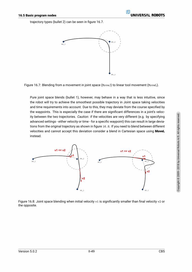
16.5 Basic program nodes
trajectory types (bullet 2) can be seen in figure 16.7.
WP_1WP_2
WP_3
Figure 16.7: Blending from a movement in joint space (MoveJ) to linear tool movement (MoveL).
Pure joint space blends (bullet 1), however, may behave in a way that is less intuitive, sincethe robot will try to achieve the smoothest possible trajectory in Joint space taking velocitiesand time requirements into account. Due to this, they may deviate from the course specified bythe waypoints. This is especially the case if there are significant differences in a joint’s veloc-ity between the two trajectories. Caution: if the velocities are very different (e.g. by specifyingadvanced settings - either velocity or time - for a specific waypoint) this can result in large devia-tions from the original trajectory as shown in figure 16.8. If you need to blend between differentvelocities and cannot accept this deviation consider a blend in Cartesian space using MoveLinstead.
v1
v2
v1 << v2
WP_1
WP_2
WP_3
WP_1 WP_2
WP_3
v1
v2
v1 >> v2
Figure 16.8: Joint space blending when initial velocity v1 is significantly smaller than final velocity v2 orthe opposite.
Version 5.0.2
Copy
right
©20
09–2
018by
Universa
lRob
otsA/
S.Allrightsrese
rved
.
II-49 CB5
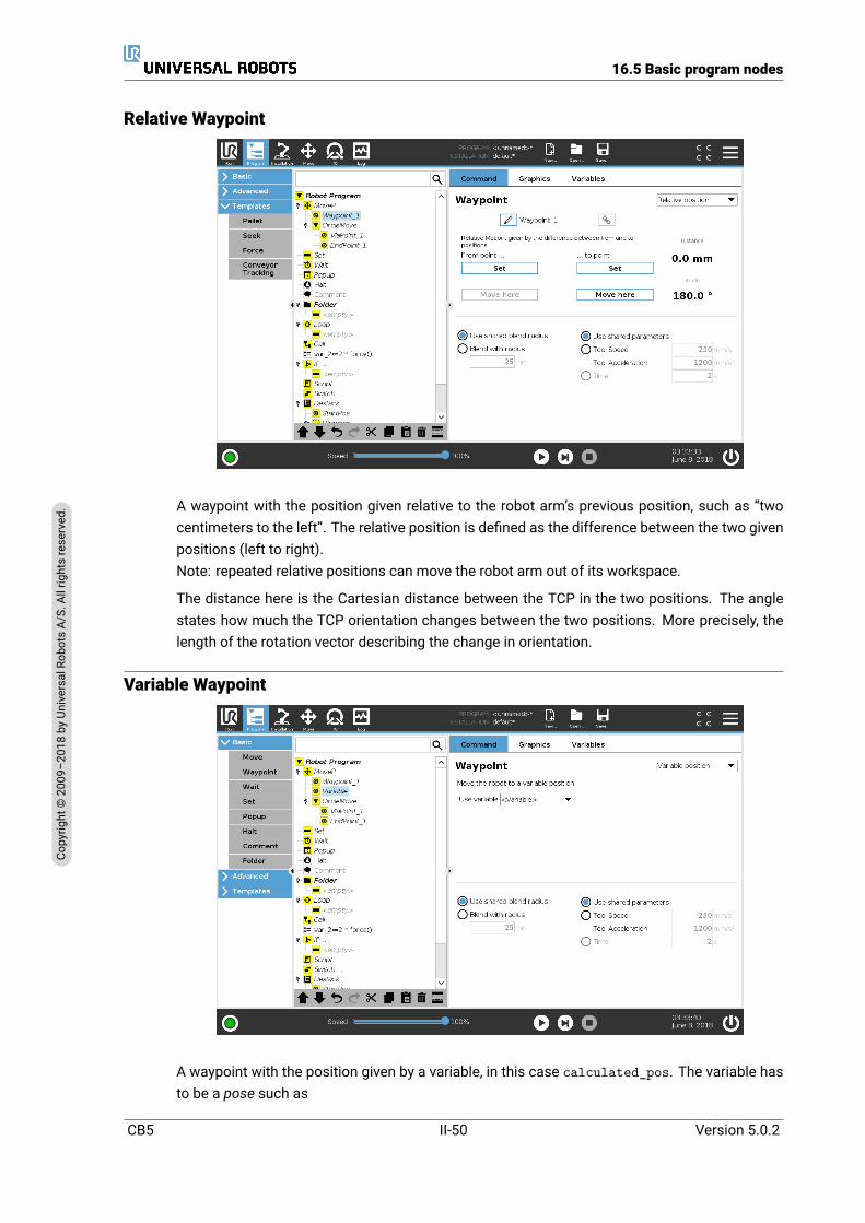
16.5 Basic program nodes
Relative Waypoint
A waypoint with the position given relative to the robot arm’s previous position, such as “twocentimeters to the left”. The relative position is defined as the difference between the two givenpositions (left to right).Note: repeated relative positions can move the robot arm out of its workspace.
The distance here is the Cartesian distance between the TCP in the two positions. The anglestates how much the TCP orientation changes between the two positions. More precisely, thelength of the rotation vector describing the change in orientation.
Variable Waypoint
A waypoint with the position given by a variable, in this case calculated_pos. The variable hasto be a pose such as
CB5 II-50 Version 5.0.2
Copy
right
©20
09–2
018by
Universa
lRob
otsA/
S.Allrightsrese
rved
.

16.5 Basic program nodes
var=p[0.5,0.0,0.0,3.14,0.0,0.0]. The first three are x,y,z and the last three are the orienta-tion given as a rotation vector given by the vector rx,ry,rz. The length of the axis is the angle tobe rotated in radians, and the vector itself gives the axis about which to rotate. The positionis always given in relation to a reference frame or coordinate system, defined by the selectedfeature. If a blend radius is set on a fixed waypoint and the waypoints preceding and succeedingit are variable or if the blend radius is set on a variable waypoint, then the blend radius will notbe checked for overlap (see 16.5.1). If, when running the program, the blend radius overlapsa point, the robot will ignore it and move to the next one.
For example, to move the robot 20mm along the z-axis of the tool:
var_1=p[0,0,0.02,0,0,0]Movel
Waypoint_1 (variable position):Use variable=var_1, Feature=Tool
16.5.2 Wait
Wait pauses I/O signal, or expression, for a given amount of time. If NoWait is selected, nothingis done.
Note: Once Tool Communication Interface TCI is enabled, the tool analog input is unavailableforWait For selection and expressions (see 17.1.10).
Version 5.0.2
Copy
right
©20
09–2
018by
Universa
lRob
otsA/
S.Allrightsrese
rved
.
II-51 CB5
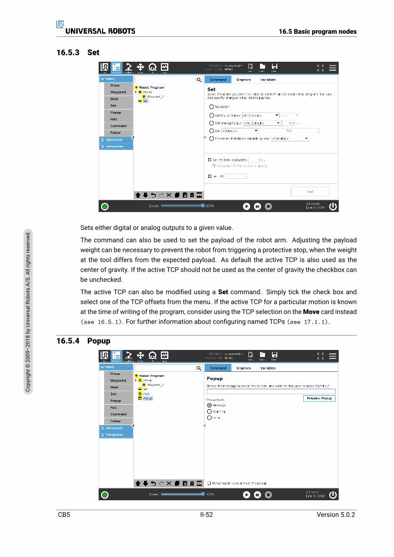
16.5 Basic program nodes
16.5.3 Set
Sets either digital or analog outputs to a given value.
The command can also be used to set the payload of the robot arm. Adjusting the payloadweight can be necessary to prevent the robot from triggering a protective stop, when the weightat the tool differs from the expected payload. As default the active TCP is also used as thecenter of gravity. If the active TCP should not be used as the center of gravity the checkbox canbe unchecked.
The active TCP can also be modified using a Set command. Simply tick the check box andselect one of the TCP offsets from the menu. If the active TCP for a particular motion is knownat the time of writing of the program, consider using the TCP selection on theMove card instead(see 16.5.1). For further information about configuring named TCPs (see 17.1.1).
16.5.4 Popup
CB5 II-52 Version 5.0.2
Copy
right
©20
09–2
018by
Universa
lRob
otsA/
S.Allrightsrese
rved
.

16.5 Basic program nodes
The popup is a message that appears on the screen when the program reaches this command.The style of the message can be selected, and the text itself can be given using the on-screenkeyboard. The robot waits for the user/operator to press the “OK” button under the popup beforecontinuing the program. If the “Halt program execution” item is selected, the robot program haltsat this popup.Note: Messages are limited to a maximum of 255 characters.
16.5.5 Halt
The program execution stops at this point.
16.5.6 Comment
Gives the programmer an option to add a line of text to the program. This line of text does notdo anything during program execution.
Version 5.0.2
Copy
right
©20
09–2
018by
Universa
lRob
otsA/
S.Allrightsrese
rved
.
II-53 CB5
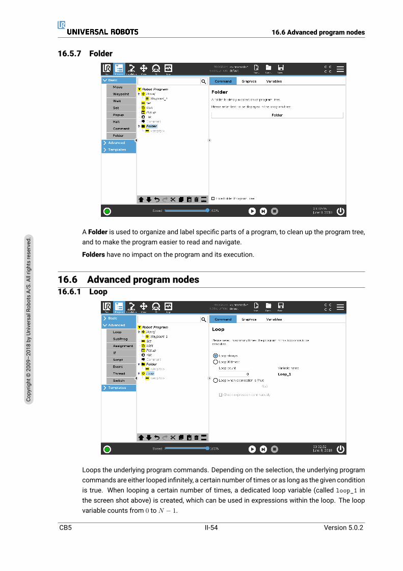
16.6 Advanced program nodes
16.5.7 Folder
A Folder is used to organize and label specific parts of a program, to clean up the program tree,and to make the program easier to read and navigate.
Folders have no impact on the program and its execution.
16.6 Advanced program nodes16.6.1 Loop
Loops the underlying program commands. Depending on the selection, the underlying programcommands are either looped infinitely, a certain number of times or as long as the given conditionis true. When looping a certain number of times, a dedicated loop variable (called loop_1 inthe screen shot above) is created, which can be used in expressions within the loop. The loopvariable counts from 0 to N − 1.
CB5 II-54 Version 5.0.2
Copy
right
©20
09–2
018by
Universa
lRob
otsA/
S.Allrightsrese
rved
.
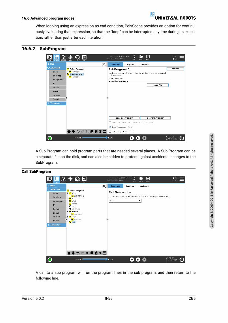
16.6 Advanced program nodes
When looping using an expression as end condition, PolyScope provides an option for continu-ously evaluating that expression, so that the “loop” can be interrupted anytime during its execu-tion, rather than just after each iteration.
16.6.2 SubProgram
A Sub Program can hold program parts that are needed several places. A Sub Program can bea separate file on the disk, and can also be hidden to protect against accidental changes to theSubProgram.
Call SubProgram
A call to a sub program will run the program lines in the sub program, and then return to thefollowing line.
Version 5.0.2
Copy
right
©20
09–2
018by
Universa
lRob
otsA/
S.Allrightsrese
rved
.
II-55 CB5

16.6 Advanced program nodes
16.6.3 Assignment
Assigns values to variables. An assignment puts the computed value of the right hand side intothe variable on the left hand side. This can be useful in complex programs.
16.6.4 If
An If...Else command construction changes the robot’s behavior based on sensor inputs or vari-able values. Use the Expression Editor to describe the condition under which the robot followsthe statements of this If command. If the condition is evaluated as True, the statements withinthis If command are executed.
An If command can have several ElseIf statements that can be added and removed using theAdd ElseIf and the Remove ElseIf buttons. However, an If command can have only one Elsestatement.
CB5 II-56 Version 5.0.2
Copy
right
©20
09–2
018by
Universa
lRob
otsA/
S.Allrightsrese
rved
.
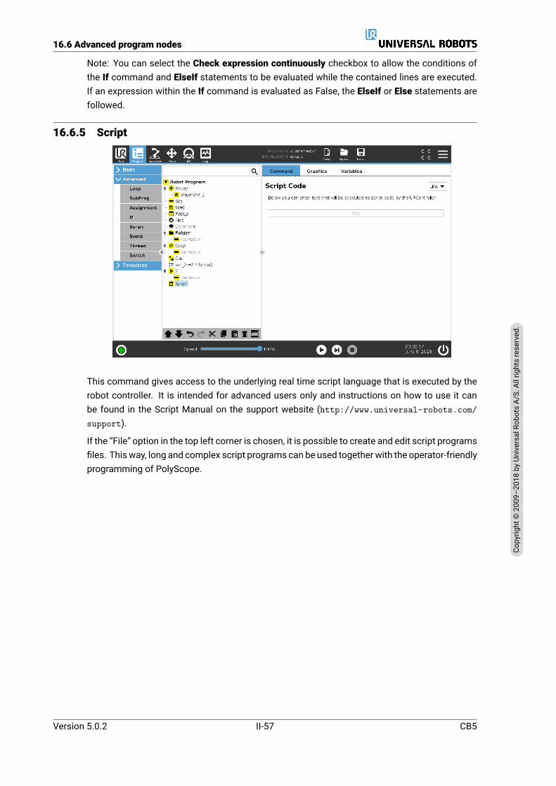
16.6 Advanced program nodes
Note: You can select the Check expression continuously checkbox to allow the conditions ofthe If command and ElseIf statements to be evaluated while the contained lines are executed.If an expression within the If command is evaluated as False, the ElseIf or Else statements arefollowed.
16.6.5 Script
This command gives access to the underlying real time script language that is executed by therobot controller. It is intended for advanced users only and instructions on how to use it canbe found in the Script Manual on the support website (http://www.universal-robots.com/support).
If the “File” option in the top left corner is chosen, it is possible to create and edit script programsfiles. Thisway, long and complex script programs can be used togetherwith the operator-friendlyprogramming of PolyScope.
Version 5.0.2
Copy
right
©20
09–2
018by
Universa
lRob
otsA/
S.Allrightsrese
rved
.
II-57 CB5
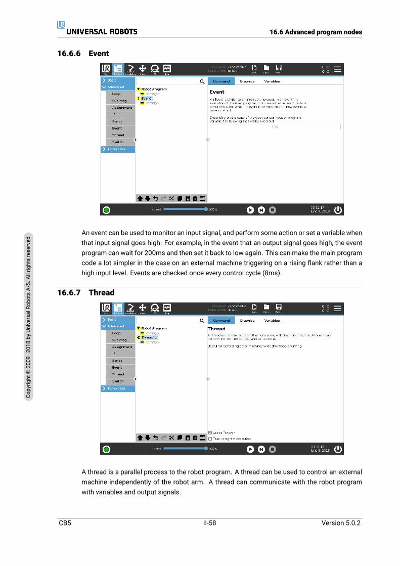
16.6 Advanced program nodes
16.6.6 Event
An event can be used tomonitor an input signal, and perform some action or set a variable whenthat input signal goes high. For example, in the event that an output signal goes high, the eventprogram can wait for 200ms and then set it back to low again. This can make the main programcode a lot simpler in the case on an external machine triggering on a rising flank rather than ahigh input level. Events are checked once every control cycle (8ms).
16.6.7 Thread
A thread is a parallel process to the robot program. A thread can be used to control an externalmachine independently of the robot arm. A thread can communicate with the robot programwith variables and output signals.
CB5 II-58 Version 5.0.2
Copy
right
©20
09–2
018by
Universa
lRob
otsA/
S.Allrightsrese
rved
.
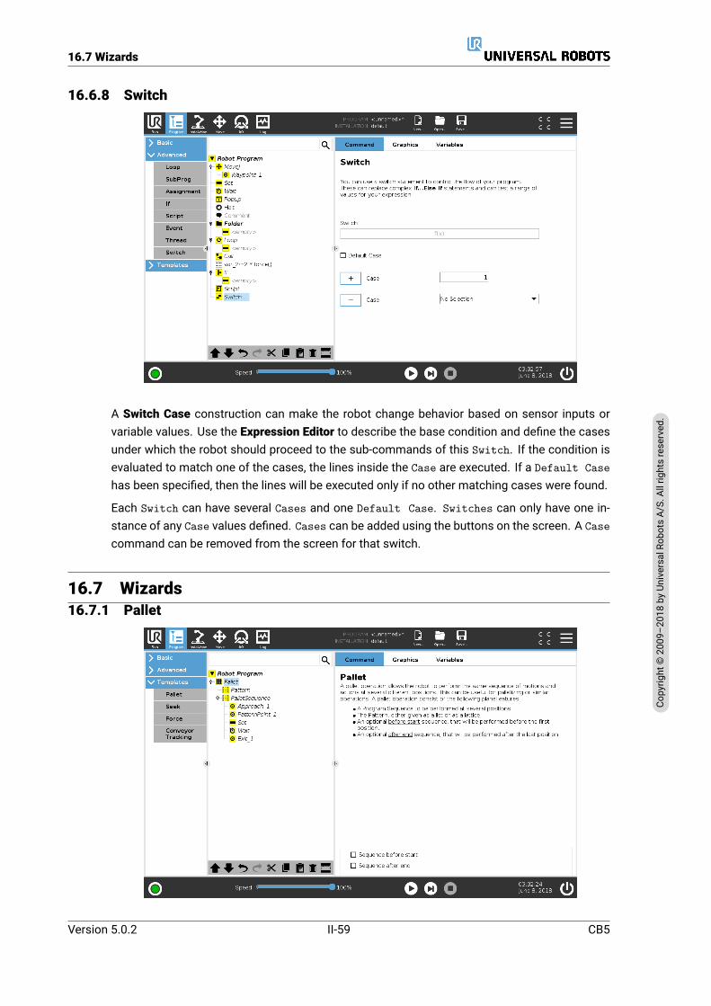
16.7 Wizards
16.6.8 Switch
A Switch Case construction can make the robot change behavior based on sensor inputs orvariable values. Use the Expression Editor to describe the base condition and define the casesunder which the robot should proceed to the sub-commands of this Switch. If the condition isevaluated to match one of the cases, the lines inside the Case are executed. If a Default Casehas been specified, then the lines will be executed only if no other matching cases were found.
Each Switch can have several Cases and one Default Case. Switches can only have one in-stance of any Case values defined. Cases can be added using the buttons on the screen. A Casecommand can be removed from the screen for that switch.
16.7 Wizards16.7.1 Pallet
Version 5.0.2
Copy
right
©20
09–2
018by
Universa
lRob
otsA/
S.Allrightsrese
rved
.
II-59 CB5

16.7 Wizards
A pallet operation can perform a sequence of motions in a set of places given as a pattern (see16.7.1.1). At each of the positions in the pattern, the sequence of motions will be run relativeto the pattern position.
Programming a Pallet OperationThe steps to go through are as follows;
1. Define the pattern.
2. Make a PalletSequence for picking up/placing at each single point. The sequence de-scribes what should be done at each pattern position.
3. Use the selector on the sequence command screen to define which of the waypoints in thesequence should correspond to the pattern positions.
Pallet Sequence/Anchorable SequenceIn a Pallet Sequence node, the motions of the robot arm are relative to the pallet position. Thebehavior of a sequence is such that the robot arm will be at the position specified by the patternat the Anchor Position/Pattern Point. The remaining positions will all be moved to make this fit.
Do not use theMove command inside a sequence, as it will not be relative to the anchor position.
“BeforeStart”The optional BeforeStart sequence is run just before the operation starts. This can be used towait for ready signals.
“AfterEnd”The optionalAfterEnd sequence is run when the operation is finished. This can be used to signalconveyor motion to start, preparing for the next pallet.
16.7.1.1 Pattern
The Pattern command can be used to cycle through positions in the robot program. The Patterncommand corresponds to one position at each execution.
A pattern can be given as one of four types. The first three, Line, Square or Box can be usedfor positions in a regular pattern. The regular patterns are defined by a number of characteristic
CB5 II-60 Version 5.0.2
Copy
right
©20
09–2
018by
Universa
lRob
otsA/
S.Allrightsrese
rved
.

16.7 Wizards
points, where the points define the edges of the pattern. For Line this is the two end points, forSquare this is three of the four corner points, where as for Box this is four of the eight cornerpoints. The programmer enters the number of positions along each of the edges of the pattern.The robot controller then calculates the individual pattern positions by proportionally adding theedge vectors together.
If the positions to be traversed do not fall in a regular pattern, the List option can be chosen,where a list of all the positions is provided by the programmer. This way any kind of arrangementof the positions can be realized.
Defining the PatternWhen the Box pattern is selected, the screen changes to what is shown below.
A Box pattern uses three vectors to define the side of the box. These three vectors are given asfour points, where the first vector goes from point one to point two, the second vector goes frompoint two to point three, and the third vector goes from point three to point four. Each vector isdivided by the interval count numbers. A specific position in the pattern is calculated by simplyadding the interval vectors proportionally.
The Line and Square patterns work similarly.
A counter variable is used while traversing the positions of the pattern. The name of the variablecan be seen on the Pattern command screen. The variable cycles through the numbers from 0
to X ∗ Y ∗ Z − 1, the number of points in the pattern. This variable can be manipulated usingassignments, and can be used in expressions.
16.7.2 SeekA seek function uses a sensor to determine when the correct position is reached to grab or dropan item. The sensor can be a push button switch, a pressure sensor or a capacitive sensor. Thisfunction is made for working on stacks of items with varying item thickness, or where the exactpositions of the items are not known or too hard to program.
Version 5.0.2
Copy
right
©20
09–2
018by
Universa
lRob
otsA/
S.Allrightsrese
rved
.
II-61 CB5

16.7 Wizards
Stacking Destacking
When programming a seek operation for working on a stack, onemust define s the starting point,d the stack direction and i the thickness of the items in the stack.
On top of this, one must define the condition for when the next stack position is reached, anda special program sequence that will be performed at each of the stack positions. Also speedand accelerations need to be given for the movement involved in the stack operation.
Stacking
When stacking, the robot arm moves to the starting position, and then moves opposite the di-rection to search for the next stack position. When found, the robot remembers the positionand performs the special sequence. The next time round, the robot starts the search from theremembered position incremented by the item thickness along the direction. The stacking isfinished when the stack height is more than some defined number, or when a sensor gives asignal.
CB5 II-62 Version 5.0.2
Copy
right
©20
09–2
018by
Universa
lRob
otsA/
S.Allrightsrese
rved
.

16.7 Wizards
Destacking
When destacking, the robot armmoves from the starting position in the given direction to searchfor the next item. The condition on the screen determines when the next item is reached. Whenthe condition becomes satisfied, the robot remembers the position and performs the specialsequence. The next time round, the robot starts the search from the remembered position, in-cremented by the item thickness along the direction.
Starting position
The starting position is where the stack operation starts. If the starting position is omitted, thestack starts at the robot arm’s current position.
Direction
The direction is given by two positions, and is calculated as the position difference from the firstpositions TCP to the second positions TCP.
Version 5.0.2
Copy
right
©20
09–2
018by
Universa
lRob
otsA/
S.Allrightsrese
rved
.
II-63 CB5

16.7 Wizards
Note: A direction does not consider the orientations of the points.
Next Stacking Position Expression
The robot arm moves along the direction vector while continuously evaluating whether the nextstack position has been reached. When the expression is evaluated to True the special sequenceis executed.
“BeforeStart”
The optional BeforeStart sequence is run just before the operation starts. This can be used towait for ready signals.
“AfterEnd”
The optional AfterEnd sequence is runwhen the operation is finished. This can be used to signalconveyor motion to start, preparing for the next stack.
Pick/Place Sequence
Like for the Pallet operation (16.7.1), a special program sequence is performed at each stackposition.
16.7.3 ForceIn the robot workspace Forcemode allows for compliance and force in selectable axes. All robotarm movements under a Force command are in Force mode. When the robot arm is moving inForce mode, it is possible to select one or more axes there the robot arm is compliant. Therobot arm complies with the environment along a compliant axes. This means the robot armautomatically adjusts its position in order to achieve the desired force. It is also possible tomake the robot arm itself apply a force to its environment, e.g. a workpiece.
Forcemode is suited to applications where the actual TCP position along a predefined axis is notimportant, but instead a desired force along that axis is required. For example if the robot TCProlls against a curved surface, pushes or pulls a workpiece. Force mode also supports applyingcertain torques around predefined axes.Note: if no obstacles are met in an axis where a non-zero force is set, the robot arm attempts toaccelerate along that axis.Although an axis is selected to be compliant, the robot program still tries tomove the robot alongthat axis. However, force control assures that the robot arm still approaches the specified force.
WARNING:
1. Avoid high deceleration just before entering force mode.
2. Avoid high acceleration in force mode, since it decreasesforce control accuracy.
3. Avoid movements parallel to compliant axes before enteringforce mode.
CB5 II-64 Version 5.0.2
Copy
right
©20
09–2
018by
Universa
lRob
otsA/
S.Allrightsrese
rved
.
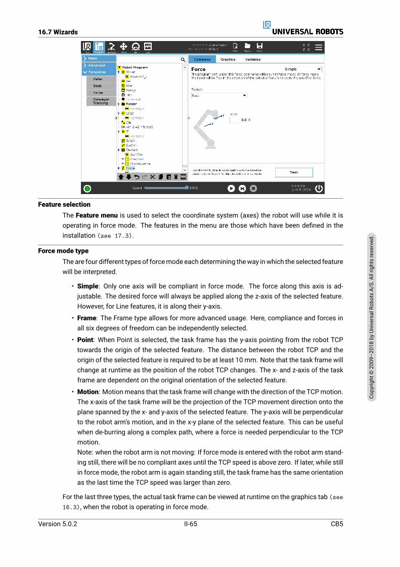
16.7 Wizards
Feature selectionThe Feature menu is used to select the coordinate system (axes) the robot will use while it isoperating in force mode. The features in the menu are those which have been defined in theinstallation (see 17.3).
Force mode typeThe are four different types of forcemode each determining theway inwhich the selected featurewill be interpreted.
• Simple: Only one axis will be compliant in force mode. The force along this axis is ad-justable. The desired force will always be applied along the z-axis of the selected feature.However, for Line features, it is along their y-axis.
• Frame: The Frame type allows for more advanced usage. Here, compliance and forces inall six degrees of freedom can be independently selected.
• Point: When Point is selected, the task frame has the y-axis pointing from the robot TCPtowards the origin of the selected feature. The distance between the robot TCP and theorigin of the selected feature is required to be at least 10 mm. Note that the task frame willchange at runtime as the position of the robot TCP changes. The x- and z-axis of the taskframe are dependent on the original orientation of the selected feature.
• Motion: Motionmeans that the task framewill changewith the direction of the TCPmotion.The x-axis of the task frame will be the projection of the TCP movement direction onto theplane spanned by the x- and y-axis of the selected feature. The y-axis will be perpendicularto the robot arm’s motion, and in the x-y plane of the selected feature. This can be usefulwhen de-burring along a complex path, where a force is needed perpendicular to the TCPmotion.Note: when the robot arm is not moving: If force mode is entered with the robot arm stand-ing still, there will be no compliant axes until the TCP speed is above zero. If later, while stillin forcemode, the robot arm is again standing still, the task frame has the same orientationas the last time the TCP speed was larger than zero.
For the last three types, the actual task frame can be viewed at runtime on the graphics tab (see16.3), when the robot is operating in force mode.
Version 5.0.2
Copy
right
©20
09–2
018by
Universa
lRob
otsA/
S.Allrightsrese
rved
.
II-65 CB5

16.8 URCaps
Force value selection• Force or torque value can be set for compliant axes, and robot arm adjusts its position toachieve the selected force.
• For non-compliant axes robot arm will follow the trajectory set by the program.
For translational parameters, the force is specified in Newtons [N] and for rotational the torqueis specified in Newton meters [Nm].
NOTE:You must do the following:
• Use get_tcp_force() script function in separate thread, toread actual force and torque.
• Correct wrench vector, if actual force and/or torque is lowerthan requested.
Limits selectionFor all axes a limit can be set, but these have different meaning corresponding to the axes beingcompliant or non-compliant.
Test force settingsThe on/off button, labelled Test, toggles the behavior of the Freedrive button on the back of theTeach Pendant from normal Freedrive mode to testing the force command.
When theTest button is on and the Freedrive button on the back of the TeachPendant is pressed,the robot will perform as if the program had reached this force command, and this way the set-tings can be verified before actually running the complete program. Especially, this possibilityis useful for verifying that compliant axes and forces have been selected correctly. Simply holdthe robot TCP using one hand and press the Freedrive button with the other, and notice in whichdirections the robot arm can/cannot be moved. Upon leaving this screen, the Test button auto-matically switches off, which means the Freedrive button on the back of the Teach Pendant isagain used for regular Freedrivemode.Note: The Freedrive button will only be effectual when a valid feature has been selected for theForce command.
16.8 URCaps16.8.1 Conveyor Tracking
The robot can be configured to track conveyor movement. Conveyor Tracking is defined in theInstallation Tab. Once onfigured correctly, the robot adjusts its movements to follow the con-veyor. The Conveyor Tracking setup (see section 17.1.7) provides options for configuringthe robot to work with absolute and incremental encoders, as well as, linear and circular convey-ors. The Conveyor Tracking program node is available in the Program Tab under Templates. Allmovements under this node are allowed while tracking the conveyor, but they are relative to themotion of the conveyor belt.
CB5 II-66 Version 5.0.2
Copy
right
©20
09–2
018by
Universa
lRob
otsA/
S.Allrightsrese
rved
.

16.9 The First Program
16.9 The First ProgramA program is a list of commands telling the robot what to do. PolyScope allows people withonly little programming experience to program the robot. For most tasks, programming is doneentirely using the touch panel without typing in any cryptic commands.
Toolmotion is the part of a robot program that teaches theRobot Armhow tomove. In PolyScope,tool motions are set using a series of waypoints. The combined waypoints form a path that theRobot Arm follows. A waypoint is set by using the Move Tab, manually moving (teaching) therobot to a certain position, or it can be calculated by software. Use the Move tab (see 18) tomove the Robot Arm to a desired position, or teach the position by pulling the Robot Arm intoplace while holding the Freedrive button at the top of the Teach Pendant.
Besides moving through waypoints, the program can send I/O signals to other machines at cer-tain points in the robot’s path, and perform commands like if…then and loop, based on variablesand I/O signals.
The following is a simple program that allows a Robot arm that has been started up, to movebetween two waypoints.
1. In the PolyScope Header File Path, tap New... and select Program.
2. Under Basic, tapWaypoint to add a waypoint to the program tree. A default MoveJ is alsoadded to the program tree.
3. Select the new waypoint and in the Command tab, tapWaypoint.
4. On the Move Tool screen, move the Robot arm by pressing the move arrows.You can also move the Robot arm by holding down the Freedrive button and pulling theRobot arm into desired positions.
5. Once the Robot arm is in position, press OK and the new waypoint displays as Waypoint_1.
6. Follow steps 2 to 5 to create Waypoint_2.
7. Select Waypoint_2 and press the Move Up arrow until it is above Waypoint_1 to change theorder of the movements.
8. Stand clear, hold on to the emergency stop button and in the PolyScope Footer, press Playbutton for the Robot arm to move between Waypoint_1 and Waypoint_2.Congratulations! You have now produced your first robot program that moves the Robotarm between the two given waypoints.
Version 5.0.2
Copy
right
©20
09–2
018by
Universa
lRob
otsA/
S.Allrightsrese
rved
.
II-67 CB5

16.9 The First Program
WARNING:
1. Do not drive the robot into itself or anything else as this maycause damage to the robot.
2. Keep your head and torso outside the reach (workspace) ofthe robot. Do not place fingers where they can be caught.
3. This is only a quick start guide to show how easy it is to usea UR robot. It assumes a harmless environment and a verycareful user. Do not increase the speed or acceleration abovethe default values. Always conduct a risk assessment beforeplacing the robot into operation.
CB5 II-68 Version 5.0.2
Copy
right
©20
09–2
018by
Universa
lRob
otsA/
S.Allrightsrese
rved
.

17 Installation Tab
17.1 GeneralThe Installation Tab allows you to configure the settings which affect the overall performanceof the robot and PolyScope.
17.1.1 TCP Configuration
A Tool Center Point (TCP) is a point on the robot’s tool. The TCP is defined and named in theInstallation Tab Setup for the Tool Center Point screen (shown above). Each TCP contains atranslation and a rotation relative to the center of the tool output flange.When programmed to return to a previously stored waypoint, a robot moves the TCP to the po-sition and orientation saved within the waypoint. When programmed for linear motion, the TCPmoves linearly.The X, Y and Z coordinates specify the TCP position, while theRX, RY and RZ coordinates spec-ify its orientation. When all values are zero, the TCP coincides with the center point of the tooloutput flange and adopts the coordinate system depicted on the screen.
Adding, modifying and removing TCPs
To define a new TCP, tap theNew button. The created TCP automatically receives a unique nameand becomes selectable in the drop-down menu. The translation and rotation of the selectedTCP can be modified by tapping the respective white text fields and entering new values. Toremove the selected TCP, simply tap the Remove button. The last remaining TCP cannot bedeleted.
The default and the active TCP
There is one default configured TCP, marked by a green checkmark icon to the laft of its namein the Available TCPs drop-downmenu. To set a TCP as the default, select the desired TCP and
Version 5.0.2
Copy
right
©20
09–2
018by
Universa
lRob
otsA/
S.Allrightsrese
rved
.
II-69 CB5
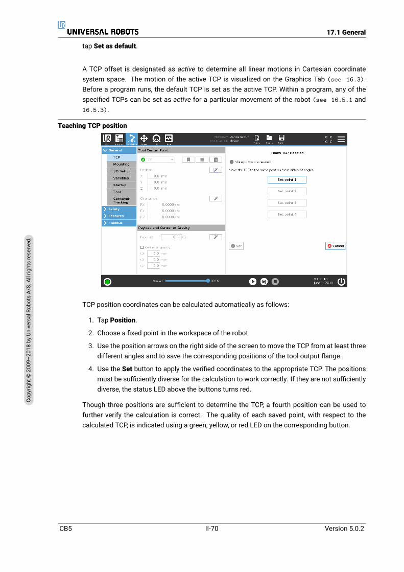
17.1 General
tap Set as default.
A TCP offset is designated as active to determine all linear motions in Cartesian coordinatesystem space. The motion of the active TCP is visualized on the Graphics Tab (see 16.3).Before a program runs, the default TCP is set as the active TCP. Within a program, any of thespecified TCPs can be set as active for a particular movement of the robot (see 16.5.1 and16.5.3).
Teaching TCP position
TCP position coordinates can be calculated automatically as follows:
1. Tap Position.
2. Choose a fixed point in the workspace of the robot.
3. Use the position arrows on the right side of the screen to move the TCP from at least threedifferent angles and to save the corresponding positions of the tool output flange.
4. Use the Set button to apply the verified coordinates to the appropriate TCP. The positionsmust be sufficiently diverse for the calculation to work correctly. If they are not sufficientlydiverse, the status LED above the buttons turns red.
Though three positions are sufficient to determine the TCP, a fourth position can be used tofurther verify the calculation is correct. The quality of each saved point, with respect to thecalculated TCP, is indicated using a green, yellow, or red LED on the corresponding button.
CB5 II-70 Version 5.0.2
Copy
right
©20
09–2
018by
Universa
lRob
otsA/
S.Allrightsrese
rved
.
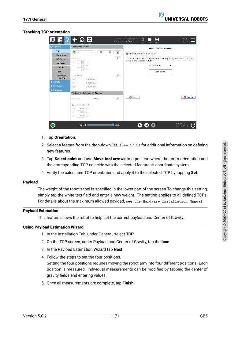
17.1 General
Teaching TCP orientation
1. Tap Orientation.
2. Select a feature from the drop-down list. (See 17.3) for additional information on definingnew features
3. Tap Select point and use Move tool arrows to a position where the tool’s orientation andthe corresponding TCP coincide with the selected features’s coordinate system.
4. Verify the calculated TCP orientation and apply it to the selected TCP by tapping Set.
Payload
The weight of the robot’s tool is specified in the lower part of the screen.To change this setting,simply tap the white text field and enter a new weight. The setting applies to all defined TCPs.For details about the maximum allowed payload, see the Hardware Installation Manual.
Payload Estimation
This feature allows the robot to help set the correct payload and Center of Gravity.
Using Payload Estimation Wizard
1. In the Installation Tab, under General, select TCP
2. On the TCP screen, under Payload and Center of Gravity, tap the Icon.
3. In the Payload Estimation Wizard tap Next
4. Follow the steps to set the four positions.Setting the four positions requires moving the robot arm into four different positions. Eachposition is measured. Individual measurements can be modified by tapping the center ofgravity fields and entering values.
5. Once all measurements are complete, tap Finish
Version 5.0.2
Copy
right
©20
09–2
018by
Universa
lRob
otsA/
S.Allrightsrese
rved
.
II-71 CB5
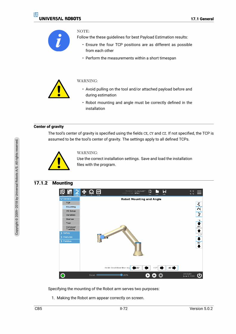
17.1 General
NOTE:Follow the these guidelines for best Payload Estimation results:
• Ensure the four TCP positions are as different as possiblefrom each other
• Perform the measurements within a short timespan
WARNING:
• Avoid pulling on the tool and/or attached payload before andduring estimation
• Robot mounting and angle must be correctly defined in theinstallation
Center of gravity
The tool’s center of gravity is specified using the fields CX, CY and CZ. If not specified, the TCP isassumed to be the tool’s center of gravity. The settings apply to all defined TCPs.
WARNING:Use the correct installation settings. Save and load the installationfiles with the program.
17.1.2 Mounting
Specifying the mounting of the Robot arm serves two purposes:
1. Making the Robot arm appear correctly on screen.
CB5 II-72 Version 5.0.2
Copy
right
©20
09–2
018by
Universa
lRob
otsA/
S.Allrightsrese
rved
.
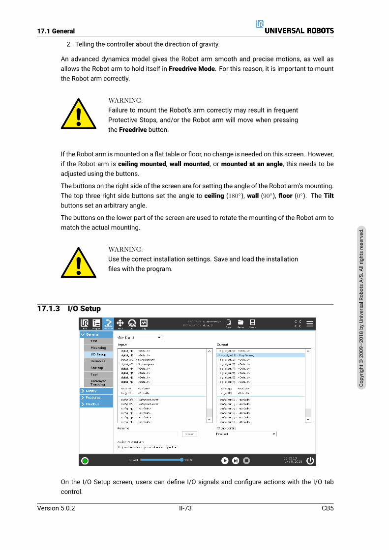
17.1 General
2. Telling the controller about the direction of gravity.
An advanced dynamics model gives the Robot arm smooth and precise motions, as well asallows the Robot arm to hold itself in Freedrive Mode. For this reason, it is important to mountthe Robot arm correctly.
WARNING:Failure to mount the Robot’s arm correctly may result in frequentProtective Stops, and/or the Robot arm will move when pressingthe Freedrive button.
If the Robot arm ismounted on a flat table or floor, no change is needed on this screen. However,if the Robot arm is ceiling mounted, wall mounted, or mounted at an angle, this needs to beadjusted using the buttons.
The buttons on the right side of the screen are for setting the angle of the Robot arm’s mounting.The top three right side buttons set the angle to ceiling (180), wall (90), floor (0). The Tiltbuttons set an arbitrary angle.
The buttons on the lower part of the screen are used to rotate the mounting of the Robot arm tomatch the actual mounting.
WARNING:Use the correct installation settings. Save and load the installationfiles with the program.
17.1.3 I/O Setup
On the I/O Setup screen, users can define I/O signals and configure actions with the I/O tabcontrol.
Version 5.0.2
Copy
right
©20
09–2
018by
Universa
lRob
otsA/
S.Allrightsrese
rved
.
II-73 CB5
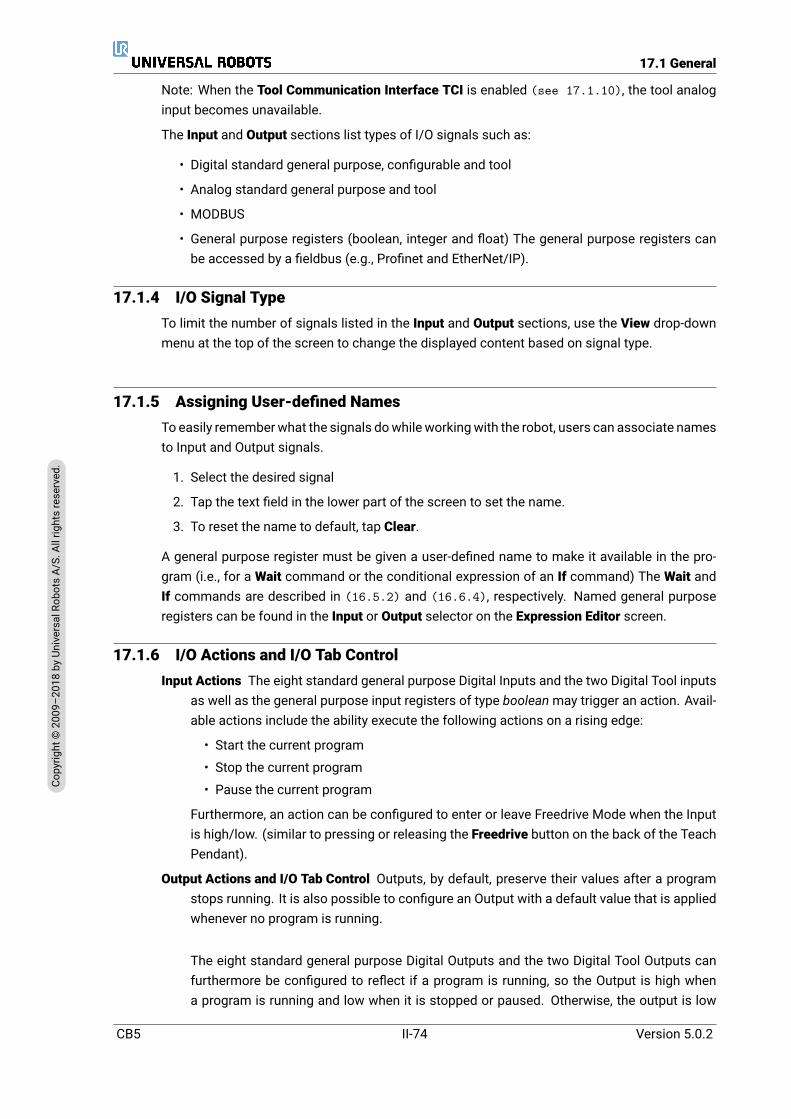
17.1 General
Note: When the Tool Communication Interface TCI is enabled (see 17.1.10), the tool analoginput becomes unavailable.
The Input and Output sections list types of I/O signals such as:
• Digital standard general purpose, configurable and tool
• Analog standard general purpose and tool
• MODBUS
• General purpose registers (boolean, integer and float) The general purpose registers canbe accessed by a fieldbus (e.g., Profinet and EtherNet/IP).
17.1.4 I/O Signal TypeTo limit the number of signals listed in the Input and Output sections, use the View drop-downmenu at the top of the screen to change the displayed content based on signal type.
17.1.5 Assigning User-defined NamesTo easily rememberwhat the signals dowhile workingwith the robot, users can associate namesto Input and Output signals.
1. Select the desired signal
2. Tap the text field in the lower part of the screen to set the name.
3. To reset the name to default, tap Clear.
A general purpose register must be given a user-defined name to make it available in the pro-gram (i.e., for a Wait command or the conditional expression of an If command) The Wait andIf commands are described in (16.5.2) and (16.6.4), respectively. Named general purposeregisters can be found in the Input or Output selector on the Expression Editor screen.
17.1.6 I/O Actions and I/O Tab ControlInput Actions The eight standard general purpose Digital Inputs and the two Digital Tool inputs
as well as the general purpose input registers of type booleanmay trigger an action. Avail-able actions include the ability execute the following actions on a rising edge:
• Start the current program
• Stop the current program
• Pause the current program
Furthermore, an action can be configured to enter or leave Freedrive Mode when the Inputis high/low. (similar to pressing or releasing the Freedrive button on the back of the TeachPendant).
Output Actions and I/O Tab Control Outputs, by default, preserve their values after a programstops running. It is also possible to configure an Output with a default value that is appliedwhenever no program is running.
The eight standard general purpose Digital Outputs and the two Digital Tool Outputs canfurthermore be configured to reflect if a program is running, so the Output is high whena program is running and low when it is stopped or paused. Otherwise, the output is low
CB5 II-74 Version 5.0.2
Copy
right
©20
09–2
018by
Universa
lRob
otsA/
S.Allrightsrese
rved
.

17.1 General
when a program is running and high when it is stopped or paused. These values can be setwhile the program is running. General purpose output registers of type boolean and digitalMODBUS output signals also support this.
Finally, it is also possible to specify whether an output can be controlled on the I/O tab (byeither programmers, or both operators and programmers) or if it is only robot programs thatmay alter the output value.
17.1.7 Conveyor TrackingWhen using a conveyor, the robot can be configured to track its movement. The Conveyor Track-ing Setup provides options for configuring the robot to work with absolute and incremental en-coders, as well as linear and circular conveyors.
Conveyor Parameters
Incremental encoders can be connected to Digital Inputs 0 to 3. Decoding of digital signalsruns at 40kHz. Using a Quadrature encoder (requiring two inputs), the robot can determinethe speed and direction of the conveyor. If the direction of the conveyor is constant, asingle input can be used to detect either Rising, Falling, or Rise and Fall edges whichdetermine conveyor speed.
Absolute encoders can be connected through a MODBUS signal. This requires a Digital MOD-BUS Input register is preconfigured in (section 17.4.1).
Linear conveyors
When a linear conveyor is selected, a line feature must be configured in the Features part ofthe installation to determine the direction of the conveyor. The line feature should be parallelto the direction of the conveyor, and there should be a large distance between the two pointsdefining the line feature. Configure the line feature by placing the tool firmly against the sideof the conveyor when teaching the two points. If the line feature’s direction is opposite to theconveyor’s movement, use the Reverse direction button.
The field Ticks per meter field displays the number of ticks the encoder generates when theconveyor moves one meter.
Ticks per meter =ticks per revolution of encoder2π · radius of encoder disc[m]
(17.1)
Circular conveyors
When tracking a circular conveyor, the conveyor center point must be defined.
1. Define the center point in the Features part of the installation. The value of Ticks per rev-olutionmust be the number of ticks the encoder generates when the conveyor rotates onefull revolution.
2. Select the Rotate tool with conveyor checkbox if the tool’s orientation should be with re-spect to the conveyor (e.g. if the tool is perpendicular to the conveyor, it will stay perpen-dicular during the movement).
3. Deselect the Rotate tool with conveyor checkbox if the orientation should be controlled bythe trajectory.
Version 5.0.2
Copy
right
©20
09–2
018by
Universa
lRob
otsA/
S.Allrightsrese
rved
.
II-75 CB5
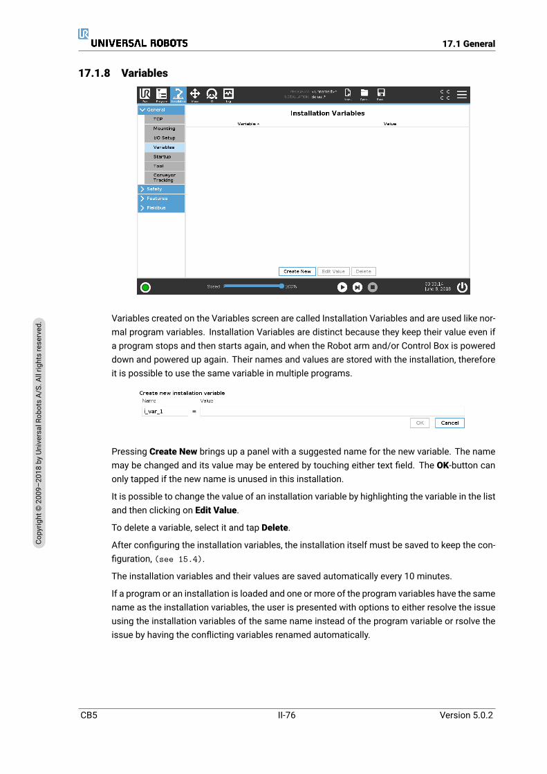
17.1 General
17.1.8 Variables
Variables created on the Variables screen are called Installation Variables and are used like nor-mal program variables. Installation Variables are distinct because they keep their value even ifa program stops and then starts again, and when the Robot arm and/or Control Box is powereddown and powered up again. Their names and values are stored with the installation, thereforeit is possible to use the same variable in multiple programs.
Pressing Create New brings up a panel with a suggested name for the new variable. The namemay be changed and its value may be entered by touching either text field. The OK-button canonly tapped if the new name is unused in this installation.
It is possible to change the value of an installation variable by highlighting the variable in the listand then clicking on Edit Value.
To delete a variable, select it and tap Delete.
After configuring the installation variables, the installation itself must be saved to keep the con-figuration, (see 15.4).
The installation variables and their values are saved automatically every 10 minutes.
If a program or an installation is loaded and one or more of the program variables have the samename as the installation variables, the user is presented with options to either resolve the issueusing the installation variables of the same name instead of the program variable or rsolve theissue by having the conflicting variables renamed automatically.
CB5 II-76 Version 5.0.2
Copy
right
©20
09–2
018by
Universa
lRob
otsA/
S.Allrightsrese
rved
.

17.1 General
17.1.9 Startup
The Startup screen contains settings for automatically loading and starting a default program,and for auto-initializing the Robot arm during power up.
WARNING:
1. When autoload, auto start and auto initialize are enabled, therobot runs the program as soon as the Control Box is pow-ered up as long as the input signalmatches the selected signallevel. For example, the edge transition to the selected signallevel will not be required in this case.
2. Use caution when the signal level is set to LOW. Input signalsare low by default, leading the program to automatically runwithout being triggered by an external signal.
3. You must be in Remote Control Mode before running a pro-gram where auto start and auto initialize are enabled.
Loading a Startup Program
A default program is loaded after the Control Box is powered up. Furthermore, the default pro-gram is auto loaded when the Run Program screen (see 14) is entered and no program isloaded.
Starting a Startup Program
The default program is auto started in the Run Program screen. When the default program isloaded and the specified external input signal edge transition is detected, the program is startedautomatically.On Startup, the current input signal level is undefined. Choosing a transition that matches thesignal level on startup starts the program immediately. Furthermore, leaving the Run Program
Version 5.0.2
Copy
right
©20
09–2
018by
Universa
lRob
otsA/
S.Allrightsrese
rved
.
II-77 CB5

17.2 Safety
screen or tapping the Stop button in the Dashboard disables the auto start feature until the Runbutton is pressed again.
Auto Initialization
The Robot arm is automatically initialized. On the specified external input signal edge transition,the Robot arm is completely initialized, regardless of the visible screen.BrakeRelease is the final initialization stage. During BrakeRelease, the Robot armmakes aminormovement and a clicking noise. Furthermore, the brakes cannot be automatically released if theconfigured mounting does not match the mounting detected (based on sensor data). In thiscase, the robot must be initialized manually on the initialization screen (see 15).On Startup, the current input signal level is undefined. Choosing a transition that matches thesignal level on startup initializes the Robot arm immediately.
17.1.10 ToolThe Tool Communication Interface (TCI) enables the robot to communicate with an attachedtool via the robot tool analog input. This removes the need for external cabling.Once the Tool Communication Interface is enabled, all tool analog inputs are unavailable.
Enabling the Tool Communication Interface
1. In Polyscope, tap the Enable button to edit baud rate, parity and stop bits.
2. On the relevant drop downmenus, select the appropriate values. You can edit the Transmitand receive idle in characters, by tapping on the text field and entering a new value
3. Tap the Disable button to disable TCI.Note: Any changes in values are immediately sent to the tool. If any installation valuesdiffer from what the tool is using, a warning appears.
Disabled Analog Input
Once the TCI is enabled, the tool analog input is unavailable for the I/O Setup of the Installationand does not appear in the input list. Tool analog input is also unavailable for programs asWaitFor options and expressions.In the Tool Input section of I/O, the parameters received from the tool are displayed instead ofanalog values.
17.2 SafetySee chapter 13.
CB5 II-78 Version 5.0.2
Copy
right
©20
09–2
018by
Universa
lRob
otsA/
S.Allrightsrese
rved
.
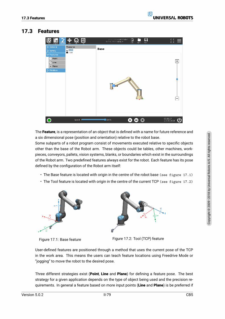
17.3 Features
17.3 Features
The Feature, is a representation of an object that is defined with a name for future reference anda six dimensional pose (position and orientation) relative to the robot base.Some subparts of a robot program consist of movements executed relative to specific objectsother than the base of the Robot arm. These objects could be tables, other machines, work-pieces, conveyors, pallets, vision systems, blanks, or boundaries which exist in the surroundingsof the Robot arm. Two predefined features always exist for the robot. Each feature has its posedefined by the configuration of the Robot arm itself:
• The Base feature is located with origin in the centre of the robot base (see figure 17.1)
• The Tool feature is located with origin in the centre of the current TCP (see figure 17.2)
Figure 17.1: Base feature Figure 17.2: Tool (TCP) feature
User-defined features are positioned through a method that uses the current pose of the TCPin the work area. This means the users can teach feature locations using Freedrive Mode or”jogging” to move the robot to the desired pose.
Three different strategies exist (Point, Line and Plane) for defining a feature pose. The beststrategy for a given application depends on the type of object being used and the precision re-quirements. In general a feature based on more input points (Line and Plane) is be preferred if
Version 5.0.2
Copy
right
©20
09–2
018by
Universa
lRob
otsA/
S.Allrightsrese
rved
.
II-79 CB5

17.3 Features
applicable to the specific object.To accurately define the direction of a linear conveyor, define two points of a Line feature withas much physical separation as possible. The Point feature can also be used to define a linearconveyor, however, the user must point the TCP in the direction of the conveyor movement.Using more points to define the pose of a table means that the orientation is based on the posi-tions rather than the orientation of a single TCP. A single TCP orientation is harder to configurewith high precision.To learn about the different methods to define a feature see (sections: 17.3.2), (17.3.3) and(17.3.4).
17.3.1 Using a featureWhen a feature is defined in the installation, you can refer to it from the robot program to relaterobot movements (e.g. MoveL and MoveP commands) to the feature (see section 16.5.1).This allows for easy adaptation of a robot program (e.g., when there are multiple robot stations,when an object is moved during program runtime, or when an object is permanently moved inthe scene). By adjusting the feature of an object, all program movements relative to the objectis moved accordingly. For further examples, see (sections 17.3.5) and (17.3.6).
Features configured as joggable are also useful tools when manually moving the robot in theMove Tab (section 18) or the Pose Editor screen (see 18.3.1). When a feature is chosenas a reference, the Move Tool buttons for translation and rotation operate in the selected fea-ture space (see 18.3) and (18.1), reading of the TCP coordinates. For example, if a table isdefined as a feature and is chosen as a reference in the Move Tab, the translation arrows (i.e.,up/down, left/right, forward/backward) move the robot in these directions relative to the table.Additionally, the TCP coordinates will be in the frame of the table.
• In the Features tree you can rename a Point, Line or Plane by tapping the pencil button.
• In the Features tree you can delete a Point, Line or Plane by tapping the Delete button.
JoggableChoose whether the selected feature should be joggable. This determines whether the featurewill appear in the feature menu on the Move screen.
Using Move robot herePush the Move robot here button to move the Robot arm towards the selected feature. At theend of this movement, the coordinate systems of the feature and the TCP will coincide.
17.3.2 Adding a PointPush the Pointbutton to add a point feature to the installation. The point feature defines a safetyboundary or a global home configuration of the Robot arm. The point feature pose is defined asthe position and orientation of the TCP.
CB5 II-80 Version 5.0.2
Copy
right
©20
09–2
018by
Universa
lRob
otsA/
S.Allrightsrese
rved
.

17.3 Features
17.3.3 Addine a LinePush the Line button to add a line feature to the installation. The line feature defines lines thatthe robot needs to follow. (e.g., when using conveyor tracking). A line l is defined as an axisbetween two point features p1 and p2 as shown in figure 17.3.
Figure 17.3: Definition of the line feature
In figure 17.3 the axis directed from the first point towards the second point, constitutes they-axis of the line coordinate system. The z-axis is defined by the projection of the z-axis of p1onto the plane perpendicular to the line. The position of the line coordinate system is the sameas the position of p1.
Version 5.0.2
Copy
right
©20
09–2
018by
Universa
lRob
otsA/
S.Allrightsrese
rved
.
II-81 CB5

17.3 Features
17.3.4 Plane FeatureSelect the plane feature when you need a frame with high precision: e.g., when working with avision system or doing movements relative to a table.
Adding a plane
1. In Installation, select Features.
2. Under Features select Plane.
Teaching a plane
When you press the plane button to create a new plane, the on-screen guide assists you creatinga plane.
1. Select Origo
2. Move robot to define the direction of the positive x-axis of the plane
3. Move robot to define the direction of the positive y-axis of the plane
The plane is defined using the right hand rule so the z- axis is the cross product of the x-axis andthe y-axis, as illustrated below.
CB5 II-82 Version 5.0.2
Copy
right
©20
09–2
018by
Universa
lRob
otsA/
S.Allrightsrese
rved
.
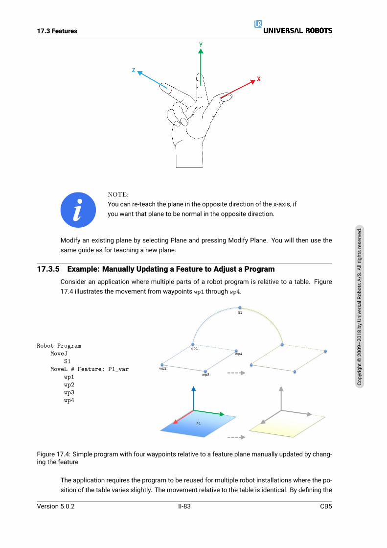
17.3 Features
NOTE:You can re-teach the plane in the opposite direction of the x-axis, ifyou want that plane to be normal in the opposite direction.
Modify an existing plane by selecting Plane and pressing Modify Plane. You will then use thesame guide as for teaching a new plane.
17.3.5 Example: Manually Updating a Feature to Adjust a ProgramConsider an application where multiple parts of a robot program is relative to a table. Figure17.4 illustrates the movement from waypoints wp1 through wp4.
Robot ProgramMoveJ
S1MoveL # Feature: P1_var
wp1wp2wp3wp4
Figure 17.4: Simple program with four waypoints relative to a feature plane manually updated by chang-ing the feature
The application requires the program to be reused for multiple robot installations where the po-sition of the table varies slightly. The movement relative to the table is identical. By defining the
Version 5.0.2
Copy
right
©20
09–2
018by
Universa
lRob
otsA/
S.Allrightsrese
rved
.
II-83 CB5
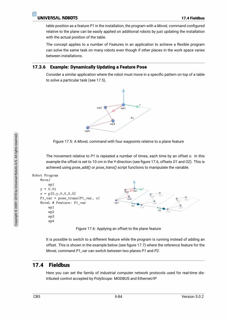
17.4 Fieldbus
table position as a feature P1 in the installation, the programwith aMoveL command configuredrelative to the plane can be easily applied on additional robots by just updating the installationwith the actual position of the table.
The concept applies to a number of Features in an application to achieve a flexible programcan solve the same task on many robots even though if other places in the work space variesbetween installations.
17.3.6 Example: Dynamically Updating a Feature PoseConsider a similar application where the robot must move in a specific pattern on top of a tableto solve a particular task (see 17.5).
Figure 17.5: AMoveL command with four waypoints relative to a plane feature
The movement relative to P1 is repeated a number of times, each time by an offset o. In thisexample the offset is set to 10 cm in the Y-direction (see figure 17.6, offsets O1 and O2). This isachieved using pose_add() or pose_trans() script functions to manipulate the variable.
Robot ProgramMoveJ
wp1y = 0.01o = p[0,y,0,0,0,0]P1_var = pose_trans(P1_var, o)MoveL # Feature: P1_var
wp1wp2wp3wp4
Figure 17.6: Applying an offset to the plane feature
It is possible to switch to a different feature while the program is running instead of adding anoffset. This is shown in the example below (see figure 17.7) where the reference feature for theMoveL command P1_var can switch between two planes P1 and P2.
17.4 FieldbusHere you can set the family of industrial computer network protocols used for real-time dis-tributed control accepted by PolyScope: MODBUS and Ethernet/IP
CB5 II-84 Version 5.0.2
Copy
right
©20
09–2
018by
Universa
lRob
otsA/
S.Allrightsrese
rved
.

17.4 Fieldbus
Robot ProgramMoveJ
S1if (digital_input[0]) then
P1_var = P1else
P1_var = P2MoveL # Feature: P1_var
wp1wp2wp3wp4
Figure 17.7: Switching from one plane feature to another
17.4.1 MODBUS client I/O Setup
Here, the MODBUS client (master) signals can be set up. Connections to MODBUS servers (orslaves) on specified IP addresses can be created with input/output signals (registers or digital).Each signal has a unique name so it can be used in programs.
Refresh
Push this button to refresh all MODBUS connections. Refreshing disconnects all modbus units,and connects them back again. All statistics are cleared.
Add unit
Push this button to add a new MODBUS unit.
Version 5.0.2
Copy
right
©20
09–2
018by
Universa
lRob
otsA/
S.Allrightsrese
rved
.
II-85 CB5
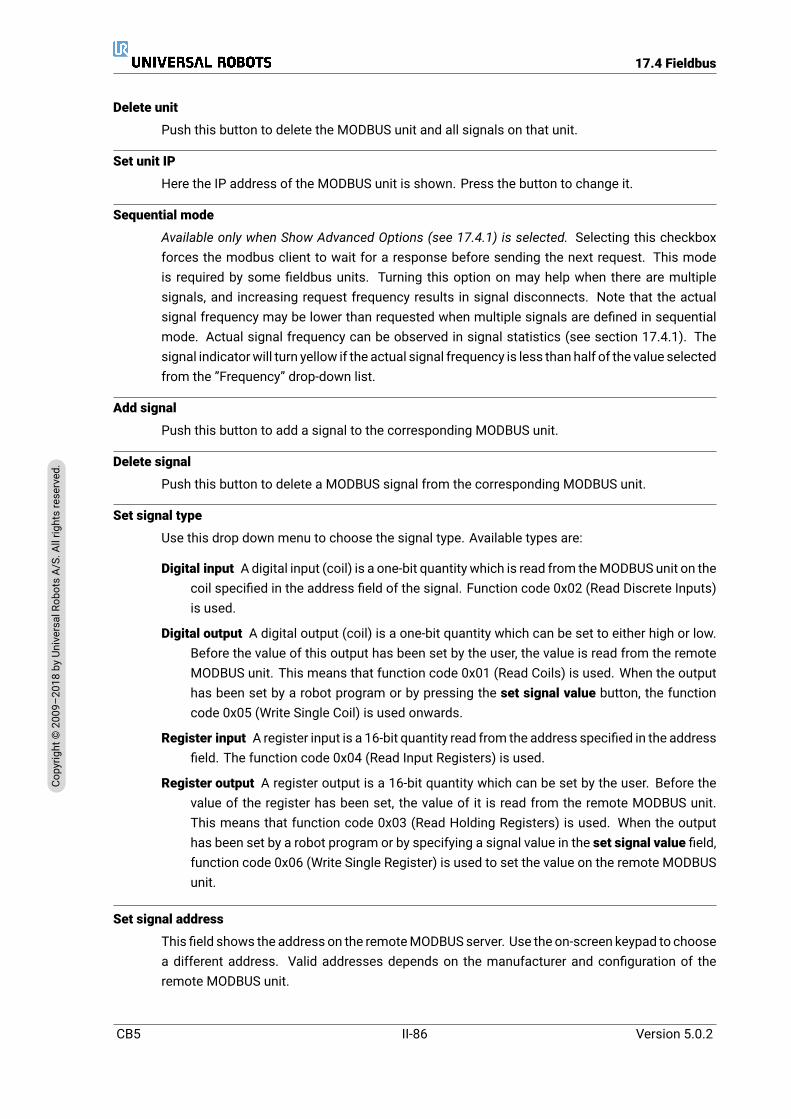
17.4 Fieldbus
Delete unit
Push this button to delete the MODBUS unit and all signals on that unit.
Set unit IP
Here the IP address of the MODBUS unit is shown. Press the button to change it.
Sequential mode
Available only when Show Advanced Options (see 17.4.1) is selected. Selecting this checkboxforces the modbus client to wait for a response before sending the next request. This modeis required by some fieldbus units. Turning this option on may help when there are multiplesignals, and increasing request frequency results in signal disconnects. Note that the actualsignal frequency may be lower than requested when multiple signals are defined in sequentialmode. Actual signal frequency can be observed in signal statistics (see section 17.4.1). Thesignal indicatorwill turn yellow if the actual signal frequency is less than half of the value selectedfrom the ”Frequency” drop-down list.
Add signal
Push this button to add a signal to the corresponding MODBUS unit.
Delete signal
Push this button to delete a MODBUS signal from the corresponding MODBUS unit.
Set signal type
Use this drop down menu to choose the signal type. Available types are:
Digital input Adigital input (coil) is a one-bit quantity which is read from theMODBUS unit on thecoil specified in the address field of the signal. Function code 0x02 (Read Discrete Inputs)is used.
Digital output A digital output (coil) is a one-bit quantity which can be set to either high or low.Before the value of this output has been set by the user, the value is read from the remoteMODBUS unit. This means that function code 0x01 (Read Coils) is used. When the outputhas been set by a robot program or by pressing the set signal value button, the functioncode 0x05 (Write Single Coil) is used onwards.
Register input A register input is a 16-bit quantity read from the address specified in the addressfield. The function code 0x04 (Read Input Registers) is used.
Register output A register output is a 16-bit quantity which can be set by the user. Before thevalue of the register has been set, the value of it is read from the remote MODBUS unit.This means that function code 0x03 (Read Holding Registers) is used. When the outputhas been set by a robot program or by specifying a signal value in the set signal value field,function code 0x06 (Write Single Register) is used to set the value on the remote MODBUSunit.
Set signal address
This field shows the address on the remoteMODBUS server. Use the on-screen keypad to choosea different address. Valid addresses depends on the manufacturer and configuration of theremote MODBUS unit.
CB5 II-86 Version 5.0.2
Copy
right
©20
09–2
018by
Universa
lRob
otsA/
S.Allrightsrese
rved
.
17.4 Fieldbus
Set signal name
Using the on-screen keyboard, the user can give the signal a name. This name is used when thesignal is used in programs.
Signal value
Here, the current value of the signal is shown. For register signals, the value is expressed as anunsigned integer. For output signals, the desired signal value can be set using the button. Again,for a register output, the value to write to the unit must be supplied as an unsigned integer.
Signal connectivity status
This icon shows whether the signal can be properly read/written (green), or if the unit respondsunexpected or is not reachable (gray). If aMODBUSexception response is received, the responsecode is displayed. The MODBUS-TCP Exception responses are:
E1 ILLEGAL FUNCTION (0x01) The function code received in the query is not an allowable actionfor the server (or slave).
E2 ILLEGAL DATA ADDRESS (0x02) The function code received in the query is not an allowableaction for the server (or slave), check that the entered signal address corresponds to thesetup of the remote MODBUS server.
E3 ILLEGAL DATA VALUE (0x03) A value contained in the query data field is not an allowablevalue for server (or slave), check that the enterd signal value is valid for the specified ad-dress on the remote MODBUS server.
E4 SLAVE DEVICE FAILURE (0x04) An unrecoverable error occurred while the server (or slave)was attempting to perform the requested action.
E5 ACKNOWLEDGE (0x05) Specialized use in conjunction with programming commands sentto the remote MODBUS unit.
E6 SLAVE DEVICE BUSY (0x06) Specialized use in conjunction with programming commandssent to the remote MODBUS unit, the slave (server) is not able to respond now.
Show Advanced Options
This check box shows/hides the advanced options for each signal.
Advanced Options
Update Frequency This menu can be used to change the update frequency of the signal. Thismeans the frequency with which requests are sent to the remote MODBUS unit for eitherreading or writing the signal value. When the frequency is set to 0, then modbus requestsare initiated on demand using a modbus_get_signal_status, modbus_set_output_register,andmodbus_set_output_signal script functions.
Slave Address This text field can be used to set a specific slave address for the requests cor-responding to a specific signal. The value must be in the range 0-255 both included, andthe default is 255. If you change this value, it is recommended to consult the manual of theremote MODBUS device to verify its functionality when changing slave address.
Reconnect count Number of times TCP connection was closed, and connected again.
Connection status TCP connection status.
Version 5.0.2
Copy
right
©20
09–2
018by
Universa
lRob
otsA/
S.Allrightsrese
rved
.
II-87 CB5
17.4 Fieldbus
Response time [ms ] Time between modbus request sent, and response received - this is up-dated only when communication is active.
Modbus packet errors Number of received packets that contained errors (i.e. invalid lenght,missing data, TCP socket error).
Timeouts Number of modbus requests that didn’t get response.
Requests failed Number of packets that could not be sent due to invalid socket status.
Actual freq. The average frequency of client (master) signal status updates. This value is re-calculated each time the signal receives a response from the server (or slave).
All counters count up to 65535, and then wrap back to 0.
17.4.2 Ethernet/IPEtherNet/IP is where you can enable or disable the connection of the robot to a EtherNet/IP. IfEnable, you can selectwhich action should occur to a programwhen there is a loss of EtherNet/IPscanner connection. Those actions are:
None: PolyScope will ignore the loss of EtherNet/IP connection and continue normally with theprogram.
Pause: PolyScope will pause the current program. Program will resume where it stopped.
Stop: PolyScope will stop the current program.
CB5 II-88 Version 5.0.2
Copy
right
©20
09–2
018by
Universa
lRob
otsA/
S.Allrightsrese
rved
.

18 Move Tab
On this screen, you can move (jog) the robot arm directly, either by translating/rotating the robottool, or by moving robot joints individually.
18.1 Move ToolHold down any of theMove Tool arrows to move the robot arm in a particular direction.
• The Translate arrows (upper) move the robot tool-tip in the direction indicated.
• TheRotate arrows (lower) change the orientation of the robot tool in the indicated direction.The rotation point is the Tool Center Point (TCP), i.e. the point at the end of the robot armthat gives a characteristic point on the robot’s tool. The TCP is shown as a small blue ball.
18.2 RobotIf the current position of the robot TCP comes close to a safety or trigger plane, or the orientationof robot tool is near the tool orientation boundary limit (see 13.2.5), a 3D representation of theproximate boundary limit is shown.Note: when the robot is running a program, the visualization of boundary limits is disabled.
Safety planes are visualized in yellow and black with a small arrow representing the plane nor-mal, which indicates the side of the plane on which the robot TCP is allowed to be positioned.Trigger planes are displayed in blue and green and a small arrow pointing to the side of the plane,where the Normalmode limits (see 13.2.2) are active. The tool orientation boundary limit isvisualized with a spherical cone together with a vector indicating the current orientation of therobot tool. The inside of the cone represents the allowed area for the tool orientation (vector).
Version 5.0.2
Copy
right
©20
09–2
018by
Universa
lRob
otsA/
S.Allrightsrese
rved
.
II-89 CB5

18.3 Tool Position
When the robot TCP is no longer in proximity of the limit, the 3D representation disappears. Ifthe TCP is in violation or very close to violating a boundary limit, the visualization of the limitturns red.
FeatureIn the top left corner of the Robot field, under Feature, you can define how to control the robotarm relative to View, Base or Tool features.Note: For the best feel for controlling the robot arm you can select the View feature, then useRotate arrows to change the viewing angle of the 3D image to match your view of the real robotarm.
Active TCPIn the to right corner of the Robot field, under Active TCP, the name of the current active ToolCenter Point (TCP) is displayed.
18.3 Tool PositionThe text boxes display the full coordinate values of the TCP relative to the selected feature.Note: You can configure several named TCPs (see 17.1.1). You can also tap Edit pose toaccess the Pose Editor screen.
18.3.1 Pose Editor ScreenOn this screen you can specify target joint positions, or a target pose (position and orientation)of the robot tool. This screen is “offline” and does not control the robot arm directly.
18.3.1.1 Robot
The current position of the robot arm and the specified new target position are shown in 3Dgraphics. The 3D drawing of the robot arm shows the current position of the robot arm, and the
CB5 II-90 Version 5.0.2
Copy
right
©20
09–2
018by
Universa
lRob
otsA/
S.Allrightsrese
rved
.

18.3 Tool Position
“shadow” of the robot arm shows the target position of the robot arm controlled by the specifiedvalues on the right hand side of the screen. Push the magnifying glass icons to zoom in/out ordrag a finger across to change the view.
If the specified target position of the robot TCP is close to a safety or trigger plane, or the orien-tation of robot tool is near the tool orientation boundary limit (see 13.2.5), a 3D representationof the proximate boundary limit is shown.
Safety planes are visualized in yellow and blackwith a small arrow representing the plane normal,which indicates the side of the plane on which the robot TCP is allowed to be positioned. Triggerplanes are displayed in blue and green and a small arrow pointing to the side of the plane, wherethe Normalmode limits (see 13.2.2) are active. The tool orientation boundary limit is visualizedwith a spherical cone together with a vector indicating the current orientation of the robot tool.The inside of the cone represents the allowed area for the tool orientation (vector).
When the target robot TCP no longer is in the proximity of the limit, the 3D representation disap-pears. If the target TCP is in violation or very close to violating a boundary limit, the visualizationof the limit turns red.
18.3.1.2 Feature and tool position
In the top right corner of the screen, the feature selector can be found. The feature selectordefines which feature to control the robot arm relative to
Below the feature selector, the name of the currently active Tool Center Point (TCP) is displayed.For further information about configuring several named TCPs, see 17.1.1. The text boxes showthe full coordinate values of that TCP relative to the selected feature. X, Y and Z control theposition of the tool, while RX, RY and RZ control the orientation of the tool.
Use the drop downmenu above the RX, RY and RZ boxes to choose the orientation representation.Available types are:
• Rotation Vector [rad] The orientation is given as a rotation vector. The length of the axis isthe angle to be rotated in radians, and the vector itself gives the axis about which to rotate.This is the default setting.
• Rotation Vector [] The orientation is given as a rotation vector, where the length of thevector is the angle to be rotated in degrees.
• RPY [rad] Roll, pitch and yaw (RPY) angles, where the angles are in radians. The RPY-rotation matrix (X, Y’, Z” rotation) is given by:
Rrpy(γ, β, α) = RZ(α) ·RY (β) ·RX(γ)
• RPY [] Roll, pitch and yaw (RPY) angles, where angles are in degrees.
Values can be edited by clicking on the coordinate. Clicking on the + or - buttons just to theright of a box allows you to add or subtract an amount to/from the current value. Pressing andholding down a button will directly increase/decrease the value. The longer the button is down,the larger the increase/decrease will be.
18.3.1.3 Joint positions
Allows the individual joint positions to be specified directly. Each joint position can have a valuein the range from −360 to +360, which are the joint limits. Values can be edited by clicking onthe joint position. Clicking on the + or - buttons just to the right of a box allows you to add or
Version 5.0.2
Copy
right
©20
09–2
018by
Universa
lRob
otsA/
S.Allrightsrese
rved
.
II-91 CB5

18.6 Freedrive
subtract an amount to/from the current value. Pressing and holding down a button will directlyincrease/decrease the value. The longer the button is down, the larger the increase/decreasewill be.
18.3.1.4 OK button
If this screen was activated from the Move tab (see 18), clicking the OK button will return to theMove tab, where the robot arm will move to the specified target. If the last specified value was atool coordinate, the robot arm will move to the target position using theMoveLmovement type,while the robot arm will move to the target position using the MoveJ movement type, if a jointposition was specified last. The different movement types are described in 16.5.1.
18.3.1.5 Cancel button
Clicking the Cancel button leaves the screen discarding all changes.
18.4 Joint PositionThe Joint Position field allows you to directly control individual joints. Each joint moves alonga default joint limit range from −360 to +360, defined by a horizontal bar. Once the limit isreached you cannot move a joint any further.Note: You can configure joints with a position range different from the default (see 13.2.4),this new range is indicated with red zone inside the horizontal bar.
18.5 HomePress the Home tab to access the Move Robot into Position screen, where you can hold downthe Auto tab to return robot arm to its start position (see 14.4).
18.6 FreedriveHold down the Freedrive tab to physically grab the robot arm and pull it to your desired posi-tion/pose.
CB5 II-92 Version 5.0.2
Copy
right
©20
09–2
018by
Universa
lRob
otsA/
S.Allrightsrese
rved
.

18.6 Freedrive
WARNING:
1. In the Setup tab, if the gravity setting (see 17.1.2) is wrong,or the robot arm carries a heavy load, the robot arm can startmoving (falling) when you press the Freedrive tab. In thatcase, release Freedriveagain.
2. Make sure to use the correct installation settings (e.g. Robotmounting angle, weight in TCP, TCP offset). Save and load theinstallation files along with the program.
3. Make sure that the TCP settings and the robot mounting set-tings are set correctly before operating Freedrive tab. If thesesettings are not correct, the robot arm will move when you ac-tivate Freedrive.
4. The Freedrive function (Impedance/Backdrive) must only beused in installations where the risk assessment allows it.Tools and obstacles must not have sharp edges or pinchpoints. Make sure that all personnel remain outside the reachof the robot arm.
Version 5.0.2
Copy
right
©20
09–2
018by
Universa
lRob
otsA/
S.Allrightsrese
rved
.
II-93 CB5

18.6 Freedrive
CB5 II-94 Version 5.0.2
Copy
right
©20
09–2
018by
Universa
lRob
otsA/
S.Allrightsrese
rved
.
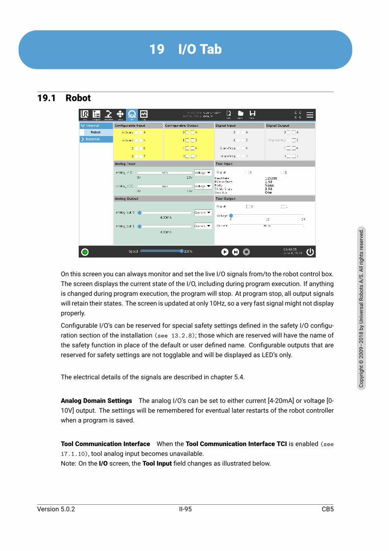
19 I/O Tab
19.1 Robot
On this screen you can always monitor and set the live I/O signals from/to the robot control box.The screen displays the current state of the I/O, including during program execution. If anythingis changed during program execution, the program will stop. At program stop, all output signalswill retain their states. The screen is updated at only 10Hz, so a very fast signal might not displayproperly.
Configurable I/O’s can be reserved for special safety settings defined in the safety I/O configu-ration section of the installation (see 13.2.8); those which are reserved will have the name ofthe safety function in place of the default or user defined name. Configurable outputs that arereserved for safety settings are not togglable and will be displayed as LED’s only.
The electrical details of the signals are described in chapter 5.4.
Analog Domain Settings The analog I/O’s can be set to either current [4-20mA] or voltage [0-10V] output. The settings will be remembered for eventual later restarts of the robot controllerwhen a program is saved.
Tool Communication Interface When the Tool Communication Interface TCI is enabled (see17.1.10), tool analog input becomes unavailable.Note: On the I/O screen, the Tool Input field changes as illustrated below.
Version 5.0.2
Copy
right
©20
09–2
018by
Universa
lRob
otsA/
S.Allrightsrese
rved
.
II-95 CB5

19.2 MODBUS
19.2 MODBUSHere, the digital MODBUS client I/O signals as set up in the installation are shown. If the signalconnection is lost, the corresponding entry on this screen is disabled.
19.2.1 InputsView the state of digital MODBUS client inputs.
19.2.2 OutputsView and toggle the state of digital MODBUS client outputs. A signal can only be toggled if thechoice for I/O tab control (see 17.1.3) allows it.
CB5 II-96 Version 5.0.2
Copy
right
©20
09–2
018by
Universa
lRob
otsA/
S.Allrightsrese
rved
.

20 Log Tab
20.1 ReadingsThe top half of the screen displays the ”health” of the Robot Arm and Control Box.
20.2 Joint LoadThe left side of the screen shows information related to the Control Box, while the right side ofthe screen displays robot joint information. Each joint dsiplays the temperature of themotor andelectronics, the load of the joint, and the voltage.
20.3 Date LogMessages are displayed on the bottom half of the screen. The first column categorizes theseverity of the log entry. The second column shows the messages’ time of arrival. The next col-umn shows the sender of the message. The last column shows the message itself. Messagescan be filtered by selecting the toggle buttons which correspond to the severity of the log entry.The figure above shows errors will be displayed while information and warning messages willbe filtered. Some log messages are designed to provide more information that is accessible byselecting the log entry.
20.4 Saving Error ReportsWhen an error occurs in PolyScope, a log of the error is generated. In the Log Tab, you can trackand/or export generated reports to a USB drive (see 20). The following list of errors can betracked and exported:
Version 5.0.2
Copy
right
©20
09–2
018by
Universa
lRob
otsA/
S.Allrightsrese
rved
.
II-97 CB5

20.4 Saving Error Reports
• Fault
• Internal PolyScope exceptions
• Protective Stop
• Unhandled exception in URCap
• Violation
The exported report contains: a user program, a history log, an installation and a list of runningservices.
Error Report
A detailed status report is available when a paper clip icon appears on the log line.
• Select a log line and tap the Save Report button to save the report to a USB drive.
• The report can be saved while a program is running.
NOTE:The oldest report is deleted when a new one is generated. Only thefive most recent reports are stored.
CB5 II-98 Version 5.0.2
Copy
right
©20
09–2
018by
Universa
lRob
otsA/
S.Allrightsrese
rved
.
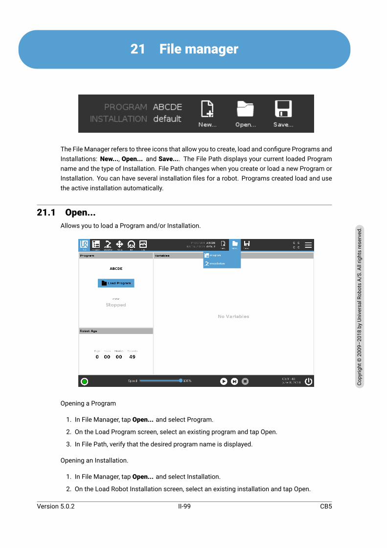
21 File manager
The File Manager refers to three icons that allow you to create, load and configure Programs andInstallations: New..., Open... and Save.... The File Path displays your current loaded Programname and the type of Installation. File Path changes when you create or load a new Program orInstallation. You can have several installation files for a robot. Programs created load and usethe active installation automatically.
21.1 Open...Allows you to load a Program and/or Installation.
Opening a Program
1. In File Manager, tap Open... and select Program.
2. On the Load Program screen, select an existing program and tap Open.
3. In File Path, verify that the desired program name is displayed.
Opening an Installation.
1. In File Manager, tap Open... and select Installation.
2. On the Load Robot Installation screen, select an existing installation and tap Open.
Version 5.0.2
Copy
right
©20
09–2
018by
Universa
lRob
otsA/
S.Allrightsrese
rved
.
II-99 CB5
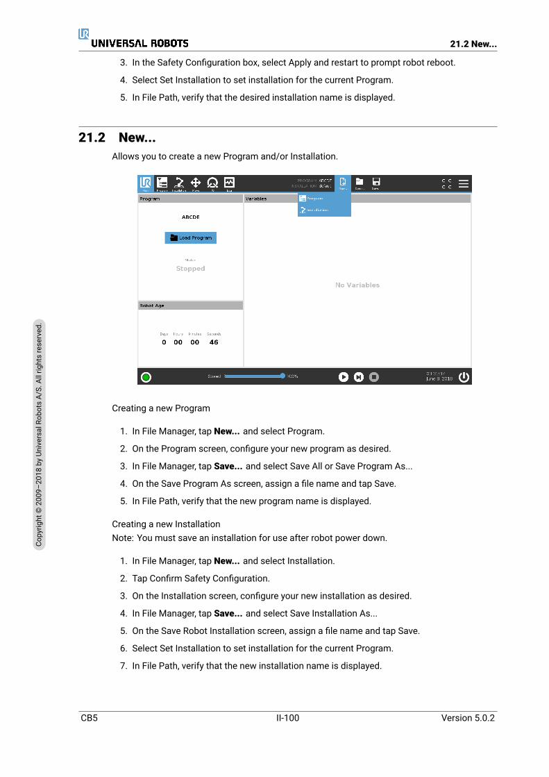
21.2 New...
3. In the Safety Configuration box, select Apply and restart to prompt robot reboot.
4. Select Set Installation to set installation for the current Program.
5. In File Path, verify that the desired installation name is displayed.
21.2 New...Allows you to create a new Program and/or Installation.
Creating a new Program
1. In File Manager, tap New... and select Program.
2. On the Program screen, configure your new program as desired.
3. In File Manager, tap Save... and select Save All or Save Program As...
4. On the Save Program As screen, assign a file name and tap Save.
5. In File Path, verify that the new program name is displayed.
Creating a new InstallationNote: You must save an installation for use after robot power down.
1. In File Manager, tap New... and select Installation.
2. Tap Confirm Safety Configuration.
3. On the Installation screen, configure your new installation as desired.
4. In File Manager, tap Save... and select Save Installation As...
5. On the Save Robot Installation screen, assign a file name and tap Save.
6. Select Set Installation to set installation for the current Program.
7. In File Path, verify that the new installation name is displayed.
CB5 II-100 Version 5.0.2
Copy
right
©20
09–2
018by
Universa
lRob
otsA/
S.Allrightsrese
rved
.

21.3 Save...
21.3 Save...
Save... proposes three options. Depending on the program/installation you load-create, youcan:
SaveAll to save the current Programand Installation immediately, without the systempromptingto save to a different location or different name. Note: If no changes are made to the Programor Installation, the Save All... button appears deactivated.
Save Program As... to change the new Program name and location. Note: the current Installa-tion is also saved, with the existing name and location.
Save Installation As... to change the new Installation name and location. Note: the currentProgram is saved, with the existing name and location.
Version 5.0.2
Copy
right
©20
09–2
018by
Universa
lRob
otsA/
S.Allrightsrese
rved
.
II-101 CB5
21.3 Save...
CB5 II-102 Version 5.0.2
Copy
right
©20
09–2
018by
Universa
lRob
otsA/
S.Allrightsrese
rved
.
22 Hamburger menu
22.1 HelpYou can find definitions for all elements that make up PolyScope capabilities.
1. In the right corner of the Header, tap the Hamburgermenu and select Help.
2. Tap one of the red question marks that appears, to define desired element.
3. In the top right corner of element definition screen, tap the red X to exit Help.
22.2 AboutYou can display Version and Legal data.
1. Tap the Hamburgermenu and select About.
2. Tap either Version or Legal to display data.
3. Tap Close to return to your screen.
22.3 SettingsPersonalizing PolyScope Settings
1. In the Header, tap the Hamburger menu and select Settings.
2. On the left, in the Settings screen action menu, select an item to personalize. Note: If anoperational mode password was set, in the action menu, System is only available to theprogrammer.
3. On the bottom right, tap Apply and Restart to implement your changes.
4. On the bottom left, tap Exit to close Settings screen without changes.
Hiding Speed Slider
Located at the base of the Run tab screen, the Speed Slider allows the operator to change thespeed of a running Program.
1. In the Header, tap the Hamburger menu icon and select Settings.
2. Under Preferences, tap Run Screen.
3. Select check box to show or hide Speed Slider.
22.3.1 PreferencesLanguage
You can change PolyScope language and measurement unit (Metric or Imperial).
Time
You can adjust the current time displayed on PolyScope (format: 12 or 24 hour).
Version 5.0.2
Copy
right
©20
09–2
018by
Universa
lRob
otsA/
S.Allrightsrese
rved
.
II-103 CB5
22.3 Settings
22.3.2 PasswordMode
The operational mode password prevents unauthorized modification of robot setup, by creatingtwo different user roles on PolyScope: Automatic and Maual. When you set operational modepassword, programs or installations can only be created and loaded in manual mode. Any timeyou enter manual mode, PolyScope prompts for the password that was previously set on thisscreen.
Safety
The Safety password prevents unauthorized modification of the Safety settings.
22.3.3 SystemUpdate
You can search for updates to verify that the robot software is up-to-date.
1. On the left, in the Settings screen action menu, select System
2. In the Update robot software field, tap Search.
3. In the Description field, observe as updates are listed.
4. Select desired update/s and press Update to install.
Network
You can configure robot connection to a network by selecting one of three available networkmethods:
• DHCP
• Static Address
• Disabled network (if you don’t wish to connect your robot to a network)
Depending on the network method you select, configure your network settings:
• IP Address
• Subnet Mask
• Default Gateway
• Preferred DNS Server
• Alternative DNS Server
Note: Press Apply to apply changes.
URCaps
You can manage your existing URCaps or install a new one in your robot.
1. In the Header, press the Hamburger menu and select Settings.
2. Under System, select URCaps.
3. Press the + tab, select the .urcap file and press Open Note: Check more details about thenew URCap by selecting it in Active URCaps field. More information appears below in UR-Cap Information field below.
CB5 II-104 Version 5.0.2
Copy
right
©20
09–2
018by
Universa
lRob
otsA/
S.Allrightsrese
rved
.

22.3 Settings
4. If you wish to proceed with the installation of that URCap, press Restart. After that step,the URCap is installed and ready to be used.
5. To eliminate an installed URCap, select it from Active URCaps, press the - button and pressRestart so changes can take effect.
Remote Control
A robot can either be in Local Control (controlled from the Teach Pendant) or Remote Control(controlled externally).
Local Control does not allow Remote Control does not allowPower on and brake release sent tothe robot over network
Moving the robot from Move Tab
Receiving and executing robot pro-grams and installation sent to therobot over network
Start in programs from Teach Pendant
Autostart of programs at boot, con-trolled from digital inputs
Load programs and installations fromthe Teach Pendant
Auto brake release at boot, con-trolled from digital inputs
Freedrive
Start of programs, controlled fromdigital inputs
Control of the robot via network or digital input is, by default, restricted. Enabling and selectingthe Remote Control feature removes this restriction. Enable Remote Control by switching to theLocal Control profile (PolyScope control) of the robot, allowing all control of running programsand executing scripts to be performed remotely.Note: Enable the Remote Control feature in Settings to access Remote mode and Local mode inthe profile.
1. In the Header, press the Hamburger menu and select Settings.
2. Under System, select Remote Control.
3. Press Enable to make the Remote Control feature available. PolyScope remains active.Note: Enabling Remote Control does not immediately start the feature. It allows you toswitch from Local Control to Remote Control.
4. In the profile menu, select Remote Control to alter PolyScope. Note: You can return toLocal Control by switching back in the profile menu, or selecting Operator or Programmerif a password is specified.
NOTE:
• Although Remote Control limits your actions in PolyScope,you can still monitor robot state.
• When a robot system is powered off in Remote Control, itstarts up in Remote Control.
Version 5.0.2
Copy
right
©20
09–2
018by
Universa
lRob
otsA/
S.Allrightsrese
rved
.
II-105 CB5

22.3 Settings
CB5 II-106 Version 5.0.2
Copy
right
©20
09–2
018by
Universa
lRob
otsA/
S.Allrightsrese
rved
.
Glossary
Stop Category 0 Robot motion is stopped by immediate removal of power to the robot. It is anuncontrolled stop, where the robot can deviate from the programmed path as each jointbrake as fast as possible. This protective stop is used if a safety-related limit is exceededor in case of a fault in the safety-related parts of the control system. For more information,see ISO 13850 or IEC 60204-1.
Stop Category 1 Robot motion is stopped with power available to the robot to achieve the stopand then removal of power when the stop is achieved. It is a controlled stop, where therobot will continue along the programmed path. Power is removed as soon as the robotstands still. For more information, see ISO 13850 or IEC 60204-1.
Stop Category 2 A controlled stop with power left available to the robot. The safety-relatedcontrol system monitors that the robot stays at the stop position. For more information,see IEC 60204-1.
Category 3 The term Category should not be confused with the term Stop Category. Categoryrefers to the type of architecture used as basis for a certainPerformance Level. A significantproperty of a Category 3 architecture is that a single fault cannot lead to loss of the safetyfunction. For more information, see ISO 13849-1.
Performance Level A Performance Level (PL) is a discrete level used to specify the ability ofsafety-related parts of control systems to perform a safety functions under foreseeableconditions. PLd is the second highest reliability classification, meaning that the safety func-tion is extremely reliable. For more information, see ISO 13849-1.
Diagnostic coverage (DC) is a measure of the effectiveness of the diagnostics implemented toachieve the rated performance level. For more information, see ISO 13849-1.
MTTFd The Mean time to dangerous failure (MTTFd) is a value based on calculations and testsused to achieve the rated performance level. For more information, see ISO 13849-1.
Integrator The integrator is the entity that designs the final robot installation. The integrator isresponsible for making the final risk assessment and must ensure that the final installationcomplies with local laws and regulations.
Risk assessment A risk assessment is the overall process of identifying all risks and reducingthem to an appropriate level. A risk assessment should be documented. Consult ISO 12100for further information.
Collaborative robot application The term collaborative refers to collaboration between operatorand robot in a robot application. See precise definitions and descriptions in ISO 10218-1and ISO 10218-2.
Safety configuration Safety-related functions and interfaces are configurable through safetyconfiguration parameters. These are defined through the software interface, see part II.
Version 5.0.2
Copy
right
©20
09–2
018by
Universa
lRob
otsA/
S.Allrightsrese
rved
.
II-107 CB5

22.3 Settings
CB5 II-108 Version 5.0.2
Copy
right
©20
09–2
018by
Universa
lRob
otsA/
S.Allrightsrese
rved
.

Index
AAbout . . . . . . . . . . . . . . . . . . . . . . . . . . . . . . . . . . . . II-103AfterEnd . . . . . . . . . . . . . . . . . . . . . . . . . . . . . . . . . . II-60Anchor Position . . . . . . . . . . . . . . . . . . . . . . . . . . . II-60Auto . . . . . . . . . . . . . . . . . . . . . . . . . . . . . . . . . II-30, II-92Automatic mode . . . . . . . . . . . . . . . . . . . . . . . . . . II-11Automove . . . . . . . . . . . . . . . . . . . . . . . . . . . II-30, II-31
Bback-driving, Forced . . . . . . . . . . . . . . . . . . . . . . . I-10Backdrive . . . . . . . . . . . . . . . . . . . . . . . . . . . . . . . . . II-93Base . . . . . . . . . . . . . . . . . . . . . . . . . . . . . I-51, II-7, II-44Base feature . . . . . . . . . . . . . . . . . . . . . . . . . . . . . . II-79BeforeStart . . . . . . . . . . . . . . . . . . . . . . . . . . . . . . . II-60Blend parameters . . . . . . . . . . . . . . . . . . . . . . . . . II-46Blending . . . . . . . . . . . . . . . . . . . . . . . . . . . . . . . . . . II-45Box pattern . . . . . . . . . . . . . . . . . . . . . . . . . . II-60, II-61Bracket . . . . . . . . . . . . . . . . . . . . . . . . . . . . . . . . . . . . I-25
CClock . . . . . . . . . . . . . . . . . . . . . . . . . . . . . . . . . . . . . . . II-5Command . . . . . . . . . . . . . . . . . . . . . . . . . . . . . . . . II-39Cone angle . . . . . . . . . . . . . . . . . . . . . . . . . . . . . . . . II-25Cone center . . . . . . . . . . . . . . . . . . . . . . . . . . . . . . . II-25Configurable I/O . . . . . . . . . . . . . . . . . . . . . . . . . . . I-28Configure Robot Installation . . . . . . . . . . . . . . . . II-5Control Box . . . . . . . . . ix, I-23, I-25, I-28, I-36–I-38control box . . . . . . . . . . . . I-61, II-8, II-76, II-95, II-97Conveyor Tracking . . . . . . . . . . . . . . I-28, II-66, II-75Custom . . . . . . . . . . . . . . . . . . . . . . . . . . . . . . . . . . . II-18
DDelete . . . . . . . . . . . . . . . . . . . . . . . . . . . . . . . . . . . . . II-21Disabled . . . . . . . . . . . . . . . . . . . . . . . . . . . . . II-21, II-22Disabled Tool direction limit . . . . . . . . . . . . . . . II-25
EEdit Position . . . . . . . . . . . . . . . . . . . . . . . . . . . . . . II-24Elbow . . . . . . . . . . . . . . . . . . . . . . . . . . . . . . . . . I-51, II-7Elbow Force . . . . . . . . . . . . . . . . . . . . . . . . . . . . . . . II-18Elbow Speed . . . . . . . . . . . . . . . . . . . . . . . . . . . . . . II-18Ethernet . . . . . . . . . . . . . . . . . . . . . . . . . . . . . . I-25, II-84EtherNet/IP . . . . . . . . . . . . . . . . . . . . . I-25, II-74, II-88Expression Editor . . . . . . . . . . . . . . . . . . . . . . . . . II-59
FFactory Presets . . . . . . . . . . . . . . . . . . . . . . . . . . . II-18Feature . . . . . . . . . . . . . . . . . . . . . . . . . II-75, II-79, II-90Feature menu . . . . . . . . . . . . . . . . . . . . . . . . . . . . . II-65File Manager . . . . . . . . . . . . . . . . . . . . . . . . . . . . . . II-99File Path . . . . . . . . . . . . . . . . . . . . . . . . . . . . . . II-4, II-99Folder . . . . . . . . . . . . . . . . . . . . . . . . . . . . . . . . . . . . . II-54Footer . . . . . . . . . . . . . . . . . . . . . . . . . . . . . . . . II-3, II-30Force mode . . . . . . . . . . . . . . . . . . . . . . . . . . . . . . . II-64Frame . . . . . . . . . . . . . . . . . . . . . . . . . . . . . . . . . . . . . II-65Freedrive . I-17, II-11, II-23, II-66, II-73, II-74, II-79,
II-92, II-93
GGeneral purpose I/O . . . . . . . . . . . . . . . . . . . . . . . I-28Getting Started . . . . . . . . . . . . . . . . . . . . . . . . . . . . . II-5
HHamburger Menu . . . . . . . . . . . . . . . . . . . . . . . . . . . II-4Header . . . . . . . . . . . . . . . . . . . . . . . . . . . . . . . . . . . . . II-3Home . . . . . . . . . . . . . . . . . . . . . . . . . . . . . . . . . . . . . II-92
II/O . . . . I-25, I-29, II-4, II-26, II-35, II-73, II-75, II-95Initialize . . . . . . . . . . . . . . . . . . . . . . . . . . . . . . II-3, II-33input signals . . . . . . . . . . . . . . . . . . . . . . . . . . . . . . II-26Installation . . . . . . . . . . II-3, II-35, II-76, II-99, II-100Installation file . . . . . . . . . . . . . . . . . . . . . . . . . . . . II-33Installation variables . . . . . . . . . . . . . . . . . . . . . . II-76integrator . . . . . . . . . . . . . . . . . . . . . . . . . . . . . . . . . . . I-8
JJoint Limits . . . . . . . . . . . . . . . . . . . . . . . . . . . . . . . II-20Joint load . . . . . . . . . . . . . . . . . . . . . . . . . . . . . . . . . II-97joint space . . . . . . . . . . . . . . . . . . . . . . . . . . . . . . . . II-43
LLine pattern . . . . . . . . . . . . . . . . . . . . . . . . . . II-60, II-61List (pattern) . . . . . . . . . . . . . . . . . . . . . . . . . . . . . . II-61Log . . . . . . . . . . . . . . . . . . . . . . . . . . . . . . . . . . . . . . . . II-4
MManual mode . . . . . . . . . . . . . . . . . . . . . . . . . . . . . II-11MODBUS . . . . . . . I-25, II-75, II-84, II-85, II-87, II-96
II-109

mode: Automatic . . . . . . . . . . . . . . . . . . . . . . . . . . . II-4mode: Manual . . . . . . . . . . . . . . . . . . . . . . . . . . . . . . II-4Modes . . . . . . . . . . . . . . . . . . . . . . . . . . . . . . . I-17, II-21Momentum . . . . . . . . . . . . . . . . . . . . . . . . . . . . . . . II-18Motion . . . . . . . . . . . . . . . . . . . . . . . . . . . . . . . . . . . . II-65Mounting bracket . . . . . . . . . . . . . . . . . . . . . . . . . . . . ixMove . . . . . . II-4, II-11, II-42, II-44, II-52, II-60, II-80Move Tool . . . . . . . . . . . . . . . . . . . . . . . . . . . . . . . . II-89MoveJ . . . . . . . . . . . . . . . . . . . . . . . . . . . . . . . . . . . . II-43MoveL . . . . . . . . . . . . . . . . . . . . . . . . . . . . . . . II-43, II-80MoveP . . . . . . . . . . . . . . . . . . . . . . . . . . . . . . . II-43, II-80
NNew... . . . . . . . . . . . . . . . . . . . . . . . . . . . . . . . . II-4, II-99Normal . . . . . . . . . . . . . . . . . . . . . . . . . . . . . . . . . . . . II-21Normal & Reduced . . . . . . . . . . . . . . . . . . . . . . . . II-21Normal & Reduced Tool direction limit . . . . . II-25Normal mode . . . . . . . . . . . . . . . . . . II-19, II-25, II-41Normal Plane . . . . . . . . . . . . . . . . . . . . . . . . . . . . . II-23Normal Tool direction limit . . . . . . . . . . . . . . . . II-25Not Reduced mode . . . . . . . . . . . . . . . . . . . . . . . . II-27
OOpen... . . . . . . . . . . . . . . . . . . . . . . . . . . . . . . . . II-4, II-99output signals . . . . . . . . . . . . . . . . . . . . . . . . . . . . . II-27
PPallet Sequence . . . . . . . . . . . . . . . . . . . . . . . . . . . II-60Pan angle . . . . . . . . . . . . . . . . . . . . . . . . . . . . . . . . . II-25Pattern . . . . . . . . . . . . . . . . . . . . . . . . . . . . . . II-60, II-61Play . . . . . . . . . . . . . . . . . . . . . . . . . . . . . . . . . . . II-4, II-30Point . . . . . . . . . . . . . . . . . . . . . . . . . . . . . . . . . . . . . . II-65PolyScope . ix, I-17, II-3, II-7, II-8, II-28, II-29, II-55,
II-57, II-67, II-69, II-84, II-88, II-103,II-105
Polyscope . . . . . . . . . . . . . . . . . . . . . . . . . . . . . . . . . II-78popup . . . . . . . . . . . . . . . . . . . . . . . . . . . . . . . . . . . . . II-53Pose Editor . . . . . . . . . . . . . . . . . . . . . . . . . . II-80, II-90Position . . . . . . . . . . . . . . . . . . . . . . . . . . . . . . . . . . . II-24Position range . . . . . . . . . . . . . . . . . . . . . . . . . . . . II-20Power . . . . . . . . . . . . . . . . . . . . . . . . . . . . . . . . . . . . . II-18powered on . . . . . . . . . . . . . . . . . . . . . . . . . . . . . . . II-33powered on and ready . . . . . . . . . . . . . . . . . . . . . II-33Program . . . . . . . . . . . . . II-3, II-29, II-66, II-99, II-100Program a Robot . . . . . . . . . . . . . . . . . . . . . . . . . . . II-5Program Node . . . . . . . . . . . . . . . . . . . . . . . II-37, II-39Program Tree . . . . . . . . . . . . . . . . . . . . . . . . II-37, II-38
RRadius . . . . . . . . . . . . . . . . . . . . . . . . . . . . . . . . . . . . II-23Recovery mode . . . . . . . . . . . . . . . . . . . . . . . I-17, II-19
Reduced . . . . . . . . . . . . . . . . . . . . . . . . . . . . . . . . . . II-21Reduced mode . . . . . . I-17, II-19, II-23, II-25–II-27Reduced Tool direction limit . . . . . . . . . . . . . . . II-25Relative waypoint . . . . . . . . . . . . . . . . . . . . . . . . . II-44Remote Control . . . . . . . . . . . . . . . . . . . . . II-77, II-105Rename . . . . . . . . . . . . . . . . . . . . . . . . . . . . . . . . . . . II-21Restrict Elbow . . . . . . . . . . . . . . . . . . . . . . . . . . . . . II-22risk assessment . . . . . . . . . . . . . x, I-3, I-8, I-10, I-16Robot . . . . . . . . . . . . . . . . . . . . . . . . . . II-23, II-89, II-90Robot Arm . . . . . . . . . . . . . . . . . . . . . . . . . . . . . . . . . I-25Robot arm . I-61, II-7, II-33, II-62–II-65, II-76, II-89,
II-97Robot Installation . . . . . . . . . . . . . . . . . . . . . . . . . II-34Robot Limits . . . . . . . . . . . . . . . . . . . . . . . . . . . . . . II-17Robot Moving . . . . . . . . . . . . . . . . . . . . . . . . . . . . . II-27Robot Not Stopping . . . . . . . . . . . . . . . . . . . . . . . II-27Run . . . . . . . . . . . . . . . . . . . . . . . . . . . . . . . . . . . II-3, II-29Run a Program . . . . . . . . . . . . . . . . . . . . . . . . . . . . . II-5
SSafeguard Reset . . . . . . . . . . . . . . . . . . . . . . . . . . II-26Safety Checksum . . . . . . . . . . . . . . . . . . . . . II-4, II-17Safety Configuration . . . . . . . . I-9, II-15–II-17, II-20Safety functions . . . . . . . . . . . . . . . . . . . . . . I-13, I-14Safety I/O . . . . . . . . . . . . . . . . . . . I-13, I-15, I-28–I-30Safety instructions . . . . . . . . . . . . . . . . . . . . . . . . . I-43Safety planes . . . . . . . . . . . . . . . . . . . . . . . . II-21, II-89Safety Settings . . . . . . . . . . . . . . . . . . I-3, II-15, II-104Save... . . . . . . . . . . . . . . . . . . . . II-4, II-35, II-99, II-101Screen . . . . . . . . . . . . . . . . . . . . . . . . . . . . . . . . . . . . . II-3Script manual . . . . . . . . . . . . . . . . . . . . . . . . . . . . . . . . xiService manual . . . . . . . . . . . . . . . . . . . . . . . . . . . . . . xiSet . . . . . . . . . . . . . . . . . . . . . . . . . . . . . . . . . . . . . . . . II-52Settings . . . . . . . . . . . . . . . . . . . . . . . . . . . . . . . . . II-103Setup . . . . . . . . . . . . . . . . . . . . . . . . . . . . . . . . . . . . . II-93Shoulder . . . . . . . . . . . . . . . . . . . . . . . . . . . . . . I-51, II-7Show . . . . . . . . . . . . . . . . . . . . . . . . . . . . . . . . . . . . . II-21Shutdown . . . . . . . . . . . . . . . . . . . . . . . . . . . . . . . . . . II-5Simple . . . . . . . . . . . . . . . . . . . . . . . . . . . . . . . . . . . . II-65Speed Slider . . . . . . . . . . . . . . . . . . . . . . . . . . II-4, II-11Square pattern . . . . . . . . . . . . . . . . . . . . . . . II-60, II-61standard . . . . . . . . . . . . . . . . . . . . . . . . . . . . . . I-61, I-63Step . . . . . . . . . . . . . . . . . . . . . . . . . . . . . . . . . . . . . . . . II-4Stop . . . . . . . . . . . . . . . . . . . . . . . . . . . . . . . . . . . . . . . . II-5stopped state . . . . . . . . . . . . . . . . . . . . . . . . . . . . . II-33Stopping Distance . . . . . . . . . . . . . . . . . . . . . . . . . II-18Stopping Time . . . . . . . . . . . . . . . . . . . . . . . . . . . . II-18Switch Case construction . . . . . . . . . . . . . . . . . II-59System Emergency Stop . . . . . . . . . . . . . . . . . . II-27System Emergency stop . . . . . . . . . . . . . . . . . . . II-26
CB5 II-110 Version 5.0.2
Copy
right
©20
09–2
018by
Universa
lRob
otsA/
S.Allrightsrese
rved
.
TTCI . . . . . . . . . . . . . . . . . . . . . . . . . . . . . . . . . . . . . . . . II-51Teach Pendant . ix, I-23, I-36, II-3, II-8, II-27, II-66,
II-74, II-105Templates . . . . . . . . . . . . . . . . . . . . . . . . . . . . . . . . II-66Test button . . . . . . . . . . . . . . . . . . . . . . . . . . . . . . . . II-66Tilt angle . . . . . . . . . . . . . . . . . . . . . . . . . . . . . . . . . . II-25Tool . . . . . . . . . . . . . . . . . . . . . . . . . . . . . . . . . . . . . . . II-23Tool Center Point . . . . . . . . . . . . . . . II-19, II-69, II-90Tool Center Position . . . . . . . . . . . . . . . . . . . . . . . II-24Tool Communication Interface . . . . . . . . . . . . II-78Tool Direction . . . . . . . . . . . . . . . . . . . . . . . . II-24, II-25Tool feature . . . . . . . . . . . . . . . . . . . . . . . . . . . . . . . II-79Tool Force . . . . . . . . . . . . . . . . . . . . . . . . . . . . . . . . II-18Tool I/O . . . . . . . . . . . . . . . . . . . . . . . . . . . . . . . . . . . . I-39Tool Position . . . . . . . . . . . . . . . . . . . . . . . . II-23, II-24Tool Speed . . . . . . . . . . . . . . . . . . . . . . . . . . . . . . . . II-18Trigger Plane . . . . . . . . . . . . . . . . . . . . . . . . . . . . . . II-23
Trigger Reduced Mode . . . . . . . . . . . . . . . . . . . . II-21
UURCaps . . . . . . . . . . . . . . . . . . . . . . . . . . . . . . . xi, II-104
VVariable feature . . . . . . . . . . . . . . . . . . . . . . . . . . . II-44Variable waypoint . . . . . . . . . . . . . . . . . . . . . . . . . II-44Variables . . . . . . . . . . . . . . . . . . . . . . . II-29, II-30, II-42
WWait . . . . . . . . . . . . . . . . . . . . . . . . . . . . . . . . . . . . . . II-51Warning signs . . . . . . . . . . . . . . . . . . . . . . . . . . . . . . . I-4Warranty . . . . . . . . . . . . . . . . . . . . . . . . . . . . . . . . . . . I-49Waypoint . . . . . . II-41, II-42, II-44, II-45, II-50, II-60Waypoints . . . . . . . . . . . . . . . . . . . . . . . . . . . . . . . . II-67Wrist . . . . . . . . . . . . . . . . . . . . . . . . . . . . . . . . . . . . . . . II-7
Version 5.0.2
Copy
right
©20
09–2
018by
Universa
lRob
otsA/
S.Allrightsrese
rved
.
II-111 CB5