UNIT – I - Laser Physics – SPH1312
113
1 SCHOOL OF SCIENCE AND HUMANITIES DEPARTMENT OF PHYSICS UNIT – I - Laser Physics – SPH1312
-
Upload
khangminh22 -
Category
Documents
-
view
3 -
download
0
Transcript of UNIT – I - Laser Physics – SPH1312

1
SCHOOL OF SCIENCE AND HUMANITIES
DEPARTMENT OF PHYSICS
UNIT – I - Laser Physics – SPH1312

2
UNIT - 1 Laser Physics
Basic Principle of Laser – Einstein Coefficients – Condition for light amplification –
Population Inversion – Threshold Condition – Line Shape Function – Optical Resonators –
Three level and four level systems.
I Introduction
LASER stands for Light Amplification by Stimulated Emission of Radiation. Laser is a
device which emits a powerful, monochromatic collimated beam of light. The emitted light waves
are coherent in nature.
The first laser, ruby laser was invented by Dr.T.H. Maiman in the year 1960. Since then, the
development of lasers is extremely rapid. The laser action is being demonstrated in many solids,
liquids, gases and semiconductor.
1.1 CHARACTERISTICS OF LASER
Laser is basically a light source. Laser light has the following important characteristics
� High Directionality
� High Intensity
� Highly Monochromatic
� Highly Coherence
1. Directionality
Ordinary light spreads in all directions and its angular spread is 1m/m.
Fig. 1.1 Directionality property of Laser
But it is found that laser is highly directional and is angular spread is 1mm/m. For example,
the laser beam can be focused to very long distance with a few divergence or angular spread shown
in Fig. 1.1.
2. Intensity
Since an ordinary light spreads in all directions, the intensity reaching the target is very less.
But in the case of laser, due to high directionality, the intensity of laser beam reaching the
target is of high intense beam. For example, 1 mill watt power of He-Ne laser appears to be brighter
than the sunlight (Fig. 1.2).

3
Fig. 1.2 Intensity variation
3. Monochromatic
Laser beam is highly monochromatic; the wavelength is single, whereas in ordinary light
like mercury vapour lamp, many wavelengths of light are emitted Fig.1.3.
Fig. 1.3 Monochromaticity nature of Laser
4. Coherence
It is an important characteristic of laser beam. In lasers the wave trains of same frequency
are in phase, the radiation given out is in mutual agreement not only in phase but also in the
direction of emission and polarization. Thus it is a coherent beam. Due to high coherence it results
in an extremely high power. Fig. 1.4 shows the coherence nature of Laser
Fig. 1.4 shows the coherence property of Laser
Differences between ordinary light and Laser beam.
S.No. Ordinary light Laser beams
1 In ordinary light the angular spread is
more
In laser beam the angular spread is
less.
2 They are not directional. They are highly directional.
3 It is less intense It is highly intense
4 It is not a coherent beam and is not in It is a coherent beam and is in phase
4
phase.
5 The radiation are polychromatic The radiations are monochromatic
6 Example: Sun light, Mercury vapor lamp He- Ne Laser, Co2 laser
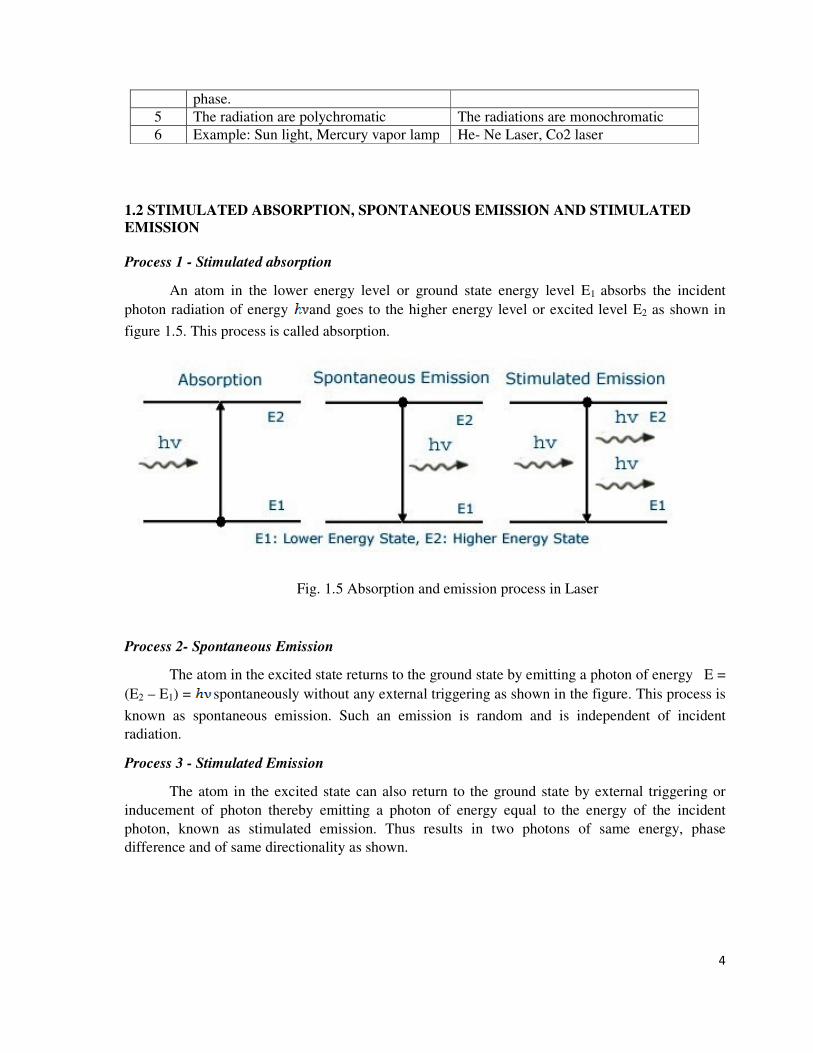
1.2 STIMULATED ABSORPTION, SPONTANEOUS EMISSION AND STIMULATED
EMISSION
Process 1 - Stimulated absorption
An atom in the lower energy level or ground state energy level E1 absorbs the incident
photon radiation of energy and goes to the higher energy level or excited level E2 as shown in
figure 1.5. This process is called absorption.
Fig. 1.5 Absorption and emission process in Laser
Process 2- Spontaneous Emission
The atom in the excited state returns to the ground state by emitting a photon of energy E =
(E2 – E1) = spontaneously without any external triggering as shown in the figure. This process is
known as spontaneous emission. Such an emission is random and is independent of incident
radiation.
Process 3 - Stimulated Emission
The atom in the excited state can also return to the ground state by external triggering or
inducement of photon thereby emitting a photon of energy equal to the energy of the incident
photon, known as stimulated emission. Thus results in two photons of same energy, phase
difference and of same directionality as shown.

5
Table 1.1 Differences between Stimulated and spontaneous emission of radiation
S. No. Stimulated Emission Spontaneous emission
1.
An atom in the excited state is induced to
return to the ground state , thereby
resulting in two photons of same
frequency and energy is called
Stimulated emission
The atom in the excited state returns to the
ground state thereby emitting a photon,
without any external inducement is called
Spontaneous emission.
2 The emitted photons move in the same
direction and is highly directional
The emitted photons move in all directions
and are random
3 The radiation is highly intense,
monochromatic and coherent
The radiation is less intense and is
incoherent
4 The photons are in phase, there is a
constant phase difference
The photons are not in phase (i.e.) there is
no phase relationship between them.
5 The rate of transition is given by
The rate of transition is given by
1.3 POPULATION INVERSION
Population Inversion creates a situation in which the number of atoms in higher energy state
is more than that in the lower energy state. Usually at thermal equilibrium, the number of atoms N2
i.e., the population of atoms at higher energy state is much lesser than the population of the atoms
at lower energy state N1 that is N1>N2. The Phenomenon of making N2> N1 is known as Population
Inversion (Fig. 1.6).
Fig. 1.6 . Population Inversion
Condition for Population inversion
1. There must be at least two energy levels E2> E1.
2. There must be a source to supply the energy to the medium.
3. The atoms must be continuously raised to the excited state.
1.4 META STABLE STATES
An atom can be excited to a higher level by supplying energy to it. Normally, excited atoms
have short life times and release their energy in a matter of nano seconds (10-9
) through

6
spontaneous emission. It means atoms do not stay long to be stimulated. As a result, they undergo
spontaneous emission and rapidly return to the ground level; thereby population inversion could not
be established. In order to do so, the excited atoms are required to ‘wait’ at the upper energy level
till a large number of atoms accumulate at that level. In other words, it is necessary that excited
state have a longer lifetime.
A Meta stable state is such a state. Metastable can be readily obtained in a crystal system
containing impurity atoms. These levels lie in the forbidden gap of the host crystal. There could be
no population inversion and hence no laser action, if metastable states don’t exist.
1.5 EINSTEIN’S “A & B” COEFFICIENTS - DERIVATION
We know that, when light is absorbed by the atoms or molecules, then it goes from the
lower energy level (E1) to the higher energy level (E2) and during the transition from higher energy
level (E2) to lower energy level (E1) the light is emitted from the atoms or molecules. Fig. 1.7.,
process involved in Laser.
Let us consider an atom exposed to light photons of energy, three distinct processes take
place. (a). Absorption (b). Spontaneous emission (c). Stimulated Emission
a). Absorption
An atom in the lower energy level or ground state energy level E1 absorbs the incident
photon radiation of energy and goes to the higher energy level or excited level E2 as shown in
figure. This process is called absorption.
Fig. 1.7 Various process involved in Laser
If there are many numbers of atoms in the ground state then each atom will absorb the
energy from the incident photon and goes to the excited state then,
The rate of absorption (R12) is proportional to the following
= Energy density of incident radiation, N1 = no. of atoms in the ground state
and B12- is a constant which gives the probability of absorption transition per unit time.

7
Normally, the atoms in the excited state will not stay there for a long period of time, rather it
comes to ground state by emitting a photon of energy . Such an emission takes place by one
of the following two methods.
b). Spontaneous emission:
The atom in the excited state returns to the ground state by emitting a photon of energy E =
(E2 – E1) = spontaneously without any external triggering as shown in the figure. This process is
known as spontaneous emission. Such an emission is random and is independent of incident
radiation. If N1 and N2 are the numbers of atoms in the ground state (E1) and excited state (E2)
respectively, then
The rate of spontaneous emission is
Where A21- is a constant which gives the probability of spontaneous emission transitions per
unit time.
c). Stimulated Emission:
The atom in the excited state can also return to the ground state by external triggering or
inducement of photon thereby emitting a photon of energy equal to the energy of the incident
photon, known as stimulated emission. Thus results in two photons of same energy, phase
difference and of same directionality as shown.
Therefore, the rate of stimulated emission is given by
Where B21- is a constant which gives the probability of stimulated emission transitions per
unit time.
Einstein’s theory
Einstein’s theory of absorption and emission of light by an atom is based on Planck’s theory
of radiation. Also under thermal equilibrium, the population of energy levels obeys the Maxwell
Boltzmann distribution law
Under thermal equilibrium
(or)
We know from the Boltzmann distribution law

8
Where KB is the Boltzmann Constant, T is the absolute temperature and N0 is the number of
atoms at absolute zero.
At equilibrium, we can write the ratio of population levels as follows
2 1
1
2
B
E E
K TNe
N
−
=
Substituting equation (8) in equation (9)
This equation has a very good agreement with Planck’s energy distribution radiation law.
Therefore comparing equations (6) and (7) , we can write
Taking A21 =A
The constants A and B are called as Einstein Coefficients, which accounts for spontaneous
and stimulated emission probabilities.
Generally Spontaneous emission is more predominant in the optical region (Ordinary light).
To increase the number of coherent photons stimulated emission should dominate over spontaneous
emission. To achieve this, an artificial condition called Population Inversion is necessary.
1.6 PRINCIPLE OF LASER ACTION
Let as consider many number atoms in the excited state. We know the photons emitted
during stimulated emission have same frequency, energy and are in phase as the incident photon.
Thus result (fig. 1.7) in 2 photons of similar properties.
Fig. 1.7 Amplification in Laser process

9
These two photons induce stimulated emission of 2 atoms in excited state there by resulting
in 4 photons. These 4 photons induce 4 more atoms and give rise to 8 photons etc., as shown in
figure.
Principle:
Due to stimulated emission the photons multiply in each step-giving rise to an intense beam
of photons that are coherent and moving in the same direction. Hence the light is amplified by
Stimulated Emission of the Radiation termed LASER.
ACTIVE MEDIUM
A medium in which population inversion can be achieved is known as active medium.
ACTIVE CENTER
The material in which the atoms are raised to the excited state to achieve Population
Inversion is called Active Center.
1.7 PUMPING ACTION
The process to achieve the population inversion in the medium is called Pumping action. It
is essential requirement for producing a laser beam.
Methods of pumping action
The methods commonly used for pumping action are:
1. Optical pumping (Excitation by Photons)
2. Electrical discharge method (Excitation by electrons)
3. Direct conversion
4. In elastic atom – atom collision between atoms
1. Optical pumping
When the atoms are exposed to light radiations energy, atoms in the lower energy state
absorb these radiations and they go to the excited state. This method is called Optical pumping. It is
used in solid state lasers like ruby laser and Nd-YAG laser. In ruby laser, xenon flash lamp is used
as pumping source.
2. Electrical discharge method (Excitation by electrons)
In this method, the electrons are produced in an electrical discharge tube. These electrons
are accelerated to high velocities by a strong electrical field. These accelerated electrons collide
with the gas atoms.
By the process, energy from the electrons is transferred to gas atoms. Some atoms gain
energy and they go to the excited state. This results in population inversion. This method is called
Electrical discharge method. It is represented by the equation
A + e* = A* + e
Where A – gas atom in the ground state A* = same gas atom in the excited state
e* = Electrons with higher Kinetic energy e – Same electron with lesser energy.
This method of pumping is used in gas lasers like argon and CO2 Laser.

10
3. Direct Conversion
In this method, due to electrical energy applied in direct band gap semiconductor like Ga
As, recombination of electrons and holes takes place. During the recombination process, the
electrical energy is directly is converted into light energy.
4. In elastic atom – atom collision
In this method, a combination of two gases (Say A and B are used). The excited states of A
and B nearly coincides in energy.
In the first step during the electrical discharge atoms of gas A are excited to their higher
energy state A* (metastable state) due to collision with the electrons . A + e* = A* + e
Now A* atoms at higher energy state collide with b atoms in the lower state. Due to
inelastic atom - atom collision B atoms gain energy and they are excited to a higher state B*.
Hence, A atoms lose energy and return to lower state. A* + B = A + B*
1.8 OPTICAL RESONATOR
An optical resonator consists of a pair of reflecting surfaces in which one is fully reflecting
(R1) and the other is partially reflecting (R2). The active material is placed in between these two
reflecting
surfaces.
Fig. 1.8 View of optical resonator
The photons generated due to transitions between the energy states of active material are
bounced back and forth between two reflecting surfaces. This will induce more and more
stimulated transition leading to laser action.
� Interaction of radiation with matter is better explained using concept of photon rather than
by the wave concept.
� Energy exchange can take place only at certain discrete values for which the photon energy
is the minimum energy unit that light can give or accept.
� Wave picture of light is Classical and Photon picture is Quantum Mechanical.
� Laser- inherently a Quantum Mechanical device------ its operation depends on the existence
of photons.
� Maxwell: Light belongs to group of EM waves; propagate with speed “c‟ in vacuum.
� Frequency and wavelength related through

11
Light incident on a substance, may undergo reflection, transmission, absorption and
scattering to varying degrees depending on nature of substance.
� Results in loss of energy and hence
decrease in light intensity with distance
� Absorption or Attenuation
� Attenuation Coefficient (α) - A measure of absorption of light in an optical medium. Is
different for different medium and is a function of incident energy.
� At temperature above 0K,
� Atoms always have some thermal energy;
� Distributed among available energy levels according to their energy.
� At Thermal Equilibrium;
� Population at each energy level decreases with increase of energy level,
For energy levels E1 and E2,
� Populations can be computed with Boltzmann′s equation
� Ratio of populations, N2/N1 is called Relative Population.
� Relative Population (N2/N1); dependent on two factors
Energy difference (E2-E1)
Temperature, T
At Lower Temperature; All atoms are in the ground states.
At higher Temperature; Atoms move to higher states
� Relative Population (N2/N1); dependent on two factors
Energy difference (E2-E1)
Temperature, T
At Lower Temperature; All atoms are in the ground states.
At higher Temperature; Atoms move to higher states
Important Conclusions
As long as the material is in thermal equilibrium, the population of the higher state
cannot exceed the population of lower states
� Excitation: Electron in the ground state receives an amount of energy equal to the difference
of energy of ground state and one of the excited states, absorbs energy and jumps to the
excited state. Electron cannot stay in the excited state for a longer time.

12
� Has to get rid of the excess energy in order to come to the lower energy level
� Only mechanism is through emission of a photon.
� De-excitation: The excited electron emits a photon of energy, hν= (E2 - E1)
� and jumps from excited state to the ground state ⇒ Spontaneous Emission
1.9 METASTABLE STATE
� An atom can be excited to a higher level by supplying energy to it. Normally, excited states
have short lifetimes ⇒ nanoseconds (10-9
s) and release their excess energy by spontaneous
emission.
� Atoms do not stay at such excited states long enough to be stimulated to emit their energy.
Though, the pumping agent continuously raises the atoms to the excited level, many of them
rapidly undergo spontaneous transitions to the lower energy level Population inversion
cannot be established.
� For establishing population inversion, the excited atoms are required to “wait” at the
upper lasing level till a large number of atoms accumulate at that level.
longer-lived upper levels from where an excited atom does not return to lower level at once,
but remains excited for an appreciable time, are known as Metastable States.
� Atoms stay in metastable states for about 10-6
to 10-3
s. This is 103 to 10
6 times
longer than the time of stay at excited levels.
� Possible for a large number of atoms to accumulate at a metastable level.
� The metastable state population can exceed the population of a lower level
and lead to the state of population inversion.
� If the metastable states do not exist, What happens ????
there could be no population inversion, no stimulated emission and hence
no laser operation.
1.10 THRESHOLD CONDITION
Light bouncing back and forth in the optical resonator
Undergoes amplification as well as suffers various losses
Losses occur mainly due to
(i) Transmission at the output mirror
(ii) Scattering & Diffraction of light within the active medium.
For the proper build up of oscillations
� Essential is that the amplification between two consecutive reflections of light from
reflecting end mirror can balance losses.

13
� Determination of threshold gain by considering the change in intensity of a beam of light
undergoing a round trip within the resonator ?
� Consider the laser medium fills the space between the mirrors M1 & M2, of
reflectivity R1 & R2 respectively and mirrors separated by a distance L.
� Let I0 - the intensity of the light beam at M1
� Traveling from mirror M1 to mirror M2 ⇒ beam intensity increases from I0 to I(L),
After reflection at M2, the beam Intensity will be;
After a complete round trip (Reflection from M1), the final Intensity will be
Growth of output Power Through Cavity
Fig. 1.9 setup of optical resonator
Consider the laser medium fills the space between the mirrors M1 & M2, of reflectivity R1
& R2 respectively and mirrors separated by a distance L
Let I0 - the intensity of the light beam at M1
Let E0 – the Energy of the light beam at M1
Product R1 R2 represents the losses at the mirrors, whereas αs includes all the distributed
losses such as scattering, diffraction and absorption occurring in the medium.

14
Condition for Lasing
Shows that the initial gain must exceed the sum of losses in the cavity. The condition is used
to determine the threshold value of pumping energy necessary for lasing action.
‘γ’- Amplification of the laser, dependent on how hard the laser medium is pumped.
As the pump power is slowly increased, a value of ‘γth’ called threshold value will be
reached and the laser starts oscillating.
Threshold value ‘γth’ is given by
Value of ‘γ’ must be atleast ‘γth’ for laser oscillations to commence
If γ > γth the waves grow and the amplifier reaches saturation.
It lowers the value of γ in turn and eventually an equilibrium value is attained at γth
LINESHAPE FUNCTION
Define lineshape function g(ν)
g(ν) gives the probability that a transition between two levels is an emission (or
absorption) of photon whose frequency lies in the range ν and ν+dν . Normalization
demands

15
If N is the number of atoms in a given energy level, the spectral distribution of population in
the level is given by N(ν) = g(ν)N, i.e., N(ν)dν is the number of atoms in the levels within
frequency range ν and ν+d ν, so that
Using the above, one can rewrite the equation defining Einstein's A - coefficient for
spontaneous emission
g(ν) is a complicated function which depends on the transition involved and also on
external factors.
The broadening of spectral lines is classified into two major categories :

16
1,11 Febry-Perot resonator
Fig. 1.10 View of Febry-Perot resonator
Fig. 1.11 Common model of Laser cavity

17
1.12 Laser Modes
A wave of frequency ν, that travel along the axis of cavity forms a series of standing waves
within the cavity.
� They are discrete resonant conditions determined by the physical dimensions of the cavity.
• Modes governed by the cross-sectional dimension of the optical cavity - Transverse modes
• modes governed by the axial dimension of the resonant cavity - Longitudinal or Axial
modes
• In a cavity flanked by two plane parallel mirrors, the standing waves in the cavity satisfy the
condition. The axial modes contribute to a single spot of light in the laser spot.
Pumping Schemes
� Atoms characterized by a large number of energy levels.
� Only two, three or four levels are pertinent to the pumping process.
Types are
� Two-level,
� Three-level and
� Four –level schemes.
Two-level Pumping system: Appears to be most simple and straight-forward method to
establish population inversion;
Pumping an excess of atoms into the higher energy state by applying intense radiation fig.
2.2
A two-level pumping scheme is not suitable for attaining P.I.
Fig. 1.12 Two level Laser system
P.I. requires the lifetime ∆t of upper level E2 must be longer.

18
� Achieving population inversion in a two-level atom is not very practical.
� Such a task would require a very strong pumping transition that would send any decaying
atom back into its excited state.
� This would be similar to reversing the flow of water in a water fall. It can be done, but is
very energy costly and inefficient.
� In a sense, the pumping transition would have to work against the lasing transition.
� That is to say, once the population inversion is achieved the laser would lase.
� But immediately it would end up with more atoms in the lower level.
� Such two-level lasers involve a more complicated process.
� inversion is a familiar prevalent physical system this is not the usual case. Because the
probalities for raising an electron to the upper level and inducing the decay of electrons to
lower level known as population inversion are exactly the same, so optical pumping will at
most only achieve equal population of a two level system.
� In simple words, when both levels are equally populated,the no of electrons going up and
down will be same and so the most important ingredient population inversion can not be
achieved in case of two levels.
� The only way out is to use a third METASTABLE STATE to solve the problem.
1.13 Three Level Pumping Scheme
A three level scheme; Lower level is either the ground state or a level whose separation
from the ground state is small compared to kT as shown in fig. 2.3.
Fig. 1.13 Three level Laser system
� A photon of hν(=E2-E1) can induce stimulated emission and laser action.
Major disadvantage of a three level scheme ⇒ it requires very high pump powers.
Terminal level of the laser transition is the ground state.

19
As the ground state is heavily populated, large pumping power is to be used to
depopulate the ground level to the required extent (N2 > N1)
Three level scheme can produce light only in Pulses.
� Once stimulated emission commences, the metastable state E2 gets depopulated very rapidly
and the population of the ground state increases quickly.
� As a result the population inversion ends. One has to wait till the population inversion is
again established.
� Three level lasers operate in Pulsed Mode.
1.14 Four Level Pumping Scheme
Fig. 1.14 Four level Laser System
In Four level scheme, the terminal laser level E2 is well above the ground level such that
(E2-E1) >> kT.
� It guarantees that the thermal equilibrium population of E2 level is negligible.
� In contrast to three level scheme, the lower laser transition level in four level scheme
is not the ground state and is virtually vacant.
� It requires less pumping energy than does a three level laser.
� Further, the lifetime of the lower laser transition level E2 is much shorter, hence
atoms in level E2 quickly drop to the ground state.
� This steady depletion of E2 level helps sustain the population inversion by avoiding
an accumulation of atoms in the lower lasing level fig. 2.4.
� Four level lasers can operate in Continuous Wave mode
� Most of the working lasers are based on Four Level Scheme

20
Comparison of Three level and Four level Systems
Three level laser,
Nth = (N2-N1) and N0 = N2+N1
Four level laser
Implies that it is much easier to pump a four level laser than a three level laser.
This is the reason why most of the lasers are of four-level.

1
SCHOOL OF SCIENCE AND HUMANITIES
DEPARTMENT OF PHYSICS
UNIT – II - Types of Lasers and Output Modulation methods – SPH1312

2
UNIT – II: TYPES OF LASERS AND OUTPUT MODULATION
METHODS
Solid State Lasers – Ruby and Nd-YAG Laser – Gas Lasers – He-Ne and CO2 lasers – semiconductor lasers – Heterojunction Lasers – Liquid Dye Lasers – Q switching and mode locking.
Several ways to classify the different types of lasers
What material or element is used as active medium
Mode of operation : CW or Pulsed
Classification may be done on basis of other parameters
Gain of the laser medium
Power delivered by laser
Efficiency or
Applications
Preference to classify the lasers on the basis of material used as Active Medium.
Broadly divided into four categories
Solid lasers
Gas lasers
Liquid lasers
Semiconductor lasers
TYPES OF LASERS
Based on the type of active medium, Laser systems are broadly classified into the following categories.
S.No TYPES OF LASER EXAMPLES
1. Solid State laser Ruby Laser Nd:YAG laser 2. Gas laser He-Ne Laser, CO2 Laser, Argon – ion laser
3. Liquid Laser SeOCL2 Laser, Europium Chelate Laser
4. Dye laser Rhodamine 6G laser, Coumarin dye laser
5 Semiconductor Laser GaAs laser, GaAsP laser

3
olid state Laser - NdYAG LASER
It is a solid state and 4 level system as it consists of 4 energy levels. Nd ion is rare earth metal and it is doped with solid state host.Due to doping, yttrium ions get replaced by the Nd3+ ions. Also, the doping concentration is around 0.725% by weight.
Fig. 2.1
Construction of Nd:YAG laser
Active medium: when the external energy source is provided then the electrons from lower energy state moves to higher energy state thereby causing lasing action
External Energy source: optical pumping, xenon or krypton flash tube is taken
Nd:YAG rod and the flash tube are placed inside an elliptical cavity
Optical resonator: two ends of the Nd:YAG rod is coated with silver. - to achieve maximum light reflection.
other end is partially coated in order to provide a path for the light ray from an external source to reach the active medium.
E1 is the lowest energy state while E4 is the highest energy level, electrons present in the energy state E1 gains energy and moves to energy state E4.E4 is an unstable state.
electrons that were excited to this state by the application external pumping will not stay at this state for much longer duration and comes to lower energy state E3 very fastly but without radiating any photon.
E3 is the metastable state and exhibits longer lifespan. Thereby attaining population inversion.

4
lifetime of the electrons at the metastable state gets exhausted then these electrons by releasing photons come to lower energy state E2.
E2 also exhibit shorter lifespan like E4. Thus, electrons present in E2 state will come to E1
Electrons by gaining single photon of energy releases the energy of 2 photons. Also, as the system is equipped with optical resonators so, more number of photons will get generated as the pumped energy will get reflected inside the active medium.

5
Fig. 2.2
several electrons on stimulation produce photons thereby generating a coherent laser beam of 1.064 µm.
Applications of Nd:YAG Laser
Military applications to find the desired target.
Application in medical field for the surgical purpose.
Used in welding and cutting of steel and
Used in communication system
Solid State Laser - Ruby Lser
Fig. 2.3

6
Construction of Ruby laser
Ruby is a crystal of aluminium oxide (Al2O3) in which some of the aluminium ions (Al3+) are replaced by chromium ions (Cr3+). This is done by doping small amounts of chromium oxide
pink or red color depending upon the concentration of chromium ions
Al2O3 does not participate in the laser action. It only acts as the host.
Length of ruby crystal is usually 2 cm to 30 cm and diameter 0.5 cm to 2 cm.
High temperature is produced during the operation of the laser, the rod is surrounded by liquid nitrogen to cool
Active medium or active center: Chromium ions act as active centers in ruby crystal. So it is the chromium ions that produce the laser
Pumping source: A helical flash lamp filled with xenon is used as a pumping source. The ruby crystal is placed inside a xenon flash lamp. Thus, optical pumping is used to achieve population inversion in ruby laser.
Optical resonator system: The ends of ruby crystal are polished, grounded and made flat. The one of the ends is completely silvered while the other one is partially silvered to get the output. Thus the two polished ends act as optical resonator system.
Working
� Ruby is a three level laser system.
� there are three levels E1, E2 and (E3 & E4). E1 is the ground level, E2 is the metastable level, E3 and E4 are the bands. E3 & E4 are considered as only one level because they are very closed to each other.
� Pumping: The ruby crystal is placed inside a xenon flash lamp
� A part of this energy is absorbed by chromium ions in the ground state.
� optical pumping raises the chromium ions to energy levels inside the bands E3 and E4. This process is called stimulated absorption.

7
Fig. 2.4
Achievement of population inversion:
Cr3+ ions in the excited state loose a part of their energy
The transition from excited states to metastable state is non-radiative transition or in other words there is no emission of photons.
The number of chromium ions goes on increasing in E2 state, while due to pumping
As a result, the number of chromium ions become more in excited state(metastable state) as compared to ground state E1.
Hence, the population inversion is achieved between states E2 and E1.
Photon travels through the ruby rod and if it is moving in a direction parallel to the axis of the crystal, then it is reflected to and fro by the silvered ends of the ruby rod until it stimulates the other excited ions and cause it to emit a fresh photon in phase with the stimulating photon.
Emitted photons will knock out more photons by stimulating the chromium ions and their total number sufficiently increases.
Output Measurement
In the energy level diagram, E2 is the upper laser level and E1 is the lower laser level because laser beam is achieved in between these levels. Thus, the ruby laser fits into the definition of three level laser system.
Output: The output wavelength of ruby laser is 6943 Å and output power is 10 raise to power 4 to 10 raise to power 6 watts and it is in the form of pulses.
Table 2.1

8
APPLICATIONS
1. Ruby laser has very high output power of the order of 104 – 106 watts. It
has wavelength of 6943 Angstroms.
2. Ruby lasers are used in industrial cutting and welding.
3. They are used for hair removal and tattoo
4. Holography, NDT, Decoration, Display and toys
GAS LASER
A gas laser is a type of laser in which a mixture of gas is used as the active medium or laser medium. Gas lasers are the most widely used lasers.
Gas lasers range from the low power helium-neon lasers to the very high power carbon dioxide lasers. commonly used in college laboratories whereas the carbon dioxide lasers are used in industrial applications.
The main advantage of gas lasers (eg: He-Ne lasers) over solid state lasers is that they are less prone to damage by overheating so they can be run continuously.
Helium-neon laser
9
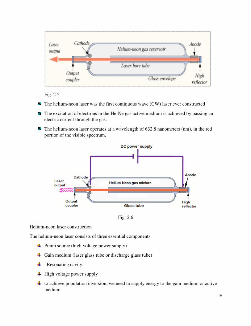
Fig. 2.5
The helium-neon laser was the first continuous wave (CW) laser ever constructed
The excitation of electrons in the He-Ne gas active medium is achieved by passing an electric current through the gas.
The helium-neon laser operates at a wavelength of 632.8 nanometers (nm), in the red portion of the visible spectrum.
Fig. 2.6
Helium-neon laser construction
The helium-neon laser consists of three essential components:
Pump source (high voltage power supply)
Gain medium (laser glass tube or discharge glass tube)
Resonating cavity
High voltage power supply
to achieve population inversion, we need to supply energy to the gain medium or active medium

10
In helium-neon lasers, a high voltage DC power supply is used as the pump source. A high voltage DC supplies electric current through the gas mixture of helium and neon.
Fig. 2.7
Gain medium
� The partial pressure of helium is 1 mbar whereas that of neon is 0.1 mbar.
� to excite primarily the lower energy state electrons of the helium atoms.
� neon atoms are the active centers and have energy levels suitable for laser transitions while helium atoms help in exciting neon atoms.
� Electrodes (anode and cathode) are provided in the glass tube to send the electric current through the gas mixture. These electrodes are connected to a DC

11
Fig. 2.1
the power is switched on, a high voltage of about 10 kV is applied It is enough to excite the electrons and are accelerated
Electrons transfer some of their energy to the helium atoms, jumps into the excited states
Assume that these metastable states are F3 and F5
Metastable state electrons of the helium atoms, return to ground state by transferring their energy to the lower energy state electrons of the neon atoms.
The energy levels of some of the excited states of the neon atoms are identical to the energy levels of metastable states of the helium atoms.
Let us assume that these identical energy states are F3 = E3 and F5 = E5. E3 and E5 are excited states or metastable states of neon atoms.

12
the lower energy state electrons of the neon atoms gain enough energy from the helium atoms and jumps into the higher energy states or metastable states (E3 and E5) whereas the excited electrons of the helium atoms will fall into the ground state. Thus, helium atoms help neon atoms in achieving population inversion.
millions of ground state electrons of neon atoms are excited to the metastable states having longer lifetime
electrons (E3 and E5) of the neon atoms will spontaneously fall into the next lower energy states (E2 and E4) by releasing photons or red light.
Neon excited electrons continue on to the ground state through radiative and nonradiative transitions.

13
Photons emitted from the neon atoms will moves back and forth between two mirrors until it stimulates other electrons
optical gain is achieved due to stimulated emission
Fig. 2.8
photons emitted will escape through the partially reflecting mirror or output coupler to produce laser.
Advantages of helium-neon laser
� Helium-neon laser emits laser light in the visible portion of the spectrum.
� High stability
� Low cost
� Operates without damage at higher temperatures
Disadvantages of helium-neon laser
� Low efficiency
� Low gain
� Helium-neon lasers are limited to low power tasks
Applications of helium-neon lasers
� Helium-neon lasers are used in industries.

14
� Helium-neon lasers are used in scientific instruments.
� Helium-neon lasers are used in the college laboratories
MOLECULAR GAS LASER -CO2
CO2 Molecular gas laser: Principle, Construction, Working, Characteristics, Advantages, Disadvantages and Applications
In a molecular gas laser, laser action is achieved by transitions between vibrational and rotational levels of molecules. Its construction is simple and the output of this laser is continuous. Molecular Gas laser
In a molecular gas laser, laser action is achieved by transitions between vibrational and rotational levels of molecules. Its construction is simple and the output of this laser is continuous.
In CO2 molecular gas laser, transition takes place between the vibrational states of Carbon dioxide molecules. CO2 Molecular gas laser
It was the first molecular gas laser developed by Indian born American scientist Prof.C.K.N.Pillai.
It is a four level laser and it operates at 10.6 µm in the far IR region. It is a very efficient laser.
Energy states of CO2 molecules.
A carbon dioxide molecule has a carbon atom at the center with two oxygen atoms attached, one at both sides. Such a molecule exhibits three independent modes of vibrations. They are
a) Symmetric stretching mode.
b) Bending mode
c) Asymmetric stretching mode.

15
a. Symmetric stretching mode In this mode of vibration, carbon atoms are at rest and both oxygen atoms vibrate simultaneously along the axis of the molecule departing or approaching the fixed carbon atoms.
Fig. 2.9 b. Bending mode:
In this mode of vibration, oxygen atoms and carbon atoms vibrate perpendicular to molecular axis.
Fig.2.10 2.1
c. Asymmetric stretching mode:

16
Fig. 2.11 In this mode of vibration, oxygen atoms and carbon atoms vibrate asymmetrically, i.e.,
oxygen atoms move in one direction while carbon atoms in the other direction.
Principle: The active medium is a gas mixture of CO2, N2 and He. The laser transition takes place between the vibrational states of CO2molecules.
Fig. 2.12
Construction:
It consists of a quartz tube 5 m long and 2.5 cm in the diameter. This discharge tube is filled with gaseous mixture of CO2(active medium), helium and nitrogen with suitable partial pressures.
The terminals of the discharge tubes are connected to a D.C power supply. The ends of the discharge tube are fitted with NaCl Brewster windows so that the laser light generated will be polarized.
Two concave mirrors one fully reflecting and the other partially form an optical resonator. Working:
Figure shows energy levels of nitrogen and carbon dioxide molecules.

17
Fig. 2.13 When an electric discharge occurs in the gas, the electrons collide with nitrogen
molecules and they are raised to excited states. This process is represented by the equation
N2 + e* = N2* + e N2 = Nitrogen molecule in ground state e* = electron with kinetic energy
N2* = nitrogen molecule in excited state e= same electron with lesser energy
Now N2 molecules in the excited state collide with CO2 atoms in ground state and excite to higher electronic, vibrational and rotational levels.
This process is represented by the equation N2* + CO2 = CO2* + N2
N2* = Nitrogen molecule in excited state. CO2 = Carbon dioxide atoms in ground state CO2* = Carbon dioxide atoms in excited state N2 = Nitrogen molecule in ground state.
Since the excited level of nitrogen is very close to the E5 level of CO2 atom,
population in E5 level increases.
As soon as population inversion is reached, any of the spontaneously emitted photon will trigger laser action in the tube. There are two types of laser transition possible.
1.Transition E5 to E4 :
This will produce a laser beam of wavelength 10.6µm 2.Transition E5 to E3 This transition will produce a laser beam of wavelength 9.6µm. Normally 10.6µm transition is more intense than 9.6µm transition. The power output from this laser is 10kW.

18
Characteristics:
1. Type: It is a molecular gas laser.
2. Active medium: A mixture of CO2 , N2 and helium or water vapour is used as active medium
3. Pumping method: Electrical discharge method is used for Pumping action
4. Optical resonator: Two concave mirrors form a resonant cavity
5. Power output: The power output from this laser is about 10kW.
6. Nature of output: The nature of output may be continuous wave or pulsed
wave.
7. Wavelength of output: The wavelength of output is 0.6µm and 10.6µm. Advantages:
1. The construction of CO2 laser is simple
2. The output of this laser is continuous.
3. It has high efficiency
4. It has very high output power.
5. The output power can be increased by extending the length of the gas tube.
Disadvantages:
1. The contamination of oxygen by carbon monoxide will have some effect on laser action
2. The operating temperature plays an important role in determining the output
power of laser.
3. The corrosion may occur at the reflecting plates.
4. Accidental exposure may damage our eyes, since it is invisible (infra red region) to our eyes.
Applications:

19
1. High power CO2 laser finds applications in material processing, welding,
drilling, cutting soldering etc. 2. The low atmospheric attenuation (10.6µm makes CO2 laser suitable for open air
communication. 3. It is used for remote sensing
4. It is used for treatment of liver and lung diseases.
5. It is mostly used in neuro surgery and general surgery.
6. It is used to perform microsurgery and bloodless operations.
SEMICONDUCTOR LASER
Laser action can also be produced semiconductors. The most compact of all the lasers in semiconductor diode laser. It is also called injection laser. There are two types of semiconductor diode lasers (i.) Homo - junction laser (ii.) Hetero- Junction laser.
HOMO – JUNCTION SEMICONDUCTOR DIODE LASER
Definition
It is specifically fabricated p-n junction diode. This diode emits laser light when it is forward biased. Principle
When a p-n junction diode is forward biased, the electrons from n – region and the holes from the p- region cross the junction and recombine with each other. During the recombination process, the light radiation (photons) is released from a certain specified direct band gap semiconductors like Ga-As. This light radiation is known as recombination radiation.
The photon emitted during recombination stimulates other electrons and holes to recombine. As a result, stimulated emission takes place which produces laser.
Construction
Figure shows the basic construction of semiconductor laser. The active medium is a p-n
junction diode made from the single crystal of gallium arsenide. This crystal is cut in the form of
a platter having thickness of 0.5µm. The platelet consists of two parts having an electron
conductivity (n-type) and hole conductivity (p-type).

20
Fig. 2.14
The photon emission is stimulated in a very thin layer of PN junction (in order of few
microns). The electrical voltage is applied to the crystal through the electrode fixed on the upper
surface. The end faces of the junction diode are well polished and parallel to each other. They
act as an optical resonator through which the emitted light comes out.
Working
Figure shows the energy level diagram of semiconductor laser. When the PN junction is forward biased with large applied voltage, the electrons and holes are injected into junction region in considerable concentration. The region around the junction contains a large amount of electrons in the conduction band and a large amount of holes in the valence band.
If the population density is high, a condition of population inversion is achieved. The electrons and holes recombine with each other and this recombination’s produce radiation in the form of light. When the forward – biased voltage is increased, more and more light photons are emitted and the light production instantly becomes stronger.

21
Fig. 2.15 These photons will trigger a chain of stimulated recombination resulting in the release of photons in phase. The photons moving at the plane of the junction travels back and forth by reflection between two sides placed parallel and opposite to each other and grow in strength.
After gaining enough strength, it gives out the laser beam of wavelength 8400A0
The wavelength of laser light is given by
where Eg is the band gap energy in joule.
Characteristics
1. Type: It is a solid state semiconductor laser. 2. Active medium: A PN junction diode made from single crystal of gallium arsenide is used as an active medium. 3. Pumping method: The direct conversion method is used for pumping action
4. Power output: The power output from this laser is a few mW. 5. Nature of output: The nature of output is continuous wave or pulsed output. 6. Wavelength of Output: gallium arsenide laser gives infrared radiation in the wavelength 8300 to 8500A0.
Advantages:
1. It is very small in dimension. The arrangement is simple and compact. 2. It exhibits high efficiency. 3. The laser output can be easily increased by controlling the junction current 4. It is operated with lesser power than ruby and CO2 laser. 5. It requires very little auxiliary equipment 6. It can have a continuous wave output or pulsed output.
Disadvantages
1. It is difficult to control the mode pattern and mode structure of laser. 2. The output is usually from 5° to 15° i.e., laser beam has large divergence. 3. The purity and monochromacity are poor than other types of laser
4. Threshold current density is very large (400A/mm2). 5. It has poor coherence and poor stability.
Application

22
1. It is widely used in fiber optic communication 2. It is used to heal the wounds by infrared radiation 3. It is also used as a pain killer 4. It is used in laser printers and CD writing and reading
HETERO - JUNCTION SEMICONDUCTOR DIODE LASER
A p-n junction made up of the different materials in two regions ie., n type and p type is known as Hetero junction. Principle:
When a PN junction diode is forward biased, the electrons from the n region and holes from the p region recombine with each other at the junction. During recombination process, light is released from certain specified direct band gap semiconductors.
Construction:
This laser consists of five layers as shown in the figure. A layer of Ga-As p – type (3rd layer) will act as the active region. This layer is sand witched between two layers having wider band gap viz. Ga Al As-p – type (2nd layer) and Ga Al As-n- type (4th layer). The end faces of the junctions of 3rd and 4th layer are well polished and parallel to each other. They act as an optical resonator.
Fig. 2.16
Working:
When the PN junction is forward biased, the electrons and holes are injected into the junction region. The region around the junction contains large amount of electrons in the conduction band and holes in the valence band. Thus the population inversion is achieved. At

23
this stage, some of the injected charge carriers recombines and produce radiation in the form of light.
When the forward biased voltage is increased, more and more light photons are emitted and the light intensity is more. These photons can trigger a chain of stimulated recombination’s resulting in the release of photons in phase.
The photons moving at the plane of the junction travels back and forth by reflection between two sides and grow its strength. A coherent beam of laser having wavelength nearly 8000A0 emerge out from the junction region.
Fig. 2.17
Characteristics:
1. Type: It is a Hetero junction semiconductor laser 2. Active medium: PN junctions made from different layers. 3. Pumping method: Direct conversion method 4. Power output: The power output of laser beam is 1 mW 5. Nature of the Output: Continuous wave form 6. Wavelength of the output: Nearly 8000 A0
Advantages:
1. It produces continuous wave output. 2. The power output is very high. Disadvantages:
1. It is very difficult to grow different layers of PN junction. 2. The cost is very high. Applications:
1. This type of laser is mostly used in optical applications 2. It is widely used in computers, especially on CD-ROMs.

24
LIQUID DYE LASER
Dye is a liquid laser with an active medium Doped with Rhodamine B, Rhodamine 6G, fluoresein
Characteristics Output lies in UV, Visible or IR Using dye the output can be varied from 390nm to 1000nm Power output starts from 1 watt, beam diameter of 0.5mm Conversion efficiency is relatively high than 25%
Construction
It has two configuration
The dye is pumped through the capillary tube from the storage tank It gets optically excited by the flash tube Output pass through the Brewster window
Fig. 2.18
2nd Configuration

25
Fig. 2.19 The dye is pumped through the nozzle to form a Brewster Angle Excitation mechanism involves here Laser gets reflected from two HR mirror passed through the output coupler
Birefringent filter is used to tune the output of Laser Working
Active medium in Laser may be of organic dye mixed with ethanol, water Dyes like Rhodamine B, Sodium fluorisin it’s difficult to determine the element So organic dye is prefered It provides the output in various ranges of wavelength The amount of amplification also varies Birefringent filter acts as a prism Filters certain specified frequency, it bends the other wavelength, tune the output with
accuracy Applications It is used as research tool in medical Applications Advantages
It is available in visible and non-visible form Construction of a dye laser is not so complex Beam dia. is less Ranges of wavelength can be gained as output Having greater efficiency High power output is possible
Disadvamtages
� Cost of dye laser is high � Using filter as birefringent makes it costly � To determine the particular element of output, a complex dye has to be used
Q SWITCHING

26
Q switching is a technique for obtaining energetic short (but ot ultrashot) pulses from a laser by modulating the intracavity losses and thus the Q-factor of the laser resonator. The technique is mainly applied for the generation of nanosecond pulses of high energy and peak power with solid-state bulk lasers. Generation of a Q-switched pulse
The resonator losses are kept at a high level - As lasing cannot occur, gain medium enhanced by the pumping mechanism - spontaneous emission
The losses are suddenly (with active or passive means) reduced The power of the laser radiation builds up very quickly in the laser resonator The saturation energy of the gain medium, starts to be saturated. When the gain equals the loss, peak of the pulse is reached The pulse duration achieved with Q switching is typically in the nanosecond range The energy of the generated pulse is typically higher than the energy of the gain
medium In most cases, Q-switched lasers generate regular pulse trains via repetitive Q
switching. Q-switched lasers have reached pulse durations far below 1 ns and repetition rates up
to several megahertz laser systems can deliver pulses with many kilojoules of energy and durations in the
nanosecond range. The first experimental demonstrations were performed in 1961 at Hughes Aircraft
Company The resonator losses can basically be switched in different ways:
Active Q Switching Passive Q Switching
In order to store many atoms in an upper level, the flow to a lower level must first be limited. Thus, stimulated emission must be prevented by placing an attenuator in the cavity to stop light from travelling back and forth (note: this attenuator is usually a light modulator, rather than a mechanical shutter, which reduces the amplitude or power of the light beam). In this case, for a radiative transition, the only decay to a lower level is due to spontaneous emission. When the pumping system supplies more atoms per second than lose energy by spontaneous emission, the population in the upper level can become very large

27
Fig. 2.20
� After a certain time, the energy losses in the cavity are suddenly reduced so that laser oscillation becomes possible.
� As there is a very large population in the upper level, stimulated emission becomes very probable and the laser is suddenly triggered.
� The flow due to stimulated emission is much greater than the other flows (filling by pumping and emptying by spontaneous emission): all the atoms stored in the upper level fall sharply, emitting stimulated photons (starting with the spontaneous emission trapped in the cavity).
� Thus, the laser cavity fills with stimulated photons at the same time as the upper level empties
� Eventually, the upper level is completely empty. � There is no further stimulated emission and the cavity will also empty due to the
losses created by the output mirror (in general, the cavity empties after only a few round trips)

28
Fig. 2.21
� This process gives rise to a dramatic variation in the number of photons in the cavity (first by a significant amplification due to stimulated emission then by the complete emptying of the cavity at the end).
� The net result is the emission of a short pulse of light via the output mirror. � Generally, several round trips are needed to completely depopulate the upper
energy level and several more round trips to empty the optical cavity so the duration of the pulse is greater than one round trip.
� This means that for optical cavities shorter than a metre, it is possible to generate short pulses of only a few nanoseconds but several millijoules in power.
� The peak power (the pulse energy divided by its duration) of these lasers can be in the megawatt range or even higher.
� It should be noted that Q-switched lasers never reach a steady state as they stop functioning after several round trips of the light in the cavity.
Active Q Switching For active Q switching, the losses are modulated with an active control element (active Q switch), typically either an acousto-optic or electro-optic modulator.
Fig. 2.22

29
the switching time of the modulator is not comparable to the pulse duration For many applications, Q-switched pulses are generated in a periodic fashion, i.e., with a given pulse repetition rate.
Passive Q Switching
Fig. 2.23 MODE-LOCKING
Operating technique is completely different. The cavity is filled with photons everywhere at the same time: only a packet of photons is
allowed to propagate in the cavity. This pulse lasts for a shorter time than a round trip in the cavity. In other words, its
spatial extension is markedly shorter than the length of the cavity. operating conditions consists a light modulator, that can chop the light in the cavity into
periods of exactly the same length as a round trip. Those photons allowed to pass through the modulator in its on-state will be amplified
Fig. 2.24 A pulse propagating in the optical cavity of a mode-locked laser
It reaches the modulator in this state after each round trip. The other photons elsewhere in the cavity will be subject to losses when they travel
through the modulator. The pulses last for a much shorter time than a round trip in the cavity. photons allowed to pass, will be amplified the pulses last for a much shorter time than a round trip in the cavity.

30
They are limited by the Fourier transform of the spectrum emitted by the laser: the wider the spectrum, the shorter the pulse.
exceptionally wide - pulse generated will be only several femtoseconds long The pulse repetition period corresponds to the cavity round-trip time The average power of a mode-locked laser is of the same order of magnitude as that of
continuous-wave lasers. In fact, in contrast to Q-switched lasers, these can also reach a steady state like
continuous-wave lasers. The fundamental difference is that the stimulated photons are condensed in a packet
rather than spread all around the cavity. During one round trip, only one laser pulse is emitted via the output mirror. The pulse energy is thus equal to the average power multiplied by the duration of a
round trip. Generally, these energies are of the order of several nanojoules. The term “mode-locking” comes from the analysis of the various frequencies. A laser operating under these conditions will emit over several different frequencies due
to the rapid modulation of the modulator. if the laser emits continuously at two frequencies separated by , the light output due to
interference of the two waves will be modulated by a sinusoidal term of frequency modulation is generally very rapid, detected by photodiodes known as beating and results from the interference of beams with different frequencies When a large number of frequencies are emitted by the laser, the beat signal becomes
quite complex. Its shape depends on the relative phase of the waves with different frequencies. However, the beat signal has a very regular shape in one particular case: when all the
waves emitted by the cavity are in phase. Then, there are certain times and spots in the cavity where all the waves beat in phase and
the interference signal is thus very powerful
Fig. 2.25

31
When the longitudinal modes are in phase, in the cavity where the electric fields add
together constructively. Everything occurs as if a pulse was travelling inside the cavity
Fig. 2.1 LASERS MODES: THE SHAH FUNCTION
The Shah function, III(t), is an infinitely long train of equally spaced delta-functions. The
symbol III is pronounced shah after the Cyrillic character III, which is said to have been modeled
on the Hebrew letter (shin) which, in turn, may derive from the Egyptian a
hieroglyph depicting papyrus plants along the Nile.
The Fourier transform of the Shah function
If w = 2np, where n is an integer, every term is exp(-2mnp i) = 1, and the sum diverges; otherwise, cancellation occurs. So:
) exp( )
)exp( )
exp( )
m
m
m
t m i t dt
t m i t dt
i m
δ ω
δ ω
ω
∞ ∞
=−∞−∞
∞∞
=−∞ −∞
∞
=−∞
= ( − −
= ( − −
= −
∑∫
∑ ∫
∑
{III( )} III(t ω π∝ /2 )Y

32
Fig. 2.1 The Fourier transform of an infinite train of pulses An infinite train of identical pulses can be written: E(t) = III(t/T) * f(t) where f(t) represents a single pulse and T is the time between pulses. The Convolution Theorem states that the Fourier Transform of a convolution is the product of the Fourier Transforms. So:
Fig. 2.1
Fig. 2.1
A train of pulses results from a single pulse bouncing back and forth inside a laser cavity of round-trip time T. The spacing between frequencies—called laser modes—is then dw = 2p/T or δδδδn = 1/T.
MODE-LOCKED VS. NON-MODE-LOCKED LIGHT
( )
III( / ) (2
E
FT
ω
ω π ω )
∝�

33
Mode-locked pulse train:
Generating short pulses = mode-locking
Locking the phases of the laser modes yields an ultrashort pulse.
Fig. 2.1
Locked modes
( ) ( ) ( 2 / )m
E F m Tω ω δ ω π∞
=−∞
= −∑�
( ) ( 2 / ) ( III( / 2 )m
F m T F Tω δ ω π ω ω π∞
=−∞
= − = )∑exp( )( ) ( ) ( 2 / )
m
m
iE F m Tω ω ϕ δ ω π∞
=−∞
= −∑�
( ) () /exp( 2 )m
m
F m Tiω δ ω πϕ∞
=−∞
= −∑

34
Fig. 2.1
Numerical simulation of mode-locking
Fig. 2.1 Ultrafast lasers often have thousands of modes.

35
A generic ultrashort-pulse laser
A generic ultrafast laser has a broadband gain medium, a pulse-shortening device, and two or more mirrors:
Fig. 2.1 Many pulse-shortening devices have been proposed and used.
Passive mode-locking: the saturable absorber

36
Fig. 2.1
High-intensity spikes (i.e., short pulses) see less loss and hence can lase while low-intensity backgrounds (i.e., long pulses) won’t.
Passive mode-locking with a slow saturable absorber
What if the absorber responds slowly (more slowly than the pulse)?
Then only the leading edge will experience pulse shortening.

37
Fig. 2.1
This is the most common situat
The Passively Mode-locked Dye Laser
Fig. 2.1
Passively mode-locked dye lasers yield pulses as short as a few hundred fs.
They’re limited by our ability to saturate the absorber.
Commercial fs lasers - Availability
• Ti:Sapphire
• Coherent:
• Mira (<35 fs pulse length, 1 W ave power),
• Chameleon (Hands-free, ~100 fs pulse length),
• Spectra-Physics:
• Tsunami (<35 fs pulse length, 1 W ave power)

38
• Mai Tai (Hands-free, ~100 fs pulse length)
Active mode-locking
� Any amplitude modulator can preferentially induce losses for times other than that of the intended pulse peak. This produces short pulses.
� It can be used to start a Ti:Sapphire laser mode-locking
Hybrid mode-locking
Hybrid mode-locking is any type of mode-locking incorporating two or more techniques simultaneously.
� Sync-pumping and passive mode-locking
� Active and passive mode-locking
However, using two lousy methods together doesn’t really work all that much better than one good method.
Diode lasers use hybrid mode-locking
Fig. 2.1

39

1
SCHOOL OF SCIENCE AND HUMANITIES
DEPARTMENT OF PHYSICS
UNIT – III - Applications of Laser – SPH1312

2
UNIT III - APPLICATIONS OF LASER
Application of laser in industry – cutting and welding – Drilling – Surface Hardening – Medical
applications – Laser as diagnostic and therapeutic tool – Holography – Theory of recording and
reconstruction – application of Holography.
3. Introduction
Lasers deliver coherent, monochromatic, well-controlled, and precisely directed light beams. A
priori, therefore, lasers would seem tobe poor choices for general-purpose illumination, however,
they are ideal for concentrating light in space, time, or particular wavelengths. Lasers have been
regularly used to measure, cut, drill, weld, read, write, send messages, solve crimes, burn plaque
out of arteries, and perform delicate eye operations.
Over and over again the laser has proved to be an extremely practical tool. Nevertheless, lasers
have also proved their usefulness in non-practical applications, especially in the realm of art and

3
entertainment. Lasers are involved in almost all aspects of these fields, from “light shows” to
Compact Discs (CDs) and Digital Video Discs (DVDs), to special effects in the movies. Some
other commonplace application of lasers are as Laser pointers, barcode scanners, laser printers,
etc.
Still, much of the important modern day celebrated applications lie in the fiber-optic
communication, laser machining and fabrication, trace element detection, laser metrology and
medical imaging.
3.1 Laser Machining and cutting
Laser energy can be focused in space and concentrated in time so that it heats, burns away, or
vaporizes many materials. Although the total energy in a laser beam may be small, the
concentrated power on small spots or during short intervals can be enormous. Although lasers
cost much more than mechanical drills or blades, their different properties allow them to perform
otherwise difficult tasks.
Fig. 2.1
A laser beam does not deform flexible materials as a mechanical drill would, so it can drill holes
in materials such as soft rubber nipples for baby bottles. Likewise, laser beams can drill or cut
into extremely hard materials without dulling bits or blades. Laser machining is not dependent on
the material hardness but on the optical properties of the laser and the optical and thermo-
physical properties of the material. For example, lasers have drilled holes in diamond dies used
for drawing wire.Several recent research have shown that laser cutting is best achieved with
ultrafast lasers (Fig. 2), as the material only ablates and does not get a chance to melt under such
ultrafast time scale interactions.
3.2 Laser cutting
4
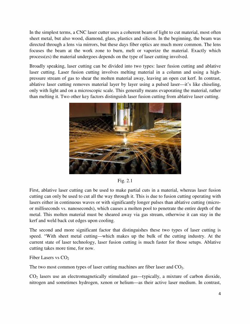
In the simplest terms, a CNC laser cutter uses a coherent beam of light to cut material, most often
sheet metal, but also wood, diamond, glass, plastics and silicon. In the beginning, the beam was
directed through a lens via mirrors, but these days fiber optics are much more common. The lens
focuses the beam at the work zone to burn, melt or vaporize the material. Exactly which
process(es) the material undergoes depends on the type of laser cutting involved.
Broadly speaking, laser cutting can be divided into two types: laser fusion cutting and ablative
laser cutting. Laser fusion cutting involves melting material in a column and using a high-
pressure stream of gas to shear the molten material away, leaving an open cut kerf. In contrast,
ablative laser cutting removes material layer by layer using a pulsed laser—it’s like chiseling,
only with light and on a microscopic scale. This generally means evaporating the material, rather
than melting it. Two other key factors distinguish laser fusion cutting from ablative laser cutting.
Fig. 2.1
First, ablative laser cutting can be used to make partial cuts in a material, whereas laser fusion
cutting can only be used to cut all the way through it. This is due to fusion cutting operating with
lasers either in continuous waves or with significantly longer pulses than ablative cutting (micro-
or milliseconds vs. nanoseconds), which causes a molten pool to penetrate the entire depth of the
metal. This molten material must be sheared away via gas stream, otherwise it can stay in the
kerf and weld back cut edges upon cooling.
The second and more significant factor that distinguishes these two types of laser cutting is
speed. “With sheet metal cutting—which makes up the bulk of the cutting industry. At the
current state of laser technology, laser fusion cutting is much faster for those setups. Ablative
cutting takes more time, for now.
Fiber Lasers vs CO2
The two most common types of laser cutting machines are fiber laser and CO2.
CO2 lasers use an electromagnetically stimulated gas—typically, a mixture of carbon dioxide,
nitrogen and sometimes hydrogen, xenon or helium—as their active laser medium. In contrast,

5
fiber lasers—which are a type of solid-state laser—use an optical fiber doped with rare-earth
elements, such as erbium, ytterbium, neodymium or dysprosium. As indicated by Houldcroft’s
experiments, the industry began with CO2, and that technology dominated until only recently.
“Potentially, CO2 lasers will be replaced completely. If so, this would happen mid-term while the
fiber laser technology further evolves. Currently, CO2 lasers still have some specific advantages,
e.g., better edge quality in thick material and smaller burrs.
CNC laser cutters are used on a wide range of materials in a variety of industries. Since cutting
sheet metal is the most common application, it’s worth focusing on the particularities involved.
For instance, reflectance and surface thickness are two of the most important factors to consider.
Laser cutting uses high-pressure gas—5-25 bars for nitrogen cutting—so you need the parts to
either be supported by their own weight, which works if they’re thicker than 2-3 mm and
relatively large in size, but for the parts that are thin and small, to resist the force of the gas
stream, small sections need to remain uncut,” Sarrafi said. “These micro-joints are very small,
0.2-0.4 mm wide, so they’re easy to break in post processing, but sometimes they’re necessary to
connect the parts to the frame so the parts don’t fly away
3.3 Laser welding
Laser welding is used more frequently in industrial processes because it has wider application
than traditional welding as less heat is created because the beam is so focused. This means that
heat transfer to the workpiece is much less and the metallurgical structure is less affected and the
quality of the weld is much higher than with traditional forms of welding.
Laser welding is a much more accurate manufactoring process and welds can be as small as one
hundredths of a millimetre. Small pulses of heat are used to create the weld which leads to a
higher quality finish which is stronger providing a better depth to width ratio. Depending on the
power of the laser, welding penetration up to 15 millimetre of steel or stainless steel can be
achieved.
Another distinct advantage of laser welding over other methods is that lasers can weld a greater
variety of metals such as high strength stainless steel, titanium, aluminium, carbon steel as well
as precious metals like gold and silver.
With laser welding, welds are much more accurate and finish is superior as is strength. The
manufactoring process is therefore excellent for fine components and it can be used in areas
where there is limited access. Lasers enable precision and quality where required for fine
components.

6
Fig. 2.1
Summary of Laser Welding Advantages
� Aesthetically better weld finishes
� More suited to high value items such as jewellery
� Great for inaccessible places
� Ideal for solenoids and machined components
� Perfect for medical devices where weld quality is vital for hygiene and precision
� Better weld quality for a variety of metals and metal depths
� No concerns for weld weaknesses due to minimal distortion
� Workpieces can be handled almost immediately because heat transference is low
� Overall improved productivity
The benefits of laser welding for modern processes over traditional welding are many. Laser
welding overall has a much wider application and an ability to weld a greater number of metals
to a much higher quality which is vital where precision engineering is required.
Laser - Hole drilling
We will describe the physical processes that occur in the interaction of high-power laser radiation with surfaces. An understanding of these processes is important for understanding thecapabilities and limitations of laser vaporization. We will emphasize metallic targets, but muchof what is said applies to other absorbing surfaces as well.

7
Lasers used—The Nd:YAG laser has often been used for drilling holes in metals. It can deliver an irradiance of 106–109 watts/cm2 to a target surface. For most metals, it offers lower reflectivity than the CO2 laser, so that less light energy is lost by reflection. It also offers high processing speed. The CO2 laser, with a wavelength 10 times larger than the Nd:YAG laser, has less importance in drilling of metals, because the beam cannot be focused to as small a spot, and because the absorption is not so high as for the Nd:YAG laser. But for many nonmetals, like alumina, the absorption is much higher for the CO2 laser than for the Nd:YAG laser. Thus, CO2 lasers have an important role in the drilling of materials like ceramics and plastic. The copper vapor laser, with a high pulse repetition rate, has also found a role in the drilling of metals. Excimer lasers offer material removal with relatively little heating of the surrounding material, because the chemical bonds in the target can be broken by shorter, ultraviolet wavelengths of the excimer laser. The material is removed without significant thermal conduction of heat into the interior of the workpiece. Thus, excimer lasers may be used for hole drilling in materials that are sensitive to heat, like plastics.
Fig. 2.1
Depth of holes—When high-power laser radiation is absorbed by a target, the surface is heated by the incoming laser light. The surface temperature goes quickly through the melting point and reaches the vaporization temperature (boiling point). Material begins to vaporize and a hole is produced in the surface. When a pulsed laser beam with duration around 1 millisecond interacts with a surface, the process of material involves conventional heating, melting, and vaporization. The time scale is 10 Optics and Photonics Series, Photonics-Enabled Technologies: Manufacturing long enough so that vaporized material can flow away from the point of the interaction. Vaporization occurs at a continually retreating surface.

8
Advantages
Hole drilling with lasers offers many advantages over competing techniques.
1. There is no contact of external materials with the workpiece, and hence, no contamination.
2. Hard, brittle materials that are difficult to drill with conventional techniques are often easily
drilled with lasers.
3. The heat-affected zones around the holes can be very small.
4. It is possible to produce very small holes in thin materials.
5. Laser drilling is compatible with automation, so that it is possible to produce large numbers of
holes and complex patterns of holes in a completely automated process.
6. There is no wear of expensive tool bits, so that in some cases, laser drilling offers an economic
advantage.
7. Holes can be drilled with high throughput rate, so that the cost is low.
Limitations
Laser hole drilling, of course, will not completely replace conventional hole drilling. There are a
number of limitations for laser hole drilling.
1. Laser energy is relatively expensive and may not compete economically with other processes
for specific applications.
2. The holes drilled by lasers tend to have limited depth. One might think that one could use a
CO2 laser and allow it to dwell on a spot for a long time. But the heat then spreads over a
1arger volume and much of the advantage in using lasers is lost.
3. There may be a recondensation of vaporized material around the entrance to the hole, which
forms a crater-like lip. The lip can be removed fairly easily, but this adds one more step to the
laser-drilling process.

9
3.4 Surface hardening
Laser beams are invisible electromagnetic radiations in the infra-red portion of the
spectrum, and are increasingly being used for surface-hardening of ferrous materials to improve
mechanical properties like wear resistance and even fatigue resistance. There are two main type
of Lasers used- YAG Solid-state type and the carbon-dioxide gas type. The output of YAG laser
has much shorter wavelength, 1.064 µm, whereas the carbon dioxide laser emits radiations with
10.8 µm wavelength. Carbondioxide laser is more commonly used and is suitable for surface
hardening, particularly when the process requires more than 500 W of power.
The power density of laser beam is usually expressed as watts per square centimeter.
The power densities used in laser surface hardening are in the range of 500 to 5000 W/cm2 with
dwell times in the range of 0.1 s to 10 s. For carbon steels, power densities used are from 1000 to
1500W/cm2 with dwell time of 1 to 2 s.
During Laser surface hardening, a laser can generate very intense energy fluxes at the surface of
the component, when the Laser radiations impinge on it, and are absorbed to generate heat
energy. This heat is then conducted inside the component. When the power density of the laser
beam is high, the rate of heat generation is much higher than the rate of heat conduction. The
temperature of the surface layer increases rapidly to soon attain the austenitising temperature.
Fig. 2.1
A moderate power density of 500 W/m2, results in temperature gradient of 500°C/mm. The laser
beam may be moved over the surface of the component as illustrated in Fig. 8.78. The surface
which meets the laser beam gets heated up. Once the beam passes over, the heated volume gets
subsequently ‘self-quenched’. Thus, by selecting power density and the speed of the laser spot
(i.e., the dwell time), a desired case depth can be hardened.
Laser-surface-hardening is similar to any other surface-hardening method such as induction, or
flame, except that the laser beam is used to generate heat here. The heating time to the
austenitising temperature, particularly in laser heating, is very short-fractions of seconds to few
seconds. The dwell time cannot be made very large as surface melting may occur which is
undesirable.
Alloy steels intended to have higher hardenabilities should have very fine carbides particles even
then their dissolution is difficult. Diffusion of carbon though faster than alloying elements
requires longer dwell time (low speed of motion of laser spot) to obtain homogeneous structure.

10
where,
Y = depth of hardening (mm),
P = Laser power (W),
Db = incident beam diameter (mm)
V = travel speed (mm/s)
but with a considerable scatter of experimental data. At a constant value of P/√DhV, the depth of
hardening can vary by a factor of 2.
Advantages and Disadvantages of Laser Hardening:
1. Non-hardenable steels like mild steels can be surface hardened.
2. Hardness obtained is slightly higher than conventional hardening.
3 Closer control over power inputs helps in eliminating dimensional distortion.
4. Beam (with the help of optical parts) can easily reach the inaccessible areas of components,
and re-entrant surfaces.
5. No vacuum or protective atmosphere is required.
6. The last optical element of the Laser and the component to be surface hardened may be far-
placed.
7. Very long and irregular-shaped components can be hardened easily.
Disadvantages:
1. High initial cost particularly of large lasers.
2. Lasers use 10% of the input energy, i.e., there are inefficient.
3. The depth of case is very limited.
4. Working cost is high.
3.5 Medical Applications
Surgical removal of tissue with a laser is a physical process similar to industrial laser
drilling. Carbon-dioxide lasers operating at 10.6 micrometers can burn away tissue as the
infrared beams are strongly absorbed by the water that makes up the bulk of living cells. A laser
beam cauterizes the cuts, stopping bleeding in blood-rich tissues such as gums. Similarly, laser
wavelengths near one micrometer (Neodymium-YAG Laser) can penetrate the eye, welding a
detached retina back into place, or cutting internal membranes that often grow cloudy after

11
cataract surgery (Fig. 5a). Less-intense laser pulses can destroy abnormal blood vessels that
spread across the retina in patients suffering from diabetes, delaying the blindness often
associated with the disease. Ophthalmologists surgically correct visual defects by removing
tissue from the cornea, reshaping the transparent outer layer of the eye with intense ultraviolet
pulses from Excimer Lasers.
Fig. 2.1 (a) Schematic of Laser Eye Surgery. (b) Laser energy delivery to precise spots
in joints for arthroscopic surgery.
Laser light can be delivered to places within the body that the beams could not otherwise reach
through optical fibers similar to the tiny strands of glass that carry information in telephone
systems. One important example involves threading a fiber through the urethra and into the
kidney so that the end of the fiber can deliver intense laser pulses to kidney stones. The laser
energy splits the stones into fragments small enough to pass through the urethra without
requiring surgical incisions. Fibers also can be inserted through small incisions to deliver laser
energy to precise spots in the knee joint during arthroscopic surgery (Fig. 5b). Another medical
application for lasers is in the treatment of skin conditions. Pulsed lasers can bleach certain types
of tattoos as well as dark-red birthmarks called port-wine stains. Cosmetic laser treatments
include removing unwanted body hair and wrin-kles.
3.6 Biomedical Imaging and superresolution
Confocal microscopy (Fig. 6) is a ubiquitous imaging tool for imaging thick specimen in a wide
range of investigations in biological, medical and material sciences. It uses UV or visible light
for the single photon excitation of fluorophore from ground state to the excited state followed by
deactivation through fluorescence emission which is detected through high quantum efficiency
photomultiplier tube (PMT) in the range of near ultraviolet, visible and near infrared spectral
region. The basic difference of confocal Light Scanning Microscope with the conventional
optical microscope is the confocal aperture arranged in a plane conjugate to the intermediate
image plane and thus, to the object plane of the microscope. The PMT can only detect the light
that passed the pinhole. As the laser beam is focused to a diffraction limited spot, which
illuminates only a point of the object at a time, the point illuminated and the point observed are

12
situated in conjugate planes, i.e. they are focused onto each other. The perfection of focused
beam which is connected to the resolution has always been a matter of concern in the far-field
fluorescence microscopy. Still, optical microscopy remains the best choice for monitoring live
specimens despite the resolution advantage of, say electron microscopes, since the energy
deposited in electron microscopy adversely affects the viability of live specimens. This practical
compromise implicitly sets resolution enhancement as one of the most important development in
optical microscopy. Finally, all these images are combined into one super-resolved image with
complete structural information. They demonstrated this method first in 2006 and called it Photo
Activated Localization Microscopy (PALM)
3.7 Laser Imaging and Holography
Holography is a much broader field than most people have perceived. Recording and displaying
truly three-dimensional images are only small parts of it. Holographic optical elements (HOE)
can perform the functions of mirrors, lenses, gratings, or combinations of them, and they are
used in myriad technical devices. Holographic interferometry measures microscopic
displacements on the surface of an object and small changes in index of refraction of transparent
objects like plasma and heat waves.
The coherence of laser light is crucial for interferometry and holography, which depend on
interactions between light waves to make extremely precise measurements and to record three-
dimensional images. The result of adding light waves together depends on their relative phases.
If the peaks of one align with the valleys of the other, they will interfere destructively to cancel
each other out; if their peaks align, they will interfere constructively to produce a bright spot.
This effect can be used for measurement by splitting a beam into two identical halves that follow
different paths. Changing one path just half a wavelength from the other will shift the two out of
phase, producing a dark spot. This technique has proved invaluable for precise measurements of
very small distances. Holograms are made by splitting a laser beam into two identical halves,
using one beam to illuminate an object. This object beam then is combined with the other half—
the reference beam—in the plane of a photographic plate, producing a random-looking pattern of
light and dark zones that record the wave front of light from the object (Fig. 4). Later, when laser
light illuminates that pattern from the same angle as the reference beam, it is scattered to
reconstruct an identical wave front of light, which appears to the viewer as a three-dimensional
image of the object. Holograms now can be mass-produced by an embossing process, as used on
credit cards, and do not have to be viewed in laser light.

13
Fig. 2.1 Schematic of Holography process where the laser beam is split into three components.
First two beams are needed to create the hologram which is viewed with the help of the third.
3.7.1 TYPES OF HOLOGRAMS
A hologram is a recording in a two- or three-dimensional medium of the interference pattern
formed when a point source of light (the reference beam) of fixed wavelength encounters light of
the same fixed wavelength arriving from an object (the object beam). When the hologram is
illuminated by the reference beam alone, the diffraction pattern recreates the wave fronts of light
from the original object. Thus, the viewer sees an image indistinguishable from the original
object.
The reflection hologram
Transmission holograms
Hybrid holograms
3.7.2 Recording and reconstruction of holograms
Recording of hologram. The recording of hologram is based on the phenomenon of
interference. It requires a laser source, a plane mirror or beam splitter, an object and a
photographic plate. A laser beam from the laser source is incident on a plane mirror or beam
splitter. As the name suggests, the function of the beam splitter is to split the laser beam. One
part of splitted beam, after reflection from the beam splitter, strikes on the photographic plate.
This beam is called reference beam. While other part of splitted beam (transmitted from beam

14
splitter) strikes on the photographic plate after suffering reflection from the various points of
object. This beam is called object beam.
The object beam reflected from the object interferes with the reference beam when both the
beams reach the photographic plate. The superposition of these two beams produces an
interference pattern (in the form of dark and bright fringes) and this pattern is recorded on the
photographic plate. The photographic plate with recorded interference pattern is called hologram.
Photographic plate is also known as Gabor zone plate in honour of Denis Gabor who developed
the phenomenon of holography.
Each and every part of the hologram receives light from various points of the object. Thus, even
if hologram is broken into parts, each part is capable of reconstructing the whole object.
Reconstruction of image.
In the reconstruction process, the hologram is illuminated by laser beam and this beam is called
reconstruction beam. This beam is identical to reference beam used in construction of hologram.
The hologram acts a diffraction grating. This reconstruction beam will undergo phenomenon of
diffraction during passage through the hologram. The reconstruction beam after passing through
the hologram produces a real as well as virtual image of the object.
One of the diffracted beams emerging from the hologram appears to diverge from an apparent
object when project back. Thus, virtual image is formed behind the hologram at the original site
of the object and real image in front of the hologram. Thus an observer sees light waves
diverging from the virtual image and the image is identical to the object. If the observer moves
round the virtual image then other sides of the object which were not noticed earlier would be
observed. Therefore, the virtual image exhibits all the true three dimensional characteristics. The
real image can be recorded on a photographic plate.
3.7.3 Applications of holography
The three-dimensional images produced by holograms have been used in various fields,
such as technical, educational also in advertising, artistic display etc.
Holographic diffraction gratings: The interference of two plane wavefronts of laser
beams on the surface of holographic plate produces holographic diffraction grating. The
lines in this grating are more uniform than in case of conventional grating.
Hologram is a reliable object for data storage, because even a small broken piece of
hologram contains complete data or information about the object with reduced clarity.
The information-holding capacity of a hologram is very high because many objects can
be recorded in a single hologram, by slightly changing ...
33..88 HHoollooggrraapphhyy ––FFuuttuurree AApppplliiccaattiioonnss

15
Holography is a very useful tool in many areas, such as in commerce, scientific research,
medicine, and industry.
Some current applications that use holographic technology are:
• Holographic interferometry is used by researchers and industry designers to test and design many things, from tires and engines to prosthetic limbs and artificial bones and joints.
• Supermarket and department store scanners use a holographic lens system that directs laser
light onto the bar codes of the merchandise.
• Holographic optical elements (HOE’s) are used for navigation by airplane pilots. A
holographic image of the cockpit instruments appears to float in front of the windshield. This
allows the pilot to keep his eyes on the runway or the sky while reading the instruments. This
feature is available on some models of automobiles.
Fig. 2.1
• Medical doctors can use three-dimensional holographic CAT scans to make measurements
without invasive surgery. This technique is also used in medical education.
• Holograms are used in advertisements and consumer packaging of products to attract potential
buyers.
• Holograms have been used on covers of magazine publications. One of the most memorable Sports Illustrated covers was the December 23, 1992 issue featuring Michael Jordan. Holograms have also been used on sports trading cards.
• The use of holograms on credit cards and debit cards provide added security to minimize
counterfeiting.
• Holography has been used to make archival recordings of valuable and/or fragile museum
artifacts.

16
• Sony Electronics uses holographic technology in their digital cameras. A holographic crystal
is used to allow the camera to detect the edge of the subject and differentiate between it and the
background. As a result, the camera is able to focus accurately in dark conditions.
• Holography has been use by artists to create pulsed holographic portraits as well as other
works of art.
Future applications of holography include:
• Future colour liquid crystal displays (LCD’s) will be brighter and whiter as a result of
holographic technology. Scientists at Polaroid Corp. have developed a holographic reflector that
will reflect ambient light to produce a whiter background.
• Holographic night vision goggles
Fig. 2.1
• Many researchers believe that holographic televisions will become available within 10 years at
a cost of approximately $5000. Holographic motion picture technology has been previously
attempted and was successful in the 1970s. The future of holographic motion pictures may
become a reality within the next few years.

17
Fig. 2.1
• Holographic memory is a new optical storage method that can store 1 terabyte (= 1000 GB) of
data in a crystal approximately the size of a sugar cube. In comparison, current methods of
storage include CD’s that hold 650 to 700 MB, DVD’s that store 4.7 GB, and computer hard
drives that hold up to 120 GB.
• Optical computers will be capable of delivering trillions of bits of information faster than the
latest computers.
3.9 MEDICAL ENDOSCOPE - FIBER OPTIC: CONSTRUCTION AND WORKING
Optical fibers are very much useful in medical field. Using low quality, large diameter and short
length silica fibers we can design a fiber optic endoscope or fibroscope.
MEDICAL ENDOSCOPE
Optical fibers are very much useful in medical field. Using low quality, large diameter and short length silica fibers we can design a fiber optic endoscope or fibroscope. A medical endoscope is a tubular optical instrument, used to inspect or view the internal parts of human body which are not visible to the naked eye. The photograph of the internal parts can also be taken using this endoscope. Construction Figure shows the structure of endoscope. It has two fibers viz., 1. Outer fiber(f0) 2. The inner fiber (fi).

18
Outer fiber The outer fiber consists of many fibers bundled together without any particular order of arrangement and is called incoherent bundle. These fiber bundles as a whole are enclosed in a thin sleeve for protection. The outer fiber is used to illuminate or focus the light onto the inner parts of the body. Inner fiber The inner fiber also consists of a bundle of fibers, but in perfect order. Therefore this arrangement is called coherent bundle. This fiber is used to collect the reflected light from the object. A tiny lens is fixed to one end of the bundle in order to effectively focus the light, reflected from the object. For a wider field of view and better image quality, a telescope system is added in the internal part of the telescope. Working Light from the source is passed through the outer fiber (f0). The light is illuminated on the internal part of the body. The reflected light from the object is brought to focus using the telescope to the inner fiber (fi). Here each fiber picks up a part of the picture from the body. Hence the picture will be collected bit by bit and is transmitted in an order by the array of fibers. As a result, the whole picture is reproduced at the other end of the receiving fiber as shown in the figure. The output is properly amplified and can be viewed through the eye piece at the receiving end. The cross sectional view is as shown in the figure. In figure, we can see that along with input and output fibers, we have two more channels namely, (i) Instrumental Channel (C1) and (ii) Irrigation channel (C2) used for the following purposes. Instrumental Channel (C1) It is used to insert or take the surgical instruments needed for operation.

19
Irrigational Channel (C2) It is used to blow air or this is used to clear the blood in the operation region, so that the affected parts of the body can be clearly viewed.
1
SCHOOL OF SCIENCE AND HUMANITIES
DEPARTMENT OF PHYSICS
UNIT – IV - OPTIC FIBERS – SPH1312

2
UNIT IV
Fiber optic revolution – basic characteristics of optical fiber – acceptance angle – numerical
aperture – propagation of light through optical fiber – theory of mode formation – classification
of fibers – step index and graded index fibers – single mode and multi mode fibers – losses in
fibers – fabrication techniques of fibers.
4 INTRODUCTION TO FIBER OPTICS
The development of lasers and optical fiber has brought about a revolution in the field
of communication systems. Experiments on the propagation of information – carrying light
waves through an open atmosphere were conducted. The atmospheric conditions like rain, fog
etc. affected the efficiency of communication through light waves.
To have efficient communication systems, the information carried by light waves should
need a guiding medium through which it can be transmitted safely.
This guiding mechanism is optical fiber. The communication through optical fiber is
known as light wave communication or optical communication.
A light beam acting as a carrier wave is capable of carrying more information than that of
radio waves and microwaves due to its larger bandwidth.
Currently in most part of the world, fiber optics is used to transmit voice, video and
digital data signals using light waves from one place to other place.
Optical fiber
The optical fiber is a wave guide. It is made up of transparent dielectrics (SiO2), (glass or
plastics).
4.1 STRUCTURE OF OPTICAL FIBER
Fiber Construction
It consists of an inner cylinder made of glass or plastic called core. The core has high
refractive index n1. This core is surrounded by cylindrical shell of glass or plastic called
cladding. The cladding has low refractive index n2. This cladding is covered by a jacket which is
made of polyurethane. It protects the layer from moisture and abrasion.

3
4.2 Principle of propagation of light in an optical fiber
The light launched inside the core at one end of the fiber propagates to the other end due
to total internal reflection at the core and cladding interface.
Total internal reflection at the fiber wall can occur only if two conditions are satisfied.
1. The refractive index of the core material n1 must be higher than that of the cladding n2
surrounding it (n1> n2).
2. At the core – cladding interface, the angle of incidence (between the ray and normal to
the interface) must be greater than the critical angle
a) When, it is refracted into rarer medium
b) When , it traverses along the interface so that angle of
refraction is
c) When , it is totally reflected back into the denser
medium itself.
When , then by Snell’s law,

4
4.3 PROPAGATION OF LIGHT IN OPTICAL FIBER
(Acceptance Angle and Numerical Aperture Derivation)
Let as consider an optical fiber through which the light is being sent. Let the refractive
indices of the core and cladding be n1 and n2 respectively; n1> n2. Let the refractive index of the
medium from which the light is launched be n0.
Let the light ray enter at an angle ‘i’ to the axis of the fiber. The ray is refracted along OB
at an angle θ in the core as shown in the figure.
The angle of incidence at interface of the core and cladding this angle is
more than the critical angle Hence the ray is totally internally reflected
Applying Snell’s law at the point of the entry of ray (AO)
Applying Snell’s law at the point B (on interface)
Substituting eqn, (2) in equ. (1)

5
If the refractive index of the air n0= 1 then the maximum value of Sin im is given as
4.4 ACCEPTANCE ANGLE
Definition
Acceptance angle is defined as the maximum angle that a light ray can have relative to
the axis of the fiber and propagate down the fiber. Or the maximum angle at or below which the
light can suffer Total Internal Reflection is called acceptance angle.
Acceptance cone
The cone of rays that are accepted by the fiber to have total internal reflection inside the
fiber is referred as acceptance cone.
The light rays contained within the cone having a full
angle im are accepted and transmitted along the fiber. Therefore,
the cone is called the acceptance cone.
Light incident at an angle beyond im refracts through the
cladding and the corresponding optical energy is lost. It is
obvious that the larger the diameter of the core, the larger the
acceptance angle.
4.5 NUMERICAL APERTURE
Definition
Numerical aperture (NA) is the light gathering capacity of the fiber, which depends on
the acceptance angle. It is also defined as the Sine of the acceptance angle of the fiber.
Numerical aperture determines the light gathering ability of the fiber.

6
4.6 FRACTIONAL INDEX CHANGE
It is the ratio of refractive index difference in core and cladding to the refractive index of
the core.
Relation between NA and ∆
If n1≈n2
The above equation gives the relation between Numerical aperture and fractional index
change of optical fibre.
4.7 TYPES OF OPTICAL FIBERS BASED ON MATERIALS MODES AND
REFRACIVE INDICES
Optical fibers are classified into three major categories
i. The type of material used ii. The number of modes iii. The refractive index profile
GLASS AND PLASTIC FIBRE
Based on the type of the material used, fiber are classified into two types as follows
Glass fiber: If the optical fiber is made up of mixture of silica glasses and metal oxides, then it is
called glass fiber.
Example: (i) Core: GeO2 -SiO2 Cladding: SiO2

7
(ii) Core: SiO2 Cladding: P2O3-SiO2
Plastic fiber: If the optical fiber is made up of plastic then it is called plastic fiber.
Example: (i) Core: Poly methyl mentha crylate
Cladding: Co- Polymer
(ii). Core: Polystyrene:
Cladding: Methyl mentha crylate
4.8 SINGLE AND MULTI MODE FIBERS
Depending on the number of modes of propagation, the optical fibers are classified into
two types they are classified as (i) Single-mode fiber and (ii) Multimode fiber.
(i) Single-mode fiber
If only one mode is transmitted through an optical fiber, then the optical fiber is called
single-mode fiber.
In general, the single mode fibers are step – index fibers. These types of fibers are made
from doped silica. It has a very small core diameter so that it can allow only one mode of
propagation and hence called single mode fibers.
The cladding diameter must be very large compared to the core
diameter. Thus in the case of single mode fiber, the optical loss is very
much reduced. The structure of a single mode fiber as shown in figure.
Structure
Core diameter: 5-10µm Cladding diameter
Cladding diameter: Generally around 125µm
Protective layer: 250 to 1000µm
Numerical aperture: 0.08 to 0.10
Band width: More than 50MHz km.
Application: Because of high bandwidth, they are used in long haul communication systems.
(ii). Multi- Mode Fibers
If more than one mode is transmitted through an optical fiber, then the optical fiber is
called multimode fiber.
The multi modes fibers are useful in manufacturing both for step – index and graded
index fibers. The multi-mode fibers are made by multi-component glass compounds such as
Glass – Clad -Glass, Silica – Clad – Silica, doped silica etc.
Here the core diameter is very large compared to single mode fibers, so that it can allow
many modes to propagate through it and hence called as Multi mode fibers. The cladding
diameter is also larger than the diameter of the single mode fibers. The structure of the
multimode fiber is as shown in the figure.

8
Structure:
Core diameter: 50-350µm
Cladding diameter: 125µm - 500µm
Protective layer: 250 to 1100µm
Numerical aperture: 0.12 to 0.5
Band width: Less than 50MHz km.
Application: Because of its less band width it is very useful in short haul communication
systems.
4.9. STEP INDEX AND GRADED INDEX (GRIN) FIBRE
Based on the variation in the refractive index of the core and cladding, the optical fibers
are classified into two types (i) Step-index fiber and (ii) Graded-index fiber.
(i). Step-index fiber
In step fiber, the variation in refractive indices of air, cladding and core vary step by step.
Hence, this type of fiber is known as step index fiber.
Based on the refractive index and the number of modes, further step – index Fiber is
classified into two types as,
(i) Step index – single mode fiber (ii) Step index – multi mode fiber
(i). SINGLE MODE STEP INDEX FIBER
A single mode step index fiber consists of a very thin core of uniform refractive index
surrounded by a cladding of refractive index lower than that of core. The refractive index
abruptly changes

9
at the core cladding boundary. Light travels along a side path, i.e., along the axis only. So zero
order modes is supported by Single Mode Fiber.
(ii). MULTIMODE STEP INDEX FIBER
A multimode step index fiber consists of a core of uniform refractive index surrounded
by cladding of refractive index lower than that of the core. The refractive index abruptly changes
at the core cladding boundary.
The core is of large diameter. Light follows zigzag paths inside the fiber. Many such
zigzag paths of propagation are permitted in Multi-Mode Fiber. The Numerical Aperture of a
Multi-mode fiber is larger as the core diameter of the fiber is larger.
(iii). GRADED INDEX FIBER
GRIN fiber is one in which
refractive index varies radially, decreasing
continuously in a parabolic manner from
the maximum value of n1, at the center of

10
the core to a constant value of n2 at the core cladding interface.
In graded index fiber, light rays travel at different speeds in different parts of the fiber
because the refractive index varies throughout the fiber. Near the outer edge, the refractive index
is lower. As a result, rays near the outer edge travel faster than the rays at the center of the core.
Because of this, rays arrive at the end of the fiber at approximately the same time.
In effect light rays arrive at the end of the fiber are continuously refocused as they travel
down the fiber. All rays take the same amount of time in traversing the fiber. This leads to small
pulse dispersion.
4.10. DIFFERENCE BETWEEN STEP INDEX FIBER AND GRADED INDEX FIBER
S.
No STEP INDEX FIBER GRADED INDEX FIBER
1
The refractive index of the core is uniform
throughout and undergoes on abrupt change at
the core cladding boundary
The refractive index of the core is made
to vary gradually such that it is
maximum at the center of the core.
2
The diameter of the core is about 50-200µm in
the case of multimode fiber and 10µm in the
case of single mode fiber
The diameter of the core is about 50µm
in the case of multimode fiber
3 The path of light propagation is zig- zag in
manner The path of light is helical in manner
4 Attenuation is more for multimode step index
fiber but for single mode it is very less. Attenuation is less.
5 This fiber has lower bandwidth This fiber has higher bandwidth
6
The light ray propagation is in the form of
meridional rays and it passes through the fiber
axis.
The light propagation is in the form of
skew rays and it will not cross fiber axis.
7
No of Mode of propagation
Where d= diameter of the fiber core
λ= wavelength
NA = Numerical Aperture
V- V-number is less than or equal to 2.405 for
single mode fibers and greater than 2.405 for
multimode fibers.
No of Mode of propagation
4.11. DIFFERENCES BETWEEN SINGLE AND MULTIMODE FIBER
S.N
O
SINGLE MODE FIBER
MULTIMODE FIBER

11
1
In single mode fiber only one mode can
propagate through the fiber
In multimode it allows a large number of
paths or modes for the light rays travelling
through it.
2
It has smaller core diameter and the
difference between the refractive index of the
core and cladding is very small.
It has larger core diameter and refractive
index difference is larger than the single
mode fiber.
3 Advantages: No dispersion(i.e. there is no degradation of
signal during propagation)
Disadvantages: Dispersion is more due to degradation of
signal owing to multimode.
4
Since the information transmission capacity
is inversely proportional to dispersion the
fiber can carry information to longer
distances.
Information can be carried to shorter
distances only.
5 Disadvantages: Launching of light and connecting of two
fibers difficult.
Advantages: Launching of light and also connecting of
two fibers is easy.
6 Installation (fabrication) is difficult as it is
more costly
Fabrication is easy and the installation
cost is low.
4.12 LOSSES IN OPTICAL FIBERS
When light propagates through an optical fiber, a small percentage of light is lost
through different mechanisms. The loss of optical power is measured in terms of decibels per km
for attenuation losses.
ATTENUATION
It is defined as the ratio of optical power output (Pout) from a fiber of length ‘L’ to the power
output (Pin)
Attenuation
Since attenuation plays a major role in determining the transmission distance, the
following attenuation mechanisms are to be considered in designing an optical fiber.
1. Absorption
Usually absorption of light occurs due to imperfections of the atomic structure such as
missing molecules (OH-), hydroxyl ions, high density cluster of atoms etc., which absorbs light.
2. Scattering
Scattering is also a wavelength dependent loss, which occurs inside the fibers. Since the
glass is used in fabrication of fibers, the disordered structure of glass will make some variations

12
in the refractive index inside the fiber. As a result, if light is passed through the atoms in the
fiber, a portion of light is scattered (elastic scattering) .this type of scattering is called Raleigh
scattering. Raleigh scattering loss
3. Radiative loss or bending loss
Radiative loss occurs in fibers due to bending of finite radius of curvature in optical
fibers. The types of bends are
a. Macroscopic bends b. Microscopic bends
a. Macroscopic bends
If the radius of the core is large compared to fiber
diameter, it may cause large-curvature at the position where the
fiber cable turns at the corner. At these corners the light will not
satisfy the condition for total internal reflection and hence it
escapes out from the fiber. This is called as macroscopic /
macro bending losses. Also note that this loss is negligible for
small bends.
b. Microscopic bends
Micro-bends losses are caused due to non-uniformities
or micro bends inside the fiber as shown. This micro bends in
fiber appears due to non-uniform pressures created during the
cabling of the fiber or even during the manufacturing itself.
This is lead to losses of light by leakage through the fiber.
Remedy
Micro-bend losses can be minimized by extruding
(squeezing out) a compressible jacket over the fiber. In such
cases, even when the external forces are applied, the jacket
will be deformed but the fiber will tend to stay relatively straight and safe, without causing more
loss.
4.13 DISTORTION AND DISPERSION
The optical signal becomes increasingly distorted as it travels along a fiber. This
distortion is due to dispersion effect.
Dispersion
When an optical signal or pulse is sent
into the fiber the pulse spreads /broadens as it
propagates through the fiber. This phenomenon is
called dispersion as shown in the figure.
From figure we can see that the pulse
received at the output is wider than the input

13
pulse. Hence the output pulse is said to be distorted, due to dispersion effect.
The pulse broadening or dispersion will occur in three ways, viz.,
1. Inter-modal dispersion
2. Material dispersion or chromatic dispersion
3. Waveguide dispersion
Intermodal dispersion
When more than one mode is propagating through
the fiber, then the inter modal dispersion will occur. Since,
many modes are propagating; they will have different
wavelengths and will take different time to propagate
through the fiber, which leads to intermodal dispersion.
Explanation
When a ray of light is launched into the fiber, the
pulse is dispersed in all possible paths through the core, so
called different modes. Each mode will be different wavelength and has different velocity as
shown in the figure. Hence, they reach the end of the fiber at different time. This results in the
elongation or stretching of data in the pulse. Thus causes the distorted pulse. This is called
intermodal dispersion.
Material dispersion
In material dispersion, the dispersion occurs due to
different wavelength travelling at different speed inside the
fibers shown in the figure.
Remedy
The material dispersion can be minimized at certain
wavelengths say 870nm, 1300 nm and 1550 nm; these
wavelengths are termed Zero Dispersion wavelengths (ZDW).
Whether light wavelength is lesser than Zero Dispersion wavelengths, it travels slower
and when it is higher than ZDW it travels faster. Thus the speed is altered and adjusted in such a
way that all the waves passing through the fiber will move with constant speed and hence the
material dispersion is minimized.
Note: this dispersion will not occur in single mode fibers
Wave guide dispersion
The wave guide dispersion arises due to the
guiding property of the fiber and due to their different
angles at which they incident at the core-cladding
interface of the fiber.

14
In general:
Inter-modal dispersion > Material Dispersion > Waveguide dispersion
4.14 FIBER OPTIC SENSORS
Optical sensor is a transducer which converts any form of signal into optical signal in the
measurable form. Here optical fibers are used as a guiding media and hence called as wave
guides. The block diagram of a sensor system is as follows.
The optical sources used here are LED/Laser. The optical signal produced by the optical
source and is transmitted through the transmitting fiber in the modulation zone.
The optical signals are modulated based on any one of these properties, viz., Optical
intensity, phase, polarization, Wavelength and spectral distribution. These modulated signals
with any one of these properties are received by the receiving / fiber and is sent to the optical
detector.
TYPES OF SENSORS
There are two types of sensors, viz.
(i). Intrinsic sensors or Active sensors (ii). Extrinsic sensors or Passive sensors
INTRINSIC SENSORS OR ACTIVE SENSORS
In intrinsic sensors or active sensors the physical parameter to be sensed directly acts on
the fiber itself to produce the changes in the transmission characteristics.
Example: (i). Temperature / Pressure Sensor (Phase and polarization sensor) and (ii).
Liquid level sensor.
EXTRINSIC SENSORS OR PASSIVE SENSORS
In extrinsic sensors or passive sensors, separate sensing element will be used and the
fiber will act as a guiding media to the sensors. Examples:
Example: (i). Displacement sensor (ii). Laser Doppler velocimeter sensor
TEMPERATURE SENSOR (Intrinsic sensors or Active sensors)
Principle
It is based on the principle of interference between the beams emerging out from the
reference fiber and the fiber kept in the measuring environment.
Description

15
It consists of a Laser source to emit light. A beam splitter, made of glass plate is inclined
at an angle 450 with respect to the direction of the laser beam. Two fibers viz.,
i. Reference fiber which is isolated from the environment
ii. Test fiber kept in the environment to be sensed, are placed as shown in the figure.
Separate lens systems are provided to split and to collect the beam.
Working
1. A monochromatic source of light is emitted from the laser source.
2. The beam splitter kept at an angle 450 inclination divides the beam emerging from the laser
source into two beams (i) main beam and (ii) splitted beam, exactly at right angles to each
other.
3. The main beam passes through the lens L1 and is focused ontothe reference fiber which is
isolated from the environment to be sensed.
4. The beam after passing through the reference fiber then falls on the Lens L2.
5. The splitted beam passes through the Lens L3 and is focused onto the test fiber kept in the
environment to be sensed.
6. The splitted beam after passing through the test fiber is made to fall on lens L2.
7. The two beams after passing through the fibers, produces a path difference due to change in
parameters such as pressure, temperature etc. in the environment.
8. Therefore a path difference is produced between two beams causing the interference pattern as
shown in the figure.
9. Thus the change in pressure or temperature can be accurately measured with the help of the
interference pattern obtained.

16
DISPLACEMENT SENSOR (EXTRINSIC SENSORS OR PASSIVE SENSORS)
Principle
Light is sent through a transmitting fiber and is made to fall on a moving target. The
reflected light from the target is sensed by a detector. With respect to intensity of light reflected
from its displacement of the target is measured.
Description
It consists of a bundle of transmitting fibers coupled to the laser source and a bundle of
receiving fibers coupled to the detector as shown in the figure.
The axis of the transmitting fiber and the receiving fiber with respect to the moving target
can be adjusted to increase the sensitivity of the sensor.
Working
Light from the source is transmitted through the transmitting fiber and is made to fall on
the moving target. The light reflected from the target is made to pass through the receiving fiber
and the same is detected by the detector.
Based on the intensity of the light received, the displacement of the target can be
measured, (i.e.) if the received intensity is more than we can say that the target is moving
towards the sensor and if the intensity is less, we can say that the target is moving away from the
sensor.
4.15 FABRICATION OF OPTICAL FIBER

17
Double Crucible Method
A method of fabricating an Optical Wave guide by melting the core and clad glasses in two
suitably joined concentric crucibles and then drawing a fiber from the combined melted glass.
Double Crucible Method
A method of fabricating an Optical Wave guide by melting the core and clad glasses in
two suitably joined concentric crucibles and then drawing a fiber from the combined melted
glass.
1. Highly purified glass powders of various refractive indices are fed into the inner
crucible for the core in the outer crucible for cladding.
2. The electric furnace is switched on and the materials are heated to very high
temperature.
3. The material goes to molten state and the material starts squeezing through the
orifice of the crucible.
4. Now the core material will start diffusing into cladding material to form an
optical fiber.

18
5. The fiber is drawn through the bottom surface of the crucible and dopant such as
thallium with high rate of diffusion in silica is used to maintain the difference in
refractive index.

1
SCHOOL OF SCIENCE AND HUMANITIES
DEPARTMENT OF PHYSICS
UNIT – V - FIBER OPTIC COMMUNICATION – SPH1312

2
UNIT 5 - FIBER OPTIC COMMUNICATION
Source and detectors for fiber optic communication – Laser and LED – Analog and digital
modulation methods – Principle of optical detection – Pin APD photodetectors – Noise – Design
consideration of a fiber optic communication system.
5.1 Source and Detectors for fiber Optic communication
Transmitter:
• The transmitter first converts the input voltage to current value which is used to drive the
light source. Thus it interfaces the input circuit and the light source.
• The light source is normally an infrared LED or LASER device which is driven by the
current value from the V to I convertor. It emits light which is proportional to the drive
current. Thus light which is proportional to the input voltage value is generated and given
as input to fiber.

3
• A source to fiber interface is used for coupling the light source to the fiber optic cable.
The light emitted from the source is inserted into the fiber such that maximum light
emitted from it is coupled to the fiber.
Optical Splice:
• For creating long haul communication link, it is necessary to join one fiber to other fibers
permanently. For this purpose, optical splicing techniques are used to join different
fibers.
Optical Coupler/ Beam splitter:
• Optical couplers are used to couple the light output from the fiber end to the device which
can be receiver or regenerator.
• Beam splitters are used to split the light beam which can be given to other equipment.
Regenerator/ Repeater:
• After an optical signal is launched in to a fiber, it will become progressively attenuated
and distorted with increasing distance because of scattering, absorption and dispersion
mechanisms in the glass material.
• Therefore repeaters are placed in between to reconstruct the original signal and again
retransmit it.
• The signal is processed in electronics domain and hence optical to electrical conversion
and electrical to optical conversions are performed in the repeater.
Optical Amplifier:
• After an optical signal has travelled a certain distance along a fiber, it becomes greatly
weakened due to power loss along the fiber.
• Therefore, when setting up an optical link, engineers formulate a power loss budget and
add amplifiers or repeaters when the path loss exceeds the available power margin.
• The periodically placed amplifiers merely give the optical signal a power boost, whereas
a repeater attempts to restore the signal to its original shape.

4
Receiver:
• At the destination of an optical fiber transmission line there is a coupling device
(connector) which couples the light signal to the detector.
• Inside the receiver is a photodiode that detects the weakened and distorted optical signal
emerging from the end of an optical fiber and converts it to an electrical signal. (Referred
to as photo current).
• I to V convertor produce an output voltage proportional to the current generated by the
light detector. Thus, we obtain output value which was given to the system as data input.
Advantages:
• Good information carrying capacity, which depends on bandwidth of the cable and fiber
optical cable have much greater bandwidth.
• Lower loss as there is less signal attenuation over long distances.
• Fiber optical cable has lightweight and small size as compared to electrical cable.
• Optical cable does not cause interface because they do not carry the signals, which cause
interference.
• Fiber optical cables cannot be tapped as easily as electrical cables.
• Fiber optical cables do not carry electricity. Therefore, there is no shock hazard.
• Fiber Optical cables are stronger than electrical cables.
• Materials required for fiber optical cables are easily available.
• They are simple in construction
Disadvantages:
1. Interfacing Costs: To be practical and useful, they must be connected to standard electronic
facilities, which often require expensive interfaces.
2. Strength: Optical fibers by themselves have a significantly lower tensile strength than coaxial
cable. This can be improved by coating the fiber with a protective jacket of PVC.

5
3. Remote electrical power: Occasionally it is necessary to provide electrical power to remote
interface or regenerating equipment. This cannot be accomplished with the optical cable, so
additional metallic cables must be included in the cable assembly.
4. Optical fiber cables are more susceptible to losses introduced by bending the
cable: Bending the cable causes irregularities in the cable dimensions, resulting in a loss of
signal power.
5. Specialized tools, equipment and training: Optical fiber cables require special tools to splice
and repair cables and special test equipment to make routine measurements. Sometimes it is
difficult to locate faults in optical cables because there is no electrical continuity.
5.2 LASER and LED
5.2.1 LED
It is a semiconductor p-n junction diode which emits light when it is forward biased.
Principle:
The electrons injected into the p- region make a direct downward transition from the
conduction band into valence band and they recombine with holes and emit photons of energy
Eg.
We know that the forbidden gap energy is given by

6
Construction
Figure shows crossectional view of a LED.
A n- type layer is grown on a substrate and a p- type layer is deposited on it by diffusion.
Since carrier recombination takes place in the p-layer, it is deposited upper most.
For maximum light emission, a metal film anode is deposited at the outer edges of the p-layer.
The bottom of the substrate is coated with metal (gold) film for reflecting most of the light
surface of the device and also to provide connection with n- type layer.

7
Working
When the p –n junction diode is forward biased, the barrier width is reduced, raising the
potential energy on the n-side and lowering that on the p-side. The free electrons and holes have
sufficient energy to move into the junction region. If a free electron meets a hole, it recombines
with each other resulting in the release of a photon. Thus light radiation of the LED is caused by
the recombination of holes and electrons that are injected into the junction by forward bias
voltage.
Advantages of LED
1. Light output is proportional to the current. Hence, the light intensity of LEDs can be
controlled easily by varying the current flow. LEDs are rugged and therefore withstand
shocks and vibrations.
2. Varieties of LEDs are available which emit in different colours like red, green, yellow
etc.
3. It has long life time and high degree of reliability.
4. It has low drive voltage and low noise.
5. It is easily interfaced to digital logic circuits.
6. It can be operated over a wide range of temperatures.
Disadvantages of LED:
1. It requires high power.
2. Its preparation cost is high.
3. LED is not suitable for large area display because of its high cost.
4. It cannot be used for illumination purposes.

8
Principle of operation of a Photo Detector
A photodiode is a PN junction or PIN structure. When a Photon of sufficient energy strikes the
diode, it excites an electron, thereby creating a free electron and a hole.
Analog and digital modulation and modulation measurements
In amplitude modulation (AM), the amplitude of a carrier wave whose frequency remains
constant changes in response to the modulating signal. In frequency modulation (FM), it is the
frequency of the carrier that varies with the amplitude of the modulating signal. The carrier
frequency deviates more when the modulating signal amplitude is higher. There are two
important consequences. Because noise is characterized by large amplitude variations, it impacts
AM transmission to a greater degree than FM transmission, giving FM a higher signal-to-noise
ratio. FM transmission, however, requires greater bandwidth, which in today’s crowded FM
spectrum, may be seen as a liability.
AM and FM are two widely-used analog modulation methods. Others are phase modulation
(PM), quadrature amplitude modulation (QAM), space modulation (SM) and single-sideband
modulation (SSBM). Phase modulation, like frequency modulation, is a form of angle
modulation. In FM the frequency of the carrier varies to signify changes in amplitude of the
modulating signal. In PM it is the phase of the carrier wave that is varied. Here again, frequency
and amplitude of the carrier remain constant. The phase of a propagated wave with respect to
another propagated wave refers to the relative difference in their instantaneous values in time, as
represented by positions on the X-axis of an oscilloscope display when the instrument is
operating in the time domain. If successive waveforms are time-shifted in that way, information
can be conveyed.
Common applications for phase modulation are Wi-Fi, the Global System for Mobile
Communications (GSM), satellite television, signal and waveform generation in digital
synthesizers, and phase distortion in sound synthesizers.
Quadrature amplitude modulation appears as a scheme for information encoding in both analog
and digital modulation. In both modes, two analog signals or two digital bit streams are
conveyed by modulating the amplitudes of two simultaneous carrier waves. In the digital
domain, amplitude-shift keying is used while in the analog domain it is amplitude modulation
that is operative.
The two carrier waves, which are of the same frequency, are in a quadrature relationship, or
orthogonality, which is to say that they are 90° out of phase. Accordingly, they can be
demodulated. QAM is used for Wi-Fi and for optical fiber signal transmission. The sender and
receiver must have accurate clock signals in common. If they do not maintain synchronicity, the

9
signals lose resolution and are subject to crosstalk. To avoid this corruption, a burst subcarrier is
typically included. An example, in NTSC TV transmission, is the color burst.
Forms of modulation are described by a modulation index. For AM, the index can be defined as
the extent of amplitude variation about an unmodulated carrier. When expressed as a percentage
it is equal to M/A where M is the peak change in the RF amplitude from its unmodulated value,
and A is the carrier amplitude.
Space Modulation (SM) differs from the types discussed above in that its purpose is not to
facilitate transmission between transmitters and receivers, but rather to aid aircraft in modeling
surrounding spaces to help land safely. Demodulation takes place in the space between an
aircraft and its intended touchdown location rather than within the instrumentation. Multiple
antennas fed with diverse signals create discrete depths of modulation, from which is derived the
required positional information. In SM, carriers at 110 MHz and 330 MHz are modulated by 90

10
Hz and 150 Hz tones. These signals are conveyed from runway to aircraft to facilitate accurate
landing.
The trapezoid method of measuring amplitude modulation uses a scope’s X-Y inputs. The
modulating signal goes on the X input while the modulated signal drives Y. For broadcast AM, a
radio tuned to the signal of interest can provide the modulating audio for a microphone. The AM
signal itself drives the Y axis. (Real measurements probably would require a tunable RF amp to
get the correct RF signal to the scope.) The audio level is adjusted to produce a usable trapezoid
display. The length of the trapezoid’s left side shrinks with a rising modulation level. The
modulation index M = (A-B)/(A+B).
Single-sideband (SSB) modulation, also known as single-sideband suppressed-carrier (SSB-SC)
modulation, has been used since the first decades of radio transmission to convey information
using reduced power and bandwidth. Conventional amplitude modulation concerns itself with an
output signal that is twice the bandwidth of the modulating signal. Accordingly, one-half of an
AM transmission is eliminated in SSB modulation by suitable filtering with no loss of
information; dual sidebands are essentially redundant. The downside and reason SSB is not used
universally is the more complicated circuitry at the transmitter and tuning problems at the
receiver.
Despite its greater efficiency and lower bandwidth requirements, SSB is not used for
broadcasting. Frequency stability and selectivity are beyond the capability of inexpensive
receivers. But SSB is justified in point-to-point communication where more advanced receivers
are the norm and can be modified as needed.

11
SSB was first patented in 1915 and used successfully in a 1920s radio-telephone link between
New York and London. Telephone companies in the 1930s used SSB over long-distance lines in
conjunction with frequency-division multiplexing (FDM).
FDM is a basic form of multiplexing which, as the name implies, consists of conveying two or
more signals simultaneously through a link. In its simplest form FDM frequencies have non-
overlapping bandwidths, so they can be selected at the receiver using ordinary filtering
techniques.
Multiplexing is a generic term meaning that multiple signals are sent through a single conductor
without mutual interference. SSB lends itself to FDM because one sideband is not part of the
transmission, so the modulated carrier occupies only one-half the conventional FM bandwidth.
So twice as many multiplexed signal can be transmitted.
Frequency modulation is also used to convey digitized data. This is done by shifting the carrier
frequency among various frequencies that represent digits. In a typical implementation, one
specified frequency represents 0 and another represents 1. This is frequency-shift keying (FSK)
and it is used in fax and other modems, for Morse Code and in radioteletype. Other varieties of
modulation adapted for digital communication are ASK, APSK, CPM, MFSK, MSK, OOK,
PPM, PSK, SC-FDE, TCM and WDM:

12
Amplitude-shift keying (ASK) is a variety of AM that varies the amplitude of a carrier wave to
denote 0 or 1. Asymmetric phase-shift keying (APSK) conveys digital information by
modulating amplitude and phase of the carrier. Continuous phase modulation (CPm0) is used in
wireless modems. Rather than the carrier phase resetting to zero at the start of each symbol, the
carrier phase is modulated continuously. CPM is characterized by high spectral and power
efficiency. Multiple frequency-shift-keying (MFSK) resembles FSK, but more than two
frequencies are used. Minimum-shift keying (MSK) rather than using square pulses, consists of
half sinusoids to encode each bit. On-off keying (OOK) denotes digital voltage levels, i.e. zeros
and ones, by the presence or absence of the carrier wave.
Pulse-position modulation (PPM) denotes digital bits by transmitting single pulses in shifting
positions. Phase-shift keying (PSK) denotes digital bits by modulating the phase of the carrier
wave. It is used for LANs, RFID and Bluetooth protocols.
Single-carrier FDMA is a frequency-division multiple access format. It assigns multiple users to
a single communications channel.
Trellis coded modulation (TCM) efficiently transmits information over narrow-band telephone
lines. Wavelet digital modulation (WDM) uses wavelet transformations to denote digital values.
Pulse-width modulation is used primarily to control industrial machinery including the speed and
torque of three-phase induction motors by means of variable frequency drives (VFD).
Prior to the introduction of VFD in the 1960s, the speed of an ac motor could not be controlled
practically. Reducing the voltage supplied to the motor would slow it down, but this transformed

13
it into a less powerful motor, slowed only because it was now overloaded. The unfortunate result
was immediate heating of the motor windings. For this reason, the ac motor was unsuitable for
many applications, such as for elevators and ski lifts, where smooth speed control is essential.
The VFD functions by feeding into the motor windings, not the traditional sine wave as supplied
by the utility, but a square wave, whose duty cycle can be varied. The traditional square wave
has a 50% duty cycle, which means half the time the voltage is high (on) and half the time it is
low (off), with fast transitions. The VFD, in response to a low-voltage control signal, can vary
the duty cycle. Lowering the duty cycle, meaning the power is off a greater portion of the time,
slows the motor because it reduces the average voltage. Under these conditions, however, the
motor never overheats because it is not actually powered by a lower voltage.
Similarly, the duty cycle can be raised above 50%, and the motor will run at higher-than-rated
speed with no adverse effects provided the bearings and cooling system are okay with the
increased RPM.
5.3 DETECTOR
A detector is one which converts photons into electrons
A detector is one which converts light into either current or voltage.
PRINCIPLE OF OPERATION of a Photo Detector
A photodiode is a PN junction or PIN structure. When a Photon of sufficient energy
strikes the diode, it excites an electron, thereby creating a free electron and a hole.
If the absorption occurs in the junction's depletion region, these carriers are swept from
the junction by the built-in field of the depletion region. Thus holes move towards the anode, and
electrons toward the cathode, and a photocurrent is produced.
Definition:
It is a device which converts light signal to electrical wave forms. Types of photo detectors:
There are three types of Photo-detectors
i. Photo emissive
ii. Photo conductive
iii. Photo voltaic
Photo voltaic devices:

14
We will study the three forms of devices.
i. PN junction photo detector
ii. PIN photo diode
iii. Avalanche photo diode(APD)
Figure explains the basic detection mechanism of PN junction diode photo detector.
When reverse biased, the potential barrier between p and n regions increases. Therefore
no current flows.
Figure shows an incident photons being absorbed in the junction after passing through the p
layer. The light photons incident on the junction produce large number of electron – hole pairs.
The electrons are attracted towards n region and holes are attracted towards p-region due to
reverse bias of the diode. Thus the current passes through the external resistor.
The current through the load depends upon on the intensity of the light incident on the
diode.
The absorbed energy raises a bound electron across the band gap.
5.3.1 PIN Photo Diode
It is a device which consists of a p and n regions separated by a lightly doped
intrinsic region. The cross-sectional view of p-i-n photodiode is as shown.

15
A sufficiently large reverse bias is applied across the device. When an incident photon
has energy greater than or equal to the band gap energy of the semiconductor material, an
electron excites from valence band to conduction band.
These carriers are mainly generated in the depletion region where most of the incident
light is absorbed. The high electric filed present in the depletion region causes the carriers to
separate and be collected across the reverse biased junction. This gives rise to a current flow in
the external circuit.
5.3.2 Avalanche Photo detector
An avalanche photodiode is more sophisticated than a p-i-n diode and it incorporates
internal gain mechanism. So the photo-electric current is amplified within the detector. This
device is a reverse biased p-n junction that is operated at voltage close to the breakdown voltage.

16
The electron and hole pairs are generated in the depletion layer acquire sufficient energy
from the field to liberate secondary electrons and holes with in the layer by impact ionization.
The secondary electron – hole pair drift in opposite directions and together with the primary
carriers may produce new carriers. Thus, carrier multiplication and internal amplification occurs.
This internal amplification process enhances the responsivity of the detectors.
OPTICAL FIBER AS AN OPTICAL WAVEGUIDE
Optical fibers are used as dielectric waveguides for electromagnetic signals of optical
frequencies. Figure shows the block diagram of transmission of sound along the optical fiber and
conversion again to sound at the other end.
i. Sound is first converted into electrical signal by a microphone.
ii. The electrical signals modulate the intensity of light from laser.

17
iii. Then the information is carried along the fiber in a digital form.
Boosters or repeaters are placed at a distance of about 50km of cable to make up
the signal loses occurring due to scattering and absorption.
iv. At the receiving place, a photodiode converts the digital light pulses into
corresponding electrical signals.
v. The electrical signals are then converted into sound by an earphone ( receiver)
Time division multiplexing system is used to transmit many thousands of
telephone cells through a single optical fiber with the use of digital pulses.