Unit 2 Review
77
Unit 2 Review
-
Upload
khangminh22 -
Category
Documents
-
view
1 -
download
0
Transcript of Unit 2 Review

Unit 2 Review

Statics

Statics Principles
The laws of motion describe the interaction of forces acting on a body
–Newton’s First Law of Motion (law of inertia):
An object in a state of rest or uniform motion will continue to be so unless acted upon by another force.
–Newton’s Second Law of Motion:
Force = Mass x Acceleration
©iStockphoto.com

Statics Principles
Newton’s Third Law of Motion:
For every action force, there is an equal and opposite reaction force.
©iStockphoto.com

Equilibrium
Static Equilibrium: A condition where there are no net external forces acting upon a particle or rigid body and the body remains at rest or continues at a constant velocity
©iStockphoto.com
SUM OF ALL FORCES EQUALS ZERO

Structural Member Properties• Centroid: center of gravity or center of mass. Object
is in state of equilibrium if balanced along its centroid
• Moment of Inertia: Stiffness of an object related to its shape. a higher Moment of Inertia produces a greater resistance to deformation.
• Modulus of Elasticity
Ratio of stress to strain. Inherent to the material.

Right Triangle Review
SOHCAHTOA
Sin q = O/HCos q = A/HTan q = O/A
Be able to use Right triangle properties or Pythagorean’s Theorem to solve for a hypotenuse

The vector has a magnitude of 100
lbs, a direction of 30 degrees CCW
from the positive x axis. Its sense is
up and to the right.
Fx = F * cos q
Fx = 100lbs * cos 30
Fx = 87 lbs
Fy = F * sin q
Fy = 100lbs * sin 30
Fy = 50 lbs
x - axis
y - axis
30
100 lbs
Vectors: have magnitude, direction and sense

A force is a push or pull exerted by one
object on another.
A tensile force expands or
lengthens the object it is acting
on.
A compressive force
compresses or shortens
the object it is acting on.
Forces in Tension
and Compression

A moment of a force is a measure of its tendency to cause a body to rotate about a point or axis.
It is the same as torque.
A moment (M) is calculated using the formula:
Moment = Force * Distance
M = F * D
Always use the
perpendicular
distance
between the force
and the point!

Typically it is assumed:
•A moment with a tendency to rotate counter clockwise
(CCW) is considered to be a positive moment.
•A moment with a tendency to rotate clockwise (CW) is
considered to be a negative moment.

FBDs are used to illustrate and calculate forces acting upon a
given body.
Roller:
Pin
Connection:
Fixed
Support:
Fy
Fy
Fx
Fx
Fy
Mo

Pin-Connected Pratt Through
Truss Bridge
Draw a FBD of the pin at point A:
A B
E
D
CFree Body Diagram of pin A
(If you consider the third dimension, then
there is an additional force acting on point A
into the paper: The force of the beam that
connects the front of the bridge to the back of
the bridge.)
TAETAC
TAB
TAD

Steps for finding Reaction Forces
1. Draw a FBD of the entire system
2. FX = 0
3. FY = 0
4. M = 0
5. Use the above equations to solve for reaction forces (substitute back into 2 or 3)
6. Redraw the FBD with reaction forces
You may need to summoments about morethan 1 point

A
B
C
Step 1: FBD of system
Ay Cy
Cx
Each block is 1’ by 1’

A
B
C
Step 2: Sum Forces in X direction = to zero
50 lb + Cx = 0
Cx = -50 lbsTherefore, Cx = 50 lb pointing left, not right
Cy
Cx
Ay
A
B
C
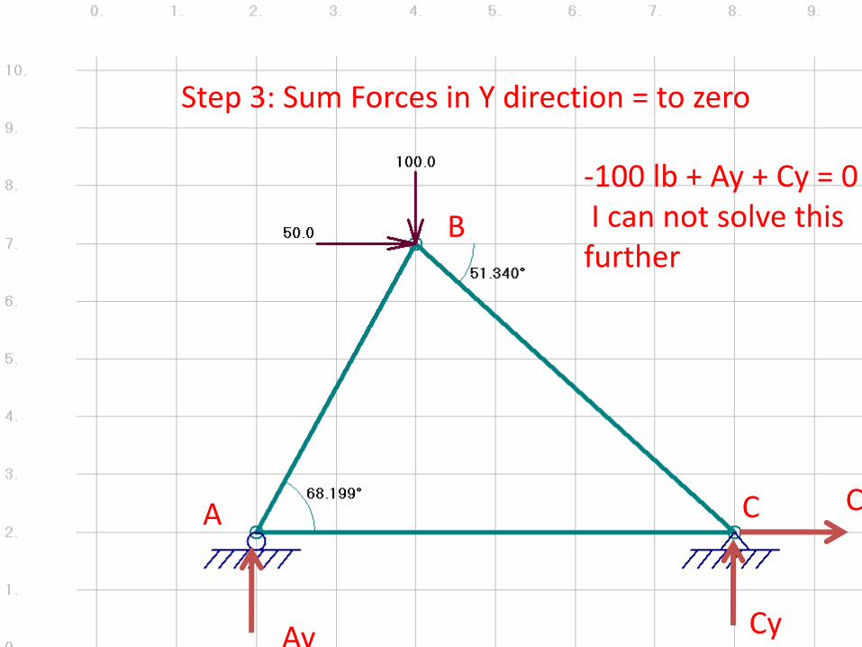
Step 3: Sum Forces in Y direction = to zero
-100 lb + Ay + Cy = 0I can not solve this further
Cy
Cx
Ay

A
B
C
Step 4: Sum Moments = to zero
Sum mom. about C = 0
-Ay*6’ + -50lb*5’ + 100lb * 4’ = 0
-6 Ay +150 = 0Ay = 25 lb
Cy
Cx
Ay
Each block is 1’ by 1’

A
B
C
Step 5: Use other equations to find unknowns
Cy
Cx
Ay
-100 lb + Ay + Cy = 0
-100 + 25 lb + Cy = 0
Cy = 75 lb

A
B
C
Step 6: Redraw FBD
75 lb25 lb
50 lb

Truss Review

Steps for finding Truss Forces
1. Solve for Reaction forces
a. Draw a FBD of the entire system
b. FX = 0; FY = 0; M = 0
c. Use the above equations to solve for reaction forces
2. FBD of each joint (use vector properties)
3. FX = 0; FY = 0 at each joint
4. Solve for forces
5. Draw final FBD

A
B
C
Truss Example
Ay Cy
Cx

A
B
C
Truss FBD with solved Reaction Forces
75 lb25 lb
50 lb

Steps for finding Truss Forces
1. Solve for Reaction forces
a. Draw a FBD of the entire system
b. FX = 0; FY = 0; M = 0
c. Use the above equations to solve for reaction forces
2. FBD of each joint (use vector properties)
3. FX = 0; FY = 0 at each joint
4. Solve for forces
5. Draw final FBD

A
Fab
Fac
25 lb
CFac
Fbc
75 lb
50 lb
Joint AJoint C
Joint B
100 lb
50 lbB
FabFbc

Steps for finding Truss Forces
1. Solve for Reaction forces
a. Draw a FBD of the entire system
b. FX = 0; FY = 0; M = 0
c. Use the above equations to solve for reaction forces
2. FBD of each joint (use vector properties)
3. FX = 0; FY = 0 at each joint
4. Solve for forces
5. Draw final FBD

A
Fab
Fac
25 lb
Joint A
2
5
A
B
Fab
Fac
25 lb
Find q:Tan q = O/ATan q = 5/2q = 68.2 deg
q
FIND q For Joint A
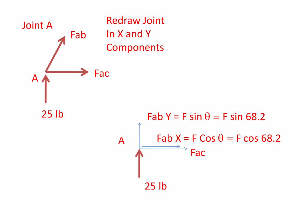
A
Fab
Fac
25 lb
Joint A
A
Fab Y = F sin q = F sin 68.2
Fac
25 lb
Redraw JointIn X and YComponents
Fab X = F Cos q = F cos 68.2

A
Fab
Fac
25 lb
Joint A
A
Fab Y = F sin q = F sin 68.2
Fac
25 lb
Sum Forces in X and Y directions
Fab X = F Cos q = F cos 68.2Sum forces in x = 0Fcos 68.2 + F ac = 0-26.9 * cos 68.2 = -Fac-10 = -FacFac = 10 lb in tension
Sum forces in y = 0F sin 68.2 + 25 lb = 00.93 F = -25 lbFab = -26.9 lbFab = 26.9 lb in compression

Joint C
Find q:Tan q = O/ATan q = 5/4q = 51.3 deg
q
FIND q For Joint CB
4
5

CFac
Fbc
75 lb
50 lb
Joint CRedraw JointIn X and YComponents
Fac = 10 lbs
Fbc Y = F sin q = F sin 51.3
50 lb
75 lb
Fbc X = F cos q = F cos 51.3

CFac
Fbc
75 lb
50 lb
Joint CSum Forces in X and Y directions
Fac = 10 lbs
Fbc Y = F sin q = F sin 51.3
50 lb
75 lb
Fbc X = F cos q = F cos 51.3 Sum forces in y = 0F sin 51.3 + 75 lb = 00.78 F = -75 lbFbc = -96 lbFab = 96 lb in compression
Sum forces in x = 0-50 lb – 10 lb - Fcos 51.3 = 0-60 lb = .625Fbc-96 = FbcFbc = 96 lb in compression

Material Properties

What Are Materials?
Materials: Substances out of which all things are made
Materials are consist of pure elements and are categorized by physical and chemical properties
Elements
Metals Nonmetals Metalloids

Material Composition - ElementsMetal Elements
Good conductors of heat and electricity, hard, shiny, reflect light, malleable, ductile, typically have one to three valence electrons
Distinguishing Characteristics

Material Composition - ElementsNonmetal Elements
Most are gases at room temperature
Solids are dull, brittle, and powdery; electrons are tightly attracted and restricted to one atom; poor conductors of heat and electricity
Distinguishing Characteristics

Material Composition - Elements
Metalloids
Possess both metallic and nonmetallic properties
Distinguishing Characteristics

Material Composition – Compounds and Mixtures
Compounds: created when two or more elements are chemically combined
Most substances are compounds
Mixtures: Non-chemical combination of any two or more substances
Elements within the mixture retain their identity
Material Classification
Metallic Materials
Ceramic Materials
Organic Materials
Polymeric Materials
Composite Materials
Common material classification categories:

Metallic Materials
Pure metal elements (Not commonly found or used)
Thermal and electrical conductors
Mechanical properties include strength and plasticity
Metal element compounds (alloy)(Commonly used due to the engineered
properties of the compound)
Distinguishing Characteristics
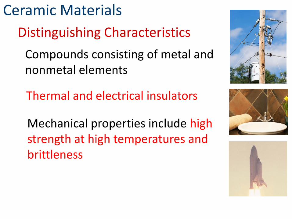
Compounds consisting of metal and nonmetal elements
Thermal and electrical insulators
Mechanical properties include high strength at high temperatures and brittleness
Ceramic Materials
Distinguishing Characteristics

Are or were once living organisms
Consist of mostly carbon and hydrogen
Renewable
Genetically alterable
Organic Materials
Distinguishing Characteristics
Sustainable

Compounds consist of mostly organic elements
Low density
Mechanical properties include flexibility and elasticity
Polymeric Materials
Distinguishing Characteristics
Polymeric Subgroups
Plastics
Elastomers

Composite Materials
Composed of more then one material
Designed to obtain desirable properties from each individual material
Distinguishing Characteristics

Refined material selection based upon:
Material Selection
Mechanical PhysicalThermal Electromagnetic Chemical
Should also include recyclability and cost when choosing appropriate materials for a design

Mechanical Properties
Deformation and fracture as a response to applied mechanical forces
Material Selection
Strength
Hardness
Ductility
Stiffness

Thermal Properties
Affected by heat fluxes and temperature changes
Material Selection
Thermal Capacity – Heat storage capacity of a material
Thermal Conductivity – Capacity of a material to transport heat
Thermal Expansion – How a material expands or contracts if the temperature is raised or lowered

Electrical Properties
Material response to electromagnetic fields
Material Selection
Electrical Conductivity – Insulators, dielectrics, semiconductors, semimetals, conductors, superconductors
Thermoelectric – Electrical stimuli provoke thermo responses; thermo stimuli provoke electrical responses

Chemical Properties
Response and impact of environment on material structures
Material Selection
Oxidation and Reduction – Occur in corrosion and combustion
Toxicity – The damaging effect a material has on other materials
Flammability – The ability of a material to ignite and combust

Product Creation CycleDesign → Material Selection → Process Selection → Manufacture → Inspection →Feedback
Typical product cost breakdown
Manufacturing Process

Manufacturing Processes
• Raw Materials undergo various manufacturing processes in the production of consumer goods

Material Testing

Material Testing
• Engineers use a design process and formulas to solve and document design problems.
• Engineers use destructive and nondestructive testing on materials for the purpose if identifying and verifying the properties of various materials.
• Materials testing provides reproducible evaluation of material properties

Strain
StressE ==
E is the Elastic
Modulus.
E is the slope of the
line in the elastic
region.
Stress- Strain Curve: created
from tensile testing data

Using data points, you can identify and calculate material properties:-Modulus of elasticity-Elastic limit-Resilience-Yield point-Plastic deformation-Ultimate strength-Failure-Ductility

Stress:average amount of force
exerted per unit area

Strain: a measurement of deformation in a structure due to applied forces.
• Strain is calculated from:
Strain = DeformationOriginal Length
or
ε= / L
• Strain is deformation per unit length, a
dimensionless quantity

Proportional Limit: greatest stress a material is capable of withstanding without deviation from straight line proportionality between the stress and strain. If the force applied to a material is released, the material will return to its original size and shape.
• Yield Point: The point at which a sudden elongation takes place, while the load on the sample remains the same or actually drops. If the force applied to the material is released, the material will not return to its original shape.

• Ultimate Strength: The point at which a maximum load for a sample is achieved. Beyond this point elongation of the sample continues, but the force exerted decreases.

• Modulus of Elasticity: A measure of a material’s ability to regain its original dimensions after the removal of a load or force. The modulus is the slope of the straight line portion of the stress-strain diagram up to the proportional limit.
• Modulus of Resilience: A measure of a material’s ability to absorb energy up to the elastic limit. This modulus is represented by the area under the stress vs. strain curve from 0-force to the elastic limit.

• Modulus of Toughness: A measure of a material’s ability to plastically deform without fracturing. Work is performed by the material absorbing energy by the blow or deformation. This measurement is equal to the area under the stress vs. strain curve from its origin through the rupture point.

Calculate Ultimate stress, stress at proportional limit, and modulus of elasticity given an initial length of 3 inches and a cross
sectional area of 0.02 in2.

Ultimate stress = 443 lb / .02 in2
Ultimate stress = 22,150 psi
PL stress = 340 lb / 0.02 in2
PL stress = 17,000 psi
Modulus of elasticity = P*L/(Area* deformation)
E @ (proportional limit)=340 lb * 3 in / (0.02 in2 * 0.01 in)
= 5,100,000 psi

A 1” diameter piece of steel is 15 feet long. If the total
tensile load in the steel is 125,000 pounds and the modulus
of elasticity is 30,000,000 psi, calculate using the 5 step
engineering process:
a) The tensile stress-
b) The total elongation caused by the load-
c) The unit elongation-

A 1” diameter piece of steel is 15 feet long. If the total
tensile load in the steel is 125,000 pounds and the modulus
of elasticity is 30,000,000 psi, calculate using the 5 step
engineering process:
a) The tensile stress-
b) The total elongation caused by the load-
c) The unit elongation-
•Stress = P/A = 125,000 lbs/ (pi* 0.5 in* 0.5in) = 159,155
psi
•Elongation = P*L / (A*E) = 125,000 lbs * 15 feet / (pi*
0.5 in* 0.5in* 30,000,000 psi) = 0.08 ft or 0.96 inches.
•Unit Elongation is Strain, or deformation divided by length.
=0.08 feet/15 feet = 0.00533

A 2” by 6” rectangular steel beam is 60 feet long
and supports an axial load of 15, 000 lbs.
Calculate using the 5 step engineering process:
a) The maximum unit tensile stress in the rod.
b) The maximum allowed load (P) if the unit
tensile stress must not exceed 20,000 psi.
c) The total elongation if = 30,000,000 psi
using the maximum allowed load from part B.

A 2” by 6” rectangular steel beam is 60 feet long and supports an axial load of 15, 000 lbs. Calculate using the 5 step engineering process: a) The maximum unit tensile stress in the rod.b) The maximum allowed load (P) if the unit tensile stress must not exceed 20,000 psi.c) The total elongation if = 30,000,000 psi using the maximum allowed load from part B.
Area = 2” * 6” = 12 in^2• Stress = P/A = 15000 lbs /12in^2 = 1,250 psi•Stress = P/A 20,000 psi = P/12 in^2 P = 240,000 lbs•Elongation is (P*L)/(A*E) = 240,000 lbs * 60 feet / (12 in^2 * 30,000,000 psi) = 0.04 feet or 0.48 in.
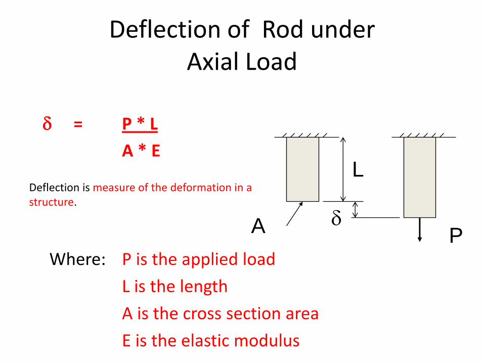
Deflection of Rod under Axial Load
= P * L
A * E
Where: P is the applied load
L is the length
A is the cross section area
E is the elastic modulus
P
L
A
Deflection is measure of the deformation in a structure.

Stress/ Strain Example 1
A sample of material is ¼”diameter and must be turned to a smaller diameter to be able to be used in a tensile machine. The target breaking point for the material is 925 pounds. The tensile strength of the material is 63,750 psi. What diameter would the sample have to be turned to in order to meet the specified requirements?

Stress/ Strain Example 1
Knowns: Unknowns:
Load = 925 lb Dia final = ?
Stress = 63,750 psi

Stress/ Strain Example 1
Drawing:
Equations:
• A = σ = 2
2
7854.4
DD
=
A
P

Stress/ Strain Example 1
Substitution:
Solve:
63750 psi = 27854.
925
D
lbs
2018454413.)63750)(7854(.
925in
psiin
lbs
218454413.0 in
D2 =
D = = 0.136”

Stress/ Strain Example 2
A strand of wire 1,000 ft. long with a cross-sectional area of 3.5 sq. inches must be stretched with a load of 2000 lb. The modulus of Elasticity of this metal is 29,000,000 psi. What is the unit deformation of this material?

Stress/ Strain Example 2
Drawing:
Equations:
= ε =
AE
PLL

Stress/ Strain Example 2
Knowns:
L = 1000’ = 12000” A = 3.5 in2
P = 2000 lb E = 29 x 106 psi
Unknowns:
Unknowns: ε

Stress/ Strain Example 2
Substitution/Solve:
= = =0.236 in
ε = = = 0.0000197in
AE
PL)1029)(5.3(
)12000)(2000(62 psixin
inlb
L
in
in
12000
236.