UNIT 1 - IARE
333
INSTITUTE OF AERONAUTICAL ENGINEERING Dundigal, Hyderabad -500 043 Department of Civil Engineering CONCRETE TECHNOLOGY Course lecturer: Mr. Suraj Baraik Assistant Professor Mr. N Venkat Rao Assistant Professor
-
Upload
khangminh22 -
Category
Documents
-
view
0 -
download
0
Transcript of UNIT 1 - IARE

INSTITUTE OF AERONAUTICAL ENGINEERING Dundigal, Hyderabad -500 043
Department of Civil Engineering
CONCRETE TECHNOLOGY
Course lecturer:
Mr. Suraj Baraik Assistant Professor Mr. N Venkat Rao Assistant Professor

COURSE GOAL
To introduce properties of concrete and it constituent materials and the role of various admixtures in modifying these properties to suit specific requirements, such as ready mix concrete, reinforcement detailing, disaster-resistant construction, and concrete machinery have been treated exhaustively the and also special concrete in addition to the durability maintenance and quality control of concrete structure.

COURSE OUTLINE UNIT TITILE CONTENT
I CEMENT ADMIXTURE & AGGREGATE
Portland cement, chemical composition, Hydration, Setting of cement, Structure of hydrate cement, Test on physical properties, Different grades of cement. Mineral and chemical admixtures, properties, dosage, effects, usage. Classification of aggregate, Particle shape & texture, Bond, strength & other mechanical properties of aggregate, Specific gravity, Bulk density, porosity, adsorption & moisture content of aggregate, Bulking of sand, Deleterious substance in aggregate, Soundness of aggregate, Alkali aggregate reaction, Thermal properties, Sieve analysis, Fineness modulus, Grading curves, Grading of fine & coarse Aggregates, Gap graded aggregate, Maximum aggregate size.
II FRESH CONCRETE
Workability, Factors affecting workability, Measurement of workability by different tests, Setting times of concrete, Effect of time and temperature on workability, Segregation & bleeding, Mixing and vibration of concrete, Steps in manufacture of concrete, Quality of mixing water.

UNIT TITILE CONTENT
III HARDENED CONCRETE TESTING OF
HARDENED CONCRETE ELASTICITY, CREEP &
SHRINKAGE
Water / Cement ratio, Abram’s Law, Gel space ratio, Nature of strength of concrete, Maturity concept, Strength in tension & compression, Factors affecting strength, Relation between compression & tensile strength, Curing. Compression tests, Tension tests, Factors affecting strength, Flexure tests, Splitting tests, Non-destructive testing methods, codal provisions for NDT. Modulus of elasticity, Dynamic modulus of elasticity, Poisson’s ratio, Creep of concrete, Factors influencing creep, Relation between creep & time, Nature of creep, Effects of creep, Shrinkage, types of shrinkage.
IV MIX DESIGN Factors in the choice of mix proportions, Durability of concrete, Quality Control of concrete, Statistical methods, Acceptance criteria, Proportioning of concrete mixes by various methods, BIS method of mix design.
V SPECIAL CONCRETES Light weight aggregates, Light weight aggregate concrete, Cellular concrete, No-fines concrete, High density concrete, Fibre reinforced concrete, Different types of fibres, Factors affecting properties of F.R.C, Applications, Polymer concrete, Types of Polymer concrete, Properties of polymer concrete, Applications, High performance concrete, Self consolidating concrete, SIFCON.

Text books: 1. Concrete Technology by M.S.Shetty. – S.Chand & Co. ; 2004 2. Concrete Technology by M.L. Gambhir. – Tata Mc. Graw Hill
Publishers, New Delhi
References: 1. Properties of Concrete by A.M.Neville – Low priced Edition –
4th edition 2. Concrete Technology by A.R. Santha Kumar, Oxford university Press,
New Delhi

COURSE OBJECTIVES:
At the end of the course, the students will be able to:
I. Classify basic principles in concrete science.
II. Understand the influence of various materials in concreting.
III. Analyze the mechanism of concrete and its properties.
IV. Identify the various defects in concrete.

V. Create various concrete mix designs.
VI. Discover the various types of innovative concretes.
VII. Summarize research including the fundamentals of scientific writing, literature search, how to give a scientific presentation, how to evaluate a scientific paper, and research ethics.

UNIT 1 CEMENT

CEMENT

Definition: “Cement is a crystalline compound of calcium silicates and other calcium compounds having hydraulic properties”
History
• Lime and clay have been used as cementing material on constructions
through many centuries.
• Romans are commonly given the credit for the development of hydraulic
cement, the most significant incorporation of the Roman’s was the use of pozzolan-lime cement by mixing volcanic ash from the Mt. Vesuvius with lime. Best know surviving example is the Pantheon in Rome
• In 1824 Joseph Aspdin from England invented the Portland cement

Types of Cement :
• Cements are considered hydraulic because of their ability to set and harden
under or with excess water through the hydration of the cement’s chemical
compounds or minerals
• There are two types: Those that activate with the addition of water and
pozzolanic that develop hydraulic properties when the interact with hydrated
lime Ca(OH)2
• Pozzolanic : any siliceous material that develops hydraulic cementitious
properties when interacted with hydrated lime.
• HYDRAULIC CEMENTS:
• Hydraulic lime: Only used in specialized mortars. Made from calcination of
clay-rich limestones.
• Natural cements: Misleadingly called Roman. It is made from argillaceous
limestones or interbedded limestone and clay or shale, with few raw materials.
Because they were found to be inferior to portland, most plants switched.

Portland cement: Artificial cement. Made by the mixing clinker with gypsum in
a 95:5 ratio.
Portland-limestone cements: Large amounts (6% to 35%) of ground limestone
have been added as a filler to a portland cement base.
Blended cements: Mix of portland cement with one or more SCM
(supplementary cemetitious materials) like pozzolanic additives.
Pozzolan-lime cements: Original Roman cements. Only a small quantity is
manufactured in the U.S. Mix of pozzolans with lime.
Masonry cements: Portland cement where other materials have been added
primarily to impart plasticity.
Aluminous cements: Limestones and bauxite are the main raw materials.
Used for refractory applications (such as cementing furnace bricks) and certain
applications where rapid hardening is required. It is more expensive than
portland. There is only one producing facility in the U.S.

GEOLOGY (RAW MATERIALS)
The fundamental chemical compounds to produce cement clinker are:
Lime (CaO)
Silica (SiO2)
Alumina (Al2O3)
Iron Oxide (Fe2O3)
Raw materials used in the production of clinker cement
Fly ash: by-product of burning finely grounded coal either for industrial
application or in the production of electricity
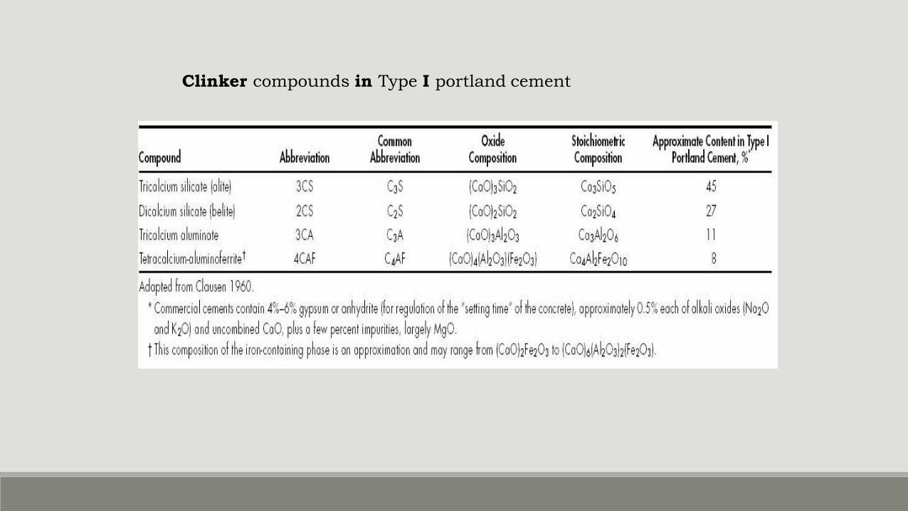
Clinker compounds in Type I portland cement

AGGREGATES

In concrete mixtures the proportions of cement paste & aggregates is controlled by the following factors:
1) Suitable workability & placeability of fresh mass.
2) Adequate strength & durability of hardened product.
3) Minimum cost of the final product
binding medium (mortar)
Portland Cement Concrete
filler materials relatively inert (aggregates)

The aggregate occupies ~70-75% of the volume of concrete, so its quality is of great importance.
Aggregates may affect the following properties of concrete: ◦ Strength
◦ Durability
◦ Structural Performance
◦ Economy

Aggregates have 3 main functions in concrete:
1) To provide a mass of particles which are suitable to resist the action of applied loads & show better -durability then cement paste alone.
2) To provide a relatively cheap filler for the cementing material.
3) To reduce volume changes resulting from setting & hardening process & from
moisture changes during drying.

The properties of concrete are affected by the properties of aggregate:
1. The mineral character of aggregate affects the strength, durability, elasticity of concrete.
2. The surface characteristics of aggregate affects the workability of fresh mass & the bond between the aggregate & cement paste in hardened concrete. If it is rough, workability decreases & bond increases.
3. The grading of aggregate affects the workability, density & economy.
4. The amount of aggregate in unit volume of concrete

Higher aggregate amount/unit volume of concrete ◦ Results in less volume changes during setting & hardening or moisture changes.
(increase in volume stability)
◦ Increase in strength & durability
◦ Decrease in cost
It is a common practice to use as much aggregate as possible in concrete

However, all aggregates are not inert: ◦ The physical action: swelling & shrinkage
◦ The chemical action: alkali-agg. Reaction
◦ The thermal action: expansion & contraction
Like the other ingredients of concrete, aggregates must also be chosen with certain care to end up with a satisfactory concrete.

CLASSIFICATION OF AGGREGATES
According to Source: 1. Natural aggregate: Native deposits with no change in their natural state
other than washing, crushing & grading. (sand, gravel, crush stone)
2. Artificial aggregates: They are obtained either as a by-product or by a
special manufacturing process such as heating. (blast furnace slag, expanded perlite)

According to Petrological Characteristics: 1. Igneous rocks: are formed by solidification of molten lava.
(granite)
2. Sedimentary rocks: are obtained by deposition of weathered & transported pre-existing rocks or solutions. (limestone)
3. Metamorphic rocks: are formed under high heat & pressure alteration of either igneous & sedimentary rocks (marble).

According to Unit Weight:
1. Heavy weight agg.: Hematite, Magnetit Specific Gravity, Gs > 2.8
2. Normal weight agg.:Gravel, sand, crushed stone 2.8 < Gs < 2.4
3. Light weight agg.:Expanded perlite, burned clay Gs < 2.4

Normal-Weight Aggregate
Most common aggregates
Sand
Gravel
Crushed stone
Produce normal-weight concrete 2200 to 2400 kg/m3
ASTM C 33

Expanded
◦ Shale
◦ Clay
◦ Slate
◦ Slag
Produce structural lightweight concrete
1350 to 1850 kg/m3
Lightweight Aggregate (1) ASTM C 330

Pumice
Scoria
Perlite
Vermiculite
Diatomite
Produce lightweight insulating concrete—
250 to 1450 kg/m3
Lightweight Aggregate (2) ASTM C 330

Heavyweight Aggregate
Barite
Limonite
Magnetite
Ilmenite
ASTM C 637, C 638 (Radiation Shielding)
Produce high-density concrete up to 6400 kg/m3
Hematite
Iron
Steel punchings or shot

According to Size: 1. Fine aggregate: d ≤ 5 mm
2. Coarse aggregate: d > 5 mm
Aggregates containing a whole range of particles are named as “all-in” or “pit-run” aggregates.

Fine Aggregate Sand and/or crushed stone
< 5 mm
F.A. content usually 35% to 45% by mass or volume of total aggregate

Coarse Aggregate Gravel and crushed stone
5 mm
typically between 9.5 and 37.5 mm

Aggregate Characteristics and Tests Characteristic Test
Abrasion resistance ASTM C 131 (AASHTO T 96), ASTM C 535,
ASTM C 779
Freeze-thaw resistance ASTM C 666 (AASHTO T 161), ASTM C 682,
AASHTO T 103
Sulfate resistance ASTM C 88 (AASHTO T 104)
Particle shape and
surface texture ASTM C 295, ASTM D 3398
Grading ASTM C 117 (AASHTO T 11), ASTM C 136
(AASHTO T 27)
Fine aggregate
degradation ASTM C 1137
Void content ASTM C 1252 (AASHTO T 304)
Bulk density ASTM C 29 (AASHTO T 19)
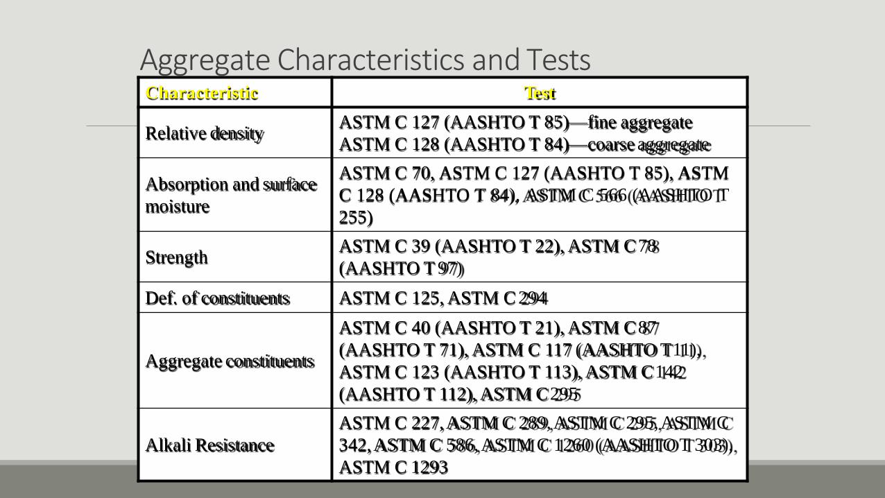
Aggregate Characteristics and Tests Characteristic Test
Relative density ASTM C 127 (AASHTO T 85)—fine aggregate
ASTM C 128 (AASHTO T 84)—coarse aggregate
Absorption and surface
moisture
ASTM C 70, ASTM C 127 (AASHTO T 85), ASTM
C 128 (AASHTO T 84), ASTM C 566 (AASHTO T
255)
Strength ASTM C 39 (AASHTO T 22), ASTM C 78
(AASHTO T 97)
Def. of constituents ASTM C 125, ASTM C 294
Aggregate constituents
ASTM C 40 (AASHTO T 21), ASTM C 87
(AASHTO T 71), ASTM C 117 (AASHTO T 11),
ASTM C 123 (AASHTO T 113), ASTM C 142
(AASHTO T 112), ASTM C 295
Alkali Resistance
ASTM C 227, ASTM C 289, ASTM C 295, ASTM C
342, ASTM C 586, ASTM C 1260 (AASHTO T 303),
ASTM C 1293

SAMPLING
Tests in the lab is carried out on the samples. So, certain precautions in obtaining a sample must be taken to obtain “representative sample”.
The main sample is made up of portions drawn from different points. The minimum number of portions, increment, is 10 & they should add up to a weight not less than:

Max. Particle
Size
Min. Weight of Sample
(kg)
> 25 mm 50
25-5 mm 25
< 5 mm 13
* Details are provided in ASTM D 75 & TS 707

Methods of reducing the amount of sample:
1) Quartering:
Mix the field sample over three times on a level surface.
Shovel the sample to a conical shape.
Press the apex & flatten the conical shape.
Divide them into four equal quarters.
Discard two diagonally opposite quarters & use the remainder.
If this remainder is still too large follow the same path.
Side Side Top Top
2

2) Splitting:
Use the “sample splitter” to divide the aggregate sample into two.
Sample splitter is a box with an even # of chutes alternately discharging to two sides.
The width of each chute should be greater than 1.5 times the size of the largest aggregate size.
If the remainder is still too large follow the same path.


PARTICLE SHAPE & SURFACE TEXTURE
In addition to petrological character, the external characteristics, i.e. The shape & surface texture of aggregates are of importance.
Particle Shape
Rounded: Completely water worn & fully shaped by attrition. (River Gravel)
Irregular: Partly shaped by attrition so it contains some rounded edges. (Land Gravel)

Angular: Has sharp corners, show little evidence of wear. (Crushed Stone)
Flaky: Thickness is relatively small with respect to two other dimensions. (Laminated Rocks)
Elongated: Have lengths considerably larger than two other dimensions
L
w t

FLAT ELONGATED
ROUND ANGULAR

Rounded aggregates are suitable to use in concrete because flaky & elongated particles reduce workability, increase water demand & reduce strength.
In the case of angular particles, the bond between agg. Particles is higher due to interlocking but due to higher surface area, angular particles increase water demand & therefore reduce workability. As a result, for the same cement content & same workability rounded agg. Give higher strength. ?

Surface Texture
This affects the bond to the cement paste & also influences the water demand of the mix.
Smooth: Bond b/w cement paste & agg is weak.
Rough: Bond b/w cement paste & agg. is strong.
Surface texture is not a very important property from compressive strength point of view but agg. Having rough surface texture perform better under flexural & tensile stresses.
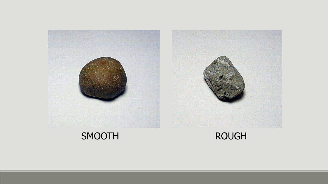
SMOOTH ROUGH

Grading of Aggregates
―Grading is the particle-size distribution of an aggregate as determined by a sieve analysis using wire mesh sieves with square openings.
ASTM C 33
Fine aggregate―7 standard sieves with openings from 150 μm to 9.5 mm
Coarse aggregate―13 sieves with openings from 1.18 mm to 100 mm

TS 706
125 mm
90 mm
63 mm
31.5 mm
16 mm
8 mm
4 mm
2 mm
1 mm
0.5 mm
0.25 mm
ASTM C 33
125 mm
100 mm
90 mm
75 mm (3")
63 mm
50 mm (2")
37.5 mm (1-1/2")
25 mm (1")
12.5 mm (1/2")
9.5 mm (3/8")
4.75 mm (#4)
2.38 mm (#8)
1.19 mm (#16)
0.595 mm (#30)
0.297 mm (#50)
0.149 mm (#100)

The material is sieved through a series of sieves that are placed one above the other in order of size with the largest sieve at the top.
Dry agg. is sieved to prevent lumps.
*****
Agg.
#4
#8
#16
#30
#50
#100
Pan Sieve shaker Lateral & Vertical motion


The particle size distribution in an aggregate sample is known as “gradation”.
Strength development of concrete depends on degree of compaction & workability together with many other factors. So, a satisfactory concrete should be compacted to max density with a reasonable work.
On the other hand, in good concrete all aggregate particles must be covered by cement paste.

The grading of aggregate must be so that the workability, density & volume stability of concrete may not be adversely affected by it.
Fine Particles → higher cost
Coarse Particles → less workability
A reasonable combination of fine & coarse aggregate must be used. This can be expressed by maximum density or minimum voids concept.

A cube with a dimension of 2Dx2Dx2D is filled with spheres of diameter D
Vcube=(2D)3=8D3
1Vsphere=(4/3)π(D/2)3≈0.52D3
8*Vsp=8*0.52D3≈4.2D3 (solid volume)
Void Volume=8D3-4.2D3=3.8D3 2D
D

Same cube filled with spheres of diameter D/4.
Solid Volume=8*8*8*(4/3)π(D/8)3≈4.2D3
#of spheres
Void Volume≈3.8D3
Size of agg. is not important. If an agg. with the same size is used amount of void volume will not change. So, to overcome this different sizes of particles should be used.
However, you should not forget that as agg. get finer, the surface area increases.
More surface area → more paste & water requirement

Reduction of Voids

Factors Affecting a Desired Grading
1) Surface area of the Aggregate
The lower the surface area, the lesser is the paste requirement.
2) Relative Volume of Agg. in Concrete
Higher volume of agg.:
→economical
→higher strength, higher volume stability
→less workability !

3) Workability: The ease with which a concrete mixture can be mixed, transported, placed in theform & compacted without any segregation.
Workability increases as the amount of paste b/w fine agg. part increases. It also increases as the amount of mortar b/w coarse agg. particles increases.
4) Segregation: Seperation of the particles with different sizes & specific
gravities.
The requirements of workability and absence of segregation tend to oppose each other. Thus, these two factors are interrelated. The major of these is workability which, in turn, affects most of the properties of concrete.

Determination of the Grading of Aggregate
There are two different methods for determining the agg. grading:
Fineness Modulus (FM)
Granulometry
The grading of the particles in an agg. sample is performed by “sieve analysis”. The sieve analysis is conducted by the use of “standard test sieves”. Test sieves have square openings & their designation correspond to the sizes of those openings.

1) Fineness Modulus (FM):
FM is a single figure which is the sum of cumulative % retained on a series of sieves having a clear opening half that of the preceeding one. Usually determined for fine agg.
FM = Σ (% cumulative retained on each sieve)
100 For Fine Agg.→#4, #8, #16, #30, #50, #100
{practical limits→2-3.5}
For Coarse Agg.→Fine set+3/8”+3/4”+1 ½”+3”
{practical limits→5.5-8.0}
The FM of the mixture of two or more agg. is the weighted average of the FM of that two more agg.

Sieve Amount Retained
on (gr)
Amount Retained
on (%)
% Cumulative
Retained on
3/8" 0 0 0
#4 30 6 6
#8 80 16 22
#16 100 20 42
#30 120 24 66
#50 125 25 91
#100 35 7 98
Pan 10 2 100
Ex:A 500gr sample of a Fine Agg. was sieved. Determine FM?
Pan is not included.
Only standard sieves are included, if we were given #10 sieve you should not use that in calculations
6+22+42+66+91+98 FM = = 3.25
100

Ex: Determine the FM for the 1000gr sample of Coarse Agg.
Amount Amount % Cumulative
Sieve Retained on (gr) Retained on (%) Retained on
2" 70 7 7
1 1/2" 230 23 30
3/4" 350 35 65
3/8" 250 25 90
#4 100 10 100
FM = Fine Set+3/8”+3/4”+1 ½”+3”
100
FM = 30+65+90+100+100+100+100+100+100
100 = 7.85

Ex: The fine agg. with the FM=3.25 and the coarse agg. with the FM=7.85 are available. Combine them in such a way that the FM becomes 6.8
X : Volume of Fine agg.
3.25X+7.85(100-X)
100 = 6.8 X = 23
*23% of fine agg. and 77% of coarse agg. should be mixed.

2) Granulometry:
The FM is not always representative of the gradation of an aggregate sample and various gradation curves may give the same FM.
In the gradation curves, the vertical axis represents the % passing & the horizontal axis represents the sieve opening.
A logarithmic scale is used for horizontal axis.
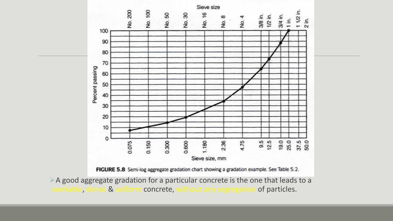
A good aggregate gradation for a particular concrete is the one that leads to a workable, dense & uniform concrete, without any segregation of particles.

There is no single “ideal” grading curve. Instead, standards provide upper & lower limits.

ASTM Requirement for CA
Sieve % Passing ASTM Requirement for
FA 1 ½"- #4 3/4" - #4 1/2" - #4
Sieve % Passing 3" – – –
2 ½" – – – 3/8" 100
2" 100 – – #4 95-100
1 ½" 95-100 – – #8 80-100
1" – 100 –
#16 50-85 3/4" 35-70 90-100 100
#30 25-60 1/2" – – 90-100
#50 10-30 3/8" 10-30 20-55 40-70
#100 2-10 #4 0-5 0-15 0-15
#6 – 0-5 0-5
* Changes with max aggregate size

20
* Gap Graded agg. No particles between #30 & #16
#30 #16
#30 #16
* Single sized agg.
Most of the particles are between #30 & #16
100
90

Handling & Stockpiling of Agg.
Handling and stockpiling of coarse aggregates may easily lead to segregation. To overcome this segregation CA are handled and stockpiled in different size fractions, such as 5-15mm, 15-25mm, and these aggregates are mixed in specified proportions only when fed into the mixer.
Segregation: seperation of particles having different sizes
coarser

Aggregate Stockpiling

Stock Pile Segregation

Aggregate Proportions

Specific gravity is the ratio of the weight oa a unit volume
of material to the
Weight of the same volume of water at 20º to 25ºC.
2
Wt γ
G= V = Wtw γH O
V
G = specific gravity
Wt = weight of material
V = volume
Wtw = weight of water
where :
SPECIFIC GRAVITY

SPECIFIC GRAVITY OF AGG.
Sp.Gr. is used in certain computations for concrete mix design or control work, such as, absolute volume of aggregate in concrete. It is not a measure of the quality of aggregate.
Sp.Gr.= Weight of Agg. (WA)
Weight of an equal volume of water (VA*ρw)
= WA
VA*ρw
= ρA
ρw
Density of Agg.
Density of Water

Volume of Aggregate?

MOISTURE CONDITION OF AGGREGATES

Apparent Specific Gravity
a
s ip H2O
WOD G
V V
Overall volume of the aggregate exclusive of the volume of the pores or
Capillaries which become filled with water in 24 hrs of soaking
where:
Ga = apparent specific gravity of solids (aggregate)
WOD oven dry weight of aggregae
Vs = volume of solids
Vip = volume of impermeable pores
γw = unit weight of water (1 g/ml)

Bulk Specific Gravity
s
Wssd
WOD =
ip pp H2O
bod s ip pp H2O
Gbssd =
G
V V V *
V V V *
WtOD oven dry weight of aggregate
Vs = volume of solids
Vip = volume of impermeable pores
Vpp = volume of water permeable pores
w = unit weight of water 1 g/ml

Determination of Sp. Gr. of Aggregates Archimedes Principle
H2O
OD Aggregate
WOD
Wg. of OD Aggregate under H2 O
WSW
WOD
a G =
WOD WSW

1) Coarse Agg.
Aggs are oven dried at 105±5°C overnight & the weight is measured as (A)→oven dry weight
Aggs are soaked in water for 24 hours
Aggs are taken out from water & rolled in a large absorbent cloth, until all visible films of water are removed & then weighed (B)→saturated surface dry weight
Aggs are then weighed in water (C)

A % Absorption =
B-A *100
Apparent Specific Gravity = A
A-C
Dry Bulk Specific Gravity = A
B-C
SSD Bulk Sp.Gr. = B
B-C

2) Fine Agg.
Aggs are oven dried to constant weight at 105±5°C. Measure the dry weight as (A)
Soak them in water for 24hrs
Stir the sample to bring it to SSD condition. Use the Cone Test for Surface Moisture Determination (Weight as S)
Fill the aggs in SSD condition into a pycnometer (to a calibrated level) and weight it, (water+pyconometer+agg) (C)
Fill the pyconometer with water only (to a calibrated level) and weight it (water+pyconometer) (B)

OD Aggregate
(A)
Container
with H2O
(B)
Container
with H2O
and with
Aggregate
(C)
Specific Gravity Test for Sand
SSD Aggregate
(S)

A % Absorption =
S-A *100
Apparent Specific Gravity = A
B+A-C
Dry Bulk Specific Gravity = A
B+S-C
SSD Bulk Sp.Gr. = S B+S-C
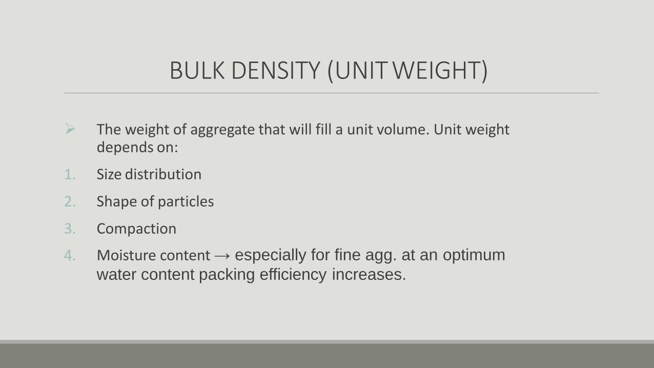
BULK DENSITY (UNIT WEIGHT)
The weight of aggregate that will fill a unit volume. Unit weight depends on:
1. Size distribution
2. Shape of particles
3. Compaction
4. Moisture content → especially for fine agg. at an optimum
water content packing efficiency increases.

Unit Weight
Loose Agg. are dropped to a container at a specified height (ρl=W1/V)
Compacted Agg. are compacted in three layers, each layer is rodded 25 times (ρc=W2/V)

Bulking of Sand

MOISTURE CONDITION OF AGGREGATES

SIGNIFICANCE OF DETERMINING THE MOISTURE STATE & ABSORPTION CAPACITY
SSD Condition → Equilibrium for Mositure Condition
1. If total moisture content = 0 → Agg. is bone-dry (oven dry)
2. If total moisture content < absorption capacity → It can absorb water
3. If total moisture content > absorption capacity → There is free water on the surface of agg.
Mix Design Calculations are Based on Aggs in SSD Condition. Therefore, for aggs not being in that condition corrections have to be made
w/c ratio → w should be “free water”

Porosity / Absorption of Aggregates
Porosity or permeability of aggregates and its absorption may affect the following factors: The bond between aggregate and cement paste
Resistance to freezing & thawing of concrete
Chemical stability
Resistance to abrasion
Specific gravity
Yield of concrete for a given weight of agg.

% Absorption = WSSD-WDry
W Dry
(Absorption Capacity)
WDry = WSSD
(1+Abs.Cap.)
Moisture Content (m) = Wagg-WDry
W Dry
Wagg = WDry (1+m)
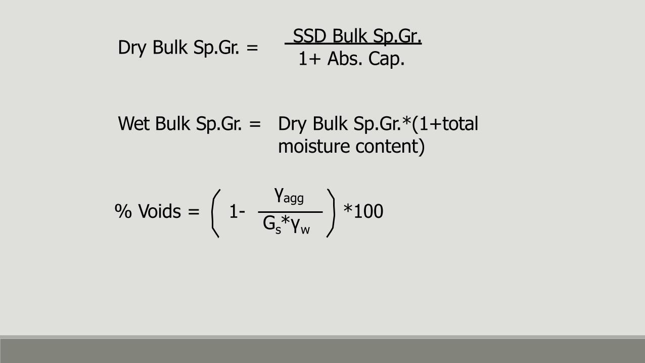
Dry Bulk Sp.Gr. = SSD Bulk Sp.Gr.
1+ Abs. Cap.
Wet Bulk Sp.Gr. = Dry Bulk Sp.Gr.*(1+total moisture content)
γagg
G *γ s w
% Voids = 1- *100

DELETERIOUS MATERIALS IN AGGREGATES
Organic Impurities in natural aggs may interfere with the setting & hardening of concrete. They can be detected by tests, ASTM C40, TS 3673

DELETERIOUS MATERIALS IN AGGREGATES
Very Fine Particles: They can appear in the form of clay and silt or in the form of stone dust → they increase the water requirement or in other words decrease workability.
◦ They can appear as coatings on the surface of agg particles → they affect bonding properties.
◦ TS 3527→ particles smaller than 63μm
◦ ASTM C 117→ #200 sieve (75μm)

DELETERIOUS MATERIALS IN AGGREGATES
Weak & Unsound Materials Light weight materials (coals, lignide): In excessive amounts may affect durability of concrete. If these impurities occur at or near the surface, they may disintegrate & cause pop-outs & stains.

DELETERIOUS MATERIALS IN AGGREGATES
Soft particles : they are objectionable because they affect the durability adversely. They may cause pop-outs & may brake up during mixing and increase the water demand.
Salt contamination : Most important effects are:
Corrosion of reinforcement
Effloresence: presence of white deposits on the surface of concrete.

SOUNDNESS OF AGGREGATES
Soundness is the ability of agg to resist volume changes to environmental effects. ◦ Freezing & Thawing
◦ Alternate Wetting & Drying
◦ Temperature Changes

SOUNDNESS OF AGGREGATES
Aggs are said to be unsound when volume changes induced by the above, results in deterioration of concrete. This effect may be: ◦ Local scaling
◦ Extensive surface cracking
◦ Disintegration over a considerable depth

SOUNDNESS OF AGGREGATES
To detect unsound particles, aggs are treated with Na2SO4 or MgSO4
solutions. ◦ 18 hours of immersion
◦ Dry at 105°C+5°C to constant weight
◦ After 5 cycles determine the loss in weight of the agg.

SOUNDNESS OF AGGREGATES
According to TS following limits should not be exceeded.
Na2SO4 MgSO4
Fine Agg.
Coarse Agg.
19%
22% 15%
27%

ABRASION RESISTANCE Especially when concrete is used in roads or floor surfaces subjected to heavy traffic load.
Hardness, or resistance to wear (abrasion) is determined by Los- Angeles abrasion test.

Los Angeles Abrasion Test:
The agg with a specified grading is placed inside the L.A. Testing Machine
Loose steel balls are placed inside the drum
The apparatus is rotated for a specified cycles
Finally the loss in weight is determined. by screening with #12 sieve.
Resistant → <10% for 100 revolutions
→ <50% for 500 revolutions

Alkali- Aggregate Reactivity ( AAR )
—is a reaction between the active mineral constituents of some aggregates and the sodium and potassium alkali hydroxides and calcium hydroxide in the concrete.
◦ Alkali-Silica Reaction (ASR) ◦ Alkali-Carbonate Reaction (ACR )

Alkali-Silica Reaction (ASR)
Visual Symptoms
◦ Network of cracks
◦ Closed or spalled joints
◦ Relative displacements

Alkali-Silica Reaction (ASR)
Visual Symptoms (cont.)
◦ Fragments breaking out of the surface (popouts)
Mechanism
1. Alkali hydroxide + reactive
silica gel reaction
product (alkali-silica gel)
2. Gel reaction product +
moisture expansion

Alkali-Silica Reaction (ASR)
Influencing Factors
◦ Reactive forms of silica in the aggregate,
◦ High-alkali (pH) pore solution
◦ Sufficient moisture
If one of these conditions is
absent ― ASR cannot occur.

Alkali-Silica Reaction (ASR)
Test Methods ◦ Mortar-Bar Method
◦ Chemical Method
(ASTM 227)
(ASTM C 289)
◦ Petrographic Examination (ASTM C 295)
◦ Rapid Mortar-Bar Test (ASTM C 1260)
◦ Concrete Prism Test (ASTM C 1293 )

Alkali-Silica Reaction (ASR)
Controlling ASR ◦ Non-reactive aggregates
◦ Supplementary cementing materials or blended cements
◦ Limit alkalis in cement
◦ Lithium-based admixtures
◦ Limestone sweetening (~30% replacement of reactive aggregate with crushed limestone

Effect of Supplementary Cementing Materials on ASR

MAX AGG SIZE
It’s the smallest sieve size through which the entire amount of the agg particles can pass.
The larger the size of agg, the smaller the surface area to be wetted per unit weight. Thus, extending the grading of agg to a larger max size lowers the water requirement of the mix. So, for the same workability & cement content higher strength will be obtained.

Optimum max agg size for structural concrete is 25mm.
Studies have shown that concrete’s made with max agg size greater than 40mm have lower strength. Because of the smaller surface area for the bond between agg to paste. Volume changes in the paste causes larger stresses at the interface.

Standard Limitations for Max Agg Size
The concrete mix must be so that, it can be placed inside the molds and between the reinforcing bars easily without any segregation. So, max agg size (Dmax) should not exceed:
d2
d1
d3
1) 1/5 of the narrowest dimension of the mold.
d=min (d1,d2,d3)
Dmax < d
5

2) 1/3 of the depth of the slab
slab Dmax <
h
h 3
3) ¾ of the clear spacing between reinforcement
S:face of the distance
Dmax < 3
4 S
S
4) Dmax < 40mm

slab
5cm
Example:
6cm
40cm
9cm
beam
Φ=10mm
Dmax=?
20cm
1) Dmax < 1/5 min (20,40)=4cm
2) Dmax < 1/3(9)=3cm
3) Dmax < 3/4(4)=3cm
4) Dmax < 4cm
Dmax < 3cm

Admixtures

Admixtures are those ingredients in concrete other than Portland cement, water, and aggregates that are added to the mixture immediately before or during mixing (Fig. 6-1). Admixtures can be classified by function as follows:

1. Air-entraining admixtures 2. Water-reducing admixtures 3. Plasticizers 4. Accelerating admixtures 5. Retarding admixtures 6. Hydration-control admixtures

7. Corrosion inhibitors
8. Shrinkage reducers
9. Alkali-silica reactivity inhibitors
10. Colouring admixtures
11.Miscellaneous admixtures such workability, bonding, damp proofing, permeability reducing, grouting, gas-forming, and pumping admixtures


The major reasons for using admixtures are: 1.To reduce the cost of concrete construction 2. To achieve certain properties in concrete more effectively than by other means 3.To maintain the quality of concrete during the stages of mixing, transporting, placing, and curing in adverse weather conditions 4. To overcome certain emergencies during concreting operations

Air-Entraining Admixtures used to purposely introduce and stabilize microscopic air bubbles in concrete. Air-entrainment will dramatically improve the durability of concrete exposed to cycles of freezing and thawing (Fig. 6-2). Entrained air greatly improves concrete's resistance to surface scaling caused by chemical
de-icers

Frost damage at joints of a pavement

Frost induced cracking near joints

Scaled concrete surface resulting from lack of air entrainment, use of deicers, and poor finishing and curing practices

The primary ingredients used in air-entraining admixtures are salts of wood resin (Vinsol resin), synthetic detergents, salts of petroleum acids, etc.
See Table 6-1 p.106 in the text for more details.

Water-Reducing Admixtures used to reduce the quantity of mixing water required to produce concrete of a certain slump, reduce water-cementing materials ratio, reduce cement content, or increase slump.
Typical water reducers reduce the water content by approximately 5% to 10%.

Water-Reducing Admixtures Materials: ◦ Lignosulfonates.
◦ Carbohydrates.
◦ Hydroxylated carboxylic acids.


Water-Reducing Admixtures The effectiveness of water reducers on concrete is a function of their chemical composition, concrete temperature, cement composition and fineness, cement content, and the presence of other admixtures.

Superplasticizers (High-Range Water Reducers) These admixtures are added to concrete with a low-to-normal slump and water- cementing materials ratio to make high-slump flowing concrete.
Flowing concrete is a highly fluid but workable concrete that can be placed with little or no vibration or compaction while still remaining essentially free of excessive bleeding or segregation.

Superplasticizers (High-Range Water Reducers) Applications where flowing concrete is used:
1. thin-section placements,
2. areas of closely spaced and congested reinforcing steel,
3. pumped concrete to reduce pump pressure, thereby increasing lift and distance capacity,
4. areas where conventional consolidation methods are impractical or can not be used, and
5. for reducing handling costs.

Flowable concrete with high slump

Is easily placed

Even in areas of heavy reinforcing steel cong estion

Low water to cement ratio concrete with low chloride permeability--- easily made with high-range water reducers- is ideal for bridge decks
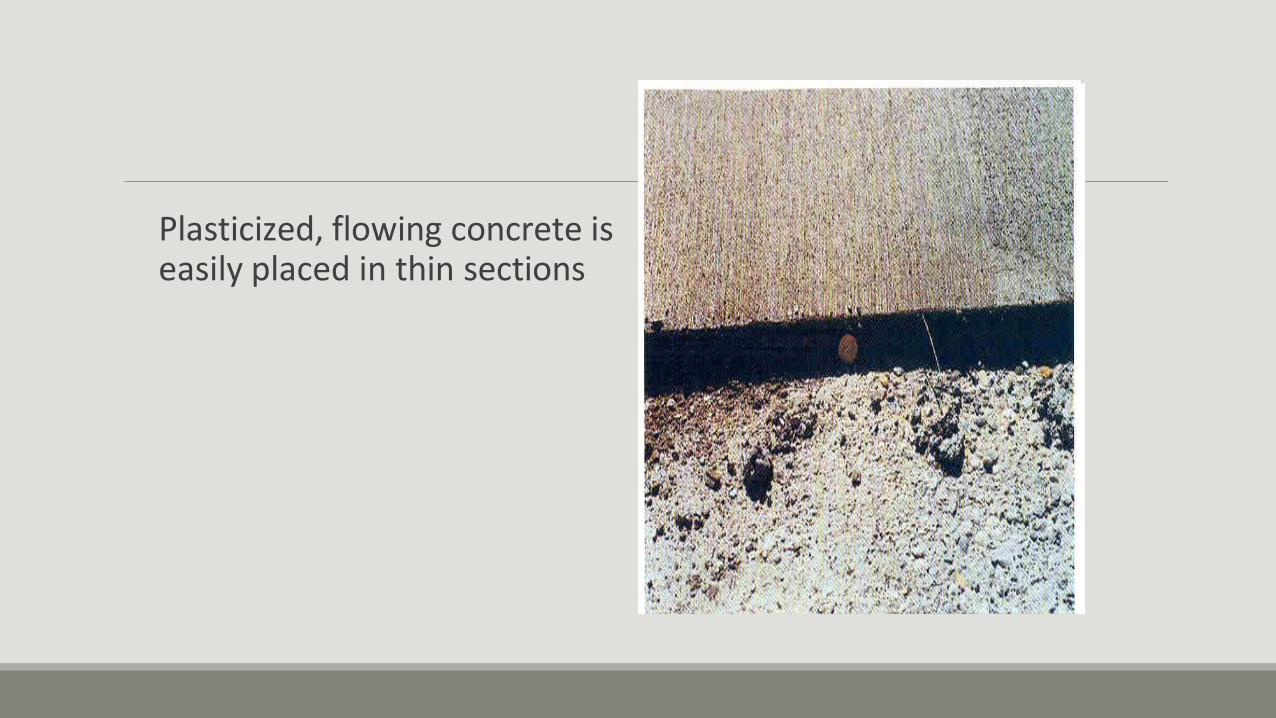
Plasticized, flowing concrete is easily placed in thin sections

Superplasticizers (High-Range Water Reducers) Typical superplasticizers include:
◦ Sulfonated melamine formaldehyde condensates.
◦ Sulfonated naphthalene formaldehyde condensate.
◦ Lignosulfonates.
◦ Polycarboxylates.

Superplasticizers (High-Range Water Reducers) bleed significantly less than control concretes of equally high slump and higher water content. High-slump, low-water-content, plasticized concrete has less drying shrinkage than a high-slump, high-water-content conventional concrete. has similar or higher drying shrinkage than conventional low- slump, low-water-content concrete.
The effectiveness of the plasticizer is increased with an increasing amount of cement and fines in the concrete.

Retarding Admixtures used to retard the rate of setting of concrete at high temperatures of fresh concrete (30°C or more).
One of the most practical methods of counteracting this effect is to reduce the temperature of the concrete by cooling the mixing water or the aggregates.
Retarders do not decrease the initial temperature of concrete.
The bleeding rate and capacity of plastic concrete is increased with retarders.

Retarding Admixtures The typical materials used as retarders are: ◦ Lignin,
◦ Borax,
◦ Sugars,
◦ Tartaric acid and salts.


Retarding Admixtures Retarders are used to:
1. offset the accelerating effect of hot weather on the setting of concrete,
2. delay the initial set of concrete when difficult or unusual conditions of placement occur,
3. delay the set for special finishing processes such as an exposed aggregate surface.

Retarding Admixtures some reduction in strength at early ages (one to three days) accompanies the use of retarders.
The effects of these materials on the other properties of concrete, such as shrinkage, may not be predictable.
Therefore, acceptance tests of retarders should be made with actual job materials under anticipated job conditions.
Accelerating Admixtures used to accelerate strength development of concrete at an early age.
Typical Materials are: ◦ Calcium chloride: most commonly used for plain concrete.
◦ Triethanolamine.
◦ Calcium formate.
◦ Calcium nitrate.
◦ Calcium nitrite.

Corr osion Inhibitors

Corrosion Inhibitors The chlorides can cause corrosion of steel reinforcement in concrete.
Ferrous oxide and ferric oxide form on the surface of reinforcing steel in concrete.
Ferrous oxide reacts with chlorides to form complexes that move away from the steel to form rust. The chloride ions continue to attack the steel until the passivating oxide layer is destroyed.

Corrosion Inhibitors Corrosion-inhibiting admixtures chemically arrest the corrosion reaction.
Commercially available corrosion inhibitors include: ◦ calcium nitrite,
◦ sodium nitrite,
◦ dimethyl ethanolamine,
◦ amines,
◦ phosphates,
◦ ester amines.

Shrinkage-Reducing Admixtures n Shrinkage cracks, such as show
on this bridge deck, can be reduced with the use of good concreting practices and shrinkage reducing admixtures.

Chemical Admixtures to reduce Alkali-aggregate Reactivity (ASR Inhibitors)
Expansion of specimens made with lithium carbonate admixture

Coloring admixtures (Pigments)
Red and blue pigments were used to color this floor

UNIT 2 FRESH CONCRETE

PROPERTIES OF FRESH CONCRETE

Quality Control Satisfactory concrete construction and performance requires concrete with specific properties.
To assure that these properties are obtained, quality control and acceptance testing are very important.
Most specifications today are still a combination of prescriptive and performance requirements.

Quality Control
Performance-based specifications (also called end-result or end- property specifications) that require the final performance of concrete be achieved independent of the process used to achieve the performance such as compressive strength, low permeability, documented durability, and minimum cracks.

Quality Control
Frequency of testing is a significant factor in the effectiveness of quality control of concrete.
Specified test frequencies are intended for acceptance of the material at a random location within the quantity or time period represented by the test.
Sampling Fresh Concrete Sample should be representative.
Except for routine slump and air-content tests performed for process control, standards require that the sample size be at least 30 Liter.
The time allowed to obtain the grab samples is 10 to 15 minutes.
The sample should be protected from sunlight, wind, and other sources of rapid evaporation during sampling and testing.

Consistency of Concrete The slump test is the most generally accepted method used to measure the consistency of concrete.
The test for slump must be completed within 10 minutes after sampling is completed.
The entire test through removal of the cone should be completed in 2 minutes .

Slu mp Test
Temperature - Test Many specifications place limits on the temperature of fresh concrete.
The thermometer should be accurate to plus or minus 0.5°C and should remain in a representative sample of concrete for a minimum of 2 minutes or until the reading stabilizes.
A minimum of 75 mm of concrete should surround the sensing portion of the thermometer.


AIR CONTENT Pressure Method For Air Content based on Boyle's law, which relates pressure to volume.
Many commercial air meters of this type are calibrated to read air content directly when a predetermined pressure is applied.
The applied pressure compresses the air within the concrete sample, including the air in the pores of aggregates.
The instrument should be calibrated for various elevations above sea level if it is to be used in localities having considerable differences in elevation.


Volumetric Method for Air Content requires removal of air from a known volume of concrete by agitating the concrete in an excess of water.
This method can be used for concrete containing any type of aggregate including low density or porous materials.
The volumetric test is not affected by atmospheric pressure, and relative density of the materials need not be known.

500 mL of isopropyl
alcohol

MASS DENSITY Determination of the density of freshly mixed concrete is made in accordance with Test for Density, Yield and Cement Factor of Plastic Concrete
Yield of concrete is the volumetric quantity of concrete produced per batch.
Time of Setting Test Method ASTM C 403 is used to determine the time of setting of concrete by means of penetration resistance measurements made at regular time intervals on mortar sieved from concrete.

Chloride Content Test The chloride content of concrete and its ingredients should be checked to make sure it is below the limit necessary to avoid corrosion of reinforcing steel.
An approximation of the water-soluble chloride content of freshly mixed concrete, aggregates, and admixtures can be made using a method initiated by the National Ready Mixed Concrete Association (NRMCA 1986).

Chloride Content Test The water-soluble chloride-ion content of hardened concrete is determined in accordance with procedures specified in ASTM C 1218.
ASTM C1152 test method for the acid-soluble chloride content of concrete, which in most case is equivalent to total chloride.

Portland Cement Content, Water content, and Water-Cement Ratio These test results can assist in determining the strength and durability potential of concrete prior to setting and hardening and can indicate whether or not the desired cement and water contents were obtained.

Portland Cement Content, Water content, and Water-Cement Ratio Some tests require sophisticated equipment and special operator skills, which may not be readily available.
Other tests for determining cement or water contents can be classified into four categories: chemical determination, separation by settling and decanting, nuclear related, and electrical.

Bleeding Bleeding is the development of a layer of water at the top or surface of freshly placed concrete.
It is caused by the settlement of solid particles and the simultaneous upward migration of water.
Excessive bleeding increases the water-cement ratio near the top surface; a weak top layer with poor durability may result, particularly if finishing operations take place while bleed water is present.
A water pocket or void can develop under a prematurely finished surface.


Concrete Test Cylinders Premoulded specimens for field and laboratory strength tests should be made and cured.
Molding of strength specimens should be completed within 20 minutes after sampling.
Rigid and nonabsorbent moulds should be used.


Compressive Strength

Flexural Strength The cross-section of beams used for the flexural strength test should not be less than 150 x 150 mm, or three times the maximum size of aggregate, whichever is larger.
The length of beams should be at least three times the depth of the beam plus 50 mm.
For example, if the maximum size of aggregate in the concrete is 40 mm, the total length should be not less than 500 mm for a 150 x 150-mm beam.

Strength tests of hardened concrete 1. cured specimens moulded in accordance with ASTM C 31 or
ASTM C 192 from samples of freshly mixed concrete;
2. in-situ specimens cored or sawed from hardened concrete in accordance with ASTM C 42;
3. specimens made from cast-in-place cylinder moulds

CURING CONCRETE Curing is the maintenance of a satisfactory moisture content and temperature in concrete for a period of time immediately following placing and finishing so that the desired properties may develop.
Curing has a strong influence on the properties of hardened concrete; proper curing will increase durability, strength, watertightness, abrasion resistance, volume stability, and resistance to freezing and thawing and deicers.
CURING CONCRETE The most effective method for curing concrete depends on the materials used, method of construction, and the intended use of the hardened concrete.
strong influence on the properties of hardened concrete; proper curing will increase durability, strength, watertightness, abrasion resistance, volume stability, and resistance to freezing and thawing and deicers.

CURING concrete becomes stronger, more impermeable, and more resistant to stress, abrasion, and freezing and thawing.
The improvement is rapid at early ages but continues more slowly thereafter for an indefinite period.


Curing Methods and Materials maintain the presence of mixing water in the concrete during the early hardening period [ponding or immersion, spraying or fogging, and saturated wet coverings].
prevent loss of mixing water from the concrete by sealing the surface.
accelerate strength gain by supplying heat and additional moisture to the concrete.

Pounding or Immersion Earth or sand dikes around the perimeter of the concrete surface can retain a pond of water
On flat surfaces such as pavements and floors.
an ideal method for preventing loss of moisture and is also effective for maintaining a uniform temperature in the concrete.
the method is generally used only for small jobs.
the water used for curing by ponding or immersion must be free of substances that will stain or discolour the concrete.

Spraying or Fogging excellent methods of curing when the ambient temperature is well above freezing and the humidity is low.
applied through a system of nozzles or sprayers to raise the relative humidity of the air over flatwork, thus slowing evaporation from the surface.
Fogging is applied to minimize plastic shrinkage cracking until finishing operations are complete.


Spraying or Fogging Once the concrete has set sufficiently to prevent water erosion, ordinary lawn sprinklers are effective if good coverage is provided and water runoff is of no concern.
Soaker hoses are useful on surfaces that are vertical or nearly so.

Wet Coverings Fabric coverings saturated with water, such as burlap, cotton mats, rugs, or other moisture-retaining fabrics, are commonly used for curing.
Burlap must be free of any substance that is harmful to concrete or causes discolouration.
Wet, moisture-retaining fabric coverings should be placed as soon as the concrete has hardened sufficiently to prevent surface damage.
Use of polyethylene film over burlap will eliminate the need for continuous watering of the covering.

Wet Coverings Use of polyethylene film over burlap will eliminate the need for continuous watering of the covering.
Wet coverings of earth, sand, or sawdust are effective for curing and may be useful on small jobs. A layer about 50 mm thick should be evenly distributed over the previously moistened surface of the concrete and kept continuously wet.

Wet Coverings
A major disadvantage of moist earth, sand, or sawdust, is the possibility of discolouring the concrete


Impervious Paper consists of two sheets of kraft paper cemented together by a bituminous adhesive with fibre reinforcement.
Curing with impervious paper enhances the hydration of cement by preventing loss of moisture from the concrete
an efficient means of curing horizontal surfaces and structural concrete of relatively simple shapes.
Advantage: periodic additions of water are not required.

Impervious Paper As soon as the concrete has hardened sufficiently to prevent surface damage.
The sheets must be weighted to maintain close contact with the concrete surface during the entire curing period.


Plastic Sheets Plastic sheet materials such as polyethylene film can be used to cure concrete.
Polyethylene film is a lightweight, effective moisture barrier and is easily applied to complex as well as simple shapes.
Its application is the same as described for impervious paper.
Polyethylene film may also be placed over wet burlap or other wet covering materials to retain the water in the wet covering material.
This procedure eliminates the labor-intensive need for continuous watering of wet covering materials.


Membrane-Forming Curing Compounds Liquid membrane-forming compounds consisting of waxes, resins, chlorinated rubber, and other materials can be used to retard or reduce evaporation of moisture from concrete.
Curing compounds should be able to maintain the relative humidity of the concrete surface above 80% for seven days to sustain cement hydration.
Membrane-Forming Curing Compounds Membrane-forming curing compounds are of two general types: ◦ clear, or translucent;
◦ white pigmented.
applied by hand-operated or power-driven spray equipment immediately after final finishing of the concrete.


Internal Moist Curing providing moisture from within the concrete as opposed to outside the concrete.
Low-density fine aggregate or absorbent polymer particles with an ability to retain a significant amount of water may provide additional moisture for concretes prone to self desiccation.

Curing Using Forms leave forms in place as long as possible to continue the curing period.
Forms provide satisfactory protection against loss of moisture if the top exposed concrete surfaces are kept wet.
A soil- soaker hose is excellent for this.
The forms should be left on the concrete as long as practical.

Steam Curing A method for the accelerated curing of concrete.
It is advantageous where early strength gain in concrete is important or where additional heat is required to accomplish hydration, as in cold weather.

Steam Curing Two methods of steam curing are used: ◦ live steam at atmospheric pressure (for enclosed cast-in-place
structures and large precast concrete units)
◦ high-pressure steam in autoclaves (for small manufactured units).

Live Steam Curing A typical steam-curing cycle consists of
1. an initial delay prior to steaming,
2. a period for increasing the temperature,
3. a period for holding the maximum temperature constant,
4. a period for decreasing the temperature.

Steam Curing Steam curing at atmospheric pressure is generally done in an enclosure to minimize moisture and heat losses.
Application of steam to the enclosure should be delayed until initial set occurs or delayed at least 3 hours after final placement of concrete to allow for some hardening of the concrete.
Steam temperature in the enclosure should be kept at about 60°C until the desired concrete strength has developed.

Steam Curing Avantages early strength gain,
reduced drying shrinkage
Reduced creep


Other Curing Methods Insulating Blankets or Covers Layers of dry, porous material such as straw or hay can be used to provide insulation against freezing of concrete when temperatures fall below 0°C.
Electrical, Oil, Microwave, and Infrared Curing have been available for accelerated and normal curing of concrete for many years.

Curing Period and Temperature The period of time that concrete should be protected from freezing, abnormally high temperatures, premature drying, and against loss of moisture depends upon the type of cement, mixture proportions, required strength, size and shape of the concrete member, ambient weather, and future exposure conditions.

Curing Period and Temperature Local specifications require a minimum of 7 days of curing for Portland cement concrete without supplementary cementing materials, and 21 days for concrete with supplementary cementing materials.


UNIT 3 HARDENED CONCRETE

Hardened Concrete Properties Testing of concrete

The basic method of verifying that concrete complies with the specifications is to test its strength using cubes or cylinders made from samples of fresh concrete.
concrete assumed as a brittle material

Compressive Strength Cylinder : ASTM C470
Cubes : British standard 150x150x150 mm3
Other sizes:
Cylinder:
Cubes:
100 × 200 or 150 × 300 mm
100 × 100 × 100 mm3 or
C
P
A

•For 150 mm cubes fill in 3 layers compact
each layer 35 times.
•For 100 mm cubes fill in 3 layers compact
each layer 25 times.
•No need for capping.

•For 150 x 300 mm cylinder, fill in 3 layers
compact each layer 25 times.
•Capping to obtain a plane and smooth surface
(thin layer ≈ 3mm), using:
Stiff Portland cement paste on freshly cast
concrete, or mixture of sulphur and granular
material, or high-strength gypsum plaster on
hardened concrete.

Factors Affecting Measured Compressive Strength
1. Stress Distribution in Specimens.
2. Effect of L/d ratio.
3. Specimen Geometry.
4. Rate of Loading.
5. Moisture Content.
6. Temperature at Testing.

Typical Failure Modes for Test Cubes: (a) Non- explosive; (b) explosive

Typical Failure Modes for Test Standard Cylinders:
(c) Splitting and shear
a) Splitting; (b) Shear;
(cone).

2. Effect of L/d ratio
The standard cylinder has a length to diameter ratio of 2.0 If L/D ratio is other than 2.0 a correction factor must be applied to count for the restrainment effect of the platens; discussed earlier.

Reference Cylinder : L/D =2
Strength (L/D) = C.F x Strength (L/D=2)

3. Specimen Geometry
Different geometries for a concrete specimen can be used: Prisms, Cubes, and cylinders.
As stated before, cube are more confined by the platens thus have higher strength than cylinder made of the same concrete. It has been found that c=1.25 cyl .
As specimen size increases, strength decreases.

4. Rate of Loading
Higher rate of lading higher strength.
5. Moisture Content
Standards require testing of concrete in SSD conditions (ASTM C39).
6. Temperature at Testing
Higher Temperature lower strength

1. Direct Tensile: No standard Test
2. Indirect Tensile: A. Splitting Tension Test.
The tensile strength of concrete is approximately equal to 10% of its compressive strength.
Tensile strength:

2P sp
LD

f :The test is useful since most concrete members is loaded in bending rather than in axial tension. Thus, it represents the concrete property of interest.
f is calculated as:
M C
I
B.Flexural strength


This test is mostly used for quality control of highways and airport runways. It gives more useful information than do compression tests.
Flexural strength:
Affected by:
- Specimen Size strength
- Temperature: Same as in compression.
The tensile strength of concrete is approximately equal to 10% of its compressive strength.

Strength of concrete
Strength = ability to resist stress without
failure.
Concrete strength made of:
1. Strength of paste or mortar.
2. Strength of CA-paste (mortar) interface.
3. Strength of CA.
Cracks at the bond between the
aggregate, rebar, and paste
(see arrows).

Factors Affecting Strength of Concrete
1.Water/Cement Ratio
Since the W/C ratio controls the porosity of concrete, it controls the strength as well.
W/C strength
2.Degree of Compaction
Strength = f (full compaction)

Relation between strength and W/C ratio

3.Curing Time:
In practice, it is common to obtain 7-day as well as 28-day compressive strength.
4. Cement:
The effect of Portland cement on concrete strength depends on the chemical composition and fineness of the cement.
5.Aggregates: aggregates
Shape and Texture
Texture depends on whether aggregate is natural (gravel )or crushed.

Dmax Reducing the specific surface area Less Bond Strength
II. Dmax More restraint on volume changes in the paste
Inducing additional stresses in paste Strength
III. Dmax Water content Strength
C. Aggregate Strength
B. maximum Aggregate Size (Dmax)

Stress-Strain Diagram of Concrete:

MIX DESIGN UNIT 4

239
CONCRETE MIX DESIGN

240
Cement Concrete Mix Design means,
determination of the proportion of the concrete
ingredients i.e. Cement, Water, Fine
Coarse Aggregate which would
Aggregate,
produce
concrete possessing specified properties such
durability with as workability, strength and
maximum overall economy.

241
Methods of Concrete Mix Design I.S. Method
British Method
A.C.I. Method etc.

242
are based on two basic These Methods
assumptions
Compressive Strength of Concrete is
governed by its Water-Cement Ratio
Workability of Concrete is governed by
its Water Content

243
Data required for concrete mix design
1.
2.
3.
4.
5.
Grade of Concrete
Eg: RCC-M30-A20
Slump required in mm
Eg: 25 – 75 mm
Degree of Site Control
Eg: Good
Type of Exposure
Eg: Moderate
Grade of Cement
Eg: OPC 43 Grade

244
Placing Conditions Degree of Workability Slump
(mm)
1 2 3
Blinding Concrete; Shallow Sections; Pavements using pavers
Very Low
See 7.1.1
Mass Concrete; Lightly reinforced sections in Slabs, Beams, Walls, Columns; Floors; Hand placed Pavements; Canal lining; Strip Footings
Low
25-75
Heavily reinforced sections in Slabs, Beams, Walls, Columns; Slip form work; Pumped Concrete.
Medium
50-100
Trench fill; In-Situ Piling; Tremie Concrete High 100-150

245
Good
Site control having proper storage of cement; weigh batching of all materials; Controlled addition of water, regular checking of all materials, aggregate grading and moisture content; And periodical checking of workability and strength.
Fair Site control having deviation from the above.

246
Sl. No.
Environment Exposure Conditions
1 2 3
i)
Mild
Concrete surfaces protected against weather or aggressive conditions, except those situated in coastal area.
ii)
Moderate
Concrete surfaces sheltered from severe rain or freezing whilst wet. Concrete exposed to condensation and rain. Concrete continuously under water. Concrete in contact or buried under non-aggressive soil/ground water. Concrete surfaces sheltered from saturated salt air in coastal area.
iii)
Severe
Concrete surfaces exposed to severe rain, alternate wetting and drying or occasional freezing whilst wet or severe condensation. Concrete completely immersed in sea water. Concrete exposed to coastal environment.
iv)
Very Severe
Concrete exposed to sea water spray, corrosive fumes or severe freezing conditions whilst wet. Concrete in contact with or buried under aggressive sub-soil/ground water.
v)
Extreme
Surface of members in tidal zone. Members in direct contact with liquid/solid aggressive chemicals.

247
Approximate Quantity of Materials
required for concrete mix design
1.
2.
3.
Cement : 200 Kg.
Fine Aggregate : 240 Kg.
Coarse Aggregate : 180 Kg. (20 mm)
180 Kg. (10 mm)

248
STEPS INVOLVED IN CONCRETE MIX DESIGN
Step I:- Determine the physical
properties of concrete ingredients.
I. CEMENT (OPC 43 Grade)
Sl.
No.
Particulars of Test Result Specifications
As per IS:8112-1976
1 Standard consistency (% by weight)
25.6
2 Setting Time in minutes a) Initial b) Final
95 210
30 Minimum 600 Maximum
3 Compressive Strength in N/sq.mm at the age of
a) 3 days b) 7 days c) 28 days
24 35 46
23 Minimum 33 Minimum 43 Minimum
4 Specific Gravity 3.00
5 Fineness in Sq.m/Kg 337 225 Minimum

249
Sieve Size % Passing Specifications for Zone–II
As per IS:383-1970
10.0 mm 100 100
4.75 mm 100 90-100
2.36 mm 98 75-100
1.18 mm 65 55-90
600 micron 42 35-59
300 micron 8 8-30
150 micron 0 0-10
II. FINE AGGREGATE
1. Sieve Analysis
2. Specific Gravity : 2.60
3. Unit Weight in Kg/Cu.m
a) Loose
b) Rodded
: 1460
: 1580
: 1.00 3 Max 4. Materials Finer than 75 micron
(% by weight)

250
Sieve Size % Passing Specifications
As per IS:383-1970
Graded Single Sized
40.00mm 100 100 100
20.00mm 90 95-100 85-100
10.00mm 3 25-55 0-20
4.75mm 0 0-10 0-5
III. 20.0mm COARSE AGGREGATE
1. Sieve Analysis
2. Specific Gravity
3. Unit Weight in Kg/Cu.m
a) Loose
b) Rodded
: 2.65
:
1467
: 1633

251
Sl.
No.
Particulars of Test Result Specifications
As per IS: 383-1970
1 Crushing Value in % 28 30 Maximum For wearing surfaces
45 Maximum For other concrete
2 Impact Value in % 24 30 Maximum For wearing surfaces
45 Maximum For other concrete
3 Los Angeles Abrasion Value in %
30 30 Maximum For wearing surfaces
50 Maximum For other concrete
IV. MECHANICAL PROPERTIES

252
Sieve Size % Passing Specifications
As per IS:383-1970
Graded Single Sized
12.50mm 100 – 100
10.00mm 85 – 85-100
4.75mm 19 – 0-20
2.36mm 0 – 0-5
V. 10.0mm COARSE AGGREGATE
1. Sieve Analysis
2. Unit Weight in Kg/Cu.m
a) Loose
b) Rodded
: 1427
: 1587

253
VI. BLENDING OF COARSE AGGREGATE:
Sieve
size
(mm)
IS:383-1970
Specifications
(Graded)
% Passing
20 mm
10 mm
60%+40%
50%+50%
40 100 100 100 100 100
20 95-100 90 100 94 95
10 25-55 3 85 40 44
4.75 0-10 0 19 7 10
254
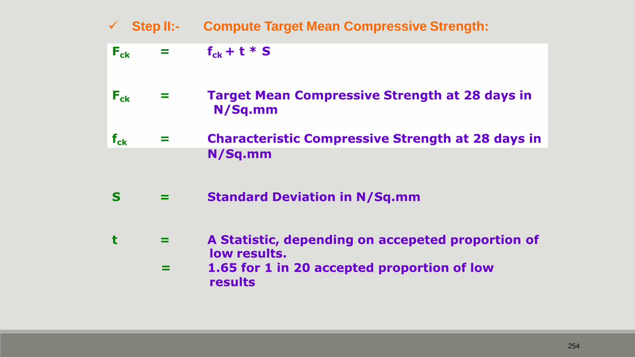
Step II:- Compute Target Mean Compressive Strength:
Fck = fck + t * S
Fck = Target Mean Compressive Strength at 28 days in N/Sq.mm
fck = Characteristic Compressive Strength at 28 days in
N/Sq.mm
S
=
Standard Deviation in N/Sq.mm
t
=
A Statistic, depending on accepeted proportion of low results.
= 1.65 for 1 in 20 accepted proportion of low results

255
Values of t
Accepted proportion
of low results
t
1 in 5, 20% 0.84
1 in 10, 10% 1.28
1 in 15, 6.7% 1.50
1 in 20, 5% 1.65
1in 40, 2.5% 1.86
1 in 100, 1% 2.33

256
Assumed Standard Deviation
(Table 8, IS:456-2000)
Grade of
Concrete
Assumed Standard Deviation
(N/Sq.mm)
Good Site Control Fair Site Control
M10, M15 3.5 4.5
M20, M25 4.0 5.0
M30, M35
M,40,M45
M50
5.0
6.0

257
Step III:- Select the Water-Cement ratio of trial
mix from experience
S. No.
Concrete Grade
Minimum expected W/C
1 M10 0.9
2 M15 0.7
3 M20 0.55
4 M25 0.50
5 M30 0.45
6 M35 0.40
7 M40 0.35
8 M45 0.30

258
Step IV:- Select the water content per cubic metre of
concrete from table2 of I.S: 10262-2009.
Maximum size of Aggregate
(mm)
Water Content per
cubic metre of concrete
(Kg)
10 208
20 186
40 165

259
Approximate water content (Kg)
per cubic metre of concrete
(Table 32, SP:23-1982)
Slump
(mm)
Maximum Size of
Aggregate
(mm)
10 20 40
30-50 205 185 160
80-100 225 200 175
150-180 240 210 185

260
Volume of Coarse Aggregate per
Unit Volume of Total Aggregate
(Table 3, IS:10262-2009)
Maximum
Size of
Aggregate
(mm)
Volume of Coarse Aggregate per Unit
Volume of Total Aggregate
Zone IV Zone III Zone II Zone I
10 0.50 0.48 0.46 0.44
20 0.66 0.64 0.62 0.60
40 0.75 0.73 0.71 0.69

261

262

263
of Fine & Coarse Step VI:- Then we find the quantities
aggregate by absolute volume method.
- (Eq.1) V = (W+C/Sc+(1/p) * (fa/Sfa)) * (1/1000)
and
V = (W+C/Sc+(1/(1-p)) * (ca/Sca)) * (1/1000) - (Eq.2)
Where
V = Absolute volume of fresh concrete = 1 m3
W = Mass of Water (Kg) per m3 of concrete
C = Mass of Cement (Kg) per m3 of
concrete
p = Percentage of fine aggregate.
fa = Mass of fine aggregate
ca = Mass of coarse aggregate
Sc = Specific gravity of cement.
Sfa = Specific gravity of fine aggregate.
Sca = Specific gravity of coarse aggregate.

264
Substituting the values in Eq(1), we get
1000 = 185 + 411/3.0 + (1/0.36) * fa /2.6)
= 185 + 137 + fa/0.936
= 322 + fa/0.936
fa = (1000 – 322) * 0.936
= 678 * 0.936
= 635 Kg.

265
Substituting the values in Eq(2), we get
1000 = 185 + 411/3.0 + (1/0.64) * ca /2.65)
= 185 + 137 + ca/1.696
= 322 + ca/1.696
ca = (1000 – 322) * 1.696
= 678 * 1.696
= 1150 Kg.

266
So the mix proportion works out to be
W : C : fa : ca
= 185 : 411 : 635 : 1150
= 0.45 : 1 : 1.55 : 2.80
This mix will be considered as Trial Mix No.2
267
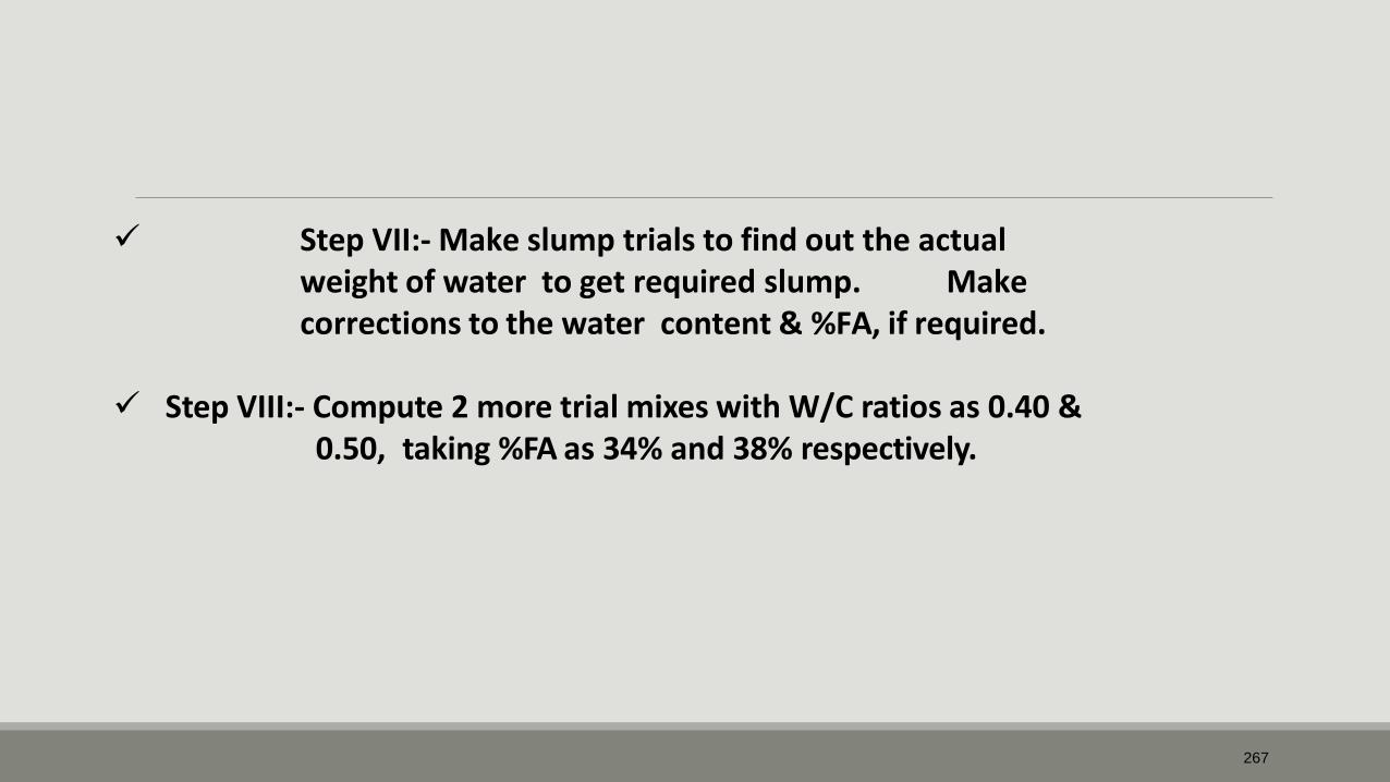
Step VII:- Make slump trials to find out the actual weight of water to get required slump. Make corrections to the water content & %FA, if required.
Step VIII:- Compute 2 more trial mixes with W/C ratios as 0.40 & 0.50, taking %FA as 34% and 38% respectively.

268
Trial Mix No. 1:-
Cement = 185 / 0.4 = 462.5 Kg.
Substituting the values in Eq(1), we get
1000 = 185 + 462.5/3.0 + (1/0.34) * fa /2.6)
fa = 584 Kg.
Substituting the values in Eq(2), we get
1000 = 185 + 462.5/3.0 + (1/0.66) * ca /2.65)
ca = 1156 Kg.
So the mix proportion works out to be
W : C : fa : ca
= 185 : 462.5 : 584 : 1156
= 0.4 : 1 : 1.26 : 2.50

269
Trial Mix No. 3:-
Cement = 185 / 0.5 = 370 Kg.
Substituting the values in Eq(1), we get
1000 = 185 + 370/3.0 + (1/0.38) * fa /2.6)
fa = 683 Kg.
Substituting the values in Eq(2), we get
1000 = 185 + 370/3.0 + (1/0.62) * ca /2.65)
ca = 1136 Kg.
So the mix proportion works out to be
W : C : fa : ca
= 185 : 370 : 683 : 1136
= 0.5 : 1 : 1.85 : 3.07
270
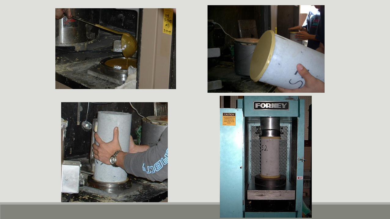
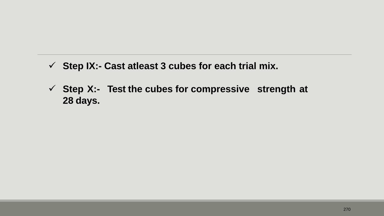
Step IX:- Cast atleast 3 cubes for each trial mix.
Step X:- Test the cubes for compressive strength at
28 days.

271
28 Days Compressive Strengths of Trial Mixes
W/C
Ratio
C/W Ratio
Compressive
Strength
(Kg/Cm2)
0.40 2.50 457
0.45 2.22 420
0.50 2.00 360

272
Step XI:- Draw a graph between compressive strength
Vs C/W Ratio.

273

274
Step XII:- From the graph, find the W/C ratio for the required target mean compressive strength.
Step XIII:- Calculate the mix proportions corresponding to the W/C ratio, obtained from the graph.

275
Final Mix:-
From the graph, for a target strength of 390 Kg/Cm2, W/C ratio = 0.47
Cement = 185 / 0.47 = 394 Kg.
Substituting the values in Eq(1), we get
1000 = 185 + 394/3.0 + (1/0.38) * fa /2.6)
fa = 675 Kg.
Substituting the values in Eq(2), we get
1000 = 185 + 394/3.0 + (1/0.62) * ca /2.65)
ca = 1123 Kg.
So the mix proportion works out to be
W : C : fa : ca
= 185 : 394 : 675 : 1123
= 0.47 : 1 : 1.71 : 2.85

276
Step XIV:- Check the cement content & W/C ratio against the limiting I.S: 456-2000 for
values given in Table-5 of given type of exposure & type of
Concrete.

277
Table-5 Minimum Cement content Maximum Water-Cement ratio and Minimum Grade of Concrete for different exposures with normal weight of aggregate of 20mm nominal maximum size.
Sl. No.
Exposure
Plain Concrete Reinforced Concrete
Minimum Cement Content kg/m3
Maximum Free
Water Cement Ratio
Minimum Grade of Concrete
Minimum Cement Content kg/m3
Maximum Free
Water Cement Ratio
Minimum Grade of Concrete
i) Mild 220 0.60 - 300 0.55 M20
ii) Moderate 240 0.60 M15 300 0.50 M25
iii) Severe 250 0.50 M20 320 0.45 M30
iv) Very Severe
260 0.45 M20 340 0.45 M35
v) Extreme 280 0.40 M25 360 0.40 M40

278
From the table 5 of IS: 456–2000, the minimum Cement content & W/C ratio, For moderate, for RCC are 300Kgs. & 0.5
The Cement content = 394Kgs. > 300Kgs. Hence Ok
The W/C Ratio = 0.47 < 0.5 Hence Ok

279
TEST REPORT
Concrete Mix RCC M30 with 20.0mm M.S.A.
Sl. No.
Particulars
Result
1 Characteristic Compressive strength in 30
N/Sq.mm
2 Maximum size of Aggregate in mm 20.0
3 Type of Exposure Moderate
4 Type of Site control Good
5 Target Average Compressive Strength in N/Sq.mm
38.2
6 Workability in terms of Slump in mm 25-75
7 Mode of Compaction Vibration
8 Mix Partiuclars: a. Water-Cement Ratio b. Materials per cubic metre of concrete in
Kg. i) Water ii) Cement (OPC 43 Grade) iii) Fine Aggregate iv) Coarse Aggregate
c. Mix Portion by weight
0.47
185
394 675
1123 1:1.71:2.85

Sieve Analysis of Fine Aggregate
•Weight of sample = 500g (approx)
•Observations:
Cumulative Cumulative %
IS:383-1970
Zone =II
Sieve
Weight retained(g)
%
size weight Trail 1 Trail2 Total retained (g)
weight Passing Specifications
retained (g)
10 mm 0 0 0 0 0 100 100
4.75 mm 2 2 4 4 0 100 90-100
2.36 mm 6 7 13 17 2 98 75-100
1.18 mm 166 165 331 348 35 65 55-90
600 micron 118 117 235 583 58 42 35-59
300 micron 175 160 335 918 92 8 8-30
150 micron 36 42 78 996 100 0 0-10
150 micron pass
2
2
4
-
-
-
-
280

Zones of Fine Aggregate
Sieve Size
Zone I
IS : 383 – 1970
% Passing for
Zone II Zone III
Zone IV
10.00 mm 100 100 100 100
4.75 mm 90-100 90-100 90-100 95-100
2.36 mm 60-95 75-100 85-100 95-100
1.18 mm 30-70 55-90 75-100 90-100
600 micron 15-34 35-59 60-79 80-100
300 micron 5-20 8-30 12-40 15-50
150 micron 0-10 0-10 0-10 0-15
281

282
Sieve Analysis of Coarse Aggregate 2 20 mm aggregate :
a. Minimum weight of sample = 25 Kg
b. Observations :
Sieve
size
Weight
retained
(Kg)
Cumulative
weight
retained
(Kg)
%
Cumulative
weight
retained
(Kg)
%
Passing
IS:383-1970
Specifications
Graded
Single
sized
40 0.0 0.0 0 100 100 100
20 4.7 4.7 10 90 95-100 85-100
10 41.5 46.2 97 3 25-55 0-20
4.75 1.6 47.8 100 0 0-10 0-5
4.75 P 0 47.8 - - - -

283
Sieve Analysis of Coarse Aggregate 2 10 mm aggregate :
a. Minimum weight of sample = 12 Kg
b. Observations :
Sieve
size
Weight
retained
(Kg)
Cumulative
weight
retained
(Kg)
%
Cumulative
weight
retained
(Kg)
%
Passing
IS:383-1970
Specifications
Single
Sized
12.5 0.0 0.0 0 100 100
10 5.4 5.4 15 85 85-100
4.75 24.3 29.7 81 19 0-20
2.36 6.9 36.6 100 0 0-5
2.36 P 0 36.6 - - - -

284
N = 20 N = 20
Avg = 30 Avg = 35
27,30,30,32,35,
27,33,34,29,28,
30,28,31,32,26,
34,33,25,27,29
28, 32,35,38,40,
34,35,35,36,39,
33,32,32,34,37,
32,35,38,39,36
Total = 600 Total = 700
Target mean compressive strength

The value of ‘S’ depends on Degree of Site control
and grade of concrete as given in I.S: 456–2000 (Table.8)
Sl. Concrete No. Grade
S 1.65XS S 1.65XS
Good Fair
Fck Fck
N/mm Kg/cm2 N/mm2 Kg/cm2
2
1 M10 3.5 58 15.8 161 4.5 7.4 17.4 178
2 M15 3.5 58 20.8 212 4.5 7.4 22.4 229
3 M20 4.0 6.6 26.6 271 5.0 8.3 28.3 288
4 M25 4.0 6.6 31.6 322 5.0 8.3 33.3 339
5 M30 5.0 8.3 38.3 390 6.0 9.9 39.9 407
6 M35 5.0 8.3 43.3 441 6.0 9.9 44.9 458
285

286
Step IV:-Fixation of Water Cement ratios for trial mixes.
Sl. No.
Required Grades
Trial W/C
1 M20, M15, M10 0.55, 0.6, 0.9
2 M25, M20, M15 0.5, 0.6, 0.7

287
Final Mix for RCC-M25:-
From the graph, for a target strength of 322 Kg/Cm2, W/C ratio = 0.57
which is > 0.5, So, limit W/C ratio to 0.5 only.
Cement = 185 / 0.5 = 370 Kg.
Substituting the values in Eq(1), we get
1000 = 185 + 370/3.0 + (1/0.38) * fa /2.6)
fa = 683 Kg.
Substituting the values in Eq(2), we get
1000 = 185 + 370/3.0 + (1/0.62) * ca /2.65)
ca = 1136 Kg.
So the mix proportion works out to be
W : C : fa : ca
= 185 : 370 : 683 : 1136
= 0.50 : 1 : 1.85 : 3.07

288
Specific Gravity of Cement [ IS : 4031 – 1988]:
(Sc) Specific gravity of cement (W2 - W1)
= ---------------------------- x 0.79 (W4 - W1) - (W3 - W2)
Where,
W1 = Weight of specific gravity bottle in g W2 = Weight of specific gravity bottle with about half filled cement in g W3 = Weight of specific gravity bottle with about half filled cement
& rest is filled with kerosene in g. W4 = Weight of specific gravity bottle completely filled with kerosene in g 0.79 = Specific Gravity of Kerosene.

289
Specific Gravity of Fine Aggregate & Coarse Aggregate [ IS : 2386 (Part.3) - 1963]:
D Specific gravity (Gs) = --------------
C – ( A – B)
Where,
A = Weight of Pycnometer vessel containing sample & filled with distilledwater in g B = Weight of Pycnometer completely filled with distilled water only in g C = Weight of saturated surface dry sample in g D = Weight of oven dried sample in g

SPECIAL CONCRETES UNIT 5

Special concrete

• Concrete is most vital material in modern construction.
• In addition to normal concrete, other varieties in use are, high strength and high performance concrete, self compacting, light weight, high density, fibre reinforced, polymer, coloured concrete etc.
• The making of concrete is an art as well as a science.
Overview

• Special types of concrete are those with out-of-the- ordinary properties or those produced by unusual techniques. Concrete is by definition a composite material consisting essentially of a binding medium and aggregate particles, and it can take many forms.
• These concretes do have advantages as well as disadvantages.
Introduction

1. High Volume Fly Ash Concrete.
2. Silica fume concrete.
3. GGBS, Slag based concrete.
4. Ternary blend concrete.
5. Light weight concrete.
6. Polymer concrete.
7. Self Compacting Concrete.
8. Coloured Concrete.
9. Fibre-reinforced Concrete.
10. Pervious Concrete.
11. Water-proof Concrete.
12. Temperature Controlled Concrete.
Types of special concrete

• Is used to replace a portion of the portland cement used in the mix.
• According to IS: 456 – 2000 replacement of OPC by Fly-ash up to 35% as binding material is permitted.
• HVFAC is a concrete where excess of 35%of fly-ash is used as replacement.
• Use of fly ash is because of many factors such as a) Abundance of fly ash i.e. 110million tons of fly ash is produced in India
every year.
b) Fly ashes from major TPP are of very high quality i.e. quality of fly ash. c) Economic factor i.e. Cost of fly ash with in 200 km from a TPP is as low as
10% to 20% of the cost of cement.
d) Environmental factors i.e. reduction in CO2 emission.
1.High Volume Fly Ash Concrete.

Strength relation between control concrete and fly ash concrete

Permeability relation between control and fly ash concrete.

• Very fine non-crystalline silica produced in electric arc furnaces as a by product.
• Highly reactive pozzolan used to improve mortar and concrete.
• Silica fume in concrete produces two types of effect viz. ◦ Physical effect
◦ Chemical effect
• The transition zone is a thin layer between the bulk hydrated cement paste and the aggregate particles in concrete. This zone is the weakest component in concrete, and it is also the most permeable area. Silica fume plays a significant role in the transition zone through both its physical and chemical effects.
2.Silica fume concrete

• The presence of any type of very small particles will improve concrete properties. This effect is termed either “particle packing” or “micro filling”.
• physical mechanisms do play a significant role, particularly at early ages.
Physical Effect

• Silica fume is simply a very effective pozzolanic material.
• pozzolanic means a siliceous or siliceous and aluminous material, which in itself possess little or no cementious value but will, in finely divided form and in the presence of moisture , chemically react with calcium hydroxide at ordinary temperatures to form compounds possessing cementious properties.
Chemical Effect

• By-product of the iron manufacturing industry, replacement of Portland cement with GGBS will lead to significant reduction of carbon dioxide gas emission.
• GGBS powder is almost white in colour in the dry state Fresh GGBS concrete may show mottled green or bluish-green areas on the surface mainly due to the presence of a small amount of sulphide.
• GGBS concrete requires longer setting times than Portland cement concrete, probably due to the smooth and glassy particle forms of GGBS. If the temperature is 23oC or replacement level of portland cement by GGBS is less than 30% , the setting times will not significantly be affected.
• when GGBS replacement level is less than 40%, bleeding is generally unaffected. At higher replacement levels, bleeding rates may be higher.
3. GGBS, Slag based concrete
• GGBS concrete has lower early strengths because the rate of initial reaction of GGBS is slower than that of Portland cement. GGBS is therefore generally grounded to a finer state than Portland cement i.e. from around 4000 cm2/g to 6000 cm2/g resulting in significant increase in 28-day strength.
• It was also reported that the early strengths (up to 28 days) of concrete mixes (with 25%, 35%, 50%, and 60% GGBS replacements) were lower than that of Portland cement concrete mixes. By 56 days, the strength of 50% and 60% GGBS mixes exceeded that of the Portland cement mix, and by one year all GGBS mixes were stronger than the Portland cement mixes.
• Due to its longer setting time, it can be transported to distant places but care should be taken while casting because there are chances that bleeding may take place.

Ground granulated blast furnace slag

• Ternary concrete mixtures include three different cementitious materials i.e. combinations of portland cement, slag cement, and a third cementitious material. The third component is often fly ash, but silica fume is also common.
• Other material in combination with portland and slag cement, such as rice husk ash
are not currently in common usage.
• Slag cement has been used in ternary mixtures for decades.
4. Ternary blend concrete

1. High strength
2. Low permeability
3. Corrosion resistance
4. Sulphate resistance
5. ASR resistance
6. Elimination of thermal cracking
Benefits

1. General construction (residential, commercial, industrial)
2. Paving
3. High performance concrete
4. Precast concrete
5. Masonry and masonry units
6. Mass concrete
7. Shotcrete
Ternary mixtures can be used and have been used in virtually any concrete application

The optimum mixture proportions for ternary blends, as with other concrete, will be dependent on the final use of the concrete, construction requirements and seasonal considerations. As with other concrete, cold weather will affect the early strength gain and mixture proportions may need to be adjusted to assure job-site performance. In low W/CM applications such as paving, mixtures with 15percent fly ash and 30% slag cement component have been used successfully.
Mixture proportion
Fly ash, a powder resembling cement, has been used in concrete since the 1930s.
Ground granulated blast
furnace slagc Silica fume powder


• Structural lightweight concrete is similar to normal weight concrete except that it has a lower density.
• Made with lightweight aggregates.
• Air-dry density in the range of 1350 to 1850 kg/m3
• 28-day compressive strength in excess of 17 Mpa.
• Structural lightweight concrete is used primarily to reduce the dead-load weight in concrete members, such as floors in high-rise buildings.
• Structural Lightweight Aggregates:
Rotary kiln expanded clays, shales, and slates
Sintering grate expanded shales and slates
Pelletized or extruded fly ash
Expanded slags
5.Light weight concrete

• Compressive Strength:
The compressive strength of structural lightweight concrete is usually related to the cement content at a given slump and air content, rather than to a water-to-cement ratio. This is due to the difficulty in determining how much of the total mix water is absorbed into the aggregate and thus not available for reaction with the cement.
• Slump:
1. Due to lower aggregate density, structural lightweight concrete does not slump as much as normal-weight concrete with the same workability.
2. A lightweight air-entrained mixture with a slump of 50 to 75 mm (2 to 3 in.) can be placed under conditions that would require a slump of 75 to 125 mm (3 to 5 in.)
3. With higher slumps, the large aggregate particles tend to float to the surface, making finishing difficult.
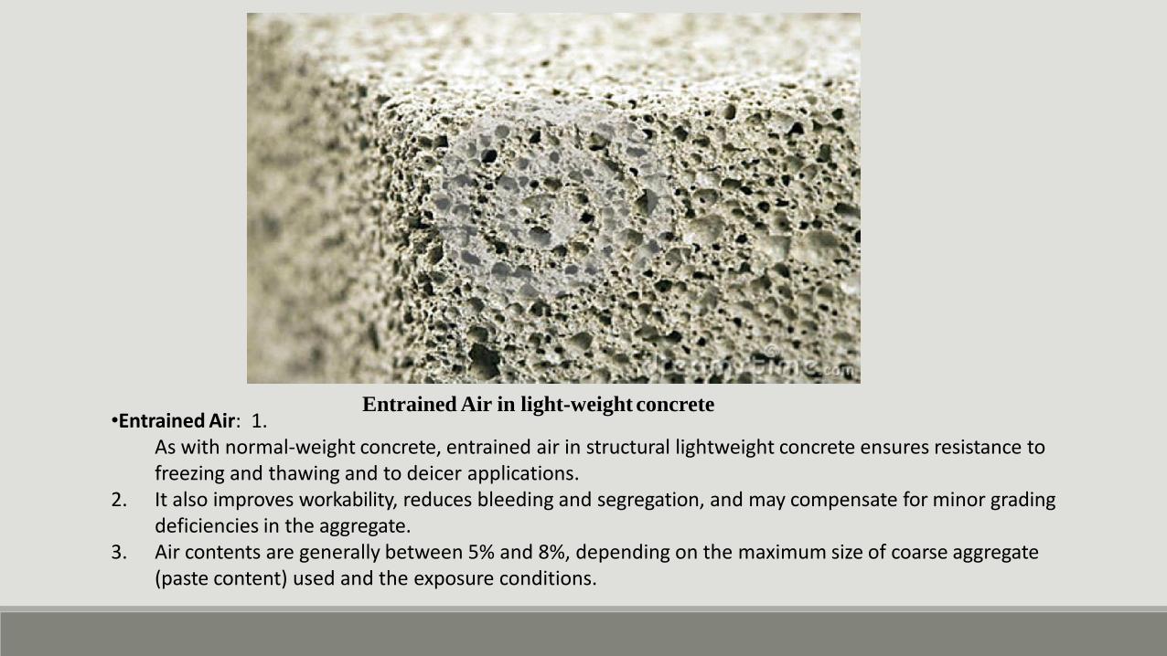
Entrained Air in light-weight concrete •Entrained Air: 1.
As with normal-weight concrete, entrained air in structural lightweight concrete ensures resistance to freezing and thawing and to deicer applications.
2. It also improves workability, reduces bleeding and segregation, and may compensate for minor grading deficiencies in the aggregate.
3. Air contents are generally between 5% and 8%, depending on the maximum size of coarse aggregate (paste content) used and the exposure conditions.

1. Structural lightweight concrete is generally easier to handle and place than normal-weight concrete.
2. A slump of 50 to 100 mm (2 to 4 in.) produces the best results for finishing.
3. If pumped concrete is being considered, the specified suppliers and contractor should all be consulted about performing a field trial using the pump and mixture planned for the project.
4. Adjustments to the mixture maybe necessary.
5. pumping pressure causes the aggregate to absorb more water, thus reducing the slump and increasing the density of the concrete.
Placing, Finishing, and Curing

PLACING AND FINISHING OF CONCRETE.

Polymer concrete is part of group of concretes that use polymers to supplement or replace cement as a binder. The types include polymer-impregnated concrete, polymer concrete, and polymer-Portland-cement concrete.
6.Polymer concrete

• In polymer concrete, thermosetting resins are used as the principal polymer component due to their high thermal stability and resistance to a wide variety of chemicals.
• Polymer concrete is also composed of aggregates that include silica, quartz, granite, limestone, and other high quality material.
• Polymer concrete may be used for new construction or repairing of old concrete.
• The low permeability and corrosive resistance of polymer concrete allows it to be used in swimming pools, sewer structure applications, drainage channels, electrolytic cells for base metal recovery, and other structures that contain liquids or corrosive chemicals.
• It is especially suited to the construction and rehabilitation of manholes due to their ability to withstand toxic and corrosive sewer gases and bacteria commonly found in sewer systems.
• It can also be used as a replacement for asphalt pavement, for higher durability and higher strength.
• Polymer concrete has historically not been widely adopted due to the high costs and difficulty associated with traditional manufacturing techniques.

1. Product hard to manipulate with conventional tools such as drills and presses due to its strength and density. Recommend getting pre-modified product from the manufacturer
2. Small boxes are more costly when compared to its precast counterpart however pre cast concretes induction of stacking or steel covers quickly bridge the gap.
Advantages Disadvantages
1. Rapid curing at ambient temperatures
2. High tensile, flexural, and compressive strengths
3. Good adhesion to most surfaces
4. Good long-term durability with respect to freeze and thaw cycles
5. Low permeability to water and aggressive solutions
6. Good chemical resistance
7. Good resistance against corrosion
8. Lighter weight (only somewhat less dense than traditional concrete, depending on the resin content of the mix)
9. May be vibrated to fill voids in forms
10. Allows use of regular form-release agents (in some applications)
11. Dielectric
Advantages & Disadvantages
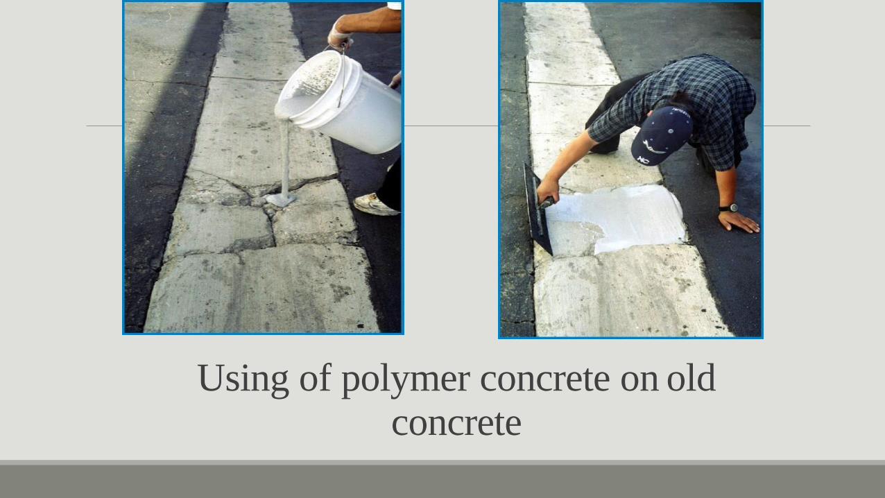
Using of polymer concrete on old concrete

• Self-compacting concrete (SCC) is an innovative concrete that does not require vibration for placing and compaction. It is able to flow under its own weight, completely filling formwork and achieving full compaction, even in the presence of congested reinforcement.
• The hardened concrete is dense, homogeneous and has the same engineering properties and durability as traditional vibrated concrete.
• Very close to the Kolhapur there is project of steel industry, sand used for the formation of mould when the moulds are opened the waste sand is dumped for the filling the low lying areas while doing this the agriculture areas is converted into barren area. Because there is no space for the waste other than the land filling. similar case is in case of aluminium industry where red mud is concluded to be waste, which contains lot amount of bauxite and that is why red mud is also dump in the nearby areas here it is causing big threat for the society and it is disturbing the eco system of the environment. So it is the need to use this particular otherwise waste material for the constructive in such fashion in the case of concrete so that concrete which became cost effective as well as eco-friendly.
7.Self compacting concrete

• Types:
1. Powder type of self-compacting concrete: This is proportioned to give the required self- compactibility by reducing the water-powder ratio and provide adequate segregation resistance.
2. Viscosity agent type self-compacting concrete: This type is proportioned to provide self- compaction by the use of viscosity modifying admixture to provide segregation resistance.
3. Combination type self-compacting concrete: This type is proportioned so as to obtain self-compactibility mainly by reducing the water powder ratio.
• Fresh SCC Properties:
1. Filling ability (excellent deformability)
2. Passing ability (ability to pass reinforcement without blocking)
3. High resistance to segregation.

• It has been observed that the compressive strength of selfcompacting concrete produced with the combination of admixtures goes on increasing up to 2% addition of red mud.
• After 2% addition of red mud, the compressive strength starts decreasing, i.e. the compressive strength of self-compacting concrete produced is maximum when 2% red mud is added.
• The percentage increase in the compressive strength at 2% addition of red mud is +9.11 .

Placing of self compacting concrete

• Coloured concrete can be produced by using coloured aggregates or by adding colour pigments (ASTM C 979) or both.
• If surfaces are to be washed with acid, a delay of approximately two weeks after casting is necessary.
• Coloured aggregates may be natural rock such as quartz, marble, and granite, or they may be ceramic materials.
• synthetic pigments generally give more uniform results.
• The amount of colour pigments added to a concrete mixture should not be more than 10% of the mass of the cement.
• .For example, a dose of pigment equal to 1.5% by mass of cement may produce a pleasing pastel colour, but 7% may be needed to produce a deep colour. Use of white portland cement with a pigment will produce cleaner, brighter colours and is recommended in preference to gray cement, except for black or dark gray colours.
8.Coloured concrete:

Coloured concrete

• Fibre reinforced concrete (FRC) may be defined as a composite materials made with Portland cement, aggregate, and incorporating discrete discontinuous fibres.
• The role of randomly distributes discontinuous fibres is to bridge across the cracks that develop provides some post- cracking “ductility”.
• The real contribution of the fibres is to increase the toughness of the concrete under any type of loading.
• The fibre reinforcement may be used in the form of three – dimensionally randomly distributed fibres throughout the structural member when the added advantages of the fibre to shear resistance and crack control can be further utilised.
9. Fibre reinforced concrete:
• Tensile Strength:
1. Fibres aligned in the direction of the tensile stress may bring about very large increases in direct tensile strength, as high as 1.33% for 5% of smooth, straight steel fibres.
2. Thus, adding fibres merely to increase the direct tensile strength is probably worthwhile.
3. However, as in compression, steel fibres do lead to major increases in the post cracking behaviour or toughness of the composites.
• Application of SFRC:
The most common applications are
1. pavements
2. tunnel linings
3. pavements and slabs
4. shotcrete
5. shotcrete also containing silica fume, airport pavements, bridge deck slab repairs
The fibres themselves are, unfortunately, relatively expensive; a 1% steel fibre addition will approximately double the rate.

Fibre reinforced concrete

• Pervious (porous or no-fines) concrete contains a narrowly graded coarse aggregate, little to no fine aggregate, and insufficient cement paste to fill voids in the coarse aggregate.
• Low water-cement ratio, low-slump concrete resembling popcorn held together by cement paste.
• Produces a concrete with a high volume of voids (20% to 35%) and a high permeability that allows water to flow through it easily.
• Pervious concrete is used in hydraulic structures as drainage media, and in parking lots, pavements, and airport local groundwater supply by allowing water to penetrate the concrete to the ground below.
• Pervious concretes have also been used in tennis courts and greenhouses.
• The compressive strength of different mixes can range from 3.5 to 27.5 Mpa.
• Drainage rates commonly range from 100 to 900 lit.per minute per square meter.
10.Pervious concrete:

Pervious concrete

Top Proof waterproof concrete contains two specially formulated admixtures. The first reduces the water/cement ratio, increasing the density of the mix and minimising the size of the pores. The second fills the remaining pores ensuring a completely watertight finish. This means there is no need for external membranes, reducing cost and labour.
11. Water-proof concrete:

Waterproof concrete benefits: Waterproof concrete applications:
1. Basements
2. Underground car parks
3. Electrical and other plant rooms
4. Swimming pools
5. Aquariums and aquatic centres
6. Waterside buildings
1. No need for external membranes, reducing cost and labour
2. Water resistant, quality- assured waterproof concrete
3. Less susceptible to cracking
4. No minimum order size
5. 100% recyclable
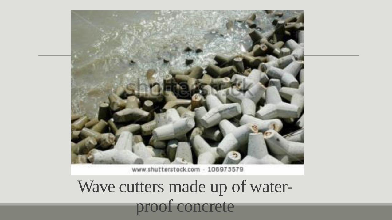
Wave cutters made up of water- proof concrete

• “An large volume of cast-in-place concrete with dimensions large enough to require that measures be taken to cope with the generation of heat and attendant volume change to minimize cracking.”
• Mass concrete includes not only low-cement-content concrete used in dams and other massive structures but also moderate to high cement content concrete in structural members of bridges and buildings.
• As the interior concrete increases in temperature and expands, the surface concrete may be cooling and contracting.
• The width and depth of cracks depends upon the temperature differential, physical properties of the concrete, and the reinforcing steel.
12. Mass concrete:
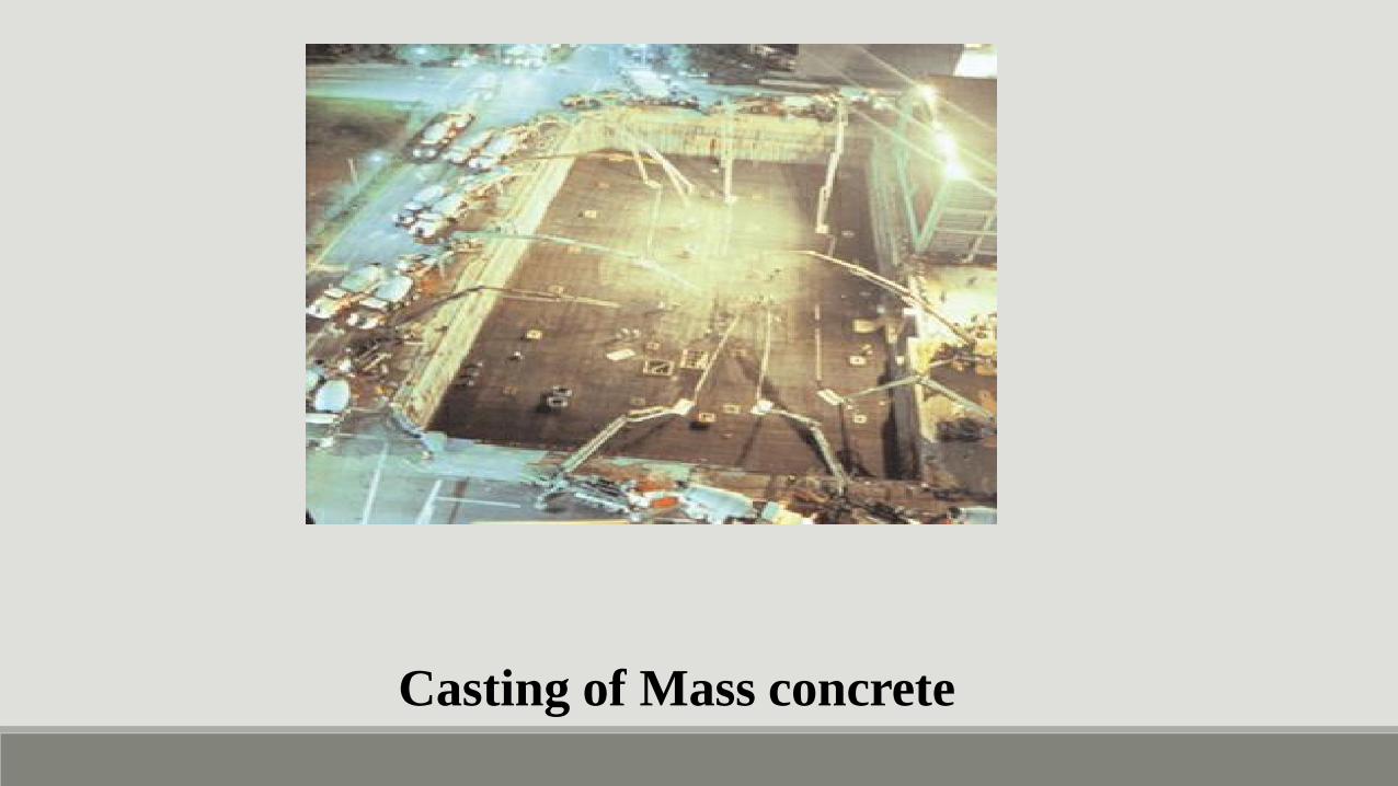
Casting of Mass concrete