Unified CCE Reference Designs - Cisco
28
Unified CCE Reference Designs • Introduction to the Reference Designs, on page 1 • Benefits of a Reference Design Solution, on page 3 • Specifications for a Reference Design Solution, on page 3 • Contact Center Enterprise Reference Designs, on page 7 Introduction to the Reference Designs The first four chapters of this book are for anyone who wants to get familiar with the three contact center enterprise solutions: • Packaged Contact Center Enterprise • Cisco Hosted Collaboration Solution for Contact Center • Unified Contact Center Enterprise For information about design considerations and guidelines specific to Unified CCE, see the remaining chapters. Note The Contact Center Enterprise Reference Designs are a set of Cisco validated designs of our contact center enterprise solutions. The Reference Designs define the technologies and topologies that fit the needs for most deployments. The Reference Designs focus on simplifying the contact center enterprise solution design. They provide complete contact center functionality based on components that are strategic to Cisco. We have defined the Reference Designs in the following table to cover most contact center needs: Table 1: Reference Design Use by Contact Center Enterprise Solution Unified CCE Cisco HCS for Contact Center Packaged CCE Reference Design Yes Yes Yes 2000 Agents Yes Yes Yes 4000 Agents Yes Yes Yes 12000 Agents Unified CCE Reference Designs 1
-
Upload
khangminh22 -
Category
Documents
-
view
1 -
download
0
Transcript of Unified CCE Reference Designs - Cisco
Unified CCE Reference Designs
• Introduction to the Reference Designs, on page 1• Benefits of a Reference Design Solution, on page 3• Specifications for a Reference Design Solution, on page 3• Contact Center Enterprise Reference Designs, on page 7
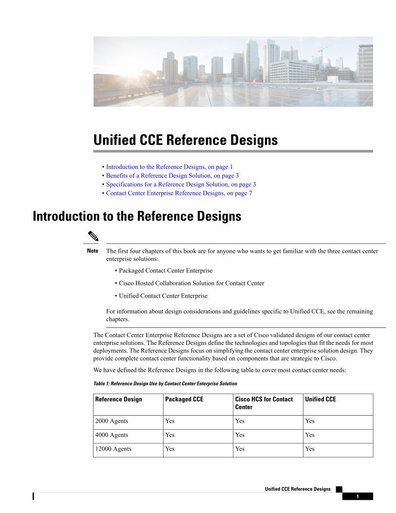
Introduction to the Reference Designs
The first four chapters of this book are for anyone who wants to get familiar with the three contact centerenterprise solutions:
• Packaged Contact Center Enterprise
• Cisco Hosted Collaboration Solution for Contact Center
• Unified Contact Center Enterprise
For information about design considerations and guidelines specific to Unified CCE, see the remainingchapters.
Note
The Contact Center Enterprise Reference Designs are a set of Cisco validated designs of our contact centerenterprise solutions. The Reference Designs define the technologies and topologies that fit the needs for mostdeployments. The Reference Designs focus on simplifying the contact center enterprise solution design. Theyprovide complete contact center functionality based on components that are strategic to Cisco.
We have defined the Reference Designs in the following table to cover most contact center needs:
Table 1: Reference Design Use by Contact Center Enterprise Solution
Unified CCECisco HCS for ContactCenter
Packaged CCEReference Design
YesYesYes2000 Agents
YesYesYes4000 Agents
YesYesYes12000 Agents
Unified CCE Reference Designs1
Unified CCECisco HCS for ContactCenter
Packaged CCEReference Design
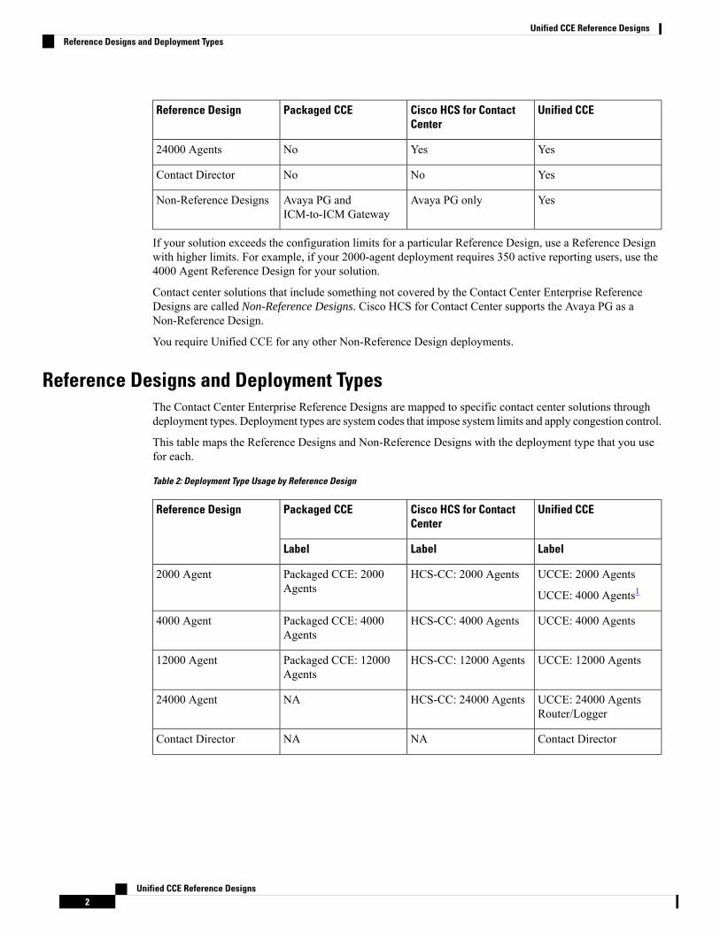
YesYesNo24000 Agents
YesNoNoContact Director
YesAvaya PG onlyAvaya PG andICM-to-ICM Gateway
Non-Reference Designs
If your solution exceeds the configuration limits for a particular Reference Design, use a Reference Designwith higher limits. For example, if your 2000-agent deployment requires 350 active reporting users, use the4000 Agent Reference Design for your solution.
Contact center solutions that include something not covered by the Contact Center Enterprise ReferenceDesigns are called Non-Reference Designs. Cisco HCS for Contact Center supports the Avaya PG as aNon-Reference Design.
You require Unified CCE for any other Non-Reference Design deployments.
Reference Designs and Deployment TypesThe Contact Center Enterprise Reference Designs are mapped to specific contact center solutions throughdeployment types. Deployment types are system codes that impose system limits and apply congestion control.
This table maps the Reference Designs and Non-Reference Designs with the deployment type that you usefor each.
Table 2: Deployment Type Usage by Reference Design
Unified CCECisco HCS for ContactCenter
Packaged CCEReference Design
LabelLabelLabel
UCCE: 2000 Agents
UCCE: 4000 Agents1HCS-CC: 2000 AgentsPackaged CCE: 2000
Agents2000 Agent
UCCE: 4000 AgentsHCS-CC: 4000 AgentsPackaged CCE: 4000Agents
4000 Agent
UCCE: 12000 AgentsHCS-CC: 12000 AgentsPackaged CCE: 12000Agents
12000 Agent
UCCE: 24000 AgentsRouter/Logger
HCS-CC: 24000 AgentsNA24000 Agent
Contact DirectorNANAContact Director
Unified CCE Reference Designs2
Unified CCE Reference DesignsReference Designs and Deployment Types
Unified CCECisco HCS for ContactCenter
Packaged CCEReference Design
LabelLabelLabel
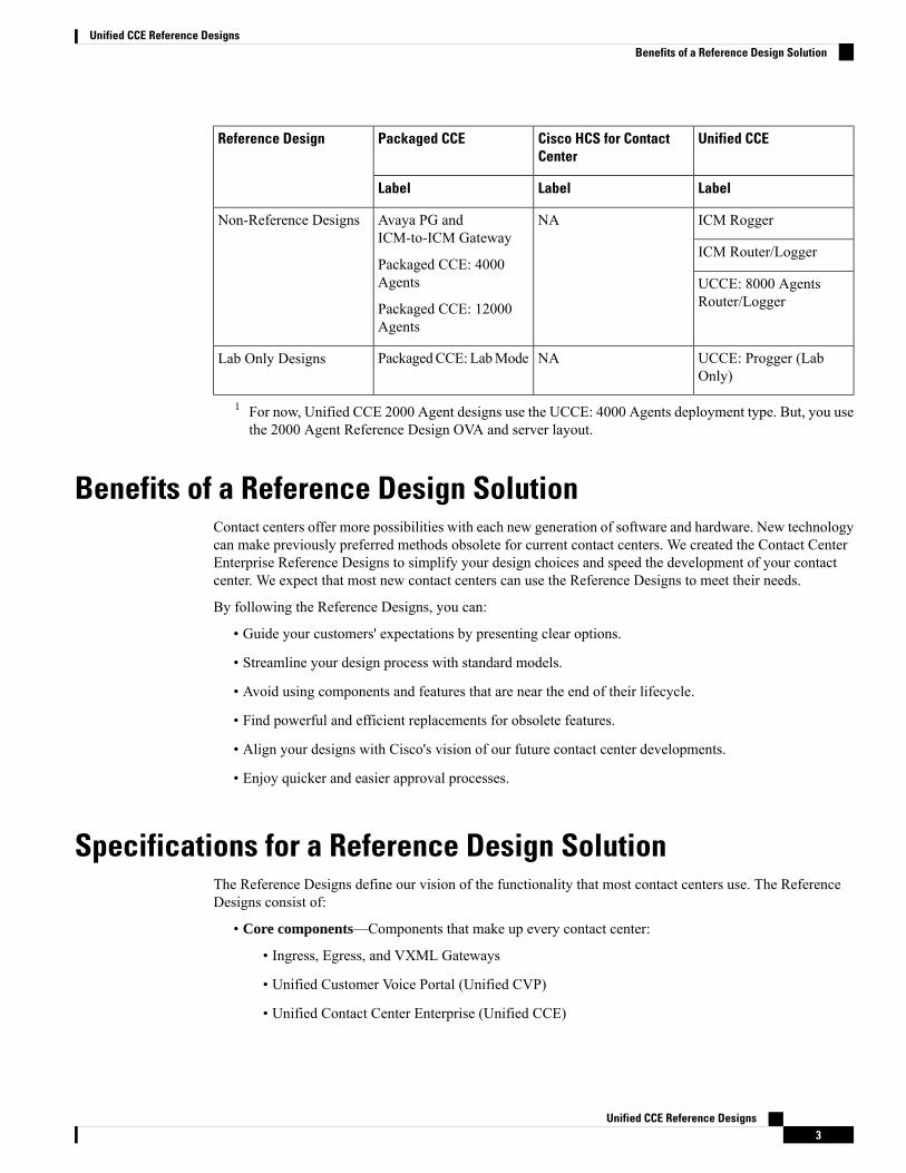
ICM RoggerNAAvaya PG andICM-to-ICM Gateway
Packaged CCE: 4000Agents
Packaged CCE: 12000Agents
Non-Reference Designs
ICM Router/Logger
UCCE: 8000 AgentsRouter/Logger
UCCE: Progger (LabOnly)
NAPackagedCCE:LabModeLab Only Designs
1 For now, Unified CCE 2000 Agent designs use the UCCE: 4000 Agents deployment type. But, you usethe 2000 Agent Reference Design OVA and server layout.
Benefits of a Reference Design SolutionContact centers offer more possibilities with each new generation of software and hardware. New technologycan make previously preferred methods obsolete for current contact centers. We created the Contact CenterEnterprise Reference Designs to simplify your design choices and speed the development of your contactcenter. We expect that most new contact centers can use the Reference Designs to meet their needs.
By following the Reference Designs, you can:
• Guide your customers' expectations by presenting clear options.
• Streamline your design process with standard models.
• Avoid using components and features that are near the end of their lifecycle.
• Find powerful and efficient replacements for obsolete features.
• Align your designs with Cisco's vision of our future contact center developments.
• Enjoy quicker and easier approval processes.
Specifications for a Reference Design SolutionThe Reference Designs define our vision of the functionality that most contact centers use. The ReferenceDesigns consist of:
• Core components—Components that make up every contact center:
• Ingress, Egress, and VXML Gateways
• Unified Customer Voice Portal (Unified CVP)
• Unified Contact Center Enterprise (Unified CCE)
Unified CCE Reference Designs3
Unified CCE Reference DesignsBenefits of a Reference Design Solution
• Cisco Virtualized Voice Browser (VVB)
• Unified Communications Manager (Unified CM)
• Cisco Finesse
• Cisco Unified Intelligence Center
• Optional Cisco components—Components that add functionality that not every contact center needs.
• Cisco Remote Expert
• SocialMiner
• Cisco Unified SIP Proxy
• Enterprise Chat and Email
• Cisco IdS
• Optional third-party components—Third-party components that you can add to provide other features.
• Load balancers
• Recording
• Speech servers - ASR/TTS
• Wallboards
• Workforce management
• Integrated features—These features do not require you to add an optional solution component to enablethem. But, these features can require configuration in multiple solution components to activate them.They can affect your solution sizing and might have specific design considerations.
• Call flows—Standard contact handling and routing methods.
• Inbound Calls:
• New calls from a carrier
• New internal calls
• Supplementary services
• Hold and resume
• Transfers and conferences
• Refer transfers
• Network transfers
• Requery and survivability
• Topologies—Standard layouts for your contact center components:
• Centralized
Unified CCE Reference Designs4
Unified CCE Reference DesignsSpecifications for a Reference Design Solution
• Distributed
• Global
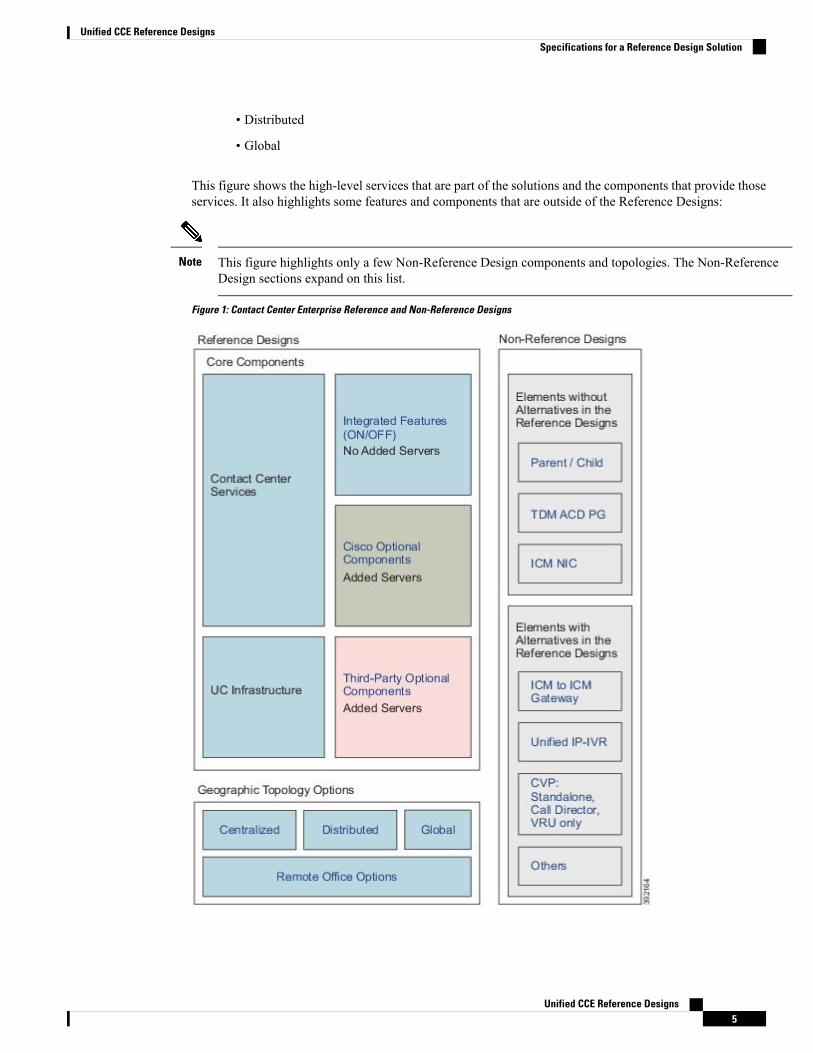
This figure shows the high-level services that are part of the solutions and the components that provide thoseservices. It also highlights some features and components that are outside of the Reference Designs:
This figure highlights only a few Non-Reference Design components and topologies. The Non-ReferenceDesign sections expand on this list.
Note
Figure 1: Contact Center Enterprise Reference and Non-Reference Designs
Unified CCE Reference Designs5
Unified CCE Reference DesignsSpecifications for a Reference Design Solution
In general, you cannot use the ICM-to-ICM Gateway in Reference Designs. Only the Contact DirectorReference Design allows you to use that gateway.
Note
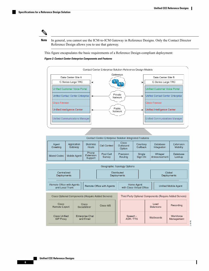
This figure encapsulates the basic requirements of a Reference Design-compliant deployment:
Figure 2: Contact Center Enterprise Components and Features
Unified CCE Reference Designs6
Unified CCE Reference DesignsSpecifications for a Reference Design Solution
Contact Center Enterprise Reference DesignsThe following sections describe the Contact Center Enterprise Reference Designs.
The Reference Designs show the layout of the core components on Cisco UCS B200 and C240 M4 and C240M5SX Tested Reference Configuration servers which are referred to as the Reference Design servers hereinterchangeably.
For more details on supported servers for the Reference Designs, see the Cisco Collaboration Virtualizationpage for your solution at http://www.cisco.com/c/dam/en/us/td/docs/voice_ip_comm/uc_system/virtualization/cisco-collaboration-virtualization.html.
Note
The following notes apply to all the Reference Designs:
• Contact Center Enterprise solutions use vCPU oversubscription. This policy applies for both ReferenceDesign and Non-Reference Design solutions.
• The standard PG VM includes an Agent (Unified CM) PG, a VRU PG, and an MR PG. Unified CCEand Cisco HCS for Contact Center allow you to add more PGs and their peripherals onto this base layout.
• The CVP Reporting Server is an optional component. You can deploy more external CVP Reportingservers based on your deployment type.
• For information on the data source allocation of the components in the Reference Design layouts, seethe Cisco Unified Contact Center Enterprise Installation and Upgrade Guide at https://www.cisco.com/c/en/us/support/customer-collaboration/unified-contact-center-enterprise/products-installation-guides-list.html
• The Reference Design layouts in this section do not show off-box components like SocialMiner.
Virtual Machines Resource Provisioning Policy
The previously used Oversubscription policy is a part of the Virtual Machine (VM) Resource ProvisioningPolicy.
Note
The Unified CCE Reference Designs support the virtual machine vCPU oversubscription of the physical CPUcores on a server. For the purposes of oversubscription, the hyper-thread cores do not count as physical cores.Whether or not you use oversubscription, use the VM Resource Provisioning policy. This policy limits thetotal available CPU MHz and the memory of a server that the host-resident VMs can consume.
Apply the VM Resource Provisioning policy when:
• You change the documented Reference Design VM layout by adding or replacing VMs. This means thatyou use a custom or non-Reference VM layout in a Reference Design solution.
• You provision a non-Reference Design server.
• You provision a Reference Design server for optional and third-party components that are not given areference VM layout.
Unified CCE Reference Designs7
Unified CCE Reference DesignsContact Center Enterprise Reference Designs
• You use UCS or third-party specifications-based servers.
• You upgrade an existing solution and do not migrate to a Reference Design VM layout.
Apply the VMResource Provisioning policy on a per-server basis. This policy does not apply to the ReferenceDesign VM layouts. Your solution can contain servers that use the Reference Design VM layouts and otherVM layouts that use the VM Resource Provisioning policy rules.
Note
The application of the VM Resource Provisioning policy requires meeting the following conditions:
• You can use up to two vCPUs for every physical core on each server.
• You can use up to 65% of the total available CPU MHz on each server.
• You can use up to 80% of the total available memory on each server.
For more information on virtualization and specification-based server policies, see the Cisco CollaborationVirtualization at http://www.cisco.com/c/dam/en/us/td/docs/voice_ip_comm/uc_system/virtualization/cisco-collaboration-virtualization.html.
The Virtual Machine Placement Tool does not currently allow you to oversubscribe. This limitation is onlyan issue with the tool. You can oversubscribe within the limits that are provided here.
Note
2000 Agent Reference DesignsAll contact center enterprise solutions support the 2000 Agent Reference design on the Cisco UCS C240M5SX and the Cisco HX220c-M5SX Large TRC servers.
• In this Reference Design, Cisco Unified Intelligence Center, Live Data, and the Identity Service forSingle Sign-On are coresident on a single VM. In the larger Reference Designs, they reside in separateVMs.
• You can optionally deploy the Unified Communications Manager Publisher and Subscribers on separateservers, instead of deploying them as shown in the 2000 Agent Reference Design layout. You shoulddedicate two of the subscribers to Unified CCE. All devices on these subscribers must be SIP.
In 2000 Agent Reference Designs, a coresident Unified CM can support a maximum of 2000 phones.This includes your phones for all types of agents, whether contact center agents or back-office workers.If your solution requires more than 2000 phones, use a Unified CM on a separate server instead.
• In the global deployment topology, each remote site can have its own Unified CM cluster. A remote sitecannot include a Cisco Unified Intelligence Center server.
• You can deploy optional AW-HDS-DDS per site on external servers for longer data retention.
• In 2000 Agent Reference Designs, you can deploy ECEData Server on-box for up to 400 agents. DeployECE off-box for up to 1500 agents.
You can also deploy the ECE Data Server on a separate server.
Unified CCE Reference Designs8
Unified CCE Reference Designs2000 Agent Reference Designs
• Deploy the ECE Web Server on an external server. You can place that server either in the same datacenter as the ECE Data Server or in a DMZ if customer chat interactions require that.
Support on the Cisco UCS C240 M5SX Large TRC Server
If you plan to upgrade to 12.x on Cisco UCS C240 M4SX servers, deploy Unified CM and ECE HA VMs onexternal servers.
Important
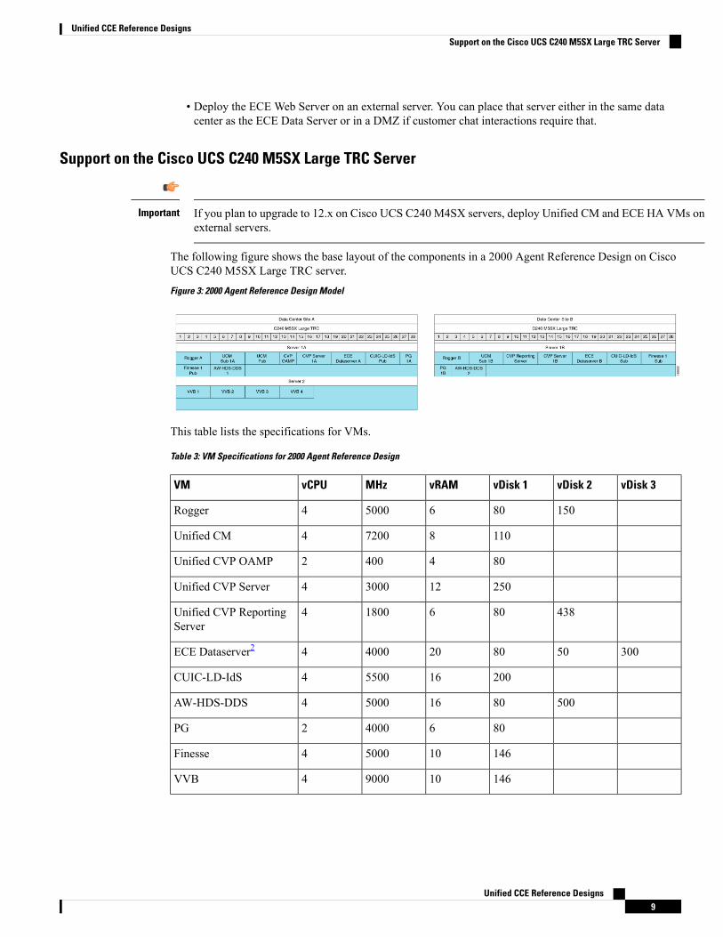
The following figure shows the base layout of the components in a 2000 Agent Reference Design on CiscoUCS C240 M5SX Large TRC server.
Figure 3: 2000 Agent Reference Design Model
This table lists the specifications for VMs.
Table 3: VM Specifications for 2000 Agent Reference Design
vDisk 3vDisk 2vDisk 1vRAMMHzvCPUVM
15080650004Rogger
110872004Unified CM
8044002Unified CVP OAMP
2501230004Unified CVP Server
43880618004Unified CVP ReportingServer
30050802040004ECE Dataserver2
2001655004CUIC-LD-IdS
500801650004AW-HDS-DDS
80640002PG
1461050004Finesse
1461090004VVB
Unified CCE Reference Designs9
Unified CCE Reference DesignsSupport on the Cisco UCS C240 M5SX Large TRC Server
2 For the latest VM specifications, see the row for 400 agents in the Virtualization for Enterprise Chatand Email page at https://www.cisco.com/c/dam/en/us/td/docs/voice_ip_comm/uc_system/virtualization/virtualization-enterprise-chat-email.html.
Table 4: Total VM Requirements for 2000 Agent Reference Design
vDiskvRAMMHzvCPUServer
22161064630036Data Center Site A
25441004050034Data Center Site B
584403600016Server 2
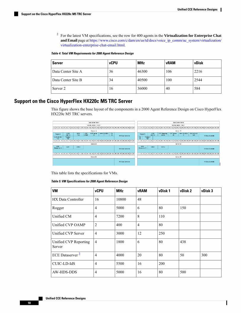
Support on the Cisco HyperFlex HX220c M5 TRC ServerThis figure shows the base layout of the components in a 2000 Agent Reference Design on Cisco HyperFlexHX220c M5 TRC servers.
This table lists the specifications for VMs.
Table 5: VM Specifications for 2000 Agent Reference Design
vDisk 3vDisk 2vDisk 1vRAMMHzvCPUVM
481080016HX Data Controller
15080650004Rogger
110872004Unified CM
8044002Unified CVP OAMP
2501230004Unified CVP Server
43880618004Unified CVP ReportingServer
30050802040004ECE Dataserver 3
2001655004CUIC-LD-IdS
500801650004AW-HDS-DDS
Unified CCE Reference Designs10
Unified CCE Reference DesignsSupport on the Cisco HyperFlex HX220c M5 TRC Server
vDisk 3vDisk 2vDisk 1vRAMMHzvCPUVM
80640002PG
1461050004Finesse
1461090004VVB
3 For the latest VM specifications, see the row for 400 agents in the Virtualization for Enterprise Chatand Email page at https://www.cisco.com/c/dam/en/us/td/docs/voice_ip_comm/uc_system/virtualization/virtualization-enterprise-chat-email.html.
Table 6: Total VM Requirements for 2000 Agent Reference Design
vDiskvRAMMHzvCPUServer
17861345310048Data Center Site 1A
21141284730046Data Center Site 1B
722883280028Data Center Site 2A
722883280028Data Center Site 2B
4000 Agent Reference DesignsAll contact center enterprise solutions support the 4000 Agent Reference design on the Cisco UCS C240M5SX TRC and Cisco HyperFlex HX220c M5 TRC servers.
This model adds servers to scale up from the 2000 Agent Reference Design.
You can only deploy two AW-HDS-DDS per data center site in the 4000 Agent Reference Design. In largersolutions, you use a combination of HDS-DDS and AW-HDS.
Note
Support on the Cisco UCS C240 M5SX TRC Server
If you plan to upgrade to 12.x on Cisco UCS C240M4SX servers, make the following changes to your serversand VM layouts:
• Deploy Unified CM and ECE HA VMs on external servers.
• Add 16 GB of physical RAM to each server that hosts Unified CVP call and VXML servers.
• Increase the memory reservations for the Unified CVP VMs to 12 GB.
Important
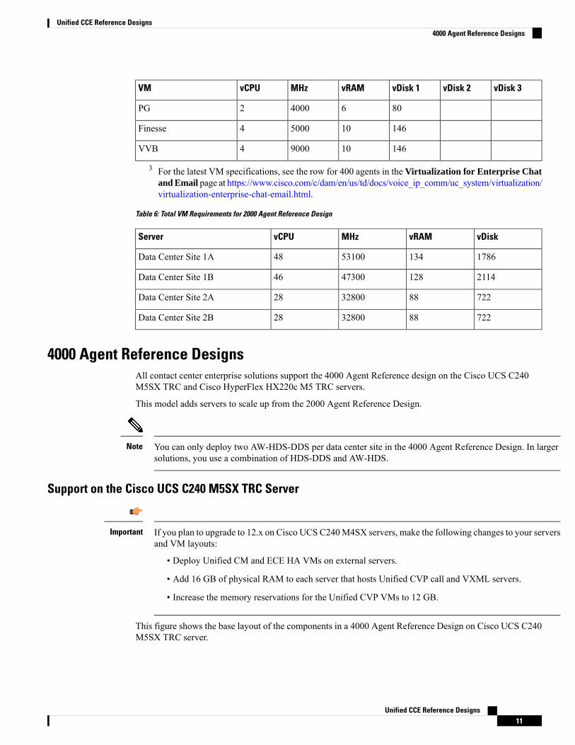
This figure shows the base layout of the components in a 4000 Agent Reference Design on Cisco UCS C240M5SX TRC server.
Unified CCE Reference Designs11
Unified CCE Reference Designs4000 Agent Reference Designs
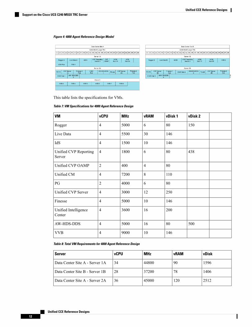
Figure 4: 4000 Agent Reference Design Model
This table lists the specifications for VMs.
Table 7: VM Specifications for 4000 Agent Reference Design
vDisk 2vDisk 1vRAMMHzvCPUVM
15080650004Rogger
1463055004Live Data
1461015004IdS
43880618004Unified CVP ReportingServer
8044002Unified CVP OAMP
110872004Unified CM
80640002PG
2501230004Unified CVP Server
1461050004Finesse
2001636004Unified IntelligenceCenter
500801650004AW-HDS-DDS
1461090004VVB
Table 8: Total VM Requirements for 4000 Agent Reference Design
vDiskvRAMMHzvCPUServer
1596904480034Data Center Site A - Server 1A
1406783720028Data Center Site B - Server 1B
25121204500036Data Center Site A - Server 2A
Unified CCE Reference Designs12
Unified CCE Reference DesignsSupport on the Cisco UCS C240 M5SX TRC Server
vDiskvRAMMHzvCPUServer
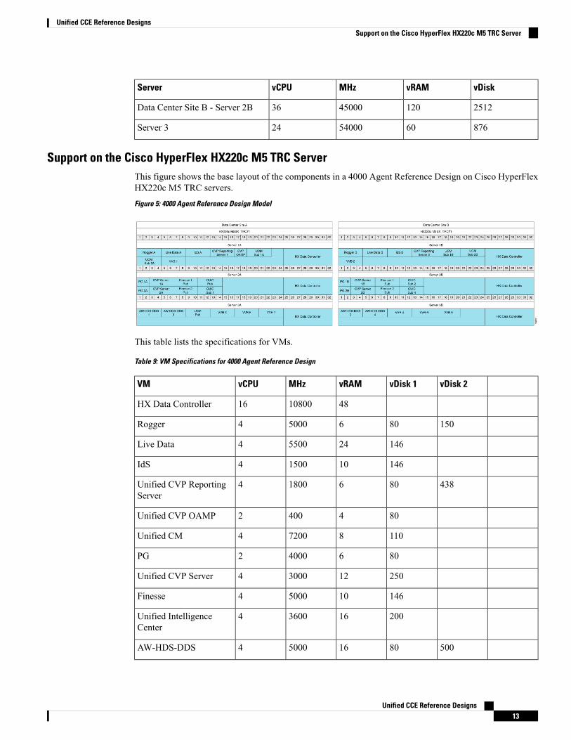
25121204500036Data Center Site B - Server 2B
876605400024Server 3
Support on the Cisco HyperFlex HX220c M5 TRC ServerThis figure shows the base layout of the components in a 4000 Agent Reference Design on Cisco HyperFlexHX220c M5 TRC servers.
Figure 5: 4000 Agent Reference Design Model
This table lists the specifications for VMs.
Table 9: VM Specifications for 4000 Agent Reference Design
vDisk 2vDisk 1vRAMMHzvCPUVM
481080016HX Data Controller
15080650004Rogger
1462455004Live Data
1461015004IdS
43880618004Unified CVP ReportingServer
8044002Unified CVP OAMP
110872004Unified CM
80640002PG
2501230004Unified CVP Server
1461050004Finesse
2001636004Unified IntelligenceCenter
500801650004AW-HDS-DDS
Unified CCE Reference Designs13
Unified CCE Reference DesignsSupport on the Cisco HyperFlex HX220c M5 TRC Server
vDisk 2vDisk 1vRAMMHzvCPUVM
1461090004VVB
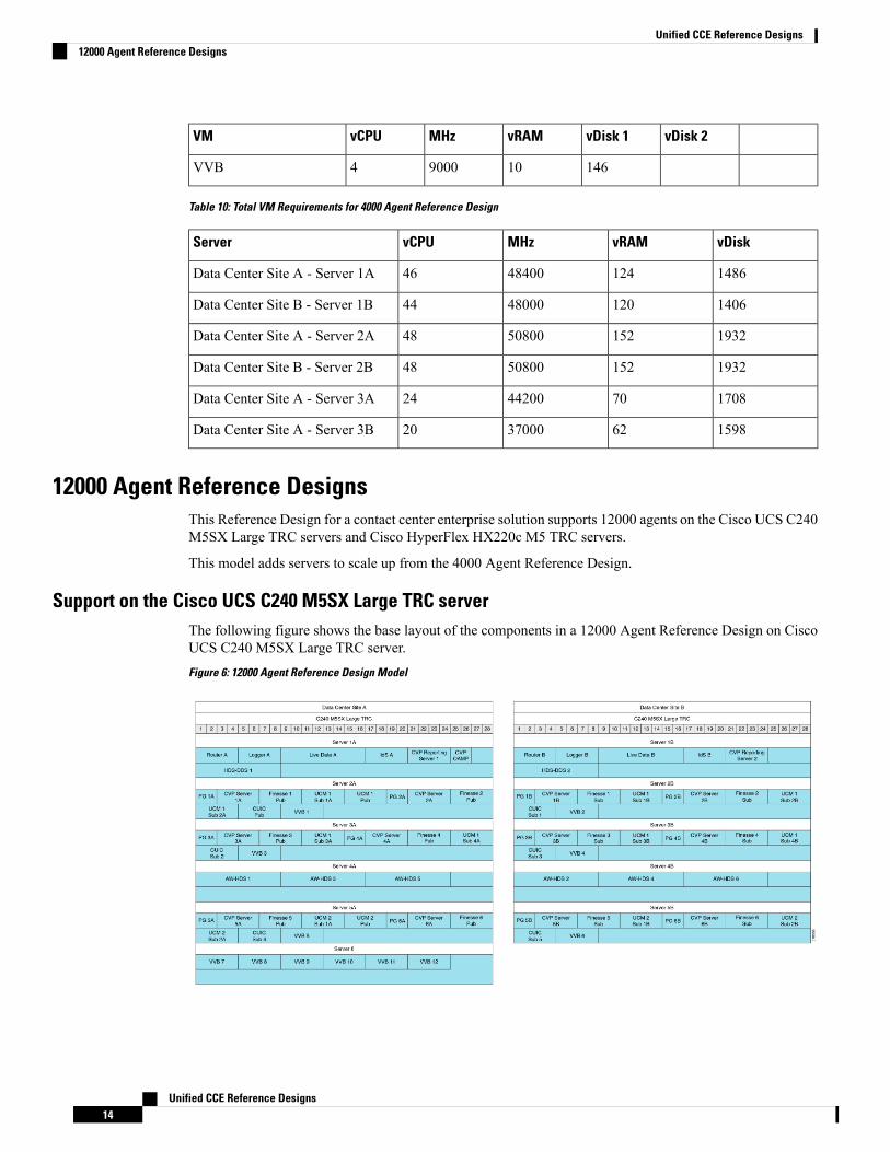
Table 10: Total VM Requirements for 4000 Agent Reference Design
vDiskvRAMMHzvCPUServer
14861244840046Data Center Site A - Server 1A
14061204800044Data Center Site B - Server 1B
19321525080048Data Center Site A - Server 2A
19321525080048Data Center Site B - Server 2B
1708704420024Data Center Site A - Server 3A
1598623700020Data Center Site A - Server 3B
12000 Agent Reference DesignsThis Reference Design for a contact center enterprise solution supports 12000 agents on the Cisco UCS C240M5SX Large TRC servers and Cisco HyperFlex HX220c M5 TRC servers.
This model adds servers to scale up from the 4000 Agent Reference Design.
Support on the Cisco UCS C240 M5SX Large TRC serverThe following figure shows the base layout of the components in a 12000 Agent Reference Design on CiscoUCS C240 M5SX Large TRC server.
Figure 6: 12000 Agent Reference Design Model
Unified CCE Reference Designs14
Unified CCE Reference Designs12000 Agent Reference Designs
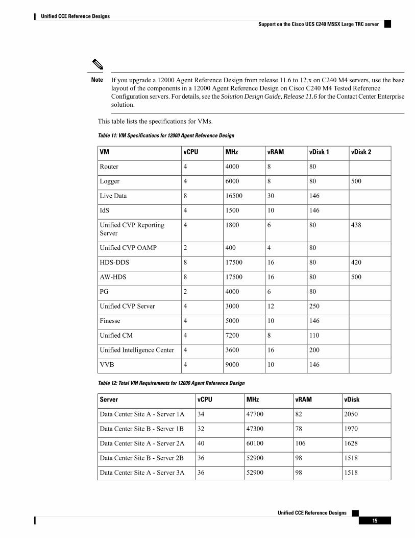
If you upgrade a 12000 Agent Reference Design from release 11.6 to 12.x on C240 M4 servers, use the baselayout of the components in a 12000 Agent Reference Design on Cisco C240 M4 Tested ReferenceConfiguration servers. For details, see the Solution Design Guide, Release 11.6 for the Contact Center Enterprisesolution.
Note
This table lists the specifications for VMs.
Table 11: VM Specifications for 12000 Agent Reference Design
vDisk 2vDisk 1vRAMMHzvCPUVM
80840004Router
50080860004Logger
14630165008Live Data
1461015004IdS
43880618004Unified CVP ReportingServer
8044002Unified CVP OAMP
4208016175008HDS-DDS
5008016175008AW-HDS
80640002PG
2501230004Unified CVP Server
1461050004Finesse
110872004Unified CM
2001636004Unified Intelligence Center
1461090004VVB
Table 12: Total VM Requirements for 12000 Agent Reference Design
vDiskvRAMMHzvCPUServer
2050824770034Data Center Site A - Server 1A
1970784730032Data Center Site B - Server 1B
16281066010040Data Center Site A - Server 2A
1518985290036Data Center Site B - Server 2B
1518985290036Data Center Site A - Server 3A
Unified CCE Reference Designs15
Unified CCE Reference DesignsSupport on the Cisco UCS C240 M5SX Large TRC server
vDiskvRAMMHzvCPUServer
1518985290036Data Center Site B - Server 3B
1740485250024Data Center Site A - Server 4A
1740485250024Data Center Site B - Server 4B
16281066010040Data Center Site A - Server 5A
1518985290036Data Center Site B - Server 5B
876605400024Server 6
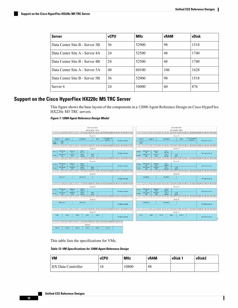
Support on the Cisco HyperFlex HX220c M5 TRC ServerThis figure shows the base layout of the components in a 12000 Agent Reference Design on Cisco HyperFlexHX220c M5 TRC servers.
Figure 7: 12000 Agent Reference Design Model
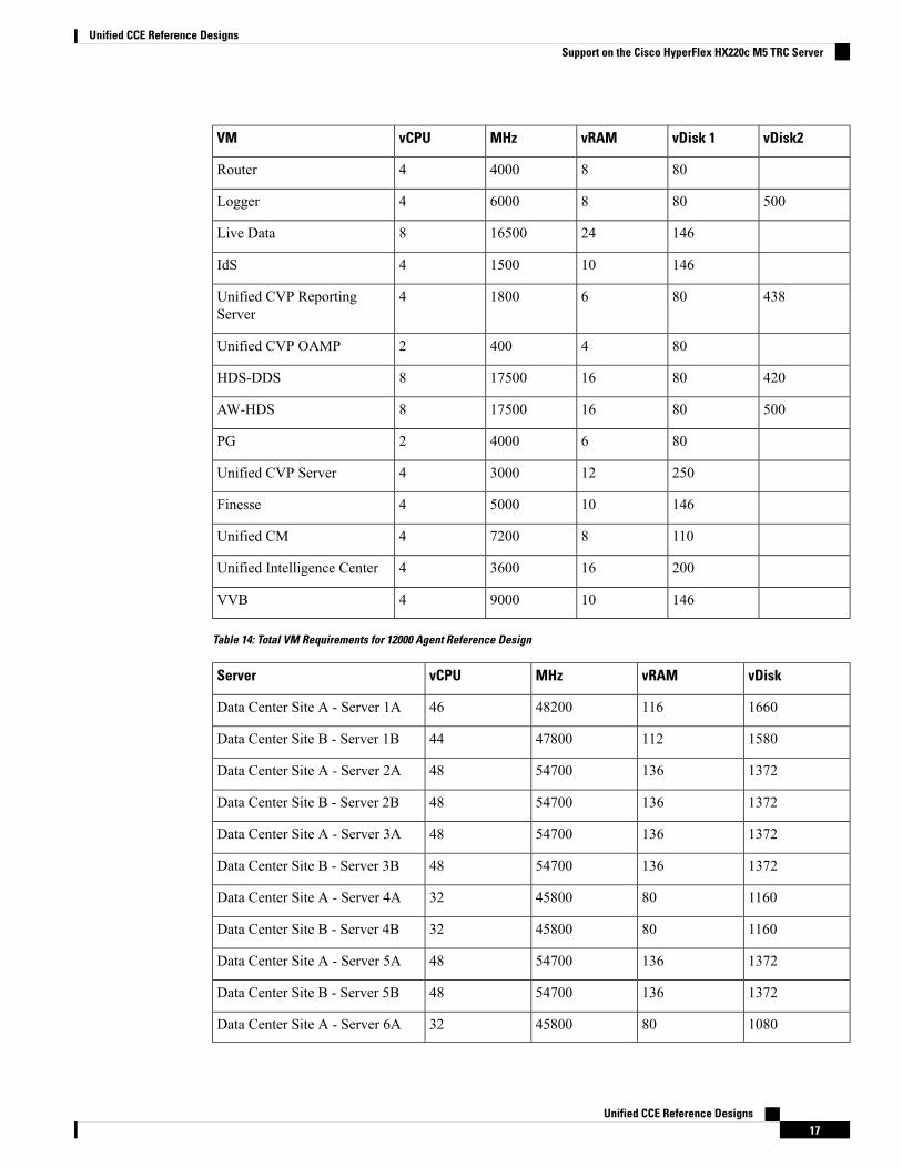
This table lists the specifications for VMs.
Table 13: VM Specifications for 12000 Agent Reference Design
vDisk2vDisk 1vRAMMHzvCPUVM
481080016HX Data Controller
Unified CCE Reference Designs16
Unified CCE Reference DesignsSupport on the Cisco HyperFlex HX220c M5 TRC Server
vDisk2vDisk 1vRAMMHzvCPUVM
80840004Router
50080860004Logger
14624165008Live Data
1461015004IdS
43880618004Unified CVP ReportingServer
8044002Unified CVP OAMP
4208016175008HDS-DDS
5008016175008AW-HDS
80640002PG
2501230004Unified CVP Server
1461050004Finesse
110872004Unified CM
2001636004Unified Intelligence Center
1461090004VVB
Table 14: Total VM Requirements for 12000 Agent Reference Design
vDiskvRAMMHzvCPUServer
16601164820046Data Center Site A - Server 1A
15801124780044Data Center Site B - Server 1B
13721365470048Data Center Site A - Server 2A
13721365470048Data Center Site B - Server 2B
13721365470048Data Center Site A - Server 3A
13721365470048Data Center Site B - Server 3B
1160804580032Data Center Site A - Server 4A
1160804580032Data Center Site B - Server 4B
13721365470048Data Center Site A - Server 5A
13721365470048Data Center Site B - Server 5B
1080804580032Data Center Site A - Server 6A
Unified CCE Reference Designs17
Unified CCE Reference DesignsSupport on the Cisco HyperFlex HX220c M5 TRC Server
vDiskvRAMMHzvCPUServer
1080804580032Data Center Site B - Server 6B
730985580036Data Center Site B - Server 7A
730985580036Data Center Site B - Server 7B
876605400024Server 8
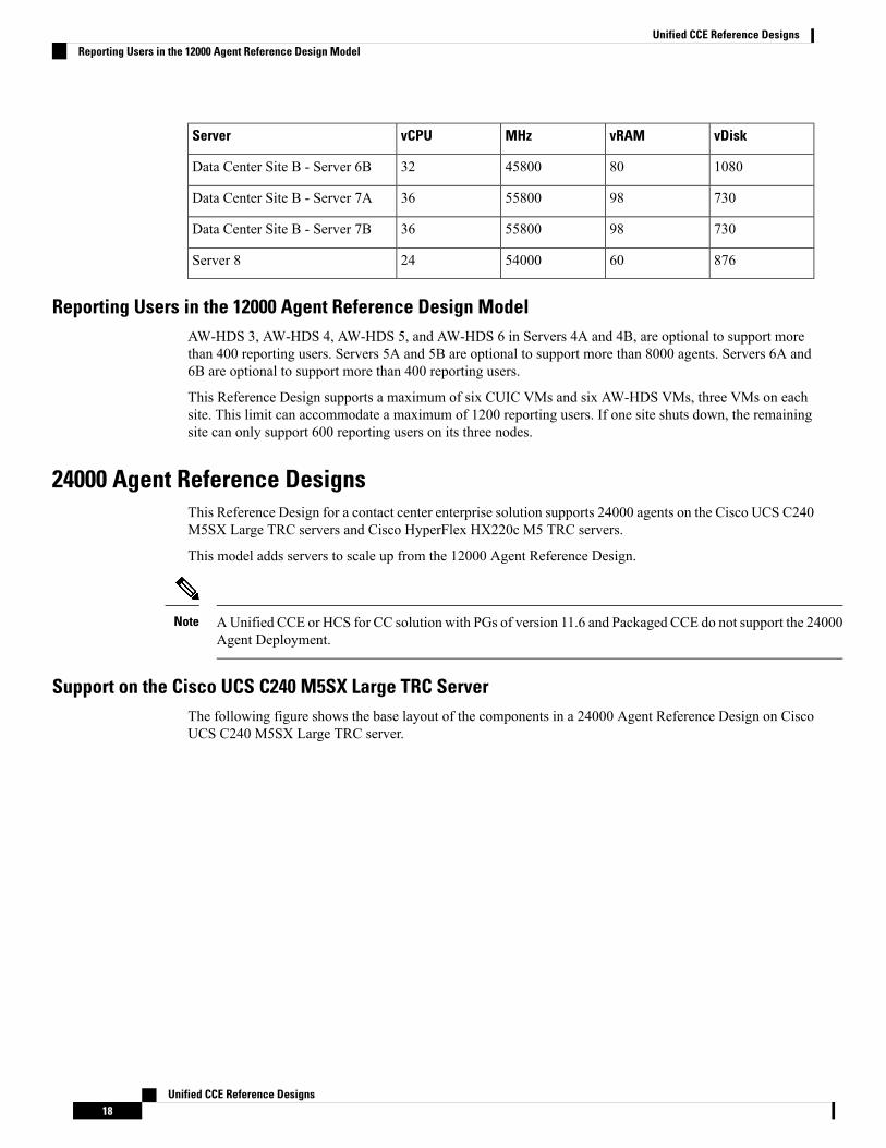
Reporting Users in the 12000 Agent Reference Design ModelAW-HDS 3, AW-HDS 4, AW-HDS 5, and AW-HDS 6 in Servers 4A and 4B, are optional to support morethan 400 reporting users. Servers 5A and 5B are optional to support more than 8000 agents. Servers 6A and6B are optional to support more than 400 reporting users.
This Reference Design supports a maximum of six CUIC VMs and six AW-HDS VMs, three VMs on eachsite. This limit can accommodate a maximum of 1200 reporting users. If one site shuts down, the remainingsite can only support 600 reporting users on its three nodes.
24000 Agent Reference DesignsThis Reference Design for a contact center enterprise solution supports 24000 agents on the Cisco UCS C240M5SX Large TRC servers and Cisco HyperFlex HX220c M5 TRC servers.
This model adds servers to scale up from the 12000 Agent Reference Design.
A Unified CCE or HCS for CC solution with PGs of version 11.6 and Packaged CCE do not support the 24000Agent Deployment.
Note
Support on the Cisco UCS C240 M5SX Large TRC ServerThe following figure shows the base layout of the components in a 24000 Agent Reference Design on CiscoUCS C240 M5SX Large TRC server.
Unified CCE Reference Designs18
Unified CCE Reference DesignsReporting Users in the 12000 Agent Reference Design Model
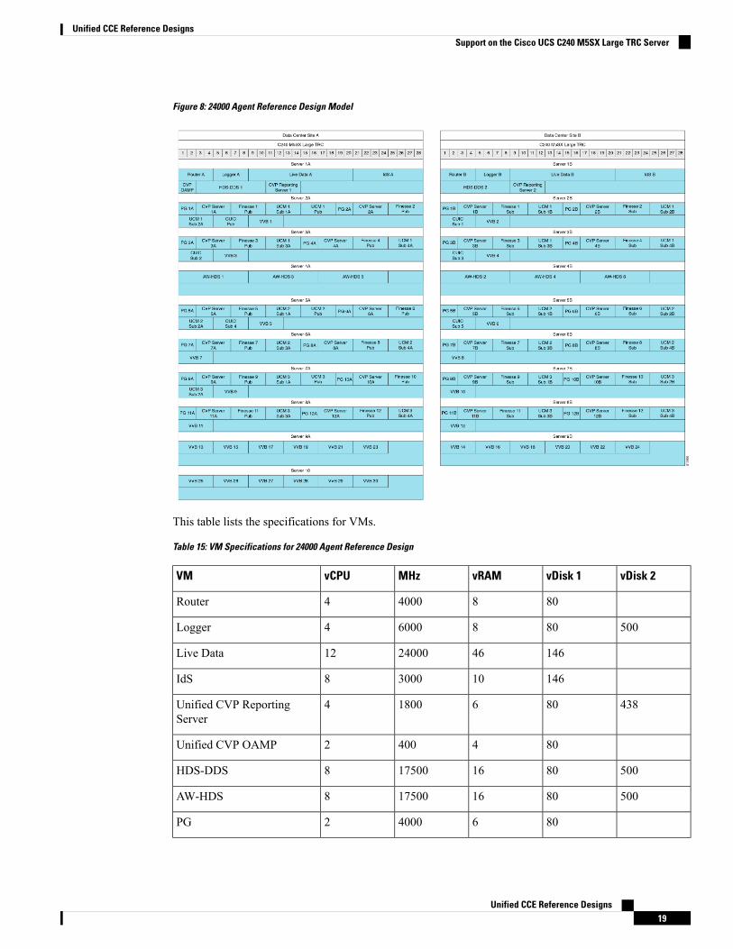
Figure 8: 24000 Agent Reference Design Model
This table lists the specifications for VMs.
Table 15: VM Specifications for 24000 Agent Reference Design
vDisk 2vDisk 1vRAMMHzvCPUVM
80840004Router
50080860004Logger
146462400012Live Data
1461030008IdS
43880618004Unified CVP ReportingServer
8044002Unified CVP OAMP
5008016175008HDS-DDS
5008016175008AW-HDS
80640002PG
Unified CCE Reference Designs19
Unified CCE Reference DesignsSupport on the Cisco UCS C240 M5SX Large TRC Server
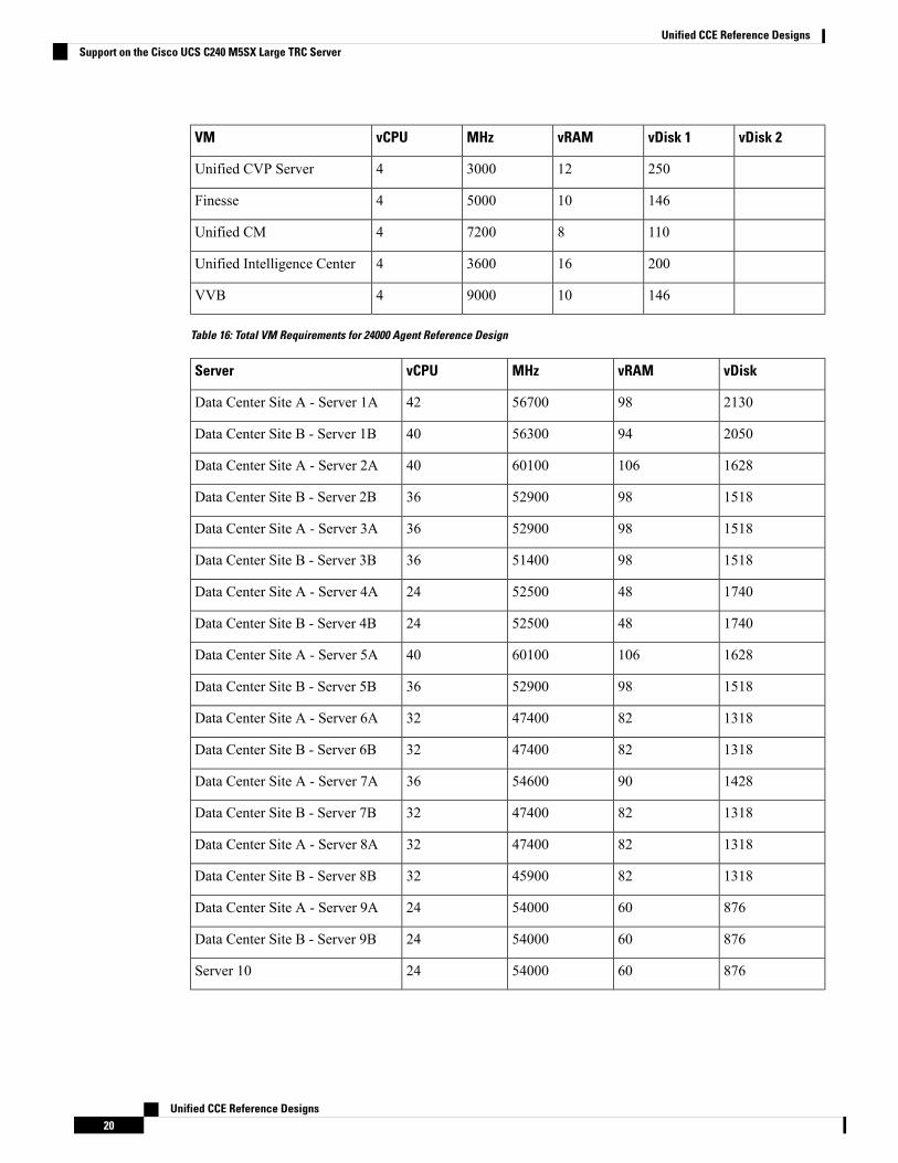
vDisk 2vDisk 1vRAMMHzvCPUVM
2501230004Unified CVP Server
1461050004Finesse
110872004Unified CM
2001636004Unified Intelligence Center
1461090004VVB
Table 16: Total VM Requirements for 24000 Agent Reference Design
vDiskvRAMMHzvCPUServer
2130985670042Data Center Site A - Server 1A
2050945630040Data Center Site B - Server 1B
16281066010040Data Center Site A - Server 2A
1518985290036Data Center Site B - Server 2B
1518985290036Data Center Site A - Server 3A
1518985140036Data Center Site B - Server 3B
1740485250024Data Center Site A - Server 4A
1740485250024Data Center Site B - Server 4B
16281066010040Data Center Site A - Server 5A
1518985290036Data Center Site B - Server 5B
1318824740032Data Center Site A - Server 6A
1318824740032Data Center Site B - Server 6B
1428905460036Data Center Site A - Server 7A
1318824740032Data Center Site B - Server 7B
1318824740032Data Center Site A - Server 8A
1318824590032Data Center Site B - Server 8B
876605400024Data Center Site A - Server 9A
876605400024Data Center Site B - Server 9B
876605400024Server 10
Unified CCE Reference Designs20
Unified CCE Reference DesignsSupport on the Cisco UCS C240 M5SX Large TRC Server
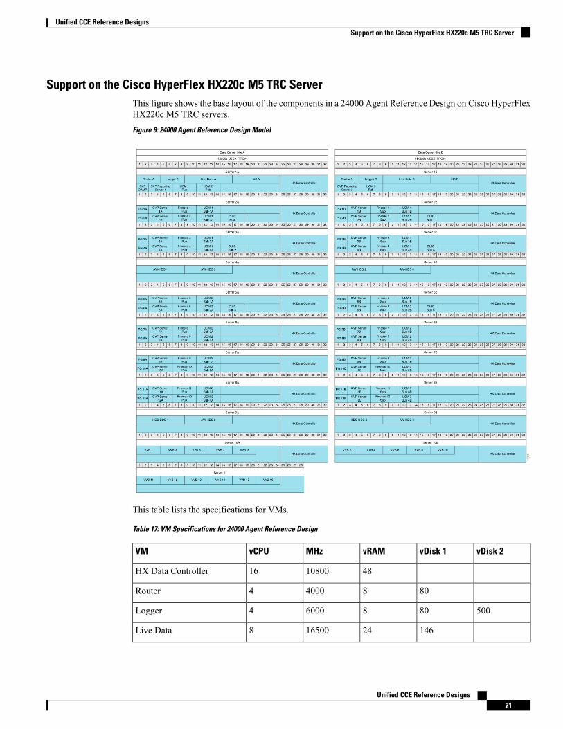
Support on the Cisco HyperFlex HX220c M5 TRC ServerThis figure shows the base layout of the components in a 24000 Agent Reference Design on Cisco HyperFlexHX220c M5 TRC servers.
Figure 9: 24000 Agent Reference Design Model
This table lists the specifications for VMs.
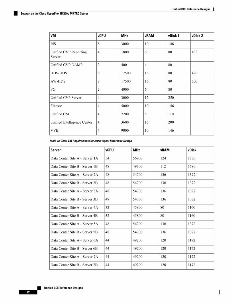
Table 17: VM Specifications for 24000 Agent Reference Design
vDisk 2vDisk 1vRAMMHzvCPUVM
481080016HX Data Controller
80840004Router
50080860004Logger
14624165008Live Data
Unified CCE Reference Designs21
Unified CCE Reference DesignsSupport on the Cisco HyperFlex HX220c M5 TRC Server
vDisk 2vDisk 1vRAMMHzvCPUVM
1461030008IdS
43880618004Unified CVP ReportingServer
8044002Unified CVP OAMP
4208016175008HDS-DDS
5008016175008AW-HDS
80640002PG
2501230004Unified CVP Server
1461050004Finesse
110872004Unified CM
2001636004Unified Intelligence Center
1461090004VVB
Table 18: Total VM Requirements for 24000 Agent Reference Design
vDiskvRAMMHzvCPUServer
17701245690054Data Center Site A - Server 1A
15801124930048Data Center Site B - Server 1B
13721365470048Data Center Site A - Server 2A
13721365470048Data Center Site B - Server 2B
13721365470048Data Center Site A - Server 3A
13721365470048Data Center Site B - Server 3B
1160804580032Data Center Site A - Server 4A
1160804580032Data Center Site B - Server 4B
13721365470048Data Center Site A - Server 5A
13721365470048Data Center Site B - Server 5B
11721204920044Data Center Site A - Server 6A
11721204920044Data Center Site B - Server 6B
11721204920044Data Center Site A - Server 7A
11721204920044Data Center Site B - Server 7B
Unified CCE Reference Designs22
Unified CCE Reference DesignsSupport on the Cisco HyperFlex HX220c M5 TRC Server
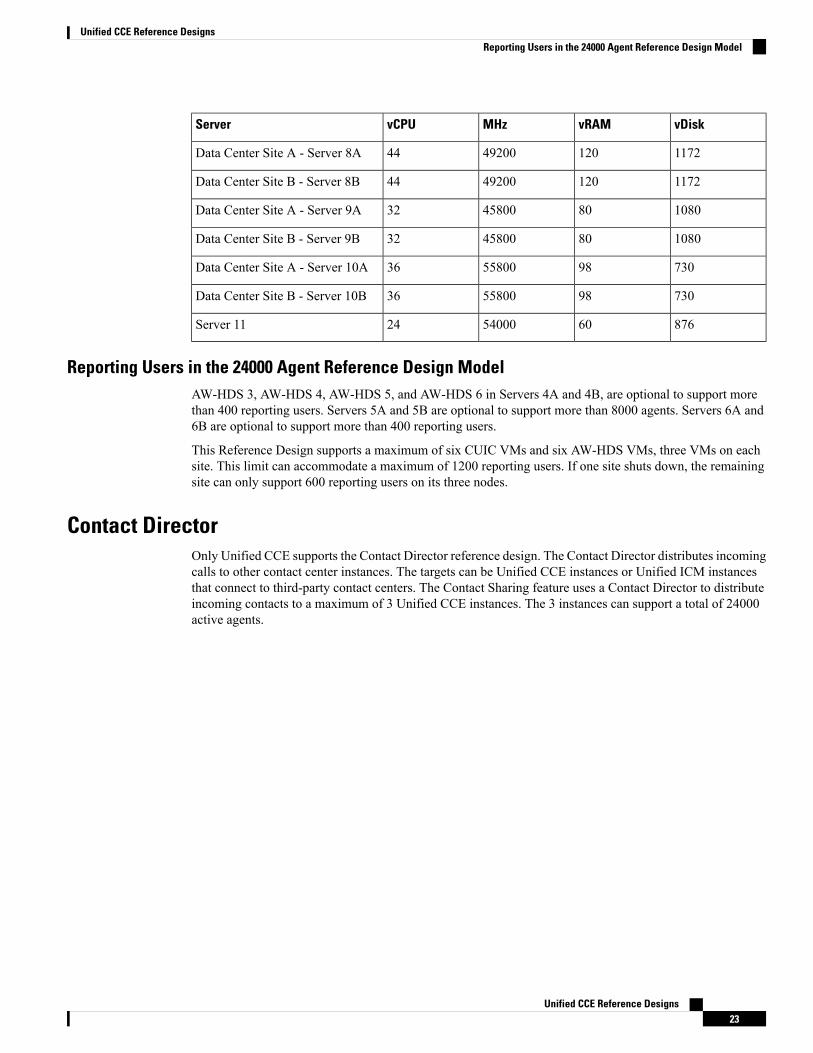
vDiskvRAMMHzvCPUServer
11721204920044Data Center Site A - Server 8A
11721204920044Data Center Site B - Server 8B
1080804580032Data Center Site A - Server 9A
1080804580032Data Center Site B - Server 9B
730985580036Data Center Site A - Server 10A
730985580036Data Center Site B - Server 10B
876605400024Server 11
Reporting Users in the 24000 Agent Reference Design ModelAW-HDS 3, AW-HDS 4, AW-HDS 5, and AW-HDS 6 in Servers 4A and 4B, are optional to support morethan 400 reporting users. Servers 5A and 5B are optional to support more than 8000 agents. Servers 6A and6B are optional to support more than 400 reporting users.
This Reference Design supports a maximum of six CUIC VMs and six AW-HDS VMs, three VMs on eachsite. This limit can accommodate a maximum of 1200 reporting users. If one site shuts down, the remainingsite can only support 600 reporting users on its three nodes.
Contact DirectorOnly Unified CCE supports the Contact Director reference design. The Contact Director distributes incomingcalls to other contact center instances. The targets can be Unified CCE instances or Unified ICM instancesthat connect to third-party contact centers. The Contact Sharing feature uses a Contact Director to distributeincoming contacts to a maximum of 3 Unified CCE instances. The 3 instances can support a total of 24000active agents.
Unified CCE Reference Designs23
Unified CCE Reference DesignsReporting Users in the 24000 Agent Reference Design Model
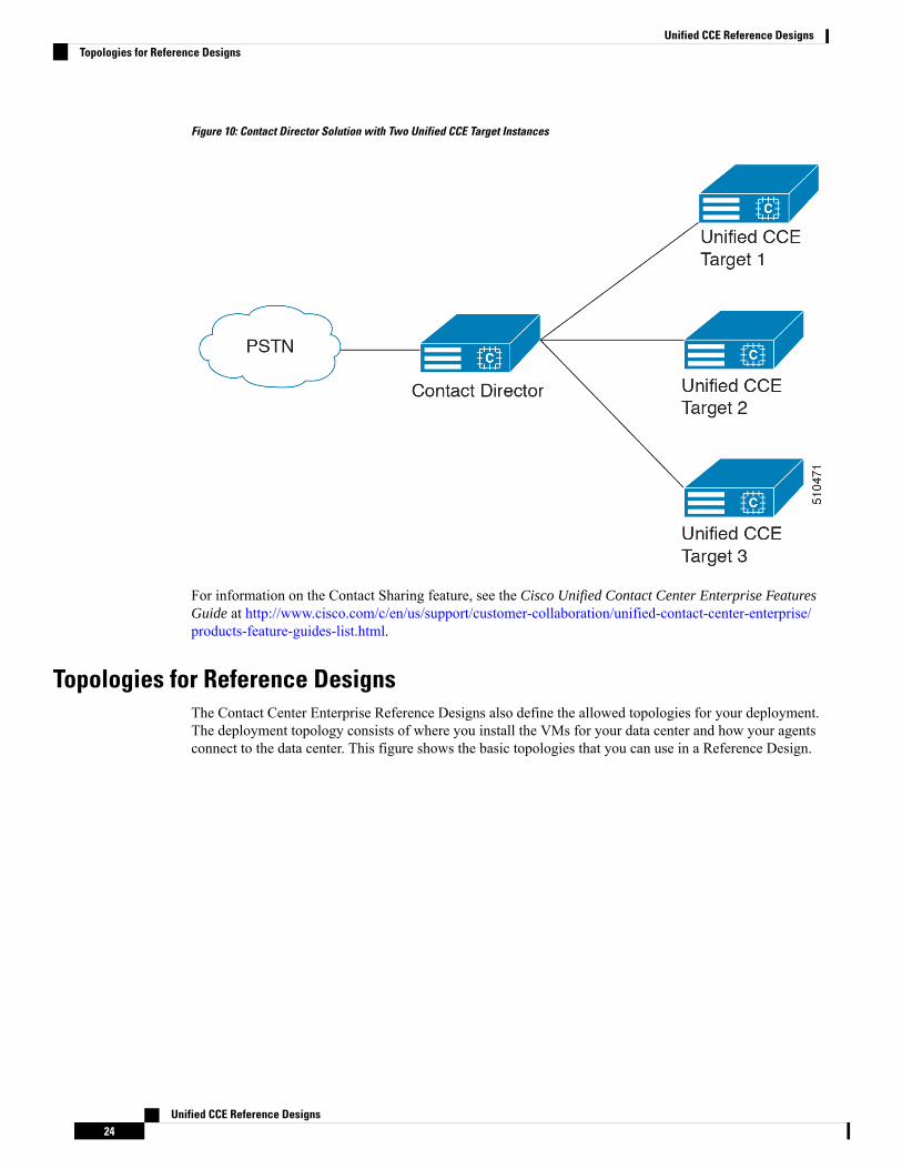
Figure 10: Contact Director Solution with Two Unified CCE Target Instances
For information on the Contact Sharing feature, see the Cisco Unified Contact Center Enterprise FeaturesGuide at http://www.cisco.com/c/en/us/support/customer-collaboration/unified-contact-center-enterprise/products-feature-guides-list.html.
Topologies for Reference DesignsThe Contact Center Enterprise Reference Designs also define the allowed topologies for your deployment.The deployment topology consists of where you install the VMs for your data center and how your agentsconnect to the data center. This figure shows the basic topologies that you can use in a Reference Design.
Unified CCE Reference Designs24
Unified CCE Reference DesignsTopologies for Reference Designs
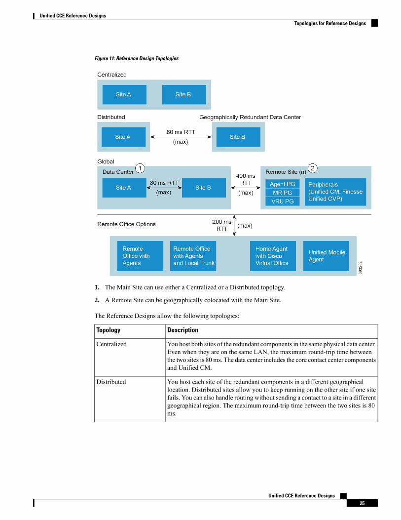
Figure 11: Reference Design Topologies
1. The Main Site can use either a Centralized or a Distributed topology.
2. A Remote Site can be geographically colocated with the Main Site.
The Reference Designs allow the following topologies:
DescriptionTopology
You host both sites of the redundant components in the same physical data center.Even when they are on the same LAN, the maximum round-trip time betweenthe two sites is 80ms. The data center includes the core contact center componentsand Unified CM.
Centralized
You host each site of the redundant components in a different geographicallocation. Distributed sites allow you to keep running on the other site if one sitefails. You can also handle routing without sending a contact to a site in a differentgeographical region. The maximum round-trip time between the two sites is 80ms.
Distributed
Unified CCE Reference Designs25
Unified CCE Reference DesignsTopologies for Reference Designs
DescriptionTopology
You have a centralized or distributed main site. You also have a remote site thatis generally in a different geographical location. The remote site gives you localaccess in that geographic region. The remote site allows you to handle your globalwork load without creating another contact center instance.
The remote site requires a separate Unified CM cluster and a separate CiscoFinesse cluster if the RTT from the data center is greater than 80 ms. Themaximum round-trip time between the main site and remote sites is 400 ms.
A remote site cannot include a CiscoUnified Intelligence Center server.Note
This topology fits the outsourcer model where the outsourcer has a separateperipheral gateway and a corresponding peripheral.
Starting in Release 11.6, Packaged CCE supports this topology.Note
Global
The Reference Designs allow the following methods for connecting your agents to a site:
DescriptionRemote Office Topology
A contact center office with agent workstations that connects to a site through aWAN router. The voice termination is at the site. All contacts go through the sitefirst and then to the agents.
Remote Office withAgents
A contact center office with a connection to the local PSTN. Contacts come inon the local trunk and the local gateway passes them to the data center for routing.
Remote Office withAgents and Local Trunk
An agent at a remote location with a VPN connection to a site. The agent has aCisco IP Phone and a Cisco Finesse desktop. The agent can optionally use a CiscoVirtual Office (CVO) router for a permanent VPN connection.
Home Agent withBroadband - Cisco VirtualOffice (CVO)
An agent who uses a PSTN phone.Unified Mobile Agent
The maximum allowed round-trip time between any remote office and the data center is 200 ms.Note
Related TopicsReference Design and Topology Design ConsiderationsTopologies
Non-Reference Design SolutionsThe Contact Center Enterprise Reference Designs define what you can use in your contact center solution. Ifyour solution includes anything that the Reference Designs do not explicitly allow, your solution is aNon-Reference Design. Most Non-Reference Design solutions require Unified CCE.
Unified CCE Reference Designs26
Unified CCE Reference DesignsNon-Reference Design Solutions
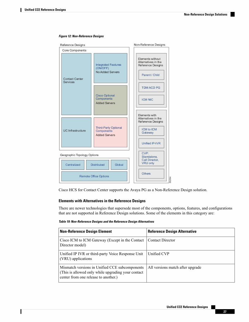
Figure 12: Non-Reference Designs
Cisco HCS for Contact Center supports the Avaya PG as a Non-Reference Design solution.
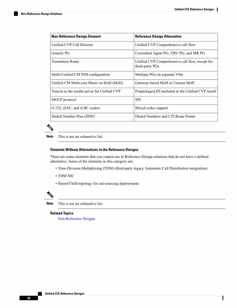
Elements with Alternatives in the Reference Designs
There are newer technologies that supersede most of the components, options, features, and configurationsthat are not supported in Reference Design solutions. Some of the elements in this category are:
Table 19: Non-Reference Designs and the Reference Design Alternatives
Reference Design AlternativeNon-Reference Design Element
Contact DirectorCisco ICM to ICM Gateway (Except in the ContactDirector model)
Unified CVPUnified IP IVR or third-party Voice Response Unit(VRU) applications
All versions match after upgradeMismatch versions in Unified CCE subcomponents(This is allowed only while upgrading your contactcenter from one release to another.)
Unified CCE Reference Designs27
Unified CCE Reference DesignsNon-Reference Design Solutions
Reference Design AlternativeNon-Reference Design Element
Unified CVP Comprehensive call flowUnified CVP Call Director
Coresident Agent PG, VRU PG, and MR PGGeneric PG
Unified CVP Comprehensive call flow, except forthird-party PGs
Translation Route
Multiple PGs on separate VMsMulti-Unified CM PIM configuration
Gateway-based MoH or Unicast MoHUnified CM Multi-cast Music on Hold (MoH)
Prepackaged IIS included in the Unified CVP installTomcat as the media server for Unified CVP
SIPMGCP protocol
Mixed codec supportG.722, iSAC, and iLBC codecs
Dialed Numbers and CTI Route PointsDialed Number Plan (DNP)
This is not an exhaustive list.Note
Elements Without Alternatives in the Reference Designs
There are some elements that you cannot use in Reference Design solutions that do not have a definedalternative. Some of the elements in this category are:
• Time-Division Multiplexing (TDM) (third-party legacy Automatic Call Distribution integration)
• TDM NIC
• Parent/Child topology for out-sourcing deployments
This is not an exhaustive list.Note
Related TopicsNon-Reference Designs
Unified CCE Reference Designs28
Unified CCE Reference DesignsNon-Reference Design Solutions