Uncommon Iatrogenic Devices Seen on Chest Radiographs
13
THIEME 172 Uncommon Iatrogenic Devices Seen on Chest Radiographs Vimal Raj 1 Santhosh Kumar DG 1 Richard A. Tobias 1 1 Cardiothoracic Imaging Unit, Narayana Hrudayalaya, Bengaluru, Karnataka, India Address for correspondence Vimal Raj, MBBS, FRCR, Cardiothoracic Imaging Unit, Narayana Hrudayalaya, Hosur Road, Bommasandra Industrial Estate, Bengaluru- 560 099, Karnataka, India (e-mail: [email protected]). Chest radiograph (CXR) is the most common imaging performed for both inpatients and outpatients. With advances in medicine and technology, newer devices/prosthe- sis are being used in the treatment of cardiothoracic conditions. Some of these are common while others are seen only in a handful of cases, especially in patients being treated or referred from tertiary care centers. It is important to know about these devices, their functionality, and radiographic appearances. Many of these devices also help us in understanding the clinical condition of the patient, as some are only used in unstable patients. Newer methods of life support are now available in inten- sive care units and these also can be seen on CXRs. In this review, we present various iatrogenic devices that we come across on a CXR and highlight important features to determine their correct placement and potential complications. The review looks at cardiac temporary and permanent pacing devices, cardiac interventional devices used to treat congenital heart disease, newer cardiac monitoring devices, and unusual surgi- cal devices that one may come across on a CXR. We also suggest a stepwise algorithm to assess these devices on a CXR. Abstract DOI https://doi.org/ 10.1055/s-0041-1729487 ISSN 0971-3026 © 2021. Indian Radiological Association This is an open access article published by Thieme under the terms of the Creative Commons Attribution-NonDerivative-NonCommercial-License, permitting copying and reproduction so long as the original work is given appropriate credit. Contents may not be used for commercial purposes, or adapted, remixed, transformed or built upon. (https://creativecommons.org/licenses/by-nc-nd/4.0/). Thieme Medical and Scientific Publishers Private Ltd. A-12, Second Floor, Sector -2, NOIDA -201301, India Introduction The chest radiograph (CXR) is the most common imaging performed with almost all patients attending the hospital having one. CXR is performed “round the clock” due to its clinical utility and easy availability. Clinicians are expected to review these radiographs, make a preliminary diagnosis, and treat patients accordingly. It is very important to make an accurate assessment of the radiographs as it will not only impact the clinical management but may also streamline the need for other investigations. Most of the clinicians and radiologists are comfortable in reviewing a CXR; however, it can be a daunting task to some juniors. A logical process of interpretation of CXR involves a review of iatrogenic foreign bodies (IFB) first (lines and drains), followed by a review of the mediastinum, the lungs, and finally the bony architecture. With advances in the field of cardiothoracic surgery and increased usage of percutaneous procedures for placement of devices, more and more IFB are seen on CXRs. Every doctor interpreting these images needs to be aware of these proce- dures, normal appearances of the prosthesis, and should be able to recognize potential complications relating to these devices/IFB. In this review, we present a selection of findings on CXR that includes postoperative appearances, cardiothoracic devices, and their complications. We will review these devices according to their location within the body, that is, cardiac, vascular, thoracic, musculoskeletal, and miscellaneous. Some Indian J Radiol Imaging 2021;31:172–184. Keywords ► chest radiograph ► foreign body ► iatrogenic ► LVAD ► pacemaker Pictorial Essay published online May 31, 2021 Article published online: 2021-05-31
-
Upload
khangminh22 -
Category
Documents
-
view
1 -
download
0
Transcript of Uncommon Iatrogenic Devices Seen on Chest Radiographs

Uncommon Iatrogenic Devices Seen on Chest Radiographs Raj et al.THIEME
172
Uncommon Iatrogenic Devices Seen on Chest Radiographs Vimal Raj 1 Santhosh Kumar DG 1 Richard A. Tobias 1
1 Cardiothoracic Imaging Unit, Narayana Hrudayalaya, Bengaluru, Karnataka, India
Address for correspondence Vimal Raj, MBBS, FRCR, Cardiothoracic Imaging Unit, Narayana Hrudayalaya , Hosur Road , Bommasandra Industrial Estate , Bengaluru- 560 099 , Karnataka , India (e-mail: [email protected] ) .
Chest radiograph (CXR) is the most common imaging performed for both inpatients and outpatients. With advances in medicine and technology, newer devices/prosthe-sis are being used in the treatment of cardiothoracic conditions. Some of these are common while others are seen only in a handful of cases, especially in patients being treated or referred from tertiary care centers. It is important to know about these devices, their functionality, and radiographic appearances. Many of these devices also help us in understanding the clinical condition of the patient, as some are only used in unstable patients. Newer methods of life support are now available in inten-sive care units and these also can be seen on CXRs. In this review, we present various iatrogenic devices that we come across on a CXR and highlight important features to determine their correct placement and potential complications. The review looks at cardiac temporary and permanent pacing devices, cardiac interventional devices used to treat congenital heart disease, newer cardiac monitoring devices, and unusual surgi-cal devices that one may come across on a CXR. We also suggest a stepwise algorithm to assess these devices on a CXR.
Abstract
DOI https://doi.org/10.1055/s-0041-1729487ISSN 0971-3026
© 2021. Indian Radiological AssociationThis is an open access article published by Thieme under the terms of the Creative Commons Attribution-NonDerivative-NonCommercial-License, permitting copying and reproduction so long as the original work is given appropriate credit. Contents may not be used for commercial purposes, or adapted, remixed, transformed or built upon. (https://creativecommons.org/licenses/by-nc-nd/4.0/).Thieme Medical and Scientific Publishers Private Ltd. A-12, Second Floor, Sector -2, NOIDA -201301, India
Introduction
The chest radiograph (CXR) is the most common imaging performed with almost all patients attending the hospital having one. CXR is performed “round the clock” due to its clinical utility and easy availability. Clinicians are expected to review these radiographs, make a preliminary diagnosis, and treat patients accordingly. It is very important to make an accurate assessment of the radiographs as it will not only impact the clinical management but may also streamline the need for other investigations. Most of the clinicians and radiologists are comfortable in reviewing a CXR; however, it can be a daunting task to some juniors. A logical process of interpretation of CXR involves a review of iatrogenic foreign
bodies (IFB) first (lines and drains), followed by a review of the mediastinum, the lungs, and finally the bony architecture.
With advances in the field of cardiothoracic surgery and increased usage of percutaneous procedures for placement of devices, more and more IFB are seen on CXRs. Every doctor interpreting these images needs to be aware of these proce-dures, normal appearances of the prosthesis, and should be able to recognize potential complications relating to these devices/IFB.
In this review, we present a selection of findings on CXR that includes postoperative appearances, cardiothoracic devices, and their complications. We will review these devices according to their location within the body, that is, cardiac, vascular, thoracic, musculoskeletal, and miscellaneous. Some
Indian J Radiol Imaging 2021;31:172–184.
Keywords ► chest radiograph ► foreign body ► iatrogenic ► LVAD ► pacemaker
Pictorial Essay
published onlineMay 31, 2021
Article published online: 2021-05-31

173Uncommon Iatrogenic Devices Seen on Chest Radiographs Raj et al.
Indian Journal of Radiology and Imaging Vol. 31 No. 1/2021 ©2021. Indian Radiological Association
of the well-known devices/lines (central venous line/chest drains) are not covered in this review.
Cardiac DevicesDefibrillator and PacemakerCardiovascular implantable electronic device is nowadays commonly seen on CXR and includes permanent pacemaker and implantable cardiac defibrillator (ICD). These devices are implanted in patients with cardiac rhythm disturbances, to improve cardiac function and/or prophylactically in patients susceptible to life-threatening arrhythmias. These are import-ant devices and can have varied appearances on a CXR. These consist of a pulse generator and some transvenous pacing leads. The pulse generator is often implanted in a subcutane-ous pocket within the pectoralis muscle or in the abdomen (►Fig. 1). Abdominal placement is preferred in children to accommodate their growth. Pacemaker leads (generally 1–3) are metallic wires with silicone or polyurethane insulation. Cephalic or subclavian veins are commonly used access points with jugular and femoral veins being other alternatives. The right ventricular (RV) lead courses along the lateral wall of the right atrium, passes through the tricuspid valve with its tip at the ventricular apex directed anteriorly and inferiorly, just to the left of the spine.1 On the lateral film, the lead should be directed anteriorly and inferiorly, to differentiate it from coro-nary sinus or left ventricular lead. The right atrial (preferably within the atrial appendage) lead on the frontal CXR should terminate over the right upper heart border, with a J-shaped curve and tip-directed upward.2 On a lateral radiograph, the
lead should follow a smooth anterior curve in the midportion of the heart with its tip angled cephalad into the right atrial appendage3 (►Figs. 2 and 3). In case of a biventricular pace-maker or cardiac resynchronization therapy (CRT) device, the left ventricular lead is placed through the coronary sinus into a cardiac vein, usually along the lateral or posterior free wall of the left ventricle (►Fig. 4). The left ventricular lead will course inferiorly and laterally on a frontal radiograph (cannot distin-guish from a lead in RV apex) and posteriorly on the lateral view (RV lead is anterior in location on this view).4 ICDs are most often composed of a single lead with two shock coils (located in the region of the brachiocephalic vein–superior vena cava junction and in the RV).4 The shock coils appear as cylindri-cal thickening in the lead and can be used to differentiate ICD from a pacemaker (►Fig. 5). CRT may also have a defibrillator component (CRT-D) (►Fig. 6). Pacemaker leads may also be placed along the epicardial surface of the heart rather than the transvenous position (►Figs. 7 and 8). Important complica-tions of pacemaker insertion include malpositioned/retained
Fig. 1 Frontal chest radiograph showing a single lead pacemaker device with the pacing lead within the right ventricle (white arrow). The pulse generator is projected in the left upper part of the chest (black arrow).
Fig. 2 Frontal (A) and lateral (B) chest radiograph in a patient with dual-chamber pacemaker. The pacing lead in the right atrium (black arrow) shows the typical J-shaped curve with the tip directed upwards. The lead in the right ventricle projects anteriorly and infe-riorly on the lateral film.
Fig. 3 Frontal (A) and lateral (B) chest radiograph in a patient with biventricular pacing (cardiac resynchronization therapy). The right atrial (white dotted arrow) and right ventricle leads (white arrow) are normal in position. A third lead (black arrow) is noted to pass posteriorly in the lateral view and in between the other two leads in the frontal view in keeping with its location in the coronary sinus. Prior sternotomy (white star) is also noted with intact sternal wires in the midline.

174
Indian Journal of Radiology and Imaging Vol. 31 No. 1/2021 ©2021. Indian Radiological Association
Uncommon Iatrogenic Devices Seen on Chest Radiographs Raj et al.
or fractured wires/leads, pneumothorax, Twiddler syndrome, and cardiac perforation (►Figs. 9 and 10). Aberrant vascular anatomy may also simulate malpositioned leads (►Fig. 11).
In patients who may have thrombosis of the upper limb veins, congenital heart anomalies, or in children who have pacing generator in the abdomen, a transhepatic route for the wires may be undertaken. In this, venous access is achieved via the hepatic vein via transcutaneous puncture. The leads are then passed into the inferior vena cava and then the cardiac chambers.
Fig. 4 Frontal chest radiograph in a patient with cardiac resynchroni-zation therapy device wherein the coronary sinus lead (black arrow) is positioned along the lateral wall of the left ventricle. The right atrial (dotted arrow) and ventricular leads (white arrow) are also normal in location.
Fig. 5 Frontal chest radiograph showing single lead defibrillator (implantable cardiac defibrillator) device. Two shock coils (white arrows) are clearly seen as areas of dense cylindrical thickening in the leads. Also noted is sternotomy wires (star) and surgical clips (black arrow) relating to prior coronary artery bypass surgery.
Fig. 6 Frontal chest radiograph showing a cardiac resynchronization therapy-defibrillator device with two shock coils (white arrow) along the right ventricle lead and a coronary sinus lead (black arrow). Right atrial lead (black dotted arrow) is also seen. In the background, a central venous catheter (white dotted arrow) is noted along the right superior vena cava.
Fig. 7 Frontal chest radiograph in a patient with a hybrid pacing/defibrillator device. There are three leads along the intrave-nous route into the heart (right atrium [white dotted arrow], right ventricle [white arrow], and coronary sinus [not seen well on]), and a further fourth lead from the pulse generator implanted directly on the epicardial surface of the heart. Endotracheal tube is also noted (black dotted arrow).

175Uncommon Iatrogenic Devices Seen on Chest Radiographs Raj et al.
Indian Journal of Radiology and Imaging Vol. 31 No. 1/2021 ©2021. Indian Radiological Association
Epicardial PacingEpicardial pacing can be either permanent or temporary. Permanent epicardial pacing involves surgical placement of the epicardial leads directly on the epicardium. The leads are then tunneled through the chest wall and connected to the pacing box usually in the subcutaneous pocket of the upper abdomen5 (►Fig. 12). Currently, they are used only in unusual circumstances such as patients with recurrent dislodgement of transvenous systems, patients with prosthetic tricuspid valves or congenital anomalies such as tricuspid atresia, and in patients underlying CRT in whom the coronary sinus lead placement was unsuccessful.5
Temporary epicardial pacing is commonly used follow-ing cardiothoracic surgery in which the pacemaker leads are attached to the epicardium of the atrium and/or ventricle and then connected to the external pacer.6 These leads are generally used in temporary treatment of arrhythmias in the perioperative period, and usually removed by 4 to 5 days after cardiac surgery by transcutaneous retraction.7 They are seen on radiographs as coiled up thin wires over the cardiac silhou-ette and connected to two small cylindrical external metallic connectors on the surface (►Fig. 13). Retained surgical swab can sometimes mimic epicardial-pacing wires. At discharge, most of these leads are removed but some portion of the wires may be retained within the deeper tissues. Such wires are often left behind without any major impact or complication.
Temporary Transvenous Ventricular PacingPatients with acute hemodynamic compromise caused by bradycardia and/or episodes of asystole should be consid-ered for temporary cardiac pacing.8 This often occurs in the setting of acute myocardial infarction. Transvenous pacing is
Fig. 9 Frontal chest radiograph in a patient postimplantation of dual lead pacing device showing a left apical pneumothorax (black arrow showing lung edge) secondary to the procedure.
Fig. 10 Frontal chest radiograph in two different patients with com-plications relating to pacing leads. (A) Retained pacemaker lead (white arrow) is noted from a prior pacing device. Also, note a poorly defined opacity (star) in the left upper lobe partially masked by the generator box. This turned out to be a malignancy. (B) There is a break in the right ventricular lead (black arrow) for which another lead was inserted.
Fig. 8 Flowchart depicting an approach to analyze any cardiac implanted external device. CIED, cardiovascular implantable electronic device.

176
Indian Journal of Radiology and Imaging Vol. 31 No. 1/2021 ©2021. Indian Radiological Association
Uncommon Iatrogenic Devices Seen on Chest Radiographs Raj et al.
superior to the transcutaneous method because of patient comfort and stability of pacing.6 Central venous access is gained through femoral vein (in some cases via the jugular system) and the pacing lead is advanced into the right atrium and then across the tricuspid valve with the tip in the RV. On CXR, the lead can be seen coming along the right para-vertebral aspect and then angling along the diaphragm with the tip toward the cardiac apex (►Fig. 14). The lead may be displaced with the tip either along the RV outflow tract or in the atrium.
Loop RecorderLoop recorder or reveal device is an insertable cardiac monitor used to record electrocardiogram (ECG). These devices are used when long-term monitoring of cardiac rhythm is required. These are patient-activated or automatically activated moni-toring systems wherein the recorded data are analyzed later for the evaluation of suspected cardiac arrhythmias.7 Reveal devices are subcutaneously placed on the anterior chest wall (usually left parasternal area extending to the midclavicular line between the first intercostal space and the fourth rib or in the lower chest—V3 area, between the fourth and fifth rib) (►Fig. 15). These devices are usually magnetic resonance imaging compatible and can be confused as a USB device in patients clothing. There are often no complications related to these devices. Newer ECG monitoring/recording devices are also being tried in various institutes as a mode of remote mon-itoring of patients in postoperative period (►Fig. 16)
Fig. 11 Frontal chest radiograph in a patient with a dual lead pacing device and a variant anatomy. The leads are seen to pass through a persistent left-sided superior vena cava (white dotted arrow) into the right ventricle via the coronary sinus. The right atrial (white arrow) and ventricular (black arrow) leads are seen.
Fig. 12 Frontal chest radiograph in two patients with permanent epicardial pacing devices. (A) Retained pacing leads from an older device (white arrows) and a newer lead (dotted arrow) is seen with the generator box (black arrow) in the lower abdomen. (B) A gener-ator box in the upper abdomen and a single epicardial pacing lead. Note the tip of the lead is different from a pacing wire and is embed-ded into the epicardium (black arrow).
Fig. 13 Frontal chest radiograph (A) and abdominal radiograph (B) in two patients postvalve replacement surgery. The temporary epi-cardial pacing leads (white arrows) are seen connected to an external pacing device connector (black arrow). Thin cylindrical small rods are also seen at the end of the wires (B); these are outside the skin and used to connect to the pacing device. Sternotomy wires (dotted arrow) are seen in both images with a prosthetic aortic valve (star). Mediastinal and pleural drains (black dotted arrows) are seen with central venous line (black star) and endotracheal tube (black arrow head) in part A.
Fig. 14 Frontal chest radiograph demonstrates temporary trans-venous pacing leads (black arrow) in the right ventricle. The access route is via femoral vein in part A and jugular vein in part B.

177Uncommon Iatrogenic Devices Seen on Chest Radiographs Raj et al.
Indian Journal of Radiology and Imaging Vol. 31 No. 1/2021 ©2021. Indian Radiological Association
Atrial Septal Defect (ASD) Closure DeviceAtrial septal defects (ASD) can be closed by open surgical tech-niques or by percutaneous catheter-guided means avoiding thoracotomy/sternotomy. The decision on closing of an ASD depends on the patient symptoms and the amount of shunt from left to the right. Smaller defects with insignificant shunts are often medically managed. Various types of percutaneous ASD closure devices are in use, which are placed in posi-tion under fluoroscopic, transesophageal echocardiographic (TOE), or intracardiac echocardiographic imaging guidance. These are generally self-centering devices constructed from thin nitinol wires tightly woven onto two flat discs with a con-necting waist (sizes 4–40 mm). Polyester mesh is sewn into each disc and mesh to induce stasis and thrombosis. On CXRs, they appear as one or two discs or two dots (corresponding to the ends of the waist of the device)4 (►Fig. 17). The position of the device is described with respect to the thoracic verte-bral bodies on both frontal and lateral radiographs and with respect to the hilar–caval line (drawn from anterior margin of right hilum to posterior margin of inferior vena cava on the
lateral view—expected position of the interatrial septum). In children, these are generally projected over T7 to T9 vertebrae with the centers at or just to the right of the vertebral spinous process.4 On the lateral radiograph, the waist of the occluder is usually seen on the hilar–caval line.
Ventricular Septal Defect (VSD) Closure DeviceVSD is the most common congenital cardiac defect (it can be seen as an isolated anomaly or in association with various other complex cardiac anomalies). Here again, catheter-based closure devices can be used besides direct surgical closure. On CXR, VSD occluder appears similar to ASD closure device (one or two radiopaque discs or two dots) but in the region of the interventricular septum (►Fig. 17).
Prosthetic Cardiac ValvesProsthetic cardiac valves are implanted surgically or via transcutaneous route to treat valvular stenosis or regurgi-tant pathologies. In younger patients, valve-sparing surgeries are preferred wherever possible. Correct identification of prosthetic cardiac valves is easy when clinical details or echo-cardiography reports are available. In emergency, correct iden-tification of the valve (without any prior history) on a CXR may be useful as aortic valves are more susceptible to endocarditis and the mitral valves to thrombotic complications.9 On a pos-teroanterior CXR, an imaginary line is drawn from right car-diophrenic angle to inferior aspect of left hilum and the aortic valve should lie above and the mitral valve below this line. This however is not very reliable on an anteroposterior CXR.9 The aortic valves are often oriented horizontally and valve orifice is often in profile. In comparison, the mitral valve is vertical in location and the valve orifice appears en face. The pulmonary valve prosthesis is much higher and lateral to the other valves along the outflow tract. The tricuspid valve pros-thesis is also seen en face on frontal CXR and is seen along the right paravertebral region (►Fig. 18 and ►Table 1). Lateral views are also helpful in differentiating one valve from the other but are often not performed in routine clinical practice.10
Fig. 17 Frontal chest radiograph in two patients with septal defect closure devices. (A) A device used to close an atrial septal defect (white arrow). The two discs of the device are superimposed and only separate central radiopaque dots are seen. Ventricular septal defect closure is seen in B with two discs (black arrow) and two central dots clearly delineated due to the oblique nature of the defect. Also note mediastinal/pleural drains (black dotted arrows), epicardial pacing leads (white dotted arrows), right central line (white star), and endo-tracheal tube (arrowhead).
Fig. 15 Frontal chest radiograph depicting loop recorder (REVEAL) device (black arrow) in two patients (A and B). Also note prior ster-notomy (star) and a hiatus hernia (dotted arrow) in part B.
Fig. 16 Frontal chest radiograph in a patient postaortic valve replacement (black arrow) showing remote monitoring device (star), which records the electrocardiogram of the patients though surface leads and beams the information via Bluetooth to a central console. Also note right central venous line (white arrow).

178
Indian Journal of Radiology and Imaging Vol. 31 No. 1/2021 ©2021. Indian Radiological Association
Uncommon Iatrogenic Devices Seen on Chest Radiographs Raj et al.
Ventricular Assist DeviceVentricular assist devices (VAD) are used to support the mechanical function of a failing heart and can be biventricular or only for the left ventricle. They are used for short term/tem-porary use (wherein the pump and controller are generally outside the patient) or long term (in such situations the pump is implanted in a peritoneal or abdominal wall pocket with exter-nal control and power). These devices have inflow cannulae placed in the cardiac apex/right atrium/atrial appendage and outflow cannulae placed in the aorta/main pulmonary artery or right pulmonary artery depending on whether they are left or RV assist devices, respectively (►Fig. 19). Biventricular assist devices have both sets of cannulae (►Fig. 20). On CXR, these appear as short radiopaque cylindrical structures (espe-cially the left ventricular assist device [LVAD] inflow cannula at the LV apex on frontal CXR) when seen enface or as radi-opaque rings when seen end-on (the other mentioned cannu-lae on the frontal CXR). Chest/mediastinal drains that mimic
these cannulae are long tubes with breaks in the radiopaque line indicating side holes. The pump, external controls, and battery pack may or may not be seen on the CXR depending on where they are located. Computed tomography (CT) may be a better modality for the assessment of complications related to the LVAD, which include thrombosis and misplacement of the cannula (►Fig. 20). CXR is useful in assessing the position of the device on serial films and associated complications such as pleural effusions/pneumothorax.
Fig. 18 Frontal chest radiograph demonstrating various prosthetic valves. In part A, both aortic (white arrowhead and mitral valve (black arrow) can be seen. Notice the en-face view of the mitral valve with the aortic valve being more horizontal in nature. Prosthetic pul-monary valve can be seen at a higher location (dashed arrow) in part B. Prosthetic tricuspid valve can be seen in parts C and D along the right paravertebral aspect (white arrow). Median sternotomy (white star) and right central venous line (black dotted arrow) are also seen.
Table 1 Various parameters of valves on CXR helping in deciding their anatomical location
Type of valve Valve orifice Location with respect to line from right cardiophrenic angle to left hila
Location with respect to spine
Aortic In profile Above Left paravertebral
Mitral En face Below Left paravertebral
Pulmonary Variable Above Left paravertebral
Tricuspid En face Variable Right paravertebral
Abbreviation: CXR, chest radiograph.
Fig. 19 Frontal chest radiograph (CXR) in two patients with left ven-tricular assist device. The pump can be seen (black arrow) with the inflow cannula (white dotted arrow) in the left ventricle (A and B). Both patients (A and B) have biventricular pacing defibrillator devices in situ. The outflow tract is not radiopaque and is often not visualized on a CXR.
Fig. 20 Frontal scannogram from a computed tomography (CT) examination (A) showing two ventricular assist devices, one for each ventricle with outflow and inflow systems clearly visualized from the pump mechanism (black arrow and white arrowhead). (B) CT exam-ination of a patient with left ventricular assist device showing throm-bus in the left ventricular apex around the inflow cannula (black dotted arrow).

179Uncommon Iatrogenic Devices Seen on Chest Radiographs Raj et al.
Indian Journal of Radiology and Imaging Vol. 31 No. 1/2021 ©2021. Indian Radiological Association
Vascular DevicesIntraaortic Balloon PumpIntraaortic balloon pump (IABP) is a simple, cost-effec-tive, and easily implantable circulatory support device in patients requiring hemodynamic support either in cardio-genic chock or at a higher risk of hemodynamic decompres-sion during a high-risk coronary intervention.11 The pump inflates during cardiac diastole along with aortic valve closure, thereby displacing the blood from the aorta into the peripheral vessels. Then it rapidly deflates before the onset of systole. This results in improved diastolic pressure, reduced systolic aortic pressure, and myocardial oxygen demand.11 The tip of the IABP should be distal to the left subclavian artery and the proximal portion of the balloon above the origin of the renal arteries. On CXR, the tip of the IABP (seen as a linear radiopaque) should be above the carina at the level of the arch. If the tip is lower than this, then the abdominal visceral branches of the aorta can be compressed during inflation of the pump leading to visceral hypoxia (►Fig. 21)
PDA Closure DevicePatent ductus arteriosus (PDA) is one of the causes of pulmo-nary arterial hypertension. It contributes to 10% of the con-genital cardiac anomalies.1 It is more common in premature babies and females. Obstructive pulmonary diseases and heart failure are the complications of untreated PDA. Surgical clo-sure is the treatment of choice when medical treatment fails. Surgical/interventional closure can be done either by clips or coils. On frontal CXR, it is seen on left side of the spine below the aortic arch. Different types of devices may be seen (►Fig. 22).
Coarctation StentCoarctation of aorta accounts for 5 to 8% of congenital car-diac anomalies. Congestive cardiac failure, stroke, aortic rupture, and infective endocarditis are associated with late complications in untreated aortic coarctation.12 Endovascular treatment avails minimally invasive alternative techniques to conventional open surgeries with shorter hospital stay.
Intravascular stent grafts can be seen on plain radiographs as tubular mesh-like radio-opacity. We should look for its position, extent, and continuity or any break (►Fig. 23).
Pulmonary Artery StentBranch pulmonary artery stenosis can be seen in isolation or part of the other congenital cardiac defects. RV hypertro-phy and failure are the delayed complications. RV systolic pressure >50% of aortic pressure or ipsilateral lung perfu-sion <35% are the indications for intervention.13 Balloon dilatation or stent placement is the treatment option. Early postoperative pulmonary stenosis, postoperative kink-ing, external compression, elastic recoil, and intimal tear are some of the indications for stenting. Stents may also be placed in the RV outflow tract in cases of Tetralogy of Fallot. These stents can be seen on plain radiographs as tubular
Fig. 23 Frontal chest radiograph with aortic stents in situ for coarcta-tion (white arrow in parts A and B). One can also notice the notching of the ribs inferiorly in both cases due to long-standing coarctation and subsequent collaterals.
Fig. 24 Frontal chest radiograph in different patients showing stents (white arrow) in the right and left pulmonary artery (A) and in the right ventricular outflow tract (B). Both patients had Tetralogy of Fallot.
Fig. 21 Frontal chest radiograph showing good position of the intraaor-tic balloon pump tip (white arrow) in part A and low position of the tip in part B (black arrow). Temporary transvenous pacing wire is seen in part A (white dotted arrow), nasogastric tube (black dotted arrow). In part B, we can also see a coiled nasogastric tube (black dotted arrow) along with Swan-Ganz catheter (white star) and chest drains (white dotted arrows) and a pacemaker with a single right ventricular lead (black star). The endotracheal tube is also seen in both images (arrowhead).
Fig. 22 Frontal chest radiograph showing different patent ductus arteriosus closure devices (black arrow and dotted arrow) (A and B). The device shown in part B is similar to the atrial septal defect/ventric-ular septal defect closure device with two discs and two central dots.

180
Indian Journal of Radiology and Imaging Vol. 31 No. 1/2021 ©2021. Indian Radiological Association
Uncommon Iatrogenic Devices Seen on Chest Radiographs Raj et al.
mesh-like radio-opacity (►Fig. 24). Complications of stenosis or underlying thrombosis are not properly seen on CXR and CT is better for this.
Arteriovenous Malformation/Embolization ClipTranscatheter intervention for hemoptysis is now becoming the first line of management in most cases. Bronchial artery and arteriovenous malformations are often the cause of hemopty-sis and these can be well visualized on CT and/or catheter angi-ography.14 Different materials can be instilled into the culprit vessels such as glue (N-butyl cyanoacrylate) or metallic clips. The glue is not radiopaque but is mixed with Lipiodol, which is radiopaque and can be seen on CXR. The clips on the other hand are radiopaque on their own and can be seen as well-defined structures along the path of intervention (►Fig. 25).
Musculoskeletal Implants/DevicesPectus BarPectus excavatum is the most common congenital deformity of the chest wall accounts for 1: 400 births. It is four times more common in males. The deformity is more pronounced during the adolescent stage of life. Many are asymptomatic. Symptoms that can occur in severe cases include dyspnea, chest pain, exercise intolerance, and psychological prob-lems.15 Surgery in most of the cases is for cosmetic reasons. The main aim of surgery is to correct the chest deformity, which improves the self-acceptance, breathing, and car-diac function.16 Two commonly used correction methods are highly modified Ravitch’s repair and Nuss procedure. In both procedures, metallic bar is placed behind the sternum. Wound infection, pneumothorax, overcorrection, and bar displacement/migration are some of the associated com-plications.17 Nuss procedure involves the placement of a U-shaped rod with lateral anchor points and are well recog-nized. The Ravitch’s bar is a linear metal density bar with no anchor points (►Fig. 26). It can be confused as a foreign body if clinical history is not known.
Spinal FixationSpinal instrumentation is done commonly to restore the spinal stability, correcting the deformities, in degenerative diseases,
trauma, infection, and neoplasms. These can be anterior spinal fixation devices, posterior or posterolateral spinal fixa-tion devices, and interbody grafts.18 These are easily recognized due to their paravertebral location (►Fig. 27).
SternotomyStandard median sternotomy sutures are seen along the ster-num and are well spaced out. These are seen as a coiled metal wire without any breaks (►Figs. 3 and 5). It is essential to ensure continuity of each of the wire knots and to make note of any broken wire. In some cases, break in the sternal wires is often ignored, if the patient has no symptoms. In patients who have infections along the sternum, elaborate operations are often required for osteomyelitis and different varieties of sternal fixation may be seen (►Figs. 28 and 29).
Fig. 25 Frontal chest radiograph in a patient who underwent bron-chial artery embolization for hemoptysis with metal clips (white arrow) (A) and a zoomed-up view of the same (B). Also, note a peripherally inserted central catheter with its tip in right superior vena cava (black dotted arrow).
Fig. 26 Ravitch’s bar is seen on the frontal chest radiograph (arrow) in a patient who was treated for pectus deformity of the chest wall.
Fig. 27 Frontal chest radiograph in two patients with spinal fixation devices. (A)A thoracic spinal fixation device with a disc prosthesis (arrow) and (B) a cervicothoracic spinal fixation device (arrow). Also note symmetrical well-defined increased density in both breasts (arrowhead) in part B with clear margins in keeping with bilateral breast implants.

181Uncommon Iatrogenic Devices Seen on Chest Radiographs Raj et al.
Indian Journal of Radiology and Imaging Vol. 31 No. 1/2021 ©2021. Indian Radiological Association
Rotator Cuff AnchorsFull-thickness rotator cuff tear repair is performed using suture anchors that produce secure and effective soft tissue fixation to bone. Both metallic and biodegradable suture anchors can be used and have similar results.19 On CXR, they are projected over the humeral head and can be confused with clothing artifacts (►Fig. 30).
MiscellaneousTracheobronchial StentsAirway stenting is performed to relieve airway obstruction/strictures that are not suitable for resection and reconstruction. They are made of metal or silicon. Some of the silicon stents are not radiopaque and hence may not be seen on CXRs. Stents can be covered or uncovered (appears like a mesh with perforations to allow for epithelial growth).
Fig. 28 Frontal (A) and lateral (B) chest radiograph of a patient with unusual metal ware (arrow) for sternal fixation in a patient poststernal osteomyelitis.
Fig. 29 Frontal chest radiograph in a patient (A) who underwent extensive reconstructive surgery of the sternum and the adjoin-ing costochondral junctions for osteomyelitis. (B) Patient with redo-sternotomy for aortic valve replacement (black arrow) showing interconnecting sternal wires (white arrow). Also note the presence of right central line (star), endotracheal tube (arrowhead) and naso-gastric tube (black dotted arrow).
Fig. 30 Frontal chest radiograph zoomed view, showing metalware in right humeral head in keeping with rotator cuff anchors (arrow).
Fig. 31 Frontal chest radiograph in a patient with extensive stents in the trachea and proximal bronchi (arrow) in a patient with relapsing polychondritis.
182
Indian Journal of Radiology and Imaging Vol. 31 No. 1/2021 ©2021. Indian Radiological Association
Uncommon Iatrogenic Devices Seen on Chest Radiographs Raj et al.
Some stents are expandable for easy insertion. The choice of stent type depends on the location and type of lesion to be tackled. When seen on CXRs, they appear like a cylinder within the lumen of trachea/bronchus (►Fig. 31). It is useful to compare previous radiographs for ensuring the stent has not migrated from its intended location.
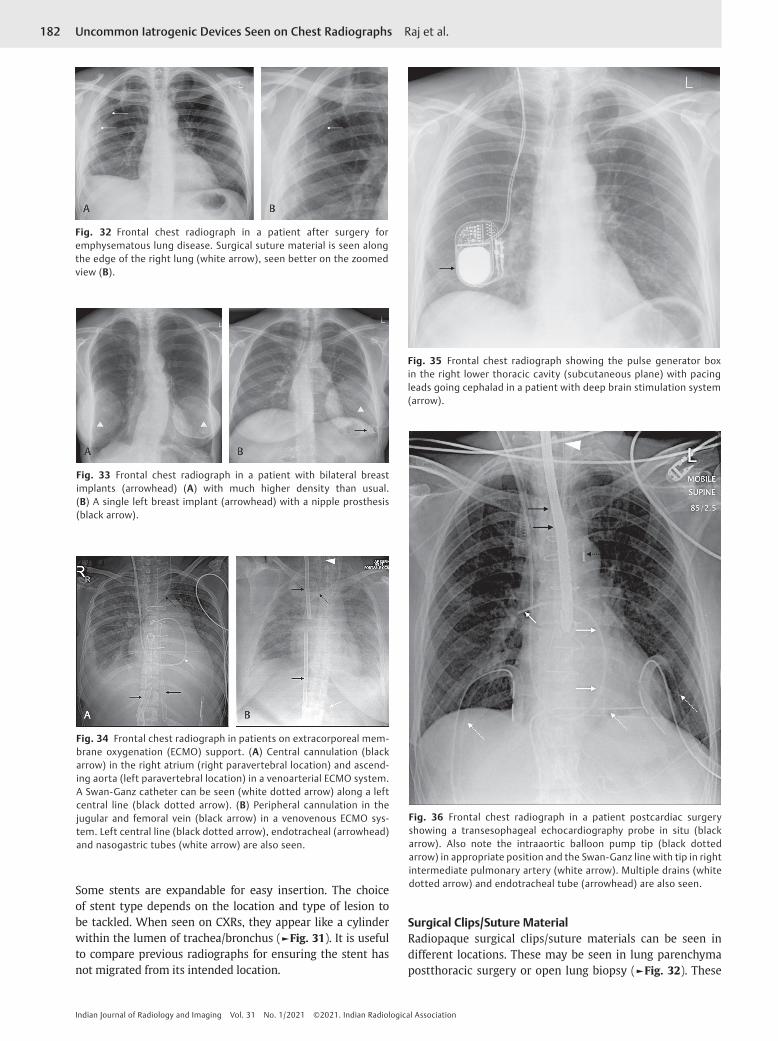
Surgical Clips/Suture MaterialRadiopaque surgical clips/suture materials can be seen in different locations. These may be seen in lung parenchyma postthoracic surgery or open lung biopsy (►Fig. 32). These
Fig. 32 Frontal chest radiograph in a patient after surgery for emphysematous lung disease. Surgical suture material is seen along the edge of the right lung (white arrow), seen better on the zoomed view (B).
Fig. 33 Frontal chest radiograph in a patient with bilateral breast implants (arrowhead) (A) with much higher density than usual. (B) A single left breast implant (arrowhead) with a nipple prosthesis (black arrow).
Fig. 34 Frontal chest radiograph in patients on extracorporeal mem-brane oxygenation (ECMO) support. (A) Central cannulation (black arrow) in the right atrium (right paravertebral location) and ascend-ing aorta (left paravertebral location) in a venoarterial ECMO system. A Swan-Ganz catheter can be seen (white dotted arrow) along a left central line (black dotted arrow). (B) Peripheral cannulation in the jugular and femoral vein (black arrow) in a venovenous ECMO sys-tem. Left central line (black dotted arrow), endotracheal (arrowhead) and nasogastric tubes (white arrow) are also seen.
Fig. 35 Frontal chest radiograph showing the pulse generator box in the right lower thoracic cavity (subcutaneous plane) with pacing leads going cephalad in a patient with deep brain stimulation system (arrow).
Fig. 36 Frontal chest radiograph in a patient postcardiac surgery showing a transesophageal echocardiography probe in situ (black arrow). Also note the intraaortic balloon pump tip (black dotted arrow) in appropriate position and the Swan-Ganz line with tip in right intermediate pulmonary artery (white arrow). Multiple drains (white dotted arrow) and endotracheal tube (arrowhead) are also seen.

183Uncommon Iatrogenic Devices Seen on Chest Radiographs Raj et al.
Indian Journal of Radiology and Imaging Vol. 31 No. 1/2021 ©2021. Indian Radiological Association
may also be seen along the mediastinum in patients postcor-onary artery bypass surgeries whereby the clips are put in vessels (►Fig. 5).
Breast ImplantsProsthetic breast implants are increasingly used for breast augmentation surgeries, postmastectomy, and cosmetic augmentation.20 On CXR, these are recognized as areas of increased density in the lower part of the chest and in many cases, they are not apparent. Nipple prosthesis may also be present and are well recognized on CXR as radiopaque mate-rial. On long standing or following untreated rupture of the prosthesis, there may be calcification of the breast prosthesis where these can be well seen on CXR (►Figs. 27 and 33).
Extracorporeal Membrane OxygenationExtracorporeal membrane oxygenation (ECMO) provides circulatory support to patients with respiratory, cardiac, or combined failure for days to a week. Two types of ECMO are used VV (venovenous) system is used to support the lungs and give them time to recover and VA (venoarterial) system is used for cases of cardiac or cardiopulmonary fail-ure.21 On CXR, the ECMO cannulae are different from the nor-mal lines because of their corrugated appearance/large size. The cannulation for the VV ECMO is usually in the jugular vein and femoral vein. The cannulation in the VA ECMO can be obtained centrally (right atrium and ascending aorta) or peripherally (jugular/femoral vein and carotid or femoral artery) (►Fig. 34).
Deep Brain StimulatorDeep brain stimulation is a well-established therapy for movement disorders. In this technique, thin wires are placed intracranially and are connected to a neurostimula-tor (very similar to the pacing box in the pacemaker) via an insulated wire that is implanted under the skin. The stimu-lator is placed in the subcutaneous tissue of the chest wall and can be seen on the CXR with wires leading along the neck superiorly (►Fig. 35).
Transesophageal Echocardiography ProbeThere is increasing use of TOE in routine practice especially in sick patients or during cardiac surgeries. Some ill patients often have a TOE probe in situ for a longer time and the probes may be seen in a CXR. It is seen as a linear structure along the path of the esophagus and is much thicker and denser com-pared with a nasogastric tube (►Fig. 36).
Surgical GauzeRetained surgical gauze material after cardiothoracic surgery can be a major complication and needs to be identified at the earliest. It is customary to do a swab count at the end of the surgery to avoid such a mishap but such mistakes can still happen. CXR is a good test in depicting these surgical gauze materials as they are embedded with radiopaque linear structures. These radiopaque materials are irregular and do not follow any vascular anatomy (►Fig. 37).
ConclusionVarious IFB may be seen on a CXR. It is important to recognize them and any complications associated with it. This review will act as a ready reckoner and guide for radiologists and clinicians when they come across uncommon/unusual pros-thesis on a CXR.
Financial Support and SponsorshipNil.
Conflicts of InterestThere are no conflicts of interest.
References
1 Edwards NC, Varma M, Pitcher DW. Routine chest radiography after permanent pacemaker implantation: is it necessary? J Postgrad Med 2005;51(2):92–96, discussion 96–97
2 Costelloe CM, Murphy WA Jr, Gladish GW, Rozner MA. Radiography of pacemakers and implantable cardioverter defibrillators. AJR Am J Roentgenol 2012;199(6):1252–1258
Fig. 37 Frontal chest radiograph in patients with inadvertent retained surgical gauze material (black arrow). Note radiopaque linear material in keeping with the gauze (A–C). Also note nasogastric tube (white dotted arrow), tracheostomy (star), right central line (black dotted arrow), and right chest drain (arrowhead) in part B.

184
Indian Journal of Radiology and Imaging Vol. 31 No. 1/2021 ©2021. Indian Radiological Association
Uncommon Iatrogenic Devices Seen on Chest Radiographs Raj et al.
3 Hertzberg BS, Chiles C, Ravin CE. Right atrial appendage pac-ing: radiographic considerations. AJR Am J Roentgenol 1985; 145(1):31–33
4 Lee EY, Siegel MJ, Chu CM, Gutierrez FR, Kort HW. Amplatzer atrial septal defect occluder for pediatric patients: radio-graphic appearance. Radiology 2004;233(2):471–476
5 Belott P, Reynolds D, Permanent pacemaker and implant-able cardioverter- defibrillator implantation in adults. In: Ellenbogen K, Kay GN, Auricchio A, et al.,eds. Clinical Cardiac Pacing, Defibrillation and Resynchronization Therapy. 5th edi-tion. Philadelphia: Elsevier; 2017: 631–691
6 Sovari AA, Zarghamravanbakhsh P, Shehata M, Temporary car-diac pacing. In: Brown DL, ed. Cardiac Intensive Care. 3rd edi-tion. Philadelphia: Elsevier; 2019: 456–460
7 Hunter TB, Taljanovic MS, Tsau PH, Berger WG, Standen JR. Medical devices of the chest. Radiographics 2004;24(6):1725–1746
8 Gammage MD. Temporary cardiac pacing. Heart 2000;83(6): 715–720
9 Foot CL, Coucher J, Stickley M, Mundy J, Venkatesh B. The imaginary line method is not reliable for identification of prosthetic heart valves on AP chest radiographs. Crit Care Resusc 2006;8(1):15–18
10 Saxena P, Bhan A, Sharma RK, Mehta Y. Which valve is which? Ann Card Anaesth 2015;18(4):587–588
11 Khan TM, Siddiqui AH, Intra-Aortic Balloon Pump (IABP). Treasure Island (FL): StatPearls; 2020
12 Turner DR, Gaines PA. Endovascular management of coarcta-tion of the aorta. Semin Intervent Radiol 2007;24(2):153–166
13 Mercieca V, Grech V, Degiovanni J. Use of stents for correc-tion of pulmonary artery branch stenosis. Images Paediatr Cardiol 2004;6(3):1–10
14 Sopko DR, Smith TP. Bronchial artery embolization for hemop-tysis. Semin Intervent Radiol 2011;28(1):48–62
15 Johnson WR, Fedor D, Singhal S. Systematic review of surgi-cal treatment techniques for adult and pediatric patients with pectus excavatum. J Cardiothorac Surg 2014;9:25
16 Tocchioni F, Ghionzoli M, Messineo A, Romagnoli P. Pectus excavatum and heritable disorders of the connective tissue. Pediatr Rep 2013;5(3):e15
17 Tahmassebi R, Ashrafian H, Salih C, Deshpande RP, Athanasiou T, Dussek JE. Intra-abdominal pectus bar migra-tion–a rare clinical entity: case report. J Cardiothorac Surg 2008;3:39
18 Nouh MR. Spinal fusion-hardware construct: basic concepts and imaging review. World J Radiol 2012;4(5):193–207
19 Longo UG, Petrillo S, Loppini M, et al. Metallic versus biode-gradable suture anchors for rotator cuff repair: a case control study. BMC Musculoskelet Disord 2019;20(1):477
20 Shah AT, Jankharia BB. Imaging of common breast implants and implant-related complications: a pictorial essay. Indian J Radiol Imaging 2016;26(2):216–225
21 Squiers JJ, Lima B, DiMaio JM. Contemporary extracorpo-real membrane oxygenation therapy in adults: fundamental principles and systematic review of the evidence. J Thorac Cardiovasc Surg 2016;152(1):20–32